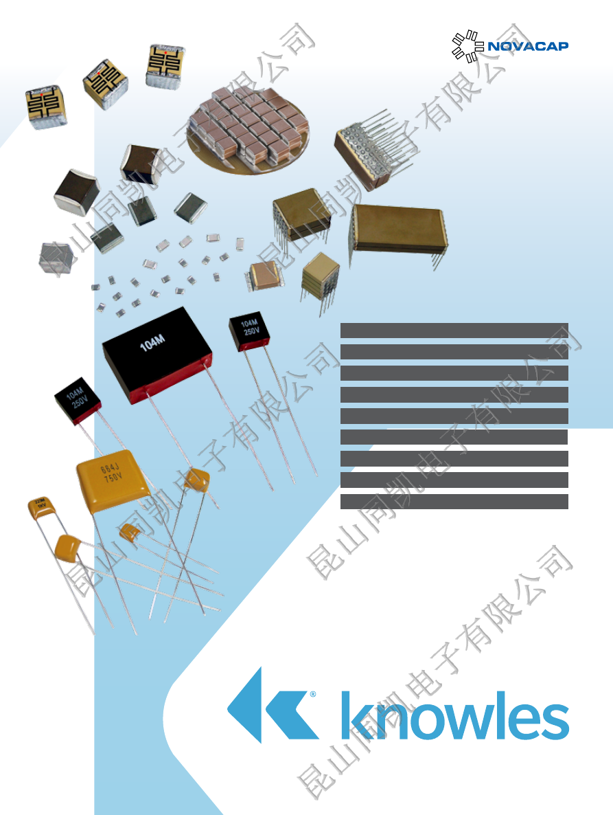
background image

Commercial Products

High Reliability Products

Application Specific

Capacitor Assemblies

Detonation & Pluse Energy Capacitors

High Temperature Products

Specialty Products

MLC 

Capacitors

Custom Designs

Radial Leaded capacitors

www.knowlescapacitors.com


Novacap-Catalog-html.html
background image

Contents

Note:

 Novacap reserves the right to make changes in product designs and/or pricing. Sales are subject to Novacap terms and conditions.  

Novacap warrants that its product(s) will be free from defects in workmanship or materials at the time of delivery, subject to the provisions of  

this Limited Warranty. For complete terms and conditions of sale please refer to the Sales Office or on the web at http://novacap.com/terms.php.

Intro

Products by Market

Page 1

Aer

ospace & A

vionics

Automotive

Medical

Military & Defense

Oil Exploration

Power Conversion

Tele/Datacom

The Company

Page 2

Technical  

Data

Technical Summary

Page 3

Dielectric Characteristics

Page 4 - 7

Capacitor Manufacturing Process

Page 8

MIL PRF-123 Periodic Testing

Page 9

Board Design Considerations

Page 10

FlexiCap™ Polymer Termination

Page 11

Chip Dimensions

Page 12

Capacitor Marking System

Page 13

Chip Taping Details

Page 14

Chip Ordering Information

Page 15

Commercial  

Products

Commercial Chip - C0G 16Vdc to 10kVdc

Page 16 - 17

Commercial Chip - R3L 16Vdc to 5kVdc

Page 18 - 19

Commercial Chip - X7R 16Vdc to 10kVdc

Page 20 - 21

Commercial Chip - BX

Page 22

Commercial Chip - Z5U & Y5V

Page 22

Commercial Chip - BX & X7R RF series 

Page 23

Commercial Radial Lead - 50V to 5kV

Page 24

Commercial Radial Lead - 500V to 10kV

Page 25

 Leaded Products Ordering Information

Page 26

High  

Reliability  

Products

High Reliability Testing

Page 27

High Reliability Chip - C0G 16Vdc to 10kVdc

Page 28 - 29

High Reliability Chip - X7R 16Vdc to 10kVdc

Page 30 - 31

High Reliability Radial Lead - 500Vdc to 10kVdc

Page 32

DSCC Approved - Radial Lead

Page 33

DSCC Approved - Capacitor Assemblies

Page 34

Product Reliability Groups

Page 35

Lot Testing

Page 36

Lot Test Details

Page 37

High  

Temperature  

Products

High Temperature Applications Introduction

Page 38

High Temperature Chip - 150ºC, 160ºC & 200ºC

Page 39

High Temperature Radial Lead - Epoxy Coated

Page 40

High Temperature Radial Lead - Encapsulated

Page 41

Application  

Specific

Certified Safety Chip - X

2

, Y

3

 & X

1

, Y

2

Page 42 - 43

High Capacitance Chip - X7R & X5R (BME)

Page 44 - 45

Non Magnetic Chip - C0G & X7R

Page 46

Thin Profile Chip 

Page 47

Capacitor  

Assemblies

Capacitor Assemblies - ST & SM

Page 48 - 49

Capacitor Assemblies - C0G Commercial & High Reliability

Page 50 - 51

Capacitor Assemblies - X7R Commercial & High Reliability

Page 52 - 53

Capacitor Assemblies - ‘Cap-Rack’ Arrays

Page 54

Specialty  

Products

Specialty Capacitors - Application Specific

Page 55

Specialty Capacitors - Detonation & Pulse Energy Capacitors

Page 56 - 57

Specialty Capacitors - Custom Designs

Page 58 - 59


Novacap-Catalog-html.html
background image

Products by Market

Intro

Products by Market

Page 1

Aer

ospace & A

vionics

Automotive

Medical

Military & Defense

Oil Exploration

Power Conversion

Tele/Datacom

The Company

Page 2

Technical  

Data

Technical Summary

Page 3

Dielectric Characteristics

Page 4 - 7

Capacitor Manufacturing Process

Page 8

MIL PRF-123 Periodic Testing

Page 9

Board Design Considerations

Page 10

FlexiCap™ Polymer Termination

Page 11

Chip Dimensions

Page 12

Capacitor Marking System

Page 13

Chip Taping Details

Page 14

Chip Ordering Information

Page 15

Commercial  

Products

Commercial Chip - C0G 16Vdc to 10kVdc

Page 16 - 17

Commercial Chip - R3L 16Vdc to 5kVdc

Page 18 - 19

Commercial Chip - X7R 16Vdc to 10kVdc

Page 20 - 21

Commercial Chip - BX

Page 22

Commercial Chip - Z5U & Y5V

Page 22

Commercial Chip - BX & X7R RF series 

Page 23

Commercial Radial Lead - 50V to 5kV

Page 24

Commercial Radial Lead - 500V to 10kV

Page 25

 Leaded Products Ordering Information

Page 26

High  

Reliability  

Products

High Reliability Testing

Page 27

High Reliability Chip - C0G 16Vdc to 10kVdc

Page 28 - 29

High Reliability Chip - X7R 16Vdc to 10kVdc

Page 30 - 31

High Reliability Radial Lead - 500Vdc to 10kVdc

Page 32

DSCC Approved - Radial Lead

Page 33

DSCC Approved - Capacitor Assemblies

Page 34

Product Reliability Groups

Page 35

Lot Testing

Page 36

Lot Test Details

Page 37

High  

Temperature  

Products

High Temperature Applications Introduction

Page 38

High Temperature Chip - 150ºC, 160ºC & 200ºC

Page 39

High Temperature Radial Lead - Epoxy Coated

Page 40

High Temperature Radial Lead - Encapsulated

Page 41

Application  

Specific

Certified Safety Chip - X

2

, Y

3

 & X

1

, Y

2

Page 42 - 43

High Capacitance Chip - X7R & X5R (BME)

Page 44 - 45

Non Magnetic Chip - C0G & X7R

Page 46

Thin Profile Chip 

Page 47

Capacitor  

Assemblies

Capacitor Assemblies - ST & SM

Page 48 - 49

Capacitor Assemblies - C0G Commercial & High Reliability

Page 50 - 51

Capacitor Assemblies - X7R Commercial & High Reliability

Page 52 - 53

Capacitor Assemblies - ‘Cap-Rack’ Arrays

Page 54

Specialty  

Products

Specialty Capacitors - Application Specific

Page 55

Specialty Capacitors - Detonation & Pulse Energy Capacitors

Page 56 - 57

Specialty Capacitors - Custom Designs

Page 58 - 59

www.novacap.com  |  Phone: +1.661.295.5920  |   

1


Novacap-Catalog-html.html
background image

The Company

We are flexible, quick, 
reliable and innovative!  
Call us with your 
particular requirements.

Novacap


manufactures surface 

mount and leaded Multilayer 
Ceramic Capacitors (MLC) as 
well as specialty assemblies for 
your circuit applications.  We are 
part of Knowles Capacitors, an 
operating company within Knowles 
Corporation.


Some of our offerings include:

Full range of surface mount chip capacitors

l


High Reliability capacitors for use in Medical  


  Implantable Devices and Life Support Systems

l


High Temperature capacitors for harsh  

  environments such as Oil Exploration, Automotive  
  and Avionics Engine Compartment circuitry

l


Custom Capacitor Modules for ratings up to 20kV

l


Capacitor Arrays for highly efficient use of  


  board space 

l


Certified Safety (Y², Y³) and Ring Detect  


  Capacitors for Telecommunications

l


High Voltage capacitors, with ratings up to 10kV,  

  designed for Commercial and Military use in    
  Power Supply and Voltage Multiplier circuits

l


Pulsed Energy capacitors for Oil Exploration and  

  Detonation

l


Radial Leaded capacitors

l


Thin Profile capacitors for RFID and smart cards.

l


Stacked Capacitor Assemblies for input and  


  output filters in Switch Mode Power Supplies,    
  High Capacitance Discharge Circuitry and High   
  Temperature Filtering and Decoupling

Our standard sizes range from 

0402 to 7565, and we provide 

voltage ratings from 4V to 10kV.

Guaymas, Mexico.


Valencia, California

2


|  Phone: +1.661.295.5920  |  www.novacap.com


Novacap-Catalog-html.html
background image

L

W

MB

T

L

W

MB

T

Technical Summary

Palladium Silver

Palladium Silver

Solderable 

Palladium Silver

Nickel Barrier 

100% tin

Nickel Barrier 

90/10% tin/lead

Nickel Barrier 

Gold flash

FlexiCap™/Nickel Barrier

100% tin

FlexiCap™/Nickel Barrier 

90/10% tin/lead

Copper Barrier 

100% tin

Copper Barrier 

90/10% tin/lead

Solderable Silver

RoHS RoHS RoHS

RoHS RoHS

RoHS

RoHS

Dielectric

Code

P

PR

K

N

Y

NG

C

D

B

E

S

C0G/NP0

N/RN

R3L

K

X7R

B/RB

X7R BME

BB

X5R BME

BW

BX

X

Y5V

Y

Z5U

Z

C0G/NP0 (

Mag free

)

M

X7R (

Mag free

)

C

X8R

S

C0G/NP0 (160ºC)

F

C0G/NP0 (200ºC)

D

Class II (160ºC)

G

Class II (200ºC)

E

Pulse Power

P

R2D

R

Technical Information 

Novacap provides application notes throughout this catalog 
as a guide to chip selection and attachment methods.  Refer 
to the Novacap Technical Brochure found at www.novacap.
com for more details.  This technical information includes 
the nature of capacitance, dielectric properties, electrical 
properties, classes of dielectrics, ferroelectric behavior, test 
standards, and high reliability test plans.  Please do not 
hesitate to contact the sales office for any product or technical 
assistance.

Capacitor Size

Size availability is based primarily on capacitance values and 
voltage rating.  Smaller units are generally less expensive.  
Because mass affects the thermal shock susceptibility of chip 
capacitors, size selection should consider the soldering method 
used to attach the chip to the board.  Sizes 1812 and smaller 
can be wave, vapor phase, or reflow soldered.  Larger units 
require reflow soldering.

Chip Selection

Multilayer capacitors (MLC) are categorized by dielectric 
performance with temperature.  The Temperature Coefficient 
of Capacitance describes the variance of capacitance value 
with temperature.  The choice of components is therefore 
largely determined by the temperature stability required of the 
device and the size necessary for the desired capacitance value 
and voltage rating.

Packaging

Units are available reeled, in waffle pack, or bulk packaged.  
Bar coded labels are standard for reeled and bulk packaging.

Dielectric 
Termination 
Combinations

Primary Dielectric Types

C0G/NP0:


Ultra stable Class I dielectric, with negligible dependence of 
capacitance on temperature, voltage, frequency, and time.  
Used in circuitry requiring very stable performance.

X7R:


Stable Class II dielectric, with predictable change in properties 
across a temperature range of -55°C to +125°C.  Used as 
blocking, decoupling, bypassing, and frequency discriminating 
elements.  This dielectric is ferroelectric and provides higher 
capacitance than Class I materials.

BX:


The military specification for ceramic chip capacitors (MIL-
PRF-55681) defines a mid-K stable dielectric designated as BX.  
The BX specification has voltage temperature limits in addition 
to temperature limits of capacitance.  The BX dielectric is 
limited to ±15% maximum change in capacitance between 
25°C and -55°C or +125°C and also has a voltage restriction 
of +15% / -25% maximum change in capacitance between 
25°C and -55°C or +125°C at rated voltage.

Z5U/Y5V:


General purpose Class III dielectrics with higher dielectric 
constant and greater variation of properties over temperature 
and voltage.  Very high capacitance per volume is attainable 
for general purpose applications where stability over a wide 
temperature range is not critical.

Termination Material

We recommend the following 
termination types:

Solder Attachment:


N

  Nickel Barrier, 100% matte  

tin plated - RoHS

C

   FlexiCap™ with Nickel 

Barrier, 100% tin plated - RoHS

Y

   Nickel Barrier, tin-lead plated 

D

   FlexiCap™ Nickel Barrier, 

tin-lead plated

B

   Copper Barrier 100% matte 

tin plated - RoHS

E

   Copper Barrier, tin-lead  

plated 

K

   Solderable Palladium Silver -  

RoHS 

(suitable for conductive epoxy attach)

S

   Solderable Silver - RoHS

Conductive Epoxy attachment:

P

   Palladium Silver 

PR

  Palladium Silver - RoHS

NG

 Nickel Barrier Gold Flash - 

RoHS 

(suitable for soldering attach) 

www.novacap.com  |  Phone: +1.661.295.5920  |   

3


Novacap-Catalog-html.html
background image

C0G/NP0 (F) Ultra Stable High Temperature (up to 160ºC)

Operating temperature range:

-55°C to 160°C

Temperature coefficient:

0 ±30 ppm/ºC

Dissipation factor:

0.1% max @ 25ºC

Insulation resistance

@25ºC: 

  @160ºC:

>100G

W

 or >1000

W

whichever is less


>1G

W

 or >10

W

whichever is less

Dielectric                            <200V:
withstanding                 201-500V: 
voltage


>500V:

250%  
150% or 500V 

whichever is greater

120% or 750V 

whichever is greater

Ageing rate:

0% per decade

Test parameters:

1KHz, 1.0 ±0.2 VRMS, 25°C 
1MHz for Capacitance <100pF

Dielectric Characteristics

C0G/NP0 (N) Ultra Stable and RoHS 2013 (RN) type

Operating temperature range:

-55°C to 125°C

Temperature coefficient:

0 ±30 ppm/ºC

Dissipation factor:

0.1% max @ 25ºC

Insulation resistance

@25ºC: 

  @125ºC:

>100G

W

 or >1000

W

whichever is less


>10G

W

 or >100

W

whichever is less

Dielectric                            <200V:
withstanding                 201-500V: 
voltage


>500V:

250%  
150% or 500V 

whichever is greater

120% or 750V 

whichever is greater

Ageing rate:

0% per decade

Test parameters:

1KHz, 1.0 ±0.2 VRMS, 25°C 
1MHz for Capacitance <100pF

C0G/NP0 (D) Ultra Stable High Temperature (up to 200ºC)

Operating temperature range:

-55°C to 200°C

Temp. coefficient <200ºC:

0 ±30 ppm/ºC

Dissipation factor @ 25ºC:

0.1% Max.

Insulation resistance

@25ºC:

@200ºC:

>100G

W

 or >1000

W

whichever is less


>1G

W

 or >10

W

whichever is less

Dielectric
withstanding 
voltage

<200V:

201-500V: 

>500V:

250%  
150% or 500V 

whichever is greater

120% or 750V 

whichever is greater

Ageing rate:

0% per decade

Test parameters:

1KHz, 1.0 ±0.2 VRMS, 25°C 
1MHz for capacitance <100pF

TEMPERATURE COEFFICIENT

50

25

0

-25

-50

-55

-25

0

25

 50

 75

 100

 125

D

C ppm

% CAPACITANCE CHANGE 

TEMPERATURE °C

TYPICAL

UPPER LIMIT

LOWER LIMIT

C0G/NP0 (M) Ultra Stable Non Magnetic

Operating temperature range:

-55°C to 125°C

Temperature coefficient:

0 ±30 ppm/ºC

Dissipation factor:

0.1% max @ 25ºC

Insulation resistance

@25ºC: 

  @125ºC:

>1000

W

F or >10000

W

whichever is less


>100

W

F or >1000

W

whichever is less

Dielectric                            <200V:
withstanding                 201-500V: 
voltage


>500V:

250%  
150% or 500V 

whichever is greater

120% or 750V 

whichever is greater

Ageing rate:

0% per decade

Test parameters:

1KHz, 1.0 ±0.2 VRMS, 25°C 
1MHz for Capacitance <100pF

TEMPERATURE COEFFICIENT

50

25

0

-25

-50

-55

-25

0

25

 50

 75

 100

 125

D

C ppm

% CAPACITANCE CHANGE 

TEMPERATURE °C

TYPICAL

UPPER LIMIT

LOWER LIMIT

-55

-25

0

25

50

 100

75

 125  150

 175  200

20

40

0

-20

-40

TEMPERATURE COEFFICIENT

D

C ppm

% CAPACITANCE CHANGE 

TEMPERATURE °C

-55

-25

0

25

50

 100

75

 125

 150

20

40

0

-20

-40

TEMPERATURE COEFFICIENT

D

C ppm

% CAPACITANCE CHANGE 

TEMPERATURE °C

4


|  Phone: +1.661.295.5920  |  www.novacap.com


Novacap-Catalog-html.html
background image

Y5V (Y) General Purpose

Operating temperature range:

-30°C to 85°C

Temperature coefficient:

+22% -82% 

D

C Max.

Dissipation factor        >25V rating:
                                  <25V rating:

5.0% max 
7.0% max

Insulation resistance @25%:

>10G

W

 or >100

W

whichever is less

Dielectric                            <200V:
withstanding voltage            250V:

250%  
150%

Ageing rate:

4.0% per decade

Test parameters:

1KHz, 1.0 ±0.2 VRMS, 25°C

R3L (K) Ultra Stable

Operating temperature range:

-55°C to 125°C

Temperature coefficient:

-2200 ±500 ppm/ºC

Dissipation factor:

0.1% max @ 25ºC

Insulation resistance

      @25ºC: 
    @125ºC:

>1000

W

F or >10000

W

whichever is less


>100

W

F or >1000

W

whichever is less

Dielectric                            <200V:
withstanding                 201-500V: 
voltage


>500V:

250%  
150% or 500V 

whichever is greater

120% or 750V 

whichever is greater

Ageing rate:

0% per decade

Test parameters:

1KHz, 1.0 ±0.2 VRMS, 25°C 
1MHz for Capacitance <100pF

R2D (R) Pulse Energy

Operating temperature range:

-55°C to 200°C

Temperature coefficient:

-2200 ±500 ppm/ºC

Dissipation factor:

0.1% max @ 25ºC

Insulation resistance

      @25ºC: 
    @200ºC:

>100G

W

 or >1000

W

whichever is less

>1G

W

 or >10

W

whichever is less

Dielectric withstanding voltage:                              


120% 

Ageing rate:

0% per decade

Test parameters:

1KHz, 1.0 ±0.2 VRMS, 25°C 

Dielectric Characteristics

Z5U (Z) General Purpose

Operating temperature range:

+10°C to 85°C

Temperature coefficient:

+22% -56% 

D

C Max.

Dissipation factor:

4.0% max @ 25ºC

Insulation resistance @25%

>10G

W

 or >100

W

whichever is less

Dielectric                             <200V:
withstanding voltage            250V:

250%  
150%

Ageing rate:

4.0% per decade

Test parameters:

1KHz, 0.5 ±0.2 VRMS, 25°C

TEMPERATURE COEFFICIENT

-55

-35

-15

5

25

45

 65

 105

85

 125

TYPICAL

UPPER LIMIT

LOWER LIMIT

20
15
10

5
0

-5

-10
-15
-20

%

D

C

TEMPERATURE °C

%CAPACITANCE CHANGE 

TEMPERATURE COEFFICIENT

-30

0

30

60

90

100

50

0

-50

-100

%

D

C

TEMPERATURE °C

%CAPACITANCE CHANGE 

TYPICAL

UPPER LIMIT

LOWER LIMIT

-15

15

45

75

TEMPERATURE COEFFICIENT

50

25

-25

0

-50

-55

-25

0

25

 50

 75

 100

 125

TEMPERATURE °C 

%

D

C

% CAPACITANCE CHANGE 

50

25

0

-25

-50

-55

-25

0

25

50

75

100

125

150

175

200

TEMPERATURE °C

TEMPERATURE COEFFICIENT

%

C

% CAPACITANCE CHANGE 

www.novacap.com  |  Phone: +1.661.295.5920  |   

5


Novacap-Catalog-html.html
background image

Dielectric Characteristics

X7R (B) Stable and RoHS 2013 (RB) type

Operating temperature range:

-55°C to 125°C

Temperature coefficient :

±15% 

D

C Max.

Dissipation factor        >25V rating:
                                  <25V rating:

2.5% max  
3.5% max 

Insulation resistance:         @25ºC: 

      @125ºC:

>100G

W

 or >1000

W

whichever is less


>10G

W

 or >100

W

whichever is less

Dielectric                            <200V:
withstanding                 201-500V: 
voltage


>500V:

250%  
150% or 500V 

whichever is greater

120% or 750V 

whichever is greater

Ageing rate:

<2.0% per decade

Test parameters:

1KHz, 1.0 ±0.2 VRMS, 25°C

TEMPERATURE COEFFICIENT

-55

-35

-15

5

25

45

 65

 105

85

 125

TYPICAL

UPPER LIMIT

LOWER LIMIT

20
15
10

5
0

-5

-10
-15
-20

%

D

C

TEMPERATURE °C

%CAPACITANCE C

HANGE 

X8R (S) Stable

Operating temperature range:

-55°C to 150°C

Temp. coefficient <150ºC:

±15% 

D

C Max.

Dissipation factor

>25V rating: 

 <25V rating:

2.5% max  
3.5% max

Insulation 
resistance

@25ºC: 

@150ºC:

>100G

W

 or >1000

W

whichever is less


>10G

W

 or >100

W

whichever is less

Dielectric
withstanding 
voltage

<200V:

201-500V:

>500V:

 250%  
 150% or 500V 

whichever is greater

 120% or 750V 

whichever is greater

Ageing rate:

<2.0% per decade

Test parameters:

1KHz, 1.0 ±0.2 VRMS, 25°C

TEMPERATURE °C

-55

-25

0

25

50

 100

75

 125

 150

20

40

0

-20

-40

%

D

C

% CAPACITANCE CHANGE 

TEMPERATURE COEFFICIENT

X7R (C) Stable Non Magnetic

Operating temperature range:

-55°C to 125°C

Temperature coefficient:

±15% 

D

C Max.

Dissipation factor        >25V rating:
                                  <25V rating:

2.5% max  
3.5% max 

Insulation resistance:         @25ºC: 

      @125ºC:

>100G

W

 or >1000

W

whichever is less


>10G

W

 or >100

W

whichever is less

Dielectric                            <200V:
withstanding                 201-500V: 
voltage


>500V:

250%  
150% or 500V 

whichever is greater

120% or 750V 

whichever is greater

Ageing rate:

<2.0% per decade

Test parameters:

1KHz, 1.0 ±0.2 VRMS, 25°C

TEMPERATURE COEFFICIENT

-55

-35

-15

5

25

45

 65

 105

85

 125

TYPICAL

UPPER LIMIT

LOWER LIMIT

20
15
10

5
0

-5

-10
-15
-20

%

D

C

TEMPERATURE °C

%CAPACITANCE CHANGE 

BX (X) Stable

Operating temperature range:

-55°C to 125°C

Temperature coefficient:
Temp-voltage coefficient:

±15% 

D

C Max.

+15% -25% 

D

C Max.

Dissipation factor        >25V rating:
                                  <25V rating:

2.5% max  
3.5% max 

Insulation resistance:         @25ºC: 

      @125ºC:

>100G

W

 or >1000

W

whichever is less


>10G

W

 or >100

W

whichever is less

Dielectric                            <200V:
withstanding                 201-500V: 
voltage


>500V:

250%  
150% or 500V 

whichever is greater

120% or 750V 

whichever is greater

Ageing rate:

<2.0% per decade

Test parameters:

1KHz, 1.0 ±0.2 VRMS, 25°C

TEMPERATURE COEFFICIENT

-55

-35

-15

5

25

45

 65

 105

85

 125

TYPICAL

UPPER LIMIT

LOWER LIMIT

20
15
10

5
0

-5

-10
-15
-20

%

D

C

TEMPERATURE °C

%CAPACITANCE CHANGE 

6


|  Phone: +1.661.295.5920  |  www.novacap.com


Novacap-Catalog-html.html
background image

Dielectric Characteristics

Class II (E) Stable High Temperature (up to 200ºC)

Operating temperature range:

-55°C to 200°C

Temperature coefficient up to 200ºC:

+15 -65% 

D

C Max.

Dissipation factor @ 25ºC:

2.5% Max.

Insulation resistance              @25ºC: 

           @200ºC:

>100G

W

 or >1000

W

whichever is less


>1G

W

 or >10

W

whichever is less

Dielectric                                 <200V:
withstanding                      201-500V: 
voltage


>500V:

250%  
150% or 500V 

whichever is greater

120% or 750V 

whichever is greater

Ageing rate:

< 2.0% per decade

Test parameters:

1KHz, 1.0 ±0.2 VRMS, 25°C

-55

-25

0

25

50

 100

75

 125  150

 175  200

15

0

-15

-30

-60

-75

-45

TEMPERATURE COEFFICIENT

%

 D

C

% CAPACITANCE CHANGE 

TEMPERATURE °C

X5R (W) Stable

Operating temperature range:

-55°C to 85°C

Temperature coefficient up to 200ºC:

±15% 

D

C Max.

Dissipation factor @ 25ºC:

5% Max.

Insulation resistance @25%:

>10G

W

 or >500

W

whichever is less

Dielectric withstanding voltage:    

250%

Ageing rate:

< 5.0% per decade

Test parameters:
Except: 22µF, 47µF & 100µF

1KHz, 1.0 ±0.2 VRMS, 25°C
120KHz, 0.5 ±0.1 VRMS, 25°C

TEMPERATURE COEFFICIENT

-55

-15

5

45

85

10

0

-10

-20

-30

%

 D

C

TEMPERATURE °C

%CAPACITANCE CHANGE 

65

25

-35

Class II (G) Stable High Temperature (up to 160ºC)

Operating temperature range:

-55°C to 160°C

Temperature coefficient up to 160ºC:

+15 -40% 

D

C Max.

Dissipation factor @ 25ºC:

2.5% Max.

Insulation resistance              @25ºC: 

           @160ºC:

>100G

W

 or >1000

W

whichever is less


>1G

W

 or >10

W

whichever is less

Dielectric                                 <200V:
withstanding                      201-500V: 
voltage


>500V:

250%  
150% or 500V 

whichever is greater

120% or 750V 

whichever is greater

Ageing rate:

< 2.0% per decade

Test parameters:

1KHz, 1.0 ±0.2 VRMS, 25°C

15

0

-15

-30

-60

-75

-45

TEMPERATURE COEFFICIENT

%

 D

C

% CAPACITANCE CHANGE 

TEMPERATURE °C

-55

-25

0

25

50

 100

75

 125

 150

www.novacap.com  |  Phone: +1.661.295.5920  |   

7


Novacap-Catalog-html.html
background image

Raw 

material

inspection

Ceramic

slip

manufacture

Ceramic

tape

manufacture

Cutting

Pressing

Electrode 

print &

multilayer

build up

Burn out

Firing

Initial

electrical

inspection

Plating

Termination

Tumbling

Testing & 

inspection 

of chip

Application 

Hi-Rel

screening

QA

inspection

Process flow diagram for Novacap ceramic chip capacitors

RoHS compliance

Novacap routinely monitors world wide material restrictions 
(e.g. EU / China and Korea RoHS mandates) and is actively 
involved in monitoring future legislation.
In an effort to meet the RoHS directives and its Recast aimed 
at reducing hazardous substances (Restriction of Hazardous 
Substances (RoHS) directive 2012/65/EU), Novacap has 
introduced new RoHS Lead-Free compliant lines.  The new 
dielectric codes for these are “RN” for C0G/NP0 and “RB” 
for X7R. This is not a transition from the current product. The 
current product lines with dielectric codes “N” and “B” will 
not be phased out and can still be purchased. Please refer to 
our web site for further details.
Breakdown of material content, SGS analysis reports and tin 
whisker test results are available on request.  
Most Novacap MLCC components are available with non 
RoHS compliant tin lead (SnPb) solderable termination finish 
by special request for exempt applications and where pure tin 
is not acceptable. Other tin free termination finishes may also 
be available – please refer to Novacap for further details.
Radial components have tin (Sn) plated leads as standard, but  
Sn/Pb leads are available as a special option. Please refer to the 
radial section of the catalog for further details.

REACH (Registration, Evaluation, Authorization and 
restriction of Chemicals) statement

The main purpose of REACH is to improve the protection of 
human health and the environment from the risks arising from 
the use of chemicals.
Novacap maintains both ISO14001, Environmental 
Management System and OHSAS 18001 Health and Safety 
Management System approvals that require and ensure 
compliance with corresponding legislation such as REACH.
For further information, please contact the sales office.

Novacap’s “Green” Policy

It is Novacap policy to comply with the global environmental 
directives pertaining to the use of hazardous materials in 
manufacturing and to that end can supply products meeting 
RoHS standards – details can be found throughout this 
catalog.

Capacitor Manufacturing Process

8


|  Phone: +1.661.295.5920  |  www.novacap.com


Novacap-Catalog-html.html
background image

MIL-PRF-123 Periodic Lot Testing

Test Name

Test Method

Details 

Sample Size

Rejects Allowed

Electrical Characteristics

Capacitance/Dissipation Factor

MIL-STD-202 M305

1Vrms, 1kHz   

325

0

Insulation Resistance 

MIL-STD-202 M302

Rated Voltage 

1000 M

W

 - µF min

325

0

Dielectric Withstanding Voltage

MIL-STD-202 M301

2.5x Rated Vdc min

325

0

Group A - Subgroup 1

Thermal Shock

MIL-PRF-123 4.6.6.1 

MIL-STD-202 M107

20 cycles -55ºC to +125ºC

325

5% PDA (16 pcs) 

and  

< 0.2% (0 pcs)  

in last 48 hrs

Voltage Conditioning

MIL-PRF-123 4.6.6.2 

 2x Rated Vdc, 125ºC,  

168-264 Hours

Group A - Subgroup 2

“Visual and mechanical 
inspection; material, 
physical dimensions, design, 
construction, marking and 
workmanship”.

MIL-PRF-123 4.6.3

Parts must pass criteria

20

0

Group A - Subgroup 3

Destructive Physical Analysis

MIL-PRF-123 4.6.11

Parts must pass criteria

10

0

Group B - Subgroup 1

Thermal Shock

MIL-PRF-123 4.6.6.1 

MIL-STD-202 M107

100 cycles -55ºC to +125ºC

200

Report

Life Test

MIL-PRF-123 4.6.19 
MIL-STD-202 M108

2xVdc, 125ºC, 1000 Hours

Group B - Subgroup 2

Humidity, Steady State Low 
Voltage

MIL-PRF-123 4.6.16.1 

MIL-STD-202 M103

85% RH, 85ºC, 240 Hrs, 1.3V

12

0

Group B - Subgroup 3

Voltage - Temperature Limits

MIL-PRF-123 4.6.15

-55ºC -25ºC -125ºC  

1Vrms ±15%(X7R), ±30ppm (C0G)

12

1

Moisture Resistance

MIL-PRF-123 4.6.16.2 

MIL-STD-202 M106

20 cycles 25V 1st 10 cycles

Group C - Subgroup 2 Chip Devices

Terminal Strength

MIL-PRF-123 4.6.12.2 

MIL-STD-202 M211

Pull test, nail leads, x-x kg

6

1

Solderability

MIL-PRF-123 4.6.13.2 

MIL-STD-202 M208   

J-STD 002C

8 Hr Steam Age,  

SAC305 at 255ºC, 5 seconds,  

95% coverage 

6

Resistance To Soldering Heat

MIL-PRF-123 4.6.14.2 

MIL-STD-202 M210

60/40 Tin/Lead at 230ºC,  

2 five second dips

6

C0G and X7R test packages available on request.

www.novacap.com  |  Phone: +1.661.295.5920  |   

9


Novacap-Catalog-html.html
background image

Board Design Considerations

Bonding of capacitors to substrates can be categorized into 
two methods, those involving solder, which are prevalent, 
and those using other materials, such as epoxies and thermo-
compression or ultrasonic bonding with wire.
The amount of solder applied to the chip capacitor will 
influence the reliability of the device. Excessive solder can 
create thermal and tensile stresses on the component which 
could lead to fracturing of the chip or the solder joint itself. 
Insufficient or uneven solder application can result in weak 
bonds; rotation of the device off line or lifting of one terminal 
off the pad (tombstoning).
There are practical limitations on capacitor sizes that prohibit 
reliable direct mounting of chip capacitors larger than 2225 to 
a substrate. Without mechanical restriction, thermally induced 
stresses are released once the capacitor attains a steady state 
condition, at any given temperature. Capacitors bonded to 
substrates, however, will retain some stress, due primarily to 
the mismatch of expansion of the component to the substrate; 
the residual stress on the chip is also influenced by the ductility 
and hence the ability of the bonding medium to relieve 
the stress. Unfortunately, the thermal expansions of chip 
capacitors differ significantly from those of substrate materials. 
At 25°C to 300°C, capacitors typically range in expansion 
coefficient from 8.3 x 10⁻⁶ to 12.2 x 10⁻⁶ in/in/°C, while 99% 
Alumina is approximately 6.0 x 10⁻⁶ in/in/°C and P.C. board is 
typically 16.0 x 10⁻⁶ in/in/°C. 

Soldering

The volume of solder is process and board pad size 
dependent. Soldering methods commonly used in the 
industry, and recommended, are Reflow Soldering, Wave 
Soldering, and to a lesser extent, Vapor Phase Soldering. All 
these methods involve thermal cycling of the components and 

Wave Soldering exposes the devices to a large solder volume; 
hence the pad size area must be restricted to accept an 
amount of solder which is not detrimental to the chip size 
utilized. Typically the pad width is 66% of the component 
width, and the length is 
.030” (.760 mm) longer than 
the termination band on the 
chip. For example, an 0805 
chip which is .050” wide 
and has a .020” termination 
band therefore requires a 
pad .033” wide by .050” in 
length. Opposing pads should 
be identical in size to preclude 
uneven solder fillets and 
mismatched surface tension 
forces which can misalign 
the device. It is preferred 
that the pad layout results in 
alignment of the long axis of 
the chips at right angles to 
the solder wave, to promote 
even wetting of all terminals. Orientation of components in 
line with the board travel direction may require dual waves 
with solder turbulence to preclude cold solder joints on the 
trailing terminals of the devices, as these are blocked from full 
exposure to the solder by the body of the capacitor.
Restrictions in chip alignment do not apply to Solder Reflow or 
Vapor Phase processes, where the solder volume is controlled 
by the solder paste deposition on the circuit pads. Novacap 
has adopted the IPC-SM-782 methodology for solder reflow 
land patterns. The Novacap recommended solder pads 
brochure is available for reference on our website. Large 
chips are more prone to thermal shock as their greater bulk 
will result in sharper thermal gradients within the device 
during thermal cycling. Units larger than 1812 experience 
excessive stress if processed through the fast cycles typical 
of solder wave or vapor phase operations. Solder reflow is 
most applicable to the larger chips as the rates of heating and 
cooling can be slowed within safe limits.
Attachment using a soldering iron requires extra care, 
particularly with large components, as thermal gradients are 
not easily controlled and may cause cracking of the chip. 
Precautions include preheating of the assembly to within 
100°C of the solder flow temperature; the use of a fine tip 
iron which does not exceed 30 watts and limitation of contact 
of the iron to the circuit pad areas only.

Bonding

Hybrid assembly using conductive epoxy or wire bonding 
requires the use of silver palladium or gold terminations. 
Nickel barrier termination is not practical in these applications, 
as intermetallics will form between the dissimilar metals. The 
ESR will increase over time and may eventually break contact 
when exposed to temperature cycling.

Cleaning

Chip capacitors can withstand common agents such as water, 
alcohol and degreaser solvents used for cleaning boards. 
Ascertain that no flux residues are left on the chip surfaces as 
these diminish electrical performance.

20

40

60

80

100 120

SECONDS

140 160 180 200

250

TEMPERATURE °C

225

200

150

175

125

100

75

50

Solder Wave

Vapor Phase

Solder Reflow

therefore the rate of heating and cooling must be controlled 
to preclude thermal shocking of the devices. In general, rates 
which do not exceed 120°C per minute and a T spike of 
100°C maximum for any soldering process on sizes 1812 and 
smaller is advisable. Other precautions include post soldering 
handling, primarily avoidance of rapid cooling with contact 
with heat sinks, such as conveyors or cleaning solutions.

Novacap publishes a technical 
brochure which provides 
detailed information on the 
properties of ceramic chip 
capacitors, dielectric behavior, 
product classifications, test 
and quality standards, and 
other information relevant to 
their use. 
The Novacap technical 
brochure is available upon 
request. For quick reference 
see the brochure on the 
Novacap website at 


www.novacap.com

Recommendations


Preheat/Cooling rates not to exceed 120°C /minute with 

D

T spikes to 

max temperature not to exceed 100ºC for 1812 size and smaller.

10


|  Phone: +1.661.295.5920  |  www.novacap.com


Novacap-Catalog-html.html
background image

FlexiCap™ termination

MLCCs are widely used in electronic circuit design for a 
multitude of applications. Their small package size, technical 
performance and suitability for automated assembly makes 
them the component of choice.
However, despite the technical 
benefits, ceramic components  
are brittle and need careful 
handling on the production floor. 
In some circumstances they may be prone to mechanical stress 
damage if not used in an appropriate manner. Board flexing, 
depanelization, mounting through hole components, poor 
storage and automatic circuit testing may all result in cracking.
Careful process control is important at all stages of circuit 
board assembly and transportation - from component 
placement to test and packaging. Any significant board flexing 
may result in stress fractures in ceramic devices that may 
not always be evident during the board assembly process. 
Sometimes it may be the end customer who finds out - when 
equipment fails!

The solution - FlexiCap™

FlexiCap™ was developed as a result of listening to 
customers’ experiences of stress damage to MLCCs from 
many manufacturers, often caused by variations in production 
processes.
Our answer is a proprietary flexible epoxy polymer termination 
material, that is applied to the device under the usual nickel 
barrier finish. FlexiCap™ will accommodate a greater degree 
of board bending than conventional capacitors.

FlexiCap™ termination

All capacitance ranges are available with FlexiCap™ 
termination material offering increased reliability and superior 
mechanical performance (board flex and temperature 
cycling) when compared with standard termination materials. 
FlexiCap™ capacitors enable the board to be bent almost 
twice as much before mechanical cracking occurs. 
FlexiCap™ is also suitable for Space applications having 
passed thermal vacuum outgassing tests.

Application notes

FlexiCap™ may be handled, stored and transported in 
the same manner as standard terminated capacitors. The 
requirements for mounting and soldering FlexiCap™ are the 
same as for standard SMD capacitors.
For customers currently using standard terminated capacitors 
there should be no requirement to change the assembly 
process when converting to FlexiCap™.
Based upon board bend tests in accordance with IEC 60384-1 
the amount of board bending required to mechanically crack 
a FlexiCap™ terminated capacitor is significantly increased 
compared with standard terminated capacitors.
It must be stressed however, that capacitor users must not 
assume that the use of FlexiCap™ terminated capacitors will 
totally eliminate mechanical cracking. Good process controls 
are still required for this objective to be achieved.
Product not available for 200°C applications.

l


Picture taken at 1,000x magnification using 

a SEM to demonstrate the fibrous nature 
of the FlexiCap

TM

 termination that absorbs 

increased levels of mechanical stress.

Available on the following ranges:
  All High Reliability ranges
  Standard and High Voltage chips
  X8R High Temperature capacitors

Summary of PCB bend test results

The bend tests conducted on X7R have proven that the 
FlexiCap™ termination withstands a greater level of 
mechanical stress before mechanical cracking occurs.
The AEC-Q200 test for X7R requires a bend level of 2mm 
minimum and a cap change of less than 10%.

Product
X7R

Typical bend performance under AEC-Q200 

test conditions

Standard termination

2mm to 3mm

FlexiCap™ termination

Typically 8mm to 10mm

FlexiCap™ benefits

With traditional termination materials and assembly, the chain 
of materials from bare PCB to soldered termination, provides 
no flexibility. In circumstances where excessive stress is applied 
- the weakest link fails. This means the ceramic itself may fail.
The benefit to the user is to facilitate a wider process window 
- giving a greater safety margin and substantially reducing the 
typical root causes of mechanical stress cracking.
FlexiCap™ may be soldered using your traditional wave 
or reflow solder techniques and needs no adjustment to 
equipment or current processes.

Novacap has delivered millions of FlexiCap™ components and 
during that time has collected substantial test and reliability 
data, working in partnership with customers world wide, to 
eliminate mechanical cracking.
An additional benefit of FlexiCap™ is that  MLCCs can 
withstand temperature cycling -55ºC to 125ºC in excess of 
1,000 times without cracking. 
FlexiCap™ termination has no adverse effect on any electrical 
parameters, nor affects the operation of the MLCC in any 
way.

Fired ceramic
dielectric

FlexiCap

TM

termination
base

Intermediate
nickel layer

Tin outer
layer

Metal
electrodes

FlexiCap

TM

 MLCC cross section

FlexiCap™ Polymer Termination

www.novacap.com  |  Phone: +1.661.295.5920  |   

11


Novacap-Catalog-html.html
background image

L

W

MB

T

Chip Dimensions

Dimensions - inches (mm)

Size

Length (L)

Width (W)

Max. Thickness (T)*

Termination Band (MB)

0402

0.040 ± 0.004 (1.02 ± 0.102)

 0.020 ± 0.004 (0.508 ± 0.102)

 0.024 (0.610)

 0.010 ± 0.006 (0.254 ± 0.152)

0504

0.050 ± 0.006 (1.27 ± 0.152)

 0.040 ± 0.006 (1.02 ± 0.152)

 0.044 (1.12)

 0.014 ± 0.006 (0.356 ± 0.152)

RF0505

0.055 +0.015 -0.010 (1.4 +0.38 -0.25)

 0.055 ± 0.015 (1.40 ± 0.381)

 0.057 (1.45)

 0.014 ± 0.006 (0.356 ± 0.152)

0603

0.060 ± 0.006 (1.52 ± 0.152)

 0.030 ± 0.006 (0.762 ± 0.152)

 0.035 (0.889)

 0.014 ± 0.006 (0.356 ± 0.152)

0805

0.080 ± 0.008 (2.03 ± 0.203)

 0.050 ± 0.008 (1.27 ± 0.203)

 0.054 (1.37)

 0.020 ± 0.010 (0.508 ± 0.254)

0907

0.090 ± 0.008 (2.29 ± 0.203)

 0.070 ± 0.008 (1.78 ± 0.203)

 0.060 (1.52)

 0.020 ± 0.010 (0.508 ± 0.254)

1005

0.100 ± 0.008 (2.54 ± 0.203)

 0.050 ± 0.008 (1.27 ± 0.203)

 0.054 (1.37)

 0.020 ± 0.010 (0.508 ± 0.254)

RF1111

0.110+0.025 -0.010 (2.79 +0.64 -0.25)

 0.110 ± 0.015 (2.79 ± 0.381)

 0.102 (2.59)

 0.020 ± 0.010 (0.508 ± 0.254)

1206

0.125 ± 0.008 (3.18 ± 0.203)

 0.060 ± 0.008 (1.52 ± 0.203)

 0.064 (1.63)

 0.020 ± 0.010 (0.508 ± 0.254)

1210

0.125 ± 0.008 (3.18 ± 0.203)

 0.100 ± 0.008 (2.54 ± 0.203)

 0.065 (1.65)

 0.020 ± 0.010 (0.508 ± 0.254)

1515

0.150 ± 0.015 (3.81 ± 0.381)

0.150 ± 0.015 (3.81 ± 0.381)

 0.130 (3.30)

 0.030 ± 0.015 (0.762 ± 0.381)

1808

0.180 ± 0.012 (4.57 ± 0.305)

 0.080 ± 0.008 (2.03 ± 0.203)

 0.065 (1.65)

 0.024 ± 0.014 (0.610 ± 0.356)

1812

0.180 ± 0.012 (4.57 ± 0.305)

 0.125 ± 0.008 (3.18 ± 0.203)

 0.065 (1.65)

 0.024 ± 0.014 (0.610 ± 0.356)

1825

0.180 ± 0.012 (4.57 ± 0.305)

 0.250 ± 0.015 (6.35 ± 0.381)

 0.080 (2.03)

 0.024 ± 0.014 (0.610 ± 0.356)

2020

0.200 ± 0.015 (5.08 ± 0.381)

0.200 ± 0.015 (5.08 ± 0.381)

 0.180 (4.57)

 0.024 ± 0.014 (0.610 ± 0.356)

2221

0.220 ± 0.015 (5.59 ± 0.381)

 0.210 ± 0.015 (5.33 ± 0.381)

 0.080 (2.03)

 0.030 ± 0.015 (0.762 ± 0.381)

2225

0.220 ± 0.015 (5.59 ± 0.381)

 0.250 ± 0.015 (6.35 ± 0.381)

 0.080 (2.03)

 0.030 ± 0.015 (0.762 ± 0.381)

2520

0.250 ± 0.015 (6.35 ± 0.381)

0.200 ± 0.015 (5.08 ± 0.381)

 0.180 (4.57)

 0.030 ± 0.015 (0.762 ± 0.381)

RF2525

0.230 +0.020 -0.012 (5.84 +0.51 -0.30)

 0.250 ± 0.015 (6.35 ± 0.381)

 0.165 (4.19)

 0.030 ± 0.015 (0.762 ± 0.381)

3333

0.330 ± 0.017 (8.38 ± 0.432)

0.330 ± 0.017 (8.38 ± 0.432)

 0.250 (6.35)

 0.030 ± 0.015 (0.762 ± 0.381)

3530

0.350 ± 0.018 (8.89 ± 0.457)

 0.300 ± 0.015 (7.62 ± 0.381)

 0.250 (6.35)

 0.030 ± 0.015 (0.762 ± 0.381)

4040

0.400 ± 0.020 (10.2 ± 0.508)

0.400 ± 0.020 (10.2 ± 0.508)

 0.300 (7.62)

 0.040 ± 0.020 (1.02 ± 0.508)

4540

0.450 ± 0.023 (11.4 ± 0.584)

0.400 ± 0.020 (10.2 ± 0.508)

 0.300 (7.62)

 0.040 ± 0.020 (1.02 ± 0.508)

5440

0.540 ± 0.027 (13.7 ± 0.686)

0.400 ± 0.020 (10.2 ± 0.508)

 0.300 (7.62)

 0.040 ± 0.020 (1.02 ± 0.508)

5550

0.550 ± 0.028 (14.0 ± 0.711)

 0.500 ± 0.025 (12.7 ± 0.635)

 0.300 (7.62)

 0.040 ± 0.020 (1.02 ± 0.508)

6560

0.650 ± 0.033 (16.5 ± 0.838)

 0.600 ± 0.030 (15.2 ± 0.762)

 0.300 (7.62)

 0.040 ± 0.020 (1.02 ± 0.508)

7565

0.750 ± 0.038 (19.1 ± 0.965)

 0.650 ± 0.033 (16.5 ± 0.838)

 0.300 (7.62)

 0.040 ± 0.020 (1.02 ± 0.508)

* Non standard thicknesses are available - consult the sales office for details.

12


|  Phone: +1.661.295.5920  |  www.novacap.com


Novacap-Catalog-html.html
background image

Chip Marking System

A5

NA5

Marking Code 

- value in picofarads for alpha-numeric code

Number

0

1

2

3

4

5

6

7

Letter

A

1.0

10

100

1,000

10,000

100,000

1,000,000

10,000,000

B

1.1

11

110

1,100

11,000

110,000

1,100,000

11,000,000

C

1.2

12

120

1,200

12,000

120,000

1,200,000

12,000,000

D

1.3

13

130

1,300

13,000

130,000

1,300,000

13,000,000

E

1.5

15

150

1,500

15,000

150,000

1,500,000

15,000,000

F

1.6

16

160

1,600

16,000

160,000

1,600,000

16,000,000

G

1.8

18

180

1,800

18,000

180,000

1,800,000

18,000,000

H

2.0

20

200

2,000

20,000

200,000

2,000,000

20,000,000

J

2.2

22

220

2,200

22,000

220,000

2,200,000

22,000,000

K

2.4

24

240

2,400

24,000

240,000

2,400,000

24,000,000

L

2.7

27

270

2,700

27,000

270,000

2,700,000

27,000,000

M

3.0

30

300

3,000

30,000

300,000

3,000,000

30,000,000

N

3.3

33

330

3,300

33,000

330,000

3,000,000

33,000,000

P

3.6

36

360

3,600

36,000

360,000

3,600,000

36,000,000

Q

3.9

39

390

3,900

39,000

390,000

3,900,000

39,000,000

R

4.3

43

430

4,300

43,000

430,000

4,300,000

43,000,000

S

4.7

47

470

4,700

47,000

470,000

4,700,000

47,000,000

T

5.1

51

510

5,100

51,000

510,000

5,100,000

51,000,000

U

5.6

56

560

5,600

56,000

560,000

5,600,000

56,000,000

V

6.2

62

620

6,200

62,000

620,000

6,200,000

62,000,000

W

6.8

68

680

6,800

68,000

680,000

6,800,000

68,000,000

X

7.5

75

750

7,500

75,000

750,000

7,500,000

75,000,000

Y

8.2

82

820

8,200

82,000

820,000

8,200,000

82,000,000

Z

9.1

91

910

9,100

91,000

920,000

9,200,000

92,000,000

a

2.5

25

250

2,500

25,000

250,000

2,500,000

25,000,000

b

3.5

35

350

3,500

35,000

350,000

3,500,000

35,000,000

d

4.0

40

400

4,000

40,000

400,000

4,000,000

40,000,000

e

4.5

45

450

4,500

45,000

450,000

4,500,000

45,000,000

f

5.0

50

500

5,000

50,000

500,000

5,000,000

50,000,000

m

6.0

60

600

6,000

60,000

600,000

6,000,000

60,000,000

n

7.0

70

700

7,000

70,000

700,000

7,000,000

70,000,000

t

8.0

80

800

8,000

80,000

800,000

8,000,000

80,000,000

y

9.0

90

900

9,000

90,000

900,000

9,000,000

90,000,000

Two position alpha numeric marking 
is available on chip sizes 0805 through 
3333.  
The marking denotes retma value and 
significant figures of capacitance  
(see table) eg: A5 = 100,000pF.

Three position alpha numeric marking 
is available on chip sizes 1206 and 
larger.   
The making denotes Novacap as 
vendor (N), followed by the standard 
two digit alpha numeric identification.

If required, we can mark capacitors with the EIA 198 two digit 
code to show the capacitance value of the part. On chips larger 
than 3333, or for leaded encapsulated devices, ink marking 
is available. However, for chip sizes 0805 through to 3333 
identification marking is accomplished by using either laser or ink 
jet printer. This system does not degrade the ceramic surface, or 
induce microcracks in the part.  
Marking for other sizes may be available upon special request to 
determine if applicable; please contact the sales office.  
Marking is an option, and needs to be specified when ordering 
by using the letter M in the part number code, see page 15 for 
details.

www.novacap.com  |  Phone: +1.661.295.5920  |   

13


Novacap-Catalog-html.html
background image

Chip Tape and Reel Details 

Embossment
3.8 x 3.2mm
maximum

Cover Tape
.05 thick

4.00 ±.10

ø1.5 +0.1

-0.0

1.75

±.05

Feed

Direction

8.0

± 0.2

0.3 Max.

4.00 ±.10

3.5

±.05

Novacap chip capacitors are available packaged in 8mm to 
24mm embossed carrier, per EIA 481. Specify the reeled option 
(T) in the Novacap part number code. Chips are also supplied in 
bulk or waffle pack.

Units per reel (typical)

Chip 

size

Tape 

width

Tape 

pocket 

pitch

Units per reel*

7”

(178mm) 

dia.

13”

(330mm) 

dia.

0402

8 mm

2 mm

 10,000

0504

8 mm

4 mm

3,000-4,000

15,000

0603

8 mm

4 mm

3,000-4,000

15,000

0805

8 mm

4 mm

3,000-4,000

15,000

1005

8 mm

4 mm

2,000-4,000

15,000

1206

8 mm

4 mm

2,000-4,000

15,000

1210

8 mm

4 mm

2,000-3,000

10,000

1505

12 mm

4 mm

2,000-3,000

10,000

1808

12 mm

4 mm

2,000-3,000

10,000

1812

12 mm

8 mm

1,000

10,000

1825

12 mm

8 mm

1,000

5,000

2221

12 mm

8 mm

1,000

5,000

2225

12 mm

8 mm

1,000

5,000

2628

16 mm

12 mm

1,000

3333

16 mm

12 mm

1,000

3530

16 mm

12 mm

1,000

4040

16 mm

12 mm

1,000

* Quantity per reel varies with chip thickness. Thicker chips 
(typically higher capacitance values) will result in lesser quantities. 
Please specify preferred reel size when ordering. 

Dimensions for 8mm tape with 4mm pitch.

14


|  Phone: +1.661.295.5920  |  www.novacap.com


Novacap-Catalog-html.html
background image

Chip Ordering Information

Capacitance Code

1st two digits are 
significant, third 
digit denotes 
number of zeros, 
R = decimal 
Examples:

1R0 = 1.0pF

120 = 12pF

471 = 470pF

102 = 1,000pF

273 = 0.027µF

474 = 0.47µF

105 = 1.0µF

Voltage Code

1st two digits are significant, 
third digit denotes number of 
zeros. For example:

160  = 16 Volts

101  = 100 Volts

501  = 500 Volts

102  = 1,000 Volts

502  = 5,000 Volts

103  = 10,000 Volts

Termination Codes

P

Palladium Silver

PR

Palladium Silver

*

K

Solderable Palladium Silver

*

N

Nickel Barrier

*

100% tin

Y

Nickel Barrier 

90% tin, 10% lead

NG

Nickel Barrier Gold Flash

*

C

FlexiCap™/Nickel Barrier

*

100% tin

D

FlexiCap™/Nickel Barrier

90% tin, 10% lead

B

Copper Barrier

*

100% tin

E

Copper Barrier 

90% tin, 10% lead

S

Silver

*

Indicates RoHS terminations

Marking

None 

Unmarked

M

Marked 
*

Marking not 

available on 
sizes < 0603

Packaging

None

Bulk

T

Tape & Reel

Waffle Pack

Hi-Reliability  
Testing Criteria

HB

MIL-PRF-55681 Group A

HV

MIL-PRF-49467 Group A

HS

MIL-PRF-123 Group A

Pr

efix

Case Size

Dielectric

Capacitance

Capacitance  

Tolerance

V

oltage

Termination

Special  

Thickness

High Reliability 

Testing

Packaging

Marking

High Reliability 

Test Criteria

XX

1206

N

472

J

101

N

X050

H

T

M

HB

Dielectric Codes

N

C0G/NP0

Ultra Stable

M

C0G/NP0

Ultra Stable Magnetic Free

F

C0G/NP0

High Temp. (up to 160ºC)

D

C0G/NP0

High Temp. (up to 200ºC)

K

R3L

Ultra Stable

R

R2D

Pulse Energy

Y

Y5V

General Purpose

Z

Z5U

General Purpose

B

X7R

Stable

C

X7R

Stable Magnetic Free

X

BX

MIL

S

X8R

High Temp. (up to 150ºC)

E

Class II

High Temp. (up to 200ºC)

G

Class II

High Temp. (up to 160ºC)

W

X5R

Stable

RN

Lead free C0G/NP0 Ultra Stable

RB

Lead free X7R

Stable

BB

X7R BME

Stable

BW

X5R BME

Stable

Capacitance Tolerance Codes

Code Tolerance

*

 Not RF series

C0G/NP0

R3L

R2D Y5V 

Z5U

X7R

BX X8R

Class 

II

X5R

Positive


VTC

N

M

F/D

K

R

Y/Z

B

C

X

S

E/G

W

P

B

±0.10pF

Cap. Value


< 10pF

C

±0.25pF

D

±0.50pF

F

±1%

G

±2%

J

±5%

*

*

K

±10%

M

±20%

Z

+80% -20%

*

P

+100% -0%

*

High Reliability 
Testing

None

Standard product

High Reliability Testing

H

High Temp Screening

Special Thickness

None Standard thickness 

as per Novacap 
catalog specifications

X


Denotes a special 
thickness other than 
standard. Specify in 
inches if required. 
(As shown above 

X


= 0.050”)

{

-

Prefix Definitions

None

Standard chip

RF

Improved ESR Capacitor

p. 23

LS

Y

3

 Certified Safety Capacitor

p. 42 - 43

ES

Y

2

 Certified Safety Capacitor

p. 42 - 43

ST

Stacked Capacitor Assembly

p. 48 - 53

SM

Stacked Hi-Rel Capacitor Assembly

p. 48 - 53

CR

Cap-Rack Capacitor Array

p. 54

RC

Bleed Resistor

p. 58 - 61

www.novacap.com  |  Phone: +1.661.295.5920  |   

15


Novacap-Catalog-html.html
background image

Commercial Chip - C0G 

16Vdc to 10kVdc

A range of commercial MLC chip capacitors in Ultra stable EIA 
Class I C0G, or NP0, dielectric. C0G chips are used in precision 
circuitry requiring Class I stability and exhibit linear temperature 
coefficient, low loss and stable electrical properties with time, 
voltage and frequency. 

Designed for surface mount application with nickel barrier 
terminations making them suitable for solder wave and reflow 
solder board attachment as well as vapor phase attachment for 
part sizes 2225 or smaller. Silver-palladium terminations are also 
available for hybrid use with conductive epoxy. 

Capacitance and voltage selection for popular chip sizes

Size

0402 0504 0603 0805 1005 1206 1210 1515

1808

1812

1825

Min cap.

0R3

0R5

0R3

0R5

0R5

3R0

5R0

3R0

5R0

5R0

100

100

150

150

  Tmax   

inches: 

mm:

0.024

0.61

0.044

1.12

0.035

0.89

0.054

1.37

0.054

1.37

0.064

1.63

0.065

1.63

0.130

3.02

0.065

1.63

0.080*

2.03

0.065

1.63

0.100*

2.54

0.080

2.03

0.140*

3.56

16V

271

222

152

562

822

153

273

473

393

393

563

563

104

104

25V

221

182

122

472

682

123

273

393

333

333

563

563

104

104

50V

181

152

102

392

562

123

223

333

223

273

393

393

104

104

100V

181

152

102

392

562

103

183

333

153

223

273

393

683

823

200V

101

821

561

182

272

562

103

223

103

153

183

273

473

683

250V

560

561

331

152

222

392

822

223

682

103

153

223

393

563

300V

821

122

272

472

153

472

562

103

153

223

473

400V

821

122

182

472

103

472

472

103

123

223

333

500V

821

122

182

392

822

472

472

103

123

223

273

600V

681

102

152

332

682

392

472

822

103

183

183

800V

681

102

152

332

682

392

472

822

103

183

183

1kV

471

391

102

222

562

222

332

472

822

103

153

1.5kV

561

122

392

122

182

272

472

562

103

2kV

391

821

272

821

122

182

272

272

562

3kV

122

391

471

821

122

122

222

4kV

681

221

271

471

821

681

122

5kV

391

821

6kV

7kV

8kV

9kV

10kV


Units rated above 800V may require conformal coating to preclude arcing over chip surface

Capacitance and voltage selection for popular chip sizes

2020

2221

2225

2520

3333

3530

4040

4540

5440

5550

6560

7565

Size

270

270

270

270

390

390

390

390

390

390

390

560

101

Min cap.

0.180

4.57

0.080

2.03

0.080

2.03

0.150*

3.81

0.180

4.57

0.250

6.35

0.250

6.35

0.300

7.62

0.300

7.62

0.300

7.62

0.300

7.62

0.300

7.62

0.300

7.62

:inches   

Tmax

:mm

683

104

124

124

104

184

184

334

334

394

394

684

824

16V

683

104

124

124

104

184

184

334

334

394

394

684

824

25V

683

104

124

124

104

154

184

274

334

394

394

684

824

50V

563

683

823

104

823

124

154

224

274

274

274

474

564

100V

563

473

563

823

683

104

124

184

224

274

274

474

564

200V

473

393

473

683

563

104

124

184

204

224

224

394

474

250V

393

223

273

563

473

823

104

154

184

224

224

394

474

300V

333

223

273

393

393

563

823

124

154

184

184

334

394

400V

273

223

273

333

393

473

683

104

124

154

184

274

334

500V

153

183

273

273

223

393

393

823

823

104

154

224

274

600V

153

183

273

273

183

333

333

563

683

823

124

184

224

800V

103

103

153

223

123

273

273

563

563

683

104

154

184

1kV

822

562

822

153

103

183

223

393

393

393

563

823

124

1.5kV

472

272

392

822

562

153

153

273

333

333

473

683

104

2kV

222

122

182

332

272

822

103

183

223

223

333

473

683

3kV

122

681

102

182

152

332

562

123

123

123

183

273

393

4kV

821

391

561

122

102

222

332

682

822

822

123

183

223

5kV

182

182

392

392

472

562

103

123

6kV

122

272

272

332

472

682

822

7kV

102

222

222

272

332

562

682

8kV

821

152

182

182

272

392

472

9kV

681

122

152

152

222

332

392

10kV

* Denotes non standard chip thickness. 
   Order code needs to have an ’X’ inserted together with the dimension in inches e.g. X080 where dimension is 0.080”

Standard EIA case sizes and available C/V values are listed 
below - special sizes, thicknesses and other voltage ratings are 
available; please contact the sales office for information.

16


|  Phone: +1.661.295.5920  |  www.novacap.com


Novacap-Catalog-html.html
background image

Commercial Chip - C0G 

16Vdc to 10kVdc

Capacitance and voltage selection for popular chip sizes

2020

2221

2225

2520

3333

3530

4040

4540

5440

5550

6560

7565

Size

270

270

270

270

390

390

390

390

390

390

390

560

101

Min cap.

0.180

4.57

0.080

2.03

0.080

2.03

0.150*

3.81

0.180

4.57

0.250

6.35

0.250

6.35

0.300

7.62

0.300

7.62

0.300

7.62

0.300

7.62

0.300

7.62

0.300

7.62

:inches   

Tmax

:mm

683

104

124

124

104

184

184

334

334

394

394

684

824

16V

683

104

124

124

104

184

184

334

334

394

394

684

824

25V

683

104

124

124

104

154

184

274

334

394

394

684

824

50V

563

683

823

104

823

124

154

224

274

274

274

474

564

100V

563

473

563

823

683

104

124

184

224

274

274

474

564

200V

473

393

473

683

563

104

124

184

204

224

224

394

474

250V

393

223

273

563

473

823

104

154

184

224

224

394

474

300V

333

223

273

393

393

563

823

124

154

184

184

334

394

400V

273

223

273

333

393

473

683

104

124

154

184

274

334

500V

153

183

273

273

223

393

393

823

823

104

154

224

274

600V

153

183

273

273

183

333

333

563

683

823

124

184

224

800V

103

103

153

223

123

273

273

563

563

683

104

154

184

1kV

822

562

822

153

103

183

223

393

393

393

563

823

124

1.5kV

472

272

392

822

562

153

153

273

333

333

473

683

104

2kV

222

122

182

332

272

822

103

183

223

223

333

473

683

3kV

122

681

102

182

152

332

562

123

123

123

183

273

393

4kV

821

391

561

122

102

222

332

682

822

822

123

183

223

5kV

182

182

392

392

472

562

103

123

6kV

122

272

272

332

472

682

822

7kV

102

222

222

272

332

562

682

8kV

821

152

182

182

272

392

472

9kV

681

122

152

152

222

332

392

10kV

* Denotes non standard chip thickness. 
   Order code needs to have an ’X’ inserted together with the dimension in inches e.g. X080 where dimension is 0.080”

l


For dielectric characteristics see page 4.

l


For dimensions see page 12.

For termination options see pages 3 & 15.

For capacitance tolerances available see page 15.

For ordering information see page 15. 

Note:

 Maximum capacitance values are shown below as 3 digit  


code: 2 significant figures followed by the no. of zeros 


e.g. 183 = 18,000pF. R denotes decimal e.g. 2R7 = 2.7pF.

www.novacap.com  |  Phone: +1.661.295.5920  |   

17


Novacap-Catalog-html.html
background image

Capacitance and voltage selection for popular chip sizes

Size

0402

0504

0603

0805

1206

1210

1515

1808

1812

1825

2020

Min cap.

1R5

2R2

2R2

2R2

8R2

220

220

220

390

680

101

 Tmax   

inches:

                       mm:

0.024

0.61

0.044

1.12

0.035

0.89

0.054

1.37

0.064

1.63

0.065

1.63

0.130

3.02

0.065

1.63

0.065

1.63

0.080

2.03

0.180

4.57

16V

391

472

222

103

223

473

823

473

104

184

154

25V

391

472

222

103

223

473

823

473

104

184

154

50V

391

472

222

103

223

393

683

333

683

184

154

100V

391

472

222

103

223

393

683

333

683

154

124

200V

221

272

122

472

123

223

473

223

393

104

104

250V

121

152

821

332

103

183

473

183

333

823

823

300V

222

562

123

333

103

223

563

683

400V

182

392

103

223

103

223

563

683

500V

182

392

822

223

822

183

473

563

600V

152

272

682

123

682

153

333

393

800V

821

152

392

103

392

103

153

223

1kV

471

102

222

822

222

562

123

153

1.5kV

471

122

392

122

272

682

103

2kV

271

561

182

561

122

332

562

3kV

102

271

681

152

272

4kV

471

151

331

821

152

5kV

561

102

 Units rated above 800V may require conformal coating to preclude arcing over chip surface

Commercial Chip - R3L 

16Vdc to 5kVdc

A range of commercial MLC chip capacitors in R3L dielectric. 
This is a Class I temperature compensating N2200 dielectric 
with an energy density that exceeds conventional Class 
I materials.  R3L has a predictable negative temperature 
coefficient, low loss, stable electrical properties with time, 
voltage, and frequency.
The components are non-piezoelectric and are well suited for 
repetitive high current and pulse type applications. 
With exceptionally low ESR, ESL, and low signal distortion 
applications include power supply filtering, energy storage, 
coupling/decoupling and snubber.

Capacitance and voltage selection for popular chip sizes

2221

2225

2520

3333

3530

4040

4540

5440

5550

6560

7565

Size

101

101

101

151

151

151

151

151

151

221

391

Min cap.

0.080

2.03

0.080

2.03

0.180

4.57

0.250

6.35

0.250

6.35

0.300

7.62

0.300

7.62

0.300

7.62

0.300

7.62

0.300

7.62

0.300

7.62

:inches   

Tmax

:mm

184

224

224

334

334

564

564

684

824

125

185

16V

184

224

184

334

334

564

564

684

824

125

185

25V

184

224

184

334

334

564

564

684

824

125

185

50V

154

184

184

334

334

474

564

684

824

125

155

100V

104

124

154

224

224

394

394

474

684

105

125

200V

823

104

124

184

184

334

334

394

564

824

105

250V

563

683

104

184

184

274

274

334

474

684

824

300V

473

563

823

154

154

224

224

274

394

564

684

400V

393

473

683

124

124

224

224

274

334

474

564

500V

333

393

563

104

104

184

184

224

274

394

474

600V

223

273

393

563

563

104

124

124

184

274

334

800V

123

153

223

473

473

823

104

104

154

224

274

1kV

562

822

123

333

333

563

563

563

104

154

184

1.5kV

332

392

682

223

223

393

473

473

683

104

124

2kV

152

182

332

103

103

223

273

273

393

563

683

3kV

821

102

182

682

682

123

153

153

223

273

393

4kV

561

821

122

392

392

822

103

103

123

183

223

5kV

 Units rated above 800V may require conformal coating to preclude arcing over chip surface

18


|  Phone: +1.661.295.5920  |  www.novacap.com


Novacap-Catalog-html.html
background image

Capacitance and voltage selection for popular chip sizes

Size

0402

0504

0603

0805

1206

1210

1515

1808

1812

1825

2020

Min cap.

1R5

2R2

2R2

2R2

8R2

220

220

220

390

680

101

 Tmax   

inches:

                       mm:

0.024

0.61

0.044

1.12

0.035

0.89

0.054

1.37

0.064

1.63

0.065

1.63

0.130

3.02

0.065

1.63

0.065

1.63

0.080

2.03

0.180

4.57

16V

391

472

222

103

223

473

823

473

104

184

154

25V

391

472

222

103

223

473

823

473

104

184

154

50V

391

472

222

103

223

393

683

333

683

184

154

100V

391

472

222

103

223

393

683

333

683

154

124

200V

221

272

122

472

123

223

473

223

393

104

104

250V

121

152

821

332

103

183

473

183

333

823

823

300V

222

562

123

333

103

223

563

683

400V

182

392

103

223

103

223

563

683

500V

182

392

822

223

822

183

473

563

600V

152

272

682

123

682

153

333

393

800V

821

152

392

103

392

103

153

223

1kV

471

102

222

822

222

562

123

153

1.5kV

471

122

392

122

272

682

103

2kV

271

561

182

561

122

332

562

3kV

102

271

681

152

272

4kV

471

151

331

821

152

5kV

561

102

 Units rated above 800V may require conformal coating to preclude arcing over chip surface

Commercial Chip - R3L 

16Vdc to 5kVdc

Capacitance and voltage selection for popular chip sizes

2221

2225

2520

3333

3530

4040

4540

5440

5550

6560

7565

Size

101

101

101

151

151

151

151

151

151

221

391

Min cap.

0.080

2.03

0.080

2.03

0.180

4.57

0.250

6.35

0.250

6.35

0.300

7.62

0.300

7.62

0.300

7.62

0.300

7.62

0.300

7.62

0.300

7.62

:inches   

Tmax

:mm

184

224

224

334

334

564

564

684

824

125

185

16V

184

224

184

334

334

564

564

684

824

125

185

25V

184

224

184

334

334

564

564

684

824

125

185

50V

154

184

184

334

334

474

564

684

824

125

155

100V

104

124

154

224

224

394

394

474

684

105

125

200V

823

104

124

184

184

334

334

394

564

824

105

250V

563

683

104

184

184

274

274

334

474

684

824

300V

473

563

823

154

154

224

224

274

394

564

684

400V

393

473

683

124

124

224

224

274

334

474

564

500V

333

393

563

104

104

184

184

224

274

394

474

600V

223

273

393

563

563

104

124

124

184

274

334

800V

123

153

223

473

473

823

104

104

154

224

274

1kV

562

822

123

333

333

563

563

563

104

154

184

1.5kV

332

392

682

223

223

393

473

473

683

104

124

2kV

152

182

332

103

103

223

273

273

393

563

683

3kV

821

102

182

682

682

123

153

153

223

273

393

4kV

561

821

122

392

392

822

103

103

123

183

223

5kV

 Units rated above 800V may require conformal coating to preclude arcing over chip surface

l


For dielectric characteristics see page 5.

l


For dimensions see page 12.

For termination options see pages 3 & 15.

For capacitance tolerances available see page 15.

For ordering information see page 15.

Note:

 Maximum capacitance values are shown below as 3 digit  


code: 2 significant figures followed by the no. of zeros 


e.g. 183 = 18,000pF. R denotes decimal e.g. 2R7 = 2.7pF.

www.novacap.com  |  Phone: +1.661.295.5920  |   

19


Novacap-Catalog-html.html
background image

Commercial Chip - X7R 

16Vdc to 10kVdc

A range of commercial MLC chip capacitors in Stable EIA Class 
II dielectric. Class II X7R chips are used as decoupling, by-pass, 
filtering and transient voltage suppression elements and exhibit 
+/-15% temperature coefficient and predictable variation of 
electrical properties with time, temperature and voltage. 
Designed for surface mount application with nickel barrier 
terminations making them suitable for solder wave and reflow 
solder board attachment as well as vapor phase attachment for 
part sizes 2225 or smaller. Silver-palladium terminations are also 
available for hybrid use with conductive epoxy. 

Capacitance and voltage selection for popular chip sizes

Size

0402 0504 0603 0805 1005 1206 1210 1515

1808

1812

1825

Min cap.

121

121

121

121

121

121

121

151

151

151

151

151

471

471

  Tmax   

inches:

mm:

0. 024

0.61

0.044

1.12

0.035

0.89

0.054

1.37

0.054

1.37

0.064

1.63

0.065

1.63

0.130

3.02

0.065

1.63

0.080*

2.03

0.065

1.63

0.100*

2.54

0.080

2.03

0.140*

3.56

16V

562

393

273

124

154

334

474

125

684

824

125

155

185

225

25V

472

333

223

104

124

274

474

105

564

564

105

125

155

225

50V

472

333

223

104

124

274

474

824

394

564

824

125

155

225

100V

472

333

223

683

823

184

334

684

274

394

564

824

125

185

200V

222

153

103

333

473

104

184

564

184

224

334

564

824

155

250V

152

103

682

273

393

683

124

394

124

154

224

394

684

125

300V

153

183

473

823

274

823

104

154

224

474

824

400V

123

123

273

563

224

563

823

104

184

334

564

500V

123

822

223

563

154

563

683

104

154

334

474

600V

822

822

183

393

124

393

563

683

124

224

394

800V

472

472

103

273

823

273

333

473

683

124

274

1kV

272

272

682

153

563

153

223

273

473

823

154

1.5kV

222

472

183

472

682

822

153

273

563

2kV

102

222

822

272

332

472

682

123

273

3kV

152

561

821

122

222

272

472

4kV

122

331

391

681

122

152

272

5kV

821

182

6kV

7kV

8kV

9kV


10kV

• 

• 

 Units rated above 800V may require conformal coating to preclude arcing over chip surface

Capacitance and voltage selection for popular chip sizes

2020

2221

2225

2520

3333

3530

4040

4540

5440

5550

6560

7565

Size

471

471

471

471

102

102

102

102

102

102

102

222

222

Min cap.

0.180

4.57

0.080

2.03

0.080

2.03

0.150*

3.81

0.180

4.57

0.250

6.35

0.250

6.35

0.300

7.62

0.300

7.62

0.300

7.62

0.300

7.62

0.300

7.62

0.300

7.62

:inches   

Tmax

:mm

185

155

225

275

355

525

525

825

905

106

126

206

256

16V

155

125

185

225

325

505

505

755

805

106

106

186

226

25V

155

125

185

225

325

425

425

705

755

905

106

156

206

50V

155

125

155

225

275

405

405

625

685

825

905

126

186

100V

125

684

105

185

225

355

355

565

625

705

825

825

156

200V

105

564

824

155

185

325

325

505

605

685

805

825

126

250V

824

394

474

105

125

225

225

475

505

575

705

755

106

300V

564

274

394

684

824

125

125

255

275

305

375

545

875

400V

474

274

334

564

684

105

105

185

185

185

225

335

475

500V

274

224

274

474

394

684

684

155

155

155

225

275

395

600V

224

124

154

334

274

474

394

684

824

105

155

225

275

800V

154

823

104

224

184

334

334

564

684

684

105

155

185

1kV

393

273

333

683

563

124

124

274

334

344

474

684

824

1.5kV

273

123

153

333

273

823

683

154

184

184

274

394

474

2kV

472

272

332

682

822

333

273

473

563

683

823

124

184

3kV

272

152

152

332

472

183

153

223

333

393

473

823

104

4kV

152

821

102

222

272

123

103

123

183

223

333

473

563

5kV

682

562

822

123

153

223

333

393

6kV

472

472

562

822

103

153

223

273

7kV

332

472

682

822

123

153

223

8kV

272

332

472

562

103

123

183

9kV

182

272

392

472

682

103

123

10kV

* Denotes non standard chip thickness. 
   Order code needs to have an ’X’ inserted together with the dimension in inches e.g. X080 where dimension is 0.080”

Standard EIA case sizes and available C/V values are listed 
below - special sizes, thicknesses and other voltage ratings are 
available; please contact the sales office for information.

20


|  Phone: +1.661.295.5920  |  www.novacap.com


Novacap-Catalog-html.html
background image

Capacitance and voltage selection for popular chip sizes

Size

0402 0504 0603 0805 1005 1206 1210 1515

1808

1812

1825

Min cap.

121

121

121

121

121

121

121

151

151

151

151

151

471

471

  Tmax   

inches:

mm:

0. 024

0.61

0.044

1.12

0.035

0.89

0.054

1.37

0.054

1.37

0.064

1.63

0.065

1.63

0.130

3.02

0.065

1.63

0.080*

2.03

0.065

1.63

0.100*

2.54

0.080

2.03

0.140*

3.56

16V

562

393

273

124

154

334

474

125

684

824

125

155

185

225

25V

472

333

223

104

124

274

474

105

564

564

105

125

155

225

50V

472

333

223

104

124

274

474

824

394

564

824

125

155

225

100V

472

333

223

683

823

184

334

684

274

394

564

824

125

185

200V

222

153

103

333

473

104

184

564

184

224

334

564

824

155

250V

152

103

682

273

393

683

124

394

124

154

224

394

684

125

300V

153

183

473

823

274

823

104

154

224

474

824

400V

123

123

273

563

224

563

823

104

184

334

564

500V

123

822

223

563

154

563

683

104

154

334

474

600V

822

822

183

393

124

393

563

683

124

224

394

800V

472

472

103

273

823

273

333

473

683

124

274

1kV

272

272

682

153

563

153

223

273

473

823

154

1.5kV

222

472

183

472

682

822

153

273

563

2kV

102

222

822

272

332

472

682

123

273

3kV

152

561

821

122

222

272

472

4kV

122

331

391

681

122

152

272

5kV

821

182

6kV

7kV

8kV

9kV


10kV

• 

• 

 Units rated above 800V may require conformal coating to preclude arcing over chip surface

Commercial Chip - X7R 

16Vdc to 10kVdc

Capacitance and voltage selection for popular chip sizes

2020

2221

2225

2520

3333

3530

4040

4540

5440

5550

6560

7565

Size

471

471

471

471

102

102

102

102

102

102

102

222

222

Min cap.

0.180

4.57

0.080

2.03

0.080

2.03

0.150*

3.81

0.180

4.57

0.250

6.35

0.250

6.35

0.300

7.62

0.300

7.62

0.300

7.62

0.300

7.62

0.300

7.62

0.300

7.62

:inches   

Tmax

:mm

185

155

225

275

355

525

525

825

905

106

126

206

256

16V

155

125

185

225

325

505

505

755

805

106

106

186

226

25V

155

125

185

225

325

425

425

705

755

905

106

156

206

50V

155

125

155

225

275

405

405

625

685

825

905

126

186

100V

125

684

105

185

225

355

355

565

625

705

825

825

156

200V

105

564

824

155

185

325

325

505

605

685

805

825

126

250V

824

394

474

105

125

225

225

475

505

575

705

755

106

300V

564

274

394

684

824

125

125

255

275

305

375

545

875

400V

474

274

334

564

684

105

105

185

185

185

225

335

475

500V

274

224

274

474

394

684

684

155

155

155

225

275

395

600V

224

124

154

334

274

474

394

684

824

105

155

225

275

800V

154

823

104

224

184

334

334

564

684

684

105

155

185

1kV

393

273

333

683

563

124

124

274

334

344

474

684

824

1.5kV

273

123

153

333

273

823

683

154

184

184

274

394

474

2kV

472

272

332

682

822

333

273

473

563

683

823

124

184

3kV

272

152

152

332

472

183

153

223

333

393

473

823

104

4kV

152

821

102

222

272

123

103

123

183

223

333

473

563

5kV

682

562

822

123

153

223

333

393

6kV

472

472

562

822

103

153

223

273

7kV

332

472

682

822

123

153

223

8kV

272

332

472

562

103

123

183

9kV

182

272

392

472

682

103

123

10kV

* Denotes non standard chip thickness. 
   Order code needs to have an ’X’ inserted together with the dimension in inches e.g. X080 where dimension is 0.080”

l


For dielectric characteristics see page 6.

l


For dimensions see page 12.

For termination options see pages 3 & 15.

For capacitance tolerances available see page 15.

For ordering information see page 15. 

Note:

 Maximum capacitance values are shown below as 3 digit  


code: 2 significant figures followed by the no. of zeros 


e.g. 183 = 18,000pF. 

www.novacap.com  |  Phone: +1.661.295.5920  |   

21


Novacap-Catalog-html.html
background image

Commercial Chip - BX

Manufactured with layer thickness, and minimal voltage 
coefficient, to meet BX requirements. BX characteristics are 
identical to X7R dielectric with the added restriction that 
the Temperature-Voltage Coefficient (TVC) does not exceed 
-25% DC at rated voltage, over -55°C to 125°C operating 
temperature.
High Reliability Testing available:  HB = MIL-PRF-55681 Group A.   
HK = MIL-PRF-38534 Class K.   HS = MIL-PRF-123 Group A

BX - Capacitance and Voltage Selection

Size

0402

0504

0603

0805

1005

1206

1210

1808

1812

1825

2221

2225

Min cap.

121

121

121

121

121

121

121

151

151

471

471

471

16V

562

393

273

104

124

274

474

564

105

185

155

225

25V

472

333

223

104

124

274

474

564

105

155

125

185

50V

182

183

123

473

683

124

274

274

564

125

125

155

100V

681

682

472

183

183

473

104

104

184

394

334

474

200V

221

182

122

562

822

153

273

333

563

104

823

124

250V

681

391

182

272

472

103

103

223

563

473

683

300V

122

122

332

562

682

123

393

333

473

400V

681

681

182

332

392

562

183

183

223

500V

391

471

102

222

222

392

123

103

153

Z5U/Y5V - Capacitance and Voltage Selection

Size

0402

0504

0603

0805

1005

1206

1210

1808

1812

1825

2221

2225

Min cap.

121

121

121

471

681

681

681

222

332

103

103

103

16V

563

474

334

125

185

225

475

565

106

226

186

226

25V

473

394

224

105

155

225

395

395

685

186

156

226

50V

333

224

154

684

105

185

335

335

565

156

126

186

100V

103

823

563

224

334

474

105

105

185

395

395

475

200V

682

223

153

563

823

154

334

334

564

155

155

185

250V

222

183

123

473

683

104

224

224

394

105

105

125

l


For dielectric characteristics see page 6.

l


For dimensions see page 12.

For termination options see pages 3 & 15.

For capacitance tolerances available see page 15.

For ordering information see page 15. 

Note:

 Maximum capacitance values are shown below as 3 digit  


code: 2 significant figures followed by the no. of zeros 


e.g. 183 = 18,000pF. 

General purpose Class III dielectrics, very stable with time, 
exhibiting +22% to -56% (Z5U) and +22% -82% (Y5V) 
temperature coefficients with very high capacitance density - 
typically aging less than 4% per decade. 

Commercial Chip - Z5U & Y5V

They find application in by-pass and decoupling functions along 
with other applications where capacitance change over the 
operating temperature range is not critical. 
FlexiCap™ is the preferred termination to reduce the chance of 
mechanical cracking due to board flexure.

22


|  Phone: +1.661.295.5920  |  www.novacap.com


Novacap-Catalog-html.html
background image

Commercial Chip - RF Series BX & X7R

A range of commercial MLC chip capacitors with improved 
ESR performance.  This series has been designed for rugged 
environments in high power broadband coupling and switching 
power supplies. The Class II ceramic dielectric (BX or X7R 
dependant on chip size) affords high volumetric efficiency with 
negligible piezoelectric effects. 
Please consult the Sales Office if your specific requirement 
exceeds our catalog maximums (size, capacitance value, and 
voltage).

RF Series BX & X7R Capacitance and Voltage Selection

Size

0505

1111

2525

Tmax


inches - mm:

0.057 - 1.45*

0.102 - 2.59*

0.165 - 4.19*

Dielectric

BX

BX

X7R

Rated Voltage

50

50

100

150

200

250

300

471

• 

561

681

821

102

122

152

182

222

272

332

392

472

502

562

682

822

103

123

153

183

223

273

333

393

473

503

563

683

823

104

124

154

224

334

474

564

684

824

105

* Denotes non standard chip thickness. Order code needs to have an ’X’ inserted together  
with the dimension in inches e.g. X057 where dimension is 0.057”

l


For dielectric characteristics see page 6.

l


For dimensions see page 12.

Termination options:  

P = Palladium/Silver 


N = Nickel barrier 100% Tin (RoHS)


Y = Nickel barrier 90% Tin/10% Lead     


B = Copper barrier 100% Tin (RoHS) 


E = Copper barrier 90% Tin/10% Lead   

Capacitance tolerances available ± 10%, ± 20%

For ordering information see page 15. 

Note:

 Maximum capacitance values are shown below as 3 digit  


code: 2 significant figures followed by the no. of zeros 


e.g. 183 = 18,000pF.


CURRENT RATING VS. CAPACITANCE

0.001

0.01

0.1

100

10

1

RMS CURRENT (Amps)

CAPACITANCE (µF)

RF0505

RF1111

RF2525

ESR VS. CAPACITANCE

0.001

0.01

0.1

1

0.1

0.01

ESR (Ohms)

CAPACITANCE (µF)

RF0505

RF1111

RF2525

Q VS. CAPACITANCE

0.001

0.01

0.1

100

10

1

Q

CAPACITANCE (µF)

RF0505

RF1111

RF2525

SERIES RESONANCE VS. CAPACITANCE

0.001

0.01

0.1

1000

100

10

FREQUENCY (MHz)

CAPACITANCE (µF)

RF0505

RF1111

RF2525

www.novacap.com  |  Phone: +1.661.295.5920  |   

23


Novacap-Catalog-html.html
background image

Dimensions - inches/mm

Lead Style

LE

LD

LR

LD

LQ

LD

LE

LB

Size

0805 0805 1206 1206 1206 1210 1812 2225

Wmax  

inches:

                      mm:

0.150

3.81

0.150

3.81

0.200

5.08

0.200

5.08

0.200

5.08

0.200

5.08

0.300

7.62

0.350

8.89

Hmax   

inches:

                      mm:

0.150

3.81

0.150

3.81

0.150

3.81

0.150

3.81

0.150

3.81

0.200

5.08

0.250

6.35

0.350

8.89

Tmax    

inches:

                       mm:

0.100

2.54

0.100

2.54

0.125

3.18

0.125

3.18

0.125

3.18

0.175

4.45

0.200

5.08

0.200

5.08

HSmax  

inches:

                       mm:

0.200

5.08

0.250

6.35

0.250

6.35

0.250

6.35

0.250

6.35

0.300

7.62

0.350

8.89

0.500
12.70

S  

inches ±0.02:

          mm ±0.51:

0.100

2.54

0.200

5.08

0.100

2.54

0.200

5.08

0.250

6.35

0.200

5.08

0.200

5.08

0.200

5.08

WD 

inches ±0.02:

            mm ±0.51:

0.020

0.51

0.020

0.51

0.020

0.51

0.020

0.51

0.020

0.51

0.020

0.51

0.025

0.64

0.025

0.64

WD

T

H

0.060
(1.50)

Max

HS

1.000

(25.40)

Min

W

S

LR

H

HS

1.000

(25.40)

Min

W

S

0.060
(1.50)

Max

LB

H

HS

W

S

1.000

(25.40)

Min

0.060
(1.50)

Max

W

S

1.000

(25.40)

Min

H

0.060
(1.50)

Max

LE

LD/LQ

Commercial Radial Lead 

50V to 5kV

RoHS compliant interconnects, small case size, Radial Leaded 
Capacitors available in C0G, X7R and X8R dielectrics. The 
conformal coating and lead mounting style provide a rugged 
configuration for optimum performance. Units exhibit high 
capacitance efficiency per KV rating and find application in 
commercial/industrial use up to 5kV, such as power supplies 
and voltage multiplier circuits. They are offered in bulk pack or 
taped form, Ref EIA-RS468, making them suitable for automatic 
insertion.

For dielectric characteristics see pages 4 & 6.
For capacitance tolerances available see page 26.
For ordering information see page 26. 

Capacitance and Voltage Selection

Size

0805

1206

1210

1812

2225

Min cap.

100

121

121

100

121

221

100

121

331

101

151

221

101

471

102

C0G

X7R

X8R

C0G

X7R

X8R

C0G

X7R

X8R

C0G

X7R

X8R

C0G

X7R

X8R

50V

392

104

473

123

274

154

223

474

274

393

125

564

124

185

125

100V

392

683

333

103

184

104

183

334

184

273

824

394

823

155

105

250V

152

273

183

392

683

333

822

124

823

223

394

154

473

824

564

500V

821

123

562

182

223

153

472

563

393

123

154

563

273

334

154

1kV

471

272

102

682

222

153

822

473

153

104

2kV

391

102

821

222

272

682

392

153

3kV

122

272

182

562

4kV

821

122

102

152

5kV

561

102

Note:

  Maximum capacitance values are shown above as 3 digit code: 2 significant figures followed by the no. of zeros 


e.g. 183 = 18,000pF. R denotes decimal e.g. 2R7 = 2.7pF.

24


|  Phone: +1.661.295.5920  |  www.novacap.com


Novacap-Catalog-html.html
background image

Commercial Radial Lead 

500V to 10kV

RoHS or Non RoHS Radial Leaded Capacitors available in C0G 
and X7R dielectrics with high voltage ratings from 500V. The 
conformal coating and lead mounting style provide a rugged 
configuration for optimum performance. Units exhibit high 
capacitance efficiency per KV rating and find application in 
commercial/industrial use up to 10kV, such as power supplies 
and voltage multiplier circuits. They are also offered without the 
conformal coating for less harsh environmental applications.

l


For dielectric characteristics see pages 4 & 6.

For capacitance tolerances available see page 26.

For ordering information see page 26. 

Dimensions - inches/mm

Lead Style

LE with conformal coating - LO without

Size

1515

2520

3530

4540

5550

6560

7565

Wmax    

inches:

mm:

0.250

6.35

0.400
10.20

0.500
12.70

0.600
15.20

0.700
17.80

0.800
20.30

0.900
22.80

Hmax   

inches:

                      mm:

0.250

6.35

0.350

8.89

0.450
11.40

0.550
14.00

0.650
16.50

0.750
19.00

0.850
21.60

Tmax    

inches:

                       mm:

0.200

5.08

0.250

6.35

0.350

8.89

0.400
10.20

0.400
10.20

0.400
10.20

0.400
10.20

S  

inches ±0.02:

          mm ±0.51:

0.170

4.32

0.280

7.10

0.380

9.65

0.480
12.20

0.580
14.70

0.680
17.30

0.780
19.80

Capacitance and Voltage Selection

Size

1515

2520

3530

4540

5550

6560

7565

Min cap.

100

151

390

102

390

102

390

102

390

102

560

222

101

222

C0G

X7R

C0G

X7R

C0G

X7R

C0G

X7R

C0G

X7R

C0G

X7R

C0G

X7R

500V

822

154

393

684

683

105

124

185

184

225

274

335

334

475

600V

682

124

223

394

393

684

823

155

154

225

224

275

274

395

800V

682

823

183

274

333

394

683

824

124

155

184

225

224

275

1kV

562

563

123

184

273

334

563

684

104

105

154

155

184

225

2kV

272

822

562

273

153

683

333

184

473

274

683

394

104

474

3kV

122

332

272

123

103

273

223

683

333

124

473

184

563

224

4kV

681

122

152

472

562

153

123

333

183

473

273

823

393

104

5kV

102

272

332

103

822

183

123

333

183

473

223

563

6kV

182

562

392

123

562

223

103

333

123

393

7kV

122

472

272

822

472

153

682

223

822

273

8kV

102

332

222

682

332

123

562

153

682

223

9kV

272

182

472

272

103

392

123

472

183

10kV

182

152

392

222

682

332

103

392

123

Note:

  Maximum capacitance values are shown above as 3 digit code: 2 significant figures followed by the no. of zeros:

            e.g. 183 = 18,000pF.

TYPICAL VOLTAGE COEFFICIENT

2kV

4kV

 8kV

6kV

 10kV

0

-10
-20
-30
-40
-50
-60

C0G

X7R

X7R

X7R

X7R

%

C

%CAPACITANCE CHANGE 

VOLTAGE Vdc

H

W

STYLE LE

S

0.025

(0.635)

T

1.200

(30.48)

Min

0.125
(3.18)

Max

www.novacap.com  |  Phone: +1.661.295.5920  |   

25


Novacap-Catalog-html.html
background image

Radial Ordering Information

How to Order - Radial Lead - Commercial & High Rel

0805

B

123

K

501

LE

H

A

R

SIZE

See 

charts

DIELECTRIC

N = C0G

B = X7R

RN = C0G RoHS

2013  

 200V

RB = X7R RoHS

2013  

 200V

S = X8R  

not RoHS 

compliant

CAPACITANCE

Value in 

Picofarads. 

Two significant 

figures, 

followed by 

number of 

zeros: 

123 = 12,000pF

TOLERANCE

F = ±1%

*

G = ±2%

*

J = ± 5%

K = ± 10% 

M = ± 20%

VOLTAGE-

VDCW

Two 

significant 

figures, 

followed by 

number of 

zeros:

501 = 500V

LEAD STYLES

HIGH 

RELIABILITY

Specify testing  

- see page 27

PACKING

No suffix = Bulk


A = Ammo pack 

2K/pack

T = Tape & Reel 

4K/Reel

RoHS

R = RoHS 

Compliant

LE, LB, LD, LR, 

LQ

*

 = Yellow 

conformal 

coated

LO = without 

any coating

*

C0G parts only

Product & Case 

size dependant

How to Order - Radial Lead - High Temperature

2520

E

563

K

501

LG

H

W

R

SIZE

See 

charts

DIELECTRIC

D = 200

o

C

      C0G
E = 200

o

C

      Class II

CAPACITANCE

Value in 

Picofarads. 

Two significant 

figures, 

followed by 

number of 

zeros: 

563 = 56,000pF

TOLERANCE

F = ±1%

*

G = ±2%

*

J = ± 5%

K = ± 10% 

M = ± 20%

VOLTAGE-

VDCW

Two 

significant 

figures, 

followed by 

number of 

zeros:

501 = 500V

LEAD STYLES

HIGH TEMP 
SCREENING

Novacap High 

Temperature 

screening 

procedure

PACKING

No suffix = Bulk


W = Waffle 

pack

RoHS

R = RoHS 

Compliant 

Only available 

on  

250V

LC = 

Encapsulated

LG = Black 

Epoxy Coated

LO = without 

any coating

*

C0G parts only

26


|  Phone: +1.661.295.5920  |  www.novacap.com


Novacap-Catalog-html.html
background image

High Reliability Testing

Our High Rel products are designed for 
optimum reliability and are burned in at 
elevated voltage and temperature levels. They 
are 100% electrically inspected to ascertain 
conformance to a strict performance criteria. 
Applications for High Reliability products 
include medical implanted devices, aerospace, 
airborne, various military applications, and 
consumer uses requiring safety margins not 
attainable with conventional product.  
We have the ability to test surface mount and 
leaded capacitors to High Reliability standards 
as detailed below, or to customer SCD. 
Military performance specifications are 
designed and written for the voltage/
capacitance ratings of the individual 
product slash numbers associated with the 
specification. 
Some of the requirements of the military 
document may not apply to the NOVACAP 
High Reliability product. The following 
details the intent of the individual military 
specifications available for test and the 
deviations that may apply. 
Product voltage ratings outside of the intended 
military specification will follow the NOVACAP 
voltage test potential outlined.
Contact the sales office with any requirements 
or deviations that are not covered here.

Military Performance Specifications

MIL-PRF-55681 (GROUP A)

General purpose military high reliability 
specification for surface mount sizes 0805 
through 2225 in 50V and 100V.

• VOLTAGE CONDITIONING
• 100 HRS, 2X VDCW, 125°C
• DWV, IR, 125°C IR, CAP, DF TEST
• VISUAL & MECH. INSPECTION 


   (AQL SAMPLE PLAN)

• SOLDERABILITY, SAMPLE 13(0)
• 8% PDA MAXIMUM

MIL-PRF-123 (GROUP A)

The specification affords an increased reliability 
level over MIL-PRF-55681 for space, missile 
and other high reliability applications such as 
medical implantable or life support equipment. 
The specification covers surface mount sizes 
0805 through 2225 in 50V rating and various 
radial / axial leaded products in 50V, 100V, and 
200V ratings.

• THERMAL SHOCK, 20 CYCLES
• VOLTAGE CONDITIONING168/264 HRS, 


   2X VDCW, 125°C

• DWV, IR, 125°C IR, CAP, DF TEST
• VISUAL & MECH. INSPECTION SAMPLE 20(0)
• DPA

(1)

• PDA, 3% (0.1%), 5% (0.2%)  MAX

(2)

MIL-PRF-39014 (GROUP A)

The specification covers general military 
purpose radial / axial leaded and encapsulated 
product in 50V, 100V, and 200V ratings.

• THERMAL SHOCK, 5 CYCLES
• VOLTAGE CONDITIONING 96 HRS, 


   2X VDCW, 125°C

• DWV, IR, 125°C IR, CAP, DF TEST
• VISUAL & MECH. INSPECTION 


   (AQL SAMPLE PLAN)

• SOLDERABILITY, SAMPLE 13(0)
• 8% PDA MAXIMUM

MIL-PRF-49467 (GROUP A)

General purpose military high reliability 
specification for radial leaded epoxy coated. 
The specification covers sizes 1515 through 
13060 with 600V, 1000V, 2000V, 3000V, 
4000V, and 5000V ratings.

• THERMAL SHOCK, 5 CYCLES
• VOLTAGE CONDITIONING 96 HRS, 


   RATED VDCW, 125°C

• PARTIAL DISCHARGE (OPTION) 

(3)

• DWV, IR, 125°C IR, CAP, DF TEST
• VISUAL & MECH. INSPECTION SAMPLE 13(0)
• SOLDERABILITY, SAMPLE 5(0)
• 10% PDA MAXIMUM

MIL-PRF-49470 (DSCC 87106) 
(GROUP A)

General purpose military high reliability 
specification for stacked and leaded capacitors 
for switch mode power supplies. The 
specification covers sizes 2225 through 120200 
in 50V, 100V, 200V and 500V ratings.

• THERMAL SHOCK, 5 CYCLES
• VOLTAGE CONDITIONING 96 HRS, 


   2X VDCW

(4)

, 125°C

• DWV, IR, 125°C IR, CAP, DF TEST
• VISUAL & MECH. INSPECTION SAMPLE 13(0)
• SOLDERABILITY, SAMPLE 5(0)
• 10% PDA MAXIMUM

MIL-PRF-38534 

Specification for Hybrid Microcircuits with 
a section for Element Evaluation on passive 
components. 
There are two classification levels of reliability. 
Class H is for a standard military quality 
level. Class K is for the highest reliability level 
intended for space application. 
Novacap will perform a 100-hour burn-in on 
all Class K products. Novacap assumes Class K 
Subgroup 3 samples will be unmounted and 
Subgroup 4 (wirebond) shall not apply unless 
otherwise stated.

NOVACAP TEST VOLTAGE (VDC) 

This test potential shall be used on all High 
Reliability Testing unless otherwise specified. 

*V/C Is Voltage Conditioning.

WVDC 

DWV 

V/C*


<200 

2.5X Rated 

2.0X Rated 

  250 

500V 

400V

  300 

500V 

400V

  400 

600V 

500V

  500  

750V 

600V

  600 

750V 

600V

>700 

1.2X Rated 

1.0X Rated

(1)

 MIL-PRF-123 DPA shall be per TABLE XIV AQL requirements unless otherwise specified.

(2)

 MIL-PRF-123 allowable PDA shall be 3% overall and 0.1% in the last 48 hours for capacitance/

voltage values listed in MIL-PRF-123, and be 5% overall and 0.2% in the last 48 hours for 
capacitance/voltage values beyond MIL-PRF-123.  

(3)

 MIL-PRF-49467 standard Group A is without Partial Discharge. Partial Discharge test is 

optional and must be specified. 

(4)

 MIL-PRF-49470 (DSCC 87106) 500V rated product has Voltage Conditioning at 1.2X VDCW.

Environmental Testing

We also have the capability to perform 
all the Environmental Group B, Group C, 
and Qualification testing to the referenced 
military specifications. 
Testing abilities include the following:

• 

Nondestructive internal examination

• 

Destructive physical analysis

• 

Radiographic inspection

• 

Terminal strength

• 

Resistance to soldering heat

• 

Voltage-temperature limits

• 

Temperature coefficient

• 

Moisture resistance

• 

Humidity, steady state, low voltage

• 

Vibration

• 

Resistance to solvents

• 

Life

• 

Thermal shock and immersion

• 

Low temperature storage

• 

Barometric pressure

• 

Shock, specified pulse

• 

Mechanical shock

• 

Constant acceleration

• 

Wire bond evaluation

• 

Partial discharge (corona)

• 

200°C Voltage Conditioning

www.novacap.com  |  Phone: +1.661.295.5920  |   

27


Novacap-Catalog-html.html
background image

High Reliability Chip - C0G 

16Vdc to 10kVdc

A range of MLC chip capacitors in Ultra stable EIA Class I C0G, 
or NP0, dielectric with special testing for long term reliability. 
They are designed for optimum reliability; burned in at elevated 
voltage and temperature, and 100% physically and electrically 
inspected to ascertain conformance to strict performance 
criteria. Units may be tested in accordance with MIL-PRF-55681, 
MIL-PRF-123, MIL-PRF-49467, or customer SCD. 
Designed for surface mount application with nickel barrier 
terminations making them suitable for solder wave and reflow 
solder board attachment as well as vapor phase attachment for 
part sizes 2225 or smaller. Silver-palladium terminations are also 
available for hybrid use with conductive epoxy. 

Capacitance and voltage selection for popular chip sizes

Size

0402 0504 0603 0805 1206 1206 1210 1515

1808

1812

1825

Min cap.

0R3

0R5

0R3

0R5

0R5

3R0

5R0

3R0

5R0

5R0

100

100

150

150

  Tmax   

inches:

                        mm:

0.024

0.61

0.044

1.12

0.035

0.89

0.054

1.37

0.054

1.37

0.064

1.63

0.065

1.63

0.130

3.02

0.065

1.63

0.080*

2.03

0.065

1.63

0.100*

2.54

0.080

2.03

0.140*

3.56

16V

81

152

102

392

562

103

223

393

223

273

473

473

104

104

25V

181

152

102

392

562

123

223

393

223

273

473

473

104

104

50V

181

152

102

392

562

123

223

333

183

223

393

393

104

104

100V

101

821

561

222

332

682

123

273

123

183

273

273

683

823

200V

101

561

331

152

222

392

822

223

822

103

153

273

473

683

250V

390

391

271

102

152

272

562

183

562

682

123

183

273

473

300V

681

681

182

392

123

392

472

822

123

223

273

400V

681

561

152

392

822

392

472

822

103

183

183

500V

681

561

152

392

682

392

392

822

103

183

183

600V

122

392

682

392

392

822

103

183

183

800V

102

222

472

222

222

472

682

123

153

1kV

681

152

392

152

152

332

562

822

123

1.5kV

271

681

222

681

102

152

222

392

682

2kV

151

391

122

391

391

821

122

222

392

3kV

561

181

181

391

561

102

182

4kV

391

681

5kV

221

471

6kV

7kV

8kV

9kV

10kV

• 

• 

 Units rated above 800V may require conformal coating to preclude arcing over chip surface

Maximum voltage for MIL-PRF-123 tested parts is 1kV 

C0G chips are used in precision circuitry requiring Class I 
stability and exhibit linear temperature coefficient, low loss and 
stable electrical properties with time, voltage & frequency. 
They find application for High Reliability use such as medical 
implanted devices, aerospace, airborne and military use as well 
as consumer uses requiring safety margins not attainable with 
commercial products. 
Standard EIA case sizes and available C/V values are listed 
below - special sizes, thicknesses and other voltage ratings are 
available; please contact the sales office for information.

Capacitance and voltage selection for popular chip sizes

2020

2221

2225

2520

3333

3530

4040

4540

5440

5550

6560

7565

Size

270

270

270

270

390

390

390

390

390

390

390

560

101

Min cap.

0.180

4.57

0.080

2.03

0.080

2.03

0.150*

3.81

0.180

4.57

0.250

6.35

0.250

6.35

0.300

7.62

0.300

7.62

0.300

7.62

0.300

7.62

0.300

7.62

0.300

7.62

   :inches   

Tmax

   :mm

683

104

124

124

104

184

184

334

334

334

394

684

824

16V

683

104

124

124

104

184

184

334

334

334

394

684

824

25V

683

104

124

124

104

154

184

274

334

274

394

564

824

50V

563

683

823

104

823

124

154

224

274

224

274

474

564

100V

473

393

473

823

683

104

104

184

184

184

224

394

474

200V

393

223

273

563

563

823

104

154

184

184

224

394

474

250V

333

183

273

473

473

823

823

154

154

154

184

334

394

300V

223

183

273

273

333

563

563

124

124

124

154

274

334

400V

153

183

273

273

183

473

473

823

104

104

124

224

274

500V

153

183

273

273

183

393

393

683

823

823

124

184

274

600V

103

103

153

223

123

333

333

563

683

683

104

154

184

800V

103

822

123

183

123

273

273

473

563

563

823

124

184

1kV

682

392

562

103

822

183

183

333

393

393

563

823

124

1.5kV

392

182

272

562

472

153

153

223

273

333

473

683

823

2kV

182

821

122

272

222

682

682

153

183

183

273

393

473

3kV

681

331

471

102

102

272

272

562

682

822

103

153

223

4kV

391

221

331

681

561

182

182

392

472

472

682

103

123

5kV

152

152

272

332

332

472

822

822

6kV

821

152

182

182

272

392

472

7kV

102

122

122

182

272

392

8kV

821

102

122

222

272

9kV

681

821

122

182

222

10kV

* Denotes non standard chip thickness. 
   Order code needs to have an ’X’ inserted together with the dimension in inches e.g. X080 where dimension is 0.080”

28


|  Phone: +1.661.295.5920  |  www.novacap.com


Novacap-Catalog-html.html
background image

High Reliability Chip - C0G 

16Vdc to 10kVdc

Capacitance and voltage selection for popular chip sizes

2020

2221

2225

2520

3333

3530

4040

4540

5440

5550

6560

7565

Size

270

270

270

270

390

390

390

390

390

390

390

560

101

Min cap.

0.180

4.57

0.080

2.03

0.080

2.03

0.150*

3.81

0.180

4.57

0.250

6.35

0.250

6.35

0.300

7.62

0.300

7.62

0.300

7.62

0.300

7.62

0.300

7.62

0.300

7.62

   :inches   

Tmax

   :mm

683

104

124

124

104

184

184

334

334

334

394

684

824

16V

683

104

124

124

104

184

184

334

334

334

394

684

824

25V

683

104

124

124

104

154

184

274

334

274

394

564

824

50V

563

683

823

104

823

124

154

224

274

224

274

474

564

100V

473

393

473

823

683

104

104

184

184

184

224

394

474

200V

393

223

273

563

563

823

104

154

184

184

224

394

474

250V

333

183

273

473

473

823

823

154

154

154

184

334

394

300V

223

183

273

273

333

563

563

124

124

124

154

274

334

400V

153

183

273

273

183

473

473

823

104

104

124

224

274

500V

153

183

273

273

183

393

393

683

823

823

124

184

274

600V

103

103

153

223

123

333

333

563

683

683

104

154

184

800V

103

822

123

183

123

273

273

473

563

563

823

124

184

1kV

682

392

562

103

822

183

183

333

393

393

563

823

124

1.5kV

392

182

272

562

472

153

153

223

273

333

473

683

823

2kV

182

821

122

272

222

682

682

153

183

183

273

393

473

3kV

681

331

471

102

102

272

272

562

682

822

103

153

223

4kV

391

221

331

681

561

182

182

392

472

472

682

103

123

5kV

152

152

272

332

332

472

822

822

6kV

821

152

182

182

272

392

472

7kV

102

122

122

182

272

392

8kV

821

102

122

222

272

9kV

681

821

122

182

222

10kV

* Denotes non standard chip thickness. 
   Order code needs to have an ’X’ inserted together with the dimension in inches e.g. X080 where dimension is 0.080”

l


For dielectric characteristics see page 4.

l


For dimensions see page 12.

For termination options see pages 3 & 15.

For capacitance tolerances available see page 15.

For ordering information see page 15. 

Note:

 Maximum capacitance values are shown below as 3 digit  


code: 2 significant figures followed by the no. of zeros 


e.g. 183 = 18,000pF. 

www.novacap.com  |  Phone: +1.661.295.5920  |   

29


Novacap-Catalog-html.html
background image

Capacitance and voltage selection for popular chip sizes

Size

0402 0504 0603 0805 1005 1206 1210 1515

1808

1812

1825

Min cap.

121

121

121

121

121

121

121

151

151

151

151

151

471

471

  Tmax   

inches:

                        mm:

0.024

0.61

0.044

1.12

0.035

0.89

0.054

1.37

0.054

1.37

0.064

1.63

0.065

1.63

0.130

3.02

0.065

1.63

0.080*

2.03

0.065

1.63

0.100*

2.54

0.080

2.03

0.140*

3.56

16V

472

333

223

104

124

274

474

105

394

684

824

824

155

225

25V

472

333

223

104

124

274

474

824

394

564

824

824

155

225

50V

472

333

223

823

104

224

394

824

334

474

684

684

125

185

100V

392

273

183

563

683

154

274

684

224

334

474

474

105

185

200V

182

123

822

223

333

823

124

394

124

154

224

394

564

105

250V

102

822

562

183

273

393

823

224

683

104

124

124

394

684

300V

103

123

273

563

184

563

683

104

154

274

474

400V

682

682

183

333

104

333

393

563

124

184

334

500V

472

472

123

273

823

273

333

473

683

124

274

600V

332

272

682

153

563

183

223

273

473

823

184

800V

222

182

472

103

333

103

123

183

273

563

104

1kV

122

821

222

562

183

562

822

103

183

333

563

1.5kV

102

222

822

272

332

392

822

123

273

2kV

471

102

392

122

152

182

332

682

123

3kV

102

391

471

821

152

152

332

4kV

181

271

391

681

821

182

5kV

561

102

6kV

7kV

8kV

9kV


10kV

• 

• 

 Units rated above 800V may require conformal coating to preclude arcing over chip surface.

Maximum voltage for MIL-PRF-123 tested parts is 1kV.

High Reliability Chip - X7R 

16Vdc to 10kVdc

A range of MLC chip capacitors in Stable EIA Class II dielectric 
with special testing for long term reliability.  They are designed 
for optimum reliability; burned in at elevated voltage and 
temperature, and 100% physically and electrically inspected 
to ascertain conformance to strict performance criteria.  Units 
may be tested in accordance with MIL-PRF-55681, MIL-PRF-123, 
MIL-PRF-49467, or customer SCD. 
Designed for surface mount application with nickel barrier 
terminations making them suitable for solder wave and reflow 
solder board attachment as well as vapor phase attachment for 
part sizes 2225 or smaller. Silver-palladium terminations are also 
available for hybrid use with conductive epoxy. 

Class II X7R chips are used as decoupling, by-pass, filtering and 
transient voltage suppression elements and exhibit +/-15% 
temperature coefficient and predictable variation of electrical 
properties with time, temperature and voltage. 
They find application for High Reliability use such as medical 
implanted devices, aerospace, airborne and military use as well 
as consumer uses requiring safety margins not attainable with 
commercial products. 
Standard EIA case sizes and available C/V values are listed 
below - special sizes, thicknesses and other voltage ratings are 
available; please contact the sales office for information.

Capacitance and voltage selection for popular chip sizes

2020

2221

2225

2520

3333

3530

4040

4540

5440

5550

6560

7565

Size

102

471

471

471

102

102

102

102

102

102

102

222

222

Min cap.

0.180

4.57

0.080

2.03

0.080

2.03

0.150*

3.81

0.180

4.57

0.250

6.35

0.250

6.35

0.300

7.62

0.300

7.62

0.300

7.62

0.300

7.62

0.300

7.62

0.300

7.62

   :inches   

Tmax

   :mm

185

125

185

275

225

475

475

825

825

106

126

186

226

16V

155

125

185

225

225

475

475

685

825

106

126

186

206

25V

155

125

155

225

155

395

395

685

685

825

106

156

186

50V

125

824

125

185

125

335

335

565

685

685

825

106

156

100V

105

474

564

125

125

275

275

475

475

565

685

825

106

200V

684

394

394

684

804

225

225

475

475

565

685

825

106

250V

564

224

334

684

684

185

185

335

335

395

475

685

825

300V

334

154

184

394

394

105

105

185

225

225

275

335

565

400V

224

154

154

334

274

684

684

125

155

155

185

275

395

500V

154

823

104

224

184

474

474

824

824

105

155

225

275

600V

104

563

683

124

124

334

334

564

684

824

125

185

225

800V

563

273

393

823

683

184

184

394

474

474

684

105

125

1kV

123

123

153

333

333

823

823

184

184

224

274

474

564

1.5kV

123

562

822

153

153

473

473

104

104

124

184

224

334

2kV

272

182

222

392

562

223

223

333

473

473

683

104

154

3kV

182

821

102

222

272

123

123

183

223

273

393

563

823

4kV

102

561

561

122

182

682

822

103

153

183

273

393

473

5kV

472

562

682

103

123

183

273

333

6kV

392

472

682

822

123

183

273

7kV

272

392

562

682

103

153

183

8kV

222

272

392

472

682

123

153

9kV

152

222

332

392

562

822

123

10kV

* Denotes non standard chip thickness. 
   Order code needs to have an ’X’ inserted together with the dimension in inches e.g. X080 where dimension is 0.080”

30


|  Phone: +1.661.295.5920  |  www.novacap.com


Novacap-Catalog-html.html
background image

Capacitance and voltage selection for popular chip sizes

2020

2221

2225

2520

3333

3530

4040

4540

5440

5550

6560

7565

Size

102

471

471

471

102

102

102

102

102

102

102

222

222

Min cap.

0.180

4.57

0.080

2.03

0.080

2.03

0.150*

3.81

0.180

4.57

0.250

6.35

0.250

6.35

0.300

7.62

0.300

7.62

0.300

7.62

0.300

7.62

0.300

7.62

0.300

7.62

   :inches   

Tmax

   :mm

185

125

185

275

225

475

475

825

825

106

126

186

226

16V

155

125

185

225

225

475

475

685

825

106

126

186

206

25V

155

125

155

225

155

395

395

685

685

825

106

156

186

50V

125

824

125

185

125

335

335

565

685

685

825

106

156

100V

105

474

564

125

125

275

275

475

475

565

685

825

106

200V

684

394

394

684

804

225

225

475

475

565

685

825

106

250V

564

224

334

684

684

185

185

335

335

395

475

685

825

300V

334

154

184

394

394

105

105

185

225

225

275

335

565

400V

224

154

154

334

274

684

684

125

155

155

185

275

395

500V

154

823

104

224

184

474

474

824

824

105

155

225

275

600V

104

563

683

124

124

334

334

564

684

824

125

185

225

800V

563

273

393

823

683

184

184

394

474

474

684

105

125

1kV

123

123

153

333

333

823

823

184

184

224

274

474

564

1.5kV

123

562

822

153

153

473

473

104

104

124

184

224

334

2kV

272

182

222

392

562

223

223

333

473

473

683

104

154

3kV

182

821

102

222

272

123

123

183

223

273

393

563

823

4kV

102

561

561

122

182

682

822

103

153

183

273

393

473

5kV

472

562

682

103

123

183

273

333

6kV

392

472

682

822

123

183

273

7kV

272

392

562

682

103

153

183

8kV

222

272

392

472

682

123

153

9kV

152

222

332

392

562

822

123

10kV

* Denotes non standard chip thickness. 
   Order code needs to have an ’X’ inserted together with the dimension in inches e.g. X080 where dimension is 0.080”

l


For dielectric characteristics see page 6.

l


For dimensions see page 12.

For termination options see pages 3 & 15.

For capacitance tolerances available see page 15.

For ordering information see page 15.


Note:

 Maximum capacitance values are shown below as 3 digit  


code: 2 significant figures followed by the no. of zeros 


e.g. 183 = 18,000pF.

High Reliability Chip - X7R 

16Vdc to 10kVdc

www.novacap.com  |  Phone: +1.661.295.5920  |   

31


Novacap-Catalog-html.html
background image

Radial Leaded Capacitors available in C0G and X7R characteristics 
with special testing for long term reliability.  The conformal coating 
and lead mounting style provide a rugged configuration for 
optimum performance. Units may be tested to MIL-PRF-49467 and/
or MIL-PRF-39014 and find application for High Reliability use such 
as power supplies, voltage multiplier circuits, aerospace, airborne 
and military use for radar.  They are also offered without the 
conformal coating for less harsh environmental applications, and as 
RoHS compliant parts upon request. 

l


For dielectric characteristics see pages 4 & 6.

For capacitance tolerances available see page 15.

For ordering information see page 26.

Dimensions - inches/mm

Lead 

Style

LE with conformal coating - LO without coating

Size

1515

2520

3530

4540

5550

6560

7565

Wmax  

inches:

                      mm:

0.250

6.35

0.400
10.20

0.500
12.70

0.600
15.20

0.700
17.80

0.800
20.30

0.900
22.80

Hmax   

inches:

                      mm:

0.250

6.35

0.350

8.89

0.450
11.40

0.550

14.0

0.650
16.50

0.750

19.0

0.850
21.60

Tmax   

inches:

                       mm:

0.200

5.08

0.250

6.35

0.350

8.89

0.400
10.20

0.400
10.20

0.400
10.20

0.400
10.20

inches ±0.02:

        mm ±0.51:

0.170

4.32

0.280

7.10

0.380

9.65

0.480
12.20

0.580
14.70

0.680
17.30

0.780
19.80

Capacitance and Voltage Selection

Size

1515

2520

3530

4540

5550

6560

7565

Min cap.

3R0

151

390

102

390

102

390

102

390

102

560

222

101

222

Dielectric

C0G

X7R

C0G

X7R

C0G

X7R

C0G

X7R

C0G

X7R

C0G

X7R

C0G

X7R

500V

682

823

183

274

473

684

823

155

124

185

224

275

274

395

600V

682

563

183

184

393

474

823

824

124

155

184

225

274

275

800V

472

333

123

124

333

334

683

684

104

125

154

185

184

225

1kV

392

183

123

683

273

184

563

474

823

684

124

105

184

125

2kV

122

392

472

153

153

473

273

104

473

184

683

224

823

334

3kV

561

152

222

562

682

223

183

472

273

683

393

104

473

154

4kV

102

272

272

123

682

223

103

393

153

563

223

823

5kV

561

182

182

822

472

153

682

273

103

393

123

473

6kV

152

562

332

103

472

183

822

273

822

333

7kV

821

392

182

682

272

123

392

183

472

273

8kV

272

122

562

182

103

272

153

392

183

9kV

821

392

122

682

222

123

272

153

10kV

681

332

122

562

182

822

222

123

Note:

  Maximum capacitance values are shown above as 3 digit code: 2 significant figures followed by the no. of zeros 


e.g. 183 = 18,000pF. R denotes decimal e.g. 2R7 = 2.7pF.

TYPICAL VOLTAGE COEFFICIENT

2kV

4kV

 8kV

6kV

 10kV

0

-10
-20
-30
-40
-50
-60

C0G

X7R

X7R

X7R

X7R

%

C

%CAPACITANCE CHANGE 

VOLTAGE Vdc

H

W

STYLE LE

S

0.025
(0.64)

T

1.250

(31.75)

Min

0.060
(1.52)

Max

High Reliability Radial Lead 

500V to 10kV

32


|  Phone: +1.661.295.5920  |  www.novacap.com


Novacap-Catalog-html.html
background image

DSCC Approved Radial Lead

Dash Numbers

DSCC#

Rated 

Voltage

1515 2020 2520 3015 3530 4020 4540 5550 6560 9040 11050 13060

87043

1kV

01-50

51-58

59-60

61-70

71-78

79-84

85-90

87046

1kV

01-50

51-56

57-58

59-66

67-74

75-80

81-84

87040

2kV

04-40

41-46

47-50

51-60

61-66

67-70

71-74

75-78

79-82

87047

3kV

01-38

39-42

43-54

55-62

63-64

65-68

69-70

71-75

87114

3kV

01-44

45-46

47-54

55-64

65-68

69-72

87076

4kV

01-24

25-50

51-58

59-62

63-64

65-70

89044

4kV

01-24

25-46

47-50

51-54

55-60

61-62

63-68

87070

5kV

01-24

25-46

47-50

51-54

55-58

59-60

61-62

87077

5kV

01-40

41-58

59-60

61-68

87081

10kV

01-22

23-26

27-34

How to Order - The purchase order or contract must specify the following:

1

2

3

The Complete DSCC part number - 

Drawing Number 

and

 Dash Number      

Example:  87043-47

Whether you want Novacap to 

perform the Group B Test, or provide a 
certification of compliance for Group B 

requirement.

Specify requirements for packaging.

Dimensions - inches/mm

Lead Style

LE with conformal coating

Size

1515

2020

2520

3015

3530

4020

4540

5550

6560

9040

11050 13060

Wmax  

inches:

                      mm:

0.250

6.35

0.320

8.13

0.370

9.40

0.450
11.43

0.470
11.94

0.550
13.97

0.570
14.48

0.670
17.02

0.770
19.56

1.050
26.67

1.250
31.75

1.450
36.83

Hmax   

inches:

                      mm:

0.220

5.59

0.280

7.11

0.300

7.62

0.220

5.59

0.400
10.16

0.280

7.11

0.500
12.70

0.600
15.24

0.720
18.29

0.500

12.7

0.600
15.24

0.720
18.29

Tmax    

inches:

                       mm:

0.200

5.08

0.250

6.35

0.250

6.35

0.270*

6.86

0.270

6.86

0.250

6.35

0.270

6.86

0.270

6.86

0.270

6.86

0.270

6.86

0.270

6.86

0.270

6.86

S  

±0.03 inches:

            ±0.76 mm:

0.170

4.32

0.220

5.59

0.275

6.98

0.300

7.62

0.375

9.53

0.400
10.16

0.475
12.07

0.575
14.61

0.675
17.15

0.900
22.86

1.100
27.94

1.300
33.02

*Maximum thickness for 87076 is 0.200/5.08

A range of High Voltage leaded capacitors available in ten 
DSCC approved specifications.  
The below referenced DSCC (Defense Supply Center Columbus) 
drawing numbers cover the NP0 and X7R dielectrics with a 
voltage rating from 1kV to 10kVDC.  
Novacap Vendor CAGE code is 65238.

H

W

STYLE LE

S

0.025
(0.64)

T

1.250

(31.75)

Min

0.060
(1.52)

Max

www.novacap.com  |  Phone: +1.661.295.5920  |   

33


Novacap-Catalog-html.html
background image

A range of switch mode leaded capacitor assemblies in three 
approved DSCC 87106 case codes sizes.  
The below referenced DSCC (Defense Supply Center Columbus) 
dash numbers show our approved range.  
Novacap Vendor CAGE code is 65238.

How to Order - The purchase order or contract must specify the following:

1

2

3

The Complete DSCC part number - 

Drawing Number 

and

 Dash Number      

Example:  87106-222

Whether you want Novacap to 

perform the Group B Test, or provide a 
certification of compliance for Group B 

requirement.

Specify requirements for packaging.

 Lead style N - DSCC 87106 Dash Numbers

Voltage Case code

5

4

3

50V

Dash#

001-020

021-028

029-040

Cap value

105-565

825-156

186-476

Dash#

222-223

Cap value

685

100V

Dash#

055-072

073-082

083-092

Cap value

684-335

395-825

126-276

Dash#

229-230

Cap value

106

200V

Dash#

113-126

127-136

137-148

Cap value

474-155

185-395

475-126

500V

Dash#

173-190

191-198

199-208

Cap value

154-684

105-185

275-565

Dash#

231-232

233-234

Cap value

824

225

Lead style J - DSCC 87106 Dash Numbers

Voltage Case code

5

4

3

50V

Dash#

241-260

261-270

271-282

Cap value

105-565

685-156

186-476

100V

Dash#

301-318

319-328

329-340

Cap value

684-335

395-825

106-276

200V

Dash#

361-374

375-384

385-396

Cap value

474-155

185-395

475-126

500V

Dash#

421-438

439-448

449-460

Cap value

154-684

824-185

225-565

Dimensions - inches/mm

Case code

5

4

3

C   

±0.025 inches:

              ±0.635 mm:

0.250

6.35

0.400
10.16

0.450
11.43

D

min


inches:

                         mm:

0.224

5.69

0.350

8.89

0.950
24.13

D

max


inches:

                          mm:

0.275

6.99

0.425
10.80

1.075
27.30

E

max


inches:

                         mm:

0.300

7.62

0.440
11.18

0.500
12.70

Leads per side

3

4

10

For dimensions A and B please refer to DSCC 87106

C

0.010
(0.25)

E

Lead Style N

0.070 ±0.010

(1.78 ±0.25)

E

Lead Style J

A

B

0.100 (2.54)

0.020 ±0.002

(0.51 ±0.05)

D

0.025 min/0.100 max

(0.63 min/2.54 max)

0.055 ±0.010

(1.40 ±0.25)

0.250 min
(6.35 min)

DSCC Approved Capacitor Assemblies

34


|  Phone: +1.661.295.5920  |  www.novacap.com


Novacap-Catalog-html.html
background image

Product Reliability Groups

Standard 

Commercial

Capacitors

HH


MIL-PRF-38534 

Class H

HB


MIL-PRF-55681

HK


MIL-PRF-38534 

Class K

HS


MIL-PRF-123

Standard

n

n

High Reliability

n

n

n

Typical Termination Options

P: Silver Palladium

n

n

n

n

n

N: Silver base with Nickel Barrier 

(100% Matte Tin Plating)

n

n

o

o

o

Y: Silver base with Nickel Barrier  

(Tin/Lead Plating with min 10% Lead)

n

n

n

n

n

C: FlexiCap™ with Nickel Barrier 

(100% Matte Tin Plating)

n

n

o

o

o

D: FlexiCap™ with Nickel Barrier  

(Tin/Lead Plating with min 10% Lead)

n

n

n

n

n

n


Termination available. 

o


Termination available but generally not requested for Military/Space Grade components. Please discuss with 

Novacap Sales.

Documentation

Certificate of Conformance

S

S

S

S

S

Electrical Test Report

(10 piece read and record report

)

O

S

O

S

O

Full Data Package

O

O

S

S

S

S

 = Test conducted as standard. 

O

 = Optional test. Please discuss with Novacap Sales.

Certifications and Approvals

Rheinland

Product Safety

BAUART
GEPRÜFT

TYPE
APPROVED

ISO 9001:2008

FM 75371

Novacap’s management has defined and 

documented our Quality Policy.

Quality at Novacap is the enhancement of 

customer satisfaction by meeting our customer 

requirements in all our dealings with

Our Customers 

Our Vendors 

The Environment

Our system for quality is to attain effective, 

continuous, measurable improvement through 

systematic prevention of defects and errors in 

all activities. 

Quality and customer satisfaction are the 

responsibility of every Novacap employee.

Novacap is certified to ISO 
9001:2008, Certificate 
#FM75371. 
 
10 DSCC approvals for radial 
leaded high voltage capacitors 
rated 1KV through 10KV.  
(87043, 87046, 87040, 
87047, 87114, 87076, 89044, 
87070, 87077, and 87081)
DSCC approval for 87106 
stacked leaded switch mode 
power supply capacitors.

UL, TÜV and CSA approvals 
for Isolation Surge Protection 
Capacitors, Class Y

2

 and Y

3

 in 

both C0G and X7R dielectrics.

www.novacap.com  |  Phone: +1.661.295.5920  |   

35


Novacap-Catalog-html.html
background image

Lot Testing

Standard 

Commercial

Capacitors

HH


MIL-PRF-38534 

Class H

HB


MIL-PRF-55681

HK


MIL-PRF-38534 

Class K

HS


MIL-PRF-123

Destructive Physical 
Analysis 

(DPA)

S

S

S

S

S

CSAM  

(C-Mode Scanning 
Acoustic Microscopy)

O

O

O

O

O

Plating Thickness 
Verification

S

S

S

S

S

Solderability

*

S

S

S

S

S

Electrical 
Characteristics  

(DWV, IR, Cap, DF)

S

S

S

S

S

Sample Visual 
Inspection

S

S

S

S

S

100% Visual 
Inspection

O

O

O

S

S

Thermal Shock 
-55°C to +125°C

O

O

O

O

S

100% Burn-In

**

O

O

S

S

S

100% Hot IR

O

O

O

O

S

Hot IR sample test  

(at rated voltage)

O

O

S

S

S

10 Piece Sample 
Temp Cycling, 
Constant 
Acceleration, Burn-In

O

O

O

S

O

Life Sample Test

O

O

O

O

O

Humidity Sample Test

O

O

O

O

O

Resistance to 
Soldering Heat 
Sample Test

O

O

O

O

O

Terminal Strength 
Sample Test

O

O

O

O

O

Group B Testing

N/A

N/A

N/A

N/A

O

Group C Testing

N/A

N/A

O

O

O

S


= Test conducted as standard.

O


= Optional test. Please discuss with Novacap Sales.

*

 Solderability and plating thickness verification does not apply to palladium/silver terminations.

**

 Burn-In for MIL-PRF-55681 and MIL-PRF-38534 Class K is 100 hours.  Burn-In for MIL-PRF-123 is 168 to 264 hours.

36


|  Phone: +1.661.295.5920  |  www.novacap.com


Novacap-Catalog-html.html
background image

Lot Test Details

DPA

Destructive Physical Analysis, Device is mounted in an epoxy plug and cross sectioned, with a fine grit sand paper while 
examining the internal construction of the device per relevant sections of EIA 469 and NOVACAP’s internal design criteria.

CSAM

C-Mode Scanning Acoustic Microscopy; A method of non-destructive analysis is of the internal construction of a device per  
MIL-PRF-123. The optional test is to assure the highest quality of internal microstructure.

Plating Thickness 
Verification

X-Ray fluorescent [XRF) equipment/instrument is utilized to verily the plating thickness of a device according to NOVACAP’s 
criteria.

Solderability

Determines the ability for solder to wet/adhere to the termination by dipping the component into molten solder according to 
MIL-STD-202 Method 208.

Electrical Characteristics  

(DWV, IR, Cap, DF)

DWV: Dielectric Withstanding Voltage, Determines the ability of the dielectric to withstand accelerated voltage without 
breaking down.
IR:  Insulation Resistance; The insulation resistance is a measure of the capability of a material To withstand leakage of current 
under a VDC potential gradient.

Sample Visual 
Inspection

Is an AQL level inspection, which is based on lot size and consists of a bulk scan under microscope between 7-10X 
magnification.

100% Visual Inspection

Each side of every part in a lot is subjected to inspection under microscope between 7-10X magnification in accordance with 
MIL-PRF-123 Appendix B.

Thermal Shock 
-55°C to +125°C

Devices are subjected to sudden temperature extremes (hot and cold) to determine the physical integrity of the components. 
All parts receive 20 cycles in accordance with MIL-PRF-123.

100% Burn-In

A method of screening infantile failures by testing at accelerated conditions.
Product groups HB and HK follow the guidelines of MIL-PRF-55681. The parts receive a 100% Burn-in at 125°C and a voltage 
specified in page 27 for 100 hours.
Product group HS follows the guidelines of MIL-PRF-123. The parts receive a 100% Bum-in at 125°C and a voltage specified in 
page 27 for a minimum of 168 and a maximum of 264 hours. The Burn-In may be terminated at any time between the hours 
of 168 and 264 when failures are less than 0.1% or 1 pieces during the last 48 hours of the test.

100% Hot IR

Tested for IR at rated voltage and elevated temperatures.

Hot IR sample test 

A sample that is tested for IR at rated voltage and elevated temperatures.

10 Piece Sample Temp 
Cycling, Constant 
Acceleration, Burn-In

The 10 piece sample is tested in accordance with MIL-PRF-38534 TABLE C-lll Subgroup 3. The tests include Temperature 
Cycling per MIL-STD-883 Method 1010 Condition C, Constant Acceleration per MIL-STD-883 Method 2001 with 3,000g’s in 
Y1 direction, Burn-in according to MIL-PRF-55681, and Visual inspection.

Life Sample Test

A test that determines the long-term reliability of a device that is performed at accelerated electrical and environ mental 
conditions. Life test for product groups HH,HB, and HK shall be in accordance with MIL PRF-55681. Life test for product group 
HS shall be in accordance with MlL-PRF-123.

Humidity Sample Test

Humidity, steady state, low voltage test in accordance with MIL-PRF-202 method 103 condition A with the capacitor 
requirements of MIL-PRF-55681/MIL-PRF-123. A twelve piece sample is tested with accept on zero failures.

Resistance to Soldering 
Heat Sample Test

The ability of a device to withstand soldering temperatures. Capacitors shall be tested in accordance with MIL-STD-202 Method 
210 with applicable detail of MIL-PRF-55681/MIL-PRF-123.

Terminal Strength 
Sample Test

It is the strength of the adhesion of the termination to the ceramic body. Capacitors shall be tested in accordance with MIL-
STD-202 Method 211 Test Condition A with applicable details of MlL-PRF-123. A six piece sample is tested with accept on zero 
failures.

Group B Testing

Group B environmental testing for product group HS shall consist of the tests specified in table XII of MIL-PRF-123 and shall 
be performed on sample units from lots that have been subjected to and have passed group A inspection.  Copies of Group B 
data shall be forwarded to purchaser with parts.
Parts may not be shipped until the conclusion of life test.

Group C Testing

Group C environmental testing shall consist of the tests specified in table XI of MIL-PRF-55681 for product groups HB and HK. 
Testing shall consist of the tests specified in table XIII of MIL-PRF-123 for product group HS. Tests shall be performed on sample 
units from lots that have been subjected to and have passed group A inspection. Copies of Group C data shall be forwarded to 
purchaser with parts. Parts may not be shipped until the conclusion of life test.

www.novacap.com  |  Phone: +1.661.295.5920  |   

37


Novacap-Catalog-html.html
background image

Modules

Sector Capacitors

Harsh Environments 

l


Gas and oil well logging

l


Geothermal

l


Military/Aerospace

Novacap offers a range of high temperature, high reliability, 
and stable capacitors designed and tested to operate from 
-55°C to 150°C, 160°C, 200°C and 230°C in both Class I and 
Class II dielectric product families. Our proprietary dielectric 
formulations, voltage derating, special design criteria and 
testing regimen insure stable capacitance at temperature, 
voltage and frequency. Novacap High Temperature capacitors 
are available in both SMT and Leaded formats. When even 
MIL-spec capacitors don’t stand up, our products are ideally 
suited for critical circuitry in extreme conditions.

A novel dielectric, designated H, with maximum +5% 
capacitance change over the temperature range of 25°C to 
230°C offers design advantages where capacitance change 
over temperature cannot be tolerated.

In many applications such as avionics where temperature 
variations occur very quickly as altitude is achieved 
temperature stability becomes critical.

Other applications such as battle field electric power, inverters, 
DC/DC converters and spacecraft require the temperature/
capacitance stability and performance characteristics of 
this novel dielectric composition. Currently many of these 
applications use conventional ferroelectric material systems 
such as X7R, X8R and BX materials. Enhanced electrical 
performance characteristic of H product will improve 
performance and may offer the opportunity to down size 
capacitor requirements.

30

20

10

-10

-20

-30

-40

-50

-60

-70

0

-55 -25

25

50

75

100 125 150 175 200 250

0

Degrees (C)

Capacitance Change (%)

Temperature Coefficient

D,F

E,G

S

J/R

Potted Radials

Specialty parts

High Temperature Applications

38


|  Phone: +1.661.295.5920  |  www.novacap.com


Novacap-Catalog-html.html
background image

A range of chip capacitors, available in sizes 0805 to 7565, 
designed to operate from -55°C to 150°C, (Class 2 dielectric) 
and from -55ºC to 200ºC (C0G & Class II dielectrics). Voltage 
ratings of 25V to 4kV. 

Maximum capacitance values - 160

o

C C0G (F)/Class II (G) and 200

o

C C0G (D)/Class II (E) dielectrics

Size

0805

1206

1210

1515

1808

1812

1825

2225

3530

4540

6560

7565

Min cap.

0R5 121 1R0 121 5R0 121 5R0 151 120 151 220 151 330 471 470 471 221 102 390 102 560 222 101 222

T

max


inches:

                  mm:

0.054

1.37

0.064

1.63

0.065

1.65

0.130

3.30

0.065

1.65

0.065

1.65

0.080

2.03

0.080

2.03

0.250

6.35

0.300

7.62

0.300

7.62

0.300

7.62

Dielectric

C0G Class II C0G Class II C0G Class II C0G Class II C0G Class II C0G Class II C0G Class II C0G Class II C0G Class II C0G Class II C0G Class II C0G Class II

25V

272 823 562 224 123 394 223 824 123 334 223 684 563 155 563 185 104 395 184 565 334 156 394 186

50V

182 473 392 124 822 224 183 684 822 274 153 474 393 105 473 125 823 275 154 475 274 126 334 156

100V

681 183 182 473 332 104 103 274 332 823 822 154 153 474 183 474 563 225 104 335 224 825 274 126

250V

181 472 102 103 222 273 392 683 222 223 562 473 123 124 183 154 333 564 563 125 124 275 154 395

500V

101 102 391 222 821 562 272 183 102 562 222 103 392 273 562 333 123 124 273 334 563 684 683 824

1kV

470 181 101 391 221 821 821 272 221 821 561 152 821 472 102 562 562 273 153 683 333 154 393 224

2kV

270

560 151 181 561 560

121 221 181 561 271 681 152 682 332 183 822 393 103 473

3kV

820

220

560

820

101

561 272 152 682 332 153 392 183

4kV

470

120

270

330

470

331 122 821 272 182 562 222 822

Maximum capacitance values - 150

o

C X8R (S) dielectric

Size

0805

1206

1210

1812

1825

2225

4540

7565

Min cap.

121

221

221

221

102

102

102

222

25V

563

184

334

684

125

155

565

156

50V

473

154

274

564

105

125

475

126

100V

333

104

184

394

824

105

395

106

250V

183

333

823

154

474

564

275

695

500V

562

153

393

563

124

154

125

325

l


For dielectric characteristics see pages 4 & 7.

l


For dimensions see page 12.

For termination options see pages 3 & 15.

For ordering information, inc. tolerances available, see page 15. 

Note:

 Maximum capacitance values are shown below as 3 digit  


code: 2 significant figures followed by the no. of zeros 


e.g. 183 = 18,000pF. 

High Temperature Chip

www.novacap.com  |  Phone: +1.661.295.5920  |   

39


Novacap-Catalog-html.html
background image

Dimensions - inches/mm

Lead Style

LG with black epoxy coating - LO without

Size

1515

1812

2520

3530

4540

6560

7565

Wmax 

 inches:

mm:

0.250

6.35

0.300

7.62

0.370

9.40

0.470
11.90

0.570
14.50

0.770
19.60

0.870
22.10

Hmax

  inches:

                     mm:

0.250

6.35

0.200

5.08

0.300

7.62

0.400
10.20

0.500
12.70

0.720
18.30

0.770
19.60

Tmax   

 inches:

                  mm:

0.190

4.83

0.160

4.06

0.240

6.10

0.310

7.87

0.360

9.14

0.360

9.14

0.360

9.14

inches ±0.02: 

mm ±0.508:

0.170

4.32

0.200

5.08

0.280

7.10

0.380

9.65

0.480
12.20

0.680
17.30

0.780
19.80

A range of Radial Leaded Capacitors available in sizes 1515 to 
7565 designed to operate from -55ºC to 200ºC in C0G (NP0) 
& Class II dielectrics with voltage ratings of 25V to 4kV. These 
capacitors find typical application in harsh environments such as 
Oil Exploration and Automotive/Avionics engine compartment 
circuitry. The epoxy coating ensures environmental protection 
and a rugged configuration for optimum performance. They 
are also offered without the conformal coating for less harsh 
environmental applications.  

For dielectric characteristics see pages 4 & 7.

Capacitance tolerances ±1%*, ±2%*, ±5%, ±10%, ±20% (*C0G only) 

For ordering information see page 26.

High Temperature Radial Lead 

Epoxy Coated

H

W

STYLE LE

S

0.025
(0.64)

T

1.250

(31.75)

Min

0.060
(1.52)

Max

Maximum capacitance values - 200

o

C C0G (D)/Class II (E) dielectrics

Size

1515

1812

2520

3530

4540

6560

7565

Min cap.

5R0

151

220

151

390

102

390

102

390

102

560

222

101

222

Dielectric

C0G Class II C0G Class II C0G Class II C0G Class II C0G Class II C0G Class II C0G Class II

25V

223

824

273

105

563

225

104

395

184

565

334

156

394

186

50V

183

684

223

654

563

185

823

275

154

475

274

126

334

156

100V

103

274

103

274

333

125

563

225

104

335

224

825

274

126

250V

392

823

682

104

153

274

333

564

563

125

124

275

154

395

500V

272

183

332

223

562

563

123

124

273

334

563

684

683

824

1kV

821

272

102

332

182

123

562

273

153

683

333

154

393

224

2kV

181

561

221

681

391

222

152

682

332

183

822

393

103

473

3kV

820

221

101

221

181

821

561

272

152

682

332

153

392

183

4kV

470

101

221

331

122

821

272

182

562

222

822

Note:

 Maximum capacitance values are shown above as 3 digit code: 2 significant figures followed by the no. of zeros 


e.g. 183 = 18,000pF. R denotes decimal e.g. 2R7 = 2.7pF.

40


|  Phone: +1.661.295.5920  |  www.novacap.com


Novacap-Catalog-html.html
background image

Dimensions - inches/mm

Lead Style

 LC with encapsulation - LO without

Size

1515

2520

3530

4540

5550

6560

7565

W

 inches ±0.015:

mm ±0.381:

0.300

7.62

0.400
10.20

0.500
12.70

0.725
18.40

0.795
20.20

0.925
23.50

1.125
28.60

H

 inches ±0.015:

mm ±0.381:

0.300

7.62

0.400
10.20

0.500
12.70

0.500
12.70

0.745
18.90

0.750
19.00

0.750
19.00

T

 inches ±0.015: 

mm ±0.381:

0.150

3.81

0.200

5.08

0.265

6.73

0.325

8.26

0.370

9.40

0.350

8.89

0.375

9.52

S

 inches ±0.02: 

mm ±0.508: 

0.170

4.32

0.280

7.10

0.380

9.65

0.480
12.20

0.580
14.70

0.680
17.30

0.780
19.80

H

W

S

0.025
(0.64)

T

1.250
(3.48)

Min

A range of Radial Leaded Capacitors available in sizes 1515 to 
7565 designed to operate from -55ºC to 200ºC in C0G (NP0) 
& Class II dielectrics. Voltage ratings of 25V to 500V. These 
capacitors find typical application in very harsh environments 
where isolation and protection of the device is required for 
optimum reliability. They are also offered without the molded 
case for less harsh environmental applications. Consult the 
Sales Office if your specific requirements exceed our catalog 
maximums (size, cap. value and voltage).  

For dielectric characteristics see pages 4 & 7.

Capacitance tolerances ±1%*, ±2%*, ±5%, ±10%, ±20% (*C0G only) 

For ordering information see page 26.

Maximum capacitance values - 200

o

C C0G (D)/Class II (E) dielectrics

Size

1515

2520

3530

4540

5550

6560

7565

Min cap.

3R0

221

390

102

390

102

390

102

390

102

560

222

101

222

Dielectric

C0G Class II C0G Class II C0G Class II C0G Class II C0G Class II C0G Class II C0G Class II

25V

183

564

563

225

104

395

184

565

224

106

334

156

394

186

50V

153

394

563

155

823

275

154

475

184

685

274

126

334

156

100V

562

124

273

824

563

185

104

335

154

565

224

825

274

106

250V

392

393

123

184

273

564

563

125

823

225

124

275

154

395

500V

152

822

562

393

123

823

273

224

393

334

563

474

823

684

Note:

 Maximum capacitance values are shown above as 3 digit code: 2 significant figures followed by the no. of zeros 


e.g. 183 = 18,000pF. R denotes decimal e.g. 2R7 = 2.7pF.

High Temperature Radial Lead 

Encapsulated

www.novacap.com  |  Phone: +1.661.295.5920  |   

41


Novacap-Catalog-html.html
background image

Certified Safety Capacitors 

X

2

, Y

& X

1

, Y

2


X

2

, Y

3

 (LS style) and X

1

, Y

2

 (ES style) Class Compliant* chip 

capacitors specifically designed for use in modem, facsimile, 
telephone and other electronic equipment where lightning or 
overvoltage surges can occur.  Both styles are rated at 250 Vac 
safety approved with C0G (NP0) and X7R dielectrics available 
(dependant on style).

X

2

, Y

3

 (LS style) is certified to EN 60950 and compliant to 

Standards EN 132400: 1994/A2: 1998/IEC60384-14, Second 
Edition: 1993/A1:1995.  
X

1

, Y

2

 (ES style) is certified to IEC60384-14, Second Edition: 

1993/A1:1995 and compliant to Standards EN 132400: 1994/
A2:1998.  
Both styles meet the requirements of EN61000-4-5,  IEC1000-
4-5 and IEC801-4-5.

Dimensions - inches/mm

Safety 

Classification

X

2

,Y

3

X

1

, Y

2

Size

LS 1808

LS 1812

ES 1808

ES 2211

ES 2215

ES 2225

L


inches ±0.015/0.38:

         mm ±0.015/0.38:

0.180

4.57

0.180

4.57

0.180*

4.57

0.220

5.58

0.220

5.58

0.220

5.58

W         

inches ±0.02:

                 mm ±0.508:

0.080

2.03

0.125

3.18

0.080**

2.03

0.110

2.79

0.150

3.81

0.250

6.35

MB


inches:

typical                    mm: 

0.024
0.609

0.024
0.609

0.020

5.08

0.300
0.762

0.300
0.762

0.300
0.762

Creepage


inches:

min                        mm:

0.102

2.60

0.102

2.60

0.100

2.50

0.157

3.99

0.157

3.99

0.157

3.99

*Tolerance is ±0.014/0.35  **Tolerance is ±0.012/0.30

L

W

MB

T

How to Order - Certified Safety Capacitors

LS

1808

N

122

K

302

N

X080

T

M

STYLE 

LS = 

X

2

, Y

3

ES = 

X

1

, Y

2

SIZE

See 

Chart

DIELECTRIC

N = C0G

B = X7R

CAPACITANCE

Value in 

Picofarads. 

Two significant 

figures, 

followed by 

number of 

zeros: 

121 = 120pF

TOLERANCE

J = ± 5%

K = ± 10% 

M = ± 20%

VOLTAGE-

SURGE

Two significant 

figures, 

followed by 

number of 

zeros:

302 = 3000V

(X

2

, Y

3

)

502 = 5000V

(X

1

, Y

2

)

TERMINATION

N = Nickel 

Barrier

THICKNESS 

OPTION

Blank = 

Standard 
thickness

X = special 

thickness, 

specified in 

inches:

X080 = 0.08”
X100 = 0.10”
X010 = 0.11”
X150 = 0.15”

PACKING

No suffix 

= Bulk


T = Tape 

& Reel

MARKING

Parts 

marked:

NLS 

(X

2

, Y

3

)

NY2 

(X

1

, Y

2

)

Certification numbers

Safety 

Classification

X

2

,Y

3

X

1

, Y

2

TUV

LS1808N, LS1812N - *T72140287.01

LS1808B - *T72140286.01 

ES 1808 - R60012089 

ES 2211, ES 2215 - R2072738.01

ES 2225 - R2072738.02

Standards

EN 132400, EN 60950, IEC 60384-14 2nd Edition, 

Class X

2

 Y

3

.

EN 132400, IEC 60384-14 2nd Edition, Class X¹ Y²

UL

NWGQ2.E208336  and  NWGQ8.E208336

*LS style is compliant with Robustness of Termination (cl 4.3) test according to IEC 60384-1 amendment 3 cl 4.34 and 4.35 Resistance 
to Soldering Heat (cl 4.4) tested according to IEC 60384-1 amendment 3 cl. 4.14.2, Impulse Test made with 2.5 KV or 5.0KV as required 
according to 6.4.2.1 in EN 60950.  The creepage distance between live parts of different polarity meets the requirements of IEC 60950.

42


|  Phone: +1.661.295.5920  |  www.novacap.com


Novacap-Catalog-html.html
background image

Certified Safety Capacitors 

X

2

, Y

& X

1

, Y

2

l


For dielectric characteristics see page 4 & 7.

Nickel Barrier terminations.

Capacitance tolerances available ±5%, ±10%, ±20% 

Note:

 Capacitance values are shown below as 3 digit code: 

           2 significant figures followed by the no. of zeros 
 

e.g. 183 = 18,000pF. 

Capacitance values 

Safety 

Classification

X

2

,Y

3

X

1

, Y

2

Size

LS 1808

LS 1812

ES 1808

ES 2211 ES 2215 ES 2225

T

max


inches:

                                  mm:

0.065

1.65

0.080*

2.03

0.065

1.65

0.065

1.65

0.100*

2.54

0.080*

2.03

0.150*

4.00

0.150*

4.00

0.150*

4.00

Dielectric

C0G/NP0

X7R

C0G/NP0

C0G/NP0

X7R

C0G/NP0

C0G/NP0

C0G/NP0

4R7

5R0

6R8

8R2

100

120

150

180

220

270

330

390

470

560

680

820

101

121

151

181

221

271

331

391

471

561

681

821

102

122

152

182

222

* Denotes non standard chip thickness. 
Order code needs to have an'X' inserted together with the dimension in inches -e.g. X080 where dimension is 0.080"

www.novacap.com  |  Phone: +1.661.295.5920  |   

43


Novacap-Catalog-html.html
background image

High Capacitance Chip X7R & X5R 

A range of High Capacitance value BME MLC chip capacitors, 
in stable Class II dielectrics X7R & X5R, with a spread of 
capacitance values offered up to 100µF. Comparable circuit 
designs can be achieved at typically a third to a fifth of the 
capacitance values because of the low ESR characteristics 
these parts exhibit. As a consequence they are also ideal to 
replace Tantalum and Low ESR Electrolytic Capacitors without 
polarity concerns. They find application as power supply bypass 
capacitors, smoothing capacitors, input/output filters in DC-DC 
Converters and in digital circuits and LCD modules. Parts are 
RoHS Compliant and suitable for reflow soldering process. 

How to Order - High Capacitance Chip Capacitors

1206

W

476

K

6R3

N

X080

T

SIZE

See Chart

DIELECTRIC

BB

*

 = X7R

BW

*

= X5R

*

Formally B & W 

codes

CAPACITANCE

Value in 

Picofarads. 

Two significant 

figures, followed 

by number of 

zeros: 

476 = 47µF

(47,000,000pF)

TOLERANCE

K = ± 10% 

M = ± 20%

VOLTAGE-

VDCW

Two significant 

figures, followed 

by number of 

zeros. R denotes 

decimal point:

6R3 = 6.3V

501 = 500V

TERMINATION

N = Nickel
      Barrier
      (100%tin)
Y = Nickel
      Barrier
      (90%tin
      10% lead)
NG = Nickel
      Barrier
      Gold Flash

THICKNESS 

OPTION

Blank = Standard 

thickness

X = special 

thickness, 

specified in inches:

X085 = 0.085”

PACKING

No suffix = Bulk


T = Tape & Reel

Note:


BME parts available with added high reliability test. Consult factory.

Comparison with other dielectric capacitors

Size

10,000

1,000

100

10

1

0.1

0.01

0.001

1

10

100

1,000

10,000

100,000

FREQUENCY (KHz)

IMPEDANCE (

)

22µF Tantalum Cap +0.1µF MLC, standard

4.7µF MLC
10µF MLC

IMPEDANCE CURVES

10

1

0.1

0.01

0.001

1

10

100

1,000

10,000

100,000

FREQUENCY (KHz)

IMPEDANCE (

)

4.7µF, MLC

10µF, Tantalum

47µF, Aluminum

ESR CHARACTERISTICS

Dielectric 

Characteristics

X7R (BB) Stable X5R (BW) Stable

Operating temperature range:

-55°C to 125°C

-55°C to 85°C

Temperature coefficient:

±15% 

D

C Max.

±15% 

D

C Max.

Dissipation factor:

3.5% max except:

0402 > 0.1µF = 5%,
0603 > 0.22µF = 10%,  
0805 > 1.0µF = 5%, 
0805 > 2.2µF = 10%,
1206 > 2.2µF = 10%, 
1210 > 4.7µF = 5%,
1210 > 22µF = 10%

5% max except:        

0402 > 1.0µF = 10%,
0603 > 1.0µF = 10%,
0805 > 4.7µF = 10%, 
1206 > 4.7µF = 10%,
1210 > 10µF = 10%

Insulation resistance @25ºC:    

>10G

W

 or >100

W

whichever is less

>10G

W

 or >100

W

whichever is less

Dielectric withstanding voltage:                        250%

250%

Aging Rate:

X7R 3.5% typical

X5R 5% typical

Test parameters @ 25°C:

1KHz, 1.0 ±0.2 VRMS

1KHz, 1.0 ±0.2 VRMS 

120Hz, 0.5 ±0.1 VRMS 
for 22µF, 47µF & 100µF

Dimensions and Tolerances - inches/mm

Size

L

W

MB

0402

inches

mm

0.040 ± 0.004

1.02 ± 0.10

0.020 ± 0.004

0.51 ± 0.10

0.010 ± 0.004

0.25 ± 0.10

0603

inches

mm

0.063 ± 0.006

1.60 ± 0.15

0.032 ± 0.006

0.81 ± 0.15

0.014 ± 0.010

0.36 ± 0.25

0805

inches

mm

0.080 ± 0.008

2.00 ± 0.20

0.050 ± 0.008

1.30 ± 0.20

0.020 ± 0.010

0.51 ± 0.25

1206

inches

mm

0.126 ± 0.008

3.20 ± 0.20

0.063 ± 0.008

1.60 ± 0.20

0.020 ± 0.010

0.51 ± 0.30

1210

inches

mm

0.126 ± 0.012

3.20 ± 0.31

0.100 ± 0.012

2.50 ± 0.31

0.024 ± 0.012

0.61 ± 0.31

1812

inches

mm

0.180 ± 0.016

4.60 ± 0.41

0.125 ± 0.012

3.20 ± 0.31

0.035 ± 0.020

0.90 ± 0.51

L

W

MB

T

44


|  Phone: +1.661.295.5920  |  www.novacap.com


Novacap-Catalog-html.html
background image

High Capacitance Chip X7R & X5R

l


For dielectric characteristics see page 44.

Nickel Barrier terminations with tin, tin/lead or gold flash

Capacitance tolerances available: ±10%, ±20% 

Available with high reliability screening. Contact sales office  

  for details

Note:

 Capacitance values are shown below as 3 digit code: 

           2 significant figures followed by the no. of zeros 
 

e.g. 183 = 18,000pF.

Capacitance values 

Size

0402

0603

0805

1206

1210

1812

T

max


inches:

                         mm:

0.024

0.61

0.035

0.89

0.054

1.37

0.072*

1.83

0.085*

2.16

0.110*

2.79

0.110*

2.79

Dielectric

X7R

X5R

X7R

X5R

X7R

X5R

X7R

X5R

X7R

X5R

X7R

X5R

X7R

X5R

4V

226†

107†

-

6.3V

224

105

225†
475†

475

106†

226†

476†

476†

476†

107†

-

10V

474

225

475

106†

106†

106

226†

226†

226†

476†

-

16V

153 
223 
333 
473 
104

224
474
105


105

225
475

474 
105 
225
475

475 
106

106

106

226†

475†
106†

226†

-

25V

682 
103
473

104
224

474
105

224 
474
105
225

105
225
475

225
475

225
475
106

475 
106 

335†
475†

475†
106†

226†

-

35V

225†
475†

-

50V

103

104

224
474

104
474
105

224
474
105

224 
474
105

474
105
225
475

475

105

475†

475†
106†

-

100V

104

224

105

105 
225

105 
225

-

* Denotes non standard chip thickness. Order code needs to have an 'X' inserted                      † Denotes only available
together with the dimension in inches -e.g. X072 where dimension is 0.072".                            in ±20% capacitance tolerance

www.novacap.com  |  Phone: +1.661.295.5920  |   

45


Novacap-Catalog-html.html
background image

Non Magnetic Chip C0G & X7R 

Capacitance and Voltage Selection

Size

0402

0504

0603

0805

1206

1210

1808

1812

1825

2221

2225

Min cap.

0R3 121 0R5 121 0R3 121 0R5 121 2R0 121 5R0 121 5R0 151 100 151 150 471 270 471 270 471

T

max


inches:

                   mm:

0.024

0.61

0.044

1.12

0.035

0.89

0.054

1.37

0.064

1.63

0.065

1.65

0.065

1.65

0.065

1.65

0.080

2.03

0.080

2.03

0.080

2.03

Dielectric C0G X7R C0G X7R C0G X7R C0G X7R C0G X7R C0G X7R C0G X7R C0G X7R C0G X7R C0G X7R C0G X7R

16V

470 562 561 393 271 273 122 124 272 334 562 474 562 684 103 125 223 185 183 155 223 225

25V

390 472 471 333 221 223 102 104 272 274 562 474 562 564 103 105 223 155 183 125 223 185

50V

330 472 391 333 181 223 821 104 222 274 472 474 472 394 682 824 223 155 183 125 223 185

100V

330 472 391 333 181 223 821 683 182 184 392 334 332 274 562 564 153 125 123 125 153 155

200V

180 222 221 153 101 103 391 333 102 104 222 184 182 184 392 334 103 824 822 684 123 105

250V

120 152 121 103 680 682 271 273 821 683 152 124 152 124 272 224 822 684 682 564 822 824

300V

181 153 471 473 102 823 102 823 222 154 472 474 472 394 682 474

400V

181 123 391 273 821 563 102 563 222 104 472 334 472 274 682 394

500V

181 103 391 223 821 563 102 563 222 104 472 334 472 274 682 334

600V

151 822 331 183 681 393 821 393 182 683 392 224 392 224 562 274

800V

151 472 331 103 681 273 821 273 182 473 392 124 392 124 562 154

1kV

820 272 181 682 471 153 471 153 102 273 222 823 222 823 332 104

1.5kV

101 222 271 472 271 472 561 822 122 273 102 273 152 333

2kV

680 102 151 222 181 272 391 472 561 123 561 123 821 153

3kV

820 561 181 122 271 472 221 472 331 562

4kV

390 331 101 681 121 152 121 152 181 152

5kV

820 821 820 821 121 102

Note:

 Maximum capacitance values are shown above as 3 digit code: 2 significant figures followed by the no. of zeros 


e.g. 183 = 18,000pF. R denotes decimal e.g. 2R7 = 2.7pF.

l


For characteristics of dielectrics M (C0G) and  

  C (X7R) see pages 4 & 6.

l


For dimensions see page 12.

For termination options see pages 3 & 15.

For capacitance tolerances available see page 15. 

For ordering information see page 15.

This range of MLC chip capacitors that are completely non 
magnetic. They are designed to operate in non magnetic 
environments such as Magnetic Resonance Imaging (MRI) 
and Nuclear Magnetic Resonance (NMR) systems. Copper 
barrier terminations are available for soldering applications and 
palladium silver terminations for conductive epoxy.  
Consult the Sales Office if your specific requirements exceed our 
catalog maximums (size, cap. value, and voltage).

46


|  Phone: +1.661.295.5920  |  www.novacap.com


Novacap-Catalog-html.html
background image

Ultra thin profile chips available in C0G, X7R, Z5U and Y5V 
dielectrics, and three maximum thicknesses of 0.015”, 0.018” 
and 0.020”. These devices find application as decoupling 
capacitors mounted underneath other circuit elements where 
space is restricted, and for low profile RFID and “Smart Card” 
circuitry.  Three popular size chips are offered with voltage 
ratings of 5Vdc to 50Vdc. 

l


For dielectric characteristics see pages 4,5 & 6.

l


For dimensions see page 12.

Capacitance values

Size

0805

1206

1210

T

max 


inches:

                   mm:

0.015

0.38

0.018

0.46

0.015

0.38

0.018

0.46

0.020

0.51

0.015

0.38

0.018

0.46

0.020

0.51

C0G

5V

102

152

222

332

392

392

682

682

10V

102

152

222

332

392

392

682

682

25V

821

122

182

272

272

332

472

562

50V

561

821

122

182

222

272

392

472

X7R

5V

223

333

473

683

823

823

124

154

10V

223

333

473

683

683

683

104

124

25V

153

223

333

563

683

683

104

124

50V

153

223

333

563

683

683

104

124

Y5V

-Z5U

5V

184

274

274

474

564

564

824

105

10V

184

274

274

474

564

564

824

105

25V

124

224

224

394

394

474

684

824

50V

823

124

184

274

334

394

564

684

How to Order - Thin Profile Capacitors

0805

Y

103

M

250

N

X015

T

SIZE

See Chart

DIELECTRIC

N = C0G

B = X7R

Y = Y5V

Z = Z5U

CAPACITANCE

Value in 

Picofarads. 

Two significant 

figures, followed 

by number of 

zeros: 

103 = 10,000pF

TOLERANCE

J = ± 5%

*

K = ± 10%

*


M = ± 20%

Z = +80%

     -20%

P = +100% 

  -0%

*

C0G & X7R 

only

VOLTAGE-

VDCW

Two significant 

figures, 

followed by 

number of 

zeros:

250 = 25V

TERMINATION

N = Nickel
       Barrier
       (100% tin)
Y = Nickel
       Barrier
      (90%tin -
      10% lead)
P = Palladium
      Silver

THICKNESS 

OPTION

X = Non 

standard 

thickness. Specify 

in inches:

X015 = 0.015”
X018 = 0.018”
X020 = 0.020”

PACKING

No suffix = Bulk


T = Tape & Reel

*

*

Please consult 

the sales office

Thin Profile Chip

www.novacap.com  |  Phone: +1.661.295.5920  |   

47


Novacap-Catalog-html.html
background image

These ranges of both High Capacitance and High Voltage MLC 
assemblies are available in C0G and X7R dielectrics.  
Low ESR and Low ESL are inherent in the design giving the 
assemblies a high capability up to 1MHz and offer far superior 
performance than either Aluminum or Tantalum electrolytic 
capacitors.  
They are designed for use in high power or high frequency 
applications such as switched mode power supplies, DC-
DC converters, high capacitance discharge circuits, high 
temperature filtering/decoupling. 

They can be made with up to five same size chips with 
various lead configurations to safeguard against thermal and 
mechanical stresses.  
The commercial ‘ST’ series provide the highest capacitance 
available and are 100% tested for Dielectric Withstanding 
Voltage, Insulation Resistance, Capacitance, and Dissipation 
Factor.  
In contrast, the High Reliability ‘SM’ series is designed and 
tested for military and industrial applications and tested as per 
of MIL-PRF-49470 (DSCC 87106), Group A.  

Dimensions - inches/mm

Size

1812

1825

2225

3640

4540

5550

7565

C


inches ±0.025/mm ±0.64:

0.210/5.33

0.210/5.33

0.250/6.35

0.400/10.20 0.480/12.20 0.580/14.70 0.780/19.80

inches ±0.025:/mm ±0.64:

0.125/3.18

0.250/6.35

0.250/6.35

0.400/10.20 0.400/10.20 0.500/12.70 0.650*/16.50

E max             

inches:/

mm: 

0.260/6.60

0.260/6.60

0.300/7.62

0.430/10.90 0.530/13.50 0.630/16.00 0.830/21.10

L nom   

            inches:/

mm: 

0.180/4.57

0.180/4.57

0.220/5.59

0.360/9.14

0.450/11.40 0.550/14.00 0.750/19.10

Leads 

per side

N/A

3

3

4

4

5

6

*±0.035/1.89

Capacitor Assemblies - ST & SM 

0.100 (2.54)

0.020 ±0.002
(0.51 ±0.05)

0.025 min / 0.100 max
(0.63 min / 2.54 max)

0.055 ±0.010
(1.40 ±0.25)

0.250 min

(6.35 min)

X

D

0.010

(0.25)

C

E

LN

D

L

E

X

0.070 ±0.010
(1.78 ±0.25)

0.005
(0.13)

0.050 min

(1.27 min)

TJ

C

E

TL

X

D

S

TL & TJ (tab leads)

0.020 ±0.002
(0.51 ±0.05)

X

D

C

E

LL

LJ & LL (bent wire leads)

0.010
(0.25)

0.050 min

(1.27 min)

LJ

0.070 ±0.010
(1.78 ±0.25)

0.100 (2.54)

0.025 min / 0.100 max
(0.63 min / 2.54 max)

NN or NP (no leads)

TJ & TL (tab leads)

LN (straight wire leads)

LJ & LL (bent wire leads)

48


|  Phone: +1.661.295.5920  |  www.novacap.com


Novacap-Catalog-html.html
background image

Capacitor Assemblies - ST & SM

Maximum stack height, X dimension - inches/mm

No. of 

chips

Chip size

Style 

NN, NP

Style 

TJ & TL

Style 

LN, LJ & LL

1

1812
1825
2225

>2225

0.100/2.54
0.100/2.54
0.120/3.05

N/A

0.180/4.57
0.180/4.57
0.200/5.08
0.200/5.08

N/A

0.180/4.57
0.200/5.08
0.200/5.08

2

1812
1825
2225

>2225

0.200/5.08
0.200/5.08
0.240/6.10

N/A

0.280/7.11
0.280/7.11
0.320/8.13
0.320/8.13

N/A

0.280/7.11
0.320/8.13
0.320/8.13

3

812

1825
2225

>2225

0.300/7.62
0.300/7.62
0.360/9.14

N/A

0.380/9.65
0.380/9.65
0.440/11.2
0.440/11.2

N/A

0.380/9.65

0.440/11.20
0.440/11.20

4

1812
1825
2225

>2225

0.400/10.20
0.400/10.20
0.480/12.20

N/A

0.480/12.2
0.480/12.2
0.560/14.2
0.560/14.2

N/A

0.480/12.20
0.560/14.20
0.560/14.20

5

1812
1825
2225

>2225

0.520/13.20
0.520/13.20
0.635/16.10

N/A

0.600/15.2
0.600/15.2
0.715/18.2
0.715/18.2

N/A

0.600/15.2
0.715/18.2
0.715/18.2

Our complete testing facility is available for any additional 
military testing requirements. 
Options available include thru-hole and surface mount lead 
styles, to make them suitable for mounting on ceramic 
substrates or epoxy PCBs. 
Consult the Sales Office if your specific requirements exceed our 
catalog maximums (size, cap. value, and voltage).

How to Order - ST & SM Capacitor Assemblies

ST

3640

B

474

M

101

LJ

X

W

-5

R

STYLE 

ST = 

Commercial

SM = High 

Reliability

SIZE

See 

Chart

DIELECTRIC

N = C0G

B = X7R

CAPACITANCE

Value in 

Picofarads. 

Two significant 

figures, followed 

by number of 

zeros: 
825 = 

8,200,000pF

(8.2µF)

TOLERANCE

F = ±1%

*

G = ±2%

*

H = ±3%

*

J = ±5%

K = ±10% 

M = ±20%

Z = +80 -20%
P = +100 -0%

VOLTAGE-

VDCW

Two 

significant 

figures, 

followed by 

number of 

zeros:

101 = 100V

LEAD STYLE

LN = Straight

*

LL = L Lead

*

LJ = J Lead

*

TL = L Tab

TJ = J tab

NN = Nickel

*

NP = Pd/Ag

THICKNESS 

OPTION

Specify 

standoff 

dimension  

if less than 

max.

PACKING

W = Waffle

T = Tape  

& Reel

*

No. 

Chips

1 to 5

RoHS

250V 

RoHS

*

C0G only

*

Not


1812

*

Consult the 

sales office

www.novacap.com  |  Phone: +1.661.295.5920  |   

49


Novacap-Catalog-html.html
background image

C0G Capacitance & Voltage Selection

Size

1812

1825

2225

3640

Size

Rated 

Voltage

50V

100V

200V

500V

50V

100V

200V

500V

50V

100V

200V

500V

50V

100V

200V

500V

Rated 

Voltage

Type ST SM ST SM ST SM ST SM ST SM ST SM ST SM ST SM ST SM ST SM ST SM ST SM ST SM ST SM ST SM ST SM Type

100

1

1

1

1

1

1

1

1

100

120

1

1

1

1

1

1

1

1

120

150

1

1

1

1

1

1

1

1

1

1

1

1

1

1

1

1

150

180

1

1

1

1

1

1

1

1

1

1

1

1

1

1

1

1

180

220

1

1

1

1

1

1

1

1

1

1

1

1

1

1

1

1

220

270

1

1

1

1

1

1

1

1

1

1

1

1

1

1

1

1

1

1

1

1

1

1

1

1

270

330

1

1

1

1

1

1

1

1

1

1

1

1

1

1

1

1

1

1

1

1

1

1

1

1

330

390

1

1

1

1

1

1

1

1

1

1

1

1

1

1

1

1

1

1

1

1

1

1

1

1

1

1

1

1

1

1

1

1

390

470

1

1

1

1

1

1

1

1

1

1

1

1

1

1

1

1

1

1

1

1

1

1

1

1

1

1

1

1

1

1

1

1

470

560

1

1

1

1

1

1

1

1

1

1

1

1

1

1

1

1

1

1

1

1

1

1

1

1

1

1

1

1

1

1

1

1

560

680

1

1

1

1

1

1

1

1

1

1

1

1

1

1

1

1

1

1

1

1

1

1

1

1

1

1

1

1

1

1

1

1

680

820

1

1

1

1

1

1

1

1

1

1

1

1

1

1

1

1

1

1

1

1

1

1

1

1

1

1

1

1

1

1

1

1

820

101

1

1

1

1

1

1

1

1

1

1

1

1

1

1

1

1

1

1

1

1

1

1

1

1

1

1

1

1

1

1

1

1

101

121

1

1

1

1

1

1

1

1

1

1

1

1

1

1

1

1

1

1

1

1

1

1

1

1

1

1

1

1

1

1

1

1

121

151

1

1

1

1

1

1

1

1

1

1

1

1

1

1

1

1

1

1

1

1

1

1

1

1

1

1

1

1

1

1

1

1

151

181

1

1

1

1

1

1

1

1

1

1

1

1

1

1

1

1

1

1

1

1

1

1

1

1

1

1

1

1

1

1

1

1

181

221

1

1

1

1

1

1

1

1

1

1

1

1

1

1

1

1

1

1

1

1

1

1

1

1

1

1

1

1

1

1

1

1

221

271

1

1

1

1

1

1

1

1

1

1

1

1

1

1

1

1

1

1

1

1

1

1

1

1

1

1

1

1

1

1

1

1

271

331

1

1

1

1

1

1

1

1

1

1

1

1

1

1

1

1

1

1

1

1

1

1

1

1

1

1

1

1

1

1

1

1

331

391

1

1

1

1

1

1

1

1

1

1

1

1

1

1

1

1

1

1

1

1

1

1

1

1

1

1

1

1

1

1

1

1

391

471

1

1

1

1

1

1

1

1

1

1

1

1

1

1

1

1

1

1

1

1

1

1

1

1

1

1

1

1

1

1

1

1

471

561

1

1

1

1

1

1

1

1

1

1

1

1

1

1

1

1

1

1

1

1

1

1

1

1

1

1

1

1

1

1

1

1

561

681

1

1

1

1

1

1

1

1

1

1

1

1

1

1

1

1

1

1

1

1

1

1

1

1

1

1

1

1

1

1

1

1

681

821

1

1

1

1

1

1

1

1

1

1

1

1

1

1

1

1

1

1

1

1

1

1

1

1

1

1

1

1

1

1

1

1

821

102

1

1

1

1

1

1

1

1

1

1

1

1

1

1

1

1

1

1

1

1

1

1

1

1

1

1

1

1

1

1

1

1

102

122

1

1

1

1

1

1

1

1

1

1

1

1

1

1

1

1

1

1

1

1

1

1

1

1

1

1

1

1

1

1

1

1

122

152

1

1

1

1

1

1

1

1

1

1

1

1

1

1

1

1

1

1

1

1

1

1

1

1

1

1

1

1

1

1

1

1

152

182

1

1

1

1

1

1

1

1

1

1

1

1

1

1

1

1

1

1

1

1

1

1

1

1

1

1

1

1

1

1

1

1

182

222

1

1

1

1

1

1

1

1

1

1

1

1

1

1

1

1

1

1

1

1

1

1

1

1

1

1

1

1

1

1

1

1

222

272

1

1

1

1

1

1

1

1

1

1

1

1

1

1

1

1

1

1

1

1

1

1

1

1

1

1

1

1

1

1

1

1

272

332

1

1

1

1

1

1

1

1

1

1

1

1

1

1

1

1

1

1

1

1

1

1

1

1

1

1

1

1

1

1

1

1

332

392

1

1

1

1

1

1

1

1

1

1

1

1

1

1

1

1

1

1

1

1

1

1

1

1

1

1

1

1

1

1

1

1

392

472

1

1

1

1

1

1

1

1

1

1

1

1

1

1

1

1

1

1

1

1

1

1

1

1

1

1

1

1

1

1

1

1

472

562

1

1

1

1

1

1

1

2

1

1

1

1

1

1

1

1

1

1

1

1

1

1

1

1

1

1

1

1

1

1

1

1

562

682

1

1

1

1

1

1

1

2

1

1

1

1

1

1

1

1

1

1

1

1

1

1

1

1

1

1

1

1

1

1

1

1

682

822

1

1

1

1

1

1

2

2

1

1

1

1

1

1

1

1

1

1

1

1

1

1

1

1

1

1

1

1

1

1

1

1

822

103

1

1

1

1

1

1

1

2

1

1

1

1

1

1

1

2

1

1

1

1

1

1

1

1

1

1

1

1

1

1

1

1

103

123

1

1

1

1

1

1

1

3

1

1

1

1

1

1

1

2

1

1

1

1

1

1

1

1

1

1

1

1

1

1

1

1

123

153

1

1

1

1

1

1

1

3

1

1

1

1

1

1

1

2

1

1

1

1

1

1

1

2

1

1

1

1

1

1

1

1

153

183

1

1

1

1

1

1

1

4

1

1

1

1

1

1

1

2

1

1

1

1

1

1

1

2

1

1

1

1

1

1

1

1

183

223

1

1

1

1

1

1

3

5

1

1

1

1

1

1

2

3

1

1

1

1

1

1

2

2

1

1

1

1

1

1

1

1

223

273

1

1

1

1

2

2

4

1

1

1

1

1

1

2

3

1

1

1

1

1

1

2

3

1

1

1

1

1

1

1

1

273

333

1

1

2

1

2

2

4

1

1

1

1

1

1

2

4

1

1

1

1

1

1

2

3

1

1

1

1

1

1

1

2

333

393

2

1

2

1

2

2

5

1

1

1

1

1

1

3

5

1

1

1

1

1

1

2

4

1

1

1

1

1

1

1

2

393

473

2

2

2

2

2

3

1

1

1

1

1

1

3

1

1

1

1

1

1

3

4

1

1

1

1

1

1

2

2

473

563

2

2

3

3

3

3

1

1

1

1

2

2

4

1

1

1

1

1

1

3

5

1

1

1

1

1

1

2

2

563

683

3

3

3

3

3

3

1

1

2

2

2

2

4

1

1

1

1

2

2

4

1

1

1

1

1

1

2

3

683

823

3

3

3

3

4

4

2

2

2

2

2

2

5

1

1

2

2

2

2

5

1

1

1

1

1

1

2

3

823

104

3

3

4

4

5

5

2

2

2

2

2

3

2

2

2

2

2

2

1

1

1

1

1

1

3

4

104

124

4

4

5

5

2

2

2

2

3

3

2

2

2

2

2

2

1

1

1

1

1

1

3

4

124

154

5

5

3

3

3

3

3

4

2

2

3

3

3

3

1

1

1

1

2

2

4

5

154

184

3

3

3

3

4

4

2

2

3

3

3

4

1

1

1

2

2

2

4

184

224

4

4

4

4

5

5

3

3

4

4

4

4

2

2

2

2

2

3

5

224

274

4

4

5

5

4

4

4

4

5

5

2

2

2

2

3

3

274

334

5

5

4

4

5

5

2

2

2

2

3

4

334

394

5

5

2

3

3

3

4

4

394

474

3

3

3

3

4

5

474

564

3

3

4

4

5

564

684

4

4

4

4

684

824

4

4

5

5

824

105

5

5

105

125

125

155

155

185

185

225

225

275

275

Capacitor Assemblies - ST & SM - C0G

Number of chips required to 

achieve the capacitance value

Capacitance 

V

alues

50


|  Phone: +1.661.295.5920  |  www.novacap.com


Novacap-Catalog-html.html
background image

C0G Capacitance & Voltage Selection

Size

1812

1825

2225

3640

Size

Rated 

Voltage

50V

100V

200V

500V

50V

100V

200V

500V

50V

100V

200V

500V

50V

100V

200V

500V

Rated 

Voltage

Type ST SM ST SM ST SM ST SM ST SM ST SM ST SM ST SM ST SM ST SM ST SM ST SM ST SM ST SM ST SM ST SM Type

100

1

1

1

1

1

1

1

1

100

120

1

1

1

1

1

1

1

1

120

150

1

1

1

1

1

1

1

1

1

1

1

1

1

1

1

1

150

180

1

1

1

1

1

1

1

1

1

1

1

1

1

1

1

1

180

220

1

1

1

1

1

1

1

1

1

1

1

1

1

1

1

1

220

270

1

1

1

1

1

1

1

1

1

1

1

1

1

1

1

1

1

1

1

1

1

1

1

1

270

330

1

1

1

1

1

1

1

1

1

1

1

1

1

1

1

1

1

1

1

1

1

1

1

1

330

390

1

1

1

1

1

1

1

1

1

1

1

1

1

1

1

1

1

1

1

1

1

1

1

1

1

1

1

1

1

1

1

1

390

470

1

1

1

1

1

1

1

1

1

1

1

1

1

1

1

1

1

1

1

1

1

1

1

1

1

1

1

1

1

1

1

1

470

560

1

1

1

1

1

1

1

1

1

1

1

1

1

1

1

1

1

1

1

1

1

1

1

1

1

1

1

1

1

1

1

1

560

680

1

1

1

1

1

1

1

1

1

1

1

1

1

1

1

1

1

1

1

1

1

1

1

1

1

1

1

1

1

1

1

1

680

820

1

1

1

1

1

1

1

1

1

1

1

1

1

1

1

1

1

1

1

1

1

1

1

1

1

1

1

1

1

1

1

1

820

101

1

1

1

1

1

1

1

1

1

1

1

1

1

1

1

1

1

1

1

1

1

1

1

1

1

1

1

1

1

1

1

1

101

121

1

1

1

1

1

1

1

1

1

1

1

1

1

1

1

1

1

1

1

1

1

1

1

1

1

1

1

1

1

1

1

1

121

151

1

1

1

1

1

1

1

1

1

1

1

1

1

1

1

1

1

1

1

1

1

1

1

1

1

1

1

1

1

1

1

1

151

181

1

1

1

1

1

1

1

1

1

1

1

1

1

1

1

1

1

1

1

1

1

1

1

1

1

1

1

1

1

1

1

1

181

221

1

1

1

1

1

1

1

1

1

1

1

1

1

1

1

1

1

1

1

1

1

1

1

1

1

1

1

1

1

1

1

1

221

271

1

1

1

1

1

1

1

1

1

1

1

1

1

1

1

1

1

1

1

1

1

1

1

1

1

1

1

1

1

1

1

1

271

331

1

1

1

1

1

1

1

1

1

1

1

1

1

1

1

1

1

1

1

1

1

1

1

1

1

1

1

1

1

1

1

1

331

391

1

1

1

1

1

1

1

1

1

1

1

1

1

1

1

1

1

1

1

1

1

1

1

1

1

1

1

1

1

1

1

1

391

471

1

1

1

1

1

1

1

1

1

1

1

1

1

1

1

1

1

1

1

1

1

1

1

1

1

1

1

1

1

1

1

1

471

561

1

1

1

1

1

1

1

1

1

1

1

1

1

1

1

1

1

1

1

1

1

1

1

1

1

1

1

1

1

1

1

1

561

681

1

1

1

1

1

1

1

1

1

1

1

1

1

1

1

1

1

1

1

1

1

1

1

1

1

1

1

1

1

1

1

1

681

821

1

1

1

1

1

1

1

1

1

1

1

1

1

1

1

1

1

1

1

1

1

1

1

1

1

1

1

1

1

1

1

1

821

102

1

1

1

1

1

1

1

1

1

1

1

1

1

1

1

1

1

1

1

1

1

1

1

1

1

1

1

1

1

1

1

1

102

122

1

1

1

1

1

1

1

1

1

1

1

1

1

1

1

1

1

1

1

1

1

1

1

1

1

1

1

1

1

1

1

1

122

152

1

1

1

1

1

1

1

1

1

1

1

1

1

1

1

1

1

1

1

1

1

1

1

1

1

1

1

1

1

1

1

1

152

182

1

1

1

1

1

1

1

1

1

1

1

1

1

1

1

1

1

1

1

1

1

1

1

1

1

1

1

1

1

1

1

1

182

222

1

1

1

1

1

1

1

1

1

1

1

1

1

1

1

1

1

1

1

1

1

1

1

1

1

1

1

1

1

1

1

1

222

272

1

1

1

1

1

1

1

1

1

1

1

1

1

1

1

1

1

1

1

1

1

1

1

1

1

1

1

1

1

1

1

1

272

332

1

1

1

1

1

1

1

1

1

1

1

1

1

1

1

1

1

1

1

1

1

1

1

1

1

1

1

1

1

1

1

1

332

392

1

1

1

1

1

1

1

1

1

1

1

1

1

1

1

1

1

1

1

1

1

1

1

1

1

1

1

1

1

1

1

1

392

472

1

1

1

1

1

1

1

1

1

1

1

1

1

1

1

1

1

1

1

1

1

1

1

1

1

1

1

1

1

1

1

1

472

562

1

1

1

1

1

1

1

2

1

1

1

1

1

1

1

1

1

1

1

1

1

1

1

1

1

1

1

1

1

1

1

1

562

682

1

1

1

1

1

1

1

2

1

1

1

1

1

1

1

1

1

1

1

1

1

1

1

1

1

1

1

1

1

1

1

1

682

822

1

1

1

1

1

1

2

2

1

1

1

1

1

1

1

1

1

1

1

1

1

1

1

1

1

1

1

1

1

1

1

1

822

103

1

1

1

1

1

1

1

2

1

1

1

1

1

1

1

2

1

1

1

1

1

1

1

1

1

1

1

1

1

1

1

1

103

123

1

1

1

1

1

1

1

3

1

1

1

1

1

1

1

2

1

1

1

1

1

1

1

1

1

1

1

1

1

1

1

1

123

153

1

1

1

1

1

1

1

3

1

1

1

1

1

1

1

2

1

1

1

1

1

1

1

2

1

1

1

1

1

1

1

1

153

183

1

1

1

1

1

1

1

4

1

1

1

1

1

1

1

2

1

1

1

1

1

1

1

2

1

1

1

1

1

1

1

1

183

223

1

1

1

1

1

1

3

5

1

1

1

1

1

1

2

3

1

1

1

1

1

1

2

2

1

1

1

1

1

1

1

1

223

273

1

1

1

1

2

2

4

1

1

1

1

1

1

2

3

1

1

1

1

1

1

2

3

1

1

1

1

1

1

1

1

273

333

1

1

2

1

2

2

4

1

1

1

1

1

1

2

4

1

1

1

1

1

1

2

3

1

1

1

1

1

1

1

2

333

393

2

1

2

1

2

2

5

1

1

1

1

1

1

3

5

1

1

1

1

1

1

2

4

1

1

1

1

1

1

1

2

393

473

2

2

2

2

2

3

1

1

1

1

1

1

3

1

1

1

1

1

1

3

4

1

1

1

1

1

1

2

2

473

563

2

2

3

3

3

3

1

1

1

1

2

2

4

1

1

1

1

1

1

3

5

1

1

1

1

1

1

2

2

563

683

3

3

3

3

3

3

1

1

2

2

2

2

4

1

1

1

1

2

2

4

1

1

1

1

1

1

2

3

683

823

3

3

3

3

4

4

2

2

2

2

2

2

5

1

1

2

2

2

2

5

1

1

1

1

1

1

2

3

823

104

3

3

4

4

5

5

2

2

2

2

2

3

2

2

2

2

2

2

1

1

1

1

1

1

3

4

104

124

4

4

5

5

2

2

2

2

3

3

2

2

2

2

2

2

1

1

1

1

1

1

3

4

124

154

5

5

3

3

3

3

3

4

2

2

3

3

3

3

1

1

1

1

2

2

4

5

154

184

3

3

3

3

4

4

2

2

3

3

3

4

1

1

1

2

2

2

4

184

224

4

4

4

4

5

5

3

3

4

4

4

4

2

2

2

2

2

3

5

224

274

4

4

5

5

4

4

4

4

5

5

2

2

2

2

3

3

274

334

5

5

4

4

5

5

2

2

2

2

3

4

334

394

5

5

2

3

3

3

4

4

394

474

3

3

3

3

4

5

474

564

3

3

4

4

5

564

684

4

4

4

4

684

824

4

4

5

5

824

105

5

5

105

125

125

155

155

185

185

225

225

275

275

Capacitor Assemblies - ST & SM - C0G

C0G Capacitance & Voltage Selection

Size

4540

5550

6560

7565

Size

Rated 

Voltage

50V

100V

200V

500V

50V

100V

200V

500V

50V

100V

200V

500V

50V

100V

200V

500V

Rated 

Voltage

Type ST SM ST SM ST SM ST SM ST SM ST SM ST SM ST SM ST SM ST SM ST SM ST SM ST SM ST SM ST SM ST SM Type

100

100

120

120

150

150

180

180

220

220

270

270

330

330

390

1

1

1

1

1

1

1

1

1

1

1

1

1

1

1

1

1

1

1

1

1

1

1

1

390

470

1

1

1

1

1

1

1

1

1

1

1

1

1

1

1

1

1

1

1

1

1

1

1

1

470

560

1

1

1

1

1

1

1

1

1

1

1

1

1

1

1

1

1

1

1

1

1

1

1

1

560

680

1

1

1

1

1

1

1

1

1

1

1

1

1

1

1

1

1

1

1

1

1

1

1

1

680

820

1

1

1

1

1

1

1

1

1

1

1

1

1

1

1

1

1

1

1

1

1

1

1

1

820

101

1

1

1

1

1

1

1

1

1

1

1

1

1

1

1

1

1

1

1

1

1

1

1

1

1

1

1

1

1

1

1

1

101

121

1

1

1

1

1

1

1

1

1

1

1

1

1

1

1

1

1

1

1

1

1

1

1

1

1

1

1

1

1

1

1

1

121

151

1

1

1

1

1

1

1

1

1

1

1

1

1

1

1

1

1

1

1

1

1

1

1

1

1

1

1

1

1

1

1

1

151

181

1

1

1

1

1

1

1

1

1

1

1

1

1

1

1

1

1

1

1

1

1

1

1

1

1

1

1

1

1

1

1

1

181

221

1

1

1

1

1

1

1

1

1

1

1

1

1

1

1

1

1

1

1

1

1

1

1

1

1

1

1

1

1

1

1

1

221

271

1

1

1

1

1

1

1

1

1

1

1

1

1

1

1

1

1

1

1

1

1

1

1

1

1

1

1

1

1

1

1

1

271

331

1

1

1

1

1

1

1

1

1

1

1

1

1

1

1

1

1

1

1

1

1

1

1

1

1

1

1

1

1

1

1

1

331

391

1

1

1

1

1

1

1

1

1

1

1

1

1

1

1

1

1

1

1

1

1

1

1

1

1

1

1

1

1

1

1

1

391

471

1

1

1

1

1

1

1

1

1

1

1

1

1

1

1

1

1

1

1

1

1

1

1

1

1

1

1

1

1

1

1

1

471

561

1

1

1

1

1

1

1

1

1

1

1

1

1

1

1

1

1

1

1

1

1

1

1

1

1

1

1

1

1

1

1

1

561

681

1

1

1

1

1

1

1

1

1

1

1

1

1

1

1

1

1

1

1

1

1

1

1

1

1

1

1

1

1

1

1

1

681

821

1

1

1

1

1

1

1

1

1

1

1

1

1

1

1

1

1

1

1

1

1

1

1

1

1

1

1

1

1

1

1

1

821

102

1

1

1

1

1

1

1

1

1

1

1

1

1

1

1

1

1

1

1

1

1

1

1

1

1

1

1

1

1

1

1

1

102

122

1

1

1

1

1

1

1

1

1

1

1

1

1

1

1

1

1

1

1

1

1

1

1

1

1

1

1

1

1

1

1

1

122

152

1

1

1

1

1

1

1

1

1

1

1

1

1

1

1

1

1

1

1

1

1

1

1

1

1

1

1

1

1

1

1

1

152

182

1

1

1

1

1

1

1

1

1

1

1

1

1

1

1

1

1

1

1

1

1

1

1

1

1

1

1

1

1

1

1

1

182

222

1

1

1

1

1

1

1

1

1

1

1

1

1

1

1

1

1

1

1

1

1

1

1

1

1

1

1

1

1

1

1

1

222

272

1

1

1

1

1

1

1

1

1

1

1

1

1

1

1

1

1

1

1

1

1

1

1

1

1

1

1

1

1

1

1

1

272

332

1

1

1

1

1

1

1

1

1

1

1

1

1

1

1

1

1

1

1

1

1

1

1

1

1

1

1

1

1

1

1

1

332

392

1

1

1

1

1

1

1

1

1

1

1

1

1

1

1

1

1

1

1

1

1

1

1

1

1

1

1

1

1

1

1

1

392

472

1

1

1

1

1

1

1

1

1

1

1

1

1

1

1

1

1

1

1

1

1

1

1

1

1

1

1

1

1

1

1

1

472

562

1

1

1

1

1

1

1

1

1

1

1

1

1

1

1

1

1

1

1

1

1

1

1

1

1

1

1

1

1

1

1

1

562

682

1

1

1

1

1

1

1

1

1

1

1

1

1

1

1

1

1

1

1

1

1

1

1

1

1

1

1

1

1

1

1

1

682

822

1

1

1

1

1

1

1

1

1

1

1

1

1

1

1

1

1

1

1

1

1

1

1

1

1

1

1

1

1

1

1

1

822

103

1

1

1

1

1

1

1

1

1

1

1

1

1

1

1

1

1

1

1

1

1

1

1

1

1

1

1

1

1

1

1

1

103

123

1

1

1

1

1

1

1

1

1

1

1

1

1

1

1

1

1

1

1

1

1

1

1

1

1

1

1

1

1

1

1

1

123

153

1

1

1

1

1

1

1

1

1

1

1

1

1

1

1

1

1

1

1

1

1

1

1

1

1

1

1

1

1

1

1

1

153

183

1

1

1

1

1

1

1

1

1

1

1

1

1

1

1

1

1

1

1

1

1

1

1

1

1

1

1

1

1

1

1

1

183

223

1

1

1

1

1

1

1

1

1

1

1

1

1

1

1

1

1

1

1

1

1

1

1

1

1

1

1

1

1

1

1

1

223

273

1

1

1

1

1

1

1

1

1

1

1

1

1

1

1

1

1

1

1

1

1

1

1

1

1

1

1

1

1

1

1

1

273

333

1

1

1

1

1

1

1

1

1

1

1

1

1

1

1

1

1

1

1

1

1

1

1

1

1

1

1

1

1

1

1

1

333

393

1

1

1

1

1

1

1

2

1

1

1

1

1

1

1

1

1

1

1

1

1

1

1

1

1

1

1

1

1

1

1

1

393

473

1

1

1

1

1

1

1

2

1

1

1

1

1

1

1

1

1

1

1

1

1

1

1

1

1

1

1

1

1

1

1

1

473

563

1

1

1

1

1

1

2

2

1

1

1

1

1

1

1

2

1

1

1

1

1

1

1

1

1

1

1

1

1

1

1

1

563

683

1

1

1

1

1

1

2

2

1

1

1

1

1

1

1

2

1

1

1

1

1

1

1

1

1

1

1

1

1

1

1

1

683

823

1

1

1

1

1

1

2

3

1

1

1

1

1

1

1

2

1

1

1

1

1

1

1

2

1

1

1

1

1

1

1

1

823

104

1

1

1

1

1

1

2

3

1

1

1

1

1

1

2

3

1

1

1

1

1

1

1

2

1

1

1

1

1

1

1

2

104

124

1

1

1

1

1

1

3

4

1

1

1

1

1

1

2

3

1

1

1

1

1

1

2

2

1

1

1

1

1

1

1

2

124

154

1

1

1

1

2

2

3

5

1

1

1

1

1

2

3

4

1

1

1

1

1

1

2

3

1

1

1

1

1

1

1

2

154

184

1

1

1

1

2

2

4

5

1

1

1

1

2

2

3

4

1

1

1

1

1

1

2

3

1

1

1

1

1

1

2

2

184

224

1

1

2

2

2

2

5

1

1

1

2

2

2

3

5

1

1

1

1

1

2

2

4

1

1

1

1

1

1

2

3

224

274

2

2

2

2

2

3

1

1

2

2

2

2

4

1

1

1

1

2

2

3

4

1

1

1

1

1

1

2

3

274

334

2

2

2

2

3

3

2

2

2

2

3

3

5

1

1

2

2

2

2

3

5

1

1

1

1

1

2

3

4

334

394

2

2

2

3

3

3

2

2

2

2

3

3

1

1

2

2

2

2

1

1

1

1

2

2

3

4

394

474

2

3

3

3

4

4

2

2

3

3

3

4

2

2

2

2

3

3

1

1

2

2

2

2

4

5

474

564

3

3

3

3

4

5

2

2

3

3

4

4

2

2

2

2

3

3

1

1

2

1

2

1

4

564

684

3

4

4

4

5

3

3

3

4

4

5

2

2

3

3

3

4

2

2

2

2

2

3

5

684

824

4

4

4

5

3

3

4

4

5

2

2

3

3

4

4

2

2

2

2

3

3

824

105

4

5

5

4

4

4

5

3

3

4

4

4

5

2

2

3

3

3

4

105

125

5

4

5

5

3

3

4

4

5

2

2

3

3

4

4

125

155

5

4

4

5

5

3

3

4

4

5

5

155

185

5

5

5

5

3

3

4

4

185

225

5

4

4

5

5

225

275

5

5

275

Number of chips required to 

achieve the capacitance value

Note:

 Capacitance values are shown as 3 digit code:  

2 significant figures followed by the no. of zeros e.g. 183 = 18,000pF.

Capacitance 

V

alues

www.novacap.com  |  Phone: +1.661.295.5920  |   

51


Novacap-Catalog-html.html
background image

X7R Capacitance & Voltage Selection

Size

1812

1825

2225

3640

Size

Vdc

50V

100V

200V

500V

50V

100V

200V

500V

50V

100V

200V

500V

50V

100V

200V

500V

Vdc

Type

ST SM ST SM ST SM ST SM ST SM ST SM ST SM ST SM ST SM ST SM ST SM ST SM ST SM ST SM ST SM ST SM

Type

102

1

1

1

1

1

1

1

1

1

1

1

1

1

1

1

1

1

1

1

1

1

1

1

1

1

1

1

1

1

1

1

1

102

122

1

1

1

1

1

1

1

1

1

1

1

1

1

1

1

1

1

1

1

1

1

1

1

1

1

1

1

1

1

1

1

1

122

152

1

1

1

1

1

1

1

1

1

1

1

1

1

1

1

1

1

1

1

1

1

1

1

1

1

1

1

1

1

1

1

1

152

182

1

1

1

1

1

1

1

1

1

1

1

1

1

1

1

1

1

1

1

1

1

1

1

1

1

1

1

1

1

1

1

1

182

222

1

1

1

1

1

1

1

1

1

1

1

1

1

1

1

1

1

1

1

1

1

1

1

1

1

1

1

1

1

1

1

1

222

272

1

1

1

1

1

1

1

1

1

1

1

1

1

1

1

1

1

1

1

1

1

1

1

1

1

1

1

1

1

1

1

1

272

332

1

1

1

1

1

1

1

1

1

1

1

1

1

1

1

1

1

1

1

1

1

1

1

1

1

1

1

1

1

1

1

1

332

392

1

1

1

1

1

1

1

1

1

1

1

1

1

1

1

1

1

1

1

1

1

1

1

1

1

1

1

1

1

1

1

1

392

472

1

1

1

1

1

1

1

1

1

1

1

1

1

1

1

1

1

1

1

1

1

1

1

1

1

1

1

1

1

1

1

1

472

562

1

1

1

1

1

1

1

1

1

1

1

1

1

1

1

1

1

1

1

1

1

1

1

1

1

1

1

1

1

1

1

1

562

682

1

1

1

1

1

1

1

1

1

1

1

1

1

1

1

1

1

1

1

1

1

1

1

1

1

1

1

1

1

1

1

1

682

822

1

1

1

1

1

1

1

1

1

1

1

1

1

1

1

1

1

1

1

1

1

1

1

1

1

1

1

1

1

1

1

1

822

103

1

1

1

1

1

1

1

1

1

1

1

1

1

1

1

1

1

1

1

1

1

1

1

1

1

1

1

1

1

1

1

1

103

123

1

1

1

1

1

1

1

1

1

1

1

1

1

1

1

1

1

1

1

1

1

1

1

1

1

1

1

1

1

1

1

1

123

153

1

1

1

1

1

1

1

1

1

1

1

1

1

1

1

1

1

1

1

1

1

1

1

1

1

1

1

1

1

1

1

1

153

183

1

1

1

1

1

1

1

1

1

1

1

1

1

1

1

1

1

1

1

1

1

1

1

1

1

1

1

1

1

1

1

1

183

223

1

1

1

1

1

1

1

1

1

1

1

1

1

1

1

1

1

1

1

1

1

1

1

1

1

1

1

1

1

1

1

1

223

273

1

1

1

1

1

1

1

1

1

1

1

1

1

1

1

1

1

1

1

1

1

1

1

1

1

1

1

1

1

1

1

1

273

333

1

1

1

1

1

1

1

1

1

1

1

1

1

1

1

1

1

1

1

1

1

1

1

1

1

1

1

1

1

1

1

1

333

393

1

1

1

1

1

1

1

1

1

1

1

1

1

1

1

1

1

1

1

1

1

1

1

1

1

1

1

1

1

1

1

1

393

473

1

1

1

1

1

1

1

1

1

1

1

1

1

1

1

1

1

1

1

1

1

1

1

1

1

1

1

1

1

1

1

1

473

563

1

1

1

1

1

1

1

1

1

1

1

1

1

1

1

1

1

1

1

1

1

1

1

1

1

1

1

1

1

1

1

1

563

683

1

1

1

1

1

1

1

2

1

1

1

1

1

1

1

1

1

1

1

1

1

1

1

1

1

1

1

1

1

1

1

1

683

823

1

1

1

1

1

1

1

2

1

1

1

1

1

1

1

1

1

1

1

1

1

1

1

1

1

1

1

1

1

1

1

1

823

104

1

1

1

1

1

1

1

2

1

1

1

1

1

1

1

1

1

1

1

1

1

1

1

1

1

1

1

1

1

1

1

1

104

124

1

1

1

1

1

1

2

2

1

1

1

1

1

1

1

1

1

1

1

1

1

1

1

1

1

1

1

1

1

1

1

1

124

154

1

1

1

1

1

1

2

3

1

1

1

1

1

1

1

2

1

1

1

1

1

1

1

1

1

1

1

1

1

1

1

1

154

184

1

1

1

1

1

1

2

3

1

1

1

1

1

1

1

2

1

1

1

1

1

1

1

1

1

1

1

1

1

1

1

1

184

224

1

1

1

1

1

1

3

4

1

1

1

1

1

1

1

2

1

1

1

1

1

1

1

2

1

1

1

1

1

1

1

1

224

274

1

1

1

1

1

1

3

5

1

1

1

1

1

1

2

3

1

1

1

1

1

1

1

2

1

1

1

1

1

1

1

1

274

334

1

1

1

1

1

1

4

1

1

1

1

1

1

2

3

1

1

1

1

1

1

1

2

1

1

1

1

1

1

1

1

334

394

1

1

1

1

1

1

4

1

1

1

1

1

1

2

4

1

1

1

1

1

1

2

3

1

1

1

1

1

1

1

1

394

474

1

1

1

1

1

1

5

1

1

1

1

1

1

3

4

1

1

1

1

1

1

2

3

1

1

1

1

1

1

1

2

474

564

1

1

1

1

2

2

1

1

1

1

1

1

3

5

1

1

1

1

1

1

2

4

1

1

1

1

1

1

2

2

564

684

1

1

2

2

2

3

1

1

1

1

1

2

4

1

1

1

1

1

1

3

4

1

1

1

1

1

1

2

2

684

824

2

2

2

2

2

3

1

1

1

1

1

2

4

1

1

1

1

1

1

3

5

1

1

1

1

1

1

2

3

824

105

2

2

2

2

3

3

1

1

1

1

2

2

5

1

1

1

1

1

2

4

1

1

1

1

1

1

2

3

105

125

2

2

2

2

3

4

1

1

1

2

2

3

1

1

1

1

2

2

4

1

1

1

1

1

1

3

3

125

155

2

3

3

3

4

5

2

2

2

2

2

3

1

1

1

1

2

2

5

1

1

1

1

1

1

3

4

155

185

3

3

3

3

4

2

2

2

2

3

4

1

2

2

2

2

3

1

1

1

1

1

2

4

5

185

225

3

3

4

4

5

2

2

2

3

3

4

2

2

2

2

2

3

1

1

1

1

2

2

5

225

275

4

4

4

5

2

3

3

3

4

5

2

2

2

2

3

4

1

1

1

2

2

2

275

335

5

5

5

3

3

3

4

4

2

2

3

3

3

4

1

1

2

2

2

3

335

395

5

3

3

4

4

5

3

3

3

3

4

5

1

1

2

2

3

3

395

475

4

4

4

5

3

3

4

4

5

2

2

2

2

3

3

475

565

4

5

5

4

4

4

4

2

2

2

3

3

4

565

685

5

4

4

5

5

2

2

3

3

4

5

685

825

5

5

2

2

3

4

5

825

106

3

3

4

4

106

126

3

3

4

5

126

156

4

4

5

156

186

4

5

186

226

5

226

276

276

336

336

396

396

476

476

566

566

686

686

826

826

107

107

X7R Capacitance & Voltage Selection

Size

4540

5550

6560

7565

Size

Vdc

50V

100V

200V

500V

50V

100V

200V

500V

50V

100V

200V

500V

50V

100V

200V

500V

Vdc

Type

ST SM ST SM ST SM ST SM ST SM ST SM ST SM ST SM ST SM ST SM ST SM ST SM ST SM ST SM ST SM ST SM

Type

102

1

1

1

1

1

1

1

1

1

1

1

1

1

1

1

1

1

1

1

1

1

1

1

1

1

1

1

1

1

1

1

1

102

122

1

1

1

1

1

1

1

1

1

1

1

1

1

1

1

1

1

1

1

1

1

1

1

1

1

1

1

1

1

1

1

1

122

152

1

1

1

1

1

1

1

1

1

1

1

1

1

1

1

1

1

1

1

1

1

1

1

1

1

1

1

1

1

1

1

1

152

182

1

1

1

1

1

1

1

1

1

1

1

1

1

1

1

1

1

1

1

1

1

1

1

1

1

1

1

1

1

1

1

1

182

222

1

1

1

1

1

1

1

1

1

1

1

1

1

1

1

1

1

1

1

1

1

1

1

1

1

1

1

1

1

1

1

1

222

272

1

1

1

1

1

1

1

1

1

1

1

1

1

1

1

1

1

1

1

1

1

1

1

1

1

1

1

1

1

1

1

1

272

332

1

1

1

1

1

1

1

1

1

1

1

1

1

1

1

1

1

1

1

1

1

1

1

1

1

1

1

1

1

1

1

1

332

392

1

1

1

1

1

1

1

1

1

1

1

1

1

1

1

1

1

1

1

1

1

1

1

1

1

1

1

1

1

1

1

1

392

472

1

1

1

1

1

1

1

1

1

1

1

1

1

1

1

1

1

1

1

1

1

1

1

1

1

1

1

1

1

1

1

1

472

562

1

1

1

1

1

1

1

1

1

1

1

1

1

1

1

1

1

1

1

1

1

1

1

1

1

1

1

1

1

1

1

1

562

682

1

1

1

1

1

1

1

1

1

1

1

1

1

1

1

1

1

1

1

1

1

1

1

1

1

1

1

1

1

1

1

1

682

822

1

1

1

1

1

1

1

1

1

1

1

1

1

1

1

1

1

1

1

1

1

1

1

1

1

1

1

1

1

1

1

1

822

103

1

1

1

1

1

1

1

1

1

1

1

1

1

1

1

1

1

1

1

1

1

1

1

1

1

1

1

1

1

1

1

1

103

123

1

1

1

1

1

1

1

1

1

1

1

1

1

1

1

1

1

1

1

1

1

1

1

1

1

1

1

1

1

1

1

1

123

153

1

1

1

1

1

1

1

1

1

1

1

1

1

1

1

1

1

1

1

1

1

1

1

1

1

1

1

1

1

1

1

1

153

183

1

1

1

1

1

1

1

1

1

1

1

1

1

1

1

1

1

1

1

1

1

1

1

1

1

1

1

1

1

1

1

1

183

223

1

1

1

1

1

1

1

1

1

1

1

1

1

1

1

1

1

1

1

1

1

1

1

1

1

1

1

1

1

1

1

1

223

273

1

1

1

1

1

1

1

1

1

1

1

1

1

1

1

1

1

1

1

1

1

1

1

1

1

1

1

1

1

1

1

1

273

333

1

1

1

1

1

1

1

1

1

1

1

1

1

1

1

1

1

1

1

1

1

1

1

1

1

1

1

1

1

1

1

1

333

393

1

1

1

1

1

1

1

1

1

1

1

1

1

1

1

1

1

1

1

1

1

1

1

1

1

1

1

1

1

1

1

1

393

473

1

1

1

1

1

1

1

1

1

1

1

1

1

1

1

1

1

1

1

1

1

1

1

1

1

1

1

1

1

1

1

1

473

563

1

1

1

1

1

1

1

1

1

1

1

1

1

1

1

1

1

1

1

1

1

1

1

1

1

1

1

1

1

1

1

1

563

683

1

1

1

1

1

1

1

1

1

1

1

1

1

1

1

1

1

1

1

1

1

1

1

1

1

1

1

1

1

1

1

1

683

823

1

1

1

1

1

1

1

1

1

1

1

1

1

1

1

1

1

1

1

1

1

1

1

1

1

1

1

1

1

1

1

1

823

104

1

1

1

1

1

1

1

1

1

1

1

1

1

1

1

1

1

1

1

1

1

1

1

1

1

1

1

1

1

1

1

1

104

124

1

1

1

1

1

1

1

1

1

1

1

1

1

1

1

1

1

1

1

1

1

1

1

1

1

1

1

1

1

1

1

1

124

154

1

1

1

1

1

1

1

1

1

1

1

1

1

1

1

1

1

1

1

1

1

1

1

1

1

1

1

1

1

1

1

1

154

184

1

1

1

1

1

1

1

1

1

1

1

1

1

1

1

1

1

1

1

1

1

1

1

1

1

1

1

1

1

1

1

1

184

224

1

1

1

1

1

1

1

1

1

1

1

1

1

1

1

1

1

1

1

1

1

1

1

1

1

1

1

1

1

1

1

1

224

274

1

1

1

1

1

1

1

1

1

1

1

1

1

1

1

1

1

1

1

1

1

1

1

1

1

1

1

1

1

1

1

1

274

334

1

1

1

1

1

1

1

1

1

1

1

1

1

1

1

1

1

1

1

1

1

1

1

1

1

1

1

1

1

1

1

1

334

394

1

1

1

1

1

1

1

1

1

1

1

1

1

1

1

1

1

1

1

1

1

1

1

1

1

1

1

1

1

1

1

1

394

474

1

1

1

1

1

1

1

1

1

1

1

1

1

1

1

1

1

1

1

1

1

1

1

1

1

1

1

1

1

1

1

1

474

564

1

1

1

1

1

1

1

2

1

1

1

1

1

1

1

1

1

1

1

1

1

1

1

1

1

1

1

1

1

1

1

1

564

684

1

1

1

1

1

1

2

2

1

1

1

1

1

1

1

2

1

1

1

1

1

1

1

1

1

1

1

1

1

1

1

1

684

824

1

1

1

1

1

1

2

2

1

1

1

1

1

1

2

2

1

1

1

1

1

1

1

1

1

1

1

1

1

1

1

1

824

105

1

1

1

1

1

1

2

3

1

1

1

1

1

1

2

2

1

1

1

1

1

1

1

2

1

1

1

1

1

1

1

1

105

125

1

1

1

1

1

1

2

3

1

1

1

1

1

1

2

2

1

1

1

1

1

1

2

2

1

1

1

1

1

1

1

2

125

155

1

1

1

1

1

1

3

4

1

1

1

1

1

1

2

3

1

1

1

1

1

1

2

2

1

1

1

1

1

1

2

2

155

185

1

1

1

1

1

1

3

4

1

1

1

1

1

1

3

3

1

1

1

1

1

1

2

3

1

1

1

1

1

1

2

2

185

225

1

1

1

1

1

2

4

5

1

1

1

1

1

1

3

4

1

1

1

1

1

1

2

3

1

1

1

1

1

1

2

3

225

275

1

1

1

1

2

2

5

1

1

1

1

1

2

4

5

1

1

1

1

1

1

3

4

1

1

1

1

1

1

3

3

275

335

1

1

1

2

2

2

1

1

1

1

2

2

5

1

1

1

1

1

1

3

4

1

1

1

1

1

1

3

4

335

395

1

1

2

2

2

3

1

1

1

2

2

2

1

1

1

1

1

1

4

5

1

1

1

1

1

1

3

4

395

475

1

1

2

2

3

3

1

1

2

2

2

2

1

1

1

1

2

2

5

1

1

1

1

1

2

4

5

475

565

2

2

2

2

3

3

1

1

2

2

2

3

1

1

1

1

2

2

1

1

1

1

2

2

5

565

685

2

2

2

3

4

4

1

1

2

2

3

3

1

1

2

2

2

2

1

1

1

2

2

2

685

825

2

2

3

3

4

5

2

2

2

3

3

4

1

1

2

2

2

3

1

1

2

2

2

2

825

106

2

3

3

4

5

2

2

3

3

4

4

1

1

2

2

3

3

1

1

2

2

2

3

106

126

3

3

4

5

2

2

3

4

4

5

1

2

2

3

3

3

1

1

2

2

3

3

126

156

3

4

5

2

3

4

4

5

2

2

3

3

4

4

2

2

2

3

3

4

156

186

4

4

5

3

3

5

5

2

2

3

4

4

5

2

2

3

3

4

4

186

226

4

5

3

4

5

2

2

4

4

5

2

2

3

4

4

5

226

276

5

4

5

3

3

5

5

2

3

4

4

5

276

336

5

5

3

3

5

3

3

5

5

336

396

5

4

4

3

3

5

396

476

4

5

4

4

476

566

5

4

5

566

686

5

686

826

826

107

107

Capacitor Assemblies - ST & SM - X7R

Capacitance 

V

alues

Number of chips required to 

achieve the capacitance value

52


|  Phone: +1.661.295.5920  |  www.novacap.com


Novacap-Catalog-html.html
background image

X7R Capacitance & Voltage Selection

Size

1812

1825

2225

3640

Size

Vdc

50V

100V

200V

500V

50V

100V

200V

500V

50V

100V

200V

500V

50V

100V

200V

500V

Vdc

Type

ST SM ST SM ST SM ST SM ST SM ST SM ST SM ST SM ST SM ST SM ST SM ST SM ST SM ST SM ST SM ST SM

Type

102

1

1

1

1

1

1

1

1

1

1

1

1

1

1

1

1

1

1

1

1

1

1

1

1

1

1

1

1

1

1

1

1

102

122

1

1

1

1

1

1

1

1

1

1

1

1

1

1

1

1

1

1

1

1

1

1

1

1

1

1

1

1

1

1

1

1

122

152

1

1

1

1

1

1

1

1

1

1

1

1

1

1

1

1

1

1

1

1

1

1

1

1

1

1

1

1

1

1

1

1

152

182

1

1

1

1

1

1

1

1

1

1

1

1

1

1

1

1

1

1

1

1

1

1

1

1

1

1

1

1

1

1

1

1

182

222

1

1

1

1

1

1

1

1

1

1

1

1

1

1

1

1

1

1

1

1

1

1

1

1

1

1

1

1

1

1

1

1

222

272

1

1

1

1

1

1

1

1

1

1

1

1

1

1

1

1

1

1

1

1

1

1

1

1

1

1

1

1

1

1

1

1

272

332

1

1

1

1

1

1

1

1

1

1

1

1

1

1

1

1

1

1

1

1

1

1

1

1

1

1

1

1

1

1

1

1

332

392

1

1

1

1

1

1

1

1

1

1

1

1

1

1

1

1

1

1

1

1

1

1

1

1

1

1

1

1

1

1

1

1

392

472

1

1

1

1

1

1

1

1

1

1

1

1

1

1

1

1

1

1

1

1

1

1

1

1

1

1

1

1

1

1

1

1

472

562

1

1

1

1

1

1

1

1

1

1

1

1

1

1

1

1

1

1

1

1

1

1

1

1

1

1

1

1

1

1

1

1

562

682

1

1

1

1

1

1

1

1

1

1

1

1

1

1

1

1

1

1

1

1

1

1

1

1

1

1

1

1

1

1

1

1

682

822

1

1

1

1

1

1

1

1

1

1

1

1

1

1

1

1

1

1

1

1

1

1

1

1

1

1

1

1

1

1

1

1

822

103

1

1

1

1

1

1

1

1

1

1

1

1

1

1

1

1

1

1

1

1

1

1

1

1

1

1

1

1

1

1

1

1

103

123

1

1

1

1

1

1

1

1

1

1

1

1

1

1

1

1

1

1

1

1

1

1

1

1

1

1

1

1

1

1

1

1

123

153

1

1

1

1

1

1

1

1

1

1

1

1

1

1

1

1

1

1

1

1

1

1

1

1

1

1

1

1

1

1

1

1

153

183

1

1

1

1

1

1

1

1

1

1

1

1

1

1

1

1

1

1

1

1

1

1

1

1

1

1

1

1

1

1

1

1

183

223

1

1

1

1

1

1

1

1

1

1

1

1

1

1

1

1

1

1

1

1

1

1

1

1

1

1

1

1

1

1

1

1

223

273

1

1

1

1

1

1

1

1

1

1

1

1

1

1

1

1

1

1

1

1

1

1

1

1

1

1

1

1

1

1

1

1

273

333

1

1

1

1

1

1

1

1

1

1

1

1

1

1

1

1

1

1

1

1

1

1

1

1

1

1

1

1

1

1

1

1

333

393

1

1

1

1

1

1

1

1

1

1

1

1

1

1

1

1

1

1

1

1

1

1

1

1

1

1

1

1

1

1

1

1

393

473

1

1

1

1

1

1

1

1

1

1

1

1

1

1

1

1

1

1

1

1

1

1

1

1

1

1

1

1

1

1

1

1

473

563

1

1

1

1

1

1

1

1

1

1

1

1

1

1

1

1

1

1

1

1

1

1

1

1

1

1

1

1

1

1

1

1

563

683

1

1

1

1

1

1

1

2

1

1

1

1

1

1

1

1

1

1

1

1

1

1

1

1

1

1

1

1

1

1

1

1

683

823

1

1

1

1

1

1

1

2

1

1

1

1

1

1

1

1

1

1

1

1

1

1

1

1

1

1

1

1

1

1

1

1

823

104

1

1

1

1

1

1

1

2

1

1

1

1

1

1

1

1

1

1

1

1

1

1

1

1

1

1

1

1

1

1

1

1

104

124

1

1

1

1

1

1

2

2

1

1

1

1

1

1

1

1

1

1

1

1

1

1

1

1

1

1

1

1

1

1

1

1

124

154

1

1

1

1

1

1

2

3

1

1

1

1

1

1

1

2

1

1

1

1

1

1

1

1

1

1

1

1

1

1

1

1

154

184

1

1

1

1

1

1

2

3

1

1

1

1

1

1

1

2

1

1

1

1

1

1

1

1

1

1

1

1

1

1

1

1

184

224

1

1

1

1

1

1

3

4

1

1

1

1

1

1

1

2

1

1

1

1

1

1

1

2

1

1

1

1

1

1

1

1

224

274

1

1

1

1

1

1

3

5

1

1

1

1

1

1

2

3

1

1

1

1

1

1

1

2

1

1

1

1

1

1

1

1

274

334

1

1

1

1

1

1

4

1

1

1

1

1

1

2

3

1

1

1

1

1

1

1

2

1

1

1

1

1

1

1

1

334

394

1

1

1

1

1

1

4

1

1

1

1

1

1

2

4

1

1

1

1

1

1

2

3

1

1

1

1

1

1

1

1

394

474

1

1

1

1

1

1

5

1

1

1

1

1

1

3

4

1

1

1

1

1

1

2

3

1

1

1

1

1

1

1

2

474

564

1

1

1

1

2

2

1

1

1

1

1

1

3

5

1

1

1

1

1

1

2

4

1

1

1

1

1

1

2

2

564

684

1

1

2

2

2

3

1

1

1

1

1

2

4

1

1

1

1

1

1

3

4

1

1

1

1

1

1

2

2

684

824

2

2

2

2

2

3

1

1

1

1

1

2

4

1

1

1

1

1

1

3

5

1

1

1

1

1

1

2

3

824

105

2

2

2

2

3

3

1

1

1

1

2

2

5

1

1

1

1

1

2

4

1

1

1

1

1

1

2

3

105

125

2

2

2

2

3

4

1

1

1

2

2

3

1

1

1

1

2

2

4

1

1

1

1

1

1

3

3

125

155

2

3

3

3

4

5

2

2

2

2

2

3

1

1

1

1

2

2

5

1

1

1

1

1

1

3

4

155

185

3

3

3

3

4

2

2

2

2

3

4

1

2

2

2

2

3

1

1

1

1

1

2

4

5

185

225

3

3

4

4

5

2

2

2

3

3

4

2

2

2

2

2

3

1

1

1

1

2

2

5

225

275

4

4

4

5

2

3

3

3

4

5

2

2

2

2

3

4

1

1

1

2

2

2

275

335

5

5

5

3

3

3

4

4

2

2

3

3

3

4

1

1

2

2

2

3

335

395

5

3

3

4

4

5

3

3

3

3

4

5

1

1

2

2

3

3

395

475

4

4

4

5

3

3

4

4

5

2

2

2

2

3

3

475

565

4

5

5

4

4

4

4

2

2

2

3

3

4

565

685

5

4

4

5

5

2

2

3

3

4

5

685

825

5

5

2

2

3

4

5

825

106

3

3

4

4

106

126

3

3

4

5

126

156

4

4

5

156

186

4

5

186

226

5

226

276

276

336

336

396

396

476

476

566

566

686

686

826

826

107

107

X7R Capacitance & Voltage Selection

Size

4540

5550

6560

7565

Size

Vdc

50V

100V

200V

500V

50V

100V

200V

500V

50V

100V

200V

500V

50V

100V

200V

500V

Vdc

Type

ST SM ST SM ST SM ST SM ST SM ST SM ST SM ST SM ST SM ST SM ST SM ST SM ST SM ST SM ST SM ST SM

Type

102

1

1

1

1

1

1

1

1

1

1

1

1

1

1

1

1

1

1

1

1

1

1

1

1

1

1

1

1

1

1

1

1

102

122

1

1

1

1

1

1

1

1

1

1

1

1

1

1

1

1

1

1

1

1

1

1

1

1

1

1

1

1

1

1

1

1

122

152

1

1

1

1

1

1

1

1

1

1

1

1

1

1

1

1

1

1

1

1

1

1

1

1

1

1

1

1

1

1

1

1

152

182

1

1

1

1

1

1

1

1

1

1

1

1

1

1

1

1

1

1

1

1

1

1

1

1

1

1

1

1

1

1

1

1

182

222

1

1

1

1

1

1

1

1

1

1

1

1

1

1

1

1

1

1

1

1

1

1

1

1

1

1

1

1

1

1

1

1

222

272

1

1

1

1

1

1

1

1

1

1

1

1

1

1

1

1

1

1

1

1

1

1

1

1

1

1

1

1

1

1

1

1

272

332

1

1

1

1

1

1

1

1

1

1

1

1

1

1

1

1

1

1

1

1

1

1

1

1

1

1

1

1

1

1

1

1

332

392

1

1

1

1

1

1

1

1

1

1

1

1

1

1

1

1

1

1

1

1

1

1

1

1

1

1

1

1

1

1

1

1

392

472

1

1

1

1

1

1

1

1

1

1

1

1

1

1

1

1

1

1

1

1

1

1

1

1

1

1

1

1

1

1

1

1

472

562

1

1

1

1

1

1

1

1

1

1

1

1

1

1

1

1

1

1

1

1

1

1

1

1

1

1

1

1

1

1

1

1

562

682

1

1

1

1

1

1

1

1

1

1

1

1

1

1

1

1

1

1

1

1

1

1

1

1

1

1

1

1

1

1

1

1

682

822

1

1

1

1

1

1

1

1

1

1

1

1

1

1

1

1

1

1

1

1

1

1

1

1

1

1

1

1

1

1

1

1

822

103

1

1

1

1

1

1

1

1

1

1

1

1

1

1

1

1

1

1

1

1

1

1

1

1

1

1

1

1

1

1

1

1

103

123

1

1

1

1

1

1

1

1

1

1

1

1

1

1

1

1

1

1

1

1

1

1

1

1

1

1

1

1

1

1

1

1

123

153

1

1

1

1

1

1

1

1

1

1

1

1

1

1

1

1

1

1

1

1

1

1

1

1

1

1

1

1

1

1

1

1

153

183

1

1

1

1

1

1

1

1

1

1

1

1

1

1

1

1

1

1

1

1

1

1

1

1

1

1

1

1

1

1

1

1

183

223

1

1

1

1

1

1

1

1

1

1

1

1

1

1

1

1

1

1

1

1

1

1

1

1

1

1

1

1

1

1

1

1

223

273

1

1

1

1

1

1

1

1

1

1

1

1

1

1

1

1

1

1

1

1

1

1

1

1

1

1

1

1

1

1

1

1

273

333

1

1

1

1

1

1

1

1

1

1

1

1

1

1

1

1

1

1

1

1

1

1

1

1

1

1

1

1

1

1

1

1

333

393

1

1

1

1

1

1

1

1

1

1

1

1

1

1

1

1

1

1

1

1

1

1

1

1

1

1

1

1

1

1

1

1

393

473

1

1

1

1

1

1

1

1

1

1

1

1

1

1

1

1

1

1

1

1

1

1

1

1

1

1

1

1

1

1

1

1

473

563

1

1

1

1

1

1

1

1

1

1

1

1

1

1

1

1

1

1

1

1

1

1

1

1

1

1

1

1

1

1

1

1

563

683

1

1

1

1

1

1

1

1

1

1

1

1

1

1

1

1

1

1

1

1

1

1

1

1

1

1

1

1

1

1

1

1

683

823

1

1

1

1

1

1

1

1

1

1

1

1

1

1

1

1

1

1

1

1

1

1

1

1

1

1

1

1

1

1

1

1

823

104

1

1

1

1

1

1

1

1

1

1

1

1

1

1

1

1

1

1

1

1

1

1

1

1

1

1

1

1

1

1

1

1

104

124

1

1

1

1

1

1

1

1

1

1

1

1

1

1

1

1

1

1

1

1

1

1

1

1

1

1

1

1

1

1

1

1

124

154

1

1

1

1

1

1

1

1

1

1

1

1

1

1

1

1

1

1

1

1

1

1

1

1

1

1

1

1

1

1

1

1

154

184

1

1

1

1

1

1

1

1

1

1

1

1

1

1

1

1

1

1

1

1

1

1

1

1

1

1

1

1

1

1

1

1

184

224

1

1

1

1

1

1

1

1

1

1

1

1

1

1

1

1

1

1

1

1

1

1

1

1

1

1

1

1

1

1

1

1

224

274

1

1

1

1

1

1

1

1

1

1

1

1

1

1

1

1

1

1

1

1

1

1

1

1

1

1

1

1

1

1

1

1

274

334

1

1

1

1

1

1

1

1

1

1

1

1

1

1

1

1

1

1

1

1

1

1

1

1

1

1

1

1

1

1

1

1

334

394

1

1

1

1

1

1

1

1

1

1

1

1

1

1

1

1

1

1

1

1

1

1

1

1

1

1

1

1

1

1

1

1

394

474

1

1

1

1

1

1

1

1

1

1

1

1

1

1

1

1

1

1

1

1

1

1

1

1

1

1

1

1

1

1

1

1

474

564

1

1

1

1

1

1

1

2

1

1

1

1

1

1

1

1

1

1

1

1

1

1

1

1

1

1

1

1

1

1

1

1

564

684

1

1

1

1

1

1

2

2

1

1

1

1

1

1

1

2

1

1

1

1

1

1

1

1

1

1

1

1

1

1

1

1

684

824

1

1

1

1

1

1

2

2

1

1

1

1

1

1

2

2

1

1

1

1

1

1

1

1

1

1

1

1

1

1

1

1

824

105

1

1

1

1

1

1

2

3

1

1

1

1

1

1

2

2

1

1

1

1

1

1

1

2

1

1

1

1

1

1

1

1

105

125

1

1

1

1

1

1

2

3

1

1

1

1

1

1

2

2

1

1

1

1

1

1

2

2

1

1

1

1

1

1

1

2

125

155

1

1

1

1

1

1

3

4

1

1

1

1

1

1

2

3

1

1

1

1

1

1

2

2

1

1

1

1

1

1

2

2

155

185

1

1

1

1

1

1

3

4

1

1

1

1

1

1

3

3

1

1

1

1

1

1

2

3

1

1

1

1

1

1

2

2

185

225

1

1

1

1

1

2

4

5

1

1

1

1

1

1

3

4

1

1

1

1

1

1

2

3

1

1

1

1

1

1

2

3

225

275

1

1

1

1

2

2

5

1

1

1

1

1

2

4

5

1

1

1

1

1

1

3

4

1

1

1

1

1

1

3

3

275

335

1

1

1

2

2

2

1

1

1

1

2

2

5

1

1

1

1

1

1

3

4

1

1

1

1

1

1

3

4

335

395

1

1

2

2

2

3

1

1

1

2

2

2

1

1

1

1

1

1

4

5

1

1

1

1

1

1

3

4

395

475

1

1

2

2

3

3

1

1

2

2

2

2

1

1

1

1

2

2

5

1

1

1

1

1

2

4

5

475

565

2

2

2

2

3

3

1

1

2

2

2

3

1

1

1

1

2

2

1

1

1

1

2

2

5

565

685

2

2

2

3

4

4

1

1

2

2

3

3

1

1

2

2

2

2

1

1

1

2

2

2

685

825

2

2

3

3

4

5

2

2

2

3

3

4

1

1

2

2

2

3

1

1

2

2

2

2

825

106

2

3

3

4

5

2

2

3

3

4

4

1

1

2

2

3

3

1

1

2

2

2

3

106

126

3

3

4

5

2

2

3

4

4

5

1

2

2

3

3

3

1

1

2

2

3

3

126

156

3

4

5

2

3

4

4

5

2

2

3

3

4

4

2

2

2

3

3

4

156

186

4

4

5

3

3

5

5

2

2

3

4

4

5

2

2

3

3

4

4

186

226

4

5

3

4

5

2

2

4

4

5

2

2

3

4

4

5

226

276

5

4

5

3

3

5

5

2

3

4

4

5

276

336

5

5

3

3

5

3

3

5

5

336

396

5

4

4

3

3

5

396

476

4

5

4

4

476

566

5

4

5

566

686

5

686

826

826

107

107

Note:

 Capacitance values are shown as 3 digit code:  

2 significant figures followed by the no. of zeros e.g. 183 = 18,000pF.

Capacitor Assemblies - ST & SM - X7R

Capacitance 

V

alues

Number of chips required to 

achieve the capacitance value

www.novacap.com  |  Phone: +1.661.295.5920  |   

53


Novacap-Catalog-html.html
background image

Capacitor Assemblies - ‘Cap-Rack’ Arrays

How to Order - ‘Cap-Rack’ Arrays

CR

1206

N

562

K

101

N

H

T

- 4

STYLE

SIZE

DIELECTRIC CAPACITANCE TOLERANCE VOLTAGE VDCW TERMINATION

HI-REL 

OPTION

PACKING

No. 

of 

chips

Cap-
Rack

Size of 

individual 

chips that 

make up 
the array

N = C0G

B = X7R

Y = Y5V

Value in 

Picofarads. 

Two  

significant 

figures, 

followed by 

number of 

zeros: 

562 = 5600pF

B = 0.10pF

*

C = 0.25pF

*


D = 0.50pF

*


F = ± 1.0%

*


G = ± 2.0%

*


H = ± 3.0%

J = ± 5%

K = ± 10% 

M = ± 20% 

Z = +80% -20% 
P = +100% -0%

Two significant 

figures, followed 

by number of 

zeros:

101 = 100V

N = Nickel 

Barrier  

(100% tin)

P = Palladium 

Silver

Y = Nickel 

Barrier 

(90% tin/ 

10% lead)

Ref:  

MIL-PRF-55681 

& MIL-PRF-123

T =  

Tape & 

Reel
W = 

Waffle 

Pack

*

C0G only

Size

0603

0805

1005

1206

1210

1808

1812

1825

2221

2225

Max number of Caps

6

6

6

6

6

6

8

8

8

8

For capacitance values and voltage offerings for the case sizes shown above please refer to the appropriate dielectric (C0G, X7R, Y5V), High Voltage or High 
Reliability catalog pages.

L

AW

MB

T

P

0.010
(0.25)

typ.

H

The Cap-Rack (US Patent 6,058,004) is an assembly of 
individual chip capacitors, bonded with high temperature 
epoxy. A Cap-Rack can be made up of a pair, to as many as 
eight same size chips - 0603, 0805, 1005, 1206, 1210, 1808, 
1812, 1825, 2221 and 2225 - into one single component 
providing extended freedom for PCB space utilization. Footprint 
dimensions can also vary to further optimize board space 
usage. The patented design allows the chips to behave as 
individual components, not as a single large ceramic mass, 
and therefore reduces harmful thermal stress during assembly. 
Typical applications are in Multi-line designs, Mobile phones, 
Automotive, Computers, Network Devices and Medical 
products.
Electrical advantages include reduction in “cross talk”, to 
insignificant levels, by elimination of capacitance coupling 
between adjacent capacitors; the ability to combine resistors 
and inductors within the Cap-Rack, as well as mixing and 
matching capacitance values and dielectrics.
Mechanical advantages include reduced board area; easier to 
handle; reduced placement cost; reduces component stress 
and decreased cycle time. Cap-Rack can also be used with 
traditional pick and place equipment.
Consult the sales office for High Reliability versions and custom 
designs, particularly for high voltage applications.

•  For dielectric characteristics see page 15.
•  For dimensions of individual chips see page 12.
•  P & AW dimensions are dependant on the chips utilized in 


  the array.

•  Cap Arrays require drawings to specify length and width of  

  array and chip size used. Please contact the sales office.

Dimensions - inches/mm

54


|  Phone: +1.661.295.5920  |  www.novacap.com


Novacap-Catalog-html.html
background image

Novacap is recognized as a leading supplier of specialty 
multilayer ceramic capacitors, differentiated by 
offering a wide range of high-voltage, high-reliability, 
high-temperature and high-energy components for 
specialized applications. Application specific custom 
chips and modules are available, operating from 1.5V 
to >20KV and sized from 0201 to >7560 throughout a 
range of material options. Modular units in series/parallel 
arrangements are offered.

Novacap Specialty Components 
takes it one step further. Our 
catalog is only the starting 
point. Our unique dielectric 
systems coupled with a “Can 
Do” attitude and a multi-
disciplined engineering staff 
can create and manufacture 
capacitors and modules 
impossible to find off the 
shelf. Have an unusual 
package size? We can do 
that. Have a non-standard 
capacitance/voltage 
requirement? We can do 
that. Need to take to the 
extremes of temperature 
and shock/vibration? We can do that too!

Novacap excels at application specific ceramic capacitor 
solutions for unique applications. We possess a 
full machine shop that affords the customer quick 
development times and lower NRE charges. We have 
extensive tooling and screens for a wide variety of 
sizes other than EIA and what is listed in this catalog. 
Novacap’s R&D and Engineering Departments have 
extensive industry experience to provide a solution for 
your application. Please consult the factory with your 
specific requirements.

Your Premier 

Source for 

Specialty Products

www.novacap.com  |  Phone: +1.661.295.5920  |   

55


Novacap-Catalog-html.html
background image

Specialty Products

Detonator & Pulse Energy

l


In sizes 1825, 2225, 3040, 3640, 6560

l


Designed for oil field exploration and perforation

These high temperature, high energy, capacitors are 
manufactured with  a dielectric formulation designed for 
reliable operation under single or multiple pulse firing 
applications. Energy density exceeds that of conventional 
Class 1 materials and offers excellent short duration pulse 
delivery at temperatures to 200ºC. Discharge pulse width 
which is typically less than 100 nanoseconds will vary 
with load conditions which are influenced by inductive 
and resistive load components.
All parts are 100% tested to Novacap High Reliability Pulse 
Screening tests and are evaluated at temperature extremes 
up to 200ºC consistent with munitions and oil field 
exploration/seismic detonation conditions. 
As an added safety feature, these pulse discharge capacitors 
can be supplied with integral bleed resistors at various 
resistance values. With exceptionally low ESR and low signal 
distortion, additional applications at high temperature 
include power supply filtering, energy storage and coupling/
decoupling. When operated at temperatures less than 
200ºC, higher capacitance values are available.

Pulsed Power - Capacitance and Voltage Selection

Size

1825

2225

3040

3640

6560

1kV

473

683

174

204

594

1.5kV

223

393

124

144

404

Note:

 1) Maximum capacitance values are shown above as 3 digit code: 2 significant figures followed by the no. of zeros e.g. 473 = 47,000pF


 2) Capacitance values at 25ºC, 1vrms & 1kHz. Additional case sizes & voltages available. Listed capacitance values and performance characteristics are for reference only.

Dimensions - inches/mm

Size

1825

2225

3040

3640

6560

Length L

0.180/4.57 

±0.012/0.31

0.220/5.59

±0.015/0.38

0.300/7.62 

±0.015/0.38

0.360/9.14

±0.018/0.46

0.750/19.10
±0.038/0.97

Width W

0.250/6.35

±0.015/0.38

0.250/6.35

±0.015/0.38

0.400/10.20
±0.015/0.38

0.400/10.20
±0.020/0.51

0.650/16.50
±0.033/0.84

Tmax


inches - mm:

0.150/3.81

0.150/3.81

0.250/6.35

0.200/5.08

0.300/7.62

L

W

MB

T

56


|  Phone: +1.661.295.5920  |  www.novacap.com


Novacap-Catalog-html.html
background image

Voltage-Capacitance Coefficient

Temperature-Capacitance Coefficient

-2

0

-4

-6

-8

-10

-12

0

100

200

300

400

500

600

700

800

900

1000

1100

1200

1300

1400

1500

1600

VOLTS

% CAP CHANGE

Typical 1500VDC Design

VOLTAGE COEFFECIENT

How to Order - Detonator & Pulse Energy

RC

3640

R

124

K

102

P

X

T

STYLE

RC = Bleed 

Resistor

(optional)

SIZE

See 

chart

DIELECTRIC

R = R2D

CAPACITANCE

Value in Picofarads. 

Two significant 

figures, followed by 

number of zeros: 

124 = 120,000pF

TOLERANCE

J = ± 5.0% 
K = ± 10% 

M = ± 20%

Z = +80-20% 
P = +100-0%

VOLTAGE

VDCW

Two significant 

figures, followed by 

number of zeros:

102 = 1000V

TERMINATION

K = Palladium Silver 

for Lead  

Free Solder

P = Palladium Silver

THICKNESS

Size 1825 & 

2225 require 

an X in the 

part number.

PACKING

T = Reeled

Dielectric Characteristics - Pulse Energy (R)

Operating temperature 
range:

-55°C to 200°C

Temperature coefficient:

-2200 ±500 ppm/ºC

Dissipation factor @ 25ºC:

0.1% Max.

Insulation resistance

     @25ºC: 

                @200ºC:

 
>100G

W

 or >1000

W

whichever is less


>1G

W

 or >10

W

whichever is less

Dielectric withstanding 

voltage:        

120%

Ageing rate:

0% per decade

Test parameters:

1KHz, 1.0 ±0.2 VRMS, 25°C

50

40
30
20
10

-10

0

-20
-30
-40
-50

TEMPERATURE °C

% CAP CHANGE

TEMPERATURE COEFFECIENT

-55

-25

0

25

50

75

100

125

150

175

200

Specialty Products

Detonator & Pulse Energy

Other sizes, voltages and capacitance ratings are available 
in single, series and series/parallel arrangement for custom 
applications. 
500 Megohm safety bleed resistor are standard but other 
values are available. 
Please consult the sales office to best determine part size 
needed to meet your application requirements.

L

W

MB

T

www.novacap.com  |  Phone: +1.661.295.5920  |   

57


Novacap-Catalog-html.html
background image

Specialty Products

Custom Designs

High Voltage 
Encapsulated Assemblies

Series-parallel assemblies encapsulated 
for harsh environments.

Vertical Mount 
Capacitor

A vertical surface mount of a single 
large capacitor using specially 
designed and developed leads to 
allow for board space savings.

Specialty Feed Thru 

Capacitors

Feed Thru/High Current units for 

pacemaker/defibrillator applications. 

These units provide signal conduits 

through openings while suppressing EMI 

and RFI interference. Manufactured to 

customer SCD.

(Patent numbers 5,825,608 & 6,058,004)

58


|  Phone: +1.661.295.5920  |  www.novacap.com


Novacap-Catalog-html.html
background image

Free Form Capacitors

The Free Form capacitor allows 

any size geometry and shape for 

utilization in custom fit applications. 

High Energy Modules

Specifically designed to offer high 
capacitance value in modular form 
for single component installation.

Specialty Products

Custom Designs

Vertical Capacitor 
Assemblies

Novacap is capable of stacking 
capacitors on the side for 
applications of limited height.

www.novacap.com  |  Phone: +1.661.295.5920  |   

59


Novacap-Catalog-html.html
background image

Multilayer Ceramics for aerospace, automotive, medical, detonation, military,  

power conversion, tele/Datacom, oil/gas/geothermal exploration and harvesting

Munitions

Pulse Capacitors

Aerospace

Missiles

High Temperature Products

Implantable Medical Devices

Specialty Products

Automotive

Application Specific

Industrial


Novacap-Catalog-html.html
background image

Multilayer Ceramics for aerospace, automotive, medical, detonation, military,  

power conversion, tele/Datacom, oil/gas/geothermal exploration and harvesting

Anti-IED

Military

High Temperature Products

Oil Exploration

Capacitor Assemblies

MRI

Commercial Products

High Reliability Products

Telecom


Novacap-Catalog-html.html
background image

www.novacap.com

9345/14

Knowles designs, manufactures and sells special 
electronic components and systems. Our products are 
used in military, space, telecom infrastructure, medical 
and industrial applications where function and reliability 
are crucial.

© Copyright Knowles Corp. 2014   -   design: creations@panpublicity.co.uk

Dielectric Laboratories, Inc
2777 Route 20 East, Cazenovia, NY 13035 USA

Phone: +1 315 655 8710
Fax: +1 315 655 0445
Email: sales@dilabs.com

Novacap
25111 Anza Drive, Valencia, CA 91355 USA

Phone: +1 661 295 5920
Fax: +1 661 295 5928
Email: info@novacap.com

Syfer Technology Limited
Old Stoke Road, Arminghall, Norwich, NR14 8SQ UK

Phone: +44 1603 723300
Fax: +44 1603 723301
Email: sales@syfer.co.uk

Voltronics Corporation
2250 Northwood Drive, Salisbury, MD 21801 USA

Phone: +1 410 749 2424
Fax: +1 443 260 2263
Email: info@voltronicscorp.com