ETALDOC 479/14
Page 1 of 5
February 2006
PRODUCT DATA SHEET
LOW PROFILE LINE
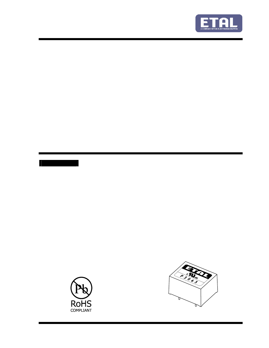
P3065
MATCHING TRANSFORMER
Features
Applications
∗
Low Distortion
∗
V.34 modems
∗
Lead-free (Pb-free)
∗
Data rates to 33.6kbps
∗
RoHS compliant
∗
Line matching
∗
Low Profile (11mm)
∗
Portable computers
∗
Vacuum encapsulated
∗
Fax/modems
∗
IEC 60950 and UL 60950 certified
∗
Instrumentation
∗
UL Recognized Component
∗
High Thermal Stability
DESCRIPTION
P3065 is intended for data communications to
33,600 bits/second data rates. P3065 is specifically
designed to be easily matched to both 600 ohm and
complex impedance telephone lines, using a
minimum of external components.
P3065 also exhibits stable characteristics over its
operating temperature range to maximize data
throughput under varying environmental
conditions without the need for modem retraining.
P3065 is certified to IEC 60950 and UL 60950.
P3065 is a UL Recognized Component, and is
supported by an IEC CB Test Certificate. The part
is completely lead-free, compliant with RoHS
Directive 2002/95/EC, and suitable for lead-free
and conventional processing.