background image


ETALDOC 725/12 

Page 1 of 5 

October 2007


PRODUCT DATA SHEET 


MICROPROFILE PICK-OFF 
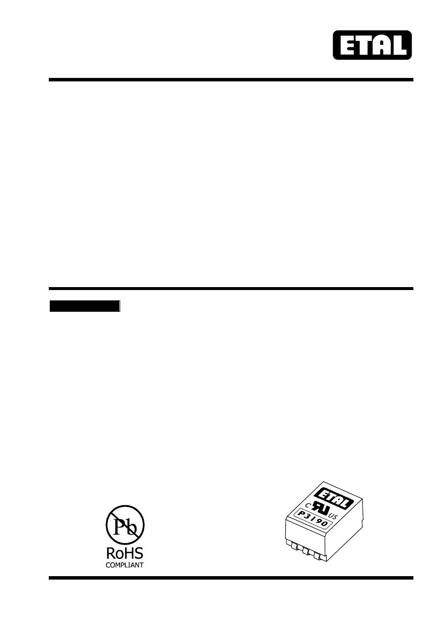
P3190 

TRANSFORMER 


Features


Applications


  Surface Mount 


  Telecommunications 

  Lead-free (Pb-free) 


  Pick-off applications 

  RoHS compliant 


  Voice recording 

  7mm seated height 


  Instrumentation 

  Vacuum encapsulated 


  IEC 60950 and UL 60950 Certified 


  UL Recognized Component 


DESCRIPTION 


P3190 is a high impedance microprofile transformer 
for 

applications 

where 

safety 

isolation 

to 

international  standards  is  required  in  an  extremely 
small case size. 
 
Designed  specifically  as  a  surface  mount  device, 
P3190  features  a  7mm  seated  height.  The  part  is 
compliant  with  RoHS  Directive  2002/95/EC,  and 
suitable  for  lead-free  and  conventional  placement 
and reflow. 


P3190  is  designed  for  "listening"  applications 
when  placed  across  a  line,  presenting  a  high 
impedance exceeding 10k

 across the voiceband 

to minimize circuit loading. 
 
For  applications  requiring  higher  impedance, 
P2769 offers >30k

 in a compatible package. 

 
To  meet  requirements  for 

40k

  across  the 

voiceband,  P3190  can  be  used  in  an  application 
circuit described herein. 
 
P3190  is  certified  to  IEC 60950  and  UL 60950. 
P3190  is  a  UL  Recognized  Component  and  is 
supported by an IEC CB Test Certificate. 


P3190-html.html
background image


P3190


ETALDOC 725/12 

Page 2 of 5 

October 2007


SPECIFICATIONS 


Electrical 


At T = 25°C unless otherwise stated. 
 

Parameter 

Conditions 

Min 

Typ 

Max 

Units 

Voltage 

isolation

(1) 

50Hz 

DC 

3.88 

5.5 

kVrms 

kV 

Input impedance

(4)


300Hz - 3.4kHz, 1Vrms, 

circuit as Fig.2. 

10 

k


Operating range: 
Functional 
Storage

(3) 

Humidity 

Ambient temperature 


-25 

–40 


+85 

+125 

95 


°C 
°C 

%R.H. 


Lumped equivalent circuit parameters as Fig. 1


DC resistance, R

DC

(2)


Sum of windings 

882 

1055 


Leakage 
inductance 


18 

22 

mH 

Shunt  

inductance Lp 

200Hz  10mV 

6.5 

16 

Shunt loss Rp 

200Hz  10mV 

22 

66 

k


Notes


1.  Components are 100% tested at 6.5 kVDC. 
2.  Caution:    do  not  pass  DC  through  windings.  

Telephone  line  current,  etc.  must  be  diverted 
using choke or semiconductor line hold circuit. 

3.  Excludes  shipping  materials.      Components 

are  dry-packed  and  sealed  as  shipped

Handle  in  accordance  with  IPC/JEDEC 
J-STD-033 

procedure 

for 

components 

classified as IPC/JEDEC J-STD-020 Moisture 
Sensitivity Level 5a.


4.  For  applications  requiring  higher  input 

impedance  (e.g. 

40k

),  see  application 

circuits below.


Equivalent  Circuit

Fig.  1

IDEAL

1:1

½   L

½   L

½ R

½ R

P3190-html.html
background image


P3190


ETALDOC 725/12 

Page 3 of 5 

October 2007


Reference Circuit 


In  practice,  the  47k

  load  can  be  increased 

without  limit.  The  DC  blocking  capacitor  should 
be maintained within the range 0.22µF to 0.33µF 
to  obtain  a  flat  frequency  response  and  input 
impedance  to specification. 


40k


APPLICATION CIRCUITS 


For applications requiring impedance greater than 40k

 for parallel-connected Terminal Equipment 

(e.g. ETSI TS 103 021, 

40k

, 200Hz – 4.3kHz) the following circuits may be helpful. 


At  the  expense  of  a  small  loss,  the  circuit  in 
Fig. 3  provides  an  impedance  exceeding  40k


from DC upwards. 


Due  to  the  finite  primary  inductance  of  the 
P3190,  the  circuit  of  Fig. 3  suffers  from  low 
frequency rolloff below 500Hz. At the expense of 
around 6dBV loss, the circuit of Fig. 4 provides a 
relatively flat response from 300Hz to 4kHz. 
 
The  load  resistance,  R

Load

,  across  which  the 

output voltage appears, should be a minimum of 
470k

, and can be increased without limit. 


Fig  3

39k

47n

270k

P3190

Z  > 40k

in

Fig  4

39k

68n

R

Load

P3190

Z  > 40k

in

39k

6.8n

V

out

Fig  2

47k

0.27µF

Z

in

P3190-html.html
background image


P3190


ETALDOC 725/12 

Page 4 of 5 

October 2007


CONSTRUCTION 


Dimensions shown are in millimetres (inches). 
Geometric centres of outline and pad grid coincide within a tolerance circle of 0.3mm

∅.


Windings may be used interchangeably as primary or secondary. 


SAFETY 


CERTIFICATION 


Manufactured 

from 

materials 

conforming 

to 

flammability requirements of UL94V-0. 
Distance  through  reinforced  insulation  0.4mm 
minimum. 
Creepage  and  clearances  in  circuit  are  7mm 
minimum where PCB pads do not exceed 3mmØ. 
Construction 

complies 

with 

IEC 60950-1, 

EN 60950-1  and  UL 60950-1,  reinforced  insulation, 
250Vrms maximum working voltage 


ABSOLUTE MAXIMUM RATINGS


(Ratings of components independent of circuit). 
 
Short term isolation voltage (2s) 

 
4.6 kVrms, 
6.5kVDC 

DC current 

100

µ

Storage temperature 

-40°C to  
+125°C 

Soldering temperature 
Profile peak  

 
260°C  10s 

Recommended  peak  body  temperature  245°C  in 
accordance with IPC/JEDEC J-STD-033. 


Certified by BSI to IEC 60950 Third Edition (1999) 
(IEC CB  Test  Certificate  No.  GB592W)  sub-
clauses  1.5,  1.5.1,  1.5.2,  2.9,  2.9.1,  2.9.2,  2.9.3, 
2.9.4, 2.9.5, 2.10, 2.10.1, 2.10.2, 2.10.3, 2.10.3.1, 
2.10.3.2,  2.10.4,  2.10.5,  2.10.5.1,  2.10.7,  2.10.8, 
4.7,  4.7.3,  4.7.3.1,  4.7.3.4,  (Flammability  Class 
V-0) ,5.2, 5.2.1, and 5.2.2 for a maximum working 
voltage of 250Vrms, nominal mains supply voltage 
not exceeding 250Vrms and a maximum operating 
temperature  of  +85°C  in  Pollution  Degree  2 
environment, reinforced insulation. 
 
Recognized  under  the  Component  Recognition 
Program of Underwriters Laboratories Inc. to US and 
Canadian 

requirements 

CAN/CSA 

C22.2 

No. 60950-1-03/UL60950-1,  First  Edition,  based  on 
IEC 60950-1, First Edition, maximum working voltage 
250Vrms, Pollution Degree 2, reinforced insulation. 
 
UL File number E203175. 
 
Additionally,  Profec  Technologies  certifies  all 
transformers  as  providing  voltage  isolation  of 
3.88kVrms,  5.5kV  DC  minimum.      All  shipments 
are  supported  by  a  Certificate  of  Conformity  to 
current applicable safety standards. 


2.54 2.54

13.0  max

(0.51)

9.0  max

(0.36)

7.0  max

(0.28)

(0.1) (0.1)

NOTE:

Dimensions  shown  are  in  millimetres  (inches)

Dimensions

Fig  5

(0.06)

1.5

1.32

1.77

(0.052)

(0.07)

e

3

Tolerance 

0.3mm

Terminals  electroplated  pure  tin  (Sn)  5µm  minimum.
  JESD97  category  =  e3.
Terminal  size  :  1.5  (0.06)  long,  1.32  (0.05)  wide

±

Connections

Fi g  6

1

2

3

4

5

6

P3190-html.html
background image


P3190


ETALDOC 725/12 

Page 5 of 5 

October 2007


ORDERING CODE 


COPYRIGHT 


P3190


TR = Tape and Reel 
(Blank) = Bulk in tubes. 


Carrier tape width 24mm, 
500 parts per 13” reel. 


ETAL,  P3190  and  P2769  are  Trade  Marks  of 
Profec Technologies Ltd. 
The  Trade  Mark  ETAL  is  registered  at  the  UK 
Trade Marks Registry. 
Profec  Technologies  Ltd.  is  the  owner  of  the 
design  right  under  the  Copyright  Designs  and 
Patents  Act  1988  and  no  rights  or  licences  are 
hereby granted or implied to any third party. 
 
British Patent No. 2283195 
US Patent No. 5879598 
European Patent No. 0725719 
 
© 1999 - 2007 Profec Technologies Ltd. 
Reproduction prohibited. 


T R A N S F O R M I N G    T H E    F U T U R E


Profec Technologies Ltd., 10 Betts Avenue, Martlesham Heath, Ipswich, IP5 3RH, England 

                           Telephone:  +44 (0) 1473 611422 

Fax:  +44 (0) 1473 611919 


Website: www.profec.com   

Email:  info@profec.co.uk  sales@profec.com


FM 25326

ISO 9001

E203175