
Terminals
A1
For service and technical support, call 800-777-3300
or visit www.panduit.com.
PANDUIT
Termination Solutions
Success
Depends on the
Crimp.
A proper crimp is the key element
of an overall wire termination
assembly that unfortunately is all
too often overlooked.
Proper terminal selection, application and crimping are critical factors to
the safety, performance and reliability of an electrical connection.When
selected and installed properly, the function of a terminal is transparent
in the overall operation of a product; however, when selected or installed
improperly, it can result in rework, recalls and downtime, which could
result in loss of productivity and profitability.
To produce a high-quality crimp you can rely upon to resist failure, you
need the right terminal, right tool and right technique.
The purpose of the Technical Reference Guide is to give you the
necessary tools to:
•
Select the right terminal for a specific application
•
Select the right tool for the terminal and the application
•
Produce a high-quality crimp
PANDUIT Termination Solutions-html.html
Terminals
A2
Crimping Guidelines for
PANDUIT
®
P
AN
-T
ERM
®
Terminals,Disconnects,Splices and Wire Joints
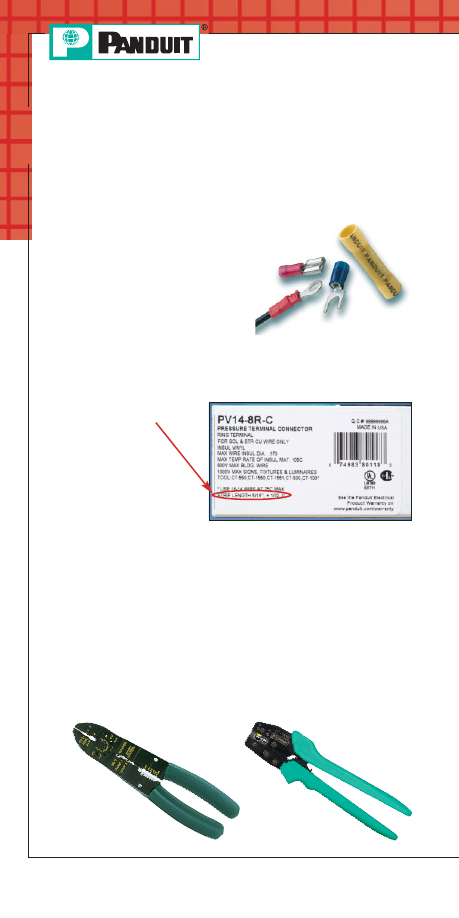
1. Select the proper
PANDUIT terminal for the application and
wire size used
• Ring terminals are used
for high vibration and
grounding applications
• Fork terminals are used for static
(non-vibration) applications
• Disconnects are used for
applications that require quick
connection of wires without the use of tools
• Splices and wire joints are used to join wires together
•
PANDUIT product
packaging label
• Packaging
instructions
included with the
PANDUIT product
• Or if no packaging
instructions are
available, plan your strip length so that 1/32 of an inch of
wire can be seen protruding through the tongue end of
the terminal barrel
2. Strip wire to the proper length as specified on:
• Use crimping tools that provide a UL Listed and/or CSA
Certified electrical termination, to assure a safe and
reliable connection
•
PANDUIT terminals are UL Listed and CSA Certified when
crimped with
PANDUIT plier type crimping tool or with the
preferred
C
ONTOUR
C
RIMP
™
Controlled Cycle Crimping Tool
specified on the packaging label
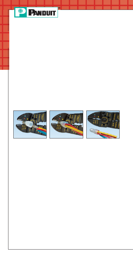
3. Select the proper crimp tool to be used
Plier Type
Crimping Tool
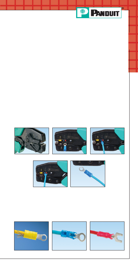
C
ONTOUR
C
RIMP
™
Controlled Cycle
Crimping Tool
PANDUIT Termination Solutions-html.html
Terminals
A3
For service and technical support, call 800-777-3300
or visit www.panduit.com.
Crimping Guidelines for
PANDUIT
®
P
AN
-T
ERM
®
Terminals,Disconnects,Splices and Wire Joints
(continued)
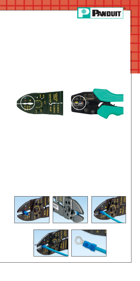
Insulated Terminals and Disconnects
4. Select the proper crimp pocket for the terminals and wire
size you are using
•
PANDUIT crimping tools simplify this process with color
coded crimp pockets. The yellow, blue and red pockets
are specifically designed for the industry standard barrel
sizes, each with a specific color code.
A. Locate terminal in appropriate size color-coded crimp die pocket
with tool centered on insulation sleeve.
(See Note 1 page A6)
B. Rotate terminal so tongue is level with crimp die.
C. Insert properly stripped wire into terminal until a minimum of
1/32" of wire extends beyond the terminal barrel.
D. Squeeze tool handles firmly to perform the electrical crimp.
(See Note 2 page A6)
E. Provide second crimp on the flared portion of the insulation
housing to close the insulation as shown. Caution: when using
plier type crimping tools, do not squeeze as firmly as you did
for the electrical crimp.
(See Note 3 page A6)
Step A
Step B
Complete Crimp
Steps C & D
Step E
5. Perform the electrical crimp
For the plier type tool
PANDUIT Termination Solutions-html.html
Terminals
A4
Crimping Guidelines for
PANDUIT
®
P
AN
-T
ERM
®
Terminals,Disconnects,Splices and Wire Joints
(continued)
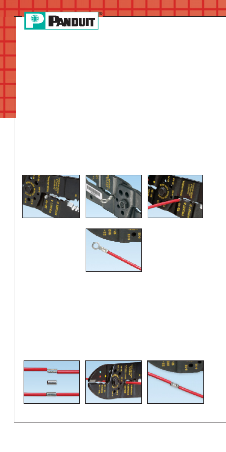
Non-Insulated Terminals and Disconnects
Insulated and Non-Insulated Parallel Splices
A. Locate terminal in appropriate wire gauge crimp die pocket
with indenter centered on barrel seam.
B. Rotate terminal so tongue is level with crimp die.
C. Insert properly stripped wire (based on recommendations on
package label) into terminal until a minimum of 1/32" of wire
extends beyond the terminal barrel.
D. Squeeze tool handles firmly to perform the electrical crimp.
(See Note 2 page A6)
Step A
Step B
Steps C & D
Complete Crimp
A. Locate parallel splice in appropriate wire gauge crimping die
pocket and position tool on the center of the splice.
B. Insert properly stripped wire (based on recommendations
on package label) into each end of the parallel splice.
C. Squeeze tool handles firmly.
(See Note 2 page A6)
D. An insulation crimp is not required on an insulated
parallel splice.
Steps A & B
Steps C & D
Complete Crimp
PANDUIT Termination Solutions-html.html
Terminals
A5
For service and technical support, call 800-777-3300
or visit www.panduit.com.
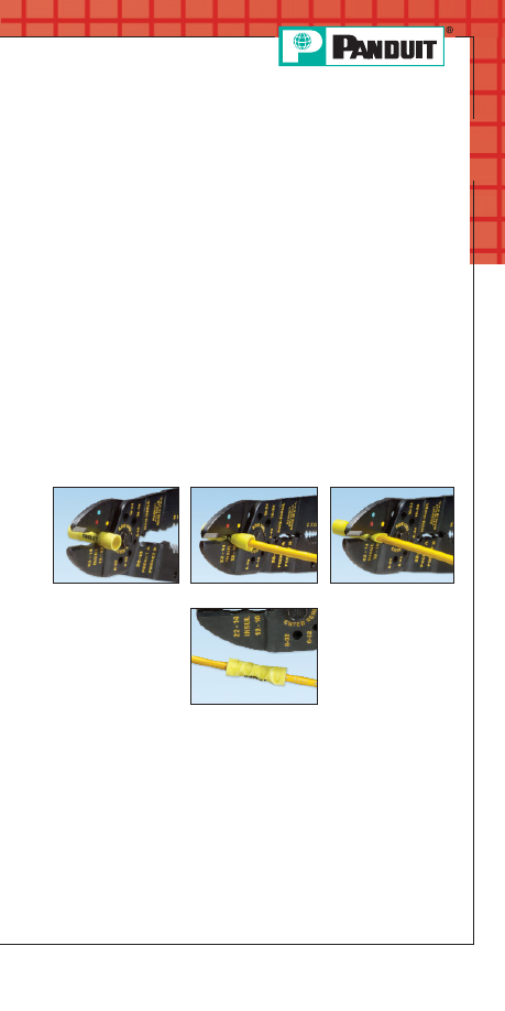
Insulated and Non-Insulated Butt Splices
Crimping Guidelines for
PANDUIT
®
P
AN
-T
ERM
®
Terminals,Disconnects,Splices and Wire Joints
(continued)
A. Locate butt splice in appropriate color-coded crimp die pocket
and position crimp halfway between the wire stop (center
of splice) and the end of the insulation crimp area.
(See
Note 4 page A6)
B. Insert properly stripped wire (based on recommendations on
package label) into one end of butt splice.
C. Squeeze tool handles firmly to perform the electrical crimp.
(See Note 2 page A6)
D. Provide second crimp on the flared portion of the insulation
housing to close the insulation. Caution: When using plier
type crimping tools, do not squeeze as firmly as you did for
the electrical crimp.
(See Note 3 page A6)
E. Repeat steps one to four for opposite end of butt splice.
Steps A & B
Steps C
Complete Crimp
Step D & E
PANDUIT Termination Solutions-html.html
Terminals
A6
Insulated and Non-Insulated Wire Joints
NOTES for Crimping with the preferred Hand Operated
Controlled Cycle Crimping Tools:
A. Properly strip wires per manufacturer’s recommendations
on product package label.
B. Twist stripped wire ends together, and insert wires into
wire joint.
C. Locate wire joint in appropriate wire gauge crimp die pocket
and position crimp in the center of the metal insert.
D. Squeeze tool handles firmly to perform the electrical crimp.
(See Note 2 below)
Note: an insulation crimp is not required on an insulated
wire joint.
Steps 1 & 2
Steps 3 & 4
Complete Crimp
1.
PANDUIT controlled cycle crimping tools properly locate rings, forks,
and barrel insulated disconnects, pins, and blades. No further
positioning is required.
2. When using the preferred controlled cycle tool, once a crimp has been
started, the ratchet device of controlled cycle tools will not release until
the crimp is complete, independent of operator expertise.
3. Controlled cycle tools provide the electrical crimp and the insulation
closure in a single cycle of the tool.
4. When using controlled cycle tooling, insulated butt splices must be
inserted from the back of the tool to ensure that the electrical and
insulation closure crimp pockets are properly aligned with the splice.
Crimping Guidelines for
PANDUIT
®
P
AN
-T
ERM
®
Terminals,Disconnects,Splices and Wire Joints
(continued)
PANDUIT Termination Solutions-html.html
Terminals
A7
For service and technical support, call 800-777-3300
or visit www.panduit.com.
Bent Back Strands
Over Crimp
Rotated Crimp
Crimping Guidelines for
PANDUIT
®
P
AN
-T
ERM
®
Terminals,Disconnects,Splices and Wire Joints
(continued)
A. Make sure the terminal barrel is centered correctly in the
right die pocket by using the product locator on the backside
of the tool.
B. Determine the correct die pocket to use based on the color
code of the terminal.
C. Squeeze the handles of the tool until one click is heard; this
click indicates the terminal is now held in place securely to
insert the wire.
D. Insert the wire and complete cycle to perform the electrical
and insulation crimp simultaneously.
E. Crimp complete.
Note: If your crimp looks like any of the examples shown below,
cut off the terminal and recrimp. These crimps would
provide a poor connection!
5. Perform the electrical crimp
using the preferred controlled cycle tool
6. Inspect the crimp
Step A
Step B
Complete Crimp
Step C
Step D
PANDUIT Termination Solutions-html.html

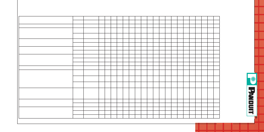
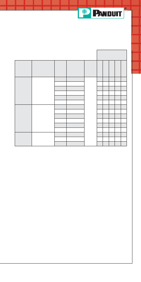
Terminal Series
Std.
Wire
Range
(AWG)
Wire
Strip
Length
(In.)
[+1/32;-0]
Plier Tools
Controlled Cycle Hand Tools
Crimp Heads
for Pneumatic
CT-600 Tool
Butt Splices
BS – Non-Insulated Butt Splices
26-22
1/4
X
X
22-18
9/32
X
X
X
X
X
X
16-14
9/32
X
X
X
X
X
X
12-10
9/32
X
X
X
X
X
X
X
BSH – Heat Shrink
22-18
5/16
X
16-14
5/16
X
12-10
5/16
X
BSN – Nylon Insulated
26-22
1/4
X
X
X
22-18
9/32
X
X
X
X
X
X
16-14
9/32
X
X
X
X
X
X
X
X
12-10
9/32
X
X
X
X
X
X
X
BSV – Vinyl Insulated
22-18
5/16
X
X
X
X
X
X
X
X
16-14
5/16
X
X
X
X
X
X
X
X
X
12-10
5/16
X
X
X
X
X
X
X
Disconnects
D, DR – Non-Insulated, Sleeve Barrel
(Includes Right Angle)
22-18
9/32
X
X
X
X
X
16-14
9/32
X
X
X
X
X
X
12-10
9/32
X
X
X
X
X
X
X
Terminals
A8
PANDUIT
Installa
tion T
ooling
for T
erminals
,
Disconnec
ts and S
plices
CT
-100
CT
-160
CT
-200
CT
-260
CT
-300-1
CT
-310
CT
-400
CT
-460
CT
-1014
CT
-1015
CT
-1525
CT
-1550
CT
-1551
CT
-1570
CT
-1701
CT
-500CH
CT
-520CH
CT
-550CH
CT
-570CH
CT
-720 Mec
hanical
PANDUIT Termination Solutions-html.html
Terminals
A9
F
o
r ser
v
ice and technical suppor
t, call 800-777-3300
or visit www
.panduit.com.
PANDUIT
Installa
tion T
ooling
for T
erminals
,
Disconnec
ts and S
plices (continued)
D-M – Non-Insulated Male Blade
Adapters
22-18
9/32
X
X
X
X
X
X
16-14
9/32
X
X
X
X
X
X
D-M – Non-Insulated Male
12-10
9/32
X
X
X
X
X
X
D-MB, DR-B – Non-Insulated Right
Angle Female & Non-Insulated Male
Butted Seam
22-18
9/32
X
X
X
X
16-14
9/32
X
X
X
X
DNF – Nylon, Funnel Entry, Barrel
Insulated (not .110/.111)
22-18
9/32
X
X
X
X
16-14
9/32
X
X
X
X
X
X
X
X
DNF-110, DNF-111 – Nylon, Funnel
Entry Barrel Insulated .110/.111 Tab Size
22-18
7/32
X
X
X
X
16-14
9/32
X
X
X
DNF-FI – Nylon, Fully Insulated
22-18
9/32
X
X
X
X
X
X
X
X
16-14
9/32
X
X
X
X
X
X
X
12-10
3/8
X
X
X
X
X
X
X
DPF-FI – Premium Nylon, Fully Insulated 12-10
3/8
X
X
X
X
X
X
X
DNF-FIB, DNF-FIM, DNF-FIMB,
DPF-FIB, DPF-FIMB, DNF-LPB,
DPF-LPB – Nylon & Premium Grade
Nylon, Fully Insulated, Funnel Entry,
Male/Female Couplers (not .110/.111)
22-18
9/32
X
X
X
16-14
9/32
X
X
X
12-10
3/8
X
DMF-FIB, DPF-FIB – Nylon Premium
Grade Nylon, Fully Insulated, Funnel
Entry, .110/.111 Tab Size
22-18
7/32
X
X
X
DNF-FIBX – Nylon, Expanded Wire
Entry, Fully Insulated
22-18
9/32
X
16-14
9/32
X
DNF-M – Nylon Insulated, Funnel
Entry, Barrel Insulated, Male
22-18
9/32
X
X
X
X
X
X
X
16-14
9/32
X
X
X
X
X
X
X
12-10
9/32
X
X
X
X
X
PANDUIT Termination Solutions-html.html
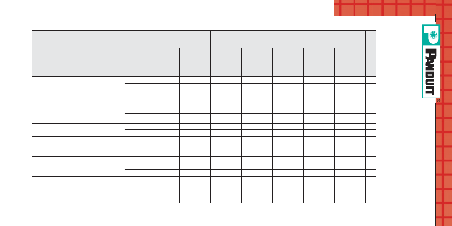
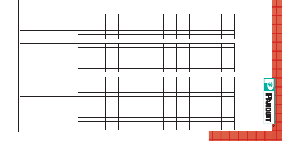
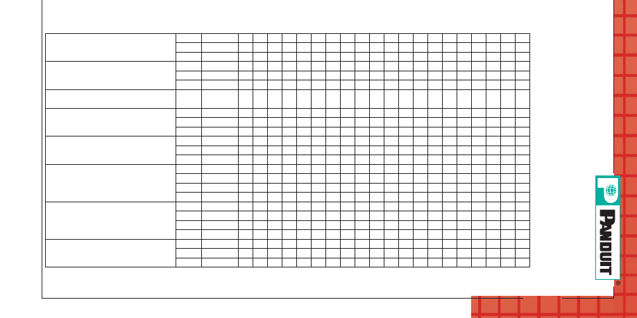
Terminal Series
Std.
Wire
Range
(AWG)
Wire
Strip
Length
(In.)
+1/32;-0]
Plier Tools
Controlled Cycle Hand Tools
Crimp Heads
for Pneumatic
CT-600 Tool
DNFR-B – Nylon Pre-Insulated,
Right Angle
22-18
9/32
X
X
16-14
9/32
X
X
DNFR-FIB – Nylon Butted Seam,
Right Angle
22-18
11/32
X
16-14
11/32
X
DNG-FB – Supra Grip Nylon Fully
Insulated (Except DNG14-187FB &
DNG14-188FB)
22-18
1/4
X
16-14
1/4
X
DNG-FL – Disco-Lok Nylon, Fully
Insulated
22-18
1/4
X
16-14
1/4
X
DNH – Heat Shrink
22-18
5/16
X
16-14
5/16
X
12-10
5/16
X
DV – Vinyl Barrel Insulated Sleeve
12-10
9/32
X
X
X
X
DV-B – Vinyl Insulated, Butted Seam
22-18
1/4
X
X
X
16-14
1/4
X
X
X
DV-M – Non-Insulated Male Blade
Adapters
22-18
9/32
X
X
X
X
X
X
X
X
16-14
9/32
X
X
X
X
X
X
X
X
X
DV-M – Non-Insulated Male
Disconnects
12-10
9/32
X
X
X
Terminals
A10
CT
-100
CT
-160
CT
-200
CT
-260
CT
-300-1
CT
-310
CT
-400
CT
-460
CT
-1014
CT
-1015
CT
-1525
CT
-1550
CT
-1551
CT
-1570
CT
-1701
CT
-500CH
CT
-520CH
CT
-550CH
CT
-570CH
CT
-720 Mec
hanical
PANDUIT
Installa
tion T
ooling
for T
erminals
,
Disconnec
ts and S
plices (continued)
PANDUIT Termination Solutions-html.html
Terminals
A11
F
o
r ser
v
ice and technical suppor
t, call 800-777-3300
or visit www
.panduit.com.
PANDUIT
Installa
tion T
ooling
for T
erminals
,
Disconnec
ts and S
plices (continued)
DV-MB – Vinyl Insulated Butted Seam
Male Disconnects
22-18
9/32
X
X
X
X
X
16-14
9/32
X
X
X
X
X
X
DV-P – Vinyl Insulated Piggyback
Disconnects
22-18
1/4
X
X
X
X
X
X
X
16-14
1/4
X
X
X
X
X
X
X
DVF – Vinyl Funnel Entry Barrel
Insulated Female Disconnect
22-18
9/32
X
X
X
X
16-14
9/32
X
X
X
X
Wire Joints
J – Non-Insulated J214-312,
J318-412,
J216-410
18-12
1/2
X
X
18-12
1/2
X
X
16-10
3/4
X
JN – Nylon Insulated JN224-318,
JN218-216,
JN418-212,
JN314-212
24-16
7/16
X
X
X
X
X
X
X
X
22-14
7/16
X
X
X
X
X
X
X
18-12
1/2
X
X
X
X
X
X
14-12
5/8
X
Terminals
P-HDR – Non-Insulated Heavy
Duty Rings
16-12
9/32
X
X
X
X
X
X
X
P-P – Non-Insulated Pin Terminals
22-18
9/32
X
X
X
X
X
X
16-14
9/32
X
X
X
X
X
X
12-10
9/32
X
X
X
X
X
X
X
P-R – Non-Insulated Large Ring
Terminals
8
3/8
X
6
7/16
X
4
1/2
X
2
1/2
X
P-R, P-R, P-LF, P-SLF, P-FF –
Non-Insulated Rings, Forks, Locking
Forks, Short Locking Forks, Flanged
Forks
22-26
3/16
X
X
X
22-18
7/32
X
X
X
X
X
X
16-14
7/32
X
X
X
X
X
X
12-10
9/32
X
X
X
X
X
X
X
PANDUIT Termination Solutions-html.html
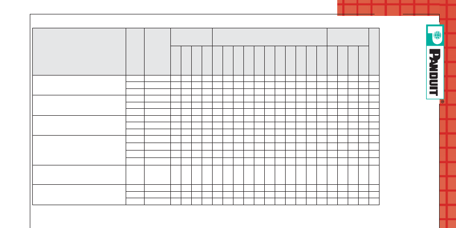
Terminal Series
Std.
Wire
Range
(AWG)
Wire
Strip
Length
(In.)
[+1/32;-0]
Plier Tools
Controlled Cycle Hand Tools
Crimp Heads
for Pneumatic
CT-600 Tool
P-RHT6 – High Temperature Rings
22-18
9/32
X
X
X
X
X
X
16-14
9/32
X
X
X
X
X
X
12-10
9/32
X
X
X
X
X
X
X
PH – Heat Shrink Terminals
22-18
5/16
X
16-14
5/16
X
12-10
5/16
X
PK-R – KYNAR* Rings
22-18
7/32
X
X
X
X
X
16-14
7/32
X
X
X
X
X
12-10
9/32
X
X
X
X
PN-R, PN-RX, PN-F, PN-LF, PN-FF,
PNF-R, PNF-F, PNF-LF – Nylon &
Nylon Funnel Entry Forks, Locking
Forks, Flanged Forks (Includes
Expanded Insulated)
26-22
3/16
X
X
X
22-18
7/32
X
X
X
X
X
X
16-14
7/32
X
X
X
X
X
X
X
12-10
9/32
X
X
X
X
X
PN-HDR, PN-HDRX – Nylon Insulated
Heavy Duty & Nylon Expanded
Insulated Heavy Duty Rings
16-12
9/32
X
X
X
X
PN-SLF, PNF-SLF – Nylon Insulated
Short Locking Forks
22-18
7/32
X
X
X
X
16-14
7/32
X
X
X
X
X
12-10
9/32
X
X
X
X
Terminals
A12
PANDUIT
Installa
tion T
ooling
for T
erminals
,
Disconnec
ts and S
plices (continued)
CT
-100
CT
-160
CT
-200
CT
-260
CT
-300-1
CT
-310
CT
-400
CT
-460
CT
-1014
CT
-1015
CT
-1525
CT
-1550
CT
-1551
CT
-1570
CT
-1701
CT
-500CH
CT
-520CH
CT
-550CH
CT
-570CH
CT
-720 Mec
hanical
PANDUIT Termination Solutions-html.html
Terminals
A13
F
o
r ser
v
ice and technical suppor
t, call 800-777-3300
or visit www
.panduit.com.
PANDUIT
Installa
tion T
ooling
for
Te
rminals
,
Disconnec
ts and S
plices (continued)
*KYNAR is a registered trademark of Atofina Chemicals, Inc.
‡Use Die CD-700P-8-2
PS – Non-Insulated Parallel Splices
22-18
5/16
X
X
X
20-16
5/16
X
X
X
14-12
7/16
X
X
X
PSN – Nylon Insulated Parallel
Splices
22-18
5/16
X
20-16
5/16
X
X
X
X
14-12
7/16
X
PV-HDR, PV-HDRX – Vinyl Insulated
Heavy Duty Rings
16-12
5/16
X
X
X
X
PV-LF, PV-LFX – Vinyl Insulated
Locking Forks (includes Expanded
Insulation)
22-18
5/16
X
X
X
X
X
X
X
16-14
5/16
X
X
X
X
X
X
X
12-10
5/16
X
X
X
X
X
X
PV-P – Vinyl Insulated Pin Terminals
22-18
5/16
X
X
X
X
X
X
X
16-14
5/16
X
X
X
X
X
X
X
12-10
5/16
X
X
X
X
X
X
PV-R, PV-F, PV-FF, PV-RX,
PV-FX – Vinyl Insulated Rings & Forks
(includes Expanded Insulation)
26-22
3/16
X
X
X
22-18
5/16
X
X
X
X
X
X
X
X
16-14
5/16
X
X
X
X
X
X
X
X
X
12-10
5/16
X
X
X
X
X
X
X
PV-R, PV-RX – Vinyl Insulated Large
Ring Terminals
8
3/8
X
‡
6
7/16
X
‡
4
1/2
X
‡
2
1/2
X
‡
PV-SLF – Vinyl Insulated Short
Locking Forks
22-18
5/16
X
X
X
X
X
16-14
5/16
X
X
X
X
X
X
12-10
5/16
X
X
X
X
PANDUIT Termination Solutions-html.html
A14
Tooling
CT-1700
CT-720
CT-930,
CT-930CH,
CT-920,
CT-920CH,
CT-2920,
CT-940CH
CT-980,
CT-980CH,
CT-2950,
CT-2980
CT-2001
PANDUIT
®
Part Number
PANDUIT
®
Die Part Number
Die Index Number
(Number of Crimps)
S8-10R-Q
P21
(2)
CD-720-1
P21
(1)
CD-920-8
P21
(1)
—
CD-2001-8
P21
(1)
S8-14R-Q
S8-56R-Q
S8-38R-Q
S6-10R-E
P24
(2)
CD-720-1
P24
(1)
CD-920-6
P24
(1)
—
CD-2001-6
P24
(1)
S6-14R-E
S6-56R-E
S6-38R-E
S4-10R-E
P29
(2)
CD-720-1
P29
(1)
CD-920-4
P28
(1)
STD
(1)
CD-2001-4
P29
(1)
S4-14R-E
S4-56R-E
S4-38R-E
S2-10R-X
P37
(3)
CD-720-2
P37
(1)
CD-920-1
P37
(1)
STD
(1)
CD-2001-1
P37
(1)
S2-14R-X
S2-56R-X
S2-38R-X
S2-12R-X
S1/0-14R-X
—
CD-720-2
P42
(1)
CD-920-1/0
P42
(1)
STD
(1)
CD-2001-1/0
P42
(1)
S1/0-56R-X
S1/0-38R-X
S1/0-12R-X
S2/0-14R-X
—
CD-720-2
P45
(2)
CD-920-2/0
P45
(1)
STD
(1)
CD-2001-2/0
P45
(2)
S2/0-56R-X
S2/0-38R-X
S2/0-76R-X
S2/0-12R-X
S3/0-14R-5
—
CD-720-2
P50
(2)
CD-920-3/0
P50
(1)
STD
(1)
CD-2001-3/0
P50
(2)
S3/0-56R-5
S3/0-38R-5
S3/0-76R-5
S3/0-12R-5
S4/0-38R-5
—
CD-720-3
P54
(2)
CD-920-4/0
P54
(1)
STD
(1)
CD-2001-4/0
P54
(2)
S4/0-76R-5
S4/012R-5
S250-56R-5
—
CD-720-3
P62
(2)
CD-920-250
P62
(1)
STD
(1)
CD-2001-250
P62
(2)
S250-38R-5
S250-76R-5
S250-12R-5
Terminals
PANDUIT
Installation Tooling for Tubular
Ring Terminals
PANDUIT Termination Solutions-html.html
Terminals
A15
For service and technical support, call 800-777-3300
or visit www.panduit.com.
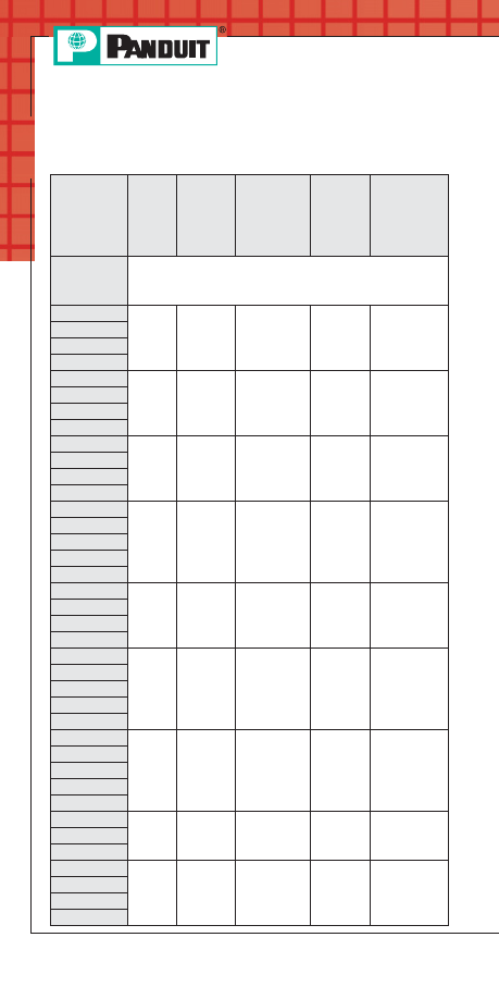
Controlled Cycle
Hand Tools
PANDUIT
Ferrule
Series
Ferrule
Description
Wire
Range
(AWG)
Wire
Range
(mm²)
Wire
Strip
Length
F
Non-Insulated
Ferrules
24-18
.25-1.00
Varies
X
X
16-14
1.50-2.00
X
X
12-10
4.00-6.00
X
X
8-6
10.0-16.0
X
X
4-2
25.0-35.0
X
1
50.0
X
FSD, FSF Insulated
Single Wire
Ferrules (DIN
or French
color code)
26-18
.41-1.00
X
X
16-14
1.50-2.00
X
X
12-10
4.00-6.00
X
X
8-6
10.0-16.0
X
X
4-2
25.0-35.0
X
1
50.0
X
FTD
Insulated
Twin Wire
Ferrules
22-18
.50-1.00
X
X
16-14
1.50-2.00
X
X
12-10
4.00-6.00
X
X
CT
-1002
CT
-1003
CT
-1004
CT
-1005
CT
-1006
PANDUIT
Installation Tooling for Ferrules
PANDUIT Termination Solutions-html.html
Terminals
A16
Prime items appear in BOLD.
Order number of pieces required, in multiples of Standard Package Quantity.
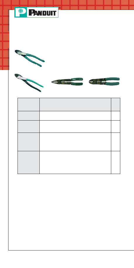
Hand Operated Plier Type Tools
• Installer controlled crimp
• General purpose
• Plier type crimp for #22 thru #10 insulated
and non-insulated terminal products
CT-260
CT-200
CT-160
CT-100
Termination Tooling
Part Number
Part Description
Std.
Pkg.
Qty.
CT-260
Crimps insulated and non-insulated terminals.
Forged steel tool. Cuts wire.
1
CT-200
Crimps most
PANDUIT #18 – #10 AWG
non-insulated terminals, disconnects and splices.
Forged steel tool. Cuts wire.
1
CT-160
Crimps most
PANDUIT #26 – #10 AWG insulated
and non-insulated terminals, disconnects and
splices. Cuts three U.S. and three Metric
screw sizes. Cuts and strips wire. Has insulation
closure pocket.
1
CT-100
Crimps most
PANDUIT #26 – #10 AWG insulated
and non-insulated terminals, disconnects and
splices. Cuts #4, #6, #8 and #10 screw sizes. Cuts
and strips wire. Excellent all-around application
tool of heat treated finished steel with comfortable
cushioned plastic grip handles.
1
PANDUIT Termination Solutions-html.html
Terminals
A17
Prime items appear in BOLD.
For service and technical support, call 800-777-3300
or visit www.panduit.com.
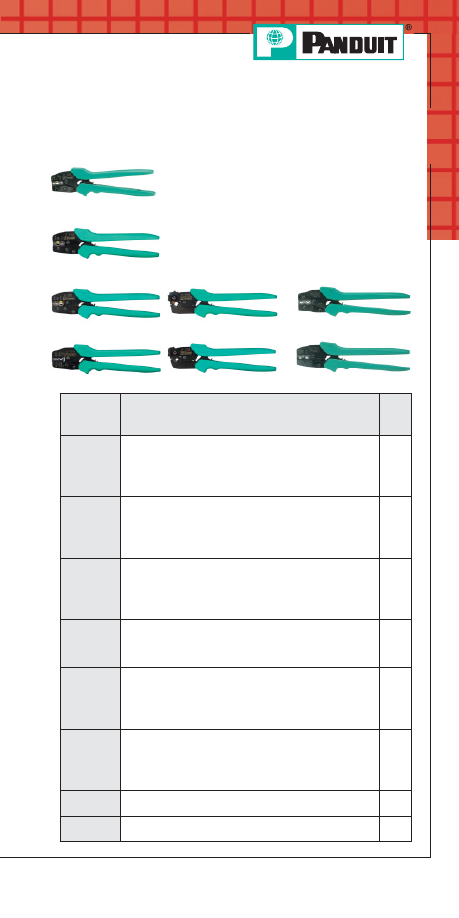
C
ONTOUR
C
RIMP
™
Controlled Cycle Tools
• Specifically designed for the installation of
P
AN
-T
ERM
®
terminals, disconnects and splices
• Controlled cycle mechanism assures high
quality, consistent terminations
• Ergonomic tool design assures operator
comfort, safety, and performance
• Polypropylene handles provide chemical
resistance and a cushioned, non-slip grip
• Multi-position locator facilitates a high quality
repeatable crimp
CT-1525
CT-1550
CT-1551
CT-1570
CT- 1700
CT-1701
CT-1014
CT-1015
Part
Number
Part Description
Std.
Pkg.
Qty.
CT-1525
Crimps
PANDUIT #26 – #22 AWG insulated
terminals and splices, #22 – #10 AWG fully
insulated disconnects and insulated parallel splices.
Crimps
PANDUIT #22 – #14 AWG barrel
insulated disconnects.
1
CT-1550
Crimps most
P
AN
-T
ERM
®
#22 – #10 AWG nylon and
vinyl insulated terminals, splices and disconnects.
The CT-1550 has the red/blue pocket closest to the
pivot which provides a reduced crimp effort for those
who make red/blue terminations.
1
CT-1551
Crimps most
P
AN
-T
ERM
®
#22 – #10 AWG nylon and
vinyl insulated terminals, splices and disconnects.
The CT-1551 has the yellow pocket closest to the
pivot which provides a reduced crimp effort for those
who make yellow terminations.
1
CT-1570
Crimps most
P
AN
-T
ERM
®
#22 – #10 AWG and
.5 – 6.0mm non-insulated terminals and disconnects.
Crimps
PANDUIT #22 – #10 AWG and .5 – 6.0mm
non-insulated splices, and #10 AWG compression lugs.
1
CT-1700
Crimps
PANDUIT #8 – #2 AWG non-insulated tubular
terminals (S series), #8 – #1 AWG copper lugs and
splices, #6 – #4 AWG aluminum lugs and splices and
CTAPF copper taps for #14 – #3 AWG. Includes five
position, color coded rotating die.
1
CT-1701
Crimps
PANDUIT #10 – #2 AWG non-insulated large
gauge ring terminal (P series). Crimps #8 – #1 AWG
copper lugs and splices, and #6 – #4 AWG aluminum
lugs and splices, and #14 – #3 AWG CTAPF copper
taps. Includes 5 position rotating die.
1
CT-1014
Crimps
PANDUIT #22 – #14 AWG loose piece
D
ISCO
-L
OK
™
disconnects.
1
CT-1015
Crimps
PANDUIT #22 – #14 AWG loose piece
S
UPRA
-G
RIP
™
disconnects.
1
PANDUIT Termination Solutions-html.html
Terminals
A18
Prime items appear in BOLD.
Order number of pieces required, in multiples of Standard Package Quantity.
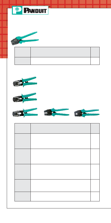
Controlled Cycle Crimping Tools
Ferrule End Sleeve Crimping Tools
• Speciality crimping tools for fully
insulated right angle disconnects and
heat shrink insulated terminals,
disconnects, and splices.
Part
Number
Part Description
Std.
Pkg.
Qty.
CT-300-1
Crimps
PANDUIT #22 – #14 AWG fully insulated
right angle disconnects. (DNFR-FIB series).
1
Part
Number
Part Description
Std.
Pkg.
Qty.
CT-1002
Crimps
PANDUIT #26 – #10 AWG single vinyl
insulated ferrules (DIN). #26 – #10 AWG single
wire insulated ferrules (French).
#22 – #12 AWG vinyl insulated dual-wire ferrules
(DIN). #24 – #10 AWG non-insulated ferrules.
1
CT-1003
Crimps
PANDUIT #22 – #8 AWG single wire
insulated ferrules (DIN). #22 – #8 AWG single wire
vinyl insulated ferrules (French). #22 – #10 AWG
vinyl insulated dual-wire (DIN) ferrules. #22 – #10
AWG non-insulated ferrules.
1
CT-1004
Crimps
PANDUIT #8 – #6 AWG single wire vinyl
insulated ferrule (DIN). #8 – #6 AWG single wire
vinyl insulated ferrules (French).
#10 AWG vinyl insulated dual-wire (DIN) ferrule.
#8 – #6 AWG non-insulated ferrules.
1
CT-1005
Crimps
PANDUIT #4 – #2 AWG single wire vinyl
insulated ferrule (DIN). #4 – #2 AWG single wire
vinyl insulated ferrules (French).
#4 – #2 AWG non-insulated ferrules.
1
CT-1006
Crimps
PANDUIT #1 AWG single wire vinyl
insulated ferrule (DIN) and (French). #1 AWG
non-insulated ferrules.
1
• Specifically designed for the installation of
P
AN
-T
ERM
®
ferrules
• Controlled cycle mechanism assures high
quality, consistent terminations
• Ergonomic tool design assures operator
comfort, safety and performance
• Multi-position locator facilitates a high
quality repeatable crimp
CT-1002
CT-1003
CT-1004
CT-1005
CT-1006
PANDUIT Termination Solutions-html.html
Terminals
A19
Prime items appear in BOLD.
For service and technical support, call 800-777-3300
or visit www.panduit.com.
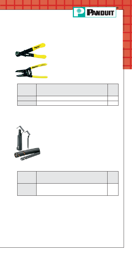
Cable Stripping Tools for Small
Cable Sizes
• Strips and cuts 10 – 20 AWG wire
• Lightweight and durable for comfortable
long use
• Rust resistant coating included to improve
durability of tool
Cable Stripping Tool for Large Cable Sizes
• Cutting blade provides circular, spiral and
in-line insulation cutting
• Cutting blade easily adjusts to proper
height to cut insulation without nicking
conductor strands
• Unique blade profile for long life, low friction
stripping of difficult insulations like rubber
and silicon
• Ergonomic shape for safe comfortable use
• Compact design
CST101
CST115
Part
Number
Part Description
Std.
Pkg.
Qty.
CST101
V notch wire stripper.
1
CST115
Plier nose wire stripper.
1
Item
Part Description
Std.
Pkg.
Qty.
CST114-157 Cable stripping tool for stripping insulation from
cables 3/16" to 1 9/16" diameter. Includes
replacement cutting blade. Warranty: 90 days
1
PANDUIT Termination Solutions-html.html
Terminals
A20
Features and Benefits –
P
AN
-T
ERM
®
Terminals
Non-Insulated Terminals
Type P
Maximum recommended
operating temperature 150°C (302°F)
Extended barrel length
assures a good quality
crimp and makes
crimping easier
Product
markings
provide easy
identification of
wire size
Brazed seam
assures crimp reliability
Internally beveled
barrel for quick easy
wire insertion
Internal barrel serrations
assure good wire
contact and maximum
tensile strength
UL and CSA rated up to 2000V per UL486A.
Nickel plated terminals rated up to 343°C (650°F)
maximum operating temperature.
All
PANDUIT Terminals feature high quality materials made with
electrolytic copper for high conductivity and are tin plated for
corrosion resistance.
Nylon Insulated Terminals With
Insulation Grip Sleeve
Type PN or PNF
UL and CSA rated up to 600V per UL486.
Flammability – UL94V-2/HB.
Proprietary blend of UL94V-2 and UL94HB
flammability rated materials.
Internal barrel
serrations assure
good wire contact
and maximum
tensile strength
Maximum
insulation
temperature
105°C (221°F)
Color coded
insulation identifies
wire range
Funnel entry for
faster insertion and
lower installed cost
Insulation grip sleeve
provides a superior
insulation crimp for high
vibration and high strain
relief applications
PANDUIT Termination Solutions-html.html
Terminals
A21
For service and technical support, call 800-777-3300
or visit www.panduit.com.
Features and Benefits –
P
AN
-T
ERM
®
Terminals
(continued)
Vinyl Insulated Terminals With
Insulation Support
Type PV
Funnel entry for faster
insertion and lower
installed cost
Brazed seam assures
crimp reliability
Internal barrel
serrations assure
good wire contact
and maximum
tensile strength
Insulation crimp
provides insulation
support to protect
electrical crimp
Color coded insulation
identifies wire range
Maximum insulation
temperature 105°C (221°F)
UL and CSA rated up to 600V per UL486.
Flammability – UL94V-0.
Non-Insulated Seamless Tubular Terminals
Type S
UL and CSA rated up to 2000V per UL486A.
Internally beveled
barrel for quick
easy wire insertion
Maximum recommended
operating temperature
150°C (302°F)
Double thickness
provides a strong
ring tongue
Product markings
provide easy
identification of
wire sizes
Inspection hole allows
visual inspection for
proper wire insertion
Seamless tubular
barrel provides
consistent, high
performance,
quality crimps
PANDUIT Termination Solutions-html.html
Terminals
A22
Prime items appear in BOLD.
Order number of pieces required, in multiples of Standard Package Quantity.
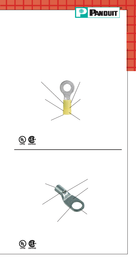
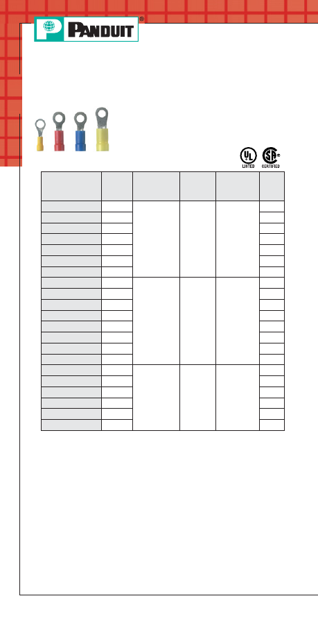
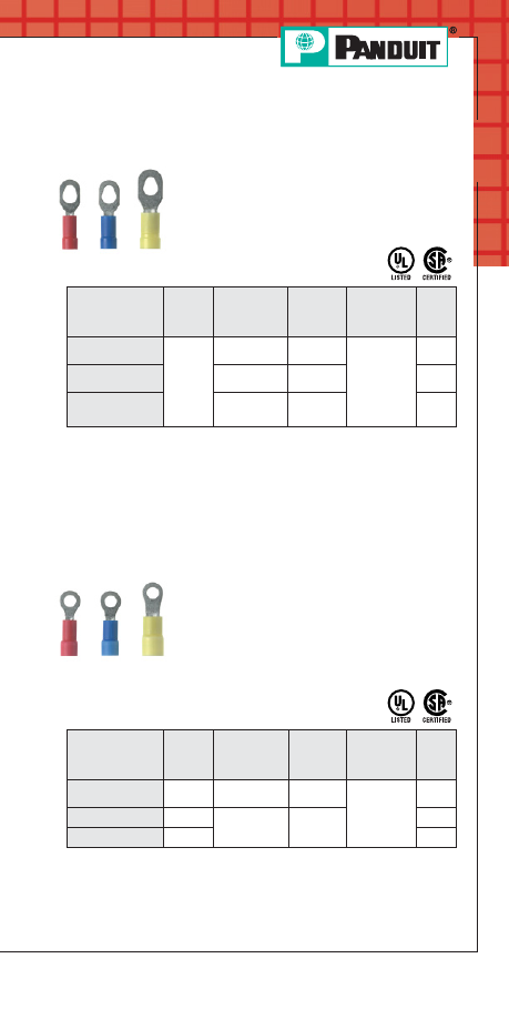
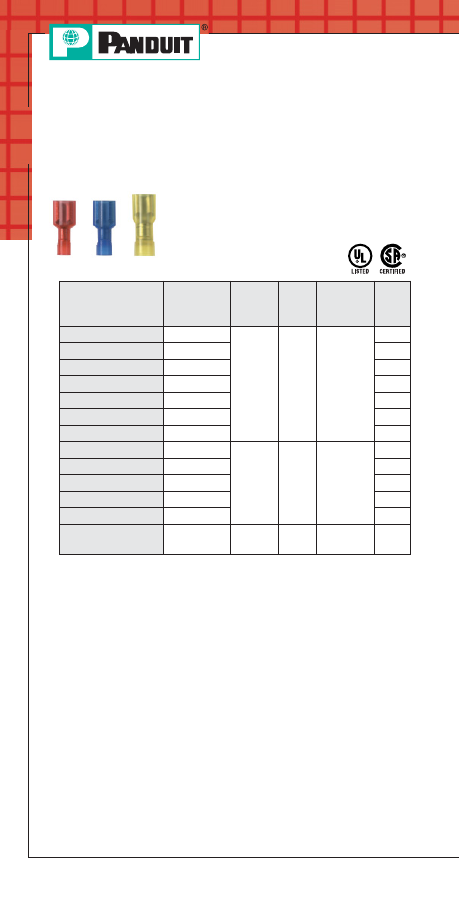
Ring Terminal, Vinyl Insulated –
Funnel Entry
• Insulation support helps to prevent wire
damage in bending applications to provide
a reliable connection
• Brazed seam protects terminal barrel
from splitting during the
crimp process
**To order in bulk, replace -C or -CY in the part number with -M or -MY for
a bulk package of 1000 and replace -L with -D for a bulk package of 500.
‡UL and CSA approved tooling/product combinations.
◆
For a complete line of terminal products, see the
PANDUIT Electrical
Solutions Catalog, SAC-ELCB03 at www.panduit.com
Part Number
Stud
Size
Wire Range
Color
Code
Tool
Std.
Pkg.
Qty.**
PV18-4R-CY
#4
22 – 18
AWG
Red
CT-100‡,
CT-600‡,
CT-1550‡,
CT-1551‡
100
PV18-6R-CY
#6
100
PV18-8R-CY
#8
100
PV18-10R-CY
#10
100
PV18-14R-CY
1/4"
100
PV18-56R-CY
5/16"
100
PV18-38R-CY
3/8"
100
PV14-4R-C
#4
16 – 14
AWG
Blue
CT-100‡,
CT-600‡,
CT-1550‡,
CT-1551‡
100
PV14-6RN-C
#6
100
PV14-6R-C
#6
100
PV14-8R-C
#8
100
PV14-10R-C
#10
100
PV14-14R-C
1/4"
100
PV14-56R-C
5/16"
100
PV14-38R-L
3/8"
50
PV10-6R-L
#6
12 – 10
AWG
Yellow
CT-100‡,
CT-600‡,
CT-1550‡,
CT-1551‡
50
PV10-8R-L
#8
50
PV10-10R-L
#10
50
PV10-14R-L
1/4"
50
PV10-56R-L
5/16"
50
PV10-38R-L
3/8"
50
PANDUIT Termination Solutions-html.html
A23
Prime items appear in BOLD.
For service and technical support, call 800-777-3300
or visit www.panduit.com.
Terminals
Multiple Stud Terminal, Vinyl Insulated –
Funnel Entry
• Insulation support helps to prevent wire
damage in bending applications for a
reliable connection
• Brazed seam protects terminal barrel
from splitting during the
crimp process
**To order in bulk, replace -C or -CY in the part number with -M or -MY for
a bulk package of 1000 and replace -L with -D for a bulk package of 500.
‡UL and CSA approved tooling/product combinations.
Ring Terminal, Vinyl Expanded Insulation
• Insulation support helps to prevent wire
damage in bending applications
• Brazed seam protects terminal barrel from
splitting during the crimp process
• Expanded funnel entry designed to
accommodate wire with a larger than
standard outside diameter insulation
Part Number
Stud
Size
Wire
Range
Color
Code
Tool
Std.
Pkg.
Qty.**
PV14-10RX-C
#10
16 – 14
AWG
Blue
CT-100‡,
CT-600‡,
CT-1550‡,
CT-1551‡
100
PV10-10RX-L
#10
12 – 10
AWG
Yellow
50
PV10-14RX-L
1/4"
50
**To order in bulk, replace -C in the part number with -M for a bulk
package of 1000 and replace -L with -D for a bulk package of 500.
‡UL and CSA approved tooling/product combinations.
Part Number
Stud
Size
Wire Range
Color
Code
Tool
Std.
Pkg.
Qty.**
PV18-610R-CY
#6, #8,
#10
22 – 18
AWG
Red
CT-100,
CT-600‡,
CT-1550‡,
CT-1551‡
100
PV14-610R-C
16 – 14
AWG
Blue
100
PV10-610R-L
12 – 10
AWG
Yellow
50
PANDUIT Termination Solutions-html.html
A24
Prime items appear in BOLD.
Order number of pieces required, in multiples of Standard Package Quantity.
Terminals
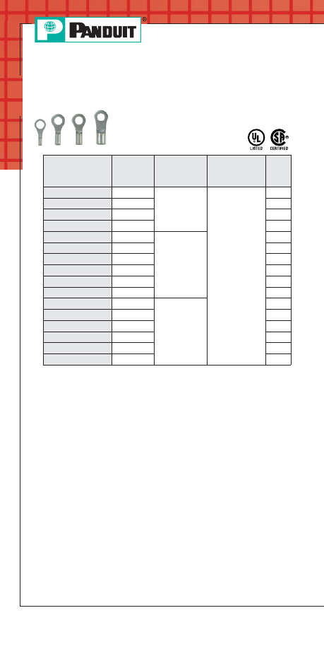
Ring Terminal, Non-Insulated
• Brazed seam protects terminal barrel from
splitting during the crimp process
• Barrel of terminal internally beveled to
provide quick and easy
wire insertion
**To order in bulk, replace -C in the part number with -M for a bulk
package of 1000 and replace -L with -D for a bulk package of 500.
‡UL and CSA approved tooling/product combinations.
Part Number
Stud
Size
Wire
Range
Tool
Std.
Pkg.
Qty.**
P18-6R-C
#6
22 – 18 AWG
CT-100‡,
CT-200‡,
CT-600‡,
CT-1570‡
100
P18-8R-C
#8
100
P18-10R-C
#10
100
P18-14R-C
1/4"
100
P14-6R-C
#6
16 – 14 AWG
100
P14-8R-C
#8
100
P14-10R-C
#10
100
P14-14R-C
1/4"
100
P14-56R-C
5/16"
100
P14-38R-C
3/8"
100
P10-6R-L
#6
12 – 10 AWG
50
P10-8R-L
#8
50
P10-10R-L
#10
50
P10-14R-L
1/4"
50
P10-56R-L
5/16"
50
P10-38R-L
3/8"
50
◆
For a complete line of terminal products, see the
PANDUIT Electrical
Solutions Catalog, SA-ELCB03 at www.panduit.com
PANDUIT Termination Solutions-html.html
A25
Prime items appear in BOLD.
For service and technical support, call 800-777-3300
or visit www.panduit.com.
Terminals
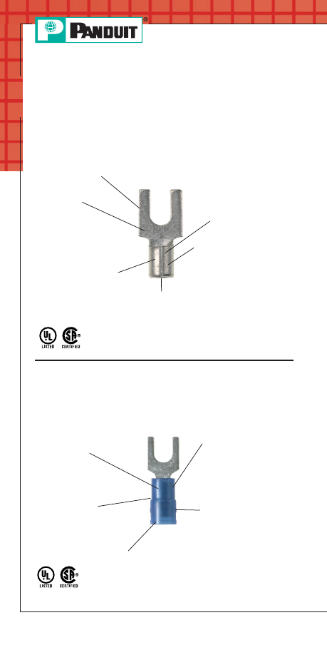
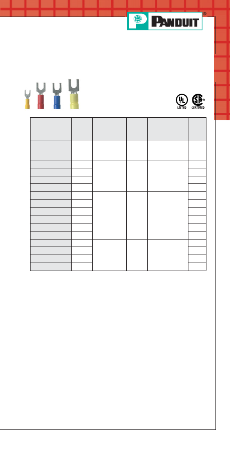
Fork Terminal, Vinyl Insulated –
Funnel Entry
• Insulation support helps to prevent wire
damage in bending applications
• Brazed seam protects terminal
barrel from splitting during the
crimp process
*Not UL Listed or CSA Certified.
**To order in bulk, replace -C or -CY in the part number with -M or -MY
for a bulk package of 1000 and replace -L with -D for a bulk package
of 500.
‡UL and CSA approved tooling/product combinations.
Part Number
Stud
Size
Wire Range
Color
Code
Tool
Std.
Pkg.
Qty.**
PV22-6F-C*
#6
26 – 22
AWG
Yellow
CT-100,
CT-600,
CT-1525
100
PV18-6FN-CY
#6
22 – 18
AWG
Red
CT-100‡,
CT-600‡,
CT-1550‡,
CT-1551‡
100
PV18-6F-CY
#6
100
PV18-8F-CY
#8
100
PV18-10F-CY
#10
100
PV14-6FN-C
#6
16 – 14
AWG
Blue
CT-100‡,
CT-600‡,
CT-1550‡,
CT-1551‡
100
PV14-6F-C
#6
100
PV14-8F-C
#8
100
PV14-10FN-C
#10
100
PV14-10F-C
#10
100
PV14-14F-C
1/4"
100
PV10-6F-L
#6
12 – 10
AWG
Yellow
CT-100‡,
CT-600‡,
CT-1550‡,
CT-1551‡
50
PV10-8F-L
#8
50
PV10-10F-L
#10
50
PV10-14F-L
1/4"
50
PANDUIT Termination Solutions-html.html

A26
Prime items appear in BOLD.
Order number of pieces required, in multiples of Standard Package Quantity.
Terminals
*Not UL Listed or CSA Certified.
**To order in bulk, replace -C in the part number with -M for a bulk
package of 1000 and replace -L with -D for a bulk package of 500.
‡UL and CSA approved tooling/product combinations.
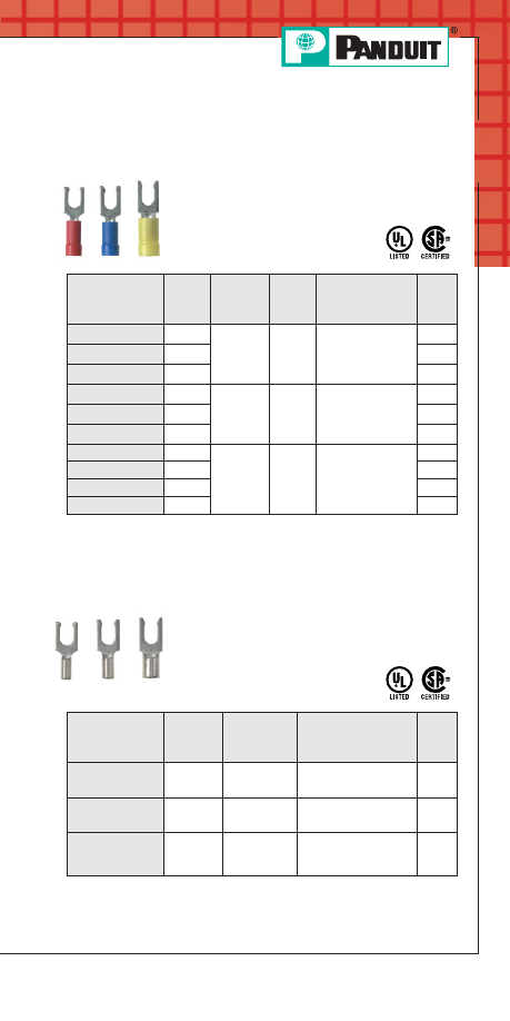
Fork Terminal, Non-Insulated
• Brazed seam protects terminal barrel from
splitting during the crimp process
• Barrel of terminal internally
beveled to provide quick and
easy wire insertion
Part Number
Stud
Size
Wire
Range
Tool
Std.
Pkg.
Qty.**
P22-4F-C*
#4
26 – 22
AWG
CT-100, CT-200
100
P18-6FN-C
#6
22 – 18
AWG
CT-100‡, CT-200‡,
CT-600‡, CT-1570‡
100
P18-6F-C
#6
100
P18-8F-C
#8
100
P18-10F-C
#10
100
P14-6F-C
#6
16 – 14
AWG
CT-100‡, CT-200‡,
CT-600‡, CT-1570‡
100
P14-8F-C
#8
100
P14-10F-C
#10
100
P10-6F-L
#6
12 – 10
AWG
CT-100‡, CT-200‡,
CT-600‡, CT-1570‡,
CT-1701‡
50
P10-8F-L
#8
50
P10-10F-L
#10
CT-100‡, CT-200‡,
CT-600‡, CT-1570‡,
CT-1701‡
50
◆
For a complete line of terminal products, see the
PANDUIT Electrical
Solutions Catalog, SA-ELCB03 at www.panduit.com
PANDUIT Termination Solutions-html.html
A27
Prime items appear in BOLD.
For service and technical support, call 800-777-3300
or visit www.panduit.com.
Terminals
Locking Fork Terminal, Vinyl Insulated –
Funnel Entry
• Insulation support helps to prevent wire
damage in bending applications
• Brazed seam protects terminal
barrel from splitting during the
crimp process
**To order in bulk, replace -C or -CY in the part number with -M or -MY
for a bulk package of 1000 and replace -L with -D for a bulk package
of 500.
‡UL and CSA approved tooling/product combinations.
Locking Fork Terminal, Non-Insulated
• Brazed seam protects terminal barrel from
splitting during the crimp process
• Barrel of terminal internally
beveled to provide quick and
easy wire insertion
Part Number
Stud
Size
Wire
Range
Tool
Std.
Pkg.
Qty.**
P18-6LF-C
#6
22 – 18
AWG
CT-100‡, CT-200‡,
CT-600‡, CT-1570‡
100
P14-6LF-C
#6
16 – 14
AWG
CT-100‡, CT-200‡,
CT-600‡, CT-1570‡
100
P10-10LF-L
#10
12 – 10
AWG
CT-100‡, CT-200‡,
CT-600‡, CT-1570‡,
CT-1701‡
50
**To order in bulk, replace -C in the part number with -M for a bulk
package of 1000 and replace -L with -D for a bulk package of 500.
‡UL and CSA approved tooling/product combinations.
Part Number
Stud
Size
Wire
Range
Color
Code
Tool
Std.
Pkg.
Qty.
PV18-6LF-CY
#6
22 – 18
AWG
Red
CT-100‡,
CT-600‡,
CT-1550‡,
CT-1551‡
100
PV18-8LF-CY
#8
100
PV18-10LF-CY
#10
100
PV14-6LF-C
#6
16 – 14
AWG
Blue
CT-100‡,
CT-600‡,
CT-1550‡,
CT-1551‡
100
PV14-8LF-C
#8
100
PV14-10LF-C
#10
100
PV10-6LF-L
#6
12 – 10
AWG
Yellow
CT-100‡,
CT-600‡,
CT-1550‡,
CT-1551‡
50
PV10-8LF-L
#8
50
PV10-10LF-L
#10
50
PV10-14LF-L
1/4"
50
PANDUIT Termination Solutions-html.html
A28
Prime items appear in BOLD.
Order number of pieces required, in multiples of Standard Package Quantity.
Terminals
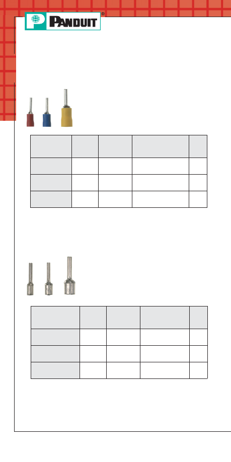
Pin Terminal, Vinyl Insulated –
Funnel Entry
• Insulation support helps to prevent wire
damage in bending applications for a
reliable connection
• Brazed seam protects terminal barrel from
splitting during the crimp process
• Solid pin designed to prevent damage to
the wire from over tightening, resulting in a
reliable electrical connection
**To order in bulk, replace -C or -CY in the part number with -M or -MY
for a bulk package of 1000 and replace -L with -D for a bulk package
of 500.
Pin Terminal, Non-Insulated
• Brazed seam protects terminal barrel from
splitting during the crimp process
• Barrel of terminal internally beveled to
provide quick and easy wire insertion
• Solid pin designed to prevent damage to
the wire from over tightening, resulting in a
reliable electrical connection
Part Number
Stud
Size
Wire
Range
Tool
Std.
Pkg.
Qty.**
P18-P47-C
—
22 – 18
AWG
CT-100, CT-200,
CT-260, CT-1570
100
P14-P47-C
—
16 – 14
AWG
CT-100, CT-200,
CT-260, CT-1570
100
P10-P55-L
—
12 – 10
AWG
CT-100, CT-200,
CT-260, CT-1570
50
**To order in bulk, replace -C in the part number with -M for a bulk
package of 1000 and replace -L with -D for a bulk package of 500.
◆
For a complete line of terminal products, see the
PANDUIT Electrical
Solutions Catalog, SA-ELCB03 at www.panduit.com
Part Number
Stud Size Wire Range
Tool
Std.
Pkg.
Qty.
PV18-P47-CY
—
22 – 18
AWG
CT-100, CT-260,
CT-1550, CT-1551
100
PV14-P47-C
—
16 – 14
AWG
CT-100, CT-260,
CT-1550, CT-1551
100
PV10-P55-L
—
12 – 10
AWG
CT-100, CT-260,
CT-1550, CT-1551
50
PANDUIT Termination Solutions-html.html
A29
For service and technical support, call 800-777-3300
or visit www.panduit.com.
Terminals
Features and Benefits –
P
AN
-T
ERM
®
Disconnects
P
AN
-T
ERM
®
disconnects are fabricated from brass and are
electro-tin plated for a long, corrosion resistant operating life.
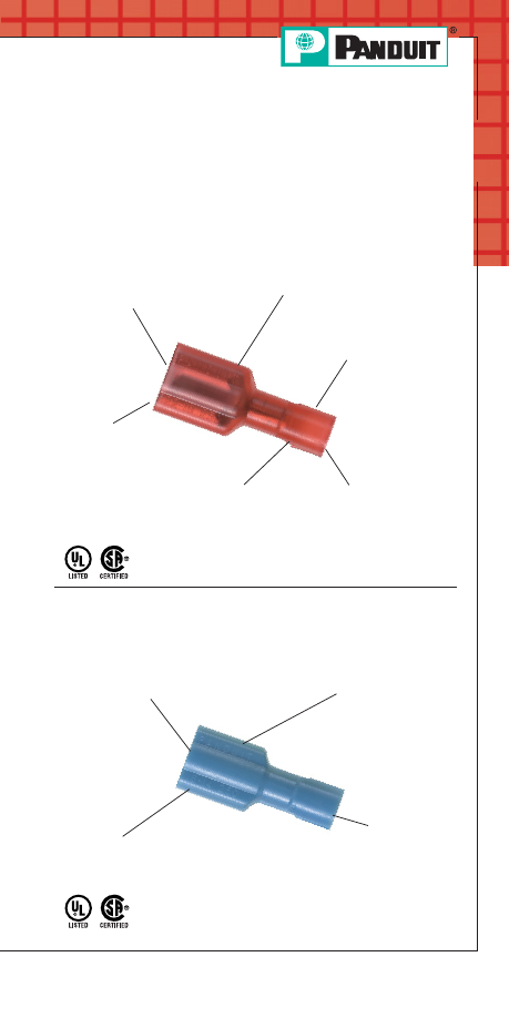
Nylon Fully Insulated
Female Receptacles and Male Tabs
Type DNF-FIB
Maximum
insulation
temperature
105°C (221°F)
Insulation support
restricts excessive wire
movement to minimize
stress on crimp joint
UL and CSA rated up to 600V per UL310.
Funnel entry for
faster wire insertion
and lower installed cost
Expanded wire entry
(on select sizes)
accommodates
large insulation or
multiple wires
Available in tab
sizes to
accommodate
.110", .187", .205"
or .250" tabs
Fully insulated
design provides
protection from
electrical shorts
D
ISCO
-G
RIP
™
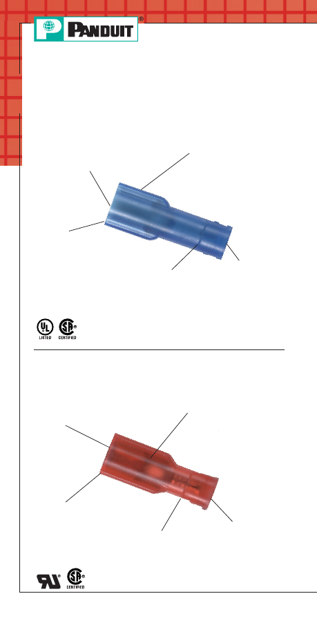
Premium Nylon Fully Insulated
Female Receptacles and Male Tabs
Type DNF and DPF
Maximum
insulation
temperature
105°C (221°F)
UL and CSA rated up to 600V per UL310.
Male products available .250" width in standard
and oversized housing configurations.
Funnel entry
for faster
wire insertion
and lower
installed cost
Available in tab
sizes to
accommodate
.250" tabs
Fully insulated
design provides
protection from
electrical shorts
PANDUIT Termination Solutions-html.html
A30
Terminals
S
UPRA
-G
RIP
™
Nylon Fully
Insulated Female Disconnects
Type DNG-FB
Maximum
insulation
temperature
105°C (221°F)
Fully integrated metal
insulation grip for high
vibration, high strain
relief, and double
crimp requirements
Funnel entry
for faster
wire insertion
and lower
installed cost
Available in tab sizes
to accommodate
.187" or .250" tabs
Fully insulated
design provides
protection from
electrical shorts
UL and CSA rated up to 600V per UL310.
D
ISCO
-L
OK
™
Nylon Fully Insulated
Locking Female Disconnects
Type DNG-FL
Maximum
insulation
temperature
105°C (221°F)
Insulation grip sleeve
provides a superior insulation
crimp for high vibration and
high strain relief applications
UL and CSA rated up to 300V.
Funnel entry for
faster wire insertion
and lower installed cost
Available in tab sizes
to accommodate
250" tabs
Unique locking mechanism
allows for low insertion forces
(mating) and positive locking
for secure connections
Features and Benefits –
P
AN
-T
ERM
®
Disconnects
(continued)
PANDUIT Termination Solutions-html.html
A31
For service and technical support, call 800-777-3300
or visit www.panduit.com.
Terminals
Nylon Barrel Insulated
Female Receptacles and Male Tabs
Type DNF
Insulation grip sleeve provides
a superior insulation crimp for
high vibration and high strain
relief applications
Funnel entry
for faster
wire insertion
and lower
installed cost
Available in tab
sizes to
accommodate
.110", .187",
.205" or
.250" tabs
UL and CSA rated up to 300V.
Male products available .250" width.
Maximum insulation
temperature 105°C (221°F)
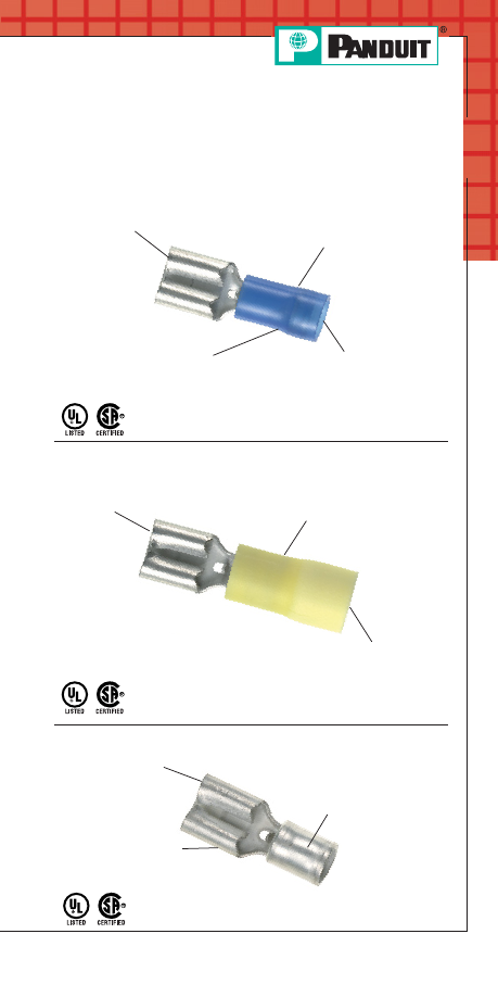
Vinyl Barrel Insulated
Female Receptacles and Male Tabs
Type DV and DVF
Insulation support to
protect electrical crimp
Available in
tab sizes to
accommodate
.187", .205"
or .250" tabs
UL and CSA rated up to 600V.
Male products available .250" width.
Flammability – UL94V-0.
Maximum insulation
temperature 105°C (221°F)
Non-Insulated Female Receptacles and Male Tabs
Type D
Male products available .250" width.
Available in tab sizes
to accommodate
.187" or .250" tabs
Sleeved barrel assures
crimp reliability
Maximum recommended
operating temperature
150°C (302°F)
Features and Benefits –
P
AN
-T
ERM
®
Disconnects
(continued)
PANDUIT Termination Solutions-html.html
A32
Prime items appear in BOLD.
Order number of pieces required, in multiples of Standard Package Quantity.
Terminals
Female Disconnect Nylon Fully
Pre-Insulated – Funnel Entry
• Insulation support helps to prevent wire
damage in bending applications
• Internal wire stop assures proper length of
insertion into terminal barrel
**To order in bulk, replace -C in the part number with -M for a bulk
package of 1000 and replace -L with -D for a bulk package of 500.
‡UL and CSA approved tooling/product combinations.
Part Number
Tab
Size
(In.)
Wire
Range
Color
Code
Tool
Std.
Pkg.
Qty.**
DNF18-110FIB-C
.110 x .032
22 – 18
AWG
Red
CT-100,
CT-600,
CT-1525‡
100
DNF18-111FIB-C
.110 x .020
100
DNF18-187FIB-C
.187 x .032
100
DNF18-188FIB-C
.187 x .020
100
DNF18-205FIB-C
.205 x .032
100
DNF18-206FIB-C
.205 x .020
100
DNF18-250FIB-C
.250 x .032
100
DNF14-187FIB-C
.187 x .032
16 – 14
AWG
Blue
CT-100,
CT-600,
CT-1525‡
100
DNF14-188FIB-C
.187 x .020
100
DNF14-205FIB-C
.205 x .032
100
DNF14-206FIB-C
.205 x .020
100
DNF14-250FIB-C
.250 x .032
100
DNF10-250FIB-L
.250 x .032
12 – 10
AWG
Yellow
CT-1525‡
50
P
AN
-T
ERM
®
Disconnects
◆
For a complete line of terminal products, see the
PANDUIT Electrical
Solutions Catalog, SA-ELCB03 at www.panduit.com
PANDUIT Termination Solutions-html.html
A33
Prime items appear in BOLD.
For service and technical support, call 800-777-3300
or visit www.panduit.com.
Terminals
Male /Female Coupler, Nylon Fully
Pre-Insulated – Funnel Entry
• Insulation support helps to prevent wire
damage in bending applications
• Internal wire stop assures proper
length of insertion into
terminal barrel
*UL Listed only.
**To order in bulk, replace -C in the part number with -M for a bulk
package of 1000 and replace -L with -D for a bulk package of 500.
‡UL and CSA approved tooling/product combinations.
Female Disconnect, Vinyl Barrel
Insulated – Butted Seam
• Insulation support helps to prevent wire
damage in bending applications
*UL Recognized and CSA approved.
**To order in bulk, replace -C or -CY in the part number with -M or -MY for
a bulk package of 1000.
^CSA approved tooling/product combinations.
‡UL and CSA approved tooling/product combinations.
Part Number
Tab
Size
(In.)
Wire
Range
Color
Code
Tool
Std.
Pkg.
Qty.**
DNF18-250FIM-C
.250 x
.032
22 – 18
AWG
Red
CT-100‡, CT-600,
CT-1525‡
100
DNF18-250FIB-C
CT-100, CT-600,
CT-1525‡
100
DNF14-250FIM-C
.250 x
.032
16 – 14
AWG
Blue
CT-600,
CT-1525‡
100
DNF14-250FIMB-L
50
DNF10-250FIMB-L
*
.250 x
.032
12 – 10
AWG
Yellow
CT-600‡,
CT-1550‡,
CT-1551‡
50
DNF10-250FI-L
CT-100‡, CT-460‡,
CT-550‡, CT-600‡,
CT-1550‡,
CT-1551‡
50
*Recognized
Part Number
Tab
Size
(In.)
Wire
Range
Color
Code
Tool
Std.
Pkg.
Qty.**
DV18-187B-CY
.187 x .032
22 – 18
AWG
Red
CT-1525‡
100
DV18-188B-CY
.187 x .020
100
DV18-250B-CY
.250 x .032
100
DV14-187B-C*
.187 x .032
16 – 14
AWG
Blue
CT-1525^
100
DV14-188B-C*
.187 x .020
100
DV14-205B-C*
.205 x .032
100
DV14-250B-C*
.250 x .032
100
PANDUIT Termination Solutions-html.html
A34
Prime items appear in BOLD.
Order number of pieces required, in multiples of Standard Package Quantity.
Terminals
Female Disconnect, Non-Insulated –
Butted Seam
**To order in bulk, replace -C in the part number with -M for a bulk
package of 1000.
Piggyback Disconnect, Vinyl Insulated
• Metal insulation grip sleeve crimps to wire
insulation providing protection to the crimp
joint during high vibration applications
• Combination of female disconnect and male
tab allows versatility in points of connection
• Multiple connection points allow additional
circuits to be added to existing
equipment without
expensive rework
**To order in bulk, replace -C or -CY in the part number with -M or -MY
for a bulk package of 1000.
Disconnect Adapter, Non-Insulated
• Converts one male tab to two male tabs,
allowing two female disconnects to be
connected to the same circuit
**To order in bulk, replace -C in the part number with -M for a bulk
package of 1000.
Part Number
Tab
Size
(In.)
Wire
Range
Tool
Std
Pkg.
Qty.**
D14-250B-C
.250 x .032
16 – 14 AWG
CT-100
100
Part Number
Tab
Size
(In.)
Wire
Range
Std.
Pkg.
Qty.**
D-250A-C
.250 x .032
—
100
◆
For a complete line of terminal products, see the
PANDUIT Electrical
Solutions Catalog, SA-ELCB03 at www.panduit.com
• Non-insulated barrel can be used to
provide an economical termination when
insulation is not required
Part Number
Tab
Size
(In.)
Wire Range
Color
Code
Tool
Std.
Pkg.
Qty.**
DV18-250P-CY
.250 x
.032
22 – 18
AWG
Red
CT-100,
CT-260,
CT-1550,
CT-1551
100
DV14-250P-C
16 – 14
AWG
Blue
100
PANDUIT Termination Solutions-html.html
A35
Prime items appear in BOLD.
For service and technical support, call 800-777-3300
or visit www.panduit.com.
Terminals
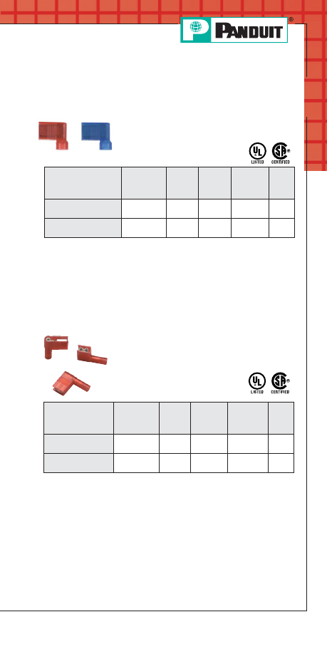
Right Angle Female Disconnect, Nylon
Fully Insulated – Funnel Entry
• Insulation support helps to prevent wire
damage in bending applications
• Right angle design allows low
profile routing of wire in limited
application space
**To order in bulk, replace -C in the part number with -M for a bulk
package of 1000.
Part Number
Tab
Size
(In.)
Wire
Range
Color
Code
Tool
Std.
Pkg.
Qty.**
DNFR18-250FIB-C
.250 x .032
22 – 18
AWG
Red
CT-300-1
100
DNFR14-250FIB-C
.250 x .032
16 – 14
AWG
Blue
CT-300-1
100
Right Angle Female Disconnect, Nylon
Insulated – Funnel Entry
• Insulation support helps to prevent wire
damage in bending applications
• Right angle design allows low profile
routing of wire in limited
application space
**To order in bulk, replace -C in the part number with -M for a bulk
package of 1000.
‡UL and CSA approved tooling/product combinations.
Part Number
Tab
Size
(In.)
Wire
Range
Color
Code
Tool
Std.
Pkg.
Qty.**
DNFR18-250B-C
.250 x .032
22 – 18
AWG
Red
CT-1525‡
100
DNFR14-250B-C
.250 x .032
16 – 14
AWG
Blue
CT-1525‡
100
PANDUIT Termination Solutions-html.html
A36
Prime items appear in BOLD.
Order number of pieces required, in multiples of Standard Package Quantity.
Terminals
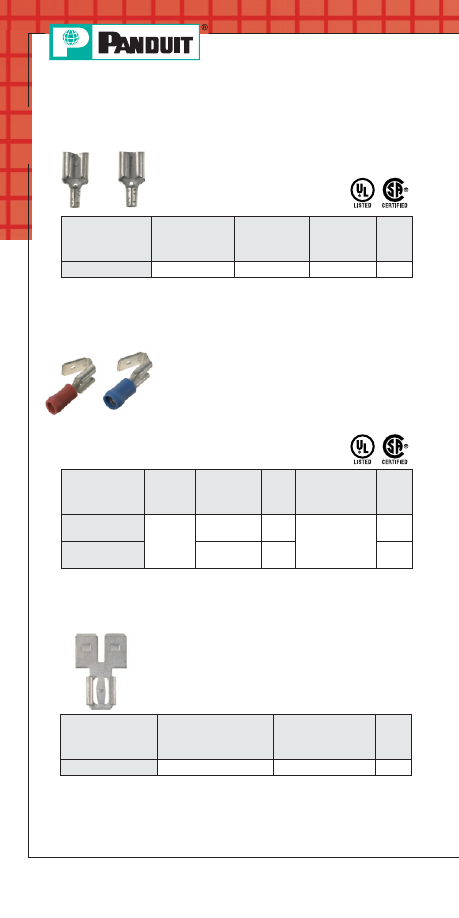
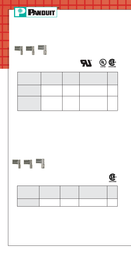
Right Angle Female Disconnect,
Non-Insulated – Metal Sleeve
• Sleeved barrel helps to facilitate high
mechanical and electrical performance
when crimping in any orientation
**To order in bulk, replace -C in the part number with -M for a bulk
package of 1000 and replace -L with -D for a bulk package of 500.
‡UL and CSA approved tooling/product combinations.
Right Angle Female Disconnect
Non-Insulated
• Serrated barrel helps to facilitate high
mechanical and electrical performance
when crimping in any orientation
**To order in bulk, replace -C in the part number with -M for a bulk
package of 1000.
*Recognized
Part Number
Tab
Size
(In.)
Wire
Range
Tool
Std.
Pkg.
Qty.**
DR14-250-C*
.250 x .032
16 – 14
AWG
CT-100‡, CT-200‡,
CT-600‡,
CT-1570‡
100
DR10-250-L
.250 x .032
12 – 10
AWG
CT-100‡, CT-200‡,
CT-600‡,
CT-1570‡,
CT-1701‡
50
Part Number
Tab
Size
(In.)
Wire
Range
Tool
Std.
Pkg.
Qty.**
DR14-250B-C
.250 x .032
16 – 14
AWG
CT-100, CT-200
100
◆
For a complete line of terminal products, see the
PANDUIT Electrical
Solutions Catalog, SA-ELCB03 at www.panduit.com
PANDUIT Termination Solutions-html.html
A37
Prime items appear in BOLD.
For service and technical support, call 800-777-3300
or visit www.panduit.com.
Terminals
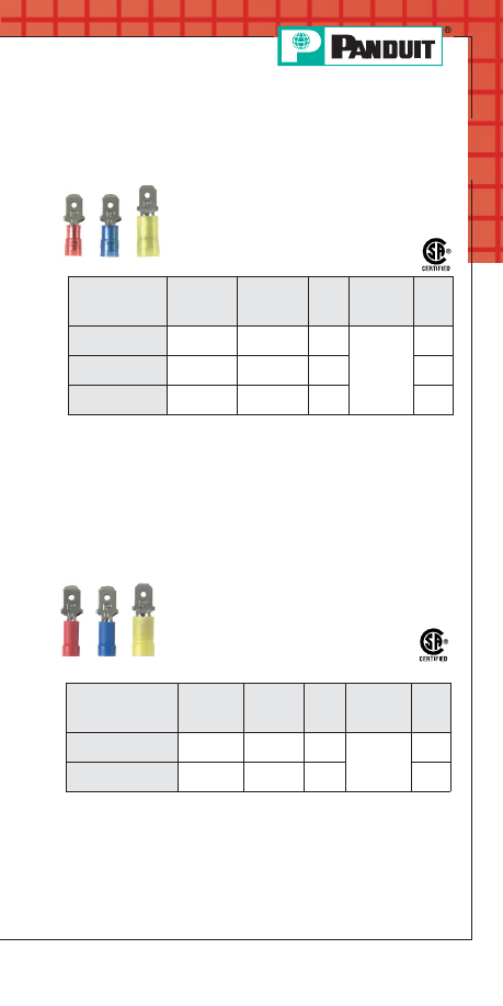
Male Disconnect, Nylon Barrel
Insulated – Funnel Entry
• Metal insulation grip sleeve crimps to wire
insulation providing protection to the crimp
joint during high vibration applications
*Not CSA Certified.
**To order in bulk, replace -C in the part number with -M for a bulk
package of 1000 and replace -L with -D for a bulk package of 500.
Part Number
Tab
Size
(In.)
Wire
Range
Color
Code
Tool
Std.
Pkg.
Qty.**
DNF18-250M-C
.250 x .032
22 – 18
AWG
Red
CT-1550,
CT-1551
100
DNF14-250M-C
.250 x .032
16 – 14
AWG
Blue
100
DNF10-250M-L*
.250 x .032
12 – 10
AWG
Yellow
50
Male Disconnect, Vinyl Barrel
Insulated – Funnel Entry
**To order in bulk, replace -C or -CY in the part number with -M or -MY for
a bulk package of 1000.
• Butted seam offers an economical solution
for less demanding applications
Part Number
Tab Size
(In.)
Wire
Range
Color
Code
Tool
Std
Pkg.
Qty.**
DV18-250MB-CY
.250 x
.032
22 – 18
AWG
Red
CT-1550,
CT-1551
100
DV14-250MB-C
.250 x
.032
16 – 14
AWG
Blue
100
PANDUIT Termination Solutions-html.html
A38
Prime items appear in BOLD.
Order number of pieces required, in multiples of Standard Package Quantity.
Terminals
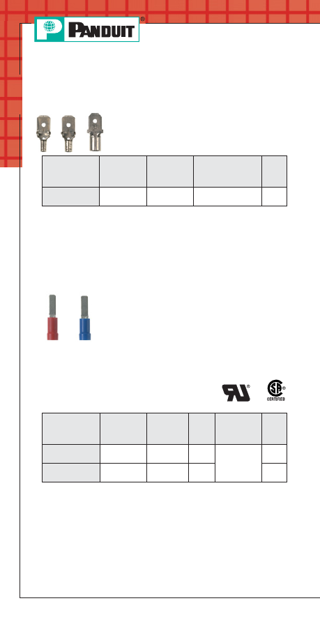
Male Disconnect, Non-Insulated –
Butted Seam
Part Number
Tab
Size
(In.)
Wire
Range
Tool
Std.
Pkg.
Qty.**
D14-250MB-C
.250 x .032
16 – 14
AWG
CT-100
100
**To order in bulk, replace -C in the part number with -M for a bulk
package of 1000.
Male Blade Adapter, Vinyl Insulated –
Funnel Entry
• Brazed seam protects terminal barrel from
splitting during the crimp process
• Flat blade design to prevent damage to
the wire from over tightening, resulting in a
reliable electrical connection
• Designed specifically for blade-type
terminal blocks
• Insulation support helps to prevent
wire damage in
bending applications
**To order in bulk, replace -C or -CY in the part number with -M or -MY for
a bulk package of 1000.
‡UL and CSA approved tooling/product combinations.
*Recognized
◆
For a complete line of terminal products, see the
PANDUIT Electrical
Solutions Catalog, SA-ELCB03 at www.panduit.com
• Butted seam offers an economical
solution for less demanding applications
Part Number
Tab Size
(In.)
Wire
Range
Color
Code
Tool
Std.
Pkg.
Qty.
DV18-145M-CY
.145 x .032
22 – 18
AWG
Red
CT-600,
CT-1550‡,
CT-1551‡
100
DV14-145M-C
.145 x .032
16 – 14
AWG
Blue
100
PANDUIT Termination Solutions-html.html
A39
For service and technical support, call 800-777-3300
or visit www.panduit.com.
Terminals
Features and Benefits –
P
AN
-T
ERM
®
Splices
Non-Insulated Parallel Splices
Type PS
Nylon Parallel Splices
Type PSN
Maximum
recommended
operating
temperature
150°C (302°F)
Seamless
tubular barrel
provides
consistent high
performance
quality crimps
UL and CSA rated up to 300V.
Only one crimp
needed to
complete splice
Only one
crimp needed
to complete
splice
Maximum insulation
temperature 105°C
(221°F)
PANDUIT Termination Solutions-html.html
A40
Terminals
Features and Benefits –
P
AN
-T
ERM
®
Splices
(continued)
Internal wire
stops assure
proper insertion
length
Maximum insulation
temperature 105°C
(221°F)
Brazed seam
assures crimp
reliability
UL and CSA rated up to 600V.
Maximum insulation
temperature 105°C
(221°F)
Internal wire
stops assure
proper
insertion
length
Expanded
wire entry
accommodates
larger insulation
UL and CSA rated up to 600V.
Flammability – UL94V-0.
Metric versions available.
Brazed seam
assures crimp
reliability
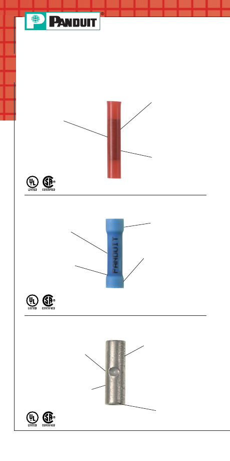
Nylon Butt Splices
Type BSN
Vinyl Butt Splices
Type BSV
Non-Insulated Butt Splices
Type BS
Internally beveled
barrel for quick easy
wire insertion
Internal wire stops
assure proper
insertion length
UL and CSA rated up to 600V.
Metric versions available.
Brazed seam
assures crimp
reliability
Maximum recommended
operating temperature
150°C (302°F)
PANDUIT Termination Solutions-html.html
A41
Prime items appear in BOLD.
For service and technical support, call 800-777-3300
or visit www.panduit.com.
Terminals
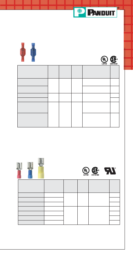
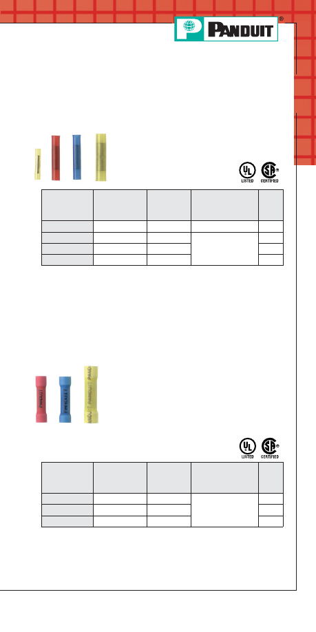
Butt Splice, Nylon Insulated
• Brazed seam protects terminal barrel from
splitting during the crimp process
• Internal wire stop assures proper length of
insertion into terminal barrel
*Not UL Listed.
**To order in bulk, replace -C in the part number with -M for a bulk
package of 1000 and replace -L with -D for a bulk package of 500.
Part Number
Wire
Range
Color
Code
Tool
Std.
Pkg.
Qty.**
BSN22-C
*
26 – 22 AWG
Yellow
CT-100, CT-1525
100
BSN18-C
22 – 18 AWG
Red
CT-100, CT-600,
CT-1550, CT-1551
100
BSN14-C
16 – 14 AWG
Blue
100
BSN10-L
12 – 10 AWG
Yellow
50
P
AN
-T
ERM
®
Splices
Butt Splice, Vinyl Insulated
• Expanded funnel entry designed to
accommodate wire with a larger than
standard outside diameter insulation
• Insulation support helps to prevent wire
damage in bending applications
• Internal wire stop assures proper length of
insertion into terminal barrel
**To order in bulk, replace -C or -CY in the part number with -M or -MY
for a bulk package of 1000 and replace -L with -D for a bulk package
of 500.
Part Number
Wire Range
Color Code
Tool
Std.
Pkg.
Qty.
BSV18X-CY
22 – 18 AWG
Red
CT-100, CT-600,
CT-1550, CT-1551
100
BSV14X-C
16 – 14 AWG
Blue
100
BSV10X-L
12 – 10 AWG
Yellow
50
PANDUIT Termination Solutions-html.html
A42
Prime items appear in BOLD.
Order number of pieces required, in multiples of Standard Package Quantity.
Terminals
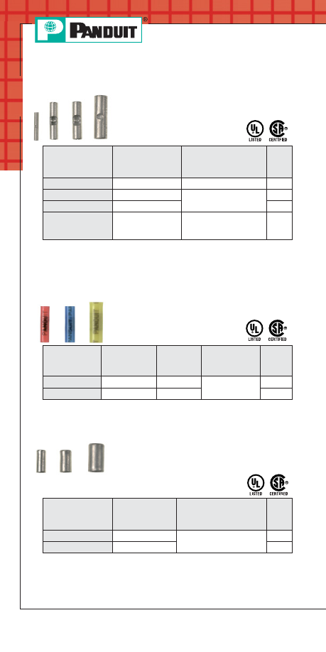
Butt Splice, Non-Insulated
• Brazed seam protects terminal barrel from
splitting during the crimp process
• Internal wire stop assures
proper length of insertion into
terminal barrel
*Not UL Listed.
**To order in bulk, replace -C in the part number with -M for a bulk
package of 1000 and replace -L with -D for a bulk package of 500.
‡UL and CSA approved tooling/product combinations.
Part Number
Wire
Range
Tool
Std.
Pkg.
Qty.**
BS22-C*
26 – 22 AWG
CT-100
100
BS18-C
22 – 18 AWG
CT-100, CT-200,
CT-600, CT-1570
100
BS14-C
16 – 14 AWG
100
BS10-L
12 – 10 AWG
CT-100, CT-200,
CT-600, CT-1570,
CT-1701‡
50
Parallel Splice, Nylon Insulated
• Parallel design results in only one crimp
required to combine two wires
Parallel Splice, Non-Insulated
• Parallel design results in only one crimp
required to combine two wires
• Non-insulated barrel can be used to provide
an economical termination
when insulation is not required
**To order in bulk, replace -C in the part number with -M for a bulk
package of 1000.
**To order in bulk, replace -C in the part number with -M for a bulk
package of 1000 and replace -L with -D for a bulk package of 500.
Part Number
Wire
Range
Tool
Std.
Pkg.
Qty.**
PS16-C
20 – 16 AWG
CT-100, CT-200
100
PS12-L
14 – 12 AWG
50
◆
For a complete line of terminal products, see the
PANDUIT Electrical
Solutions Catalog, SA-ELCB03 at www.panduit.com
Part Number
Wire
Range
Color
Code
Tool
Std.
Pkg.
Qty.**
PSN18-C
22 – 18 AWG
Red
CT-100,
CT-1525
100
PSN16-C
20 – 16 AWG
Blue
100
PANDUIT Termination Solutions-html.html
A43
For service and technical support, call 800-777-3300
or visit www.panduit.com.
Terminals
Features and Benefits –
P
AN
-T
ERM
®
Wire Joints
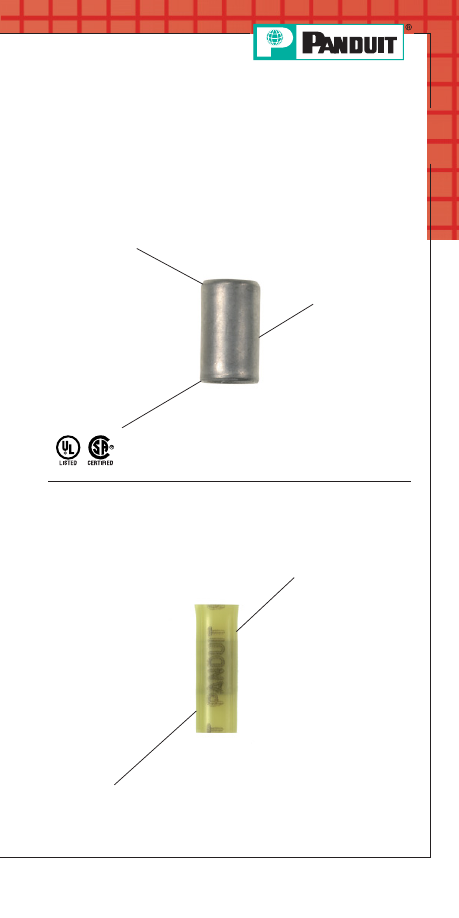
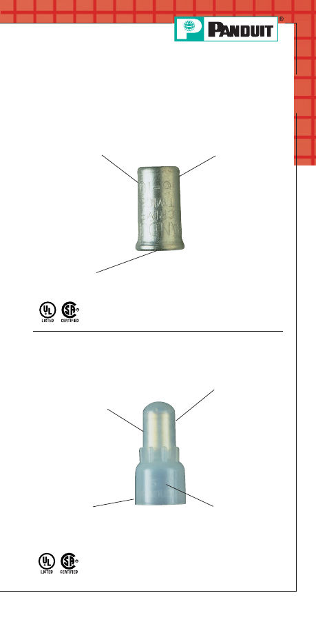
Non-Insulated Wire Joints
Type J
Nylon Wire Joints
Type JN
Internally
beveled barrel
for quick easy
wire insertion
UL and CSA rated up to 600V.
Maximum
recommended
operating
temperature
150°C (302°F)
Only one crimp
needed to
complete splice
Maximum insulation
temperature 105°C
(221°F)
Deep skirt to
accommodate
multiple variations of
wire combinations
Only one
crimp needed
to complete
splice
UL and CSA rated up to 600V
Metric versions available
Fully insulated
housing protects
crimp joint
PANDUIT Termination Solutions-html.html
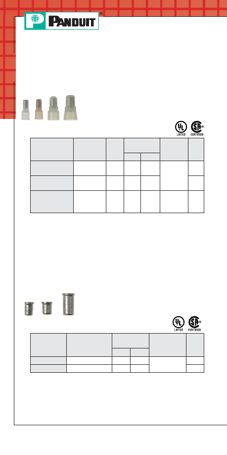
A44
Prime items appear in BOLD.
Order number of pieces required, in multiples of Standard Package Quantity.
Terminals
Wire Joint, Nylon Insulated
• Large barrel designed to accommodate
multiple combinations of wires (up to seven
wires) with just one crimp
• Fully pre-insulated housing designed to
protect crimp joint and reduce
the potential for shorting
and shocks
**To order in bulk, replace -C in the part number with -M for a bulk
package of 1000, with exception of JN418-212-C, replace -C with -D
for bulk package of 500.
‡UL and CSA approved tooling/product combinations.
Wire Joint, Non-Insulated
• Large barrel designed to accommodate
multiple combinations of wires (up to seven
wires) with just one crimp
• Non-insulated barrel can be used to provide
an economical termination
when insulation is not required
**To order in bulk, replace -T in the part number with -2M for a bulk
package of 2000.
‡UL and CSA approved tooling/product combinations.
P
AN
-T
ERM
®
Wire Joints
Part Number
Min/Max Wire
Range
CMA Range
Tool
Std.
Pkg.
Qty.**
Min.
Max.
J214-312-T
(2) #14 – (3) #12
5760
19590
CT-100‡,
CT-200‡
200
J318-412-T
(3) #18 – (4) #12
4860
27330
200
Part Number
Min/Max
Wire Range
Color
Code
CMA Range
Tool
Std.
Pkg.
Qty.**
Min.
Max.
JN224-318-C
(2) #24 –
(2) #16
Red
808
5160
CT-1550‡,
CT-1551‡
100
JN218-216-C
(2) #22 –
(2) #16
Clear
1284
5160
100
JN418-212-C
(4) #18 –
(2) #12
Clear
6480
14750
CT-100‡,
CT-1550‡,
CT-1551‡
100
PANDUIT Termination Solutions-html.html
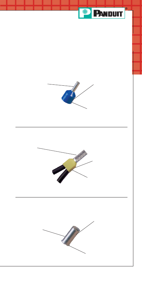
A45
For service and technical support, call 800-777-3300
or visit www.panduit.com.
Terminals
Features and Benefits –
P
AN
-T
ERM
®
Ferrules
Insulated Ferrules – Single Wire
Type FSF and FSD
Non-Insulated Ferrules
Type F
Insulated Ferrules – Twin Wire
Type FTD
Seamless tubular
barrel provides
consistent
quality crimps
Maximum insulation
temperature 89°C
(192°F)
Color coded
polypropylene identifies
wire range.
(DIN codes available)
Maximum insulation
temperature 89°C
(192°F)
Oversized
seamless
tubular barrel
provides
consistent, high
performance
quality crimps
for two wire
applications
Color coded
polypropylene identifies
wire range. (German and
French codes available)
Maximum operating
temperature 89°C
(192°F)
Seamless tubular barrel
provides consistent
quality crimps
Flared barrel
for quick easy wire insertion
PANDUIT Ferrules are available for wiring applications from
#26 AWG to #1 AWG. Offerings include insulated and non-insulated
ferrules, in single-wire or double-wire configurations. Insulated
ferrules are color coded to DIN standards.
PANDUIT Termination Solutions-html.html
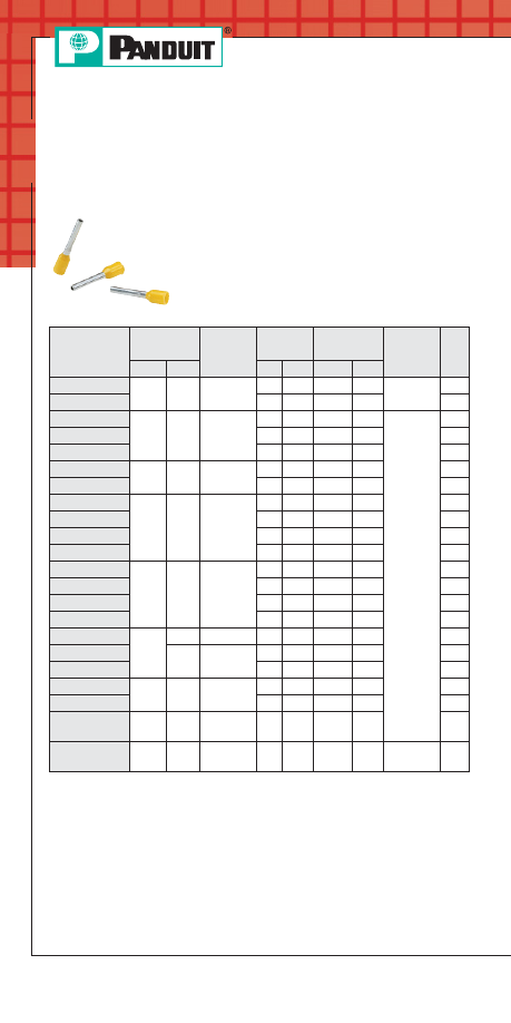
A46
Prime items appear in BOLD.
Order number of pieces required, in multiples of Standard Package Quantity.
Terminals
Part Number
Wire Size
Color
Code
Pin
Length
Wire Strip
Length
Tool
Std.
Pkg.
Qty.
AWG mm²
In.
mm
In.
mm
FSD74-6-D
24
AWG
.34
Turquoise
.24
6.0
3/8
9.5
CT-1002
500
FSD74-8-D
.31
8.0
15/32 11.9
500
FSD75-6-D
22
AWG
.50
White
.24
6.0
3/8
9.5
CT-1002,
CT-1003
500
FSD75-8-D
.31
8.0
15/32 11.9
500
FSD75-10-D
.39 10.0 17/32 13.5
500
FSD76-6-D
20
AWG
.75
Gray
.24
6.0
3/8
9.5
500
FSD76-8-D
.31
8.0
15/32 11.9
500
FSD77-6-D
18
AWG
1.00
Red
.24
6.0
3/8
9.5
500
FSD77-8-D
.31
8.0
15/32 11.9
500
FSD77-10-D
.39 10.0 17/32 13.5
500
FSD77-12-D
.47 12.0
5/8
15.9
500
FSD78-6-D
16
AWG
1.50
Black
.24
6.0
3/8
9.5
500
FSD78-8-D
.31
8.0
15/32 11.9
500
FSD78-10-D
.39 10.0 17/32 13.5
500
FSD78-12-D
.47 12.0
5/8
15.9
500
FSD79-8-D
14
AWG
2.08
Yellow
.31
8.0
15/32 11.9
500
FSD80-8-D
2.50
Blue
.31
8.0
15/32 11.9
500
FSD80-12-D
.47 12.0
5/8
15.9
500
FSD81-10-D
12
AWG
4.00
Gray
.39 10.0 17/32 13.5
500
FSD81-12-C
.47 12.0
5/8
15.9
100
FSD82-12-C
10
AWG
6.00
Yellow
.47 12.0
5/8
15.9
100
FSD83-12-C
8
AWG
10.0
Red
.47 12.0
5/8
15.9 CT-1003,
CT-1004
100
• Molded housing allows easy insertion
of wire
• Seamless barrel contains wire strands
preventing fraying or bending, resulting in
high quality, reliable connections
Insulated Ferrules – Single Wire DIN
End Sleeve
P
AN
-T
ERM
®
Ferrules
PANDUIT Termination Solutions-html.html

A47
Prime items appear in BOLD.
For service and technical support, call 800-777-3300
or visit www.panduit.com.
Terminals
• Oversized seamless tubular provides
consistent, high performance quality crimps
for two wire applications
• Molded housing allows easy insertion
of wire
Insulated Ferrules – Twin Wire DIN
End Sleeve
Part Number
Wire Size
Color
Code
Pin
Length
Wire Strip
Length
Tool
Std.
Pkg.
Qty.
AWG mm²
In.
mm
In.
mm
FTD75-8-D
22
AWG
.50
White .31
8.0
7/16
11.2
CT-1002,
CT-1003
500
FTD76-8-D
20
AWG
.75
Gray
.31
8.0
7/16
11.2
500
FTD76-10-D
.39 10.0
9/16
14.0
500
FTD77-8-D
18
AWG
1.00
Red
.31
8.0
7/16
11.2
500
FTD77-10-D
.39 10.0
9/16
14.0
500
FTD78-8-D
16
AWG
1.50
Black
.31
8.0
7/16
11.2
500
FTD78-12-D
.47 12.0 21/32 16.8
500
FTD80-10-TL
14
AWG
2.50
Blue
.39 10.0
9/16
14.0
250
FTD80-13-TL
.51 13.0 23/32 16.2
250
FTD81-12-C
12
AWG
4.00
Gray
.47 12.0 21/32 16.8
100
FTD82-14-C
10
AWG
6.00 Yellow .55 14.0 25/32 19.6 CT-1003,
CT-1004
100
PANDUIT Termination Solutions-html.html
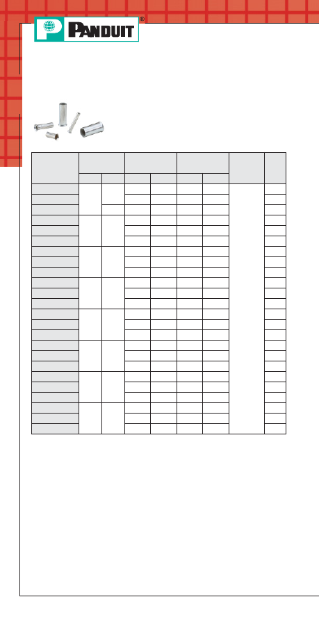
A48
Prime items appear in BOLD.
Order number of pieces required, in multiples of Standard Package Quantity.
Terminals
• Flared barrel allows easy insertion of wire
• Non-insulated barrel can be used to provide
an economical termination when insulation
is not required
Ferrules, Non-Insulated
Part
Number
Wire Size
Length
Wire Strip
Length
Tool
Std.
Pkg.
Qty.
In.
mm²
In.
mm
In.
mm
F73-5-M
24
AWG
.25
.20
5.0
7/32
5.0
CT-1002,
CT-1003
1000
F73-7-M
.28
7.0
9/32
7.0
1000
F74-5-M
.34
.20
5.0
7/32
5.0
1000
F75-6-M
22
AWG
.50
.24
6.0
1/4
6.0
1000
F75-8-M
.31
8.0
5/16
8.0
1000
F75-10-M
.39
10.0
13/32
10.0
1000
F76-6-M
20
AWG
.75
.24
6.0
1/4
6.0
1000
F76-8-M
.31
8.0
5/16
8.0
1000
F76-10-M
.39
10.0
13/32
10.0
1000
F77-6-M
18
AWG
1.0
.24
6.0
1/4
6.0
1000
F77-7-M
.28
7.0
9/32
7.0
1000
F77-8-M
.31
8.0
5/16
8.0
1000
F78-7-M
16
AWG
1.5
.28
7.0
9/32
7.0
1000
F78-8-M
.31
8.0
5/16
8.0
1000
F78-10-M
.39
10.0
13/32
10.0
1000
F80-7-M
14
AWG
2.5
.28
7.0
9/32
7.0
1000
F80-8-M
.31
8.0
5/16
8.0
1000
F80-10-M
.39
10.0
13/32
10.0
1000
F81-9-M
12
AWG
4.0
.35
9.0
11/32
8.0
1000
F81-10-M
.39
10.0
13/32
10.0
1000
F81-12-M
.47
12.0
15/32
12.0
1000
F82-10-M
10
AWG
6.0
.39
10.0
13/32
10.0
1000
F82-12-M
.47
12.0
15/32
12.0
1000
F82-15-M
.59
15.0
19/32
15.0
1000
PANDUIT Termination Solutions-html.html
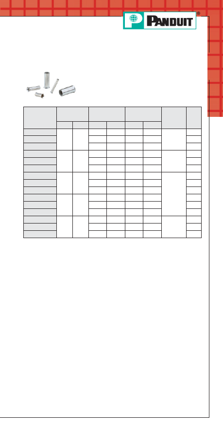
A49
Prime items appear in BOLD.
For service and technical support, call 800-777-3300
or visit www.panduit.com.
Terminals
• Flared barrel allows easy insertion of wire
• Non-insulated barrel can be used to provide
an economical termination when insulation
is not required
Ferrules, Non-Insulated (continued)
Part
Number
Wire Size
Length
Wire Strip
Length
Tool
Std.
Pkg.
Qty.
In.
mm²
In.
mm
In.
mm
F83-12-D
8
AWG
10.0
.47
12.0
15/32
12.0
CT-1003,
CT-1004
500
F83-15-D
.59
15.0
19/32
15.0
500
F83-18-D
.71
18.0
23/32
18.0
500
F84-12-TL
6
AWG
16.0
.47
12.0
15/32
12.0
CT-1004
250
F84-15-TL
.59
15.0
19/32
15.0
250
F84-18-TL
.71
18.0
23/32
18.0
250
F85-12-C
4
AWG
25.0
.47
12.0
15/32
12.0
CT-1005
100
F85-15-C
.59
15.0
19/32
15.0
100
F85-18-C
.71
18.0
23/32
18.0
100
F86-18-C
2
AWG
35.0
.71
18.0
23/32
18.0
100
F86-20-C
.79
20.0
25/32
20.0
100
F86-25-C
.98
25.0
31/32
25.0
100
F87-18-C
1
AWG
50.0
.71
18.0
23/32
18.0
CT-1006
100
F87-22-C
.87
22.0
7/8
22.0
100
F87-25-C
.98
25.0
31/32
25.0
100
PANDUIT Termination Solutions-html.html
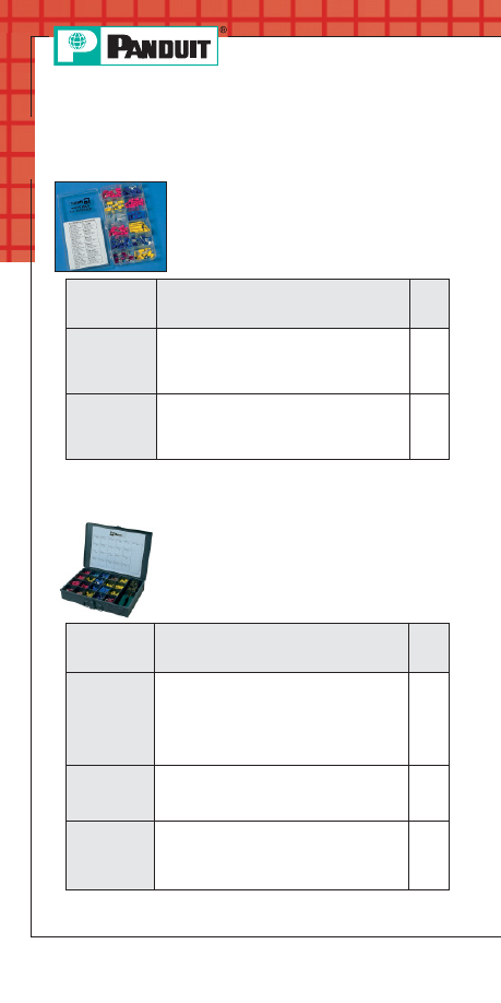
A50
Prime items appear in BOLD.
Order number of pieces required, in multiples of Standard Package Quantity.
Terminals
Plastic Box Terminal Kits
• Ideal for maintenance and
construction wiring
• Rugged plastic construction
• Kit has hanging tab for easy storage
Part Number
Part Description
Std.
Pkg.
Qty.
KP-1075
Terminal kit without crimping tool. Includes the
following: (20) PV18-8R; PV18-6F; PV14-8F;
PV14-10R; (10) PV10-8R; PV10-10R;
DNF14-250; DNF-18-250; BSV18X; BSV14X;
BSV10X; (5) JN418-212.
1
KP-1165
Includes the following: (18) PV18-8R;
PV14-10R; P18-6F; P14-8F; (10) PV10-8R;
PV10-10R; BSV18X; BSV14X; BSV10X;
DV18-250B; DV14-188B; (5) JN418-212;
(1) CT-160 Tool; KP-1000 Box.
1
Steel Kit Boxes
• Terminal kit in rugged steel case that can
be used stand-alone or fits into two, four or
six drawer slide racks
Part Number
Part Description
Std.
Pkg.
Qty.
K-1000
Empty steel box, 20 terminal compartments and
1 tool compartment, measures
13 21/64" wide x 9 21/64" deep x 2" high
• Latch prevents accidental opening
• Handle for portability or as drawer pull when
used in rack
• Drop-in label area on front
1
K-1102
Includes the following: (100) PV18-6LF;
PV18-8LF; PV14-8LF; PV14-10LF; BSV18X;
BSV14X; (50) PV10-10LF; BSV10X;
(1) CT-100 Tool; K-1000 Box.
1
K-1104
Includes the following: (50) PN18-10R;
PN14-6R; PN14-10R; PN18-6F; PN14-6F;
PN14-10F; (25) PN10-10R; PN10-56R;
PN10-10F; BSN14; BSN10; JN418-212;
(1) CT-100 Tool; K-1000 Box.
1
Terminal Kits
PANDUIT Termination Solutions-html.html
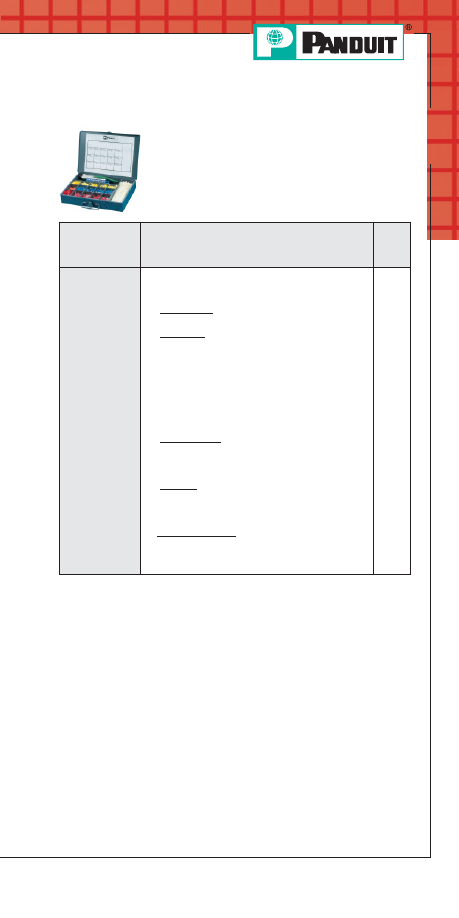
A51
Prime items appear in BOLD.
For service and technical support, call 800-777-3300
or visit www.panduit.com.
Terminals
Industrial Maintenance Kits
• Steel kits have individual compartments for
storage of terminals
• Convenient carrying handle
• Once top is closed, terminals remain in
their compartments
Part Number
Part Description
Std.
Pkg.
Qty.
K1-PNKIT
Kit contains:
(1) K-1001 steel kit box
(1) CT-260 installation tool
Cable Ties
(100) PLT2S cable ties
Terminals
(100) PN14-610R multi-stud terminals
(100) PN18-610R multi-stud terminals
(100) PN18-6LF locking fork terminals
(100) PN14-8LF locking fork terminals
(50) PN10-10LF locking fork terminals
(100) PN18-8F fork terminals
(100) PN14-10R ring terminals
(50) PN10-10R ring terminals
Disconnects
(100) DNF18-250 disconnects
(100) DNF14-250 disconnects
(50) DV10-250 disconnects
Splices
(50) BSN18 butt splices
(50) BSN14 butt splices
(25) BSN10 butt splices
Marking System
(1) PMD-0-9 marking dispenser and tape
(100) MP150 marker tags
(1) PX-0 marker
1
PANDUIT Termination Solutions-html.html
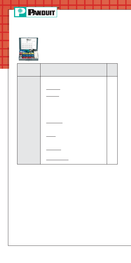
A52
Prime items appear in BOLD.
Order number of pieces required, in multiples of Standard Package Quantity.
Terminals
Industrial Maintenance Kits (continued)
• Steel kits have individual compartments for
storage of terminals
• Convenient carrying handle
• Once top is closed, terminals remain in
their compartments
Part Number
Part Description
Std.
Pkg.
Qty.
K2-PVKIT
Kit contains:
(1) K-1001 steel kit box
(1) CT-260 installation tool
Cable Ties
(100) PLT2S cable ties
Terminals
(100) PV18-8F fork terminals
(100) PV18-6LF locking fork terminals
(100) PV14-8LF locking fork terminals
(50) PV10-10LF locking fork terminals
(100) PV18-610R multi-stud terminals
(100) PV14-10R ring terminals
(50) PV10-10R ring terminals
Disconnects
(100) DV18-250B disconnects
(100) DV14-250B disconnects
(50) DV10-250 disconnects
Splices
(50) BSV18X butt splices
(50) BSV14X butt splices
(25) BSV10X butt splices
Wire Joints
(30) JN224-318
(15) JN314-412
Marking System
(1) PMD-0-9 marking dispenser and tape
1
PANDUIT Termination Solutions-html.html
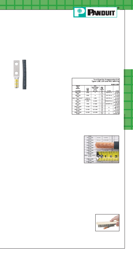
Po
w
er C
onnec
tors
B1
For service and technical support, call 800-777-3300
or visit www.panduit.com.
Crimping Guidelines for
PANDUIT
®
P
AN
-L
UG
™
Compression Lugs and Splices
1. Select the proper
PANDUIT compression connector for the
conductor type and size being used.
•
PANDUIT compression connectors are identified with
the proper conductor size and conductor type marked
on the tongue or barrel of the connector
• The proper conductor
size and type to be used
with each connector can
also be found in the
installation instructions
included with
PANDUIT
product packaging and
in the tool charts*
2. Strip the conductor to the proper strip length.
As specified:
• On the
PANDUIT product packaging label or
• On the installation instructions
included with
PANDUIT
product packaging or
• In the tool charts*
Make sure the conductor is not stripped too long, which
would result in exposed wire between the barrel of the
connector and the cable insulation.
Make sure the conductor is not stripped too short,
which would result in a less than complete contact area
with the connector when the conductor is inserted in
the barrel.
Do not nick or cut strands of conductor during
crimping, which would result in a less than premium
conductor termination.
Make sure conductor strands are free
from corrosion.
*See condensed tool charts on pages B4-B27; for complete tool charts
refer to pages D2.148-D2.186 of the Electrical Solutions Catalog,
SA-ELCB03, at www.panduit.com.
PANDUIT Termination Solutions-html.html
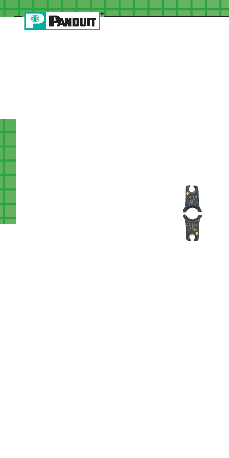
Po
w
er C
onnec
tors
B2
*See condensed tool charts on pages B4-B27; for complete tool charts
refer to pages D2.148-D2.186 of the Electrical Solutions Catalog,
SA-ELCB03, at www.panduit.com.
3. Select the proper crimping die and crimping tool to be used
with the connector.
Use crimping tools and dies that provide a UL Listed and/or
CSA Certified electrical termination, to assure a safe and
reliable connection.
Many
PANDUIT compression connectors are UL Listed and
CSA Certified when crimped with
PANDUIT and specified
competitor crimping tools and dies. These tools and dies are
listed in the tool charts*.
PANDUIT crimping tools and dies to
be used with each connector are also listed on the installation
instructions included with
PANDUIT product packaging.
PANDUIT compression connectors are color
coded and marked with
PANDUIT and specified
competitor die index numbers. Select the proper
crimping die to be used by matching the color code
and die index number marked on the connector to
the same markings on the crimping die.
Crimping Guidelines for
PANDUIT
®
P
AN
-L
UG
™
Compression Lugs and Splices (continued)
PANDUIT Termination Solutions-html.html
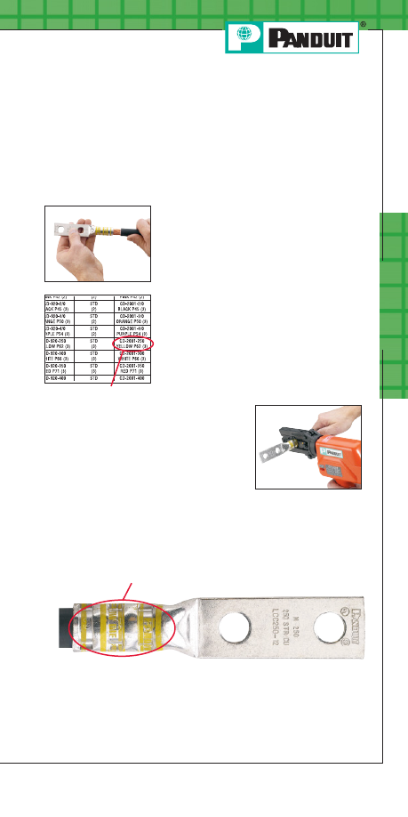
Po
w
er C
onnec
tors
B3
For service and technical support, call 800-777-3300
or visit www.panduit.com.
*See condensed tool charts on pages B4-B27; for complete tool charts
refer to pages D2.148-D2.186 of the Electrical Solutions Catalog,
SA-ELCB03, at www.panduit.com.
4. Crimp the connector.
Insert the conductor into the barrel of the connector. The
conductor should stop against the end of the barrel of the
lug, or wire stop in the butt splice, upon
complete insertion of the conductor
in the barrel. Some lugs are offered
with inspection windows that provide
visual inspection of the complete
conductor insertion.
Review the installation instructions
included with the
PANDUIT product
packaging or the tool charts* for the
proper number of crimps to be placed
in the connector. Make the first crimp in
the barrel nearest the tongue of the lug,
or wire stop in a butt splice, and make
successive crimps in the barrel working
towards the conductor entry at the
end of the barrel. Use the color coded
or knurled band markings on the
barrel of the connector to evenly
space the placement of the crimps in
the barrel.
When properly crimped, the die index number engraved in the
crimping die will be embossed into the barrel of the connector.
The crimp should be placed in the connector so the die index
number can be easily read when the connector is installed.
Crimping Guidelines for
PANDUIT
®
P
AN
-L
UG
™
Compression Lugs and Splices (continued)
Identify
Die index number must be visible
PANDUIT Termination Solutions-html.html
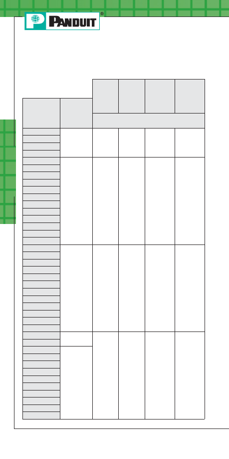
Po
w
er C
onnec
tors
B4
PANDUIT
Installation Tooling and Die Selection
Note: See page B27 for note references.
CT-1570 CT-1701
➀
CT-1700
➀
CT-720
PANDUIT
Connector
Type
Std.
Wire
Size
Die Part Number / Color Code & Die
Index Number
LCA10
#14 – #10
AWG STR,
#12 – #10
AWG SOL
12 – 10
P10
—
—
LCB10
LCD10
LCC10
LCAS8
#8 AWG
—
—
Red P21
CD-720-1
Red P21
LCA8
LCAN8
LCB8
LCBN8
LCD8
LCDN8
LCC8
LCCN8
SCSS8
SCS8
SCL8
LCAS6
#6 AWG
—
—
Blue P24
CD-720-1
Blue P24
LCA6
LCAN6
LCB6
LCBN6
LCD6
LCDN6
LCC6
LCCN6
SCSS6
SCS6
SCL6
LCAS4
#4 AWG
STR
—
—
Gray P29
CD-720-1
Gray P29
SCSS4
LCA4
#4 – #3
AWG STR,
#2 AWG
SOL
LCAN4
LCB4
LCBN4
LCD4
LCDN4
LCC4
LCCN4
SCS4
SCL4
PANDUIT Termination Solutions-html.html

CT-920, CT-920CH,
CT-930, CT-930CH,
CT-2930, CT-930LPCH,
➅
CT-2931, CT-2940,
➂
CT-2920, CT940CH
➂
U
NI
-D
IE
™
CT-980, CT-2980, CT980CH,
CT-2981, CT980LPCH,
➅
CT-2950
➄
Extended Wire Range
➉
CT-2001,
CT-2002
Die Part Number / Color Code & Die
Index Number
—
—
—
CD-920-8
Red P21
—
CD-2001-8
Red P21
CD-920-6
Blue P24
—
CD-2001-6
Blue P24
CD-920-4
Gray P29
#4 AWG STR
CD-2001-4
Gray P29
Po
w
er C
onnec
tors
B5
For service and technical support, call 800-777-3300
or visit www.panduit.com.
PANDUIT
Installation Tooling and Die Selection
(continued)
Note: See page B27 for note references.
11
11
11
PANDUIT Termination Solutions-html.html
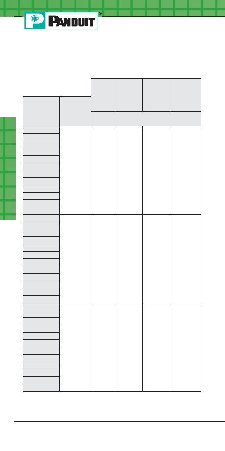
Po
w
er C
onnec
tors
B6
PANDUIT
Installation Tooling and Die Selection
(continued)
CT-1570 CT-1701
➀
CT-1700
➀
CT-720
PANDUIT
Connector
Type
Std.
Wire
Size
Die Part Number / Color Code & Die
Index Number
LCAS2
#2 AWG
—
—
Brown P33
CD-720-1
Brown P33
LCA2
LCAN2
➈
LCB2
LCBN2
LCD2
LCDN2
LCC2
LCCN2
SCSS2
SCS2
SCL2
LCAS1
#1 AWG
—
—
Green P37
CD-720-2
Green P37
LCA1
LCAN1
LCB1
LCBN1
LCD1
LCDN1
LCC1
LCCN1
SCSS1
SCS1
SCL1
LCAS1/0
1/0 AWG
—
—
—
CD-720-2
Pink P42
LCA1/0
LCAN1/0
LCB1/0
LCBN1/0
LCD1/0
LCDN1/0
LCC1/0
LCCN1/0
SCSS1/0
SCS1/0
SCL1/0
Note: See page B27 for note references.
PANDUIT Termination Solutions-html.html

Po
w
er C
onnec
tors
B7
For service and technical support, call 800-777-3300
or visit www.panduit.com.
PANDUIT
Installation Tooling and Die Selection
(continued)
CT-920, CT-920CH,
CT-930, CT-930CH,
CT-2930, CT-930LPCH
➅
,
CT-2931, CT-2940,
➂
CT-2920, CT940CH
➂
U
NI
-D
IE
™
CT-980, CT-2980, CT-980CH,
CT-2981, C-T980LPCH,
➅
CT-2950
➄
Extended Wire Range
➉
CT-2001,
CT-2002
Die Part Number / Color Code & Die
Index Number
CD-920-2
Brown P33
#6 – #2 AWG
CD-2001-2
Brown P33
CD-920-1
Green P37
#6 – #1 AWG
CD-2001-1
Green P37
CD-920-1/0
Pink P42
#6 – 1/0 AWG
CD-2001-1/0
Pink P42
Note: See page B27 for note references.
11
11
11
PANDUIT Termination Solutions-html.html

Po
w
er C
onnec
tors
B8
PANDUIT
Installation Tooling and Die Selection
(continued)
CT-1570
CT-1701
CT-1700
CT-720
PANDUIT
Connector
Type
Std.
Wire
Size
Die Part Number / Color Code & Die
Index Number
LCAS2/0
2/0 AWG
—
—
—
CD-720-2
Black P45
LCA2/0
LCAN2/0
LCB2/0
LCBN2/0
LCD2/0
LCDN2/0
LCC2/0
LCCN2/0
SCSS2/0
SCS2/0
SCL2/0
LCAS3/0
3/0 AWG
—
—
—
CD-720-2
Orange
P50
LCA3/0
LCAN3/0
LCB3/0
LCBN3/0
LCD3/0
LCDN3/0
LCC3/0
LCCN3/0
SCSS3/0
SCS3/0
SCL3/0
LCAS4/0
4/0 AWG
—
—
—
CD-720-3
Purple
P54
LCA4/0
LCAN4/0
LCB4/0
LCBN4/0
LCD4/0
LCDN4/0
LCC4/0
LCCN4/0
SCSS4/0
SCS4/0
SCL4/0
PANDUIT Termination Solutions-html.html

Po
w
er C
onnec
tors
B9
For service and technical support, call 800-777-3300
or visit www.panduit.com.
PANDUIT
Installation Tooling and Die Selection
(continued)
CT-920, CT-920CH,
CT-930, CT-930CH,
CT-2930, CT-930LPCH,
➅
CT-2931, CT-2940,
➂
CT-2920, CT940CH
➂
U
NI
-D
IE
™
CT-980, CT-2980, CT-980CH,
CT-2981, CT-980LPCH,
➅
CT-2950
➄
Extended Wire Range
➉
CT-2001,
CT-2002
Die Part Number / Color Code & Die
Index Number
CD-920-2/0
Black P45
#4 – 2/0 AWG
CD-2001-2/0
Black P45
CD-920-3/0
Orange P50
#2 – 3/0 AWG
CD-2001-3/0
Orange P50
CD-920-4/0
Purple P54
#1 – 4/0 AWG
CD-2001-4/0
Purple P54
Note: See page B27 for note references.
11
11
11
PANDUIT Termination Solutions-html.html
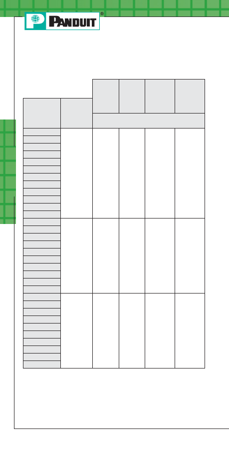
Po
w
er C
onnec
tors
B10
PANDUIT
Installation Tooling and Die Selection
(continued)
CT-1570
CT-1701
CT-1700
CT-720
PANDUIT
Connector
Type
Std.
Wire
Size
Die Part Number / Color Code & Die
Index Number
LCAS250
250 kcmil
—
—
—
CD-720-3
Yellow P62
LCA250
LCAN250
LCB250
LCBN250
LCD250
LCDN250
LCC250
LCCN250
SCSS250
SCS250
SCL250
LCA300
300 kcmil
—
—
—
CD-720-4
White P66
LCAN300
LCB300
LCBN300
LCD300
LCDN300
LCC300
LCCN300
SCS300
SCL300
LCA350
350 kcmil
—
—
—
CD-720-5
Red P71
LCAN350
LCB350
LCBN350
LCD350
LCDN350
LCC350
LCCN350
SCS350
SCL350
PANDUIT Termination Solutions-html.html
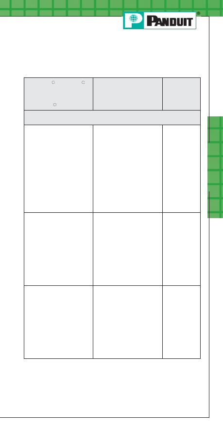
Po
w
er C
onnec
tors
B11
For service and technical support, call 800-777-3300
or visit www.panduit.com.
PANDUIT
Installation Tooling and Die Selection
(continued)
CT-920, CT-920CH,
CT-930, CT-930CH,
CT-2930, CT-930LPCH,
➅
CT-2931, CT-2940,
➂
CT-2920, CT940CH
➂
U
NI
-D
IE
™
CT-980, CT-2980, CT-980CH,
CT-2981, CT-980LPCH,
➅
CT-2950
➄
Extended Wire Range
➉
CT-2001,
CT-2002
Die Part Number / Color Code & Die
Index Number
CD-920-250
Yellow P62
1/0 AWG – 250 kcmil
CD-2001-250
Yellow P62
CD-920-300
White P66
2/0 AWG – 300 kcmil
CD-2001-300
White P66
CD-920-350
Red P71
3/0 AWG – 350 kcmil
CD-2001-350
Red P71
Note: See page B27 for note references.
11
11
11
PANDUIT Termination Solutions-html.html
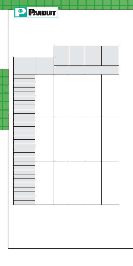
Po
w
er C
onnec
tors
B12
PANDUIT
Installation Tooling and Die Selection
(continued)
CT-1570
CT-1701
CT-1700
CT-720
PANDUIT
Connector
Type
Std.
Wire
Size
Die Part Number / Color Code & Die
Index Number
LCA400
400 kcmil
—
—
—
CD-720-6
Blue P76
LCAN400
LCB400
LCBN400
LCD400
LCDN400
LCC400
LCCN400
SCS400
SCL400
LCA500
500 kcmil
—
—
—
CD-720-7
Brown P87
LCAN500
LCB500
LCBN500
LCD500
LCDN500
LCC500
LCCN500
SCS500
SCL500
LCA600
600 kcmil
—
—
—
—
LCAN600
LCB600
LCBN600
LCD600
LCDN600
LCC600
LCCN600
SCS600
SCL600
PANDUIT Termination Solutions-html.html
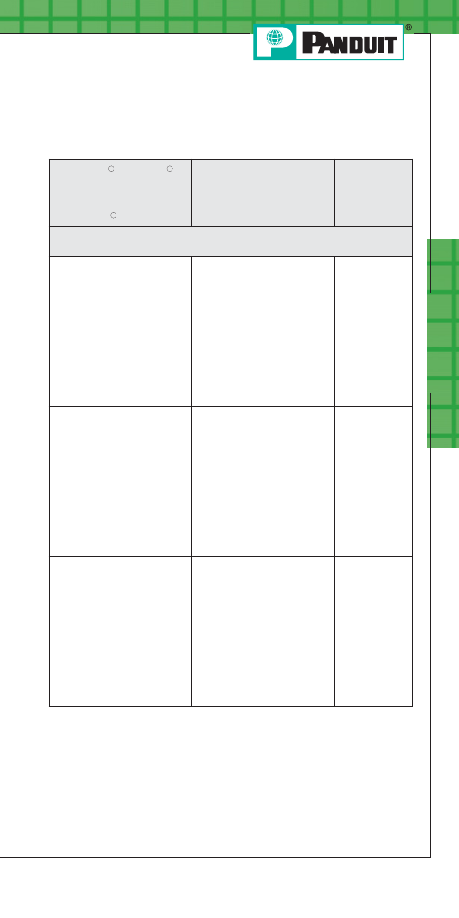
Po
w
er C
onnec
tors
B13
For service and technical support, call 800-777-3300
or visit www.panduit.com.
PANDUIT
Installation Tooling and Die Selection
(continued)
CT-920, CT-920CH,
CT-930, CT-930CH,
CT-2930, CT-930LPCH,
➅
CT-2931, CT-2940,
➂
CT-2920, CT940CH
➂
U
NI
-D
IE
™
CT-980, CT-2980, CT-980CH,
CT-2981, CT-980LPCH,
➅
CT-2950
➄
Extended Wire Range
➉
CT-2001,
CT-2002
Die Part Number / Color Code & Die
Index Number
CD-920-400
Blue P76
4/0 AWG – 400 kcmil
CD-2001-400
Blue P76
CD-920-500
Brown P87
4/0 AWG – 500 kcmil
CD-2001-500
Brown P87
CD-920-600
Green P94
250 – 600 kcmil
—
Note: See page B27 for note references.
11
11
11
PANDUIT Termination Solutions-html.html
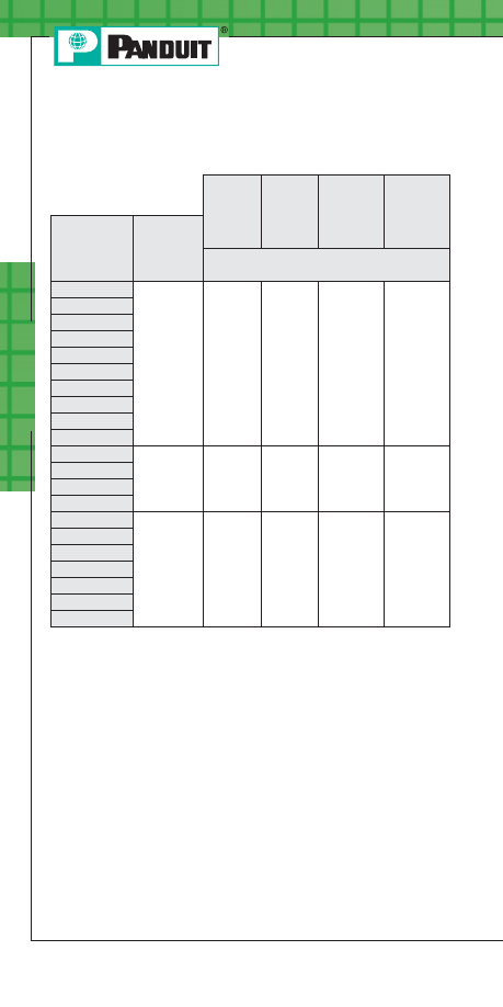
Po
w
er C
onnec
tors
B14
PANDUIT
Installation Tooling and Die Selection
(continued)
CT-1570
CT-1701
CT-1700
CT-720
PANDUIT
Connector
Type
Std.
Wire
Size
Die Part Number / Color Code & Die
Index Number
LCA750
750 kcmil
—
—
—
—
LCAN750
LCB750
LCBN750
LCD750
LCDN750
LCC750
LCCN750
SCS750
SCL750
LCB800
800 kcmil
—
—
—
—
LCBN800
LCC800
LCCN800
LCB1000
1000 kcmil
—
—
—
—
LCBN1000
LCD1000
LCC1000
LCCN1000
SCS1000
SCL1000
PANDUIT Termination Solutions-html.html
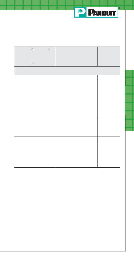
Po
w
er C
onnec
tors
B15
For service and technical support, call 800-777-3300
or visit www.panduit.com.
PANDUIT
Installation Tooling and Die Selection
(continued)
CT-920, CT-920CH,
CT-930, CT-930CH,
CT-2930, CT-930LPCH,
➅
CT-2931, CT-2940,
➂
CT-2920, CT940CH
➂
U
NI
-D
IE
™
CT-980, CT-2980, CT-980CH,
CT-2981, CT-980LPCH,
➅
CT-2950
➄
Extended Wire Range
➈
CT-2001,
CT-2002
Die Part Number / Color Code & Die
Index Number
CD-920-750
CD-940-750
➃
Black P106
500 – 750 kcmil
—
CD-940-800
➃
Orange P107
—
—
CD-940-1000
➃
White P125
—
—
Note: See page B27 for note references.
11
11
11
PANDUIT Termination Solutions-html.html
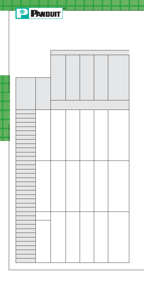
Po
w
er C
onnec
tors
B16
Installation Tooling and Die Selection
Cross Reference
Thomas & Betts
TBM20S,
TBM25S
TBM5
TBM8
TBM12,
13642M
TBM15,
TBM15I,
TBM15BSCR
PANDUIT
Connector
Type
Std.
Wire
Size
Die Part Number / Color Code & Die
Index Number
LCAS8
#8 AWG
Red
21
Red
21
Red
21
Red
21
Red
21
LCA8
LCAN8
LCB8
LCBN8
LCD8
LCDN8
LCC8
LCCN8
SCSS8
SCS8
SCL8
LCAS6
#6 AWG
Blue
24
Blue
24
Blue
24
Blue
24
Blue
24
LCA6
LCAN6
LCB6
LCBN6
LCD6
LCDN6
LCC6
LCCN6
SCSS6
SCS6
SCL6
LCAS4
#4 AWG
STR
Gray
29
Gray
29
Gray
29
Gray
29
Gray
29
SCSS4
LCA4
#4 – #3
AWG
STR,
#2 AWG
SOL
LCAN4
LCB4
LCBN4
LCD4
LCDN4
LCC4
LCCN4
SCS4
SCL4
PANDUIT Termination Solutions-html.html

Po
w
er C
onnec
tors
B17
For service and technical support, call 800-777-3300
or visit www.panduit.com.
Installation Tooling and Die Selection
Cross Reference (continued)
Note: See page B27 for note references.
Thomas & Betts
Burndy
TBM8-750M-1,
TBM8-750,
TBM8-750BSCR,
TMB750BSCR
➇
TBM14M,
TBM14BSCR,
BPLT14BSCR,
13100A
Y2MR,
Y1MRTC,
Y1MR
MY29
Y35,
Y35BH,
Y39,
Y39BH,
Y750,
Y750-2,
Y750BH,
Y750BH-2,
Y750HS,
PAT750,
BAT750,
BAT35
Y45,
➆
Y46
➆
Y644M,
Y644HS,
Y644MBH,
PAT644,
BAT644
Die Part Number / Color Code & Die
Index Number
STD
Red
21
Red
49
#8
U8CRT
Red
49
U8CRT
Red
49
—
STD
Blue
24
Blue
7
#6
U5CRT
Blue
7
U5CRT
Blue
7
STD
STD
Gray
29
Gray
8
#4
U4CRT
Gray
8
U4CRT
Gray
8
STD
PANDUIT Termination Solutions-html.html
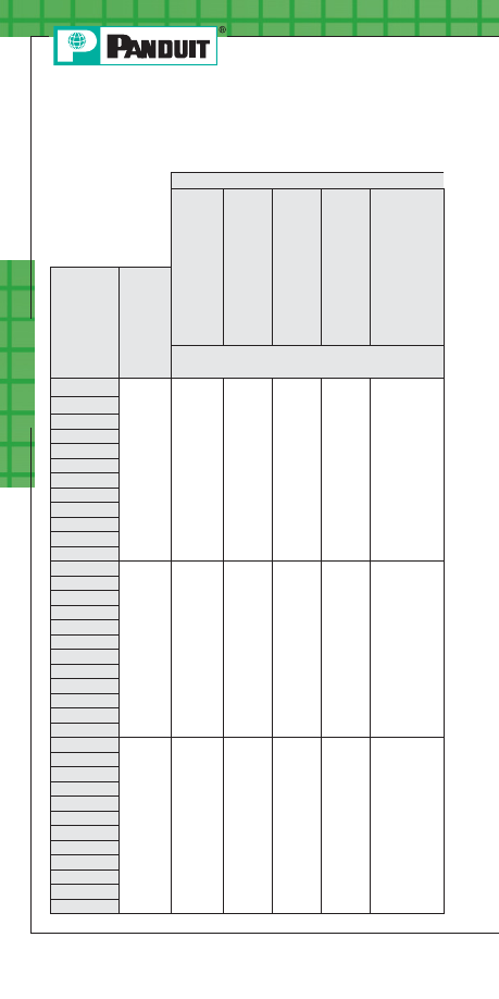
Po
w
er C
onnec
tors
B18
Installation Tooling and Die Selection
Cross Reference (continued)
Thomas & Betts
TBM20S,
TBM25S
TBM5
TBM8
TBM12,
13642M
TBM15,
TBM15I,
TBM15BSCR
PANDUIT
Connector
Type
Std.
Wire
Size
Die Part Number / Color Code & Die
Index Number
LCAS2
#2 AWG
Brown
33
Brown
33
Brown
33
Brown
33
Brown
33
SCSS2
LCA2
LCAN2
➁
LCB2
LCBN2
LCD2
LCDN2
LCC2
LCCN2
SCS2
SCL2
LCAS1
#1 AWG
—
Green
37
Green
37
Green
37
Green
37
LCA1
LCAN1
LCB1
LCBN1
LCD1
LCDN1
LCC1
LCCN1
SCSS1
SCS1
SCL1
LCAS1/0
1/0
AWG
—
Pink
42
Pink
42
Pink
42
Pink
42H
➁
LCA1/0
LCAN1/0
LCB1/0
LCBN1/0
LCD1/0
LCDN1/0
LCC1/0
LCCN1/0
SCSS1/0
SCS1/0
SCL1/0
Note: See page B27 for note references.
PANDUIT Termination Solutions-html.html
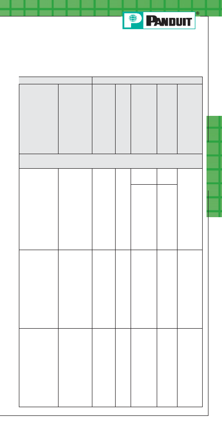
Po
w
er C
onnec
tors
B19
For service and technical support, call 800-777-3300
or visit www.panduit.com.
Installation Tooling and Die Selection
Cross Reference (continued)
Thomas & Betts
Burndy
TBM8-750M-1,
TBM8-750,
TBM8-750BSCR,
TMB750BSCR
➇
TBM14M,
TBM14BSCR,
BPLT14BSCR,
13100A
Y2MR,
Y1MRTC,
Y1MR
MY29
Y35,
Y35BH,
Y39,
Y39BH,
Y750,
Y750-2,
Y750BH,
Y750BH-2,
Y750HS,
PAT750,
BAT750,
BAT35
Y45,
➆
Y46
➆
Y644M,
Y644HS,
Y644MBH,
PAT644,
BAT644
Die Part Number / Color Code & Die
Index Number
STD
Brown
33
Brown
10
#2
U2CRT
Brown
10
U2CRT
Brown
10
STD
U2CRT
Brown
9
(SOL)/
Brown
10
(STR)
U2CRT
Brown
9
(SOL)/
Brown
10
(STR)
STD
Green
37
—
#1
U1CRT
Green
11
U1CRT
Green
11
STD
STD
Pink
42H
➁
—
1/0
U25RT
Pink
12
U25RT
Pink
12
STD
Note: See page B27 for note references.
PANDUIT Termination Solutions-html.html

Po
w
er C
onnec
tors
B20
Installation Tooling and Die Selection
Cross Reference (continued)
Thomas & Betts
TBM20S,
TBM25S
TBM5
TBM8
TBM12,
13642M
TBM15,
TBM15I,
TBM15BSCR
PANDUIT
Connector
Type
Std.
Wire
Size
Die Part Number / Color Code & Die
Index Number
LCAS2/0
2/0
AWG
—
Black
45
Black
45
Black
45
Black
45
LCA2/0
LCAN2/0
LCB2/0
LCBN2/0
LCD2/0
LCDN2/0
LCC2/0
LCCN2/0
SCSS2/0
SCS2/0
SCL2/0
LCAS3/0
3/0
AWG
—
Orange
50
Orange
50
Orange
50
Orange
50
LCA3/0
LCAN3/0
LCB3/0
LCBN3/0
LCD3/0
LCDN3/0
LCC3/0
LCCN3/0
SCSS3/0
SCS3/0
SCL3/0
LCAS4/0
4/0
AWG
—
Purple
54
Purple
54
Purple
54
Purple
54H
➁
LCA4/0
LCAN4/0
LCB4/0
LCBN4/0
LCD4/0
LCDN4/0
LCC4/0
LCCN4/0
SCSS4/0
SCS4/0
SCL4/0
Note: See page B27 for note references.
PANDUIT Termination Solutions-html.html

Po
w
er C
onnec
tors
B21
For service and technical support, call 800-777-3300
or visit www.panduit.com.
Installation Tooling and Die Selection
Cross Reference (continued)
Thomas & Betts
Burndy
TBM8-750M-1,
TBM8-750,
TBM8-750BSCR,
TMB750BSCR
➇
TBM14M,
TBM14BSCR,
BPLT14BSCR,
13100A
Y2MR,
Y1MRTC,
Y1MR
MY29
Y35,
Y35BH,
Y39,
Y39BH,
Y750,
Y750-2,
Y750BH,
Y750BH-2,
Y750HS,
PAT750,
BAT750,
BAT35
Y45,
➆
Y46
➆
Y644M,
Y644HS,
Y644MBH,
PAT644,
BAT644
Die Part Number / Color Code & Die
Index Number
STD
Black
45
—
2/0
U26RT
Black
13
U26RT
Black
13
STD
STD
Orange
50
—
3/0
U27RT
Orange
14
U27RT
Orange
14
STD
STD
Purple
54H
➁
—
4/0
U28RT
Purple
15
U28RT
Purple
15
STD
Note: See page B27 for note references.
PANDUIT Termination Solutions-html.html
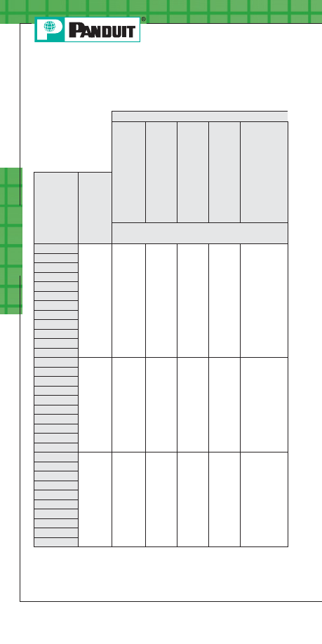
Po
w
er C
onnec
tors
B22
Installation Tooling and Die Selection
Cross Reference (continued)
Note: See page B27 for note references.
Thomas & Betts
TBM20S,
TBM25S
TBM5
TBM8
TBM12,
13642M
TBM15,
TBM15I,
TBM15BSCR
PANDUIT
Connector
Type
Std.
Wire
Size
Die Part Number / Color Code & Die
Index Number
LCAS250
250
kcmil
—
Yellow
62
Yellow
62
Yellow
62
Yellow
62
LCA250
LCAN250
LCB250
LCBN250
LCD250
LCDN250
LCC250
LCCN250
SCSS250
SCS250
SCL250
LCA300
300
kcmil
—
—
White
66
White
66H
➁
White
66
LCAN300
LCB300
LCBN300
LCD300
LCDN300
LCC300
LCCN300
SCS300
SCL300
LCA350
350
kcmil
—
—
Red
71
Red
71H
➁
Red
71H
➁
LCAN350
LCB350
LCBN350
LCD350
LCDN350
LCC350
LCCN350
SCS350
SCL350
PANDUIT Termination Solutions-html.html
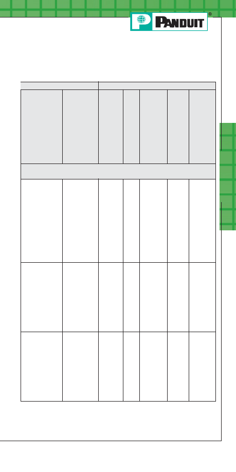
Po
w
er C
onnec
tors
B23
For service and technical support, call 800-777-3300
or visit www.panduit.com.
Installation Tooling and Die Selection
Cross Reference (continued)
Thomas & Betts
Burndy
TBM8-750M-1,
TBM8-750,
TBM8-750BSCR,
TMB750BSCR
➇
TBM14M,
TBM14BSCR,
BPLT14BSCR,
13100A
Y2MR,
Y1MRTC,
Y1MR
MY29
Y35,
Y35BH,
Y39,
Y39BH,
Y750,
Y750-2,
Y750BH,
Y750BH-2,
Y750HS,
PAT750,
BAT750,
BAT35
Y45,
➆
Y46
➆
Y644M,
Y644HS,
Y644MBH,
PAT644,
BAT644
Die Part Number / Color Code & Die
Index Number
STD
Yellow
62
—
250
U29RT
Yellow
16
U29RT
Yellow
16
STD
STD
White
66
—
—
U30RT
White
17
U30RT
White
17
STD
STD
Red
71H
➁
—
—
U31RT
Red
18
U31RT
Red
18
STD
Note: See page B27 for note references.
PANDUIT Termination Solutions-html.html
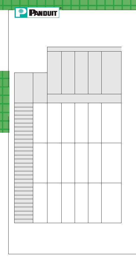
Po
w
er C
onnec
tors
B24
Installation Tooling and Die Selection
Cross Reference (continued)
Note: See page B27 for note references.
Thomas & Betts
TBM20S,
TBM25S
TBM5
TBM8
TBM12,
13642M
TBM15,
TBM15I,
TBM15BSCR
PANDUIT
Connector
Type
Std.
Wire
Size
Die Part Number / Color Code & Die
Index Number
LCA400
400
kcmil
—
—
Blue
76
Blue
76H
➁
Blue
76H
➁
LCAN400
LCB400
LCBN400
LCD400
LCDN400
LCC400
LCCN400
SCS400
SCL400
LCA500
500
kcmil
—
—
Brown
87
Brown
87H
➁
Brown
87H
➁
LCAN500
LCB500
LCBN500
LCD500
LCDN500
LCC500
LCCN500
SCS500
SCL500
LCA600
600
kcmil
—
—
—
Green
94H
➁
Green
94H
➁
LCAN600
LCB600
LCBN600
LCD600
LCDN600
LCC600
LCCN600
SCS600
SCL600
PANDUIT Termination Solutions-html.html

Po
w
er C
onnec
tors
B25
For service and technical support, call 800-777-3300
or visit www.panduit.com.
Installation Tooling and Die Selection
Cross Reference (continued)
Thomas & Betts
Burndy
TBM8-750M-1,
TBM8-750,
TBM8-750BSCR,
TMB750BSCR
➇
TBM14M,
TBM14BSCR,
BPLT14BSCR,
13100A
Y2MR,
Y1MRTC,
Y1MR
MY29
Y35,
Y35BH,
Y39,
Y39BH,
Y750,
Y750-2,
Y750BH,
Y750BH-2,
Y750HS,
PAT750,
BAT750,
BAT35
Y45,
➆
Y46
➆
Y644M,
Y644HS,
Y644MBH,
PAT644,
BAT644
Die Part Number / Color Code & Die
Index Number
STD
Blue 76
—
—
U32RT
Blue
19
U32RT
Blue
19
STD
STD
Brown
87H
➁
—
—
U34RT
Brown
20
U34RT
Brown
20
STD
STD
Green
94H
➁
—
—
U36RT
Green
22
U36RT
Green
22
STD
Note: See page B27 for note references.
PANDUIT Termination Solutions-html.html
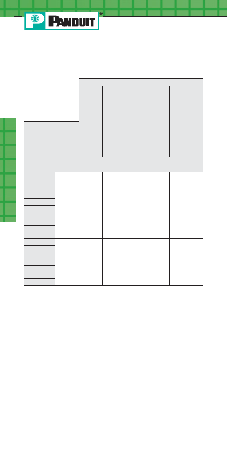
Po
w
er C
onnec
tors
B26
Installation Tooling and Die Selection
Cross Reference (continued)
Note: See page B27 for note references.
Thomas & Betts
TBM20S,
TBM25S
TBM5
TBM8
TBM12,
13642M
TBM15,
TBM15I,
TBM15BSCR
PANDUIT
Connector
Type
Std.
Wire
Size
Die Part Number / Color Code & Die
Index Number
LCA750
750
kcmil
—
—
—
Black
106H
➁
Black
106H
➁
LCAN750
LCB750
LCBN750
LCD750
LCDN750
LCC750
LCCN750
SCS750
SCL750
LCB1000
1000
kcmil
—
—
—
Yellow
125H
➁
Yellow
125H
➁
LCBN1000
LCD1000
LCC1000
LCCN1000
SCS1000
SCL1000
PANDUIT Termination Solutions-html.html
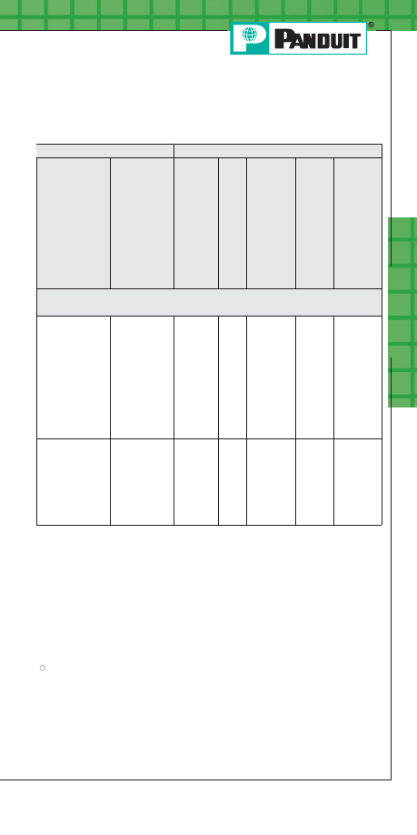
Po
w
er C
onnec
tors
B27
For service and technical support, call 800-777-3300
or visit www.panduit.com.
Installation Tooling and Die Selection
Cross Reference (continued)
Thomas & Betts
Burndy
TBM8-750M-1,
TBM8-750,
TBM8-750BSCR,
TMB750BSCR
➇
TBM14M,
TBM14BSCR,
BPLT14BSCR,
13100A
Y2MR,
Y1MRTC,
Y1MR
MY29
Y35,
Y35BH,
Y39,
Y39BH,
Y750,
Y750-2,
Y750BH,
Y750BH-2,
Y750HS,
PAT750,
BAT750,
BAT35
Y45,
➆
Y46
➆
Y644M,
Y644HS,
Y644MBH,
PAT644,
BAT644
Die Part Number / Color Code & Die
Index Number
STD
Black
106H
➁
—
—
U39RT
Black
24
U39RT
Black
24
STD
—
125H
➁
—
—
—
S44RT
White
27
—
➀
The CT-1700 and CT-1701 crimp die pockets are integrated into the tool frame.
➁
Half width dies.
➂
CD-920 dies can be used with CT-940CH and CT-2940 tools with
CD-940-DA adapter.
➃
CD-940 dies to be used exclusively with CT-940CH and CT-2940 tools.
➄
Maximum size: 500 kcmil lugs and 250 kcmil splices.
➅
Maximum size: 250 kcmil lugs and splices.
➆
Requires U die adapter.
➇
Minimum size: #4 AWG lugs and splices.
➈
LCAN2 lugs for use with #2 AWG and #3 AWG wire.
➉
Extended wire range when crimped with these
PANDUIT
®
U
NI
-D
IE
™
Dieless
Crimping Tools, except LCAS parts.
Maximum splice size for CT-920, CT920CH and CT-2920 tools is 400 kcmil.
11
PANDUIT Termination Solutions-html.html
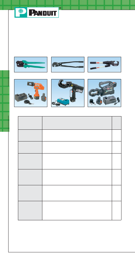
Po
w
er C
onnec
tors
B28
Prime items appear in BOLD.
Order number of pieces required, in multiples of Standard Package Quantity.
Compression Connector Crimping Tools
CT-1700
CT-930
CT-720
CT-2001
CT-2931
CT-2940
Part Number
Description
Std.
Pkg.
Qty.
CT-1700
Ergonomic, Hand Tool; Includes 5 position
color coded rotating die; Installs #8 - #1 AWG
P
AN
-L
UG
™
Compression Connectors.
1
CT-720
Die Type, Manual, Crimping Tool; Installs
#8 AWG - 500 kcmil
P
AN
-L
UG
™
Compression Connectors.
1
CT-930
Die Type, Manual Hydraulic, 14 Ton, Crimping
Tool; Includes tool case with die storage;
Installs #14 AWG - 750 kcmil
P
AN
-L
UG
™
Compression Connectors.
1
CT-2001
Die Type, Battery Powered Hydraulic, 6 Ton,
Crimping Tool; Includes two batteries, charger,
shoulder strap, tool case; Installs #14 AWG -
500 kcmil
P
AN
-L
UG
™
Compression Connectors.
1
CT-2931
Die Type, Battery Powered Hydraulic, 12 Ton,
Crimping Tool; Includes two batteries, charger,
tool case; Installs #14 AWG - 750 kcmil
P
AN
-L
UG
™
Compression Connectors.
1
CT-2940
Die Type, Battery Powered Hydraulic, 15 Ton,
Crimping Tool; Includes two batteries,
charger, shoulder strap, tool case; Installs
#14 AWG - 1,000 kcmil
P
AN
-L
UG
™
Compression Connectors.
1
Manual & Battery Powered Die Type
Crimping Tools
PANDUIT Termination Solutions-html.html
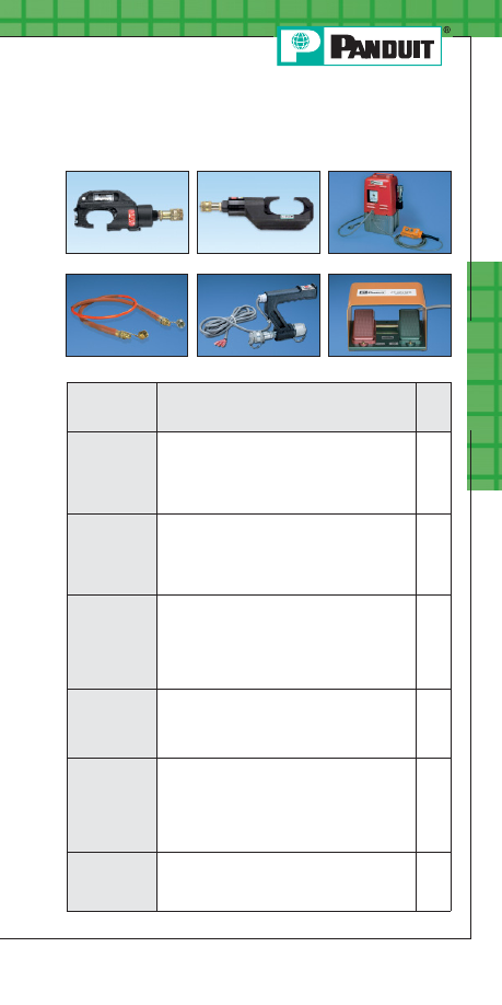
Po
w
er C
onnec
tors
B29
For service and technical support, call 800-777-3300
or visit www.panduit.com.
Die Type, High Pressure Remote Hydraulic,
Crimp Heads & Hydraulic Pump
CT-930CH
CT-901HP
CT-940CH
CT-900HPH
CT-901RCH
Prime items appear in BOLD.
CT-901RFS
Part Number
Description
Std.
Pkg.
Qty.
CT-930CH
Die Type, Remote Hydraulic, 14 Ton, Crimp
Head; Used with 10,000 PSI hydraulic systems;
Includes tool case and female Parker type
quick-connect fitting assembled to tool;
Installs #14 AWG - 750 kcmil
P
AN
-L
UG
™
Compression Connectors.
1
CT-940CH
Die Type, Remote Hydraulic, 15 Ton, Crimp
Head; Used with 10,000 PSI hydraulic systems;
Includes tool case and female Parker type
quick-connect fitting assembled to tool;
Installs #10 AWG - 1000 kcmil
P
AN
-L
UG
™
Compression Connectors.
1
CT-901HP
Hydraulic Pump; Develops 10,000 PSI output;
Includes on/off pendant switch on 10' electric
cord, 3 prong A/C plug on 10' electric cord, female
Parker type quick-connect fitting assembled to
pump; Compatible with CT-900HPH hydraulic
hose, CT-930CH, CT-940CH and CT-980CH
crimp heads sold separately.
1
CT-900HPH
Electrically Non-Conductive 10' Hose; Includes
two male Parker type quick-connect fittings;
Compatible with CT-901HP hydraulic pump and
CT-930CH, CT-940CH and CT-980CH crimp
heads, sold separately.
1
CT-901RCH
Remote Control Handle; Incorporates plastic
carrying handle with on/off activation switch for
one hand operation; Used with remote hydraulic
crimp heads CT-930CH, CT-940CH and
CT-980CH; Includes 10' three wire control
cable that can be directly connected to the
CT-901HP pump.
1
CT-901RFS
Dual Electrical Foot Switch; Allows “hands-free”
operation of CT-901HP or CT-8250HP electric
hydraulic pumps used with
PANDUIT remote
hydraulic crimp heads; Includes 10' electric cord.
1
PANDUIT Termination Solutions-html.html
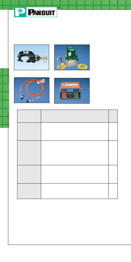
Po
w
er C
onnec
tors
B30
Order number of pieces required, in multiples of Standard Package Quantity.
Prime items appear in BOLD.
Die Type, Low Pressure Remote
Hydraulic, Crimp Head & Hydraulic Pump
CT-930LPCH
CT-900LPHPH
CT-8250HP
CT-901RFS
Part Number
Description
Std.
Pkg.
Qty.
CT-930LPCH
Die Type, Remote Hydraulic, 10.5 Ton,
Crimp Head; Includes tool case and male
Parker type quick-connect fitting assembled to
tool; Installs #8 AWG – 250 kcmil
P
AN
-L
UG
™
Compression Connectors.
1
CT-8250HP
Hydraulic Pump; Develops 7,500 PSI output;
Includes on/off pendant switch on 10' electric
cord, 3 prong A/C plug on 10' electric cord, male
Parker type quick-connect fitting assembled to
pump; Compatible with CT-900LPHPH hydraulic
hose, CT-930LPCH and CT-980LPCH crimp
heads sold separately.
1
CT-900LPHPH
Electrically Non-Conductive 10' Hose; Includes
two female Parker type quick-connect fittings;
Compatible with CT-901LPHPH hydraulic pump
and CT-930LPCH and CT-980LPCH
crimp heads.
1
CT-901RFS
Dual Electrical Foot Switch; Allows “hands-free”
operation of CT-901HP or CT-8250HP electric
hydraulic pumps used with
PANDUIT remote
hydraulic crimp heads; Includes 10' electric cord.
1
PANDUIT Termination Solutions-html.html
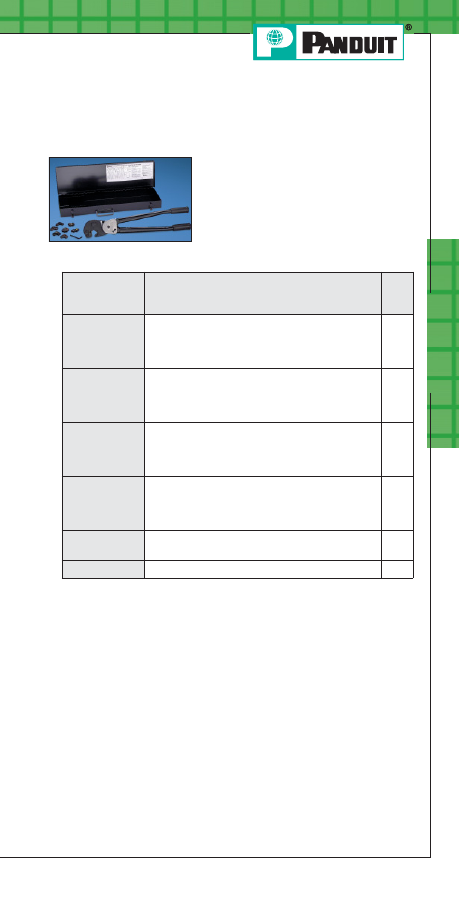
Prime items appear in BOLD.
Po
w
er C
onnec
tors
B31
For service and technical support, call 800-777-3300
or visit www.panduit.com.
Die Type, Manual, Crimping Tool and
Die Kits
Part Number
Part Description
Std.
Pkg.
Qty.
CT-720-7
Tool kit for installing #8 AWG – 500 kcmil
P
AN
-L
UG
™
Compression Connectors; Includes
seven dies (CD-720-1 through CD-720-7) and
carrying/storage case (C-720).
1
CT-720-7CC
Controlled cycle tool kit for installing #8 AWG –
500 kcmil
P
AN
-L
UG
™
Compression Connectors;
Includes seven dies (CD-720-1 through
CD-720-7) and carrying/storage case (C-720).
1
CT-720-3
Tool kit for installing #8 AWG – 250 kcmil
P
AN
-L
UG
™
Compression Connectors; Includes
three dies (CD-720-1 through CD-720-3) and
carrying/storage case (C-720).
1
CT-720-3CC
Controlled cycle tool kit for installing #8 AWG –
250 kcmil
P
AN
-L
UG
™
Compression Connectors;
I2ncludes three dies (CD-720-1 through
CD-720-3) and carrying/storage case (C-720).
1
CC-720
Optional controlled cycle mechanism only. Total
weight of tool with CC-720 is 8.25 lbs.
1
C-720
Steel carrying case for CT-720 crimping tool.
1
• Available with or without controlled
cycle feature to meet
specific applications
• Kits available with three or full set of
seven dies for crimping partial or full
range of connector sizes
PANDUIT Termination Solutions-html.html
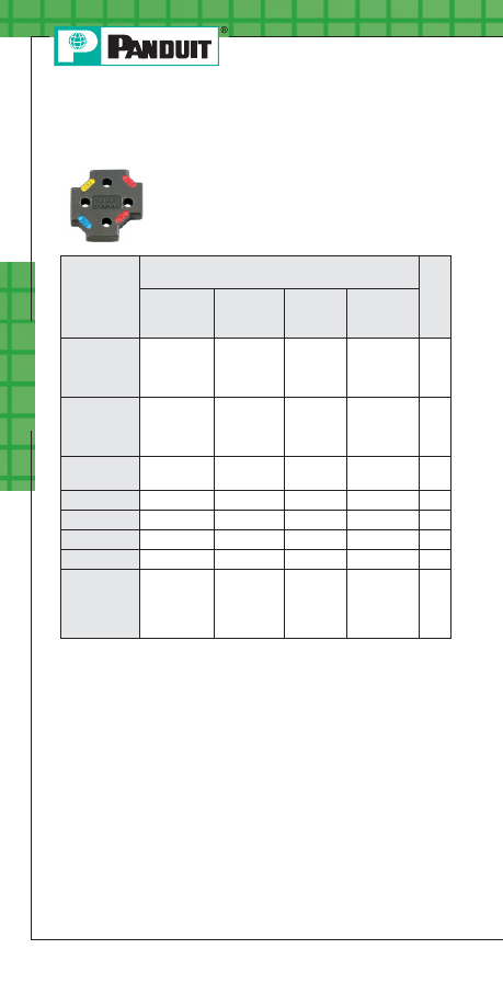
Po
w
er C
onnec
tors
B32
Prime items appear in BOLD.
Order number of pieces required, in multiples of Standard Package Quantity.
CD-720 Crimping Dies
Compression dies for crimping tool:
CT-720
Part Number
Used to Install
PANDUIT Compression
Lug & Splice Sizes
Std.
Pkg.
Qty.
Copper
Conductor
Size
Copper
Die Color
& Die No.
Aluminum
Conductor
Size
Aluminum
Die Color
& Die No.
CD-720-1
#8 – #2
AWG
Red P21,
Blue P24,
Gray P29,
Brown P33
#6 AWG
Gray P29
1
CD-720-2
#1 – 3/0
AWG
Green P37,
Pink P42,
Black P45,
Orange P50
#4 – 1/0
AWG
Green P37,
Pink P42,
Gold P45,
Tan P50
1
CD-720-3
4/0 AWG –
250 kcmil
Purple P54,
Yellow P62
2/0 – 3/0
AWG
Olive P54,
Ruby P62
1
CD-720-4
300 kcmil
White P66
4/0 AWG
White P66
1
CD-720-5
350 kcmil
Red P71
250 kcmil
Red P71
1
CD-720-6
400 kcmil
Blue P76
300 kcmil
Blue P76
1
CD-720-7
500 kcmil
Brown P87
350 kcmil
Brown P87
1
CD-720PV8-2
#8 – #2
AWG, vinyl
insulated
P
AN
-T
ERM
®
Terminals
Red, Blue,
Yellow
—
—
1
PANDUIT Termination Solutions-html.html

Prime items appear in BOLD.
Po
w
er C
onnec
tors
B33
For service and technical support, call 800-777-3300
or visit www.panduit.com.
CD-2001 Crimping Dies
Compression dies for crimping tools:
CT-2001 and CT-2002
Part Number
Used to Install
PANDUIT Compression Lug &
Splice Sizes
Std.
Pkg.
Qty.
Copper Code
Conductor
Size
Copper
Die Color &
Die No.
Aluminum
Code
Conductor
Size
Aluminum
Die Color
& Die No.
CD-2001-8
#8 AWG
Red P21
—
—
1
CD-2001-6
#6 AWG
Blue P24
—
—
1
CD-2001-4
#4 AWG STR
#3 AWG STR
#2 AWG SOL
Gray P29
#6 AWG
Gray P29
1
CD-2001-2
#2 AWG
Brown P33
—
—
1
CD-2001-1
#1 AWG
Green P37
#4 AWG
Green P37
1
CD-2001-1/0
1/0 AWG
Pink P42
#2 AWG
Pink P42
1
CD-2001-2/0
2/0 AWG
Black P45
#1 AWG
Gold P45
1
CD-2001-3/0
3/0 AWG
Orange P50
1/0 AWG
Tan P50
1
CD-2001-4/0
4/0 AWG
Purple P54
2/0 AWG
Olive P54
1
CD-2001-250
250 kcmil
Yellow P62
3/0 AWG
Ruby P62
1
CD-2001-300
300 kcmil
White P66
4/0 AWG
White P66
1
CD-2001-350
350 kcmil
Red P71
250 kcmil
Red P71
1
CD-2001-400
400 kcmil
Blue P76
300 kcmil
Blue P76
1
CD-2001-500
500 kcmil
Brown P87
—
—
1
PANDUIT Termination Solutions-html.html
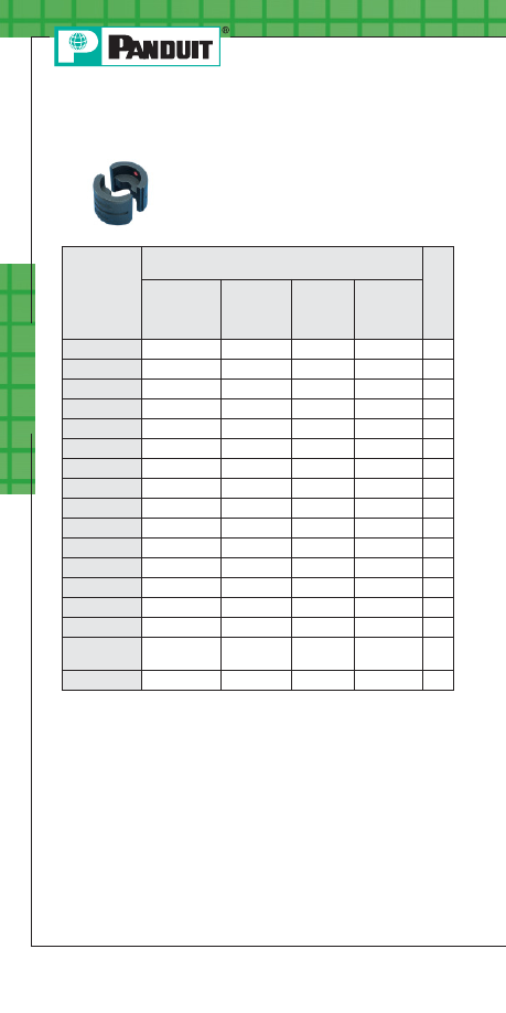
Po
w
er C
onnec
tors
B34
Prime items appear in BOLD.
Order number of pieces required, in multiples of Standard Package Quantity.
CD-920 Crimping Dies
Compression dies for crimping tools:
CT-930, CT-2931, CT-2930, CT-2940*,
CT-930CH, CT-940CH* and CT-930LPCH
Part Number
Used to Install
PANDUIT Compression
Lug & Splice Sizes
Std.
Pkg.
Qty.
Copper
Code
Conductor
Size
Copper
Die Color
& Die No.
Aluminum
Code
Conductor
Size
Aluminum
Die Color
& Die No.
CD-920-8
#8 AWG
Red P21
—
—
1
CD-920-6
#6 AWG
Blue P24
—
—
1
CD-920-4
#4 AWG
Gray P29
#6 AWG
Gray P29
1
CD-920-2
#2 AWG
Brown P33
—
—
1
CD-920-1
#1 AWG
Green P37
#4 AWG
Green P37
1
CD-920-1/0
1/0 AWG
Pink P42
#2 AWG
Pink P42
1
CD-920-2/0
2/0 AWG
Black P45
#1 AWG
Gold P45
1
CD-920-3/0
3/0 AWG
Orange P50
1/0 AWG
Tan P50
1
CD-920-4/0
4/0 AWG
Purple P54
2/0 AWG
Olive P54
1
CD-920-250
250 kcmil
Yellow P62
3/0 AWG
Ruby P62
1
CD-920-300
300 kcmil
White P66
4/0 AWG
White P66
1
CD-920-350
350 kcmil
Red P71
250 kcmil
Red P71
1
CD-920-400
400 kcmil
Blue P76
300 kcmil
Blue P76
1
CD-920-500
500 kcmil
Brown P87
350 kcmil
Brown P87
1
CD-920-600
600 kcmil
Green P94
400 kcmil
Green P94
1
CD-920-500A 500 kcmil flex,
600 kcmil flex
Pink P99
500 kcmil
Pink P99
1
CD-920-750
750 kcmil
Black P106
600 kcmil
Black P106
1
*Requires CD-940-DA die adapter.
PANDUIT Termination Solutions-html.html
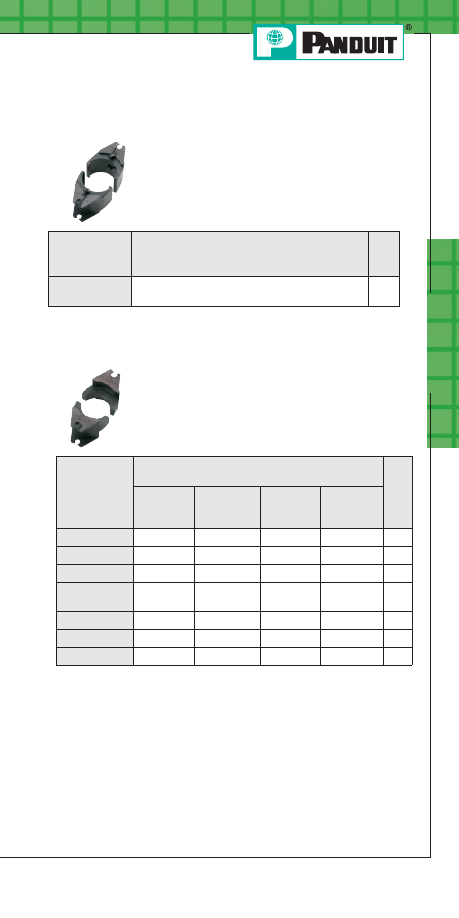
Prime items appear in BOLD.
Po
w
er C
onnec
tors
B35
For service and technical support, call 800-777-3300
or visit www.panduit.com.
Die Adapter
CD-940 Crimping Dies
Compression dies for crimping tools:
CT-2940 and CT-940CH
Die adapter for crimping tools:
CT-2940 and CT-940CH
Part Number
Used to Install
PANDUIT Compression
Lug & Splice Sizes
Std.
Pkg.
Qty.
Copper
Conductor
Size
Copper
Die Color
& Die No.
Aluminum
Conductor
Size
Aluminum
Die Color &
Die No.
CD-940-750
750 kcmil
Black P106
—
—
1
CD-940-800
800 kcmil
Orange P107
—
—
1
CD-940-1000
1000 kcmil
White P125
—
—
1
CD-940-750X
777.7 kcmil
flex
Yellow P115
—
—
1
CD-940-750A
—
—
750 kcmil
Red P125
1
CD-940-800A
—
—
800 kcmil
Gray P140
1
CD-940-1000A
—
—
1000 kcmil Brown P161
1
Part Number
Part Description
Std.
Pkg.
Qty.
CD-940-DA
Die Adapter for use with
PANDUIT CD-920,
CDM-920 and CD-930 crimping dies.
1
PANDUIT Termination Solutions-html.html
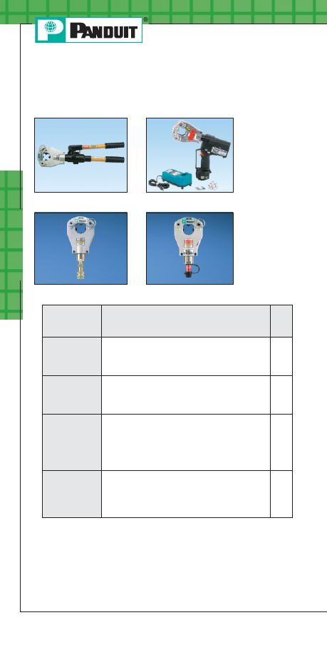
Po
w
er C
onnec
tors
B36
Prime items appear in BOLD.
Order number of pieces required, in multiples of Standard Package Quantity.
U
NI
-D
IE
™
Dieless, Crimping Tools and
Crimp Heads
CT-980
CT-2981
CT-980CH
CT-980LPCH
Part Number
Description
Std.
Pkg.
Qty.
CT-980
U
NI
-D
IE
™
Dieless, Manual Hydraulic, 6.2 Ton,
Crimping Tool; Includes tool case;
Installs #4 AWG - 750 kcmil
P
AN
-L
UG
™
Compression Connectors.
1
CT-2981
U
NI
-D
IE
™
Dieless, Battery Powered Hydraulic,
6.2 Ton, Crimping Tool; Includes two batteries,
charger, tool case; Installs #4 AWG - 750 kcmil
P
AN
-L
UG
™
Compression Connectors.
1
CT-980CH
U
NI
-D
IE
™
Dieless, Remote Hydraulic, 6.2 Ton,
Crimp Head used with 10,000 PSI hydraulic
system; Includes tool case and female Parker
type quick-connect fitting assembled to tool;
Installs #4 AWG - 750 kcmil
P
AN
-L
UG
™
Compression Connectors.
▲
1
CT-980LPCH
U
NI
-D
IE
™
Dieless, Remote Hydraulic, 4.7 Ton,
Crimp Head; Includes tool case and male Parker
type quick-connect fitting assembled to tool;
Installs #4 AWG - 250 kcmil
P
AN
-L
UG
™
Compression Connectors.
■
1
▲
CT-980CH to be used with CT-901HP and CT-900HPH. See page B29
for more information.
■
CT-980LPCH to be used with CT-8250HP, CT-900LPHPH and
CT-901RFS. See page B30 for more information.
PANDUIT Termination Solutions-html.html
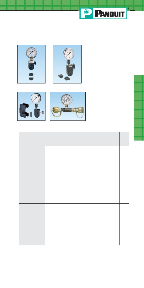
Prime items appear in BOLD.
Po
w
er C
onnec
tors
B37
For service and technical support, call 800-777-3300
or visit www.panduit.com.
Pressure Gauges
CG-920
CG-940
CG-980
PG-1
Part Number
Description
Std.
Pkg.
Qty.
CG-920
Compression Gauge; Used to measure crimping
force generated by
PANDUIT crimping tools:
CT-930, CT-930CH, CT-930LPCH, CT-2930
and CT-2931; Includes blank die set and
storage case.
1
CG-940
Compression Gauge; Used to measure output
force generated by
PANDUIT crimping tools:
CT-940CH and CT-2940; Includes blank die set
and storage case.
1
CG-980
Compression Gauge; Used to insure proper
compression force for
U
NI
-D
IE
™
Dieless
Crimping Tools: CT-980, CT-980CH, CT-2980
and CT-2981; Includes fixture for mounting
gauge in crimping tool and storage case.
1
PG-1
In-Line Pressure Gauge; Provides visual
verification of hydraulic output pressure when
used with CT-930LPCH and CT-980LPCH crimp
heads, CT-8250HP pump and CT-900LPHPH
hose; Includes storage case.
1
PG-1SC
In-Line Pressure Gauge provides visual
identification of hydraulic output pressure
when used with
PANDUIT CT-8250HP pump
and CT-900LPHPH hose; Includes steel
storage case.
1
PANDUIT Termination Solutions-html.html
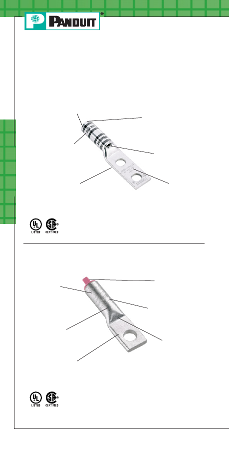
Po
w
er C
onnec
tors
B38
Features and Benefits –
P
AN
-L
UG
™
Compression Connectors
Copper Lugs
Bolded features are unique to
PANDUIT.
Aluminum Lugs
Color coded bands for
proper die selection
and crimp placement
Inspection windows
available to
assure complete
conductor insertion
Part number, stud
size and conductor
size marked on part
for easy identification
Easy-to-read, color
coded die index numbers
for
PANDUIT and
specified competitor
crimping dies
for selection
Internally beveled barrel
end for easy conductor
insertion (types LCCF and
LCAF available with flared
entry for flex conductor)
Made from seamless,
high conductivity copper
tubing and electro tin
plated and burnished to
inhibit corrosion
Factory pre-filled
with oxide inhibitor
to prevent oxidation
Part number and
conductor size
marked on part for
easy identification
Easy-to-read
die index numbers
for
PANDUIT and
specified competitor
crimping dies
for selection
Color coded
end plugs
for proper
die selection
Crimping areas
marked on part
for proper
crimp placement
Made from seamless
wrought aluminum and
electro tin plated to
inhibit corrosion
PANDUIT Termination Solutions-html.html
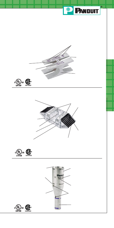
Po
w
er C
onnec
tors
B39
For service and technical support, call 800-777-3300
or visit www.panduit.com.
Features and Benefits –
P
AN
-L
UG
™
Compression Connectors (continued)
Copper HTAPs
Part number and agency
listings marked on part
for easy identification
Conductor sizes for
each tap pocket
marked on part
Made from high
conductivity copper
and electro tin plated
to inhibit corrosion
Slotted design to
reduce installation
time when used
with
PANDUIT cable
ties (included)
Easy-to-read,
color coded
die index number
for
PANDUIT
crimping dies,
legible after crimping,
for selection
Clear Covers for Copper HTAPs
*Labels shown printed with
PANDUIT LS7 Printer.
Retainer clips to hold labels inside
cover*. Retainer clips have a write-
on surface for manual marking
Optically clear to allow
360° inspections
Made from high
impact strength
self-extinguishing
plastic with UL94V-0
flammability rating
and minimum
oxygen index of 28
Built-in flanges
retain HTAP in cover
Easy to assemble
snap-on design
Flexible fingers closely conform to
conductor preventing foreign objects
from entering cover
Corresponding
PANDUIT HTAP
part number,
voltage rating and
temperature rating
molded into
cover half for
easy identification
Low profile
design minimizes
space requirements
Molded in flash
barriers protect against
electrical flash over
Copper In-Line Reducing Splices
Internally beveled barrel end
for easy conductor insertion
Color coded for proper
die selection
Inspection windows
to assure complete
conductor insertion
Crimping areas marked
on each barrel for proper
crimp placement
Compact size provides
low profile installation
Easy-to-read, color coded
die index numbers for
PANDUIT and specified
competitor crimping dies
for selection
Made from seamless, high
conductivity copper tubing
and electro tin plated and
burnished to inhibit corrosion
Part number and conductor
size and type marked on
part for easy identification
PANDUIT Termination Solutions-html.html
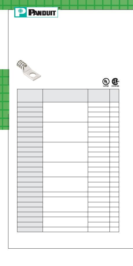
Po
w
er C
onnec
tors
B40
Prime items appear in BOLD.
Order number of pieces required, in multiples of Standard Package Quantity.
Code Conductor, One-Hole, Short Barrel
with Window Lug
Part Number
Copper Conductor Size
Stud Hole
Size
(In.)
Std.
Pkg.
Qty.
LCAS8-10-L
#8 AWG
#10
50
LCAS8-14-L
1/4
50
LCAS8-56-L
5/16
50
LCAS8-38-L
3/8
50
LCAS6-10-L
#6 AWG
#10
50
LCAS6-14-L
1/4
50
LCAS6-56-L
5/16
50
LCAS6-38-L
3/8
50
LCAS4-10-L
#4 AWG
#10
50
LCAS4-14-L
1/4
50
LCAS4-56-L
5/16
50
LCAS4-38-L
3/8
50
LCAS2-14-Q
#2 AWG
1/4
25
LCAS2-56-Q
5/16
25
LCAS2-38-Q
3/8
25
LCAS1-14-E
#1 AWG
1/4
20
LCAS1-56-E
5/16
20
LCAS1-38-E
3/8
20
LCAS1/0-38-X
1/0 AWG
3/8
10
LCAS2/0-14-X
2/0 AWG
1/4
10
LCAS2/0-38-X
3/8
10
LCAS2/0-12-X
1/2
10
LCAS3/0-38-X
3/0 AWG
3/8
10
LCAS4/0-38-X
4/0 AWG
3/8
10
LCAS4/0-12-X
1/2
10
LCAS250-12-X
250 kcmil
1/2
10
For 45° and 90° bent lugs available as standard parts and complete tool
and die information, see the Electrical Solutions Catalog, SA-ELCB03, at
www.panduit.com.
Type LCAS
• For use with stranded copper conductors
• UL Listed and CSA Certified when crimped
with
PANDUIT and specified competitor
crimping tools and dies
• Tested by Telcordia – meets
NEBS Level 3
P
AN
-L
UG
™
Copper Compression Connectors
PANDUIT Termination Solutions-html.html
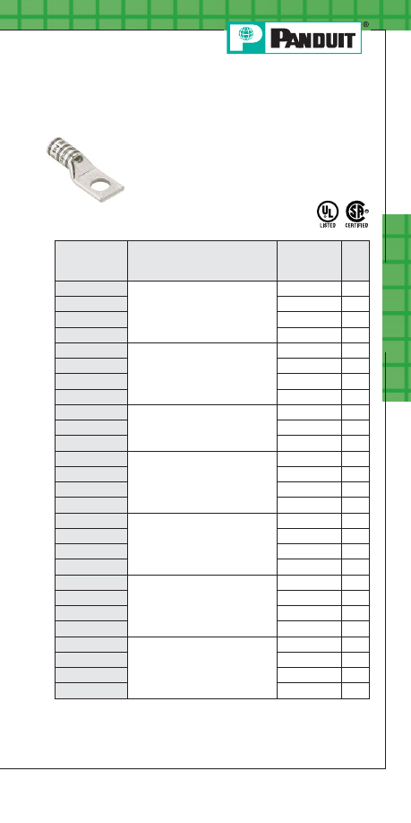
Prime items appear in BOLD.
Po
w
er C
onnec
tors
B41
For service and technical support, call 800-777-3300
or visit www.panduit.com.
Code Conductor, One-Hole, Standard
Barrel with Window Lug
Part Number
Copper Conductor Size
Stud Hole
Size
(In.)
Std.
Pkg.
Qty.
LCA8-10-L
#8 AWG
#10
50
LCA8-14-L
1/4
50
LCA8-56-L
5/16
50
LCA8-38-L
3/8
50
LCA6-10-L
#6 AWG
#10
50
LCA6-14-L
1/4
50
LCA6-56-L
5/16
50
LCA6-38-L
3/8
50
LCA4-14-L
#4 – #3 AWG STR, #2 AWG SOL
1/4
50
LCA4-56-L
5/16
50
LCA4-38-L
3/8
50
LCA2-14-Q
#2 AWG
1/4
25
LCA2-56-Q
5/16
25
LCA2-38-Q
3/8
25
LCA2-12-Q
1/2
25
LCA1-14-E
#1 AWG
1/4
20
LCA1-56-E
5/16
20
LCA1-38-E
3/8
20
LCA1-12-E
1/2
20
LCA1/0-14-X
1/0 AWG
1/4
10
LCA1/0-56-X
5/16
10
LCA1/0-38-X
3/8
10
LCA1/0-12-X
1/2
10
LCA2/0-14-X
2/0 AWG
1/4
10
LCA2/0-56-X
5/16
10
LCA2/0-38-X
3/8
10
LCA2/0-12-X
1/2
10
Type LCA
• For use with stranded copper conductors
• UL Listed and CSA Certified when crimped
with
PANDUIT and specified competitor
crimping tools and dies
• Tested by Telcordia – meets
NEBS Level 3
For 45° and 90° bent lugs available as standard parts and complete tool
and die information, see the Electrical Solutions Catalog, SA-ELCB03, at
www.panduit.com.
continued on page B42
PANDUIT Termination Solutions-html.html
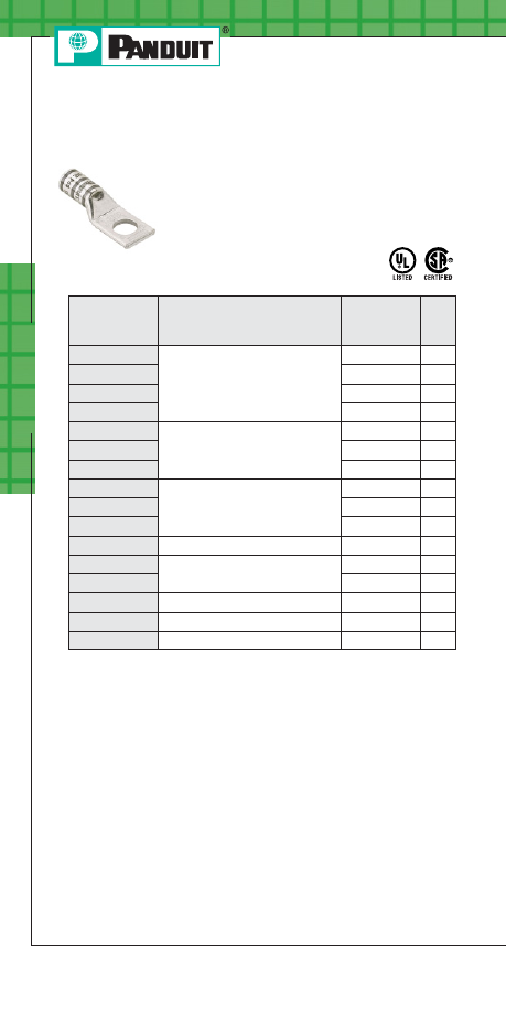
LCA3/0-14-X
3/0 AWG
1/4
10
LCA3/0-56-X
5/16
10
LCA3/0-38-X
3/8
10
LCA3/0-12-X
1/2
10
LCA4/0-56-X
4/0 AWG
5/16
10
LCA4/0-38-X
3/8
10
LCA4/0-12-X
1/2
10
LCA250-56-X
250 kcmil
5/16
10
LCA250-38-X
3/8
10
LCA250-12-X
1/2
10
LCA300-12-X
300 kcmil
1/2
10
LCA350-38-X
350 kcmil
3/8
10
LCA350-12-X
1/2
10
LCA400-12-6
400 kcmil
1/2
6
LCA500-12-6
500 kcmil
1/2
6
LCA600-12-6
600 kcmil
1/2
6
Po
w
er C
onnec
tors
B42
Order number of pieces required, in multiples of Standard Package Quantity.
Prime items appear in BOLD.
Code Conductor, One-Hole, Standard
Barrel with Window Lug (continued)
Part Number
Copper Conductor Size
Stud Hole
Size
(In.)
Std.
Pkg.
Qty.
For 45° and 90° bent lugs available as standard parts and complete tool
and die information, see the Electrical Solutions Catalog, SA-ELCB03, at
www.panduit.com.
Type LCA
• For use with stranded copper conductors
• UL Listed and CSA Certified when crimped
with
PANDUIT and specified competitor
crimping tools and dies
• Tested by Telcordia – meets
NEBS Level 3
PANDUIT Termination Solutions-html.html
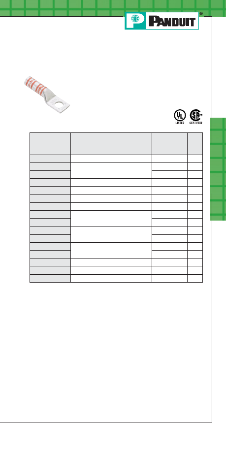
Prime items appear in BOLD.
Po
w
er C
onnec
tors
B43
For service and technical support, call 800-777-3300
or visit www.panduit.com.
Code Conductor, One-Hole, Long
Barrel Lug
• For use with stranded copper conductors
• UL Listed and CSA Certified when crimped
with
PANDUIT and specified competitor
crimping tools and dies
• Tested by Telcordia – meets NEBS
Level 3
Part Number
Copper Conductor Size
Stud Hole
Size
(In.)
Std.
Pkg.
Qty.
LCB8-14-L
#8 AWG
1/4
50
LCB6-14-L
#6 AWG
1/4
50
LCB6-38-L
3/8
50
LCB4-14-L
#4 – 3 AWG STR, #2 AWG SOL
1/4
50
LCB2-56-Q
#2 AWG
5/16
25
LCB1-56-E
#1 AWG
5/16
20
LCB1/0-38-X
1/0 AWG
3/8
10
LCB2/0-38-X
2/0 AWG
3/8
10
LCB2/0-12-X
1/2
10
LCB3/0-38-X
3/0 AWG
3/8
10
LCB3/0-12-X
1/2
10
LCB4/0-38-X
4/0 AWG
3/8
10
LCB4/0-12-X
1/2
10
LCB250-12-X
250 kcmil
1/2
10
LCB350-12-X
350 kcmil
1/2
10
LCB500-12-6
500 kcmil
1/2
6
Type LCB
For 45° and 90° bent lugs available as standard parts and complete tool
and die information, see the Electrical Solutions Catalog, SA-ELCB03, at
www.panduit.com.
PANDUIT Termination Solutions-html.html
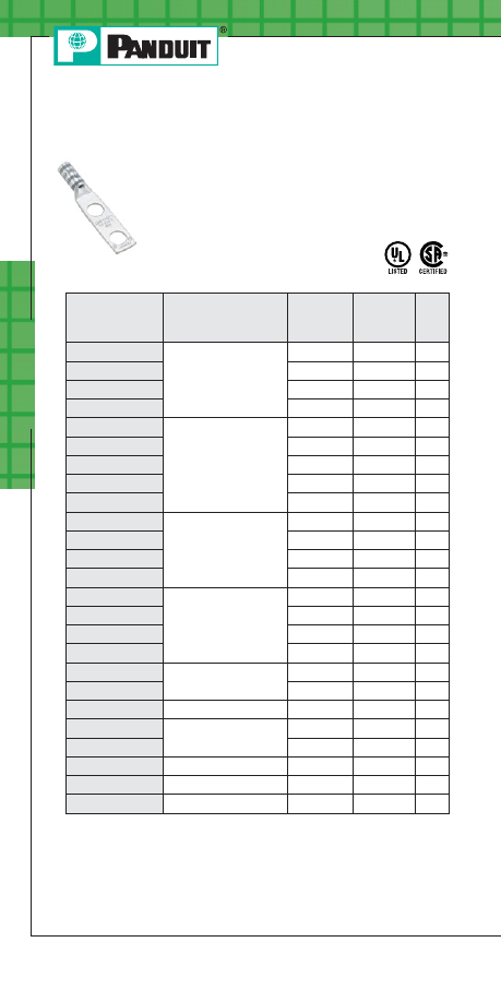
Po
w
er C
onnec
tors
B44
Prime items appear in BOLD.
Order number of pieces required, in multiples of Standard Package Quantity.
Type LCD
For 45° and 90° bent lugs available as standard parts and complete tool
and die information, see the Electrical Solutions Catalog, SA-ELCB03, at
www.panduit.com.
Code Conductor, Two-Hole, Standard
Barrel with Window Lug
• For use with stranded copper conductors
• UL Listed and CSA Certified when crimped
with
PANDUIT and specified competitor
crimping tools and dies
• Tested by Telcordia – meets
NEBS Level 3
Part Number
Copper Conductor
Size
Stud Hole
Size
(In.)
Stud Hole
Spacing
(In.)
Std.
Pkg.
Qty.
LCD8-10A-L
#8 AWG
#10
.63
50
LCD8-14A-L
1/4
.63
50
LCD8-14B-L
1/4
.75
50
LCD8-14D-L
1/4
1.00
50
LCD6-10A-L
#6 AWG
#10
.63
50
LCD6-14A-L
1/4
.63
50
LCD6-14B-L
1/4
.75
50
LCD6-14D-L
1/4
1.00
50
LCD6-38D-L
3/8
1.00
50
LCD4-14A-L
#4 – #3 AWG STR,
#2 AWG SOL
1/4
.63
50
LCD4-14B-L
1/4
.75
50
LCD4-14D-L
1/4
1.00
50
LCD4-38D-L
3/8
1.00
50
LCD2-14A-Q
#2 AWG
1/4
.63
25
LCD2-14B-Q
1/4
.75
25
LCD2-14D-Q
1/4
1.00
25
LCD2-38D-Q
3/8
1.00
25
LCD1-14A-E
#1 AWG
1/4
.63
20
LCD1-38D-E
3/8
1.00
20
LCD1/0-38D-X
1/0 AWG
3/8
1.00
10
LCD2/0-14B-X
2/0 AWG
1/4
.75
10
LCD2/0-38D-X
3/8
1.00
10
LCD3/0-38D-X
3/0 AWG
3/8
1.00
10
LCD4/0-38D-X
4/0 AWG
3/8
1.00
10
LCD250-38D-X
250 kcmil
3/8
1.00
10
PANDUIT Termination Solutions-html.html
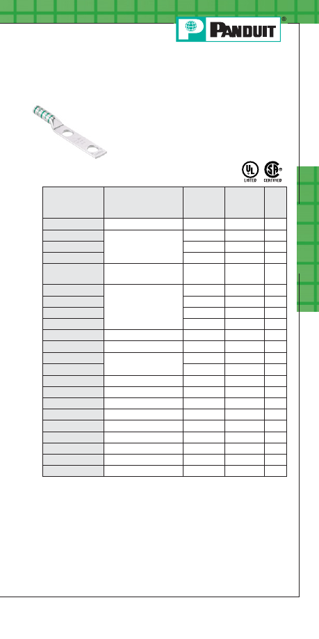
Prime items appear in BOLD.
Po
w
er C
onnec
tors
B45
For service and technical support, call 800-777-3300
or visit www.panduit.com.
Code Conductor, Two-Hole, Long
Barrel Lug
• For use with stranded copper conductors
• UL Listed and CSA Certified when
crimped with
PANDUIT and specified
competitor crimping tools and dies
• Tested by Telcordia – meets
NEBS Level 3
Type LCC
For 45° and 90° bent lugs available as standard parts and complete tool
and die information, see the Electrical Solutions Catalog, SA-ELCB03, at
www.panduit.com.
◆
NEMA hole sizes and spacing.
Part Number
Copper Conductor
Size
Stud Hole
Size
(In.)
Stud Hole
Spacing
(In.)
Std.
Pkg.
Qty.
LCC8-14A-L
#8 AWG
1/4
.63
50
LCC6-14A-L
#6 AWG
1/4
.63
50
LCC6-14B-L
1/4
.75
50
LCC6-38D-L
3/8
1.00
50
LCC4-14A-L
#4 – #3 AWG STR,
#2 AWG SOL
1/4
.63
50
LCC2-56B-Q
#2 AWG
5/16
.75
25
LCC2-38D-Q
3/8
1.00
25
LCC2-38-Q
3/8
1.75
25
LCC2-12-Q
1/2
1.75
25
LCC1-14A-E
#1 AWG
1/4
.63
20
LCC1/0-12-X
1/0 AWG
1/2
1.75
10
LCC2/0-38D-X
2/0 AWG
3/8
1.00
10
LCC2/0-12-X
1/2
1.75
10
LCC3/0-12-X
3/0 AWG
1/2
1.75
10
LCC4/0-12-X
◆
4/0 AWG
1/2
1.75
10
LCC250-12-X
◆
250 kcmil
1/2
1.75
10
LCC300-12-X
◆
300 kcmil
1/2
1.75
10
LCC350-12-X
◆
350 kcmil
1/2
1.75
10
LCC400-12-6
◆
400 kcmil
1/2
1.75
6
LCC500-12-6
◆
500 kcmil
1/2
1.75
6
LCC600-12-6
◆
600 kcmil
1/2
1.75
6
LCC750-12-6
◆
750 kcmil
1/2
1.75
6
PANDUIT Termination Solutions-html.html
Po
w
er C
onnec
tors
B46
Prime items appear in BOLD.
Order number of pieces required, in multiples of Standard Package Quantity.
Type SCS
For complete tool and die information, see the Electrical Solutions
Catalog, SA-ELCB03, at www.panduit.com.
Code Conductor, Standard Barrel,
Butt Splice
• For use with stranded copper conductors
• UL Listed and CSA Certified when
crimped with
PANDUIT and specified
competitor crimping tools and dies
• Tested by Telcordia – meets
NEBS Level 3
Part Number
Copper Conductor Size
Length
(In.)
Std.
Pkg.
Qty.
SCS8-L
#8 AWG
1.50
50
SCS6-L
#6 AWG
1.75
50
SCS4-L
#4 – #3 AWG STR,
#2 AWG SOL
1.75
50
SCS2-Q
#2 AWG
1.87
25
SCS1-E
#1 AWG
1.87
20
SCS1/0-X
1/0 AWG
1.87
10
SCS2/0-X
2/0 AWG
2.00
10
SCS3/0-X
3/0 AWG
2.12
10
SCS4/0-X
4/0 AWG
2.12
10
SCS250-X
250 kcmil
2.25
10
SCS350-X
350 kcmil
2.37
10
SCS500-6
500 kcmil
2.87
6
PANDUIT Termination Solutions-html.html
Prime items appear in BOLD.
Po
w
er C
onnec
tors
B47
For service and technical support, call 800-777-3300
or visit www.panduit.com.
Code Conductor, Long Barrel, Butt Splice
• For use with stranded copper conductors
• UL Listed and CSA Certified when
crimped with
PANDUIT and specified
competitor crimping tools and dies
• Tested by Telcordia – meets
NEBS Level 3
Part Number
Copper Conductor Size
Length
(In.)
Std.
Pkg.
Qty.
SCL8-L
#8 AWG
2.25
50
SCL6-L
#6 AWG
2.38
50
SCL4-L
#4 – #3 AWG STR,
#2 AWG SOL
2.38
50
SCL2-Q
#2 AWG
2.62
25
SCL1-E
#1 AWG
2.87
20
SCL1/0-X
1/0 AWG
2.87
10
SCL2/0-X
2/0 AWG
3.13
10
SCL3/0-X
3/0 AWG
3.12
10
SCL4/0-X
4/0 AWG
3.37
10
SCL250-X
250 kcmil
3.38
10
SCL350-X
350 kcmil
4.12
10
SCL500-6
500 kcmil
4.62
6
SCL600-6
600 kcmil
5.50
6
Type SCL
Type PS
Code Conductor, Parallel Splice
• For use with stranded copper conductors
Part Number
Circular MIL Range
Length
(In.)
Std.
Pkg.
Qty.
Min.
Max.
PS8-L
19,000
25,000
.40
50
PS6-L
25,000
40,000
.44
50
PS2-Q
65,000
100,000
.64
25
PS4/0-X
240,000
280,000
.77
10
For complete tool and die information, see the Electrical Solutions
Catalog, SA-ELCB03, at www.panduit.com.
For complete tool and die information, see the Electrical Solutions
Catalog, SA-ELCB03, at www.panduit.com.
PANDUIT Termination Solutions-html.html
Po
w
er C
onnec
tors
B48
Prime items appear in BOLD.
Order number of pieces required, in multiples of Standard Package Quantity.
Type LCAX
Flex Conductor, One-Hole, Standard
Barrel with Window Lug
• For use with flexible and extra-flexible
copper conductors
• For use with code stranded copper conductors
up to 4/0 AWG
• UL Listed and CSA Certified when crimped
with
PANDUIT and specified competitor
crimping tools and dies
Part Number
Flex Conductor Size
Stud Hole
Size
(In.)
Std.
Pkg.
Qty.
Class
G, H, I, K, M
Locomotive
LCAX8-10-L
#8 AWG
#8 AWG
#10
50
LCAX8-14-L
1/4
50
LCAX8-56-L
5/16
50
LCAX8-38-L
3/8
50
LCAX6-10-L
#6 AWG
#6 AWG
#10
50
LCAX6-14-L
1/4
50
LCAX6-56-L
5/16
50
LCAX6-38-L
3/8
50
LCAX4-14-L
#4 AWG
#5, #4, #3 AWG
1/4
50
LCAX4-56-L
5/16
50
LCAX4-38-L
3/8
50
LCAX2-14-E
#2 AWG
#2 AWG
1/4
20
LCAX2-56-E
5/16
20
LCAX2-38-E
3/8
20
LCAX2-12-E
1/2
20
LCAX1-14-X
#1 AWG
#1 AWG
1/4
10
LCAX1-56-X
5/16
10
LCAX1-38-X
3/8
10
LCAX1-12-X
1/2
10
LCAX1/0-14-X
1/0 AWG
1/0 AWG
1/4
10
LCAX1/0-56-X
5/16
10
LCAX1/0-38-X
3/8
10
LCAX1/0-12-X
1/2
10
For 45° and 90° bent lugs available as standard parts and complete tool
and die information, see the Electrical Solutions Catalog, SA-ELCB03, at
www.panduit.com
PANDUIT Termination Solutions-html.html
Prime items appear in BOLD.
Po
w
er C
onnec
tors
B49
For service and technical support, call 800-777-3300
or visit www.panduit.com.
LCAX2/0-14-X
2/0 AWG
2/0 AWG
1/4
10
LCAX2/0-56-X
5/16
10
LCAX2/0-38-X
3/8
10
LCAX2/0-12-X
1/2
10
LCAX3/0-14-X
3/0 AWG
3/0 AWG
1/4
10
LCAX3/0-56-X
5/16
10
LCAX3/0-38-X
3/8
10
LCAX3/0-12-X
1/2
10
LCAX4/0-56-X
4/0 AWG
4/0 AWG
5/16
10
LCAX4/0-38-X
3/8
10
LCAX4/0-12-X
1/2
10
LCAX250-56-X
250 kcmil
262.6 kcmil
5/16
10
LCAX250-38-X
3/8
10
LCAX250-12-X
1/2
10
LCAX300-12-6
300 kcmil
313.1 kcmil
1/2
6
LCAX350-38-6
350 kcmil
373.7 kcmil
3/8
6
LCAX350-12-6
1/2
6
LCAX500-12-6
500 kcmil
535.3 kcmil
1/2
6
Part Number
Flex Conductor Size
Stud Hole
Size
(In.)
Std.
Pkg.
Qty.
Class
G, H, I, K, M
Locomotive
Flex Conductor, One-Hole, Standard
Barrel with Window Lug (continued)
Type LCAX
• For use with flexible and extra-flexible
copper conductors
• For use with code stranded copper conductors
up to 4/0 AWG
• UL Listed and CSA Certified when crimped
with
PANDUIT and specified competitor
crimping tools and dies
For 45° and 90° bent lugs available as standard parts and complete tool
and die information, see the Electrical Solutions Catalog, SA-ELCB03, at
www.panduit.com.
PANDUIT Termination Solutions-html.html
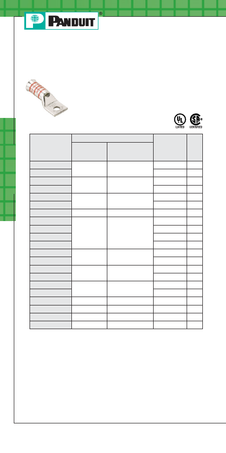
Po
w
er C
onnec
tors
B50
Prime items appear in BOLD.
Order number of pieces required, in multiples of Standard Package Quantity.
For 45° and 90° bent lugs available as standard parts and complete tool
and die information, see the Electrical Solutions Catalog, SA-ELCB03, at
www.panduit.com.
Flex Conductor, One-Hole, Standard
Barrel with Window, Flared Lug
• For use with flexible and extra-flexible
copper conductors
• Tested by Telcordia – meets NEBS Level 3
Type LCAF
Part Number
Flex Conductor Size
Stud Hole
Size
(In.)
Std.
Pkg.
Qty.
Class K & M
Locomotive
LCAF6-14-L
#6 AWG
#6 AWG
1/4
50
LCAF6-38-L
3/8
50
LCAF4-14-L
#4 AWG
#4 AWG
1/4
50
LCAF4-38-L
3/8
50
LCAF2-14-E
#2 AWG
#2 AWG
1/4
20
LCAF2-38-E
3/8
20
LCAF1-38-X
#1 AWG
#1 AWG
3/8
10
LCAF1/0-14-X
1/0 AWG
1/0 AWG
1/4
10
LCAF1/0-56-X
5/16
10
LCAF1/0-38-X
3/8
10
LCAF1/0-12-X
1/2
10
LCAF2/0-38-X
2/0 AWG
2/0 AWG
3/8
10
LCAF2/0-12-X
1/2
10
LCAF3/0-38-X
3/0 AWG
3/0 AWG
3/8
10
LCAF3/0-12-X
1/2
10
LCAF4/0-38-X
4/0 AWG
4/0 AWG
3/8
10
LCAF4/0-12-X
1/2
10
LCAF250-12-X
250 kcmil
262.6 kcmil
1/2
10
LCAF350-12-6
350 kcmil
373.7 kcmil
1/2
6
LCAF400-12-6
400 kcmil
444.4 kcmil
1/2
6
LCAF600-12-6
—
646.4 kcmil
1/2
6
PANDUIT Termination Solutions-html.html
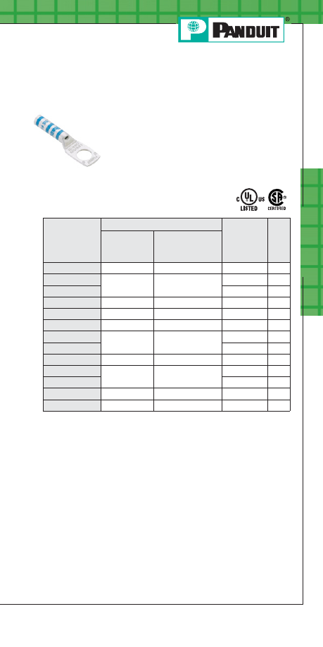
Prime items appear in BOLD.
Po
w
er C
onnec
tors
B51
For service and technical support, call 800-777-3300
or visit www.panduit.com.
Flex Conductor, One-Hole, Long Barrel
with Window Lug
• For use with flexible and extra-flexible
copper conductors
• For use with code stranded copper conductors
up to 4/0 AWG
• UL Listed and CSA Certified when crimped
with
PANDUIT and specified competitor
crimping tools and dies
Part Number
Flex Conductor Size
Stud Hole
Size
(In.)
Std.
Pkg.
Qty.
Class
G, H, I, K, M
Locomotive
LCBX8-14-L
#8 AWG
#8 AWG
1/4
50
LCBX6-14-L
#6 AWG
#6 AWG
1/4
50
LCBX6-38-L
3/8
50
LCBX4-14-L
#4 AWG
#5, #4, #3 AWG
1/4
50
LCBX1-56-X
#1 AWG
#1 AWG
5/16
10
LCBX1/0-38-X
1/0 AWG
1/0 AWG
3/8
10
LCBX2/0-38-X
2/0 AWG
2/0 AWG
3/8
10
LCBX2/0-12-X
1/2
10
LCBX3/0-38-X
3/0 AWG
3/0 AWG
3/8
10
LCBX4/0-38-X
4/0 AWG
4/0 AWG
3/8
10
LCBX4/0-12-X
1/2
10
LCBX350-12-6
350 kcmil
373.7 kcmil
1/2
6
LCBX500-12-6
500 kcmil
535.3 kcmil
1/2
6
Type LCBX
For 45° and 90° bent lugs available as standard parts and complete tool
and die information, see the Electrical Solutions Catalog, SA-ELCB03, at
www.panduit.com.
PANDUIT Termination Solutions-html.html
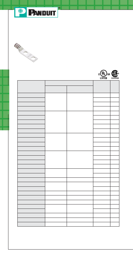
Po
w
er C
onnec
tors
B52
Prime items appear in BOLD.
Order number of pieces required, in multiples of Standard Package Quantity.
Type LCDX
For 45° and 90° bent lugs available as standard parts and complete tool
and die information, see the Electrical Solutions Catalog, SA-ELCB03, at
www.panduit.com.
◆
NEMA hole sizes and spacing.
Flex Conductor, Two-Hole, Standard
Barrel with Window Lug
• For use with flexible and extra-flexible
copper conductors
• For use with code stranded copper conductors
up to 4/0 AWG
• UL Listed and CSA Certified when crimped
with
PANDUIT and specified
competitor crimping tools
and dies
Part Number
Flex Conductor Size
Stud Hole
Size
(In.)
Std.
Pkg.
Qty.
Class
G, H, I, K, M
Locomotive
LCDX8-10A-L
#8 AWG
#8 AWG
#10
50
LCDX8-14A-L
1/4
50
LCDX8-14B-L
1/4
50
LCDX8-14D-L
1/4
50
LCDX6-10A-L
#6 AWG
#6 AWG
#10
50
LCDX6-14A-L
1/4
50
LCDX6-14B-L
1/4
50
LCDX6-14D-L
1/4
50
LCDX6-38D-L
3/8
50
LCDX4-14A-L
#4 AWG
#5, #4, #3 AWG
1/4
50
LCDX4-14B-L
1/4
50
LCDX4-14D-L
1/4
50
LCDX4-38D-L
3/8
50
LCDX2-14A-E
#2 AWG
#2 AWG
1/4
20
LCDX2-14B-E
1/4
20
LCDX2-14D-E
1/4
20
LCDX2-38D-E
3/8
20
LCDX1-14A-X
#1 AWG
#1 AWG
1/4
10
LCDX1-38D-X
3/8
10
LCDX1/0-38D-X
1/0 AWG
1/0 AWG
3/8
10
LCDX2/0-14B-X
2/0 AWG
2/0 AWG
1/4
10
LCDX2/0-38D-X
3/8
10
LCDX3/0-38D-X
3/0 AWG
3/0 AWG
3/8
10
LCDX3/0-12-X
◆
3/0 AWG
3/0 AWG
1/2
10
LCDX4/0-38D-X
4/0 AWG
4/0 AWG
3/8
10
LCDX250-38D-X
250 kcmil
262.6 kcmil
3/8
10
LCDX250-12-X
◆
1/2
10
LCDX300-12-6
◆
300 kcmil
313.1 kcmil
1/2
6
LCDX600-12-6
◆
600 kcmil
—
1/2
6
LCDX750-12-3
◆
—
777.7 kcmil
1/2
3
PANDUIT Termination Solutions-html.html
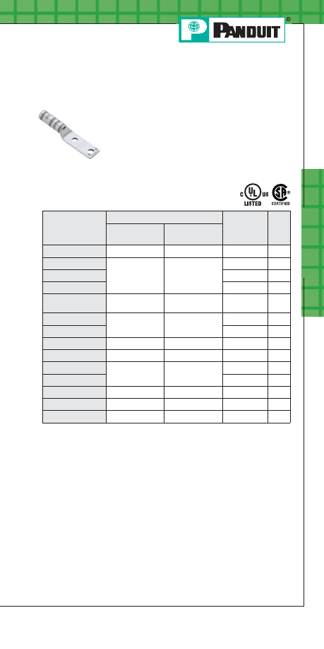
Prime items appear in BOLD.
Po
w
er C
onnec
tors
B53
For service and technical support, call 800-777-3300
or visit www.panduit.com.
Flex Conductor, Two-Hole, Long Barrel
with Window Lug
• For use with flexible and extra-flexible
copper conductors
• For use with code stranded copper
conductors up to 4/0 AWG
• UL Listed and CSA Certified when
crimped with
PANDUIT and specified
competitor crimping tools
and dies
Type LCCX
For 45° and 90° bent lugs available as standard parts and complete tool
and die information, see the Electrical Solutions Catalog, SA-ELCB03, at
www.panduit.com.
◆
NEMA hole sizes and spacing.
Part Number
Flex Conductor Size
Stud Hole
Size
(In.)
Std.
Pkg.
Qty.
Class
G, H, I, K, M
Locomotive
LCCX8-14A-L
#8 AWG
#8 AWG
1/4
50
LCCX6-14A-L
#6 AWG
#6 AWG
1/4
50
LCCX6-14B-L
1/4
50
LCCX6-38D-L
3/8
50
LCCX4-14A-L
#4 AWG
#5, #4, #3
AWG
1/4
50
LCCX2-38D-E
#2 AWG
#2 AWG
3/8
20
LCCX2-12-E
1/2
20
LCCX1-14A-X
#1 AWG
#1 AWG
1/4
10
LCCX1/0-12-X
1/0 AWG
1/0 AWG
1/2
10
LCCX2/0-38D-X
2/0 AWG
2/0 AWG
3/8
10
LCCX2/0-12-X
1/2
10
LCCX4/0-12-X
◆
◆
4/0 AWG
4/0 AWG
1/2
10
LCCX350-12-6
◆
◆
350 kcmil
373.7 kcmil
1/2
6
LCCX500-12-6
◆
◆
500 kcmil
535.3 kcmil
1/2
6
PANDUIT Termination Solutions-html.html
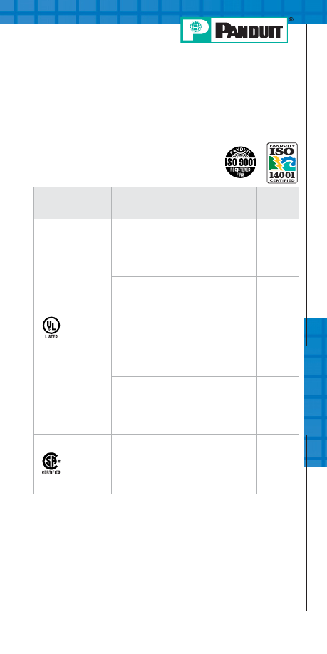
Te
chnic
al Inf
orma
tion
C1
For service and technical support, call 800-777-3300
or visit www.panduit.com.
Technical Specification and
Selection Information
PANDUIT
Terminal Approvals
Logo
(Symbol)
Agency
Spec/Approval
Requirement
Applicable
Products
Underwriters
Laboratories,
Inc.
#E52164 – UL486A
Minimum Tensile
Strength (Pull out
force for the crimp
terminal) and test
current for Max.
50°C Rise (Amps)
All Ring and
Fork
Terminals
#E78522 – UL310
Minimum Tensile
Strength (Pull out
force for the crimp
terminal) and
continuous test
current for Max.
30°C Rise (Amps)
(for .187", .205",
.250" tab widths)
and (.110"
tab width)
All
Disconnects
#E52164 – UL486C
Minimum Tensile
Strength (Pull out
force for the crimp
terminal) and test
current for Max.
50°C Rise (Amps)
All Splices
Canadian
Standards
Association
#LR31212 – C22.2 No. 65
Minimum Tensile
Strength (Pull out
force for the crimp
terminal) and test
current for Max.
50°C Rise (Amps)
All Ring and
Fork
Terminals
#LR31212 – C22.2 No. 153
All
Disconnects
PANDUIT Termination Solutions-html.html
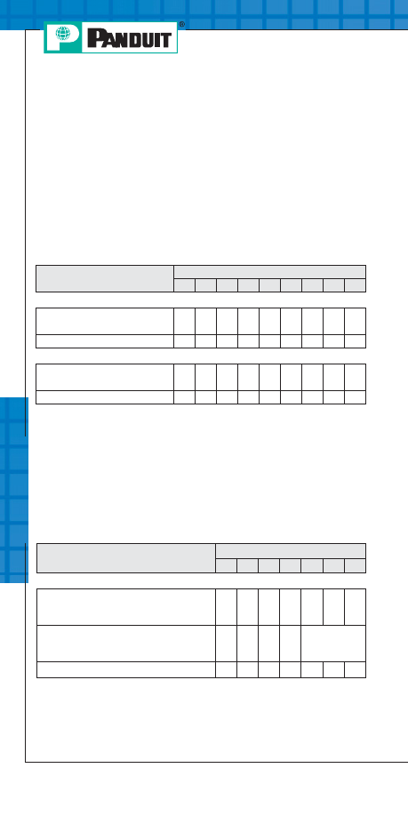
Te
chnic
al Inf
orma
tion
C2
Applicable
P
AN
-T
ERM
®
products meet or exceed
the following test specifications:
• UL486A (Terminals)
• UL486C (Splices)
• UL310 (Blade Adapters)
• CSA C22.2 No. 65 (all designs)
UL and CSA approved products are shown with
the applicable logos in the product section.
UL file #E52164, CSA File #LR31212
Applicable
P
AN
-T
ERM
®
products meet or exceed
the following test specifications:
• UL310 (Disconnects)
• CSA C22.2 No. 153 (all designs)
UL and CSA Listed products are shown with
the applicable logos in the product section.
UL file #E78522 and CSA file #LR31212.
*Pull-out force of the crimped disconnect.
Performance Requirements
Wire Size (AWG)
#26 #24 #22 #20 #18 #16 #14 #12 #10
UL 486A (TERMINALS), UL310 (MALE BLADE ADAPTERS)
Test Current for Max. 50°C
Rise (Amps)
3.5
7
9
12
17
18
30
35
50
Min. Tensile Strength* (Lbs.)
3
5
8
13
20
30
50
70
80
UL 486C (SPLICES)
Test Current for Max. 50°C
Rise (Amps)
5.5
7
9
12
17
18
30
35
50
Min. Tensile Strength* (Lbs.)
3
5
8
10
10
15
25
35
40
*Pull-out force of the crimped terminal
Wire Size (AWG)
#22 #20 #18 #16 *#14 #12 #10
UL310 (DISCONNECTS)
Continuous Test Current for Max.
30°C Rise (amps)
(for 187", 205", 250" tab widths)
3
4
7
10
15
20
24
Continuous Test Current for Max.
30°C Rise (amps)
(for .110", tab width)
2
3
4
5
Not
Applicable
Min. Tensile Strength* (Lbs.)
8
13
20
30
50
70
80
PANDUIT Termination Solutions-html.html
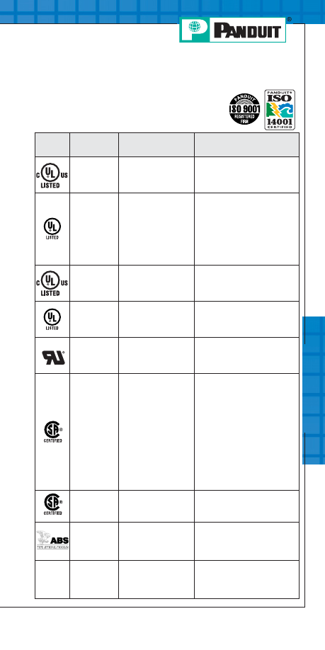
Logo
(Symbol)
Agency
Spec/Approval
Applicable Products
Underwriters
Laboratories,
Inc.
UL 486A
Wire Connectors &
Soldering Lugs
for use in US & Canada
CLRCVR, HTCT, CTAPF, CTAP,
LCAX, LCBX, LCCX, LCDX, LCAN,
LCDN, RSC, LCEX
Underwriters
Laboratories,
Inc.
UL 486A
Wire Connectors &
Soldering Lugs
for use in US
Copper & aluminum compression
connectors (except: PS, SCT,
HTAP, TAPC, SAR); Copper &
aluminum split bolts; Copper &
aluminum mechanical lugs &
splices (except: PNLC,
LAM2A1000, LAM3B, LAM3D,
LAM4D, PCSB750, LAM2LB800)
Underwriters
Laboratories,
Inc.
UL 467
Grounding & Bonding
Equipment
for use in US & Canada
SP1, SP2, SPF1, SPF2, GPL,
GMS, GM
Underwriters
Laboratories,
Inc.
UL 467
Grounding & Bonding
Equipment
for use in US
CTAP, KP, WB, GC
Underwriters
Laboratories,
Inc.
UL 486A
Wire Connectors &
Soldering Lugs
for use in US
LCA-00, LCD-00, LCC-00
Canadian
Standards
Association
C22.2 No. 65-03
Wire Connectors
Copper & aluminum compression
connectors (except: PS, SCT,
HTAP, TAPC, SAR, CTAP, BPC);
Copper & aluminum split bolts
(except: SBCL, VT, VTA);
Copper & aluminum mechanical
lugs & splices (except: ML, ML-T,
HL, HLB, HLA-90, PNL-2, HL-2,
HL-2N, HHL-2N, H2L-2N, P2NLT,
PNLC, HC, LAM2A1000, LAM2B,
LAM2SB600, LAM2SB750,
LAM3B, LAM3D, LAM4D,
PCSB750)
Canadian
Standards
Association
C22.2 No. 41-M1987
(R1999) Grounding
& Bonding Equipment
WB, KP
American
Bureau
of Shipping
ABS Rules
Steel Vessel Rules
1-1-4/7.7, 4-8-3/9.19,
4-8-4/21.27
Copper compression connectors
LCA, LCAF, LCAS, LCAX, LCB,
LCC, LCD, S-R,
LCDX, SCS, SCSF
NEBS
Level 3
Telcordia
Technologies,
Inc.
Network Equipment –
Building Systems
Copper compression connectors
LCAS, LCA, LCD, LCB, LCC,
LCAF, LCCF, SCSS,
SCS, SCL, SCSF
Te
chnic
al Inf
orma
tion
C3
For service and technical support, call 800-777-3300
or visit www.panduit.com.
PANDUIT
Power & Grounding Connector Approvals
PANDUIT Termination Solutions-html.html
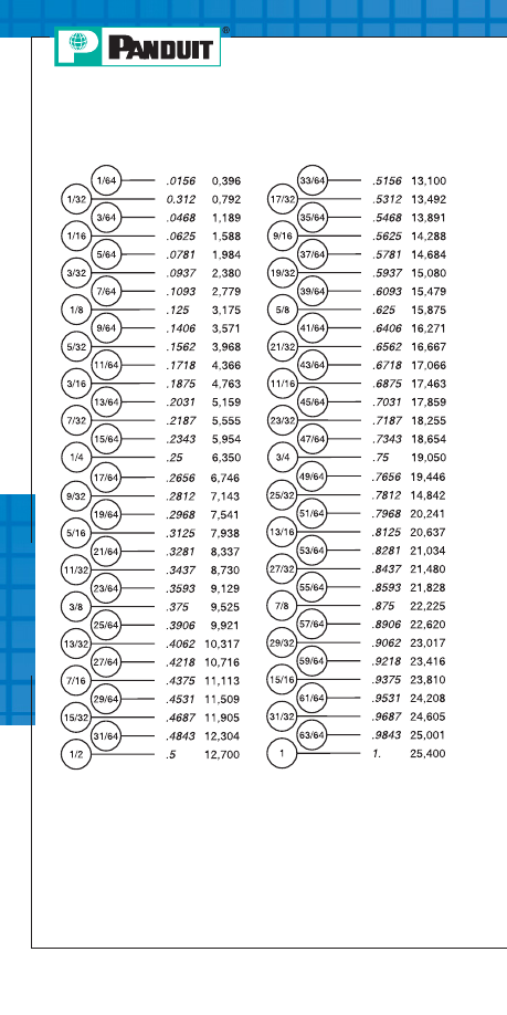
Te
chnic
al Inf
orma
tion
C4
Equivalent Tables
Fractional Inches/Decimal Inches/Millimeters
PANDUIT Termination Solutions-html.html
Te
chnic
al Inf
orma
tion
C5
For service and technical support, call 800-777-3300
or visit www.panduit.com.
Stud Size Chart (Inches)
*Terminal Stud.
**Power Connector Stud.
Standard Stud Size
Stud Size Decimal
Equivalent
Terminal Hole
Diameter
Stud Size
Designation in
PANDUIT
Part Number
3/4"
7/8"
1"
.750"
.875"
1.00"
.810"
.906"
1.031"
34
78
1
#2
#4
#5
#6
#8
#10
1/4"
5/16"
.086" .112"
.127"
.138"
.164"
.190"
.250"
.312"
.090" .118"
.130"
.147"
.173"
.204"
.270"
.343"
2
4
5
6
8
10
14
56
Standard Stud Size
Stud Size Decimal
Equivalent
Terminal Hole
Diameter
Stud Size
Designation in
PANDUIT
Part Number
3/8"
7/16"
1/2"
5/8"
.375"
.438"
.500"
.625"
.392"*
.456"
.531"
.656"
.406"**
38
76
12
58
Standard Stud Size
Stud Size Decimal
Equivalent
Terminal Hole
Diameter
Stud Size
Designation in
PANDUIT
Part Number
PANDUIT Termination Solutions-html.html
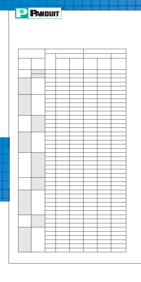
Te
chnic
al Inf
orma
tion
C6
Common Conductor Sizes and Strandings
Reference Chart
*Strandings required for UL and CSA Certification testing.
Conductor
Individual Strands
Overall Conductor Size
No.
Diameter
Diameter
Area
AWG
Metric
mm
2
mm
In.
mm
In.
Circ.
MILS
0.05
25
.05
.002
.25
.010
97
0.06
41
.05
.002
.36
.014
159
26
10
.13
.005
.53
.021
250
1
.41
.016
.41
.016
256
7
.16
.006
.48
.019
278
19
.10
.004
.51
.020
304
24
41
.08
.003
.58
.023
384
10
.16
.006
.58
.023
397
1
.51
.020
.51
.020
400
7
.20
.008
.61
.024
448
19
.13
.005
.61
.024
475
0.25
65
.07
.003
.65
.026
484
128
.05
.002
.65
.026
496
32
.10
.004
.65
.026
496
14
.16
.006
.65
.026
556
22
1
.64
.025
.64
.025
625
16
.16
.006
.76
.030
635
26
.13
.005
.76
.030
650
7
.25
.010
.76
.030
700
19
.16
.006
.79
.031
754
0.38
48
.10
.004
.80
.031
744
194
.05
.002
.80
.031
752
100
.07
.003
.80
.031
760
7
.27
.011
.80
.031
791
12
.21
.008
.80
.031
820
21
.16
.006
.80
.031
833
0.5
7
.30
.012
.90
.035
977
16
.20
.008
.90
.035
992
1
.80
.031
.80
.031
992
20
*10
.25
.010
.89
.035
1000
1
.81
.032
.81
.032
1024
41
.13
.005
.91
.036
1025
26
.16
.006
91
.036
1032
*7
.32
.013
.97
.038
1111
19
.20
.008
.94
.037
1216
0.75
7
.37
.015
1.10
.043
1485
24
.20
.008
1.20
.047
1488
1
1.00
.039
1.00
.039
1550
18
*16
.25
.010
1.19
.047
1600
1
1.02
.040
1.02
.040
1600
65
.13
.005
1.19
.047
1625
41
.16
.006
1.19
.047
1627
*7
.40
.016
1.22
.048
1770
19
.25
.010
1.24
.049
1900
PANDUIT Termination Solutions-html.html
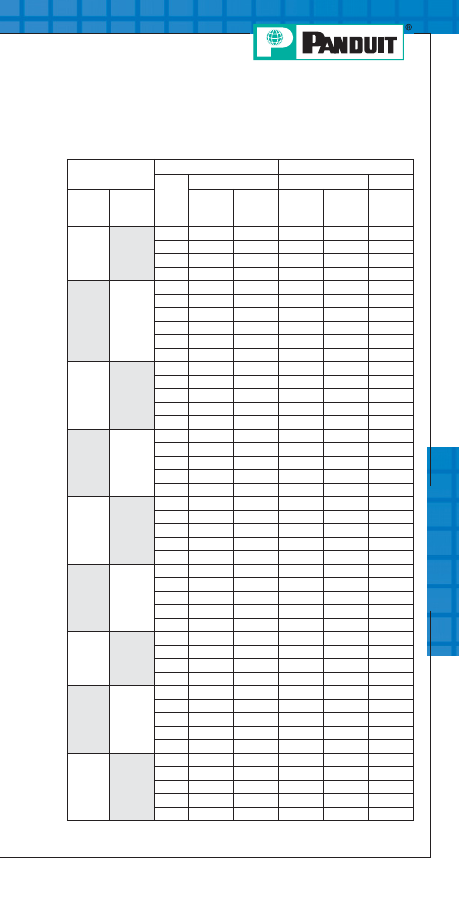
Te
chnic
al Inf
orma
tion
C7
For service and technical support, call 800-777-3300
or visit www.panduit.com.
Common Conductor Sizes and Strandings
Reference Chart (continued)
Conductor
Individual Strands
Overall Conductor Size
No.
Diameter
Diameter
Area
AWG
Metric
mm
2
mm
In.
mm
In.
Circ.
MILS
1.0
19
0.25
.010
1.30
.051
1841
1
1.13
.044
1.13
.044
1979
32
.20
.008
1.30
.051
1984
7
.43
.017
1.30
.051
2006
16
19
.29
.011
1.47
.058
2426
65
.16
.006
1.50
.059
2580
*26
.25
.010
1.50
.059
2600
1
1.30
.051
1.30
.051
2601
105
.13
.005
1.50
.059
2625
*7
.51
.020
1.52
.060
2828
1.5
30
.25
.010
1.70
.067
2906
21
.30
.012
1.60
.063
2930
189
.10
.004
1.90
.075
2930
7
.52
.020
1.60
.063
2934
1
1.38
.054
1.38
.054
2952
14
45
.16
.006
1.85
.073
3786
19
.38
.014
1.85
.073
3831
1
1.63
.064
1.63
.064
4096
*41
.25
.010
1.85
.073
4100
*7
.64
.025
1.85
.073
4481
2.5
50
.25
.010
2.20
.087
4844
7
.67
.026
2.10
.083
4871
35
.30
.012
2.20
.087
4883
315
.10
.004
2.20
.087
4883
1
1.78
.070
1.78
.070
4911
12
19
.45
.018
2.36
.093
6088
*65
.25
.010
2.41
.095
6500
165
.16
.006
2.41
.095
6549
1
2.06
.081
2.06
.081
6561
*7
.81
.032
2.44
.096
7168
4.0
56
.30
.012
3.10
.122
7812
1
2.26
.089
2.26
.089
7917
511
.10
.004
3.00
.118
7921
19
.52
.020
2.70
.106
7963
10
37
.40
.016
2.92
.115
9354
49
.36
.014
2.95
.116
9880
*7
.98
.039
2.95
.116
10376
1
2.59
.102
2.59
.102
10404
*105
.25
.010
2.95
.116
10500
6.0
84
.30
.012
3.50
.138
11718
756
.10
.004
3.70
.146
11718
1
2.76
.109
2.76
.109
11807
7
1.05
.041
3.20
.126
11962
19
.64
.025
3.30
.130
12063
*Strandings required for UL and CSA Certification testing.
PANDUIT Termination Solutions-html.html
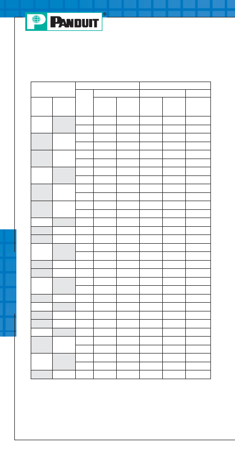
Te
chnic
al Inf
orma
tion
C8
Common Conductor Sizes and Strandings
Reference Chart (continued)
Conductor
Individual Strands
Overall Conductor Size
No.
Diameter
Diameter
Area
AWG
Metric
mm
2
mm
In.
mm
In.
Circ.
MILS
6
7
0.107
0.042
3.21
0.126
11840
1
2.77
0.109
2.77
0.109
11840
9
7
1.1
0.0432
3.3
0.13
13000
1
2.91
0.1144
2.91
0.114
13090
8
1
3.26
0.1285
3.25
0.128
16510
7
1.23
0.0486
3.7
0.146
16510
10
7
1.37
0.054
4.12
0.162
19740
1
3.58
0.141
3.58
0.141
19740
7
7
1.38
0.0545
4.15
0.164
20520
1
3.67
0.1443
3.67
0.144
20520
6
7
1.55
0.0612
4.66
0.184
26240
1
4.11
0.162
4.11
0.162
26240
16
7
1.73
0.008
5.13
0.204
31580
5
7
1.75
0.0688
5.24
0.206
33090
4
7
1.96
0.0772
5.88
0.232
41740
25
7
2.16
0.085
6.48
0.255
49340
19
1.32
0.052
6.6
0.26
49340
3
7
2.2
0.0867
6.61
0.26
52620
2
7
2.47
0.0974
7.42
0.292
66300
35
7
2.54
0.1
7.62
300
69070
19
1.55
0.001
7.75
0.305
69070
1
19
1.5
0.0064
8.43
0.332
83690
50
19
1.85
0.073
9.27
0.365
98680
1/0
19
1.59
0.0745
9.46
0.373
10500
2/0
19
2.13
0.0837
10.6
0.419
133100
70
19
2.18
0.086
10.9
0.43
138100
3/0
19
2.59
0.094
11.9
0.47
167800
36
1.71
0.0673
12
0.471
167800
95
19
2.57
0.101
12.8
0.505
187500
37
1.83
0.072
12.5
0.504
187500
4/0
19
2.89
0.1055
13.4
0.528
211600
PANDUIT Termination Solutions-html.html
Te
chnic
al Inf
orma
tion
C9
For service and technical support, call 800-777-3300
or visit www.panduit.com.
Common Conductor Sizes and Strandings
Reference Chart (continued)
Conductor
Individual Strands
Overall Conductor Size
No.
Diameter
Diameter
Area
AWG
Metric
mm
2
mm
In.
mm
In.
Circ.
MILS
120
37
2.06
0.081
14.4
0.567
237.8
kcmil
250
kcmil
37
2.07
0.0822
14.6
0.575
250
kcmil
300
kcmil
150
37
2.29
0.09
16
0.63
300
kcmil
350
kcmil
37
2.47
0.0973
17.3
0.681
350
kcmil
185
37
2.54
0.1
17.8
0.7
365.1
kcmil
400
kcmil
37
2.64
0.104
18.5
0.728
400
kcmil
240
37
2.9
0.114
20.3
0.798
473.6
kcmil
61
2.26
0.089
20.3
0.801
473.6
kcmil
500
kcmil
37
2.95
0.1162
20.7
0.813
500
kcmil
61
2.3
0.0905
20.7
0.814
500
kcmil
300
kcmil
61
2.51
0.099
22.6
0.891
592.1
kcmil
600
kcmil
61
2.52
0.0992
22.7
0.893
600
kcmil
700
kcmil
61
2.72
0.1071
24.5
0.964
700
kcmil
750
kcmil
61
2.82
0.1109
25.4
0.998
750
kcmil
91
2.31
0.0908
25.4
0.998
750
kcmil
400
61
2.9
0.114
26.1
1.026
798.4
kcmil
800
kcmil
61
2.91
0.1145
26.2
1.031
800
kcmil
91
2.38
0.0938
26.2
1.032
800
kcmil
1000
kcmil
500
61
3.25
0.128
28.3
1.152
986.8
kcmil
91
2.66
0.1048
29.3
1.153
1000
kcmil
625
91
2.97
0.117
32.7
1.287
1233.7
kcmil
PANDUIT Termination Solutions-html.html

Inde
x
D1
For service and technical support, call 800-777-3300
or visit www.panduit.com.
B
BS10-L...........................A42
BS14-C ..........................A42
BS18-C ..........................A42
BS22-C ..........................A42
BSN10-L ........................A41
BSN14-C .......................A41
BSN18-C .......................A41
BSN22-C .......................A41
BSV10X-L......................A41
BSV14X-C .....................A41
BSV18X-CY...................A41
C
C-720.............................B31
CC-720 ..........................B31
CD-2001-1 .....................B33
CD-2001-1/0 ..................B33
CD-2001-2 .....................B33
CD-2001-2/0 ..................B33
CD-2001-250 .................B33
CD-2001-3/0 ..................B33
CD-2001-300 .................B33
CD-2001-350 .................B33
CD-2001-4 .....................B33
CD-2001-4/0 ..................B33
CD-2001-400 .................B33
CD-2001-500 .................B33
CD-2001-6 .....................B33
CD-2001-8 .....................B33
CD-720-1 .......................B32
CD-720-2 .......................B32
CD-720-3 .......................B32
CD-720-4 .......................B32
CD-720-5 .......................B32
CD-720-6 .......................B32
CD-720-7 .......................B32
CD-720PV8-2 ................B32
CD-920-1 .......................B34
CD-920-1/0 ....................B34
CD-920-2 .......................B34
CD-920-2/0 ....................B34
CD-920-250 ...................B34
CD-920-3/0 ....................B34
CD-920-300 ...................B34
CD-920-350 ...................B34
CD-920-4 .......................B34
CD-920-4/0 ....................B34
CD-920-400 ...................B34
CD-920-500 ...................B34
CD-920-500A.................B34
CD-920-6 .......................B34
CD-920-600 ...................B34
CD-920-750 ...................B34
CD-920-8 .......................B34
CD-940-1000 .................B35
CD-940-1000A...............B35
CD-940-750 ...................B35
CD-940-750A.................B35
CD-940-750X.................B35
CD-940-800 ...................B35
CD-940-800A.................B35
CD-940-DA ....................B35
CG-920 ..........................B37
CG-940 ..........................B37
CG-980 ..........................B37
CST101 .........................A19
CST114-157 ..................A19
CST115 .........................A19
CT-100 ...........................A16
CT-1002 .........................A18
Part Number Index
PANDUIT
Part
Number
Page
No.
PANDUIT
Part
Number
Page
No.
PANDUIT Termination Solutions-html.html

CT-1003 .........................A18
CT-1004 .........................A18
CT-1005 .........................A18
CT-1006 .........................A18
CT-1014 .........................A17
CT-1015 .........................A17
CT-1525 .........................A17
CT-1550 .........................A17
CT-1551 .........................A17
CT-1570 .........................A17
CT-160 ...........................A16
CT-1700.................A17, B28
CT-1701 .........................A17
CT-200 ...........................A16
CT-2001 .........................B28
CT-260 ...........................A16
CT-2931 .........................B28
CT-2940 .........................B28
CT-2981 .........................B36
CT-300-1 ........................A18
CT-720 ...........................B28
CT-720-3 ........................B31
CT-720-3CC...................B31
CT-720-7 ........................B31
CT-720-7CC...................B31
CT-8250HP ....................B30
CT-900HPH....................B29
CT-900LPHPH ...............B30
CT-901HP ......................B29
CT-901RCH ...................B29
CT-901RFS ...........B29, B30
CT-930 ...........................B28
CT-930CH ......................B29
CT-930LPCH..................B30
CT-940CH ......................B29
CT-980 ...........................B36
CT-980CH ......................B36
CT-980LPCH..................B36
D
D14-250B-C...................A34
D14-250MB-C................A38
D-250A-C.......................A34
DNF10-250FI-L..............A33
DNF10-250FIB-L ...........A32
DNF10-250FIMB-L ........A33
DNF10-250M-L..............A37
DNF14-187FIB-C...........A32
DNF14-188FIB-C...........A32
DNF14-205FIB-C...........A32
DNF14-206FIB-C...........A32
DNF14-250FIB-C...........A32
DNF14-250FIM-C ..........A33
DNF14-250FIMB-L ........A33
DNF14-250M-C .............A37
DNF18-110FIB-C...........A32
DNF18-111FIB-C...........A32
DNF18-187FIB-C...........A32
DNF18-188FIB-C...........A32
DNF18-205FIB-C...........A32
DNF18-206FIB-C...........A32
DNF18-250FIB-C...........A32
DNF18-250FIB-C...........A33
DNF18-250FIM-C ..........A33
DNF18-250M-C .............A37
DNFR14-250B-C ...........A35
DNFR14-250FIB-C ........A35
DNFR18-250B-C ...........A35
DNFR18-250FIB-C ........A35
DR10-250-L ...................A36
DR14-250B-C ................A36
Inde
x
D2
Part Number Index
PANDUIT
Part
Number
Page
No.
PANDUIT
Part
Number
Page
No.
PANDUIT Termination Solutions-html.html

DR14-250-C ..................A36
DV14-145M-C ................A38
DV14-187B-C ................A33
DV14-188B-C ................A33
DV14-205B-C ................A33
DV14-250B-C ................A33
DV14-250MB-C .............A37
DV14-250P-C ................A34
DV18-145M-CY .............A38
DV18-187B-CY ..............A33
DV18-188B-CY ..............A33
DV18-250B-C ................A33
DV18-250MB-C .............A37
DV18-250P-CY ..............A34
F
F73-5-M .........................A48
F73-7-M .........................A48
F74-5-M .........................A48
F75-10-M .......................A48
F75-6-M .........................A48
F75-8-M .........................A48
F76-10-M .......................A48
F76-6-M .........................A48
F76-8-M .........................A48
F77-6-M .........................A48
F77-7-M .........................A48
F77-8-M .........................A48
F78-10-M .......................A48
F78-7-M .........................A48
F78-8-M .........................A48
F80-10-M .......................A48
F80-7-M .........................A48
F80-8-M .........................A48
F81-10-M .......................A48
F81-12-M .......................A48
F81-9-M .........................A48
F82-10-M .......................A48
F82-12-M .......................A48
F82-15-M .......................A48
F83-12-D .......................A49
F83-15-D .......................A49
F83-18-D .......................A49
F84-12-TL......................A49
F84-15-TL......................A49
F84-18-TL......................A49
F85-12-C .......................A49
F85-15-C .......................A49
F85-18-C .......................A49
F86-18-C .......................A49
F86-20-C .......................A49
F86-25-C .......................A49
F87-18-C .......................A49
F87-22-C .......................A49
F87-25-C .......................A49
FSD74-6-D ....................A46
FSD74-8-D ....................A46
FSD75-10-D ..................A46
FSD75-6-D ....................A46
FSD75-8-D ....................A46
FSD76-6-D ....................A46
FSD76-8-D ....................A46
FSD77-10-D ..................A46
FSD77-12-D ..................A46
FSD77-6-D ....................A46
FSD77-8-D ....................A46
FSD78-10-D ..................A46
FSD78-12-D ..................A46
FSD78-6-D ....................A46
FSD78-8-D ....................A46
FSD79-8-D ....................A46
Inde
x
D3
For service and technical support, call 800-777-3300
or visit www.panduit.com.
Part Number Index
PANDUIT
Part
Number
Page
No.
PANDUIT
Part
Number
Page
No.
PANDUIT Termination Solutions-html.html

Inde
x
D4
FSD80-12-D ..................A46
FSD80-8-D ....................A46
FSD81-10-D ..................A46
FSD81-12-C ..................A46
FSD82-12-C ..................A46
FSD83-12-C ..................A46
FTD75-8-D.....................A47
FTD76-10-D...................A47
FTD76-8-D.....................A47
FTD77-10-D...................A47
FTD77-8-D.....................A47
FTD78-12-D...................A47
FTD78-8-D.....................A47
FTD80-10-TL .................A47
FTD80-13-TL .................A47
FTD81-12-C...................A47
FTD82-14-C...................A47
J
J214-312-T ....................A44
J318-412-T ....................A44
JN218-216-C .................A44
JN224-318-C .................A44
JN418-212-C .................A44
K
K-1000 ...........................A50
K-1102 ...........................A50
K-1104 ...........................A50
K1-PNKIT ......................A51
K2-PVKIT.......................A52
KP-1075.........................A50
KP-1165.........................A40
L
LCA1-12-E.....................B41
LCA1-14-E.....................B41
LCA1-38-E.....................B41
LCA1-56-E.....................B41
LCA1/0-12-X..................B41
LCA1/0-14-X..................B41
LCA1/0-38-X..................B41
LCA1/0-56-X..................B41
LCA2-12-Q ....................B41
LCA2-14-Q ....................B41
LCA2-38-Q ....................B41
LCA2-56-Q ....................B41
LCA2/0-12-X..................B41
LCA2/0-14-X..................B41
LCA2/0-38-X..................B41
LCA2/0-56-X..................B41
LCA250-12-X.................B42
LCA250-38-X.................B42
LCA250-56-X.................B42
LCA3/0-12-X..................B42
LCA3/0-14-X..................B42
LCA3/0-38-X..................B42
LCA3/0-56-X..................B42
LCA300-12-X.................B42
LCA350-12-X.................B42
LCA350-38-X.................B42
LCA4-14-L .....................B41
LCA4-38-L .....................B41
LCA4-56-L .....................B41
LCA4/0-12-X..................B42
LCA4/0-38-X..................B42
LCA4/0-56-X..................B42
LCA400-12-6 .................B42
LCA500-12-6 .................B42
LCA6-10-L .....................B41
Part Number Index
PANDUIT
Part
Number
Page
No.
PANDUIT
Part
Number
Page
No.
PANDUIT Termination Solutions-html.html

Inde
x
D5
For service and technical support, call 800-777-3300
or visit www.panduit.com.
LCA6-14-L .....................B41
LCA6-38-L .....................B41
LCA6-56-L .....................B41
LCA600-12-6 .................B42
LCA8-10-L .....................B41
LCA8-14-L .....................B41
LCA8-38-L .....................B41
LCA8-56-L .....................B41
LCAF1-38-X...................B50
LCAF1/0-12-X................B50
LCAF1/0-14-X................B50
LCAF1/0-38-X................B50
LCAF1/0-56-X................B50
LCAF2-14-E...................B50
LCAF2-38-E...................B50
LCAF2/0-12-X................B50
LCAF2/0-38-X................B50
LCAF250-12-X...............B50
LCAF3/0-12-X................B50
LCAF3/0-38-X................B50
LCAF350-12-6 ...............B50
LCAF4-14-L ...................B50
LCAF4-38-L ...................B50
LCAF4/0-12-X................B50
LCAF4/0-38-X................B50
LCAF400-12-6 ...............B50
LCAF6-14-L ...................B50
LCAF6-38-L ...................B50
LCAF600-12-6 ...............B50
LCAS1-14-E ..................B40
LCAS1-38-E ..................B40
LCAS1-56-E ..................B40
LCAS1/0-38-X ...............B40
LCAS2-14-Q ..................B40
LCAS2-38-Q ..................B40
LCAS2-56-Q ..................B40
LCAS2/0-12-X ...............B40
LCAS2/0-14-X ...............B40
LCAS2/0-38-X ...............B40
LCAS250-12-X ..............B40
LCAS3/0-38-X ...............B40
LCAS4-10-L...................B40
LCAS4-14-L...................B40
LCAS4-38-L...................B40
LCAS4-56-L...................B40
LCAS4/0-12-X ...............B40
LCAS4/0-38-X ...............B40
LCAS6-10-L...................B40
LCAS6-14-L...................B40
LCAS6-38-L...................B40
LCAS6-56-L...................B40
LCAS8-10-L...................B40
LCAS8-14-L...................B40
LCAS8-38-L...................B40
LCAS8-56-L...................B40
LCAX1-12-X ..................B48
LCAX1-14-X ..................B48
LCAX1-38-X ..................B48
LCAX1-56-X ..................B48
LCAX1/0-12-X ...............B48
LCAX1/0-14-X ...............B48
LCAX1/0-38-X ...............B48
LCAX1/0-56-X ...............B48
LCAX2-12-E ..................B48
LCAX2-14-E ..................B48
LCAX2-38-E ..................B48
LCAX2-56-E ..................B48
LCAX2/0-12-X ...............B49
LCAX2/0-14-X ...............B49
LCAX2/0-38-X ...............B49
LCAX2/0-56-X ...............B49
LCAX250-12-X ..............B49
Part Number Index
PANDUIT
Part
Number
Page
No.
PANDUIT
Part
Number
Page
No.
PANDUIT Termination Solutions-html.html

Inde
x
D6
LCAX250-38-X ..............B49
LCAX250-56-X ..............B49
LCAX3/0-12-X ...............B49
LCAX3/0-14-X ...............B49
LCAX3/0-38-X ...............B49
LCAX3/0-56-X ...............B49
LCAX300-12-6...............B49
LCAX350-12-6...............B49
LCAX350-38-6...............B49
LCAX4-14-L...................B48
LCAX4-38-L...................B48
LCAX4-56-L...................B48
LCAX4/0-12-X ...............B49
LCAX4/0-38-X ...............B49
LCAX4/0-56-X ...............B49
LCAX500-12-6...............B49
LCAX6-10-L...................B48
LCAX6-14-L...................B48
LCAX6-38-L...................B48
LCAX6-56-L...................B48
LCAX8-10-L...................B48
LCAX8-14-L...................B48
LCAX8-38-L...................B48
LCAX8-56-L...................B48
LCB1-56-E.....................B43
LCB1/0-38-X..................B43
LCB2-56-Q ....................B43
LCB2/0-12-X..................B43
LCB2/0-38-X..................B43
LCB250-12-X.................B43
LCB3/0-12-X..................B43
LCB3/0-38-X .................B43
LCB350-12-X.................B43
LCB4-14-L .....................B43
LCB4/0-12-X..................B43
LCB4/0-38-X..................B43
LCB500-12-6 .................B43
LCB6-14-L .....................B43
LCB6-38-L .....................B43
LCB8-14-L .....................B43
LCBX1-56-X ..................B51
LCBX1/0-38-X ...............B51
LCBX2/0-12-X ...............B51
LCBX2/0-38-X ...............B51
LCBX3/0-38-X ...............B51
LCBX350-12-6...............B51
LCBX4-14-L...................B51
LCBX4/0-12-X ...............B51
LCBX4/0-38-X ...............B51
LCBX500-12-6...............B51
LCBX6-14-L...................B51
LCBX6-38-L...................B51
LCBX8-14-L...................B51
LCC1-14A-E ..................B45
LCC1/0-12-X..................B45
LCC2-12-Q ....................B45
LCC2-38-Q ....................B45
LCC2-38D-Q..................B45
LCC2-56B-Q..................B45
LCC2/0-12-X..................B45
LCC2/0-38D-X ...............B45
LCC250-12-X.................B45
LCC3/0-12-X..................B45
LCC300-12-X.................B45
LCC350-12-X.................B45
LCC4-14A-L...................B45
LCC4/0-12-X..................B45
LCC400-12-6 .................B45
LCC500-12-6 .................B45
LCC6-14A-L...................B45
LCC6-14B-L...................B45
LCC6-38D-L ..................B45
Part Number Index
PANDUIT
Part
Number
Page
No.
PANDUIT
Part
Number
Page
No.
PANDUIT Termination Solutions-html.html

Inde
x
D7
For service and technical support, call 800-777-3300
or visit www.panduit.com.
LCC600-12-6 .................B45
LCC750-12-6 .................B45
LCC8-14A-L...................B45
LCCX1-14A-X................B53
LCCX1/0-12-X ...............B53
LCCX2-12-E ..................B53
LCCX2-38D-E................B53
LCCX2/0-12-X ...............B53
LCCX2/0-38D-X.............B53
LCCX350-12-6...............B53
LCCX4-14A-L ................B53
LCCX4/0-12-X ...............B53
LCCX500-12-6...............B53
LCCX6-14A-L ................B53
LCCX6-14B-L ................B53
LCCX6-38D-L ................B53
LCCX8-14A-L ................B53
LCD1-14A-E ..................B44
LCD1-38D-E ..................B44
LCD1/0-38D-X ...............B44
LCD2-14A-Q..................B44
LCD2-14B-Q..................B44
LCD2-14D-Q..................B44
LCD2-38D-Q..................B44
LCD2/0-14B-X ...............B44
LCD2/0-38D-X ...............B44
LCD250-38D-X . . . . . . .B44
LCD3/0-38D-X ...............B44
LCD4-14A-L...................B44
LCD4-14B-L...................B44
LCD4-14D-L ..................B44
LCD4-38D-L ..................B44
LCD4/0-38D-X ...............B44
LCD6-10A-L...................B44
LCD6-14A-L...................B44
LCD6-14B-L...................B44
LCD6-14D-L ..................B44
LCD6-38D-L ..................B44
LCD8-10A-L...................B44
LCD8-14A-L...................B44
LCD8-14B-L...................B44
LCD8-14D-L ..................B44
LCDX1-14A-X................B52
LCDX1-38D-X................B52
LCDX1/0-38D-X.............B52
LCDX2-14A-E................B52
LCDX2-14B-E................B52
LCDX2-14D-E................B52
LCDX2-38D-E................B52
LCDX2/0-14B-X.............B52
LCDX2/0-38D-X.............B52
LCDX250-12-X ..............B52
LCDX250-38D-X............B52
LCDX3/0-12-X ...............B52
LCDX3/0-38D-X.............B52
LCDX300-12-6 . . . . . . .B52
LCDX4-14A-L ................B52
LCDX4-14B-L ................B52
LCDX4-14D-L ................B52
LCDX4-38D-L ................B52
LCDX4/0-38D-X.............B52
LCDX6-10A-L ................B52
LCDX6-14A-L ................B52
LCDX6-14B-L ................B52
LCDX6-14D-L ................B52
LCDX6-38D-L ................B52
LCDX600-12-6...............B52
LCDX750-12-3...............B52
LCDX8-10A-L ................B52
LCDX8-14A-L ................B52
LCDX8-14B-L ................B52
LCDX8-14D-L ................B52
Part Number Index
PANDUIT
Part
Number
Page
No.
PANDUIT
Part
Number
Page
No.
PANDUIT Termination Solutions-html.html

Inde
x
D8
Order number of pieces required, in multiples of Standard Package Quantity.
P
P10-10F-L......................A26
P10-10LF-L....................A27
P10-10R-L .....................A24
P10-14R-L .....................A24
P10-38R-L .....................A24
P10-6F-L........................A26
P10-6R-L .......................A24
P10-8F-L........................A26
P10-8R-L .......................A24
P10-56R-L .....................A24
P10-P55-L .....................A28
P14-10F-C .....................A26
P14-10R-C.....................A24
P14-14R-C.....................A24
P14-38R-C.....................A24
P14-56R-C.....................A24
P14-6F-C .......................A26
P14-6LF-C .....................A27
P14-6R-C.......................A24
P14-8F-C .......................A26
P14-8R-C.......................A24
P14-P47-C.....................A28
P18-10F-C .....................A26
P18-10R-C.....................A24
P18-14R-C.....................A24
P18-6F-C .......................A26
P18-6FN-C ....................A26
P18-6LF-C .....................A27
P18-6R-C.......................A24
P18-8F-C .......................A26
P18-8R-C.......................A24
P18-P47-C.....................A28
P22-4F-C .......................A26
PG-1 ..............................B37
PG-1SC .........................B37
PS12-L...........................A42
PS16-C ..........................A42
PS2-Q............................B47
PS4/0-X .........................B47
PS6-L.............................B47
PS8-L.............................B47
PSN16-C .......................A42
PSN18-C .......................A42
PV10-10F-L ...................A25
PV10-10LF-L .................A27
PV10-10R-L...................A22
PV10-10RX-L ................A23
PV10-14F-L ...................A25
PV10-14LF-L .................A27
PV10-14R-L...................A22
PV10-14RX-L ................A23
PV10-38R-L...................A22
PV10-56R-L...................A22
PV10-610R-L.................A23
PV10-6F-L .....................A25
PV10-6LF-L ...................A27
PV10-6R-L.....................A22
PV10-8F-L .....................A25
PV10-8LF-L ...................A27
PV10-8R-L.....................A22
PV10-P55-L ...................A28
PV14-10F-C...................A25
PV14-10LF-C.................A27
PV14-10FN-C ................A25
PV14-10R-C ..................A22
PV14-10RX-C................A23
PV14-14F-C...................A25
PV14-14R-C ..................A22
PV14-38R-L...................A22
PV14-4R-C ....................A22
Part Number Index
PANDUIT
Part
Number
Page
No.
PANDUIT
Part
Number
Page
No.
PANDUIT Termination Solutions-html.html

Inde
x
D9
For service and technical support, call 800-777-3300
or visit www.panduit.com.
PV14-56R-C ..................A22
PV14-610R-C ................A23
PV14-6F-C.....................A25
PV14-6FN-C ..................A25
PV14-6LF-C...................A27
PV14-6R-C ....................A22
PV14-6RN-C..................A22
PV14-8F-C.....................A25
PV14-8LF-C...................A27
PV14-8R-C ....................A22
PV14-P47-C ..................A28
PV18-10F-CY ................A25
PV18-10LF-CY ..............A27
PV18-10R-CY................A22
PV18-14R-CY................A22
PV18-38R-CY................A22
PV18-4R-CY..................A22
PV18-56R-CY................A22
PV18-610R-CY..............A23
PV18-6F-CY ..................A25
PV18-6FN-CY................A25
PV18-6LF-CY ................A27
PV18-6R-CY..................A22
PV18-8F-CY ..................A25
PV18-8LF-CY ................A27
PV18-8R-CY..................A22
PV18-P47-CY ................A28
PV22-6F-C.....................A25
S
SCL1-E ..........................B47
SCL1/0-X .......................B47
SCL2-Q..........................B47
SCL2/0-X .......................B47
SCL250-X ......................B47
SCL3/0-X .......................B47
SCL350-X ......................B47
SCL4-L ..........................B47
SCL4/0-X .......................B47
SCL500-6 ......................B47
SCL6-L ..........................B47
SCL600-6 ......................B47
SCL8-L ..........................B47
SCS1-E..........................B46
SCS1/0-X.......................B46
SCS2-Q .........................B46
SCS2/0-X.......................B46
SCS250-X......................B46
SCS3/0-X.......................B46
SCS350-X......................B46
SCS4-L ..........................B46
SCS4/0-X.......................B46
SCS500-6 ......................B46
SCS6-L ..........................B46
SCS8-L ..........................B46
Part Number Index
PANDUIT
Part
Number
Page
No.
PANDUIT
Part
Number
Page
No.
PANDUIT Termination Solutions-html.html

PANDUIT is a global leader in cabling and communication
products, delivering end-to-end solutions in support
of demanding electrical and networking requirements.
Cable
Modules
Work Area
Outlet Solutions
Surface Raceway
Zone Cabling
Patch Panels,
Copper Patch Cords
& Punchdowns
Fiber Connectors,
Enclosures & Patch Cords
Fiber Routing Systems
Racks &
Cable Management
Grounding & Bonding
Wireless Solutions
Managed System
Solutions
Industrial
Labeling & Administration
Wiring Duct
Cable Ties & Accessories
Network Connectivity
SA-NCCB34
Cable Ties
Cable Accessories
Stainless Steel
Wiring Duct
Surface Raceway
Abrasion Protection
Cable Management
Terminals
Power and Grounding
Connectors
Labeling System
Labels
Pre-Printed &
Write-On Markers
Lockout/Tagout and
Safety Solutions
Electrical Solutions
SA-ELCB03
PANDUIT Catalogs