PTC Thermistors
Temperature Sensors for Motor
Protection and Electronics
(temperature-sensitive resistors)
FEATURES
– rapid response protection for electrical machines
– compact size for easy assembly into windings
– silvered copper leads
PTC-Ther
mistors
02-02-02
1000-Y
-180
Microtherm International Cooperation
YD
1
YG
1
YD
3
YG
3
EF
1
YGM 1
YGM 3
TKA 1
TKA 2
DESCRIPTION
PTC thermistors act as thermal protection for electrical machines, and
are well known particularly as motor-protectors. They are available with
or without insulating sleeve and have flexible connecting leads.
PTC thermistors have a non-linear resistance/temperature response,
and at a specified temperature the resistance changes rapidly to a very
high value.
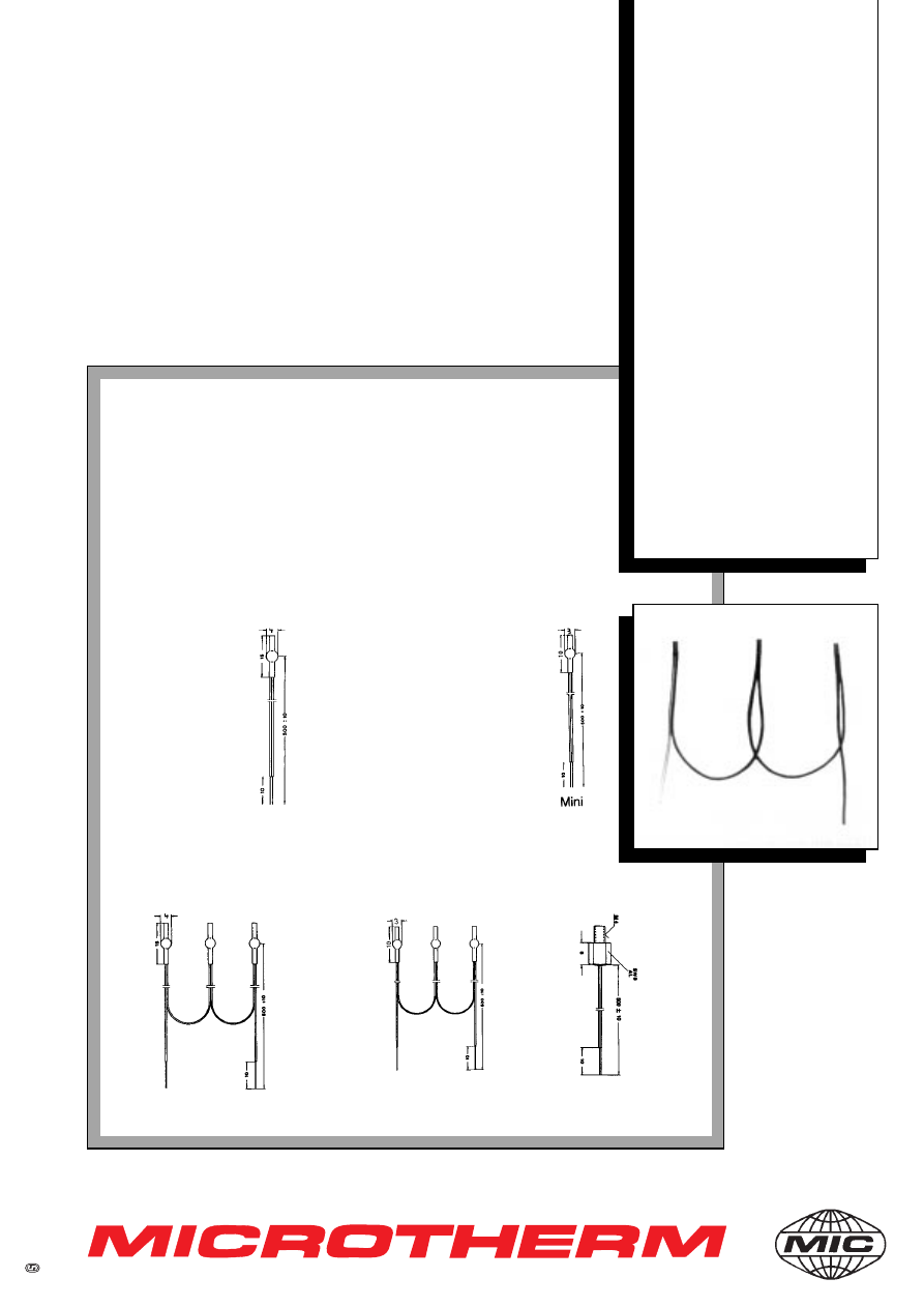
DIMENSIONS
YD 1
Single thermistor
with shrunk-sleeve
YGM 1
Mini-version
with shrunk-sleeve
YD 3
Triplet version (in series)
YGM 3
Mini-version
EF 1
Sensor
Standard
mini
threaded