background image

engineering a better life

Product Catalog  2021-07
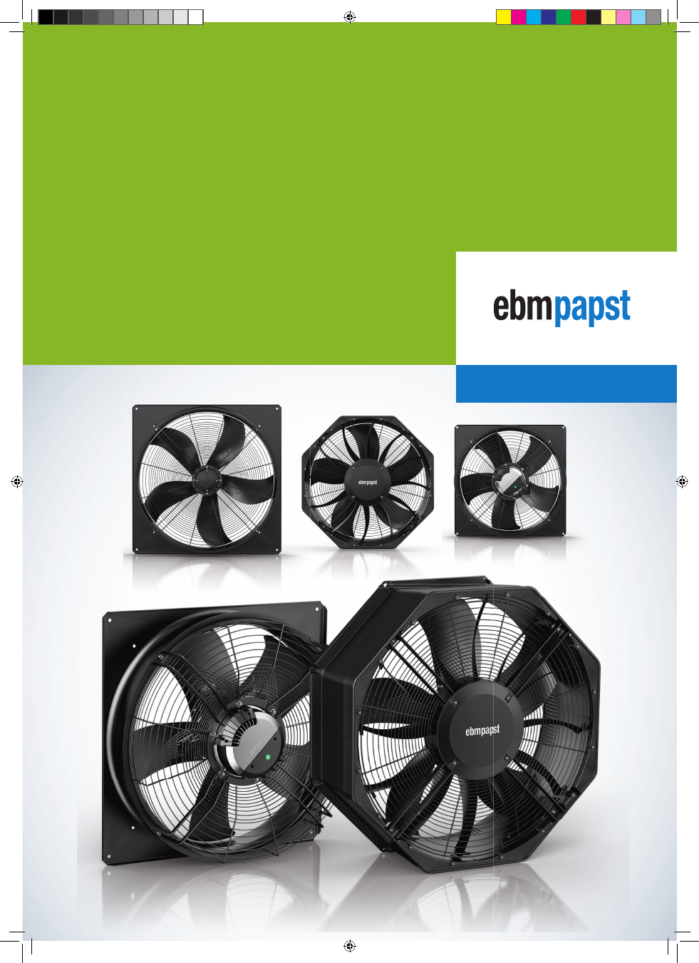
EC axial fans

AxiBlade

AxiBlade-Katalog_2021_Vorspann_US_22_07_2021_Final_.indd   1

AxiBlade-Katalog_2021_Vorspann_US_22_07_2021_Final_.indd   1

22.07.2021   12:26:25

22.07.2021   12:26:25

Product_Catalog_EC_axial_fans_AxiBlade-html.html
background image

2

Air performance range for AxiBlade 630 - 910

The graph shows the maximum air performance for each size. If less performance is required, variants with smaller motors can be used.
This saves additional costs. The right fan for every application!

910

630

710

800

5000

10000

15000

20000

25000

30000

0

2000

4000

6000

8000

10000

12000

14000

16000

18000

q

v

m³/h

cfm

p

fs

Pa

in.

 wg

100

200

300

400

0.

20

.4

0.6

0.8

1.0

1.2

1.4

1.6

1.8

Air performance range for AxiBlade

The new ebm-papst

AxiBlade 

series

AxiBlade-Katalog_2021_Vorspann_US_22_07_2021_Final_.indd   2

AxiBlade-Katalog_2021_Vorspann_US_22_07_2021_Final_.indd   2

22.07.2021   12:26:27

22.07.2021   12:26:27

Product_Catalog_EC_axial_fans_AxiBlade-html.html
background image

3

EC axial fans - AxiBlade · Edition 2021-07

engineering a better life

Page

Page

Information

4

About ebm-papst   /   GreenIntelligence
Four sizes, almost unlimited possibilities
Do we deliver the best values for each operating point ?
ebm-papst FanScout: click your way to the optim. AxiBlade
Product overview

4

6

8

AxiBlade

630 -910

10

EC axial fans - AxiBlade

630

12

EC axial fans - AxiBlade

710

16

EC axial fans - AxiBlade

800

20

EC axial fans - AxiBlade

910

48

Technology

64

Connection diagrams
Technical parameters & scope

66
70

Contacts

ebm-papst worldwide

74

www.ebmpapst.com/contact

74

Informati

on

Informati

on

EC axial fans - 

Axi

Blade · Editi

on 2

021-

07

EC axial fans - 

Axi

Blade · Editi

on 2

021-

07

Tech

nology

Tech

nology

Contacts

Contacts

EC axial fans

AxiBlade

AxiBlade-Katalog_2021_Vorspann_US_22_07_2021_Final_.indd   3

AxiBlade-Katalog_2021_Vorspann_US_22_07_2021_Final_.indd   3

22.07.2021   12:26:28

22.07.2021   12:26:28

Product_Catalog_EC_axial_fans_AxiBlade-html.html
background image

4

EC axial fans - AxiBlade · Edition 2021-07

Informati

on

Informati

on

EC axial fans - 

Axi

Blade · Edi

tion 2

021-

07

EC axial fans - 

Axi

Blade · Edi

tion 2

021-

07

Zubehör

Zubehör

Tech

nologi

e

Tech

nologi

e

Kontakte

Kontakte

About ebm-papst   /   GreenIntelligence

ebm-papst is a leader in ventilation and drive engineering technology and a much sought-after engineering partner in many industries. 

With around 20.000 different products, we have the perfect solution for practically every requirement. We believe the consistent further 

development of our highly-efficient GreenTech EC technology provides our customers with the best opportunities for the future in indust-
rial digitization. With GreenIntelligence, ebm-papst already offers intelligent networked complete solutions that are unique anywhere in 
the world today.

So much GreenIntelligence


is in the AxiBlade:


– Simple monitoring via MODBUS


Easy control via 0-10 V or MODBUS 


– Efficient operation over a wide range

Six reasons that make us the ideal partner:

Our systems expertise: 

as experts in advanced motor technology,

electronics and aerodynamics, we provide system solutions from
a single source.

Our spirit of invention: 

our 600 engineers and technicians will

develop a solution that precisely fits your needs.

Our lead in technology:

 with our EC technology and

GreenIntelligence, we combine the highest energy efficiency 
with the advantages of IoT and digital networking.

Closeness to our customers: 

at 48 sales offices worldwide.

Our standard of quality:

 our quality management is uncompromi-

sing, at every step in every process.

Our sustainable approach: 

we assume responsibility with our

energy-saving products, environmentally-friendly processes, 
and social commitment.

Why do our customers look so happy? Because when it comes to the Internet of Things and the digital transformation, we provide them 
with a clear competitive edge with GreenIntelligence for intelligent control and interconnection of fans, drives and systems to make appli-
cations more powerful, processes more efficient, businesses more successful and their customers more satisfied.

Modern, functional and reliable solutions are in high demand for 

refrigeration and air conditioning.

 GreenIntelligence supplies 

easy-to-install fan solutions with intelligent networking capabilities and a wide variety of ideas and functions that make it possible to 
exploit the great potential of digitalization right away.

GreenIntelligence.


Making Engineers Happy.

Björn

 already has a 

lot of ideas for ma-
king his refrigeration 
systems smarter.

AxiBlade-Katalog_2021_Vorspann_US_22_07_2021_Final_.indd   4

AxiBlade-Katalog_2021_Vorspann_US_22_07_2021_Final_.indd   4

22.07.2021   12:26:29

22.07.2021   12:26:29

Product_Catalog_EC_axial_fans_AxiBlade-html.html
background image

5

EC axial fans - AxiBlade · Edition 2021-07

Informati

on

Informati

on

EC axial fans - 

Axi

Blade · Editi

on 2

021-

07

EC axial fans - 

Axi

Blade · Editi

on 2

021-

07

Zubehör

Zubehör

Tech

nologi

e

Tech

nologi

e

Kontakte

Kontakte

Four sizes,

almost unlimited possibilities

The innovative AxiBlade range sets the benchmark for large axial
fans when it comes to energy efficiency and noise characteristics.

There are four sizes from 630 to 910 to choose from as well as dif-

ferent motor designs with EC technology. AxiBlades are real all-
rounders as they can be individually configured for each appli-
cation.

The large fans in sizes 800 and 910 are particularly applicable to 

refrigerating plants like evaporators or condensers. They allow

air flows up to 40.000 m³/h, with a maximum pressure range of
up to 350 Pa.

The sizes 630 and 710 are even more versatile. They are perfectly

suited to heat pumps or exhaust air FanGrid solutions, for examp-

le. Offering air flows of up to 25.000 m³/h at a maximum pressure 
range of up to 450 Pa, they open up a myriad of applications in 

ventilation, air conditioning and refrigeration technology.

Commercial evaporator

Cooling tower

Transformer station

Condenser

The highly efficient, whisper-quiet
ebm-papst axial fans convey air for
heating and cooling purposes in a
variety of different devices and systems.

Oil cooler

Process refrigeration systems

Condenser unit

Air/water heat pump

Heat pump

Exhaust FanGrid

AxiBlade-Katalog_2021_Vorspann_US_22_07_2021_Final_.indd   5

AxiBlade-Katalog_2021_Vorspann_US_22_07_2021_Final_.indd   5

22.07.2021   12:26:33

22.07.2021   12:26:33

Product_Catalog_EC_axial_fans_AxiBlade-html.html
background image

6

EC axial fans - AxiBlade · Edition 2021-07

We deliver the best values


for each operating poin

t

Informati

on

Informati

on

EC axial fans - 

Axi

Blade · Editi

on 2

021-

07

EC axial fans - 

Axi

Blade · Editi

on 2

021-

07

Zubehör

Zubehör

Technologi

e

Technologi

e

Kontakte

Kontakte

Modular design – the right solution for every pressure range.

With fans, different back pressures have to be taken into consi-
deration depending on the application and installation conditions.
There is no fan that will work with the same efficiency or noise
levels in all conditions: searching for an all-purpose unit is futile.

Air performance

The diagram shows the AxiBlade’s operating points typical in applications, for example for sizes 800 and 910. The dark areas represent high
back pressures of up to approx. 350 Pa, where the benefits of the system with the guide vanes come into full play. The light areas represent
low to medium back pressures up to approx. 200 Pa.

q

v

p

fs

Operating range 2

Operating range 1

AR

Because it is adapted to each application

With clever individual solutions

In a uniquely broad performance spectrum

However, with their modular design, the AxiBlade axial fans can
be combined with great flexibility. Components can be combined 
depending on the pressure ranges required and the fans can be
produced accordingly. There are optimized plug & play system
solutions available to suit the conditions expected for a specific
application.

AxiBlade-Katalog_2021_Vorspann_US_22_07_2021_Final_.indd   6

AxiBlade-Katalog_2021_Vorspann_US_22_07_2021_Final_.indd   6

22.07.2021   12:26:34

22.07.2021   12:26:34

Product_Catalog_EC_axial_fans_AxiBlade-html.html
background image

7

EC axial fans - AxiBlade · Edition 2021-07

ebm-papst Fan Scout

click your way to the optimum AxiBlade

Informati

on

Informati

on

EC axial fans - 

Axi

Blade · Editi

on 2

021-

07

EC axial fans - 

Axi

Blade · Editi

on 2

021-

07

Zubehör

Zubehör

Tech

nologi

e

Tech

nologi

e

Kontakte

Kontakte

Our axial fans can be configured individually for each application,
and it is important to correctly consider all the relevant aspects 
when selecting your axial fan. When making your selection, you
can rely on our experts’ many years of experience – and on our
professional fan selection software as well.

The ebm-papst FanScout has proven itself with its combination of
user friendliness and real-world measured values. Not only is the
performance of the individual fan components measured but also 
that of the fan as a complete system. The program allows you to 
quickly select the best fan for your application, to describe and
modify the operating behavior and to document the technical
specifications. During this process, factors such as air performance, 
operating time and installation space can be taken into account. 

TÜV SÜD has tested the difference between the actual measure-

ments and the data calculated using the software and assigned the 
accuracy of the calculation to the highest class.

Exact presentation of the life cycle costs:

The costs of everything from operation, procurement and installati-
on to service can be calculated over a time period that can be indi-
vidually defined. Practical: The software can be integrated into your
device’s configuration program very easily, via DLL interface.

The best part:

ebm-papst will pre-select the products that are suitable for you.
This saves you the trouble of searching through the broad product
portfolio and helps you configure your application in advance.

AxiBlade-Katalog_2021_Vorspann_US_22_07_2021_Final_.indd   7

AxiBlade-Katalog_2021_Vorspann_US_22_07_2021_Final_.indd   7

22.07.2021   12:26:34

22.07.2021   12:26:34

Product_Catalog_EC_axial_fans_AxiBlade-html.html
background image

8

EC axial fans - AxiBlade · Edition 2021-07

EC axial fans AxiBlade

630 - 800

Informati

on

Informati

on

EC axial fans - 

Axi

Blade · Edi

tion 2

021-

07

EC axial fans - 

Axi

Blade · Edi

tion 2

021-

07

Zubehör

Zubehör

Tech

nologi

e

Tech

nologi

e

Kontakte

Kontakte

Type

Nominal

voltage

range

VAC

    Axial fans

Size

on

Page

Max. 

input

power

W

EC axial fans - AxiBlade

1~200-277

630

12

410

Part number

VWA0630BSPMS

W3G630NP04H1

3~380-480

450

VWA0630BTPMS

W3G630NP04M1

3~380-480

1.150

VWA0630BTRLS

W3G630NR6301

3~380-480

3.600

VWA0630BTTPS

W3G630NU3303

3~380-480

370

VWA0710BTPMS

W3G710NP19M1

3~380-480

1.000

VWA0710BTRLS

W3G710NK6701

710

3~380-480

3.800

VWA0710BTTPS

W3G710NU3103

1~200-277

250

VWA0800BSRHS

W3G800NB8641

1~200-277

250

VWA0800BSRHS

W3G800NB8643

3~380-480

660

VWA0800BTRLS

W3G800NE5751

3~380-480

660

VWA0800BTRLS

W3G800NE5753

800

3~380-480

660

VWA0800BTRLS

W3G800KE5751

3~380-480

830

VWA0800BTRNS

W3G800KH9401

3~380-480

1.570

VWA0800BTTLS

W3G800NS2671

3~380-480

1.570

VWA0800BTTLS

W3G800NS2673

800

3~380-480

1.950

VWA0800BTTLS

W3G800KS39D1

3~380-480

VWA0800BTTPZ

W3G800NU2106

3~380-480

2.450

VWA0800BTTPS

W3G800LU2103

3~380-480

2.650

VWA0800BTTPS

W3G800KU2103

3~380-480

2.900

3~380-480

830

VWA0800BTRNS

W3G800NH9401

3~380-480

2.450

VWA0800BTTPZ

W3G800NU2108

3~380-480

2.650

3~380-480

2.900

3~380-480

3.000

VWA0800BTTPS

W3G800KU21D1

VWR0800BTTPZ

W3G800OU2305

VWA0800BTTPS

W3G800LU21D1

3~380-480

830

VWA0800BTRNS

W3G800NH9403

3~380-480

1.950

VWA0800BTTLS

W3G800KS3903

2.650

VWA0800BTTPS

W3G800LU2136

800

800

16

26

34

20

30

AxiBlade-Katalog_2021_Vorspann_US_22_07_2021_Final_.indd   8

AxiBlade-Katalog_2021_Vorspann_US_22_07_2021_Final_.indd   8

22.07.2021   12:26:35

22.07.2021   12:26:35

Product_Catalog_EC_axial_fans_AxiBlade-html.html
background image

9

EC axial fans - AxiBlade · Edition 2021-07

Subject to technical changes.

EC axial fans AxiBlade

800 - 910

Informati

on

Informati

on

EC axial fans - 

Axi

Blade · Edition 2

021-

07

EC axial fans - 

Axi

Blade · Edition 2

021-

07

Zubehör

Zubehör

Tech

nologi

e

Tech

nologi

e

Kontakte

Kontakte

Type

Nominal

voltage

range

VAC

    Axial fans

Size

on

Page

Max. 

input

power

W

EC axial fans - AxiBlade

3~380-480

800

42

3.400

Part number

VWA0800BTTRS

W3G800KV0503

3~380-480

3.500

VWA0800BTTRS

W3G800LV0503

3~380-480

3.500

VWA0800BTTRS

W3G800LV0536

3~380-480

3.500

VWA0800BTTRS

W3G800LV05D1

3~380-480

3.500

VWR0800BTTRZ

W3G800OV0506

3~380-480

4.000

VWA0800BTTRS

W3G800NV0510

3~380-480

630

VWA0910BTRNS

W3G910KH0251

3~380-480

1.770

VWA0910BTTLS

W3G910KS3503

3~380-480

1.770

VWA0910BTTLS

W3G910KS35D1

3~380-480

2.500

VWA0910BTTPS

W3G910LU2503

3~380-480

2.500

VWA0910BTTPS

W3G910LU25D1

3~380-480

2.550

VWR0910BTTPZ

W3G910OU2507

3~380-480

3.200

VWA0910BTTRS

W3G910KV1203

3~380-480

3.250

VWA0910BTTRS

W3G910LV1203

3~380-480

3.250

VWA0910BTTRS

W3G910LV1236

3~380-480

2.550

VWA0910BTTPS

W3G910KU2503

3~380-480

3.250

VWA0910BTTRS

W3G910LV12D1

3~380-480

2.550

VWA0910BTTPS

W3G910KU25D1

3~380-480

3.250

VWR0910BTTRZ

W3G910OV1205

910

910

52

58

910

48

AxiBlade-Katalog_2021_Vorspann_US_22_07_2021_Final_.indd   9

AxiBlade-Katalog_2021_Vorspann_US_22_07_2021_Final_.indd   9

22.07.2021   12:26:35

22.07.2021   12:26:35

Product_Catalog_EC_axial_fans_AxiBlade-html.html
background image

AxiBlade_08072021_AK_US_CC2020_.indd   10

AxiBlade_08072021_AK_US_CC2020_.indd   10

22.07.2021   11:37:21

22.07.2021   11:37:21

Product_Catalog_EC_axial_fans_AxiBlade-html.html
background image

engineering a better life

11

EC axial fans - AxiBlade · Edition 2021-07

Page

630

12

710

16

800

20

800

26

800

30

800

34

800

42

910

48

910

52

910

58

AxiBlade 630 - 910

EC axial fans - 

Axi

Blade · Editi

on 2

021-

07

EC axial fans - 

Axi

Blade · Editi

on 2

021-

07

AxiBlade_08072021_AK_US_CC2020_.indd   11

AxiBlade_08072021_AK_US_CC2020_.indd   11

22.07.2021   11:37:21

22.07.2021   11:37:21

Product_Catalog_EC_axial_fans_AxiBlade-html.html
background image

12

EC axial fans - AxiBlade · Edition 2021-07

2000

4000

6000

8000 10000 12000 14000 16000 18000 20000

0

2000

4000

6000

8000

10000

12000

q

v

m³/h

cfm

100

200

300

400

0.

20

.4

0.6

0.8

1

1.2

1.4

1.6

1.8

p

fs

Pa

in.

 wg

1

1

1

4

4

3

3

3

3

2

2

2

2

4

4

A

B

C

D

Material/Surface

Guard grille: Steel, coated with black plastic 

(RAL 9005)

Wallring: Sheet steel, galvanized and coated 

with black plastic (RAL 9005)

Impeller: PP plastic

Rotor: Painted black

Electronics housing: Die-cast aluminum, 

painted black, Die-cast aluminum, painted gray

Mechanical characteristics

Number of blades: 5

Direction of rotation: Clockwise, viewed toward 

rotor

Installation position: Shaft horizontal or rotor 

on bottom; rotor on top on request

Condensation drainage holes: On rotor side

Mode: S1

Motor bearing: Ball bearing

Additional Information

Information about touch current, electrical 

connection, degree of protection, insulation 

class, environmental protection class, EMC 

standards as well as standards and approvals 

can be found in the product-specifi c data 

sheets.

from page 14

Drawings

from page 66

Connection diagrams and technical equipment

from page 70

Environment and general conditions

More at

www.ebmpapst.com/worldwide www.ebmpapst.com/

Measuring conditions

Air performance measured after: ISO 5801, installation category A, in ebm-papst full nozzle without contact protection.
Suction-side noise level: LwA according to ISO 13347, LpA measured at a distance of 1 m on the fan axis.
The specifi cations apply only under the specifi ed measuring conditions and may change due to installation conditions.

In case of deviations from the standard design, the characteristic values must be checked in the installed condition!

AxiBlade 630

EC axial fans

=

η

max.

4

AxiBlade_08072021_AK_US_CC2020_.indd   12

AxiBlade_08072021_AK_US_CC2020_.indd   12

22.07.2021   11:37:23

22.07.2021   11:37:23

Product_Catalog_EC_axial_fans_AxiBlade-html.html
background image

13

EC axial fans - AxiBlade · Edition 2021-07

AxiBlade 630

Characteristic 

Curve

Operating point

Nominal voltage

Speed n

Max. Input power  P

ed

Max. Input current I

Sound power le

vel 

Lw

A

Max. back pressure

Perm. ambient  temp.

Protection class

Connection diagram

Nominal voltage range 1~ 200-277 VAC, 50/60 Hz

V

rpm

W

A

dB(A)

Pa

°C

Type

Part number

Fan type

Main 

feature

VWA0630BSPMS

W3G630NP04H1

With guard 

grille and wall 

ring

A


230 


230 


230 


230 

830 


830 


830 


830 

225 


295 


355 


410 

1.01 


1.31 


1.57 


1.80 

70 


67 


67 


71 

100  -25…+60  IP55

AB2

Nominal voltage range 3~ 380-480 VAC, 50/60 Hz

V

rpm

W

A

dB(A)

Pa

°C

Type

Part number

Fan type

Main 

feature

VWA0630BTPMS

W3G630NP04M1

With guard 

grille and wall 

ring

B


400 


400 


400 


400 

840 


840 


840 


840 

240 


318 


386 


450 

0.44 


0.55 


0.64 


0.70 

70 


67 


68 


75 

115  -40…+60  IP55

AB3

VWA0630BTRLS

W3G630NR6301

With guard 

grille and wall 

ring

C


400 


400 


400 


400 

1,260 


1,260 


1,260 


1,260 

620 


810 


982 


1,150 

0.99 


1.26 


1.52 


1.80 

80 


76 


78 


87 

240  -40…+60  IP55

AB3

VWA0630BTTPS

W3G630NU3303

With guard 

grille and wall 

ring

D


400 


400 


400 


400 

1,800 


1,800 


1,800 


1,800 

1,991 


2,570 


3,090 


3,600 

3.12 


3.96 


4.72 


5.50 

86 


85 


87 


98 

440  -40…+60  IP55

AB1

Subject to changes.

Values   set in blue are nominal data at the operating point at maximum load.

EC axial fans - 

Axi

Blade · Edi

ti

on 2

021-

07

EC axial fans - 

Axi

Blade · Edi

ti

on 2

021-

07

AxiBlade_08072021_AK_US_CC2020_.indd   13

AxiBlade_08072021_AK_US_CC2020_.indd   13

22.07.2021   11:37:23

22.07.2021   11:37:23

Product_Catalog_EC_axial_fans_AxiBlade-html.html
background image

14

EC axial fans - AxiBlade · Edition 2021-07

AxiBlade 630

A

VWA0630BSPMS


W3G630NP04H1

    EC axial fan - AxiBlade

Dimensions in mm

Pin assignment: See connection diagram
Mounting position: 

Shaft horizontal or 

rotor on bottom; rotor on top on request

Airflow direction „V“

Cable diameter min. 8 mm, max. 12 mm, tightening torque 1.8±0.3 Nm (use must be made of seal provided); 
Cable diameter min. 4 mm, max. 10 mm, tightening torque 1.8±0.3 Nm

Cable diameter min. 6 mm, max. 10 mm, tightening torque 1.8±0.3 Nm (use must be made of seal provided); 
Cable diameter min. 4 mm, max. 7 mm, tightening torque 1.8±0.3 Nm

Tightening torque 1.5 ± 0.2 Nm

B

VWA0630BTPMS


W3G630NP04M1

    EC axial fan - AxiBlade

Dimensions in mm

Pin assignment: See connection diagram
Mounting position: 

Shaft horizontal or 

rotor on bottom; rotor on top on request

Airflow direction „V“

Cable diameter min. 8 mm, max. 12 mm, tightening torque 1.8±0.3 Nm (use must be made of seal provided); 
Cable diameter min. 4 mm, max. 10 mm, tightening torque 1.8±0.3 Nm

Cable diameter min. 6 mm, max. 10 mm, tightening torque 1.8±0.3 Nm (use must be made of seal provided); 
Cable diameter min. 4 mm, max. 7 mm, tightening torque 1.8±0.3 Nm

Tightening torque 1.5 ± 0.2 Nm

AxiBlade_08072021_AK_US_CC2020_.indd   14

AxiBlade_08072021_AK_US_CC2020_.indd   14

22.07.2021   11:37:27

22.07.2021   11:37:27

Product_Catalog_EC_axial_fans_AxiBlade-html.html
background image

15

EC axial fans - AxiBlade · Edition 2021-07

AxiBlade 630

C

VWA0630BTRLS


W3G630NR6301

    EC axial fan - AxiBlade

Dimensions in mm

Pin assignment: See connection diagram
Mounting position: 

Shaft horizontal or 

rotor on bottom; rotor on top on request

Airflow direction „V“

Cable diameter min. 8 mm, max. 12 mm, tightening torque 1.8±0.3 Nm (use must be made of seal provided); 
Cable diameter min. 4 mm, max. 10 mm, tightening torque 1.8±0.3 Nm

Cable diameter min. 6 mm, max. 10 mm, tightening torque 1.8±0.3 Nm (use must be made of seal provided); 
Cable diameter min. 4 mm, max. 7 mm, tightening torque 1.8±0.3 Nm

Tightening torque 1.5 ± 0.2 Nm

D

VWA0630BTTPS


W3G630NU3303

    EC axial fan - AxiBlade

Dimensions in mm

Pin assignment: See connection diagram
Mounting position: 

Shaft horizontal or 

rotor on bottom; rotor on top on request

Airflow direction „V“

Cable diameter min. 4 mm, max. 10 mm, tightening torque 4 ± 0.6 Nm

Tightening torque 1.5 ± 0.2 Nm

EC axial fans - 

Axi

Blade · Edi

ti

on 2

021-

07

EC axial fans - 

Axi

Blade · Edi

ti

on 2

021-

07

AxiBlade_08072021_AK_US_CC2020_.indd   15

AxiBlade_08072021_AK_US_CC2020_.indd   15

22.07.2021   11:37:31

22.07.2021   11:37:31

Product_Catalog_EC_axial_fans_AxiBlade-html.html
background image

16

EC axial fans - AxiBlade · Edition 2021-07

50

100

150

200

250

300

350

400

0.

20

.4

0.6

0.8

1

1.2

1.4

1.6

q

v

p

fs

Pa

in.

 wg

5000

10000

15000

20000

m³/h

0

2000

4000

6000

8000

10000

12000

14000

cfm

1

2

3

4

1

2

3

4

1

2

3

4

A

B

C

Material/Surface

Guard grille: Steel, coated with black plastic 

(RAL 9005)

Wallring: Sheet steel, galvanized and coated 

with black plastic (RAL 9005)

Impeller: PP plastic

Rotor: Painted black

Electronics housing: Die-cast aluminum, 

painted black, Die-cast aluminum, painted gray

Mechanical characteristics

Number of blades: 5

Direction of rotation: Clockwise, viewed toward 

rotor

Installation position: Shaft horizontal or rotor 

on bottom; rotor on top on request

Condensation drainage holes: On rotor side

Mode: S1

Motor bearing: Ball bearing

Additional Information

Information about touch current, electrical 

connection, degree of protection, insulation 

class, environmental protection class, EMC 

standards as well as standards and approvals 

can be found in the product-specifi c data 

sheets.

from page 18

Drawings

from page 66

Connection diagrams and technical equipment

from page 70

Environment and general conditions

More at

www.ebmpapst.com/worldwide www.ebmpapst.com/

Measuring conditions

Air performance measured after: ISO 5801, installation category A, in ebm-papst full nozzle without contact protection.
Suction-side noise level: LwA according to ISO 13347, LpA measured at a distance of 1 m on the fan axis.
The specifi cations apply only under the specifi ed measuring conditions and may change due to installation conditions.

In case of deviations from the standard design, the characteristic values must be checked in the installed condition!

AxiBlade 710

EC axial fans

=

η

max.

4

AxiBlade_08072021_AK_US_CC2020_.indd   16

AxiBlade_08072021_AK_US_CC2020_.indd   16

22.07.2021   11:37:34

22.07.2021   11:37:34

Product_Catalog_EC_axial_fans_AxiBlade-html.html
background image

17

EC axial fans - AxiBlade · Edition 2021-07

AxiBlade 710

Characteristic 

Curve

Operating point

Nominal voltage

Speed n

Max. Input power  P

ed

Max. Input current I

Sound power le

vel 

Lw

A

Max. back pressure

Perm. ambient  temp.

Protection class

Connection diagram

Nominal voltage range 3~ 380-480 VAC, 50/60 Hz


V

rpm

W

A

dB(A)

Pa

°C

Type

Part number

Fan type

Main 

feature

VWA0710BTPMS

W3G710NP19M1

With guard 

grille and wall 

ring


A


400 


400 


400 


400 

720 


720 


720 


720 

195 


264 


328 


370 

0.39 


0.48 


0.56 


0.65 

67 


65 


67 


75 

100  -40…+60  IP55

AB3

VWA0710BTRLS

W3G710NK6701

With guard 

grille and wall 

ring


B


400 


400 


400 


400 

1,100 


1,100 


1,100 


1,100 

551 


729 


884 


1,000 

0.89 


1.14 


1.37 


1.50 

77 


74 


77 


86 

200  -40…+60  IP55

AB3

VWA0710BTTPS

W3G710NU3103

With guard 

grille and wall 

ring


C


400 


400 


400 


400 

1,680 


1,680 


1,680 


1,680 

2,150 


2,780 


3,366 


3,800 

3.35 


4.28 


5.15 


5.80 

86 


85 


86 


96 

420  -40…+60  IP55

AB1

Subject to changes.

Values   set in blue are nominal data at the operating point at maximum load.

EC axial fans - 

Axi

Blade · Edi

ti

on 2

021-

07

EC axial fans - 

Axi

Blade · Edi

ti

on 2

021-

07

AxiBlade_08072021_AK_US_CC2020_.indd   17

AxiBlade_08072021_AK_US_CC2020_.indd   17

22.07.2021   11:37:34

22.07.2021   11:37:34

Product_Catalog_EC_axial_fans_AxiBlade-html.html
background image

18

EC axial fans - AxiBlade · Edition 2021-07

AxiBlade 710

A

VWA0710BTPMS


W3G710NP19M1

    EC axial fan - AxiBlade

Dimensions in mm

Pin assignment: See connection diagram
Mounting position: 

Shaft horizontal or 

rotor on bottom; rotor on top on request

Airflow direction „V“

Cable diameter min. 8 mm, max. 12 mm, tightening torque 1.8±0.3 Nm (use must be made of seal provided); 
Cable diameter min. 4 mm, max. 10 mm, tightening torque 1.8±0.3 Nm

Cable diameter min. 6 mm, max. 10 mm, tightening torque 1.8±0.3 Nm (use must be made of seal provided); 
Cable diameter min. 4 mm, max. 7 mm, tightening torque 1.8±0.3 Nm

Tightening torque 1.5 ± 0.2 Nm

B

VWA0710BTRLS


W3G710NK6701

    EC axial fan - AxiBlade

Dimensions in mm

Pin assignment: See connection diagram
Mounting position: 

Shaft horizontal or 

rotor on bottom; rotor on top on request

Airflow direction „V“

Cable diameter min. 8 mm, max. 12 mm, tightening torque 1.8±0.3 Nm (use must be made of seal provided); 
Cable diameter min. 4 mm, max. 10 mm, tightening torque 1.8±0.3 Nm

Cable diameter min. 6 mm, max. 10 mm, tightening torque 1.8±0.3 Nm (use must be made of seal provided); 
Cable diameter min. 4 mm, max. 7 mm, tightening torque 1.8±0.3 Nm

Tightening torque 1.5 ± 0.2 Nm

AxiBlade_08072021_AK_US_CC2020_.indd   18

AxiBlade_08072021_AK_US_CC2020_.indd   18

22.07.2021   11:37:37

22.07.2021   11:37:37

Product_Catalog_EC_axial_fans_AxiBlade-html.html
background image

19

EC axial fans - AxiBlade · Edition 2021-07

AxiBlade 710

C

VWA0710BTTPS


W3G710NU3103

    EC axial fan - AxiBlade

Dimensions in mm

Pin assignment: See connection diagram
Mounting position: 

Shaft horizontal or 

rotor on bottom; rotor on top on request

Airflow direction „V“

Tightening torque 1.5 ± 0.2 Nm

Cable diameter min. 4 mm, max. 10 mm, tightening torque 4 ± 0.6 Nm

EC axial fans - 

Axi

Blade · Edi

ti

on 2

021-

07

EC axial fans - 

Axi

Blade · Edi

ti

on 2

021-

07

AxiBlade_08072021_AK_US_CC2020_.indd   19

AxiBlade_08072021_AK_US_CC2020_.indd   19

22.07.2021   11:37:39

22.07.2021   11:37:39

Product_Catalog_EC_axial_fans_AxiBlade-html.html
background image

20

EC axial fans - AxiBlade · Edition 2021-07

20

40

60

80

100

120

0.

10

.2

0.3

0.4

0.5

q

v

p

fs

Pa

in.

 wg

2000

4000

6000

8000

10000

12000

14000

16000

m³/h

0

2000

4000

6000

8000

10000

cfm

A

B

C

1

2

3

4

1

2

3

4

1

2

3

4

Material/Surface

Guard grille: Steel, coated with black plastic 

(RAL 9005)

Wallring: PP plastic

Impeller: PP plastic

Rotor: Painted black

Electronics housing: Die-cast aluminum, 

painted black

Mechanical characteristics

Number of blades: 5

Direction of rotation: Clockwise, viewed toward 

rotor

Installation position: Shaft horizontal or rotor 

on bottom; rotor on top on request, See fi tting 

instructions

Condensation drainage holes: On rotor side

Mode: S1

Motor bearing: Ball bearing with low-

temperature lubricant

Additional Information

Information about touch current, electrical 

connection, degree of protection, insulation 

class, environmental protection class, EMC 

standards as well as standards and approvals 

can be found in the product-specifi c data 

sheets.

from page 22

Drawings

from page 66

Connection diagrams and technical equipment

from page 70

Environment and general conditions

More at

www.ebmpapst.com/worldwide www.ebmpapst.com/

Measuring conditions

Air performance measured after: ISO 5801, installation category A, in ebm-papst full nozzle without contact protection.
Suction-side noise level: LwA according to ISO 13347, LpA measured at a distance of 1 m on the fan axis.
The specifi cations apply only under the specifi ed measuring conditions and may change due to installation conditions.

In case of deviations from the standard design, the characteristic values must be checked in the installed condition!

AxiBlade 800

EC axial fans

=

η

max.

4

AxiBlade_08072021_AK_US_CC2020_.indd   20

AxiBlade_08072021_AK_US_CC2020_.indd   20

22.07.2021   11:37:41

22.07.2021   11:37:41

Product_Catalog_EC_axial_fans_AxiBlade-html.html
background image

21

EC axial fans - AxiBlade · Edition 2021-07

AxiBlade 800

Characteristic 

Curve

Operating point

Nominal voltage

Speed n

Max. Input power  P

ed

Max. Input current I

Sound power le

vel 

Lw

A

Max. back pressure

Perm. ambient  temp.

Protection class

Connection diagram

Nominal voltage range 1~ 200-277 VAC, 50/60 Hz


V

rpm

W

A

dB(A)

Pa

°C

Type

Part number

Fan type

Main 

feature

VWA0800BSRHS

W3G800NB8641

AxiCool Stan-

dard


A


230 


230 


230 


230 

520 


520 


520 


520 

170 


204 


232 


250 

0.75 


0.90 


1.02 


1.10 

59 


60 


60 


69 

60 

-40…+40  IP55

AB4

VWA0800BSRHS

W3G800NB8643

AxiCool High-

End


Nominal voltage range 3~ 380-480 VAC, 50/60 Hz


V

rpm

W

A

dB(A)

Pa

°C

Type

Part number

Fan type

Main 

feature

VWA0800BTRLS

W3G800NE5751

AxiCool Stan-

dard


B


400 


400 


400 


400 

720 


720 


720 


720 

404 


487 


571 


660 

0.66 


0.78 


0.90 


1.00 

70 


69 


70 


77 

110  -40…+40  IP55

AB5

VWA0800BTRLS

W3G800NE5753

AxiCool High-

End


VWA0800BTRNS

W3G800NH9401

AxiCool Stan-

dard


C


400 


400 


400 


400 

780 


780 


780 


780 

537 


653 


744 


830 

0.86 


1.03 


1.16 


1.29 

71 


70 


70 


83 

135  -40…+40  IP55

AB5

VWA0800BTRNS

W3G800NH9403

AxiCool High-

End


Subject to changes.

Values   set in blue are nominal data at the operating point at maximum load.

EC axial fans - 

Axi

Blade · Edi

ti

on 2

021-

07

EC axial fans - 

Axi

Blade · Edi

ti

on 2

021-

07

AxiBlade_08072021_AK_US_CC2020_.indd   21

AxiBlade_08072021_AK_US_CC2020_.indd   21

22.07.2021   11:37:41

22.07.2021   11:37:41

Product_Catalog_EC_axial_fans_AxiBlade-html.html
background image

22

EC axial fans - AxiBlade · Edition 2021-07

AxiBlade 800

A

VWA0800BSRHS


W3G800NB8641

    EC axial fan - AxiBlade

Dimensions in mm

Pin assignment: See connection diagram
Mounting position: 

Shaft horizontal or 

rotor on bottom; rotor on top on request


Airflow direction „V“

Cable PVC AWG18, 5x crimped ferrules

Cable PVC AWG22, 5x crimped ferrules

Mounting holes for FlowGrid

A

VWA0800BSRHS


W3G800NB8643

    EC axial fan - AxiBlade

Dimensions in mm

Pin assignment: See connection diagram
Mounting position: 

Shaft horizontal or 

rotor on bottom; rotor on top on request


Airflow direction „V“

Cable PVC AWG18, 5x crimped ferrules

Cable PVC AWG22, 5x crimped ferrules

Mounting holes for FlowGrid

AxiBlade_08072021_AK_US_CC2020_.indd   22

AxiBlade_08072021_AK_US_CC2020_.indd   22

22.07.2021   11:37:46

22.07.2021   11:37:46

Product_Catalog_EC_axial_fans_AxiBlade-html.html
background image

23

EC axial fans - AxiBlade · Edition 2021-07

AxiBlade 800

B

VWA0800BTRLS


W3G800NE5751

    EC axial fan - AxiBlade

Dimensions in mm

Pin assignment: See connection diagram
Mounting position: 

See product specific 

data sheets

Airflow direction „V“

Cable PVC AWG18, 6x crimped ferrules

Cable PVC AWG22, 5x crimped ferrules

Mounting holes for FlowGrid

B

VWA0800BTRLS


W3G800NE5753

    EC axial fan - AxiBlade

Dimensions in mm

Pin assignment: See connection diagram
Mounting position: 

See product specific 

data sheets

Airflow direction „V“

Cable PVC AWG18, 6x crimped ferrules

Cable PVC AWG22, 5x crimped ferrules

Mounting holes for FlowGrid

EC axial fans - 

Axi

Blade · Edi

ti

on 2

021-

07

EC axial fans - 

Axi

Blade · Edi

ti

on 2

021-

07

AxiBlade_08072021_AK_US_CC2020_.indd   23

AxiBlade_08072021_AK_US_CC2020_.indd   23

22.07.2021   11:37:52

22.07.2021   11:37:52

Product_Catalog_EC_axial_fans_AxiBlade-html.html
background image

24

EC axial fans - AxiBlade · Edition 2021-07

AxiBlade 800

C

VWA0800BTRNS


W3G800NH9401

    EC axial fan - AxiBlade

Dimensions in mm

Pin assignment: See connection diagram
Mounting position: 

See product specific 

data sheets

Airflow direction „V“

Cable PVC AWG18, 6x crimped ferrules

Cable PVC AWG22, 5x crimped ferrules

Mounting holes for FlowGrid

C

VWA0800BTRNS


W3G800NH9403

    EC axial fan - AxiBlade

Dimensions in mm

Pin assignment: See connection diagram
Mounting position: 

Shaft horizontal or 

rotor on bottom; rotor on top on request


Airflow direction „V“

Cable PVC AWG18, 6x crimped ferrules

Cable PVC AWG22, 5x crimped ferrules

Mounting holes for FlowGrid

AxiBlade_08072021_AK_US_CC2020_.indd   24

AxiBlade_08072021_AK_US_CC2020_.indd   24

22.07.2021   11:37:57

22.07.2021   11:37:57

Product_Catalog_EC_axial_fans_AxiBlade-html.html
background image

25

EC axial fans - AxiBlade · Edition 2021-07

AxiBlade 800

EC axial fans - 

Axi

Blade · Edi

ti

on 2

021-

07

EC axial fans - 

Axi

Blade · Edi

ti

on 2

021-

07

AxiBlade_08072021_AK_US_CC2020_.indd   25

AxiBlade_08072021_AK_US_CC2020_.indd   25

22.07.2021   11:37:57

22.07.2021   11:37:57

Product_Catalog_EC_axial_fans_AxiBlade-html.html
background image

26

EC axial fans - AxiBlade · Edition 2021-07

20

40

60

80

100

120

0.

10

.2

0.3

0.4

0.5

q

v

p

fs

Pa

in.

 wg

2000

4000

6000

8000

10000

12000

14000

16000

0

2000

4000

6000

8000

10000

m³/h

cfm

1

2

3

4

1

2

3

4

A

B

Material/Surface

Guard grille: Steel, coated with black plastic 

(RAL 9005)

Wallring: Sheet steel, galvanized and coated 

with black plastic (RAL 9005)

Rotor: Painted black

Electronics housing: Die-cast aluminum, 

painted black

Mechanical characteristics

Number of blades: 5

Direction of rotation: Clockwise, viewed toward 

rotor

Installation position: Shaft horizontal or rotor 

on bottom; rotor on top on request

Condensation drainage holes: On rotor side

Mode: S1

Motor bearing: Ball bearing

Additional Information

Information about touch current, electrical 

connection, degree of protection, insulation 

class, environmental protection class, EMC 

standards as well as standards and approvals 

can be found in the product-specifi c data 

sheets.

from page 28

Drawings

from page 66

Connection diagrams and technical equipment

from page 70

Environment and general conditions

More at

www.ebmpapst.com/worldwide www.ebmpapst.com/

Measuring conditions

Air performance measured after: ISO 5801, installation category A, in ebm-papst full nozzle without contact protection.
Suction-side noise level: LwA according to ISO 13347, LpA measured at a distance of 1 m on the fan axis.
The specifi cations apply only under the specifi ed measuring conditions and may change due to installation conditions.

In case of deviations from the standard design, the characteristic values must be checked in the installed condition!

AxiBlade 800

EC axial fans

=

η

max.

4

AxiBlade_08072021_AK_US_CC2020_.indd   26

AxiBlade_08072021_AK_US_CC2020_.indd   26

22.07.2021   11:37:59

22.07.2021   11:37:59

Product_Catalog_EC_axial_fans_AxiBlade-html.html
background image

27

EC axial fans - AxiBlade · Edition 2021-07

AxiBlade 800

Characteristic 

Curve

Operating point

Nominal voltage

Speed n

Max. Input power  P

ed

Max. Input current I

Sound power le

vel 

Lw

A

Max. back pressure

Perm. ambient  temp.

Protection class

Connection diagram

Nominal voltage range 3~ 380-480 VAC, 50/60 Hz


V

rpm

W

A

dB(A)

Pa

°C

Type

Part number

Fan type

Main 

feature

VWA0800BTRLS

W3G800KE5751

With guard 

grille and wall 

ring


A


400 


400 


400 


400 

720 


720 


720 


720 

381 


484 


568 


660 

0.63 


0.78 


0.90 


1.00 

69 


67 


67 


70 

95 

-40…+60  IP55

AB3

VWA0800BTRNS

W3G800KH9401

With guard 

grille and wall 

ring


B


400 


400 


400 


400 

780 


780 


780 


780 

494 


614 


721 


830 

0.80 


0.97 


1.13 


1.30 

69 


69 


69 


75 

120  -40…+60  IP55

AB3

Subject to changes.

Values   set in blue are nominal data at the operating point at maximum load.

EC axial fans - 

Axi

Blade · Edi

ti

on 2

021-

07

EC axial fans - 

Axi

Blade · Edi

ti

on 2

021-

07

AxiBlade_08072021_AK_US_CC2020_.indd   27

AxiBlade_08072021_AK_US_CC2020_.indd   27

22.07.2021   11:37:59

22.07.2021   11:37:59

Product_Catalog_EC_axial_fans_AxiBlade-html.html
background image

28

EC axial fans - AxiBlade · Edition 2021-07

AxiBlade 800

A

VWA0800BTRLS


W3G800KE5751

    EC axial fan - AxiBlade

Dimensions in mm

Pin assignment: See connection diagram
Mounting position: 

Shaft horizontal or 

rotor on bottom; rotor on top on request

Airflow direction „V“

Cable diameter min. 8 mm, max. 12 mm, tightening torque 1.8±0.3 Nm (use must be made of seal provided); 
Cable diameter min. 4 mm, max. 10 mm, tightening torque 1.8±0.3 Nm

Cable diameter min. 6 mm, max. 10 mm, tightening torque 1.8±0.3 Nm (use must be made of seal provided); 
Cable diameter min. 4 mm, max. 7 mm, tightening torque 1.8±0.3 Nm

Tightening torque 1.5 ± 0.2 Nm

Mounting holes for FlowGrid

B

VWA0800BTRNS


W3G800KH9401

    EC axial fan - AxiBlade

Dimensions in mm

Pin assignment: See connection diagram
Mounting position: 

Shaft horizontal or 

rotor on bottom; rotor on top on request

Airflow direction „V“

Cable diameter min. 8 mm, max. 12 mm, tightening torque 1.8±0.3 Nm (use must be made of seal provided); 
Cable diameter min. 4 mm, max. 10 mm, tightening torque 1.8±0.3 Nm

Cable diameter min. 6 mm, max. 10 mm, tightening torque 1.8±0.3 Nm (use must be made of seal provided); 
Cable diameter min. 4 mm, max. 7 mm, tightening torque 1.8±0.3 Nm

Tightening torque 1.5 ± 0.2 Nm

Attachment holes for FlowGrid 80000-2-2957 (not included in scope of delivery)

AxiBlade_08072021_AK_US_CC2020_.indd   28

AxiBlade_08072021_AK_US_CC2020_.indd   28

22.07.2021   11:38:02

22.07.2021   11:38:02

Product_Catalog_EC_axial_fans_AxiBlade-html.html
background image

29

EC axial fans - AxiBlade · Edition 2021-07

AxiBlade 800

EC axial fans - 

Axi

Blade · Edi

ti

on 2

021-

07

EC axial fans - 

Axi

Blade · Edi

ti

on 2

021-

07

AxiBlade_08072021_AK_US_CC2020_.indd   29

AxiBlade_08072021_AK_US_CC2020_.indd   29

22.07.2021   11:38:03

22.07.2021   11:38:03

Product_Catalog_EC_axial_fans_AxiBlade-html.html
background image

30

EC axial fans - AxiBlade · Edition 2021-07

5000

10000

15000

20000

25000

50

100

150

200

250

0.

20

.4

0.6

0.8

1

q

v

m³/h

p

fs

Pa

in. wg

0

2000

4000

6000

8000

10000

12000

14000

cfm

1

2

3

4

1

2

3

4

A

B

Material/Surface

Guard grille: Steel, coated with black plastic 

(RAL 9005)

Wallring: PP plastic

Rotor: Painted black

Electronics housing: Die-cast aluminum, 

painted black, Die-cast aluminum, painted gray

Mechanical characteristics

Number of blades: 5

Direction of rotation: Clockwise, viewed toward 

rotor

Installation position: See fi tting instructions

Condensation drainage holes: On rotor side

Mode: S1

Motor bearing: Ball bearing with low-

temperature lubricant, Ball bearing

Additional Information

Information about touch current, electrical 

connection, degree of protection, insulation 

class, environmental protection class, EMC 

standards as well as standards and approvals 

can be found in the product-specifi c data 

sheets.

from page 32

Drawings

from page 66

Connection diagrams and technical equipment

from page 70

Environment and general conditions

More at

www.ebmpapst.com/worldwide www.ebmpapst.com/

Measuring conditions

Air performance measured after: ISO 5801, installation category A, in ebm-papst full nozzle without contact protection.
Suction-side noise level: LwA according to ISO 13347, LpA measured at a distance of 1 m on the fan axis.
The specifi cations apply only under the specifi ed measuring conditions and may change due to installation conditions.

In case of deviations from the standard design, the characteristic values must be checked in the installed condition!

AxiBlade 800

EC axial fans

=

η

max.

4

AxiBlade_08072021_AK_US_CC2020_.indd   30

AxiBlade_08072021_AK_US_CC2020_.indd   30

22.07.2021   11:38:04

22.07.2021   11:38:04

Product_Catalog_EC_axial_fans_AxiBlade-html.html
background image

31

EC axial fans - AxiBlade · Edition 2021-07

AxiBlade 800

Characteristic 

Curve

Operating point

Nominal voltage

Speed n

Max. Input power  P

ed

Max. Input current I

Sound power le

vel 

Lw

A

Max. back pressure

Perm. ambient  temp.

Protection class

Connection diagram

Nominal voltage range 3~ 380-480 VAC, 50/60 Hz


V

rpm

W

A

dB(A)

Pa

°C

Type

Part number

Fan type

Main 

feature

VWA0800BTTLS

W3G800NS2671

AxiCool Stan-

dard


A


400 


400 


400 


400 

930 


930 


930 


930 

1,179 


1,365 


1,526 


1,570 

1.93 


2.19 


2.43 


2.50 

77 


76 


79 


86 

190  -40…+40  IP55

AB6

VWA0800BTTLS

W3G800NS2673

AxiCool High-

End


VWA0800BTTPZ

W3G800NU2108

AxiCool Stan-

dard


B


400 


400 


400 


400 

1,080 


1,080 


1,080 


1,080 

1,794 


2,089 


2,349 


2,450 

2.83 


3.26 


3.64 


3.80 

81 


80 


83 


93 

270  -40…+60  IP55

AB1

Subject to changes.

Values   set in blue are nominal data at the operating point at maximum load.

EC axial fans - 

Axi

Blade · Edi

ti

on 2

021-

07

EC axial fans - 

Axi

Blade · Edi

ti

on 2

021-

07

AxiBlade_08072021_AK_US_CC2020_.indd   31

AxiBlade_08072021_AK_US_CC2020_.indd   31

22.07.2021   11:38:05

22.07.2021   11:38:05

Product_Catalog_EC_axial_fans_AxiBlade-html.html
background image

32

EC axial fans - AxiBlade · Edition 2021-07

AxiBlade 800

A

VWA0800BTTLS


W3G800NS2671

    EC axial fan - AxiBlade

Dimensions in mm

Pin assignment: See connection diagram
Mounting position: 

See product specific 

data sheets

Airflow direction „V“

Cable silicone 8x0.5 mm², 8x crimped ferrules

Cable silicone 4G 1.5 mm², 4x crimped ferrules

Mounting holes for FlowGrid

A

VWA0800BTTLS


W3G800NS2673

    EC axial fan - AxiBlade

Dimensions in mm

Pin assignment: See connection diagram
Mounting position: 

See product specific 

data sheets

Airflow direction „V“

Cable silicone 8x0.5 mm², 8x crimped ferrules

Cable silicone 4G 1.5 mm², 4x crimped ferrules

Mounting holes for FlowGrid

AxiBlade_08072021_AK_US_CC2020_.indd   32

AxiBlade_08072021_AK_US_CC2020_.indd   32

22.07.2021   11:38:09

22.07.2021   11:38:09

Product_Catalog_EC_axial_fans_AxiBlade-html.html
background image

33

EC axial fans - AxiBlade · Edition 2021-07

AxiBlade 800

B

VWA0800BTTPZ


W3G800NU2108

    EC axial fan - AxiBlade

Dimensions in mm

Pin assignment: See connection diagram
Mounting position: 

See product specific 

data sheets

Airflow direction „V“

Cable silicone 8x0.5 mm²
8x wire-end ferrule

Cable silicone 4G 1.5 mm²

Mounting holes for FlowGrid

EC axial fans - 

Axi

Blade · Edi

ti

on 2

021-

07

EC axial fans - 

Axi

Blade · Edi

ti

on 2

021-

07

AxiBlade_08072021_AK_US_CC2020_.indd   33

AxiBlade_08072021_AK_US_CC2020_.indd   33

22.07.2021   11:38:12

22.07.2021   11:38:12

Product_Catalog_EC_axial_fans_AxiBlade-html.html
background image

34

EC axial fans - AxiBlade · Edition 2021-07

5000

10000

15000

20000

25000

30000

0

2000

4000

6000

8000

10000

14000

16000

18000

50

100

150

200

250

0.

20

.4

0.6

0.8

1

q

v

m³/h

cfm

p

fs

Pa

in.

 wg

12000

1

2

3

4

3

4

4

1

2

3

4

1

2

3

4

1

2

2

E

A

B

D

C

Material/Surface

Guard grille: Steel, coated with black plastic 

(RAL 9005)

Wallring: Sheet steel, galvanized and coated 

with black plastic (RAL 9005), PP plastic

Impeller: PP plastic

Rotor: Painted black

Electronics housing: Die-cast aluminum, 

painted gray

Mechanical characteristics

Number of blades: 5

Direction of rotation: Clockwise, viewed toward 

rotor

Installation position: Shaft horizontal or rotor 

on bottom; rotor on top on request, See fi tting 

instructions

Condensation drainage holes: On rotor side

Mode: S1

Motor bearing: Ball bearing

Additional Information

Information about touch current, electrical 

connection, degree of protection, insulation 

class, environmental protection class, EMC 

standards as well as standards and approvals 

can be found in the product-specifi c data 

sheets.

from page 36

Drawings

from page 66

Connection diagrams and technical equipment

from page 70

Environment and general conditions

More at

www.ebmpapst.com/worldwide www.ebmpapst.com/

Measuring conditions

Air performance measured after: ISO 5801, installation category A, in ebm-papst full nozzle without contact protection.
Suction-side noise level: LwA according to ISO 13347, LpA measured at a distance of 1 m on the fan axis.
The specifi cations apply only under the specifi ed measuring conditions and may change due to installation conditions.

In case of deviations from the standard design, the characteristic values must be checked in the installed condition!

AxiBlade 800

EC axial fans

=

η

max.

4

AxiBlade_08072021_AK_US_CC2020_.indd   34

AxiBlade_08072021_AK_US_CC2020_.indd   34

22.07.2021   11:38:14

22.07.2021   11:38:14

Product_Catalog_EC_axial_fans_AxiBlade-html.html
background image

35

EC axial fans - AxiBlade · Edition 2021-07

AxiBlade 800

Characteristic 

Curve

Operating point

Nominal voltage

Speed n

Max. Input power  P

ed

Max. Input current I

Sound power le

vel 

Lw

A

Max. back pressure

Perm. ambient  temp.

Protection class

Connection diagram

Nominal voltage range 3~ 380-480 VAC, 50/60 Hz


V

rpm

W

A

dB(A)

Pa

°C

Type

Part number

Fan type

Main 

feature

VWA0800BTTLS

W3G800KS3903

With guard 

grille and wall 

ring


A


400 


400 


400 


400 

940 


940 


940 


940 

1,166 


1,457 


1,667 


1,950 

1.93 


2.35 


2.65 


3.10 

76 


74 


76 


86 

220  -40…+60  IP55

AB1

VWA0800BTTLS

W3G800KS39D1

With guard 

grille and wall 

ring


VWA0800BTTPZ

W3G800NU2106

AxiCool with 

wall ring


B


400 


400 


400 


400 

1,080 


1,080 


1,080 


1,080 

1,794 


2,089 


2,349 


2,450 

2.83 


3.26 


3.64 


3.80 

81 


80 


83 


93 

270  -40…+60  IP55

AB1

VWA0800BTTPS

W3G800LU2103

With guard 

grille and wall 

ring


C


400 


400 


400 


400 

1,090 


1,090 


1,090 


1,090 

1,835 


2,188 


2,454 


2,650 

2.89 


3.41 


3.80 


4.00 

80 


79 


82 


91 

290  -40…+60  IP55

AB1

VWA0800BTTPS

W3G800LU2136

With guard 

grille and wall 

ring


VWA0800BTTPS

W3G800LU21D1

With guard 

grille and wall 

ring


VWA0800BTTPS

W3G800KU2103

With guard 

grille and wall 

ring


D


400 


400 


400 


400 

1,080 


1,080 


1,080 


1,080 

1,776 


2,168 


2,515 


2,900 

2.80 


3.38 


3.89 


4.40 

80 


78 


81 


92 

300  -40…+60  IP55

AB1

VWA0800BTTPS

W3G800KU21D1

With guard 

grille and wall 

ring


VWR0800BTTPZ

W3G800OU2305

With guard 

grille and wall 

ring


E


400 


400 


400 


400 

1,250 


1,225 


1,175 


1,150 

2,775 


3,000 


3,000 


3,000 

4.23 


4.50 


4.50 


4.50 

89 


87 


85 


92 

300  -40…+40  IP55

AB1

Subject to changes.

Values   set in blue are nominal data at the operating point at maximum load.

EC axial fans - 

Axi

Blade · Edi

ti

on 2

021-

07

EC axial fans - 

Axi

Blade · Edi

ti

on 2

021-

07

AxiBlade_08072021_AK_US_CC2020_.indd   35

AxiBlade_08072021_AK_US_CC2020_.indd   35

22.07.2021   11:38:15

22.07.2021   11:38:15

Product_Catalog_EC_axial_fans_AxiBlade-html.html
background image

36

EC axial fans - AxiBlade · Edition 2021-07

AxiBlade 800

A

VWA0800BTTLS


W3G800KS3903

    EC axial fan - AxiBlade

Dimensions in mm

Pin assignment: See connection diagram
Mounting position: 

Shaft horizontal or 

rotor on bottom; rotor on top on request

Airflow direction „V“

Cable diameter min. 4 mm, max. 10 mm, tightening torque 4 ± 0.6 Nm

Tightening torque 1.5 ± 0.2 Nm

Attachment holes for FlowGrid (80000-2-2957 not included in scope of delivery)

A

VWA0800BTTLS


W3G800KS39D1

    EC axial fan - AxiBlade

Dimensions in mm

Pin assignment: See connection diagram
Mounting position: 

Shaft horizontal or 

rotor on bottom; rotor on top on request

Airflow direction „V“

Cable diameter min. 6 mm, max. 12 mm, tightening torque 4 ± 0.6 Nm

Tightening torque 3.5 ± 0.5 Nm

Mounting holes for FlowGrid

AxiBlade_08072021_AK_US_CC2020_.indd   36

AxiBlade_08072021_AK_US_CC2020_.indd   36

22.07.2021   11:38:18

22.07.2021   11:38:18

Product_Catalog_EC_axial_fans_AxiBlade-html.html
background image

37

EC axial fans - AxiBlade · Edition 2021-07

AxiBlade 800

B

VWA0800BTTPZ


W3G800NU2106

    EC axial fan - AxiBlade

Dimensions in mm

Pin assignment: See connection diagram
Mounting position: 

See product specific 

data sheets

C

VWA0800BTTPS


W3G800LU2103

    EC axial fan - AxiBlade

Dimensions in mm

Pin assignment: See connection diagram
Mounting position: 

Shaft horizontal or 

rotor on bottom; rotor on top on request

Airflow direction „V“

Cable diameter min. 4 mm, max. 10 mm, tightening torque 4 ± 0.6 Nm

Tightening torque 1.5 ± 0.2 Nm

Tightening torque 3 ± 0.3 Nm

Attachment holes for FlowGrid (80000-2-2957 not included in scope of delivery)

EC axial fans - 

Axi

Blade · Edi

ti

on 2

021-

07

EC axial fans - 

Axi

Blade · Edi

ti

on 2

021-

07


Airflow direction „V“

Tightening torque 1.8 ± 0.3 Nm

Cable diameter min. 9 mm, max. 16 mm, tightening torque 2.5 ± 0.4 Nm

Attachment holes for FlowGrid

AxiBlade_08072021_AK_US_CC2020_.indd   37

AxiBlade_08072021_AK_US_CC2020_.indd   37

22.07.2021   11:38:23

22.07.2021   11:38:23

Product_Catalog_EC_axial_fans_AxiBlade-html.html
background image

38

EC axial fans - AxiBlade · Edition 2021-07

AxiBlade 800

C

VWA0800BTTPS


W3G800LU2136

    EC axial fan - AxiBlade

Dimensions in mm

Pin assignment: See connection diagram
Mounting position: 

Shaft horizontal or 

rotor on bottom; rotor on top on request

Airflow direction „V“

Cable diameter min. 4 mm, max. 10 mm, tightening torque 4 ± 0.6 Nm

Tightening torque 1.5 ± 0.2 Nm

Tightening torque 3 ± 0.3 Nm

Attachment holes for FlowGrid (80000-2-2957 not included in scope of delivery)

C

VWA0800BTTPS


W3G800LU21D1

    EC axial fan - AxiBlade

Dimensions in mm

Pin assignment: See connection diagram
Mounting position: 

Shaft horizontal or 

rotor on bottom; rotor on top on request

Airflow direction „V“

Cable diameter min. 6 mm, max. 12 mm, tightening torque 4 ± 0.6 Nm

Tightening torque 3.5 ± 0.5 Nm

Tightening torque 3 ± 0.3 Nm

Mounting holes for FlowGrid

AxiBlade_08072021_AK_US_CC2020_.indd   38

AxiBlade_08072021_AK_US_CC2020_.indd   38

22.07.2021   11:38:27

22.07.2021   11:38:27

Product_Catalog_EC_axial_fans_AxiBlade-html.html
background image

39

EC axial fans - AxiBlade · Edition 2021-07

AxiBlade 800

D

VWA0800BTTPS


W3G800KU2103

    EC axial fan - AxiBlade

Dimensions in mm

Pin assignment: See connection diagram
Mounting position: 

Shaft horizontal or 

rotor on bottom; rotor on top on request

Airflow direction „V“

Cable diameter min. 4 mm, max. 10 mm, tightening torque 4 ± 0.6 Nm

Tightening torque 1.5 ± 0.2 Nm

Attachment holes for FlowGrid (80000-2-2957 not included in scope of delivery)

D

VWA0800BTTPS


W3G800KU21D1

    EC axial fan - AxiBlade

Dimensions in mm

Pin assignment: See connection diagram
Mounting position: 

Shaft horizontal or 

rotor on bottom; rotor on top on request

Airflow direction „V“

Cable diameter min. 6 mm, max. 12 mm, tightening torque 4 ± 0.6 Nm

Tightening torque 3.5 ± 0.5 Nm

Mounting holes for FlowGrid

EC axial fans - 

Axi

Blade · Edi

ti

on 2

021-

07

EC axial fans - 

Axi

Blade · Edi

ti

on 2

021-

07

AxiBlade_08072021_AK_US_CC2020_.indd   39

AxiBlade_08072021_AK_US_CC2020_.indd   39

22.07.2021   11:38:30

22.07.2021   11:38:30

Product_Catalog_EC_axial_fans_AxiBlade-html.html
background image

40

EC axial fans - AxiBlade · Edition 2021-07

AxiBlade 800

E

VWR0800BTTPZ


W3G800OU2305

    EC axial fan - AxiBlade

Dimensions in mm

Pin assignment: See connection diagram
Mounting position: 

Shaft horizontal or 

rotor on bottom; rotor on top on request

Airflow direction „V“

Cable diameter min. 4 mm, max. 10 mm, tightening torque 4 ± 0.6 Nm

Tightening torque 1.5 ± 0.2 Nm

Tightening torque 3 ± 0.3 Nm

Attachment holes for FlowGrid (80000-2-2957 not included in scope of delivery)

AxiBlade_08072021_AK_US_CC2020_.indd   40

AxiBlade_08072021_AK_US_CC2020_.indd   40

22.07.2021   11:38:32

22.07.2021   11:38:32

Product_Catalog_EC_axial_fans_AxiBlade-html.html
background image

41

EC axial fans - AxiBlade · Edition 2021-07

AxiBlade 800

EC axial fans - 

Axi

Blade · Edi

ti

on 2

021-

07

EC axial fans - 

Axi

Blade · Edi

ti

on 2

021-

07

AxiBlade_08072021_AK_US_CC2020_.indd   41

AxiBlade_08072021_AK_US_CC2020_.indd   41

22.07.2021   11:38:32

22.07.2021   11:38:32

Product_Catalog_EC_axial_fans_AxiBlade-html.html
background image

42

EC axial fans - AxiBlade · Edition 2021-07

5000

10000

15000

20000

25000

30000

0

2000

4000

6000

8000

10000

12000

14000

16000

18000

q

v

m³/h

cfm

50

100

150

200

250

300

350

0.

20

.4

0.6

0.8

1

1.2

1.4

p

fs

Pa

in.

 wg

3

4

1

2

3

4

1

2

3

4

2

1

A

B

C

Material/Surface

Guard grille: Steel, coated with black plastic 

(RAL 9005)

Wallring: Sheet steel, galvanized and coated 

with black plastic (RAL 9005), PP plastic

Support plate: Sheet steel, galvanized and 

painted black

Impeller: PP plastic

Rotor: Painted black

Electronics housing: Die-cast aluminum, 

painted gray

Mechanical characteristics

Number of blades: 5

Direction of rotation: Clockwise, viewed toward 

rotor

Installation position: Shaft horizontal or rotor 

on bottom; rotor on top on request, See fi tting 

instructions

Condensation drainage holes: On rotor side

Mode: S1

Motor bearing: Ball bearing

Additional Information

Information about touch current, electrical 

connection, degree of protection, insulation 

class, environmental protection class, EMC 

standards as well as standards and approvals 

can be found in the product-specifi c data 

sheets.

from page 44

Drawings

from page 66

Connection diagrams and technical equipment

from page 70

Environment and general conditions

More at

www.ebmpapst.com/worldwide www.ebmpapst.com/

Measuring conditions

Air performance measured after: ISO 5801, installation category A, in ebm-papst full nozzle without contact protection.
Suction-side noise level: LwA according to ISO 13347, LpA measured at a distance of 1 m on the fan axis.
The specifi cations apply only under the specifi ed measuring conditions and may change due to installation conditions.

In case of deviations from the standard design, the characteristic values must be checked in the installed condition!

AxiBlade 800

EC axial fans

=

η

max.

4

AxiBlade_08072021_AK_US_CC2020_.indd   42

AxiBlade_08072021_AK_US_CC2020_.indd   42

22.07.2021   11:38:34

22.07.2021   11:38:34

Product_Catalog_EC_axial_fans_AxiBlade-html.html
background image

43

EC axial fans - AxiBlade · Edition 2021-07

AxiBlade 800

Characteristic 

Curve

Operating point

Nominal voltage

Speed n

Max. Input power  P

ed

Max. Input current I

Sound power le

vel 

Lw

A

Max. back pressure

Perm. ambient  temp.

Protection class

Connection diagram

Nominal voltage range 3~ 380-480 VAC, 50/60 Hz


V

rpm

W

A

dB(A)

Pa

°C

Type

Part number

Fan type

Main 

feature

VWA0800BTTRS

W3G800KV0503

With guard 

grille and wall 

ring


A


400 


400 


400 


400 

1,150 


1,150 


1,150 


1,150 

2,075 


2,537 


2,947 


3,400 

3.25 


3.93 


4.53 


5.20 

81 


78 


81 


94 

330  -40…+60  IP55

AB1

VWA0800BTTRS

W3G800LV0503

With guard 

grille and wall 

ring


B


400 


400 


400 


400 

1,190 


1,190 


1,190 


1,190 

2,377 


2,825 


3,160 


3,500 

3.68 


4.34 


4.85 


5.30 

82 


81 


83 


93 

350  -40…+60  IP55

AB1

VWA0800BTTRS

W3G800LV0536

With guard 

grille and wall 

ring


VWA0800BTTRS

W3G800LV05D1

With guard 

grille and wall 

ring


VWR0800BTTRZ

W3G800OV0506

With guard 

grille and wall 

ring


VWA0800BTTRS

W3G800NV0510

AxiCool with 

wall ring


C


400 


400 


400 


400 

1,270 


1,270 


1,270 


1,270 

2,802 


3,388 


3,846 


4,000 

4.31 


5.18 


5.86 


6.00 

90 


89 


91 


98 

380  -40…+45  IP55

AB1

Subject to changes.

Values   set in blue are nominal data at the operating point at maximum load.

EC axial fans - 

Axi

Blade · Edi

ti

on 2

021-

07

EC axial fans - 

Axi

Blade · Edi

ti

on 2

021-

07

AxiBlade_08072021_AK_US_CC2020_.indd   43

AxiBlade_08072021_AK_US_CC2020_.indd   43

22.07.2021   11:38:34

22.07.2021   11:38:34

Product_Catalog_EC_axial_fans_AxiBlade-html.html
background image

44

EC axial fans - AxiBlade · Edition 2021-07

AxiBlade 800

A

VWA0800BTTRS


W3G800KV0503

    EC axial fan - AxiBlade

Dimensions in mm

Pin assignment: See connection diagram
Mounting position: 

Shaft horizontal or 

rotor on bottom; rotor on top on request

Airflow direction „V“

Cable diameter min. 4 mm, max. 10 mm, tightening torque 4 ± 0.6 Nm

Tightening torque 1.5 ± 0.2 Nm

Attachment holes for FlowGrid (80000-2-2957 not included in scope of delivery)

B

VWA0800BTTRS


W3G800LV0503

    EC axial fan - AxiBlade

Dimensions in mm

Pin assignment: See connection diagram
Mounting position: 

Shaft horizontal or 

rotor on bottom; rotor on top on request

Airflow direction „V“

Cable diameter min. 4 mm, max. 10 mm, tightening torque 4 ± 0.6 Nm

Tightening torque 1.5 ± 0.2 Nm

Tightening torque 3 ± 0.3 Nm

Attachment holes for FlowGrid (80000-2-2957 not included in scope of delivery)

AxiBlade_08072021_AK_US_CC2020_.indd   44

AxiBlade_08072021_AK_US_CC2020_.indd   44

22.07.2021   11:38:37

22.07.2021   11:38:37

Product_Catalog_EC_axial_fans_AxiBlade-html.html
background image

45

EC axial fans - AxiBlade · Edition 2021-07

AxiBlade 800

B

VWA0800BTTR

S   

W3G800LV0536

    EC axial fan - AxiBlade

Dimensions in mm

Pin assignment: See connection diagram
Mounting position: 

Shaft horizontal or 

rotor on bottom; rotor on top on request

Airflow direction „V“

Cable diameter min. 4 mm, max. 10 mm, tightening torque 4 ± 0.6 Nm

Tightening torque 1.5 ± 0.2 Nm

Tightening torque 3 ± 0.3 Nm

Attachment holes for FlowGrid (80000-2-2957 not included in scope of delivery)

B

VWA0800BTTRS


W3G800LV05D1

    EC axial fan - AxiBlade

Dimensions in mm

Pin assignment: See connection diagram
Mounting position: 

Shaft horizontal or 

rotor on bottom; rotor on top on request

Airflow direction „V“

Cable diameter min. 6 mm, max. 12 mm, tightening torque 4 ± 0.6 Nm

Tightening torque 3.5 ± 0.5 Nm

Tightening torque 3 ± 0.3 Nm

Mounting holes for FlowGrid

EC axial fans - 

Axi

Blade · Edi

ti

on 2

021-

07

EC axial fans - 

Axi

Blade · Edi

ti

on 2

021-

07

AxiBlade_08072021_AK_US_CC2020_.indd   45

AxiBlade_08072021_AK_US_CC2020_.indd   45

22.07.2021   11:38:40

22.07.2021   11:38:40

Product_Catalog_EC_axial_fans_AxiBlade-html.html
background image

46

EC axial fans - AxiBlade · Edition 2021-07

AxiBlade 800

B

VWR0800BTTRZ


W3G800OV0506

    EC axial fan - AxiBlade

Dimensions in mm

Pin assignment: See connection diagram
Mounting position: 

Shaft horizontal or 

rotor on bottom; rotor on top on request

Airflow direction „V“

Cable diameter min. 4 mm, max. 10 mm, tightening torque 4 ± 0.6 Nm

Tightening torque 1.5 ± 0.2 Nm

Tightening torque 3 ± 0.3 Nm

C

VWA0800BTTRS


W3G800NV0510

    EC axial fan - AxiBlade

Dimensions in mm

Pin assignment: See connection diagram
Mounting position: 

See product specific 

data sheets


Airflow direction „V“

Cable 

silicone 8X 0.5 mm², 8x crimped ferrules

Cable 

silicone 4G 1.5 mm², 4x crimped ferrules

AxiBlade_08072021_AK_US_CC2020_.indd   46

AxiBlade_08072021_AK_US_CC2020_.indd   46

22.07.2021   11:38:43

22.07.2021   11:38:43

Product_Catalog_EC_axial_fans_AxiBlade-html.html
background image

47

EC axial fans - AxiBlade · Edition 2021-07

AxiBlade 800

EC axial fans - 

Axi

Blade · Edi

ti

on 2

021-

07

EC axial fans - 

Axi

Blade · Edi

ti

on 2

021-

07

AxiBlade_08072021_AK_US_CC2020_.indd   47

AxiBlade_08072021_AK_US_CC2020_.indd   47

22.07.2021   11:38:44

22.07.2021   11:38:44

Product_Catalog_EC_axial_fans_AxiBlade-html.html
background image

48

EC axial fans - AxiBlade · Edition 2021-07

2000

4000

6000

8000

10000 12000 14000 16000 18000

0

2000

4000

6000

8000

10000

q

v

m³/h

cfm

10

20

30

40

50

60

70

0.05

0.1

0.15

0.2

0.25

p

fs

Pa

in.

 wg

A

1

2

3

4

Material/Surface

Guard grille: Steel, coated with black plastic 

(RAL 9005)

Wallring: Sheet steel, galvanized and coated 

with black plastic (RAL 9005)

Impeller: PP plastic

Rotor: Painted black

Electronics housing: Die-cast aluminum, 

painted black

Mechanical characteristics

Number of blades: 5

Direction of rotation: Clockwise, viewed toward 

rotor

Installation position: Shaft horizontal or rotor 

on bottom; rotor on top on request

Condensation drainage holes: On rotor side

Mode: S1

Motor bearing: Ball bearing

Additional Information

Information about touch current, electrical 

connection, degree of protection, insulation 

class, environmental protection class, EMC 

standards as well as standards and approvals 

can be found in the product-specifi c data 

sheets.

from page 50

Drawings

from page 66

Connection diagrams and technical equipment

from page 70

Environment and general conditions

More at

www.ebmpapst.com/worldwide www.ebmpapst.com/

Measuring conditions

Air performance measured after: ISO 5801, installation category A, in ebm-papst full nozzle without contact protection.
Suction-side noise level: LwA according to ISO 13347, LpA measured at a distance of 1 m on the fan axis.
The specifi cations apply only under the specifi ed measuring conditions and may change due to installation conditions.

In case of deviations from the standard design, the characteristic values must be checked in the installed condition!

AxiBlade 910

EC axial fans

=

η

max.

4

AxiBlade_08072021_AK_US_CC2020_.indd   48

AxiBlade_08072021_AK_US_CC2020_.indd   48

22.07.2021   11:38:46

22.07.2021   11:38:46

Product_Catalog_EC_axial_fans_AxiBlade-html.html
background image

49

EC axial fans - AxiBlade · Edition 2021-07

AxiBlade 910

Characteristic 

Curve

Operating point

Nominal voltage

Speed n

Max. Input power  P

ed

Max. Input current I

Sound power le

vel 

Lw

A

Max. back pressure

Perm. ambient  temp.

Protection class

Connection diagram

Nominal voltage range 3~ 380-480 VAC, 50/60 Hz


V

rpm

W

A

dB(A)

Pa

°C

Type

Part number

Fan type

Main 

feature

VWA0910BTRNS

W3G910KH0251

With guard 

grille and wall 

ring


A


400 


400 


400 


400 

610 


610 


610 


610 

407 


485 


557 


630 

0.67 


0.78 


0.89 


1.00 

68 


65 


65 


69 

75 

-25…+60  IP55

AB3

Subject to changes.

Values   set in blue are nominal data at the operating point at maximum load.

EC axial fans - 

Axi

Blade · Edi

ti

on 2

021-

07

EC axial fans - 

Axi

Blade · Edi

ti

on 2

021-

07

AxiBlade_08072021_AK_US_CC2020_.indd   49

AxiBlade_08072021_AK_US_CC2020_.indd   49

22.07.2021   11:38:46

22.07.2021   11:38:46

Product_Catalog_EC_axial_fans_AxiBlade-html.html
background image

50

EC axial fans - AxiBlade · Edition 2021-07

AxiBlade 910

A

VWA0910BTRNS


W3G910KH0251

    EC axial fan - AxiBlade

Dimensions in mm

Pin assignment: See connection diagram
Mounting position: 

Shaft horizontal or 

rotor on bottom; rotor on top on request

Airflow direction „V“

Cable diameter min. 8 mm, max. 12 mm, tightening torque 1.8±0.3 Nm (use must be made of seal provided); 
Cable diameter min. 4 mm, max. 10 mm, tightening torque 1.8±0.3 Nm

Cable diameter min. 6 mm, max. 10 mm, tightening torque 1.8±0.3 Nm (use must be made of seal provided); 
Cable diameter min. 4 mm, max. 7 mm, tightening torque 1.8±0.3 Nm

Tightening torque 1.5 ± 0.2 Nm

Mounting holes for FlowGrid

AxiBlade_08072021_AK_US_CC2020_.indd   50

AxiBlade_08072021_AK_US_CC2020_.indd   50

22.07.2021   11:38:47

22.07.2021   11:38:47

Product_Catalog_EC_axial_fans_AxiBlade-html.html
background image

51

EC axial fans - AxiBlade · Edition 2021-07

AxiBlade 910

EC axial fans - 

Axi

Blade · Edi

ti

on 2

021-

07

EC axial fans - 

Axi

Blade · Edi

ti

on 2

021-

07

AxiBlade_08072021_AK_US_CC2020_.indd   51

AxiBlade_08072021_AK_US_CC2020_.indd   51

22.07.2021   11:38:48

22.07.2021   11:38:48

Product_Catalog_EC_axial_fans_AxiBlade-html.html
background image

52

EC axial fans - AxiBlade · Edition 2021-07

5000

10000

15000

20000

25000

30000

0

2000

4000

6000

8000

10000

12000

14000

16000

18000

q

v

m³/h

cfm

50

100

150

200

0.

20

.4

0.6

0.8

p

fs

Pa

in.

 wg

A

C

B

1

2

3

4

1

2

3

4

1

2

3

4

250

Material/Surface

Guard grille: Steel, coated with black plastic 

(RAL 9005)

Wallring: Sheet steel, galvanized and coated 

with black plastic (RAL 9005)

Impeller: PP plastic

Rotor: Painted black

Electronics housing: Die-cast aluminum, 

painted gray

Mechanical characteristics

Number of blades: 5

Direction of rotation: Clockwise, viewed toward 

rotor

Installation position: Shaft horizontal or rotor 

on bottom; rotor on top on request

Condensation drainage holes: On rotor side

Mode: S1

Motor bearing: Ball bearing

Additional Information

Information about touch current, electrical 

connection, degree of protection, insulation 

class, environmental protection class, EMC 

standards as well as standards and approvals 

can be found in the product-specifi c data 

sheets.

from page 54

Drawings

from page 66

Connection diagrams and technical equipment

from page 70

Environment and general conditions

More at

www.ebmpapst.com/worldwide www.ebmpapst.com/

Measuring conditions

Air performance measured after: ISO 5801, installation category A, in ebm-papst full nozzle without contact protection.
Suction-side noise level: LwA according to ISO 13347, LpA measured at a distance of 1 m on the fan axis.
The specifi cations apply only under the specifi ed measuring conditions and may change due to installation conditions.

In case of deviations from the standard design, the characteristic values must be checked in the installed condition!

AxiBlade 910

EC axial fans

=

η

max.

4

AxiBlade_08072021_AK_US_CC2020_.indd   52

AxiBlade_08072021_AK_US_CC2020_.indd   52

22.07.2021   11:38:50

22.07.2021   11:38:50

Product_Catalog_EC_axial_fans_AxiBlade-html.html
background image

53

EC axial fans - AxiBlade · Edition 2021-07

AxiBlade 910

Characteristic 

Curve

Operating point

Nominal voltage

Speed n

Max. Input power  P

ed

Max. Input current I

Sound power le

vel 

Lw

A

Max. back pressure

Perm. ambient  temp.

Protection class

Connection diagram

Nominal voltage range 3~ 380-480 VAC, 50/60 Hz


V

rpm

W

A

dB(A)

Pa

°C

Type

Part number

Fan type

Main 

feature

VWA0910BTTLS

W3G910KS3503

With guard 

grille and wall 

ring


A


400 


400 


400 


400 

850 


850 


850 


850 

1,019 


1,307 


1,600 


1,770 

1.72 


2.13 


2.55 


2.80 

75 


72 


75 


86 

185  -40…+60  IP55

AB1

VWA0910BTTLS

W3G910KS35D1

With guard 

grille and wall 

ring


VWA0910BTTPS

W3G910LU2503

With guard 

grille and wall 

ring


B


400 


400 


400 


400 

980 


980 


980 


980 

1,637 


1,919 


2,282 


2,500 

2.60 


3.02 


3.55 


3.90 

79 


79 


80 


90 

260  -40…+60  IP55

AB1

VWA0910BTTPS

W3G910LU25D1

With guard 

grille and wall 

ring


VWA0910BTTPS

W3G910KU2503

With guard 

grille and wall 

ring


C


400 


400 


400 


400 

980 


980 


980 


980 

1,563 


1,938 


2,245 


2,550 

2.50 


3.04 


3.49 


3.90 

79 


76 


77 


82 

220  -40…+60  IP55

AB1

VWA0910BTTPS

W3G910KU25D1

With guard 

grille and wall 

ring


VWR0910BTTPZ

W3G910OU2507

With guard 

grille and wall 

ring


Subject to changes.

Values   set in blue are nominal data at the operating point at maximum load.

EC axial fans - 

Axi

Blade · Edi

ti

on 2

021-

07

EC axial fans - 

Axi

Blade · Edi

ti

on 2

021-

07

AxiBlade_08072021_AK_US_CC2020_.indd   53

AxiBlade_08072021_AK_US_CC2020_.indd   53

22.07.2021   11:38:50

22.07.2021   11:38:50

Product_Catalog_EC_axial_fans_AxiBlade-html.html
background image

54

EC axial fans - AxiBlade · Edition 2021-07

AxiBlade 910

A

VWA0910BTTLS


W3G910KS3503

    EC axial fan - AxiBlade

Dimensions in mm

Pin assignment: See connection diagram
Mounting position: 

Shaft horizontal or 

rotor on bottom; rotor on top on request

Airflow direction „V“

Cable diameter min. 4 mm, max. 10 mm, tightening torque 4 ± 0.6 Nm

Tightening torque 1.5 ± 0.2 Nm

Attachment holes for FlowGrid (91000-2-2957 not included in scope of delivery)

A

VWA0910BTTLS


W3G910KS35D1

    EC axial fan - AxiBlade

Dimensions in mm

Pin assignment: See connection diagram
Mounting position: 

Shaft horizontal or 

rotor on bottom; rotor on top on request

Airflow direction „V“

Cable diameter min. 6 mm, max. 12 mm, tightening torque 4 ± 0.6 Nm

Tightening torque 3.5 ± 0.5 Nm

Mounting holes for FlowGrid

AxiBlade_08072021_AK_US_CC2020_.indd   54

AxiBlade_08072021_AK_US_CC2020_.indd   54

22.07.2021   11:38:54

22.07.2021   11:38:54

Product_Catalog_EC_axial_fans_AxiBlade-html.html
background image

55

EC axial fans - AxiBlade · Edition 2021-07

AxiBlade 910

B

VWA0910BTTPS


W3G910LU2503

    EC axial fan - AxiBlade

Dimensions in mm

Pin assignment: See connection diagram
Mounting position: 

Shaft horizontal or 

rotor on bottom; rotor on top on request

Airflow direction „V“

Cable diameter min. 4 mm, max. 10 mm, tightening torque 4 ± 0.6 Nm

Tightening torque 1.5 ± 0.2 Nm

Tightening torque 3 ± 0.3 Nm

Attachment holes for FlowGrid (91000-2-2957 not included in scope of delivery)

B

VWA0910BTTPS


W3G910LU25D1

    EC axial fan - AxiBlade

Dimensions in mm

Pin assignment: See connection diagram
Mounting position: 

Shaft horizontal or 

rotor on bottom; rotor on top on request

Airflow direction „V“

Cable diameter min. 6 mm, max. 12 mm, tightening torque 4 ± 0.6 Nm

Tightening torque 3.5 ± 0.5 Nm

Tightening torque 3 ± 0.3 Nm

Mounting holes for FlowGrid

EC axial fans - 

Axi

Blade · Edi

ti

on 2

021-

07

EC axial fans - 

Axi

Blade · Edi

ti

on 2

021-

07

AxiBlade_08072021_AK_US_CC2020_.indd   55

AxiBlade_08072021_AK_US_CC2020_.indd   55

22.07.2021   11:38:57

22.07.2021   11:38:57

Product_Catalog_EC_axial_fans_AxiBlade-html.html
background image

56

EC axial fans - AxiBlade · Edition 2021-07

AxiBlade 910

C

VWA0910BTTPS


W3G910KU2503

    EC axial fan - AxiBlade

Dimensions in mm

Pin assignment: See connection diagram
Mounting position: 

Shaft horizontal or 

rotor on bottom; rotor on top on request

Airflow direction „V“

Cable diameter min. 4 mm, max. 10 mm, tightening torque 4 ± 0.6 Nm

Tightening torque 1.5 ± 0.2 Nm

Attachment holes for FlowGrid (91000-2-2957 not included in scope of delivery)

C

VWA0910BTTPS


W3G910KU25D1

    EC axial fan - AxiBlade

Dimensions in mm

Pin assignment: See connection diagram
Mounting position: 

Shaft horizontal or 

rotor on bottom; rotor on top on request

Airflow direction „V“

Cable diameter min. 6 mm, max. 12 mm, tightening torque 4 ± 0.6 Nm

Tightening torque 3.5 ± 0.5 Nm

Mounting holes for FlowGrid

AxiBlade_08072021_AK_US_CC2020_.indd   56

AxiBlade_08072021_AK_US_CC2020_.indd   56

22.07.2021   11:39:02

22.07.2021   11:39:02

Product_Catalog_EC_axial_fans_AxiBlade-html.html
background image

57

EC axial fans - AxiBlade · Edition 2021-07

AxiBlade 910

C

VWR0910BTTPZ


W3G910OU2507

    EC axial fan - AxiBlade

Dimensions in mm

Pin assignment: See connection diagram
Mounting position: 

Shaft horizontal or 

rotor on bottom; rotor on top on request

Airflow direction „V“

Cable diameter min. 4 mm, max. 10 mm, tightening torque 4 ± 0.6 Nm

Tightening torque 1.5 ± 0.2 Nm

EC axial fans - 

Axi

Blade · Edi

ti

on 2

021-

07

EC axial fans - 

Axi

Blade · Edi

ti

on 2

021-

07

AxiBlade_08072021_AK_US_CC2020_.indd   57

AxiBlade_08072021_AK_US_CC2020_.indd   57

22.07.2021   11:39:04

22.07.2021   11:39:04

Product_Catalog_EC_axial_fans_AxiBlade-html.html
background image

58

EC axial fans - AxiBlade · Edition 2021-07

5000

10000

15000

20000

25000

30000

0

2000

4000

6000

8000

10000

12000

14000

16000

18000

q

v

m³/h

cfm

50

100

150

200

250

0.

20

.4

0.6

0.8

1

p

fs

Pa

in.

 wg

A

B

C

3

4

2

3

4

1

2

3

4

2

1

Material/Surface

Guard grille: Steel, coated with black plastic 

(RAL 9005)

Wallring: Sheet steel, galvanized and coated 

with black plastic (RAL 9005)

Impeller: PP plastic

Rotor: Painted black

Electronics housing: Die-cast aluminum, 

painted gray

Mechanical characteristics

Number of blades: 5

Direction of rotation: Clockwise, viewed toward 

rotor

Installation position: Shaft horizontal or rotor 

on bottom; rotor on top on request

Condensation drainage holes: On rotor side

Mode: S1

Motor bearing: Ball bearing

Additional Information

Information about touch current, electrical 

connection, degree of protection, insulation 

class, environmental protection class, EMC 

standards as well as standards and approvals 

can be found in the product-specifi c data 

sheets.

from page 60

Drawings

from page 66

Connection diagrams and technical equipment

from page 70

Environment and general conditions

More at

www.ebmpapst.com/worldwide www.ebmpapst.com/

Measuring conditions

Air performance measured after: ISO 5801, installation category A, in ebm-papst full nozzle without contact protection.
Suction-side noise level: LwA according to ISO 13347, LpA measured at a distance of 1 m on the fan axis.
The specifi cations apply only under the specifi ed measuring conditions and may change due to installation conditions.

In case of deviations from the standard design, the characteristic values must be checked in the installed condition!

AxiBlade 910

EC axial fans

=

η

max.

4

AxiBlade_08072021_AK_US_CC2020_.indd   58

AxiBlade_08072021_AK_US_CC2020_.indd   58

22.07.2021   11:39:06

22.07.2021   11:39:06

Product_Catalog_EC_axial_fans_AxiBlade-html.html
background image

59

EC axial fans - AxiBlade · Edition 2021-07

AxiBlade 910

Characteristic 

Curve

Operating point

Nominal voltage

Speed n

Max. Input power  P

ed

Max. Input current I

Sound power le

vel 

Lw

A

Max. back pressure

Perm. ambient  temp.

Protection class

Connection diagram

Nominal voltage range 3~ 380-480 VAC, 50/60 Hz


V

rpm

W

A

dB(A)

Pa

°C

Type

Part number

Fan type

Main 

feature

VWA0910BTTRS

W3G910KV1203

With guard 

grille and wall 

ring


A


400 


400 


400 


400 

1,050 


1,050 


1,050 


1,050 

1,897 


2,436 


2,791 


3,200 

2.98 


3.77 


4.30 


4.90 

81 


78 


79 


84 

260  -40…+60  IP55

AB1

VWA0910BTTRS

W3G910LV1203

With guard 

grille and wall 

ring


B


400 


400 


400 


400 

1,070 


1,070 


1,070 


1,070 

2,143 


2,624 


2,945 


3,250 

3.34 


4.05 


4.52 


5.00 

82 


81 


82 


91 

300  -40…+60  IP55

AB1

VWA0910BTTRS

W3G910LV1236

With guard 

grille and wall 

ring


VWA0910BTTRS

W3G910LV12D1

With guard 

grille and wall 

ring


VWR0910BTTRZ

W3G910OV1205

With guard 

grille and wall 

ring


C


400 


400 


400 


400 

1,100 


1,100 


1,100 


1,100 

2,289 


2,633 


2,961 


3,250 

3.55 


4.06 


4.55 


5.00 

85 


84 


84 


85 

245  -40…+50  IP55

AB1

Subject to changes.

Values   set in blue are nominal data at the operating point at maximum load.

EC axial fans - 

Axi

Blade · Edi

ti

on 2

021-

07

EC axial fans - 

Axi

Blade · Edi

ti

on 2

021-

07

AxiBlade_08072021_AK_US_CC2020_.indd   59

AxiBlade_08072021_AK_US_CC2020_.indd   59

22.07.2021   11:39:06

22.07.2021   11:39:06

Product_Catalog_EC_axial_fans_AxiBlade-html.html
background image

60

EC axial fans - AxiBlade · Edition 2021-07

AxiBlade 910

A

VWA0910BTTRS


W3G910KV1203

    EC axial fan - AxiBlade

Dimensions in mm

Pin assignment: See connection diagram
Mounting position: 

Shaft horizontal or 

rotor on bottom; rotor on top on request

Airflow direction „V“

Cable diameter min. 4 mm, max. 10 mm, tightening torque 4 ± 0.6 Nm

Tightening torque 1.5 ± 0.2 Nm

Attachment holes for FlowGrid (91000-2-2957 not included in scope of delivery)

B

VWA0910BTTRS


W3G910LV1203

    EC axial fan - AxiBlade

Dimensions in mm

Pin assignment: See connection diagram
Mounting position: 

Shaft horizontal or 

rotor on bottom; rotor on top on request

Airflow direction „V“

Cable diameter min. 4 mm, max. 10 mm, tightening torque 4 ± 0.6 Nm

Tightening torque 1.5 ± 0.2 Nm

Tightening torque 3 ± 0.3 Nm

Attachment holes for FlowGrid (91000-2-2957 not included in scope of delivery)

AxiBlade_08072021_AK_US_CC2020_.indd   60

AxiBlade_08072021_AK_US_CC2020_.indd   60

22.07.2021   11:39:10

22.07.2021   11:39:10

Product_Catalog_EC_axial_fans_AxiBlade-html.html
background image

61

EC axial fans - AxiBlade · Edition 2021-07

AxiBlade 910

B

VWA0910BTTRS


W3G910LV1236

    EC axial fan - AxiBlade

Dimensions in mm

Pin assignment: See connection diagram
Mounting position: 

Shaft horizontal or 

rotor on bottom; rotor on top on request

Airflow direction „V“

Cable diameter min. 4 mm, max. 10 mm, tightening torque 4 ± 0.6 Nm

Tightening torque 1.5 ± 0.2 Nm

Tightening torque 3 ± 0.3 Nm

Attachment holes for FlowGrid (91000-2-2957 not included in scope of delivery)

B

VWA0910BTTRS


W3G910LV12D1

    EC axial fan - AxiBlade

Dimensions in mm

Pin assignment: See connection diagram
Mounting position: 

Shaft horizontal or 

rotor on bottom; rotor on top on request

Airflow direction „V“

Cable diameter min. 6 mm, max. 12 mm, tightening torque 4 ± 0.6 Nm

Tightening torque 3.5 ± 0.5 Nm

Tightening torque 3 ± 0.3 Nm

Mounting holes for FlowGrid

EC axial fans - 

Axi

Blade · Edi

ti

on 2

021-

07

EC axial fans - 

Axi

Blade · Edi

ti

on 2

021-

07

AxiBlade_08072021_AK_US_CC2020_.indd   61

AxiBlade_08072021_AK_US_CC2020_.indd   61

22.07.2021   11:39:14

22.07.2021   11:39:14

Product_Catalog_EC_axial_fans_AxiBlade-html.html
background image

62

EC axial fans - AxiBlade · Edition 2021-07

AxiBlade 910

C

VWR0910BTTRZ


W3G910OV1205

    EC axial fan - AxiBlade

Dimensions in mm

Pin assignment: See connection diagram
Mounting position: 

Shaft horizontal or 

rotor on bottom; rotor on top on request

Airflow direction „V“

Cable diameter min. 4 mm, max. 10 mm, tightening torque 4 ± 0.6 Nm

Tightening torque 1.5 ± 0.2 Nm

Tightening torque 3 ± 0.3 Nm

Attachment holes for FlowGrid (91000-2-2957 not included in scope of delivery)

AxiBlade_08072021_AK_US_CC2020_.indd   62

AxiBlade_08072021_AK_US_CC2020_.indd   62

22.07.2021   11:39:16

22.07.2021   11:39:16

Product_Catalog_EC_axial_fans_AxiBlade-html.html
background image

AxiBlade 910

63

EC axial fans - AxiBlade · Edition 2021-07

EC axial fans - 

Axi

Blade · Edi

ti

on 2

021-

07

EC axial fans - 

Axi

Blade · Edi

ti

on 2

021-

07

Seite_63_US_zum_Tausch_.indd   1

Seite_63_US_zum_Tausch_.indd   1

22.07.2021   09:39:14

22.07.2021   09:39:14

Product_Catalog_EC_axial_fans_AxiBlade-html.html
background image

2

EC axial fans - AxiBlade · Ausgabe 2021-07

64

AxiBlade-Katalog_2021_Nachspann_US_16_07_2021_Final_.indd   2

AxiBlade-Katalog_2021_Nachspann_US_16_07_2021_Final_.indd   2

16.07.2021   13:48:00

16.07.2021   13:48:00

Product_Catalog_EC_axial_fans_AxiBlade-html.html
background image

3

EC axial fans - AxiBlade · Ausgabe 2021-07

engineering a better life

Technology

for EC axial fans - AxiBlade

Page

Con

n

ection diagrams

66

Technical parameters & scope

70

65

Tech

nology

Tech

nology

AxiBlade-Katalog_2021_Nachspann_US_16_07_2021_Final_.indd   3

AxiBlade-Katalog_2021_Nachspann_US_16_07_2021_Final_.indd   3

16.07.2021   13:48:01

16.07.2021   13:48:01

Product_Catalog_EC_axial_fans_AxiBlade-html.html
background image

4

EC axial fans - AxiBlade · Ausgabe 2021-07

66

Connection diagram: AB1) & AB2)

Technische Ausstattung:

• Configurable inputs/outputs (I/O) 

• Voltage output 3,3-24 VDC, Pmax = 800 mW

• RFID - ISO 15693 compatible

• RS 485 MODBUS-RTU / MODBUS V6

• Operation and fault indicator with LED

• Thermal overload protection for electronics/motor

• Integrated PI controller 

• Undervoltage/phase failure detection

• Soft start / Alarm relay

• Reverse polarity and Locked-rotor protection

• Motor current limitation

• External 15-50 VDC input (parameterization)
• Control interface with SELV potential safely disconnected from supply

GND

Vout

NC

GND

RSA

RSB

RSA

RSB

COM

LED

RFID

L

1

L

2

L

3

PE

PE

CON

1

CON

2

IO

1

IO

2

IO

3

Connection diagram: AB1)

Connection diagram: AB2)

Technische Ausstattung:

• Control input 0-10 VDC / PWM

• Thermal overload protection for electronics/motor

• Output 10 VDC max. 10 mA

• Motor current limitation / Integrated PI controller

• RS 485 MODBUS-RTU / PFC, aktiv e 

• Undervoltage/phase failure detection

• Operation and fault indicator

• Control interface with SELV potential safely disconnected from supply

• Power limitation
• Alarm relay
• Soft start

PE

N

4

3

2

PE

1

L

5

COM

GND

RSA

9

8

7

NC

6

RSB

10

0-1

V

11

+10 

V

12

Technology

Technology

AxiBlade-Katalog_2021_Nachspann_US_16_07_2021_Final_.indd   4

AxiBlade-Katalog_2021_Nachspann_US_16_07_2021_Final_.indd   4

16.07.2021   13:48:01

16.07.2021   13:48:01

Product_Catalog_EC_axial_fans_AxiBlade-html.html
background image

5

EC axial fans - AxiBlade · Ausgabe 2021-07

67

Connection diagram: AB3) & AB4)

Technische Ausstattung:

• Control input 0-10 VDC / PWM

• Thermal overload protection for electronics/motor

• Output 10 VDC max. 10 mA

• Motor current limitation / Alarm relay

• RS 485 MODBUS-RTU / PFC, passive 

• Undervoltage/phase failure detection

• Operation and fault indicator

• Control interface with SELV potential safely disconnected from supply

• Integrated PI controller 

• External 24 V input (parameterization)

• Soft start 

• EEPROM write cycles: 100.000 maximum

L2

L3

NC

Leitung 1

weiß 1

schwarz

schwarz

L1

schwarz

COM

weiß 2

RSA

RSB

0-1

V

Leitung 2

gelb

braun

weiß

GND

blau

+10 

V


24 

V IN

rot

PE

grün/gelb

PE

grün/gelb

Connection diagram: AB3)

Technische Ausstattung:

• Control input 0-10 VDC / PWM

• Thermal overload protection for electronics/motor

• Output 10 VDC max. 10 mA

• Motor current limitation

• RS 485 MODBUS-RTU / PFC, aktive

• Undervoltage/phase failure detection

• Operation and fault indicator

• Control interface with SELV potential safely disconnected from supply

• Power limitation

• Tach output / Integrated PI controller

• Alarm relay
• Soft start

N

L

NC

Leitung 1

weiß 1

schwarz

blau

PE

grün/gelb

COM

weiß 2

RSB

RSA

GND

Leitung 2

blau

weiß

braun

0-1

V

gelb

+10 

V

rot

Connection diagram: AB4)

Technology

Technology

AxiBlade-Katalog_2021_Nachspann_US_16_07_2021_Final_.indd   5

AxiBlade-Katalog_2021_Nachspann_US_16_07_2021_Final_.indd   5

16.07.2021   13:48:01

16.07.2021   13:48:01

Product_Catalog_EC_axial_fans_AxiBlade-html.html
background image

6

EC axial fans - AxiBlade · Ausgabe 2021-07

68

Connection diagram: AB5) & AB6)

Technische Ausstattung:

• Control input 0-10 VDC / PWM 


• Soft start /  Motor current limitation

• Output 10 VDC, max. 10 mA 


• Thermal overload protection for electronics/motor

• Operation and fault indicator 


• Undervoltage/phase failure detection

• RS 485 MODBUS-RTU /  PFC, passive 

• Control interface with SELV potential safely disconnected from supply

• Integrated PI controller   


• External enable input / External 24 V input (parameterization)

• Alarm relay
• Integrated PI controller

+ 10 

V

Ain 1 

U

                                      KL 2                                                            PE                                     KL 1

Din1

RS B

GND

3

2

RS 

A

1

9

8

7

NC

C

6

5

4

12

11

10

L1

L2

2

1

L3

3

PE

Connection diagram: AB6)

Technische Ausstattung:

• Control input 0-10 VDC / PWM 


• Thermal overload protection for electronics/motor

• Output 10 VDC max. 10 mA 


• Motor current limitation / Alarm relay

• RS 485 MODBUS-RTU / PFC, passive 

• Undervoltage/phase failure detection

• Operation and fault indicator 


• Control interface with SELV potential safely disconnected from supply

• Integrated PI controller   


• External 24 V input (parameterization)

• Soft start 


• EEPROM write cycles: 100.000 maximum

L2

L3

NC

Leitung 1

weiß 1

schwarz

schwarz

L1

schwarz

COM

weiß 2

RSB

RSA

GND

Leitung 2

blau

weiß

braun

0-1

V

gelb

+10 

V

rot

PE

grün/gelb

Connection diagram: AB5)

Technology

Technology

AxiBlade-Katalog_2021_Nachspann_US_16_07_2021_Final_.indd   6

AxiBlade-Katalog_2021_Nachspann_US_16_07_2021_Final_.indd   6

16.07.2021   13:48:01

16.07.2021   13:48:01

Product_Catalog_EC_axial_fans_AxiBlade-html.html
background image

7

EC axial fans - AxiBlade · Ausgabe 2021-07

69

Technology

Technology

AxiBlade-Katalog_2021_Nachspann_US_16_07_2021_Final_.indd   7

AxiBlade-Katalog_2021_Nachspann_US_16_07_2021_Final_.indd   7

16.07.2021   13:48:01

16.07.2021   13:48:01

Product_Catalog_EC_axial_fans_AxiBlade-html.html
background image

8

EC axial fans - AxiBlade · Ausgabe 2021-07

70

Technical parameters & scope

High standards for all ebm-papst products

Here at ebm-papst, we constantly strive to further improve our products in order to be able to offer you the best possible product for your
application. Careful monitoring of the market ensures that technical innovations are reflected in the improvements of our products. Based
on the technical parameters listed below and the ambience you want our product to operate in, we here at ebm-papst can always work
out the best solution for your specific application.

The service life of the insulation system is essentially governed by 
the voltage level, the temperature and the ambient conditions such 
as humidity and condensation.

The service life of the bearing system is primarily governed by the 
thermal load on the bearings. For the majority of our products we 
use maintenance-free ball bearings which can be fitted in any ins-
tallation position. Sleeve bearings can alternatively be employed, 
as described in the product-specific data sheets.
As a rough guide (depending on the general conditions), the ball 
bearings have a life expectancy L10 of approx. 40.000 hours of 
operation at an ambient temperature of 40 °C.
We will gladly provide you with a life expectancy calculation based 
on your specific usage conditions.

Motor protection/thermal protection

Information on motor protection and thermal protection is provi-
ded in the product-specific data sheets.
The following protection methods are provided depending on the 
type of motor and area of application:
–  Thermal overload protector with electronic diagnostics
–  Current limitation via electronics
If use is made of an external thermal overload protector, a commer-
cially available tripping unit must be connected by the customer for 
shut-off. Motor protection conforming to the applicable standard 
must be fitted for products not provided with a built-in thermal 
overload protector and not protected against improper use.

Mechanical strain/performance parameters

All ebm-papst products are subjected to comprehensive testing in 
conformity with the normative specifications and also incorpora-
ting the extensive experience of ebm-papst.

High voltage and insulation testing

If high voltage or insulation testing is carried out in the application, 
then all connection lines from the fan must be disconnected in 
advance.

General performance parameters

Any deviations from the technical data and parameters described
here are listed on the product-specific data sheet.

Degree of protection

The type of protection is specified in the product-specific data
sheets.

Insulation class

The insulation class is specified in the product-specific data sheets.

Installation position

The mounting position is specified in the product-specific data
sheets.

Condensate discharge holes

Information on the condensate discharge holes is provided in the
product-specific data sheets.

Mode of operation

The mode of operation is specified in the product-specific data

sheets.

Protection class

The protection class is specified in the product-specific data sheets.

Tightening torques for fan assembly

Please consult your ebm-papst contact for questions about which
tightening torque to use.

Service life

The service life of ebm-papst products depends on two main 
factors:

–  The service life of the insulation system
–  The service life of the bearing system


Technology

Technology

AxiBlade-Katalog_2021_Nachspann_US_16_07_2021_Final_.indd   8

AxiBlade-Katalog_2021_Nachspann_US_16_07_2021_Final_.indd   8

16.07.2021   13:48:01

16.07.2021   13:48:01

Product_Catalog_EC_axial_fans_AxiBlade-html.html
background image

9

EC axial fans - AxiBlade · Ausgabe 2021-07

71

Technical parameters & scope

Standards

Information on standards is provided in the product-specifi c data 
sheets.

EMC

Information on EMC standards is provided in the product-specifi c 
data sheets. Compliance with EMC standards has to be assessed on 
the fi nal product, as EMC properties may change under diff erent 
installation conditions.

Touch current

Information on touch current is provided in the product-specifi c 
data sheets. Measurement is performed according to IEC 60990.

Approvals

Please contact us if you require a specifi c type of approval (VDE, 
UL, GOST, CCC, CSA, etc.) for your ebm-papst product. Most of
our products can be supplied with the applicable approval. Infor-
mation on existing approvals is provided in the product-specifi c 
data sheets.

Air performance measurements

All air performance measurements are conducted on intake-side 
chamber test rigs conforming to the requirements of ISO 5801 
and DIN 24163. The fans under test are attached to the measuring  
chamber with free air intake and exhaust (installation category A) 
and operated at nominal voltage, with alternating current also at 
nominal frequency.
As required by the standards, the air performance curves shown are
referenced to an air density of 1,15 kg/m³.

Vibration testing

Vibration testing is performed as follows:
–   Vibration test in operation according to
     DIN EN 61373:2010 Category 1
–   Vibration test at standstill according to
     DIN EN 61373:2010 Category 1

Shock load

Shock load testing is performed as follows:
–   Shock load according to DIN EN 60068-2-27

Balancing grade

Balancing grade testing is performed as follows:
–   Residual imbalance according to DIN ISO 1940
–   Standard balancing quality level G 6.3
Should your particular application require a higher level of
balancing, please contact us and specify the details in your order.

Chemical and physical strain/performance parameters

Please consult your ebm-papst contact for any questions regarding
chemical and physical strain.

Areas of use, industries & applications

Our products are used in a variety of industries and for numerous
applications:
Ventilation, air conditioning and refrigeration technology, clean 
room technology, automotive and railway engineering, medi-
cal and laboratory technology, electronics, computer and offi  ce 
systems, telecommunications, household appliances, heating 
systems, machinery and installations, drive engineering.
Our products are not intended for use in the aerospace or
military industries!

Legal and normative specifi cations

The products described in this catalog are developed and manufac-
tured in accordance with the standards applying to the particular 
product and, if known, in accordance with the conditions of the 
particular area of application.

Tech

nology

Tech

nology

AxiBlade-Katalog_2021_Nachspann_US_16_07_2021_Final_.indd   9

AxiBlade-Katalog_2021_Nachspann_US_16_07_2021_Final_.indd   9

16.07.2021   13:48:01

16.07.2021   13:48:01

Product_Catalog_EC_axial_fans_AxiBlade-html.html
background image

10

EC axial fans - AxiBlade · Ausgabe 2021-07

72

Technical parameters & scope

3d

2d

h

D

1,5d

Sound pressure and sound power level

All acoustic values are determined in accordance with ISO 13347,


DIN 45635 and ISO 3744/3745 as per accuracy class 2 and given in 
A-rated form.
For measurement of the sound pressure level Lp the microphone 
is located on the intake side of the fan being tested, generally at a 
distance of 1 m on the fan axis.
For measurement of the sound power level Lw 10 microphones are 
distributed over an enveloping surface on the intake side of the fan 
being tested (see graphic). The measured sound power level can be 
roughly calculated from the sound pressure level by adding 7 dB.

Measurement set-up

 according to ISO 13347-3 and DIN 45635-38:

     10 measuring points
d ≥ D
h = 1,5d ... 4,5d
Measurement area S = 6d² + 7d (h + 1,5d)

Air and sound measurement conditions

Measurements on ebm-papst products are taken under the


following conditions:
 

–   Axial and diagonal fans in airflow direction

                         "V" or "A" in full nozzle
 

–   Backward-curved centrifugal fans, free-running

                         with inlet ring
 

–   Forward-curved single and dual-inlet centrifugal

                         fans with housing
                    –  Backward-curved dual-inlet centrifugal fans with
                         housing

Sound measurements

All sound measurements are taken in anechoic rooms with rever-
berant floor. ebm-papst acoustic test chambers meet the require-
ments of accuracy class 1 as per DIN EN ISO 3745.
For sound measurement, the fans being tested are positioned in


a reverberant wall and operated at nominal voltage, with alterna-
ting current also at nominal frequency.

Technology

Technology

AxiBlade-Katalog_2021_Nachspann_US_16_07_2021_Final_.indd   10

AxiBlade-Katalog_2021_Nachspann_US_16_07_2021_Final_.indd   10

16.07.2021   13:48:02

16.07.2021   13:48:02

Product_Catalog_EC_axial_fans_AxiBlade-html.html
background image

11

EC axial fans - AxiBlade · Ausgabe 2021-07

73

Technical parameters & scope

15

10

15

20 25

5

8

2

3

10

5

9

0

1


Number of sources of sound with identical level 

Increase in sound pressure / sound power level 

4

6 7

9

[dB]

[dB(A)]

3

12

16

20

24

8

4

2

1

1,5

0

0

Difference in level with two sources of sound 

Increase in sound pressure / sound power level 

[dB]

[dB(A)]

[dB]

[dB(A)]

0

10

20

50

100

5

2

-10

-26

-20

-30

-40

1

[m] 

Distance 

Decrease in sound pressure level 

[dB]

[dB(A)]

Cumulative level of several sound sources with the same level

The addition of two sound sources with the same level produces a 
level increase of approx. 3 dB.
The noise characteristics of several identical fans can be predicted 
on the basis of the sound values specified in the data sheet. This is 
shown in the adjacent graph.
Example: There are 8 fans on a device. According to the data sheet, 
the sound pressure level of one fan is 75 dB(A). The level increase 
determined from the graph is 9 dB. This means that a total level of 
84 dB(A) is to be expected for the installation.

Cumulative level of two sound sources with different levels

The noise characteristics of two different fans can be predicted


on the basis of the sound values specified in the data sheet. This


is shown in the adjacent graph.
Example: In a ventilation unit, there is one fan with a sound pres-


sure level of 75 dB(A) at the point of operation and one fan with


71 dB(A). The difference in level is 4 dB. The level increase of 
approx. 1.5 dB can now be read off the graph. This means that


a total level of 76.5 dB(A) is to be expected for the unit.

Distance laws

The sound power level is not governed by the distance from the 
noise source. By contrast, the sound pressure level decreases with 
increasing distance from the sound source. The adjacent graph 
shows the decrease in level under far fi eld conditions. Far field 
conditions apply if there is a considerable distance between the 
microphone and the fan in relation to the fan diameter and the wa-
velength under consideration. On account of the complexity of the 
topic, literature should be consulted for more detailed information 
on far fields. The level in the far field decreases by 6 dB each time 
the distance is doubled. Different relationships apply in the near
field of the fan and the level may decrease to a far lesser extent. 
The following example only applies to far field conditions and may 
vary considerably as a result of installation effects:
For a fan, a sound pressure level of 65 dB(A) was measured at a 
distance of 1 m. From the adjacent graph, this would yield a re-


duction of 26 dB at a distance of 20 m, i.e. a sound pressure level


of 39 dB(A).

Technology

Technology

AxiBlade-Katalog_2021_Nachspann_US_16_07_2021_Final_.indd   11

AxiBlade-Katalog_2021_Nachspann_US_16_07_2021_Final_.indd   11

16.07.2021   13:48:02

16.07.2021   13:48:02

Product_Catalog_EC_axial_fans_AxiBlade-html.html
background image

12

EC axial fans - AxiBlade · Ausgabe 2021-07

74

www.ebmpapst.com/kontakt

Always fi nd the right 

contact person!

AxiBlade-Katalog_2021_Nachspann_US_16_07_2021_Final_.indd   12

AxiBlade-Katalog_2021_Nachspann_US_16_07_2021_Final_.indd   12

16.07.2021   13:48:03

16.07.2021   13:48:03

Product_Catalog_EC_axial_fans_AxiBlade-html.html
background image

13

EC axial fans - AxiBlade · Ausgabe 2021-07

engineering a better life

75

ebm-papst Mulfi ngen GmbH & Co. KG

Bachmühle 2
74673 Mulfi ngen
GERMANY
Phone +49 7938 81-0
Fax +49 7938 81-110
info1@de.ebmpapst.com

ebm-papst St. Georgen GmbH & Co. KG

Hermann-Papst-Straße 1
78112 St. Georgen
GERMANY
Phone +49 7724 81-0
Fax +49 7724 81-1309
info2@de.ebmpapst.com

ebm-papst Landshut GmbH

Hofmark-Aich-Straße 25
84030 Landshut
GERMANY
Phone +49 871 707-0
Fax +49 871 707-465
info3@de.ebmpapst.com

Germany

Contacts

Worldwide

Contacts

Contacts

AxiBlade-Katalog_2021_Nachspann_US_16_07_2021_Final_.indd   13

AxiBlade-Katalog_2021_Nachspann_US_16_07_2021_Final_.indd   13

16.07.2021   13:48:04

16.07.2021   13:48:04

Product_Catalog_EC_axial_fans_AxiBlade-html.html
background image

ebm-papst
Mulfingen GmbH & Co. KG

Bachmühle 2
74673 Mulfingen
Germany
Phone +49 7938 81-0
Fax +49 7938 81-110
info1@de.ebmpapst.com

engineering a better life

www.ebmpapst.com

AxiBlade-Katalog_2021_Nachspann_US_16_07_2021_Final_.indd   14

AxiBlade-Katalog_2021_Nachspann_US_16_07_2021_Final_.indd   14

16.07.2021   13:48:05

16.07.2021   13:48:05