background image


Rev Date:  03/02/2016 

1


www.seielect.com


This specification may be changed at any time without prior notice 


marketing@seielect.com


Please confirm technical specifications before you order and/or use. 


Stackpole Electronics, Inc. 

Resistive Product Solutions 

Packaging and Technical Information


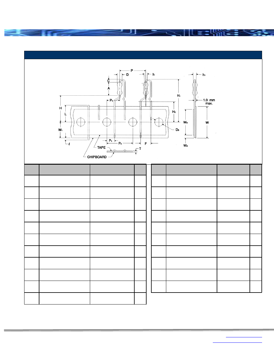
Carbon Film & Metal Film Resistors (1/4W Body Size) 


0.256 ± 0.020

inches

0.433

inches

6.50 ± 0.50

mm

11.00

mm

0.098 ± 0.020

inches

0.500 ± 0.039

inches

2.50 ± 0.50

mm

12.70 ± 1.00

mm

0.091 ± 0.008

inches

0.500 ± 0.012

inches

2.30 ± 0.20

mm

12.70 ± 0.30

mm

0.157 ± 0.012

inches

0.152 ± 0.028

inches

4.00 ± 0.30

mm

3.85 ± 0.70

mm

0.197 ± 0.039

inches

0.250 ± 0.051

inches

5.00 ± 1.00

mm

6.35 ± 1.30

mm

0.748 ± 0.039

inches

0.028 ± 0.008

inches

19.00 ± 1.00

mm

0.70 ± 0.20

mm

0.630 ± 0.020

inches

0.709 ± 0.039

inches

16.00 ± 0.50

mm

18.00 ± 1.00

mm

1.122

inches

0.49

inches

28.50

mm

12.50

mm

0 ± 0.079

inches

0.354 ± 0.030

inches

0 ± 2.00

mm

9.00 ± 0.75

mm

0 ± 0.079

inches

0.118

inches

0 ± 2.00

mm

3.00

mm

0.079

inches

2.00

mm

max.

C

Height of bending

F

Resistor lead spacing

T

P

1

P

D

0

Sprocket-hole diameter

(0±5º)

Sprocket-hole position

W

0

Hold-down tape width

min.

L

max.
max.

max.
max.

max.

(0±5º)

max.

W

Chipboard width(1)

Thickness                                          

(chipboard and tape)

Resitor pitch(1)

(0±5º)
(0±5º)

min.

W

1

I

Lead protrusion

H

0

Height to lead clinch

h

1

h

Resistor alignment

H

1

Height of resistor

Resistor alignment

Unit

max.

A

Resistor body length

H

Height to bottom of resistor

D

Resistor body diameter

W

2

Hold-down tape position

Cutout Length(1)

P

2

Sprocket-hole center to               

resistor center(1)

P

0

Sprocket-hole pitch(1)

Sprocket-hole center to                 

lead center

Symbol

Description

PANA-SERT

Unit

PANA-SERT

Symbol

Description

Radial Lead Taping Specification – Pana-Sert 


SEI-Packaging-html.html
background image


Rev Date:  03/02/2016 

2


www.seielect.com


This specification may be changed at any time without prior notice 


marketing@seielect.com


Please confirm technical specifications before you order and/or use. 


Stackpole Electronics, Inc. 

Resistive Product Solutions 

Packaging and Technical Information


(1)

(2)

Dimension "E":

The given dimension "D" expresses the standard width spacing.  A 26mm narrow spacing is available as option "N" packaging code.

The distance between flanges shall be 0.059 inches (1.50 mm) to 0.315 (8.00 mm) greater than the overall component.

Reference value only.  The "A" dimension shall be governed by the overall length of the taped component.  

Range of diameters is from 0.547 inches (13.90 mm) to 1.500 inches (38.10 mm).

This is a non-critical dimension that does not have a tolerance in the standard.

Lead-Tape Specifications:  Reeled in accordance with EIA-296-F 

Series

Code

Tape

Unit

0.394 ± 0.020

2.063 ± 0.079

0.250

inches

10.00 ± 0.50

52.40 ± 2.00

6.35

mm

0.197 ± 0.020

2.063 ± 0.079

0.250

inches

5.00 ± 0.50

52.40 ± 2.00

6.35

mm

0.197 ± 0.020

2.063 ± 0.079

0.250

inches

5.00 ± 0.50

52.40 ± 2.00

6.35

mm

0.197 ± 0.020

2.063 ± 0.079

0.250

inches

5.00 ± 0.50

52.40 ± 2.00

6.35

mm

0.197 ± 0.020

2.063 ± 0.079

0.250

inches

5.00 ± 0.50

52.40 ± 2.00

6.35

mm

0.197 ± 0.020

2.063 ± 0.079

0.250

inches

5.00 ± 0.50

52.40 ± 2.00

6.35

mm

0.197 ± 0.020

2.063 ± 0.079

0.250

inches

5.00 ± 0.50

52.40 ± 2.00

6.35

mm

0.197 ± 0.020

2.063 ± 0.079

0.250

inches

5.00 ± 0.50

52.40 ± 2.00

6.35

mm

0.197 ± 0.020

2.063 ± 0.079

0.250

inches

5.00 ± 0.50

52.40 ± 2.00

6.35

mm

0.197 ± 0.020

2.063 ± 0.079

0.250

inches

5.00 ± 0.50

52.40 ± 2.00

6.35

mm

0.394 ± 0.020

2.063 ± 0.079

0.250

inches

10.00 ± 0.50

52.40 ± 2.00

6.35

mm

0.197 ± 0.020

2.063 ± 0.079

0.250

inches

5.00 ± 0.50

52.40 ± 2.00

6.35

mm

0.197 ± 0.020

2.063 ± 0.079

0.250

inches

5.00 ± 0.50

52.40 ± 2.00

6.35

mm

0.197 ± 0.020

2.063 ± 0.079

0.250

inches

5.00 ± 0.50

52.40 ± 2.00

6.35

mm

0.197 ± 0.020

2.063 ± 0.079

0.250

inches

5.00 ± 0.50

52.40 ± 2.00

6.35

mm

0.197 ± 0.020

2.063 ± 0.079

0.250

inches

5.00 ± 0.50

52.40 ± 2.00

6.35

mm

0.394 ± 0.020

2.500 ± 0.079

0.250

inches

10.00 ± 0.50

63.50 ± 2.00

6.35

mm

61.50

2.508

343.00

13.504

2.736
69.50

2.421

13.504

343.00

13.504

343.00

13.504

343.00

13.504

343.00

63.70

2.638
67.00

69.50

2.972
75.50

3.130
79.50

2.508

13.504

343.00

13.504

343.00

13.504

3.917
99.50

66.50

13.504

343.00

63.70

2.638
67.00

13.504

343.00

2.618

343.00

13.504

343.00

13.504

343.00

D

(2)

B max

2.736

63.70

2.618
66.50

2.736
69.50

343.00

13.504

A max

.(1)

3.917
99.50

63.70

2.618
66.50

ASR

ASRM

CD

CFM

12

14

12

14

CF

18

14

12

1

2

1

14

FRN

14

12

2

1

12

C

18

2.508

2.508

13.504
343.00

343.00

13.504

343.00

13.504

343.00

13.504

Axial Leaded Resistor 
Packaging & Identification Variations 


SEI-Packaging-html.html
background image


Rev Date:  03/02/2016 

3


www.seielect.com


This specification may be changed at any time without prior notice 


marketing@seielect.com


Please confirm technical specifications before you order and/or use. 


Stackpole Electronics, Inc. 

Resistive Product Solutions 

Packaging and Technical Information


(1)

(2)

Dimension "E":

The given dimension "D" expresses the standard width spacing.  A 26mm narrow spacing is available as option "N" packaging code.

The distance between flanges shall be 0.059 inches (1.50 mm) to 0.315 (8.00 mm) greater than the overall component.

Reference value only.  The "A" dimension shall be governed by the overall length of the taped component.  

Range of diameters is from 0.547 inches (13.90 mm) to 1.500 inches (38.10 mm).

This is a non-critical dimension that does not have a tolerance in the standard.

Axial Leaded Resistors 
Packaging 


Lead Tape Specifications:  Reeled in accordance with EIA-296-F (cont.) 

Series

Code

Tape

Unit

0.197 ± 0.020

2.063 ± 0.079

0.250

inches

5.00 ± 0.50

52.40 ± 2.00

6.35

mm

0.394 ± 0.020

2.063 ± 0.079

0.250

inches

10.00 ± 0.50

52.40 ± 2.00

6.35

mm

0.394 ± 0.020

2.875 ± 0.079

0.250

inches

10.00 ± 0.50

73.03 ± 2.00

6.35

mm

0.394 ± 0.020

4.310 ± 0.079

0.250

inches

10.00 ± 0.50

109.47 ± 2.00

6.35

mm

0.394 ± 0.020

2.063 ± 0.079

0.250

inches

10.00 ± 0.50

52.40 ± 2.00

6.35

mm

0.394 ± 0.020

2.063 ± 0.079

0.250

inches

10.00 ± 0.50

52.40 ± 2.00

6.35

mm

0.394 ± 0.020

2.063 ± 0.079

0.250

inches

10.00 ± 0.50

52.40 ± 2.00

6.35

mm

0.394 ± 0.020

2.063 ± 0.079

0.250

inches

10.00 ± 0.50

52.40 ± 2.00

6.35

mm

0.394 ± 0.020

2.063 ± 0.079

0.250

inches

10.00 ± 0.50

52.40 ± 2.00

6.35

mm

0.394 ± 0.020

2.063 ± 0.079

0.250

inches

10.00 ± 0.50

52.40 ± 2.00

6.35

mm

0.394 ± 0.020

2.063 ± 0.079

0.250

inches

10.00 ± 0.50

52.40 ± 2.00

6.35

mm

2.756 ± 0.118

11.811 ± 0.197

0.197 ± 0.020

2.047 ± 0.020

0.250

inches

70.00 ± 3.00

300.00 ± 5.00

5.00 ± 0.50

52.00 ± 0.50

6.35

mm

2.756 ± 0.118

11.811 ± 0.197

0.197 ± 0.020

2.047 ± 0.020

0.250

inches

70.00 ± 3.00

300.00 ± 5.00

5.00 ± 0.50

52.00 ± 0.50

6.35

mm

2.756 ± 0.118

11.811 ± 0.197

0.197 ± 0.020

2.047 ± 0.020

0.250

inches

70.00 ± 3.00

300.00 ± 5.00

5.00 ± 0.50

52.00 ± 0.50

6.35

mm

2.756 ± 0.118

11.811 ± 0.197

0.197 ± 0.020

2.047 ± 0.020

0.250

inches

70.00 ± 3.00

300.00 ± 5.00

5.00 ± 0.50

52.00 ± 0.50

6.35

mm

2.756 ± 0.118

11.811 ± 0.197

0.197 ± 0.020

2.047 ± 0.020

0.250

inches

70.00 ± 3.00

300.00 ± 5.00

5.00 ± 0.50

52.00 ± 0.50

6.35

mm

2.756 ± 0.118

11.811 ± 0.197

0.197 ± 0.020

2.047 ± 0.020

0.250

inches

70.00 ± 3.00

300.00 ± 5.00

5.00 ± 0.50

52.00 ± 0.50

6.35

mm

2.756 ± 0.118

11.811 ± 0.197

0.197 ± 0.020

2.047 ± 0.020

0.250

inches

70.00 ± 3.00

300.00 ± 5.00

5.00 ± 0.50

52.00 ± 0.50

6.35

mm

343.00

13.504
343.00

13.504
343.00

13.504

343.00

13.504
343.00

13.504
343.00

343.00

13.504

2.756
70.00

2.728

94.90

343.00

13.504
343.00

13.504
343.00

13.504
343.00

13.504

69.30

2.787
70.80

4.094

104.00

5.118

130.00

4.764

121.00

3.563
90.50

3.736

RC

14

12

1

RNMF

14

12

RNF

18

14

12

1

2

10

MWW

1

3

5

10

MR

1

3

5

84.10

3.484
88.50

3.850
97.80

D

(2)

A max

.(1)

B max

C

3.311

13.504

SEI-Packaging-html.html
background image


Rev Date:  03/02/2016 

4


www.seielect.com


This specification may be changed at any time without prior notice 


marketing@seielect.com


Please confirm technical specifications before you order and/or use. 


Stackpole Electronics, Inc. 

Resistive Product Solutions 

Packaging and Technical Information


Lead Tape Specifications:  Reeled in accordance with EIA-296-F (cont.) 

(1)

(2)

Dimension "E":

The given dimension "D" expresses the standard width spacing.  A 26mm narrow spacing is available as option "N" packaging code.

The distance between flanges shall be 0.059 inches (1.50 mm) to 0.315 (8.00 mm) greater than the overall component.

Reference value only.  The "A" dimension shall be governed by the overall length of the taped component.  

Range of diameters is from 0.547 inches (13.90 mm) to 1.500 inches (38.10 mm).

This is a non-critical dimension that does not have a tolerance in the standard.

Axial Leaded Resistors 
Packaging 


Series

Code

A max

.(1)

B max

Tape

Unit

2.736

13.504

0.197 ± 0.020

2.063 ± 0.079

0.250

inches

69.50

343.00

5.00 ± 0.50

52.40 ± 2.00

6.35

mm

2.815

13.504

0.197 ± 0.020

2.063 ± 0.079

0.250

inches

71.50

343.00

5.00 ± 0.50

52.40 ± 2.00

6.35

mm

3.524

13.504

0.394 ± 0.020

2.500 ± 0.079

0.250

inches

89.50

343.00

10.00 ± 0.50

63.50 ± 2.00

6.35

mm

3.740

12.008

0.394 ± 0.020

2.874 ± 0.079

0.250

inches

95.00

305.00

10.00 ± 0.50

73.00 ± 2.00

6.35

mm

4.331

12.008

0.394 ± 0.020

3.465 ± 0.079

0.250

inches

110.00

305.00

10.00 ± 0.50

88.00 ± 2.00

6.35

mm

2.618

13.504

0.197 ± 0.020

2.063 ± 0.079

0.250

inches

66.50

343.00

5.00 ± 0.50

52.40 ± 2.00

6.35

mm

2.736

13.504

0.197 ± 0.020

2.063 ± 0.079

0.250

inches

69.50

343.00

5.00 ± 0.50

52.40 ± 2.00

6.35

mm

2.815

13.504

0.197 ± 0.020

2.063 ± 0.079

0.250

inches

71.50

343.00

5.00 ± 0.50

52.40 ± 2.00

6.35

mm

3.524

13.504

0.394 ± 0.020

2.500 ± 0.079

0.250

inches

89.50

343.00

10.00 ± 0.50

63.50 ± 2.00

6.35

mm

3.740

12.008

0.394 ± 0.020

2.874 ± 0.079

0.250

inches

95.00

305.00

10.00 ± 0.50

73.00 ± 2.00

6.35

mm

2.618

13.504

0.197 ± 0.020

2.063 ± 0.079

0.250

inches

66.50

343.00

5.00 ± 0.50

52.40 ± 2.00

6.35

mm

2.736

13.504

0.197 ± 0.020

2.063 ± 0.079

0.250

inches

69.50

343.00

5.00 ± 0.50

52.40 ± 2.00

6.35

mm

2.815

13.504

0.197 ± 0.020

2.063 ± 0.079

0.250

inches

71.50

343.00

5.00 ± 0.50

52.40 ± 2.00

6.35

mm

3.524

13.504

0.197 ± 0.020

2.063 ± 0.079

0.250

inches

89.50

343.00

5.00 ± 0.50

52.40 ± 2.00

6.35

mm

2.618

13.504

0.197 ± 0.020

2.063 ± 0.079

0.250

inches

66.50

343.00

5.00 ± 0.50

52.40 ± 2.00

6.35

mm

2.736

13.504

0.197 ± 0.020

2.063 ± 0.079

0.250

inches

69.50

343.00

5.00 ± 0.50

52.40 ± 2.00

6.35

mm

3.366

13.504

0.197 ± 0.020

2.063 ± 0.079

0.250

inches

85.50

343.00

5.00 ± 0.50

52.40 ± 2.00

6.35

mm

3.524

13.504

0.394 ± 0.020

2.063 ± 0.079

0.250

inches

89.50

343.00

10.00 ± 0.50

52.40 ± 2.00

6.35

mm

1

2

3

12

1

2

3

12

RSPF

RSPL

D

(2)

RSF

12

1

2

3

C

5

RSMF

12

1

2

3

5

SEI-Packaging-html.html
background image


Rev Date:  03/02/2016 

5


www.seielect.com


This specification may be changed at any time without prior notice 


marketing@seielect.com


Please confirm technical specifications before you order and/or use. 


Stackpole Electronics, Inc. 

Resistive Product Solutions 

Packaging and Technical Information


Lead Tape Specifications:  Reeled in accordance with EIA-296-F 

(1)

(2)

Dimension "E":

The given dimension "D" expresses the standard width spacing.  A 26mm narrow spacing is available as option "N" packaging code.

The distance between flanges shall be 0.059 inches (1.50 mm) to 0.315 (8.00 mm) greater than the overall component.

Reference value only.  The "A" dimension shall be governed by the overall length of the taped component.  

Range of diameters is from 0.547 inches (13.90 mm) to 1.500 inches (38.10 mm).

This is a non-critical dimension that does not have a tolerance in the standard.

Series

Code

A max

.(1)

B max

Unit

2.063

11.000

0.400 ± 0.020

2.063 ± 0.079

inches

52.40

279.40

10.16 ± 0.50

52.40 ± 2.00

mm

2.736

13.504

0.197 ± 0.020

2.063 ± 0.079

inches

69.50

343.00

5.00 ± 0.50

52.40 ± 2.00

mm

3.917

13.504

0.394 ± 0.020

2.063 ± 0.079

inches

99.50

343.00

10.00 ± 0.50

52.40 ± 2.00

mm

6.299

13.504

0.394 ± 0.020

2.063 ± 0.079

inches

160.00

343.00

10.00 ± 0.50

52.40 ± 2.00

mm

6.614

13.504

0.394 ± 0.020

2.063 ± 0.079

inches

168.00

343.00

10.00 ± 0.50

52.40 ± 2.00

mm

2.756

11.933

0.197 ± 0.020

2.047 ± 0.079

0.236 ± 0.039

inches

70.00

303.10

5.00 ± 0.50

52.00 ± 2.00

6.00 ± 1.00

mm

2.756

11.933

0.197 ± 0.020

2.047 ± 0.079

0.236 ± 0.039

inches

70.00

303.10

5.00 ± 0.50

52.00 ± 2.00

6.00 ± 1.00

mm

2.756

11.933

0.197 ± 0.020

2.047 ± 0.079

0.236 ± 0.039

inches

70.00

303.10

5.00 ± 0.50

52.00 ± 2.00

6.00 ± 1.00

mm

2.756

11.933

0.197 ± 0.020

2.047 ± 0.079

0.236 ± 0.039

inches

70.00

303.10

5.00 ± 0.50

52.00 ± 2.00

6.00 ± 1.00

mm

2.880

11.000

0.200 ± 0.020

2.063 ± 0.079

inches

73.15

279.40

5.08 ± 0.50

52.40 ± 2.00

mm

2.880

11.000

0.200 ± 0.020

2.063 ± 0.079

inches

73.15

279.40

5.08 ± 0.50

52.40 ± 2.00

mm

2.880

11.000

0.200 ± 0.020

2.063 ± 0.079

inches

73.15

279.40

5.08 ± 0.50

52.40 ± 2.00

mm

2.880

11.000

0.200 ± 0.020

2.063 ± 0.079

inches

73.15

279.40

5.08 ± 0.50

52.40 ± 2.00

mm

2.880

11.000

0.200 ± 0.020

2.063 ± 0.079

inches

73.15

279.40

5.08 ± 0.50

52.40 ± 2.00

mm

2.063

11.000

0.200 ± 0.020

2.500 ± 0.079

inches

52.40

279.40

5.08 ± 0.50

63.50 ± 2.00

mm

3.740

11.000

0.400 ± 0.020

2.874 ± 0.079

inches

95.00

279.40

10.16 ± 0.50

73.00 ± 2.00

mm

2.500

11.000

0.400 ± 0.020

2.500 ± 0.079

inches

63.50

279.40

10.16 ± 0.50

63.50 ± 2.00

mm

3.740

11.000

0.400 ± 0.020

2.874 ± 0.079

inches

95.00

279.40

10.16 ± 0.50

73.00 ± 2.00

mm

5.100

11.000

0.400 ± 0.020

2.874 ± 0.079

inches

129.54

279.40

10.16 ± 0.50

73.00 ± 2.00

mm

5.100

11.000

0.400 ± 0.020

2.874 ± 0.079

inches

129.54

279.40

10.16 ± 0.50

73.00 ± 2.00

mm

5.100

11.000

0.400 ± 0.020

2.874 ± 0.079

inches

129.54

279.40

10.16 ± 0.50

73.00 ± 2.00

mm

6.35

0.250

6.35

0.250

6.35

0.250

6.35

0.250

6.35

0.250

6.35

0.250

6.35

0.250

6.35

0.250

6.35

0.250

6.35

0.250

6.35

0.250

6.35

0.250

6.35

0.250

6.35

0.250

6.35

0.250

6.35

Tape

0.250

6.35

0.250

WW

H

1/WWS2

1A

2/WWS3

2A

3/WWS4

3A

10

5/WWS7

7

7B/WWS10

C

SP

3A

WRC

D

(2)

TMR

3

5

SPR

12

1

1S

1

2, 2A, 3A, 4A, 5A

3B, 4B, 5B

4/WWS5

Axial Leaded Resistors 
Packaging 


SEI-Packaging-html.html
background image


Rev Date:  03/02/2016 

6


www.seielect.com


This specification may be changed at any time without prior notice 


marketing@seielect.com


Please confirm technical specifications before you order and/or use. 


Stackpole Electronics, Inc. 

Resistive Product Solutions 

Packaging and Technical Information


 RAVF10 - RAVF32  Packaging Specifications 

FEATURES

Material Pieces/Reel

0.046 ± 0.004

0.051 ± 0.008

0.071 ± 0.004

0.079 ± 0.008

0.134 ± 0.004

inches

1.17 ± 0.10

1.30 ± 0.20

1.80 ± 0.10

2.00 ± 0.20

3.40 ± 0.10

mm

0.046 ± 0.004

0.091 ± 0.008

0.071 ± 0.004

0.142 ± 0.008

0.220 ± 0.004

inches

1.17 ± 0.10

2.30 ± 0.20

1.80 ± 0.10

3.60 ± 0.20

5.60 ± 0.10

mm

0.157 ± 0.004

0.157 ± 0.004

0.157 ± 0.004

0.157 ± 0.004

0.157 ± 0.004

inches

4.00 ± 0.10

4.00 ± 0.10

4.00 ± 0.10

4.00 ± 0.10

4.00 ± 0.10

mm

0.059 ± 0.004

0.059 ± 0.004

0.059 ± 0.004

0.059 ± 0.004

0.039 ± 0.004

inches

1.50 ± 0.10

1.50 ± 0.10

1.50 ± 0.10

1.50 ± 0.10

1.00 ± 0.10

mm

0.138 ± 0.002

0.138 ± 0.002

0.138 ± 0.002

0.138 ± 0.002

0.217 ± 0.002

inches

3.50 ± 0.05

3.50 ± 0.05

3.50 ± 0.05

3.50 ± 0.05

5.50 ± 0.05

mm

7.008 ± 0.079

7.008 ± 0.079

7.008 ± 0.079

7.008 ± 0.079

7.008 ± 0.079

inches

178.00 ± 2.00

178.00 ± 2.00

178.00 ± 2.00

178.00 ± 2.00

178.00 ± 2.00

mm

inches

mm

0.512 ± 0.039

0.512 ± 0.039

0.512 ± 0.039

0.512 ± 0.039

0.512 ± 0.008

inches

13.00 ± 1.00

13.00 ± 1.00

13.00 ± 1.00

13.00 ± 1.00

13.00 ± 0.20

mm

0.827 ± 0.039

0.827 ± 0.039

0.827 ± 0.039

0.827 ± 0.039

0.827 ± 0.031

inches

21.00 ± 1.00

21.00 ± 1.00

21.00 ± 1.00

21.00 ± 1.00

21.00 ± 0.80

mm

0.079 ± 0.039

0.079 ± 0.039

0.079 ± 0.039

0.079 ± 0.039

0.079 ± 0.020

inches

2.00 ± 1.00

2.00 ± 1.00

2.00 ± 1.00

2.00 ± 1.00

2.00 ± 0.50

mm

0.079 ± 0.002

0.079 ± 0.002

0.157 ± 0.004

0.157 ± 0.004

0.157 ± 0.004

inches

2.00 ± 0.05

2.00 ± 0.05

4.00 ± 0.10

4.00 ± 0.10

4.00 ± 0.10

mm

0.531 ± 0.079

0.531 ± 0.079

0.531 ± 0.079

0.531 ± 0.079

0.354 ± 0.012

inches

13.50 ± 2.00

13.50 ± 2.00

13.50 ± 2.00

13.50 ± 2.00

9.00 ± 0.30

mm

0.031 ± 0.008

0.031 ± 0.008

0.031 ± 0.008

0.031 ± 0.008

inches

0.80 ± 0.20

0.80 ± 0.20

0.80 ± 0.20

0.80 ± 0.20

mm

0.039

0.039

0.020

0.039

0.010 ± 0.002

inches

1.00

1.00

0.50

1.00

0.25 ± 0.05

mm

0.055

0.055

0.039

0.055

0.043

inches

1.40

1.40

1.00

1.40

1.10

mm

inches

mm

0.315 ± 0.008

0.315 ± 0.008

0.315 ± 0.008

0.315 ± 0.008

0.472 ± 0.008

inches

8.00 ± 0.20

8.00 ± 0.20

8.00 ± 0.20

8.00 ± 0.20

12.00 ± 0.20

mm

T2

U

P

T

J

Hub Diameter

W

Symbol

Unit

A

Pocket Width

RAVF324D

RAVF102D

K

L

M

RAVF104D

RAVF162D

RAVF164D/RAVF328

T1

B

C

D

F

H

Paper - 5,000

Embossed - 4,000

60.00

50.00

2.362

1.969

Paper - 10,000

Paper - 10,000

Paper - 5,000

50.00

50.00

1.969

Key Diameter

Strip Width

Strip Thickness

Total Thickness

Key Width

Side Thickness

Reel Outside Width

Reel Inside Width

Pocket Spacing

-

Pocket Length

max

max

max

1.969
50.00

1.969

max

max

max

Pin Spacing

Pin Diameter

Pin-Pocket C/L

Reel Diameter

Hole Diameter

11.40

max

max

max

max

max

max
max

0.449

max

max

max

max

max

-

Chip Array Resistors 
Packaging Specifications 


SEI-Packaging-html.html
background image


Rev Date:  03/02/2016 

7


www.seielect.com


This specification may be changed at any time without prior notice 


marketing@seielect.com


Please confirm technical specifications before you order and/or use. 


Stackpole Electronics, Inc. 

Resistive Product Solutions 

Packaging and Technical Information


FEATURES

Material Pieces/Reel

0.079 ± 0.008

0.138 ± 0.004

0.098 ± 0.004

0.138 ± 0.004

inches

2.00 ± 0.20

3.50 ± 0.10

2.50 ± 0.10

3.50 ± 0.10

mm

0.142 ± 0.008

0.224 ± 0.004

0.173 ± 0.004

0.266 ± 0.004

inches

3.60 ± 0.20

5.70 ± 0.10

4.40 ± 0.10

6.75 ± 0.10

mm

0.157 ± 0.004

0.157 ± 0.004

0.157 ± 0.004

0.157 ± 0.004

inches

4.00 ± 0.10

4.00 ± 0.10

4.00 ± 0.10

4.00 ± 0.10

mm

0.059 ± 0.004

0.039 ± 0.004

0.059 ± 0.004

0.059 ± 0.004

inches

1.50 ± 0.10

1.00 ± 0.10

1.50 ± 0.10

1.50 ± 0.10

mm

0.138 ± 0.002

0.217 ± 0.002

0.217 ± 0.020

0.217 ± 0.002

inches

3.50 ± 0.05

5.50 ± 0.05

5.50 ± 0.50

5.50 ± 0.05

mm

7.008 ± 0.079

7.008 ± 0.079

7.008 ± 0.079

7.008 ± 0.079

inches

178.00 ± 2.00

178.00 ± 2.00

178.00 ± 2.00

178.00 ± 2.00

mm

2.362 ± 0.039

2.362 ± 0.039

2.362 ± 0.039

inches

60.00 ± 1.00

60.00 ± 1.00

60.00 ± 1.00

mm

0.512 ± 0.039

0.512 ± 0.008

0.512 ± 0.008

0.512 ± 0.008

inches

13.00 ± 1.00

13.00 ± 0.20

13.00 ± 0.20

13.00 ± 0.20

mm

0.827 ± 0.039

0.827 ± 0.031

0.827 ± 0.031

0.827 ± 0.031

inches

21.00 ± 1.00

21.00 ± 0.80

21.00 ± 0.80

21.00 ± 0.80

mm

0.079 ± 0.039

0.079 ± 0.020

0.079 ± 0.020

0.079 ± 0.020

inches

2.00 ± 1.00

2.00 ± 0.50

2.00 ± 0.50

2.00 ± 0.50

mm

0.157 ± 0.004

0.157 ± 0.004

0.157 ± 0.004

0.157 ± 0.004

inches

4.00 ± 0.10

4.00 ± 0.10

4.00 ± 0.10

4.00 ± 0.10

mm

0.531 ± 0.079

0.354 ± 0.012

0.354 ± 0.012

0.354 ± 0.012

inches

13.50 ± 2.00

9.00 ± 0.30

9.00 ± 0.30

9.00 ± 0.30

mm

0.031 ± 0.008

inches

0.80 ± 0.20

mm

0.020

0.010 ± 0.002

0.010 ± 0.002

0.010 ± 0.002

inches

0.50

0.25 ± 0.05

0.25 ± 0.05

0.25 ± 0.05

mm

0.039

0.043

0.043

0.043

inches

1.00

1.10

1.10

1.10

mm

0.449 ± 0.039

0.449 ± 0.039

0.449 ± 0.039

inches

11.40 ± 1.00

11.40 ± 1.00

11.40 ± 1.00

mm

0.315 ± 0.008

0.472 ± 0.008

0.472 ± 0.008

0.472 ± 0.008

inches

8.00 ± 0.20

12.00 ± 0.20

12.00 ± 0.20

12.00 ± 0.20

mm

U

W

Symbol

P

T

T1

J

K

L

M

C

D

F

H

T2

max

max

Embossed - 4,000

A

B

Pocket Width

Pin Spacing

Pin Diameter

max
max

1.969

Pocket Length

max
max

Unit

Embossed - 4,000

RACF408M

RACF648N/RACF648R

max

Pin-to-Pocket Center

-

-

max

max
max

RACF164D

RACF324D

Paper - 5,000

Embossed - 4,000

50.00

Strip Width

Strip Thickness

Total Thickness

Reel Side Thickness

Reel Diameter

Hub Diameter

Hole Diameter

Key Width

Reel Inside Width

Pocket Spacing

Key Diameter

Reel Outside Width

Chip Array Resistors 
Packaging Specifications


RACF16 - RACF64  Packaging Specifications 

SEI-Packaging-html.html
background image


Rev Date:  03/02/2016 

8


www.seielect.com


This specification may be changed at any time without prior notice 


marketing@seielect.com


Please confirm technical specifications before you order and/or use. 


Stackpole Electronics, Inc. 

Resistive Product Solutions 

Packaging and Technical Information


RMCS Packaging Specifications 

Type

Unit

0.015 ± 0.002

0.027 ± 0.002

0.315 ± 0.008

0.069 ± 0.004

0.138 ± 0.002

inches

0.38 ± 0.05

0.68 ± 0.05

8.00 ± 0.20

1.75 ± 0.10

3.50 ± 0.05

mm

0.026 ± 0.004

0.045 ± 0.004

0.315 ± 0.008

0.069 ± 0.004

0.138 ± 0.002

inches

0.65 ± 0.10

1.15 ± 0.10

8.00 ± 0.20

1.75 ± 0.10

3.50 ± 0.05

mm

0.043 ± 0.004

0.075 ± 0.004

0.315 ± 0.008

0.069 ± 0.004

0.138 ± 0.002

inches

1.10 ± 0.10

1.90 ± 0.10

8.00 ± 0.20

1.75 ± 0.10

3.50 ± 0.05

mm

0.063 ± 0.004

0.094 ± 0.008

0.315 ± 0.008

0.069 ± 0.004

0.138 ± 0.002

inches

1.60 ± 0.10

2.40 ± 0.20

8.00 ± 0.20

1.75 ± 0.10

3.50 ± 0.05

mm

0.075 ± 0.004

0.138 ± 0.008

0.315 ± 0.008

0.069 ± 0.004

0.138 ± 0.002

inches

1.90 ± 0.10

3.50 ± 0.20

8.00 ± 0.20

1.75 ± 0.10

3.50 ± 0.05

mm

0.110 ± 0.004

0.138 ± 0.008

0.315 ± 0.008

0.069 ± 0.004

0.138 ± 0.002

inches

2.80 ± 0.10

3.50 ± 0.20

8.00 ± 0.20

1.75 ± 0.10

3.50 ± 0.05

mm

0.110 ± 0.008

0.217 ± 0.008

0.472 ± 0.012

0.069 ± 0.004

0.217 ± 0.002

inches

2.80 ± 0.20

5.50 ± 0.20

12.00 ± 0.30

1.75 ± 0.10

5.50 ± 0.05

mm

0.138 ± 0.008

0.264 ± 0.008

0.472 ± 0.012

0.069 ± 0.004

0.217 ± 0.002

inches

3.50 ± 0.20

6.70 ± 0.20

12.00 ± 0.30

1.75 ± 0.10

5.50 ± 0.05

mm

RMCS0201

RMCS0402

F

L

M

W

E

RMCS2010

RMCS2512

RMCS0603 

RMCS0805

RMCS1206

RMCS1210

Chip Resistors 


  RMCS Paper Tape Specifications 


  RMCS Embossed Plastic Tape Specifications 


SEI-Packaging-html.html
background image


Rev Date:  03/02/2016 

9


www.seielect.com


This specification may be changed at any time without prior notice 


marketing@seielect.com


Please confirm technical specifications before you order and/or use. 


Stackpole Electronics, Inc. 

Resistive Product Solutions 

Packaging and Technical Information


RMCS Packaging Specifications (cont.) 

Chip Resistors 


  RMCS Paper Tape Specifications 


  RMCS Embossed Plastic Tape Specifications 


Type

Unit

0.157 ± 0.004

0.079 ± 0.002

0.079 ± 0.002

0.059 ± 0.004

0.017 ± 0.008

inches

4.00 ± 0.10

2.00 ± 0.05

2.00 ± 0.05

1.50 ± 0.10

0.42 ± 0.20

mm

0.157 ± 0.004

0.079 ± 0.002

0.079 ± 0.002

0.059 ± 0.004

0.018 ± 0.004

inches

4.00 ± 0.10

2.00 ± 0.05

2.00 ± 0.05

1.50 ± 0.10

0.45 ± 0.10

mm

0.157 ± 0.004

0.157 ± 0.004

0.079 ± 0.002

0.059 ± 0.004

0.028 ± 0.004

inches

4.00 ± 0.10

4.00 ± 0.10

2.00 ± 0.05

1.50 ± 0.10

0.70 ± 0.10

mm

0.157 ± 0.004

0.157 ± 0.004

0.079 ± 0.002

0.059 ± 0.004

0.033 ± 0.004

inches

4.00 ± 0.10

4.00 ± 0.10

2.00 ± 0.05

1.50 ± 0.10

0.85 ± 0.10

mm

0.157 ± 0.004

0.157 ± 0.004

0.079 ± 0.002

0.059 ± 0.004

0.033 ± 0.004

inches

4.00 ± 0.10

4.00 ± 0.10

2.00 ± 0.05

1.50 ± 0.10

0.85 ± 0.10

mm

0.157 ± 0.004

0.157 ± 0.004

0.079 ± 0.002

0.059 ± 0.004

0.033 ± 0.004

inches

4.00 ± 0.10

4.00 ± 0.10

2.00 ± 0.05

1.50 ± 0.10

0.85 ± 0.10

mm

0.157 ± 0.004

0.157 ± 0.004

0.079 ± 0.002

0.059 ± 0.004

0.047 - 0

inches

4.00 ± 0.10

4.00 ± 0.10

2.00 ± 0.05

1.50 ± 0.10

1.20 - 0

mm

0.157 ± 0.004

0.157 ± 0.004

0.079 ± 0.002

0.059 ± 0.004

0.047 - 0

inches

4.00 ± 0.10

4.00 ± 0.10

2.00 ± 0.05

1.50 ± 0.10

1.20 - 0

mm

ØD

0

K1/K2

RMCS0201

RMCS0402

P

0

P1

P2

RMCS0603 

RMCS0805

RMCS1206

RMCS1210

RMCS2010

RMCS2512

SEI-Packaging-html.html
background image


Rev Date:  03/02/2016 

10


www.seielect.com


This specification may be changed at any time without prior notice 


marketing@seielect.com


Please confirm technical specifications before you order and/or use. 


Stackpole Electronics, Inc. 

Resistive Product Solutions 

Packaging and Technical Information


RNCS Packaging Specifications 

Chip Resistors 
 
 
  RNCS Paper Tape Specifications 


  RNCS Embossed Plastic Tape Specifications 


Type

Unit

0.028 ± 0.002

0.046 ± 0.002

0.315 ± 0.004

0.069 ± 0.004

0.138 ± 0.002

inches

0.70 ± 0.05

1.16 ± 0.05

8.00 ± 0.10

1.75 ± 0.10

3.50 ± 0.05

mm

0.043 ± 0.002

0.075 ± 0.002

0.315 ± 0.004

0.069 ± 0.004

0.138 ± 0.002

inches

1.10 ± 0.05

1.90 ± 0.05

8.00 ± 0.10

1.75 ± 0.10

3.50 ± 0.05

mm

0.063 ± 0.002

0.093 ± 0.002

0.315 ± 0.004

0.069 ± 0.004

0.138 ± 0.002

inches

1.60 ± 0.05

2.37 ± 0.05

8.00 ± 0.10

1.75 ± 0.10

3.50 ± 0.05

mm

0.079 ± 0.002

0.140 ± 0.002

0.315 ± 0.004

0.069 ± 0.004

0.138 ± 0.002

inches

2.00 ± 0.05

3.55 ± 0.05

8.00 ± 0.10

1.75 ± 0.10

3.50 ± 0.05

mm

0.112 ± 0.004

0.215 ± 0.004

0.472 ± 0.004

0.069 ± 0.004

0.217 ± 0.002

inches

2.85 ± 0.10

5.45 ± 0.10

12.00 ± 0.10

1.75 ± 0.10

5.50 ± 0.05

mm

0.134 ± 0.004

0.262 ± 0.004

0.472 ± 0.004

0.069 ± 0.004

0.217 ± 0.002

inches

3.40 ± 0.10

6.65 ± 0.10

12.00 ± 0.10

1.75 ± 0.10

5.50 ± 0.05

mm

Type

Unit

0.157 ± 0.004

0.079 ± 0.002

0.079 ± 0.002

0.061 ± 0.002

0.016 ± 0.001

inches

4.00 ± 0.10

2.00 ± 0.05

2.00 ± 0.05

1.55 ± 0.05

0.40 ± 0.03

mm

0.157 ± 0.004

0.157 ± 0.004

0.079 ± 0.002

0.061 ± 0.002

0.024 ± 0.001

inches

4.00 ± 0.10

4.00 ± 0.10

2.00 ± 0.05

1.55 ± 0.05

0.60 ± 0.03

mm

0.157 ± 0.004

0.157 ± 0.004

0.079 ± 0.002

0.061 ± 0.002

0.030 ± 0.002

inches

4.00 ± 0.10

4.00 ± 0.10

2.00 ± 0.05

1.55 ± 0.05

0.75 ± 0.05

mm

0.157 ± 0.004

0.157 ± 0.004

0.079 ± 0.002

0.061 ± 0.002

0.030 ± 0.002

inches

4.00 ± 0.10

4.00 ± 0.10

2.00 ± 0.05

1.55 ± 0.05

0.75 ± 0.05

mm

0.157 ± 0.004

0.157 ± 0.004

0.079 ± 0.002

0.061 ± 0.002

0.039 ± 0.008

inches

4.00 ± 0.10

4.00 ± 0.10

2.00 ± 0.05

1.55 ± 0.05

1.00 ± 0.20

mm

0.157 ± 0.004

0.157 ± 0.004

0.079 ± 0.002

0.061 ± 0.002

0.039 ± 0.008

inches

4.00 ± 0.10

4.00 ± 0.10

2.00 ± 0.05

1.55 ± 0.05

1.00 ± 0.20

mm

RNCS0805

RNCS1206

RNCS2010

RNCS2512

RNCS0402

RNCS0603

K1/K2

P

0

P1

P2

ØD

0

W

E

F

RNCS2010

RNCS2512

L

M

RNCS0402

RNCS0603

RNCS0805

RNCS1206

SEI-Packaging-html.html
background image


Rev Date:  03/02/2016 

11


www.seielect.com


This specification may be changed at any time without prior notice 


marketing@seielect.com


Please confirm technical specifications before you order and/or use. 


Stackpole Electronics, Inc. 

Resistive Product Solutions 

Packaging and Technical Information


RPC Packaging Specifications 

Chip Resistors 


  RPC Paper Tape Specifications 


  RPC Embossed Plastic Tape Specifications 


Type

Unit

0.043 ± 0.004

0.075 ± 0.004

0.315 ± 0.008

0.069 ± 0.004

0.138 ± 0.002

inches

1.10 ± 0.10

1.90 ± 0.10

8.00 ± 0.20

1.75 ± 0.10

3.50 ± 0.05

mm

0.063 ± 0.004

0.094 ± 0.008

0.315 ± 0.008

0.069 ± 0.004

0.138 ± 0.002

inches

1.60 ± 0.10

2.40 ± 0.20

8.00 ± 0.20

1.75 ± 0.10

3.50 ± 0.05

mm

0.075 ± 0.004

0.138 ± 0.008

0.315 ± 0.008

0.069 ± 0.004

0.138 ± 0.002

inches

1.90 ± 0.10

3.50 ± 0.20

8.00 ± 0.20

1.75 ± 0.10

3.50 ± 0.05

mm

0.110 ± 0.004

0.138 ± 0.008

0.315 ± 0.008

0.069 ± 0.004

0.138 ± 0.002

inches

2.80 ± 0.10

3.50 ± 0.20

8.00 ± 0.20

1.75 ± 0.10

3.50 ± 0.05

mm

0.110 ± 0.008

0.217 ± 0.008

0.472 ± 0.012

0.069 ± 0.004

0.217 ± 0.002

inches

2.80 ± 0.20

5.50 ± 0.20

12.00 ± 0.30

1.75 ± 0.10

5.50 ± 0.05

mm

0.138 ± 0.008

0.264 ± 0.008

0.472 ± 0.012

0.069 ± 0.004

0.217 ± 0.002

inches

3.50 ± 0.20

6.70 ± 0.20

12.00 ± 0.30

1.75 ± 0.10

5.50 ± 0.05

mm

Type

Unit

0.157 ± 0.004

0.157 ± 0.394

0.079 ± 0.002

0.059 ± 0.004

0.028 ± 0.004

inches

4.00 ± 0.10

4.00 ± 10.00

2.00 ± 0.05

1.50 ± 0.10

0.70 ± 0.10

mm

0.157 ± 0.004

0.157 ± 0.394

0.079 ± 0.002

0.059 ± 0.004

0.033 ± 0.004

inches

4.00 ± 0.10

4.00 ± 10.00

2.00 ± 0.05

1.50 ± 0.10

0.85 ± 0.10

mm

0.157 ± 0.004

0.157 ± 0.394

0.079 ± 0.002

0.059 ± 0.004

0.033 ± 0.004

inches

4.00 ± 0.10

4.00 ± 10.00

2.00 ± 0.05

1.50 ± 0.10

0.85 ± 0.10

mm

0.157 ± 0.004

0.157 ± 0.394

0.079 ± 0.002

0.059 ± 0.004

0.033 ± 0.004

inches

4.00 ± 0.10

4.00 ± 10.00

2.00 ± 0.05

1.50 ± 0.10

0.85 ± 0.10

mm

0.157 ± 0.004

0.157 ± 0.394

0.079 ± 0.002

0.059 ± 0.004

0.047 - 0.000

inches

4.00 ± 0.10

4.00 ± 10.00

2.00 ± 0.05

1.50 ± 0.10

1.20 - 0.00

mm

0.157 ± 0.004

0.157 ± 0.394

0.079 ± 0.002

0.059 ± 0.004

0.047 - 0.000

inches

4.00 ± 0.10

4.00 ± 10.00

2.00 ± 0.05

1.50 ± 0.10

1.20 - 0.00

mm

RPC2512

P

0

P1

P2

K1/K2

RPC1210

RPC0805

RPC1206

RPC2010

RPC2512

RPC1206

RPC1210

RPC2010

RPC0603

F

E

ØD0

L

M

W

RPC0603

RPC0805

SEI-Packaging-html.html
background image


Rev Date:  03/02/2016 

12


www.seielect.com


This specification may be changed at any time without prior notice 


marketing@seielect.com


Please confirm technical specifications before you order and/or use. 


Stackpole Electronics, Inc. 

Resistive Product Solutions 

Packaging and Technical Information


CSS Packaging Specifications 

Type

Unit

0.137 ± 0.004

0.072 ± 0.004

0.315 ± 0.006

0.069 ± 0.004

0.138 ± 0.004

0.043 ± 0.004

inches

3.48 ± 0.10

1.83 ± 0.10

8.00 ± 0.15

1.75 ± 0.10

3.50 ± 0.10

1.10 ± 0.10

mm

0.215 ± 0.004

0.114 ± 0.004

0.472 ± 0.006

0.069 ± 0.004

0.217 ± 0.004

0.052 ± 0.004

inches

5.45 ± 0.10

2.90 ± 0.10

12.00 ± 0.15

1.75 ± 0.10

5.50 ± 0.10

1.33 ± 0.10

mm

0.266 ± 0.004

0.138 ± 0.004

0.472 ± 0.006

0.069 ± 0.004

0.217 ± 0.004

0.051 ± 0.004

inches

6.75 ± 0.10

3.50 ± 0.10

12.00 ± 0.15

1.75 ± 0.10

5.50 ± 0.10

1.30 ± 0.10

mm

0.281 ± 0.004

0.266 ± 0.004

0.472 ± 0.006

0.069 ± 0.004

0.217 ± 0.004

0.077 ± 0.004

inches

7.15 ± 0.10

6.75 ± 0.10

12.00 ± 0.15

1.75 ± 0.10

5.50 ± 0.10

1.95 ± 0.10

mm

0.281 ± 0.004

0.303 ± 0.004

0.472 ± 0.006

0.069 ± 0.004

0.217 ± 0.004

0.057 ± 0.004

inches

7.15 ± 0.10

7.70 ± 0.10

12.00 ± 0.15

1.75 ± 0.10

5.50 ± 0.10

1.45 ± 0.10

mm

0.465 ± 0.004

0.283 ± 0.004

0.945 ± 0.006

0.069 ± 0.004

0.453 ± 0.004

0.079 ± 0.004

inches

11.80 ± 0.10

7.20 ± 0.10

24.00 ± 0.15

1.75 ± 0.10

11.50 ± 0.10

2.00 ± 0.10

mm

Type

0.008 ± 0.002

0.157 ± 0.004

0.157 ± 0.004

0.079 ± 0.004

0.059 ± 0.004

0.20 ± 0.05

4.00 ± 0.10

4.00 ± 0.10

2.00 ± 0.10

1.50 ± 0.10

0.009 ± 0.002

0.157 ± 0.004

0.157 ± 0.004

0.079 ± 0.004

0.059 ± 0.004

0.23 ± 0.05

4.00 ± 0.10

4.00 ± 0.10

2.00 ± 0.10

1.50 ± 0.10

0.008 ± 0.002

0.157 ± 0.004

0.157 ± 0.004

0.079 ± 0.004

0.059 ± 0.004

0.20 ± 0.05

4.00 ± 0.10

4.00 ± 0.10

2.00 ± 0.10

1.50 ± 0.10

0.010 ± 0.002

0.315 ± 0.004

0.157 ± 0.004

0.079 ± 0.004

0.059 ± 0.004

0.25 ± 0.05

8.00 ± 0.10

4.00 ± 0.10

2.00 ± 0.10

1.50 ± 0.10

0.010 ± 0.002

0.472 ± 0.004

0.157 ± 0.004

0.079 ± 0.004

0.059 ± 0.004

0.25 ± 0.05

12.00 ± 0.10

4.00 ± 0.10

2.00 ± 0.10

1.50 ± 0.10

0.012 ± 0.004

0.472 ± 0.004

0.157 ± 0.004

0.079 ± 0.004

0.059 ± 0.004

0.30 ± 0.10

12.00 ± 0.10

4.00 ± 0.10

2.00 ± 0.10

1.50 ± 0.10

E

F

CSS2725

CSS2728

A

B

W

CSS2728

CSS4527

T2

P

T1

CSS1206               

CSS2010

CSS2512

CSS2725

P0

P1

Φ

D

CSS1206               

CSS4527

CSS2010

CSS2512

Unit

inches

mm

inches

mm

inches

mm

inches

mm

inches

mm

inches

mm

Chip Resistors 


  CSS Embossed Plastic Tape Specifications 


SEI-Packaging-html.html
background image


Rev Date:  03/02/2016 

13


www.seielect.com


This specification may be changed at any time without prior notice 


marketing@seielect.com


Please confirm technical specifications before you order and/or use. 


Stackpole Electronics, Inc. 

Resistive Product Solutions 

Packaging and Technical Information


Type

Unit

7.087 ± 0.118

2.362 ± 0.039

0.512 ± 0.008

0.827 ± 0.031

0.079 ± 0.020

0.512 ± 0.012

0.606 ± 0.039

Inches

180.00 ± 3.00

60.00 ± 1.00

13.00 ± 0.20

21.00 ± 0.80

2.00 ± 0.50

13.00 ± 0.30

15.40 ± 1.00

mm

RHC2512

W2

A

B

C

D

E

W1


  RHC Embossed Plastic Tape Specifications 


RHC Packaging Specifications 

Type

Unit

0.134 ± 0.004

0.260 ± 0.004

0.472 ± 0.008

0.217 ± 0.002

0.069 ± 0.004

0.157 ± 0.004

Inches

3.40 ± 0.10

6.60 ± 0.10

12.00 ± 0.20

5.50 ± 0.05

1.75 ± 0.10

4.00 ± 0.10

mm

Type

0.079 ± 0.002

0.157 ± 0.004

0.061 ± 0.002

0.010 ± 0.002

0.039 ± 0.004

2.00 ± 0.05

4.00 ± 0.10

1.55 ± 0.05

0.25 ± 0.05

1.00 ± 0.10

P1

t1

t2

A

B

W

F

E

RHC2512

RHC2512

P2

P0

D0

Unit

Inches

mm

RHC Reel Specifications 

SEI-Packaging-html.html
background image


Rev Date:  03/02/2016 

14


www.seielect.com


This specification may be changed at any time without prior notice 


marketing@seielect.com


Please confirm technical specifications before you order and/or use. 


Stackpole Electronics, Inc. 

Resistive Product Solutions 

Packaging and Technical Information


Notes: 1. Dimensions are 0.472 ± 0.004 inches (12 ± 0.1 mm) for 2010 and 2512 size.

2. 5,000 per 7" reel - 0603, 0805 & 1206 size; 4,000 per 7" reel - 1210, 2010 & 2512 size.  Available options - 10,000 piece 13" reels.

3. Embossed taping standard 4,000 per 7" reel on 1210, 2010 & 2512 size.

E

G

Unit

0.157 ± 0.004

0.079 ± 0.004

0.157 ± 0.004

0.059 + 0.004 / -0

0.039

0.069 ± 0.002

0.197

0.138 ± 0.002

0.315 ± 0.004

inches 

4.00 ± 0.10

2.00 ± 0.10

4.00 ± 0.10

1.50 + 0.10

/ -0

1.00

1.75 ± 0.05

5.00

3.50 ± 0.05

8.00 ± 0.10

mm

F

H

J (1)

A

B

C

D

Packaging:  Chips per EIA Standard RS-481 

Unit

0.043 max

0.043 ± 0.008

0.075 ± 0.008

inches 

1.10 max

1.10 ± 0.20

1.90 ± 0.20

mm

0.043 max

0.065 ± 0.008

0.094 ± 0.008

inches

1.10 max

1.65 ± 0.20

2.40 ± 0.20

mm

0.043 max

0.094 max

0.079 ± 0.004

0.138 ± 0.002

inches

1.10 max

2.40 max

2.00 ± 0.10

3.50 ± 0.05

mm

0.094 max

0.110 ± 0.008

0.142 ± 0.008

inches 

2.40 max

2.80 ± 0.20

3.60 ± 0.20

mm

0.094 max

0.110 ± 0.008

0.217 ± 0.008

inches 

2.40 max

2.80 ± 0.20

5.50 ± 0.20

mm

0.094 max

0.150 ± 0.008

0.264 ± 0.008

inches 

2.40 max

3.80 ± 0.20

6.70 ± 0.20

mm

Type

CSR0603, HVC0603, RGC0603,                             

RMCF0603, RNCF0603

K1

L

M

K2

-

CSR0805, FCR0805, HMC0805, HVC0805,                         

RGC0805, RMCF0805, RNCF0805

CSR2512, HVC2512, RMCF2512, RNCF2512

RMCF1210, FCR1210, RNCF1210

CSR2010, HVC2010, RMCF2010, RNCF2010

-

CSR1206, FCR1206, HMC1206, HVC1206,                           

RGC1206, RMCF1206, RNCF1206

Chip Resistor Reel 


  Nominal Dimensions 
  Inches (mm) 


SEI-Packaging-html.html
background image


Rev Date:  03/02/2016 

15


www.seielect.com


This specification may be changed at any time without prior notice 


marketing@seielect.com


Please confirm technical specifications before you order and/or use. 


Stackpole Electronics, Inc. 

Resistive Product Solutions 

Packaging and Technical Information


Standard Tape Packaging

2mm Pitch - 10,000 per reel

Reel diameter - 7 inches (178 mm)

Reel width - 0.315 inches (8 mm)

Packaging:  HPC and SM 

Unit

0.026 ± 0.004

0.045 ± 0.004

0.315 ± 0.008

0.138 ± 0.002

0.069 ± 0.004

inches 

0.65 ± 0.10

1.15 ± 0.10

8.00 ± 0.20

3.50 ± 0.05

1.75 ± 0.10

mm

Unit

0.079 ± 0.002

0.039 ± 0.002

0.059 ± 0.004

0.016 ± 0.002

0.020

inches 

2.00 ± 0.05

1.00 ± 0.05

1.50 ± 0.10

0.40 ± 0.05

0.50

mm

F

G

E

A

B

C

D

max

max

J

K

L

Chip Resistors 
Packaging Specifications 


HPC and SMD Resistors 
Packaging Specifications 


Packaging 0201 and 0402 Chip Size (2mm pitch) 

Product

P

0

E

1

T

S

0

P

1

A

0

K

0

B

0

Unit

1.260 ± 0.012

0.157

0.069

0.018

1.118

0.945

0.529

0.440

0.529

inches

32.00 ± 0.30

4.00

1.75

0.45

28.40

24.00

13.44

11.17

13.44

mm

0.630 + 0.012

0.157

0.069

0.018

0.315

0.161

0.159

0.302

inches

16.00 + 0.30

4.00

1.75

0.45

8.00

4.10

4.03

7.66

mm

0.945 + 0.012

0.157

0.069

0.018

0.472

0.257

0.206

0.457

inches

24.00 + 0.30

4.00

1.75

0.45

12.00

6.53

5.22

11.60

mm

1.260 ± 0.012

0.157

0.069

0.018

1.118

0.472

0.276

0.271

0.665

inches

32.00 ± 0.30

4.00

1.75

0.45

28.40

12.00

7.01

6.88

16.89

mm

1.732 ± 0.012

0.157

0.069

0.018

1.591

0.630

0.343

0.396

0.856

inches

44.00 ± 0.30

4.00

1.75

0.45

40.40

16.00

8.71

10.05

21.73

mm

1.732 ± 0.012

0.157

0.069

0.018

1.591

0.630

0.395

0.423

0.837

inches

44.00 ± 0.30

4.00

1.75

0.45

40.40

16.00

10.04

10.75

21.25

mm

W

SM4

SM4C

HPC

SM1

SM2

SM3

-

-

SEI-Packaging-html.html
background image


Rev Date:  03/02/2016 

16


www.seielect.com


This specification may be changed at any time without prior notice 


marketing@seielect.com


Please confirm technical specifications before you order and/or use. 


Stackpole Electronics, Inc. 

Resistive Product Solutions 

Packaging and Technical Information


1% Marking 

The nominal resistance is marked on the 

surface of the overcoating with the use                    

of 4 digit markings.                                                

0201 and 0402 are not marked. 

5% Marking 

The nominal resistance is marked on the 

surface of the overcoating with the use                 

of 3 digit markings.                                           

0201 and 0402 are not marked. 

Chip Resistors – Part Marking Instructions 

Mark Instructions for 0603 1% Chip Resistor (per EIA-J) 

A = 10

D = 10,000

X = 1

C = 1,000

F = 1,000,000

Y = 0.1

B = 100

E = 100,000

EXAMPLE:

1%

#

1%

#

1%

#

1%

#

1%

#

1%

#

10.0

01

14.7

17

21.5

33

31.6

49

46.4

65

68.1

81

10.2

02

15.0

18

22.1

34

32.4

50

47.5

66

69.8

82

10.5

03

15.4

19

22.6

35

33.2

51

48.7

67

71.5

83

10.7

04

15.8

20

23.2

36

34.0

52

49.9

68

73.2

84

11.0

05

16.2

21

23.7

37

34.8

53

51.1

69

75.0

85

11.3

06

16.5

22

24.3

38

35.7

54

52.3

70

76.8

86

11.5

07

16.9

23

24.9

39

36.5

55

53.6

71

78.7

87

11.8

08

17.4

24

25.5

40

37.4

56

54.9

72

80.6

88

12.1

09

17.8

25

26.1

41

38.3

57

56.2

73

82.5

89

12.4

10

18.2

26

26.7

42

39.2

58

57.6

74

84.5

90

12.7

11

18.7

27

27.4

43

40.2

59

59.0

75

86.6

91

13.0

12

19.1

28

28.0

44

41.2

60

60.4

76

88.7

92

13.3

13

19.6

29

28.7

45

42.2

61

61.9

77

90.9

93

13.7

14

20.0

30

29.4

46

43.2

62

63.4

78

93.1

94

14.0

15

20.5

31

30.1

47

44.2

63

64.9

79

95.3

95

14.3

16

21.0

32

30.9

48

45.3

64

66.5

80

97.6

96

01B

01 means 10.0 and B = 100

10.0 x 100 = 1 K ohm

E96

25C

25 means 17.8 and C = 1,000

17.8 x 1,000 = 17.8 K ohm

93D

93 means 90.9 and D = 10,000

90.9 x 10,000 = 909 K ohm

Chip Marking

Explanation

Value


For shared E24/E96 values, 1% tolerance product may be marked with three digit marking instead of the standard four 
digit marking for all other E96 values.  All E24 values available in 1% tolerance are also marked with three digit marking.  
Standard HVC is unmarked. 


A two-digit number is assigned to each standard R-Value (E96) as shown in the chart below. 
This is followed by one alpha character which is used as a multiplier.  Each letter from “Y” – “F” represents a 
specific multiplier as follows: 


SEI-Packaging-html.html
background image


Rev Date:  03/02/2016 

17


www.seielect.com


This specification may be changed at any time without prior notice 


marketing@seielect.com


Please confirm technical specifications before you order and/or use. 


Stackpole Electronics, Inc. 

Resistive Product Solutions 

Packaging and Technical Information


Stackpole/MIL Reference

Tolerance

S

±40%

Series

Tolerance

N

±30%

E12

±10%

M

±20%

±5%

K

±10%

±2%

J

±5%

E96

±1%

H

±3%

±0.5%

G

±2%

±0.25%

F

±1%

±0.1%

D

±0.5%

C

±0.25%

B

±0.1%

A

±0.05%

T

±0.01%

Stackpole Standard for Nominal Values & Tolerances

E24

Note:  Non-standard ohmic values are available.                                          

Consult factory for minimum order quantities

E192

General Product Information 


Temperature Coefficient Codes 

Tolerance Codes 


Resistance Values 

Component Flammability 

Stackpole TC Code

MIL TC Code

Industry Std TC Code

Temperature Coefficient

M

N/A

-

±300 ppm/ºC

L

N/A

T0

±200 ppm/ºC

D

D

T1

±100 ppm/ºC

C

C

T2

±50 ppm/ºC

E

E

T9

±25 ppm/ºC

S

N/A

T10

±15 ppm/ºC

N/A

T13

±10 ppm/ºC

Y

N/A

T16

±5 ppm/ºC

Product Type

Polymer Type

IEC 695-2-2

UL94V Rating

Total Polymer Mass

Oxygen Index

Carbon Films

CF18 (CFM14)

Epoxy

Meets Specification

N/A

3 mg

N/A

CF14 (CFM12)

Epoxy

Meets Specification

N/A

15 mg

N/A

CF12

Epoxy

Meets Specification

N/A

30 mg

N/A

Metal Films

RNF18 (RNMF14)

Epoxy

Meets Specification

N/A

3 mg

N/A

RNF14 (RNMF12)

Epoxy

Meets Specification

N/A

15 mg

N/A

RNF12

Epoxy

Meets Specification

N/A

30 mg

N/A

Metal Oxides

RSMF12

Silicone

Meets Specification

94V-0

20 mg

46 - 48%

RSMF1 (RSF12)

Silicone

Meets Specification

94V-0

30 mg

46 - 48%

RSMF2 (RSF1)

Silicone

Meets Specification

94V-0

50 mg

46 - 48%

RSMF3 (RSF2)

Silicone

Meets Specification

94V-0

130 mg

46 - 48%

RSMF5 (RSF3)

Silicone

Meets Specification

94V-0

500 mg

46 - 48%

RSF5

Silicone

94V-0

400 mg

46 - 48%

Chip Resistors

RMCF Series

Boro-Silicated Acid Lead 

Glass

Meets Specification

94V-0

N/A

N/A

Chip Networks

RACF Series

Boro-Silicated Acid Lead 

Meets Specification

94V-0

N/A

N/A

RAVF Series

Boro-Silicated Acid Lead 

Meets Specification

94V-0

N/A

N/A

SEI-Packaging-html.html
background image


Rev Date:  03/02/2016 

18


www.seielect.com


This specification may be changed at any time without prior notice 


marketing@seielect.com


Please confirm technical specifications before you order and/or use. 


Stackpole Electronics, Inc. 

Resistive Product Solutions 

Packaging and Technical Information


Band Color

Nominal

Multiplier

Tolerance (%)

Black

0

1

-

Brown

1

10

1

Red

2

100

2

Orange

3

1K

-

Yellow

4

10K

-

Green

5

100K

0.5

Blue

6

1,000K

0.25

Violet

7

-

-

Gray

8

-

-

White

9

0.001

-

Silver

-

0.01

10

Gold

-

0.1

5

Band

Precision

General Purpose

Have three significant-figure bands, a multiplier band                        

and a tolerance band.  Tolerances 1% or less.

Have two significant-figure bands, a multiplier band                    

and a tolerance band.  Tolerances 2% or greater.

1st Band

Nominal

Nominal

2nd Band

Nominal

Nominal

3rd Band

Nominal

Multiplier

4th Band

Multiplier

Tolerance

5th Band

Tolerance

Standard Color Codes 


Standard Color Codes 

Color Band Description 

SEI-Packaging-html.html
background image


Rev Date:  03/02/2016 

19


www.seielect.com


This specification may be changed at any time without prior notice 


marketing@seielect.com


Please confirm technical specifications before you order and/or use. 


Stackpole Electronics, Inc. 

Resistive Product Solutions 

Packaging and Technical Information


Term

Definition

Ambient temperature

The ambient temperature is the temperature in the immediate environment of the resistor.

Carbon-composition

Resistor with the resistance element formed by molding a body of carbon powder mixed with a phenolic binder.

Carbon-film

Resistor whose resistance element is carbon film deposited on a ceramic core.

Climate category

Indicates the lowest and the highest ambient temperature at which the resistors may be operated continuously.

Color-band or color code

Method of indicating value and tolerance on axial leaded resistors whose body is too small for legible alphanumerical 
marking.

Critical resistance

The critical resistance (Rcrit) is the resistance that can be calculated from the rated dissipation Pv occurring under operating 
voltage Vmax.  A resistor of critical resistance will exhibit the largest drift in a style, because it is the highest value that may 
carry the full rated power load.

Current noise

Random low frequency electrostatic noise arising from current fluctuations in parallel with the resistor.

Current sensor

A resistive device employed to sense levels of changes in current.

Derating

The power load capability of a resistor is limited by its permissible element temperature.  Since the rated power dissipation is 
referenced to a specific ambient temperature, higher ambient temperatures require a reduced permissible load, i.e., a 
derating.  The derating curve indicates the permissible power load as a function of the ambient temperature.

Dielectric strength         (dielectric 
withstanding voltage)

The ultimate breakdown voltage of the dielectric or insulation of the resistor when the voltage is applied between the case 
and all terminals tied together.  Dielectric strength is usually specified at sea level and simulated at high altitude air 
pressures.

DIP

Dual-in-line package resistor network.

E-series

Method of deriving nominal resistance values required for each tolerance level.  The series E24 is comprised of 24 values 
per decade and applies to 2% and 5% tolerances.  The series E96 applies to 1% tolerance and E192 applies to 0.1%, 0.25% 
and 0.5%.

Failure rate

The failure rate indicates the statistically established maximum rate of failures at a level of confidence of 60%.  The figures 
are derived from certified results of standard endurance tests after 1000 hours duration at the rated dissipation.

Film temperature

The temperature of the resistive film is considered in discussions about power rating and pulse load capability.  The film 
temperature determines the drift and stability of the resistor.  For resistors that feature hot spots in the resistive film, the 
higher temperature of the hot spot is to be considered.  Since most resistors are covered with lacquer or protective coating, 
only the surface temperature can be measured on the outside.  However, the surface temperature is almost as high as the 
film temperature.

Fixed resistors

Resistors whose value is set in the manufacturing process.

Insulation resistance

The DC resistance measured between all terminals connected together and the case, exterior insulation, or external 
hardware.

Kelvin connection

Four-terminal connection required in low-resistance measurements to eliminate the effects of contact resistance and lead 
resistance, as well as the effects of lead temperature, providing accurate measurements.  Invented by Lord Kelvin in the 19th 
Century.


Resistor Glossary 

SEI-Packaging-html.html
background image


Rev Date:  03/02/2016 

20


www.seielect.com


This specification may be changed at any time without prior notice 


marketing@seielect.com


Please confirm technical specifications before you order and/or use. 


Stackpole Electronics, Inc. 

Resistive Product Solutions 

Packaging and Technical Information


Term

Definition

Maximum working voltage

The maximum voltage stress (DC or rms) that may be applied to the resistor (resistance element).  A function of 
the materials used, the required performance, and the physical dimensions.

Metal oxide

Resistor whose resistance element is a thick film ruthenium oxide paste deposited on a cylindrical ceramic core 
by means of dipping or spiral-coating.

Operating voltage

The limiting element voltage Vmax is the maximum voltage that may be applied continuously to the resistor, 
provided its resistance value is equal to or higher than the critical resistance.  The limit applies to DC voltages 
and to AC rms voltage of undistorted sinusoidal shape.

Power rating

Maximum power in still air that will limit the resistor internal hot-spot temperature to a satisfactory level.  Power 
ratings must be reduced as the temperature rises, so derating curves or charts are published.  These 
parameters are application-dependent.

Pulse load capability

The pulse load capability of a resistor is its ability to withstand transient loads that considerably exceed the rated 
dissipation with its peak value.

Resistance temperature 
characteristic (coefficient)

The magnitude of change in resistance due to temperature, expressed in percent or degree centigrade or parts-
per-million per degree centigrade (PPM/C).  If the resistance changes are linear over the specified temperature 
range, the parameter is known as the temperature "coefficient".  This assumption of linearity is usually made in 
order to ease calculations.

Resistance tolerance

The permissible deviation of the manufactured resistance value (express in percent) from the specified nominal 
resistance value at standard or stated environmental conditions.

Resistor

A device that converts electrical energy to thermal energy according to Ohm's Law.

Shunt

A resistive device employed to divert most of the current in an electric circuit.

SIP

Single-in-line package resistor network.

SMD

Surface mount devices.  Chips and chip arrays are examples.

Solderability

Property of the termination to accept new solder in a soldering process.

Stability

Ability of a resistor to maintain its initial resistance value of extended periods of time when subjected to any 
combination of electrical stresses and environmental conditions.

Temperature rise

Thermal resistance that impedes the dissipation of heat from the resistor.

Thick-film

Resistor whose resistance element consists of a ruthenium oxide (also called cermet) screen printed onto a 
ceramic substrate and fired at a high temperature.

Variable resistors

Resistors whose value can be adjusted (trimmed) by the user, typically by means of a dial.

Voltage coefficient

A resistor has a voltage coefficient if measurements of resistance with different voltages yield different results.  
The voltage coefficient is the quotient of the relative difference in resistance and the difference of measuring 
voltage.

Wirewound

Resistor whose resistance element consists of a wire (nickel-chromium, copper-nickel, or gold-platinum) wound 
around a bobbin or core.

Zero-ohm resistors

Jumpers that are manufactured into resistor bodies for ease of insertion by the user.


Resistor Glossary 

(cont.)


SEI-Packaging-html.html
background image


Rev Date:  03/02/2016 

21


www.seielect.com


This specification may be changed at any time without prior notice 


marketing@seielect.com


Please confirm technical specifications before you order and/or use. 


Stackpole Electronics, Inc. 

Resistive Product Solutions 

Packaging and Technical Information


EIA Standard Resistor Values