background image

C

APAX

 T

ECHNOLOGIES

, I

NC


º

 24842 A

VE

 T

IBBITTS


º

 V

ALENCIA

,  C

A


º

 91355 

º

 661.257.7666 

º

 F

AX

: 661.257.4819 


WWW

.C

APAX

T

ECHNOLOGIES

.C

OM


º

 P

AGE

 1 

º


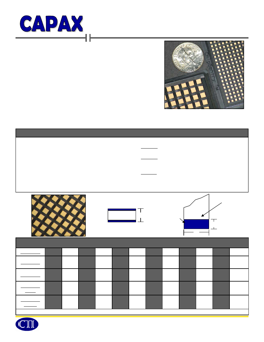
Parallel Plate Ceramic Single Layer Microwave Capacitors (SLCs) 
are ideally suited for applications such as GaAs integrated 


circuits, microwave integrated circuits, DC block, bypass, and tuning,  
and RF/microwave components. The SLC design offers 


increased capacitance for additional bandwidth, increased stability in 
capacitance over various temperatures, and more capacitance in 
smaller case sizes for greater board density.   


SLCs are suitable solutions for applications that require: 

• 

Through 40 GHz with minimum insertion loss. 

• 

Specified material from a selection of fourteen standard 
dielectric options. 

• 

Imperviousness to electrostatic discharge and more ruggedness than MOS/MNS capacitors. 

• 

Gold plated electrode termination, which is compatible with solder, eutectic, epoxy and wire  
bonding production methods. 

C

ASE

 D

IMENSIONS


in  Inches (mm)


Case Size 

P10 

P13 

P15 

P20 

P25 

P30 

P35 

P40 

P50 

P70 

P90 

PA0 

Width (W) 

.010  

(.254) 

.013 

(.330) 

.015 

 (.381) 

.020  

(.508) 

.025  

(.635) 

.030  

(.762) 

.035  

(.889) 

.040  

(1.02) 

.050  

(1.27) 

.070  

(1.78) 

.90 

(2.29) 

.100  

(2.54) 

Length (L) 

.010 

(.254) 

.013 

(.330) 

.015 

(.381) 

.020 

(.508) 

.025 

(.635) 

.030 

(.762) 

.035 

(.889) 

.040 

(1.02) 

.050 

(1.27) 

.070 

(1.78) 

.100 

(2.54) 

.100 

(2.54) 

Thickness 

(50V) 

.005 

(.127) 

.005 

(.127) 

.005 

(.127) 

.005 

(.127) 

.005 

(.127) 

.005 

(.127) 

.005 

(.127) 

.005 

(.127) 

— 

— 

— 

— 

Thickness 

(100V) 

.007 

(.178) 

.007 

(.178) 

.007 

(.178) 

.007 

(.178) 

.007 

(.178) 

.007 

(.178) 

.007 

(.178) 

.007 

(.178) 

.008 

(.203) 

.008 

(.203) 

.009 

(.229) 

.010 

(.254) 

 ** Tolerance: ±.002 (.050) or 10%  

M

ECHANICAL


• 

Bond Strength: Exceeds MIL-STD-883,  


   Method 2011 Destructive Bond Pull Test 

• 

Die Shear Strength:  Exceeds applicable  


   MIL-STD-883 requirements. 


E

NVIRONMENTAL


• 

Low Voltage Humidity: Paragraph 3.17, MIL-C-49464 

• 

Burn-in/Life Test: MIL-STD-202, Method 108, Condition A/F 

• 

Solderability: MIL-STD-202, Method 208 

H

IGH

 R

ELIABILITY

 T

ESTING


• 

Group A: 100 Hour burn-in, 100% screening. 


• 

Group B: Group A tests, solderability, bond strength,   
   die shear strength, and temperature coefficient. 


• 

Group C: Group B tests, thermal shock, resistance to  
   soldering heat, low voltage humidity, and life test. 

General Specifications 

C

AP


S

TRIPLINE


T

HICKNESS


Ceramic Single-Layer 

Microwave Capacitors


Technologies, Inc 

SLCMicrowaveCapacitors-html.html
background image

C

APAX

 T

ECHNOLOGIES

, I

NC


º

 24842 A

VE

 T

IBBITTS


º

 V

ALENCIA

,  C

A


º

 91355 

º

 661.257.7666 

º

 F

AX

: 661.257.4819 


WWW

.C

APAX

T

ECHNOLOGIES

.C

OM


º

 P

AGE

 2 

º


Dielectric Characteristics


Temperature  

Coefficient 

Temperature  

Range 

Dissipation  

Factor/Frequency 

Insulation  

Resistance 

23 

0 ± 30 ppm 

-55°C to +125°C 

< 0.15%/1MHz 

> 1000 G


37/80/110 

0 ± 30 ppm 

-55°C to +125°C 

< 0.15%/1MHz 

> 1000 G


120 

-750 ± 120 ppm 

-55°C to +125°C 

< 0.25%/1MHz 

> 1000 G


160 

-1500 ± 300 ppm 

-55°C to +125°C 

< 0.25%/1MHz 

> 1000 G


270 

-2200 ± 500 ppm 

-55°C to +125°C 

< 0.25%/1MHz 

> 1000 G


330 

-3300 ± 500 ppm 

-55°C to +125°C 

< 1.50%/1MHz 

> 1000 G


600 

-4700 ± 1000 ppm 

-55°C to +125°C 

< 2.50%/1KHz 

> 100 G


1200 

-5600 ± 1000 ppm 

-55°C to +125°C 

< 2.50%/1KHz 

> 100 G


2000/3000/4000 

± 15% 

-55°C to +125°C 

< 2.50%/1KHz 

> 100 G


12000 

+22%,  -82% 

-30°C to +85°C 

< 4.00%/1KHz 

> 10 G


D

IELECTRIC


    Code             Constant    

.


8000 

+22%,  -56% 

+10°C to +85°C 

< 4.00%/1KHz 

> 10 G


C

APACITANCE


P10  P13  P15  P20 P25 P30 P35  P40 P50 P70 P90 PA0 

C

ODE

  V

ALUE


0R1  0.1pF 


0R2  0.2pF  G 


0R3  0.3pF  G 


0R4  0.4pF 


0R5  0.5pF 


0R6  0.6pF 


0R7  0.7pF 


0R8  0.8pF 


0R9  0.9pF 


1R0  1.0pF 


1R1  1.1pF 


1R2  1.2pF 


1R3  1.3pF 


1R4  1.4pF 


1R5  1.5pF 


1R6  1.6pF 


1R7  1.7pF 


1R8  1.8pF 


1R9  1.9pF 


2R0  2.0pF 


2R1  2.1pF 


2R2  2.2pF 


2R4  2.4pF 


2R7  2.7pF 


3R0  3.0pF 


3R3  3.3pF 


3R6  3.6pF 

3R9  3.9pF 

4R3  4.3pF 

4R7  4.7pF 

5R1  5.1pF 

5R6  5.6pF 

6R2  6.2pF 

6R8  6.8pF 

Capacitance Selection


Ceramic Single-Layer 

Microwave Capacitors


Technologies, Inc 

C

APACITANCE


P10  P13  P15  P20 P25 P30 P35  P40 P50 P70 P90 PA0 

C

ODE

  V

ALUE


6R8 

6.8pF 

7R5 

7.5pF 

8R2 

8.2pF 

9R1 

9.1pF 

100 

10pF 

120 

12pF 

150 

15pF 

180 

18pF 

200 

20pF 

220 

22pF 

270 

27pF 

330 

33pF 

390 

39pF 

470 

47pF 

500 

50pF 

510 

51pF 

560 

56pF 

680 

68pF  

820 

82pF  

101 

100pF    

121 

120pF      

151 

150pF      

181 

180pF      

201 

200pF      

221 

220pF      

271 

270pF 


331 

330pF 


391 

390pF 


471 

470pF 


561 

560pF 


681 

680pF 


821 

820pF 


102  1000pF 


122  1200pF 


SLCMicrowaveCapacitors-html.html
background image

C

APAX

 T

ECHNOLOGIES

, I

NC


º

 24842 A

VE

 T

IBBITTS


º

 V

ALENCIA

,  C

A


º

 91355 

º

 661.257.7666 

º

 F

AX

: 661.257.4819 


WWW

.C

APAX

T

ECHNOLOGIES

.C

OM


º

 P

AGE

 3 

º


Typical Temperature Coefficient 

5.0 


4.0 


3.0 


2.0 


1.0 


-1.0 


-2.0 


-3.0 


-4.0 


-5.0


-60     -40     -20     0       20      40      60     80     100     120   140  

% Capac

itanc

e Change 

Temperature (°C) 

Temperature (°C) 

50 


40 


30 


20 


10 


-10 


-20 


-30 


-40 


-50


% Capac

itanc

e Change 

5.0 


4.0 


3.0 


2.0 


1.0 


-1.0 


-2.0 


-3.0 


-4.0 


-5.0


-60     -40     -20     0       20      40      60     80     100     120   140  

% Capac

itanc

e Change


Temperature (°C) 

-60     -40     -20     0       20      40      60     80     100     120   140  

Temperature (°C) 

50 


40 


30 


20 


10 


-10 


-20 


-30 


-40 


-50


% Capac

itanc

e Change


O

RDERING

 I

NFORMATION


Style 

Case Size 

Dielectric 

Capacitance 

Tolerance 

Voltage 

Termination 

High Rel Testing 

20 

500 

101 

P   Parallel 

     Plate 

10 
15 

20 
25 
30 
35 

40 
50 
70 
90 

A0 


First 2 digits are 

Significant; Third 

digit indicates  

number of Zeros 


Examples:  

201 = 200pF 

2R2 = 2.2pF 

A  ±0.05pF 
B  ±0.10pF 

C  ±0.25pF 
F  ±1% 
G  ±2% 
J   ±5% 

K  ±10% 
M  ±20% 
X  Special 

First 2 digits are 

Significant; Third 

digit indicates  

number of Zeros 

Examples:  

201 = 200V 

151 = 150V 

202 = 2000V 

G   Gold over   
     Nickel Plated 

(RoHS Compliant) 

(Optional) 


 A = Group A 
 B = Groups A & B 
 C = Groups A,  
        B, & C 

 D = Special  
        Testing 

Ceramic Single-Layer 

Microwave Capacitors


Technologies, Inc 

“Z” 

“Y” 

“Y” 

“Z” 

“X” 

“M” 

“L” 

“K” 

“J” 

“U” 

“G” 

“G” 

“U” 

“J” 

“K” 

“L” 

“M” 

-60     -40     -20     0       20      40      60     80     100     120   140  

“V” 

“T” 

“R” 

“P” 

“N” 

“N” 

“P” 

“R” 

“T” 

“V”