116
S
ur
fa
ce
M
ou
nt
Surface Mount
C
ap
ac
ito
rs
Capacitors
S
ur
fa
ce
M
ou
nt
C
ap
ac
ito
rs
High Voltage Ceramic Chip Capacitors
Type CFH
∆
Features
• Surface Mount
• Rated Voltage: 250 VAC, 3000VDC
• Chip Size: 1808, 1812
∆
Applications
• Suitable for wave and reflow soldering
• Use in mobile, facsimile, telephone and other
telecom electronic equipment where lightning
surges occur.
∆
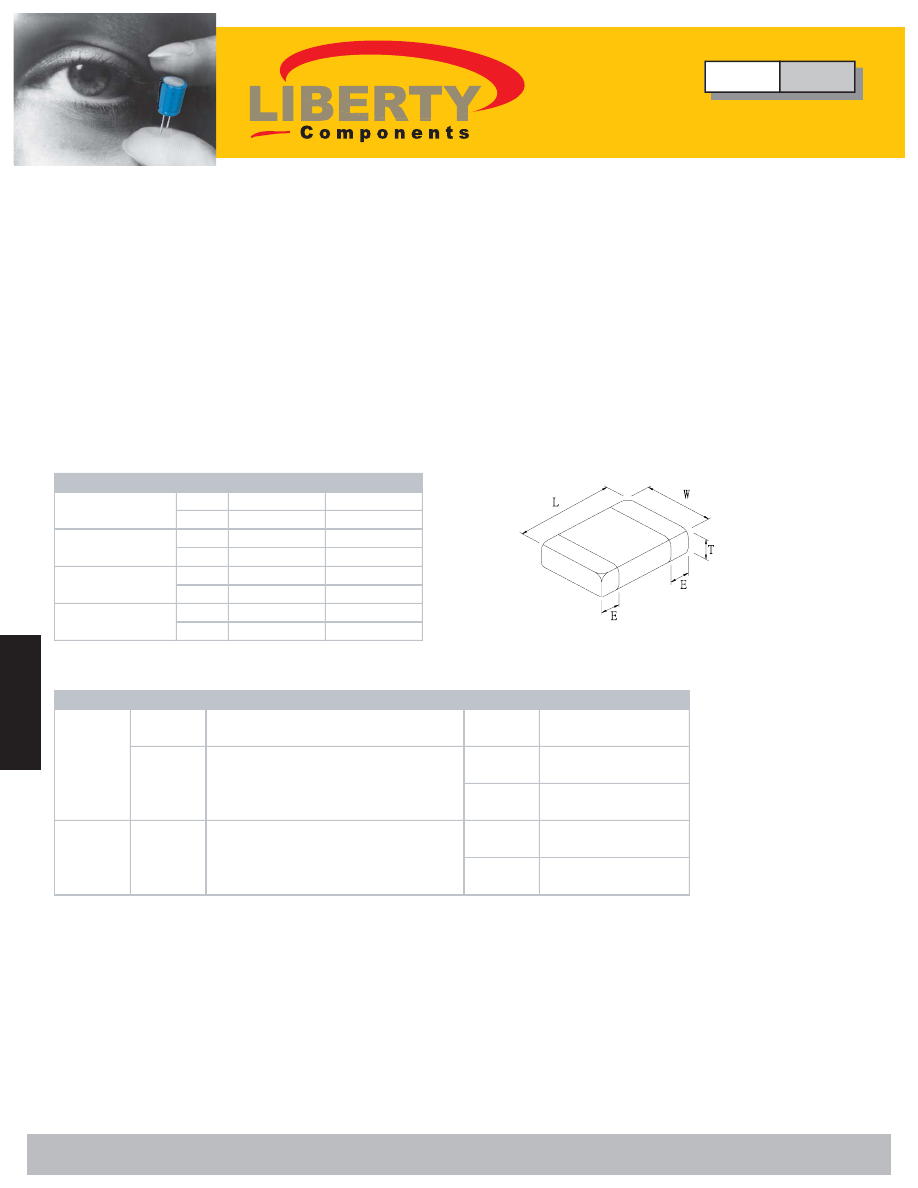
Dimensions
Size
1808
1812
mm
4.60±0.30
0.30± 4.60
(in)
(0.181±0.12)
(0.12±0.181)
mm
2.00±0.20
0.20±3.20
(in)
(0.080±0.008) (0.008±0.126)
mm
0.64±0.38
0.64±0.38
(in)
(0.025±0.015) (0.015±0.025)
mm
2.20
2.70
(in)
(0.087)
(0.106)
(L) Length
(W) Width
(E) Termination
(T) Thickness
Size
Length / Width
Volt
Capacitance
1812
L: 4.60±0.030mm (0.181±0.012)
W: 3.20±0.030mm (0.126±0.012)
250
300pF-2700pF
X2Y3 - TUV/UL
250
150pF-1000pF
X2Y3 - SEMKO
250
150pF-1800pF
X2Y3 - TUV/UL
250
5.0pF-220pF
X2Y3 - SEMKO
250
3pF-1000pF
X2Y3 - TUV/UL
L: 4.60±0.030mm (0.181±0.012)
W: 2.00±0.020mm (0.080±0.008)
1808
X7R
NPO
1808
L: 4.60±0.030mm (0.181±0.012)
W: 2.00±0.020mm (0.080±0.008)
∆
Specifications
Type
CFH
High Voltage Ceramic Chip Capacitors
Liberty Bell Components, Inc. 11631 Seaboard Circle, Stanton, CA 90680 (888)820-8885
Fax: (888)820-8884 email: sales@libertycomponents.com website: www.libertycomponents.com