120
S
ur
fa
ce
M
ou
nt
Surface Mount
C
ap
ac
ito
rs
Capacitors
S
ur
fa
ce
M
ou
nt
C
ap
ac
ito
rs
High Voltage Ceramic Chip Capacitors
Type CFV
∆
Features
• Rated Voltage: 6000VDC
• Chip Size: 2211
∆
Applications
• LAN / WAN Interface
• Telecom Devices
• Industrial Controls
• Power Supply
• Back-Lighting Inverter
• Modems
∆
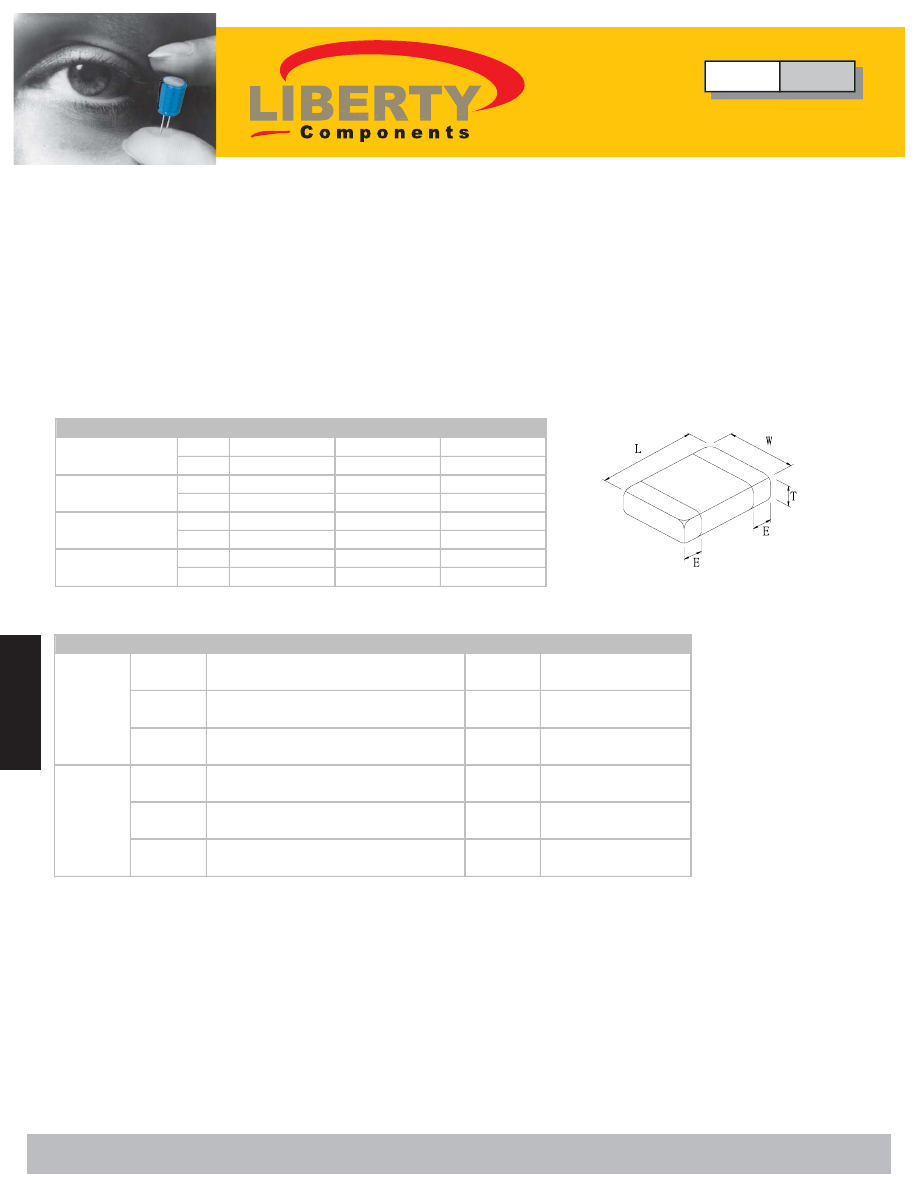
Dimensions
Size
1808
1812
2211
mm
4.60±0.30
4.60±0.30
5.70±0.40
(in)
(.181±.012)
(0.181±.012) (0.224±0.016)
mm
2.00±0.25
3.20±0.30
2.80±0.30
(in)
(.080±.008)
(.126±.012)
(0.112±0.012)
mm
0.64±0.38
0.64±0.38
0.85±0.55
(in)
(.025±.015)
(.025±.015)
(0.033±0.022)
mm
2.20
2.70
2.75
(in)
(0.087)
(0.106)
(0.108)
(L) Length
(W) Width
(E) Termination
(T) Thickness
Size
Length / Width
Volt
Capacitance
1808
L: 4.60±0.30mm (0.181±0.012)
W: 2.00±0.20mm (0.080±0.012)
4000
3pF±100
μ
F
1812
L: 4.60±0.30mm (0.181±0.012)
W: 3.20±0.30mm (0.126±0.012)
5000
1.5pF±100
μ
F
2211
L: 5.70±0.040mm (0.224±0.016)
W: 2.80±0.030mm (0.112±0.012)
6000
2pF±100
μ
F
1808
L: 4.60±0.30mm (0.181±0.012)
W: 2.00±0.20mm (0.080±0.012)
4000
120pF±1000
μ
F
1812
L: 4.60±0.30mm (0.181±0.012)
W: 3.20±0.30mm (0.126±0.012)
4000
150pF±1000
μ
F
2211
L: 5.70±0.040mm (0.224±0.016)
W: 2.80±0.030mm (0.112±0.012)
4000
120pF±2200
μ
F
NPO
X7R
∆
Specifications
Type
CFV
High Voltage Ceramic Chip Capacitors
Liberty Bell Components, Inc. 11631 Seaboard Circle, Stanton, CA 90680 (888)820-8885
Fax: (888)820-8884 email: sales@libertycomponents.com website: www.libertycomponents.com

121
S
ur
fa
ce
M
ou
nt
C
ap
ac
ito
rs
S
ur
fa
ce
M
ou
nt
Surface Mount
C
ap
ac
ito
rs
Capacitors
High Voltage Ceramic Chip Capacitors
Type CFV
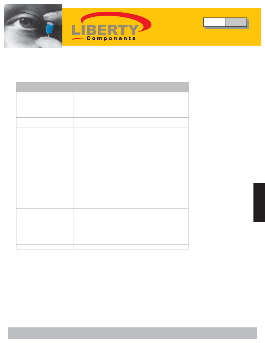
∆
Electrical
EIA
IEC
≤
100V
2.5xUR
≤
100V
2.5xUR
200V/250V
2.0xUR
200V/250V
2.0xUR
500V
1.5xUR
500V
1.5xUR
1KV
≤
UR
≤
3KV 1.2xUR
≥
1KV
1.2xUR
>3KV
1.1xUR
Dissipation Factor (D.F.) and
Tangent of Loss Angle (tan
δ
)
Insulation Resistance (I.R.)
UR<500V:I.R. after 60secs.
Charging at UR (DC)
UR
≥
500V: I.R. after 60 secs.
Charging at 500V (DC)
25°C, 55% RH max.
Withstanding Voltage, 25°C, 1-
5sec.
Capacitance Aging
Not Applicable
≈
1.5% per decade hour
Rated Voltage
Rated Voltage
1KHz, 1Vrms
≤
2.5%
≥
10G
Ω
or
≥
100M
Ω
·
μ
F
whichever is less
≤
0.1% for C
≥
30pF
≤
100% / (400+20C)
for C
≥
30pF
≥
100G
Ω
or
≥
1000M
Ω
·
μ
F
whichever is less
X7R
2R1
∆
C ± 15% maximum
over -55°C tp +125°C
-55°C to +125°C
Dielectric Code
1BCG
COG
0±30ppm/°C, C>20pF
0-40+120ppm/°C, C>20pF
-55°C to +125°C
1MHz, 1Vrms, C
≤
1000pF
1KHz, 1Vrms, C>1000pF
Temperature
Characteristics
Operating Temperature Range
Measuring Conditions for
Capacitance and D.F.
Type
CFV
High Voltage Ceramic Chip Capacitors
Liberty Bell Components, Inc. 11631 Seaboard Circle, Stanton, CA 90680 (888)820-8885
Fax: (888)820-8884 email: sales@libertycomponents.com website: www.libertycomponents.com

122
S
ur
fa
ce
M
ou
nt
Surface Mount
C
ap
ac
ito
rs
Capacitors
S
ur
fa
ce
M
ou
nt
C
ap
ac
ito
rs
High Voltage Ceramic Chip Capacitors
Type CFV
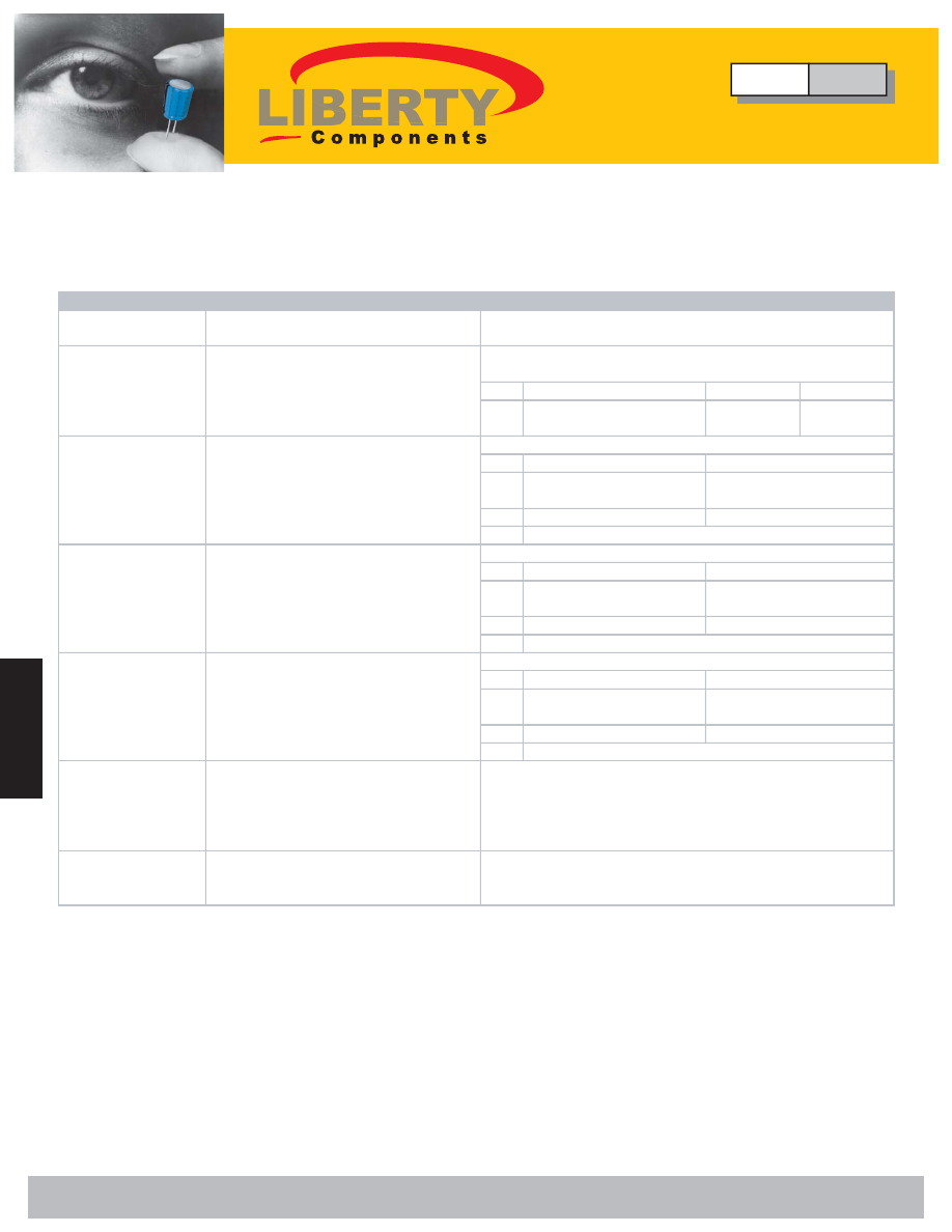
∆
Environmental
Test Test
Conditions
Solderability
Immersed in Solder bath at 245 ± 5°C for
5 ± 0.5 sec.
COG(1BCG) X7R(2R1) Z5U(2E6)
∆
C/C
≤
±1% or ±1pF
whichever is larger
≤
±1%
≤
-10%+20%
COG(1BCG)
∆
C/C
≤
±1% or ±1pF
whichever is larger
D.F.
≤
2.0x initial requirement
I.R.
COG(1BCG)
∆
C/C
≤
±1% or ±1pF
whichever is larger
D.F.
≤
2.0x initial requirement
I.R.
COG(1BCG)
∆
C/C
≤
±2% or ±2pF
whichever is larger
D.F.
≤
2.0x initial requirement
I.R.
Adhesion Strength
of Termination
Capacitors mounted on a substrate. A
force of 5N applied perpendicular to the
place of substrate and parallel the line
joining the center of terminations for 10±1
sec.
Resistance to
Flexure Stress
Capacitors mounted on a substrate. The
board shall then be bent by 1mm at a rate
of 1mm/sec.
No Visible Damage
No Visible Damage
Change in capacitance is less than 10%
Post-Test Inspection Requirements
No Visible Damage
At least 75% of termination area should be well tinned
No Visible Damage
At least 75% of termination area should be well tinned
No Visible Damage
No Visible Damage
X7R(2R1)
≤
±15%
≤
7x initial requirement
≥
0.25x initial requirement
Humidity Test
(Damp heat, steady
state)
500+24-0 hr. at 40 ± 2°C, 90~95% RH
Recovery: 6 ~ 24hr. (COG)
24 ± 2hr. (X7R, Z5U)
Immersed in Solder bath at
260 ± 5°C for 10 ± 1 sec.
Recovery: 6 ~ 24hr. (COG)
24 ± 2hr. (X7R, Z5U)
Resistance to
Soldering Heat
≥
0.25x initial requirement
-55°C to +125°C, 5 cycles (COG,X7R)
Duration: 30 Min.
Recovery: 6 ~ 24hr. (COG)
24 ± 2hr. (X7R, Z5U)
Rapid Change of
Temperature
No Visible Damage
Endurance
(Life Test)
1000+48-0 hr. at maximum temperature
with
≤
3KV: 1.2 x rated voltage applied
>3KV: 1.2 x rated voltage applied
Recovery: 6 ~ 24hr. (COG)
24 ± 2hr. (X7R, Z5U)
≤
±15%
≤
1.5x initial requirement
X7R(2R1)
X7R(2R1)
≤
±15%
≤
1.5x initial requirement
≥
0.25x initial requirement
Type
CFV
High Voltage Ceramic Chip Capacitors
Liberty Bell Components, Inc. 11631 Seaboard Circle, Stanton, CA 90680 (888)820-8885
Fax: (888)820-8884 email: sales@libertycomponents.com website: www.libertycomponents.com

123
S
ur
fa
ce
M
ou
nt
C
ap
ac
ito
rs
S
ur
fa
ce
M
ou
nt
Surface Mount
C
ap
ac
ito
rs
Capacitors
High Voltage Ceramic Chip Capacitors
Type CFV
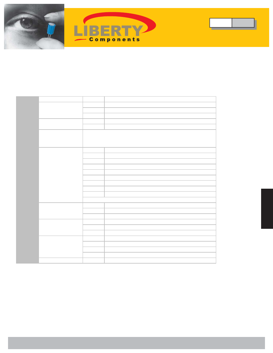
∆
Ordering
CFV 2211 N - 100
J - 602 E F G
(1)
(2) (3)
(4)
(5)
(6) (7) (8) (9)
(1)
Series
CFV:
(2)
1808
1812
2211
N: COG (1BCG)
X: X7R (2R1)
(4)
Capacitance Code
Code
Tolerance
C
±0.25pF
D
±0.5pF
F
±1%
G
±2%
J
±5%
K
±10%
M
±20%
Z
+80% -20%
(6)
402 4000V
502 5000V
602 6000V
TR: Tape and Reel, Cardboard Tape
ER: Tape and Reel, Embossed Tape
No Code: Bulk
Code
Tolerance (mm)
E
1.51-1.80
F
1.81-2.20
G
2.21-2.70
(9)
Special Code
G: Cd/Pb Free
(8)
Thickness Code
(7)
Packaging Code
Size Code
Rated Voltage Code
Capacitance expressed in pF. First two digits are significant
figures. The third Digit denotes number of zeros. Use R for
decimal point for values less than 10pF. (eg. R47: 0.47pF)
Other Tolerances Available Upon Request
(3)
Dielectric Code
(5)
Tolerance Code
Type
CFV
High Voltage Ceramic Chip Capacitors
Liberty Bell Components, Inc. 11631 Seaboard Circle, Stanton, CA 90680 (888)820-8885
Fax: (888)820-8884 email: sales@libertycomponents.com website: www.libertycomponents.com


