98
S
ur
fa
ce
M
ou
nt
Surface Mount
C
ap
ac
ito
rs
Capacitors
S
ur
fa
ce
M
ou
nt
C
ap
ac
ito
rs
• General electronic equipment.
• Class I (T.C. Type) Temperature compensation.
• Class I (T.C. Type) Tuned Circuits and Filters.
• Class II (Hi-K type) By pass and coupling.
CMC 0805 CG 102 J 1H
(1) Type
(2) EIA size code
(3) Temperature characteristics
(4) Nominal capacitance
(5) Capacitance tolerance
(6) Rated voltage
(1)
(2) (3) (4) (5)(6)
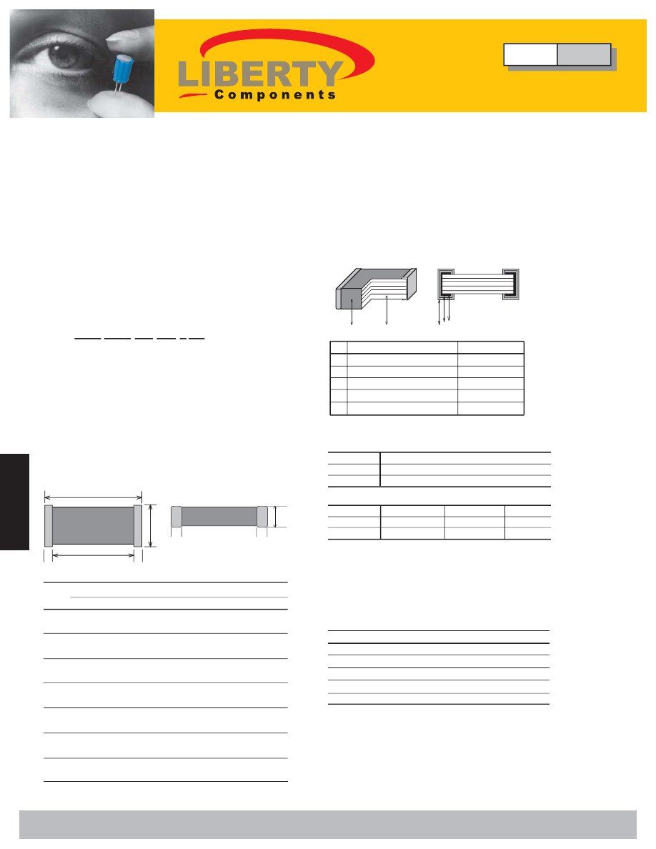
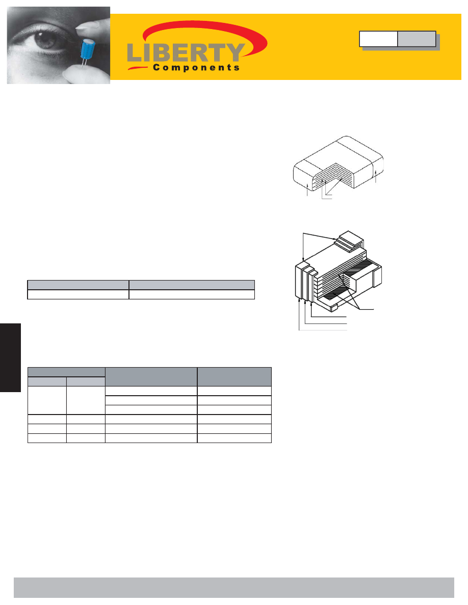
5.
External Electrode
Solder
1
2
5 4 3
NO.
Name
Material
1.
Ceramic Dielectric
Ceramics
2.
Inner Electrode
Palladium
3.
Substrate Electrode
Silver
4.
Intermediate Electrode
Nickel
Class I (Temperature compensating type)
Class II (High dielectric constant type)
Code
C0G(CG)
Temp. range
-55 to 125°C
Temp. Coeff.
0 ± 30ppm/°C
Code
X7R(XR)
Z5U(ZU) Y5V(YV)
Temp. range
-55 to 125°C
+10 to 85°C -30 to 85°C
Cap. change
±15%
+22 to -56% +22 to -82%
(4) Nominal Capacitance Designation
Stated in three digits and in units of pico farads (pF).
The capacitance shall be expressed in a 3 digits code.
The first and second digits identify the first and second
significant figures of the capacitance, the third digit
identifies the multiplier. However, when capacitance is
below 10pF there are decimal digits included, they are
stated as D. Please check examples below:
Symbol
Capacitance (pF)
D50
0.5
D75
0.75
1D5
1.5
100
10
101
100
(3) Temperature characteristics
∆
Features
• Small in size and wide capacitance range.
• Superior humidity characteristic and long life thanks to
the monolithic construction.
• Three layer terminals are made of metal, excellent
solderability and high resistance to migration.
• Low inductance and excellent frequency characteristics
enable a circuit with parameters nearly to the designed
theoretical values.
∆
Part Numbering
∆
Applications
∆
Construction
Nickel Barrier Termination Type
(5) Capacitance Tolerance
(6) Rated Voltage
J = ±5% K = ±10%
1H = 50V
Type
CMC
Multilayer Ceramic Chip Capacitors
"T"
Size
0402
0603
0805
1206
1210
1812
2220
Dimensions in (mm) [Brackets indicate in inches]
L
W
T max. B min.
G min.
1±0.05 0.5±0.05
0.5
0.15
0.3
[0.39±.002] [0.20±.002] [0.20]
[.006]
[0.12]
1.6±0.1 0.8±0.1
0.9
0.2
0.3
[.063±.004] [.031±.004] [.035]
[.008]
[.012]
2.0±0.2 1.25±0.2
1.45
0.2
0.5
[.079±.008] [.049±.008] [.057]
[.008]
[.020]
3.2±0.2 1.6±0.2
1.30
0.2
1.0
[.126±.008] [.063±.008] [.051]
[.008]
[.039]
3.2±0.4 2.5±0.3
1.90
0.3
1.0
[.126±.016] [.098±.012] [.075]
[.012]
[.039]
4.5±0.5 3.2±0.4
1.90
0.4
2.0
[.177±0.20] [.126±.016] [.075]
[.016]
[.079]
5.6±0.5 5.0±0.5
1.90
0.4
2.0
[.220±.020] [.197±.020] [.075]
[.016]
[.079]
"L"
"G"
"W"
B
B
B
B
(2) Size and Dimensions
Liberty Bell Components, Inc. 11631 Seaboard Circle, Stanton, CA 90680 (888)820-8885
Fax: (888)820-8884 email: sales@libertycomponents.com website: www.libertycomponents.com
SMD-C-S-NPO-html.html
99
S
ur
fa
ce
M
ou
nt
C
ap
ac
ito
rs
S
ur
fa
ce
M
ou
nt
Surface Mount
C
ap
ac
ito
rs
Capacitors
Multilayer Ceramic Chip Capacitors
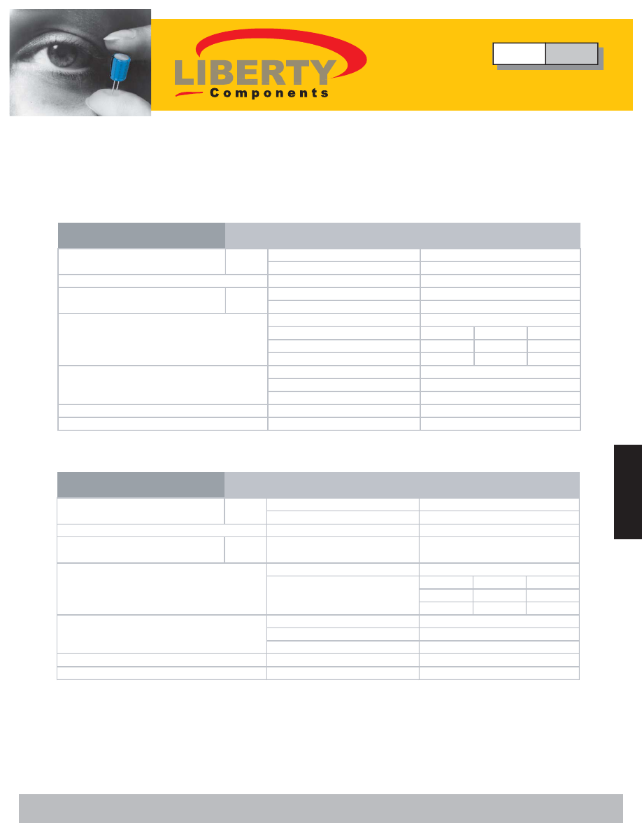
Performance Specifications
1. Electrical
Dielectric Code
DIA
COG
IEC
1BCG
Temperature Characteristics
*1
0±30ppm/ºC, C>20pF
+120 ~ -40ppm/ºC,C 20pF
-55ºC to +125ºC
Measuring Conditions for
*2
1 MHz, 1 Crms, C 1000pF
Capacitance and D.F.
1 MHz, 1 Crms, C > 1000pF
0.1% for C 30 pF
100%/(400+20C) for C < 30pF 2.5%
50V
3.5%
25V
16V
5.0%
10V
6.3V
100 G
Ω
or
1000 M
Ω
x
μ
F
whichever is less
2.5 x Rated Voltage
0
Operating Temperature Range
Insulation Resistance (I.R.) after
Angle (tan
δ
)
and Tangent of Loss
Dissipation Factor (D.F.)
Voltage Proof, 25ºC, 1-5 secs.
Capacitance Aging
voltage, 25ºC, 55% RH max.
60 secs. Charging at rated
100 M
Ω
x
μ
F
whichever is less
2.5 x Rated Voltage
approx. = 1.5% per decade hour
-55ºC to +125ºC
1KHz, 1 Vrms
rated voltage
10 G
Ω
or
X7R
2R1
Δ
C±15% maximum
over -55ºC to +125ºC
Dielectric Code
DIA
Z5U
IEC
2E6
Temperature Characteristics
*1
Δ
C+22%,-56% maximum
over +10ºC to +85ºC
+10ºC to +85ºC
Measuring Conditions for
*2
1KHz, 0.5Vrms
Capacitance and D.F.
4.0% 50V
6.0% 25V
5.0%
50V
50V
7.0%
25V
16V
10.0%
10V
6.3V
10 G
Ω
or
100 M
Ω
x
μ
F
whichever is less
2.5 x Rated Voltage
approx. = 5% per decade hour
Operating Temperature Range
Insulation Resistance (I.R.) after
Angle (tan
δ
)
and Tangent of Loss
Dissipation Factor (D.F.)
Voltage Proof, 25ºC, 1-5 secs.
Capacitance Aging
voltage, 25ºC, 55% RH max.
60 secs. Charging at rated
100 M
Ω
x
μ
F
whichever is less
2.5 x Rated Voltage
approx. = 3% per decade hour
-30ºC to +85ºC
1KHz, 10 Vrms
rated voltage
10 G
Ω
or
Y5V
2F4
Δ
C+22%,-82% maximum
over -30ºC to +85ºC
Type
CMC
Multilayer Ceramic Chip Capacitors
Liberty Bell Components, Inc. 11631 Seaboard Circle, Stanton, CA 90680 (888)820-8885
Fax: (888)820-8884 email: sales@libertycomponents.com website: www.libertycomponents.com
SMD-C-S-NPO-html.html
100
S
ur
fa
ce
M
ou
nt
Surface Mount
C
ap
ac
ito
rs
Capacitors
S
ur
fa
ce
M
ou
nt
C
ap
ac
ito
rs
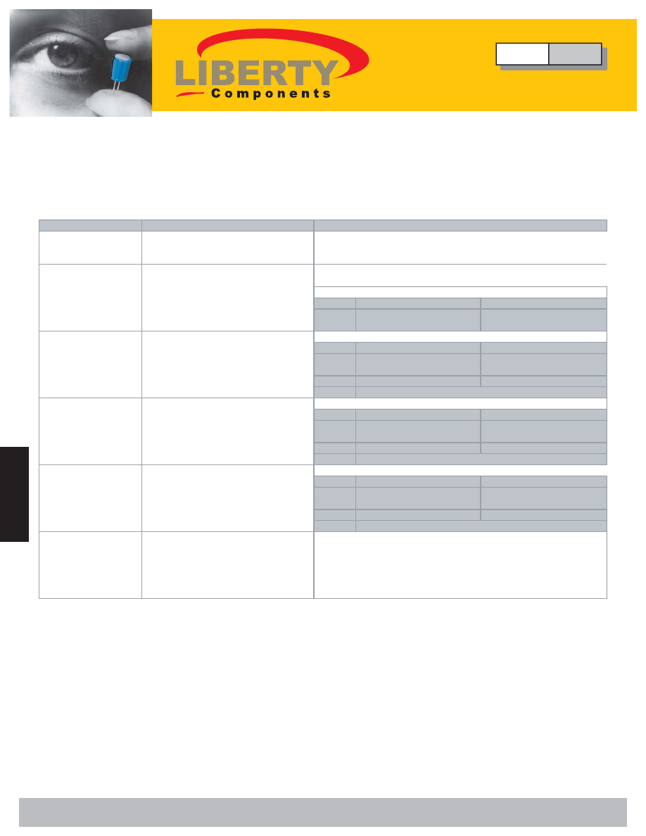
Multilayer Ceramic Chip Capacitors
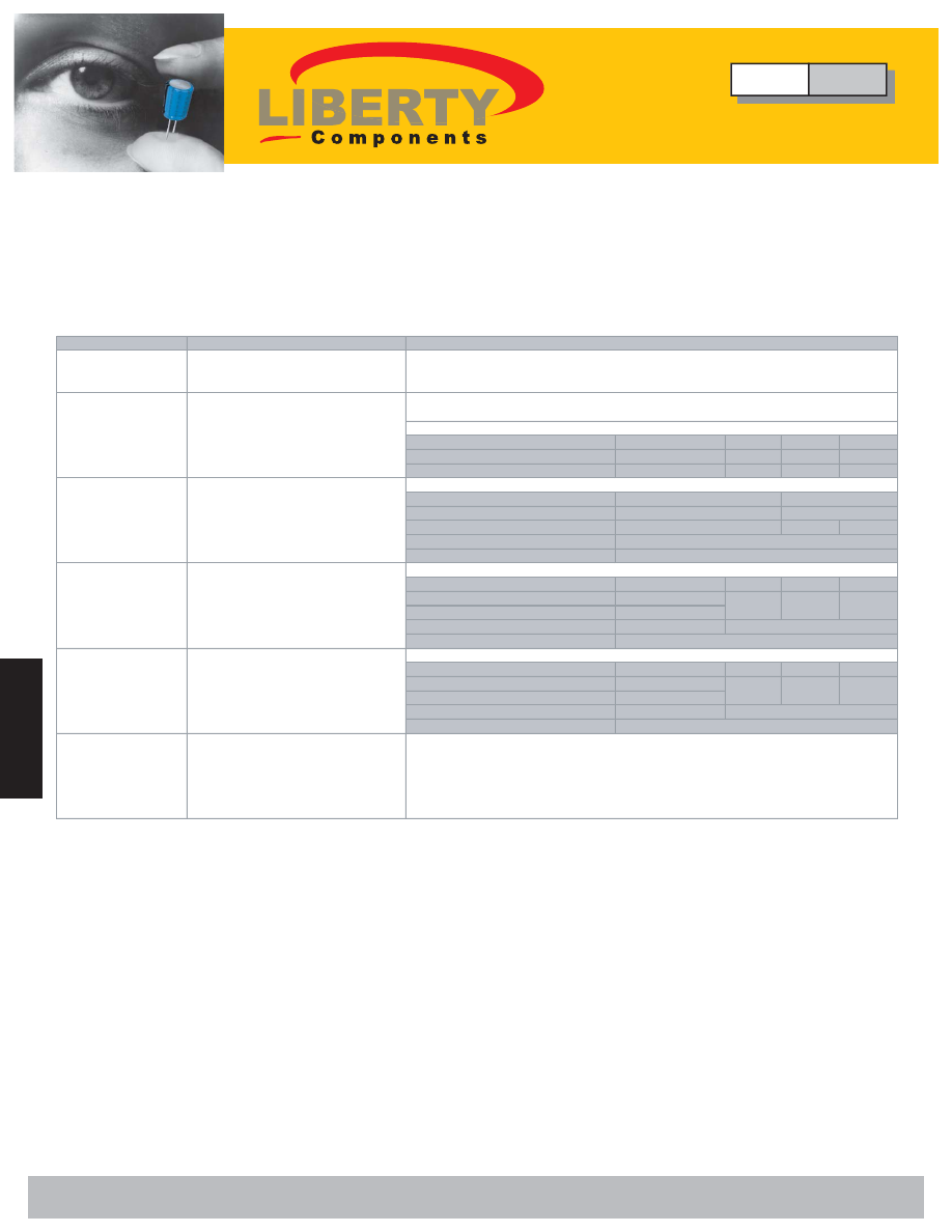
Performance Specifications
2. Environmental
Test Test
Conditions
Solderability
IEC 384-10 4.11/JIS C 5102 8.13
Solder 60 Sn/40 Pb, 235±1 secs.
Immersed for 5 secs.
Resistance to
IEC 384-10 4.10/JIS C 5102 8.14
Soldering Heat
Immersed in solder bath at
260±5ºC for 10±1 secs.
Recovery: 6~24 hrs. (COG)
COG(1BCG)
X7R(2R1) Z5U(2E6) Y5U(2F4)
24±2 hrs. (X7R, Z5U, Y5V)
Δ
C/C
±0.5%, or ±0.5pF + 10%
+20%
+20%
whichever is greater -5%
-10%
-10%
Rapid Change of
IEC 384-10 4.12/JIS C 5102 9.3
Temperature
-55ºC to + 125ºC, 5 cycles(COG,X7R)
Duration: 30 mins.
Δ
C/C
Recovery: 6~24 hrs. (COG)
24±2hrs. (X7R)
D.F.
I.R.
Endurance (Life Test)
IEC 384-10 4.15
1000 hrs. at max. temperature with
COG(1BCG)
X7R(2R1) Z5U(2E6) Y5U(2F4)
1.5 x rated voltage applied
Δ
C/C
±2%, or ±1pF
±20%
±20%
±30%
Recovery: 6~24 hrs. (COG)
whichever is greater
24±2 hrs. (X7R, Z5U, Y5V)
D.F.
2.0 x initial req.
I.R.
Humidity Test
IEC 384-10 4.14/JIS C 5102 9.5
(Damp heat,
500 hrs. at 40±2ºC, 90-95% RH
COG(1BCG)
X7R(2R1) Z5U(2E6) Y5U(2F4)
steady state)
Recovery: 6~24 hrs. (COG)
Δ
C/C
±2%, or ±1pF
±10%
±20%
±30%
24±2 hrs. (X7R, Z5U, Y5V)
whichever is greater
D.F.
2.0 x initial req.
I.R.
Adhesion
IEC 384-10 4.8/JIS C 5102 8.11.2
Capacitors mounted on a substrate.
A force of 5N applied perpendicular to
the plane of substrate and parallel the
line joining the center of terminations for
10±1 secs.
No visible damage.
No visible damage.
No visible damage.
No visible damage.
No visible damage.
At least 75% of termination area should
be well tinned.
No visible damage.
At least 75% of termination area should
be covered by solder.
1.5 x initial requirement
0.25 x initial requirement
Post-Test Inspection Requirements
X7R(2R1)
±10%
COG(1BCG)
±1%, or ±1pF
whichever is greater
1.5 x initial requirement
0.25 x initial requirement
1.5 x initial requirement
0.25 x initial requirement
Type
CMC
Multilayer Ceramic Chip Capacitors
Liberty Bell Components, Inc. 11631 Seaboard Circle, Stanton, CA 90680 (888)820-8885
Fax: (888)820-8884 email: sales@libertycomponents.com website: www.libertycomponents.com
SMD-C-S-NPO-html.html
101
S
ur
fa
ce
M
ou
nt
C
ap
ac
ito
rs
S
ur
fa
ce
M
ou
nt
Surface Mount
C
ap
ac
ito
rs
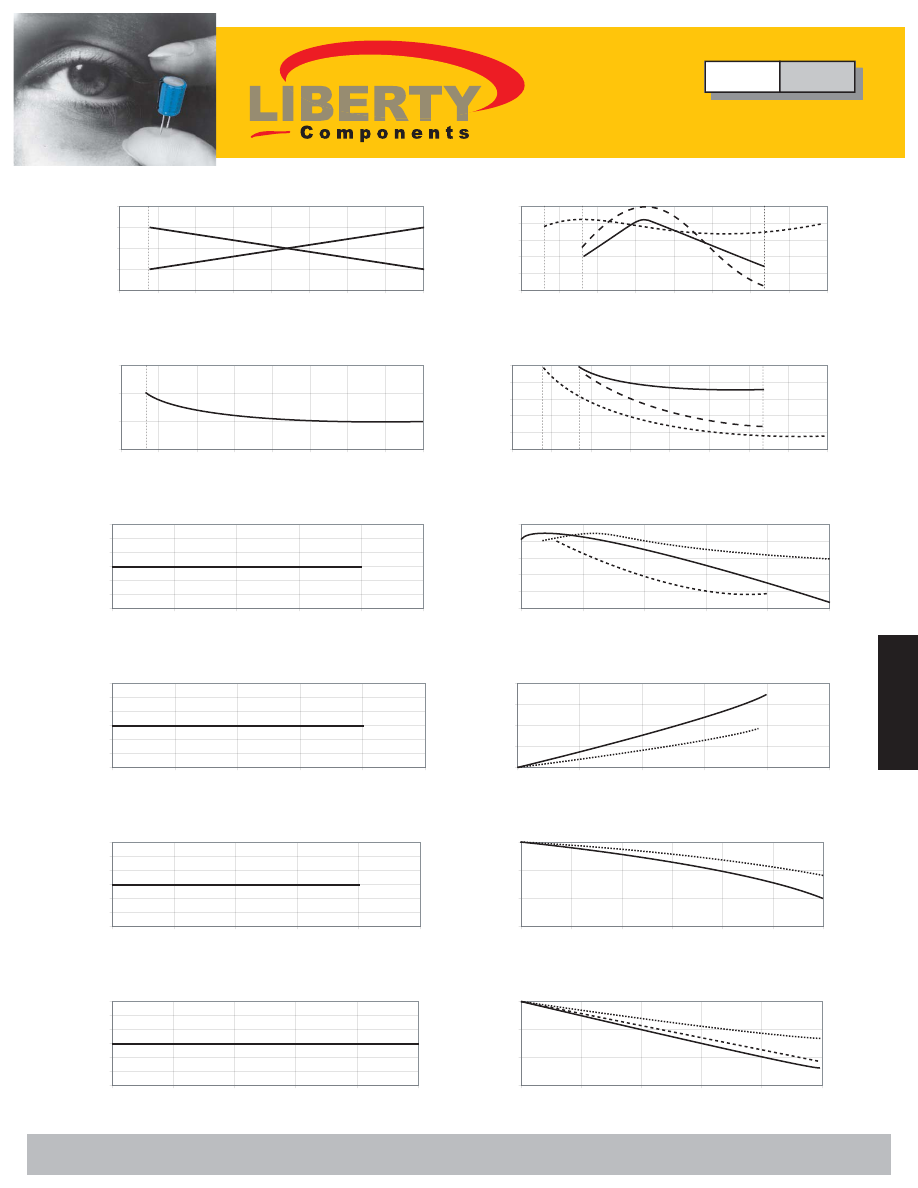
Capacitors
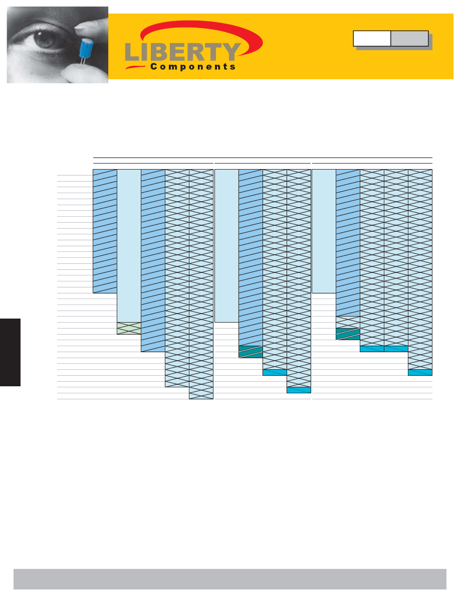
-0.6
-0.3
0
0.3
0.6
-75
-50
-25
0
25
50
75
100
125
Temperature (°C)
Δ
C
(
%
)
0
0.05
0.1
0.15
-75
-50
-25
0
25
50
75
100
125
Temperature (°C)
D.F. (%)
-3
-2
-1
0
1
2
3
0
50
100
150
200
250
DC Voltage (V)
Δ
C (
%
)
-3
-2
-1
0
1
2
3
0
4
8
12
16
20
AC Voltage (Vrms)
Δ
C (
%
)
-3
-2
-1
0
1
2
3
0.1
1
10
100
1000
10000
Time (hours)
Δ
C
(
%
)
-80
-60
-40
-20
0
20
-75
-50
-25
0
25
50
75
100
125
Temperature (°C)
Δ
C
(
%
)
0
1
2
3
4
5
-75
-50
-25
0
25
50
75
100
125
Temperature (°C)
D.
F
. (
%
)
-80
-60
-40
-20
0
20
0
10
20
30
40
50
DC Voltage (V)
Δ
C (
%
)
0
10
20
30
40
0
5
10
15
20
25
AC Voltage (Vrms)
Δ
C (
%
)
-30
-20
-10
0
0.1
1
10
100
1000
10000
Time (hours)
Δ
C
(
%
)
-3
-2
-1
0
1
2
3
0.01
0.1
1
10
100
1000
Frequency (MHz)
Δ
C (
%
)
-30
-20
-10
0
0.001
0.01
0.1
1
10
100
1000
Frequency (MHz)
Δ
C (
%
)
COG(1B)
X7R (2R1), Z5U (2E6), Y5V(2F4)
X7R
Z5U
Y5V
X7R
Z5U
Y5V
X7R
Z5U
Y5V
X7R
Z5U & Y5V
X7R
Z5U & Y5V
X7R
Y5V
Z5U
Type
CMC
Multilayer Ceramic Chip Capacitors
Liberty Bell Components, Inc. 11631 Seaboard Circle, Stanton, CA 90680 (888)820-8885
Fax: (888)820-8884 email: sales@libertycomponents.com website: www.libertycomponents.com
SMD-C-S-NPO-html.html
102
S
ur
fa
ce
M
ou
nt
Surface Mount
C
ap
ac
ito
rs
Capacitors
S
ur
fa
ce
M
ou
nt
C
ap
ac
ito
rs
Multilayer Ceramic Chip Capacitors
Type CMC Series
• Nickel-barrier terminations are finished by electroplated solder
• Suitable for thick-film hybrid circuits and automatic surface mounting
• Nickel barrier layer in terminations prevents dissolution of termination
Termination
Electrodes
Ceramic Layer
Termination
Electrodes
Silver Metallization
Nickel Barrier Layer
Solder Plated Layer
Termination (Nickel Barrier)
Termination Material
Test Conditions
Nickel-barrier, Solder plated 260 ºC, 60 Sn/40 Pb, 10 secs
Available Tolerance
Capacitance
EIA
IEC
± 0.25 pF
5 pF
COG
1BCG
± 0.5 pF
5pF < CAP < 10 pF
± 1%, ±2%, ±5%, ±10%
10 pF
X7R
2R1
± 5%, ±10%, ±20%
All values
Z5U
2E6
± 20%, +80% ~ -20%
All values
Y5V
2F4
± 20%, +80% ~ -20%
All values
Dielectric
∆
Features
∆
Applications
∆
Resistance to Soldering
∆
Tolerances Available
Type
CMC
Multilayer Ceramic Chip Capacitors
Liberty Bell Components, Inc. 11631 Seaboard Circle, Stanton, CA 90680 (888)820-8885
Fax: (888)820-8884 email: sales@libertycomponents.com website: www.libertycomponents.com
SMD-C-S-NPO-html.html
103
S
ur
fa
ce
M
ou
nt
C
ap
ac
ito
rs
S
ur
fa
ce
M
ou
nt
Surface Mount
C
ap
ac
ito
rs
Capacitors
Multilayer Ceramic Chip Capacitors
Application Notes
COOLING
After soldering, cool the chips and the substrate gradually to room temperature.
Natural cooling in air is recommend to minimize stress in the colder joint. A cooling
rate not exceeding 4° C/sec should be used when forced cooling is necessary.
CLEANING
All flux residues must be removed by using suitable electronix-grade vapor-cleaning
solvents to eleiminate contamination that could cause electrolytic-surface corrosion.
Good results can be obtained by using ultrasonic cleaning of the solvent. The choice of
the proper system is dependent upon many factors such as componenet mix, flux, and
solder paste and assembly method. The ability of the cleaning system to remove flux
residues and contamination from under the chips is very important.
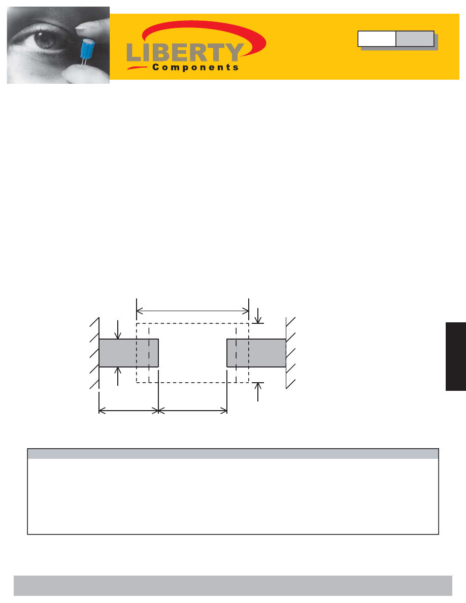
RECOMMENED PAD DIMENSIONS (for reflow soldering)
L
W
B
C
A
Unit: mm (inch)
Chip Size
L
W
A
B
C
0603
1.6 (0.063)
0.8 (0.032)
0.6~0.8 (0.024~0.032)
0.6~0.8 (0.024~0.032)
0.6~0.7 (0.024~0.028)
0805
2.0 (0.080)
1.2 (0.050)
1.0~1.2 (0.039~0.047)
0.8~1.1 (0.032~0.043)
0.6~0.7 (0.024~0.028)
1206
3.2 (0.126)
1.6 (0.063)
2.2~2.4 (0.087~0.094)
1.0~1.4 (0.039~0.055)
0.8~0.9 (0.032~0.035)
1210
3.2 (0.126)
2.5 (0.100)
2.0~2.4 (0.080~0.094)
1.8~2.3 (0.071~0.091)
1.0~1.2 (0.039~0.047)
1808
4.5 (0.177)
2.0 (0.080)
2.8~3.4 (0.110~0.134)
1.4~1.8 (0.055~0.071)
1.2~1.4 (0.047~0.055)
1812
4.5 (0.177)
3.2 (0.126)
3.0~3.5 (0.118~0.138)
2.3~3.0 (0.091~0.118)
1.2~1.4 (0.047~0.055)
Type
CMC
Multilayer Ceramic Chip Capacitors
Liberty Bell Components, Inc. 11631 Seaboard Circle, Stanton, CA 90680 (888)820-8885
Fax: (888)820-8884 email: sales@libertycomponents.com website: www.libertycomponents.com
SMD-C-S-NPO-html.html
104
S
ur
fa
ce
M
ou
nt
Surface Mount
C
ap
ac
ito
rs
Capacitors
S
ur
fa
ce
M
ou
nt
C
ap
ac
ito
rs
Multilayer Ceramic Chip Capacitors
Performance Specifications
2. Environmental
Test Test
Conditions
IEC 384-10 4.11/JIS C 5102 8.13
Solder 60 Sn/40 Pb, 235±5ºC
Immersed for 5 secs.
IEC 384-10 4.10/JIS C 5102 8.14
Immersed in solder bath at
260±5ºC for 10±1 secs.
Recovery: 6~24 hrs. (COG)
COG(1BCG)
X7R(2R1)
24±2 hrs. (X7R)
Δ
C/C
±1%, or ±1pF
whichever is greater
IEC 384-10 4.12/JIS C 5102 9.3
-55ºC to + 125ºC, 5 cycles(COG,X7R)
COG(1BCG)
X7R(2R1)
Duration: 30 mins.
Δ
C/C
±1%, or ±1pF
Recovery: 6~24 hrs. (COG)
whichever is greater
24±2hrs. (X7R)
D.F.
≤
2.0 x initial requirement
≤
1.5 x initial requirement
I.R.
IEC 384-10 4.15
1000 hrs. at max. temperature with
COG(1BCG)
X7R(2R1)
1.5 x rated voltage applied
Δ
C/C
±2%, or ±1pF
Recovery: 6~24 hrs. (COG)
whichever is greater
24±2hrs. (X7R)
D.F.
≤
2.0 x initial requirement
≤
7%
I.R.
IEC 384-10 4.14/JIS C 5102 9.5
500 hrs. at 40±2ºC, 90-95% RH
COG(1BCG)
X7R(2R1)
Recovery: 6~24 hrs. (COG)
Δ
C/C
±2%, or ±1pF
±10%
24±2hrs. (X7R)
whichever is greater
D.F.
≤
2.0 x initial requirement
≤
7%
I.R.
IEC 384-10 4.8/JIS C 5102 8.11.2
No visible damage.
≤
±7%
≤
±15%
≤
±20%
≥
0.25 x initial requirement
≥
0.25 x initial requirement
≥
0.25 x initial requirement
No visible damage.
be covered by solder.
No visible damage.
No visible damage.
No visible damage.
Post-Test Inspection Requirements
At least 75% of termination area should
be well tinned.
No visible damage.
Solderability
Resistance to
Soldering Heat
Rapid Change of
Temperature
Endurance (Life Test)
At least 75% of termination area should
Humidity Test (Damp
heat, steady state)
Adhesion
Capacitors mounted on a substrate. A
force of 5N applied perpendicular to the
lane of substrate and parallel the line
joining the center of terminations for 10±1
secs.
Type
CMC
Multilayer Ceramic Chip Capacitors
C0G(NP0)
Liberty Bell Components, Inc. 11631 Seaboard Circle, Stanton, CA 90680 (888)820-8885
Fax: (888)820-8884 email: sales@libertycomponents.com website: www.libertycomponents.com
SMD-C-S-NPO-html.html
105
S
ur
fa
ce
M
ou
nt
C
ap
ac
ito
rs
S
ur
fa
ce
M
ou
nt
Surface Mount
C
ap
ac
ito
rs
Capacitors
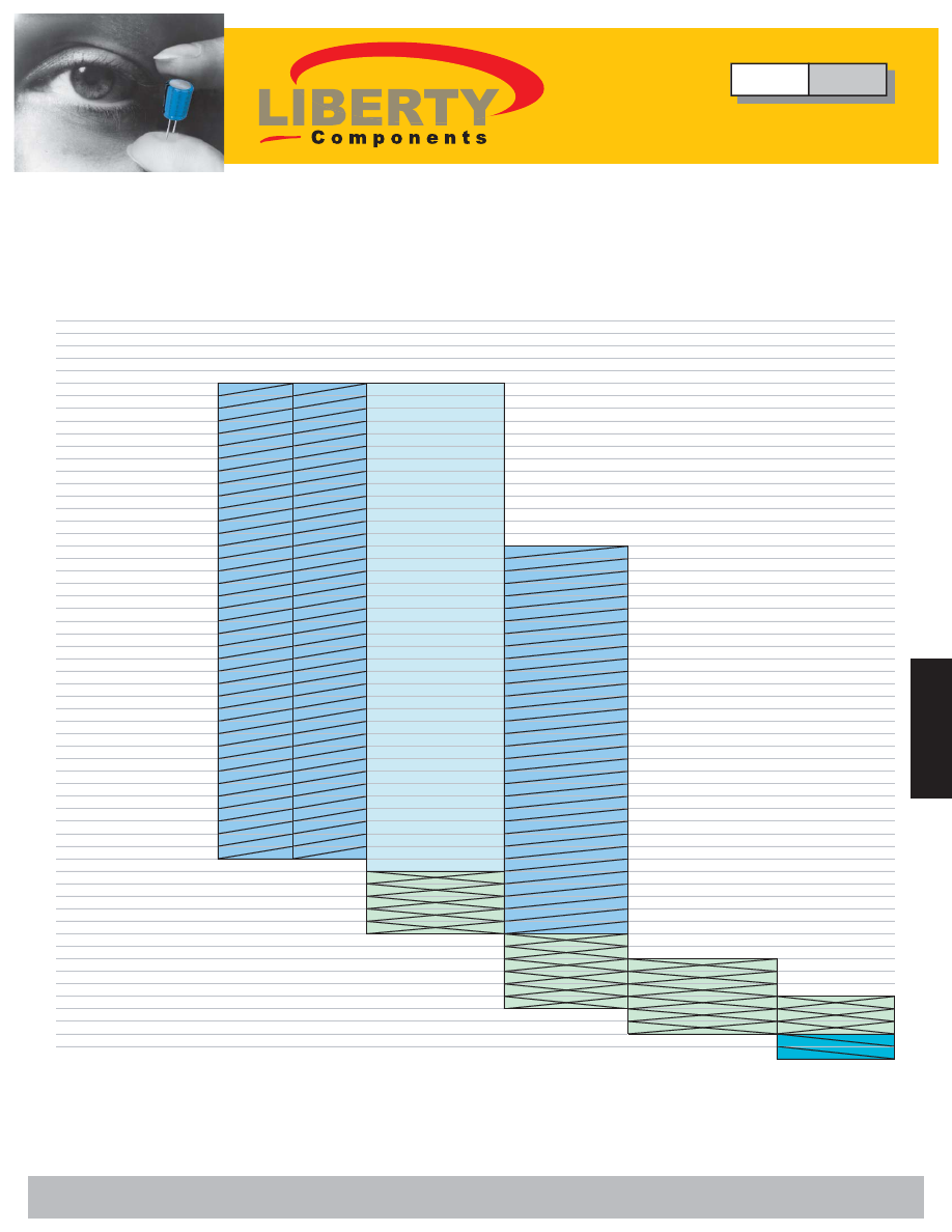
Multilayer Ceramic Chip Capacitors
Type CMC Series
COG (NPO)
EIA/IEC Dielectric Code: COG/1BCG
0805
1206
1210
1812
2.00±0.20(0.080±0.008)
3.20±0.20(0.126±0.008)
3.20±0.30(0.126±0.012)
4.50±0.30(0.177±0.012)
1.20±0.20(0.050±0.008)
1.60±0.20(0.063±0.008)
2.50±0.30(0.100±0.012)
3.20±0.30(0.126±0.012)
0.50±0.20(0.020±0.008)
0.50±0.20(0.020±0.008)
0.50±0.20(0.020±0.008)
0.64±0.38(0.025±0.015)
25
50
50
50
50
50
Cap 0.47
(pf)
1.0
1.2
1.5
1.8
2.2
2.7
3.3
3.9
4.7
5.6
6.8
8.2
10
12
15
18
22
27
33
39
47
56
68
82
100
120
150
180
220
270
330
390
470
560
680
820
1000
1200
1500
1800
2200
2700
3300
3900
4700
5600
6800
8200
Cap.
.010
(
μ
F)
.012
.015
.018
.022
1.60±0.15(0.063±0.006)
0.08±0.15(0.032±0.06)
0.40±0.20(0.16±0.008)
COG/1BCG
Size
EIA/IEC Dielectric Code
0603
W.V.D.C.
(E) Termination mm(in)
(W) Width mm(in)
(L) Length mm(in)
Type
CMC
Multilayer Ceramic Chip Capacitors
C0G(NP0)
Liberty Bell Components, Inc. 11631 Seaboard Circle, Stanton, CA 90680 (888)820-8885
Fax: (888)820-8884 email: sales@libertycomponents.com website: www.libertycomponents.com
SMD-C-S-NPO-html.html
106
S
ur
fa
ce
M
ou
nt
Surface Mount
C
ap
ac
ito
rs
Capacitors
S
ur
fa
ce
M
ou
nt
C
ap
ac
ito
rs
Multilayer Ceramic Chip Capacitors
Type CMC - High Voltage Series
COG (NPO)
EIA/IEC Dielectric Code: COG/1BCG
0603
0805
1206
1210
1812
0805
1206
1210
1812
0805
1206
1210
1808
1812
Cap. 10
(pF)
12
15
18
22
27
33
39
47
56
68
82
100
120
150
180
220
270
330
390
470
560
680
820
1000
1200
1500
1800
2200
2700
3300
3900
4700
5600
6800
8200
Cap. .010
(pF)
.012
.015
500V
COG / 1BCG
EIA/IEC Dielectric Code
Size
W.V.D.C.
100V
250V
Type
CMC
Multilayer Ceramic Chip Capacitors
C0G(NP0)
Liberty Bell Components, Inc. 11631 Seaboard Circle, Stanton, CA 90680 (888)820-8885
Fax: (888)820-8884 email: sales@libertycomponents.com website: www.libertycomponents.com