98
S
ur
fa
ce
M
ou
nt
Surface Mount
C
ap
ac
ito
rs
Capacitors
S
ur
fa
ce
M
ou
nt
C
ap
ac
ito
rs
• General electronic equipment.
• Class I (T.C. Type) Temperature compensation.
• Class I (T.C. Type) Tuned Circuits and Filters.
• Class II (Hi-K type) By pass and coupling.
CMC 0805 CG 102 J 1H
(1) Type
(2) EIA size code
(3) Temperature characteristics
(4) Nominal capacitance
(5) Capacitance tolerance
(6) Rated voltage
(1)
(2) (3) (4) (5)(6)
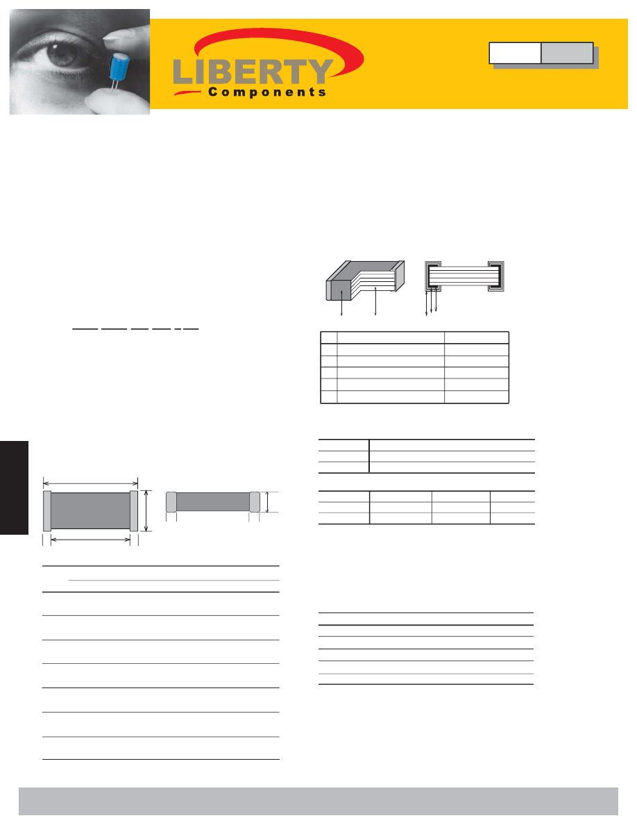
5.
External Electrode
Solder
1
2
5 4 3
NO.
Name
Material
1.
Ceramic Dielectric
Ceramics
2.
Inner Electrode
Palladium
3.
Substrate Electrode
Silver
4.
Intermediate Electrode
Nickel
Class I (Temperature compensating type)
Class II (High dielectric constant type)
Code
C0G(CG)
Temp. range
-55 to 125°C
Temp. Coeff.
0 ± 30ppm/°C
Code
X7R(XR)
Z5U(ZU) Y5V(YV)
Temp. range
-55 to 125°C
+10 to 85°C -30 to 85°C
Cap. change
±15%
+22 to -56% +22 to -82%
(4) Nominal Capacitance Designation
Stated in three digits and in units of pico farads (pF).
The capacitance shall be expressed in a 3 digits code.
The first and second digits identify the first and second
significant figures of the capacitance, the third digit
identifies the multiplier. However, when capacitance is
below 10pF there are decimal digits included, they are
stated as D. Please check examples below:
Symbol
Capacitance (pF)
D50
0.5
D75
0.75
1D5
1.5
100
10
101
100
(3) Temperature characteristics
∆
Features
• Small in size and wide capacitance range.
• Superior humidity characteristic and long life thanks to
the monolithic construction.
• Three layer terminals are made of metal, excellent
solderability and high resistance to migration.
• Low inductance and excellent frequency characteristics
enable a circuit with parameters nearly to the designed
theoretical values.
∆
Part Numbering
∆
Applications
∆
Construction
Nickel Barrier Termination Type
(5) Capacitance Tolerance
(6) Rated Voltage
J = ±5% K = ±10%
1H = 50V
Type
CMC
Multilayer Ceramic Chip Capacitors
"T"
Size
0402
0603
0805
1206
1210
1812
2220
Dimensions in (mm) [Brackets indicate in inches]
L
W
T max. B min.
G min.
1±0.05 0.5±0.05
0.5
0.15
0.3
[0.39±.002] [0.20±.002] [0.20]
[.006]
[0.12]
1.6±0.1 0.8±0.1
0.9
0.2
0.3
[.063±.004] [.031±.004] [.035]
[.008]
[.012]
2.0±0.2 1.25±0.2
1.45
0.2
0.5
[.079±.008] [.049±.008] [.057]
[.008]
[.020]
3.2±0.2 1.6±0.2
1.30
0.2
1.0
[.126±.008] [.063±.008] [.051]
[.008]
[.039]
3.2±0.4 2.5±0.3
1.90
0.3
1.0
[.126±.016] [.098±.012] [.075]
[.012]
[.039]
4.5±0.5 3.2±0.4
1.90
0.4
2.0
[.177±0.20] [.126±.016] [.075]
[.016]
[.079]
5.6±0.5 5.0±0.5
1.90
0.4
2.0
[.220±.020] [.197±.020] [.075]
[.016]
[.079]
"L"
"G"
"W"
B
B
B
B
(2) Size and Dimensions
Liberty Bell Components, Inc. 11631 Seaboard Circle, Stanton, CA 90680 (888)820-8885
Fax: (888)820-8884 email: sales@libertycomponents.com website: www.libertycomponents.com