background image

155

S

ur

fa

ce

 M

ou

nt

R

es

is

to

rs

S

ur

fa

ce

 M

ou

nt

Surface Mount

R

es

is

to

rs

Resistors

Chip Resistor Array 
Type RCA 

 Features 

• Suitable for lead free soldering 
• compatible with flow and reflow soldering 

 Applications 

• Automotive, Medical, and Telecom Industries

 Part Number

Type

Size

Isolated

Circuit Configuration

Packaging

Tolerance

Resistor Value

RCA

1206

B

8

T

J

103

Chip Size

Isolated

Circuit 8P/4R

Taping

Example

Example

J=5%

102=1K

Ω

F=1%

103=10K

Ω

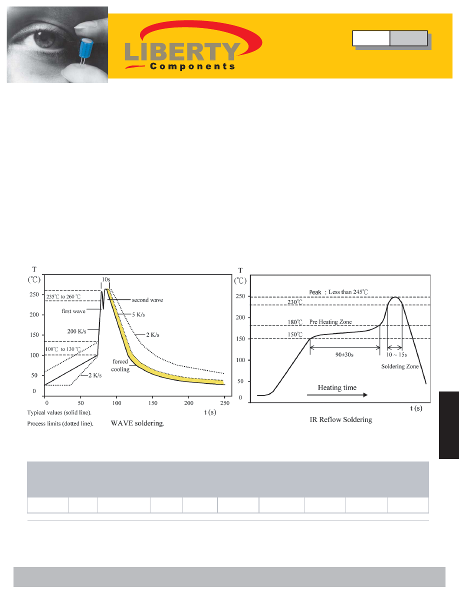
 Soldering Temperature Curve

Min.

Max.

RCA 1206

8P4R

1/16W (Element)

50V

100V

±5%(J)

±1%(F)

±200

0

Ω

,10

Ω

1M

Ω

E-24

Standard 

Resistance 

Values

·Lead Free Chip Resistor Array

Jumper: 8P4R size maximum resistance Rmax = 50m

Ω

 and rated current I

R

 = 1A

Resistance Range (

Ω

)

Type

Size

Power
Rating

at 70°C

Max. 

RCWV

Max. 

Overload

Voltage

Resistance

Tolerance (%)

Temperature 

Coefficient 

(TCR: ppm/°C)

 Rating

Type

RCA

Chip Resistor Array

 Liberty Bell Components, Inc. 11631 Seaboard Circle,  Stanton, CA 90680 (888)820-8885

Fax: (888)820-8884   email: sales@libertycomponents.com   website: www.libertycomponents.com

SMD-R-CR-RCA-html.html
background image

156

S

ur

fa

ce

 M

ou

nt

Surface Mount

R

es

is

to

rs

Resistors

S

ur

fa

ce

 M

ou

nt

R

es

is

to

rs

 Configuration 

Inner Termination Layer: Ag, Pd/Ag 
MIddle Termination Layer: Nickel 
Outer Termination Layer: Solder 

 Dimensions 

 Circuit 

Size L  W  T  C  D  P  b1 b2 

8P4R 3.20±0.20 

1.60±0.10 

0.50±0.10 

0.30±0.20 0.30±0.20 0.80±0.05 0.45±0.10 0.70±0.20 

(unit: mm) 

RCA1206 

20 

40 

60 

80 

100 

-55 -45 -35 -25 -15 -5  5  15 25 35 45 55 65 75 85 95 105 115 125 

Temperature °C 

Ra

te

d

 L

o

ad

 (

%

 Power Derating Curve 

For resistors operated in ambient temperature over 70°C, Power rating shall be 
derated in accordance with the curve above. 

 Product Category 

• Lead Free Chip Resistor Array (RCA1206) Convex

Type

RCA

Chip Resistor Array

 Liberty Bell Components, Inc. 11631 Seaboard Circle,  Stanton, CA 90680 (888)820-8885

Fax: (888)820-8884   email: sales@libertycomponents.com   website: www.libertycomponents.com

SMD-R-CR-RCA-html.html
background image

157

S

ur

fa

ce

 M

ou

nt

R

es

is

to

rs

S

ur

fa

ce

 M

ou

nt

Surface Mount

R

es

is

to

rs

Resistors

 Product Category 

• Specification and Test Method 

ITEM SPECIFICATION 

TEST 

METHOD 

DC Resistance 

J :  ± 5 % ,  F : ± 1 % 

Zero Ohm Jumper  <  50 m

Ω


IEC 115-1 4.5 / JIS C 5202 5.1 
Measure the resistance value. 

Short Time 

Overload 

J :   

 ±  ( 2 % +  0 . 1 

Ω

 ) 

F :   

 ±  ( 1 % +  0 . 05 

Ω

 ) 

IEC 115-1 4.13 / JIS C 5202 5.5 
2.5xRated voltage or Max. Overload Voltage for 5 sec. 
measure resistance after 30 minutes. 

Solderability 

Over 95% of termination 

must be covered with solder 

IEC 115-1 4.17 / JIS C 5202 6.5 
After immersing flux ,  dip in the  245 ± 2 °C molten solder 
bath for  3 ± 0 . 5  sec . 

Resistance to 

Solder Heat 

J :   

 ±  ( 1 % +  0 . 1 

Ω

 ) 

F :   

 ±  ( 0 . 5 % +  0 . 05 

Ω

 ) 

No mechanical damage 

IEC 115-1 4.18 / JIS C 5202 6.4 
with  260 ± 5 °C for  10 ± 1 sec . 

Temperature 

Coefficient of  

Resistance 

(TCR) 

± 200 ppm / °C 

IEC 115-1 4.8.4.2 / JIS C 5202 5.2 
Test Temperature :  25 °C ( T 1 )  

  - 55 °C ( T 2 ) 

                           25 °C ( T 1 )  

  125 °C ( T 2 ) 

TCR  ( ppm / °C ) = ( R 2 - R 1 )/ R 1 ( T 2 - T 1 )  x 10

R1: Resistance at reference temperature (T1) 
R2: Resistance at test temperature (T2) 

Load Life 

Humidity 

J :   

 ±  ( 3 % +  0 . 1 

Ω

 ) 

F :   

 ±  ( 1 % +  0 . 05 

Ω

 ) 

IEC 115-1 4.24.2 / JIS C 5202 7.9 
Maintain the temperature of the resistor at  40 ± 2 °C and  
90~95% R.H. with the rated voltage applied. Cycle ON  
for 1.5 hours. After 1~4 hour, measure the resistance  
value. 

Load Life 

J :   

 ±  ( 3 % +  0 . 1 

Ω

 ) 

F :   

 ±  ( 1 % +  0 . 05 

Ω

 ) 

IEC 115-1 4.25.1 / JIS C 5202 7.10 
Permanent resistance change after 1000+48/-0 hours  
(1.5 hours ON, 0.5 hour OFF) at RCWV or MAX. 
Keep the resistor at  70 ± 2 °C ambient 

Intermittent 

Overload 

 ±  ( 3 % +  0 . 1 

Ω

 ) 

No mechanical damage 

JIS C 5202 5.8 
4.0xRated voltage (Max. Overload Voltage) 
1 sec ON, 25 sec OFF, test 10,000 cycles 

Temperature 

Cycle 

J :   

 ±  ( 1 % +  0 . 1 

Ω

 ) 

F :   

 ±  ( 0 . 5 % +  0 . 05 

Ω

 ) 

No mechanical damage 

IEC 115-1 4.19 / JIS C 5202 7.4 
Repeat 5 cycles as follows 
- 55 °C  ( 30 min ) + 25 °C ( 2 ~ 3 min ) 
+ 125 °C  ( 30 min ) + 25 °C ( 2 ~ 3 min ) 

Insulation Resistance 

Between termination and coating 

must be over  1000 M

Ω


IEC 115-1 4.6.1.1 / JIS C 5202 5.6 
Test voltage :  100 ± 15 V 

Bending Strength 

J :   

 ±  ( 1 % +  0 . 1 

Ω

 ) 

F :   

 ±  ( 0 . 5 % +  0 . 05 

Ω

 ) 

No mechanical damage 

IEC 115-1 4.33 
Resistance change after bended on the 90mm PCB. 
Bend: 3min 

Type

RCA

Chip Resistor Array

 Liberty Bell Components, Inc. 11631 Seaboard Circle,  Stanton, CA 90680 (888)820-8885

Fax: (888)820-8884   email: sales@libertycomponents.com   website: www.libertycomponents.com