background image

135

S

ur

fa

ce

 M

ou

nt

R

es

is

to

rs

S

ur

fa

ce

 M

ou

nt

Surface Mount

R

es

is

to

rs

Resistors

Part Number

E-24 Series

E-96 Series

Thick Film Chip Resistors
Type MCR Series

 How to Order

 Resistance Marking

473

1542

0C2

ex. 473: 47x10^3 = 47K

Ω

105: 10x10^5 = 1M

Ω

1R5: 15x10^-1 = 1.5

Ω

0:  0

Ω

3 digit marking for E24

1R00

ex. 1R00: 1

Ω

R470 470m

Ω

R010 10m

Ω

4 digit marking for E241: 

Ω

~10m

Ω

ex. 1542: 154x10^2 = 15K4

Ω

4 digit marking for E96

ex.

0C2 (see table)

102x10^2 = 10K2

Ω

3 digit marking for E96 - 0603

• Small size and lightweight with size range per int’l standard.
• Highly stable in auto-placement surface mounting application.

• Compatible with flow and reflow soldering.

 Features

• Suitable for lead free soldering.

 Applications

• Consumer electronics

• Automotive, industry
• Computer

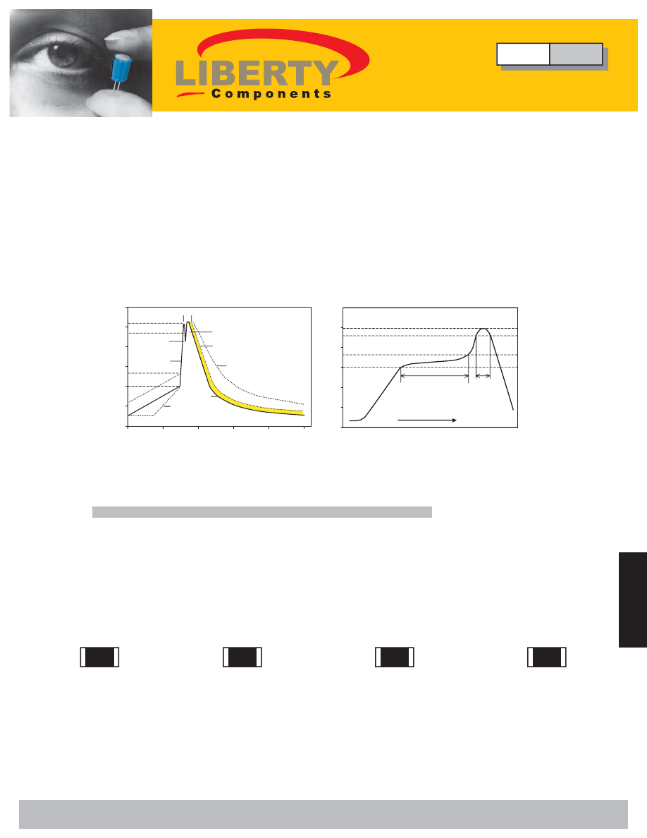
 Soldering Temperature Curve

Typical values (solid line).

Process limits (dotted line).

WAVE soldering.

IR Reflow Soldering

Peak : Less than 245

˚

C

230

˚

C

180

˚

C Pre Heating Zone

150

˚

C

Soldering Zone

0

t (s)

T

(

˚

C

)

90±30s

   10 ~ 15s

Heating time

50

250

200

150

100

second wave

0

0

t (s)

200 K/s

2 K/s

200

250

150

100

50

50

100

150

200

2 K/s

5 K/s

250

T

(

˚

C

)

first wave

forced

cooling

10s

235

˚

C to 260

˚

C

100

˚

C to 130

˚

C

Example

MCR

0603

Type

Size

MCR

0201

T: Tape

B: ±0.1%

123 = 12x10^3 LF = Lead Free

0402

C: ±0.25%

= 12k 

Ω

0603

D: ±0.5%

0805

F: ±1%

1206

G: ±2%

1210

J: ±5%

2010
2512

LF

123

Resistance Value

Packing

Tolerance

T

J

• Medical equipment
• Telecom equipment

Type

MCR

Thick Film Chip Resistors

 Liberty Bell Components, Inc. 11631 Seaboard Circle,  Stanton, CA 90680 (888)820-8885

Fax: (888)820-8884   email: sales@libertycomponents.com   website: www.libertycomponents.com

SMD-R-MCR-html.html
background image

136

S

ur

fa

ce

 M

ou

nt

Surface Mount

R

es

is

to

rs

Resistors

S

ur

fa

ce

 M

ou

nt

R

es

is

to

rs

Thick Film Chip Resistors 
Type MCR Series 

 Configuration 

Protective Coating 

High Purity 
Alumina Substrate 

Resistive Element (RuO

2

Inner Termination 
Layer: Ag.Pd/Ag 

Outer Termination 
Layer: Solder 

Middle Termination 
Layer: Nickel 

 Dimensions 

Size L 


0201 

0.60 ± 0.05 

0.30 ± 0.05 

0.25 ± 0.05 

0.15 ± 0.05 

0.25 ± 0.05 

0402 

1.00 ± 0.05 

0.50 ± 0.05 

0.20 ± 0.10  

0.25 ± 0.10  

0.35 ± 0.05 

0603 

1.60 ± 0.10  

0.80 ± 0.10  

0.30 ± 0.20  

0.30 ± 0.20  

0.45 ± 0.10  

0805 

2.00 ± 0.15  

1.20 ± 0.15  

0.40 ± 0.20 

0.40 ± 0.20 

0.50 ± 0.10 

1206 

3.10 ± 0.15  

1.60 ± 0.15  

0.50 ± 0.25  

0.50 ± 0.25  

0.55 ± 0.10 

1210 

3.10 ± 0.15  

2.65 ± 0.15  

0.50 ± 0.20  

0.50 ± 0.25  

0.55 ± 0.10 

2010 

5.00 ± 0.20  

2.50 ± 0.20  

0.60 ± 0.25  

0.60 ± 0.25  

0.60 ± 0.10 

2512 

6.30 ± 0.20  

3.10 ± 0.20  

0.60 ± 0.25  

0.60 ± 0.25  

0.60 ± 0.15  

1225 

3.10 ± 0.20 

6.30 ± 0.20 

0.60 ± 0.25  

0.90 ± 0.25  

0.60 ± 0.15  

 Power Derating Curve 

 *Maximum dissipation in percentage of rated power as a function of the ambient temperature. 

For All Except 0201 

50 

100 

-50 0  50 100 

150 

Temperature (°C) 

Ra

te

d

 L

o

ad

 (

%

For 0201 Only 

50 

100 

-50 0  50 100 

150 

Temperature (°C) 

Ra

te

d

 L

o

ad

 (

%

70 155 

70 

125 

Type

MCR

Thick Film Chip Resistors

units: mm

 Liberty Bell Components, Inc. 11631 Seaboard Circle,  Stanton, CA 90680 (888)820-8885

Fax: (888)820-8884   email: sales@libertycomponents.com   website: www.libertycomponents.com

SMD-R-MCR-html.html
background image

137

S

ur

fa

ce

 M

ou

nt

R

es

is

to

rs

S

ur

fa

ce

 M

ou

nt

Surface Mount

R

es

is

to

rs

Resistors

Thick Film Chip Resistors
Type MCR Series

 Rating

 Low Resistance

Type

Size

0201

0402

0603

0805

1206

2010

2512

Power 

Rating

at 70

˚

1/20W

1/16W

1/10W

1/8W

1/4W

1/2W

1W

Max.

RCWV

15V 

50V 

50V 

150V 

200V 

200V 

200V 

Max. 

Overload

Voltage

30V

100V

100V

300V

400V

400V

400V

± 300

± 200

± 50
± 50

1M

Ω

1M

Ω

1M

Ω

10M

Ω

510K

Ω

510K

Ω

510K

Ω

1M

Ω

10M

Ω

10M

Ω

10M

Ω

10M

Ω

10M

Ω

10M

Ω

20

Ω

20

Ω

20

Ω

10

Ω

1

Ω

0

Ω

&1

Ω

1

Ω

0

Ω

&1

Ω

1

Ω

0

Ω

&1

Ω

10

Ω

0

Ω

&1

Ω

10

Ω

0

Ω

&1

Ω

± 200
± 200

± 100
± 200

± 100
± 200

± 50

± 100   ± 50

Resistance 

Tolerance 

(%) 

± 1%(F)

± 1%(F)

±0. 1%(B)

± 0.5%(D)

± 2%(G)

± 1%(F)

± 1%(F)

± 5%(J)

± 5%(J)

±0.2 5%(C)

± 1%(F)

± 5%(J)

± 5%(J)

± 5%(J)

Temperature 

Coefficient

 (TCR; ppm/

˚

C )

Resistance

Range

Standard 

Resistance 

Values

Min.           Max.

E-24 

E-96 
E-24 
E-96 
E-96 

E-96 
E-96 

E-24 
E-24 

E-96 
E-24 

E-96 
E-24 

Type

Size

0603

0805

1206

2010

2512

1225

Power 

Rating

at 70

˚

1/10W

1/8W

1/4W

1/2W

1W

2W

Max.

RCWV

302mV 

337mV 

477mV 

675mV 

954mV 

1349mV 

Max. 

Overload

Voltage

754mV

843mV

1192mV

1686mV

2385mV

3373mV

± 300

± 400

± 200

910m

Ω

91m

Ω

910m

Ω

20m

Ω

47m

Ω

39m

Ω

910m

Ω

19m

Ω

40m

Ω

22m

Ω

100m

Ω

10m

Ω

50m

Ω

50m

Ω

20m

Ω

10m

Ω

± 400
± 600

± 1%(F)

± 5%(J)

± 1%(F)

± 5%(J)

± 1%(F)

± 5%(J)

± 100
± 150

Resistance 

Tolerance 

(%) 

Temperature 

Coefficient

 (TCR; ppm/

˚

C )

Resistance

Range

Min.           Max.

± 1000

0201,0402,0603 size maximum resistance Rmax

50m

Ω

 and rated current I

R

1A

0805,1206,2010,2512 size maximum resistance Rmax

50m

Ω

 and rated current I

R

2A

Temperature Coefficient of Resistance for 0402,0603,0805,1206 = -300~+500

Temperature Coefficient of Resistance for 0201,2010,2512 = ± 300

Jumper : 

1

Ω

~10

Ω

:

Type

MCR

Thick Film Chip Resistors

 Liberty Bell Components, Inc. 11631 Seaboard Circle,  Stanton, CA 90680 (888)820-8885

Fax: (888)820-8884   email: sales@libertycomponents.com   website: www.libertycomponents.com

SMD-R-MCR-html.html
background image

138

S

ur

fa

ce

 M

ou

nt

Surface Mount

R

es

is

to

rs

Resistors

S

ur

fa

ce

 M

ou

nt

R

es

is

to

rs

Thick Film Chip Resistors
Type MCR Series

 Specifications and Test Methods

ITEM

SPECIFICATION

DC Resistance

J :± 5%  

G:± 2% F: 

± 1%

D:± 0.5%     C: ± 0.25% B: 

± 0.1%

Zero ohm Jumper

50m

Ω

TEST METHOD

Between termination and coating
must be over 1000M

Ω

Insulation
Resistance

IEC 60115-1 4.6.1.1 / JIS C 5202 5.6
Test voltage: 100 ± 15V

         J,G:

R

±  (1% + 0.1

Ω

F,D,C,B:

R

±  (0.5% + 0.05

Ω

No mechanical damage 

Bending
Strength

IEC 60115-1 4.33
Resistance change after bended on the 90mm PCB.
Bend: 3mm for 0201 , 0402 , 0603 , 0805
2mm for 1206 , 2010 , 1225 , 2512 

IEC 60115-1 4.5 / JIS C 5202 5.1                              
Measure the resistance value.

J,G:


R

±  (2% + 0.1

Ω

F,D:


R

±  (1% + 0.05

Ω

C,B:


R

±  (0.5% + 0.05

Ω

)

Short time         
Overload

IEC 60115-1 4.13 / JIS C 5202 5.5
2.5X Rated voltage or Max. Overload Voltage 
for 5 sec. measure resistance after 30 minutes                         

Over 95%  of  termination
must be covered with solder

Solderability

IEC 60115-1 4.17 / JIS C 5202 6.5                                                    
After immersing flux, dip in the 245

± 2

˚

molten solder bath for 3 ± 0.5 sec. 

 J,G:

R

±  (1% + 0.1

Ω

F,D,C,B:

R

±  (0.5% + 0.05

Ω

)

No mechanical damage 

Resistance to
Solder Heat

IEC 60115-1 4.18 / JIS C 5202 6.4                                               
With 260 ± 5

˚

C  for 10 ± 1 sec.

J,G:

R

±  (3% + 0.1

Ω

F,D:

R

±  (1% + 0.05

Ω

C,B:

R

±  (0.5% + 0.05

Ω

)

Load Life
Humidity

IEC 60115-1 4.24.2 / JIS C 5202 7.9                                      
Maintain the temperature of the resistor at 40

± 2

˚

and 90~95% R.H. with the rated voltage 
applied.Cycle ON for 1.5 hours and OFF for 0.5 hour 
for 1000+48/-0 hours. After 1~4 hour, measure the 
resistance value.                           

J,G:

R

±  (3% + 0.1

Ω

F,D:

R

±  (1% + 0.05

Ω

C,B:

R

±  (0.5% + 0.05

Ω

)

Load Life

IEC 60115-1 4.25.1 / JIS C 5202 7.10                                                             
Permanent resistance change after 1000+48/-0 
hours (1.5 hours ON , 0.5 hour OFF) at   RCWV 
or Max.Keep the resistor at 70 ± 2

˚

C   ambient 

R

±  (5% + 0.1

Ω

No mechanical damage 

Intermittent
Overload

JIS C 5202 5.8                                                                          
4.0xRated voltage (Max. Overload Voltage)                             
1 sec ON, 25 sec OFF, test 10,000 cycles  

         J,G:

R

±  (1% + 0.1

Ω

F,D,C,B:

R

±  (0.5% + 0.05

Ω

No mechanical damage 

Temperature
Cycle

IEC 60115-1 4.19 / JIS C 5202 7.4                                                
Repeat 5 cycles as follows                                                                         
 -55

˚

C(30 min.) ~  + 25

˚

C(2~3 min.)                                         

+125

˚

C(30 min.) ~  + 25

˚

C(2~3 min.) for 0201                     

 -55

˚

C(30 min.) ~  + 25

˚

C(2~3 min.)                                         

+155

˚

C(30 min.) ~  + 25

˚

C(2~3 min.) for  others 

      J,G:± 200ppm/

˚

C


F:± 100  ± 50ppm/

˚

C

D,C,B:± 50ppm/

˚

C

Temperature
Coefficient of 
Resistance
 (TCR)

IEC 60115-1 4.8.4.2 / JIS C 5202 5.2 
Test temperature : 25

˚

C (T1)

 -55

˚

C (T2)

                                          25

˚

C (T1)

 125

˚

C (T2)

TCR (ppm/

˚

C)   =

R2-R1

R1

x

x

T2-T1

1

10

6

T1: 25

˚

C    T2: Test temperature

R1: Resistance at reference temperature (T1)
R2: Resistance at test temperature (T2)

Type

MCR

Thick Film Chip Resistors

 Liberty Bell Components, Inc. 11631 Seaboard Circle,  Stanton, CA 90680 (888)820-8885

Fax: (888)820-8884   email: sales@libertycomponents.com   website: www.libertycomponents.com

SMD-R-MCR-html.html
background image

139

S

ur

fa

ce

 M

ou

nt

R

es

is

to

rs

S

ur

fa

ce

 M

ou

nt

Surface Mount

R

es

is

to

rs

Resistors

Thick Film Chip Resistors
Type MCR Series - Low Resistance

 Specifications and Test Methods

ITEM

SPECIFICATION

DC Resistance

J :± 5%,  F:  ±1% 

J:

R

±  (2% + 0.5m

Ω

F:

R

±  (1% + 0.5m

Ω

J:

R

±  (3% + 0.5m

Ω

F:

R

±  (1% + 0.5m

Ω

J:

R

±  (3% + 0.5m

Ω

F:


R

±  (1% + 0.5m

Ω

J:


R

±  (1% + 0.5m

Ω

F:


R

±  (0.5% + 0.5m

Ω

)

No mechanical damage 

J:

R

±  (1% + 1m

Ω

F:


R

±  (0.5% +1m

Ω

)

No mechanical damage 

J:


R

±  (1% + 1m

Ω

F:

R

±  (0.5% +1m

Ω

)

No mechanical damage 

Size : 0603 , 0805
             100m

Ω

 ~ 910m

Ω

:± 300ppm/

˚

C

Size : 1206 , 2010 , 2512
             50m

Ω

 ~ 910m

Ω

:± 200ppm/

˚

C

Size : 1225
             20m

Ω

 ~ 910m

Ω

:± 100ppm/

˚

C

Over 95%  of  termination
must be covered with solder

TEST METHOD

Short time         
Overload

Solderability

Resistance to
Solder Heat

Load Life
Humidity

Load Life

Temperature
Cycle

Insulation
Resistance

Bending
Strength

Temperature
Coefficient of 
Resistance
 (TCR)

referance for other resistance 
range in page 4

Between termination and coating
must be over 1000M

Ω

IEC 60115-1 4.6.1.1 / JIS C 5202 5.6
Test voltage: 100 ± 15V

IEC 60115-1 4.33
Resistance change after bended on the 90mm PCB.
Bend: 3mm for 0201 , 0402 , 0603 , 0805
2mm for 1206 , 2010 , 1225 , 2512 

IEC 60115-1 4.5 / JIS C 5202 5.1                              
Measure the resistance value.

IEC 60115-1 4.13 / JIS C 5202 5.5
2.5X Rated voltage or Max. Overload Voltage 
for 5 sec. measure resistance after 30 minutes                         

IEC 60115-1 4.17 / JIS C 5202 6.5                                                    
After immersing flux, dip in the 245 ± 2 

˚

C  

molten solder bath for 3 ± 0.5 sec. 

IEC 60115-1 4.18 / JIS C 5202 6.4                                               
With 260 ± 5

˚

C for 10 ± 1 sec.

IEC 60115-1 4.24.2 / JIS C 5202 7.9                                      
Maintain the temperature of the resistor at 40 ± 2 

˚

C


and 90~95% R.H. with the rated voltage 
applied.Cycle ON for 1.5 hours and OFF for 0.5 hour 
for 1000+48/-0 hours. After 1~4 hour, measure the 
resistance value.                           

IEC 60115-1 4.25.1 / JIS C 5202 7.10                                                             
Permanent resistance change after 1000+48/-0 
hours (1.5 hours ON , 0.5 hour OFF) at   RCWV 
or Max.Keep the resistor at 70 ± 2

˚

C ambient 

IEC 60115-1 4.8.4.2 / JIS C 5202 5.2 
Test temperature : 25

˚

C (T1)

 -55

˚

C (T2)

                                          25

˚

C (T1)

 -125

˚

C (T2)

TCR (ppm/

˚

C)   =

R2-R1

R1

x

x

T2-T1

1

10

6

T1: 25

˚

C    T2: Test temperature

R1: Resistance at reference temperature (T1)
R2: Resistance at test temperature (T2)

IEC 60115-1 4.19 / JIS C 5202 7.4                                                
Repeat 5 cycles as follows                                                                         
 -55

˚

C(30 min.) ~  + 25

˚

C(2~3 min.)                                         

+125

˚

C(30 min.) ~  + 25

˚

C(2~3 min.) for 0201                     

 -55

˚

C(30 min.) ~  + 25

˚

C(2~3 min.)                                         

+155

˚

C(30 min.) ~  + 25

˚

C(2~3 min.) for  others 

Type

MCR

Thick Film Chip Resistors

 Liberty Bell Components, Inc. 11631 Seaboard Circle,  Stanton, CA 90680 (888)820-8885

Fax: (888)820-8884   email: sales@libertycomponents.com   website: www.libertycomponents.com