146
S
ur
fa
ce
M
ou
nt
Surface Mount
R
es
is
to
rs
Resistors
S
ur
fa
ce
M
ou
nt
R
es
is
to
rs
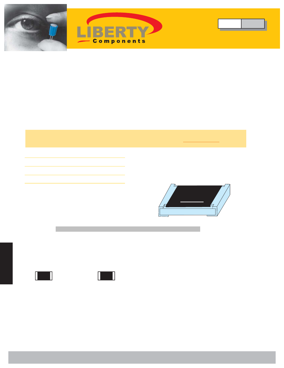
Thick Film Chip Resistor - Surge
Type SCR Series
• Suitable for withstanding circuit for surge voltage
• Suitable for lead free soldering.
∆
Features
∆
Applications
• Measurement Instrument
• Power Supply
• Compatible with flow and reflow soldering.
∆
Rating
Part Number
∆
How to Order
Type
Size
0603
0805
1206
2010
2512
Power
Rating
at 70
˚
C
1/10W
1/8W
1/4W
1/2W
1W
Max.
RCWV
50V
150V
200V
200V
200V
Max.
Overload
Voltage
100V
300V
400V
400V
400V
10
Ω
1M
Ω
E-24
Resistance
Tolerance
(%)
Temperature
Coefficient
(TCR; ppm/
˚
C )
Resistance
Range
Min. Max.
± 100
± 5%(J)
± 10%(K)
±1 5%(L)
± 20%(M)
Standard
Resistance
Values
103
example
SCR
0603
Type
Size
SCR
0603
T: Tape
J: ±5%
123 = 12x10^3
LF = Lead Free
0805
K: ±10%
= 12k
Ω
1206
L: ±15%
2010
M: ±20%
2512
LF
123
Resistance Value
Packing
Tolerance
T
J
E-24 Series
∆
Resistance Marking
473
ex. 473: 47x10^3 = 47K
Ω
105: 10x10^5 = 1M
Ω
1R5: 15x10^-1 = 1.5
Ω
0: 0
Ω
3 digit marking for E24
1R00
ex. 1R00: 1
Ω
R470 470m
Ω
R010 10m
Ω
4 digit marking for E241:
Ω
~10m
Ω
Type
SCR
Thick Film Chip Resistor - Surge
• Medical Equipment
• Telecom Equipment
• Consumer Electronics
• Automotive Industry
Liberty Bell Components, Inc. 11631 Seaboard Circle, Stanton, CA 90680 (888)820-8885
Fax: (888)820-8884 email: sales@libertycomponents.com website: www.libertycomponents.com