background image

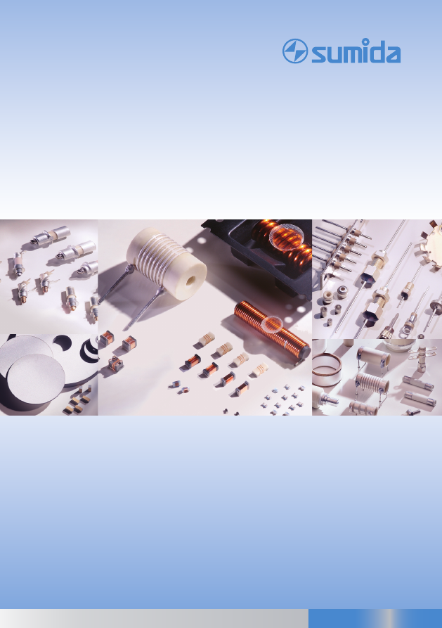
INDUCTORS | CAPACITORS | PIEZO CERAMICS

SUMIDA_Components_GmbH_-_Catalogue-html.html
background image

Firmenprofi l

Wir sind ein traditionsreicher Hersteller passiver elektro-

nischer Komponenten mit Sitz in Neumarkt i. d. Opf. Die 

im Dezember 1999 gegründete STELCO GmbH ging aus 

der bereits im Jahre 1922 entstandenen Stettner GmbH 

& Co hervor. Seit dem 01.01.2005 gehören wir zum japa-

nischen SUMIDA Konzern. Ende 2009 haben wir in SUMI-

DA Components GmbH umfi rmiert. 

SUMIDA Components GmbH beliefert neben Kunden aus 

dem  Telekommunikationsbereich  und  dem  Automobil-

sektor  zahlreiche  andere  Hersteller  modernster  Elektro-

nik  und  Elektrotechnik  weltweit.  Zu  der  Produktpalette 

gehören passive Bauelemente für elektronische Anwen-

dungen sowie piezokeramische Komponenten. 

SUMIDA Components GmbH kooperiert mit Produktions-

partnern in Osteuropa und China. 

Moderne Fertigungseinheiten und ein Team erfahrener, 

motivierter Techniker  garantieren  den  hohen  Qualitäts-

standard der SUMIDA Components GmbH - Produkte. 

Die  breite  Palette  standardisierter  Katalogware  wird 

durch  das  Angebot  individueller,  kundenspezifi scher 

Problemlösungen  in  Zusammenarbeit  mit  unserer  Ent-

wicklungsabteilung ergänzt. 

SUMIDA  Components  GmbH  erfüllt  die  Anforderungen 

der internationalen Zertifi zierungssysteme und ist nach 

ISO/TS 16949 und ISO 9001 zertifi ziert.

Mit  der  Einführung  des  Umweltmamagementsystems 

nach ISO 14001 im April 2012 leistet SUMIDA Componen-

ts GmbH als Teilnehmer des Umweltpacktes Bayern einen 

freiwilligen Beitrag zum Erhalt unserer Umwelt.

Die  Märkte  von  SUMIDA  Components  GmbH  wachsen 

und zugleich steigen die Ansprüche an unsere Produkte. 

Wir arbeiten, zusammen mit unseren Partnern aus dem 

Sondermaschinenbau,  an  der  stetigen  Verbesserung 

unserer  Produktionstechnologie  und  dem  Ausbau  der 

Kapazitäten. Die Qualität der Produkte, die Zuverlässig-

keit und die Flexibilität vereinen sich bei uns bewusst mit 

ausdrücklicher Kundenorientierung.

Eine  enge  Kooperation  mit  Hochschulen  und  For-

schungsinstituten  erlaubt  es  uns,  spezifi sche  Probleme 

effi  zient  zu  lösen  und  die  Entwicklung  neuer  Produkte 

und Verfahren zu verfolgen.

Unser weltweites Vertriebsnetz arbeitet eng mit unseren 

Produktingenieuren  zusammen,  um  Kunden  die  best-

mögliche technische Unterstützung zu bieten.

Wir haben uns das Ziel gesetzt, Partnern erstklassige Pro-

dukte und die bestmögliche Unterstützung anzubieten, 

so dass wir mit Ihnen wachsen können. 

Company Profi le

We  are  a  traditional  manufacturer  of  passive  electronic 

components  located  in  Neumarkt  i.  d.  OPf  in  Bavaria.

Founded in December 1999, Stelco GmbH emerged from 

the Stettner GmbH & Co, already founded in 1922. Since 

January 2005 we are member of the Japanese SUMIDA 

Group.

End of 2009 we have renamed in SUMIDA Components 

GmbH.

SUMIDA  Components  GmbH  supplies  customers  in  the 

fi eld of Telecommunication and Automotive and a lot of 

other  important  manufacturers  of  modern  electronics 

worldwide.  The  product  line  includes  passive  compo-

nents for electronic applications and piezoceramic com-

ponents.

SUMIDA Components GmbH cooperates with production 

partners in Eastern Europe and China.

State-of-the-art  production  equipment  and  an  expe-

rienced and motivated team of technicians guarantee the 

high quality of SUMIDA Components GmbH products. 

The wide selection of standard products is complemen-

ted  by  individual,  custom  specifi c  problem  solutions 

worked out in cooperation with the support of our en-

gineers. 

SUMIDA Components GmbH meets the requirements of 

the international certifi cation system and is certifi ed ac-

cording to ISO/TS 16949 and ISO 9001. 

By implementing an environmental management system 

in  April  2012  according  to  ISO  14001,  SUMIDA  Compo-

nents  GmbH  have  fully  achieved  all  necessary  require-

ments to participate in the Bavaria‘s Environmental Pact 

and obligates to fulfi ll voluntary environmental topics.

The  markets  of  SUMIDA  Components  GmbH  grow  and 

the requirements on our products are increasing. We are 

commited to responding proactively to the changing en-

vironment in all areas. SUMIDA Components GmbH has 

an active investment policy. Existing production lines are 

being modernised and, where appropriate, expanded. 

We work closely with Technical Universities, Research In-

stitutes in our search for better ways to help our partners 

optimise their solutions. 

Our world-wide distribution network co-operates closely 

with  our  in-house  product  engineers  to  off er  ongoing 

technical support.

Our aim is to provide top quality products and the best 

service  possible  for  all  our  partners  as  we  grow  with 

them.

SUMIDA_Components_GmbH_-_Catalogue-html.html
background image


Seite / Page

Induktivitäten, Drosseln und Transformer 


3

Inductors, Chokes and Transformer

Keramik-EMV-Bauelemente 


139

Ceramic EMI Components 

Keramik-Rohr-Trimmerkondensatoren 


223

Ceramic Tubular Trimmer Capacitors 

Optoelektronische Bauelemente 


249

Optoelectronic Components

Keramik-Montage-Teile 


265

Ceramic Mounting Parts

Piezokeramische Bauelemente und Signalgeber 


273

Piezoceramic Components and Sounders

Unsere Distributoren 


307

Our Distributors

Gesamtkatalog 
Catalogue

Inhaltsverzeichnis / Contents

Certifi ed QM-System: 

ISO/TS 16949 Third Edition

ISO 9001:2008
Certifi ed EM-System: 

ISO 14001

Zertifi ziertes QM-System:  

ISO/TS 16949 Version 3

ISO 9001:2008
Zertifi ziertes UM-System: 

ISO 14001

- 1 -

SUMIDA_Components_GmbH_-_Catalogue-html.html
background image

- 2 -

SUMIDA_Components_GmbH_-_Catalogue-html.html
background image

Induktivitäten, Drosseln und Transformer

Inductors, Chokes and Transformer

Certifi ed QM-System: 

ISO/TS 16949 Third Edition

ISO 9001:2008
Certifi ed EM-System: 

ISO 14001

Zertifi ziertes QM-System:  

ISO/TS 16949 Version 3

ISO 9001:2008
Zertifi ziertes UM-System: 

ISO 14001

- 3 -

SUMIDA_Components_GmbH_-_Catalogue-html.html
background image

- 4 -

SUMIDA_Components_GmbH_-_Catalogue-html.html
background image


Seite / Page

Chipinduktivitäten 


7

Chip Inductors

Übertrager 1008 


85

Chip Transformer 1008

Stromkompensierte Drossel 1008 


103

Common Mode Choke 1008

Stabkerndrosseln und Luftspulen 


118

Rod Core Chokes and Air Coils 

Hochkonstante Keramik-HF-Spulen  


128

Highly Constant Ceramic - RF Coils 


Induktivitäten, Drosseln und Transformer

Inductors, Chokes and Transformer

Inhaltsverzeichnis / Contents

Certifi ed QM-System: 

ISO/TS 16949 Third Edition

ISO 9001:2008
Certifi ed EM-System: 

ISO 14001

Zertifi ziertes QM-System:  

ISO/TS 16949 Version 3

ISO 9001:2008
Zertifi ziertes UM-System: 

ISO 14001

- 5 -

SUMIDA_Components_GmbH_-_Catalogue-html.html
background image

compliant

- 6 -

SUMIDA_Components_GmbH_-_Catalogue-html.html
background image

Chipinduktivitäten 

Chip Inductors

Inhaltsverzeichnis / Contents


Seite / Page

Allgemeines  


8

General Information

Chipinduktivitäten Lasergewendelt / Chip Inductors Laser-trimmed:

0603 (1608) Baugröße / Size 


5516 

14

Chipinduktivitäten Drahtgewickelt / Chip Inductors Wire-wound:
0603 (1608) Baugröße / Size - AgPd/Ni/Sn 


5406 

18

0603 (1608) Baugröße / Size - AgPd/Ni/Sn (E-Series) 


5206 

26

0805 (2012) Baugröße / Size - AgPd/Ni/Sn 


5408 

34

0805 (2012) Baugröße / Size - AgPdPt 


5508 

42

0805 (2012) Baugröße / Size - AgPd/Ni/Sn (E-Series) 


5208 

50

1008 (2520) Baugröße / Size - AgPdPt 


5501 

58

1206 (3216) Baugröße / Size - AgPd/Ni/Sn 


5403 

64 

1206 (3216) Baugröße / Size - AgPdPt 


5503 

72

Gurtung und Verpackung 


80

Taping and Packing

Musterkästen 


83

Sample Kits

Certifi ed QM-System: 

ISO/TS 16949 Third Edition

ISO 9001:2008
Certifi ed EM-System: 

ISO 14001

Zertifi ziertes QM-System:  

ISO/TS 16949 Version 3

ISO 9001:2008
Zertifi ziertes UM-System: 

ISO 14001

- 7 -

SUMIDA_Components_GmbH_-_Catalogue-html.html
background image

Baugröße / Size 

Ausführung / Version 

0603  

lasergewendelt / laser-trimmed  

0603, 0805,1008,1206  

drahtgewickelte Version / wire-wound version  

Produktspektrum Chipinduktivitäten

Product Spectrum Chip Inductors

1008

SUMIDA
Ceramic

Ferrit

Ferrite

1,0 nH - 220nH

0805

10 nH -1200 nH

1206

0603

3,3 nH -1200 nH

0603 laser

Al

2

0

Ceramic

1,5 µH - 10 µH

0603

1,5 µH - 18 µH

0805

1008

1206

Induktivitätenübersicht 

Inductance overview

0,47 µH - 2,7 µH

1,5 nH - 470 nH

2,7 nH - 820 nH

0,68 µH - 4,7 µH

- 8 -

SUMIDA_Components_GmbH_-_Catalogue-html.html
background image

Allgemeine Hinweise

Lagerbedingungen

Für  die  Aufbewahrung  der  Bauelemente  in  einem 

Warenlager sollten die folgenden Bedingungen einge-

halten  werden.  Die  Lagerbedingungen  sind  bei  allen 

Baureihen der SMD-Spulen (Bauteile gegurtet auf Rollen) 

anzuwenden.

Lagerung: 1 Jahr ab Versanddatum

Temperatur: 10 °C - 35 °C

Rel. Luftfeuchte: 50 % - 70 %

Um die zuverlässige Verarbeitung mittels Zuführ- und 

Bestückungseinrichtungen  sicherzustellen,  sollten  für 

die angelieferten Waren bzw. gelagerten Verpackungen 

(Blistergurte) folgende Einfl üsse vermieden werden:

Staubatmosphäre

chemische Atmosphäre

extreme Temperaturänderung

Vibrationen

direkte Sonneneinstrahlung

Verarbeitung und Montage

Aufgrund  der  konstruktiven  Beschaffenheit  der  Wick-

lungsträger (die Spulenwindungen liegen weitgehend 

geschützt in einer Vertiefung des Spulenkörpers) sind 

die  Miniatur-SMD-Spulen  auch  zur  Verarbeitung  auf 

Längsförderern oder ähnlichen Zuführeinrichtungen von 

Bestückungsautomaten geeignet. 

Die SMD-Spulen können mittels Leitkleber aufgeklebt 

bzw. kontaktiert werden. Die in SMT üblichen Lötverfahren 

(wie z.B. Refl owlöten, Wellenlöten

1)

) können angewandt 

werden.  Um  bei  der  Refl owlötung  eine  Benetzung  an 

den seitlichen Kontaktierungsfl ächen zu gewährleisten, 

ist für eine ausreichende Menge an Lot- und Flussmittel 

zu sorgen.

1)

 ausgenommen Baugröße 1008

Storage conditions

For storage of components in a warehouse the following 

conditions should be observed. Storage conditions apply 

to all series of SMD coils (components taped on reel). 

Storage: 1 year from date of delivery

Temperature: 10 °C - 35 °C

Humidity: 50 % - 70 %

To ensure reliable processing with feeding and pick and 

place equipment, on all delivered or stored components/

packages the following infl uences should be avoided:

dust atmosphere

chemical atmosphere

rapid change of temperature

vibration

direct solar radiation

Processing and Mounting

Due to the construction (coil windings are securely in a 

cavity of the winding body) the SMT coils can be used 

for  processing  on  linear  feeder  or  similar  mounting 

equipment. 

The SMD coils can be mounted or fi xed with conductive 

adhesives. All customary soldering processes (e.g. refl ow 

or wave soldering

1)

) can be used. A suffi  cient quantity of 

solder and fl ux should be used in order to guarantee that 

the lateral metallization areas are wetted during the refl ow 

soldering process.

1)

 except size 1008

General Information

- 9 -

SUMIDA_Components_GmbH_-_Catalogue-html.html
background image

Lötprofi le (Empfehlungen)

Die SMD- Bauteile müssen eine gute Lötbarkeit aufweisen, 

damit eine sichere mechanische und elektrische Verbin-

dung zur Leiterplatte hergestellt wird. Die Bauteile dürfen 

durch den Lötprozess nicht beschädigt werden. Für die 

Verarbeitung mit Pb-haltiger sowie Pb-freier Lotpaste mit-

tels Refl owlötung, werden Lötprofi le in Übereinstimmung 

mit der Prüfnorm IPC/JEDEC  J-STD020D (wie nachfolgend 

angeführt) empfohlen. Je nach eingesetzter Lotpaste sind 

die Prozessparameter vom Anwender anzupassen.

Profi le for Pb-free applications (SAC)

Recommended Soldering Profi le

For secure electric and mechanic connection with PCB 

the SMT components have to show a good solderability. 

The components shall not be damaged during soldering. 

For refl ow soldering with lead-content and lead-free sol-

dering pastes solder profi les according test specifi ca-tion                   

IPC/JEDEC  J-STD020D  are  recommended  (please  see 

profi les below). Depending on the soldering paste used 

process parameters have to be adjusted by the user.

Profi le for SnPb applications

Prüfung der Refl ow-Lötung

Profi lparameter:

Lotpaste SAC

Aufheizgradient: 


<1 K/s

Vorwärmen (150 °C-200 °C): 

80 s

Zeit über Liquidus (217 °C): 

120 s

Peaktemperatur: 


257 °C

Zeit 5K unter Peaktemp.:  

24 s

Abkühlgradient: 


<1 K/s

Zeit 25 °C bis Peaktemp.:   

5:00 min 

Lotpaste SnPb

Aufheizgradient: 


<1 K/s

Vorwärmen (100 °C-150 °C): 

87 s

Zeit über Liquidus (183 °C): 

145 s

Peaktemperatur: 


240 °C

Zeit 5K unter Peaktemp.:  

20 s

Abkühlgradient: 


<1 K/s

Zeit 25 °C bis Peaktemp.:   

5:10 min 

Test refl ow soldering

Soldering profi le:

Soldering paste SAC

Ramp-up:   


<1 K/s

Preheating (150 °C-200 °C): 

80 s

Time above liquidus (217 °C): 

120 s

Peak temperature: 


257 °C

Time 5K below peak temp.: 

24 s

Ramp-down: 


<1 K/s

Time 25 °C to peak temp.:   

5:00 min 

Soldering paste SnPb

Ramp-up:   


<1 K/s

Preheating (100 °C-150 °C): 

87 s

Time above liquidus (183 °C): 

145 s

Peak temperature: 


240 °C

Time 5K below peak temp.: 

20 s

Ramp-down: 


<1 K/s

Time 25 °C to peak temp.:   

5:10 min

Reflow Profile in accordance with IPC/JEDEC J-STD-020D (Pb-free)

Time 

Ramp-down: max. 6K/s

Preheat: 60 s- 120 s

Peak temperature: 260 °C

Ramp-up: max. 3K/s

25 °C to Peak: max. 8min.

min. 150 °C

max. 200 °C

Temp

er

a

tur

60 s  - 150 s

20 s- 40 s

217 °C

min. 100 °C

Temp

er

a

tur

Time 

max. 150 °C

Peak temperature: 240 °C

10 s- 30 s

183 °C

Preheat: 60 s- 120 s

60 s  - 150 s

Ramp-up: max. 3K/s

Ramp-down: max. 6K/s

25 °C to Peak: max. 6min.

Reflow Profile in accordance with IPC/JEDEC J-STD-020D (Sn-Pb)

- 10 -

SUMIDA_Components_GmbH_-_Catalogue-html.html
background image

Reinigung

Die Bauteile können mit branchenüblichen Reinigungsmit-

teln und Waschmethoden gereinigt werden.

Qualifi kationsprüfungen

Die Qualifi kation der SMD-Induktivitäten* erfolgt nach 

AEC-Q200 - Rev. C - Table 5 (induktive Bauelemente). 

Cleaning

The components can be cleaned with industry standard 

cleaning agents and washing methods. 

Qualifi cation tests

The qualifi cation of SMD - Inductances* is done according to 

AEC-Q200 - Rev. C - Table 5 (inductive components).

No.

Test

Conditon

(referenced at Tab. 5)

Notes

1

Physical Dimensions

JESD22 Method JB-100

and SUMIDA Components Spec.

2

Electrical Characterization

AEC Q 200

and SUMIDA Components Spec

Temp.: -55°C / 25 °C / 125 °C

3

Solderability / Resistance to 

dissolution of metallization

J-STD-002

4

Terminal Strength

AEC-Q200-006

1.8 kg for 60 sec. 

(except size 0603)

5

Board Flex

AEC-Q200-005

2 mm for 60 sec.

6

Resistance to Soldering Heat

J-STD-020

7

High Temperature Exposure

MIL-STD-202 Method 108

T = 125 °C  (t = 1000 hrs.)

8

Temperature Cycling /

Thermal Shock

MIL-STD-202 Method 107

JESD22 Method JA-104

T = -55 / 125 °C  (1000 cycles)

9

Biased Humidity

MIL-STD-202 Method 103

85 °C / 85% RH (t = 1000 hrs.)

10

Mechanical Shock

MIL-STD-202 Method 213

Condition C

11

Vibration

MIL-STD-202 Method 204

5 g and condition H

12

ESD

AEC-Q200-002

13

Resistance to Solvents

MIL-STD-202 Method 215

14

Operational Life

MIL-PRF-27

T = 125 °C  

(t = 1000 hrs. with rated current) 

15

Moisture Resistance

MIL-STD-202 Method 106

16

Moisture Sensitivity (MSL)

J-STD-020

17

Sn Whisker

JESD22 Method A104 JESD 201

*   Gilt nicht für Serien 5206, 5208, 5501 / not valid for series 5206, 5208, 5501.

AEC-Q200 Tab. 5*

- 11 -

SUMIDA_Components_GmbH_-_Catalogue-html.html
background image

Chipspulen - drahtgewickelt 

0603 / 0805 / 1008 / 1206

-   Quaderförmiger Spulenkörper aus Keramik- bzw.  


Ferritmaterial je nach Induktivitätswert

-   Zwei lötfähig metallisierte Kontaktierungsfl ächen 


aus AgPdPt (Standard) / AgPd/Ni/Sn (Spezial)

-   Kupferlackdraht-Wicklung 

-   Wicklungsenden auf den Kontaktierungsfl ächen 


verschweißt

Bauform mit vergossenen Windungen:

Wicklung mit mechanisch und thermisch hochbeständiger 

sowie  elektrisch  neutraler  Kunststoff masse  geschützt, 

die gleichzeitig die Windungen auf dem Spulenkörper 

fi xiert.

Chip Coils - wire-wound

0603 / 0805 / 1008 / 1206

-   Coil body  of ceramic or ferrite material according 


to inductance value

-  Two solderable metallized terminations of AgPdPt  


(Standard) / AgPd/Ni/Sn (Special)

-   Wound with enamelled copper wire

-   Wire ends welded onto the terminations


Type  with coated windings:

Windings are protected by a mechanically  and thermically 

highly constant as well as electrically neutral plastic mate-

rial which also fi xes the windings in position.

Messgeräte

Test Equipment

Chipspulen - lasergewendelt 0603:

Induktivität L: 

Impedanz-Analysator 4291A

Meßaufnahme: 

Agilent 16196A

Güte Q: 

Impedanz-Analysator 4291A

Meßaufnahme: 

Agilent 16196A

R

DC

gemessen bei 20 °C 


f

res

Netzwerk Analysator 8720D

Chipspulen - drahtgewickelt 0603

Induktivität L und Güte Q:

RF LCR Meter: 

4286 A

Messaufnahme: 

Agilent 16193 A

Resonanzfrequenz f

res

:  

Netzwerk Analysator:  8753E

Messaufnahme nach

CECC: 

1 mm Pad-Abstand

R

DC

gemessen bei 20 °C 

Digital Multimeter: 

Burster Resistomat 2329

Messaufnahme: 

4-pol-Messung

Chip Coils - laser-trimmed 0603:

Inductance L: 

Impedance Analyzer 4291A

Test Fixture: 

Agilent 16196A

Quality Factor Q: 

Impedance Analyzer 4291A

Test Fixture: 

Agilent 16196A

R

DC

measured at 20 °C 


f

res

Network Analyzer 8720D

Chip Coils - wire-wound 0603:

Inductance L and Quality Factor Q:

RF LCR Meter: 

4286 A

Test Fixture: 

Agilent 16193 A

Resonance Frequency f

res

:


Network Analyzer: 

8753E

Test Fixture acc. 

to CECC: 

1 mm pad distance

R

DC

measured at 20 °C

Digital Multimeter: 

Burster Resistomat 2329

Test Fixture: 

4 pole measure

Aufbau

Constructional Feature

- 12 -

SUMIDA_Components_GmbH_-_Catalogue-html.html
background image

Chipspulen  - drahtgewickelt 0805:

Induktivität L und Güte Q:

RF LCR Meter: 

4286 A

Messaufnahme: 

Agilent 16193 A

Resonanzfrequenz f

res

:  

Netzwerk Analysator:  8753E

Messaufnahme nach

CECC: 

1 mm Pad-Abstand

R

DC

gemessen bei 20 °C

Digital Multimeter: 

Burster Resistomat 2329

Messaufnahme: 

4-pol-Messung

Chipspulen - drahtgewickelt 1008

Induktivität L und Güte Q:

RF LCR Meter: 

4287 A

Messaufnahme: 

Agilent 16093 A


+ STCO 5135

Resonanzfrequenz f

res

:   

Netzwerk Analysator:  8753E

Messaufnahme nach

CECC: 

1 mm Pad-Abstand

R

DC

gemessen bei 20 °C 

Digital Multimeter: 

Burster Resistomat 2329

Messaufnahme: 

4-pol-Messung

Chipspulen - drahtgewickelt 1206

Induktivität L und Güte Q:

RF LCR Meter: 

4287 A

Messaufnahme: 

Agilent 16093 A


+ STCO 5135

Resonanzfrequenz f

res

:   

Netzwerk Analysator:  8753E

Messaufnahme nach

CECC: 

1 mm Pad-Abstand

R

DC

gemessen bei 20 °C 

Digital Multimeter: 

Burster Resistomat 2329

Messaufnahme: 

4-pol-Messung

Chip Coils - wire-wound 0805:

Inductance L and Quality Factor Q:

RF LCR Meter: 

4286 A

Test Fixture: 

Agilent 16193 A

Resonance Frequency f

res

:


Network Analyzer: 

8753E

Test Fixture acc. 

to CECC: 

1 mm pad distance

R

DC

measured at 20 °C

Digital Multimeter: 

Burster Resistomat 2329

Test Fixture: 

4 pole measure

Chip Coils - wire-wound 1008::

Inductance L and Quality Factor Q:

RF LCR Meter: 

4287 A

Test Fixture: 

Agilent 16093 A


+ STCO 5135

Resonance Frequency f

res

:


Network Analyzer: 

8753E

Test Fixture acc. 

to CECC: 

1 mm pad distance

R

DC

measured at 20 °C

Digital Multimeter: 

Burster Resistomat 2329

Test Fixture: 

4 pole measure

Chip Coils - wire-wound 1206:

Inductance L and Quality Factor Q:

RF LCR Meter: 

4287 A

Test Fixture: 

Agilent 16093 A


+ STCO 5135

Resonance Frequency f

res

:

Network Analyzer: 

8753E

Test Fixture acc. 

to CECC: 

1 mm pad distance

R

DC

measured at 20 °C

Digital Multimeter: 

Burster Resistomat 2329

Test Fixture: 

4 pole measure

- 13 -

SUMIDA_Components_GmbH_-_Catalogue-html.html
background image

0603 (1608) lasergewendelt

0603 (1608) laser-trimmed

compliant

- 14 -

SUMIDA_Components_GmbH_-_Catalogue-html.html
background image

Allgemeine Eigenschaften zu den 

lasergewendelten SMD-Spulen

Bauform 0603 / Baureihe 5516

SMD-Spulen aus galvanisch verkupferten Keramik-Kör-

pern. Die Anschlüsse haben eine Ni-Sperrschicht und als 

lötfähige Oberfl äche Reinzinn. Die Windungen werden 

durch Trennen der Metallisierung mittels Laser erzeugt 

und sind zum Schutz vollständig mit Lack umhüllt.

Die Lieferung erfolgt gegurtet auf Rollen für automatische 

Bestückung.

Typische Anwendungen sind Resonanzschaltkreise oder 

Impedanzanpassung in Video-Kameras, Mobiltelefonen 

und Antennenverstärkern usw.

Bestellhinweise:

Erklärungen des Artikelnummern-Schlüssels

General Characterisitics of Laser-

trimmed SMD Inductors

Size 0603 Series 5516 

Miniature SMD-inductors on gal. copper-plated ceramic 

cores with tinned Ni barrier layer terminations and pure 

tin as solderable surface.  The windings are  generated 

by laser cutting and are -  for protection - completely 

coated.

Delivery on tape and reel for automatic pick and place.

Typical applications are resonant circuits or impedance 

matching  for  video  cameras,  mobile  telephones  and 

antenna amplifi ers etc.

Ordering Instructions:

Explanations of Part Code

Verpackungseinheit 0603: 

Rollen Ø 180 mm, 4.000 Stück 

Packing Unit 0603: 

Reels Ø 180 mm,   4.000 pcs. 

Bestellbeispiel / Ordering examples:

Chipspule / Chip Coil 0603, laser  82 nH, Tol. 5 %

vergossen gegurtet 

coated, tape & reel 

= 5516 820 3451

Bezeichnung / Designation

Chip-Induktivität / Inductance

(Beispiel Baugröße 0603  

example Size 0603)

Induktivität L / Inductance L

Multiplikator für L: 10

x

Multiplier for L: 10

x

(Beispiel / example 27 nH)

Induktivitäts-Toleranz

Inductance Tolerance

                8 ± 0,2 nH

                9 ± 0,3 nH

                3 ± 5 %

                4 ± 2 %

Lieferform / Delivery Form

4  vergossen, gegurtet auf   

    8mm Pappgurt

    coated, taped on 8 mm 

    cardboard tape 


5516      27    0      *   4   51

- 15 -

SUMIDA_Components_GmbH_-_Catalogue-html.html
background image

Technische Informationen

Baugröße 0603 / Baureihe 5516:

Bauteilabmessungen und 

Pad-Layout-Empfehlung

Technical Details 

Size 0603 / Series 5516:

Component Dimensions and 

Pad Layout Recommendation

Artikel-Nr.

  L

Q

min

Q

typ

 f

L,Q


 f

res,min

R

DC,max

 I

N,max

 Tol. 

Order No.

 [nH]

@ 800 MHz  [MHz]

 [MHz]

[m

]

[mA]

 [%]

5516 010 ** 51

1

7

60

100

16000

20

1800

±0,2 /0,3 nH

5516 012 ** 51

1,2

8

60

100

15000

25

1800

±0,2 /0,3 nH

5516 015 ** 51

1,5

8

50

100

13000

30

1500

 ±0,2 /0,3 nH

5516 018 ** 51

1,8

12

50

100

12000

33

1500

 ±0,2 /0,3 nH

5516 022 ** 51

2,2

14

50

100

10000

35

1500

 ±0,2 /0,3 nH

5516 027 ** 51

2,7

14

40

100

10000

40

1400

 ±0,2 /0,3 nH

5516 033 ** 51

3,3

14

40

100

9000

60

1200

 ±0,2 /0,3 nH

5516 039 ** 51

3,9

14

40

100

8000

65

1100

 ±0,2 / 5 %

5516 047 ** 51

4,7

14

40

100

7000

100

800

 ±0,2 / 5 %

5516 056 ** 51

5,6

14

40

100

6000

150

700

±0,2 / 5 %

5516 068 ** 51

6,8

14

40

100

6000

150

700

±0,2 / 5 %

5516 082 ** 51

8,2

14

40

100

6000

180

650

±0,2 / 5 %

5516 100 ** 51

10

14

40

100

5000

200

600

 2 % / 5 %

5516 120 ** 51

12

14

40

100

5000

350

450

 2 % / 5 %

5516 150 ** 51

15

14

40

100

4500

400

420

 2 % / 5 %

5516 180 ** 51

18

14

40

100

4000

450

400

 2 % / 5 %

5516 220 ** 51

22

14

40

100

4000

500

360

 2 % / 5 %

5516 270 ** 51

27

14

35

100

3000

550

350

 2 % / 5 %

5516 330 ** 51

33

14

35

100

3000

600

300

 2 % / 5 %

5516 390 ** 51

39

14

35

100

2000

800

270

 2 % / 5 %

5516 470 ** 51

47

14

35

100

2500

950

250

 2 % / 5 %

5516 560 ** 51

56

14

35

100

2500

1200

230

 2 % / 5 %

5516 680 ** 51

68

14

35

100

2000

1300

220

 2 % / 5 %

5516 820 ** 51

82

14

35

100

2000

1500

200

 2 % / 5 %

5516 101 ** 51

100

14

30

100

1800

1800

160

 2 % / 5 %

5516 121 ** 51

120

5

30

25,2

1800

3000

130

 2 % / 5 %

5516 151 ** 51

150

5

30

25,2

1600

5000

120

 2 % / 5 %

5516 181 ** 51

180

4

25

25,2

1400

6000

110

 2 % / 5 %

5516 221 * *51

220

4

25

25,2

1300

7000

110

 2 % / 5 %


Elektrische Eigenschaften 

Baugröße 0603 / Baureihe 5516:

Electrical Parameters 

Size 0603 / Series 5516:

Alle Werte auf Al

2

O

3

- Kern

Klimakategorie gemäß DIN IEC 68-1: 55 / 125 / 56

Messgeräte siehe Allgemeinen Teil

All values on Al

2

O

3

- core

Climatic category acc. to DIN IEC 68-1: 55 / 125 / 56

Test Equipment see General Information

a

ä]no£]ä

>~iÊÉʈ“i˜Ãˆœ˜ÃÊQ““R

Ó]äoÓ]È

ä]Çoä]™

b

c

£°È

³

-

ä]£x

+

‡ ä]Ó

ä°Î

³‡ä]Ó

ä°n

+

‡ ä]£x

0

°

8

+

‡

0,

£

5

>

L

V

ä°Î

- 16 -

SUMIDA_Components_GmbH_-_Catalogue-html.html
background image

-

-

-

Güte Q über Frequenz f 

Q-Factor vs. Frequency f

Impedanz IZI über Frequenz f

Impedance /Z/ vs. frequency f

Induktivität L über Gleichstrom I

DC


Inductance L vs DC Current

I

B

/I

N

 über Umgebungstemperatur T

A

I

op

/I

R

 vs ambient temperature T

A

- 17 -

SUMIDA_Components_GmbH_-_Catalogue-html.html
background image

0603 (1608) drahtgewickelt 

(AgPd/Ni/Sn Metallisierung)

0603 (1608) wire-wound 

(AgPd/Ni/Sn Metallisation)

compliant

- 18 -

SUMIDA_Components_GmbH_-_Catalogue-html.html
background image

Allgemeine Eigenschaften zu den 

drahtgewickelten SMD-Spulen 

Bauform 0603 / Baureihe 5406

SUMIDA  Components  erweitert  sein  Spektrum  der 

drahtgewickelten Chipspulen der Baugröße 0603. Auf 

Keramikkörper sind nun Induktivitäten von 1,5 nH bis 

470 nH verfügbar. 

Diese Induktivitätswerte werden auf SUMIDA Compo-

nents-Keramikkörpern  gewickelt,  wodurch  besonders 

hohe Resonanzfrequenzen bzw. Güten spezifiziert wer-

den können. Dadurch eignen sie sich für Applikationen 

mit besonderen Ansprüchen z.B. für


HF-Technik


Antennenverstärker


Tuner, Basisstationen oder


SAT-Receiver

Zusätzlich bietet SUMIDA Components nun auch SMD-

Spulen  der  Bauform  0603  gewickelt  auf  einem  Ferrit-

Kern an. Hier sind Induktivitäten von 470 nH bis 2700 

nH verfügbar.

Anfragen  nach  Sonderinduktivitäten  oder  -toleranzen 

werden auf Machbarkeit überprüft.

General Characteristics of Wire-

wound SMD Inductors 

Size 0603 / Series 5406 

SUMIDA Components´ extended the programme of exi-

sting wire-wound chip inductors size 0603. On ceramic 

bodies there are a  wide range of inductances available 

from 1,5 nH to 470 nH. All inductance values are wound 

on SUMIDA Components ceramic bodies which perform 

extraordinary high resonance frequencies and quality 

factors. Therefore, they are  suited for applications with 

special requirements as for:


RF technique


Antenna Amplifi ers


Tuners, Base Stations or


SAT Receivers

Additional  SUMIDA  Components  offers  now  the  SMD 

inductors  size 0603 wired on a ferrite body. Here are 

inductances from 470nH to 2700 nH available.

Feasibility of special inductances or tolerances are  tested 

on request.   

1)

  Standard-Toleranzen - engere Toleranzen auf Anfrage

  Standard tolerances - tighter tolerances on request 


2)

  Nennstrom (max) bis 85° C Umgebungstemperatur

  maximum rated current at ambient temperature 85° C

Symbol 

Symbol 

 Material des Spulenkerns 

Material of the coil core

Keramik / Ceramic

 Material des Spulenkerns

Material of the coil core

Ferrit / Ferrite

Induktivität

L

1,5 ...470 nH

470 ... 2700 nH

Inductance

Toleranz 

-

2/5/10/20 %

  1)

2/5/10/20 %

  1)

Tolerance

Minimale Güte 

Q

min

22 ... 45

12

Minimum Q-factor

Eigenresonanzfrequenz

f

res , min 

> 6000 ... 700 MHz

650 ... 260 MHz

Self resonance frequency

Max. Gleichstromwiderstand 

R

DC, max

25 ... 6200 mΩ

400 ... 4000 mΩ

Max. DC resistance

Nennstrom (bez. auf 85 °C) 

I

rated

1000 ... 80 mA 

2)

460 ... 180  mA 

2)

Nominal Current (ref. To 85 °C)

Zulässiger Betriebstemperaturbereich 

-

- 55 ... 125° C

- 55  ... 125° C

permissable operating temperature range

- 19 -

SUMIDA_Components_GmbH_-_Catalogue-html.html
background image

Bestellhinweise:

Erklärung des Artikelnummern-Schlüssels

Ordering Instructions:

Explanation of Part Code

Verpackungseinheit 0603: 

Rollen Ø 180 mm, 4.000 Stück 

Packing Unit 0603: 

Reels Ø 180 mm,   4.000 pcs.


5406      27     0     *   4   00

Bezeichnung / Designation

Chip-Induktivität / Inductance

(Baugröße 0603 / Size 0603)

Induktivität L / Inductance L

Multiplikator für L: 10

x

Multiplier for L: 10

x

(Beispiel / example 27 nH)

Abweichender Artikelnummernschlüssel für L-Werte < 10nH

Abnormal order number for L-values < 10 nH

Induktivitäts-Toleranz

Inductance Tolerance

         1 ± 20 %

         2 ± 10 %

         3 ± 5 %

         4 ± 2 %

Lieferform / Delivery Form

4  vergossen, gegurtet auf   

    8 mm Blistergurt

    coated, taped on 8 mm 

    blister tape 

Bestellbeispiel / Ordering examples:

Chipspule / Chip Coil  0603, 270 nH, Tol. 5 %

vergossen gegurtet 

coated, tape & reel    

=  5406 271 34 00

Chipspule / Chip Coil  0603, 3,6 nH, Tol. 10 %

vergossen gegurtet 

coated, tape & reel    

=  5406 036 24 00

- 20 -

SUMIDA_Components_GmbH_-_Catalogue-html.html
background image

Technische Informationen 

Baugröße 0603 / Baureihe 5406 

drahtgewickelt:

Bauteilabmessungen und Pad-Layout-Empfehlung

Technical Details 

Size 0603 / Series 5406 

wire-wound:

Component Dimensions and Pad Layout 

Recommendation


1,2

±0,2

1,60

- 0,05

+0,10

0,90

±0,15

Drahtenden verschweißt (=metallisierte Fläche) /

wire leads welded (=metallization area)

0,45

±0,2

0,90

-

+

0,05

0,03

0,85

-0,10

+0,15

 C

1,7

±0,1

C = Inkl. Metallisierung, Wicklung und Verguss /

        with metallization, winding and coating

= Metallisierung / metallization

= Verguss / coating

Pad-Layout-Empfehlung / Pad Layout Recommendation

a

b

c

a

0,8....1,0

2,0....2,5

b

c

0,7....1,0

Maße / 

Dimensions

(mm)

- 21 -

SUMIDA_Components_GmbH_-_Catalogue-html.html
background image

Elektrische Eigenschaften 

Baugröße 0603 / Baureihe 5406 

drahtgewickelt: 

Electrical Parameters 

Size 0603 / Series 5406 

wire-wound:

Artikel-Nr.

L

Q

min

 Q

typ

f

L,Q


f

res,min


R

DC,max


I

rated,max


 Tol.

Order No.

[nH]

@ 800 MHz

[MHz]

[MHz]

[mΩ]

[mA]

 [%]

5406 015 *4 00

1,5

22

45

250

6000

25

1000

   10/20

5406 018 *4 00

1,8

22

35

250

6000

35

900

   10/20

5406 033 *4 00

3,3

30

55

250

6000

40

800

   10/20

5406 036 *4 00

3,6

35

50

250

6000

35

900

   10/20

5406 039 *4 00

3,9

35

50

250

6000

35

900

   10/20

5406 047 *4 00

4,7

28

45

250

6000

75

620

   10/20

5406 056 *4 00

5,6

35

60

250

6000

40

840

 5/10/20

5406 068 *4 00

6,8

40

70

250

5600

35

890

 5/10/20

5406 082 *4 00

8,2

40

55

250

5500

60

700

 5/10/20

5406 087 *4 00

8,7

35

70

250

5300

60

700

 5/10/20

5406 100 *4 00

10

45

80

250

5000

45

780

  2/5/10/20

5406 120 *4 00

12

40

70

250

4100

90

560

  2/5/10/20

5406 150 *4 00

15

45

80

250

3300

55

710

  2/5/10/20

5406 180 *4 00

18

45

75

250

3700

90

560

  2/5/10/20

5406 220 *4 00

22

45

70

250

3100

135

450

  2/5/10/20

5406 270 *4 00

27

45

70

250

2900

115

500

  2/5/10/20

5406 330 *4 00

33

45

70

250

2550

115

490

  2/5/10/20

5406 390 *4 00

39

45

65

250

2150

120

480

  2/5/10/20

5406 470 *4 00

47

40

55

200

2050

200

380

  2/5/10/20

5406 560 *4 00

56

40

50

200

2000

290

310

  2/5/10/20

5406 680 *4 00

68

40

50

200

1700

360

280

  2/5/10/20

5406 820 *4 00

82

35

60

150

1700

590

220

  2/5/10/20

5406 101 *4 00

100

35

50

150

1550

890

180

  2/5/10/20

5406 121 *4 00

120

35

50

150

1300

1100

160

  2/5/10/20

5406 151 *4 00

150

30

40

100

1200

1200

150

  2/5/10/20

5406 181 *4 00

180

30

35

100

1150

1300

140

  2/5/10/20

5406 221 *4 00

220

30

30

100

1050

1900

120

  2/5/10/20

5406 271 *4 00

270

30

-

100

990

2100

115

  2/5/10/20

5406 331 *4 00

330

30

-

100

890

2900

95

  2/5/10/20

5406 391 *4 00

390

30

-

100

810

4000

80

  2/5/10/20

5496 471 *4 00

470

30

-

100

700

6200

80

2/5/10/20

5406 471 *4 00

470

12

-

7,9

650

400

460

2/5/10/20 

5406 561 *4 00

560

12

-

7,9

535

410

360

2/5/10/20

5406 681 *4 00

680

12

-

7,9

510

580

330

2/5/10/20

5406 821 *4 00

820

12

-

7,9

470

780

320

2/5/10/20

5406 102 *4 00

1000

12

-

7,9

400

1100

280

2/5/10/20

5406 122 *4 00

1200

12

-

7,9

390

1160

230

2/5/10/20

5406 152 *4 00

1500

12

-

7,9

340

1580

220

2/5/10/20

5406 182 *4 00

1800

12

-

7,9

310

2340

190

2/5/10/20

5406 222 *4 00

2200

12

-

7,9

280

3320

185

2/5/10/20

5406 272 *4 00

2700

12

-

7,9

260

4000

180

2/5/10/20

Ker

amik / 

Cer

amic

Fer

rit / 

Fer

rit

e

Ker

amik / 

Cer

amic

Fer

rit / 

Fer

rit

e

- 22 -

SUMIDA_Components_GmbH_-_Catalogue-html.html
background image

Güte Q über Frequenz f 

Q factor vs. frequency f  

Induktivität L über Frequenz f 

Inductance L vs. frequency f  

Spule auf Keramikkörper 

Spule auf Ferritkörper 

Coil on ferrite body

Coil on ceramic body

0

5

10

15

20

1

10

100

1000

f [MHz]

Q [ ]

1000 nH
820 nH
680 nH
1800 nH
2700 nH

100

1000

10000

1

10

100

1000

f [MHz]

L [nH]

1000 

2700 
nH

1800 
nH

680 
nH

820 nH

nH

nH

nH

nH

Elektrische Eigenschaften 

Baugröße 0603 / Baureihe 5406 

drahtgewickelt: 

Electrical Parameters 

Size 0603 / Series 5406 

wire-wound:

- 23 -

SUMIDA_Components_GmbH_-_Catalogue-html.html
background image

Empfohlene Strombelastbarkeit I

B

/I

N, 85 °C


in Abhängigkeit von der Umgebungstemperatur T

a


Recommended  Current-carrying  capacity  I

op

/I

R,  85  °C


depending on the ambient temperature T

a

0

0,2

0,4

0,6

0,8

1

1,2

0

20

40

60

80

100 120 140

T

a

 [°C ]

I

B

/I

N

Ferrit
Ferrite

Keramik
Ceramic

Elektrische Eigenschaften 

Baugröße 0603 / Baureihe 5406 

drahtgewickelt: 

Electrical Parameters 

Size 0603 / Series 5406 

wire-wound:

- 24 -

SUMIDA_Components_GmbH_-_Catalogue-html.html
background image

- 25 -

SUMIDA_Components_GmbH_-_Catalogue-html.html
background image

„E“ Serie - 0603 (1608) für SM-Technologie

„E“ Series - 0603 (1608) for SM-Technology

NE

W


NEU


compliant

- 26 -

SUMIDA_Components_GmbH_-_Catalogue-html.html
background image

Allgemeine Eigenschaften zu den 

drahtgewickelten SMD-Spulen 

Bauform 0603 / Baureihe 5206

Diese Baureihe zeichnet sich durch ein exzellentes 

Preis-/ Leistungsverhältnis aus.

Für Systemlieferanten der Elektronikindustrie bietet 

unsere „E-Serie“ eine sehr kosteneffi  ziente sowie

zuverlässige induktive Komponentenlösung zur 

Massenproduktion von elektronischen Schaltungen (Non-

Automotive Applikationen).

Eigenschaften:

- Kleine Bauformen für SMT

- Stabile Induktivität auch bei hohen Frequenzen

- Eng tolerierte Induktivitäten

- Niedriger Gleichstromwiderstand

- Betriebstemperaturbereich -40 °C bis +85 °C

Mögliche Anwendungsgebiete:

- Antennenverstärker

- Mobile Telefone (GSM etc.)

- Global Positioning Systems (GPS)

- Digitalkameras

- HDD (Hard Disk Drives)

- etc.

General Characteristics of Wire-

wound SMD Inductors 

Size 0603 / Series 5206 

This series is characterised by an excellent 

price/performance ratio.

The “E“ series SMT inductors are highly cost eff ective

and highly reliable inductive component solutions for

mass production of electronic circuits for smart system

suppliers of the electronic industry (Non-automotive

applications). 

Features:

- small sizes for SMT

- rugged inductance even in high frequencies

- tight tolerances

- low DC resistance

- operating temperature range -40 °C to +85 °C

Applications:

- antenna amplifi er

- mobile phones (GSM etc.)

- Global Positioning Systems (GPS)

- digital cameras

- HDD (Hard Disk Drives)

- etc.

1)

  Standard-Toleranzen - engere Toleranzen auf Anfrage

  Standard tolerances - tighter tolerances on request 


2)

  Nennstrom (max) bis 85° C Umgebungstemperatur

  maximum rated current at ambient temperature 85° C

Symbol 

Symbol 

 Material des Spulenkerns 

Material of the coil core

Keramik / Ceramic

 Material des Spulenkerns

Material of the coil core

Ferrit / Ferrite

Induktivität

L

1,5 ...470 nH

470 ... 2700 nH

Inductance

Toleranz 

-

2/5/10/20 %

  1)

2/5/10/20 %

  1)

Tolerance

Minimale Güte 

Q

min

16 ... 42

12

Minimum Q-factor

Eigenresonanzfrequenz

f

res , min 

> 6000 ... 700 MHz

600 ... 200 MHz

Self resonance frequency

Max. Gleichstromwiderstand 

R

DC, max

30 ... 6300 mΩ

430 ... 4040 mΩ

Max. DC resistance

Nennstrom (bez. auf 85 °C) 

I

rated

2200 ... 100 mA 

2)

440 ... 160  mA 

2)

Nominal Current (ref. To 85 °C)

Zulässiger Betriebstemperaturbereich 

-

- 40 ... 85° C

permissable operating temperature range

- 27 -

SUMIDA_Components_GmbH_-_Catalogue-html.html
background image

Bestellhinweise:

Erklärung des Artikelnummern-Schlüssels

Ordering Instructions:

Explanation of Part Code

Verpackungseinheit 0603: 

Rollen Ø 180 mm, 4.000 Stück 

Packing Unit 0603: 

Reels Ø 180 mm,   4.000 pcs.


5206      27    0      *    4  00

Bezeichnung / Designation

Chip-Induktivität / Inductance

(Baugröße 0603 / Size 0603)

Induktivität L / Inductance L

Multiplikator für L: 10

x

Multiplier for L: 10

x

(Beispiel / example 27 nH)

Abweichender Artikelnummernschlüssel für L-Werte < 10nH

Abnormal order number for L-values < 10 nH

Induktivitäts-Toleranz

Inductance Tolerance

         1 ± 20 %

         2 ± 10 %

         3 ± 5 %

         4 ± 2 %

Lieferform / Delivery Form

4  vergossen, gegurtet auf   

    8 mm Blistergurt

    coated, taped on 8 mm 

    blister tape 

Bestellbeispiel / Ordering examples:

Chipspule / Chip Coil  0603, 270 nH, Tol. 5 %

vergossen gegurtet 

coated, tape & reel    

=  5206 271 3400

Chipspule / Chip Coil  0603, 3.6 nH, Tol. 10 %

vergossen gegurtet 

coated, tape & reel    

=  5206 036 2400

- 28 -

SUMIDA_Components_GmbH_-_Catalogue-html.html
background image

Technische Informationen 

Baugröße 0603 / Baureihe 5206 

drahtgewickelt:

Bauteilabmessungen und Pad-Layout-Empfehlung

Technical Details 

Size 0603 / Series 5206 

wire-wound:

Component Dimensions and Pad Layout 

Recommendation

a

b

c

a

0,8....1,0

2,0....2,5

b

c

0,7.... 0

,

Maße / Dimensions (mm)


Layoutempfehlung / Layout recommendation:

1,2

±0,2

1,60

- 0,05

+0,10

0,90

±0,15

Drahtenden verschweißt (=metallisierte Fläche) /

wire leads welded (=metallization area)

0,45

±0,2

0,90

- 0,05

0

0,85

-0,10

+0,15

 C

1,7

±0,1

C = Inkl. Metallisierung, Wicklung und Verguss /

        with metallization, winding and coating

= Metallisierung / metallization

= Verguss / coating

1

1

- 29 -

SUMIDA_Components_GmbH_-_Catalogue-html.html
background image

Elektrische Eigenschaften 

Baugröße 0603 Keramik / Baureihe 5206 

E-Serie:

Electrical Parameters 

Size 0603 ceramic / Series 5206

E-Series:

Artikel-Nr.

L

Q

min

f

L,Q 

f

res,min


R

DC,max 

I

rated,max


 Tol.

Order No.

[nH]

[MHz]

[MHz]

[mΩ]

[mA]

 [%]

5206 015 *4 00

1,5

20

250

>6000

30

2200

10/20

5206 018 *4 00

1,8

16

250

>6000

50

1000

10/20

5206 033 *4 00

3,3

25

250

5400

40

1300

10/20

5206 036 *4 00

3,6

30

250

5400

40

1300

10/20

5206 039 *4 00

3,9

30

250

5400

40

1300

10/20

5206 047 *4 00

4,7

22

250

5300

120

900

10/20

5206 056 *4 00

5,6

30

250

6000

45

1500

5/10/20

5206 068 *4 00

6,8

38

250

6000

50

1500

5/10/20

5206 082 *4 00

8,2

35

250

6000

90

1100

5/10/20

5206 087 *4 00

8,7

35

250

5500

70

1400

5/10/20

5206 100 *4 00

10

40

250

5200

65

1400

2/5/10/20

5206 120 *4 00

12

38

250

4500

70

1400

2/5/10/20

5206 150 *4 00

15

38

250

3300

80

1400

2/5/10/20

5206 180 *4 00

18

42

250

3600

95

1300

2/5/10/20

5206 220 *4 00

22

42

250

3000

120

1000

2/5/10/20

5206 270 *4 00

27

42

250

2600

130

900

2/5/10/20

5206 330 *4 00

33

42

250

2400

135

900

2/5/10/20

5206 390 *4 00

39

40

250

2200

150

850

2/5/10/20

5206 470 *4 00

47

38

200

2100

230

750

2/5/10/20

5206 560 *4 00

56

38

200

1900

280

700

2/5/10/20

5206 680 *4 00

68

38

200

1700

320

650

2/5/10/20

5206 820 *4 00

82

34

150

1600

470

520

2/5/10/20

5206 101 *4 00

100

34

150

1400

550

500

2/5/10/20

5206 121 *4 00

120

34

150

1400

830

450

2/5/10/20

5206 151 *4 00

150

28

100

1250

950

400

2/5/10/20

5206 181 *4 00

180

28

100

1050

1300

320

2/5/10/20

5206 221 *4 00

220

25

100

1000

1700

240

2/5/10/20

5206 271 *4 00

270

25

100

970

2600

220

2/5/10/20

5206 331 *4 00

330

25

100

800

2850

200

2/5/10/20

5206 391 *4 00

390

25

100

800

3800

170

2/5/10/20

5296 471 *400

470

30

100

700

6300

100

2/5/10/20

5206 471 *4 00

470

12

7,9

650

430

440

2/5/10/20

5206 561 *4 00

560

12

7,9

535

440

340

2/5/10/20

5206 681 *4 00

680

12

7,9

510

610

310

2/5/10/20

5206 821 *4 00

820

12

7,9

470

820

300

2/5/10/20

5206 102 *4 00

1000

12

7,9

400

1150

260

2/5/10/20

5206 122 *4 00

1200

12

7,9

390

1200

210

2/5/10/20

5206 152 *4 00

1500

12

7,9

340

1600

200

2/5/10/20

5206 182 *4 00

1800

12

7,9

310

2360

170

2/5/10/20

5206 222*4 00

2200

12

7,9

280

3350

165

2/5/10/20

5206 272*4 00

2700

12

7,9

260

4040

160

2/5/10/20

Ker

amik / 

Cer

amic

Fer

rit / 

Fer

rit

e

Ker

amik / 

Cer

amic

Fer

rit / 

Fer

rit

e

- 30 -

SUMIDA_Components_GmbH_-_Catalogue-html.html
background image

Güte Q über Frequenz f

Q-Factor vs. Frequency f

Spule auf Keramikkörper 

Coil on ceramic body

Spule auf Ferritkörper 

Coil on ferrite body

0

5

10

15

20

1

10

100

1000

f [MHz]

Q [ ]

1000 nH
820 nH
680 nH
1800 nH
2700 nH

Elektrische Eigenschaften 

Baugröße 0603 Keramik / Baureihe 5206 

E-Serie:

Electrical Parameters 

Size 0603 ceramic / Series 5206

E-Series:

- 31 -

SUMIDA_Components_GmbH_-_Catalogue-html.html
background image

Induktivität L über Frequenz f

Inductance L vs. Frequency f

Spule auf Keramikkörper 

Spule auf Ferritkörper 

Coil on ceramic body

Coil on ferrite body

100

1000

10000

1

10

100

1000

f [MHz]

L [nH]

1000 

2700 
nH

1800 
nH

680 
nH

820 nH

Elektrische Eigenschaften 

Baugröße 0603 Keramik / Baureihe 5206 

E-Serie:

Electrical Parameters 

Size 0603 ceramic / Series 5206

E-Series:

- 32 -

SUMIDA_Components_GmbH_-_Catalogue-html.html
background image

- 33 -

SUMIDA_Components_GmbH_-_Catalogue-html.html
background image


0805 (2012) drahtgewickelt 

(AgPd/Ni/Sn Metallisierung)

0805 (2012) wire-wound 

(AgPd/Ni/Sn Metallisation)

compliant

- 34 -

SUMIDA_Components_GmbH_-_Catalogue-html.html
background image

Allgemeine Eigenschaften und 

technische Informationen zu den 

drahtgewickelten SMD-Spulen 

Bauform 0805 / Baureihe 5408

Die  Baugröße  0805  zeichnet  sich  durch  die  Mischung 

von kleiner Abmessung und hervorragenden elektrischen 

Werten aus.

General Characterisitics and 

Technical Information of wire-

wound SMD Inductors 

Size 0805 / Series 5408

Size 0805 is characterized by the mixture of small dimen-

sions and extraordinary electrical values.

Symbol 

Symbol 

Material des Spulenkerns / Material of the coil core

Keramik / Ceramic

Ferrit / Ferrite

Induktivität

L

2,7 ... 820 nH

680 ... 4700 nH

Inductance

Toleranz 

-

2/5/10/20 %

  1)

2/5/10/20 % 

 1)

Tolerance

Minimale Güte 

Q

min

20 ... 50

20

Minimum Q-factor

Eigenresonanzfrequenz

f

res , min 

> 6000 ... 510 MHz

450 ... 150 MHz

Self resonance frequency

Max. Gleichstromwiderstand 

R

DC, max

30 ... 5000 mΩ 

500 ... 3800 mΩ

Max. DC resistance

Nennstrom (bez. auf 85 °C) 

I

N

1000 ... 75 mA 

2)

250 ... 90 mA 

2)

Nominal Current (ref. To 85 °C)

Zulässiger Betriebstemperaturbereich 

-

- 55 ... 125° C

permissable operating temperature range

1)

  Standard-Toleranzen - engere Toleranzen auf Anfrage

  Standard tolerances - tighter tolerances on request 


2)

  Nennstrom (max) bis 85° C Umgebungstemperatur

  maximum rated current at ambient temperature


85° C

- 35 -

SUMIDA_Components_GmbH_-_Catalogue-html.html
background image

Technische Informationen 

Baugröße 0805 / Baureihe 5408 

drahtgewickelt:

Bauteilabmessungen und Pad-Layout-Empfehlung

Technical Details 

Size 0805 / Series 5408 

wire-wound:

Component Dimensions and Pad Layout 

Recommendation

Layoutempfehlung / Layout recommendation

a

b

c

a

1,0....1,2

....

b

c

....

Maße / Dimensions (mm)

1,2

1,5

2,8

3,2

max. 1,42 C

1,2

-0,1

0

 A

1,4

- 0,2

0

 B

2

0

+0,1

 A

Drahtenden verschweißt / 

wire leads welded

1,4      B

max. 2,2 B

0 -0,2

A = Abmessungen / core dimensions

= Metallisierung / metallization

B = Inkl. Metallisierung und Wicklung / with metallization and winding

C = Inkl. Metallisierung, Wicklung und Verguss / with metallization, winding and coating

- 36 -

SUMIDA_Components_GmbH_-_Catalogue-html.html
background image

Bestellhinweise:

Erklärung des Artikelnummern-Schlüssels

Ordering Instructions:

Explanation of Part Code


       5408       27    0    *     *    **

Bezeichnung / Designation

(Baugröße 0805 / Size 0805) 

Induktivität L / Inductance L

Multiplikator für L: 10

x

Multiplier for L: 10

x

(Beispiel / example 27 nH)

Induktivitäts-Toleranz 

Inductance Tolerance

         1 ± 20 %

         2 ± 10 %

         3 ± 5 %

         4 ± 2 %


Lieferform / Delivery Form

2 unvergossen, gegurtet

   Standard, tape&reel

4 vergossen, gegurtet 

   coated, tape & reel 

Verpackungseinheit gegurtet 

packing unit tape & reel

00 = Rollen Ø 180 mm - 3.000 Stück


Reels Ø 180 mm - 3.000 pcs.

03 = Rollen Ø 330 mm - 10.000 Stück


Reels Ø 330 mm - 10.000 pcs.

05 = Rollen Ø 180 mm - 500 Stück


Reels Ø 180 mm - 500 pcs.

Bestellbeispiel / Ordering examples:

Chipspule / Chip Coil  0805, 270 nH, Tol. 5 %

vergossen gegurtet (3.000 Stück)

coated, tape & reel (3.000 pcs.)  

 =  5408 271 3400

- 37 -

SUMIDA_Components_GmbH_-_Catalogue-html.html
background image

Elektrische Eigenschaften 

Baugröße 0805 / Baureihe 5408 

drahtgewickelt: 

Electrical Parameters 

Size 0805 / Series 5408 

wire-wound:

Artikel-Nr.

L

Q

min

 Q

typ

f

L,Q


f

res,min


R

DC,max


I

N,max


Tol. 

Order No.

[nH]

@ 800 MHz

[MHz]

[MHz]

[mΩ]

[mA]

 [%]          

5408 020 ** **

   2,7

20

50

250

6000

    30          

1000

20

5408 050 ** **

   5,6

25

60

250

6000

    40

900

10/20

5408 060 ** **

   6,8

30

70

250

5500

    50

800

10/20

5408 080 ** **

   8,2

35

75

250

5000

    60

700

20

5408 100 ** **

   10

40

80

250

4500

    60

700

5/10/20

5408 120 ** **

   12

40

85

250

4000

    60

700

5/10/20

5408 150 ** **

   15

40

85

250

3500

    70

670

5/10/20

5408 180 ** **

   18

45

90

250

3300

    70

670

5/10/20

5408 220 ** **

   22

45

85

250

2600  

    90

600

5/10/20

5408 270 ** **

   27

50

90

250

2500

    90

600

5/10/20

5408 330 ** **

   33

45

80

250

2150

  120

520

5/10/20

5408 390 ** **

   39

50

90

250

2050

   100

560

5/10/20

5408 470 ** **

   47

45

85

200

1900

  130

500

2/5/10/20

5408 560 ** **

   56

45

60

200

1700

  140

480

2/5/10/20

5408 680 ** **

   68

45

60

200

1550

  190

410

2/5/10/20

5408 820 ** **

   82

40

60

150

1430

  210

390

2/5/10/20

5408 101 ** **

 100

40

50

150

1310

  260

350

2/5/10/20

5408 121 ** **

 120

40

45

150

1210

  440

270

2/5/10/20

5408 151 ** **

 150

35

40

100

1120

  440

270

2/5/10/20

5408 181 ** **

 180

35

30

100

1030

  470

260

2/5/10/20

5408 221 ** **

  220

35

 -

100

950

  550

240

2/5/10/20

5408 271 ** **

  270

35

 -

100

870

1000

180

2/5/10/20

5408 331 ** **

  330

35

 -

100

800

1000

180

2/5/10/20

5408 391 ** **

  390

35

 -

100

730

1900

130

2/5/10/20

5408 471 ** **

  470

35

 -

100

660

2400

115

2/5/10/20

5408 561 ** **

  560

35

 -

100

600

3200

100

2/5/10/20

5498 681 ** **

  680

35

 -

100

550

3700

  95  

5/10

5498 821 ** **

  820

35

 -

100

510

5000

  75

5/10

5408 681 ** **

  680

20

 -

25,2

450

  500

250

2/5/10/20

5408 821 ** **

  820

20

 -

25,2 

400

  550

240

2/5/10/20

5408 102 ** **

1000

20       

 -

7,96

350

  500

250

2/5/10/20

5408 122 ** **

1200

20

 -

7,96

300

  650

220

2/5/10/20

5408 152 ** **

1500

20

 -

7,96

250

  750

200

2/5/10/20

5408 182 ** **

1800

20

 -

7,96

250

  850

190

2/5/10/20

5408 222 ** **

2200

20

 -

7.96

200

1700

130

2/5/10/20

5408 272 ** **

2700

20

 -

7,96

200

2000

120

2/5/10/20

5408 332 ** **

3300

20

 -

7,96

200

3300

100

2/5/10/20

5408 392 ** **

3900

20

 - 

7.96

150

3600

  95

2/5/10/20

5408 472 ** **

4700  

20

 -

7.96

150

3800

  90

2/5/10/20

Ker

amik / 

Cer

amic

Fer

rit / 

Fer

rit

e

Alle Werte < 680 nH auf Keramikkern

Die Werte 680 und 820 nH auf Keramik- und Ferritkern

Die Werte  > 820 nH nur auf Ferritkern

Messgeräte siehe Allgemeine Hinweise

All values  < 680 nH on ceramic core

The values 680 and 820 nH on ceramic and ferrite core

The values > 820 nH on ferrite core only 

Test Equipment see General Information

Ker

amik / 

Cer

amic

Fer

rit / 

Fer

rit

e

- 38 -

SUMIDA_Components_GmbH_-_Catalogue-html.html
background image

Güte Q über Frequenz f

Q-Factor vs. Frequency f

Spule auf Keramikkörper 

Spule auf Ferritkörper 

Coil on ferrite body

Coil on ceramic body

0

20

40

60

80

100

10

100

1000

f [MHz]

Q [ ]

10 nH

27 nH

68 nH

220 nH

560 nH

0

5

10

15

20

25

30

1

10

100

1000

f [MHz]

Q [ ]

4700 nH

2700 nH
2200 nH

1000 nH

680 nH

Elektrische Eigenschaften 

Baugröße 0805 / Baureihe 5408 

drahtgewickelt: 

Electrical Parameters 

Size 0805 / Series 5408 

wire-wound:

- 39 -

SUMIDA_Components_GmbH_-_Catalogue-html.html
background image

Induktivität L über Frequenz f

Inductance L vs. Frequency f

Spule auf Keramikkörper 

Spule auf Ferritkörper 

Coil on ceramic body

Coil on ferrite body

1

10

100

1000

10000

10

100

1000

f [MHz]

L [nH]

560 nH

220 nH

68nH

27 nH

10 nH

100

1000

10000

100000

1

10

100

1000

f [MHz]

L [nH]

4700 nH

2700 nH

2200 nH

1000 nH

680 nH

Elektrische Eigenschaften 

Baugröße 0805 / Baureihe 5408 

drahtgewickelt: 

Electrical Parameters 

Size 0805 / Series 5408 

wire-wound:

- 40 -

SUMIDA_Components_GmbH_-_Catalogue-html.html
background image

Induktivität L in Abhängigkeit vom Nennstrom I

DC 

Empfohlene Strombelastbarkeit I

B

/I

N, 85 °C

 in Abhängigkeit 

von der Umgebungstemperatur T

a

Inductance L depending on rated current I

DC

Recommended  Current-carrying  capacity  I

op

/I

R,  85  °C


depending on the ambient temperature T

a

1

10

100

1000

10000

10

100

1000

10000

I

D C

 [m A]

L [nH]

10 nH

100 nH

560 nH

680 nH

4700 

0

0,2

0,4

0,6

0,8

1

1,2

0

20

40

60

80

100 120 140

T

a

 [°C ]

I

B

/I

N

Ferrit
Ferrite

Keramik
Ceramic

Elektrische Eigenschaften 

Baugröße 0805 / Baureihe 5408 

drahtgewickelt: 

Electrical Parameters 

Size 0805 / Series 5408 

wire-wound:

- 41 -

SUMIDA_Components_GmbH_-_Catalogue-html.html
background image


0805 (2012) drahtgewickelt 

(AgPdPt Metallisierung)

0805 (2012) wire-wound 

(AgPdPt Metallisation)

compliant

- 42 -

SUMIDA_Components_GmbH_-_Catalogue-html.html
background image

Allgemeine Eigenschaften und 

technische Informationen zu den 

drahtgewickelten SMD-Spulen 

Bauform 0805 / Baureihe 5508

Die  Baugröße  0805  zeichnet  sich  durch  die  Mischung 

von kleiner Abmessung und hervorragenden elektrischen 

Werten aus.

General Characterisitics and 

Technical Information of wire-

wound SMD Inductors 

Size 0805 / Series 5508 

Size 0805 is characterized by the mixture of small dimen-

sions and extraordinary electrical values.

Symbol 

Symbol 

Material des Spulenkerns / Material of the coil core

Keramik / Ceramic

Ferrit / Ferrite

Induktivität

L

2,7 ... 820 nH

680 ... 4700 nH

Inductance

Toleranz 

-

2/5/10/20 %

  1)

2/5/10/20 % 

 1)

Tolerance

Minimale Güte 

Q

min

20 ... 50

20

Minimum Q-factor

Eigenresonanzfrequenz

f

res , min 

> 6000 ... 510 MHz

450 ... 150 MHz

Self resonance frequency

Max. Gleichstromwiderstand 

R

DC, max

30 ... 5000 mΩ 

500 ... 3800 mΩ

Max. DC resistance

Nennstrom (bez. auf 85 °C) 

I

N

1000 ... 75 mA 

2)

250 ... 90 mA 

2)

Nominal Current (ref. To 85 °C)

Zulässiger Betriebstemperaturbereich 

-

- 55 ... 125° C

permissable operating temperature range

1)

  Standard-Toleranzen - engere Toleranzen auf Anfrage

  Standard tolerances - tighter tolerances on request 


2)

  Nennstrom (max) bis 85° C Umgebungstemperatur

  maximum rated current at ambient temperature 85° C

- 43 -

SUMIDA_Components_GmbH_-_Catalogue-html.html
background image

Technische Informationen 

Baugröße 0805 / Baureihe 5508 

drahtgewickelt:

Bauteilabmessungen und Pad-Layout-Empfehlung

Technical Details 

Size 0805 / Series 5508 

wire-wound:

Component Dimensions and Pad Layout 

Recommendation

Pad-Layout-Empfehlung / Pad Layout Recommendation

max. 1,42 C

1,2

-0,1

0

 A

1,4

- 0,2

0

 B

2

0

+0,1

 A

Drahtenden verschweißt / 

wire leads welded

1,4      B

max. 2,2 B

0 -0,2

A = Abmessungen / core dimensions

= Metallisierung / metallization

B = Inkl. Metallisierung und Wicklung / with metallization and winding

C = Inkl. Metallisierung, Wicklung und Verguss / with metallization, winding and coating

a

b

c

a

1,0....1,2

2,8....3,2

b

c

1,2....1,5

Maße / 

Dimensions

(mm)

- 44 -

SUMIDA_Components_GmbH_-_Catalogue-html.html
background image

Bestellhinweise:

Erklärung des Artikelnummern-Schlüssels

Ordering Instructions:

Explanation of Part Code


     5508      27    0      *    *   **

Bezeichnung / Designation

(Baugröße 0805 / Size 0805) 

Induktivität L / Inductance L

Multiplikator für L: 10

x

Multiplier for L: 10

x

(Beispiel / example 27 nH)

Induktivitäts-Toleranz 

Inductance Tolerance

         1 ± 20 %

         2 ± 10 %

         3 ± 5 %

         4 ± 2 %

Lieferform / Delivery Form

2 unvergossen, gegurtet

   Standard, tape&reel

4 vergossen, gegurtet 

   coated, tape & reel 

Verpackungseinheit gegurtet 

packing unit tape & reel

00 = Rollen Ø 180 mm - 3.000 Stück


Reels Ø 180 mm - 3.000 pcs.

03 = Rollen Ø 330 mm - 10.000 Stück


Reels Ø 330 mm - 10.000 pcs.

05 = Rollen Ø 180 mm - 500 Stück


Reels Ø 180 mm - 500 pcs.

Bestellbeispiel / Ordering examples:

Chipspule / Chip Coil  0805,  270 nH, Tol. 5 %

vergossen gegurtet (3.000 Stück)

coated, tape & reel (3.000 pcs.)  

 =  5508 271 34 00

Chipspule / Chip Coil  0805,  2200 nH, Tol. 10 %

vergossen gegurtet (3.000 Stück)

coated, tape & reel (3.000 pcs.)  

 =  5508 222 24 00

- 45 -

SUMIDA_Components_GmbH_-_Catalogue-html.html
background image

Elektrische Eigenschaften 

Baugröße 0805 / Baureihe 5508 

drahtgewickelt: 

Electrical Parameters 

Size 0805 / Series 5508 

wire-wound:

Artikel-Nr.

L

Q

min

 Q

typ

f

L,Q


f

res,min


R

DC,max


I

N,max


Tol. 

Order No.

[nH]

@ 800 MHz

[MHz]

[MHz]

[mΩ]

[mA]

 [%]          

5508 020 ** **

   2,7

20

50

250

6000

    30          

1000

20

5508 050 ** **

   5,6

25

60

250

6000

    40

900

10/20

5508 060 ** **

   6,8

30

70

250

5500

    50

800

10/20

5508 080 ** **

   8,2

35

75

250

5000

    60

700

20

5508 100 ** **

   10

40

80

250

4500

    60

700

5/10/20

5508 120 ** **

   12

40

85

250

4000

    60

700

5/10/20

5508 150 ** **

   15

40

85

250

3500

    70

670

5/10/20

5508 180 ** **

   18

45

90

250

3300

    70

670

5/10/20

5508 220 ** **

   22

45

85

250

2600  

    90

600

5/10/20

5508 270 ** **

   27

50

90

250

2500

    90

600

5/10/20

5508 330 ** **

   33

45

80

250

2150

  120

520

5/10/20

5508 390 ** **

   39

50

90

250

2050

   100

560

5/10/20

5508 470 ** **

   47

45

85

200

1900

  130

500

2/5/10/20

5508 560 ** **

   56

45

60

200

1700

  140

480

2/5/10/20

5508 680 ** **

   68

45

60

200

1550

  190

410

2/5/10/20

5508 820 ** **

   82

40

60

150

1430

  210

390

2/5/10/20

5508 101 ** **

 100

40

50

150

1310

  260

350

2/5/10/20

5508 121 ** **

 120

40

45

150

1210

  440

270

2/5/10/20

5508 151 ** **

 150

35

40

100

1120

  440

270

2/5/10/20

5508 181 ** **

 180

35

30

100

1030

  470

260

2/5/10/20

5508 221 ** **

  220

35

 -

100

950

  550

240

2/5/10/20

5508 271 ** **

  270

35

 -

100

870

1000

180

2/5/10/20

5508 331 ** **

  330

35

 -

100

800

1000

180

2/5/10/20

5508 391 ** **

  390

35

 -

100

730

1900

130

2/5/10/20

5508 471 ** **

  470

35

 -

100

660

2400

115

2/5/10/20

5508 561 ** **

  560

35

 -

100

600

3200

100

2/5/10/20

5598 681 ** **

  680

35

 -

100

550

3700

  95  

5/10

5598 821 ** **

  820

35

 -

100

510

5000

  75

5/10

5508 681 ** **

  680

20

 -

25,2

450

  500

250

2/5/10/20

5508 821 ** **

  820

20

 -

25,2 

400

  550

240

2/5/10/20

5508 102 ** **

1000

20       

 -

7,96

350

  500

250

2/5/10/20

5508 122 ** **

1200

20

 -

7,96

300

  650

220

2/5/10/20

5508 152 ** **

1500

20

 -

7,96

250

  750

200

2/5/10/20

5508 182 ** **

1800

20

 -

7,96

250

  850

190

2/5/10/20

5508 222 ** **

2200

20

 -

7.96

200

1700

130

2/5/10/20

5508 272 ** **

2700

20

 -

7,96

200

2000

120

2/5/10/20

5508 332 ** **

3300

20

 -

7,96

200

3300

100

2/5/10/20

5508 392 ** **

3900

20

 - 

7.96

150

3600

  95

2/5/10/20

5508 472 ** **

4700  

20

 -

7.96

150

3800

  90

2/5/10/20

Ker

amik / 

Cer

amic

Fer

rit / 

Fer

rit

e

Alle Werte < 680 nH auf Keramikkern

Die Werte 680 und 820 nH auf Keramik- und Ferritkern

Die Werte  > 820 nH nur auf Ferritkern

Messgeräte siehe Allgemeine Hinweise

All values  < 680 nH on ceramic core

The values 680 and 820 nH on ceramic and ferrite core

The values > 820 nH on ferrite core only 

Test Equipment see General Information

Ker

amik / 

Cer

amic

Fer

rit / 

Fer

rit

e

- 46 -

SUMIDA_Components_GmbH_-_Catalogue-html.html
background image

0

10

20

30

40

50

60

70

80

90

100

10

100

1000

f [MHz]

Q

270nH

100nH

68nH

39nH

2,7nH

6,8nH

560nH

x

£ä

£x

Óä

Óx

Îä

Îx

£

£ä

£ää

vÊQâR

+

£äää˜

{Çää˜

Ènä˜
ÓÓää˜

Güte Q über Frequenz f

Q-Factor vs. Frequency f

Spule auf Keramikkörper 

Spule auf Ferritkörper 

Coil on ferrite body

Coil on ceramic body

Elektrische Eigenschaften 

Baugröße 0805 / Baureihe 5508 

drahtgewickelt: 

Electrical Parameters 

Size 0805 / Series 5508 

wire-wound:

- 47 -

SUMIDA_Components_GmbH_-_Catalogue-html.html
background image

Induktivität L über Frequenz f

Inductance L vs. Frequency f

Spule auf Keramikkörper 

Spule auf Ferritkörper 

Coil on ceramic body

Coil on ferrite body

Spule auf Keramikkörper

Seite 1

1

10

100

1000

10000

10

100

1000

f [MHz]

L

[nH]

560 nH

270 nH

100 nH

68 nH

39 nH

56 nH

6,8 nH

2,7 nH

Spule auf Ferritkörper 

Seite 1

100

1000

10000

100000

1

10

100

1000

f [MHz]

L

[nH]

4700 nH

2200 nH

1000 nH

680 nH

Elektrische Eigenschaften 

Baugröße 0805 / Baureihe 5508 

drahtgewickelt: 

Electrical Parameters 

Size 0805 / Series 5508 

wire-wound:

- 48 -

SUMIDA_Components_GmbH_-_Catalogue-html.html
background image

Induktivität L in Abhängigkeit vom Nennstrom I

DC 

Strombelastbarkeit I

B

/I

N,85°C

 in Abhängigkeit von der Um-

gebungstemperatur T

a

0

0,2

0,4

0,6

0,8

1

1,2

0

20

40

60

80

100

120

140

T

a

 [°C]

I

B

/I

N

Inductance L depending on rated current I

DC

Current-carrying  capacity  I

op

/I

R

  depending  on 

the ambient temperature T

a

1

10

100

1000

10000

10

100

1000

10000

I

D C

 [m A]

L [nH]

10 nH

100 nH

560 nH

680 nH

4700 nH

Elektrische Eigenschaften 

Baugröße 0805 / Baureihe 5508 

drahtgewickelt: 

Electrical Parameters 

Size 0805 / Series 5508 

wire-wound:

- 49 -

SUMIDA_Components_GmbH_-_Catalogue-html.html
background image

„E“ Serie - 0805 (2012) für SM-Technologie

„E“ Series - 0805 (2012) for SM-Technology

NE

W


NEU


compliant

- 50 -

SUMIDA_Components_GmbH_-_Catalogue-html.html
background image

Allgemeine Eigenschaften zu den 

drahtgewickelten SMD-Spulen 

Bauform 0805 / Baureihe 5208 E-Serie

Diese Baureihe zeichnet sich durch ein exzellentes Preis-/ 

Leistungsverhältnis aus.

Für Systemlieferanten der Elektronikindustrie bietet 

unsere „E-Serie“ eine sehr kosteneffi  ziente sowie

zuverlässige induktive Komponentenlösung zur 

Massenproduktion von elektronischen Schaltungen 

(Non-Automotive Applikationen).

Eigenschaften:

- Kleine Bauformen für SMT

- Stabile Induktivität auch bei hohen Frequenzen

- Eng tolerierte Induktivitäten

- Niedriger Gleichstromwiderstand

- Betriebstemperaturbereich -40 °C bis +85 °C

Mögliche Anwendungsgebiete:

- Antennenverstärker

- Mobile Telefone (GSM etc.)

- Global Positioning Systems (GPS)

- Digitalkameras

- HDD (Hard Disk Drives)

- etc.

General Characteristics of Wire-wound 

SMD Inductors 

Size 0805 / Series 5208 E-Series

This series is characterised by an excellent price/

performance ratio.

The “E“ series SMT inductors are highly cost eff ective

and highly reliable inductive component solutions for

mass production of electronic circuits for smart system

suppliers of the electronic industry (Non-automotive

applications). 

Features:

- small sizes for SMT

- rugged inductance even in high frequencies

- tight tolerances

- low DC resistance

- operating temperature range -40 °C to +85 °C

Applications:

- antenna amplifi er

- mobile phones (GSM etc.)

- Global Positioning Systems (GPS)

- digital cameras

- HDD (Hard Disk Drives)

- etc.

1)

  Standard-Toleranzen - engere Toleranzen auf Anfrage

  Standard tolerances - tighter tolerances on request 


2)

  Nennstrom (max) bis 85° C Umgebungstemperatur

  maximum rated current at ambient temperature 85° C

Symbol 

Symbol 

 Material des Spulenkerns 

Material of the coil core

Keramik / Ceramic

 Material des Spulenkerns

Material of the coil core

Ferrit / Ferrite

Induktivität

L

2,7 ...820 nH

680 ... 4700 nH

Inductance

Toleranz 

-

2/5/10/20 %

  1)

2/5/10/20 %

  1)

Tolerance

Minimale Güte 

Q

min

25 ... 48

15

Minimum Q-factor

Eigenresonanzfrequenz

f

res , min 

> 6000 ... 480 MHz

490 ... 185 MHz

Self resonance frequency

Max. Gleichstromwiderstand 

R

DC, max

30 ... 3500 mΩ

500 ... 3400 mΩ

Max. DC resistance

Nennstrom (bez. auf 85 °C) 

I

N

1700 ... 140 mA 

2)

600 ... 200  mA 

2)

Nominal Current (ref. To 85 °C)

Zulässiger Betriebstemperaturbereich 

-

- 40 ... 85° C

permissable operating temperature range

- 51 -

SUMIDA_Components_GmbH_-_Catalogue-html.html
background image

Bestellhinweise:

Erklärung des Artikelnummern-Schlüssels

Ordering Instructions:

Explanation of Part Code


         5208       27     0    *      4    **

Bezeichnung / Designation

(Baugröße 0805 / Size 0805) 

Induktivität L / Inductance L

Multiplikator für L: 10

x

Multiplier for L: 10

x

(Beispiel / example 27 nH)

Induktivitäts-Toleranz 

Inductance Tolerance

         1 ± 20 %

         2 ± 10 %

         3 ± 5 %

         4 ± 2 %


Lieferform / Delivery Form

4 vergossen, gegurtet 

   coated, tape & reel 

Verpackungseinheit gegurtet 

packing unit tape & reel

00 = Rollen Ø 180 mm - 3.000 Stück


Reels Ø 180 mm - 3.000 pcs.

03 = Rollen Ø 330 mm - 10.000 Stück


Reels Ø 330 mm - 10.000 pcs.

05 = Rollen Ø 180 mm - 500 Stück


Reels Ø 180 mm - 500 pcs.

Bestellbeispiel / Ordering examples:

Chipspule / Chip Coil  0805, 270 nH, Tol. 5 %

vergossen gegurtet (3.000 Stück)

coated, tape & reel (3.000 pcs.)  

 =  5208 271 3400

- 52 -

SUMIDA_Components_GmbH_-_Catalogue-html.html
background image

Technische Informationen 

Baugröße 0805 / Baureihe 5208 E-Serie 

drahtgewickelt:

Bauteilabmessungen und Pad-Layout-Empfehlung

Technical Details 

Size 0805 / Series 5208 

E-Series wire-wound:

Component Dimensions and Pad Layout 

Recommendation

max. 1,42 C

1,2

-0,1

0

 A

1,4

- 0,2

0

 B

2

0

+0,1

 A

Drahtenden verschweißt / 

wire leads welded

1,4      B

max. 2,2 B

0 -0,2

A = Abmessungen / core dimensions

= Metallisierung / metallization

B = Inkl. Metallisierung und Wicklung / with metallization and winding

C = Inkl. Metallisierung, Wicklung und Verguss / with metallization, winding and coating

Pad-Layout-Empfehlung / Pad Layout Recommendation

a

b

c

a

1,0....1,2

2,8....3,2

b

c

1,2....1,5

Maße / 

Dimensions

(mm)

- 53 -

SUMIDA_Components_GmbH_-_Catalogue-html.html
background image

Elektrische Eigenschaften 

Baugröße 0805 Keramik / Baureihe 5208 

E-Serie:


Electrical Parameters 

Size 0805 ceramic / Series 5208 

E-Series:

Artikel-Nr.

L

Q

min

f

L,Q


f

res,min


R

DC,max


I

N,max


Tol. 

Order No.

[nH]

[MHz]

[MHz]

[mΩ]

[mA]

 [%]          

5208 020 *4 00

   2,7

25

250

> 6000

    30          

1700

10/20

5208 050 *4 00

   5,6

35

250

> 6000

    40

1700

10/20

5208 060 *4 00

   6,8

28

250

5400

    60

1700

10/20

5208 080 *4 00

   8,2

18

250

5200

    180

1700

10/20

5208 100 *4 00

   10

38

250

5000

    75

1600

5/10/20

5208 120 *4 00

   12

38

250

4100

    60

1600

5/10/20

5208 150 *4 00

   15

38

250

3700

    80

1500

5/10/20

5208 180 *4 00

   18

45

250

3300

    80

1400

5/10/20

5208 220 *4 00

   22

45

250

2600  

    80

1500

5/10/20

5208 270 *4 00

   27

45

250

2580

    90

1300

5/10/20

5208 330 *4 00

   33

48

250

2130

  110

1300

5/10/20

5208 390 *4 00

   39

48

250

2000

  120

1100

5/10/20

5208 470 *4 00

   47

42

250

1960

  130

1100

2/5/10/20

5208 560 *4 00

   56

40

250

1680

  140

1000

2/5/10/20

5208 680 *4 00

   68

40

200

1540

  200

900

2/5/10/20

5208 820 *4 00

   82

38

200

1400

  220

1000

2/5/10/20

5208 101 *4 00

 100

38

200

1300

  260

700

2/5/10/20

5208 121 *4 00

 120

38

150

1150

  400

600

2/5/10/20

5208 151 *4 00

 150

32

150

1100

  530

500

2/5/10/20

5208 181 *4 00

 180

32

150

1010

  480

500

2/5/10/20

5208 221 *4 00

  220

32

100

880

  700

350

2/5/10/20

5208 271 *4 00

  270

32

100

800

  850

350

2/5/10/20

5208 331 *4 00

  330

32

100

790

1500

300

2/5/10/20

5208 391 *4 00

  390

32

100

690

1650

240

2/5/10/20

5208 471 *4 00

  470

32

100

650

2300

200

2/5/10/20

5208 561 *4 00

  560

30

100

580

2550

160

2/5/10/20

5298 681 *4 00

  680

30

100

500

3200

160

2/5/10/20

5298 821 *4 00

  820

30

100

480

3500

140

2/5/10/20

5208 681 *4 00

  680

15

25,2

490

  500

600

2/5/10/20

5208 821 *4 00

  820

15

25,2 

430

  540

500

2/5/10/20

5208 102 *4 00

1000

15       

7,96

380

  840

400

2/5/10/20

5208 122 *4 00

1200

15

7,96

360

  510

450

2/5/10/20

5208 152 *4 00

1500

15

7,96

340

1550

300

2/5/10/20

5208 182 *4 00

1800

15

7,96

300

1660

300

2/5/10/20

5208 222 *4 00

2200

15

7,96

240

2180

250

2/5/10/20

5208 272 *4 00

2700

15

7,96

250

2250

250

2/5/10/20

5208 332 *4 00

3300

15

7,96

200

2800

240

2/5/10/20

5208 392 *4 00

3900

15

7,96

200

4385

200

2/5/10/20

5208 472 *4 00

4700  

15

7,96

185

3400

200

2/5/10/20

Ker

amik / 

Cer

amic

Fer

rit / 

Fer

rit

e

Alle Werte < 680 nH auf Keramikkern

Die Werte 680 und 820 nH auf Keramik- und Ferritkern

Die Werte  > 820 nH nur auf Ferritkern

Messgeräte siehe Allgemeine Hinweise

All values  < 680 nH on ceramic core

The values 680 and 820 nH on ceramic and ferrite core

The values > 820 nH on ferrite core only 

Test Equipment see General Information

Ker

amik / 

Cer

amic

Fer

rit / 

Fer

rit

e

- 54 -

SUMIDA_Components_GmbH_-_Catalogue-html.html
background image

Güte Q über Frequenz f

Q-Factor vs. Frequency f

Spule auf Keramikkörper 

Coil on ceramic body

Spule auf Ferritkörper 

Coil on ferrite body

Chipspule / 

chip coil

 5208 - Q ( f )

0

20

40

60

80

100

120

140

160

1

10

100

1000

10000

f [MHz]

Q [ ]

47 nH

18 nH

6.8 nH

120 nH

390 nH

820 nH

Chipspule / 

chip coil

 5208 - Q ( f )

0

10

20

30

1

10

100

1000

f [MHz]

Q [ ]

4700 nH
2700 nH

1200 nH
  680 nH

Elektrische Eigenschaften 

Baugröße 0805 Keramik / Baureihe 5208 

E-Serie:


Electrical Parameters 

Size 0805 ceramic / Series 5208 

E-Series:

- 55 -

SUMIDA_Components_GmbH_-_Catalogue-html.html
background image

Induktivität L über Frequenz f

Inductance L vs. Frequency f

Spule auf Keramikkörper 

Coil on ceramic body

Spule auf Ferritkörper 

Coil on ferrite body

Chipspule / 

chip coil 

5208


- L ( f )

1

10

100

1000

10000

1

10

100

1000

10000

f [MHz]

L [nH]

820 nH

390 nH

120 nH

47 nH

18 nH

6.8 nH

Chipspule / 

chip coil 

5208


- L ( f )

100

1000

10000

100000

1

10

100

1000

f [MHz]

L [nH]

4700 nH

2700 nH

1200 nH

680 nH

Elektrische Eigenschaften 

Baugröße 0805 Keramik / Baureihe 5208 

E-Serie:


Electrical Parameters 

Size 0805 ceramic / Series 5208 

E-Series:

- 56 -

SUMIDA_Components_GmbH_-_Catalogue-html.html
background image

- 57 -

SUMIDA_Components_GmbH_-_Catalogue-html.html
background image

1008 (2520) drahtgewickelt

1008 (2520) wire-wound

compliant

- 58 -

SUMIDA_Components_GmbH_-_Catalogue-html.html
background image

Allgemeine Eigenschaften und 

technische Informationen zu den 

drahtgewickelten SMD-Spulen 

Bauform 1008 / Baureihe 5501

Die  Baugröße 1008 verbindet kleine Abmessungen mit 

hoher Strombelastbarkeit.

General Characterisitics and 

Technical Information of 

wire-wound SMD Inductors 

Size 1008 / Series 5501 

Size 1008 combines small dimensions with a 

high permissible current load.


Symbol 

Symbol 

Material des Spulenkerns / Material of the coil core

Keramik / Ceramic

Ferrit / Ferrite

Induktivität

L

10 ... 1200 nH

1,5 ... 10 µH

Inductance

Toleranz 

-

5/10/20 %

  1)

5/10/20 % 

 1)

Tolerance

Minimale Güte 

Q

min

35 ... 50

20

Minimum Q-factor

Eigenresonanzfrequenz

f

res , min 

3000 ... 310 MHz

240 ... 95 MHz

Self resonance frequency

Max. Gleichstromwiderstand 

R

DC, max

50 ... 3000 mΩ 

650 ... 8000 mΩ

Max. DC resistance

Nennstrom (bez. auf 85 °C) 

I

N

1850 ... 170 mA 

2)

370 ... 130 mA 

2)

Nominal Current (ref. To 85 °C)

Zulässiger Betriebstemperaturbereich 

-

- 55 ... 125° C

permissable operating temperature range

1)

  Standard-Toleranzen - engere Toleranzen auf Anfrage

  Standard tolerances - tighter tolerances on request 


2)

  Nennstrom (max) bis 85° C Umgebungstemperatur

  maximum rated current at ambient temperature


85° C

- 59 -

SUMIDA_Components_GmbH_-_Catalogue-html.html
background image

Technische Informationen 

Baugröße 1008 / Baureihe 5501 

drahtgewickelt:

Bauteilabmessungen und Pad-Layout-Empfehlung

Technical Details 

Size 1008 / Series 5501 

wire-wound:

Component Dimensions and Pad Layout 

Recommendation

Pad-Layout-Empfehlung / Pad Layout Recommendation

=Metallisierung / 

Metallization

=Schweißbereich /

 Welding area

Windings: Enamelled copper wire

left turned

linksgängig

Wicklung: Kupferlackdraht

coating material

Vergußmasse

2.5 max

0.4 min

2.5 max

Bauteilhöhe ohne Vergußmasse: max. 2.2 mm

2.5 max

*)

*)

component heigth without coating material: max. 2.2 mm

0.6

+0.0 -0.3

Maße / 

Dimensions

(mm)

2,2

c

b

3,4

1,4

a

c

b

a

- 60 -

SUMIDA_Components_GmbH_-_Catalogue-html.html
background image

Bestellhinweise:

Erklärung des Artikelnummern-Schlüssels

Ordering Instructions:

Explanation of Part Code


       5501       27    0     *    *    **

Bezeichnung / Designation

(Baugröße 1008 / Size 1008)

Induktivität L / Inductance L

Multiplikator für L: 10

x

Multiplier for L: 10

x

(Beispiel / example 27 nH)

Induktivitäts-Toleranz 

Inductance Tolerance

         1 ± 20 %

         2 ± 10 %

         3 ± 5 %

         4 ± 2 %


Lieferform / Delivery Form

2 unvergossen, gegurtet 

   Standard, tape & reel

4 vergossen, gegurtet 

   coated, tape & reel 

Verpackungseinheit gegurtet /

packing unit tape & reel

00 = Rollen Ø 180 mm - 1.700 Stück


Reels Ø 180 mm - 1.700 pcs.

03 = Rollen Ø 330 mm - 6.800 Stück


Reels Ø 330 mm - 6.800 pcs.

Bestellbeispiel / Ordering examples:

Chipspule / Chip Coil 1008, 270 nH, Tol. 5 %

vergossen gegurtet (1.700 Stck.)

coated, tape & reel (1.700 pcs.)  

 = 5501 271 34 00

Chipspule / Chip Coil 1008, 2200 nH, Tol. 10 %

standard gegurtet (1.700 Stck.)

standard, tape & reel (1.700 pcs.)  

 = 5501 222 22 00

- 61 -

SUMIDA_Components_GmbH_-_Catalogue-html.html
background image

Artikel-Nr.

L

Qmin

fL,Q 

fres,min 

RDC,max 

IN,max 

Tol. 

Order No.

[nH]

[MHz]

[MHz]

[m

]

[mA]

 [%]          

5501 100 ** **

10

35

100

3000

50

1850

10/20

5501 120 ** **

12

35

100

2000

50

1650

10/20

5501 180 ** **

18

40

100

1700

50

1550

10/20

5501 220 ** **

22

45

100

1500

60

1450

10/20

5501 270 ** **

27

40

100

1300

90

1300

5/10/20

5501 330 ** **

33

45

100

1300

60

1450

10/20

5501 390 ** **

39

45

100

1200

75

1300

5/10/20

5501 470 ** **

47

50

100

1000

75

1300

5/10/20

5501 560 ** **

56

50

100

1000  

90

1260

5/10/20

5501 680 ** **

68

50

100

1000

90

1260

5/10/20

5501 820 ** **

82

50

100

950

150

820

5/10/20

5501 101 ** **

100

45

100

900

150

820

5/10/20

5501 121 ** **

120

45

100

900

150

820

5/10/20

5501 151 ** **

150

45

100

825

180

820

5/10/20

5501 181 ** **

180

40

50

800

200

770

5/10/20

5501 221 ** **

220

40

50

700

260

660

5/10/20

5501 271 ** **

270

40

50

650

350

610

5/10/20

5501 331 ** **

330

40

50

570

450

500

5/10/20

5501 391 ** **

390

40

50

520

750

360

5/10/20

5501 471 ** **

470

35

50

490

800

310

5/10/20

5501 561 ** **

560

35

35

440

1200

260

5/10/20

5501 681 ** **

680

35

35

390

1900

200

5/10/20

5501 821 ** **

820

35

35

360

2300

170

5/10/20

5501 102 ** **

1000

35

35

330

2700

170

5/10/20

5501 122 ** **

1200

35

35

310

3000

170

5/10/20

5501 152 ** **

1500

20

7,9

240

650

370

5/10/20

5501 182 ** **

1800

20

7,9

200

800

320

5/10/20

5501 222 ** **

2200

20       

7,9

200

1150

280

5/10/20

5501 272 ** **

2700

20

7,9

180

1300

280

5/10/20

5501 332 ** **

3300

20

7,9

170

1500

250

5/10/20

5501 392 ** **

3900

20

7,9

150

2100

200

5/10/20

5501 472 ** **

4700

20

7.9

140

2600

180

5/10/20

5501 562 ** **

5600

20

7,9

130

2900

180

5/10/20

5501 682 ** **

6800

20

7,9

100

3700

180

5/10/20

5501 822** **

8200

20

7.9

110

5500

130

5/10/20

5501 103 ** **

10000

20

7,9

95

8000

130

5/10/20

Ker

amik / 

Cer

amics

Fer

rit / 

Fer

rit

e

Alle Werte bis 1200 nH auf Keramikkern

Die Werte ab 1500 nH auf Ferritkern

Messgeräte siehe Allgemeinen Teil

All values up to 1200 nH on ceramic core

The values from 1500 nH on ferrite core

Test Equipment see General Information

Elektrische Eigenschaften 

Baugröße 1008 / Baureihe 5501 

drahtgewickelt:

Electrical Parameters 

Size 1008 / Series 5501 

wire-wound:

- 62 -

SUMIDA_Components_GmbH_-_Catalogue-html.html
background image

Güte Q über Frequenz f 

Q-Factor vs. Frequency f 

Spule auf Keramikkörper 

Coil on ceramic body

Spule auf Ferritkörper 

Coil on ferrite body

Spule auf Keramikkörper 

Coil on ceramic body

Induktivität L über Frequenz f 

Spule auf Ferritkörper 

Coil on ferrite body

Inductance L vs. Frequency f 

Elektrische Eigenschaften 

Baugröße 1008 / Baureihe 5501 

drahtgewickelt:

Electrical Parameters 

Size 1008 / Series 5501 

wire-wound:

- 63 -

SUMIDA_Components_GmbH_-_Catalogue-html.html
background image

1206 (3216) drahtgewickelt 

(AgPd/Ni/Sn Metallisierung)

1206 (3216) wire-wound 

(AgPd/Ni/Sn Metallisation)

compliant

- 64 -

SUMIDA_Components_GmbH_-_Catalogue-html.html
background image

Allgemeine Eigenschaften und 

technische Informationen zu den 

drahtgewickelten SMD-Spulen 

Bauform 1206 / Baureihe 5403

Die  Baugröße  1206  ist  für  die  Pad  Layouts  1206  und 

1210 geeignet.

General Characterisitics and 

Technical Information of 

wire-wound SMD Inductors 

Size 1206 / Series 5403 

Size 1206 is suitable for pad layouts 1206 and 1210.

Symbol 

Symbol 

Material des Spulenkerns / Material of the coil core

Keramik / Ceramic

Ferrit / Ferrite

Induktivität

L

3,3 ... 1200 nH

1,5 ... 18 µH

Inductance

Toleranz 

-

2/5/10/20 %

  1)

2/5/10/20 % 

 1)

Tolerance

Minimale Güte 

Q

min

30 ... 45

25 ... 16

Minimum Q-factor

Eigenresonanzfrequenz

f

res , min 

> 5000 ... 430 MHz

260 ... 95 MHz

Self resonance frequency

Max. Gleichstromwiderstand 

R

DC, max

40 ... 3200 mΩ 

1200 ... 9000 mΩ

Max. DC resistance

Nennstrom (bez. auf 85 °C) 

I

N

1000 ... 220 mA 

2)

320 ... 130 mA 

2)

Nominal Current (ref. To 85 °C)

Zulässiger Betriebstemperaturbereich 

-

- 55 ... 125° C

permissable operating temperature range

1)

  Standard-Toleranzen - engere Toleranzen auf Anfrage

  Standard tolerances - tighter tolerances on request 


2)

  Nennstrom (max) bis 85° C Umgebungstemperatur

  maximum rated current at ambient temperature


85° C

- 65 -

SUMIDA_Components_GmbH_-_Catalogue-html.html
background image

Technische Informationen 

Baugröße 1206 / Baureihe 5403 

drahtgewickelt:

Bauteilabmessungen und Pad-Layout-Empfehlung

Technical Details 

Size 1206 / Series 5403

wire-wound:

Component Dimensions and Pad Layout 

Recommendation

Layoutempfehlung / Layout recommendation

a

b

c

a

b

c

Maße /  Dimensions


(mm)

3,8 ... 4,2

2,0 ... 2,2

1,6 ... 2,0

- 66 -

SUMIDA_Components_GmbH_-_Catalogue-html.html
background image

Bestellhinweise:

Erklärung des Artikelnummern-Schlüssels

Ordering Instructions:

Explanation of Part Code


         5403     27    0      *      *    **

Bezeichnung / Designation

(Baugröße 1206 / Size 1206)

Induktivität L / Inductance L

Multiplikator für L: 10

x

Multiplier for L: 10

x

(Beispiel / example 27 nH)

Induktivitäts-Toleranz 

Inductance Tolerance

       1 ± 20 %

       2 ± 10 %

       3 ± 5 %

       4 ± 2 %

Lieferform / Delivery Form

2 Standard, gegurtet 

   Standard, tape & reel

4 vergossen, gegurtet 

   coated, tape & reel 


Verpackungseinheit gegurtet 

packing unit tape & reel

00 = Rollen Ø 180 mm - 3.000 Stück


Reels Ø 180 mm - 3.000 pcs.

03 = Rollen Ø 330 mm - 10.000 Stück


Reels Ø 330 mm - 10.000 pcs.

05 = Rollen Ø 180 mm - 500 Stück


Reels Ø 180 mm - 500 pcs.

Bestellbeispiel / Ordering examples:

Chipspule / Chip Coil 1206, 270 nH, Tol. 5 %

vergossen gegurtet (3.000 Sütck)

coated, tape & reel (3.000 pcs.)  

 = 5403 271 34 00

Chipspule / Chip Coil  1206, 18000 nH, Tol. 10 %

standard gegurtet (10.000 Stück)

standard, tape & reel (10.000 pcs.)    = 5403 183 22 03

- 67 -

SUMIDA_Components_GmbH_-_Catalogue-html.html
background image

Artikel-Nr.

L

Qmin

fL,Q  fres,min  RDC,max  IN,max 

Tol. 

Order No.

[nH]

[MHz]

[MHz]

[m

Ω

]

[mA]

 [%]          

5403 030 ** **

3,3

30

100 

>5000

40

1000

10/20

5403 060 ** **

6,8

30

100    >5000

50

1000

10/20

5403 120 ** **

12

30

100  

4000

80

1000

10/20

5403 150 ** **

15

30

100

3200

80

1000

10/20

5403 180 ** **

18

35

100  

2800

80

1000

2/5/10/20

5403 220 ** **

22

35

100

2300

100

1000

2/5/10/20

5403 270 ** **

27

40

100

2000

110

1000

2/5/10/20

5403 330 ** **

33

40

100

1900

110

1000

2/5/10/20

5403 390 ** **

39

40

100

1800

130

1000

2/5/10/20

5403 470 ** **

47

40

100

1400

130

1000

2/5/10/20

5403 560 ** **

56

35

100  

1400

230

  840

2/5/10/20

5403 680 ** **

68

40

100 

1300

230

  570

2/5/10/20

5403 820 ** **

82

40

100

1200

210

  660

2/5/10/20

5403 101 ** **

100

40

100

1100

230

  660

2/5/10/20

5403 121 ** **

120

40

100

1000

290

  570

2/5/10/20

5403 151 ** **

150

45

100

970

300

  530

2/5/10/20

5403 181 ** **

180

35

  50

880

400

  450

2/5/10/20

5403 221 ** **

220

35

  50

850

470

  430

2/5/10/20

5403 271 ** **

270

35

  50

800

500

  420

2/5/10/20

5403 331 ** **

330

35

  50

710

620

  410

2/5/10/20

5403 391 ** **

390

35

  50

650

820

  410

2/5/10/20

5403 471 ** **

470

35

  50

640

1100

  290

2/5/10/20

5403 561 ** **

560

30

  35

560

1300

  280

2/5/10/20

5403 681 ** **

680

30

  35

540

1500

  270

2/5/10/20

5403 821 ** **

820

30

  35

470

1800

  260

2/5/10/20

5403 102 ** ** 1000

30

  35

450

2800

  230

2/5/10/20

5403 122 ** ** 1200

30

  35

430

3200

  220

2/5/10/20

5403 152 ** ** 1500

25

  7,9

260

1200

  320

2/5/10/20

5403 182 ** ** 1800

25

  7,9

250

1200

  320

2/5/10/20

5403 222 ** ** 2200

25          7,9

240

1300

  300

2/5/10/20

5403 272 ** ** 2700

25

  7,9

230

1400

  300

2/5/10/20

5403 332 ** ** 3300

25

  7,9

200

1500

  280

2/5/10/20

5403 392 ** ** 3900

25

  7,9

190

1900

  280

2/5/10/20

5403 472 ** ** 4700

25

  7.9

170

2200

  280

2/5/10/20

5403 562 ** ** 5600

25

  7,9

160

2400

  260

2/5/10/20

5403 682 ** ** 6800

25

  7,9

150

2800

  240

2/5/10/20

5403 822 ** ** 8200

25

  7.9

130

3100

  220

2/5/10/20

5403 103 ** ** 10000

25

  7,9

120

4000

  200

2/5/10/20

5403 123 ** ** 12000

18

  2,5

110

4600

  200

2/5/10/20

5403 153 ** ** 15000

16

  2,5

100

8200

  160

2/5/10/20

5403 183 ** ** 18000

16

  2,5

95

9000

  130

2/5/10/20

Ker

amik / 

Cer

amics

Fer

rit / 

Fer

rit

e

Elektrische Eigenschaften 

Baugröße 1206 / Baureihe 5403 

drahtgewickelt:

Electrical Parameters 

Size 1206 / Series 5403 

wire-wound:

Alle Werte bis 1200 nH auf Keramikkern

Die Werte ab 1500 nH auf Ferritkern

Messgeräte siehe Allgemeine Hinweise

All values up to 1200 nH on ceramic core

The values from 1500 nH on ferrite core

Test Equipment see General Information

- 68 -

SUMIDA_Components_GmbH_-_Catalogue-html.html
background image

Güte Q über Frequenz f

Spule auf Keramikkörper 

0

20

40

60

80

100

120

140

10

100

1000

10000

f [MHz]

Q [ ]

12 nH

180 nH

1200 nH

Q-Factor vs. Frequency f

Coil on ceramic body

Spule auf Ferritkörper 

Coil on ferrite body

0

5

10

15

20

25

30

35

1

10

100

1000

f [MHz]

Q [ ]

18000 nH
4700 nH
1500 nH

Elektrische Eigenschaften 

Baugröße 1206 / Baureihe 5403 

drahtgewickelt:

Electrical Parameters 

Size 1206 / Series 5403 

wire-wound:

- 69 -

SUMIDA_Components_GmbH_-_Catalogue-html.html
background image

Induktivität L über Frequenz f 

Inductance L vs. Frequency f

Spule auf Keramikkörper 

Coil on ceramic body

Spule auf Ferritkörper 

Coil on ferrite body

1

10

100

1000

10000

100000

10

100

1000

10000

f [MHz]

L [nH]

1200nH

180 nH

12 nH

100

1000

10000

100000

1

10

100

1000

f [MHz]

L [nH]

18000 nH

4700 nH

1500 nH

Elektrische Eigenschaften 

Baugröße 1206 / Baureihe 5403 

drahtgewickelt:

Electrical Parameters 

Size 1206 / Series 5403 

wire-wound:

- 70 -

SUMIDA_Components_GmbH_-_Catalogue-html.html
background image

Induktivität L in Abhängigkeit vom Gleichstrom I

DC 

Empfohlene Strombelastbarkeit I

B

/I

N, 85 °C

 in Abhängigkeit 

von der Umgebungstemperatur T

a


Inductance L depending on direct current I

DC

Recommended  Current-carrying  capacity  I

op

/I

R,  85  °C


depending on the ambient temperature T

a

1

10

100

1000

10000

100000

10

100

1000

10000

I

DC

 [mA]

L [nH]

12nH

100nH

1500nH

1000nH

5600nH

18000nH

0

0,2

0,4

0,6

0,8

1

1,2

0

20

40

60

80

100 120 140

T

a

 [°C]

I

B

/I

N

Keramik
Ceramic

Ferrit
Ferrite

Elektrische Eigenschaften 

Baugröße 1206 / Baureihe 5403 

drahtgewickelt:

Electrical Parameters 

Size 1206 / Series 5403 

wire-wound:

- 71 -

SUMIDA_Components_GmbH_-_Catalogue-html.html
background image

1206 (3216) drahtgewickelt 

(AgPdPt Metallisierung)

1206 (3216) wire-wound

 (AgPdPt Metallisation)

compliant

- 72 -

SUMIDA_Components_GmbH_-_Catalogue-html.html
background image

Allgemeine Eigenschaften und 

technische Informationen zu den 

drahtgewickelten SMD-Spulen 

Bauform 1206 / Baureihe 5503

Die    Baugröße  1206  ist  für  die  Pad  Layouts  1206  und 

1210 geeignet.

General Characterisitics and 

Technical Information of 

wire-wound SMD Inductors 

Size 1206 / Series 5503 

Size 1206 is suitable for pad layouts 1206 and 1210.

Symbol 

Symbol 

Material des Spulenkerns / Material of the coil core

Keramik / Ceramic

Ferrit / Ferrite

Induktivität

L

3,3 ... 1200 nH

1,5 ... 18 µH

Inductance

Toleranz 

-

2/5/10/20 %

  1)

2/5/10/20 % 

 1)

Tolerance

Minimale Güte 

Q

min

30 ... 45

25 ... 16

Minimum Q-factor

Eigenresonanzfrequenz

f

res , min 

> 5000 ... 430 MHz

260 ... 95 MHz

Self resonance frequency

Max. Gleichstromwiderstand 

R

DC, max

40 ... 3200 mΩ 

1200 ... 9000 mΩ

Max. DC resistance

Nennstrom (bez. auf 85 °C) 

I

N

1000 ... 220 mA 

2)

320 ... 130 mA 

2)

Nominal Current (ref. To 85 °C)

Zulässiger Betriebstemperaturbereich 

-

- 55 ... 125° C

permissable operating temperature range

1)

  Standard-Toleranzen - engere Toleranzen auf Anfrage

  Standard tolerances - tighter tolerances on request 


2)

  Nennstrom (max) bis 85° C Umgebungstemperatur

  maximum rated current at ambient temperature


85° C

- 73 -

SUMIDA_Components_GmbH_-_Catalogue-html.html
background image

Technische Informationen 

Baugröße 1206 / Baureihe 5503 

drahtgewickelt:

Bauteilabmessungen und Pad-Layout-Empfehlung

Technical Details 

Size 1206 / Series 5503 

wire-wound:

Component Dimensions and Pad Layout 

Recommendation

n

Wicklung: Kupferlackdraht
linksgängig

max 3. 2

2.2±0. 1

=Metallisierung /  Metallizatio

=Schweißbereich / Welding area

left turned

Windings: Enamelled copper wire

min 0. 4

Vergußmasse

coating material

max 1.42

max 1.

6

0.

5

+0 -0

.2

Layoutempfehlung / Layout recommendation

a

b

c

a

b

c

Maße /  Dimensions


(mm)

3,8 ... 4,2

2,0 ... 2,2

1,6 ... 2,0

- 74 -

SUMIDA_Components_GmbH_-_Catalogue-html.html
background image

Bestellhinweise:

Erklärung des Artikelnummern-Schlüssels

Ordering Instructions:

Explanation of Part Code


          5503      27    0     *      *    **

Bezeichnung / Designation

(Baugröße 1206 / Size 1206)

Induktivität L / Inductance L

Multiplikator für L: 10

x

Multiplier for L: 10

x

(Beispiel / example 27 nH)

Induktivitäts-Toleranz 

Inductance Tolerance

       1 ± 20 %

       2 ± 10 %

       3 ± 5 %

       4 ± 2 %

Lieferform / Delivery Form

2 unvergossen, gegurtet 

   Standard, tape & reel

4 vergossen, gegurtet 

   coated, tape & reel 

6 Sondertype vergossen, gegurtet

   (kundenspezifi sch)

   special type coated, tape & reel

   (customer-specifi c)


Verpackungseinheit gegurtet 

packing unit tape & reel

00 = Rollen Ø 180 mm - 3.000 Stück


Reels Ø 180 mm - 3.000 pcs.

03 = Rollen Ø 330 mm - 10.000 Stück


Reels Ø 330 mm - 10.000 pcs.

05 = Rollen Ø 180 mm - 500 Stück


Reels Ø 180 mm - 500 pcs.

Bestellbeispiel / Ordering examples:

Chipspule / Chip Coil 1206, 270 nH, Tol. 5 %

vergossen gegurtet (3.000 Sütck)

coated, tape & reel (3.000 pcs.)  

 = 5503 271 34 00

Chipspule / Chip Coil  1206, 18000 nH, Tol. 10 %

standard gegurtet (10.000 Stück)

standard, tape & reel (10.000 pcs.)    = 5503 183 22 03

- 75 -

SUMIDA_Components_GmbH_-_Catalogue-html.html
background image

Artikel-Nr.

L

Qmin

fL,Q  fres,min  RDC,max  IN,max 

Tol. 

Order No.

[nH]

[MHz]

[MHz]

[m

Ω

]

[mA]

 [%]          

5503 030 ** **

3,3

30

100 

>5000

40

1000

10/20

5503 060 ** **

6,8

30

100    >5000

50

1000

10/20

5503 120 ** **

12

30

100  

4000

80

1000

10/20

5503 150 ** **

15

30

100

3200

80

1000

10/20

5503 180 ** **

18

35

100  

2800

80

1000

2/5/10/20

5503 220 ** **

22

35

100

2300

100

1000

2/5/10/20

5503 270 ** **

27

40

100

2000

110

1000

2/5/10/20

5503 330 ** **

33

40

100

1900

110

1000

2/5/10/20

5503 390 ** **

39

40

100

1800

130

1000

2/5/10/20

5503 470 ** **

47

40

100

1400

130

1000

2/5/10/20

5503 560 ** **

56

35

100  

1400

230

  840

2/5/10/20

5503 680 ** **

68

40

100 

1300

230

  570

2/5/10/20

5503 820 ** **

82

40

100

1200

210

  660

2/5/10/20

5503 101 ** **

100

40

100

1100

230

  660

2/5/10/20

5503 121 ** **

120

40

100

1000

290

  570

2/5/10/20

5503 151 ** **

150

45

100

970

300

  530

2/5/10/20

5503 181 ** **

180

35

  50

880

400

  450

2/5/10/20

5503 221 ** **

220

35

  50

850

470

  430

2/5/10/20

5503 271 ** **

270

35

  50

800

500

  420

2/5/10/20

5503 331 ** **

330

35

  50

710

620

  410

2/5/10/20

5503 391 ** **

390

35

  50

650

820

  410

2/5/10/20

5503 471 ** **

470

35

  50

640

1100

  290

2/5/10/20

5503 561 ** **

560

30

  35

560

1300

  280

2/5/10/20

5503 681 ** **

680

30

  35

540

1500

  270

2/5/10/20

5503 821 ** **

820

30

  35

470

1800

  260

2/5/10/20

5503 102 ** ** 1000

30

  35

450

2800

  230

2/5/10/20

5503 122 ** ** 1200

30

  35

430

3200

  220

2/5/10/20

5503 152 ** ** 1500

25

  7,9

260

1200

  320

2/5/10/20

5503 182 ** ** 1800

25

  7,9

250

1200

  320

2/5/10/20

5503 222 ** ** 2200

25          7,9

240

1300

  300

2/5/10/20

5503 272 ** ** 2700

25

  7,9

230

1400

  300

2/5/10/20

5503 332 ** ** 3300

25

  7,9

200

1500

  280

2/5/10/20

5503 392 ** ** 3900

25

  7,9

190

1900

  280

2/5/10/20

5503 472 ** ** 4700

25

  7.9

170

2200

  280

2/5/10/20

5503 562 ** ** 5600

25

  7,9

160

2400

  260

2/5/10/20

5503 682 ** ** 6800

25

  7,9

150

2800

  240

2/5/10/20

5503 822 ** ** 8200

25

  7.9

130

3100

  220

2/5/10/20

5503 103 ** ** 10000

25

  7,9

120

4000

  200

2/5/10/20

5503 123 ** ** 12000

18

  2,5

110

4600

  200

2/5/10/20

5503 153 ** ** 15000

16

  2,5

100

8200

  160

2/5/10/20

5503 183 ** ** 18000

16

  2,5

95

9000

  130

2/5/10/20

Ker

amik / 

Cer

amics

Fer

rit / 

Fer

rit

e

Elektrische Eigenschaften 

Baugröße 1206 / Baureihe 5503 

drahtgewickelt:

Electrical Parameters 

Size 1206 / Series 5503 

wire-wound:

Alle Werte bis 1200 nH auf Keramikkern

Die Werte ab 1500 nH auf Ferritkern

Messgeräte siehe Allgemeine Hinweise

All values up to 1200 nH on ceramic core

The values from 1500 nH on ferrite core

Test Equipment see General Information

- 76 -

SUMIDA_Components_GmbH_-_Catalogue-html.html
background image

Güte Q über Frequenz f

Q-Factor vs. Frequency f

Spule auf Keramikkörper 

Coil on ceramic body

Spule auf Ferritkörper 

Coil on ferrite body

Spule auf Keramikkörper 

Coil on ceramic body

Induktivität L über Frequenz f 

Spule auf Ferritkörper 

Coil on ferrite body

Inductance L vs. Frequency f

3,3 nH

,

Elektrische Eigenschaften 

Baugröße 1206 / Baureihe 5503 

drahtgewickelt:

Electrical Parameters 

Size 1206 / Series 5503 

wire-wound:

- 77 -

SUMIDA_Components_GmbH_-_Catalogue-html.html
background image

Induktivität L in Abhängigkeit vom Gleichstrom I

DC 

Empfohlene Strombelastbarkeit I

B

/I

N, 85 °C


in Abhängigkeit von der Umgebungstemperatur T

a


Inductance L depending on direct current I

DC

Recommended  Current-carrying  capacity  I

op

/I

R,  85  °C


depending on the ambient temperature T

a

0

0,2

0,4

0,6

0,8

1

1,2

0

20

40

60

80

100

120 140

T

a

 [°C]

I

B

/I

N

1

10

100

1000

10000

100000

10

100

1000

10000

I

DC

 [mA]

L [nH]

12nH

100nH

1500nH

1000nH

5600nH

18000nH

Elektrische Eigenschaften 

Baugröße 1206 / Baureihe 5503 

drahtgewickelt:

Electrical Parameters 

Size 1206 / Series 5503 

wire-wound:

- 78 -

SUMIDA_Components_GmbH_-_Catalogue-html.html
background image

- 79 -

SUMIDA_Components_GmbH_-_Catalogue-html.html
background image

Gurtung und Verpackung

Taping and Packing

- 80 -

SUMIDA_Components_GmbH_-_Catalogue-html.html
background image

Gurtung und Verpackung 

Zur automatischen Bestückung werden unsere Chipspulen 

für SMT in Super 8 Gurtverpackung geliefert. Die Gurtung 

erfolgt nach DIN EN 60286 Teil 3, jedoch ist zum Schutz der 

Spulen vor mechanischer und/oder klimatischer Beein-

trächtigung kein Loch im Boden des Bauelementefachs 

vorgesehen.*

* ausgenommen Baugröße 0603 drahtgewickelt

Darüberhinaus sind Leerstellen von 0,35 % je 

Verpackungseinheit zulässig.

Taping and Packing

Our chip coils for SMT are supplied on super 8 tape for 

automatic mounting. Coils are taped acc. to DIN EN 60286, 

part 3, however there is no hole in the bottom of the 

component sector to protect the coils against mechanic 

and/or climatic infl uences.*

*Size 0603 wire-wound excluded

In  addition  blank  spaces  of  0,35  %  per  packing  unit 

are acceptable.

Abspulrichtung

Unreeling direction

0,25

5,5

0,05

4

±0,1

4

±0,1

A

A-B

B

2

±0,05

8

1,75

±0,1

3,5

1,5

A

0

B

0

K

0

+0,05

+0,1

-0,1

0

±0,05

Baugröße 

Size

A

0

 [mm]

B

0

 [mm]

K

0

 [mm]

Gurtbandtyp  

Type of Tape

0603

lasergewendelt 

laser-trimmed

1,00 ± 0,1

1,80 ± 0,1

0,95 ± 0,05

Cardboard 

Tape

0603

drahtgewickelt 

wire-wound

1,30 ± 0,07

1,90± 0,07

1,05 ± 0,07

Blister Tape

0805

1,45 ± 0,07

2,35 ± 0,07

1,5 ± 0,07

Blister Tape

1008

2,6 ± 0,07

2,7± 0,07

2,4 ± 0,07

Blister Tape

1206

1,95 ± 0,07

3,55 ± 0,07

1,5 ± 0,07

Blister Tape

- 81 -

SUMIDA_Components_GmbH_-_Catalogue-html.html
background image

Verpackung


Packing

Baugröße 

Size

Rollenabmessung (mm)  

Reel Dimensions (mm)

Verpackungseinheit pro Rolle  

Packing Units per Reel

A

W1

W2

Stück / pcs

0603

180 +0/-3

9,0 ±0,3

-

4.000

lasergewendelt

laser-trimmed

0603

180 +0/-3

8,4 +1,5/-0

14,4 max.

4.000

drahtgewickelt 

wire-wound

0805

180 +0/-3

8,4 +1,5/-0

14,4 max.

500

180 +0/-3

8,4 +1,5/-0

14,4 max.

3.000

330 +0/-1

8,4 +1,5/-0

14,4 max.

10.000

1008

180 +0/-3

8,4 +1,5/-0

14,4 max.

1.700

330 +0/-1

8,4 +1,5/-0

14,4 max.

6.800

1206

180 +0/-3

8,4 +1,5/-0

14,4 max.

500

180 +0/-3

8,4 +1,5/-0

14,4 max.

3.000

330 +0/-1

8,4 +1,5/-0

14,4 max.

10.000

- 82 -

SUMIDA_Components_GmbH_-_Catalogue-html.html
background image

Musterkästen

Für  folgende  Baugrößen  steht  ein  Musterkasten  zur 

Verfügung. Er enthält eine Auswahl jeweils 10 Stück der 

gängigsten Typen und Toleranzen.

Sample Kits

A sample kit is available for the following sizes. It con-

tains a selection - 10 pcs. each - of various types and 

tolerances.

Kennzeichnung

Auf den Gurtrollen sind Aufkleber mit folgenden Anga-

ben angebracht:

Kundenname

Kunden-Bestellnummer

-  

SUMIDA Components -Artikelnummer 

1)

Bezeichnung

-  

Induktivität und Toleranz

-  

Ausführung

-  

Lieferdatum 

1)

-  

Kundensachnummer 

1)

-  

Menge in Stück 

1)

1)

 werden zusätzlich im Barcode 39 angegeben.

Marking

The  following  details  are  applied  on  all  reels  stickers 

indicating:

Customer´s name

Customer´s order number

-  

SUMIDA Components part number 

1)

Designation

-  

Inductance value and tolerance

-  

Version

-  

Date of delivery 

1)

-  

Customer´s part number 

1)

-  

Quantity in pcs. 

1)

1)

 are additionally indicated in barcode 39.

Baugröße / Size 0603: 

5516 000 0151  (lasergewendelt / laser-trimmed)

Baugröße / Size 0603: 

5406 000 0100  (drahtgewickelt / wire-wound) 

Version: AgPd/Ni/Sn

Baugröße / Size 0603: 

5206 000 0100  (drahtgewickelt / wire-wound) 

Version: E-Series 

Baugröße / Size 0805: 

5408 000 0100  (drahtgewickelt / wire-wound) 

Version: AgPd/Ni/Sn

Baugröße / Size 0805: 

5508 000 0100  (drahtgewickelt / wire-wound) 

Version: AgPdPt

Baugröße / Size 0805: 

5208 000 0100  (drahtgewickelt / wire-wound) 

Version: E-Series

Baugröße / Size 1008: 

5501 000 0100  (drahtgewickelt / wire-wound) 

Version: AgPdPt

Baugröße / Size 1206: 

5403 000 0100  (drahtgewickelt / wire-wound) 

Version: AgPd/Ni/Sn

Baugröße / Size 1206: 

5503 000 0100  (drahtgewickelt / wire-wound) 

Version: AgPdPt

Bestellnummern für 

Mustersortiment


Part Numbers for 

Sample Kits

- 83 -

SUMIDA_Components_GmbH_-_Catalogue-html.html
background image

compliant

- 84 -

SUMIDA_Components_GmbH_-_Catalogue-html.html
background image

Übertrager 1008
Chip Transformer 1008

Inhaltsverzeichnis / Contents


Seite / Page

Allgemeines  


87

General Information

Übertrager 1008 / Chip Transformer 1008 - AgPdPt 


5531 

93

Übertrager 1008 / Chip Transformer 1008 - AgPd/Ni/Au 


5331 

97

Pad Layout Empfehlung 


100

Pad Layout Recommendations

Gurtung und Verpackung 


100

Taping and Packing

Certifi ed QM-System: 

ISO/TS 16949 Third Edition

ISO 9001:2008
Certifi ed EM-System: 

ISO 14001

Zertifi ziertes QM-System:  

ISO/TS 16949 Version 3

ISO 9001:2008
Zertifi ziertes UM-System: 

ISO 14001

- 85 -

SUMIDA_Components_GmbH_-_Catalogue-html.html
background image

- 86 -

SUMIDA_Components_GmbH_-_Catalogue-html.html
background image

Allgemeines

Aufbau

Quaderförmiger Körper aus Ferritmaterial

Baugröße 1008

Vier lötfähig metallisierte Kontaktierungsfl ächen

Wicklung: Kupferlackdraht

Wicklungsenden auf den Kontaktierungsfl ächen 


verschweißt

Gleich- bzw. gegensinnige Wicklung

Verarbeitung und Montage

Die Bestückung der Bauelemente auf Leiterplatten kann 

mit herkömmlichen Bestückungseinheiten direkt aus dem 

Blistergurt vorgenommen werden.

Die in SMT üblichen Lötverfahren wie z.B. Refl owlöten (aus-

genommen Wellenlöten) können angewandt werden. 

Lagerbedingungen:

Für die Aufbewahrung der Bauelemente in einem Wa-

renlager sollten die folgenden Bedingungen eingehalten 

werden. Die Lagerbedingungen gelten für Bauteile im 

Blistergurt auf Rollen.

Lagerung: 1 Jahr ab Versanddatum

Temperatur: 10 °C - 35 °C

Rel. Luftfeuchte: 50 % - 70 %

Um die zuverlässige Verarbeitung mittels Zuführ- und 

Bestückungseinrichtungen  sicherzustellen,  sollten  für 

die angelieferten Waren bzw. gelagerten Verpackungen 

(Blistergurte) folgende Einfl üsse vermieden werden:

-   Staubatmosphäre

-   chemische Atmosphäre

-   extreme Temperaturänderung

-   Vibrationen

-   direkte Sonneneinstrahlung

Verpackungseinheit

Alle Bauelemente sind mit einer Ansaugfl äche (Umhül-

lung) versehen und gegurtet auf Rollen (Ø 180mm)

Stückzahl 1 VPE = 1700 Stück

Reinigung

Die Bauteile können mit handelsüblichen Reinigungs-

mitteln  und  den  allgemein  üblichen Waschmethoden 

gereinigt werden.

General Information

Constructional features

Body of ferrite material

Size 1008

Four solderable metallized terminations

Wound with enamelled copper wire

Wire ends welded to terminations

Equal or opposite winding direction

Processing and mounting

Pick and place of components on PCB can be done with 

common Pick and Place equipment feeded directly from 

the blister tape.

All customary soldering processes e.g. refl ow soldering 

(excl. wave soldering) can be used.

Storage conditions:

For storage of components in a warehouse the following 

conditions should be observed. These conditions are valid 

for components taped and reeled.

Time of storage: 1 year from date of delivery

Temperature: 10 °C - 35 °C

Rel. Humidity: 50 % - 70 %

For reliable processing with feeding and automatic place-

ment equipment the following infl uences on components 

and stored packages (blister tapes) should be avoided:  

-   dust atmosphere

-   chemical atmosphere

-   extreme change of temperature

-   vibration

-   direct solar radiation

Packing unit

All components have a pick and place device (coating).

Tape/Reel (Ø 180mm)

Quantity 1 PU = 1700 pieces

Cleaning

The components can be cleaned with commercial deter-

gents and by customary methods.

- 87 -

SUMIDA_Components_GmbH_-_Catalogue-html.html
background image

Messgeräte

Bandbreite:  Netzwerk Analysator  HP8753E


Messaufnahme SUMIDA Components

R

DC

Digital Multimeter Agilent 34401A

Lötprofi le (Empfehlungen)

Die SMT-Bauteile müssen eine gute Lötbarkeit aufweisen, 

damit eine sichere mechanische und elektrische Verbin-

dung zur Leiterplatte hergestellt wird. Die Bauteile dürfen 

durch den Lötprozess nicht beschädigt werden. Für die 

Verarbeitung mit Pb-haltiger sowie Pb-freier Lotpaste mit-

tels Refl owlötung werden Lötprofi le in Übereinstimmung 

mit der Prüfnorm IPC/JEDEC J-STD020 (wie nachfolgend 

angeführt) empfohlen. Je nach eingesetzter Lotpaste sind 

die Prozessparameter vom Anwender anzupassen.

Reflow Profile in accordance with IPC/JEDEC J-STD-020 (Pb-free)

Time 

Ramp-down: max. 6K/s

Preheat: 60 s- 120 s

Peak temperature: 260 °C

Ramp-up: max. 3K/s

25 °C to Peak: max. 8min.

min. 150 °C

max. 200 °C

Temp

er

a

tur

60 s  - 150 s

20 s- 40 s

217 °C

Prüfung der Refl ow-Lötung

Profi lparameter:

Lotpaste SAC

Aufheizgradient: 


<1 K/s

Vorwärmen (150 °C-200 °C): 

80 s

Zeit über Liquidus (217 °C): 

120 s

Peaktemperatur: 


257 °C

Zeit 5K unter Peaktemp.:  

24 s

Abkühlgradient: 


<1 K/s

Zeit 25 °C bis Peaktemp.:   

5:00 min 

Lotpaste SnPb

Aufheizgradient: 


<1 K/s

Vorwärmen (100 °C-150 °C): 

87 s

Zeit über Liquidus (183 °C): 

145 s

Peaktemperatur: 


240 °C

Zeit 5K unter Peaktemp.:  

20 s

Abkühlgradient: 


<1 K/s

Zeit 25 °C bis Peaktemp.:   

5:10 min 

Test Equipment

Bandwidth:  Network Analyzer HP8753E


Test Fixture, 4 pole SUMIDA Components

R

DC

:  

Digital Multimeter Agilent 34401A

Recommended soldering profi le

The SMT components have to show a good solderability 

for secure electric and mechanic connection with PCB. 

The components shall not be damaged during soldering. 

Solder  profiles  according  test  specification  IPC/JEDEC 

J-STD020 are recommended for refl ow soldering with 

lead-content and lead-free soldering pastes (please see 

profi les below). Depending on used soldering paste pro-

cess parameters are to be adjusted by the users.

min. 100 °C

Temp

er

a

tur

Time 

max. 150 °C

Peak temperature: 240 °C

10 s- 30 s

183 °C

Preheat: 60 s- 120 s

60 s  - 150 s

Ramp-up: max. 3K/s

Ramp-down: max. 6K/s

25 °C to Peak: max. 6min.

Reflow Profile in accordance with IPC/JEDEC J-STD-020 (Sn-Pb)

Test refl ow soldering

Soldering profi le:

Soldering paste SAC

Ramp-up:   


<1 K/s

Preheating (150 °C-200 °C): 

80 s

Time above liquidus (217 °C): 

120 s

Peak temperature: 


257 °C

Time 5K below peak temp.: 

24 s

Ramp-down: 


<1 K/s

Time 25 °C to peak temp.:   

5:00 min 

Soldering paste SnPb

Ramp-up:   


<1 K/s

Preheating (100 °C-150 °C): 

87 s

Time above liquidus (183 °C): 

145 s

Peak temperature: 


240 °C

Time 5K below peak temp.: 

20 s

Ramp-down: 


<1 K/s

Time 25 °C to peak temp.:   

5:10 min

- 88 -

SUMIDA_Components_GmbH_-_Catalogue-html.html
background image

Qualifi kationsprüfungen

Die Qualifi kation der SMD-Transformer erfolgt nach 

AEC-Q200 Table 5 (induktive Bauelemente). 

Qualifi cation tests

The qualifi cation of SMD-Transformer is done accor-

ding to AEC-Q200 Table 5 (inductive components). 

No.

Test

Conditon

(referenced at Tab. 5)

Notes

1

Physical Dimensions

JESD22 Method JB-100

and SUMIDA Components Spec.

2

Electrical Characterization

AEC Q 200

and SUMIDA Components Spec

Temp.: -55°C / 25 °C / 125 °C

3

Solderability / Resistance to 

dissolution of metallization

J-STD-002

4

Terminal Strength

AEC-Q200-006

1.8 kg for 60 sec. 

5

Board Flex

AEC-Q200-005

1 mm for 60 sec.

6

Resistance to Soldering Heat

J-STD-020

7

High Temperature Exposure

MIL-STD-202 Method 108

T = 125 °C  (t = 1000 hrs.)

8

Temperature Cycling /

Thermal Shock

MIL-STD-202 Method 107

JESD22 Method JA-104

T = -55 / 125 °C  (1000 cycles)

9

Biased Humidity

MIL-STD-202 Method 103

85 °C / 85% RH (t = 1000 hrs.)

10

Mechanical Shock

MIL-STD-202 Method 213

Condition C

11

Vibration

MIL-STD-202 Method 204

5 g

12

ESD

AEC-Q200-002

13

Resistance to Solvents

MIL-STD-202 Method 215

14

Operational Life

MIL-PRF-27

T = 125 °C  

(t = 1000 hrs. with rated current) 

15

Moisture Resistance

MIL-STD-202 Method 106

16

Moisture Sensitivity (MSL)

J-STD-020

17

Sn Whisker

JESD22 Method A104 JESD 201

only for 5531-Series

AEC-Q200 Tab. 5

AEC-Q200 Tab. 5

- 89 -

SUMIDA_Components_GmbH_-_Catalogue-html.html
background image

Bestellhinweise 

Ordering Instructions


5*31   **  **   *  00

Produktreihe / Series
Übertrager / Transformer

Wickelsinn :

Winding direction:

1 ... gleichsinning / equal

3 ... gegensinning / opposite

Verpackungseinheit 

Packing units

1700 Stück / pcs.

Baugröße / Size 1008

Windungsanzahl primär 

Number of turns primary

Windungsanzahl sekundär 

Number of turns secondary

Metallisierung

Metalization

3 ... AgPd/Ni/Au

5 ... AgPdPt

- 90 -

SUMIDA_Components_GmbH_-_Catalogue-html.html
background image

Applikation

Applications

Schaltbild

Schematic

Strom-

kompensierte 

Drossel

common 

mode coke

Stromkreis-

entkopplung

Ciruit isolation

Impedanz-

anpassung

Impedance 

matching

Signalumkehr

Signal 

inversion

Spannung/

Strom

Transformation

Voltage/Current 

transformation

Übertragungs-

bandbreite

@ - 3dB

Signal 

Transmission 

Bandwidth 

@ - 3dB

5*31 0303 100

x

x

50 - 420 MHz

5*31 0606 100

x

x

20 - 290 MHz

5*31 0104 300

x

x

x

x

730 - 1900 MHz

5*31 0212 300

x

x

x

x

10 - 2200 MHz

Anwendungsbereich

- Antennen Technologie

- Audio / Video

- Datenverarbeitung

- GPS

- Internet (WLAN, LAN)

- Mobiltelefone

- Handgeräte

- Messeinrichtungen

Mögliche Applikationen

- Verstärker

- Modems

- Transceiver, Receiver, Transmitter

- Entstörer

- Impedanzwandler

Field of Applications

- Antenna Technologie

- Audio / Video

- Dataprocession

- GPS

- Internet (WLAN, LAN)

- Dect-, Mobile Phones

- Base Stations

- Test equipment

Possible Applications

- Amplifi er

- Modems

- Transceiver, Receiver, Transmitter

- Suppressor

- Impendance converter

Applikationshinweise

Signal Transformer

Application Guide

Signal Transformer

- 91 -

SUMIDA_Components_GmbH_-_Catalogue-html.html
background image

- 92 -

SUMIDA_Components_GmbH_-_Catalogue-html.html
background image

Übertrager 1008 

(AgPdPt Metallisierung)

Chip Transformer 1008 

(AgPdPt Metallisation)

compliant

- 93 -

SUMIDA_Components_GmbH_-_Catalogue-html.html
background image

Elektrische Eigenschaften 

(typische Werte)

Electrical Parameters


(typical values)

Bestellnummer

Order No. 

Bandbreite [MHz]

min./max. 

Bandwidth 

Wickelsinn 

Winding direction

Wickelverhältnis  

Winding Ratio

L [nH] @ 100 MHz  

primär / sekundär

(Pin 1-2 / Pin 3-4)

primary / secondary

R

DC max

 [m

Ω]   

primär / sekundär

(Pin 1-2 / Pin 3-4)

primary / secondary

5531 0104 300

730 - 1900

gegensinning 

opposite

1:4

15 / 200 (±20 %)

70 / 160

5531 0212 300

10 - 2200

gegensinning 

opposite

2:12

62 / 2250 (±20 %)

110 / 460

Kundenspezifi sche Typen auf Anfrage / Custom-designed Types on Request

T1008  2:12 - Übertragungsverhalten

(transfer behaviour)

-27

-24

-21

-18

-15

-12

-9

-6

-3

0

0

0

0

0

1

0

0

0

1

0

0

1

0

1

1

f [MHz]

D

äm

pf

un

g

(in

se

rti

on

lo

ss

)

 [d

B

]

- 94 -

SUMIDA_Components_GmbH_-_Catalogue-html.html
background image

£

rÊiÌ>ˆâ>̈œ˜

Î

{

£

Ó

>ÀŽˆ˜}Ê\Ê*ˆ˜Ê£

/>«ˆ˜}ʜ˜`ˆÌˆœ˜ÃÊ\

՘Àiiˆ˜}Ê`ˆÀiV̈œ˜

*ˆ˜Ê£

“>Ý°ÊÓ°™x

“>ÝÊÓ°xx

“>Ý°ÊÓ°{

£

rÊ*œÌÌ>˜Ì

£

Ó

Î

{

Schematische Darstellung

Schematical drawing

2

1

4

2

3

3

1

4

Primärwicklung

Primary winding

Sekundärwicklung

Secondary winding

2.95 max.

2.55 max.

2.4 max.

- 95 -

SUMIDA_Components_GmbH_-_Catalogue-html.html
background image

- 96 -

SUMIDA_Components_GmbH_-_Catalogue-html.html
background image

Übertrager 1008 

(AgPd/Ni/Au Metallisierung)

Chip Transformer 1008 

(AgPd/Ni/Au Metallisation)

compliant

- 97 -

SUMIDA_Components_GmbH_-_Catalogue-html.html
background image

Elektrische Eigenschaften 

(typische Werte)

Electrical Parameters

(typical values)

Bestellnummer

Order No. 

Bandbreite [MHz]

min./max. 

Bandwidth 

Wickelsinn 

Winding direction

Wickelverhältnis  

Winding Ratio

L [nH] @ 100 MHz  

primär / sekundär

(Pin 1-2 / Pin 3-4)

primary / secondary

R

DC max

 [m

Ω]   

primär / sekundär

(Pin 1-2 / Pin 3-4)

primary / secondary

5331 0104 300

730 - 1900

gegensinning 

opposite

1:4

13 / 220 (±20 %)

70 / 160

5331 0212 300

10 - 2200

gegensinning 

opposite

2:12

56 / 2200 (±20 %)

110 / 460

Kundenspezifi sche Typen auf Anfrage / Custom-designed Types on Request

T1008  2:12 - Übertragungsverhalten

(transfer behaviour)

-27

-24

-21

-18

-15

-12

-9

-6

-3

0

0

0

0

0

1

0

0

0

1

0

0

1

0

1

1

f [MHz]

D

äm

pf

un

g

(in

se

rti

on

lo

ss

)

 [d

B

]

- 98 -

SUMIDA_Components_GmbH_-_Catalogue-html.html
background image

£

rÊiÌ>ˆâ>̈œ˜

Î

{

£

Ó

>ÀŽˆ˜}Ê\Ê*ˆ˜Ê£

/>«ˆ˜}ʜ˜`ˆÌˆœ˜ÃÊ\

՘Àiiˆ˜}Ê`ˆÀiV̈œ˜

*ˆ˜Ê£

“>Ý°ÊÓ°™x

“>ÝÊÓ°xx

“>Ý°ÊÓ°{

£

rÊ*œÌÌ>˜Ì

£

Ó

Î

{

Schematische Darstellung

Schematical drawing

2

1

4

2

3

3

1

4

Primärwicklung

Primary winding

Sekundärwicklung

Secondary winding

2.95 max.

2.55 max.

2.4 max.

- 99 -

SUMIDA_Components_GmbH_-_Catalogue-html.html
background image

Gurtung und Verpackung

Taping and Packaging

Pad-Layout-Empfehlung

Pad Layout Recommendation

A

A-A

A

Abspulrichtung
Unreeling direction

A0

B0

P0

10xP0 = 40±0.2

3,5

±0,05

5,5

3° max.

3,1

±0,07

2,7

±0,07

1,5

±0,10

K0

2,55

±0,07

0,25

0,05

4

±0,10

4

±0,10

2

±0,05

8

1,75

±0,10

+0,30 -0,10

Blistertape

0,30-0,40

0,80-0,90

2,05-2,20

3,10-3,30

0,85-1,05

1,10-1,30

- 100 -

SUMIDA_Components_GmbH_-_Catalogue-html.html
background image

Gurtung und Verpackung

Taping and Packaging

Baugröße  

Component Size

[mm]

W

[mm]

W

2

[mm]

Verpackungseinheit pro Rolle  

Packing Units per reel

1008

180 +0 / -4

8,4 +1,5 / -0

14,4 max

1700

- 101 -

SUMIDA_Components_GmbH_-_Catalogue-html.html
background image

compliant

- 102 -

SUMIDA_Components_GmbH_-_Catalogue-html.html
background image

Stromkompensierte Drossel
Common Mode Choke

Inhaltsverzeichnis / Contents


Seite / Page

Allgemeines  


105

General Information

Stromkompensierte Drossel / Common Mode Choke - AgPdPt 


5531 

109

Stromkompensierte Drossel / Common Mode Choke - AgPd/Ni/Au 


5331 

113

Pad Layout Empfehlung 


116

Pad Layout Recommendations

Gurtung und Verpackung 


116

Taping and Packing

Certifi ed QM-System: 

ISO/TS 16949 Third Edition

ISO 9001:2008
Certifi ed EM-System: 

ISO 14001

Zertifi ziertes QM-System:  

ISO/TS 16949 Version 3

ISO 9001:2008
Zertifi ziertes UM-System: 

ISO 14001

- 103 -

SUMIDA_Components_GmbH_-_Catalogue-html.html
background image

- 104 -

SUMIDA_Components_GmbH_-_Catalogue-html.html
background image

Allgemeines

Aufbau

Quaderförmiger Körper aus Ferritmaterial

Baugröße 1008

Vier lötfähig metallisierte Kontaktierungsfl ächen

Wicklung: Kupferlackdraht

Wicklungsenden auf den Kontaktierungsfl ächen 


verschweißt

Verarbeitung und Montage

Die Bestückung der Bauelemente auf Leiterplatten kann 

mit herkömmlichen Bestückungseinheiten direkt aus dem 

Blistergurt vorgenommen werden.

Die in SMT üblichen Lötverfahren wie z.B. Refl owlöten (aus-

genommen Wellenlöten) können angewandt werden. 

Lagerbedingungen:

Für die Aufbewahrung der Bauelemente in einem Wa-

renlager sollten die folgenden Bedingungen eingehalten 

werden. Die Lagerbedingungen gelten für Bauteile im 

Blistergurt auf Rollen.

Lagerung: 1 Jahr ab Versanddatum

Temperatur: 10 °C - 35 °C

Rel. Luftfeuchte: 50 % - 70 %

Um die zuverlässige Verarbeitung mittels Zuführ- und 

Bestückungseinrichtungen  sicherzustellen,  sollten  für 

die angelieferten Waren bzw. gelagerten Verpackungen 

(Blistergurte) folgende Einfl üsse vermieden werden:

-   Staubatmosphäre

-   chemische Atmosphäre

-   extreme Temperaturänderung

-   Vibrationen

-   direkte Sonneneinstrahlung

Verpackungseinheit

Alle Bauelemente sind mit einer Ansaugfl äche (Umhül-

lung) versehen und gegurtet auf Rollen (Ø 180mm)

Stückzahl 1 VPE = 1700 Stück

Reinigung

Die Bauteile können mit handelsüblichen Reinigungs-

mitteln  und  den  allgemein  üblichen Waschmethoden 

gereinigt werden.

General Information

Constructional features

Body of ferrite material

Size 1008

Four solderable metallized terminations

Wound with enamelled copper wire

Wire ends welded onto terminations

Processing and mounting

Pick and place of components on PCB can be done with 

common Pick and Place equipment feeded directly from 

the blister tape.

All customary soldering processes e.g. refl ow soldering 

(excl. wave soldering) can be used.

Storage conditions:

For storage of components in a warehouse the following 

conditions should be observed. These conditions are valid 

for components taped and reeled.

Time of storage: 1 year from date of delivery

Temperature: 10 °C - 35 °C

Rel. Humidity: 50 % - 70 %

For reliable processing with feeding and automatic place-

ment equipment the following infl uences on components 

and stored packages (blister tapes) should be avoided:  

-   dust atmosphere

-   chemical atmosphere

-   extreme change of temperature

-   vibration

-   direct solar radiation

Packing unit

All components have a pick and place device (coating).

Tape/Reel (Ø 180mm)

Quantity 1 PU = 1700 pieces

Cleaning

The components can be cleaned with commercial deter-

gents and by customary methods.

- 105 -

SUMIDA_Components_GmbH_-_Catalogue-html.html
background image

Messgeräte

Bandbreite:  Netzwerk Analysator  HP8753E


Messaufnahme SUMIDA Components

R

DC

Digital Multimeter Agilent 34401A

Lötprofi le (Empfehlungen)

Die SMT-Bauteile müssen eine gute Lötbarkeit aufweisen, 

damit eine sichere mechanische und elektrische Verbin-

dung zur Leiterplatte hergestellt wird. Die Bauteile dürfen 

durch den Lötprozess nicht beschädigt werden. Für die 

Verarbeitung mit Pb-haltiger sowie Pb-freier Lotpaste mit-

tels Refl owlötung werden Lötprofi le in Übereinstimmung 

mit der Prüfnorm IPC/JEDEC J-STD020 (wie nachfolgend 

angeführt) empfohlen. Je nach eingesetzter Lotpaste sind 

die Prozessparameter vom Anwender anzupassen.

Reflow Profile in accordance with IPC/JEDEC J-STD-020 (Pb-free)

Time 

Ramp-down: max. 6K/s

Preheat: 60 s- 120 s

Peak temperature: 260 °C

Ramp-up: max. 3K/s

25 °C to Peak: max. 8min.

min. 150 °C

max. 200 °C

Temp

er

a

tur

60 s  - 150 s

20 s- 40 s

217 °C

Prüfung der Refl ow-Lötung

Profi lparameter:

Lotpaste SAC

Aufheizgradient: 


<1 K/s

Vorwärmen (150 °C-200 °C): 

80 s

Zeit über Liquidus (217 °C): 

120 s

Peaktemperatur: 


257 °C

Zeit 5K unter Peaktemp.:  

24 s

Abkühlgradient: 


<1 K/s

Zeit 25 °C bis Peaktemp.:   

5:00 min 

Lotpaste SnPb

Aufheizgradient: 


<1 K/s

Vorwärmen (100 °C-150 °C): 

87 s

Zeit über Liquidus (183 °C): 

145 s

Peaktemperatur: 


240 °C

Zeit 5K unter Peaktemp.:  

20 s

Abkühlgradient: 


<1 K/s

Zeit 25 °C bis Peaktemp.:   

5:10 min 

Test Equipment

Bandwidth:  Network Analyzer HP8753E


Test Fixture, 4 pole SUMIDA Components

R

DC

:  

Digital Multimeter Agilent 34401A

Recommended soldering profi le

The SMT components have to show a good solderability 

for secure electric and mechanic connection with PCB. 

The components shall not be damaged during soldering. 

Solder  profiles  according  test  specification  IPC/JEDEC 

J-STD020 are recommended for refl ow soldering with 

lead-content and lead-free soldering pastes (please see 

profi les below). Depending on used soldering paste pro-

cess parameters are to be adjusted by the users.

min. 100 °C

Temp

er

a

tur

Time 

max. 150 °C

Peak temperature: 240 °C

10 s- 30 s

183 °C

Preheat: 60 s- 120 s

60 s  - 150 s

Ramp-up: max. 3K/s

Ramp-down: max. 6K/s

25 °C to Peak: max. 6min.

Reflow Profile in accordance with IPC/JEDEC J-STD-020 (Sn-Pb)

Test refl ow soldering

Soldering profi le:

Soldering paste SAC

Ramp-up:   


<1 K/s

Preheating (150 °C-200 °C): 

80 s

Time above liquidus (217 °C): 

120 s

Peak temperature: 


257 °C

Time 5K below peak temp.: 

24 s

Ramp-down: 


<1 K/s

Time 25 °C to peak temp.:   

5:00 min 

Soldering paste SnPb

Ramp-up:   


<1 K/s

Preheating (100 °C-150 °C): 

87 s

Time above liquidus (183 °C): 

145 s

Peak temperature: 


240 °C

Time 5K below peak temp.: 

20 s

Ramp-down: 


<1 K/s

Time 25 °C to peak temp.:   

5:10 min

- 106 -

SUMIDA_Components_GmbH_-_Catalogue-html.html
background image

Qualifi kationsprüfungen

Die  Qualifikation  der  SMD-Transformer  erfolgt 

nach AEC-Q200 - Rev. C - Table 5 (induktive Baue-

lemente). 

Qualifi cation tests

The qualifi cation of SMD-Transformer is done ac-

cording to AEC-Q200 - Rev. C - Table 5 (inductive 

components). 

No.

Test

Conditon

(referenced at Tab. 5)

Notes

1

Physical Dimensions

JESD22 Method JB-100

and SUMIDA Components Spec.

2

Electrical Characterization

AEC Q 200

and SUMIDA Components Spec

Temp.: -55°C / 25 °C / 125 °C

3

Solderability / Resistance to 

dissolution of metallization

J-STD-002

4

Terminal Strength

AEC-Q200-006

1.8 kg for 60 sec. 

5

Board Flex

AEC-Q200-005

1 mm for 60 sec.

6

Resistance to Soldering Heat

J-STD-020

7

High Temperature Exposure

MIL-STD-202 Method 108

T = 125 °C  (t = 1000 hrs.)

8

Temperature Cycling /

Thermal Shock

MIL-STD-202 Method 107

JESD22 Method JA-104

T = -55 / 125 °C  (1000 cycles)

9

Biased Humidity

MIL-STD-202 Method 103

85 °C / 85% RH (t = 1000 hrs.)

10

Mechanical Shock

MIL-STD-202 Method 213

Condition C

11

Vibration

MIL-STD-202 Method 204

5 g

12

ESD

AEC-Q200-002

13

Resistance to Solvents

MIL-STD-202 Method 215

14

Operational Life

MIL-PRF-27

T = 125 °C  

(t = 1000 hrs. with rated current) 

15

Moisture Resistance

MIL-STD-202 Method 106

16

Moisture Sensitivity (MSL)

J-STD-020

17

Sn Whisker

JESD22 Method A104 JESD 201

only for 5531-Series

AEC-Q200 Tab. 5

- 107 -

SUMIDA_Components_GmbH_-_Catalogue-html.html
background image

Bestellhinweise

Ordering Instructions


5*31   **  **   1  00

Produktreihe / Series
Übertrager / Transformer

Wickelsinn :

Winding direction:

gleichsinning / equal

Verpackungseinheit 

Packing units

1700 Stück / pcs.

Baugröße / Size 1008

Windungsanzahl primär 

No of turns primary

Windungsanzahl sekundär 

No of turns secondary

Metallisierung

Metalization

3 ... AgPd/Ni/Au

5 ... AgPdPt

- 108 -

SUMIDA_Components_GmbH_-_Catalogue-html.html
background image

Stromkompensierte Drossel 

(AgPdPt Metallisierung)

Common Mode Choke 

(AgPdPt Metallisation)

compliant

- 109 -

SUMIDA_Components_GmbH_-_Catalogue-html.html
background image

Bestellnummer

Order No. 

Bandbreite [MHz]

min./max. 

Bandwidth 

Wickelverhältnis  

Winding Ratio

L [nH] @ 100 MHz  

primär / sekundär

(Pin 1-2 / Pin 3-4)

primary / secondary

R

DC max

 [m

Ω]   

primär / sekundär

(Pin 1-2 / Pin 3-4)

primary / secondary

5531 0303 100

50 - 420

3:3

110 ±20 %

90

5531 0606 100

20 - 290

6:6 

415±20 %

260

Hinweis:

Diese Bauteile sind auch als Übertrager für SM-Techno-

logie einsetzbar

Advice:

This  devices  can  be  used  as  transformer  for  SM-Tech-

nology.


Kundenspezifi sche Typen auf Anfrage / Custom-designed Types on Request

T1008 3:3 - Übertragungsverhalten

(transfer behaviour)

-24

-21

-18

-15

-12

-9

-6

-3

0

0

0

0

0

1

0

0

0

1

0

0

1

0

1

1

f [MHz]

D

äm

pf

un

g

(in

se

rti

on

lo

ss

)

[d

B]

Elektrische Eigenschaften 

(typische Werte)

Electrical Parameters

(typical values)

- 110 -

SUMIDA_Components_GmbH_-_Catalogue-html.html
background image

£

rÊiÌ>ˆâ>̈œ˜

/>«ˆ˜}ʜ˜`ˆÌˆœ˜ÃÊ\

>ÀŽˆ˜}Ê\Ê*ˆ˜Ê£

{

Î

£

Ó

՘Àiiˆ˜}Ê`ˆÀiV̈œ˜

*ˆ˜Ê£

“>ÝÊÓ°xx

“>ÝÊÓ°™x

“>ÝÊÓ°{

£

rÊ*œÌÌ>˜Ì

£

Ó

Î

{

Schematische Darstellung

Schematical drawing

1

2

4

3

2

1

4

3

Primärwicklung

Primary winding

Sekundärwicklung

Secondary winding

max 2.95

max 2.55

max 2.4

- 111 -

SUMIDA_Components_GmbH_-_Catalogue-html.html
background image

- 112 -

SUMIDA_Components_GmbH_-_Catalogue-html.html
background image

Stromkompensierte Drossel 

(AgPd/Ni/Au Metallisierung)

Common Mode Choke 

(AgPd/Ni/Au Metallisation)

compliant

- 113 -

SUMIDA_Components_GmbH_-_Catalogue-html.html
background image

Bestellnummer

Order No. 

Bandbreite [MHz]

min./max. 

Bandwidth 

Wickelverhältnis  

Winding Ratio

L [nH] @ 100 MHz  

primär / sekundär

(Pin 1-2 / Pin 3-4)

primary / secondary

R

DC max

 [m

Ω]   

primär / sekundär

(Pin 1-2 / Pin 3-4)

primary / secondary

5331 0303 100

50 - 420

3:3

91±20 %

110

5331 0606 100

20 - 290

6:6 

340±20 %

260

Hinweis:

Diese Bauteile sind auch als Übertrager für 

SM-Technologie einsetzbar

Advice:

This devices can be used as transformer for 

SM-Technology.


Kundenspezifi sche Typen auf Anfrage / Custom-designed Types on Request

T1008 3:3 - Übertragungsverhalten

(transfer behaviour)

-24

-21

-18

-15

-12

-9

-6

-3

0

0

0

0

0

1

0

0

0

1

0

0

1

0

1

1

f [MHz]

D

äm

pf

un

g

(in

se

rti

on

lo

ss

)

[d

B]

Elektrische Eigenschaften 

(typische Werte)

Electrical Parameters

(typical values)

- 114 -

SUMIDA_Components_GmbH_-_Catalogue-html.html
background image

£

rÊiÌ>ˆâ>̈œ˜

/>«ˆ˜}ʜ˜`ˆÌˆœ˜ÃÊ\

>ÀŽˆ˜}Ê\Ê*ˆ˜Ê£

{

Î

£

Ó

՘Àiiˆ˜}Ê`ˆÀiV̈œ˜

*ˆ˜Ê£

“>ÝÊÓ°xx

“>ÝÊÓ°™x

“>ÝÊÓ°{

£

rÊ*œÌÌ>˜Ì

£

Ó

Î

{

Schematische Darstellung

Schematical drawing

1

2

4

3

2

1

4

3

Primärwicklung

Primary winding

Sekundärwicklung

Secondary winding

max 2.95

max 2.55

max 2.4

- 115 -

SUMIDA_Components_GmbH_-_Catalogue-html.html
background image

Gurtung und Verpackung

Taping and Packing

Pad-Layout-Empfehlung

Pad Layout Recommendation

ä°Îä‡ä°{ä

ä°nä‡ä°™ä

Ó°äx‡Ó°Óä

ΰ£ä‡Î°Îä

ä°nx‡£°äx

£°£ä‡£°Îä

3.10 - 3.30

0.85 - 1.05

1.10 - 1.30

2.05 - 2.20

0.80 - 0.90

0.30 - 0.40

A

A-A

A

Abspulrichtung
Unreeling direction

A0

B0

P0

10xP0 = 40±0.2

3,5

±0,05

5,5

3° max.

3,1

±0,07

2,7

±0,07

1,5

±0,10

K0

2,55

±0,07

0,25

0,05

4

±0,10

4

±0,10

2

±0,05

8

1,75

±0,10

+0,30 -0,10

Blistertape

- 116 -

SUMIDA_Components_GmbH_-_Catalogue-html.html
background image

Gurtung und Verpackung

Taping and Packaging

Baugröße  

Component Size

[mm]

W

[mm]

W

2

[mm]

Verpackungseinheit pro Rolle  

Packing Units per reel

1008

180 +0 / -4

8,4 +1,5 / -0

14,4 max

1700

- 117 -

SUMIDA_Components_GmbH_-_Catalogue-html.html
background image

- 118 -

SUMIDA_Components_GmbH_-_Catalogue-html.html
background image

Stabkerndrosseln und Luftspulen
Rod Core Chokes and Air Coils

Inhaltsverzeichnis / Contents


Seite / Page

Allgemeines  


120

General Information

Bauformen - SMD (Beispiele) 


123

SMD Types (Samples) 


Bauformen - THD, axial und sonstige (Beispiele) 


125

THD Types axial and others (Samples)

Certifi ed QM-System: 

ISO/TS 16949 Third Edition

ISO 9001:2008
Certifi ed EM-System: 

ISO 14001

Zertifi ziertes QM-System:  

ISO/TS 16949 Version 3

ISO 9001:2008
Zertifi ziertes UM-System: 

ISO 14001

- 119 -

SUMIDA_Components_GmbH_-_Catalogue-html.html
background image

Stabkerndrosseln

Stabkerndrosseln  werden  meist  zur  Entstörung 

von  Motoren,  Kontakten  und  zur  Entkopplung  in 

elektronischen Schaltkreisen verwendet. 

Applikationsbeispiele:

-  LCD Displays

-  Kabel-TV

-  Display / Monitore

-  HDD

-  CD-ROM-R/RW/DVD

-  Digitalkameras

-  AC/DC Wandler

-  Verstärker

-  E-Motoren

-  Wegfahrsperre

-  Abstandsmesser

-  unterbrechungsfreie Stromversorgung

-  Airbags

-  elektronische Parkhilfen

Ihre Vorteile unserer Stabkerndrosseln:

-  Kundenspezifi sche Produkte

-  SMT oder bedrahtet

- SMD

Luftspulen

Luftspulen  werden  meist  zur  Entkopplung  in  HF-

Schaltungen verwendet und zeichnen sich durch hohe 

Güten (Q) aus.

Applikationsbeispiele:

-  Basisstationen

-  Tuner

-  Lautsprecher

-  kontaktlose Drehmomentaufzeichnung

Ihre Vorteile unserer Luftspulen:

-  Kundenspezifi sche Produkte

-  SMT - abhängig von der Windungsanzahl 

  oder bedrahtet

-  günstiger Preis

Rod Core Chokes

Rod  Core  Chokes  are  mainly  used  for  EMI  protection 

of  motors,  contacts  and  for  decoupling  of  electronic 

circuits.

Application examples:

-  LCD Displays

-  Cable TV

-  Display / Monitors

-  HDD

-  CD-ROM-R/RW/DVD

-  Digital Cameras

-  AC/DC Inverters

-  Amplifi ers

-  E-Motors

-  Immobilizers

-  Distance indicators 

-  No-break power supply

-  Airbags

-  Electronic parking aids

Your advantages of our Rod Core Chokes:

-  Customized products

-  SMT or leaded

- SMD

Air Coils

Air coils are mostly used for decoupling in RF circuits and   

stand out due to high quality factors (Q).

Application examples:

-  Base Stations

-  Tuners

-  Loud Speakers

-  Contactless Recording of Torque

Your Advantages of our Air Coils:

-  Customized Products

-  SMT - depending on winding package 

  or leaded

-  Favourable cost of ownership

- 120 -

SUMIDA_Components_GmbH_-_Catalogue-html.html
background image

Allgemeine Hinweise

Lötprofi le (Empfehlungen)

Für  die Verarbeitung  von  oberflächenmontierbaren 

Bauteilen mit Pb-haltiger sowie Pb-freier Lotpaste mittels 

Reflowlötung  werden  Lötprofile  in  Übereinstimmung 

mit der Prüfnorm IPC/JEDEC J-STD020 (wie nachfolgend 

angeführt) empfohlen. Je nach Bauteildimensionen und 

eingesetzter  Lotpaste  sind  die  Prozessparameter  vom 

Anwender anzupassen.

Anwendung / Application :  Bleifrei /Pb-free

Für  alle  nicht  oberflächenmontierbaren  Bauteile  sind 

ebenfalls,  je  nach  Bauteildimension  und  eingesetzter 

Lotpaste,  die  Prozessparameter  vom  Anwender 

anzupassen.

Prüfung AEC-Q200 (Table 5)

Exemplarisch erfolgte die Prüfung nach AEC-Q200 (Table 

5) am je 1 Bauteil in SMD und THD Bauform.

Lagerbedingungen

Für  die  Aufbewahrung  der  Bauelemente  in  einem 

Warenlager  sollten  die  folgenden  Bedingungen  ein-

gehalten  werden.  Die  Lagerbedingungen  gelten  für 

Bauteile im Blistergurt auf Rollen.

Lagerung: 1 Jahr ab Versanddatum

Temperatur: 10 °C - 35 °C

Rel. Luftfeuchte: 50 % - 70 %

Um  die  zuverlässige Verarbeitung    der  Bauelemente 

sicherzustellen, sollten für die angelieferten Waren bzw. 

gelagerten Verpackungen (Blistergurte) folgende Einfl üsse 

vermieden werden.

-    Staubatmosphäre

-    chemische Atmosphäre

-    extreme Temperaturänderung

-    Vibrationen

-    direkte Sonneneinstrahlung

General Information

Recommended Soldering Profi le

Soldering profi les acc. test specifi cation IPC/JEDEC              J-

STD020 are recommended for refl ow soldering of the 

surface mounted devices with lead-contained and lead-

free solder paste. Depending on component dimension 

and soldering paste used process parameters are to be 

adjusted by the users.

Anwendung / Application :  Sn-Pb

For all non-surface mounted devices also, the process 

parameters  are  to  be  adjusted  by  the  user. Taking  in 

consideration  component  dimensions  and  soldering 

paste used. 

Test acc. AEC-Q200 (Table 5)

The test was performed exemplarily acc. AEC-Q200 (Table 

5) per one component of SMD and THD type.

Storage conditions

The following conditions should be observed for storage 

of components in a warehouse. Storage conditions apply 

to components taped on reel. 

Storage: 1 year from date of delivery

Temperature: 10 °C - 35 °C

Rel. humidity: 50 % - 70 %

For reliable processing with feeding and automatic place-

ment equipment following infl uences should be avoided 

for delivered components and respectively the stored 

package (blister tapes).

-    dust atmosphere

-    chemical atmosphere

-    rapid change of temperature

-    vibration

-    direct solar radiation

Reflow Profile in accordance with IPC/JEDEC J-STD-020 (Pb-free)

Time 

Ramp-down: max. 6K/s

Preheat: 60 s- 120 s

Peak temperature: 260 °C

Ramp-up: max. 3K/s

25 °C to Peak: max. 8min.

min. 150 °C

max. 200 °C

Temp

er

a

tur

60 s  - 150 s

20 s- 40 s

217 °C

min. 100 °C

Temp

er

a

tur

Time 

max. 150 °C

Peak temperature: 240 °C

10 s- 30 s

183 °C

Preheat: 60 s- 120 s

60 s  - 150 s

Ramp-up: max. 3K/s

Ramp-down: max. 6K/s

25 °C to Peak: max. 6min.

Reflow Profile in accordance with IPC/JEDEC J-STD-020 (Sn-Pb)

- 121 -

SUMIDA_Components_GmbH_-_Catalogue-html.html
background image

Wir fertigen für Sie nach Maß!

Gerne stehen wir Ihnen auch bei der Entwicklung zur 

Seite!

-    Wir verarbeiten CuL-Drähte von 0,3 bis 

    2,5 mm Durchmesser, auch versilbert

-    Anschlüsse abisoliert und verzinnt bleifrei mit 

    SAC-Lot für optimale Lötbarkeit

-    Wickelsinn: rechts oder links

-    freitragende Spulen   

-    Windung an Windung oder auf

    Steigung gewickelt   

-    einlagige oder mehrlagige Wicklung

-    SMT oder bedrahtet (axial, radial)

-    Ansaugfl äche bei SMD-Versionen

-    Fixierung der Windungen mit Kleber

-    auf Wunsch und bei techn. Machbarkeit auch im

    Blistergurt lieferbar

We produce custom-designed!

We also help you designing your new product!

-    We  use CuL-wires with a  diameter between

    0,3 and 2,5 mm, also  silvered  


-    Terminals stripped and tinned leadfree with 

    SAC for optimal soldering 


-    Direction of winding: right or left

-    Self-supporting coils    

-    Wound winding by winding or on pitch

-    Singlelayer or multilayer winding

-    SMT or leaded (axially, radially)

-    Pick and place area for SMD

-    Fixing of the windings with glue

-    On request and if technically produceable also 

    deliverable blister taped

- 122 -

SUMIDA_Components_GmbH_-_Catalogue-html.html
background image


Bauformen - SMD (Beispiele)

SMD Types (Samples)

Applikation:

z.B. Automotive Antennenverstärker

Application:

e.g. automotive antenna amplifi er

Applikation:

z.B. Automotive Standheizung

Application:

e.g. automotive auxiliary heating

Applikation:

z.B. GSM Filterschaltung


Application:

e.g. GSM Filter Connection

Stabkerndrossel SMD mit Ansaugfl äche

Rod core choke SMD version for pick and place

Stabkerndrossel SMD mit Ansaugfl äche

SMD Rod Core Choke for pick and place

Luftstpule SMD

SMD Air Coil

Bitte beachten Sie unseren Fragebogen im Anhang! Teilen Sie 

uns Ihre Anforderungen und ggf. technischen Daten mit!

Please fi nd our questionnaire here-attached! Let us 

know your ideas and the technical parametrs requested!!

AEC-Q200 geprüft (exemplarisch)

AEC-Q200 proved (exemplarily)

- 123 -

SUMIDA_Components_GmbH_-_Catalogue-html.html
background image

Artikelnummer  

Order No.

Induktivität L [nH]  

Inductance L [nH]

Wickelsinn  

winding direction

[mm]

[mm]

C

[mm]

[mm]

[mm]

[mm]

5701 1008 303

2200 ± 10 %

Links

max. 10,3

-

2,55 ± 0,05 4,0 

- 0,5

Ohne ASF

-

5701 1009 403

790 ± 15 %

Rechts

max. 17,3

-

-

14,0 ± 1

7,5

max. 6,5

5701 1010 403

790 ± 15 %

Links

max. 17,3

-

-

14,0 ± 1

7,5

max. 6,5

5701 1011 403

750 ± 15 %

Links

max. 18,0

-

-

15,0 ± 1

9,0

max. 8,1

5701 1012 403

770 ± 15 %

Links

max. 19,0

-

-

16,0 ± 1,6

9,0

max. 7,6

5701 1013 403

750 ± 15 %

Rechts

max. 18,0

-

-

15,0 ± 1

9,0

max. 8,1

5701 1016 403

2400 ± 20 %

Links

max. 25,0 19,0 ± 1

-

16,0 ± 1

10,5

-

5701 1017 403

4100 ± 20 %

Rechts

max. 14,0 11,6 ± 0,8

-

8,6 

- 2

9,0

10,5 

- 1

5701 0018 403

2000 ± 20 %

Links

max. 15,3 8,5 ± 0,5

5,8 

- 0,45

9,8 

- 1

6,0

max. 6,25

5701 1019 403

1600 ± 10 %

Links

max. 25,0 21,2 ± 1

-

8,2 

- 1

9,0

max. 9,5

Stabkerndrosseln

Verfügbare SMD-Bauformen

Rod Core Chokes

SMD Designs Available

˜`i˜Ê>LˆÃœˆiÀÌÊ՘`ÊÛiÀ∘˜ÌÊÉ

i˜`ÃÊÃÌÀˆ««i`Ê>˜`Ê̈˜˜i`


- 124 -

SUMIDA_Components_GmbH_-_Catalogue-html.html
background image

Bauformen - THD, axial und 

sonstige (Beispiele)

Stabkerndrossel axial bedrahtet


THD Types axial and 

others (Samples)

Rod core choke axially leaded

Applikation:

z.B. Automotive Antennenverstärker,

einkonfektioniert in Kabelzuführung

Stabkerndrossel stehende Ausführung

Application:

e.g. automotive antenna amplifi er

pre-assembled into harnesses

Rod Core Choke vertical version

Applikation:

z.B. Automotive Elektromotoren u.a.,

Fensterheber, Wischermotoren

Miniatur-Stabkerndrossel 

radial bedrahtet

Applikation:

z.B. Automotive Airbag, im Steckverbinder

Luftspule axial bedrahtet

Air Coil axially leaded

Applikation:

Installations- und Schaltgeräte

z. B. Leitungsschutzschalter

Application:

Installation equipment and switching devices

e.g. circuit breakers

Application:

e.g. automotive electric motors a.o., window lifters,

wiper motors

Miniature Rod Core Choke

radially leaded

Application:

e.g. for automotive airbags, in connections

AEC-Q200 geprüft (exemplarisch)

AEC-Q200 proved (exemplarily)

- 125 -

SUMIDA_Components_GmbH_-_Catalogue-html.html
background image

- 126 -

SUMIDA_Components_GmbH_-_Catalogue-html.html
background image

Hochkonstante Keramik-HF-Spulen
Highly Constant Ceramic RF Coils

Inhaltsverzeichnis / Contents


Seite / Page

Festinduktivitäten für gedruckte Schaltungen 


130

Fixed Inductances for PC Boards

Certifi ed QM-System: 

ISO/TS 16949 Third Edition

ISO 9001:2008
Certifi ed EM-System: 

ISO 14001

Zertifi ziertes QM-System:  

ISO/TS 16949 Version 3

ISO 9001:2008
Zertifi ziertes UM-System: 

ISO 14001

- 127 -

SUMIDA_Components_GmbH_-_Catalogue-html.html
background image

Festinduktivitäten für 

Gedruckte Schaltungen

Baureihe 5120

Hochkonstante Keramikspulen mit eingebrannten 

Silberwindungen 

Größen 0 bis IV 


Hochkonstante Keramik-HF-Spulen:    

Die  eingebrannten  und  galvanisch  verstärkten 

Silberwindungen  sind  fest  mit  dem  Keramikkörper 

verbunden.  Damit  wird  durch  die  äußerst  geringe 

Temperaturkonstante des Keramikkörpers der konstant 

niedrige Temperaturkoeffizient  der  Spuleninduktivität 

erzielt.

Konstruktiver Aufbau:

Keramikkörper: 


C-221 DIN VDE 0335

Silberwindungen:   

eingebrannt und galvanisch 


verstärkt

Anschlussdrähte:   

Kupfer verzinnt

Abgriff e: 


auf Anfrage

Kennzeichnung:   

Induktivitätswert L in nH


L-Toleranz in Codebuchstaben        


(K für ± 10 %, J für ± 5 %, 


G für ± 2 % und F für ± 1 %)

Technische Daten:


Induktivitätswerte:  


12 ... 2660 nH

Induktivitätstoleranz: 


1 %, 2 %, 5 %


und 10 %


(siehe Tabelle)

Temperaturkoeffi  zient T

C


der Keramik 

nach DIN60672-3:   


8 x 10

-6

/K

Betriebstemperaturbereich: 

-55 ... +125 °C

Fixed Inductances for PC Boards

Series 5120

Highly constant ceramic coils with burnt-in silver 

windings

Sizes 0 to IV

Highly constant ceramic RF-coils:

The burnt-in and galvanically strengthened silver win-

dings are fi rmly united with the ceramic body. The very  

low temperature constant of the ceramic body results 

in a constantly low temperature coeffi  cient of the coil 

inductances.

Design:

Ceramic body: 

C-221 DIN VDE 0335

Silver windings: 

burnt-in and galvanically


strengthened  

Terminals:      

copper tinned

Pick-off : 


on request

Marking: 


inductance value L in nH


L-tolerance in code letters


(K for ± 10 %, J for ± 5 %, 


 G for ± 2 % and F for ± 1 %)

Technical data:

Inductance values: 


12 ... 2660 nH

Tolerance of inductance:    

1 %, 2 %, 5 % and 


10 % (see table)

Temperature coeffi  cient T

C


of the Ceramic 

according to  DIN60642-3: 

8 x 10

-6

/K

Operating temperature range:   

-55 ... + 125 °C

- 128 -

SUMIDA_Components_GmbH_-_Catalogue-html.html
background image

Größe / Size

A

B

C

D

E

F

G

H

I

0

12,2

5,3

2,8

0,7

1,2

1

3

+0,3

10,15

5,7

I

16,4

7

4,6

0,7

1,2

3

4,5

+0,5

12,7

7,6

II

19,5

9,4

7

0,7

1,2

3

4,5

+0,5

15,25

10,15

III

21,5

14,2

10,8

1

1,6

3

4,5

+0,5

17,8

15,25

IV

34,8

14,2

10,8

1

1,6

3

4,5

+0,5

30,5

15,25

Größe / Size

K

L

M

0

1,1

10,15

5,7

I

1,1

12,7

7,6

II

1,1

15,25

10,15

III

1,4

17,8

15,25

IV

1,4

30,5

15,25

C

min

ø E

min

A

max

ø B

max

Technische Informationen zur Baureihe 5120

Bauteilabmessungen

Technical Details for Series 5120

Component Dimensions

Empfehlung Montagebohrungen

Recommendation mounting holes

Abmessungen / Dimension in mm

Abmessungen / Dimension in mm

- 129 -

SUMIDA_Components_GmbH_-_Catalogue-html.html
background image

nH

L-Tol. 

*%

Q

min

f

Q


MHz

R

20max


mW

f

r min 

MHz

Größe / 

Size

12

10

220

80

4

1800

0

18,5

10

200

80

12

1600

0

30

10

180

80

20

1500

0

44

10

160

80

28

1200

0

66

5

160

80

40

1000

0

94

5

150

80

60

850

0

128

5

140

80

80

700

0

165

5

140

80

100

600

0

40

5

220

80

18

1300

I

59,5

5/2

200

80

26

1000

I

94

5/2

180

80

38

720

I

135

5/2/1

170

80

55

600

I

177

5/2/1

170

80

85

510

I

229

5/2/1

160

80

100

450

I

129

5/2/1

220

80

38

560

II

167

5/2/1

220

80

42

510

II

224

5/2/1

220

80

80

430

II

318

5/2/1

200

80

120

350

II

394

5/2/1

200

80

140

300

II

500

5/2/1

180

80

200

260

II

228

5/2/1

200

40

35

330

III

305

5/2/1

200

40

50

280

III

455

5/2/1

200

40

100

230

III

560

5/2/1

200

40

120

210

III

715

5/2/1

180

40

160

160

III

905

5/2/1

180

40

190

160

III

1045

5/2/1

180

40

200

150

III

1290

5/2/1

170

40

210

120

III

1110

5/2/1

220

40

260

160

IV

1310

5/2/1

200

40

310

150

IV

1480

5/2/1

200

40

320

140

IV

1670

5/2/1

200

40

330

130

IV

1880

5/2/1

200

40

350

120

IV

2100

5/2/1

180

25

380

110

IV

2380

5/2/1

170

25

430

100

IV

2660

5/2/1

160

25

620

90

IV

Elektrische Werte - Baureihe 5120

Electrical values - Series 5120

Alle angegeben Werte sind Richtwerte!

All values given are values for orientation!

- 130 -

SUMIDA_Components_GmbH_-_Catalogue-html.html
background image

Messungen - Baureihe 5120
Messgeräte:

Induktivität L: 

RF LCR Meter HP 4286A

Messaufnahme: 

HP16093A + STCO 9095

Güte Q: 

RF LCR Meter HP 4286A

Messaufnahme: 

HP16093A + STCO 9095

Messfrequenz für L: 

10 MHz

Messfrequenz für Q: 

siehe Tabelle

L und Q gemessen an 2 Anschlüssen in einer Ebene, parallel 

zur Spulenachse.

R

DC(20° C)

HP 3486A + 4 pol test fi xture

Bestellhinweise

Measurements - Series 5120
Test equipment:

Inductance L: 

RF LCR Meter HP 4286A

Test Fixture: 

HP16093A + STCO 9095

Quality Q: 

RF LCR Meter HP 4286A

Test Fixture: 

HP16093A + STCO 9095

Measuring frequency for L: 

10 MHz

Measuring frequency for Q: 

see table

L and Q measured at 2 terminals in one plane, parallel to 

the coil axis.

R

DC(20° C)

HP 3486A + 4 pol test fi xture

Ordering Instructions

L nH

L-Tol. ±10 %

L-Tol. ±5 %

L-Tol. ±2 %

L-Tol. ±1 %

12

5587 240 41 00

18,5

42 00

30

43 00

44

44 00

66

5587 040 45 00

94

46 00

128

47 00

165

48 00

40

5587 027 60 00

59,5

61 00

5587 427 61 00

94

62 00

62 00

135

63 00

63 00

5587 527 63 00

177

64 00

64 00

64 00

229

65 00

65 00

65 00

129

5587 027 80 00

5587 427 80 00

5587 527 80 00

167

81 00

81 00

81 00

224

82 00

82 00

82 00

318

83 00

83 00

83 00

394

84 00

84 00

84 00

500

85 00

85 00

85 00

228

5587 028 00 00

5587 428 00 00

5587 528 00 00

305

 01 00

 01 00

 01 00

455

02 00

02 00

02 00

560

03 00

03 00

03 00

715

04 00

04 00

04 00

905

05 00

05 00

05 00

1045

06 00

06 00

06 00

1290

07 00

07 00

07 00

1110

5587 028 20 00

5587 428 20 00

5587 528 20 00

1310

21 00

21 00

21 00

1480

22 00

22 00

22 00

1670

23 00

23 00

23 00

1880

24 00

24 00

24 00

2100

25 00

25 00

25 00

2380

26 00

26 00

26 00

2660

27 00

27 00

27 00

- 131 -

SUMIDA_Components_GmbH_-_Catalogue-html.html
background image

0

50

100

150

200

250

300

1

10

100

1000

f [MHz]

Q

66nH

165nH

1

10

100

1000

10000

1

10

100

1000

f [MHz]

L [nH]

165nH

66nH

12nH

Typische Güte Q in Abhängigkeit von der 

Frequenz f - Serie 5120, Baugröße 0

Typical quality Q versus frequency f - 

Series 5120, size 0

Induktivität L in Abhängigkeit von der 

Frequenz f - Serie 5120, Baugröße 0

Inductance L versus frequency f - 

Series 5120, size 0

- 132 -

SUMIDA_Components_GmbH_-_Catalogue-html.html
background image

0

50

100

150

200

250

300

350

1

10

100

1000

f [MHz]

Q

229nH

135nH

59,5nH

1

10

100

1000

10000

1

10

100

1000

f [MHz]

L [nH]

229nH

135nH

59,5nH

Typische Güte Q in Abhängigkeit von der 

Frequenz f - Serie 5120, Baugröße I

Typical quality Q versus frequency f - 

Series 5120, size I

Induktivität L in Abhängigkeit von der 

Frequenz f - Serie 5120, Baugröße I

Inductance L versus frequency f - 

Series 5120, size I

- 133 -

SUMIDA_Components_GmbH_-_Catalogue-html.html
background image

0

50

100

150

200

250

1

10

100

1000

f [MHz]

Q

318nH
500nH

10

100

1000

10000

100000

1

10

100

1000

f [MHz]

L [nH]

500nH

318nH

Typische Güte Q in Abhängigkeit von der 

Frequenz f - Serie 5120, Baugröße II

Typical quality Q versus frequency f - 

Series 5120, size II

Induktivität L in Abhängigkeit von der 

Frequenz f - Serie 5120, Baugröße II

Inductance L versus frequency f - 

Series 5120, size II

- 134 -

SUMIDA_Components_GmbH_-_Catalogue-html.html
background image

0

50

100

150

200

250

300

350

1

10

100

1000

f [MHz]

Q

715nH

1290nH

305nH

100

1000

10000

100000

1

10

100

1000

f [MHz]

L [nH]

1290nH

715nH

305nH

Typische Güte Q in Abhängigkeit von der 

Frequenz f - Serie 5120, Baugröße III

Typical quality Q versus frequency f - 

Series 5120, size III

Induktivität L in Abhängigkeit von der 

Frequenz f - Serie 5120, Baugröße III

Inductance L versus frequency f - 

Series 5120, size III

- 135 -

SUMIDA_Components_GmbH_-_Catalogue-html.html
background image

0

100

200

300

400

1

10

100

1000

f [MHz]

Q

1310nH

1880nH

2660nH

100

1000

10000

100000

1

10

100

1000

f [MHz]

L [nH]

2660nH

1880nH

1310nH

Typische Güte Q in Abhängigkeit von der 

Frequenz f - Serie 5120, Baugröße IV

Typical quality Q versus frequency f - 

Series 5120, size IV

Induktivität L in Abhängigkeit von der 

Frequenz f - Serie 5120, Baugröße IV

Inductance L versus frequency f - 

Series 5120, size IV

- 136 -

SUMIDA_Components_GmbH_-_Catalogue-html.html
background image

- 137 -

SUMIDA_Components_GmbH_-_Catalogue-html.html
background image

- 138 -

SUMIDA_Components_GmbH_-_Catalogue-html.html
background image

Keramik-EMV-Bauelemente

Ceramic EMI Components

Certifi ed QM-System: 

ISO/TS 16949 Third Edition

ISO 9001:2008
Certifi ed EM-System: 

ISO 14001

Zertifi ziertes QM-System:  

ISO/TS 16949 Version 3

ISO 9001:2008
Zertifi ziertes UM-System: 

ISO 14001

- 139 -

SUMIDA_Components_GmbH_-_Catalogue-html.html
background image

- 140 -

SUMIDA_Components_GmbH_-_Catalogue-html.html
background image

Keramik-EMV-Bauelemente
Ceramic EMI Components

Inhaltsverzeichnis / Contents


Seite / Page

Normen 


144

Standards

Kondensatorkeramik 


144

Capacitor Ceramic

Mess- und Prüfbedingungen 


150

Measuring and Test Conditions

Durchführungskondensatoren 


154

Feedthrough Capacitors

EMV-Schutz im Steckverbinder 


186

EMI Protection within the Connector

Pi-Filter 


196

Pi-Filter

Filterplatten 


200

Filter Plates

Keramik-Vielschicht-Chipkondensatoren 


204

Multilayer Chip Capacitors

Certifi ed QM-System: 

ISO/TS 16949 Third Edition

ISO 9001:2008
Certifi ed EM-System: 

ISO 14001

Zertifi ziertes QM-System:  

ISO/TS 16949 Version 3

ISO 9001:2008
Zertifi ziertes UM-System: 

ISO 14001

- 141 -

SUMIDA_Components_GmbH_-_Catalogue-html.html
background image

Normen


Unsere Kondensatoren entsprechen dem neuesten Stand 

der Normung nach IEC und DIN.

Ihre Herstellung erfolgt gemäß den Normen:

DIN EN 60384-8 und 60384-9

CECC 30000 und folgende.

Kondensatorkeramik

Grenzkurven der Kapazitätsänderung in  Abhängigkeit 

von der Temperatur für die zulässigen Abweichungen der 

verschiedenen Temperaturkoeffi  zienten der Keramik.

Klasse 1

Standards


Our capacitors correspond to the latest status of

standardization according to IEC and DIN.

They are produced according to the standards:

DIN EN 60384-8 and 60384-9

CECC 30000 and following

Capacitor Ceramics

Limit curves of the capacitance variation dependant on 

the  temperature  for  the  permissible  deviations  of  the 

diff erent temperature coeffi  cients of the ceramic.

Class 1

P100 (1B)

-15

-10

-5

0

5

10

15

-80 -60 -40 -20

0

20

40

60

80 100 120 140

T [°C]

D

C/C

20

[10

-3

]

NP0 (1B)

-4

-2

0

2

4

6

-80 -60 -40 -20

0

20

40

60

80 100 120 140

T [°C]

D

C/C

20

[10

-3

]

- 142 -

SUMIDA_Components_GmbH_-_Catalogue-html.html
background image

N075 (1B)

-15

-10

-5

0

5

10

15

-80 -60 -40 -20

0

20

40

60

80 100 120 140

T [°C]

D

C/C

20

[10

-3

]

N150 (1B)

-30

-20

-10

0

10

20

30

-80 -60 -40 -20

0

20

40

60

80 100 120 140

T [°C]

D

C/C

20

[10

-3

]

N470 (1B)

-80

-60

-40

-20

0

20

40

60

-80 -60 -40 -20

0

20

40

60

80 100 120 140

T [°C]

D

C/C

20

[10

-3

]

- 143 -

SUMIDA_Components_GmbH_-_Catalogue-html.html
background image

N750 (1B)

-150

-100

-50

0

50

100

150

-80 -60 -40 -20

0

20 40 60 80 100 120 140

T [°C]

D

C/C

20

[10

-3

]

N1500 (1F)

-300

-200

-100

0

100

200

300

-80 -60 -40 -20 0 20 40 60 80 100 120 140

T [°C]

D

C/C

20

[10

-3

]

N2200 (1F)

-400

-200

0

200

400

-80 -60 -40 -20

0

20

40 60

80 100 120 140

T [°C]

D

C/C

20

[10

-3

]

- 144 -

SUMIDA_Components_GmbH_-_Catalogue-html.html
background image

N4700 (1F)

-800

-400

0

400

800

-80 -60 -40 -20

0

20 40

60 80 100 120 140

T [°C]

D

C/C

20

[10

-3

]

- 145 -

SUMIDA_Components_GmbH_-_Catalogue-html.html
background image

Die  abgebildeten  Kurven  sollen  die  Abhängigkeit  der 

verschiedenen  Klasse  2  -  Keramik-Materialien  veran-

schaulichen.

Die Kurvenverläufe sind typisch, jedoch nicht bindend. Für 

eine Beurteilung der Temperaturabhängigkeit sind nur die 

von der IEC vorgegebenen Grenzwerte maßgebend, 

ε - Werte sind nicht bindend.

The graphs are to illustrate the dependence of the diff e-

rent class 2 ceramic materials.

The curves of the graph are typical but not binding. Only 

the limit values stated by IEC are obligatory for determi-

ning the temperature dependence.

ε - values are not binding.

Temperaturcharakteristik der Keramik / Klasse 2

Temperature Characteristics of Ceramic / Class 2

-100

-80

-60

-40

-20

0

20

-60

-40

-20

0

20

40

60

80

100

120

140

T [°C]

d

[%

]

D9000

D6000

Temperaturcharakteristik der Keramik  

Klasse 2

Typische Änderung der Kapazität in Abhängigkeit von der 

Temperatur bei verschiedenen Grundwerten der Dielektri-

zitätskonstante (ε

r

)

Temperature characteristic of the ceramic

Class 2

Typical change of capacitance as a function of the tem-

perature in case of diff erent basic values of the dielectric 

constant (ε

r

)

Temperaturcharakteristik der Keramik / Klasse 2

Temperature Characteristics of Ceramic / Class 2

-25

-20

-15

-10

-5

0

5

10

15

20

-60

-40

-20

0

20

40

60

80

100

120

140

T [°C]

D

C [%]

D900

D2000

X7R

Temperaturcharakteristik der Keramik / Klasse 2

Temperature Characteristics of Ceramic / Class 2

Temperaturcharakteristik der Keramik / Klasse 2

Temperature Characteristics of Ceramic / Class 2

- 146 -

SUMIDA_Components_GmbH_-_Catalogue-html.html
background image

Kennzeichnung für Klasse 2

Keramikkondensatoren

DIN EN 60384-9:2006

Beispiel: 

4

1. Ziff er:

Typ 2 - 

Kondensatoren

2. Buchstabe:

max. Abweichung 

des Kapazitätswertes 

in % bezogen auf 20 °C.

B ±10

C ± 20 

D +20 - 30

E +20 - 56

F +30 - 80

R ± 15

X ± 15

3. Ziff er:

Code für Tem-

peraturbereich 

in ° C:

1: -55 bis +125

2: -55 bis +85

3: -40 bis +85

4: -25 bis +85

6: -10 bis +85

Identifi cation for class 2

ceramic capacitors

DIN EN 60384-9:2006

Example: 

4

1. fi gure:

Typ 2 - 

capacitors

2. letter:

max. deviation of the 

capacitance value in % 

based on 20 °C.

B ±10

C ± 20 

D +20 - 30

E +20 - 56

F +30 - 80

R ± 15

X ± 15

3. fi gure:

Code for tem-

perature range 

in °C:

1: -55 bis +125

2: -55 bis +85

3: -40 bis +85

4: -25 bis +85

6: -10 bis +85

EIA - Kennzeichnung für Klasse 2

Keramikkondensatoren

gemäß EIA-198-1-F

Beispiel: 

P

1. Buch-

stabe:

untere Temperatur                             

in °C

Z +10

Y -30

X -55

2. Ziff er:

obere Temperatur 

in °C

2 +45

4 +65

5 +85

6 +105

7 +125

8 +150

9 +200

3. Buchstabe:

max. Abwei-

chung des Kapa-

zitätswertes in 

% bezogen auf 

25 °C

A: ±1,0

B: ±1,5

C: ±2,2

D: ±3,3

E: ±4,7

F:  ±7,5

P: ±10,0

R: ±15,0

S: ±22,0

T: +22 - 33

U:+22 - 56

V: +22 - 82

EIA Identifi cation for class 2

ceramic capacitors 

acc. to EIA-198-1-F

Example: 

P

1. letter:

lower temperature 

in °C

Z +10

Y -30

X -55

2. fi gure:

upper temperature 

in °C

2 +45

4 +65

5 +85

6 +105

7 +125

8 +150

3. letter:

max deviation of 

the capacitance 

value in % ba-

sed on 25 °C:

A: ±1.0

B: ±1.5

C: ±2.2

D: ±3.3

E: ±4.7

F:  ±7.5

P: ±10.0

R: ±15.0

S: ±22.0

T: +22 - 33

U:+22 - 56

V: +22 - 82

- 147 -

SUMIDA_Components_GmbH_-_Catalogue-html.html
background image

Mess- und Prüfbedingungen

1. Klimatische Messbedingungen

Alle Messungen werden entsprechend DIN EN 60068-1 bei 

folgenden Bedingungen durchgeführt:

Bezugstemperatur: 


20 °C

Messraumtemperatur:   

15...35 °C

Relative Feuchte des Messraumes:  45...75 %

Schiedsmessungen sollten bei 20±1 °C erfolgen.

2. Kapazität und Verlustfaktor tan ð 

a) Messbedingungen

Klasse 1

Messfrequenz für C < 1000 pF:

1 MHz ± 20 % oder 100 kHz ± 20 % 

Schiedsmessungen bei 1 MHz.

Messfrequenz für C > 1000 pF: 

1 kHz ± 20 % oder 100 kHz ± 20 % 

Schiedsmessungen bei 1 kHz. 

Messspannung:

(Eff ektivwert): ≤ 5 V, falls in den Datenblättern nicht anders 

angegeben.

Klasse 2

Messfrequenz:

1 kHz ± 20 % für alle Kapazitätswerte, 

Schiedsmessung bei 1 kHz

Messspannung:

(Eff ektivwert): ≤ 1 V

b) Messgenauigkeit

Kapazität Klasse 1 und 2

Messfehler  <  10  %  der  zulässigen  Abweichung  des 

Prüfl ings.

Für  Kondensatoren  mit  sehr  kleinen  Kapazitäten  und 

engen Toleranzen  wird  der  Austausch  von Vergleichs-

normalen empfohlen. Andernfalls werden - über IEC und 

DIN hinausgehend - bei uns Kondensatoren <  2 pF und 

Kondensatoren mit Toleranzen < ± 0,25 pF an einer unge-

erdeten Messbrücke gemessen.

Die  Anschlussdrähte  werden  bei  der  Messung  dieser 

Kondensatoren entweder gestreckt oder die Kapazität 

der  Anschlussdrähte  durch  spezielle  Messklemmen 

kompensiert.

Verlustfaktor tan d:

Klasse 1

Messfehler  <  10  %  der  jeweils  zulässigen  Grenze  des 

Prüfl ings.

Klasse 2

Messfehler < 1 x 10

-3

Measuring and Test Conditions

1. Climatic test conditions

All measurements are carried out under the following 

conditions according to DIN EN 60068-1:

Reference temperature:   

20 °C

Test room temperature:   

15...35 °C

Relative humidity: 


45...75 %

Correlation  measurements  should  be  carried  out  at  a 

test 20 ±1 °C.

2. Capacitance and dissipation factor tan ð

a) Measuring conditions

Class 1

Measuring frequency for 

C < 1000 pF

:

1 MHz ± 20 % or 100 kHz ± 20 %,

correlation measurements at 1 MHz.

Measuring frequency for 

C > 1000 pF: 

1kHz ± 20 % or 100 kHz ± 20 %,

correlation measurements at 1 kHz.

Measuring voltage:

(r. m. s. value):  ≤ 5 V, unless otherwise specifi ed in the 

data sheets.

Class 2

Measuring frequency:

1 kHz ± 20 % for all capacitance values,

correlation measurement at 1 kHz.

Measuring voltage:

(r. m. s. value): ≤ 1 V

b) Measurement accuracy

Capacitance class 1 and 2

The measurement error shall not exceed 10 % of the per-

missible deviation of the test piece.

For capacitors of very small capacitance and tight toleran-

ces an exchange of secondary standards is recommended. 

Otherwise - additional to IEC and DIN - we measure capaci-

tors < 2 pF and capacitors with tolerances < ± 0,25 pF with 

an ungrounded measuring bridge.

When measuring these capacitors the leads are either 

stretched or the capacitance of the leads is balanced out 

by special measuring terminals.

Dissipation factor tan 

d

:

Class 1

The measurement error shall not exceed 10 % of the per-

missible deviation of the test piece.

Class 2

Measurement error < 1 x 10

-3

- 148 -

SUMIDA_Components_GmbH_-_Catalogue-html.html
background image

3. Temperaturkoeffi  zient und 

Temperaturcharakteristik

Klasse 1

Der Nenntemperaturkoeffi  zient α wird aus der Kapazi-

tätsänderung durch die Temperaturerhöhung von 20 °C 

auf 85 °C ermittelt.

Falls der Temperaturkoeffi  zient in einem anderen Tem-

peraturbereich bestimmt werden soll, gelten die auf den 

Seiten 100 - 103 dargestellten Diagramme.

Messfrequenz:

1 MHz oder 100 kHz ± 20 %

Messspannung: < 5 V

Klasse 2

Die Temperaturcharakteristik ist die prozentuale Kapazi-

tätsabweichung innerhalb des Kategorietemperaturbe-

reiches bezogen auf die Kapazität bei 20 °C.

Messfrequenz:

1 MHz ± 20 % für Kapazitätswerte > 100 pF

Messspannung: <1 V

4. Isolationswiderstand

Klasse 1 und 2

3. Temperature coeffi  cient and   


temperature characteristic

Class 1

The rated temperature coeffi  cient α is ascertained from 

the capacitance change due to the temperature increase 

from 20 °C to 85 °C. If the temperature coeffi  cient has 

to  be  determined  in  another  temperature  range,  the 

diagrams on page 100 - 103 apply.

Measuring frequency:

1 MHz or 100 kHz ± 20 %

Measuring voltage: < 5 V

Class 2

The temperature characteristic is the capacitance change  

in percent within the category temperature range based 

on the capacitance at 20 °C.

Measuring frequency:

1 MHz ± 20 % for capacitance values > 100 pF

Measuring voltage: < 1 V

4. Insulation resistance

Class 1 and 2

Nennspannung des Kondensators (V)  

Rated voltage of the capacitors (V)

Messspannung (V)  

Test voltage (V)

100 ... 500

100 ±15

>500

500 ±50

Bauart  

Style

Messpunkte 

Test points

isoliert  

insulated

1a; 1b

nicht isoliert  

non insulated

1a

Messspannung: / Test voltage:

Messpunkte: / Test points:

1a = Belag gegen Belag / electrode to electrode

1b = Belag gegen Umhüllung / electrode to coating

Messzeit / measuring time: 1 min ±5 sec

- 149 -

SUMIDA_Components_GmbH_-_Catalogue-html.html
background image

5. Spannungsprüfung - Klasse 1 und 2

5. Voltage test - Class 1 and 2

Nennspannung des Kondensators (V) 

Rated voltage of the capacitors (V)

Prüfspannung (V) / Test voltage (V)

lackiert oder umhüllt  

lacquered or coated

Oberfl äche ungeschützt 

surface unprotected

< 500

2,5 U

R

2 U

R

> 500 ... 1000

1,5 U

R

 + 500

2 U

R

Bauart  

Style

Messspannung  

Test voltage

isoliert  /  insulated

1a; 1b

nicht isoliert  /  non insulated

1a

Prüfspannung: / Test voltage:

Messpunkte: / Test points:

1a = Belag gegen Belag / electrode to electrode

1b = Belag gegen Umhüllung / electrode to coating  


Messzeit / measuring time: 2 sec

Pb-haltig  

Pb-containing

Pb-frei  

Pb-free

Lötbarkeit  

Solderability

Prüfung nach DIN EN 60068-2-20, 

Prüfung Ta, Verfahren 1 : 

Lötbad mit 235 °C ±3 °C

Verweildauer:  

5 s ±0,5 s

Test acc. to DIN EN 60068-2-20, 

Test Ta, Method 1: 

Bath temperature:  

235 °C 

±3 °C

Duration:    

5 s ±0,5 s

Prüfung nach DIN EN 60068-2-20

Prüfung Ta, Verfahren 1 : 

Lötbad mit 245 °C ±3 °C

Verweildauer:  

3 s ±0,3 s

Test acc. to DIN EN 60068-2-20,

Test Ta, Method 1:

Bath temperature:  

245 °C ±3 °C

Duration:    

3 s ±0,3 s

Lötwärmebeständigkeit 

Resistance  to  soldering 

heat

Prüfung nach DIN EN 60068 -2-20,

Prüfung Tb, Verfahren 1:

Badtemperatur 260 °C ±3 °C

Verweildauer:  kunststoffumhüllte  Kon-

densatoren: 10 s ± 1 s

alle anderen Kondensatoren: 5 s ±0,5 s

Test acc. to DIN EN 60068-2-20, 

Test Tb, Method 1:

Bath temperature: 260 °C ±3 °C

Duration: plastic coated capacitors: 

10 s ±1 s

all other capacitors: 5 s ±0,5 s

Prüfung nach DIN EN 60068 -2-20 

Prüfung Tb, Verfahren 1:

Badtemperatur 260 °C ±3 °C

Verweildauer: kunststoff umhüllte Konden-

satoren: 10 s ± 1 s

alle anderen Kondensatoren: 5 s ±0,5 s

Test acc. to DIN EN 60068-2-20,

Test Tb, Method 1:

Bath temperature: 260 °C ±3 °C

Duration: plastic coated capacitors: 

10 s ±1 s

all other capacitors: 5 s ±0,5 s

6. Lötbarkeit und Lötwärmebeständigkeit

a) Kondensatoren mit Anschlussdrähten

6. Solderability and resistance to soldering heat

a) Leaded capacitors

Kriterien: 

Zwischen dem Kondensatorkörper und dem Lötbad muss 

ein Wärmeschutzschirm aus thermisch isolierendem Ma-

terial mit einer Dicke von 1,5 mm ±0,5 mm angebracht 

werden.

Criteria: 

A  heat  screen  of  thermally  insulating  material  with  a 

thickness of 1,5 mm ±0,5 mm must be fi tted between 

the capacitor body and the solder bath.

- 150 -

SUMIDA_Components_GmbH_-_Catalogue-html.html
background image

Der Kondensator darf keine sichtbaren Schäden aufwei-

sen. Die elektrischen Werte müssen den Katalogwerten 

entsprechen.

b)  Kondensatoren  ohne  Anschlussdrähte  mit  lötfähig 

metallisierten Belägen

The capacitor must not display any visible damage.

The electrical values must correspond to the catalogue 

values.

b) Leadless capacitors with solderable 

metallization

Kriterien:

Mind.estens  90  %  der  ins  Lötbad  getauchten  lötfähig 

metallisierten  Beläge  müssen  einwandfrei  mit  Lot  be-

deckt sein.

Die lötfähig metallisierten Beläge dürfen nicht abgelöst 

oder ablegiert sein

Criteria:

At least 90 % of the solderable metallized area which is 

immersed in the solder bath must be completely covered 

with solder. The solderable metallization areas should not 

come off  or delaminate.

Pb-haltig  

Pb-containing

Pb-frei  

Pb-free

Lötbarkeit  

Solderability

Prüfung nach DIN EN 60068-2-20, 

Prüfung Ta, Verfahren 1 : 

Lötbad mit 235 °C ±3 °C

Verweildauer:  

5 s ±0,5 s

Test acc. to DIN EN 60068-2-20, 

Test Ta, Method 1: 

Bath temperature:  

235 °C 

±3 °C

Duration:    

5 s ±0,5 s

Prüfung nach DIN EN 60068-2-20 

Prüfung Ta, Verfahren 1 : 

Lötbad mit 245 °C ±3 °C

Verweildauer:  

3 s ±0,3 s

Test acc. to DIN EN 60068-2-20,

Test Ta, Method 1: 

Bath temperature:  

245 °C ±3 °C

Duration:    

3 s ±0,3 s

Lötwärmebeständigkeit 

Resistance  to  soldering 

heat

Prüfung nach DIN EN 60068 -2-20,

Prüfung Tb, Verfahren 1:

Badtemperatur 260 °C ±3 °C

Verweildauer:  kunststoffumhüllte  Kon-

densatoren: 10 s ± 1 s

alle anderen Kondensatoren: 5 s ±0,5 s

Test acc. to DIN EN 60068-2-20, 

Test Tb, Method 1:

Bath temperature: 260 °C ±3 °C

Duration: plastic coated capacitors: 

10 s ±1 s

all other capacitors: 5 s ±0,5 s

Prüfung nach DIN EN 60068 -2-20 

Prüfung Tb, Verfahren 1:

Badtemperatur 260 °C ±3 °C

Verweildauer: kunststoff umhüllte Konden-

satoren: 10 s ± 1 s

alle anderen Kondensatoren: 5 s ±0,5 s

Test acc. to DIN EN 60068-2-20,

Test Tb, Method 1:

Bath temperature: 260 °C ±3 °C

Duration: plastic coated capacitors: 

10 s ±1 s

all other capacitors: 5 s ±0,5 s

- 151 -

SUMIDA_Components_GmbH_-_Catalogue-html.html
background image

- 152 -

SUMIDA_Components_GmbH_-_Catalogue-html.html
background image

Durchführungskondensatoren
Feedthrough Capacitors

Inhaltsverzeichnis / Contents


Seite / Page

Allgemeines 


154

General Information

Durchführungskondensatoren mit Anschlussdraht 


162

Feedthrough Capacitors with Pin

Durchführungskondensatoren ohne Anschlussdraht 


174

Feedthrough Capacitors without Pin

Certifi ed QM-System: 

ISO/TS 16949 Third Edition

ISO 9001:2008
Certifi ed EM-System: 

ISO 14001

Zertifi ziertes QM-System:  

ISO/TS 16949 Version 3

ISO 9001:2008
Zertifi ziertes UM-System: 

ISO 14001

- 153 -

SUMIDA_Components_GmbH_-_Catalogue-html.html
background image

Allgemeines


Hochfrequenzverstärker, z. B. Antennenverstärker, FM-, 

VHF-, UHF-Tuner und Oszillatoren werden vorwiegend 

in  Metallgehäuse  eingebaut,  damit  hochfrequente 

Störstrahlungen vermieden werden.

Zur Einführung der spannungsführenden Leitungen in das 

Metallgehäuse bietet SUMIDA keramische Durchführungs-

kondensatoren in den verschiedensten Bauformen an.

Hochintegrierte Bauelemente und elektronische Schal-

tungen sind in hohem Maße anfällig für Fehlfunktionen 

durch  elektromagnetische  Störeinflüsse.  Deshalb  sind 

immer umfangreichere Maßnahmen zur Störspannungs-

unterdrückung  notwendig.  Eine  wirksame  Methode, 

diese  Störungen  abzufangen,  ist  z.  B.  der  Einsatz  von 

Steckverbindern mit Durchführungskondensatoren der 

Ausführungen DEEQ und BEEQ.

Die wichtigsten Merkmale des SUMIDA-Durchfüh-

rungskondensatoren-Programmes sind:


Großes Kapazitätsspektrum


Kleine Eigeninduktivität


Hohe Dämpfung für Frequenzen bis 3 GHz


Umfangreiches Typenprogramm


Kleinste Abmessungen


Widerstandsfähigkeit gegen Spannungs- 


impulse

Die wesentlichsten Anwendungsgebiete liegen 

in der:


Unterhaltungselektronik


Büro- und Datentechnik


Telekommunikation


Luftfahrt-Technik


Automobil-Elektronik


Industrie-Elektronik

Kondensator-Keramik

Siehe Teil: Keramik-Festkondensatoren

General Information


High-frequency amplifi ers, e.g. antenna amplifi ers, FM-

VHF-,  UHF-tuners  and  oscillators  are  mostly  built  into 

metal housings in order to avoid spurious radiation.

For insertion of the  current lines into the metal housing 

SUMIDA off ers ceramic feedthrough capacitors in many 

diff erent styles.

High-integrated components and electronic circuits are 

very susceptible to malfunction due to electro-magnetic 

interference. Therefore more and more comprehensive 

measures to suppress interference voltages are necessary. 

An eff ective method to intercept these interferences is 

e.g.  the  application  of  connectors  with  feedthrough 

capacitors styles DEEQ and BEEQ.

The  most  important  properties  of  the  SUMIDA-feed-

through capacitor  programme are the following:


Wide capacitance range


Low self-inductance


High attenuation for frequencies 


up to 3 GHz


Extensive style programme


Smallest dimensions


Resistibility to voltage impulses

The main application areas are: 


Entertainment electronics


Offi  ce and data processing


Telecommunications


Aeronautics technics


Automotive electronics


Industrial electronics

Capacitor Ceramics

See part: Ceramic Fixed Capacitors

- 154 -

SUMIDA_Components_GmbH_-_Catalogue-html.html
background image

Einbauhinweise

Mounting Instructions

Für Lötanschluss in der metallisierten Innenbohrung:

Bauart BEBQ

For soldering connection into metallized bore-hole:

type BEBQ

Für Steckanschluss: 

Bauart BDBQ mit Innenleiter ø 1.3 mm

For plug-in connection:

type BDBQ with pin ø 1.3 mm

Für PCB-Montage:

Bauart BDBQ mit Innenleiter ø 0.7 mm oder ø 1.0 mm

For PCB mounting:

type BDBQ with pin ø 0.7 mm or ø 1.0 mm

Für Steckermontage:

Bauarten DEEQ und BEEQ

For plug-in mounting:

types DEEQ and BEEQ

- 155 -

SUMIDA_Components_GmbH_-_Catalogue-html.html
background image

Löthinweise

Keramik ist ein temperaturwechselempfi ndliches Material. 

Die Temperatur an der Lötstelle sollte daher so niedrig 

wie möglich gehalten werden. Sie darf auf keinen Fall 

260 °C überschreiten. Zur Vermeidung von Lötrissen in 

der  Keramik  muss  darauf  geachtet  werden,  dass  kein 

plötzlicher Temperaturwechsel eintritt, d.h. Vorwärmen ist 

ratsam und nach dem Löten langsam Abkühlen, hierbei 

ist jeglicher Luftzug zu vermeiden. Dies betriff t vor allem 

Kondensatoren der Klasse 2.

Alle  Durchführungskondensatoren  in  tauchbeloteter 

Ausführung (BUBQ, BEBQ, BDBQ) haben genügend Lot-

reserve (Lot Sn 99,3/Cu 0,7) und können ohne zusätzliche 

Lotzufuhr gelötet werden (Bild 1).

Bei allen unbeloteten Ausführungen (BEEQ, LUEQ, LDEQ, 

LEEQ, DEEQ) ist für ausreichende Zinnzufuhr durch do-

sierte Lotpaste oder durch Lotring zu sorgen.

Für die Verarbeitung und Lötung von Durchführungs-

kondensatoren  der  Baureihe  2710  und  2720  (z.B.  für 

gefi lterte Steckverbinder) wird eine Lötung wie im Bild 

2 empfohlen.

Fluxen wird in jedem Fall empfohlen.

Bild 1:

Fig. 1:

Soldering Instructions

Ceramic  material  is  very  sensitive  to  changes  in 

temperature.  The  temperature  at  the  soldering  point 

should therefore be kept as low as possible and should 

in  no  case  exceed  260  °C. To  avoid  soldering  cracks  in 

the ceramic it must be ensured that there is no sudden 

change  in  temperature,  that  means  preheating  should 

be  carried  out  and  after  soldering,  the  part  allowed  to 

cool  slowly, avoiding any draught. This applies especially 

to capacitors of class 2.

All  feedthrough  capacitors  in  tin-dipped  style  (BUBQ, 

BEBQ,  BDBQ)  have  suffi  cient  solder  reserve  (solder  Sn 

99,3/Cu  0,7)    and  can  therefore  be  soldered  without 

additional solder (Fig. 1).

Care  must  be  taken  that  there  is  a  suffi  cient  tin  supply 

for all unsoldered styles (BEEQ, LUEQ, LDEQ, LEEQ, DEEQ) 

by dosed solder paste or a solder ring.

Soldering  according  to  fi gure  2  is  recommended  for 

processing  and  soldering  of  feedthrough  capacitors  of 

series 2710 and 2720 (e.g. for fi ltered connectors) 

Flux is recommended in all cases.

Bild 2:

Fig. 2:

Keramik /

Ceramic

Lot Sn99,3Cu0,7 /

Solder Sn99,3Cu0,7

Durchführungsleiter /

Centre wire

Lötung empfohlen /

Soldering recommended

Soldering not recommended

Lötung nicht empfohlen /

Innenleiter /

Inner Conductor

Capacitor

Kondensator /

- 156 -

SUMIDA_Components_GmbH_-_Catalogue-html.html
background image

Lötmethoden und Lötzeit

Kolbenlötung:

Für  die  Kolbenlötung  wird  ein  temperaturgeregelter 

Lötkolben  empfohlen.  Eine  Spitzentemperatur  von

260 °C sollte nicht überschritten werden.

Schwalllötung:

Beim  Schwalllöten  hat  sich  die  Doppelwelle  bewährt. 

Die  erste  turbulente  Welle  umspült  und  verlötet  das 

Bauelement.  Die  zweite  Laminarwelle  entfernt  das 

überfl üssige Zinn.

Die  Badtemperatur  ist  vom  jeweiligen  Lötmedium 

abhängig.

Refl ow-Lötung:

Die  Erwärmung  erfolgt  mittels  IR-Strahlung,  Heizplatte 

oder Heißluft.

Soldering Methods and Soldering Time

Soldering iron:

A temperature-controlled soldering iron is recommended. 

A peak temperature of 260 °C should not be exceeded.

Flow  soldering:

As to fl ow soldering the double wave is a proved method. 

The fi rst turbulent wave washes around the component 

and  solders  it. The  second  laminary  wave  removes  the 

superfl uous tin.

The  solder  bath  temperature  is  depending  on  the 

respective soldering medium.

Refl ow soldering:

Heating  is  made  by  means  of  infra-red  radiation,  hot-

plate or hot-air.

Dampfphasenlötung:

Hier  wird  der  physikalische  Eff ekt  des  Kondensierens 

einer  Flüssigkeit  unter  Abgabe  von Wärme  ausgenutzt. 

Die Löttemperatur wird ausschließlich durch die Siede-

temperatur der Flüssigkeit bestimmt.

Reinigen

Nach dem Löten der Kondensatoren sollte ein Waschvor-

gang mit einem handelsüblichen Reinigungsmittel oder 

in einem Ultraschallbad erfolgen. Dabei ist zu beachten, 

dass schockartige Temperaturbelastungen mit Tempera-

turdiff erenzen größer 100 °C vermieden werden.

Vapour phase soldering:

Vapour  phase  soldering  uses  the  physical  effect  of 

condensing a liquid by emission of heat. The soldering 

temperature  is  solely  determined  by  the  boiling 

temperature  of the  liquid.

Cleaning:

After the capacitors are soldered, they should be cleaned 

with a customary cleaning agent or in an ultrasonic bath. 

Temperature shocks with temperature diff erences of more 

than 100 °C should be avoided.

Typical Reflow - Soldering Profil (depending on used solder paste)

20

110

140

245

285

245

25

20

70

110

217

240

217

25

0

50

100

150

200

250

300

0

100

200

300

400

500

600

700

time in sec

temperatuer °C

MA X

min

opening ramp

preheat

end ramp

soldering

anneal

t

m ax

 90sec

solder paste S n96A g4

- 157 -

SUMIDA_Components_GmbH_-_Catalogue-html.html
background image

Resonanzfrequenz

Die  Resonanzfrequenz  von  Keramik-Durchführungs-

kondensatoren  hängt  ab  von  der  Keramik  sowie  der 

Bauart.

c =  Lichtgeschwindigkeit im Vakuum 


( 3,0 x 10⁸  m / sec)

L =  Länge des Durchführungskondensators

e = Dielektrizitätskonstante der Keramik

Dämpfung:

Typischer  Verlauf  der  Dämpfung  in  Abhängigkeit  von 

der  Frequenz  bei  Durchführungskondensatoren  mit 

verschiedenen  Kapazitätswerten,  gemessen  im  50 

Ohm-System.

Messanordnung

Resonance Frequency

The  resonance  frequency  of  ceramic  feedthrough 

capacitors  depends  on  the  ceramic  as  well  as  on  their 

style.

c = speed of light in vacuum

       (3,0 x 10⁸  m / sec)

L =   lengths of feedthrough capacitors

e =  dielectric constant of ceramic

Attenuation:

Typical  characteristic  of  attenuation  dependant  on 

frequency  of  feedthrough  capacitors  with  different  

capacitance values, measured in 50 Ohm system.

Measuring technique

f

c

L

res

=

2

1

e

- 158 -

SUMIDA_Components_GmbH_-_Catalogue-html.html
background image

Dämpfungskurve  Durchführungskondensatoren 

Bauart BDBQ (typische Kurven)

Attenuation curve of feedthrough capacitors 

style BDBQ (typical curves)

1 = BDBQ 5 220 pF 3 = BDBQ 5 2200 pF 

2 = BDBQ 5 820 pF 4 = BDBQ 6 7000 pF (Sonderausführung special type)

Dämpfungskurve  Durchführungskondensatoren 

Bauart DEEQ (typische Kurven)

Attenuation curve of feedthrough capacitors 

style DEEQ (typical curves)

1 = DEEQ 2,4 x 2,0 330 pF 

3 = DEEQ 2,4 x 2,0 1000 pF

2 = DEEQ 2,4 x 2,8 1000 pF 

4 = DEEQ 2,0 x 3,5 2200 pF

Die  Dämpfung  im  Durchlassbereich  hängt  von  der  Ke-

ramikart ab.

The  attenuation  in  the  transmission  area  depends  on 

the ceramic type.

- 159 -

SUMIDA_Components_GmbH_-_Catalogue-html.html
background image

Stromimpulsprüfungen an 

Durchführungskondensatoren

gemäß DIN VDE 0839 / 0846 / 0847

Anschlüsse mit Epoxid vergossen

1. Festigkeit gegen Prüfi mpuls 1.2 µs / 50 µs

Current Impulse Tests with 

Feedthrough Capacitors

acc. to DIN VDE 0839 / 0846 / 0847

connections potted with epoxide

1. Stability against test impulse 1.2 µs / 50 µs 

2. Festigkeit gegen Burstsignal 5 ns / 50 ns

Typ / Style  

U


U

kmin


U

kmax

  in kV

DEEQ 1,6 x 0,88 x 2,8 

2,93 

2,58 

3,28

DEEQ 1,8 x 1,0 x 2,8 

4,19 

3,81 

4,57

DEEQ 2,4 x 1,65 x 2,8 

4,19 

3,81 

4,57

2. Stability against burst signal 5 ns / 50 ns

Typ / Style 

U


U

kmin


U

kmax

  in kV

DEEQ 1,6 x 0,88 x 2,8 

> 4 

3,9 

> 4

DEEQ 1,8 x 1,0 x 2,8 

> 4 

> 4 

> 4

DEEQ 2,4 x 1,65 x 2,8 

3,8 

3,5 

> 4

Nennstrom und Nennleistung

Rated Current and Rated Power

Nenngröße  

Rated size 

(mm)

Max. zul. Strom 

Max. perm. current 

(A)

Max. zul. Verlustleistung 

Max. permissible leakage power 

(MW)

Max. zul. Blindleistung bei einem Verlustwinkel tan d in 10

-3


Max. permissible reactive power at a loss angle tan d of 10

-3

(VA) 

0,5

1

10

15

25

35

Durchführungskondensatoren / Feedthrough capacitors

Ø 5

0,5

125

250

125

12,5

8,5

5,0

3,6

Ø 6

0,75

150

300

150

15,0

10,0

6,0

4,3

Höchster zulässiger Strom für den Durchführungsleiter 

bei Drahtdurchmesser:  0,7 mm: 4A


1,0 mm: 6A

Weitere Angaben über:

- Betriebsbedingungen und Eigenschaften

- Mess- und Prüfbedingungen

Siehe Teil: Keramik-Festkondensatoren

Maximum permissible current for the center wire with 

lead diameter: 

0,7 mm: 4A


1,0 mm: 6A

Further information about:

- operating conditions and characteristics

- measuring and test conditions

See Part: Ceramic Fixed Capacitors

- 160 -

SUMIDA_Components_GmbH_-_Catalogue-html.html
background image

Kennbuchstaben für 

Durchführungskondensatoren

Code Letters for 

Feedthrough Capacitors

Kennbuchstaben in 

alphabet. Reihenfolge 

Code letters in 

alphabetical order

1. Kennbuchstabe 

1. Code Letter

2. Kennbuchstabe 

2. Code Letter

3. Kennbuchstabe  

3. Code Letter

4. Kennbuchstabe 

4. Code Letter

Körperform  

Size

Art der Durchführungsleiter 

Type of center lead

Art der Außenbefestigung 

Type of Outer Mounting

Oberfl äche 

Surface

B

Buchse mit Bund

Sleeve with collar

beloteter Belag 

soldered electrode

beloteter Belag 

soldered electrode

-

D

Rohr 

Tube

Drähte gestreckt 

streched leads

-

-

E

-

unbeloteter Belag 

unsoldered termination

unbeloteter Belag  

unsoldered termination

-

F

-

Lötfahnen oder Ösen 

soldering lug or eyelet

-

-

L

Lochscheibe 

Hole disc

-

metallische Lotscheibe  

metallic soldering disc

vollständig lackiert 

completely lacquered

M

-

-

Gewinde mit Bund 

thread with collar

teilweise lackiert 

partially lacquered

N

-

-

metallische Lötbuchse 

metallic soldering bushing

teilweise umhüllt  

partially coated

Q

-

-

-

unlackiert 

unlacquered 

U

-

Draht u. runde Öse 

wire and round eyelet

-

vollständig umhüllt 

completely coated

V

-

Draht u. ovale Öse 

Wire and oval eyelet

-

-

Z

Sonderausführung 

Special style

Sonderausführung 

Special style

Sonderausführung 

Special style

Sonderausführung 

Special style

- 161 -

SUMIDA_Components_GmbH_-_Catalogue-html.html
background image


PLQ

PD[


 O|WIlKLJH0HWDOOLVLHUXQJ

VROGHUDEOHPHWDOOL]DWLRQ

 DEKlQJLJYRQ.DSD]LWlWVXQG

İ

:HUW

GHSHQGVRQFDSDFLW\DQG

İ

YDOXH

 RKQH0HWDOOLVLHUXQJ

ZLWKRXWPHWDOOL]DWLRQ

 EHORWHWWLQQHG

Klasse 1 / Class 1

Klasse 2 / Class 2

Bauart 

Style

BDBQ 3-01

BDBQ 3-01

Nennspannung 

Rated voltage

160 V DC

160 V DC

Prüfspannung  

Test voltage

320 V DC

320 V DC

Verlustfaktor tan δ

Dissipation factor tan δ

C = 5 ... 50 pF < 2 (15/C +0,7)x10

-3

<35x10

-3

C > 50 pF: < 2 x 10

-3

 (2,5 x 10

-3

 for N2200)

Der Verlustfaktor für Kapazitätswerte < 5 pF wird 

nur für die verwendete Keramikart garantiert.


The dissipation factor for capacitance values < 5 pF 

is guaranteed for ceramic material used only .

Isolationswiderstand 

Insulation restistance

R

is

 > 10

10

R

is

 > 3 x 10

9

IEC Temp. - Koeff . bzw. Char. 

IEC temp. coeff . or char.  

NP0

2E4

Prüfklasse 

Climatic category

25/085/04

25/085/04

Zulässiger Betriebstemperaturbereich  

Permissible operating temperature range

-25 °C ... +85 °C

-25 °C ... +85 °C

Oberfl äche  

Surface

unlackiert 

unlacquered

unlackiert 

unlacquered

Kennzeichnung  

Marking

entfällt  

none

entfällt 

none

BDBQ 3-01 Baureihe 2709

BDBQ 3-01 Series 2709

Bestellbeispiel / Ordering example: 2709 BDBQ 3-01 1000 pF /+80 - 20% 2E4 160 VDC

BDBQ 3-01

Der Durchführungsleiter ist in Pfeilrichtung gegen 

Durchrutschen gesichert. 

The centre wire is protected against sliding 

through in the direction of the arrow.

- 162 -

SUMIDA_Components_GmbH_-_Catalogue-html.html
background image

C-Wert 

C-Value [pF]

Baugröße  

Size [D x L]

Baugröße 

Size [D x L]

Klasse 1B / Class 1B

Klasse 2 / Class 2

4,7

3 x 5

-

5,6

3 x 5

-

470

-

3 x 5

680

-

3 x 5

820

-

3 x 5

1000

-

3 x 5

Kapazitätswerte - Abmessungen

BDBQ 3-01 Baureihe 2709

Capacitance Value - Dimensions

BDBQ 3-01 Series 2709

Kapazitätstoleranzen

BDBQ 3-01 Baureihe 2709

Capacitance Tolerances

BDBQ 3-01 Series 2709

Keramik  

Ceramic

Kapazitätstoleranzen  

Capacitance Tolerances

NP0

0,5 pF

1 pF

2E4

+ 50  - 20 %

(D 6000)

+ 80 - 20 %

- 163 -

SUMIDA_Components_GmbH_-_Catalogue-html.html
background image

/


PLQ

PD[


“


 EHORWHWWLQQHG

 DEKlQJLJYRQ.DSD]LWlWV

XQG

İ

:HUW

GHSHQGVRQFDSDFLW\DQG

İ

YDOXH

 O|WIlKLJH0HWDOOLVLHUXQJ

VROGHUDEOHPHWDOOL]DWLRQ

/


“

PLQ

“

PD[

 EHORWHWWLQQHG

 DEKlQJLJYRQ.DSD]LWlWV

XQG

İ

:HUW

GHSHQGVRQFDSDFLW\DQG

İ

YDOXH

 O|WIlKLJH0HWDOOLVLHUXQJ

VROGHUDEOHPHWDOOL]DWLRQ

BUBQ 5-00, BDBQ 5-00,

BDBQ 5-02, BDBQ 5-12

Baureihe 2701

BUBQ 5-00, BDBQ 5-00,

BDBQ 5-02, BDBQ 5-12

Series 2701


“

/

“

PLQ

PD[

'UDKW|VHPXVVLQ

=LQQHLQJHEHWWHWVHLQ

:LUHH\HOHWPXVWEH

HPEHGGHGLQWLQ

 EHORWHWWLQQHG

 O|WIlKLJH0HWDOOLVLHUXQJ

VROGHUDEOHPHWDOOL]DWLRQ

 DEKlQJLJYRQ.DSD]LWlWV

XQG

İ

:HUW

GHSHQGVRQFDSDFLW\DQG

İ

YDOXH

Der Durchführungsleiter ist in Pfeilrichtung gegen 

Durchrutschen gesichert. 

The centre wire is protected against sliding 

through in the direction of the arrow.

BDBQ 5-12

BDBQ 5-00

BDBQ 5-02

BUBQ 5-00

/


PLQ

PD[


“

 EHORWHWWLQQHG

 DEKlQJLJYRQ.DSD]LWlWV

XQG

İ

:HUW

GHSHQGVRQFDSDFLW\DQG

İ

YDOXH

 O|WIlKLJH0HWDOOLVLHUXQJ

VROGHUDEOHPHWDOOL]DWLRQ

- 164 -

SUMIDA_Components_GmbH_-_Catalogue-html.html
background image

Klasse 1 

Class 1

Klasse 2 

Class 2

Bauart 

Style

BUBQ 5-00, BDBQ 5-02, 

BDBQ 5-00 (5-12)

BUBQ 5-00,

BDBQ 5-02, 

BDBQ 5-00 (5-12)

Nennspannung 

Rated voltage

160 V DC / 400 V DC

160 V DC / 

400 V DC

Prüfspannung 

Test voltage

320 V DC / 800 V DC

320 V DC / 

800 V DC

Verlustfakor tan δ

Dissipation factor tan δ

C = 5 ... 50 pF < 2 (15/C +0,7)x10

-3

<35x10

-3

C > 50 pF: < 2 x 10

-3

 (2,5 x 10

-3

 for N2200)

Der Verlustfaktor für Kapazitätswerte < 5 pF wird 

nur für die verwendete Keramikart garantiert


The dissipation factor for capacitance values < 5 pF 

is guaranteed for ceramic material used only.

Isolationswiderstand 

Insulation resistance

R

is

 > 10

10

R

is

 > 3 x 10

9

IEC Temp. - Koeff . bzw. Char. 

IEC temp. coeff . or char.  

P100, NP0, N470, N1500, N2200

2B4, 2C4, 

2E4, 2F4

Prüfklasse 

Climatic category

25/085/04

25/085/04

Zulässiger Betriebstemperaturbereich 

Permissible operating temperature range

-25 °C ... +85 °C

-25 °C ... +85 °C

Oberfl äche 

Surface

unlackiert 

unlacquered

unlackiert 

unlacquered

Kennzeichnung 

Marking

entfällt 

none

entfällt  

none

Bestellbeispiel / Ordering example: 2701 BDBQ 5-12 33 pF / 10% 1B 160 V DC

- 165 -

SUMIDA_Components_GmbH_-_Catalogue-html.html
background image

Kapazitätswerte - Abmessungen

Baureihe 2701

Capacitance Value - Dimensions

Series 2701

C-Wert  

C-Value 

[pF]

Baugröße 

Size [D x L]

P100

NP0

N470

N750

N1500

N2200

2B4 

(D900)

2C4 

D2000)

2E4 

(D6000)

2F4 

(D9000)

1,5

4,5 x 6

1,8

4,5 x 6

2,2

4,5 x 6

2,7

4,5 x 7,5

3,3

4,5 x 7,5

3,9

4,5 x 7,5

4,5 x 6

4,7

4,5 x 7,5

4,5 x 6

5,6

4,5 x 7,5

4,5 x 7,5

6,8

4,5 x 7,5

8,2

4,5 x 7,5

10

4,5 x 7,5

12

4,5 x 7,5

15

4,5 x 7,5

4,5 x 6

18

4,5 x 7,5

22

4,5 x 6

27

4,5 x 7,5

33

4,5 x 7,5

39

4,5 x 6

47

4,5 x 7,5

56

4,5 x 7,5

68

4,5 x 8,5

82

4,5 x 7,5

100

4,5 x 7,5

220

4,5 x 6

270

4,5 x 7,5

330

4,5 x 7,5

390

4,5 x 7,5

470

4,5 x 7,5

560

4,5 x 7,5

680

4,5 x 6

820

4,5 x 6

1000

4,5 x 6

1200

4,5 x 7,5

1500

4,5 x 7,5

2000

4,5 x 8,5

4,5 x 6

2200

4,5 x 6,5

2700

4,5 x 8,5

- 166 -

SUMIDA_Components_GmbH_-_Catalogue-html.html
background image

Kapazitätstoleranzen

Baureihe 2701

Capacitance Tolerances

Series 2701

Keramik  

Ceramic

Kapazitätswerte  

Capacitance Values

Kapazitätstoleranzen 

Capacitance Tolerances

P 100 ... N 2200

<10 pF

±0,5 pF

±1 pF

>10 pF

±10 %

±20 %

2B4 

(D900)

alle Werte 

all values

±20 %

+50 -20 %

+50 -20 %

2C4 / 2E4 

(D2000 / D6000)

alle Werte 

all values

+80 -20 %

+100 -0 %

2F4 (D9000)

alle Werte 

all values

+80 -20 %

+100 -0 %

- 167 -

SUMIDA_Components_GmbH_-_Catalogue-html.html
background image

LUEQ 6-01, LDEQ 6-01 

Baureihe 2703

LUEQ 6-01, LDEQ 6-01

Series 2703

Klasse 2 

Class 2

Bauart  

Style

LUEQ 6-01, LDEQ 6-01

Nennspannung 

Rated voltage

30 V DC

Prüfspannung  

Test voltage

60 V DC

Kapazität  

Capacitance

1000 pF

Kapazitätstoleranz  

Capacitance Tolerance

+50 - 20 % / +80 - 20 %

Verlustfakor tan δ 

Dissipation factor tan δ

<35 x 10

-3

Isolationswiderstand 

Insulation resistance

R

is

 > 3 x 10

IEC Temp. - Koeff . bzw. Char.  

IEC temp. coeff . or char.  

2E4 (D6000)

Prüfklasse 

Climatic category

25/085/04

Zulässiger Betriebstemperaturbereich 

Permissible operating temperature range

-25 °C ... +85 °C

Oberfl äche 

Surface

unlackiert 

unlacquered

Kennzeichnung 

Marking

entfällt 

none

Bestellbeispiel / Ordering example: 2703 LDEQ 6-01 1000 pF / +80-20% 2E4 40 V DC

LUEQ 6-01

LDEQ 6-01

- 168 -

SUMIDA_Components_GmbH_-_Catalogue-html.html
background image

- 169 -

SUMIDA_Components_GmbH_-_Catalogue-html.html
background image

DDMN 1,7-00,

Baureihe 2706

DDMN 1,7-00, 

Series 2706

Zulässiges Anzugsdrehmoment 50Ncm.

Besondere Merkmale:

- Miniaturbauform

- Bruchsicher

Permissible starting torque 50 Ncm.

Special features:

- Miniature Style

- Unbreakable

Klasse 1  

Class 1

Klasse 2 

Class 2

Bauart  

Style

DDMN 1,7-00

DDMN 1,7-00

Nennspannung  

Rated voltage

63 V DC

63 V DC

Prüfspannung 

Test voltage

320 V DC

320 V DC

Verlustfaktor tan δ

Dissipation factor tan δ

<1,5 x 10

-3

< 25 x 10

-3

Isolationswiderstand  

Insulation resistance

R

is

 > 10

10 

R

is

 > 3 x 10

IEC Temp. - Koeff . bzw. Char. 

IEC temp. coeff . or char.  

N750, N1500

2B2, 2C2, 2E2, 2F2

Prüfklasse  

Climatic category

55/085/21

55/085/21

Zulässiger Betriebstemperaturbereich 

Permissible operating temperature range

-55 °C ... +85 °C

-55 °C ... +85 °C

Gewindeanschluss 

Threaded connector

versilbert  

silvered

versilbert  

silvered

Kennzeichnung 

Marking

entfällt  

none

entfällt 

none

Bestellbeispiel / Ordering example: 2706 DDMN 1,7-00 1200 pF / +50-20% 2D3 63 V DC

- 170 -

SUMIDA_Components_GmbH_-_Catalogue-html.html
background image

C-Wert  

C-Value [pF]

Baugröße / Size [D x L]

Klasse 1B 

Class 1B

Klasse 1F  

Class 1F

Klasse 2  

Class 2

N750

N1500

2B2 (D900)

2C2 (D2000)

2E2 (D3500)

2F2 (D6000)

47

1,7 x 7

68

1,7 x 7

82

1,7 x 7

100

1,7 x 7

330

1,7 x 7

470

1,7 x 7

680

1,7 x 7

820

1,7 x 7

1000

1,7 x 7

1200

1,7 x 7

1500

1,7 x 7

1800

1,7 x 7

2000

1,7 x 7

2200

1,7 x 7

2700

1,7 x 7

3300

1,7 x 7

Keramik  

Ceramic

Kapazitätstoleranzen 

Capacitance Tolerances

N750 / N1500

±10 %

2B2 (D900)

±20 %

+50 -20 %

2C2 / 2E2 / 2F2 / 

(D2000 / D3500 / D6000)

+50 -20 %

+80 -20 %

Kapazitätswerte - Abmessungen

Baureihe 2706

Capacitance Value - Dimensions

Series 2706

Kapazitätstoleranzen

Baureihe 2706

Capacitance Tolerances

Series 2706

- 171 -

SUMIDA_Components_GmbH_-_Catalogue-html.html
background image

Die Befestigungsmutter wird lose mitgeliefert.

Zulässiges Anzugsdrehmoment 120 Ncm.

Besondere Merkmale:

- Bruchsicheres Gehäuse

- Hohe Feuchtigkeitsbeständigkeit

Nut is supplied in bulk. 

Permissible starting torque 120 Ncm.

Special features:

- Unbreakable housing

- Moisture resistance

Klasse 1 

Class 1

Klasse 2  

Class 2

Bauart  

Style

DDMZ 3-00

DDMZ 3-00

Nennspannung 

Rated voltage

500 V DC

500 V DC

Prüfspannung 

Test voltage

1250 V DC

1250 V DC

Verlustfaktor tan δ 

Dissipation factor tan δ

C  = 5 ... 50 pF: < 1,5 (15/C +0,7) x 10

-3

< 25 x 10

-3

C > 50 pF: < 1,5 x 10

-3

Isolationswiderstand 

Insulation resistance

R

is

 > 10

10 

R

is

 > 3 x 10

IEC Temp. - Koeff . bzw. Char. 

IEC temp. coeff . or char.  

N150, N470, N750, N1500

2B2, 2D2, 2F2

Prüfklasse 

Climatic category

55/085/56

55/085/56

Zulässiger Betriebstemperaturbereich 

Permissible operating temperature range

-55 °C ... +85 °C

-55 °C ... +85 °C

Oberfl äche 

Surface

bruchsicher kunststoff vergossen

break-proof plastic-coated 

bruchsicher kunststoff vergossen

break-proof plastic-coated 

Kennzeichnung  

Marking

Kapazitätswert, Keramik  

capacitance value, ceramic

Kapazitätswert, Keramik  

capacitance value, ceramic

Bestellbeispiel / Ordering example: 2705 DDMZ 3-00 47 pF / +10% N150 / 1B 500 V

DDMZ 3-00,

Baureihe 2705

DDMZ 3-00, 

Series 2705

- 172 -

SUMIDA_Components_GmbH_-_Catalogue-html.html
background image

C-Wert  

C-Value [pF]

Baugröße 

Size [D x L]

Klasse 1B 

Class 1B

Klasse 1F  

Class 1F

Klasse 2  

Class 2

N150

N470

N750

N1500

2B2 (D900)

2C2 (D2000)

2F2 (D6000)

47

3 x 16

56

3 x 16

68

3 x 16

100

3 x 16

150

3 x 16

220

3 x 16

330

3 x 16

470

3 x 16

680

3 x 16

1000

3 x 16

1500

3 x 16

2200

3 x 16

3300

3 x 16

4700

3 x 16

Keramik 

Ceramic

Kapazitätstoleranzen 

Capacitance Tolerances

N150 ... N1500

±10 %

±20 %

2B2 (D900)

±20 %

+50 -20 %

2C2 / 2F2

(D2000 / D6000)

+50 - 20 %

+80 -20 %

Kapazitätstoleranzen

Baureihe 2705

Capacitance Tolerances

Series 2705

Kapazitätswerte - Abmessungen

Baureihe 2705

Capacitance Values - Dimensions

Series 2705

- 173 -

SUMIDA_Components_GmbH_-_Catalogue-html.html
background image


“


“

PLQ

PD[

‘PLW0HWDOOLVLHUXQJ

 0HWDOOLVLHUXQJPHWDOOL]DWLRQ

 DEKlQJLJYRQ.DSD]LWlWVXQG

İ

:HUW

GHSHQGVRQFDSDFLW\DQG

İ

YDOXH

 RKQH0HWDOOLVLHUXQJ

ZLWKRXWPHWDOOL]DWLRQ

ZLWKFRDWLQJ

Baureihe 2709

BEEQ 3-01

Series 2709

BEEQ 3-01

Klasse 1

Class 1

Klasse 2 

Class 2

Bauart  

Style

BEEQ 3-01

BEEQ 3-01

Nennspannung  

Rated voltage

160 V DC

160 V DC

Prüfspannung  

Test voltage

320 V DC

320 V DC

Verlustfaktor tan ð  

Dissipation factor tan ð

C = 5 ... 50 pF < 2 (15/C +0,7)x10

-3

<35x10

-3

C > 50 pF: < 2 x 10

-3


Der Verlustfaktor für Kapazitätswerte < 5 pF wird nur 

für die verwendete Keramikart garantiert.


The dissipation factor for capacitance values < 5 pF 

is guaranteed for ceramic material used only.

Isolationswiderstand 

Insulation resistance

R

is

 > 10

10 

R

is

 > 3 x 10

IEC Temp. - Koeff . bzw. Char.  

IEC temp. coeff . or char.  

NP0

2E4

Prüfklasse  

Climatic category

25/085/04

25/085/04

Zulässiger Betriebstemperaturbereich  

Permissible operating temperature range

-25 °C ... +85 °C

-25 °C ... +85 °C

Oberfl äche 

Surface

unlackiert  

unlacquered

unlackiert  

unlacquered

Kennzeichnung  

Marking

entfällt 

none

entfällt  

none

Bestellbeispiel / Ordering example: 2709 BEEQ 3-01 1000 pF / +80 - 20 % 2E4 160 V DC

BEEQ 3-01

- 174 -

SUMIDA_Components_GmbH_-_Catalogue-html.html
background image

C-Wert 

C-Value [pF]

Baugröße 

Size [D x L]

Klasse 1B  

Class 1B

Klasse 2  

Class 2

NP0

2E4 

(D6000)

4,7

3 x 5

5,6

3 x 5

470

3 x 5

680

3 x 5

820

3 x 5

1000

3 x 5

Kapazitätswerte - Abmessungen

Baureihe 2709 BEEQ 3-01

Capacitance Values - Dimensions

Series 2709 BEEQ 3-01

Keramik 

Ceramic

Kapazitätstoleranzen 

Capacitance Tolerances

NP0

±0,5 pF

±1 pF

2E4

(D 6000)

+50  - 20 %

+80 - 20 %

+100 - 20 %

Kapazitätstoleranzen

Baureihe 2709 BEEQ 3-01

Capacitance Tolerances

Series 2709 BEEQ 3-01

- 175 -

SUMIDA_Components_GmbH_-_Catalogue-html.html
background image


PLQ

PD[

/


‘PLW0HWDOOLVLHUXQJ

MHQDFK&:HUW GHSHQGVRQ FDSDFLW\YDOXH

ZLWKFRDWLQJ

 O|WIlKLJH0HWDOOLVLHUXQJ

VROGHUDEOHPHWDOOL]DWLRQ

 RKQH0HWDOOLVLHUXQJXQG%HORWXQJ

ZLWKRXWPHWDOOL]DWLRQDQGVROGHULQJ

 DEKlQJLJYRQ.DSD]LWlWVXQG

İ

:HUW

GHSHQGVRQFDSDFLW\DQG

İ

YDOXH

 EHORWHWWLQQHG

Klasse 1 

Class 1

Klasse 2  

Class 2

Bauart  

Style

BEBQ 5-00, BEEQ 5-00

BEBQ 5-00, 

BEEQ 5-00

Nennspannung  

Rated voltage

160 V DC / 400 V DC  

160 V DC / 

400 V DC

Prüfspannung 

Test voltage

320 V DC / 800 V DC

320 V DC /

800 V DC

Verlustfaktor tan ð 

Dissipation factor tan ð

C = 5 ... 50 pF < 2 (15/C +0,7)x10

-3

<35x10

-3

C > 50 pF: < 2 x 10

-3


(< 2,5 x 10

-3

 bei N2200 u. N4700)

Der Verlustfaktor für Kapazitätswerte < 5 pF wird nur 

für die verwendete Keramikart garantiert.


The dissipation factor for capacitance values < 5 pF 

is guaranteed for ceramic material used only.

Isolationswiderstand  

Insulation resistance

R

is

 > 10

10 

R

is

 > 3 x 10

IEC Temp. - Koeff . bzw. Char. 

IEC temp. coeff . or char.  

P100, NP0, N470, N750, N1500, N2200, N4700

2B4, 2C4, 2E4, 

2F4

Prüfklasse 

Climatic category

25/085/04

25/085/04

Zulässiger Betriebstemperaturbereich 

Permissible operating temperature range

-25 °C ... +85 °C

-25 °C ... +85 °C

Oberfl äche 

Surface

unlackiert 

unlacquered

unlackiert 

unlacquered

Kennzeichnung 

Marking

entfällt   

none

entfällt  

none

Bestellbeispiel / Ordering example: 2701 BEBQ 5-00 33 pF / ±20 % N750 1B 160 V DC

Baureihe 2701

BEBQ 5-00, BEEQ 5-00

Series 2701    

BEBQ 5-00, BEEQ 5-00


PLQ

PD[

/


‘PLW0HWDOOLVLHUXQJ

 0HWDOOLVLHUXQJPHWDOOL]DWLRQ

 DEKlQJLJYRQ.DSD]LWlWVXQG

İ

:HUW

GHSHQGVRQFDSDFLW\DQG

İ

YDOXH

 RKQH0HWDOOLVLHUXQJ

ZLWKRXWPHWDOOL]DWLRQ

MHQDFK&:HUW GHSHQGVRQ FDSDFLW\YDOXH

ZLWKFRDWLQJ

BEBQ 5-00

BEEQ 5-00

- 176 -

SUMIDA_Components_GmbH_-_Catalogue-html.html
background image

C-Wert 

C-Value

 [pF]

Baugröße 

 Size [D x L] mm

Klasse 1B 

Class 1B

Klasse 1F  

Class 1F

Klasse 2 

 Class 2

P100

NP0

N470

N750

N1500

N2200

N4700

2B4 

(D900)

2C4 

(D2000)

2E4 

(D6000)

2F4 

(D9000)

1,8

4,5 x 6

2,2

4,5 x 6

2,7

4,5 x 7,5

3,3

4,5 x 7,5

3,9

4,5 x 7,5

4,7

4,5 x 7,5

4,5 x 6

5,6

4,5 x 7,5

4,5 x 7,5

6,8

4,5 x 7,5

8,2

4,5 x 7,5

10

4,5 x 7,5

12

4,5 x 7,5

15

4,5 x 7,5

4,5 x 6

18

4,5 x 7,5

22

4,5 x 7,5

4,5 x 6

27

4,5 x 7,5

33

4,5 x 7,5

39

4,5 x 7,5

4,5 x 6

47

4,5 x 7,5

56

4,5 x 7,5

68

4,5 x 7,5

82

4,5 x 7,5

100

4,5 x 7,5

150

4,5 x 7,5

180

4,5 x 7,5

220

4,5 x 6

270

4,5 x 7,5

330

4,5 x 7,5

390

4,5 x 7,5

470

4,5 x 7,5

560

4,5 x 7,5

680

4,5 x 6

820

4,5 x 6

1000

4,5 x 6

1200

4,5 x 7,5

1500

4,5 x 7,5

2000

4,5 x 7,5

4,5 x 6

Kapazitätswerte - Abmessungen

Baureihe 2701 BEBQ 5-00, BEEQ 5-00

Capacitance Values - Dimensions

Series 2701 BEBQ 5-00, BEEQ 5-00

- 177 -

SUMIDA_Components_GmbH_-_Catalogue-html.html
background image

Kapazitätstoleranzen

Baureihe 2701 BEBQ 5-00, BEEQ 5-00           

Capacitance Tolerances

Series 2701 BEBQ 5-00, BEEQ 5  -00

Keramik 

Ceramic

Kapazitätswert  

Capacitance value

Kapazitätstoleranzen  

Capacitance Tolerances

P100 ... N4700

< 10 pF

> 10 pF

±0,5 pF         ±1 pF

±10 %          ±20 %

2B4

(D900)

alle Werte 

all values

                                    ± 20 %

                             +50 - 20 %

2C4/2E4 

(D2000 / D6000)

alle Werte 

all values

                            +50  - 20 %

                            +80  - 20 %

                          +100  -   0 %

2F4 

(D9000)

alle Werte  

all values

                            +80  - 20 %

- 178 -

SUMIDA_Components_GmbH_-_Catalogue-html.html
background image

- 179 -

SUMIDA_Components_GmbH_-_Catalogue-html.html
background image

PD[


/PD[


PLQ

‘'PLW0HWDOOLVLHUXQJ

[

 EHORWHWWLQQHG

 DEKlQJLJYRQ.DSD]LWlWVXQG

İ

:HUW

GHSHQGVRQFDSDFLW\DQG

İ

YDOXH

 RKQH0HWDOOLVLHUXQJXQG%HORWXQJ

ZLWKRXWPHWDOOL]DWLRQDQGVROGHULQJ

MHQDFK&:HUW GHSHQGVRQ FDSDFLW\YDOXH

ZLWKFRDWLQJ

“

[ ZHLFKWDEEHL6RQGHUW\SHQ

GHYLDWHVIURPQRQVWDQGDUG

 O|WIlKLJH0HWDOOLVLHUXQJ

VROGHUDEOHPHWDOOL]DWLRQ

PD[


/PD[


PLQ

‘'PLW0HWDOOLVLHUXQJ

[

 0HWDOOLVLHUXQJPHWDOOL]DWLRQ

 DEKlQJLJYRQ.DSD]LWlWVXQG

İ

:HUW

GHSHQGVRQFDSDFLW\DQG

İ

YDOXH

 RKQH0HWDOOLVLHUXQJ

ZLWKRXWPHWDOOL]DWLRQ

MHQDFK&:HUW GHSHQGVRQ FDSDFLW\YDOXH

ZLWKFRDWLQJ

[ ZHLFKWDEEHL6RQGHUW\SHQ

GHYLDWHVIURPQRQVWDQGDUG

Klasse 1  

Class 1

Klasse 2  

Class 2

Bauart  

Style

BEBQ 6-00, BEEQ 6-00

BEBQ 6-00, 

BEEQ 6-00

Nennspannung  

Rated voltage

160 V DC / 400 V DC

160 V DC / 

400 V DC

Prüfspannung 

Test voltage

320 V DC / 800 V DC

320 V DC / 

800 V DC

Verlustfaktor tan ð  

Dissipation factor tan ð

C = 5 ... 50 pF: < 2 (15/C +0,7)x10

-3

<35x10

-3

C > 50 pF: < 2 x 10

-3

Der Verlustfaktor für Kapazitätswerte < 5 pF wird nur 

für die verwendete Keramikart verwendet. 

The dissipation factor for capacitance values < 5 pF 

is guaranteed for ceramic material used only.

Isolationswiderstand  

Insulation resistance

R

is

 > 10

10 

R

is

 > 3 x 10

IEC Temp. - Koeff . bzw. Char.  

IEC temp. coeff . or char.  

P100, NP0, N470, N750, N1500

2B4, 2C4, 2E4, 

2F4

Prüfklasse  

Climatic category

25/085/04

25/085/04

Zulässiger Betriebstemperaturbereich  

Permissible operating temperature range

-25 °C ... +85 °C

-25 °C ... +85 °C

Oberfl äche  

Surface

unlackiert 

unlacquered

unlackiert 

unlacquered

Kennzeichnung  

Marking

entfällt  

none

entfällt  

none

Bestellbeispiel / Ordering example: 2702 BEBQ 6-00 33 pF / ±20 % N750 1B 160 V DC

Baureihe 2702

BEBQ 6-00, BEEQ 6-00

Series 2702  

BEBQ 6-00, BEEQ 6-00

BEBQ 6-00

BEEQ 6-00

- 180 -

SUMIDA_Components_GmbH_-_Catalogue-html.html
background image

C-Wert 

C-Value 

[pF]

Baugröße  

Size [D x L] mm

Klasse 1B 

Class 1B 

Klasse 1F 

Class 1F

Klasse 2 

Class 2

P100

NP0

N470

N750

N1500

2B4 (D900)

2C4 (D2000)

2E4 (D6000)

2F4 (D9000)

4,7

6 x 6,5

5,6

6 x 6,5

6,8

6 x 6,5

8,2

6 x 6,5

10

6 x 6,5

12

6 x 6,5

15

6 x 6,5

18

6 x 6,5

22

6 x 6,5

27

6 x 6,5

33

6 x 6,5

39

6 x 6,5

47

6 x 6,5

56

6 x 6,5

68

6 x 6,5

82

6 x 6,5

100

6 x 6,5

390

6 x 6,5

470

6 x 6,5

560

6 x 6,5

680

6 x 6,5

820

6 x 6,5

1000

6 x 7

6 x 6,5

1200

6 x 6,5

1500

6 x 6,5

2200

6 x 8,5

2700

6 x 8,5

3300

6 x 8,5

3900

6 x 8,5

4700

6 x 8,5

6 x 8,5

5600

6 x 8,5

Kapazitätswerte - Abmessungen

Baureihe 2702 BEBQ 6-00, BEEQ 6-00

Capacitance Values - Dimensions

Series 2702 BEBQ 6-00, BEEQ 6-00

- 181 -

SUMIDA_Components_GmbH_-_Catalogue-html.html
background image

Kapazitätstoleranzen

Baureihe 2702 BEBQ 6-00, BEEQ 6-00           

Capacitance Tolerances

Series 2702 BEBQ 6-00, BEEQ 6-00

Keramik 

Ceramic

Kapazitätswert  

Capacitance value

Kapazitätstoleranzen  

Capacitance Tolerances

P100 ... N1500

< 10 pF

> 10 pF

±0,5 pF         ±1 pF

±10%          ±20%

2B4

(D900)

alle Werte  

all values

±20%   

+50 - 20 %

2C4/2E4 

(D2000 / D6000)

alle Werte  

all values

+50  - 20 %

+80  - 20 %

2F4 

(D9000)

alle Werte  

all values

+80  - 20 %

+100 - 0 %

- 182 -

SUMIDA_Components_GmbH_-_Catalogue-html.html
background image

Baureihe 2704

LEEQ 6-00

Series 2704

LEEQ 6-00

Klasse 2  

Class 2

Bauart  

Style

LEEQ 6-00

Nennspannung  

Rated voltage

50 V DC (30 V DC)

Prüfspannung  

Test voltage

100 V DC (60 V DC)

Kapazität  

Capacitance

1000 pF    *

Kapazitätstoleranz  

Capacitance Tolerance

+50 - 20 % / +80 - 20 %

Verlustfaktor tan ð 

Dissipation factor tan ð

<35 x 10

-3

Isolationswiderstand  

Insulation resistance

R

is

 > 3 x 10

IEC Temp. - Koeff . bzw. Char.  

IEC temp. coeff . or char.  

2E4 (D6000)

Prüfklasse 

Climatic category

25/085/04

Zulässiger Betriebstemperaturbereich  

Permissible operating temperature range

-25 °C ... +85 °C

Oberfl äche 

Surface

unlackiert  

unlacquered

Kennzeichnung  

Marking

entfällt 

none

Bestellbeispiel / Ordering example: 2704 LEEQ 6-00 1000 pF / +50 - 20 % 2E4 40 V DC

* auch in ander

en K

apazitä

ten er

hältlich. / A

lso a

vailable in other capacitanc

es

.

- 183 -

SUMIDA_Components_GmbH_-_Catalogue-html.html
background image

compliant

- 184 -

SUMIDA_Components_GmbH_-_Catalogue-html.html
background image

Durchführungskondensatoren für Steckverbinder 

Feedthrough Capacitors for Connectors

Inhaltsverzeichnis / Contents


Seite / Page

Allgemeines zur Baureihe 2710 und 2720  


186

General Information Series 2710 and 2720

Baureihe 2710 - BEEQ 2,6 


190

Series 2710 - BEEQ 2,6 

Baureihe 2720 - DEEQ 1,6; 2,0; 2,2; 2,4; 4,9 


192

Series 2720 - DEEQ 1,6; 2,0; 2,2; 2,4; 4,9

Certifi ed QM-System: 

ISO/TS 16949 Third Edition

ISO 9001:2008
Certifi ed EM-System: 

ISO 14001

Zertifi ziertes QM-System:  

ISO/TS 16949 Version 3

ISO 9001:2008
Zertifi ziertes UM-System: 

ISO 14001

- 185 -

SUMIDA_Components_GmbH_-_Catalogue-html.html
background image

Durchführungskondensatoren für 

Steckverbinder

In  elektrischen  Anlagen,  Fahrzeugen,  Maschinen 

und  Geräten  entstehen  aus  verschiedenen  Gründen 

hochfrequente  Störspannungen.  Abhängig  von  ihrer 

Frequenz  breiten  sie  sich  über  Zuleitungen  durch  in-

duktive oder kapazitive Kopplung sowie durch direkte 

Abstrahlung aus.

Die Vorschriften für elektromagnetische Verträglichkeit 

(EMV) und Störstrahlsicherheit müssen, da immer kom-

plexere  integrierte  Schaltungen  wie  z.  B.  Mikroprozes-

soren  zum  Einsatz  kommen,    zwangsläufi g  eingeengt 

werden.  Dies  gilt  für  alle  Bereiche  der  Kfz-Elektronik, 

der  Büro-  und  Datentechnik,  der  Telekommunikation, 

der Luftfahrttechnik, der Industrie- und Unterhaltungs-

elektronik.

In  den  meisten  Fällen  lässt  sich  das  Auftreten  hoch-

frequenter  Störspannungen  nicht  verhindern.  Neben 

optimierter Kabelführung ist es notwendig, Leitungen,  

auf  denen  sensitive  Signale  verarbeitet  werden,  mit 

geeigneten  Abschirmmaßnahmen  zu  entstören  und 

dadurch sauber zu halten.

Eine dieser Maßnahmen ist der Einsatz von geschirmten 

Steckverbindern, wobei die einzelnen Pins der Steckver-

binder  mit  Kondensatoren  direkt  beschaltet  sind  und 

die  Störimpulse  direkt  über  die  Kondensatoren  gegen 

Masse abgeleitet werden.

Durch  diese  Beschaltung  wird  eine  hohe  Geräusch-     

pegelunterdrückung für Frequenzen bis zu 3 GHz erzielt. 

Ein weiterer Vorteil liegt in dem ausgezeichneten Preis- / 

Leistungsverhältnis.

Baureihe 2710 und 2720

Entstörung im Steckverbinder

Keramische  Durchführungskondensatoren,  aufgebaut 

in  der  Art  gewöhnlicher  Rohrkondensatoren  oder  in 

angelehnter  Bauform,  können  aus  einer  Vielzahl  von 

dielektrischen  Materialien  hergestellt  werden.  Als  er-

fahrener  Hersteller  keramischer  Materialien  produziert 

SUMIDA  eine  Palette  von Werkstoff en  mit  verschiede-

nen  Dielektrizitätskonstanten  bei  unterschiedlichem 

Temperaturverhalten,  mit  denen  die  gewünschten 

Kapazitätswerte und damit Dämpfungscharakteristiken  

erzeugt werden können.

Feedthrough Capacitors for 

Connectors

High-frequency interferences arise from various sources 

in  all  electric  and  electronic  equipment,  in  vehicles, 

machines  and  devices.  Depending  on  their  frequency 

they propagate through feed lines as well by inductive 

or capacitive coupling or by direct radiation.

The regulations concerning electromagnetic compatibility 

(EMC)  and  interference  (EMI)  have  inevitably  become 

more  restrictive  as  increasingly  complex  integrated 

circuits as e.g. microprocessors are being used. This is of 

critical importance in all areas of automotive electronics, 

data processing, telecommunication, avionics as well as 

in industrial  and entertainment electronics.

In  most  cases  the  occurrence  of  high-frequency 

interference  is  unavoidable.  Besides  an  optimal  cable 

run it is necessary to keep lines, where sensitive signals 

are  processed,  clean  from  interference  by  suppression 

or by suitable shielding measures.

One  of  these  measures  is  the  application  of  shielded 

connectors, in which the individual pins of the connectors 

are directly wired with capacitors and  the interference 

pulses  are  fi ltered  through  the  capacitor  directly  to 

the earth.

This technique yields a high suppression of noise levels 

in frequencies up to 3 GHz. A further advantage can be 

seen in the excellent price to capacity ratio.

Series 2710 and 2720

EMI Protection within the Connector

Ceramic feedthrough capacitors designed  like ordinary 

tubular capacitors or related designs  can be produced 

from a variety of dielectric materials. As an experienced 

manufacturer  of  ceramic  materials,  SUMIDA  off ers  a 

broad range of materials with diff erent permittivities at 

various temperature behaviours to obtain  the requested  

values  of  capacitance  and  therefore  attenuation 

characteristics. 

- 186 -

SUMIDA_Components_GmbH_-_Catalogue-html.html
background image

Bild  1  zeigt  einige  Beispiele  von  Temperaturkurven 

prinzipiell  unterschiedlicher  Werkstoffe.  Besondere 

Bedeutung  erlangten,  aufgrund  ihrer  hohen  Dielektri-

zitätszahl von bis zu 4000, die sog. X7R-Materialien, die 

über den Temperaturbereich von -50 °C bis zu + 125 °C 

um  nicht  mehr  als  ±15  %  ihres  Kapazitätsnennwertes 

schwanken dürfen.

Diagram 1 shows some examples of temperature curves 

of  basically  diff erent  materials.  Because  of  their  high 

dielectric  constant  of  up  to  4000,  the  so-called    X7R 

materials are of special interest due to  the fact that their 

capacitance value has vary not more than ±15 % over a 

temperature range from -50 up to +125 °C.

Abb. 1 :  Typische Kapazitätsänderung als Funktion 

der Temperatur

Um  den fi ligranen und sehr  eng tolerierten  Röhrchen 

ihre  Gestalt  zu  geben,  kommen  keramische  Formge-

bungsverfahren  wie  Extrudieren  oder  Trockenpressen 

zum Einsatz. Der Werkstoff  erhält dann bei einem  Sinter-

brand von in der Regel über 1300 °C seine endgültigen 

Eigenschaften (Dielektrizitätskonstante, Isoliervermögen 

etc.).  Zur  Ausbildung  eines  Rohrkondensators  werden 

die Keramikröhrchen als Schüttgut voll metallisiert unter 

Anwendung  von  stromlosen  Metallisierungsverfahren 

(Nickel)  und  galvanischer  Verstärkung  (Zinn),  um  hin-

terher  wieder  an  den  Stirnfl ächen  freigeschliff en  zu 

werden. Durch die 4 bis 10 µm dicke Zinnschicht sind 

die  Durchführungskondensatoren  ohne  Probleme  mit 

Innenleitern und Masseblech zu verlöten.

Diagr. 1 :  Typical change of capacitance as a 

function of  temperature

To form the fi ligree and very tight tolerated tubes, ceramic 

forming processes like extruding and dry pressing are 

used. Then the material gets its fi nal properties (dielectric 

constant,  insulating  property,  etc.)  by  sintering  at  a 

temperature normally above 1300 °C.

To  form  a  tubular  capacitor  the  ceramic  tubes  are 

completely metallized as bulk using electroless plating 

(nickel) and electrodeposition  (tin). Later on the frontal 

areas are grinded to remove the metallization. Due to the 

4  to 10 µm thick tin layer the feedthrough capacitors 

are solderable to the inner line and to the ground plate 

without any problems.

-100

-80

-60

-40

-20

0

20

-60

-40

-20

0

20

40

60

80

100

120

140

T [°C]

D

C [%]

D6000

X7R

N1500

- 187 -

SUMIDA_Components_GmbH_-_Catalogue-html.html
background image

Serie 2710 und 2720

Der  Durchführungskondensator  erfüllt  seine  Filter-

funktion als Tiefpaßfi lter gegen Erde, mit der Aufgabe, 

hochfrequente  Störsignale  gegen  Masse  abzuleiten, 

während die niederfrequenten Nutzsignale ungedämpft 

übertragen  werden.  Ist  der  Abstand  der  Frequenzen 

von    Nutz-  und  Störsignal  genügend  groß,  so  ist  mit 

dieser einfachen Maßnahme eine klare Trennung beider 

Signale möglich. In der Praxis sind die Störsignale oft sehr 

hochfrequente Spannungspitzen und Störstrahlungen, 

welche  somit  leicht  von  einem  elektronischen  System 

ferngehalten werden können.

Für den EMV-gerecht konstruierenden Ingenieur ergibt 

sich nun die Möglichkeit, durch verschiedene Kapazitäts-

werte  die  gewünschte  Filtercharakteristik  einzustellen. 

Dabei zeigt sich, dass mit Durchführungskondensatoren 

eine Dämpfungsgüte von bis zu 50 dB (1500 pF) erreicht 

werden kann. Eine Kurvenschar von  "Filterfl anken"  mit 

Kapazitäten  von 330 pF bis 1500 pF zeigt Bild 2.

Series 2710 and 2720

The feedthrough capacitor fulfi ls its function as a low-

pass fi lter against earth in order to derive high-frequent 

noise  signals  against  ground,  whereas  low-frequent 

information signals are transferred undamped. As long as 

the distance in frequency between information and noise 

signal is suffi  cient, it is possible to have a clear distinction 

between both signals by means of such a simple method. 

In  practice  noise  signals  are    often  very  high-frequent 

voltage  peaks and radio interferences which thereby can 

easily be kept away from an electronic system.

There  is  a  possibility  for  engineers  designing  acc.  to 

EMI principles to adjust the desired fi lter characteristic 

by using diff erent values of capacitance. It shows that 

with  feedthrough  capacitors  the  damping  ratio  of  up 

to 50 dB (1500 pF) may be reached. A set of curves of 

"fi lter  characteristics"  with  capacitances  ranging  from 

330 pF to 1500 pF is shown in diagram 2.

Abb. 2 :  Dämpfungskennlinien befi lterter 

Steckverbinder mit 

Durchführungskondensatoren

Für  den  Anwender  dieser  im  hohen  Frequenzbereich 

sicheren Filterlösung ist die Zusammenarbeit mit dem 

Bauelementdesigner von entscheidender Bedeutung. So 

kann beispielsweise bei ungeschickter Wahl von Material 

und Dimension,  bei ein und derselben Kapazität, eine  

völlig  ungenügende  Dämpfungskennlinie  über 1 GHz 

erzielt werden. Der Einfl uss der Eigeninduktivität, wie im 

Ersatzschaltbild dargestellt (Bild 3), darf bei Frequenzen 

um 1 GHz nicht vernachlässigt werden. Gerade im Fre-

quenzband der heutigen (D-Netz: 900 MHz und 1,6 bis 1,8 

GHz) Telekommunikation muß eine saubere Dämpfung 

ohne störende Eigenresonanz gewährleistet sein.

Diagr. 2 :  Attenuation of fi ltered connectors 

with feedthrough capacitors

 For the user of this in the high-frenquency range  reliable 

fi lter solution it is essential to have a good cooperation 

with  the  designer  of  the  component.  For  example  a 

careless  choice  of  material  and  dimension  may  cause 

an absolutely insuffi  cient attenuation above 1 GHz with 

one  and  the  some  capacitance.  The  infl uence  of  self-

inductance, as shown in the equivalent circuit diagram 

(diagr. 3) may not be neglected at frequencies around 

1  GHz.  Especially  in  the  frequency  band  of  nowadays 

(D-net 900 MHz  and 1,6 to 1,8 GHz) telecommunications 

a proper damping without any disturbing selfresonance 

must be guaranteed. 

- 188 -

SUMIDA_Components_GmbH_-_Catalogue-html.html
background image

Serie 2710 und 2720

Series 2710 and 2720

Abb.  3  :    Ersatzschaltbild  eines  realen  Durchführungs-

kondensators

Neben  der  aufgezeigten  Möglichkeit  in  Bezug  auf 

resonanzfreie  Dämpfungskurven  sind  mit  Hilfe  der 

kleinen Keramikröhrchen weitere Vorteile in befi lterten 

Steckverbindern zu nutzen:

-  Flexibles Bestücken von Pin zu Pin:  


Verschiedene Filterkennlinien können 


verschiedenen Signalleitungen zuge-


ordnet werden.


-  Hohe Spannungsfestigkeit gegen 


Störimpulse:


Leitungsgeführte Störimpulse liegen 


oft im kV-Bereich und werden von 


den Keramikröhrchen verkraftet .

-  Einfacher Steckeraufbau: 


Die gut lötfähigen Keramikröhrchen


lassen sich problemlos verarbeiten.

-  Hohe Integrationsdichte:


Durch den Einsatz der Duko-C-Filter 


ist eine Miniaturisierung der Steck-


verbinder (High-Density, Micro-Sub-D)  


gewährleistet. 

Diagr.  3  :    Equivalent  circuit  of  a  real  feedthrough 

capacitors

Other  advantages  besides  the  shown  possibility 

concerning  the  attenuation  curves  free  of  resonance 

are achieved by using the small ceramic tubes in fi ltered 

connectors:

Flexible mounting from pin to pin:


Diff erent fi lter characteristics may be 


selected for diff erent signal lines.

High voltage resistances against 


disturbing pulses:    


Disturbing pulses on the line are often 


ranging in the kV area and are withstood 


by the ceramic tubes.


Simple connector design:


The excellent solderable ceramic tubes 


can be handled without any problems.

High integration density:


By using feedthrough capacitor fi lters 


a  miniaturization of connectors 


(high-density, Micro-Sub-D) is guaranteed.

- 189 -

SUMIDA_Components_GmbH_-_Catalogue-html.html
background image

Baureihe 2710 für Steckverbinder und 

andere Anwendugen 

BEEQ 2,6

Series  2710  for  Connectors  and  other 

Applications 

BEEQ 2,6

Klasse 1**

Class 1 

Klasse 2 

Class 2

Bauart 

Style

BEEQ 2,6

BEEQ 2,6

Nennspannung  

Rated voltage

100 V DC

100 V DC

Prüfspannung 

Test voltage

500 V DC

500 V DC

Verlustfaktor tan ð  

Dissipation factor tan ð

< 2,5 x 10

-3

< 25 x 10

-3

Isolationswiderstand 

Insulation res istance

R

is

 > 10

10

R

is

 > 5 x 10

9

IEC Temp. - Koeff . bzw. Char.  

IEC temp. coeff . or char.  

N750, N1500, N2200, N4700

2B1, 2C1, 2F1

Prüfklasse 

Climatic category

55/125/04

55/125/04

Zulässiger Betriebstemperaturbereich 

Permissible operating temperature range

-55 °C ... +125 °C

-55 °C ... +125 °C

Oberfl äche 

Surface

unlackiert  

unlacquered

unlackiert  

unlacquered

Kennzeichnung 

Marking

entfällt  

none

entfällt 

none

Bestellbeispiel / Ordering example: 2710 BEEQ 2,6 1000 pF / +50 -20 % 2C4 100 V DC

** Kleine Kapazitäten (Klasse 1) auf Anfrage! / 

Small Capacitances (Class 1) on request!


*

*) Version 204: ø 


    Version 203: ø 1,1 ± 0,04

06

,

0

02

,

0

25

,

1

+

- 190 -

SUMIDA_Components_GmbH_-_Catalogue-html.html
background image

* L 

≅ 

Richtwert / approx. value

Keramik 

Ceramic

Kapazitätswert  

Capacitance value

Kapazitätstoleranzen  

Capacitance Tolerances

Klasse 1

alle Werte  

all values

±20 %

Klasse 2

alle Werte 

all values

±20 %

Kapazitätstoleranzen

Baureihe 2710

Capacitance Tolerances

Series 2710

Kapazitätswerte - Abmessungen

Baureihe 2710

Kleine Kapazitäten (Klasse 1) auf Anfrage!

Capacitance Values - Dimensions

Series 2710

Small Capacitances (Class 1) on request!

C-Wert  

C-Value [pF]

Baugröße 

Size [D x L*]

Klasse 2  

Class 2

2B1 

(D900)

2B1 

(D1400)

2C1 

(D2000)

2C1/X7R 

(D4000)

220

2,6 x 2,5

330

2,6 x 2,6

470

2,6 x 2,9

680

2,6 x 2,85

820

2,6 x 2,9

1000

2,6 x 2,5

1500

2,6 x 2,85

1800

2,6 x 2,9

- 191 -

SUMIDA_Components_GmbH_-_Catalogue-html.html
background image

Klasse 1 *

Class 1

Klasse 2  

Class 2

Bauart 

Style

DEEQ 1,6; 2,0; 2,2; 2,4; 4,9

DEEQ 1,6; 2,0; 2,2; 2,4; 4,9

Nennspannung  

Rated voltage

100 V DC

100 V DC

Prüfspannung 

Test voltage

500 V DC

500 V DC

Verlustfaktor tan ð 

Dissipation factor tan ð

< 2,5 x 10

-3

< 25 x 10

-3

Isolationswiderstand 

Insulation resistance

R

is

 > 10

10 

R

is

 > 5 x 10

IEC Temp. - Koeff . bzw. Char.  

IEC temp. coeff . or char.  

N1500, N2200, N4700

2B1, 2C1,2E1, 2F1

Prüfklasse 

Climatic category

55/125/04

55/125/04

Zulässiger Betriebstemperaturbereich  

Permissible operating temperature range

-55 °C ... +125 °C

-55 °C ... +125 °C

Oberfl äche 

Surface

unlackiert  

unlaquered

unlackiert  

unlaquered

Kennzeichnung 

Marking

entfällt  

none

entfällt 

none

Baureihe  2720  für  Steckverbinder 

und andere Anwendugen 

DEEQ 1,6; 2,0; 2,2; 2,4; 4,9

Series 2720 for Connectors and other 

Applications 

DEEQ 1,6; 2,0; 2,2; 2,4; 4,9

Bestellbeispiel / Ordering example: 2720 DEEQ 2,2 x 2,6 470 pF / +50 -20 % 2C1 100 V DC

solderably metallized 

lötbar metallisiert 

=

±0.1

±0.2

±0.1

D

d

L

* Kleine Kapazitäten (Klasse 1) auf Anfrage! / 

Small Capacitances (Class 1) on request!


- 192 -

SUMIDA_Components_GmbH_-_Catalogue-html.html
background image

Kapazitätswerte - Abmessungen

Baureihe 2720

Kleine Kapazitäten (Klasse 1) auf Anfrage!

Capacitance Values - Dimensions

Series 2720

Small Capacitances (Class 1) on request!

Keramik   

Ceramic

Kapazitätswert  

Capacitance value

Kapazitätstoleranzen 

Capacitance Tolerances

Klasse 1

Class 1

alle Werte  

all values

±20 %

Klasse 2

Class 2

alle Werte  

all values

±20 %

Kapazitätstoleranzen

Baureihe 2720

Capacitance Tolerances

Series 2720

C-Wert  

C-Value 

[pF]

Klasse 2 

Class 2

2B1 (D900)

2B1 

(D1400)

2C1

(D2000)

2F1 

(D6000)

220

2,2x1,10x2,4

330

1,6x0,90x2,5

2,0x1,15x2,9

2,4x1,60x2,4

2,2x1,10x2,4

4,9x3,50x2,3

470

4,9x3,50x3,2

2,4x1,60x2,2

2,2x1,10x2,6

680

2,4x1,60x2,4

820

2,4x1,60x2,8

1000

1,6x0,90x2,8
2,0x1,15x2,9

2,2x1,10x2,85
2,4x1,60x2,20

4,9x3,50x3,0

1500

2,4x1,60x2,20 2,0x1,15x2,6

4,9x3,50x2,6

2,2x1,10x3,0

2000

2,4x1,60x2,6

2200

1,6x0,90x3,6

Baugröße 

Size [D x L]

- 193 -

SUMIDA_Components_GmbH_-_Catalogue-html.html
background image

compliant

- 194 -

SUMIDA_Components_GmbH_-_Catalogue-html.html
background image

Pi-Filter BDMN 2,6 / BDNN 2,6

Inhaltsverzeichnis / Contents


Seite / Page

Allgemeines  


196

General Information  

BDMN 2,6 Baureihe 2707 


196

BDMN 2,6 Series 2707 

Certifi ed QM-System: 

ISO/TS 16949 Third Edition

ISO 9001:2008
Certifi ed EM-System: 

ISO 14001

Zertifi ziertes QM-System:  

ISO/TS 16949 Version 3

ISO 9001:2008
Zertifi ziertes UM-System: 

ISO 14001

- 195 -

SUMIDA_Components_GmbH_-_Catalogue-html.html
background image

Allgemeines zu Pi-Filtern

Anwendungsrichtlinien

In  Pi-Filtern  sind  zwei  kapazitive  und  ein  induktives 

Element  enthalten;  damit  ergibt  sich  zur  Primär-  und 

Sekundärseite  ein  geringerer  Eingangswiderstand. 

Infolge  der  Verwendung  von  3  Elementen  wird  ein 

besseres  Hochfrequenzverhalten  als  bei  reinen  L/C 

Kombinationen erreicht. 

General Information about Pi-Filter

Application guidelines

Pi-Filters  contain  two  capacitive  and  one  inductive 

element  resulting  in  low  impedance  to  primary  and 

secondary side (source and load). Using these 3 elements 

a better high frequency performance is obtained than 

with pure L/C combinations. 

±1,0

6,5

8

30

SW5

…

2.6

M4

0,7

0,7

2

Baureihe 2707

Series 2707

0,7

7,5

0,7

…

3

…

4,3

30

5,9

±1.0

Pi-Filter BDMQ 2,6, BDMN 2,6,

BDNQ 2,6, BDNN 2,6

BDMQ 2,6

BDMN 2,6

Pi-Filter BDMQ 2,6, BDMN 2,6,

BDNQ 2,6, BDNN 2,6

BDNQ 2,6

BDNN 2,6

- 196 -

SUMIDA_Components_GmbH_-_Catalogue-html.html
background image

Klasse 1  

Class 1

Klasse 2 

Class 2

Bauart  

Style

Pi - BDMN 2,6

Pi- DDMN 2,6

Pi - BDMN 2,6

Pi- DDMN 2,6

Nennspannung  

Rated voltage

100 V DC

100 V DC

Prüfspannung  

Test voltage

250 V DC

250 V DC

Verlustfaktor tan ð 

Dissipation factor tan ð

< 2,5 x 10

-3

< 25 x 10

-3

Isolationswiderstand  

Insulation resistance

R

is

 > 10

10 

R

is

 > 5 x 10

IEC Temp. - Koeff . bzw. Char.  

IEC temp. coeff . or char.  

N1500

2B1, 2C1, 2F4

Prüfklasse  

Climatic category

55/125/21

55/125/21

Zulässiger Betriebstemperaturbereich  

Permissible operating temperature range

-55 °C ... +125 °C

 -55 °C ... +125 °C

Kennzeichnung  

Marking

entfällt  

none

entfällt  

none

Bestellbeispiel / Ordering example: 2707 Pi-BDMN 2,6 2000 pF / +50 - 20 % X7R 100  V DC

C-Wert  

C-Value 

[pF]

Kapazitäts-

toleranzen  

Capacitance 

Tolerances

Klasse 

Class

Einfügungsdämpfung in dB  

Insertion loss in dB

10 MHz 30 MHz 50 MHz 100 MHz 300 MHz 500 MHz 1 GHz 3 GHz 6 GHz

100

±20 %

N1500

-1

-2

-3

-6

-18

-24

-35

-50

-54

470

±20 %

2B1

-3

-8

-14

-22

-40

-48

-57

-68

-75

680

±20 %

2B1

-3

-10

-16

-27

-45

-53

-59

-65

-78

820

±20 %

2B1

-5

-14

-20

-32

-49

-56

-57

-70

-79

1000

±20 %

2C1

-8

-14

-25

-36

-55

-60

-56

-80

-80

2000

+50 - 20 %

2C1/X7R

-10

-22

-31

-42

-58

-62

-60

-85

-81

3000

+50 - 20 %

2C1/X7R

-12

-30

-38

-49

-63

-65

-56

-85

-81

Andere Kapazitätswerte und Anschlüsse auf Anfrage. / Other capacitance values and terminations on request.

Bestellbeispiel / Ordering example: 2707 Pi-BDMN 2,6 2000 pF / +50 - 20 % X7R 100  V DC

- 197 -

SUMIDA_Components_GmbH_-_Catalogue-html.html
background image

- 198 -

SUMIDA_Components_GmbH_-_Catalogue-html.html
background image

EMV-Lösungen mit Filterplatten
EMI Filter Plate Assemblies

Inhaltsverzeichnis / Contents


Seite / Page

Durchführungskondensatoren mit Pin 

- eingelötet auf Metallplatten 


200

Feedthrough Capacitors with Pin 

- Soldered into Metal Plate

Durchführungskondensatoren mit Pin 

- eingelötet in PC Board 


201

Feedthrough Capacitors with Pin 

- soldered into PC Board

Certifi ed QM-System: 

ISO/TS 16949 Third Edition

ISO 9001:2008
Certifi ed EM-System: 

ISO 14001

Zertifi ziertes QM-System:  

ISO/TS 16949 Version 3

ISO 9001:2008
Zertifi ziertes UM-System: 

ISO 14001

- 199 -

SUMIDA_Components_GmbH_-_Catalogue-html.html
background image

Durchführungskondensatoren mit Pin 

- eingelötet auf Metallplatten

Feedthrough Capacitors with Pin

- soldered into Metal Plates

Die  fortschreitende  Entwicklung  im  Telekom-Bereich, 

in  der  Automobil-  und  Industrieelektronik  erfordert 

immer kleinere leistungsfähigere Komponenten, wobei 

neben den Bauelementekosten auch die Montagekosten 

verträglich sein müssen.

Der  Einbau  von  diskreten  Filtern  ist  lohnintensiv  und 

zeitraubend und führt auch oft zu Platzproblemen.

Neue  Lösungen  waren  gefordert  mit  dem  Ziel,  eine 

große  Anzahl  von  Leitungen  kostengünstig  und  auch 

platzsparend  zu  fi ltern,  die  Montagekosten  zu  senken 

und trotzdem für die Störprobleme einen EMV-gerechten 

Filter anzubieten.

Hier bietet SUMIDA eine Reihe von Filterplatten an (auch 

nach Ihren Wünschen gefertigt), die gerade beim Einbau 

mehrerer Filter (auch mit unterschiedlichen Kapazitäts-

werten) zu diesen Kosteneinsparungen führen. 

The  ongoing  development  of  telecommunication, 

automotive  and  industrial  electronics  requires  ever 

smaller  components  with  ever  higher  efficiency.  In 

addition to the component cost, the cost of mounting 

must remain at tolerable levels.

The application of discrete fi lters is wage-intensive and 

time-consuming and often leads to space problems.

Clients  demand  new  solutions  to  filter  a  greater 

number of lines at an adequate price and a minimum 

use of space.  They also want to reduce the mounting 

cost  while  still  off ering  an  EMI-suited  fi lter  to  solve 

interference problems.

SUMIDA  off ers  a  range  of  fi lter  plates  (also  can  be 

produced according to your demands) with which these 

cost  reductions  are  obtained  -  especially  complicated 

arrays  of  fi lters  (even  including  diff erent  capacitance 

values) are required. 

- 200 -

SUMIDA_Components_GmbH_-_Catalogue-html.html
background image

Durchführungskondensatoren mit Pin 

- eingelötet in PC Board

Feedthrough Capacitors with Pin

- soldered into PC Board

Die Filterplatten können je nach Kundenwunsch gestaltet 

werden. Es gibt die Möglichkeit, die Kondensatoren in 

Metall- oder in Leiterplatten einzulöten. 

Abmessungen, Anzahl der Kondensatoren, verschiedene 

Kapazitätswerte,  PIN-Durchmesser  und  Länge  können 

je nach Kundenwunsch gefertigt werden.

Bei den Filterplatten kann eine 100-prozentige Stückprü-

fung durchgeführt (Kapazität) werden.

The  fi lter  plates  can  be  designed  in  accordance  with 

customer requirements. The capacitors can be soldered 

onto metal or PC-boards as the client prefers.

Dimensions, number of capacitors, multiple capacitance 

values,  pin  diameters  and  lengths  can  be  individually 

determined for these custom-designed parts.

A 100 % piece by piece capacitance test  carried out with 

the fi lter plates. 

- 201 -

SUMIDA_Components_GmbH_-_Catalogue-html.html
background image

compliant

- 202 -

SUMIDA_Components_GmbH_-_Catalogue-html.html
background image

Keramik-Vielschicht-

Chipkondensatoren 

Ceramic Multilayer 

Chip Capacitors

Inhaltsverzeichnis / Contents


Seite / Page

Allgemeine Informationen 


204

General Information 

Empfehlungen für die 

Oberfl ächenmontage 


213

Recommendation for Surface 

Mounting   

Prüfmethoden 


215

Test Methods

Certifi ed QM-System: 

ISO/TS 16949 Third Edition

ISO 9001:2008
Certifi ed EM-System: 

ISO 14001

Zertifi ziertes QM-System:  

ISO/TS 16949 Version 3

ISO 9001:2008
Zertifi ziertes UM-System: 

ISO 14001

- 203 -

SUMIDA_Components_GmbH_-_Catalogue-html.html
background image

Keramik-Vielschicht-

Chipkondensatoren

KEFQ - Baureihe 2535

Allgemeine Informationen

ALLGEMEINES:  Keramik-Multilayer-Chipkondensatoren 

bestehen  aus  bestimmten  Keramischen  Dielektrika 

-  Materialien  in  Schichten  mit  dazwischenliegenden 

Metallelektroden.  Diese  Strukturen  werden  bei  hoher 

Temperatur  zusammengebrannt,  danach  werden  auf 

den  gegenüberliegenden  Enden  leitende  Anschlüsse 

angebracht,  um  die  überstehenden  Elektrodenkanten 

zu kontaktieren. Die Anschlussmaterialien sind je nach 

beabsichtigter Verwendung unterschiedlich.

SUMIDA  bietet  Keramik-Multilayer-Kondensatoren  für 

die Oberfl ächenmontage (SMD) an.

Die  oberfl ächenmontierbaren Chips sind mit 2 verschie-

denen Basisschichten verfügbar: Silber-Palladium- (AgPd) 

und Kupfer-Elektroden (Cu).

Ceramic Multilayer 

Chip Capacitors

KEFQ - Series 2535

General Information

GENERAL: The ceramic multilayer chip capacitors con-

sist of formulated ceramic dielectric materials in layers 

interspersed  with  metal  electrode  layers. The  entire 

structure  is  fired  together  at  high  temperature,  after 

which conductive terminations are applied on opposite 

ends to contact protruding electrode edges. Termination 

materials vary depending on the intended use.

SUMIDA off ers multilayer ceramic capacitors in surface 

mounted version (SMD).

Surface mounted chips are available in 2 kinds of termi-

nations: Silver-Palladium (AgPd) and copper electrodes 

(Cu).

DIELEKTRISCHE TYPEN: Keramik-Multilayer-Kondensatoren 

werden in drei gängigen Temperatur-Charakteristiken an-

geboten. Sie entsprechen der internationalen Spezifi kation 

IEC (oder aber EIA), wie das ultrastabile CG, bekannt als NP0 

(C0G), das stabile 2R1 (X7R) und für allgemeine Zwecke 2F4 

(Y5V). NP0 Dielektrika bestehen aus nicht-ferroelektrischen  

Keramikmaterialien. Dies schaff t ausgezeichnete  Stabilität-

seigenschaften, aber eine relativ niedrige Kapazität.

Beide,  2R1  (X7R)  und  2F4  (Y5V)  werden  aus  ferro-

elektrischen  Materialien,  hauptsächlich  Bariumtitanat,  

hergestellt.

NP0-Kondensatoren  werden  meist  für  Anwendungen 

eingesetzt,  die    hohe    Stabilitätseigenschaften  ohne 

Abhängigkeit von Kapazität und Verlustfaktor (tanδ) ggf. 

Spannung  und  Frequenz  erfordern.    Der Verlustfaktor 

(tanδ) ist relativ niedrig.

DIELECTRIC TYPES: ceramic multilayer capacitors are of-

fered in three most popular temperature characteristics. 

They are designed according to international specifi cation 

IEC (or to EIA) as the ultrastable CG, known as NPO  (C0G), 

the stable 2R1 (X7R) and for general purpose 2F4 (Y5V). 

NP0 dielectric is made of ceramic materials which are not 

ferroelectric. This yields a superior stability characteristic, 

but relatively low capacitance.

Both 2R1 (X7R) and 2F4 (Y5V) are made from ferroelectric 

materials, principally barium titanate.

The  NP0  capacitors  are  used  in  applications  which 

require very stable characteristics without dependence 

of  capacitance  and  dissipation  factor  (tanδ)  on  time, 

voltage and frequency. The dissipation factor (tanδ) is 

relatively low.

˜ÃV…Õ~Ê

/iÀ“ˆ˜>̈œ˜

iÀ>“ˆŽ‡ˆiiŽÌÀˆŽÕ“Ê

iÀ>“ˆVÊ`ˆiiVÌÀˆV

ŸÌ∘˜ÃV…ˆV…ÌÊ­-˜®Ê

-œ`iÀˆ˜}ʏ>ÞiÀʭ̈˜®

ˆvvÕȜ˜ÃëiÀÀiÊ‡Ê ˆVŽiÊ­ ˆ®Ê

ˆvvÕȜ˜ÊL>ÀÀˆiÀʇʘˆVŽi

 >ÈÃÃV…ˆV…ÌʇÊ-ˆLiÀʜ`iÀÊÕ«viÀ

 >Ãiʏ>ÞiÀʇÊȏÛiÀʜÀÊVœ««iÀÊ

­}*`ʜ`iÀÉ

œÀ

ÊÕ®

iÌ>ÃV…ˆV…Ìi˜Ê

iÌ>Ê>ÞiÀÃ

ss

- 204 -

SUMIDA_Components_GmbH_-_Catalogue-html.html
background image

Kondensatoren  der  ferroelektrischen Typen  haben 

nicht-lineare Temperatureigenschaften;  Kapazität  und 

tanδ werden von Temperatur, Spannung und Frequenz 

beeinfl usst.  Der Verlustfaktor  ist  normalerweise  höher 

als NP0.

ALTERUNG:    Ferroelektrische  Materialien  unterliegen 

einer  Zeitabhängigkeit,  bekannt  als  Alterung.  Man 

glaubt, dass diese Eigenschaft auf die Formänderungs-

energie  im  ferroelektrischen  Bereich  zurückzuführen 

ist, die nach der Formierung  stets nach Orientierung in 

gegenseitigem Bezug bestrebt ist. D.h. ferroelektrische 

Materialien  unterliegen  nach  Abkühlung  unter  den 

Curiepunkt einer Alterung der dielektrischen Konstante 

logarithmisch zur Zeit.

Die Alterungsrate von Kondensatoren wird in Stunden-

dekaden ausgedrückt.   2R1 (X7R) Dielektrika z.B. altern 

um    2  %  per  Stundendekade;  d.h.  der  Kondensator 

verliert  2%  an  Kapazität  zwischen  1  und  10  Stunden 

nach  Abkühlung  und  weitere  2%  zwischen  10  und 

100  Stunden  und  zusätzliche  2  %  zwischen  100  und 

1000 Stunden.

Der  Alterungsprozess  von  Ferroelektrika  ist  reversibel. 

Bei Erwärmen des Materials über den Curiepunkt  fällt 

die Strukturdomäne wieder zurück auf ihren Ausgangs-

punkt, und der Alterungsprozess beginnt neu. Anwender 

sollten  sich  vor  Augen  halten,  dass  verschiedene  An-

schlussbehandlungen den Curiepunkt des Dielektrikums 

übersteigen und daher ein vorübergehender Anstieg der 

Kapazität zu erwarten ist. Die angegebene C-Toleranz des 

Kondensators bezieht sich auf 1000 Std. Alterung.

SPANNUNGSEFFEKTE:  Ferroelektrische Materialien wer-

den auch durch die angelegte Spannung, durch beide   

-    Gleich-  und Wechselstrom    -    beeinflusst. Wird  die 

Spannung in Richtung Nennspannung erhöht, fällt die 

Kapazität. Dieser Kapazitätsabfall ist eine Eigenschaft der 

dielektrischen Stärke und des Dielektrikums selbst.

Dieser Kapazitätsabfall erfolgt aufgrund eines Polarisati-

onseff ekts im ferroelektrischen Material. 

In  einem  spezifischen  Spannungsbereich  (nahe  der 

Durchschlagspannung) kann ein Varistoreff ekt gemes-

sen werden.

FREQUENZEFFEKTE: Die Frequenz wirkt sich auf Kapazität, 

Verlustfaktor und Impedanz eines Kondensators aus. Er-

höhte Frequenz resultiert in einem Abfall des gemessenen 

Kapazitätswerts und in einem Anstieg des Verlustfaktors. 

Dieser Eff ekt ist allen dielektrischen Materialien eigen, 

ist  aber  in  Massen  mit  hoher  Dielektrizitätskonstante 

wesentlich mehr ausgeprägt.

Capacitors  of  the  ferroelectric  types  have  non-linear 

temperature  characteristics;  capacitance  and  tanδ  are 

effected  by  temperature,  voltage  and  frequency. The 

dissipation factor is usually higher than NP0.

AGEING:  Ferroelectric materials also exhibit a time de-

pendence, known as ageing. It is believed that this beha-

viour is due to strain energy of the ferroelectric domains 

striving for orientation relative to one another after their 

formation. Thus, ferroelectric materials are subject to an 

ageing of the dielectric constant after cooling below the 

Curie temperature, which is logarithmic with time.

The ageing rate of capacitors is expressed in terms of 

decade hours. 2R1 (X7R) dielectrics, for example, ages 

at 2 % per decade hour; i.e. the capacitors will lose 2 % 

capacity between 1 and 10 hours after cooling, an addi-

tional 2 % between 10 and 100 hours and an additional 

2 % between 100 and 1000 hours.

The ageing process of ferroelectrics is reversible. Hea-

ting the material exceeding the Curie point reverts the 

domains structure to its previous state and the ageing 

process starts again. Users should be aware that certain 

capacitor attachment processes exceed the Curie tem-

perature  of  the  dielectric  and,  therefore,  a  temporary 

increase in capacitance should be expected. The rated 

C-tolerance  of  capacitors  is  defi ned  for  1000  hours  of 

ageing.

VOLTAGE EFFECTS:  Ferroelectric materials are also aff ec-

ted by applied voltage, both AC and DC. As the voltage 

is increased towards the rated voltage, the capacitance 

will decrease. This decrease in capacitance is a function 

of dielectric  thickness and dielectrics itself. 

This decrease in capacitance is due to a polarizing eff ect 

in the ferroelectric material.

In  a  specific  voltage  range  (close  to  the  breakdown 

voltage) a varistor eff ect can be measured.

FREQUENCY  EFFECTS:    Frequency  aff ects  capacitance, 

dissipation factor and impedance of capacitors. Increased 

frequency results in a decrease of the measured capaci-

tance value and in an increase of the dissipation factor. 

The eff ect is common to all dielectric types, but is more 

pronounced in high dielectric constant formulations.

- 205 -

SUMIDA_Components_GmbH_-_Catalogue-html.html
background image

MECHANISCHE BEANSPRUCHUNG:  Dielektrische Mate-

rialien zeigen in geringem Maße Elektrostriktionen und 

piezoelektrische Eigenschaften. Elektrostriktion besagt, 

dass ein elektrisches Feld eine Veränderung bewirkt, aber 

eine mechanische Beanspruchung kein elektrisches Feld 

verursacht. Piezoelektrizität besagt, dass mechanische 

Beanspruchung  ein    elektrisches  Feld  ergibt  und  dass 

dieses  eine Veränderung  verursacht.  Es  ist  eine Wech-

selverbindung.

DIELEKTRISCHE  ABSORPTION:    Nach  der  Entladung 

wird  eine  Restpannung  auf  dem  Kondensator  gemes-

sen. Hochdielektrische Materialien haben eine höhere 

dielektrische Absorption.

CORONA: Die Ionisierung von Luft verursacht niedrigere 

Isolationseigenschaften auf der Kondensatoroberfl äche 

und kann zu gegebener Zeit Ausfälle bewirken.

MECHANICAL  STRESS  EFFECTS:    Dielectric  materials 

exhibit some low level electrostriction and piezoelectric 

behaviour. Electrostriction means that an electric fi eld 

causes deformation, but a mechanical stress does not 

produce an electric fi eld. Piezoelectricity means that a 

mechanical stress produces an electric fi eld and an electric 

fi eld causes deformation. It is a two-sided relationship.

DIELECTRIC ABSORPTION:  It is a residual voltage measu-

red on a capacitor after discharge. High dielectric con-

stant formulations display more dielectric absorption.

CORONA:  The ionization of the air causes lower insula-

tion properties on the surface of capacitors and can in 

time cause failures.

Parameter

Dielektrikum / Dielectric Material

CG (NP0)

2R1 (X7R)

2F4 (Y5V)

Messfrequenz (für C, tand)  

Measuring frequency (for C, tand)

1 MHz für/for C < 1000 pF 

1 kHz für/for C > 1000 pF

1 MHz für/for C < 100 pF 

1 kHz für/for C > 100 pF

1 kHz

Kapazitätstoleranz 

Capacitance tolerance

C, D, G, J, K, M

K, M, S, Z

M, S, Z

Verlustfaktor tand  

Dissipation factor tand

15 x 10

-4

 für/

for C > 50 pF

350 x 10

-4

350 x 10

-4

Messspannung (C, tand)  

Measuring voltage (C, tand)

1 Vrms

1 Vrms

1 Vrms

Nennspannung 

Rated voltage

16 V - 10 kV

Prüfspannung

Test voltage

  16 V - 10 kV      2,5xUr

               200 V - 500 V      1,5xUr + 100 V

          > 500 V      1,2xUr

Isolationswiderstand Ri

Insulation resistance Ri

> 10 GΩ oder/

or RixC > 100 ΩF

whichever is less

> 4 GΩ oder/

or RixC > 100 ΩF

whichever is less

> 4 GΩ oder/

or RixC > 100 ΩF

whichever is less

Messspannung (für R

i

Measuring voltage (for R

i

)

16 V - 500 V     Ur

              > 500 V     500 V

Temperaturbereich 

Temperature range

-55 °C bis/to 125 °C

-55 °C bis/to 125 °C

-25 °C bis/to 85 °C

Temperaturcharakteristik  

Temperature characteristics

0 ±30 ppm/ °C

±15 %

+30 / -80 %

Klimakategorie  

Climatic category

55/125/56

55/125/56

25/85/21

Referenztemperatur  

Reference temperature

23 °C

Spannungsabhängigkeit  

Voltage dependence

Nein/No

Ja/Yes

Ja/Yes

Alterung (pro Stundendekade)

Aging (per hour decade)

0

< 2 %

< 6 %

Anschluss  

Termination (chip)

AgPd oder/or Ni barrier

Verpackung 

Packaging

Lose oder gegurtet / bulk or taped

- 206 -

SUMIDA_Components_GmbH_-_Catalogue-html.html
background image

KUNDENTESTS: Infolge von Temperatur- und Spannungs-

abhängigkeit ist beim Erstellen einer Testreihe Vorsicht 

geboten. Tests  der  dielektrischen  Festigkeit  und  des 

Isolationswiderstands  werden  beide  mit  Gleichstrom 

durchgeführt und senken die Kapazität; sie sollte somit 

vor den Spannungstests gemessen werden. 

Für Temperaturtests ist es empfehlenswert, dass 2R1 und 

2F4 Kondensatoren vor der Kapazitätsmessung für 

2 Stunden bei 125 °C entaltert und für 24 Stunden bei 

Raumtemperatur stabilisiert werden.

CUSTOMER TESTING:  Because of the temperature and 

voltage  effects,  caution  must  be  used  in  establishing 

a  testing  sequence.  Dielectric  strength  and  insulation 

resistance  tests  both  apply  DC  voltage  and  depress 

capacitance, so capacitance should be measured prior 

to the voltage tests.

For  temperature  tests,  it  is  recommendable  that  2R1 

and  2F4  capacitors  be  de-aged  for  2  hours  at  125  °C 

and stabilized at room temperature for 24 hours before 

capacitance measurements are done.

$

ÉÊ­¯®


Ê­ *ä®

Ó,£Ê­8Ç,®

Ó{Ê­9x6®

/Ê­cÊ®

>«>âˆÌBÌʈ˜Ê/i“«iÀ>ÌÕÀ>L…B˜}ˆ}ŽiˆÌÊ

>«>VˆÌ>˜ViÊ>ÃÊv՘V̈œ˜ÊœvÊÌi“«iÀ>ÌÕÀi

$

ÉÊ­¯®


Ê­ *ä®

Ó,£Ê­8Ç,®

Ó{Ê­9x6®

>«>âˆÌBÌʈ˜Ê7iV…ÃiÃÌÀœ“>L…B˜}ˆ}ŽiˆÌÊ­1ÀÊrÊxäÊ6®ÊÊ

>«>VˆÌ>˜ViÊ>ÃÊv՘V̈œ˜ÊœvÊÊۜÌ>}iÊ­1ÀÊrÊxäÊ6®

1ÀÊ­¯®

>«>âˆÌBÌʈ˜ÊÀiµÕi˜â>L…B˜}ˆ}ŽiˆÌÊÊ

>«>VˆÌ>˜ViÊ>ÃÊv՘V̈œ˜ÊœvÊvÀiµÕi˜VÞ

$

ÉÊ­¯®

Ê­ *ä®

Ó,£Ê­8Ç,®

Ó{Ê­9x6®

Êâ

ʎâ

Žâ

ʎâ

â

Êâ

v

- 207 -

SUMIDA_Components_GmbH_-_Catalogue-html.html
background image

Baugröße / Size

Abmessungen / Dimensions [mm]

L

W

T

max

M

KEFQ 0603

1,6 ±0,15

0,80 ±0,15

0,95

0,30 ±0,15

KEFQ 0805

2,00 ±0,20

1,25 ±0,20

1,20

0,50 ±0,20

KEFQ 1206

3,20 ±0,30

1,60 ±0,20

1,50

0,60 ±0,30

KEFQ 1210

3,20 ±0,40

2,50 ±0,30

2,50

0,60 ±0,30

KEFQ 1812

4,50 ±0,50

3,20 ±0,40

3,00

0,60 ±0,30

KEFQ 2220

5,70 ±0,50

5,00 ±0,50

3,00

0,60 ±0,30

Bauart 

Style

Nennspannung  

Rated voltage

Keramik  

Ceramics

Kapazitätsbereich  

Capacitance range

Kapazitätstoleranzen  

Capacitance tolerances

KEFQ

50 und/and 100 V

COG (NP0)

14 pF bis/up to 82 nF

< 10 pF: ±0,25 pF ( C) / ±0,5 pF (D)

> 10 pF: ±2 % (G) / ±5 % (J) / ±10 % (K) / ±20 % (M)

2R1 (X7R)

100 pF bis/up to 2,0 µF

±10 % (K) / ±20 % (M) / +50 -20 % (S)

2F4 (Y5V)

1 nF bis/up to 10 µF

±20 % (M) +50 -20 % (S) / +80 -20 % (Z)

Kontaktierung / Termination: Cu + gal.Ni + gal.Sn

W

L

M

T

M

- 208 -

SUMIDA_Components_GmbH_-_Catalogue-html.html
background image

CG (NP0) - 50 V und 100 V

CG (NP0) - 50 V and 100 V

Kapazitätstoleranzen / Capacitance tolerances:   < 10 pF: ±0,25 pF (C) / ± 0,5 pF (D) /


> 10 pF: ± 2 % (G) / ± 5 % (J) / ± 10 % (K) / ± 20 % (M)

Bauform
Size

0603

0805

1206

1210

1812

2220

L           (mm) 

1.6 

2.0 

3.2 

3.2 

4.5 

5.7 

W         (mm) 

0.8 

1.25 

1.6 

2.5 

3.2 

5.0 

M         (mm) 

0.3

r

0,15


0,5

r

0,2


0.6

r

0,3


0.6

r

0,3


0.6

r

0,3


0.6

r

0,3

Tmax   (mm) 

0.95 

1.2 

1.5 

2.5 

3.0 

3.0 

Nominalspannung  /  Rated Voltage 


V 50       100 V    V 50       100 V 

V 50       100 V 

V 50      100 V 

V 50     100 V  V 50       100 V 

Cn


1-8,2   

pF

10

10

10

10

10

12

15

18

22

27

27

27

33

39

47

56

68

82

100

120

150

180

220

270

330

390

470

560

680

680

820

1

nF

1,2 

1,5 

1,8 

2,2 

2,7 

2,7 

3,3 

3,3 

3,9 


4,7 


5,6 


6,8 


6,8 

8,2 


8,2 

10 


12 


12

15 


18 


22 


22

27 


33 


33

33

33

39 


47 


47

56 


56

68 


82 


100 


120 


150 


- 209 -

SUMIDA_Components_GmbH_-_Catalogue-html.html
background image

2R1 (X7R) - 50 V und 100 V

2R1 (X7R) - 50 V and 100 V

Kapazitätstoleranzen / Capacitance tolerances:    ± 10 % (K) / ± 20 % (M) / ± 10 % (K) / +50  -20 % (S)

Bauform
Size

0603

0805

1206

1210

1812

2220

L           (mm) 

1.6 

2.0 

3.2 

3.2 

4.5 

5.7 

W         (mm) 

0.8 

1.25 

1.6 

2.5 

3.2 

5.0 

M         (mm) 

0.3

r

0,15


0,5

r

0,2


0.6

r

0,3


0.6

r

0,3


0.6

r

0,3


0.6

r

0,3

Tmax   (mm) 

0.95 

1.2 

1.5 

2.5 

3.0 

3.0 

Nominalspannung  /  Rated Voltage 

V 50       100 V     V 50       100 V 

V 50       100 V 

V 50       100 V 

V 50       100 V 

V 50       100 V 

Cn


100

pF

100

100

100

100


120


150


180


220


270


330

330

330


390


470

470

470


560


680


820


1

nF

1

1

1,2 

1,5 

1,8 

2,2 

2,2 

2,2 

2,7 

3,3 

3,9 

4,7 

5,6 

6,8 

8,2 

10

12

15

18

22

22

27

33

39

47

56

68

82

100

100

100

120 


150 


180 


220 


270 


330 


330

390 


470 


470

470

560 


680 


680

820 


1,0    

P

F


1

1

1

1

1,2 


1,5 


1,5 

1,8 


2,2 


2,7 


- 210 -

SUMIDA_Components_GmbH_-_Catalogue-html.html
background image

2F4 (Z5Y) - 50 V und 100 V

2F4 (Z5Y) - 50 V and 100 V

Bestellbeispiel / Ordering example:    

Baureihe / Serie 2535 KEFQ 1206 10 nF +80  -20 % 2F4 50 V DC

Verpackung / Packing:    


Lose oder gegurtet / bulk or taped

Kapazitätstoleranzen / Capacitance tolerances:  ± 20 % (M) / +50 % -20 % (S) / +80 -20 % (Z)

Bauform  
Size

0603

0805

1206

1210

1812

2220

L           (mm) 

1.6 

2.0 

3.2 

3.2 

4.5 

5.7 

W         (mm) 

0.8 

1.25 

1.6 

2.5 

3.2 

5.0 

M         (mm) 

0.3

r

0,15


0,5

r

0,2


0.6

r

0,3


0.6

r

0,3


0.6

r

0,3


0.6

r

0,3

Tmax   (mm) 

0.95 

1.2 

1.5 

2.5 

3.0 

3.0 

Nominalspannung  /  Rated Voltage 


V 50     100 V 

V 50        100 V 

V 50          100 V  V 50     100 V 

V 50   100 V 

V 50     100 V 

Cn 


2,2

nF

2,2

   2,2

2,2

2,2

2,7

3,3
3,9

4,7

4,7

4,7

5,6
6,8
8,2
10

    10

10

12
15

18
22

27
33

33

39
47

47

47

56
68
82
100

100

100

120

150
180

180

220

220

270
330
390

470
560
680

680

820

1,0

P

F

1

1,2

1,2

1,5
1,8
2,2

2,2

2,2

2,2

2,7

2,7

3,3
3,9

4,7
5,6
6,8
8,2

8,2

10

10

12

15
18

- 211 -

SUMIDA_Components_GmbH_-_Catalogue-html.html
background image

Bauform / Size

0603

0805

1206

1210

1812

2220

P

1

4

4

4

4

8

8

F

3,5

3,5

3,5

3,5

5,5

5,5

W

8

8

8

8

12

12

T

8,4

8,4

8,4

8,4

12,4

12,4

D

1

 min

1

1

1

1

1,5

1,5

Bauform / Size

0603

0805

1206

1210

1812

2220

Gurt / Reel 180 mm

4000

4000

4000

4000

1500

1000

Gurt / Reel 330 mm

16000

16000

16000

16000

6000

4000

Lose / Bulk

200x100x50 mm

12000

12000

12000

12000

3000

3000

W

D

ir

ec

tion of unr

eeling 

1.75

±0.1

P

2

±0.05

4

±0.1

F

0.3

±0.1

3,5 max for W= 8mm
6,5 max for W= 12mm

+0.1

±0.1

D1

±0.05

±0.2

1.5

- 212 -

SUMIDA_Components_GmbH_-_Catalogue-html.html
background image

Empfehlungen  für  die  Oberflächen-

montage

1. Lötmethoden:

Die allgemein verwendeten und in der Industrie emp-

fohlenen Lötmethoden sind Infrarot-, Refl ow-, Wellen- 

und Dampfphasenlötung. Wenn Löten von Hand nicht 

vermieden  werden  kann,  ist  Sorgfalt  nicht  nur  beim 

Löten, sondern auch in der korrekten Behandlung des 

Bauteils angebracht.

2. Lötwärme- und Thermoschock:

Keramikmaterial  reagiert  sehr  sensiblel  auf  schnellen 

Temperaturwechsel, daher ist es sehr wichtig, während 

des Lötprozesses plötzliche Temperaturschwankungen 

zu vermeiden. Plötzliche Erwärmung kann Mikrorisse in 

der Keramik verursachen und damit den Isolationswider-

stand und die Spannungsfestigkeit reduzieren. Das Risiko 

nimmt mit der Größe des Chips zu.

Alle Lötmethoden setzen die Kondensatoren einem Tem-

peraturwechsel aus. Die Erwärmungs- und Abkühlrate 

müssen  kontrolliert  werden,  um Thermoschock-Risse 

der MLC Chips zu vermeiden. Im Allgemeinen sollte das 

Bauteil  mit  einer  Aufheizgeschwindigkeit  von  ca.  2  °C 

pro Sekunde - bei großen Chips sogar etwas langsamer 

-  auf  eine Temperatur  von  max.  100  °C  unter  der  Löt-

temperatur (DT) vorerhitzt werden. Bei der Lötung von 

größeren  Chips  ist  eine  Durchwärmung  am  Ende  des 

Vorheizens angebracht. 

Ein empfohlenes Temperatur/Zeit-Profi l für die meisten der 

Lötsysteme wird in Fig. 1 (S. 202) gezeigt.

3. Lötzeit:

Die Lötschmelzzeit sollte minimal sein. Die max. zulässige 

Lötzeit, der ein MLC Chip ausgesetzt werden darf, hängt 

vom Material der Anschlüsse, dem Lötverfahren und der 

Löttemperatur ab.

Fig.  2  (S.  202)  zeigt Vergleichskurven  des Temperatur-

/Zeitplans für Silberpalladium- und nickelumhüllte oder 

verzinnte Kupferanschlüsse.

Typische Lötzeiten sind:

Wellenlötung 

     3 -   5  Sek. bei 270 °C

Refl ow 


   40 - 50  Sek. bei 250 °C

Dampfphasen 

   10 - 20  Sek. bei 240 °C

Abkühlung  auf  Raumtemperatur  sollte  natürlich  ab-

laufen.

4. Behandlung:

Keramik-Chipkondensatoren sollten vorsichtig behandelt 

werden,  um  mechanische  Beschädigungen  und  eine 

Oberfl ächenkontamination des Chips zu vermeiden.

Recommendation for Surface 

Mounting

1. Soldering Methods:

Soldering methods commonly used and industry-recom-

mended are Infrared Refl ow Soldering, Wave Soldering 

and Vapor Phase Soldering.

If  hand  soldering  cannot  be  avoided,  care  should  be 

taken not only in soldering, but also in correct compo-

nent handling.

2. Solder Heat and Thermal Shock:

Ceramic material is very sensitive to quick changes in 

temperature,  therefore  it  is  very  important  to  avoid 

sudden temperature cycles during the soldering process. 

Sudden heating may cause microcracks in the ceramics 

and consequently may reduce the insulation resistance 

and withstand voltage. The risk increases with the size 

of the chips.

All  soldering  methods  involve  thermal  cycling  of  the 

capacitors. The  rate  of  heating  and  cooling  must  be 

controlled to avoid thermal shock cracking of the MLC 

chips. In general the components should be preheated 

using a heating speed  of around 2 °C per second and 

even  slower  for  large  chips,  up  to  a  temperature  of 

maximum 100 °C under soldering temperature (DT). A 

soak  at  the  end  of  the  pre-heat  is  useful  when  larger 

components are soldered.

A  recommended Temperature  - Time  profile  for  most 

soldering systems is shown in Fig. 1 (page 202)

3. Solder Time:

Solder melting time should be minimized. The maximum 

permissible solder time that a MLC chip may be subjected 

to is depending on the termination material and soldering 

process and temperature of solder.

Figure 2 (page 202) shows comparative temperature/time 

data for silver palladium and nickel barrier or tinned copper 

terminations. 

Typical solder times are:

Wave Soldering 

    3 -   5  sec. at 270 °C

Refl ow 


  40 - 50  sec. at 250 °C

Vapor Phase    

  10 - 20  sec. at 240 °C

Cooling  to  ambient  temperature  should  be  run  natu-

rally.

4. Handling:

Chip  ceramic  capacitors  should  be  handled  with  care 

to  avoid  any  mechanical  damage  and  chip  surface 

contamination.

- 213 -

SUMIDA_Components_GmbH_-_Catalogue-html.html
background image

5. Lötbarkeit:

Bevorzugte  Anwendung:  mittelaktivierte  Flussmittel. 

Die Anschlüsse sollten nach dem Tauchen in ein Lötbad 

(Sn96,5 /Ag 3,0 /Cu 0,5) bei 260 ± 5 °C für 2±1 Sek. gut 

belötet sein.

6. Auftrag des Lötmaterials:

Wird zu viel Lot aufgebracht, wird der Chip anfällig für 

thermalen  und  mechanischen  Stress  resultierend  aus 

der Lötschwindung und kann brechen. Wird zu wenig 

Lötmaterial  aufgebracht,  ist  die  Adhäsion  an  den  An-

schlusselektroden schwach, und es ergibt eine schlechte 

Verbindung.

Eine Lötfi lmdicke von 200 - 250 µm wird empfohlen.

7. Reinigung:

MLC Chipkondensatoren sind resistent gegen alle her-

kömmlich  angewandten  Reinigungsmittel  wie Wasser, 

Alkohol  und  fettlösende  Mittel.  Bitte  beachten,  dass 

keine  Flussmittelrückstände  auf  der  Chipoberfläche 

zurückbleiben.

8. Lagerfähigkeit:

Kondensatoren sind mindestens 1 Jahr lang nach dem 

Versanddatum, bei ordungsgemäßer Lagerung (trockene 

Umgebung) in der Originalverpackung, lötbar.

5. Solderability:

Favoured  application:  middle  activated  fluxes. Termi-

nations  should  be  well  soldered  after  immersion  in  a 

solder  bath  (Sn96,5  /Ag  3,0  /Cu  0,5)  at  260  ±  5  °C  for 

2±1 sec.

6. Soldering Deposition:

If too much solder is deposited, the chip will become 

more susceptible to the thermal and mechanical stress 

that result from solder contraction, and it could break. 

If  not  enough  solder  is  deposited,  adhesion  to  the 

terminal  electrodes  will  be  weak  resulting  in  a  worse 

connection.

A solder fi lm thickness of 200 - 250 µm is recommen-

ded.

7. Cleaning:

MLC chip capacitors can withstand the commonly used 

cleaning  agents  such  as  water,  alcohol  and  degreaser 

solvents. Be careful that no fl ux residues are left on the 

chip surface.

8. Shelf Life:

Capacitors will be solderable for a minimum of one year 

from the date of shipment, if they are stored properly 

(dry environment) in the original packaging. 

- 214 -

SUMIDA_Components_GmbH_-_Catalogue-html.html
background image

Prüfmethoden 

Test Methods

Nr.

Prüfung  

Test

Prüfbedingungen  

Conditions of Test

Anforderungen  

Performance requirements

1.

Erstmaßnahmen:  

Initial measurements:

Sichtprüfung  

Visual examination

10fache Vergrößerung 

10 x magnifi cation

Metallisierung: keine sichtbare Ablösung,

keine freiliegenden Elektroden

Keramik: frei von Rissen, frei von Delaminierung

keine freiliegenden Elektroden

Metallization: no visible delamination, no 

exposed electrodes

Ceramic: free of cracks, free of delamination

no exposed electrodes

Abmessungen  

Dimensions

Siehe Abmessungstabelle 

See dimension tables

Innerhalb der spezifi zierten Toleranz 

Within specifi ed tolerance

Kapazität 

Capacitance

1 MHz ≤ 1000 pF

1 kHz > 1000 pF bei 1 Vrms für CG 

und 0,3 Vrms für 2R1 und 2FA / 

1 MHz ≤ 1000 pF

1 kHz > 1000 pF at 1 Vrms for CG and

0,3 Vrms for 2R1 and 2FA

Innerhalb der spezifi zierten Toleranz  

Within specifi ed tolerance

Verlustfaktor (tanδ) 

Dissipation factor (tanδ)

Wie für Kapazität 

As for capacitance

CG: 15 10

-4

 für C ≥ 50 pF

1.5 (150/C+7)10-4 für C<50 pF

2R1, 2F4: 350 10-4 

CG: 15 10

-4

 for C ≥ 50 pF

1.5 (150/C+7)10

-4  

for C<50 pF

2R1, 2F4: 350 10

-4

Isolationswiderstand  

Insulation resistance

16-500 V Nennspannung - Ur

>  500 V       500 V 

16-500 V Rated voltage - Ur

>  500 V       500 V

10 GΩ oder Rx C ≥ 100 Ω je nachdem was 

weniger ist 

10 GΩ or Rx C ≥ 100 Ω whichever is less

Spannungsfestigkeit 

Voltage proof

16-100 V       2,5xUr

200-500 V     1,5xUr + 100 V

t: 1-5 sec, max 50 mA 

Für Ur> 1000 V in Isolierfl üssigkeit 


16-100 V       2,5xUr

200-500 V     1,5xUr + 100 V

t: 1-5 sec, max 50 mA

For Ur> 1000 V in insulating liquid

Kein Fehler, kein Ausfall oder Überschlag 

No failure, no breakdown or fl ashover

Spezialvorbehandlung nur 

für 2R1 und 2F4 vor dem 

Test oder einer Prüff olge 

(Entalterungsprozess) 

Special preconditioning

for 2R1 and 2F4 only

before a test or sequence 

of tests (de-ageing 

process)

125 °C für 1 Stunde mit anschl.

Ruhephase bei Standard-Um-

weltbedingungen für 24 Std. 

125 °C for 1 hour followed by recovery 

during 24 hours at standard 

atmospheric conditions

Bringt die Kapazität auf einen defi nierten 

Stand - Ausgangswert - 

Brings the capacitance to a defi ned state 

- initial value -

- 215 -

SUMIDA_Components_GmbH_-_Catalogue-html.html
background image

Nr.

Prüfung  

Test

Prüfbedingungen  

Conditions of Test

Anforderungen  

Performance requirements

2.

Widerstandskraft der An-

schlüsse: Haftfestigkeit 

Robustness of termina-

tion: Adhesion test

10 sec in axialer Richtung für Chips  

10 sec in axial direction for chips 

Kein Ablösen der Anschlüsse oder andere 

Anzeichen von Beschädigung  

No removal of the termination or other 

signs of damage

Biegetest  

Bending test (chips only)

1 mm Biegung über 10 sec  

1 mm of bending for 10 sec

Keine sichtbaren Schäden 

Kapazitätsabfall: ≤ 10 % 

No signs of damage 

Capacitance decrease : ≤ 10 %

Lötbarkeit 

Solderability

Flussmittel: 25 % Kolophonium in 

Isopropanol - Lot:  Sn 96,5/Ag 3,0/Cu 0,5 

Temp. Lötbad: 245 ±5 °C Tauchzeit: 2 

±0.5 sec Vorheizen: 5 Min. bei 100 °C 1-2 

Minuten bei 170 °C 

Flux: 25 % colophony in isopropanol - 

Solder: Sn 96,5/Ag 3,0/Cu 0,5 Bath 

temperature: 245 ±5 °C Immersion 

time 2 ±0.5 sec Preheating: 5 minutes 

at 100 °C 1-2 minutes at 170 °C

Elektroden bedeckt mit einer glatten u. hellen 

Lotumhüllung mit nur geringen Streu-

unregelmäßigkeiten. Sie sollen nicht auf einer 

Stelle konzentriert sein 

Electrode covered with a smooth and bright 

solder coating with no more than a small 

amount of scattered imperfections. They shall 

not be concentrated in one area.

3.

Lötwärmebeständigkeit  

Resistance to soldering 

heat

Flussmittel und Vorheizen: wie bei 

Lötbarkeit Lötbad-Temperatur: 

260 ±5 °C  Eintauchzeit:  5 ±0.5 sec. 

Regenerierung: 24 Std. bei Raumtem-

peratur

Flux and preheating: as at solderability 

Bath temperature: 260 ±5 °C Immer-

sion time 5 ±0.5 sec. Recovery: 24 

hours at room temperature

Keine sichtbaren Schäden Kapazitätsänderung 

∆ C/C: CG - 0.5 % oder 0.5 pF 1R1 - 5 % / 

+10 % 2R4 - 10 % / +20 % tanδ, 

Isolationswiderstand, Spannungsfestigkeit: 

kein Ausfall  

No visual defects capacitance change ∆ C/C: 

CG - 0.5 % or 0.5 pF 1R1 - 5 % / +10 % 2R4 

- 10 % / +20 % tanδ, Insulating resistance, 

voltage proof: no failure

4.

Ablegierwiderstand (nur 

für Chips) 

Leaching resistance (for 

chips only)

Tauchen in Lot  Sn 96,5/Ag 3,0/Cu 0,5 

bei 260 °C für 10 sec. 

Dipping into solder  Sn 96,5/Ag 3,0/

Cu 0,5 at 260° C for 10 sec.

Glatter Lotüberzug auf min. 95 % 

der Anschlussoberfl äche 

Smooth solder coating on min. 95 % of the 

termination surface

Prüfmethoden 

Test Methods

- 216 -

SUMIDA_Components_GmbH_-_Catalogue-html.html
background image

Nr.

Prüfung  

Test

Prüfbedingungen  

Conditions of Test

Anforderungen  

Performance requirements

5.

Temperaturkoeffi  zient 

nur CG (NP0) oder Tem-

peraturcharakteristik der 

Kapazität ( 2R1, 2F4 )

Temperature coeffi  cient 

CG (NP0) only or tem-

perature characteristics of 

capacitance ( 2R1, 2F4 )

Temperatur-, Spannungs-

Charakteristik 

Temperature - Voltage 

characteristics

1C - Messung in der Temperaturkam-

mer bei 20 °C und bei maximaler und 

minimaler Kategorietemperatur

C measurement in the temperature 

chamber at 20° C and at max. and 

minimum category temperature

C - Messung in der Temperaturkam-

mer mit Nennspannung bei 20 °C 

und bei maximaler und minimaler 

Kategorietemperatur 

C measurement in the temperature 

chamber with applied rated voltage 

at 20 °C and at max. and minimum 

category temperature

Kapazitätsänderung ∆ C/C: CG - 0 ±30 

ppm 2R1 - ±15% - 2F4 - +30/80 %  

Capacitance change  ∆ C/C: CG - 0 ±30 

ppm 

2R1 - ±15% - 2F4 - +30/80 %

∆ C/C bei Ur: CG - 0 ± 30 ppm

2R1 - +15/40 % - 2F4 - +30/-90 % 

∆ C/C at Ur: CG - 0 ± 30 ppm 

2R1 - +15/40 % - 2F4 - +30/-90 %

6.

Temperaturzyklus 

Temperature cycle 

Zyklus: max. Kategorietemp.: 

30 Minuten minimum  

Kategorietemperatur:

30 Minuten Anzahl der Zyklen: 5 

Regenerierung: 24 Stunden Endtest-

limit bei 23 °C 

Cycle: max. category temp.: 

30 minutes  min.

Category temp.: 30 minutes 

Number of cycles: 5 

Recovery: 24 hours Final test limits 

at 23 °C 

Keine mechan. Schäden Kapazitätsän-

derung ∆ C/C: CG: 0.5 % oder 0.5 pF je 

nachdem was höher ist: 

2R1: ±10 % - 2F4: ±20 %

Verlustfaktor(tanδ): 

 200 % der Bemes-

sungswerte 

Isolationswiderstand: 

CG ≥ 2,5. 10

9

 Ω oder IRxC ≥ 25 ΩF je nach-

dem was niedriger ist: 2R1 ≥ 1. 10

9

 Ω oder 

IRxC ≥ 25 ΩF je nachdem was niedriger 

ist: 2F4 ≥ 1. 10

9

 Ω oder IRxC ≥ 25 ΩF je 

nachdem was niedriger ist.

No mechanical damages capacitance 

change ∆ C/C: CG: 0.5 % or 0.5 pF which-

ever is higher 2R1: ±10 % - 2F4: ±20 % 

Dissipation factor (tanδ): ≤ 200 % of rated 

values Insulation resistance: CG ≥ 2.5. 10

9


Ω or IRxC  ≥  25 ΩF whichever is less 2R1 ≥ 

1. 10

9

 Ω or IRxC  ≥  25 ΩF whichever is less 

2F4 ≥ 1. 10

9

 Ω or IRxC  ≥  25 ΩF whichever 

is less.

Prüfmethoden 

Test Methods

- 217 -

SUMIDA_Components_GmbH_-_Catalogue-html.html
background image

Nr.

Prüfung  

Test

Prüfbedingungen  

Conditions of Test

Anforderungen  

Performance requirements

7.

Feuchte Wärme  

Damp heat

56 Tage (21 Tage für  2F4), bei 40 °C 

96 % relative Feuchte 

1/2 Muster ohne Spannung 

1/2 1.5 Wechselstromspannung 

Regenerierung: 24 Stunden 

Endtestlimit bei 23 °C 

56 days (21 days for 2F4), at 40 °C 

96% relative humidity 

1/2 sample no voltage applied 

1/2 1.5 Vdc applied 

Recovery: 24 hours 

Final test limits at 23 °C

Kapazitätsänderung ∆ C/C : CG - weniger als 

2 % oder 1 pF, je nachdem was niedriger ist 

2R1 - ±15 % der Ausgangswerte 2F4 - ±30 

% der Ausgangswerte 

Verlustfaktor (tanδ): ≤ 200 % des Nennwerts 

Isolationswiderstand: CG ≥ 2,5. 10

9

 Ω oder 

IRxC ≥ 25 ΩF je nachdem was niedriger ist 

2R1 ≥ 1. 

10

9

 Ω oder IRxC ≥ 25 ΩF je nachdem was 

niedriger ist 2F4 ≥ 1. 10

9

 Ω oder IRxC ≥ 25 

ΩF je nachdem was niedriger ist. 

Capacitance change ∆ C/C : CG - less than 

2 % or 1 pF, whichever is higher 2R1 - ±15 

% of initial values 2F4 - ±30 % of initial 

values 

Dissipation factor (tanδ): ≤ 200 % of rated 

value

Insulation resistance: CG ≥ 2.5. 10

9

 Ω or IRxC 

≥ 25 ΩF whichever is less 2R1 ≥ 1. 10

9

 Ω or 

IRxC ≥ 25 ΩF whichever is less 2F4 ≥ 1. 10

9

 Ω 

or IRxC ≥ 25 ΩF whichever is less.

8.

Lebensdauer

Life test

1000 Std. bei 150 % der Nennspan-

nung bei maximaler Kategorietem-

peratur 

Regenerierung: 24 Stunden 

Endtestlimit bei 23 °C 

1000 hours at 150 % of rated voltage 

at maximal category temperature 

Recovery: 24 hours 

Final test limits at 23 °C

Kapazitätsänderung ∆ C/C : CG - weniger 

als 2 % oder 1 pF, je nachdem was höher ist 

2R1 - ±20% des Ausgangswerts 2F4 - 

±30 % des Ausgangswerts Verlustfaktor 

(tanδ): Alle 3 Typen ≤ 200 % der Nennwerte 

Isolationswiderstand: CG ≥ 4. 10

9

 Ω oder 

IRxC ≥ 40 ΩF je nachdem was niedriger ist 

2R1 ≥ 2. 10

9

 Ω oder IRxC ≥ 50 ΩF je nach-

dem was niedriger ist 2F4 ≥ 2. 10

9

 Ω oder 

IRxC ≥ 50 ΩF je nachdem was niedriger ist. 

Capacitance change ∆ C/C : CG - less than 2 

% or 1 pF, whichever is higher 2R1 - ±20 % 

of initial values 2F4 - ±30 % of initial values 

Dissipation factor (tanδ): All 3 Types ≤ 200 % 

of rated values Insulation resistance: CG ≥ 4. 

10

9

 Ω or IRxC ≥ 40 ΩF whichever is less 2R1 

≥ 2. 10

9

 Ω or IRxC ≥ 50 ΩF whichever is less 

2F4 ≥ 2 . 10

9

 Ω or IRxC  ≥  50 ΩF whichever 

is less.

Prüfmethoden 

Test Methods

- 218 -

SUMIDA_Components_GmbH_-_Catalogue-html.html
background image

Prüfmethoden 

Test Methods

Weitere Tests auf Anfrage. / Additional test on request.

Nr.

Prüfung  

Test

Prüfbedingungen  

Conditions of Test

Anforderungen  

Performance requirements

9.

Spannungsbedingungen 

Voltage conditioning

100 Std. bei 200 % der Nennspan-

nung bei maximaler Kategorietem-

peratur 

100 hours at 200 % of rated voltage 

at maximal category temperature

Kein Spannungsabbruch 

Isolationswiderstand:CG ≥ 2,5. 108 Ω oder 

IRxC ≥ 2,5 ΩF je nachdem was niedriger ist 

2R1 ≥ 1. 108 Ω oder IRxC ≥ 2,5 ΩF je nach-

dem was niedriger ist 2F4 ≥ 1. 108 Ω oder 

IRxC ≥ 2.5 ΩF je nachdem was niedriger ist. 

No voltage breakdowns insulation resis-

tance: CG ≥ 2.5. 108 Ω or IRxC ≥ 2.5 ΩF 

whichever is less 2R1 ≥ 1. 108 Ω or IRxC ≥ 

2.5 ΩF whichever is less 2F4 ≥ 1. 108 Ω or 

IRxC ≥ 2.5 ΩF whichever is less.

10.

Alterungsrate (konstant)

Ageing rate (constant)

Aufheizen des Kondensators bei 

unterer  Kategorietemp. für 2 Std. 

Regenerierung: 1 Std. Alterung bei 

einer konstanten Temp. von 23 °C 

C-Messung (bei 23 °C) jede Stun-

dendekade bis zu 1000 Stunden 

Heating of capacitor at upper 

category temp. for 2 hours 

Recovery 1 hour ageing at constant 

temperature 23 °C C-measuring 

(at 23 °C) every hour decade up to 

1000 hours

∆ C/C in % per Stundendekade: 

2R1 ≤ 2 % - Y5V ≤ 6 %

Ct = C1 ( 1-K/100.lgt )

k = 100(Ct1- Ct2)/( Dt1.lgt2 - Ct2.lgt1)

Ct - Kapazität t Stunden nach Start des 

Alterungsprozesses

C1 - Kapazität 1 Stunde nach Beginn des 

Alterungsprozesses

k - Alterungskonstante

t -  Zeit in Stunden vom Beginn des Alte-

rungsprozesses 

∆ C/C in % per decade hour:

2R1 ≤ 2 % - Y5V ≤ 6 %

Ct = C1 ( 1-K/100.lgt )

k = 100(Ct1- Ct2)/( Dt1.lgt2 - Ct2.lgt1) 

Ct - capacitance t hours after the start of 

the ageing process 

C1 - capacitance 1 hour after the start of 

the ageing process 

k - the ageing constant 

t - the time in hour from the start of the 

ageing process

- 219 -

SUMIDA_Components_GmbH_-_Catalogue-html.html
background image

Produktionstest

Folgende Produktionstests werden durchgeführt:

1.)  

100 % Kapazitäts- und tanδ-Prüfung

2.) 

100 % Spannungsfestigkeitstest

3.) 

100 % Visuelle Kontrolle

Mit der Aufrechterhaltung unseres Qualitätssicherungs-

programmes garantieren wir die Übereinstimmung unse-

rer Produkte mit den Anforderungen der Kunden.

Production Tests

The following production tests are made:

1.)  

100 % capacitance and tanδ testing

2.)  

100 % voltage proof test

3.)  

100 % visual control

Maintaining  our  Quality  Assurance  Programme  we 

ensure the conformance of our products to customers 

requirements.

- 220 -

SUMIDA_Components_GmbH_-_Catalogue-html.html
background image

- 221 -

SUMIDA_Components_GmbH_-_Catalogue-html.html
background image

- 222 -

SUMIDA_Components_GmbH_-_Catalogue-html.html
background image

Keramik-Rohr-Trimmer-

Kondensatoren

Ceramic Tubular Trimmer 

Capacitors 

Certifi ed QM-System: 

ISO/TS 16949 Third Edition

ISO 9001:2008
Certifi ed EM-System: 

ISO 14001

Zertifi ziertes QM-System:  

ISO/TS 16949 Version 3

ISO 9001:2008
Zertifi ziertes UM-System: 

ISO 14001

- 223 -

SUMIDA_Components_GmbH_-_Catalogue-html.html
background image

compliant

- 224 -

SUMIDA_Components_GmbH_-_Catalogue-html.html
background image

Keramik-Rohr-Trimmer-

Kondensatoren

Ceramic Tubular Trimmer 
Capacitors

Inhaltsverzeichnis / Contents


Seite / Page

Allgemeines 


226

General Information 

Keramik-Rohrtrimmer-Kondensatoren  


228

Ceramic Tubular Trimmer Capacitors

Certifi ed QM-System: 

ISO/TS 16949 Third Edition

ISO 9001:2008
Certifi ed EM-System: 

ISO 14001

Zertifi ziertes QM-System:  

ISO/TS 16949 Version 3

ISO 9001:2008
Zertifi ziertes UM-System: 

ISO 14001

- 225 -

SUMIDA_Components_GmbH_-_Catalogue-html.html
background image

Normen

Die in diesem Katalog beschriebenen Trimmer-Kondensa-

toren entsprechen der Normung nach DIN EN 134000.

Weitere Vorschriften : MIL-STD-202.

Weitere technische Informationen

auf Anfrage!

Standards


The  trimmer  capacitors  described  in  this  catalogue 

correspond to the standardization according to DIN EN 

134000.

Further specifi cations: MIL-STD-202.

Further technical information on request!

- 226 -

SUMIDA_Components_GmbH_-_Catalogue-html.html
background image

Bestell-Nummernschlüssel für 

variable Kondensatoren

Die Bestellnummer unserer keramischen Rohrtrimmer 

wird nach folgendem Schema verschlüsselt:

Ordering Number Code for 

variable Capacitors

The ordering number of our ceramic  tubular trimmers is 

encoded according to the following code: 

** siehe Datenblätter / see data sheets

Spindelmaterial

Spindle material

0   =   Messingspindel, blank

           Brass spindle, bare

1   =   Stahlspindel, blank

           Steel spindle, bare

2   =   Messingspindel, vernickelt

           Brass spindle, nickel-plated

4   =   Messingspindel, versilbert

           Brass spindle, silver-plated

Keramik-Rohrtrimmer-Kondensatoren

Ceramic Tubular Trimmer Capacitors

Warengruppe

Article group

3    =   Variable Kondensatoren

            Variable capacitors

1    2    34       56         78         9

Untergruppe

Sub-group

1    =   Keramik-Rohrtrimmer

            Ceramic tubular trimmer

Bauform (verschlüsselt)**

Style (coded)**

Statoranschluss (verschlüsselt)**

Stator terminal (coded)**

Nennkapazität (verschlüsselt)**

Nominal capacitance (coded)**

- 227 -

SUMIDA_Components_GmbH_-_Catalogue-html.html
background image

Allgemeines - 

Keramik-Rohrtrimmer

Als keramische Rohrtrimmer werden veränderbare Kon-

densatoren nach DIN-EN 134000, Bauform 3 bezeichnet, 

bei denen ein Keramikrohr mit defi nierter Dielektrizitäts-

konstante das Dielektrikum bildet.  Der wirksame Drehwin-

kel, mit dem die Minimal- und Maximalkapazität erreicht 

werden, beträgt ein Mehrfaches von 360°.

Aufgrund ihres einfachen und stabilen Aufbaus sind diese 

Trimmer frei von jeglichem Mikrophonieeff ekt.

Keramische Rohrtrimmer haben ein geschichtetes Dielek-

trikum, das sich aus dem verwendeten Keramikmaterial 

des Rohres und dem Luftspalt zwischen Keramikrohr und 

Rotor (Spindel, Kolben) zusammensetzt.

Die Kapazität wird beim Rohrtrimmer vorwiegend durch 

den Luftspalt bestimmt. Zur Erreichung verschiedener elek-

trischer T

K

-Werte werden Spindelmaterialien verwendet, 

die durch ihre Ausdehnungskoeffi  zienten, in Verbindung 

mit dem elektrischen T

K

 des Keramikrohres, diese Werte 

bestimmen. Bei der Verwendung einer Messingspindel 

setzt sich der elektrische T

K

 vorwiegend zusammen aus 

dem Ausdehnungskoeffi  zienten der Spindel und des Ke-

ramikrohres, während bei Verwendung einer Stahlspindel 

der elektrische T

K

 des Keramikrohres für den elektrischen 

T

K

 des Trimmers maßgebend ist.  Bei Verwendung eines  

Keramikkolbens als Rotor ist das Material des Keramik-

rohres und des Kolbens maßgebend für den gesamten 

elektrischen T

K

.

Aufbau  und  Funktionsbeschreibung  am  Beispiel  eines 

Rohrtrimmers

1. 

Rohranschluss

2. 

Kontaktfeder

3.   Metallspindel

4.   Statorelektrode bzw. 


Statoranschluss

5.   Keramikrohr (Stator)

Auf  einem  keramischen  Rohr  mit  defi nierter  Dielek-

trizitätskonstante ist auf einer Seite die Statorelektrode 

aufgebracht.  Als Abstimmelement dient eine Metallspin-

del, die über eine Kontaktfeder mit dem Rotoranschluss 

elektrisch verbunden ist.  Die Kontaktfeder, bestehend 

aus hochwertigem Federmaterial, garantiert sowohl eine 

gute Führung der Spindel als auch eine möglichst ver-

lustarme elektrische Kontaktübertragung bei Frequenzen 

bis zu 800 MHz (UHF). Je nach Frequenzbereich weist die 

Kontaktfeder entweder einen runden Querschnitt (VHF) 

auf, oder sie ist als Bandfeder ausgebildet (UHF).  Durch 

Verdrehen der Rotorspindel wird die Eintauchtiefe des 

Rotors in den Stator verändert und somit die Kapazität 

zwischen Minimal- und Maximalwert variiert.

General Information -

Ceramic Tubular Trimmers

Ceramic tubular trimmers are variable capacitors acc. to 

DIN-EN 134000, style 3 whereby a ceramic tube with a de-

fi ned dielectric constant forms the dielectric. The eff ective 

angle of rotation with which the minimum and maximum 

capacitance is reached is a multiple of 360°.

Based on its simple and stable construction these trim-

mers are free of any microphonic eff ect.

Ceramic tubular trimmers have a layered dielectric which 

is made up of the ceramic material of the rotor and the 

air  gap  between  the  ceramic  tube  and  rotor  (spindle, 

piston).

With tubular trimmers the capacitance is mainly determi-

ned by the air gap.  In order to achieve diff erent electrical 

T

C

 values, spindle materials are used, which through their 

coeffi  cients of expansion together with the electric T

C

 of 

the ceramic tube, determine these values.  If a brass spindle 

is used, the electrical T

C

 is mainly composed of the coef-

fi cients of expansion of the spindle and the ceramic tube 

whereas, if a steel spindle is used, the T

of the ceramic tube 

determines the electrical T

C

 of the trimmer.  If a ceramic 

piston is used as a rotor, the material of the ceramic tube 

and the piston are controlling the entire electrical T

C

.

Construction and functional description using a tubular 

trimmer as example


1.   Rotor terminal


2. 

Contact spring


3.   Metal spindle (Rotor)


4.   Stator electrode 


or terminal


5. 

Ceramic tube (Stator)

The stator electrode is on one side of a ceramic tube 

with defi ned dielectric constant.  A metal spindle, 

which is electrically connected to the rotor terminal 

through a contact spring, serves as tuning element.  

The contact spring, which consists of high-grade 

spring material, guarantees both a good guidance of 

the spindle and low-loss electrical contact transfer at 

frequencies up to 800 MHz (UHF).

Depending on the frequency range the contact spring 

is either a round cross section (VHF) or it is designed 

as a ribbon spring (UHF).  By rotating the rotor spindle 

the insertion depth of the rotor into the stator changes 

and thus the capacitance is varied between minimum 

and maximum value.

- 228 -

SUMIDA_Components_GmbH_-_Catalogue-html.html
background image

Spindelausführungen

Da der Ausdehnungskoeffi  zient des Spindelmaterials den 

elektrischen T

K

 des Rohrtrimmers wesentlich beeinfl usst, 

kommen in unserem Rohrtrimmerprogramm zwei Werk-

stoff e zur Anwendung.

1. Abstimmschlitz

2. Metallspindel 

a) Spindel aus Messing

Messing hat einen Ausdehnungskoeffi  zienten von 

18 • 10

-6

/K, während das Keramikrohr einen Ausdehnungs-

koeffi  zienten von 6 - 8 • 10

-6

/K hat. Durch diese verschie-

denen Ausdehnungskoeffi  zienten wird der Luftspalt bei 

Erwärmung kleiner und damit der elektrische Gesamt-T

K


positiv. Der T

K

 des verwendeten Keramikrohres ist dabei 

von untergeordneter Bedeutung.

b) Spindel aus Spezial-Stahllegierung

Um zu gewährleisten, dass der elektrische T

K

 des Rohrtrim-

mers von der Ausdehnung der Spindel nicht beeinfl usst  

wird, wird eine Spindel aus einer rostfreien Stahllegierung 

verwendet.  Der  Ausdehnungskoeffi  zient  mit  8  •  10

-6

/K 

entspricht annähernd dem der Keramik. Dadurch wird 

der elektrische T

K

 des Trimmers im wesentlichen von der 

Keramik bestimmt.

Dieses Spindelmaterial kann nicht oberfl ächenveredelt 

werden,  da  keine  ausreichende  Haftfestigkeit  erreich-

bar ist. 

Beide Spindelausführungen haben eine Gewindesteigung 

von 1,5 mm.

Types of Spindle

As the coeffi  cient of expansion of the spindle material has 

a considerable aff ect on the electrical T

C

 of the tubular 

trimmer, two materials are used in our tubular trimmer 

programme.


1. Adjustment slot


2. Metal spindle

a) Brass spindle

Brass has a coeffi  cient of expansion of 18 • 10

-6

/K, whe-

reas the  ceramic tube has a coeffi  cient of expansion of 

6 - 8 • 10

-6

/K. 

Based on these diff erent coeffi  cients of expansion, the 

air gap becomes smaller when heated and thereby the 

electric overall T

C

 becomes positive, whereby the T

C

 of the 

used ceramic tube is of lesser importance.

b) Spindle of special steel alloys

In order to guarantee that the electrical T

C

 of the tubular 

trimmer is not aff ected by the expansion of the spindle, 

a spindle of stainless steel alloy is used. The coeffi  cient of 

expansion of 8 • 10

-6

/K corresponds almost to that of cera-

mic. Thereby, the electrical T

C

 of the trimmer is considerably 

aff ected by the ceramic.

The spindle material cannot be surface-plated 

as a suffi  cient bond strength is not possible.

Both types of spindle have a thread pitch of 1,5 mm.

- 229 -

SUMIDA_Components_GmbH_-_Catalogue-html.html
background image

Armaturenausführung

Armaturen unserer Keramik-Rohrtrimmer bestehen aus 

lötbar oberfl ächenveredeltem Messing. 

Anwendungsbereich

Die  Anwendung  unserer  keramischen  Rohrtrimmer 

erstreckt sich praktisch auf alle Gebiete der modernen 

Elektronik, wie z. B.

-   Unterhaltungselektronik

-   Kfz-Elektronik

-   Konsumelektronik

-   Büroelektronik und Datentechnik

-   Nachrichtentechnik

-   Industrieelektronik

Standard Programm

Durch  einen  speziellen  Arbeitsgang,  Honen  des  In-

nendurchmessers,  wird  eine  geschliffene  Oberfläche 

erreicht, die eine optimale Abstimmung von Spindel und 

Keramikrohr gewährleistet. Dadurch wird der Luftspalt 

(der maßgeblich, zusammen mit dem verwendeten Kera-

mikmaterial, das Dielektrikum des Trimmers beeinfl usst) 

zwischen Keramikrohr und Spindel auf < 10 µm begrenzt. 

Dies garantiert eine hohe Stabilität bei hohen Frequenzen. 

Dies betriff t alle Artikelnummern 310....


Kostenreduzierte Version

Für    bestimmte    Applikationen,  bei  denen  Stabilität 

und hohe Frequenzen weniger Bedeutung haben, hat  

SUMIDA, für einige gängige Artikel, eine Version kreiert, 

bei der dieser aufwändige Arbeitsgang entfällt und somit 

der Trimmer günstiger hergestellt werden kann. Die Ar-

tikelnummern dieser kostengünstigen Version beginnen 

alle mit 316....

Types of Armature

The  armatures  of  our  ceramic  tubular  trimmers  are  of 

solderable brass which is surface-plated. 

Application area

Our ceramic tubular trimmers are used in almost every 

area of modern electronics, e. g. 

-   entertainment electronics

-   automotive electronics

-   consumer electronics

-   offi  ce electronics and data system engineering

-   communication engineering

-   industrial electronics

Standard Programme

By a special procedure, fi ne grinding of the inner diame-

ter, a smooth surface is obtained, ensuring an optimal 

tuning of spindle and ceramic tube. Thereby the air gap  

(which mainly infl uences -  together with the ceramic 

material used - the dielectric of the trimmers) between 

ceramic tube and spindle is limited  to < 10µm, guaran-

teeing a high stability at high frequences. This concerns 

all part numbers 310....

Cost-Reduced Version

For  certain  applications  where  stability  and  high  fre-

quences are of minor importance, SUMIDA created - for 

some popular parts - a version without this costly process 

and so the trimmer can be manufactured at a more reso-

nable price. This concerns all part numbers 316....

- 230 -

SUMIDA_Components_GmbH_-_Catalogue-html.html
background image

Keramik-Rohrtrimmer-Kondensa-

toren mit Metallspindel für 

gedruckte Schaltungen

Mit  metallischen  Anschlussarmaturen  im  Raster,  für 

den Abgleich senkrecht oder parallel zur Leiterplatten-  

ebene.

Ceramic Tubular Trimmer Capacitors 

with Metal Spindle for PCB Mounting

With metal terminal mountings with a defi ned lead space 

for adjustment vertical or parallel to PCB.

Eigenschaften

• hohe Kapazitätsaufl ösung und daher gutes Einstel-

   len der Kapazität mittels Gewindespindel

• günstige T

K

-Werte durch exakte Spindelführung und                   

   Wahl zweier Spindelmaterialien mit unterschiedli-

   chem Ausdehnungskoeffi  zienten

• breites Typenspektrum an Bauformen

• die Anschlüsse sind für die Montage auf gedruckte   

   Leiterplatten ausgelegt

• unempfi ndlich gegen Schock- und Vibrations- 

   beanspruchung

Prüfklasse

25/085/21 (HPF)

Lötung

geeignet für alle üblichen Lötverfahren

Waschen

Keramische  Rohrtrimmer  sind  zusammengesetzte, 

ungeschützte Bauteile und sollten aus diesem Grunde 

möglichst nicht gewaschen werden.

Verpackung

In Styroporverpackung

Characteristics

• high capacitance resolution and therefore good  

   capacitance adjustment through screw spindle

• favourable T

C

 values due to exact screw control

   and choice of two spindle materials with diff erent

   coeffi  cients of expansion

• wide range of style and designs

• the terminals are designed for mounting on PCBs

• insensitive to shock and vibration

Climatic category

25/085/21 (HPF)

Soldering

suitable for all soldering methods

Washing

Ceramic  tubular trimmers are assembled, unprotected 

components  and  for  this  reason  they  should  not  be 

washed.

Packing

In polyfoam packing

- 231 -

SUMIDA_Components_GmbH_-_Catalogue-html.html
background image

Baureihe 3101

Keramik-Rohrtrimmer-

Kondensatoren 250 V-

Ausführung für gedruckte Schaltungen im Rastermaß.

Lieferbar mit Messing- oder Stahlspindel (bitte Bestell-

nummer beachten)

311 609 ...

Montagebohrungen

Series 3101

Ceramic Tubular Trimmer 

Capacitors 250 V DC

Model for printed boards with defi ned lead space.

Available with brass or steel spindle (please pay attention 

to ordering number)

Mounting holes

- 232 -

SUMIDA_Components_GmbH_-_Catalogue-html.html
background image

Technische Daten / Technical data

Nennspannung / Rated voltage

250 V DC

Prüfspannung / Test voltage

500 V DC

Kapazitätstoleranz bei: / Capacitance tolerance at:

Minimalkapazität (Nennwert) / Minimum capacitance (nominal)

+ 0 %

Maximalkapazität (Nennwert) / Maximum capacitance (nominal)

- 0 % + 50 %

(für Regelbereich 3,0/15 pF / for range of adjustment 3,0/15 pF) *

- 0 % + 70 %

Verlustfaktor tand (1 MHz) / Dissipation factor tan (1 MHz)

≤ 2 x 10

-3

Isolationswiderstand / Insulation resistance

R

is

 >10

10 

Übergangswiderstand / Rotor contact resistance

≤ 10 mΩ

Max. zul. HF-Strom / Max. perm. RF-current

0,3 A

Verlustleistung / Leakage power

120 mW

Betriebsdrehmoment / Operation torque

0,5 ... 4 Ncm

Max. zul. axialer Druck / Max. perm. axial pressure

2 N

Einstellgenauigkeit (der jeweils größere Wert gilt) / Accuracy of adjustment (the larger value is valid)

0,05 pF / 1%

Tiefste Lagertemperatur / Lowest storage temperature

-40 °C

Nennkapazität 

bei 1 MHz 

Rated cap. 

at 1 MHz

T

k

 des Trimmers in 10

-6

/K (1MHz, 20 ... 85 °C)  

T

C

 of trimmer in 10

-6

/K (1MHz, 20 ... 85 °C) 

Spindel / Spindle

Drehwinkel 

Rotation angle

Bestell-Nr.: 

Ordering no.: 

311609 ...

Messing / brass

Stahl / steel

(n±1) x 360°

Messing / brass Stahl / steel

0,5/3

+150 ±150

+100 ±100

4,5

020

021

0,8/5

+150 ±150

-25 ±100

4,0

100

101

0,8/6

+150 ±150

-25 ±100

4,0

150

151

1,0/6

+300 ±200

-100 ±100

4,0

220

221

1,2/10

+300 ±200

-100 ±100

4,5

240

241

3,0/15 *

+100 ±400

-450 ±150

4,0

500

501

- 233 -

SUMIDA_Components_GmbH_-_Catalogue-html.html
background image

Baureihe 3103

Keramik-Miniatur- Rohrtrimmer-

Kondensatoren 160 V

DC

Ausführung für gedruckte Schaltungen im Rastermaß.

Lieferbar mit Messing- oder Stahlspindel (bitte Bestell-

nummer beachten)

311 908 ...

Montagebohrungen

Series 3103

Ceramic miniature Tubular Trimmer 

Capacitors 160 V

DC

Model for printed boards with defi ned lead space.

Available with brass or steel spindle (please pay attention 

to ordering no.)

Mounting holes

- 234 -

SUMIDA_Components_GmbH_-_Catalogue-html.html
background image

Technische Daten / Technical data

Nennspannung / Rated voltage

160 V

DC

Prüfspannung / Test voltage

320 V

DC

Kapazitätstoleranz bei: / Capacitance tolerance at:

Minimalkapazität (Nennwert) / Minimum capacitance (nominal)

+ 0 %

Maximalkapazität (Nennwert) / Maximum capacitance (nominal)

- 0 % + 50 %

Verlustfaktor tand (1 MHz) / Dissipation factor tan (1 MHz)

≤ 2 x 10

-3

Isolationswiderstand / Insulation resistance

R

is  

> 10

10 

Übergangswiderstand / Rotor contact resistance

≤ 10 mΩ

Max. zul. HF-Strom / Max. perm. RF-current

0,3 A

Verlustleistung / Leakage power

120 mW

Betriebsdrehmoment / Operation torque

0,3 ... 2,0 Ncm

Max. zul. axialer Druck / Max. perm. axial thrust

2 N

Einstellgenauigkeit (der jeweils größere Wert gilt) / Accuracy of adjustment (the larger value is valid)

0,05 pF / 1%

Tiefste Lagertemperatur / Lowest storage temperature

-40 °C

Nennkapazität 

bei 1 MHz 

Rated cap. 

at 1 MHz

T

k

 des Trimmers in 10

-6

/K (1MHz, 20 ... 85 °C) 

T

C

 of trimmer in 10

-6

/K (1MHz, 20 ... 85 °C) 

Spindel / Spindle

Drehwinkel 

Rotation angle

Bestell-Nr.: 

Ordering no.: 

311908 ...

Messing / brass

Stahl / steel

(n±1) x 360°

Messing / brass Stahl / steel

0,5/1,8

+150 ±100

+100 ±100

3,5

010

011

0,6/3,5

+150 ±150

-25 ±100

3,5

140

141

1,0/5

+250 ±200

-100 ±100

3,5

210

211

- 235 -

SUMIDA_Components_GmbH_-_Catalogue-html.html
background image

Baureihe 3103

Kostenreduzierte Version

Keramik-Miniatur-Rohrtrimmer-

Kondensatoren 160 V

DC

Miniatur-Rohrtrimmer  für  gedruckte  Schaltungen  im 

Rastermaß

316 908 ...

Montagebohrungen

Baureihe 3103

Cost-reduced Version

Ceramic Miniature Tubular Trimmer

Capacitors 160 V

DC

Miniature tubular trimmer for printed boards with de-

fi ned lead space.

Mounting holes

- 236 -

SUMIDA_Components_GmbH_-_Catalogue-html.html
background image

Technische Daten / Technical data

Nennspannung / Rated voltage

160 V

DC

Prüfspannung / Test voltage

320 V

DC

Kapazitätstoleranz bei: / Capacitance tolerance at:

Minimalkapazität (Nennwert) / Minimum capacitance (nominal)

+ 0 %

Maximalkapazität (Nennwert) / Maximum capacitance (nominal)

- 0 % + 50 %

Verlustfaktor tand (1 MHz) / Dissipation factor tan (1 MHz)

≤ 2 x 10

-3

Isolationswiderstand / Insulation resistance

R

is

 >10

10 

Übergangswiderstand / Rotor contact resistance

≤ 10 mΩ

Max. zul. HF-Strom / Max. perm. RF-current

0,3 A

Verlustleistung / Leakage power

120 mW

Betriebsdrehmoment / Operation torque

0,3 ... 2,0 Ncm

Max. zul. axialer Druck / Max. perm. axial thrust

2 N

Einstellgenauigkeit (der jeweils größere Wert gilt) / Accuracy of adjustment (the larger value is valid)

0,05 pF / 1%

Tiefste Lagertemperatur / Lowest storage temperature

-40 °C

Nennkapazität 

bei 1 MHz  

Rated cap. 

at 1 MHz

T

k

 des Trimmers in 10

-6

/K (1MHz, 20 ... 85 °C)  

T

C

 of trimmer in 10

-6

/K (1MHz, 20 ... 85 °C) 

Spindel / Spindle

Drehwinkel 

Rotation angle

Bestell-Nr.: 

Ordering no.: 

316908 ...

Messing / brass

Stahl / steel

(n±1) x 360°

Messing / brass Stahl / steel

0,5/1,8

+150 ±100

+100 ±100

3,5

010

011

0,6/3,5

+150 ±150

-25 ±100

3,5

140

141

1,0/5

+250 ±200

-100 ±100

3,5

210

211

- 237 -

SUMIDA_Components_GmbH_-_Catalogue-html.html
background image

Keramik-Rohrtrimmer-Kondensatoren 

mit Metallspindel für zentrale Lötbefe-

stigung

Vornehmlich für die Montage im Metallchassis

Eigenschaften

• hohe Kapazitätsaufl ösung und daher gutes Einstel-

   len der Kapazität mittels Gewindespindel

• günstige T

k

-Werte durch exakte Spindelführung und

   Wahl zweier Spindelmaterialien mit unterschied-

   lichem Ausdehnungskoeffi  zienten

• unempfi ndlich gegen Schock- und Vibrations-

   beanspruchung

Prüfklasse

25/085/21 (HPF)

Montagehinweis

Vorzugsweise für Chassismontage

Lötung

Beim Einlöten in ein Metallchassis ist besonders darauf 

zu achten, dass die Keramik keinen Temperaturschock 

erleidet. Vorwärmen und langsames Abkühlen während 

des Lötvorgangs werden daher empfohlen.

Waschen

Keramische  Rohrtrimmer  sind  zusammengesetzte, 

ungeschützte Bauteile und sollten aus diesem Grunde 

möglichst nicht gewaschen werden.

Verpackung

In Styroporverpackung

Standard Tubular Trimmer  Capacitors 

with  Metal  Spindle  for  Central  Solder 

Mounting

Especially for mounting in metal chassis


Characteristics

• high capacitance resolution and therefore good

   capacitance adjustment through screw spindle

• favourable T

C

 values due to exact screw control 

   and choice of two spindle materials with diff erent

   coeffi  cients of expansion

• insensitive to shock and vibration

Climatic category

25/085/21 (HPF)

Mounting

Preferable for chassis mounting

Soldering

When soldering into a metal chassis special care should 

be taken that ceramic is not subject to temperature shock. 

Pre-heating and slow cooling is therefore recommended 

during the soldering process.

Washing

Ceramic  tubular trimmers are assembled, unprotected 

components  and  for  this  reason  they  should  not  be 

washed.

Packing

In polyfoam packing

- 238 -

SUMIDA_Components_GmbH_-_Catalogue-html.html
background image

- 239 -

SUMIDA_Components_GmbH_-_Catalogue-html.html
background image

Baureihe 3101

Keramik-Rohrtrimmer-

Kondensatoren 250 V

DC

Ausführung für zentrale Lötbefestigung.

Lieferbar mit Messing- oder Stahlspindel (bitte Bestell-

nummer beachten)

310 601 ...

Auch mit folgenden Statoranschlüssen lieferbar:

310 602 ...

Series 3101

Ceramic Tubular Trimmer 

Capacitors 250 V

DC

Model for central solder mounting.

Available  with  brass  or  steel  spindle  (please  note  the 

order number)

Montagebohrungen / Mounting holes

Also available with stator terminals: 

310 604 ...

2,6

6,4

1,3

L

1

3

- 240 -

SUMIDA_Components_GmbH_-_Catalogue-html.html
background image

Technische Daten / Technical data

Nennspannung / Rated voltage

250 V

DC

Prüfspannung / Test voltage

500 V

DC

Kapazitätstoleranz bei: / Capacitance tolerance at:

Minimalkapazität (Nennwert) / Minimum capacitance (nominal)

+ 0 %

Maximalkapazität (Nennwert) / Maximum capacitance (nominal)

- 0 % + 50 %

(für Regelbereich 3,0/15 pF / for range of adjustment 3,0/15 pF) *

- 0 % + 70 %

Verlustfaktor tand (1 MHz) / Dissipation factor tan (1 MHz)

≤ 2 x 10

-3

Isolationswiderstand / Insulation resistance

R

is 

> 10

10 

Übergangswiderstand / Rotor contact resistance

≤ 10 mΩ

Max. zul. HF-Strom / Max. perm. RF-current

0,3 A

Verlustleistung / Leakage power

120 mW

Betriebsdrehmoment / Operation torque

0,5 ... 4 Ncm

Max. zul. axialer Druck / Max. perm. axial thrust

2 N

Einstellgenauigkeit (der jeweils größere Wert gilt) / Accuracy of adjustment (the larger value is valid)

0,05 pF / 1%

Tiefste Lagertemperatur / Lowest storage temperature

-40 °C

Nennkapazität 

bei 1 MHz  

Rated cap. 

at 1 MHz

T

k

 des Trimmers in 10

-6

/K (1MHz, 20 ... 85 °C)  

T

C

 of trimmer in 10

-6

/K (1MHz, 20 ... 85 °C) 

Spindel / Spindle

Drehwinkel  

Rotation angle

Bestell-Nr.: 

Ordering no.: 

310601 ...

310602 ...

310604 ...

Messing / brass

Stahl / steel

(n±1) x 360°

Messing / brass Stahl / steel

0,5/3

+150 ±150

+100 ±100

4,0

020

021

0,8/5

+150 ±150

-25 ±100

3,5

100

101

0,8/6

+150 ±150

-25 ±100

4,0

150

151

1,0/6

+300 ±200

-100 ±100

4,0

220

221

1,2/10

+300 ±200

-100 ±100

4,5

240

241

3,0/15 *

+100 ±400

-450 ±150

4,0

500

501

- 241 -

SUMIDA_Components_GmbH_-_Catalogue-html.html
background image

Baureihe 3102

Keramik-Rohrtrimmer-

Kondensatoren 250 V

DC

Ausführung für zentrale Lötbefestigung.

Frequenzbereich bis 800 MHz.

Lieferbar  mit  Stahlspindel  oder  hartglanzvernickelter 

Messingspindel  (bitte Bestellnummer beachten).

Bauart Nr. 3110 .....

Oberfl ächenveredelte, tiefgezogene Rotorkappe.

Bauart Nr.  3112 .....

Oberflächenveredelte,  gedrehte  Rotorkappe  aus  Mes-

sing.

311 001 ...

Montagebohrungen

Mounting holes

311 201 ...

Montagebohrungen

Mounting holes

Series 3102

Ceramic Tubular Trimmer 

Capacitors 250 V

DC

Model for central solder mounting.

Frequency range up to 800 MHz.

Available with steel spindle or hard-gloss nickel-plated 

brass spindle (please pay attention to ordering no.)

Type No. 3110 .....

Surface-plated, pressed rotor cap.

Type No. 3112 .....

Surface-plated, machined rotor cap of brass.

- 242 -

SUMIDA_Components_GmbH_-_Catalogue-html.html
background image

Technische Daten / Technical data

Nennspannung / Rated voltage

250 V

DC

Prüfspannung / Test voltage

500 V

DC

Kapazitätstoleranz bei: / Capacitance tolerance at:

Minimalkapazität (Nennwert) / Minimum capacitance (nominal)

+ 0 %

Maximalkapazität (Nennwert) / Maximum capacitance (nominal)

- 0 % + 50 %

(für Regelbereich 3,0/15 pF / for range of adjustment 3,0/15 pF) *

- 0 % + 70 %

Verlustfaktor tand (1 MHz) / Dissipation factor tan (1 MHz)

≤ 2 x 10

-3

Isolationswiderstand / Insulation resistance

R

is 

> 10

10 

Übergangswiderstand / Rotor contact resistance

≤ 10 mΩ

Max. zul. HF-Strom / Max. perm. RF-current

0,3 A

Verlustleistung / Leakage power

120 mW

Betriebsdrehmoment / Operation torque

1,0 ... 6 Ncm

Max. zul. axialer Druck / Max. perm. axial thrust

2 N

Einstellgenauigkeit (der jeweils größere Wert gilt) / Accuracy of adjustment (the larger value is valid)

0,05 pF / 1%

Tiefste Lagertemperatur / Lowest storage temperature

-40 °C

Nennkapazität 

bei 1 MHz  

Rated cap. 

at 1 MHz

T

k

 des Trimmers in 10

-6

/K (1MHz, 20 ... 85 °C) 

T

C

 of trimmer in 10

-6

/K (1MHz, 20 ... 85 °C) 

Spindel / Spindle

Drehwinkel  

Rotation angle

Bestell-Nr.: 

Ordering no.: 

311001 ...

311201 ...

31 .. 02 ...

31 .. 04 ...

Messing / brass

Stahl / steel

(n±1) x 360°

Messing / brass Stahl / steel

0,5/3

+150 ±150

+100 ±100

4,0

022

021

0,8/5

+150 ±150

-25 ±100

3,5

102

101

0,8/6

+150 ±150

-25 ±100

4,0

152

151

1,0/6

+300 ±200

-100 ±100

4,0

222

221

1,2/10

+300 ±200

-100 ±100

4,5

242

241

3,0/15 *

+100 ±400

-450 ±150

4,0

502

501

Auch mit folgenden Statoranschlüssen lieferbar:

   31..02 ...

Also available with the following stator terminals:

31..04 ...

- 243 -

SUMIDA_Components_GmbH_-_Catalogue-html.html
background image

Baureihe 3102

Kostenreduzierte Version

Keramik-Rohrtrimmer-

Kondensatoren 250 V

DC 

Ausführung für zentrale Lötbefestigung.

Bauart Nr. 3160 .....

Oberfl ächenveredelte, tiefgezogene Rotorkappe.

Bauart Nr.  3162 .....

Oberflächenveredelte,  gedrehte  Rotorkappe  aus  Mes-

sing.

316 001 ...

Montagebohrungen

Mounting holes

316 201 ...

Montagebohrungen

Mounting holes

Series 3102

Cost-reduced Version

Ceramic Tubular Trimmer 

Capacitors 250 V

DC

Model for central solder mounting.

Type No. 3160 .....

Surface-plated, pressed rotor cap.

Type No. 3162 .....

Surface-plated, machined rotor cap of brass.

- 244 -

SUMIDA_Components_GmbH_-_Catalogue-html.html
background image

2,6

6,4

1,3

L

1

3

Technische Daten / Technical data

Nennspannung / Rated voltage

250 V

DC

Prüfspannung / Test voltage

500 V

DC

Kapazitätstoleranz bei: / Capacitance tolerance at:

Minimalkapazität (Nennwert) / Minimum capacitance (nominal)

+ 0 %

Maximalkapazität (Nennwert) / Maximum capacitance (nominal)

- 0 % + 50 %

Verlustfaktor tand (1 MHz) / Dissipation factor tan (1 MHz)

≤ 2 x 10

-3

Isolationswiderstand / Insulation resistance

R

is

 10

10 

Übergangswiderstand / Rotor contact resistance

≤ 10 mΩ

Max. zul. HF-Strom / Max. perm. RF-current

0,3 A

Verlustleistung / Leakage power

120 mW

Betriebsdrehmoment / Operation torque

1,0 ... 6 Ncm

Max. zul. axialer Druck / Max. perm. axial thrust

2 N

Einstellgenauigkeit (der jeweils größere Wert gilt) / Accuracy of adjustment (the larger value is valid)

0,05 pF / 1%

Tiefste Lagertemperatur / Lowest storage temperature

-40 °C

Nennkapazität 

bei 1 MHz  

Rated cap. 

at 1 MHz

T

k

 des Trimmers in 10

-6

/K (1MHz, 20 ... 85 °C)  

T

C

 of trimmer in 10

-6

/K (1MHz, 20 ... 85 °C) 

Spindel / Spindle

Drehwinkel  

Rotation angle

Bestell-Nr.: 

Ordering no.: 

316001 ...

316201 ...

31 .. 02 ...

31 .. 04 ...

Messing / brass

(n±1) x 360°

Messing / brass

0,2/2,0

+150 ±150

4,0

702

0,5/3

+150 ±150

4,0

022

0,8/6

+150 ±150

3,5

152

1,0/6

+300 ±200

4,5

222

1,2/8,0

+300 ±200

4,5

352

Auch mit folgenden Statoranschlüssen lieferbar:

   31..02 ...

Also available with the following stator terminals:

31..04 ...

- 245 -

SUMIDA_Components_GmbH_-_Catalogue-html.html
background image

Baureihe 3103

Keramik-Miniatur-Rohrtrimmer-

Kondensatoren 160 V

DC

Miniatur-Rohrtrimmer für zentrale Lötbefestigung.

Direkt  einlötbar  in  Chassis  oder  gedruckte  Schaltun-

gen.

Lieferbar mit Messing- oder Stahlspindel (bitte Bestell-

nummer beachten).

311801 ...

Montagebohrungen

Series 3103

Ceramic Miniature Tubular Trimmer 

Capacitors 160 V

DC

Miniature tubular trimmer for central solder mounting.

Directly solderable in chassis or printed boards.

Available with brass or steel spindle (please pay attention 

to ordering no.)

Mounting holes

- 246 -

SUMIDA_Components_GmbH_-_Catalogue-html.html
background image

Technische Daten / Technical data

Nennspannung / Rated voltage

160 V

DC

Prüfspannung / Test voltage

320 V

DC

Kapazitätstoleranz bei: / Capacitance tolerance at:

Minimalkapazität (Nennwert) / Minimum capacitance (nominal)

+ 0 %

Maximalkapazität (Nennwert) / Maximum capacitance (nominal)

- 0 % + 50 %

Verlustfaktor tand (1 MHz) / Dissipation factor tan (1 MHz)

≤ 2 x 10

-3

Isolationswiderstand / Insulation resistance

R

is 

> 10

10 

Übergangswiderstand / Rotor contact resistance

≤ 10 mΩ

Max. zul. HF-Strom / Max. perm. RF-current

0,3 A

Verlustleistung / Leakage power

120 mW

Betriebsdrehmoment / Operation torque

0,3 ... 2,0 Ncm

Max. zul. axialer Druck / Max. perm. axial thrust

2 N

Einstellgenauigkeit (der jeweils größere Wert gilt) / Accuracy of adjustment (the larger value is valid)

0,05 pF / 1%

Tiefste Lagertemperatur / Lowest storage temperature

-40° C

Nennkapazität 

bei 1 MHz 

Rated cap. 

at 1 MHz

T

k

 des Trimmers in 10

-6

/K 

(1MHz, 20 ... 85° C)  

T

C

 of trimmer in 10

-6

/K 

(1MHz, 20 ... 85° C) 

Spindel / Spindle

Bauhöhe  

Constr. height

Drehwinkel  

Rotation angle

Bestell-Nr.: 

Ordering no.: 

311801 ...

Messing / brass

Stahl / steel

L (mm) a (mm)

(n±1) x 360°

Messing / brass Stahl / steel

0,3/1,8

+150 ±100

+100 ±100

10,8

11,5

4,0

000

001

0,5/1,8

+150 ±100

+100 ±100

8,3

8,5

3,5

010

011

0,5/3

+150 ±100

+100 ±100

10,8

11,5

4,5

020

021

0,5/3,5

+150 ±150

-25 ±100

10,8

11,5

3,5

130

131

0,6/3,5

+150 ±150

-25 ±100

8,3

8,5

3,5

140

141

0,8/6

+150 ±150

-25 ±100

10,8

11,5

4,5

150

151

0,8/5

+250 ±200

-100 ±100

10,8

11,5

4,0

200

201

1,0/5

+250 ±200

-100 ±100

8,3

8,5

4,0

210

211

1,0/8,5

+250 ±200

-100 ±100

10,8

11,5

4,5

230

231

- 247 -

SUMIDA_Components_GmbH_-_Catalogue-html.html
background image

- 248 -

SUMIDA_Components_GmbH_-_Catalogue-html.html
background image

Optoelektronische 

Bauelemente SMT 

Optoelectronic 

Components SMT

Certifi ed QM-System: 

ISO/TS 16949 Third Edition

ISO 9001:2008
Certifi ed EM-System: 

ISO 14001

Zertifi ziertes QM-System:  

ISO/TS 16949 Version 3

ISO 9001:2008
Zertifi ziertes UM-System: 

ISO 14001

- 249 -

SUMIDA_Components_GmbH_-_Catalogue-html.html
background image

- 250 -

SUMIDA_Components_GmbH_-_Catalogue-html.html
background image

Optoelektronische Bauelemente SMT 

Optoelectronic  Components SMT

Inhaltsverzeichnis / Contents


Seite / Page

LEDs  


254

Photo-Pin Diodes 


258

7 Segment Display 


262

Packages 


264

Certifi ed QM-System: 

ISO/TS 16949 Third Edition

ISO 9001:2008
Certifi ed EM-System: 

ISO 14001

Zertifi ziertes QM-System:  

ISO/TS 16949 Version 3

ISO 9001:2008
Zertifi ziertes UM-System: 

ISO 14001

- 251 -

SUMIDA_Components_GmbH_-_Catalogue-html.html
background image

SMT-LEDs

compliant

- 252 -

SUMIDA_Components_GmbH_-_Catalogue-html.html
background image

LED - Visible SMD LED

CR 10 Series (1205)

Type

Colour

Wave 

length 

in nm

Luminous intensity

 in mcd (lF=20mA)

Forward 

voltage in V 

(lF=20mA)

Continuous 

forward current 

in mA

Orientation

min.

typ.

CR 10 SG

standard 

green

565

5

15

2,3

50

Cathode

CR 10 YG

yellow 

green

570

6

15

2,3

50

Cathode

CR 10 Y

yellow

590

6

12

2,1

50

Cathode

CR 10 R

orange 

red

630

6

10

2,0

50

Cathode

CR 10 NR

red

650

2

6

1,9

60

Cathode

CR 10 1M

hyper 

red

658

25

50

1,8

70

Cathode

CR 50 SG

standard 

green

565

5

15

2,2

50

Cathode

CR 50 YG

yellow 

green

570

6

15

2,2

50

Cathode

CR 50 Y

yellow

590

6

12

2,1

50

Cathode

CR 50 R

orange 

red

630

6

10

2,0

50

Cathode

CR 50 NR

red

650

2

6

1,9

60

Cathode

CR 50 SR

super 

red

655

10

15

1,85

70

Anode

CR 50 UR

ultra 

red

660

17

40

1,8

70

Cathode

CR 50 1M

hyper 

red

658

25

50

1,8

70

Anode

CR 50 Series (1205)

- 253 -

SUMIDA_Components_GmbH_-_Catalogue-html.html
background image

Note for visible SMD LED :

- Most types are also available with diff used epoxy, ordering code: CR12 / 52 xx

- CR10 can be delivered in solid strips

- All types can be glued

- More colours on request

General Data at 25° C:

Power Dissipation 

130 mV

Reverse Voltage 

5 V

Peak Current 

800 mA

Cont. Current 

75 mA

Radiation Angle 

180 °

Temperatures: 

Operating   

-25 to +80 °C

Storage 


-25 to +120 °C

Soldering   

10 sec at 250 °C

Junction 


120 °C

SR 10 Series (1206) 

High Precision of Chip Position

Type

Colour

Wave length 

in nM

Luminous intensity 

in mcd 

(l

F

=20mA)

Forward voltage 

in V 

(l

F

=20mA)

Continuous 

forward current 

in mA

Orientation 

min.

typ.

SR10 HR

hyper red

655

12

25

1,8

30

Anode

SR10 HR-B

hyper red

655

12

25

1,8

30

Anode

SR10 UR

ultra red

660

25

50

1,8

30

Cathode

SR10 UR-B

ultra red

660

40

70

1,8

30

Cathode

- 254 -

SUMIDA_Components_GmbH_-_Catalogue-html.html
background image

EM 20 Series (0805) 

Surface Mount LED

2,0 x 1,25 mm

Type

Colour

Wave length 

in nM

Luminous intensity 

in mcd 

(l

F

=20mA)

Forward voltage 

in V 

(l

F

=20mA)

Forward current 

I

F

 [mA]

min.

typ.

EM 20 SG

standard green

565

3

12,5

2,2

25

EM 20 Y

yellow

590

3

8

2,1

30

EM 20 UY

ultra yellow

595

50

80

2,2

25

EM 20 A

amber

610

4

10

2,2

30

EM 20 R

red

625

4

12,5

2,0

30

EM 20 SR

super red

660

40

70

1,85

30

EM 20 UR

ultra red

660

40

70

1,85

30

See package and solder terminals.

INFRARED SMD SERIES

CR 10 Series (1205)


CR 50 Series (1205)

Type

Power

Rise 

time tr 

in ns

Fall 

time tf 

in ns

Forward voltage

Wave length 

in nm

Continuous 

forward 

current 

in mA

Orientation 

at 50 mA 

(MW)

at 20 mA 

(MW)

at 50 mA 

(V)

at 20 mA 

(V)

CR 10 IRD

6,3

2,4

40

30

1,75

1,6

770

75

Anode

CR 50 IRK

11,4

4,4

500

500

1,35

1,2

930

80

Cathode

CR 50 IRDA

20,0

8,2

30

15

1,5

1,4

870

75

Cathode

CR 50 IRH

10,6

4,5

1500

800

-

1,35

870

75

Anode

- 255 -

SUMIDA_Components_GmbH_-_Catalogue-html.html
background image

Photo-Pin Diodes

compliant

- 256 -

SUMIDA_Components_GmbH_-_Catalogue-html.html
background image

Photo-Pin Diodes

CR 50 Series (1205)

Type

Reverse voltage 

(V)

Dark 

Current

 I

R

 (nA)

Active 

Area A 

(mm

2

)

Sensitivity 

(A/W)

Rise / 

Fall Time 

T

r

/t

f

 (µs)

Capacitance (pF)

CR 50 DE

50

0,5

0,31

0,5

3

2,5

PFD 10

32

5

6,71

0,6

0,2

25

SR 10 Series - High precision of chip position

Type

Reverse voltage 

(V)

Dark 

Current

 I

R

 (nA)

Active 

Area A 

(mm

2

)

Sensitivity 

(A/W)

Rise / 

Fall Time 

T

r

/t

f

 (ns)

Capacitance 

(pF)

Tolerance 

Chip Position

SR 10BP

170

10

0,65

-

10

10

±100µm

SR 10 BP-B

170

10

0,65

-

10

10

±50µm

SR 10 DE

50

0,5

0,56

0,5

150

-

±100µm

SR 10 DE-B

50

0,5

0,56

0,5

150

-

±50µm

SR 10 SPD 470-0,9

10

0,03

0,7

0,18

N/A

N/A

±100µm

SR 10 SPD 525-0,9

5

0,005

0,73

0,25

N/A

N/A

±100µm

SR 10 SPD 880-0,9

5

0,001

0,73

0,25

N/A

N/A

±100µm

Photo Transistors

Type

Active 

area A 

in mm

2

Rise / 

Fall Time 

T

r

/t

f

 (ns)

Dark 

current 

I

CEO


in nA

Spectral range

(nm)

Peak Sensitivity 

Wavelength (nm) Vce (V)

P-current I

pce


(mA) 

CR 50 TE

0,19

10/10

400

400 ... 1070

850

40

3

All detectors available with daylight fi lter on special request.

More information see package and solder terminals.

N/A = Not Available/Applicable

- 257 -

SUMIDA_Components_GmbH_-_Catalogue-html.html
background image

Light emitting characteristics

CR 10 Serie / CR 50 Serie

Dimensions in mm

Packages and Solder Terminals

CR 10 Series (1205)

2,00

3,20   MAX

0,

50

1,

20

1,50 1,00

1,50

1,

00

1,

27

Orienta tion

Tol.: + 0,20
        - 0,05

Tol.: + 0,20
        - 0,05

Orienta tion

2,00

3,20     MAX

0,

50

1,

27

CR 50 Series (1205)

Epoxy bubble

Epoxy bubble

: cathode

: cathode

- 258 -

SUMIDA_Components_GmbH_-_Catalogue-html.html
background image

- 259 -

SUMIDA_Components_GmbH_-_Catalogue-html.html
background image

7 Segment Display

compliant

- 260 -

SUMIDA_Components_GmbH_-_Catalogue-html.html
background image

7 Segment Display

- Brilliant light output

- Only 4 mm total height

- Withstands high solder treatment

- For all miniature applications

- On 24 mm blister tape

Type

Peak

 emission 

wavelength 

(nm)

Dominant 

emission 

wavelength 

(nm)

Max 

forward 

voltage 

(V)

Max

 reverse  

current 

(µA)

Min luminous 

intensity 

per segment 

(mcd)

Typ luminous 

intensity 

per segment 

(mcd)

Forward 

voltage (V) 

(I

F

=20mA)

ED-07.CA-R

632

624

2,4

10

4

7,5

2

ED-07-CC-R

632

624

2,4

10

4

7,5

2

ED-07.CA-YG

575

573

2,4

10

1,4

2,3

2

ED-07.CC-YG

575

573

2,4

10

1,4

2,3

2

- 261 -

SUMIDA_Components_GmbH_-_Catalogue-html.html
background image

Packages

- 262 -

SUMIDA_Components_GmbH_-_Catalogue-html.html
background image

Standard Verpackung für feuchtigkeitsempfi ndliche Bauteile gemäß JEDEC-Norm J-STD-033B.1

Standard packaging for moisture-sensitive components in accordance to JEDEC standard 

J-STD-033B.1 

- 263 -

SUMIDA_Components_GmbH_-_Catalogue-html.html
background image

- 264 -

SUMIDA_Components_GmbH_-_Catalogue-html.html
background image

Keramik-Montage-Teile

Ceramic Mounting Parts

Certifi ed QM-System: 

ISO/TS 16949 Third Edition

ISO 9001:2008
Certifi ed EM-System: 

ISO 14001

Zertifi ziertes QM-System:  

ISO/TS 16949 Version 3

ISO 9001:2008
Zertifi ziertes UM-System: 

ISO 14001

- 265 -

SUMIDA_Components_GmbH_-_Catalogue-html.html
background image

- 266 -

SUMIDA_Components_GmbH_-_Catalogue-html.html
background image

Keramik-Montage-Teile
Ceramic Mounting Parts 

Inhaltsverzeichnis / Contents


Seite / Page

Allgemeines 


268

General Information

Keramik-Montage-Teile nach 

Kundenspezifi kation 


270

Ceramic Mounting Parts acc. to 

Customer‘s Specifi cation

Beispiele kundenspezifi scher 

Keramik-Produkte  


271

Examples for custom-designed

Ceramic Products 

Certifi ed QM-System: 

ISO/TS 16949 Third Edition

ISO 9001:2008
Certifi ed EM-System: 

ISO 14001

Zertifi ziertes QM-System:  

ISO/TS 16949 Version 3

ISO 9001:2008
Zertifi ziertes UM-System: 

ISO 14001

- 267 -

SUMIDA_Components_GmbH_-_Catalogue-html.html
background image

Metallisierte und/oder armierte 

Keramik-Montage-Teile

Keramik, ein traditioneller Werkstoff, ist seit Jahrzehnten 

aus  vielen  Zweigen  der  Technik  nicht  mehr  wegzu-

denken.  Bewährte  und  moderne  Keramik-Werkstoffe 

zeichnen  sich  durch  eine  Reihe  außergewöhnlicher 

Eigenschaften aus:

Mechanisch:

Verschleissfestigkeit

Härte

Formstabilität

Niedrige Dichte

Elektrisch:

Isolierfähigkeit

Durchschlagsfestigkeit

Hohe Dielektrizitätskonstanten

Thermisch:

Temperaturfestigkeit

Hohe Temperatur-Wechselbeständigkeit

Geringe Wärmeausdehnung

Chemisch:

Korrosionsbeständigkeit

Metallized and/or armoured 

Ceramic Mounting Parts

Hightech ceramics have established themselves as essential 

materials for many technical applications in the past de-

cades. Traditional and modern ceramic materials provide 

users with a combination of unique properties:

Mechanical:

Abrasion resistance

Hardness

Geometric stability

Low density

Electrical:

Insulation property

Dielectric strength

High dielectric constant

Thermical:

Temperature resistance

High resistance changes in temperature

Low heat dilatation

Chemical:

Corrosion resistance

- 268 -

SUMIDA_Components_GmbH_-_Catalogue-html.html
background image

C-221

C-310 bis/

to C-350

C-795

C-799

Mechanisch 

Mechanical:

Symbol 

Symbol

Einheit 

Unit

Sonder-Steatit 

kleiner 

Verlustfaktor 

Special Steatite

low dissipation

 factor

Dielektrische 

Materialien 

Dielectric 

Materials

Aluminium-

oxid 

Alumina

95-99 % 

Al

2

O

3

Aluminium-

oxid 

Alumina

> 99 % 

Al

2

O

3

Off ene Porosität  

Open porosity

[Vol%]

0

0

0

0

Dichte min. 

Density min.

r

[10

-3 

g/cm

3

]

2,7

3,1 - 4,5

3,5

3,7

Biegefestigkeit 

Flexural strength

sB

[MPa]

140

50 - 80

280

300

Elastizitätsmodul 

Modulus of elasticity

E

[GPa]

110

-

280

300

Elektrisch: 

Electrical:

Durchschlagsfestigkeit 

Dielectric strength

E

d

[kV/mm]

20

2 - 10

15

17

Stehspannung min. 

Withstand voltage min.

U

[kV]

30

2 - 15

18

20

Permittivitätszahl 

Permittivity 48-62 Hz

ε

r

[--]

6

12 - 3000

9

9

Verlustfaktor bei 

Dissipation factor at 

20 °C, 48-62 Hz

tan d

pf

[10

-3

]

1,5

2 - 20

0,5

0,2

Verlustfaktor bei  

Dissipation factor at 

20 °C, 1 MHz

tan d

1M

[10

-3

]

1,2

1 - 35

1

1

Spez. Widerstand bei 

Spec. Resistance at 20 °C

pV

>20

[

m]

10

11

10

- 10

10

10

12

10

12

Spez. Widerstand bei 

Spec. Resistance at 600 °C

pV

>600

[

m]

10

5

-

10

6

10

6

Thermisch: 

Thermal:

Mittlerer Längen-

ausdehnungskoeff . bei 

Average Coeff . of linear 

expansion at 30-600 °C

a

30-600

[10

-6 

K

-1

]

7 - 9

6 - 10

6 - 8

7 - 8

Spez. Wärmekapazität bei 

Spec. Heat capacitance at 

30-600 °C

C

p,30-600

[Jkg

-1

K

-1

]

800 - 900

700 - 1000

850 - 1050

850 - 1050

Wärmeleitfähigkeit 

Therm. Conductivity

l

30-600

[

m

-1

K

-1

]

2 - 3

3 - 4

16 - 28

19 - 30

Die wichtigsten Keramik-

Eigenschaften

Technische Eigenschaften:

Major Lines of Ceramic Materials

Technical Data:

- 269 -

SUMIDA_Components_GmbH_-_Catalogue-html.html
background image

Keramik-Montageelemente

nach Kundenspezifikation

SUMIDA  fertigt  Keramik-Montageelemente  nach  Ihren 

Wünschen und Ihren Spezifikationen.

Gerne erarbeiten wir mit Ihnen gemeinsam Lösungen, bei 

welchen - neben Funktionalität, Qualität und Verfügbar-

keit - die kostenoptimierte Fertigung der Problemlösung 

im Vordergrund steht.

Neben keramischem Material-Know How kann SUMIDA 

folgende  Bearbeitungsmöglichkeiten  für  Keramiken 

anbieten:

-   Schleifen, Polieren  

Metallisieren mit nachfolgend galvanischer Verstär-


kung, z. B. mit Ag, Ni, Cu, Sn, Sn/Pb, Pd, Au...

-   Löten, Kitten , Kleben, Stecken, Pressen, Crimpen,  


Bördeln, Nieten, Rollieren, Schrauben, Klemmen...

Applikationen:

Aufgrund  der  besonderen  Eigenschaften  bietet  die 

Keramik eine Vielfalt von Anwendungen.

Nachfolgend einige Beispiele:

Elektrotechnik, Isolier- und Lichttechnik

Elektronik

Meßgeräteindustrie

-  

Sensorik

-  

Medizintechnik

Präzisionstechnik

-  

Maschinen- und Vorrichtungsbau

Chemie- und Verfahrenstechnik

Ceramic Mounting Parts 

Custom-designed 

SUMIDA produces ceramic mounting elements according 

to customers´ specifi cation.

We  would  be  pleased  to  develop  -  together  with  ours 

clients  -  technical  solutions  combining  quality  and 

manufacturability  resulting  in  optimized  and  low  cost 

production.

Besides  the  ceramic  material  know  how  SUMIDA  off ers 

the  following  possibilities  of  a  further  treatment  of  the 

ceramics:

-  

Grinding, polishing, glazing

-  

Metallizing with subsequent galvanic strengthe- 


ning for example with Ag, Ni, Cu, Sn, Sn/Pb, Pd, 


Au...

-  

Soldering, cementing, glueing, inserting, pressing, 


crimping, fl anging, rivetting, rolling, screwing, 


clamping...

Applications:

The  ceramic  off ers  a  variety  of  applications  due  to  its 

special properties.

Examples:

Electro-technique, insulating and light technique

Electronics

Measuring equipment industry

Sensor technique

Medical technique

Precision technology

Engineering technologies

Chemical engineering and processing technology

- 270 -

SUMIDA_Components_GmbH_-_Catalogue-html.html
background image

Beispiele kundenspezifischer 

Keramik-Produkte

Halterungen

Stützer

Achsen

Lötstützpunkte

Lötleisten

Regler-Justierschrauben

Keramik-Durchführungen


- einlötbar


- einschraubbar

Keramik-Rohre

Kapazitiv-Sensorplatte

Träger für Induktiv-Sensor

Sensor-Aufnehmer

Nehmen Sie Kontakt mit uns auf - wir finden Ihre kunden-

spezifischen Lösungen! Nutzen Sie die mehr als  90 Jahre 

Erfahrung in keramischen Bauelementen!

Examples for custom-designed

Ceramic Products


Mountings 


Insulated Supports


Axles


Soldering Terminals


Soldering Strips


Control Adjusting Screws


Ceramic Bushings


- solderable


- screwable


Ceramic Tubes


Capacitive Sensor Plate


Support for Inductive Sensor


Sensor Receiver

Get into touch with us - we will fi nd your custom-designed 

solutions!  Take  advantage  from  more  than  a  90  years´ 

experience in ceramic components!

- 271 -

SUMIDA_Components_GmbH_-_Catalogue-html.html
background image

- 272 -

SUMIDA_Components_GmbH_-_Catalogue-html.html
background image

Piezokeramische Bauelemente 

und Signalgeber

Piezoceramic Components 

and Sounders

Certifi ed QM-System: 

ISO/TS 16949 Third Edition

ISO 9001:2008
Certifi ed EM-System: 

ISO 14001

Zertifi ziertes QM-System:  

ISO/TS 16949 Version 3

ISO 9001:2008
Zertifi ziertes UM-System: 

ISO 14001

- 273 -

SUMIDA_Components_GmbH_-_Catalogue-html.html
background image

- 274 -

SUMIDA_Components_GmbH_-_Catalogue-html.html
background image

Piezokeramische Bauelemente
Piezoceramic Components

Inhaltsverzeichnis / Contents


Seite / Page

Piezokeramik - Grundlagen 


276

Piezoceramic - Basics

Piezokeramik Bauelemente 


280

Piezoceramic Components 

Piezokeramische Signalgeber 


296

Piezoceramic Sounders

Certifi ed QM-System: 

ISO/TS 16949 Third Edition

ISO 9001:2008
Certifi ed EM-System: 

ISO 14001

Zertifi ziertes QM-System:  

ISO/TS 16949 Version 3

ISO 9001:2008
Zertifi ziertes UM-System: 

ISO 14001

- 275 -

SUMIDA_Components_GmbH_-_Catalogue-html.html
background image

Piezoelektrizität

Der piezoelektrische Eff ekt wurde bereits 1880 von den 

Gebrüdern  Curie  an  natürlichen  Kristallen  entdeckt.  Zu 

den damals bekannten piezoelektrischen Stoff en zählten 

Seignette-Salz und Turmalin.

Die in den 30er Jahren des 20sten Jahrhunderts für die 

Herstellung von elektrischen Kondensatoren entwickelten 

ferroelektrischen Keramiken zeigen ebenfalls piezoelek-

trische Eigenschaften.

Gezielte  Forschung  und  Materialentwicklung  führte  zu 

den heutigen piezokeramischen Werkstoff en mit hohem 

Wirkungsgrad  und  Variationsmöglichkeiten  der  Materi-

alparameter in weiten Bereichen.

Direkter Piezoeff ekt

Wirkt  auf  einen  piezoelektrischen  Körper  eine  Kraft, 

so  entstehen  durch  die  dielektrische  Verschiebung 

Oberfl ächenladungen,  und  ein  elektrisches  Feld  baut 

sich auf. An aufgebrachten Elektroden kann dieses Feld 

als  elektrische  Spannung  abgegriff en  werden.  Werden 

die  Elektroden  kurzgeschlossen,  gleichen  sich  die 

Oberfl ächenladungen in Form eines Stromes aus.


Piezoelectricity

The piezoelectric eff ect of natural crystals was discovered 

by  the  Curie  brothers  in  1880.  At  that  time  Rochelle 

salt and tourmaline were the best known piezoelectric 

materials.

The ferroelectric ceramics, developed in the 1930s for 

the production of electrical capacitors, also show piezo-

electric properties.

Concentrated research and material development led to 

the present highly-eff ective piezoceramic materials whose 

material parameters can be varied in a wide range and 

can  therefore  be  optimally  adapted  to  the  customers  

requirements.

Direct Piezoelectric Eff ect

If  a  force  is  applied  to  a  piezoelectric  body,  surface 

charges are induced by the dielectric displacement and 

therefore an electric fi eld is built up. On applied elec-

trodes this fi eld can be tapped as electrical voltage. If 

the electrodes are shorted, the surface charges balance 

out by a current.

Indirekter Piezoeff ekt

Wirkt auf einen piezoelektrischen Körper ein elektrisches 

Feld, so verformt er sich. Wird der Körper daran gehindert 

sich zu verformen, entsteht eine elastische Spannung T. 

Auf  die  Vorrichtung,  die  den  piezoelektrischen  Körper 

an  seiner  Verformung  hindert,  wird  damit  eine  Kraft  F 

ausgeübt.

Indirect Piezoelectric Eff ect

If an electric fi eld acts on a piezoelectric body it becomes 

distorted. If this distortion is prevented, an elastic stress  

T occurs. A force F is thereby applied to the device which 

prevents the distortion of the piezoelectric body.

F

-

+

-

+ U

F

-

+

-

+ U

>ÃÌ܈`iÀÃÌ>˜`Ê

∞ / 

œ>`ÊÀiÈÃÌ>˜ViÊ

F

-

+

-

+ I

F

-

+

-

+ I

>ÃÌ܈`iÀÃÌ>˜`Êä

 / 

œ>`ÊÀiÈÃÌ>˜ViÊä

U

T

U

¹vÀiˆº

 / 

ºvÀiiº

¹}iŽi““̺

 / 

ºV>“«i`º

- 276 -

SUMIDA_Components_GmbH_-_Catalogue-html.html
background image

Diese  Umkehrung  des  direkten  Piezoeff ektes  wird  als 

indirekter  oder  auch  reziproker  Piezoeff ekt  bezeichnet. 

In  der  Praxis  wird  der  indirekte  Piezoeff ekt  sowohl  im 

statischen als auch im dynamischen Betrieb genutzt.

This reversal of the direct piezoelectric eff ect is defi ned 

as  indirect  or  inverse  piezo  effect.  In  practice,  the 

indirect piezo eff ect is used in static as well as dynamic 

operation.

Bei gleichem Arbeitsvermögen kann durch den Verbund 

von Metall und Keramik die Auslenkung vergrößert wer-

den bei gleichzeitiger Reduzierung der Kräfte.

In case of equal working conditions the deviation can be 

increased by the compound of metal and ceramic with 

simultaneous reduction of force.

Resonanzeff ekte

Jeder Körper hat eine mechanische Grundresonanz, die 

durch  seine  Geometrie  festgelegt  ist.  Daneben  treten 

harmonische  Oberschwingungen  und  Resonanzen  in 

anderen  Moden  auf.  Dieser  Eff ekt  wird  zur  gezielten 

Bestimmung der Materialparameter genutzt.

Radialresonanz einer Scheibe
Bedingung: Durchmesser  >>  Dicke

 Resonance Eff ects

Each body has a mechanical basic resonance, determined 

by its geometry. Moreover, harmonics and resonances  in 

other modes  are arising. This eff ect is used for specifi c 

determination of the material parameters.

Radial resonance of a disc

condition : diameter  >>  thickness

Längs- und Querresonanz eines Stabes

Bedingung : Länge >> Breite und Dicke

Longitudinal and transversal resonance of a bar

condition : length >> width and thickness

0 V

-

+

-
+

-

+

ÃÌ>̈ÃV…

 / 

ÃÌ>̈V

*ˆi✎iÀ>“ˆŽ

*ˆiâœViÀ>“ˆV

iÌ>

iÌ>

6

dynamisch /

dynamic

- 277 -

SUMIDA_Components_GmbH_-_Catalogue-html.html
background image

Piezokeramische Werkstoff e

Der  Übergang  von  den  "natürlichen"  piezoelektri-

schen Werkstoffen  wie Turmalin  und  Quarz  zu  den 

synthetischen ferroelektrischen Keramiken entwickelte 

sich  in  den  Jahren  nach  1945.  Aus  den  hochwertigen 

Kondensatorkeramiken  auf  der  Basis  Bariumtitanat 

wurden gezielt piezokeramische Werkstoff e entwickelt, 

deren  Eigenschaften  sich  über  einen  weiten  Bereich 

durch Variationen  der  Materialzusammensetzung  be-

einfl ussen lassen.

Blei-Zirkonat-Titanat

Die heutigen piezokeramischen Materialien sind meist 

oxidische Werkstoffe  auf  der  Basis  von  Bleioxid,  Zir-

konoxid und Titanoxid. Zur Feinabstimmung der Mate-

rialparameter  bzw.  deren  Stabilisierung  werden  unter 

anderem Oxide der Metalle Lithium, Magnesium, Zink, 

Nickel, Mangan, Niob, Antimon oder Strontium zugege-

ben. Durch unterschiedliche Mischungsverhältnisse der 

Grundstoff e, Mahldauer, Kalzination, Formgebung und 

Sinterung lassen sich die physikalischen Eigenschaften 

der resultierenden Blei-Zirkonat-Titanat-Verbindungen 

steuern.

Kristallstruktur und Polarisation

Den  Grundaufbau  von  Blei-Zirkonat-Titanat  zeigt  die 
folgende Abbildung.

Piezoceramic Materials

The  change  from  the  "natural"  piezoelectric  materials 

such as tourmaline and quartz to the synthetic, artifi cial 

ferroelectric  ceramics  occurred  in  the  years  following 

1945. Piezoceramic materials - whose properties could be 

infl uenced over a wide range by variations of the material 

composition  -  were  developed  from  the  high-quality 

barium-titanate based ceramics used for capacitors. 


Lead-zirconate-titanate

Nowadays  piezoceramic  materials  are  mostly  oxide 

materials  based  on  lead  oxide,  zirconium  oxide  and 

titanium  oxide.  Other  metal  oxides  like  lithium, 

magnesium, zinc, nickel, manganese, niobium, antimony 

or strontium are added for the appropriate adjustment 

or stabilization of the material parameters. The physical 

properties  of  the  resulting  lead-zirconate-titanate 

compound  can  be  controlled  by  diff erent  composition 

ratios  of  the  basic  materials,  by  grinding  duration, 

calcination, shaping and sintering.

Crystal structure and polarization

The  fi gure  below  shows  the  basic  structure  of  lead-

zirconate-titanate.

Die  Kristallstruktur  leitet  sich  vom  Mineral  Perowskit 

(CaTiO

3

) her. Oberhalb einer bestimmten Temperatur, der 

Curie-Temperatur, hat das Gitter kubische Struktur, d.h. 

es besteht aus regelmäßig angeordneten  Sauerstoff ok-

taedern, in deren Zentrum die Titan- bzw. Zirkonionen 

sitzen. Beim Unterschreiten der Curie-Temperatur ordnet 

sich das Gitter zu einem Gemisch rhomboedrischer und 

tetragonaler Kristalle um. In diesen ist das zentrale Titan 

bzw. Zirconium nicht mehr im Zentrum, so dass es zu 

einer Ladungstrennung kommt und damit zur Ausbildung 

elektrischer Dipole.

The  crystalline  structure  is  derived  from  the  mineral 

perovskite (CaTiO3). Above a specifi c temperature, called 

Curie temperature, the lattice has a cubic structure, that 

means it consists of regularly arranged oxygen  octahedra  

in  the  center  of  which  the  titanium  resp.  zirconium  is 

placed. Below the Curie temperature the lattice structure 

reorders  to  a  mixture  of  rhombohedral  and  tetragonal 

cystals in which the central titanium resp. zirconium is no 

longer placed in the center and so a separation of charges 

takes place and electrical dipoles are formed.

- 278 -

SUMIDA_Components_GmbH_-_Catalogue-html.html
background image

Die Richtungen der einzelnen Dipole sind zunächst unge-

ordnet in den Kristalliten verteilt, so dass die resultierende, 

nach außen hin messbare Polarisation des Materials Null 

beträgt. Erst durch einen Polarisationsprozess wird eine 

Piezokeramik  piezoelektrisch.  Das  bei  diesem  Prozess 

angelegte hohe elektrische Feld bewirkt in jedem Kristall 

eine  Ausrichtung  der  einzelnen  Dipole  annähernd  in 

Richtung des angelegten Feldes.

First the directions of the single dipoles are distributed 

randomly in the crystallites so that no resulting polarization 

can  be  measured.  It  is  only  after  a  polarization  process 

that  the  piezoceramic  becomes  piezoelectric.  The 

strong  electric  fi eld  applied  during  the  process  causes 

an alignment of the individual dipoles in each crystallite 

along the direction of the applied fi eld.

Nach dem Entfernen des Feldes bleibt die eingeprägte Aus-

richtung erhalten. Die Keramik ist remanent polarisiert.

After the fi eld has been removed the distinct alignment is 

maintained. The ceramic has remanent polarization.


-


Es wird keine Gewähr übernommen, dass die  angege-

benen  Produkte,  Verfahren  und  Schaltungen  frei  von 

Schutzrechten Dritter sind.

Mit  den  Angaben  werden  Produkte  spezifi ziert,  nicht 

Eigenschaften zugesichert.

Liefermöglichkeiten  und  technische  Änderungen  vor-

behalten.

Ein Nachdruck - auch auszugsweise - ist nur zulässig mit 

Zustimmung  des  Herausgebers  und  genauer  Quellen-

angabe.

There is no guarantee that the products, processes and 

circuits  described  are  free  from  patent  rights  of  third 

parties.

The  information  given  in  this  data  sheet  describe  the 

products and shall not be considered as assured

characteristics. We reserve the rights for delivery availability 

and technical changes.

No part of this publication may be reproduced without 

the prior permission of the publisher - exact source must 

be cited.

- 279 -

SUMIDA_Components_GmbH_-_Catalogue-html.html
background image

Piezokeramik Bauelemente

Piezoceramic Components

- 280 -

SUMIDA_Components_GmbH_-_Catalogue-html.html
background image

Piezokeramik Materialien

SUMIDA Components bietet eine breite Palette von Piezo-

keramik für die verschiedensten Anwendungsbereiche an. 

Angefertigt werden piezokeramsiche Bauelemente gezielt 

nach Kundenspezifi kation, aber auch Standardprodukte 

in Vorzugsabmessungen.

Piezoceramic Materials

SUMIDA Components off ers a broad sprectrum of piezo-

ceramics for various application fi elds.

Piezoceramic Components are manufactured according 

to customer specifi cations and also as standard products 

with prefered dimensions.

Eigenschaft 

Property

Symbol

Symbol

Einheit 

Unit

PZT 4D                

PZT 5A

PKT 23

PKT 26

PKT 42

PKT 52

PKT 53

Thermische Daten 

Thermal Data

Curietemperatur 

Curie Temperature

C

°C

350

300

310

310

358

Mechanische Daten

Mechanical Data

Dichte 

Density

r

103 kg/m3

7,8

7,6

7,7

7,6

7,6

Steifi gkeitskonstante 

Stiff ness constant 

s

11

E

10

-12

/Pa

-

-

13,3

13,5

-

s

33

E

10

-12

/Pa

-

-

16,1

20,0

-

Güte 

Mechanical Quality Factor

Q

m

100

70

1200

65

75

Frequenzkonstanten 

Frequency Constants

N

p

m/s

2000

1960

2180

2010

2000

N

31

m/s

1470

1450

1560

1560

1480

N

33

m/s

2000

1980

2010

1900

1960

Poisson-Zahl 

Poisson Ratio

s

E

-

-

0,35

0,35

0,34

Elektrische Daten 

Electrical Data

rel. Dielektrizitätskonstante 

Relative Dielectric Constant

e

33

T

/e

0

1050

2800

1280

1800

1800

Dielektrischer Verlustfaktor 

Dissipation Factor

tan d

10

-3

18

20

5

16

15

Elektromechanische Daten

Electromech. Data

Kopplungsfaktoren                   

Coupling Coeffi  cient

k

p

0,63

0,7

0,62

0,62

0,63

k

31

0,37

0,4

0,33

0,34

0,35

k

33

0,66

0,75

0,71

0,71

0,71

Piezoel. Ladungskonstante     

Piezoel. Charge Constant

-d

31

10

-12

 C/N

150

290

145

170

172

d

33

10

-12

 C/N

280

600

360

450

440

Piezoel. Spannungskonstante 

Piezoel. Voltage Constant

-g

31

10

-3 

Vm/N

16,1

11,7

13

11

9,1

g

33

10

-3

 Vm/N

30,1

24,2

32

27

27,5

Technische Daten

Technical Data

Alle angegeben Werte sind Richtwerte!

All values given are values for orientation!

- 281 -

SUMIDA_Components_GmbH_-_Catalogue-html.html
background image

Eigenschaft 

Property

Symbol

Symbol

Einheit 

Unit

PZT 5B

PZT 5H                         

PZT 5J

PZT 8               

PKT 54

PKT 55

PKT 56

PKT 57

PKT 60

PKT 61

PKT 81

Thermische Daten

Thermal Data

Curietemperatur 

Curie Temperature

C

°C

310

300

250

260

250

260

320

Mechanische Daten 

Mechanical Data

Dichten 

Density

r

103 kg/m3

7,6

7,6

7,7

7,7

7,7

7,7

7,7

Steifi gkeitskonstante 

Stiff ness constant

s

11

E

10

-12

/Pa

13,3

13,5

16,9

16,4

16,1

14,7

11,6

s

33

E

10

-12

/Pa

18,2

20,0

19,6

20,0

18,9

20,0

14,1

Güte

Mechanical Quality Factor

Q

m

60

65

65

100

65

110

800

Frequenzkonstanten 

Frequency Constants

N

p

m/s

2030

1995

1920

1980

1980

1990

2330

N

31

m/s

1430

1420

1390

1450

1413

1490

1670

N

33

m/s

1910

2005

2079

2000

2072

2130

2100

Poisson-Zahl 

Poisson Ratio

s

E

0,35

0,39

0,34

0,34

0,33

0,34

0,33

Elektrische Daten

Electrical Data

rel. Dielektrizitätskonstante 

Relative Dielectric Constant

e

33

T

/e

0

1950

2300

3300

3800

2750

2800

1000

Dielektrischer Verlustfaktor

Dissipation Factor

tan d

10

-3

16

16

13

9

16

7

2

Elektromechanische Daten

Electromech. Data

Kopplungsfaktoren                   

Coupling Coeffi  cient

k

p

0,62

0,62

0,68

0,69

0,65

0,65

0,57

k

31

0,34

0,35

0,40

0,40

0,36

0,34

0,34

k

33

0,71

0,72

0,76

0,77

0,74

0,72

0,68

Piezoel. Ladungskonstante 

Piezoel. Charge Constant

-d

31

10

-12

 C/N

180

210

275

280

235

210

105

d

33

10

-12

 C/N

430

460

630

600

540

550

280

Piezoel. Spannungskonstante 

Piezoel. Voltage Constant

-g

31

10

-3

 Vm/N

11

10

9

9

10

8

12

g

33

10

-3

 Vm/N

25

25

21

22

22

23

31

Technische Daten

Technical Data

Alle angegeben Werte sind Richtwerte!

Weitere PZT Materialien auf Anfrage.

All values given are values for orientation!

Other PZT materials on request.

- 282 -

SUMIDA_Components_GmbH_-_Catalogue-html.html
background image

Anwendung     

Application

                                                                                    Materialien 

                                                                                    Materials

PZT 4D

PZT 5A

PZT 5H

PZT 8

Beschleunigungsaufnehmer / Accelerometers

X

X

Aktuatoren / Actuators

X

X

X

Luft-Ultraschallwandler / Ultrasonic Air Transducers

X

Fernsteuersysteme / Remote Control Systems

X

Zahnhygiene/Zahnmedizin / Dentistry

X

X

medizinische Ultraschalldiagnose / Diagnostic Medical Ultrasound

X

X

Detektoren / Detectors

X

X

Piezoelektrische Filter / Piezoelectric Filters

X

X

Elektroakustische Wandler / Electroacoustic Transducer

Kraftaufnehmer / Force Transducers

X

X

Zündelemente / Gas Ignitors

X

X

X

X

Tintendruckköpfe / Ink Jet Printer Heads

X

X

Bewegungsmelder / Movement Control

X

X

Schallempfänger / Receiving Transducers

X

Mikrofone / Microphones

X

X

Tonaufnehmer / Musical Pick-ups

X

X

Unterwasserakustik / Underwater Hydrophones

X

X

X

X

Drucksensoren / Pressure Sensors

X

X

X

Durchfl ussmessung / Flow Meters

X

X

Ultraschall-Reinigung / Ultrasonic Cleaning

X

X

Ultraschall-Schweißen / Ultrasonic Welding

X

X

Ultraschall-Dispergieren / Ultrasonic Dispersion

X

Ultraschall-Zerstäuber / Ultrasonic Atomizers

X

X

Hochleistungs-Ultraschallwandler / High Power Ultrasonic Transducers

X

X

X

Transformatoren / Transformers

X

X

Anwendungsbeispiele

Application Examples

- 283 -

SUMIDA_Components_GmbH_-_Catalogue-html.html
background image

Piezokeramische 

Materialkonstanten

Thermische Daten 

ϑ

c

 - Curietemperatur (übliche Dimension:°C)

Die Curietemperatur ist derjenige Temperaturwert, bei dem 

ein Phasenübergang der Kristallstruktur stattfi ndet (von 

kubisch paraelektrisch nach tetragonal ferro-elektrisch). 

Wird diese Temperatur überschritten, verliert die Keramik 

ihre piezoelektrischen Eigenschaften - sie wird depolari-

siert. In der Regel liegt der Einsatztemperaturbereich bei 

50 % von 

ϑ

c

.

Mechanische Daten

ρ - Dichte (übliche Dimension: 10

3

 kg/m

3

)

Die spezifi sche Dichte ist ein Maß für die Porigkeit eines 

Materials. 

Die  vakuumgesinterte  porenfreie  Piezokeramik  PPK 

erreicht  bei  einer  Restporigkeit  von  <  0,2  %  nahezu 

die theoretische Dichte der Einheitszellen der jeweiligen 

Gitterstruktur.  In  dieser  Eigenschaft  liegen  die  außer-

ordentlich  hohe  piezoelektrische  Aktivität,  die  hohen 

mechanischen Güten und die eng tolerierbaren Materi-

aleigenschaften von PPK begründet.

s  -    Steifi gkeitskonstante

         (übliche Dimension: m

2

/N = 1/Pa)

Die Steifi gkeitskonstante ist das Verhältnis der relativen 

Längenänderung  S  zur  mechanischen  Spannung  T  bei 

konstanter elektrischer Feldstärke E.

Material Constants of 

Piezoceramics

Thermal data

ϑ

c

 - Curie temperature (usual dimension: °C)

The Curie temperature is the temperature value at which 

phase  transition  of  the  crystal  structure  occurs  (from 

cubic  para-electric  to  tetragonal  ferro-electric).  Should 

this  temperature  value  be  exceeded  the  ceramic  loses 

its  piezoelectric  properties  -  it  is  depolarized.  As  a  rule 

the application temperature range of Piezoceramics lies 

at 50 % of 

ϑ

c

.

Mechanical data

ρ - Density (usual dimension 10

3

 kg/m

3

)

The  specifi c  density  is  a  determitation  for  the  porosity 

of a material.

The vacuum sintered pore-free Piezoceramics PPK with a 

residual porosity of < 0,2 % almost reach the theoretical 

density of the unit cells of each lattice structure. 

The  extraordinarily  high  piezoelectric  activity,  the  high 

mechanical quality and the low-toleranced material cha-

racteristics of PPK have their roots in this property.

s -     Stiff ness constant  

         (usual dimension: m

2

/N = 1/Pa)

The stiff ness constant is the ration of the relative elonga-

tion S to the mechanical tension T at a constant electrical 

fi eld strength E.

s

S
T

E

l m

l

m

d

d

=

In der angloamerikanischen Literatur wird ersatzweise das 

Elastizitätsmodul oder Youngsche Modul Y in Form von 

Y

11

- und Y

33

-Werten angegeben. Der allgemeine Zusam-

menhang lautet (mit ausreichender Genauigkeit):

In Anglo-American literature the modulus of elasticity or 

Young´s modulus of elasticity Y is described in Y

11

E

 and 

Y

33

E

  values.The  general  connection  is  as  follows  (with 

suffi  cient exactness):

Y

s

D E

D E

l m

l m

,

,

=

1

- 284 -

SUMIDA_Components_GmbH_-_Catalogue-html.html
background image

Q

m

 - Mechanische Güte

Die mechanische Güte ist das Verhältnis der Längenän-

derungen eines schwingfähigen Körpers im Resonanzfall 

(dynamischer Betrieb) zum statischen Betrieb - bei gleich 

großer elektrischer Feldstärke.

Die mechanische Güte wird normalerweise aus der 3dB-

Bandbreite der Serienresonanz bestimmt.

Q

m

 - Mechanical quality factor

The mechanical quality factor is the ratio of the elonga-

tions  of  a  body,  able  to  vibrate,  in  resonance  (dynamic 

operation)  and  in  static  operation  -  with  an  identically 

value electrical fi eld strength.

Usually the mechanical quality factor is determined from 

the 3dB-bandwidth of the series-resonance curve.

N - Frequenzkonstanten (übliche Dimension: m/s)

Die Frequenzkonstanten N

1

, N

3

 und N

5

 entsprechen der 

halben  Schallgeschwindigkeit  in  der  durch  die  Indizes 

bezeichneten Schwingungsrichtung. 

Die  Frequenzkonstante  N

p

  hingegen  entspricht  der 

Schallgeschwindigkeit  in  einer  fl ächenförmig  schwin-

genden Scheibe.

Die  Parameter  werden  durch  Messen  der  Resonanzfre-

quenz bestimmt:

N - Frequency constants (usual dimensions: m/s)

The  frequency  constants  N

1

,  N

3

  and  N

5

  correspond  to 

half the sound velocity in the oscillating direction marked 

by the index.

On the other hand the frequency constant Np corresponds 

to the sound velocity in a laminar oscillating disc.

The parameters are determined by measuring the reso-

nance frequency:

Q

f

f

m

dB

s

=

3

N

l f

i

i

=

N

d f

p

s

=

Elektrische Daten

ε

11

T

/ ε

0

, ε

33

T

/ ε

0

 -  Relative Dielektrizitätskonstanten

Die im Datenblatt angegebenen Dielektrizitätswerte sind 

mit einer Frequenz von 1kHz und einer Spannung von 1 V

eff 


bei  Raumtemperatur,  unter  konstantem  mechanischen 

Druck gemessen. 

Die elektrische Feldkonstante hat den Wert

Electrical Data

ε

11

T

/ ε

0

, ε

33

T

/ ε

0

   - Relative dielectric constants

The dielectric values stated in the data sheet are measured 

at a frequency of 1 kHz with a voltage of 

1  V

eff 

  at  room  temperature  under  constant  mechanical 

pressure. 

The electrical fi eld constant has the value

ϕ

el

  - spezifi scher Widerstand (25° C ) 

(übliche Dimension: Ωm)

ϕ

el

 beschreibt den Isolationswiderstand der spezifi schen 

Keramiken.

ϕ

el

 - Specifi c resistance (25° C)

(usual dimension: Ωm)

ϕ

el

  describes  the  insulation  resistance  of  the  specifi c 

ceramic materials.

- 285 -

SUMIDA_Components_GmbH_-_Catalogue-html.html
background image

tan δ - Dielektrischer Verlustfaktor

Der  dielektrische  Verlustfaktor  charakterisiert  die  im 

Material auftretenden elektrischen Verluste, die bedingt 

sind durch die Trägheit der Umladungsprozesse im Dielek-

trikum. Im elektrischen Sinne bedeutet tan δ das Verhältnis 

der  umgesetzten  Verlustleistung  zur  durchströmten 

Blindleistung.  Gemessen  wird  bei  einer  Frequenz  von 

1kHz und mit einer Eff ektivspannung von 1 V.

Elektromechanische Daten

k - Koppelfaktoren

Die  Koppelfaktoren  sind  ein  Maß  für  das  Vermögen 

eines Materials elektrische in mechanische Energie - und 

umgekehrt - umzuwandeln.

Im einzelnen bedeuten:

k

33


Koppelfaktor des longitudinalen Längsmodes

K

31


Koppelfaktor des transversalen Längsmodes

k

p


Koppelfaktor des Radialmodes

k

15


Koppelfaktor des Schermodes

d

33

 -  Piezoelektrische Ladungskonstante

(übliche Dimension: C/N)

Die Ladungskonstante beschreibt das Verhältnis aus rela-

tiver Längenänderung S und elektrischer Feldstärke E bei 

konstanter mechanischer Spannung:

tan δ - Dielectric dissipation factor

The dielectric dissipation factor characterizes the electrical 

losses which occur in the material due to the inertia of 

the charge exchange process in the dielectric. Electrically 

tan δ signifi es the ratio of the converted power dissipa-

tion  to  the  reactive  power  which  fl ows  through.  The 

measurement is made at a frequency of 1 kHz and with 

an eff ective voltage of 1 V.

Electro-mechanical data

k - Coupling factor

The coupling factors refl ects the capability of a material 

to convert electrical energy into mechanical energy and 

vice versa. 

Individually explained:

k

33


coupling factor of the length mode

k

31


coupling factor of the transverse mode

k

p


coupling factor of the radial mode

k

15


coupling factor of the shear mode

d

33

 - Piezoelectric strain constant

(usual dimension: C/N)

The  strain  constant  describes  the  ratio  from  relative 

elongation  S  and  electrical  fi eld  strength  E  at  constant 

mechanical tension:

d

S

E

i

i

m

m

d

d

=

g

33

 - Piezoelektrische Spannungskonstante

(übliche Dimension: Vm/N)

Das  Verhältnis  von  elektrischer  Feldstärke  E  zur  me-

chanischen  Spannung  T  bei  konstanter  dielektrischer 

Verschiebung  D  wird  durch  die  Spannungskonstante 

beschrieben:

g

33

 - Piezoelectric voltage constant

(usual dimension: Vm/N)

The ratio of electrical fi eld strength E to the mechanical 

tension T at constant dielectrical displacement D is de-

scribed by the voltage constant:

g

S

D

i

i

m

m

d
d

=

- 286 -

SUMIDA_Components_GmbH_-_Catalogue-html.html
background image

Betriebsbedingungen,

Einsatzgrenzen

Alterung 

Wie  bereits  erwähnt,  ist  der  Zustand  der  Polarisation 

nicht  stabil.  Um  die  inneren  Spannungen  auszuglei-

chen,  klappen  immer  mehr  Dipole  in  eine  günstigere 

Stellung  zurück.  Dabei  wird  die  treibende  Kraft  durch 

die neue Ausrichtung immer kleiner, so dass es zu einem 

Alterungsprozess  kommt,  der  im  wesentlichem  einem 

logarithmischen Zeitgesetz gehorcht.

Operating Conditions and Limits

Ageing 

As already mentioned, the state of polarization is instable. 

In order to balance the interior tensions more and more 

dipoles are turning back in a more favourable position. 

Thus  the  motive  power  becomes  lower  by  the  new  di-

rection so that it results in an aging process, essentially 

responding to a logarithmic time law.

=   interessierende Eigenschaft

=   Alterungskoeffzient

=   Zeit

=  interesting parameter

=  ageing coeffi  cient

=  time

I I e

a t

= ⋅

0

In Abhängigkeit von der Zusammensetzung kann dieser 

Prozeß aber zum Stillstand kommen. Eine Erklärung dafür 

ist die Vorstellung, dass sich durch die Alterung ein inneres 

Feld ausbildet, das der Polarisation entgegengesetzt ist, 

wodurch der Alterungsprozeß zum Stillstand kommt.

Da  die  Alterung  ein  logarithmischer  Prozeß  ist,  werden 

die  elektrischen  Eigenschaften  frühestens  24  Stunden 

nach der Polarisation gemessen. Danach ist die Änderung 

so gering, dass sie gegenüber anderen Größen wie z.B. 

dem Temperaturgang vernachlässigbar sind.

In dependance of the composition this process however 

may stop. An explanation for this is the idea that an in-

ternal bias fi eld is formed by the ageing process working 

contrary  to  the  polarization  and  therefore  the  ageing 

process is stopped.

As  ageing  is  a  logarithmic  process,  the  electrical  para-

meters are measured 24 hours after polarization at the 

earliest. After that the change is so low that it is negligible 

in comparison to other parameters such as e.g. the eff ect 

of temperature.

Temperaturverhalten

Wie alle Ferroelektrika zeigen auch Piezokeramiken beim 

Curiepunkt ein Maximum der dielektrischen Werte.   Daher 

haben Piezokeramiken im Bereich um die Betriebstempera-

tur einen positiven Temperaturkoeffizienten des Epsilons.

Der  Kopplungsfaktor  als  das Verhältnis  der  Resonanzfre-

quenzen wird dabei weniger von der Temperatur beeinflußt 

als die Resonanzfrequenzen selber durch die thermische 

Expansion der Probekörper.

Da sich die kristallographische Struktur der Keramik mit der 

Temperatur ändert, zeigt der thermische Ausdehnungsko-

effizient starke Nichtlinearitäten in einem weiten Tempe-

raturbereich. Bei der Auslegung von Verbünden, die über 

einen weiten Temperaturbereich betrieben werden sollen, 

müssen diese Effekte  berücksichtigt werden.

Temperature stability

As all ferroelectric materials, piezoceramics are showing a 

maximum of dielectric values at the Curie point. Therefore 

the piezoceramics have a positive temperature coeffi  cient 

of the Epsilon at operating temperature.

In this case the coupling factor as a ratio of the resonance 

frequencies is therefore less infl uenced by the temperature 

than the resonance frequencies themselves by the thermal 

expansion of the bodies. 

Because  the  cristallographic  structure  of  the  ceramic  is 

changed by temperature, thermal expansion coeffi  cient 

shows strong non-linearities in a wide temparature range. 

For the designs of composites which are operating in a wide 

temperature range these eff ects have to be considered.

- 287 -

SUMIDA_Components_GmbH_-_Catalogue-html.html
background image

Festigkeitsbedingte Einsatzgrenzen

Wie bei allen spröden Materialien reagiert Piezokeramik 

sehr empfindlich auf Belastung durch Zugspannungen. 

Mikrorisse,  die  praktisch  immer  an  der  Oberfläche  vor-

handen sind, begrenzen die Festigkeit. Daher muss in der 

Anwendung  darauf  geachtet  werden,  Zugbelastung  zu 

vermeiden, in dem das Material z.B. vorgespannt wird.

Die Druckfestigkeit ist dagegen deutlich höher. Bei Bela-

stung auf Druck ist zu beachten, dass vor dem Erreichen 

der  mechanischen  Belastungsgrenze  die  Piezokeramik 

bereits  depolarisiert  werden  kann  (siehe  dazu  Depola-

risations-Druck).

Betrieb bei höheren Temperaturen

Für den Betrieb von Piezokeramiken bei höheren Tempe-

raturen sind bestimmte Grenzwerte einzuhalten. Für die 

meisten Materialien liegt der Einsatzbereich bei maximal 

der Hälfte der Curietemperatur. 

Oberhalb  dieser  Grenzen  ist  ein  Einsatz  der  Piezokera-

mik  nicht  mehr  sinnvoll,  da  ein  Depolarisationsprozeß 

einsetzt. 

Durch die Temperatureinwirkung beginnen sich die aus-

gerichteten  Dipolmomente  in  der  Piezokeramik  wieder 

gleichmäßig zu verteilen - die Keramik verliert ihre pie-

zoelektrischen Eigenschaften. Bereits das unsachgemäße 

Anlöten  von  Kontaktierungsmaterial  an  die  Elektroden 

der Piezokeramik kann zur teilweisen Depolarisation der 

Piezo-Elemente führen.

Eine kurze Belastung mit erhöhter Temperatur ist mög-

lich.  Während  des  Temperaturanstiegs  bildet  sich  ein 

elektrisches Feld durch den Pyro-Effekt, das so stark sein 

kann, dass es zu Überschlägen am Rand kommen kann. 

Dieses Feld unterstützt die Wirkung der Temperatur auf 

die  Depolarisation,  und  daher  sollten  die  Elektroden 

kurzgeschlossen werden.

Material strength-based application limits

As with all brittle materials piezoceramic is very sensitive 

against tensile stress. Microcracks which are always pre-

sent on the surface are limiting the strength. Therefore, it 

must be taken into consideration in  a specifi c application 

to  avoid  tensile  stresses  for  example  by  a  compressive 

preload to the material.

In comparison the compressive strength is much higher. 

When  pressure  stress  is  applied,  it  has  to  be  observed 

that  the  piezoceramic  can  already  be  depolarized  (see 

depolarazation pressure) before the mechanical fracture  

stress has been reached.

Operation at higher temperatures

Certain limit values have to be observed for operation of 

piezoceramics  at  higher  temperatures.  The  application 

range  of  most  of  the  materials  reaches  at  best  half  of 

the Curie temperature. The use of piezoceramics above 

these  limits  is  no  longer  feasible  as  a  depolarization 

process begins. 

By  the  infl uence  of  temperature  the  oriented  dipole 

moments in the piezoceramic again begin to distribute 

themselves evenly - the ceramic losses its piezoelectric 

properties. Even the appropriate soldering  of the contact 

materials to the electrodes of the piezoceramic can lead 

to partial depolarization of the piezo element.

A  short  exposure  to  elevated  temperatures  is  allowed. 

During the increase of temperature an electrical fi eld is 

formed due to pyroelectricily which may be strong enough 

to cause a fl ashover at the edge. This fi eld  supports the 

dipolarization  eff ect  of  temperature  and  therefore  the 

electrodes ceramic should be short-cutted.

- 288 -

SUMIDA_Components_GmbH_-_Catalogue-html.html
background image

Bauformen und Abmessungen

Shapes and Dimensions

Minimale und maximale Abmessungen in mm

Minimum and maximum Dimensions in mm

Standardtoleranzen in mm

Standard tolerance values in mm

Platten

Plates

Scheiben

Discs

Ringe

Rings

L

1 ... 153

B

1 .... 153

H

0,08 ... 25

0,08 ... 25

0,15 ... 25

D

a

1 ... 204

1 ... 204

D

i

0,5 ... 195

Platten

Plates

Scheiben

Discs

Ringe

Rings

L / B

          <13   ±0,13

13 ... <25   ±0,25

25 ... <38   ±0,38

38 ... <50   ±0,60

        ≥50   ±1,00

H

all dimensions   ±0,05

D

a

          <25   ±0,25

25 ... <38   ±0,38

38 ... <50   ±0,60

        ≥50   ±1,00

D

i

        <6     ±0,25

6   ... <13   ±0,38

13 ... <25   ±0,50

        ≥25   ±0,60

Weitere Bauformen und engere Toleranzen auf Anfrage!

Further shapes and tighter tolerances on request!

el. Kapazität / el. Capacity C: 


± 20 %

Piezoel. Ladungskonst. / Piezoel. Charge Const. d

33

± 20 %

Frequenzen / Frequencies f: 


±    5 %  (± 0,5 % auf Anfrage / on request)

- 289 -

SUMIDA_Components_GmbH_-_Catalogue-html.html
background image

Elektroden

Ag-Elektroden

Elektroden gedruckt und eingebrannt

Schichtdicke >2 µm

Pluspol gekennzeichnet 

Umkontaktierte Elektrode möglich

Zerstäuberscheiben sind auf Anfrage mit einer zusätz-

lichen Schutzschicht erhältlich.

Electrodes

Ag-Electrodes

Printed and burned-in electrodes

Layer thickness >2 µm

Positive pole marked

Wrap-around electrode possible

Atomizer discs are available with an additional protec-

ture layer on request.

Layoutbeispiele / Layout examples

Pluspol markiert

Positive pole marked 

„Insel“

„bull eye“ 

„Halbmond“

„crescent“

Standard / standard

Umkontaktierung / wrap around

NiAu-Elektroden

gesputtert

auf Anfrage

NiAu-Electrodes

sputtered

on request

- 290 -

SUMIDA_Components_GmbH_-_Catalogue-html.html
background image

Allgemeine Anwendungen

Der  piezoelektrische  Effekt  kann  sowohl  zur  Umwand-

lung  elektrischer  in  mechanische  Energie  (Aktor)  als 

auch in entgegengesetzter Richtung (Sensor) eingesetzt 

werden.  Nur  durch  die  Anwendung  wird  bestimmt,  ob 

ein  Bauteil  als  Aktor  oder  als  Sensor  verwendet  wird. 

Bei  dem  piezoelektrischen  Effekt  handelt  es  sich  um 

eine  Eigenschaft  des  Festkörpers.  Dieser  wird  in  seinen 

Dimensionen durch das Anlegen einer elektrischen oder 

mechanischen Spannung verändert, wodurch eine Ände-

rung der jeweils anderen Größe bewirkt wird. Als spröder, 

mechanisch  fester  Werkstoff,  sind  die  Änderungen  der 

Dimension sehr klein. Daraus ergeben sich die typischen 

Eigenschaften  der  Piezokeramik  sowohl  im  Betrieb  als 

Aktor wie auch als Sensor. In den folgenden Abschnitten 

werden die Grundlagen zur Auslegung der Piezokeramik 

für einige typische Anwendungsfälle vorgestellt. Aufgrund 

der  Vielzahl  möglicher  Anwendungen  können  hier  nur 

die  Grundzüge  dargestellt  werden.  Durch  frühzeitige 

Einbindung in die Entwicklung kann die für den Kunden 

optimale Lösung erarbeitet werden.

Sensoren

Als  Sensoren  wandeln  Piezokeramiken  Druck  in  ein 

elektrisches  Signal  um.  Da  hierbei  die  Keramik  gegen 

ihre  hohe  Steifigkeit  zusammengedrückt  wird,  erfolgt 

die Umsetzung praktisch ohne Weg. 

General Applications

The piezoelectric eff ect may be used as well for transfor-

mation of electrical to mechanical energy (actuator) as vice 

versa (sensor). Only the application determines whether 

the  component  is  used  as  an  actuator  or  a  sensor. The 

piezoelectric eff ect is a solid state property. The dimension 

of a body is changed by applying electrical fi eld or mecha-

nical stress resulting in a change of the other parameters. 

As  a  brittle,  mechanically  rigid  material  the  changes  of 

the dimensions are very small. This results in the typical 

properties of the piezoceramic in operation as actuator 

as  well  as  sensor.  In  the  following  the  fundamentals  of 

designing  the  piezoceramic  for  typical  applications  is 

demonstrated. Due to the variety of possible applications 

this can be shown in principles only. By engaging in a very 

early stage our material experts in customer's development 

an optimum solution can be reached. 

Sensors

Used as a sensor, the piezoceramic transforms pressure 

into an electrical signal. Because the ceramic is pressed 

against  its  high  stiff eness,  this  transformation  occurs 

practically without way.

π

2

33

4

1

D

F

h

g

U

=

F

    D

h

F

d

Q

=

33

Q :  

erzeugte Ladung

d

33

Ladungskonstante

F:  

aufgebrachte Kraft

U:  

erzeugte Spannung

g

33

Spannungskonstante

h:  

Höhe der Scheibe

D: 

Durchmesser der Scheibe.

Wird  die  Piezokeramik  als  Generator  zur  Ladungser-

zeugung  eingesetzt,  so  kann  die  entstehende  Ladung 

durch die Formel (1) bestimmt werden. Beispiele hierfür 

sind  Gasanzünder  oder  der  Sekundärteil  von  Transfor-

matoren.


Q :  

created charge


d

33

:  

charging constant


F:  

applied charge


U:  

generated voltage


g

33

:  

voltage constant


h:  

height of disc


D:  

diameter of disc

Using the piezoceramic as a generator to create charges, 

this charge can be calculated by equation (1). Examples 

for this application are gas ignitors or the secondary side 

of transformers.

(1)

(2)

- 291 -

SUMIDA_Components_GmbH_-_Catalogue-html.html
background image

Bei der Anwendung als Sensor wird aber meistens nicht 

die  Ladung  direkt  gemessen,  sondern  die  Spannung, 

die  an  den  Elektroden  der  Keramik  entsteht.  Für  eine 

Rundscheibe kann diese mit der Formel (2) (siehe Seite  

285) berechnet werden.

Eine Kraft von 1 N, ausgeübt auf eine Scheibe mit dem 

Durchmesser 10 mm und der Dicke 1 mm erzeugt eine 

Spannung von etwa 250 mV.

Zeitverhalten

Da die Ladung direkt proportional zu der Kraft ist, ent-

stehen  neue  Ladungen  nur  dann,  wenn  sich  die  Kraft 

ändert. Eine konstante Kraft auf den Piezo bewirkt keine 

Änderung der Ladung.

Jede Piezokeramik ist auch ein Kondensator, so dass die 

entstehende  Ladung  an  den  Elektroden  als  Spannung 

abgegriffen  werden  kann.  Bei  einem  unendlich  hohen 

Isolationswiderstand  würde  die  Spannung  unendlich 

lange bestehen bleiben. Praktisch bewirken aber endliche 

Isolationswiderstände eine endliche Zeitkonstante.

In sensor applications mostly the charge is not directly 

monitored, but the voltage generated at the electrodes 

of the ceramics. This can be calculated for a round disc 

by equation (2) (See page 285) . 

A force of 1 N applied to a disc with a diameter 10mm and 

a thickness 1 mm, creates a voltage of about 250 mV.

Time Behaviour

Because the charge is directly proportional to the applied 

force  new  charges  are  only  created  while  the  force  is 

changing.  A  constant  force  on  a  piezo  does  not  cause 

any change in charges. 

Every piezoceramic is also a capacitor so the created charge 

can be taken off  from the electrodes as a voltage. With 

an infi nitely high insulating resistance, the voltage would 

stay for ever. But practically fi nite insulating resistances 

creates a fi nite time constant.

Ein Beispiel mit typischen Zahlen soll dies verdeutlichen: 

Bei einer Kapazität von 10 nF und einem Widerstand von 

100 M

 ergibt sich eine Zeitkonstante t von 1 s. Durch eine 

zusätzlichen Kondensator parallel zu dem Piezoelement 

kann diese Zeitkonstante erhöht und dadurch die untere 

Grenzfrequenz reduziert werden. So  können auch lang-

samere Vorgänge erfaßt werden.

Der Einsatz piezoelektrischer Sensoren ist daher im we-

sentlichen auf dynamische Anwendungen beschränkt, mit 

einer unteren Grenzfrequenz von etwa 1 Hz.

Einsatz

Vergleicht man Piezokeramiken mit Quarzen ergeben sich 

deutliche  Unterschiede,  die  das  Einsatzfeld  der  beiden 

Materialien voneinander abgrenzen. Die piezoelektrische 

Spannungskonstante ist bei Quarz etwa doppelt so groß, 

d.h. die Empfindlichkeit ist ebenfalls höher. Allerdings ist 

die Dielektrizitätszahl von Quarz mit 4,5 sehr viel niedriger 

als  für  Piezokeramik  mit  1000  bis  5000.  Die  erzeugte 

Spannung ist daher bei Piezokeramik sehr viel höher.

Piezokeramiken  werden  daher  dann  eingesetzt,  wenn 

eine hohe Ausgangsspannung gefordert wird. Aufgrund 

von  Alterung,  Temperaturgang  und  Hysterese  eignen 

sich Keramiken aber weniger zur absoluten Messung von 

Kräften.  Bei  relativen  Messungen  haben  die  Piezokera-

miken den Vorteil des niedrigen Preises und der nahezu 

beliebigen Formbarkeit.

An example with typcal fi gures shall make clear: With the 

capacitance of 10 nF and a resistor of 100 M

  results in a 

time constant t of 1 sec. By adding an extra capacitor parallel 

to the piezoelement the time consant can be increased and 

thus the limiting frequency can be lowered. Slow changes 

so can be monitored. 

Therefore the application of piezoelectric sensor mainly  

is  limited  to  dynamic  applications  the  lower  frequency 

limit laying at about 1 Hz. 

Applications

Comparing piezoceramic to quartz signifi cant diff erences 

cause a clear separation of the application fi elds of the 

two  materials.  The  piezoelectric  charge  constant  for 

quartz is about double that of ceramic; that means also 

the sensitivity is higher. On the other hand the permittivity 

of quartz of 4.5 is much lower than that of piezoceramic 

with 1000 to 5000. So the created voltage is much higher 

for piezoceramic.

That's  why  a  piezoceramic  is  used  when  a  high  output 

voltage  is  required.  Because  of  ageing,  temperature 

dependence  and  hysteresis  piezoceramics  are  less  sui-

table  for  absolute  measurement  of  forces.  For  relative 

measurements the piezoceramics have the advantage of 

low price and almost every shape produceable.

t

t

t

e

U

t

U

C

R

=

=

0

)

(

- 292 -

SUMIDA_Components_GmbH_-_Catalogue-html.html
background image

Aufgrund des hohen g

33

 hat sich aus der Palette der bei 

SUMIDA verfügbaren Materialien insbesondere die PPK 

23  in  vielen  Applikationen  als  Material  für  Sensoren 

bewährt.

Aktoren

Beim Betrieb als Aktor wird durch den Festkörper elektri-

sche Spannung in mechanische Deformation umgesetzt. 

Im  statischen  Betrieb  werden  die  Elemente  deutlich 

unterhalb ihrer Resonanzfrequenz eingesetzt. 

Daneben  gibt  es  das  weite  Feld  der  Ultraschallanwen-

dungen, bei denen die Keramik bei ihrer Eigenresonanz 

betrieben wird.

Im direkten Betrieb sind die erreichbaren Dehnungen sehr 

klein - typisch sind 1 bis 3 ‰ bezogen auf die Länge des 

Aktors - bei sehr großen Kräften.

Due to its high g

33

 out of the variety of materials  available 

at  SUMIDA,  the    PPK  23  has  been  proven  as  a  good 

material for sensors in  many applications.

Actuators

Operated  as  an  actuator  the  solid  body  transforms 

electrical voltage into mechanical deformation. In static 

operation  the  elements  are  driven  well  below  their 

resonant frequency.

Besides  that  there  is  a  wide  variety  of  ultrasonic  ap-

plications  where  the  ceramic  is  driven  at  its  resonant 

frequency.

In direct operation the achieveable strain is very small - 

typically 1 to 3‰ referring to the length of the actuator 

- combined with very high forces.

Freier Weg ohne Kraft 

Free way without force

Blockierkraft ohne Weg 

Blocking force without way

Resonanzfrequenz des ungeklemmten Elements 

Resonant frequency of unclamped elements

h d U

F

d lb

s h

U

f

N

h

b

E

r

D

=

=

=

33

33

33

3

h d

h
b

U

=

31

F

d

s

lU

b

E

=

31

11

f

N

h

r

E

=

1

Die  Blockierkraft  F

b

  ist  die  Kraft,  die  ein  Piezoelement 

ausübt, wenn der Weg null ist. 

Bei der Auslegung muss berücksichtigt werden, dass die 

in den Tabellen angegebenen Werte das Kleinsignalver-

halten wiedergeben. Bei höheren Feldstärken müssen die 

Nichtlinearitäten berücksichtigt werden (siehe Abschnitt 

Großsignalmessungen).

The blocking force F

b

 is defi ned as the force generated 

by the piezo element with  zero displacement.

Designing  must  into  account  that  the  values  given  in 

tables show the behaviour with small signal values. For 

higher fi elds non-linearities must observed (see chapter 

large-signal measurements).

- 293 -

SUMIDA_Components_GmbH_-_Catalogue-html.html
background image

Verbundelemente

Mit einem einzelnen Element lassen sich nur sehr kleine 

Wege erzeugen. Daher werden oft einzelne Elemente zu 

sogenannten Stapeln verbunden. 

Eine andere Möglichkeit zur Erhöhung des Hubes besteht 

darin,  eine  piezokeramische  Platte  flächig  mit  einem 

anderen  Material  (z.B.  Metall)  zu  verbinden.  Wird  die 

Keramik angesteuert, so ändert sich deren Länge. Da das 

Metall nicht gedehnt wird, entsteht eine Schubspannung, 

und der Verbund biegt sich. 

Composites 

Only  very  small  displacements  can  be  achieved  with  a 

single  element.  So  very  often  the  single  elements  are 

assembled to so-called stacks.

Another  possibility  to  increase  the  travel  is  to  connect 

a  piezoceramic  plate  to  another  material  (for  example 

metal). When the ceramic is driven its length is changed. 

Because the metal is not expanding shear stress is created 

and the composite bends.

Eine  weit  verbreitete  Anwendung  dieses  Prinzips  sind 

Biegelemente  in  der  Form  runder  Scheiben,  die  z.B.  als 

akustische Schallgeber eingesetzt werden. 

A widely used application of this principle are bending 

elements in shape of round discs which are used e.g. as 

accoustic buzzers.

- 294 -

SUMIDA_Components_GmbH_-_Catalogue-html.html
background image

- 295 -

SUMIDA_Components_GmbH_-_Catalogue-html.html
background image

Piezokeramische Signalgeber

Piezoceramic Sounders

- 296 -

SUMIDA_Components_GmbH_-_Catalogue-html.html
background image

Allgemeines

Piezokeramische Signalgeber finden heute in nahezu all 

den Fällen Anwendung, in denen Geräte und Einrichtun-

gen dem Menschen eine akustische Information mitteilen 

müssen.  SUMIDA  Components  GmbH  liefert  piezokera-

mische  Signalgeber  als  Standardbauelemente  sowie  in 

kundenspezifischer Ausführung.

Im einfachsten Fall besteht ein piezoelektrischer Signal-

geber aus dem Verbund einer dünnen Piezokeramik mit 

einer  Metallmembrane.  Solche  Schallgebermembrane 

sind  das  Kernstück  aller  Piezo-Akustikwandler.  Durch 

Einbringen  der  Schallgebermembrane  in  ein  Gehäuse 

werden die darin befindlichen Luftmassen mit der Mem-

brane gekoppelt. Das eingeschlossene Luftpolster wirkt 

als Feder-Masse-System und erzeugt eine schwingende 

Luftsäule im Bereich der Resonatoröffnung.

Die Signalgeber besitzen  eine breitbandige Abstrahlcha-

rakteristik und sind für eine große Anzahl unterschiedlicher 

Applikationen geeignet.

Die Schalldruckwerte sind je nach Typ im Freifeld oder auf 

einer definierten Messplatte ermittelt. Bei der Montage 

innerhalb  von  Gehäusen  und  auf  Leiterplatten  unter-

schiedlicher Ausführung und Größe kann es zu akustischen 

Gesamtbedingungen kommen, die eine andere Frequenz-

charakteristik zeigen als die von uns ermittelten Werte.

Eine  Optimierung  unter  Berücksichtigung  der  anwen-

dungspezifischen  Einbaubedingungen  wird  dem  An-

wender empfohlen. 

Sämtliche  Signalgeber  werden  in  montagefreundlicher 

Printausführung geliefert.

General Information

Today  piezoceramic  sounders  can  be  used  in  nearly  all 

applications where devices and equipment have to yield 

acoustic information. SUMIDA Components GmbH supplies 

piezo-ceramic sounders as standard components and also 

according to customers` specifi cation. 

In the simple case the piezoelectric sounder is a compound 

of a thin piezoceramic plate with a metal diaphragm. Such 

sound-transducer-membranes are the main items of all 

piezo-sound-transducers. By positioning a sound-trans-

ducer-membrane in a housing the enclosed airmass will 

be coupled with this membrane. The indoor air cushion 

aff ects such a Clip-Mass-System and excites a swinging air 

column in the range of the resonatorhole. 

The sounders have a wide-band characteristic and are there-

fore usable for a great variety of diff erent applications.

The sound pressure values are measured in free-fi eld or 

defi ned measuring boards acc. to type.  Mounting in boxes 

and  on  printed  boards  of  diff erent  types  and  sizes  can 

result in acoustic conditions which show a frequency cha-

racteristic diff erent from the values measured by us.

We recommend the customer to consider his own appli-

cation in order to reach the best conditions.

All sounders are supplied in print design which can be 

easily mounted.

- 297 -

SUMIDA_Components_GmbH_-_Catalogue-html.html
background image

U

o


Ansteuerspannung, für die der SDP bekannt ist             


(z.B. 12 Vss siehe Messdaten).

U

x


die höhere (oder niedrigere) zur Verfügung 


stehende Ansteuerspannung.

∆ 

SDP  die Änderung in dB, die der bekannte Schall-


druckpegel SDP erfährt.

U

o


the control voltage for which the SPL is known 


(for examples 12 Vp-p see measuring data).

U

x


the higher (or lower) drive voltage available.

∆ 

SDP  the change in dB, applied to the known sound 


pressure level SPL.

[ ]

SDP

U

U

dB

x

=





20

0

log

Ansteuerung von Signalgebern

Die Ansteuerung der Signalgeber kann je nach Ansteuertyp 

mit  dem  Hauptspannungsnetz  oder  Batterie  erfolgen. 

SUMIDA Components GmbH bietet dabei zwei folgende 

Typen:

-  

Schallgebermembrane für selbstschwingenden 


Betrieb (Wechselstrom)

-  

Schallgebermembrane für Fremdansteuerung


(Wechselstrom)

-  

Piezokeramik Breitbandsignalgeber für 


Fremdansteuerung (Wechselstrom)

Piezokeramik Breitbandsignalgeber für selbst-


schwingenden Betrieb (Gleichstrom)

Die erzielbare Lautstärke, Schalldruckpegel SDP genannt, 

ist natürlich auch direkt abhängig von der Ansteuerspan-

Driving of sounders

Depending on the drive type the sounders may be powered 

from the mains or by batteries. SUMIDA Components GmbH 

provides two circuit designs as follows:

Sound-transducer membranes for self drive 


elements (AC)

Sound-transducer membranes for external 


drive elements (AC)

Piezoceramic wideband sounders - external 


drive elements (AC)

-  

Piezoceramic wideband sounders - self drive 


elements (DC)

The loudness level which can be achieved - the so-called 

pressure  level  SPL  -  of  course  depends  directly  on  the 

drive voltage and follows the formula:

- 298 -

SUMIDA_Components_GmbH_-_Catalogue-html.html
background image

Piezokeramische Schallgeber-

membrane - für Fremdansteue-

rung (Wechselstrom)

Piezoceramic Sound-Transducer 

Membranes - External Drive 

Element (AC)

#

F

:

!

"

#

$

L

E

E

T

3

L

H

A

T

3

/

!

#

¬

3

3

33¬¬¬!.

-ESSING

"RASS

33¬¬¬#".

3TAHL

3TEEL

33¬¬¬".

-ESSING

"RASS

33¬*#/

3TAHL

3TEEL

33¬*$1

3TAHL

3TEEL

33¬$.

-ESSING

"RASS

33¬$0

-ESSING

"RASS

33¬$3

-ESSING

"RASS

33¬$4

-ESSING

"RASS

33¬.1

-ESSING"RASS

33¬$.

-ESSING

"RASS

33¬!$6

-ESSING

"RASS

33¬*$2

3TAHL

3TEEL

33¬$3

-ESSING

"RASS

33¬%4

-ESSING

"RASS

33¬&2

-ESSING

"RASS

33¬1&4

3TAHL

3TEEL

33¬!&8

-ESSING

"RASS

33¬&3

-ESSING

"RASS

33¬!(6

-ESSING

"RASS

33¬*'3

3TAHL

3TEEL

33¬(5

-ESSING

"RASS

33¬(0

-ESSING

"RASS

33¬1(8

3TAHL

3TEEL

33¬0(4

-ESSING

"RASS

33¬!(8

-ESSING

"RASS

33¬(2

-ESSING

"RASS

33¬!(3

-ESSING

"RASS

33¬*(2

3TAHL

3TEEL

33¬*3

-ESSING

"RASS

33¬!+8

-ESSING

"RASS

33¬+1

-ESSING

"RASS

33¬!+4

-ESSING

"RASS

33¬"+9

-ESSING

"RASS

33¬*+3

3TAHL

3TEEL

33¬1+6

3TAHL

3TEEL

33¬*3

-ESSING

"RASS

33¬!+9

-ESSING

"RASS

33¬*+,

3TAHL

3TEEL

33¬1+8

3TAHL

3TEEL

33¬+3

-ESSING

"RASS

33¬,3

-ESSING

"RASS

33¬",8

-ESSING

"RASS

33¬.,4

-ESSING

"RASS

33¬1,4

3TAHL

3TEEL

33¬0,7

3TAHL

3TEEL

33¬!,3

-ESSING

"RASS

33¬1,6

3TAHL

3TEEL

33¬,3

-ESSING

"RASS

33¬.,8

-ESSING

"RASS

33¬!,8

-ESSING

"RASS

33¬*,3

3TAHL

3TEEL

33¬*+3

3TAHL

3TEEL

33¬,3

-ESSING

"RASS

33¬!,6

-ESSING

"RASS

33¬,3

-ESSING

"RASS

33¬!,8

-ESSING

"RASS

4YP

4YPE

;N&=

!BMESSUNGEN

$IMENSIONS

-ETALLSCHEIBE¬

-ETAL¬$ISC

;K(Z=

;7=

;MM=

- 299 -

SUMIDA_Components_GmbH_-_Catalogue-html.html
background image

C = Kapazität / Capacitance

f = Resonanzfrequenz / Resonant frequency

Z = Resonanzimpedanz / Resonant impedance

Isolationswiderstand / 

Insulation resistance Ris: > 100 M

Max. Betriebsspannung / 

Max. operating voltage: Umax: 30 Vpp

Standard-Keramik / Standard ceramic material: PZT SA

Die  Schallgeber  sind  auch  mit  einer  zweiten  Kera-

mikscheibe erhältlich.

Beim Serienbimorph ist die Polarisation in beiden Kera-

mikscheiben  entgegengesetzt;  die  Spannung  wird  an 

den  Außenelektroden  angelegt  bzw.  abgenommen. 

Diese  Anordnung  wird  oft  für  Sensoren  eingesetzt,  da 

sich bei gleicher Auslenkung die abgreifbare Spannung 

verdoppelt im Vergleich zur Verwendung von nur einer 

Piezokeramikscheibe.

Beim Parallelbimorph ist die Polarisation in beiden Kera-

mikscheiben gleichsinnig; die Auslenkung erfolgt durch 

eine Spannung zwischen Mittenelektrode und den Außen-

elektroden. Diese Anordnung wird meist für Aktuatoren 

zum Reduzieren der Ansteuerspannung gewählt. 

Discs also available with second ceramic disc.

The  series  bimorph  consists  of  two  plates  polarized  in 

opposite  directions  and  can  be  contacted  at  the  outer 

electrodes. It is the preferred type for sensors, because 

voltage is doubled for same displacement compared to 

a disc with just one piezo.

The  parallel  bimorph  consists  of  two  plates  polarized 

in  the  same  direction.  A  parallel  connection  is  made 

by  contacting  inner  and  outer  electrode.  That  is  the 

preferred type for actuators because the driving voltage 

is reduced.


Serienbimorph / serial bimorph

Parallelbimorph / parallel bimorph

Bestellbezeichnung z.B.: 

SS 23 - JHR - 000-S

Auf Anfrage sind folgende Variationen lieferbar:

>  isolierende Schutzlackschicht auf Keramik

>  weitere Kombinationen von Metall- und Keramik-

  scheibe

>  Anschlüsse mit Litzen AWG 30 oder AWG 28

Bestellbezeichnung für Anschlüsse z.B.:

Scheibe mit 50 mm langer Litze 

SS 23 - JHR - 050

Bitte geben Sie an, ob AWG 28 oder 30 gewünscht 

wird.

Ordering number e.g.:  

SS 23- Jhr - 000-P


Following variations on request:

>  protective lacquer on ceramic disc

>  other combinations of metal and ceramic disc

>  terminals with wire AWG 30 or AWG 28

Ordering number for terminals e.g.:

Disc with terminal of 50 mm in length 

SS 23 - JHR - 050

Please note if you wish AWG 28 or 30.

A


B


Rot / 

red 

Schwarz / 

black


- 300 -

SUMIDA_Components_GmbH_-_Catalogue-html.html
background image

Typ /

Type

C

0

[nF]

C

f

[nF]

f

[kHz]

Z

[Ω]

Abmessungen / Dimensions

[mm]

Metallscheibe / 

Metal Disc

A

B

C

D

SS 12-7DN-000-F

12

2,5

5,3

1200

12

9

0,05

0,11

Messing / Brass

SS 15-9FR-000-F

13

1,3

6

500

15

11

0,1

0,21

Messing / Brass

SS 20-9HP-000-F

30

3,5

3,3

400

20

15

0,1

0,19

Messing / Brass

SS 20-9HQ-000-F

27

3

3,6

400

20

15

0,1

0,2

Messing / Brass

SS 20-9HS-000-F

25

2,7

3,8

400

20

15

0,1

0,22

Messing / Brass

SS 20-HHS-000-F

18

2,5

4

400

20

15

0,12

0,24

Messing / Brass

SS 20-0HS-000-F

25

2,7

4,3

400

20

15

0,15

0,27

Messing / Brass

SS 21-9HP-000-F

33

3,5

3,1

500

21

15

0,1

0,19

Messing / Brass

SS 21-9HS-000-F

18

2,5

3,4

500

21

15

0,1

0,22

Messing / Brass

SS 21-0HS-000-F

25

2,7

4

400

21

15

0,15

0,27

Messing / Brass

SS 27-0KT-000-F

24

2,4

2,8

300

27

20

0,15

0,31

Messing / Brass

SS 27-0KU-000-F

30

3,1

3

300

27

20

0,15

0,32

Messing / Brass

SS 27-JKT-000-F

31

3,4

3,3

400

27

20

0,1

0,26

Stahl / Steel

SS 27-AKU-000-F

30

3

3,3

250

27

20

0,2

0,37

Messing / Brass

SS 27-AKV-000-F

24

2,7

3,6

300

27

20

0,2

0,41

Messing / Brass

SS 27-AKX-000-F

21

2,4

3,9

300

27

20

0,2

0,44

Messing / Brass

SS 27-BKY-000-F

21

2,3

4,4

300

27

20

0,25

0,51

Messing / Brass

SS 27-BKY2-000-F

16

1,9

4,4

300

27

20

0,25

0,51

Messing / Brass

SS 27-PKX-000-F

22

1,8

4,6

300

27

20

0,25

0,49

Stahl / Steel

SS 31-QKV-000-F

25

2,7

2,9

500

31

20

0,2

0,41

Stahl / Steel

SS 35-JLS-000-F

68

7,8

1,8

200

35

25

0,1

0,22

Stahl / Steel

SS 35-QLT-000-F

50

6,2

2,3

200

35

25

0,2

0,36

Stahl / Steel

SS 35-ALX-000-F

38

4,2

2,4

350

35

25

0,2

0,44

Messing / Brass

SS 35-BLZ-000-F

28

2,2

2,4

250

35

25

0,25

0,44

Messing / Brass

SS 35-BLX-000-F

40

4

2,6

250

35

25

0,25

0,49

Messing / Brass

SS 35-DLY-000-F

36

4,4

2,9

250

35

25

0,3

0,56

Messing / Brass

SS 35-ULY-000-F

32

4

3,2

200

35

25

0,3

0,56

Stahl / Steel

SS 35-WLT-000-F

35

4,2

3,4

250

35

25

0,4

0,56

Stahl / Steel

SS 41-ALX-000-F

35

4,6

1,5

800

41

25

0,2

0,44

Messing / Brass

SS 50-ALX-000-F

37

3,8

3,1

300

50

25

0,2

0,44

Messing / Brass

SS 50-QMT-000-F

75

8

1

500

50

30

0,2

0,36

Stahl / Steel

SS 50-AMV-000-F

55

6

1,1

1000

50

30

0,2

0,41

Messing / Brass

Piezokeramische Schallgeber-

membrane - für selbstschwingen-

den Betrieb (Wechselstrom)

Piezoceramic Sound-Transducer 

Membranes - 

Self Drive Element (AC)

- 301 -

SUMIDA_Components_GmbH_-_Catalogue-html.html
background image

C

0

 = Capacitance of electrode

C

f

 = Capacitance of feedback electrode

f = Resonant frequency

Z = Resonant impedance

Insulation resistance Ris: > 100 MΩ

Max. operating voltage Umax: 30 Vpp

Auf Anfrage sind folgende Variationen lieferbar:

>  isolierende Schutzlackschicht auf Keramik

>   Metallscheiben mit Arretierungskerben oder 

  -flächen

>   weitere Kombinationen von Metall- und Keramik-

  scheibe 

>   Anschlüsse mit Litzen AWG 30

Bestellbezeichnung für Anschlüsse z.B.:

Scheibe mit 50 mm langer Litze 

SS 23 - JHR - 050-F

Following variations on request:

>   protective lacquer on ceramic disc

>   metal disc with slot or area for adjustment

>   other combinations of metal and ceramic disc

>   terminals with wire AWG 30

Ordering number for terminals e.g.:

Disc with terminal of 50 mm in length 

SS - 23 JHR - 050-F

C

0

 = Kapazität der Elektrode 

C

f

 = Kapazität der Rückkoppelelektrode

f = Resonanzfrequenz

Z = Resonanzimpedanz

Isolationswiderstand Ris: > 100 MΩ

Max. Betriebsspannung Umax: 30 Vpp

- 302 -

SUMIDA_Components_GmbH_-_Catalogue-html.html
background image

TYP PS 22-01-E

TYPE PS 22-01-E

SDP / SPL

Schalldruckpegel SDP als Funktion von der Frequenz f 

Sound Pressure Level SPL as a function of the frequency f

f / f

Elektrische Bedingungen 

Electrical Specifi cations:

Nennspannung 

Rated Voltage

12 Vp-p Square Wave

Max. Betriebsspannung 

Max. allowable Voltage

30 Vp-p Square Wave

Max. Nennstrom  

Max. Rated Current

3 mA at 4.0 kHz / 12 Vp-p Square Wave

Min. Schalldruckpegel 

Min. Sound Pressure Level

88 dB at 4.0 kHz / 12 Vp-p Square Wave / 10 cm

Kapazität bei 120 Hz  

Capacitance at 120 Hz

15 nF ± 30 %

Resonanzfrequenz 

Resonant Frequency 

4.0 ± 0,5 kHz

Betriebstemperatur  

Operating Temperature

-20 +80 °C

Gewicht 

Weight

2,5 g

Piezokeramik-Breitband-Signal-

geber

Piezoceramic Wideband Sounders

- 303 -

SUMIDA_Components_GmbH_-_Catalogue-html.html
background image

TYP PS 27-01-E

TYPE PS 27-01-E

SDP / SPL

Schalldruckpegel SDP als Funktion von der Frequenz f 

Sound Pressure Level SPL as a function of the frequency f

f / f

Elektrische Bedingungen 

Electrical Specifi cations:

Nennspannung

Rated Voltage

3Vms Sine Wave

Max. Betriebsspannung 

Max. allowable Voltage

30Vp-p Square Wave

Max. Nennstrom 

Max. Rated Current

2 mA at 2.0 kHz / 3Vms Sine Wave

Min. Schalldruckpegel 

Min. Sound Pressure Level

75dB at 2.0   kHz / 3Vms Sine Wave / 10cm

Kapazität bei 120 Hz 

Capacitance at 120 Hz

30 nF ±30 %

Resonanzfrequenz 

Resonant Frequency 

2.0 ±0,5 kHz

Betriebstemperatur 

Operating Temperature

-20 +80 °C

Gewicht 

Weight

3g

Àii˜ÊœÛiÀi`

- 304 -

SUMIDA_Components_GmbH_-_Catalogue-html.html
background image

- 305 -

SUMIDA_Components_GmbH_-_Catalogue-html.html
background image

- 306 -

SUMIDA_Components_GmbH_-_Catalogue-html.html
background image

Unsere Distributoren

Our Distributors

- 307 -

SUMIDA_Components_GmbH_-_Catalogue-html.html
background image

Unsere Distributoren

Our Distributors

AUSTRIA

RUTRONIK Elektronische Bauelemente Ges. m. b. H.

Durisolstraße 1

A-4600 Wels

Phone:  +43 (0) 7242/4 4901

Email:  rutronik_a@rutronik.com

Website:  www.rutronik.com

BELGIUM

Nijkerk Electronics NV

Noorderlaan 139

B-2030 Antwerpen

Phone:  +32 - 3 - 544 70 66

Fax:  +32 - 3 - 544 48 56 

Email:  ne@nijkerk.be

Website:  www.nijkerk-ne.com

BEL RUSSIA

Compel JSC

Derbenevskaya st., 1

Moscow, 115114

Russia

Phone:  + 7 – 495 - 995 09 01

Email:  msk@compel.ru

Website:  www.compel.ru 

BULGARIA

CODICO

Mladost 2, bl. 242, ent. 4, fl . 2, ap. 3, 

1799 Sofi a

Bulgaria

Phone:  +359 2 4224174

Email:  martin.kolev@codico.com

Website:  http://www.codico.com

AUSTRIA

CODICO

Zwingenstrasse 6-8

A-2380 Perchtoldsdorf

Phone:  +43 (0) 186 305-0

Email:  offi  ce@codico.com

Website: www.codico.com

BELGIUM

RUTRONIK Elektronische Bauelemente GmbH

Keppekouter 1, Ninovesteenweg 198

B - 9320 Erembodegem-Aaslst

Phone:  +32 - 60 65 90

Email: rutronik_b@rutronik.com

Website:  www.rutronik.com

BEL RUSSIA

RUTRONIK Elektronische Bauelemente GmbH

Building 3, Offi  ce 403

Leningradskoje Chaussee

125171 Moscow

Russia

Phone:  + 7 – 495 - 786 28 02

Email: rutronik_ru@rutronik.com

Website:  www.rutronik.com

BULGARIA

RUTRONIK Elektronische Bauelemente GmbH

Blvd. Nikola Vaptzarov 35

Business centre „Lozenetz“

1407 Sofi a

Bulgaria

Phone:  +35 92 974 86 46

Email:  rutronik_bg@rutronik.com

Website:  www.rutronik.com

- 308 -

SUMIDA_Components_GmbH_-_Catalogue-html.html
background image

CZECH REPUBLIC

RUTRONIK CZ, s.r.o. 

Papirenska 1

160 00 Praha 6

Czech Republic 

Phone:  +420 233 343 120

Email:  rutronik_cz@rutronik.com

Website:  www.rutronik.com

DENMARK

Jørgensen & Co. A/S

Præstemarksvej 8

P.O. Box 348

DK - 4000 Roskilde

Phone:  +45 - 46 75 63 22

Fax:  +45 - 46 75 61 40

Email:  contact@h-jorgensen.dk

Website:  www.h-jorgensen.dk

FINLAND

RUTRONIK Elektronische Bauelemente GmbH

Kirkonkyläntie 3

FN - 00700 Helsinki

Phone:  +358 - 9 - 32 91 22 00

Email:  sales_fi nland@rutronik.com

Website:  www.rutronik.com

FRANCE

RUTRONIK S.A.S.

6, Mail de l´Europe 

78170 La Celle St Cloud

France 

Phone:  +33 (0) 1/30 08 33 00

Email:  rutronik_sas@rutronik.com

Website:  www.rutronik.com

CZECH REPUBLIC

CODICO

Hüttlova 871 

54101 Trutnov

Czech Republic

Phone:  +420 499 82 80 88

Email:  jiri.subrt@codico.com

Website:  http://www.codico.com

DENMARK

RUTRONIK Elektronische Bauelemente GmbH

Herstedøstervej 27-29

DK - 2620 Albertslund

Phone:  +45 - 7020 1963

Email:  rutronik_dk@rutronik.com

Website:  www.rutronik.com

FINLAND

T&G Sarkkinen Oy  (D)

Hirsalantie 11

FIN - 02420 Jorvas

Phone:  +358 - 20 - 793 97 50

Fax:  +358 - 20 - 793 97 69

Email:  sales@tgsarkkinen.fi 

Website:  www.sarkkinen.fi 

FRANCE

Yellozcomponents

4, rue de Mayotte  /  Z.A. de Courtaboeuf

91940 Les Ulis

France

Phone:  +33 (0) 555 18 20 53

Email:  mboussahaba@yellozgroup.com

Website:  www.yellozgroup.com

Unsere Distributoren

Our Distributors

- 309 -

SUMIDA_Components_GmbH_-_Catalogue-html.html
background image

GERMANY 

Alfatec GmbH & Co KG

Meckenloher Strasse 11

D - 91126 Rednitzhembach

Phone:  +49(0)9122 97 96 0

Email:  info@alfatec.de

Website:  www.alfatec.de

GERMANY 

RUTRONIK Elektronische Bauelemente GmbH

Industriestrasse 2

D - 75228 Ispringen

Phone:  +49 (0) 7231/801-0

Email:  rutronik@rutronik.com

Website:  www.rutronik.com 

HUNGARY

CODICO

Zwingenstrasse 6-8 

2380 Perchtoldsdorf

Austria

Phone:  +43 1 86 305 - 124

Email:  arnold.geitzenauer@codico.com

Website:  http://www.codico.com

ITALY

RUTRONIK Italia S.r.l.

Via Caldera 21, Centro Dir. S. Siro

I-20153 Milano

Phone:  +39 - 02 - 40 951 1

Email:  rutronik_MI@rutronik.com

Website:  www.rutronik.com

GERMANY 

CODICO

Zwingenstrasse 6-8

A - 2380 Perchtoldsdorf

Phone:  +43 (0) 186 305-0

Email:  offi  ce@codico.com

Website:  www.codico.com

HUNGARY

RUTRONIK Elektronische Bauelemente GmbH

Magyarorszag Kft. Fehervari ut 89-95

1119 Budapest

Hungary

Phone:  +36 (0) 1/371 06 66

Email:  rutronik_h@rutronik.com

Website:  www.rutronik.com

ISRAEL

VECSYS Ltd.

45th Hamelacha Street, Poleg Industrial Zone

42505 Netanya

Israel

Phone:  +972 - 9 - 836 07 00

Email:  udi@vecsysnet.com 

Webside:  www.vecsysnet.com 

LUXEMBOURG

Nijkerk Electronics NV

Noorderlaan 139

B - 2030 Antwerpen

Phone:  +32 - 3 - 544 70 66

Fax:  +32 - 3 - 544 48 56

Email:  ne@nijkerk.be

Website:  www.nijkerk-ne.com

Unsere Distributoren

Our Distributors

- 310 -

SUMIDA_Components_GmbH_-_Catalogue-html.html
background image

NETHERLANDS

Nijkerk Electronics BV

Tommaso Albinonistraat 9

NL-1083 HM Amsterdam

Phone:  +31 - 20 - 504 14 24

Fax:  +31 - 20 - 642 39 48

Email:  ne@nijkerk.nl

Website:  www.nijkerk-ne.com

NORWAY

Comptronic AB

Stormbyvägen 2-4

16329 Spanga

Sweden

Phone:   +46 - 8 - 56 47 06 40

Email: info@comptronic.se 

Website:  www.comptronic.se

POLAND

RUTRONIK Elektronische Bauelemente GmbH

ul. Bojkowska 37

PL - 44 101 Gliwice

Phone:  +48 - 32 - 461 20 00

Email:  rutronik_pl@rutronik.com

Website:  www.rutronik.com 

LUXEMBOURG

RUTRONIK Elektronische Bauelemente GmbH

Keppekouter 1, Ninovesteenweg 198

B - 9320 Erembodegem-Aaslst

Phone:  +32 - 60 65 90

Email:  rutronik_b@rutronik.com 
Website:  www.rutronik.com

NETHERLANDS 

RUTRONIK Elektronische Bauelemente GmbH

Papland 4a

NL - 4206 CL Gorinchem

Phone:  +31 - 183 - 64 60 50

Email:  rutronik_nl@rutronik.com

Website:  www.rutronik.com

NORWAY

RUTRONIK Elektronische Bauelemente GmbH

Olaf Helsets vei 6

0694 Oslo

Norway

Phone:  +47 22 76 79 20

Email:  sales_norway@rutronik.com

Website:  www.rutronik.com

Unsere Distributoren

Our Distributors

- 311 -

SUMIDA_Components_GmbH_-_Catalogue-html.html
background image

POLAND

MASTERS Sp. z o.o.

ul. Objazdowa 5B

PL - 83-010 Straszyn

Phone:  +48 - 58 - 691 06 91

Email:  masters@masters.com.pl

Website:  www.masters.com.pl 

PORTUGAL

RC Microelectronica, S.A.

Francesc Moragas 72, nave 3

ES - 08907 L’Hospitalet de Llobregat (Barcelona)

Phone:  +34 - 93 - 260 21 66

Fax:  +34 - 93 – 338 36 02

Email:  ventas@rcmicro.es

Website:  www.rcmicro.es

ROMANIA

RUTRONIK Elektronische Bauelemente GmbH

Dr. T. Grigore Popa Str. No. 81

300291 Timisoara

Romania

Phone:  +40 25 64 01 240

Email:  rutronik_ro@rutronik.com

Website:  www.rutronik.com

RUSSIA

Compel JSC

Derbenevskaya st., 1

Moscow, 115114

Russia

Phone:  + 7 – 495 - 995 09 01

Email:  msk@compel.ru

Website:  www.compel.ru

PORTUGAL

RUTRONIK Elektronische Bauelemente GmbH

Avenida General Humberto Delgado,

Porta 8, 1°Andar, Sala R

PT - 4760-012 Vila Nova de Famalicao

Phone:  +35 - 1 - 252 31 23 37

Email:  nadia_carlino@rutronik.com

Website:  www.rutronik.com 

ROMANIA

CODICO

Str. Amiral I. Murgescu Nr. 1 

021753 Bukarest

Romania

Phone:  +40 21 250 99 44

Email:  nicodin.turdeanu@codico.com

Website:  http://www.codico.com

RUSSIA

RUTRONIK Elektronische Bauelemente GmbH

Building 3, Offi  ce 403

Leningradskoje Chaussee

125171 Moscow

Russia

Phone:  +7 (495) 786 28 02

Email:  rutronik_ru@rutronik.com

Website:  www.compel.ru 

SLOVAKIA

CODICO

Zwingenstrasse 6-8 

2380 Perchtoldsdorf

Austria

Phone:  +43 1 86 305 - 124

Email:  arnold.geitzenauer@codico.com

Website:  www.codico.com

Unsere Distributoren

Our Distributors

- 312 -

SUMIDA_Components_GmbH_-_Catalogue-html.html
background image

SLOVAKIA

RUTRONIK Elektronische Bauelemente GmbH

Lazovna 11

97401 Banska Bystrica 

Slovakia

Phone:  +421 (0) 48-47 223-00 

Email:  rutronik_sk@rutronik.com

Website:  www.rutronik.com

SLOVENIA

CODICO

Celovska c.150 

1000 Ljubljana

Slovenia

Phone:  +386 1 515 57 10

Email:  borut.jamsek@codico.com

Website:  http://www.codico.com

SPAIN

R.C. Microelectronica, S.A.

Francesc Moragas 72, nave 3

ES - 08907 L’Hospitalet de Llobregat (Barcelona)

Phone:  +34 - 93 - 26 02 166

Fax:  +34 - 93 – 33 83 602

Email:  ventas@rcmicro.es

Website:  www.rcmicro.es

SWEDEN

RUTRONIK Nordic AB

Kista Science Tower, Färögatan 33

16451 Kista

Sweden

Phone:  +46 8 505 54900 

Email:  sales_sweden@rutronik.com

Website:  www.rutronik.com

Unsere Distributoren

Our Distributors

SLOVENIA

RUTRONIK Elektronische Bauelemente GmbH

Motnica 5

1236 Trzin

Slovenia

Phone:  +386 1 561 09-80

Email:  rutronik_si@rutronik.com

Website:  www.rutronik.com

SPAIN 

RUTRONIK ESPAÑA S.L.

Ctra. Canillas 134 -1a Planta

ES - 28043 Madrid

Phone:  +34 - 91 - 300 55 28

Email:  rutronik_madrid@rutronik.com

Website:  www.rutronik.com

SWEDEN

Comptronic AB 

Stormbyvägen 2-4

16329 Spanga

Sweden

Phone:   +46 - 8 - 56 47 06 40

Email:  info@comptronic.se 
Website:  www.comptronic.se

SWITZERLAND

Sicovend AG

Alte Poststrasse 1

8310 Kemptthal

Switzerland 

Phone:  +41 52 354 8080

Email:  info@sicovend.ch

Web:  www.sicovend.ch

- 313 -

SUMIDA_Components_GmbH_-_Catalogue-html.html
background image

SWITZERLAND

RUTRONIK Elektronische Bauelemente AG

Hölziwisenstrasse 5

8604 Volketswil

Switzerland

Phone:  +41 (0) 44/947 37 37 

Email:  rutronik_ch@rutronik.com

Website:  www.rutronik.com

UKRAINE

Compel JSC

Derbenevskaya st., 1

Moscow, 115114

Russia

Phone:  + 7 – 495 - 995 09 01

Email:  msk@compel.ru

Website:  www.compel.ru 

United Kingdom

RUTRONIK UK Ltd.

Blackburn Road, Egerton

Dunscar House, Deakins B

BL7 9RP Bolton, Lancashire

United Kingdom

Phone:  +44 1204 602200

Email:  rutronik_uk@rutronik.com

Website:  www.rutronik.com

Unsere Distributoren

Our Distributors

TURKEY

Elektro Elektronik San. ve Tic A.S

Burhaniye Mahallesi Bahceler Sokak No:10

Beylerbeyi 34676 Uskudar / Istanbul

Turkey

Phone:  +90 216 557 6700

Email:  bulent@elektro.com.tr

Website:  www.elektro.com.tr

UKRAINE

RUTRONIK Elektronische Bauelemente GmbH

Building 3, Offi  ce 403

Leningradskoje Chaussee

125171 Moscow

Russia

Phone:  +7 (495) 786 28 02

Email:  rutronik_ru@rutronik.com

Website:  www.rutronik.com

- 314 -

SUMIDA_Components_GmbH_-_Catalogue-html.html
background image

- 315 -

SUMIDA_Components_GmbH_-_Catalogue-html.html
background image

- 316 -

SUMIDA_Components_GmbH_-_Catalogue-html.html
background image

Mit den Angaben dieses Katalogs werden 

die  Produkte  spezifiziert,  nicht  Eigen-

schaften zugesichert.

Die  Produkte  müssen  der  bildlichen 

Darstellung nicht entsprechen, nur die 

angegebenen Maße sind einzuhalten. 

Liefermöglichkeiten  und  technische 

Änderungen vorbehalten.

Sonderausführungen auf Anfrage!

The information given in this catalogue 

describes  the  products  and  does  not 

warrant characteristics.

The products do not have to correspond 

to  the  graphic  presentation,  only  the 

stated dimensions have to be kept.

We reserve the rights to change delive-

ry  schedule,  availability  and  technical 

parameters.

Special design on request.

- 317 -