Catalog
2017
Schneider Electric
Legacy Time Delay
and Sensor Relays
Catalog
2017
Schneider Electric
Legacy Time Delay
and Sensor Relays

2
Contents
Legacy Time Delay and
Sensor Relays
Series Overview . . . . . . . . . . . . . . . . . . . . . . . . . . . . . . . . . . . . . . . . . . . . . . . . . . . 3
820 Series Relays . . . . . . . . . . . . . . . . . . . . . . . . . . . . . . . . . . . . . . . . . . . . . . . . . . 4
831 Series Voltage Sensing Relays . . . . . . . . . . . . . . . . . . . . . . . . . . . . . . . . . . . . 7
841 Series Current Sensing Relays . . . . . . . . . . . . . . . . . . . . . . . . . . . . . . . . . . . 10
800 Series Accessories . . . . . . . . . . . . . . . . . . . . . . . . . . . . . . . . . . . . . . . . . . . . . 13
TDR782 Series Relays . . . . . . . . . . . . . . . . . . . . . . . . . . . . . . . . . . . . . . . . . . . . . 14
TDR782 Series Accessories . . . . . . . . . . . . . . . . . . . . . . . . . . . . . . . . . . . . . . . . . 17
TDRPRO Series Relays . . . . . . . . . . . . . . . . . . . . . . . . . . . . . . . . . . . . . . . . . . . . 22
TDRPRO Series Accessories . . . . . . . . . . . . . . . . . . . . . . . . . . . . . . . . . . . . . . . . 25
Application Data . . . . . . . . . . . . . . . . . . . . . . . . . . . . . . . . . . . . . . . . . . . . . . . . . . 31
Website Guide . . . . . . . . . . . . . . . . . . . . . . . . . . . . . . . . . . . . . . . . . . . . . . . . . . . 33
Index . . . . . . . . . . . . . . . . . . . . . . . . . . . . . . . . . . . . . . . . . . . . . . . . . . . . . . . . . . . 34
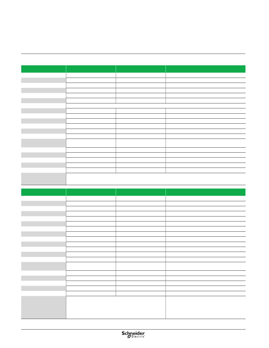
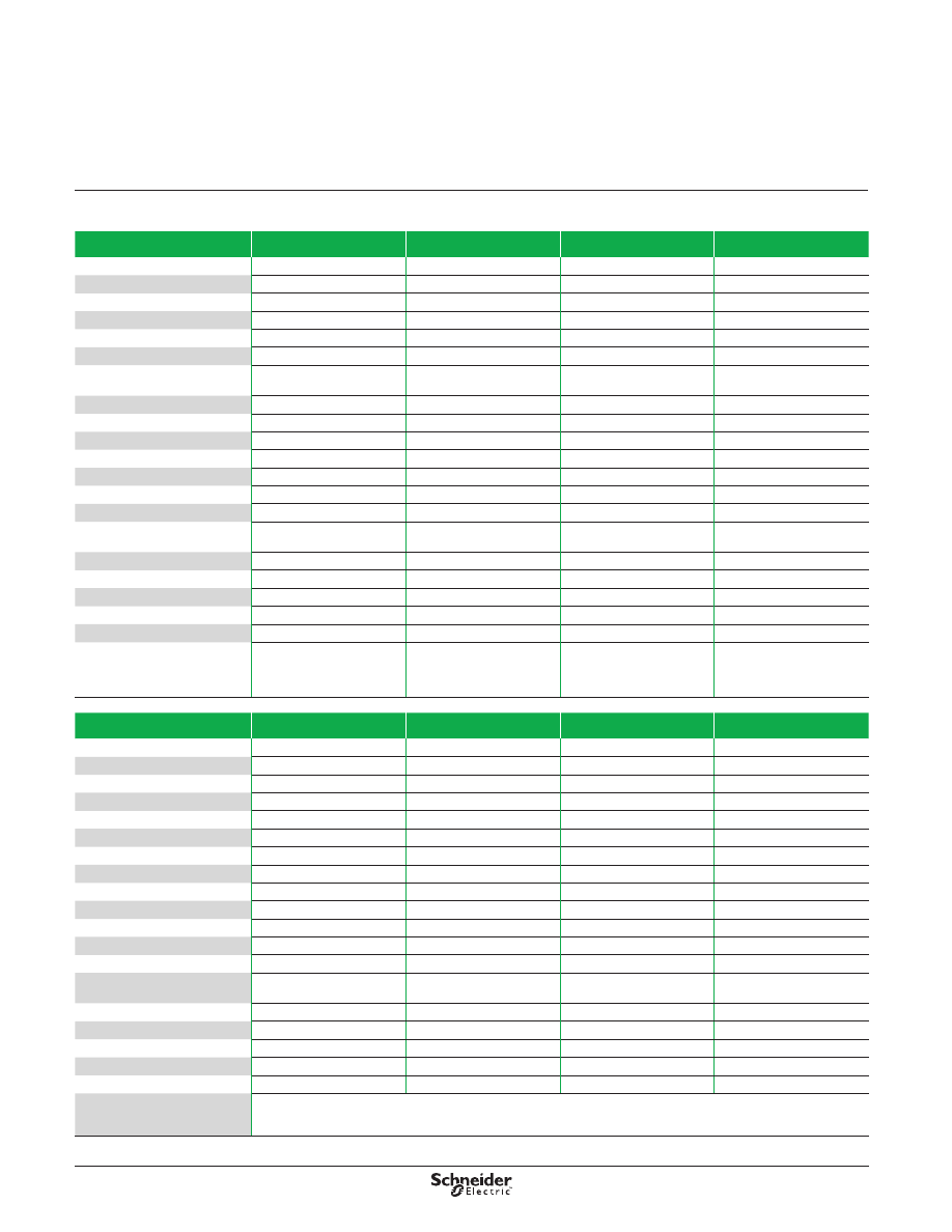
3
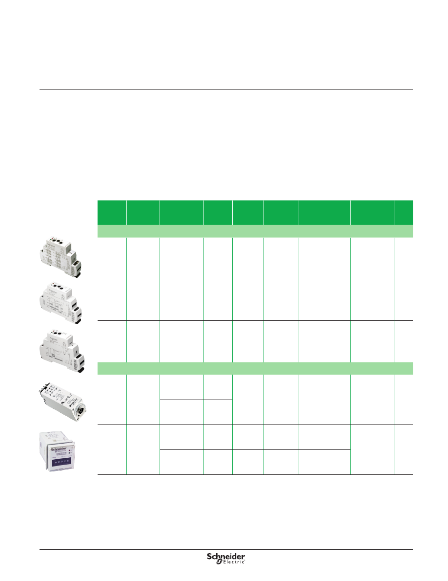
Series
Style
Contact
Configuration
Rated
Current
Load (A)
Timing
Range
Number of
Functions Function Type
Input Voltage
Range
Page
DIN Mounting
820
Relays
Time
delay
relay
SPST
DPDT
15
100 ms to
10 days
10
All
12–240
Vac/Vdc
831
Voltage
Sensing
Relays
Voltage
sensing
relay
SPDT
15
100 ms to
10 s
1
On-Delay
120, 240 Vac;
24 Vdc
841
Current
Sensing
Relays
Current
sensing
relay
SPDT
15
100 ms to
10 s
1
On-Delay
24–240 Vac
Plug-in Mounting
TDR782
Relays
Time delay
relay with
dial
DPDT
5
100 ms to
100 hr
1
On-Delay
12, 24 Vdc;
24, 110, 230 Vac 14
4PDT
3
TDRPRO
Relays
Time delay
relay with
5-digit
thumb-wheel
SPDT
12
100 ms to
9990 hr
10
All
12–240
Vac/Vdc
DPDT
12
100 ms to
9990 hr
3
On-Delay / Repeat
Cycle / On Interval
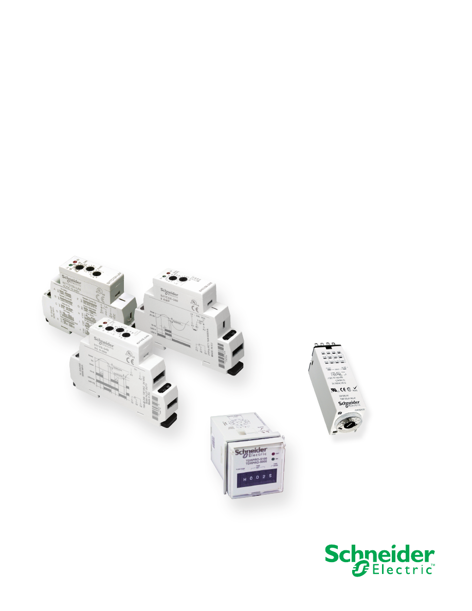
Legacy Schneider Electric™ time delay and sensor relays provide cost effective
solutions for your industrial timing and sensing needs . Available in a wide array
of forms, fits, and functions, these timers offer the ultimate in flexibility and
performance . Accurate adjustments, legible wiring diagrams, and an interactive timer
demo make selection quick and easy .
Key Features
Multiple timing functions
Wide input voltage range
Wide timing range
DIN, panel, or plug-in mounting styles
Conforms to international standards including UL, CSA, RoHS, and CE IEC
Series Overview
Legacy Time Delay and
Sensor Relays
4
Description
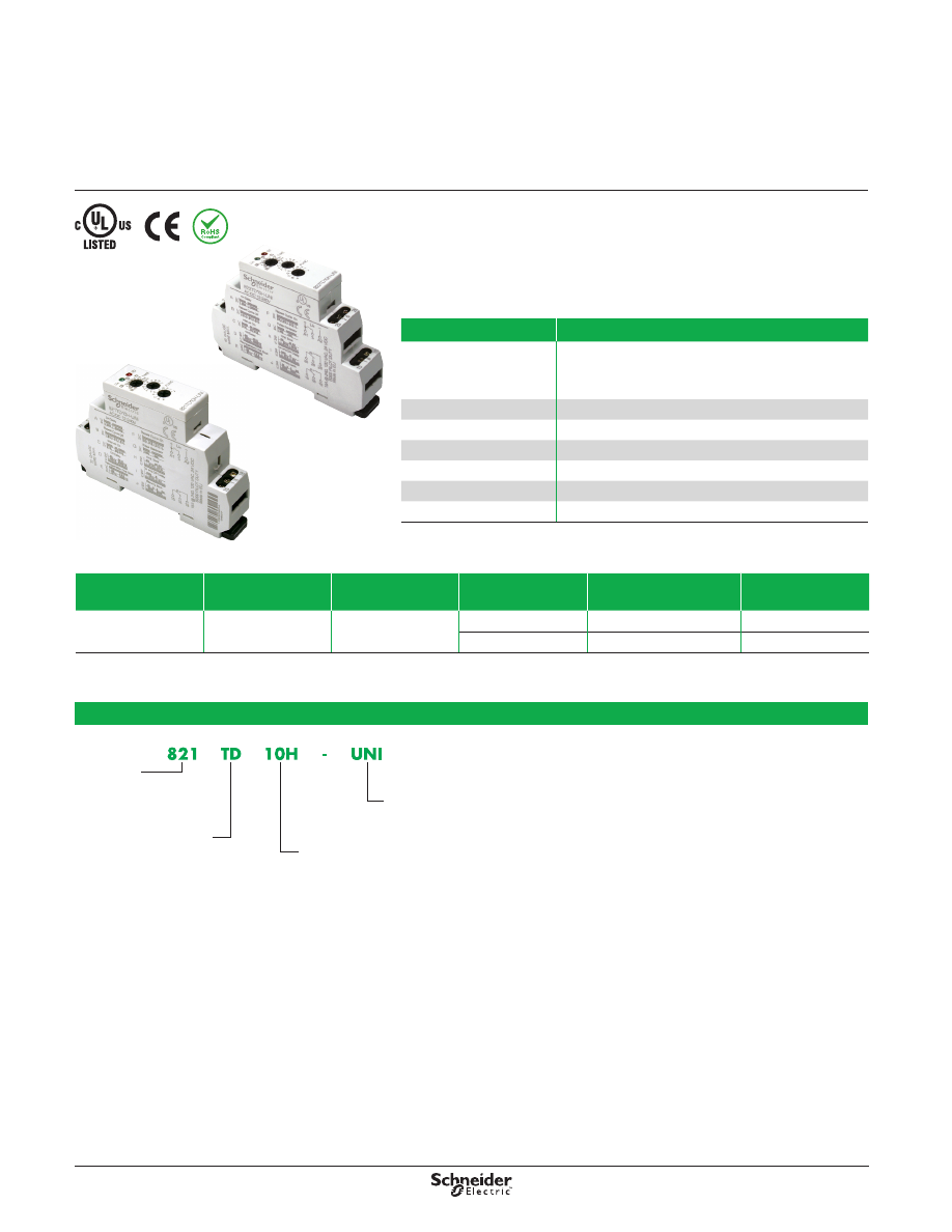
The 820 Series time delay relays are 35-mm DIN-rail mountable products offering ten
different timing functions, ultra-wide timing range (10 ms to 10 days), and a universal
voltage input (12–240 Vac/Vdc), all in a slim 17 .5 mm (0 .69 in .) modular package .
Input Voltage
Functions
Available
(1)
Timing Range
Contact
Configuration
Rated Current
Standard
Part Number
12–240 Vac/Vdc
A,B,C,D,E,F,G,H,I,J
10 ms to 10 days
SPDT
15 A
821TD10H-UNI
DPDT
15 A (2 pairs of contacts)
822TD10H-UNI
(1) For function descriptions, see page 31.
Part Number Explanation
Series:
821 =
SPDT
822 =
DPDT
Relay Style:
TD =
Time Delay
Input Voltage:
UNI =
12–240 Vac/Vdc
Number of Functions:
10H =
10 Functions
Feature
Benefit
Up to 10 functions
■ 5 timing functions controlled via supply voltage
■ 4 timing functions controlled via trigger input
■ 1 memory latching function
Meets most timing requirements
Contact configuration
SPDT or DPDT
Universal power supply
12–240 Vac/Vdc
2 LED status indicators
Shows status at a glance
Only 17 .5 mm (0 .69 in .) wide Ideal for tight spaces
DIN-rail mountable
Easy installation (screwdriver required)
RoHS compliant
Environmentally friendly
Description
Legacy Time Delay and
Sensor Relays
820 Series
SPDT, 15 A; DPDT, 15 A
821 Relay
822 Relay
5
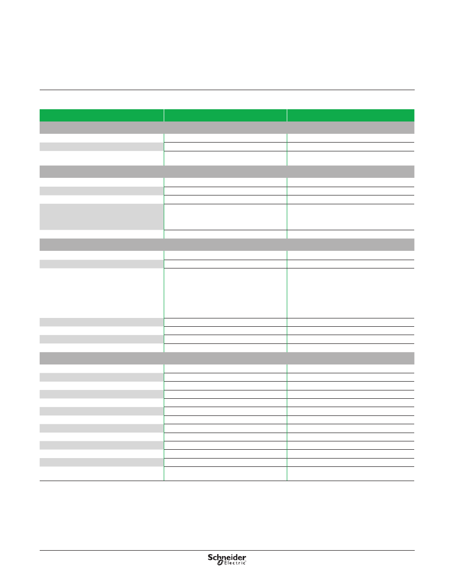
Specifications
Part Number
821TD10H-UNI
822TD10H-UNI
Input Characteristics
Input Voltage Range
12–240 Vac/Vdc
12–240 Vac/Vdc
Operating Voltage (% of Nominal)
85% of 12 V to 110% of 240 V
85% of 12 V to 110% of 240 V
Maximum Power Consumption
3 VA
1 .7 W
3 VA
1 .7 W
Output Characteristics
Contact Configuration
SPDT
DPDT
Output Current Rating
15 A
15 A
Contact Material
Silver alloy
Silver alloy
Switching Capability
15 A @ 240 Vac, 50/60 Hz, 24 Vdc
1/2 hp @ 120 Vac
1 hp @ 240 Vac
Pilot duty B300
15 A @ 240 Vac, 50/60 Hz, 24 Vdc
1/2 hp @ 120 Vac
1 hp @ 240 Vac
Pilot duty B300
Minimum Switching Requirement
100 mA
100 mA
Timing Characteristics
Functions Available
(1)
Multifunction
Multifunction
Time Scales
8
8
Time Ranges
100 ms to 1 s
1 s to 10 s
0 .1 min to 1 min
1 min to 10 min
0 .1 hr to 1 hr
1 hr to 10 hr
0 .1 day to 1 day
1 day to 10 days
100 ms to 1 s
1 s to 10 s
0 .1 min to 1 min
1 min to 10 min
0 .1 hr to 1 hr
1 hr to 10 hr
0 .1 day to 1 day
1 day to 10 days
Tolerance
5% of mechanical setting
5% of mechanical setting
Repeatability at Constant Voltage and Temperature
0 .2%
0 .2%
Reset Time
150 ms maximum
150 ms maximum
Trigger Pulse Length
50 ms minimum
50 ms minimum
General Characteristics
Electrical Life (Operations at Rated Current)
(2)
70,000 operations
70,000 operations
Mechanical Life (Unpowered)
(2)
10,000,000 operations
10,000,000 operations
Dielectric Strength (Input to Contacts)
2500 Vac
2500 Vac
Dielectric Strength (Between Open Contacts)
1600 Vac
1600 Vac
Storage Temperature Range
−30 to +70 °C (−22 to +158 °F)
−30 to +70 °C (−22 to +158 °F)
Operating Temperature Range
−20 to +55 °C (−4 to +131 °F)
−20 to +55 °C (−4 to +131 °F)
Terminal Wire Capacity (Input and Output)
14 AWG (2 .1 mm²) maximum
14 AWG (2 .1 mm²) maximum
Terminal Screw Torque
7 .1 lb-in (0 .8 N•m) maximum
7 .1 lb-in (0 .8 N•m) maximum
Weight
55 g (1 .9 oz)
70 g (2 .5 oz)
Input Indication
Green LED
Green LED
Output Indication (Blinking = Timing; On = Energized)
Red LED
Red LED
Enclosure Rating (according to IEC 60529 IP rating) IP20
IP20
Approvals
cULus (File: E234203, CCN: NKCR, NKCR7),
CE 61810-1, RoHS
cULus (File: E234203, CCN: NKCR, NKCR7),
CE 61810-1, RoHS
(1) For function descriptions, see page 31.
(2) Actual product life varies based on electrical load, duty cycle, application, and environmental conditions.
Specifications
Legacy Time Delay and
Sensor Relays
820 Series
SPDT, 15 A; DPDT, 15 A
6
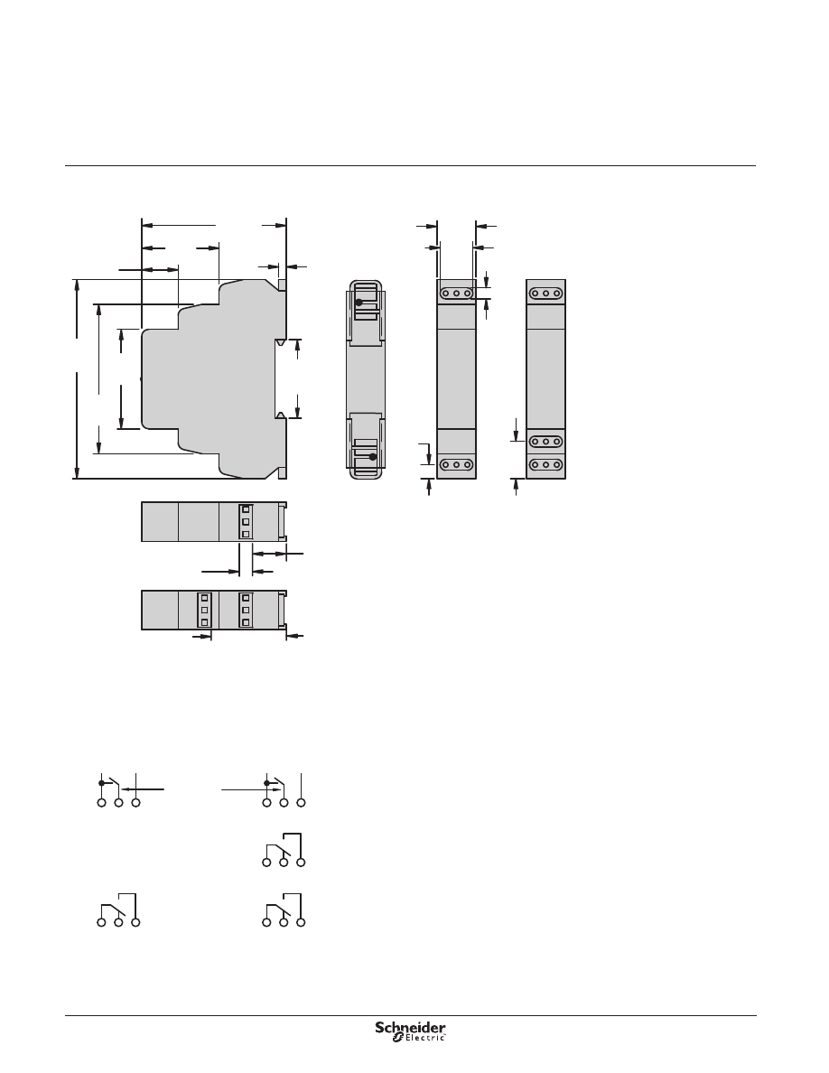
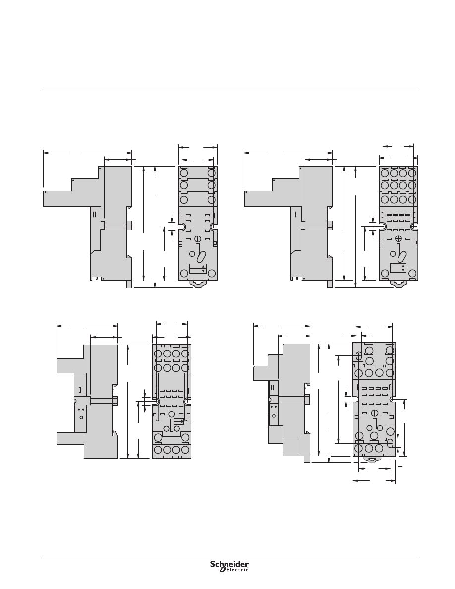
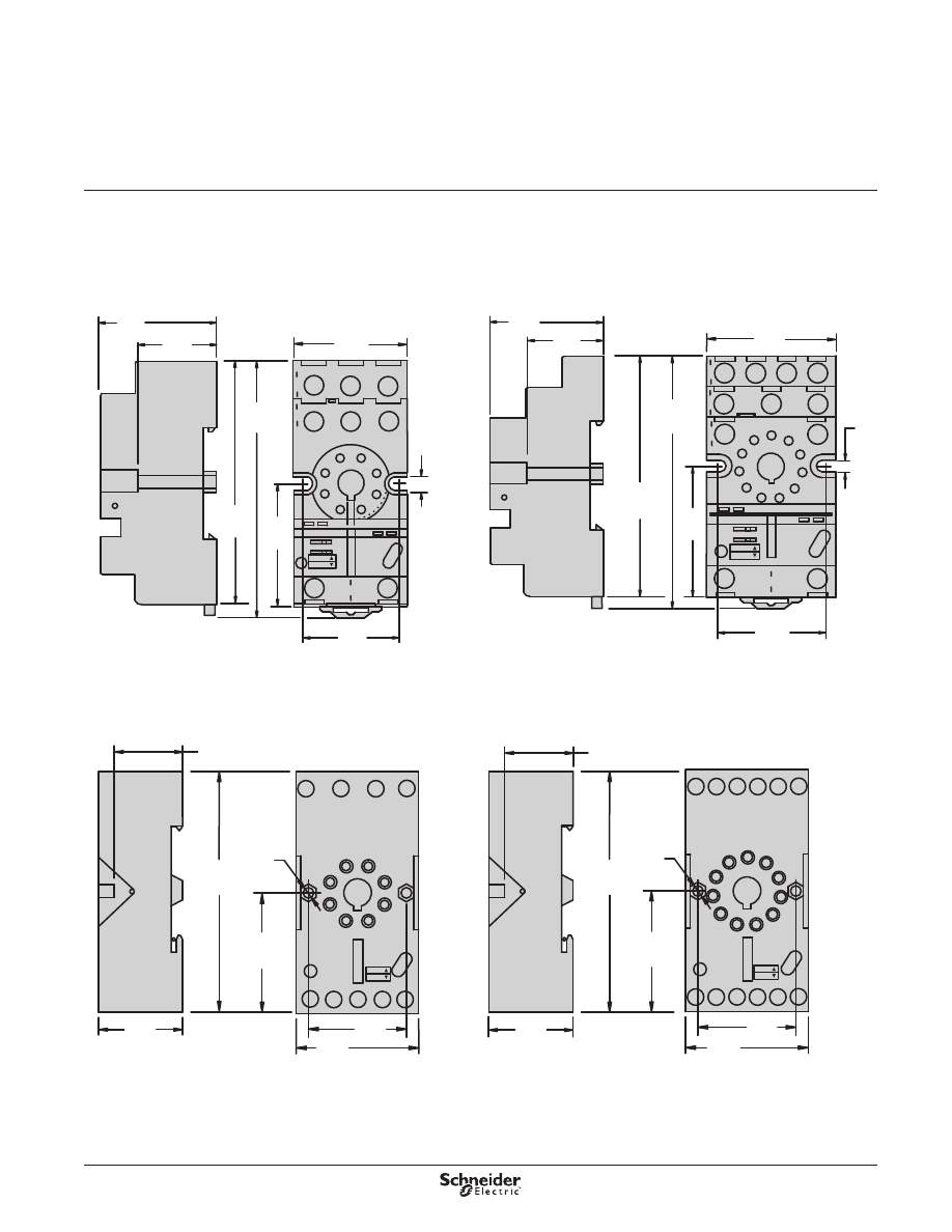
Wiring Diagram
Dimensions—in. (mm)
R
16
15
18
U
n
R
28
25 26
+
−
S
A1
A2
R
16
15
18
U
n
+
−
S
A1
A2
821TD10H-UNI
822TD10H-UNI
Input
Voltage
External
Control
Switch
(Dry Switch
Only)
15
—
Common
16
—Normally Closed
18
—Normally Open
26
—Normally Closed
28
—Normally Open
25
—Common
Input
Voltage
(7.4)
0.3
0.7
(17.6)
0.6
(14.2)
(5)
0.2
(65)
(16)
(45.3)
1.8
0.63
(67.5)
2.7
(90)
3.5
1.4
2.6
(34.2)
1.35
(3.4)
0.13
(35)
0.6
(16)
0.236
(6)
(16.71)
0.7
1.3
(34)
Dimensions,
Wiring Diagram
Legacy Time Delay and
Sensor Relays
820 Series
SPDT, 15 A; DPDT, 15 A
7
Description
Legacy Time Delay and
Sensor Relays
831 Series
SPDT, 15 A
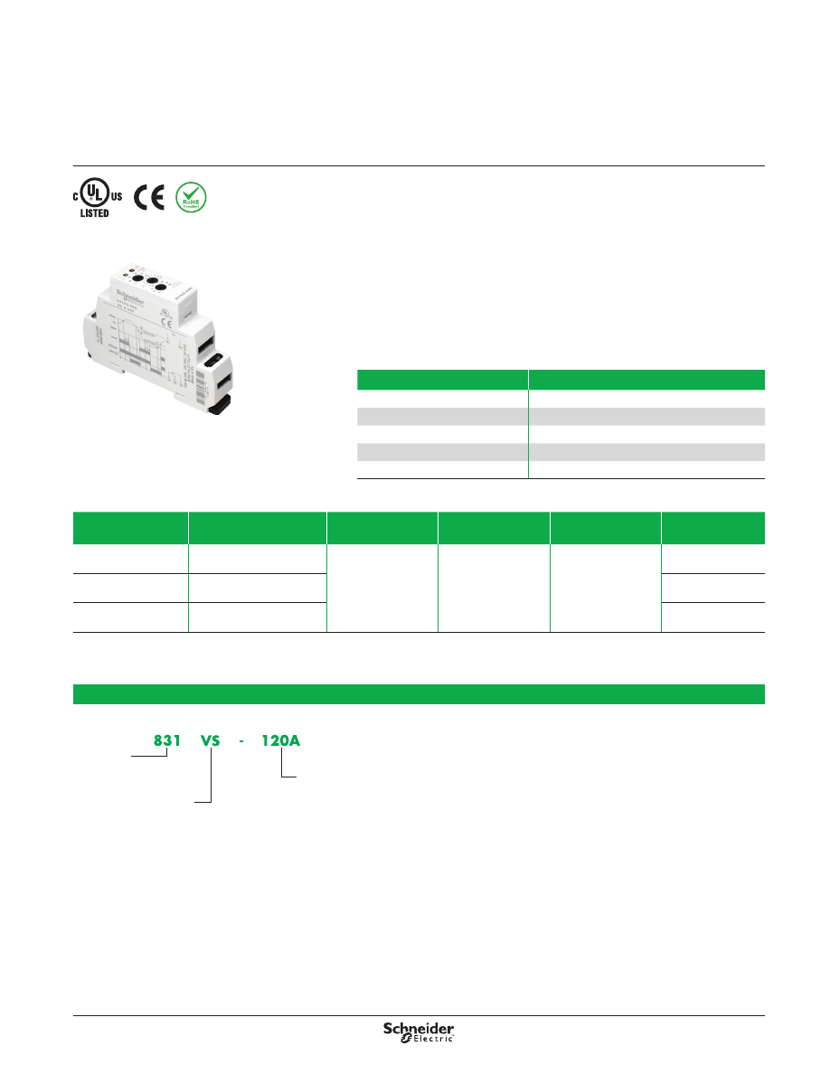
Description
The 831 voltage sensor is a single-phase AC voltage sensing device capable of
monitoring and reacting to overvoltage and undervoltage conditions . This product is
designed to be wired across terminals A1 and A2 with the voltage being monitored .
The two LED lamps indicate when the input voltage is present (green LED) and
when the output is energized (red LED) .
The Umax dial is used to set the upper trip-point for the voltage sensor . The Umin
dial is a percentage of the Umax dial and is used to set the lower trip-point for the
voltage sensor . The timing dial is used to delay the transfer of the contacts, from
0–10 s, when a set point has been violated .
Nominal
Input Voltage
Sensing
Voltage Range
Timing Range
Contact
Configuration
Rated Current
Standard
Part Number
120 Vac
Upper: 85–150 Vac
Lower: 30–99% of upper
0–10 s
SPDT
15 A
831VS-120A
240 Vac
Upper: 160–276 Vac
Lower: 30–99% of upper
831VS-240A
24 Vdc
Upper: 18–30 V
Lower: 30–99% of upper
831VS-24D
Part Number Explanation
Series:
831 =
SPDT
Relay Style:
VS =
Voltage Sensor
Nominal Input Voltage:
120A =
120 Vac
240A =
240 Vac
24D =
24 Vdc
Feature
Benefit
Three-state indication LEDs
Indicate normal state and two types of faulted states
Timing dial
Adjustable delay 0–10 s
DIN mounting capability
Mounts directly on a 35 mm DIN rail
Current rating: 15 A @ 240 Vac, 24 Vdc High switching capacity
Narrow width: 17 .5 mm (0 .69 in .)
Ideal for tight spaces
831 Relay
8
Specifications
Legacy Time Delay and
Sensor Relays
831 Series
SPDT, 15 A
Specifications
Part Number
831VS-120A
831VS-240A
831VS-24D
Input Characteristics
Nominal Input Voltage
120 Vac
240 Vac
24 Vdc
Absolute Input Voltage Maximum
200 Vac
280 Vac
35 Vdc
Upper Supply Voltage Range
85–150 Vac
160–276 Vac
18–30 Vdc
Lower Supply Voltage Range
30–99% of upper preset
30–99% of upper preset
30–99% of upper preset
Maximum Power Consumption
1 .2 VA
1 .2 VA
1 .2 W
Time Delay
adjustable, 0–10 s
adjustable, 0–10 s
adjustable, 0–10 s
Accuracy
Mechanical Setting
5%
5%
5%
Repeat Accuracy
<1%
<1%
<1%
Temperature Variation
<1% / ºC
<1% / ºC
<1% / ºC
Hysteresis (from fault to normal)
2–6% of adjusted value
2–6% of adjusted value
2–6% of adjusted value
Output Characteristics
Contact Configuration
SPDT
SPDT
SPDT
Output Current Rating
15 A @ 120, 240 Vac, 24 Vdc
15 A @ 120, 240 Vac, 24 Vdc
15 A @ 120, 240 Vac, 24 Vdc
Breaking Capacity
4000 VA/AC1, 384 W/DC
4000 VA/AC1, 384 W/DC
4000 VA/AC1, 384 W/DC
Inrush Current
30 A / <3 s
30 A / <3 s
30 A / <3 s
Maximum Switching Voltage
250 Vac / 24 Vdc
250 Vac / 24 Vdc
250 Vac / 24 Vdc
Minimum Breaking Capacity DC
500 mW
500 mW
500 mW
Mechanical Life
(1)
10,000,000 operations
10,000,000 operations
10,000,000 operations
Electrical Life
(1)
70,000 operations
70,000 operations
70,000 operations
Contact Material
Silver alloy
Silver alloy
Silver alloy
Switching Capability
15 A @ 240 Vac, 50/60 Hz, 24 Vdc
1/2 hp @ 120 Vac
1 hp @ 240 Vac
Pilot duty B300
15 A @ 240 Vac, 50/60 Hz, 24 Vdc
1/2 hp @ 120 Vac
1 hp @ 240 Vac
Pilot duty B300
15 A @ 240 Vac, 50/60 Hz, 24 Vdc
1/2 hp @ 120 Vac
1 hp @ 240 Vac
Pilot duty B300
Minimum Switching Requirement
100 mA at 5 Vac/Vdc
100 mA at 5 Vac/Vdc
100 mA at 5 Vac/Vdc
Timing/Sensing Characteristics
Time Scales
1
1
1
Time Ranges
0–10 s
0–10 s
0–10 s
Tolerance
5% of mechanical setting
5% of mechanical setting
5% of mechanical setting
Repeatability at Constant Voltage and Temperature
1%
1%
1%
Upper Sensing Voltage Range
85–150 Vac
160–276 Vac
18–30 Vdc
Lower Sensing Voltage Range
30–99% of upper preset
30–99% of upper preset
30–99% of upper preset
General Characteristics
Dielectric Strength (Input to Contacts)
2500 Vac
2500 Vac
2500 Vac
Dielectric Strength (Between Open Contacts)
1600 Vac
1600 Vac
1600 Vac
Mounting Position
Any, 35 mm DIN rail EN 50022
Any, 35 mm DIN rail EN 50022
Any, 35 mm DIN rail EN 50022
Overvoltage Category
III
III
III
Pollution Degree
2
2
2
Storage Temperature Range
−30 to +70 °C (−22 to +158 °F)
−30 to +70 °C (−22 to +158 °F)
−30 to +55 °C (−22 to +131 °F)
Operating Temperature Range
−20 to +55 °C (−4 to +131 °F)
−20 to +55 °C (−4 to +131 °F)
−20 to +55 °C (−4 to +131 °F)
Terminal Wire Capacity (Input and Output)
14 AWG (2 .5 mm²) maximum
14 AWG (2 .5 mm²) maximum
14 AWG (2 .5 mm²) maximum
Terminal Screw Torque
7 .1 lb-in (0 .8 N•m) maximum
7 .1 lb-in (0 .8 N•m) maximum
7 .1 lb-in (0 .8 N•m) maximum
Weight
62 g (2 .19 oz)
62 g (2 .19 oz)
88 g (3 .10 oz)
Input Indication
Green LED
Output Indication (Blinking = Timing; On = Energized)
Red LED
Enclosure Rating (according to IEC 60529 IP rating) IP40
Approvals
UL (E234203, CCN: NKCR, NKCR7),
CE (IEC 60947-1, 61000-4),
RoHS
(1) Actual product life varies based on electrical load, duty cycle, application, and environmental conditions.
9
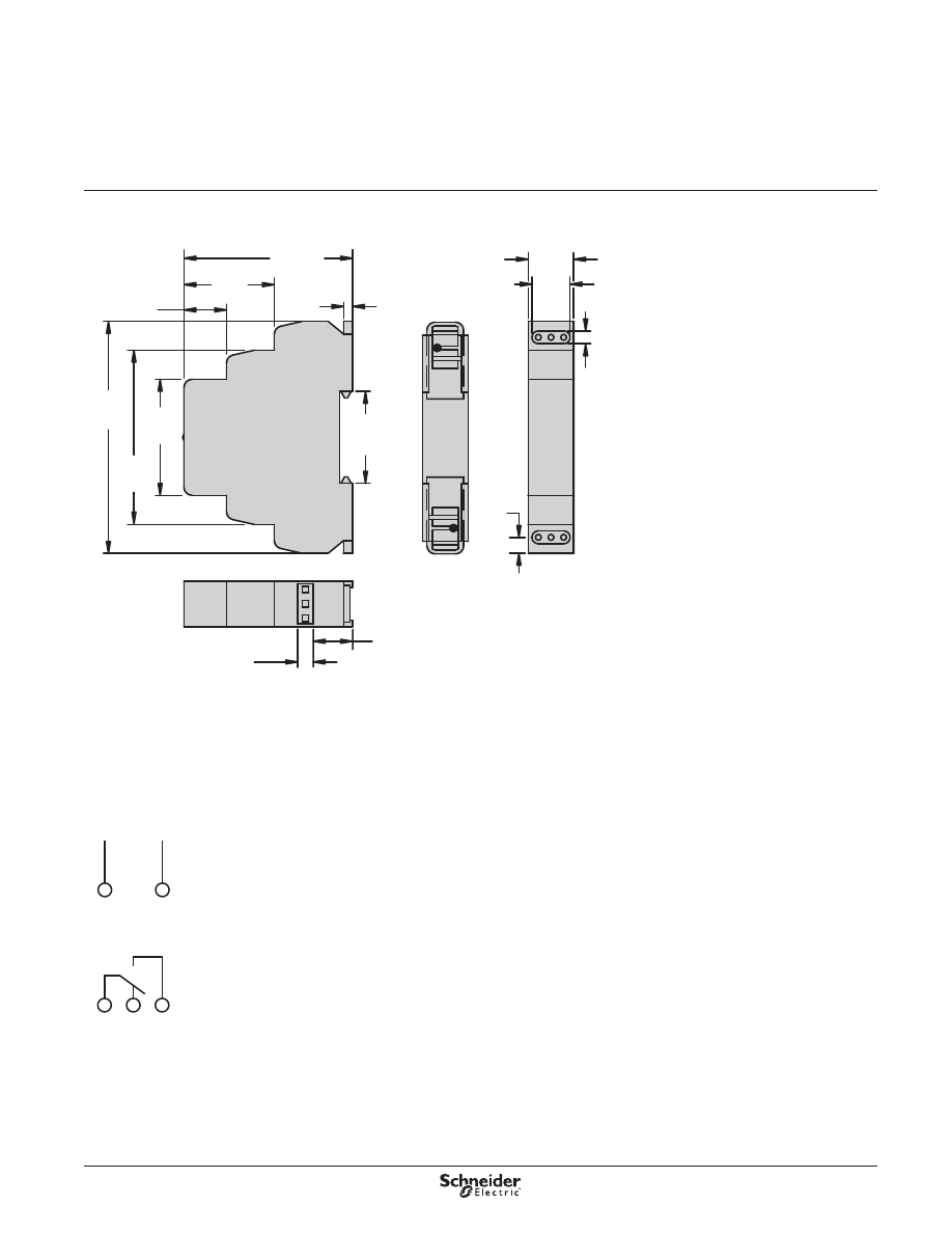
Dimensions—in. (mm)
Wiring Diagram
16
15
18
U
n
+
–
A1
A2
Input
Voltage
15
—Common
16
—Normally Closed
18
—Normally Open
(7.4)
0.3
0.7
(17.6)
0.6
(14.2)
(5)
0.2
(65)
(16)
(45.3)
1.8
0.63
(67.5)
2.7
(90)
3.5
1.4
2.6
(34.2)
1.35
(3.4)
0.13
(35)
0.6
(16)
0.236
(6)
Dimensions,
Wiring Diagram
Legacy Time Delay and
Sensor Relays
831 Series
SPDT, 15 A
10
Description
Legacy Time Delay and
Sensor Relays
841 Series
SPDT, 15 A
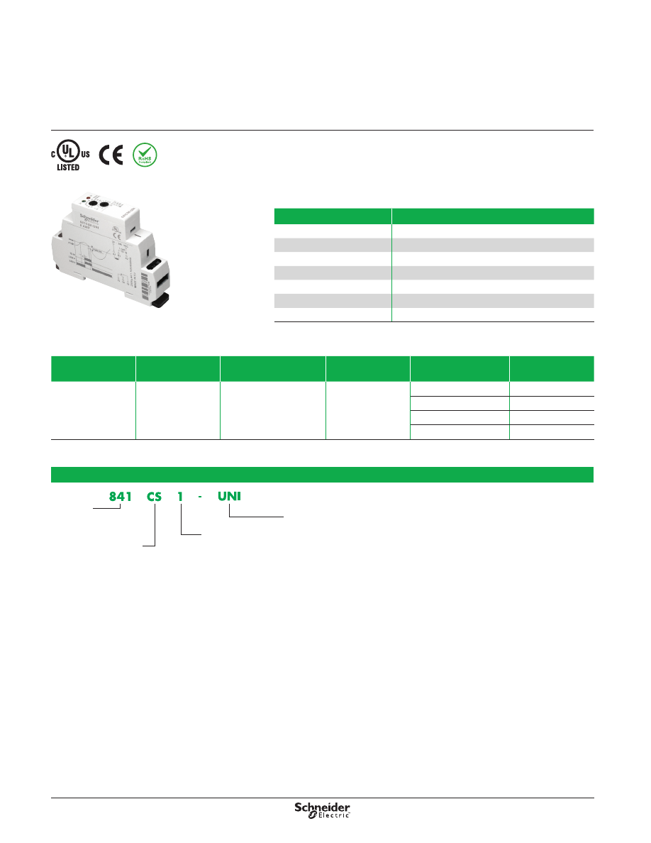
Description
This current sensing relay allows you to monitor the current of one circuit (1–8 A) and
switch another circuit in case of an overcurrent condition . The relays are modular and
finger protected (according to IEC 60529 IP rating) .
Input Voltage
Timing Range
Contact Configuration
Output (A)
Sensing
Current Range (AC)
Standard
Part Number
24–240 Vac
100 ms to 10 s
SPDT
15
100 mA to 1 A
841CS1-UNI
200 mA to 2 A
841CS2-UNI
500 mA to 5 A
841CS5-UNI
800 mA to 8 A
841CS8-UNI
Part Number Explanation
Series:
841 = SPDT
Relay Style:
CS = Current Sensor
Sensing Range:
1 = 100 mA to 1 A
2 = 200 mA to 2 A
5 = 500 mA to 5 A
8 = 800 mA to 8 A
Nominal Input Voltage:
UNI = 24–240 Vac
Feature
Benefit
Current-sensing adjustment knob Sense from 10–100% of the rated sensing current
Input/ouput terminals
Accepts wire up to 14 AWG
Solid-state circuitry
Used for precise sensing and timing control
Input/output indication
Shows status at a glance
DIN rail mounting capability
Mounts directly on a DIN Rail
Narrow width: 17 .5 mm (0 .69 in .) Ideal for tight spaces
Wide input range
Works with common AC voltages
841 Relay
11
Specifications
Legacy Time Delay and
Sensor Relays
841 Series
SPDT, 15 A
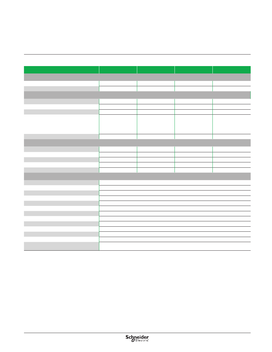
Specifications
Part Number
841CS1-UNI
841CS2-UNI
841CS5-UNI
841CS8-UNI
Input Characteristics
Input Voltage Range
24–240 Vac
24–240 Vac
24–240 Vac
24–240 Vac
Maximum Power Consumption
1 .2 VA
1 .2 VA
1 .2 VA
1 .2 VA
Output Characteristics
Contact Configuration
SPDT
SPDT
SPDT
SPDT
Output Current Rating
15 A
15 A
15 A
15 A
Contact Material
Silver alloy
Silver alloy
Silver alloy
Silver alloy
Switching Capability
15 A @ 240 Vac,
50/60 Hz, 24 Vdc
1/2 hp @ 120 Vac
1 hp @ 240 Vac
Pilot duty B300
15 A @ 240 Vac,
50/60 Hz, 24 Vdc
1/2 hp @ 120 Vac
1 hp @ 240 Vac
Pilot duty B300
15 A @ 240 Vac,
50/60 Hz, 24 Vdc
1/2 hp @ 120 Vac
1 hp @ 240 Vac
Pilot duty B300
15 A @ 240 Vac,
50/60 Hz, 24 Vdc
1/2 hp @ 120 Vac
1 hp @ 240 Vac
Pilot duty B300
Minimum Switching Requirement
100 mA at 5 Vac/Vdc
100 mA at 5 Vac/Vdc
100 mA at 5 Vac/Vdc
100 mA at 5 Vac/Vdc
Timing/Sensing Characteristics
Time Scales
1
1
1
1
Time Ranges
0–10 s
0–10 s
0–10 s
0–10 s
Tolerance
5% of mechanical setting 5% of mechanical setting 5% of mechanical setting 5% of mechanical setting
Repeatability at Constant Voltage and Temperature
1%
1%
1%
1%
Sensing Range
100 mA to 1 A
200 mA to 2 A
500 mA to 5 A
800 mA to 8 A
General Characteristics
Electrical Life (Operations at Rated Current)
(1)
70,000 operations
Mechanical Life (Unpowered)
(1)
10,000,000 operations
Dielectric Strength (Input to Contacts)
2500 Vac
Dielectric Strength (Between Open Contacts)
1600 Vac
Storage Temperature Range
−30 to +70 °C (−22 to +158 °F)
Operating Temperature Range
−20 to +55 °C (−4 to +131 °F)
Terminal Wire Capacity (Input and Output)
14 AWG (2 .1 mm²) maximum
Terminal Screw Torque
7 .1 lb-in (0 .8 N•m) maximum
Weight
60 g (2 .12 oz)
Input Indication
Green LED
Output Indication (Blinking = Timing; On = Energized)
Red LED
Enclosure Rating (according to IEC 60529 IP rating) IP20
Approvals
cULus (File: E234203, CCN: NKCR, NKCR7),
CE 61810-1, RoHS
(1) Actual product life varies based on electrical load, duty cycle, application, and environmental conditions.
12
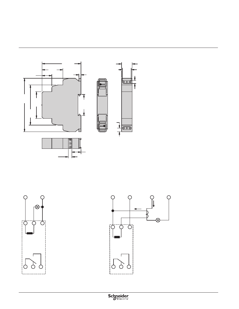
Dimensions—in. (mm)
Wiring Diagram
(7.4)
0.3
0.7
(17.6)
0.6
(14.2)
(5)
0.2
(65)
(16)
(45.3)
1.8
0.63
(67.5)
2.7
(90)
3.5
1.4
2.6
(34.2)
1.35
(3.4)
0.13
(35)
0.6
(16)
0.236
(6)
A1
A2
Input
Voltage
B1
Sensing
Circuit
16
15
18
15
—Common
16
—Normally Closed
18
—Normally Open
Direct current sensing
16
15
18
A1
A2
Input
Voltage
B1
Current sensing through a current transformer
Ip
Is
Input
Voltage
Current
Transformer
Ip:
Primary Current
Is:
Secondary Current
Inner
Shunt
Inner
Shunt
Dimensions,
Wiring Diagram
Legacy Time Delay and
Sensor Relays
841 Series
SPDT, 15 A
13
Accessories
Legacy Time Delay and
Sensor Relays
800 Series Accessories
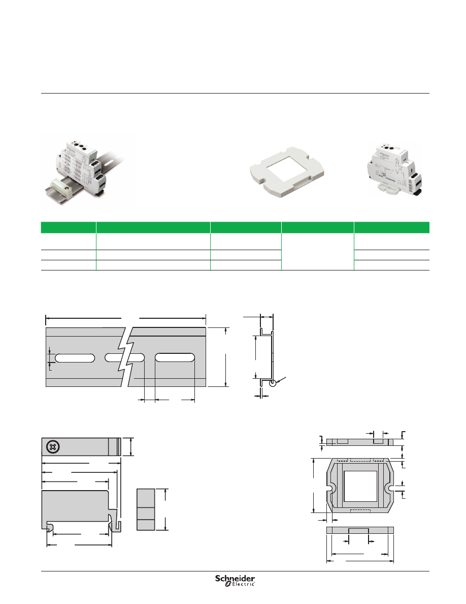
Description
The 16-700DIN DIN rail provides for quick removal and installation of most sockets,
while the 16-788C1 panel adapter provides a panel mounting option .
Description
Function
For Use With Relays
Packaging Quantities
Standard Part Number
Metal DIN Rail
39 .3 in . (1 m) .
Quick installation and removal
821, 822, 831, 841
10
16-700DIN
DIN Rail End Clip
Holds sockets firmly in place on the DIN rail
—
16-DCLIP-1
Panel Adapter
Provides additional panel mounting option
821, 822, 831, 841
16-788C1
16-700DIN DIN Rail,
16-DCLIP-1 DIN Rail
End Clip
Shown with an 821 Relay
Shown with an 831 Relay
16-788C1 Panel Adapter
Dimensions—in. (mm)
Note
: The lips at the
base of the DIN rail may
or may not be present
on DIN rail extrusions .
16-700DIN Metal DIN Rail
(5)
0.19
1.377
+0.011 / −0.007
(35 ± 0.3)
0.99
(10)
0.39
(25)
(1 ± 0.04)
0.039
(25.5)
1.0
39.3
(1000)
0.3
(7.5 +0.0 / −0.4)
0.165 TYP
(4.19)
1.39 Max.
(35.3)
0.06 TYP
(1.4)
16-788C1 Panel Adapter
1.7
(43.18)
1.4 Max.
(35.5)
0.585
(14.95)
0.17 TYP
(4.31)
0.165
(4.19)
0.256
(6.5)
0.12
(3.04)
0.37
(9.4)
1.39
(35.5)
1.55
(39.5)
1.65
(42.0)
1.37
(34.7)
1.17
(29.7)
0.86
(22.0)
14
Description
Legacy Time Delay and
Sensor Relays
TDR782 Series
DPDT, 5 A; 4PDT, 3 A
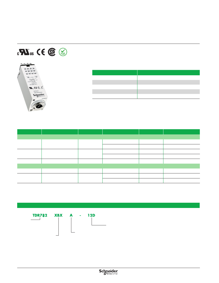
Description
Miniature time delay relay that is single-function, single-voltage, and socket-
compatible . Ideal for tight spaces .
Input Voltage
Functions Available
(1)
Timing Range
Contact Configuration
Rated Current
Standard Part Number
AC
24 Vac
A (On-Delay)
100 ms to 100 hr
4PDT
3 A
TDR782XDXA-24A
DPDT
5 A
TDR782XBXA-24A
110 Vac
A (On-Delay)
100 ms to 100 hr
4PDT
3 A
TDR782XDXA-110A
DPDT
5 A
TDR782XBXA-110A
230 Vac
A (On-Delay)
100 ms to 100 hr
4PDT
3 A
TDR782XDXA-230A
DC
12 Vdc
A (On-Delay)
100 ms to 100 hr
4PDT
3 A
TDR782XDXA-12D
24 Vdc
A (On-Delay)
100 ms to 100 hr
4PDT
3 A
TDR782XDXA-24D
DPDT
5 A
TDR782XBXA-24D
(1) For function descriptions, see page 31.
Part Number Explanation
Series:
TDR782 =
782 Miniature
Timer
Contact Configuration:
XBX =
DPDT
XDX =
4PDT
Functions:
A =
On Delay
Input
V
oltage:
12D =
12 Vdc
24D =
24 Vdc
24A =
24 Vac
110A =
110/120 Vac
230A =
230/240 Vac
Feature
Benefit
Time setting
Selects between 7 different time scales
Socket compatible
Mounts directly to DIN rail or panel
Input/output indication
Shows status at a glance
Time adjustment dial
Fine-tunes the time setting
IEC and NEMA terminal numbering
Allows numbering compatibility
TDR782 Relay
15
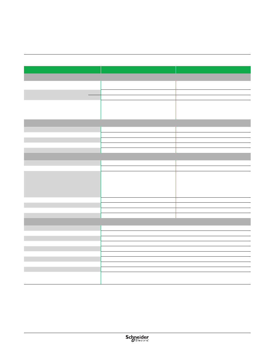
Specifications
Legacy Time Delay and
Sensor Relays
TDR782 Series
DPDT, 5 A; 4PDT, 3 A
Specifications
Part Number
TDR782XBX
TDR782XDX
Input Characteristics
Input Voltage Range
24, 110/120, 230/240 Vac
12, 24 Vdc
24, 110/120, 230/240 Vac
12, 24 Vdc
Operating Voltage
Vac
85–115% of nominal
85–115% of nominal
Vdc
90–110% of nominal
90–110% of nominal
Maximum Power Consumption
1 .7 VA @ 24 Vac
2 .6 VA @ 120 Vac
3 VA @ 230 Vac
1 .5 W @ 12 Vdc
1 .2 W @ 24 Vdc
1 .7 VA @ 24 Vac
2 .6 VA @ 120 Vac
3 VA @ 230 Vac
1 .5 W @ 12 Vdc
1 .2 W @ 24 Vdc
Output Characteristics
Contact Configuration
DPDT
4PDT
Output Current Rating
5 A
3 A
Contact Material
Silver alloy
Silver alloy
Maximum Inrush Current
10 A @ < 100 ms
10 A @ < 100 ms
Minimum Switching Requirement
100 mA at 5 Vac/Vdc
100 mA at 5 Vac/Vdc
Timing Characteristics
Functions Available
(1)
A (On-Delay)
A (On-Delay)
Time Scales
7
7
Time Ranges
100 ms to 1 s
1 s to 10 s
0 .1 min to 1 min
1 min to 10 min
0 .1 hr to 1 hr
1 hr to 10 hr
10 hr to 100 hr
100 ms to 1 s
1 s to 10 s
0 .1 min to 1 min
1 min to 10 min
0 .1 hr to 1 hr
1 hr to 10 hr
10 hr to 100 hr
Tolerance
5% of mechanical setting
5% of mechanical setting
Repeatability at Constant Voltage and Temperature
0 .5%
0 .5%
Reset Time
50 ms maximum
50 ms maximum
Temperature Drift
0.05% / °C
0.05 % / °C
General Characteristics
Electrical Life (Operations at Rated Current)
(2)
100,000 operations
Mechanical Life (Unpowered)
(2)
10,000,000 operations
Dielectric Strength (Input to Contacts)
2000 Vrms
Storage Temperature Range
−40 to +70 °C (−40 to +158 °F)
Operating Temperature Range
−20 to +60 °C (−4 to +140 °F)
Weight
43 g (1 .52 oz)
Input Indication
Green LED
Output Indication (On = Energized)
Amber LED
Enclosure Rating (According to IEC 60529 IP Rating) IP50
Approvals
cURus (File: E191122, CCN: NRNT2, NRNT8),
CSA (File No . 254373),
CE 61810-1, RoHS
(1) For function descriptions, see page 31.
(2) Actual product life varies based on electrical load, duty cycle, application, and environmental conditions.
16
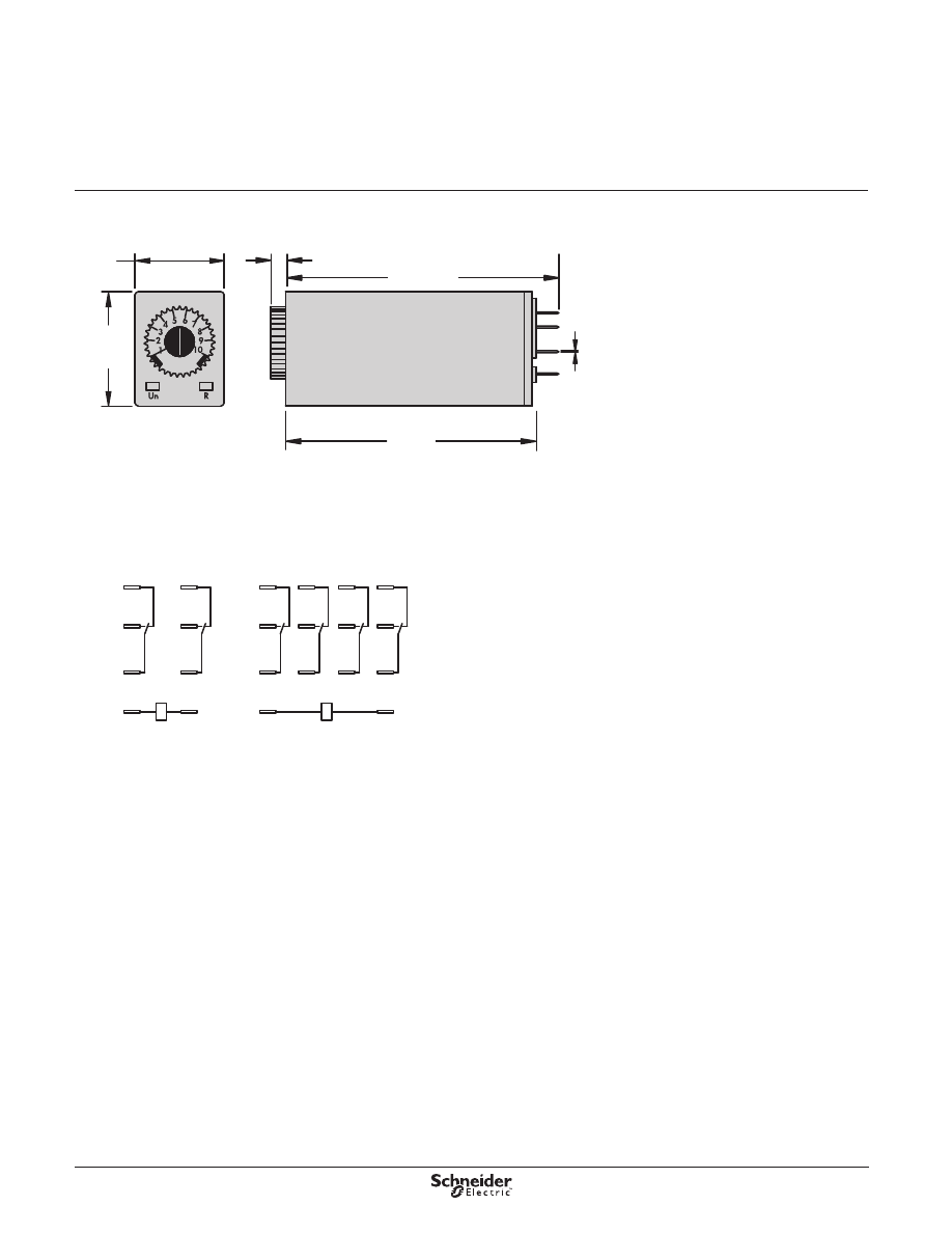
Dimensions—in. (mm)
Wiring Diagram
0.8
(21)
1.0
(27)
0.14
(3.5)
2.3
(59.4)
2.57
(65.28)
0.02
(0.48)
13
5
9
1
14
6
10
2
8
7
11
12
3
4
8
5
13
9
14
12
1
4
SPDT
NEMA
DPDT
NEMA
Dimensions,
Wiring Diagram
Legacy Time Delay and
Sensor Relays
TDR782 Series
DPDT, 5 A; 4PDT, 3 A
17
Description
Legacy Time Delay and
Sensor Relays
TDR782 Series Accessories
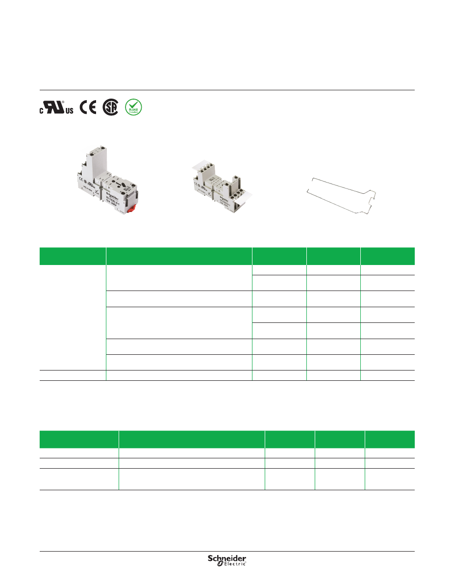
Description
The TDR782 accessories create a complete system solution for all your application
needs .
The 70-782EL socket offers an alternate installation option for plug-in models .
The 16-TDR782SC retention clip holds the relay securely in place while allowing
quick and efficient installation and maintenance .
Relay Accessories
Description
Function
For Use
With Relays
Packaging
Quantities
Standard
Part Number
Socket
Mounts directly to the DIN rail or panel
TDR782XBX
10
70-782EL8-1
TDR782XBX
TDR782XDX
10
70-782EL14-1
DIN or panel mounting with rising elevator box terminals
TDR782XBX
TDR782XDX
10
70-782E14-1
DIN or panel mounting with screw terminals and clamping
plates
TDR782XBX
TDR782XDX
10
70-782D14-1
TDR782XBX
TDR782XDX
10
70-461-1
Solder terminals for chassis mounting
TDR782XBX
TDR782XDX
10
70-378-1
Printed circuit terminals
TDR782XBX
TDR782XDX
10
70-379-1
Metal Retention Clip
Helps secure the relay in the socket
TDR782●●
(1)
10
16-TDR782SC
(1)
Replace the bullets (
●●) with the the part number suffix. See page
14 .
70-782EL8-1 Socket
70-782E14-1 Socket
16-TDR782SC Retention Clip
Socket Accessories
Description
Function
For Use
With Sockets
Packaging
Quantities
Standard
Part Number
Metal DIN Rail, 1 m (39 .3 in .)
Quick installation and removal of sockets
See table above
10
16-700DIN
DIN Rail End Clip
Holds sockets firmly in place on the DIN rail
—
10
16-DCLIP-1
ID Tags
Allows for identification of circuits in multi-relay applications
70-782EL8-1
70-782EL14-1
70-782E14-1
10
16-782FT-1
18
Specifications
Legacy Time Delay and
Sensor Relays
TDR782 Series Accessories
Specifications
Part Number
70-782EL8-1
70-782EL14-1
70-782E14-1
Contact Configuration
DPDT
4PDT
4PDT
Number of Terminals
8
14
14
Mounting Style
Panel or DIN Rail
Panel or DIN Rail
Panel or DIN Rail
Current Rating
12 A
10 A
10 A
Nominal Voltage Rating
300 V
300 V
300 V
Storage Temperature Range
−40 to +105 °C (−40 to +221 °F)
−40 to +105 °C (−40 to +221 °F)
−40 to +105 °C (−40 to +221 °F)
Protection Category
IP20 (Finger Protection)
Internal Metal Tracks
Copper Alloy, Zinc Plated
Copper Alloy, Zinc Plated
Copper Alloy, Zinc Plated
Screw Terminals
Steel, Zinc Plated
Steel, Zinc Plated
Steel, Zinc Plated
Screw Style
Combination Head
Combination Head
Combination Head
Screw Size
M3
M3
M3
Terminal Connection
Elevator
Elevator
Elevator
Terminal Layout
Logic
Logic
Non-Logic
Wire Size Capacity
Solid or Stranded Cu:
Two 14–16 AWG (1 .5–2 .5 mm²)
Solid or Stranded Cu:
Two 14–16 AWG (1 .5–2 .5 mm²)
Solid or Stranded Cu:
Two 14–16 AWG (1 .5–2 .5 mm²)
DIN Rail Mounting, EN 60715
35 mm (1 .38 in)
35 mm (1 .38 in)
35 mm (1 .38 in)
Maximum Screw Torque
7 lb-in (0 .8 N•m)
7 lb-in (0 .8 N•m)
7 lb-in (0 .8 N•m)
Flammability Rating
UL94 Class V-0
UL94 Class V-0
UL94 Class V-0
Body Color
Light Gray
Light Gray
Light Gray
DIN Locking Method
Red Plastic Locking Clip
Red Plastic Locking Clip
Metal Compression Spring
Product Certifications
cURus (File: E70550, CCN: SWIV2, SWIV8),
CSA (File: 40787, Class: 3211 07),
CE 60947-1, RoHS
Part Number
70-379-1
70-378-1
70-461-1, 70-782D14-1
Contact Configuration
4PDT
4PDT
4PDT
Number of Terminals
14
14
14
Mounting Style
PCB
Chassis
Panel or DIN Rail
Current Rating
5 A
5 A
10 A
Nominal Voltage Rating
300 V
300 V
300 V
Storage Temperature Range
−40 to +105 °C (−40 to +221 °F)
−40 to +105 °C (−40 to +221 °F)
−40 to +105 °C (−40 to +221 °F)
Protection Category
–
–
70-782D14-1
: IP20 (Finger Protection)
Internal Metal Tracks
Copper Alloy, Zinc Plated
Copper Alloy, Zinc Plated
Copper Alloy, Zinc Plated
Screw Terminals
Copper Alloy, Zinc Plated
Copper Alloy, Zinc Plated
Steel, Zinc Plated
Screw Style
–
–
Combination Head
Screw Size
–
–
M3 mm
Terminal Connection
PCB
Solder
Screw Clamping
Terminal Layout
Non-Logic
Non-Logic
Non-Logic
Wire Size Capacity
–
Solid or Stranded Cu:
Two 14–16 AWG (1 .5–2 .5 mm²)
Solid or Stranded Cu:
Two 14–16 AWG (1 .5–2 .5 mm²)
DIN Rail Mounting, EN 60715
–
–
35 mm (1 .38 in)
Maximum Screw Torque
–
–
7 lb-in (0 .8 N•m)
Flammability Rating
UL94 Class V-0
UL94 Class V-0
UL94 Class V-0
Body Color
Light Gray
Light Gray
Light Gray
DIN Locking Method
–
–
Red Plastic Locking Clip
Product Certifications
cURus (File: E70550, CCN: SWIV2, SWIV8),
CSA (File: 40787 Class: 3211 07),
CE 60947-1, RoHS
70-461-1:
cURus (File: E70550, CCN: SWIV2, SWIV8),
CSA (File: 40787 Class: 3211 07),
CE 60947-1, RoHS
70-782D14-1:
cURus (File: E70550),
CSA (File: 40787 Class: 3211 07),
CE 60947-1, RoHS
19
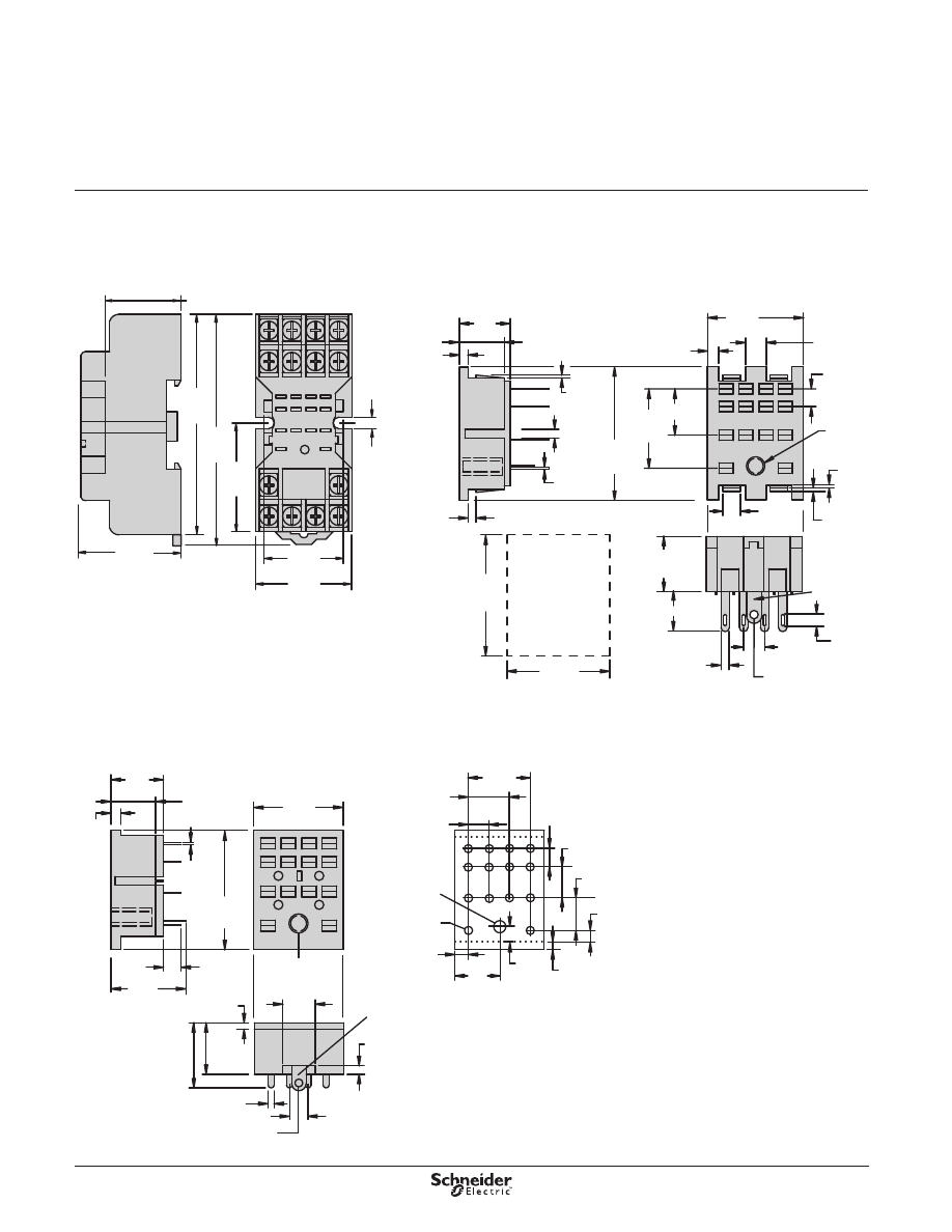
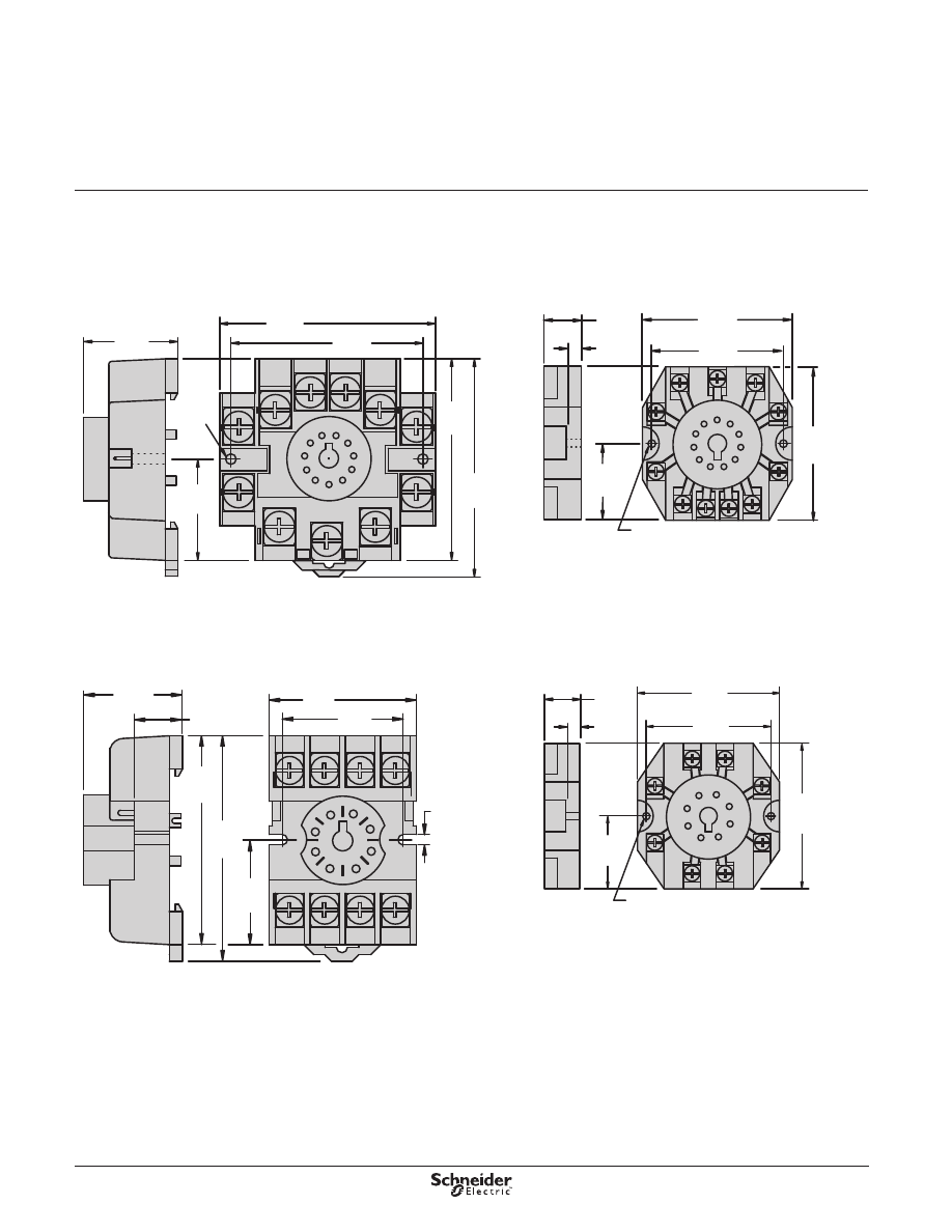
Dimensions—in. (mm)
1.06
(26.9)
A1
INPUT
A2
14
13
12
5
9
11
14
4
1
8
12
42
41
44
NEMA:
IEC:
70-782EL8-1
Mounts Directly to the DIN Rail or Panel
0.9
(22)
(19.0)
(61.0)
2.4
0.74
3.11
(79.0)
(85.0)
3.34
(38.0)
1.49
0.2
(5.6)
Dimensions
Legacy Time Delay and
Sensor Relays
TDR782 Series Accessories
70-782EL14-1
Mounts Directly to the DIN Rail or Panel
0.9
(22)
1.06
(25.4)
(19.0)
(61.0)
2.4
0.74
3.11
(79.0)
(85.0)
3.34
(38.0)
1.49
0.2
(5.6)
1
A1
12
5
9
11
14
INPUT
A2
14
3
4
7
8
11
12
32
42
41
31
34
44
13
2
6
10
22
21
24
NEMA:
IEC:
70-782E14-1
DIN or Panel Mounting with Rising Elevator Box Terminals
10
12
11
9
21
41
31
11
INPUT
14
13
A1
A2
6
8
7
5
24
44 34
14
12
1
42
3
22
2
4
32
(26.9)
(22.0)
(43.0)
(79.0)
(17.0)
(3.0)
(40.0)
1.69
3.12
0.67
1.57
0.12
0.86
1.06
NEMA:
IEC:
70-782D14-1
DIN or Panel Mounting with Screw Terminals and Clamping Plates
(3.8)
(30.0)
(21.0)
(84.0)
(79.0)
(6.4)
(39.5)
(61.0)
(40.0)
(3.8)
(25.5)
0.14
1.0
1.55
0.25
0.82
0.14
3.3
3.11
1.57
2.4
1.18
44 14
11
12
10
INPUT
INPUT
31
14
A2
41
13
9
A1
21
11
3
4
2
1
8
32
42
5
22
12
34
7
24
6
0.74
(19.0)
20
Dimensions
(continued)
Legacy Time Delay and
Sensor Relays
TDR782 Series Accessories
70-378-1
Solder Terminals for Chassis Mount
0.105
(2.67)
(17.7)
0.07
(28.5)
1.14
(2.59)
0.102
(9.52)
0.375
(11.1)
0.44
Ground
Lug
(3.17)
(3.81)
0.15
(1.77)
0.07 Dia.
0.125
(4.06)
0.16
0.05
(1.27)
(1.27)
0.05
(16.5)
0.65
(9.9)
0.39
0.16 Dia.
(4.06)
(1.98)
0.078
0.10
0.145
(3.68)
(2.54)
(21.8)
0.86
(4.57)
0.18
(2.54)
(0.381)
0.015
0.44
(11.1)
0.375
(9.52)
0.10
Recommended
Chassis Cutout
Top View
(25.7)
1.01
(21.5)
0.86
Dimensions—in. (mm)
70-379-1
Printed Circuit Terminals
0.625
(15.8)
0.30
(1.54)
0.061
(11.1)
0.44
(1.52)
0.06
(7.82)
Ground
Lug
0.07 Dia. (1.77)
(3.81)
0.15
(2.03)
0.08
(25.4)
1.0
0.16 Dia.
(4.06)
0.75
(19.0)
(2.66)
0.105
0.674
(17.0)
(4.76)
0.1875
0.375
(9.52)
(11.17)
0.44
Recommended
Circuit Board Layout
Top View
0.015
(0.381)
0.16
(2.4)
0.095
(6.35)
0.25
(6.35)
0.25
(4.06)
0.175
(4.44)
(2.6)
0.102
0.35
(8.89)
0.525
(13.3)
0.10
(2.5)
0.12
(3.04)
(9.5)
0.375
0.07 (1.78) Dia.
14 Places
0.145 (3.68) Dia.
70-461-1
DIN or Panel Mounting with Screw Terminals and Clamping Plates
2.71
(69.0)
(64.0)
2.51
(25.4)
1.0
9
5
1
4
8
3
7
6
2
1
1
4
1
2
1
3
1
0
1
(22.7)
0.89
0.17
(4.32)
Dia.
Typ.
(30.7)
1.2
1.25
(32.0)
0.708 (18)
21
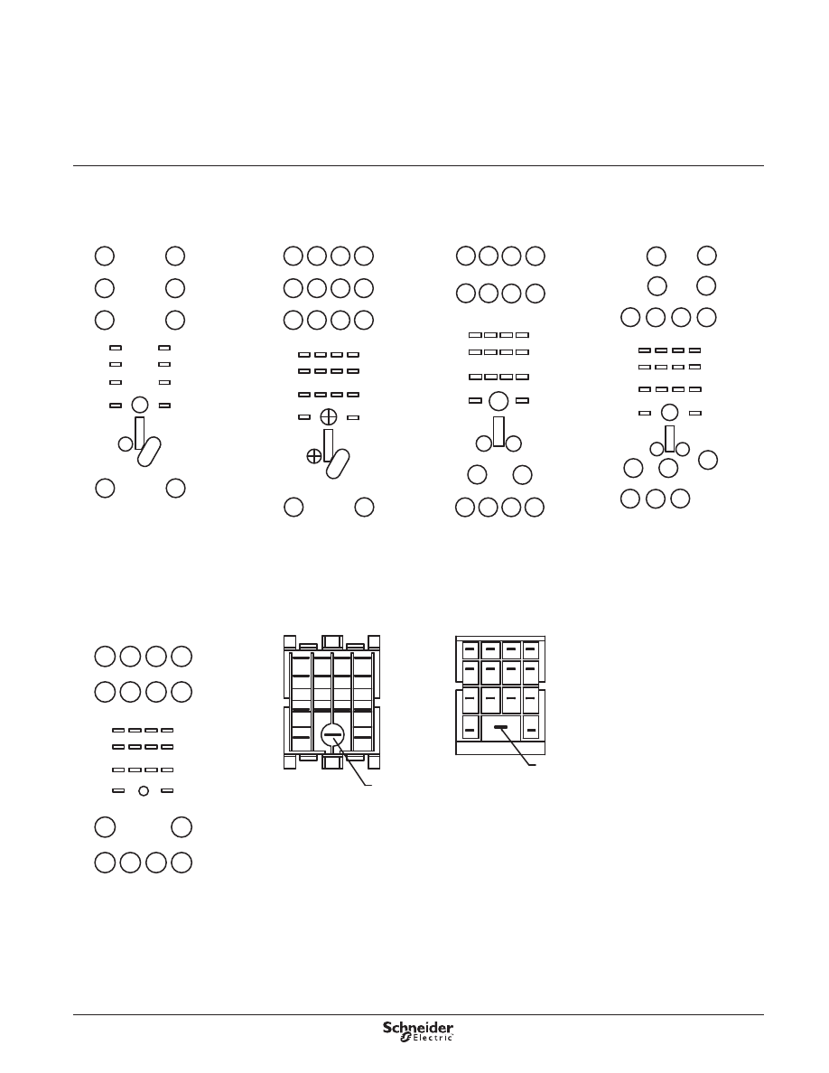
Wiring Diagrams
Legacy Time Delay and
Sensor Relays
TDR782 Series Accessories
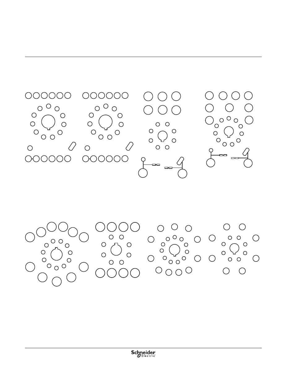
Wiring Diagrams
70-782EL14-1
A2
14
13
INPUT
A1
44
41
42
4
8
12
2
32
3
22 12
1
14
6
34
7
24
5
21
10
31
11
11
9
1
2
3
4
5
6
7
8
9
10
11
12
14
13
MODULE
INPUT
COM
INPUT
N.O.
N.C.
IEC
NEMA
70-782EL8-1
1
A1
12
5
9
11
14
INPUT
A2
14
4
8
12
42
41
44
13
N.O.
INPUT
COM
N.C.
4
1
5
8
9
12
14
13
MODULE
INPUT
IEC
NEMA
70-378-1
11
10
9
13
5
7
6
12
14
8
1
3
2
4
N.O.
N.C.
COM
INPUT
12
22
32
42
14
24
34
44
11
21
31
41
A1
A2
GROUND
LUG
IEC
NEMA
70-379-1
INPUT
COM
N.C.
N.O.
2
3
4
5
6
7
8
9
10
11
12
13
14
22
32
42
14
24
34
44
11
21
31
41
A1
A2
GROUND
LUG
IEC
NEMA
1
12
70-461-1
8
4
7
5
6
3
1
2
10
11
12
14
13
9
41 31 21 11
A2
A1
42 32 22 12
44 34 24 14
N.C.
N.O.
COM
INPUT
8 7 6 5
4 3 2 1
14
13
9
10
11
12
IEC
NEMA
INPUT
70-782D14-1
A2
14
12
41
9
A1
13
11 10
31 21
11
4
42
1
2
3
24
34
14
6
7
44
12
22
32
5
8
INPUT
COM
N.O.
N.C.
4 3 2 1
5
8
6
7
12 11 10
14
13
9
MODULE
INPUT
IEC
NEMA
INPUT
70-782E14-1
N.O.
INPUT
COM
N.C.
1
12
2
22
3
32
4
42
5
14
6
24
7
34
8
44
A1
13
A2
14
11
9
21
10
31
11
41
12
13
14
8 7 6 5
3
4
2 1
12 11 10 9
IEC
NEMA
MODULE
INPUT
INPUT
22
Description
Legacy Time Delay and
Sensor Relays
TDRPRO Series
SPDT, 12 A; DPDT, 12 A
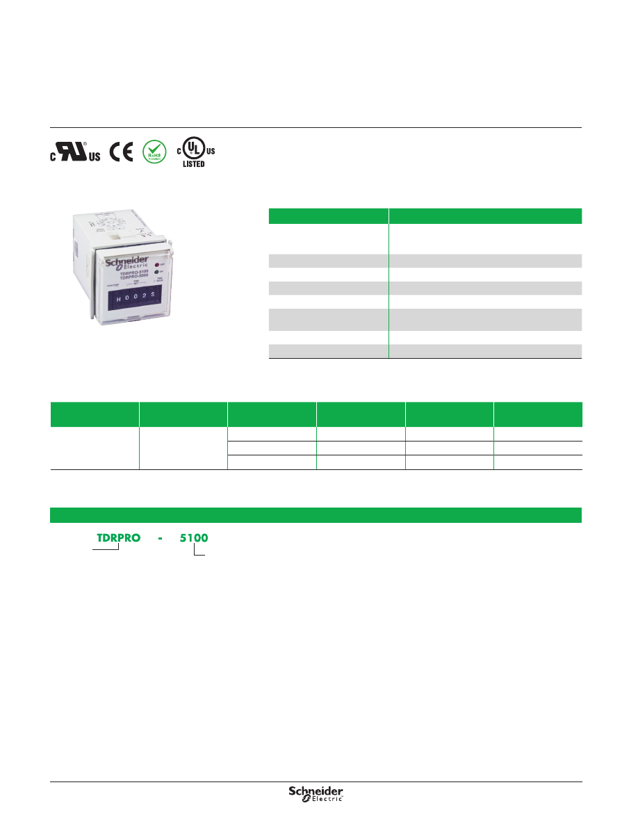
Description
Time delay relays that are programmable, multifunction, multi-voltage, and socket-
compatible—offering the ultimate in design flexibility . The thumb-wheel adjustment
dials result in no mechanical deviation for supreme accuracy .
Input Voltage
Timing Range
Functions
Available
(1)
Contact
Configuration
Rated Current
Standard
Part Number
12–240 Vac/Vdc
100 ms to 9990 hr
A,B,C,D,E,F,G,H,I,J
DPDT
12 A
TDRPRO-5100
A,B,C,D,E,F,G,H,I,J
SPDT
12 A
TDRPRO-5101
A,B,C
DPDT
12 A
TDRPRO-5102
(1) For function descriptions, see page 31.
Part Number Explanation
Series:
TDRPRO =
48 x 48 mm
Time Delay Relay
Contact Configuration and Number of Functions:
5100 =
DPDT, 10 Functions
5101 =
SPDT, 10 Functions
5102 =
DPDT, 3 Functions
Feature
Benefit
Up to 10 functions
5 timing functions controlled via supply voltage
4 timing functions controlled via trigger input
1 memory latching function
Broad timing range
0 .1 s to 9990 hr
Panel-mounting adapter
Panel mountable
Dust cover
Retains settings and keeps dust out
Universal power supply
12–240 Vac/Vdc
Thumb-wheel adjustment for
function / timing
Helps ensure accuracy and reduces timing deviations
2 LED status indicators
Indicate coil power, timing out, and output state
RoHS compliant
Environmentally friendly
TDRPRO Relay
23
Specifications
Legacy Time Delay and
Sensor Relays
TDRPRO Series
SPDT, 12 A; DPDT, 12 A
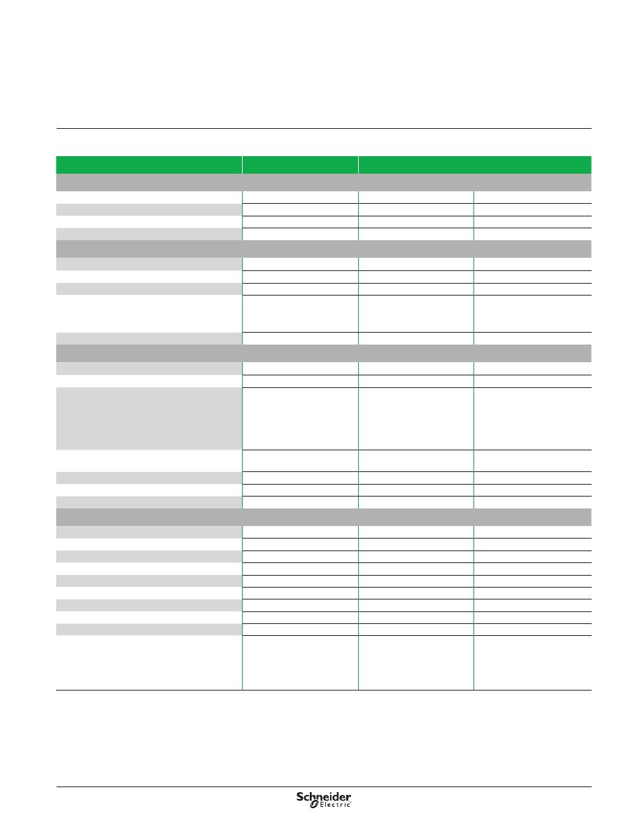
Specifications
Part Number
TDRPRO-5100
TDRPRO-5101
TDRPRO-5102
Input Characteristics
Input Voltage Range
12–240 Vac/Vdc
12–240 Vac/Vdc
12–240 Vac/Vdc
Operating Voltage
85–115% of nominal
85–115% of nominal
85–115% of nominal
Maximum Power Consumption (AC)
2 .5 VA
2 .5 VA
2 .5 VA
Maximum Power Consumption (DC)
2 W
2 W
2 W
Output Characteristics
Contact Configuration
DPDT
SPDT
DPDT
Output Current Rating
12 A
12 A
12 A
Contact Material
Silver alloy
Silver alloy
Silver alloy
Switching Capabilties
12 A, 240 Vac, 50/60 Hz, 30 Vdc
1/3 hp @ 120 Vac
1/2 hp @ 240 Vac
Pilot duty B300
12 A, 240 Vac, 50/60 Hz, 30 Vdc
1/3 hp @ 120 Vac
1/2 hp @ 240 Vac
Pilot duty B300
12 A, 240 Vac, 50/60 Hz, 30 Vdc
1/3 hp @ 120 Vac
1/2 hp @ 240 Vac
Pilot duty B300
Minimum Switching Requirement
100 mA
100 mA
100 mA
Timing Characteristics
Functions Available
(1)
A,B,C,D,E,F,G,H,I,J
A,B,C,D,E,F,G,H,I,J
A,B,C
Time Scales
7
7
7
Time Ranges
0–999 by 0 .1 s
0–999 by 1 s
0–999 by 0 .1 min
0–999 by 1 min
0–999 by 0 .1 hr
0–999 by 1 hr
0–999 by 10 hr
0–999 by 0 .1 s
0–999 by 1 s
0–999 by 0 .1 min
0–999 by 1 min
0–999 by 0 .1 hr
0–999 by 1 hr
0–999 by 10 hr
0–999 by 0 .1 s
0–999 by 1 s
0–999 by 0 .1 min
0–999 by 1 min
0–999 by 0 .1 hr
0–999 by 1 hr
0–999 by 10 hr
Repeatability of the Time Delay
at Constant Voltage and Temperature
0 .1%
0 .1%
0 .1%
Reset Time
150 ms
150 ms
150 ms
Operate Time
(3)
25 ms maximum
25 ms maximum
25 ms maximum
Release Time
(3)
25 ms maximum
25 ms maximum
25 ms maximum
General Characteristics
Electrical Life (Operations at Rated Current)
(2)
100,000 operations
100,000 operations
100,000 operations
Mechanical Life (Unpowered)
(2)
10,000,000 operations
10,000,000 operations
10,000,000 operations
Dielectric Strength (Input to Contacts)
2500 Vrms
2500 Vrms
2500 Vrms
Storage Temperature Range
−30 to +70 °C (−22 to +158 °F)
−30 to +70 °C (−22 to +158 °F)
−30 to +70 °C (−22 to +158 °F)
Operating Temperature Range
−20 to +60 °C (−4 to +140 °F)
−20 to +60 °C (−4 to +140 °F)
−20 to +60 °C (−4 to +140 °F)
Weight
133 g (4 .69 oz)
133 g (4 .69 oz)
133 g (4 .69 oz)
Input Indication
Green LED
Green LED
Green LED
Output Indication (Blinking = Timing; On = Energized)
Red LED
Red LED
Red LED
Enclosure Rating (according to IEC 60529 IP rating)
IP40
IP40
IP40
Approvals
cURus (File: E43641, CCN:
NLDX2), CE 61810-1, RoHS,
cULus (File: E43641, CCN:
NLDX2, UL Listed when used
with Schneider Electric socket
70-465)
cURus (File: E43641, CCN:
NLDX2), CE 61810-1, RoHS,
cULus (File: E43641, CCN:
NLDX2, UL Listed when used
with Schneider Electric socket
70-464)
cURus (File: E43641, CCN:
NLDX2), CE 61810-1, RoHS,
cULus (File: E43641, CCN:
NLDX2, UL Listed when used
with Schneider Electric socket
70-464)
(1) For function descriptions, see page 31.
(2) Actual product life varies based on electrical load, duty cycle, application, and environmental conditions.
(3) After the time delay period expires, or upon application of the trigger signal (depending on the selected function).
24
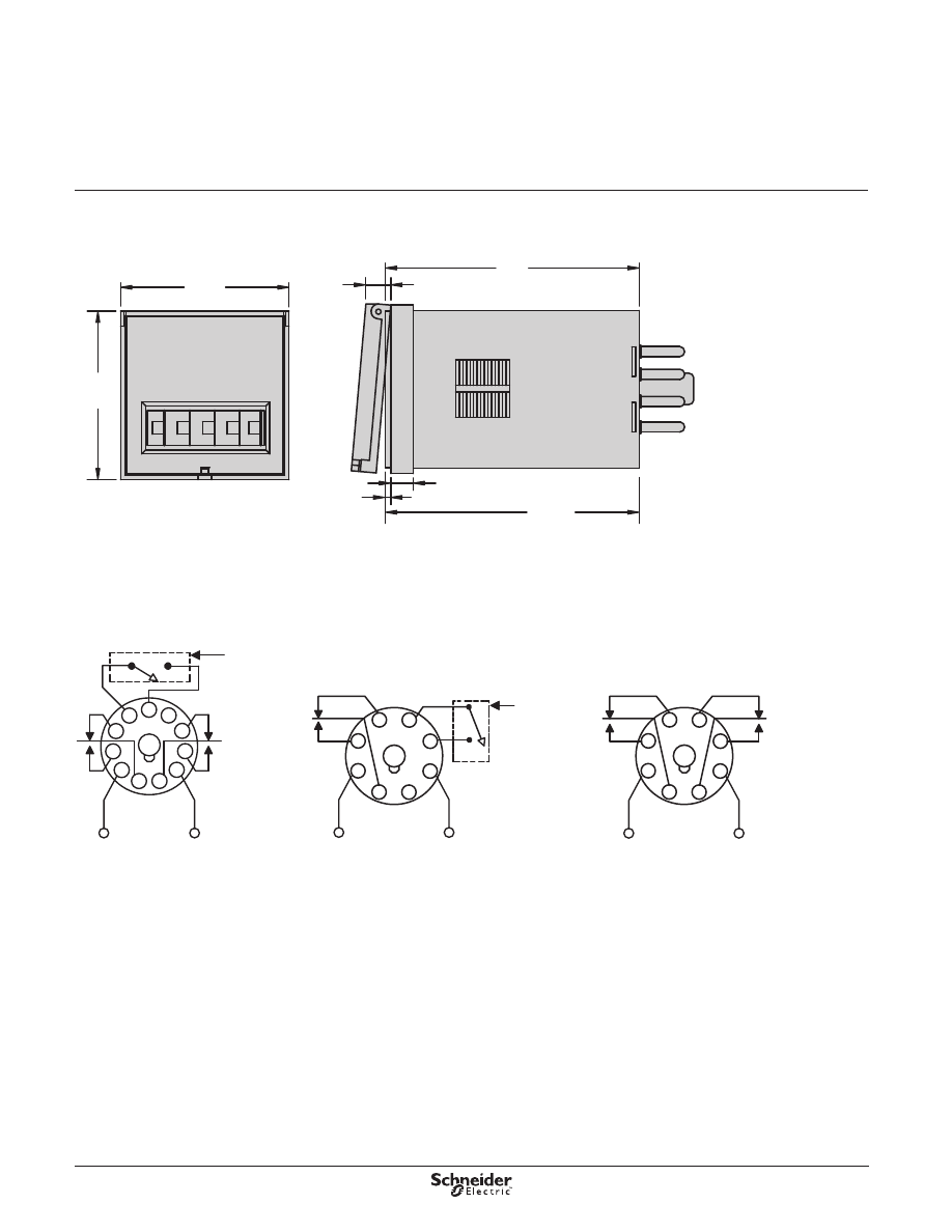
Dimensions—in. (mm)
Wiring Diagrams
(48)
1.9
(48)
1.9
(6)
0.23
0.06
(1.52)
(72)
2.8
3.15
(80.0)
(6.35)
0.25
Input
3
2
1
6
7
8
4
5
Input
2
1
4
3
7
8
5
6
3
2
1
4
9
10
11
8
6
5
7
Input
TDRPRO-5100
TDRPRO-5101
TDRPRO-5102
External
Control
Switch
(Dry Switch
Only)
External
Control
Switch
(Dry Switch
Only)
Dimensions,
Wiring Diagrams
Legacy Time Delay and
Sensor Relays
TDRPRO Series
SPDT, 12 A; DPDT, 12 A
25
Description
Legacy Time Delay and
Sensor Relays
TDRPRO Series Accessories
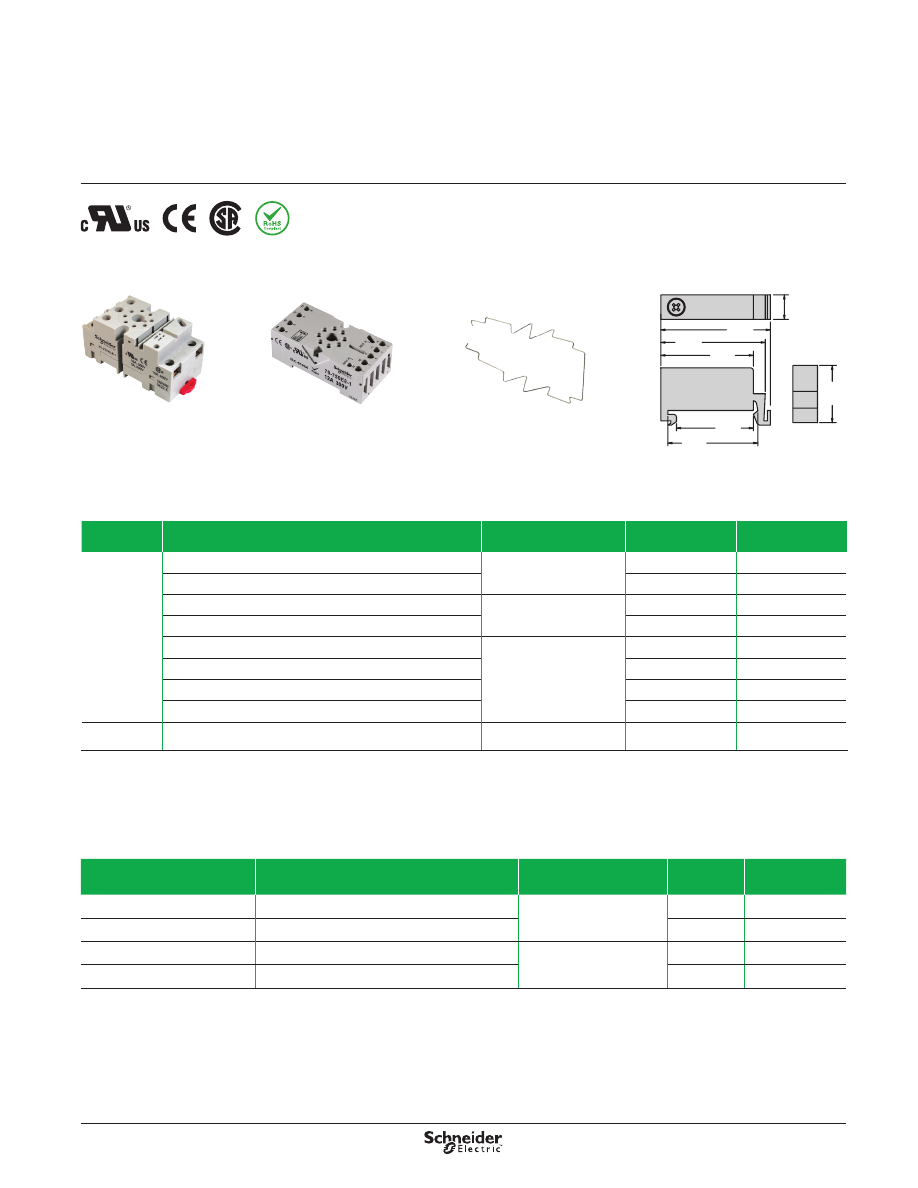
Description
The TDRPRO accessories create a complete system solution for your application
needs . The 70-750DL socket offers an alternative installation option for plug-in
models . The 16-TDRPROSC retention clip holds the relay securely in place while
allowing quick and efficient installation and maintenance .
Relay Accessories
Description Function
For Use With Relays
Packaging
Quantities
Standard Part
Number
Socket
Mounting directly to DIN Rail or Panel
TDRPRO-5101,
TDRPRO-5102
10
70-750DL8-1
Panel Mounting with Screw Terminals and Clamping Plates
10
70-169-1
DIN or Panel Mounting with Elevator Terminals
TDRPRO-5101
10
70-750E8-1
DIN or Panel Mounting with Screw Terminals and Clamping Plates
10
70-464-1
Mounting directly to DIN Rail or Panel
TDRPRO-5100
10
70-750DL11-1
DIN or Panel Mounting with Elevator Terminals
10
70-750E11-1
DIN or Panel Mounting with Screw Terminals and Clamping Plates
10
70-465-1
Panel Mounting with Screw Terminals and Clamping Plates
10
70-170-1
Metal
Retention Clip Helping secure the relay in the socket
TDRPRO
10
16-TDRPROSC
70-750DL8-1 Socket
70-750E8-1 Socket
16-TDRPROSC Retention Clip
0.37
(9.4)
1.39
(35.5)
1.55
(39.5)
1.65
(42.0)
1.37
(34.7)
1.17
(29.7)
0.86
(22.0)
16-DCLIP-1 DIN Rail End Clip
Socket Accessories
Description
Function
For Use With Sockets
Packaging
Quantities
Standard
Part Number
Metal DIN Rail, 1 m (39 .3 in .)
Quick installation and removal of sockets
Compatible with all sockets
listed in the table above .
10
16-700DIN
DIN Rail End Clip
Holding sockets firmly in place on the DIN rail
10
16-DCLIP-1
ID Tags
Identification of circuits in multi-relay applications
70-750E8-1, 70-750EL8-1,
70-750DL8-1, 70-750E11-1,
70-750EL11, 70-750DL11-1
10
16-750/782FT-1
Insulated Coil Bus Jumper System Wireless socket connection
10
16-750/788CBJ-1
26
Specifications
Legacy Time Delay and
Sensor Relays
TDRPRO Series Accessories
Specifications
Part Number
70-750DL8-1
70-750DL11-1
70-750E8-1
70-750E11-1
Contact Configuration
DPDT
3PDT
DPDT
3PDT
Number of Terminals
8
11
8
11
Mounting Style
Panel or DIN rail
Panel or DIN rail
Panel or DIN rail
Panel or DIN rail
Current Rating
16 A
5 A
12 A
12 A
Nominal Voltage Rating
300 V
600 V
600 V
300 V
Storage Temperature Range
−40 to +105 °C (−40 to +221 °F) −40 to +105 °C (−40 to +221 °F) −40 to +105 °C (−40 to +221 °F) −40 to +105 °C (−40 to +221 °F)
Protection Category according to
IEC 60529 IP rating (finger protection)
IP20
IP20
IP20
IP20
Internal Metal Tracks
Copper Alloy, Zinc Plated
Copper Alloy, Zinc Plated
Copper Alloy, Zinc Plated
Copper Alloy, Zinc Plated
Screw Terminals
Steel, Zinc Plated
Steel, Zinc Plated
Steel, Zinc Plated
Steel, Zinc Plated
Screw Style
Combination Head
Combination Head
Combination Head
Combination Head
Screw Size
M3 .5 mm
M3 .5 mm
M3 .5 mm
M3 .5 mm
Maximum Screw Torque
9 lb-in (1 .0 N•m)
9 lb-in (1 .0 N•m)
9 lb-in (1 .0 N•m)
9 lb-in (1 .0 N•m)
Terminal Connection
Screw Clamping
Screw Clamping
Elevator
Elevator
Terminal Layout
Logic
Logic
Non-Logic
Non-Logic
Maximum Wire Size
Solid or Stranded Cu:
two 12–14 AWG (2 .5–4 mm²)
Solid or Stranded Cu:
two 12–14 AWG (2 .5–4 mm²)
Solid or Stranded Cu:
two 12–14 AWG (2 .5–4 mm²)
Solid or Stranded Cu:
two 12–14 AWG (2 .5–4 mm²)
DIN Rail Mounting, EN 60715
35 mm (1 .38 in)
35 mm (1 .38 in)
35 mm (1 .38 in)
35 mm (1 .38 in)
Chassis Mounting Screw Torque
7 lb-in (0 .8 N•m)
7 lb-in (0 .8 N•m)
7 lb-in (0 .8 N•m)
7 lb-in (0 .8 N•m)
Flammability Rating
94V-0 Class
94V-0 Class
94V-0 Class
94V-0 Class
Body Color
Light Gray
Light Gray
Light Gray
Light Gray
DIN Locking Method
Red Plastic Locking Clip
Red Plastic Locking Clip
Red Plastic Locking Clip
Red Plastic Locking Clip
Agency Approvals
cURus (File: E70550, CCN:
SWIV2, SWIV8), CSA (File:
40787, Class: 3211 07), CE
60947-1, RoHS
cURus (File: E70550, CCN:
SWIV2, SWIV8), CSA (File:
40787, Class: 3211 07), CE
60947-1, RoHS
cURus (File: E70550, CCN:
SWIV2, SWIV8), CSA (File:
40787, Class: 3211 07), CE
60947-1, RoHS
cURus (File: E70550, CCN:
SWIV2, SWIV8), CSA (File:
40787, Class: 3211 07), CE
60947-1, RoHS
Part Number
70-169-1
70-170-1
70-464-1
70-465-1
Contact Configuration
DPDT
3PDT
DPDT
3PDT
Number of Terminals
8
11
8
11
Mounting Style
Panel
Panel
Panel or DIN rail
Panel or DIN rail
Current Rating
15 A
15 A
15/10 A
15/5 A
Nominal Voltage Rating
300 V
600 V
300/600 V
300/600 V
Temperature Storage Range
−40 to +105 °C (−40 to +221 °F) −40 to +105 °C (−40 to +221 °F) −40 to +105 °C (−40 to +221 °F) −40 to +105 °C (−40 to +221 °F)
Internal Metal Tracks
Copper Alloy, Zinc Plated
Copper Alloy, Zinc Plated
Copper Alloy, Zinc Plated
Copper Alloy, Zinc Plated
Screw Terminals
Steel, Zinc Plated
Steel, Zinc Plated
Steel, Zinc Plated
Steel, Zinc Plated
Screw Style
Combination Head
Combination Head
Combination Head
Combination Head
Screw Size
M3 .5 mm
M3 .5 mm
M3 .5 mm
M3 .5 mm
Maximum Screw Torque
9 lb-in (1 .0 N•m)
9 lb-in (1 .0 N•m)
9 lb-in (1 .0 N•m)
9 lb-in (1 .0 N•m)
Terminal Connection
Screw Clamping
Screw Clamping
Screw Clamping
Screw Clamping
Terminal Layout
Non-Logic
Non-Logic
Non-Logic
Non-Logic
Maximum Wire Size
Solid or Stranded Cu:
two 12–14 AWG (2 .5–4 mm²)
Solid or Stranded Cu:
two 12–14 AWG (2 .5–4 mm²)
Solid or Stranded Cu:
two 12–14 AWG (2 .5–4 mm²)
Solid or Stranded Cu:
two 12–14 AWG (2 .5–4 mm²)
DIN Rail Mounting, EN 60715
35 mm (1 .38 in)
35 mm (1 .38 in)
35 mm (1 .38 in)
35 mm (1 .38 in)
Chassis Mount Screw Torque
7 lb-in (0 .8 N•m)
7 lb-in (0 .8 N•m)
7 lb-in (0 .8 N•m)
7 lb-in (0 .8 N•m)
Flammability Rating
94 V-0 Class
94 V-0 Class
94 V-0 Class
94 V-0 Class
Body Color
Light Gray
Light Gray
Light Gray
Light Gray
DIN Locking Method
–
–
Red Plastic Locking Clip
Red Plastic Locking Clip
Product Certifications
cURus (File: E70550, CCN: SWIV2, SWIV8),
CSA (File: 40787, Class: 3211 07),
CE 60947-1, RoHS
27
Dimensions—in. (mm)
Dimensions
Legacy Time Delay and
Sensor Relays
TDRPRO Series Accessories
70-750DL11-1
Mounts Directly to the DIN Rail or Panel
(38)
1.5
(3.8)
0.15
(76.8)
3.02
(37)
1.45
(81)
3.19
(40)
1.58
(34.2)
1.35
11
4
1
12
14
3
A2
10
5
22
21
24
6
7
A1
2
INPUT
INPUT
34
9
31
11
32
8
1.1
(27.9)
NEMA:
IEC:
70-750DL8-1
Mounts Directly to the DIN Rail or Panel
(36)
1.42
(3.8)
0.15
1.1
(27.9)
11
4
1
12
14
3
A2
7
5
22
21
24
6
8
A1
2
(72.7)
2.86
(36)
1.42
INPUT
INPUT
(77.5)
3.0
(40)
1.58
(30)
1.2
NEMA:
IEC:
70-750E11-1
DIN or Panel Mounting with Elevator Terminals
INPUT A1
10
INPUT A2
2
A1
A2 A2 31 21 11
10
11
10
6
1
2
14
34
24
32
22
12
9
7
8
4
3
5
2.95
(22)
0.86
(27)
1.06
1.45
1.49
0.12
(75)
(37)
(30)
(38)
NEMA:
IEC:
(3.1)
0.12
70-750E8-1
DIN or Panel Mounting with Elevator Terminals
11
7
7
INPUT A1
INPUT A2
A2
7
A2
8
21
2
1
A1
12
5
6
24
4
22
3
14
2
(3.1)
2.95
1.45
0.12
1.49
0.12
0.86
(22)
(27)
1.06
(75)
(30)
(38)
(37)
NEMA:
IEC:
28
Dimensions
(continued)
Legacy Time Delay and
Sensor Relays
TDRPRO Series Accessories
Dimensions—in. (mm)
70-169-1
Panel Mounting with Screw Terminals and Clamping Plates
7
6
8
1
2
3
5
4
0.17 DIA. (4.3)
0.25
(6.3)
0.625
(16)
2.0
(50)
1.68
(42.8)
2.25
(57)
1.12
(28)
70-464-1
DIN Mounting with Screw Terminals and Clamping Plates
3
5
4
6
8
2
1
(4.2)
0.16
7
(33)
1.29
(40)
1.6
(54)
2.12
2.02
(51)
(24.6)
0.97
(25.6)
1.01
0.59
(15)
70-465-1
DIN Mounting with Screw Terminals and Clamping Plates
3
4
5
6
7
11
2
1
10
8
9
(59)
(52)
2.06
2.32
(54.8)
2.16
2.05
(52)
(24.6)
0.97
(40)
1.6 DIA.
1.02
(25)
70-170-1
Panel Mounting with Screw Terminals and Clamping Plates
0.17 DIA. (4.3)
7
6
11
9
8
10
1
2
3
5
4
2.5
(64)
2.2
(56)
2.59
(65)
1.29
(32)
0.25
(6.3)
0.629
(16)
29
Wiring Diagrams
(continued)
Legacy Time Delay and
Sensor Relays
TDRPRO Series Accessories
Wiring Diagrams
70-169-1
3
4
2
1
6
5
8
7
24
A2
14
12
22
A1
11
1
2
5
4
3
7
6
21
8
INPUT
INPUT
IEC
NEMA
70-170-1
5
11
1
3
9
10
2
4
8
6
7
4
3
8
9
14
34
12
5
7
6
22
24
21
32
2
10
1
11
A1
A2
11
31
INPUT
INPUT
IEC
NEMA
70-464-1
3
4
2
1
6
5
8
7
14
12
22
24
A1
11
21
A2
3
4
2
1
6
5
8
7
INPUT
INPUT
IEC
NEMA
70-465-1
5
4
5
7
6
3
2
10
1
11
8
9
14
A1
A2
11
31
34
12
22
24
21
32
11
1
3
9
10
2
4
8
6
7
INPUT
INPUT
IEC
NEMA
70-750DL11-1
5
34
14
9
3
31
11
6
21
5
7
8
32
22
24
1
11
4
12
11
1
3
9
10
2
4
8
6
7
A1
A2
10
Coil Bus
Jumper
2
Module
Input
INPUT
IEC
NEMA
70-750DL8-1
2
7
Coil Bus
Jumper
A1
A2
5
4
7
8
1
2
6
3
21
14
24
6
3
8
11
12
22
5
1
4
Module
Input
INPUT
IEC
NEMA
70-750E11-1
10
1
11
6
2
11
A2
31 21
A1
14
34
24 22
12
3
9
7
5
4
10
8
32
A2
4
3
9
8
7
5
6
1
10
11
2
INPUT
INPUT
Module
Input
IEC
NEMA
70-750E8-1
10
1
11
6
2
11
A2
31 21
A1
14
34
24 22
12
3
9
7
5
4
10
8
32
A2
4
3
9
8
7
5
6
1
10
11
2
INPUT
INPUT
Module
Input
IEC
NEMA

30
Application Data
Legacy Time Delay and
Sensor Relays
Definition
A time delay is a controlled period between the functioning of two events . A time
delay relay combines an electromechanical output relay and a control circuit . The
control circuit is composed of solid-state components that control the operation of
the relay and the timing range .
Typical time delay functions include:
On-Delay
Repeat Cycle (Starting Off)
Interval
Off-Delay
Retriggerable One-Shot
Repeat Cycle (Starting On)
Pulse Generator
One-Shot
On- and Off-Delay
Memory Latch
Each function is explained in the table on page 31 . Time delay relays offer a broad
choice of timing ranges from less than one second to many days . There are many
choices of timing adjustments from calibrated external knobs, DIP switches, thumb-
wheel switches, or a recessed potentiometer .
Principle of Operation
Time delay relays are simply control relays with a time delay built in . Their purpose
is to control an event based on time . The difference between relays and time delay
relays is
when
the output contacts open and close:
on a control relay, contacts change state when voltage is applied and removed
from the coil
on time delay relays, contacts change state before or after a pre-selected, timed
interval
Typically, time delay relays are initiated or triggered by one of two methods:
application of input voltage (On-Delay, Interval On, Flasher, Repeat Cycle,
Delayed Interval, and Interval/Flasher)
opening or closing of a trigger signal (Off-Delay, Single Shot, and Watchdog)
These trigger signals can be one of two designs:
a control switch (dry contact)—for example, limit switch, push button, float switch
voltage (commonly known as a power trigger)
Definitions
:
Input Voltage:
Control voltage applied to the input terminals (see the wiring
diagrams on page 31) . Depending on the function, input voltage either initiates
the unit or readies it to initiate when a trigger signal is applied .
Trigger Signal:
On certain timing functions, a trigger signal initiates the unit after
input voltage has been applied . As noted above, this trigger signal can either be a
control switch (dry contact switch) or a power trigger (voltage) .
Output (Load):
A time delay relay has an internal relay (usually mechanical) with
contacts that open and close to control the load . The contacts are represented by
the dotted lines in the wiring diagrams .
NOTE
: For the time delay relay to operate properly, voltage must be applied to
power the load being switched by the relay’s output contacts.
31
Application Data
(continued)
Legacy Time Delay and
Sensor Relays
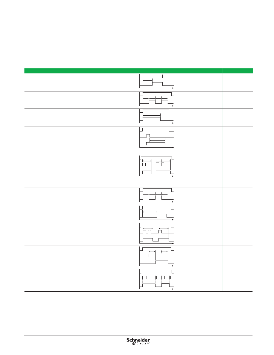
Time Delay Relay Functions
Function
Description
Timing Chart
Relays
On-Delay
(A)
When the input voltage U is applied, time delay T begins . Relay
contact(s) R change state after the time delay is complete .
Contacts R return to their shelf state when input voltage U is
removed . A trigger switch is not used in this function .
time
U
R
T
821, 822, TDR782,
TDRPRO-5100,
TDRPRO-5101,
TDRPRO-5102,
831, 841
Repeat Cycle:
Starting Open
(B)
When input voltage U is applied, time delay T begins . When
time delay T is complete, relay contact(s) R change state
for time delay T . This cycle repeats until input voltage U is
removed . A trigger switch is not used in this function .
time
U
R
T
T
T
T
Off On Off On
821, 822,
TDRPRO-5100,
TDRPRO-5101,
TDRPRO-5102
Interval
(C)
When input voltage U is applied, relay contact(s) R change
state immediately and the timing cycle begins . When time
delay T is complete, contacts return to shelf state . When input
voltage U is removed, contacts also return to their shelf state . A
trigger switch is not used in this function .
time
U
R
T
821, 822,
TDRPRO-5100,
TDRPRO-5101,
TDRPRO-5102
Off-Delay,
with
Switch Trigger
(D)
Input voltage U must be applied continuously . When trigger
switch S is closed, relay contacts R change state . When trigger
switch S is opened, delay T begins . When delay T is complete,
contacts R return to their shelf state . If trigger switch S is closed
before time delay T is complete, then time is reset . When trigger
switch S is opened, the delay begins again, and relay contacts
R remain in their energized state . If input voltage U is removed,
then relay contacts R return to their shelf state .
time
U
S
R
T
821, 822,
TDRPRO-5100,
TDRPRO-5101,
TDRPRO-5102
Retriggerable
One-Shot
with
Switch Trigger
(E)
Upon application of input voltage U, the relay is ready to accept
trigger signal S . Upon application of trigger signal S, relay
contacts R transfer, and preset time T begins . At the end of
preset time T, relay contacts R return to their normal condition—
unless trigger switch S is opened and closed before before
preset time T elapses . Continuous cycling of trigger switch S
at a rate faster than preset time T causes relay contacts R to
remain closed . If input voltage U is removed, relay contacts R
return to their shelf state .
time
U
S
R
T
T
821, 822,
TDRPRO-5100,
TDRPRO-5101,
TDRPRO-5102
Repeat Cycle:
Starting
Closed
(F)
When input voltage U is applied, relay contacts R change state
immediately and time delay T begins . When time delay T is
complete, contacts return to their shelf state for time delay T .
This cycle repeats until input voltage U is removed . A trigger
switch is not used in this function .
time
U
R
T
T
T
T
On
Off
On
Off
821, 822,
TDRPRO-5100,
TDRPRO-5101
Pulse
Generator
(G)
Upon application of input voltage U, a single output pulse of
0 .5 s is delivered to the relay after time delay T . Power must be
removed and reapplied to repeat the pulse . A trigger switch is
not used in this function .
time
U
R
T
Pulse
821, 822,
TDRPRO-5100,
TDRPRO-5101
One-Shot with
Switch Trigger
(H)
Upon application of input voltage U, the relay is ready to accept
trigger signal S . Upon application of trigger signal S, relay
contacts R transfer, and preset time T begins . During time-out,
trigger signal S is ignored .
The relay is reset by applying trigger switch S when the relay is
not energized .
time
U
S
R
T
T
821, 822,
TDRPRO-5100,
TDRPRO-5101
On- and Off-
Delay with
Switch Trigger
(I)
Input voltage U must be applied continuously . When trigger
switch S is closed, time delay T begins . When time delay
T is complete, relay contacts R change state and remain
transferred until trigger switch S is opened . If input voltage U is
removed, relay contacts R return to their shelf state .
time
U
S
R
T
T
821, 822,
TDRPRO-5100,
TDRPRO-5101
Memory Latch
with Switch
Trigger
(J)
Input voltage U must be applied continuously . The output
changes state with every closure of trigger switch S . If input
voltage U is removed, relay contacts R return to their shelf
state .
time
U
S
R
821, 822,
TDRPRO-5100,
TDRPRO-5101
Note
: G = Gate . R = Relay contacts or outputs . S = Switch trigger . Y1 = Control contact . T = Time delay setting . U = Input voltage (power supply) .

32
Applications
Legacy Schneider Electric time delay and sensor relays provide cost effective
solutions for your industrial timing and sensing needs . Available in a wide array of
forms, fits, and functions, these timers offer flexibility and performance for process
control and industrial building applications .
Application Data
(continued)
Legacy Time Delay and
Sensor Relays
Automation Panels
Process controls, motor controls,
emergency lighting
Power Supplies
Universal power supplies, battery backup
systems
Appliances
Air conditioners, water heaters, portable
heaters, spa controls, water pumps
Packaging Machinery
Conveyor motors, food processors,
product/shrink wrap, solenoid controls
Material Handling
Motor control, conveyor controls
HVAC & Refrigeration
Anti-condensation equipment, compressor
controls, blower controls, motorized
duct/vent controls
Lighting Control
Traffic signal systems, motorway information
systems, theatrical lighting, ballast lighting
Food & Beverage
Commercial/industrial cooking equipment,
filtration systems, bottling, chillers,
convection ovens
Typical Examples of Timer Applications
33
The Schneider Electric Relays website
(www.serelays.com)
helps you to easily
find the proper relay to fit your design requirements, and to simplify and shorten
workflow .
Easily find the proper relay to fit your design
requirements
Online Catalog
Find the right product by choosing specifications, compare products side-by-
side, and view technical specifications, 2D and 3D drawings, and associated
accessories .
Cross-Reference Search
Search our comprehensive database to identify products by manufacturer and
part number, and link directly to part specifications .
3D CAD Library
View, email, download, or insert a file directly into your open CAD software .
You can choose from 18 different file formats .
Order Free Samples
Schneider Electric offers free samples as a courtesy to individuals and
companies evaluating our products for their designs and applications . Sample
orders are subject to approval .
Simplify and shorten workflow
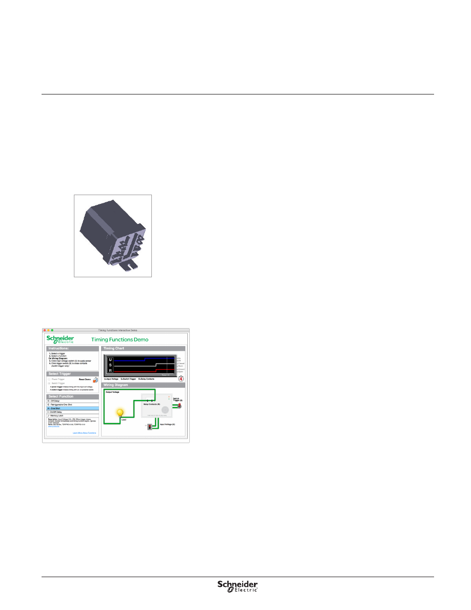
Interactive Tools
View interactive demonstrations, such as our Time Delay Relay Interactive Demo
(left), which visually demonstrates the ten different timing functions offered on
legacy Schneider Electric time delay relays .
Distributor Inventory Search
Search authorized distributors’ current Schneider Electric inventory and buy
online .
(Buy online is not available for all distributors .)
Website Guide
Legacy Time Delay and
Sensor Relays
Time Delay Relay Demo
3D Models

34
Index
Legacy Time Delay and
Sensor Relays
16-700DIN
16-750/782FT-1
16-782FT-1
16-788C1
16-DCLIP-1
16-TDR782SC
16-TDRPROSC
70-169-1
70-170-1
70-378-1
70-379-1
70-461-1
70-464-1
70-465-1
70-750DL8-1
70-750DL11-1
70-750E8-1
70-750E11-1
70-782D14-1
70-782E14-1
70-782EL8-1
70-782EL14-1
821TD10H-UNI
822TD10H-UNI
831VS-24D
831VS-120A
831VS-240A
841CS1-UNI
841CS2-UNI
841CS5-UNI
841CS8-UNI
TDR782XBX
TDR782XDX
TDRPRO-5100
TDRPRO-5101
TDRPRO-5102


Electrical equipment should be installed, operated, serviced, and maintained only by qualified
personnel . No responsibility is assumed by Schneider Electric for any consequences arising out of
the use of this material .
© 2012–2017 Schneider Electric . All Rights Reserved .
Schneider Electric is a trademark and the property of Schneider Electric SE, its subsidiaries and
affiliated companies. All other trademarks are the property of their respective owners.
8501CT1104R01/17, 06/2017
Replaces 8501CT1104R05/15 dated 02/2016
Schneider Electric USA, Inc.
200 N . Martingale Road
Schaumburg, IL 60173
Tel: 847-441-2540
www .serelays .com