background image

FUSES 

/ SICHERUNGEN

 PFME

Resettable fuses 

www.schurter.com

15

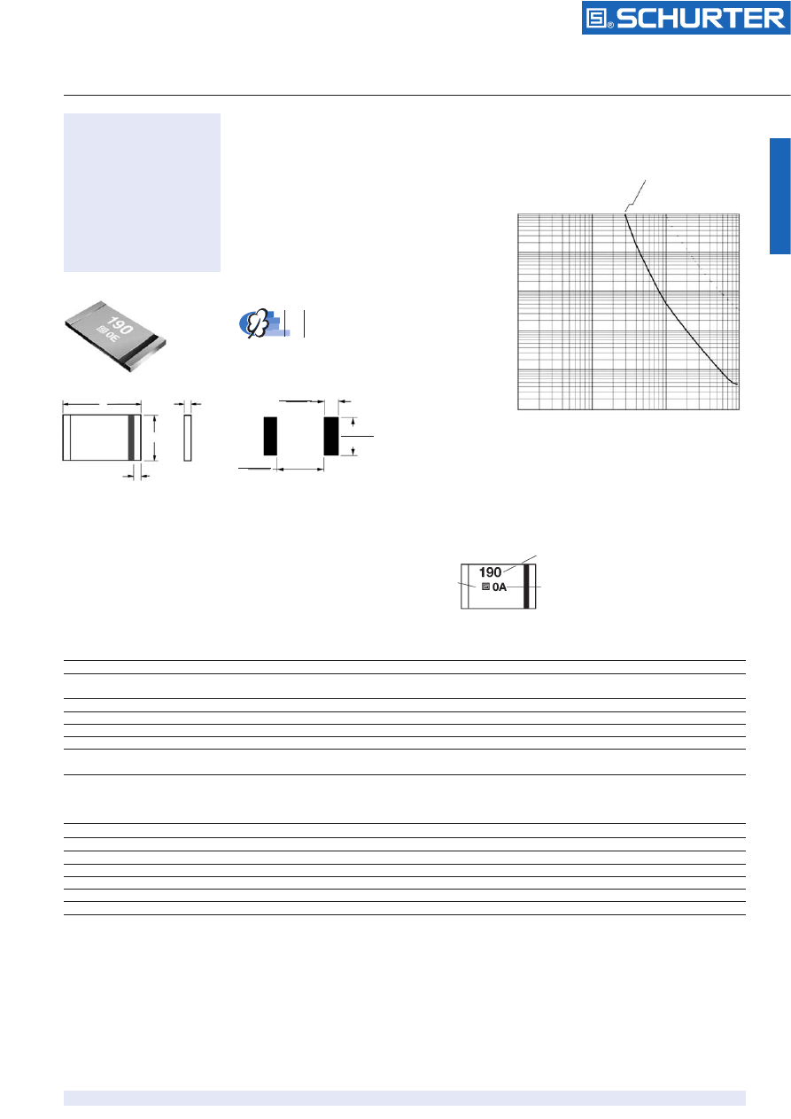
Typical Time to Trip at 23 ˚C 

Time to trip 


(s)

Dimensions 

/ Abmessungen


Solder pad layouts 

Applications

• battery cell protection

Test Procedures And Requirements For Model PFME Series 

Test 

/ Test


Test Conditions 

/ Bedingungen


Accept/Reject Criteria 

Visual/Mech. 

/ visuell/mech.


Verify dimensions and materials 

/ Kontrolle Abmess./Mat.


Per MF physical description 

Resistance 

/ Widerstand


In still air @ 23 °C 

/ bei ruhiger Luft 23 °C

 R

min 

 R 

 R

max

Time to Trip 

/ Trip-Zeit


At specified current, V

max 

23 °C 

/ Bei entspr. Strom

 T 

 max. 

time to trip


(sec.) 

Hold Current 

/ Haltestrom


30 min. at I

hold 

/ bei Haltestrom


No trip 

Trip Cycle Life 

/ Trip-Zyklen


V

max

, I

max

, 100 cycles 

/ Zyklen


No arcing or burning 

Trip Endurance 

/ Zeit im Tripzustand


V

max

, 48 hours 

/ Stunden


No arcing or burning 

Environmental Characteristics 

Operating/Storage Temperature 

/ Einsatz/Lagertemp.

 -40 °C 

to 

 +85 °C

Maximum Device Surface Temperature in Tripped State 

/


125 °C

Passive Aging 

/ passive Alterung

 +85 °C, 1000 

hours 

/ Std.

 ± 5% 

typ. resist. change 

Humidity Aging 

/ Feuchtigkeitsalterung

 +85 °C, 85% R.H. 1000 

hours 

/ Std.

± 5% 

typ. resist. change 

Thermal Shock 

/ Thermischer Schock

 +85 °C/–40 °C 20 

times 

/ Zyklen

 ±10% 

typ. resist. change 

Solvent Resistance 

/ Lösungsmittel-Beständigkeit

 MIL-STD-202, Method 215 

No change 

Vibration 

MIL-STD-883C, Method 2007.1, 

No change 

Condition A 

Typical Part Marking 

Layout may vary 

Manufacturer’s
Trademark 

Part identification 

Date code week 1 of 2000 = 0A (year and week)
week 27 of 2000 = A0 (week and year)

50          75         100

100

10

1

0.1

0.01

0.001

PFME.190.2

A

C

D

4.75
(0.187)

1.45
(0.057)

9.57
(0.377)

Fault current 

 (A)

Surface Mount
PTC-Fuses
Type PFME

5,3 x 11,5 mm 
fast tripping
Packaged per EIA 481-1 

100 °C trip temperature
Agency recognition: 
UL, CSA, TÜV

0.1

1

10

100

Schurter_PFME-html.html
background image

FUSES 

/ SICHERUNGEN

 PFME

Resettable fuses 

www.schurter.com

16

Type 

/ Typ

 I

max

V

max

I

hold

I

trip

Initial 

1 Hour (R1) Post-

Max. Time

Tripped Power

Resistance 

/


Reflow Resistance 

/


to trip at 23 °C/8A 

/

 Dissipation 


Amperes at 23 °C 

/

 Ohms at 23 °C 

/

 Amperes 

/

 Seconds 

/

 Watts at 23 °C 


A

V

Hold

Trip

R

min. 

R

1 max. 

at 

/ bei

 23 °C 

at 

 23 °C

PFME.190.2

100

16

1.9

3.8

0.017

0.08

10

2.0

1.5

Electrical Characteristics 

Soldering Profile 

How To Order 

PF     ME  .xxx     .x

PTC-Fuse 

Style 

ME = 11.5 mm Surface Mount Component

Hold Current, I

hold 

190 (1.9 A)

Packaging 
Packaged per EIA 481-1

2 = 

Tape and reel 

Note 
• PFME models can be wave soldered and reworked.

Thermal Derating Chart-I

hold 

(Amps) 

Type 

/ Typ


Ambient Operating Temperature 

–40 ˚C

–20 ˚C

0 ˚C

23 ˚C

40 ˚C

50 ˚C

60 ˚C

70 ˚C

85 ˚C

PFME.190.2

3.04

2.7

2.2

1.9

1.44

1.23

1.00

0.78

0.49

Type 

/ Typ

 A

B

C

D

min.

max.

min.

max.

min.

max.

min.

max.

PFME.190.2

11.15

11.51

4.83

5.33

0.33

0.63

0.53

1.02

(0.439)

(0.453)

(0.190)

(0.210)

(0.013)

(0.025)

(0.021)

(0.040)

Dimensions 

Dimensions in mm/inches 

Maximum Package Body Temperature (220 °C)

Melting Temperature of Solder (183 °C)

2 Minutes or More

Preheat

Flux Activation

Reflow

Cool

10° to 20 C
per Second

Less than
120 °C per
Second

300

250

200

150

100

50

0

0        30       60            100              150             200              250 

T

emperatu

re (°

 C) 

Time (Seconde) 

 (s)

Packaging: 2000 pcs. per reel