FUSES
/ SICHERUNGEN
PFST
Resettable fuses
www.schurter.com
32
Axial leaded
PTC-Fuses
Type PFST
Fully compatible with cur-
rent industry standards
Weldable nickel terminals
Very low internal resistance
Available in lead-free
version
Agency recognition:
UL, CSA, TÜV
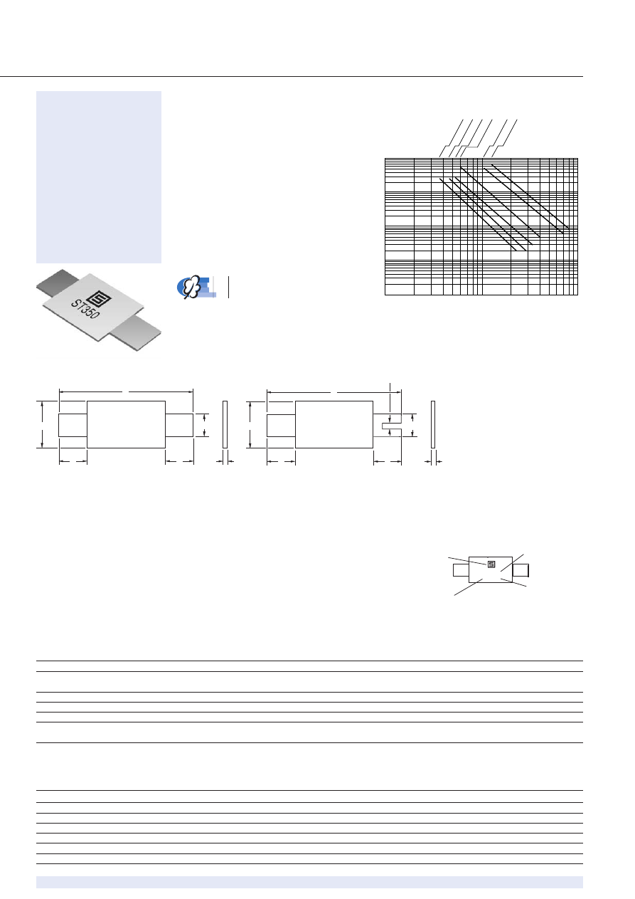
0.01
0.001
1
10
100
0.1
1
10
Ti
me to T
rip (Seconds)
PFST
.120
PFST
.150
PFST
.350
PFST
.420
PFST
.175
PFST
.200
Typical Time to Trip at 23 ˚C
Fault current
(A)
Time to trip
(s)
Test Procedures And Requirements For Model PFST Series
Test
/ Test
Test Conditions
/ Bedingungen
Accept/Reject Criteria
Visual/Mech.
/ visuell/mech.
Verify dimensions and materials
/ Kontrolle Abmess./Mat.
Per PF physical description
Resistance
/ Widerstand
In still air @ 23 °C
/ bei ruhiger Luft
R
min
≤
R
≤
R
max
Time to Trip
/ Trip-Zeit
5 times I
hold
, V
max
, 23 °C
/ unter spez. Strom
T
≤
max.
time to trip
(sec.
)
Hold Current
/ Haltestrom
30 min. at I
hold
/ bei Haltestrom
No trip
Trip Cycle Life
/ Trip-Zyklen
V
max
, I
max
, 100 cycles
/ Zyklen
No arcing or burning
Trip Endurance
/ Zeit im Tripzustand
V
max
, 48 hours
/ Stunden
No arcing or burning
Environmental Characteristics
Operating/Storage Temperature
/ Einsatz/Lagertemp.
–40 °C
to
+85 °C
Maximum Device Surface Temperature in Tripped State
/
125°C
Passive Aging
/ passive Alterung
+85 °C, 1000
hours
/ Std.
±5%
typ. resist. change
Humidity Aging
/ Feuchtigkeitsalterung
+85 °C, 85% R.H. 1000
hours
/ Std.
±5%
typ. resist. change
Thermal Shock
*) Thermischer Schock
+85 °C/–40 °C 10
times
/ Zyklen
±10%
typ. resist. change
Vibration
MIL-STD-883C, Method 2007.1,
No change
Condition
A
*) MIL-STD-202F, Method 107G
Applications
• Rechargable battery pack
protection
• Cellular phones
Typical Part Marking
Layout may vary
ern
ST120
6180T
Manufacturer’s
Trademark /
Part identification
Date Code (Last
Digit of Year and
Julian Date)
Lot No (T=Taiwan)
50 75 100
Terminal material: Quarter hard nickel
F
B
D
E
A
C
F
B
D
E
A
C
0.5 X 4.0
Standard Style
/ Standard-Ausführung
“S” Style
FUSES
/ SICHERUNGEN
PFST
Resettable fuses
www.schurter.com
33
Type
/ Typ
V
max
I
max
I
hold
I
trip
Initial
1 Hour (R1) Post-
Max. Time
Tripped Power
Resistance
/
Trip Resistance
/
to trip at 23 °C
/
Dissipation /
Amperes
/
Ohms at 23 °C
/
Ohms at 23 °C
/
Seconds at 23 °C
/
Watts at 23 °C
/
Ampere
at 23 °C
V
A
Hold
Trip
min.
max.
R
1 max.
PFST.120
15
100
1.20
2.7
0.085
0.160
0.22
5.0
1.2
PFST.120.S
15
100
1.20
2.7
0.085
0.160
0.22
5.0
1.2
PFST.150
15
100
1.50
3.00
0.05
0.09
0.11
5.0
1.30
PFST.175
15
100
1.75
3.8
0.05
0.09
0.120
4.0
1.5
PFST.175.S
15
100
1.75
3.8
0.05
0.09
0.120
4.0
1.5
PFST.200
30
100
2.00
4.4
0.03
0.06
0.080
4.0
1.90
PFST.350
30
100
3.50
6.3
0.017
0.031
0.040
3.0*
2.50
PFST.420
30
100
4.20
7.6
0.012
0.024
0.040
6.0*
2.90
Electrical Characteristics
Packaging
All models packaged in bulk, 500 pieces each.
Packaged loose; optional slotted leads (.S) available for 1.20 A and 1.75 A ratings
Type
/ Typ
A B C D F
Material
min. max. min. max. min. max. mn. max. min. max.
PFST.120 19.9 22.1 4.9 5.2 0.6 1.0 5.5 7.5 3.9 4.1
nickel
PFST.120.S 19.9 22.1 4.9 5.2 0.6 1.0 5.5 7.5 3.9 4.1
nickel
PFST.150 20.9 23.1 10.2 11.8 0.6 1.0 4.1 5.5 4.8 5.5
nickel
PFST.175 20.9 23.1 4.9 5.2 0.6 1.0 4.1 5.5 3.9 4.1
nickel
PFST.175.S 20.9 23.1 4.9 5.2 0.6 1.0 4.1 5.5 3.9 4.1
nickel
PFST.200 21.3 23.4 10.2 11.0 0.5 1.1 5.0 7.6 4.8 5.4
nickel
PFST.350 28.4 31.8 13.0 13.5 0.5 1.1 6.3 8.9 6.0 6.6
nickel
PFST.420 30.6 32.4 13.0 13.5 0.5 1.1 5.0 7.5 6.0 6.7
nickel
Dimensions
Dimension
Thermal Derating Chart - I
hold
(Amps)
Type
/ Typ
Ambient Operating Temperature
–40 ˚C
–20 ˚C
0 ˚C
23 ˚C
40 ˚C
50 ˚C
60 ˚C
70 ˚C
85 ˚C
PFST.120
1.9
1.7
1.5
1.2
1.0
0.9
0.8
0.7
0.5
PFST.120.S
1.9
1.7
1.5
1.2
1.0
0.9
0.8
0.7
0.5
PFST.150
2.2
2.0
1.8
1.5
1.3
1.1
1.0
0.9
0.7
PFST.175
2.5
2.3
2.0
1.7
1.5
1.3
1.2
1.1
0.9
PFST.175.S
2.5
2.3
2.0
1.7
1.5
1.3
1.2
1.1
0.9
PFST.200
3.2
2.8
2.5
2.0
1.7
1.6
1.4
1.2
0.9
PFST.350
5.4
4.8
4.3
3.5
3.0
2.8
2.5
2.2
1.7
PFST.420
6.4
5.7
5.1
4.2
3.6
3.3
3.0
2.6
2.1
How To Order
PF
ST
. xxx . x
PTC-Fuse
Style
ST =
Axial Leaded “Strap” Component
Hold Current, I
hold
120-420 (1.20 mA - 4.20 A)
Slotted Lead Option