
THERMAL CIRCUIT BREAKERS
THERMAL CIRCUIT BREAKERS

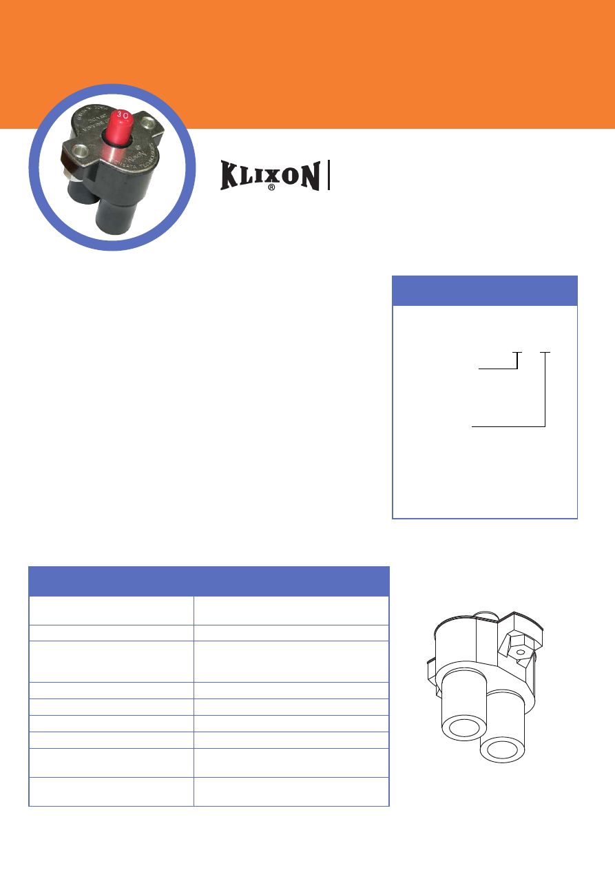
KLIXON® thermal circuit breakers are
compact, lightweight, protective devices
designed to repeatedly interrupt short circuits
or extended overloads in applications which
require precise, dependable operation plus
high resistance to shock and vibration. To
avoid nuisance tripping caused by harmless
transient or momentary overloads, these
circuit breakers feature an inherent thermal
time-lag characteristic. This enables
equipment to operate at maximum limits with
complete safety.
The heart of the thermal circuit breaker is the
KLIXON® metal disc. At a predetermined
overload, the heat caused by current passing
through the disc causes the disc to reverse its
curvature, or snap. This snapping action
separates the electrical contacts and opens
the circuit.
Trip curves provide the approximate time vs
current characteristics based on the ambient
“room” temperature of 77°F (25°C). Should
your application require performance
characteristics beyond the ambient “room”
temperature of 77°F (25°C), derating curves
provide additional data for ambient
temperatures significantly higher or lower than
standard room temperature.
KLIXON® thermal circuit breakers are
available in automatic reset and manual reset.
Some manual reset devices offer a switchable
feature whereby the contacts can be manually
opened to de-energize the circuit. For the
automatic reset device, the circuit stays open
until the disc cools and returns to its original
curvature, completing the circuit. For the
trip-free manual reset device, the contacts will
remain open until the device’s pushbutton is
depressed to reset the device and complete
the circuit.
KLIXON®
Thermal Circuit Breakers

“With over 90 years of experience in a myriad
of industries and mission-critical applications,
Sensata Technologies is one of the world’s
leading suppliers of sensing, electrical
protection, control and power management
solutions.
Motors, machines, equipment and vehicles in
the industrial, heating, ventilation, air
conditioning, appliance, automotive,
recreational, mobile work, data and
telecommunications industries operate safely
and efficiently thanks to reliable and robust
Sensata circuit protectors, switches, and
sensors. Our products sense and monitor
position, temperature and pressure, provide
power protection and help manage challenging
DC-to-AC power conversions.
From design to manufacturing and every
business process in between, our people strive
not just to meet standards of excellence but to
set them. Serving you is mission-critical to us.”
Tom Wroe
,
Chairman of the Board and Chief
Executive Officer, Sensata Technologies
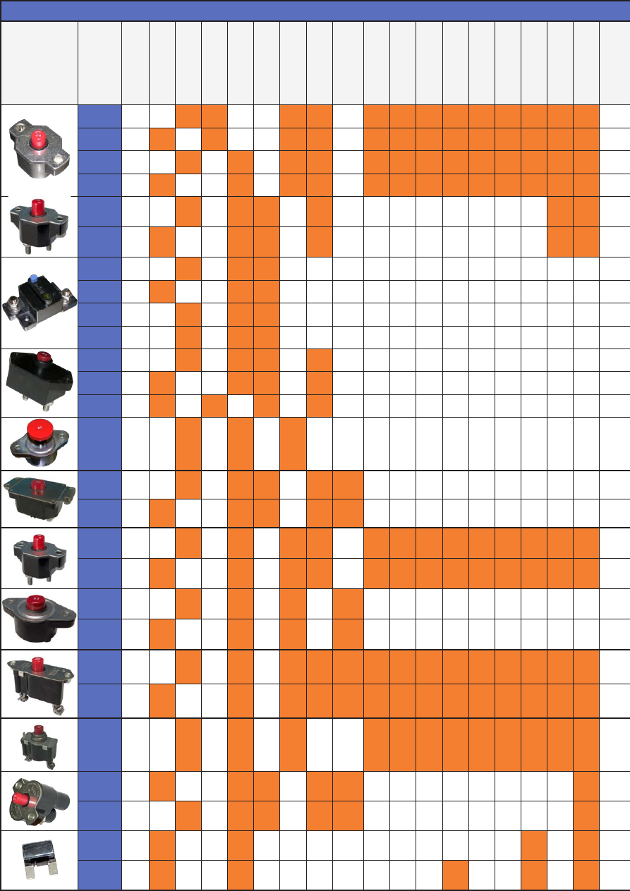
Cross Reference for KLIXON® Thermal Circuit Breakers
SERIES
PAGE
AUTOMA
TIC
MANUAL
OPEN
COVERED
STUD
SCREW
UL
CID AA55571
2 Amps
3 Amps
4 Amps
5 Amps
6 Amps
8 Amps
10 Amps
12.5 Amps
15 Amps
CM
6
•
•
•
•
•
•
•
•
•
•
•
•
•
CA
6
•
•
•
•
•
•
•
•
•
•
•
•
•
CDM
6
•
•
•
•
•
•
•
•
•
•
•
•
•
CDA
6
•
•
•
•
•
•
•
•
•
•
•
•
•
7851
8
•
•
•
•
•
•
7854
8
•
•
•
•
•
•
FDLM
10
•
•
•
FDLA
10
•
•
•
FDLS
10
•
•
•
FDLT
10
•
•
•
SDLM
12
•
•
•
•
SDLA
12
•
•
•
•
SLA
12
•
•
•
•
6766-19
14
•
•
•
7855-6
16
•
•
•
•
/ 03
7855-7
16
•
•
•
•
/ 08
PDM
18
•
•
•
•
•
•
•
•
•
•
•
•
•
PDA
18
•
•
•
•
•
•
•
•
•
•
•
•
•
PDLM
20
•
•
•
/ 04
PDLA
20
•
•
•
/ 07
PSM
22
•
•
•
•
/ 06
•
•
•
•
•
•
•
•
•
PSA
22
•
•
•
•
/ 05
•
•
•
•
•
•
•
•
•
PSM-N
24
•
•
•
•
•
•
•
•
•
•
•
•
9115-5
26
•
•
•
•
/ 01
•
9115-6
26
•
•
•
•
/ 02
•
MAXI
28
•
•
•
•
EXT 200
29
•
•
•
•
•

Cross Reference for KLIXON® Thermal Circuit Breakers
17.5 Amps
20 Amps
25 Amps
30 Amps
35 Amps
40 Amps
45 Amps
50 Amps
60 Amps
70 Amps
80 Amps
90 Amps
100 Amps
105 Amps
120 Amps
135 Amps
150 Amps
175 Amps
200 Amps
PAGE
SERIES
TYPE
•
•
•
•
•
•
6
CM
COMMERCIAL
•
•
•
•
•
•
6
CA
•
•
•
•
•
•
6
CDM
•
•
•
•
•
•
6
CDA
•
•
•
•
•
•
•
•
8
7851
•
•
•
•
•
•
•
•
8
7854
•
•
•
•
•
•
•
•
•
•
•
•
•
10
FDLM
•
•
•
•
•
•
•
•
•
•
•
•
•
10
FDLA
•
•
•
•
•
•
•
•
•
•
•
•
•
10
FDLS
•
•
•
•
•
•
•
•
•
•
•
•
•
10
FDLT
•
•
•
•
•
•
•
•
•
•
•
•
•
12
SDLM
•
•
•
•
•
•
•
•
•
•
•
•
•
12
SDLA
•
•
•
•
•
•
•
•
•
•
•
•
•
12
SLA
•
•
•
•
•
•
•
•
•
•
•
•
•
14
6766-19
•
•
16
7855-6
PRECISION
•
•
16
7855-7
•
•
•
•
•
•
18
PDM
•
•
•
•
•
•
18
PDA
•
•
•
•
•
•
•
•
•
•
•
•
20
PDLM
•
•
•
•
•
•
•
•
•
•
•
•
20
PDLA
•
•
•
•
22
PSM
•
•
•
•
22
PSA
•
•
•
•
24
PSM-N
•
•
•
26
9115-5
•
•
•
26
9115-6
•
•
•
•
•
•
28
MAXI
MINI
•
•
•
29
EXT 200
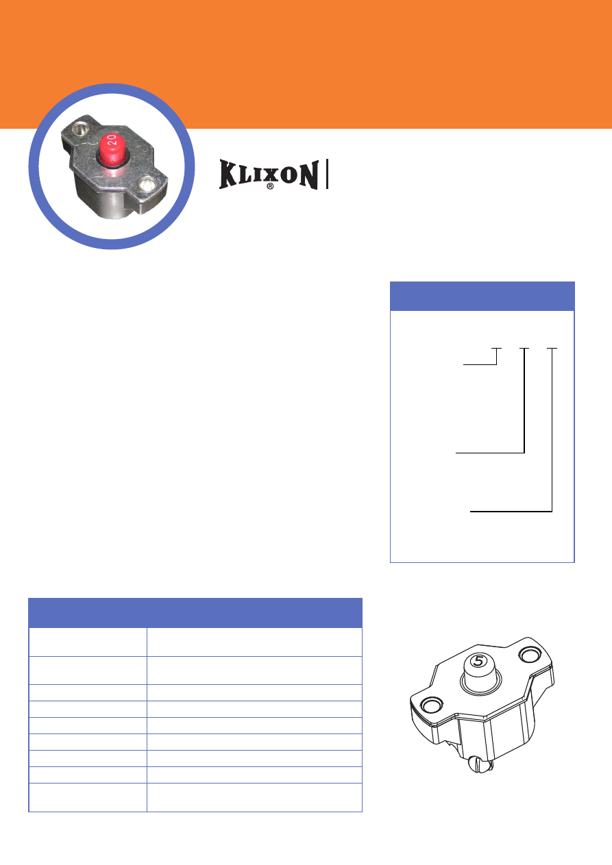
ORDERING INFORMATION
FEATURES
• 30VDC or 120VAC, 2 to 40 Amps
• Open and closed construction
• Automatic and manual reset options
• Ignition protected SAE J1171
• Weatherproof SAE J553
• UL Recognized E36869
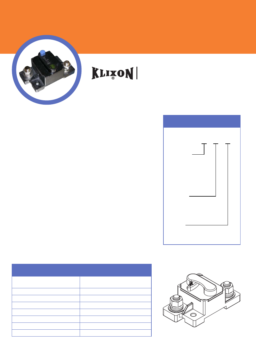
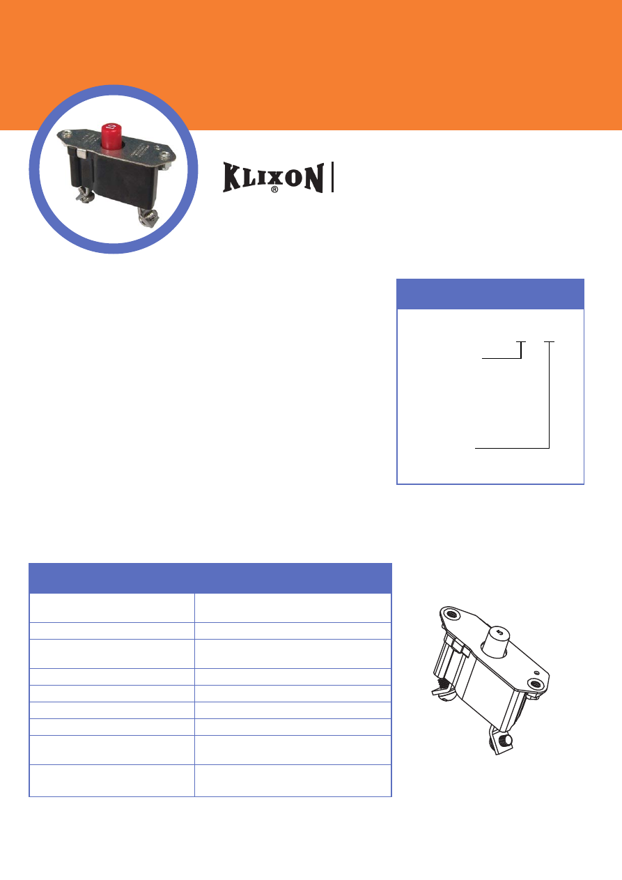
DESCRIPTION
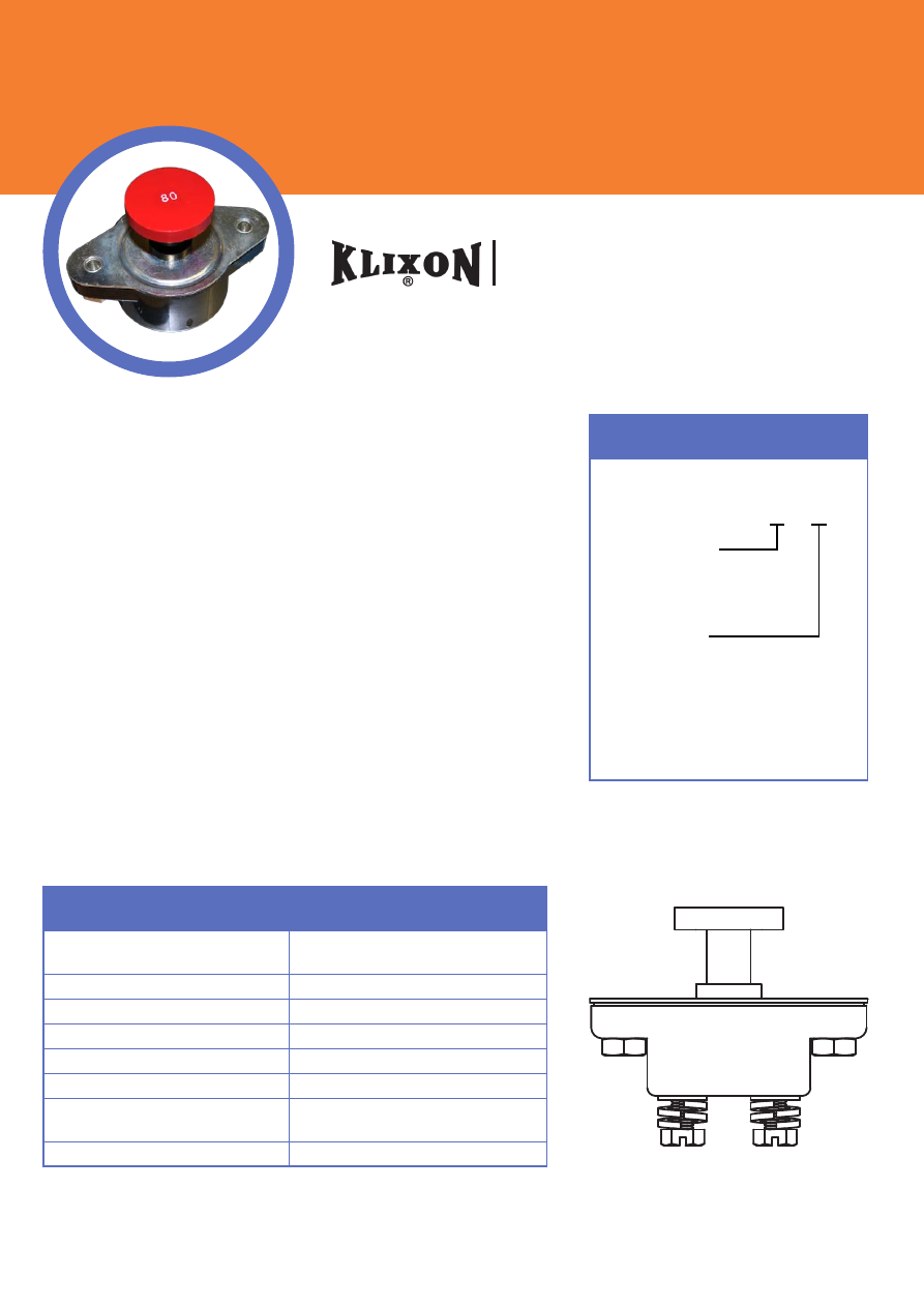
The KLIXON® C series thermal breakers are designed to protect wiring
and meet the harshest environmental requirements. The C series closed
construction circuit breakers are weatherproof sealed for protection
against moisture, dust, grease, fuel vapors and other harsh environments.
The C series breakers are compact, lightweight and designed to interrupt
short circuits or overloads, and combine trip-free protection with fast
response time. Typical applications are protection of wire cable of
accessory circuits, equipment and battery protection in construction
and off-road equipment, marine, recreational vehicles (RV’s), mining,
agricultural equipment and electric (hybrid) vehicles.
C Series (CM, CA, CDM, CDA)
2 to 40 Amp Commercial Thermal Circuit Breaker
Configuration
CA = Auto, open unit
CM = Manual, open unit
CDM = Manual, sealed unit
CDA = Auto, sealed unit
X − X − X
Amp Rating
(2, 3, 4, 5, 6, 8, 10, 12.5, 15
17.5, 20, 25, 30, 35, 40)
Mounting Nuts
= leave blank for none
I
= include optional mounting nuts
PERFORMANCE CHARACTERISTICS
Calibration : 200% rated
current, 77°F (25°C)
2 to 10 amps : 20 to 150 seconds
12.5 to 40 amps : 5 to 55 seconds
Ultimate Trip at
77°F (25°C) Must hold 100%, Must trip 135%
Endurance Per SAE J553
Interrupt Current Capacity Per SAE J553 and ABYC E-11
Vibration 10G MIL-STD-202 Method 204, Condition A
Salt Spray MIL-STD-202 Method 101D (sealed only)
Dielectric Strength MIL-STD-202 Method 301, 1500VAC min
Insulation Resistance MIL-STD-202 Method 302, Condition B, 100 M
Ω
min
Weight (with mounting
nuts)
CDM: 48 grams max CDA: 41 grams max
CM : 37 grams max CA : 32 grams max
R
Se
ns
at
a
Te
ch
no
lo
gi
es
2.0)
SEE NOTE 1
(
R
Se
ns
at
a
Te
ch
no
lo
gi
es
3
2
M
A
D
E
IN
M
EX
IC
O
BOTTOM VIEW FOR 2 AMP THRU 10 AMP
FIG. #1
1
.641
.312
ROUND HEAD SCREW
(2 PLACES)
.250 LONG #8-32 UNC-2A
(2 PLACES)
LOCKWASHER
.047 REF. THK.
A
PART NUMBER
AND DATE CODE
LOCATION
.430
1.145
.562
MIN. PANEL HOLE DIA.
.380
OPTIONAL
#8-32 UNC-2B THREADED LOCKING
MOUNTING BUSHING FURNISHED ONLY
WHEN SPECIFIED ON ORDER. (2 PLACES)
DETAIL A
NOTES:
1. DIMENSION DOES NOT INCLUDE SEALING GASKET.
1.586
1.562
SEE NOTE 1
(1.221 / 1.159)
3
1
M
A
D
E
IN
M
EX
IC
O
BOTTOM VIEW FOR 12½ AMP THRU 40 AMP
EYELET FOR #10 SCREW
(2 PLACES)
FIG. #2
2
.906
C
A
V
0
2
1
/
C
D
V
0
3
G
N
IT
A
R
E
G
A
T
L
O
V
200% OVERLOAD
S
D
N
O
C
E
S
0
5
1
-
0
2
S
P
M
A
0
1
-
2
S
D
N
O
C
E
S
5
5
-
5
S
P
M
A
0
4
-
5
.
2
1
ULTIMATE TRIP % AT 77° F RATED CURRENT
%
0
0
1
M
U
M
I
N
I
M
%
5
3
1
M
U
M
I
X
A
M
1
1
E
-
C
Y
B
A
D
N
A
3
5
5
J
E
A
S
Y
TI
C
A
P
A
C
T
P
U
R
R
E
T
N
I
3
5
5
J
E
A
S
H
TI
W
S
E
I
L
P
M
O
C
E
C
N
A
R
U
D
N
E
3
5
5
J
E
A
S
P
M
A
0
4
-
5
.
2
1
P
O
R
D
E
G
A
T
L
O
V
M
U
M
I
N
I
M
C
A
V
0
0
5
1
H
T
G
N
E
R
T
S
C
I
R
T
C
E
L
E
I
D
M
0
0
1
E
C
N
A
T
S
I
S
E
R
N
O
IT
A
L
U
S
N
I
Ω
MINIMUM
A
N
O
IT
I
D
N
O
C
4
0
2
D
O
H
T
E
M
2
0
2
-
D
T
S
-
L
I
M
G
0
1
E
C
N
A
T
S
I
S
E
R
N
O
IT
A
R
B
I
V
MECHANICAL SHOCK RESISTANCE
100G
D
1
0
1
D
O
H
T
E
M
2
0
2
-
D
T
S
-
L
I
M
Y
A
R
P
S
T
L
A
S
1
7
1
1
J
E
A
S
D
E
T
C
E
T
O
R
P
N
O
IT
I
N
G
I
3
5
5
J
E
A
S
F
O
O
R
P
R
E
H
T
A
E
W
.
X
A
M
S
M
A
R
G
8
4
S
T
R
E
S
N
I
H
TI
W
:
T
H
G
I
E
W
9
6
8
6
3
E
D
E
T
S
I
L
L
U
PERFORMANCE CHARACTERISTICS
CDM-40
40
2
CDM-40-I
CDM-35
35
2
CDM-35-I
CDM-30
30
2
CDM-30-
CDM-25
25
2
CDM-25-I
CDM-20
20
2
CDM-20-I
CDM-17½
17½
2
CDM-17½-I
CDM-15
15
2
CDM-15-I
CDM-12½
12½
2
CDM-12½-I
CDM-10
10
1
CDM-10-I
CDM-8
8
1
CDM-8-I
CDM-6
6
1
CDM-6-I
CDM-5
5
1
CDM-5-I
CDM-4
4
1
CDM-4-I
CDM-3
3
1
CDM-3-I
CDM-2
2
1
CDM-2-I
PART NO.
AMP RATING
FIGURE NO.
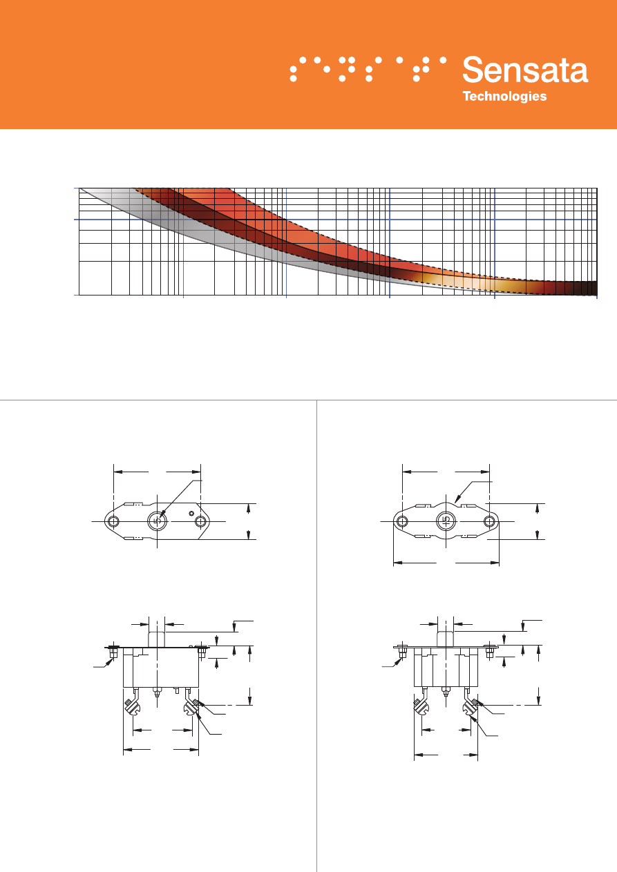
PART NO. WITH THREADED INSERTS
6
.250 [6.35] LONG
#8-32 UNC-2A ROUND
HEAD SCREW (2 PLACES)
LOCKWASHER (2 PLACES)
.047 [1.19] REF. THK.
.430 [10.92]
1.145 [29.08]
MIN. PANEL HOLE DIA.
2.0 [ 50.8]
.562 [ 14.27]
SEE NOTE 1
INCHES [MM]
1.586 [40.28]
1.562 [39.67]
1.221 [31.01]
1.159 [29.44]
(DOES NOT INCLUDE SEALING GASKET)
R
Se
ns
at
a
Te
ch
no
lo
gi
es
3
2
M
A
DE
IN
M
EX
IC
O
BOTTOM VIEW
2 AMP THRU 10 AMP
1
.641 [16.28]
.312 [7.93]
R
Se
ns
at
a
Te
ch
no
lo
gi
es
3
1
M
A
DE
IN
M
EX
IC
O
BOTTOM VIEW
12½ AMP THRU 40 AMP
EYELET FOR
#10 SCREW
(2 PLACES)
2
.906 [23.01]
.380 [9.65]
OPTIONAL #8-32 UNC-2B
MOUNTING NUT
(2 PLACES)
100˚F
140˚F
160˚F
70˚F
-60˚F
-40˚F
0˚F
32˚F
38˚C
60˚C
71˚C
21˚C
-51˚C
-40˚C
-18˚C
0˚C
40
60
80
Ultimate Trip in % Rated Load
Ambient T
emperature in °F
, °C
100
120
140
160
180
3
4
1
2
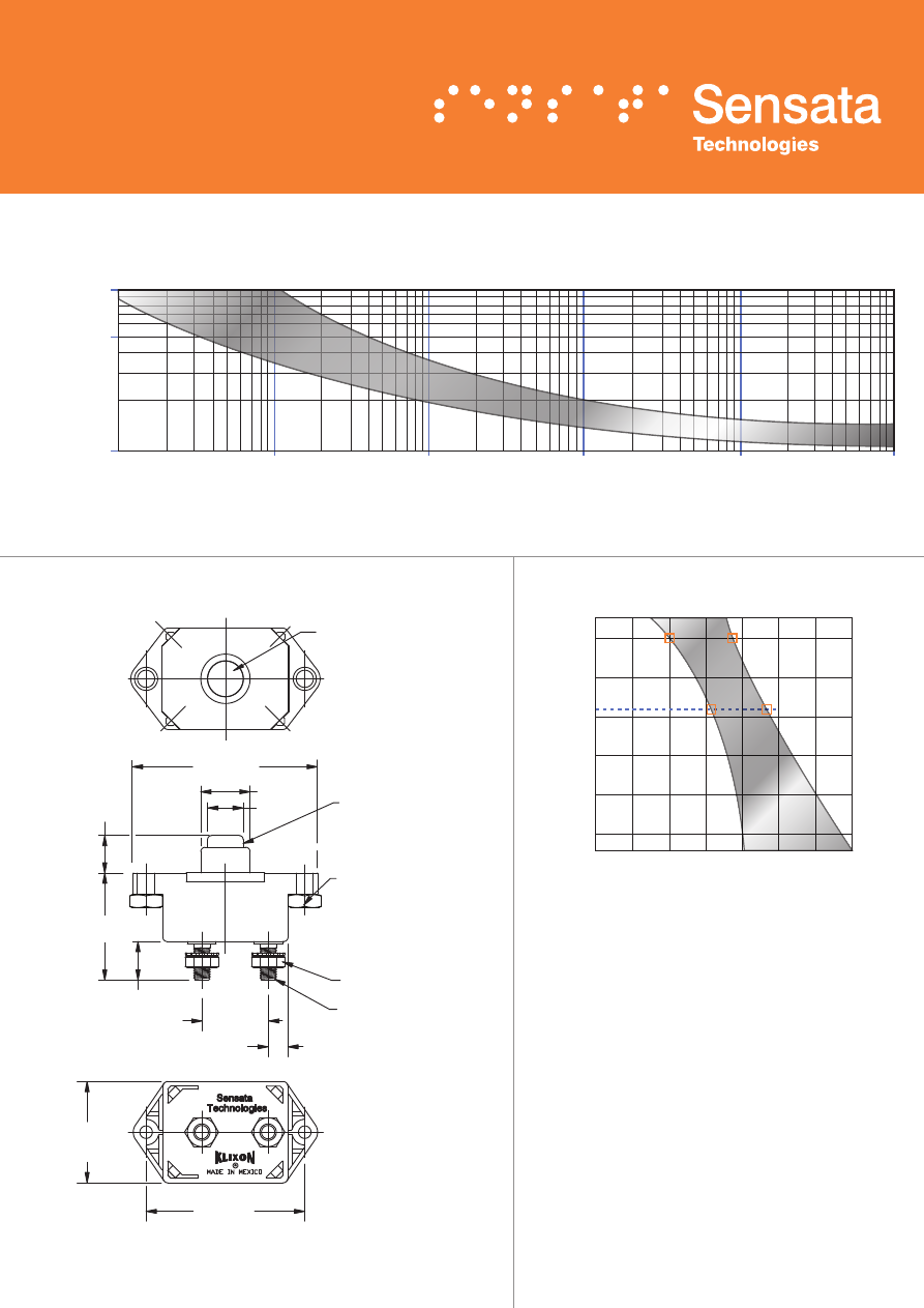
77°F, 25°C
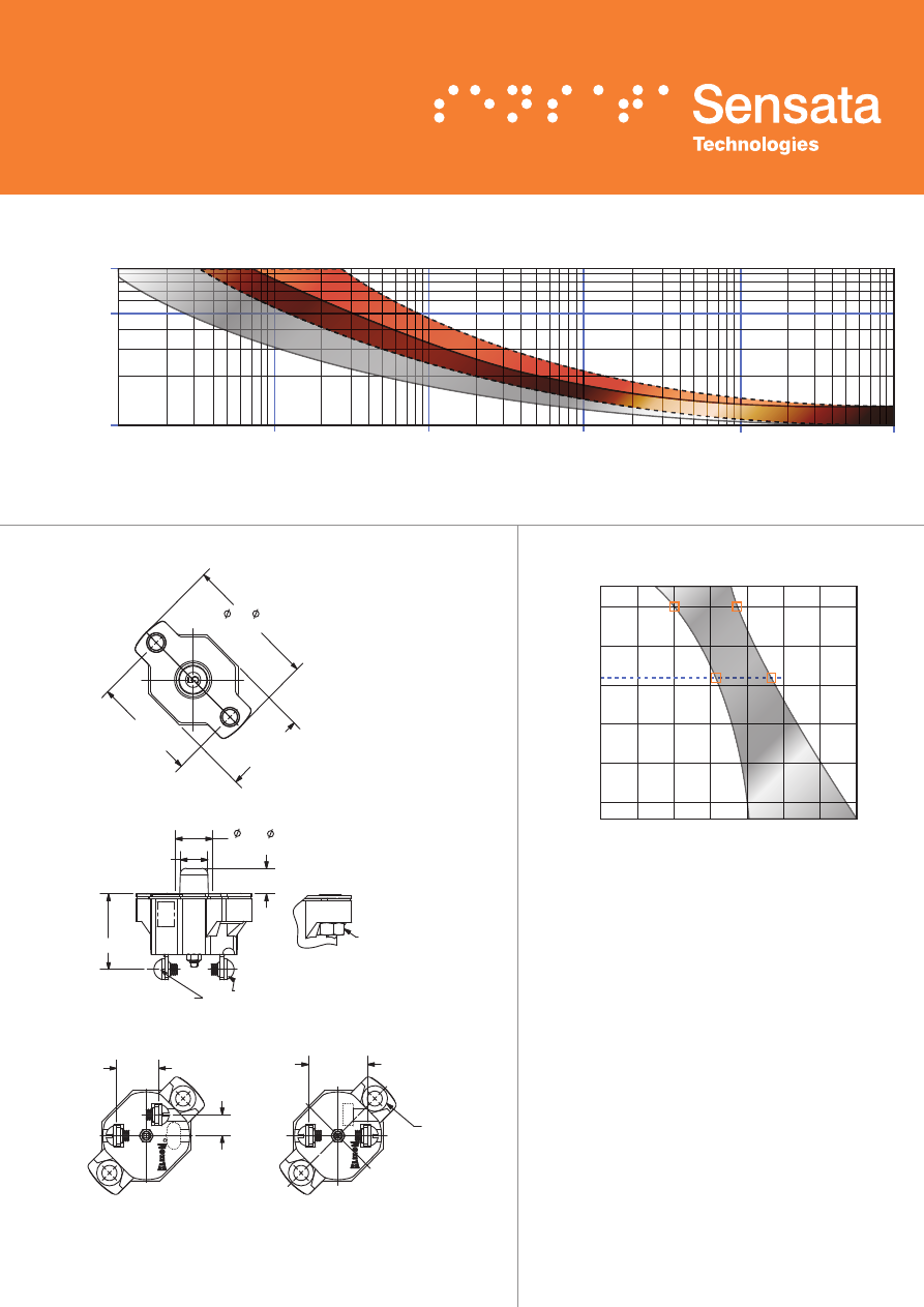
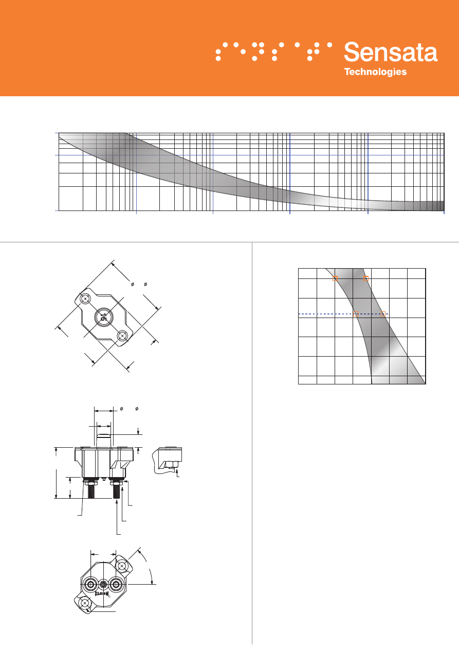
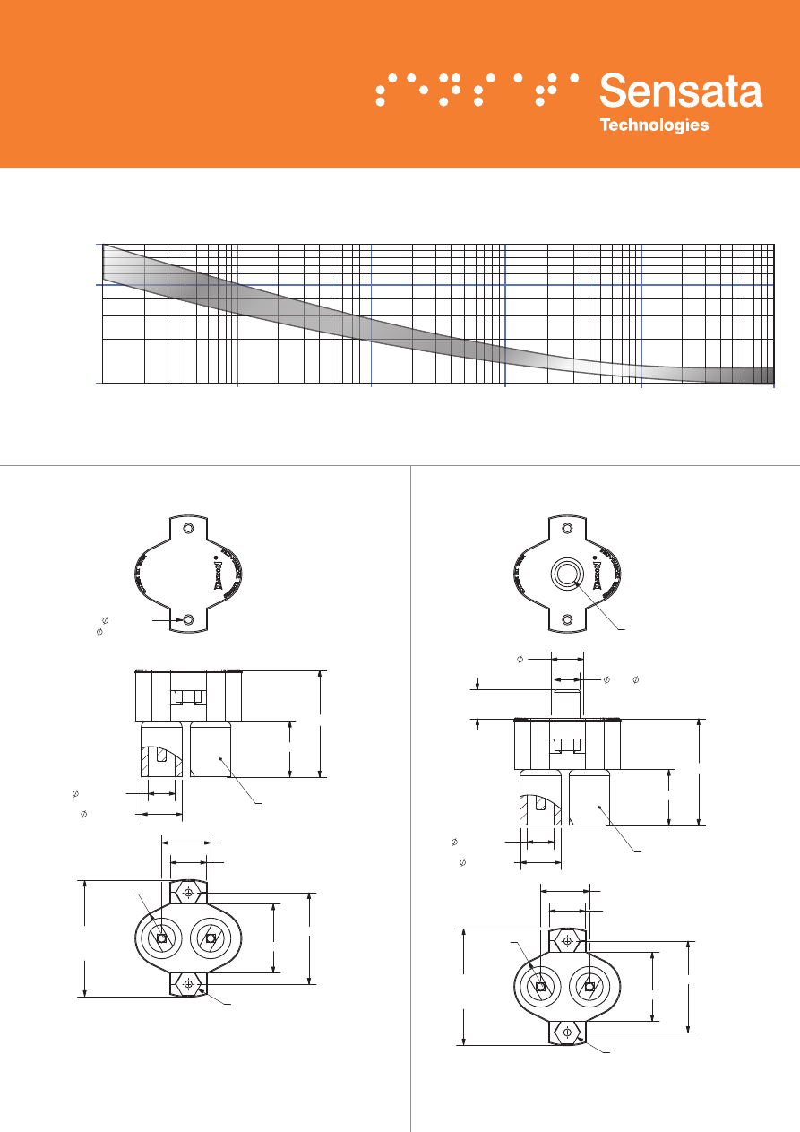
DERATING CURVE
Performance characteristics are based on room
temperature (77°F, 25°C). Consult Derating curve for
ambient temperatures significantly higher or lower than
standard room temperature.
Example:
At 77°F (25°C) the device is calibrated to hold
at 100% of rated current (1) and trip at 135% of rated
current (2). At 140°F (60°C), the same device will hold
at approximately 78% of rated current (3), and trip at
approximately 115% of rated current (4).
Dotted Lines:
10 amps or below
Solid Lines:
Above
10 amps
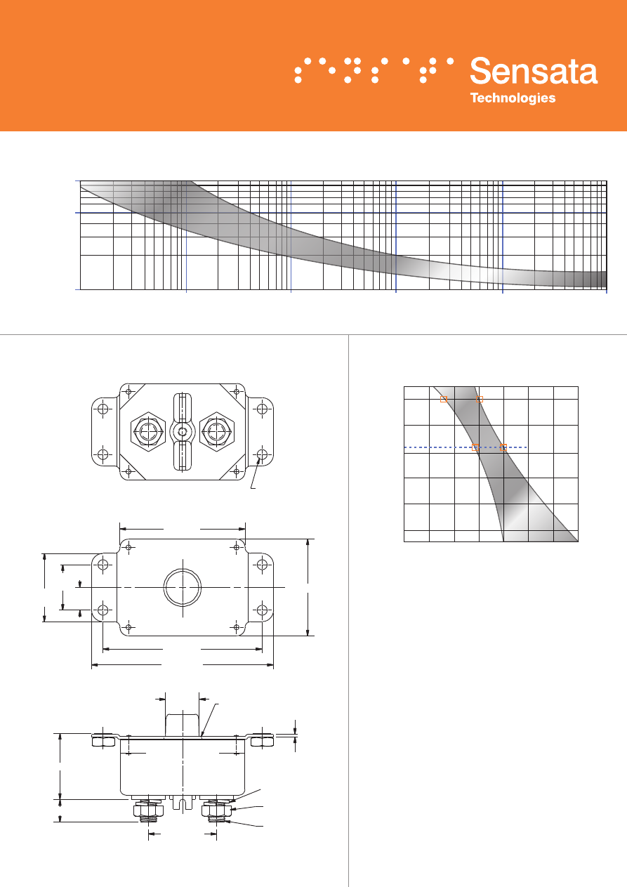
DIMENSIONS -
CDM
1000
500
100
.10
1
10
Trip Time in Seconds
Current in % Rated Load
100
1000
10,000
TRIP CURVE -
Approximate Time, Current Characteristics At 77°F (25°C)
7
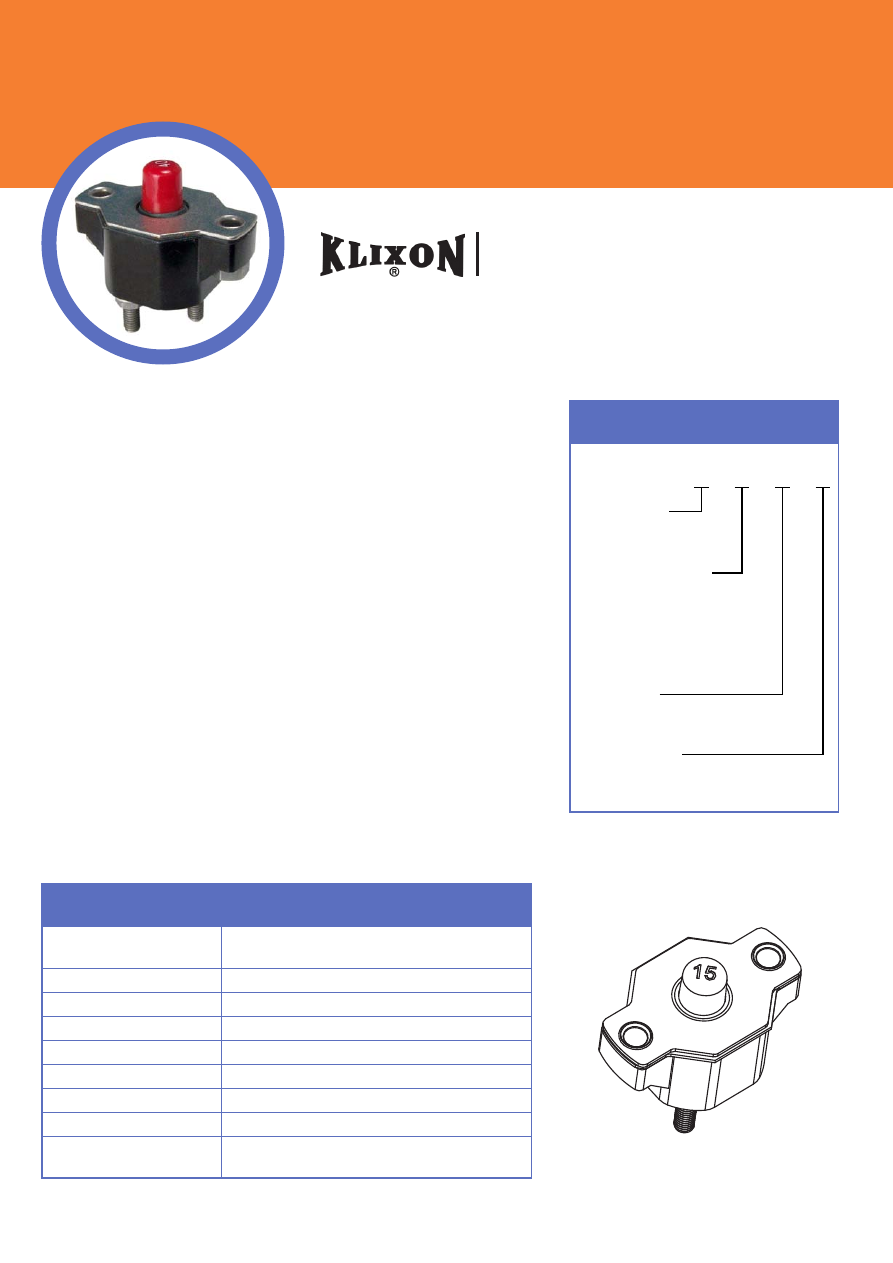
ORDERING INFORMATION
FEATURES
• 30VDC or 120VAC, 12.5 to 60 Amps
• Sealed assemblies, manual and automatic reset options
• Ignition protected SAE J1171
• Weatherproof SAE J553
• UL Recognized E36869
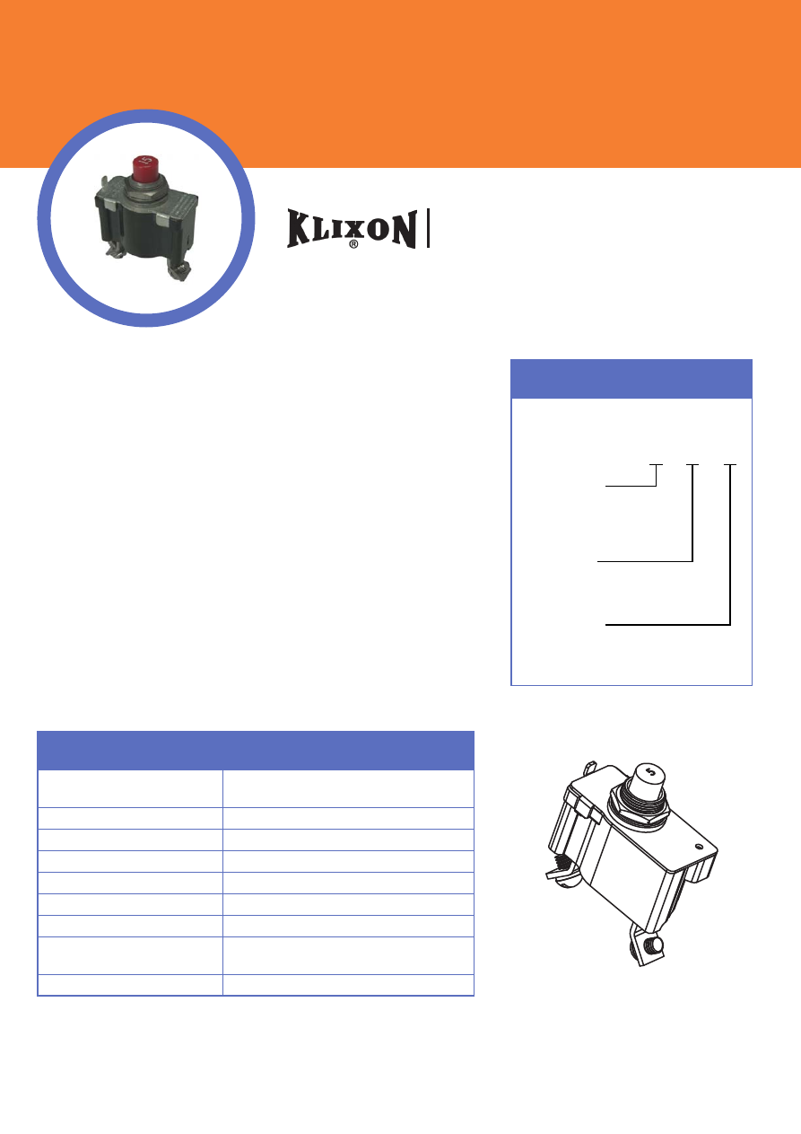
DESCRIPTION
The KLIXON® 7851 and 7854 series thermal breakers were designed
to protect wiring and meet the harshest environmental requirements.
The 7851 and 7854 series closed construction circuit breakers are
weatherproof sealed for protection against moisture, dust, grease, fuel
vapors and other harsh environments. The 7851 and 7854 series breakers
are compact, lightweight and designed to interrupt short circuits or
overloads, and combine trip-free protection with fast response time.
Typical applications are protection of wire cable of accessory circuits,
equipment and battery protection in construction and off-road equipment,
marine, recreational vehicles (RV’s), mining, agricultural equipment and
electric (hybrid) vehicles.
7851 & 7854 Series
12.5 to 60 Amp Commercial Thermal Circuit Breaker
Configuration
7851 = Manual, sealed
7854 = Auto, sealed
X − X − X − X
Stud Length (approx)
18 = 0.310” for 7851 & 7854
37 = 0.455” for 7851
26 = 0.455” for 7854
13 = 0.610” for 7851
15 = 0.610” for 7854
Amp Rating
(12.5, 15, 17.5, 20, 25, 30
35, 40, 50, 60)
PERFORMANCE CHARACTERISTICS
Calibration : 200% rated
current, 77°F (25°C) 12.5 to 60 amps : 5 to 55 seconds
Ultimate Trip At 77°F (25°C) Must hold 100%, Must trip 135%
Endurance Per SAE J553
Interrupt Current Capacity Per SAE J553 and ABYC E-11
Vibration 10G MIL-STD-202 Method 204, Condition A
Salt Spray MIL-STD-202 Method 101D
Dielectric Strength MIL-STD-202 Method 301, 1500VAC min
Insulation Resistance MIL-STD-202 Method 302, Condition B, 100M
Ω
min
Weight (with mounting nuts) 7851 : 54 grams max
7854 : 49 grams max
Mounting Nuts
= leave blank for none
I
= optional mounting nuts
8
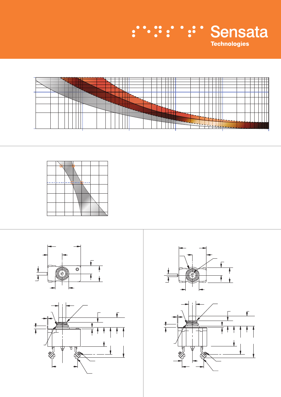
x2 WASHER FOR #10 SCREW (2 PLACES)
#10-32 UNF - 2A TERMINAL (2 PLACES)
# 10-32 UNF - 2B NUT (2 PLACES)
(2 PLACES)
STYCAST SEAL
.430 [10.92]
1.531 [38.89]
1.469 [37.31]
.484 [12.29]
MIN. PANEL HOLE DIA.
.562 [ 14.27]
.637 [16.18]
2.0 [ 50.8]
SEE NOTE 1
1.586 [40.28]
1.562 [39.67]
(DOES NOT INCLUDE SEALING GASKET)
1.221 [31.01]
1.159 [29.44]
Sensata
Technologies
R
MADE IN MEXICO
EYELET FOR #10 SCREW (2 PLACES)
.729 [18.52]
.791 [20.09]
(45°)
INCHES [MM]
OPTIONAL #8-32 UNC-2B
MOUNTING NUT
(2 PLACES)
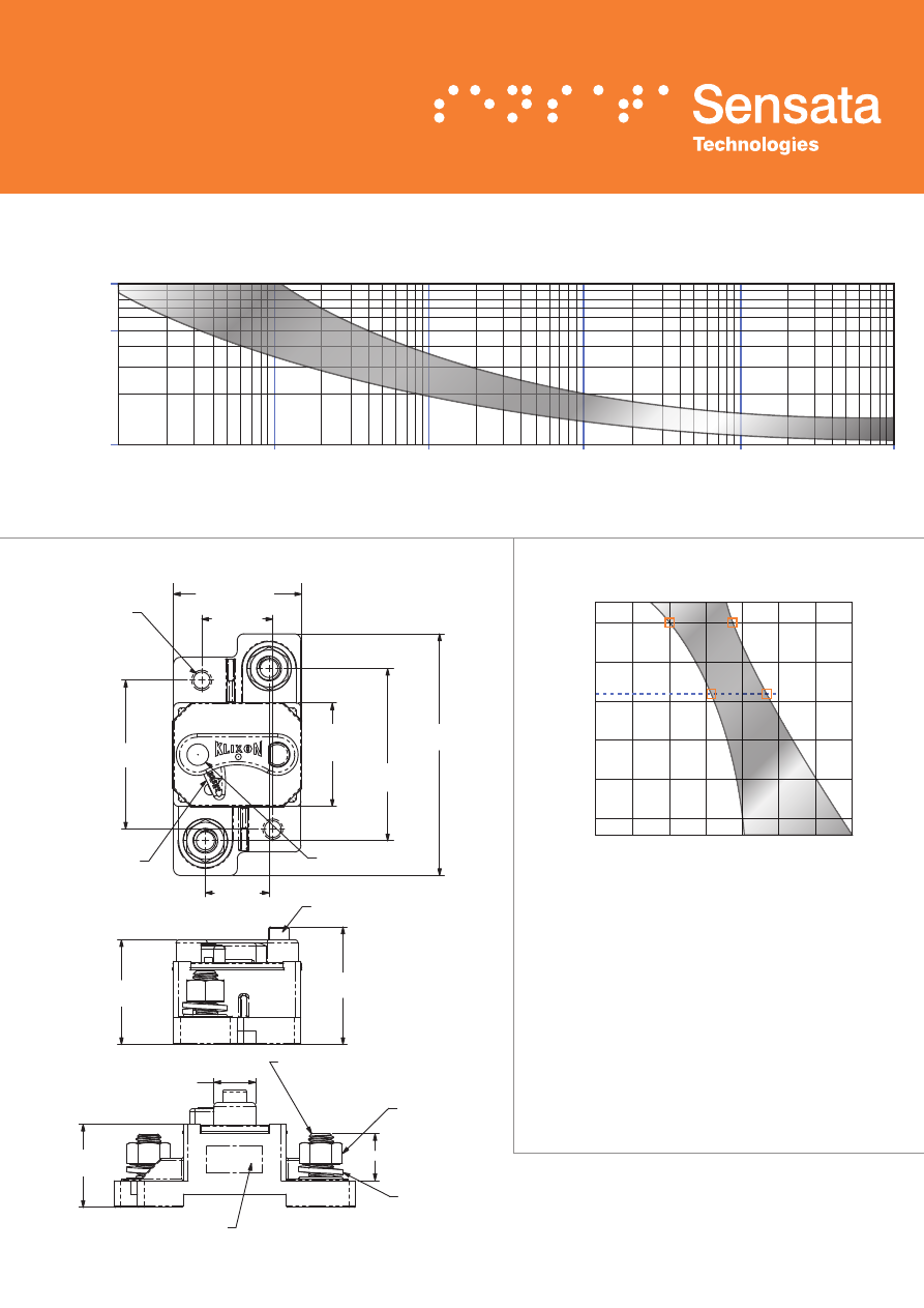
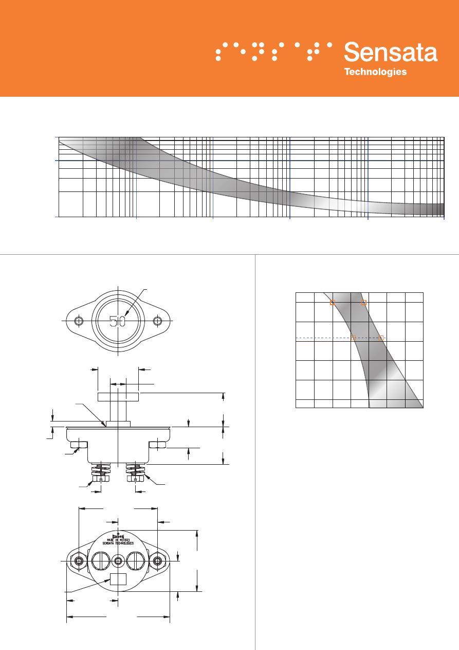
DERATING CURVE
Performance characteristics are based on room
temperature (77°F, 25°C). Consult Derating curve for
ambient temperatures significantly higher or lower than
standard room temperature.
Example:
At 77°F (25°C) the device is calibrated to hold
at 100% of rated current (1) and trip at 135% of rated
current (2). At 140°F (60°C), the same device will hold
at approximately 78% of rated current (3), and trip at
approximately 115% of rated current (4).
DIMENSIONS -
7851
TRIP CURVE -
Approximate Time, Current Characteristics At 77°F (25°C)
1000
500
100
.10
1
10
Trip Time in Seconds
Current in % Rated Load
100
1000
10,000
9
100˚F
140˚F
160˚F
70˚F
-60˚F
-40˚F
0˚F
32˚F
38˚C
60˚C
71˚C
21˚C
-51˚C
-40˚C
-18˚C
0˚C
40
60
80
Ultimate Trip in % Rated Load
Ambient T
emperature in °F
, °C
100
120
140
160
180
3
4
1
2
77°F, 25°C
ORDERING INFORMATION
F Series (FDLM, FDLA, FDLS, FDLT)
35 to 150 Amp Surface Mounted Thermal Circuit Breaker
Configuration
A = Auto
M = Manual
S = Manual Reset / Switch
T = Trip Lever
FDL X − X − X
Amp Rating
(35, 40, 45, 50, 60, 70, 80, 90, 100,
105, 120, 135, 150)
Terminals
1 = 1/4-28 UNF-2A
2 = 3/8-16 UNC-2A
FEATURES
• 30VDC, 35 to 150 Amps
• Weatherproof, ignition protected, trip-free design
• Stronger housing material for increased robustness
• Ability to accommodate heavy gauge wire lugs across terminal studs
• SAE J1625 surface vehicles circuit breaker standards
• SAE J1171 marine circuit breaker standards
• Meets 5000 amps @ 12VDC for interrupt capacity per ABYC E-11,
DC electrical systems of boats
DESCRIPTION
The KLIXON® F series thermal breaker series are designed for surface
mount applications and are available with automatic trip, manual reset,
trip indication, and a switchable option in a single device. The internal
components are enclosed in a vibration resistant, weatherproof, robust
casing to provide protection in the harshest environments found in
heavy truck, off-road, marine and construction applications. The F series
thermal breakers are designed to combine trip-free protection with fast
response time. Terminal studs are available in 1/4” or a larger 3/8” option
to allow higher torque connections and provide wider spacing for heavy
gauge wire lugs.
PERFORMANCE CHARACTERISTICS
Calibration : 200% rated current,
77°F (25°C) 35 to 150 Amps : 8 to 100 seconds
Ultimate Trip At 77°F (25°C) Must hold 100%, Must trip 135%
Endurance Per SAE J1625
Interrupt Current Capacity Per SAE J1625 and ABYC E-11
Mechanical Vibration Per SAE J1455, 4G’s 10-2K Hz
Voltage Breakdown Per SAE J1625 500VAC
Salt Spray Per SAE J1455, 96 hours
Weight 150 grams max
10
3.800 [96.52]
MAX.
(2 PLACES)
LOCKWASHER
1.260 [32.00]
REF.
.650 [16.51]
REF.
'B' REF.
PUSHBUTTON
(BLUE)
1.900 [48.26]
REF.
1.600 [40.64]
REF.
135
MOUNTING HOLE
FOR 1/4" SCREW
2 PLACES
RESET LEVER
(RED)
AMP RATING
(FOR EXAMPLE: 135A)
2.242 [56.95]
2.600 [66.04]
REF.
.950 [24.13]
REF.
SEE NOTE 1
1.085 [27.56]
1.560 [39.62]
REF.
1.035 [26.29]
2.192 [55.68]
SEE NOTE 1
2.100 [53.34] MAX
R
HEX NUT
(2 PLACES)
PART NUMBER AND DATE CODE
1/4 - 28 UNF - 2A ('B' = 0.55 [13.97] REF) OR
TERMINAL STUDS 2 PLACES
3/8 -16 UNC - 2A ('B' = 0.65 [16.51] REF)
INCHES [MM]
DERATING CURVE
DIMENSIONS -
FDLS
Performance characteristics are based on room
temperature (77°F, 25°C). Consult Derating curve for
ambient temperatures significantly higher or lower than
standard room temperature.
Example:
At 77°F (25°C) the device is calibrated to hold
at 100% of rated current (1) and trip at 135% of rated
current (2). At 140°F (60°C), the same device will hold
at approximately 78% of rated current (3), and trip at
approximately 115% of rated current (4).
Notes:
1. Dimension does not include sealing gasket.
1000
500
100
.10
1
10
Trip Time in Seconds
Current in % Rated Load
100
1000
10,000
TRIP CURVE -
Approximate Time, Current Characteristics At 77°F (25°C)
11
100˚F
140˚F
160˚F
70˚F
-60˚F
-40˚F
0˚F
32˚F
38˚C
60˚C
71˚C
21˚C
-51˚C
-40˚C
-18˚C
0˚C
40
60
80
Ultimate Trip in % Rated Load
Ambient T
emperature in °F
, °C
100
120
140
160
180
3
4
1
2
77°F, 25°C
S Series (SDLM, SDLA, SLA)
35 to 150 Amp Commercial Thermal Circuit Breaker
FEATURES
• 30VDC, 35 to 150 Amps
• Open and sealed assemblies, manual and automatic reset options
• Ignition protected
• UL Recognized E69772
DESCRIPTION
The KLIXON® S series thermal breakers are designed to protect wiring
and meet the harshest environmental requirements. The sealed circuit
breakers are weatherproof for protection against moisture, dust, grease,
fuel vapors and other harsh environments. The S series breakers are
lightweight and designed to interrupt short circuits or overloads and
combine trip-free protection with fast response time. Typical applications
are protection of wire and cable of accessory circuits, equipment and
battery protection on heavy trucks, buses, construction equipment, off-
road vehicles, marine, recreational vehicles (RVs) and electric (hybrid)
vehicles, and battery chargers.
The S series is available in both open and sealed body configurations with
manual and automatic reset options.
PERFORMANCE CHARACTERISTICS
Calibration : 200% rated current,
77°F (25°C) 35 to 150 Amps : 8 to 100 seconds
Ultimate Trip At 77°F (25°C) Must hold 100%, Must trip 135%
Endurance Per SAE J1625
Interrupt Current Capacity Per SAE J1625 and ABYC E-11
Mechanical Vibration Per SAE J1455, 4G’s, 10-2K Hz
Voltage Breakdown Per SAE J1625 500VAC
Salt Spray Per SAE J1625, 96 hours
Voltage Drop Per SAE J1625
Weight (with mounting nuts) SDLM (A) : 75 grams (71 grams) max
SLA : 62 grams max
ORDERING INFORMATION
Configuration
SLA = Auto, open unit
SDLM = Manual, sealed unit
SDLA = Auto, sealed unit
X − X − X
Amp Rating
(35, 40, 45, 50, 60, 70, 80, 90, 100,
105, 120, 135, 150)
Terminals
1 = 1/4-28 UNF-2A
with optional mounting nuts
12
AMP RATING
FOR ILLUSTRATION
PUSH BUTTON
(RED)
2.930 [74.42]
MAX
150
1.650 [41.91]
MAX
.580 [14.73]
.750 [19.05]
.540 [13.72]
.590 [14.99]
2X THREADED STUD
1/4-28 UNF-2A
2.429 [61.70]
2.399 [60.93]
1.550 [39.37]
MAX
(SEE NOTE 1)
2X PRE-ASM NUT
2X (
Ø .261 [Ø 6.63])
MOUNTING HOLE
10-32-UNF-2B
MOUNTING NUTS
FURNISHED WHEN
SPECIFIED
1.009 [25.63]
.284 [7.21]
INCHES [MM]
DERATING CURVE
Performance characteristics are based on room
temperature (77°F, 25°C). Consult Derating curve for
ambient temperatures significantly higher or lower than
standard room temperature.
Example:
At 77°F (25°C) the device is calibrated to hold
at 100% of rated current (1) and trip at 135% of rated
current (2). At 140°F (60°C), the same device will hold
at approximately 78% of rated current (3), and trip at
approximately 115% of rated current (4).
DIMENSIONS -
SDLM
1000
500
100
.10
1
10
Trip Time in Seconds
Current in % Rated Load
100
1000
10,000
TRIP CURVE -
Approximate Time, Current Characteristics At 77°F (25°C)
13
100˚F
140˚F
160˚F
70˚F
-60˚F
-40˚F
0˚F
32˚F
38˚C
60˚C
71˚C
21˚C
-51˚C
-40˚C
-18˚C
0˚C
40
60
80
Ultimate Trip in % Rated Load
Ambient T
emperature in °F
, °C
100
120
140
160
180
3
4
1
2
77°F, 25°C
ORDERING INFORMATION
6766-19 Series
35 to 150 Amp Commercial Thermal Circuit Breaker
FEATURES
• 30VDC, 35 to 150 Amps
• Manual reset
• Weatherproof SAE J1625 and ideally suited for rugged applications
• Ignition protected SAE J1171
DESCRIPTION
The KLIXON® 6766-19 series is a manually switchable thermal
circuit breaker that is designed to meet the harshest environmental
requirements. The 6766-19 series breakers are weatherproof for
protection against moisture, dust, grease, fuel vapors, and other harsh
environments. The 6766-19 series of breakers is suited for rugged
applications, where a robust switchable breaker is required for
accessory, equipment and battery protection on heavy trucks, buses,
construction equipment, off-road vehicles, marine, recreational vehicles
(RVs) and electric (hybrid) vehicles.
Configuration
6766-19 = Manual, sealed
X − X
Amp Rating
(35, 40, 45, 50, 60, 70, 80,
90 105, 120, 135, 150)
PERFORMANCE CHARACTERISTICS
Calibration : 200% rated current,
77°F (25°C) 35 to 150 Amps : 8 to 100 seconds
Ultimate Trip At 77°F (25°C) Must hold 100%, Must trip 135%
Endurance Per SAE J1625
Interrupt Current Capacity Per SAE J1625 and ABYC E-11
Vibration Per SAE J1455, 4G’s, 10-2K Hz
Dielectric Strength MIL-STD-202 Method 301, 1500VAC min
Insulation Resistance MIL-STD-202 Method 302, Condition B,
100 M
Ω
min
Weight (with mounting nuts) 6766-19 : 129 grams max
14
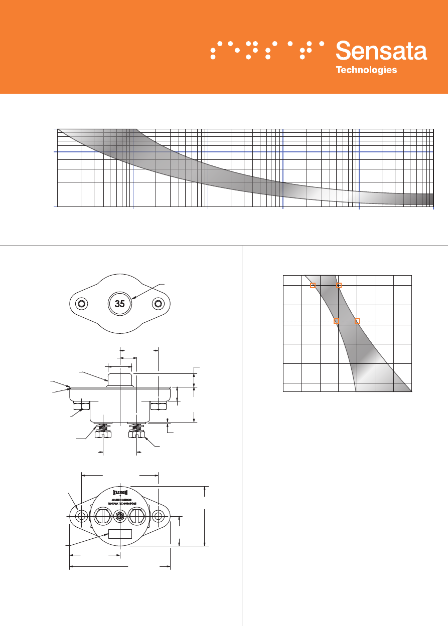
AMP RATING
FOR ILLUSTRATION
Ø
1.250 [31.75]
1.230 [31.24]
Ø
.531 [13.49]
.469 [11.91]
Ø
.750 MIN PANEL HOLE
.202
.140
1.072 [27.23]
1.052 [26.72]
.687 [17.45]
.625 [15.88] 1.187 [30.15]
1.125 [28.58]
1.043 [26.49] MAX OPEN
.872 [22.15] MIN CLOSE
2X #10-32 UNC-2B
LOCKNUTS
2X 1/4-28UNF-2 HEX
HEAD CAP SCREW
4X SPLIT LOCKWASHER
2.416 [61.37]
2.396 [60.86]
1.208 [30.68]
1.198 [30.43]
1.906 [48.41]
1.844 [46.84]
SEE NOTE 1
.958 [24.33]
.922 [23.42]
3.187 [80.95]
3.125 [79.38]
(DOES NOT INCLUDE SEALING GASKET)
1.594 [40.49]
1.562 [39.67]
PART NO. AND
DATE CODE
LOCATION
INCHES [MM]
DERATING CURVE
Performance characteristics are based on room
temperature (77°F, 25°C). Consult Derating curve for
ambient temperatures significantly higher or lower than
standard room temperature.
Example:
At 77°F (25°C) the device is calibrated to hold
at 100% of rated current (1) and trip at 135% of rated
current (2). At 140°F (60°C), the same device will hold
at approximately 78% of rated current (3), and trip at
approximately 115% of rated current (4).
DIMENSIONS -
6766-19
TRIP CURVE -
Approximate Time, Current Characteristics At 77°F (25°C)
1000
500
100
.10
1
10
Trip Time in Seconds
Current in % Rated Load
100
1000
10,000
15
100˚F
140˚F
160˚F
70˚F
-60˚F
-40˚F
0˚F
32˚F
38˚C
60˚C
71˚C
21˚C
-51˚C
-40˚C
-18˚C
0˚C
40
60
80
Ultimate Trip in % Rated Load
Ambient T
emperature in °F
, °C
100
120
140
160
180
3
4
1
2
77°F, 25°C
ORDERING INFORMATION
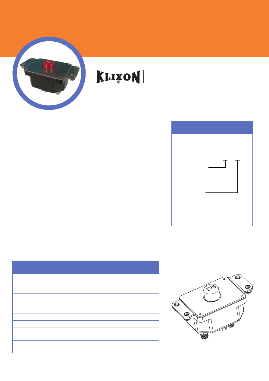
7855 Series
175 to 200 Amp Commercial Thermal Circuit Breaker
FEATURES
• 30VDC, 175 to 200 Amps
• Sealed assemblies, manual and automatic reset options
• Ignition protected
• 7855-6 meets CID A-A-55571/03 specifications
• 7855-7 meets CID A-A-55571/08 specifications
DESCRIPTION
The KLIXON® 7855 series thermal breaker are designed to meet the
harshest environmental requirements. The 7855 series breakers are
weatherproof for protection against moisture, dust, grease, fuel vapors
and other harsh environments. The 7855 series breakers are designed to
interrupt short circuits or overloads and combine trip free protection with
fast response time.
The 7855 series of breakers typical applications are protection of wire and
cable of accessory circuits, military vehicles, lift gates, and recreational
vehicles.
Configuration
7855-6 = Manual, sealed
7855-7 = Auto, sealed
X − X
Amp Rating
(175, 200)
PERFORMANCE CHARACTERISTICS
Calibration : 200% rated
current, 77°F (25°C) 8 to 100 seconds
Ultimate Trip At 77°F (25°C) Must hold 100%, Must trip 138%
Endurance Manual 500 cycles @ 200%
Automatic 2000 cycles @ 200%
Interrupt Current Capacity Per SAE J1625, 900A
Vibration 10G MIL-STD-202 Method 204, Condition A
Dielectric Strength MIL-STD-202, Method 301, 1500VAC min
Insulation Resistance MIL-STD-202, Method 302, Condition B, 100 M
Ω
min
Weight 7855-6 : 241 grams max
7855-7 : 237 grams max
16
4 MTG HOLES
Ø
.218 [
Ø 5.54]
MOUNTING NUTS
SUPPLIED FOR
7855-6
BOTTOM VIEW
.78 [19.81]
Ø
.875 [22.23] MIN CLEARANCE
HOLE FOR PUSH BUTTON
REQ’D FOR MOUNTING
.062 [1.58]
1.47 [37.34]
.500 ± .015 [12.700 ± .381]
1.500 ± .015
[38.100 ± .381]
LOCK WASHER x2
HEX NUT x2
3/8 - 24 UNF - 2B
THREAD
2.75 [69.85]
3.500 [88.9]
4.000 [101.6]
2.12 [53.85]
1.000
[25.4]
.500
[12.7]
1.50
[38.1]
INCHES [MM]
1000
500
100
.10
1
10
Trip Time in Seconds
Current in % Rated Load
100
1000
10,000
60
80
100
Ultimate Trip in % Rated Load
38˚C
60˚C
71˚C
21˚C
-51˚C
-40˚C
-18˚C
0˚C
Ambient T
emperature in °F
, °C
120
140
160
180
200
3
4
1
2
77°F, 25°C
100˚F
140˚F
160˚F
70˚F
-60˚F
-40˚F
32˚F
DERATING CURVE
DIMENSIONS -
7855-6
TRIP CURVE -
Approximate Time, Current Characteristics At 77°F (25°C)
Performance characteristics are based on room
temperature (77°F, 25°C). Consult Derating curve for
ambient temperatures significantly higher or lower than
standard room temperature.
Example:
At 77°F (25°C) the device is calibrated to hold
at 110% of rated current (1) and trip at 138% of rated
current (2). At 140°F (60°C), the same device will hold
at approximately 92% of rated current (3), and trip at
approximately 120% of rated current (4).
17

ORDERING INFORMATION
Small Frame PD Series (PDM, PDA)
2 to 40 Amp Precision Thermal Circuit Breaker
FEATURES
• 30VDC or 120VAC, 2 to 40 Amps
• Sealed assemblies, available in manual and automatic reset options
• Ignition protected
• UL Recognized E36869
DESCRIPTION
The KLIXON® PD series thermal breakers are designed to protect wiring
and meet the harshest environmental requirements. The PD series are
weatherproof sealed for protection against moisture, dust, grease,
fuel vapors and other harsh environments. The PD series breakers
are compact, lightweight and designed to interrupt short circuits or
overloads, and combine trip-free protection with fast response time.
Typical applications are protection of wire and cable of accessory circuits,
equipment and battery protection in construction and off-road equipment,
marine, recreational vehicles (RV’s), mining, agricultural equipment and
electric (hybrid) vehicles.
The PD series is used in commercial and military applications.
Configuration
PDM = Manual, sealed
PDA = Auto, sealed
X − X − X
Amp Rating
(2, 3, 4, 5, 6, 8, 10, 12.5, 15
17.5, 20, 25, 30, 35, 40)
Mounting Nuts
= leave blank for none
I
= include optional mounting nuts
PERFORMANCE CHARACTERISTICS
Calibration :
200% rated current, 77°F (25°C)
2 to 10 amps : 20 to 150 seconds
12.5 to 40 amps : 8 to 50 seconds
Ultimate Trip at 77°F (25°C) Must hold 110%, must trip 138%
Endurance Per SAE J553
Interrupt Current Capacity Per SAE J553 and ABYC E-11
Vibration 10G MIL-STD-202 Method 204, Condition A
Mechanical Shock MIL-STD-202 Method 213, Condition C, 100G
Salt Spray MIL-STD-202 Method 101D
Dielectric Strength MIL-STD-202 Method 301, 1500VAC min
Insulation Resistance MIL-STD-202 Method 302, Condition B,
100 M
Ω
min
Weight (with mounting nuts) PDM : 48 grams max
PDA : 41 grams max
18
ROUND HEAD SCREW
2X .250 [6.35] LONG #8-32 UNC-2A
2X (.047 [1.1938]) THK.
LOCKWASHER
.430 [10.92]
.562 [ 14.28]
MIN. PANEL HOLE DIA.
1.145 [29.08]
.380 [9.65]
2.0 [ 50.8]
SEE NOTE 1
1.586 [40.28]
1.562 [39.68]
(DOES NOT INCLUDE SEALING GASKET)
1.221 [31.01]
1.159 [29.44]
R
Se
ns
at
a
Te
ch
no
lo
gi
es
3
2
M
AD
E
IN
M
EX
IC
O
1
Se
ns
at
a
Te
ch
no
lo
gi
es
R
1
3
M
AD
E
IN
M
EX
IC
O
2
BOTTOM VIEW
FOR 2 AMP THRU 10 AMP
.312 [7.93]
.641
[16.28]
(45°)
BOTTOM VIEW
FOR 12½ AMP THRU 40 AMP
2X EYELET
FOR #10 SCREW
.906 [23.01]
INCHES [MM]
2X #8-32 UNC-2B
MOUNTING NUTS
FURNISHED WHEN
SPECIFIED
DERATING CURVE
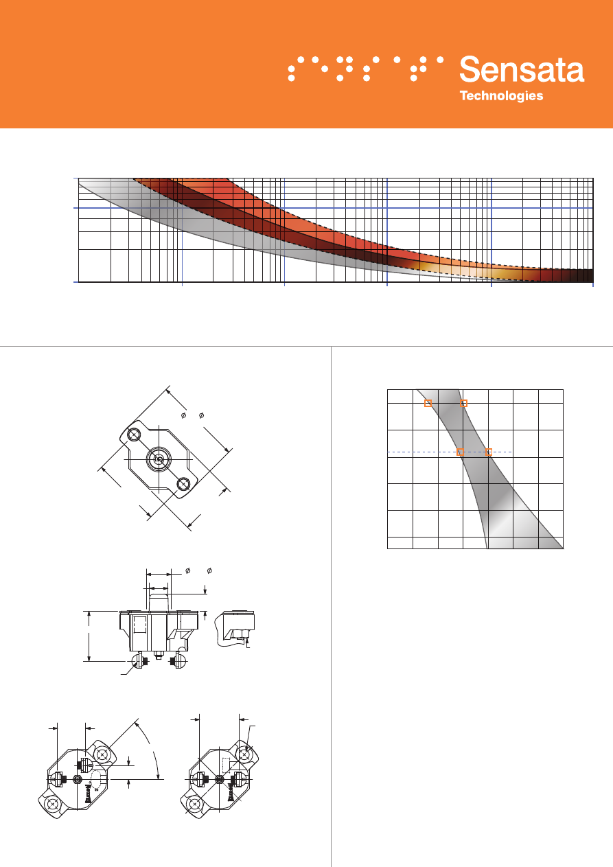
DIMENSIONS -
PDM
TRIP CURVE -
Approximate Time, Current Characteristics At 77°F (25°C)
Performance characteristics are based on room
temperature (77°F, 25°C). Consult Derating curve for ambient
temperatures significantly higher or lower than standard
room temperature.
Example: At 77°F (25°C) the device is calibrated to hold
at 110% of rated current (1) and trip at 138% of rated
current (2). At 140°F (60°C), the same device will hold
at approximately 92% of rated current (3), and trip at
approximately 120% of rated current (4).
Dotted Lines:
10 amps or below
Solid Lines:
Above
10 amps
0
60
80
100
Ultimate Trip in % Rated Load
120
140
160
180
200
3
4
1
2
77°F, 25°C
100˚F
140˚F
160˚F
70˚F
-60˚F
-40˚F
0˚F
32˚F
38˚C
60˚C
71˚C
21˚C
-51˚C
-40˚C
-18˚C
0˚C
Ambient T
emperature in °F
, °C
1000
500
100
.10
1
10
Trip Time in Seconds
Current in % Rated Load
100
1000
10,000
19
ORDERING INFORMATION
Large Frame PDL Series (PDLM, PDLA)
35 to 150 Amp Precision Thermal Circuit Breaker
FEATURES
• 30VDC, 35 to 150 Amps
• Sealed assemblies, available in manual and automatic reset options
• Ignition protected & CCC certified
• PDLM meets CID A-A-55571/04 specifications
• PDLA meets CID A-A-55571/07 specifications
DESCRIPTION
The KLIXON® PDL series thermal breakers are designed to meet the
harshest environmental requirements. The PDL series breakers are
weatherproof for protection against moisture, dust, grease, fuel vapors,
and other harsh environments. The PDL series of breakers are designed
to interrupt short circuits or overloads and combine trip-free protection
with fast response time. The PDL series of breakers can be used in
commercial and military vehicles and equipment where more precise
ultimate trip characteristics are required.
Configuration
PDLM = Manual, sealed
PDLA = Auto, sealed
X − X − X
Amp Rating
(35, 40, 45, 50, 60, 70, 80, 90,
105, 120, 135, 150)
Mounting Nuts
= leave blank for none
I
= include optional mounting nuts
PERFORMANCE CHARACTERISTICS
Calibration : 200% rated current,
77°F (25°C) 8 to 100 seconds
Ultimate Trip At 77°F (25°C) Must hold 100%, Must trip 138%
Endurance Automatic: 2,000 cycles @ 200% rated current
Manual: 500 cycles @ 200% rated current
Interrupt Current Capacity Per SAE J1625 and ABYC E-11
Vibration 10G MIL-STD-202 Method 204, Condition A
Mechanical Shock 100G MIL-STD-202 Method 213, Condition C
Dielectric Strength MIL-STD-202 Method 301, 1500VAC min
Insulation Resistance MIL-STD-202 Method 302, Condition B,
100 M
Ω
min
Weight (with mounting nuts) PDLM : 129 grams max
PDLA : 116 grams max
20
1000
500
100
.10
1
10
Trip Time in Seconds
Current in % Rated Load
100
1000
10,000
AMP RATING
ILLUSTRATION
1.213 [30.81]
1.193 [30.30]
.536 [13.61]
.526 [13.36]
.422
[10.72]
.781 [19.84]
MAX
PUSHBUTTON (RED)
.875 [22.23]
MIN PANEL HOLE
COVER
GASKET
4X LOCKWASHER
.469 [11.91]
.437 [11.10]
1.140 [28.96]
1.078 [27.38]
.063 [1.60]
.031 [.78]
1.072 [27.23]
1.052 [26.72]
2x 1/4-28 x 1/2” LG.
HEX HEAD CAP SCREWS
1.891 [48.03]
1.859 [47.22]
.954 [24.23]
.922 [23.42]
2.416 [61.37]
2.396 [60.86]
DIMENSIONS
DO NOT INCLUDE
SEALING GASKET
3.187 [80.95]
3.125 [79.38]
1.594 [40.49]
1.562 [39.68]
PART NO.
AND DATE CODE
LOCATION
2X EYELET FOR #10
SCREW
(SEE NOTE 1)
INCHES [MM]
MOUNTING NUTS
FURNISHED WHEN
SPECIFIED
DERATING CURVE
DIMENSIONS -
PDLM
TRIP CURVE -
Approximate Time, Current Characteristics At 77°F (25°C)
Performance characteristics are based on room
temperature (77°F, 25°C). Consult Derating curve for ambient
temperatures significantly higher or lower than standard
room temperature.
Example: At 77°F (25°C) the device is calibrated to hold
at 110% of rated current (1) and trip at 138% of rated
current (2). At 140°F (60°C), the same device will hold
at approximately 92% of rated current (3), and trip at
approximately 120% of rated current (4).
0
60
80
100
Ultimate Trip in % Rated Load
120
140
160
180
200
3
4
1
2
77°F, 25°C
100˚F
140˚F
160˚F
70˚F
-60˚F
-40˚F
0˚F
32˚F
38˚C
60˚C
71˚C
21˚C
-51˚C
-40˚C
-18˚C
0˚C
Ambient T
emperature in °F
, °C
21
ORDERING INFORMATION
PS Series (PSM, PSA)
2 to 35 Amp Precision Thermal Circuit Breaker
FEATURES
• 30VDC, 2 to 35 Amps
• Available in manual and automatic reset options
• PSM meets CID A-A-55571/06 specifications
• PSA meets CID A-A-55571/05 specifications
• UL Recognized E36869
DESCRIPTION
The KLIXON® PS series of breakers are designed to interrupt
short circuits or overloads and combines trip-free protection with
fast response time. The PS series thermal breaker is ideal for
commercial and military vehicle equipment where precise ultimate trip
characteristics are required.
Configuration
PSM = Manual
PSA = Automatic
X − X
Amp Rating
(2, 3, 4, 5, 6, 8, 10, 12.5, 15
20, 25, 30, 35)
PERFORMANCE CHARACTERISTICS
Calibration : 200% rated current,
77°F (25°C)
≤
10A for 20 to 150 seconds
>
10A for 8 to 50 seconds
Ultimate Trip At 77°F (25°C) Must hold 100%, Must trip 138%
Endurance Automatic: 2,000 cycles @ 200% rated current
Manual: 500 cycles @ 200% rated current
Interrupt Current Capacity Per SAE J553, 600A
Vibration 10G MIL-STD-202 Method 204, Condition A
Mechanical Shock 100G MIL-STD-202 Method 213, Condition C
Dielectric Strength MIL-STD-202, Method 301, 1500VAC min
Insulation Resistance MIL-STD-202, Method 302, Condition B,
100 M
Ω
min
Weight PSA : 30 grams max
PSM : 32 grams max
22
AMP RATING
FOR ILLUSTRATION
1.812
[46.02]
1.234
[31.34]
1.57
[39.88]
.760
[19.30]
2X #6-32 UNC-2B
MOUNTING NUTS
2X .250 LONG #8-32 UNC-2A
ROUND HEAD SCREW
2X LOCK WASHER
.338
[8.59]
REF
REF
1.234
[31.34]
.315
[8.00]
.250
[6.35]
1.031
[26.19]
2X #6-32 UNC-2B
MOUNTING NUTS
2X .250 LONG #8-32 UNC-2A
ROUND HEAD SCREW
2X LOCK WASHER
R .375 [9.53]
1.812
[46.02]
2.19
[55.63]
.750
[19.05]
.338
[8.59]
REF
REF
.280
[7.11]
.250
[6.35]
1.234
[31.34]
1.313
[33.35]
DIMENSIONS -
PSM (10 amps or less)
TRIP CURVE -
Approximate Time, Current Characteristics At 77°F (25°C)
Dotted Lines:
10 amps or below
Solid Lines:
Above
10 amps
1000
500
100
.10
1
10
Trip Time in Seconds
Current in % Rated Load
100
1000
10,000
DIMENSIONS -
PSM (over 10 amps)
23
AMP RATING
FOR ILLUSTRATION
1.812
[46.02]
1.234
[31.34]
1.57
[39.88]
.760
[19.30]
2X #6-32 UNC-2B
MOUNTING NUTS
2X .250 LONG #8-32 UNC-2A
ROUND HEAD SCREW
2X LOCK WASHER
.338
[8.59]
REF
REF
1.234
[31.34]
.315
[8.00]
.250
[6.35]
1.031
[26.19]
2X #6-32 UNC-2B
MOUNTING NUTS
2X .250 LONG #8-32 UNC-2A
ROUND HEAD SCREW
2X LOCK WASHER
R .375 [9.53]
1.812
[46.02]
2.19
[55.63]
.750
[19.05]
.338
[8.59]
REF
REF
.280
[7.11]
.250
[6.35]
1.234
[31.34]
1.313
[33.35]
ORDERING INFORMATION
PS Neck Mounting Series (PSM-XX-N)
2 to 35 Amp Precision Thermal Circuit Breaker
FEATURES
• 30VDC, 2 to 35 Amps
• Manual reset neck mount circuit breaker
DESCRIPTION
The KLIXON® PSM-XX-N series of breakers are designed to interrupt
short circuits or overloads and combines trip-free protection with
fast response time. The PSM-XX-N series thermal breaker is ideal for
commercial and military vehicle equipment where precise ultimate trip
characteristics are required.
Configuration
PSM = Manual, sealed
X − X − N
Amp Rating
(2, 3, 4, 5, 6, 8, 10, 12.5, 15
17.5, 20, 25, 30, 35)
Neck Mount
N = neck mount
PERFORMANCE CHARACTERISTICS
Calibration : 200% rated
current, 77°F (25°C)
2 to 10 amps : 20 to 150 seconds
12.5 to 35 amps : 8 to 50 seconds
Ultimate Trip At 77°F (25°C) Must hold 100%, Must trip 138%
Endurance Per SAE J553, 500 cycles @ 200%
Interrupt Current Capacity Per SAE J553
Vibration 10G MIL-STD-202 Method 204, Condition A
Mechanical Shock MIL-STD-202, Method 213, Condition C, 100G
Dielectric Strength MIL-STD-202, Method 301, 1500VAC min
Insulation Resistance MIL-STD 202, Method 302, Condition B,
100 M
Ω
min
Weight PSM-N : 35 grams max
24
DERATING CURVE
DIMENSIONS -
PSM-XX-N (10 amps and less)
TRIP CURVE -
Approximate Time, Current Characteristics At 77°F (25°C)
Performance characteristics are based on room
temperature (77°F, 25°C). Consult Derating curve for ambient
temperatures significantly higher or lower than standard
room temperature.
Example: At 77°F (25°C) the device is calibrated to hold
at 110% of rated current (1) and trip at 138% of rated
current (2). At 140°F (60°C), the same device will hold
at approximately 92% of rated current (3), and trip at
approximately 120% of rated current (4).
Dotted Lines:
10 amps or below
Solid Lines:
Above
10 amps
0
60
80
100
Ultimate Trip in % Rated Load
120
140
160
180
200
3
4
1
2
77°F, 25°C
100˚F
140˚F
160˚F
70˚F
-60˚F
-40˚F
0˚F
32˚F
38˚C
60˚C
71˚C
21˚C
-51˚C
-40˚C
-18˚C
0˚C
Ambient T
emperature in °F
, °C
1000
500
100
.10
1
10
Trip Time in Seconds
Current in % Rated Load
100
1000
10,000
1.566 [39.78]
.688 [17.48]
Ø .625
[15.88]
.125 [3.18]
.75 [19.05]
.375 [9.53]
1.234 [31.34]
NASM 35333-136
INTERNAL TOOTH
LOCK WASHER
MS 25082-C21 NUT
.030 [.762]
15/32 - 32UNS-2 THREAD
2X .250 [6.35] LONG
#8-32 UNC-2A ROUND HEAD
SCREW
2X LOCK WASHER
.338 [8.59]
1.282
[32.56]
1.390
[35.31]
.908
[23.06]
.060
[1.52]
.49 [12.45]
.25 [6.35]
.125 [3.175]
1.032
.516
INTERNAL
TOOTH LOCK
WASHER
CLINCH NUT
.032
15/32 - 32UNS-2 THREAD
2X .250 LONG #8-32 UNC-2A
ROUND HEAD SCREW
2X .047 THICK
LOCK WASHER
.344
REF
1.282
1.391
.907
.063
.469
.25
.125
AMP RATING
FOR ILLUSTRATION
1.313
.688
.563
.125
.704
.375
0.375 RADIUS
INCHES [MM]
25
DIMENSIONS -
PSM-XX-N (over 10 amps)
1.566 [39.78]
.688 [17.48]
Ø .625
[15.88]
.125 [3.18]
.75 [19.05]
.375 [9.53]
1.234 [31.34]
NASM 35333-136
INTERNAL TOOTH
LOCK WASHER
MS 25082-C21 NUT
.030 [.762]
15/32 - 32UNS-2 THREAD
2X .250 [6.35] LONG
#8-32 UNC-2A ROUND HEAD
SCREW
2X LOCK WASHER
.338 [8.59]
1.282
[32.56]
1.390
[35.31]
.908
[23.06]
.060
[1.52]
.49 [12.45]
.25 [6.35]
.125 [3.175]
1.032
.516
INTERNAL
TOOTH LOCK
WASHER
CLINCH NUT
.032
15/32 - 32UNS-2 THREAD
2X .250 LONG #8-32 UNC-2A
ROUND HEAD SCREW
2X .047 THICK
LOCK WASHER
.344
REF
1.282
1.391
.907
.063
.469
.25
.125
AMP RATING
FOR ILLUSTRATION
1.313
.688
.563
.125
.704
.375
0.375 RADIUS
INCHES [MM]
PERFORMANCE CHARACTERISTICS
Calibration : 200% rated current,
77°F (25°C) 8 to 50 seconds
Ultimate Trip At 77°F (25°C) Must hold 100%, Must trip 138%
Endurance
Per SAE J553:
Automatic: 2,000 cycles @ 200% rated current
Manual: 500 cycles @ 200% rated current
Interrupt Current Capacity Per SAE J553, 600A
Vibration 10G MIL-STD-202 Method 204, Condition A
Mechanical Shock 100G MIL-STD-202 Method 213, Condition C
Dielectric Strength MIL-STD-202 Method 301, 1500VAC min
Insulation Resistance MIL-STD-202 Method 302, Condition B,
100 M
Ω
min
Weight 9115-5 : 65 grams max
9115-6 : 76 grams max
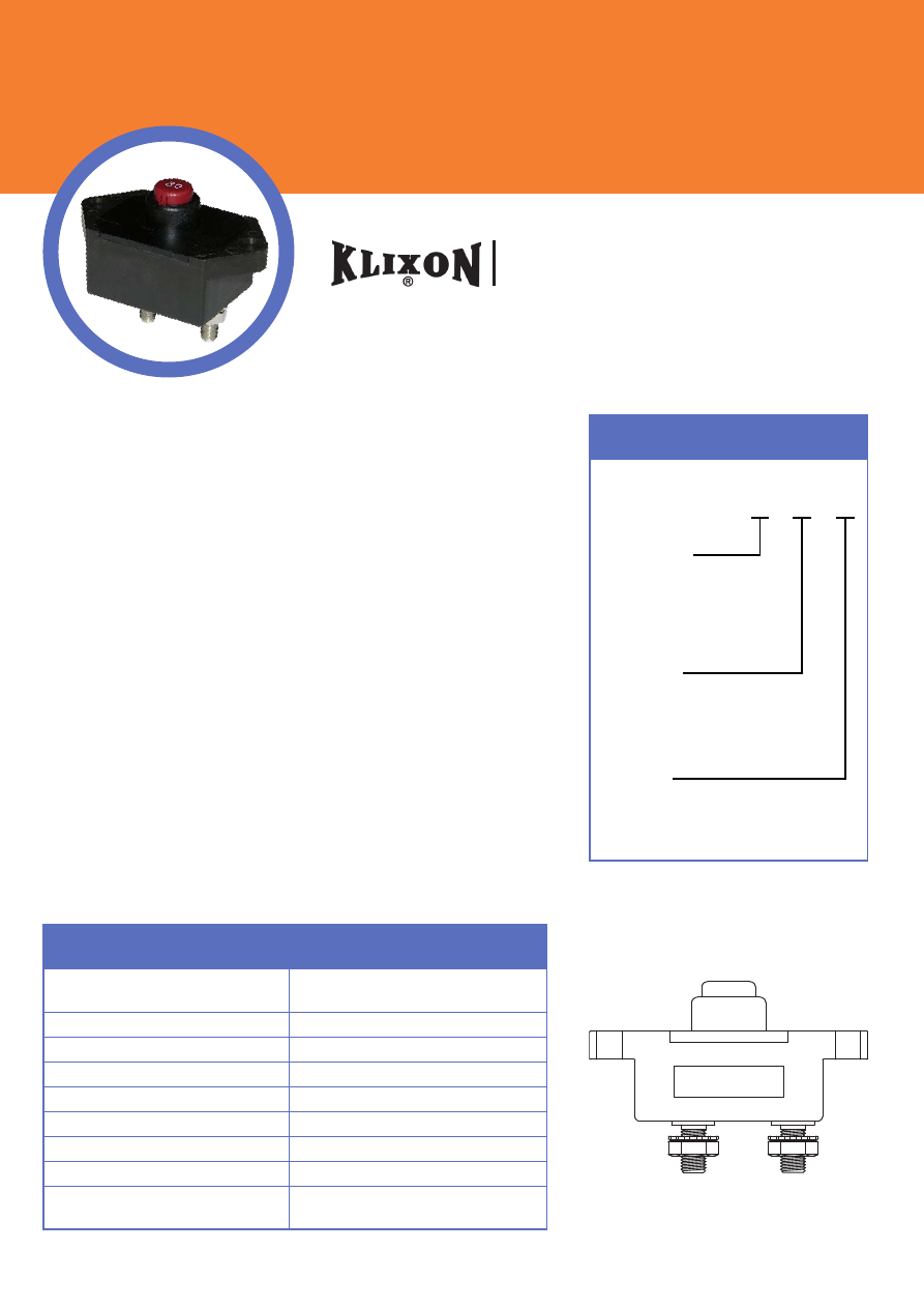
ORDERING INFORMATION
9115 Series
15 to 30 Amp Precision Thermal Circuit Breaker
FEATURES
• 30VDC, 15 to 30 Amps
• Sealed assemblies, available in manual and automatic reset options
• Ignition protected SAE J1171 & CCC certified
• 9115-5 meets CID A-A-55571/01 specifications
• 9115-6 meets CID A-A-55571/02 specifications
• UL Recognized E36869
DESCRIPTION
The KLIXON® 9115 series of circuit breakers was designed for
waterproof electrical systems of ordnance vehicles. The 9115 series is
recommended for other mobile military and ground equipment, including
trucks, tractors, graders, earth movers, fuel units, and amphibious as well
as commercial vehicles. In addition to a complete sealed thermal element
this series of thermal breakers has molded in terminals and are supplied
with rubber connectors (shells).
Configuration
9115-5 = Auto, sealed
9115-6 = Manual, sealed
X − X
Amp Rating
(15, 20, 25, 30)
26
Notes:
1. Shell female MS33800 mates with MS27143 or MS27144.
28
V
D
C
CI
R
CUI
T
B
R
E
A
K
E
R
2.000±.032 [50.8±.813]
DOES NOT INCLUDE
SEALING GASKET
2X #8-32 MOUNTING NUTS
1.187
1.574
± .032 [15.88 ± .813]
±.032
.485
[12.32]
.625
2X R
±.008
.843 ± .032 [21.41 ± .813]
SHELL, FEMALE
MS33800
2X( .700 [17.78])
.960 [24.4]
.470 [11.94])
2X (
1.875 [47.63] MAX.
AMP RATING SHOWN
FOR ILLUSTRATION
INCHES [MM]
.174 ± .002
2X
[4.42 ± .051]
MTG. HOLE
2X
DIMENSIONS -
9115-5
TRIP CURVE -
Approximate Time, Current Characteristics At 77°F (25°C)
1000
500
100
.10
1
10
Trip Time in Seconds
Current in % Rated Load
100
1000
10,000
15
28
V
D
C
CI
R
CUI
T
B
R
E
A
K
E
R
2.000±.032 [50.8±.813]
DOES NOT INCLUDE
SEALING GASKET
2X #8-32 MOUNTING NUTS
1.187
1.574
± .032 [15.88 ± .813]
±.032
.485
[12.32]
.625
2X R
±.008
.843 ± .032 [21.41 ± .813]
SHELL, FEMALE
MS33800
.562 [14.27]
MIN. PANEL HOLE
2X(
.440 [ 11.18]
.700 [17.78])
.960 [24.4]
.470 [11.94])
2X (
.500 [12.7]
1.875 [47.63] MAX.
AMP RATING SHOWN
FOR ILLUSTRATION
INCHES [MM]
DIMENSIONS -
9115-6
27
28
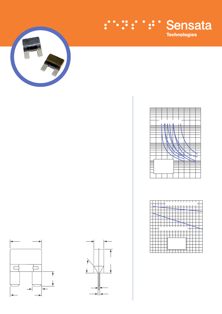
MAXI BREAKER® Series
Miniature Circuit Breakers
FEATURES
• Available in SAE Type 1 (cycling) and SAE Type 2 (non-cycling)
• Multiple bimetallic resistivities available
• Heater wire wrapped around the bimetal keeps the protector open
until power is removed (Type 2 only)
DESCRIPTION
The MAXI BREAKER® series of circuit protectors are rated for use
up to 125ºC. This patented device is available both as a cycling (SAE
Type 1) and non-cycling (SAE Type 2) device. Typical placement
of the MAXI BREAKER® is under the hood fuse blocks or other
areas of the vehicle that house a MAXI™ Blade Fuse*. The MAXI
BREAKER® protects against momentary overloads and eliminates
the need for fuse replacement.
SPECIFICATIONS
• Nominal Operating Voltage: 14 Volts DC
• Typicale Voltage Drop at Operating Current: 200 mV max
• Current Rating: 10 to 50 amps @ 25ºC (in 5 amp increments)
• Typical Ambient Temperature Range: -40ºC to 125ºC
DIMENSIONS, mm (inches)
29.21
(1.150)
29.21
(1.150)
12.70 (.500)
8.9
(.350)
60.0º
21.60 (.850)
.82 (.032)
2.54 (.100)
10000
8000
6000
4000
2000
1000
800
600
400
200
100
80
60
40
20
10
8
6
4
2
1
Trip T
ime in Seconds
0 10 20 30 40 50 60 70 80 90
Current in Amperes
Typical
Maxi Breaker
Trip Time Curves
at 25ºC
160
150
140
130
120
110
100
90
80
70
60
50
40
30
20
10
0
-50 -30 -10 10 30 50 70 90 110 130
Temperature in ºCelsius
Percent of Rated Current
Typical
Maxi Breaker
Derating Curves
All breakers will trip in this area
All breakers hold in this area
20A 25A 30A 40A
These curves are to be used only as a guide in
selecting a protector for a particular application.
Factors such as distance from the heat
source and the method of mounting should be
considered in selecting a protector. Final trip
times are dependent upon terminal configuration
and mounting in the application.
* MAXI™ Blade Fuse is a trademark of Littelfuse®
CURVES
10000
8000
6000
4000
2000
1000
800
600
400
200
100
80
60
40
20
10
8
6
4
2
1
Trip T
ime in Seconds
0 10 20 30 40 50 60 70 80 90
Current in Amperes
Typical
Maxi Breaker
Trip Time Curves
at 25ºC
160
150
140
130
120
110
100
90
80
70
60
50
40
30
20
10
0
-50 -30 -10 10 30 50 70 90 110 130
Temperature in ºCelsius
Percent of Rated Current
Typical
Maxi Breaker
Derating Curves
All breakers will trip in this area
All breakers hold in this area
20A 25A 30A 40A
29
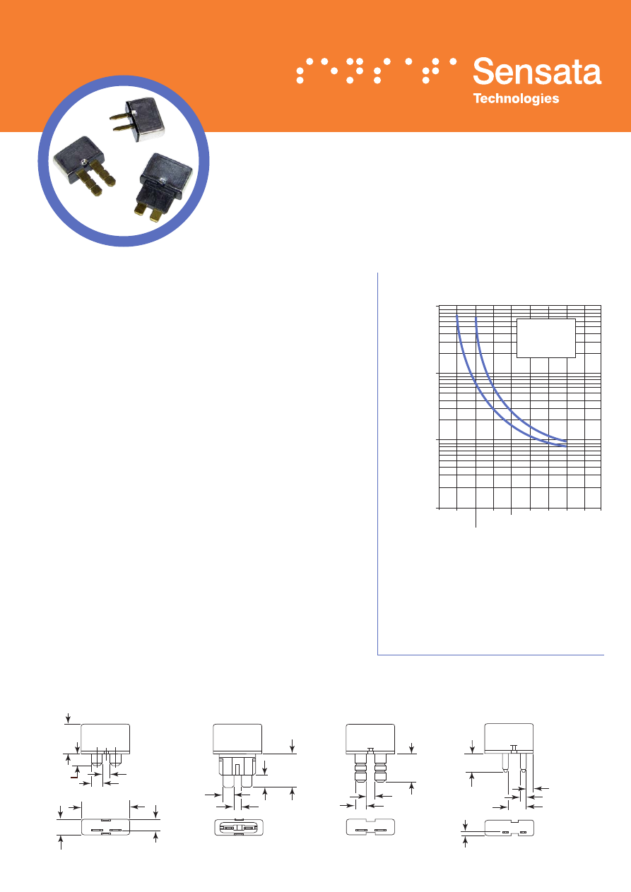
EXT 200 Series
Miniature Circuit Breakers
FEATURES
• SAE Type 2 (non-cycling) device
• Multiple bimetallic resistivities available
• Multiple terminal configurations available
• Metal encased
DESCRIPTION
The EXT 200 Series of mini remote reset circuit breakers are
commonly designed for 12 Volt DC wiring harness protection. The
device is ideal for the protection of circuits that may experience
momentary overloads and is often chosen as an alternative to
fuses, where nuisance replacement can be an inconvenience. The
EXT 200 can be mounted in the fuse block or elsewhere within the
wiring harness. This bimetallic device is sensitive to both over-
current and over-temperature fault conditions.
SPECIFICATIONS
• Nominal Operating Voltage: 12 Volts DC
• Typicale Voltage Drop at Operating Current: 200 mV max
• Current Rating: 5 to 35 amps @ 25ºC (in 5 amp increments)
• Typical Ambient Temperature Range: -40ºC to 85ºC
DIMENSIONS, mm (inches)
These curves are to be used only as a guide in
selecting a protector for a particular application.
Factors such as distance from the heat
source and the method of mounting should be
considered in selecting a protector. Final trip
times are dependent upon terminal configuration
and mounting in the application.
CURVES
Typical
EXT 200
Trip Time Curve
at 25ºC
1000
800
600
400
200
100
80
60
40
20
10
8
6
4
2
0
Trip T
ime in Seconds
Rated
Current
200% Rated
Current
Test Current
135% Rated
Current
7.3 (.29)
EXT 221
EXT 234
EXT 229
EXT 232
17.8 (.70)
5.4 (.21)
4.45 (.175)
25.1 (.99)
9.9 (.39)
7.8 (.31)
19.7 (.78)
5.2 (.20)
4.2 (.17)
12.3 (.48)
6.6 (.26)
5.2 (.20)
4.0 (.16)
11.0 (.43)
2.8 (.11)
3.8 (.15)
10.9 (.43)
2.25 (.88)

30
Amp Rating
The nominal electrical current in amperes
that the breaker will carry at room
temperature without tripping
Automatic
Reset
A device that opens by a combination of
overcurrent and elevated temperature,
with a design feature that allows the
breaker to cycle or continuously self reset.
Circuit
Breaker
A device designed to carry a specific value
of current and automatically open a circuit
upon overloads or short circuits.
Dielectric
Strength
A device’s ability to withstand a deliberate
application of pre–determined over–
voltage for a specified time.
Dielectric
Withstanding
Voltage
The maximum voltage that a switch can
withstand between specified points
without leaking current exceeding a
specified value.
Endurance
Refers to the longevity cycling of a circuit
breaker under less than direct short
conditions
Insulation
Resistance
The resistance offered by the insulating
members of a component part to direct
voltage tending to produce a leakage
current through or on the surface of these
members. Insulation resistance should
not be considered the equivalence of
dielectric withstanding voltage. Also:
Measures the resistance of the insulating
member of the device to a target voltage.
Manual Reset
A device that opens by a combination of
overcurrent and elevated temperature,
and remain open until manually reset into a
conducting state.
Maximum
Ultimate Trip
Current rating at which breaker must trip
within a certain period (usually 1 hour) at a
specified temperature.
GLOSSARY OF TERMS
Minimum
Ultimate Trip
Current rating at which breaker will not
trip within a certain period (usually 1 hour)
at a specified temperature.
Switchable
A design feature that allows a switchable
circuit breaker to function as a
conventional manual reset circuit breaker
and also has a mechanism, which when
exercised at the discretion of the user,
permits opening of the breaker internal
circuit to stop current flow. The breaker is
reset to its normal condition by the manual
rest function, whether tripped unattended
by a real fault condition or by the user.
Thermal
Circuit
Breaker
A circuit breaker that senses a current
overload based on thermal heating of the
sensing element.
Thermal
Derating
The effect of ambient temperature on
the trip characteristics of the breaker.
For example, as ambient temperature
increases, the amount of current required
to trip the breaker decreases.
Time-Current
Curve
An approximate graph showing the
minimum and maximum time a specific
breaker will trip at various degrees of
overload.
Trip Free
A design feature that makes it impossible
to hold the breaker closed against an
overload.
UL
Underwriters Laboratory
Voltage Drop
The voltage decrease across the breaker
due to internal resistance of the device.
Weatherproof
Circuit breakers designed such that
if immersed or submerged in fluid (for
example, water) no fluid shall infiltrate the
internal cavities or workings of the circuit
breaker.
ABOUT SENSATA TECHNOLOGIES
Sensata Technologies provides leaders in the automotive, appliance, aircraft, industrial,
HVAC/R, over-the-road truck, heavy vehicle, bus, RV, marine, telecom and datacom global
markets with sensing, protection and control solutions. Our mission is to improve safety,
efficiency and environmental protection for millions of people worldwide.
Sensata Technologies is headquartered in Attleboro, Massachusetts in the United States
and has business and manufacturing centers and sales offices throughout the world.
THE SUPPLIER YOU WANT. THE PARTNER YOU NEED.
At Sensata Technologies we do all we can to ensure your satisfaction. We apply our
unsurpassed experience and expertise to focus on your needs. We adhere to the highest
technical, manufacturing and testing standards. Our experts work with you to ensure the
quality and precision it takes to meet the most demanding application requirements. No
wonder a world of businesses relies on the more than 1 billion sensor, protection and
control devices we manufacture each year to optimize our customers’ own leading-edge
technologies.
WE DO IT ALL FOR YOU.
We are dedicated to being our customers’ first choice – no matter where in the world you
are located. We do this by:
• Offering rugged designs and in-house testing facilities to ensure consistent quality
• Locating business centers close to your markets in every region of the world
• Consolidating manufacturing in large Make sites in cost-effective locations
• Partnering with those setting the latest standards in industrial and automotive system
performance, safety and emission control
SAFETY, PERFORMANCE, RELIABILITY
You will find Sensata products wherever increased safety, performance and reliability are
required and where improved machine productivity and efficiency are desired. You will
find our products in an endless number of applications including HVAC and refrigeration,
transportation, aircraft, trucks, buses, trains, datacom and telecom, construction, mining,
agriculture, boats, recreational vehicles and material handling equipment. Our products
are also found in compressors, pumps, hydraulics, pneumatics, process control and factory
automation equipment, alternative fuel systems, communication towers and much more.
MANUFACTURING PRODUCTS TO THE HIGHEST STANDARDS.
Sensata’s manufacturing and technology
centers are ISO / TS16949 and ISO 14001
certified throughout the world.
2455009003 | Printed In USA, October, 2008
Important Notice: Sensata Technologies (Sensata) reserves the right
to make changes to or discontinue any product or service identified in
this publication without notice. Sensata advises its customers to obtain
the latest version of the relevant information to verify, before placing
any orders, that the information being relied upon is current. Sensata
assumes no responsibility for infringement of patents or rights of others
based on Sensata applications assistance or product specifications since
Sensata does not possess full access concerning the use or application
of customers’ products. Sensata also assumes no responsibility for
customers’ product designs.
www.sensata.com
OTHER SENSATA CATALOGS THAT MAY INTEREST YOU:
Airpax™ Power Protection Catalog
Literature PN 2455005000
Klixon™ Aircraft Circuit Breakers
Literature PN 2455009002
Dimensions™ DC to AC Inverters
Literature PN 2455008000
BUSINESS CENTERS
Sensata Technologies Inc.
529 Pleasant Street
Attleboro, MA 02703, USA
Phone: +1 508-236-3287
Brands: Klixon™, Sensata Technologies™
Sensata Technologies
807 Woods Road
Cambridge, MD 21613, USA
Phone: +1 410-228-1500
Brands: Airpax™
Sensata Technologies
4467 White Bear Lake Parkway
St. Paul, MN 55110, USA
Phone: +1 800-553-6418
Brands: Dimensions™
Sensata Technologies Holland B.V.
Kolthofsingel 8
7602 EM Almelo, The Netherslands
Phone: +31 546 87 95 55
Brands: Klixon™, Sensata Technologies™
Sensata Technologies China Co., Ltd.
Novel Plaza, 8th Floor
128 Nanjing Road West
Shaghai, 20003
People’s Republic of China
Phone: +86 21 23061500
Brands: Klixon™, Sensata Technologies™
Sensata Technologies Korea Ltd.
29F, Trade Tower
159-1 SamSung-Dong, KangNam-Ku, Seoul
135-729, Korea
Phone: +81-2-551-2918
Brands: Klixon™, Sensata Technologies™
Sensata Technologies Japan Ltd.
305, Tanagashira
Oyama-cho, Sunto-gun, Shizuoka-ken
Japan, 410-1396
Phone: +81 550 78 1211
Brands: Klixon™, Sensata Technologies™
Sensata Technologies Nihon-Airpax
6-3, Chi Yoda 5 Chome
Saitama-Ken
Japan, 350-0214
Phone: +81 492 83 7575
Brands: Airpax™