Sensotec Sensors
Full Line Catalog
27th Edition, 2006
Pressure. Load. Force. Torque.
Displacement. Vibration. Instrumentation.
Courtesy of Steven Engineering, Inc.-230 Ryan Way, South San Francisco, CA 94080-6370-Main Office: (650) 588-9200-Outside Local Area: (800) 258-9200-www.stevenengineering.com
Sensotec Sensors Full Line Catalog-html.html
Whether you need measurements in a laboratory, industrial, or hazardous
environment, ...whether your application involves a vacuum, 200,000 psi, 10 gms,
or 3 million lbs., ...whether you need one unit or several thousand, ...Honeywell
Sensotec can help you achieve your measurement goals.
For more than 30 years, Sensotec has provided quality, high performance pressure transducers, load cells,
torque cells, accelerometers, LVDTs and associated instrumentation to a wide variety of industries. Having
produced nearly 5000 different types of transducers and instruments, we will frequently have an existing
design to meet your specific needs.
Our sales and R & D engineers have accumulated years of experience in pressure and force measurement
applications. This knowledge, combined with the industry’s broadest line of products and options, allows
Honeywell Sensotec to provide transducers and instrumentation which meet your specific needs at the
minimum cost.
This catalog is designed to help you:
Select the transducer and/or instrument models, options and accessories which best meet your
needs.
Place an order.
Set up and operate transducers and instrumentation in the field.
First time users and individuals with limited knowledge about Sensotec products should consult the
product
selection flow chart
located at the beginning of each section to identify the best model for their application
and to determine its page location in the catalog.
Individuals who have already identified the model or order code for the required product can use the index on
pages 2 and 3 to determine its page location in the catalog and in the price book.
After selecting the appropriate product model, refer to the appendix for guidelines on selecting range codes,
options and accessories, building an order code string, and preparing a purchase order.
If you need help selecting the proper transducer or instrument, or have requirements that aren’t met by the
models described, call our Customer Service department or your local Sensotec Sales Representative for
assistance.
Honeywell Sensotec Engineers are continually working to improve our products. Honeywell reserves
the right to make changes, without notice, in design and specifications of any product as engineering
advances and necessity requires.
Introduction
How To Use
This Catalog
Design and
Specifications
SENSOTEC is a registered
trademark of HONEYWELL
WARNING
MISUSE OF DOCUMENTATION
The information presented in this catalog is for
reference only, DO NOT USE this document as
product installation information.
Complete installation, operation and
maintenance information is provided in the
instructions supplied with each product.
Failure to comply with these instructions could
result in death or serious injury.
WARNING
PERSONAL INJURY
DO NOT USE these products as safety or
emergency stop devices or in any other application
where failure of the product could result in personal
injury.
Failure to comply with these instructions could
result in death or serious injury.
..
www.honeywell.com/sensotec
1-888-282-9891
Courtesy of Steven Engineering, Inc.-230 Ryan Way, South San Francisco, CA 94080-6370-Main Office: (650) 588-9200-Outside Local Area: (800) 258-9200-www.stevenengineering.com
Sensotec Sensors Full Line Catalog-html.html

1
General Instruction
......................................................... Inside Front Cover
How to Use This Catalog .................................................... Inside Front Cover
Contents .............................................................................
1
Index by Model Name.........................................................
2
Index by Order Code ..........................................................
3
Our People, Products and Facilities ...................................
4
Honeywell Sensotec on the web.........................................
7
Product Overview ...............................................................
8
Design and Delivery Options ..............................................
10
STOCKING PROGRAM
...............................................
12
Pressure – Amplified & Unamplified
Gage, Absolute & Vacuum
..........................................
15
Pressure – Differential
..................................................
91
Load Cells – Amplified & Unamplified
....................
150
Torque Cells
......................................................................
281
Accelerometers
................................................................
321
LVDTs
...................................................................................
347
Instruments
........................................................................
397
APPENDIX
Accessories ........................................................................
450
Internal Amplifiers ...............................................................
461
Wiring Codes ......................................................................
463
Field Set-Up of Transducer and Instrument........................
467
Conversion Tables ..............................................................
469
Technical Terms ..................................................................
470
How to Order and Use the Order Code ..............................
473
Options List.........................................................................
474
Range Codes......................................................................
476
Sample Purchase Order .....................................................
479
Plug & Play .........................................................................
480
Troubleshooting .................................................................. Inside Back Cover
Warranty/Repair Policy .......................................................
Back Cover
Contents
www.honeywell.com/sensotec
1-888-282-9891
Courtesy of Steven Engineering, Inc.-230 Ryan Way, South San Francisco, CA 94080-6370-Main Office: (650) 588-9200-Outside Local Area: (800) 258-9200-www.stevenengineering.com
Sensotec Sensors Full Line Catalog-html.html

2
Index By Model Name
www.honeywell.com/sensotec
1-888-282-9891
11
211
13
205
13E
208
31 (H)
189
31 (L)
184
31 (M)
186
31E (H)
196
31E (L)
191
31E (M)
193
34 (L)
198
34 (M)
200
41
152
41E
156
43
159
45
171
47
175
53
179
53E
182
73
167
75
163
81
249
82
251
101
277
102
253
103
279
123
255
125
259
127
257
129
261
355
54
366
315
415
60
420DP (D)(H)
143
420DP (D)(L)
139
420DP (D)(M)
141
424
82
425
84
440
57
651
315
811
63
911FMD (D)(H)
137
911FMD (D)(L)
133
911FMD (D)(M)
135
940
315
1202B
303
1205B
305
1211D
289
1400 Series
438
1602A
290
1603A
292
1605A
294
1642
296
1700 Series
439
2100 Series
297
2120
299
2126A
300
2145
301
2175
302
6200
285
9300
287
A-105
45
A-105a
48
A-205
50
A-205a
52
A-5 (G,A)
21
A-5 (D)(H)
118
A-5 (D)(L)
97
A-5 (D)(M)
112
Accugage
88
AL-JP
275
AL-SC
273
Model Catalog
Name
Page
MBL
263
MPB
218
MS3
360
MS7A
392
MVL7
372
MVL7C
374
NK
434
P-30-P
145
PA
322
PLVX
380
QFFH-9
309
QSFK-9
307
QWFK-8M
311
QWLC-8M
313
RF
235
RGF
246
RGH
243
RGM
239
RH
231
RM
227
RTC
282
S
36
S3C
362
S5
382
S7C
394
SC500
419
SC1000
423
SC2000
423
SC2001
433
SC3004
428
SSA
386
SSD
370
STJE (G,A)
33
TH
224
TJE (G,A)
29
TJE (D)(M,H)
124
TJE (D)(L)
106,109
TMS9000
316
TS
443
U2W
402
U3W
401
UBP
400
UG
214
UV
398
UV-10
399
VL7A
376
VM110
346
VM120
346
WG
216
Z (G,A)
25
Z (D)(H)
121
Z (D)(L)
103
Z (D)(M)
115
Notation Key:
(A) — absolute pressure
(D) — differential pressure
(G) — gage pressure
(H) — high range
(L) — low range
(M) — mid range
Model Catalog
Name
Page
Model Catalog
Name
Page
AS17 (A)
86
AS19 (G)
86
AS25 (D)
147
BDR
70
CA2
403
CA3
403
CC2
444
CIP-Ultra
79
D
221
DA-05
406
DC Power
445
DLB
350
DLD-CH
411
DLD-VH
410
DLE
354
DLF
358
DM
412
DW7C
366
DW7S
368
DW7U
364
DS
75
DV-05
404
DV-10
408
F
42
FP2000
16
FP2000 (D)
94
G
39
GM
414
GM-A
417
HH
436
HL-A-5 (D)
127
HL-Z (D)
130
HP
65
IC48
270
JEC
348
JEC-AG
356
JEC-C
352
JK
446
JTF
332
KZ
100
LCP
73
LFH-7I
202
LK
447
LL-V
77
LM
68
LP
267
LW7C
388
LW7S
390
LW7U
384
M5C
378
MA11
323
MA12
325
MA15
342
MA21
328
MA23
329
MA311
330
MA312
330
MA321
331
MA322
331
MA331
345
MA332
345
MA341
327
MA342
327
MAQ13
335
MAQ14
336
MAQ36
334
MAQ41
337
MAT53
340
MAV51
338
MAV52
343
MBH
265
Courtesy of Steven Engineering, Inc.-230 Ryan Way, South San Francisco, CA 94080-6370-Main Office: (650) 588-9200-Outside Local Area: (800) 258-9200-www.stevenengineering.com
Sensotec Sensors Full Line Catalog-html.html

3
www.honeywell.com/sensotec
1-888-282-9891
Index By Order Code
13E
208
31E
191
41E
156
53E
182
1000-1211 289
1000-1642 296
1000-2120 299
1000-2126 300
1000-2145 301
1000-2175 302
AA951
445
AA952
445
AA953
445
AA954
445
AA955
445
AA956
445
AA957
445
AD111
103
AD112
97
AD114
106
AD115
100
AD116
109
AD122
115
AD123
112
AD411
139
AD412
141
AD413
143
AE213
414
AE214
412
AE216
417
AE221
434
AE222
436
AE236
419
AE237
419
AE238
419
AE411
403
AE412
444
AE413
403
AE415
443
AE600
423
AE601
423
AE602
433
AE606
428
AE607
428
AE608
428
AE616
423
AE617
423
AE618
433
AE622
428
AE623
428
AE624
428
AE632
423
AE633
423
AE634
433
AE648
423
AE649
423
AE650
433
AG111
332
AG112
332
AG113
332
AG400
88
AL616
235
AL617
227
AL618
235
AL619
231
AL620
231
AL624
231
AL626
239
AL627
243
AL628
246
AP111
33
AP112
33
AP121
29
AP122
29
AP131
25
AP132
25
AP141
21
AP142
21
AP161
86
AP162
86
AP311
45
AP313
48
AP314
48
AP315
48
AP316
48
AP317
48
AP318
48
AP411
60
AP412
60
AP415
57
AP416
57
AP611
75
AP612
75
AP613
75
AP614
75
AY111
380
AY112
382
AY200
384
AY201
388
AY202
390
AY250
364
AY251
366
AY252
368
AY318
378
AY321
348
AY322
356
AY323
352
AY910
386
AY911
370
BD121
124
BD141
121
BD142
118
BD311
145
BD312
145
BD313
147
BD421
133
BD422
135
BD423
137
BD511
130
BD512
127
BE123
400
BE124
398
AG401
88
AG714
322
AG901
323
AG902
323
AG903
325
AG904
325
AG905
323
AG906
342
AG907
342
AG908
335
AG909
336
AG910
336
AG913
328
AG914
329
AG915
330
AG916
330
AG917
331
AG918
331
AG919
346
AG920
346
AG922
328
AG923
328
AG924
335
AG925
338
AG926
339
AG927
339
AG928
343
AG929
343
AG930
340
AG931
340
AG932
343
AG941
346
AG942
346
AL111
152
AL112
159
AL116
171
AL117
175
AL121
270
AL131
179
AL311
184
AL312
198
AL322
205
AL411
227
AL412
235
AL413
227
AL414
235
AL415
227
AL416
235
AL417
227
AL418
235
AL419
231
AL420
231
AL424
231
AL425
231
AL426
239
AL427
243
AL428
246
AL441
267
AL613
227
AL614
235
AL615
227
BE125
401
BE127
399
BE128
402
BE151
404
BE152
410
BE153
406
BE154
411
BE155
408
BL113
167
BL114
163
BL122
214
BL125
216
BL321
211
BL341
263
BL342
265
BL351
202
BL433
249
BL434
251
BL515
218
BL803
277
BL804
253
BL805
279
BL807
257
BL808
261
BL810
255
BL811
259
BL911
224
BL912
221
BL913
221
BL914
221
BL915
221
BP211
68
BP217
70
BP223
73
BP224
73
BP312
50
BP313
54
BP314
52
BP315
52
BP316
52
BP340
42
BP341
42
BP342
42
BP343
42
BP344
42
BP345
42
BP346
42
BP357
36
BP358
36
BP386
39
BP387
39
BP421
63
BP422
63
BP424
82
BP425
84
BP521
65
BP712
77
BT111
307
BT121
309
BT211
282
BT212
285
Order Catalog
Code Page
BT213
287
BT311
311
BT312
313
BY122
376
BY125
372
BY126
374
BY127
350
BY128
354
BY129
358
BY324
362
BY327
360
BY912
394
BY921
392
CP100
79
CP101
79
CP200
79
CP201
79
CP300
79
CP301
79
FPA
16,92
FPB
16,92
FPG
16,92
FPV
16,92
FDD
16,92
FDW
16,92
TL121
275
TL131
273
TQ651C1
315
TQ651C2
315
TQ651C3
315
TQ651X2
315
TQ651X3
315
TQ651X4
315
TQ3660
315
TQ3662
315
TQ3663
315
TQ9401
315
TQ9402
315
WE1000
439
WE1100
439
WE1300
439
WE1400
439
WI1000
303
WI1100
305
WK1000
438
WK1100
438
WM1000
291
WM1100
291
WM1200
293
WM1300
293
WM1400
294
WN1100
297
WN1200
297
WN1300
297
WN1400
297
WN1500
297
WN1600
297
Order Catalog
Code Page
Order Catalog
Code Page
Order Catalog
Code Page
Order Catalog
Code Page
Courtesy of Steven Engineering, Inc.-230 Ryan Way, South San Francisco, CA 94080-6370-Main Office: (650) 588-9200-Outside Local Area: (800) 258-9200-www.stevenengineering.com
Sensotec Sensors Full Line Catalog-html.html
4
Test & Measurement Solutions from Honeywell Sensotec
Honeywell Sensotec…one of the broadest product
ranges in the industry.
Sensotec products, part of Honeywell Sensing and
Control, has one of the broadest product ranges in the
industry. We design and manufacture a comprehensive
product line of pressure transducers (10 inches of water
to 170,000 psi), load cells (25 gms to 3 million pounds),
torque cells (0.02 in.-oz. to 3000k in.-lb.) and electronic
sensor instrumentation. In addition Sensotec
manufactures a full line of sensors for acceleration and
position (LVDT’s). As a leader in the measurement
market we work to integrate our extensive capability to
meet our customers’ quality, reliability, cost and
performance requirements.
Honeywell Sensotec…providing customers with a
single source for the measurement of load, pressure,
position, torque and vibration.
Sensotec products provide you with complete engineered
solutions whether they are standard off-the-shelf
transducers developed for general applications or sensors
developed to meet your unique requirements. Sensotec
transducers can be designed for the harshest environments
such as temperatures as low as –325°F or as high as
+425°F or ambient conditions up to 10,000 ft. of sea water.
Our breadth of core sensor and electronic engineering
competencies has supported our continuous growth
through 30 years of working to build a full product line
directed to solve thousands of specific customer needs.
Honeywell Sensotec…Creating a name in miniature
pressure and load.
Sensotec’s unique expertise is in the packaging of its sensor technology.
Sensotec’s roots are in the specialization and manufacturing technology of
subminiature sensors. Customer demand drove the expansion of the product
range into the areas that today form one of the most comprehensive product lines
of strain gage based, piezoelectric and coil wound transducers. Accuracies of
0.05% are available in pressure sensors and calibration standard load cells have
accuracies of 0.02%
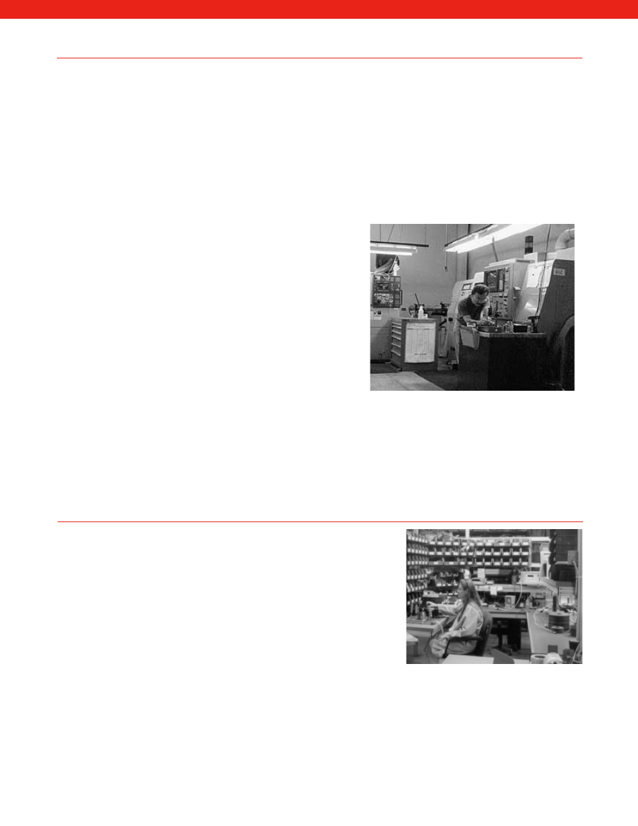
Honeywell Sensotec… manufacturing
excellence sets us apart from the
competition.
At Sensotec much of the design,
manufacturing, assembly, testing and
calibration is done in house. This enables
Sensotec to have complete control over the
manufacturing process. At all stages of
production individual sensors are tracked
as they go through each stage of the
manufacturing process. Individual product
testing records are maintained during
manufacture. Several times throughout
manufacture, transducers and instruments
are tested in environmental chambers or
fixtures that simulate the customer’s exact
field conditions.
Honeywell’s facility in Columbus, Ohio
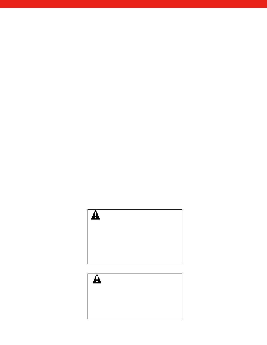
Automotive industry instrumentation.
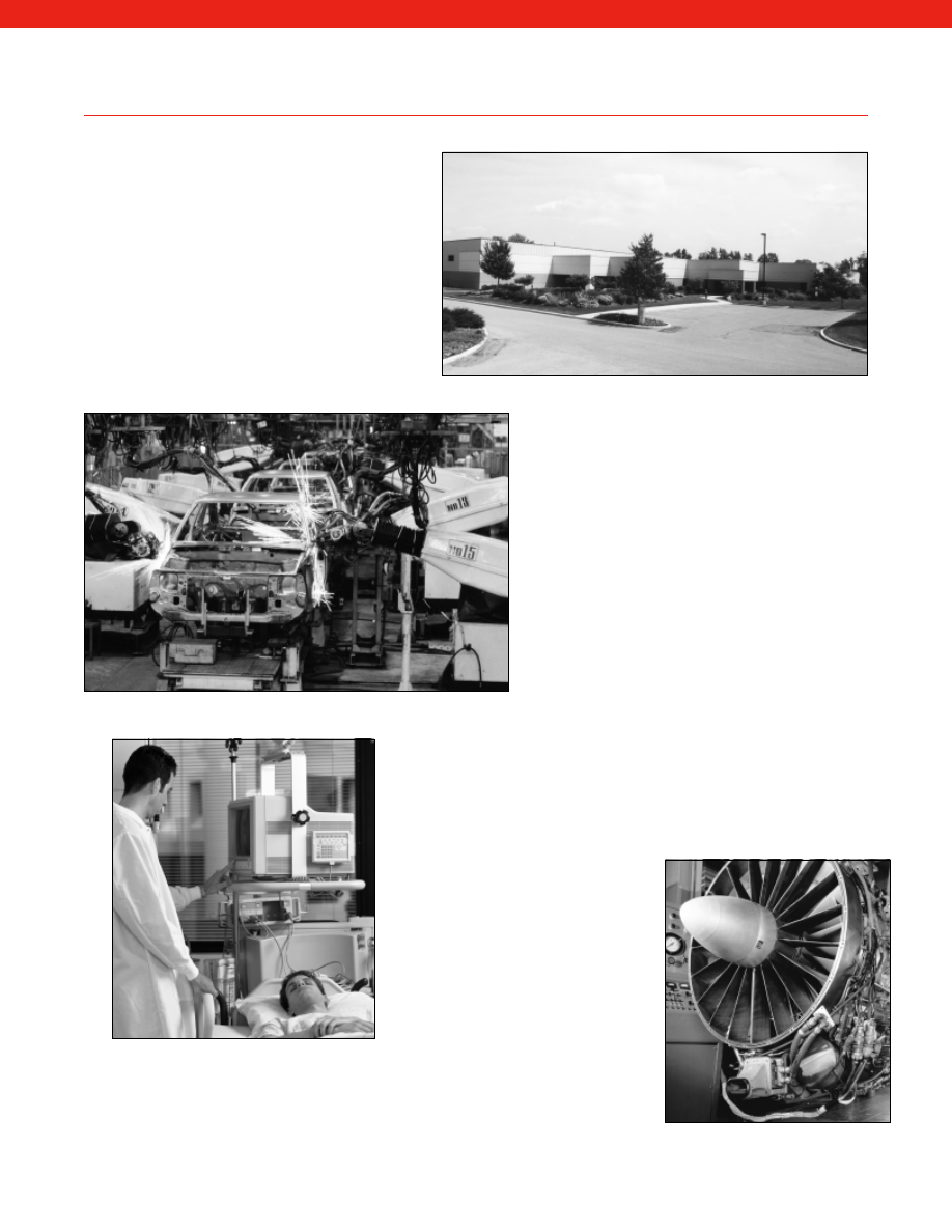
Sensotec supplies many medical
instrument manufacturers.
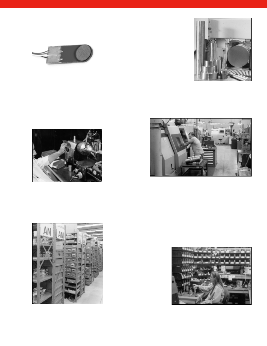
Jet engine and gas turbine monitoring.
www.honeywell.com/sensotec
1-888-282-9891
Courtesy of Steven Engineering, Inc.-230 Ryan Way, South San Francisco, CA 94080-6370-Main Office: (650) 588-9200-Outside Local Area: (800) 258-9200-www.stevenengineering.com
Sensotec Sensors Full Line Catalog-html.html
5
Honeywell Sensotec…sensors and instrumentation when you need them.
Sensotec’s stocking program is based on having
thousands of finished and calibrated pressure, load,
acceleration, transducers and associated
instrumentation available on the shelf for immediate
delivery. Those products available in the stocking
program are listed in the catalog and regularly
updated on the website. The FP2000 Pressure
Sensor is a unique new concept in producing a
tailored product in a very short delivery time. We have found that customers often need
products with a particular connector, wiring code, output, pressure port, but they need
delivery quickly. Tailoring an FP2000 model to meet each customers needs does not mean
long delivery. The Sensotec FP2000 manufacturing cells have an inventory of pre-tested
modular sub assemblies. As soon as the order hits the manufacturing cell your transducer is built from these interchangeable
sub assemblies in a matter of days. The result is a pressure transducer for your specific requirements in short time delivery.
Sensotec offers the most sophisticated and extensive Custom Engineering capabilities in the test and measurement industry
and allows us to expand the product range “outside the catalog”.
Our customer special products program works because we have
an internal culture of process and people that can respond to
small batch sizes. Our
in-house manufacturing,
flexible designs and
technologies are
structured to support
this extensive custom
engineering program.
Whether you need a
simple modification of a
standard product or
complete customized
engineering product, we
are organized to
accommodate your special product request.
Honeywell Sensotec…keeping ahead of fast growing markets by constant investment in engineering and product
development.
Sensotec is at heart a production engineering facility. We know that that the key to sustained growth and customer
satisfaction is a strong engineering foundation that is responsive to be able to meet customer delivery dates. Every year
Sensotec invests more and more in engineering and manufacturing to ensure our
designs and assembly processes continue to be at the forefront of the industry.
Sensotec embraces the new technologies of ASIC chips, smart transducers, micro
machining, digital compensation and wireless technology and fits them into the
constantly evolving product line. The use of lean manufacturing processes and the
latest in engineering software tools
ensure we stay ahead of the
competition by bringing fast
delivery, customer configured and
technologically advanced products.
Honeywell Sensotec… quality
control by involvement of
everyone in the company.
Sensotec has a stringent quality
control regime that governs the way
the whole company operates. This
all encompassing quality control
program is based on and certified in
ISO 9001:2000 standards.
The original patented miniature
pressure transducer.
Sensotec transducers are
manufactured from stainless steel.
Welding technology for hermetic sealing of
transducers.
Sensotec machine shop and prototype workshop.
Extensive stock ensures next day shipment
for a large portion of our customer orders.
FP2000 manufacturing cells provide total customer
configurable transducers.
www.honeywell.com/sensotec
1-888-282-9891
Courtesy of Steven Engineering, Inc.-230 Ryan Way, South San Francisco, CA 94080-6370-Main Office: (650) 588-9200-Outside Local Area: (800) 258-9200-www.stevenengineering.com
Sensotec Sensors Full Line Catalog-html.html
6
Honeywell Sensing and Control is a worldwide leader in
advanced switching and sensing technology and our
reputation for technology, quality and reliability is second to
none. Honeywell is a recognized technology leader in the
development and manufacture of pressure and position-
sensing transducers and controls, as well as speed and
position sensors for the industrial marketplace.
Marine propulsion monitoring.
Stringent process control and ongoing inspections ensures quality
and reliability.
Sensotec supplies specially designed
sensors for harsh applications.
Weld automation and control.
www.honeywell.com/sensotec
1-888-282-9891
Our final inspection and testing is based upon ANSI
Z540-1and NIST traceable standards. Like all good
quality control programs Sensotec’s procedures are
based on constant quality audits and self-improvement
programs.
Honeywell Sensotec…customer service is the
sustainable competitive advantage that our people
strive to maintain every working hour of their day.
We are dedicated to providing responsive local support
where it is needed. At Sensotec we believe in working in
a consultative partnership with our customers. All of our
application engineers, service engineers and sales
people are trained in our products,
applications and our customer’s needs.
Customers can use our website www.honeywell.com/sensing or
www.sensotec.com as a resource, they can call into our
technical sales engineers and application engineers or they can
call our customer service hotline. Our aim is to be your choice
as business partner because we care about customer service.
Honeywell Sensotec…known by the company it keeps.
One of the first internally
amplified pressure sensors.
Our engineering capability can design custom built
transducers for your unique requirements.
Sensotec transducers undergo
extensive environmental testing
during manufacture.
Courtesy of Steven Engineering, Inc.-230 Ryan Way, South San Francisco, CA 94080-6370-Main Office: (650) 588-9200-Outside Local Area: (800) 258-9200-www.stevenengineering.com
Sensotec Sensors Full Line Catalog-html.html
7
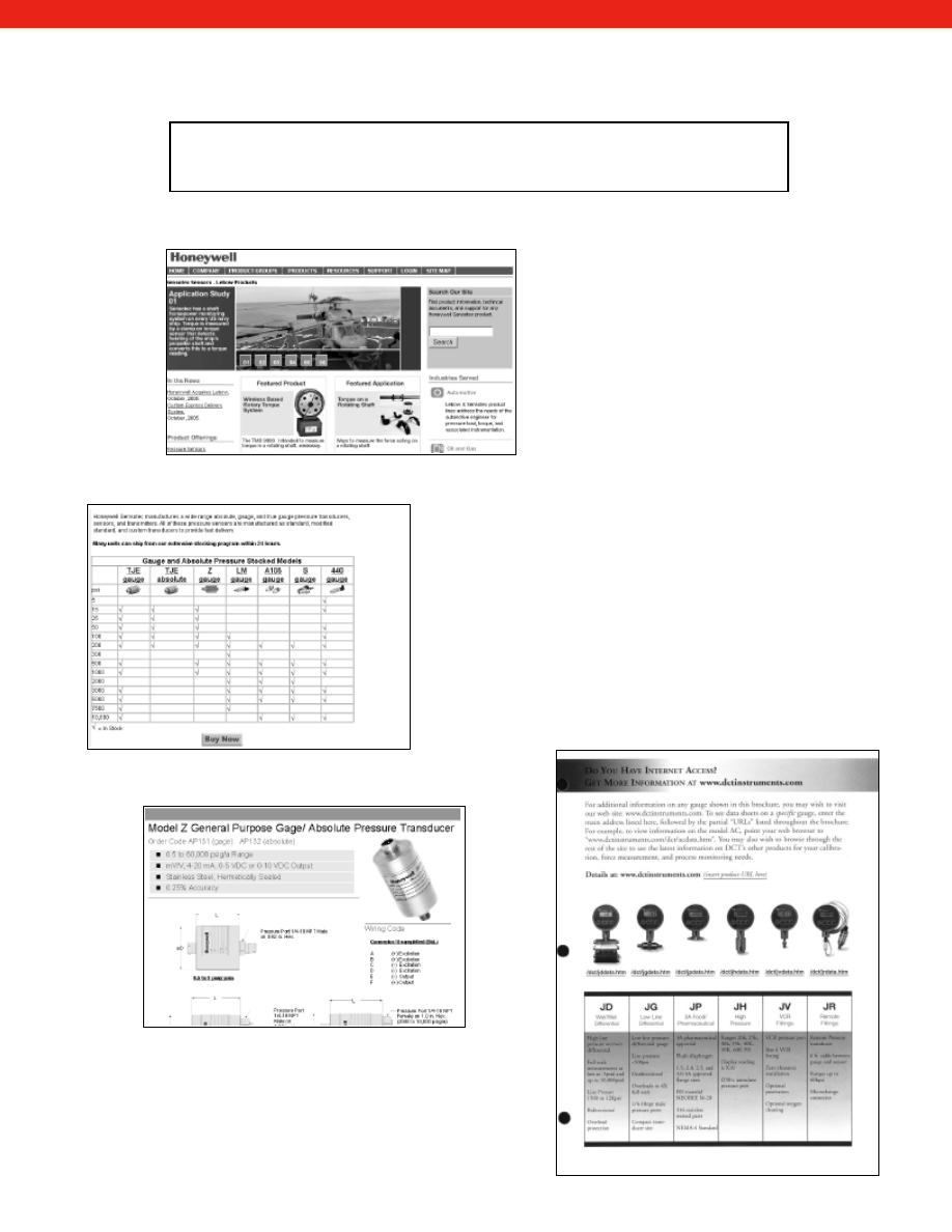
Honeywell Sensotec on the Web
www.honeywell.com/sensing
www.sensotec.com
Bookmark Us Today as Your Sensor Supplier and Resource
Sensotec Home Page
Sensotec Stocking Program and Online Purchasing
Download Datasheets and user Manuals Online
Linking Literature to
More Detailed
Information
Visit www.honeywell.com/sensing or
www.sensotec.com to get all the latest product
news and information from the people who
understand sensors, test and measurement and
customer service!
The site is continually being updated to provide the
latest information. At www.honeywell.com/sensing
or www.sensotec.com you can access detailed
data sheets, view new product releases, or locate
the nearest Sensotec Representative. Existing
customers can download instruction manuals or
obtain return material authorization to ensure
speedy repairs or calibration. You can even order
products on line! Browse through our extensive
stocking program and, with your credit card handy,
you can painlessly be on your way to next day
delivery.
You can also configure your own FP2000 pressure
transducer from one of 19,000 permutations. Day
or night you can order a specially-configured
FP2000 transducer to meet the needs of your
application. And FP2000 delivery is guaranteed in
only 2 weeks!
Whatever your needs, www.sensotec.com is a
resource that you should be making the most of.
Bookmark and return to the site whenever you
need sensor information.
www.honeywell.com/sensotec
1-888-282-9891
Courtesy of Steven Engineering, Inc.-230 Ryan Way, South San Francisco, CA 94080-6370-Main Office: (650) 588-9200-Outside Local Area: (800) 258-9200-www.stevenengineering.com
Sensotec Sensors Full Line Catalog-html.html
8
www.honeywell.com/sensotec
1-888-282-9891
Fast Delivery
Test & Measurement
High
Industrial
Precision
OEM
Miniature
Wet/Wet Differential
Special Application
Low Profile
Miniature
Multi-Function Applications
Custom
Specials
Customer Configurable
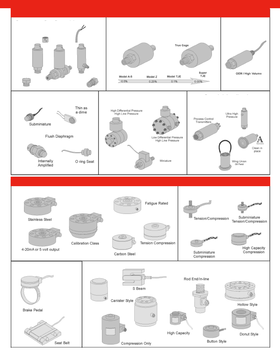
Pressure
Load
Courtesy of Steven Engineering, Inc.-230 Ryan Way, South San Francisco, CA 94080-6370-Main Office: (650) 588-9200-Outside Local Area: (800) 258-9200-www.stevenengineering.com
Sensotec Sensors Full Line Catalog-html.html
9
www.honeywell.com/sensotec
1-888-282-9891
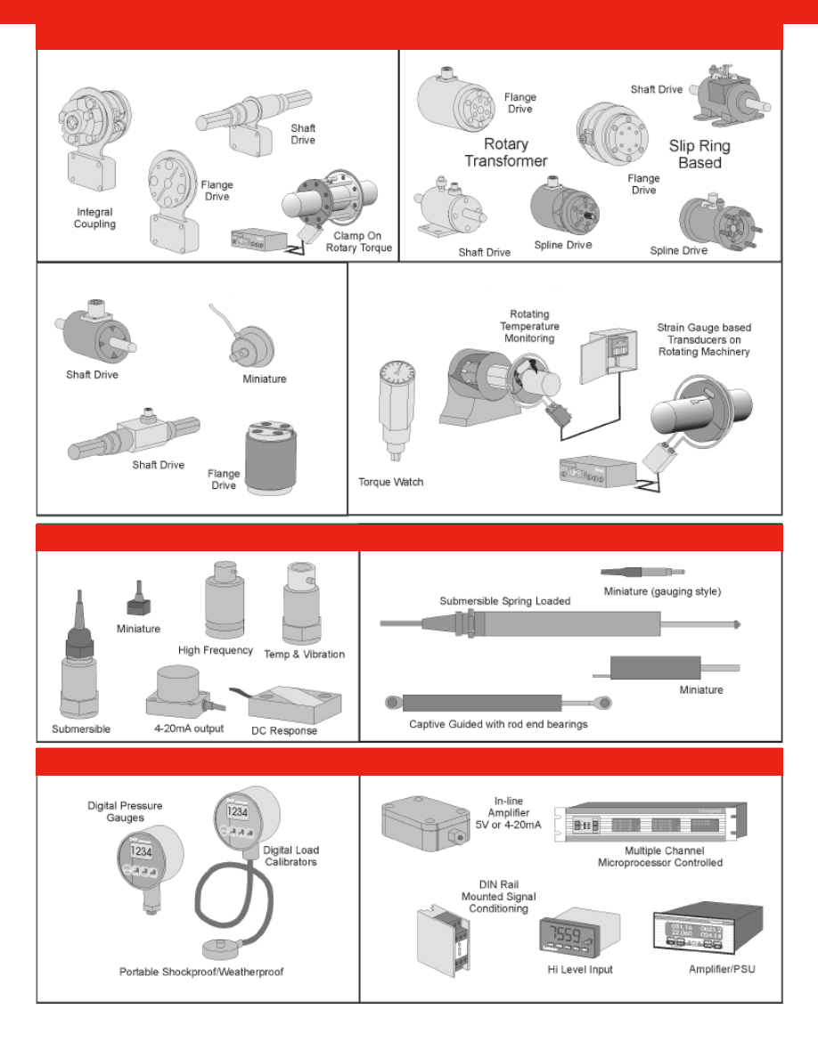
Wireless Telemetry Rotary Torque
Rotary Torque
Reaction Torque
Special Applications
Torque
Accelerometers
LVDTs
Digital Gauges
Instrumentation
Courtesy of Steven Engineering, Inc.-230 Ryan Way, South San Francisco, CA 94080-6370-Main Office: (650) 588-9200-Outside Local Area: (800) 258-9200-www.stevenengineering.com
Sensotec Sensors Full Line Catalog-html.html
10
www.honeywell.com/sensotec
1-888-282-9891
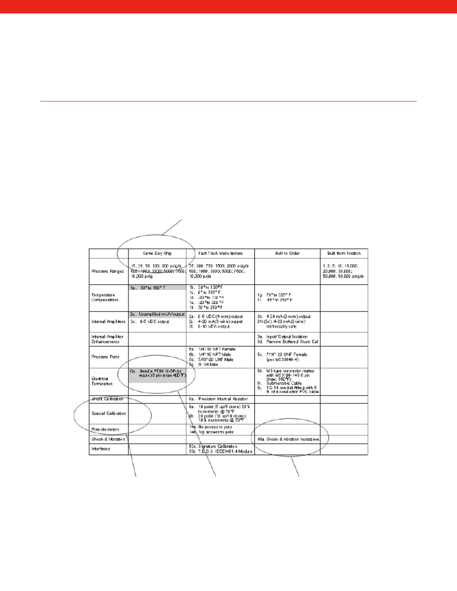
Flexibility is the Cornerstone of Honeywell’s Sensotec Sensors
Honeywell Sensotec offers a wide array of product and delivery options to meet even the most
stringent requirements. From same day shipping of stock items to custom designed and built
from scratch, Honeywell Sensotec offers you an option to fit your needs.
Delivery Program for which the selected
production and option is supplied.
Options Category Gray indicates Specific option (with option
standard options code) in the delivery column
under which it is supplied.
Meeting Design Challenges
We step up to the design challenge and aim to meet almost any need. For some applications, it is a situation where our team
works with you to develop the necessary sensor to fit your requirements and we manufacture the sensor. In other cases, your
needs can be easily met by configuring standard products. Sensotec has 185 standard products. Each of those products can
be configured to meet most requirements. As an example, each model listed in this catalog has typically 12 different ranges.
Additionally, each model has typically 5 different amplifiers and typically 4 different temperature compensations. A model can
have an average of 4 electrical termination options and as many as 6 different pressure ports. Plus there are 5 other
miscellaneous categories with 2 options in each. That means each model in the catalog has approximately 921,000 different
permutations. With 229 models in the catalog this gives you the option of 210 million different permutations that can be
ordered to meet your needs.
The products listed in this catalog are only part of the story. Most sensor manufacturers' story ends after the
standard products chapter. Honeywell Sensotec’s sensor capability extends beyond the standard published
product catalog, which is only about 50 percent of what we actually build.
Courtesy of Steven Engineering, Inc.-230 Ryan Way, South San Francisco, CA 94080-6370-Main Office: (650) 588-9200-Outside Local Area: (800) 258-9200-www.stevenengineering.com
Sensotec Sensors Full Line Catalog-html.html
11
Honeywell offers a variety of delivery options to meet your needs. If you need fast delivery, our same day shipping program is
designed to help you. We offer Same Day Ship, Fast Track Manufacture, Built to Order and Built From Scratch programs on
key products to help you meet your schedules. Not all customer needs and time tables are the same and that is exactly why
we have developed these delivery programs.
Fast Track Program
Our fast track program is designed to give you “Made to Order Product” from the millions of permutations available. We have
committed additional resources to be able to offer you quicker delivery for engineered products. We accomplish this through
utilizing common sub assemblies that have been pre-tested and are in stock. With the Fast Track program you have the ability
to have special options or requirements. Yet, your projected delivery will only be 2 to 6 weeks depending on the degree of
customization required.
Built to Order
We also will configure your order to your requirements. Many times,
customers will a solution to their that requires options that are not as
common. Generally, the products that fall in this category have
components kept in stock. All that is required is for us to take these
components and build a sensor to your selected configuration. The
estimated delivery time is 6 to 8 weeks.
Built From Scratch
Our “Built From Scratch” program is for products without a predictable
annual usage but can still be considered standard product. As annual
usages are low many components are not stocked so they have to be
sourced and fabricated upon receipt of an order. However, our
experience in building these products and the relationships we have
with our many vendors will help shorten the delivery time. Generally,
an engineered order takes approximately 10-12 weeks for delivery.
Custom Designed
Honeywell Sensotec offers the most sophisticated and extensive Custom Engineering capabilities in the test and
measurement industry and allows us to expand the product range “outside the catalog”. Our experience in designing and
building custom sensors began in the late 60’s and continues today with modified standard products, or complete custom
solutions for difficult sensor requirements. Every year Honeywell Sensotec supplies nearly 100,000 sensors to our industrial
markets of which 30-40% will have some customized feature. The chances are that whatever your pressure, load, torque,
displacement or vibration application that we have encountered the problem before and have already found the solution.
Delivery Options to Meet Your Needs
One of the keys to success in manufacturing specials
is to have the ability to quickly produce prototypes.
Flexible Design Capability
The manufacturing of the FP2000 series pressure sensors starts with the completion of the FP2000 configurator. The
configurator is sent directly to one of the FP2000 manufacturing cells. The manufacturing cell is completely self contained. All
of the subassemblies for each of the 49 different configurations (that’s 25,000 different permutations) are stored in bins at the
cell and are constantly replenished. The cell technician kits the parts, assembles the sensors, welds them, tests them and
packs the units ready for fast delivery.
Our Model FP 2000 pressure sensors and Model 41 load cells are available
through our Custom Express delivery Program. Our Custom Express Delivery
program offers guarantees a 2 week delivery on products that the customer
configures using a “features configurator” to meet their unique needs.
Many of the pressure sensors and load cells that we build today are built-up (all
welded) from groups of pre-engineered and pre-tested subassemblies with over
25,000 specification possibilities from just the FP2000 Series Pressure Sensors
alone. The modular design of many of these sensors allows the customer to have
the flexibility of selecting a modified standard, or a custom sensor configured from
standard components.
The FP2000 Manufacturing cell. Custom
configuration with fast delivery.
www.honeywell.com/sensotec
1-888-282-9891
Courtesy of Steven Engineering, Inc.-230 Ryan Way, South San Francisco, CA 94080-6370-Main Office: (650) 588-9200-Outside Local Area: (800) 258-9200-www.stevenengineering.com
Sensotec Sensors Full Line Catalog-html.html
12
www.honeywell.com/sensotec
1-888-282-9891
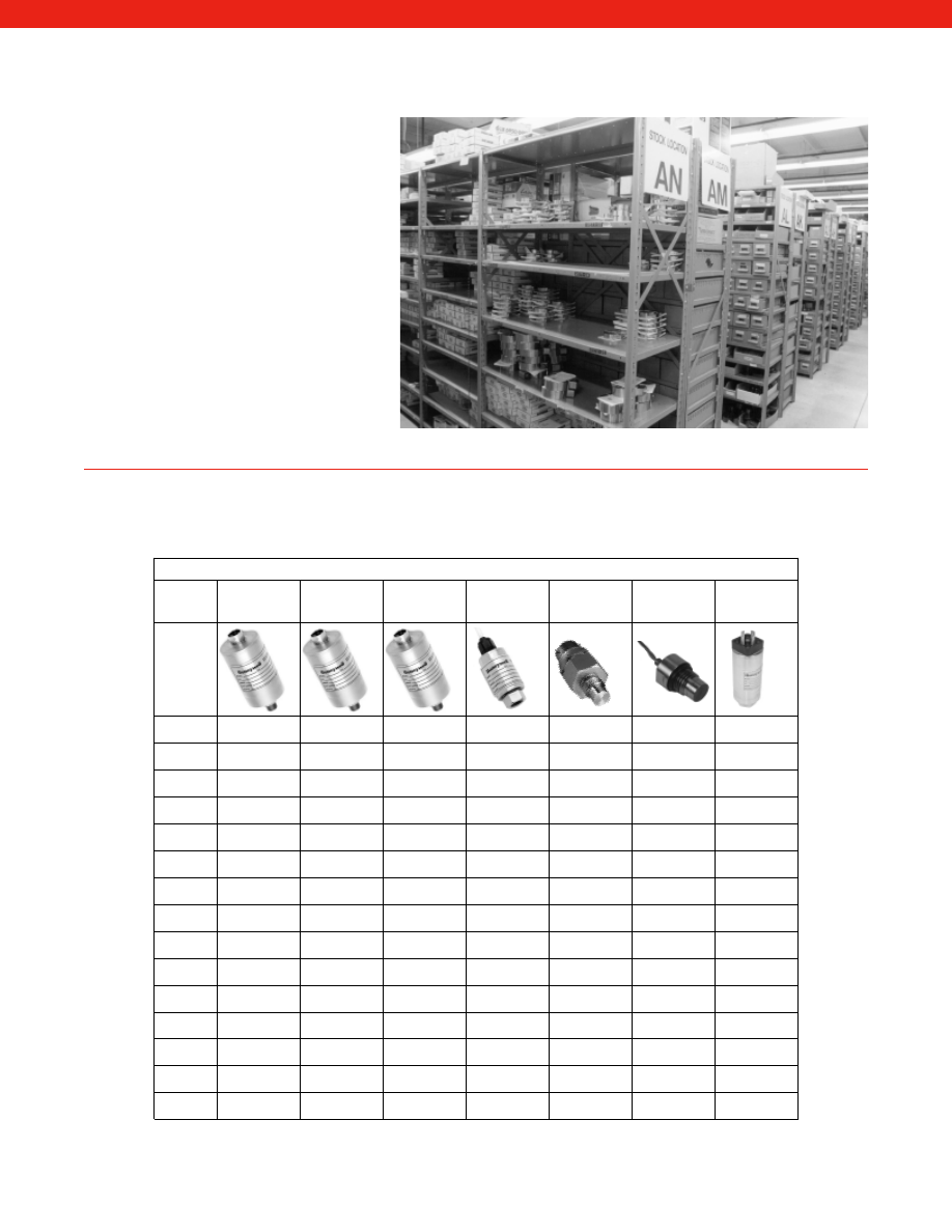
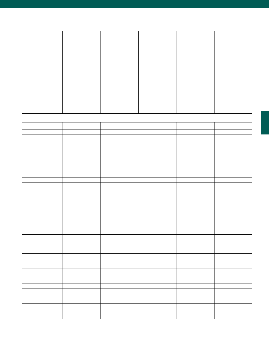
Same Day Ship Program
Pressure
Honeywell Sensotec manufactures a wide range absolute, gauge, and true gauge pressure transducers, sensors, and
transmitters. All of these pressure sensors are manufactured as standard, modified standard, and custom transducers
to provide fast delivery.
Gauge and Absolute Pressure Stocked Models
TJE
gauge
TJE
absolute
Z
gauge
LM
gauge
A105
gauge
S
gauge
440
gauge
psi
5
x
10
x
x
x
x
15
x
x
x
25
x
x
x
50
x
x
x
x
100
x
x
x
x
x
200
x
x
x
x
x
x
x
300
x
500
x
x
x
x
x
x
1000
x
x
x
x
x
x
2000
x
x
x
3000
x
x
x
x
x
5000
x
x
x
x
x
7500
x
x
10,000
x
x
x
x
x
= In Stock
The Honeywell Sensotec stocking program
includes thousands of finished transducers,
load cells, accelerometers, LVDTS,
instrumentation and amplifiers in a wide variety
of models and ranges. This stock diversity
readily accommodates most applications, and
provides immediate solutions to your urgent
challenges. Orders for stock complete units
placed before Noon can ship the same day –
at no additional cost to you!
Many pre-assembled, temperature compensated and pre-tested subassemblies are
stocked at Honeywell Sensotec to aid fast delivery.
Courtesy of Steven Engineering, Inc.-230 Ryan Way, South San Francisco, CA 94080-6370-Main Office: (650) 588-9200-Outside Local Area: (800) 258-9200-www.stevenengineering.com
Sensotec Sensors Full Line Catalog-html.html
13
www.honeywell.com/sensotec
1-888-282-9891
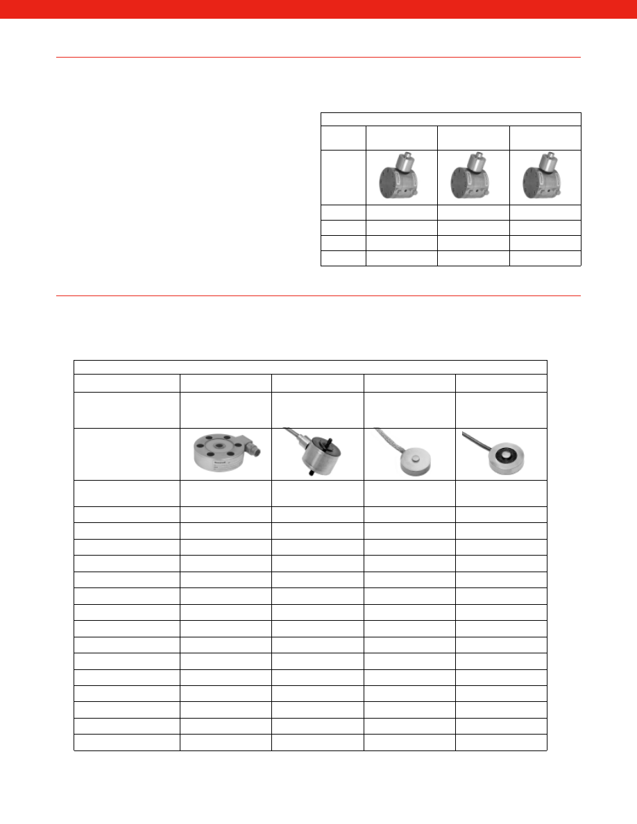
Load Cells
Our load cells are stocked in a variety of configurations to suit customer needs. These industrially rugged load cells are
constructed from stainless steel and are hermetically welded to insure performance in the most hostile environments.
The stocking program includes miniature load cell units in compression only or tension and compression models.
Load Cell Stocked Models
Model 41
Model 31
Model 13
Model 53
Low Profile, Hermetic,
Stainless
Welded, Stainless,
Rugged, Miniature
Subminiature,
Height 0.12” to 0.30”,
High Frequency
Low Cost, Stainless
Accuracy
(+/-%F.S.)
0.1%
0.2%
0.25%
0.25%
250 grams
x
1000 grams
x
x
5 lbs.
x
10 lbs.
x
x
25 lbs.
x
x
50 lbs.
x
x
x
100 lbs.
x
x
x
250 lbs.
x
x
500 lbs.
x
x
x
x
1000 lbs.
x
x
x
x
2000 lbs.
x
x
5000 lbs.
x
x
10,000 lbs.
x
x
20,000 lbs.
x
50,000 lbs.
x
x
x
= In Stock
Differential Pressure
Honeywell Sensotec manufactures a wide range of wet/wet and wet/dry differential pressure transducers, sensors, and
transmitters. These differential sensors are manufactured to provide the fastest possible delivery. Many of these pressure
sensors can ship from our extensive stocking program within 24 hours.
Honeywell Sensotec offers a wide range of transducer
technologies such as bonded foil, semiconductor, sputtered,
etc., so that your sensor will provide the best measurements
possible given the conditions encountered.
Differential Pressure Stocked Models
TJE
wet/wet
Z
wet/wet
A-5
wet/wet
psi
50
x
x
x
100
x
x
x
200
x
x
x
500
x
x
x
x
= In Stock
Courtesy of Steven Engineering, Inc.-230 Ryan Way, South San Francisco, CA 94080-6370-Main Office: (650) 588-9200-Outside Local Area: (800) 258-9200-www.stevenengineering.com
Sensotec Sensors Full Line Catalog-html.html
14
www.honeywell.com/sensotec
1-888-282-9891
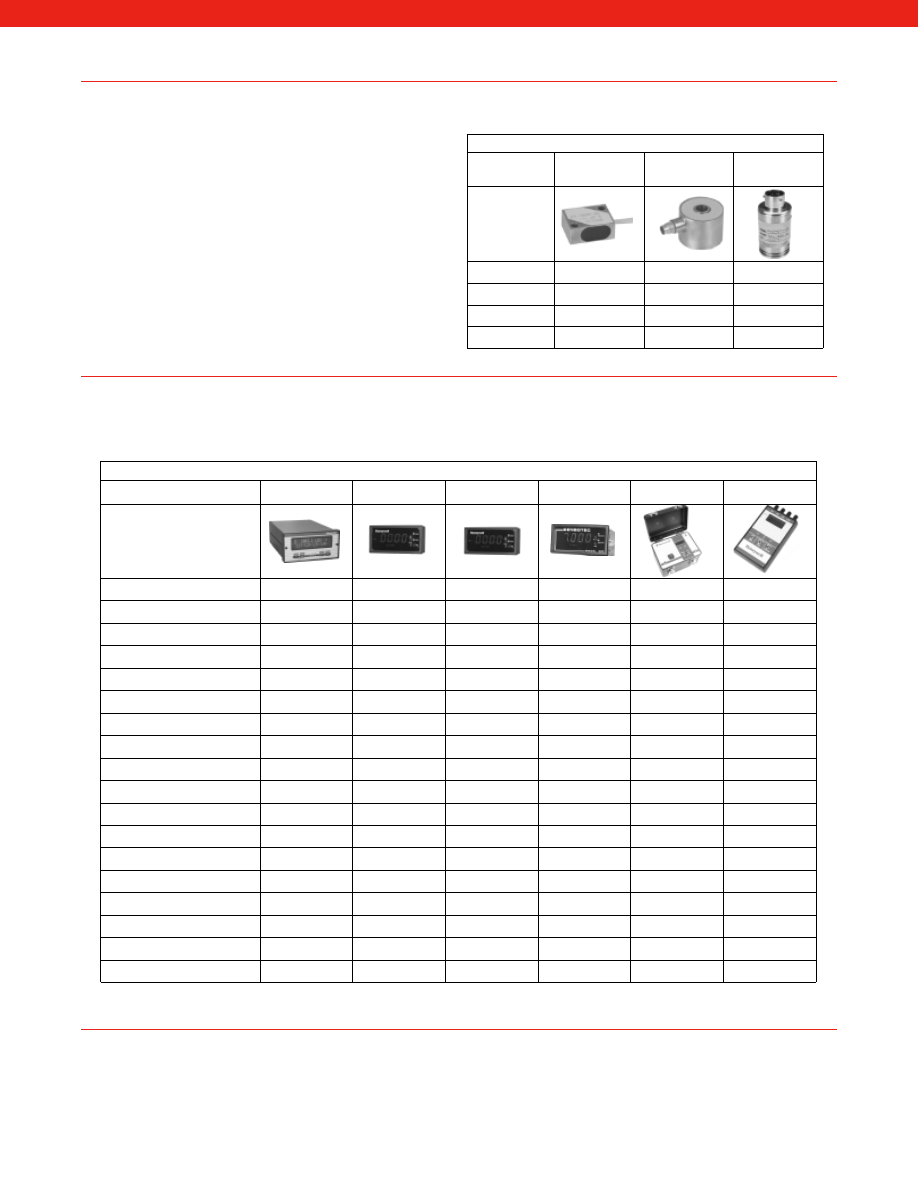
Instrumentation
Honeywell Sensotec manufactures a wide range of low to medium priced instruments including single-channel, multi-channel,
and microprocessor-based units. These instruments are manufactured as standard and modified standard units to provide the
fastest possible delivery.
Instrumentation Stocked Models
SC
GM
GM-A
DM
NK
HH
RS 232 Output
x
x
+/- VDC Output
x
x
x
x
4-20mA Output
x
x
x
5-40mV F.S. Input
x
x
x
x
5 VDC F.S. Input
x
x
x
0-2 VDC Input
x
x
6 Digit Display
x
4 1/2 Digit Display
x
x
x
x
3 1/2 Digit Display
x
Dummy Zero
x
x
x
Peak and Hold
x
x
x
x
Limits
x
x
x
Switchable Gain
x
x
x
x
Shunt Calibration
x
x
x
Auto Zero
x
Signature Calibration
x
100% Tare
x
Can Drive 4 Sensors
x
x
= In Stock
x
= Available with Short Lead Time
All of Honeywell Sensotec products are ISO9001:2000 Registered and Atex Certified where appropriate. These certifications
and implementation of Six Sigma Quality programs ensure that both the product and delivery are at optimal levels.
Honeywell Sensotec provides customers with a single source for the measurement of load, pressure, position, torque and
vibration. Our expertise in design and production planning gives you the flexibility you need to meet your needs.
Accelerometer Stocked Models
JTF
Flat Pack
JTF
Donut
PA
Internal Amp.
Piezoelectric
x
Strain Gauge
x
x
10G
x
x
50G
x
x
x
= In Stock
Accelerometers
We offer both strain gauge and piezoelectric accelerometers aimed to provide you the best measurements possible given
the conditions encountered.
Our accelerometers measure a wide range of frequencies and
are available with a range of outputs are as varied as any
manufacturer in the world.
Courtesy of Steven Engineering, Inc.-230 Ryan Way, South San Francisco, CA 94080-6370-Main Office: (650) 588-9200-Outside Local Area: (800) 258-9200-www.stevenengineering.com
Sensotec Sensors Full Line Catalog-html.html
15
www.honeywell.com/sensotec
1-888-282-9891
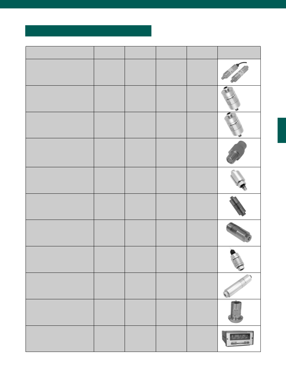
PRESSURE TRANSDUCERS
Potential Application
Model
Order Code
Accuracy
Page
Quick Ship
FP2000
FPA,FPB,FPG,
FPV,FDD,FDW
0.10% - 0.25%
16
General Purpose
A-5
Z
TJE
AP141,AP142
AP131,AP132
AP121,AP122
0.5%
0.25%
0.1%
21
25
29
Ultra High Accuracy
Super TJE
AP111,AP112
0.05%
33
Miniature Flush
Diaphragm
S
G
F
A-105
A-105a
A-205
A-205a
BP357,BP358
BP386,BP387
BP340-BP346
AP311
AP313-AP318
BP312
BP314-316
1%
1%
1%
0.5%
0.5%
0.5%
0.5%
36
39
42
45
48
50
52
Flush Diaphragm
355
BP313
0.25%
54
Transmitters
440
415
811
AP415,AP416
AP411,AP412
BP421,BP422
0.2%
0.1%
0.25%
57
60
63
High Pressure
HP
BP521
0.5%
65
OEM
LM
BDR
LCP
BP211
BP217
BP223,BP224
0.10%
0.5% - 0.75%
1%
68
70
73
Digital O/P
DS
AP611-AP614
0.1%
75
Special Applications
LL-V
CIP-Ultra
424
425
AS17A
AS19G
BP712
see datasheet
BP424
BP425
AP161
AP162
0.1%
0.15% - 0.5%
0.25%
0.25%
0.15%
0.15%
77
79
82
84
86
86
Calibration
Accugage
AG400,AG401 0.05% - 0.10%
88
Courtesy of Steven Engineering, Inc.-230 Ryan Way, South San Francisco, CA 94080-6370-Main Office: (650) 588-9200-Outside Local Area: (800) 258-9200-www.stevenengineering.com
Sensotec Sensors Full Line Catalog-html.html
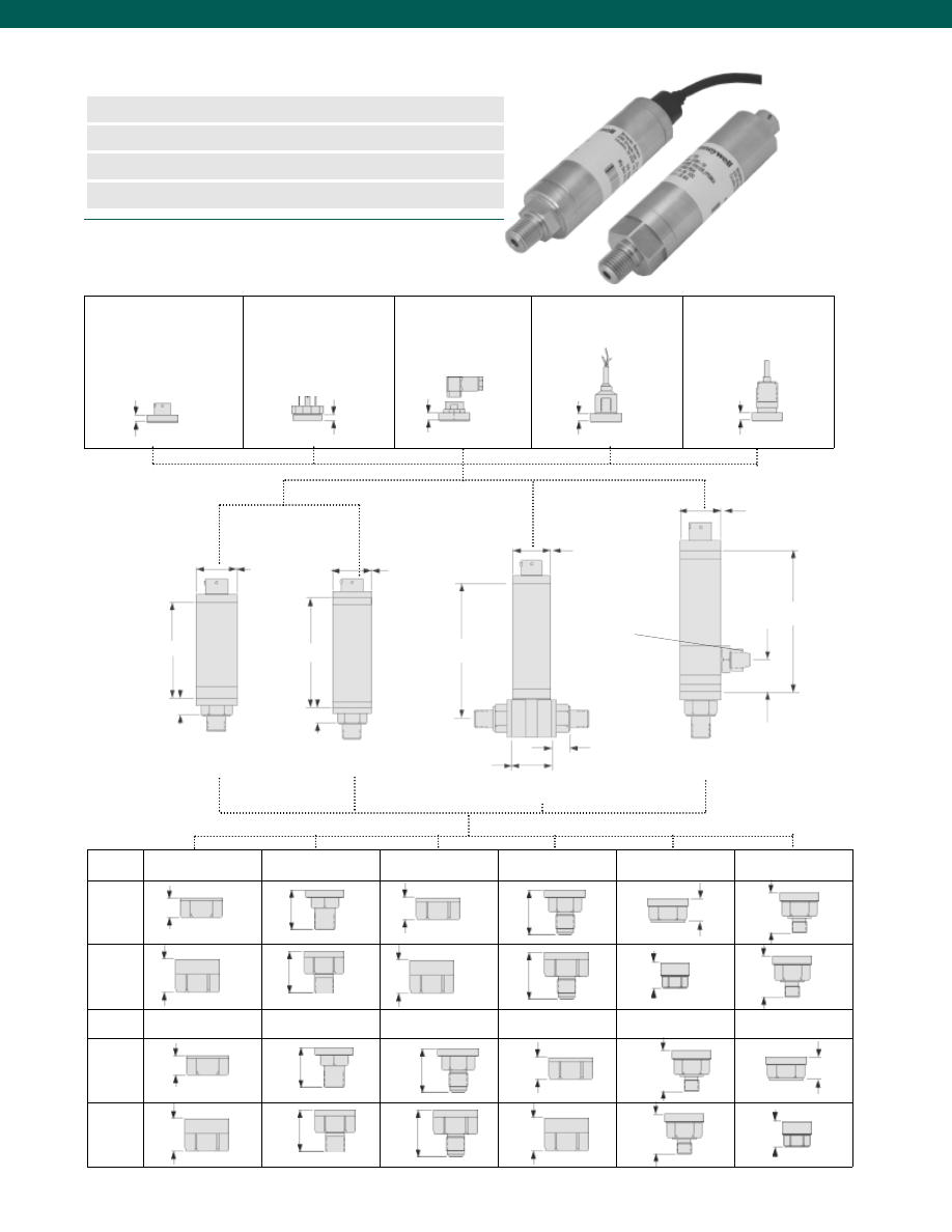
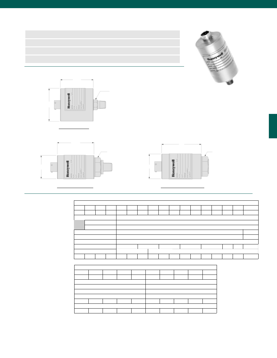
16
Dimensions
n
2-Week Delivery
n
mV/V, 0-5, 0-10 VDC, or 4-20 mA
n
Gage, Absolute, Barometric, Vacuum
n
Differential (Wet/ Wet, Wet/ Dry)
2.9 in.
0.5 in.
0.3 in.
0.2 in.
0.3 in.
0.3 in.
0.3 in.
ø1.13 in.
ø1.13 in.
ø1.13 in.
ø1.13 in.
3.2 in.
3.8 in.
1.5 in.
0.5 in.
4.1 in.
0.9 in.
0.5 in.
Code 6a
6-Pin, Vented,
Bendix Style
Code 6m
4-Pin, Vented,
Standard DIN (43650)
Code 6n
4-Pin, Vented,
Mini DIN
Code 6q
4-Conductor, Vented,
Integral Cable, 5 ft.
Code 6r
4-Conductor, Vented,
Integral Cable,
Conduit Fitting 5 ft.
www.honeywell.com/sensotec
1-888-282-9891
1.3”
Code 5a
1/4-18 NPT Female
Code 5b
1/4-18 NPT Male
Code 5c
7/16-20 UNF Female
Code 5d
7/16-20 UNF Male
Code 5f
G 1/4 B Female
Code 5g
G 1/4 B Male
Le
ss
th
an
10
00
ps
i
G
re
at
er
th
an
15
00
ps
i
0.5”
1.0”
1.1”
0.6”
1.0”
1.0”
1.3”
1.0”
0.7”
1.2”
1.2”
Electrical Termination
Greater than
or Equal to 15 psi
FPA; FPG; FPB; FPV
FDW
FDD
Pressure Ports
Less than
or Equal to 5 psi
7/16-20 UN
Not Selectable
Wet/Wet
Differential
Wet/Dry
Differential
Model FP2000 Configurable Pressure Transducers
Order Code (see below)
1.12”
Le
ss
th
an
10
00
ps
i
G
re
at
er
th
an
15
00
ps
i
0.525”
1.05”
0.905”
0.500”
1.05”
1.025”
1.32”
1.05”
0.625”
1.075”
1.353”
Code 5h
1/8-27 NPT Female
Code 5i
1/8-27 NPT Male
Code 5p
M12-1.5 Male
Code 5q
M12-1.5 Female
Code 5r
9/16-18 SAE Male
Code 5s
9/16-18 SAE Female
Courtesy of Steven Engineering, Inc.-230 Ryan Way, South San Francisco, CA 94080-6370-Main Office: (650) 588-9200-Outside Local Area: (800) 258-9200-www.stevenengineering.com
Sensotec Sensors Full Line Catalog-html.html

17
www.honeywell.com/sensotec
1-888-282-9891
Model FP2000
Performance
psi Range
Code
torr Range
Code
mBar Range
Code
kPa Range
Code
Bar Range
Code
in Hg Range
Code
mm Hg Range
Code
in H
2
O Range
Code
Gage, Absolute
(Order Codes
FPG, FPA)
0.5*
AN
1*
AP
2*
AR
2.5*
AS
5
AT
10
AV
15
BJ
25
BL
30
BM
50
BN
75
BP
100
BR
150
CJ
200
CL
150
CN
300
CP
400
CQ
500
CR
600
CS
750
CT
1000 CV
1500 DJ
2000 DL
2500 DM
3000 DN
5000 DR
6000 DS
7500 DT
10000 DV
15
HA
50
HB
135
HC
250
HD
750
HE
1500 HF
35
JA
70
JB
175
JC
350
JD
700
JE
750
JF
1000 JG
3500 JH
7000 JI
10000 JK
2
KA
7
KB
15
KC
35
KD
70
KE
100
KF
200
KG
300
KH
700
KJ
1000 KL
1500 KM
1700 KN
2000 KP
3000 KQ
5000 KR
7000 KS
10000 KT
15000 KU
20000 KV
35000 KW
50000 KY
70000 KZ
0.035 MA
0.1
MB
0.2
MC
0.5
MD
1
ME
2
MF
3.5
NA
5
MG
7
NB
10
MH
20
MI
30
MJ
35
NC
50
MK
70
ND
100
ML
135
NE
350
NG
500
MM
700
NH
1
UB
2
UD
5
UF
10
UA
15
UC
20
UE
30
UG
50
UI
60
UK
80
UM
100
UP
200
UH
300
UJ
500
UL
1000 UN
0-32
US
16-32 UQ
26-32 UR
15
VA
50
VB
135
VC
250
VD
750
VE
1500 VF
5
WB
10
WA
20
WC
30
WE
50
WG
100
WI
120
WK
150
WM
200
WP
300
WR
500
WS
Barometric
(Order Code
FPB)
0-30
UG
16-32 UQ
26-32 UR
Vacuum
(Order Code
FPV)
1
AP
5
AT
10
AV
15
BJ
50
HB
135
HC
250
HD
750
HE
35
JA
70
JB
175
JC
350
JD
700
JE
750
JF
1000 JG
7
KB
15
KC
35
KD
100
KF
0.035 MA
0.1
MB
0.2
MC
0.5
MD
1
ME
10
UA
20
UE
30
UG
15
VA
50
VB
135
VC
250
VD
750
VE
10
WA
20
WC
30
WE
50
WG
100
WI
Differential
(Order Codes
FDD, FDW)
0.5
AN
1
AP
2
AR
2.5
AS
5
AT
10
AV
15
BJ
25
BL
30
BM
50
BN
75
BP
100
BR
150
CJ
200
CL
150
CN
300
CP
400
CQ
500
CR
600
CS
750
CT
1000 CV
15
HA
50
HB
135
HC
250
HD
750
HE
1500 HF
35
JA
70
JB
175
JC
350
JD
700
JE
750
JF
1000 JG
3500 JH
7000 JI
10000 JK
2
KA
7
KB
15
KC
35
KD
70
KE
100
KF
200
KG
300
KH
700
KJ
1000 KL
1500 KM
1700 KN
2000 KP
3000 KQ
5000 KR
7000 KS
10000 KT
15000 KU
20000 KV
35000 KW
50000 KY
0.035 MA
0.1
MB
0.2
MC
0.5
MD
1
ME
2
MF
3.5
NA
5
MG
7
NB
10
MH
20
MI
30
MJ
35
NC
50
MK
70
ND
100
ML
135
NE
350
NG
500
MM
1
UB
2
UD
5
UF
10
UA
15
UC
20
UE
30
UG
50
UI
60
UK
80
UM
100
UP
200
UH
300
UJ
500
UL
1000 UN
0-32
US
16-32 UQ
26-32 UR
15
VA
50
VB
135
VC
250
VD
750
VE
1500 VF
5
WB
10
WA
20
WC
30
WE
50
WG
100
WI
120
WK
150
WM
200
WP
300
WR
500
WS
Pressure Ranges &
Range codes
*0.5 to 2.5 psi ranges not available for absolute pressure
Courtesy of Steven Engineering, Inc.-230 Ryan Way, South San Francisco, CA 94080-6370-Main Office: (650) 588-9200-Outside Local Area: (800) 258-9200-www.stevenengineering.com
Sensotec Sensors Full Line Catalog-html.html
18
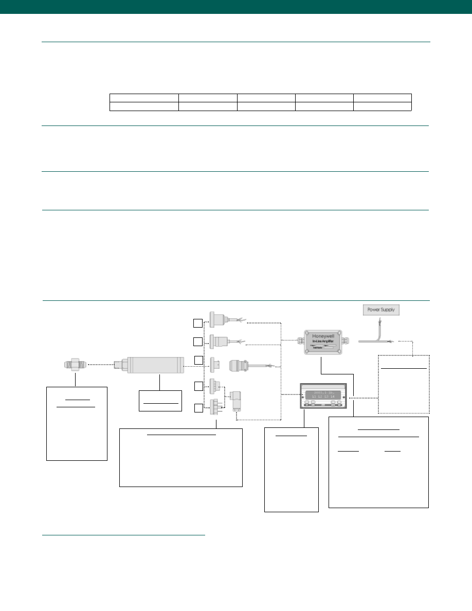
Typical System Diagram
www.honeywell.com/sensotec
Adaptors
Compatible with:
1/4-18 NPT Male
1/4-18 NPT Female
7/16-20 UNF Male
7/16-20 UNF Female
G 1/4 B Male
G 1/4 B Female
Model FP2000
Mating Connectors & Cables
PT06A-10-6S (option 6a)
mV/V - 4 conductor cable
4-20 mA - 3 conductor cable
0-5/ 0-10 VDC - 3 conductor cable
Standard DIN 43650 (option 6m)
Mini DIN 40050 (option 6n)
Display Units
SC500
SC1000
SC2000
SC2001
SC3004
GM (Unamp. only)
GM-A (Amp. only)
NK (Unamp. only)
HH (Unamp. only)
Customer Supplied
Chart Recorder
Alarm Panel
Data Acquisition
Computer
PLC
In-Line Amplifiers
(Used with unamplified units only)
Amplifier
Output
Universal In-Line Amplifiers
U2W
4-20 mA (2 wire)
6q
6r
6a
6n
6m
1-888-282-9891
Model FP2000
Accuracy (note 1)........See table below
Output (selectable)........mV/V (See table below), 0-5 VDC, 0-10 VDC, or 4-20 mA (2 wire)
Resolution........Infinite
0.10% accuracy
50 mV (note 4)
25 mV
40 mV
50 mV (note 4)
0.25% accuracy
100 mV
50 mV
80 mV
100 mV
Non-amplified output
@ 10 VDC excitation Gage & Absolute Vacuum Barometric Differential
Temperature, Operating........-40° to 240°F
Temperature, Compensated........40° to 140°F (note 2)
Temperature, Error Band (note 2)
0.10% accuracy........+/- 0.5% F.S.
0.25% accuracy........+/- 1.0% F.S.
Excitation (calibration)
Amplified (4-20 mA, 0-5 VDC)........9-28 VDC
Amplified (0-10 VDC)........15-28 VDC
Unamplified (mV/V)........10 VDC
Media (note 3)........Gas, Liquid
Overload-Safe
1000 psi and below........4x Full Scale or 3,000 psi, whichever is less
1500 psi and above........4x Full Scale or 15,000 psi, whichever is less
Negative Direction (for Differential)........4x Full Scale or 250 psi, whichever is less
Overload-Burst........300% over capacity
Pressure Port........200% over capacity
Wetted Parts Material........Ha C276 & 316L Stainless Steel
Performance
Environmental
Electrical
Mechanical
1. Accuracies stated are expected for Best Fit Straight Line for all errors, including linearity, hysteresis & non-repeatability thru zero.
2. For low pressure ranges, temperature effects may vary.
3. The Wet/Wet differential pressure transducer has two separate, welded Hastelloy diaphragms. In the Wet/Dry unit, the wet port (high port)
has all-welded stainless and Hastelloy construction. The dry port (low port) has no isolation diaphragm.
4. For low gage and differential pressure ranges at 0.10% accuracy, non-amplified output @ 10 VDC excitation = 100mV.
Notes
Courtesy of Steven Engineering, Inc.-230 Ryan Way, South San Francisco, CA 94080-6370-Main Office: (650) 588-9200-Outside Local Area: (800) 258-9200-www.stevenengineering.com
Sensotec Sensors Full Line Catalog-html.html
19
Internal Amplifiers
www.honeywell.com/sensotec
1-888-282-9891
Model FP2000
Wiring Codes
Amplifier
Specifications
Unamplified Output
Option 2u
Voltage Output
Option 2d
Voltage Output
Option 2g
Current 2 Wire
Option 2p
Intrinsically Safe Amp
2n (2N)***
Output Signal
Input Power (Voltage)
Input Power (Current)
Frequency Response
Power Supply Rejection
Operating Temperature
Reverse Voltage Protection
Short Circuit Protection
see table on previous page
10 VDC
2mA @ 10 VDC
Natural Frequency
N/A
-100° to 250°F
N/A
N/A
0-5 VDC
9-28 VDC
10mA
300Hz
60db
-20° to 185°F
Yes
Momentary
0-10 VDC
15-28VDC
15mA
300Hz
60db
-20° to 185°F
Yes
Momentary
4-20 mA
9-32 VDC
4-24 mA
300 Hz
60 db
-20° to 185° F
Yes
Yes
4-20 mA
9-28 VDC
4-24 mA
2000 Hz
60 db
-20° to 185° F
Yes
Yes
Amplifier
Specifications
Unamplified Output
Option 2u
Voltage Output
Option 2e
Voltage Output
Option 2f
Current 2 Wire
Option 2y
Intrinsically Safe Amp
2n (2N)***
Output Signal
Input Power (Voltage)
Input Power (Current)
Frequency Response
Power Supply Rejection
Operating Temperature
Reverse Voltage Protection
Short Circuit Protection
see table on previous page
10 VDC
2mA @ 10 VDC
Natural Frequency
N/A
-100° to 250°F
N/A
N/A
0-5 VDC
9-28 VDC
10mA
2000Hz
60db
-20° to 185°F
Yes
Momentary
0-10 VDC
15-28VDC
15mA
2000Hz
60db
-20° to 185°F
Yes
Momentary
4-20 mA
9-32 VDC
4-24 mA
2000 Hz
60 db
-20° to 185° F
Yes
Yes
4-20 mA
9-28 VDC
4-24 mA
2000 Hz
60 db
-20° to 185° F
Yes
Yes
Note: For Wiring Codes, R=Red; Bl = Black; W = White; G = Green.
Color specifies cable and letter or number specifies connection
*** See Sensotec website for most up-to-date information regarding Intrinsically Safe approvals ref. #008-0547-00.
Unamplified Output
Option 2u
Voltage Output
Option 2d/ 2e
Voltage Output
Option 2g/ 2f
Current 2 Wire
Option 2p/ 2y
Intrinsically Safe Amp
Option 2n (2N)***
Bendix PTIH-10-6P (Opt. 6a)
No Shunt Cal
A
(+) Excitation
B
(+) Excitation
C
(-) Excitation
D
(-) Excitation
E
(+) Output
F
(-) Output
A
(+) Supply
B
(-) Supply Return
C
(+) Output
D
(-) Output 0-5VDC
E
No Connection
F
No Connection
A
(+) Supply
B
(-) Supply Return
C
(+) Output
D
(-) Output 0-10VDC
E
No Connection
F
No Connection
A
(+) Supply
B
No Connection
C
No Connection
D
(+) Output 4-20 mA
E
No Connection
F
No Connection
A
(+) Supply
B
No Connection
C
No Connection
D
(+) Output 4-20 mA
E
Case Ground
F
No Connection
With Shunt Cal (Opt. 3d)
A
(+) Excitation
B
(-) Excitation
C
(+) Output
D
(-) Output
E
No Connection
F
Shunt Cal
A
(+) Supply
B
(-) Supply Return
C
(+) Output
D
(-) Output 0-5VDC
E
No Connection
F
Shunt Cal
A
(+) Supply
B
(-) Supply Return
C
(+) Output
D
(-) Output 0-10VDC
E
No Connection
F
Shunt Cal
A
(+) Supply
B
No Connection
C
No Connection
D
(+) Output 4-20 mA
E
No Connection
F
Shunt Cal
A
(+) Supply
B
No Connection
C
No Connection
D
(+) Output 4-20 mA
E
No Connection
F
Shunt Cal
Std. DIN 43650 (Opt. 6m)
No Shunt Cal
1
(+) Excitation
2
(+) Output
3
(-) Output
4
(-) Excitation
1
(+) Supply
2
(+) Output
3
Supply/ Output com.
GNDNo Connect. to case
1
(+) Supply
2
(+) Output
3
Supply/ Output com.
GNDNo Connect. to case
1
(+) Supply
2
(+) Output 4-20 mA
3
No Connection
GNDNo Connection
1
(+) Supply
2
(+) Output
3
Case Ground
With Shunt Cal (Opt. 3d)
Not Applicable
1
(+) Supply
2
(+) Output
3
Supply/ Output com.
GNDShunt Cal
1
(+) Supply
2
(+) Output
3
Supply/ Output com.
GNDShunt Cal
1
(+) Supply
2
(+) Output 4-20 mA
3
No Connection
GNDShunt Cal
1
(+) Supply
2
(+) Output
3
Case Ground
GNDShunt Cal
Mini DIN 40050 (Opt. 6n)
No Shunt Cal
1
(+) Excitation
2
(+) Output
3
(-) Output
4
(-) Excitation
1
(+) Supply
2
(+) Output
3
Supply/ Output com.
GNDNo Connect. to case
1
(+) Supply
2
(+) Output
3
Supply/ Output com.
GNDNo Connect. to case
1
(+) Supply
2
(+) Output 4-20 mA
3
No Connection
GNDNo Connection
1
(+) Supply
2
(+) Output
3
Case Ground
With Shunt Cal (Opt. 3d)
Not Applicable
1
(+) Supply
2
(+) Output
3
Supply/ Output com.
GNDShunt Cal
1
(+) Supply
2
(+) Output
3
Supply/ Output com.
GNDShunt Cal
1
(+) Supply
2
(+) Output 4-20 mA
3
No Connection
GNDShunt Cal
1
(+) Supply
2
(+) Output
3
Case Ground
GNDShunt Cal
5’ Integral Cable (Opt. 6q)
No Shunt Cal
R
(+) Excitation
Bl
(-) Excitation
G
(-) Output
W
(+) Output
R
(+) Supply
Bl
(-) Supply Return
G
(-) Output
W
(+) Output 0-5VDC
R
(+) Supply
Bl
(-) Supply Return
G
(-) Output
W
(+) Output 0-10VDC
R
(+) Supply
Bl
(+) Output 4-20 mA
R
(+) Supply
Bl
(+) Output 4-20 mA
W
Case Ground
With Shunt Cal (Opt. 3d)
Not Applicable
R
(+) Supply
Bl
(-) Supply Return
G
Shunt Cal
W
(+) Output 0-5VDC
R
(+) Supply
Bl
(-) Supply Return
G
Shunt Cal
W
(+) Output 0-10VDC
R
(+) Supply
Bl
(+) Output 4-20 mA
G
Shunt Cal
R
(+) Supply
Bl
(+) Output 4-20 mA
W
Case Ground
G
Shunt Cal
Conduit Fitting (Opt. 6r)
No Shunt Cal
R
(+) Excitation
Bl
(-) Excitation
G
(-) Output
W
(+) Output
R
(+) Supply
Bl
(-) Supply Return
G
(-) Output
W
(+) Output 0-5VDC
R
(+) Supply
Bl
(-) Supply Return
G
(-) Output
W
(+) Output 0-10VDC
R
(+) Supply
Bl
(+) Output 4-20 mA
R
(+) Supply
Bl
(+) Output 4-20 mA
W
Case Ground
With Shunt Cal (Opt. 3d)
Not Applicable
R
(+) Supply
Bl
(-) Supply Return
G
Shunt Cal
W
(+) Output 0-5VDC
R
(+) Supply
Bl
(-) Supply Return
G
Shunt Cal
W
(+) Output 0-10VDC
R
(+) Supply
Bl
(+) Output 4-20 mA
G
Shunt Cal
R
(+) Supply
Bl
(+) Output 4-20 mA
W
Case Ground
G
Shunt Cal
Courtesy of Steven Engineering, Inc.-230 Ryan Way, South San Francisco, CA 94080-6370-Main Office: (650) 588-9200-Outside Local Area: (800) 258-9200-www.stevenengineering.com
Sensotec Sensors Full Line Catalog-html.html
20
www.honeywell.com/sensotec
1-888-282-9891
How To Order
The FP2000 Order Code
is an easy way for you to order exactly what you want the factory to build. Simply make one selection in each of the
six required categories. Choose adders and accessories only if you require them. By visiting our website at
www.honeywell.com/sensotec
you can view complete technical specifications for the FP2000, or click to our on-line shopping site and actually place your order.
TRANSDUCER TYPE
UNIT
Step 1
Type Code
O Pressure - Gage
FPG
O Pressure - Absolute
FPA
O Diff - wet/wet
FDW
O Pressure - barometric FPB
O Diff - wet/dry
FDD
O Pressure - vacuum
FPV
O psi
O bar
O torr
O in Hg
O mBar
O mm Hg
O kPa
O in H2O
PRESSURE RANGE
ACCURACY
OUTPUT
PRESSURE PORT
ELECTRICAL CONNECTOR
Step 2
Step 3
Gage, Absolute and Differential
O
0.5 psi
AN
O
250 psi
CN
O
1 psi
AP
O
300 psi
CP
O
2 psi
AR
O
400 psi
CQ
O
2.5 psi
AS
O
500 psi
CR
O
5 psi
AT
O
600 psi
CS
O
10 psi
AV
O
750 psi
CT
O
15 psi
BJ
O 1,000 psi
CV
O
25 psi
BL
O 1,500 psi
DJ
O
30 psi
BM
O 2,000 psi
DL
O
50 psi
BN
O 2,500 psi
DM
O
75 psi
BP
O 3,000 psi
DN
O
100 psi
BR
O 5,000 psi
DR
O
150 psi
CJ
O 6,000 psi
DS
O
200 psi
CL
O 7,500 psi
DT
O 10,000 psi
DV
Barometric
Vacuum
O 16-32”Hga
UQ
O
1 psi
AP
O 26-32”Hga
UR
O
5 psi
AT
O 0-30”Hga
UG
O
10 psi
AV
O
15 psi
BJ
Accuracy Code
O 0.10%
1
O 0.25%
2
Range Range
Code Code
O
mV/V
2u
N.A.
2u
O
5 VDC
2d
N.A.
2e
O
10 VDC
2g
N.A.
2f
O
4-20 mA
2p
2n(2N) 2y
Note: If any ADDERS are required, the output code
must be revised. See Screen 4.
Basic
Output
Code
If Adding
9d or 9f
(<5,000 psi)
If Adding
1y, 3d, 9e
or 14c
Port Code
O 1/4-18 NPT Female
5a
O 1/4-18 NPT Male
5b
O 7/16-20 UNF Female
5c
O 7/16-20 UNF Male
5d
O G 1/4 B Female
5f
O G 1/4 B Male
5g
O 1/8-27 NPT Female
5h
O 1/8-27 NPT Male
5i
O M12 x 1.5 Male
5p
O M12 x 1.5 Female
5q
O 9/16-18 UNF SAE Male
5r
O 9/16-18 UNF SAE Female
5s
Connector Code
O Bendix PTIH-10-6P
6a
O DIN 43650
6m
O Mini DIN (40050)
6n
O Integral Polyurethane 5’ Cable
6q
O 1/2 x 14 NPT Conduit 5’ Cable Exit 6r
ADDERS
ACCESSORIES
COMMENTS:
Potentiometers are located on the side. See drawing for details.
No potentiometers are available on mV/V output option.
Step 4
Step 5
Adder Code
O Enhanced Thermals
1y
O Shunt Cal
3d
O IS Rating
9d
O CE Rating
9e
O IS & CE Rating
9f
O Potentiometers
14c
Adder Output Code
2u
2e
2f
2y
2n(2N)
2n(2N)
O mV/V
O 5 VDC
O 10VDC
O 4-20mA
(CE only)
O 4-20 mA
(I.S. only)
O 4-20mA
(I.S. & CE)
Note: If you choose
any Adder Output from
Screen 4, you must
revise your output
code selection using
this output code chart.
I.S Outputs available
only on ranges up to
5,000 psi.
Mating Connectors Only
Acc.Code
O Mini Din
AA161
O Bendix
AA111
Mating Connectors with Without
With
15’Cable for Bendix
Shunt
Shunt
Connector (6A)
(3d)
O mV/V
AA113
AA513
O 4-20mA
AA116
AA516
O 0-5/0-10VDC
AA117
AA517
EXAMPLE ORDER CODE:
FDW 1 CN 2y 5b 6a 1y AA116
Selection
Description
Code
Transducer Type
Differential wet/wet
FDW
Accuracy
0.10%
1
Pressure Range
250 psi
CN
Output
4-20mA
2y
Pressure Port
1/4 - 18 NPT Male
5b
Electrical Output Connections
Bendix PTIH-10-6P
6a
Adders
Enhanced Temp. Range
1y
Accessories
Mating Connector w/Cable
AA116
There must be a code in each of the 6 Basic Code Boxes.
If there are no Adders or Accessories chosen, leave their boxes blank.
TYPE
ACCU-
RACY
RANGE
OUT-
PUT
PRES-
SURE
ELECT.
CONN.
EX-
TENDED
SHUNT
CAL
I.S/CE
RATED
POTS
DESCRIPTION
Order Code
Accessory
Code
BASIC CODE
ADDER CODE
See Screen 4
Approved Approved Approved
Intrinsically Safe Amp
Courtesy of Steven Engineering, Inc.-230 Ryan Way, South San Francisco, CA 94080-6370-Main Office: (650) 588-9200-Outside Local Area: (800) 258-9200-www.stevenengineering.com
Sensotec Sensors Full Line Catalog-html.html
21
0.5**
1
2
5
10
15
25
50
75
100
150
200
300
500
750 1,000 1,500
8k
12k
20k
25k
25k
40k
45k
60k
80k
80k
100 200 400 800 2k 3k 3.5k 4k
0.25/ 4.1
0.17/ 2.8
n
0.5 to 60,000 psig/a Range
n
mV/V, 4-20 mA, 0-5 VDC or 0-10 VDC Output
n
Stainless Steel, Hermetically Sealed
n
0.5% Accuracy
Range Code
D (in./ mm) for psia/g
L (in./ mm) for psia
L* (in./ mm) for psia
L (in./ mm) for psig
L* (in./ mm) for psig
Over Pressure (test) (psi)
Over Pressure (burst) (psi)
Port Volume (in.3/ cm3)
Natural Frequency (Hz)
Range Code
D (in./ mm)
L (in./ mm)
L* (in./ mm)
Over Pressure (test) (psi)
Over Pressure (burst) (psi)
Port Volume (in.3/ cm3)
Natural Frequency (Hz)
Dimensions
www.honeywell.com/sensotec
Model A-5 General Purpose Gage/ Absolute Pressure Transducer
Order Code AP141 (gage) AP142 (absolute)
1-888-282-9891
L
Pressure Port
1/4-18 NPT Male
L
Pressure Port 1/4-18 NPT Male
0.5 to 9 psig/ psia
10 to 1,500 psig/ psia
L
Pressure Port 1/4-18 NPT
Female on 1.0 in. Hex.
(2000 to 10,000 psig/a)
Pressure Port 9/16-18
Cone Seal (F-250-C)
on 1.0 in. Hex.
(15,000 to 60,000 psig/a)
øD
øD
2,000 to 60,000 psig/ psia
øD
AN
AP
AR
AT
AV
BJ
BL
BN
BP
BR
CJ
CL
CP
CR
CT
CV
DJ
Pressure Ranges (psi)
35k
40k
54k
60k
80k
100k
>100k
>100k
>100k
>100k
0.12/ 3.1
0.06/ 1.5
Pressure Ranges (psi)
* Length of pressure transducer with amplified option (see options on third page)
** 0.5 psi is available for gage only.
2.25/ 57
2.54/ 65
3.79/ 96
2.41/ 61
3.66/ 93
150% Full Scale
50
0.32/ 5.2
1.50/ 38
2.35/ 60
3.60/ 91
2.35/ 60 2.13/ 54
3.60/ 91
3.38/ 86
150% Full Scale
500
500
550 1000 1.3k 2.1k 2.5k 2.9k 3.5k 4.6k
6k
7k
9k
9.5k
12k
17k
20k
1.50/ 38
1.50/ 38
1.90/ 48
2.21/ 56
3.15/ 80
3.46/ 89
150% Full Scale
Contact Factory
2,000
3,000
5,000
7,500
10,000 15,000 20,000 30,000 50,000 60,000
DL
DN
DR
DT
DV
EJ
EL
EN
EP
ES
N/A
N/A
Courtesy of Steven Engineering, Inc.-230 Ryan Way, South San Francisco, CA 94080-6370-Main Office: (650) 588-9200-Outside Local Area: (800) 258-9200-www.stevenengineering.com
Sensotec Sensors Full Line Catalog-html.html

22
Performance
Environmental
Electrical
Mechanical
Internal Amplifiers
Accuracy (note 1)................+/-0.5% Full Scale
Resolution................Infinite
Calibration................5 point calibration: 0%, 50% and 100% of Full Scale
Temperature, Compensated................60° to 160°F
Temperature, Effect
Zero................0.0075% Full scale/ °F
Span................0.01% Reading/ °F
Sealing................Hermetically sealed IP68/ Nema 6P (AP142)
Strain Gage Type................Bonded foil
Insulation Resistance................5000 Megohms @ 50VDC
Bridge Resistance................350 Ohms
Shunt Calibration Data................Included
Electrical Termination (std)................PTIH-10-6P or equiv. (Hermetic Stainless)
Mating Connector (not incl.)................PT06A-10-6S or equiv.
Media................All gases/ liquids compatible with wetted parts
Wetted Parts Material
Less than 2000 psig/a................17-4 PH Stainless Steel
Greater than or equal to 2000 psig/a................15-5 PH Stainless Steel
Weight................10 oz.
Case Material................304 Stainless Steel
Marking................Permanent metal nameplate MIL-STD130F 4.3;
Individual sequential serial number per sensor;
Country of origin and date of manufacture
www.honeywell.com/sensotec
1-888-282-9891
Model A-5
* Black and Green wires are internally connected.
** Pins B and C are internally connected.
Notes:
1. Accuracies stated are expected for Best Fit Straight Line for all errors including linearity, hysteresis & non-repeatability thru zero.
2. Output for 0.5, 1, 2 psig/a units is 1-2mV/V.
3. Input power (voltage) for internal amplifier options 2j, 2k, 2n(2N) depends on load resistance.
4. CE mark requires options 6a & 3d.
5. Interconnecting shunt cal. 1 with shunt cal. 2 terminal provides 50% (unamplified units), 75% (4-20 mA 3 wire units), or 80% (voltage amp. units) of full scale
output for quick calibration. Shunt Calibration comes standard with internal amplifier options 2a, 2b, 2c, 2t and 2j.
6. G=Green; B=Blue; W=White; Bl=Black; Br=Brown; Y=Yellow; R=Red; O=Orange. Color specifying cable and number or letter specifying connector
7. No mating connector necessary with cable option.
Amplifier
Specifications
mV/V Output
Standard
Voltage Output
Option 2a
(note 4)
Vehicle Voltage Output
Option 2c
(note 4)
Vehicle Voltage Output
Option 2t
(note 4)
Current 3 Wire
Option 2j
(note 4)
Current 2 Wire
Option 2k
(note 4)
Intrinsically Safe Amp
Option 2N (2n)
Output Signal
Input Power (Voltage)
Input Power (Current)
Frequency Response (amp)
Power Supply Rejection
Operating Temperature
Reverse Voltage Protection
Short Circuit Protection
3 mV/V
(note 2)
10 VDC Regulated
28.5 mA @ 10 VDC
Natural Frequency
--
-100° to 250° F
Not Applicable
Not Applicable
0-5VDC
+/-15VDC or 26-32VDC
45 mA
2000 Hz
60 db
-20° to 185° F
Yes
Momentary
0-5VDC or +/- 5VDC
@ 5mA
11-28 VDC
40 mA
3000 Hz
60 db
-40° to 200° F
Yes
Momentary
0-10VDC or +/- 10VDC
@ 5mA
15-28 VDC
40 mA
3000 Hz
60 db
-40° to 185° F
Yes
Momentary
4-20 mA
22-32 VDC (note 3)
65 mA
2500 Hz
60 db
-40° to 185° F
Yes
Yes
4-20 mA
9-32 VDC (note 3)
4-28 mA
300 Hz
60 db
-40° to 185° F
Yes
Yes
4-20 mA
9-28 VDC (note 3)
4-24 mA
2000 Hz
60 db
-20° to 185° F
Yes
Yes
Wiring Code: Connector
(Std.)
(note 5)
A
(+) Excitation
B
(+) Excitation
C
(-) Excitation
D
(-) Excitation
E
(-) Output
F
(+) Output
A
(+) Supply
B Output Common/
C Supply Return
D
(+) Output
E
Shunt Cal 1
F
Shunt Cal 2
A
(+) Supply
B** Output Common/
C** Supply Return
D
(+) Output
E
Shunt Cal 1
F
Shunt Cal 2
A
(+) Supply
B** Output Common/
C** Supply Return
D
(+) Output
E
Shunt Cal 1
F
Shunt Cal 2
A
(+) Supply
B** Output Common/
C** Supply Return
D
(+) Output
E
Shunt Cal 1
F
Shunt Cal 2
A (+) Supply
B No Connection
C No Connection
D (+) Output
E Case Ground
F No Connection
A (+) Supply
B No Connection
C No Connection
D (+) Output
E Case Ground
F No Connection
Wiring Code: Cable
(note 5)
(note 6)
(note 7)
R
(+) Excitation
Bl (-) Excitation
G
(-) Output
W
(+) Output
R (+) Supply
Bl Output Common/
G Supply Return
W (+) Output
B
Shunt Cal 1
Br Shunt Cal 2
R (+) Supply
Bl* Output Common/
G* Supply Return
W (+) Output
B
Shunt Cal 1
Br Shunt Cal 2
R (+) Supply
Bl* Output Common/
G* Supply Return
W (+) Output
B
Shunt Cal 1
Br Shunt Cal 2
R (+) Supply
Bl* Output Common/
G* Supply Return
W (+) Output
B
Shunt Cal 1
Br Shunt Cal 2
R
(+) Supply
Bl (+) Output
W
Case
Ground
R (+) Supply
Bl (+) Output
W Case
Ground
For Current Information
Reference application
sheet #008-0356-00 for
current information.
Reference application
sheet #008-0357-00 for
current information.
Reference application
sheet #008-0360-00 for
current information.
Reference application
sheet #008-0361-00
for current information.
Reference applica
tion sheet #008-
0361-60 for current
information.
See Sensotec web
site for most up-to-
date information
regarding Intrinsically
safe approvals ref.
#008-0547-00.
Courtesy of Steven Engineering, Inc.-230 Ryan Way, South San Francisco, CA 94080-6370-Main Office: (650) 588-9200-Outside Local Area: (800) 258-9200-www.stevenengineering.com
Sensotec Sensors Full Line Catalog-html.html
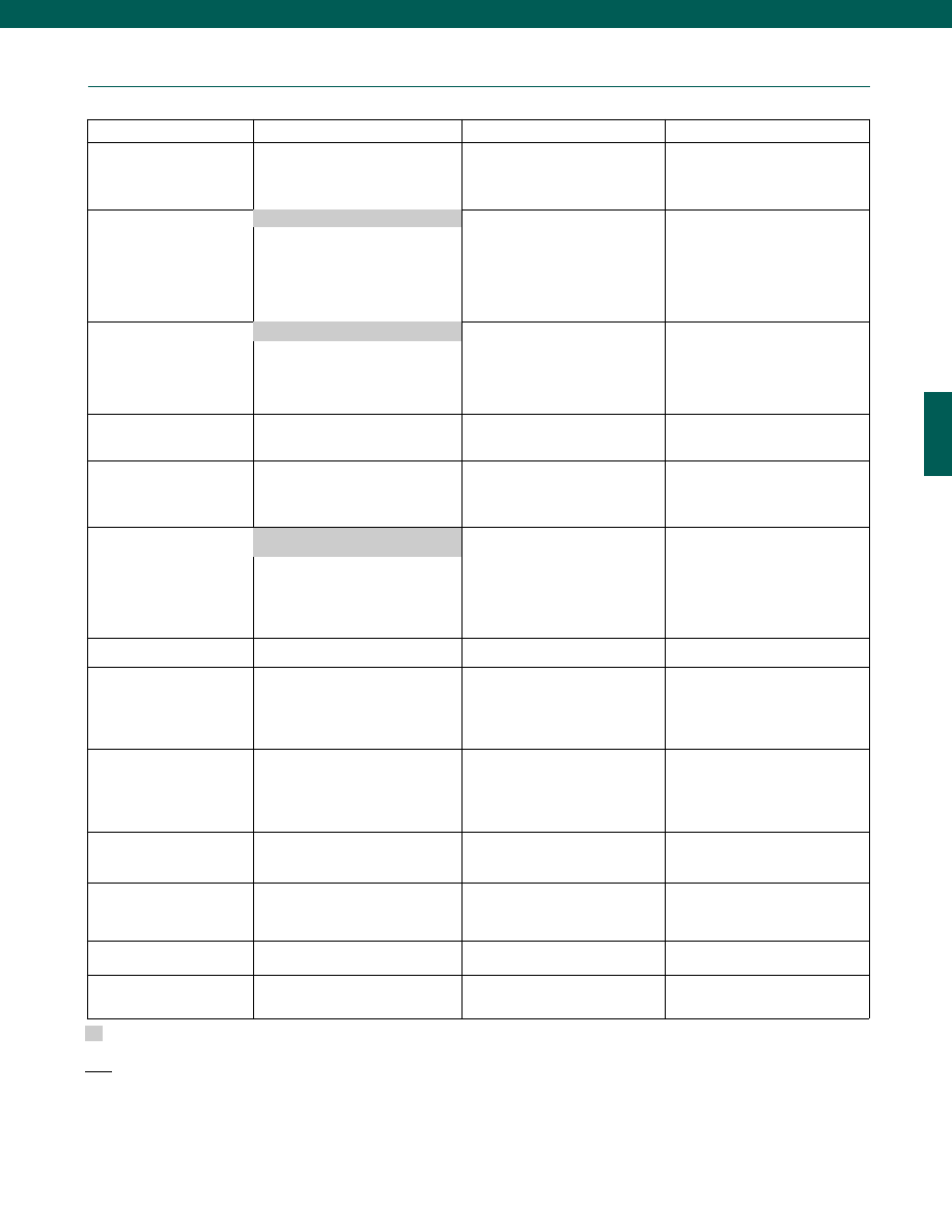
23
Options
www.honeywell.com/sensotec
1-888-282-9891
Fast Track Manufacture
Built to Order
Built from Scratch
Pressure Ranges
15; 25; 50; 75; 100; 200; 300;
500; 750; 1000; 1500; 2000;
3000; 5000; 7500; 10,000 psig/a
0.5 psig
1; 2; 5; 10; 15,000; 20,000; 30,000;
50,000; 60,000 psig/a
Temperature Compensation
1b.
30° to 130° F
1c.
0° to 185° F
1d.
-20° to 130° F
1e.
-20° to 200° F
1f.
70° to 250° F
1g.
70° to 325° F (note 9)
1i.
-65° to 250° F (note 9)
Internal Amplifiers
(note 10)
2c.
0-5 VDC output
2j.
4-20 mA (3-wire) output
2t.
0-10 VDC output
2a.
0-5 VDC (4-wire) output
2k.
4-20 mA (2-wire) output
2N (2n).4-20 mA (2-wire)
Intrinsically safe
Internal Amplifier
Enhancements
3a.
Input/ Output Isolation
3d.
Remote Buffered Shunt Cal.
Pressure Ports
(note 9)
5a.
1/4-18 NPT Female
5b.
1/4-18 NPT Male
5d.
7/16-20 UNF Male
5g.
G 1/4 Male
5c.
7/16-20 UNF Female
(per MS33649-4)
Electrical Termination
6b.
MS type connector mates
with MS3106-14S 6 pin
(max. 160°F)
6j.
1/2-14 conduit fitting with 5 ft.
of 4 conductor PVC cable
Shunt Calibration
8a.
Precision Internal Resistor (note 11)
Special Calibration
(note 9)
9a.
10 point (5 up/5 down) 20%
increments @ 70°F (gage)
9b.
20 point (10 up/10 down) 10%
increments @ 70°F (gage)
Wetted Diaphragm
(note 9)
10a. 316 Stainless steel (note 9)
10b. Crucible A-286
10c. Hastelloy-C
10d. Monel K-500
Bridge Resistance
(note 9)
12a. 1,000 Ohms (foil) (max. 400°F)
12b. 5,000 Ohms (foil) (max. 250°F)
Potentiometers
14a. No access to pots
14b. Top access to pots
Shock & Vibration
44a. Shock & vibration resistance
Interfaces
53e. Signature Calibration (note 9)
53t. T.E.D.S. IEEE1451.4 Module
(note 13)
Supplied as standard
Model A-5
Notes:
9.
Availability varies according to range.
10. Not available with temperatures below -20°F or above 185°F.
11. Cannot be used with amplified option.
12. Gage pressure units greater than 200 psi are sealed at atmospheric pressure.
13. Consult factory for TEDS availability with amplified models.
1a. 60° to 160° F
2u. Unamplified, mV/V Output
6a. Bendix PTIH-10-6P (or equivalent)
6 pin (max. 250° F)
Courtesy of Steven Engineering, Inc.-230 Ryan Way, South San Francisco, CA 94080-6370-Main Office: (650) 588-9200-Outside Local Area: (800) 258-9200-www.stevenengineering.com
Sensotec Sensors Full Line Catalog-html.html
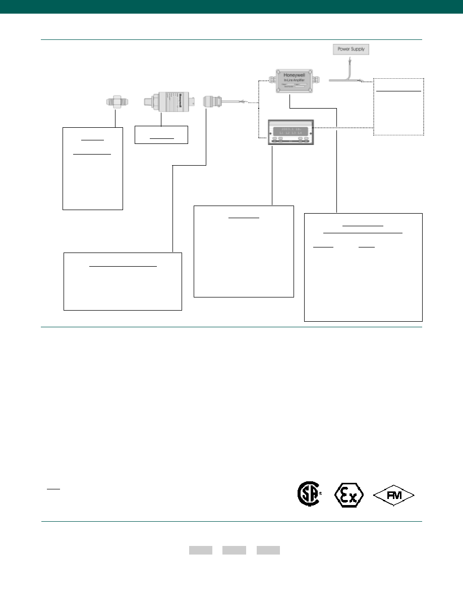
24
How to Order
Combine the order code, the range code and the options code.
Order Code
Range Code
Options Code
Sample Code: AP141 AT 1c,2a
www.honeywell.com/sensotec
1-888-282-9891
Case pressure
Different cable lengths
Different materials
ESD
Fatigue rating
Lightning protection
O2 Clean
OEM labels
Overload stops
Radiation proof
Sig Cal
Special electrical O/P
Special temp comp
Special wiring codes
Temperature & pressure calibration
Special Customer Requirements
(Consult Factory)
Model A-5
Adaptors
Compatible with:
1/4-18 NPT Male
1/4-18 NPT Female
7/16-20 UNF Male
7/16-20 UNF Female
1/8-27 NPT Male
1/8-27 NPT Female
9/16-18 UNF Male
Model A-5
Mating Connectors & Cables
PT06A-10-6S (4 conductor cable), Std.
PT06E-10-6S (4 conductor cable)
MS3106A-14S-6S (4 conductor cable)
Display Units
SC500
SC1000
SC2000
SC2001
SC3004
GM (Unamp. only)
GM-A (Amp. only)
NK (Unamp. only)
HH (Unamp. only)
Customer Supplied
Chart Recorder
Alarm Panel
Data Acquisition
Computer
PLC
In-Line Amplifiers
(Used with unamplified units only)
Amplifier
Output
Universal In-Line Amplifiers
UV
+/- 5 VDC
UV-10
+/- 10 VDC
UBP
0 +/- 5 VDC
U3W
4-20 mA (3 wire)
U2W
4-20 mA (2 wire) (note 14)
DIN Rail Mount In-Line Amplifiers
DV-05
0 +/- 5 VDC (3 wire)
DA-05
4-20 mA (3 wire)
DV-10
0 +/- 10 VDC (3 wire)
Typical System Diagram
Notes:
14. 5,000 Ohm bridge required
Approved Approved
Intrinsically Safe Amp
Courtesy of Steven Engineering, Inc.-230 Ryan Way, South San Francisco, CA 94080-6370-Main Office: (650) 588-9200-Outside Local Area: (800) 258-9200-www.stevenengineering.com
Sensotec Sensors Full Line Catalog-html.html
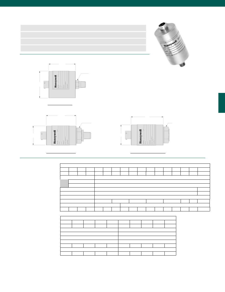
25
100
200
400
800
2k
3k
3.5k
4k
n
0.5 to 60,000 psig/a Range
n
mV/V, 4-20 mA, 0-5 VDC or 0-10 VDC Output
n
Stainless Steel, Hermetically Sealed
n
0.25% Accuracy
Range Code
D (in./ mm) for psia/g
L (in./ mm) for psia
L* (in./ mm) for psia
L (in./ mm) for psig
L* (in./ mm) for psig
Over Pressure (test) (psi)
Over Pressure (burst) (psi)
Port Volume (in.3/ cm3)
Natural Frequency (Hz)
Range Code
D (in./ mm)
L (in./ mm)
L* (in./ mm)
Over Pressure (test) (psi)
Over Pressure (burst) (psi)
Port Volume (in.3/ cm3)
Natural Frequency (Hz)
Dimensions
www.honeywell.com/sensotec
Model Z General Purpose Gage/ Absolute Pressure Transducer
Order Code AP131 (gage) AP132 (absolute)
1-888-282-9891
L
Pressure Port
1/4-18 NPT Male
L
Pressure Port 1/4-18 NPT Male
0.5 to 9 psig/ psia
10 to 1,500 psig/ psia
L
Pressure Port 1/4-18 NPT
Female on 1.0 in. Hex.
(2000 to 10,000 psig/a)
Pressure Port 9/16-18
Cone Seal (F-250-C)
on 1.0 in. Hex.
(15,000 to 60,000 psig/a)
øD
øD
2,000 to 60,000 psig/ psia
øD
Pressure Ranges (psi)
0.5**
1
2
5
10
15
25
50
75
100
150
200
300
500
750 1,000 1,500
35k
40k
54k
60k
80k
100k
>100k
>100k
>100k
>100k
0.12/ 3.1
0.06/ 1.5
Pressure Ranges (psi)
* Length of pressure transducer with amplified option (see options on third page)
** 0.5 psi is available for gage only.
2.25/ 57
2.54/ 65
3.79/ 96
2.41/ 61
3.66/ 93
150% Full Scale
50
0.32/ 5.2
1.50/ 38
2.35/ 60
3.60/ 91
2.35/ 60
2.13/ 54
3.60/ 91
3.38/ 86
150% Full Scale
500
500
550 1000 1.3k 2.1k 2.5k 2.9k 3.5k 4.6k
6k
7k
9k
9.5k
12k
17k
20k
1.50/ 38
1.50/ 38
1.90/ 48
2.21/ 56
3.15/ 80
3.46/ 89
150% Full Scale
Contact Factory
2,000
3,000
5,000
7,500
10,000 15,000 20,000 30,000 50,000 60,000
DL
DN
DR
DT
DV
EJ
EL
EN
EP
ES
N/A
N/A
8k
12k
20k
25k
25k
40k
45k
60k
80k
80k
0.25/ 4.1
0.17/ 2.8
AN
AP
AR
AT
AV
BJ
BL
BN
BP
BR
CJ
CL
CP
CR
CT
CV
DJ
Courtesy of Steven Engineering, Inc.-230 Ryan Way, South San Francisco, CA 94080-6370-Main Office: (650) 588-9200-Outside Local Area: (800) 258-9200-www.stevenengineering.com
Sensotec Sensors Full Line Catalog-html.html

26
Performance
Environmental
Electrical
Mechanical
Internal Amplifiers
Accuracy (note 1)................+/-0.25% Full Scale
Linearity................+/-0.15% Full Scale
Hysteresis................+/-0.10% Full Scale
Media................All gases/ liquids compatible with wetted parts
Resolution................Infinite
Calibration................5 point calibration: 0%, 50% and 100% of Full Scale
Temperature, Compensated................60° to 160°F
Temperature, Effect
Zero................0.005% Full scale/ °F
Span................0.005% Reading/ °F
Sealing................Hermetically sealed IP68/ Nema 6P (AP132)
Strain Gage Type................Bonded foil
Insulation Resistance................5000 Megohms @ 50VDC
Bridge Resistance................350 Ohms
Shunt Calibration Data................Included
Electrical Termination (std)................PTIH-10-6P or equiv. (Hermetic Stainless)
Mating Connector (not incl.)................PT06A-10-6S or equiv.
Wetted Parts Material
Less than 2000 psig/a................17-4 PH Stainless Steel
Greater than or equal to 2000 psig/a................15-5 PH Stainless Steel
Weight................10 oz.
Case Material................304 Stainless Steel
Marking................Permanent metal nameplate MIL-STD130F 4.3;
Individual sequential serial number per sensor;
Country of origin and date of manufacture
www.honeywell.com/sensotec
1-888-282-9891
Model Z
* Black and Green wires are internally connected.
** Pins B and C are internally connected.
Notes:
1. Accuracies stated are expected for Best Fit Straight Line for all errors including linearity, hysteresis & non-repeatability thru zero.
2. Output for 0.5, 1, 2 psig/a units is 1-2mV/V.
3. Input power (voltage) for internal amplifier options 2j, 2k, 2n(2N) depends on load resistance.
4. CE mark requires options 6a & 3d.
5. Interconnecting shunt cal. 1 with shunt cal. 2 terminal provides 50% (unamplified units), 75% (4-20 mA 3 wire units), or 80% (voltage amp. units) of full scale
output for quick calibration. Shunt Calibration comes standard with internal amplifier options 2a, 2b, 2c, 2t and 2j.
6. G=Green; B=Blue; W=White; Bl=Black; Br=Brown; Y=Yellow; R=Red; O=Orange. Color specifying cable and number or letter specifying connector
7. No mating connector necessary with cable option.
Amplifier
Specifications
mV/V Output
Standard
Voltage Output
Option 2a
(note 4)
Vehicle Voltage Output
Option 2c
(note 4)
Vehicle Voltage Output
Option 2t
(note 4)
Current 3 Wire
Option 2j
(note 4)
Current 2 Wire
Option 2k
(note 4)
Intrinsically Safe Amp
Option 2N (2n)
Output Signal
Input Power (Voltage)
Input Power (Current)
Frequency Response (amp)
Power Supply Rejection
Operating Temperature
Reverse Voltage Protection
Short Circuit Protection
3 mV/V
(note 2)
10 VDC Regulated
28.5 mA @ 10 VDC
Natural Frequency
--
-100° to 250° F
Not Applicable
Not Applicable
0-5VDC
+/-15VDC or 26-32VDC
45 mA
2000 Hz
60 db
-20° to 185° F
Yes
Momentary
0-5VDC or +/- 5VDC
@ 5mA
11-28 VDC
40 mA
3000 Hz
60 db
-40° to 200° F
Yes
Momentary
0-10VDC or +/- 10VDC
@ 5mA
15-28 VDC
40 mA
3000 Hz
60 db
-40° to 185° F
Yes
Momentary
4-20 mA
22-32 VDC (note 3)
65 mA
2500 Hz
60 db
-40° to 185° F
Yes
Yes
4-20 mA
9-32 VDC (note 3)
4-28 mA
300 Hz
60 db
-40° to 185° F
Yes
Yes
4-20 mA
9-28 VDC (note 3)
4-24 mA
2000 Hz
60 db
-20° to 185° F
Yes
Yes
Wiring Code: Connector
(Std.)
(note 5)
A
(+) Excitation
B
(+) Excitation
C
(-) Excitation
D
(-) Excitation
E
(-) Output
F
(+) Output
A
(+) Supply
B Output Common/
C Supply Return
D
(+) Output
E
Shunt Cal 1
F
Shunt Cal 2
A
(+) Supply
B** Output Common/
C** Supply Return
D
(+) Output
E
Shunt Cal 1
F
Shunt Cal 2
A
(+) Supply
B** Output Common/
C** Supply Return
D
(+) Output
E
Shunt Cal 1
F
Shunt Cal 2
A
(+) Supply
B** Output Common/
C** Supply Return
D
(+) Output
E
Shunt Cal 1
F
Shunt Cal 2
A (+) Supply
B No Connection
C No Connection
D (+) Output
E Case Ground
F No Connection
A (+) Supply
B No Connection
C No Connection
D (+) Output
E Case Ground
F No Connection
Wiring Code: Cable
(note 5)
(note 6)
(note 7)
R
(+) Excitation
Bl (-) Excitation
G
(-) Output
W
(+) Output
R (+) Supply
Bl Output Common/
G Supply Return
W (+) Output
B
Shunt Cal 1
Br Shunt Cal 2
R (+) Supply
Bl* Output Common/
G* Supply Return
W (+) Output
B
Shunt Cal 1
Br Shunt Cal 2
R (+) Supply
Bl* Output Common/
G* Supply Return
W (+) Output
B
Shunt Cal 1
Br Shunt Cal 2
R (+) Supply
Bl* Output Common/
G* Supply Return
W (+) Output
B
Shunt Cal 1
Br Shunt Cal 2
R
(+) Supply
Bl (+) Output
W
Case
Ground
R (+) Supply
Bl (+) Output
W Case
Ground
For Current Information
Reference application
sheet #008-0356-00 for
current information.
Reference application
sheet #008-0357-00 for
current information.
Reference application
sheet #008-0360-00 for
current information.
Reference application
sheet #008-0361-00
for current information.
Reference applica
tion sheet #008-
0361-60 for current
information.
See Sensotec web
site for most up-to-
date information
regarding Intrinsically
safe approvals ref.
#008-0547-00.
Courtesy of Steven Engineering, Inc.-230 Ryan Way, South San Francisco, CA 94080-6370-Main Office: (650) 588-9200-Outside Local Area: (800) 258-9200-www.stevenengineering.com
Sensotec Sensors Full Line Catalog-html.html

27
Options
www.honeywell.com/sensotec
1-888-282-9891
Supplied as standard
Model Z
Notes:
8. Options 2k, 2n(2N) only available with option 12b.
9. Availability varies according to range.
10. Not available with temperatures below -20°F or above 185°F.
11. Cannot be used with amplified option.
12. Gage pressure units greater than 200 psi are sealed at atmospheric pressure.
13. No pot access available with MS type connector.
14. Consult factory for TEDS availability with amplified models.
Same Day Ship
Fast Track Manufacture
Built to Order
Built from Scratch
Pressure Ranges
15; 25; 50; 100; 200; 500;
1000 psig
75; 300; 750; 1500; 2000; 3000;
5000; 7500; 10,000 psig/a
15; 25; 50; 100; 200; 500; 1000 psia
0.5 psig
1; 2; 5; 10; 15,000;
20,000; 30,000;
50,000; 60,000 psig/a
Temperature Compensation
1b. 30° to 130° F
1c. 0° to 185° F
1d. -20° to 130° F
1e. -20° to 200° F
1f.
70° to 250° F (note 11)
1g. 70° to 325° F (note 11)
1i.
-65° to 250° F (note 11)
Internal Amplifiers (note 10)
2c. 0-5 VDC output
2j.
4-20 mA (3-wire) output
2t. 0-10 VDC output
2a. 0-5 VDC (4-wire) output
2k. 4-20 mA (2-wire) output (note 8)
2N (2n). 4-20 mA (2-wire)
Intrinsically safe (note 8)
Internal Amplifier
Enhancements
3a. Input/ Output Isolation
3d. Remote Buffered Shunt Cal.
Pressure Ports (note 9)
5a. 1/4-18 NPT Female
5b. 1/4-18 NPT Male
5d. 7/16-20 UNF Male
5g. G 1/4 Male
5c. 7/16-20 UNF Female
(per MS33649-4)
Electrical Termination
6b. MS type connector mates with
MS3106-14S 6 pin (max.
160°F) (note 13)
6j. 1/2-14 conduit fitting with 5 ft.
of 4 conductor PVC cable
Shunt Calibration
8a. Precision Internal Resistor
(note 11)
Special Calibration (note 9)
9a. 10 point (5 up/5 down) 20%
increments @ 70°F (gage)
9b. 20 point (10 up/10 down) 10%
increments @ 70°F (gage)
Wetted Diaphragm (note 9)
10a. 316 Stainless steel
(note 9)
10b. Crucible A-286
10c. Hastelloy-C
10d. Monel K-500
Bridge Resistance (note 9)
12a. 1,000 Ohms (foil) (max. 400°F)
12b. 5,000 Ohms (foil) (max. 400°F)
Potentiometers
14a. No access to pots
14b. Top access to pots
Shock & Vibration
44a. Shock & vibration resistance
Interfaces
53e. Signature Calibration (note 11)
53t. T.E.D.S. IEEE1451.4 Module
(note 14)
1a. 60° to 160° F
2u. Unamplified mV/V output
6a. Bendix PTIH-10-6P-(or
equiv.) 6 pin (max. 400°F)
Courtesy of Steven Engineering, Inc.-230 Ryan Way, South San Francisco, CA 94080-6370-Main Office: (650) 588-9200-Outside Local Area: (800) 258-9200-www.stevenengineering.com
Sensotec Sensors Full Line Catalog-html.html
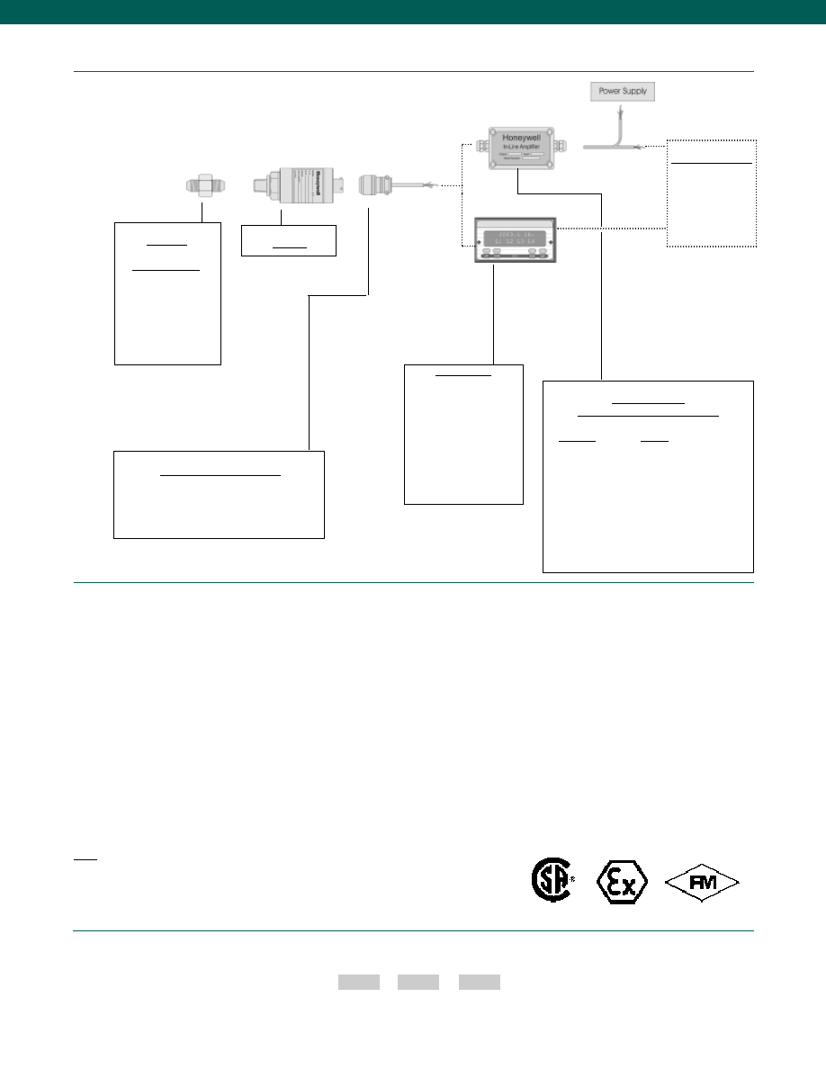
28
How to Order
Combine the order code, the range code and the options code.
Order Code
Range Code
Options Code
Sample Code: AP131 AT 1c,2a
www.honeywell.com/sensotec
1-888-282-9891
Case pressure
Different cable lengths
Different materials
ESD
Fatigue rating
Lightning protection
O2 Clean
OEM labels
Overload stops
Radiation proof
Sig Cal
Special electrical O/P
Special temp comp
Special wiring codes
Temperature & pressure calibration
Special Customer Requirements
(Consult Factory)
Model Z
Adaptors
Compatible with:
1/4-18 NPT Male
1/4-18 NPT Female
7/16-20 UNF Male
7/16-20 UNF Female
1/8-27 NPT Male
1/8-27 NPT Female
9/16-18 UNF Male
Model Z
Mating Connectors & Cables
PT06A-10-6S (4 conductor cable), Std.
PT06E-10-6S (4 conductor cable)
MS3106A-14S-6S (4 conductor cable)
Customer Supplied
Chart Recorder
Alarm Panel
Data Acquisition
Computer
PLC
In-Line Amplifiers
(Used with unamplified units only)
Amplifier
Output
Universal In-Line Amplifiers
UV
+/- 5 VDC
UV-10
+/- 10 VDC
UBP
0 +/- 5 VDC
U3W
4-20 mA (3 wire)
U2W
4-20 mA (2 wire) (note 15)
DIN Rail Mount In-Line Amplifiers
DV-05
0 +/- 5 VDC (3 wire)
DA-05
4-20 mA (3 wire)
DV-10
0 +/- 10 VDC (3 wire)
Typical System Diagram
Notes:
15. 5,000 Ohm bridge required
Display Units
SC500
SC1000
SC2000
SC2001
SC3004
GM (Unamp. only)
GM-A (Amp. only)
NK (Unamp. only)
HH (Unamp. only)
Approved Approved
Intrinsically Safe Amp
Courtesy of Steven Engineering, Inc.-230 Ryan Way, South San Francisco, CA 94080-6370-Main Office: (650) 588-9200-Outside Local Area: (800) 258-9200-www.stevenengineering.com
Sensotec Sensors Full Line Catalog-html.html
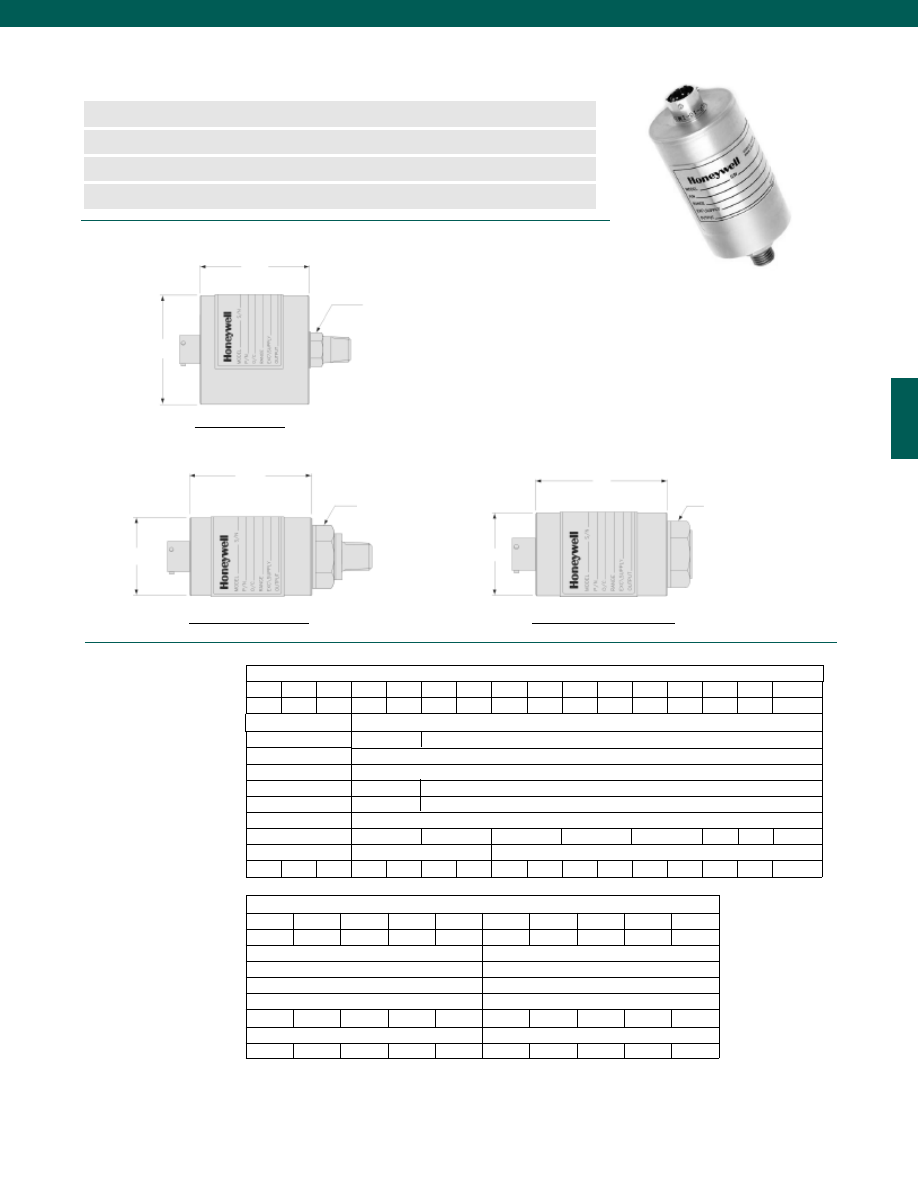
29
8k
12k
20k
25k
25k
40k
45k
60k
80k
80k
100
200
400
800
2k
3k
3.5k
4k
0.25/ 4.1
0.17/ 2.8
n
1 to 60,000 psig/a Range
n
mV/V, 4-20 mA, 0-5 VDC or 0-10 VDC Output
n
Stainless Steel, Hermetically Sealed
n
0.1% Accuracy
Range Code
D (in./ mm) for psia
D (in./ mm) for psig
L (in./ mm) for psia
L* (in./ mm) for psia
L (in./ mm) for psig
L* (in./ mm) for psig
Over Pressure (test) (psi)
Over Pressure (burst) (psi)
Port Volume (in.3/ cm3)
Natural Frequency (Hz)
Range Code
D (in./ mm)
L (in./ mm)
L* (in./ mm)
Over Pressure (test) (psi)
Over Pressure (burst) (psi)
Port Volume (in.3/ cm3)
Natural Frequency (Hz)
Dimensions
www.honeywell.com/sensotec
Model TJE Precision Gage/ Absolute Pressure Transducer
Order Code AP121 (gage) AP122 (absolute)
1-888-282-9891
L
Pressure Port
1/4-18 NPT Male
L
Pressure Port 1/4-18 NPT Male
1 to 5 psig/ psia
10 to 1,500 psig/ psia
L
Pressure Port 1/4-18 NPT
Female on 1.0 in. Hex.
(2000 to 10,000 psig/a)
Pressure Port 9/16-18
Cone Seal (F-250-C)
on 1.0 in. Hex.
(15,000 to 60,000 psig/a)
øD
øD
2,000 to 60,000 psig/ psia
øD
AP
AR
AT
AV
BJ
BL
BN
BP
BR
CJ
CL
CP
CR
CT
CV
DJ
Pressure Ranges (psi)
1
2
5
10
15
25
50
75
100
150
200
300
500
750 1,000 1,500
35k
40k
54k
60k
80k
100k
>100k
>100k
>100k
>100k
0.12/ 3.1
0.06/ 1.5
Pressure Ranges (psi)
* Length of pressure transducer with amplified option (see options on third page)
** 0.5 psi is available for gage only.
2.25/ 57
2.54/ 65
3.79/ 96
1.81/ 46
3.06/ 78
150% Full Scale
50
0.32/ 5.2
1.50/ 38
2.35/ 60
3.60/ 91
2.00/ 51
2.02/ 51
3.25/ 83
3.27/ 83
150% Full Scale
500
550 1000 1.3k 2.1k 2.5k 2.9k 3.5k 4.6k
6k
7k
9k
9.5k
12k
17k
20k
1.50/ 38
1.50/ 38
1.90/ 48
2.21/ 56
3.15/ 80
3.46/ 89
150% Full Scale
Contact Factory
2,000
3,000
5,000
7,500
10,000 15,000 20,000 30,000 50,000 60,000
DL
DN
DR
DT
DV
EJ
EL
EN
EP
ES
2.25/ 57 1.50/ 38
1.75/ 45
Courtesy of Steven Engineering, Inc.-230 Ryan Way, South San Francisco, CA 94080-6370-Main Office: (650) 588-9200-Outside Local Area: (800) 258-9200-www.stevenengineering.com
Sensotec Sensors Full Line Catalog-html.html
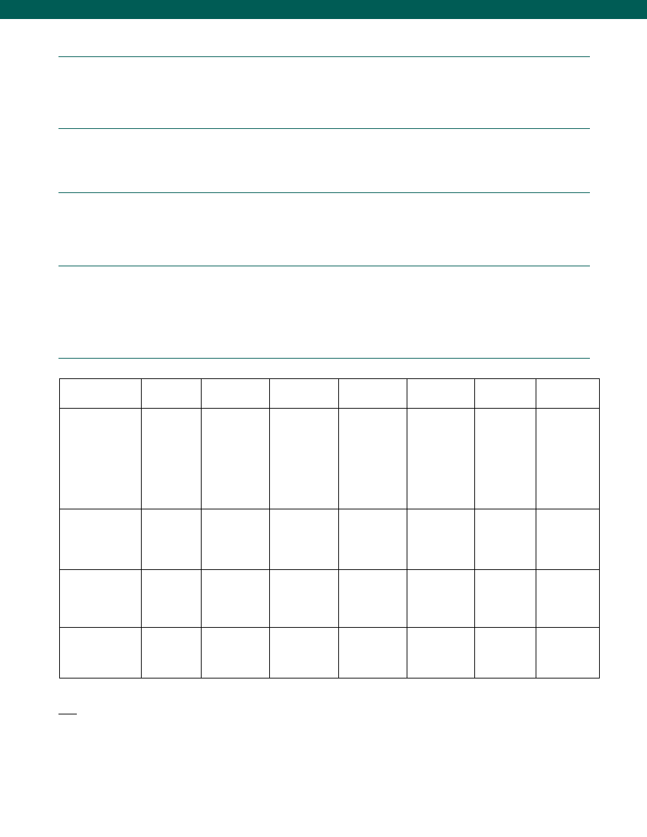
30
Performance
Environmental
Electrical
Mechanical
Internal Amplifiers
Accuracy (note 1)................+/-0.10% Full Scale
Linearity................+/-0.10% Full Scale
Hysteresis................+/-0.05% Full Scale
Media................All gases/ liquids compatible with wetted parts
Resolution................Infinite
Calibration................5 point calibration: 0%, 50% and 100% of Full Scale
Temperature, Compensated................60° to 160°F
Temperature, Effect
Zero................0.0025% Full scale/ °F
Span................0.0025% Reading/ °F
Sealing................Hermetically sealed IP68/ Nema 6P
Strain Gage Type................Bonded foil
Insulation Resistance................5,000 Megohms @ 50VDC
Bridge Resistance................350 Ohms
Shunt Calibration Data................Included
Electrical Termination (std)................PTIH-10-6P or equiv. (Hermetic Stainless)
Mating Connector (not incl.)................PT06A-10-6S or equiv.
Wetted Parts Material
Less than 2000 psig/a................17-4 PH Stainless Steel
Greater than or equal to 2000 psig/a................15-5 PH Stainless Steel
Weight................10 oz.
Case Material................304 Stainless Steel
Marking................Permanent metal nameplate MIL-STD130F 4.3; Individual
sequential serial number per sensor; Country of origin and
date of manufacture
www.honeywell.com/sensotec
1-888-282-9891
Model TJE
* Black and Green wires are internally connected.
** Pins B and C are internally connected.
Notes:
1. Accuracies stated are expected for Best Fit Straight Line for all errors including linearity, hysteresis & non-repeatability thru zero.
2. Output for 0.5, 1, 2 psig/a units is 1-2mV/V.
3. Input power (voltage) for internal amplifier options 2j, 2k, 2n(2N) depends on load resistance.
4. CE mark requires options 6a & 3d.
5. Interconnecting shunt cal. 1 with shunt cal. 2 terminal provides 50% (unamplified units), 75% (4-20 mA 3 wire units), or 80% (voltage amp. units) of full scale
output for quick calibration. Shunt Calibration comes standard with internal amplifier options 2a, 2b, 2c, 2t and 2j.
6. G=Green; B=Blue; W=White; Bl=Black; Br=Brown; Y=Yellow; R=Red; O=Orange. Color specifying cable and number or letter specifying connector
7. No mating connector necessary with cable option.
Amplifier
Specifications
mV/V Output
Standard
Voltage Output
Option 2a
(note 4)
Vehicle Voltage Output
Option 2c
(note 4)
Vehicle Voltage Output
Option 2t
(note 4)
Current 3 Wire
Option 2j
(note 4)
Current 2 Wire
Option 2k
(note 4)
Intrinsically Safe Amp
Option 2N (2n)
Output Signal
Input Power (Voltage)
Input Power (Current)
Frequency Response (amp)
Power Supply Rejection
Operating Temperature
Reverse Voltage Protection
Short Circuit Protection
3 mV/V
(note 2)
10 VDC Regulated
28.5 mA @ 10 VDC
Natural Frequency
Not Applicable
-100° to 250° F
Not Applicable
Not Applicable
0-5VDC
+/-15VDC or 26-32VDC
45 mA
2000 Hz
60 db
-20° to 185° F
Yes
Momentary
0-5VDC or +/- 5VDC
@ 5mA
11-28 VDC
40 mA
3000 Hz
60 db
-40° to 200° F
Yes
Momentary
0-10VDC or +/- 10VDC
@ 5mA
15-28 VDC
40 mA
3000 Hz
60 db
-40° to 185° F
Yes
Momentary
4-20 mA
22-32 VDC (note 3)
65 mA
2500 Hz
60 db
-40° to 185° F
Yes
Yes
4-20 mA
9-32 VDC (note 3)
4-28 mA
300 Hz
60 db
-40° to 185° F
Yes
Yes
4-20 mA
9-28 VDC (note 3)
4-24 mA
2000 Hz
60 db
-20° to 185° F
Yes
Yes
Wiring Code: Connector
(Std.)
(note 5)
A
(+) Excitation
B
(+) Excitation
C
(-) Excitation
D
(-) Excitation
E
(-) Output
F
(+) Output
A
(+) Supply
B Output Common/
C Supply Return
D
(+) Output
E
Shunt Cal 1
F
Shunt Cal 2
A
(+) Supply
B** Output Common/
C** Supply Return
D
(+) Output
E
Shunt Cal 1
F
Shunt Cal 2
A
(+) Supply
B** Output Common/
C** Supply Return
D
(+) Output
E
Shunt Cal 1
F
Shunt Cal 2
A
(+) Supply
B** Output Common/
C** Supply Return
D
(+) Output
E
Shunt Cal 1
F
Shunt Cal 2
A (+) Supply
B No Connection
C No Connection
D (+) Output
E Case Ground
F No Connection
A (+) Supply
B No Connection
C No Connection
D (+) Output
E Case Ground
F No Connection
Wiring Code: Cable
(note 5)
(note 6)
(note 7)
R
(+) Excitation
Bl (-) Excitation
G
(-) Output
W
(+) Output
R (+) Supply
Bl Output Common/
G Supply Return
W (+) Output
B
Shunt Cal 1
Br Shunt Cal 2
R (+) Supply
Bl* Output Common/
G* Supply Return
W (+) Output
B
Shunt Cal 1
Br Shunt Cal 2
R (+) Supply
Bl* Output Common/
G* Supply Return
W (+) Output
B
Shunt Cal 1
Br Shunt Cal 2
R (+) Supply
Bl* Output Common/
G* Supply Return
W (+) Output
B
Shunt Cal 1
Br Shunt Cal 2
R
(+) Supply
Bl (+) Output
W
Case
Ground
R (+) Supply
Bl (+) Output
W Case
Ground
For Current Information
Reference application
sheet #008-0356-00 for
current information.
Reference application
sheet #008-0357-00 for
current information.
Reference application
sheet #008-0360-00 for
current information.
Reference application
sheet #008-0361-00
for current information.
Reference applica
tion sheet #008-
0361-60 for current
information.
See Sensotec web
site for most up-to-
date information
regarding Intrinsically
Safe approvals ref.
#008-0547-00.
Courtesy of Steven Engineering, Inc.-230 Ryan Way, South San Francisco, CA 94080-6370-Main Office: (650) 588-9200-Outside Local Area: (800) 258-9200-www.stevenengineering.com
Sensotec Sensors Full Line Catalog-html.html
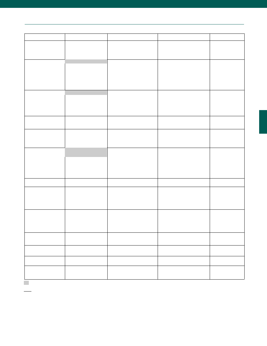
31
Options
www.honeywell.com/sensotec
1-888-282-9891
Same Day Ship
Fast Track Manufacture
Built to Order
Built from Scratch
Pressure Ranges
15; 25; 50; 100; 200 psig/a
500; 1000; 3000; 5000; 7500;
10,000 psig
75; 300; 750; 1500; 2000 psig/a
500; 1000; 3000; 5000; 7500;
10,000 psia
1; 2; 5; 10; 15,000;
20,000; 30,000;
50,000; 60,000 psig/a
Temperature Compensation
1b. 30° to 130° F
1c. 0° to 185° F
1d. -20° to 130° F
1e. -20° to 200° F
1f.
70° to 250° F (note 11)
1g. 70° to 325° F (note 11)
1i.
-65° to 250° F (note 11)
Internal Amplifiers (note 10) 2c. 0-5 VDC output
2a. 0-5 VDC (4-wire) output
2j.
4-20 mA (3-wire) output
2t. 0-10 VDC output
2k. 4-20 mA (2-wire) output (note 8)
2N (2n). 4-20 mA (2-wire)
Intrinsically safe (note 8)
Internal Amplifier
Enhancements
3a. Input/ Output Isolation (note 15)
3d. Remote Buffered Shunt Cal.
Pressure Ports (note 9)
5a. 1/4-18 NPT Female
5b. 1/4-18 NPT Male
5d. 7/16-20 UNF Male
5g. G 1/4 Male
5c. 7/16-20 UNF Female
(per MS33649-4)
Electrical Termination
6b. MS type connector mates with
MS3106-14S 6 pin (max.
160°F) (note13)
6i.
Submersible Cable (note 14)
6j. 1/2-14 conduit fitting with 5 ft.
of 4 conductor PVC cable
Shunt Calibration
8a. Precision Internal Resistor
(note 11)
Special Calibration (note 9)
9a. 10 point (5 up/5 down) 20%
increments @ 70°F (gage)
9b. 20 point (10 up/10 down) 10%
increments @ 70°F (gage)
Wetted Diaphragm (note 9)
10a. 316 Stainless steel
(note 9)
10b. Crucible A-286
10c. Hastelloy-C
10d. Monel K-500
Bridge Resistance (note 9)
12a. 1,000 Ohms (foil) (max. 400°F)
12b. 5,000 Ohms (foil) (max. 400°F)
Potentiometers
14a. No access to pots
14b. Top access to pots
Shock & Vibration
44a. Shock & vibration resistance
Interfaces
53e. Signature Calibration (note 11)
53t. T.E.D.S. IEEE1451.4 Module
(note 16)
Supplied as standard
Model TJE
Notes:
8. Options 2k, 2n(2N) only available with option 12b.
9. Availability varies according to range.
10. Not available with temperatures below -20°F or above 185°F.
11. Cannot be used with amplified option.
12. Gage pressure units greater than 200 psi are sealed at atmospheric pressure.
13. No pot access available with MS type connector.
14. Temp 180° F max, nonshielded standard, shielded available.
15. Input/Output Isolation only available with Voltage output (options 2a, 2b, 2c).
16. Consult factory for TEDS availability with amplified models.
1a. 60° to 160° F
2u. Unamplified mV/V output
6a. Bendix PTIH-10-6P-(or
equiv.) 6 pin (max. 400°F)
Courtesy of Steven Engineering, Inc.-230 Ryan Way, South San Francisco, CA 94080-6370-Main Office: (650) 588-9200-Outside Local Area: (800) 258-9200-www.stevenengineering.com
Sensotec Sensors Full Line Catalog-html.html
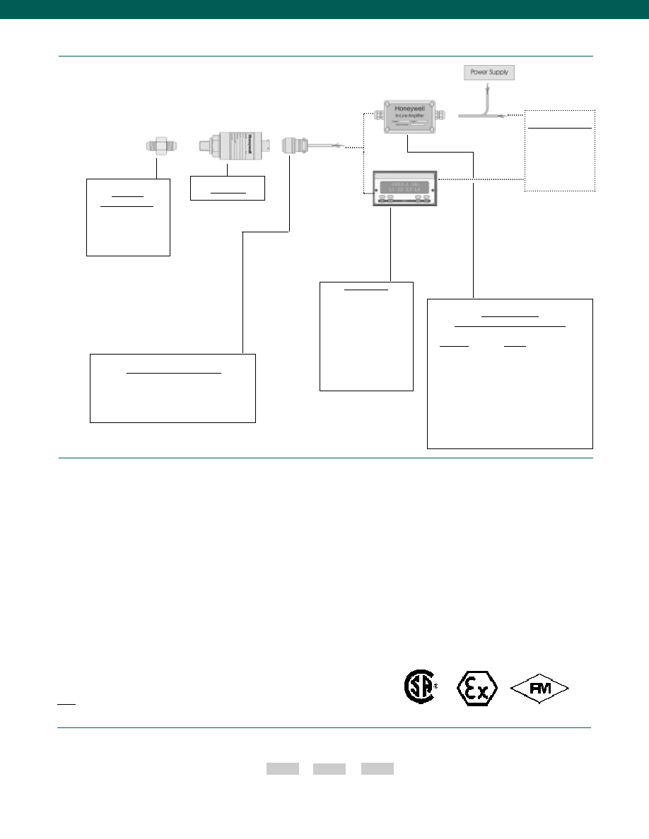
32
How to Order
Combine the order code, the range code and the options code.
Order Code
Range Code
Options Code
Sample Code: AP121 AT 1c,2a
www.honeywell.com/sensotec
1-888-282-9891
Case pressure
Different cable lengths
Different materials
ESD
Fatigue rating
Lightning protection
O2 Clean
OEM labels
Overload stops
Radiation proof
Sig Cal
Special electrical O/P
Special temp comp
Special wiring codes
Temperature & pressure calibration
Special Customer Requirements
(Consult Factory)
Model TJE
Adaptors
Compatible with:
1/4-18 NPT Male
1/4-18 NPT Female
7/16-20 UNF Male
7/16-20 UNF Female
Model TJE
Mating Connectors & Cables
PT06A-10-6S (4 conductor cable), Std.
PT06E-10-6S (4 conductor cable)
MS3106A-14S-6S (4 conductor cable)
Customer Supplied
Chart Recorder
Alarm Panel
Data Acquisition
Computer
PLC
In-Line Amplifiers
(Used with unamplified units only)
Amplifier
Output
Universal In-Line Amplifiers
UV
+/- 5 VDC
UV-10
+/- 10 VDC
UBP
0 +/- 5 VDC
U3W
4-20 mA (3 wire)
U2W
4-20 mA (2 wire) (note 17)
DIN Rail Mount In-Line Amplifiers
DV-05
0 +/- 5 VDC (3 wire)
DA-05
4-20 mA (3 wire)
DV-10
0 +/- 10 VDC (3 wire)
Typical System Diagram
Notes:
17. 5,000 Ohm bridge required
Display Units
SC500
SC1000
SC2000
SC2001
SC3004
GM (Unamp. only)
GM-A (Amp. only)
NK (Unamp. only)
HH (Unamp. only)
Approved Approved
Intrinsically Safe Amp
Courtesy of Steven Engineering, Inc.-230 Ryan Way, South San Francisco, CA 94080-6370-Main Office: (650) 588-9200-Outside Local Area: (800) 258-9200-www.stevenengineering.com
Sensotec Sensors Full Line Catalog-html.html
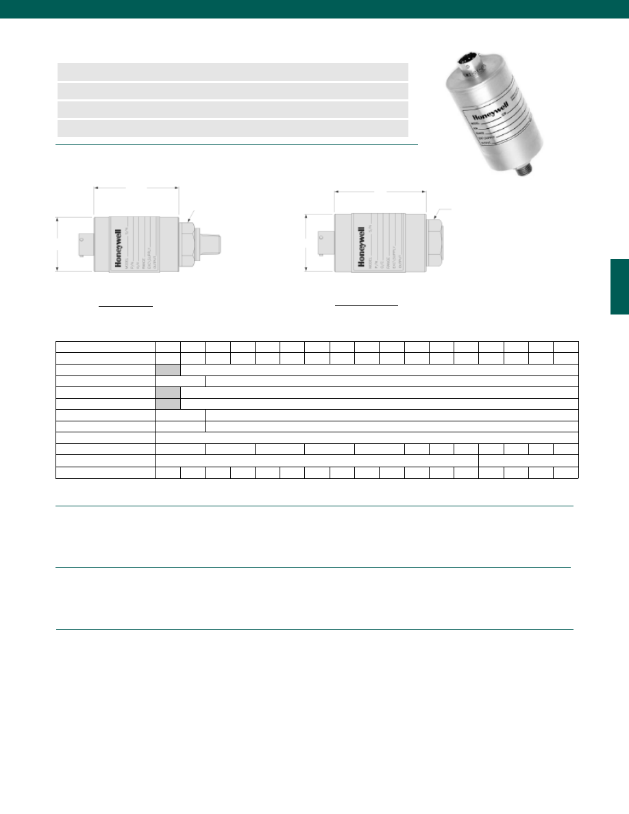
33
Pressure Ranges (note1)................10 psig; 15; 25; 50; 75; 100; 150; 200; 300; 500; 750;
................1000; 1500; 2000; 3000; 5000; 7500 psig/a
Accuracy (note 10)................+/-0.05% Full Scale
Resolution................Infinite
Calibration................5 point calibration: 0%, 50% and 100% of Full Scale
Temperature, Compensated................60° to 160°F
Temperature, Effect
Zero................0.0015% Full scale/ °F
Span................0.0015% Reading/ °F
Sealing................Hermetically Sealed IP68/ NEMA 6P
Strain Gage Type................Bonded foil
Insulation Resistance................5000 Megohms @ 50VDC
Bridge Resistance................350 Ohms
Shunt Calibration Data................Included
Electrical Termination (std)................PTIH-10-6P or equiv. (Hermetic Stainless)
Mating Connector (not incl.)................PT06A-10-6S or equiv.
www.honeywell.com/sensotec
n
10 to 7500 psig Range
n
Isolated Double Wall Construction
n
Enhanced Temperature Stability
n
0.05% Accuracy
Pressure Port 1/4-18 NPT
Female on 1.0 in. Hex.
Pressure Port 1/4-18 NPT Male
L
L
Model Super TJE Ultra Precision Pressure Transducer
Order Code AP111 (gage); AP112 (absolute)
øD
øD
10 to 1500 psi
2000 to 7500 psi
1-888-282-9891
Pressure Ranges (psi)
10**
15
25
50
75
100
150
200
300
500
750 1000 1500 2000 3000 5000 7500
Range Code
AV
BJ
BL
BN
BP
BR
CJ
CL
CP
CR
CT
CV
DJ
DL
DN
DR
DT
D (in./mm) for psia
N/A
1.63/41
D (in./mm) for psig
2.0/51
1.63/41
L (in./mm) for psia
N/A
2.62/66
L* (in./mm) for psia
N/A
3.63/92
L (in./mm) for psig
2.5/64
2.62/66
L* (in./mm) for psig
3.5/89
3.63/92
Over Pressure (test) (psi)
150% F.S.
Over Pressure (burst) (psi)
100
200
400
800
2000
3000 3500 4000 8000 12k
20k
25k
Port Volume (in.
3
/ cm
3
)
0.17/2.8
0.12/3.1
Natural Frequency (Hz)
1.3k
2.1k
2.5k
2.9k
3.5k
4.5k
6k
7k
9k
9.5k
12k
17k
20k
35k
40k
54k
60k
Dimensions
Performance
Environmental
Electrical
*Length with amplified option.
**10 psi not available with absolute pressure
Courtesy of Steven Engineering, Inc.-230 Ryan Way, South San Francisco, CA 94080-6370-Main Office: (650) 588-9200-Outside Local Area: (800) 258-9200-www.stevenengineering.com
Sensotec Sensors Full Line Catalog-html.html
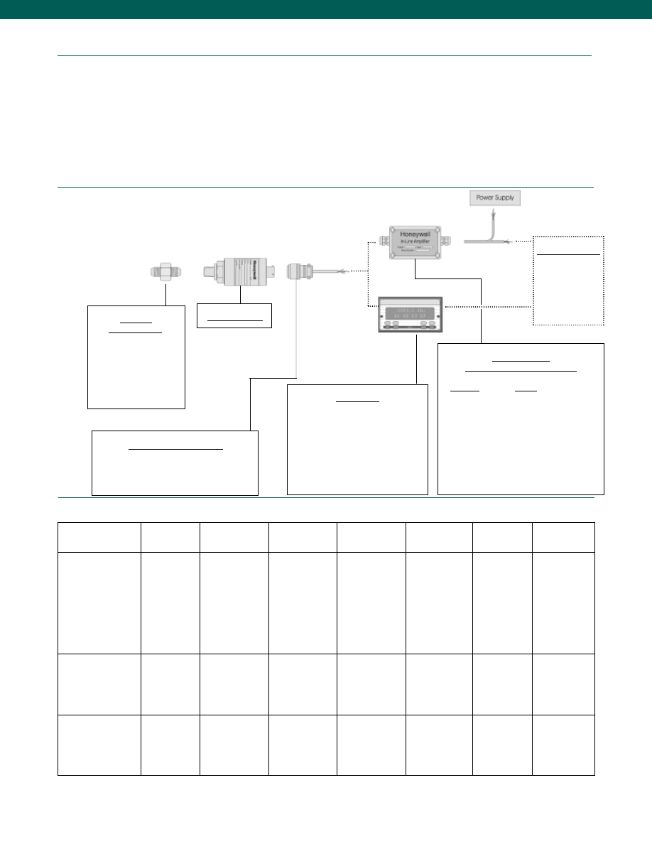
34
Adaptors
Compatible with:
G 1/4 British Pipe Female
1/4-18 NPT Male
1/4-18 NPT Female
7/16-20 UNF Male
G 1/4 Male
G 1/2 Male
Model SuperTJE
Mating Connectors & Cables
PT06A-10-6S (4 conductor cable), Std.
PT06E-10-6S (4 conductor cable)
MS3106A-14S-6S (4 conductor cable)
Display Units
SC1000
SC2000
SC2001
SC3004
GM (Unamp. only)
GM-A (Amp. only)
NK (Unamp. only)
HH (Unamp. only)
Customer Supplied
Chart Recorder
Alarm Panel
Data Acquisition
Computer
PLC
In-Line Amplifiers
(Used with unamplified units only)
Amplifier
Output
Universal In-Line Amplifiers
UV
+/- 5 VDC
UV-10
+/- 10 VDC
UBP
0 +/- 5 VDC
U3W
4-20 mA (3 wire)
U2W
4-20 mA (2 wire)
DIN Rail Mount In-Line Amplifiers
DV-05
0 +/- 5 VDC (3 wire)
DA-05
4-20 mA (3 wire)
DV-10
0 +/- 10 VDC (3 wire)
www.honeywell.com/sensotec
Internal Amplifiers
1-888-282-9891
Model Super TJE
Mechanical
Typical System Diagram
Amplifier
Specifications
mV/V Output
Standard
Voltage Output
Option 2a
(note 4)
Vehicle Voltage Output
Option 2c
(note 4)
Vehicle Voltage Output
Option 2t
(note 4)
Current 3 Wire
Option 2j
(note 4)
Current 2 Wire
Option 2k
(note 4)
Intrinsically Safe Amp
Option 2N (2n)***
Output Signal
Input Power (Voltage)
Input Power (Current)
Frequency Response (amp)
Power Supply
Rejection
Operating Temperature
Reverse Voltage
Protection
Short Circuit Protection
2 mV/V
10 VDC Regulated
28.5 mA @ 10 VDC
Natural Frequency
Not Applicable
-100° to 250° F
Not Applicable
Not Applicable
0-5VDC
+/-15VDC or 26-32VDC
45 mA
2000 Hz
60 db
-20° to 185° F
Yes
Momentary
0-5VDC or +/- 5VDC
@ 5mA
11-28 VDC
40 mA
3000 Hz
60 db
-40° to 200° F
Yes
Momentary
0-10VDC or +/- 10VDC
@ 5mA
15-28 VDC
40 mA
3000 Hz
60 db
-40° to 185° F
Yes
Momentary
4-20 mA
22-32 VDC (note 3)
65 mA
2500 Hz
60 db
-40° to 185° F
Yes
Yes
4-20 mA
9-32 VDC (note 3)
4-28 mA
300 Hz
60 db
-40° to 185° F
Yes
Yes
4-20 mA
9-28 VDC (note 3)
4-24 mA
2000 Hz
60 db
-20° to 185° F
Yes
Yes
Wiring Code: Connector
(Std.)
(note 3)
A (+) Excitation
B (+) Excitation
C (-) Excitation
D (-) Excitation
E (-) Output
F (+) Output
A (+) Supply
B Output Common/
C Supply Return
D (+) Output
E Shunt Cal 1
F Shunt Cal 2
A (+) Supply
B** Output Common/
C** Supply Return
D (+) Output
E Shunt Cal 1
F Shunt Cal 2
A (+) Supply
B** Output Common/
C** Supply Return
D (+) Output
E Shunt Cal 1
F Shunt Cal 2
A (+) Supply
B** Output Common/
C** Supply Return
D (+) Output
E Shunt Cal 1
F Shunt Cal 2
A (+) Supply
B No Connection
C No Connection
D (+) Output
E Case Ground
F No Connection
A (+) Supply
B No Connection
C No Connection
D (+) Output
E Case Ground
F No Connection
Wiring Code: Cable
(note 3)
(note 8)
(note 9)
R (+) Excitation
Bl (-) Excitation
G (-) Output
W (+) Output
R (+) Supply
Bl Output Common/
G Supply Return
W (+) Output
B Shunt Cal 1
Br Shunt Cal 2
R (+) Supply
Bl* Output Common/
G* Supply Return
W (+) Output
B Shunt Cal 1
Br Shunt Cal 2
R (+) Supply
Bl* Output Common/
G* Supply Return
W (+) Output
B Shunt Cal 1
Br Shunt Cal 2
R (+) Supply
Bl* Output Common/
G* Supply Return
W (+) Output
B Shunt Cal 1
Br Shunt Cal 2
R (+) Supply
Bl (+) Output
W Case Ground
R (+) Supply
Bl (+) Output
W Case Ground
Media................All gases and liquids compatible with wetted parts
Wetted Parts Material
10-1500 psi................17-4 PH Stainless Steel
2000-7500 psi................15-5 PH Stainless Steel
Weight................12 oz.
Case Material................Stainless Steel
Marking................Permanent metal nameplate MIL-STD130F 4.3;
Individual sequential serial number per sensor;
Country of origin and date of manufacture
* Black and Green wires are internally connected.
** Pins B and C are internally connected.
*** See Sensotec website for most up-to-date information regarding Intrinsically Safe approvals ref. #008-0547-00.
Courtesy of Steven Engineering, Inc.-230 Ryan Way, South San Francisco, CA 94080-6370-Main Office: (650) 588-9200-Outside Local Area: (800) 258-9200-www.stevenengineering.com
Sensotec Sensors Full Line Catalog-html.html
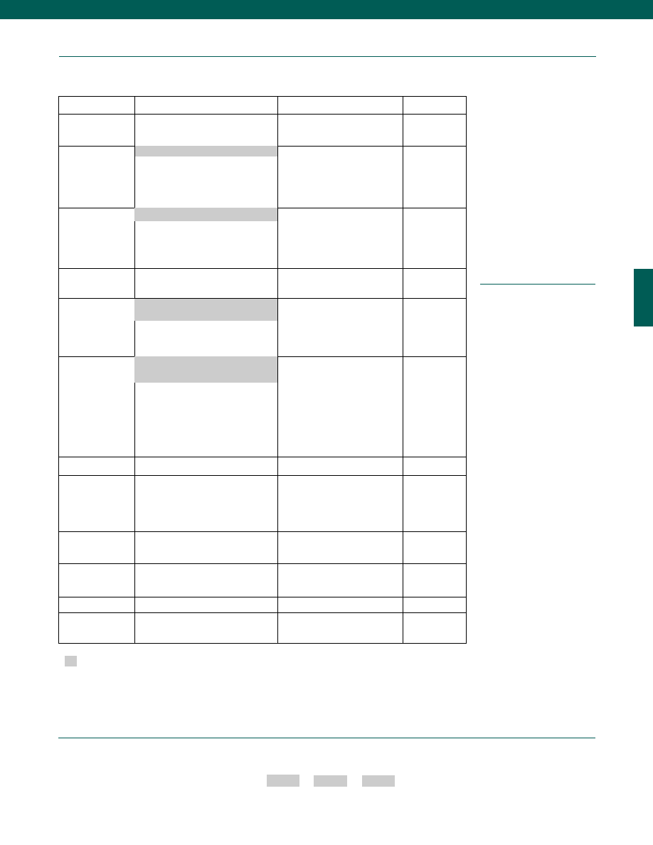
35
www.honeywell.com/sensotec
Options
Fast Track Manufacture
Built to Order
Built from Scratch
Pressure Ranges
15; 25; 50; 75; 100; 200; 300; 500; 750;
1000; 1500; 2000; 3000; 5000; 7500 psig/a
10 psig/a
Temperature
Compensation
1b. 30° to 130° F
1c. 0° to 185° F
1d. -20° to 130° F
1e. -20° to 200° F (note 6)
1f. 70° to 250° F (note 6)
1g. 70° to 325° F (note 6)
Internal Amplifiers
(note 4)
2a. 0-5 VDC (4-wire) output
2c. 0-5 VDC output
2j. 4-20 mA (3-wire) output
2t. 0-10 VDC output
2k. 4-20 mA (2-wire) output
2N (2n). 4-20 mA (2-wire)
Intrinsically safe
Internal Amplifier
Enhancements
3a. Input/ Output Isolation
3d. Remote Buffered Shunt Cal.
Pressure Ports
(note 6)
5d. 7/16-20 UNF Male
5g. G 1/4 Male
5t. G 1/2 Male
Electrical Termination
6f. Integral cable: PVC (-20° to 160°F)
6i. Integral underwater cable
(max. 180°F) (note 5)
6e. Integral cable: Teflon (0° top 180°F)
6g. Integral cable: Neoprene
(0° to 180°F) (note 5)
6h. Integral cable: Silicone
(-65° to 300°F)
6m. DIN 43650
6q. Molded integral cable:
Polyurethane (max. 180°F)
(note 5)
6t. Integral cable with Heyco
Spring Strain relief (5ft.)
Shunt Calibration
8a. Precision Internal Resistor (note 7)
Special Calibration
(note 6)
9a. 10 point (5 up/5 down) 20%
increments @ 70°F (gage)
9b. 20 point (10 up/10 down) 10%
increments @ 70°F (gage)
Bridge Resistance
(note 6)
12a. 1,000 Ohms (foil) (max. 400°F)
12b. 5,000 Ohms (foil) (max. 400°F)
Potentiometers
14a. No access to pots
14b. Top access to pots
Shock & Vibration
44a. Shock & vibration resistance
Interfaces
53e. Signature Calibration (note 6)
53t. T.E.D.S. IEEE1451.4 Module
(note 11)
1a. 60° to 160° F
Supplied as standard
1-888-282-9891
Model Super TJE
2u. Unamplified, mV/V Output
5b. 1/4-18 NPT Male (10 to 1500 psi)
5a. 1/4-18 NPT Female (2000 to 7500 psi)
6a. Bendix PTIH-10-6P (or equivalent)
6 pin (max. 250° F)
Case pressure
Different cable lengths
Different electrical connectors
Different materials
Electro-static discharge immunity
Fatigue rating
Lightning protection
O2 Clean
OEM labels
Special electrical output
Special ports
Special wiring codes
Temperature & pressure calibration
Special Customer
Requirements
(Consult Factory)
Notes
1. Gage pressure units greater than 500 psi
are sealed at atmospheric pressure
2. Input power (voltage) for internal amplifier
options 2j, 2k, 2n (2N) depends on load
resistance.
3. Interconnecting shunt cal. 1 with shunt cal.
2 terminal provides 50% (unamplified units),
75% (4-20 mA 3 wire units), or 80% (voltage
amp. units) of full scale output for quick
calibration. Shunt Calibration comes
standard with internal amplifier options 2a,
2b, 2c, 2t and 2j.
4. Not available with temperatures below -20°F
or above 185°F.
5. Not available with option 1c, 1e, 1f, 1g, 1h
or 1i.
6. Availability varies according to range.
7. Cannot be used with amplified option.
8. G=Green; B=Blue; W=White; Bl=Black;
Br=Brown; Y=Yellow; R=Red; O=Orange.
Color specifying cable and number or letter
specifying connector.
9. No mating connector necessary with cable
option.
10. Accuracies stated are expected for Best Fit
Straight Line for all errors including linearity,
hysteresis & non-repeatability thru zero.
11. Consult factory for TEDS availability with
amplified models.
How to Order
Combine the order code, the range code and the options code.
Order Code
Range Code
Options Code
Sample Code: AP111 AV 1c,2a
Courtesy of Steven Engineering, Inc.-230 Ryan Way, South San Francisco, CA 94080-6370-Main Office: (650) 588-9200-Outside Local Area: (800) 258-9200-www.stevenengineering.com
Sensotec Sensors Full Line Catalog-html.html
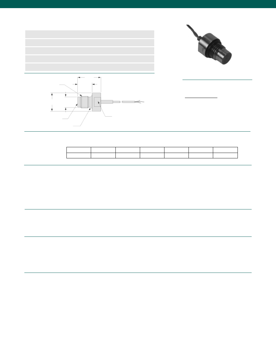
36
Pressure Ranges ..
3/8-24 UNF Thread................100; 150; 200; 300; 500; 750; 1000; 1500; 2000; 3000;
................5000; 7500; 10,000; 15,000 psig
7/16-20 UNF Thread................150; 300; 750; 1500; 7500; 15,000 psig
Accuracy (note 2)................1.0% Full Scale (note 6)
Non-Linearity and Hysteresis................1.0% Full Scale (note 2)
Non-Repeatability................+/-0.15% Full Scale
Output................2 mV/V (note 6)
Resolution................Infinite
Temperature, Operating................-65° to 300°F
Temperature, Compensated................60° to 160°F
Temperature, Effect
Zero................0.01% Full scale/ °F (note 6)
Span................0.02% Reading/ °F (note 6)
Strain Gage Type................Bonded Foil
Excitation (calibration)................5 VDC
Excitation (acceptable)................Up to 5VDC (or AC)
Insulation Resistance................5000 Megohm @ 50 VDC
Bridge Resistance................350 Ohms
Shunt Calibration Data................Included
Electrical Termination (std)................4 twisted leads (5 ft.) with external balance board
Media................Gases, Liquids compatible with wetted parts
Overload-Safe................50% over capacity
Overload-Burst................400% Full Scale
Dead Volume................Flush
Wetted Parts Material................17-4 PH Stainless Steel
Weight................2 oz.
Case Material................Stainless Steel
Dimensions
Performance
Environmental
Electrical
Mechanical
www.honeywell.com/sensotec
n
100 to 15,000 psi Range
n
Flush Mount Design
n
High Frequency
n
mV/V Output
n
1% Accuracy
G
T
B
Model S Subminiature, Flush Diaphragm Pressure Transducers
Order Code BP357; BP358
(note 1)
O-Ring Seal
Pressure Diaphragm
Order Code
T (thread)
ø A (in.)
ø D (in.)
B (in.)
G (in.)
Diaphragm
Wrench Flat
øD
øA
BP357
3/8-24 UNF
0.310
0.50
0.45
0.69
Welded
BP358
7/16-20 UNF
0.375
0.56
0.50
0.75
Welded
1-888-282-9891
Wiring Code
Cable/ Unamplified
Red
(+) Excitation
Black
(-) Excitation
Green
(-) Output
White
(+) Output
Courtesy of Steven Engineering, Inc.-230 Ryan Way, South San Francisco, CA 94080-6370-Main Office: (650) 588-9200-Outside Local Area: (800) 258-9200-www.stevenengineering.com
Sensotec Sensors Full Line Catalog-html.html
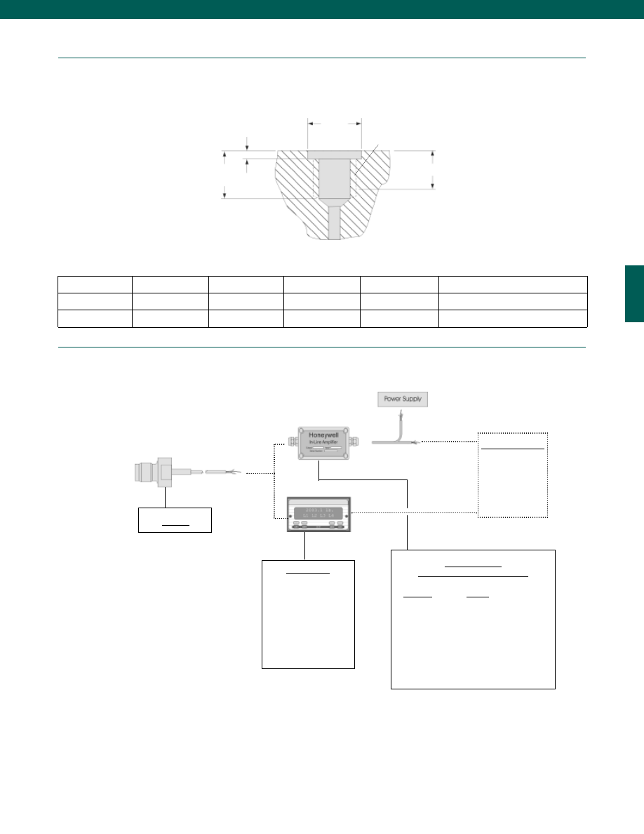
37
Installation
(note 3)
www.honeywell.com/sensotec
T
A (in.) (note 5)
B (in.)
D (in.) +.000/-.002”
O-Ring
Max. Torque (for 17-4 PH only)
3/8-24 UNF
0.47
0.30
0.445
#11
300 in.-lb.
7/16-20 UNF
0.54
0.36
0.504
#12
500 in.-lb.
Thread T
Perfect threads to this depth
Minimum tap drill depth
B
A
0.048 in.
0.050 in.
øD
1-888-282-9891
Typical System Diagram
Model S
Customer Supplied
Chart Recorder
Alarm Panel
Data Acquisition
Computer
PLC
In-Line Amplifiers
(Used with unamplified units only)
Amplifier
Output
Universal In-Line Amplifiers
UV
+/- 5 VDC
UV-10
+/- 10 VDC
UBP
0 +/- 5 VDC
U3W
4-20 mA (3 wire)
DIN Rail Mount In-Line Amplifiers
DV-05
0 +/- 5 VDC (3 wire)
DA-05
4-20 mA (3 wire)
DV-10
0 +/- 10 VDC (3 wire)
Model S
Display Units
SC500
SC1000
SC2000
SC2001
SC3004
GM
NK
HH
Courtesy of Steven Engineering, Inc.-230 Ryan Way, South San Francisco, CA 94080-6370-Main Office: (650) 588-9200-Outside Local Area: (800) 258-9200-www.stevenengineering.com
Sensotec Sensors Full Line Catalog-html.html
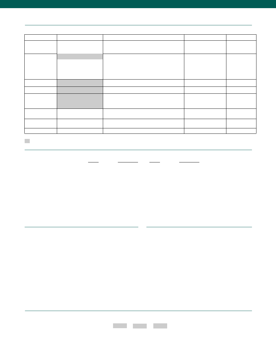
38
www.honeywell.com/sensotec
Options
Same Day Ship (BP357 only)
Fast Track Manufacture
Built to Order
Built from Scratch
Pressure Ranges
200; 500; 1000; 2000; 3000;
5000; 10,000 psig
100; 150; 300; 750; 1500; 7500 psig
15,000 psig
Temperature
Compensation
1b. 30° to 130° F
1c. 0° to 185° F
1d. -20° to 130° F
1e. -20° to 200° F
1i.
-65° to 250° F
1g. 70° to 325° F
1h. 70° to 400° F
Internal Amplifiers
2u. Unamplified, mV/V output
Pressure Ports
3/8-24 UNF
7/16 -20 UNF (BP358)
Electrical Termination 4 Twisted Leads (5 ft.)
6d. Microtec DR-4S-4H 4 pin (max. 250° F) (note 4)
6i. Integral underwater cable (max. 180° F) (note 4)
6e. Integral cable: Teflon
6h. Integral cable: Silicone
Special Calibration
9a. 10 point (5 up/ 5 down) 20% increments @ 70°F
9b. 20 point (10 up/ 10 down) 10% increments @ 70°F
Wetted Diaphragm
10c. Hastelloy C
10e. Inconel X-750
Shock & Vibration
44a. Shock and Vibration Resistance
Supplied as standard
1-888-282-9891
How to Order
Combine the order code, the range code and the options code.
Order Code
Range Code
Options Code
Sample Code: BP357 DN 1c
Different electrical termination
Different materials
Different threads
O ring material
O2 Clean
Radiation proof
Special temperature compensation
Temperature and pressure calibration
Special Customer Requirements
(Consult Factory)
Notes
1. Order Code subject to change with varying thread, range and electrical termination
2. Accuracies stated are expected for Best Fit Straight Line for all errors, including linearity,
hysteresis & non-repeatability thru zero.
3. Standard “S” type transducers have straight threads and use an O-ring for pressure sealing.
To get the best seal with the O-ring on the transducer, the tapped hole should have the
dimensions shown on previous page. For normal operating temperatures (-65° to 250° F)
use BUNA-N (black) O-rings. For high temperatures (250° to 400° F) use silicone (red).
4. Only available on certain models, consult factory.
5. “A” dimension changes with different thread options. Consult factory for specifications for
different thread options.
6. Consult factory for specifications for ranges less than 100 psi.
Range Codes
Range
Range Code
1,500 psig DJ
2,000 psig
DL
3,000 psig
DN
5,000 psig
DR
7,500 psig
DT
10,000 psig
DV
15,000 psig
EJ
Range
Range Code
100 psig
BR
150 psig
CJ
200 psig
CL
300 psig
CP
500 psig
CR
750 psig
CT
1,000 psig
CV
Model S
1a. 60° to 160° F
Courtesy of Steven Engineering, Inc.-230 Ryan Way, South San Francisco, CA 94080-6370-Main Office: (650) 588-9200-Outside Local Area: (800) 258-9200-www.stevenengineering.com
Sensotec Sensors Full Line Catalog-html.html
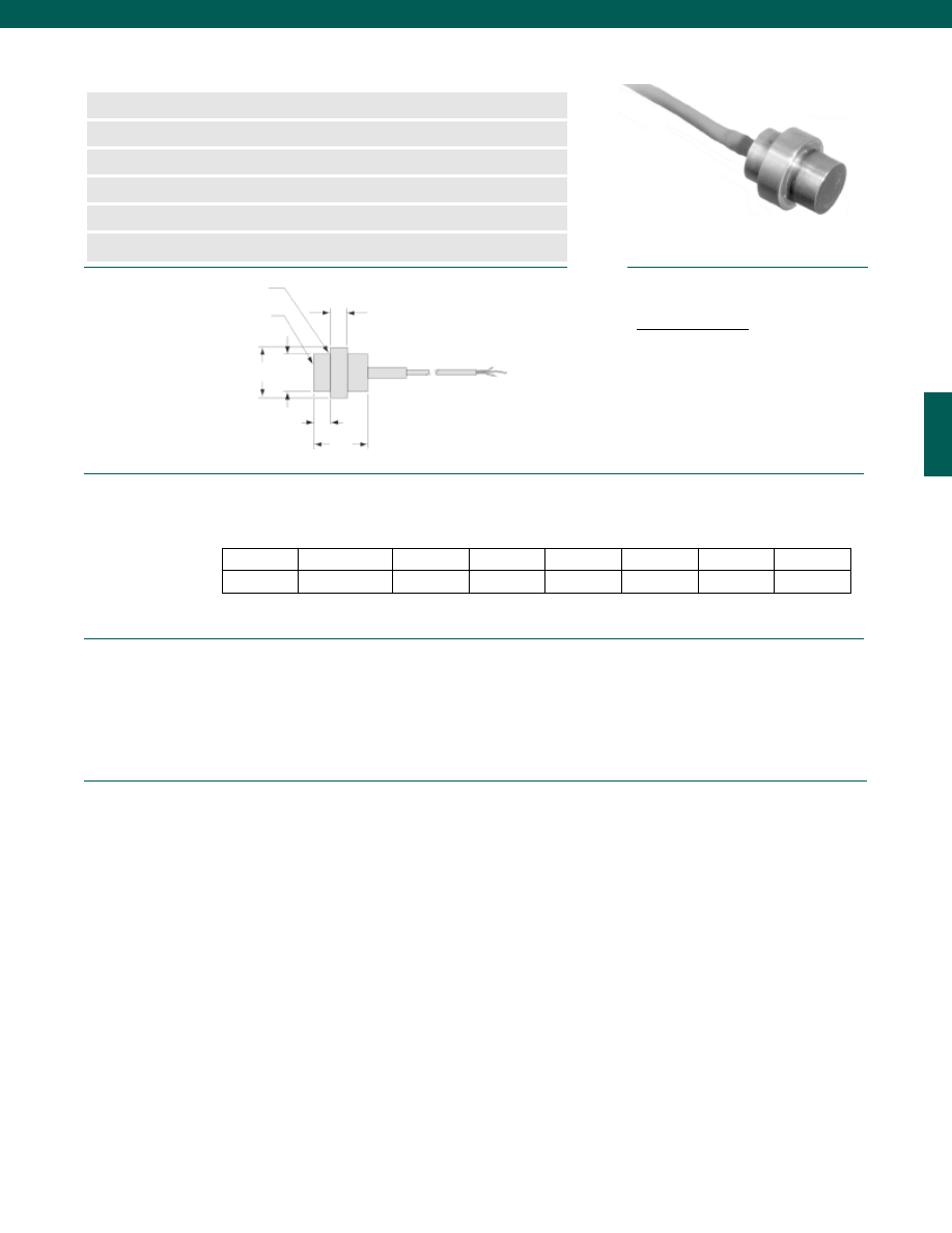
39
Dimensions
Performance
Environmental
www.honeywell.com/sensotec
n
10 to 20,000 psig Range
n
Flush Mount Design
n
High Frequency
n
mV/V Output
n
Sub-miniature Footprint
n
1% Accuracy
Model G Subminiature, Flush Diaphragm Pressure Transducer
Order Code BP386; BP387
B
C
øD
øA
Pressure Diaphragm
O-Ring Seat for Pressure Seal
Order Code
Range (psig)
øA (in.)
B (in.)
C (in.)
øD (in.)
E (in.)
Diaphragm
E
BP386
150 to 15,000
0.310
0.15
0.47
0.44
0.15
Welded
BP387
150 to 20,000
0.375
0.15
0.47
0.50
0.15
Welded
Pressure Ranges................150; 200; 250; 300; 400; 500; 600; 750; 1000; 1500; 2000; 2500;
................3000; 4000; 5000; 6000; 7500; 10,000; 15,000; 20,000 psig
Accuracy (note 1)................1.0% Full Scale
Linearity................+/-1.0% Full Scale
Hysteresis................+/-1.0% Full Scale
Non-Repeatability................+/-0.1% Full Scale
Output................2 mV/V
Resolution................Infinite
Temperature, Operating................-65° to 300°F
Temperature, Compensated................60° to 160°F
Temperature, Effect
Zero................0.01% Full scale/ °F
Span................0.02% Reading/ °F
Wiring Code
Cable/ Unamplified
Red
(+) Excitation
Black
(-) Excitation
Green
(-) Output
White
(+) Output
1-888-282-9891
Courtesy of Steven Engineering, Inc.-230 Ryan Way, South San Francisco, CA 94080-6370-Main Office: (650) 588-9200-Outside Local Area: (800) 258-9200-www.stevenengineering.com
Sensotec Sensors Full Line Catalog-html.html
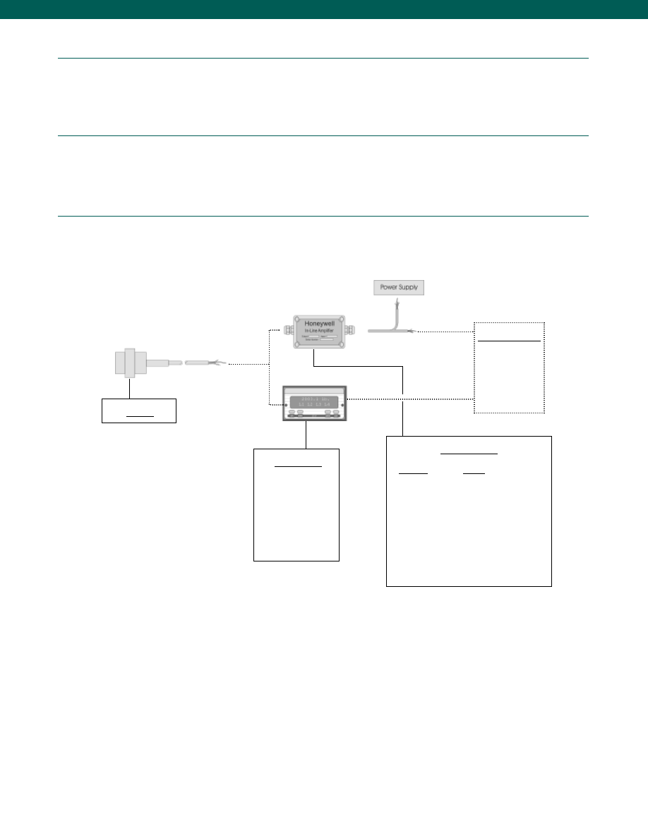
40
Electrical
Mechanical
Typical System Diagram
Strain Gage Type................Bonded foil
Excitation (calibration)................5 VDC
Bridge Resistance................350 Ohms
Shunt Calibration Data................Included
Electrical Termination (std)................4 twisted leads (5 ft.) with external balance board
Proof Pressure................Not Applicable
Media................Gases, Liquids compatible with wetted material
Overload-Safe................50% over capacity
Wetted Parts Material................17-4 PH Stainless Steel
Case Material................Stainless Steel
www.honeywell.com/sensotec
Model G
Customer Supplied
Chart Recorder
Alarm Panel
Data Acquisition
Computer
PLC
In-Line Amplifiers
Amplifier
Output
Universal In-Line Amplifiers
UV
+/- 5 VDC
UV-10
+/- 10 VDC
UBP
0 +/- 5 VDC
U3W
4-20 mA (3 wire)
U2W
4-20 mA (2 wire)
DIN Rail Mount In-Line Amplifiers
DV-05
0 +/- 5 VDC (3 wire)
DA-05
4-20 mA (3 wire)
DV-10
0 +/- 10 VDC (3 wire)
1-888-282-9891
Model G
Display Units
SC500
SC1000
SC2000
SC2001
SC3004
GM
NK
HH
Courtesy of Steven Engineering, Inc.-230 Ryan Way, South San Francisco, CA 94080-6370-Main Office: (650) 588-9200-Outside Local Area: (800) 258-9200-www.stevenengineering.com
Sensotec Sensors Full Line Catalog-html.html
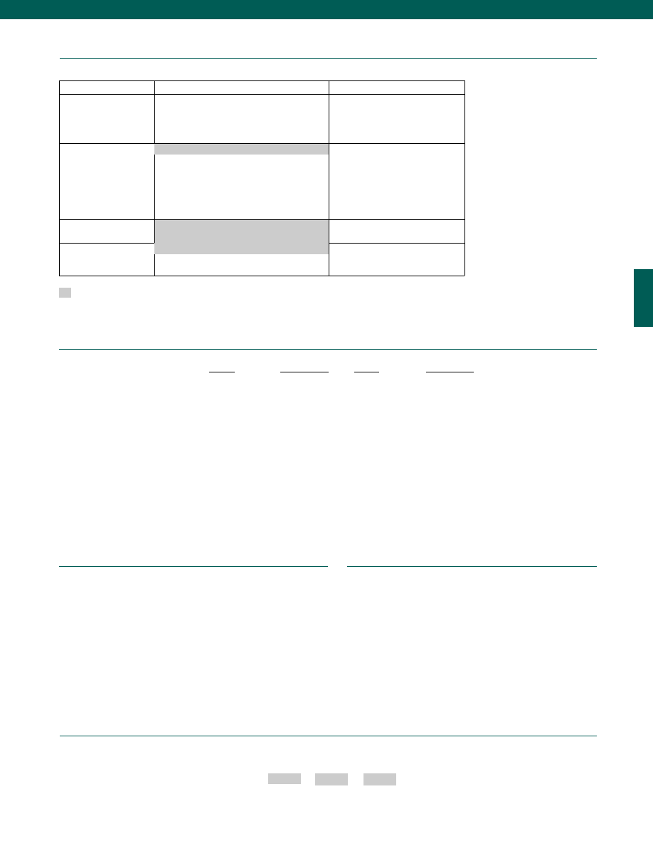
41
www.honeywell.com/sensotec
Options
Built to Order
Built from Scratch
Pressure Ranges
150; 200; 250; 300; 400; 500; 600; 750; 1000;
1500; 2000; 2500; 3000; 4000; 5000; 6000; 7500;
10,000 psig
15,000; 20,000 psig
Temperature
Compensation
1b. 30° to 130° F
1c. 0° to 185° F
1f. 70° to 250° F
1d. -20° to 130° F
1e. -20° to 200° F
1g. 70° to 325° F
1i. -65° to 250° F
Internal Amplifiers
2u. Unamplified, mV/V Output
Electrical Termination
6d. Microtec DR-4S-4H 4 pin (max. 250° F)
(note 2)
Supplied as standard
1-888-282-9891
How to Order
Combine the order code, the range code and the options code.
Order Code
Range Code
Options Code
Sample Code: BP386 CN 1c
Extended temperature ranges
Different electrical connectors
Different materials
O ring material
O2 Clean
Radiation proof
Special temperature compensation
Temperature and pressure calibration
Low Pressure Ranges
Special Customer Requirements
(Consult Factory)
Notes
1. Accuracies stated are expected for Best Fit Straight Line for all errors, including linearity,
hysteresis & non-repeatability thru zero.
2. Only available on certain models, consult factory.
Range Codes
Range
Range Code
2,000 psig
DL
2,500 psig
DM
3,000 psig
DN
5,000 psig
DR
6,000 psig
DS
7,500 psig
DT
10,000 psig
DV
15,000 psig
EJ
20,000 psig
EL
Range
Range Code
150 psig
CJ
200 psig
CL
250 psig
CN
300 psig
CP
400 psig
CQ
500 psig
CR
600 psig
CS
750 psig
CT
1,000 psig
CV
1,500 psig
DJ
Model G
1a. 60° to 160° F
4 Twisted Leads (5 ft.)
Courtesy of Steven Engineering, Inc.-230 Ryan Way, South San Francisco, CA 94080-6370-Main Office: (650) 588-9200-Outside Local Area: (800) 258-9200-www.stevenengineering.com
Sensotec Sensors Full Line Catalog-html.html
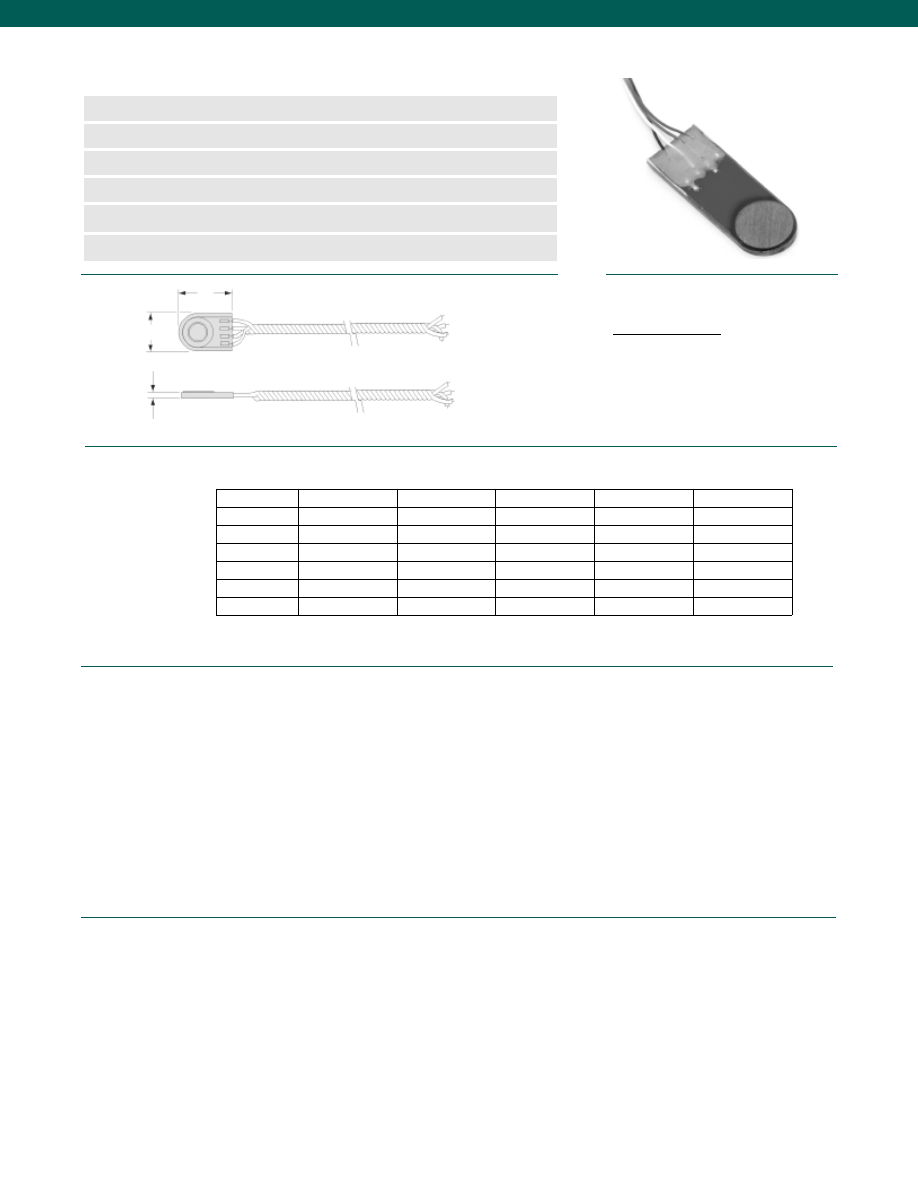
42
Pressure Ranges................10; 15; 25; 30; 50; 75; 100; 150; 200; 250; 300; 400; 500;
600; 750; 1000; 1500; 2000; 2500; 3000 psig (note 2)
Accuracy (note 1)................1.0% Full Scale
Linearity
10 to 100 psig................+/-0.5 mV
150 to 3000 psig................+/-1.0% Full Scale
Hysteresis
10 to 100 psig................+/-0.5 mV
150 to 3000 psig................+/-1.0% Full Scale
Non-Repeatability
10 to 100 psig................+/-0.1 mV
150 to 3000 psig................+/-0.1% Full Scale
Output
10 to 100 psig................2-5 mV/psi (@5 VDC)
150 to 3000 psig................2 mV/V
Resolution................Infinite
Temperature, Operating................-65° to 300°F (-20° to 250°F for semiconductor strain gage)
Temperature, Compensated................60° to 160°F
Temperature, Effect
Zero
10 to 100 psig................0.02 mV/°F
150 to 3000 psig................0.01% Full scale/ °F
Span
10 to 100 psig................0.03 mV/°F
150 to 3000 psig................0.02% Reading/ °F
Dimensions
Performance
Environmental
www.honeywell.com/sensotec
n
10 to 3000 psig Range
n
mV/V Output
n
Low Profile Design
n
Sub-miniature Footprint
n
High Frequency
n
1% Accuracy
Model F Subminiature Low Profile Pressure Transducer
(note 3)
Order Code (see table below)
T
L
A
Order Code
Foil/ Semicond.
Range (psig)
A (in.)
T (in.)
L (in.)
BP340
Foil
150-500
0.275
0.042*
0.38
BP341
Foil
150-3000
0.320
0.042*
0.50
BP342
Foil
150-3000
0.425
0.060
0.56
BP343
Semiconductor
15-500
0.150
0.042
0.38
BP344
Semiconductor
10-500
0.275
0.042
0.38
BP345
Semiconductor
10-3000
0.320
0.042
0.50
BP346
Semiconductor
10-3000
0.425
0.060
0.56
* Nominal
Wiring Code
Cable/ Unamplified
Red
(+) Excitation
Black
(-) Excitation
Green
(-) Output
White
(+) Output
1-888-282-9891
Courtesy of Steven Engineering, Inc.-230 Ryan Way, South San Francisco, CA 94080-6370-Main Office: (650) 588-9200-Outside Local Area: (800) 258-9200-www.stevenengineering.com
Sensotec Sensors Full Line Catalog-html.html
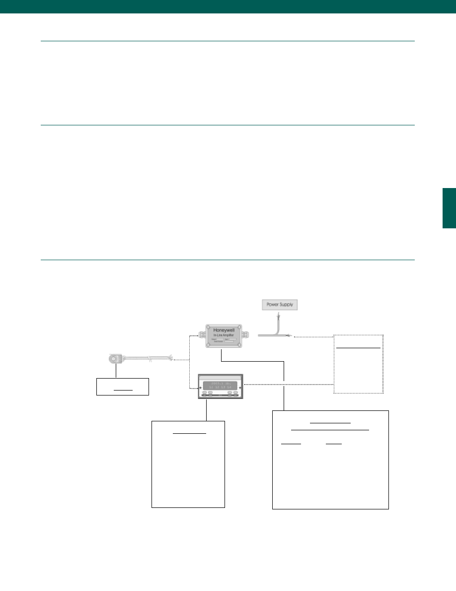
43
Electrical
Mechanical
Typical System Diagram
Strain Gage Type
10 to 100 psig................Bonded semiconductor
150 to 3000 psig................Bonded foil
Excitation (calibration)................5 VDC
Bridge Resistance
10 to 100 psig................500 Ohms
150 to 3000 psig................350 Ohms
Shunt Calibration Data................Included
Electrical Termination (std)................4 twisted leads (5 ft.) with external balance board
Proof Pressure................Not Applicable
Media................Gas, Liquid
Overload-Safe
10 to 100 psig................100% over capacity
150 to 3000 psig................50% over capacity
Wetted Parts Material
10 to 100 psig................17-4 PH Stainless Steel or BeCu
150 to 3000 psig................17-4 PH Stainless Steel
Case Material................Stainless Steel
www.honeywell.com/sensotec
Model F
Customer Supplied
Chart Recorder
Alarm Panel
Data Acquisition
Computer
PLC
In-Line Amplifiers
(Used with unamplified units only)
Amplifier
Output
Universal In-Line Amplifiers
UV
+/- 5 VDC
UV-10
+/- 10 VDC
UBP
0 +/- 5 VDC
U3W
4-20 mA (3 wire)
DIN Rail Mount In-Line Amplifiers
DV-05
0 +/- 5 VDC (3 wire)
DA-05
4-20 mA (3 wire)
DV-10
0 +/- 10 VDC (3 wire)
1-888-282-9891
Model F
Display Units
SC500
SC1000
SC2000
SC2001
SC3004
GM
NK
HH
Courtesy of Steven Engineering, Inc.-230 Ryan Way, South San Francisco, CA 94080-6370-Main Office: (650) 588-9200-Outside Local Area: (800) 258-9200-www.stevenengineering.com
Sensotec Sensors Full Line Catalog-html.html
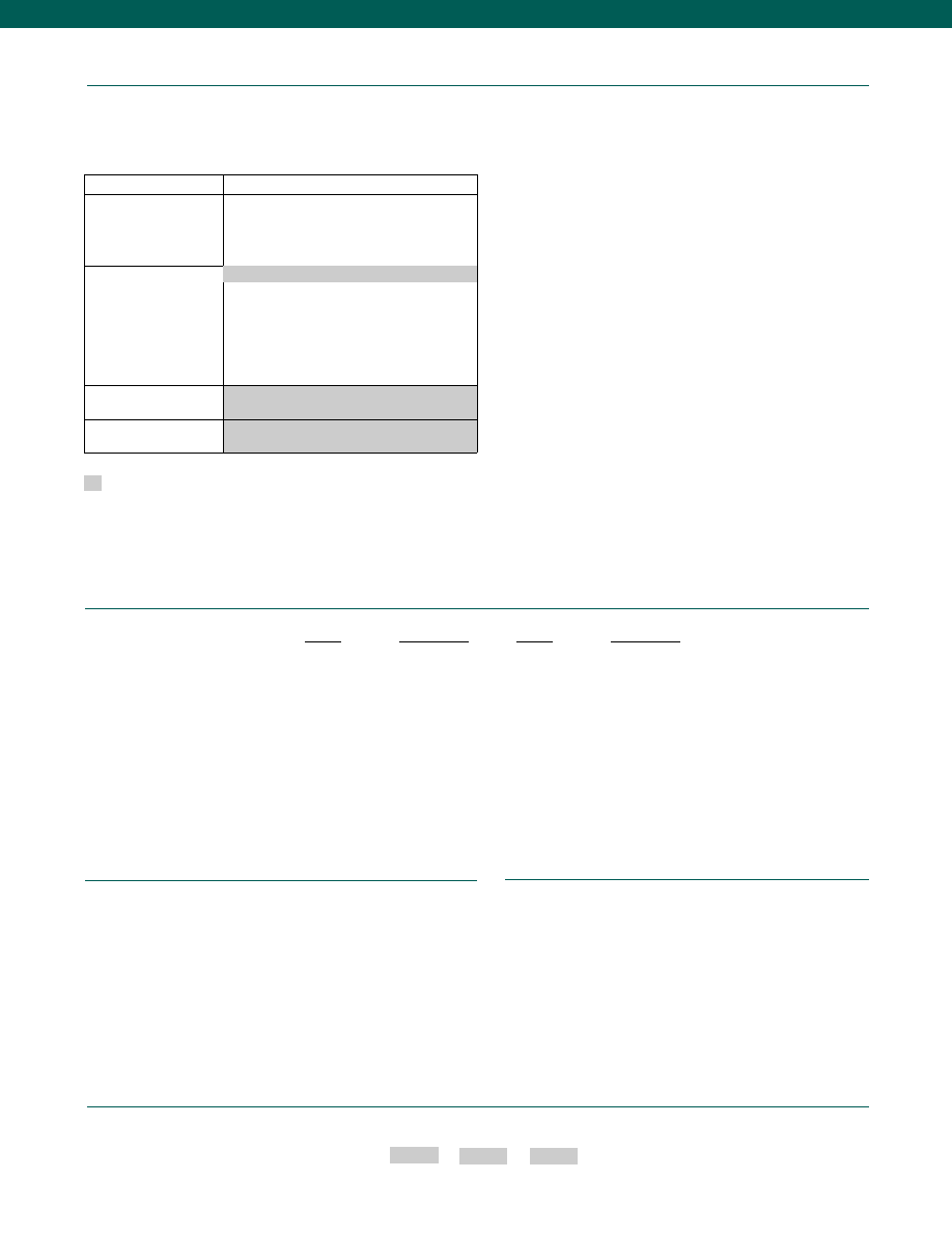
44
www.honeywell.com/sensotec
Options
1-888-282-9891
How to Order
Combine the order code, the range code and the options code.
Order Code
Range Code
Options Code
Sample Code: BP343 BN 1c
Different materials
O2 Clean
Radiation proof
Special temperature compensation
Temperature and pressure calibration
Special Customer Requirements
(Consult Factory)
Notes
1. Accuracies stated are expected for Best Fit Straight Line for all errors, including linearity,
hysteresis & non-repeatability thru zero.
2. Low pressure ranges (10 to 100 psig) - Semiconductor gages (500 Ohms)
High pressure ranges (150 to 3000 psig) - Foil gages (350 Ohms)
3. All model F’s have a cemented diaphragm.
4. Only available with foil strain gage.
Range Codes
Range
Range Code
300 psig
CP
400 psig
CQ
500 psig
CR
600 psig
CS
750 psig
CT
1,000 psig
CV
1,500 psig
DJ
2,000 psig
DL
2,500 psig
DM
3,000 psig
DN
Range
Range Code
10 psig
AV
15 psig
BJ
25 psig
BL
30 psig
BM
50 psig
BN
75 psig
BP
100 psig
BR
150 psig
CJ
200 psig
CL
250 psig
CN
Model F
Built from Scratch
Pressure Ranges
10; 15; 25; 30; 50; 75; 100; 150; 200; 250;
300; 400; 500; 600; 750; 1000; 1500; 2000;
2500; 3000 psig
Temperature
Compensation
1b. 30° to 130° F
1c. 0° to 185° F
1f. 70° to 250° F
1d. -20° to 130° F
1e. -20° to 200° F
1g. 70° to 325° F (note 4)
1i.
-65° to 250° F (note 4)
Internal Amplifiers
2u. Unamplified, mV/V Output
Electrical Termination
4 Twisted Leads (5 ft.)
Supplied as standard
1a. 60° to 160° F
Courtesy of Steven Engineering, Inc.-230 Ryan Way, South San Francisco, CA 94080-6370-Main Office: (650) 588-9200-Outside Local Area: (800) 258-9200-www.stevenengineering.com
Sensotec Sensors Full Line Catalog-html.html
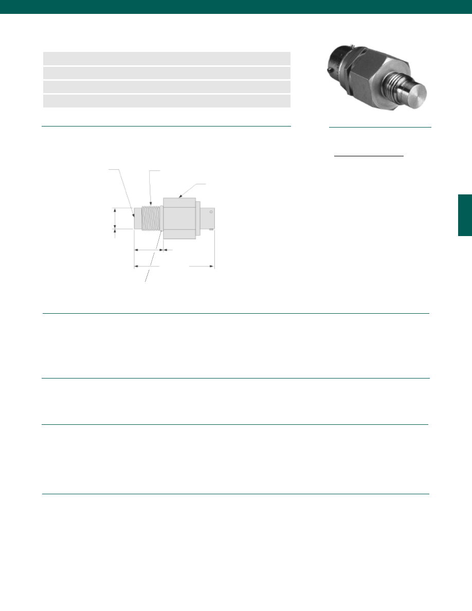
45
Pressure Ranges................100; 150; 200; 300; 500; 750; 1000; 1500; 2000; 3000; 5000;
................7500; 10,000; 15,000 psig
Accuracy (note 6)................0.5% Full Scale
Non-Linearity and Hysteresis................+/-0.5% Full Scale
Non-Repeatability................+/-0.1% Full Scale
Output................2 mV/V nominal
Resolution................Infinite
Temperature, Operating................-65° to 300°F
Temperature, Compensated................60° to 160°F
Temperature, Effect
Zero................0.01% Full scale/ °F
Span................0.02% Reading/ °F
Strain Gage Type................Bonded foil
Excitation (calibration)................5 VDC
Excitation (acceptable)................Up to 5 VDC or AC
Insulation Resistance................5000 Megohms @50 VDC
Bridge Resistance................350 Ohms
Shunt Calibration Data................Included
Electrical Termination (std)................PTIH-10-6P or equivalent (Hermetic)
Mating Connector (not incl.)................PT06-10-6S or equivalent (AA111)
Dimensions
Performance
Environmental
Electrical
Mechanical
www.honeywell.com/sensotec
n
100 to 15,000 psig
n
Flush Mount Design
n
Miniature Footprint
n
Stainless Steel
Model A-105 Flush Diaphragm Pressure Transducer
Order Code AP311
7/16-20 UNF
Pressure Diaphragm
3/4 Hex
1.8 in.
0.55 in.
ø 0.355 in.
Wiring Code
Connector/ Unamplified
A
(+) Excitation
B
(+) Excitation
C
(-) Excitation
D
(-) Excitation
E
(-) Output
F
(+) Output
1-888-282-9891
Media................Gases, Liquids compatible with wetted parts
Overload-Safe................50% over capacity
Proof Pressure................400% (Max. 25 kpsi)
Dead Volume................Flush Diaphragm
Wetted Parts Material................17-4 PH Stainless Steel
Weight................2 oz
Case Material................Stainless Steel
Viton O-Ring
0.31-0001-79
Courtesy of Steven Engineering, Inc.-230 Ryan Way, South San Francisco, CA 94080-6370-Main Office: (650) 588-9200-Outside Local Area: (800) 258-9200-www.stevenengineering.com
Sensotec Sensors Full Line Catalog-html.html
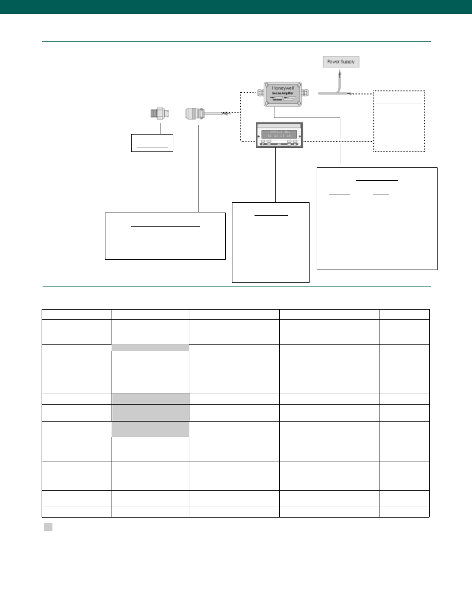
46
Typical System Diagram
www.honeywell.com/sensotec
Model A-105
Mating Connectors & Cables
PT06A-10-6S (4 conductor cable), Std.
PT06E-10-6S (4 conductor cable)
Display Units
SC500
SC1000
SC2000
SC2001
SC3004
GM
NK
HH
Customer Supplied
Chart Recorder
Alarm Panel
Data Acquisition
Computer
PLC
1-888-282-9891
In-Line Amplifiers
Amplifier
Output
Universal In-Line Amplifiers
UV
+/- 5 VDC
UV-10
+/- 10 VDC
UBP
0 +/- 5 VDC
U3W
4-20 mA (3 wire)
DIN Rail Mount In-Line Amplifiers
DV-05
0 +/- 5 VDC (3 wire)
DA-05
4-20 mA (3 wire)
DV-10
0 +/- 10 VDC (3 wire)
Model A105
Options
Same Day Ship
Fast Track Manufacture
Built to Order
Built from Scratch
Pressure Ranges
200; 500; 1000; 2000; 3000;
5000; 10,000 psig
150; 300; 750; 1500; 7500 psig
100 psig
15,000 psig
Temperature
Compensation
1b. 30° to 130° F
1c. 0° to 185° F
1d. -20° to 130° F
1e. -20° to 200° F
1f. 70° to 250° F
1i. -65° to 250° F
1g. 70° to 325° F
1h. 70° to 400° F
Internal Amplifiers
2u. Unamplified, mV/V output
Pressure Ports
5d. 7/16-20 UNF Male
5p. M12 x 1.5 Male
Electrical Termination
6e. Integral cable: Teflon
(-65° to 475°F)
6h. Integral cable: Silicone
(-65° to 300°F)
6i. Integral underwater cable
(max. 180°F) (note 1)
6v. Phoenix connector on end of cable
Special Calibration (note 3)
9a. 10 point (5 up/ 5 down) 20%
increments @ 70°F (note 3)
9b. 20 point (10 up/ 10 down) 10%
increments @ 70°F (note 3)
Wetted Diaphragm
10c. Hastelloy C
10e. Inconel X-750
Shock & Vibration
44a. Shock and vibration resistance
Supplied as standard
1a. 60° to 160° F
6a. Bendix PTIH-10-6P-(or
equiv.) 6 pin (max. 250°F)
Courtesy of Steven Engineering, Inc.-230 Ryan Way, South San Francisco, CA 94080-6370-Main Office: (650) 588-9200-Outside Local Area: (800) 258-9200-www.stevenengineering.com
Sensotec Sensors Full Line Catalog-html.html

47
Range
Range Code
100 psi
BR
150 psi
CJ
200 psi
CL
300 psi
CP
500 psi
CR
750 psi
CT
1,000 psi
CV
1,500 psi
DJ
2,000 psi
DL
3,000 psi
DN
5,000 psi
DR
7,500 psi
DT
10,000 psi
DV
15,000 psi
EJ
www.honeywell.com/sensotec
1-888-282-9891
How to Order
Combine the order code, the range code and the options code.
Order Code
Range Code
Options Code
Sample Code: AP311 BJ 1b
Different electrical connectors
Different materials
Different threads
O ring material
O2 Clean
Extended temperature ranges
Radiation proof
Special temperature compensation
Temperature and pressure calibration
Special Customer Requirements
(Consult Factory)
Notes
Model A105
Range Codes
1. Not available with option 1c.
2. G=Green; B=Blue; W=White; Bl=Black; Br=Brown; Y=Yellow; R=Red; O=Orange. Color
specifying cable and number or letter specifying connector
3. Availability varies with range.
4. No mating connector necessary with cable option.
5. Not available with temperatures below -20°F or above 185°F.
6. Accuracies stated are expected for Best Fit Straight Line for all errors, including linearity,
hysteresis & non-repeatability thru zero.
Courtesy of Steven Engineering, Inc.-230 Ryan Way, South San Francisco, CA 94080-6370-Main Office: (650) 588-9200-Outside Local Area: (800) 258-9200-www.stevenengineering.com
Sensotec Sensors Full Line Catalog-html.html
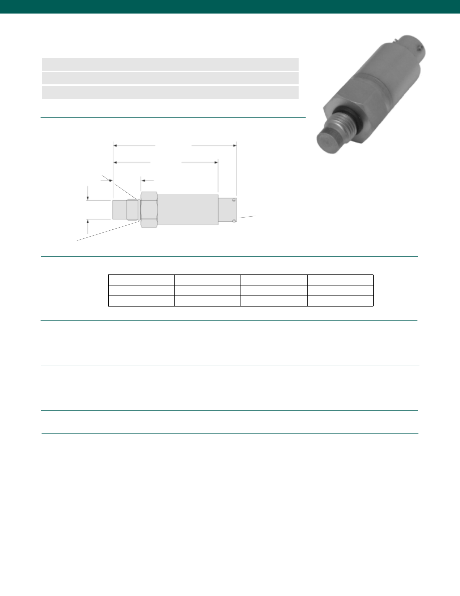
48
Pressure Ranges................500; 1000; 2000; 3000; 5000; 10,000 psi
Accuracy................+/-0.5% F.S.
Output................4-20 mA @ 9-28 VDC
..1-5 or 1-10 VDC @ 16-28 VDC
Resolution................Infinite
Temperature, Operating................-20° to 185°F
Temperature, Compensated................30° to 160°F
Temperature, Effect
Zero................0.015% Full scale/ °F
Span................0.02% Reading/ °F
Electrical Termination (std)................PTIH-10-6P or equivalent
Mating Connector (not incl.)................AA111 (PT06A-10-6S)
Media................Gases, Liquids compatible with wetted material
Overload-Safe................200% over capacity
Overload-Burst................500% over capacity to a max of 25,000 psi
Pressure Port................7/16-20 UNF
Wetted Parts Material................17-4 PH Welded Stainless Steel
Dimensions
Order Codes
Performance
Environmental
Electrical
Mechanical
www.honeywell.com/sensotec
n
Flush Diaphragm
n
Fully Welded Construction
n
Stainless Steel
Model A-105a Flush Diaphragm, High Level Output
Pressure Transducer
Order Code (see below)
7/16-20 UNF
Viton O-Ring
0.31-0001-79
6-pin connector
PTIH-10-6P
0.60 in.
2.32 in.
2.7 in.
ø 0.355 in.
Mounting Threads
4-20 mA
1-5 VDC
1-10 VDC
7/16-20 UNF
AP313
AP314
AP315
M12 x 1.75-6G
AP316
AP317
AP318
Output
1-888-282-9891
Courtesy of Steven Engineering, Inc.-230 Ryan Way, South San Francisco, CA 94080-6370-Main Office: (650) 588-9200-Outside Local Area: (800) 258-9200-www.stevenengineering.com
Sensotec Sensors Full Line Catalog-html.html
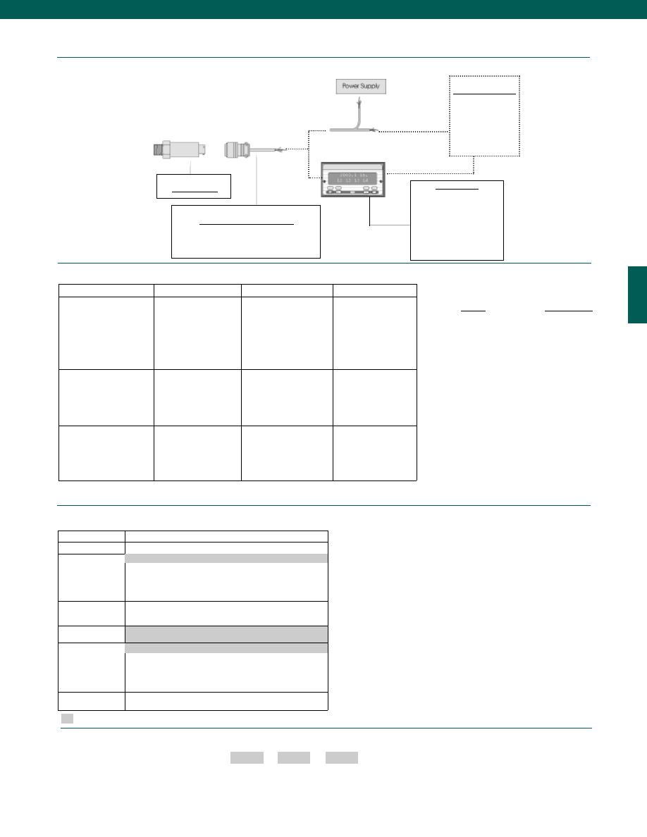
49
www.honeywell.com/sensotec
Range Codes
Model A-105a
Mating Connectors & Cables
PT06A-10-6S (4 conductor cable), Std.
PT06E-10-6S (4 conductor cable)
Customer Supplied
Chart Recorder
Alarm Panel
Data Acquisition
Computer
PLC
1-888-282-9891
Supplied as standard
How to Order
The order code consists of the product model, the desired range code and the available options.
Model Code
Range Code
Options Code
Sample Code:
AP315 DN
2t
Build to Order
Pressure Ranges
500; 1000; 2000; 3000; 5000; 10,000 psi
Temperature
Compensation
1b. 30° to 130° F
1c. 0° to 185° F
1d. -20° to 130° F
1j.
0° to 50° C
1k. -20° to 85° C
Internal Amplifiers
2k. 4-20mA (2-wire) output
2c. 1-5VDC
2t. 1-10 VDC output
Pressure Ports
5d. 7/16” - 20 UNF Male (per MS33656E4)
5p. M12 x 1.5
Electrical
Termination
6e. Integral cable: Teflon (-54° to 245° C)
6f.
Integral cable: PVC (-30° to 70° C)
6h. Integral cable: Silicon (-54° to 150° C)
6i.
Integral underwater cable (max 80° C)
6v. Phoenix connector on end of cable
Special
Calibration
9a. 10 point (5 up/5 down) 20% increments @ 20° C
9b. 20 point (10 up/10 down) 10% increments @ 20° C
Range
Range Code
500 psi
CR
1000 psi
CV
2000 psi
DL
3000 psi
DN
5000 psi
DR
10,000 psi
DV
1a. 60° to 160° F
6a. Bendix PTIH-10-6P (or equivalent) 6 pin (max. 120° C)
Model A-105a
Display Units
SC500
SC1000
SC2000
SC2001
SC3004
GM-A
Options
Typical System Diagram
Internal Amplifiers
Amplifier Specifications
Vehicle Voltage Output 2c Vehicle Voltage Output 2t Current 2 Wire Option 2k
Output Signal
Input Power (Voltage)
Input Power (Current)
Frequency Response
Power Supply Rejection
Operating Temperature
Reverse Voltage Protection
Short Circuit Protection
1-5V @ 10mA
16-28 VDC
40 mA
200 Hz
60 db
-20° to 185° F
Yes
Momentary
1-10V @ 10mA
16-28 VDC
40 mA
200 Hz
60 db
-20° to 185° F
Yes
Momentary
4-20 mA
9-28 VDC
4-28 mA
300 Hz
60 db
0° to 185° F
Yes
Yes
Wiring Code: Connector
A (+) Supply
B**Output Common/
C**Supply Return
D (+) Output
E No Connection
F No Connection
A (+) Supply
B**Output Common/
C**Supply Return
D (+) Output
E No Connection
F No Connection
A (+) Supply
B No Connection
C No Connection
D (+) Output
E Case Ground
F No Connection
Wiring Code: Cable
R (+) Supply
Bl* Output Common/
G* Supply Return
W (+) Output
B Shunt Cal 1
Br Shunt Cal 2
R (+) Supply
Bl* Output Common/
G* Supply Return
W (+) Output
B Shunt Cal 1
Br Shunt Cal 2
R (+) Supply
Bl (+) Output
W Case Ground
* Black and Green wires are internally connected.
**Pins B & C are internally connected.
Custom Pressure Ranges
Special Customer Requirements
(Consult Factory)
Courtesy of Steven Engineering, Inc.-230 Ryan Way, South San Francisco, CA 94080-6370-Main Office: (650) 588-9200-Outside Local Area: (800) 258-9200-www.stevenengineering.com
Sensotec Sensors Full Line Catalog-html.html
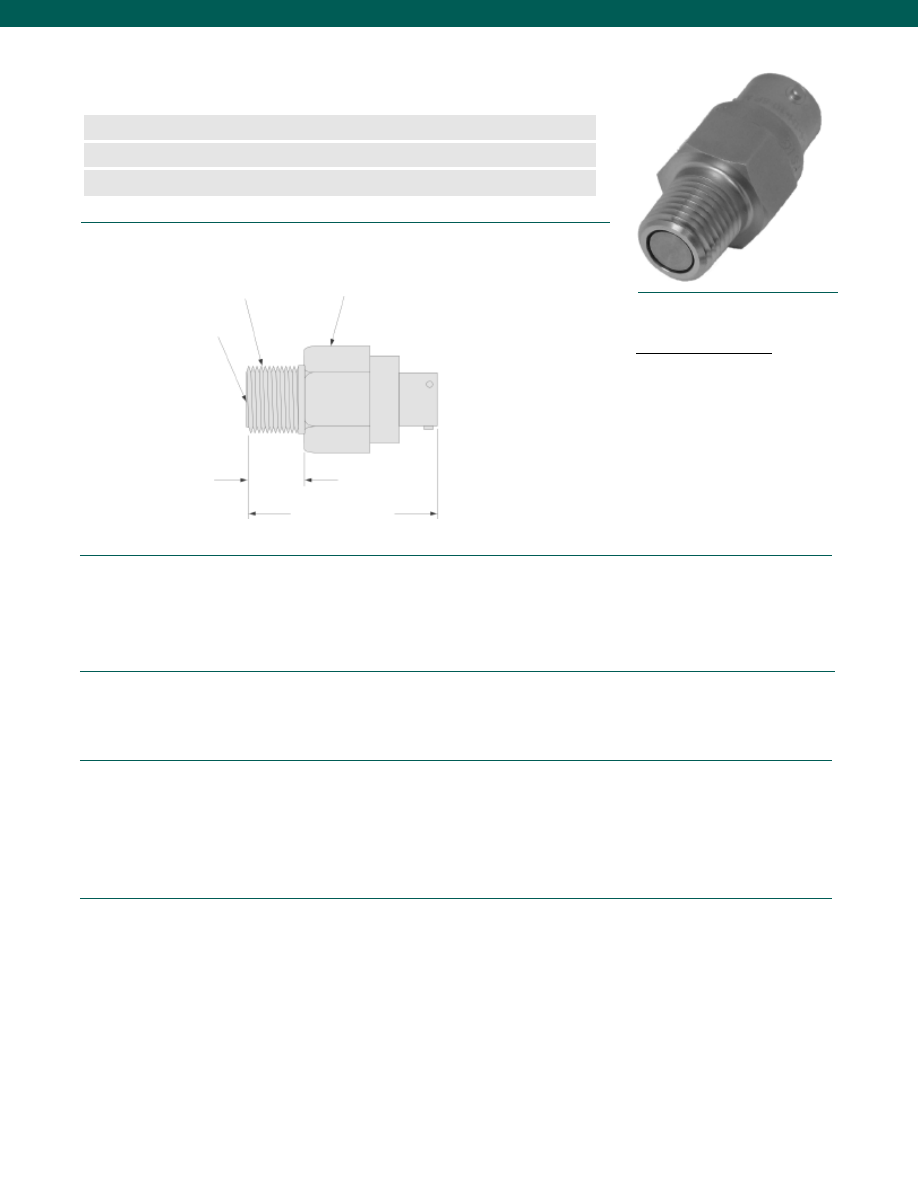
50
Pressure Ranges (note 3)................100; 150; 200; 300; 500; 750; 1,000; 1,500;
................2,000; 3,000; 5,000; 7,500; 10,000 psig/a
Accuracy (note 2)................0.5% Full Scale
Non-Linearity and Hysteresis................+/-0.5% Full Scale (note 3)
Non-Repeatability................+/-0.1% Full Scale (note 3)
Output................2 mV/V
Resolution................Infinite
Temperature, Operating................-65° to 300°F
Temperature, Compensated................60° to 160°F
Temperature, Effect
Zero................0.01 Full Scale/°F (note 3)
Span................0.02% Reading/ °F (note 3)
Strain Gage Type................Bonded foil
Excitation (calibration)................5 VDC
Excitation (acceptable)................Up to 5 VDC or AC
Insulation Resistance................5000 Megohms @50 VDC
Bridge Resistance................350 Ohms
Shunt Calibration Data................Included
Electrical Termination (std)................PTIH-10-6P or equivalent (Hermetic stainless)
Mating Connector (not incl.)................PT06-10-6S or equivalent (AA111)
Media................Gases, Liquids compatible with wetted parts
Overload-Safe................50% over capacity
Proof Pressure................400% Full Scale (Max. 20,000 psi)
Dead Volume................Flush Diaphragm (Consult factory for charged volume)
Wetted Parts Material................17-4 PH Stainless Steel
Weight................2 oz.
Case Material................Stainless Steel
Dimensions
Performance
Environmental
Electrical
Mechanical
www.honeywell.com/sensotec
n
Unitized Flush Diaphragm
n
100 to 10,000 psig
n
Stainless Steel
Model A-205 Flush Diaphragm Pressure Transducer
Order Code BP312
1/4-18 NPT
Pressure Diaphragm
3/4 Hex
1.58 in.
0.57 in.
Wiring Code
Connector/ Unamplified
A
(+) Excitation
B
(+) Excitation
C
(-) Excitation
D
(-) Excitation
E
(-) Output
F
(+) Output
1-888-282-9891
Courtesy of Steven Engineering, Inc.-230 Ryan Way, South San Francisco, CA 94080-6370-Main Office: (650) 588-9200-Outside Local Area: (800) 258-9200-www.stevenengineering.com
Sensotec Sensors Full Line Catalog-html.html
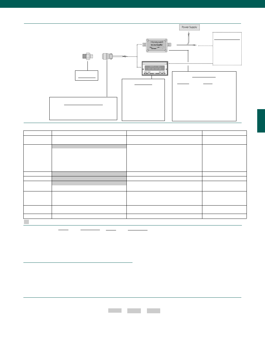
51
Fast Track Manufacture
Built to Order
Built from Scratch
Pressure Ranges
150; 200; 300; 500; 750; 1000; 1500; 2000; 3000;
5000; 7500; 10,000 psi
100 psi
Temperature
Compensation
1b. 30° to 130° F
1c. 0° to 185° F
1d. -20° to 130° F
1e. -20° to 200° F
1f. 70° to 250° F
1i. -65° to 250° F
1g. 70° to 325° F
1h. 70° to 400° F
Internal Amplifiers
2u. Unamplified, mV/V output
Pressure Ports
5b. 1/4-18 NPT Male
Electrical
Termination
6i.
Integral underwater cable (max. 180° F) (note 1)
6e. Integral cable: Teflon (-65° to 475°F)
6h. Integral cable: Silicone (-65° to 300°F)
6v. Phoenix connector on end of cable
Special Calibration
9a. 10 point (5 up/ 5 down) 20% increments @
70°F (note 4)
9b. 20 point (10 up/ 10 down) 10% increments @
70°F (note 4)
Wetted Diaphragm
10c. Hastelloy C
10e. Inconel X-750
Shock & Vibration
44a. Shock and vibration resistance
Model A-205
Mating Connectors & Cables
PT06A-10-6S (4 conductor cable), Std
.
PT06E-10-6S (4 conductor cable)
Display Units
SC500
SC1000
SC2000
SC2001
SC3004
GM
NK
HH
Customer Supplied
Chart Recorder
Alarm Panel
Data Acquisition
Computer
PLC
In-Line Amplifiers
Amplifier
Output
Universal In-Line Amplifiers
UV
+/- 5 VDC
UV-10
+/- 10 VDC
UBP
0 +/- 5 VDC
U3W
4-20 mA (3 wire)
DIN Rail Mount In-Line Amplifiers
DV-05
0 +/- 5 VDC (3 wire)
DA-05
4-20 mA (3 wire)
DV-10
0 +/- 10 VDC (3 wire)
Typical System Diagram
www.honeywell.com/sensotec
1-888-282-9891
Model A205
Range
Range Code
100 psi
BR
150 psi
CJ
200 psi
CL
300 psi
CP
500 psi
CR
750 psi
CT
1,000 psi
CV
Options
Supplied as standard
How to Order
Combine the order code, the range code and the options code.
Order Code
Range Code
Options Code
Sample Code: BP312 BJ 1b
Different electrical connectors
Different materials
Different threads
O2 Clean
Extended temperature ranges
Radiation proof
Special temperature compensation
Temperature and pressure calibration
Special Customer Requirements
(Consult Factory)
Notes
1. Not available with option 1e, 1f, 1g, 1h or 1i.
2. Accuracies stated are expected for Best Fit Straight Line for all errors, including linearity,
hysteresis & non-repeatability thru zero.
3. For ranges less than 100 psi, consult factory for specifications.
4. Not available for all ranges.
Range Codes
Range
Range Code
1,500 psi
DJ
2,000 psi
DL
3,000 psi
DN
5,000 psi
DR
7,500 psi
DT
10,000 psi
DV
1a. 60° to 160° F
6a. Bendix PTIH-10-6P-(or equiv.) 6 pin (max. 400°F)
Courtesy of Steven Engineering, Inc.-230 Ryan Way, South San Francisco, CA 94080-6370-Main Office: (650) 588-9200-Outside Local Area: (800) 258-9200-www.stevenengineering.com
Sensotec Sensors Full Line Catalog-html.html
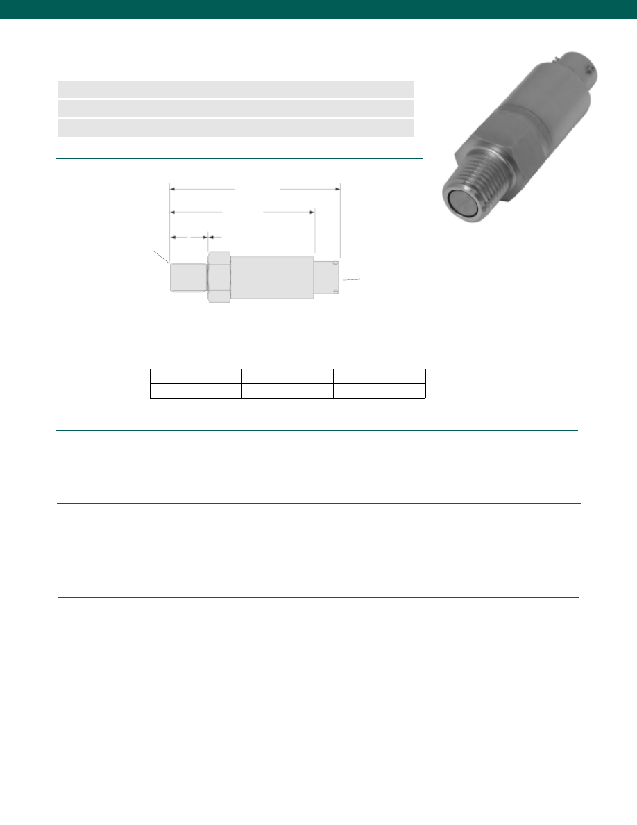
52
Pressure Ranges................300; 500; 750; 1000; 1500; 2000; 3000; 5000;
................7500; 10,000 psi
Accuracy................+/-0.5% F.S.
Output................4-20 mA @ 9-28 VDC
................1-5 or 1-10 VDC @ 16-28 VDC
Resolution................Infinite
Temperature, Operating................-20° to 180°F
Temperature, Compensated................30° to 160°F
Temperature, Effect
Zero................0.015% Full scale/ °F
Span................0.02% Reading/ °F
Electrical Termination (std)................PTIH-10-6P or equivalent
Mating Connector (not incl.)................AA111 (PT06A-10-6S)
Media................Gases, Liquids compatible with wetted material
Overload-Safe................200% over capacity
Overload-Burst................500% over capacity to a max of 20,000 psi
Pressure Port................1/4-18 NPT
Wetted Parts Material................17-4 PH Welded Stainless Steel
Dead Volume................Flush Diaphragm (consult factory for charged volume)
Dimensions
Order Codes
Performance
Environmental
Electrical
Mechanical
www.honeywell.com/sensotec
n
Flush Diaphragm
n
Fully Welded Construction
n
Metric or English Threads
Model A-205a Flush Diaphragm, High Level Output
Pressure Transducer
Order Code (see below)
1/4-18 NPT
6-pin connector
PTIH-10-6P
0.60 in.
2.32 in.
2.7 in.
4-20 mA
1-5 VDC
1-10 VDC
BP314
BP315
BP316
Output
1-888-282-9891
Courtesy of Steven Engineering, Inc.-230 Ryan Way, South San Francisco, CA 94080-6370-Main Office: (650) 588-9200-Outside Local Area: (800) 258-9200-www.stevenengineering.com
Sensotec Sensors Full Line Catalog-html.html
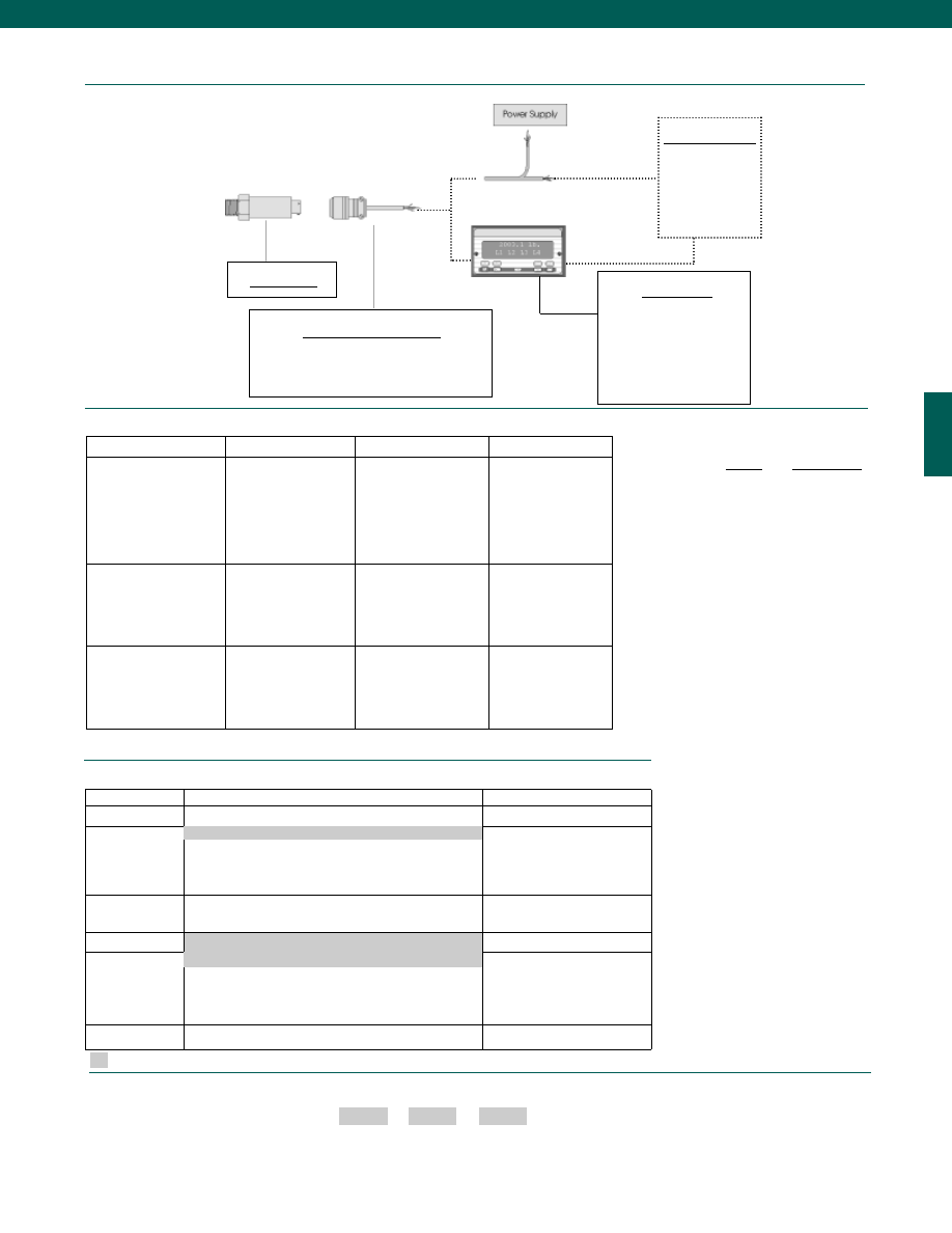
53
www.honeywell.com/sensotec
Range Codes
1-888-282-9891
Options
Supplied as standard
How to Order
The order code consists of the product model, the desired range code and the available options.
Model Code
Range Code
Options Code
Sample Code:
BP315 DN
2t
Build to Order
Build From Scratch
Pressure Ranges
500; 1000; 2000; 3000; 5000; 10,000 psi
300; 750; 1500; 7500 psi
Temperature
Compensation
1b. 30° to 130° F
1c. 0° to 185° F
1d. -20° to 130° F
1j.
0° to 50° C
1k. -20° to 85° C
Internal Amplifiers
2k. 4-20mA (2-wire) output
2c. 1-5VDC
2t. 1-10 VDC output
Pressure Ports
5b. 1/4-18 NPT
Electrical
Termination
6e. Integral cable: Teflon (-54° to 245° C)
6f.
Integral cable: PVC (-30° to 70° C)
6h. Integral cable: Silicon (-54° to 150° C)
6i.
Integral underwater cable (max 80° C)
6v. Phoenix connector on end of cable
Special Calibration 9a. 10 point (5 up/5 down) 20% increments @ 20° C
9b. 20 point (10 up/10 down) 10% increments @ 20° C
Range
Range Code
300 psi
CP
500 psi
CR
750 psi
CT
1000 psi
CV
1500 psi
DJ
2000 psi
DL
3000 psi
DN
5000 psi
DR
7500 psi
DT
10,000 psi
DV
1a. 60° to 160° F
6a. Bendix PTIH-10-6P (or equivalent) 6 pin (max. 120° C)
Model A-205a
Mating Connectors & Cables
PT06A-10-6S (4 conductor cable), Std.
PT06E-10-6S (4 conductor cable)
Customer Supplied
Chart Recorder
Alarm Panel
Data Acquisition
Computer
PLC
Typical System Diagram
Internal Amplifiers
Model A-205a
Display Units
SC500
SC1000
SC2000
SC2001
SC3004
GM-A
Amplifier Specifications
Vehicle Voltage Output 2c Vehicle Voltage Output 2t Current 2 Wire Option 2k
Output Signal
Input Power (Voltage)
Input Power (Current)
Frequency Response
Power Supply Rejection
Operating Temperature
Reverse Voltage Protection
Short Circuit Protection
1-5V @ 10mA
16-28 VDC
40 mA
200 Hz
60 db
-20° to 185° F
Yes
Momentary
1-10V @ 10mA
16-28 VDC
40 mA
200 Hz
60 db
-20° to 185° F
Yes
Momentary
4-20 mA
9-28 VDC
4-28 mA
300 Hz
60 db
0° to 185° F
Yes
Yes
Wiring Code: Connector
A (+) Supply
B**Output Common/
C**Supply Return
D (+) Output
E No Connection
F No Connection
A (+) Supply
B**Output Common/
C**Supply Return
D (+) Output
E No Connection
F No Connection
A (+) Supply
B No Connection
C No Connection
D (+) Output
E Case Ground
F No Connection
Wiring Code: Cable
R (+) Supply
Bl* Output Common/
G* Supply Return
W (+) Output
B Shunt Cal 1
Br Shunt Cal 2
R (+) Supply
Bl* Output Common/
G* Supply Return
W (+) Output
B Shunt Cal 1
Br Shunt Cal 2
R (+) Supply
Bl (+) Output
W Case Ground
* Black and Green wires are internally connected.
**Pins B & C are internally connected.
Courtesy of Steven Engineering, Inc.-230 Ryan Way, South San Francisco, CA 94080-6370-Main Office: (650) 588-9200-Outside Local Area: (800) 258-9200-www.stevenengineering.com
Sensotec Sensors Full Line Catalog-html.html
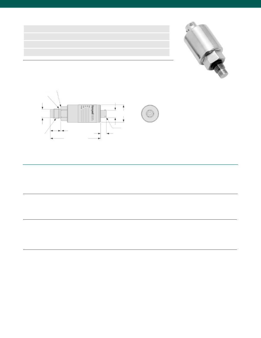
54
Pressure Ranges................0-500 psi to 0-5000 psi
Accuracy................+/- 0.25% (note 7)
Non-Linearity................0.5%
Non-Repeatability................0.1%
Output................4-20 mA (std.)
Resolution................Infinite
Temperature, Operating................-20° to 185°F
Temperature, Compensated................60° to 160°F
Temperature, Effect
Zero................0.01% Full scale/ °F
Span................0.02% Reading/ °F
Excitation (calibration)
4-20 mA, 2 wire (std.)................9-32 VDC
0-5 VDC, 3 wire (option 2c)................9-28 VDC
Insulation Resistance................50 Megohms @ 50 V
Electrical Termination (std)................PTIH-10-6P
Mating Connector (not incl.)................PT06A-10-6S
Media................Gas, Liquid compatible with 17-4 PH SS
Overload-Safe................300% over capacity
Overload-Burst................500% over capacity or 20,000 psi, whichever is less
Pressure Port................7/16-20 UNF
Wetted Parts Material................17-4 PH Stainless Steel
Case Material................Stainless Steel
Dimensions
Performance
Environmental
Electrical
Mechanical
www.honeywell.com/sensotec
n
0-500 to 0-5000 psi
n
Flush Diaphragm
n
High Level Output
n
+/-0.25% Accuracy
ø0.59 in. REF.
ø1.125 in.
2.2 in.
0.43 in. REF.
Model 355 Flush Diaphragm Pressure Transducers
Order Code BP313
0.355 in.
3/4 in. Hex
Electrical Termination PTIH-10-6P
or Equivalent
0.562 in.
1-888-282-9891
7/16-20 UNF
Viton O-Ring
0.31-0001-79
Courtesy of Steven Engineering, Inc.-230 Ryan Way, South San Francisco, CA 94080-6370-Main Office: (650) 588-9200-Outside Local Area: (800) 258-9200-www.stevenengineering.com
Sensotec Sensors Full Line Catalog-html.html
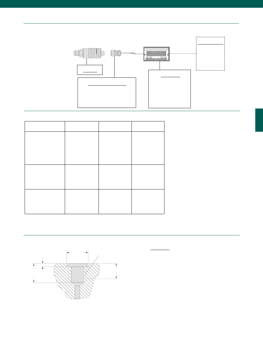
55
Typical System Diagram
MOUNTING: The Model 355 has straight threads and
uses a #12 O-ring for pressure sealing. To get the best
seal with the O-ring on the transducer, the tapped hole
should have the dimensions shown here. For normal
operating temperatures (-65° to +250°F) use the BUNA-N
(black) O-rings. For high temperatures (250° to 425°F)
use silicone rubber (red). Maximum torque is 50 in.-lb.,
17-4 PH Stainless Steel only.
Model 355
Mating Connectors & Cables
PT06A-10-6S (4 conductor cable), Std.
PT06E-10-6S (4 conductor cable)
Customer Supplied
Chart Recorder
Alarm Panel
Data Acquisition
Computer
PLC
www.honeywell.com/sensotec
Internal Amplifiers
1-888-282-9891
Amplifier
Specifications
Vehicle Voltage Output
Option 2c
Current 2 Wire
Option 2k
Intrinsically Safe Amp
Option 2N (2n)***
Output Signal
Input Power (Voltage)
Input Power (Current)
Frequency Response
Power Supply Rejection
Operating Temperature
Reverse Voltage Protection
Short Circuit Protection
0-5VDC@ 45mA
11-28 VDC
40 mA
3000 Hz
60 db
-20° to 185° F
Yes
Momentary
4-20 mA
9-28 VDC (note 3)
4-28 mA
300 Hz
60 db
0° to 185° F
Yes
Yes
4-20 mA
9-28 VDC (note 3)
4-24 mA
2000 Hz
60 db
-20° to 185° F
Yes
Yes
Wiring Code: Connector
(Std.)
(note 3)
A
(+) Supply
B** Output Common/
C** Supply Return
D
(+) Output
E
No Connection
F
No Connection
A
(+) Supply
B
No Connection
C
No Connection
D
(+) Output
E
Case Ground
F
No Connection
A
(+) Supply
B
No Connection
C
No Connection
D
(+) Output
E
Case Ground
F
No Connection
Wiring Code: Cable
(note 3)
(note 5)
(note 6)
R
(+) Supply
Bl* Output Common/
G* Supply Return
W (+) Output
B
No Connection
Br No Connection
R
(+) Supply
Bl (+) Output
W
Case Ground
R
(+) Supply
Bl
(+) Output
W
Case Ground
Model 355
7/16-20 UNF
Perfect threads
to this depth
Minimum tap
drill depth
0.36 in.
0.54 in.
0.048 in.
0.050 in.
0.504 in.
+0.000 in.
-0.002 in.
Installation
Display Units
SC500
SC1000
SC2000
SC2001
SC3004
GM-A
* Black and Green wires are internally connected.
** Pins B and C are internally connected.
*** See Sensotec website for most up-to-date information regarding Intrinsically Safe approvals ref. #008-0547-00.
Courtesy of Steven Engineering, Inc.-230 Ryan Way, South San Francisco, CA 94080-6370-Main Office: (650) 588-9200-Outside Local Area: (800) 258-9200-www.stevenengineering.com
Sensotec Sensors Full Line Catalog-html.html
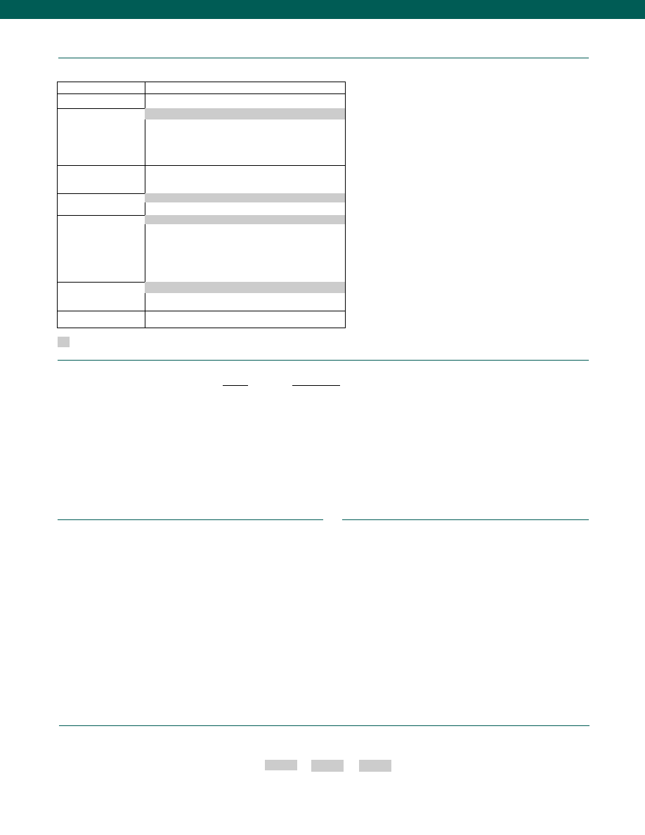
56
www.honeywell.com/sensotec
Options
Supplied as standard
1-888-282-9891
How to Order
Combine the order code, the range code and the options code.
Order Code
Range Code
Options Code
Sample Code: BP313 CS 2c
Different cable lengths
Different electrical connectors
Different materials
Fatigue rating
O2 Clean
Special electrical output
Special ports
Special wiring codes
Special pressure ranges
Temperature & pressure calibration
Special Customer Requirements
(Consult Factory)
Notes
1. Gage pressure units greater than 500 psi are sealed at atmospheric pressure
2. Input power (voltage) for internal amplifier options 2j, 2k, 2n,N depends on load resistance.
3. Interconnecting shunt cal. 1 with shunt cal. 2 terminal provides 50% (unamplified units),
75% (4-20 mA 3 wire units), or 80% (voltage amp. units) of full scale output for quick
calibration. Shunt Calibration comes standard with internal amplifier options 2a, 2b, 2c, 2t
and 2j.
4. Not available with temperatures below -20°F or above 185°F.
5. G=Green; B=Blue; W=White; Bl=Black; Br=Brown; Y=Yellow; R=Red; O=Orange. Color
specifying cable and number or letter specifying connector
6. No mating connector necessary with cable option.
7. Accuracies stated are expected for Best Fit Straight Line for all errors including linearity,
hysteresis & non-repeatability thru zero.
8. Consult factory for TEDS availability with amplified models.
Range Codes
Range
Range Code
500 psi
CR
750 psi
CT
1,000 psi
CV
1,500 psi
DJ
2,000 psi
DL
2,500 psi
DM
3,000 psi
DN
5,000 psi
DR
Model 355
Build to Order
Pressure Ranges
500; 1000; 2000; 3000; 5000 psi
Temperature
Compensation
1b. 30° to 130° F
1c. 0° to 185° F
1d. -20° to 130° F
1j.
0° to 50° C
1k. -20° to 85° C
Internal Amplifiers
2k. 4-20ma (2 wire) output
2c. 0-5VDC
2n(2N). 4-20ma (2 wire) output intrinsically safe
Pressure Ports
5d. 7/16” - 20 UNF Male (per MS33656E4)
Electrical Termination
6e. Integral cable: Teflon (-54° to 245° C)
6f.
Integral cable: PVC (-30° to 70° C)
6h. Integral cable: Silicone (-54 to 150° C)
6i.
Integral underwater cable (8m) (max 80° C)
6n. DIN 40050
6q. Molded Integral Cable: Polyurethane
6v. Phoenix connector on end of cable
Special Calibration
9a. 10 point (5 up/5 down) 20% increments @ 20° C
9b. 20 point (10 up/10 down) 10% increments @ 20° C
Interfaces
53e. Signature Calibration
53t. T.E.D.S. IEEE 1451.4 Module (note 8)
6a. Bendix PTIH-10-6P (or equivalent) 6 pin (max. 250°F)
5p. M12 x 15 Male
1a. 60° to 160° F
9e. CE mark
Courtesy of Steven Engineering, Inc.-230 Ryan Way, South San Francisco, CA 94080-6370-Main Office: (650) 588-9200-Outside Local Area: (800) 258-9200-www.stevenengineering.com
Sensotec Sensors Full Line Catalog-html.html
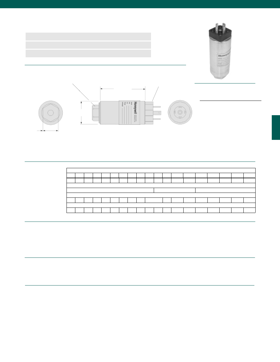
57
Pressure Ranges................5; 10; 15; 25; 50; 75; 100; 150; 200; 300; 500; 750; 1,000;
..1,500; 2,000; 2,500; 3,000; 5,000; 7,500; 10,000 psig/a
Accuracy (note 3)................+/-0.25% Full Scale
Non-Linearity and Hysteresis................+/-0.20% Best Fit Straight Line
Non-Repeatability................+/-0.20% Best Fit Straight Line
Output................4-20 mA
Resolution................Infinite
Temperature, Operating................-20° to 185°F
Temperature, Compensated................30° to 130°F
Temperature, Effect
Zero................0.01% Full scale/ °F
Span................0.01% Reading/ °F
Excitation (calibration)................24 VDC
Excitation (acceptable)................9 to 32 VDC
Insulation Resistance................5000 Megohms @ 50VDC
Electrical Termination (std)................DIN 43650 Water Resistant
Mating Connector (not incl.)................DIN mating connector with solderless terminal (note 1)
Zero and Span Adjustments................Located under top cover
Frequency Response................2000Hz
Dimensions
Performance
Environmental
Electrical
www.honeywell.com/sensotec
n
5 to 10,000 psig/a Range
n
2 wire 4-20 mA Output
n
0.25% Accuracy
Model 440 Two Wire Gage/ Absolute Pressure Transmitters
Order Code AP415 (gage); AP416 (absolute)
D
1.00 in.
hex
Pressure Port 1/4-18 NPT female
Electrical Connector
4 Pole DIN Connector
DIN Mating Connector
Sold Separately
Wiring Code
Connector/ 2 Wire Current, 4-20 mA
1
(+) Supply
2
(+) Output
3
No Connection
GND
Case Ground
1-888-282-9891
L
Range Code
D (in./ mm)
L (in./ mm)
Over Pressure (test) (psi)
Over Pressure (burst) (psi)
Port Volume (in.3/ cm3)
Natural Frequency (Hz)
AT AV
BJ
BL BN BP BR CJ
CL CP CR CT
CV
DJ
DL
DN
DR
DT
DV
1.50/ 38
2.6/ 66
3.3/ 84
3.0/ 76
150% Full Scale
Pressure Ranges (psi)
5
10
15
25
50
75 100 150 200 300 500 750 1000 1500 2000 3000 5000 7500 10,000
20
40
60 100 200 300 400 600 800
2000
3000 3500 4000 8000 12,000 20,000 25,000 25,000
0.12/ 3.1
1k 1.3k 2.1k 2.5k 2.9k 3.5k 4.6k 6k
7k
9k 9.5k 12k
17k
20k
35k
40k
54k
60k
80k
Courtesy of Steven Engineering, Inc.-230 Ryan Way, South San Francisco, CA 94080-6370-Main Office: (650) 588-9200-Outside Local Area: (800) 258-9200-www.stevenengineering.com
Sensotec Sensors Full Line Catalog-html.html
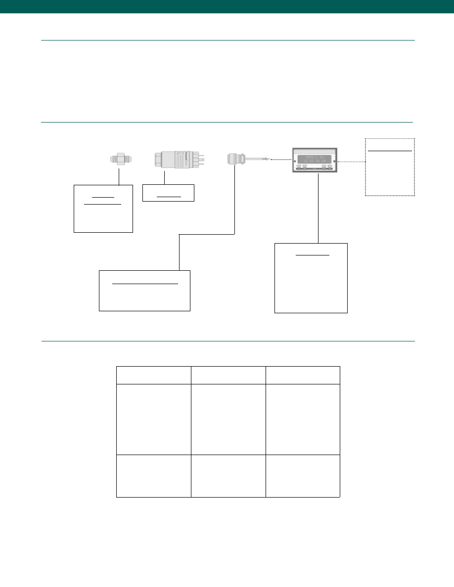
58
Mechanical
Typical System Diagram
Media................Gas, Liquid
Overload-Safe................50% over capacity
Overload-Burst................200% over capacity
Pressure Port................1/4-18 NPT female
Wetted Parts Material
<300 psig/a................HA C276/ 316 Stainless Steel
300-1500 psig/a................17-4 PH Stainless Steel
>1500 psig/a................15-5 PH Stainless Steel
Weight................13 oz.
Case Material................Stainless Steel
www.honeywell.com/sensotec
Adaptors
Compatible with:
1/4-18 NPT Female
Model 440
Mating Connectors & Cables
DIN Style: Specify cable diameter
Customer Supplied
Chart Recorder
Alarm Panel
Data Acquisition
Computer
PLC
Internal Amplifiers
Amplifier
Specifications
Current 2-wire
Option 2k (note 4)
Intrinsically Safe Amp
Option 2N (2n)*
Output Signal
Input Power (Voltage)
Input Power (Current)
Frequency Response
Power Supply Rejection
Operating Temperature
Reverse Voltage Protection
Short Circuit Protection
4-20 mA
9-32 VDC
4-24 mA
300 Hz
60 db
-20° to 185° F
Yes
Yes
4-20 mA
9-28 VDC
4-24 mA
2000 Hz
60 db
-20° to 185° F
Yes
Yes
Wiring Code: Connector
(Std.)
1
(+) Supply
2
(+) Output
3
No Connection
GND Case Ground
1
(+) Supply
2
(+) Output
3
No Connection
GND Case Ground
1-888-282-9891
Model 440
Display Units
SC500
SC1000
SC2000
SC2001
SC3004
GM-A
* See Sensotec website for most up-to-date
information regarding Intrinsically safe
approvals reference #008-0547-00.
Courtesy of Steven Engineering, Inc.-230 Ryan Way, South San Francisco, CA 94080-6370-Main Office: (650) 588-9200-Outside Local Area: (800) 258-9200-www.stevenengineering.com
Sensotec Sensors Full Line Catalog-html.html
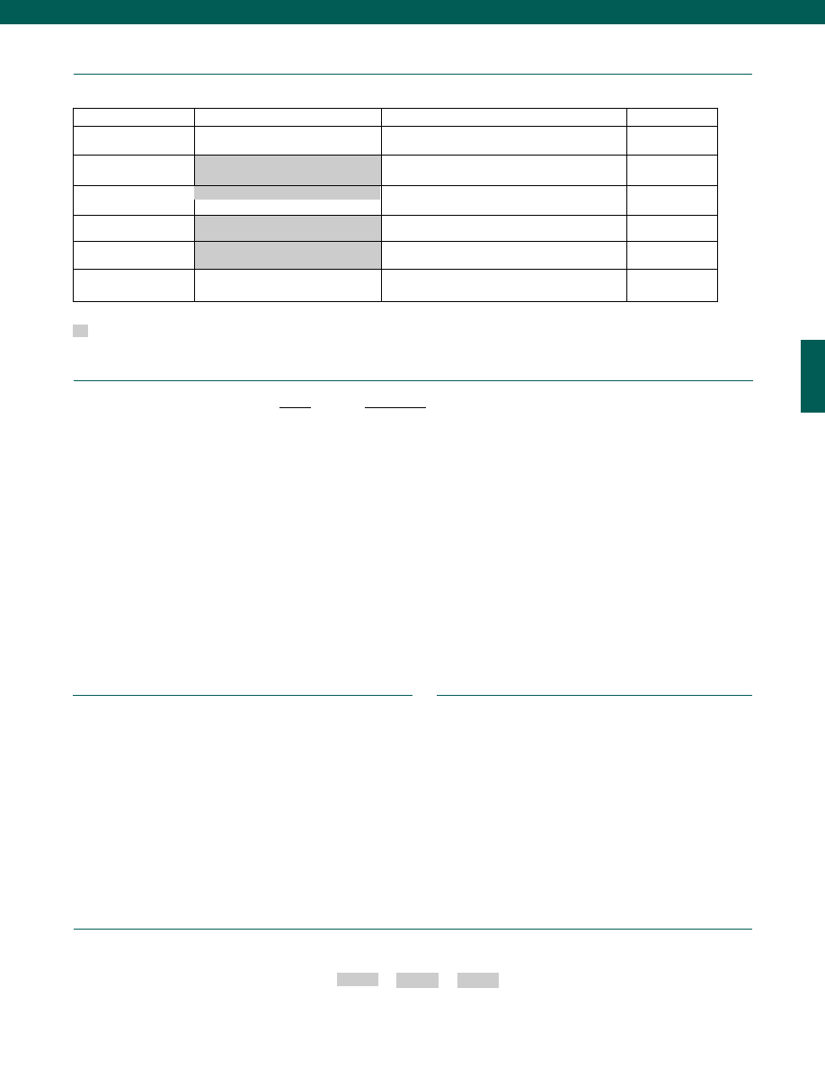
59
Range
Range Code
5 psig/a
AT
10 psig/a
AV
15 psig/a
BJ
25 psig/a
BL
50 psig/a
BN
75 psig/a
BP
100 psig/a
BR
150 psig/a
CJ
200 psig/a
CL
300 psig/a
CP
500 psig/a
CR
750 psig/a
CT
1,000 psig/a
CV
1,500 psig/a
DJ
2,000 psig/a
DL
3,000 psig/a
DN
5,000 psig/a
DR
7,500 psig/a
DT
10,000 psig/a
DV
www.honeywell.com/sensotec
Options
Same Day Ship
Fast Track Manufacture
Built from scratch
Pressure Ranges
5; 15; 50; 100; 200; 500; 1000; 3000;
5000; 10,000 psig
25; 75; 150; 300; 750; 1500; 2000; 7500; psig/a
5; 15; 50; 100; 200; 500; 1000; 3000; 5000; 10,000 psia
10 psig/a
Temperature
Compensation
1a. 60° to 160° F
Internal Amplifiers
2n (2N). 4-20 mA (2-wire) Intrinsically safe
Pressure Ports
5a. 1/4-18 NPT Female
Electrical Termination
6m. DIN 43650
Special Calibration (note 2)
9a. 10 point (5 up/ 5 down) 20% increments @ 70°F
9b. 20 point (10 up/ 10 down) 10% increments @ 70°F
Supplied as standard
1-888-282-9891
How to Order
Combine the order code, the range code and the options code.
Order Code
Range Code
Options Code
Sample Code: AP415 AT 9b
Special wiring codes
Special Temperature compensation
Special calibration
Special Customer Requirements
(Consult Factory)
Notes
1. Specify cable diameter: can handle dia. of 4.5mm to 14 mm or 1/2” NPT conduit fitting
2.
Availability varies with range.
3.
Accuracies stated are expected for Best Fit Straight Line for all errors including linearity,
hysteresis & non-repeatability thru zero.
4.
Max. load resistance is 500 Ohms @ 23 VDC
Range Codes
Model 440
2k. 4-20mA (2-wire) output
Courtesy of Steven Engineering, Inc.-230 Ryan Way, South San Francisco, CA 94080-6370-Main Office: (650) 588-9200-Outside Local Area: (800) 258-9200-www.stevenengineering.com
Sensotec Sensors Full Line Catalog-html.html
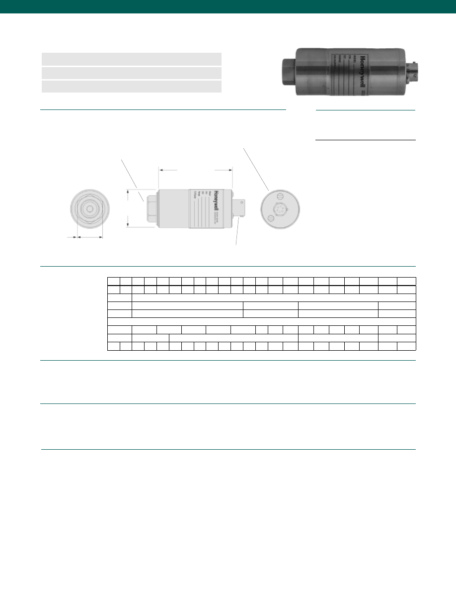
60
Range Code
D (in./ mm)
L (in./ mm) for psia
L (in./ mm) for psig
Over Pressure (test) (psi)
Over Pressure (burst) (psi)
Port Volume (in.3/ cm3)
Natural Frequency (Hz)
Accuracy (note 4)................+/-0.1% Full Scale
Non-Linearity and Hysteresis................+/-0.10% Best Fit Straight Line
Non-Repeatability................0.10% Best Fit Straight Line
Output................4-20 mA
Resolution................Infinite
Temperature, Operating................-20° to 185°F
Temperature, Compensated................60° to 160°F
Temperature, Effect
Zero................0.005% Full scale/ °F
Span................0.007% Reading/ °F
Excitation (acceptable)................9 to 32 VDC
Insulation Resistance................5,000 Megohm @ 50 VDC
Electrical Termination (std)................PTIH-10-6P or equiv. (Hermetic Stainless)
Mating Connector (not incl.)................PT06A-10-6S or equiv.
Frequency Response................300 Hz
Dimensions
Performance
Environmental
Electrical
www.honeywell.com/sensotec
n
2 to 20,000 psi Range
n
4-20 mA Output
n
0.1% Accuracy
L
Model 415 Two Wire Gage/ Absolute Pressure Transmitters
Order Code AP411 (gage) AP412 (absolute)
D
1.00 in. hex
Pressure Port for 2-10,000 psig/a:
1/4-18 NPT Female
for 15,000 - 20,000 psig/a:
9/16-18 UNF Female per AE F-250-C
Zero & Span Potentiometer
Adjustment Cover Screws
Electrical Connector Bendix
PTIH-10-6P or equivalent
Wiring Code
Connector/ 2 Wire Current, 4-20 mA
A
(+) Supply
B
No Connection
C
No Connection
D
(+) Output 4-20 mA
E
Case Ground
F
No Connection
1-888-282-9891
AR AT AV BJ BL BN BP BR CJ CL CP CR CT CV
DJ
DL
DN
DR
DT
DV
EJ
EL
2.25/ 57
1.50/ 38
3.57/ 91
3.36/ 85
3.74/ 95
3.0/ 76
3.06/ 78
3.10/ 79
3.36/ 85
3.74/ 95
3.0/ 76
3.06/ 78
150% Full Scale
2
5
10 15 25 50 75 100 150 200 300 500 750 1000 1500 2000 3000 5000 7500 10,00015,00020,000
50
100
200
400
800
2k
3k 3.5k 4k
8k
12k 20k 25k
25k
40k
45k
0.32/ 5.2
0.25/ 4.1
0.17/ 2.8
0.12/ 3.1
0.06/ 1.5
550 1k 1.3k 2.1k 2.5k 2.9k 3.5k 4.6k 6k 7k 9k 9.5k 12k 17k 20k 35k 40k 54k 60k
80k
100k >100k
Courtesy of Steven Engineering, Inc.-230 Ryan Way, South San Francisco, CA 94080-6370-Main Office: (650) 588-9200-Outside Local Area: (800) 258-9200-www.stevenengineering.com
Sensotec Sensors Full Line Catalog-html.html
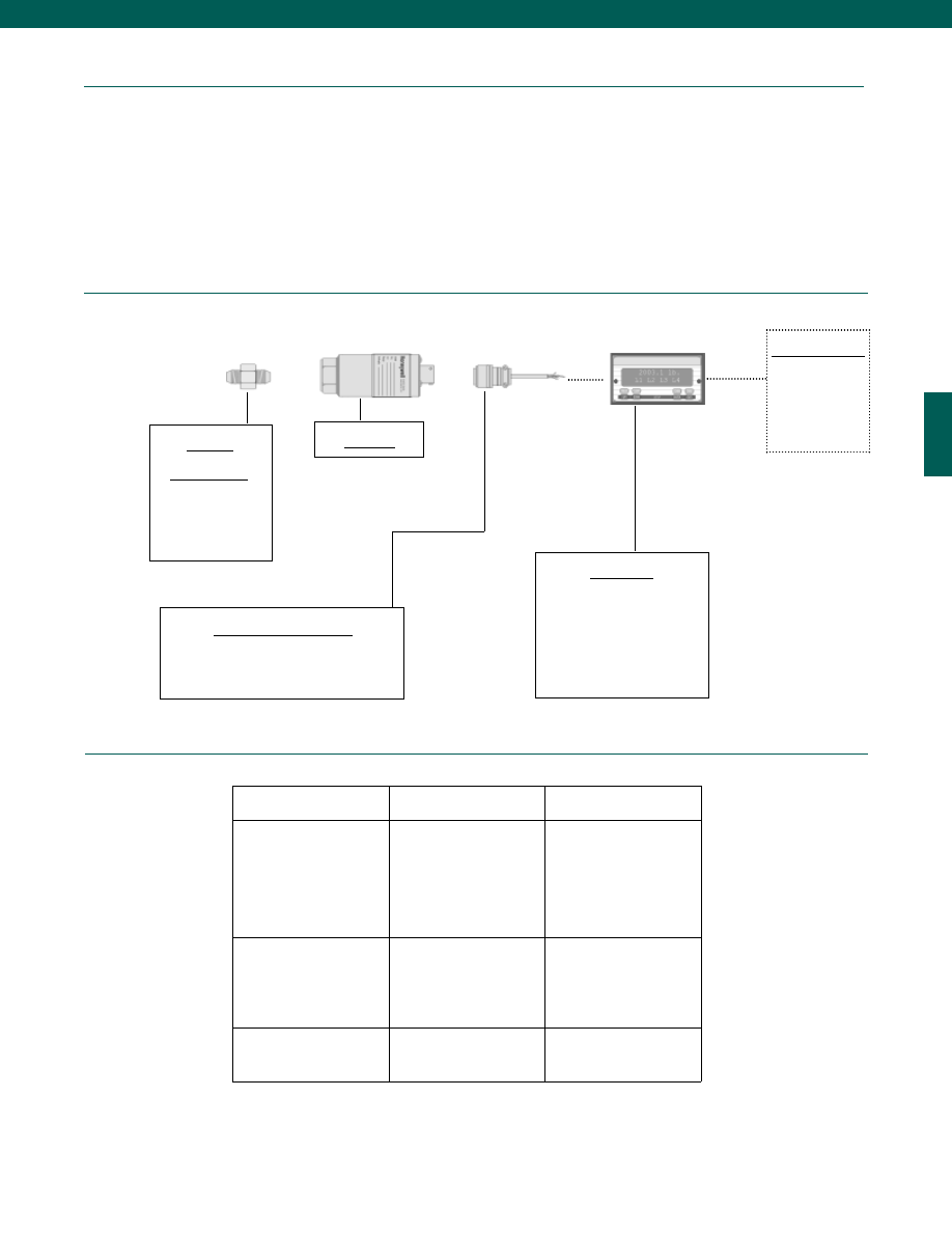
61
Mechanical
Media................Gases, Liquids compatible with wetted material
Overload-Safe................50% over capacity
Pressure Port
2 to 10,000 psig/a................1/4-18 NPT female
15,000 to 20,000 psig/a................9/16-18 UNF per Autoclave AE F250-C
Proof Pressure................400%
Dead Volume................See Table
Wetted Parts Material
2 to 1500 psig/a................17-4 PH Stainless Steel
>1500 psig/a................15-5 PH Stainless Steel
Weight................13 oz.
Case Material................Stainless Steel
www.honeywell.com/sensotec
Typical System Diagram
Adaptors
Compatible with:
1/4-18 NPT Female
9/16-18 UNF
1/4-18 NPT Male
7/16-20 UNF Male
7/16-20 UNF Female
Model 415
Mating Connectors & Cables
PT06A-10-6S (3 conductor cable), Std.
PT06E-10-6S (3 conductor cable)
Display Units
SC500
SC1000
SC2000
SC2001
SC3004
GM-A (Amp. only)
Customer Supplied
Chart Recorder
Alarm Panel
Data Acquisition
Computer
PLC
Internal Amplifiers
1-888-282-9891
Model 415
Amplifier
Specifications
Current 2-wire
Option 2k
Intrinsically Safe Amp
Option 2N (2n)*
Output Signal
Input Power (Voltage)
Input Power (Current)
Frequency Response
Power Supply Rejection
Operating Temperature
Reverse Voltage Protection
Short Circuit Protection
4-20 mA
9-32 VDC
4-24 mA
300 Hz
60 db
-20° to 185° F
Yes
Yes
4-20 mA
9-28 VDC
4-24 mA
2000 Hz
60 db
-20° to 185° F
Yes
Yes
Wiring Code: Connector
(Std.)
A
(+) Supply
B
No Connection
C
No Connection
D
(+) Output
E
Case Ground
F
No Connection
A
(+) Supply
B
No Connection
C
No Connection
D
(+) Output
E
Case Ground
F
No Connection
Wiring Code: Cable
(note 2)
R
(+) Supply
Bl
(+) Output
W
Case Ground
R
(+) Supply
Bl
(+) Output
W
Case Ground
* See Sensotec website for most up-to-date
information regarding Intrinsically safe
approvals reference #008-0547-00.
Courtesy of Steven Engineering, Inc.-230 Ryan Way, South San Francisco, CA 94080-6370-Main Office: (650) 588-9200-Outside Local Area: (800) 258-9200-www.stevenengineering.com
Sensotec Sensors Full Line Catalog-html.html
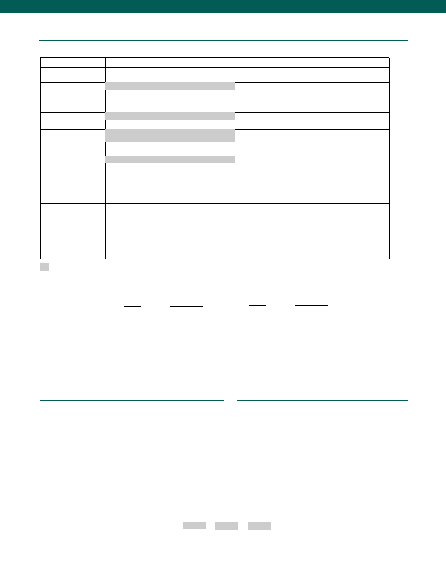
62
Range
Range Code
2 psig/a
AR
5 psig/a
AT
10 psig/a
AV
15 psig/a
BJ
25 psig/a
BL
50 psig/a
BN
75 psig/a
BP
100 psig/a
BR
200 psig/a
CL
300 psig/a
CP
www.honeywell.com/sensotec
Options
Fast Track Manufacture
Built to Order
Built from Scratch
Pressure Ranges
15; 25; 50; 75; 100; 200; 300; 500; 750;
1000; 1500; 2000; 3000; 5000; 7500; 10,000 psig/a
2; 5; 10; 15,000; 20,000 psig/a
Temperature
Compensation
1b.
30° to 130°F
1c.
0° to 185°F
1d.
-20° to 130°F
Internal Amplifiers
2n (2N). Intrinsically safe amp
Pressure Ports (note 3)
5b. 1/4-18 NPT Male
5d. 7/16-20 UNF Male
5c. 7/16-20 UNF Female
Electrical Termination
(note 2)
6e. Integral cable: Teflon (-65° to 475°F)
6f.
Integral cable: PVC (-20° to 160°F)
6g. Integral cable: Neoprene (0°to 180°F) (note 1)
6h. Integral cable: Silicone (-65° to 300°F)
6i.
Integral underwater cable
(max. 180°F)
6j.
1/2-14 conduit fitting with 5’
of 4 conductor PVC cable
(may be used with 6e-i)
Shunt Calibration
3d.
Remote Buffered Shunt Cal
Special Calibration (note 3) 9a.
10 point (5 up/ 5 down) 20% increments @ 70°F
Wetted Diaphragm (note 3)
10a. 316 Stainless Steel
10b. Crucible A-286
10c. Hastelloy C
Potentiometers
14a. No Access to Pots
14b. Top Access to Pots
Shock & Vibration
44a. Shock/ Vibration Resistance
Supplied as standard
1-888-282-9891
How to Order
Combine the order code, the range code and the options code.
Order Code
Range Code
Options Code
Sample Code: AP411 AT 5a
Special wetted material
Special ports
Special wiring codes
Special Customer Requirements
(Consult Factory)
Notes
Range Codes
Range
Range Code
500 psig/a
CR
750 psig/a
CT
1,000 psig/a
CV
1,500 psig/a
DJ
2,000 psig/a
DL
3,000 psig/a
DN
5,000 psig/a
DR
7,500 psig/a
DT
10,000 psig/a
DV
20,000 psig/a
EL
Model 415
1a. 60° to 160° F
5a. 1/4-18 NPT Female (2 - 10,000 psi)
5s.
9/16-18 UNF per AE F-250-C (15,000 - 20,000 psi)
6a. Bendix PTIH-10-6P-(or equiv.) 6 pin (max. 400°F)
1. Specify cable diameter: can handle dia. of 4.5mm to 14 mm or 1/2” NPT conduit fitting
2. G=Green; B=Blue; W=White; Bl=Black; Br=Brown; Y=Yellow; R=Red; O=Orange;
Color specifying cable and number or letter specifying connector.
3.
Availability varies with range.
4.
Accuracies stated are expected for Best Fit Straight Line for all errors including linearity,
hysteresis & non-repeatability thru zero.
2k. 4-20mA (2-wire) output
Courtesy of Steven Engineering, Inc.-230 Ryan Way, South San Francisco, CA 94080-6370-Main Office: (650) 588-9200-Outside Local Area: (800) 258-9200-www.stevenengineering.com
Sensotec Sensors Full Line Catalog-html.html
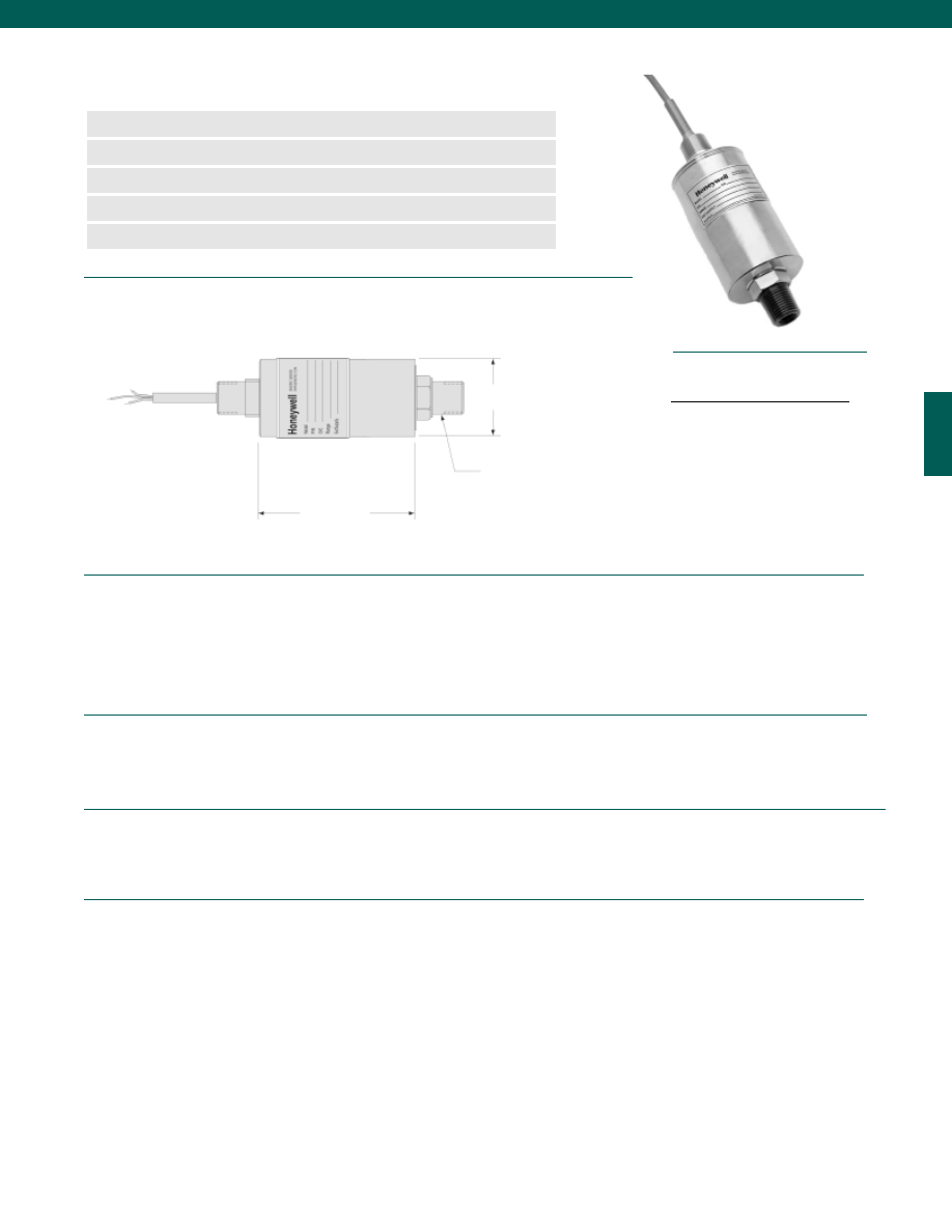
63
Pressure Ranges................2; 5; 10; 15; 25; 50; 75; 100; 150; 200; 300; 500; 750;
1000;1500; 2000; 3000; 5000; 7500; 10,000 psig/a
Accuracy (note 2)................+/-0.25% Full Scale
Linearity................+/-0.15% Full Scale
Hysteresis................+/-0.10% Full Scale
Non-Repeatability................+/-0.05% Full Scale
Output................4-20 mA
Resolution................Infinite
Temperature, Operating................0° to 180°F
Temperature, Compensated................60° to 160°F
Temperature, Effect
Zero................+/- 0.01% Full Scale/ °F
Span................+/- 0.01% Reading/ °F
Strain Gage Type................Bonded Foil
Excitation (calibration)................15 to 32 VDC
Insulation Resistance................5000 Megohms @ 50 VDC
Electrical Termination (std)................1/2-14 NPT male with 7/8” wrench flat. 20 GA
2 ft. cable with case ground
Media................Gases, Liquids compatible with wetted material
Overload-Safe................50% over capacity
Pressure Port................1/4-18 NPT Female; 1/2-14 NPT male
Wetted Parts Material................17-4 PH Stainless Steel
Case Material................Stainless Steel
Dimensions
Performance
Environmental
Electrical
Mechanical
www.honeywell.com/sensotec
n
2 to 10,000 psig/a Range
n
Bulkhead Mounting
n
True Gage Design Hermetic
n
Explosion Resistant
n
0.25% Accuracy
Model 811FM 2-Wire Gage/ Absolute Pressure Transmitters
Order Code BP421 (gage); BP422 (absolute)
ø2.25 in.
4.0 in. Max.
1/4-18 NPT Female
1/2-14 NPT Male
Pressure Port
Wiring Code
Cable, 2-wire current, 4-20 mA
Red
(+) Supply
Black
(+) Output (4-20 mA)
White
Case Ground
1-888-282-9891
Courtesy of Steven Engineering, Inc.-230 Ryan Way, South San Francisco, CA 94080-6370-Main Office: (650) 588-9200-Outside Local Area: (800) 258-9200-www.stevenengineering.com
Sensotec Sensors Full Line Catalog-html.html
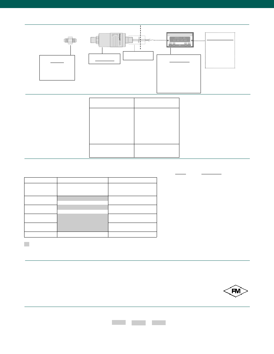
64
Typical System Diagram
www.honeywell.com/sensotec
Adaptors
Compatible with:
1/4-18 NPT Female
Model 811FM
Customer Supplied
Chart Recorder
Alarm Panel
Data Acquisition
Computer
PLC
Internal Amplifiers
Amplifier
Specifications
Current 2-wire
Option 2k (Std.)
Output Signal
Input Power (Voltage)
Input Power (Current)
Frequency Response
Power Supply Rejection
Operating Temperature
Reverse Voltage Protection
Short Circuit Protection
4-20 mA
9-32 VDC
4-24 mA
300 Hz
60 db
-20° to 185° F
Yes
Yes
Wiring Code: Cable
R
(+) Supply
Bl
(+) Output
W
Case Ground
1-888-282-9891
Model 811FM
Display Units
SC500
SC1000
SC2000
SC2001
SC3004
GM-A
Options
Built to Order
Built from Scratch
Pressure Ranges
15; 25; 50; 75; 100; 150; 200; 300;
500; 750; 1,000; 1,500; 2,000;
3,000; 5,000; 7,500; 10,000 psig/a
2; 5; 10 psig/a
Temperature
Compensation
Internal Amplifiers
Pressure Ports
Electrical Termination
Wetted Diaphragm
10a. 316 Stainless Steel (note 1)
1a. 60° to 160° F
2k. 4-20mA 2-wire
5a. 1/4-18 NPT Female
1/2-14 NPT Male w/ 1” Hex
2 ft. of 20GA cable
Supplied as standard
Range
Range Code
2 psig/a
AR
5 psig/a
AT
10 psig/a
AV
15 psig/a
BJ
25 psig/a
BL
50 psig/a
BN
75 psig/a
BP
100 psig/a
BR
150 psig/a
CJ
200 psig/a
CL
300 psig/a
CP
500 psig/a
CR
750 psig/a
CT
1,000 psig/a
CV
1,500 psig/a
DJ
2,000 psig/a
DL
3,000 psig/a
DN
5,000 psig/a
DR
7,500 psig/a
DT
10,000 psig/a
DV
Range Codes
Custom Cable Lengths
Special Customer Requirements
(Consult Factory)
Notes
1. Only available for ranges 25 to 500 psig/a
2. Accuracies stated are expected for Best Fit Straight Line for all errors,
including linearity, hysteresis, & non-repeatability thru zero.
How to Order
Combine the order code, the range code and the options code.
Order Code
Range Code
Options Code
Sample Code: BP421 BR 10a
Approved
Explosion Proof
NEC Approved
Conduit Installation
Hazardous Area Safe Area
Courtesy of Steven Engineering, Inc.-230 Ryan Way, South San Francisco, CA 94080-6370-Main Office: (650) 588-9200-Outside Local Area: (800) 258-9200-www.stevenengineering.com
Sensotec Sensors Full Line Catalog-html.html
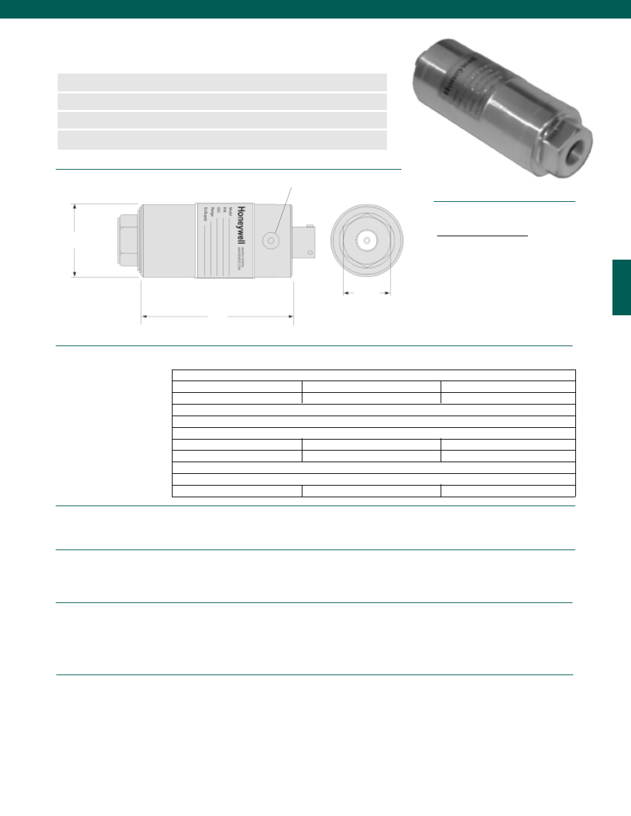
65
Range Code
D (in.)
L (in.)
L* (in.)
Over Pressure (test) (psi)
Over Pressure (burst) (psi)
Port Volume (in.3)
Natural Frequency (Hz)
Installation Torque (ft.-lb./N-m)
Dimensions
Performance
Environmental
Electrical
Mechanical
www.honeywell.com/sensotec
n
50,000 to 100,000 psi
n
AE F250-C Port
n
High Pressure Capacity
n
0.5% Accuracy
Model HP High Pressure Transducers
Order Code BP521
L
1.00 in.
Hex
øD
Accuracy (note 2)................+/- 0.5% Full Scale
Resolution................Infinite
Calibration................5 point calibration: 0%, 50% and 100% of Full Scale
Temperature, Compensated................60° to 160° F
Zero................0.005% Full Scale/° F
Span................0.005% Reading/° F
Sealing................Hermetically sealed IP68/ NEMA 6P
Strain Gage Type................Bonded Foil
Insulation Resistance................5,000 Megohms @ 50 VDC
Bridge Resistance................350 Ohms
Shunt Calibration Data................Included
Electrical Termination (std)................PTIH-10-6P or equivalent (Hermetic Stainless)
Mating Connector (not incl.)................PT06A-10-6S
Media................All gases/ liquids compatible with wetted parts
Wetted Parts Material................15-5 PH Stainless Steel
Weight................12 oz.
Case Material................304 Stainless Steel
Marking................Permanent metal nameplate MIL-STD130F 4.3;
Individual sequential serial number per sensor;
Country of origin and date of manufacture
1-888-282-9891
Pressure Range
50,000 75,000 100,000 (note 1)
EP
ER
ET
1.50
2.92
4.35
75,000 100,000 100,000
100,000 125,000 140,000
0.015
Greater than 100 kHz
25/ 34 30/ 41
35/ 47
Connector/Unamplified
A&B
(+) Excitation
C&D
(-) Excitation
E
(-) Output
F
(+) Output
Wiring Code
* Length of pressure transducer with amplified option (see options on third page)
Blow out plug
Courtesy of Steven Engineering, Inc.-230 Ryan Way, South San Francisco, CA 94080-6370-Main Office: (650) 588-9200-Outside Local Area: (800) 258-9200-www.stevenengineering.com
Sensotec Sensors Full Line Catalog-html.html
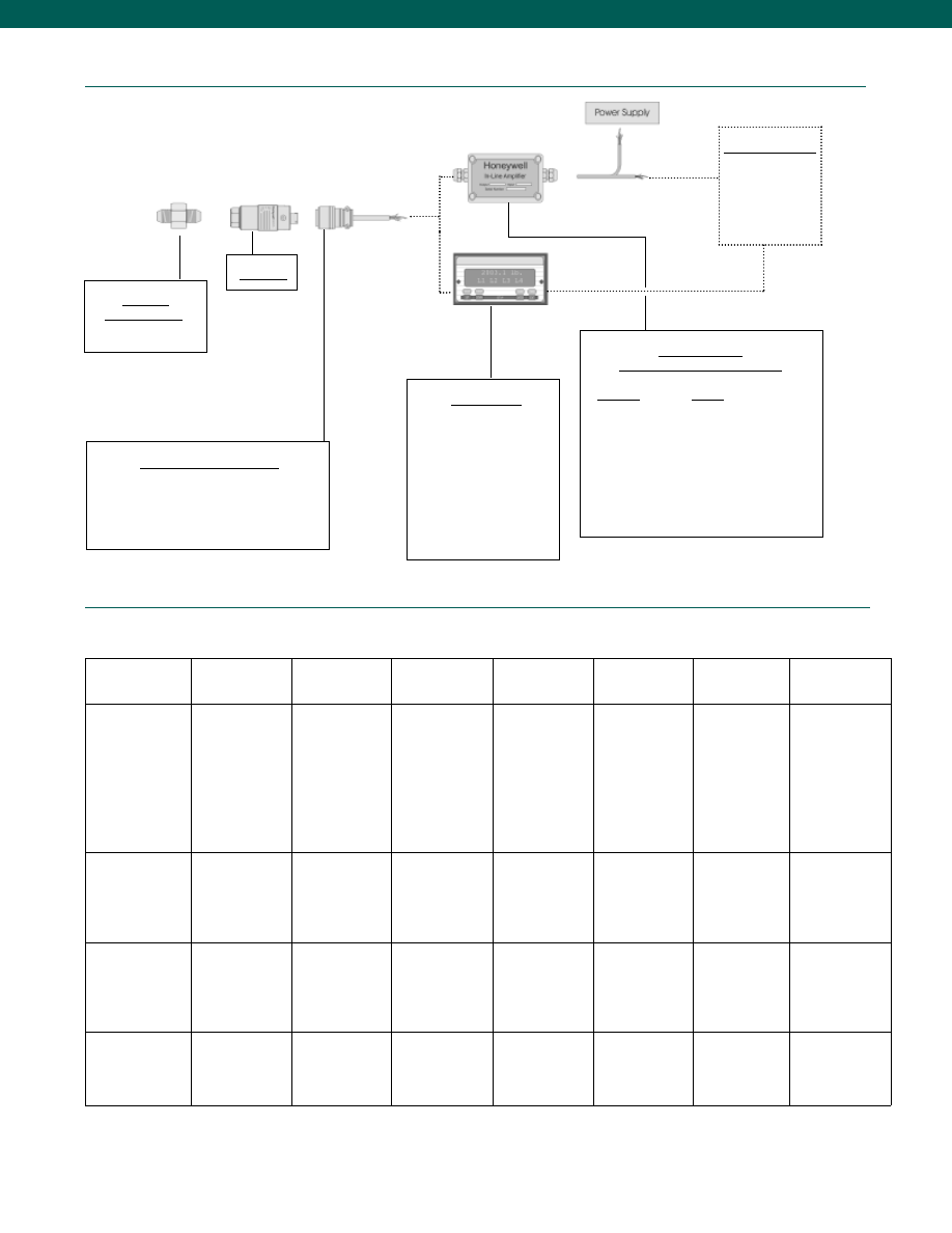
66
Typical System Diagram
www.honeywell.com/sensotec
Internal Amplifiers
1-888-282-9891
* Black and Green wires are internally connected.
** Pins B and C are internally connected.
Adaptors
Compatible with:
9/16-18 UNF Female
Model HP
Mating Connectors & Cables
PT06A-10-6S (6 conductor cable), Std.
PT06E-10-6S (6 conductor cable)
MS3106A-14S-6S (6 conductor cable)
Display Units
SC500
SC1000
SC2000
SC2001
SC3004
GM (Unamp. only)
GM-A (Amp. only)
NK (Unamp. only)
HH (Unamp. only)
Customer Supplied
Chart Recorder
Alarm Panel
Data Acquisition
Computer
PLC
In-Line Amplifiers
(Used with unamplified units only)
Amplifier
Output
Universal In-Line Amplifiers
UV
+/- 5 VDC
UV-10+/- 10 VDC
UBP
0 +/- 5 VDC
U3W
4-20 mA (3 wire)
DIN Rail Mount In-Line Amplifiers
DV-050 +/- 5 VDC (3 wire)
DA-054-20 mA (3 wire)
DV-10
0 +/- 10 VDC (3 wire)
Model HP
Amplifier
Specifications
mV/V Output
Standard
Vehicle Voltage Output
Option 2a
(note 6)
Vehicle Voltage Output
Option 2c
(note 6)
Vehicle Voltage Output
Option 2t
(note 6)
Current 3 Wire
Option 2j
(note 6)
Current 2 Wire
Option 2k
(note 6)
Intrinsically Safe Amp
Option 2N (2n)
Output Signal
Input Power (Voltage)
Input Power (Current)
Frequency Response
Power Supply
Rejection
Operating Temperature
Reverse Voltage
Protection
Short Circuit Protection
1 mV/V
10 VDC Regulated
28.5 mA @ 10 VDC
Natural Frequency
--
-100° to 250° F
Not Applicable
Not Applicable
0-5VDC
+/-15VDC or 26-32VDC
45 mA
2000 Hz
60 db
-20° to 185° F
Yes
Momentary
0-5VDC or +/- 5VDC
@ 5mA
11-28 VDC
40 mA
3000 Hz
60 db
-40° to 185° F
Yes
Momentary
0-10VDC or +/- 10VDC
@ 5mA
15-28 VDC
40 mA
3000 Hz
60 db
-40° to 185° F
Yes
Momentary
4-20 mA
22-32 VDC (note 3)
65 mA
2500 Hz
60 db
-40° to 185° F
Yes
Yes
4-20 mA
9-32 VDC (note 3)
4-28 mA
300 Hz
60 db
-40° to 185° F
Yes
Yes
20 mA
9-28 VDC (note 3)
4-24 mA
2000 Hz
60 db
-20° to 185° F
Yes
Yes
Wiring Code: Connector
(Std.)
(note 5)
A
(+) Excitation
B
(+) Excitation
C
(-) Excitation
D
(-) Excitation
E
(-) Output
F
(+) Output
A
(+) Supply
B
Output Common/
C
Supply Return
D
(+) Output
E
Shunt Cal 1
F
Shunt Cal 2
A
(+) Supply
B** Output Common/
C** Supply Return
D
(+) Output
E
Shunt Cal 1
F
Shunt Cal 2
A
(+) Supply
B** Output Common/
C** Supply Return
D
(+) Output
E
Shunt Cal 1
F
Shunt Cal 2
A
(+) Supply
B** Output Common/
C** Supply Return
D
(+) Output
E
Shunt Cal 1
F
Shunt Cal 2
A
(+) Supply
B
No Connection
C
No Connection
D
(+) Output
E
Case Ground
F
No Connection
A
(+) Supply
B
No Connection
C
No Connection
D
(+) Output
E
Case Ground
F
No Connection
Wiring Code: Cable
(note 5)
(note 6)
(note 7)
R
(+) Excitation
Bl (-) Excitation
G
(-) Output
W
(+) Output
R (+) Supply
Bl Output Common/
G Supply Return
W (+) Output
B
Shunt Cal 1
Br Shunt Cal 2
R
(+) Supply
Bl* Output Common/
G* Supply Return
W (+) Output
B
Shunt Cal 1
Br Shunt Cal 2
R
(+) Supply
Bl* Output Common/
G* Supply Return
W (+) Output
B
Shunt Cal 1
Br Shunt Cal 2
R
(+) Supply
Bl* Output Common/
G* Supply Return
W (+) Output
B
Shunt Cal 1
Br Shunt Cal 2
R
(+) Supply
Bl (+) Output
W Case Ground
R
(+) Supply
Bl (+) Output
W Case Ground
For Current Information
Reference application
sheet #008-0356-00 for
current information.
Reference application
sheet #008-0357-00 for
current information.
Reference application
sheet #008-0360-00 for
current information.
Reference application
sheet #008-0361-00
for current information.
Reference application
sheet #008-0361-60
for current information.
See Sensotec website
for most up-to-date
information regarding
Intrinsically safe
approvals reference
#008-0547-00.
Courtesy of Steven Engineering, Inc.-230 Ryan Way, South San Francisco, CA 94080-6370-Main Office: (650) 588-9200-Outside Local Area: (800) 258-9200-www.stevenengineering.com
Sensotec Sensors Full Line Catalog-html.html
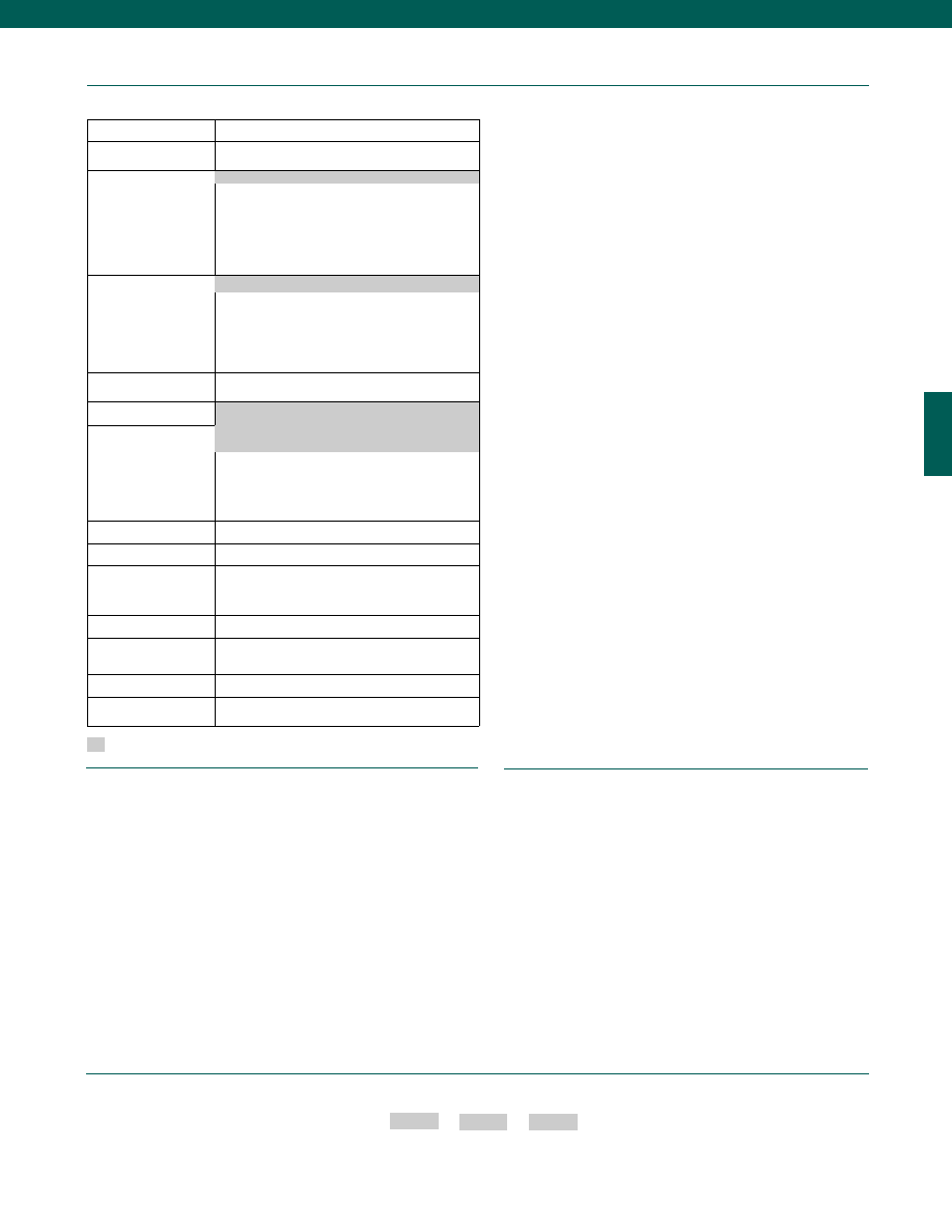
67
www.honeywell.com/sensotec
Options
Built to Order
Pressure Ranges
50,000; 75,000; 100,000 psi
Temperature
Compensation
1b. 30° to 130° F
1c. 0° to 185° F
1d. -20° to 130° F
1e. -20° to 200° F
1f. 70° to 250° F
1g. 70° to 325° F
1m. -25° to 110° C
Internal Amplifiers
2a. 0-5 VDC (4-wire) output
2c. 0-5 VDC
2j. 4-20 mA (3-wire) output
2k. 4-20 mA (2-wire) output
2N (2n). 4-20 mA (2-wire) Intrinsically safe
2t. 0-10 VDC
Internal Amp
Enhancements
3a. Input/output isolation
3d. Remote Buffered Shunt Calibration
Pressure Ports
5u. 9/16-18 Autoclave F-250-C
Electrical Termination
(note 7)
6e. Integral cable: Teflon (-65° to 475° F)
6f. Integral cable: PVC (-20° to 160° F0
6g. Integral cable: Neoprene (0° to 185° F)
6h. Integral cable: Silicone (-65° to 300° F)
6i. Integral underwater cable (max. 180° F)
Shunt Calibration
8a. Precision Internal Resistor (note 8)
Special Calibration
9a. 10 point (5 up/5 down) 20% increments@ 60° F
Bridge Type
11a. Square Bridge
11b. Symmetrical Bridge
11c. Square and symmetrical bridge
Bridge Resistance
12b. 5000 Ohm (foil) (max. 250° F)
Potentiometers
14a. No access to pots
14b. Top access to pots
Shock and Vibration
44a. Shock and vibration resistance
Interfaces
53e. Signature Calibration (note 8)
53t. T.E.D.S. IEEE 1451.4 Module (note 9)
Supplied as standard
1-888-282-9891
How to Order
Combine the order code, the range code and the options code.
Order Code
Range Code
Options Code
Sample Code: BP521 ER 1c
Different electrical connectors
Different materials
Different threads
O ring material
O2 Clean
Radiation proof
Special temperature compensation
Temperature and pressure calibration
Special Customer Requirements
(Consult Factory)
Notes
1. For pressure ranges 75,000 psi or above, consult factory for pressure port information.
2. Accuracies stated are expected for Best Fit Straight Line for all errors, including linearity,
hysteresis & non-repeatability thru zero.
3. Input power (voltage) for internal amplifier options 2j, 2k, 2n,N depends on load resistance.
4. CE mark requires options 6a & 3d.
5. Interconnecting shunt cal. 1 with shunt cal. 2 terminal provides 50% (unamplified units), 75%
(4-20 mA 3 wire units), or 80% (voltage amp. units) of full scale output for quick calibration.
6. G=Green; B=Blue; W=White; Bl=Black; Br=Brown; Y=Yellow; R=Red; O=Orange. Color
specifying cable and number or letter specifying connector
7. No mating connector necessary with cable option.
8. Cannot be used with amplified option.
9. Consult factory for TEDS availability with amplified models.
Model HP
1a. 60° to 160° F
2u. Unamplified, mV/V Output
6a. Bendix PTIH-10-6P (or equivalent)
6 pin (max. 250° F)
Courtesy of Steven Engineering, Inc.-230 Ryan Way, South San Francisco, CA 94080-6370-Main Office: (650) 588-9200-Outside Local Area: (800) 258-9200-www.stevenengineering.com
Sensotec Sensors Full Line Catalog-html.html
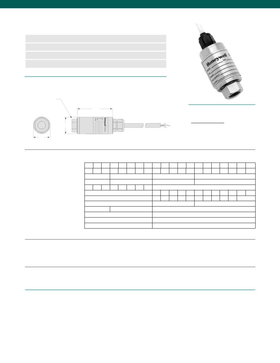
68
Dimensions
Performance
Environmental
Electrical
Mechanical
www.honeywell.com/sensotec
n
1 to 10,000 psig Range
n
Potential OEM Application
n
mV/V Output
n
0.5% Accuracy
Model LM Gage Pressure Transducer
Order Code BP211
H
L
ø1.12 in.
Pressure Port 1/4-18 NPT Female
1-888-282-9891
Wiring Code
Cable/ Unamplified
Red
(+) Excitation
Black
(-) Excitation
Green
(-) Output
White
(+) Output
AP AS AT
BJ BM BN BP BR CJ CL CP CR CT CV DJ
DL DN DR
DT DV
2.26/ 57
2.23/ 57
2.00/ 51
1.78/ 45
1/ 25.4
1/ 25.4
0.875/ 22.2
0.750/ 19.0
4
10
20
50 100 150 150 150
150% of Full Scale
Consult Factory
600 800 1.2k 2k 2k 4k 6k 8k 12k 15k 20k 20k
Consult Factory
9.8k 11k 14k 18k 22k 30k 48k 54k 66k 85k
>100k
0.15/ 2.5
0.17/ 2.8
0.12/ 3.1
5
10
2
316 Stainless Steel
17-4 PH Stainless Steel
5,000 Ohm
350 Ohm
Silicon
Foil
1
2.5
5
15
30
50
75 100 150 200 300 500 750 1k 1.5k 2k
3k
5k 7.5k 10k
Pressure (psig)
Range Code
L (in./mm)
Hex (in./mm)
Test Over Pressure (psi)
Burst Over Pressure (psi)
Natural Frequency (Hz)
Port Volume (in.3/mm3)
Output (mV/V)
Wetted Parts
Bridge Resistance
Strain Gage Type
Accuracy (note 1)................+/- 0.5% Full Scale
Temperature, Operating................-65° to 250°F
Temperature, Compensated................60° to 160°F
Temperature, Effect
Zero................0.01% Full scale/ °F
Span................0.02% Reading/ °F
Excitation (calibration)................10 VDC
Excitation (acceptable)................10 VDC
Insulation Resistance................5,000 Ohms @ 50 VDC
Electrical Termination (std)................Cable 3 ft.
Media................All Gases/ Liquids Compatible with Wetted Parts
Weight................6 oz./ 170 grams
Courtesy of Steven Engineering, Inc.-230 Ryan Way, South San Francisco, CA 94080-6370-Main Office: (650) 588-9200-Outside Local Area: (800) 258-9200-www.stevenengineering.com
Sensotec Sensors Full Line Catalog-html.html
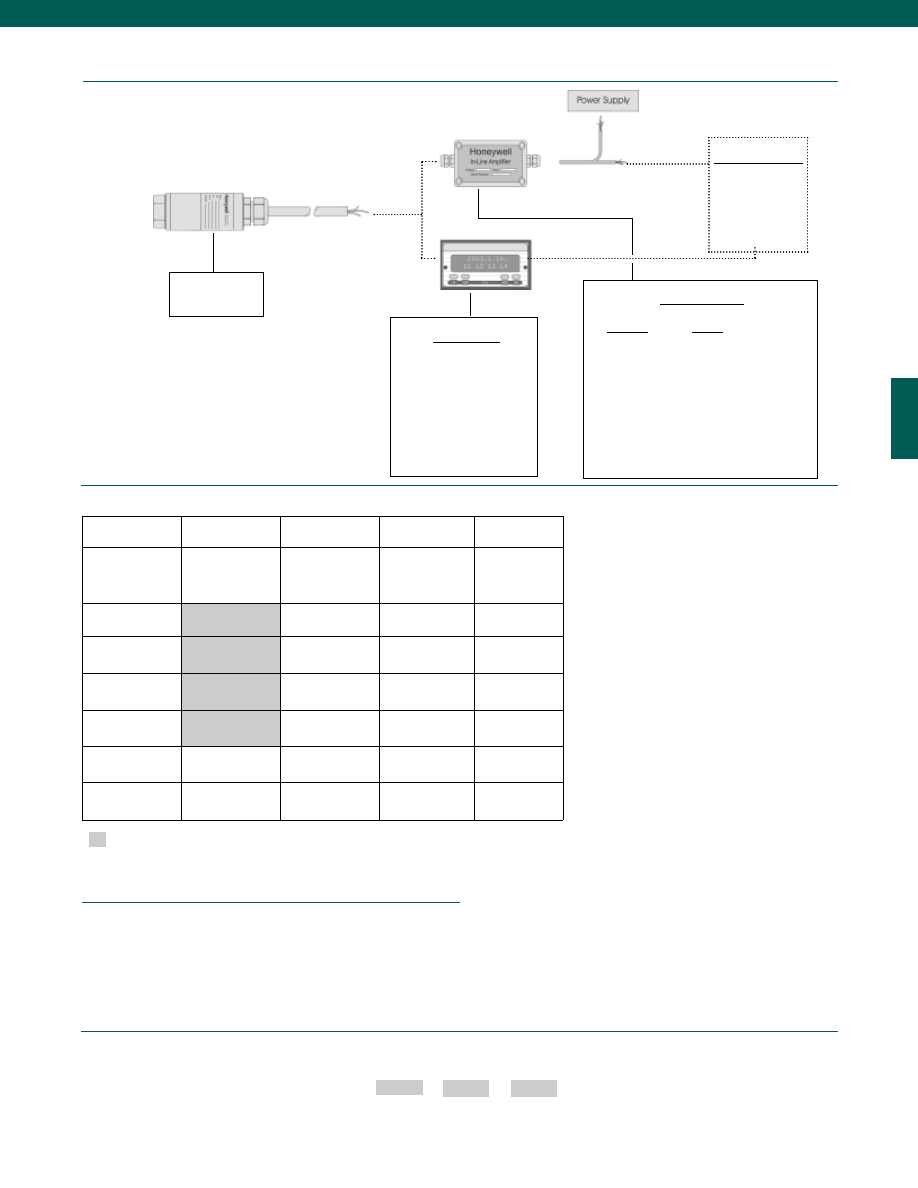
69
Different electrical connectors
Different materials
Different threads
O ring material
O2 Clean
Radiation proof
Special temperature compensation
Temperature and pressure calibration
Typical System Diagram
www.honeywell.com/sensotec
Customer Supplied
Chart Recorder
Alarm Panel
Data Acquisition
Computer
PLC
In-Line Amplifiers
Amplifier
Output
Universal In-Line Amplifiers
UV
+/- 5 VDC
UV-10
+/- 10 VDC
UBP
0 +/- 5 VDC
U3W
4-20 mA (3 wire)
U2W
4-20 mA (2 wire)
DIN Rail Mount In-Line Amplifiers
DV-05
0 +/- 5 VDC (3 wire)
DA-05
4-20 mA (3 wire)
DV-10
0 +/- 10 VDC (3 wire)
1-888-282-9891
Options
How to Order
Combine the order code, the range code and the options code.
Order Code
Range Code
Options Code
Sample Code: BP211 CV
9a
Special Customer Requirements
(Consult Factory)
Notes
1. Accuracies stated are expected for Best Fit Straight Line for all errors, including linearity,
hysteresis & non-repeatability thru zero.
Same Day Ship
Fast Track
Manufacture
Built to Order
Built from Scratch
Pressure Ranges
100; 200; 300; 500;
1k; 2k; 3k; 5k; 10k
psig
15; 25; 50; 75 psig
1; 2.5; 5; 150; 750;
1.5k; 7.5k psig
Temperature
Compensation
1a. 60° to 160° F
Internal Amplifiers
2u. Unamplified,
mV/V output
Pressure Ports
5a. 1/4-18 NPT
Female
OEM Port
Consult Factory
Electrical
Termination
Cable (3 ft.)
OEM Termination
Consult Factory
Special Calibration
9a. 10 point
(5 up/ 5 down)
Wetted Diaphragm
OEM Materials
Consult Factory
Model LM
Model LM
Supplied as standard
Display Units
SC500
SC1000
SC2000
SC2001
SC3004
GM
NK
HH
Courtesy of Steven Engineering, Inc.-230 Ryan Way, South San Francisco, CA 94080-6370-Main Office: (650) 588-9200-Outside Local Area: (800) 258-9200-www.stevenengineering.com
Sensotec Sensors Full Line Catalog-html.html
70
Pressure Ranges................0-150 to 0-15,000 psig
Accuracy (note 4)
150 psig Range................+/-0.75% Best Fit Straight Line
Ranges 300 psig and above................+/-0.5% Best Fit Straight Line
Output................+/- 5 VDC (option 2d) or 4-20 mA (option 2p)
Resolution................Infinite
Temperature, Operating................-20° to 185°F
Temperature, Compensated................60° to 160°F
Temperature, Effect
Zero................+/- 0.01% Full Scale/ °F
Span................+/- 0.01% Full Scale/ °F
Excitation (acceptable)
+/- 5 VDC................9-28 VDC @ 40 mA
4-20 mA................9-28 VDC
Electrical Termination................PTIH-10-6P or equiv.
Dimensions
Performance
Environmental
Electrical
www.honeywell.com/sensotec
n
0-150 to 0-15,000 psig Range
n
Welded Stainless Steel
n
Configurable Electrical Connection
n
Optional Unit Measurement of Inches of Hg Gage
Model BDR Universal Pressure Transducer/ Transmitter
Order Code BP217
0.5 in.
2.1 in.
ø1.13 in.
Pressure Port 1/4-18 NPT Male
1-888-282-9891
Courtesy of Steven Engineering, Inc.-230 Ryan Way, South San Francisco, CA 94080-6370-Main Office: (650) 588-9200-Outside Local Area: (800) 258-9200-www.stevenengineering.com
Sensotec Sensors Full Line Catalog-html.html
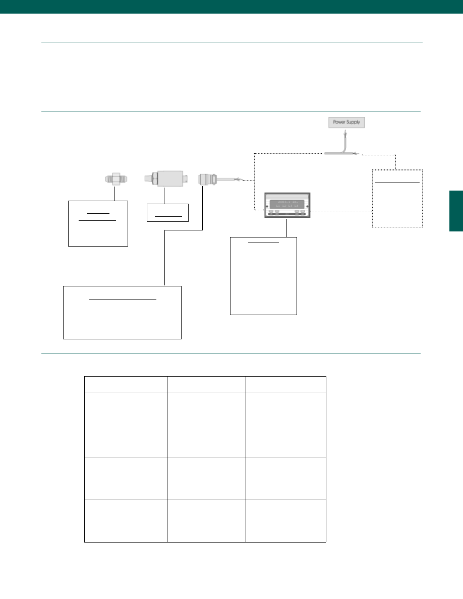
71
Mechanical
Typical System Diagram
www.honeywell.com/sensotec
Adaptors
Compatible with:
1/4-18 NPT Male
Model BDR
Customer Supplied
Chart Recorder
Alarm Panel
Data Acquisition
Computer
PLC
Mating Connectors & Cables
PT06A-10-6S (4 conductor cable), Std.
PT06E-10-6S (4 conductor cable)
1-888-282-9891
Amplifier
Specifications
Vehicle Voltage Output Option 2d
Current 2 Wire
Option 2p
Output Signal
Input Power (Voltage)
Input Power (Current)
Frequency Response
Power Supply Rejection
Operating Temperature
Reverse Voltage Protection
Short Circuit Protection
5VDC
9-28 VDC
40 mA
300 Hz
60 db
-20° to 185° F
Yes
Momentary
4-20 mA
9-28 VDC
4-28 mA
300 Hz
60 db
-20° to 185° F
Yes
Yes
Wiring Code: Connector
(Std.)
(note 5)
A
(+) Supply
B** Output Common/
C** Supply Return
D
(+) Output
E
No Connection
F
No Connection
A
(+) Supply
B
No Connection
C
No Connection
D
(+) Output
E
Case Ground
F
No Connection
Wiring Code: Cable
(note 1)
(note 2)
(note 5)
R
(+) Supply
Bl* Output Common/
G* Supply Return
W
(+) Output
B
No Connection
Br
No Connection
R
(+) Supply
Bl
(+) Output
W
Case Ground
* Black and Green wires are internally connected.
** Pins B and C are internally connected.
Internal Amplifiers
Model BDR
Media................Gas, Liquid compatible with Stainless Steel
Overload-Safe................50% over capacity
Overload-Burst................250% over capacity or 24,000 psig whichever is less
Pressure Port................1/4-18 NPT Male
Wetted Parts Material................17-4 Stainless Steel all-welded construction
Weight................10 oz.
Display Units
SC500
SC1000
SC2000
SC2001
SC3004
GM (Unamp. only)
GM-A (Amp. only)
NK (Unamp. only)
HH (Unamp. only)
Courtesy of Steven Engineering, Inc.-230 Ryan Way, South San Francisco, CA 94080-6370-Main Office: (650) 588-9200-Outside Local Area: (800) 258-9200-www.stevenengineering.com
Sensotec Sensors Full Line Catalog-html.html
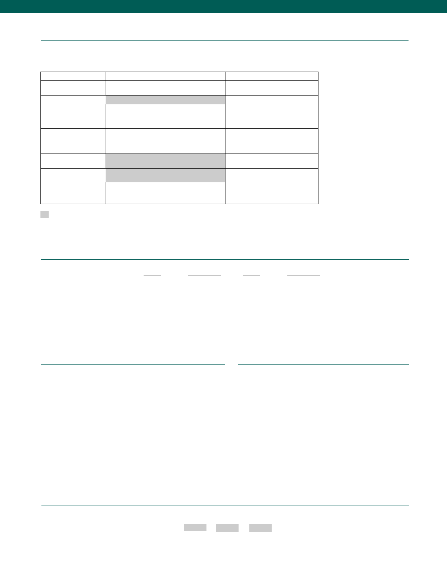
72
www.honeywell.com/sensotec
Options
Fast Track Manufacture
Built from Scratch
Pressure Ranges
150; 200; 300; 500; 750; 1000; 1500; 2000; 2500;
3000; 5000; 7500; 10,000 psig
15,000 psig
Temperature Compensation
1j.
0° to 50° C
1k. -20° to 85° C
1m. -25° to 100° C
Internal Amplifiers
2d. +/- 5 VDC
2p. 4-20
mA
Pressure Ports
5b. 1/4-18 NPT Male
Electrical Termination
6m. DIN
43650
6n. DIN
40050
6q. Molded integral cable: Polyurethane
Supplied as standard
1-888-282-9891
How to Order
Combine the order code, the range code and the options code.
Order Code
Range Code
Options Code
Sample Code: BP217 CV 1k
Different electrical connectors
Different materials
Different threads
O ring material
O2 Clean
Radiation proof
Special temperature compensation
Temperature and pressure calibration
Special Customer Requirements
(Consult Factory)
Notes
1. G=Green; B=Blue; W=White; Bl=Black; Br=Brown; Y=Yellow; R=Red; O=Orange. Color
specifying cable and number or letter specifying connector
2. No mating connector necessary with cable option.
3. Pins B and C are internally connected.
4. Accuracies stated are expected for Best Fit Straight Line for all errors, including linearity,
hysteresis & non-repeatability thru zero. For 0.25% Accuracy consult factory.
5. Interconnecting shunt cal. 1 terminal with shunt cal. 2 terminal provides 50%
(unamplified units), 75% (4-20 mA 3-wire only), 80% (voltage amp) of full scale output for
quick calibration.
6. Output varies with range.
Range Codes
Range
Range Code
2,000 psig
DL
2,500 psig
DM
3,000 psig
DN
5,000 psig
DR
6,000 psig
DS
7,500 psig
DT
10,000 psig
DV
15,000 psig
EJ
Range
Range Code
150 psig
CJ
200 psig
CL
250 psig
CN
300 psig
CP
500 psig
CR
750 psig
CT
1,000 psig
CV
1,500 psig
DJ
Model BDR
1a. 60° to 160° F
6a. Bendix PTIH-10-6P (or equivalent)
6 pin (max. 250° F)
Courtesy of Steven Engineering, Inc.-230 Ryan Way, South San Francisco, CA 94080-6370-Main Office: (650) 588-9200-Outside Local Area: (800) 258-9200-www.stevenengineering.com
Sensotec Sensors Full Line Catalog-html.html
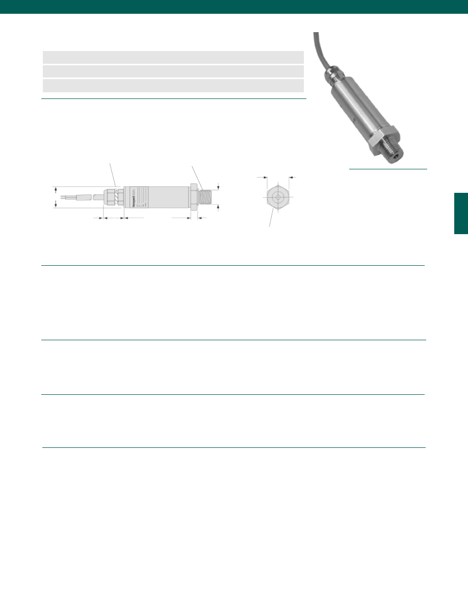
73
Dimensions
Performance
Environmental
Electrical
Mechanical
........5; 10; 15; 30; 50; 100; 200; 300; 500 psig
........15; 30; 50; 100; 200; 300; 500; 1000; 2500; 5000 psia
........+/- 0.5% Full Scale
........+/- 0.03% Full Scale
........+/- 0.03% Full Scale
........4-20 mA
........Infinite
........5ms
........-40° to 185°F
........15° to 185°F
........-40° to 185°F
........+/- 1.5 Full Scale (note 1)
........+/- 1.5 Full Scale (note 1)
........Semi-conductor
........10-24 VDC
........100 Megohms @ 50 VDC
........Cable Version (2 ft. Standard Cable Length)
........100g for 11ms
........1 million cycles
........Gases, Liquids compatible with wetted material
........200% over capacity
........>200% over capacity
........1/4-18 NPT male
........316 Stainless Steel
........304 Stainless Steel
www.honeywell.com/sensotec
n
4-20 mA 2 wire output
n
5 to 5,000 psig/ psia Range
n
1% Accuracy
Model LCP Pressure Transducer
Order Code BP223 (absolute), BP224 (gage)
0.875 in. hex
ø 0.875 in.
0.70 in.
Pressure Port 1/4-18 NPT Male
0.25 in.
ø 0.540 in.
2.12 in.
Vent Tube
(Gage units only)
ø 0.815 in.
Pressure Ranges
Gage
Absolute
Linearity
Hysteresis
Non-Repeatability
Output (std.)
Resolution
Response Time
Temperature, Operating
Temperature, Compensated
Storage Temperature
Temperature, Effect
Zero
Span
Strain Gage Type
Supply Voltage
Insulation Resistance
Electrical Termination (std)
Shock
Life
Media
Overload-Safe
Overload-Burst
Pressure Port
Wetted Parts Material
Case Material
1-888-282-9891
Wiring Code
Red (+) input
Black (+) output
Courtesy of Steven Engineering, Inc.-230 Ryan Way, South San Francisco, CA 94080-6370-Main Office: (650) 588-9200-Outside Local Area: (800) 258-9200-www.stevenengineering.com
Sensotec Sensors Full Line Catalog-html.html
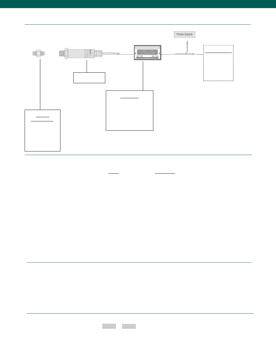
74
Typical System Diagram
www.honeywell.com/sensotec
Range
Range Code
5 psig
AT
10 psig
AV
15 psig/a
BJ
30 psig/a
BM
50 psig/a
BN
100 psig/a
BR
200 psig/a
CL
300 psig/a
CP
500 psig/a
CR
1,000 psia
CV
2,500 psia
DM
5,000 psia
DR
Range Codes
1-888-282-9891
Adaptors
Compatible with:
1/4-18 NPT Male
1/4-18 NPT Female
7/16-20 UNF Male
7/16-20 UNF Female
1/8-27 NPT Male
Model LCP
Display Units
SC500
SC1000
SC2000
SC2001
SC3004
GM-A
Customer Supplied
Chart Recorder
Alarm Panel
Data Acquisition
Computer
PLC
How to Order
The order code consists of the product model and the desired range code.
Model Code
Range Code
Sample Code:
SZ75
AT
Model LCP
Notes
1. +/- 2.5% Full Scale for 5 psi range
Courtesy of Steven Engineering, Inc.-230 Ryan Way, South San Francisco, CA 94080-6370-Main Office: (650) 588-9200-Outside Local Area: (800) 258-9200-www.stevenengineering.com
Sensotec Sensors Full Line Catalog-html.html
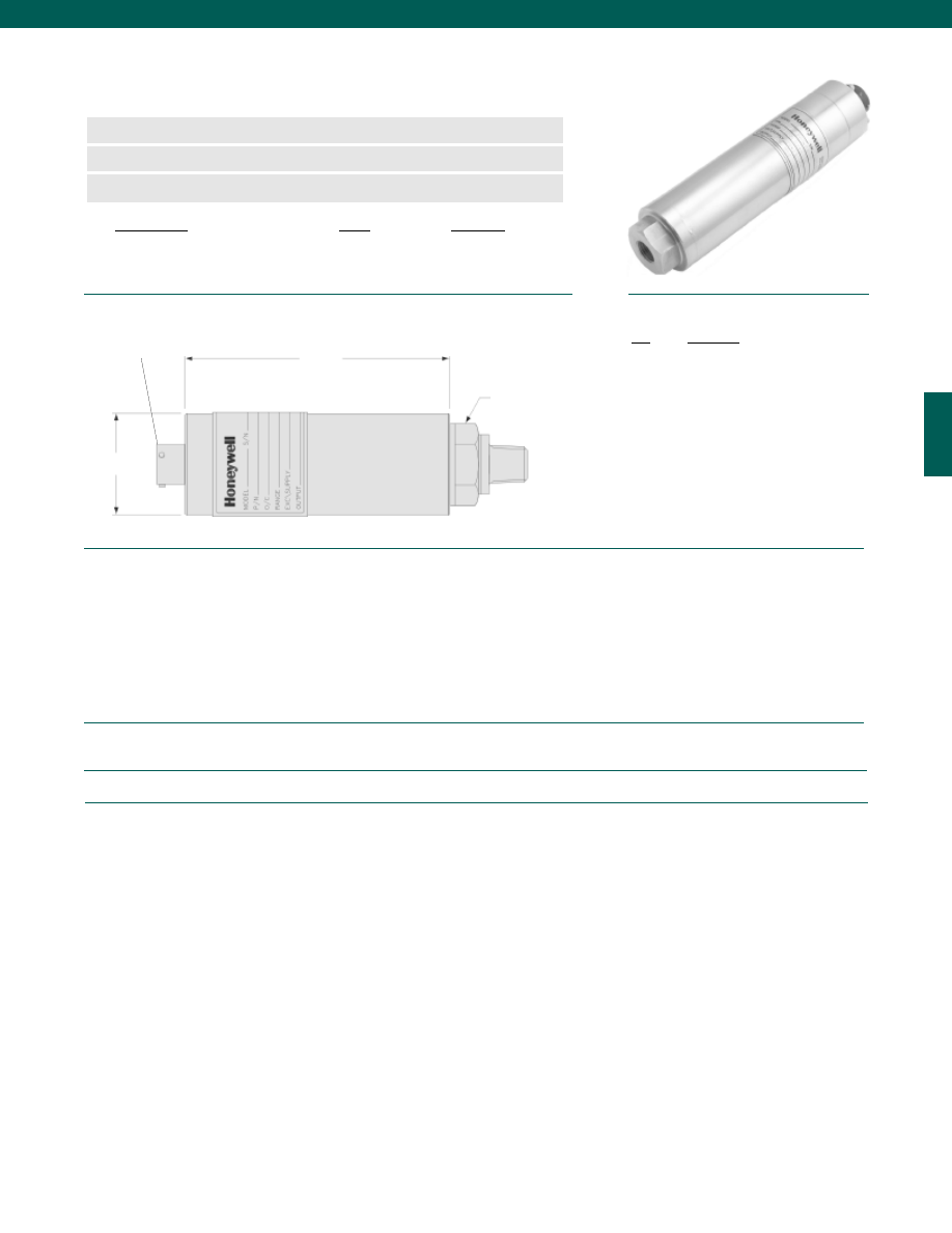
75
Pressure Ranges................5; 15; 30; 50; 100; 150; 250; 500; 750; 1000; 2000; 2500 psig/a
Accuracy (note 3)................0.1% Typical Accuracy over the Compensated Temperature range
Digital (and/or) Analog (note 4)
Outputs................RS 485 or RS232, plus 0-5 VDC (non isolated)
Baud Rate................1200, 2400, 4800, 9600, 19200, 38400, 57600, or 115200
Data Framing................1 start bit, 8 data bits, 1 stop bit
Output Response
Digital................>300 readings/ second at 115k baud
Analog................Max. 2500 updates. second with < 1 millisecond step response
Output Resolution................1.22 mV/bit (12 bits on 0-5 VDC)
Temperature, Operating................-40° to 180°F
Temperature, Compensated................40° to 140°F
Electrical Termination (std)................Bendix PT02-12-8P or equiv. mates with PT06A-12-8S
Media................Gas & Liquid compatible with 316L SS & Hastelloy C-276
Overload Burst
Ranges less than 1000 psig/a................400% over capacity or 3000 psi, whichever is less
Ranges greater than 1000 psig/a................400% over capacity or 15,000 psi, whichever is less
Pressure Port................1/4-18 NPT
Wetted Parts Material................all welded Stainless Steel
Dimensions
Performance
Environmental
Electrical
Mechanical
www.honeywell.com/sensotec
n
0.1% Accuracy Including Temperature
n
1200 Hz Analog Response
n
380 Readings/ second Digital Output
Model DS Digital/Analog Output Pressure Sensor
Order Code (see table below)
5.50 in.
ø1.50 in.
Order Code:
Gage
Absolute
Outputs: 0-5 VDC and RS-232
AP611
AP612
Outputs: 0-5 VDC and RS-485
AP613
AP614
Wiring Code
Pin
Function
A
RS-485A (+)/ RS-232 TxD
B
0-5 VDC Analog output
C
Analog Output Return
D
No Connection
E
Supply Return
F
(+) Supply 15-28 VDC
G
RS-485 B (-)/ RS-232 RxD
H
RS-485 Ground/ RS-232 Ground
1-888-282-9891
Bendix PT06A-12-8S
Pressure Port
1/4-18 NPT Male
with 0.75 in. Hex.
Courtesy of Steven Engineering, Inc.-230 Ryan Way, South San Francisco, CA 94080-6370-Main Office: (650) 588-9200-Outside Local Area: (800) 258-9200-www.stevenengineering.com
Sensotec Sensors Full Line Catalog-html.html
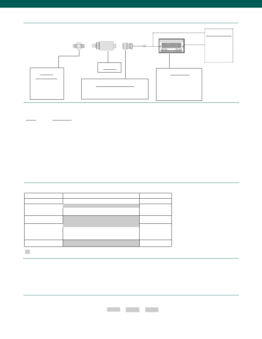
76
www.honeywell.com/sensotec
Adaptors
Compatible with:
1/4-18 NPT Male
1/4-18 NPT Female
7/16-20 UNF Male
7/16-20 UNF Female
Model DS
Display Units
SC1000
SC2000
SC2001
SC3004
GM-A
Customer Supplied
Chart Recorder
Alarm Panel
Data Acquisition
Computer
PLC
Mating Connectors & Cables
PT06A-12-8S (8 conductor cable)
1-888-282-9891
Model DS
Typical System Diagram
How to Order
Combine the order code, the range code and the options code.
Order Code
Range Code
Options Code
Sample Code: AP611 CV 1c, 5a
Options
Built to Order
Built from Scratch
Pressure Ranges
15; 30; 50; 100; 150; 250; 500; 750; 1000; 2500 psig/a
5 psig/a
Temperature
Compensation
1c. 0° to 185° F
1k. -20° to 85° C
Internal Amplifiers
RS485 or RS232, 0-5 VDC (non isolated)
Pressure Ports
5a. 1/4-18 NPT Female
5c. 7/16-20 UNF Female (per MS33649-4)
5d. 7/16-20 UNF Male (per MS33656E4)
Electrical Termination
Bendix PTIH-12-8P–(or equiv.) 8 pin (max.250°F)
40° to 140° F
Supplied as standard
Range Codes
Range
Range Code
5 psig/a
AT
15 psig/a
BJ
30 psig/a
BM
50 psig/a
BN
100 psig/a
BR
150 psig/a
CJ
250 psig/a
CN
500 psig/a
CR
750 psig/a
CT
1,000 psig/a
CV
2,500 psig/a
DM
Different electrical connectors
Different materials
Different threads
O ring material
O2 Clean
Radiation proof
Special temperature compensation
Temperature and pressure calibration
Special Customer
Requirements
(Consult Factory)
Notes
1. The dual output of both the digital and analog signals allow flexibility in potential applications
where the conventional 0-5 VDC output is desired. The digital output replaces the computer
interface A-D card with direct connection into your PC RS-232 or RS-232 port.
5b. 1/4-18 NPT Male
Courtesy of Steven Engineering, Inc.-230 Ryan Way, South San Francisco, CA 94080-6370-Main Office: (650) 588-9200-Outside Local Area: (800) 258-9200-www.stevenengineering.com
Sensotec Sensors Full Line Catalog-html.html
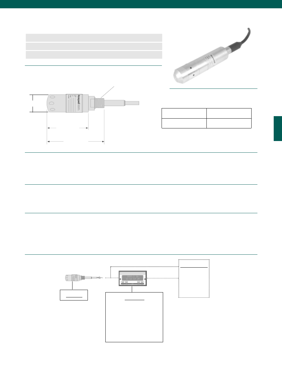
77
Dimensions
Performance
Environmental
Mechanical
Typical System Diagram
Pressure Ranges................0-20; 0-30; 0-50; 0-100; 0-120; 0-150; 0-200; 0-300;
0-500 inches of water column
1; 2; 5; 10; 15; 25; 50 psig
Accuracy (note 3)................+/-0.1% Full Scale (Static Error Band)
Output................0-5 VDC or 4-20 mA
Resolution................Infinite
Temperature, Operating................0° to 180°F
Temperature, Compensated................60° to 160°F
Temperature, Effect
Zero................+/-0.0025% Full Scale/°F
Span................+/-0.0025% Reading/°F
Media................Liquids compatible with Stainless Steel
Overload-Safe................150%
Overload-Burst................400%
Pressure Port................Screened Flush Diaphragm
Dead Volume................Not Applicable
Wetted Parts Material................Stainless Steel
Weight................14 oz.
Case Material................all welded Stainless Steel
www.honeywell.com/sensotec
n
True Gage Design
n
Conduit Connection
n
0.1% Accuracy
Model LL-V Vertical Entry Liquid Level Sensor
Order Code BP712
4.4 in.
5.6 in.
D
Cable Exit
1/2-14 NPT
0 - 2
2.25
5 - 50
1.50
Ranges (psig) D (in.)
1-888-282-9891
Model LL-V
Display Units
SC500
SC1000
SC2000
SC2001
SC3004
GM-A
Customer Supplied
Chart Recorder
Alarm Panel
Data Acquisition
Computer
PLC
*Model LL-V shown with non-standard diaphragm
Courtesy of Steven Engineering, Inc.-230 Ryan Way, South San Francisco, CA 94080-6370-Main Office: (650) 588-9200-Outside Local Area: (800) 258-9200-www.stevenengineering.com
Sensotec Sensors Full Line Catalog-html.html
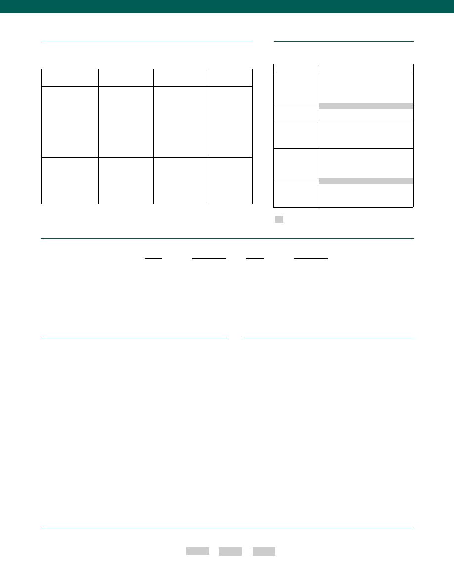
78
www.honeywell.com/sensotec
Internal Amplifiers
Options
Supplied as standard
1-888-282-9891
How to Order
Combine the order code, the range code and the options code.
Order Code
Range Code
Options Code
Sample Code: BP712 BJ 3d
Different materials
Different threads
O2 Clean
Radiation proof
Special temperature compensation
Temperature and pressure calibration
Special Customer Requirements
(Consult Factory)
Notes
1. Cables brown and orange are internally connected.
2. Interconnecting shunt cal. 1 with shunt cal. 2 terminal provides 50% (unamplified units),
75% (4-20 mA 3 wire units), or 80% (voltage amp. units) of full scale output for quick
calibration. Shunt Calibration comes standard with internal amplifier options 2c, 2j.
3. Static Error Band is the recommended performance specification. The static error band is
calculated as the best fit straight line through zero, including the effects of non-linearity,
hysteresis and non-repeatability.
4. G=Green; B=Blue; W=White; Bl=Black; Br=Brown; Y=Yellow; R=Red; O=Orange. Color
specifying cable and number or letter specifying connector
5. No mating connector necessary with cable option.
6. Input power (voltage) for internal amplifier options 2j depends on load resistance.
Range Codes
Range
Range Code
20” H2O
WC
30” H2O
WE
50” H2O
WG
100” H2O
WI
120” H2O
WK
150” H2O
WM
200” H2O
WP
300” H2O
WR
Range
Range Code
500” H2O
WS
1 psig
AP
2 psig
AR
5 psig
AT
10 psig
AV
15 psig
BJ
25 psig
BL
50 psig
BN
Model LL-V
Amplifier
Specifications
Voltage Output Option
2c
Current 3 Wire
Option 2j
Current 2 Wire
Option 2k
Output Signal
Input Power (Voltage)
Input Power (Current)
Frequency Response
Power Supply
Rejection
Operating Temperature
Reverse Voltage
Protection
Short Circuit Protection
0-5VDC @ 45mA
11-28 VDC
40 mA
3000 Hz
60 db
0° to 180° F
Yes
Momentary
4-20 mA
22-32 VDC(note 6)
65 mA
2500 Hz
60 db
0° to 180° F
Yes
Yes
4-20 mA
9-28 VDC
4-28 mA
300 Hz
60 db
0° to 185° F
Yes
Yes
Wiring Code: Cable
(note 2)
(note 4)
(note 5)
R
(+) Supply
Bl* Output Common/
G* Supply Return
W (+) Output
B
Shunt Cal 1
Br Shunt Cal 2
R
(+) Supply
Bl* Output Common/
G* Supply Return
W (+) Output
B
Shunt Cal 1
Br Shunt Cal 2
R (+) Supply
Bl (+) Output
W Case Ground
Built to Order
Pressure Ranges
0-20; 0-30; 0-50; 0-100; 0-120; 0-150;
0-200; 0-300; 0-500 in. of water column
1; 2; 5; 10; 15; 25; 50 psig
Temperature
Compensation
Internal Amplifiers
2c. 0-5 VDC output
2j. 4-20 mA (3-wire) output
2k. 4-20 mA (2-wire) output
Internal Amplifier
Enhancements
3d. Remote Buffered Shunt Cal.
Pressure Ports
1a. 60° to 160° F
Flush
* Black and Green wires are internally connected.
Courtesy of Steven Engineering, Inc.-230 Ryan Way, South San Francisco, CA 94080-6370-Main Office: (650) 588-9200-Outside Local Area: (800) 258-9200-www.stevenengineering.com
Sensotec Sensors Full Line Catalog-html.html
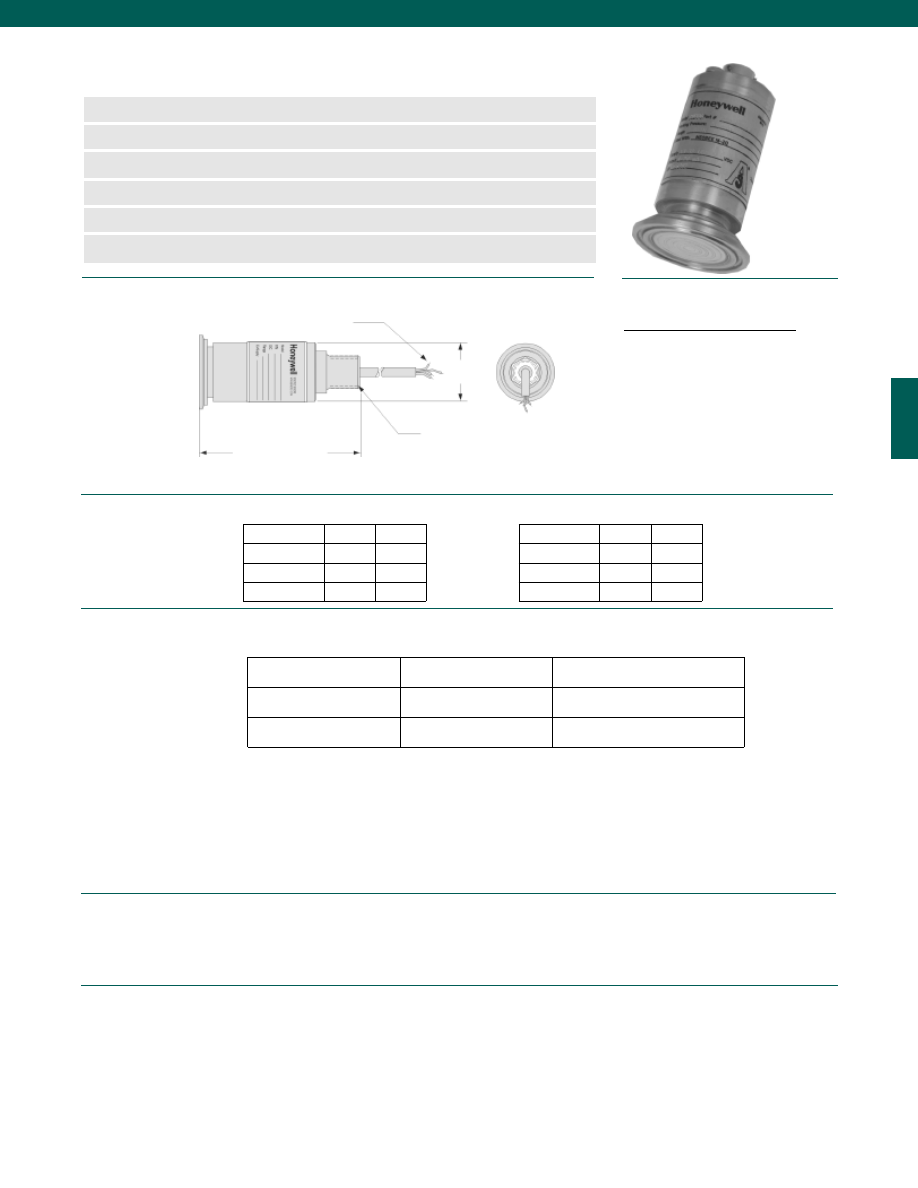
79
Accuracy (note 1)................See table
Pressure Ranges
1 1/2” Flange................0-5 to 0-600 psi
2” Flange................0-1 to 0-500 psi
2 1/2” Flange................0-1 to 0-400 psi
3” Flange................0-1 to 0-250 psi
Max. Flange Pressure................600 psi with 13MHHS clamp at 72° F, 1.5” size
Response Time (comb. mech. & elect.)................500 microseconds
Resolution................Infinite
Orientation Sensitivity................0.03 psi/G
Process Temperature (note 2 & 3)................-20° to 260° F
Sensor Temperature (note 4)................30° to 180° F
Temperature, Effect (note 5)
Zero................1% Full Scale/ 100° F (2% Full Scale/ 100° F for 1 psi)
Span................1% Full Scale/ 100° F (2% Full Scale/ 100° F for 1 psi)
Supply Voltage................9 to 28 VDC
Electrical Connection (Std.)................1/2-14 NPT Conduit Exit with 5ft. Cable
Load Impedance (Max.)................950 Ohms @ 28 VDC
Zero Balance................4 mA +/- 0.16 mA
Output (Std.)................4-20 mA, 2-wire
Dimensions
Flanges
Performance
Environmental
Electrical
www.honeywell.com/sensotec
n
0 to 600 psi Range
n
Track Temperature Changes - 200
°F/ minute
n
4-20 mA Output
n
500 µs Pressure Response T ime
n
Secondary Containment Exceeds 1500 psi
n
Accuracy to 0.1%
Model CIP-Ultra Sanitary Process Transmitters
Order Code (see table below)
1.5 in.
1/2” NPT Conduit Exit
Accuracy
Order Code
Ranges
4 Conductor Cable
4 to 5 inches
Depending on Range Code and
Option Codes
Flange
Size
Code
Flange
Size
Code
Wiring Code
1-888-282-9891
0.1%
CP100 (Gage)
CP101 (Absolute)
1; 2.5; 5; 10; 15; 25; 50; 100; 200;
250; 400; 500; 600 psi
0.25%
CP200 (gage)
CP201 (Absolute)
1; 2.5; 5; 10; 15; 25; 50; 100; 200;
250; 400; 500; 600 psi
0.5%
CP300 (Gage)
CP301 (Absolute
1; 2.5; 5; 10; 15; 25; 50; 100; 200;
250; 400; 500; 600 psi
Cherry-Burrell
1 1/2”
16f
Cherry-Burrell
2”
16g
Cherry-Burrell
2 1/2”
16h
Cherry-Burrell
3”
16i
Tri-Clover
1 1/2”
16b
Tri-Clover
2”
16c
Tri-Clover
2 1/2”
16d
Tri-Clover
3”
16e
Cable/ 2 wire current, 4-20 mA
Red
(+) Supply
Black
(+) Output (4-20 mA)
White
Case Ground
Courtesy of Steven Engineering, Inc.-230 Ryan Way, South San Francisco, CA 94080-6370-Main Office: (650) 588-9200-Outside Local Area: (800) 258-9200-www.stevenengineering.com
Sensotec Sensors Full Line Catalog-html.html
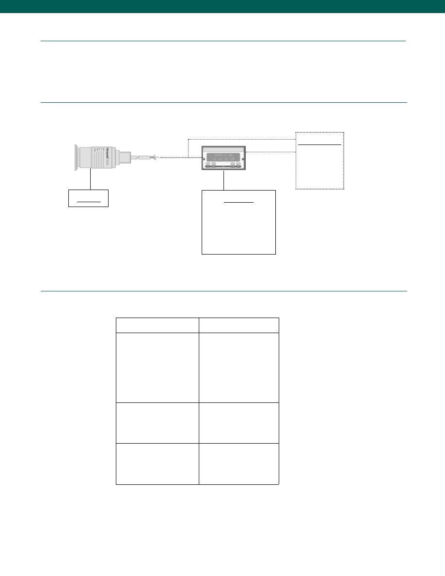
80
Mechanical
Typical System Diagram
Media................Steam, Ethylene Oxide, Liquid, Gas
Wetted Parts Material................316-L Stainless, Hastelloy C-276
Fill Material................NEOBEE M-20
Weight (nominal)................16 oz.
Case Material................316-L Stainless
Sanitary Std.................3-A, #37-01
Over Pressure................4 x To max flange pressure
www.honeywell.com/sensotec
Model CIP
Display Units
SC500
SC1000
SC2000
SC2001
SC3004
GM-A
Customer Supplied
Chart Recorder
Alarm Panel
Data Acquisition
Computer
PLC
Internal Amplifiers
Amplifier
Specifications
Intrinsically Safe Amp
Option 2N (2n)***
Output Signal
Input Power (Voltage)
Input Power (Current)
Frequency Response
Power Supply Rejection
Operating Temperature
Reverse Voltage Protection
Short Circuit Protection
4-20 mA
9-28 VDC (note 3)
4-20 mA
2000 Hz
60 db
-20° to 185° F
Yes
Yes
Wiring Code: Connector
A (+) Supply
B No Connection
C No Connection
D (+) Output
E Case Ground
F No Connection
Wiring Code: Cable (std.)
(note 6)
(note 7)
R (+) Supply
Bl (+) Output
W Case Ground
1-888-282-9891
Model CIP Ultra
*** See Sensotec website for most up-to-date information regarding Intrinsically Safe approvals ref. #008-0547-00.
Courtesy of Steven Engineering, Inc.-230 Ryan Way, South San Francisco, CA 94080-6370-Main Office: (650) 588-9200-Outside Local Area: (800) 258-9200-www.stevenengineering.com
Sensotec Sensors Full Line Catalog-html.html
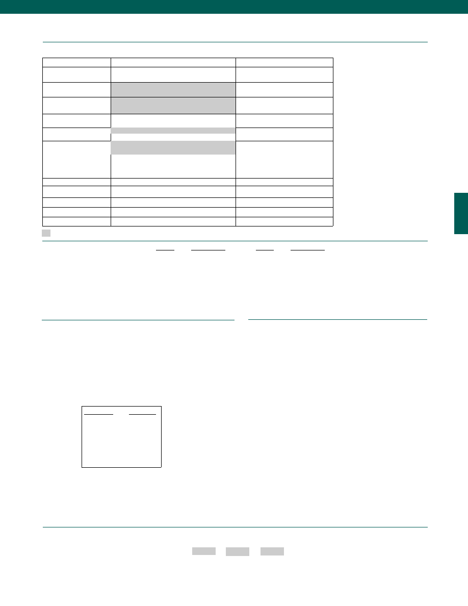
81
1. Accuracies stated are expected for Best Fit Straight Line for all
errors, including linearity, hysteresis & non-repeatability.
2. Higher ranges may be available for special applications.
Consult factory.
3. Specifications may vary with flange size and pressure range.
Consult factory.
4. 30° to 130°F for 1 psi range (only applicable for CP100, CP101,
CP200 & CP201).
5. Temperature profile for heated vessels:
6. G=Green; B=Blue; W=White; Bl=Black; Br=Brown; Y=Yellow;
R=Red; O=Orange. Color specifying cable and number or
letter specifying connector
7. No mating connector necessary with cable option.
8. For potentiometer access for zero and span adjustment by
instrumentation tech. Electrical termination is DIN 43650
Hirschmann plug; environmental class IP65 (NEMA 4). Conduit
attachment by PG 9 thread on plug.
Process temp.
Sensor temp.
260°F
180°F
200°F
145°F
150°F
120°F
100°F
90°F
75°F
75°F
50°F
65°F
0°F
40°F
-20°F
30°F
www.honeywell.com/sensotec
Options
Built to Order
Built from Scratch
Pressure Ranges
1; 2.5; 5; 10; 15; 25; 50; 75; 100; 200; 250; 400;
500; 600 psi
Temperature
Compensation
1i. -65° to 250° F
Internal Amplifiers
2N(2n). Intrinsically safe amp 4-20 mA,
2 wire current
Internal Amplifier
Enhancements
Side points
Special Filtering
Pressure Ports
Cherry Burrell
Electrical Termination
6a. Bendix PTIH-10-6P or equivalent 6 pin
6m. DIN43650 (note 8)
6n. DIN 40050
Shunt Calibration
3d. Remote Buffered Shunt Cal
Special Calibration
Compound, Vacuum, Barometric
Bar
Wetted Diaphragm
10c. Hastelloy-C 276
Bridge Resistance
12b. 5,000 Ohm (foil) (max. 250° F)
Potentiometers
14b. Top access to pots
6j. 1/2-14 NPT Conduit fitting with 5’ of 4
conductor PVC cable
30° to 180° F
Tri-clover
Supplied as standard
1-888-282-9891
How to Order
Combine the order code, the range code and the options code.
Order Code
Range Code
Options Code
Sample Code: CP100 AT 16g
Different electrical connectors
O2 Clean
Single pole 3 Hz. filter for electrical damping
(helps remove vibration induced noises from pumps, stirrers, etc.)
Special temperature compensation
Temperature and pressure calibration
3/4” CIP or ranges above 50 psi
Special Customer Requirements
(Consult Factory)
Notes
Range Codes
Model CIP Ultra
Range
Range Code
1 psi
AP
2.5 psi
AS
5 psi
AT
10 psi
AV
15 psi
BJ
25 psi
BL
50 psi
BN
Range
Range Code
100 psi
BR
200 psi
CL
250 psi
CN
400 psi
CQ
500 psi
CR
600 psi
CS
A
3
Standards
Courtesy of Steven Engineering, Inc.-230 Ryan Way, South San Francisco, CA 94080-6370-Main Office: (650) 588-9200-Outside Local Area: (800) 258-9200-www.stevenengineering.com
Sensotec Sensors Full Line Catalog-html.html
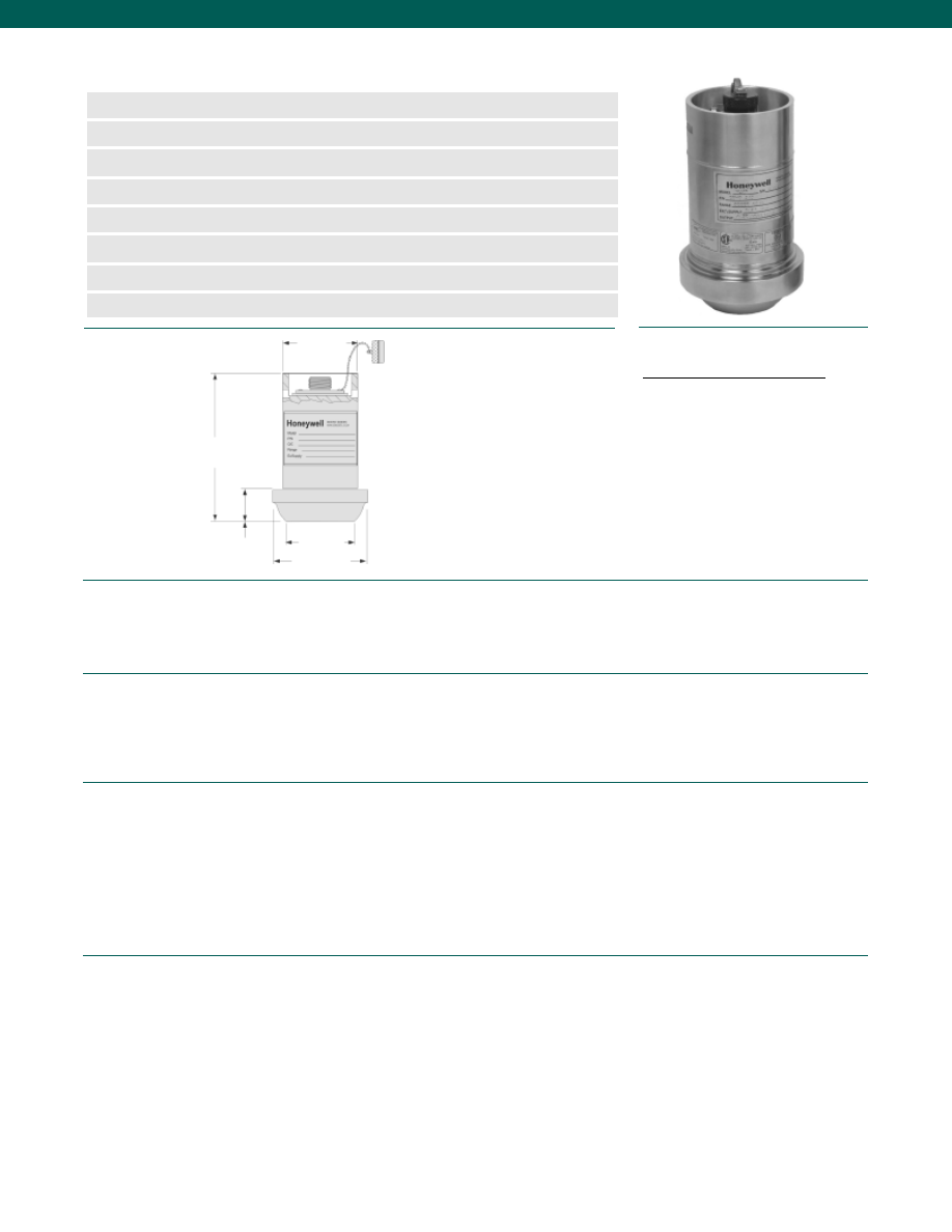
82
Pressure Ranges................0-5000 psi; 0-6000 psi; 0-10,000 psi; 0-15,000 psi; 0-20,000psi
Accuracy (note 1)................+/- 0.2% Best Fit Straight Line
Calibration................5 point calibration; 0%, 50% and 100% of Full Scale
Output................4-20 mA, 2-wire Full Scale
Resolution................Infinite
Temperature, Operating................-45° to 200° F (-43° to 93° C)
Temperature, Compensated................-30° to 180° F (-35° to 80° C)
Temperature, Effect
Zero................0.01% Full Scale/° F (0.018% Full Scale/°C)
Span................0.01% Reading/° F (0.018% Reading/°C)
Sealing................Hermetically sealed IP68/ Nema 6P
Supply Voltage................9-28 VDC
Output (standard)................4-20 mA (2-wire) Full Scale
Insulation Resistance................Greater than or equal to 100 Megohms @ 50 VDC
Maximum Loop Resistance................950 Ohms @ 28 Volts decreasing linearly to 0 Ohms @ 9 Volts
Circuit Protection................Reverse Polarity Protection of Supply Leads
RFI/ EMI Protection................Noise Immunity from 5,000 Hz to 1.0 GHz
Frequency Response................Customer specified and factory installed filter for frequency
response of min. 10 Hz to max. of 2,000 Hz (1.4 x 10⁻⁴ sec.)
Shunt Calibration Data................Included
Electrical Termination (std)................MS-3102E-14S-2P, 4 Pin Stainless Steel Hermetic Equal
Media................Corrosive & abrasive service
Overload-Safe................150% Rated Full Scale Pressure or limit of WECO 2202 fitting
Overload-Burst................250% Rated Pressure or limit of WECO 2202 fitting
Pressure Port................WECO 2202 Wing Union, 2” pipe, Male Sub End
Wetted Parts Material................Inconel X-750
Weight................6 lb.
Case Material................Inconel X-750
(labels are welded stainless steel with embossed characters)
Dimensions
Performance
Environmental
Electrical
Mechanical
www.honeywell.com/sensotec
n
Long Life X-750 Material
n
Rugged, Robust Design
n
2202 2” Wing Union Size
n
RFI/ EMI Protected
n
Intrinsically Safe
n
Quick Delivery Service
n
0.2% Accuracy
n
Optional On-Board Temperature Sensor
Model 424 Wing Union Pressure Transmitter
Order Code BP424
4.8 in.
1.15 in.
ø2.47 in.
ø1.80 in.
ø3.00 in.
Wiring Codes
1-888-282-9891
AMP (NS), 3-COND, 4 Pin, GND
A
N/C
B
(+) Output
C
(+) Supply
D
Case Ground
Courtesy of Steven Engineering, Inc.-230 Ryan Way, South San Francisco, CA 94080-6370-Main Office: (650) 588-9200-Outside Local Area: (800) 258-9200-www.stevenengineering.com
Sensotec Sensors Full Line Catalog-html.html
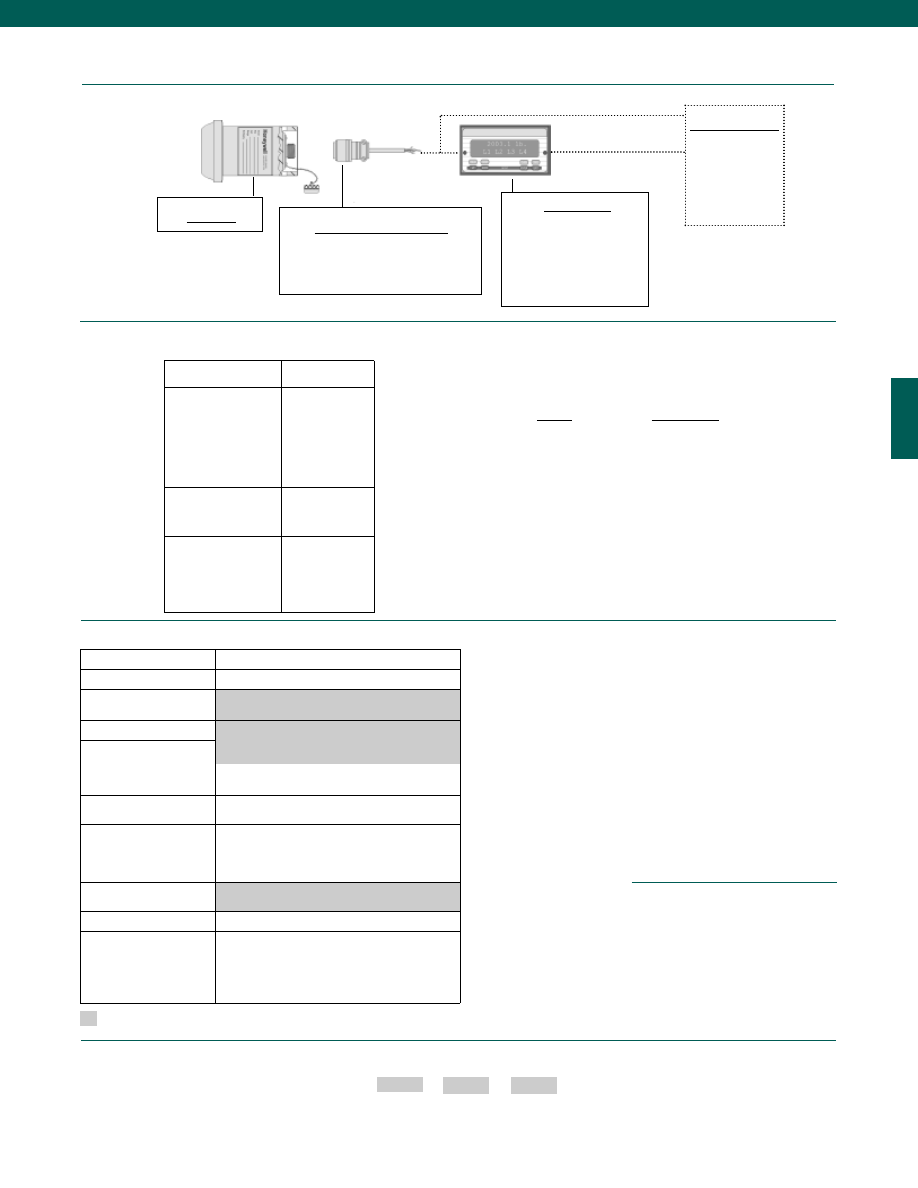
83
Model 424
Mating Connectors & Cables
MS3106A-14S-2S (3 conductor cable)
PT06A-10-6S (3 conductor cable)
PT06E-10-6S (3 conductor cable)
Customer Supplied
Chart Recorder
Alarm Panel
Data Acquisition
Computer
PLC
Typical System Diagram
www.honeywell.com/sensotec
1-888-282-9891
Model 424
How to Order
Combine the order code, the range code and the options code.
Order Code
Range Code
Options Code
Sample Code: BP424 DV 45c
Display Units
SC500
SC1000
SC2000
SC2001
SC3004
GM-A
Range
Range Code
0-5,000 psi
DR
0-6,000 psi
DS
0-10,000 psi
DV
0-15,000 psi
DJ
0-20,000 psi
EL
Options
Supplied as standard
Different wiring codes
Different electrical connectors
Different materials
Different amplifier options
DNV Approval available
Electro-static discharge immunity
Lightning protection
O2 Clean
OEM labels
Temperature & Pressure calibration
Carrying handles/ Connector guards
Special Customer
Requirements
(Consult Factory)
Notes
1. Accuracies stated are expected for Best Fit
Straight Line for all errors including linearity,
hysteresis & non-repeatability thru zero.
2. Availability varies with range.
3. Working pressure and approval limited to
15,000 psi. Amplifier will allow overpressure
readings to 20,000 psi.
Range Codes
Built to Order
Pressure Ranges (note 3)
0-5,000; 0-6,000; 0-10,000; 0-15,000; 0-20,000 psi
Temperature Compensation -30° F to 180° F
Internal Amplifiers
2n(2N). 4-20 mA (2-wire) output; Intrinsically safe
Electrical Termination
6a. Bendix PTIH-10-6P- (or equivalent) 6 pin
(max. 250° F)
Shunt Calibration
Buffered remote activated with optical isolator
available.
Special Calibration
(note 2)
9a. 10 point (5 up/ 5 down) 20% increments
@70°F
9b. 20 point (10 up/ 10 down) 10% increments
@ 70° F
Wetted Diaphragm
10e. Inconel X-750
Potentiometers
14b. Top access to pots
Temperature
Sensing Options
45c. RTD output direct to connector. Gives
temperature as a resistance reading.
Intrinsically Safe
45d. RTD with temperature as a 4-20 mA output.
Not Intrinsically Safe
MS-3102E-14S-2P, 4 pin stainless steel hermetic
Internal Amplifiers
Amplifier Specifications
Intrinsically Safe Amp
Option 2N (2n)
Output Signal
Input Power (Voltage)
Input Power (Current)
Frequency Response (amp)
Power Supply Rejection
Operating Temperature
Reverse Voltage Protection
Short Circuit Protection
4-20 mA
9-28 VDC
4-24 mA
2000 Hz
60 db
-20° to 185° F
Yes
Yes
Wiring Code: Connector
(Std.)
A No Connection
B (+) Output
C (+) Supply
D Case Ground
See Sensotec web
site for most up-to-
date information
regarding Intrinsically
Safe approvals
ref. #008-0547-00.
Courtesy of Steven Engineering, Inc.-230 Ryan Way, South San Francisco, CA 94080-6370-Main Office: (650) 588-9200-Outside Local Area: (800) 258-9200-www.stevenengineering.com
Sensotec Sensors Full Line Catalog-html.html
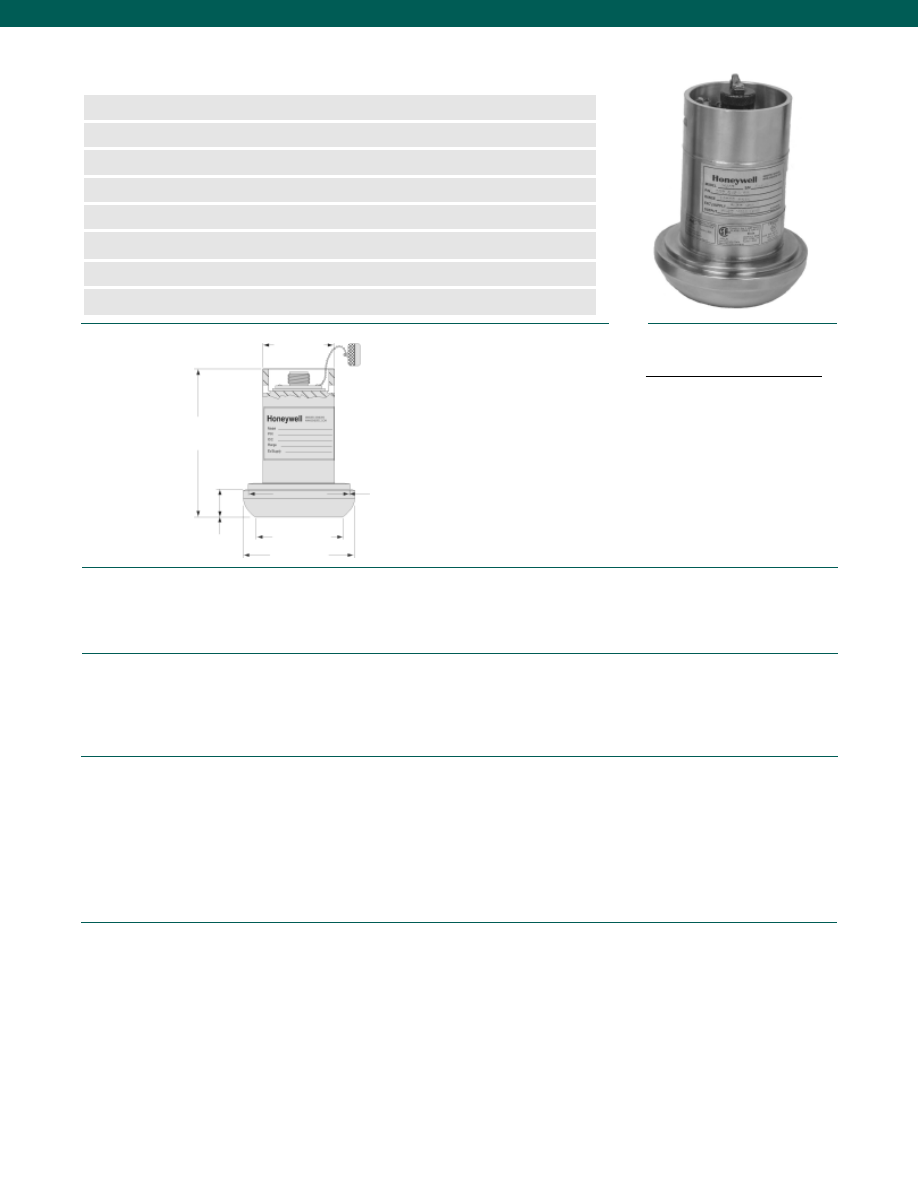
84
Pressure Ranges................0-5000; 0-6000; 0-10,000; 0-15,000; 0-20,000 psi (note 3)
Accuracy (note 1)................+/- 0.2% Best Fit Straight Line
Output................4-20 mA (2-wire)
Resolution................Infinite
Calibration................5 point calibration: 0%, 50% and 100% of Full Scale
Temperature, Operating................-45° to 200° F (-43° to 93° C)
Temperature, Compensated................-30° to 180° F (-35° to 80°C)
Temperature, Effect
Zero................0.01% Full Scale/° F (0.018% Full Scale/° C)
Span................0.01% Reading/° F (0.018% Reading/° C)
Sealing................Hermetically Sealed IP68/ NEMA 6P
Supply Voltage................9-28 VDC
Insulation Resistance................Greater than or equal to 100 Megohms @ 50 VDC
Max Loop Resistance................950 Ohms at 28 Volts decreasing linearly to 0 Ohms at 9 Volts
Circuit Protection................Reverse polarity protection of supply leads
RFI/ EMI Protection................Noise immunity from 5,000 Hz to 1.0 GHz
Frequency Response................Customer specified and factory installed filter for frequency
response of min. 10Hz to max. of 2,500 Hz
Zero and Span Adjustment................Field adjustable by removing connector
Shunt Calibration Data................Included
Electrical Termination (std)................MS-3102E-14S-2P, 4 Pin Stainless Steel Hermetic Equal
Media................Corrosive and abrasive service, Inconel X-750
Overload-Safe................150% Rated Full Scale Pressure or limit of Wing Union 1502 fitting
Overload-Burst................250% Rated Pressure or limit of Wing Union 1502 fitting
Pressure Port................1502 Wing Union, 2” pipe, Male Sub End
Wetted Parts Material................Inconel X-750
Weight................6 lb.
Case Material................Inconel X-750
(labels are welded stainless steel with embossed characters)
www.honeywell.com/sensotec
n
Long Life X-750 Material
n
Rugged, Robust Design
n
1502 2” Wing Union Size
n
RFI/ EMI Protected
n
Intrinsically Safe
n
Quick Delivery Service
n
0.2% Accuracy
n
Optional On-Board Temperature Sensor
Model 425 Wing Union Pressure Transmitter
Order Code BP425
5.0 in.
1.0 in.
ø2.47 in.
ø2.70 in.
ø3.25 in.
ø3.70 in.
Wiring Codes
1-888-282-9891
Dimensions
Performance
Environmental
Electrical
Mechanical
AMP (NS), 3-COND, 4 Pin, GND
A
N/C
B
(+) Output
C
(+) Supply
D
Case Ground
Courtesy of Steven Engineering, Inc.-230 Ryan Way, South San Francisco, CA 94080-6370-Main Office: (650) 588-9200-Outside Local Area: (800) 258-9200-www.stevenengineering.com
Sensotec Sensors Full Line Catalog-html.html
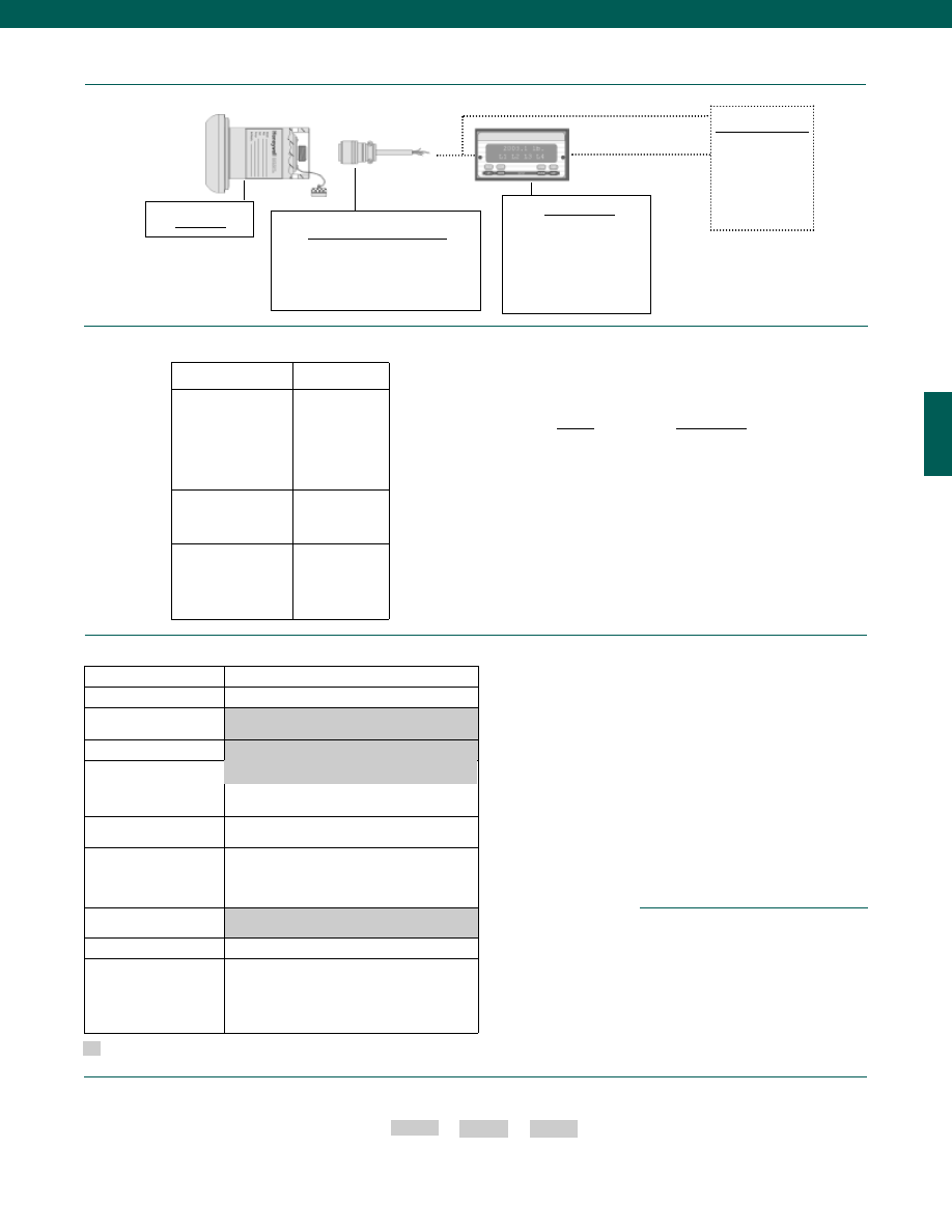
85
Model 425
Mating Connectors & Cables
MS3106A-14S-2S (3 conductor cable)
PT06A-10-6S (3 conductor cable)
PT06E-10-6S (3 conductor cable)
Customer Supplied
Chart Recorder
Alarm Panel
Data Acquisition
Computer
PLC
Typical System Diagram
www.honeywell.com/sensotec
1-888-282-9891
Model 425
Range
Range Code
0-5,000 psi
DR
0-6,000 psi
DS
0-10,000 psi
DV
0-15,000 psi
DJ
0-20,000 psi
EL
Options
Supplied as standard
How to Order
Combine the order code, the range code and the options code.
Order Code
Range Code
Options Code
Sample Code: BP425 DV 45c
Different wiring codes
Different electrical connectors
Different materials
Different amplifier options
DNV Approval available
Electro-static discharge immunity
Lightning protection
O2 Clean
OEM labels
Temperature & Pressure calibration
Carrying handles/ Connector guards
Special Customer
Requirements
(Consult Factory)
Notes
1. Accuracies stated are expected for Best Fit Straight
Line for all errors including linearity, hysteresis &
non-repeatability thru zero.
2. Availability varies with range.
3. Working pressure and approval limited to
15,000 psi. Amplifier will allow overpressure
readings to 20,000 psi.
Range Codes
Built to Order
Pressure Ranges (note 3)
0-5,000; 0-6,000; 0-10,000; 0-15,000; 0-20,000 psi
Temperature Compensation -30° F to 180° F
Internal Amplifiers
2n(2N). 4-20 mA (2-wire) output; Intrinsically safe
Electrical Termination
6a. Bendix PTIH-10-6P- (or equivalent) 6 pin
(max. 250° F)
Shunt Calibration
Buffered remote activated with optical isolator
available.
Special Calibration
(note 2)
9a. 10 point (5 up/ 5 down) 20% increments
@70°F
9b. 20 point (10 up/ 10 down) 10% increments
@ 70° F
Wetted Diaphragm
10e. Inconel X-750
Potentiometers
14b. Top access to pots
Temperature
Sensing Options
45c. RTD output direct to connector. Gives
temperature as a resistance reading.
Intrinsically Safe
45d. RTD with temperature as a 4-20 mA output.
Not Intrinsically Safe
MS-3102E-14S-2P, 4 pin stainless steel hermetic
Display Units
SC500
SC1000
SC2000
SC2001
SC3004
GM-A
Internal Amplifiers
Amplifier Specifications
Intrinsically Safe Amp
Option 2N (2n)
Output Signal
Input Power (Voltage)
Input Power (Current)
Frequency Response (amp)
Power Supply Rejection
Operating Temperature
Reverse Voltage Protection
Short Circuit Protection
4-20 mA
9-28 VDC
4-24 mA
2000 Hz
60 db
-20° to 185° F
Yes
Yes
Wiring Code: Connector
(Std.)
A No Connection
B (+) Output
C (+) Supply
D Case Ground
See Sensotec web
site for most up-to-
date information
regarding Intrinsically
Safe approvals
ref. #008-0547-00.
Courtesy of Steven Engineering, Inc.-230 Ryan Way, South San Francisco, CA 94080-6370-Main Office: (650) 588-9200-Outside Local Area: (800) 258-9200-www.stevenengineering.com
Sensotec Sensors Full Line Catalog-html.html
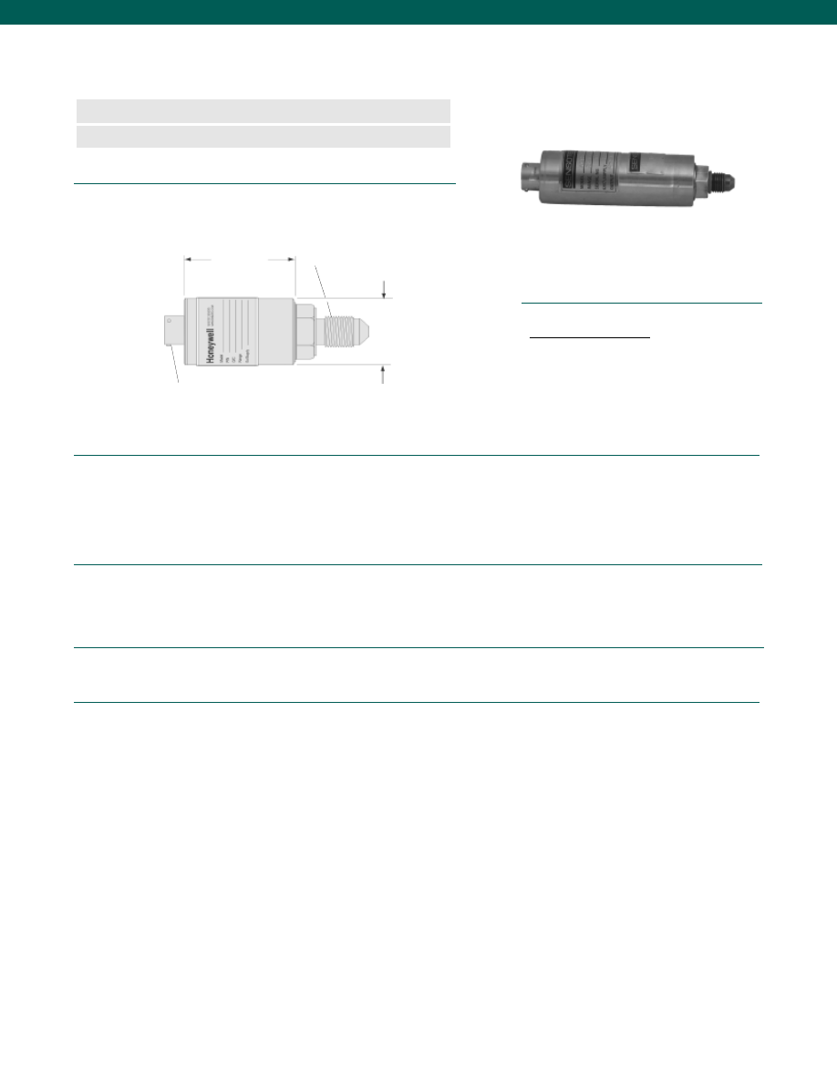
86
Pressure Ranges
Model AS17A (Absolute)................10 to 10,000 psia
Model AS19G (Gage)................25 to 10,000 psig
Linearity................+/- 0.15% Full Scale
Hysteresis................+/- 0.10% Full Scale
Output................3 mV/V Nominal
Resolution................Infinite
Temperature, Operating................-65° to 300° F
Temperature, Compensated................-65° to 250° F
Temperature, Effect
Zero................0.005% Full Scale/° F
Span................0.005% Reading/° F
Excitation (calibration)................10 VDC
Bridge Resistance................350 Ohms
Electrical Termination (std)................Bendix PTIH-10-6P or equivalent
Media................Fluids compatible with 17-4 PH Stainless Steel
Pressure Port................7/16-20 per MS33656E-4
Wetted Parts Material................17-4 PH Stainless Steel
Weight................5 oz.
Case Material................Stainless Steel
Dimensions
Performance
Environmental
Electrical
Mechanical
www.honeywell.com/sensotec
n
Non-Linearity 0.15% BFSL
n
Lightweight
Model AS17A/ AS19G Aerospace Pressure Transducers
Order Code AP161 (absolute); AP162 (gage)
PTIH-10-6P Connector
1.75 in.
ø1.13 in. (AS17A)
ø1.01 in. (AS19G)
Pressure Port
7/16-20 per MS33656E-4
Wiring Code
1-888-282-9891
Connector/Unamplified
A&B
(+) Excitation
C&D
(-) Excitation
E
(-) Output
F
(+) Output
Courtesy of Steven Engineering, Inc.-230 Ryan Way, South San Francisco, CA 94080-6370-Main Office: (650) 588-9200-Outside Local Area: (800) 258-9200-www.stevenengineering.com
Sensotec Sensors Full Line Catalog-html.html
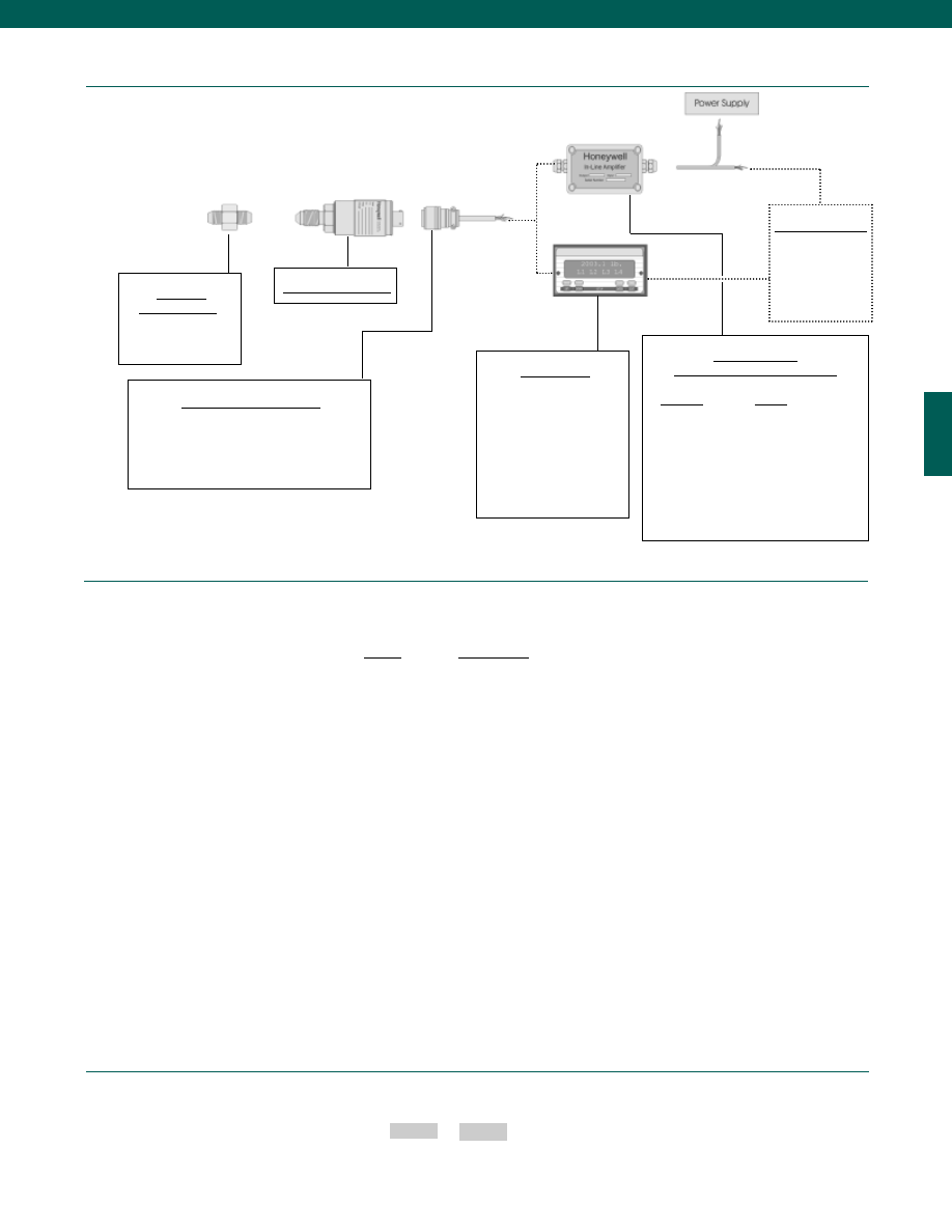
87
Range
Range Code
10 psig/a
AV
15 psig/a
BJ
25 psig/a
BL
50 psig/a
BN
75 psig/a
BP
100 psig/a
BR
150 psig/a
CJ
200 psig/a
CL
300 psig/a
CP
500 psig/a
CR
750 psig/a
CT
1,000 psig/a
CV
1,500 psig/a
DJ
2,000 psig/a
DL
3,000 psig/a
DN
5,000 psig/a
DR
7,500 psig/a
DT
10,000 psig/a
DV
www.honeywell.com/sensotec
1-888-282-9891
How to Order
Combine the order code and the range code.
Order Code
Range Code
Sample Code: AP161 BJ
Range Codes
Model AS17A/ AS19G
Typical System Diagram
Adaptors
Compatible with:
7/16-20 UNF Male
Model AS17A/ AS19G
Mating Connectors & Cables
PT06A-10-6S (6 conductor cable), Std.
PT06E-10-6S (6 conductor cable)
Customer Supplied
Chart Recorder
Alarm Panel
Data Acquisition
Computer
PLC
In-Line Amplifiers
(Used with unamplified units only)
Amplifier
Output
Universal In-Line Amplifiers
UV
+/- 5 VDC
UV-10
+/- 10 VDC
UBP
0 +/- 5 VDC
U3W
4-20 mA (3 wire)
DIN Rail Mount In-Line Amplifiers
DV-05
0 +/- 5 VDC (3 wire)
DA-05
4-20 mA (3 wire)
DV-10
0 +/- 10 VDC (3 wire)
Display Units
SC500
SC1000
SC2000
SC2001
SC3004
GM
NK
HH
Courtesy of Steven Engineering, Inc.-230 Ryan Way, South San Francisco, CA 94080-6370-Main Office: (650) 588-9200-Outside Local Area: (800) 258-9200-www.stevenengineering.com
Sensotec Sensors Full Line Catalog-html.html
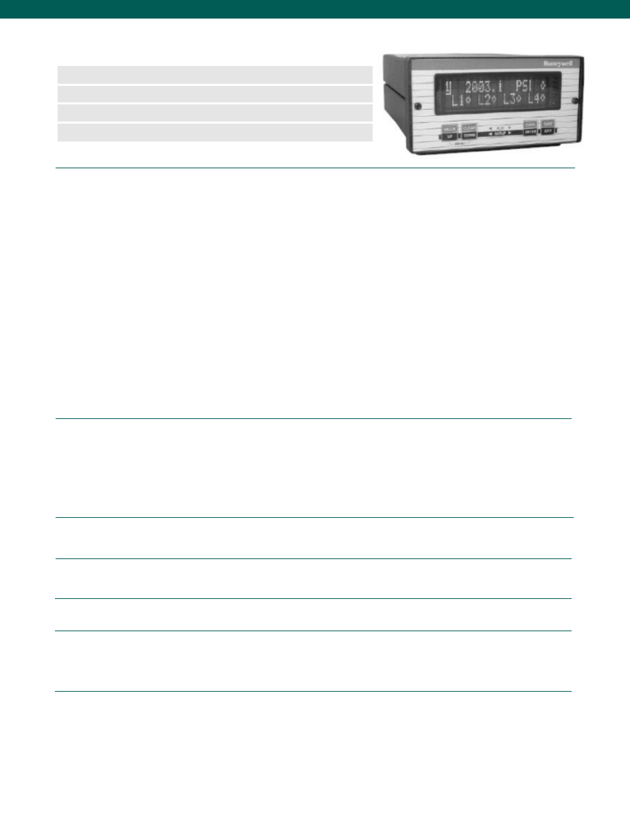
88
Performance
General
Environmental
Amplifier Characteristics
Digital Display
Characteristics
Physical Characteristics
www.honeywell.com/sensotec
n
Transducer with Readout
n
Highly Stable Reading
n
0.05% or 0.10% F.S. Accuracy
n
N.I.S.T Traceable Instrument and Transducer
Accu-Gage Digital Pressure Gages and Digital Pressure Indicators
Model AG400/AG401
1-888-282-9891
This combination pressure transducer and digital readout is designed for use in both industrial and laboratory applications.
ACCU-GAGE offers portability, enhanced accuracy, industrial grade durability, and very competitive prices.
ACCU-GAGE units are also often suitable for panel mounting to provide a clear readout of pressure or vacuum to machine
operators on the process line or as on-line quality control monitors. They are also often additions to statistical process control
systems, using the RS232 interface.
ACCU-GAGE often handles even the harshest industrial environments with a metal case and handle to avoid failures caused
by shock or vibration often associated with the use of plastics.
These instruments are often replacements for:
• Precision Dial Gages
• Mercury Columns
• Quartz Tube Barometers
ULTRA HIGH PRECISION
The ACCU-GAGE Model AG-400 was designed to provide the highest accuracy (0.05% F.S.) and overall stability available
in digital pressure indicators. To achieve the high level of stability demanded by Metrology and Calibration/Standards
laboratories, SENSOTEC has chosen to fit all AG-400 instruments with our dependable, enhanced-accuracy pressure
transducer. During manufacture these transducers undergo an extensive burn-in program. In addition, all ACCU-GAGE
Instruments undergo individual burn-in prior to shipment, thus the AG benefits from a double burn-in at both transducer and
instrument level. This truly enhances the long-term stability of the instrument enabling the AG to perform as a high integrity
pressure transfer standard. Full traceability is assured to National Standards.
Pressure Ranges
AG400................15; 25; 50; 75; 100; 200; 300; 500; 750; 1000; 1500; 2000;
................3000; 5000; 7500; 10,000; 15,000; psig/a/v
AG401................15; 25; 50; 75; 100; 200; 300; 500; 750; 1000; 1500; 2000;
................3000; 5000; 7500; 10,000; 15,000; 60,000 psig/a/v
Accuracy
AG400................+/-0.05%
AG401................+/-0.10%
Number of Channels................1
Case Material................Aluminum
Case Size................3/8 DIN
Temperature, Operating................60° to 105°F
Temperature, Effect................0.004%/ °F over operating range
Temperature, Storage................-20° to 200°F
Frequency Response................2 Hz
Step Response................40 ms
Number of Characters................6
Scaling................Automatic or manual setup
Max. Display Count................9,999,999
Field Selectable Units................psi, bar, mbar, torr, in.H
2
O, ft.H
2
O, in.Hg, mmHg, MPa
Resolution................1/50,000
Power Requirements................120 to 230 VAC, 47 to 63 Hz
Limits Output................Open-collector
Pressure Port
15 to 1000 psi................1/4-18 NPT male
1500 to 10,000 psi................1/4-18 NPT female
15,000 to 60,000 psi................Autoclave AE F250-C
Courtesy of Steven Engineering, Inc.-230 Ryan Way, South San Francisco, CA 94080-6370-Main Office: (650) 588-9200-Outside Local Area: (800) 258-9200-www.stevenengineering.com
Sensotec Sensors Full Line Catalog-html.html
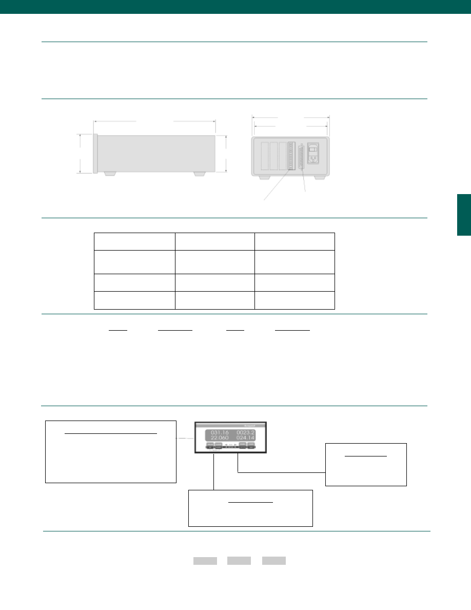
89
www.honeywell.com/sensotec
1-888-282-9891
How to Order
Combine the order code, the range code and the options code.
Order Code
Range Code
Options Code
Sample Code: AE435 CV 1b
Model
AG400
AG401
Order Codes
AE435 (gage)
AE436 (absolute)
AE437 (vacuum)
AE441 (gage)
AE442 (absolute)
AE443 (vacuum)
Accuracy
0.05%
0.10%
Pressure Ranges
15 - 15,000 psi
15 - 60,000 psi
Range
Range Code
15 psig/a/v
BJ
25 psig/a/v
BL
50 psig/a/v
BN
75 psig/a/v
BP
100 psig/a/v
BR
200 psig/a/v
CL
300 psig/a/v
CP
500 psig/a/v
CR
750 psig/a/v
CT
Range
Range Code
1,000 psig/a/v
CV
1,500 psig/a/v
DJ
2,000 psig/a/v
DL
3,000 psig/a/v
DN
5,000 psig/a/v
DR
7,500 psig/a/v
DT
10,000 psig/a/v
DV
15,000 psig/a/v
EJ
60,000 psig/a/v
ES
2.8 in.
8.6 in.
2.6 in.
5.6 in.
5.3 in.
25 Pin System Connector
12 Pin Channel Connector
Chassis & Signal Conditioning Options
• RS232 (Std.) or RS485 (Option 53d) Output
• 4-20mA Output (Option 56a)
• Expanded Temp. Range (30° to 130°F) (Option 1b)
Mounting Options
• Bench Mount
• Panel Mount (AA928)
• Carry Handle (AA926)
Cable Accessories
25 Pin D-Sub Connector (to SC Series)
to 9 Pin D-Sub Connector (to Computer) (AA178)
0-560° to 105°F or 0-10V Output (Field Selectable)
Field Selectable Engineering Units
Auto-Zero
Tare
Hi/Lo Quad Limits
Peak/ Valley Hold on Input Channels
Model Accugage
Special Features
Dimensions
Ordering Information
Range Codes
Options
Courtesy of Steven Engineering, Inc.-230 Ryan Way, South San Francisco, CA 94080-6370-Main Office: (650) 588-9200-Outside Local Area: (800) 258-9200-www.stevenengineering.com
Sensotec Sensors Full Line Catalog-html.html
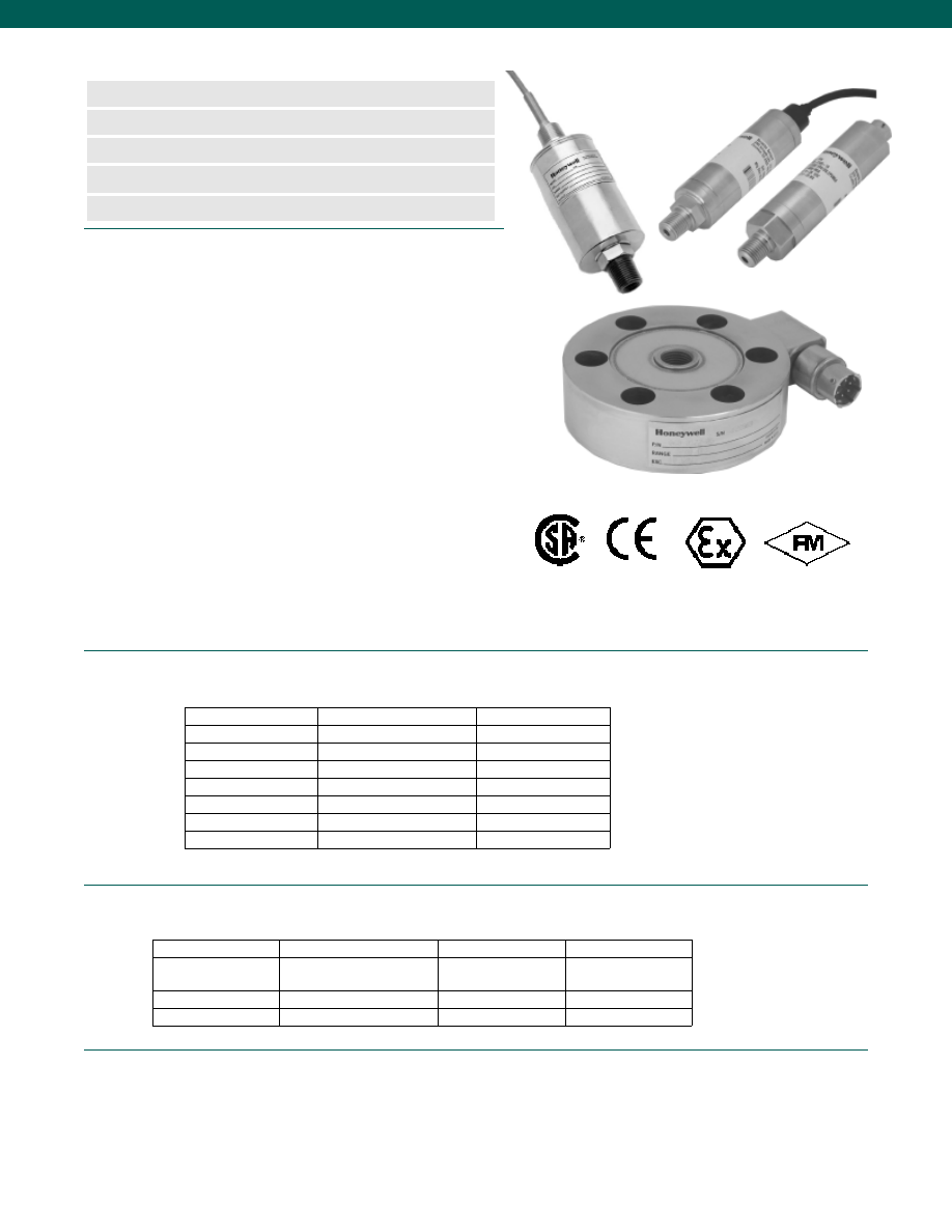
90
Pressure
Load/Force
Notes
1. Accuracy is defined as BFSL at full scale.
2. See Sensotec website for most up-to-date information regarding Intrinsically Safe approvals ref. #008-0547-00.
www.honeywell.com/sensotec
n
FM, CSA, EX, CE
n
Accuracy to 0.10%
n
Load Ranges from 5 to 400,000 lbs.
n
Pressure Ranges from 0.5 to 30,000 psi
n
True Gage, Absolute, Differential
Intrinsically Safe Rated Pressure Transmitters and Load Cells
1-888-282-9891
Intrinsically safe equipment is often not capable of releasing sufficient
electrical or thermal energy to ignite a hazardous atmosphere of gas or
dust.
Intrinsically Safe transmitter, Option 2n (2N)(note 2), is often a standard add-
on to the following models and features a welded stainless steel electrical
connection. (Options may increase length, consult factory).
NOTE: Some combination of options may not be available intrinsically safe,
consult factory.
• Automotive, Engine test
• Grain Storage
• Utilities
• Brewing, Distilling
• Munitions
• Waste Water
• Chemical
• Mining
• Oil field
• Cosmetics
• Pharmaceuticals
• Explosive
• Fuels Testing
• Petrochemical
Pellet Compaction
• Fuel Pump Testing
• Paint & Ink
Model
Accuracy (note 1)
Ranges Available
FP2000
+/- 0.25% or 0.10%
0.5 to 5000 psi
TJE
+/- 0.10%
0.5 to 60,000 psi
Z
+/- 0.25%
0.5 to 60,000 psi
A-5
+/- 0.50%
0.5 to 60,000 psi
424/425
+/- 0.25%
0 to 15,000 psi
HL-Z
+/- 0.25%
50 to 5000 psid
HL-A-5
+/- 0.50%
50 to 5000 psid
Model
Accuracy (note 1)
Ranges Available
45
+/- 0.05%
200 to 100,000 lbs.
Ultra Precision
Fatigue Rated
73,75
+/- 0.10%
50 to 200,000 lbs.
Fatigue Rated
41,43
+/- 0.10%
5 to 400,000 lbs.
Precision
Pressure and Differential Pressure Transducers
Load Cells
Approved Approved Approved
Intrinsically Safe Amp
Courtesy of Steven Engineering, Inc.-230 Ryan Way, South San Francisco, CA 94080-6370-Main Office: (650) 588-9200-Outside Local Area: (800) 258-9200-www.stevenengineering.com
Sensotec Sensors Full Line Catalog-html.html
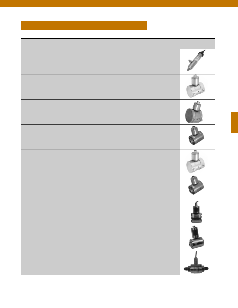
91
www.honeywell.com/sensotec
1-888-282-9891
DIFFERENTIAL PRESSURE TRANSDUCERS
Potential Application
Model
Order Code
Accuracy
Page
Quick Ship
General Purpose
FP2000
FPA,FPB,FPG,
FPV,FDD,FDW
0.10% - 0.25%
92
Low Range Differential
Pressure
A-5 (L)
KZ
Z (L)
TJE (L)
AD112
AD115
AD111
AD114,AD116
0.5%
0.25%
0.25%
0.1%
97
100
103
106
Medium Range
Differential Pressure
A-5 (M)
Z (M)
AD123
AD122
0.5%
0.25%
112
115
High Range Differential
Pressure
A-5 (H)
Z (H)
BD142
BD141
0.5%
0.25%
118
121
Ultra Precision
TJE
BD121
0.1%
124
High Line Differential
Pressure
Intrinsically Safe Option
HL-A-5
HL-Z
BD512
BD511
0.5%
0.25%
127
130
Explosion Resistant
911FMD (L)
911FMD (M)
911FMD (H)
BD421
BD422
BD423
0.25%
0.25%
0.25%
133
135
137
Transmitters
Intrinsically Safe Option
420DP (L)
420DP (M)
420DP (H)
AD411
AD412
AD413
0.5%
0.5%
0.5%
139
141
143
Special Applications
P-30-P
AS25D
BD311,BD312
BD313
0.3%
0.3%
145
147
Courtesy of Steven Engineering, Inc.-230 Ryan Way, South San Francisco, CA 94080-6370-Main Office: (650) 588-9200-Outside Local Area: (800) 258-9200-www.stevenengineering.com
Sensotec Sensors Full Line Catalog-html.html
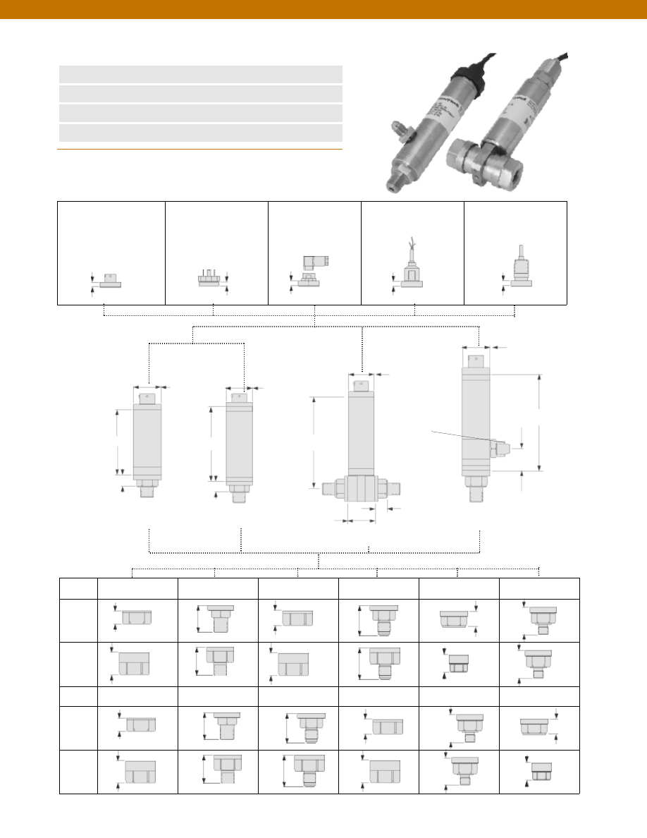
92
Dimensions
n
2-Week Delivery
n
mV/V, 0-5, 0-10 VDC, or 4-20 mA
n
Gage, Absolute, Barometric, Vacuum
n
Differential (Wet/ Wet, Wet/ Dry)
2.9 in.
0.5 in.
0.3 in.
0.2 in.
0.3 in.
0.3 in.
0.3 in.
ø1.13 in.
ø1.13 in.
ø1.13 in.
ø1.13 in.
3.2 in.
3.8 in.
1.5 in.
0.5 in.
4.1 in.
0.9 in.
0.5 in.
Code 6a
6-Pin, Vented,
Bendix Style
Code 6m
4-Pin, Vented,
Standard DIN (43650)
Code 6n
4-Pin, Vented,
Mini DIN
Code 6q
4-Conductor, Vented,
Integral Cable, 5 ft.
Code 6r
4-Conductor, Vented,
Integral Cable,
Conduit Fitting 5 ft.
www.honeywell.com/sensotec
1-888-282-9891
1.3”
Code 5a
1/4-18 NPT Female
Code 5b
1/4-18 NPT Male
Code 5c
7/16-20 UNF Female
Code 5d
7/16-20 UNF Male
Code 5f
G 1/4 B Female
Code 5g
G 1/4 B Male
Le
ss
th
an
10
00
ps
i
G
re
at
er
th
an
15
00
ps
i
0.5”
1.0”
1.1”
0.6”
1.0”
1.0”
1.3”
1.0”
0.7”
1.2”
1.2”
Electrical Termination
Greater than
or Equal to 15 psi
FPA; FPG; FPB; FPV
FDW
FDD
Pressure Ports
Less than
or Equal to 5 psi
7/16-20 UN
Not Selectable
Wet/Wet
Differential
Wet/Dry
Differential
Model FP2000 Configurable Pressure Transducers
Order Code (see below)
1.12”
Le
ss
th
an
10
00
ps
i
G
re
at
er
th
an
15
00
ps
i
0.525”
1.05”
0.905”
0.500”
1.05”
1.025”
1.32”
1.05”
0.625”
1.075”
1.353”
Code 5h
1/8-27 NPT Female
Code 5i
1/8-27 NPT Male
Code 5p
M12-1.5 Male
Code 5q
M12-1.5 Female
Code 5r
9/16-18 SAE Male
Code 5s
9/16-18 SAE Female
Courtesy of Steven Engineering, Inc.-230 Ryan Way, South San Francisco, CA 94080-6370-Main Office: (650) 588-9200-Outside Local Area: (800) 258-9200-www.stevenengineering.com
Sensotec Sensors Full Line Catalog-html.html
93
www.honeywell.com/sensotec
1-888-282-9891
Model FP2000
Performance
psi Range
Code
torr Range
Code
mBar Range
Code
kPa Range
Code
Bar Range
Code
in Hg Range
Code
mm Hg Range
Code
in H
2
O Range
Code
Gage, Absolute
(Order Codes
FPG, FPA)
0.5*
AN
1*
AP
2*
AR
2.5*
AS
5
AT
10
AV
15
BJ
25
BL
30
BM
50
BN
75
BP
100
BR
150
CJ
200
CL
150
CN
300
CP
400
CQ
500
CR
600
CS
750
CT
1000 CV
1500 DJ
2000 DL
2500 DM
3000 DN
5000 DR
6000 DS
7500 DT
10000 DV
15
HA
50
HB
135
HC
250
HD
750
HE
1500 HF
35
JA
70
JB
175
JC
350
JD
700
JE
750
JF
1000 JG
3500 JH
7000 JI
10000 JK
2
KA
7
KB
15
KC
35
KD
70
KE
100
KF
200
KG
300
KH
700
KJ
1000 KL
1500 KM
1700 KN
2000 KP
3000 KQ
5000 KR
7000 KS
10000 KT
15000 KU
20000 KV
35000 KW
50000 KY
70000 KZ
0.035 MA
0.1
MB
0.2
MC
0.5
MD
1
ME
2
MF
3.5
NA
5
MG
7
NB
10
MH
20
MI
30
MJ
35
NC
50
MK
70
ND
100
ML
135
NE
350
NG
500
MM
700
NH
1
UB
2
UD
5
UF
10
UA
15
UC
20
UE
30
UG
50
UI
60
UK
80
UM
100
UP
200
UH
300
UJ
500
UL
1000 UN
0-32
US
16-32 UQ
26-32 UR
15
VA
50
VB
135
VC
250
VD
750
VE
1500 VF
5
WB
10
WA
20
WC
30
WE
50
WG
100
WI
120
WK
150
WM
200
WP
300
WR
500
WS
Barometric
(Order Code
FPB)
0-30
UG
16-32 UQ
26-32 UR
Vacuum
(Order Code
FPV)
1
AP
5
AT
10
AV
15
BJ
50
HB
135
HC
250
HD
750
HE
35
JA
70
JB
175
JC
350
JD
700
JE
750
JF
1000 JG
7
KB
15
KC
35
KD
100
KF
0.035 MA
0.1
MB
0.2
MC
0.5
MD
1
ME
10
UA
20
UE
30
UG
15
VA
50
VB
135
VC
250
VD
750
VE
10
WA
20
WC
30
WE
50
WG
100
WI
Differential
(Order Codes
FDD, FDW)
0.5
AN
1
AP
2
AR
2.5
AS
5
AT
10
AV
15
BJ
25
BL
30
BM
50
BN
75
BP
100
BR
150
CJ
200
CL
150
CN
300
CP
400
CQ
500
CR
600
CS
750
CT
1000 CV
15
HA
50
HB
135
HC
250
HD
750
HE
1500 HF
35
JA
70
JB
175
JC
350
JD
700
JE
750
JF
1000 JG
3500 JH
7000 JI
10000 JK
2
KA
7
KB
15
KC
35
KD
70
KE
100
KF
200
KG
300
KH
700
KJ
1000 KL
1500 KM
1700 KN
2000 KP
3000 KQ
5000 KR
7000 KS
10000 KT
15000 KU
20000 KV
35000 KW
50000 KY
0.035 MA
0.1
MB
0.2
MC
0.5
MD
1
ME
2
MF
3.5
NA
5
MG
7
NB
10
MH
20
MI
30
MJ
35
NC
50
MK
70
ND
100
ML
135
NE
350
NG
500
MM
1
UB
2
UD
5
UF
10
UA
15
UC
20
UE
30
UG
50
UI
60
UK
80
UM
100
UP
200
UH
300
UJ
500
UL
1000 UN
0-32
US
16-32 UQ
26-32 UR
15
VA
50
VB
135
VC
250
VD
750
VE
1500 VF
5
WB
10
WA
20
WC
30
WE
50
WG
100
WI
120
WK
150
WM
200
WP
300
WR
500
WS
Pressure Ranges &
Range codes
*0.5 to 2.5 psi ranges not available for absolute pressure
Courtesy of Steven Engineering, Inc.-230 Ryan Way, South San Francisco, CA 94080-6370-Main Office: (650) 588-9200-Outside Local Area: (800) 258-9200-www.stevenengineering.com
Sensotec Sensors Full Line Catalog-html.html
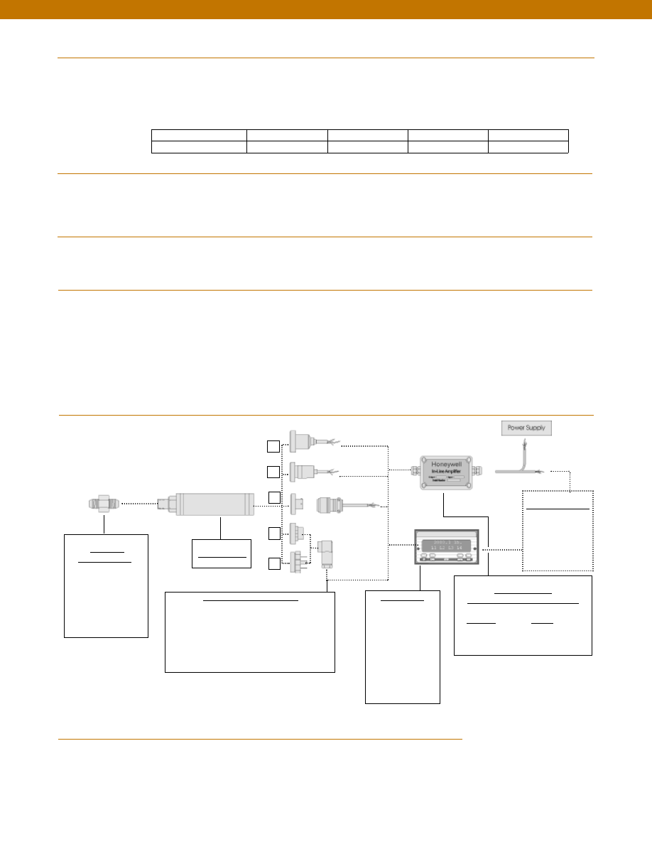
94
Typical System Diagram
www.honeywell.com/sensotec
Adaptors
Compatible with:
1/4-18 NPT Male
1/4-18 NPT Female
7/16-20 UNF Male
7/16-20 UNF Female
G 1/4 B Male
G 1/4 B Female
Model FP2000
Mating Connectors & Cables
PT06A-10-6S (option 6a)
mV/V - 4 conductor cable
4-20 mA - 3 conductor cable
0-5/ 0-10 VDC - 3 conductor cable
Standard DIN 43650 (option 6m)
Mini DIN 40050 (option 6n)
Display Units
SC500
SC1000
SC2000
SC2001
SC3004
GM (Unamp. only)
GM-A (Amp. only)
NK (Unamp. only)
HH (Unamp. only)
Customer Supplied
Chart Recorder
Alarm Panel
Data Acquisition
Computer
PLC
In-Line Amplifiers
(Used with unamplified units only)
Amplifier
Output
Universal In-Line Amplifiers
U2W
4-20 mA (2 wire)
6q
6r
6a
6n
6m
1-888-282-9891
Model FP2000
Accuracy (note 1)........See table below
Output (selectable)........mV/V (See table below), 0-5 VDC, 0-10 VDC, or 4-20 mA (2 wire)
Resolution........Infinite
0.10% accuracy
50 mV (note 4)
25 mV
40 mV
50 mV (note 4)
0.25% accuracy
100 mV
50 mV
80 mV
100 mV
Non-amplified output
@ 10 VDC excitation Gage & Absolute Vacuum Barometric Differential
Temperature, Operating........-40° to 240°F
Temperature, Compensated........40° to 140°F (note 2)
Temperature, Error Band (note 2)
0.10% accuracy........+/- 0.5% F.S.
0.25% accuracy........+/- 1.0% F.S.
Excitation (calibration)
Amplified (4-20 mA, 0-5 VDC)........9-28 VDC
Amplified (0-10 VDC)........15-28 VDC
Unamplified (mV/V)........10 VDC
Media (note 3)........Gas, Liquid
Overload-Safe
1000 psi and below........4x Full Scale or 3,000 psi, whichever is less
1500 psi and above........4x Full Scale or 15,000 psi, whichever is less
Negative Direction (for Differential)........4x Full Scale or 250 psi, whichever is less
Overload-Burst........300% over capacity
Pressure Port........200% over capacity
Wetted Parts Material........Ha C276 & 316L Stainless Steel
Performance
(Continued)
Environmental
Electrical
Mechanical
1. Accuracies stated are expected for Best Fit Straight Line for all errors, including linearity, hysteresis & non-repeatability thru zero.
2. For low pressure ranges, temperature effects may vary.
3. The Wet/Wet differential pressure transducer has two separate, welded Hastelloy diaphragms. In the Wet/Dry unit, the wet port (high port)
has all-welded stainless and Hastelloy construction. The dry port (low port) has no isolation diaphragm.
4. For low gage and differential pressure ranges at 0.10% accuracy, non-amplified output @ 10 VDC excitation = 100mV.
Notes
Courtesy of Steven Engineering, Inc.-230 Ryan Way, South San Francisco, CA 94080-6370-Main Office: (650) 588-9200-Outside Local Area: (800) 258-9200-www.stevenengineering.com
Sensotec Sensors Full Line Catalog-html.html
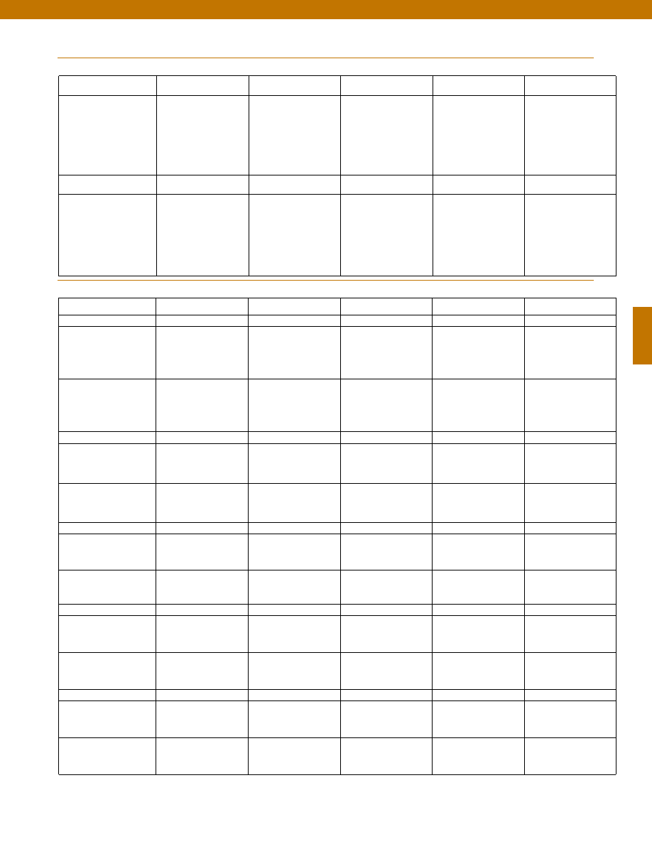
95
Internal Amplifiers
www.honeywell.com/sensotec
1-888-282-9891
Model FP2000
Amplifier
Specifications
Unamplified Output
Option 2u
Voltage Output
Option 2d
Voltage Output
Option 2g
Current 2 Wire
Option 2p
Intrinsically Safe Amp
2n (2N)***
Output Signal
Input Power (Voltage)
Input Power (Current)
Frequency Response
Power Supply Rejection
Operating Temperature
Reverse Voltage Protection
Short Circuit Protection
see table on previous page
10 VDC
2mA @ 10 VDC
Natural Frequency
N/A
-100° to 250°F
N/A
N/A
0-5 VDC
9-28 VDC
10mA
300Hz
60db
-20° to 185°F
Yes
Momentary
0-10 VDC
15-28VDC
15mA
300Hz
60db
-20° to 185°F
Yes
Momentary
4-20 mA
9-32 VDC
4-24 mA
300 Hz
60 db
-20° to 185° F
Yes
Yes
4-20 mA
9-28 VDC
4-24 mA
2000 Hz
60 db
-20° to 185° F
Yes
Yes
Amplifier
Specifications
Unamplified Output
Option 2u
Voltage Output
Option 2e
Voltage Output
Option 2f
Current 2 Wire
Option 2y
Intrinsically Safe Amp
2n (2N)***
Output Signal
Input Power (Voltage)
Input Power (Current)
Frequency Response
Power Supply Rejection
Operating Temperature
Reverse Voltage Protection
Short Circuit Protection
see table on previous page
10 VDC
2mA @ 10 VDC
Natural Frequency
N/A
-100° to 250°F
N/A
N/A
0-5 VDC
9-28 VDC
10mA
2000Hz
60db
-20° to 185°F
Yes
Momentary
0-10 VDC
15-28VDC
15mA
2000Hz
60db
-20° to 185°F
Yes
Momentary
4-20 mA
9-32 VDC
4-24 mA
2000 Hz
60 db
-20° to 185° F
Yes
Yes
4-20 mA
9-28 VDC
4-24 mA
2000 Hz
60 db
-20° to 185° F
Yes
Yes
Wiring Codes
Note: For Wiring Codes, R=Red; Bl = Black; W = White; G = Green.
Color specifies cable and letter or number specifies connection
*** See Sensotec website for most up-to-date information regarding Intrinsically Safe approvals ref. #008-0547-00.
Unamplified Output
Option 2u
Voltage Output
Option 2d/ 2e
Voltage Output
Option 2g/ 2f
Current 2 Wire
Option 2p/ 2y
Intrinsically Safe Amp
Option 2n (2N)***
Bendix PTIH-10-6P (Opt. 6a)
No Shunt Cal
A
(+) Excitation
B
(+) Excitation
C
(-) Excitation
D
(-) Excitation
E
(+) Output
F
(-) Output
A
(+) Supply
B
(-) Supply Return
C
(+) Output
D
(-) Output 0-5VDC
E
No Connection
F
No Connection
A
(+) Supply
B
(-) Supply Return
C
(+) Output
D
(-) Output 0-10VDC
E
No Connection
F
No Connection
A
(+) Supply
B
No Connection
C
No Connection
D
(+) Output 4-20 mA
E
No Connection
F
No Connection
A
(+) Supply
B
No Connection
C
No Connection
D
(+) Output 4-20 mA
E
Case Ground
F
No Connection
With Shunt Cal (Opt. 3d)
A
(+) Excitation
B
(-) Excitation
C
(+) Output
D
(-) Output
E
No Connection
F
Shunt Cal
A
(+) Supply
B
(-) Supply Return
C
(+) Output
D
(-) Output 0-5VDC
E
No Connection
F
Shunt Cal
A
(+) Supply
B
(-) Supply Return
C
(+) Output
D
(-) Output 0-10VDC
E
No Connection
F
Shunt Cal
A
(+) Supply
B
No Connection
C
No Connection
D
(+) Output 4-20 mA
E
No Connection
F
Shunt Cal
A
(+) Supply
B
No Connection
C
No Connection
D
(+) Output 4-20 mA
E
No Connection
F
Shunt Cal
Std. DIN 43650 (Opt. 6m)
No Shunt Cal
1
(+) Excitation
2
(+) Output
3
(-) Output
4
(-) Excitation
1
(+) Supply
2
(+) Output
3
Supply/ Output com.
GNDNo Connect. to case
1
(+) Supply
2
(+) Output
3
Supply/ Output com.
GNDNo Connect. to case
1
(+) Supply
2
(+) Output 4-20 mA
3
No Connection
GNDNo Connection
1
(+) Supply
2
(+) Output
3
Case Ground
With Shunt Cal (Opt. 3d)
Not Applicable
1
(+) Supply
2
(+) Output
3
Supply/ Output com.
GNDShunt Cal
1
(+) Supply
2
(+) Output
3
Supply/ Output com.
GNDShunt Cal
1
(+) Supply
2
(+) Output 4-20 mA
3
No Connection
GNDShunt Cal
1
(+) Supply
2
(+) Output
3
Case Ground
GNDShunt Cal
Mini DIN 40050 (Opt. 6n)
No Shunt Cal
1
(+) Excitation
2
(+) Output
3
(-) Output
4
(-) Excitation
1
(+) Supply
2
(+) Output
3
Supply/ Output com.
GNDNo Connect. to case
1
(+) Supply
2
(+) Output
3
Supply/ Output com.
GNDNo Connect. to case
1
(+) Supply
2
(+) Output 4-20 mA
3
No Connection
GNDNo Connection
1
(+) Supply
2
(+) Output
3
Case Ground
With Shunt Cal (Opt. 3d)
Not Applicable
1
(+) Supply
2
(+) Output
3
Supply/ Output com.
GNDShunt Cal
1
(+) Supply
2
(+) Output
3
Supply/ Output com.
GNDShunt Cal
1
(+) Supply
2
(+) Output 4-20 mA
3
No Connection
GNDShunt Cal
1
(+) Supply
2
(+) Output
3
Case Ground
GNDShunt Cal
5’ Integral Cable (Opt. 6q)
No Shunt Cal
R
(+) Excitation
Bl
(-) Excitation
G
(-) Output
W
(+) Output
R
(+) Supply
Bl
(-) Supply Return
G
(-) Output
W
(+) Output 0-5VDC
R
(+) Supply
Bl
(-) Supply Return
G
(-) Output
W
(+) Output 0-10VDC
R
(+) Supply
Bl
(+) Output 4-20 mA
R
(+) Supply
Bl
(+) Output 4-20 mA
W
Case Ground
With Shunt Cal (Opt. 3d)
Not Applicable
R
(+) Supply
Bl
(-) Supply Return
G
Shunt Cal
W
(+) Output 0-5VDC
R
(+) Supply
Bl
(-) Supply Return
G
Shunt Cal
W
(+) Output 0-10VDC
R
(+) Supply
Bl
(+) Output 4-20 mA
G
Shunt Cal
R
(+) Supply
Bl
(+) Output 4-20 mA
W
Case Ground
G
Shunt Cal
Conduit Fitting (Opt. 6r)
No Shunt Cal
R
(+) Excitation
Bl
(-) Excitation
G
(-) Output
W
(+) Output
R
(+) Supply
Bl
(-) Supply Return
G
(-) Output
W
(+) Output 0-5VDC
R
(+) Supply
Bl
(-) Supply Return
G
(-) Output
W
(+) Output 0-10VDC
R
(+) Supply
Bl
(+) Output 4-20 mA
R
(+) Supply
Bl
(+) Output 4-20 mA
W
Case Ground
With Shunt Cal (Opt. 3d)
Not Applicable
R
(+) Supply
Bl
(-) Supply Return
G
Shunt Cal
W
(+) Output 0-5VDC
R
(+) Supply
Bl
(-) Supply Return
G
Shunt Cal
W
(+) Output 0-10VDC
R
(+) Supply
Bl
(+) Output 4-20 mA
G
Shunt Cal
R
(+) Supply
Bl
(+) Output 4-20 mA
W
Case Ground
G
Shunt Cal
Courtesy of Steven Engineering, Inc.-230 Ryan Way, South San Francisco, CA 94080-6370-Main Office: (650) 588-9200-Outside Local Area: (800) 258-9200-www.stevenengineering.com
Sensotec Sensors Full Line Catalog-html.html
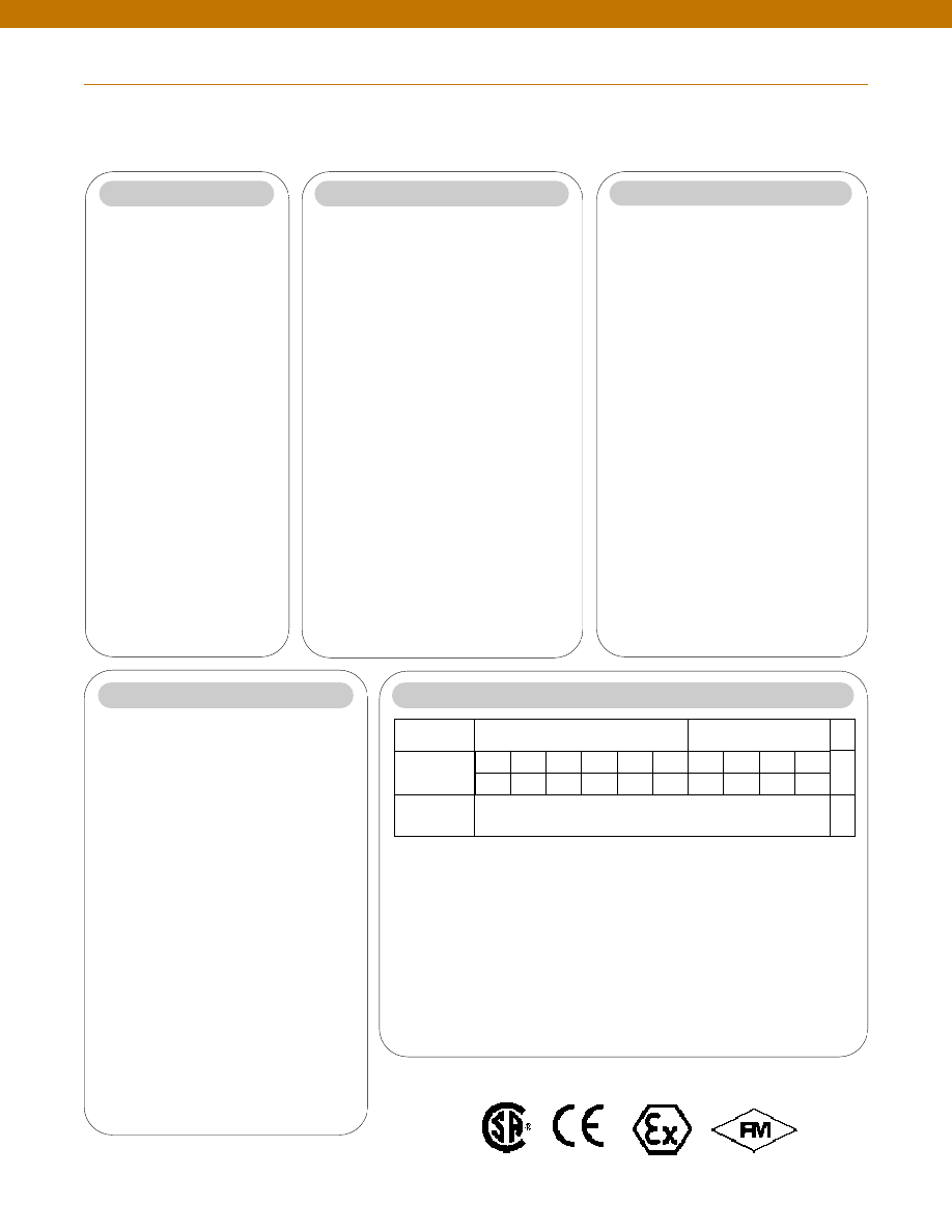
96
How To Order
The FP2000 Order Code
is an easy way for you to order exactly what you want the factory to build. Simply make one selection in each of the
six required categories. Choose adders and accessories only if you require them. By visiting our website at
www.honeywell.com/sensotec
you can view complete technical specifications for the FP2000, or click to our on-line shopping site and actually place your order.
TRANSDUCER TYPE
UNIT
Step 1
Type Code
O Pressure - Gage
FPG
O Pressure - Absolute
FPA
O Diff - wet/wet
FDW
O Pressure - barometric FPB
O Diff - wet/dry
FDD
O Pressure - vacuum
FPV
O psi
O bar
O torr
O in Hg
O mBar
O mm Hg
O kPa
O in H2O
PRESSURE RANGE
ACCURACY
OUTPUT
PRESSURE PORT
ELECTRICAL CONNECTOR
Step 2
Step 3
Gage, Absolute and Differential
O
0.5 psi
AN
O
250 psi
CN
O
1 psi
AP
O
300 psi
CP
O
2 psi
AR
O
400 psi
CQ
O
2.5 psi
AS
O
500 psi
CR
O
5 psi
AT
O
600 psi
CS
O
10 psi
AV
O
750 psi
CT
O
15 psi
BJ
O 1,000 psi
CV
O
25 psi
BL
O 1,500 psi
DJ
O
30 psi
BM
O 2,000 psi
DL
O
50 psi
BN
O 2,500 psi
DM
O
75 psi
BP
O 3,000 psi
DN
O
100 psi
BR
O 5,000 psi
DR
O
150 psi
CJ
O 6,000 psi
DS
O
200 psi
CL
O 7,500 psi
DT
O 10,000 psi
DV
Barometric
Vacuum
O 16-32”Hga
UQ
O
1 psi
AP
O 26-32”Hga
UR
O
5 psi
AT
O 0-30”Hga
UG
O
10 psi
AV
O
15 psi
BJ
Accuracy Code
O 0.10%
1
O 0.25%
2
Range Range
Code Code
O
mV/V
2u
N.A.
2u
O
5 VDC
2d
N.A.
2e
O
10 VDC
2g
N.A.
2f
O
4-20 mA
2p
2n(2N) 2y
Note: If any ADDERS are required, the output code
must be revised. See Screen 4.
Basic
Output
Code
If Adding
9d or 9f
(<5,000 psi)
If Adding
1y, 3d, 9e
or 14c
Port Code
O 1/4-18 NPT Female
5a
O 1/4-18 NPT Male
5b
O 7/16-20 UNF Female
5c
O 7/16-20 UNF Male
5d
O G 1/4 B Female
5f
O G 1/4 B Male
5g
O 1/8-27 NPT Female
5h
O 1/8-27 NPT Male
5i
O M12 x 1.5 Male
5p
O M12 x 1.5 Female
5q
O 9/16-18 UNF SAE Male
5r
O 9/16-18 UNF SAE Female
5s
Connector Code
O Bendix PTIH-10-6P
6a
O DIN 43650
6m
O Mini DIN (40050)
6n
O Integral Polyurethane 5’ Cable
6q
O 1/2 x 14 NPT Conduit 5’ Cable Exit 6r
ADDERS
ACCESSORIES
COMMENTS:
Potentiometers are located on the side. See drawing for details.
No potentiometers are available on mV/V output option.
Step 4
Step 5
Adder Code
O Enhanced Thermals
1y
O Shunt Cal
3d
O IS Rating
9d
O CE Rating
9e
O IS & CE Rating
9f
O Potentiometers
14c
Adder Output Code
2u
2e
2f
2y
2n(2N)
2n(2N)
O mV/V
O 5 VDC
O 10VDC
O 4-20mA
(CE only)
O 4-20 mA
(I.S. only)
O 4-20mA
(I.S. & CE)
Note: If you choose
any Adder Output from
Screen 4, you must
revise your output
code selection using
this output code chart.
I.S Outputs available
only on ranges up to
5,000 psi.
Mating Connectors Only
Acc.Code
O Mini Din
AA161
O Bendix
AA111
Mating Connectors with Without
With
15’Cable for Bendix
Shunt
Shunt
Connector (6A)
(3d)
O mV/V
AA113
AA513
O 4-20mA
AA116
AA516
O 0-5/0-10VDC
AA117
AA517
EXAMPLE ORDER CODE:
FDW 1 CN 2y 5b 6a 1y AA116
Selection
Description
Code
Transducer Type
Differential wet/wet
FDW
Accuracy
0.10%
1
Pressure Range
250 psi
CN
Output
4-20mA
2y
Pressure Port
1/4 - 18 NPT Male
5b
Electrical Output Connections
Bendix PTIH-10-6P
6a
Adders
Enhanced Temp. Range
1y
Accessories
Mating Connector w/Cable
AA116
There must be a code in each of the 6 Basic Code Boxes.
If there are no Adders or Accessories chosen, leave their boxes blank.
TYPE
ACCU-
RACY
RANGE
OUT-
PUT
PRES-
SURE
ELECT.
CONN.
EX-
TENDED
SHUNT
CAL
I.S/CE
RATED
POTS
DESCRIPTION
Order Code
Accessory
Code
BASIC CODE
ADDER CODE
See Screen 4
QTY
www.honeywell.com/sensotec
1-888-282-9891
Approved Approved Approved
Intrinsically Safe Amp
Courtesy of Steven Engineering, Inc.-230 Ryan Way, South San Francisco, CA 94080-6370-Main Office: (650) 588-9200-Outside Local Area: (800) 258-9200-www.stevenengineering.com
Sensotec Sensors Full Line Catalog-html.html

97
n
0.5 to 30 psid
n
All -Welded Design
n
Amplified Output Available
Mounting Holes
1/4-28 UNF x 5/16
(Both Sides)
Pressure Port 2x
1/8-27 NPT Female
3.0 in.
3.5 in.
ø1.5 in.
1.6 in.
2.25 in.
Pressure Ranges
Accuracy
Linearity
Hysteresis
Non-Repeatability
Output (standard)
0.5 psid
1 to 4 psid
5 to 30 psid
Line Pressure
Resolution
Temperature, Operating
Temperature, Compensated
Temperature, Effect
Zero
Span
Strain Gage Type
Excitation (calibration)
Excitation (acceptable)
Insulation Resistance
Bridge Resistance
Shunt Calibration Data
Electrical Termination (std)
Mating Connector (not incl.)
Media
Overload-Safe
Pressure Port
Dead Volume
Wetted Parts Material
Weight
Case Material
........0 +/- 0.5; 1; 2; 5; 10; 15; 25; 30 psid
........+/- 0.5% Full Scale
........+/- 0.25% Full Scale (typical)
........+/- 0.13% Full Scale (typical)
........+/- 0.07% Full Scale (typical)
........1.0 mV/V nominal
........1.5 mV/V nominal
........2.0 mV/V nominal
........1500 psi
........Infinite
........30° to 190°F
........30° to 130°F
........+/- 0.75% Full scale/ 100 °F
........+/- 1% Reading/ 100 °F
........Bonded Foil
........10 VDC
........Up to 10 VDC or AC
........5000 Megohms @ 50 VDC max.
........350 Ohms (nominal)
........Included
........Bendix PTIH-10-6P or equivalent
........Bendix PT06A-10-6S or equivalent
........All fluid and gases compatible with 316 stainless steel
........1500 psi
........1/8-27 NPT Female (2)
........0.4 cu. in.
........316 Stainless Steel
........8 lb.
........Stainless Steel
1-888-282-9891
www.honeywell.com/sensotec
Wiring Code
Connector/ Unamplified
A & B
(+) Excitation
C & D
(-) Excitation
E
(-) Output
F
(+) Output
Performance
Environmental
Electrical
Mechanical
Model A-5 Low Range Wet/ Wet Differential Pressure Transducer
Order Code AD112
Dimensions
0.3 in.
Bleed Port
1/8-27 NPT 2 each
Courtesy of Steven Engineering, Inc.-230 Ryan Way, South San Francisco, CA 94080-6370-Main Office: (650) 588-9200-Outside Local Area: (800) 258-9200-www.stevenengineering.com
Sensotec Sensors Full Line Catalog-html.html
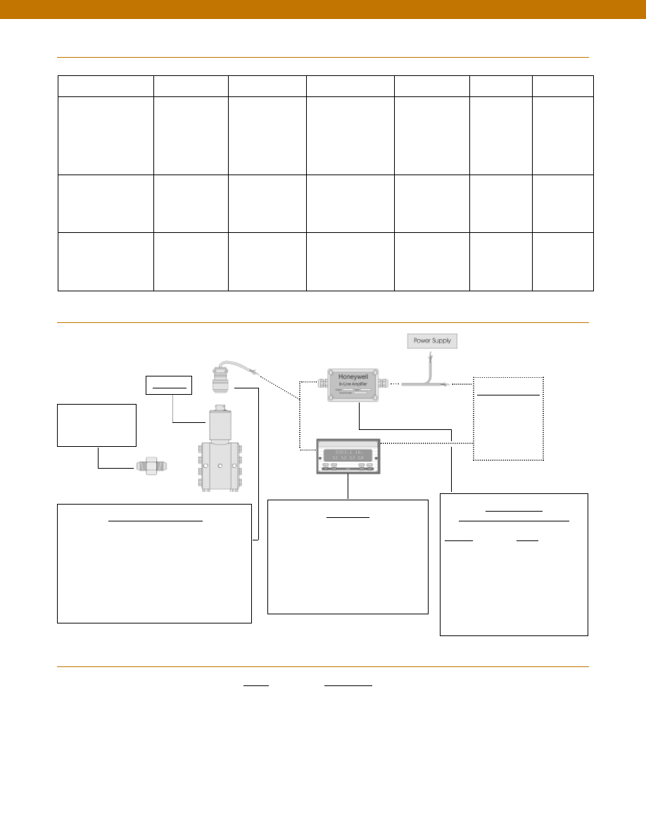
98
Range
Range Code
0.5 psid
AN
1 psid
AP
2 psid
AR
5 psid
AT
10 psid
AV
15 psid
BJ
25 psid
BL
30 psid
BM
Range Codes
In-Line Amplifiers
(Used with unamplified units only)
Amplifier
Output
Universal In-Line Amplifiers
UV
+/- 5 VDC
UV-10
+/- 10 VDC
UBP
0 +/- 5 VDC
U3W
4-20 mA (3 wire)
DIN rail Mount In-Line Amplifiers
DV-05
0 +/- 5 VDC (3 wire)
DA-05
4-20 mA (3 wire)
DV-10
0 +/- 10 VDC (3 wire)
Customer Supplied
Chart Recorder
Alarm Panel
Data Acquisition
Computer
PLC
Display Units
SC500
SC1000
SC2001
SC3004
GM (Unamplified only)
GM-A (Some amplified, see GM-A data sheet)
NK (Unamplified only)
HH (Unamplified only)
Mating Connectors & Cables
AA111 Mating Connector
AA112 Mating Connector & 6 conductor cable
(Unamplified unit with sense leads but not shunt Cal)
AA 113 Mating Connector & 4 conductor cable
(Unamplified unit with sense leads but not shunt Cal)
AA 115 Mating connector and 5 conductor cable for 2c, 2j
or 2t amplified output
AA 116 Mating connector and 3 conductor cable for 2k or
2n(2N) amplified outpu
t
Adaptors compatible
with 1/8-27 NPT
Female
For long cable runs or electrically noisy environments an
amplified sensor or locally mounted amplifier is often preferred.
Internal Amplifiers
1-888-282-9891
www.honeywell.com/sensotec
Model A-5
Typical System Diagram
Model A-5
Amplifier Specifications
Voltage Output
Option 2b
Voltage Output
Option 2c
Voltage Output
Option 2t
Current 3 Wire
Option 2j
Current 2 Wire
Option 2k
Intrinsically Safe
Option 2n (2N)***
Output Signal
Input Power (Voltage)
Input Power (Current)
Frequency Response (amp)
Power Supply Rejection
Operating Temperature
Reverse Voltage Protection
Short Circuit Protection
+/- 5V
+/-15V or 26-32 VDC
45 mA
3000 Hz
60 db
-20° to 185° F
Yes
Momentary
0-5V or +/- 5V @ 5mA
11-28 VDC
40 mA
3000 Hz
60 db
-20° to 185° F
Yes
Momentary
0-10V or +/- 10V @ 5mA
15-28 VDC
40 mA
3000 Hz
60 db
-20° to 185° F
Yes
Momentary
4-20 mA
22-32 VDC
65 mA
2500 Hz
60 db
0° to 185° F
Yes
Yes
4-20 mA
9-32 VDC
4-28 mA
300 Hz
60 db
0° to 185° F
Yes
Yes
4-20 mA
9-28 VDC
4-24 mA
2000 Hz
60 db
-20° to 185° F
Yes
Yes
Wiring Code: Connector
(Std.)
(note 2)
A (+) Supply
B Output Common/
C Supply Return
D (+) Output
E Shunt Cal 1
F Shunt Cal 2
A (+) Supply
B** Output Common/
C** Supply Return
D (+) Output
E Shunt Cal 1
F Shunt Cal 2
A (+) Supply
B** Output Common/
C** Supply Return
D (+) Output
E Shunt Cal 1
F Shunt Cal 2
A (+) Supply
B** Output Common/
C** Supply Return
D (+) Output
E Shunt Cal 1
F Shunt Cal 2
A (+) Supply
B No connection
C No connection
D (+) Output
E Case Ground
F No connection
A (+) Supply
B No connection
C No connection
D (+) Output
E Case Ground
F No connection
Wiring Code: Cable
(note 2)
(note 3)
(note 4)
R (+) Supply
Bl Output Common/
G Supply Return
W (+) Output
B Shunt Cal 1
Br Shunt Cal 2
R (+) Supply
Bl*Output Common/
G*Supply Return
W (+) Output
B Shunt Cal 1
Br Shunt Cal 2
R (+) Supply
Bl*Output Common/
G*Supply Return
W (+) Output
B Shunt Cal 1
Br Shunt Cal 2
R (+) Supply
Bl*Output Common/
G*Supply Return
W (+) Output
B Shunt Cal 1
Br Shunt Cal 2
R (+) Supply
Bl (+) Output
W Case Ground
R (+) Supply
Bl (+) Output
W Case Ground
* Black and Green wires are internally connected.
** Pins B and C are internally connected.
*** See Sensotec website for most up-to-date information regarding Intrinsically Safe approvals ref. #008-0547-00.
Courtesy of Steven Engineering, Inc.-230 Ryan Way, South San Francisco, CA 94080-6370-Main Office: (650) 588-9200-Outside Local Area: (800) 258-9200-www.stevenengineering.com
Sensotec Sensors Full Line Catalog-html.html
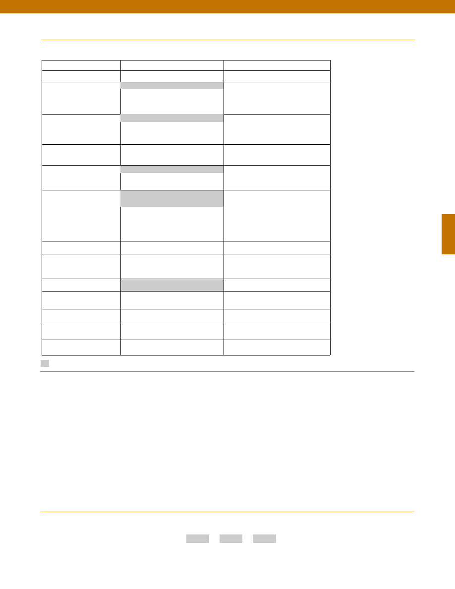
99
Options
Supplied as standard
Pressure Port adaptors
Mating connectors and cables
1-888-282-9891
www.honeywell.com/sensotec
How to Order
Combine the order code, the range code and the options code.
Order Code
Range Code
Options Code
Sample Code: AD111
AP
6h
Special Customer
Requirements
(Consult Factory)
Notes
Model A-5
1. Availability varies according to range.
2. Interconnecting shunt cal. 1 terminal with shunt cal. 2
terminal provides 50% (unamplified units), 75% (4-20mA
3-wire units) or 80% (voltage amplified units) of full scale
output for quick calibration. Shunt Calibration comes
standard with internal amplifier options 2b, 2c, 2t and 2j.
3. O=Orange; Y=Yellow; B=Blue; Bl=Black; R=Red;
Br=Brown; W=White; G=Green. Color specifying cable
and number or letter specifying connector.
4. No mating connector necessary for cable option.
5. Some pressure port options may require axial orientation.
6. Only available with unamplified option 2u.
7. Only available with amplified options.
8. Only available with VDC output options 2b, 2c.
9. Consult factory for TEDS availability with amplified models.
Build to Order
Build from Scratch
Pressure Ranges (psid)
0.5, 1, 2, 5, 10, 15, 25, 30
Temperature
Compensation
1a. 60° to 160° F
1d. -20° to 130° F
1c. 0° to 185° F
1j.
0° to 50° C
Internal Amplifiers
2b. 4 wire +/-5VDC
2c. 0-5VDC
2t.
0-10VDC
2j.
4-20mA (3 wire) output
2k. 4-20mA(2-wire) output
2n(2N). 4-20mA (2-wire) intrinsically safe
Internal Amp
Enhancements
3a. Input/ Output Isolation (note 8)
3d. Remote Buffered Shunt Calibration
Pressure Ports (note 5)
5a. 1/4” - 18 NPT Female
5c. 7/16” - 20 UNF Female (per
MS33656E4)
Electrical Termination
6e. Integral cable: Teflon (-54° to 245° C)
6f.
Integral cable: PVC (-30° to 70° C)
6i.
Integral underwater Cable(8m) (max.
80° C) (note 1)
6j.
1/2-14 conduit fitting with 5 ft. of 4
conductor PVC cable
6g. Integral cable: Neoprene (-20 to 80° C)
(note 1)
6h. Integral cable: Silicone (-54 to 150° C)
6m. DIN 43650
6q. Molded Integral Cable: Polyurethane
(note 1)
6t.
Integral Cable with Heyco Spring
Strain relief (1.6m)
Shunt Calibration
8a. Precision Internal Resistor (note 6)
Special Calibration
9a. 10 point (5 up/5 down) 20%
increments @ 20° C
9b. 20 point (10 up/10 down) 10%
increments @ 20° C
Wetted Diaphragm
10a. 316 Stainless Steel
Bridge Type
11a. Square bridge
11b. Symmetrical bridge
11c. Square & symmetrical bridge
Potentiometers
14b. Top access to pots (note 7)
14a. No access to pots
Increased Line Pressure
25a. 2000 psi line pressure
25b. 3000 psi line pressure
25c. 5000 psi line pressure (note 1)
Interfaces
53e. Signature Calibration
53t. T.E.D.S. IEEE 1451.4 Module (note 9)
1b. 30° to 130° F
2u. Unamplified, mV/V output
6a. Bendix PTIH-10-6P (or equiv.) 6 pin
(max. 120°C)
5h. 1/8-27 NPT Female (2)
Courtesy of Steven Engineering, Inc.-230 Ryan Way, South San Francisco, CA 94080-6370-Main Office: (650) 588-9200-Outside Local Area: (800) 258-9200-www.stevenengineering.com
Sensotec Sensors Full Line Catalog-html.html
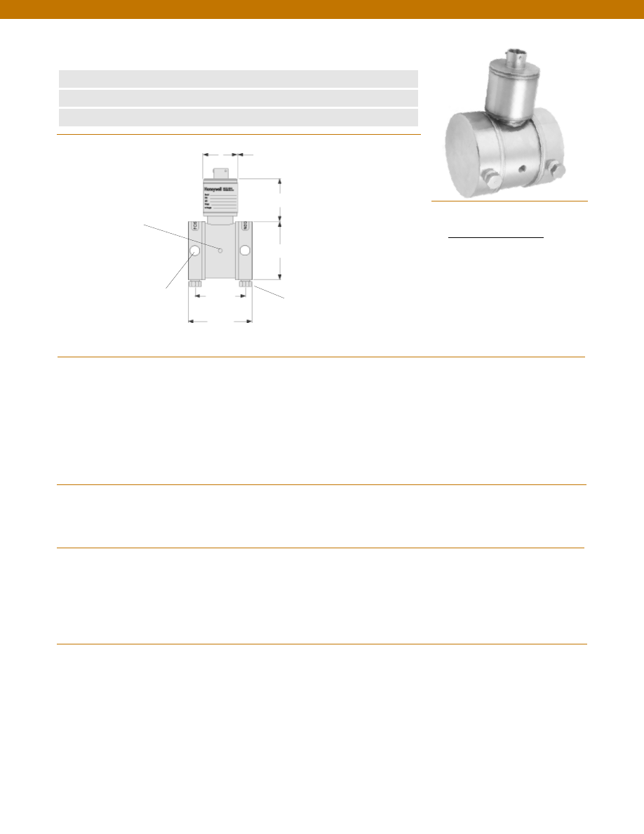
100
n
0.5 to 30 psid
n
All -Welded Design
n
Amplified Output Available
Mounting Holes
1/4-28 UNF x 5/16
(Both Sides)
Pressure Port 2x 1/8-27 NPT
Female (as shown)
Bleed Port: 2x 1/8-27 NPT
Female pipe plug
3.0 in.
2.6 in.
ø1.5 in.
1.6 in.
2.25 in.
Pressure Ranges
Accuracy
Linearity
Hysteresis
Non-Repeatability
Output (standard)
0.5 psid
1 to 4 psid
5 to 30 psid
Line Pressure
Resolution
Temperature, Operating
Temperature, Compensated
Temperature, Effect
Zero
Span
Strain Gage Type
Excitation (calibration)
Excitation (acceptable)
Insulation Resistance
Bridge Resistance
Shunt Calibration Data
Electrical Termination (std)
Mating Connector (not incl.)
Media
Overload-Safe
Pressure Port
Dead Volume
Wetted Parts Material
Weight
Case Material
........+/- 0.5; 1; 2; 5; 10; 15; 25; 30 psid**
........+/- 0.25% Full Scale
........+/- 0.15% Full Scale (typical)
........+/- 0.10% Full Scale (typical)
........+/- 0.05% Full Scale (typical)
........1.0 mV/V nominal
........1.5 mV/V nominal
........2.0 mV/V nominal
........1500 psi
........Infinite
........30° to 190°F
........30° to 130°F
........+/- 0.5% Full scale/ 100 °F
........+/- 0.5% Reading/ 100 °F
........Bonded Foil
........10 VDC
........Up to 10 VDC or AC
........5000 Megohms @ 50 VDC max.
........350 Ohms (nominal)
........Included
........Bendix PTIH-10-6P or equivalent
........Bendix PT06A-10-6S or equivalent
........All fluid and gases compatible with 316 stainless steel
........1500 psi
........1/8-27 NPT Female (2)
........0.4 cu. in.
........316 Stainless Steel
........4.2 lb.
........Stainless Steel
1-888-282-9891
www.honeywell.com/sensotec
Wiring Code
Connector/ Unamplified
A & B
(+) Excitation
C & D
(-) Excitation
E
(-) Output
F
(+) Output
Performance
Environmental
Electrical
Mechanical
**Option: specify Inches of Water Column, Inches of Hg Column, mBar or kPa for the pressure ranges
Model KZ Low Range Wet/ Wet Differential Pressure Transducer
Order Code AD115
Dimensions
Courtesy of Steven Engineering, Inc.-230 Ryan Way, South San Francisco, CA 94080-6370-Main Office: (650) 588-9200-Outside Local Area: (800) 258-9200-www.stevenengineering.com
Sensotec Sensors Full Line Catalog-html.html
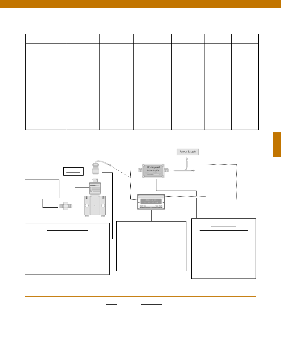
101
Range
Range Code
0.5 psid
AN
1 psid
AP
2 psid
AR
5 psid
AT
10 psid
AV
15 psid
BJ
25 psid
BL
30 psid
BM
Range Codes
In-Line Amplifiers
(Used with unamplified units only)
Amplifier
Output
Universal In-Line Amplifiers
UV
+/- 5 VDC
UV-10
+/- 10 VDC
UBP
0 +/- 5 VDC
U3W
4-20 mA (3 wire)
DIN rail Mount In-Line Amplifiers
DV-05
0 +/- 5 VDC (3 wire)
DA-05
4-20 mA (3 wire)
DV-10
0 +/- 10 VDC (3 wire)
Customer Supplied
Chart Recorder
Alarm Panel
Data Acquisition
Computer
PLC
Display Units
SC500
SC1000
SC2001
SC3004
GM (Unamplified only)
GM-A (Some amplified, see GM-A data sheet)
NK (Unamplified only)
HH (Unamplified only)
Mating Connectors & Cables
AA111 Mating Connector
AA112 Mating Connector & 6 conductor cable
(Unamplified unit with sense leads but not shunt Cal)
AA 113 Mating Connector & 4 conductor cable
(Unamplified unit with sense leads but not shunt Cal)
AA 115 Mating connector and 5 conductor cable for 2c, 2j
or 2t amplified output
AA 116 Mating connector and 3 conductor cable for 2k or
2n(2N) amplified output
Adaptors compatible
with 1/8-27 NPT
Female
For long cable runs or electrically noisy environments an
amplified sensor or locally mounted amplifier is often preferred.
Internal Amplifiers
1-888-282-9891
www.honeywell.com/sensotec
Model KZ
Typical System Diagram
Model KZ
Amplifier Specifications
Voltage Output
Option 2b
Voltage Output
Option 2c
Voltage Output
Option 2t
Current 3 Wire
Option 2j
Current 2 Wire
Option 2k
Intrinsically Safe
Option 2n (2N)***
Output Signal
Input Power (Voltage)
Input Power (Current)
Frequency Response (amp)
Power Supply Rejection
Operating Temperature
Reverse Voltage Protection
Short Circuit Protection
+/- 5V
+/-15V or 26-32 VDC
45 mA
3000 Hz
60 db
-20° to 185° F
Yes
Momentary
0-5V or +/- 5V @ 5mA
11-28 VDC
40 mA
3000 Hz
60 db
-20° to 185° F
Yes
Momentary
0-10V or +/- 10V @ 5mA
15-28 VDC
40 mA
3000 Hz
60 db
-20° to 185° F
Yes
Momentary
4-20 mA
22-32 VDC
65 mA
2500 Hz
60 db
0° to 185° F
Yes
Yes
4-20 mA
9-32 VDC
4-28 mA
300 Hz
60 db
0° to 185° F
Yes
Yes
4-20 mA
9-28 VDC
4-24 mA
2000 Hz
60 db
-20° to 185° F
Yes
Yes
Wiring Code: Connector
(Std.)
(note 2)
A (+) Supply
B Output Common/
C Supply Return
D (+) Output
E Shunt Cal 1
F Shunt Cal 2
A (+) Supply
B** Output Common/
C** Supply Return
D (+) Output
E Shunt Cal 1
F Shunt Cal 2
A (+) Supply
B** Output Common/
C** Supply Return
D (+) Output
E Shunt Cal 1
F Shunt Cal 2
A (+) Supply
B** Output Common/
C** Supply Return
D (+) Output
E Shunt Cal 1
F Shunt Cal 2
A (+) Supply
B No connection
C No connection
D (+) Output
E Case Ground
F No connection
A (+) Supply
B No connection
C No connection
D (+) Output
E Case Ground
F No connection
Wiring Code: Cable
(note 2)
(note 3)
(note 4)
R (+) Supply
Bl Output Common/
G Supply Return
W (+) Output
B Shunt Cal 1
Br Shunt Cal 2
R (+) Supply
Bl*Output Common/
G*Supply Return
W (+) Output
B Shunt Cal 1
Br Shunt Cal 2
R (+) Supply
Bl*Output Common/
G*Supply Return
W (+) Output
B Shunt Cal 1
Br Shunt Cal 2
R (+) Supply
Bl*Output Common/
G*Supply Return
W (+) Output
B Shunt Cal 1
Br Shunt Cal 2
R (+) Supply
Bl (+) Output
W Case Ground
R (+) Supply
Bl (+) Output
W Case Ground
* Black and Green wires are internally connected.
** Pins B and C are internally connected.
*** See Sensotec website for most up-to-date information regarding Intrinsically Safe approvals ref. #008-0547-00.
Courtesy of Steven Engineering, Inc.-230 Ryan Way, South San Francisco, CA 94080-6370-Main Office: (650) 588-9200-Outside Local Area: (800) 258-9200-www.stevenengineering.com
Sensotec Sensors Full Line Catalog-html.html
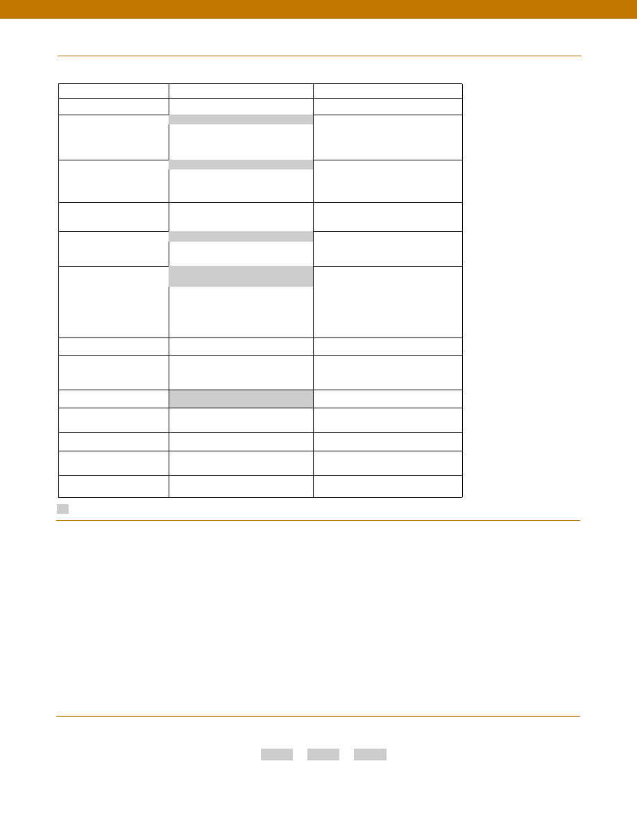
102
Options
Supplied as standard
Pressure Port adaptors
Mating connectors and cables
1-888-282-9891
www.honeywell.com/sensotec
How to Order
Combine the order code, the range code and the options code.
Order Code
Range Code
Options Code
Sample Code: AD115
AP
6h
Special Customer
Requirements
(Consult Factory)
Notes
Model KZ
1. Availability varies according to range.
2. Interconnecting shunt cal. 1 terminal with shunt cal. 2
terminal provides 50% (unamplified units), 75% (4-20mA
3-wire units) or 80% (voltage amplified units) of full scale
output for quick calibration. Shunt Calibration comes
standard with internal amplifier options 2b, 2c, 2t and 2j.
3. O=Orange; Y=Yellow; B=Blue; Bl=Black; R=Red;
Br=Brown; W=White; G=Green. Color specifying cable
and number or letter specifying connector.
4. No mating connector necessary for cable option.
5. Some pressure port options may require axial orientation.
6. Only available with unamplified option 2u.
7. Only available with amplified options.
8. Only available with VDC output options 2b, 2c.
9. Consult factory for TEDS availability with amplified models.
Build to Order
Build from Scratch
Pressure Ranges (psid)
0.5, 1, 2, 5, 10, 15, 25, 30
Temperature
Compensation
1a. 60° to 160° F
1d. -20° to 130° F
1c. 0° to 185° F
1j.
0° to 50° C
Internal Amplifiers
2b. 4 wire +/-5VDC
2c. 0-5VDC
2t.
0-10VDC
2j.
4-20mA (3 wire) output
2k. 4-20mA(2-wire) output
2n(2N). 4-20mA (2-wire) intrinsically safe
Internal Amp
Enhancements
3a. Input/ Output Isolation (note 8)
3d. Remote Buffered Shunt Calibration
Pressure Ports (note 5)
5a. 1/4” - 18 NPT Female
5c. 7/16” - 20 UNF Female (per
MS33656E4)
Electrical Termination
6e. Integral cable: Teflon (-54° to 245° C)
6f.
Integral cable: PVC (-30° to 70° C)
6i.
Integral underwater Cable(8m) (max.
80° C) (note 1)
6j.
1/2-14 conduit fitting with 5 ft. of 4
conductor PVC cable
6g. Integral cable: Neoprene (-20 to 80° C)
(note 1)
6h. Integral cable: Silicone (-54 to 150° C)
6m. DIN 43650
6q. Molded Integral Cable: Polyurethane
(note 1)
6t.
Integral Cable with Heyco Spring
Strain relief (1.6m)
Shunt Calibration
8a. Precision Internal Resistor (note 6)
Special Calibration
9a. 10 point (5 up/5 down) 20%
increments @ 20° C
9b. 20 point (10 up/10 down) 10%
increments @ 20° C
Wetted Diaphragm
10a. 316 Stainless Steel
Bridge Type
11a. Square bridge
11b. Symmetrical bridge
11c. Square & symmetrical bridge
Potentiometers
14b. Top access to pots (note 7)
14a. No access to pots
Increased Line Pressure
25a. 2000 psi line pressure
25b. 3000 psi line pressure
25c. 5000 psi line pressure (note 1)
Interfaces
53e. Signature Calibration
53t. T.E.D.S. IEEE 1451.4 Module (note 9)
1b. 30° to 130° F
2u. Unamplified, mV/V output
6a. Bendix PTIH-10-6P (or equiv.) 6 pin
(max. 120°C)
5h. 1/8-27 NPT Female (2)
Courtesy of Steven Engineering, Inc.-230 Ryan Way, South San Francisco, CA 94080-6370-Main Office: (650) 588-9200-Outside Local Area: (800) 258-9200-www.stevenengineering.com
Sensotec Sensors Full Line Catalog-html.html
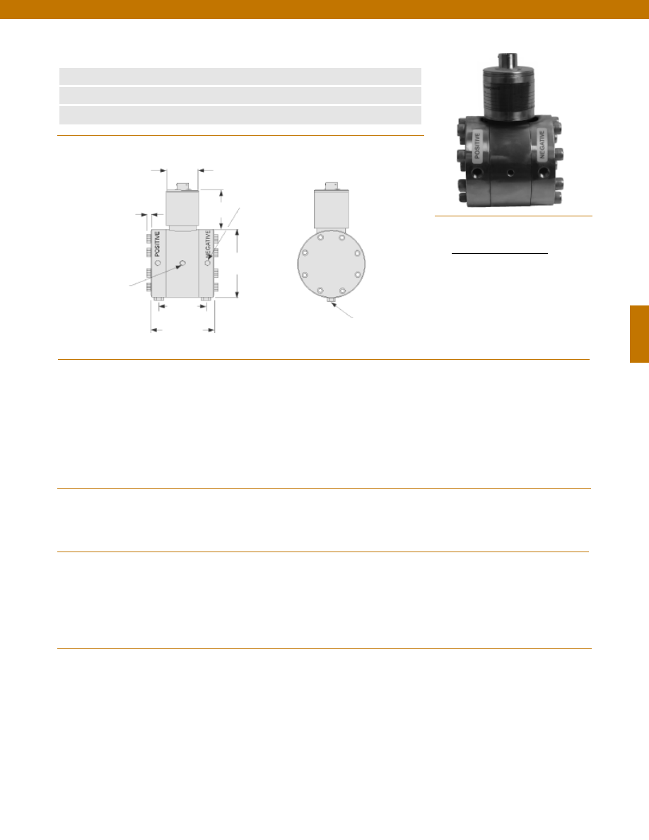
103
n
0.5 to 30 psid
n
All -Welded Design
n
Amplified Output Available
Mounting Holes
1/4-28 UNF x 5/16
(Both Sides)
Pressure Port 2x
1/8-27 NPT Female
3.0 in.
3.5 in.
ø1.5 in.
1.6 in.
2.25 in.
Pressure Ranges
Accuracy
Linearity
Hysteresis
Non-Repeatability
Output (standard)
0.5 psid
1 to 4 psid
5 to 30 psid
Line Pressure
Resolution
Temperature, Operating
Temperature, Compensated
Temperature, Effect
Zero
Span
Strain Gage Type
Excitation (calibration)
Excitation (acceptable)
Insulation Resistance
Bridge Resistance
Shunt Calibration Data
Electrical Termination (std)
Mating Connector (not incl.)
Media
Overload-Safe
Pressure Port
Dead Volume
Wetted Parts Material
Weight
Case Material
........0 +/- 0.5; 1; 2; 5; 10; 15; 25; 30 psid
........+/- 0.25% Full Scale
........+/- 0.15% Full Scale (typical)
........+/- 0.10% Full Scale (typical)
........+/- 0.05% Full Scale (typical)
........1.0 mV/V nominal
........1.5 mV/V nominal
........2.0 mV/V nominal
........1500 psi
........Infinite
........30° to 190°F
........30° to 130°F
........+/- 0.5% Full scale/ 100 °F
........+/- 0.5% Reading/ 100 °F
........Bonded Foil
........10 VDC
........Up to 10 VDC or AC
........5000 Megohms @ 50 VDC max.
........350 Ohms (nominal)
........Included
........Bendix PTIH-10-6P or equivalent
........Bendix PT06A-10-6S or equivalent
........All fluid and gases compatible with 316 stainless steel
........1500 psi
........1/8-27 NPT Female (2)
........0.4 cu. in.
........316 Stainless Steel
........8 lb.
........Stainless Steel
1-888-282-9891
www.honeywell.com/sensotec
Wiring Code
Connector/ Unamplified
A & B
(+) Excitation
C & D
(-) Excitation
E
(-) Output
F
(+) Output
Performance
Environmental
Electrical
Mechanical
Model Z Low Range Wet/ Wet Differential Pressure Transducer
Order Code AD111
Dimensions
0.3 in.
Bleed Port
1/8-27 NPT 2 each
Courtesy of Steven Engineering, Inc.-230 Ryan Way, South San Francisco, CA 94080-6370-Main Office: (650) 588-9200-Outside Local Area: (800) 258-9200-www.stevenengineering.com
Sensotec Sensors Full Line Catalog-html.html
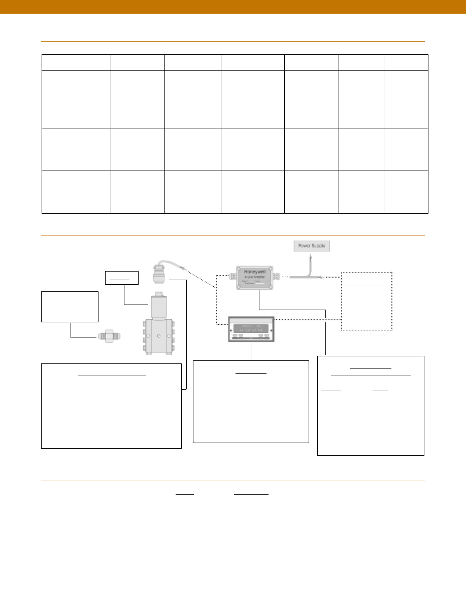
104
Range
Range Code
0.5 psid
AN
1 psid
AP
2 psid
AR
5 psid
AT
10 psid
AV
15 psid
BJ
25 psid
BL
30 psid
BM
Range Codes
In-Line Amplifiers
(Used with unamplified units only)
Amplifier
Output
Universal In-Line Amplifiers
UV
+/- 5 VDC
UV-10
+/- 10 VDC
UBP
0 +/- 5 VDC
U3W
4-20 mA (3 wire)
DIN rail Mount In-Line Amplifiers
DV-05
0 +/- 5 VDC (3 wire)
DA-05
4-20 mA (3 wire)
DV-10
0 +/- 10 VDC (3 wire)
Customer Supplied
Chart Recorder
Alarm Panel
Data Acquisition
Computer
PLC
Display Units
SC500
SC1000
SC2001
SC3004
GM (Unamplified only)
GM-A (Some amplified, see GM-A data sheet)
NK (Unamplified only)
HH (Unamplified only)
Mating Connectors & Cables
AA111 Mating Connector
AA112 Mating Connector & 6 conductor cable
(Unamplified unit with sense leads but not shunt Cal)
AA 113 Mating Connector & 4 conductor cable
(Unamplified unit with sense leads but not shunt Cal)
AA 115 Mating connector and 5 conductor cable for 2c, 2j
or 2t amplified output
AA 116 Mating connector and 3 conductor cable for 2k or
2n(2N) amplified outpu
t
Adaptors compatible
with 1/8-27 NPT
Female
For long cable runs or electrically noisy environments an
amplified sensor or locally mounted amplifier is often preferred.
Internal Amplifiers
1-888-282-9891
www.honeywell.com/sensotec
Model Z
Typical System Diagram
Model Z
Amplifier Specifications
Voltage Output
Option 2b
Voltage Output
Option 2c
Voltage Output
Option 2t
Current 3 Wire
Option 2j
Current 2 Wire
Option 2k
Intrinsically Safe
Option 2n (2N)***
Output Signal
Input Power (Voltage)
Input Power (Current)
Frequency Response (amp)
Power Supply Rejection
Operating Temperature
Reverse Voltage Protection
Short Circuit Protection
+/- 5V
+/-15V or 26-32 VDC
45 mA
3000 Hz
60 db
-20° to 185° F
Yes
Momentary
0-5V or +/- 5V @ 5mA
11-28 VDC
40 mA
3000 Hz
60 db
-20° to 185° F
Yes
Momentary
0-10V or +/- 10V @ 5mA
15-28 VDC
40 mA
3000 Hz
60 db
-20° to 185° F
Yes
Momentary
4-20 mA
22-32 VDC
65 mA
2500 Hz
60 db
0° to 185° F
Yes
Yes
4-20 mA
9-32 VDC
4-28 mA
300 Hz
60 db
0° to 185° F
Yes
Yes
4-20 mA
9-28 VDC
4-24 mA
2000 Hz
60 db
-20° to 185° F
Yes
Yes
Wiring Code: Connector
(Std.)
(note 2)
A (+) Supply
B Output Common/
C Supply Return
D (+) Output
E Shunt Cal 1
F Shunt Cal 2
A (+) Supply
B** Output Common/
C** Supply Return
D (+) Output
E Shunt Cal 1
F Shunt Cal 2
A (+) Supply
B** Output Common/
C** Supply Return
D (+) Output
E Shunt Cal 1
F Shunt Cal 2
A (+) Supply
B** Output Common/
C** Supply Return
D (+) Output
E Shunt Cal 1
F Shunt Cal 2
A (+) Supply
B No connection
C No connection
D (+) Output
E Case Ground
F No connection
A (+) Supply
B No connection
C No connection
D (+) Output
E Case Ground
F No connection
Wiring Code: Cable
(note 2)
(note 3)
(note 4)
R (+) Supply
Bl Output Common/
G Supply Return
W (+) Output
B Shunt Cal 1
Br Shunt Cal 2
R (+) Supply
Bl*Output Common/
G*Supply Return
W (+) Output
B Shunt Cal 1
Br Shunt Cal 2
R (+) Supply
Bl*Output Common/
G*Supply Return
W (+) Output
B Shunt Cal 1
Br Shunt Cal 2
R (+) Supply
Bl*Output Common/
G*Supply Return
W (+) Output
B Shunt Cal 1
Br Shunt Cal 2
R (+) Supply
Bl (+) Output
W Case Ground
R (+) Supply
Bl (+) Output
W Case Ground
* Black and Green wires are internally connected.
** Pins B and C are internally connected.
*** See Sensotec website for most up-to-date information regarding Intrinsically Safe approvals ref. #008-0547-00.
Courtesy of Steven Engineering, Inc.-230 Ryan Way, South San Francisco, CA 94080-6370-Main Office: (650) 588-9200-Outside Local Area: (800) 258-9200-www.stevenengineering.com
Sensotec Sensors Full Line Catalog-html.html
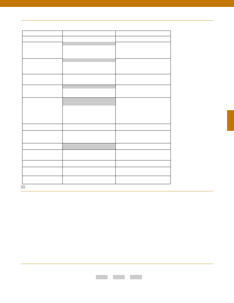
105
Options
Supplied as standard
Pressure Port adaptors
Mating connectors and cables
1-888-282-9891
www.honeywell.com/sensotec
How to Order
Combine the order code, the range code and the options code.
Order Code
Range Code
Options Code
Sample Code: AD111
AP
6h
Special Customer
Requirements
(Consult Factory)
Notes
Model Z
Build to Order
Build from Scratch
Pressure Ranges (psid)
0.5, 1, 2, 5, 10, 15, 25, 30
Temperature
Compensation
1a. 60° to 160° F
1d. -20° to 130° F
1c. 0° to 185° F
1j.
0° to 50° C
Internal Amplifiers
2b. 4 wire +/-5VDC
2c. 0-5VDC
2t.
0-10VDC
2j.
4-20mA (3 wire) output
2k. 4-20mA(2-wire) output
2n(2N). 4-20mA (2-wire) intrinsically safe
Internal Amp
Enhancements
3a. Input/ Output Isolation (note 8)
3d. Remote Buffered Shunt Calibration
Pressure Ports (note 5)
5a. 1/4” - 18 NPT Female
5c. 7/16” - 20 UNF Female (per
MS33656E4)
Electrical Termination
6e. Integral cable: Teflon (-54° to 245° C)
6f.
Integral cable: PVC (-30° to 70° C)
6i.
Integral underwater Cable(8m) (max.
80° C) (note 1)
6j.
1/2-14 conduit fitting with 5 ft. of 4
conductor PVC cable
6g. Integral cable: Neoprene (-20 to 80° C)
(note 1)
6h. Integral cable: Silicone (-54 to 150° C)
6m. DIN 43650
6q. Molded Integral Cable: Polyurethane
(note 1)
6t.
Integral Cable with Heyco Spring
Strain relief (1.6m)
Shunt Calibration
8a. Precision Internal Resistor (note 6)
Special Calibration
9a. 10 point (5 up/5 down) 20%
increments @ 20° C
9b. 20 point (10 up/10 down) 10%
increments @ 20° C
Wetted Diaphragm
10a. 316 Stainless Steel
Bridge Type
11a. Square bridge
11b. Symmetrical bridge
11c. Square & symmetrical bridge
Potentiometers
14b. Top access to pots (note 7)
14a. No access to pots
Increased Line Pressure
25a. 2000 psi line pressure
25b. 3000 psi line pressure
25c. 5000 psi line pressure (note 1)
Interfaces
53e. Signature Calibration
53t. T.E.D.S. IEEE 1451.4 Module (note 9)
1b. 30° to 130° F
2u. Unamplified, mV/V output
6a. Bendix PTIH-10-6P (or equiv.) 6 pin
(max. 120°C)
5h. 1/8-27 NPT Female (2)
1. Availability varies according to range.
2. Interconnecting shunt cal. 1 terminal with shunt cal. 2
terminal provides 50% (unamplified units), 75% (4-20mA
3-wire units) or 80% (voltage amplified units) of full scale
output for quick calibration. Shunt Calibration comes
standard with internal amplifier options 2b, 2c, 2t and 2j.
3. O=Orange; Y=Yellow; B=Blue; Bl=Black; R=Red;
Br=Brown; W=White; G=Green. Color specifying cable
and number or letter specifying connector.
4. No mating connector necessary for cable option.
5. Some pressure port options may require axial orientation.
6. Only available with unamplified option 2u.
7. Only available with amplified options.
8. Only available with VDC output options 2b, 2c.
9. Consult factory for TEDS availability with amplified models.
Courtesy of Steven Engineering, Inc.-230 Ryan Way, South San Francisco, CA 94080-6370-Main Office: (650) 588-9200-Outside Local Area: (800) 258-9200-www.stevenengineering.com
Sensotec Sensors Full Line Catalog-html.html
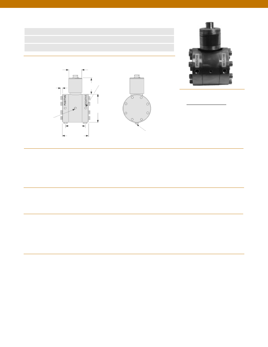
106
n
0.5 to 30 psid
n
All -Welded Design
n
Amplified Output Available
Mounting Holes
1/4-28 UNF x 5/16
(Both Sides)
Pressure Port 2x
1/8-27 NPT Female
3.0 in.
3.5 in.
ø1.5 in.
1.6 in.
2.25 in.
Pressure Ranges
Accuracy
Output (standard)
0.5 psid
1 to 4 psid
5 to 30 psid
Line Pressure
Resolution
Temperature, Operating
Temperature, Compensated
Temperature, Effect
Zero
Span
Strain Gage Type
Excitation (calibration)
Excitation (acceptable)
Insulation Resistance
Bridge Resistance
Shunt Calibration Data
Electrical Termination (std)
Mating Connector (not incl.)
Media
Overload-Safe
Pressure Port
Dead Volume
Wetted Parts Material
Weight
Case Material
........0 +/- 0.5; 1; 2; 5; 10; 15; 25; 30 psid
........+/- 0.1 % Full Scale
........1.0 mV/V nominal
........1.5 mV/V nominal
........2.0 mV/V nominal
........1500 psi
........Infinite
........30° to 190°F
........30° to 130°F
........+/- 0.5% Full scale/ 100 °F
........+/- 0.5% Reading/ 100 °F
........Bonded Foil
........10 VDC
........Up to 10 VDC or AC
........5000 Megohms @ 50 VDC max.
........350 Ohms (nominal)
........Included
........Bendix PTIH-10-6P or equivalent
........Bendix PT06A-10-6S or equivalent
........All fluid and gases compatible with 316 stainless steel
........1500 psi
........1/8-27 NPT Female (2)
........0.4 cu. in.
........316 Stainless Steel
........8 lb.
........Stainless Steel
1-888-282-9891
www.honeywell.com/sensotec
Wiring Code
Connector/ Unamplified
A & B
(+) Excitation
C & D
(-) Excitation
E
(-) Output
F
(+) Output
Performance
Environmental
Electrical
Mechanical
Model TJE Low Range Wet/ Wet Differential Pressure Transducer
Order Code AD114
Dimensions
0.3 in.
Bleed Port
1/8-27 NPT 2 each
Courtesy of Steven Engineering, Inc.-230 Ryan Way, South San Francisco, CA 94080-6370-Main Office: (650) 588-9200-Outside Local Area: (800) 258-9200-www.stevenengineering.com
Sensotec Sensors Full Line Catalog-html.html
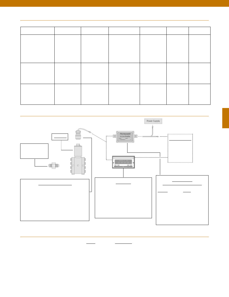
107
Range
Range Code
0.5 psid
AN
1 psid
AP
2 psid
AR
5 psid
AT
10 psid
AV
15 psid
BJ
25 psid
BL
30 psid
BM
Range Codes
In-Line Amplifiers
(Used with unamplified units only)
Amplifier
Output
Universal In-Line Amplifiers
UV
+/- 5 VDC
UV-10
+/- 10 VDC
UBP
0 +/- 5 VDC
U3W
4-20 mA (3 wire)
DIN rail Mount In-Line Amplifiers
DV-05
0 +/- 5 VDC (3 wire)
DA-05
4-20 mA (3 wire)
DV-10
0 +/- 10 VDC (3 wire)
Customer Supplied
Chart Recorder
Alarm Panel
Data Acquisition
Computer
PLC
Display Units
SC500
SC1000
SC2001
SC3004
GM (Unamplified only)
GM-A (Some amplified, see GM-A data sheet)
NK (Unamplified only)
HH (Unamplified only)
Mating Connectors & Cables
AA111 Mating Connector
AA112 Mating Connector & 6 conductor cable
(Unamplified unit with sense leads but not shunt Cal)
AA 113 Mating Connector & 4 conductor cable
(Unamplified unit with sense leads but not shunt Cal)
AA 115 Mating connector and 5 conductor cable for 2c, 2j
or 2t amplified output
AA 116 Mating connector and 3 conductor cable for 2k or
2n(2N) amplified outpu
t
Adaptors compatible
with 1/8-27 NPT
Female
For long cable runs or electrically noisy environments an
amplified sensor or locally mounted amplifier is often preferred.
Internal Amplifiers
1-888-282-9891
www.honeywell.com/sensotec
Model TJE
Typical System Diagram
Model TJE
Amplifier Specifications
Voltage Output
Option 2b
Voltage Output
Option 2c
Voltage Output
Option 2t
Current 3 Wire
Option 2j
Current 2 Wire
Option 2k
Intrinsically Safe
Option 2n (2N)***
Output Signal
Input Power (Voltage)
Input Power (Current)
Frequency Response (amp)
Power Supply Rejection
Operating Temperature
Reverse Voltage Protection
Short Circuit Protection
+/- 5V
+/-15V or 26-32 VDC
45 mA
3000 Hz
60 db
-20° to 185° F
Yes
Momentary
0-5V or +/- 5V @ 5mA
11-28 VDC
40 mA
3000 Hz
60 db
-20° to 185° F
Yes
Momentary
0-10V or +/- 10V @ 5mA
15-28 VDC
40 mA
3000 Hz
60 db
-20° to 185° F
Yes
Momentary
4-20 mA
22-32 VDC
65 mA
2500 Hz
60 db
0° to 185° F
Yes
Yes
4-20 mA
9-32 VDC
4-28 mA
300 Hz
60 db
0° to 185° F
Yes
Yes
4-20 mA
9-28 VDC
4-24 mA
2000 Hz
60 db
-20° to 185° F
Yes
Yes
Wiring Code: Connector
(Std.)
(note 2)
A (+) Supply
B Output Common/
C Supply Return
D (+) Output
E Shunt Cal 1
F Shunt Cal 2
A (+) Supply
B** Output Common/
C** Supply Return
D (+) Output
E Shunt Cal 1
F Shunt Cal 2
A (+) Supply
B** Output Common/
C** Supply Return
D (+) Output
E Shunt Cal 1
F Shunt Cal 2
A (+) Supply
B** Output Common/
C** Supply Return
D (+) Output
E Shunt Cal 1
F Shunt Cal 2
A (+) Supply
B No connection
C No connection
D (+) Output
E Case Ground
F No connection
A (+) Supply
B No connection
C No connection
D (+) Output
E Case Ground
F No connection
Wiring Code: Cable
(note 2)
(note 3)
(note 4)
R (+) Supply
Bl Output Common/
G Supply Return
W (+) Output
B Shunt Cal 1
Br Shunt Cal 2
R (+) Supply
Bl*Output Common/
G*Supply Return
W (+) Output
B Shunt Cal 1
Br Shunt Cal 2
R (+) Supply
Bl*Output Common/
G*Supply Return
W (+) Output
B Shunt Cal 1
Br Shunt Cal 2
R (+) Supply
Bl*Output Common/
G*Supply Return
W (+) Output
B Shunt Cal 1
Br Shunt Cal 2
R (+) Supply
Bl (+) Output
W Case Ground
R (+) Supply
Bl (+) Output
W Case Ground
* Black and Green wires are internally connected.
** Pins B and C are internally connected.
*** See Sensotec website for most up-to-date information regarding Intrinsically Safe approvals ref. #008-0547-00.
Courtesy of Steven Engineering, Inc.-230 Ryan Way, South San Francisco, CA 94080-6370-Main Office: (650) 588-9200-Outside Local Area: (800) 258-9200-www.stevenengineering.com
Sensotec Sensors Full Line Catalog-html.html
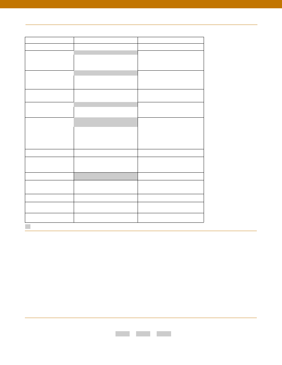
108
Options
Supplied as standard
Pressure Port adaptors
Mating connectors and cables
1-888-282-9891
www.honeywell.com/sensotec
How to Order
Combine the order code, the range code and the options code.
Order Code
Range Code
Options Code
Sample Code: AD114
AP
6h
Special Customer
Requirements
(Consult Factory)
Notes
Model TJE
Build to Order
Build from Scratch
Pressure Ranges (psid)
0.5, 1, 2, 5, 10, 15, 25, 30
Temperature
Compensation
1a. 60° to 160° F
1d. -20° to 130° F
1c. 0° to 185° F
1j.
0° to 50° C
Internal Amplifiers
2b. 4 wire +/-5VDC
2c. 0-5VDC
2t.
0-10VDC
2j.
4-20mA (3 wire) output
2k. 4-20mA(2-wire) output
2n(2N). 4-20mA (2-wire) intrinsically safe
Internal Amp
Enhancements
3a. Input/ Output Isolation (note 8)
3d. Remote Buffered Shunt Calibration
Pressure Ports (note 5)
5a. 1/4” - 18 NPT Female
5c. 7/16” - 20 UNF Female (per
MS33656E4)
Electrical Termination
6e. Integral cable: Teflon (-54° to 245° C)
6f.
Integral cable: PVC (-30° to 70° C)
6i.
Integral underwater Cable(8m) (max.
80° C) (note 1)
6j.
1/2-14 conduit fitting with 5 ft. of 4
conductor PVC cable
6g. Integral cable: Neoprene (-20 to 80° C)
(note 1)
6h. Integral cable: Silicone (-54 to 150° C)
6m. DIN 43650
6q. Molded Integral Cable: Polyurethane
(note 1)
6t.
Integral Cable with Heyco Spring
Strain relief (1.6m)
Shunt Calibration
8a. Precision Internal Resistor (note 6)
Special Calibration
9a. 10 point (5 up/5 down) 20%
increments @ 20° C
9b. 20 point (10 up/10 down) 10%
increments @ 20° C
Wetted Diaphragm
10a. 316 Stainless Steel
Bridge Type
11a. Square bridge
11b. Symmetrical bridge
11c. Square & symmetrical bridge
Potentiometers
14b. Top access to pots (note 7)
14a. No access to pots
Increased Line Pressure
25a. 2000 psi line pressure
25b. 3000 psi line pressure
25c. 5000 psi line pressure (note 1)
Interfaces
53e. Signature Calibration
53t. T.E.D.S. IEEE 1451.4 Module (note 9)
1b. 30° to 130° F
2u. Unamplified, mV/V output
6a. Bendix PTIH-10-6P (or equiv.) 6 pin
(max. 120°C)
5h. 1/8-27 NPT Female (2)
1. Availability varies according to range.
2. Interconnecting shunt cal. 1 terminal with shunt cal. 2
terminal provides 50% (unamplified units), 75% (4-20mA
3-wire units) or 80% (voltage amplified units) of full scale
output for quick calibration. Shunt Calibration comes
standard with internal amplifier options 2b, 2c, 2t and 2j.
3. O=Orange; Y=Yellow; B=Blue; Bl=Black; R=Red;
Br=Brown; W=White; G=Green. Color specifying cable
and number or letter specifying connector.
4. No mating connector necessary for cable option.
5. Some pressure port options may require axial orientation.
6. Only available with unamplified option 2u.
7. Only available with amplified options.
8. Only available with VDC output options 2b, 2c.
9. Consult factory for TEDS availability with amplified models.
Courtesy of Steven Engineering, Inc.-230 Ryan Way, South San Francisco, CA 94080-6370-Main Office: (650) 588-9200-Outside Local Area: (800) 258-9200-www.stevenengineering.com
Sensotec Sensors Full Line Catalog-html.html
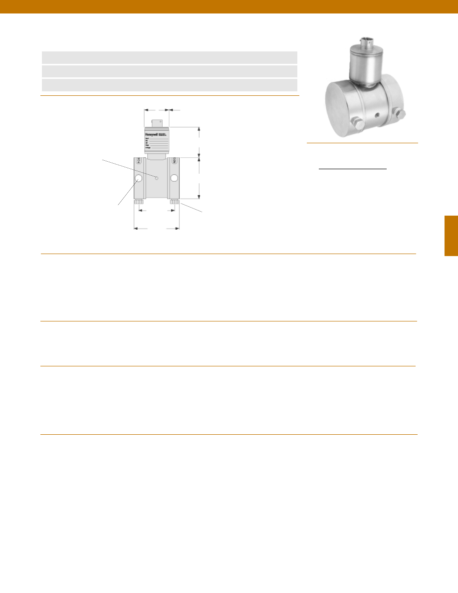
109
n
0.5 to 30 psid
n
All -Welded Design
n
Amplified Output Available
Mounting Holes
1/4-28 UNF x 5/16
(Both Sides)
Pressure Port 2x 1/8-27 NPT
Female (as shown)
Bleed Port: 2x 1/8-27 NPT
3.0 in.
2.6 in.
ø1.5 in.
1.6 in.
2.25 in.
Pressure Ranges
Accuracy
Output (standard)
0.5 psid
1 to 4 psid
5 to 30 psid
Line Pressure
Resolution
Temperature, Operating
Temperature, Compensated
Temperature, Effect
Zero
Span
Strain Gage Type
Excitation (calibration)
Excitation (acceptable)
Insulation Resistance
Bridge Resistance
Shunt Calibration Data
Electrical Termination (std)
Mating Connector (not incl.)
Media
Overload-Safe
Pressure Port
Dead Volume
Wetted Parts Material
Weight
Case Material
........0 +/- 0.5; 1; 2; 5; 10; 15; 25; 30 psid
........+/- 0.1 % Full Scale
........1.0 mV/V nominal
........1.5 mV/V nominal
........2.0 mV/V nominal
........1500 psi
........Infinite
........30° to 190°F
........30° to 130°F
........+/- 0.5% Full scale/ 100 °F
........+/- 0.5% Reading/ 100 °F
........Bonded Foil
........10 VDC
........Up to 10 VDC or AC
........5000 Megohms @ 50 VDC max.
........350 Ohms (nominal)
........Included
........Bendix PTIH-10-6P or equivalent
........Bendix PT06A-10-6S or equivalent
........All fluid and gases compatible with 316 stainless steel
........1500 psi
........1/8-27 NPT Female (2)
........0.4 cu. in.
........316 Stainless Steel
........4.2 lb.
........Stainless Steel
1-888-282-9891
www.honeywell.com/sensotec
Wiring Code
Connector/ Unamplified
A & B
(+) Excitation
C & D
(-) Excitation
E
(-) Output
F
(+) Output
Performance
Environmental
Electrical
Mechanical
Model TJE Low Range Wet/ Wet Differential Pressure Transducer
Order Code AD116
Dimensions
Courtesy of Steven Engineering, Inc.-230 Ryan Way, South San Francisco, CA 94080-6370-Main Office: (650) 588-9200-Outside Local Area: (800) 258-9200-www.stevenengineering.com
Sensotec Sensors Full Line Catalog-html.html
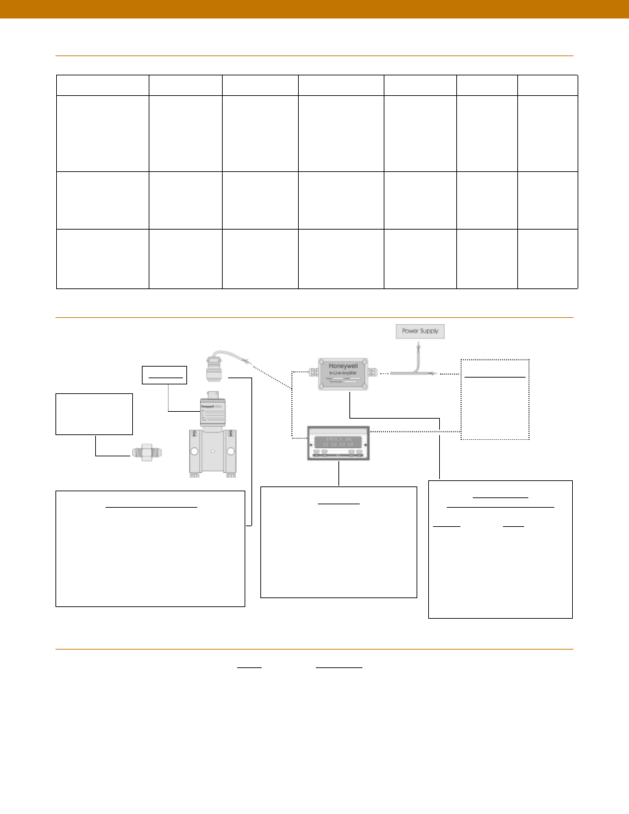
110
Range
Range Code
0.5 psid
AN
1 psid
AP
2 psid
AR
5 psid
AT
10 psid
AV
15 psid
BJ
25 psid
BL
30 psid
BM
Range Codes
In-Line Amplifiers
(Used with unamplified units only)
Amplifier
Output
Universal In-Line Amplifiers
UV
+/- 5 VDC
UV-10
+/- 10 VDC
UBP
0 +/- 5 VDC
U3W
4-20 mA (3 wire)
DIN rail Mount In-Line Amplifiers
DV-05
0 +/- 5 VDC (3 wire)
DA-05
4-20 mA (3 wire)
DV-10
0 +/- 10 VDC (3 wire)
Customer Supplied
Chart Recorder
Alarm Panel
Data Acquisition
Computer
PLC
Display Units
SC500
SC1000
SC2001
SC3004
GM (Unamplified only)
GM-A (Some amplified, see GM-A data sheet)
NK (Unamplified only)
HH (Unamplified only)
Mating Connectors & Cables
AA111 Mating Connector
AA112 Mating Connector & 6 conductor cable
(Unamplified unit with sense leads but not shunt Cal)
AA 113 Mating Connector & 4 conductor cable
(Unamplified unit with sense leads but not shunt Cal)
AA 115 Mating connector and 5 conductor cable for 2c, 2j
or 2t amplified output
AA 116 Mating connector and 3 conductor cable for 2k or
2n(2N) amplified outpu
t
Adaptors compatible
with 1/8-27 NPT
Female
For long cable runs or electrically noisy environments an
amplified sensor or locally mounted amplifier is often preferred.
Internal Amplifiers
1-888-282-9891
www.honeywell.com/sensotec
Model TJE
Typical System Diagram
Model TJE
Amplifier Specifications
Voltage Output
Option 2b
Voltage Output
Option 2c
Voltage Output
Option 2t
Current 3 Wire
Option 2j
Current 2 Wire
Option 2k
Intrinsically Safe
Option 2n (2N)***
Output Signal
Input Power (Voltage)
Input Power (Current)
Frequency Response (amp)
Power Supply Rejection
Operating Temperature
Reverse Voltage Protection
Short Circuit Protection
+/- 5V
+/-15V or 26-32 VDC
45 mA
3000 Hz
60 db
-20° to 185° F
Yes
Momentary
0-5V or +/- 5V @ 5mA
11-28 VDC
40 mA
3000 Hz
60 db
-20° to 185° F
Yes
Momentary
0-10V or +/- 10V @ 5mA
15-28 VDC
40 mA
3000 Hz
60 db
-20° to 185° F
Yes
Momentary
4-20 mA
22-32 VDC
65 mA
2500 Hz
60 db
0° to 185° F
Yes
Yes
4-20 mA
9-32 VDC
4-28 mA
300 Hz
60 db
0° to 185° F
Yes
Yes
4-20 mA
9-28 VDC
4-24 mA
2000 Hz
60 db
-20° to 185° F
Yes
Yes
Wiring Code: Connector
(Std.)
(note 2)
A (+) Supply
B Output Common/
C Supply Return
D (+) Output
E Shunt Cal 1
F Shunt Cal 2
A (+) Supply
B** Output Common/
C** Supply Return
D (+) Output
E Shunt Cal 1
F Shunt Cal 2
A (+) Supply
B** Output Common/
C** Supply Return
D (+) Output
E Shunt Cal 1
F Shunt Cal 2
A (+) Supply
B** Output Common/
C** Supply Return
D (+) Output
E Shunt Cal 1
F Shunt Cal 2
A (+) Supply
B No connection
C No connection
D (+) Output
E Case Ground
F No connection
A (+) Supply
B No connection
C No connection
D (+) Output
E Case Ground
F No connection
Wiring Code: Cable
(note 2)
(note 3)
(note 4)
R (+) Supply
Bl Output Common/
G Supply Return
W (+) Output
B Shunt Cal 1
Br Shunt Cal 2
R (+) Supply
Bl*Output Common/
G*Supply Return
W (+) Output
B Shunt Cal 1
Br Shunt Cal 2
R (+) Supply
Bl*Output Common/
G*Supply Return
W (+) Output
B Shunt Cal 1
Br Shunt Cal 2
R (+) Supply
Bl*Output Common/
G*Supply Return
W (+) Output
B Shunt Cal 1
Br Shunt Cal 2
R (+) Supply
Bl (+) Output
W Case Ground
R (+) Supply
Bl (+) Output
W Case Ground
* Black and Green wires are internally connected.
** Pins B and C are internally connected.
*** See Sensotec website for most up-to-date information regarding Intrinsically Safe approvals ref. #008-0547-00.
Courtesy of Steven Engineering, Inc.-230 Ryan Way, South San Francisco, CA 94080-6370-Main Office: (650) 588-9200-Outside Local Area: (800) 258-9200-www.stevenengineering.com
Sensotec Sensors Full Line Catalog-html.html
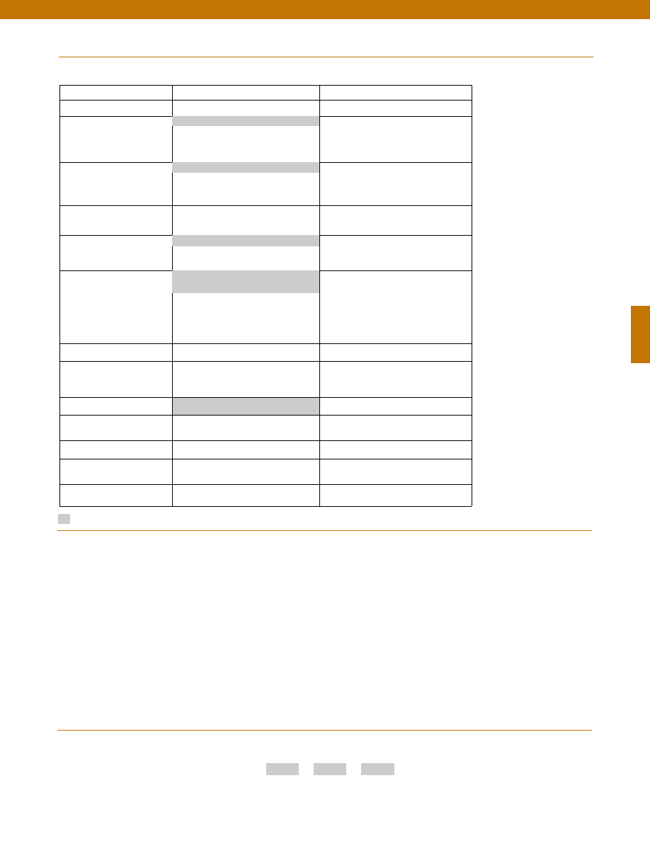
111
Options
Supplied as standard
Pressure Port adaptors
Mating connectors and cables
1-888-282-9891
www.honeywell.com/sensotec
How to Order
Combine the order code, the range code and the options code.
Order Code
Range Code
Options Code
Sample Code: AD116
AP
6h
Special Customer
Requirements
(Consult Factory)
Notes
Model TJE
Build to Order
Build from Scratch
Pressure Ranges (psid)
0.5, 1, 2, 5, 10, 15, 25, 30
Temperature
Compensation
1a. 60° to 160° F
1d. -20° to 130° F
1c. 0° to 185° F
1j.
0° to 50° C
Internal Amplifiers
2b. 4 wire +/-5VDC
2c. 0-5VDC
2t.
0-10VDC
2j.
4-20mA (3 wire) output
2k. 4-20mA(2-wire) output
2n(2N). 4-20mA (2-wire) intrinsically safe
Internal Amp
Enhancements
3a. Input/ Output Isolation (note 8)
3d. Remote Buffered Shunt Calibration
Pressure Ports (note 5)
5a. 1/4” - 18 NPT Female
5c. 7/16” - 20 UNF Female (per
MS33656E4)
Electrical Termination
6e. Integral cable: Teflon (-54° to 245° C)
6f.
Integral cable: PVC (-30° to 70° C)
6i.
Integral underwater Cable(8m) (max.
80° C) (note 1)
6j.
1/2-14 conduit fitting with 5 ft. of 4
conductor PVC cable
6g. Integral cable: Neoprene (-20 to 80° C)
(note 1)
6h. Integral cable: Silicone (-54 to 150° C)
6m. DIN 43650
6q. Molded Integral Cable: Polyurethane
(note 1)
6t.
Integral Cable with Heyco Spring
Strain relief (1.6m)
Shunt Calibration
8a. Precision Internal Resistor (note 6)
Special Calibration
9a. 10 point (5 up/5 down) 20%
increments @ 20° C
9b. 20 point (10 up/10 down) 10%
increments @ 20° C
Wetted Diaphragm
10a. 316 Stainless Steel
Bridge Type
11a. Square bridge
11b. Symmetrical bridge
11c. Square & symmetrical bridge
Potentiometers
14b. Top access to pots (note 7)
14a. No access to pots
Increased Line Pressure
25a. 2000 psi line pressure
25b. 3000 psi line pressure
25c. 5000 psi line pressure (note 1)
Interfaces
53e. Signature Calibration
53t. T.E.D.S. IEEE 1451.4 Module (note 9)
1b. 30° to 130° F
2u. Unamplified, mV/V output
6a. Bendix PTIH-10-6P (or equiv.) 6 pin
(max. 120°C)
5h. 1/8-27 NPT Female (2)
1. Availability varies according to range.
2. Interconnecting shunt cal. 1 terminal with shunt cal. 2
terminal provides 50% (unamplified units), 75% (4-20mA
3-wire units) or 80% (voltage amplified units) of full scale
output for quick calibration. Shunt Calibration comes
standard with internal amplifier options 2b, 2c, 2t and 2j.
3. O=Orange; Y=Yellow; B=Blue; Bl=Black; R=Red;
Br=Brown; W=White; G=Green. Color specifying cable
and number or letter specifying connector.
4. No mating connector necessary for cable option.
5. Some pressure port options may require axial orientation.
6. Only available with unamplified option 2u.
7. Only available with amplified options.
8. Only available with VDC output options 2b, 2c.
9. Consult factory for TEDS availability with amplified models.
Courtesy of Steven Engineering, Inc.-230 Ryan Way, South San Francisco, CA 94080-6370-Main Office: (650) 588-9200-Outside Local Area: (800) 258-9200-www.stevenengineering.com
Sensotec Sensors Full Line Catalog-html.html
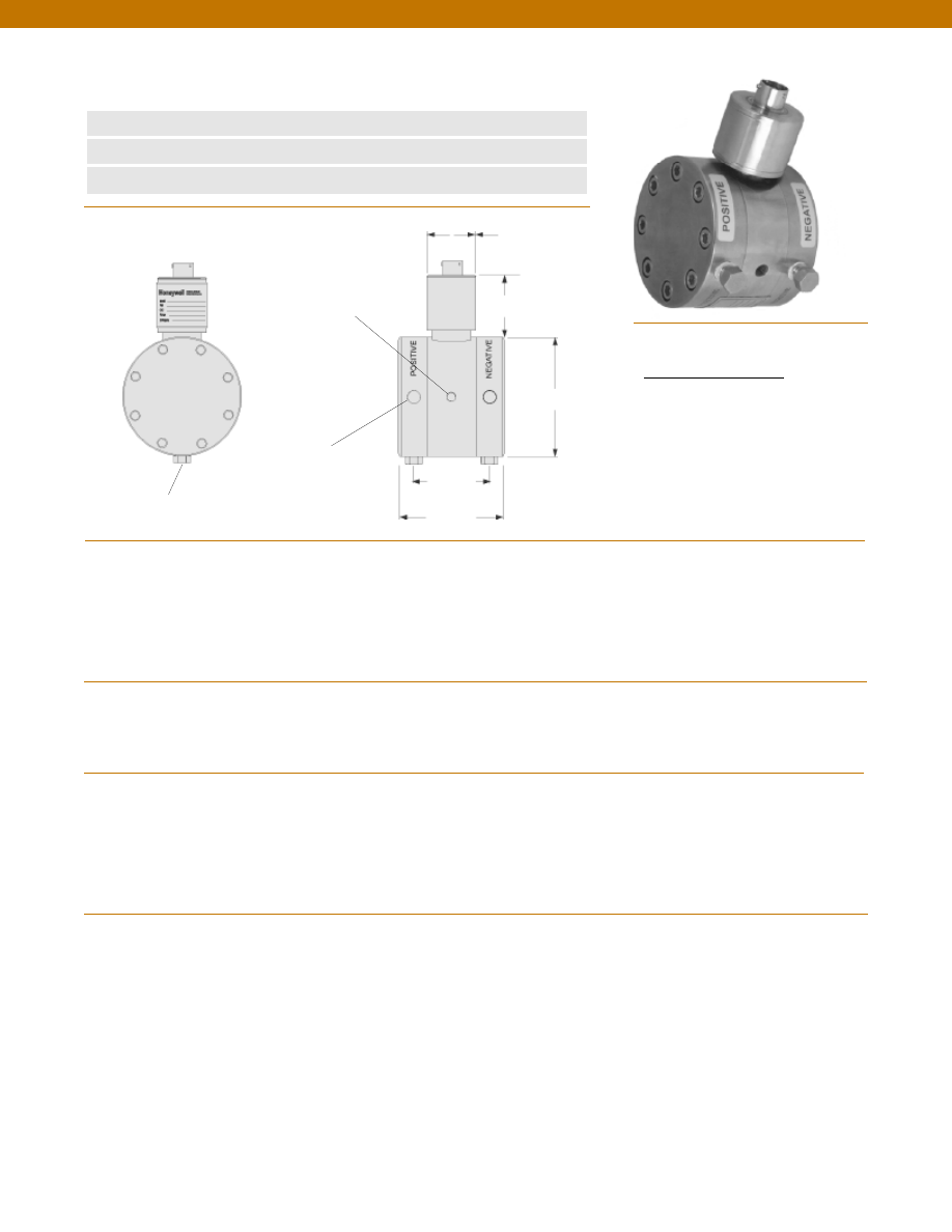
112
www.honeywell.com/sensotec
1-888-282-9891
Wiring Code
Connector/ Unamplified
A & B
(+) Excitation
C & D
(-) Excitation
E
(-) Output
F
(+) Output
Model A-5 Mid Range Wet/ Wet Differential Pressure Transducer
Order Code AD123
n
50 to 750 psid
n
0.5% Accuracy
n
Amplified Output Available
Bleed Port 1/8-27 NPT
2 each
Pressure Port
1/8-27 NPT 2 each
Mounting Holes
1/4-28 UNF x 5/16 DP.
Typ. each side
2.5 in.
ø3.00 in.
ø1.50 in.
1.4 in.
1.75 in.
Pressure Ranges
Accuracy
Linearity
Hysteresis
Non-Repeatability
Output (standard)
Line Pressure
Resolution
Temperature, Operating
Temperature, Compensated
Temperature, Effect
Zero
Span
Strain Gage Type
Excitation (calibration)
Excitation (acceptable)
Insulation Resistance
Bridge Resistance
Shunt Calibration Data
Electrical Termination (std)
Mating Connector (not incl.)
Media
Overload-Safe
Pressure Port
Dead Volume
Wetted Parts Material
Weight
Case Material
Note: Unless otherwise specified on order, amplified units with 4-20 mA output will provide 4 mA at 0 psid and 20 mA at positive full scale and the
unit will not operate in the negative direction. An available alternative is to specify 4 mA at negative full scale and 20 mA at positive full scale. All
amps add 2 in. to housing.
........50; 75; 100; 150; 200; 300; 500; 750 psid
........+/- 0.5% Full Scale
........+/- 0.25% Full Scale (typical)
........+/- 0.13% Full Scale (typical)
........+/- 0.07% Full Scale (typical)
........2 mV/V (nominal)
........1500 psi
........Infinite
........-65° to 250°F
........60° to 160°F
........+/- 0.75% Full scale/ 100 °F
........+/- 1.0% Reading/ 100 °F
........Bonded Foil
........10 VDC
........Up to 10 VDC or AC
........5000 Megohms @ 50 VDC
........350 Ohms
........Included
........PTIH-10-6P or equivalent (Hermetic stainless)
........PT06A-10-6S or equivalent
........Gas, Liquid
........1500 psi
........1/8-27 NPT Female (2)
........0.25 cu. in.
........17-4 PH Stainless Steel
........5.0 lb.
........Stainless Steel
Dimensions
Performance
Environmental
Electrical
Mechanical
Courtesy of Steven Engineering, Inc.-230 Ryan Way, South San Francisco, CA 94080-6370-Main Office: (650) 588-9200-Outside Local Area: (800) 258-9200-www.stevenengineering.com
Sensotec Sensors Full Line Catalog-html.html
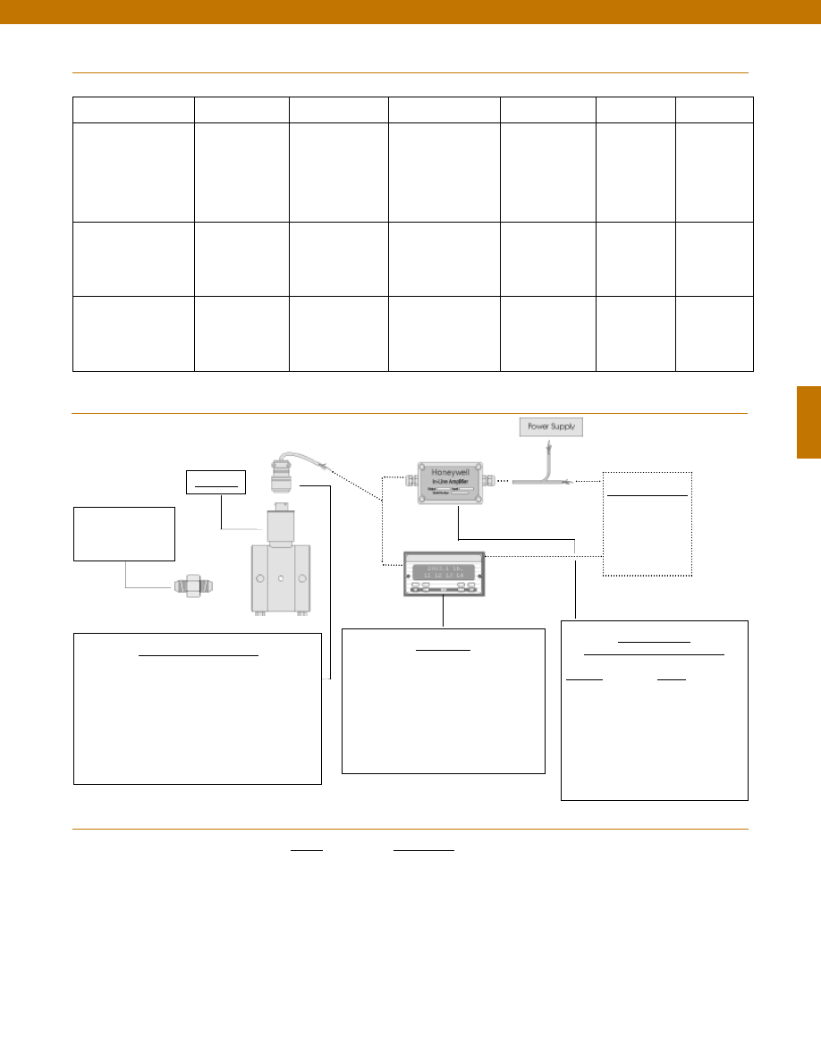
113
In-Line Amplifiers
(Used with unamplified units only)
Amplifier
Output
Universal In-Line Amplifiers
UV
+/- 5 VDC
UV-10
+/- 10 VDC
UBP
0 +/- 5 VDC
U3W
4-20 mA (3 wire)
DIN rail Mount In-Line Amplifiers
DV-05
0 +/- 5 VDC (3 wire)
DA-05
4-20 mA (3 wire)
DV-10
0 +/- 10 VDC (3 wire)
Customer Supplied
Chart Recorder
Alarm Panel
Data Acquisition
Computer
PLC
Display Units
SC500
SC1000
SC2001
SC3004
GM (Unamplified only)
GM-A (Some amplified, see GM-A data sheet)
NK (Unamplified only)
HH (Unamplified only)
Mating Connectors & Cables
AA111 Mating Connector
AA112 Mating Connector & 6 conductor cable
(Unamplified unit with sense leads but not shunt Cal)
AA 113 Mating Connector & 4 conductor cable
(Unamplified unit with sense leads but not shunt Cal)
AA 115 Mating connector and 5 conductor cable for 2c, 2j
or 2t amplified output
AA 116 Mating connector and 3 conductor cable for 2k or
2n(2N) amplified outpu
t
Adaptors compatible
with 1/8-27 NPT
Female
For long cable runs or electrically noisy environments an
amplified sensor or locally mounted amplifier is often preferred.
Model A-5
www.honeywell.com/sensotec
1-888-282-9891
Range
Range Code
50 psid
BN
75 psid BP
100 psid
BR
150 psid
CJ
200 psid
CL
300 psid CP
500 psid
CR
750 psid
CT
Range Codes
Internal Amplifiers
Model A-5
Typical System Diagram
Amplifier Specifications
Voltage Output
Option 2b
Voltage Output
Option 2c
Voltage Output
Option 2t
Current 3 Wire
Option 2j
Current 2 Wire
Option 2k
Intrinsically Safe
Option 2n (2N)***
Output Signal
Input Power (Voltage)
Input Power (Current)
Frequency Response (amp)
Power Supply Rejection
Operating Temperature
Reverse Voltage Protection
Short Circuit Protection
+/- 5V
+/-15V or 26-32 VDC
45 mA
3000 Hz
60 db
-20° to 185° F
Yes
Momentary
0-5V or +/- 5V @ 5mA
11-28 VDC
40 mA
3000 Hz
60 db
-20° to 185° F
Yes
Momentary
0-10V or +/- 10V @ 5mA
15-28 VDC
40 mA
3000 Hz
60 db
-20° to 185° F
Yes
Momentary
4-20 mA
22-32 VDC
65 mA
2500 Hz
60 db
0° to 185° F
Yes
Yes
4-20 mA
9-32 VDC
4-28 mA
300 Hz
60 db
0° to 185° F
Yes
Yes
4-20 mA
9-28 VDC
4-24 mA
2000 Hz
60 db
-20° to 185° F
Yes
Yes
Wiring Code: Connector
(Std.)
(note 2)
A (+) Supply
B Output Common/
C Supply Return
D (+) Output
E Shunt Cal 1
F Shunt Cal 2
A (+) Supply
B** Output Common/
C** Supply Return
D (+) Output
E Shunt Cal 1
F Shunt Cal 2
A (+) Supply
B** Output Common/
C** Supply Return
D (+) Output
E Shunt Cal 1
F Shunt Cal 2
A (+) Supply
B** Output Common/
C** Supply Return
D (+) Output
E Shunt Cal 1
F Shunt Cal 2
A (+) Supply
B No connection
C No connection
D (+) Output
E Case Ground
F No connection
A (+) Supply
B No connection
C No connection
D (+) Output
E Case Ground
F No connection
Wiring Code: Cable
(note 2)
(note 3)
(note 4)
R (+) Supply
Bl Output Common/
G Supply Return
W (+) Output
B Shunt Cal 1
Br Shunt Cal 2
R (+) Supply
Bl*Output Common/
G*Supply Return
W (+) Output
B Shunt Cal 1
Br Shunt Cal 2
R (+) Supply
Bl*Output Common/
G*Supply Return
W (+) Output
B Shunt Cal 1
Br Shunt Cal 2
R (+) Supply
Bl*Output Common/
G*Supply Return
W (+) Output
B Shunt Cal 1
Br Shunt Cal 2
R (+) Supply
Bl (+) Output
W Case Ground
R (+) Supply
Bl (+) Output
W Case Ground
* Black and Green wires are internally connected.
** Pins B and C are internally connected.
*** See Sensotec website for most up-to-date information regarding Intrinsically Safe approvals ref. #008-0547-00.
Courtesy of Steven Engineering, Inc.-230 Ryan Way, South San Francisco, CA 94080-6370-Main Office: (650) 588-9200-Outside Local Area: (800) 258-9200-www.stevenengineering.com
Sensotec Sensors Full Line Catalog-html.html
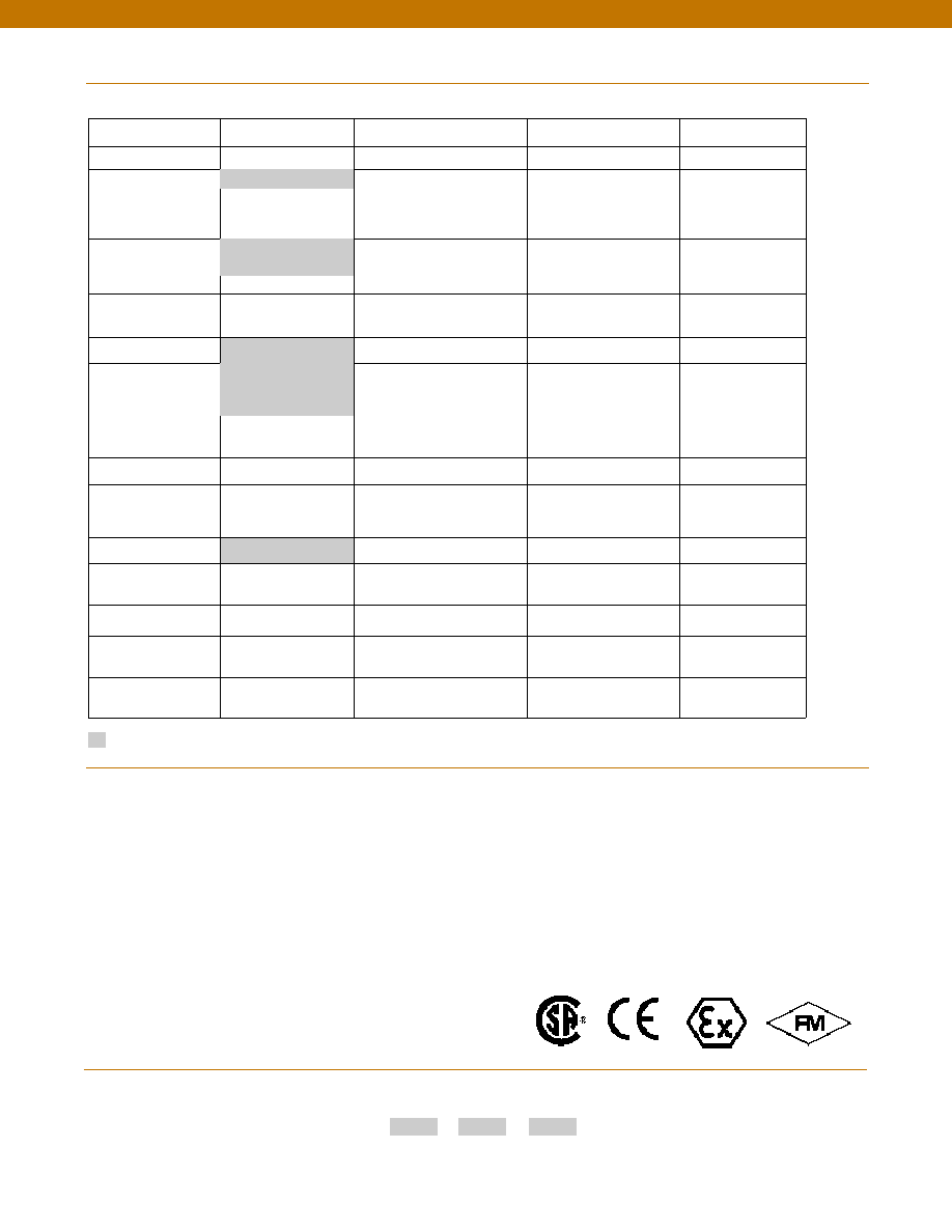
114
www.honeywell.com/sensotec
1-888-282-9891
How to Order
Combine the order code, the range code and the options code.
Order Code
Range Code
Options Code
Sample Code: AD123
CT
6h
Model A-5
Same Day Ship
Fast track manufacture
Build to Order
Build from scratch
Pressure Ranges (psid) 50, 100, 200, 500
75, 150, 300, 750
Temperature
Compensation
1b. 30° to 130° F
1c. 0° to 185° F
1f.
70° to 250° F
1j.
0° to 50° C
1d. -20° to 130° F
1e. -20° to 200° F
1i.
-65° to 250° F
1m. -25° to 110° C
1g. 70° to 325° F
1h. 70° to 400° F
Internal Amplifiers
2b. 4 wire +/-5VDC
2c. 0-5VDC
2t.
0-10VDC
2j.
4-20mA (3 wire) output
2k. 4-20mA(2-wire) output
2n(2N). 4-20mA (2-wire)
intrinsically safe
Internal Amp
Enhancements
3d. Remote Buffered Shunt
Calibration
3a. Input/ Output Isolation
(note 8)
Pressure Ports (note 5)
5h. 1/8-27 NPT Female
5c. 7/16” - 20 UNF Female
(per MS33656E4)
Electrical Termination
6e. Integral cable: Teflon
(-54° to 245° C)
6f.
Integral cable: PVC
(-30° to 70° C)
6i.
Integral underwater cable
(8m) (max 80° C) (note 1)
6j.
1/2-14 conduit fitting with
5 ft. 4 conductor PVC cable
6b. MS type connector
(note 1)
6g. Integral cable: Neoprene
(-20 to 80° C) (note 1)
6h. Integral cable: Silicone
(-54 to 150° C)
Shunt Calibration
8a. Precision Internal Resistor
(note 7)
Special Calibration
9a. 10 point (5 up/5 down)
20% increments @ 20° C
9b. 20 point (10 up/10 down)
10% increments @ 20° C
Wetted Diaphragm
17-4 PH Stainless Steel
10a. 316 Stainless Steel
Bridge Type
11a. Square bridge
11b. Symmetrical bridge
11c. Square & symmetrical bridge
Potentiometers
14a. No access to pots
14b. Top access to pots (note 6)
O Ring Seals
26a. Metal
26b. Vi-Ton
26c. Teflon
Interfaces
53e. Signature Calibration
53t. T.E.D.S. IEEE 1451.4
Module (note 9)
Options
Supplied as standard
2u. Unamplified, mV/V
output
1a. 60° to 160° F
6a. Bendix PTIH-10-6P
(or equivalent) 6 pin
(max. 250°F)
Pressure Port adaptors
Mating connectors and cables
Special Wetted Material
Special Customer
Requirements
(Consult Factory)
Notes
Approved Approved Approved
Intrinsically Safe Amp
1. Availability varies according to range.
2. Interconnecting shunt cal. 1 terminal with shunt cal. 2
terminal provides 50% (unamplified units), 75% (4-20mA
3-wire units) or 80% (voltage amplified units) of full scale
output for quick calibration. Shunt Calibration comes
standard with internal amplifier options 2b, 2c, 2t and 2j.
3. O=Orange; Y=Yellow; B=Blue; Bl=Black; R=Red;
Br=Brown; W=White; G=Green. Color specifying cable
and number or letter specifying connector.
4. No mating connector necessary for cable option.
5. Some pressure port options may require axial orientation.
6. Only available with unamplified option 2u.
7. Only available with amplified options.
8. Only available with VDC output options 2b, 2c.
9. Consult factory for TEDS availability with amplified models.
Courtesy of Steven Engineering, Inc.-230 Ryan Way, South San Francisco, CA 94080-6370-Main Office: (650) 588-9200-Outside Local Area: (800) 258-9200-www.stevenengineering.com
Sensotec Sensors Full Line Catalog-html.html
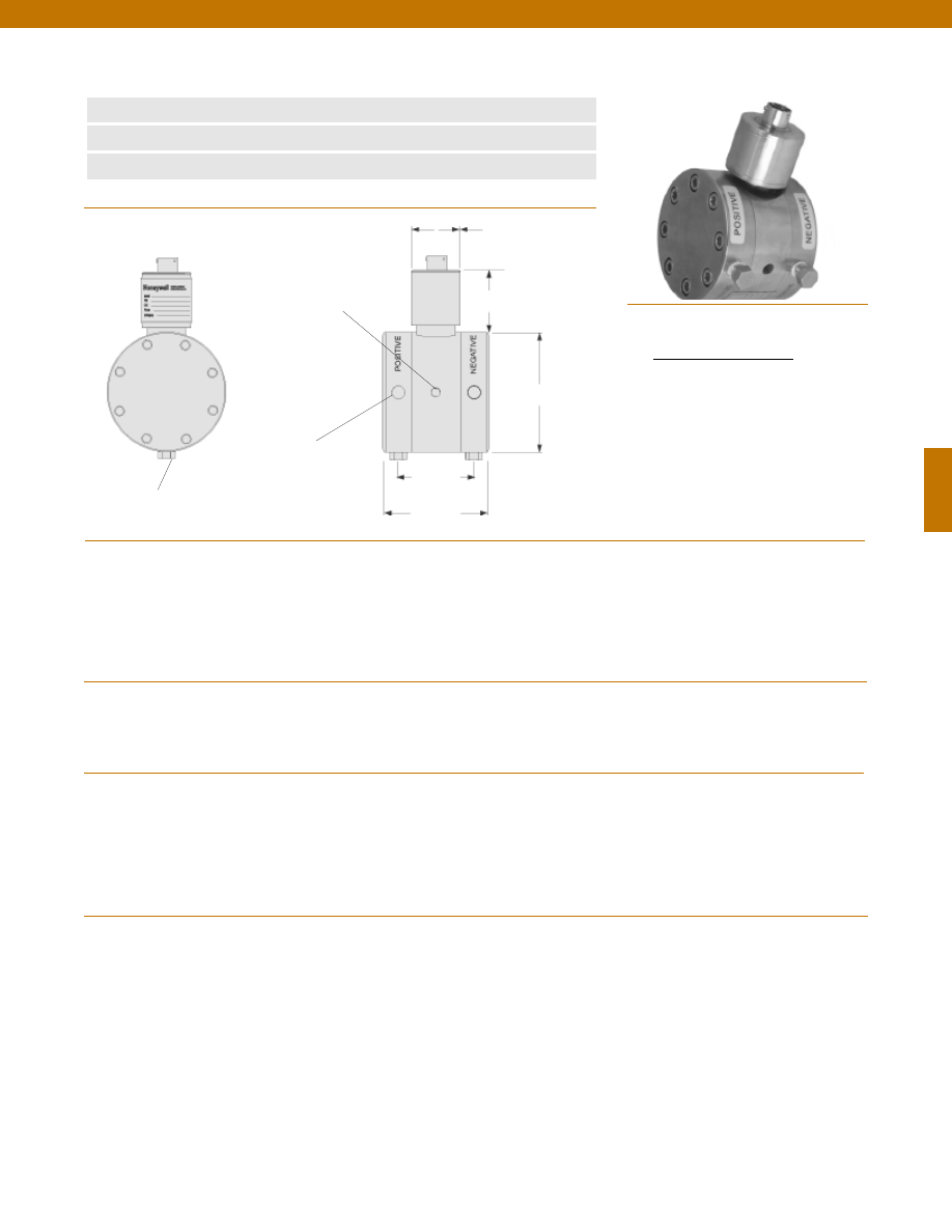
115
Pressure Ranges
Accuracy
Linearity
Hysteresis
Non-Repeatability
Output (standard)
Line Pressure
Resolution
Temperature, Operating
Temperature, Compensated
Temperature, Effect
Zero
Span
Strain Gage Type
Excitation (calibration)
Excitation (acceptable)
Insulation Resistance
Bridge Resistance
Shunt Calibration Data
Electrical Termination (std)
Mating Connector (not incl.)
Media
Overload-Safe
Pressure Port
Dead Volume
Wetted Parts Material
Weight
Case Material
........50; 75; 100; 150; 200; 300; 500; 750 psid
........+/- 0.25% Full Scale
........+/- 0.15% Full Scale (typical)
........+/- 0.10% Full Scale (typical)
........+/- 0.05% Full Scale (typical)
........2 mV/V (nominal)
........1500 psi
........Infinite
........-65° to 250°F
........60° to 160°F
........+/- 0.5% Full scale/ 100 °F
........+/- 0.5% Reading/ 100 °F
........Bonded Foil
........10 VDC
........UP to 10 VDC or AC
........5000 Megohms @ 50 VDC
........350 Ohms
........Included
........PTIH-10-6P or equivalent (Hermetic stainless)
........PT06A-10-6S or equivalent
........Gas, Liquid
........1500 psi
........1/8-27 NPT Female (2)
........0.25 cu. in.
........17-4 PH Stainless Steel
........5.0 lb.
........Stainless Steel
www.honeywell.com/sensotec
1-888-282-9891
Wiring Code
Connector/ Unamplified
A & B
(+) Excitation
C & D
(-) Excitation
E
(-) Output
F
(+) Output
Dimensions
Performance
Environmental
Electrical
Mechanical
Note: Unless otherwise specified on order, amplified units with 4-20 mA output will provide 4 mA at 0 psid and 20 mA at positive full scale and the
unit will not operate in the negative direction. An available alternative is to specify 4 mA at negative full scale and 20 mA at positive full scale. All
amps add 2 in. to housing.
Model Z Mid Range Wet/ Wet Differential Pressure Transducer
Order Code AD122
Bleed Port 1/8-27 NPT
2 each
Pressure Port
1/8-27 NPT 2 each
Mounting Holes
1/4-28 UNF x 5/16 DP.
Typ. each side
2.5 in.
ø3.00 in.
ø1.50 in.
1.4 in.
1.75 in.
n
50 to 750 psid
n
0.25% Accuracy
n
Amplified Output Available
Courtesy of Steven Engineering, Inc.-230 Ryan Way, South San Francisco, CA 94080-6370-Main Office: (650) 588-9200-Outside Local Area: (800) 258-9200-www.stevenengineering.com
Sensotec Sensors Full Line Catalog-html.html
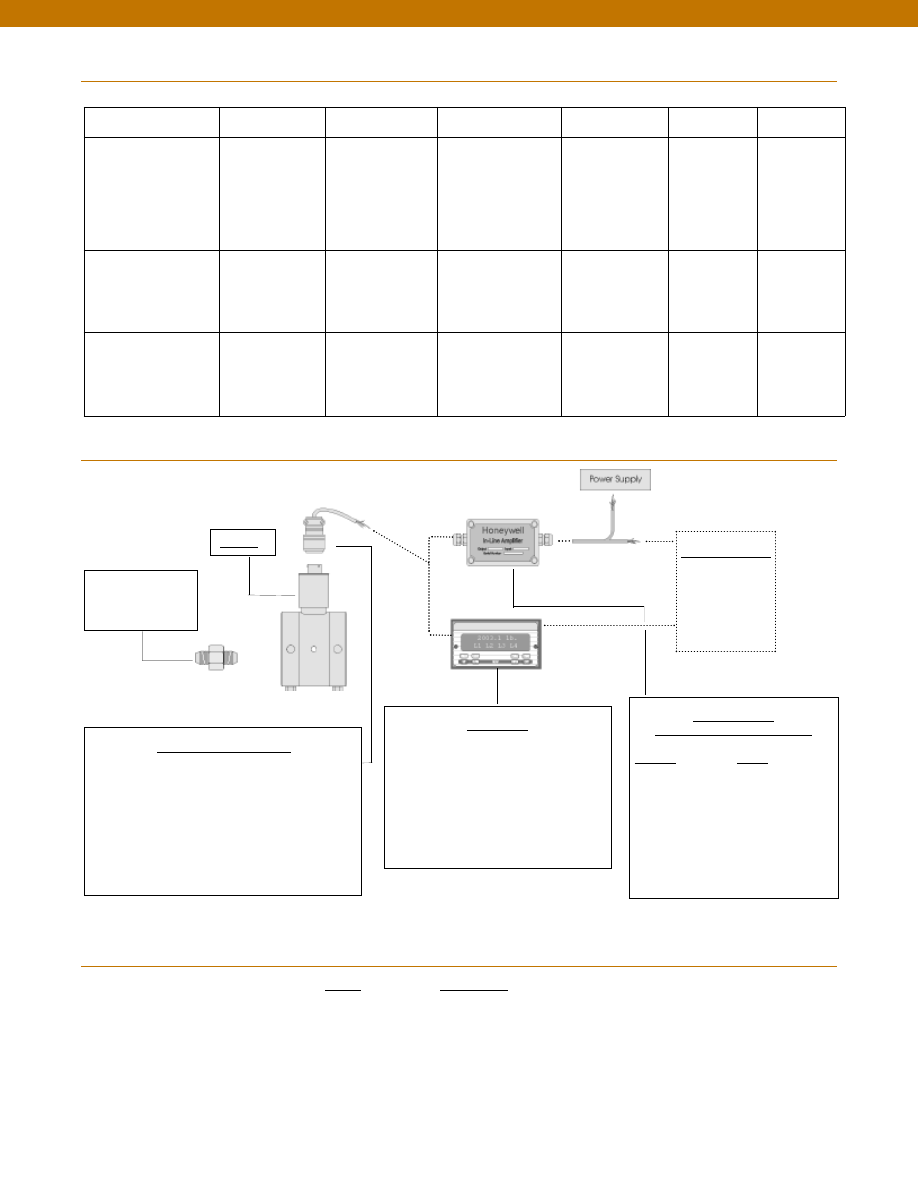
116
In-Line Amplifiers
(Used with unamplified units only)
Amplifier
Output
Universal In-Line Amplifiers
UV
+/- 5 VDC
UV-10
+/- 10 VDC
UBP
0 +/- 5 VDC
U3W
4-20 mA (3 wire)
DIN rail Mount In-Line Amplifiers
DV-05
0 +/- 5 VDC (3 wire)
DA-05
4-20 mA (3 wire)
DV-10
0 +/- 10 VDC (3 wire)
Customer Supplied
Chart Recorder
Alarm Panel
Data Acquisition
Computer
PLC
Display Units
SC500
SC1000
SC2001
SC3004
GM (Unamplified only)
GM-A (Some amplified, see GM-A data sheet)
NK (Unamplified only)
HH (Unamplified only)
Mating Connectors & Cables
AA111 Mating Connector
AA112 Mating Connector & 6 conductor cable
(Unamplified unit with sense leads but not shunt Cal)
AA 113 Mating Connector & 4 conductor cable
(Unamplified unit with sense leads but not shunt Cal)
AA 115 Mating connector and 5 conductor cable for 2c, 2j
or 2t amplified output
AA 116 Mating connector and 3 conductor cable for 2k or
2n(2N) amplified outpu
t
Adaptors compatible
with 1/8-27 NPT
Female
For long cable runs or electrically noisy environments an
amplified sensor or locally mounted amplifier is often preferred.
Model Z
www.honeywell.com/sensotec
1-888-282-9891
Range
Range Code
50 psid
BN
75 psid
BP
100 psid
BR
150 psid
CJ
200 psid
CL
300 psid CP
500 psid
CR
750 psid
CT
Typical System Diagram
Range Codes
Internal Amplifiers
Model Z
Amplifier Specifications
Voltage Output
Option 2b
Voltage Output
Option 2c
Voltage Output
Option 2t
Current 3 Wire
Option 2j
Current 2 Wire
Option 2k
Intrinsically Safe
Option 2n (2N)***
Output Signal
Input Power (Voltage)
Input Power (Current)
Frequency Response (amp)
Power Supply Rejection
Operating Temperature
Reverse Voltage Protection
Short Circuit Protection
+/- 5V
+/-15V or 26-32 VDC
45 mA
3000 Hz
60 db
-20° to 185° F
Yes
Momentary
0-5V or +/- 5V @ 5mA
11-28 VDC
40 mA
3000 Hz
60 db
-20° to 185° F
Yes
Momentary
0-10V or +/- 10V @ 5mA
15-28 VDC
40 mA
3000 Hz
60 db
-20° to 185° F
Yes
Momentary
4-20 mA
22-32 VDC
65 mA
2500 Hz
60 db
0° to 185° F
Yes
Yes
4-20 mA
9-32 VDC
4-28 mA
300 Hz
60 db
0° to 185° F
Yes
Yes
4-20 mA
9-28 VDC
4-24 mA
2000 Hz
60 db
-20° to 185° F
Yes
Yes
Wiring Code: Connector
(Std.)
(note 2)
A (+) Supply
B Output Common/
C Supply Return
D (+) Output
E Shunt Cal 1
F Shunt Cal 2
A (+) Supply
B** Output Common/
C** Supply Return
D (+) Output
E Shunt Cal 1
F Shunt Cal 2
A (+) Supply
B** Output Common/
C** Supply Return
D (+) Output
E Shunt Cal 1
F Shunt Cal 2
A (+) Supply
B** Output Common/
C** Supply Return
D (+) Output
E Shunt Cal 1
F Shunt Cal 2
A (+) Supply
B No connection
C No connection
D (+) Output
E Case Ground
F No connection
A (+) Supply
B No connection
C No connection
D (+) Output
E Case Ground
F No connection
Wiring Code: Cable
(note 2)
(note 3)
(note 4)
R (+) Supply
Bl Output Common/
G Supply Return
W (+) Output
B Shunt Cal 1
Br Shunt Cal 2
R (+) Supply
Bl*Output Common/
G*Supply Return
W (+) Output
B Shunt Cal 1
Br Shunt Cal 2
R (+) Supply
Bl*Output Common/
G*Supply Return
W (+) Output
B Shunt Cal 1
Br Shunt Cal 2
R (+) Supply
Bl*Output Common/
G*Supply Return
W (+) Output
B Shunt Cal 1
Br Shunt Cal 2
R (+) Supply
Bl (+) Output
W Case Ground
R (+) Supply
Bl (+) Output
W Case Ground
* Black and Green wires are internally connected.
** Pins B and C are internally connected.
*** See Sensotec website for most up-to-date information regarding Intrinsically Safe approvals ref. #008-0547-00.
Courtesy of Steven Engineering, Inc.-230 Ryan Way, South San Francisco, CA 94080-6370-Main Office: (650) 588-9200-Outside Local Area: (800) 258-9200-www.stevenengineering.com
Sensotec Sensors Full Line Catalog-html.html
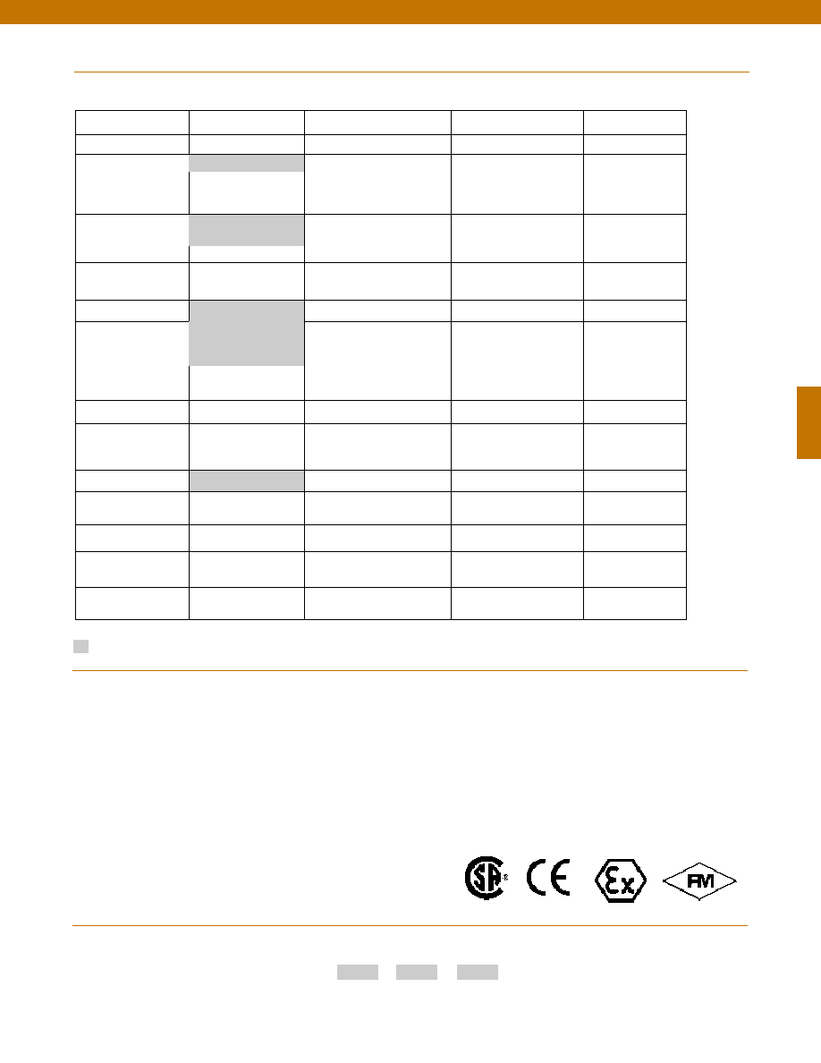
117
Same Day Ship
Fast track manufacture
Build to Order
Build from Scratch
Pressure Ranges (psid) 50, 100, 200, 500
75, 150, 300, 750
Temperature
Compensation
1b. 30° to 130° F
1c. 0° to 185° F
1f.
70° to 250° F
1j.
0° to 50° C
1d. -20° to 130° F
1e. -20° to 200° F
1i.
-65° to 250° F
1m. -25° to 110° C
1g. 70° to 325° F
1h. 70° to 400° F
Internal Amplifiers
2b. 4 wire +/-5VDC
2c. 0-5VDC
2t.
0-10VDC
2j.
4-20mA (3 wire) output
2k. 4-20mA(2-wire) output
2n(2N). 4-20mA (2-wire)
intrinsically safe
Internal Amp
Enhancements
3d. Remote Buffered Shunt
Calibration
3a. Input/ Output Isolation
(note 8)
Pressure Ports (note 5)
5h. 1/8-27 NPT Female
5c. 7/16” - 20 UNF Female
(per MS33656E4)
Electrical Termination
6e. Integral cable: Teflon
(-54° to 245° C)
6f.
Integral cable: PVC
(-30° to 70° C)
6i.
Integral underwater cable
(8m) (max 80° C) (note 1)
6j.
1/2-14 conduit fitting with
5 ft. 4 conductor PVC cable
6b. MS type connector
(note 1)
6g. Integral cable: Neoprene
(-20 to 80° C) (note 1)
6h. Integral cable: Silicone
(-54 to 150° C)
Shunt Calibration
8a. Precision Internal Resistor
(note 7)
Special Calibration
9a. 10 point (5 up/5 down)
20% increments @ 20° C
9b. 20 point (10 up/10 down)
10% increments @ 20° C
Wetted Diaphragm
17-4 PH Stainless Steel
10a. 316 Stainless Steel
Bridge Type
11a. Square bridge
11b. Symmetrical bridge
11c. Square & symmetrical bridge
Potentiometers
14a. No access to pots
14b. Top access to pots (note 6)
O Ring Seals
26a. Metal
26b. Vi-Ton
26c. Teflon
Interfaces
53e. Signature Calibration
53t. T.E.D.S. IEEE 1451.4
Module (note 9)
Options
Supplied as standard
www.honeywell.com/sensotec
1-888-282-9891
2u. Unamplified, mV/V
output
1a. 60° to 160° F
6a. Bendix PTIH-10-6P
(or equivalent) 6 pin
(max. 250°F)
How to Order
Combine the order code, the range code and the options code.
Order Code
Range Code
Options Code
Sample Code: AD122
CT
6h
Pressure Port adaptors
Mating connectors and cables
Special Wetted Material
Special Customer
Requirements
(Consult Factory)
Notes
Model Z
Approved Approved Approved
Intrinsically Safe Amp
1. Availability varies according to range.
2. Interconnecting shunt cal. 1 terminal with shunt cal. 2
terminal provides 50% (unamplified units), 75% (4-20mA
3-wire units) or 80% (voltage amplified units) of full scale
output for quick calibration. Shunt Calibration comes
standard with internal amplifier options 2b, 2c, 2t and 2j.
3. O=Orange; Y=Yellow; B=Blue; Bl=Black; R=Red;
Br=Brown; W=White; G=Green. Color specifying cable
and number or letter specifying connector.
4. No mating connector necessary for cable option.
5. Some pressure port options may require axial orientation.
6. Only available with unamplified option 2u.
7. Only available with amplified options.
8. Only available with VDC output options 2b, 2c.
9. Consult factory for TEDS availability with amplified models.
Courtesy of Steven Engineering, Inc.-230 Ryan Way, South San Francisco, CA 94080-6370-Main Office: (650) 588-9200-Outside Local Area: (800) 258-9200-www.stevenengineering.com
Sensotec Sensors Full Line Catalog-html.html
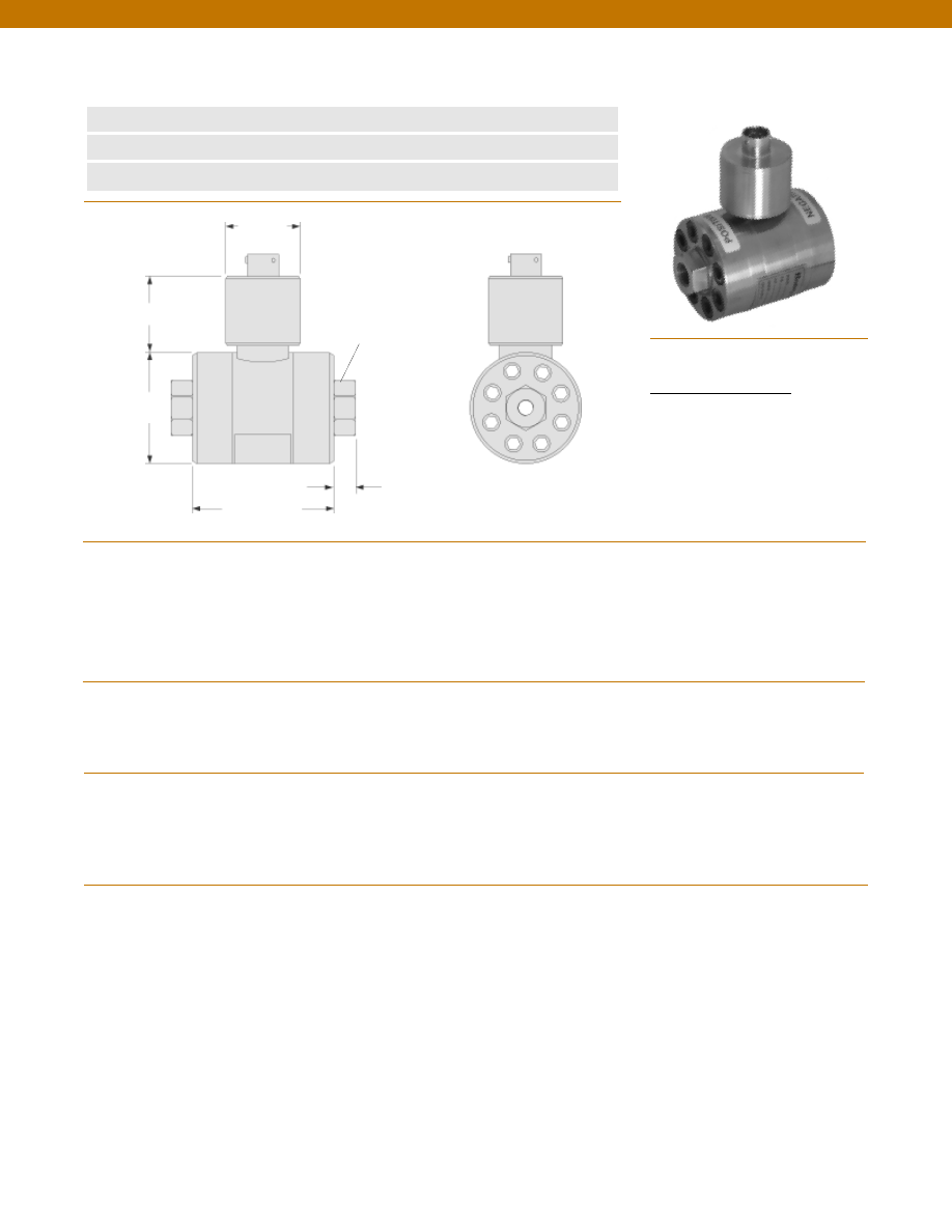
118
www.honeywell.com/sensotec
1-888-282-9891
Wiring Code
Connector/ Unamplified
A & B
(+) Excitation
C & D
(-) Excitation
E
(-) Output
F
(+) Output
Model A-5 High Range Wet/ Wet Differential Pressure Transducer
Order Code BD142
n
2000 to 10,000 psid
n
0.5% Accuracy
n
Amplified Output Available
Pressure Ranges
Accuracy
Linearity
Hysteresis
Non-Repeatability
Output (standard)
Line Pressure
Resolution
Temperature, Operating
Temperature, Compensated
Temperature, Effect
Zero
Span
Strain Gage Type
Excitation (calibration)
Bridge Resistance
Shunt Calibration Data
Electrical Termination (std)
Mating Connector (not incl.)
Media
Overload-Safe
2000 to 3000 psid
5000 to 10,000 psid
Pressure Port
Wetted Parts Material
Case Material
........2000; 3000; 5000; 7500; 10,000 psid
........+/- 0.5% Full Scale
........+/- 0.25% Full Scale (typical)
........+/- 0.13% Full Scale (typical)
........+/- 0.07% Full Scale (typical)
........2 mV/V (nominal)
........2000 psi
........Infinite
........-65° to 250°F
........60° to 160°F
........+/- 0.75% Full scale/ 100 °F
........+/- 1.0% Reading/ 100 °F
........Bonded Foil
........10 VDC
........350 Ohms (nominal)
........Included
........PTIH-10-6P or equivalent (Hermetic stainless)
........PT06A-10-6S or equivalent
........Gas, Liquid
........100% over capacity
........50% over capacity
........1/4-18 NPT female (2)
........17-4 PH Stainless Steel
........Stainless Steel
Note: Unless otherwise specified on order, amplified units with 4-20 mA output will provide 4 mA at 0 psid and 20 mA at positive full scale and the
unit will not operate in the negative direction. An available alternative is to specify 4 mA at negative full scale and 20 mA at positive full scale. All
amps add 2 in. to amplifier housing.
Pressure Port
1/4-18 NPT Typ.
2.7 in.
ø2.25 in.
ø1.50 in.
1.4 in.
0.4 in.
Dimensions
Performance
Environmental
Electrical
Mechanical
Courtesy of Steven Engineering, Inc.-230 Ryan Way, South San Francisco, CA 94080-6370-Main Office: (650) 588-9200-Outside Local Area: (800) 258-9200-www.stevenengineering.com
Sensotec Sensors Full Line Catalog-html.html

119
In-Line Amplifiers
(Used with unamplified units only)
Amplifier
Output
Universal In-Line Amplifiers
UV
+/- 5 VDC
UV-10
+/- 10 VDC
UBP
0 +/- 5 VDC
U3W
4-20 mA (3 wire)
DIN rail Mount In-Line Amplifiers
DV-05
0 +/- 5 VDC (3 wire)
DA-05
4-20 mA (3 wire)
DV-10
0 +/- 10 VDC (3 wire)
Customer Supplied
Chart Recorder
Alarm Panel
Data Acquisition
Computer
PLC
Display Units
SC500
SC1000
SC2001
SC3004
GM (Unamplified only)
GM-A (Some amplified, see GM-A data sheet)
NK (Unamplified only)
HH (Unamplified only)
Mating Connectors & Cables
AA111 Mating Connector
AA112 Mating Connector & 6 conductor cable
(Unamplified unit with sense leads but not shunt Cal)
AA 113 Mating Connector & 4 conductor cable
(Unamplified unit with sense leads but not shunt Cal)
AA 115 Mating connector and 5 conductor cable for 2c, 2j
or 2t amplified output
AA 116 Mating connector and 3 conductor cable for 2k or
2n(2N) amplified outpu
t
Adaptors compatible
with 1/4-18 NPT
Female
For long cable runs or electrically noisy environments an
amplified sensor or locally mounted amplifier is often preferred.
Model A-5
www.honeywell.com/sensotec
1-888-282-9891
Range
Range Code
2000 psid
DL
3000 psid
DN
5000 psid
DR
7500 psid
DT
10,000 psid
DV
Range Codes
Internal Amplifiers
Model A-5
Typical System Diagram
Amplifier Specifications
Voltage Output
Option 2b
Voltage Output
Option 2c
Voltage Output
Option 2t
Current 3 Wire
Option 2j
Current 2 Wire
Option 2k
Intrinsically Safe
Option 2n (2N)***
Output Signal
Input Power (Voltage)
Input Power (Current)
Frequency Response (amp)
Power Supply Rejection
Operating Temperature
Reverse Voltage Protection
Short Circuit Protection
+/- 5V
+/-15V or 26-32 VDC
45 mA
3000 Hz
60 db
-20° to 185° F
Yes
Momentary
0-5V or +/- 5V @ 5mA
11-28 VDC
40 mA
3000 Hz
60 db
-20° to 185° F
Yes
Momentary
0-10V or +/- 10V @ 5mA
15-28 VDC
40 mA
3000 Hz
60 db
-20° to 185° F
Yes
Momentary
4-20 mA
22-32 VDC
65 mA
2500 Hz
60 db
0° to 185° F
Yes
Yes
4-20 mA
9-32 VDC
4-28 mA
300 Hz
60 db
0° to 185° F
Yes
Yes
4-20 mA
9-28 VDC
4-24 mA
2000 Hz
60 db
-20° to 185° F
Yes
Yes
Wiring Code: Connector
(Std.)
(note 2)
A (+) Supply
B Output Common/
C Supply Return
D (+) Output
E Shunt Cal 1
F Shunt Cal 2
A (+) Supply
B** Output Common/
C** Supply Return
D (+) Output
E Shunt Cal 1
F Shunt Cal 2
A (+) Supply
B** Output Common/
C** Supply Return
D (+) Output
E Shunt Cal 1
F Shunt Cal 2
A (+) Supply
B** Output Common/
C** Supply Return
D (+) Output
E Shunt Cal 1
F Shunt Cal 2
A (+) Supply
B No connection
C No connection
D (+) Output
E Case Ground
F No connection
A (+) Supply
B No connection
C No connection
D (+) Output
E Case Ground
F No connection
Wiring Code: Cable
(note 2)
(note 3)
(note 4)
R (+) Supply
Bl Output Common/
G Supply Return
W (+) Output
B Shunt Cal 1
Br Shunt Cal 2
R (+) Supply
Bl*Output Common/
G*Supply Return
W (+) Output
B Shunt Cal 1
Br Shunt Cal 2
R (+) Supply
Bl*Output Common/
G*Supply Return
W (+) Output
B Shunt Cal 1
Br Shunt Cal 2
R (+) Supply
Bl*Output Common/
G*Supply Return
W (+) Output
B Shunt Cal 1
Br Shunt Cal 2
R (+) Supply
Bl (+) Output
W Case Ground
R (+) Supply
Bl (+) Output
W Case Ground
* Black and Green wires are internally connected.
** Pins B and C are internally connected.
*** See Sensotec website for most up-to-date information regarding Intrinsically Safe approvals ref. #008-0547-00.
Courtesy of Steven Engineering, Inc.-230 Ryan Way, South San Francisco, CA 94080-6370-Main Office: (650) 588-9200-Outside Local Area: (800) 258-9200-www.stevenengineering.com
Sensotec Sensors Full Line Catalog-html.html
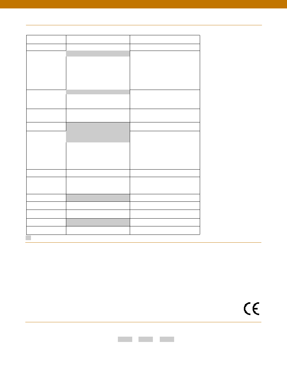
120
Build to Order
Build from scratch
Pressure Ranges (psid) 2000, 3000, 5000, 7500, 10000
Temperature
Compensation
1b. 30° to 130° F
1c. 0° to 185° F
1d. -20° to 130° F
1e. -20° to 200° F
1f.
70° to 250° F
1i.
-65° to 250° F
1j.
0° to 50° C
1m. -25° to 110° C
1g. 70° to 325° F
1h. 70° to 400° F
Internal Amplifiers
2b. 4 wire +/-5VDC
2c. 0-5VDC
2t.
0-10VDC
2j.
4-20mA (3 wire) output
2k. 4-20mA(2-wire) output
2n(2N). 4-20mA (2-wire)
intrinsically safe
Internal Amp
Enhancements
3d. Remote Buffered Shunt Calibration
3a. Input/ Output Isolation (note 6)
Pressure Ports (note 5)
5a. 1/4-18 NPT Female
5c. 7/16” - 20 UNF Female
(per MS33656E4)
Electrical Termination
6e. Integral cable: Teflon (-54° to 245° C)
6f.
Integral cable: PVC (-30° to 70° C)
6i.
Integral underwater cable(8m)
(max 80° C) (note 1)
6j.
1/2-14 conduit fitting with 5 ft.
4 conductor PVC cable
6b. MS type connector (note 1)
6g. Integral cable: Neoprene (-20 to 80° C)
(note 1)
6h. Integral cable: Silicone (-54 to 150° C)
Shunt Calibration
8a. Precision Internal Resistor (note 7)
Special Calibration
9a. 10 point (5 up/5 down) 20% increments
@ 20° C
9b. 20 point (10 up/10 down) 10%
increments @ 20° C
Wetted Diaphragm
17-4 PH Stainless Steel
Bridge Type
11a. Square bridge
11c. Square & symmetrical bridge
11b. Symmetrical bridge
Potentiometers
14b. Top access to pots (note 8)
14a. No access to pots
O Ring Seals
26a. Metal
Interfaces
53e. Signature Calibration
53t. T.E.D.S. IEEE 1451.4 Module (note 9)
Options
Supplied as standard
www.honeywell.com/sensotec
1-888-282-9891
2u. Unamplified, mV/V output
1a. 60° to 160° F
6a. Bendix PTIH-10-6P (or equivalent)
6 pin (max. 250°F)
How to Order
Combine the order code, the range code and the options code.
Order Code
Range Code
Options Code
Sample Code: BD142
DV
6h
Pressure Port adaptors
Mating connectors and cables
Enhanced Line Pressure
Special Customer
Requirements
(Consult Factory)
Notes
Model A-5
Approved
1. Availability varies according to range.
2. Interconnecting shunt cal. 1 terminal with shunt cal. 2 terminal provides 50% (unamplified units), 75%
(4-20mA 3-wire units) or 80% (voltage amplified units) of full scale output for quick calibration. Shunt
Calibration comes standard with internal amplifier options 2b, 2c, 2t and 2j.
3. O=Orange; Y=Yellow; B=Blue; Bl=Black; R=Red; Br=Brown; W=White; G=Green. Color specifying
cable and number or letter specifying connector.
4. No mating connector necessary for cable option.
5. Some pressure port options may require axial orientation.
6. Only available with unamplified option 2u.
7. Only available with amplified options.
8. Only available with VDC output options 2b, 2c.
9. Consult factory for TEDS availability with amplified models.
Courtesy of Steven Engineering, Inc.-230 Ryan Way, South San Francisco, CA 94080-6370-Main Office: (650) 588-9200-Outside Local Area: (800) 258-9200-www.stevenengineering.com
Sensotec Sensors Full Line Catalog-html.html
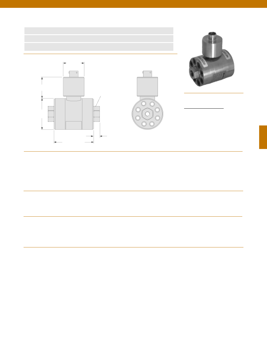
121
Pressure Ranges
Accuracy
Linearity
Hysteresis
Non-Repeatability
Output (standard)
Line Pressure
Resolution
Temperature, Operating
Temperature, Compensated
Temperature, Effect
Zero
Span
Strain Gage Type
Excitation (calibration)
Bridge Resistance
Shunt Calibration Data
Electrical Termination (std)
Mating Connector (not incl.)
Media
Overload-Safe
2000 to 3000 psid
5000 to 10,000 psid
Pressure Port
Wetted Parts Material
Case Material
........2000; 3000; 5000; 7500; 10,000 psid
........+/- 0.25% Full Scale
........+/- 0.15% Full Scale (typical)
........+/- 0.10% Full Scale (typical)
........+/- 0.05% Full Scale (typical)
........2 mV/V (nominal)
........2000 psi
........Infinite
........-65° to 250°F
........60° to 160°F
........+/- 0.5% Full scale/ 100 °F
........+/- 0.5% Reading/ 100 °F
........Bonded Foil
........10 VDC
........350 Ohms (nominal)
........Included
........PTIH-10-6P or equivalent (Hermetic stainless)
........PT06A-10-6S or equivalent
........Gas, Liquid
........100% over capacity
........50% over capacity
........1/4-18 NPT female (2)
........17-4 PH Stainless Steel
........Stainless Steel
www.honeywell.com/sensotec
1-888-282-9891
Wiring Code
Connector/ Unamplified
A & B
(+) Excitation
C & D
(-) Excitation
E
(-) Output
F
(+) Output
Note: Unless otherwise specified on order, amplified units with 4-20 mA output will provide 4 mA at 0 psid and 20 mA at positive full scale and the
unit will not operate in the negative direction. An available alternative is to specify 4 mA at negative full scale and 20 mA at positive full scale. All
amps add 2 in. to amplifier housing.
Model Z High Range Wet/ Wet Differential Pressure Transducer
Order Code BD141
n
2000 to 10,000 psid
n
0.25% Accuracy
n
Amplified Output Available
Pressure Port
1/4-18 NPT Typ.
2.7 in.
ø2.25 in.
ø1.50 in.
1.4 in.
0.4 in.
Dimensions
Performance
Environmental
Electrical
Mechanical
Courtesy of Steven Engineering, Inc.-230 Ryan Way, South San Francisco, CA 94080-6370-Main Office: (650) 588-9200-Outside Local Area: (800) 258-9200-www.stevenengineering.com
Sensotec Sensors Full Line Catalog-html.html

122
In-Line Amplifiers
(Used with unamplified units only)
Amplifier
Output
Universal In-Line Amplifiers
UV
+/- 5 VDC
UV-10
+/- 10 VDC
UBP
0 +/- 5 VDC
U3W
4-20 mA (3 wire)
DIN rail Mount In-Line Amplifiers
DV-05
0 +/- 5 VDC (3 wire)
DA-05
4-20 mA (3 wire)
DV-10
0 +/- 10 VDC (3 wire)
Customer Supplied
Chart Recorder
Alarm Panel
Data Acquisition
Computer
PLC
Display Units
SC500
SC1000
SC2001
SC3004
GM (Unamplified only)
GM-A (Some amplified, see GM-A data sheet)
NK (Unamplified only)
HH (Unamplified only)
Mating Connectors & Cables
AA111 Mating Connector
AA112 Mating Connector & 6 conductor cable
(Unamplified unit with sense leads but not shunt Cal)
AA 113 Mating Connector & 4 conductor cable
(Unamplified unit with sense leads but not shunt Cal)
AA 115 Mating connector and 5 conductor cable for 2c, 2j
or 2t amplified output
AA 116 Mating connector and 3 conductor cable for 2k or
2n(2N) amplified outpu
t
Adaptors compatible
with 1/4-18 NPT
Female
For long cable runs or electrically noisy environments an
amplified sensor or locally mounted amplifier is often preferred.
Model Z
www.honeywell.com/sensotec
1-888-282-9891
Range
Range Code
2000 psid
DL
3000 psid
DN
5000 psid
DR
7500 psid
DT
10,000 psid
DV
Range Codes
Internal Amplifiers
Model Z
Typical System Diagram
Amplifier Specifications
Voltage Output
Option 2b
Voltage Output
Option 2c
Voltage Output
Option 2t
Current 3 Wire
Option 2j
Current 2 Wire
Option 2k
Intrinsically Safe
Option 2n (2N)***
Output Signal
Input Power (Voltage)
Input Power (Current)
Frequency Response (amp)
Power Supply Rejection
Operating Temperature
Reverse Voltage Protection
Short Circuit Protection
+/- 5V
+/-15V or 26-32 VDC
45 mA
3000 Hz
60 db
-20° to 185° F
Yes
Momentary
0-5V or +/- 5V @ 5mA
11-28 VDC
40 mA
3000 Hz
60 db
-20° to 185° F
Yes
Momentary
0-10V or +/- 10V @ 5mA
15-28 VDC
40 mA
3000 Hz
60 db
-20° to 185° F
Yes
Momentary
4-20 mA
22-32 VDC
65 mA
2500 Hz
60 db
0° to 185° F
Yes
Yes
4-20 mA
9-32 VDC
4-28 mA
300 Hz
60 db
0° to 185° F
Yes
Yes
4-20 mA
9-28 VDC
4-24 mA
2000 Hz
60 db
-20° to 185° F
Yes
Yes
Wiring Code: Connector
(Std.)
(note 2)
A (+) Supply
B Output Common/
C Supply Return
D (+) Output
E Shunt Cal 1
F Shunt Cal 2
A (+) Supply
B** Output Common/
C** Supply Return
D (+) Output
E Shunt Cal 1
F Shunt Cal 2
A (+) Supply
B** Output Common/
C** Supply Return
D (+) Output
E Shunt Cal 1
F Shunt Cal 2
A (+) Supply
B** Output Common/
C** Supply Return
D (+) Output
E Shunt Cal 1
F Shunt Cal 2
A (+) Supply
B No connection
C No connection
D (+) Output
E Case Ground
F No connection
A (+) Supply
B No connection
C No connection
D (+) Output
E Case Ground
F No connection
Wiring Code: Cable
(note 2)
(note 3)
(note 4)
R (+) Supply
Bl Output Common/
G Supply Return
W (+) Output
B Shunt Cal 1
Br Shunt Cal 2
R (+) Supply
Bl*Output Common/
G*Supply Return
W (+) Output
B Shunt Cal 1
Br Shunt Cal 2
R (+) Supply
Bl*Output Common/
G*Supply Return
W (+) Output
B Shunt Cal 1
Br Shunt Cal 2
R (+) Supply
Bl*Output Common/
G*Supply Return
W (+) Output
B Shunt Cal 1
Br Shunt Cal 2
R (+) Supply
Bl (+) Output
W Case Ground
R (+) Supply
Bl (+) Output
W Case Ground
* Black and Green wires are internally connected.
** Pins B and C are internally connected.
*** See Sensotec website for most up-to-date information regarding Intrinsically Safe approvals ref. #008-0547-00.
Courtesy of Steven Engineering, Inc.-230 Ryan Way, South San Francisco, CA 94080-6370-Main Office: (650) 588-9200-Outside Local Area: (800) 258-9200-www.stevenengineering.com
Sensotec Sensors Full Line Catalog-html.html
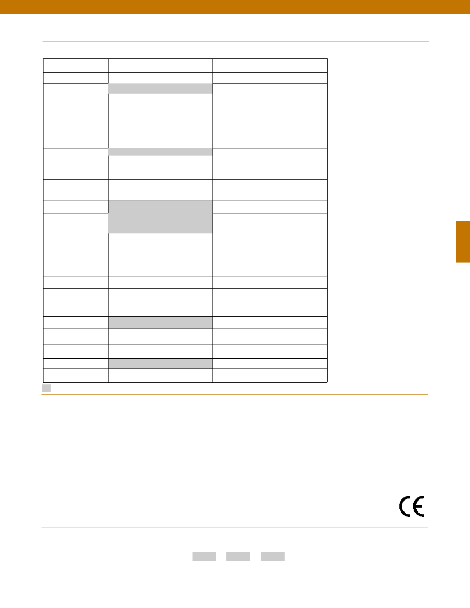
123
Build to Order
Build from scratch
Pressure Ranges (psid) 2000, 3000, 5000, 7500, 10000
Temperature
Compensation
1b. 30° to 130° F
1c. 0° to 185° F
1d. -20° to 130° F
1e. -20° to 200° F
1f.
70° to 250° F
1i.
-65° to 250° F
1j.
0° to 50° C
1m. -25° to 110° C
1g. 70° to 325° F
1h. 70° to 400° F
Internal Amplifiers
2b. 4 wire +/-5VDC
2c. 0-5VDC
2t.
0-10VDC
2j.
4-20mA (3 wire) output
2k. 4-20mA(2-wire) output
2n(2N). 4-20mA (2-wire)
intrinsically safe
Internal Amp
Enhancements
3d. Remote Buffered Shunt Calibration
3a. Input/ Output Isolation (note 6)
Pressure Ports (note 5)
5a. 1/4-18 NPT Female
5c. 7/16” - 20 UNF Female
(per MS33656E4)
Electrical Termination
6e. Integral cable: Teflon (-54° to 245° C)
6f.
Integral cable: PVC (-30° to 70° C)
6i.
Integral underwater cable(8m)
(max 80° C) (note 1)
6j.
1/2-14 conduit fitting with 5 ft.
4 conductor PVC cable
6b. MS type connector (note 1)
6g. Integral cable: Neoprene (-20 to 80° C)
(note 1)
6h. Integral cable: Silicone (-54 to 150° C)
Shunt Calibration
8a. Precision Internal Resistor (note 8)
Special Calibration
9a. 10 point (5 up/5 down) 20% increments
@ 20° C
9b. 20 point (10 up/10 down) 10%
increments @ 20° C
Wetted Diaphragm
17-4 PH Stainless Steel
Bridge Type
11a. Square bridge
11c. Square & symmetrical bridge
11b. Symmetrical bridge
Potentiometers
14b. Top access to pots (note 7)
14a. No access to pots
O Ring Seals
26a. Metal
Interfaces
53e. Signature Calibration
53t. T.E.D.S. IEEE1451.4 Module (note 9)
Options
Supplied as standard
www.honeywell.com/sensotec
1-888-282-9891
2u. Unamplified, mV/V output
1a. 60° to 160° F
6a. Bendix PTIH-10-6P (or equivalent)
6 pin (max. 250°F)
How to Order
Combine the order code, the range code and the options code.
Order Code
Range Code
Options Code
Sample Code: BD141
DV
6h
Pressure Port adaptors
Mating connectors and cables
Enhanced Line Pressure
Special Customer
Requirements
(Consult Factory)
Notes
Model Z
Approved
1. Availability varies according to range.
2. Interconnecting shunt cal. 1 terminal with shunt cal. 2 terminal provides 50% (unamplified units), 75%
(4-20mA 3-wire units) or 80% (voltage amplified units) of full scale output for quick calibration. Shunt
Calibration comes standard with internal amplifier options 2b, 2c, 2t and 2j.
3. O=Orange; Y=Yellow; B=Blue; Bl=Black; R=Red; Br=Brown; W=White; G=Green. Color specifying
cable and number or letter specifying connector.
4. No mating connector necessary for cable option.
5. Some pressure port options may require axial orientation.
6. Only available with unamplified option 2u.
7. Only available with amplified options.
8. Only available with VDC output options 2b, 2c.
9. Consult factory for TEDS availability with amplified models.
Courtesy of Steven Engineering, Inc.-230 Ryan Way, South San Francisco, CA 94080-6370-Main Office: (650) 588-9200-Outside Local Area: (800) 258-9200-www.stevenengineering.com
Sensotec Sensors Full Line Catalog-html.html
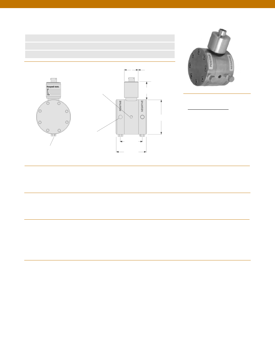
124
www.honeywell.com/sensotec
1-888-282-9891
Wiring Code
Connector/ Unamplified
A & B
(+) Excitation
C & D
(-) Excitation
E
(-) Output
F
(+) Output
Model TJE Ultra Precision Wet/ Wet Differential
Pressure Transducer
Order Code BD121
n
0.1% Accuracy
n
Bi-Directional
n
Amplified Output Available
Bleed Port 1/8-27 NPT
2 each
Pressure Port
1/8-27 NPT 2 each
Mounting Holes
1/4-28 UNF x 5/16 DP.
Typ. each side
2.5 in.
ø3.00 in.
ø1.50 in.
1.4 in.
1.75 in.
Pressure Ranges
Accuracy
Output (standard)
Line Pressure
Resolution
Temperature, Operating
Temperature, Compensated
Temperature, Effect
Zero
Span
Strain Gage Type
Excitation (calibration)
Excitation (acceptable)
Insulation Resistance
Bridge Resistance
Shunt Calibration Data
Electrical Termination (std)
Mating Connector (not incl.)
Media
Overload-Safe
Pressure Port
Dead Volume
Wetted Parts Material
Weight
Case Material
Note: Unless otherwise specified on order, amplified units with 4-20 mA output will provide 4 mA at 0 psid and 20 mA at positive full scale and the
unit will not operate in the negative direction. An available alternative is to specify 4 mA at negative full scale and 20 mA at positive full scale. All
amps add 2 in. to housing.
........50; 75; 100; 150; 200; 300; 500; 750 psid
........+/- 0.1% Full Scale
........2 mV/V (nominal)
........1500 psi
........Infinite
........-65° to 250°F
........60° to 160°F
........+/- 0.25% Full scale/ 100 °F
........+/- 0.25% Reading/ 100 °F
........Bonded Foil
........10 VDC
........UP to 10 VDC or AC
........10,000 Megohms @ 50 VDC
........350 Ohms
........Included
........PTIH-10-6P or equivalent (Hermetic stainless)
........PT06A-10-6S or equivalent
........Gas, Liquid
........1500 psi
........1/8-27 NPT Female (2)
........0.25 cu. in.
........17-4 PH Stainless Steel
........5.0 lb.
........Stainless Steel
Dimensions
Performance
Environmental
Electrical
Mechanical
Courtesy of Steven Engineering, Inc.-230 Ryan Way, South San Francisco, CA 94080-6370-Main Office: (650) 588-9200-Outside Local Area: (800) 258-9200-www.stevenengineering.com
Sensotec Sensors Full Line Catalog-html.html

125
www.honeywell.com/sensotec
1-888-282-9891
Range
Range Code
50 psid
BN
75 psid
BP
100 psid
BR
150 psid
CJ
200 psid
CL
300 psid CP
500 psid
CR
750 psid
CT
Range Codes
Internal Amplifiers
Model TJE
In-Line Amplifiers
(Used with unamplified units only)
Amplifier
Output
Universal In-Line Amplifiers
UV
+/- 5 VDC
UV-10
+/- 10 VDC
UBP
0 +/- 5 VDC
U3W
4-20 mA (3 wire)
DIN rail Mount In-Line Amplifiers
DV-05
0 +/- 5 VDC (3 wire)
DA-05
4-20 mA (3 wire)
DV-10
0 +/- 10 VDC (3 wire)
Customer Supplied
Chart Recorder
Alarm Panel
Data Acquisition
Computer
PLC
Display Units
SC500
SC1000
SC2001
SC3004
GM (Unamplified only)
GM-A (Some amplified, see GM-A data sheet)
NK (Unamplified only)
HH (Unamplified only)
Mating Connectors & Cables
AA111 Mating Connector
AA112 Mating Connector & 6 conductor cable
(Unamplified unit with sense leads but not shunt Cal)
AA 113 Mating Connector & 4 conductor cable
(Unamplified unit with sense leads but not shunt Cal)
AA 115 Mating connector and 5 conductor cable for 2c, 2j
or 2t amplified output
AA 116 Mating connector and 3 conductor cable for 2k or
2n(2N) amplified outpu
t
Adaptors compatible
with 1/8-27 NPT
Female
For long cable runs or electrically noisy environments an
amplified sensor or locally mounted amplifier is often preferred.
Model TJE
Typical System Diagram
Amplifier Specifications
Voltage Output
Option 2b
Voltage Output
Option 2c
Voltage Output
Option 2t
Current 3 Wire
Option 2j
Current 2 Wire
Option 2k
Intrinsically Safe
Option 2n (2N)***
Output Signal
Input Power (Voltage)
Input Power (Current)
Frequency Response (amp)
Power Supply Rejection
Operating Temperature
Reverse Voltage Protection
Short Circuit Protection
+/- 5V
+/-15V or 26-32 VDC
45 mA
3000 Hz
60 db
-20° to 185° F
Yes
Momentary
0-5V or +/- 5V @ 5mA
11-28 VDC
40 mA
3000 Hz
60 db
-20° to 185° F
Yes
Momentary
0-10V or +/- 10V @ 5mA
15-28 VDC
40 mA
3000 Hz
60 db
-20° to 185° F
Yes
Momentary
4-20 mA
22-32 VDC
65 mA
2500 Hz
60 db
0° to 185° F
Yes
Yes
4-20 mA
9-32 VDC
4-28 mA
300 Hz
60 db
0° to 185° F
Yes
Yes
4-20 mA
9-28 VDC
4-24 mA
2000 Hz
60 db
-20° to 185° F
Yes
Yes
Wiring Code: Connector
(Std.)
(note 2)
A (+) Supply
B Output Common/
C Supply Return
D (+) Output
E Shunt Cal 1
F Shunt Cal 2
A (+) Supply
B** Output Common/
C** Supply Return
D (+) Output
E Shunt Cal 1
F Shunt Cal 2
A (+) Supply
B** Output Common/
C** Supply Return
D (+) Output
E Shunt Cal 1
F Shunt Cal 2
A (+) Supply
B** Output Common/
C** Supply Return
D (+) Output
E Shunt Cal 1
F Shunt Cal 2
A (+) Supply
B No connection
C No connection
D (+) Output
E Case Ground
F No connection
A (+) Supply
B No connection
C No connection
D (+) Output
E Case Ground
F No connection
Wiring Code: Cable
(note 2)
(note 3)
(note 4)
R (+) Supply
Bl Output Common/
G Supply Return
W (+) Output
B Shunt Cal 1
Br Shunt Cal 2
R (+) Supply
Bl*Output Common/
G*Supply Return
W (+) Output
B Shunt Cal 1
Br Shunt Cal 2
R (+) Supply
Bl*Output Common/
G*Supply Return
W (+) Output
B Shunt Cal 1
Br Shunt Cal 2
R (+) Supply
Bl*Output Common/
G*Supply Return
W (+) Output
B Shunt Cal 1
Br Shunt Cal 2
R (+) Supply
Bl (+) Output
W Case Ground
R (+) Supply
Bl (+) Output
W Case Ground
* Black and Green wires are internally connected.
** Pins B and C are internally connected.
*** See Sensotec website for most up-to-date information regarding Intrinsically Safe approvals ref. #008-0547-00.
Courtesy of Steven Engineering, Inc.-230 Ryan Way, South San Francisco, CA 94080-6370-Main Office: (650) 588-9200-Outside Local Area: (800) 258-9200-www.stevenengineering.com
Sensotec Sensors Full Line Catalog-html.html
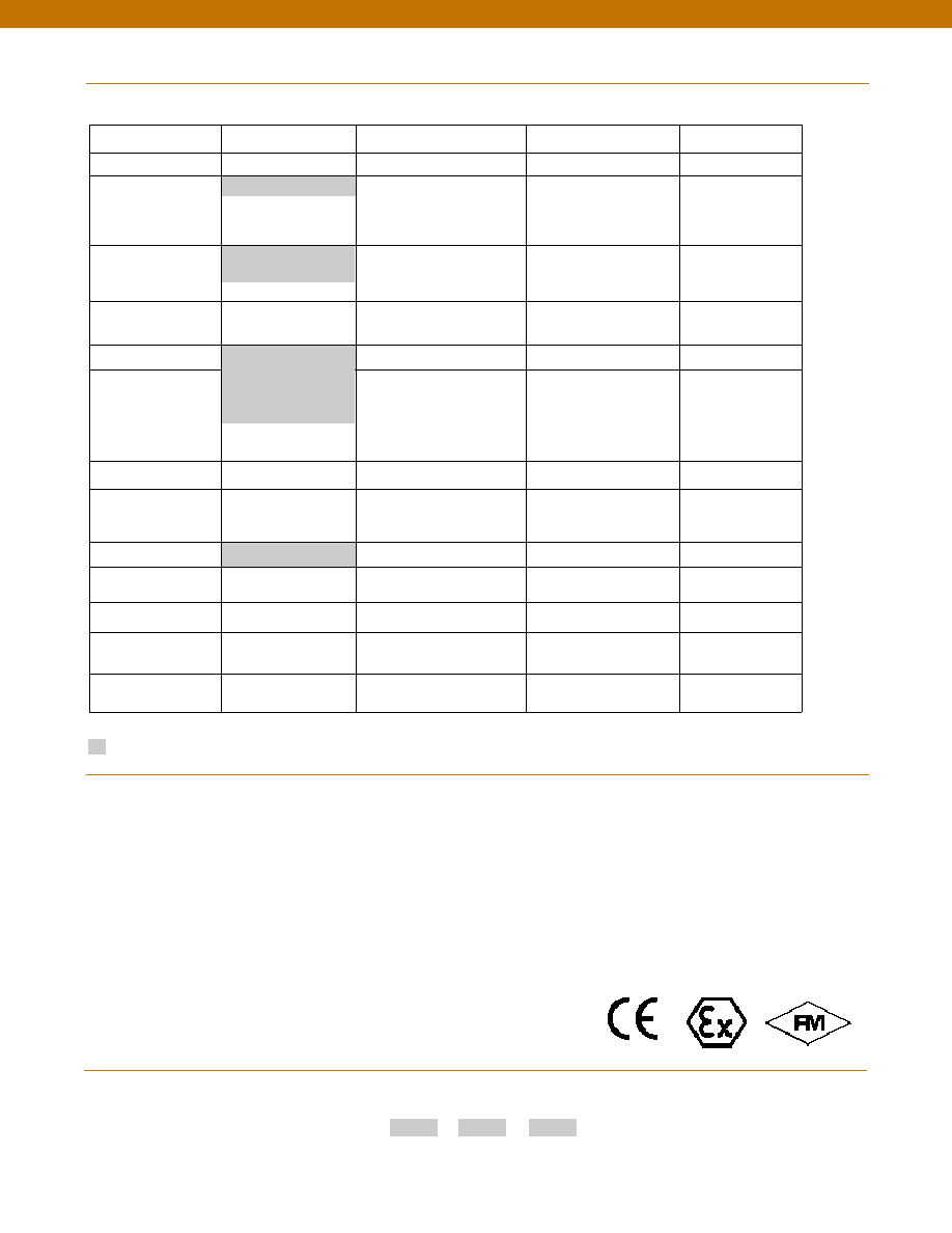
126
Options
www.honeywell.com/sensotec
1-888-282-9891
How to Order
Combine the order code, the range code and the options code.
Order Code
Range Code
Options Code
Sample Code: BD121
CR
6h
Model TJE
Same Day Ship
Fast track manufacture
Build to Order
Build from scratch
Pressure Ranges (psid) 50, 100, 200, 500
75, 150, 300, 750
Temperature
Compensation
1b. 30° to 130° F
1c. 0° to 185° F
1f.
70° to 250° F
1j.
0° to 50° C
1d. -20° to 130° F
1e. -20° to 200° F
1i.
-65° to 250° F
1m. -25° to 110° C
1g. 70° to 325° F
1h. 70° to 400° F
Internal Amplifiers
2b. 4 wire +/-5VDC
2c. 0-5VDC
2t.
0-10VDC
2j.
4-20mA (3 wire) output
2k. 4-20mA(2-wire) output
2n(2N). 4-20mA (2-wire)
intrinsically safe
Internal Amp
Enhancements
3d. Remote Buffered Shunt
Calibration
3a. Input/ Output Isolation
(note 8)
Pressure Ports (note 5)
5h. 1/8-27 NPT Female
5c. 7/16” - 20 UNF Female
(per MS33656E4)
Electrical Termination
6e. Integral cable: Teflon
(-54° to 245° C)
6f.
Integral cable: PVC
(-30° to 70° C)
6i.
Integral underwater cable
(8m) (max 80° C) (note 1)
6j.
1/2-14 conduit fitting with
5 ft. 4 conductor PVC cable
6b. MS type connector
(note 1)
6g. Integral cable: Neoprene
(-20 to 80° C) (note 1)
6h. Integral cable: Silicone
(-54 to 150° C)
Shunt Calibration
8a. Precision Internal Resistor
(note 7)
Special Calibration
9a. 10 point (5 up/5 down)
20% increments @ 20° C
9b. 20 point (10 up/10 down)
10% increments @ 20° C
Wetted Diaphragm
17-4 PH Stainless Steel
10a. 316 Stainless Steel
Bridge Type
11a. Square bridge
11b. Symmetrical bridge
11c. Square & symmetrical bridge
Potentiometers
14a. No access to pots
14b. Top access to pots (note 6)
O Ring Seals
26a. Metal
26b. Vi-Ton
26c. Teflon
Interfaces
53e. Signature Calibration
53t. T.E.D.S. IEEE 1451.4
Module (note 9)
Supplied as standard
2u. Unamplified, mV/V
output
1a. 60° to 160° F
6a. Bendix PTIH-10-6P
(or equivalent) 6 pin
(max. 250°F)
Pressure Port adaptors
Mating connectors and cables
Special Customer
Requirements
(Consult Factory)
Notes
1. Availability varies according to range.
2. Interconnecting shunt cal. 1 terminal with shunt cal. 2 terminal provides 50% (unamplified units), 75%
(4-20mA 3-wire units) or 80% (voltage amplified units) of full scale output for quick calibration. Shunt
Calibration comes standard with internal amplifier options 2b, 2c, 2t and 2j.
3. O=Orange; Y=Yellow; B=Blue; Bl=Black; R=Red; Br=Brown; W=White; G=Green. Color specifying
cable and number or letter specifying connector.
4. No mating connector necessary for cable option.
5. Some pressure port options may require axial orientation.
6. Only available with unamplified option 2u.
7. Only available with amplified options.
8. Only available with VDC output options 2b, 2c.
9. Consult factory for TEDS availability with amplified models.
Courtesy of Steven Engineering, Inc.-230 Ryan Way, South San Francisco, CA 94080-6370-Main Office: (650) 588-9200-Outside Local Area: (800) 258-9200-www.stevenengineering.com
Sensotec Sensors Full Line Catalog-html.html
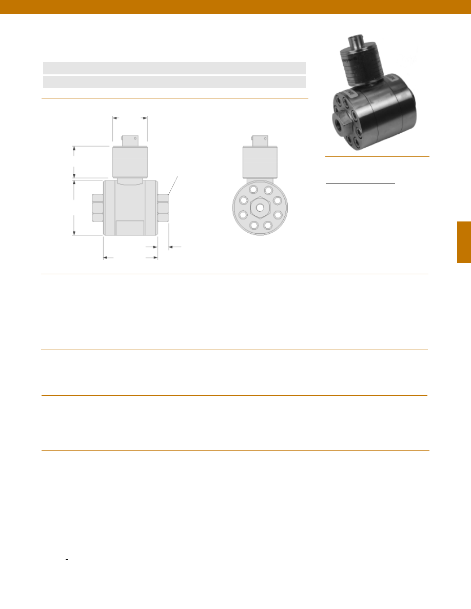
127
www.honeywell.com/sensotec
1-888-282-9891
Wiring Code
Connector/ Unamplified
A & B
(+) Excitation
C & D
(-) Excitation
E
(-) Output
F
(+) Output
Model HL-A-5 High Line Wet/ Wet Differential
Pressure Transducer
Order Code BD512
n
Line Pressure to 5000 psi
n
0.5% Accuracy
Pressure Ranges
Accuracy
Linearity
Hysteresis
Non-Repeatability
Output (standard)
Line Pressure
Resolution
Temperature, Operating
Temperature, Compensated
Temperature, Effect
Zero
Span
Strain Gage Type
Excitation (calibration)
Bridge Resistance
Shunt Calibration Data
Electrical Termination (std)
Mating Connector (not incl.)
Media
Overload-Safe
50 to 1500 psid
2000 to 7500 psid
Pressure Port
Wetted Parts Material
Case Material
........50; 75; 100; 150; 200; 300; 500; 750; 1000; 1500; 2000;
3000; 5000; 7500* psid
........+/- 0.5% Full Scale
........+/- 0.25% Full Scale (typical)
........+/- 0.13% Full Scale (typical)
........+/- 0.07% Full Scale (typical)
........2 mV/V (nominal)
........2500 psi**
........Infinite
........-65° to 250°F
........60° to 160°F
........+/- 0.75% Full scale/ 100 °F
........+/- 1% Reading/ 100 °F
........Bonded Foil
........10 VDC
........350 Ohms
........Included
........PTIH-10-6P or equivalent (Hermetic stainless)
........PT06A-10-6S or equivalent
........Gas, Liquid
........2000 psi
........Full Scale capacity + 2000 psi
........1/4-18 NPT female
........17-4 PH Stainless Steel
........Stainless Steel
Note: Unless otherwise specified on order, amplified units with 4-20 mA output will provide 4 mA at 0 psid and 20 mA at positive full scale and the
unit will not operate in the negative direction. An available alternative is to specify 4 mA at negative full scale and 20 mA at positive full scale. All
amps add 2 in. to amplifier housing.
Pressure Port
1/4-18 NPT Typ.
2.5 in.
ø2.50 in.
ø1.50 in.
1.4 in.
0.4 in. (typical)
* Not available with FM approval
** On units > 200 psid the sum of full scale pressure and line pressure must be <= 9500 psi; on units < 200 psid consult factory
Dimensions
Performance
Environmental
Electrical
Mechanical
Courtesy of Steven Engineering, Inc.-230 Ryan Way, South San Francisco, CA 94080-6370-Main Office: (650) 588-9200-Outside Local Area: (800) 258-9200-www.stevenengineering.com
Sensotec Sensors Full Line Catalog-html.html
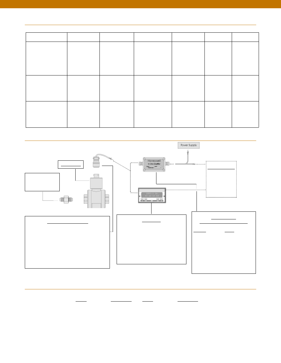
128
www.honeywell.com/sensotec
1-888-282-9891
Range
Range Code
50 psid
BN
75 psid
BP
100 psid
BR
150 psid
CJ
200 psid
CL
300 psid
CP
500 psid
CR
Range Codes
Model HL-A-5
Range
Range Code
750 psid
CT
1000 psid
CV
1500 psid
DJ
2000 psid
DL
3000 psid
DN
5000 psid
DR
7500 psid
DT
In-Line Amplifiers
(Used with unamplified units only)
Amplifier
Output
Universal In-Line Amplifiers
UV
+/- 5 VDC
UV-10
+/- 10 VDC
UBP
0 +/- 5 VDC
U3W
4-20 mA (3 wire)
DIN rail Mount In-Line Amplifiers
DV-05
0 +/- 5 VDC (3 wire)
DA-05
4-20 mA (3 wire)
DV-10
0 +/- 10 VDC (3 wire)
Customer Supplied
Chart Recorder
Alarm Panel
Data Acquisition
Computer
PLC
Display Units
SC500
SC1000
SC2001
SC3004
GM (Unamplified only)
GM-A (Some amplified, see GM-A data sheet)
NK (Unamplified only)
HH (Unamplified only)
Mating Connectors & Cables
AA111 Mating Connector
AA112 Mating Connector & 6 conductor cable
(Unamplified unit with sense leads but not shunt Cal)
AA 113 Mating Connector & 4 conductor cable
(Unamplified unit with sense leads but not shunt Cal)
AA 115 Mating connector and 5 conductor cable for 2c, 2j
or 2t amplified output
AA 116 Mating connector and 3 conductor cable for 2k or
2n(2N) amplified outpu
t
Adaptors compatible
with 1/4-18 NPT
Female
For long cable runs or electrically noisy environments an
amplified sensor or locally mounted amplifier is often preferred.
Model HL-A-5
Internal Amplifiers
Typical System Diagram
Amplifier Specifications
Voltage Output
Option 2b
Voltage Output
Option 2c
Voltage Output
Option 2t
Current 3 Wire
Option 2j
Current 2 Wire
Option 2k
Intrinsically Safe
Option 2n (2N)***
Output Signal
Input Power (Voltage)
Input Power (Current)
Frequency Response (amp)
Power Supply Rejection
Operating Temperature
Reverse Voltage Protection
Short Circuit Protection
+/- 5V
+/-15V or 26-32 VDC
45 mA
3000 Hz
60 db
-20° to 185° F
Yes
Momentary
0-5V or +/- 5V @ 5mA
11-28 VDC
40 mA
3000 Hz
60 db
-20° to 185° F
Yes
Momentary
0-10V or +/- 10V @ 5mA
15-28 VDC
40 mA
3000 Hz
60 db
-20° to 185° F
Yes
Momentary
4-20 mA
22-32 VDC
65 mA
2500 Hz
60 db
0° to 185° F
Yes
Yes
4-20 mA
9-32 VDC
4-28 mA
300 Hz
60 db
0° to 185° F
Yes
Yes
4-20 mA
9-28 VDC
4-24 mA
2000 Hz
60 db
-20° to 185° F
Yes
Yes
Wiring Code: Connector
(Std.)
(note 2)
A (+) Supply
B Output Common/
C Supply Return
D (+) Output
E Shunt Cal 1
F Shunt Cal 2
A (+) Supply
B** Output Common/
C** Supply Return
D (+) Output
E Shunt Cal 1
F Shunt Cal 2
A (+) Supply
B** Output Common/
C** Supply Return
D (+) Output
E Shunt Cal 1
F Shunt Cal 2
A (+) Supply
B** Output Common/
C** Supply Return
D (+) Output
E Shunt Cal 1
F Shunt Cal 2
A (+) Supply
B No connection
C No connection
D (+) Output
E Case Ground
F No connection
A (+) Supply
B No connection
C No connection
D (+) Output
E Case Ground
F No connection
Wiring Code: Cable
(note 2)
(note 3)
(note 4)
R (+) Supply
Bl Output Common/
G Supply Return
W (+) Output
B Shunt Cal 1
Br Shunt Cal 2
R (+) Supply
Bl*Output Common/
G*Supply Return
W (+) Output
B Shunt Cal 1
Br Shunt Cal 2
R (+) Supply
Bl*Output Common/
G*Supply Return
W (+) Output
B Shunt Cal 1
Br Shunt Cal 2
R (+) Supply
Bl*Output Common/
G*Supply Return
W (+) Output
B Shunt Cal 1
Br Shunt Cal 2
R (+) Supply
Bl (+) Output
W Case Ground
R (+) Supply
Bl (+) Output
W Case Ground
* Black and Green wires are internally connected.
** Pins B and C are internally connected.
*** See Sensotec website for most up-to-date information regarding Intrinsically Safe approvals ref. #008-0547-00.
Courtesy of Steven Engineering, Inc.-230 Ryan Way, South San Francisco, CA 94080-6370-Main Office: (650) 588-9200-Outside Local Area: (800) 258-9200-www.stevenengineering.com
Sensotec Sensors Full Line Catalog-html.html
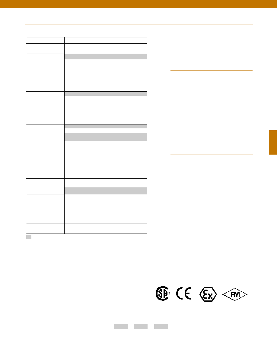
129
www.honeywell.com/sensotec
1-888-282-9891
How to Order
Combine the order code, the range code and the options code.
Order Code
Range Code
Options Code
Sample Code: BD512
CV
6h
Model HL-A-5
Options
Approved Approved Approved
Intrinsically Safe Amp
Pressure Port adaptors
Mating connectors and cables
Wetted material
Special Customer Requirements
(Consult Factory)
Build from Scratch
Pressure Ranges (psid)
50, 75, 100, 150, 200, 300, 500, 750, 1000,
1500, 3000, 5000, 7500
Temperature
Compensation
1b. 30° to 130° F
1c. 0° to 185° F
1d. -20° to 130° F
1e. -20° to 200° F
1f.
70° to 250° F
1i.
-65° to 250° F
1j.
0° to 50° C
1m. -25° to 110° C
Internal Amplifiers
2b. 4 wire +/-5VDC
2c. 0-5VDC
2t.
0-10VDC
2j.
4-20mA (3 wire) output
2k. 4-20mA(2-wire) output
2n(2N). 4-20mA (2-wire) intrinsically safe
Internal Amp
Enhancements
3a. Input/ Output Isolation (note 7)
3d. Remote Buffered Shunt Calibration
Pressure Ports (note 5)
5c. 7/16” - 20 UNF Female (per MS33656E4)
Electrical Termination
6b. MS type connector (note 1)
6e. Integral cable: Teflon (-54° to 245° C)
6f.
Integral cable: PVC (-30° to 70° C)
6g. Integral cable: Neoprene (-20 to 80° C) (note 1)
6h. Integral cable: Silicone (-54 to 150° C)
6i.
Integral underwater cable(8m) (max 80° C) (note 1)
6j.
1/2-14 conduit fitting with 5 ft. 4 conductor PVC cable
Shunt Calibration
8a. Precision Internal Resistor (note 6)
Special Calibration
9a. 10 point (5 up/5 down) 20% increments @ 20° C
9b. 20 point (10 up/10 down) 10% increments @ 20° C
Wetted Diaphragm
17-4 PH Stainless Steel
Bridge Type
11a. Square bridge
11b. Symmetrical bridge
11c. Square & symmetrical bridge
Potentiometers
14b. Top access to pots (note 8)
14a. No access to pots
Increased Line Pressure
25b. 3000 psi line pressure
25c. 5000 psi line pressure
Interfaces
53e. Signature Calibration
53t. T.E.D.S. IEEE 1451.4 Module (note 9)
Supplied as standard
1a. 60° to 160° F
2u. Unamplified, mV/V output
6a. Bendix PTIH-10-6P (or equivalent)
6 pin (max. 250°F)
1. Availability varies according to range
2. Interconnecting shunt cal. 1 terminal with shunt cal. 2 terminal
provides 50% (unamplified units), 75% (4-20mA 3-wire units)
or 80% (voltage amplified units) of full scale output for quick
calibration. Shunt Calibration comes standard with internal
amplifier options 2b, 2c, 2t and 2j.
3. O=Orange; Y=Yellow; B=Blue; Bl=Black;R=Red; Br=Brown;
W=White; G=Green. Color specifying cable and number or
letter specifying connector.
4. No mating connector necessary for cable option.
5. Some pressure port options may require axial orientation.
6. Only available with unamplified option 2u.
7. Only available with VDC output options 2b, 2c.
8. Only available on amplified units.
9. Consult factory for TEDS availability with amplified models.
Notes
5a. 1/4-18 NPT Female
Courtesy of Steven Engineering, Inc.-230 Ryan Way, South San Francisco, CA 94080-6370-Main Office: (650) 588-9200-Outside Local Area: (800) 258-9200-www.stevenengineering.com
Sensotec Sensors Full Line Catalog-html.html
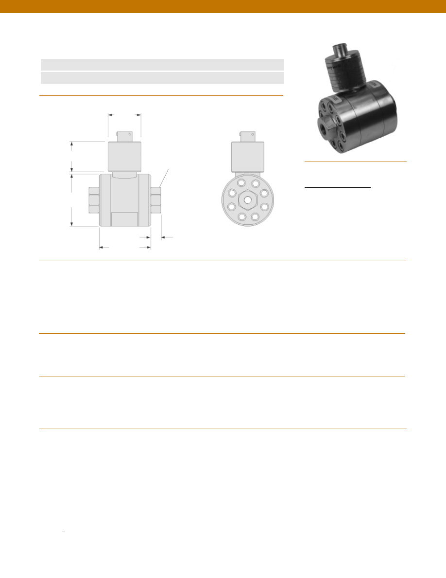
130
www.honeywell.com/sensotec
1-888-282-9891
Wiring Code
Connector/ Unamplified
A & B
(+) Excitation
C & D
(-) Excitation
E
(-) Output
F
(+) Output
Model HL-Z High Line Wet/ Wet Differential
Pressure Transducer
Order Code BD511
n
Line Pressure to 5000 psi
n
0.25% Accuracy
Pressure Ranges
Accuracy
Linearity
Hysteresis
Non-Repeatability
Output (standard)
Line Pressure
Resolution
Temperature, Operating
Temperature, Compensated
Temperature, Effect
Zero
Span
Strain Gage Type
Excitation (calibration)
Bridge Resistance
Shunt Calibration Data
Electrical Termination (std)
Mating Connector (not incl.)
Media
Overload-Safe
50 to 1500 psid
2000 to 7500 psid
Pressure Port
Wetted Parts Material
Case Material
........50; 75; 100; 150; 200; 300; 500; 750; 1000; 1500; 2000;
3000; 5000; 7500* psid
........+/- 0.25% Full Scale
........+/- 0.15% Full Scale (typical)
........+/- 0.10% Full Scale (typical)
........+/- 0.05% Full Scale (typical)
........2 mV/V (nominal)
........2500 psi**
........Infinite
........-65° to 250°F
........60° to 160°F
........+/- 0.5% Full scale/ 100 °F
........+/- 0.5% Reading/ 100 °F
........Bonded Foil
........10 VDC
........350 Ohms
........Included
........PTIH-10-6P or equivalent (Hermetic stainless)
........PT06A-10-6S or equivalent
........Gas, Liquid
........2000 psi
........Full Scale capacity + 2000 psi
........1/4-18 NPT female (2)
........17-4 PH Stainless Steel
........Stainless Steel
Note: Unless otherwise specified on order, amplified units with 4-20 mA output will provide 4 mA at 0 psid and 20 mA at positive full scale and the
unit will not operate in the negative direction. An available alternative is to specify 4 mA at negative full scale and 20 mA at positive full scale. All
amps add 2 in. to amplifier housing.
Pressure Port
1/4-18 NPT Typ.
2.5 in.
ø2.50 in.
ø1.50 in.
1.4 in.
0.4 in. (typical)
* Not available with FM approval
** On units > 200 psid the sum of full scale pressure and line pressure must be <= 9500 psi; on units < 200 psid consult factory
Dimensions
Performance
Environmental
Electrical
Mechanical
Courtesy of Steven Engineering, Inc.-230 Ryan Way, South San Francisco, CA 94080-6370-Main Office: (650) 588-9200-Outside Local Area: (800) 258-9200-www.stevenengineering.com
Sensotec Sensors Full Line Catalog-html.html

131
In-Line Amplifiers
(Used with unamplified units only)
Amplifier
Output
Universal In-Line Amplifiers
UV
+/- 5 VDC
UV-10
+/- 10 VDC
UBP
0 +/- 5 VDC
U3W
4-20 mA (3 wire)
DIN rail Mount In-Line Amplifiers
DV-05
0 +/- 5 VDC (3 wire)
DA-05
4-20 mA (3 wire)
DV-10
0 +/- 10 VDC (3 wire)
Customer Supplied
Chart Recorder
Alarm Panel
Data Acquisition
Computer
PLC
Display Units
SC500
SC1000
SC2001
SC3004
GM (Unamplified only)
GM-A (Some amplified, see GM-A data sheet)
NK (Unamplified only)
HH (Unamplified only)
Mating Connectors & Cables
AA111 Mating Connector
AA112 Mating Connector & 6 conductor cable
(Unamplified unit with sense leads but not shunt Cal)
AA 113 Mating Connector & 4 conductor cable
(Unamplified unit with sense leads but not shunt Cal)
AA 115 Mating connector and 5 conductor cable for 2c, 2j
or 2t amplified output
AA 116 Mating connector and 3 conductor cable for 2k or
2n(2N) amplified outpu
t
Adaptors compatible
with 1/4-18 NPT
Female
For long cable runs or electrically noisy environments an
amplified sensor or locally mounted amplifier is often preferred.
Model HL-Z
www.honeywell.com/sensotec
1-888-282-9891
Model HL-Z
Range
Range Code
50 psid
BN
75 psid
BP
100 psid
BR
150 psid
CJ
200 psid
CL
300 psid
CP
500 psid
CR
Range Codes
Internal Amplifiers
Typical System Diagram
Range
Range Code
750 psid
CT
1000 psid
CV
1500 psid
DJ
2000 psid
DL
3000 psid
DN
5000 psid
DR
7500 psid
DT
Amplifier Specifications
Voltage Output
Option 2b
Voltage Output
Option 2c
Voltage Output
Option 2t
Current 3 Wire
Option 2j
Current 2 Wire
Option 2k
Intrinsically Safe
Option 2n (2N)***
Output Signal
Input Power (Voltage)
Input Power (Current)
Frequency Response (amp)
Power Supply Rejection
Operating Temperature
Reverse Voltage Protection
Short Circuit Protection
+/- 5V
+/-15V or 26-32 VDC
45 mA
3000 Hz
60 db
-20° to 185° F
Yes
Momentary
0-5V or +/- 5V @ 5mA
11-28 VDC
40 mA
3000 Hz
60 db
-20° to 185° F
Yes
Momentary
0-10V or +/- 10V @ 5mA
15-28 VDC
40 mA
3000 Hz
60 db
-20° to 185° F
Yes
Momentary
4-20 mA
22-32 VDC
65 mA
2500 Hz
60 db
0° to 185° F
Yes
Yes
4-20 mA
9-32 VDC
4-28 mA
300 Hz
60 db
0° to 185° F
Yes
Yes
4-20 mA
9-28 VDC
4-24 mA
2000 Hz
60 db
-20° to 185° F
Yes
Yes
Wiring Code: Connector
(Std.)
(note 2)
A (+) Supply
B Output Common/
C Supply Return
D (+) Output
E Shunt Cal 1
F Shunt Cal 2
A (+) Supply
B** Output Common/
C** Supply Return
D (+) Output
E Shunt Cal 1
F Shunt Cal 2
A (+) Supply
B** Output Common/
C** Supply Return
D (+) Output
E Shunt Cal 1
F Shunt Cal 2
A (+) Supply
B** Output Common/
C** Supply Return
D (+) Output
E Shunt Cal 1
F Shunt Cal 2
A (+) Supply
B No connection
C No connection
D (+) Output
E Case Ground
F No connection
A (+) Supply
B No connection
C No connection
D (+) Output
E Case Ground
F No connection
Wiring Code: Cable
(note 2)
(note 3)
(note 4)
R (+) Supply
Bl Output Common/
G Supply Return
W (+) Output
B Shunt Cal 1
Br Shunt Cal 2
R (+) Supply
Bl*Output Common/
G*Supply Return
W (+) Output
B Shunt Cal 1
Br Shunt Cal 2
R (+) Supply
Bl*Output Common/
G*Supply Return
W (+) Output
B Shunt Cal 1
Br Shunt Cal 2
R (+) Supply
Bl*Output Common/
G*Supply Return
W (+) Output
B Shunt Cal 1
Br Shunt Cal 2
R (+) Supply
Bl (+) Output
W Case Ground
R (+) Supply
Bl (+) Output
W Case Ground
* Black and Green wires are internally connected.
** Pins B and C are internally connected.
*** See Sensotec website for most up-to-date information regarding Intrinsically Safe approvals ref. #008-0547-00.
Courtesy of Steven Engineering, Inc.-230 Ryan Way, South San Francisco, CA 94080-6370-Main Office: (650) 588-9200-Outside Local Area: (800) 258-9200-www.stevenengineering.com
Sensotec Sensors Full Line Catalog-html.html
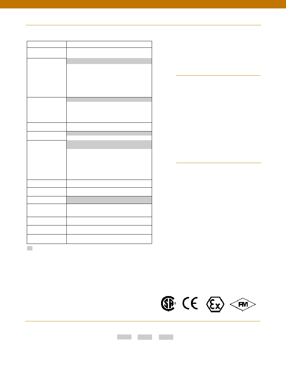
132
www.honeywell.com/sensotec
1-888-282-9891
How to Order
Combine the order code, the range code and the options code.
Order Code
Range Code
Options Code
Sample Code: BD511
CV
6h
Pressure Port adaptors
Mating connectors and cables
Wetted material
Special Customer Requirements
(Consult Factory)
Model HL-Z
Build from Scratch
Pressure Ranges (psid)
50, 75, 100, 150, 200, 300, 500, 750, 1000,
1500, 3000, 5000, 7500
Temperature
Compensation
1b. 30° to 130° F
1c. 0° to 185° F
1d. -20° to 130° F
1e. -20° to 200° F
1f.
70° to 250° F
1i.
-65° to 250° F
1j.
0° to 50° C
1m. -25° to 110° C
Internal Amplifiers
2b. 4 wire +/-5VDC
2c. 0-5VDC
2t.
0-10VDC
2j.
4-20mA (3 wire) output
2k. 4-20mA(2-wire) output
2n(2N). 4-20mA (2-wire) intrinsically safe
Internal Amp
Enhancements
3a. Input/ Output Isolation (note 7)
3d. Remote Buffered Shunt Calibration
Pressure Ports (note 5)
5c. 7/16” - 20 UNF Female (per MS33656E4)
Electrical Termination
6b. MS type connector (note 1)
6e. Integral cable: Teflon (-54° to 245° C)
6f.
Integral cable: PVC (-30° to 70° C)
6g. Integral cable: Neoprene (-20 to 80° C) (note 1)
6h. Integral cable: Silicone (-54 to 150° C)
6i.
Integral underwater cable(8m) (max 80° C) (note 1)
6j.
1/2-14 conduit fitting with 5 ft. 4 conductor PVC cable
Shunt Calibration
8a. Precision Internal Resistor (note 6)
Special Calibration
9a. 10 point (5 up/5 down) 20% increments @ 20° C
9b. 20 point (10 up/10 down) 10% increments @ 20° C
Wetted Diaphragm
17-4 PH Stainless Steel
Bridge Type
11a. Square bridge
11b. Symmetrical bridge
11c. Square & symmetrical bridge
Potentiometers
14b. Top access to pots (note 8)
14a. No access to pots
Increased Line Pressure
25b. 3000 psi line pressure
25c. 5000 psi line pressure
Interfaces
53e. Signature Calibration
53t. T.E.D.S. IEEE 1451.4 Module (note 9)
Supplied as standard
1a. 60° to 160° F
2u. Unamplified, mV/V output
6a. Bendix PTIH-10-6P (or equivalent)
6 pin (max. 250°F)
1. Availability varies according to range
2. Interconnecting shunt cal. 1 terminal with shunt cal. 2 terminal
provides 50% (unamplified units), 75% (4-20mA 3-wire units)
or 80% (voltage amplified units) of full scale output for quick
calibration. Shunt Calibration comes standard with internal
amplifier options 2b, 2c, 2t and 2j.
3. O=Orange; Y=Yellow; B=Blue; Bl=Black;R=Red; Br=Brown;
W=White; G=Green. Color specifying cable and number or
letter specifying connector.
4. No mating connector necessary for cable option.
5. Some pressure port options may require axial orientation.
6. Only available with unamplified option 2u.
7. Only available with VDC output options 2b, 2c.
8. Only available on amplified units.
9. Consult factory for TEDS availability with amplified models.
Notes
Options
Approved Approved Approved
Intrinsically Safe Amp
5a. 1/4-18 NPT Female
Courtesy of Steven Engineering, Inc.-230 Ryan Way, South San Francisco, CA 94080-6370-Main Office: (650) 588-9200-Outside Local Area: (800) 258-9200-www.stevenengineering.com
Sensotec Sensors Full Line Catalog-html.html
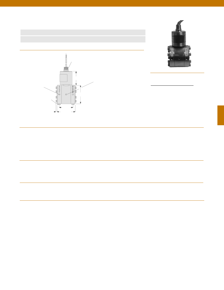
133
www.honeywell.com/sensotec
1-888-282-9891
Wiring Code
Cable/ 2 Wire Current/ 4-20 mA
Red
(+) Supply
Black
(+) Output (4-20 mA)
White
Case Ground
Model 911FMD FM Approved Low Range Wet/ Wet Differential
Pressure Transducer
Order Code BD421
n
Factory Mutual Approved
n
4-20 mA 2 Wire
Pressure Ranges
Accuracy
Linearity
Hysteresis
Non-Repeatability
Output (standard)
Maximum Line Pressure
Resolution
Temperature, Operating
Temperature, Compensated
Temperature, Effect
Zero
Span
Strain Gage Type
Excitation (calibration)
Shunt Calibration Data
Electrical Termination (std)
Media
Overload-Safe (either side)
Pressure Port
Wetted Parts Material
Case Material
........2; 5; 10; 15; 25 psid
........+/- 0.25% Full Scale
........+/- 0.15% Full Scale (typical)
........+/- 0.10% Full Scale (typical)
........+/- 0.05% Full Scale (typical)
........4-20 mA
........1500 psi
........Infinite
........0° to 180°F
........30° to 130°F
........+/- 1.2% Full scale/ 100 °F
........+/- 1.2% Reading/ 100 °F
........Bonded Foil
........15-50 VDC
........Included
........22 GA cable with case ground (2 ft.), 1/2-14 NPT
........Gas, Liquid
........1500 psi
........1/8-27 NPT female
........316 Stainless Steel
........Stainless Steel
Dimensions
Performance
Environmental
Electrical
Mechanical
Mounting Hole
1/4-28 NPT x 5/16” DP.
2 each
Bleed Port
1/8-27 NPT
2 each
Pressure Port
1/8-27 NPT 2 each
1/2-14 NPT
2.25 in.
3.0 in.
ø3.50 in.
2.5 in.
0.3 in.
(typical)
Courtesy of Steven Engineering, Inc.-230 Ryan Way, South San Francisco, CA 94080-6370-Main Office: (650) 588-9200-Outside Local Area: (800) 258-9200-www.stevenengineering.com
Sensotec Sensors Full Line Catalog-html.html
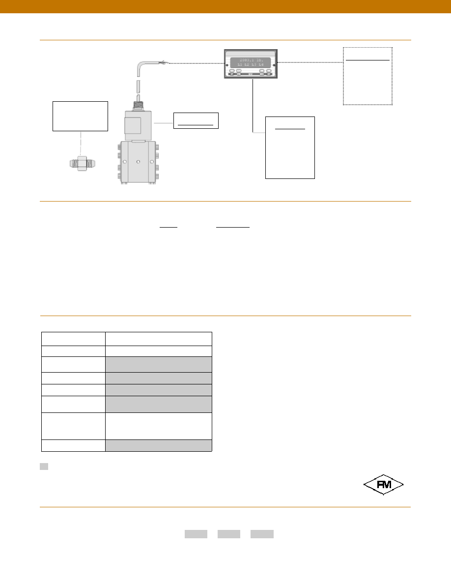
134
www.honeywell.com/sensotec
1-888-282-9891
Range
Range Code
2 psid
AR
5 psid
AT
10 psid
AV
15 psid
BJ
25 psid
BL
Customer Supplied
Chart Recorder
Alarm Panel
Data Acquisition
Computer
PLC
Display Units
SC500
SC1000
SC2001
SC3004
GM-A
Adaptors compatible
with 1/8-27 NPT
Female
Typical System Diagram
Range Codes
Build to Order
Pressure Ranges (psid)
2, 5, 10, 15, 25
Temperature
Compensation
1b. 30° to 130° F
Internal Amplifiers
2k. 4-20mA (2 wire)
Pressure Ports
5h. 1/8-27NPT Female
Electrical Termination
6j.
1/2-14 conduit fitting with 5 ft.
4 conductor PVC cable
Special Calibration
9a. 10 point (5 up/5 down) 20%
increments @ 20° C
9b. 20 point (10 up/10 down) 10%
increments @ 20° C
Wetted Diaphragm
10a. 316 Stainless Steel
Options
Supplied as standard
How to Order
Combine the order code, the range code and the options code.
Order Code
Range Code
Options Code
Sample Code: BD421
AV 9a
Model 911FMD
Model 911FMD
Courtesy of Steven Engineering, Inc.-230 Ryan Way, South San Francisco, CA 94080-6370-Main Office: (650) 588-9200-Outside Local Area: (800) 258-9200-www.stevenengineering.com
Sensotec Sensors Full Line Catalog-html.html
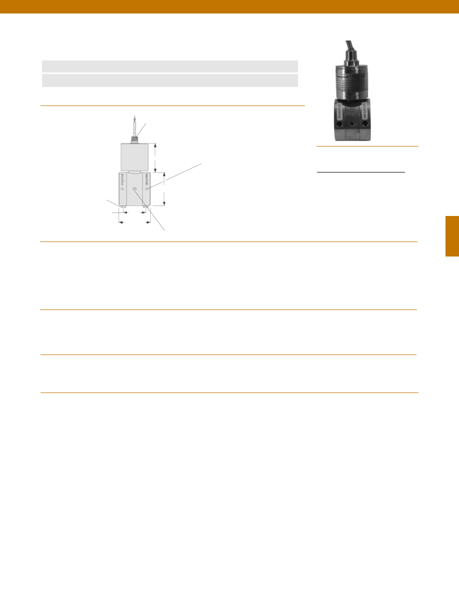
135
www.honeywell.com/sensotec
1-888-282-9891
Wiring Code
Cable/ 2 Wire Current/ 4-20 mA
Red
(+) Supply
Black
(+) Output (4-20 mA)
White
Case Ground
Model 911FMD FM Approved Mid Range Wet/ Wet Differential
Pressure Transducer
Order Code BD422
n
Factory Mutual Approved
n
4-20 mA 2 Wire
Pressure Ranges
Accuracy
Linearity
Hysteresis
Non-Repeatability
Output (standard)
Line Pressure
Resolution
Temperature, Operating
Temperature, Compensated
Temperature, Effect
Zero
Span
Strain Gage Type
Excitation (calibration)
Shunt Calibration Data
Electrical Termination (std)
Media
Overload-Safe (either side)
Pressure Port
Wetted Parts Material
Case Material
........50; 75; 100; 150; 200; 300; 500; 750 psid
........+/- 0.25% Full Scale
........+/- 0.15% Full Scale (typical)
........+/- 0.10% Full Scale (typical)
........+/- 0.05% Full Scale (typical)
........4-20 mA
........1500 psi
........Infinite
........0° to 180°F
........60° to 160°F
........+/- 1.2% Full scale/ 100 °F
........+/- 1.2% Reading/ 100 °F
........Bonded Foil
........15-50 VDC
........Included
........22 GA cable with case ground (2 ft.), 1/2-14 NPT
........Gas, Liquid
........1500 psi
........1/8-27 NPT female
........17-4 PH Stainless Steel
........Stainless Steel
Dimensions
Performance
Environmental
Electrical
Mechanical
Bleed Port
1/8-27 NPT
2 each
Mounting Hole
1/4-28 NPT x 5/16” DP.
Pressure Port
1/8-27 NPT 2 each
1/2-14 NPT
2.5 in.
1.75 in.
ø3.00 in.
2.5 in.
Courtesy of Steven Engineering, Inc.-230 Ryan Way, South San Francisco, CA 94080-6370-Main Office: (650) 588-9200-Outside Local Area: (800) 258-9200-www.stevenengineering.com
Sensotec Sensors Full Line Catalog-html.html
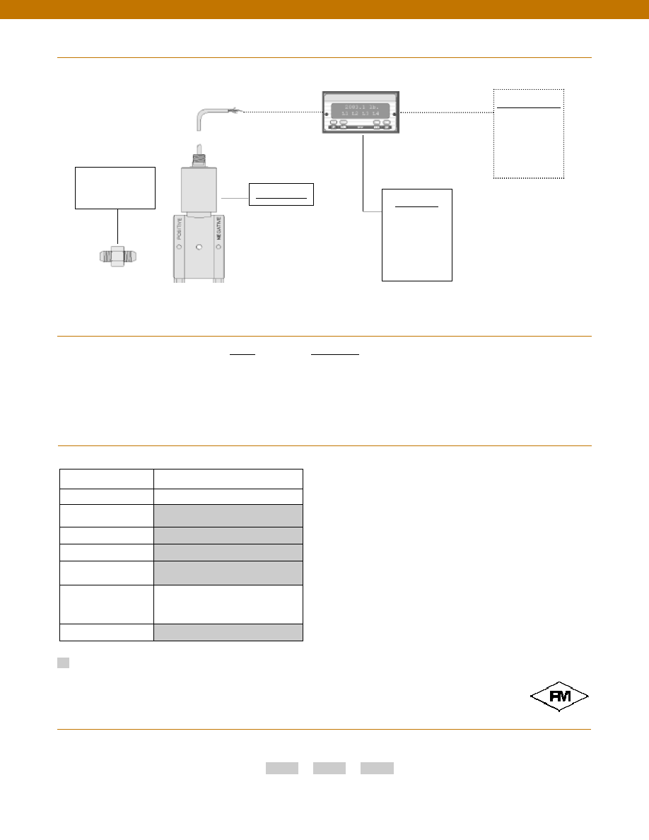
136
www.honeywell.com/sensotec
1-888-282-9891
Range
Range Code
50 psid
BN
75 psid
BP
100 psid
BR
150 psid
CJ
200 psid
CL
300 psid
CP
500 psid
CR
750 psid
CT
Typical System Diagram
Range Codes
Build to Order
Pressure Ranges (psid)
50, 75, 100, 150, 200, 300, 500, 750
Temperature
Compensation
1b. 30° to 130° F
Internal Amplifiers
2k. 4-20mA (2 wire)
Pressure Ports
5h. 1/8-27NPT Female (2)
Electrical Termination
6j.
1/2-14 conduit fitting with 5 ft.
4 conductor PVC cable
Special Calibration
9a. 10 point (5 up/5 down) 20%
increments @ 20° C
9b. 20 point (10 up/10 down) 10%
increments @ 20° C
Wetted Diaphragm
17-4 PH Stainless Steel
Options
Supplied as standard
How to Order
Combine the order code, the range code and the options code.
Order Code
Range Code
Options Code
Sample Code: BD422
CT
9a
Model 911FMD
Customer Supplied
Chart Recorder
Alarm Panel
Data Acquisition
Computer
PLC
Display Units
SC500
SC1000
SC2001
SC3004
GM-A
Adaptors compatible
with 1/8-27 NPT
Female
Model 911FMD
Approved
Explosion Proof
Courtesy of Steven Engineering, Inc.-230 Ryan Way, South San Francisco, CA 94080-6370-Main Office: (650) 588-9200-Outside Local Area: (800) 258-9200-www.stevenengineering.com
Sensotec Sensors Full Line Catalog-html.html
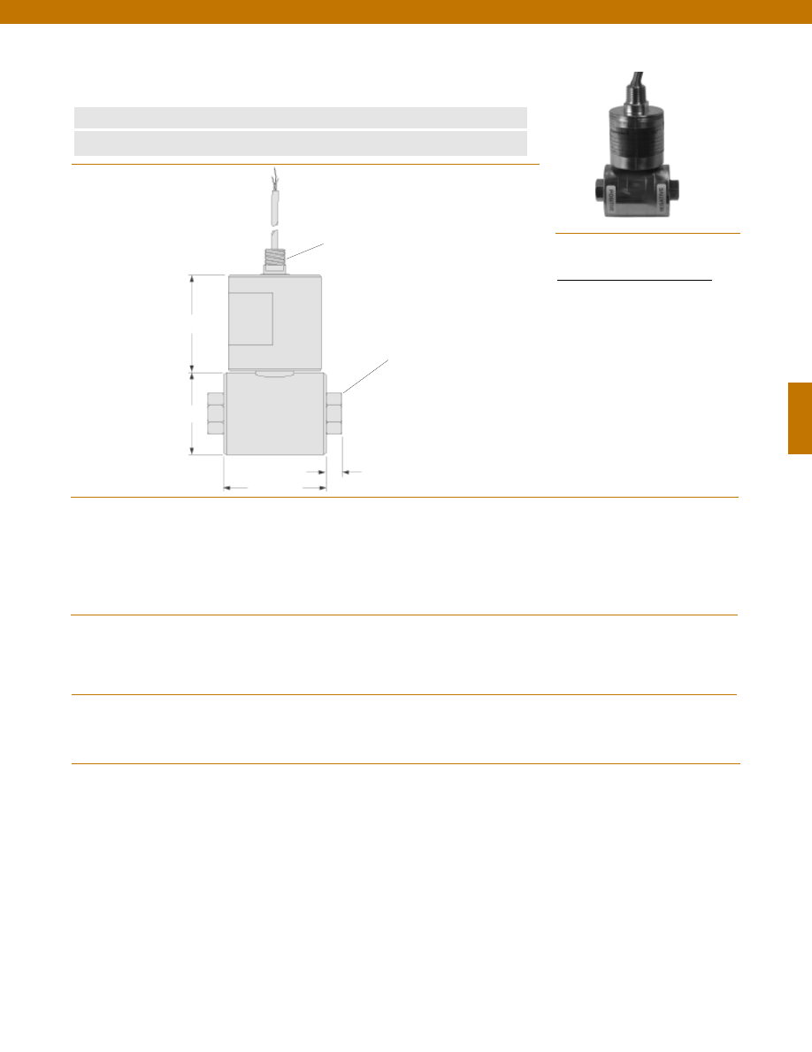
137
www.honeywell.com/sensotec
1-888-282-9891
Wiring Code
Cable/ 2 Wire Current/ 4-20 mA
Red
(+) Supply
Black
(+) Output (4-20 mA)
White
Case Ground
Model 911FMD FM Approved High Range Wet/ Wet Differential
Pressure Transducer
Order Code BD423
n
Factory Mutual Approved
n
4-20 mA 2 Wire
........1000; 2000; 3000; 5000; 7500; 10,000 psid
........+/- 0.25% Full Scale
........+/- 0.15% Full Scale (typical)
........+/- 0.10% Full Scale (typical)
........+/- 0.05% Full Scale (typical)
........4-20 mA
........Full Scale Capacity + 2000 psi
........Infinite
........0° to 180°F
........60° to 160°F
........+/- 1.2% Full scale/ 100 °F
........+/- 1.2% Reading/ 100 °F
........Bonded Foil
........15-50 VDC
........Included
........22 GA cable with case ground (2 ft.), 1/2-14 NPT
........Liquid
........100% over capacity
........50% over capacity
........1/4-18 NPT Female (2)
........17-4 PH Stainless Steel
........Stainless Steel
Dimensions
Performance
Environmental
Electrical
Mechanical
1/2-14 NPT
Pressure Port
1/4-18 NPT 2 each
ø2.25 in.
2.5 in.
2.7 in.
0.4 in. (typical)
Pressure Ranges
Accuracy
Linearity
Hysteresis
Non-Repeatability
Output (standard)
Maximum Line Pressure
Resolution
Temperature, Operating
Temperature, Compensated
Temperature, Effect
Zero
Span
Strain Gage Type
Excitation (calibration)
Shunt Calibration Data
Electrical Termination (std)
Media
Overload-Safe (either side)
1000 to 3000 psid
5000 to 10,000 psid
Pressure Port
Wetted Parts Material
Case Material
Courtesy of Steven Engineering, Inc.-230 Ryan Way, South San Francisco, CA 94080-6370-Main Office: (650) 588-9200-Outside Local Area: (800) 258-9200-www.stevenengineering.com
Sensotec Sensors Full Line Catalog-html.html
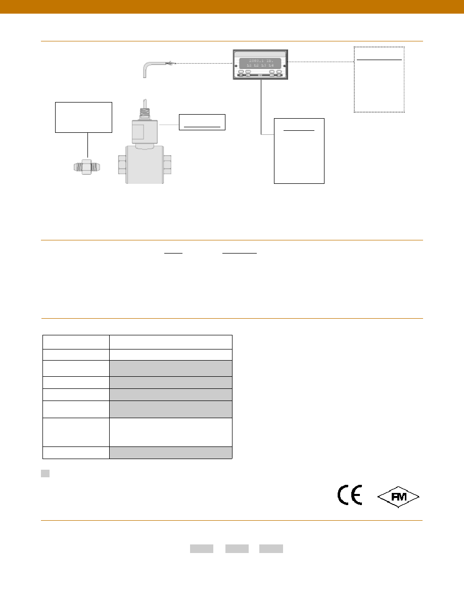
138
Customer Supplied
Chart Recorder
Alarm Panel
Data Acquisition
Computer
PLC
Display Units
SC500
SC1000
SC2001
SC3004
GM-A
Adaptors compatible
with 1/4-18 NPT
Female
Model 911FMD
www.honeywell.com/sensotec
1-888-282-9891
Range
Range Code
1000 psid
CV
2000 psid
DL
3000 psid
DN
5000 psid
DR
7500 psid
DT
10,000 psid
DV
Typical System Diagram
Range Codes
Build from Scratch
Pressure Ranges (psid)
1000, 2000, 3000, 5000, 7500, 10000
Temperature
Compensation
1b. 30° to 130° F
Internal Amplifiers
2k. 4-20mA (2 wire)
Pressure Ports
5b. 1/4-18 NPT Female(2)
Electrical Termination
6j.
1/2-14 conduit fitting with 5 ft.
4 conductor PVC cable
Special Calibration
9a. 10 point (5 up/5 down) 20%
increments @ 20° C
9b. 20 point (10 up/10 down) 10%
increments @ 20° C
Wetted Diaphragm
17-4 PH Stainless Steel
Options
Supplied as standard
How to Order
Combine the order code, the range code and the options code.
Order Code
Range Code
Options Code
Sample Code: BD423
CV
9a
Model 911FMD
Approved Approved
Explosion Proof
Courtesy of Steven Engineering, Inc.-230 Ryan Way, South San Francisco, CA 94080-6370-Main Office: (650) 588-9200-Outside Local Area: (800) 258-9200-www.stevenengineering.com
Sensotec Sensors Full Line Catalog-html.html
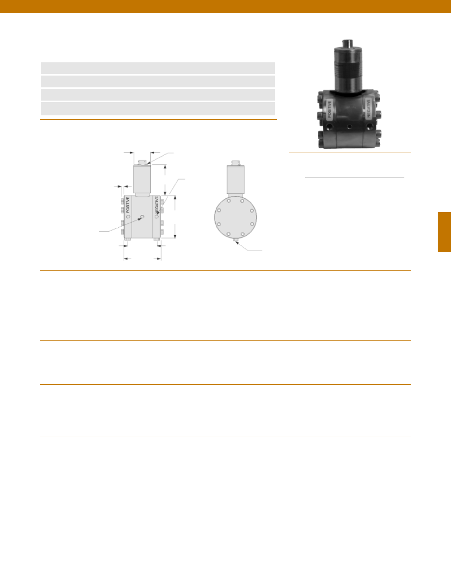
139
Dimensions
Performance
Environmental
Electrical
Mechanical
n
2 to 25 psid Range
n
OEM Applications
n
Stainless Steel
n
0.5% Accuracy
Mounting Hole
1/4-18 NPT x 5/16” DP.
Typ. each side
Pressure Port
1/8-27 NPT
2 each
Bleed Port
1/8-27 NPT 2 each
Span & Zero
Adjustment Cover Screw
2.25 in.
3.0 in.
ø1.50 in.
ø3.50 in.
2.7 in.
0.3 in.
Pressure Ranges........5; 10; 15; 25 psid
Accuracy........+/- 0.5% Full Scale
Linearity........+/- 0.25% Full Scale (typical)
Hysteresis........+/- 0.13% Full Scale (typical)
Non-Repeatability........+/- 0.07% Full Scale (typical)
Output (standard)........4-20 mA
Line Pressure........1500 psi
Resolution........Infinite
Temperature, Operating........0° to 180°F
Temperature, Compensated........30° to 130°F
Temperature, Effect
Zero........+/- 1.0% Full scale/ 100 °F
Span........+/- 1.0% Reading/ 100 °F
Strain Gage Type........Bonded Foil
Excitation (calibration)........15-40 VDC
Maximum Load Resistance........500 Ohms
Shunt Calibration Data........Included
Electrical Termination (std)........PTIH-10-6P or equivalent (Hermetic stainless)
Mating Connector (not incl.)........PT06A-10-6S or equivalent
Media........Gas, Liquid
Overload-Safe........1500 psi either side
Pressure Port........1/8-27 NPT female
Wetted Parts Material........316 Stainless Steel
Case Material........Stainless Steel
www.honeywell.com/sensotec
1-888-282-9891
Model 420 DP Low Range Two Wire Wet/ Wet Differential
Pressure Transducer
Order Code AD411
Wiring Code
Connector/ 2 Wire Current/ 4-20 mA
A
(+) Supply
B
No Connection
C
No Connection
D
(-) Output (4-20 mA)
E
Case Ground
F
No Connection
Note: Unless otherwise specified on order, amplified units with 4-20 mA output will provide 4 mA at 0 psid and 20 mA at positive full scale and the
unit will not operate in the negative direction. An available alternative is to specify 4 mA at negative full scale and 20 mA at positive full scale. All
amps add 2 in. to amplifier housing.
Courtesy of Steven Engineering, Inc.-230 Ryan Way, South San Francisco, CA 94080-6370-Main Office: (650) 588-9200-Outside Local Area: (800) 258-9200-www.stevenengineering.com
Sensotec Sensors Full Line Catalog-html.html
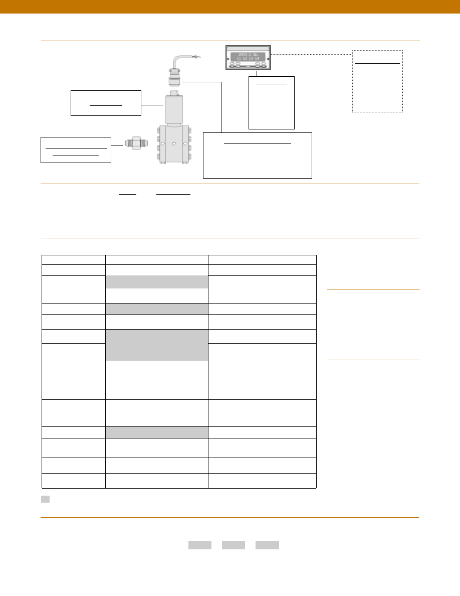
140
Build to Order
Build from Scratch
Pressure Ranges (psid) 5, 10, 15, 25
2
Temperature
Compensation
1a. 60° to 160° F
1c. 0° to 185° F
Internal Amplifiers
2k. 4-20mA (2 wire)
Internal Amp
Enhancements
3d. Remote Buffered Shunt Calibration
Pressure Ports (note 2)
5h. 1/8-27 NPT Female
5c. 7/16- 20 UNF Female
Electrical Termination
6e. Integral cable: Teflon (-54° to 245° C)
6f.
Integral cable: PVC (-30° to 70° C)
6i.
Integral underwater cable (8m)
(max 80° C) (note 1)
6j.
1/2-14 conduit fitting with 5 ft.
4 conductor PVC cable
6g. Integral cable: Neoprene (-20 to 80° C)
(note 1)
6h. Integral cable: Silicone (-54 to 150° C)
Special Calibration
9a. 10 point (5 up/5 down) 20% increments
@ 20° C
9b. 20 point (10 up/10 down) 10%
increments @ 20° C
Wetted Diaphragm
10a. 316 Stainless Steel
Increased Line Pressure
25a. 2000 psi line pressure
25b. 3000 psi line pressure
25c. 5000 psi line pressure
O Ring Seals
26c. Teflon
Interfaces
53e. Signature Calibration
53t. T.E.D.S. IEEE 1451.4 Module (note 3)
Range
Range Code
2 psid
AR
5 psid
AT
10 psid
AV
15 psid
BJ
25 psid
BL
Typical System Diagram
Model 420DP
Mating Connectors & Cables
AA111 mating connector
AA116 mating connector and 3 conductor
cable for 2k amplified output
Display Units
SC500
SC1000
SC2001
SC3004
GM-A
Customer Supplied
Chart Recorder
Alarm Panel
Data Acquisition
Computer
PLC
Options
Range Codes
Supplied as standard
www.honeywell.com/sensotec
1-888-282-9891
6a. Bendix PTIH-10-6P (or equivalent)
6 pin (max. 250°F)
Special Customer
Requirements
(Consult Factory)
1b. 30° to 130° F
Pressure Port adaptors
How to Order
Combine the order code, the range code and the options code.
Order Code
Range Code
Options Code
Sample Code: AD411
AV
6h
1. Availability varies according to range.
2. Some pressure port options may require
axial orientation.
3. Consult factory for TEDS availability with
amplified models.
Notes
Adaptors Compatible with
1/8-27 NPT Female
Model 420DP
Courtesy of Steven Engineering, Inc.-230 Ryan Way, South San Francisco, CA 94080-6370-Main Office: (650) 588-9200-Outside Local Area: (800) 258-9200-www.stevenengineering.com
Sensotec Sensors Full Line Catalog-html.html
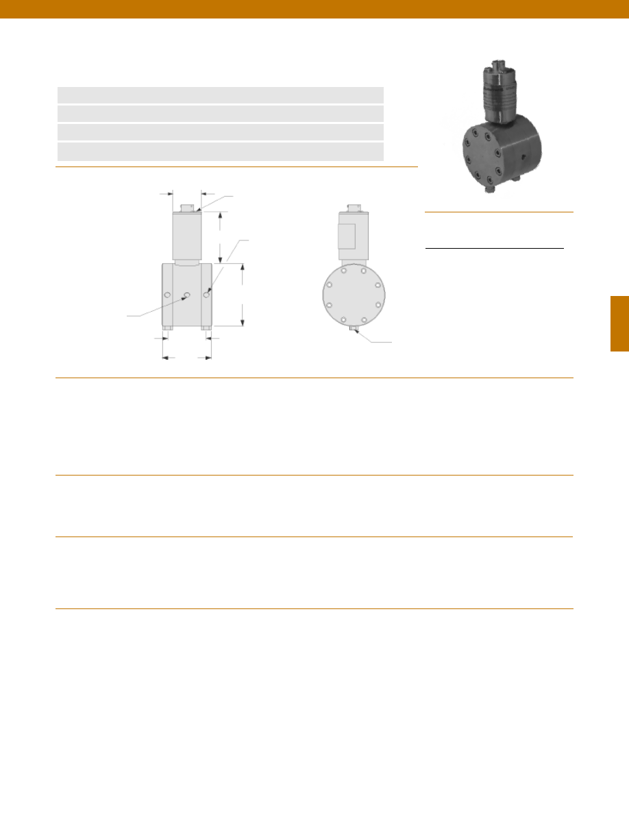
141
Dimensions
Performance
Environmental
Electrical
Mechanical
n
50 to 750 psid Range
n
OEM Applications
n
Stainless Steel
n
0.5% Accuracy
Mounting Hole
1/4-18 NPT x 5/16” DP.
Typ. each side
Pressure Port
1/8-27 NPT
2 each
Span & Zero
Adjustment Cover Screw
1.75 in.
2.5 in.
ø1.50 in.
ø3.00 in.
2.5 in.
Pressure Ranges........50; 75; 100; 150; 200; 300; 500; 750 psid
Accuracy........+/- 0.5% Full Scale
Linearity........+/- 0.25% Full Scale (typical)
Hysteresis........+/- 0.13% Full Scale (typical)
Non-Repeatability........+/- 0.07% Full Scale (typical)
Output (standard)........4-20 mA
Line Pressure........1500 psi
Resolution........Infinite
Temperature, Operating........0° to 180°F
Temperature, Compensated........60° to 160°F
Temperature, Effect
Zero........+/- 1.0% Full scale/ 100 °F
Span........+/- 1.0% Reading/ 100 °F
Strain Gage Type........Bonded Foil
Excitation (calibration)........15-40 VDC
Maximum Load Resistance........500 Ohms
Shunt Calibration Data........Included
Electrical Termination (std)........PTIH-10-6P or equivalent (Hermetic stainless)
Mating Connector (not incl.)........PT06A-10-6S or equivalent
Media........Gas, Liquid
Overload-Safe........1500 psi either side
Pressure Port........1/8-27 NPT female (2)
Wetted Parts Material........17-4 PH Stainless Steel
Case Material........Stainless Steel
www.honeywell.com/sensotec
1-888-282-9891
Model 420 DP Mid Range Two Wire Wet/ Wet Differential
Pressure Transducer
Order Code AD412
Wiring Code
Connector/ 2 Wire Current/ 4-20 mA
A
(+) Supply
B
No Connection
C
No Connection
D
(-) Output (4-20 mA)
E
Case Ground
F
No Connection
Bleed Port
1/8-27 NPT 2 each
Note: Unless otherwise specified on order, amplified units with 4-20 mA output will provide 4 mA at 0 psid and 20 mA at positive full scale and the
unit will not operate in the negative direction. An available alternative is to specify 4 mA at negative full scale and 20 mA at positive full scale. All
amps add 2 in. to amplifier housing.
Courtesy of Steven Engineering, Inc.-230 Ryan Way, South San Francisco, CA 94080-6370-Main Office: (650) 588-9200-Outside Local Area: (800) 258-9200-www.stevenengineering.com
Sensotec Sensors Full Line Catalog-html.html
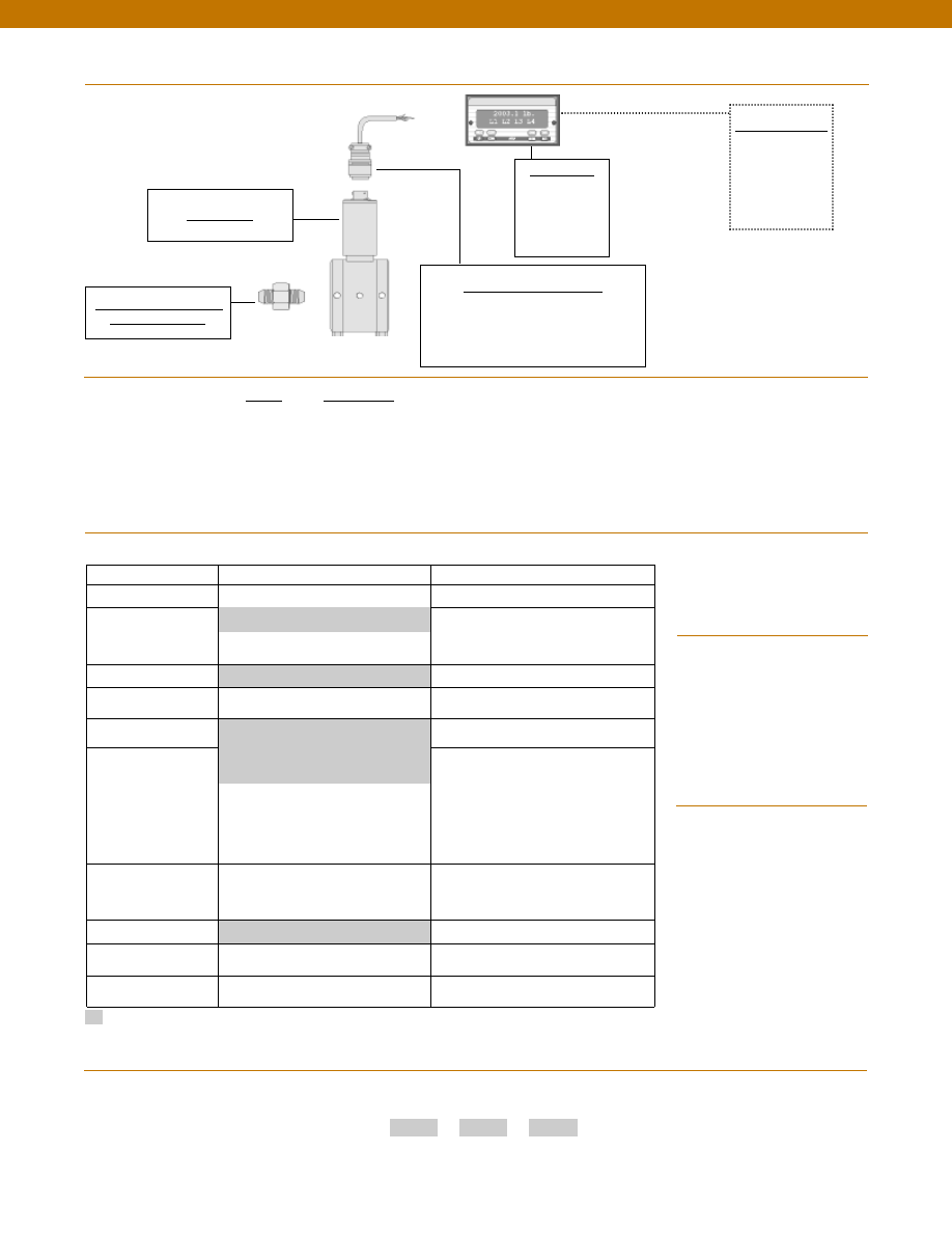
142
Build to Order
Build from Scratch
Pressure Ranges (psid) 50, 100, 200, 500
75, 150, 300, 750
Temperature
Compensation
1b. 30° to 130° F
1c. 0° to 185° F
Internal Amplifiers
2k. 4-20mA (2 wire)
Internal Amp
Enhancements
3d. Remote Buffered Shunt Calibration
Pressure Ports (note 2)
5h. 1/8-27 NPT Female(2)
5c. 7/16” - 20 UNF Female
(per MS33656E4)
Electrical Termination
6e. Integral cable: Teflon (-54° to 245° C)
6f.
Integral cable: PVC (-30° to 70° C)
6i.
Integral underwater cable(8m)
(max 80° C) (note 1)
6j.
1/2-14 conduit fitting with 5 ft.
4 conductor PVC cable
6g. Integral cable: Neoprene (-20 to 80° C)
(note 1)
6h. Integral cable: Silicone (-54 to 150° C)
Special Calibration
9a. 10 point (5 up/5 down) 20% increments
@ 20° C
9b. 20 point (10 up/10 down) 10%
increments @ 20° C
Wetted Diaphragm
17-4 Stainless Steel
O Ring Seals
26a. Metal
26c. Teflon
Interfaces
53e. Signature Calibration
53t. T.E.D.S. IEEE 1451.4 Module (note 3)
Range
Range Code
50 psid
BN
75 psid
BP
100 psid
BR
150 psid
CJ
200 psid
CL
300 psid
CP
500 psid
CR
750 psid
CT
Typical System Diagram
Model 420DP
Adaptors Compatible with
1/8-27 NPT Female
Mating Connectors & Cables
AA111 mating connector
AA116 mating connector and 3 conductor
cable for 2k amplified output
Display Units
SC500
SC1000
SC2001
SC3004
Customer Supplied
Chart Recorder
Alarm Panel
Data Acquisition
Computer
PLC
Options
Range Codes
Supplied as standard
www.honeywell.com/sensotec
1-888-282-9891
6a. Bendix PTIH-10-6P (or equivalent)
6 pin (max. 250°F)
Special Customer
Requirements
(Consult Factory)
1a. 60° to 160° F
Pressure Port adaptors
How to Order
Combine the order code, the range code and the options code.
Order Code
Range Code
Options Code
Sample Code: AD412
CT
6h
1. Availability varies according to range
2. Some pressure port options may require
axial orientation.
3. Consult factory for TEDS availability with
amplified models.
Notes
Model 420DP
Courtesy of Steven Engineering, Inc.-230 Ryan Way, South San Francisco, CA 94080-6370-Main Office: (650) 588-9200-Outside Local Area: (800) 258-9200-www.stevenengineering.com
Sensotec Sensors Full Line Catalog-html.html
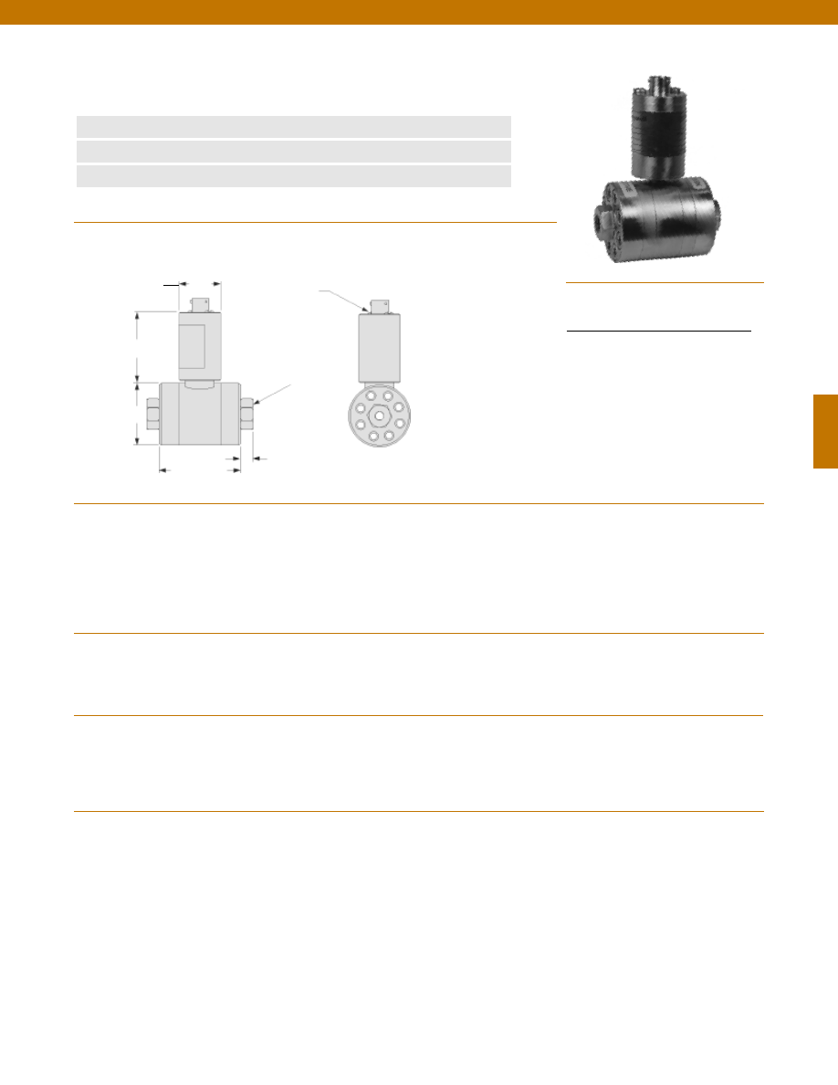
143
Dimensions
Performance
Environmental
Electrical
Mechanical
n
OEM Applications
n
Fluid in Both Ports
n
0.5% Accuracy
Pressure Port
1/4-18 NPT Female
2 each
Span & Zero
Adjustment Cover Screw
2.25 in.
2.7 in.
ø1.50 in.
2.5 in.
Pressure Ranges........2000; 3000; 5000; 7500; 10,000 psid
Accuracy........+/- 0.5% Full Scale
Linearity........+/- 0.25% Full Scale (typical)
Hysteresis........+/- 0.13% Full Scale (typical)
Non-Repeatability........+/- 0.07% Full Scale (typical)
Output (standard)........4-20 mA
Line Pressure........1500 psi
Resolution........Infinite
Temperature, Operating........0° to 180°F
Temperature, Compensated........60° to 160°F
Temperature, Effect
Zero........+/- 1.0% Full scale/ 100 °F
Span........+/- 1.0% Reading/ 100 °F
Strain Gage Type........Bonded Foil
Excitation (calibration)........15-40 VDC
Maximum Load Resistance........500 Ohms
Shunt Calibration Data........Included
Electrical Termination (std)........PTIH-10-6P or equivalent (Hermetic stainless)
Mating Connector (not incl.)........PT06A-10-6S or equivalent
Media........Gas, Liquid
Overload-Safe........50% over capacity
Pressure Port........1/4-18 NPT female (2)
Wetted Parts Material........17-4 PH Stainless Steel
Case Material........Stainless Steel
www.honeywell.com/sensotec
1-888-282-9891
Model 420 DP High Range Two Wire Wet/ Wet Differential
Pressure Transducer
Order Code AD413
Wiring Code
Connector/ 2 Wire Current/ 4-20 mA
A
(+) Supply
B
No Connection
C
No Connection
D
(-) Output (4-20 mA)
E
Case Ground
F
No Connection
0.4 in.
Note: Unless otherwise specified on order, amplified units with 4-20 mA output will provide 4 mA at 0 psid and 20 mA at positive full scale and the
unit will not operate in the negative direction. An available alternative is to specify 4 mA at negative full scale and 20 mA at positive full scale. All
amps add 2 in. to amplifier housing.
Courtesy of Steven Engineering, Inc.-230 Ryan Way, South San Francisco, CA 94080-6370-Main Office: (650) 588-9200-Outside Local Area: (800) 258-9200-www.stevenengineering.com
Sensotec Sensors Full Line Catalog-html.html
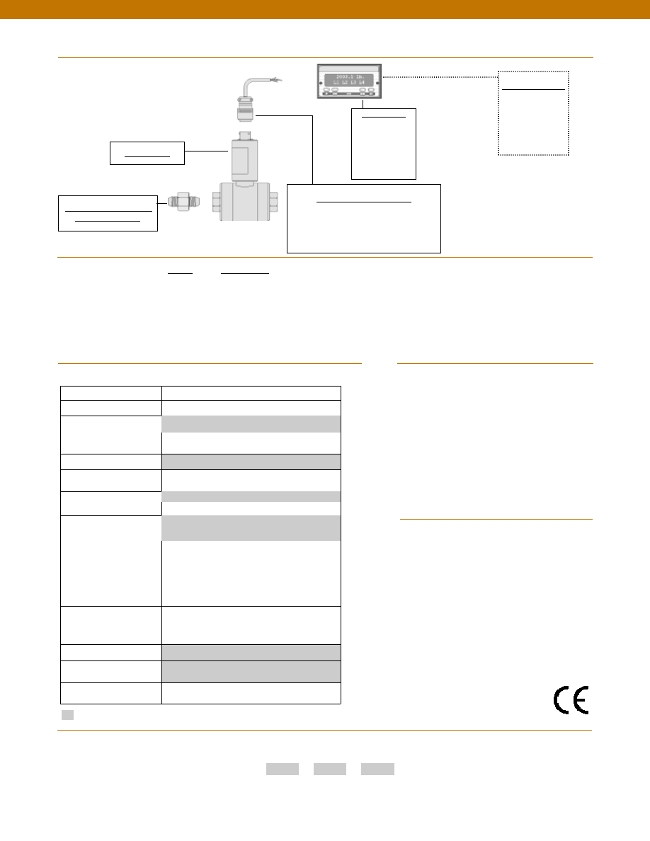
144
Built from Scratch
Pressure Ranges (psid)
2000, 3000, 5000, 7500, 10,000
Temperature
Compensation
1b. 30° to 130° F
1c. 0° to 185° F
Internal Amplifiers
2k. 4-20mA (2 wire)
Internal Amp
Enhancements
3d. Remote Buffered Shunt Calibration
Pressure Ports (note 2)
5c. 7/16” - 20 UNF Female (per MS33656E4)
Electrical Termination
6e. Integral cable: Teflon (-54° to 245° C)
6f.
Integral cable: PVC (-30° to 70° C)
6g. Integral cable: Neoprene (-20 to 80° C) (note 1)
6h. Integral cable: Silicone (-54 to 150° C)
6i.
Integral underwater cable (max 80° C) (note 1)
6j.
1/2-14 conduit fitting with 5 ft. 4 conductor
PVC cable
Special Calibration
9a. 10 point (5 up/5 down) 20%
increments @ 20° C
9b. 20 point (10 up/10 down) 10%
increments @ 20° C
Wetted Diaphragm
17-4 PH Stainless Steel
O Ring Seals
26a. Metal
Interfaces
53e. Signature Calibration
53t. T.E.D.S. IEEE 1451.4 Module (note 3)
Range
Range Code
2000 psid
DL
3000 psid
DN
5000 psid
DR
7500 psid
DT
10,000 psid
DV
Typical System Diagram
Model 420DP
Adaptors Compatible with
1/4-18 NPT Female
Mating Connectors & Cables
AA111 mating connector
AA116 mating connector and 3 conductor
cable for 2k amplified output
Display Units
SC500
SC1000
SC2001
SC3004
GM-A
Customer Supplied
Chart Recorder
Alarm Panel
Data Acquisition
Computer
PLC
Options
Range Codes
Supplied as standard
www.honeywell.com/sensotec
1-888-282-9891
6a. Bendix PTIH-10-6P (or equivalent)
6 pin (max. 250°F)
Special Customer Requirements
(Consult Factory)
1a. 60° to 160° F
Pressure Port adaptors
How to Order
Combine the order code, the range code and the options code.
Order Code
Range Code
Options Code
Sample Code: AD413
DV 6h
1. Availability varies according to range.
2. Some pressure port options may require
axial orientation.
3. Consult factory for TEDS availability with
amplified models.
Notes
Model 420DP
Approved
5h. 1/4-18 NPT Female
Courtesy of Steven Engineering, Inc.-230 Ryan Way, South San Francisco, CA 94080-6370-Main Office: (650) 588-9200-Outside Local Area: (800) 258-9200-www.stevenengineering.com
Sensotec Sensors Full Line Catalog-html.html
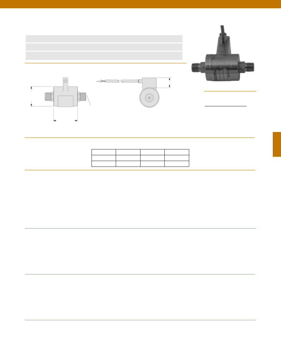
145
Pressure Port
1/8-27 NPT Typ.
øD
L
1.0 in.
Pressure Ranges
Accuracy
Linearity
Hysteresis
Non-Repeatability
Output (standard)
5 to 25 psid
50 to 2000 psid
Line Pressure
5 to 25 psid
50 to 2000 psid
Resolution
Temperature, Operating
Temperature, Compensated
Temperature, Effect
Zero
5 to 25 psid
50 to 2000 psid
Span
5 to 25 psid
50 to 2000 psid
Strain Gage Type
5 to 25 psid
50 to 2000 psid
Excitation (calibration)
Bridge Resistance
5 to 25 psid
50 to 2000 psid
Shunt Calibration Data
Electrical Termination (std)
Media
Overload-Safe
Pressure Port
Wetted Parts Material
Case Material
........5; 10; 15; 25; 50; 75; 100; 150; 200; 300; 500; 750; 1000; 2000 psid
........+/- 0.3 % Full Scale
........+/- 0.2% Full Scale (typical)
........+/- 0.1% Full Scale (typical)
........+/- 0.1% Full Scale (typical)
........100 mV/V (nominal)
........2 mV/V (nominal)
........250 psi
........500 psi or 2X Full Scale (whichever is higher)
........Infinite
........-65° to 250°F
........60° to 160°F
........+/- 1.5% Full scale/ 100 °F
........+/- 1.0% Reading/ 100 °F
........+/- 1.5% Full scale/ 100 °F
........+/- 1.0% Reading/ 100 °F
........Bonded Semiconductor
........Bonded Foil
........10 VDC
........500 Ohms
........350 Ohms
........Included
........Teflon Cable 5 ft.
........Gas, Liquid
........Maximum line pressure either side
........1/8-27 NPT male: 7/16” Hex
........17-4 PH Stainless Steel
........Stainless Steel
www.honeywell.com/sensotec
1-888-282-9891
Wiring Code
Connector/ Unamplified
Red
(+) Excitation
Black
(-) Excitation
Green (-) Output
White
(+) Output
Dimensions
Performance
Environmental
Electrical
Mechanical
Model P-30-P Subminiature Wet/ Wet Differential
Pressure Transducer
Order Code BD311 (5 to 25 psid); BD312 (50 to 2000 psid)
n
High Frequency
n
Light Weight
n
Compact Design
Range Order
(psid) Code D(in.) L(in.)
5 to 25
BD311
1.13
1.4
50 to 500
BD312
1.13
1.4
750 to 2000
BD312
1.38
1.5
Courtesy of Steven Engineering, Inc.-230 Ryan Way, South San Francisco, CA 94080-6370-Main Office: (650) 588-9200-Outside Local Area: (800) 258-9200-www.stevenengineering.com
Sensotec Sensors Full Line Catalog-html.html
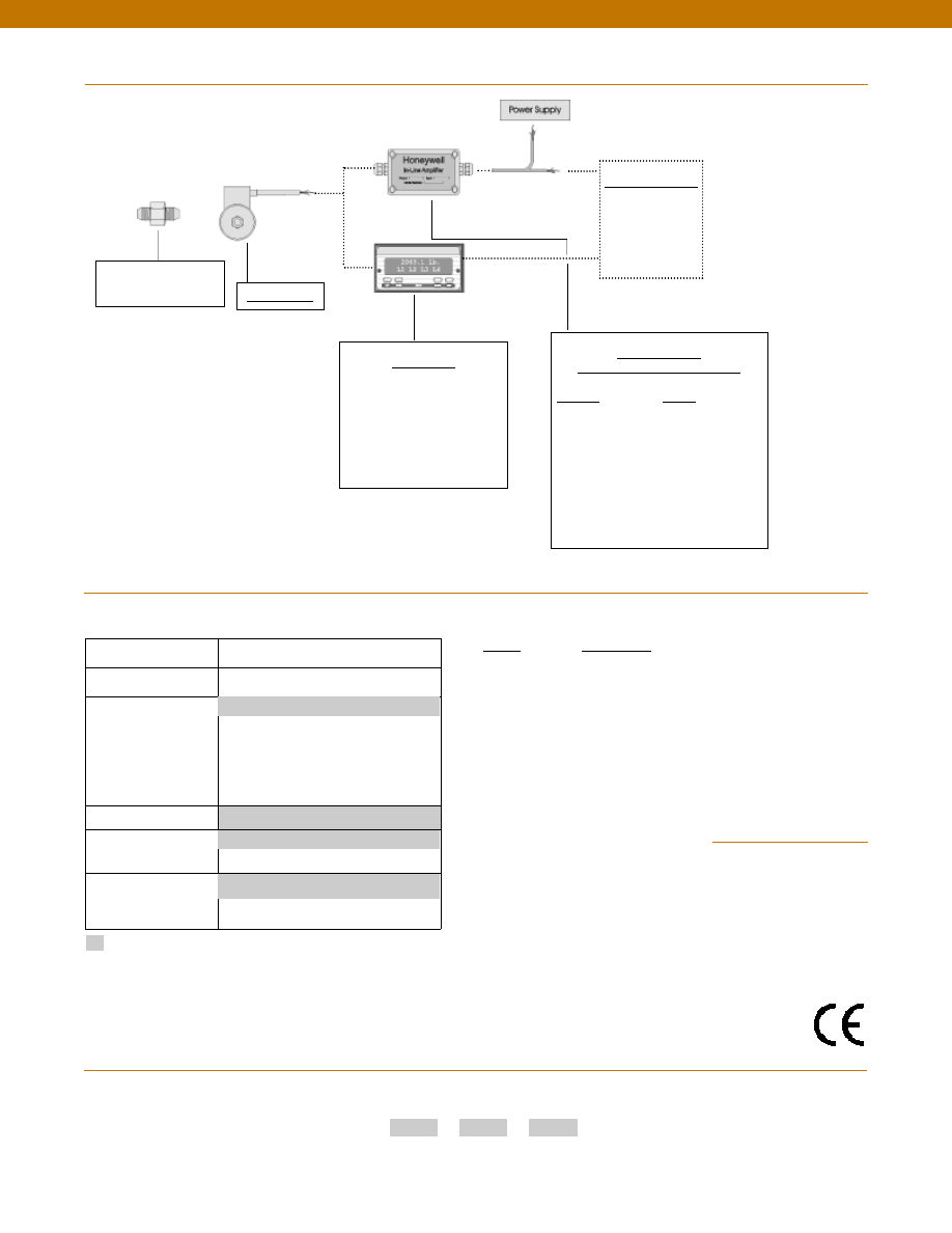
146
In-Line Amplifiers
(Used with unamplified units only)
Amplifier
Output
Universal In-Line Amplifiers
UV
+/- 5 VDC
UV-10
+/- 10 VDC
UBP
0 +/- 5 VDC
U3W
4-20 mA (3 wire)
DIN rail Mount In-Line Amplifiers
DV-05
0 +/- 5 VDC (3 wire)
DA-05
4-20 mA (3 wire)
DV-10
0 +/- 10 VDC (3 wire)
Customer Supplied
Chart Recorder
Alarm Panel
Data Acquisition
Computer
PLC
Display Units
SC500
SC1000
SC2001
SC3004
GM (Unamplified only)
NK (Unamplified only)
HH (Unamplified only)
Adaptors compatible
with 1/8-27 NPT Male
For long cable runs or electrically noisy environments an
amplified sensor or locally mounted amplifier is often preferred.
Model P-30-P
www.honeywell.com/sensotec
1-888-282-9891
Typical System Diagram
Range
Range Code
5 psid
AT
10 psid
AV
15 psid
BJ
25 psid
BL
50 psid
BN
75 psid
BP
100 psid
BR
150 psid
CJ
200 psid
CL
300 psid
CP
500 psid
CR
750 psid
CT
1000 psid
CV
2000 psid
DL
Build from scratch
Pressure Ranges (psid)
5, 10, 15, 25, 50, 75, 100, 150, 200, 300,
500, 750, 1000, 2000
Temperature
Compensation
1b. 30° to 130° F
1c. 0° to 185° F
1d. -20° to 130° F
1e. -20° to 200° F
1f.
70° to 250° F
1j.
0° to 50° C
Internal Amplifiers
2u. Unamplified, mV/V output
Pressure Ports
5d. 7/16” - 20 UNF Male (per MS33656E4)
Electrical Termination
6i.
Integral underwater cable(8m)
(max 80° C) (note 1)
Options Range Codes
1a. 60° to 160° F
6e. Integral cable: Teflon (-54 to 245° C)
5i.
1/8” - 27 NPT Male
Supplied as standard
Pressure Port adaptors
Amplifiers
Custom Connectors
Special Customer
Requirements
(Consult Factory)
How to Order
Combine the order code, the range code and the options code.
Order Code
Range Code
Options Code
Sample Code: BD312
CV 6i
1. Availability varies according to range
Notes
Model P-30-P
Approved
Courtesy of Steven Engineering, Inc.-230 Ryan Way, South San Francisco, CA 94080-6370-Main Office: (650) 588-9200-Outside Local Area: (800) 258-9200-www.stevenengineering.com
Sensotec Sensors Full Line Catalog-html.html
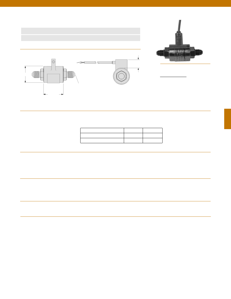
147
Pressure Port
7/16-20 per MS33656E-4
Dimensions
Performance
Environmental
Electrical
Mechanical
www.honeywell.com/sensotec
n
Non-Linearity 0.2% BFSL
n
Lightweight
Model AS25D Aerospace Pressure Transducers
Order Code BD313
L
D
ø0.8 in.
Pressure Ranges................15 to 2,000 psid
Accuracy................+/- 0.3%
Non- Linearity................+/- 0.2% Full Scale (typical)
Hysteresis................+/- 0.1% Full Scale (typical)
Output................2 mV/V Nominal
Resolution................Infinite
Temperature, Operating................-65° to 300° F
Temperature, Compensated................-65° to 250° F
Temperature, Effect
Zero................0.01% Full Scale/° F
Span................0.01% Reading/° F
Excitation (calibration)................10 VDC
Bridge Resistance................350 Ohms
Electrical Termination (std)................Shielded Cable
Media................Fluids compatible with 17-4 PH Stainless Steel
Pressure Port................7/16-20 per MS33656E-4
Wetted Parts Material................17-4 PH Stainless Steel
Weight................consult factory
Case Material................Stainless Steel
15; 25
1.13
1.4
50; 75; 100; 150; 200; 300; 500
1.13
1.4
750; 1000; 1500; 2000
1.38
1.5
Range (psid)
øD (in.)
L (in.)
Wiring Code
1-888-282-9891
Cable/Unamplified
Red
(+) Excitation
Black
(-) Excitation
Green
(-) Output
White
(+) Output
Courtesy of Steven Engineering, Inc.-230 Ryan Way, South San Francisco, CA 94080-6370-Main Office: (650) 588-9200-Outside Local Area: (800) 258-9200-www.stevenengineering.com
Sensotec Sensors Full Line Catalog-html.html
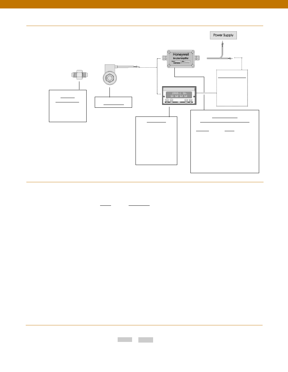
148
Range
Range Code
15 psid
BJ
25 psid
BL
50 psid
BN
75 psid
BP
100 psid
BR
150 psid
CJ
200 psid
CL
300 psid
CP
500 psid
CR
750 psid
CT
1,000 psid
CV
1,500 psid
DJ
2,000 psid
DL
www.honeywell.com/sensotec
1-888-282-9891
How to Order
Combine the order code and the range code.
Order Code
Range Code
Sample Code: BP313 BJ
Range Codes
Model AS25D
Typical System Diagram
Adaptors
Compatible with:
7/16-20 UNF Male
Model AS25D
Customer Supplied
Chart Recorder
Alarm Panel
Data Acquisition
Computer
PLC
In-Line Amplifiers
(Used with unamplified units only)
Amplifier
Output
Universal In-Line Amplifiers
UV
+/- 5 VDC
UV-10
+/- 10 VDC
UBP
0 +/- 5 VDC
U3W
4-20 mA (3 wire)
DIN Rail Mount In-Line Amplifiers
DV-05
0 +/- 5 VDC (3 wire)
DA-05
4-20 mA (3 wire)
DV-10
0 +/- 10 VDC (3 wire)
Display Units
SC500
SC1000
SC2000
SC2001
SC3004
GM
NK
HH
Courtesy of Steven Engineering, Inc.-230 Ryan Way, South San Francisco, CA 94080-6370-Main Office: (650) 588-9200-Outside Local Area: (800) 258-9200-www.stevenengineering.com
Sensotec Sensors Full Line Catalog-html.html

149
Notes
www.honeywell.com/sensotec
1-888-282-9891
Courtesy of Steven Engineering, Inc.-230 Ryan Way, South San Francisco, CA 94080-6370-Main Office: (650) 588-9200-Outside Local Area: (800) 258-9200-www.stevenengineering.com
Sensotec Sensors Full Line Catalog-html.html
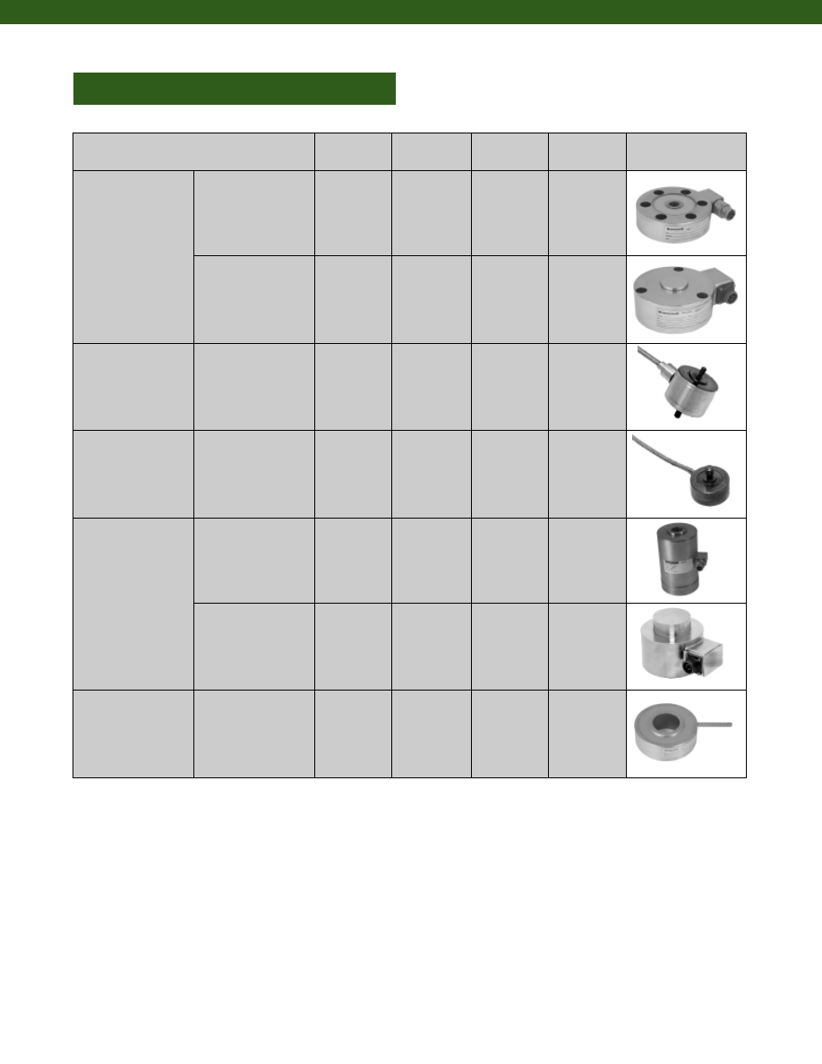
150
www.honeywell.com/sensotec
1-888-282-9891
LOAD CELLS
Potential Application
Model
Order Code Accuracy
Page
Low Profile
Stainless Steel
41
43
AL111, 41E
AL112
0.1%
0.1%
152
159
Stainless Steel
Fatigue Rated
75
73
45
47
BL114
BL113
AL116
AL117
0.1%
0.1%
0.05%
0.03%
163
167
171
175
Miniature
53
31
34
AL131, 53E
AL311, 31E
AL312
0.5%
0.1%
0.1%
179
184
198
Sub Miniature
LFH-7I
13
11
BL351
AL322, 13E
BL321
0.7%
0.5%
0.5%
202
205
211
Canister Style
Tension and
Compression
UG
BL122
0.03%
214
Compression
WG
MPB
BL125
BL515
0.03%
0.25%
216
218
Donut Style
Compression
D
TH
BL912-BL915
BL911
0.5%
0.25%
221
224
Courtesy of Steven Engineering, Inc.-230 Ryan Way, South San Francisco, CA 94080-6370-Main Office: (650) 588-9200-Outside Local Area: (800) 258-9200-www.stevenengineering.com
Sensotec Sensors Full Line Catalog-html.html
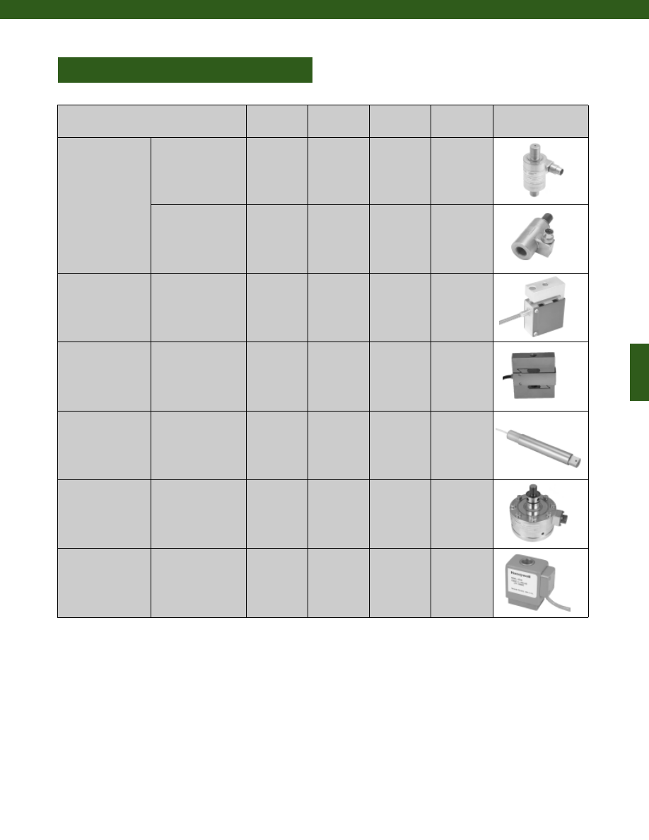
151
www.honeywell.com/sensotec
1-888-282-9891
LOAD CELLS
Potential Application
Model
Order Code Accuracy
Page
In-Line
Stainless Steel
Tension Only
RM
RH
RF
see datasheet
see datasheet
see datasheet
0.2%
0.2%
0.2%
227
231
235
Stainless Steel
RGM
RGH
RGF
AL426/AL626
AL427/AL627
AL428/AL628
0.25%
0.25%
0.25%
239
243
246
S Beam
81
82
102
BL433
BL434
BL804
0.05%
0.05%
0.02%
249
251
253
Z Beam
123
127
125
129
BL810
BL807
BL811
BL808
0.03%
0.03%
0.02%
0.02%
255
257
259
261
Load Pins
MBL
MBH
LP
BL341
BL342
AL441
0.1%
0.1%
0.5%
263
265
267
Calibration
Class
IC48
AL121
0.02%
270
Special
Applications
AL-SC
AL-JP
101
103
TL131
TL121
BL803
BL805
1.25%
0.15%
0.02%
0.02%
273
275
277
279
Courtesy of Steven Engineering, Inc.-230 Ryan Way, South San Francisco, CA 94080-6370-Main Office: (650) 588-9200-Outside Local Area: (800) 258-9200-www.stevenengineering.com
Sensotec Sensors Full Line Catalog-html.html
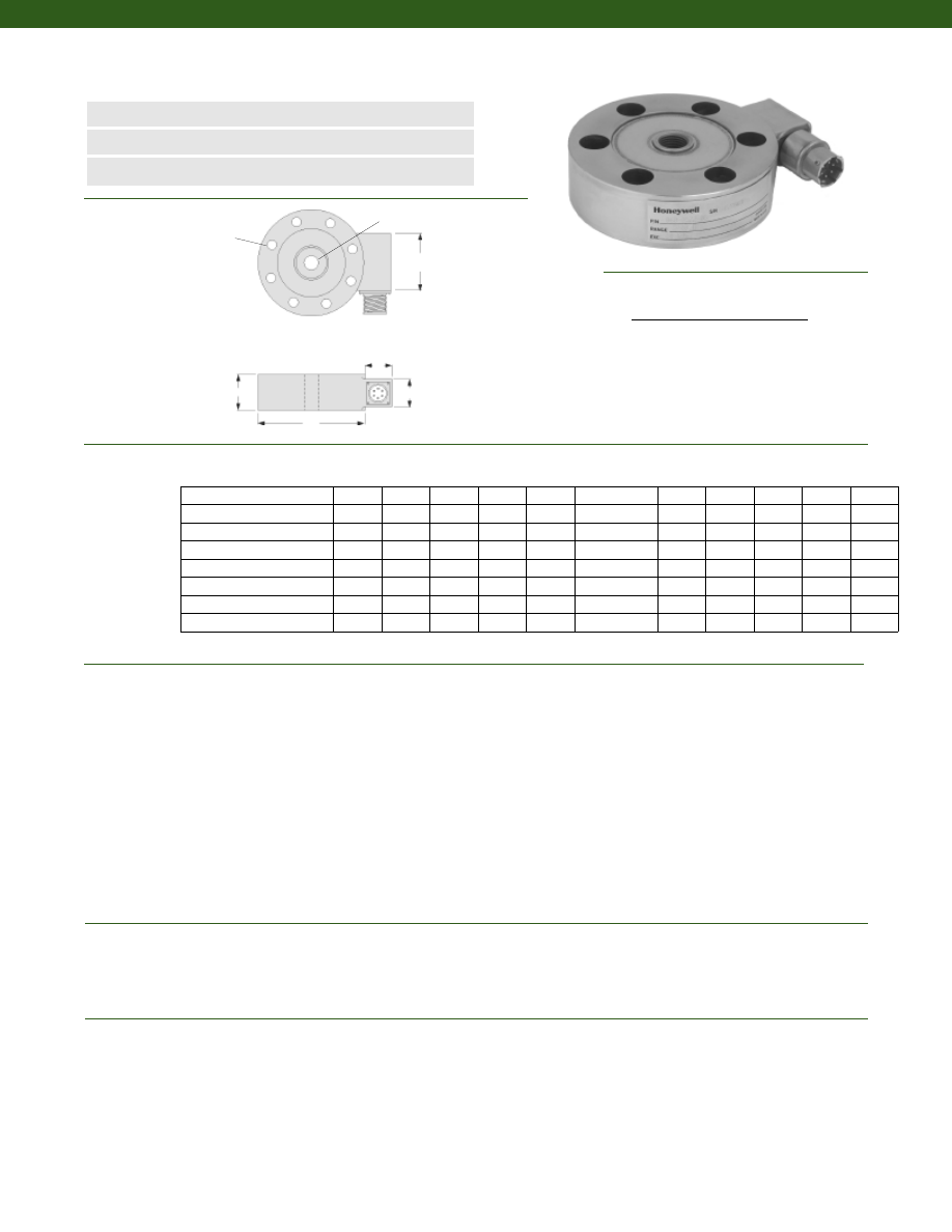
152
Dimensions
Performance
Environmental
Electrical
Model 41 Precision Low Profile Load Cell
Order Code AL111
www.honeywell.com/sensotec
1-888-282-9891
n
5 to 500,000 lb.
n
mV/V Output
n
Double Diaphragm Design
øD
H
C
A
B
Load Ranges................5 to 500,000 lb.
Non-linearity
5 to 25 lb.................+/- 0.2% Full Scale
50 to 500,000 lb.................+/- 0.1% Full Scale
Hysteresis
5 to 25 lb.................+/- 0.1% Full Scale
50 to 500,000 lb.................+/- 0.08% Full Scale
Non-Repeatability
5 to 25 lb.................+/- 0.1% Full Scale
50 to 500,000 lb.................+/- 0.03% Full Scale
Output (tolerance)
5 to 25 lb.................2 mV/V +/- 0.5% Full Scale
50 to 500,000 lb.................3 mV/V +/- 0.5% Full Scale
Operation................Compression/ Tension (note 13)
Resolution................Infinite
Standard Calibration................5 point calibration: 0%, 50% and 100% of Full Scale in tension only
Temperature, Operating................-65° to 250° F
Temperature, Compensated................60° to 160° F
Temperature, Effect
Zero................0.002% Full Scale/ °F
Span................0.002% Full Scale/ °F
Strain Gage Type................Bonded Foil
Excitation (calibration)................10 VDC
Insulation Resistance................5000 Megohms @ 50 VDC
Bridge Resistance (tolerance)................350 Ohms (nominal)
Zero Balance (tolerance)................+/- 1% Full Scale
Shunt Calibration Data................Included
Electrical Termination (std)
5 to 5,000 lb.................PTIH-10-6P
7,500 to 500,000 lb.................MS3102A-14S-6P
øG (in.) øK (in.)
Ranges (lb.) D (in.) H (in.) F# B.C. thru T A (in.) A* (in.) B (in.) B* (in.) C (in.)
T
* Length of load cell with amplified option (see options chart)
**C” dimension varies on high ranges. Consult Factory
Wiring Code
Connector/ Unamplified (Std.)
A
(+) Excitation
B
(+) Excitation
C
(-) Excitation
D
(-) Excitation
E
(-) Output
F
(+) Output
5; 10; 25
2.50
0.80
6
2.000
0.19
1/4-28 UNF
0.82
2.5
0.75
0.9
1.25
50; 100; 250; 500; 1000
3.00
1.00
6
2.250
0.28
3/8-24 UNF
0.82
2.5
0.75
0.9
1.25
2000; 3000; 4000; 5000
3.50
1.00
6
2.625
0.34
1/2-20 UNF
0.82
2.5
0.75
0.9
1.25
7500; 10,000; 15,000
5.50
1.80
8
4.500
0.40
1-14 UNS
1.25
2.3
1.50
1.5
2.00
20,000; 30,000; 50,000
6.00
1.80
8
4.875
0.53
1 1/2-12 UNF
1.25
2.3
1.50
1.5
2.00
75,000; 100,000
9.00
2.50
12
7.750
0.66
2-12 UN
1.25
2.3
1.50
1.5
2.00
150,000; 200,000
11.00
2.50
12
9.500
0.78
2 1/2-12 UN
1.25
2.3
1.50
1.5
2.00
300,000; 400,000; 500,000 14.00
4.25
12
11.750
1.03
3 1/2-12 UN
1.25
2.3
1.50
1.5
**
F Clearance Holes Equally
Spaced on G Diameter B.C.
K Diameter thru
Courtesy of Steven Engineering, Inc.-230 Ryan Way, South San Francisco, CA 94080-6370-Main Office: (650) 588-9200-Outside Local Area: (800) 258-9200-www.stevenengineering.com
Sensotec Sensors Full Line Catalog-html.html
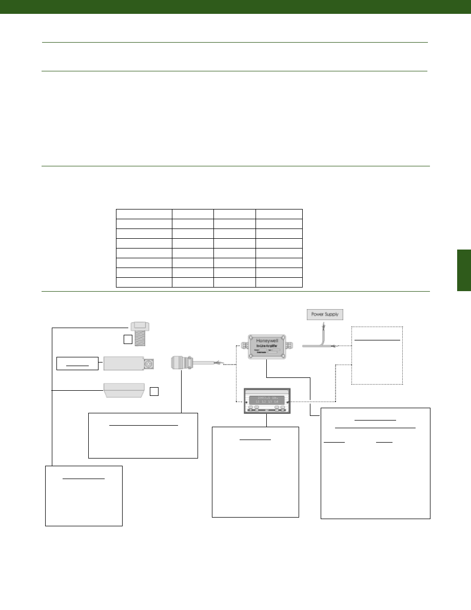
153
www.honeywell.com/sensotec
Electrical (continued)
Mechanical
Typical System Diagram
Mating Connector (not included)
5 to 5,000 lb.................PT06A-10-6S
7,500 to 500,000 lb.................MS3106A-14S-6S
Maximum Allowable Load................150% F.S. (note 1)
Weight................See table
Material
Less than 200,000 lb.................17-4PH Stainless Steel
Greater than or equal to 300,000 lb.................Carbon Steel
Deflection................See table
Natural Frequency................See table
Mating Connectors & Cables
PT06A-10-6S, Std.
PT06E-10-6S
MS3106A-14S-6S
In-Line Amplifiers
(Used with unamplified units only)
Amplifier
Output
Universal In-Line Amplifiers
UV
+/- 5 VDC
UV-10
+/- 10 VDC
UBP
0 +/- 5 VDC
U3W
4-20 mA (3 wire)
U2W
4-20 mA (2 wire)
DIN rail Mount In-Line Amplifiers
DV-05
0 +/- 5 VDC (3 wire)
DA-05
4-20 mA (3 wire)
DV-10
0 +/- 10 VDC (3 wire)
Display Units
SC500
SC1000
SC2000
SC2001
SC3004
GM (Unamplified only)
GM-A (Amplified only)
NK (Unamplified only)
HH (Unamplified only)
Customer Supplied
Chart Recorder
Alarm Panel
Data Acquisition
Computer
PLC
Mounting Options
1. Pull Plate
2. Load Button
Model 41
1
2
1-888-282-9891
Deflections and Ringing Frequencies
Capacity (lb.)
Deflection
@ Full Scale
(in.)
Natural
Ringing
Frequency
(Hz)
Weight
(lbs.)
5 to 25
0.001
2,000
0.8
50 to 1,000
0.002
4,600
1.5
2,000 to 5,000
0.002
10,000
2.0
7,500 to 15,000
0.003
6,000
8.8
20,000 to 50,000
0.004
8,000
11.0
75,000 to 100,000
0.006
5,500
30.9
150,000 to 200,000
0.010
4,500
46.3
300,000 to 500,000
0.010
4,100
130.1
Model 41
Courtesy of Steven Engineering, Inc.-230 Ryan Way, South San Francisco, CA 94080-6370-Main Office: (650) 588-9200-Outside Local Area: (800) 258-9200-www.stevenengineering.com
Sensotec Sensors Full Line Catalog-html.html
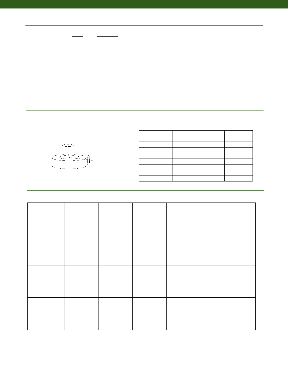
154
www.honeywell.com/sensotec
1-888-282-9891
Internal Amplifiers
Amplifier
Specifications
Voltage Output
Option 2b
Voltage Output
Option 2c
Voltage Output
Option 2t
Current 3 Wire
Option 2j
Current 2 Wire
Option 2k
Intrinsically Safe
Option 2n (2N)***
Output Signal
Input Power (Voltage)
Input Power (Current)
Frequency Response
Power Supply
Rejection
Operating Temperature
Reverse Voltage
Protection
Short Circuit Protection
+/- 5V
+/-15V or 26-32VDC
45 mA
3000 Hz
60 db
-20° to 185° F
Yes
Momentary
0-5V or +/- 5V
@ 45mA
11-28 VDC
40 mA
3000 Hz
60 db
-20° to 185° F
Yes
Momentary
0-10V or +/- 10V
@ 45mA
15-28 VDC
40 mA
3000 Hz
60 db
-20° to 185° F
Yes
Momentary
4-20 mA
22-32 VDC
65 mA
2500 Hz
60 db
0° to 185° F
Yes
Yes
4-20 mA
15-40 VDC
4-28 mA
300 Hz
60 db
0° to 185° F
Yes
Yes
4-20 mA
9-28 VDC
4-24 mA
2000 Hz
60 db
-20° to 185° F
Yes
Yes
Wiring Code: Connector
(Std.)
(note 4)
A (+) Supply
B Output Common/
C Supply Return
D (+) Output
E Shunt Cal 1
F Shunt Cal 2
A (+) Supply
B** Output Common/
C** Supply Return
D (+) Output
E Shunt Cal 1
F Shunt Cal 2
A (+) Supply
B** Output Common/
C** Supply Return
D (+) Output
E Shunt Cal 1
F Shunt Cal 2
A (+) Supply
B** Output Common/
C** Supply Return
D (+) Output
E Shunt Cal 1
F Shunt Cal 2
A (+) Supply
B No connection
C No connection
D (+) Output
E Case Ground
F No connection
A (+) Supply
B No connection
C No connection
D (+) Output
E Case Ground
F No connection
Wiring Code: Cable
(note 4)
(note 5)
(note 6)
R (+) Supply
Bl Output Common/
G Supply Return
W (+) Output
B Shunt Cal 1
Br Shunt Cal 2
R (+) Supply
Bl*Output Common/
G*Supply Return
W (+) Output
B Shunt Cal 1
Br Shunt Cal 2
R (+) Supply
Bl*Output Common/
G*Supply Return
W (+) Output
B Shunt Cal 1
Br Shunt Cal 2
R (+) Supply
Bl*Output Common/
G*Supply Return
W (+) Output
B Shunt Cal 1
Br Shunt Cal 2
R (+) Supply
Bl (+) Output
W Case Ground
R (+) Supply
Bl (+) Output
W Case Ground
Range
Range Code
5 lb.
AT
10 lb.
AV
25 lb.
BL
50 lb.
BN
100 lb.
BR
250 lb.
CN
500 lb.
CR
1000 lb.
CV
2000 lb.
DL
3000 lb.
DN
4000 lb.
DP
5000 lb.
DR
7500 lb.
DT
Range Codes
Model 41
Allowable Maximum Loads
(note 2)
Axial
Torque
Capacity (lb.)
Bending
(lb.-in.)
Torque
(lb.-ft.)
Side Load
(lb.)
Bending
5 to 25
50%
40%
25%
50 to 1,000
45%
35%
25%
2,000 to 5,000
30%
25%
25%
7,500 to 30,000
20%
20%
15%
50,000 to 100,000
20%
20%
15%
150,000 to 200,000
20%
20%
15%
300,000
20%
20%
10%
400,000
20%
20%
10%
500,000
20%
20%
10%
Range
Range Code
10,000 lb.
DV
15,000 lb.
EJ
20,000 lb.
EL
30,000 lb.
EN
50,000 lb.
EP
75,000 lb.
ER
100,000 lb.
ET
150,000 lb.
FJ
200,000 lb.
FL
300,000 lb.
FN
400,000 lb.
FP
500,000 lb.
FR
* Black and Green wires are internally connected.
** Pins B and C are internally connected.
*** See Sensotec website for most up-to-date information regarding Intrinsically Safe approvals ref. #008-0547-00.
Side
Courtesy of Steven Engineering, Inc.-230 Ryan Way, South San Francisco, CA 94080-6370-Main Office: (650) 588-9200-Outside Local Area: (800) 258-9200-www.stevenengineering.com
Sensotec Sensors Full Line Catalog-html.html
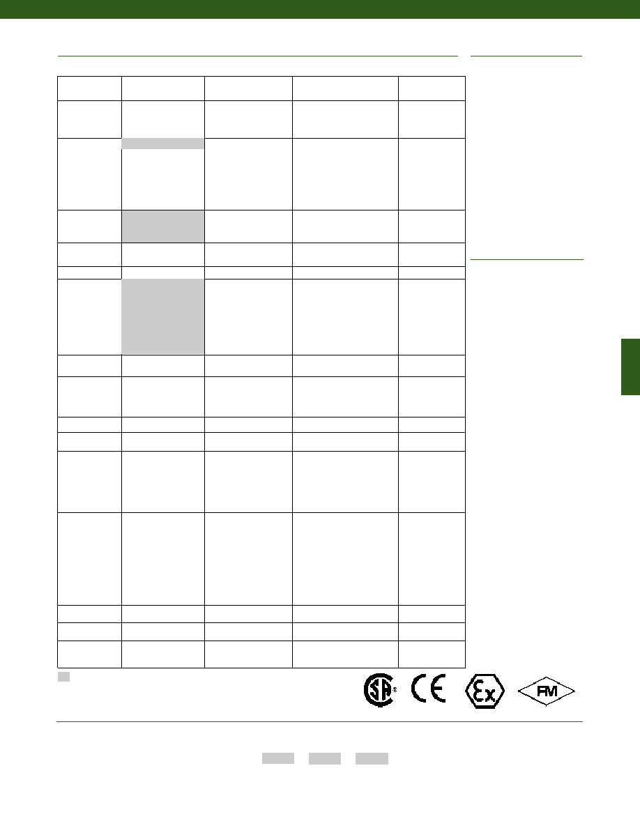
155
1. Allowable Maximum Loads- Maximum load
to be applied without damage (note 2).
2. Without Damage- loading to this level will
not cause excessive zero shift or perform-
ance degradation. The user must consider
fatigue life for long term use and structural
integrity. All structurally critical applications
(overhead loading, etc.) should always be
designed with safety redundant load paths.
3. Interconnecting shunt cal. 1 terminal with
shunt cal. 2 terminal provides 50% (unampli-
fied units), 75% (4-20mA 3-wire units) or
80% (voltage amplified units) of full scale
output for quick calibration. Shunt
Calibration comes standard with internal
amplifier options 2b, 2c, 2t and 2j.
4. O=Orange; Y=Yellow; B=Blue; Bl=Black;
R=Red; Br=Brown; W=White; G=Green.
Color specifying cable and number or letter
specifying connector
5. No mating connector necessary for cable
option.
6. Adding any internal amplifiers on 5 to 25 lb.
ranges will increase delivery time.
7. Option 2n (2N) on 5 to 5,000 lb. ranges will
typically take 12 weeks for delivery.
8. Option 3d is not available with option 2n
(2N) or 2k.
9. Not available with options 1c, 1e, 1f, 1g, 1h
or 1i.
10. Consult factory.
11. Availability varies with range, consult factory.
12. Option only pertinent when option 2n (2N)
selected.
13. Standard calibration for tension/
compression load cells is in tension only.
14. Not available with amplified output.
15. Consult factory for TEDS availability with
amplified models.
Operating temperature -60° to 400°F
Lightning protection
OEM labels
Case pressure
Radiation resistant
Cable orientation
Fatigue rating
Different cable lengths
Venting
Different materials
Electro-static discharge immunity
Different threads
Special wiring codes
Special Customer
Requirements
(Consult Factory)
Notes
Options
How to Order
Combine the order code, the range code and the options code.
Order Code
Range Code
Options Code
Sample Code: AL111
CV
6h
Supplied as standard
www.honeywell.com/sensotec
1-888-282-9891
Same Day Ship
Fast track manufacture
Build to order
Build from scratch
Load Range
50, 100, 500, 1000,
2000, 5000, 10,000,
20,000, 50,000 lb
5, 10, 25, 250, 3000, 4000,
7500, 15,000, 30,000 lb
75,000, 100,000,
150,000, 200,000,
300,000, 400,000,
500,000 lb
Temperature
Compensation
1b. 30° to 130° F
1c. 0° to 185° F
1d. -20° to 130° F
1e. -20° to 200° F
1f.
70° to 250° F
1i.
-65° to 250° F
1j. 0° to 50° C
1k. -20° to 85° C
1m. -25° to 110° C
1g. 70° to 325° F
1h. 70° to 400° F
Internal Amplifiers 2u. Unamplified,
mV/V output
2c. 0-5 VDC
2j.
4-20 mA (3-wire)
2t.
0-10 VDC
2b. 4 wire +/- 5 VDC
2k. 4-20 mA (2-wire)
2n(2N). 4-20 mA (2-wire)
Intrinsically Safe
Internal Amp
Enhancements
3a. Input/output isolation
3d. Remote Buffered Shunt
Calibration (note 8)
Overload Stops
4a. Overload stops
Electrical
Termination
6e. Integral cable:
Teflon
6q. Molded Integral
Cable: Polyurethane
(note 9)
6f.
Integral cable: PVC
6g. Integral cable: Neoprene
(note 9)
6h. Integral cable: Silicone
6i.
Integral underwater
cable (note 9)
6j.
1/2-14 conduit fitting with
5’ of 4 conductor PVC
cable
6v. Phoenix connector on
end of cable
Shunt Calibration
8a. Precision Internal
Resistor (note 14)
Special
Calibration
9a. 10 point (5 up/5 down)
20% increments @ 68° F
9b. 20 point (10 up/10 down)
10% increments @ 68° F
9c. A.S.T.M. E-74 calibration
Bridge Resistance
12b. 5,000 ohm (foil)
Potentiometers
14a. No access to pots
14b. Top access to pots
Electrical
Connector
Orientation
15a. Horizontal Electrical Exit
Port Orientation
15b. Vertical Electrical Exit
Port Orientation
15c. Radial Electrical Exit Port
Orientation
15d. Connector on end of
cable
Special
Calibration
30a. Compression only
calibration, Positive in
compression
30b. Tension and Compression
calibration, Positive in
tension
30c. Compression only
calibration, Negative in
compression
30d. Tension and Compression
calibration, Positive in
compression
Bridge Type
31a. Dual bridge
Shock & Vibration
44a. Shock and vibration
resistance
Interfaces
53e. Signature Calibration
53t. T.E.D.S. IEEE 1451.4
Module (note 15)
1a. 60° to 160° F
6a. Bendix PTIH-10-
6P-6 pin connector
(ranges to 5000 lbs.)
6b. MS3102A-14S-6P
connector (ranges
7500 lbs. and up)
(note 9)
Model 41
Approved Approved Approved
Intrinsically Safe Amp
Courtesy of Steven Engineering, Inc.-230 Ryan Way, South San Francisco, CA 94080-6370-Main Office: (650) 588-9200-Outside Local Area: (800) 258-9200-www.stevenengineering.com
Sensotec Sensors Full Line Catalog-html.html
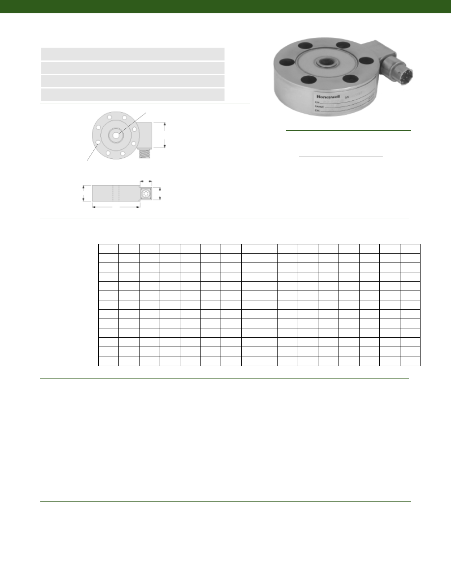
156
........20N to 200kN
........+/- 0.2% Full Scale
........+/- 0.1% Full Scale
........+/- 0.1% Full Scale
........+/- 0.08% Full Scale
........+/- 0.05% Full Scale
........+/- 0.03% Full Scale
........2 mV/V (nominal)
........3 mV/V (nominal)
........Compression/ Tension
........Infinite
........Standard calibration for tension/ compression load cells is in tension only
........-55° to 120° C
........15° to 70° C
........0.004% of Full Scale/ °C
........0.004% Reading/ °C
........IP65 (note 9)
Dimensions
Performance
Environmental
Model 41E Precision Low Profile Load Cell
Order Code 41E
www.honeywell.com/sensotec
1-888-282-9891
n
20N to 200kN Range
n
mV/V Output
n
Enhanced Thermal Stability
n
Double Diaphragm Design
øD
H
C
A
B
Load Ranges
Linearity
20N to 200N
500N to 200kN
Hysteresis
20N to 200N
500N to 200kN
Non-Repeatability
20N to 200N
500N to 200kN
Output
20N to 100N
200N to 200kN
Operation
Resolution
Standard Calibration
Temperature, Operating
Temperature, Compensated
Temperature, Effect
Zero
Span
Protection Rating
Range
Range Code D(mm) H(mm) F# G(mm) K(mm) T A(mm) A*(mm) B(mm) B*(mm) C(mm) P(mm) R(mm)
F Clearance Holes Equally Spaced on G Diameter B.C.,
K Diameter thru, c-bore P dia. X R deep
T (thread)
* Length of load cell with amplified option (see options chart)
Wiring Code
Connector/ Unamplified (Std.)
A
(+) Excitation
B
(+) Excitation
C
(-) Excitation
D
(-) Excitation
E
(-) Output
F
(+) Output
20 N
020N0
64
20
6
51
5
M6x1.0-6H
21
64
19
23
32
8
5
50 N
050N0
64
20
6
51
5
M6x1.0-6H
21
64
19
23
32
8
5
100 N
100N0
64
20
6
51
5
M6x1.0-6H
21
64
19
23
32
8
5
200 N
200N0
76
25
6
60
7
M10x1.0-6H
21
64
19
23
32
11
7
500 N
500N0
76
25
6
60
7
M10x1.0-6H
21
64
19
23
32
11
7
1 kN
01KN0
76
25
6
60
7
M10x1.0-6H
21
64
19
23
32
11
7
2 kN
02KN0
76
25
6
60
7
M10x1.0-6H
21
64
19
23
32
11
7
5 kN
05KN0
76
25
6
60
7
M10x1.0-6H
21
64
19
23
32
11
7
10 kN
10KN0
89
25
6
70
9
M12x1.5-6H
21
64
19
23
32
14
8
20 kN
20KN0
89
25
6
70
9
M12x1.5-6H
21
64
19
23
32
14
8
50 kN
50KN0
140
46
8
114
10
M24x1.5-6H
32
58
38
38
51
17
11
100 kN 100KN0
152
46
8
124
14
M36x3.0-6H
32
58
38
38
51
N/A
N/A
200 kN 200KN0
152
46
8
124
14
M36x3.0-6H
32
58
38
38
51
N/A
N/A
Courtesy of Steven Engineering, Inc.-230 Ryan Way, South San Francisco, CA 94080-6370-Main Office: (650) 588-9200-Outside Local Area: (800) 258-9200-www.stevenengineering.com
Sensotec Sensors Full Line Catalog-html.html
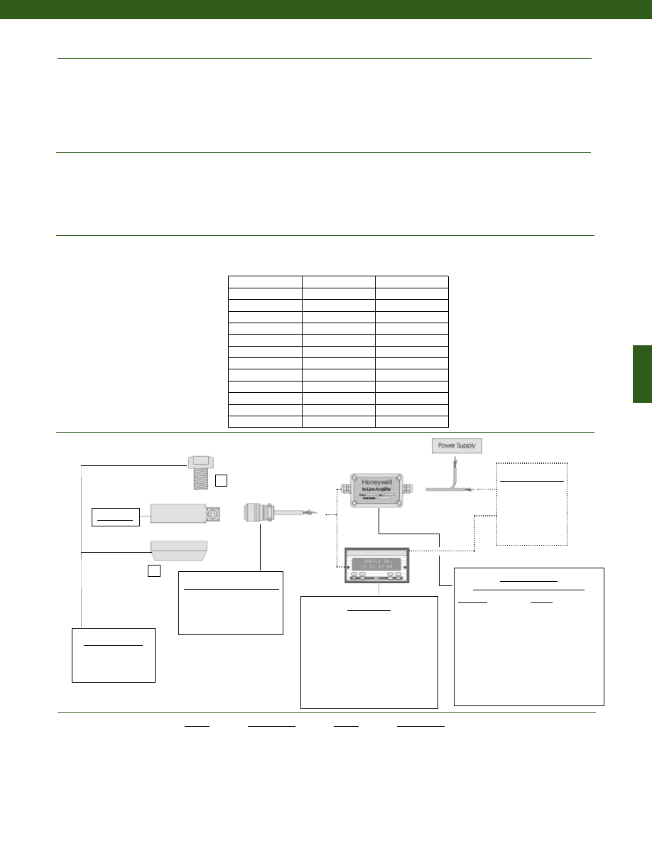
157
www.honeywell.com/sensotec
Mechanical
Electrical
Typical System Diagram
Strain Gage Type
Excitation (calibration)
Insulation Resistance
Bridge Resistance (tolerance)
Shunt Calibration Data
Electrical Termination (std)
20N to 20kN
50kN to 200kN
Maximum Allowable Load
Weight
Material
20N to 1.3kN
1.5kN to 200kN
Deflection
Natural Frequency
........Bonded Foil
........10 VDC
........5,000 Megohms @ 50 VDC
........350 Ohms (nominal)
........Included
........PTIH-10-6P Bayonet plug (MIL-C-26482)
........MS3102E-14S-6P
........150% F.S. (note 1)
........See table
........17-4PH Stainless Steel
........4340 painted
........6 micrometers
........See table
In-Line Amplifiers
(Used with unamplified units only)
Amplifier
Output
Universal In-Line Amplifiers
UV
+/- 5 VDC
UV-10
+/- 10 VDC
UBP
0 +/- 5 VDC
U3W
4-20 mA (3 wire)
U2W
4-20 mA (2 wire)
DIN rail Mount In-Line Amplifiers
DV-05
0 +/- 5 VDC (3 wire)
DA-05
4-20 mA (3 wire)
DV-10
0 +/- 10 VDC (3 wire)
Display Units
SC500
SC1000
SC2000
SC2001
SC3004
GM (Unamplified only)
GM-A (Amplified only)
NK (Unamplified only)
HH (Unamplified only)
Customer Supplied
Chart Recorder
Alarm Panel
Data Acquisition
Computer
PLC
Model 41E
1-888-282-9891
Model 41E
Deflections and Ringing Frequencies
Capacity
Natural
Ringing Frequency
(Hz)
Weight
(lb)
20 N
1,000
0.8
50 N
1,200
0.8
100 N
2,000
0.8
200 N
2,300
1.5
500 N
3,500
1.5
1 kN
4,300
1.5
2 kN
5,100
1.5
5 kN
7,000
1.5
10 kN
10,000
2.0
20 kN
14,000
2.0
50 kN
4,200
8.8
100 kN
6,400
11.0
200 kN
12,000
11.0
Range
Range Code
20 N
020N0
50 N
050N0
100 N
100N0
200 N
200N0
500 N
500N0
1 kN
01KN0
2 kN
02KN0
Range Codes
Range
Range Code
5 kN
05KN0
10 kN
10KN0
20 kN
20KN0
50 kN
50KN0
100 kN
100KN0
200 kN
200KN0
Mating Connectors & Cables
PT06A-10-6S, Std.
PT06E-10-6S
MS3106A-14S-6S
Mounting Options
1. Pull Plate
2. Load Button
1
2
Courtesy of Steven Engineering, Inc.-230 Ryan Way, South San Francisco, CA 94080-6370-Main Office: (650) 588-9200-Outside Local Area: (800) 258-9200-www.stevenengineering.com
Sensotec Sensors Full Line Catalog-html.html
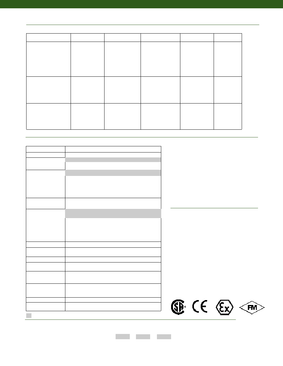
158
www.honeywell.com/sensotec
1-888-282-9891
* Black and Green wires are internally connected.
** Pins B and C are internally connected.
Internal Amplifiers
Model 41E
1. Allowable Maximum Loads- Maximum load to be applied without damage (note 2).
2. Without Damage- loading to this level will not cause excessive zero shift or
performance degradation. The user must consider fatigue life for long term
use and structural integrity. All structurally critical applications (overhead
loading, etc.) should always be designed with safety redundant load paths.
3. Interconnecting shunt cal. 1 terminal with shunt cal. 2 terminal provides 50%
(unamplified units), 75% (4-20mA 3-wire units) or 80% (voltage amplified
units) of full scale output for quick calibration. Shunt Calibration comes stan-
dard with internal amplifier options 2a, 2b, 2c, 2t and 2j.
4. O=Orange; Y=Yellow; B=Blue; Bl=Black; R=Red; Br=Brown; W=White;
G=Green. Color specifying cable and number or letter specifying connector.
5. No mating connector necessary for cable option.
6. Adding any internal amplifiers on 20N to 100N ranges will take typically 6
weeks for delivery.
7. Not available with amplified options.
8. Option 3d is not available with option 2k.
9. Availability varies with range, consult factory.
10. Consult factory for TEDS availability with amplified models.
Operating temperature -50° to 200° c
Lightning protection
OEM labels
Case pressure
Radiation resistant
Cable orientation
Fatigue rating
Different cable lengths
Venting
Different materials
Electro-static discharge immunity
Different threads
Special wiring codes
Special Customer Requirements
(Consult Factory)
Notes
Options
How to Order
Combine the order code, the range code and the options code.
Order Code
Range Code
Options Code
Sample Code: 41E 500N0
6i
Build from Scratch
Load Range
20N to 2000kN
Temperature
Compensation
1j. -65° to 50° C
1k. -20° to 85° C
Internal Amplifiers
(note 6)
2b. +/- 5 VDC
2c. 0-5VDC
2j. 4-20mA (3-wire) output
2k. 4-20mA (2-wire)
2t. 0-10 VDC output
Internal Amp
Enhancements
3a. Input/ Output Isolation (note 9)
3d. Remote Buffered Shunt Calibration (note 8)
Electrical Termination
6e. Integral cable: Teflon
6f. Integral cable: PVC
6g. Integral cable: Neoprene (note 9)
6h. Integral cable: Silicone (note 9)
6i. Integral underwater cable (note 9)
6j. 1/2-14 conduit fitting with 5 ft. of 4 conductor PVC cable
6q. Molded integral cable: Polyurethane (note 9)
Shunt Calibration
8a. Precision Internal Resistor (note 7)
Bridge Resistance
(note 9)
12a. 1,000 Ohms (foil) (max. 200° C)
12b. 5,000 Ohms (foil) (max. 120° C)
Bridge Type
31a. Dual bridge.
Potentiometers
14a. No access to pots.
14c. Side access to pots
Electrical Connector
Orientation
15b. Vertical Electrical Exit Port Orientation
15c. Radial Electrical Exit Port Orientation
15d. Connector on end of cable
Load Direction
30a. Positive in compression, compression testing only
30b. Positive in tension, tension & compression testing only
30c. Negative in compression, compression testing only
30d. Positive in compression, tension & compression testing only
Shock & Vibration
44a. Shock and vibration resistance
Interfaces
53e. Signature Calibration
53t. T.E.D.S. IEEE 1451-4 Module (note 10)
15° to 70° C
2u. Unamplified, mV/V output
6-pin Bayonet plug (MIL-C-26482) (20N to 20kN)
MS3102E-14S-9P or equivalent (50kN to 200kN)
Supplied as standard
Amplifier
Specifications
Voltage Output
Option 2b
Voltage Output
Option 2c
Voltage Output
Option 2t
Current 3 Wire
Option 2j
Current 2 Wire
Option 2k
Output Signal
Input Power (Voltage)
Input Power (Current)
Frequency Response
Power Supply Rejection
Operating Temperature
Reverse Voltage Protection
Short Circuit Protection
+/- 5V
+/-15V or 26-32VDC
45 mA
3000 Hz
60 db
-20° to 185° F
Yes
Momentary
0-5V or +/- 5V @ 45mA
11-28 VDC
40 mA
3000 Hz
60 db
-20° to 185° F
Yes
Momentary
0-10V or +/- 10V @ 45mA
15-28 VDC
40 mA
3000 Hz
60 db
-20° to 185° F
Yes
Momentary
4-20 mA
22-32 VDC
65 mA
2500 Hz
60 db
0° to 185° F
Yes
Yes
4-20 mA
15-40 VDC
4-28 mA
300 Hz
60 db
0° to 185° F
Yes
Yes
Wiring Code: Connector
(Std.)
(note 3)
A (+) Supply
B Output Common/
C Supply Return
D (+) Output
E Shunt Cal 1
F Shunt Cal 2
A (+) Supply
B** Output Common/
C** Supply Return
D (+) Output
E Shunt Cal 1
F Shunt Cal 2
A (+) Supply
B** Output Common/
C** Supply Return
D (+) Output
E Shunt Cal 1
F Shunt Cal 2
A (+) Supply
B** Output Common/
C** Supply Return
D (+) Output
E Shunt Cal 1
F Shunt Cal 2
A (+) Supply
B No connection
C No connection
D (+) Output
E Case Ground
F No connection
Wiring Code: Cable
(note 3)
(note 4)
(note 5)
R (+) Supply
Bl Output Common/
G Supply Return
W (+) Output
B Shunt Cal 1
Br Shunt Cal 2
R (+) Supply
Bl*Output Common/
G*Supply Return
W (+) Output
B Shunt Cal 1
Br Shunt Cal 2
R (+) Supply
Bl*Output Common/
G*Supply Return
W (+) Output
B Shunt Cal 1
Br Shunt Cal 2
R (+) Supply
Bl*Output Common/
G*Supply Return
W (+) Output
B Shunt Cal 1
Br Shunt Cal 2
R (+) Supply
Bl (+) Output
W Case Ground
Approved Approved Approved
Intrinsically Safe Amp
Courtesy of Steven Engineering, Inc.-230 Ryan Way, South San Francisco, CA 94080-6370-Main Office: (650) 588-9200-Outside Local Area: (800) 258-9200-www.stevenengineering.com
Sensotec Sensors Full Line Catalog-html.html
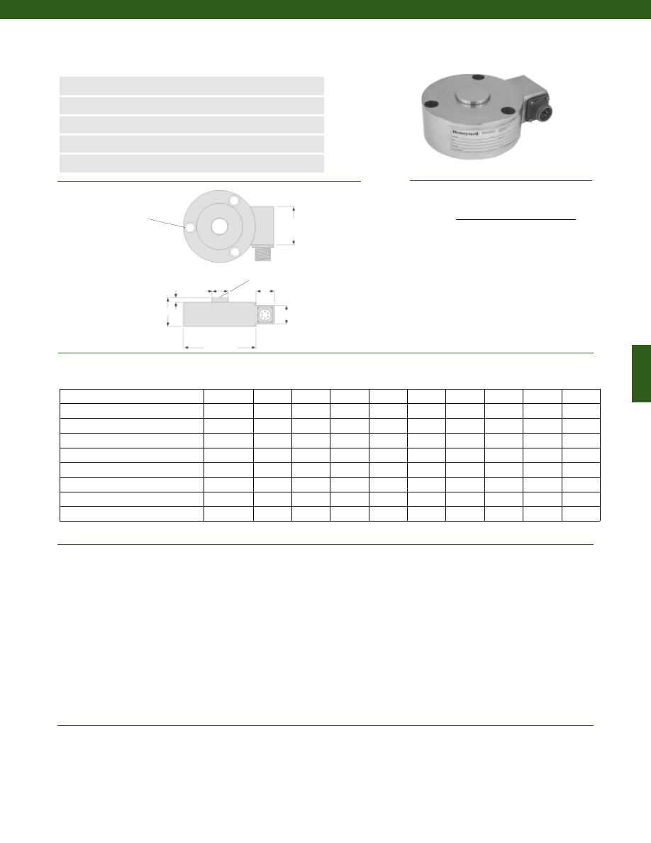
159
Model 43 Precision Low Profile Load Cell
Order Code AL112
www.honeywell.com/sensotec
1-888-282-9891
n
5 to 500,000 lb.
n
mV/V Output
n
Stainless Steel
n
Double Diaphragm Design
n
0.10% Accuracy
øD1
øD2
H
0.18 in.
C
A
B
Spherical Radius
Load Ranges................5 to 500,000 lb.
Non-Linearity
5 to 25 lb.................+/- 0.2% Full Scale
50 to 500,000 lb.................+/- 0.1% Full Scale
Hysteresis
5 to 25 lb.................+/- 0.1% Full Scale
50 to 500,000 lb.................+/- 0.08% Full Scale
Non-Repeatability
5 to 25 lb.................+/- 0.1% Full Scale
50 to 500,000 lb.................+/- 0.03% Full Scale
Output (tolerance)
5 to 25 lb.................2 mV/V +/- 0.5% Full Scale
50 to 500,000 lb.................3 mV/V +/- 0.5% Full Scale
Operation................Compression
Resolution................Infinite
Standard Calibration................5 point calibration, compression only
Temperature, Operating................-65° to 250° F
Temperature, Compensated................60° to 160° F
Temperature, Effect
Zero................0.002% Full Scale/ °F
Span................0.002% Full Scale/ °F
F
øG (in.)
Ranges (lb.)
D1 (in.) D2 (in.)
H (in.) Typ.Dia.
B.C.
A (in.)
A* (in.) B (in.) B* (in.)
C (in.)
3 Clearance Holes for F
Socket HD Cap Screws, Equally
Spaced as Shown on G
Diameter B.C.
* Length of load cell with amplified option (see options chart)
Wiring Code
Connector/ Unamplified (Std.)
A
(+) Excitation
B
(+) Excitation
C
(-) Excitation
D
(-) Excitation
E
(-) Output
F
(+) Output
5; 10; 25
2.50
0.37
0.98
#8
2.000
0.82
2.5
0.75
0.90
1.25
50; 100; 250; 500; 1000
3.00 (note 1) 0.56
1.18
1/4
2.250
0.82
2.5
0.75
0.90
1.25
2000; 3000; 4000; 5000
3.50
0.69
1.18
5/16
2.625
0.82
2.5
0.75
0.90
1.25
7500; 10,000; 15,000; 20,000; 30,000
4.50
1.50
2.00
3/8
3.790
1.25
2.3
1.50
1.50
2.00
50,000; 75,000; 100,000
4.50
1.50
2.00
3/8
3.790
1.25
2.3
1.50
1.50
2.00
150,000; 200,000
5.50
2.00
2.18
3/8
4.812
1.25
2.3
1.50
1.50
2.00
300,000
7.00
2.50
2.68
3/8
6.000
1.25
2.3
1.50
1.50
2.00
400,000
7.50
2.50
2.68
3/8
6.750
1.25
2.3
1.50
1.50
2.00
500,000
11.00
4.75
4.50
3/4
9.500
1.25
2.3
1.50
1.50
2.00
Dimensions
Performance
Environmental
Courtesy of Steven Engineering, Inc.-230 Ryan Way, South San Francisco, CA 94080-6370-Main Office: (650) 588-9200-Outside Local Area: (800) 258-9200-www.stevenengineering.com
Sensotec Sensors Full Line Catalog-html.html
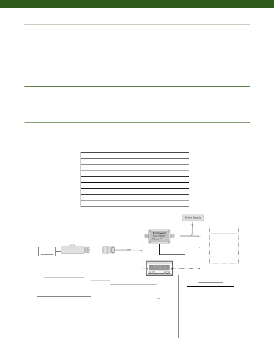
160
www.honeywell.com/sensotec
Mechanical
Typical System Diagram
Maximum Allowable Load................150% F.S. (note 2)
Weight................See table
Material................17-4PH Stainless Steel
Life Cycles (approx.)................> 10 million cycles
Deflection................See table
Natural Frequency................See table
Electrical
Strain Gage Type................Bonded Foil
Excitation (calibration)................10 VDC
Excitation (acceptable)................Up to 15 VDC or AC
Insulation Resistance................5000 Megohms @ 50 VDC
Bridge Resistance (tolerance)................350 Ohms
Zero Balance (tolerance)................+/- 1% Full Scale
Shunt Calibration Data................Included
Electrical Termination (std)
5 to 5,000 lb.................PTIH-10-6P
7,500 to 500,000 lb.................MS3106A-14S-6S
Mating Connector (not incl.)
5 to 5,000 lb.................PT06A-10-6S
7,500 to 500,000 lb.................MS3106A-14S-6S
Mating Connectors & Cables
PT06A-10-6S, Std.
PT06E-10-6S
MS3106A-14S-6S
In-Line Amplifiers
(Used with unamplified units only)
Amplifier
Output
Universal In-Line Amplifiers
UV
+/- 5 VDC
UV-10
+/- 10 VDC
UBP
0 +/- 5 VDC
U3W
4-20 mA (3 wire)
U2W
4-20 mA (2 wire)
DIN Rail Mount In-Line Amplifiers
DV-05
0 +/- 5 VDC (3 wire)
DA-05
4-20 mA (3 wire)
DV-10
0 +/- 10 VDC (3 wire)
Display Units
SC500
SC1000
SC2000
SC2001
SC3004
GM (Unamp. only)
GM-A (Amp. only)
NK (Unamp. only)
HH (Unamp. only)
Customer Supplied
Chart Recorder
Alarm Panel
Data Acquisition
Computer
PLC
Model 43
1-888-282-9891
Deflections and Ringing Frequencies
Capacity (lb.)
Deflection
@ Full Scale
(in.)
Ringing
Frequency
(Hz)
Weight
(lb)
5 to 25
0.001
2,000
0.8
50 to 1,000
0.002
4,500
1.5
2,000 to 5,000
0.002
11,000
1.6
7,500 to 30,000
0.003
9,000
6.4
50,000 to 100,000
0.004
13,000
6.6
150,000 to 200,000
0.004
11,000
11.7
300,000
0.005
10,000
23.8
400,000
0.007
8,400
26.5
500,000
0.007
4,800
90.4
Model 43
Courtesy of Steven Engineering, Inc.-230 Ryan Way, South San Francisco, CA 94080-6370-Main Office: (650) 588-9200-Outside Local Area: (800) 258-9200-www.stevenengineering.com
Sensotec Sensors Full Line Catalog-html.html
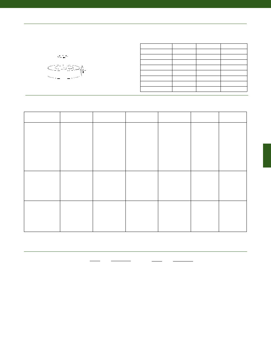
161
www.honeywell.com/sensotec
1-888-282-9891
Internal Amplifiers
Amplifier
Specifications
Voltage Output
Option 2a
Voltage Output
Option 2c
Voltage Output
Option 2t
Current 3 Wire
Option 2j
Current 2 Wire
Option 2k
Intrinsically Safe
Option 2n (2N)***
Output Signal
Input Power (Voltage)
Input Power (Current)
Frequency Response
Power Supply
Rejection
Operating Temperature
Reverse Voltage
Protection
Short Circuit Protection
0-5V
+/-15V or 26-32VDC
45 mA
3000 Hz
60 db
-20° to 185° F
Yes
Momentary
0-5V or +/- 5V
@ 45mA
11-28 VDC
40 mA
3000 Hz
60 db
-20° to 185° F
Yes
Momentary
0-10V or +/- 10V
@ 45mA
15-28 VDC
40 mA
3000 Hz
60 db
-20° to 185° F
Yes
Momentary
4-20 mA
22-32 VDC
65 mA
2500 Hz
60 db
0° to 185° F
Yes
Yes
4-20 mA
15-40 VDC
4-28 mA
300 Hz
60 db
0° to 185° F
Yes
Yes
4-20 mA
9-28 VDC
4-24 mA
2000 Hz
60 db
-20° to 185° F
Yes
Yes
Wiring Code: Connector
(Std.)
(note 4)
A (+) Supply
B Output Common/
C Supply Return
D (+) Output
E Shunt Cal 1
F Shunt Cal 2
A (+) Supply
B** Output Common/
C** Supply Return
D (+) Output
E Shunt Cal 1
F Shunt Cal 2
A (+) Supply
B** Output Common/
C** Supply Return
D (+) Output
E Shunt Cal 1
F Shunt Cal 2
A (+) Supply
B** Output Common/
C** Supply Return
D (+) Output
E Shunt Cal 1
F Shunt Cal 2
A (+) Supply
B No connection
C No connection
D (+) Output
E Case Ground
F No connection
A (+) Supply
B No connection
C No connection
D (+) Output
E Case Ground
F No connection
Wiring Code: Cable
(note 4)
(note 5)
(note 6)
R (+) Supply
Bl Output Common/
G Supply Return
W (+) Output
B
Shunt Cal 1
Br Shunt Cal 2
R (+) Supply
Bl* Output Common/
G* Supply Return
W (+) Output
B
Shunt Cal 1
Br Shunt Cal 2
R (+) Supply
Bl* Output Common/
G* Supply Return
W (+) Output
B
Shunt Cal 1
Br Shunt Cal 2
R (+) Supply
Bl* Output Common/
G* Supply Return
W (+) Output
B
Shunt Cal 1
Br Shunt Cal 2
R (+) Supply
Bl (+) Output
W Case Ground
R (+) Supply
Bl (+) Output
W Case Ground
Range
Range Code
5 lb.
AT
10 lb.
AV
25 lb.
BL
50 lb.
BN
100 lb.
BR
250 lb.
CN
500 lb.
CR
1000 lb.
CV
2000 lb.
DL
3000 lb.
DN
4000 lb.
DP
5000 lb.
DR
Range
Range Code
7500 lb.
DT
10,000 lb.
DV
15,000 lb.
EJ
20,000 lb.
EL
30,000 lb.
EN
50,000 lb.
EP
75,000 lb.
ER
100,000 lb.
ET
150,000 lb.
FJ
200,000 lb.
FL
300,000 lb.
FN
400,000 lb.
FP
500,000 lb.
FR
Range Codes
Allowable Maximum Loads
(note 2)
Side
Axial
Torque
Capacity (lb.)
Bending
(lb.-in.)
Torque
(lb.-ft.)
Side Load
(lb.)
Bending
5 to 25
50%
40%
25%
50 to 1,000
45%
35%
25%
2,000 to 5,000
30%
25%
25%
7,500 to 30,000
20%
20%
15%
50,000 to 100,000
20%
20%
15%
150,000 to 200,000
20%
20%
15%
300,000
20%
20%
10%
400,000
20%
20%
10%
500,000
20%
20%
10%
Model 43
* Black and Green wires are internally connected.
** Pins B and C are internally connected.
*** See Sensotec website for most up-to-date information regarding Intrinsically Safe approvals ref. #008-0547-00.
Courtesy of Steven Engineering, Inc.-230 Ryan Way, South San Francisco, CA 94080-6370-Main Office: (650) 588-9200-Outside Local Area: (800) 258-9200-www.stevenengineering.com
Sensotec Sensors Full Line Catalog-html.html
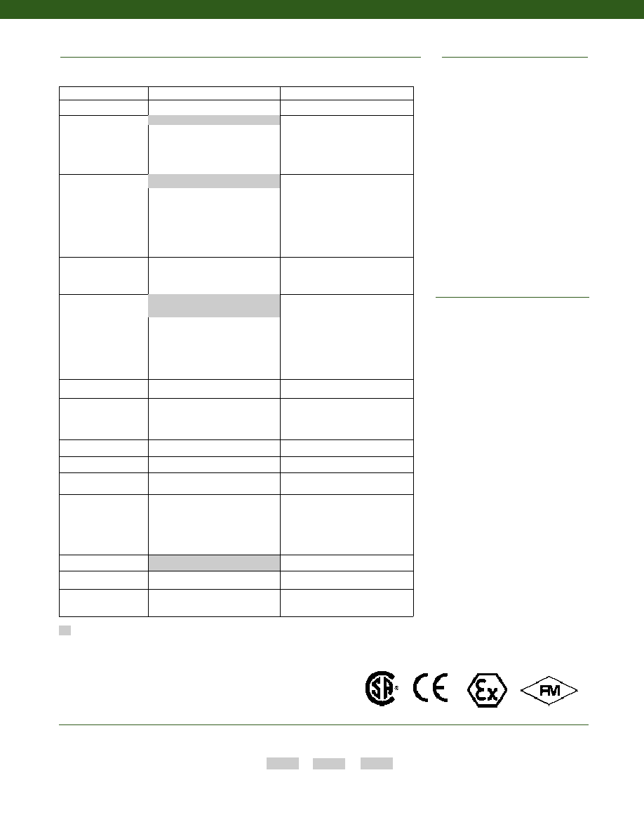
162
1. 3.00 in. diameter has six mounting holes.
2. Allowable Maximum Loads- Maximum
load to be applied without damage (note 3).
3. Without Damage- loading to this level
will not cause excessive zero shift or
performance degradation. The user must
consider fatigue life for long term use
and structural integrity. All structurally
critical applications (overhead loading,
etc.) should always be designed with
safety redundant load paths.
4. Interconnecting shunt cal. 1 terminal with
shunt cal. 2 terminal provides 50%
(unamplified units), 75% (4-20mA 3-wire
units) or 80% (voltage amplified units) of
full scale output for quick calibration.
Shunt Calibration comes standard
with internal amplifier options 2a, 2b, 2c,
2t and 2j.
5. O=Orange; Y=Yellow; B=Blue; Bl=Black;
R=Red; Br=Brown; W=White; G=Green.
Color specifying cable and number or letter
specifying connector
6. No mating connector necessary for cable
option.
7. Only available with options 2a or 2c.
8. Consult factory for TEDS availability with
amplified models.
Operation temperature -60° to 400°F
Lightning protection
Barometric compensation
OEM labels
Case pressure
Radiation proof
Cable orientation
Fatigue rating
Different cable lengths
Venting
Different materials
Electro-static discharge immunity
Different threads
Special wiring codes
Special Customer
Requirements
(Consult Factory)
Notes
Options
How to Order
Combine the order code, the range code and the options code.
Order Code
Range Code
Options Code
Sample Code:
AL112
CV
6h
Supplied as standard
Built to Order
Built from Scratch
Load Range
5 to 500,000 lb.
Temperature
Compensation
1b. 30° to 130° F
1c. 0° to 185° F
1d. -20° to 130° F
1e. -20° to 200° F
1f. 70° to 250° F
1g. 70° to 325° F
1i. -65° to 250° F
Internal Amplifiers
2a. 4 wire 0-5VDC output
2c. 0-5VDC
2j. 4-20mA (3-wire) output
2k. 4-20mA (2-wire)
2t. 0-10 VDC output
2n(2N). 4-20mA (2-wire)
Intrinsically safe
Internal Amp
Enhancements
3a. Input/ Output Isolation (note 7)
3d. Remote Buffered Shunt
Calibration
Electrical Termination
6e. Integral cable: Teflon
6f. Integral cable: PVC
6g. Integral cable: Neoprene
6h. Integral cable: Silicone
6i. Integral underwater cable
6j. 1/2-14 conduit fitting with 5 ft.
of 4 conductor PVC cable
Shunt Calibration
8a. Precision Internal Resistor
Special Calibration
9a. 10 point (5 up/5 down) 20%
increments @ 70° F
9b. 20 point (10 up/10 down)
10% increments @ 70°F
Bridge Resistance
12. 5,000 Ohms (foil) (max. 250°F)
Bridge Type
31a.Dual bridge.
Potentiometers
14a.No access to pots.
14b.Top access to pots
Electrical Connector
Orientation
15a.Horizontal Electrical Exit
Port Orientation
15b.Vertical Electrical Exit Port
Orientation
15c.Radial Electrical Exit Port
Orientation
15d.Connector on end of cable
Special Calibration
30a.Compression only (+) Output
Shock & Vibration
44a.Shock and vibration resistance
Interfaces
53e.Signature Calibration
53t. T.E.D.S. IEEE 1451-4 Module
(note 8)
6a. Bendix PTIH-10-6P –
(or equivalent) 6 pin (max. 250°F)
2u. Unamplified, mV/V output
1a. 60° to 160° F
www.honeywell.com/sensotec
1-888-282-9891
Model 43
Approved Approved Approved
Intrinsically Safe Amp
Courtesy of Steven Engineering, Inc.-230 Ryan Way, South San Francisco, CA 94080-6370-Main Office: (650) 588-9200-Outside Local Area: (800) 258-9200-www.stevenengineering.com
Sensotec Sensors Full Line Catalog-html.html
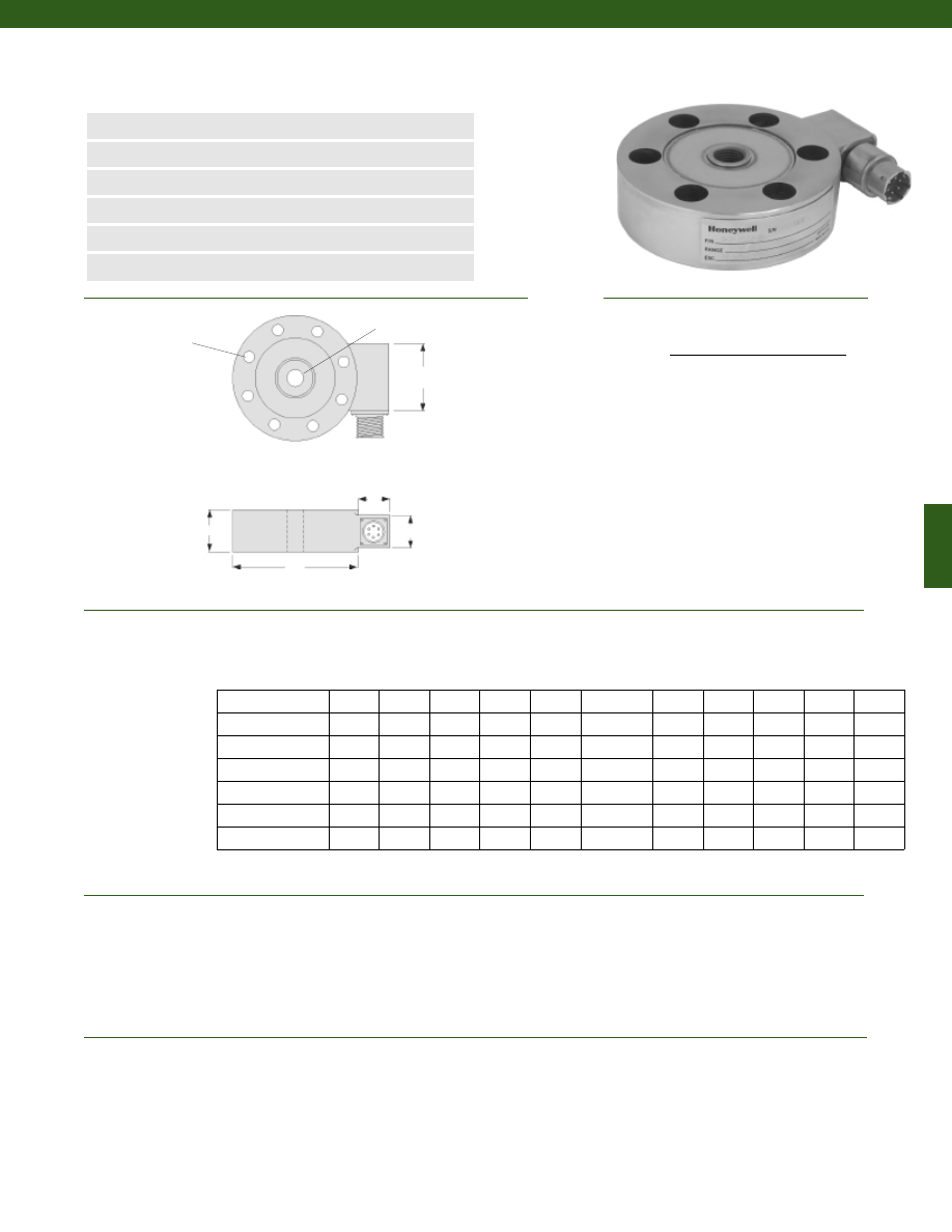
163
Dimensions
Performance
Environmental
Model 75 Precision Low Profile Load Cell
Order Code BL114
www.honeywell.com/sensotec
1-888-282-9891
n
50 to 200,000 lb.
n
mV/V Output
n
Stainless Steel
n
Dual Diaphragm Design
n
0.10% Accuracy
n
Enhanced Overload Capacity
øD
H
C
A
B
Load Ranges................50 to 200,000 lb.
Linearity................+/- 0.1% Full Scale
Hysteresis................+/- 0.1% Full Scale
Non-Repeatability................+/- 0.03% Full Scale
Output (tolerance)................2 mV/V +/- 0.5% Full Scale
Operation................Compression/ Tension
Resolution................Infinite
Standard Calibration................5 point calibration: 0%, 50% and 100% of Full Scale in tension only
Temperature, Operating................-65° to 250° F
Temperature, Compensated................60° to 160° F
Temperature, Effect
Zero................0.002% Full Scale/ °F
Span................0.002% Full Scale/ °F
øG (in.) øK (in.)
Ranges (lb.)
D (in.)
H (in.)
F#
B.C.
thru
T
A (in.) A* (in.) B (in.) B* (in.) C (in.)
F Clearance Holes
Equally Spaced on
G Diameter B.C.,
K Diameter thru
T
* Length of load cell with amplified option (see options chart)
Wiring Code
Connector/ Unamplified (Std.)
A
(+) Excitation
B
(+) Excitation
C
(-) Excitation
D
(-) Excitation
E
(-) Output
F
(+) Output
50 to 500
3.00
1.00
6
2.250
0.28
3/8-24 UNF
0.82
2.5
0.75
0.9
1.25
1000 to 2000
3.50
1.00
6
2.625
0.34
1/2-20 UNF
0.82
2.5
0.75
0.9
1.25
3000 to 7500
5.50
1.80
8
4.500
0.40
1-14 UNS
1.25
2.3
1.50
1.5
2.00
10,000 to 20,000
6.00
1.80
8
4.875
0.53
1 1/2-12 UN
1.25
2.3
1.50
1.5
2.00
30,000 to 50,000
9.00
2.00
8
6.000
0.78
2-12 UN
1.25
2.3
1.50
1.5
2.00
75,000 to 100,000
11.00
2.50
12
7.500
0.66
2 1/2-12 UN
1.25
2.3
1.50
1.5
2.00
150,000 to 200,000 14.00
4.25
12
11.750
1.03
3 1/2-12 UN
1.25
2.3
1.50
1.5
(note 1)
Courtesy of Steven Engineering, Inc.-230 Ryan Way, South San Francisco, CA 94080-6370-Main Office: (650) 588-9200-Outside Local Area: (800) 258-9200-www.stevenengineering.com
Sensotec Sensors Full Line Catalog-html.html
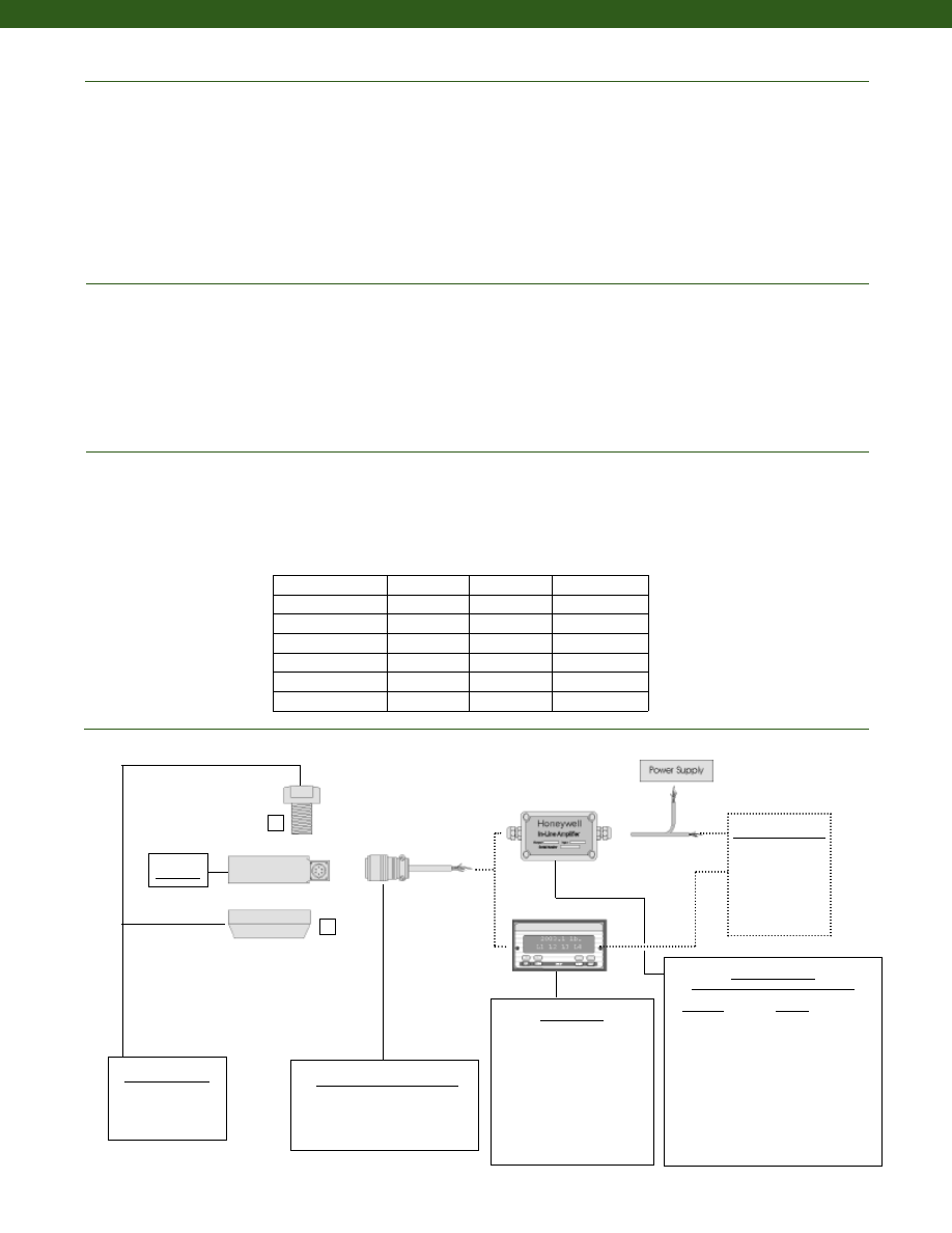
164
www.honeywell.com/sensotec
Mechanical
Typical System Diagram
Electrical
Strain Gage Type................Bonded Foil
Excitation (calibration)................10 VDC
Insulation Resistance................5,000 Megohms @ 50 VDC
Bridge Resistance (tolerance)................350 Ohms
Zero Balance (tolerance)................+/- 1% Full Scale
Shunt Calibration Data................Included
Electrical Termination (std)
50 to 2,000 lb.................PTIH-10-6P
3,000 to 200,000 lb.................MS3102E-14S-6P
Mating Connector (not incl.)
50 to 2,000 lb.................PT06A-10-6S
3,000 to 200,000 lb.................MS3106A-14S-6S
Maximum Allowable Load................200% F.S. (note 2)
Weight................See table
Material
Less than or equal to 100,000 lb.................17-4PH Stainless Steel
Greater than or equal to 125,000 lb.................Carbon Steel
Life Cycles (approx.)................>10
8
Cycles Fully Reversed
Deflection................See table
Natural Frequency................See table
Mating Connectors & Cables
PT06A-10-6S
MS3106A-14S-6S
In-Line Amplifiers
(Used with unamplified units only)
Amplifier
Output
Universal In-Line Amplifiers
UV
+/- 5 VDC
UV-10
+/- 10 VDC
UBP
0 +/- 5 VDC
U3W
4-20 mA (3 wire)
U2W
4-20 mA (2 wire)
DIN Rail Mount In-Line Amplifiers
DV-05
0 +/- 5 VDC (3 wire)
DA-05
4-20 mA (3 wire)
DV-10
0 +/- 10 VDC (3 wire)
Display Units
SC500
SC1000
SC2000
SC2001
SC3004
GM (Unamp. only)
GM-A (Amp. only)
NK (Unamp. only)
HH (Unamp. only)
Customer Supplied
Chart Recorder
Alarm Panel
Data Acquisition
Computer
PLC
Mounting Options
1. Pull Plate
2. Load Button
Model 75
1
2
1-888-282-9891
Model 75
Deflections and Ringing Frequencies
Capacity (lb.)
Deflection
@ Full Scale
(in.)
Ringing
Frequency
(kHz)
Weight
(grams)
50 to 500
0.001
2.5
730
1000 to 2000
0.002
10
900
3000 to 7500
0.002
8
4,000
10,000 to 20,000
0.003
10
5,000
30,000 to 50,000
0.003
8.2
8,600
75,000 to 100,000
0.004
7.5
15,000
150,000 to 200,000
0.006
4.5
21,000
Courtesy of Steven Engineering, Inc.-230 Ryan Way, South San Francisco, CA 94080-6370-Main Office: (650) 588-9200-Outside Local Area: (800) 258-9200-www.stevenengineering.com
Sensotec Sensors Full Line Catalog-html.html
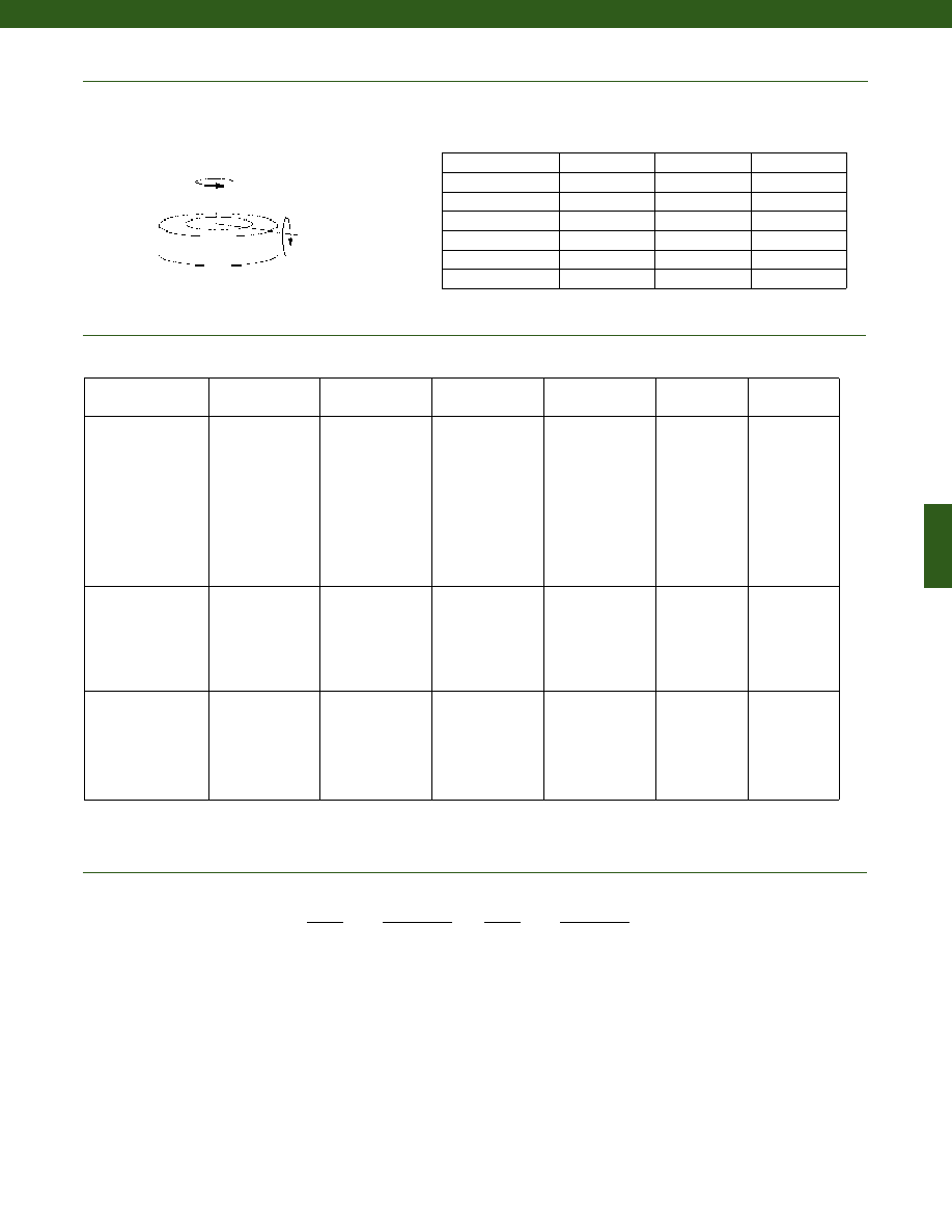
165
www.honeywell.com/sensotec
1-888-282-9891
Internal Amplifiers
Range
Range Code
50 lb.
BN
100 lb.
BR
250 lb.
CN
500 lb.
CR
1000 lb.
CV
2000 lb.
DL
3000 lb.
DN
4000 lb.
DP
5000 lb.
DR
7500 lb.
DT
Range
Range Code
10,000 lb.
DV
15,000 lb.
EJ
20,000 lb.
EL
30,000 lb.
EN
50,000 lb.
EP
75,000 lb.
ER
100,000 lb.
ET
150,000 lb.
FJ
200,000 lb.
FL
Range Codes
Model 75
Allowable Maximum Loads
(note 2)
Side
Axial
Torque
Capacity (lb.)
Side Load
(lb.)
Bending
(lb.-in.)
Torque
(lb.-ft.)
Bending
50 to 500
75%
60%
35%
1000 to 2000
45%
35%
35%
3000 to 7500
30%
30%
25%
10,000 to 20,000
30%
30%
25%
30,000 to 50,000
30%
30%
15%
75,000 to 100,000
30%
30%
15%
150,000 to 200,000
30%
30%
15%
Amplifier
Specifications
Voltage Output
Option 2b
Voltage Output
Option 2c
Voltage Output
Option 2t
Current 3 Wire
Option 2j
Current 2 Wire
Option 2k
Intrinsically Safe
Option 2n (2N)***
Output Signal
Input Power (Voltage)
Input Power (Current)
Frequency Response
Power Supply
Rejection
Operating Temperature
Reverse Voltage
Protection
Short Circuit Protection
+/- 5V
+/-15V or 26-32VDC
45 mA
3000 Hz
60 db
-20° to 185° F
Yes
Momentary
0-5V or +/- 5V
@ 45mA
11-28 VDC
40 mA
3000 Hz
60 db
-20° to 185° F
Yes
Momentary
0-10V or +/- 10V
@ 45mA
15-28 VDC
40 mA
3000 Hz
60 db
-20° to 185° F
Yes
Momentary
4-20 mA
22-32 VDC
65 mA
2500 Hz
60 db
0° to 185° F
Yes
Yes
4-20 mA
15-40 VDC
4-28 mA
300 Hz
60 db
0° to 185° F
Yes
Yes
4-20 mA
9-28 VDC
4-24 mA
2000 Hz
60 db
-20° to 185° F
Yes
Yes
Wiring Code: Connector
(Std.)
(note 4)
A (+) Supply
B Output Common/
C Supply Return
D (+) Output
E Shunt Cal 1
F Shunt Cal 2
A (+) Supply
B** Output Common/
C** Supply Return
D (+) Output
E Shunt Cal 1
F Shunt Cal 2
A (+) Supply
B** Output Common/
C** Supply Return
D (+) Output
E Shunt Cal 1
F Shunt Cal 2
A (+) Supply
B** Output Common/
C** Supply Return
D (+) Output
E Shunt Cal 1
F Shunt Cal 2
A (+) Supply
B No connection
C No connection
D (+) Output
E Case Ground
F No connection
A (+) Supply
B No connection
C No connection
D (+) Output
E Case Ground
F No connection
Wiring Code: Cable
(note 4)
(note 5)
(note 6)
R (+) Supply
Bl Output Common/
G Supply Return
W (+) Output
B Shunt Cal 1
Br Shunt Cal 2
R (+) Supply
Bl*Output Common/
G*Supply Return
W (+) Output
B Shunt Cal 1
Br Shunt Cal 2
R (+) Supply
Bl*Output Common/
G*Supply Return
W (+) Output
B Shunt Cal 1
Br Shunt Cal 2
R (+) Supply
Bl*Output Common/
G*Supply Return
W (+) Output
B Shunt Cal 1
Br Shunt Cal 2
R (+) Supply
Bl (+) Output
W Case Ground
R (+) Supply
Bl (+) Output
W Case Ground
* Black and Green wires are internally connected.
** Pins B and C are internally connected.
*** See Sensotec website for most up-to-date information regarding Intrinsically Safe approvals ref. #008-0547-00.
Courtesy of Steven Engineering, Inc.-230 Ryan Way, South San Francisco, CA 94080-6370-Main Office: (650) 588-9200-Outside Local Area: (800) 258-9200-www.stevenengineering.com
Sensotec Sensors Full Line Catalog-html.html
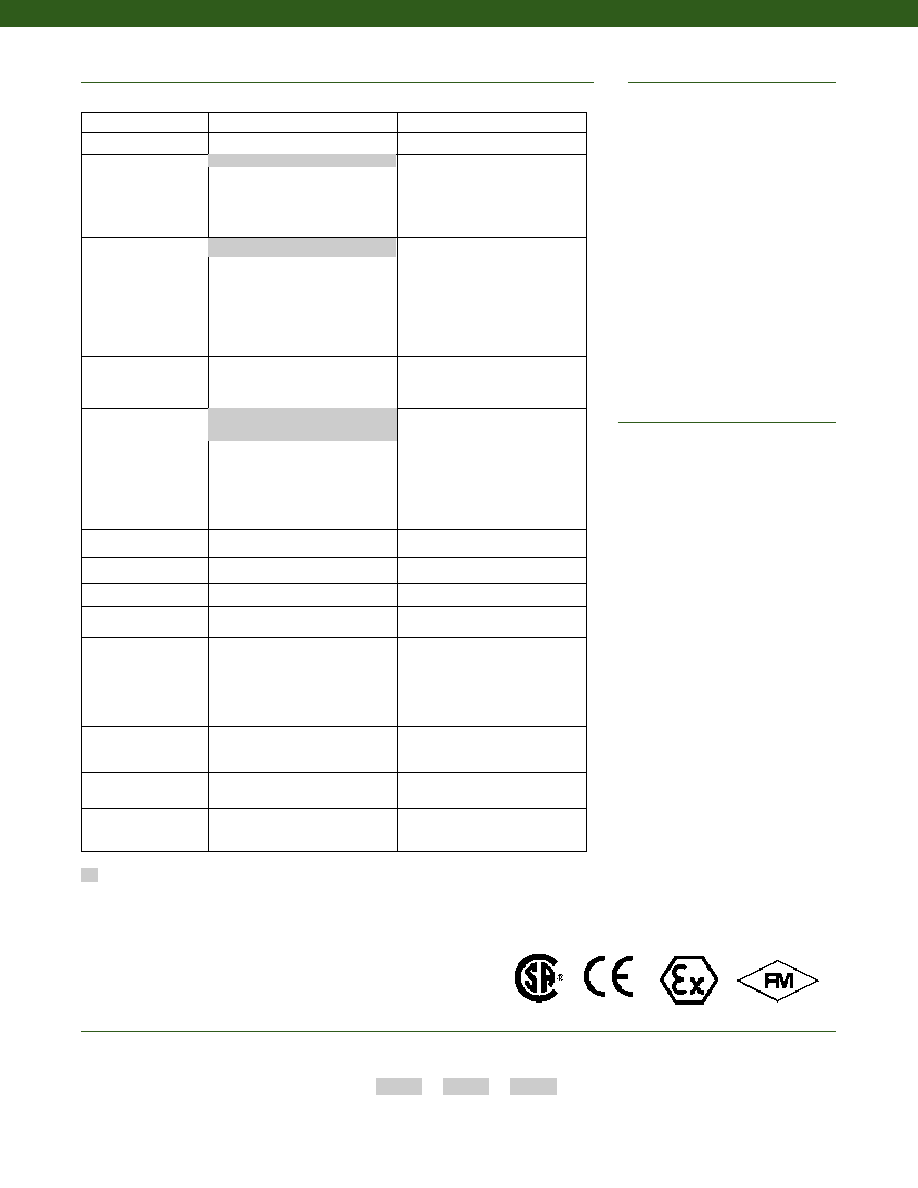
166
1. C” dimension varies on high ranges. Consult
Factory
2. Allowable Maximum Loads- Maximum
load to be applied without damage (note 3).
3. Without Damage- loading to this level
will not cause excessive zero shift or
performance degradation. The user must
consider fatigue life for long term use
and structural integrity. All structurally
critical applications (overhead loading,
etc.) should always be designed with
safety redundant load paths.
4. Interconnecting shunt cal. 1 terminal with
shunt cal. 2 terminal provides 50%
(unamplified units), 75% (4-20mA 3-wire
units) or 80% (voltage amplified units) of
full scale output for quick calibration.
Shunt Calibration comes standard
with internal amplifier options 2a, 2b, 2c,
2t and 2j.
5. O=Orange; Y=Yellow; B=Blue; Bl=Black;
R=Red; Br=Brown; W=White; G=Green.
Color specifying cable and number or letter
specifying connector
6. No mating connector necessary for cable
option.
7. Consult factory for TEDS availability with
amplified models.
Enhanced Operating Temperature
Lightning protection
Barometric compensation
OEM labels
Case pressure
Radiation proof
Cable orientation
Fatigue rating
Different cable lengths
Venting
Different materials
Electro-static discharge immunity
Different threads
Special wiring codes
Special Customer
Requirements
(Consult Factory)
Notes
Options
How to Order
Combine the order code, the range code and the options code.
Order Code
Range Code
Options Code
Sample Code:
BL114
CV
6h
Supplied as standard
www.honeywell.com/sensotec
1-888-282-9891
Model 75
Built to Order
Built from Scratch
Load Range
50 to 200,000 lb.
Temperature
Compensation
1b. 30° to 130° F
1c. 0° to 185° F
1d. -20° to 130° F
1e. -20° to 200° F
1f. 70° to 250° F
1g. 70° to 325° F
1h. 70° to 400° F
1i. -65° to 250° F
Internal Amplifiers
2b. 4 wire +/- 5VDC output
2c. 0-5VDC
2j. 4-20mA (3-wire) output
2k. 4-20mA (2-wire)
2t. 0-10 VDC output
2n (2N). 4-20mA (2-wire)
Intrinsically safe
Internal Amp
Enhancements
3a. Input/ Output Isolation
3d. Remote Buffered Shunt
Calibration
Electrical Termination
6e. Integral cable: Teflon
6f. Integral cable: PVC
6g. Integral cable: Neoprene
6h. Integral cable: Silicone
6i. Integral underwater cable
6j. 1/2-14 conduit fitting with 5 ft.
of 4 conductor PVC cable
Shunt Calibration
8a. Precision Internal Resistor
Bridge Resistance
12b.5,000 Ohms (foil) (max. 250°F)
Bridge Type
31a.Dual bridge.
Potentiometers
14a.No access to pots.
14b.Top access to pots
Electrical Connector
Orientation
15a.Horizontal Electrical Exit
Port Orientation
15b.Vertical Electrical Exit Port
Orientation
15c. Radial Electrical Exit Port
Orientation
15d.Connector on end of cable.
Special Calibration
30a.Compression only (+) Output
30b.Tension and Compression
(+,-) output
Shock & Vibration
44a.Shock and vibration resistance
Interfaces
53e.Signature Calibration
53t. T.E.D.S. IEEE 1451-4 Module
(note 7)
6a. Bendix PTIH-10-6P –
(or equivalent) 6 pin (max. 250°F)
2u. Unamplified, mV/V output
1a. 60° to 160° F
Approved Approved Approved
Intrinsically Safe Amp
Courtesy of Steven Engineering, Inc.-230 Ryan Way, South San Francisco, CA 94080-6370-Main Office: (650) 588-9200-Outside Local Area: (800) 258-9200-www.stevenengineering.com
Sensotec Sensors Full Line Catalog-html.html
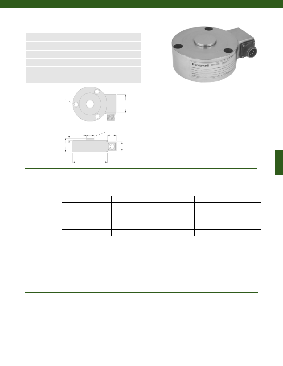
167
Dimensions
Performance
Environmental
Model 73 Precision Fatigue Rated Low Profile Load Cell
Order Code BL113
www.honeywell.com/sensotec
1-888-282-9891
n
50 to 200,000 lb.
n
mV/V Output
n
Stainless Steel
n
Double Diaphragm Design
n
0.10% Accuracy
n
Enhanced Overload Capacity
Load Ranges................50 to 200,000 lb.
Linearity................+/- 0.1% Full Scale
Hysteresis................+/- 0.1% Full Scale
Non-Repeatability................+/- 0.03% Full Scale
Output (tolerance)................2 mV/V +/- 0.5% Full Scale
Operation................Compression
Resolution................Infinite
Standard Calibration................5 point calibration: 0%, 50% and 100% F.S. in compression only
Temperature, Operating................-65° to 250° F
Temperature, Compensated................60° to 160° F
Temperature, Effect
Zero................0.002% Full Scale/ °F
Span................0.002% Full Scale/ °F
Fø
G (in.)
Ranges (lb.)
D1 (in.) D2 (in.)
H (in.) Typ. Dia.
B.C.
A (in.)
A* (in.)
B (in.)
B* (in.)
C (in.)
* Length of load cell with amplified option (see options chart)
Connector/ Unamplified (Std.)
A
(+) Excitation
B
(+) Excitation
C
(-) Excitation
D
(-) Excitation
E
(-) Output
F
(+) Output
øD1
øD2
H
0.18 in.
C
A
B
Spherical Radius
3 Clearance Holes for F
Socket HD Cap Screws,
Equally Spaced as
Shown on G
Diameter B.C.
50 to 500
3.00
0.56
1.18
1/4
2.250
0.82
2.5
0.75
0.9
1.25
1000 to 2000
3.50
0.69
1.18
5/16
2.625
0.82
2.5
0.75
0.9
1.25
3000 to 10,000
4.50
1.50
2.00
3/8
3.790
1.25
2.3
1.50
1.5
2.00
15,000 to 50,000
4.50
1.50
2.00
3/8
3.790
1.25
2.3
1.50
1.5
2.00
75,000 to 100,000
5.50
2.00
2.18
3/8
4.812
1.25
2.3
1.50
1.5
2.00
150,000 to 200,000
7.50
2.50
2.68
3/8
6.750
1.25
2.3
1.50
1.5
2.00
Wiring Code
Courtesy of Steven Engineering, Inc.-230 Ryan Way, South San Francisco, CA 94080-6370-Main Office: (650) 588-9200-Outside Local Area: (800) 258-9200-www.stevenengineering.com
Sensotec Sensors Full Line Catalog-html.html
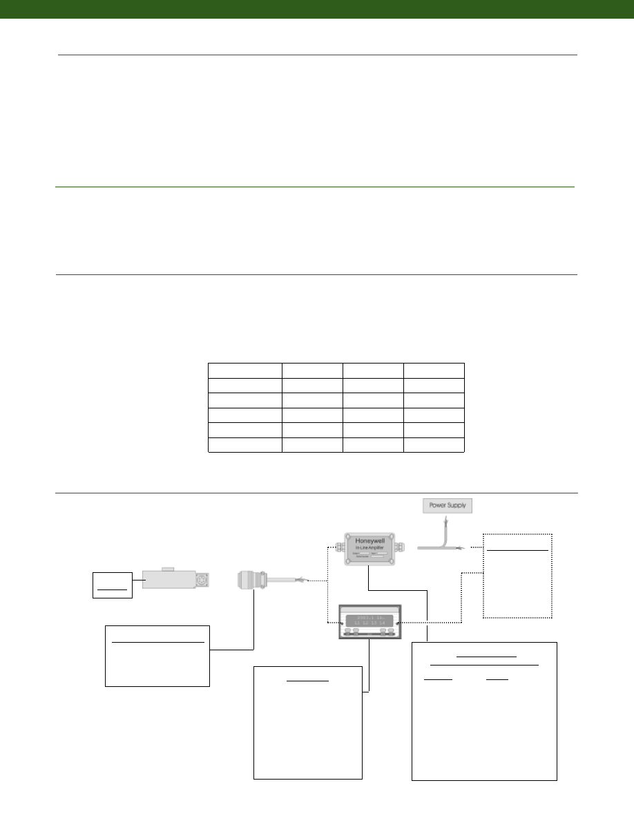
168
www.honeywell.com/sensotec
Electrical
Mechanical
Deflections and Ringing Frequencies
Typical System Diagram
Strain Gage Type................Bonded Foil
Excitation (calibration)................10 VDC
Insulation Resistance................5,000 Megohms @ 50 VDC
Bridge Resistance (tolerance)................350 Ohms
Zero Balance (tolerance)................+/- 1% Full Scale
Shunt Calibration Data................Included
Electrical Termination (std)
50 to 2,000 lb.................PTIH-10-6P
3,000 to 200,000 lb.................MS3102E-14S-6P
Mating Connector (not incl.)
50 to 2,000 lb.................PT06A-10-6S
3,000 to 200,000 lb.................MS3106A-14S-6S
Maximum Allowable Load................200% F.S. (note 1)
Weight................See table
Material................17-4PH Stainless Steel
Life Cycles (approx.)................>10
8
Cycles Fully Reversed
Deflection................See table
Natural Frequency................See table
Mating Connectors & Cables
PT06A-10-6S
MS3106A-14S-6S
In-Line Amplifiers
(Used with unamplified units only)
Amplifier
Output
Universal In-Line Amplifiers
UV
+/- 5 VDC
UV-1 0
+/- 10 VDC
UBP
0 +/- 5 VDC
U3W
4-20 mA (3 wire)
U2W
4-20 mA (2 wire)
DIN Rail Mount In-Line Amplifiers
DV-05
0 +/- 5 VDC (3 wire)
DA-05
4-20 mA (3 wire)
DV-10
0 +/- 10 VDC (3 wire)
Display Units
SC500
SC1000
SC2000
SC2001
SC3004
GM (Unamp. only)
GM-A (Amp. only)
NK (Unamp. only)
HH (Unamp. only)
Customer Supplied
Chart Recorder
Alarm Panel
Data Acquisition
Computer
PLC
Model 73
1-888-282-9891
Model 73
Capacity (lb.)
Deflection
@ Full Scale
(in.)
Ringing
Frequency
(Hz)
Weight
(grams)
50 to 500
0.001
4,500
1.6
1000 to 2000
0.002
8,000
2.1
3000 to 10,000
0.002
9,000
6.5
15,000 to 50,000
0.003
10,000
6.6
75,000 to 100,000
0.004
13,000
12.0
150,000 to 200,000
0.006
11,000
26.5
Courtesy of Steven Engineering, Inc.-230 Ryan Way, South San Francisco, CA 94080-6370-Main Office: (650) 588-9200-Outside Local Area: (800) 258-9200-www.stevenengineering.com
Sensotec Sensors Full Line Catalog-html.html
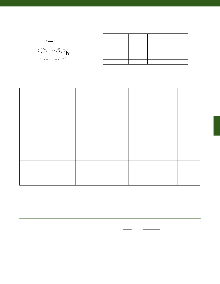
169
www.honeywell.com/sensotec
1-888-282-9891
Internal Amplifiers
Range
Range Code
50 lb.
BN
100 lb.
BR
250 lb.
CN
500 lb.
CR
1000 lb.
CV
2000 lb.
DL
3000 lb.
DN
4000 lb.
DP
5000 lb.
DR
7500 lb.
DT
Range
Range Code
10,000 lb.
DV
15,000 lb.
EJ
20,000 lb.
EL
30,000 lb.
EN
50,000 lb.
EP
75,000 lb.
ER
100,000 lb.
ET
150,000 lb.
FJ
200,000 lb.
FL
Range Codes
Model 73
Allowable Maximum Loads
(note 1)
Side
Axial
Torque
Capacity (lb.)
Side
(%F. S.)
Bending
(lb.-in.)
Torque
(lb.-ft.)
Bending
50 to 500
75%
60%
35%
1,000 to 2,000
45%
35%
35%
3,000 to 10,000
30%
30%
35%
15,000 to 50,000
30%
30%
25%
75,000 to 100,000
30%
30%
15%
150,000 to 200,000
30%
30%
15%
Amplifier
Specifications
Voltage Output
Option 2a
Voltage Output
Option 2c
Voltage Output
Option 2t
Current 3 Wire
Option 2j
Current 2 Wire
Option 2k
Intrinsically Safe
Option 2n (2N)***
Output Signal
Input Power (Voltage)
Input Power (Current)
Frequency Response
Power Supply
Rejection
Operating Temperature
Reverse Voltage
Protection
Short Circuit Protection
0-5V
+/-15V or 26-32VDC
45 mA
3000 Hz
60 db
-20° to 185° F
Yes
Momentary
0-5V or +/- 5V
@ 45mA
11-28 VDC
40 mA
3000 Hz
60 db
-20° to 185° F
Yes
Momentary
0-10V or +/- 10V
@ 45mA
15-28 VDC
40 mA
3000 Hz
60 db
-20° to 185° F
Yes
Momentary
4-20 mA
22-32 VDC
65 mA
2500 Hz
60 db
0° to 185° F
Yes
Yes
4-20 mA
15-40 VDC
4-28 mA
300 Hz
60 db
0° to 185° F
Yes
Yes
4-20 mA
9-28 VDC
4-24 mA
2000 Hz
60 db
-20° to 185° F
Yes
Yes
Wiring Code: Connector
(Std.)
(note 4)
A (+) Supply
B Output Common/
C Supply Return
D (+) Output
E Shunt Cal 1
F Shunt Cal 2
A (+) Supply
B** Output Common/
C** Supply Return
D (+) Output
E Shunt Cal 1
F Shunt Cal 2
A (+) Supply
B** Output Common/
C** Supply Return
D (+) Output
E Shunt Cal 1
F Shunt Cal 2
A (+) Supply
B** Output Common/
C** Supply Return
D (+) Output
E Shunt Cal 1
F Shunt Cal 2
A (+) Supply
B No connection
C No connection
D (+) Output
E Case Ground
F No connection
A (+) Supply
B No connection
C No connection
D (+) Output
E Case Ground
F No connection
Wiring Code: Cable
(note 4)
(note 5)
(note 6)
R (+) Supply
Bl Output Common/
G Supply Return
W (+) Output
B
Shunt Cal 1
Br Shunt Cal 2
R (+) Supply
Bl* Output Common/
G* Supply Return
W (+) Output
B
Shunt Cal 1
Br Shunt Cal 2
R (+) Supply
Bl* Output Common/
G* Supply Return
W (+) Output
B
Shunt Cal 1
Br Shunt Cal 2
R (+) Supply
Bl* Output Common/
G* Supply Return
W (+) Output
B
Shunt Cal 1
Br Shunt Cal 2
R (+) Supply
Bl (+) Output
W Case Ground
R (+) Supply
Bl (+) Output
W Case Ground
* Black and Green wires are internally connected.
** Pins B and C are internally connected.
*** See Sensotec website for most up-to-date information regarding Intrinsically Safe approvals ref. #008-0547-00.
Courtesy of Steven Engineering, Inc.-230 Ryan Way, South San Francisco, CA 94080-6370-Main Office: (650) 588-9200-Outside Local Area: (800) 258-9200-www.stevenengineering.com
Sensotec Sensors Full Line Catalog-html.html
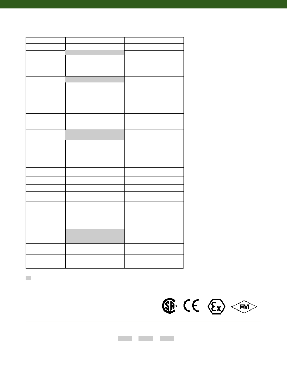
170
1. Allowable Maximum Loads- Maximum
load to be applied without damage (note 2).
2. Without Damage- loading to this level
will not cause excessive zero shift or
performance degradation. The user must
consider fatigue life for long term use
and structural integrity. All structurally
critical applications (overhead loading,
etc.) should always be designed with
safety redundant load paths.
3. Interconnecting shunt cal. 1 terminal with
shunt cal. 2 terminal provides 50%
(unamplified units), 75% (4-20mA 3-wire
units) or 80% (voltage amplified units) of
full scale output for quick calibration.
Shunt Calibration comes standard
with internal amplifier options 2a, 2b, 2c,
2t and 2j.
4. O=Orange; Y=Yellow; B=Blue; Bl=Black;
R=Red; Br=Brown; W=White; G=Green.
Color specifying cable and number or letter
specifying connector
5. No mating connector necessary for cable
option.
6. Consult factory for TEDS availability with
amplified models.
Enhanced Operating Temperature
Lightning protection
Barometric compensation
OEM labels
Case pressure
Radiation proof
Cable orientation
Different cable lengths
Venting
Different materials
Electro-static discharge immunity
Different threads
Special wiring codes
Special Customer
Requirements
(Consult Factory)
Notes
Options
How to Order
Combine the order code, the range code and the options code.
Order Code
Range Code
Options Code
Sample Code: BL113
CV
6h
Supplied as standard
Built to Order
Built from Scratch
Load Range
50 to 200,000 lb.
Temperature
Compensation
60° to 160° F
1b. 30° to 130° F
1c. 0° to 185° F
1d. -20° to 130° F
1e. -20° to 200° F
1f. 70° to 250° F
1g. 70° to 325° F
1h. 70° to 400° F
1i. -65° to 250° F
Internal Amplifiers
Unamplified, mV/V output
2a. 4 wire 0-5VDC output
2c. 0-5VDC
2j. 4-20mA (3-wire) output
2k. 4-20mA (2-wire)
2t. 0-10 VDC output
2n (2N). 4-20mA (2-wire)
Intrinsically safe
Internal Amp
Enhancements
3a. Input/ Output Isolation
3d. Remote Buffered Shunt
Calibration
Electrical Termination
Bendix PTIH-10-6P –
(or equivalent) 6 pin (max. 250°F)
6e. Integral cable: Teflon
6f. Integral cable: PVC
6g. Integral cable: Neoprene
6h. Integral cable: Silicone
6i. Integral underwater cable
6j. 1/2-14 conduit fitting with 5 ft.
of 4 conductor PVC cable
Shunt Calibration
8a. Precision Internal Resistor
Bridge Resistance
12b.5,000 Ohms (foil) (max. 250°F)
Bridge Type
31a.Dual bridge.
Potentiometers
14a.No access to pots.
14b.Top access to pots
Electrical Connector
Orientation
15a.Horizontal Electrical Exit
Port Orientation
15b.Vertical Electrical Exit Port
Orientation
15c. Radial Electrical Exit Port
Orientation
15d.Connector on end of cable.
Special Calibration
30a.Compression only (+) Output
Shock & Vibration
44a.Shock and vibration resistance
Interfaces
53e.Signature Calibration
53t. T.E.D.S. IEEE 1451-4 Module
(note 6)
6a. Bendix PTIH-10-6P –
(or equivalent) 6 pin (max. 250°F)
2u. Unamplified, mV/V output
1a. 60° to 160° F
www.honeywell.com/sensotec
1-888-282-9891
Model 73
Approved Approved Approved
Intrinsically Safe Amp
Courtesy of Steven Engineering, Inc.-230 Ryan Way, South San Francisco, CA 94080-6370-Main Office: (650) 588-9200-Outside Local Area: (800) 258-9200-www.stevenengineering.com
Sensotec Sensors Full Line Catalog-html.html
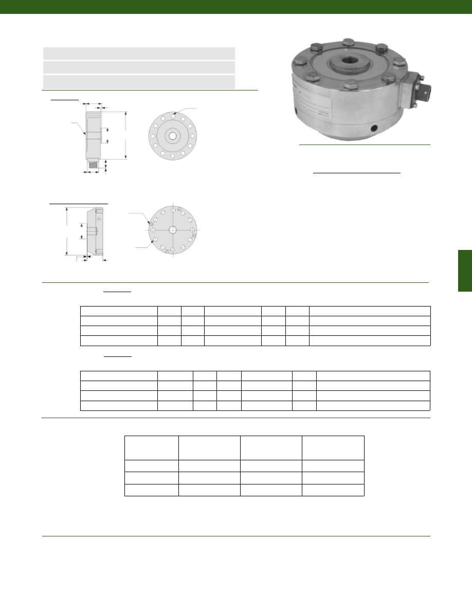
171
Dimensions
Performance
Environmental
Model 45 Fatigue Rated Universal Load Cell
Order Code AL116
n
250 to 100,000 lb. Range
n
Long Fatigue Life
n
Accuracy up to 0.04%
ø1.00 in.
Tightening
Holes
Clearance Holes for F1 Bolts
H
L
F2
N
T
øB
øG
øD1
øD2
0.82 in
0.03 in
Load Ranges................250 to 100,000 lb.
Non-Repeatability................+/- 0.02% Full Scale
Output................2.0 mV/V
Tolerance on Output................+/- 1% Full Scale
Creep in 20 min. (max.)................0.01%
Temperature, Operating................-65° to 200° F
Temperature, Compensated................30° to 130° F
Temperature, Effect
Zero................0.0008% Full Scale/ °F
Span................0.0008% Reading/ °F
Load Cell
Pull Plate (Optional)
250; 500; 1000; 2500; 5000 4.12
1.37
5/8-18 UNF-3B
1.34
0.12
9/32” Dia., 8 Holes Eq. Sp., 3.50 B.C.
12,500; 25,000
6.06
1.75
1 1/4-12 UNF-3B
2.65
0.12
13/32” Dia., 12 Holes Eq. Sp., 5.125 B.C.
50,000
8.00
2.50
1 3/4-12 UNF-3B
3.76
0.25
17/32” Dia., 16 Holes Eq. Sp., 6.50 B.C.
100,000
11.00
3.50
2 3/4-8 UNF-3B
4.81
0.50
11/16” Dia., 16 Holes Eq. Sp., 9.00 B.C.
250; 500; 1000; 2500; 5000
AA229
4.12
1.12
5/8-18 UNF-3B
1.25
1/4-28, 8 Holes Eq. Sp., 3.50 B.C.
12,500; 25,000
AA230
6.06
1.75
1 1/4-12 UNF-3B
2.25
3/8-24, 12 Holes Eq. Sp., 5.125 B.C.
50,000
AA231
8.00
2.00
1 3/4-12 UNF-3B
3.00
1/2-20, 16 Holes Eq. Sp., 6.50 B.C.
100,000
AA232
11.00
3.00
2 3/4-8 UNF-3B
4.50
5/8-18, 16 Holes Eq. Sp., 9.00 B.C.
Range (lb.) øD1(in.) H (in.)
T
øB (in.) N (in.)
F1
Pull Plate
Range (lb.)
Order Code øD2(in.) L (in.)
T
øG (in.)
F2
Wiring Code
Connector/ Unamplified (Std.)
A
(+) Excitation
B
(+) Excitation
C
(-) Excitation
D
(-) Excitation
E
(-) Output
F
(+) Output
Accuracy
(Static Error Band)
(notes 1 & 2)
Linearity
Hysteresis
250 to 1,000 lb.
+/- 0.04% Full Scale +/- 0.04% Full Scale +/- 0.03% Full Scale
2,500 to 50,000 lb. +/- 0.05% Full Scale +/- 0.05% Full Scale +/- 0.05% Full Scale
100,000 lb.
+/- 0.06% Full Scale +/- 0.05% Full Scale +/- 0.05% Full Scale
Load Cell
www.honeywell.com/sensotec
1-888-282-9891
Courtesy of Steven Engineering, Inc.-230 Ryan Way, South San Francisco, CA 94080-6370-Main Office: (650) 588-9200-Outside Local Area: (800) 258-9200-www.stevenengineering.com
Sensotec Sensors Full Line Catalog-html.html
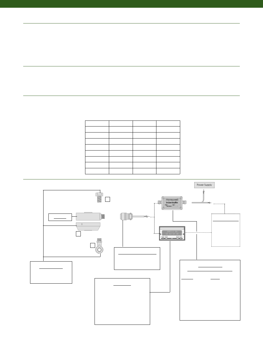
172
Mating Connectors & Cables
PC06A-10-6S
PT06A-10-6S
Electrical
Mechanical
Deflections and Ringing Frequencies
Typical System Diagram
Strain Gage Type................Foil
Excitation (calibration)................10 VDC
Excitation (acceptable)................20 VDC
Insulation Resistance................5,000 Megohms @ 50 V
Bridge Resistance................350 Ohms (nominal) (note 8)
Zero Balance................+/- 1% Full Scale
Shunt Calibration Data................Included
Electrical Termination (std)................PC02A-10-6P
Mating Connector (not incl.)................PC06A-10-6S
Maximum Allowable Load................200% F.S. (note 3 & 9)
Weight................See table below
Case Material................Stainless Steel
Life Cycles (approx.)................>108 fully reversed
Deflection................See table below
Natural Frequency................See table below
In-Line Amplifiers
(Used with unamplified units only)
Amplifier
Output
Universal In-Line Amplifiers
UV
+/- 5 VDC
UV-10
+/- 10 VDC
UBP
0 +/- 5 VDC
U3W
4-20 mA (3 wire)
U2W
4-20 mA (2 wire)
DIN rail Mount In-Line Amplifiers
DV-05
0 +/- 5 VDC (3 wire)
DA-05
4-20 mA (3 wire)
DV-10
0 +/- 10 VDC (3 wire)
Display Units
SC500
SC1000
SC2000
SC2001
SC3004
GM (Unamplified only)
GM-A (Amplified only)
NK (Unamplified only)
HH (Unamplified only)
Customer Supplied
Chart Recorder
Alarm Panel
Data Acquisition
Computer
PLC
Model 45
3
1
2
Model 45
Capacity
(lb.)
Deflection
@ Full Scale
(10-3 in.)
Ringing
Frequency
(Hz)
Weight
(lb)
250
1.5
2,400
3.1
500
1.5
2,400
3.1
1,000
1.5
3,400
3.1
2,500
1
6,800
3.2
5,000
1
9,100
3.2
12,500
2
5,700
8.8
25,000
2
7,000
8.8
50,000
2
6,300
22
100,000
2.5
4,500
55
Mounting Options
1. Pull Plate
2. Rod End Bearing Male
3. Load Button
www.honeywell.com/sensotec
1-888-282-9891
Courtesy of Steven Engineering, Inc.-230 Ryan Way, South San Francisco, CA 94080-6370-Main Office: (650) 588-9200-Outside Local Area: (800) 258-9200-www.stevenengineering.com
Sensotec Sensors Full Line Catalog-html.html

173
Range
Range Code
250 lb.
CN
500 lb.
CR
1000 lb.
CV
2500 lb.
DM
5000 lb.
DR
12,500 lb.
DW
25,000 lb.
EM
50,000 lb.
EP
100,000 lb.
ET
Range Codes
Internal Amplifiers
(note 10)
Model 45
Amplifier
Specifications
Voltage Output
Option 2b
Voltage Output
Option 2c
Voltage Output
Option 2t
Current 3 Wire
Option 2j
Current 2 Wire
Option 2k
Intrinsically Safe
Option 2n (2N)***
Output Signal
Input Power (Voltage)
Input Power (Current)
Frequency Response
Power Supply
Rejection
Operating Temperature
Reverse Voltage
Protection
Short Circuit Protection
+/- 5V
+/-15V or 26-32VDC
45 mA
3000 Hz
60 db
-20° to 185° F
Yes
Momentary
0-5V or +/- 5V
@ 45mA
11-28 VDC
40 mA
3000 Hz
60 db
-20° to 185° F
Yes
Momentary
0-10V or +/- 10V
@ 45mA
15-28 VDC
40 mA
3000 Hz
60 db
-20° to 185° F
Yes
Momentary
4-20 mA
22-32 VDC
65 mA
2500 Hz
60 db
0° to 185° F
Yes
Yes
4-20 mA
15-40 VDC
4-28 mA
300 Hz
60 db
0° to 185° F
Yes
Yes
4-20 mA
9-28 VDC
4-24 mA
2000 Hz
60 db
-20° to 185° F
Yes
Yes
Wiring Code: Connector
(Std.)
(note 5)
A (+) Supply
B Output Common/
C Supply Return
D (+) Output
E Shunt Cal 1
F Shunt Cal 2
A (+) Supply
B** Output Common/
C** Supply Return
D (+) Output
E Shunt Cal 1
F Shunt Cal 2
A (+) Supply
B** Output Common/
C** Supply Return
D (+) Output
E Shunt Cal 1
F Shunt Cal 2
A (+) Supply
B** Output Common/
C** Supply Return
D (+) Output
E Shunt Cal 1
F Shunt Cal 2
A (+) Supply
B No connection
C No connection
D (+) Output
E Case Ground
F No connection
A (+) Supply
B No connection
C No connection
D (+) Output
E Case Ground
F No connection
Wiring Code: Cable
(note 5)
(note 6)
(note 7)
R (+) Supply
Bl Output Common/
G Supply Return
W (+) Output
B Shunt Cal 1
Br Shunt Cal 2
R (+) Supply
Bl*Output Common/
G*Supply Return
W (+) Output
B Shunt Cal 1
Br Shunt Cal 2
R (+) Supply
Bl*Output Common/
G*Supply Return
W (+) Output
B Shunt Cal 1
Br Shunt Cal 2
R (+) Supply
Bl*Output Common/
G*Supply Return
W (+) Output
B Shunt Cal 1
Br Shunt Cal 2
R (+) Supply
Bl (+) Output
W Case Ground
R (+) Supply
Bl (+) Output
W Case Ground
* Black and Green wires are internally connected.
** Pins B and C are internally connected.
*** See Sensotec website for most up-to-date information regarding Intrinsically Safe approvals ref. #008-0547-00.
www.honeywell.com/sensotec
1-888-282-9891
Courtesy of Steven Engineering, Inc.-230 Ryan Way, South San Francisco, CA 94080-6370-Main Office: (650) 588-9200-Outside Local Area: (800) 258-9200-www.stevenengineering.com
Sensotec Sensors Full Line Catalog-html.html
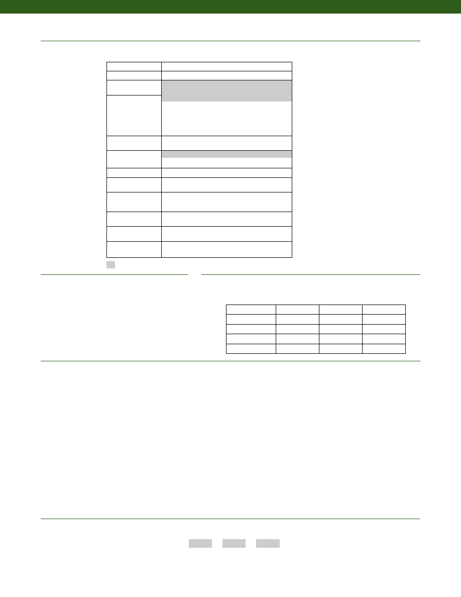
174
Special Customer Requirements
(Consult Factory)
1. Static Error Band is the recommended performance specification. The static error band is calculated as the best fit straight line through zero, including the effects of non-linearity,
hysteresis and non-repeatability.
2. Values noted are typical values but fall within the static error.
3. Allowable Maximum Loads- Maximum load to be applied without damage (note 4).
4. Without Damage- loading to this level will not cause excessive zero shift or performance degradation. The user must consider fatigue life for long term use and structural integrity. All
structurally critical applications (overhead loading, etc.) should always be designed with safety redundant load paths.
5. Interconnecting shunt cal. 1 terminal with shunt cal. 2 terminal provides 50% (unamplified units), 75% (4-20mA 3-wire units) or 80% (voltage amplified units) of full scale output for quick
calibration. Shunt Calibration comes standard with internal amplifier options 2c, 2t and 2j.
6. O=Orange; Y=Yellow; B=Blue; Bl=Black; R=Red; Br=Brown; W=White; G=Green. Color specifying cable and number or letter specifying connector.
7. No mating connector necessary for cable option.
8. 250 lb. range has 700 Ohm bridge resistance.
9. Off axis loading maximum allowable 50% F.S.
10. Internal amplifier for ranges less than 12,500 lb. may increase in height.
11. Consult factory for TEDS availability with amplified models.
Pull plates
Custom calibration
Notes
Base Plate Order Information
Options
How to Order
Combine the order code, the range code and the options code.
Order Code
Range Code
Options Code
Sample Code: AL116
CV
6h
Supplied as standard
250 to 1,000
AA229
3.5
AA290
2,500 to 5,000
AA229
3.5
AA290
12,500 to 25,000
AA230
11
AA291
50,000
AA231
20
AA292
100,000
AA232
61
AA293
Base Plate Base Plate Load Button
Range (lb.) Order Code Weight (lb.) Order Code
Model 45
Build from Scratch
Load Range
250 to 100,000 lb.
Temperature
Compensation
1b. 30° to 130° F
Internal Amplifiers
2b. +/- 5 VDC
2c. 0-5VDC
2j. 4-20mA (3-wire) output
2k. 4-20mA (2-wire)
2t. 0-10 VDC output
2n (2N).4-20mA (2-wire) Intrinsically safe
Internal Amp
Enhancements
3d. Remote Buffered Shunt Calibration
Electrical Termination 6a. Bendix PTIH-10-6P – 6 pin (max. 250°F)
Shunt Calibration
8a. Precision Internal Resistor
Special Calibration
9c. A.S.T.M. E-74 calibration
Bridge Type
31a. Dual Bridge
11c. Square & symmetrical bridge
Electrical Connector
Orientation
15a. Horizontal electrical exit port orientation
Shock & Vibration
44a. Shock and vibration resistance
Interfaces
53e. Signature Calibration
53t. T.E.D.S. IEEE 1451.4 Module (note 11)
2u. Unamplified, mV/V Output
PC02A-10-6P
www.honeywell.com/sensotec
1-888-282-9891
Courtesy of Steven Engineering, Inc.-230 Ryan Way, South San Francisco, CA 94080-6370-Main Office: (650) 588-9200-Outside Local Area: (800) 258-9200-www.stevenengineering.com
Sensotec Sensors Full Line Catalog-html.html
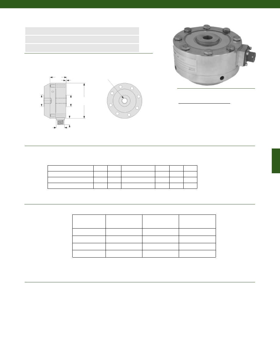
175
250; 500; 1000; 2500; 5000 4.12
1.37
5/8-18 UNF-3B
1.34
0.12
1.25
12,500; 25,000
6.06
1.75
1 1/4-12 UNF-3B
2.65
0.12
2.25
50,000
8.00
2.50
1 3/4-12 UNF-3B
3.76
0.25
3.00
100,000
11.00
3.50
2 3/4-8 UNF-3B
4.81
0.50
4.50
Range (lb.)
øD (in.) H (in.)
T
øB (in.) N (in.) øG (in.)
www.honeywell.com/sensotec
1-888-282-9891
Dimensions
Performance
Environmental
Model 47 Fatigue Rated Ultra Precision Universal Load Cell
Order Code AL117
n
250 to 100,000 lb. Range
n
Long Fatigue Life
n
Accuracy up to 0.02%
ø1.00 in.
H
N
T
øB
øG
øD
0.82 in
Load Ranges................250 to 100,000 lb.
Non-Repeatability................+/- 0.01% Full Scale
Output................2.0 mV/V
Tolerance on Output................+/- 1% Full Scale
Creep in 20 min. (max.)................0.01%
Temperature, Operating................-65° to 200° F
Temperature, Compensated................30° to 130° F
Temperature, Effect
Zero................0.0008% Full Scale/ °F
Span................0.0008% Reading/ °F
Wiring Code
Accuracy
(Static Error Band)
(notes 1 & 2)
Linearity
Hysteresis
250 to 1,000 lb.
+/- 0.02% Full Scale +/- 0.02% Full Scale +/- 0.02% Full Scale
2500 to 5000 lb.
+/- 0.03% Full Scale +/- 0.03% Full Scale +/- 0.04% Full Scale
12,500 to 50,000 lb. +/- 0.04% Full Scale +/- 0.04% Full Scale +/- 0.05% Full Scale
100,000 lb.
+/- 0.05% Full Scale +/- 0.05% Full Scale +/- 0.05% Full Scale
Connector/ Unamplified (Std.)
A
(+) Excitation
B
(+) Excitation
C
(-) Excitation
D
(-) Excitation
E
(-) Output
F
(+) Output
Courtesy of Steven Engineering, Inc.-230 Ryan Way, South San Francisco, CA 94080-6370-Main Office: (650) 588-9200-Outside Local Area: (800) 258-9200-www.stevenengineering.com
Sensotec Sensors Full Line Catalog-html.html
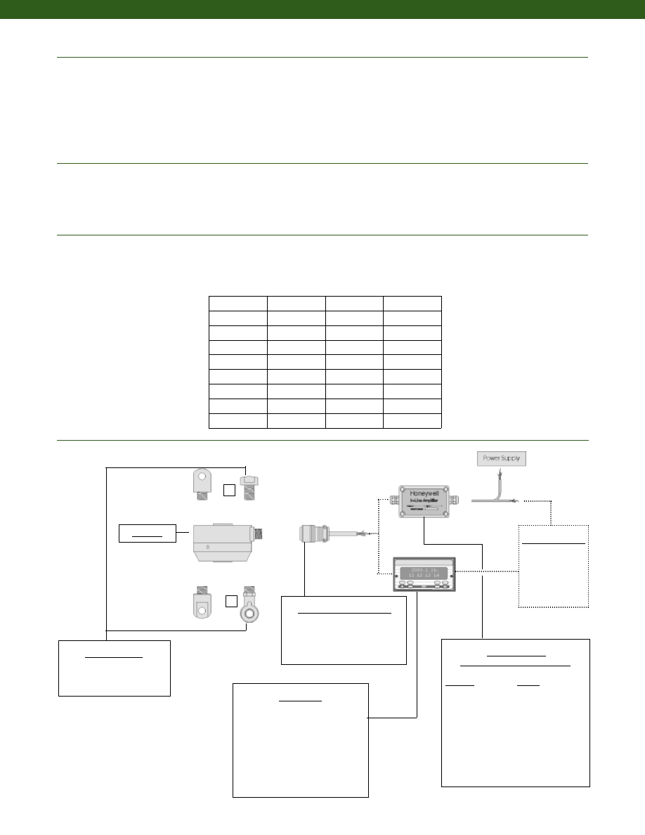
176
www.honeywell.com/sensotec
1-888-282-9891
Electrical
Mechanical
Deflections and Ringing Frequencies
Typical System Diagram
Strain Gage Type................Foil
Excitation (calibration)................10 VDC
Excitation (acceptable)................20 VDC
Insulation Resistance................5,000 Megohms @ 50 V
Bridge Resistance................350 Ohms (nominal) (note 8)
Zero Balance................+/- 1% Full Scale
Shunt Calibration Data................Included
Electrical Termination (std)................PC02A-10-6P
Mating Connector (not incl.)................PC06A-10-6S
Maximum Allowable Load................200% F.S. (note 3 & 9)
Weight................See table below
Case Material................Stainless Steel
Life Cycles (approx.)................>108 fully reversed
Deflection................See table below
Natural Frequency................See table below
Customer Supplied
Chart Recorder
Alarm Panel
Data Acquisition
Computer
PLC
Model 47
2
1
Model 47
Capacity
(lb.)
Deflection
@ Full Scale
(10-3 in.)
Ringing
Frequency
(Hz)
Weight
(lb)
250
1.5
2,400
6.6
500
1.5
2,400
6.6
1,000
1.5
3,400
6.6
2,500
1
6,800
6.7
5,000
1
9,100
6.7
12,500
2
5,700
19.8
25,000
2
7,000
19.8
50,000
2
6,300
42.0
100,000
2.5
4,500
116
Mating Connectors & Cables
PC06A-10-6S
PT06A-10-6S
In-Line Amplifiers
(Used with unamplified units only)
Amplifier
Output
Universal In-Line Amplifiers
UV
+/- 5 VDC
UV-10
+/- 10 VDC
UBP
0 +/- 5 VDC
U3W
4-20 mA (3 wire)
U2W
4-20 mA (2 wire)
DIN rail Mount In-Line Amplifiers
DV-05
0 +/- 5 VDC (3 wire)
DA-05
4-20 mA (3 wire)
DV-10
0 +/- 10 VDC (3 wire)
Display Units
SC500
SC1000
SC2000
SC2001
SC3004
GM (Unamplified only)
GM-A (Amplified only)
NK (Unamplified only)
HH (Unamplified only)
Mounting Options
1. Rod End Bearing Male
2. Load Button
Courtesy of Steven Engineering, Inc.-230 Ryan Way, South San Francisco, CA 94080-6370-Main Office: (650) 588-9200-Outside Local Area: (800) 258-9200-www.stevenengineering.com
Sensotec Sensors Full Line Catalog-html.html

177
www.honeywell.com/sensotec
1-888-282-9891
Range
Range Code
250 lb.
CN
500 lb.
CR
1000 lb.
CV
2500 lb.
DM
5000 lb.
DR
12,500 lb.
DW
25,000 lb.
EM
50,000 lb.
EP
100,000 lb.
ET
Range Codes
Internal Amplifiers
(note 10)
Model 47
Amplifier
Specifications
Voltage Output
Option 2b
Voltage Output
Option 2c
Voltage Output
Option 2t
Current 3 Wire
Option 2j
Current 2 Wire
Option 2k
Intrinsically Safe
Option 2n (2N)***
Output Signal
Input Power (Voltage)
Input Power (Current)
Frequency Response
Power Supply
Rejection
Operating Temperature
Reverse Voltage
Protection
Short Circuit Protection
+/- 5V
+/-15V or 26-32VDC
45 mA
3000 Hz
60 db
-20° to 185° F
Yes
Momentary
0-5V or +/- 5V
@ 45mA
11-28 VDC
40 mA
3000 Hz
60 db
-20° to 185° F
Yes
Momentary
0-10V or +/- 10V
@ 45mA
15-28 VDC
40 mA
3000 Hz
60 db
-20° to 185° F
Yes
Momentary
4-20 mA
22-32 VDC
65 mA
2500 Hz
60 db
0° to 185° F
Yes
Yes
4-20 mA
15-40 VDC
4-28 mA
300 Hz
60 db
0° to 185° F
Yes
Yes
4-20 mA
9-28 VDC
4-24 mA
2000 Hz
60 db
-20° to 185° F
Yes
Yes
Wiring Code: Connector
(Std.)
(note 5)
A (+) Supply
B Output Common/
C Supply Return
D (+) Output
E Shunt Cal 1
F Shunt Cal 2
A (+) Supply
B** Output Common/
C** Supply Return
D (+) Output
E Shunt Cal 1
F Shunt Cal 2
A (+) Supply
B** Output Common/
C** Supply Return
D (+) Output
E Shunt Cal 1
F Shunt Cal 2
A (+) Supply
B** Output Common/
C** Supply Return
D (+) Output
E Shunt Cal 1
F Shunt Cal 2
A (+) Supply
B No connection
C No connection
D (+) Output
E Case Ground
F No connection
A (+) Supply
B No connection
C No connection
D (+) Output
E Case Ground
F No connection
Wiring Code: Cable
(note 5)
(note 6)
(note 7)
R (+) Supply
Bl Output Common/
G Supply Return
W (+) Output
B Shunt Cal 1
Br Shunt Cal 2
R (+) Supply
Bl*Output Common/
G*Supply Return
W (+) Output
B Shunt Cal 1
Br Shunt Cal 2
R (+) Supply
Bl*Output Common/
G*Supply Return
W (+) Output
B Shunt Cal 1
Br Shunt Cal 2
R (+) Supply
Bl*Output Common/
G*Supply Return
W (+) Output
B Shunt Cal 1
Br Shunt Cal 2
R (+) Supply
Bl (+) Output
W Case Ground
R (+) Supply
Bl (+) Output
W Case Ground
* Black and Green wires are internally connected.
** Pins B and C are internally connected.
*** See Sensotec website for most up-to-date information regarding Intrinsically Safe approvals ref. #008-0547-00.
Courtesy of Steven Engineering, Inc.-230 Ryan Way, South San Francisco, CA 94080-6370-Main Office: (650) 588-9200-Outside Local Area: (800) 258-9200-www.stevenengineering.com
Sensotec Sensors Full Line Catalog-html.html
178
Build from Scratch
Load Range
250; 500; 1000; 2500; 5000; 12,500; 25,000; 50,000; 100,000 lb.
Temperature
Compensation
1b. 30° to 130° F
1c. 0° to 185° F
1d. -20° to 130° F
1e. -20° to 200° F
1f.
70° to 250° F
1g. 70° to 325° F
1h. 70° to 400° F
1i. -65° to 250° F
1j. 0° to 50° C
1k. -20° to 85° F
1m. -25° to 110° F
Internal Amplifiers
2b. +/-5 VDC
2c. 0-5VDC
2j. 4-20mA (3-wire) output
2k. 4-20mA (2-wire)
2t.
0-10 VDC output
2n (2N). 4-20mA (2-wire) Intrinsically safe
Electrical Termination
6a. Bendix PTIH-10-6P – (or equivalent) 6 pin (max. 250°F)
6b. MS Type connector mates with MS3106-14S 6 pin (max.
160° F) (note 5)
6c. Cannon WK6-325 series connector 6 pin
6f.
Integral cable: PVC
6g. Integral cable: Neoprene (note 6)
6h. Integral cable: Silicone
6i.
Integral underwater cable
6j.
1/2-14 conduit fitting with 5 ft. of 4 conductor PVC cable
6q. Molded Integral Cable: Polyurethane
6v. Phoenix connector on end of cable
15d. Connector on end of cable
Shunt Calibration
8a. Precision Internal Resistor
Special Calibration
9a. 10 point (5 up/5 down) 20% increments @ 70°F
9b. 20 point (10 up/10 down) 10% increments @ 70°F
9c. A.S.T.M. E-74 calibration
9e. CE mark
30a. Positive output in compression, compression testing only
30b. Positive output in tension, tension and compression testing
30c. Negative output in compression, compression testing only
Bridge Type
11a. Square Bridge
11c. Square and symmetrical bridge
Bridge Resistance
12b. 5,000 Ohms (foil) (max. 250°F)
Electrical Connector
Orientation
15a. Horizontal Electrical Exit Port Orientation
15b. Vertical Electrical Exit Port Orientation
15c. Radial Electrical Exit Port Orientation
Bridge Type
31a. Dual bridge
Shock & Vibration
44a. Shock and vibration resistance
Interfaces
53e. Signature Calibration
53t. T.E.D.S. IEEE 1451-4 Module (note 11)
www.honeywell.com/sensotec
1-888-282-9891
1. Static Error Band is the recommended performance specification. The
static error band is calculated as the best fit straight line through zero,
including the effects of non-linearity, hysteresis and non-repeatability.
2. Values noted are typical values but fall within the static error.
3. Allowable Maximum Loads- Maximum load to be applied without
damage (note 4).
4. Without Damage- loading to this level will not cause excessive zero
shift or performance degradation. The user must consider fatigue life
for long term use and structural integrity. All structurally critical appli-
cations (overhead loading, etc.) should always be designed with
safety redundant load paths.
5. Interconnecting shunt cal. 1 terminal with shunt cal. 2 terminal provides
50% (unamplified units), 75% (4-20mA 3-wire units) or 80% (voltage
amplified units) of full scale output for quick calibration. Shunt
Calibration comes standard with internal amplifier options 2c, 2t and 2j.
6. O=Orange; Y=Yellow; B=Blue; Bl=Black; R=Red; Br=Brown; W=White;
G=Green. Color specifying cable and number or letter specifying
connector.
7. No mating connector necessary for cable option.
8. 250 lb. range has 700 Ohm bridge resistance.
9. Off axis loading maximum allowable 50% F.S.
10. Internal amplifier for ranges less than 12,500 lb. may increase in height.
11. Consult factory for TEDS availability with amplified models.
Notes
Options
How to Order
Combine the order code, the range code and the options code.
Order Code
Range Code
Options Code
Sample Code: AL117
CV
6h
Supplied as standard
Model 47
6e. Integral Cable: Teflon
2u. Unamplified, mV/V Output
1a. 60° to 160° F
Special Customer Requirements
(Consult Factory)
Cable Orientation
Calibration Adaptor
Different Cable Lengths
Different Electrical Connectors
Different Materials
Different Threads
Dual Bridge
ESD
High Resistance Bridges
Lightning Protection
Load Button
OEM Labels
Operational Temp -200 to 400°F
Radiation Resistant
Special Electrical O/P
Special TC
Courtesy of Steven Engineering, Inc.-230 Ryan Way, South San Francisco, CA 94080-6370-Main Office: (650) 588-9200-Outside Local Area: (800) 258-9200-www.stevenengineering.com
Sensotec Sensors Full Line Catalog-html.html
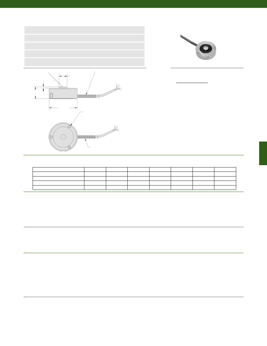
179
Dimensions
Performance
Environmental
Electrical
Mechanical
n
5 to 50,000 lb.
n
Stainless Steel
n
Mini Footprint
n
Button Style Design
n
mV/V Output
L
ø D1
ø D2
Spring
Strain Relief
Spring Strain Relief
H
Load Ranges........5 to 50,000 lbs.
Linearity (max.)........+/- 0.5% Full Scale
Hysteresis (max.)........+/- 0.3% Full Scale
Non-Repeatability (max.)........+/- 0.1% Full Scale
Output (tolerance)........2 mV/V (nominal)
Operation........Compression
Resolution........Infinite
Temperature, Operating........-65° to 250° F
Temperature, Compensated........60° to 160° F
Temperature, Effect
Zero........0.005% Full Scale/° F
Span........0.01% Full Scale/° F
Strain Gage Type........Bonded Foil
Excitation (calibration)
5 to 100 lb........5VDC
250 to 50,000 lb........10 VDC
Insulation Resistance........5000 Megohms @ 50 VDC
Bridge Resistance (tolerance)........350 Ohms (nominal)
Zero Balance (tolerance)........+/- 1% of Full Scale
Shunt Calibration Data........Included
Electrical Termination (std)........Teflon cable (5 ft.)
Weight........See table
Material........17-4 PH Stainless Steel
Maximum Allowable Load........150% F.S. (note 1)
Deflection Full Scale........See table
Natural Frequency........See table
Range (lb.)
D1 (in.)
D2 (in.)
H (in.)
L (in.)
A (in.)
B (in.)
G (in.)
Model 53 Low Cost Load Cell
Order Code AL131
3x A thread B deep on G B.C.
5; 10; 25; 50; 100
1.00
0.21
0.62
0.05
#4-40 UNC
0.22
0.750
250; 500; 1000; 2000
1.25
0.32
0.39
0.07
#6-32 UNC
0.25
1.000
3000; 4000; 5000; 7500; 10,000
1.50
0.40
0.63
0.08
#6-32 UNC
0.25
1.250
15,000; 20,000; 30,000
2.00
0.60
1.00
0.12
#6-32 UNC
0.25
1.625
50,000
3.00
0.78
1.50
0.18
#6-32 UNC
0.25
2.375
Wiring Code
Cable/ Unamplified
Red
(+) Excitation
Black
(-) Excitation
Green
(-) Output
White
(+) Output
Spherical Load Button
www.honeywell.com/sensotec
1-888-282-9891
Courtesy of Steven Engineering, Inc.-230 Ryan Way, South San Francisco, CA 94080-6370-Main Office: (650) 588-9200-Outside Local Area: (800) 258-9200-www.stevenengineering.com
Sensotec Sensors Full Line Catalog-html.html
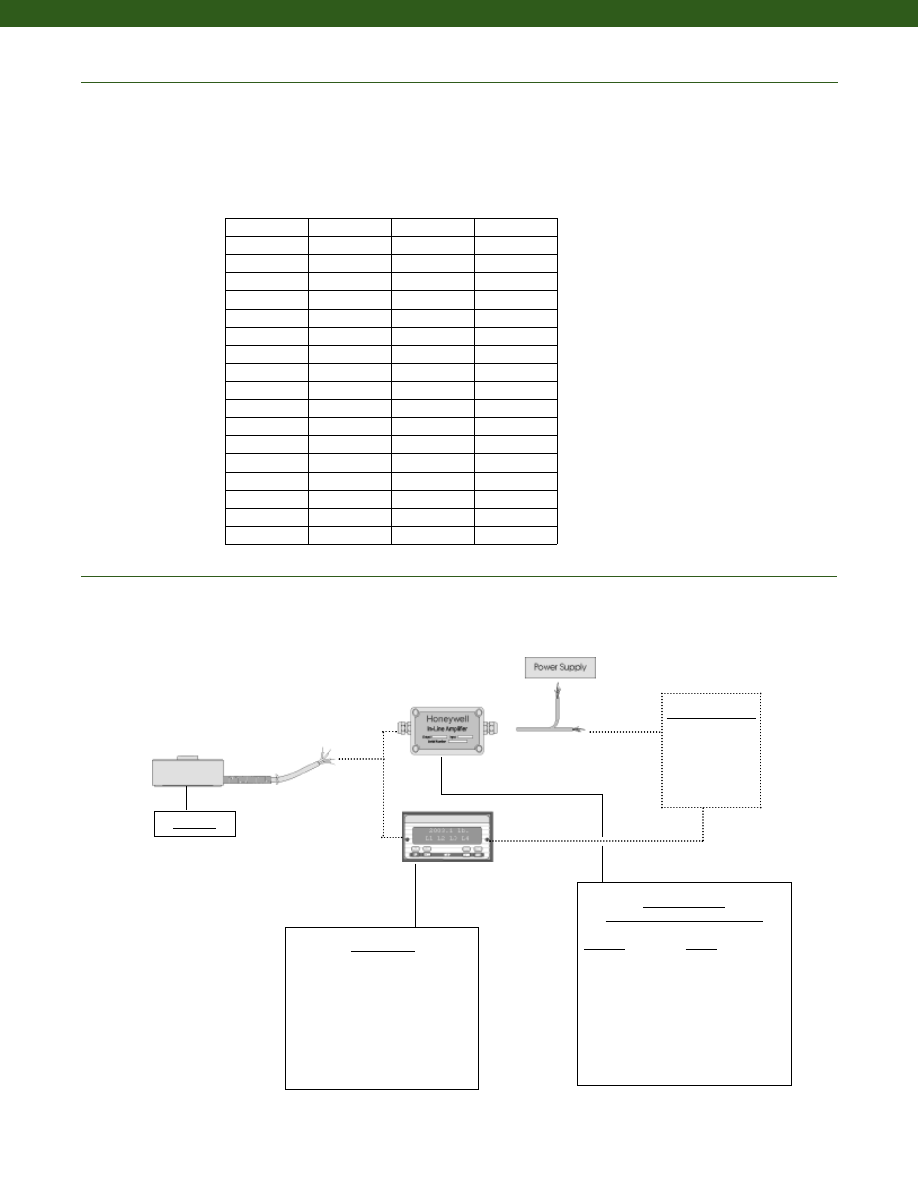
180
Typical System Diagram
In-Line Amplifiers
(Used with unamplified units only)
Amplifier
Output
Universal In-Line Amplifiers
UV
+/- 5 VDC
UV-10
+/- 10 VDC
UBP
0 +/- 5 VDC
U3W
4-20 mA (3 wire)
DIN rail Mount In-Line Amplifiers
DV-05
0 +/- 5 VDC (3 wire)
DA-05
4-20 mA (3 wire)
DV-10
0 +/- 10 VDC (3 wire)
Customer Supplied
Chart Recorder
Alarm Panel
Data Acquisition
Computer
PLC
Model 53
Deflections and Ringing Frequencies
5
.001
2,000
59
10
.001
3,000
59
25
.001
16,000
62
50
.001
21,000
63
100
.001
28,000
64
250
.001
25,000
72
500
.001
32,000
72
1,000
.001
42,000
75
2,000
.001
53,000
77
3,000
.001
27,000
137
4,000
.001
31,000
138
5,000
.001
34,000
140
7,500
.001
41,000
142
10,000
.001
47,000
145
15,000
.002
24,000
368
20,000
.002
28,000
372
30,000
.002
33,000
377
50,000
.003
24,000
1,270
Capacity
(lb.)
Deflection
@ Full Scale
(in.)
Ringing
Frequency
(Hz)
Weight with
Cable
(g)
Model 53
Display Units
SC500
SC1000
SC2000
SC2001
SC3004
GM
NK
HH
www.honeywell.com/sensotec
1-888-282-9891
Courtesy of Steven Engineering, Inc.-230 Ryan Way, South San Francisco, CA 94080-6370-Main Office: (650) 588-9200-Outside Local Area: (800) 258-9200-www.stevenengineering.com
Sensotec Sensors Full Line Catalog-html.html
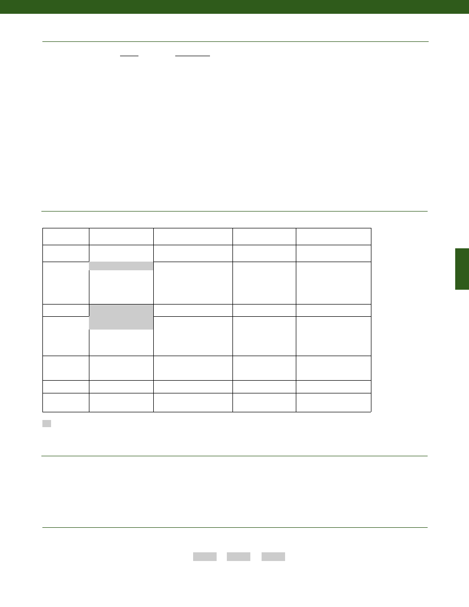
181
Options
Notes
Range
Range Code
5 lb.
AT
10 lb.
AV
25 lb.
BL
50 lb.
BN
100 lb.
BR
250 lb.
CN
500 lb.
CR
1,000 lb.
CV
2,000 lb.
DL
3,000 lb.
DN
4,000 lb.
DP
5,000 lb.
DR
7,500 lb.
DT
10,000 lb.
DV
15,000 lb.
EJ
20,000 lb.
EL
30,000 lb.
EN
50,000 lb.
EP
Range Codes
Special Customer
Requirements
(Consult Factory)
Supplied as standard
1. Allowable Maximum Loads - Maximum load to be applied without damage (note 2).
2. Without Damage - loading to this level will not cause excessive zero shift or performance degradation. The user must consider fatigue life for long term
use and structural integrity. All structurally critical applications (overhead loading, etc.) should always be designed with safety redundant load paths.
3. Dimension “H” may increase with option 6i. Consult factory. Maximum temperature is 180° F.
4. TEDS available with integral cable units only.
OEM labels
Radiation rated
Different cable lengths
Increased fatigue life
Custom cable exit
Alternate cable material
Thru mounting holes
Integral connector
How to Order
Combine the order code, the range code and the options code.
Order Code
Range Code
Options Code
Sample Code:
AL131
AT
1b
Same Day Ship
Fast track manufacture
Build to order
Build from scratch
Load Range
500, 1000, 2000, 5000,
10,000, 20,000, 50,000 lb
5, 10, 25, 50, 100, 250, 3000,
4000, 7500, 15,000, 30,000 lb
Temperature
Compensation
1b. 30° to 130° F
1c. 0° to 185° F
1d. -20° to 130° F
1e. -20° to 200° F
1j. 0° to 50° C
1k. -20° to 85° C
1m. -25° to 110° C
1f.
70° to 250° F
1g. 70° to 325° F
1h. 70° to 400° F
1i.
-65° to 250° F
Internal Amplifiers 2u. Unamplified, mV/V
output
Electrical
Termination
6d. Microtec DR-4S-4H 4 pin
6v. Phoenix connector on end
of cable
6f.
Integral cable: PVC
6g. Integral cable:
Neoprene
6h. Integral cable:
Silicone
6i.
Integral underwater
cable (note 3)
Special
Calibration
9a. 10 point (5 up/5 down)
20% increments @ 68° F
9b. 20 point (10 up/10 down)
10% increments @ 68° F
Shock & Vibration
44a. Shock and vibration
resistance
Interfaces (note 4)
53e. Signature Calibration
53t. T.E.D.S. IEEE 1451.4
Module
1a. 60° to 160° F
6e. Integral cable:
Teflon
Model 53
www.honeywell.com/sensotec
1-888-282-9891
Courtesy of Steven Engineering, Inc.-230 Ryan Way, South San Francisco, CA 94080-6370-Main Office: (650) 588-9200-Outside Local Area: (800) 258-9200-www.stevenengineering.com
Sensotec Sensors Full Line Catalog-html.html
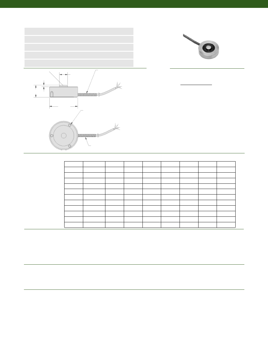
182
Dimensions
Performance
Environmental
Electrical
www.honeywell.com/sensotec
n
20N to 200kN Range
n
Stainless Steel Construction
n
Often Ideal for O.E.M. Applications
n
IP68 Version Available
n
mV/V Output
L
ø D1
ø D2
Spring
Strain Relief
Spring
Strain Relief
H
Range Range Code D1 (mm) D2 (mm) H (mm) L (mm) A B (mm) C (mm)
Model 53E Low Cost/ O.E.M. Compression Load Cell
Order Code (53E)
3 x A thread B deep on C diameter bolt circle
1-888-282-9891
20 N
020N0
25
5
16
1
M3x0.5
6
19
50 N
050N0
25
5
16
1
M3x0.5
6
19
100 N
100N0
25
5
16
1
M3x0.5
6
19
200 N
200N0
25
5
16
1
M3x0.5
6
19
500 N
500N0
25
5
16
1
M3x0.5
6
19
1 kN
01KN0
32
8
10
2
M4x0.7
5
25
2 kN
02KN0
32
8
10
2
M4x0.7
5
25
5 kN
05KN0
32
8
10
2
M4x0.7
5
25
10 kN
10KN0
32
8
10
2
M4x0.7
5
25
20 kN
20KN0
38
11
16
2
M4x0.7
6
32
50 kN
50KN0
38
11
16
2
M4x0.7
6
32
200 kN
200KN0
76
20
38
5
M4x0.7
6
60
........Bonded Foil
........5 VDC
........10 VDC
........5000 Megohms @ 50 VDC
........350 Ohms (nominal)
........+/- 1% of Full Scale
........1.5m, 4-core (shielded) p.t.f.e. cable incorporating a spring strain relief
Strain Gage Type
Excitation (calibration)
20 to 500 N
1 to 200 kN
Insulation Resistance
Bridge Resistance (tolerance)
Zero Balance (tolerance)
Electrical Termination (std)
Wiring Code
Cable/ Unamplified
Red
(+) Excitation
Black
(-) Excitation
Green
(-) Output
White
(+) Output
Spherical Load Button
........20N to 200kN
........+/- 0.5% Full Scale
........+/- 0.3% Full Scale
........+/- 0.1% Full Scale
........2 mV/V (nominal)
........Compression
........Infinite
........-55° to 120° C
........15° to 70° C
........0.01% Full Scale/° C
........0.02% Reading/° C
Load Ranges
Linearity (max.)
Hysteresis (max.)
Non-Repeatability (max.)
Output (tolerance)
Operation
Resolution
Temperature, Operating
Temperature, Compensated
Temperature, Effect
Zero
Span
Courtesy of Steven Engineering, Inc.-230 Ryan Way, South San Francisco, CA 94080-6370-Main Office: (650) 588-9200-Outside Local Area: (800) 258-9200-www.stevenengineering.com
Sensotec Sensors Full Line Catalog-html.html
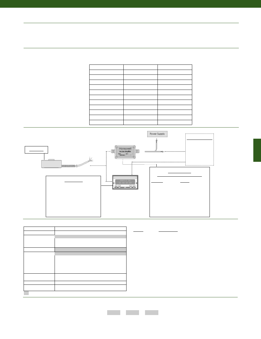
183
www.honeywell.com/sensotec
Typical System Diagram
In-Line Amplifiers
(Used with unamplified units only)
Amplifier
Output
Universal In-Line Amplifiers
UV
+/- 5 VDC
UV-10
+/- 10 VDC
UBP
0 +/- 5 VDC
U3W
4-20 mA (3 wire)
DIN rail Mount In-Line Amplifiers
DV-05
0 +/- 5 VDC (3 wire)
DA-05
4-20 mA (3 wire)
DV-10
0 +/- 10 VDC (3 wire)
Customer Supplied
Chart Recorder
Alarm Panel
Data Acquisition
Computer
PLC
Model 53E
1-888-282-9891
Model 53E
Deflections and Ringing Frequencies
Mechanical
Capacity
Ringing
Frequency
(Hz)
Weight
(g)
20 N
2,000
59
50 N
3,000
59
100 N
16,000
62
200 N
21,000
63
500 N
28,000
64
1 kN
28,000
72
2 kN
32,000
72
5 kN
42,000
75
10 kN
50,000
77
20 kN
35,000
140
50 kN
45,000
145
200 kN
25,000
1270
........150% F.S. (note 1)
........See table
........17-4 PH Stainless Steel
........0.07 mm
........See table
Maximum Allowable Load
Weight
Material
Deflection Full Scale
Natural Frequency
How to Order
Combine the order code, the range code and the options code.
Order Code
Range Code
Options Code
Sample Code:
53E 100N0
1j
Built to Order
Load Range
20 N to 200 kN
Temperature
Compensation
1j. 0° to 50° C
1k. -20° to 85° C
1m. -25° to 110° C
Internal Amplifiers
2u. Unamplified, mV/V output
Electrical Termination
6d. Microtec DR-4S-4H 4 pin (max. 120°C) (note 4)
6f.
Integral cable: PVC
6g. Integral cable: Neoprene
6h. Integral cable: Silicone
6i. Integral underwater cable (note 3)
6v. Phoenix connector on end of cable
Special Calibration
9a. 10 point (5 up/5 down) 20% increments @ 68° F
9b. 20 point (10 up/10 down)10% increments @ 68° F
Shock & Vibration
44a. Shock and vibration resistance
Interfaces (note 5)
53e. Signature Calibration
53t. T.E.D.S. IEEE 1451.4 Module
Options
Range
Range Code
20 N
020N0
50 N
050N0
100 N
100N0
200 N
200N0
500 N
500N0
1 kN
01kN0
2 kN
02kN0
5 kN
05kN0
10 kN
10kN0
20 kN
20kN0
50 kN
50kN0
200 kN
200kN0
Range Codes
1. Allowable Maximum Loads- Maximum
load to be applied without damage (note 2).
2. Without Damage- loading to this level
will not cause excessive zero shift or
performance degradation. The user must
consider fatigue life for long term use
and structural integrity. All structurally
critical applications (overhead loading,
etc.) should always be designed with
safety redundant load paths.
3. Dimension “H” will increase with option 6i.
4. Varies by capacity, consult factory.
5. TEDS available with integral cable units only.
Notes
Supplied as standard
15° to 70° C
1.5m, 4-core(shielded) p.t.f.e. cable
Display Units
SC500
SC1000
SC2000
SC2001
SC3004
GM
NK
HH
Courtesy of Steven Engineering, Inc.-230 Ryan Way, South San Francisco, CA 94080-6370-Main Office: (650) 588-9200-Outside Local Area: (800) 258-9200-www.stevenengineering.com
Sensotec Sensors Full Line Catalog-html.html
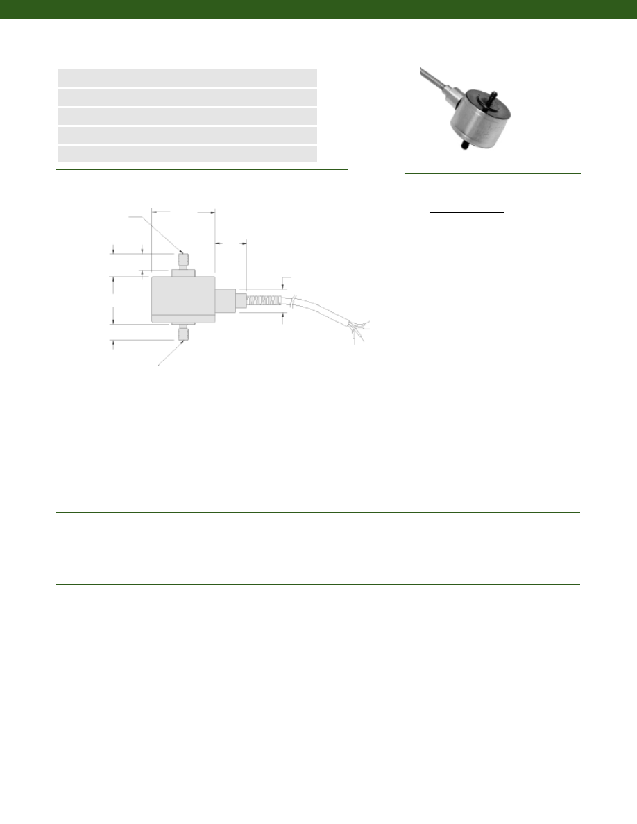
184
Dimensions
Performance
Environmental
Electrical
Mechanical
Model 31 Low Range Precision Miniature Load Cell
Order Code AL311
www.honeywell.com/sensotec
n
50 g to 500 g
n
mV/V Output
n
Stainless Steel
n
Miniature Design
n
Double Diaphragm Construction
ø1.00
0.25
0.25
0.38
0.52
0.36
0.75
4 conductor, 30 AWG,
Teflon insulated shielded
cable, 5 ft. long with 2”
spring strain relief
6-32 UNC active
thread force
transmitter
6-32 UNC base thread
Load Ranges........50; 150; 250; 500 g
Linearity........+/- 0.15% Full Scale
Hysteresis........+/- 0.15% Full Scale
Non-Repeatability........+/- 0.1% Full Scale
Tolerance on Output
50 to 150 g........0.1 mV/V/g max.
250 to 500 g........20 mV/V
Operation........Tension/ Compression (note 3)
Resolution........Infinite
Temperature, Operating........-65° to 250° F
Temperature, Compensated........60° to 160° F
Storage Temperature........-100° to 300° F
Temperature, Effect
Zero........0.015% Full Scale/° F
Span........0.015% Full Scale/° F
Strain Gage Type........Semiconductor
Excitation (calibration)........5 VDC
Insulation Resistance........5000 Megohms @ 50 VDC
Bridge Resistance........500 Ohms
Zero Balance........1% max.
Electrical Termination (std)........Teflon Cable (5 ft.)
Allowable Maximum Load........5 lb. (note 1)
Weight........90 grams
Material........17-4 PH Stainless Steel
Deflection Full Scale........11 kg/ mm
Natural Frequency........740 Hz
Wiring Code
Cable/ Unamplified
Red
(+) Excitation
Black
(-) Excitation
Green
(-) Output
White
(+) Output
1-888-282-9891
Courtesy of Steven Engineering, Inc.-230 Ryan Way, South San Francisco, CA 94080-6370-Main Office: (650) 588-9200-Outside Local Area: (800) 258-9200-www.stevenengineering.com
Sensotec Sensors Full Line Catalog-html.html
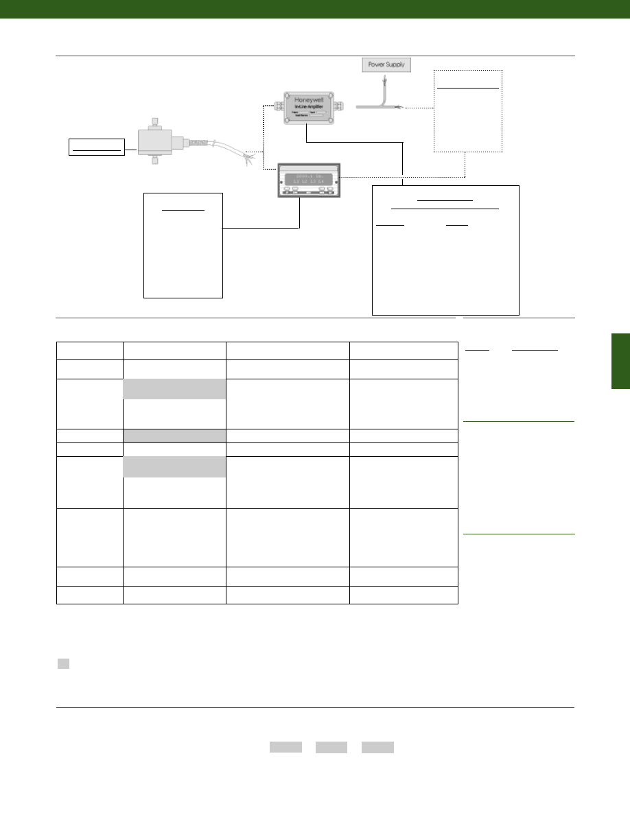
185
www.honeywell.com/sensotec
Typical System Diagram
Range
Range Code
50 g
AJ
150 g
AL
250 g
AN
500 g
AP
Range Codes
1-888-282-9891
In-Line Amplifiers
(Used with unamplified units only)
Amplifier
Output
Universal In-Line Amplifiers
UV
+/- 5 VDC
UV-10
+/- 10 VDC
UBP
0 +/- 5 VDC
U3W
4-20 mA (3 wire)
DIN rail Mount In-Line Amplifiers
DV-05
0 +/- 5 VDC (3 wire)
DA-05
4-20 mA (3 wire)
DV-10
0 +/- 10 VDC (3 wire)
Display Units
SC500
SC1000
SC2000
SC2001
SC3004
GM
Customer Supplied
Chart Recorder
Alarm Panel
Data Acquisition
Computer
PLC
Model 31 Semi
Model 31
Model Code
Range Code
Options Code
Sample Code:
AL311
AJ
1b, 30a
Same Day Ship
Fast track manufacture
Build to Order
Load Range
250 grams
50,150,500 grams
Temperature
Compensation
1b. 30° to 130° F
1c. 0° to 185° F
1d. -20° to 130° F
1e. -20° to 200° F
1j.
0° to 50° C
1k. -20° to 85° C
1m. -25° to 110° C
Internal Amplifiers
2u. Unamplified, mV/V output
3d. Remote Buffered Shunt Cal.
Electrical
Termination
6d. Microtec DR-4S-4H 4 pin
6v. Phoenix connector on end of
cable
6f.
Integral cable: PVC
6g. Integral cable: Neoprene
(max. 180° F)
6h. Integral cable: Silicone
6i.
Integral underwater cable
(max. 180° F)
15d. Connector on end of cable
Special Calibration
30a. Compression only calibration,
Positive in compression
30b. Tension and Compression
calibration, Positive in tension
30c. Compression only calibration,
Negative in compression
Shock & Vibration
44a. Shock and vibration
resistance
Interfaces (note 4)
53e. Signature Calibration
53t. T.E.D.S. IEEE 1451.4 Module
Supplied as standard
Options
OEM Labels
Radiation proof
Different cable lengths
Special Customer
Requirements
(Consult Factory)
Combine the order code, the range code and the options code.
How to Order
6e. Integral cable: Teflon
1a. 60° to 160° F
Notes
1. Allowable Maximum Loads- Maximum
load to be applied without damage (note 2).
2. Without Damage- loading to this level will
not cause excessive zero shift or
performance degradation. The user must
consider fatigue life for long term use and
structural integrity. All structurally critical
applications (overhead loading, etc.)
should always be designed with safety
redundant load paths.
3. Standard calibration for tension/
compression load cells is in tension only
4. TEDS available with integral cable units
only.
Courtesy of Steven Engineering, Inc.-230 Ryan Way, South San Francisco, CA 94080-6370-Main Office: (650) 588-9200-Outside Local Area: (800) 258-9200-www.stevenengineering.com
Sensotec Sensors Full Line Catalog-html.html
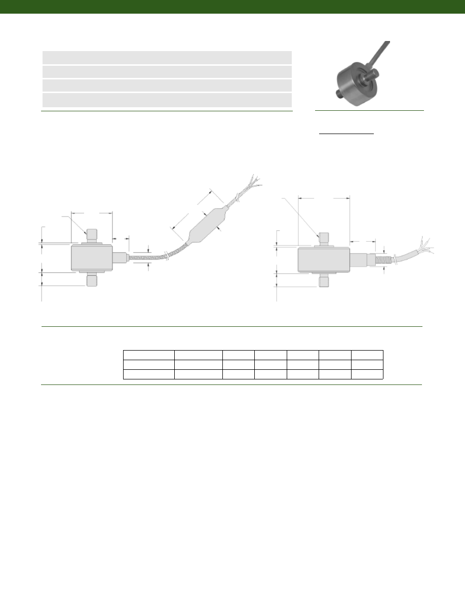
186
Dimensions
Performance
Model 31 Mid-Range Precision Miniature Load Cell
Order Code AL311
www.honeywell.com/sensotec
n
1000 g to 1,000 lb.
n
mV/V Output
n
Stainless Steel
n
Miniature Design
ø0.75
øB
H
2.0
0.3
4, 30 GA. twisted
leads teflon
insulated, color
coded 3’ long.
Balance module
2’ Stainless Steel
braided shielded
cable
F
A
2 X “T”
2 X “C”
ø1.00
øB
H
F
A
2 X “T”
2 X “C”
Load Ranges........1000 g; 5; 10; 25; 50; 100; 250; 500; 1000 lb.
Linearity
1000 g to 250 lb.........+/- 0.15% Full Scale
500 to 1,000 lb.........+/- 0.2% Full Scale
Hysteresis
1000 g to 250 lb.........+/- 0.15% Full Scale
500 to 1,000 lb.........+/- 0.2% Full Scale
Non-Repeatability
1000 g........+/- 0.1% Full Scale
5 to 1,000 lb.........+/- 0.05% Full Scale
Tolerance on Output
1000 g........1.5 mV/V (nominal)
5 to 1,000 lb.........2 mV/V
Operation........Tension/ Compression (note 3)
Resolution........Infinite
Ranges (lb.) T H (in.) C (in.) F (in.) A (in.) B (in.)
1 kg to 10 lb.
25 to 1,000 lb.
Cable/ Unamplified
Red
(+) Excitation
Black
(-) Excitation
Green
(-) Output
White
(+) Output
1-888-282-9891
1000 g; 5; 10 lb.
#6-32 UNC
0.45
0.25
0.05
0.31
0.19
25; 50; 100 lb.
#10-32 UNF
0.52
0.25
0.03
0.50
0.25
250; 500; 1000 lb.
1/4-28 UNF
0.52
0.38
0.03
0.50
0.25
4 conductor, 30 AWG,
Teflon insulated shielded
cable, 5 ft. long with 2”
spring strain relief
Wiring Code
Courtesy of Steven Engineering, Inc.-230 Ryan Way, South San Francisco, CA 94080-6370-Main Office: (650) 588-9200-Outside Local Area: (800) 258-9200-www.stevenengineering.com
Sensotec Sensors Full Line Catalog-html.html
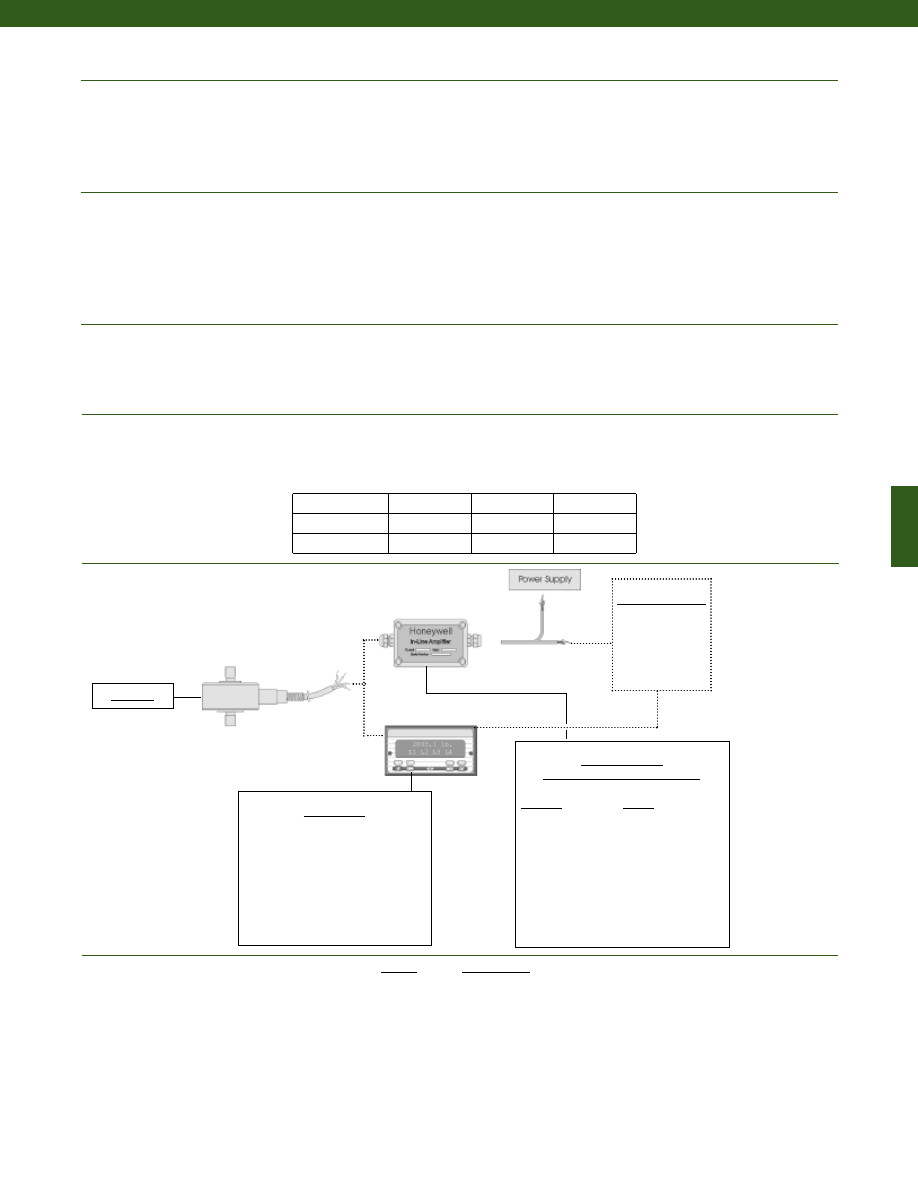
187
Typical System Diagram
Environmental
Electrical
Mechanical
Range
Range Code
1000 g.
AR
5 lb. AT
10 lb.
AV
25 lb.
BL
50 lb.
BN
100 lb.
BR
250 lb.
CN
500 lb.
CR
1000 lb.
CV
Range Codes
In-Line Amplifiers
(Used with unamplified units only)
Amplifier
Output
Universal In-Line Amplifiers
UV
+/- 5 VDC
UV-10
+/- 10 VDC
UBP
0 +/- 5 VDC
U3W
4-20 mA (3 wire)
DIN rail Mount In-Line Amplifiers
DV-05
0 +/- 5 VDC (3 wire)
DA-05
4-20 mA (3 wire)
DV-10
0 +/- 10 VDC (3 wire)
Display Units
SC500
SC1000
SC2000
SC2001
SC3004
GM
NK
HH
Customer Supplied
Chart Recorder
Alarm Panel
Data Acquisition
Computer
PLC
Model 31
Model 31 Std
Temperature, Operating................-65° to 250° F
Temperature, Compensated................60° to 160° F
Storage Temperature................-100° to 300° F
Temperature, Effect
Zero................0.005% Full Scale/° F
Span................0.005% Full Scale/° F
Strain Gage Type................Bonded Foil
Excitation (calibration)
1 kg to 10 lb.................5 VDC
25 to 1000 lb.................10VDC
Insulation Resistance................5000 Megohms @ 50 VDC
Bridge Resistance................350 Ohms
Zero Balance................1% max.
Electrical Termination (std)................Teflon Cable (5 ft.)
Maximum Allowable Load................150% F.S. (note 1)
Weight................See table
Material................17-4 PH Stainless Steel
Deflection Full Scale................See table
Natural Frequency................See table
www.honeywell.com/sensotec
1-888-282-9891
Deflections and Ringing Frequencies
Capacity (lb.)
Deflection
at Full Scale
(in.)
Ringing
Frequency
(Hz)
Weight
(grams)
1000 g to 10 lb.
0.001
3,000
21
25 to 100
0.001
10,000
63
250 to 1000
0.0015
12,000
80
Courtesy of Steven Engineering, Inc.-230 Ryan Way, South San Francisco, CA 94080-6370-Main Office: (650) 588-9200-Outside Local Area: (800) 258-9200-www.stevenengineering.com
Sensotec Sensors Full Line Catalog-html.html
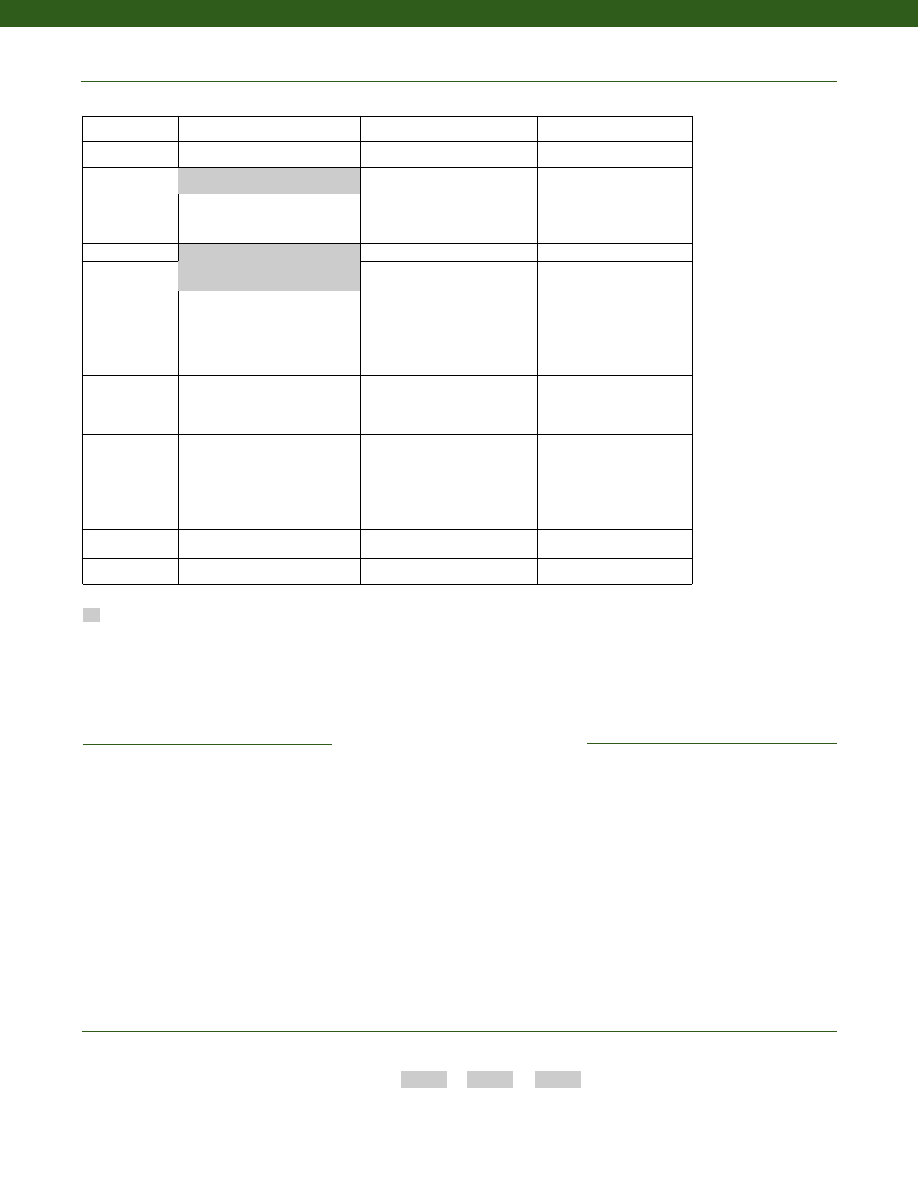
188
www.honeywell.com/sensotec
1-888-282-9891
1. Allowable Maximum Loads- Maximum
load to be applied without damage (note 2).
2. Without Damage- loading to this level will
not cause excessive zero shift or
performance degradation. The user must
consider fatigue life for long term use and
structural integrity. All structurally critical
applications (overhead loading, etc.)
should always be designed with safety
redundant load paths.
3. Standard calibration for tension/
compression load cells is in tension only.
4. TEDS available with integral cable units
only.
5. Availability varies with range.
Supplied as standard
Model Code
Range Code
Options Code
Sample Code:
AL311
CV
1b, 30a
Combine the order code, the range code and the options code.
How to Order
Model 31 Std
Same Day Ship
Fast track manufacture
Build to Order
Load Range
1000 grams
5, 10, 25, 50, 100, 250, 500, 1000 lbs
Temperature
Compensation
1b. 30° to 130° F
1c. 0° to 185° F
1d. -20° to 130° F
1e. -20° to 200° F
1j.
0° to 50° C
1k. -20° to 85° C
1m. -25° to 110° C
1f.
70° to 250° F
1g. 70° to 325° F
1h. 70° to 400° F
1i.
-65° to 250° F
Internal Amplifiers 2u. Unamplified, mV/V output
Electrical
Termination
6v. Phoenix connector on end of
cable
6a. Bendix PTIH-10-6P - 6 pin
(max. 250° F) (note 5)
6d. Microtec DR-4S-4H 4 pin
6f.
Integral cable: PVC
6g. Integral cable: Neoprene
(max. 180° F)
6h. Integral cable: Silicone
6i.
Integral underwater cable
(max. 180° F)
15d. Connector on end of cable
Special Calibration
9a. 10 point (5 up/5 down)
20% increments @ 20° C
9b. 20 point (10 up/10 down)
10% increments @ 20° C
Special Calibration
30a. Compression only calibration,
Positive in compression
30b. Tension and Compression
calibration, Positive in tension
30c. Compression only calibration,
Negative in compression
Shock & Vibration
44a. Shock and vibration resistance
Interfaces (note 4)
53e. Signature Calibration
53t. T.E.D.S. IEEE 1451.4 Module
Options
OEM Labels
Radiation proof
Different cable lengths
Special Customer
Requirements
(Consult Factory)
6e. Integral cable: Teflon
1a. 60° to 160° F
Notes
Courtesy of Steven Engineering, Inc.-230 Ryan Way, South San Francisco, CA 94080-6370-Main Office: (650) 588-9200-Outside Local Area: (800) 258-9200-www.stevenengineering.com
Sensotec Sensors Full Line Catalog-html.html
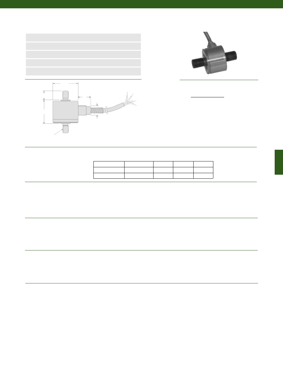
189
Dimensions
Performance
Environmental
Electrical
Mechanical
Model 31 High Range Precision Miniature Load Cell
Order Code AL311
www.honeywell.com/sensotec
n
2000 to 10,000 lb.
n
mV/V Output
n
Stainless Steel
n
Miniature Design
n
Stabilized Column Construction
Load Ranges ......2000 to 10,000 lb.
Linearity ......+/- 0.2% Full Scale
Hysteresis ......+/- 0.2% Full Scale
Non-Repeatability ......+/- 0.05% Full Scale
Tolerance on Output ......2 mV/V
Operation ......Tension/ Compression (note 3)
Resolution ......Infinite
Temperature, Operating ......-65° to 250° F
Temperature, Compensated ......60° to 160° F
Storage Temperature ......-100°to 300° F
Temperature, Effect
Zero ......0.005% Full Scale/° F
Span ......0.005% Full Scale/° F
Strain Gage Type ......Bonded Foil
Excitation (calibration) ......5 VDC
Insulation Resistance ......5000 Megohms @ 50 VDC
Bridge Resistance ......350 Ohms
Zero Balance ......1% max.
Electrical Termination (std) ......Teflon Cable (5 ft.)
Maximum Allowable Load ......150% F.S. (note 1)
Weight ......See table
Material ......17-4 PH Stainless Steel
Deflection Full Scale ......See table
Natural Frequency ......See table
Ranges (lb.) T øD (in.) H (in.) C (in.)
Wiring Code
Cable/ Unamplified
Red
(+) Excitation
Black
(-) Excitation
Green
(-) Output
White
(+) Output
1-888-282-9891
2000; 3000
3/8-24 UNF
1.00
0.72
0.50
4000; 5000
1/2-20 UNF
1.25
0.94
0.63
7500; 10,000
3/4-16 UNF
1.38
1.10
0.88
2X “C”
øD
H
2X “T”
4 conductor, 30 AWG,
Teflon insulated shielded
cable, 5 ft. long with 2”
spring strain relief
ø0.38
0.5
Courtesy of Steven Engineering, Inc.-230 Ryan Way, South San Francisco, CA 94080-6370-Main Office: (650) 588-9200-Outside Local Area: (800) 258-9200-www.stevenengineering.com
Sensotec Sensors Full Line Catalog-html.html
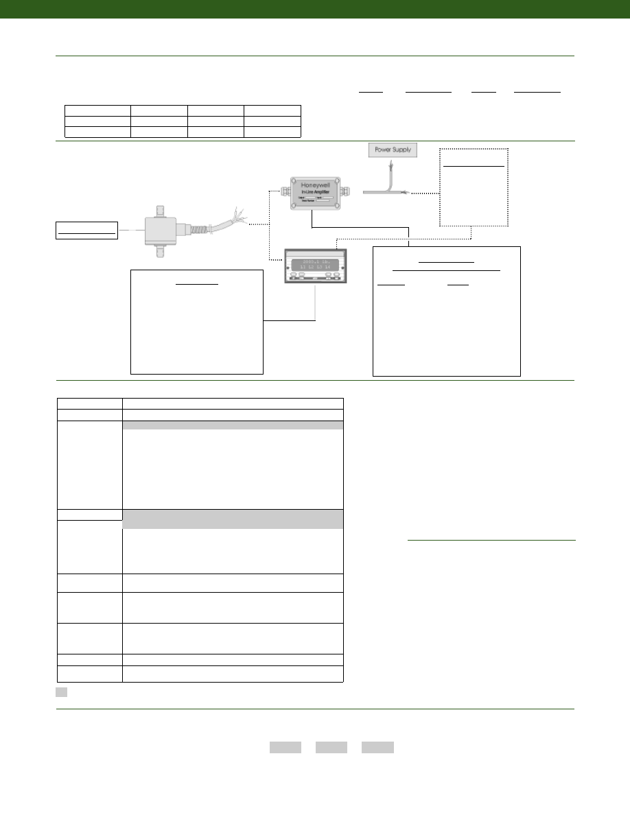
190
www.honeywell.com/sensotec
Typical System Diagram
1-888-282-9891
In-Line Amplifiers
(Used with unamplified units only)
Amplifier
Output
Universal In-Line Amplifiers
UV
+/- 5 VDC
UV-10
+/- 10 VDC
UBP
0 +/- 5 VDC
U3W
4-20 mA (3 wire)
DIN rail Mount In-Line Amplifiers
DV-05
0 +/- 5 VDC (3 wire)
DA-05
4-20 mA (3 wire)
DV-10
0 +/- 10 VDC (3 wire)
Customer Supplied
Chart Recorder
Alarm Panel
Data Acquisition
Computer
PLC
Model 31 Column
Model 31 Column
Model Code
Range Code
Options Code
Sample Code:
AL311
DV
1b, 30a
Combine the order code, the range code and the options code.
How to Order
Range
Range Code
5000 lb.
DR
7500 lb.
DT
10,000 lb.
DV
Range
Range Code
2000 lb.
DL
3000 lb.
DN
4000 lb.
DP
Range Codes
Deflections and Ringing Frequencies
Capacity (lb.)
Deflection
at Full Scale
(in.)
Ringing
Frequency
(Hz)
Weight
(grams)
2000; 3000
0.001
26,000
60
4000; 5000
0.0015
21,000
125
7500; 10,000
0.0015
17,000
250
1. Allowable Maximum Loads- Maximum
load to be applied without damage (note 2).
2. Without Damage- loading to this level will
not cause excessive zero shift or
performance degradation. The user must
consider fatigue life for long term use and
structural integrity. All structurally critical
applications (overhead loading, etc.)
should always be designed with safety
redundant load paths.
3. Standard calibration for tension/
compression load cells is in tension only
4. TEDS available with integral cable units
only.
Build to Order
Load Range
2000, 3000, 4000, 5000, 7500, 10,000 lbs
Temperature
Compensation
1b. 30° to 130° F
1c. 0° to 185° F
1d. -20° to 130° F
1e. -20° to 200° F
1f.
70° to 250° F
1g. 70° to 325° F
1h. 70° to 400° F
1i.
-65° to 250° F
1j.
0° to 50° C
1k. -20° to 85° C
1m. -25° to 110° C
Internal Amplifiers 2u. Unamplified, mV/V output
Electrical
Termination
6d. Microtec DR-4S-4H 4 pin
6f.
Integral cable: PVC
6g. Integral cable: Neoprene (max 180° F)
6h. Integral cable: Silicone
6i.
Integral underwater cable (max 180° F)
6v. Phoenix connector on end of cable
Bridge Resistance
12a. 1000 ohm (foil)
12b. 5000 ohm (foil)
Electrical
Connector
Orientation
15a. Horizontal Electrical Exit Port Orientation
15b. Vertical Electrical Exit Port Orientation
15c. Radial Electrical Exit Port Orientation
15d. Connector on end of cable
Special Calibration
30a. Compression only calibration, Positive in compression
30b. Tension and Compression calibration, Positive in tension
30c. Compression only calibration, Negative in compression
30d. Tension and Compression calibration, Positive in compression
Shock & Vibration
44a. Shock and vibration resistance
Interfaces (note 4) 53e. Signature Calibration
53t. T.E.D.S. IEEE 1451.4 Module
Options
OEM Labels
Radiation proof
Different cable lengths
Special Customer
Requirements
(Consult Factory)
6e. Integral cable: Teflon
1a. 60° to 160° F
Notes
Supplied as standard
Display Units
SC500
SC1000
SC2000
SC2001
SC3004
GM
NK
HH
Courtesy of Steven Engineering, Inc.-230 Ryan Way, South San Francisco, CA 94080-6370-Main Office: (650) 588-9200-Outside Local Area: (800) 258-9200-www.stevenengineering.com
Sensotec Sensors Full Line Catalog-html.html
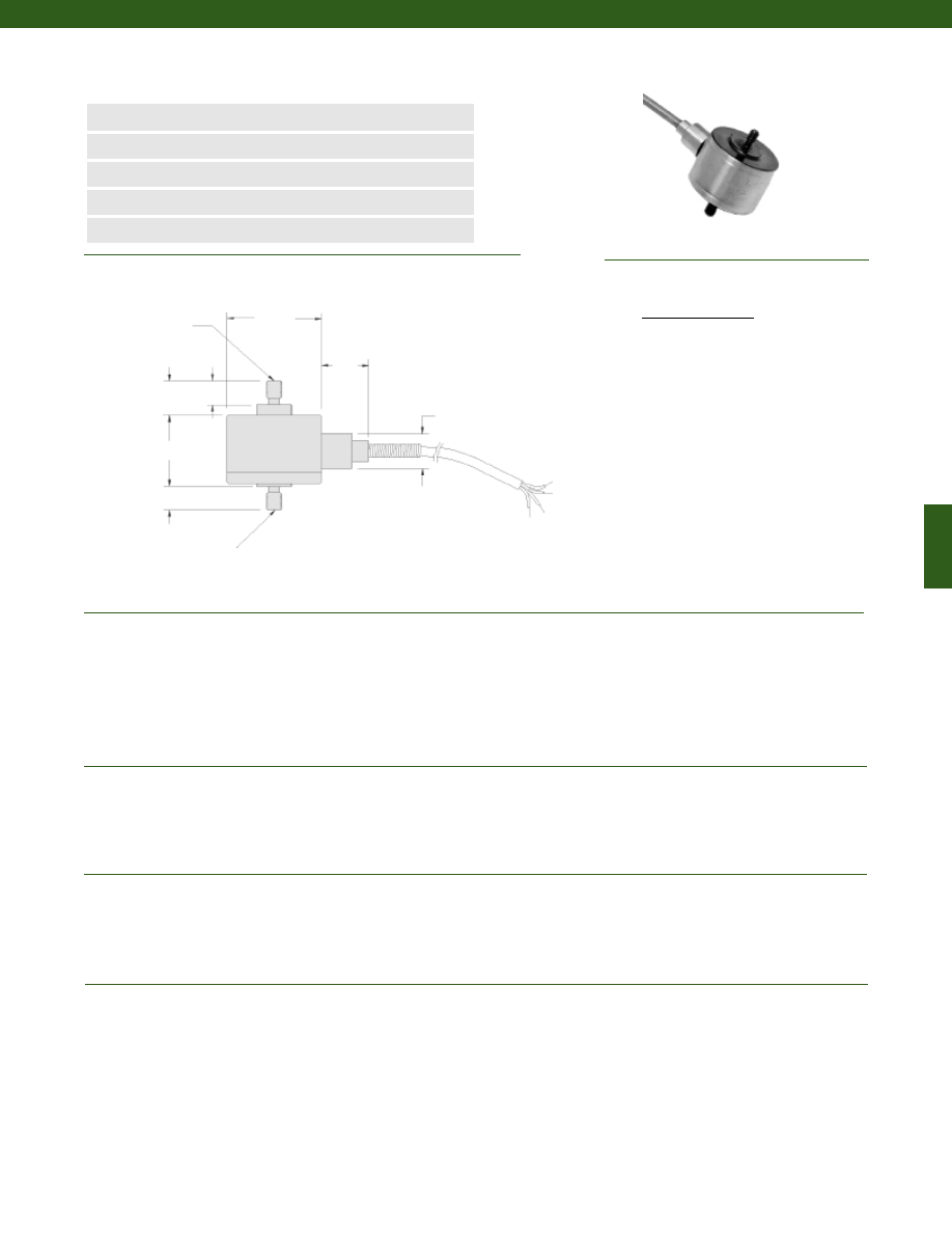
191
Dimensions
Performance
Environmental
Electrical
Mechanical
Model 31E Low Range Precision Miniature Load Cell
Order Code 31E
www.honeywell.com/sensotec
n
0.5N to 5N
n
mV/V Output
n
Stainless Steel
n
Miniature Design
n
Double Diaphragm Construction
ø25.4
6.3
6.3
10
13.2
9.1
19
4 conductor, 30 AWG,
Teflon insulated shielded
cable, 1.5m long with
50mm spring strain relief
M4 x 0.7 active
thread force
transmitter
M4 x 0.7 base thread
Load Ranges........0.5; 1.5; 2.5; 5N
Linearity........+/- 0.15% Full Scale
Hysteresis........+/- 0.15% Full Scale
Non-Repeatability........+/- 0.1% Full Scale
Tolerance on Output
0.5 to 1.5N........0.1 mV/V/N max.
2.5 to 5N........20 mV/V
Operation........Tension/ Compression (note 3)
Resolution........Infinite
Temperature, Operating........-55° to 120° C
Temperature, Compensated........15° to 70° C
Storage Temperature........-70° to 150° C
Temperature, Effect
Zero........0.03% Full Scale/° C
Span........0.03% Full Scale/° C
Strain Gage Type........Semiconductor
Excitation (calibration)........5 VDC
Insulation Resistance........5000 Megohms @ 50 VDC
Bridge Resistance........500 Ohms
Zero Balance........1% max.
Electrical Termination (std)........Teflon Cable (1.5 m)
Maximum Allowable Load........20N (note 1)
Weight........90 grams
Material........17-4 PH Stainless Steel
Deflection Full Scale........11 kg/ mm
Natural Frequency........740 Hz
Wiring Code
Cable/ Unamplified
Red
(+) Excitation
Black
(-) Excitation
Green
(-) Output
White
(+) Output
1-888-282-9891
Courtesy of Steven Engineering, Inc.-230 Ryan Way, South San Francisco, CA 94080-6370-Main Office: (650) 588-9200-Outside Local Area: (800) 258-9200-www.stevenengineering.com
Sensotec Sensors Full Line Catalog-html.html
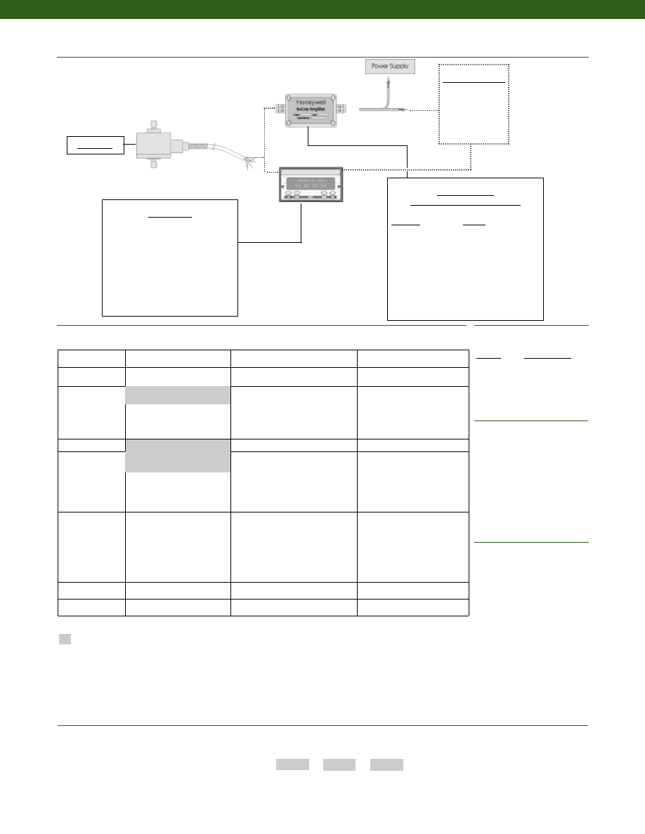
192
www.honeywell.com/sensotec
Typical System Diagram
Range
Range Code
0.5N
000N5
1.5N
001N5
2.5N
002N5
5N
005N0
Range Codes
1-888-282-9891
In-Line Amplifiers
(Used with unamplified units only)
Amplifier
Output
Universal In-Line Amplifiers
UV
+/- 5 VDC
UV-10
+/- 10 VDC
UBP
0 +/- 5 VDC
U3W
4-20 mA (3 wire)
DIN rail Mount In-Line Amplifiers
DV-05
0 +/- 5 VDC (3 wire)
DA-05
4-20 mA (3 wire)
DV-10
0 +/- 10 VDC (3 wire)
Customer Supplied
Chart Recorder
Alarm Panel
Data Acquisition
Computer
PLC
Model 31E
Model 31E
Model Code
Range Code
Options Code
Sample Code:
31E 001N0
1J, 30a
Same Day Ship
Fast track manufacture
Build to Order
Load Range
2.5N
0.5N, 1.5N, 5N
Temperature
Compensation
1j.
0° to 50° C
1k. -20° to 85° C
1m. -25° to 110° C
Internal Amplifiers 2u. Unamplified, mV/V output
Electrical
Termination
6d. Microtec DR-4S-4H 4 pin
6v. Phoenix connector on end of
cable
6f.
Integral cable: PVC
6g. Integral cable: Neoprene
(max. 80° C)
6h. Integral cable: Silicone
6i.
Integral underwater cable
(max. 80° C)
15d. Connector on end of cable
Special Calibration
30a. Compression only calibration,
Positive in compression
30b. Tension and Compression
calibration, Positive in tension
30c. Compression only calibration,
Negative in compression
30d. Tension and Compression
calibration, Positive in
compression
Shock & Vibration
44a. Shock and vibration
resistance
Interfaces (note 4)
53e. Signature Calibration
53t. T.E.D.S. IEEE 1451.4 Module
Supplied as standard
Options
OEM Labels
Radiation proof
Different cable lengths
Enhanced temperature ranges
Special Customer
Requirements
(Consult Factory)
Combine the order code, the range code and the options code.
How to Order
6e. Integral cable: Teflon
1a. 15° to 70° C
Notes
Display Units
SC500
SC1000
SC2000
SC2001
SC3004
GM
NK
HH
1. Allowable Maximum Loads- Maximum
load to be applied without damage (note 2).
2. Without Damage- loading to this level will
not cause excessive zero shift or
performance degradation. The user must
consider fatigue life for long term use and
structural integrity. All structurally critical
applications (overhead loading, etc.)
should always be designed with safety
redundant load paths.
3. Standard calibration for tension/
compression load cells is in tension only.
4. TEDS available with integral cable units
only.
Courtesy of Steven Engineering, Inc.-230 Ryan Way, South San Francisco, CA 94080-6370-Main Office: (650) 588-9200-Outside Local Area: (800) 258-9200-www.stevenengineering.com
Sensotec Sensors Full Line Catalog-html.html
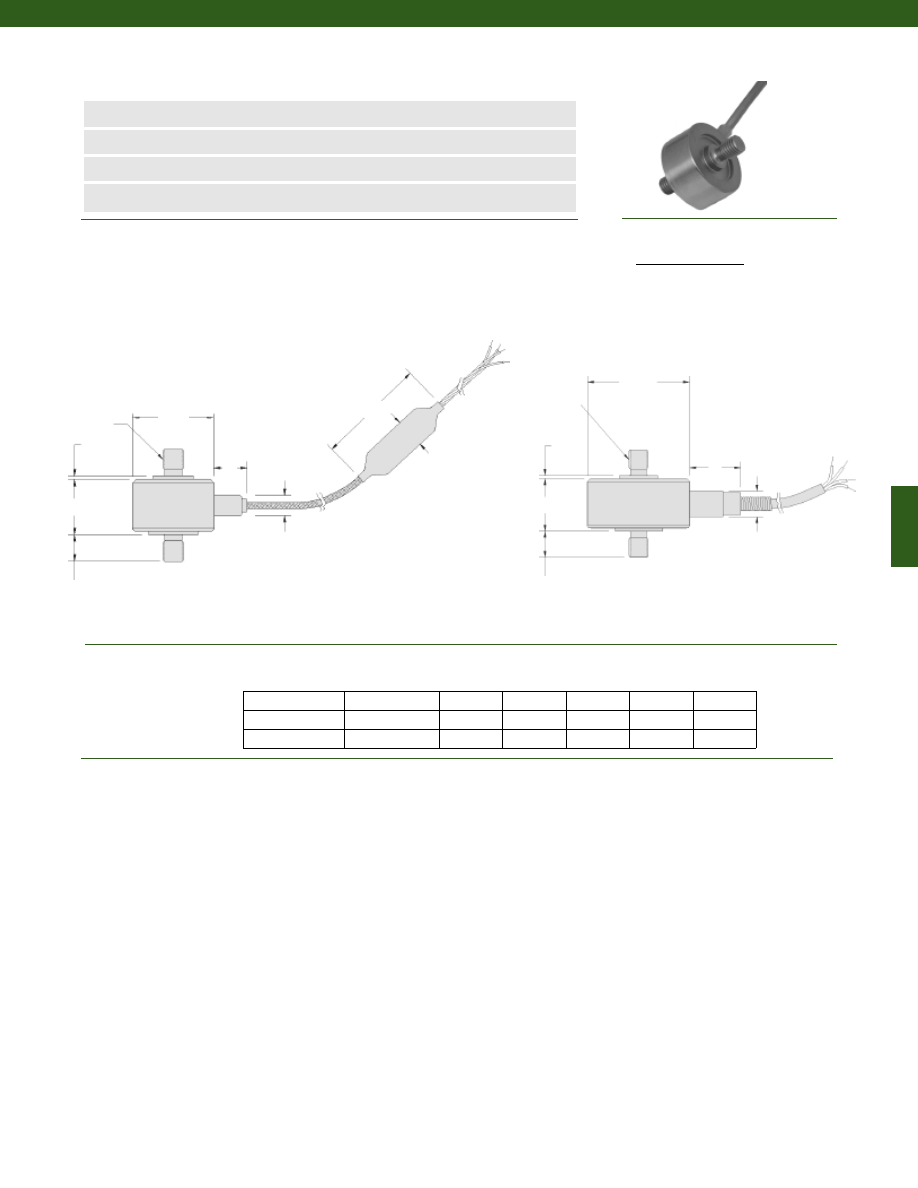
193
Dimensions
Performance
Model 31E Mid-Range Precision Miniature Load Cell
Order Code 31E
www.honeywell.com/sensotec
n
10N to 5kN
n
mV/V Output
n
Stainless Steel
n
Miniature Design
ø19.0
øB
H
50
8
4, 30 GA. twisted
leads teflon
insulated, color
coded 1m long.
Balance module
0.3m Stainless
Steel braided
shielded cable
F
A
2 X “T”
2 X “C”
ø25.4
øB
H
F
A
2 X “T”
2 X “C”
Load Ranges........10N to 5kN
Linearity
10N to 1kN.........+/- 0.15% Full Scale
2kN to 5kN.........+/- 0.2% Full Scale
Hysteresis
10N to 1kN.........+/- 0.15% Full Scale
2kN to 5kN.........+/- 0.2% Full Scale
Non-Repeatability
10N........+/- 0.1% Full Scale
20N to 5kN.........+/- 0.05% Full Scale
Tolerance on Output
10N........1.5 mV/V (nominal)
20N to 5kN.........2 mV/V
Operation........Tension/ Compression (note 3)
Resolution........Infinite
Ranges T H (mm) C (mm) F (mm) A (mm) B (mm)
10 to 50N
100N to 5 kN
Cable/ Unamplified
Red
(+) Excitation
Black
(-) Excitation
Green
(-) Output
White
(+) Output
1-888-282-9891
10; 20; 50N
M4 x 0.7
11.4
6.3
1.27
7.9
4.8
100; 200; 500N
M5 x 0.8
13.2
6.3
0.76
12.7
6.3
1; 2; 5kN
M6 x 1
13.2
9.6
0.76
12.7
6.3
Wiring Code
4 conductor, 30 AWG,
Teflon insulated shielded
cable, 5 ft. long with 2”
spring strain relief
Courtesy of Steven Engineering, Inc.-230 Ryan Way, South San Francisco, CA 94080-6370-Main Office: (650) 588-9200-Outside Local Area: (800) 258-9200-www.stevenengineering.com
Sensotec Sensors Full Line Catalog-html.html
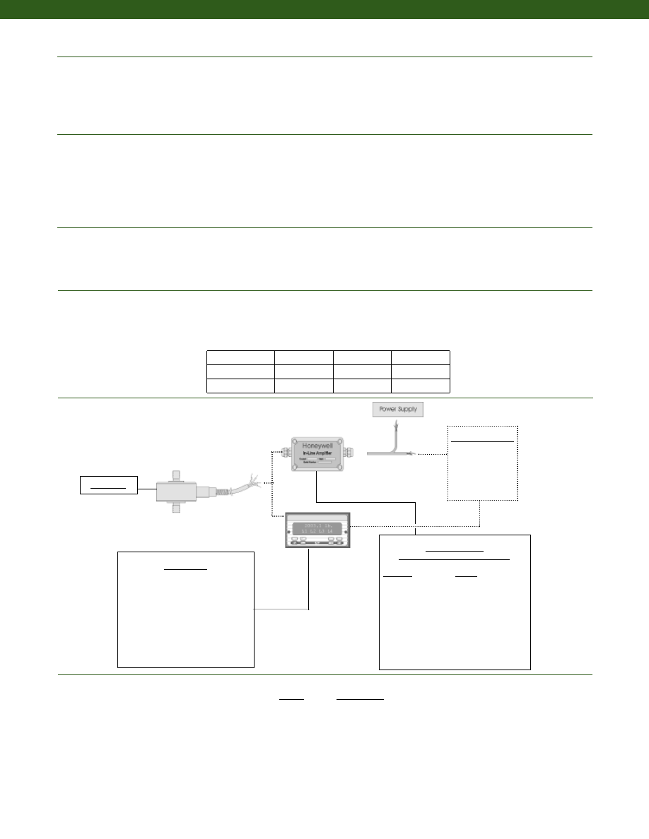
194
Temperature, Operating................-55° to 120° C
Temperature, Compensated................15° to 70° C
Storage Temperature................-70° to 150° C
Temperature, Effect
Zero................0.01% Full Scale/° C
Span................0.01% Full Scale/° C
Strain Gage Type................Bonded Foil
Excitation (calibration)
10 to 20 N................5 VDC
50 N to 5 kN................10VDC
Insulation Resistance................5000 Megohms @ 50 VDC
Bridge Resistance................350 Ohms
Zero Balance................1% max.
Electrical Termination (std)................Teflon Cable (1.5m)
Maximum Allowable Load................150% F.S. (note 1)
Weight................See table
Material................17-4 PH Stainless Steel
Deflection Full Scale................See table
Natural Frequency................See table
Typical System Diagram
Environmental
Electrical
Mechanical
Range
Range Code
10N
010N0
20N
020N0
50N
050N0
100N
100N0
200N
200N0
500N
500N0
1kN
01KN0
2kN
02KN0
5kN
05KN0
Range Codes
In-Line Amplifiers
(Used with unamplified units only)
Amplifier
Output
Universal In-Line Amplifiers
UV
+/- 5 VDC
UV-10
+/- 10 VDC
UBP
0 +/- 5 VDC
U3W
4-20 mA (3 wire)
DIN rail Mount In-Line Amplifiers
DV-05
0 +/- 5 VDC (3 wire)
DA-05
4-20 mA (3 wire)
DV-10
0 +/- 10 VDC (3 wire)
Customer Supplied
Chart Recorder
Alarm Panel
Data Acquisition
Computer
PLC
Model 31E
Model 31E
www.honeywell.com/sensotec
1-888-282-9891
Deflections and Ringing Frequencies
Capacity
Deflection
at Full Scale
(mm)
Ringing
Frequency
(Hz)
Weight
(grams)
10 to 50N
0.02
3,000
21
100N to 500N
0.02
10,000
63
1kN to 5kN
0.03
12,000
80
Display Units
SC500
SC1000
SC2000
SC2001
SC3004
GM
NK
HH
Courtesy of Steven Engineering, Inc.-230 Ryan Way, South San Francisco, CA 94080-6370-Main Office: (650) 588-9200-Outside Local Area: (800) 258-9200-www.stevenengineering.com
Sensotec Sensors Full Line Catalog-html.html
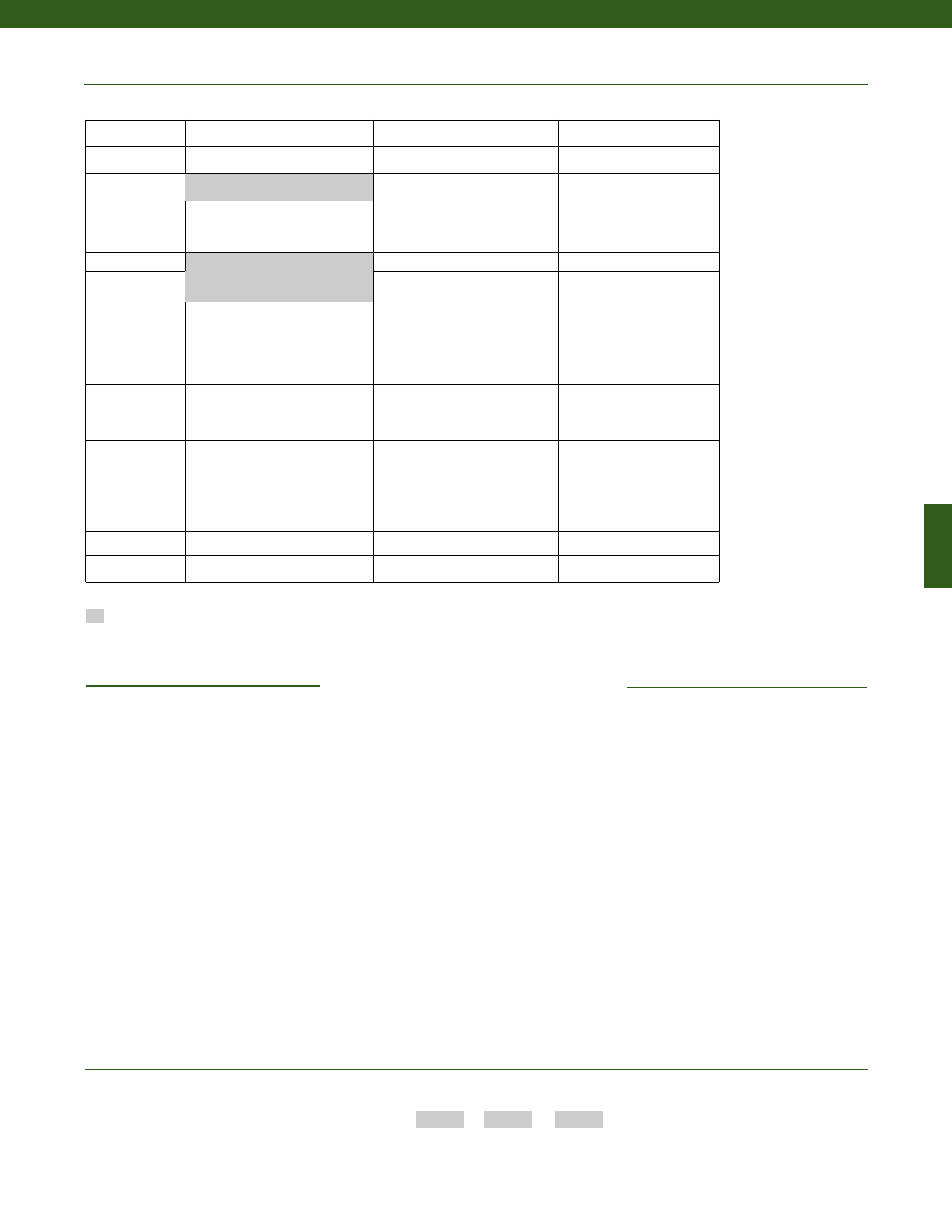
195
www.honeywell.com/sensotec
1-888-282-9891
1. Allowable Maximum Loads- Maximum
load to be applied without damage (note 2).
2. Without Damage- loading to this level will
not cause excessive zero shift or
performance degradation. The user must
consider fatigue life for long term use and
structural integrity. All structurally critical
applications (overhead loading, etc.)
should always be designed with safety
redundant load paths.
3. Standard calibration for tension/
compression load cells is in tension only.
4. TEDS available with integral cable units
only.
5. Availability varies with range.
Supplied as standard
Model Code
Range Code
Options Code
Sample Code:
31E 020N0
1J, 30a
Combine the order code, the range code and the options code.
How to Order
Model 31E
Same Day Ship
Fast track manufacture
Build to Order
Load Range
10, 20, 50, 100, 200, 500N; 1, 2, 5kN
Temperature
Compensation
1j.
0° to 50° C
1k. -20° to 85° C
1m. -25° to 110° C
Internal Amplifiers 2u. Unamplified, mV/V output
Electrical
Termination
6v. Phoenix connector on end of
cable
6a. Bendix PTIH-10-6P - 6 pin
(max. 120° C) (note 5)
6d. Microtec DR-4S-4H 4 pin
6f.
Integral cable: PVC
6g. Integral cable: Neoprene
(max. 80° C)
6h. Integral cable: Silicone
6i.
Integral underwater cable
(max. 80° C)
Special Calibration
9a. 10 point (5 up/5 down)
20% increments @ 20° C
9b. 20 point (10 up/10 down)
10% increments @ 20° C
Special Calibration
30a. Compression only calibration,
Positive in compression
30b. Tension and Compression
calibration, Positive in tension
30c. Compression only calibration,
Negative in compression
Shock & Vibration
44a. Shock and vibration resistance
Interfaces (note 4)
53e. Signature Calibration
53t. T.E.D.S. IEEE 1451.4 Module
Options
OEM Labels
Radiation proof
Different cable lengths
Enhanced temperature ranges
Special Customer
Requirements
(Consult Factory)
6e. Integral cable: Teflon
1a. 15° to 70° C
Notes
Courtesy of Steven Engineering, Inc.-230 Ryan Way, South San Francisco, CA 94080-6370-Main Office: (650) 588-9200-Outside Local Area: (800) 258-9200-www.stevenengineering.com
Sensotec Sensors Full Line Catalog-html.html
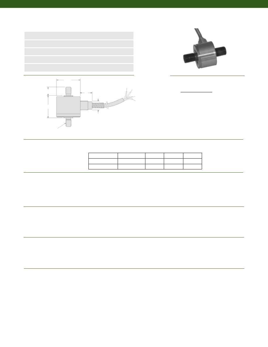
196
2X “C”
Dimensions
Performance
Environmental
Electrical
Mechanical
Model 31E High Range Precision Miniature Load Cell
Order Code 31E
www.honeywell.com/sensotec
n
10 to 50kN
n
mV/V Output
n
Stainless Steel
n
Miniature Design
n
Stabilized Column Construction
øD
H
2X “T”
Load Ranges ......10; 20; 50kN
Linearity ......+/- 0.2% Full Scale
Hysteresis ......+/- 0.2% Full Scale
Non-Repeatability ......+/- 0.05% Full Scale
Tolerance on Output ......2 mV/V
Operation ......Tension/ Compression (note 3)
Resolution ......Infinite
Temperature, Operating ......-55° to 120° C
Temperature, Compensated ......15° to 70° C
Storage Temperature ......-70°to 150° C
Temperature, Effect
Zero ......0.01% Full Scale/° C
Span ......0.01% Full Scale/° C
Strain Gage Type ......Bonded Foil
Excitation (calibration) ......5 VDC
Insulation Resistance ......5000 Megohms @ 50 VDC
Bridge Resistance ......350 Ohms
Zero Balance ......1% max.
Electrical Termination (std) ......Teflon Cable (1.5m)
Maximum Allowable Load ......150% F.S. (note 1)
Weight ......See table
Material ......17-4 PH Stainless Steel
Deflection Full Scale ......See table
Natural Frequency ......See table
Ranges (kN) T øD (mm.) H (mm) C (mm)
Wiring Code
Cable/ Unamplified
Red
(+) Excitation
Black
(-) Excitation
Green
(-) Output
White
(+) Output
1-888-282-9891
10
M10 x 1.5
25.4
18.3
12.7
20
M12 x 1.5
31.8
23.9
16.0
50
M20 x 1.5
35.1
27.9
22.3
4 conductor, 30 AWG,
Teflon insulated shielded
cable, 5 ft. long with 2”
spring strain relief
ø9.6
12.7
Courtesy of Steven Engineering, Inc.-230 Ryan Way, South San Francisco, CA 94080-6370-Main Office: (650) 588-9200-Outside Local Area: (800) 258-9200-www.stevenengineering.com
Sensotec Sensors Full Line Catalog-html.html
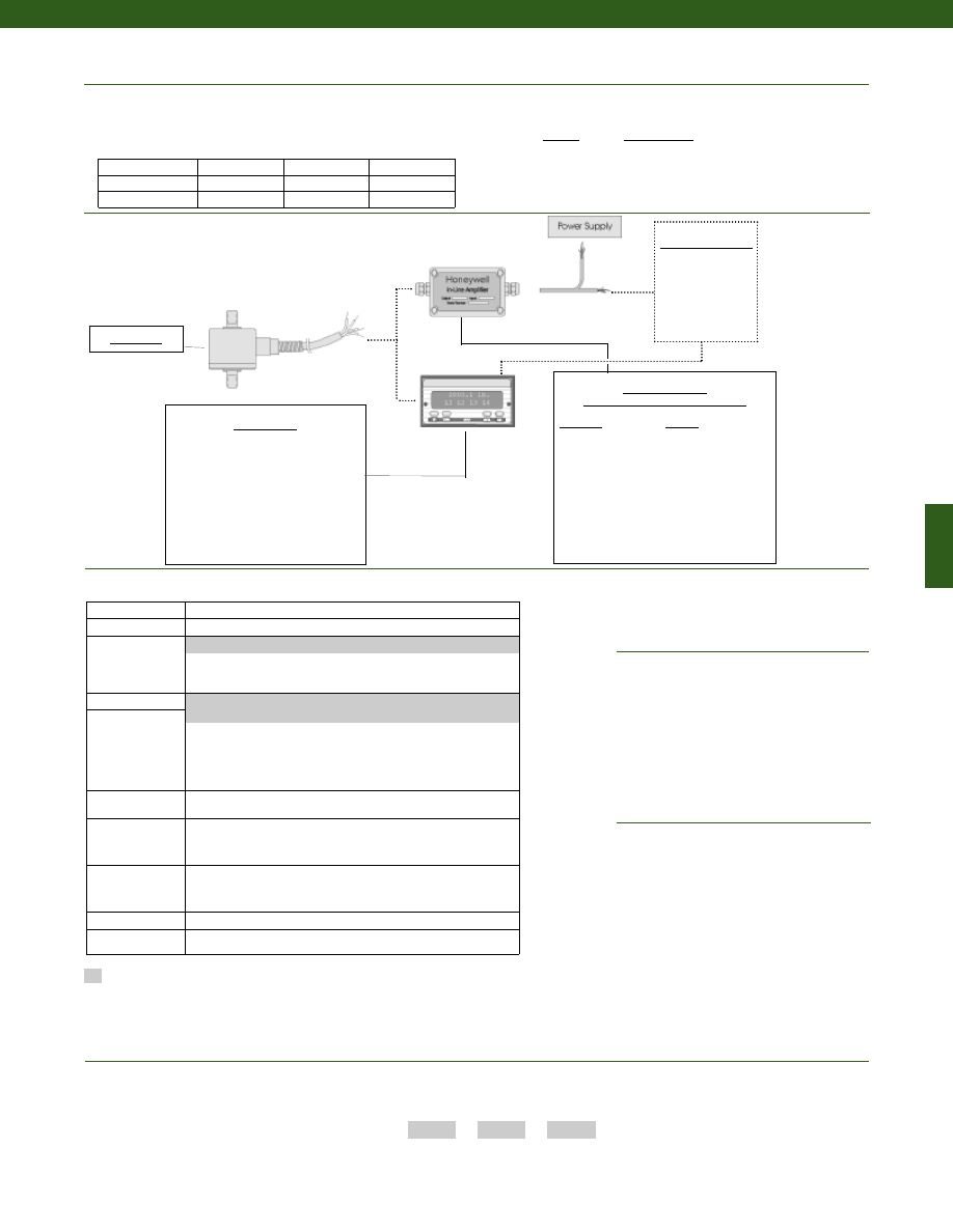
197
www.honeywell.com/sensotec
Typical System Diagram
1-888-282-9891
In-Line Amplifiers
(Used with unamplified units only)
Amplifier
Output
Universal In-Line Amplifiers
UV
+/- 5 VDC
UV-10
+/- 10 VDC
UBP
0 +/- 5 VDC
U3W
4-20 mA (3 wire)
DIN rail Mount In-Line Amplifiers
DV-05
0 +/- 5 VDC (3 wire)
DA-05
4-20 mA (3 wire)
DV-10
0 +/- 10 VDC (3 wire)
Customer Supplied
Chart Recorder
Alarm Panel
Data Acquisition
Computer
PLC
Model 31E
Model 31E
Model Code
Range Code
Options Code
Sample Code:
31E 10KN0
1j, 30a
Combine the order code, the range code and the options code.
How to Order
Range
Range Code
10kN
10KN0
20kN
20KN0
50kN
50KN0
Range Codes
Deflections and Ringing Frequencies
Capacity (kN)
Deflection
at Full Scale
(mm)
Ringing
Frequency
(Hz)
Weight
(grams)
10
0.02
26,000
60
20
0.03
21,000
125
50
0.03
17,000
250
1. Allowable Maximum Loads- Maximum
load to be applied without damage (note 2).
2. Without Damage- loading to this level will
not cause excessive zero shift or
performance degradation. The user must
consider fatigue life for long term use and
structural integrity. All structurally critical
applications (overhead loading, etc.)
should always be designed with safety
redundant load paths.
3. Standard calibration for tension/
compression load cells is in tension only
4. TEDS available with integral cable units
only.
Build to Order
Load Range
10, 20, 50kN
Temperature
Compensation
1j.
0° to 50° C
1k. -20° to 85° C
1m. -25° to 110° C
Internal Amplifiers 2u. Unamplified, mV/V output
Electrical
Termination
6d. Microtec DR-4S-4H 4 pin
6f.
Integral cable: PVC
6g. Integral cable: Neoprene (max. temp 80° C)
6h. Integral cable: Silicone
6i.
Integral underwater cable (max. temp 80° C)
6v. Phoenix connector on end of cable
Bridge Resistance
12a. 1000 ohm (foil)
12b. 5000 ohm (foil)
Electrical
Connector
Orientation
15a. Horizontal Electrical Exit Port Orientation
15b. Vertical Electrical Exit Port Orientation
15c. Radial Electrical Exit Port Orientation
15d. Connector on end of cable
Special Calibration
30a. Compression only calibration, Positive in compression
30b. Tension and Compression calibration, Positive in tension
30c. Compression only calibration, Negative in compression
30d. Tension and Compression calibration, Positive in compression
Shock & Vibration
44a. Shock and vibration resistance
Interfaces (note 4) 53e. Signature Calibration
53t. T.E.D.S. IEEE 1451.4 Module
Options
OEM Labels
Radiation proof
Different cable lengths
Enhanced Temperature Ranges
Special Customer
Requirements
(Consult Factory)
6e. Integral cable: Teflon
1a. 15° to 70° C
Notes
Supplied as standard
Display Units
SC500
SC1000
SC2000
SC2001
SC3004
GM
NK
HH
Courtesy of Steven Engineering, Inc.-230 Ryan Way, South San Francisco, CA 94080-6370-Main Office: (650) 588-9200-Outside Local Area: (800) 258-9200-www.stevenengineering.com
Sensotec Sensors Full Line Catalog-html.html
198
Dimensions
Performance
Environmental
Electrical
Mechanical
Model 34 Semi Precision Miniature Load Cell
Order Code AL312
www.honeywell.com/sensotec
n
50 g to 500 g
n
mV/V Output
n
Stainless Steel
n
Miniature Design
n
Double Diaphragm Construction
ø1.00
0.52
0.52
1.75
4 conductor, 30 AWG,
Teflon insulated shielded
cable, 5 ft. long with 2”
spring strain relief
2x 1/4-28 UNF
0.38 in. deep
Load Ranges................50; 150; 250; 500 g
Linearity................+/- 0.15% Full Scale
Hysteresis................+/- 0.15% Full Scale
Non-Repeatability................+/- 0.1% Full Scale
Tolerance on Output
50 to 150 g................0.1 mV/V/g max.
250 to 500 g................20 mV/V
Operation................Tension/ Compression (note 3)
Resolution................Infinite
Temperature, Operating................-65° to 250° F
Temperature, Compensated................60° to 160° F
Storage Temperature................-100° to 300° F
Temperature, Effect
Zero................0.015% Full Scale/° F
Span................0.015% Full Scale/° F
Strain Gage Type................Semiconductor
Excitation (calibration)................5 VDC
Insulation Resistance................5000 Megohms @ 50 VDC
Bridge Resistance................500 Ohms
Zero Balance................1% max.
Electrical Termination (std)................Teflon Cable (5 ft.)
Maximum Allowable Load................5 lb. (note 1)
Weight................110 grams
Material................17-4 PH Stainless Steel
Deflection Full Scale................11 kg/ mm
Natural Frequency................400 Hz
Cable/ Unamplified
Red
(+) Excitation
Black
(-) Excitation
Green
(-) Output
White
(+) Output
1-888-282-9891
Wiring Code
Courtesy of Steven Engineering, Inc.-230 Ryan Way, South San Francisco, CA 94080-6370-Main Office: (650) 588-9200-Outside Local Area: (800) 258-9200-www.stevenengineering.com
Sensotec Sensors Full Line Catalog-html.html
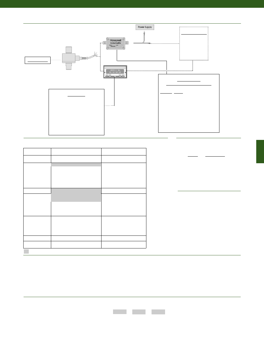
199
www.honeywell.com/sensotec
Range
Range Code
50 g
AJ
150 g
AL
250 g
AN
500 g
AP
Range Codes
1-888-282-9891
In-Line Amplifiers
(Used with unamplified units only)
Amplifier Output
Universal In-Line Amplifiers
UV
+/- 5 VDC
UV-10
+/- 10 VDC
UBP
0 +/- 5 VDC
U3W
4-20 mA (3 wire)
DIN rail Mount In-Line Amplifiers
DV-05
0 +/- 5 VDC (3 wire)
DA-05
4-20 mA (3 wire)
DV-10
0 +/- 10 VDC (3 wire)
Customer Supplied
Chart Recorder
Alarm Panel
Data Acquisition
Computer
PLC
Model 34 Semi
Model 34 semi
Model Code
Range Code
Options Code
Sample Code:
AL312
AJ
1b, 30a
Options
OEM Labels
Radiation proof
Different cable lengths
Special Customer
Requirements
(Consult Factory)
Combine the order code, the range code and the options code.
How to Order
Typical System Diagram
Display Units
SC500
SC1000
SC2000
SC2001
SC3004
GM
NK
HH
Notes
Built to Order
Built from Scratch
Load Range
50; 150; 250 grams
500 grams
Temperature
Compensation
1b. 30° to 130° F
1c. 0° to 185° F
1d. -20° to 130° F
1e. -20° to 200° F
1j.
0° to 50° C
1k. -20° to 85° C
1m. -25° to 110° C
Internal Amplifiers 2u. Unamplified, mV/V output
Electrical
Termination
6d. Microtec DR-4S-4H 4 pin
6v. Phoenix connector on end of
cable
6f.
Integral cable: PVC
6g. Integral cable: Neoprene
(max. 180° F)
6h. Integral cable: Silicone
6i.
Integral underwater cable
(max. 180° F)
15d. Connector on end of cable
Special Calibration
30a. Compression only calibration,
Positive in compression
30b. Tension and Compression
calibration, Positive in tension
30c. Compression only calibration,
Negative in compression
Shock & Vibration
44a. Shock and vibration resistance
Interfaces (note 4) 53e. Signature Calibration
53t. T.E.D.S. IEEE 1451.4 Module
Supplied as standard
6e. Integral cable: Teflon
1a. 60° to 160° F
1. Allowable Maximum Loads- Maximum load to be applied without damage (note 2).
2. Without Damage- loading to this level will not cause excessive zero shift or
performance degradation. The user must consider fatigue life for long term use and
structural integrity. All structurally critical applications (overhead loading, etc.)
should always be designed with safety redundant load paths.
3. Standard calibration for tension/ compression load cells is in tension only
4. TEDS available with integral cable units only.
Courtesy of Steven Engineering, Inc.-230 Ryan Way, South San Francisco, CA 94080-6370-Main Office: (650) 588-9200-Outside Local Area: (800) 258-9200-www.stevenengineering.com
Sensotec Sensors Full Line Catalog-html.html
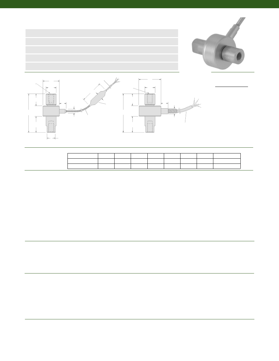
200
Dimensions
Performance
Environmental
Electrical
Mechanical
Model 34 Precision Miniature Load Cell
Order Code AL312
www.honeywell.com/sensotec
n
1000 g to 1000 lb. Range
n
Welded Stainless Steel
n
Rugged, Small Size
n
Tension/ Compression
n
0.15% Accuracy
øD
øD
F
F
G
G
A
2.5
0.3
øB
H
H
2 x T
2 x T
Load Ranges................1000 g to 1000 lb.
Linearity
1000 g to 250 lb.................+/- 0.15% Full Scale
500 to 1000 lb.................+/- 0.2% Full Scale
Hysteresis
1000 g to 250 lb.................+/- 0.15% Full Scale
500 to 1000 lb.................+/- 0.2% Full Scale
Non-Repeatability
1000 g.................+/- 0.1% Full Scale
5 to 1000 lb.................+/- 0.05% Full Scale
Tolerance on Output
1000 g................1.5 mV/V (nominal)
5 to 1000 lb.................2 mV/V
Operation................Tension/ Compression (note 3)
Resolution................Infinite
Temperature, Operating................-65° to 250° F
Temperature, Compensated................60° to 160° F
Storage Temperature................-100° to 300° F
Temperature, Effect
Zero................0.005% Full Scale/° F
Span................0.005% Full Scale/° F
Strain Gage Type................Bonded Foil
Excitation (calibration)
1000 g to 10 lb.................5 VDC
25 to 1,000 lb.................10 VDC
Insulation Resistance................5000 Megohms @ 50 VDC
Bridge Resistance................350 Ohms
Electrical Termination (std)
1000 g to 10 lb.................Teflon Cable (5 ft.) with external balance board
25 to 1,000 lb.................Teflon Cable (5 ft.)
Maximum Allowable Load................150% F.S. (note 1)
Weight................See table
Material................17-4 PH Stainless Steel
Deflection Full Scale................See table
Natural Frequency................See table
Ranges (lb.) D (in.) H (in.) A (in.) B (in.) C (in.) F (in.) G (in.) T
1-888-282-9891
0.375 Flats
2 ft. Stainless Steel
Braided Shield Cable
Balance
Module
4, 30 GA, Twisted Leads
Teflon Insulated, Color
Coded, 3 ft. Long
2x
øC
1,000 g thru 10 lb.
25 lb. thru 1,000 lb.
1000 g; 5; 10 lb.
0.75
1.75
0.31
0.19
0.46
0.60
0.72
1/4-28 UNF
25; 50; 100 lb.
1.00
1.75
0.50
0.25
0.46
0.52
0.72
1/4-28 UNF
250; 500; 1000 lb.
1.00
2.00
0.50
0.25
0.46
0.75
0.75
1/4-28 UNF
4 conductor, 30 AWG,
Teflon insulated shielded
cable, 5 ft. long with 2”
spring strain relief
2x
øC
A
øB
Wiring Code
Cable/ Unamplified
Red
(+) Excitation
Black
(-) Excitation
Green
(-) Output
White
(+) Output
Courtesy of Steven Engineering, Inc.-230 Ryan Way, South San Francisco, CA 94080-6370-Main Office: (650) 588-9200-Outside Local Area: (800) 258-9200-www.stevenengineering.com
Sensotec Sensors Full Line Catalog-html.html
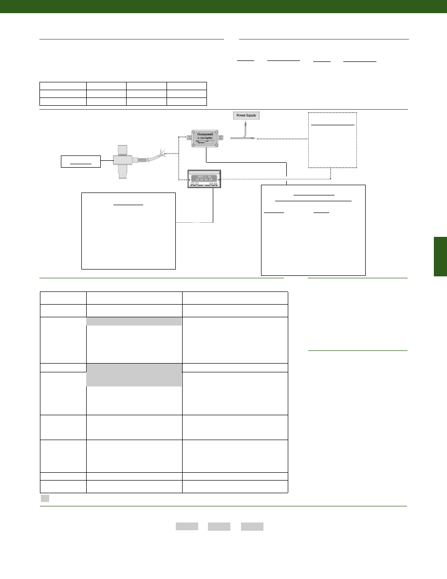
201
Range
Range Code
100 lb.
BR
250 lb.
CN
500 lb.
CR
1000 lb.
CV
Range
Range Code
1000 g
AR
5 lb.
AT
10 lb.
AV
25 lb.
BL
50 lb.
BN
Range Codes
In-Line Amplifiers
(Used with unamplified units only)
Amplifier
Output
Universal In-Line Amplifiers
UV
+/- 5 VDC
UV-10
+/- 10 VDC
UBP
0 +/- 5 VDC
U3W
4-20 mA (3 wire)
DIN rail Mount In-Line Amplifiers
DV-05
0 +/- 5 VDC (3 wire)
DA-05
4-20 mA (3 wire)
DV-10
0 +/- 10 VDC (3 wire)
Customer Supplied
Chart Recorder
Alarm Panel
Data Acquisition
Computer
PLC
Model 34
Deflections and Ringing Frequencies
Capacity (lb.)
Deflection
at Full Scale
(in.)
Ringing
Frequency
(Hz)
Weight
(grams)
1000 g to 10 lb.
0.001
1,000
40
25 to 100
0.001
3,000
80
250 to 1000
0.0015
5,000
100
Options
1. Allowable Maximum Loads- Maximum
load to be applied without damage (note 2).
2. Without Damage- loading to this level
will not cause excessive zero shift or
performance degradation. The user must
consider fatigue life for long term use and
structural integrity.All structurally critical
applications (overhead loading, etc.)
should always be designed with safety
redundant load paths.
3. Standard calibration for tension/
compression load cells is in tension only.
4. Options 53e and 53t are external
in-line interfaces.
5. Availability varies with range.
OEM Labels
Radiation proof
Different cable lengths
Special Customer
Requirements
(Consult Factory)
Notes
How to Order
Model Code
Range Code
Options Code
Sample Code:
AL312
CV 1b,
30a
Combine the order code, the range code and the options code.
Supplied as standard
Model 34 standard
Typical System Diagram
Display Units
SC500
SC1000
SC2000
SC2001
SC3004
GM
NK
HH
Fast track manufacture
Build to Order
Load Range
1000 grams
5, 10, 25, 50, 100, 250, 500, 1000 lbs
Temperature
Compensation
1b. 30° to 130° F
1c. 0° to 185° F
1d. -20° to 130° F
1e. -20° to 200° F
1j.
0° to 50° C
1k. -20° to 85° C
1m. -25° to 110° C
1f.
70° to 250° F
1g. 70° to 325° F
1h. 70° to 400° F
1i.
-65° to 250° F
Internal Amplifiers 2a. Unamplified, mV/V output
Electrical
Termination
6v. Phoenix connector on end of cable
6a. Bendix PTIH-10-6P - 6 pin
(max. 250° F) (note 5)
6d. Microtec DR-4S-4H 4 pin
6f.
Integral cable: PVC
6g. Integral cable: Neoprene (max 180° F)
6h. Integral cable: Silicone
6i.
Integral underwater cable (max 180° F)
15d. Connector on end of cable
Special Calibration
9a. 10 point (5 up/5 down)
20% increments @ 20° C
9b. 20 point (10 up/10 down)
10% increments @ 20° C
Special Calibration
30a. Compression only calibration,
Positive in compression
30b. Tension and Compression
calibration, Positive in tension
30c. Compression only calibration,
Negative in compression
Shock & Vibration
44a. Shock and vibration resistance
Interfaces (note 4) 53e. Signature Calibration
53t. T.E.D.S. IEEE 1451.4 Module
6e. Integral cable: Teflon
1a. 60° to 160° F
www.honeywell.com/sensotec
1-888-282-9891
Courtesy of Steven Engineering, Inc.-230 Ryan Way, South San Francisco, CA 94080-6370-Main Office: (650) 588-9200-Outside Local Area: (800) 258-9200-www.stevenengineering.com
Sensotec Sensors Full Line Catalog-html.html
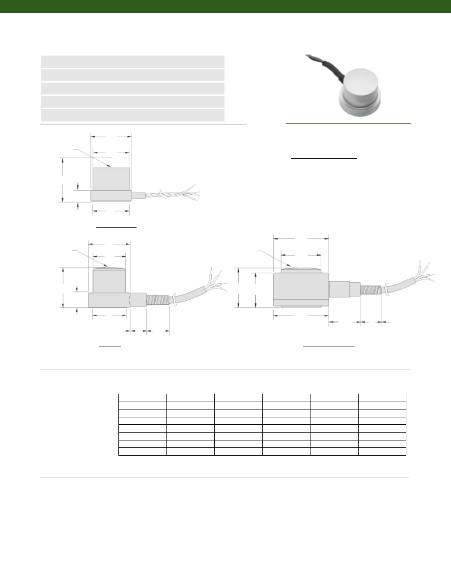
202
Dimensions
Performance
........250 to 10,000 lb.
........+/- 1% Full Scale (note 1)
........1.5 mV/V to 2.5 mV/V
........Compression only
Model LFH-7I (Top Hat) Subminiature Load Cell
Order Code BL351
www.honeywell.com/sensotec
n
250 to 10,000 lb. Range
n
Stainless Steel
n
Column Construction
n
mV/V Output
n
1% Accuracy
øD1
øD1
øD2
øD2
H
H
F
W
0.50
1.8
F
Load Ranges
Accuracy
Tolerance on Output
Operation
Ranges (lb.) øD1 (in.) øD2 (in.) H (in.) F (in.) W (in.)
Spherical Radius
Spherical Radius
250 to 3000 lb.
5000 lb.
Connector/ Unamplified
Red
(+) Excitation
Black
(-) Excitation
Green
(-) Output
White
(+) Output
1-888-282-9891
Twisted leads with
ø0.07 x 0.13 in.
strain relief
4 conductor shielded
teflon cable with
spring strain relief
øD1
øD2
H
0.50
1.8
F
Spherical Radius
7500 lb., 10,000 lb.
4 conductor shielded
teflon cable with
spring strain relief
250
0.50
0.27
0.38
0.13
0.43
500
0.50
0.28
0.38
0.13
0.43
1000
0.50
0.31
0.38
0.13
0.43
2000
0.50
0.41
0.38
0.13
0.43
3000
0.50
0.45
0.38
0.13
0.46
5000
0.63
0.53
0.60
0.23
0.51
7500
0.88
0.63
0.63
0.54
0.63
10,000
0.88
0.63
0.63
0.54
0.63
Wiring Code
W
W
Courtesy of Steven Engineering, Inc.-230 Ryan Way, South San Francisco, CA 94080-6370-Main Office: (650) 588-9200-Outside Local Area: (800) 258-9200-www.stevenengineering.com
Sensotec Sensors Full Line Catalog-html.html
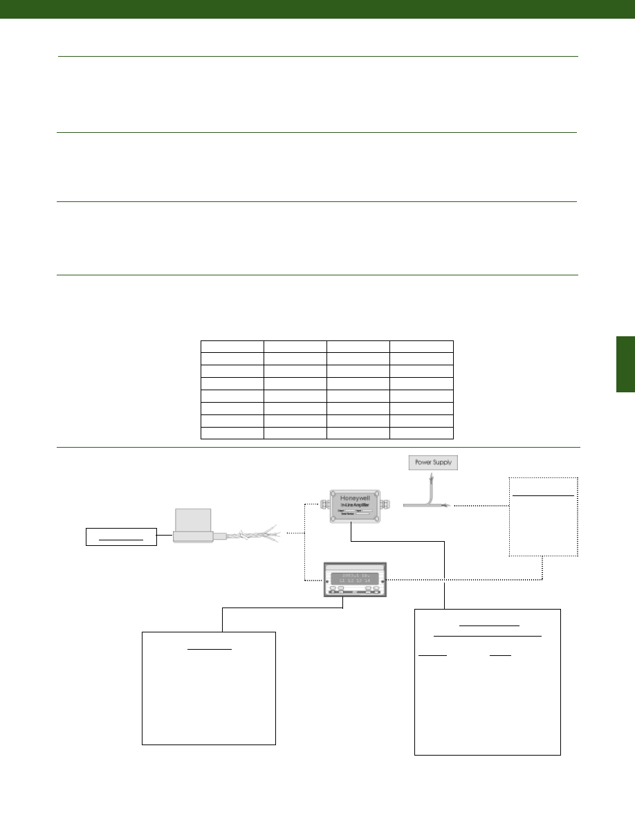
203
www.honeywell.com/sensotec
Mechanical
Typical System Diagram
Temperature, Operating
Temperature, Compensated
Storage Temperature
Temperature, Effect
Zero
Span
Strain Gage Type
Excitation (calibration)
Insulation Resistance
Bridge Resistance
Zero Balance
Electrical Termination (std)
Maximum Allowable Load
Weight
Material
Deflection Full Scale
Natural Frequency
........-65° to 250° F
........60° to 160° F
........-100° to 300 ° F
........0.01% Full Scale/ °F
........0.01% Full Scale/ °F (nominal)
........Bonded Foil
........5 VDC
........5000 Megohms @ 50 VDC
........350 Ohms
........5% max.
........Cable (5ft.)
........150% F.S. (note 2)
........See table
........17-4PH Stainless Steel
........See table
........See table
In-Line Amplifiers
(Used with unamplified units only)
Amplifier
Output
Universal In-Line Amplifiers
UV
+/- 5 VDC
UV-10
+/- 10 VDC
UBP
0 +/- 5 VDC
U3W
4-20 mA (3 wire)
DIN rail Mount In-Line Amplifiers
DV-05
0 +/- 5 VDC (3 wire)
DA-05
4-20 mA (3 wire)
DV-10
0 +/- 10 VDC (3 wire)
Display Units
SC500
SC1000
SC2000
SC2001
SC3004
GM
NK
HH
Customer Supplied
Chart Recorder
Alarm Panel
Data Acquisition
Computer
PLC
Model LFH-7I
1-888-282-9891
Model LFH-7I
Environmental
Electrical
Deflections and Ringing Frequencies
Capacity (lb.)
Deflection at
Full Scale
(in.)
Ringing
Frequency
(kHz)
Weight
(grams)
250
0.0005
30
10
500
0.0005
34
10
1000
0.001
37
10
2000
0.001
44
10
3000
0.001
46
10
5000
0.001
47
30
7500
0.0015
44
30
10,000
0.002
40
30
Courtesy of Steven Engineering, Inc.-230 Ryan Way, South San Francisco, CA 94080-6370-Main Office: (650) 588-9200-Outside Local Area: (800) 258-9200-www.stevenengineering.com
Sensotec Sensors Full Line Catalog-html.html
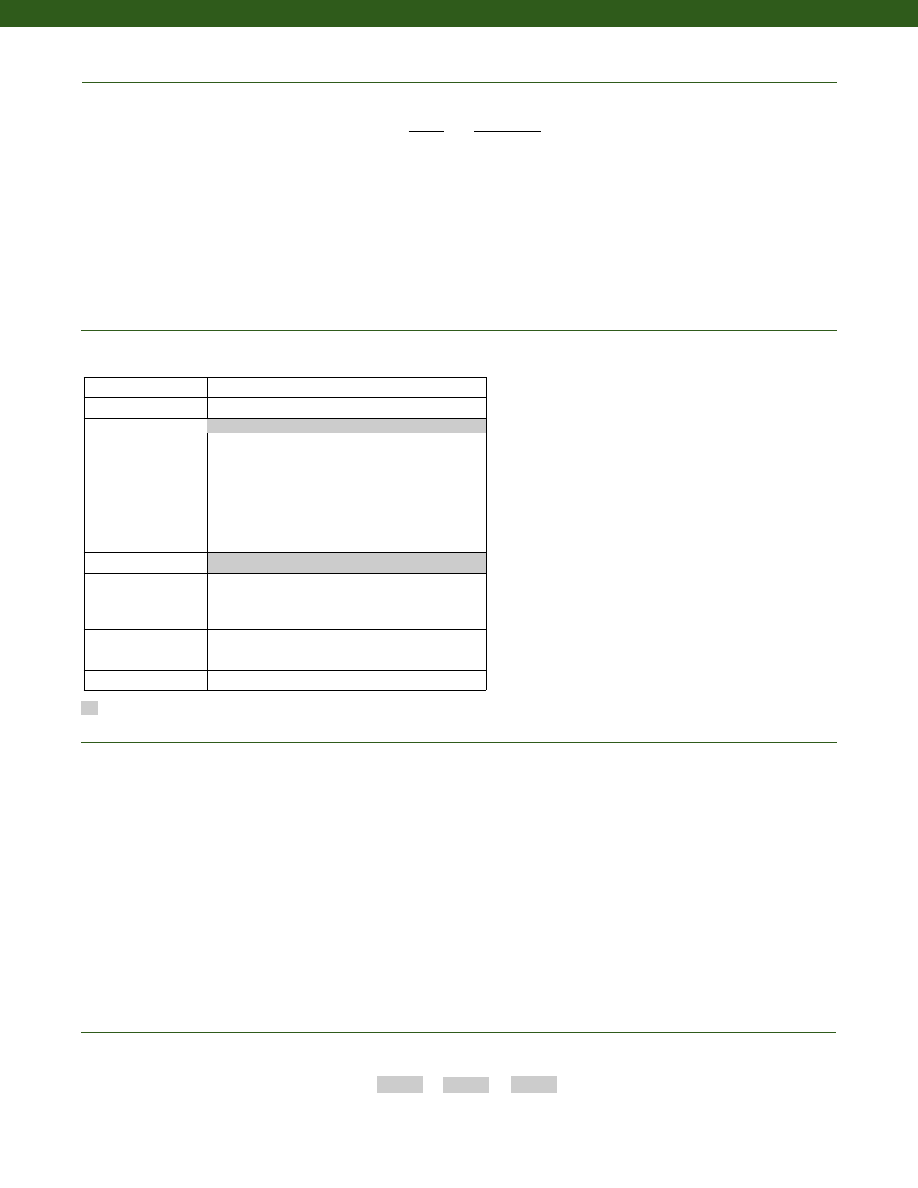
204
www.honeywell.com/sensotec
1-888-282-9891
Built to Order
Load Range
250; 500; 1000; 2000; 3000; 4000; 5000; 7500; 10,000 lb.
Temperature
Compensation
1b. 30° to 130° F
1f. 0° to 185° F
1b. -20° to 130° F
1f.
-20° to 200° F
1b. 70° to 250° F
1f.
0° to 50° C
1b. -20° to 85° C
1f.
-25° to 110° C
Internal Amplifiers
2u. Unamplified, mV/V output
Electrical Termination
6e. Integral cable: Teflon
6h. Integral cable: Silicone
6v. Phoenix connector on end of cable
15d. Connector on end of cable
Special Calibration
9a. 10 point (5 up/5 down) 20% increments @ 70° F
9b. 20 point (10 up/10 down) 10% increments @ 70° F
Shock & Vibration
44a. Shock and Vibration resistance
Supplied as standard
Options
How to Order
Combine the order code, the range code and the options code.
Order Code
Range Code
Options Code
Sample Code:
BL351
DL
1b
Model LFH-7I
Range
Range Code
250 lb. CN
500 lb. CR
1000 lb. CV
2000 lb. DL
3000 lb. DN
4000 lb. DP
5000 lb. DR
7500 lb. DT
10,000 lb. DV
Range Codes
1a. 60° to 160° F
Notes
1. Accuracies stated are expected for Best Fit Straight Line for all errors including linearity,
hysteresis and repeatability through zero.
2. Allowable Maximum Loads- Maximum load to be applied without damage (note 2).
3. Without Damage- loading to this level will not cause excessive zero shift or performance
degradation. The user must consider fatigue life for long term use and structural integrity.
All structurally critical applications (overhead loading, etc.) should always be designed
with safety redundant load paths.
Courtesy of Steven Engineering, Inc.-230 Ryan Way, South San Francisco, CA 94080-6370-Main Office: (650) 588-9200-Outside Local Area: (800) 258-9200-www.stevenengineering.com
Sensotec Sensors Full Line Catalog-html.html
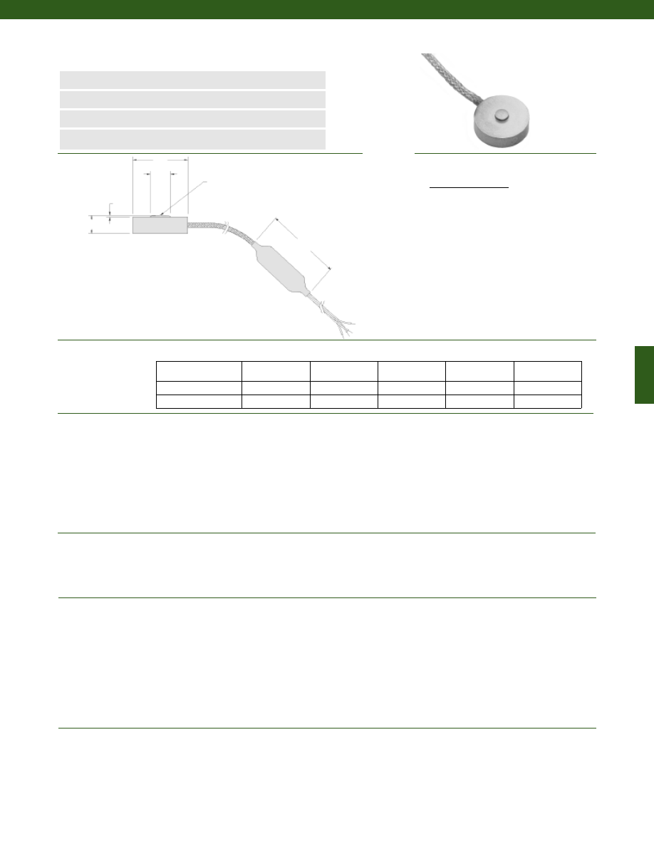
205
........150; 250; 500; 1000 g; 5; 10; 25; 50; 100; 250; 500; 1000 lb.
........+/- 0.5% Full Scale
........+/- 0.5% Full Scale
........+/- 0.1% Full Scale
........15 mV/V (nominal)
........1.5 mV/V (nominal)
........2 mV/V (nominal)
........Compression Only
........Infinite
........-65° to 250° F
........60° to 160° F
........0.01% Full Scale/ °F
........0.02% Reading/ °F
........Semiconductor
........Bonded Foil
........5 VDC
........5000 Megohms @ 50 VDC
........500 Ohms (nominal)
........350 Ohms (nominal)
........+/- 3% of Full Scale (nominal)
........Included
........5’ Integral cable with balance board (note 3)
........See table
........See table
........Stainless Steel
........See table
Dimensions
Performance
Environmental
Electrical
Mechanical
Model 13 Subminiature Load Cell
Order Code AL322
www.honeywell.com/sensotec
1-888-282-9891
n
150 g to 1,000 lb.
n
mV/V Output
n
Stainless Steel
n
Single Diaphragm Construction
øD1
øD2
H
Spherical Radius (SR)
B
2”
Load Ranges
Linearity
Hysteresis
Non-Repeatability
Output (tolerance)
150 g to 500 g
1000 g
5 lb. to 1000 lb.
Operation
Resolution
Temperature, Operating
Temperature, Compensated
Temperature, Effect
Zero
Span
Strain Gage Type
150 g to 500 g
1000 g to 1000 lb.
Excitation (calibration)
Insulation Resistance
Bridge Resistance (tolerance)
150 g to 500 g
1000 g to 1000 lb.
Zero Balance (tolerance)
Shunt Calibration Data
Electrical Termination (std)
Maximum Allowable Load
Weight
Material
Deflection @ Full Scale
Ranges D1 (in.) D2 (in.) H (in.) B (in.) SR (in.)
Wiring Code
Cable/ Unamplified
Red (+) Excitation
Black (-) Excitation
Green (-) Output
White (+) Output
150; 250; 500; 1000 g
5; 10; 25; 50 lb.
0.38
0.09
0.13
0.027
0.25
100; 250 lb.
0.50
0.12
0.15
0.020
0.50
500; 1000 lb.
0.75
0.25
0.25
0.025
0.50
2 ft. Stainless Steel
Braided Shield Cable
Balance
Module
4, 30 GA, Twisted Leads
Teflon Insulated, Color
Coded, 3 ft. Long
Courtesy of Steven Engineering, Inc.-230 Ryan Way, South San Francisco, CA 94080-6370-Main Office: (650) 588-9200-Outside Local Area: (800) 258-9200-www.stevenengineering.com
Sensotec Sensors Full Line Catalog-html.html
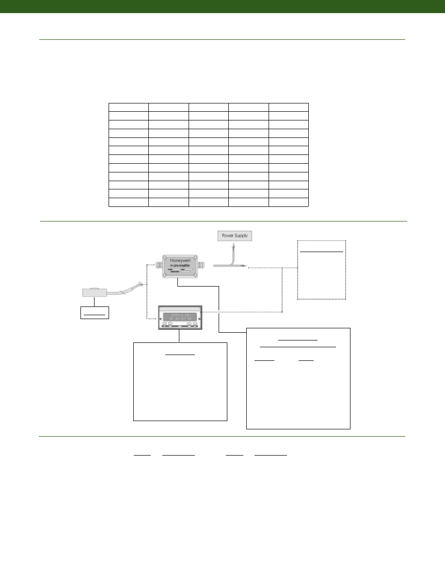
206
www.honeywell.com/sensotec
In-Line Amplifiers
(Used with unamplified units only)
Amplifier
Output
Universal In-Line Amplifiers
UV
+/- 5 VDC
UV-10
+/- 10 VDC
UBP
0 +/- 5 VDC
U3W
4-20 mA (3 wire)
DIN Rail Mount In-Line Amplifiers
DV-05
0 +/- 5 VDC (3 wire)
DA-05
4-20 mA (3 wire)
DV-10
0 +/- 10 VDC (3 wire)
Customer Supplied
Chart Recorder
Alarm Panel
Data Acquisition
Computer
PLC
Model 13
1-888-282-9891
Range
Range Code
5 lb. AT
10 lb. AV
25 lb. BL
50 lb. BN
100 lb. BR
250 lb. CN
500 lb.
CR
1000 lb.
CV
Range Codes
Model 13
Deflections and Weight
Typical System Diagram
Capacity
Deflection
at Full Scale
(10-3 in.)
Weight
(g)
Weight with
Cable
(g)
Maximum
Allowable
Load (note 1)
(%F.S.)
150 g
0.06
1
9
500
250 g
0.06
1
9
500
500 g
0.08
1
9
500
1000 g
0.05
1
9
150
5 lb.
0.5
1
9
150
10 lb.
0.4
1
9
150
25 lb.
0.4
1
9
150
50 lb.
0.4
1
9
150
100 lb.
0.4
3
11
150
250 lb.
0.5
3
11
150
500 lb.
0.5
10
18
150
1000 lb.
0.6
10
18
150
Range
Range Code
150 g AL
250 g AN
500 g AP
1000 g AR
Display Units
SC500
SC1000
SC2000
SC2001
SC3004
GM
NK
HH
Courtesy of Steven Engineering, Inc.-230 Ryan Way, South San Francisco, CA 94080-6370-Main Office: (650) 588-9200-Outside Local Area: (800) 258-9200-www.stevenengineering.com
Sensotec Sensors Full Line Catalog-html.html
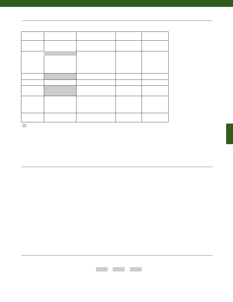
207
www.honeywell.com/sensotec
1-888-282-9891
Supplied as standard
Options
1. Allowable Maximum Loads- Maximum load to be applied without damage (note 2). Loads described allow for 100% full scale axial loading
with the bending loads specified. Torque loading maximum is without axial or other load. For any other combination consult factory.
2. Without Damage- loading to this level will not cause excessive zero shift of performance degradation. The user must consider fatigue
life for long term use and structural integrity. All structurally critical applications (overhead loading, etc.) should always be designed
with safety redundant load paths.
3. A small 2 in. circuit board is included in the cable, 2 ft. from the load cell. Do not remove this board.
4. Only for ranges greater than or equal to 1000 g.
5. Specifications may vary with this option.
OEM Labels
Radiation rated
Different cable lengths
Non-magnetic
Increased fatigue life
Custom cable exit
No circuit board (note 5)
Alternate cable materials
Special Customer
Requirements
(Consult Factory)
Notes
How to Order
Combine the order code, the range code and the options code.
Order Code
Range Code
Options Code
Sample Code:
AL322
AT
1b
Model 13
Same Day Ship
Fast track manufacture
Build to order
Build from scratch
Load Range
1000 grams
10, 25, 50, 100, 250, 500,
1000 lbs
150, 250, 500 grams
5 lbs
Temperature
Compensation
1b. 30° to 130° F
1c. 0° to 185° F
1d. -20° to 130° F
1e. -20° to 200° F
1j. 0° to 50° C
1k. -20° to 85° C
1m. -25° to 110° C
Internal Amplifiers 2u. Unamplified, mV/V
output
Overload Stops
4a. Overload Stops
Electrical
Termination
Twisted cable
6v. Phoenix connector on end
of cable
15d. Connector on end of cable
Special
Calibration
9a. 10 point (5 up/5 down)
20% increments @ 68° F
9b. 20 point (10 up/10 down)
10% increments @ 68° F
Shock & Vibration
44a. Shock and
vibration
resistance
1a. 60° to 160° F
Courtesy of Steven Engineering, Inc.-230 Ryan Way, South San Francisco, CA 94080-6370-Main Office: (650) 588-9200-Outside Local Area: (800) 258-9200-www.stevenengineering.com
Sensotec Sensors Full Line Catalog-html.html
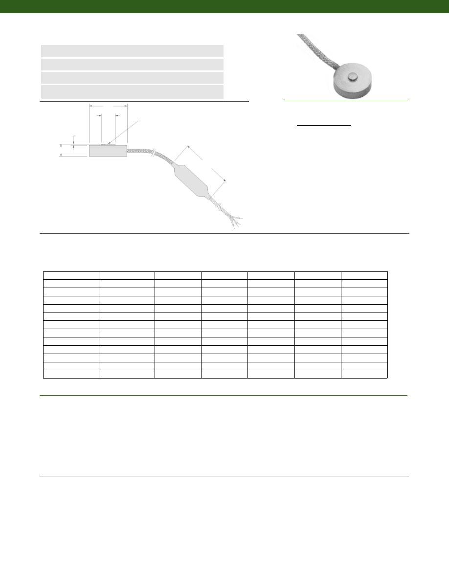
208
........0.5N to 5kN
........+/- 0.5% Full Scale
........+/- 0.5% Full Scale
........+/- 0.1% Full Scale
........15 mV/V (nominal)
........1.5 mV/V (nominal)
........2 mV/V (nominal)
........Compression Only
........Infinite
........-55° to 120° C
........15° to 70° C
........0.02% Full Scale/ °C
........0.04% Full Scale/ °C
........IP65
Model 13E Subminiature Load Cell
Order Code 13E
www.honeywell.com/sensotec
1-888-282-9891
n
0.5N to 5kN Range
n
mV/V Output
n
Stainless Steel
n
Fast Dynamic Response
øD1
øOD
H
Spherical Radius (SR)
B
50 mm
Load Ranges
Linearity
Hysteresis
Non-Repeatability
Output (tolerance)
0.5N to 5N
10N
20N to 5kN
Operation
Resolution
Temperature, Operating
Temperature, Compensated
Temperature, Effect
Zero
Span
Protection Rating
Ranges Range Code OD (mm) D1 (mm) H (mm) B (mm) SR (mm)
Wiring Code
Cable/ Unamplified
Red (+) Excitation
Black (-) Excitation
Green (-) Output
White (+) Output
0.5N
000N5
9.7
2.3
3.3
0.7
6
1.5N
001N5
9.7
2.3
3.3
0.7
6
2.5N
002N5
9.7
2.3
3.3
0.7
6
5N
005N0
9.7
2.3
3.3
0.7
6
10N
010N0
9.7
2.3
3.3
0.7
6
20N
020N0
9.7
2.3
3.3
0.7
6
50N
050N0
9.7
2.3
3.3
0.7
6
100N
100N0
9.7
2.3
3.3
0.7
6
200N
200N0
9.7
2.2
3.3
0.7
6
500N
500N0
12.7
3.0
3.8
0.5
13
1kN
01KN0
12.7
3.0
3.8
0.5
13
2kN
02KN0
19.1
6.4
6.4
0.6
13
5kN
05KN0
19.1
6.4
6.4
0.6
13
0.6m Stainless Steel
Braided Shield Cable
Balance
Module
4 Twisted Leads
Teflon Insulated, Color
Coded, 0.9m Long
Dimensions
Performance
Environmental
Courtesy of Steven Engineering, Inc.-230 Ryan Way, South San Francisco, CA 94080-6370-Main Office: (650) 588-9200-Outside Local Area: (800) 258-9200-www.stevenengineering.com
Sensotec Sensors Full Line Catalog-html.html
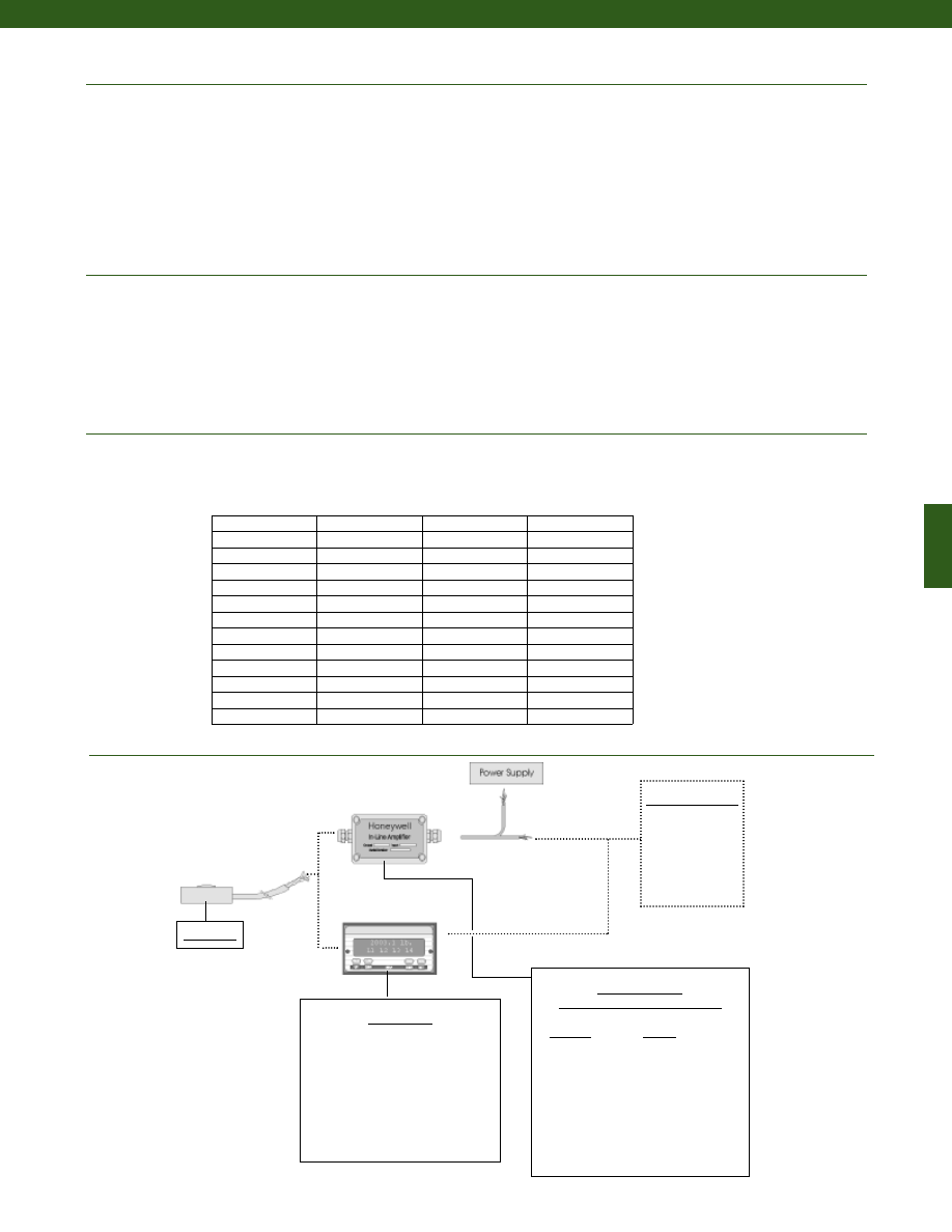
209
www.honeywell.com/sensotec
In-Line Amplifiers
(Used with unamplified units only)
Amplifier
Output
Universal In-Line Amplifiers
UV
+/- 5 VDC
UV-10
+/- 10 VDC
UBP
0 +/- 5 VDC
U3W
4-20 mA (3 wire)
DIN Rail Mount In-Line Amplifiers
DV-05
0 +/- 5 VDC (3 wire)
DA-05
4-20 mA (3 wire)
DV-10
0 +/- 10 VDC (3 wire)
Customer Supplied
Chart Recorder
Alarm Panel
Data Acquisition
Computer
PLC
Model 13E
1-888-282-9891
Model 13E
Deflections and Weight
Electrical
Mechanical
Typical System Layout
Capacity
Deflection
at Full Scale
(mm)
Weight
(g)
Weight with
Cable
(g)
0.5 N
0.0015
1
9
1.5 N
0.0015
1
9
2.5 N
0.0015
1
9
5 N
0.0020
1
9
10 N
0.0127
1
9
20 N
0.0127
1
9
50 N
0.0101
1
9
100 N
0.0101
1
9
200 N
0.0101
1
9
500 N
0.0101
3
11
1 kN
0.0127
3
11
2 kN
0.0127
10
18
5 kN
0.0152
10
18
Strain Gage Type
0.5N to 5N
10N to 5kN
Excitation (calibration)
Insulation Resistance
Bridge Resistance (tolerance)
0.5N to 5N
10N to 5kN
Zero Balance (tolerance)
Shunt Calibration Data
Electrical Termination (std)
Maximum Allowable Load
Weight
Material
Deflection @ Full Scale
........Semiconductor
........Bonded Foil
........5 VDC
........5000 Megohms @ 50 VDC
........500 Ohms (nominal)
........350 Ohms (nominal)
........+/- 3% of Full Scale (nominal)
........Included
........1.5m Integral cable with balance board (note 3)
........150% F.S. (note 1)
........See table
........Stainless Steel
........See table
Display Units
SC500
SC1000
SC2000
SC2001
SC3004
GM
NK
HH
Courtesy of Steven Engineering, Inc.-230 Ryan Way, South San Francisco, CA 94080-6370-Main Office: (650) 588-9200-Outside Local Area: (800) 258-9200-www.stevenengineering.com
Sensotec Sensors Full Line Catalog-html.html
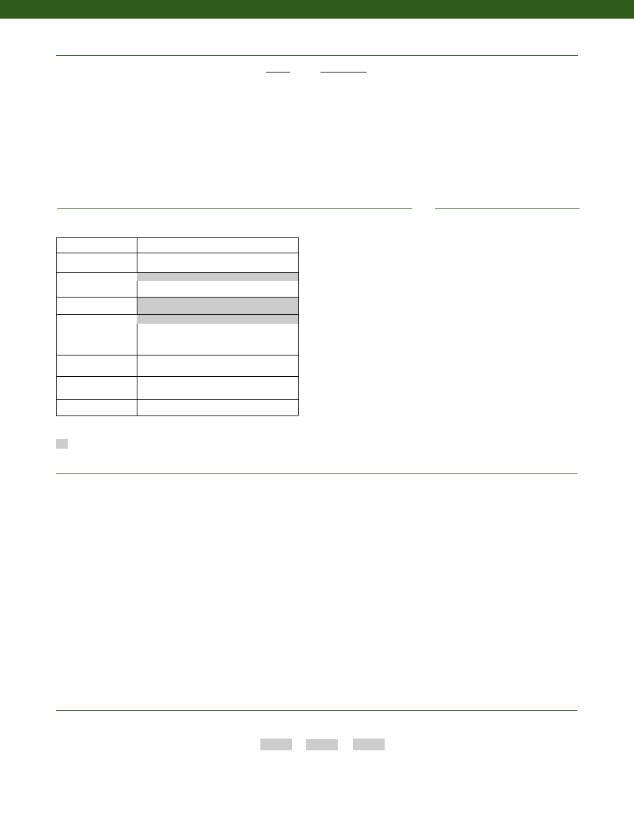
210
www.honeywell.com/sensotec
1-888-282-9891
Supplied as standard
Options
1. Allowable Maximum Loads- Maximum load to be applied without damage (note 2).
2. Without Damage- loading to this level will not cause excessive zero shift or performance degradation. The user must consider fatigue
life for long term use and structural integrity. All structurally critical applications (overhead loading, etc.) should always be designed
with safety redundant load paths.
3. A small 50mm long x 2mm thick circuit board is located approximately 60cm from cell body. Do not remove this board.
4. Only for ranges greater than or equal to 10N
5. Specifications may vary with this option.
OEM Labels
Radiation rated
Different cable lengths
Non-magnetic
Increased fatigue life
Custom cable exit
No circuit board (note 5)
Alternate cable materials
Special Customer
Requirements
(Consult Factory)
Notes
How to Order
Combine the order code, the range code and the options code.
Order Code
Range Code
Options Code
Sample Code:
13E 050N0
1j
Model 13E
Build to Order
Load Range
0.5N to 5kN
Temperature
Compensation
1j. -65° to 50° C
1k. -20° to 85° C
Internal Amplifiers
2u. Unamplified, mV/V output
Electrical Termination
6a. Bendix PTIH-10-6P - (or equivalent) 6 pin
(max. 120°C) on end of cable
6e. Integral cable: Teflon
6v. Phoenix connector on end of cable
Electrical Connector
Orientation
15d. Connector on end of cable
Load Direction
30c. Negative in compression, compression
testing only
Shock & Vibration
44a. shock rated wiring
1.5m. Integral cable with balance board (note 3)
1a. 15° to 70° C
Range Codes
Range
Range Code
0.5 N
000N5
1.5 N
001N5
2.5 N
002N5
5 N
005N0
10 N
010N0
20 N
020N0
50 N
050N0
100 N
100N0
200 N
200N0
500 N
500N0
1 kN
01KN0
2 kN
02KN0
5 kN
05KN0
Courtesy of Steven Engineering, Inc.-230 Ryan Way, South San Francisco, CA 94080-6370-Main Office: (650) 588-9200-Outside Local Area: (800) 258-9200-www.stevenengineering.com
Sensotec Sensors Full Line Catalog-html.html
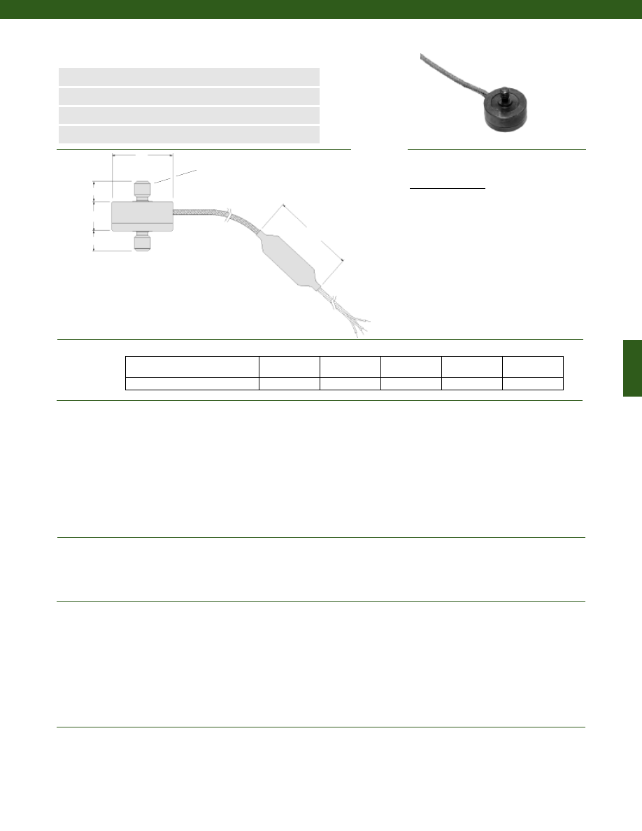
211
Dimensions
Performance
Environmental
Electrical
Mechanical
Model 11 Subminiature Load Cell
Order Code BL321
www.honeywell.com/sensotec
n
150 g to 1000 lb. Range
n
mV/V Output
n
Subminiature Design
n
Single Diaphragm Construction
B
2”
H
A
2X “T”
øD
Load Ranges................150 g to 1,000 lb.
Linearity................+/- 0.5% Full Scale
Hysteresis................+/- 0.5% Full Scale
Non-Repeatability................+/- 0.1% Full Scale
Output (tolerance)
150 to 500 g................10 mV/V (nominal)
1000 g to 1000 lb.................2 mV/V (nominal)
Operation................Tension/ Compression (note 3)
Resolution................Infinite
Maximum Permissible Torque
150 g to 100 lb.................4 in.-lb.
250 to 1000 lb.................20 in.-lb.
Temperature, Operating................-65° to 250° F
Temperature, Compensated................60° to 160° F
Temperature, Effect
Zero................0.01% of Full Scale/ °F
Span................0.02% of Reading/ °F
Strain Gage Type
150 to 500 g................Semiconductor
1000 g to 1000 lb.................Bonded Foil
Excitation (calibration)................5 VDC
Insulation Resistance................5,000 Megohms @ 50 VDC
Bridge Resistance (tolerance)
150 to 500 g................500 Ohms (nominal)
1000 g to 1000 lb.................350 Ohms (nominal)
Zero Balance (tolerance)................+/- 3% of Full Scale (nominal)
Shunt Calibration Data................Included
Electrical Termination (std)................5’ integral cable with balance board (note 4)
Maximum Allowable Load................See table (note 1)
Weight................See table
Material................Stainless Steel
Deflection @ Full Scale................See table
Natural Frequency................See table
Range (lb.)
øD (in.)
T
H (in.) A (in.)
B (in.)
1-888-282-9891
150; 250; 500; 1000 g
5; 10; 25; 50; 100 lb.
0.50
#4-40 UNC
0.29
0.19
0.18
250; 500; 1000 lb.
0.75
1/4-28 UNF
0.38
0.31
0.31
2 ft. Stainless Steel
Braided Shield Cable
Balance
Module
4, 30 GA, Twisted Leads
Teflon Insulated, Color
Coded, 3 ft. Long
Wiring Code
Cable/ Unamplified
Red
(+) Excitation
Black
(-) Excitation
Green
(-) Output
White
(+) Output
Courtesy of Steven Engineering, Inc.-230 Ryan Way, South San Francisco, CA 94080-6370-Main Office: (650) 588-9200-Outside Local Area: (800) 258-9200-www.stevenengineering.com
Sensotec Sensors Full Line Catalog-html.html
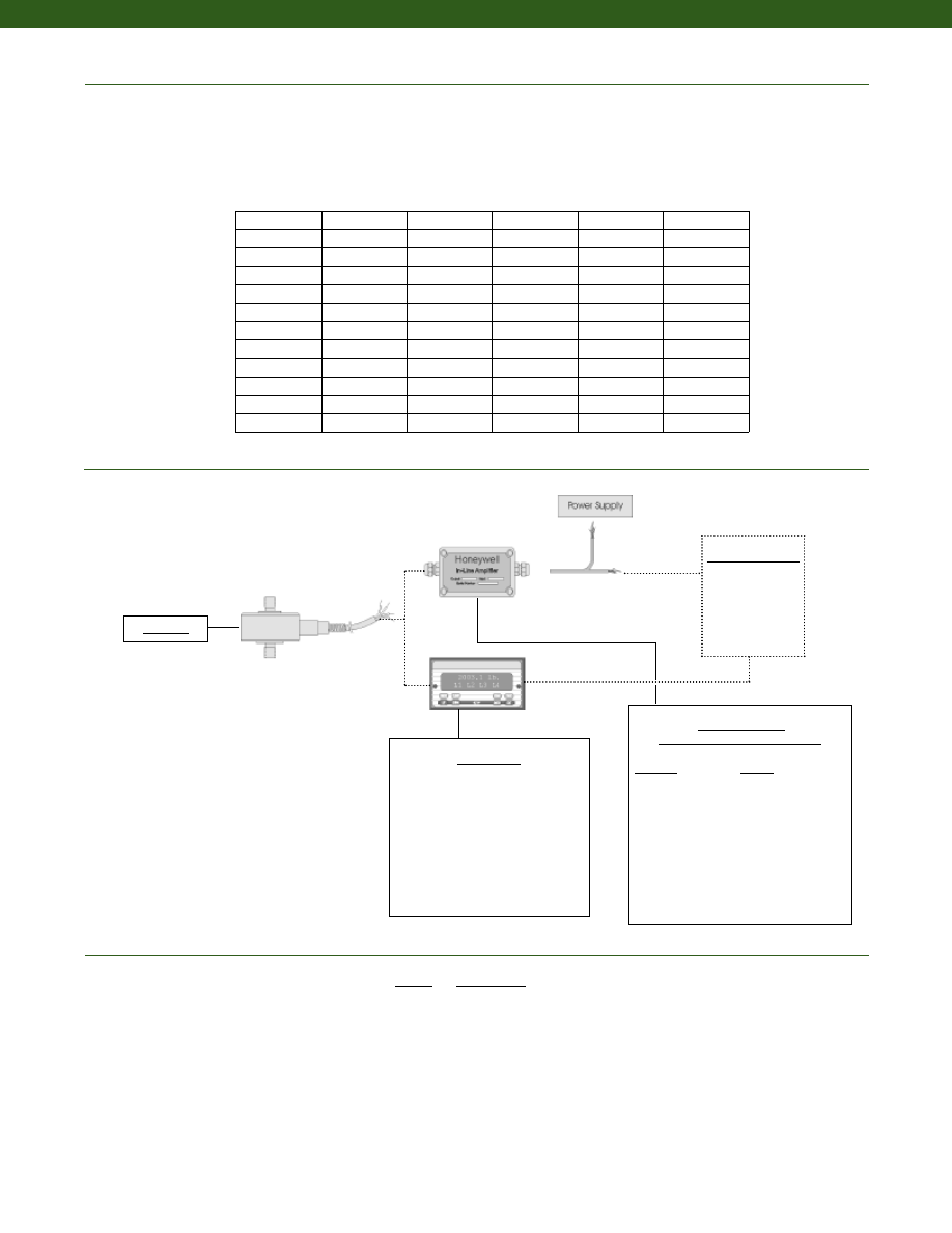
212
www.honeywell.com/sensotec
Typical System Diagram
In-Line Amplifiers
(Used with unamplified units only)
Amplifier
Output
Universal In-Line Amplifiers
UV
+/- 5 VDC
UV-10
+/- 10 VDC
UBP
0 +/- 5 VDC
U3W
4-20 mA (3 wire)
DIN rail Mount In-Line Amplifiers
DV-05
0 +/- 5 VDC (3 wire)
DA-05
4-20 mA (3 wire)
DV-10
0 +/- 10 VDC (3 wire)
Customer Supplied
Chart Recorder
Alarm Panel
Data Acquisition
Computer
PLC
Model 11
1-888-282-9891
Range
Range Code
150 g
AL
250 g
AN
500 g
AP
1000 g
AR
5 lb.
AT
10 lb.
AV
25 lb.
BL
50 lb.
BN
100 lb.
BR
250 lb.
CN
500 lb.
CR
1000 lb.
CV
Range Codes
Model 11
Deflections and Ringing Frequencies
Capacity
Deflection
at Full Scale
(10-3 in.)
Ringing
Frequency
(kHz)
Weight
(g)
Weight with
Cable
(g)
Maximum
Allowable
Load (note 1)
(% F.S.)
150 g
0.05
10
5
13
500
250 g
0.04
14
5
13
500
500 g
0.03
22
5
13
500
1000 g
0.7
8
5
13
150
5 lb.
0.6
11
5
13
150
10 lb.
0.6
17
5
13
150
25 lb.
0.5
24
5
13
150
50 lb.
0.5
34
5
13
150
100 lb.
0.5
48
5
13
150
250 lb.
0.6
25
19
27
150
500 lb.
0.7
33
19
27
150
1000 lb.
1.0
40
19
27
150
Display Units
SC500
SC1000
SC2000
SC2001
SC3004
GM
NK
HH
Courtesy of Steven Engineering, Inc.-230 Ryan Way, South San Francisco, CA 94080-6370-Main Office: (650) 588-9200-Outside Local Area: (800) 258-9200-www.stevenengineering.com
Sensotec Sensors Full Line Catalog-html.html
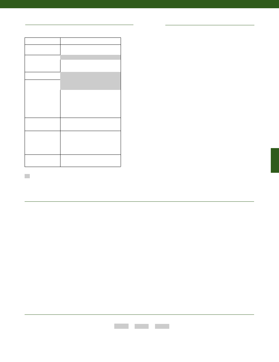
213
Built from Scratch
Load Range
150 g to 1,000 lb.
Temperature
Compensation
1b. 30° to 130° F
1c. 0° to 185° F
1e. -20° to 200° F (note 5)
1f. 70° to 250° F (note 5)
Internal Amplifiers
Electrical Termination
6a. Bendix PTIH-10-6P -
(or equivalent) 6 pin (max. 250°F)
on end of cable
6e. Integral cable: Teflon
6v. Phoenix connector on end of cable
Electrical Connector
Orientation
15d. Connector on end of cable
Load Direction
30a. Positive in compression,
compression testing only
30b. Positive in tension, tension &
compression testing only
30c. Negative in compression,
compression testing only
Shock & Vibration
44a. shock rated wiring
2u. Unamplified, mV/V output
www.honeywell.com/sensotec
1-888-282-9891
Supplied as standard
Options
1. Allowable Maximum Loads- Maximum load to be applied without damage (note 2).
2. Without Damage- loading to this level will not cause excessive zero shift or performance degradation. The user must consider fatigue
life for long term use and structural integrity. All structurally critical applications (overhead loading, etc.) should always be designed
with safety redundant load paths.
3. Standard calibration for tension/ compression load cells is in tension only.
4. A small 2 in. circuit board is included in the cable, 2 ft. from the load cell. Do not remove this board.
5. Only for ranges greater than or equal to 1,000 g.
6. Specifications may vary with this option.
OEM Labels
Radiation rated
Different cable lengths
Custom threads
Non-magnetic
Increased fatigue life
Custom cable exit
No circuit board (note 6)
Alternate cable materials
Special Customer Requirements
(Consult Factory)
Notes
How to Order
Combine the order code, the range code and the options code.
Order Code
Range Code
Options Code
Sample Code:
BL321
AT
1b
Model 11
5ft. Integral cable with balance
board (note 4)
1a. 60° to 160° F
Courtesy of Steven Engineering, Inc.-230 Ryan Way, South San Francisco, CA 94080-6370-Main Office: (650) 588-9200-Outside Local Area: (800) 258-9200-www.stevenengineering.com
Sensotec Sensors Full Line Catalog-html.html
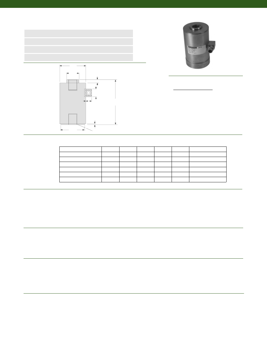
214
Dimensions
Performance
Environmental
Electrical
Mechanical
Model UG Ultra Precision Universal Canister Load Cell
Order Code BL122
www.honeywell.com/sensotec
n
100 to 150,000 lb. Range
n
Stainless Steel
n
All-Welded Design
n
0.03% Linearity
øD1
øD2
øD3
H
0.030 in.
2X “T”
1.25 in.
1.50 in.
A
Load Ranges................100 to 150,000 lb.
Linearity................+/- 0.03% Full Scale (note 1)
Hysteresis................+/- 0.03% Full Scale (note 1)
Non-Repeatability................+/- 0.02% Full Scale
Output................3 mV/V +/- 1%
Load Direction................Tension/ Compression (note 4)
Resolution................Infinite
Creep (max.)................0.02% (20 min.)
Temperature, Operating................-30° to 185° F (note 5)
Temperature, Compensated................60° to 160° F (note 5)
Storage Temperature................-100° to 250° F
Temperature, Effect
Zero................0.0015% Full Scale/ °F
Span................0.0008% Full Scale/ °F
Strain Gage Type................Bonded Foil
Excitation (calibration)................10 VDC
Insulation Resistance................5,000 Megohms @ 50 VDC
Bridge Resistance................350 Ohms
Zero Balance................1% of Full Scale
Electrical Termination (std)................MS3102E-14S-6P
Mating Connector (not incl.)................MS3106A-14S-6S
Maximum Allowable Load................150% F.S. (note 2)
Material................Stainless Steel
Ranges (lb.) H (in.) øD1 (in.) øD2 (in.) øD3 (in.) A (in.) T Typical
1-888-282-9891
Wiring Code
Connector/ Unamplified
A
(+) Excitation
B
(+) Excitation
C
(-) Excitation
D
(-) Excitation
E
(-) Output
F
(+) Output
100
2.75
2.00
0.63
1.9
0.09
3/8-24 UNF X 7/16”
250; 500
2.75
2.00
0.63
1.9
0.18
3/8-24 UNF X 7/16”
1,000; 2,000; 3,000; 4000
4.13
2.50
0.75
2.0
0.18
1/2-20 UNF X 5/8”
5,000; 7,500; 10,000
5.88
3.50
1.56
3.0
0.19
1-14 UNF X 1 1/8”
15,000; 20,000; 30,000
8.50
5.00
2.38
4.3
0.63
1 1/2-12 UNF X 2”
50,000; 75,000
12.00
6.00
3.63
5.5
0.69
2-12 UNF X 2 1/2”
100,000; 150,000
15.80
7.5
4.8
6.8
0.69
3-8 UNF X 4 1/2”
Courtesy of Steven Engineering, Inc.-230 Ryan Way, South San Francisco, CA 94080-6370-Main Office: (650) 588-9200-Outside Local Area: (800) 258-9200-www.stevenengineering.com
Sensotec Sensors Full Line Catalog-html.html
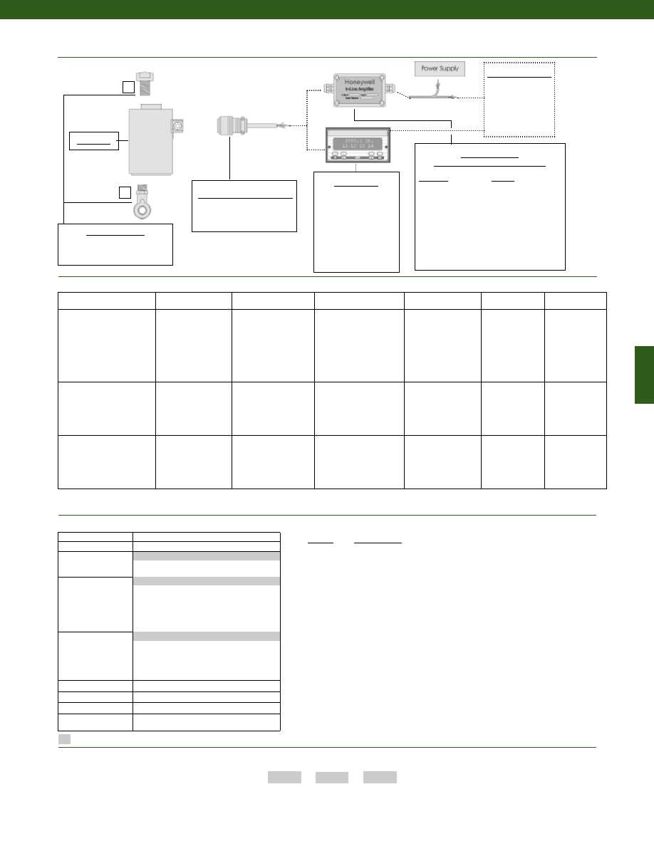
215
www.honeywell.com/sensotec
1-888-282-9891
1
2
Mounting Options
1. Load Button
2. Rod End Bearing Male
Mating Connectors & Cables
MS3106A-14S-6S
Model UG
Range
Range Code
100 lb.
BR
250 lb.
CN
500 lb.
CR
1000 lb.
CV
2000 lb.
DL
3000 lb.
DN
4000 lb.
DP
5000 lb.
DR
7500 lb.
DT
10,000 lb.
DV
15,000 lb.
EJ
20,000 lb.
EL
30,000 lb.
EN
50,000 lb.
EP
75,000 lb.
ER
100,000 lb.
ET
150,000 lb.
FJ
How to Order
Combine the order code, the range code and the options code.
Order Code
Range Code
Options Code
Sample Code:
BL122
DL
1b
Amplifier Specifications
Voltage Output
Option 2b
Voltage Output
Option 2c
Voltage Output
Option 2t
Current 3 Wire
Option 2j
Current 2 Wire
Option 2k
Intrinsically Safe
Option 2n (2N)***
Output Signal
Input Power (Voltage)
Input Power (Current)
Frequency Response
Power Supply Rejection
Operating Temperature
Reverse Voltage Protection
Short Circuit Protection
+/- 5V
+/-15V or 26-32VDC
45 mA
3000 Hz
60 db
-20° to 185° F
Yes
Momentary
0-5V or +/- 5V @ 45mA
11-28 VDC
40 mA
3000 Hz
60 db
-20° to 185° F
Yes
Momentary
0-10V or +/- 10V @ 45mA
15-28 VDC
40 mA
3000 Hz
60 db
-20° to 185° F
Yes
Momentary
4-20 mA
22-32 VDC
65 mA
2500 Hz
60 db
0° to 185° F
Yes
Yes
4-20 mA
15-40 VDC
4-28 mA
300 Hz
60 db
0° to 185° F
Yes
Yes
4-20 mA
9-28 VDC
4-24 mA
2000 Hz
60 db
-20° to 185° F
Yes
Yes
Wiring Code: Connector
(Std.)
(note 5)
A (+) Supply
B Output Common/
C Supply Return
D (+) Output
E Shunt Cal 1
F Shunt Cal 2
A (+) Supply
B** Output Common/
C** Supply Return
D (+) Output
E Shunt Cal 1
F Shunt Cal 2
A (+) Supply
B** Output Common/
C** Supply Return
D (+) Output
E Shunt Cal 1
F Shunt Cal 2
A (+) Supply
B** Output Common/
C** Supply Return
D (+) Output
E Shunt Cal 1
F Shunt Cal 2
A (+) Supply
B No connection
C No connection
D (+) Output
E Case Ground
F No connection
A (+) Supply
B No connection
C No connection
D (+) Output
E Case Ground
F No connection
Wiring Code: Cable
(note 5)
(note 6)
(note 7)
R (+) Supply
Bl Output Common/
G Supply Return
W (+) Output
B Shunt Cal 1
Br Shunt Cal 2
R (+) Supply
Bl*Output Common/
G*Supply Return
W (+) Output
B Shunt Cal 1
Br Shunt Cal 2
R (+) Supply
Bl*Output Common/
G*Supply Return
W (+) Output
B Shunt Cal 1
Br Shunt Cal 2
R (+) Supply
Bl*Output Common/
G*Supply Return
W (+) Output
B Shunt Cal 1
Br Shunt Cal 2
R (+) Supply
Bl (+) Output
W Case Ground
R (+) Supply
Bl (+) Output
W Case Ground
Typical System Diagram
In-Line Amplifiers
(Used with unamplified units only)
Amplifier
Output
Universal In-Line Amplifiers
UV
+/- 5 VDC
UV-10
+/- 10 VDC
UBP
0 +/- 5 VDC
U3W
4-20 mA (3 wire)
U2W
4-20 mA (2 wire)
DIN rail Mount In-Line Amplifiers
DV-05
0 +/- 5 VDC (3 wire)
DA-05
4-20 mA (3 wire)
DV-10
0 +/- 10 VDC (3 wire)
Display Units
SC500
SC1000
SC2000
SC2001
SC3004
GM (Unamplified only)
GM-A (Amplified only)
NK (Unamplified only)
HH (Unamplified only)
Customer Supplied
Chart Recorder
Alarm Panel
Data Acquisition
Computer
PLC
Model UG
Range Codes
Supplied as standard
1. +/- 0.05% Full Scale less than or equal to 250 lb. and
greater than or equal to 75,000 lb.
2. Allowable Maximum Loads- Maximum load to be applied
without damage (note 3).
3. Without Damage- loading to this level will not cause
excessive zero shift or performance degradation. The
user must consider fatigue life for long term use and
structural integrity. All structurally critical applications
(overhead loading, etc.) should always be designed with
safety redundant load paths.
4. Standard calibration for tension/ compression load cells
is in tension only.
5. Interconnecting shunt cal. 1 terminal with shunt cal. 2
terminal provides 50% (unamplified units), 75% (4-20mA
3-wire units) or 80% (voltage amplified units) of full scale
output for quick calibration. Shunt Calibration comes
standard with internal amplifier options 2b, 2c, 2t and 2j.
6. O=Orange; Y=Yellow; B=Blue; Bl=Black; R=Red;
Br=Brown; W=White; G=Green. Color specifying cable
and number or letter specifying connector.
7. No mating connector necessary for cable option.
8. Consult factory for extended temperature ranges.
9. Consult factory for TEDS availability with amplified models.
Notes
Build from Scratch
Load Range
100 to 150,000 lb.
Temperature
Compensation
1b. 30° to 130° F
1c.
0° to 185° F
Internal Amplifiers
2b.
4 wire +/- 5VDC output
2c.
0-5VDC
2j.
4-20mA (3-wire) output
2k.
4-20mA (2-wire)
2n (2N). 4-20mA (2-wire) Intrinsically Safe
2t.
0-10 VDC output
Electrical
Termination
6e. Integral cable: Teflon
6g. Integral cable: Neoprene
6j.
1/2-14 conduit fitting with 5 ft. of
4 conductor PVC cable
6q. Integral Cable: Polyurethane
Shunt Calibration
8a. Precision Internal Resistor
Bridge Resistance
12b. 5,000 Ohms (foil)
Shock & Vibration
44a. Shock and vibration resistance
Interfaces
53e. Signature Calibration
53t. T.E.D.S IEEE 1451.4 Module (note 9)
1a. 60° to 160° F
6b. MS Connector MS3102E-14S-6P
2u. Unamplified mV/V output
Internal Amplifiers
Options
* Black and Green wires are internally connected.
** Pins B and C are internally connected.
*** See Sensotec website for most up-to-date information regarding Intrinsically Safe approvals ref. #008-0547-00.
Courtesy of Steven Engineering, Inc.-230 Ryan Way, South San Francisco, CA 94080-6370-Main Office: (650) 588-9200-Outside Local Area: (800) 258-9200-www.stevenengineering.com
Sensotec Sensors Full Line Catalog-html.html
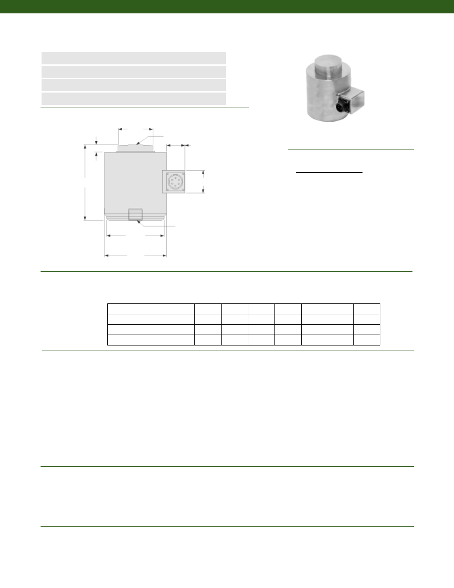
216
Dimensions
Performance
Environmental
Electrical
Mechanical
Model WG Ultra Precision Compression Canister Load Cell
Order Code BL125
www.honeywell.com/sensotec
n
10,000 to 500,000 lb. Range
n
Stainless Steel
n
Multiple Column Construction
n
0.03% Linearity & Hysteresis
øOD
øD3
H
T
1.25 in.
1.50 in.
A
Load Ranges................10,000 to 500,000 lb.
Linearity................+/- 0.03% Full Scale (note 1)
Hysteresis................+/- 0.03% Full Scale (note 1)
Non-Repeatability................+/- 0.01% Full Scale
Output................2 mV/V
Load Direction................Compression only
Resolution................Infinite
Creep (max.)................0.03% (20 min.)
Temperature, Operating................-30° to 185° F
Temperature, Compensated................60° to 160° F
Storage Temperature................-100° to 250° F
Temperature, Effect
Zero................0.0015% Full Scale/ °F
Span................0.0008% Full Scale/ °F
Strain Gage Type................Bonded Foil
Excitation (calibration)................10 VDC
Insulation Resistance................5,000 Megohms @ 50 VDC
Bridge Resistance................350 Ohms
Zero Balance................1% max.
Electrical Termination (std)................MS3102E-14S-6P
Mating Connector (not incl.)................MS3106A-14S-6S
Maximum Allowable Load................150% F.S. (note 1)
Material................Stainless Steel
Deflection Full Scale................0.003 in.
Ranges (lb.) øOD (in.) øD2 (in.) øD3 (in.) H (in.) T A (in.)
Spherical Radius
Wiring Code
Connector/ Unamplified
A
(+) Excitation
B
(+) Excitation
C
(-) Excitation
D
(-) Excitation
E
(-) Output
F
(+) Output
1-888-282-9891
10,000; 15,000; 25,000; 50,000
2.88
1.25
2.12
3.25
1/2-20 UNF-2B
0.40
100,000
4.12
2.31
3.66
5.00
3/4-16 UNF-3B
0.51
200,000; 300,000
6.00
3.13
5.31
7.25
3/4-16 UNF-3B
1.03
500,000
6.50
3.69
5.81
9.00
3/4-16 UNF-3B
1.04
øD2
Courtesy of Steven Engineering, Inc.-230 Ryan Way, South San Francisco, CA 94080-6370-Main Office: (650) 588-9200-Outside Local Area: (800) 258-9200-www.stevenengineering.com
Sensotec Sensors Full Line Catalog-html.html
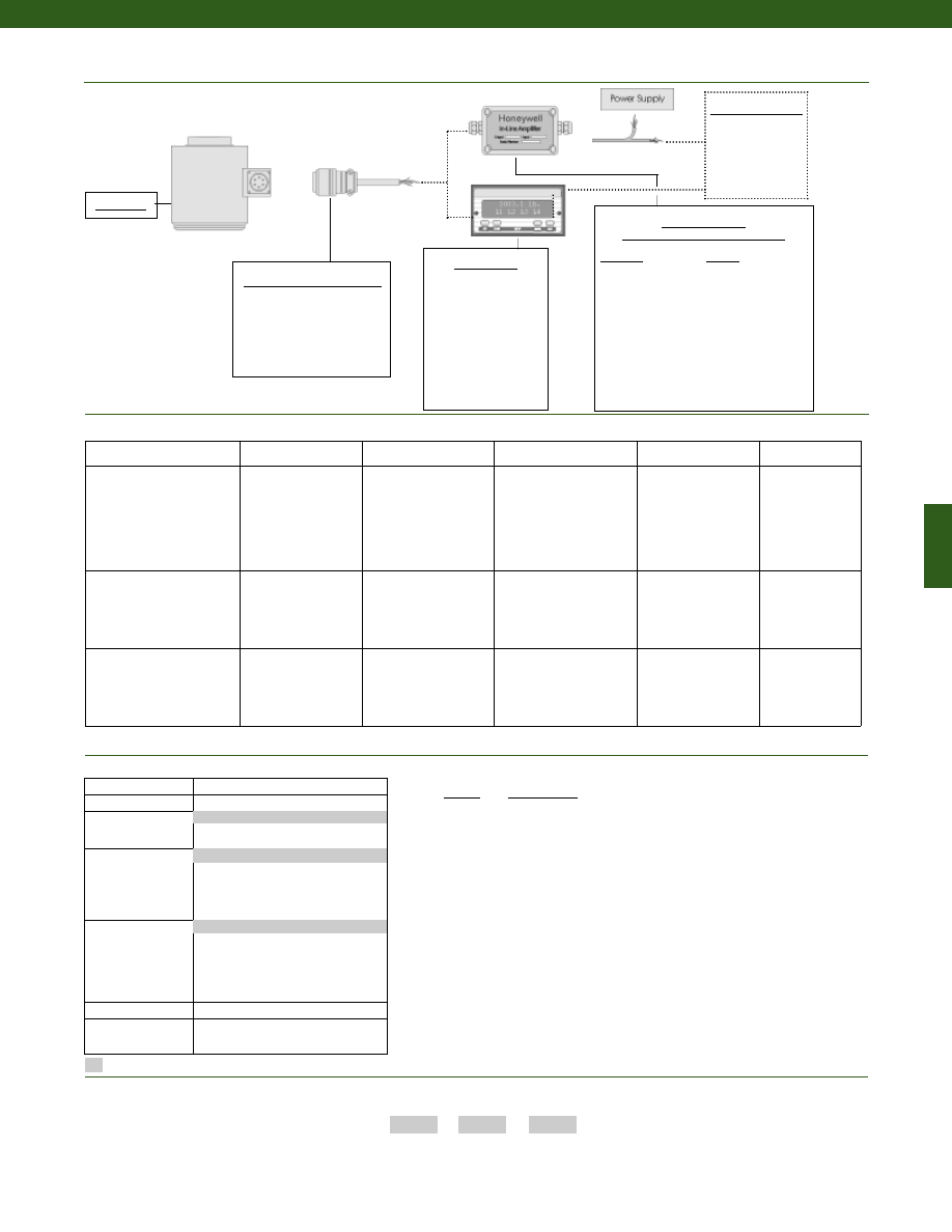
217
Amplifier Specifications
Voltage Output
Option 2b
Voltage Output
Option 2c
Voltage Output
Option 2t
Current 3 Wire
Option 2j
Current 2 Wire
Option 2k
Output Signal
Input Power (Voltage)
Input Power (Current)
Frequency Response
Power Supply Rejection
Operating Temperature
Reverse Voltage Protection
Short Circuit Protection
+/- 5V
+/-15V or 26-32VDC
45 mA
3000 Hz
60 db
-20° to 185° F
Yes
Momentary
0-5V or +/- 5V @ 45mA
11-28 VDC
40 mA
3000 Hz
60 db
-20° to 185° F
Yes
Momentary
0-10V or +/- 10V @ 45mA
15-28 VDC
40 mA
3000 Hz
60 db
-20° to 185° F
Yes
Momentary
4-20 mA
22-32 VDC
65 mA
2500 Hz
60 db
0° to 185° F
Yes
Yes
4-20 mA
15-40 VDC
4-28 mA
300 Hz
60 db
0° to 185° F
Yes
Yes
Wiring Code: Connector
(Std.)
(note 5)
A (+) Supply
B Output Common/
C Supply Return
D (+) Output
E Shunt Cal 1
F Shunt Cal 2
A (+) Supply
B** Output Common/
C** Supply Return
D (+) Output
E Shunt Cal 1
F Shunt Cal 2
A (+) Supply
B** Output Common/
C** Supply Return
D (+) Output
E Shunt Cal 1
F Shunt Cal 2
A (+) Supply
B** Output Common/
C** Supply Return
D (+) Output
E Shunt Cal 1
F Shunt Cal 2
A (+) Supply
B No connection
C No connection
D (+) Output
E Case Ground
F No connection
Wiring Code: Cable
(note 5)
(note 6)
(note 7)
R (+) Supply
Bl Output Common/
G Supply Return
W (+) Output
B Shunt Cal 1
Br Shunt Cal 2
R (+) Supply
Bl*Output Common/
G*Supply Return
W (+) Output
B Shunt Cal 1
Br Shunt Cal 2
R (+) Supply
Bl*Output Common/
G*Supply Return
W (+) Output
B Shunt Cal 1
Br Shunt Cal 2
R (+) Supply
Bl*Output Common/
G*Supply Return
W (+) Output
B Shunt Cal 1
Br Shunt Cal 2
R (+) Supply
Bl (+) Output
W Case Ground
www.honeywell.com/sensotec
Typical System Diagram
1-888-282-9891
In-Line Amplifiers
(Used with unamplified units only)
Amplifier
Output
Universal In-Line Amplifiers
UV
+/- 5 VDC
UV-10
+/- 10 VDC
UBP
0 +/- 5 VDC
U3W
4-20 mA (3 wire)
U2W
4-20 mA (2 wire)
DIN rail Mount In-Line Amplifiers
DV-05
0 +/- 5 VDC (3 wire)
DA-05
4-20 mA (3 wire)
DV-10
0 +/- 10 VDC (3 wire)
Display Units
SC500
SC1000
SC2000
SC2001
SC3004
GM (Unamplified only)
GM-A (Amplified only)
NK (Unamplified only)
HH (Unamplified only)
Customer Supplied
Chart Recorder
Alarm Panel
Data Acquisition
Computer
PLC
Model WG
Mating Connectors & Cables
MS3106A-14S-6S
PT06A-10-6S
PT06E-10-6S
Model WG
Range
Range Code
10,000 lb.
DV
15,000 lb.
EJ
25,000 lb.
EM
50,000 lb.
EP
100,000 lb.
ET
200,000 lb.
FL
300,000 lb.
FN
500,000 lb.
FR
Range Codes
Supplied as standard
1. Linearity & hysteresis are 0.05% at range greater than or
equal to 75,000 lb.
2. Allowable Maximum Loads- Maximum load to be applied
without damage (note 3).
3. Without Damage- loading to this level will not cause
excessive zero shift or performance degradation. The
user must consider fatigue life for long term use and
structural integrity. All structurally critical applications
(overhead loading, etc.) should always be designed with
safety redundant load paths.
4. Consult factory for extended temperature ranges
5. Interconnecting shunt cal. 1 terminal with shunt cal. 2
terminal provides 50% (unamplified units), 75% (4-20mA
3-wire units) or 80% (voltage amplified units) of full scale
output for quick calibration. Shunt Calibration comes
standard with internal amplifier options 2b, 2c, 2t and 2j.
6. O=Orange; Y=Yellow; B=Blue; Bl=Black; R=Red;
Br=Brown; W=White; G=Green. Color specifying cable
and number or letter specifying connector.
7. No mating connector necessary for cable option.
8. Consult factory for TEDS availability with amplified models.
Notes
How to Order
Combine the order code, the range code and the options code.
Order Code
Range Code
Options Code
Sample Code:
BL125
FL
1b
Build from Scratch
Load Range
10,000 to 500,000 lb.
Temperature
Compensation
1b. 30° to 130° F
1c.
0° to 185° F
Internal Amplifiers
2b.
4 wire +/- 5VDC output
2c.
0-5VDC
2j.
4-20mA (3-wire) output
2k.
4-20mA (2-wire)
2t.
0-10 VDC output
Electrical
Termination
6a
Bendix PTIH-10-6P
6e. Integral cable: Teflon
6g. Integral cable: Neoprene
6j.
1/2-14 conduit fitting with 5 ft. of
4 conductor PVC cable
6q. Integral Cable: Polyurethane
Shunt Calibration
8a. Precision Internal Resistor
Interfaces
53e. Signature Calibration
53t. T.E.D.S. IEEE 1451.4 Module
(note 8)
1a. 60° to 160° F
6b. MS Connector MS3102E-14S-6P
2u. Unamplified mV/V output
* Black and Green wires are internally connected.
** Pins B and C are internally connected.
Internal Amplifiers
Options
Courtesy of Steven Engineering, Inc.-230 Ryan Way, South San Francisco, CA 94080-6370-Main Office: (650) 588-9200-Outside Local Area: (800) 258-9200-www.stevenengineering.com
Sensotec Sensors Full Line Catalog-html.html
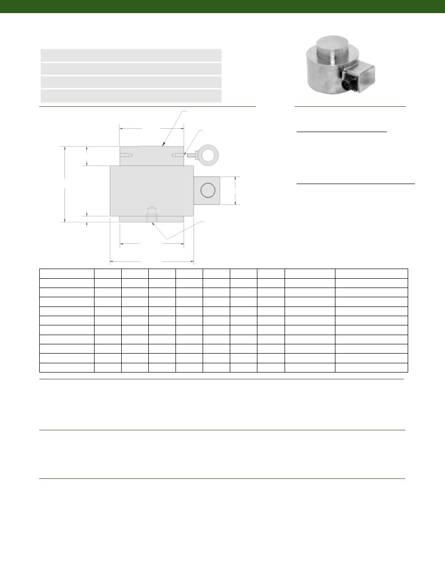
218
Dimensions
Performance
Environmental
Electrical
n
1 to 1,000 tons Range
n
Stainless Steel
n
mV/V Output
n
0.25% Accuracy
L1
L2
L3
Spherical Radius (note 1)
Lifting Eye Thread
Optional Bottom
Thread
øD0
øD2
øD1
Load Ranges................1 to 1,000 tons
Accuracy................+/- 0.25% Best Fit Straight Line (note 2)
Non-Repeatability................+/- 0.02% Full Scale
Output (tolerance)................2 mV/V (nominal)
Operation................Compression
Resolution................Infinite
Temperature, Operating................-70° to 250° F
Temperature, Compensated................70° to 160° F
Temperature, Storage................-100° to 300° F
Temperature, Effect
Zero................0.005% F.S./° F
Span................0.005% F.S./° F
Strain Gage Type................Bonded Foil
Excitation (calibration)................10 VDC
Insulation Resistance................5,000 Megohms @ 50 VDC
Bridge Resistance (tolerance)................350 Ohms (nominal)
Zero Balance (tolerance)................+/- 1% of Full Scale
Shunt Calibration Data................Included
Electrical Termination (std)
1 to 5 tons................Cable
10 to 1,000 tons................Connector
Model MPB High Capacity Compact Compression Load Cell
Order Code BL515
Capacity (US tons)
D0 (in.)
D1 (in.)
D2 (in.)
L1 (in.)
L2 (in.)
L3 (in.)
H (in.)
Thread Lifting Eye
Optional Bottom Thread
1
0.26
0.87
0.37
0.75
0.02
0.06
0.375
Not Applicable
8-32 UNC x 0.18 in. deep
2.5
0.26
0.87
0.37
0.75
0.02
0.06
0.375
Not Applicable
8-32 UNC x 0.18 in. deep
5
0.41
0.98
0.53
0.88
0.04
0.06
0.375
Not Applicable
8-32 UNC x 0.18 in. deep
10
0.75
1.49
0.75
1.12
0.06
0.16
0.375
Not Applicable
1/4-28 UNF x 0.25 in. deep
25
1.18
1.96
1.18
1.77
0.12
0.30
0.75
Not Applicable
1/4-28 UNF x 0.25 in. deep
50
1.59
2.44
1.59
2.4
0.18
0.19
1.5
Not Applicable
3/8-24 UNF x 0.38 in. deep
100
2.25
3.19
2.25
3.38
0.25
0.69
1.5
Not Applicable
3/8-24 UNF x 0.38 in. deep
250
3.57
4.44
3.57
5.35
0.25
1.7
1.5
1/4-28
3/4-16 UNF x 0.75 in. deep
500
5.05
6.44
5.05
7.57
0.25
2.6
1.5
1/4-28
3/4-16 UNF x 0.75 in. deep
1,000
7.14
8.44
7.14
10.41
0.25
4.0
1.5
3/8-16
1-12 UNF x 1 in. deep
H
Cable Exit/ 1-5 tons/ Unamplified
Red
(+) Excitation
Black
(-) Excitation
Green
(-) Output
White
(+) Output
Connector Exit/ 10-1,000 tons/ Unamplified
A
(+) Excitation
B
(+) Excitation
C
(-) Excitation
D
(-) Excitation
E
(-) Output
F
(+) Output
Wiring Code
www.honeywell.com/sensotec
1-888-282-9891
Courtesy of Steven Engineering, Inc.-230 Ryan Way, South San Francisco, CA 94080-6370-Main Office: (650) 588-9200-Outside Local Area: (800) 258-9200-www.stevenengineering.com
Sensotec Sensors Full Line Catalog-html.html
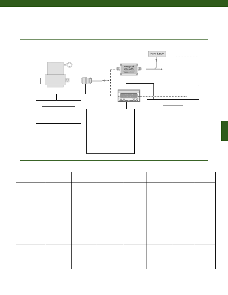
219
Model MPB
Mechanical
Typical System Diagram
Maximum Allowable Load................150% F.S. (note 3)
Material................All Welded Stainless Steel
Life Cycles (approx.)................1 million cycles
In-Line Amplifiers
(Used with unamplified units only)
Amplifier
Output
Universal In-Line Amplifiers
UV
+/- 5 VDC
UV-10
+/- 10 VDC
UBP
0 +/- 5 VDC
U3W
4-20 mA (3 wire)
U2W
4-20 mA (2 wire)
DIN rail Mount In-Line Amplifiers
DV-05
0 +/- 5 VDC (3 wire)
DA-05
4-20 mA (3 wire)
DV-10
0 +/- 10 VDC (3 wire)
Display Units
SC500
SC1000
SC2000
SC2001
SC3004
GM (Unamplified only)
GM-A (Amplified only
NK (Unamplified only)
HH (Unamplified only)
Customer Supplied
Chart Recorder
Alarm Panel
Data Acquisition
Computer
PLC
Model MPB
Mating Connectors & Cables
PT06A-10-6S, Std.
PT06E-10-6S
MS3106A-14S-6S
Internal Amplifiers
Amplifier
Specifications
Voltage Output
Option 2a
Voltage Output
Option 2b
Vehicle Voltage Output
2c
Vehicle Voltage
Output 2t
Current 3 Wire
Option 2j
Current 2 Wire
Option 2k
Intrinsically Safe
Amp
Option 2n (2N)***
Output Signal
Input Power (Voltage)
Input Power (Current)
Frequency Response
Power Supply
Rejection
Operating Temperature
Reverse Voltage
Protection
Short Circuit Protection
0-5V
+/-15V or 26-32VDC
45 mA
3000 Hz
60 db
-20° to 185° F
Yes
Momentary
+/- 5V
+/-15V or 26-32VDC
45 mA
3000 Hz
60 db
-20° to 185° F
Yes
Momentary
0-5V or +/- 5V
@ 45mA
18-28 VDC
40 mA
3000 Hz
60 db
-20° to 185° F
Yes
Momentary
0-10V or +/- 10V
@ 45mA
15-28 VDC
40 mA
3000 Hz
60 db
-20° to 185° F
Yes
Momentary
4-20 mA
22-32 VDC
65 mA
2500 Hz
60 db
0° to 185° F
Yes
Yes
4-20 mA
9-32 VDC
4-28 mA
300 Hz
60 db
0° to 185° F
Yes
Yes
4-20 mA
9-28 VDC
4-24 mA
2000 Hz
60 db
-20° to 185° F
Yes
Yes
Wiring Code: Connector
(Std.)
(note 4)
A (+) Supply
B (-) Output/ Supply
C (-) Supply
D (+) Output
E Shunt Cal 1
F Shunt Cal 2
A (+) Supply
B (-) Output/ Supply
C (-) Supply
D (+) Output
E Shunt Cal 1
F Shunt Cal 2
A (+) Supply
B** Output Common/
C** Supply Return
D (+) Output
E Shunt Cal 1
F Shunt Cal 2
A (+) Supply
B (-) Output
C Supply Return
D (+) Output
E Shunt Cal 1
F Shunt Cal 2
A (+) Supply
B** Output Common/
C** Supply Return
D (+) Output
E Shunt Cal 1
F Shunt Cal 2
A (+) Supply
B No connection
C No connection
D (+) Output
E Case Ground
F No connection
A (+) Supply
B No connection
C No connection
D (+) Output
E Case Ground
F No connection
Wiring Code: Cable
(note 4)
(note 5)
(note 6)
R (+) Supply
Br (-) Supply
O (-) Output/ Supply
G (+) Output
B Shunt Cal 1
Y Shunt Cal 2
R (+) Supply
Br (-) Supply
O (-) Output/ Supply
G (+) Output
B Shunt Cal 1
Y Shunt Cal 2
R (+) Supply
Bl* Output Common/
G* Supply Return
W (+) Output
B
Shunt Cal 1
Br Shunt Cal 2
R (+) Supply
Bl Supply Return
G (+) Output
W (+) Output
B Shunt Cal 1
Br Shunt Cal 2
R (+) Supply
Bl* Output Common/
G* Supply Return
W (+) Output
B Shunt Cal 1
Br Shunt Cal 2
R
(+) Supply
Bl (+) Output
W
Case
Ground
R (+) Supply
Bl (+) Output
W Case
Ground
* Black and Green wires are internally connected.
** Pins B and C are internally connected.
*** See Sensotec website for most up-to-date information regarding Intrinsically Safe approvals ref. #008-0547-00.
www.honeywell.com/sensotec
1-888-282-9891
Courtesy of Steven Engineering, Inc.-230 Ryan Way, South San Francisco, CA 94080-6370-Main Office: (650) 588-9200-Outside Local Area: (800) 258-9200-www.stevenengineering.com
Sensotec Sensors Full Line Catalog-html.html
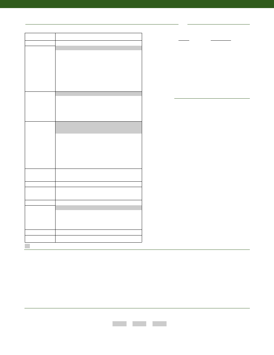
220
Supplied as standard
Options
1. For standard configuration with spherical radius, a hardened surface is recommended to maintain the best loading conditions. RC42 is recommended minimum hardness. Bearing
lubricant at loading interface recommended for maximum life.
2. Accuracies stated are expected for Best Fit Straight Line for all errors including linearity, hysteresis and non-repeatability thru zero.
3. Allowable Maximum Loads- Maximum load to be applied without damage (note 4).
4. Without Damage- loading to this level will not cause excessive zero shift or performance degradation. The user must consider fatigue life for long term use and structural integrity.
All structurally critical applications (overhead loading, etc.) should always be designed with safety redundant load paths.
5. Special Wiring Code.
6. Not available with option 1e, 1f, 1g, or 1i.
7. Amplifier options not available with low ranges. Consult factory.
8. Consult factory for TEDS availability with amplified models.
Amplified Output
Cable Orientation
Different Cable Lengths
Different Electrical Connectors
Different Materials
Different Threads
Dual Bridge
ESD
Fatigue Rating
High Resistance Bridges
Lightning Protection
OEM Labels
Operational Temp -200° F to 400° F
Radiation Resistant
Special Electrical O/P
Special TC
Special Customer Requirements
(Consult Factory)
Notes
How to Order
Combine the order code, the range code and the options code.
Order Code
Range Code
Options Code
Sample Code:
BL515
ET
1j
Model MPB
Built from Scratch
Load Range
1; 2.5; 5; 10; 25; 50; 100; 250; 500; 1000 tons
Temperature
Compensation
1b. 30° to 130° F
1c. 0° to 185° F
1d. -20° to 130° F
1e. -20° to 200° F
1f. 70° to 250° F
1g. 70° to 325° F
1h. 70° to 400° F
1i. -65° to 250° F
1j. 0° to 50° F
1k. -20° to 85° C
1m. -25° to 110° C
Internal Amplifiers
(note 7)
2a. 4 wire 0-5VDC output
2b. 4 wire +/- 5VDC output
2c. 0-5VDC
2j. 4-20mA (3-wire) output
2k. 4-20mA (2-wire)
2t. 0-10 VDC output
2n(2N). 4-20mA (2-wire)
Intrinsically safe
Electrical
Termination
6a. Bendix PTIH-10-6P (or equivalent) 6 pin (max. 250° F)
6f. Integral cable: PVC (-20° to 160°F)
6g. Integral cable: Neoprene (0° to 180°F) (note 6)
6i. Integral underwater cable (max. 180°F) (note 6)
6j. 1/2-14 conduit fitting
6q. Integral cable: Polyurethane
6v. Phoenix connector on end of cable
15d.Connector on end of cable
Electrical Connector
Orientation
15a.Horizontal Electrical Exit Port Orientation
15b.Vertical Electrical Exit Port Orientation
15c. Radial Electrical Exit Port Orientation
Shunt Calibration
8a. Precision Internal Resistor (max. 250°F)
Bridge Type
11a.Square bridge
11c. Square & symmetrical bridge
31a.Dual Bridge
Bridge Resistance
12b.5,000 Ohm (foil) (max. 250°F)
Special Calibration
9a. 10 point (5 up/5 down) 20% increments @ 70°F
9b. 20 point (10 up/10 down) 10% increments @ 70°F
9c. A.S.T.M. E-74 Calibration
9e. CE mark
30c. Negative in compression, compression testing only
Shock & Vibration
44a.Shock & vibration resistance
Interfaces
53e.Signature calibration (note 5)
53t. T.E.D.S. IEEE 1451.4 Module (note 8)
1a. 60° to 160° F
2u. Unamplified, mV/V output
Range
Range Code
1 ton
DL
2.5 tons
DR
5 tons
DV
10 tons
EL
25 tons
EP
50 tons
ET
100 tons
FL
250 tons
FR
500 tons
FT
1,000 tons
FV
Range Codes
6e. Integral cable: Teflon (1 to 5 ton range)
6b. MS3102E-14S-6P connector (10 -1000 ton range)
(note 5)
30a. Positive in compression, compression testing only
www.honeywell.com/sensotec
1-888-282-9891
Courtesy of Steven Engineering, Inc.-230 Ryan Way, South San Francisco, CA 94080-6370-Main Office: (650) 588-9200-Outside Local Area: (800) 258-9200-www.stevenengineering.com
Sensotec Sensors Full Line Catalog-html.html
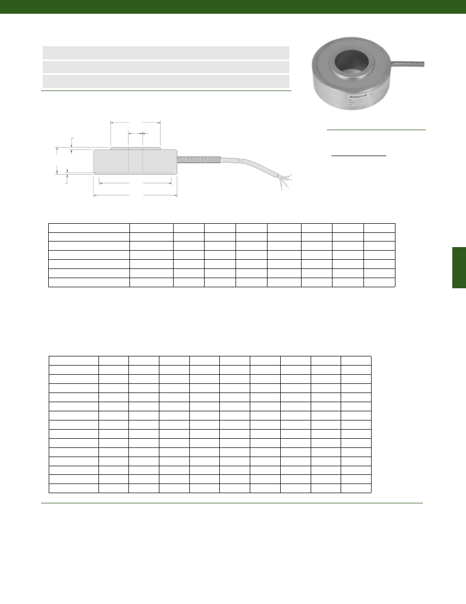
221
n
150 g to 30,000 lb.
n
Thru-Hole Design
n
Flexible Design
Load Ranges................150 g to 30,000 lb.
Linearity (max.)................+/- 0.5% Full Scale
Hysteresis (max.)................+/- 0.5% Full Scale
Non-Repeatability (max.)................+/- 0.1% Full Scale
Output (tolerance)
150 to 1,000 g................20 mV/V (nominal)
5 to 30,000 lb.................2 mV/V (nominal)
Operation................Compression
Resolution................Infinite
Model D Thru-Hole Load Cell
Order Code (see below)
Hole Letters
P
Q
R
S
T
V
W
Y
Z
øID (nominal)
1/8”
3/16”
1/4”
3/8”
1/2”
5/8”
3/4”
1”
1 1/4”
øID (actual)
0.128 in.
0.193 in.
0.266 in.
0.391 in.
0.532 in.
0.656 in.
0.781 in.
1.032 in.
1.281 in.
100 lb.
A
A
A
A
N/A
N/A
N/A
N/A
N/A
250 lb.
A or B
A or B
A or B
A or B
B
B
N/A
N/A
N/A
500 lb.
A or B
A or B
A or B
A or B
B
B
N/A
N/A
N/A
1000 lb.
A or B
A or B
A or B
B
B
B
N/A
N/A
N/A
2000 lb.
A, B, or C A, B, or C A, B, or C
B or C
B or C
B or C
C
C
C
3000 lb.
B or C
B or C
B or C
B or C
B or C
C
C
C
C
5000 lb.
B or C
B or C
B or C
B or C
B or C
C
C
C
C
7500 lb.
B or C
B or C
B or C
B or C
B or C
C
C
C
C
10,000 lb.
B or C
B or C
B or C
B or C
B or C
C
C
C
C
15,000 lb.
C
C
C
C
C
C
C
C
C
20,000 lb.
C
C
C
C
C
C
C
C
C
30,000 lb.
C
C
C
C
C
C
C
C
C
Wiring Code
Cable/ Unamplified
Red
(+) Excitation
Black
(-) Excitation
Green
(-) Output
White
(+) Output
Range/ Frame
Order Code
øOD (in.)
øID (in.)
H1 (in.)
H2 (in.)
H3 (in.)
øD1 (in.)
øD2 (in.)
150; 250; 500; 1000 g
BL912
0.50
0.10
0.15
0.02
0.01
0.20
0.45
5; 10 lb.
BL912
1.00
0.20
0.28
0.03
0.02
0.26
0.85
25; 50; 100 lb.
BL912
1.00
0.20
0.28
0.03
0.02
0.36
0.85
Frame A (100 to 2000 lb.)
BL913
1.50
See below
0.50
0.05
0.03
0.50
1.21
Frame B (250 to 10,000 lb.)
BL914
2.00
See below
0.63
0.06
0.03
0.88
1.68
Frame C (2000 to 30,000 lb.)
BL915
3.00
See below
1.00
0.08
0.03
1.70
2.46
Listed above are four different order codes; BL912, BL913, BL914, BL915. The frame size selection guide below indicates
that with a single shell size (outside diameter), different thru holes are available for order codes BL913, BL914 and BL915
(frames A, B, and C, respectively). To choose a product, first select the desired load capacity. Then, if applicable, choose
the desired inner diameter and an appropriate frame size. For example, a 250 lb. load cell is available in the small frame
size (A) with a nominal thru hole size of 1/8” (P), 3/16” (Q), 1/4” (R) or 3/8” (S) diameter, or in the medium frame size (B)
with thru hole sizes up to 5/8” (V). We manufacture the actual hole dimensions to provide some clearance; for example the
1/8” (P) dimension, the actual dimension is 0.128”.
Dimensions
Performance
øD1
H1
H3
øID
H2
øD2
øOD
www.honeywell.com/sensotec
1-888-282-9891
Courtesy of Steven Engineering, Inc.-230 Ryan Way, South San Francisco, CA 94080-6370-Main Office: (650) 588-9200-Outside Local Area: (800) 258-9200-www.stevenengineering.com
Sensotec Sensors Full Line Catalog-html.html
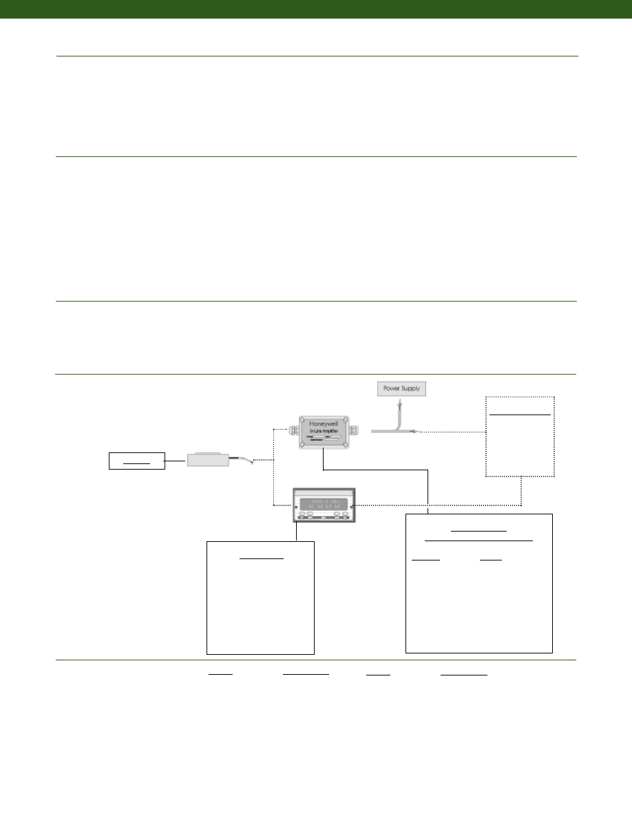
222
Environmental
Electrical
Mechanical
Typical System Diagram
Range Codes
........-65° to 250° F
........60° to 160° F
........0.01% F.S./° F
........0.005% F.S./° F
........0.02% F.S./° F
........0.010% F.S./° F
........Semiconductor
........Bonded Foil
........5 VDC
........10 VDC
........5000 Megohms @ 50 VDC
........500 Ohms (nominal)
........350 Ohms (nominal)
........+/- 1% of Full Scale
........Included
........Teflon Cable (5 ft.)
........150% F.S. (note 1)
........(note 4)
........Stainless Steel
........>10 million cycles
........(note 4)
........(note 4)
Temperature, Operating
Temperature, Compensated
Temperature, Effect
Zero
150 to 1000 g
5 to 30,000 lb.
Span
150 to 1000 g
5 to 30,000 lb.
Strain Gage Type
150 to 1000 g
5 to 30,000 lb.
Excitation (calibration)
150 to 1000 g
5 to 30,000 lb
Insulation Resistance
Bridge Resistance (tolerance)
150 to 1000 g
5 to 30,000 lb.
Zero Balance (tolerance)
Shunt Calibration Data
Electrical Termination (std)
Maximum Allowable Load
Weight
Material
Life Cycles (approx.)
Deflection Full Scale
Natural Frequency
In-Line Amplifiers
(Used with unamplified units only)
Amplifier
Output
Universal In-Line Amplifiers
UV
+/- 5 VDC
UV-10
+/- 10 VDC
UBP
0 +/- 5 VDC
U3W
4-20 mA (3 wire)
DIN rail Mount In-Line Amplifiers
DV-05
0 +/- 5 VDC (3 wire)
DA-05
4-20 mA (3 wire)
DV-10
0 +/- 10 VDC (3 wire)
Customer Supplied
Chart Recorder
Alarm Panel
Data Acquisition
Computer
PLC
Model D
Range
Range Code
150 g
AL
250 g
AN
500 g
AP
1000 g
AR
5 lb.
AT
10 lb.
AV
25 lb.
BL
50 lb.
BN
100 lb.
BR
250 lb.
CN
Range
Range Code
500 lb.
CR
1000 lb.
CV
2000 lb.
DL
3000 lb.
DN
5000 lb.
DR
7500 lb.
DT
10,000 lb.
DV
15,000 lb.
EJ
20,000 lb.
EL
30,000 lb.
EN
Model D
Display Units
SC500
SC1000
SC2000
SC2001
SC3004
GM
NK
HH
www.honeywell.com/sensotec
1-888-282-9891
Courtesy of Steven Engineering, Inc.-230 Ryan Way, South San Francisco, CA 94080-6370-Main Office: (650) 588-9200-Outside Local Area: (800) 258-9200-www.stevenengineering.com
Sensotec Sensors Full Line Catalog-html.html
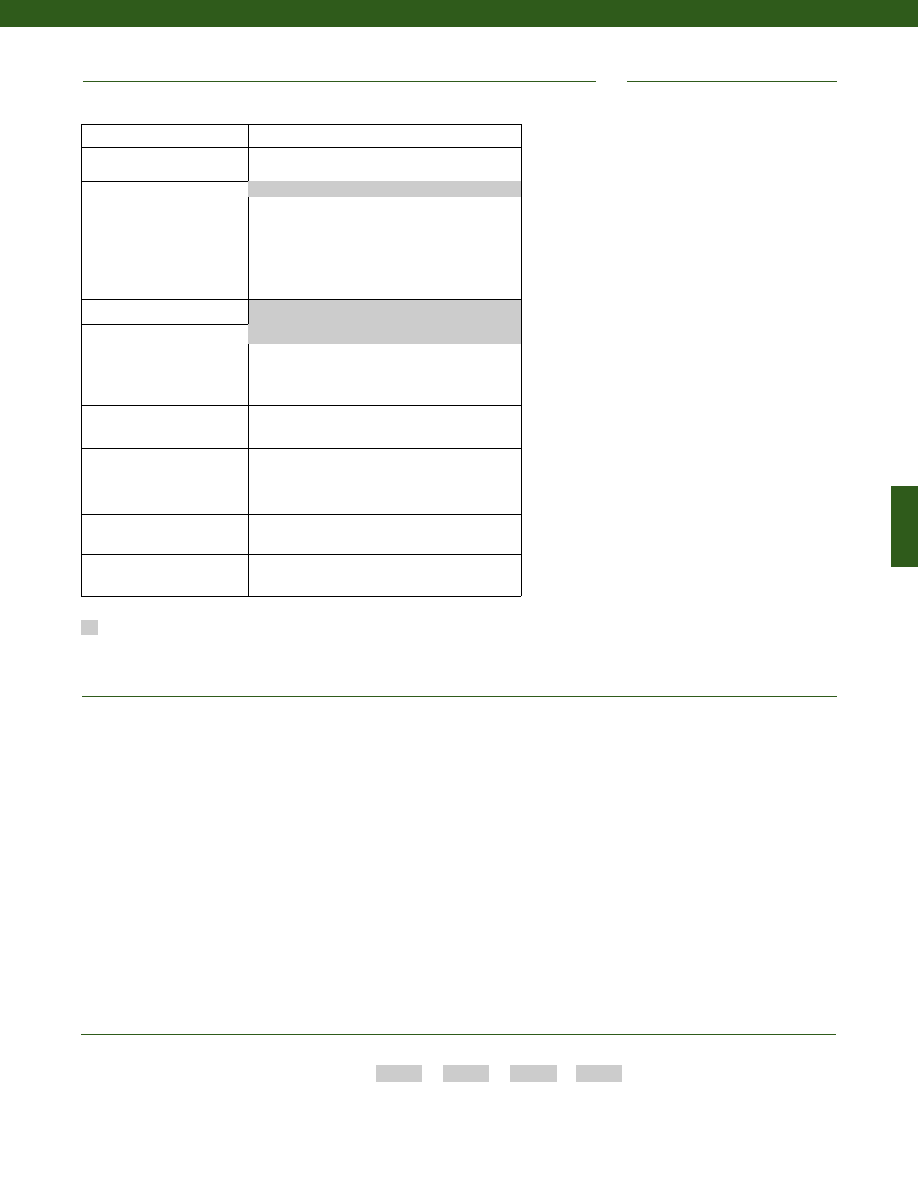
223
1. Allowable Maximum Loads- Maximum load to be applied without damage (note 2). Loads described allow for 100% full scale axial loading
with the bending loads specified. Torque loading maximum is without axial or other load. For any other combination consult factory.
2. Without Damage- loading to this level will not cause excessive zero shift of performance degradation. The user must consider fatigue
life for long term use and structural integrity. All structurally critical applications (overhead loading, etc.) should always be designed
with safety redundant load paths.
3. Only for ranges greater than or equal to 5 lb.
4. Varies by features selected, consult factory.
5. Be sure to specify electrical termination option 6a or 6v in options code. For custom connector, consult factory.
6. Dimension “H1” may increase with this option, consult factory. Not available with options 1c, 1e, 1f, 1g, 1h, or 1i.
7. Only available with integral cable units.
Options
OEM Labels
Radiation rated
Different cable lengths
Custom threads
Increased fatigue life
Custom cable exit
Alternate cable materials
Custom interior/ outer diameter
Thru mounting holes
Flange mount
Integral Connector
Special Customer
Requirements
(Consult Factory)
Notes
How to Order
Combine the order code, the range code and the options code.
Order Code
Range Code
Thru Hole dia.
Options Code
Sample Code:
BL913
BR
P
1b
Built to Order
Load Range
150 g to 30,000 lb.
Temperature Compensation
1b. 30° to 130° F
1c.
0° to 185° F
1d. -20° to 130° F
1e. -20° to 200° F
1f.
70° to 250° F
1i.
-65° to 250° F
1g. 70° to 325° F (note 3)
1h. 70° to 400° F (note 3)
Internal Amplifiers
2u. Unamplified, mV/V output
Electrical Termination
6a. Bendix PTIH-10-6P -(or equivalent) 6 pin (max.
250°F) on end of cable
6v.
Phoenix connector on end of cable
6i.
Integral underwater cable (note 6)
Electrical Connector Orientation
15d. Connector on end of cable (note 5)
Load Direction
30a. Positive in compression,
compression testing only
30c. Negative in compression,
compression testing only
Shock & Vibration
44a. Shock rated wiring
Interfaces
53s. Signature Calibration (note 5)
53t. T.E.D.S. IEEE 1451.4 Module (note 7)
1a.
60° to 160° F
6e.
Integral Cable: Teflon (5 ft.)
Supplied as standard
Model D
www.honeywell.com/sensotec
1-888-282-9891
Courtesy of Steven Engineering, Inc.-230 Ryan Way, South San Francisco, CA 94080-6370-Main Office: (650) 588-9200-Outside Local Area: (800) 258-9200-www.stevenengineering.com
Sensotec Sensors Full Line Catalog-html.html
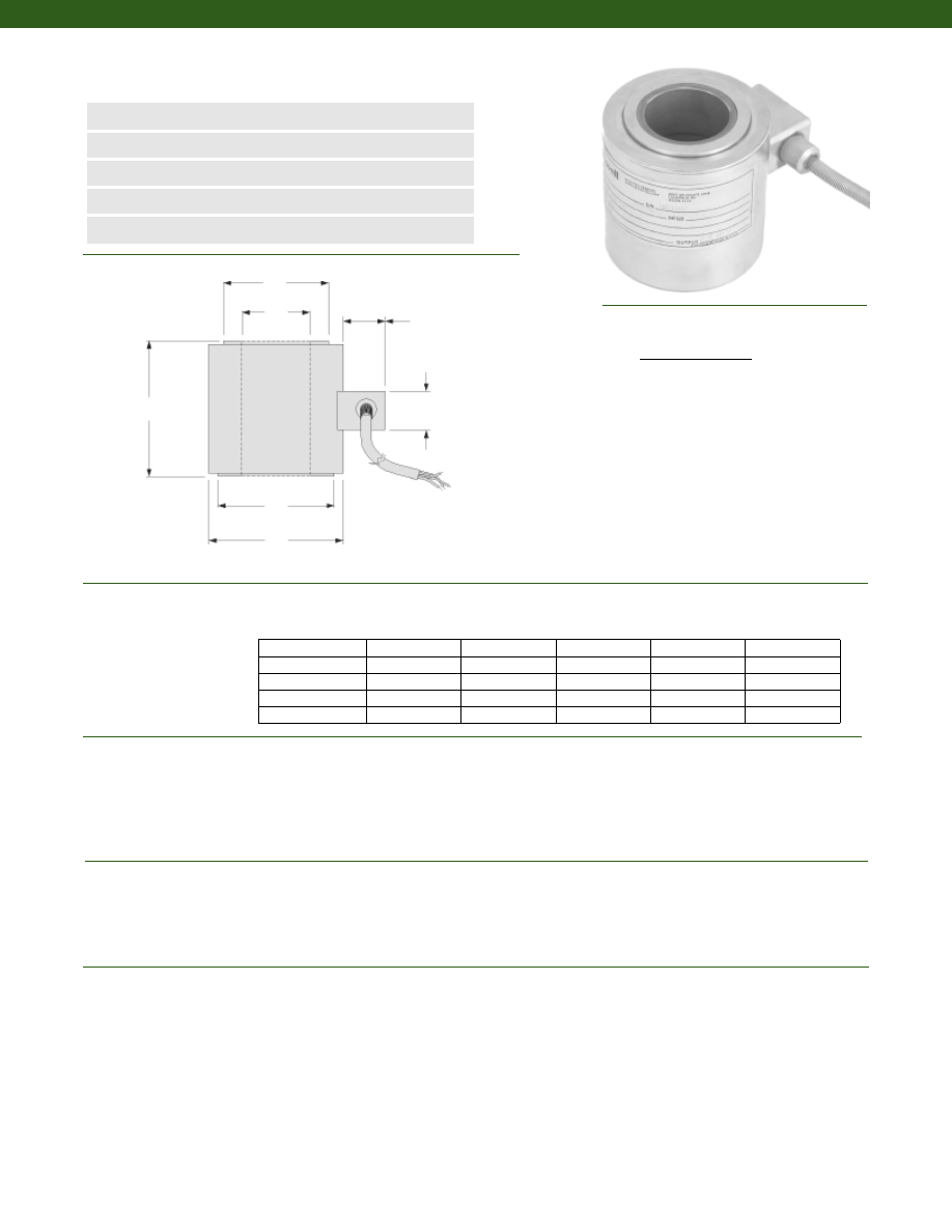
224
Dimensions
Performance
Environmental
Electrical
www.honeywell.com/sensotec
n
15,000 to 200,000 lb.
n
Thru-Hole Design
n
Compact Column Construction
n
mV/V Output
n
0.25% Linearity
D3
O.D.
D2
I.D.
0.76 in.
0.75 in.
H
Load Ranges................15,000 to 200,000 lb.
Linearity (max.)................+/- 0.25% Full Scale
Hysteresis (max.)................+/- 0.25% Full Scale
Non-Repeatability (max.)................+/- 0.1% Full Scale
Tolerance on Output................2 mV/V Nominal
Operation................Compression
Resolution................Infinite
Temperature, Operating................-65° to 250° F
Temperature, Compensated................60° to 160° F
Storage Temperature................-100° to 300° F
Temperature, Effect
Zero................0.005% Full Scale/° F
Span................0.005% Full Scale/° F
Strain Gage Type................Bonded Foil
Excitation (calibration)................10 VDC
Insulation Resistance................5000 Megohms @ 50 VDC
Bridge Resistance................350 Ohms
Zero Balance................+/- 1% Full Scale
Electrical Termination (std)................Teflon cable (5 ft.)
Range (lb.) H (in.) O.D. (in.) I.D. (in.) D2 (in.) D3 (in.)
Model TH Thru-Hole Load Cell
Order Code BL911
Wiring Code
Cable/ Unamplified
Red
(+) Excitation
Black
(-) Excitation
Green
(-) Output
White
(+) Output
1-888-282-9891
15,000; 20,000
1.50
1.50
0.76
1.06
1.15
30,000; 50,000
2.00
2.00
1.01
1.50
1.50
75,000; 100,000
2.50
2.50
1.26
1.88
1.88
150,000
3.00
3.00
1.51
2.31
2.44
200,000
3.50
3.50
1.76
2.75
3.50
5 ft. Teflon Cable
Courtesy of Steven Engineering, Inc.-230 Ryan Way, South San Francisco, CA 94080-6370-Main Office: (650) 588-9200-Outside Local Area: (800) 258-9200-www.stevenengineering.com
Sensotec Sensors Full Line Catalog-html.html
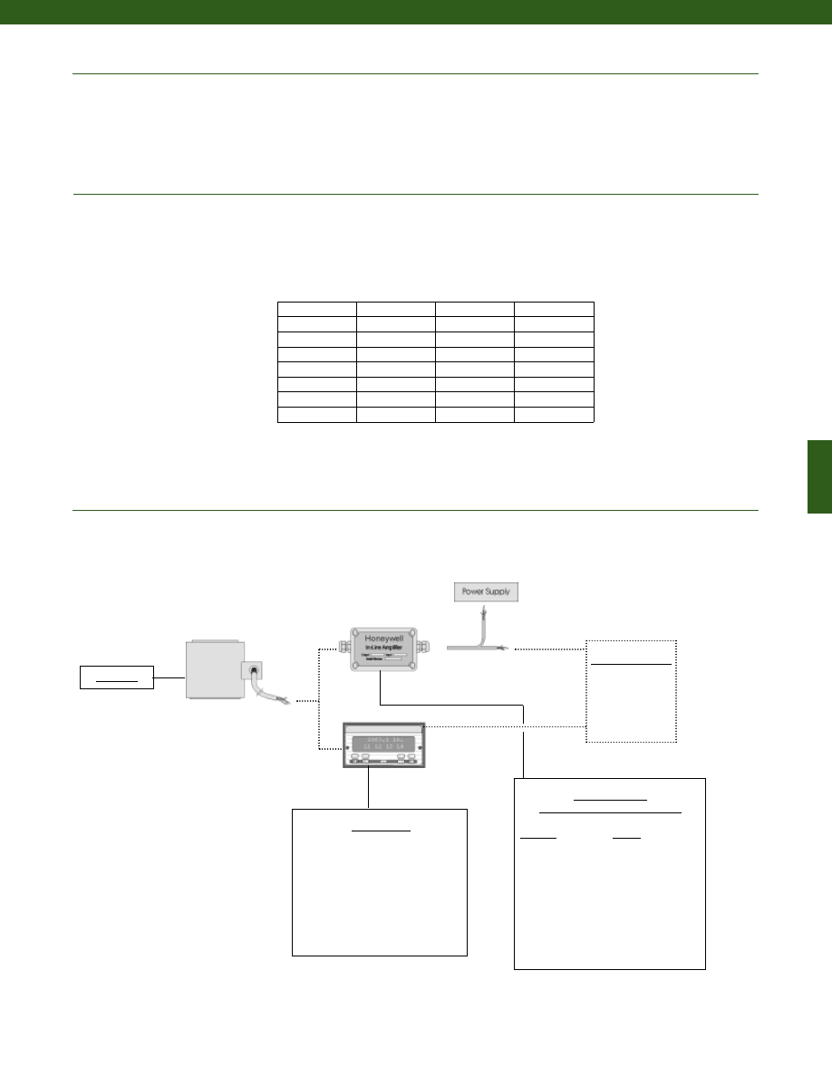
225
www.honeywell.com/sensotec
Mechanical
Typical System Diagram
Maximum Allowable Load................150% F.S. (note 1)
Weight................See table
Case Material................Stainless Steel
Deflection Full Scale................See table
Natural Frequency................See table
1-888-282-9891
In-Line Amplifiers
(Used with unamplified units only)
Amplifier
Output
Universal In-Line Amplifiers
UV
+/- 5 VDC
UV-10
+/- 10 VDC
UBP
0 +/- 5 VDC
U3W
4-20 mA (3 wire)
DIN rail Mount In-Line Amplifiers
DV-05
0 +/- 5 VDC (3 wire)
DA-05
4-20 mA (3 wire)
DV-10
0 +/- 10 VDC (3 wire)
Customer Supplied
Chart Recorder
Alarm Panel
Data Acquisition
Computer
PLC
Model TH
Model TH
Notes:
1. Allowable Maximum Loads- Maximum load to be applied without damage (note 2).
2. Without Damage- loading to this level will not cause excessive zero shift or performance degradation. The user must consider fatigue life for long
term use and structural integrity. All structurally critical applications (overhead loading, etc.) should always be designed with safety redundant load paths.
Deflections and Ringing Frequencies
Capacity (lb.)
Deflection
at Full Scale
(in.)
Ringing
Frequency
(kHz)
Weight
(lbs.)
15,000
0.001
35
0.4
20,000
0.001
35
0.4
30,000
0.002
17
1.0
50,000
0.002
17
1.0
75,000
0.003
14
2.0
100,000
0.003
14
2.0
150,000
0.006
12
2.5
200,000
0.004
10
6
Display Units
SC500
SC1000
SC2000
SC2001
SC3004
GM
NK
HH
Courtesy of Steven Engineering, Inc.-230 Ryan Way, South San Francisco, CA 94080-6370-Main Office: (650) 588-9200-Outside Local Area: (800) 258-9200-www.stevenengineering.com
Sensotec Sensors Full Line Catalog-html.html
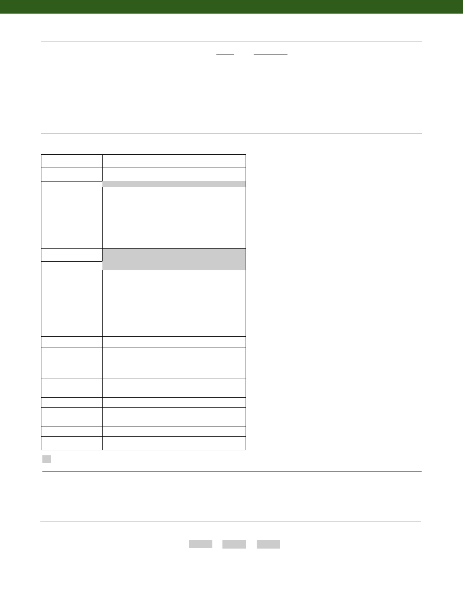
226
www.honeywell.com/sensotec
1-888-282-9891
Supplied as standard
Options
Special Customer Requirements
(Consult Factory)
How to Order
Combine the order code, the range code and the options code.
Order Code
Range Code
Options Code
Sample Code:
BL911
EJ 1b
Model TH
Range
Range Code
15,000 lb.
EJ
20,000 lb.
EL
30,000 lb.
EN
50,000 lb.
EP
75,000 lb.
ER
100,000 lb.
ET
150,000 lb.
FJ
200,000 lb.
FL
Range Codes
Build from Scratch
Load Range
15k, 20k, 30k, 50k, 75k, 100k, 150k, 200k
Temperature
Compensation
1b. 30° to 130° F
1c. 0° to 185° F
1d. -20° to 130° F
1e. -20° to 200° F
1f. 70° to 250° F
1g. 70° to 325° F
1h. 70° to 400° F
1i. -65° to 250° F
1j. 0° to 50° C
1k. -20° to 85° C
1m. -25° to 110° C
Internal Amplifiers
2u. Unamplified, mV/V output
Electrical Termination
6a. Bendix PTIH-10-6P - 6 pin (max. 250°F)
6b. MS type connector
6f. Integral cable: PVC
6g. Integral cable: Neoprene (note 4)
6h. Integral cable: Silicone
6i. Integral underwater cable (note 4)
6j. 1/2-14 conduit fitting with 5’ of 4 conductor PVC cable
6q. Integral cable: Polyurethane
6v. Phoenix connector on end of cable
15d.Connector on end of cable
Shunt Calibration
8a. Precision Internal Resistor
Special Calibration
9a. 10 point (5 up/5 down) 20% increments @ 70°F
9b. 20 point (10 up/10 down) 10% increments @ 70°F
9c. A.S.T.M. E-74 calibration
30a.Positive in compression, compression testing only
30c. Negative in compression, compression testing only
Bridge Type
11a.Square Bridge
11c. Square and Symmetrical Bridge
31a.Dual bridge
Bridge Resistance
12b.5,000 Ohms (foil)
Electrical Connector
Orientation
15a.Horizontal Electrical Exit Port Orientation
15b.Vertical Electrical Exit Port Orientation
15c. Radial Electrical Exit Port Orientation
Shock & Vibration
44a.Shock and vibration resistance
Interfaces
53e. Signature Calibration
53t. T.E.D.S IEEE 1451.4 Module
1a. 60° to 160° F
6e. Integral Cable: Teflon (5 ft.)
3. Option 6j may be used with options 6e thru 6i.
4. May not be used with options 1c, 1e, 1f, 1g, 1h or 1i.
5. Consult factory.
Notes
Amplified Output
Cable Orientation
Different Cable Lengths
Different Electrical Connectors
Different Materials
Different Threads
Dual Bridge
ESD
Fatigue Rating
High Resistance Bridges
Lightning Protection
OEM Labels
Enhanced Operational Temp
Radiation Resistant
Special Electrical O/P
Special TC
Courtesy of Steven Engineering, Inc.-230 Ryan Way, South San Francisco, CA 94080-6370-Main Office: (650) 588-9200-Outside Local Area: (800) 258-9200-www.stevenengineering.com
Sensotec Sensors Full Line Catalog-html.html
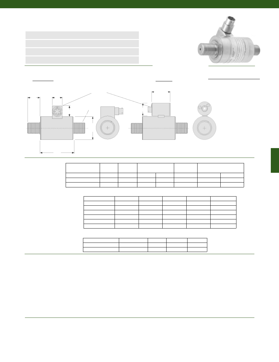
227
øD
L2
T Typ.
A
B
L1
Connector/ Unamplified (Std.)
A
(+) Excitation
B
(+) Excitation
C
(-) Excitation
D
(-) Excitation
E
(-) Output
F
(+) Output
Unamplified
Amplified
F
E
PTIH-10-6P
Wiring Code
Dimensions
Performance
Environmental
www.honeywell.com/sensotec
Load Ranges................2000 to 200,000 lb. (note 1)
Linearity
100 to 1000 lb.................+/- 0.2% Full Scale
2000 to 50,000 lb.................+/- 0.15% Full Scale
75,000 to 200,000 lb.................+/- 0.2% Full Scale
Hysteresis
100 to 1000 lb.................+/- 0.2% Full Scale
2000 to 50,000 lb.................+/- 0.15% Full Scale
75,000 to 200,000 lb.................+/- 0.2% Full Scale
Non-Repeatability................+/- 0.05% Full Scale
Output................2mV/V
Operation................Tension
Resolution................Infinite
Temperature, Operating................-65° to 250° F
Temperature, Compensated................60° to 160° F
Temperature, Effect
Zero................0.005% Full Scale/° F
Span................0.005% Full Scale/° F
Order Code
(Amplified/Unamp)
D (in.)
L1 (in.)
Unamplified only
A (in.) B (in.)
L2 (in.)
Amplified only
E (in.) F (in.)
AL413/AL613
1.50
2.60
0.75
0.82
see below
1.95
1.50
AL415/AL615
1.75
2.60
0.75
0.82
see below
1.95
1.50
AL417/AL617
2.50
3.05
0.75
0.82
see below
1.95
1.50
Range (lb.)
Thread Type
D (in.)
L1 (in.)
L2 (in.)
75,000 to 100,000
2 1/2-12 UNF
3.50
4.00
3.00
150,000 to 200,000
3 1/2-8 UNF
4.50
5.00
4.00
13a
13b
13c
13d
13e
1/2-20 UNF
3/4-16 UNF
7/8-14 UNF
1-14 UNF
1 1/2-12 UNF
2000 to 5000
AL413
AL413
AL413
7500 to 15,000
AL415
AL415
AL415
AL417
20,000
AL415
AL415
AL417
30,000 to 50,000
AL417
L2 (in.)
0.95
0.95
0.95
1.25
1.5
Range (lb.)
Thread Sizes and Option Codes
Non-standard Ranges Order Code AL411
n
2000 to 200,000 lb.
n
Hermetically Sealed
n
0-5 VDC or 4-20 mA Output Options
n
0.2% Linearity
1-888-282-9891
Model RM Rod End In-Line Tension Load Cell
Order Code (see table below)
Courtesy of Steven Engineering, Inc.-230 Ryan Way, South San Francisco, CA 94080-6370-Main Office: (650) 588-9200-Outside Local Area: (800) 258-9200-www.stevenengineering.com
Sensotec Sensors Full Line Catalog-html.html
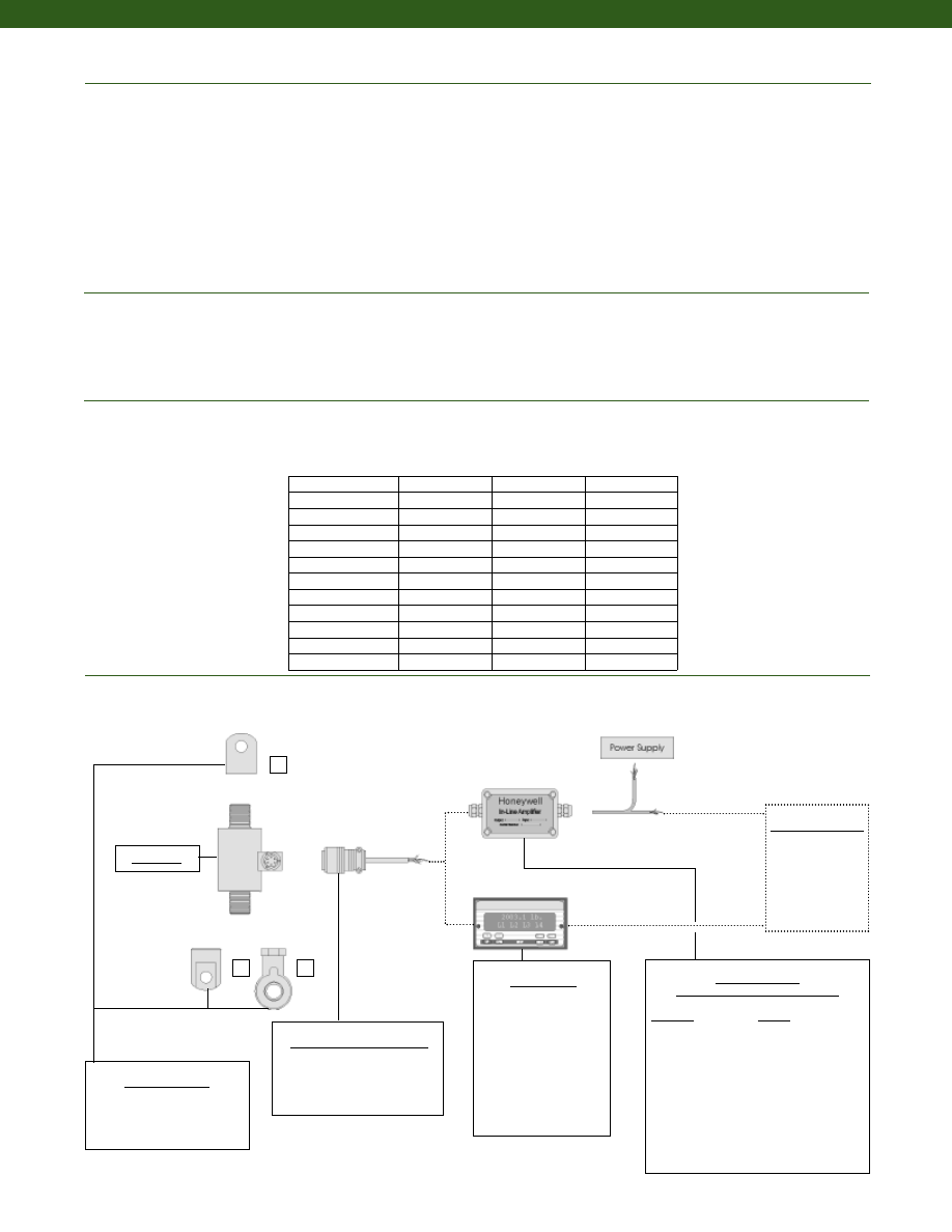
228
www.honeywell.com/sensotec
Electrical
Mechanical
Deflections and Ringing Frequencies
Typical System Diagram
Strain Gage Type................Bonded Foil
Excitation (calibration)................10 VDC
Excitation (acceptable)................up to 15 VDC or AC
Insulation Resistance................5000 Megohms @ 50 VDC
Bridge Resistance (tolerance)................350 Ohms
Zero Balance (tolerance)................+/- 1% Full Scale
Shunt Calibration Data................Included
Electrical Termination (std)
2000 to 50,000 lb.................PTIH-10-6P or equivalent (Hermetic stainless)
75,000 to 200,000 lb.................MS3102E-14S-6P
Mating Connector (not incl.)
2000 to 50,000 lb.................PT06A-10-6S or equivalent
75,000 to 200,000 lb.................MS3106A-14S-6S or equivalent
Maximum Allowable Load................150% F.S. (note 1)
Weight................See table
Material................Stainless Steel
Deflection................See table
Natural Frequency................See table
1-888-282-9891
1
2
3
In-Line Amplifiers
(Used with unamplified units only)
Amplifier
Output
Universal In-Line Amplifiers
UV
+/- 5 VDC
UV-10
+/- 10 VDC
UBP
0 +/- 5 VDC
U3W
4-20 mA (3 wire)
U2W
4-20 mA (2 wire)
DIN rail Mount In-Line Amplifiers
DV-05
0 +/- 5 VDC (3 wire)
DA-05
4-20 mA (3 wire)
DV-10
0 +/- 10 VDC (3 wire)
Customer Supplied
Chart Recorder
Alarm Panel
Data Acquisition
Computer
PLC
Mounting Options
1. Yoke Shackle Female
2. Tongue Shackle Female
3. Rod End Bearing Female
Model RM
Mating Connectors & Cables
PT06A-10-6S
MS3106A-14S-6S
PT06E-10-6S
Model RM
Capacity (lb.)
Deflection
@ Full Scale
(in.)
Weight
(lb)
Ringing
Frequency
(Hz)
2,000
0.003
5,000
1.0
3,000
0.003
5,000
1.0
4,000
0.003
5,100
1.0
5,000
0.003
5,200
1.0
7,500
0.004
7,500
1.5
10,000
0.004
7,600
1.5
15,000
0.005
8,000
1.5
20,000
0.005
9,800
1.5
30,000
0.005
8,000
4.2
50,000
0.005
8,200
4.2
75,000 to 100,000
0.006
5,000
16.5
150,000 to 200,000
0.007
4,200
35.3
Display Units
SC500
SC1000
SC2000
SC2001
SC3004
GM (Unamplified only)
GM-A (Amplified only)
NK (Unamplified only)
HH (Unamplified only)
Courtesy of Steven Engineering, Inc.-230 Ryan Way, South San Francisco, CA 94080-6370-Main Office: (650) 588-9200-Outside Local Area: (800) 258-9200-www.stevenengineering.com
Sensotec Sensors Full Line Catalog-html.html

229
Range
Range Code
2,000 lb.
DJ
3,000 lb.
DN
4,000 lb.
DP
5,000 lb.
DR
7,500 lb.
DT
10,000 lb.
DV
15,000 lb.
EJ
20,000 lb.
EL
30,000 lb.
EN
50,000 lb.
EP
75,000 lb.
ER
100,000 lb.
ET
150,000 lb.
FJ
200,000 lb.
FL
Range Codes
www.honeywell.com/sensotec
1-888-282-9891
Internal Amplifiers
Model RM
Amplifier
Specifications
Voltage Output
Option 2b
Voltage Output
Option 2c
Voltage Output
Option 2t
Current 3 Wire
Option 2j
Current 2 Wire
Option 2k
Intrinsically Safe
Option 2n (2N)***
Output Signal
Input Power (Voltage)
Input Power (Current)
Frequency Response
Power Supply
Rejection
Operating Temperature
Reverse Voltage
Protection
Short Circuit Protection
+/- 5V
+/-15V or 26-32VDC
45 mA
3000 Hz
60 db
-20° to 185° F
Yes
Momentary
0-5V or +/- 5V
@ 45mA
11-28 VDC
40 mA
3000 Hz
60 db
-20° to 185° F
Yes
Momentary
0-10V or +/- 10V
@ 45mA
15-28 VDC
40 mA
3000 Hz
60 db
-20° to 185° F
Yes
Momentary
4-20 mA
22-32 VDC
65 mA
2500 Hz
60 db
0° to 185° F
Yes
Yes
4-20 mA
15-40 VDC
4-28 mA
300 Hz
60 db
0° to 185° F
Yes
Yes
4-20 mA
9-28 VDC
4-24 mA
2000 Hz
60 db
-20° to 185° F
Yes
Yes
Wiring Code: Connector
(Std.)
(note 5)
A (+) Supply
B Output Common/
C Supply Return
D (+) Output
E Shunt Cal 1
F Shunt Cal 2
A (+) Supply
B** Output Common/
C** Supply Return
D (+) Output
E Shunt Cal 1
F Shunt Cal 2
A (+) Supply
B** Output Common/
C** Supply Return
D (+) Output
E Shunt Cal 1
F Shunt Cal 2
A (+) Supply
B** Output Common/
C** Supply Return
D (+) Output
E Shunt Cal 1
F Shunt Cal 2
A (+) Supply
B No connection
C No connection
D (+) Output
E Case Ground
F No connection
A (+) Supply
B No connection
C No connection
D (+) Output
E Case Ground
F No connection
Wiring Code: Cable
(note 5)
(note 6)
(note 7)
R (+) Supply
Bl Output Common/
G Supply Return
W (+) Output
B Shunt Cal 1
Br Shunt Cal 2
R (+) Supply
Bl*Output Common/
G*Supply Return
W (+) Output
B Shunt Cal 1
Br Shunt Cal 2
R (+) Supply
Bl*Output Common/
G*Supply Return
W (+) Output
B Shunt Cal 1
Br Shunt Cal 2
R (+) Supply
Bl*Output Common/
G*Supply Return
W (+) Output
B Shunt Cal 1
Br Shunt Cal 2
R (+) Supply
Bl (+) Output
W Case Ground
R (+) Supply
Bl (+) Output
W Case Ground
* Black and Green wires are internally connected.
** Pins B and C are internally connected.
*** See Sensotec website for most up-to-date information regarding Intrinsically Safe approvals ref. #008-0547-00.
Courtesy of Steven Engineering, Inc.-230 Ryan Way, South San Francisco, CA 94080-6370-Main Office: (650) 588-9200-Outside Local Area: (800) 258-9200-www.stevenengineering.com
Sensotec Sensors Full Line Catalog-html.html
230
1. Allowable Maximum Loads- Maximum load to be applied without damage (note 2).
2. Without Damage- loading to this level will not cause excessive zero shift or performance degradation. The user must consider fatigue life for long term
use and structural integrity. All structurally critical applications (overhead loading, etc.) should always be designed with safety redundant load paths.
3. Interconnecting shunt cal. 1 terminal with shunt cal. 2 terminal provides 50% (unamplified units), 75% (4-20mA 3-wire units) or 80% (voltage amplified
units) of full scale output for quick calibration. Shunt Calibration comes standard with internal amplifier options 2a, 2b, 2c, 2t and 2j.
4. O=Orange; Y=Yellow; B=Blue; Bl=Black; R=Red; Br=Brown; W=White; G=Green. Color specifying cable and number or letter specifying connector.
5. No mating connector necessary for cable option.
6. Not available with options 1c, 1e or 1f.
7. Only available with options 2b or 2c.
8. Not available with amplified options.
9. Consult factory for TEDS availability with amplified models.
www.honeywell.com/sensotec
1-888-282-9891
Combine the order code, the range code and the options code.
Order Code
Range Code
Options Code
Sample Code: AL413
DJ
6g
Model RM
Cable Orientation
Different Cable Lengths
Different Electrical Connectors
Different Materials
Different Threads
Dual Bridge
ESD
Fatigue Rating
High Resistance Bridges
Lightning Protection
OEM Labels
Enhanced Operational Temp
Radiation Resistant
Special Electrical O/P
Special TC
Special Customer
Requirements
(Consult Factory)
Notes
Options
How to Order
Supplied as standard
Build from Scratch
Load Range
2k, 3k, 4k, 5k, 7.5k, 10k, 15k, 20k, 30k, 50k, 75k, 100k,
150k, 200k lbs.
Temperature
Compensation
1b. 30° to 130° F
1c. 0° to 185° F
1d. -20° to 130° F
1e. -20° to 200° F
1f. 70° to 250° F
1g. 70° to 325° F
1h. 70° to 400° F
1i. -65° to 250° F
1j. 0° to 50° C
1k. -20° to 85° C
1m. -25° to 110° C
Internal Amplifiers
2b. 4 wire +/- 5VDC output
2c. 0-5VDC
2j. 4-20mA (3-wire) output
2k. 4-20mA (2-wire)
2t. 0-10 VDC output
2n (2N). 4-20mA (2-wire) Intrinsically safe
Internal Amp
Enhancements
3a. Input/ Output Isolation (note 7)
3d. Remote Buffered Shunt Calibration
Electrical
Termination
6b. MS type connector mates with MS3106- 14S 6 pin
(max. 160°F)
6e. Integral cable: Teflon
6f. Integral cable: PVC
6g. Integral cable: Neoprene
6h. Integral cable: Silicone
6i. Integral underwater cable
6j. 1/2-14 conduit fitting with 5 ft. of 4 conductor
PVC cable
6q. Molded Integral cable: Polyurethane
6v. Phoenix connector on end of cable
Shunt Calibration 8a. Precision Internal Resistor (note 8)
Bridge Type
11a.Square Bridge
11c. Square and Symmetrical Bridge
31a.Dual bridge
Bridge Resistance 12b.5,000 Ohms (foil) (max. 250°F)
Potentiometers
14a.No access to pots
Electrical
Connector
Orientation
15a.Horizontal Electrical Exit Port Orientation
15b.Vertical Electrical Exit Port Orientation
15c. Radial Electrical Exit Port Orientation
15d.Connector on end of cable
Shock & Vibration 44a.Shock and vibration resistance
Interfaces
53e.Signature Calibration
53t. T.E.D.S. IEEE 1451-4 Module (note 9)
2u. Unamplified, mV/V output
1a. 60° to 160° F
Courtesy of Steven Engineering, Inc.-230 Ryan Way, South San Francisco, CA 94080-6370-Main Office: (650) 588-9200-Outside Local Area: (800) 258-9200-www.stevenengineering.com
Sensotec Sensors Full Line Catalog-html.html
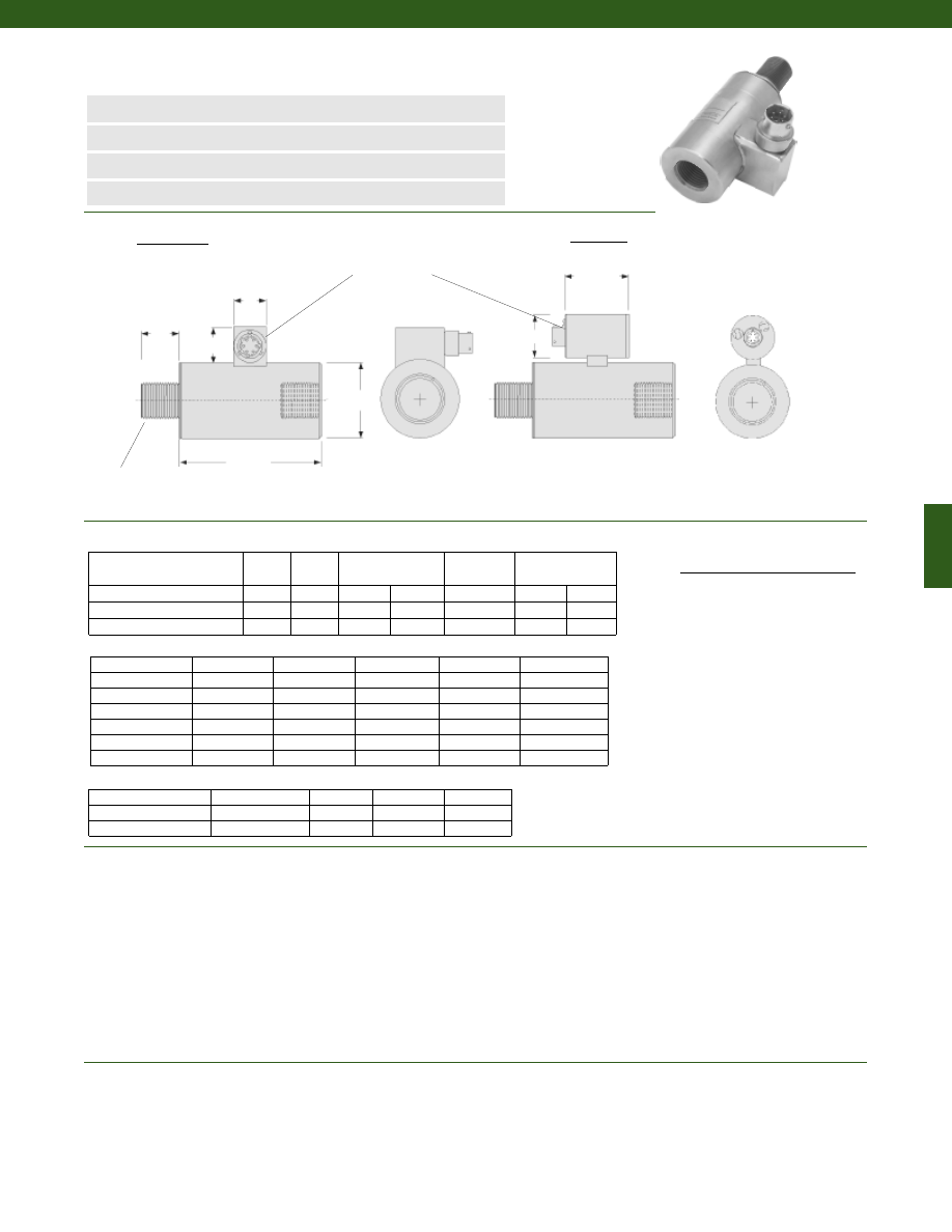
231
Model RH Rod End In-Line Tension Load Cell
Order Code (see table below)
www.honeywell.com/sensotec
øD
L2
T Typ.
A
B
L1
Load Ranges................2,000 to 200,000 lb.
Linearity
100 to 1000 lb.................+/- 0.2% Full Scale
2000 to 50,000 lb.................+/- 0.15% Full Scale
75,000 to 200,000 lb.................+/- 0.2% Full Scale
Hysteresis
100 to 1000 lb.................+/- 0.2% Full Scale
2000 to 50,000 lb.................+/- 0.15% Full Scale
75,000 to 200,000 lb.................+/- 0.2% Full Scale
Non-Repeatability................+/- 0.05% Full Scale
Output................2mV/V
Operation................Tension
Resolution................Infinite
Temperature, Operating................-65° to 250° F
Temperature, Compensated................60° to 160° F
Temperature, Effect
Zero................0.005% Full Scale/° F
Span................0.005% Full Scale/° F
Order Code
(Unamplified/Amplified)
D (in.) L1 (in.)
Unamplified only
A (in.) B (in.)
L2 (in.)
Amplified only
E (in.) F (in.)
AL419/AL619
1.50
4.25
0.75
0.82
see below
1.95
1.50
AL420/AL620
1.75
5.00
0.75
0.82
see below
1.95
1.50
AL424/AL624
2.50
7.00
0.75
0.82
see below
1.95
1.50
Range (lb.)
Thread Type
D (in.)
L1 (in.)
L2 (in.)
75,000 to 100,000
2 1/2-12 UNF
4.50
13.50
3.50
150,000 to 200,000
3 1/2-8 UNF
5.50
18.00
4.50
13a
13b
13c
13d
13e
1/2-20 UNF
3/4-16 UNF
7/8-14 UNF
1-14 UNF
1 1/2-12 UNF
2000 to 5000
AL419/AL619 AL419/AL619
7500 to 15,000
AL420/AL620 AL420/AL620 AL420/AL620 AL424/AL624
20,000
AL420/AL620 AL420/AL620 AL424/AL624
30,000 to 50,000
AL424/AL624
L2 (in.)
0.75
0.95
0.95
1.0
1.5
Range (lb.)
Thread Sizes and Option Codes
Non-standard Ranges Order Code AL425 (unamplified only)
Wiring Code
Connector/ Unamplified (Std.)
A
(+) Excitation
B
(+) Excitation
C
(-) Excitation
D
(-) Excitation
E
(-) Output
F
(+) Output
n
2,000 to 200,000 lb.
n
Hermetically Sealed
n
0-5 VDC or 4-20 mA Output Options
n
0.2% Linearity
1-888-282-9891
Unamplified
Amplified
Dimensions
Performance
Environmental
F
E
Connector:
PTIH-10-6P
(2k-50k lbs)
MS3102E-14S-6P
(75k - 200k lbs)
Courtesy of Steven Engineering, Inc.-230 Ryan Way, South San Francisco, CA 94080-6370-Main Office: (650) 588-9200-Outside Local Area: (800) 258-9200-www.stevenengineering.com
Sensotec Sensors Full Line Catalog-html.html
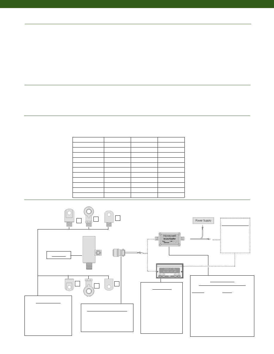
232
www.honeywell.com/sensotec
Strain Gage Type................Bonded Foil
Excitation (calibration)................10 VDC
Excitation (acceptable)................up to 15 VDC or AC
Insulation Resistance................5000 Megohms @ 50 VDC
Bridge Resistance (tolerance)................350 Ohms
Zero Balance (tolerance)................+/- 1% of Full Scale
Shunt Calibration Data................Included
Electrical Termination (std)
2000 to 50,000 lb.................PTIH-10-6P or equivalent (Hermetic stainless)
75,000 to 200,000 lb.................MS3102E-14S-6P
Mating Connector (not incl.)
2000 to 50,000 lb.................PT06A-10-6S or equivalent
75,000 to 200,000 lb.................MS3106A-14S-6S or equivalent
Maximum Allowable Load................150% F.S. (note 1)
Weight................See table
Material................Stainless Steel
Deflection Full Scale................See table
Natural Frequency................See table
1
2
3
4
5
6
Mating Connectors & Cables
PT06A-10-6S
MS3106A-14S-6S
PT06E-10-6S
In-Line Amplifiers
(Used with unamplified units only)
Amplifier
Output
Universal In-Line Amplifiers
UV
+/- 5 VDC
UV-10
+/- 10 VDC
UBP
0 +/- 5 VDC
U3W
4-20 mA (3 wire)
U2W
4-20 mA (2 wire)
DIN rail Mount In-Line Amplifiers
DV-05
0 +/- 5 VDC (3 wire)
DA-05
4-20 mA (3 wire)
DV-10
0 +/- 10 VDC (3 wire)
Customer Supplied
Chart Recorder
Alarm Panel
Data Acquisition
Computer
PLC
Mounting Options
1. Yoke Shackle Male
2. Rod End Bearing Male
3. Tongue Shackle Male
4. Yoke Shackle Female
5. Rod End Bearing Female
6. Tongue Shackle Female
Model RH
1-888-282-9891
Model RH
Capacity (lb.)
Deflection @
Full Scale
(in.)
Ringing
Frequency
(Hz)
Weight
(lb)
2,000
0.003
5,000
1.1
3,000
0.003
5,000
1.1
4,000
0.003
5,100
1.1
5,000
0.003
5,200
1.1
7,500
0.004
7,500
1.8
10,000
0.004
7,600
1.8
15,000
0.005
8,000
1.8
20,000
0.005
9,800
1.8
30,000
0.005
8,000
4.4
50,000
0.005
8,200
4.4
75,000 to 100,000
0.006
5,000
35.3
150,000 to 200,000
0.007
4,200
39.7
Electrical
Mechanical
Deflections and Ringing Frequencies
Typical System Diagram
Display Units
SC500
SC1000
SC2000
SC2001
SC3004
GM (Unamplified only)
GM-A (Amplified only)
NK (Unamplified only)
HH (Unamplified only)
Courtesy of Steven Engineering, Inc.-230 Ryan Way, South San Francisco, CA 94080-6370-Main Office: (650) 588-9200-Outside Local Area: (800) 258-9200-www.stevenengineering.com
Sensotec Sensors Full Line Catalog-html.html

233
Range
Range Code
2,000 lb.
DJ
3,000 lb.
DN
4,000 lb.
DP
5,000 lb.
DR
7,500 lb.
DT
10,000 lb.
DV
15,000 lb.
EJ
20,000 lb.
EL
30,000 lb.
EN
50,000 lb.
EP
75,000 lb.
ER
100,000 lb.
ET
150,000 lb.
FJ
200,000 lb.
FL
Range Codes
www.honeywell.com/sensotec
1-888-282-9891
Internal Amplifiers
Model RH
Amplifier
Specifications
Voltage Output
Option 2b
Voltage Output
Option 2c
Voltage Output
Option 2t
Current 3 Wire
Option 2j
Current 2 Wire
Option 2k
Intrinsically Safe
Option 2n (2N)***
Output Signal
Input Power (Voltage)
Input Power (Current)
Frequency Response
Power Supply
Rejection
Operating Temperature
Reverse Voltage
Protection
Short Circuit Protection
+/- 5V
+/-15V or 26-32VDC
45 mA
3000 Hz
60 db
-20° to 185° F
Yes
Momentary
0-5V or +/- 5V
@ 45mA
11-28 VDC
40 mA
3000 Hz
60 db
-20° to 185° F
Yes
Momentary
0-10V or +/- 10V
@ 45mA
15-28 VDC
40 mA
3000 Hz
60 db
-20° to 185° F
Yes
Momentary
4-20 mA
22-32 VDC
65 mA
2500 Hz
60 db
0° to 185° F
Yes
Yes
4-20 mA
15-40 VDC
4-28 mA
300 Hz
60 db
0° to 185° F
Yes
Yes
4-20 mA
9-28 VDC
4-24 mA
2000 Hz
60 db
-20° to 185° F
Yes
Yes
Wiring Code: Connector
(Std.)
(note 4)
A (+) Supply
B Output Common/
C Supply Return
D (+) Output
E Shunt Cal 1
F Shunt Cal 2
A (+) Supply
B** Output Common/
C** Supply Return
D (+) Output
E Shunt Cal 1
F Shunt Cal 2
A (+) Supply
B** Output Common/
C** Supply Return
D (+) Output
E Shunt Cal 1
F Shunt Cal 2
A (+) Supply
B** Output Common/
C** Supply Return
D (+) Output
E Shunt Cal 1
F Shunt Cal 2
A (+) Supply
B No connection
C No connection
D (+) Output
E Case Ground
F No connection
A (+) Supply
B No connection
C No connection
D (+) Output
E Case Ground
F No connection
Wiring Code: Cable
(note 4)
(note 5)
(note 6)
R (+) Supply
Bl Output Common/
G Supply Return
W (+) Output
B Shunt Cal 1
Br Shunt Cal 2
R (+) Supply
Bl*Output Common/
G*Supply Return
W (+) Output
B Shunt Cal 1
Br Shunt Cal 2
R (+) Supply
Bl*Output Common/
G*Supply Return
W (+) Output
B Shunt Cal 1
Br Shunt Cal 2
R (+) Supply
Bl*Output Common/
G*Supply Return
W (+) Output
B Shunt Cal 1
Br Shunt Cal 2
R (+) Supply
Bl (+) Output
W Case Ground
R (+) Supply
Bl (+) Output
W Case Ground
* Black and Green wires are internally connected.
** Pins B and C are internally connected.
*** See Sensotec website for most up-to-date information regarding Intrinsically Safe approvals ref. #008-0547-00.
Courtesy of Steven Engineering, Inc.-230 Ryan Way, South San Francisco, CA 94080-6370-Main Office: (650) 588-9200-Outside Local Area: (800) 258-9200-www.stevenengineering.com
Sensotec Sensors Full Line Catalog-html.html
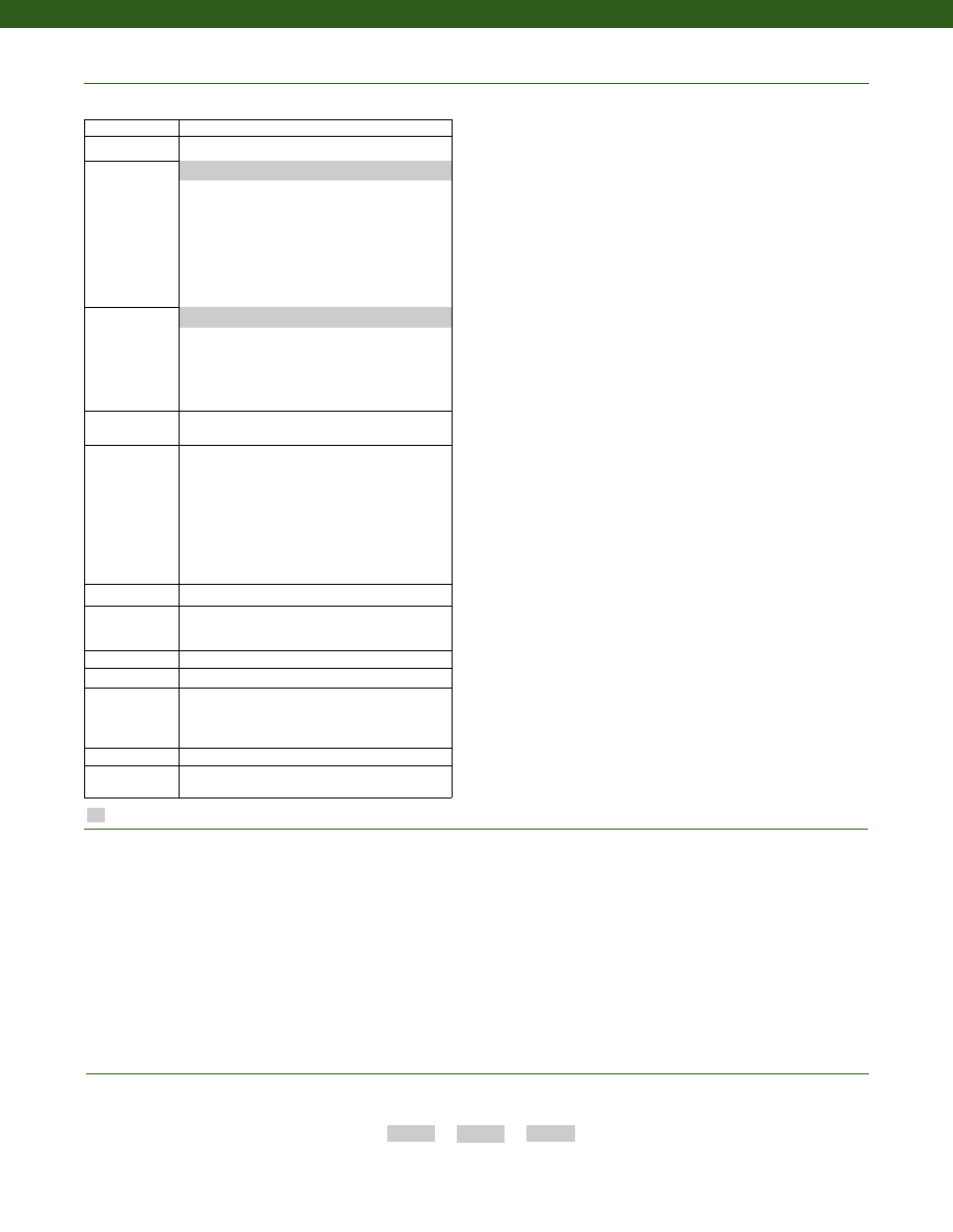
234
www.honeywell.com/sensotec
1-888-282-9891
Model RH
Combine the order code, the range code and the options code.
Order Code
Range Code
Options Code
Sample Code: AL419
DJ 6g
Cable Orientation
Different Cable Lengths
Different Electrical Connectors
Different Materials
Different Threads
Dual Bridge
ESD
Fatigue Rating
High Resistance Bridges
Lightning Protection
OEM Labels
Enhanced Operational Temp
Radiation Resistant
Special Electrical O/P
Special TC
Special Customer
Requirements
(Consult Factory)
Notes
Options
How to Order
Supplied as standard
Build from Scratch
Load Range
2k, 3k, 4k, 5k, 7.5k, 10k, 15k, 20k, 30k, 50k, 75k, 100k,
150k, 200k lbs.
Temperature
Compensation
1b. 30° to 130° F
1c. 0° to 185° F
1d. -20° to 130° F
1e. -20° to 200° F
1f. 70° to 250° F
1g. 70° to 325° F
1h. 70° to 400° F
1i. -65° to 250° F
1j. 0° to 50° C
1k. -20° to 85° C
1m. -25° to 110° C
Internal Amplifiers
2b. 4 wire +/- 5VDC output
2c. 0-5VDC
2j. 4-20mA (3-wire) output
2k. 4-20mA (2-wire)
2t. 0-10 VDC output
2n (2N). 4-20mA (2-wire) Intrinsically safe
Internal Amp
Enhancements
3a. Input/ Output Isolation (note 7)
3d. Remote Buffered Shunt Calibration
Electrical
Termination
6b. MS type connector mates with MS3106- 14S 6 pin
(max. 160°F)
6e. Integral cable: Teflon
6f. Integral cable: PVC
6g. Integral cable: Neoprene
6h. Integral cable: Silicone
6i. Integral underwater cable
6j. 1/2-14 conduit fitting with 5 ft. of 4 conductor
PVC cable
6q. Molded Integral cable: Polyurethane
6v. Phoenix connector on end of cable
Shunt Calibration 8a. Precision Internal Resistor (note 8)
Bridge Type
11a.Square Bridge
11c. Square and Symmetrical Bridge
31a.Dual bridge
Bridge Resistance 12b.5,000 Ohms (foil) (max. 250°F)
Potentiometers
14a.No access to pots
Electrical
Connector
Orientation
15a.Horizontal Electrical Exit Port Orientation
15b.Vertical Electrical Exit Port Orientation
15c. Radial Electrical Exit Port Orientation
15d.Connector on end of cable
Shock & Vibration 44a.Shock and vibration resistance
Interfaces
53e.Signature Calibration
53t. T.E.D.S. IEEE 1451-4 Module (note 9)
2u. Unamplified, mV/V output
1a. 60° to 160° F
1. Allowable Maximum Loads- Maximum load to be applied without damage (note 2).
2. Without Damage- loading to this level will not cause excessive zero shift or performance degradation. The user must consider fatigue life for long term
use and structural integrity. All structurally critical applications (overhead loading, etc.) should always be designed with safety redundant load paths.
3. Interconnecting shunt cal. 1 terminal with shunt cal. 2 terminal provides 50% (unamplified units), 75% (4-20mA 3-wire units) or 80% (voltage amplified
units) of full scale output for quick calibration. Shunt Calibration comes standard with internal amplifier options 2a, 2b, 2c, 2t and 2j.
4. O=Orange; Y=Yellow; B=Blue; Bl=Black; R=Red; Br=Brown; W=White; G=Green. Color specifying cable and number or letter specifying connector.
5. No mating connector necessary for cable option.
6. Not available with options 1c, 1e or 1f.
7. Only available with options 2b or 2c.
8. Not available with amplified options.
9. Consult factory for TEDS availability with amplified models.
Courtesy of Steven Engineering, Inc.-230 Ryan Way, South San Francisco, CA 94080-6370-Main Office: (650) 588-9200-Outside Local Area: (800) 258-9200-www.stevenengineering.com
Sensotec Sensors Full Line Catalog-html.html
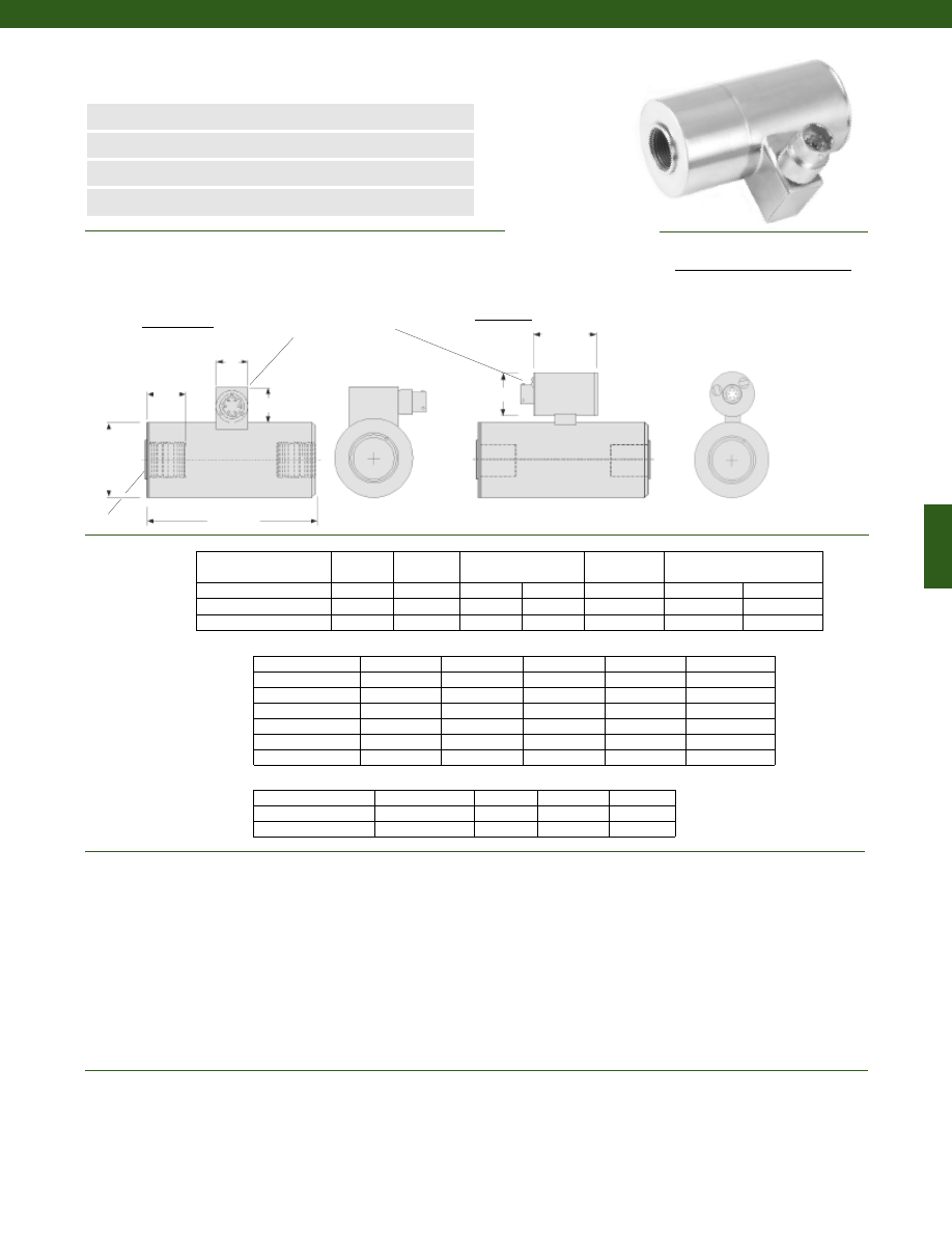
235
Dimensions
Performance
Environmental
Model RF Rod End In-Line Tension Load Cell
Order Code (see table below)
www.honeywell.com/sensotec
n
2000 to 200,000 lb.
n
Hermetically Sealed
n
0-5 VDC or 4-20 mA Output Options
n
0.2% Linearity
øD
L2
T Typ.
A
B
L1
Load Ranges................2,000 to 200,000 lb.
Linearity
100 to 1000 lb.................+/- 0.2% Full Scale
2000 to 50,000 lb.................+/- 0.15% Full Scale
75,000 to 200,000 lb.................+/- 0.2% Full Scale
Hysteresis
100 to 1000 lb.................+/- 0.2% Full Scale
2000 to 50,000 lb.................+/- 0.15% Full Scale
75,000 to 200,000 lb.................+/- 0.2% Full Scale
Non-Repeatability................+/- 0.05% Full Scale
Output................2mV/V
Operation................Tension
Resolution................Infinite
Temperature, Operating................-65° to 250° F
Temperature, Compensated................60° to 160° F
Temperature, Effect
Zero................0.005% Full Scale/° F
Span................0.005% Full Scale/° F
Order Code
(Amplified/Unamp)
D (in.)
L1 (in.)
Unamplified only
A (in.) B (in.)
L2 (in.)
Amplified only
E (in.) F (in.)
AL414/AL614
1.50
4.25
0.75
0.82
see below
1.95
1.50
AL416/AL616
1.75
5.00
0.75
0.82
see below
1.95
1.50
AL418/AL618
2.50
7.00
0.75
0.82
see below
1.95
1.50
Range (lb.)
Thread Type
D (in.)
L1 (in.)
L2 (in.)
75,000 to 100,000
2 1/2-12 UNF
4.50
13.50
3.50
150,000 to 200,000
3 1/2-8 UNF
5.50
18.00
4.50
13a
13b
13c
13d
13e
1/2-20 UNF
3/4-16 UNF
7/8-14 UNF
1-14 UNF
1 1/2-12 UNF
2000 to 5000
AL414
AL414
7500 to 15,000
AL416
AL416
AL416
AL418
20,000
AL416
AL416
AL418
30,000 to 50,000
AL418
L2 (in.)
0.75
0.95
0.95
1.0
1.5
Range (lb.)
Thread Sizes and Option Codes
Non-standard Ranges Order Code AL412
Wiring Code
Connector/ Unamplified (Std.)
A
(+) Excitation
B
(+) Excitation
C
(-) Excitation
D
(-) Excitation
E
(-) Output
F
(+) Output
1-888-282-9891
F
E
Unamplified
Amplified
Connector:
PTIH-10-6P
(2k-50k lbs)
MS3102E-14S-6P
(75k - 200k lbs)
Courtesy of Steven Engineering, Inc.-230 Ryan Way, South San Francisco, CA 94080-6370-Main Office: (650) 588-9200-Outside Local Area: (800) 258-9200-www.stevenengineering.com
Sensotec Sensors Full Line Catalog-html.html
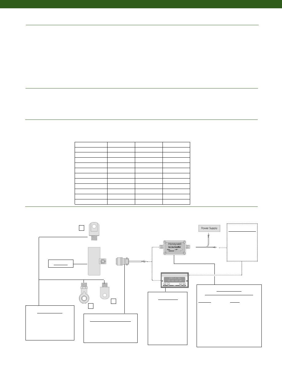
236
www.honeywell.com/sensotec
Strain Gage Type................Bonded Foil
Excitation (calibration)................10 VDC
Excitation (acceptable)................up to 15 VDC or AC
Insulation Resistance................5000 Megohms @ 50 VDC
Bridge Resistance (tolerance)................350 Ohms
Zero Balance (tolerance)................+/- 1% of Full Scale
Shunt Calibration Data................Included
Electrical Termination (std)
2000 to 50,000 lb.................PTIH-10-6P or equivalent (Hermetic stainless)
75,000 to 200,000 lb.................MS3102E-14S-6P
Mating Connector (not incl.)
2000 to 50,000 lb.................PT06A-10-6S or equivalent
75,000 to 200,000 lb.................MS3106A-14S-6S or equivalent
Maximum Allowable Load................150% F.S. (note 1)
Weight................See table
Material................Stainless Steel
Deflection Full Scale................See table
Natural Frequency................See table
1
2
3
Mating Connectors & Cables
PT06A-10-6S
MS3106A-14S-6S
PT06E-10-6S
In-Line Amplifiers
(Used with unamplified units only)
Amplifier
Output
Universal In-Line Amplifiers
UV
+/- 5 VDC
UV-10
+/- 10 VDC
UBP
0 +/- 5 VDC
U3W
4-20 mA (3 wire)
U2W
4-20 mA (2 wire)
DIN rail Mount In-Line Amplifiers
DV-05
0 +/- 5 VDC (3 wire)
DA-05
4-20 mA (3 wire)
DV-10
0 +/- 10 VDC (3 wire)
Customer Supplied
Chart Recorder
Alarm Panel
Data Acquisition
Computer
PLC
Mounting Options
1. Yoke Shackle Male
2. Tongue Shackle Male
3. Rod End Bearing Male
Model RF
1-888-282-9891
Model RF
Capacity (lb.)
Deflection @
Full Scale
(in.)
Ringing
Frequency
(Hz)
Weight
(lb)
2,000
0.003
5,000
1.3
3,000
0.003
5,000
1.3
4,000
0.003
5,100
1.3
5,000
0.003
5,200
1.3
7,500
0.003
8,000
1.6
10,000
0.003
8,500
1.6
15,000
0.003
9,000
1.6
20,000
0.004
9,000
1.7
30,000
0.004
8,000
3.5
50,000
0.005
8,000
3.7
75,000 to 100,000
0.006
3,500
39.7
150,000 to 200,000
0.007
3,000
72.8
Electrical
Mechanical
Deflections and Ringing Frequencies
Typical System Diagram
Display Units
SC500
SC1000
SC2000
SC2001
SC3004
GM (Unamplified only)
GM-A (Amplified only)
NK (Unamplified only)
HH (Unamplified only)
Courtesy of Steven Engineering, Inc.-230 Ryan Way, South San Francisco, CA 94080-6370-Main Office: (650) 588-9200-Outside Local Area: (800) 258-9200-www.stevenengineering.com
Sensotec Sensors Full Line Catalog-html.html

237
Range
Range Code
2,000 lb.
DJ
3,000 lb.
DN
4,000 lb.
DP
5,000 lb.
DR
7,500 lb.
DT
10,000 lb.
DV
15,000 lb.
EJ
20,000 lb.
EL
30,000 lb.
EN
50,000 lb.
EP
75,000 lb.
ER
100,000 lb.
ET
150,000 lb.
FJ
200,000 lb.
FL
Range Codes
www.honeywell.com/sensotec
1-888-282-9891
Internal Amplifiers
Model RF
Amplifier
Specifications
Voltage Output
Option 2b
Voltage Output
Option 2c
Voltage Output
Option 2t
Current 3 Wire
Option 2j
Current 2 Wire
Option 2k
Intrinsically Safe
Option 2n (2N)***
Output Signal
Input Power (Voltage)
Input Power (Current)
Frequency Response
Power Supply
Rejection
Operating Temperature
Reverse Voltage
Protection
Short Circuit Protection
+/- 5V
+/-15V or 26-32VDC
45 mA
3000 Hz
60 db
-20° to 185° F
Yes
Momentary
0-5V or +/- 5V
@ 45mA
11-28 VDC
40 mA
3000 Hz
60 db
-20° to 185° F
Yes
Momentary
0-10V or +/- 10V
@ 45mA
15-28 VDC
40 mA
3000 Hz
60 db
-20° to 185° F
Yes
Momentary
4-20 mA
22-32 VDC
65 mA
2500 Hz
60 db
0° to 185° F
Yes
Yes
4-20 mA
15-40 VDC
4-28 mA
300 Hz
60 db
0° to 185° F
Yes
Yes
4-20 mA
9-28 VDC
4-24 mA
2000 Hz
60 db
-20° to 185° F
Yes
Yes
Wiring Code: Connector
(Std.)
(note 4)
A (+) Supply
B Output Common/
C Supply Return
D (+) Output
E Shunt Cal 1
F Shunt Cal 2
A (+) Supply
B** Output Common/
C** Supply Return
D (+) Output
E Shunt Cal 1
F Shunt Cal 2
A (+) Supply
B** Output Common/
C** Supply Return
D (+) Output
E Shunt Cal 1
F Shunt Cal 2
A (+) Supply
B** Output Common/
C** Supply Return
D (+) Output
E Shunt Cal 1
F Shunt Cal 2
A (+) Supply
B No connection
C No connection
D (+) Output
E Case Ground
F No connection
A (+) Supply
B No connection
C No connection
D (+) Output
E Case Ground
F No connection
Wiring Code: Cable
(note 4)
(note 5)
(note 6)
R (+) Supply
Bl Output Common/
G Supply Return
W (+) Output
B Shunt Cal 1
Br Shunt Cal 2
R (+) Supply
Bl*Output Common/
G*Supply Return
W (+) Output
B Shunt Cal 1
Br Shunt Cal 2
R (+) Supply
Bl*Output Common/
G*Supply Return
W (+) Output
B Shunt Cal 1
Br Shunt Cal 2
R (+) Supply
Bl*Output Common/
G*Supply Return
W (+) Output
B Shunt Cal 1
Br Shunt Cal 2
R (+) Supply
Bl (+) Output
W Case Ground
R (+) Supply
Bl (+) Output
W Case Ground
* Black and Green wires are internally connected.
** Pins B and C are internally connected.
*** See Sensotec website for most up-to-date information regarding Intrinsically Safe approvals ref. #008-0547-00.
Courtesy of Steven Engineering, Inc.-230 Ryan Way, South San Francisco, CA 94080-6370-Main Office: (650) 588-9200-Outside Local Area: (800) 258-9200-www.stevenengineering.com
Sensotec Sensors Full Line Catalog-html.html

238
www.honeywell.com/sensotec
1-888-282-9891
Model RF
Combine the order code, the range code and the options code.
Order Code
Range Code
Options Code
Sample Code: AL414
DJ
6g
Cable Orientation
Different Cable Lengths
Different Electrical Connectors
Different Materials
Different Threads
Dual Bridge
ESD
Fatigue Rating
High Resistance Bridges
Lightning Protection
OEM Labels
Enhanced Operational Temp
Radiation Resistant
Special Electrical O/P
Special TC
Special Customer
Requirements
(Consult Factory)
Options
How to Order
Notes
Supplied as standard
Build from Scratch
Load Range
2k, 3k, 4k, 5k, 7.5k, 10k, 15k, 20k, 30k, 50k, 75k, 100k,
150k, 200k lbs.
Temperature
Compensation
1b. 30° to 130° F
1c. 0° to 185° F
1d. -20° to 130° F
1e. -20° to 200° F
1f. 70° to 250° F
1g. 70° to 325° F
1h. 70° to 400° F
1i. -65° to 250° F
1j. 0° to 50° C
1k. -20° to 85° C
1m. -25° to 110° C
Internal Amplifiers
2b. 4 wire +/- 5VDC output
2c. 0-5VDC
2j. 4-20mA (3-wire) output
2k. 4-20mA (2-wire)
2t. 0-10 VDC output
2n (2N). 4-20mA (2-wire) Intrinsically safe
Internal Amp
Enhancements
3a. Input/ Output Isolation (note 7)
3d. Remote Buffered Shunt Calibration
Electrical
Termination
6b. MS type connector mates with MS3106- 14S 6 pin
(max. 160°F)
6e. Integral cable: Teflon
6f. Integral cable: PVC
6g. Integral cable: Neoprene
6h. Integral cable: Silicone
6i. Integral underwater cable
6j. 1/2-14 conduit fitting with 5 ft. of 4 conductor
PVC cable
6q. Molded Integral cable: Polyurethane
6v. Phoenix connector on end of cable
Shunt Calibration 8a. Precision Internal Resistor (note 8)
Bridge Type
11a.Square Bridge
11c. Square and Symmetrical Bridge
31a.Dual bridge
Bridge Resistance 12b.5,000 Ohms (foil) (max. 250°F)
Potentiometers
14a.No access to pots
Electrical
Connector
Orientation
15a.Horizontal Electrical Exit Port Orientation
15b.Vertical Electrical Exit Port Orientation
15c. Radial Electrical Exit Port Orientation
15d.Connector on end of cable
Shock & Vibration 44a.Shock and vibration resistance
Interfaces
53e.Signature Calibration
53t. T.E.D.S. IEEE 1451-4 Module (note 9)
2u. Unamplified, mV/V output
1a. 60° to 160° F
1. Allowable Maximum Loads- Maximum load to be applied without damage (note 2).
2. Without Damage- loading to this level will not cause excessive zero shift or performance degradation. The user must consider fatigue life for long term
use and structural integrity. All structurally critical applications (overhead loading, etc.) should always be designed with safety redundant load paths.
3. Interconnecting shunt cal. 1 terminal with shunt cal. 2 terminal provides 50% (unamplified units), 75% (4-20mA 3-wire units) or 80% (voltage amplified
units) of full scale output for quick calibration. Shunt Calibration comes standard with internal amplifier options 2a, 2b, 2c, 2t and 2j.
4. O=Orange; Y=Yellow; B=Blue; Bl=Black; R=Red; Br=Brown; W=White; G=Green. Color specifying cable and number or letter specifying connector.
5. No mating connector necessary for cable option.
6. Not available with options 1c, 1e or 1f.
7. Only available with options 2b or 2c.
8. Not available with amplified options.
9. Consult factory for TEDS availability with amplified models.
Courtesy of Steven Engineering, Inc.-230 Ryan Way, South San Francisco, CA 94080-6370-Main Office: (650) 588-9200-Outside Local Area: (800) 258-9200-www.stevenengineering.com
Sensotec Sensors Full Line Catalog-html.html
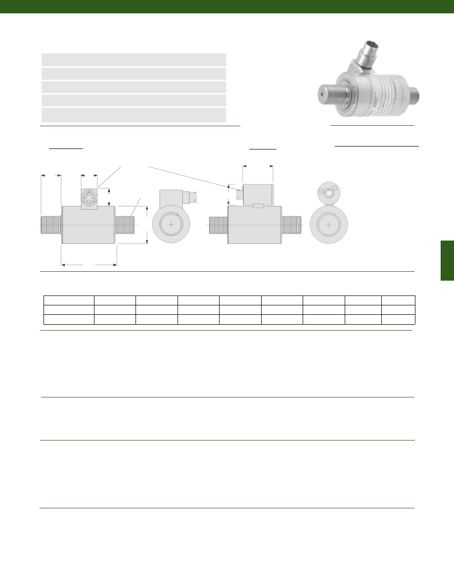
239
www.honeywell.com/sensotec
Load Ranges................2000; 3000; 4000; 5000; 10,000; 15,000; 25,000; 50,000 lb.
Accuracy................+/- 0.25% Full Scale
Linearity................+/- 0.25% Full Scale
Hysteresis................+/- 0.25% Full Scale
Non-Repeatability................+/- 0.05% Full Scale
Output (tolerance)................1mV/V (nominal)
Operation................Tension/ Compression (note 10)
Resolution................Infinite
Temperature, Operating................-65° to 250° F
Temperature, Compensated................60° to 160° F
Temperature, Effect
Zero................0.005% Full Scale/° F
Span................0.005% Full Scale/° F
Strain Gage Type................Bonded Foil
Excitation (calibration)................10 VDC
Excitation (acceptable)................up to 15 VDC or AC
Insulation Resistance................5000 Megohms @ 50 VDC
Bridge Resistance (tolerance)................700 Ohms
Zero Balance (tolerance)................+/- 3% Full Scale
Shunt Calibration Data................Included
Electrical Termination (std)................PTIH-10-6P or equivalent (Hermetic stainless)
Maximum Allowable Load................200% F.S. (note 1)
Weight................See table (next page)
Material................Stainless Steel
Life Cycles (approx.)................> 10 million cycles
Deflection Full Scale................See table (next page)
Natural Frequency................See table (next page)
2000 to 5000
1.75
3/4-16 UNF
0.95
2.63
0.75
0.82
1.95
1.50
10,000 to 15,000
2.50
1 1/2-12 UNF
1.75
3.50
0.75
0.82
1.95
1.50
25,000 to 50,000
3.50
2-12 UNF
2.25
3.50
0.75
0.82
1.95
1.50
Unamplified only
Amplified only
Range (lb.) D (in.) T L2 (in.) L1 (in.) A (in.) B (in.)
E (in.)
F (in.)
Model RGM Rod End In-Line Compression/ Tension Load Cell
Order Code AL426 (unamp); AL626 (amplified)
n
2000 to 50,000 lb.
n
Hermetically Sealed
n
0-5 VDC or 4-20 mA Output Options
n
Compression-Tension
n
0.25% Accuracy
øD
L2
T Typ.
A
B
L1
Connector/ Unamplified (Std.)
A
(+) Excitation
B
(+) Excitation
C
(-) Excitation
D
(-) Excitation
E
(-) Output
F
(+) Output
1-888-282-9891
Unamplified
Amplified
F
E
PTIH-10-6P
Dimensions
Performance
Environmental
Electrical
Mechanical
Wiring Code
Courtesy of Steven Engineering, Inc.-230 Ryan Way, South San Francisco, CA 94080-6370-Main Office: (650) 588-9200-Outside Local Area: (800) 258-9200-www.stevenengineering.com
Sensotec Sensors Full Line Catalog-html.html
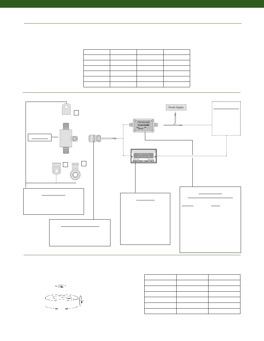
240
www.honeywell.com/sensotec
Typical System Diagram
Allowable Maximum Loads
(note 2)
Side
Axial
Torque
Capacity (lb.)
Bending
1-888-282-9891
1
2
3
In-Line Amplifiers
(Used with unamplified units only)
Amplifier
Output
Universal In-Line Amplifiers
UV
+/- 5 VDC
UV-10
+/- 10 VDC
UBP
0 +/- 5 VDC
U3W
4-20 mA (3 wire)
U2W
4-20 mA (2 wire)
DIN rail Mount In-Line Amplifiers
DV-05
0 +/- 5 VDC (3 wire)
DA-05
4-20 mA (3 wire)
DV-10
0 +/- 10 VDC (3 wire)
Customer Supplied
Chart Recorder
Alarm Panel
Data Acquisition
Computer
PLC
Mounting Options
1. Yoke Shackle Female
2. Tongue Shackle Female
3. Rod End Bearing Female
Model RGM
Mating Connectors & Cables
PT06A-10-6S
MS3106A-14S-6S
PT06E-10-6S
Model RGM
2,000
20%
20%
3,000
20%
20%
5,000
20%
20%
10,000
20%
20%
15,000
20%
20%
25,000
20%
20%
50,000
20%
20%
Deflections and Ringing Frequencies
Capacity (lb.)
Deflection
@ Full Scale
(in.)
Ringing
Frequency
(Hz)
Weight
(grams)
2000
0.001
10,000
1.2
3000
0.001
12,000
1.2
5000
0.002
15,000
1.4
10,000
0.002
10,000
2.9
15,000
0.002
10,000
2.9
25,000
0.002
6,500
9.5
50,000
0.003
7,000
9.9
Side Load (lb.)
(% of Load Capacity)
Torque (lb.-in.)
(% of Load Capacity)
Display Units
SC500
SC1000
SC2000
SC2001
SC3004
GM (Unamplified only)
GM-A (Amplified only)
NK (Unamplified only)
HH (Unamplified only)
Courtesy of Steven Engineering, Inc.-230 Ryan Way, South San Francisco, CA 94080-6370-Main Office: (650) 588-9200-Outside Local Area: (800) 258-9200-www.stevenengineering.com
Sensotec Sensors Full Line Catalog-html.html

241
Range
Range Code
2,000 lb.
DJ
3,000 lb.
DN
4,000 lb.
DP
5,000 lb.
DR
10,000 lb.
DV
25,000 lb.
EM
50,000 lb.
EP
Range Codes
www.honeywell.com/sensotec
1-888-282-9891
Internal Amplifiers
Model RGM
Amplifier
Specifications
Voltage Output
Option 2b
Voltage Output
Option 2c
Voltage Output
Option 2t
Current 3 Wire
Option 2j
Current 2 Wire
Option 2k
Intrinsically Safe
Option 2n (2N)***
Output Signal
Input Power (Voltage)
Input Power (Current)
Frequency Response
Power Supply
Rejection
Operating Temperature
Reverse Voltage
Protection
Short Circuit Protection
+/- 5V
+/-15V or 26-32VDC
45 mA
3000 Hz
60 db
-20° to 185° F
Yes
Momentary
0-5V or +/- 5V
@ 45mA
11-28 VDC
40 mA
3000 Hz
60 db
-20° to 185° F
Yes
Momentary
0-10V or +/- 10V
@ 45mA
15-28 VDC
40 mA
3000 Hz
60 db
-20° to 185° F
Yes
Momentary
4-20 mA
22-32 VDC
65 mA
2500 Hz
60 db
0° to 185° F
Yes
Yes
4-20 mA
15-40 VDC
4-28 mA
300 Hz
60 db
0° to 185° F
Yes
Yes
4-20 mA
9-28 VDC
4-24 mA
2000 Hz
60 db
-20° to 185° F
Yes
Yes
Wiring Code: Connector
(Std.)
(note 4)
A (+) Supply
B Output Common/
C Supply Return
D (+) Output
E Shunt Cal 1
F Shunt Cal 2
A (+) Supply
B** Output Common/
C** Supply Return
D (+) Output
E Shunt Cal 1
F Shunt Cal 2
A (+) Supply
B** Output Common/
C** Supply Return
D (+) Output
E Shunt Cal 1
F Shunt Cal 2
A (+) Supply
B** Output Common/
C** Supply Return
D (+) Output
E Shunt Cal 1
F Shunt Cal 2
A (+) Supply
B No connection
C No connection
D (+) Output
E Case Ground
F No connection
A (+) Supply
B No connection
C No connection
D (+) Output
E Case Ground
F No connection
Wiring Code: Cable
(note 4)
(note 5)
(note 6)
R (+) Supply
Bl Output Common/
G Supply Return
W (+) Output
B Shunt Cal 1
Br Shunt Cal 2
R (+) Supply
Bl*Output Common/
G*Supply Return
W (+) Output
B Shunt Cal 1
Br Shunt Cal 2
R (+) Supply
Bl*Output Common/
G*Supply Return
W (+) Output
B Shunt Cal 1
Br Shunt Cal 2
R (+) Supply
Bl*Output Common/
G*Supply Return
W (+) Output
B Shunt Cal 1
Br Shunt Cal 2
R (+) Supply
Bl (+) Output
W Case Ground
R (+) Supply
Bl (+) Output
W Case Ground
* Black and Green wires are internally connected.
** Pins B and C are internally connected.
*** See Sensotec website for most up-to-date information regarding Intrinsically Safe approvals ref. #008-0547-00.
Courtesy of Steven Engineering, Inc.-230 Ryan Way, South San Francisco, CA 94080-6370-Main Office: (650) 588-9200-Outside Local Area: (800) 258-9200-www.stevenengineering.com
Sensotec Sensors Full Line Catalog-html.html
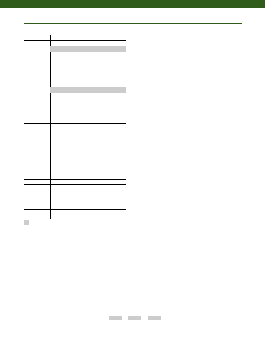
242
www.honeywell.com/sensotec
1-888-282-9891
Combine the order code, the range code and the options code.
Order Code
Range Code
Options Code
Sample Code: AL426
DJ
6g
Model RGM
Cable Orientation
Different Cable Lengths
Different Electrical Connectors
Different Materials
Different Threads
Dual Bridge
ESD
Fatigue Rating
High Resistance Bridges
Lightning Protection
OEM Labels
Enhanced Operational Temp
Radiation Resistant
Special Electrical O/P
Special TC
Special Customer
Requirements
(Consult Factory)
Options
How to Order
Notes
Build from Scratch
Load Range
2k, 3k, 4k, 5k, 10k, 15k, 25k, 50k lbs.
Temperature
Compensation
1b. 30° to 130° F
1c. 0° to 185° F
1d. -20° to 130° F
1e. -20° to 200° F
1f. 70° to 250° F
1g. 70° to 325° F
1h. 70° to 400° F
1i. -65° to 250° F
1j. 0° to 50° C
1k. -20° to 85° C
1m. -25° to 110° C
Internal Amplifiers
2b. 4 wire +/- 5VDC output
2c. 0-5VDC
2j. 4-20mA (3-wire) output
2k. 4-20mA (2-wire)
2t. 0-10 VDC output
2n (2N). 4-20mA (2-wire) Intrinsically safe
Internal Amp
Enhancements
3a. Input/ Output Isolation (note 7)
3d. Remote Buffered Shunt Calibration
Electrical
Termination
6b. MS type connector mates with MS3106- 14S 6 pin
(max. 160°F)
6e. Integral cable: Teflon
6f. Integral cable: PVC
6g. Integral cable: Neoprene
6h. Integral cable: Silicone
6i. Integral underwater cable
6j. 1/2-14 conduit fitting with 5 ft. of 4 conductor
PVC cable
6q. Molded Integral cable: Polyurethane
6v. Phoenix connector on end of cable
Shunt Calibration 8a. Precision Internal Resistor (note 8)
Bridge Type
11a.Square Bridge
11c. Square and Symmetrical Bridge
31a.Dual bridge
Bridge Resistance 12b.5,000 Ohms (foil) (max. 250°F)
Potentiometers
14a.No access to pots
Electrical
Connector
Orientation
15a.Horizontal Electrical Exit Port Orientation
15b.Vertical Electrical Exit Port Orientation
15c. Radial Electrical Exit Port Orientation
15d.Connector on end of cable
Shock & Vibration 44a.Shock and vibration resistance
Interfaces
53e.Signature Calibration
53t. T.E.D.S. IEEE 1451-4 Module (note 9)
2u. Unamplified, mV/V output
1a. 60° to 160° F
Supplied as standard
1. Allowable Maximum Loads- Maximum load to be applied without damage (note 2).
2. Without Damage- loading to this level will not cause excessive zero shift or performance degradation. The user must consider fatigue life for long term
use and structural integrity. All structurally critical applications (overhead loading, etc.) should always be designed with safety redundant load paths.
3. Interconnecting shunt cal. 1 terminal with shunt cal. 2 terminal provides 50% (unamplified units), 75% (4-20mA 3-wire units) or 80% (voltage amplified
units) of full scale output for quick calibration. Shunt Calibration comes standard with internal amplifier options 2a, 2b, 2c, 2t and 2j.
4. O=Orange; Y=Yellow; B=Blue; Bl=Black; R=Red; Br=Brown; W=White; G=Green. Color specifying cable and number or letter specifying connector.
5. No mating connector necessary for cable option.
6. Not available with options 1c, 1e or 1f.
7. Only available with options 2b or 2c.
8. Not available with amplified options.
9. Consult factory for TEDS availability with amplified models.
10. Positive in compression; calibrated in compression only.
Courtesy of Steven Engineering, Inc.-230 Ryan Way, South San Francisco, CA 94080-6370-Main Office: (650) 588-9200-Outside Local Area: (800) 258-9200-www.stevenengineering.com
Sensotec Sensors Full Line Catalog-html.html
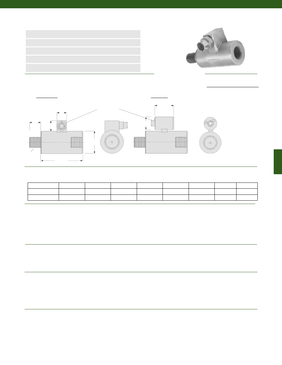
243
www.honeywell.com/sensotec
n
2000 to 50,000 lb.
n
Hermetically Sealed
n
0-5 VDC or 4-20 mA Output Options
n
Compression-Tension
n
0.25% Accuracy
Load Ranges................2000; 3000; 4000; 5000; 10,000; 15,000; 25,000; 50,000 lb.
Accuracy................0.25% Full Scale (note 1)
Linearity................+/- 0.25% Full Scale
Hysteresis................+/- 0.25% Full Scale
Non-Repeatability................+/- 0.05% Full Scale
Tolerance on Output................1mV/V nominal
Operation................Tension/ Compression
Resolution................Infinite
Temperature, Operating................-65° to 250° F
Temperature, Compensated................60° to 160° F
Temperature, Effect
Zero................0.005% Full Scale/° F
Span................0.005% Full Scale/° F
Strain Gage Type................Bonded Foil
Excitation (calibration)................10 VDC
Excitation (acceptable)................up to 15 VDC or AC
Insulation Resistance................5000 Megohms @ 50 VDC
Bridge Resistance................700 Ohms
Shunt Calibration Data................Included
Electrical Termination (std)................PTIH-10-6P or equivalent (Hermetic stainless)
Maximum Allowable Load................200% F.S. (note 1)
Case Material................Stainless Steel
Deflection Full Scale................0.003 in.
Life Cycles (approx.)................>10 Million Cycles
2000 to 5000
1.75
3/4-16 UNF
0.95
2.63
0.75
0.82
1.95
1.50
10,000 to 15,000
2.50
1 1/2-12 UNF
1.75
4.50
0.75
0.82
1.95
1.50
25,000 to 50,000
3.50
2-12 UNF
2.25
5.75
0.75
0.82
1.95
1.50
Unamplified only
Amplified only
Range (lb.) D (in.) T L2 (in.) L1 (in.) A (in.) B (in.)
E (in.)
F (in.)
Model RGH Rod End In-Line Compression-Tension Load Cell
Order Code AL427 (unamplified) AL627 (amplified)
øD
L2
T Typ.
A
B
L1
1-888-282-9891
Dimensions
Performance
Environmental
Electrical
Mechanical
F
E
Unamplified
Amplified
PTIH-10-6P
Wiring Code
Connector/ Unamplified (Std.)
A
(+) Excitation
B
(+) Excitation
C
(-) Excitation
D
(-) Excitation
E
(-) Output
F
(+) Output
Courtesy of Steven Engineering, Inc.-230 Ryan Way, South San Francisco, CA 94080-6370-Main Office: (650) 588-9200-Outside Local Area: (800) 258-9200-www.stevenengineering.com
Sensotec Sensors Full Line Catalog-html.html
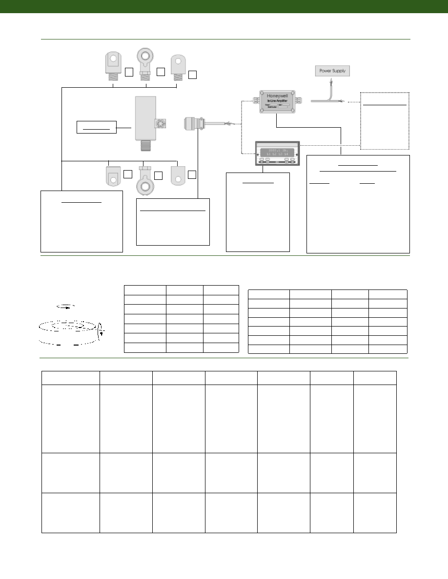
244
www.honeywell.com/sensotec
Allowable Maximum Loads
(note 2)
Side
Axial
Torque
Bending
1
2
3
4
5
6
Mating Connectors & Cables
PT06A-10-6S
MS3106A-14S-6S
PT06E-10-6S
In-Line Amplifiers
(Used with unamplified units only)
Amplifier
Output
Universal In-Line Amplifiers
UV
+/- 5 VDC
UV-10
+/- 10 VDC
UBP
0 +/- 5 VDC
U3W
4-20 mA (3 wire)
U2W
4-20 mA (2 wire)
DIN rail Mount In-Line Amplifiers
DV-05
0 +/- 5 VDC (3 wire)
DA-05
4-20 mA (3 wire)
DV-10
0 +/- 10 VDC (3 wire)
Customer Supplied
Chart Recorder
Alarm Panel
Data Acquisition
Computer
PLC
Mounting Options
1.
Yoke Shackle Male
2.
Tongue Shackle Male
3.
Rod End Bearing Male
4.
Yoke Shackle Female
5.
Tongue Shackle Female
6.
Rod End Bearing Female
Model RGH
1-888-282-9891
Model RGH
Internal Amplifiers
2,000
20%
20%
3,000
20%
20%
5,000
20%
20%
10,000
20%
20%
15,000
20%
20%
25,000
20%
20%
50,000
20%
20%
Capacity (lb.)
Deflections and Ringing Frequencies
Capacity (lb.)
Deflection
@ Full Scale
(in.)
Ringing
Frequency
(kHz)
Weight
(lb)
2000
0.001
10,000
1.2
3000
0.001
12,000
1.2
5000
0.002
15,000
1.4
10,000
0.002
10,000
2.9
15,000
0.002
10,000
2.9
25,000
0.002
6,500
9.5
50,000
0.003
7,000
9.9
Typical System Diagram
Display Units
SC500
SC1000
SC2000
SC2001
SC3004
GM (Unamplified only)
GM-A (Amplified only)
NK (Unamplified only)
HH (Unamplified only)
Amplifier
Specifications
Voltage Output
Option 2b
Voltage Output
Option 2c
Voltage Output
Option 2t
Current 3 Wire
Option 2j
Current 2 Wire
Option 2k
Intrinsically Safe
Option 2n (2N)***
Output Signal
Input Power (Voltage)
Input Power (Current)
Frequency Response
Power Supply
Rejection
Operating Temperature
Reverse Voltage
Protection
Short Circuit Protection
+/- 5V
+/-15V or 26-32VDC
45 mA
3000 Hz
60 db
-20° to 185° F
Yes
Momentary
0-5V or +/- 5V
@ 45mA
11-28 VDC
40 mA
3000 Hz
60 db
-20° to 185° F
Yes
Momentary
0-10V or +/- 10V
@ 45mA
15-28 VDC
40 mA
3000 Hz
60 db
-20° to 185° F
Yes
Momentary
4-20 mA
22-32 VDC
65 mA
2500 Hz
60 db
0° to 185° F
Yes
Yes
4-20 mA
15-40 VDC
4-28 mA
300 Hz
60 db
0° to 185° F
Yes
Yes
4-20 mA
9-28 VDC
4-24 mA
2000 Hz
60 db
-20° to 185° F
Yes
Yes
Wiring Code: Connector
(Std.)
(note 4)
A (+) Supply
B Output Common/
C Supply Return
D (+) Output
E Shunt Cal 1
F Shunt Cal 2
A (+) Supply
B** Output Common/
C** Supply Return
D (+) Output
E Shunt Cal 1
F Shunt Cal 2
A (+) Supply
B** Output Common/
C** Supply Return
D (+) Output
E Shunt Cal 1
F Shunt Cal 2
A (+) Supply
B** Output Common/
C** Supply Return
D (+) Output
E Shunt Cal 1
F Shunt Cal 2
A (+) Supply
B No connection
C No connection
D (+) Output
E Case Ground
F No connection
A (+) Supply
B No connection
C No connection
D (+) Output
E Case Ground
F No connection
Wiring Code: Cable
(note 4)
(note 5)
(note 6)
R (+) Supply
Bl Output Common/
G Supply Return
W (+) Output
B Shunt Cal 1
Br Shunt Cal 2
R (+) Supply
Bl*Output Common/
G*Supply Return
W (+) Output
B Shunt Cal 1
Br Shunt Cal 2
R (+) Supply
Bl*Output Common/
G*Supply Return
W (+) Output
B Shunt Cal 1
Br Shunt Cal 2
R (+) Supply
Bl*Output Common/
G*Supply Return
W (+) Output
B Shunt Cal 1
Br Shunt Cal 2
R (+) Supply
Bl (+) Output
W Case Ground
R (+) Supply
Bl (+) Output
W Case Ground
* Black and Green wires are internally connected.
** Pins B and C are internally connected.
*** See Sensotec website for most up-to-date information regarding Intrinsically Safe approvals ref. #008-0547-00.
Side Load (lb.)
(% of Load
Capacity)
Torque (lb.-in.)
(% of Load
Capacity)
Courtesy of Steven Engineering, Inc.-230 Ryan Way, South San Francisco, CA 94080-6370-Main Office: (650) 588-9200-Outside Local Area: (800) 258-9200-www.stevenengineering.com
Sensotec Sensors Full Line Catalog-html.html
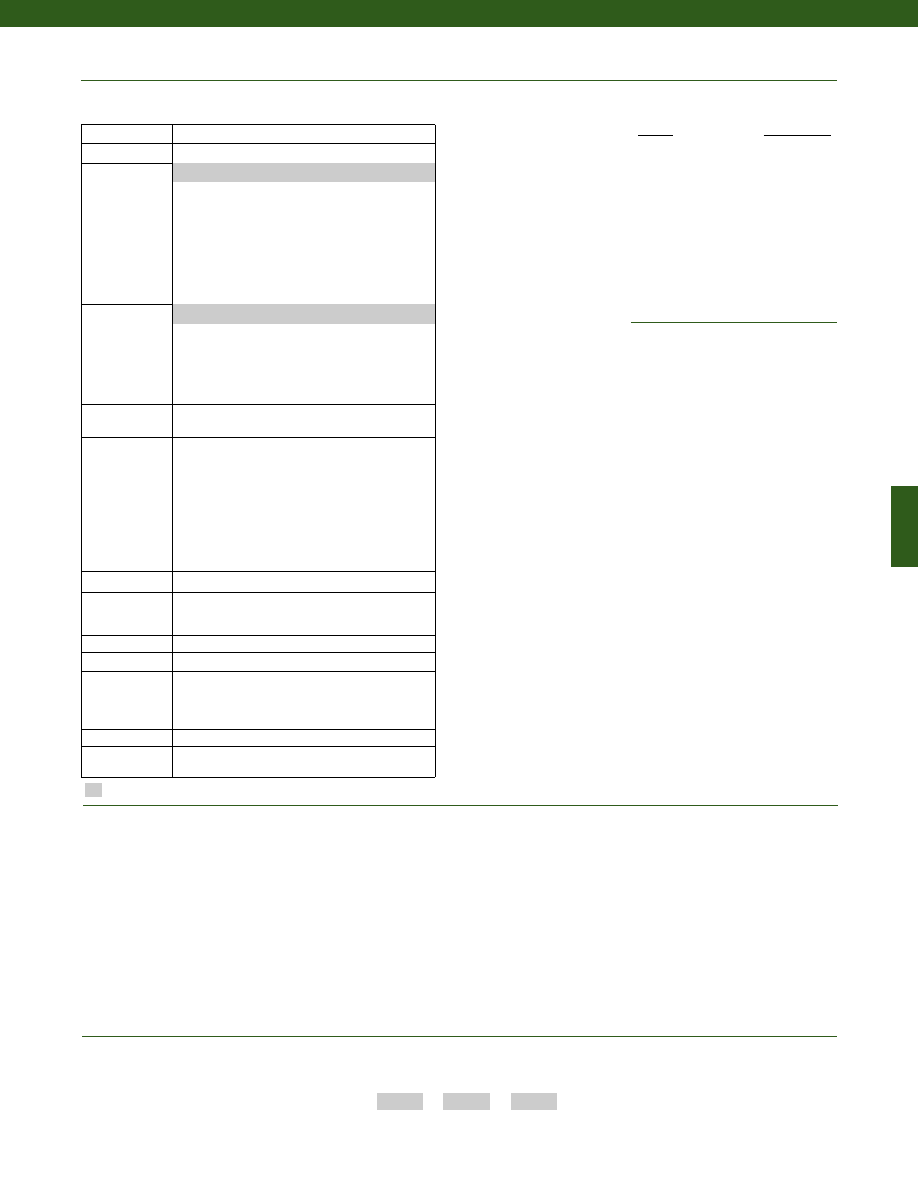
245
www.honeywell.com/sensotec
1-888-282-9891
Combine the order code, the range code and the options code.
Order Code
Range Code
Options Code
Sample Code: AL427
DJ
6g
Model RGH
Cable Orientation
Different Cable Lengths
Different Electrical Connectors
Different Materials
Different Threads
Dual Bridge
ESD
Fatigue Rating
High Resistance Bridges
Lightning Protection
OEM Labels
Enhanced Operational Temp
Radiation Resistant
Special Electrical O/P
Special TC
Special Customer
Requirements
(Consult Factory)
Options
How to Order
Range
Range Code
2,000 lb.
DJ
3,000 lb.
DN
4,000 lb.
DP
5,000 lb.
DR
10,000 lb.
DV
25,000 lb.
EM
50,000 lb.
EP
Range Codes
Notes
Supplied as standard
Build from Scratch
Load Range
2k, 3k, 4k, 5k, 10k, 15k, 25k, 50k lbs.
Temperature
Compensation
1b. 30° to 130° F
1c. 0° to 185° F
1d. -20° to 130° F
1e. -20° to 200° F
1f. 70° to 250° F
1g. 70° to 325° F
1h. 70° to 400° F
1i. -65° to 250° F
1j. 0° to 50° C
1k. -20° to 85° C
1m. -25° to 110° C
Internal Amplifiers
2b. 4 wire +/- 5VDC output
2c. 0-5VDC
2j. 4-20mA (3-wire) output
2k. 4-20mA (2-wire)
2t. 0-10 VDC output
2n (2N). 4-20mA (2-wire) Intrinsically safe
Internal Amp
Enhancements
3a. Input/ Output Isolation (note 7)
3d. Remote Buffered Shunt Calibration
Electrical
Termination
6b. MS type connector mates with MS3106- 14S 6 pin
(max. 160°F)
6e. Integral cable: Teflon
6f. Integral cable: PVC
6g. Integral cable: Neoprene
6h. Integral cable: Silicone
6i. Integral underwater cable
6j. 1/2-14 conduit fitting with 5 ft. of 4 conductor
PVC cable
6q. Molded Integral cable: Polyurethane
6v. Phoenix connector on end of cable
Shunt Calibration 8a. Precision Internal Resistor (note 8)
Bridge Type
11a.Square Bridge
11c. Square and Symmetrical Bridge
31a.Dual bridge
Bridge Resistance 12b.5,000 Ohms (foil) (max. 250°F)
Potentiometers
14a.No access to pots
Electrical
Connector
Orientation
15a.Horizontal Electrical Exit Port Orientation
15b.Vertical Electrical Exit Port Orientation
15c. Radial Electrical Exit Port Orientation
15d.Connector on end of cable
Shock & Vibration 44a.Shock and vibration resistance
Interfaces
53e.Signature Calibration
53t. T.E.D.S. IEEE 1451-4 Module (note 9)
2u. Unamplified, mV/V output
1a. 60° to 160° F
1. Allowable Maximum Loads- Maximum load to be applied without damage (note 2).
2. Without Damage- loading to this level will not cause excessive zero shift or performance degradation. The user must consider fatigue life for long term
use and structural integrity. All structurally critical applications (overhead loading, etc.) should always be designed with safety redundant load paths.
3. Interconnecting shunt cal. 1 terminal with shunt cal. 2 terminal provides 50% (unamplified units), 75% (4-20mA 3-wire units) or 80% (voltage amplified
units) of full scale output for quick calibration. Shunt Calibration comes standard with internal amplifier options 2a, 2b, 2c, 2t and 2j.
4. O=Orange; Y=Yellow; B=Blue; Bl=Black; R=Red; Br=Brown; W=White; G=Green. Color specifying cable and number or letter specifying connector.
5. No mating connector necessary for cable option.
6. Not available with options 1c, 1e or 1f.
7. Only available with options 2b or 2c.
8. Not available with amplified options.
9. Consult factory for TEDS availability with amplified models.
Courtesy of Steven Engineering, Inc.-230 Ryan Way, South San Francisco, CA 94080-6370-Main Office: (650) 588-9200-Outside Local Area: (800) 258-9200-www.stevenengineering.com
Sensotec Sensors Full Line Catalog-html.html
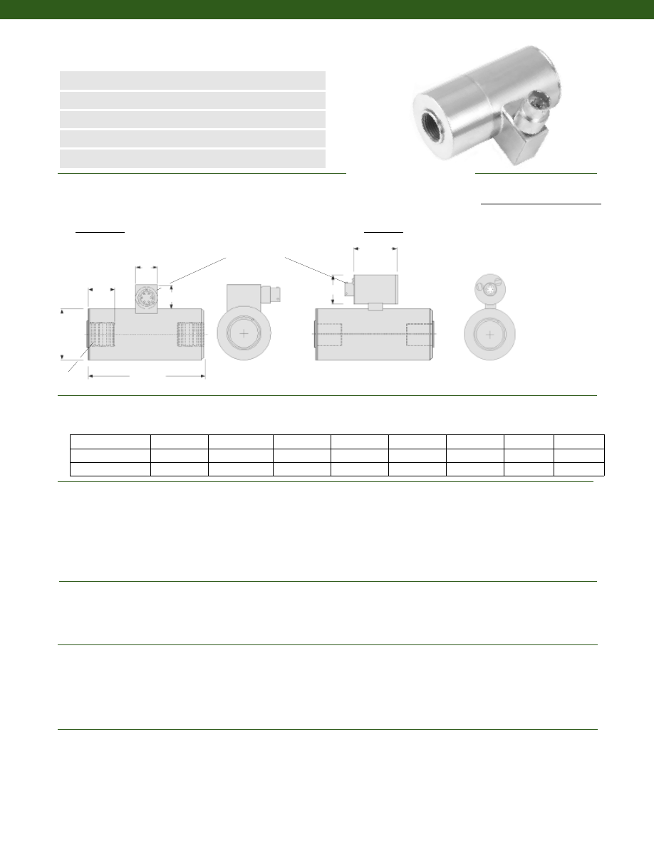
246
www.honeywell.com/sensotec
n
2000 to 50,000 lb.
n
Hermetically Sealed
n
0-5 VDC or 4-20 mA Output Options
n
Compression-Tension
n
0.25% Accuracy
Load Ranges................2000; 3000; 4000; 5000; 10,000; 15,000; 25,000; 50,000 lb.
Accuracy................0.25% Full Scale (note 1)
Linearity................+/- 0.25% Full Scale
Hysteresis................+/- 0.25% Full Scale
Non-Repeatability................+/- 0.05% Full Scale
Tolerance on Output................1mV/V nominal
Operation................Tension/ Compression
Resolution................Infinite
Temperature, Operating................-65° to 250° F
Temperature, Compensated................60° to 160° F
Temperature, Effect
Zero................0.005% Full Scale/° F
Span................0.005% Full Scale/° F
Strain Gage Type................Bonded Foil
Excitation (calibration)................10 VDC
Excitation (acceptable)................up to 15 VDC or AC
Insulation Resistance................5000 Megohms @ 50 VDC
Bridge Resistance................700 Ohms
Shunt Calibration Data................Included
Electrical Termination (std)................PTIH-10-6P or equivalent (Hermetic stainless)
Maximum Allowable Load................200% F.S. (note 1)
Case Material................Stainless Steel
Deflection Full Scale................0.003 in.
Life Cycles (approx.)................>10 Million Cycles
2000 to 5000
1.75
3/4-16 UNF
0.95
3.56
0.75
0.82
1.95
1.50
10,000 to 15,000
2.50
1 1/2-12 UNF
1.75
6.12
0.75
0.82
1.95
1.50
25,000 to 50,000
3.50
2-12 UNF
2.25
8.00
0.75
0.82
1.95
1.50
Unamplified only
Amplified only
Range (lb.) D (in.) T L2 (in.) L1 (in.) A (in.) B (in.)
E (in.)
F (in.)
Model RGF Rod End In-Line Compression-Tension Load Cell
Order Code AL428 (unamp); AL628 (amplified)
øD
L2
T Typ.
A
B
L1
Wiring Code
Connector/ Unamplified (Std.)
A
(+) Excitation
B
(+) Excitation
C
(-) Excitation
D
(-) Excitation
E
(-) Output
F
(+) Output
1-888-282-9891
F
E
Unamplified
Amplified
PTIH-10-6P
Dimensions
Performance
Environmental
Electrical
Mechanical
Courtesy of Steven Engineering, Inc.-230 Ryan Way, South San Francisco, CA 94080-6370-Main Office: (650) 588-9200-Outside Local Area: (800) 258-9200-www.stevenengineering.com
Sensotec Sensors Full Line Catalog-html.html
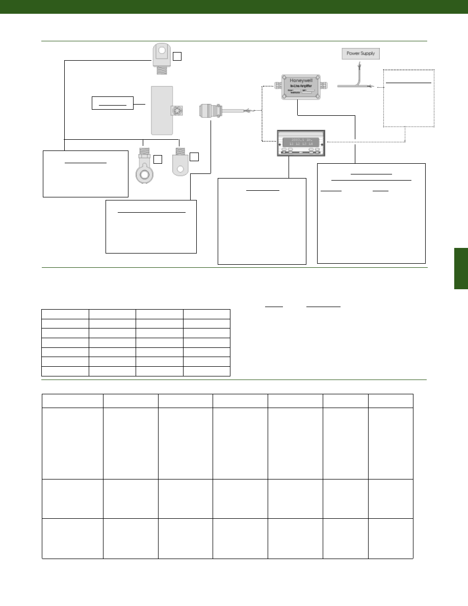
247
www.honeywell.com/sensotec
1
2
3
Mating Connectors & Cables
PT06A-10-6S
MS3106A-14S-6S
PT06E-10-6S
In-Line Amplifiers
(Used with unamplified units only)
Amplifier
Output
Universal In-Line Amplifiers
UV
+/- 5 VDC
UV-10
+/- 10 VDC
UBP
0 +/- 5 VDC
U3W
4-20 mA (3 wire)
U2W
4-20 mA (2 wire)
DIN rail Mount In-Line Amplifiers
DV-05
0 +/- 5 VDC (3 wire)
DA-05
4-20 mA (3 wire)
DV-10
0 +/- 10 VDC (3 wire)
Customer Supplied
Chart Recorder
Alarm Panel
Data Acquisition
Computer
PLC
Mounting Options
1.
Tongue Shackle Male
2.
Rod End Bearing Male
3.
Yoke Shackle Male
Model RGF
1-888-282-9891
Model RGF
Deflections and Ringing Frequencies
Capacity (lb.)
Deflection
@ Full Scale
(in.)
Ringing
Frequency
(Hz)
Weight
(lb)
2000
0.001
10,000
1.2
3000
0.001
12,000
1.2
5000
0.002
15,000
1.4
10,000
0.002
10,000
2.9
15,000
0.002
10,000
2.9
25,000
0.002
6,500
9.5
50,000
0.003
7,000
9.9
Typical System Diagram
Range
Range Code
2000 lb.
DJ
3000 lb.
DN
5000 lb.
DR
10,000 lb.
DV
15,000 lb.
EJ
25,000 lb.
EM
50,000 lb.
EP
Range Codes
Internal Amplifiers
Display Units
SC500
SC1000
SC2000
SC2001
SC3004
GM (Unamplified only)
GM-A (Amplified only)
NK (Unamplified only)
HH (Unamplified only)
Amplifier
Specifications
Voltage Output
Option 2b
Voltage Output
Option 2c
Voltage Output
Option 2t
Current 3 Wire
Option 2j
Current 2 Wire
Option 2k
Intrinsically Safe
Option 2n (2N)***
Output Signal
Input Power (Voltage)
Input Power (Current)
Frequency Response
Power Supply
Rejection
Operating Temperature
Reverse Voltage
Protection
Short Circuit Protection
+/- 5V
+/-15V or 26-32VDC
45 mA
3000 Hz
60 db
-20° to 185° F
Yes
Momentary
0-5V or +/- 5V
@ 45mA
11-28 VDC
40 mA
3000 Hz
60 db
-20° to 185° F
Yes
Momentary
0-10V or +/- 10V
@ 45mA
15-28 VDC
40 mA
3000 Hz
60 db
-20° to 185° F
Yes
Momentary
4-20 mA
22-32 VDC
65 mA
2500 Hz
60 db
0° to 185° F
Yes
Yes
4-20 mA
15-40 VDC
4-28 mA
300 Hz
60 db
0° to 185° F
Yes
Yes
4-20 mA
9-28 VDC
4-24 mA
2000 Hz
60 db
-20° to 185° F
Yes
Yes
Wiring Code: Connector
(Std.)
(note 4)
A (+) Supply
B Output Common/
C Supply Return
D (+) Output
E Shunt Cal 1
F Shunt Cal 2
A (+) Supply
B** Output Common/
C** Supply Return
D (+) Output
E Shunt Cal 1
F Shunt Cal 2
A (+) Supply
B** Output Common/
C** Supply Return
D (+) Output
E Shunt Cal 1
F Shunt Cal 2
A (+) Supply
B** Output Common/
C** Supply Return
D (+) Output
E Shunt Cal 1
F Shunt Cal 2
A (+) Supply
B No connection
C No connection
D (+) Output
E Case Ground
F No connection
A (+) Supply
B No connection
C No connection
D (+) Output
E Case Ground
F No connection
Wiring Code: Cable
(note 4)
(note 5)
(note 6)
R (+) Supply
Bl Output Common/
G Supply Return
W (+) Output
B Shunt Cal 1
Br Shunt Cal 2
R (+) Supply
Bl*Output Common/
G*Supply Return
W (+) Output
B Shunt Cal 1
Br Shunt Cal 2
R (+) Supply
Bl*Output Common/
G*Supply Return
W (+) Output
B Shunt Cal 1
Br Shunt Cal 2
R (+) Supply
Bl*Output Common/
G*Supply Return
W (+) Output
B Shunt Cal 1
Br Shunt Cal 2
R (+) Supply
Bl (+) Output
W Case Ground
R (+) Supply
Bl (+) Output
W Case Ground
* Black and Green wires are internally connected.
** Pins B and C are internally connected.
*** See Sensotec website for most up-to-date information regarding Intrinsically Safe approvals ref. #008-0547-00.
Courtesy of Steven Engineering, Inc.-230 Ryan Way, South San Francisco, CA 94080-6370-Main Office: (650) 588-9200-Outside Local Area: (800) 258-9200-www.stevenengineering.com
Sensotec Sensors Full Line Catalog-html.html
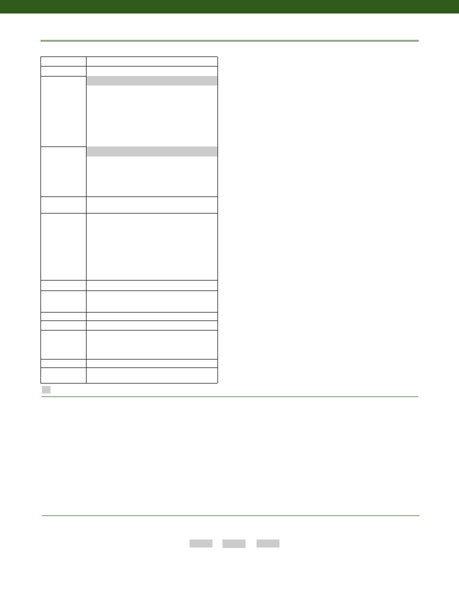
248
www.honeywell.com/sensotec
1-888-282-9891
Model RGF
How to Order
Combine the order code, the range code and the options code.
Order Code
Range Code
Options Code
Sample Code: AL428
DV 6i
Cable Orientation
Different Cable Lengths
Different Electrical Connectors
Different Materials
Different Threads
Dual Bridge
ESD
Fatigue Rating
High Resistance Bridges
Lightning Protection
OEM Labels
Enhanced Operational Temp
Radiation Resistant
Special Electrical O/P
Special TC
Special Customer
Requirements
(Consult Factory)
Options
Notes
Supplied as standard
Build from Scratch
Load Range
2k, 3k, 4k, 5k, 10k, 15k, 25k, 50k lbs.
Temperature
Compensation
1b. 30° to 130° F
1c. 0° to 185° F
1d. -20° to 130° F
1e. -20° to 200° F
1f. 70° to 250° F
1g. 70° to 325° F
1h. 70° to 400° F
1i. -65° to 250° F
1j. 0° to 50° C
1k. -20° to 85° C
1m. -25° to 110° C
Internal Amplifiers
2b. 4 wire +/- 5VDC output
2c. 0-5VDC
2j. 4-20mA (3-wire) output
2k. 4-20mA (2-wire)
2t. 0-10 VDC output
2n (2N). 4-20mA (2-wire) Intrinsically safe
Internal Amp
Enhancements
3a. Input/ Output Isolation (note 7)
3d. Remote Buffered Shunt Calibration
Electrical
Termination
6b. MS type connector mates with MS3106- 14S 6 pin
(max. 160°F)
6e. Integral cable: Teflon
6f. Integral cable: PVC
6g. Integral cable: Neoprene
6h. Integral cable: Silicone
6i. Integral underwater cable
6j. 1/2-14 conduit fitting with 5 ft. of 4 conductor
PVC cable
6q. Molded Integral cable: Polyurethane
6v. Phoenix connector on end of cable
Shunt Calibration 8a. Precision Internal Resistor (note 8)
Bridge Type
11a.Square Bridge
11c. Square and Symmetrical Bridge
31a.Dual bridge
Bridge Resistance 12b.5,000 Ohms (foil) (max. 250°F)
Potentiometers
14a.No access to pots
Electrical
Connector
Orientation
15a.Horizontal Electrical Exit Port Orientation
15b.Vertical Electrical Exit Port Orientation
15c. Radial Electrical Exit Port Orientation
15d.Connector on end of cable
Shock & Vibration 44a.Shock and vibration resistance
Interfaces
53e.Signature Calibration
53t. T.E.D.S. IEEE 1451-4 Module (note 9)
2u. Unamplified, mV/V output
1a. 60° to 160° F
1. Allowable Maximum Loads- Maximum load to be applied without damage (note 2).
2. Without Damage- loading to this level will not cause excessive zero shift or performance degradation. The user must consider fatigue life for long term
use and structural integrity. All structurally critical applications (overhead loading, etc.) should always be designed with safety redundant load paths.
3. Interconnecting shunt cal. 1 terminal with shunt cal. 2 terminal provides 50% (unamplified units), 75% (4-20mA 3-wire units) or 80% (voltage amplified
units) of full scale output for quick calibration. Shunt Calibration comes standard with internal amplifier options 2a, 2b, 2c, 2t and 2j.
4. O=Orange; Y=Yellow; B=Blue; Bl=Black; R=Red; Br=Brown; W=White; G=Green. Color specifying cable and number or letter specifying connector.
5. No mating connector necessary for cable option.
6. Not available with options 1c, 1e or 1f.
7. Only available with options 2b or 2c.
8. Not available with amplified options.
9. Consult factory for TEDS availability with amplified models.
Courtesy of Steven Engineering, Inc.-230 Ryan Way, South San Francisco, CA 94080-6370-Main Office: (650) 588-9200-Outside Local Area: (800) 258-9200-www.stevenengineering.com
Sensotec Sensors Full Line Catalog-html.html
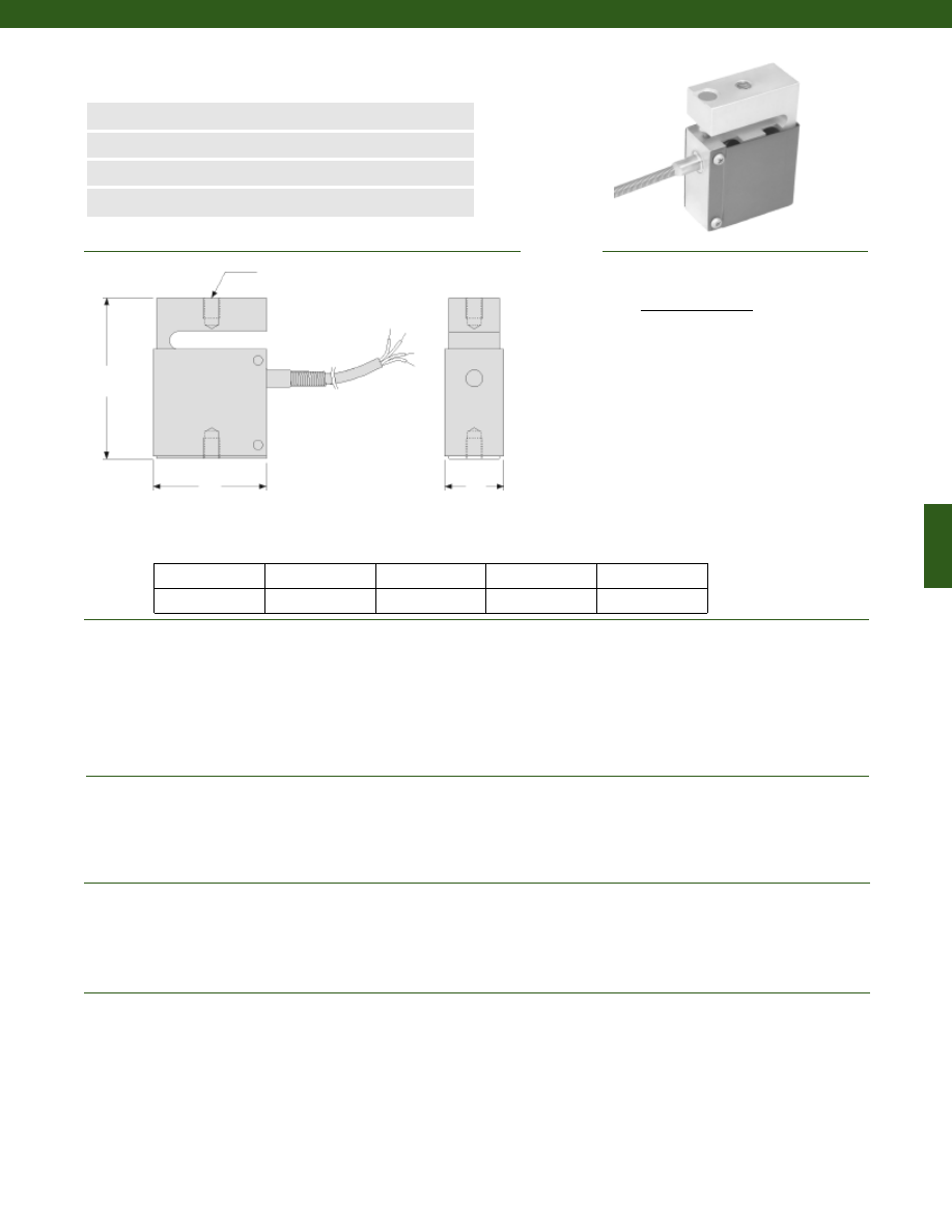
249
Dimensions
Performance
Environmental
Electrical
Mechanical
www.honeywell.com/sensotec
n
5 to 250 lb.
n
Compact Size
n
0.05% Linearity
n
Enhanced Precision
2X Thread
A
B
H
Load Ranges................5; 10; 25; 50; 100; 250 lb.
Linearity (max)................+/- 0.05% Full Scale
Hysteresis................+/- 0.03% Full Scale
Non-Repeatability................+/- 0.02% Full Scale
Output (tolerance)
5 lb.................2 mV/V +/- 1%
10 to 250 lb.................3 mV/V +/- 1%
Operation................Tension
Resolution................Infinite
Temperature, Operating................0° to 130° F
Temperature, Compensated................30° to 130° F
Storage Temperature................-100° to 200° F
Temperature, Effect
Zero................0.001% Full Scale/° F
Span................0.0008% Full Scale/° F
Strain Gage Type................Bonded Foil
Excitation (calibration)................10 VDC
Bridge Resistance (tolerance)................350 Ohms (nominal)
Zero Balance (tolerance)................1% Full Scale Max.
Shunt Calibration................Included
Electrical Termination (std)................Cable (5 ft.)
Maximum Allowable Load................150% F.S. (note 1)
Weight................0.3 lb.
Material................Aluminum
Range (lb.) H (in.) A (in.) B (in.) Thread
Model 81 Precision Tension Load Cell
Order Code BL433
5; 10; 25; 50; 100
2.38
1.7
0.9
1/4-28 UNF
250
2.75
1.7
0.9
3/8-24 UNF
1-888-282-9891
4 Conductor, 30 AWG,
Teflon Insulated, Shielded
Cable, 5 ft. Long with 2”
Spring Strain Relief
Wiring Code
Cable/ Unamplified
Red
(+) Excitation
Black
(-) Excitation
Green
(-) Output
White
(+) Output
Courtesy of Steven Engineering, Inc.-230 Ryan Way, South San Francisco, CA 94080-6370-Main Office: (650) 588-9200-Outside Local Area: (800) 258-9200-www.stevenengineering.com
Sensotec Sensors Full Line Catalog-html.html
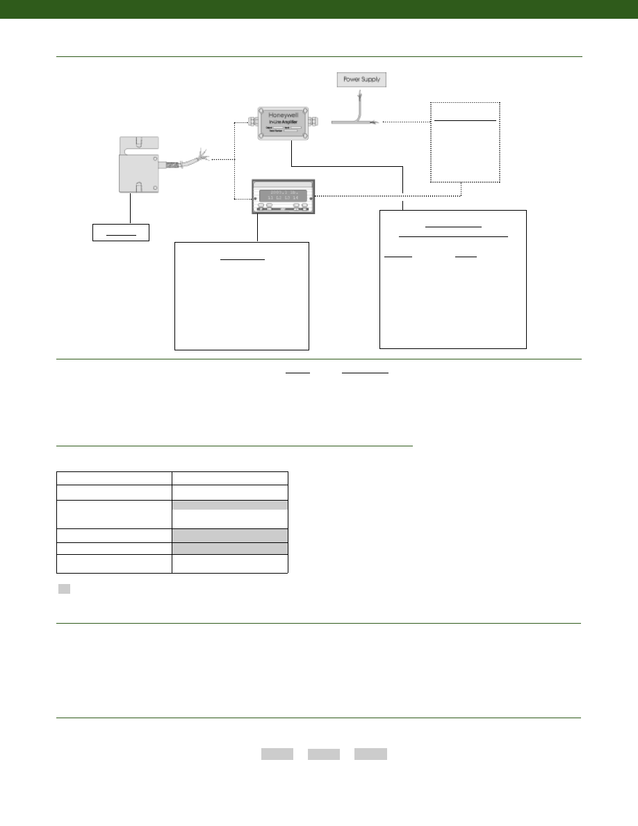
250
In-Line Amplifiers
(Used with unamplified units only)
Amplifier
Output
Universal In-Line Amplifiers
UV
+/- 5 VDC
UV-10
+/- 10 VDC
UBP
0 +/- 5 VDC
U3W
4-20 mA (3 wire)
DIN rail Mount In-Line Amplifiers
DV-05
0 +/- 5 VDC (3 wire)
DA-05
4-20 mA (3 wire)
DV-10
0 +/- 10 VDC (3 wire)
Customer Supplied
Chart Recorder
Alarm Panel
Data Acquisition
Computer
PLC
Model 81
www.honeywell.com/sensotec
Typical System Diagram
1-888-282-9891
Model 81
Range
Range Code
5 lb.
AT
10 lb.
AV
25 lb.
BL
50 lb.
BN
100 lb.
BR
250 lb.
CN
Range Codes
Build from Scratch
Load Range
5, 10, 25, 50, 100, 250 lbs.
Temperature
Compensation
1d. -20° to 130° F
Internal Amplifiers
2u. Unamplified, mV/V output
Electrical Termination
Cable (5 ft.)
Shock & Vibration
44a. Shock & vibration resistance
1b. 30° to 130° F
Options
Supplied as standard
1. Allowable Maximum Loads- Maximum load to be applied without damage (note 2).
2. Without Damage- loading to this level will not cause excessive zero shift or performance degradation. The user must consider fatigue life for long term use and structural integrity. All
structurally critical applications (overhead loading, etc.) should always be designed with safety redundant load paths.
Notes
How to Order
Combine the order code, the range code and the options code.
Order Code
Range Code
Options Code
Sample Code:
BL433
AT
1d
Display Units
SC500
SC1000
SC2000
SC2001
SC3004
GM
NK
HH
Courtesy of Steven Engineering, Inc.-230 Ryan Way, South San Francisco, CA 94080-6370-Main Office: (650) 588-9200-Outside Local Area: (800) 258-9200-www.stevenengineering.com
Sensotec Sensors Full Line Catalog-html.html
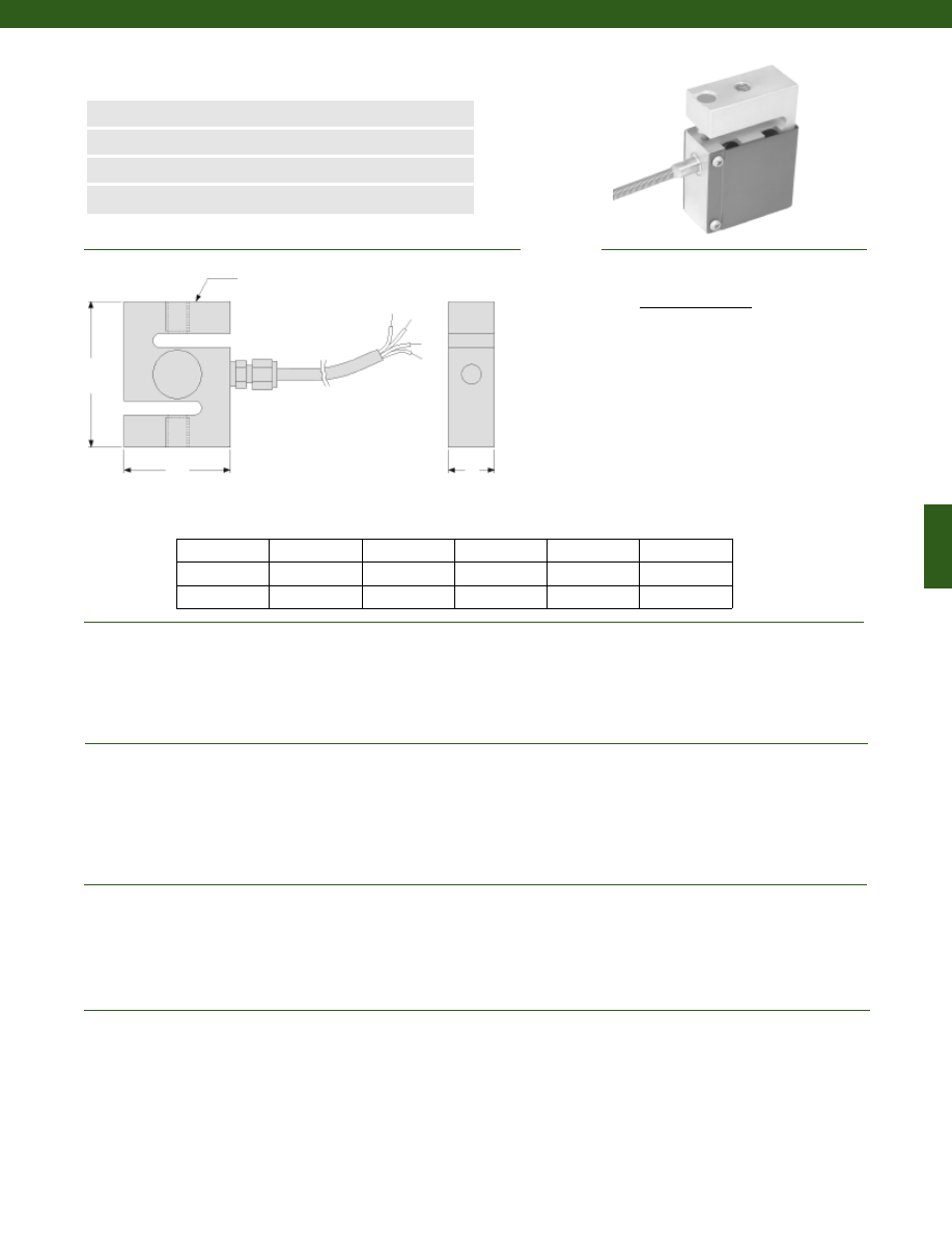
251
Dimensions
Performance
Environmental
Electrical
Mechanical
www.honeywell.com/sensotec
n
100 to 10,000 lb.
n
Compact Size
n
Enhanced Precision
n
0.03% Linearity
Load Ranges................100; 250; 500; 1,000; 2,000; 3,000; 5,000; 10,000 lb.
Linearity (max)................+/- 0.03% Full Scale
Hysteresis................+/- 0.02% Full Scale
Non-Repeatability................+/- 0.01% Full Scale
Output (tolerance)................2 mV/V (nominal)
Operation................Tension
Resolution................Infinite
Temperature, Operating................0° to 130° F
Temperature, Compensated................30° to 130° F
Storage Temperature
100 lb.; 250 lb.................-100° to 150° F
500 to 10,000 lb.................-100° to 250° F
Temperature, Effect
Zero................0.001% Full Scale/° F
Span................0.0008% Full Scale/° F
Strain Gage Type................Bonded Foil
Excitation (calibration)................10 VDC
Insulation Resistance................5,000 Megohms @ 50 VDC
Bridge Resistance (tolerance)................350 Ohms
Zero Balance (tolerance)................+/- 1% Full Scale
Shunt Calibration Data................Included
Electrical Termination (std)................Cable (5 ft.)
Maximum Allowable Load................150% F.S. (note 1)
Weight................See table
Material
100 to 250 lb.................Aluminum
5000 to 10,000 lb.................Stainless Steel
Range (lb.) H (in.) A (in.) B (in.) Thread Weight (lb.)
Model 82 Precision Tension Load Cell
Order Code BL434
2X Thread
A
B
H
1-888-282-9891
100 to 250
3.00
2.00
1.00
1/4-28 UNF
1.5
500 to 3,000
3.00
2.19
0.94
1/2-20 UNF
1.5
5,000
3.75
2.25
1.00
3/4-16 UNF
2.0
Wiring Code
Cable/ Unamplified
Red
(+) Excitation
Black
(-) Excitation
Green
(-) Output
White
(+) Output
*Housing shown not included with Model 82
Courtesy of Steven Engineering, Inc.-230 Ryan Way, South San Francisco, CA 94080-6370-Main Office: (650) 588-9200-Outside Local Area: (800) 258-9200-www.stevenengineering.com
Sensotec Sensors Full Line Catalog-html.html
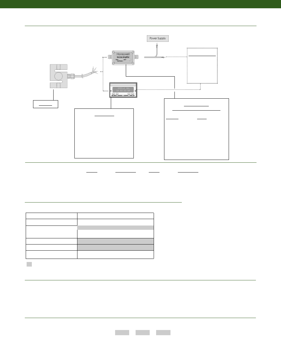
252
Customer Supplied
Chart Recorder
Alarm Panel
Data Acquisition
Computer
PLC
Model 82
www.honeywell.com/sensotec
Typical System Diagram
1-888-282-9891
Model 82
Range
Range Code
100 lb.
BR
250 lb.
CN
500 lb.
CR
1000 lb.
CV
Range
Range Code
2000 lb.
DL
3000 lb.
DN
5000 lb.
DR
10,000 lb.
DV
Range Codes
Options
Supplied as standard
1. Allowable Maximum Loads- Maximum load to be applied without damage (note 2).
2. Without Damage- loading to this level will not cause excessive zero shift or performance degradation. The
user must consider fatigue life for long term use and structural integrity. All structurally critical applications
(overhead loading, etc.) should always be designed with safety redundant load paths.
Notes
How to Order
Combine the order code, the range code and the options code.
Order Code
Range Code
Options Code
Sample Code:
BL434
DV
44a
In-Line Amplifiers
(Used with unamplified units only)
Amplifier
Output
Universal In-Line Amplifiers
UV
+/- 5 VDC
UV-10
+/- 10 VDC
UBP
0 +/- 5 VDC
U3W
4-20 mA (3 wire)
DIN rail Mount In-Line Amplifiers
DV-05
0 +/- 5 VDC (3 wire)
DA-05
4-20 mA (3 wire)
DV-10
0 +/- 10 VDC (3 wire)
Build from Scratch
Load Range
100, 250, 500, 1000, 2000, 3000, 5000, 10,000 lbs.
Temperature
Compensation
1d. -20° to 130° F
Internal Amplifiers
2u. Unamplified, mV/V output
Electrical Termination
Cable (5 ft.)
Shock & Vibration
44a. Shock & vibration resistance
1b. 30° to 130° F
Display Units
SC500
SC1000
SC2000
SC2001
SC3004
GM
NK
HH
Courtesy of Steven Engineering, Inc.-230 Ryan Way, South San Francisco, CA 94080-6370-Main Office: (650) 588-9200-Outside Local Area: (800) 258-9200-www.stevenengineering.com
Sensotec Sensors Full Line Catalog-html.html
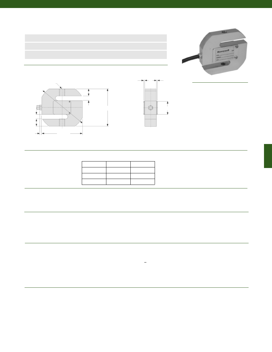
253
www.honeywell.com/sensotec
n
Low Cost
n
20 to 1,000 kg Range
n
+/- 0.02% Accuracy
Model 102 Load Cell
Order Code BL804
Wiring Code
1-888-282-9891
Red
(+) Supply
Black
(-) Supply
Green
(+) Output
White
(-) Output
Large Black Shield
Dimensions
Performance
Environmental
Electrical
Mechanical
8 mm
8 mm
70 mm
L
2 mm
2 mm
........20; 50; 100; 200; 300; 500; 1,000 kg
........+/- 0.02% Full Scale
........2.0 mV/V
........+/- 0.02% Full Scale (30 minute)
........-30° to 70° C
........-20° to 55° C
........+/- 0.02% Full Scale/ 10° C
........+/- 0.02% Full Scale/ 10° C
........IP67
........ Bonded Foil
........10-12 VDC
........15 VDC
........> 5000 Megohms
........400 +/- 10 Ohms (nominal)
........352 +/- 2 Ohms (nominal)
........+/- 1% Full Scale
........3m flying leads
........150% F.S. (note 1)
........Nickel Plated Alloy Steel or Stainless Steel
........Less than or equal to 0.5mm
Load Ranges
Accuracy
Output
Creep (max.)
Temperature, Operating
Temperature, Compensated
Temperature, Effect
Zero
Span
Protection Class
Strain Gage Type
Excitation (acceptable)
Excitation (max.)
Insulation Resistance
Bridge Resistance (tolerance)
Input Resistance
Output Resistance
Zero Balance (tolerance)
Electrical Termination (std)
Maximum Allowable Load
Material
Deflection
2xøD
24 mm
12 mm
76 mm
12 mm
3.5 mm
64 mm
Load (kg)
D (thread)
L (mm)
20 - 150
M8x1.25
12
200 - 500
M12x1.75
20
700 - 1000
M12x1.75
25
Courtesy of Steven Engineering, Inc.-230 Ryan Way, South San Francisco, CA 94080-6370-Main Office: (650) 588-9200-Outside Local Area: (800) 258-9200-www.stevenengineering.com
Sensotec Sensors Full Line Catalog-html.html
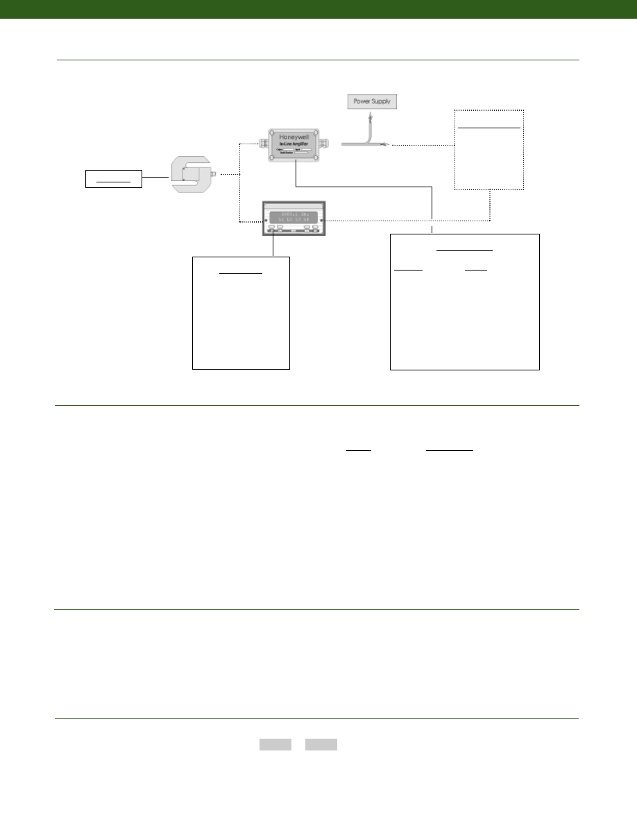
254
Typical System Diagram
www.honeywell.com/sensotec
Range
Range Code
20 kg
LD
30 kg
LE
50 kg
LF
75 kg
LG
100 kg
LH
150 kg
LJ
200 kg
LK
250 kg
LL
300 kg
LM
500 kg
LN
1000 kg
LQ
Range Codes
1-888-282-9891
In-Line Amplifiers
Amplifier
Output
Universal In-Line Amplifiers
UV
+/- 5 VDC
UV-10
+/- 10 VDC
UBP
0 +/- 5 VDC
U3W
4-20 mA (3 wire)
DIN rail Mount In-Line Amplifiers
DV-05
0 +/- 5 VDC (3 wire)
DA-05
4-20 mA (3 wire)
DV-10
0 +/- 10 VDC (3 wire)
Customer Supplied
Chart Recorder
Alarm Panel
Data Acquisition
Computer
PLC
Model 102
How to Order
Combine the order code and the range code.
Order Code
Range Code
Sample Code:
BL804
LD
1. Allowable Maximum Loads- Maximum load to be applied without damage (note 2).
2. Without Damage- loading to this level will not cause excessive zero shift or performance degradation. The user
must consider fatigue life for long term use and structural integrity. All structurally critical applications (overhead
loading, etc.) should always be designed with safety redundant load paths.
Notes
Display Units
SC500
SC1000
SC2000
SC2001
SC3004
GM
NK
HH
Model 102
Courtesy of Steven Engineering, Inc.-230 Ryan Way, South San Francisco, CA 94080-6370-Main Office: (650) 588-9200-Outside Local Area: (800) 258-9200-www.stevenengineering.com
Sensotec Sensors Full Line Catalog-html.html
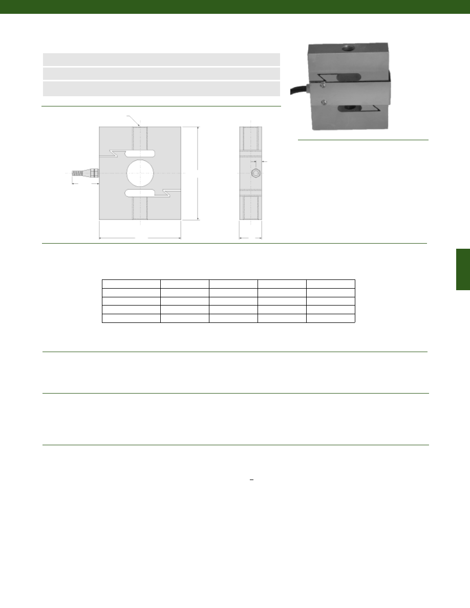
255
www.honeywell.com/sensotec
n
Low Cost
n
1,000 to 20,000 kg Range
n
+/- 0.03% Accuracy
Model 123 Load Cell
Order Code BL810
1-888-282-9891
Wiring Code
Red
(+) Supply
Black
(-) Supply
Green
(+) Output
White
(-) Output
Large Black Shield
Dimensions
Performance
Environmental
Electrical
C
D
42 mm
7 mm
A
........1,000 to 20,000 kg
........+/- 0.03% Full Scale
........2.0 mV/V
........+/- 0.03% Full Scale (30 minutes)
........-30° to 70° C
........-20° to 55° C
........+/- 0.03% Full Scale/ 10° C
........+/- 0.03% Full Scale/ 10° C
........IP67 (note 3)
........Foil
........10-12 VDC
........15 VDC
........> 5,000 Megohms
........400 +/- 10 Ohms (nominal)
........352 +/- 2 Ohms (nominal)
........+/- 1% Full Scale
........6m of 5mm diameter cable
Load Ranges
Accuracy
Output
Creep (max.)
Temperature, Operating
Temperature, Compensated
Temperature, Effect
Zero
Span
Protection Class
Strain Gage Type
Excitation (acceptable)
Excitation (max.)
Insulation Resistance
Bridge Resistance (tolerance)
Input Resistance
Output Resistance
Zero Balance (tolerance)
Electrical Termination (std)
B
Range (kg)
A (mm)
B (mm)
C (mm)
D
1,000; 1,500
80
70
25
M12x1.75
2,000; 3,000; 5,000
108
95
25
M18x1.5
7,500; 10,000
178
130
51
M30x2
15,000; 20,000
190
160
60
M39x2
Courtesy of Steven Engineering, Inc.-230 Ryan Way, South San Francisco, CA 94080-6370-Main Office: (650) 588-9200-Outside Local Area: (800) 258-9200-www.stevenengineering.com
Sensotec Sensors Full Line Catalog-html.html
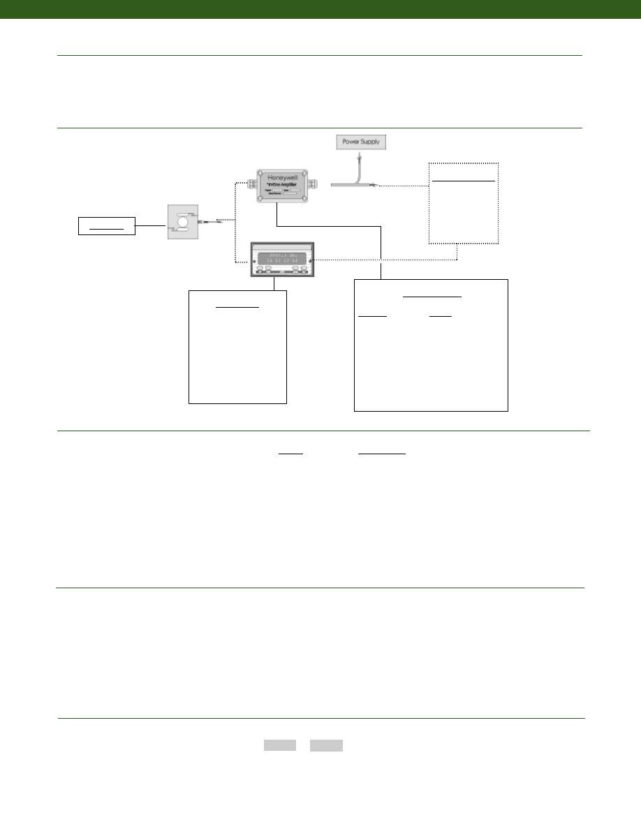
256
Mechanical
Typical System Diagram
www.honeywell.com/sensotec
Range Codes
1-888-282-9891
In-Line Amplifiers
Amplifier
Output
Universal In-Line Amplifiers
UV
+/- 5 VDC
UV-10
+/- 10 VDC
UBP
0 +/- 5 VDC
U3W
4-20 mA (3 wire)
DIN rail Mount In-Line Amplifiers
DV-05
0 +/- 5 VDC (3 wire)
DA-05
4-20 mA (3 wire)
DV-10
0 +/- 10 VDC (3 wire)
Customer Supplied
Chart Recorder
Alarm Panel
Data Acquisition
Computer
PLC
Model 123
Range
Range Code
1,000 kg
LQ
1,500 kg
LR
2,000 kg
LS
3,000 kg
LT
5,000 kg
LU
7,500 kg
LV
10,000 kg
LW
15,000 kg
LY
20,000 kg
LZ
How to Order
Combine the order code and the range code.
Order Code
Range Code
Sample Code:
BL810
LR
1. Allowable Maximum Loads- Maximum load to be applied without damage (note 2).
2. Without Damage- loading to this level will not cause excessive zero shift or performance degradation. The user
must consider fatigue life for long term use and structural integrity. All structurally critical applications (overhead
loading, etc.) should always be designed with safety redundant load paths.
3. IP68 rating for load ranges 7,500 kg and greater.
Notes
Maximum Allowable Load
Later Load Limit
Material
........120% F.S. (note 1)
........100% F.S.
........Nickel Plated Alloy Steel
Display Units
SC500
SC1000
SC2000
SC2001
SC3004
GM
NK
HH
Model 123
Courtesy of Steven Engineering, Inc.-230 Ryan Way, South San Francisco, CA 94080-6370-Main Office: (650) 588-9200-Outside Local Area: (800) 258-9200-www.stevenengineering.com
Sensotec Sensors Full Line Catalog-html.html
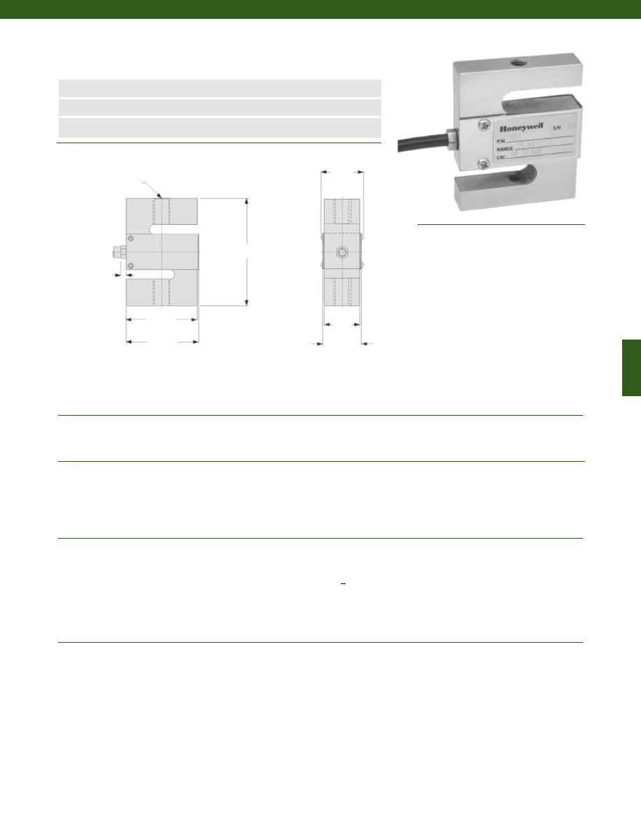
257
www.honeywell.com/sensotec
n
Low Cost
n
50 kg; 100 kg Range
n
0.03% Accuracy
Model 127 Load Cell
Order Code BL807
Wiring Code
1-888-282-9891
Red
(+) Supply
Black
(-) Supply
Green
(+) Output
White
(-) Output
Large Black Shield
12.4 mm
63.5 mm
51 mm
52 mm
........50; 100kg
........+/- 0.03% Full Scale
........3.0 mV/V
........+/- 0.03% Full Scale (30 minutes)
........-30° to 70° C
........-20° to 55° C
........+/- 0.03% Full Scale/ 10° C
........+/- 0.03% Full Scale/ 10° C
........IP67
........Bonded Foil
........10-12 VDC
........15 VDC
........> 5000 Megohms
........400 +/- 10 Ohms
........352 +/- 2 Ohms
........+/- 1% Full Scale
........5m flying leads
........150% F.S. (note 1)
........Nickel Plated Alloy Steel
Load Ranges
Accuracy
Output
Creep (max.)
Temperature, Operating
Temperature, Compensated
Temperature, Effect
Zero
Span
Environmental Protection
Strain Gage Type
Excitation (calibration)
Excitation (max.)
Insulation Resistance
Bridge Resistance (tolerance)
Input Resistance
Output Resistance
Zero Balance (tolerance)
Electrical Termination (std)
Maximum Allowable Load
Case Material
2xM6x1.0
3.5 mm
Dimensions
Performance
Environmental
Electrical
Mechanical
19.5mm
14.5 mm
Courtesy of Steven Engineering, Inc.-230 Ryan Way, South San Francisco, CA 94080-6370-Main Office: (650) 588-9200-Outside Local Area: (800) 258-9200-www.stevenengineering.com
Sensotec Sensors Full Line Catalog-html.html
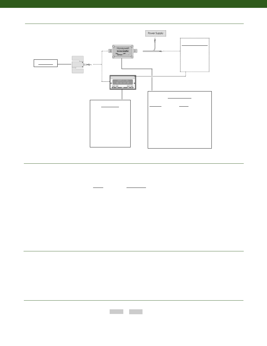
258
Typical System Diagram
www.honeywell.com/sensotec
Range Codes
1-888-282-9891
In-Line Amplifiers
Amplifier
Output
Universal In-Line Amplifiers
UV
+/- 5 VDC
UV-10
+/- 10 VDC
UBP
0 +/- 5 VDC
U3W
4-20 mA (3 wire)
DIN rail Mount In-Line Amplifiers
DV-05
0 +/- 5 VDC (3 wire)
DA-05
4-20 mA (3 wire)
DV-10
0 +/- 10 VDC (3 wire)
Customer Supplied
Chart Recorder
Alarm Panel
Data Acquisition
Computer
PLC
Model 127
Range
Range Code
50 kg
LF
100 kg
LH
How to Order
Combine the order code and the range code.
Order Code
Range Code
Sample Code:
BD807
LH
1. Allowable Maximum Loads- Maximum load to be applied without damage (note 2).
2. Without Damage- loading to this level will not cause excessive zero shift or performance degradation. The user
must consider fatigue life for long term use and structural integrity. All structurally critical applications (overhead
loading, etc.) should always be designed with safety redundant load paths.
Notes
Display Units
SC500
SC1000
SC2000
SC2001
SC3004
GM
NK
HH
Model 127
Courtesy of Steven Engineering, Inc.-230 Ryan Way, South San Francisco, CA 94080-6370-Main Office: (650) 588-9200-Outside Local Area: (800) 258-9200-www.stevenengineering.com
Sensotec Sensors Full Line Catalog-html.html
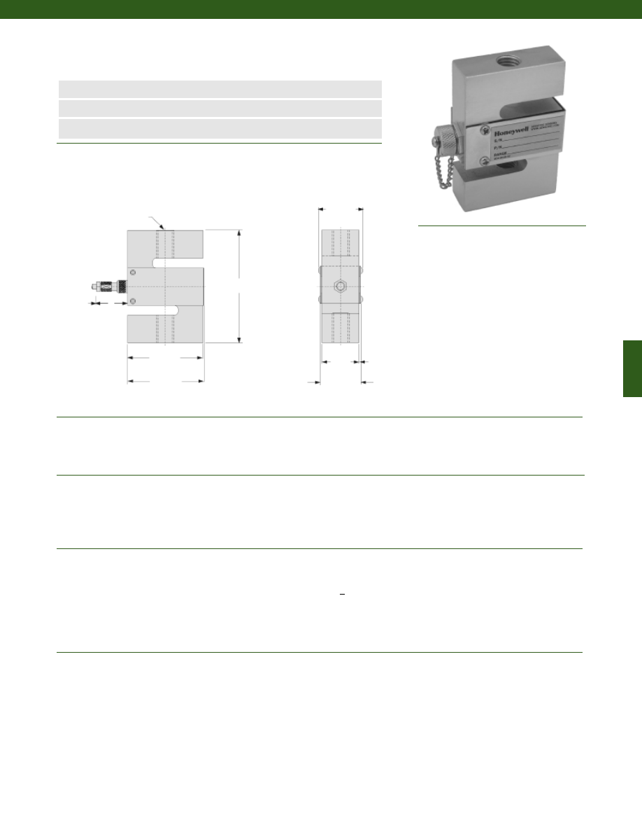
259
www.honeywell.com/sensotec
n
Low Cost
n
100 to 500 kg Range
n
0.02% Accuracy
Model 125 Load Cell
Order Code BL811
Wiring Code
(for mating cable, included)
1-888-282-9891
Red
(+) Supply
Black
(-) Supply
Green
(+) Output
White
(-) Output
Large Black Shield
........100; 200; 300; 500 kg
........+/- 0.02% Full Scale
........2.0 mV/V
........+/- 0.02% Full Scale (30 minutes)
........-30° to 70° C
........-20° to 55° C
........+/- 0.02% Full Scale/ 10° C
........+/- 0.02% Full Scale/ 10° C
........IP67
........Bonded Foil
........10-12 VDC
........15 VDC
........> 5000 Megohms
........400 +/- 10 Ohms
........352 +/- 2 Ohms
........+/- 1% Full Scale
........mating connector and 5m cable (included)
........150% F.S. (note 1)
........Nickel Plated Alloy Steel
Load Ranges
Accuracy
Output
Creep (max.)
Temperature, Operating
Temperature, Compensated
Temperature, Effect
Zero
Span
Environmental Protection
Strain Gage Type
Excitation (calibration)
Excitation (max.)
Insulation Resistance
Bridge Resistance (tolerance)
Input Resistance
Output Resistance
Zero Balance (tolerance)
Electrical Termination (std)
Maximum Allowable Load
Case Material
35 mm
19.1 mm
51 mm
52.1 mm
76.2 mm
2xM12x1.75
21.3 mm
26 mm
Dimensions
Performance
Environmental
Electrical
Mechanical
Courtesy of Steven Engineering, Inc.-230 Ryan Way, South San Francisco, CA 94080-6370-Main Office: (650) 588-9200-Outside Local Area: (800) 258-9200-www.stevenengineering.com
Sensotec Sensors Full Line Catalog-html.html
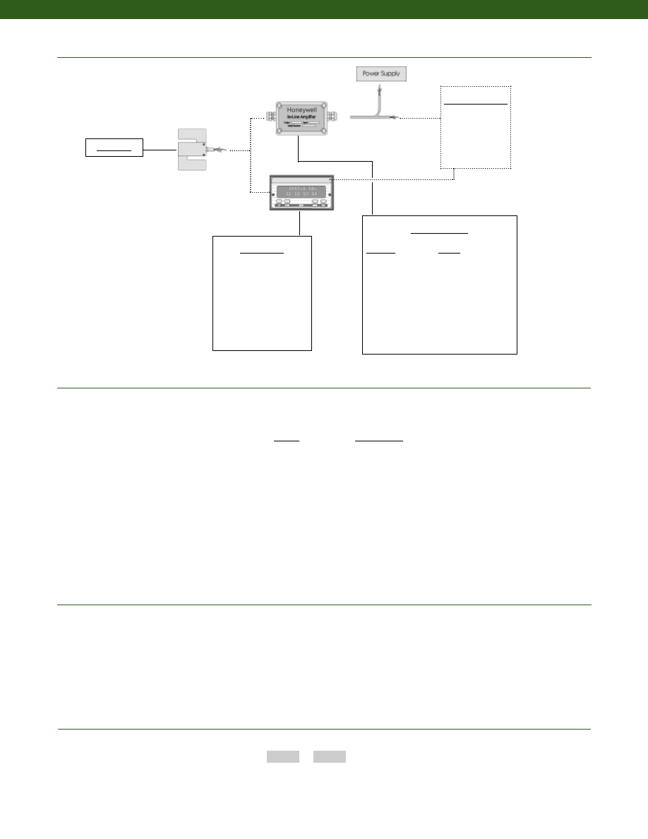
260
Typical System Diagram
www.honeywell.com/sensotec
Range Codes
1-888-282-9891
In-Line Amplifiers
Amplifier
Output
Universal In-Line Amplifiers
UV
+/- 5 VDC
UV-10
+/- 10 VDC
UBP
0 +/- 5 VDC
U3W
4-20 mA (3 wire)
DIN rail Mount In-Line Amplifiers
DV-05
0 +/- 5 VDC (3 wire)
DA-05
4-20 mA (3 wire)
DV-10
0 +/- 10 VDC (3 wire)
Customer Supplied
Chart Recorder
Alarm Panel
Data Acquisition
Computer
PLC
Model 125
Range
Range Code
100 kg
LH
200 kg
LK
300 kg
LM
500 kg
LN
How to Order
Combine the order code and the range code.
Order Code
Range Code
Sample Code:
BL811
LH
1. Allowable Maximum Loads- Maximum load to be applied without damage (note 2).
2. Without Damage- loading to this level will not cause excessive zero shift or performance degradation. The user
must consider fatigue life for long term use and structural integrity. All structurally critical applications (overhead
loading, etc.) should always be designed with safety redundant load paths.
Notes
Display Units
SC500
SC1000
SC2000
SC2001
SC3004
GM
NK
HH
Model 125
Courtesy of Steven Engineering, Inc.-230 Ryan Way, South San Francisco, CA 94080-6370-Main Office: (650) 588-9200-Outside Local Area: (800) 258-9200-www.stevenengineering.com
Sensotec Sensors Full Line Catalog-html.html
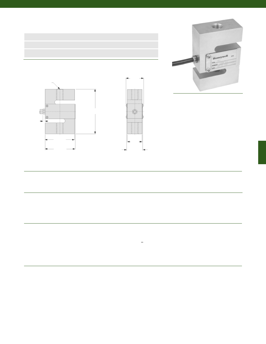
261
www.honeywell.com/sensotec
n
Low Cost
n
1000 to 5000 kg Range
n
0.02% Accuracy
Model 129 Load Cell
Order Code BL808
Wiring Code
1-888-282-9891
Red
(+) Supply
Black
(-) Supply
Green
(+) Output
White
(-) Output
Large Black Shield
Dimensions
Performance
Environmental
Electrical
Mechanical
19.1 mm
51 mm
52.1 mm
76.2 mm
........1000; 2000; 3000; 5000 kg
........+/- 0.02% Full Scale
........2.0 mV/V
........+/- 0.02% Full Scale (30 minutes)
........-30° to 70° C
........-20° to 55° C
........+/- 0.02% Full Scale/ 10° C
........+/- 0.02% Full Scale/ 10° C
........IP67
........Bonded Foil
........10-12 VDC
........15 VDC
........> 5000 Megohms
........400 +/- 10 Ohms
........352 +/- 2 Ohms
........+/- 1% Full Scale
........5m flying leads
........150% F.S. (note 1)
........Nickel Plated Alloy Steel
Load Ranges
Accuracy
Output
Creep
Temperature, Operating
Temperature, Compensated
Temperature, Effect
Zero
Span
Environmental Protection
Strain Gage Type
Excitation (calibration)
Excitation (max.)
Insulation Resistance
Bridge Resistance (tolerance)
Input Resistance
Output Resistance
Zero Balance (tolerance)
Electrical Termination (std)
Maximum Allowable Load
Case Material
2xM12x1.75
3.5 mm
21.3 mm
26 mm
Courtesy of Steven Engineering, Inc.-230 Ryan Way, South San Francisco, CA 94080-6370-Main Office: (650) 588-9200-Outside Local Area: (800) 258-9200-www.stevenengineering.com
Sensotec Sensors Full Line Catalog-html.html
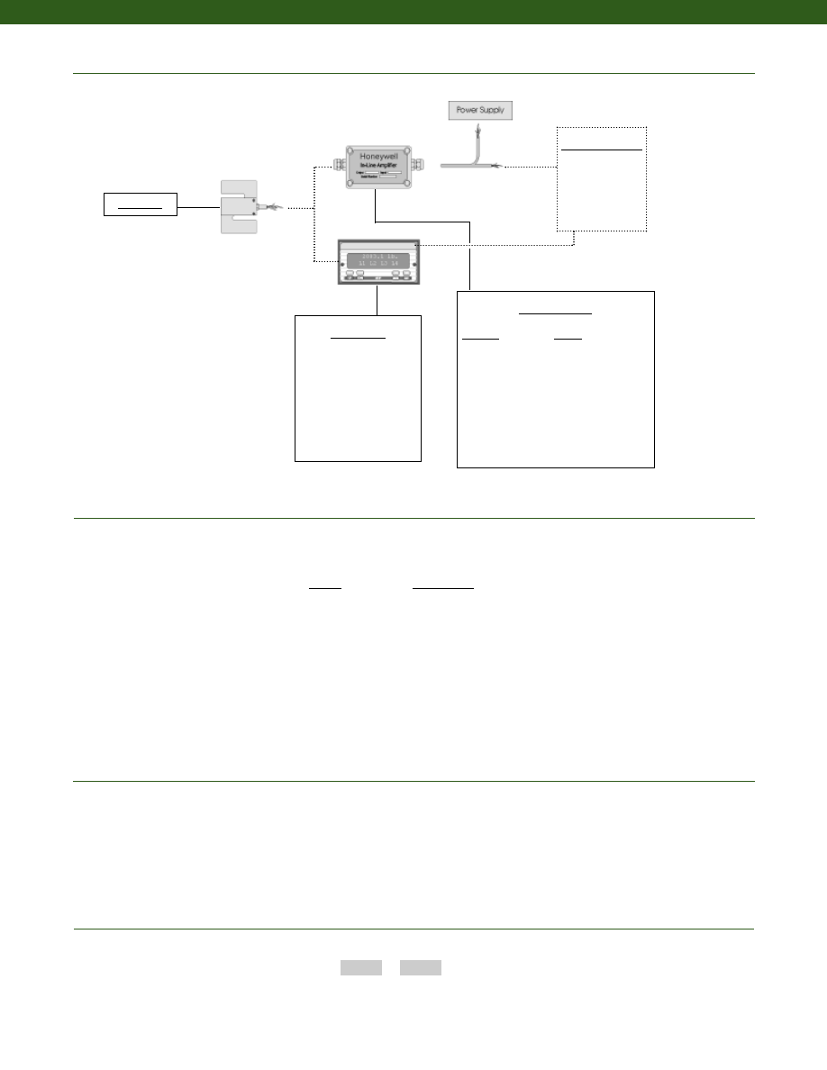
262
Typical System Diagram
www.honeywell.com/sensotec
Range Codes
1-888-282-9891
In-Line Amplifiers
Amplifier
Output
Universal In-Line Amplifiers
UV
+/- 5 VDC
UV-10
+/- 10 VDC
UBP
0 +/- 5 VDC
U3W
4-20 mA (3 wire)
U2W
4-20 mA (2 wire)
DIN rail Mount In-Line Amplifiers
DV-05
0 +/- 5 VDC (3 wire)
DA-05
4-20 mA (3 wire)
DV-10
0 +/- 10 VDC (3 wire)
Customer Supplied
Chart Recorder
Alarm Panel
Data Acquisition
Computer
PLC
Model 129
Range
Range Code
1000 kg
LQ
2000 kg
LS
3000 kg
LT
5000 kg
LU
How to Order
Combine the order code and the range code.
Order Code
Range Code
Sample Code:
BL808
LS
1. Allowable Maximum Loads- Maximum load to be applied without damage (note 2).
2. Without Damage- loading to this level will not cause excessive zero shift or performance degradation. The user
must consider fatigue life for long term use and structural integrity. All structurally critical applications (overhead
loading, etc.) should always be designed with safety redundant load paths.
Notes
Display Units
SC500
SC1000
SC2000
SC2001
SC3004
GM
NK
HH
Model 129
Courtesy of Steven Engineering, Inc.-230 Ryan Way, South San Francisco, CA 94080-6370-Main Office: (650) 588-9200-Outside Local Area: (800) 258-9200-www.stevenengineering.com
Sensotec Sensors Full Line Catalog-html.html
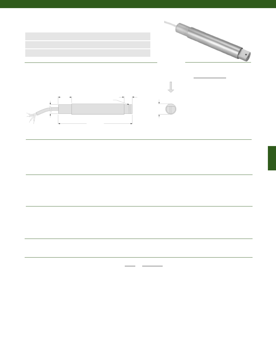
263
........25; 50; 100; 150; 250; 500; 1000 g
........+/- 0.1% Full Scale
........+/- 0.1% Full Scale
........+/- 0.03% Full Scale
........20 mV/V (nominal)
........Tension/ Compression (note 1)
........Infinite
........0° to 200° F
........60° to 160° F
........-100° to 200° F
........0.015% Full Scale/° F
........0.02% Full Scale/° F
........Bonded Semiconductor
........5 VDC
........5000 Megohms @ 50 VDC
........500 Ohms
........+/- 5% Full Scale
........Cable (5 ft.)
........400% F.S. (note 2)
........50 g
........Aluminum
Dimensions
Performance
Environmental
Electrical
Mechanical
Range Codes
www.honeywell.com/sensotec
n
25 to 1000 g
n
Miniature Size
n
0.1% Linearity
Load Ranges
Linearity (max.)
Hysteresis (max.)
Non-Repeatability (max.)
Output (tolerance)
Operation
Resolution
Temperature, Operating
Temperature, Compensated
Storage Temperature
Temperature, Effect
Zero
Span
Strain Gage Type
Excitation (calibration)
Insulation Resistance
Bridge Resistance
Zero Balance
Electrical Termination (std)
Maximum Allowable Load
Weight
Material
Model MBL Minigram Beam Load Cell
Order Code BL341
Wiring Code
Cable/ Unamplified
Red
(+) Excitation
Black
(-) Excitation
Green
(-) Output
White
(+) Output
1-888-282-9891
Range
Range Code
25 g AH
50 g AJ
100 g AK
150 g AL
250 g AN
500 g AP
1000 g AR
0.63
0.38
3.5 max.
ø0.43
ø0.062 Thru
ø0.50
Load Direction
Courtesy of Steven Engineering, Inc.-230 Ryan Way, South San Francisco, CA 94080-6370-Main Office: (650) 588-9200-Outside Local Area: (800) 258-9200-www.stevenengineering.com
Sensotec Sensors Full Line Catalog-html.html
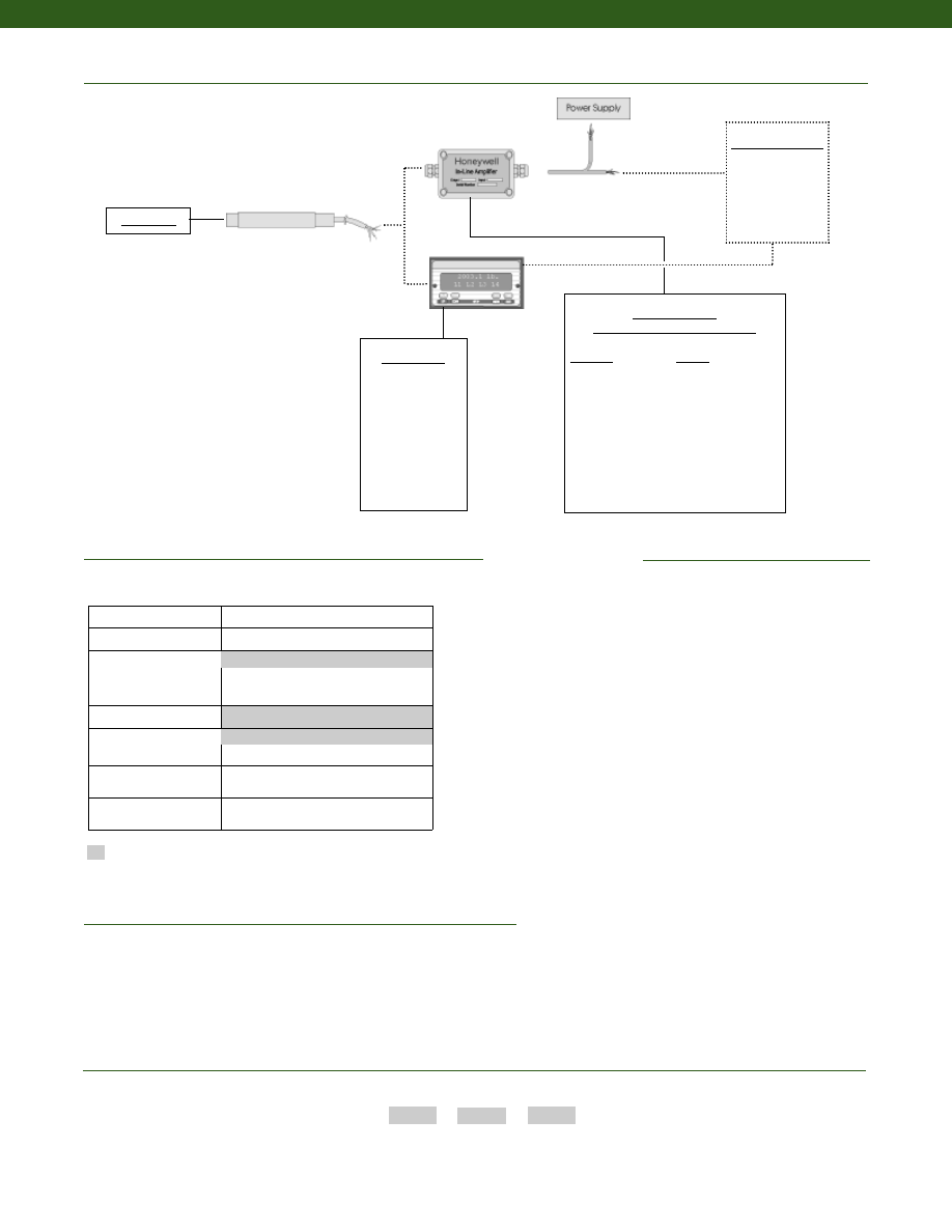
264
www.honeywell.com/sensotec
1-888-282-9891
Supplied as standard
Options
Typical System Diagram
Cable Orientation
Different Cable Lengths
Different Materials
ESD
OEM Labels
Radiation Resistant
Shock and Vibration Resistance
Special TC
Special Customer
Requirements
(Consult Factory)
How to Order
Combine the order code, the range code and the options code.
Order Code
Range Code
Options Code
Sample Code:
BL341
AH
1b
In-Line Amplifiers
(Used with unamplified units only)
Amplifier
Output
Universal In-Line Amplifiers
UV
+/- 5 VDC
UV-10
+/- 10 VDC
UBP
0 +/- 5 VDC
U3W
4-20 mA (3 wire)
DIN rail Mount In-Line Amplifiers
DV-05
0 +/- 5 VDC (3 wire)
DA-05
4-20 mA (3 wire)
DV-10
0 +/- 10 VDC (3 wire)
Display Units
SC500
SC1000
SC2000
SC2001
SC3004
GM
NK
HH
Customer Supplied
Chart Recorder
Alarm Panel
Data Acquisition
Computer
PLC
Model MBL
Model MBL
Built from Scratch
Load Ranges
25, 50, 100, 150, 250, 500, 1000g
Temperature
Compensation
1b. 30° to 130° F
1c. 0° to 185° F
Internal Amplifiers
2u. Unamplified, mV/V output
Electrical Termination
6d. Microtec DR-4S-4H 4 pin
Shunt Calibration
8a. Precision Internal Resistor
Special Calibration
9a. 10 point (5 up/5 down) 20%
increments @ 70° F
6e. Integral cable: Teflon
1a. 60° to 160° F
1. Positive in compression; calibrated in compression only.
2. Allowable Maximum Loads- Maximum load to be applied without damage (note 3).
3. Without Damage- loading to this level will not cause excessive zero shift or performance degradation. The user must consider fatigue life for long
term use and structural integrity. All structurally critical applications (overhead loading, etc.) should always be designed with safety redundant load paths.
Notes
Courtesy of Steven Engineering, Inc.-230 Ryan Way, South San Francisco, CA 94080-6370-Main Office: (650) 588-9200-Outside Local Area: (800) 258-9200-www.stevenengineering.com
Sensotec Sensors Full Line Catalog-html.html
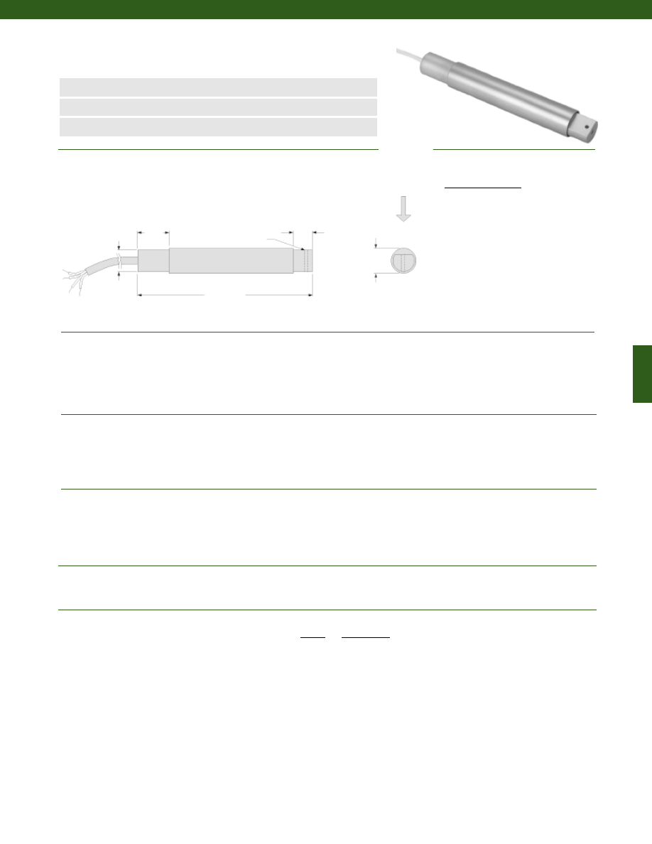
265
........150 g; 250 g; 500 g; 1000 g; 5 lb.; 10 lb.
........+/- 0.1% Full Scale
........+/- 0.1% Full Scale
........+/- 0.03% Full Scale
........2 mV/V (nominal)
........Tension/ Compression (note 1)
........Infinite
........0° to 160° F
........60° to 160° F
........-100° to 200° F
........0.005% Full Scale/° F
........0.005% Full Scale/° F
........Bonded Foil
........5 VDC
........5000 Megohms @ 50 VDC
........350 Ohms
........+/- 5% Full Scale
........Cable (5 ft.)
........400% F.S. or 20 lb., whichever is less (note 2)
........50 g
........Aluminum
Dimensions
Performance
Environmental
Electrical
Mechanical
Range Codes
www.honeywell.com/sensotec
n
150 g to 10 lb. Range
n
Miniature Size
n
0.1% Linearity
0.63
0.38
3.5 max.
ø0.43
ø0.062 Thru
ø0.50
Load Ranges
Linearity (max.)
Hysteresis (max.)
Non-Repeatability (max.)
Output (tolerance)
Operation
Resolution
Temperature, Operating
Temperature, Compensated
Storage Temperature
Temperature, Effect
Zero
Span
Strain Gage Type
Excitation (calibration)
Insulation Resistance
Bridge Resistance
Zero Balance
Electrical Termination (std)
Maximum Allowable Load
Weight
Material
Model MBH Minigram Beam Load Cell
Order Code BL342
Load
Direction
Cable/ Unamplified
Red
(+) Excitation
Black
(-) Excitation
Green
(-) Output
White
(+) Output
1-888-282-9891
Range
Range Code
150 g AL
250 g AN
500 g AP
1000 g AR
5 lb. AT
10 lb. AV
Wiring Code
Courtesy of Steven Engineering, Inc.-230 Ryan Way, South San Francisco, CA 94080-6370-Main Office: (650) 588-9200-Outside Local Area: (800) 258-9200-www.stevenengineering.com
Sensotec Sensors Full Line Catalog-html.html
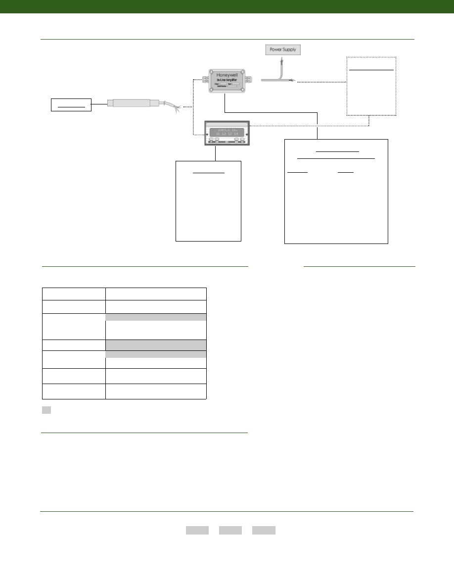
266
www.honeywell.com/sensotec
1-888-282-9891
Supplied as standard
Options
Typical System Diagram
Special Customer
Requirements
(Consult Factory)
How to Order
Combine the order code, the range code and the options code.
Order Code
Range Code
Options Code
Sample Code:
BL342
AL
1b
In-Line Amplifiers
(Used with unamplified units only)
Amplifier
Output
Universal In-Line Amplifiers
UV
+/- 5 VDC
UV-10
+/- 10 VDC
UBP
0 +/- 5 VDC
U3W
4-20 mA (3 wire)
DIN rail Mount In-Line Amplifiers
DV-05
0 +/- 5 VDC (3 wire)
DA-05
4-20 mA (3 wire)
DV-10
0 +/- 10 VDC (3 wire)
Display Units
SC500
SC1000
SC2000
SC2001
SC3004
GM
NK
HH
Customer Supplied
Chart Recorder
Alarm Panel
Data Acquisition
Computer
PLC
Model MBH
Model MBH
Cable Orientation
Different Cable Lengths
Different Materials
ESD
OEM Labels
Radiation Resistant
Shock and Vibration Resistance
Special TC
Built from Scratch
Load Ranges
150, 250, 500, 1000g
5, 10 lbs
Temperature
Compensation
1b. 30° to 130° F
1c. 0° to 185° F
Internal Amplifiers
2u. Unamplified, mV/V output
Electrical Termination
6d. Microtec DR-4S-4H 4 pin
Shunt Calibration
8a. Precision Internal Resistor
Special Calibration
9a. 10 point (5 up/5 down) 20%
increments @ 70° F
6e. Integral cable: Teflon
1a. 60° to 160° F
1. Positive in compression; calibrated in compression only.
2. Allowable Maximum Loads- Maximum load to be applied without damage (note 3).
3. Without Damage- loading to this level will not cause excessive zero shift or performance degradation. The user must consider fatigue life for long
term use and structural integrity. All structurally critical applications (overhead loading, etc.) should always be designed with safety redundant load paths.
Notes
Courtesy of Steven Engineering, Inc.-230 Ryan Way, South San Francisco, CA 94080-6370-Main Office: (650) 588-9200-Outside Local Area: (800) 258-9200-www.stevenengineering.com
Sensotec Sensors Full Line Catalog-html.html
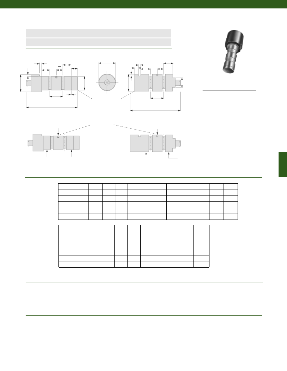
267
........2000; 3000; 5000; 6000; 10,000; 12,500; 18,000; 20,000; 30,000;
50,000; 75,000; 100,000; 125,000; 160,000; 200,000 lb.
........from +/- 0.5% Full Scale (Consult Factory)
........from +/- 0.5% Full Scale (Consult Factory)
........+/- 0.15% Full Scale
........1 mV/V nominal
........-65° to 250° F
........60° to 160°
........0.003% Full Scale/° F
........0.008% of Load/° F
Dimensions
Performance
Environmental
www.honeywell.com/sensotec
n
All Welded Construction
n
Amplified Output Available
Load Ranges
Linearity (max)
Hysteresis
Non-Repeatability
Tolerance on Output
Temperature, Operating
Temperature, Compensated
Temperature, Effect
Zero
Span
Model LP Force Sensing Clevis Pin
Order Code AL441
Capacity (lb.) A (in.)** B (in.) C (in.) D (in.) F (in.) G (in.) H (in.) J (in.) Key (in.) SRG* N (in.)
2000; 3000
0.500
0.50
0.75
1.50
3.98
0.25
0.20
0.25
N/A
0.468
0.039
5000; 6000
0.750
0.59
1.00
1.50
4.48
0.31
0.20
0.25
0.156
0.704
0.046
10,000; 12,500
1.000
0.63
1.00
1.50
4.74
0.50
0.20
0.25
0.219
0.940
0.046
18,000; 20,000
1.250
0.81
1.38
2.00
5.69
0.63
0.27
0.25
0.219
1.176
0.056
30,000
1.500
0.94
1.63
2.00
6.20
0.63
0.27
0.25
0.281
1.406
0.056
+ Center Load
Load
2
Load
2
+ Center Load
Load
2
Load
2
D
H
H
N
J
J
B
B
C
2
C
2
B
B
G
C
C
F
F
A
45ø x 0.030 Chamfer
Apply Load Uniformly
to Center Section
Key optional
* SRG = Snap Ring Groove Diameter (in inches)
Wiring Code
Connector/ Unamplified (Std.)
A
(+) Excitation
B
(+) Excitation
C
(-) Excitation
D
(-) Excitation
E
(-) Output
F
(+) Output
1-888-282-9891
D
Capacity (lb.) A (in.)** B (in.) C (in.) D (in.) F (in.) G (in.) H (in.) J (in.) Key (in.)
50,000
2.000
1.00
2.00
1.50
6.61
0.75
0.266
0.38
0.281
75,000
2.500
1.25
2.50
2.00
7.61
0.75
0.266
0.50
0.281
100,000
2.750
1.47
2.69
2.00
8.63
1.00
0.406
0.50
0.406
125,000
3.000
1.44
3.00
2.00
8.88
1.00
0.406
0.63
0.406
160,000
3.500
1.75
3.50
2.00
10.38
1.25
0.531
0.63
0.531
200,000
4.000
2.25
4.00
2.00
11.88
1.25
0.531
0.75
0.531
2000 to 30,000 lbs
50,000 to 200,000 lbs
G
A
D
**Tolerance = +0.000 in.
-0.002 in.
Courtesy of Steven Engineering, Inc.-230 Ryan Way, South San Francisco, CA 94080-6370-Main Office: (650) 588-9200-Outside Local Area: (800) 258-9200-www.stevenengineering.com
Sensotec Sensors Full Line Catalog-html.html
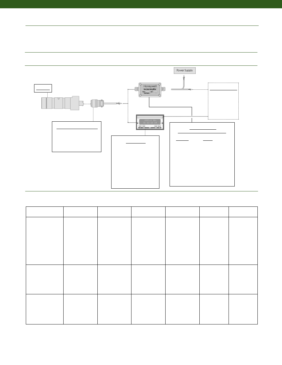
268
www.honeywell.com/sensotec
........Foil
........10 VDC
........5000 Ohms
........PTIH-10-6P
........PT06A-10-6S or equivalent
........200% F.S. (note 1)
........17-4 PH Stainless Steel
Strain Gage Type
Excitation (calibration)
Bridge Resistance
Electrical Termination (std)
Mating Connector (not incl.)
Maximum Allowable Load
Case Material
1-888-282-9891
Mating Connectors & Cables
PT06A-10-6S, Std.
PT06E-10-6S
MS3106A-14S-6S
In-Line Amplifiers
(Used with unamplified units only)
Amplifier
Output
Universal In-Line Amplifiers
UV
+/- 5 VDC
UV-10
+/- 10 VDC
UBP
0 +/- 5 VDC
U3W
4-20 mA (3 wire)
U2W
4-20 mA (2 wire)
DIN Rail Mount In-Line Amplifiers
DV-05
0 +/- 5 VDC (3 wire)
DA-05
4-20 mA (3 wire)
DV-10
0 +/- 10 VDC (3 wire)
Display Units
SC500
SC1000
SC2000
SC2001
SC3004
GM (Unamp. only)
GM-A (Amp. only)
NK (Unamp. only)
HH (Unamp. only)
Customer Supplied
Chart Recorder
Alarm Panel
Data Acquisition
Computer
PLC
Model LP
Model LP
Amplifier
Specifications
Voltage Output
Option 2a
Voltage Output
Option 2c
Voltage Output
Option 2t
Current 3 Wire
Option 2j
Current 2 Wire
Option 2k
Intrinsically Safe
Option 2n (2N)***
Output Signal
Input Power (Voltage)
Input Power (Current)
Frequency Response
Power Supply
Rejection
Operating Temperature
Reverse Voltage
Protection
Short Circuit Protection
0-5V
+/-15V or 26-32VDC
45 mA
3000 Hz
60 db
-20° to 185° F
Yes
Momentary
0-5V or +/- 5V
@ 45mA
11-28 VDC
40 mA
3000 Hz
60 db
-20° to 185° F
Yes
Momentary
0-10V or +/- 10V
@ 45mA
15-28 VDC
40 mA
3000 Hz
60 db
-20° to 185° F
Yes
Momentary
4-20 mA
22-32 VDC
65 mA
2500 Hz
60 db
0° to 185° F
Yes
Yes
4-20 mA
15-40 VDC
4-28 mA
300 Hz
60 db
0° to 185° F
Yes
Yes
4-20 mA
9-28 VDC
4-24 mA
2000 Hz
60 db
-20° to 185° F
Yes
Yes
Wiring Code: Connector
(Std.)
(note 4)
A (+) Supply
B Output Common/
C Supply Return
D (+) Output
E Shunt Cal 1
F Shunt Cal 2
A (+) Supply
B** Output Common/
C** Supply Return
D (+) Output
E Shunt Cal 1
F Shunt Cal 2
A (+) Supply
B** Output Common/
C** Supply Return
D (+) Output
E Shunt Cal 1
F Shunt Cal 2
A (+) Supply
B** Output Common/
C** Supply Return
D (+) Output
E Shunt Cal 1
F Shunt Cal 2
A (+) Supply
B No connection
C No connection
D (+) Output
E Case Ground
F No connection
A (+) Supply
B No connection
C No connection
D (+) Output
E Case Ground
F No connection
Wiring Code: Cable
(note 4)
(note 5)
(note 6)
R
(+) Supply
Bl Output Common/
G Supply Return
W (+) Output
B
Shunt Cal 1
Br Shunt Cal 2
R (+) Supply
Bl* Output Common/
G* Supply Return
W (+) Output
B
Shunt Cal 1
Br Shunt Cal 2
R (+) Supply
Bl* Output Common/
G* Supply Return
W (+) Output
B
Shunt Cal 1
Br Shunt Cal 2
R (+) Supply
Bl* Output Common/
G* Supply Return
W (+) Output
B
Shunt Cal 1
Br Shunt Cal 2
R (+) Supply
Bl (+) Output
W Case Ground
R (+) Supply
Bl (+) Output
W Case Ground
Electrical
Mechanical
Typical System Diagram
Internal Amplifiers
* Black and Green wires are internally connected.
** Pins B and C are internally connected.
*** See Sensotec website for most up-to-date information regarding Intrinsically Safe approvals ref. #008-0547-00.
Courtesy of Steven Engineering, Inc.-230 Ryan Way, South San Francisco, CA 94080-6370-Main Office: (650) 588-9200-Outside Local Area: (800) 258-9200-www.stevenengineering.com
Sensotec Sensors Full Line Catalog-html.html
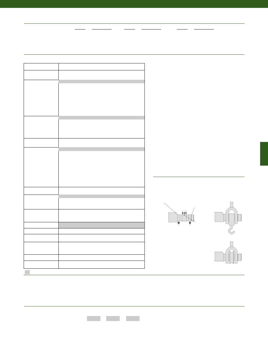
269
Supplied as standard
www.honeywell.com/sensotec
Special Customer Requirements
(Consult Factory)
Options
Installation
How to Order
The order code consists of the product model, the desired range code and the available options.
Model Code
Range Code
Options Code
Sample Code:
AL441
DV
2b
Apply Load Uniformly to
Center Section
Slip Ring
Keyway
Antirotation
keyway
Supporting Loads
Optional
Standard uses for Sensotec clevis
pins include tongue and yoke shackles
and tension pulleys. Clevis pins are
also often ideal for use in web tension
applications. Consult factory for web
tension measurement kits from 200 to
500,000 lb.
Built from Scratch
Load Range
2k, 3k, 5k, 6k, 10k, 12.5k, 18k, 20k, 30k, 50k, 75k, 100k,
125k, 160k, 200k lbs.
Temperature
Compensation
1b. 30° to 130° F
1c. 0° to 185° F
1d. -20° to 130° F
1e. -20° to 200° F
1f.
70° to 250° F
1g. 70° to 325° F
1i. -65° to 250° F
1j.
0° to 50° C
1k. -20° to 85° C
1m. -25° to 110° C
Internal Amplifiers
2a. 4 wire 0-5VDC output
2c. 0-5VDC
2j. 4-20mA (3-wire) output
2k. 4-20mA (2-wire)
2n (2N) 4-20mA (2-wire) Intrinsically Safe
2t.
0-10 VDC output
Internal Amp
Enhancements
3a. Input/ Output Isolation (note 2)
3d. Remote Buffered Shunt Calibration
Electrical Termination
6b. MS type connector
6c. Cannon WK6-325 Series connector 6 pin
6d. Microtec DR-4S-4H 4 pin
6f.
Integral cable: PVC
6g. Integral cable: Neoprene
6h. Integral cable: Silicone
6i.
Integral underwater cable
6j.
1/2-14 conduit fitting with 5 ft. of 4 conductor PVC cable
6q. Molded integral cable: Polyurethane
6v. Phoenix connector on end of cable
15d. Connector on end of cable
Shunt Calibration
8a. Precision Internal Resistor (note 3)
Special Calibration
9a. 10 point (5 up/5 down) 20% increments @ 70°F
9b. 20 point (10 up/10 down) 10% increments @ 70°F
9c. A.S.T.M. E-74 calibration
Bridge Type
11a. Square Bridge
11c. Square and Symmetrical Bridge
31a. Dual bridge.
Bridge Resistance
12b. 5,000 Ohms (foil)
Potentiometers
14a. No access to pots
Electrical Connector
Orientation
15d. Connector on end of cable
Special Calibration
30a. Compression only (+) Output
30b. Tension and Compression (+,-) output
30c. Compression only (-) Output
Shock & Vibration
44a. Shock and vibration resistance
Interfaces
53e. Signature Calibration
53t. T.E.D.S. IEEE 1451-4 Module (note 7)
6a. Bendix PTIH-10-6P - (or equivalent) 6 pin (max. 250°F)
2u. Unamplified, mV/V output
1a. 60° to 160° F
Amplified Output
Cable Orientation
Connector Guard
Different Cable Lengths
Different Electrical Connectors
Different Materials
Different Threads
Dual Bridge
ESD
Fatigue Rating
High Resistance Bridges
Lightning Protection
OEM Labels
Enhanced Operational Temp
Radiation Resistant
Special Electrical O/P
Special TC
9e. CE mark
1-888-282-9891
Model LP
Range
Range Code
2000 lb. DL
3000 lb. DN
5000 lb. DR
6000 lb. DS
10,000 lb. DV
Range
Range Code
12,500 lb. DW
20,000 lb. EL
30,000 lb. EN
50,000 lb. EP
75,000 lb. ER
Range
Range Code
100,000 lb. ET
125,000 lb. FH
150,000 lb. FJ
200,000 lb. FL
Range Codes
Notes
1. Allowable Maximum Loads- Maximum load to be applied without damage.
2. Only available with options 2b or 2c.
3. Not available with amplified options.
4. Interconnecting shunt cal. 1 terminal with shunt cal. 2 terminal provides 50% (unamplified units),
75% (4-20mA 3-wire units) or 80% (voltage amplified units) of full scale output for quick calibration.
Shunt Calibration comes standard with internal amplifier options 2a, 2b, 2c, 2t and 2j.
5. O=Orange; Y=Yellow; B=Blue; Bl=Black; R=Red; Br=Brown; W=White; G=Green. Color specifying
cable and number or letter specifying connector.
6. No mating connector necessary for cable option.
7. Consult factory for TEDS availability with amplified models.
Courtesy of Steven Engineering, Inc.-230 Ryan Way, South San Francisco, CA 94080-6370-Main Office: (650) 588-9200-Outside Local Area: (800) 258-9200-www.stevenengineering.com
Sensotec Sensors Full Line Catalog-html.html
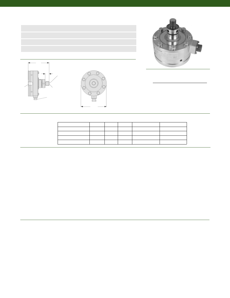
270
........100 to 100,000 lb.
........+/- 0.02% Full Scale
........+/- 0.03% Full Scale
........+/- 0.05% Full Scale
........+/- 0.02% Full Scale
........+/- 0.03% Full Scale
........+/- 0.04% Full Scale
........+/- 0.05% Full Scale
........+/- 0.02% Full Scale
........+/- 0.04% Full Scale
........+/- 0.05% Full Scale
........+/- 0.005% Full Scale
........2 mV/V
........Infinite
........+/-0.1%/ m
........-65° to 200° F
........30° to 130° F
........0.0008% Full Scale/° F
........0.0008% Full Scale/° F
Dimensions
Performance
Environmental
www.honeywell.com/sensotec
n
100 to 100,000 lb. Range
n
Designed as Calibration Reference Standards
n
Enhanced Stability
n
Optional ASTM E74 Calibration
MS3112E-12-8P
(PT02E-12-8P)
øD
L
Spherical
Surface
H
T2
T1
Load Ranges
Accuracy (Static Error Band)(notes 1&2)
100 to 1000 lb.
2500 to 50,000 lb.
100,000 lb.
Linearity (max)
100 to 1000 lb.
2500 to 5000 lb.
10,000 to 50,000 lb.
100,000 lb.
Hysteresis
100 to 1000 lb.
2500 to 25,000 lb.
50,000 to 100,000 lb.
Non-Repeatability
Tolerance on Output
Resolution
Eccentric Load Sensitivity
Temperature, Operating
Temperature, Compensated
Temperature, Effect
Zero
Span
Range (lb.) D (in.) H (in.) L (in.) T1 T2
Model IC48 Imperial Class Tension & Compression Load Cell
Order Code AL121
100; 250
3.00
2.25
0.50
3/8-24 UNF-2A
3/8-24 UNF-2B
500; 1000; 2500; 5000
4.13
4.38
0.75
5/8-18 UNF-3A
5/8-18 UNF-3B
10,000; 25,000
6.06
6.38
1.50
1 1/4-12 UNF-3A
1 1/4-12 UNF-3B
50,000
8.00
8.25
2.00
1 3/4-12 UNF-3A
1 3/4-12 UNF-3B
100,000
11.00
9.75
2.50
2 3/4-8 UNF-3A
2 3/4-8 UNF-3B
Wiring Code
Connector/ Unamplified/ Sense Leads
A
(+) Excitation
B
(+) Sense
C
(-) Excitation
D
(-) Sense
E
(-) Output
F
(+) Output
1-888-282-9891
Courtesy of Steven Engineering, Inc.-230 Ryan Way, South San Francisco, CA 94080-6370-Main Office: (650) 588-9200-Outside Local Area: (800) 258-9200-www.stevenengineering.com
Sensotec Sensors Full Line Catalog-html.html
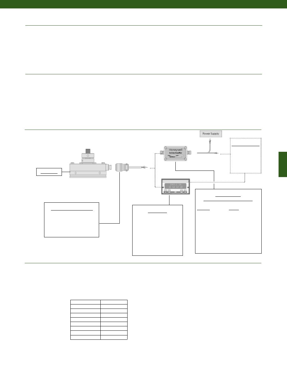
271
www.honeywell.com/sensotec
Mechanical
Typical System Diagram
Maximum Allowable Load
Weight(lb)
For Load Range: 100 to 250 lb.
500 to 5000 lb.
10,000 to 25,000 lb.
50,000 lb.
100,000 lb.
Deflection Full Scale
100 to 250 lb.
500 to 1000 lb.
2500 to 25,000 lb.
........150% F.S. (note 3)
........4.5
........7
........22
........48
........133
........0.002 in.
........0.001 in.
........0.002 in.
Electrical
........Foil
........10 VDC
........5000 Megohms @ 50 VDC
........350 Ohms
........PTIH-10-6P
........MS3112E-12-8P
........PT06A-10-6S
........MS3116A-12-8S
Strain Gage Type
Excitation (calibration)
Insulation Resistance
Bridge Resistance
Electrical Termination (std)
100 to 250 lb.
500 lb. and above
Mating Connector (not incl.)
100 to 250 lb.
500 lb. and above
1-888-282-9891
In-Line Amplifiers
(Used with unamplified units only)
Amplifier
Output
Universal In-Line Amplifiers
UV
+/- 5 VDC
UV-10
+/- 10 VDC
UBP
0 +/- 5 VDC
U3W
4-20 mA (3 wire)
DIN rail Mount In-Line Amplifiers
DV-05
0 +/- 5 VDC (3 wire)
DA-05
4-20 mA (3 wire)
DV-10
0 +/- 10 VDC (3 wire)
Display Units
SC500
SC1000
SC2000
SC2001
SC3004
GM
NK
HH
Customer Supplied
Chart Recorder
Alarm Panel
Data Acquisition
Computer
PLC
Model IC48
Model IC48
Mating Connectors & Cables
PT06A-10-6S
MS3106A-14S-6S
PT06E-10-6S
Ringing Frequencies
Capacity (lb.)
Ringing
Frequency
(Hz)
100 to 250
2,000
500
2,400
1000
3,400
2500
6,800
5000
9,100
10,000
5,700
25,000
7,000
50,000
6,300
100,000
4,500
Courtesy of Steven Engineering, Inc.-230 Ryan Way, South San Francisco, CA 94080-6370-Main Office: (650) 588-9200-Outside Local Area: (800) 258-9200-www.stevenengineering.com
Sensotec Sensors Full Line Catalog-html.html
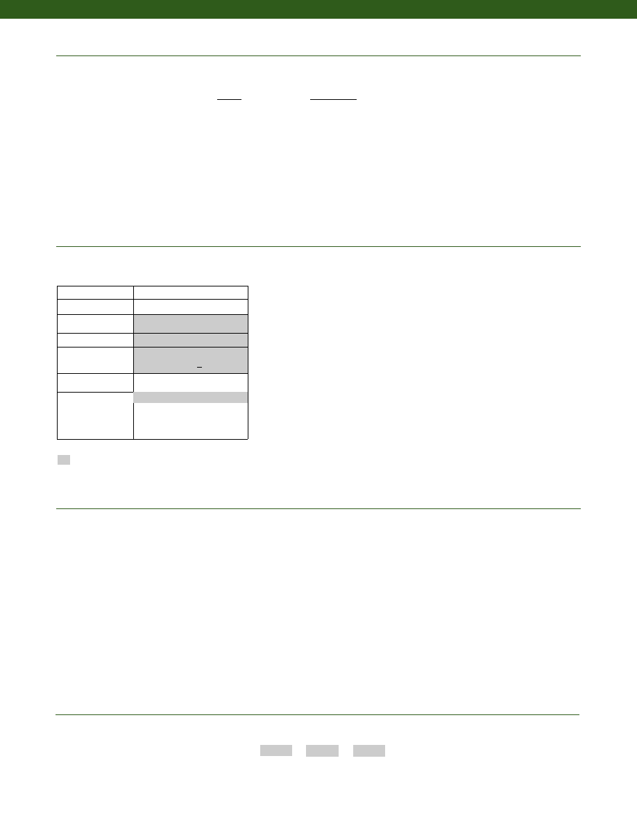
272
Range
Range Code
100 lb.
BR
250 lb.
CN
500 lb.
CR
1000 lb.
CV
2500 lb.
DM
5000 lb.
DR
10,000 lb.
DV
25,000 lb.
EM
50,000 lb.
EP
100,000 lb.
ET
Range Codes
www.honeywell.com/sensotec
1-888-282-9891
Build from Scratch
Load Range
100 to 100,000 lb.
Temperature
Compensation
1b. 30° to 130° F
Internal Amplifiers
2u. Unamplified, mV/V output
Electrical Termination 6a. PTIH-10-6P (100 to 250 lb.)
MS3112E-12-8P (> 500 lb.)
Special Calibration
9c. A.S.T.M. E-74 calibration
Electrical Connector
Orientation
30a. Compression only (+) output
30b. Tension & Compression only
(+,-) output
30c. Compression only (-) output
Tension only (+) output
Supplied as standard
Options
Calibration types, including standard calibration
(performed in-house) with two 11-point tests (note 7)
per direction specified:
Tension (std.)
Tension & Compression (30b)
Compression (30a or 30c)
Other size, range and output configurations
Special Customer
Requirements
(Consult Factory)
Notes
How to Order
Combine the order code, the range code and the options code.
Order Code
Range Code
Options Code
Sample Code:
AL121
CV
30b
1. Static Error Band is the recommended performance specification. The static error band is calculated as the best fit straight line through
zero, including the effects of linearity, hysteresis and non-repeatability.
2. Values noted are typical values but fall within the static error.
3. Allowable Maximum Loads- Maximum load to be applied without damage (note 4). Loads described allow for 100% full scale axial loading
with the bending loads specified. Torque loading maximum is without axial or other load. For any other combination consult factory.
4. Without Damage- loading to this level will not cause excessive zero shift of performance degradation. The user must consider fatigue
life for long term use and structural integrity. All structurally critical applications (overhead loading, etc.) should always be designed
with safety redundant load paths.
5. Maximum bending load without damage is 50% at capacity.
6. For Model IC48, load cell, pull plate and adapter are calibrated as a unit.
7. 11-point test is defined as 20% increments for increasing and decreasing load with one zero return reading (e.g. 0%, 20%, 40%, 60%,
80%, 100%, 80%, 60%, 40%, 20%, 0%)
Model IC48
Courtesy of Steven Engineering, Inc.-230 Ryan Way, South San Francisco, CA 94080-6370-Main Office: (650) 588-9200-Outside Local Area: (800) 258-9200-www.stevenengineering.com
Sensotec Sensors Full Line Catalog-html.html
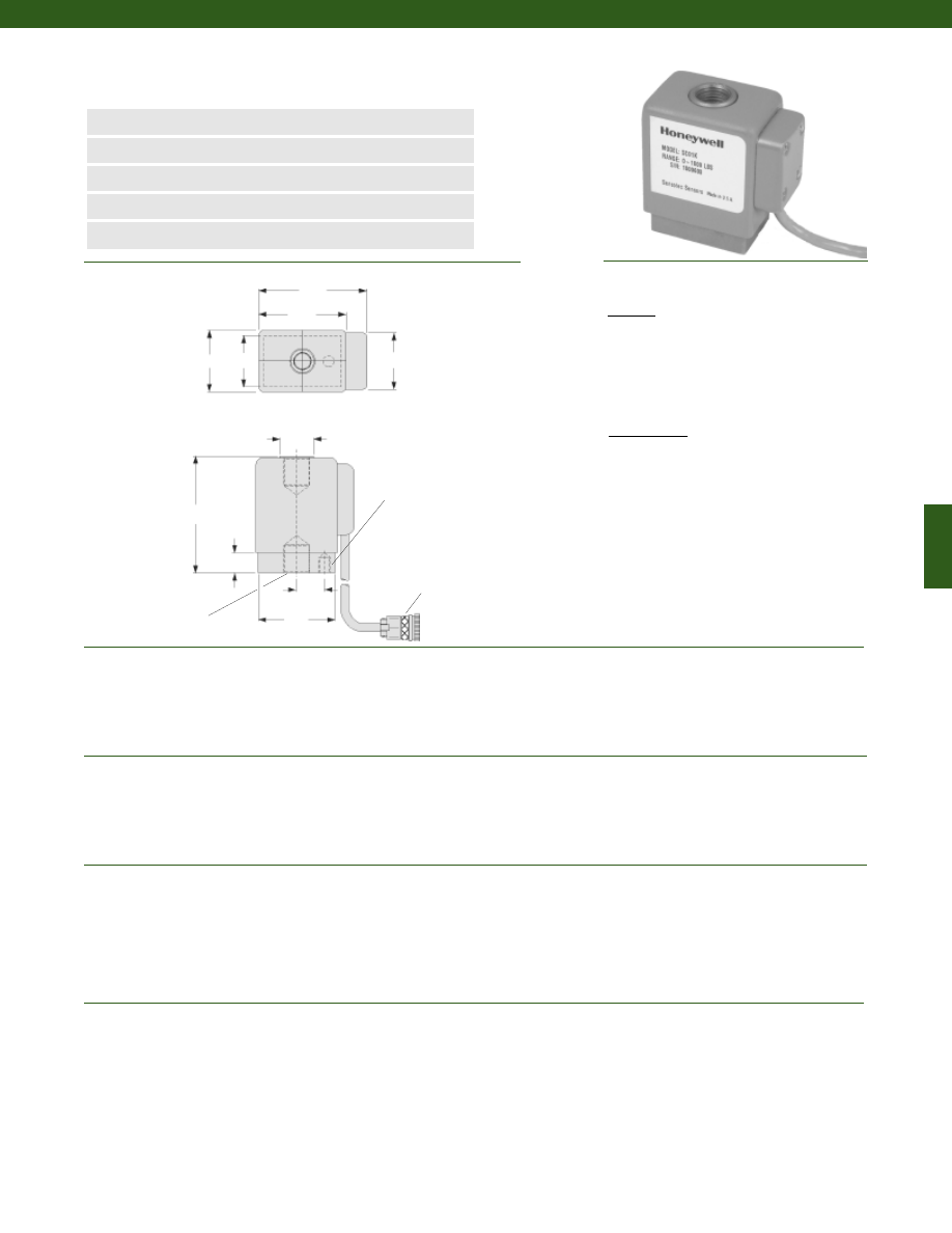
273
Dimensions
Performance
Environmental
Electrical
Mechanical
Model AL-SC High Output Load Cell
Order Code TL131
www.honeywell.com/sensotec
n
500 lb., 1,000 lb., & 2,000 lb. Range
n
Tension/ Compression
n
High Output/ Low Bridge Resistance
n
Drive Meters Without Amplification
n
Low Mechanical Deflection
Load Ranges................500; 1,000; 2,000 lb.
Accuracy (Static Error Band) (note 1)................+/- 1.25% Full Scale
Non-Repeatability................+/- 0.10% Full Scale
Output................70 mV/V Minimum
Operation................Tension/ Compression
Resolution................Infinite
Temperature, Operating................-65° to 200° F
Temperature, Compensated................10° to 120° F
Storage Temperature................-100° to 250° F
Temperature, Effect
Zero................0.5% Full Scale/ °F
Span................1.0% Reading/ °F
Strain Gage Type................Bonded semiconductor
Excitation (calibration)................24 VDC or VAC (RMS)
Insulation Resistance................5000 Megohms @ 50V
Bridge Resistance
Input................1000 Ohms (nominal)
Output................3000 Ohms (nominal)
Zero Balance................1.5% Full Scale max.
Electrical Termination (std)................MS3100A-14S-5P at end of 1’ cable
Maximum Allowable Load................200% F.S. (note 2)
Side Load Without Damage................25% Full Scale
Weight................See table
Material................17-4 PH Stainless Steel
Deflection................See table
Natural Frequency................See table
1-888-282-9891
Notes:
1. Static error band is the recommended performance specification. The static error band is calculated as the best fit straight line through zero, including the
effects of non-linearity, hysteresis and non-repeatability.
2. Allowable Maximum Loads- Maximum load to be applied without damage (note 3).
3. Without Damage- loading to this level will not cause excessive zero shift or performance degradation. The user must consider fatigue life for long term use
and structural integrity. All structurally critical applications (overhead loading, etc.) should always be designed with safety redundant load paths.
ø 0.66
ø0.281 x 0.25 in. Deep
2 x 1/2-20 UNF
0.50 in. Deep
1.2
1.0
2.4
1.7
1.1
0.4
2.25
0.53
1.5
Tension
Wiring Code
A
(+) Excitation
B
(+) Signal
C
(-) Signal
D
(-) Excitation
E
Shield
Compression
A
(+) Excitation
B
(-) Signal
C
(+) Signal
D
(-) Excitation
E
Shield
MS3100A-14S-5P connector
Courtesy of Steven Engineering, Inc.-230 Ryan Way, South San Francisco, CA 94080-6370-Main Office: (650) 588-9200-Outside Local Area: (800) 258-9200-www.stevenengineering.com
Sensotec Sensors Full Line Catalog-html.html
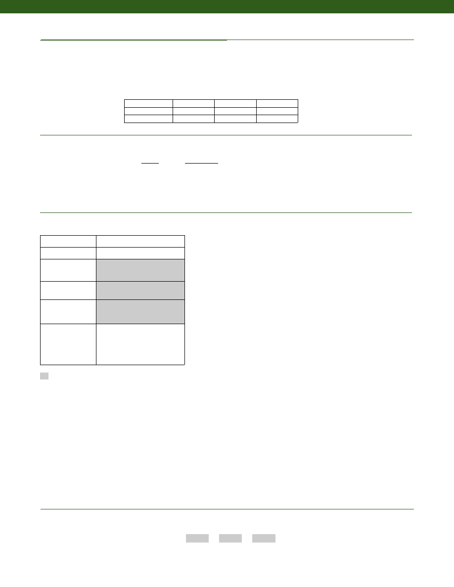
274
www.honeywell.com/sensotec
Range
Range Code
500 lb.
CR
1000 lb.
CV
2000 lb.
DL
Range Codes
1-888-282-9891
Model AL-SC
Deflections and Ringing Frequencies
Capacity (lb.)
Axial
Deflection
at Full Scale
(in.)
Natural
Frequency
(Hz)
Weight
(lb.)
500
0.0010
5000
1.2
1000
0.0015
6000
1.2
2000
0.0020
6700
1.2
Supplied as standard
Options
How to Order
Combine the order code, the range code and the options code.
Order Code
Range Code
Options Code
Sample Code:
TL131
CV
30a
Built to Order
Load Range
500; 1000; 2000 lb.
Temperature
Compensation
10° to 120° F
Internal Amplifiers
2u. Unamplified, mV/V Output
Electrical Termination
3106B-14S-5P connector mounted
at end of 10 ft. cable
Special Calibration
30a. Compression only (+) output
30b. Tension and Compression (+,-)
output
30c. Compression only (-) output
Courtesy of Steven Engineering, Inc.-230 Ryan Way, South San Francisco, CA 94080-6370-Main Office: (650) 588-9200-Outside Local Area: (800) 258-9200-www.stevenengineering.com
Sensotec Sensors Full Line Catalog-html.html
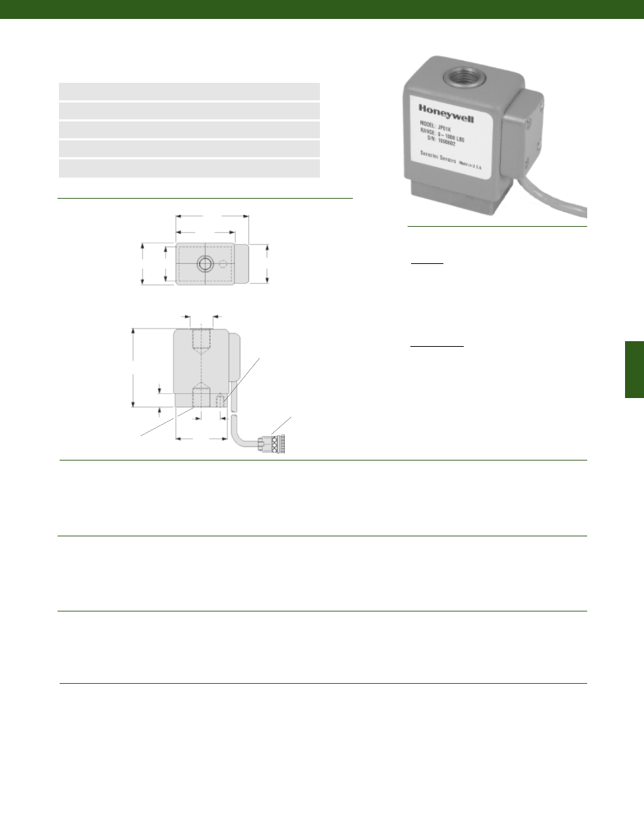
275
Dimensions
Performance
Environmental
Electrical
Mechanical
Model AL-JP High Output Load Cell
Order Code TL121
www.honeywell.com/sensotec
n
500 lb., 1000 lb., & 2000 lb. Range
n
Tension/ Compression
n
High Output/ Low Bridge Resistance
n
Drive Meters Without Amplification
n
Low Mechanical Deflection
ø 0.66
ø0.281 x 0.25 in. Deep
2 x 1/2-20 UNF
0.50 in. Deep
1.2
1.0
2.1
1.7
1.1
0.4
2.25
0.53
1.5
Load Ranges................500; 1000; 2000 lb.
Accuracy (Static Error Band) (note 1)................+/- 0.15% Full Scale
Non-Repeatability................+/- 0.05% Full Scale
Output................30 mV/V Minimum
Operation................Tension/ Compression
Resolution................Infinite
Temperature, Operating................-65° to 200° F
Temperature, Compensated................30° to 130° F
Storage Temperature................-100° to 250° F
Temperature, Effect
Zero................0.5% Full Scale/ °F
Span................0.5% Reading/ °F
Strain Gage Type................Bonded semiconductor
Excitation (calibration)................5 VDC or VAC (RMS)
Insulation Resistance................5000 Megohms @ 50V
Bridge Resistance................125 Ohms Nominal (Input and Output)
Zero Balance................3% Full Scale max.
Electrical Termination (std)................3106B-14S-5P Connector mounted at end of 10’ cable
Maximum Allowable Load................150% F.S. (note 2)
Side Load Without Damage................100%
Weight................See table
Material................17-4 PH Stainless Steel
Deflection................See table
Natural Frequency................See table
Tension
A
(+) Excitation
B
(+) Signal
C
(-) Signal
D
(-) Excitation
E
Shield
Compression
A
(+) Excitation
B
(-) Signal
C
(+) Signal
D
(-) Excitation
E
Shield
1-888-282-9891
Notes:
1. Static error band is the recommended performance specification. The static error band is calculated as the best fit straight line through zero, including the
effects of non-linearity, hysteresis and non-repeatability.
2. Allowable Maximum Loads- Maximum load to be applied without damage (note 3).
3. Without Damage- loading to this level will not cause excessive zero shift or performance degradation. The user must consider fatigue life for long term use
and structural integrity. All structurally critical applications (overhead loading, etc.) should always be designed with safety redundant load paths.
3106B-14S-5P connector
Wiring Code
Courtesy of Steven Engineering, Inc.-230 Ryan Way, South San Francisco, CA 94080-6370-Main Office: (650) 588-9200-Outside Local Area: (800) 258-9200-www.stevenengineering.com
Sensotec Sensors Full Line Catalog-html.html
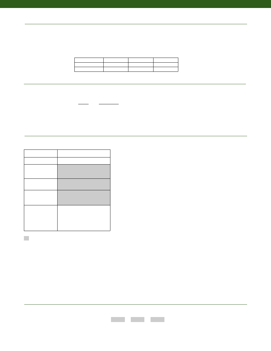
276
www.honeywell.com/sensotec
Range
Range Code
500 lb.
CR
1000 lb.
CV
2000 lb.
DL
Range Codes
1-888-282-9891
Model AL-JP
Deflections and Ringing Frequencies
Capacity (lb.)
Axial
Deflection
at Full Scale
(in.)
Natural
Frequency
(Hz)
Weight
(lb.)
500
0.0010
5000
1.2
1000
0.0015
6000
1.2
2000
0.0020
6700
1.2
Options
How to Order
Combine the order code, the range code and the options code.
Order Code
Range Code
Options Code
Sample Code:
TL121
CV
30a
Supplied as standard
Built from Scratch
Load Range
500; 1000; 2000 lb.
Temperature
Compensation
10° to 120° F
Internal Amplifiers
2u. Unamplified, mV/V Output
Electrical Termination
3106B-14S-5P connector mounted
at end of 10 ft. cable
Special Calibration
30a. Compression only (+) output
30b. Tension and Compression (+,-)
output
30c. Compression only (-) output
Courtesy of Steven Engineering, Inc.-230 Ryan Way, South San Francisco, CA 94080-6370-Main Office: (650) 588-9200-Outside Local Area: (800) 258-9200-www.stevenengineering.com
Sensotec Sensors Full Line Catalog-html.html
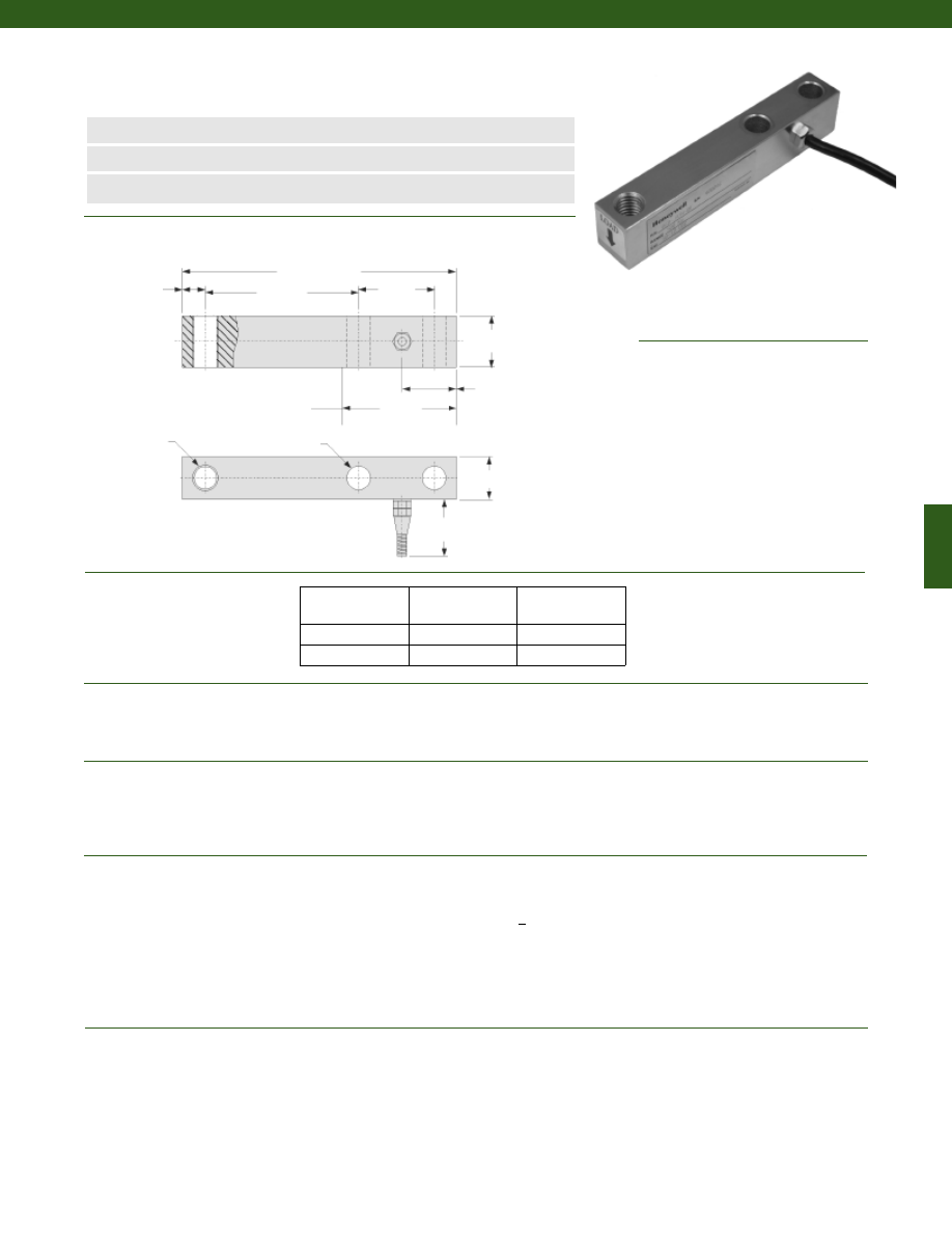
277
www.honeywell.com/sensotec
n
Low Cost
n
50 to 1,000 kg Range
n
+/- 0.02% Accuracy
Model 101 Load Cell
Order Code BL803
1-888-282-9891
Wiring Code
Red
(+) Supply
Black
(-) Supply
Green
(+) Output
White
(-) Output
Large Black Shield
Dimensions
Performance
Environmental
Electrical
Mechanical
127 mm
22 mm
Load Ranges................50; 100; 250; 500; 1,000 kg
Accuracy................+/- 0.02% Full Scale
Output................2.0 mV/V (nominal)
Creep (max.)................+/- 0.02% Full Scale ( 30 minute)
Temperature, Operating................-30° to 70° C
Temperature, Compensated................-20° to 55° C
Temperature, Effect
Zero................+/- 0.02% Full Scale/ 10° C
Span................+/- 0.02% Full Scale/ 10° C
Strain Gage Type................Bonded Foil
Excitation (calibration)................10-12 VDC
Excitation (max.)................15 VDC
Insulation Resistance................> 5000 Megohms
Bridge Resistance (tolerance)
Input Resistance................400 +/- 10 Ohms (nominal)
Output Resistance................352 +/- 2 Ohms (nominal)
Zero Balance (tolerance)................+/- 1% Full Scale
Electrical Termination (std)................3m flying leads
Maximum Allowable Load................150% F.S. (note 1)
Material................Nickel Plated Alloy Steel
Deflection................Less than or equal to 2mm
72 mm
35 mm
M12x1.75
ø 11mm
10 mm
H
42 mm
20 mm
Load (kg)
H (mm)
Recommended
Bolt Torque (N-m)
50 - 250
18
60
500; 1,000
24
60
55 mm
location of fixed support
for best performance
Courtesy of Steven Engineering, Inc.-230 Ryan Way, South San Francisco, CA 94080-6370-Main Office: (650) 588-9200-Outside Local Area: (800) 258-9200-www.stevenengineering.com
Sensotec Sensors Full Line Catalog-html.html
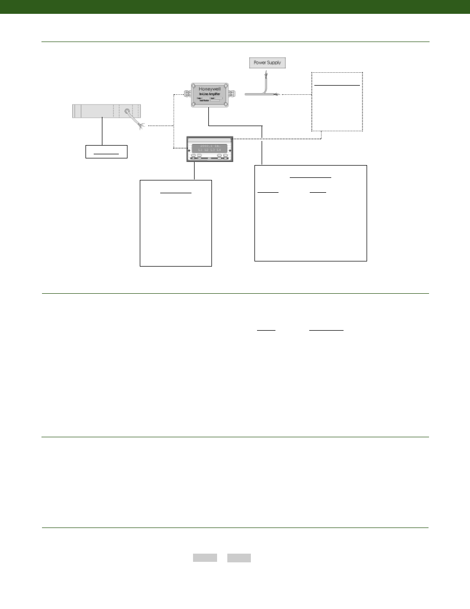
278
Typical System Diagram
www.honeywell.com/sensotec
Range Codes
1-888-282-9891
In-Line Amplifiers
Amplifier
Output
Universal In-Line Amplifiers
UV
+/- 5 VDC
UV-10
+/- 10 VDC
UBP
0 +/- 5 VDC
U3W
4-20 mA (3 wire)
DIN rail Mount In-Line Amplifiers
DV-05
0 +/- 5 VDC (3 wire)
DA-05
4-20 mA (3 wire)
DV-10
0 +/- 10 VDC (3 wire)
Display Units
SC500
SC1000
SC2000
SC2001
SC3004
GM
NK
HH
Customer Supplied
Chart Recorder
Alarm Panel
Data Acquisition
Computer
PLC
Model 101
Range
Range Code
50 kg
LF
100 kg
LH
250 kg
LL
500 kg
LN
1,000 kg
LQ
How to Order
Combine the order code and the range code.
Order Code
Range Code
Sample Code:
BL803
LL
1. Allowable Maximum Loads- Maximum load to be applied without damage (note 2).
2. Without Damage- loading to this level will not cause excessive zero shift or performance degradation. The user
must consider fatigue life for long term use and structural integrity. All structurally critical applications (overhead
loading, etc.) should always be designed with safety redundant load paths.
Notes
Model 101
Courtesy of Steven Engineering, Inc.-230 Ryan Way, South San Francisco, CA 94080-6370-Main Office: (650) 588-9200-Outside Local Area: (800) 258-9200-www.stevenengineering.com
Sensotec Sensors Full Line Catalog-html.html
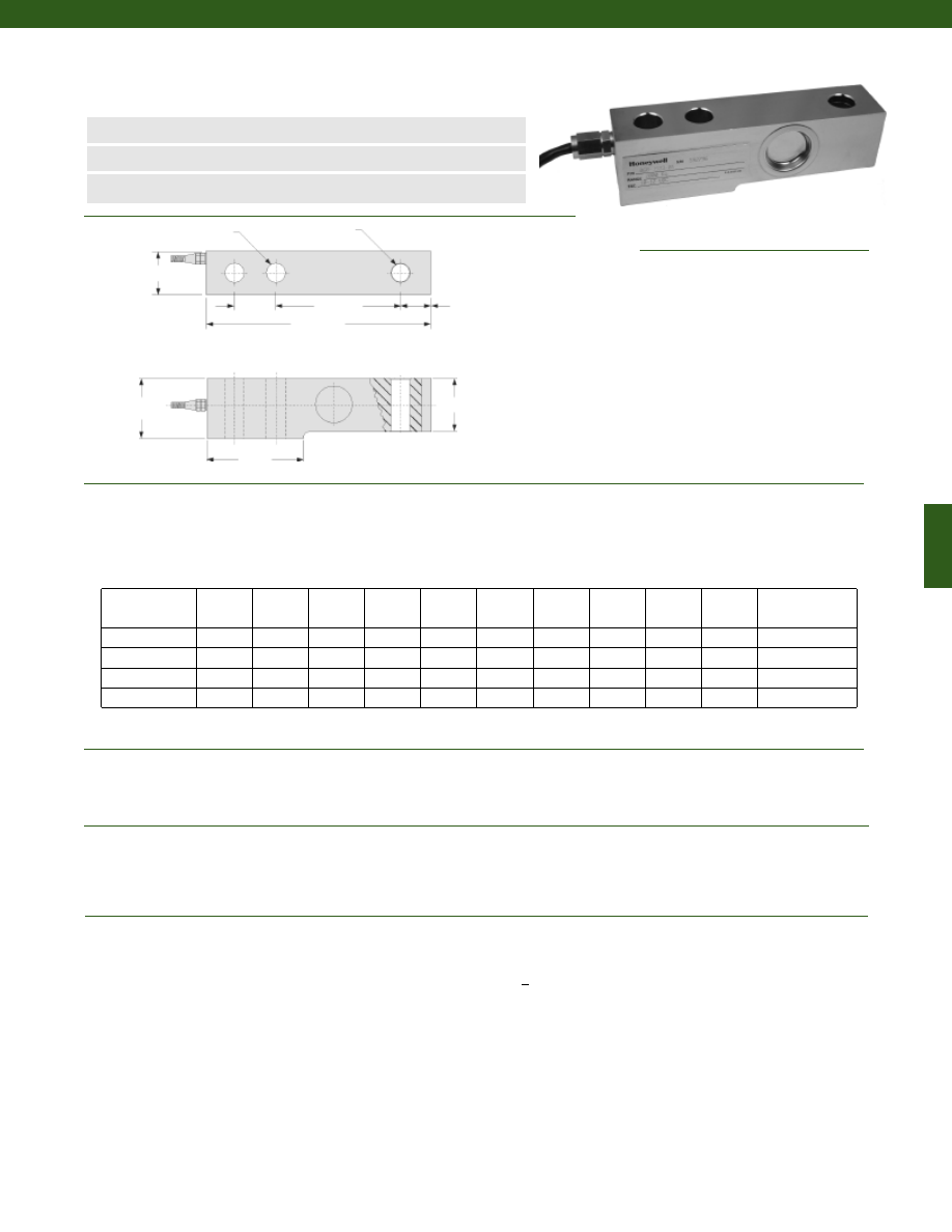
279
www.honeywell.com/sensotec
n
Low Cost
n
100 to 10,000 kg Range
n
+/- 0.02% Accuracy
Model 103 Load Cell
Order Code BL805
1-888-282-9891
Wiring Code
Red
(+) Supply
Black
(-) Supply
Green
(+) Output
White
(-) Output
Large Black Shield
Load Ranges................100; 200; 300; 500; 1,000; 2,000; 3,000; 5,000; 10,000 kg
Accuracy................+/- 0.02% Full Scale
Output................2.0 mV/V (nominal)
Creep (max.)................+/- 0.02% Full Scale ( 30 minute)
Temperature, Operating................30° to 70° C
Temperature, Compensated................-20° to 55° C
Temperature, Effect
Zero................+/- 0.02% Full Scale/ 10° C
Span................+/- 0.02% Full Scale/ 10° C
Strain Gage Type................Bonded Foil
Excitation (calibration)................10-12 VDC
Excitation (max.)................15 VDC
Insulation Resistance................> 5000 Megohms
Bridge Resistance (tolerance)
Input Resistance................400 +/- 10 Ohms (nominal)
Output Resistance................352 +/- 2 Ohms (nominal)
Zero Balance (tolerance)................+/- 1% Full Scale
Electrical Termination (std)
100 to 300 kg................3m flying leads
1,000 to 5,000 kg................5m flying leads
10,000 kg................8m flying leads
2xøL
øK
B
A
C
D
E
F
G
H
Load (kg)
A (mm)
B (mm)
C (mm)
D (mm)
E (mm)
F (mm)
G (mm)
H (mm)
L (mm)
K (mm)
Recommended
Bolt Torque (N-m)
100 to 300
135
36
26
18
75
25
32
58
11.5
11.5
60
500 to 2,000
135
38
30
18
75
25
34
58
13.5
13.5
100
3,000 to 5,000
170
48
38
20
85
50
39
79
18
18.5
255
10,000
263
60
60
30
118
90
52
134
26
26
860
Dimensions
Performance
Environmental
Electrical
Courtesy of Steven Engineering, Inc.-230 Ryan Way, South San Francisco, CA 94080-6370-Main Office: (650) 588-9200-Outside Local Area: (800) 258-9200-www.stevenengineering.com
Sensotec Sensors Full Line Catalog-html.html
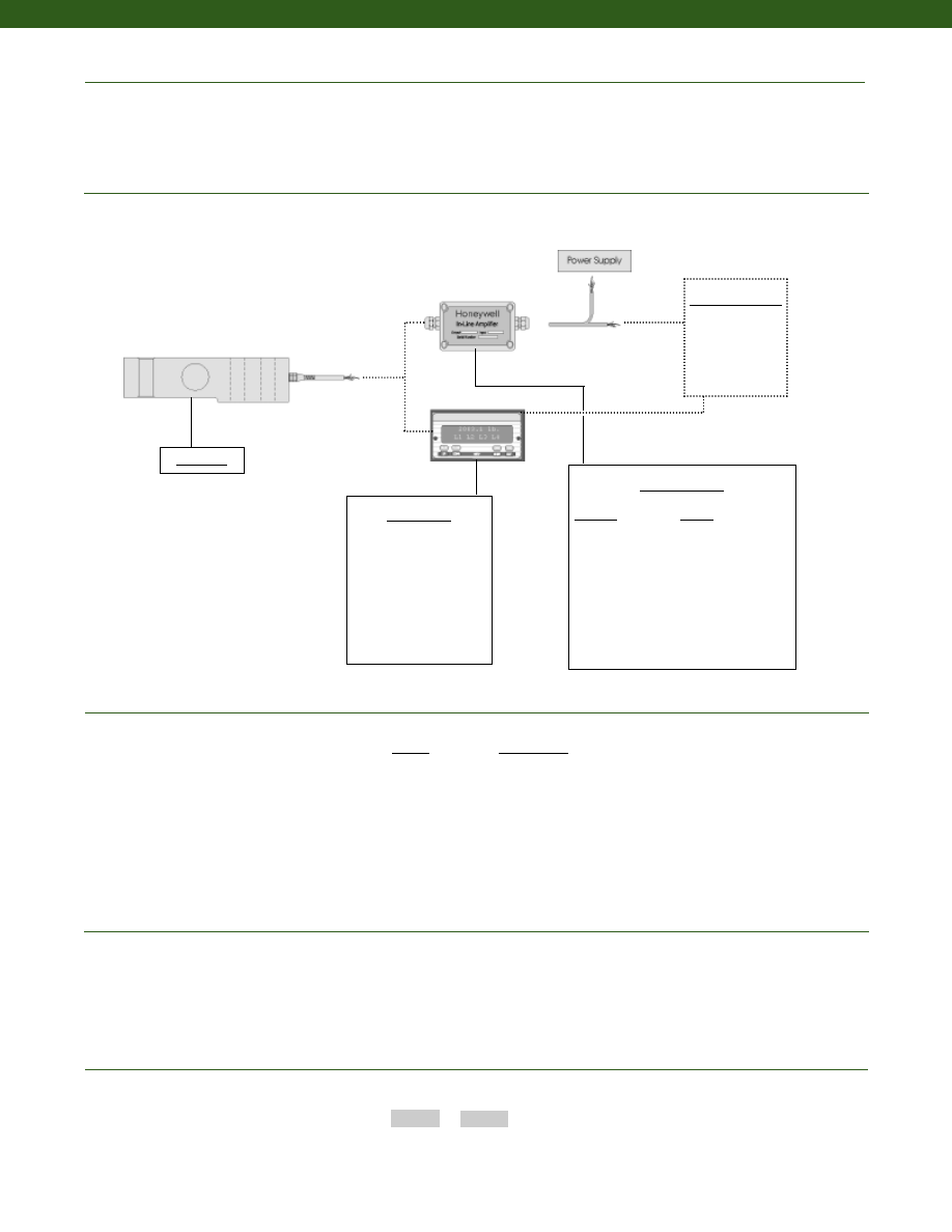
280
Mechanical
Typical System Diagram
www.honeywell.com/sensotec
Range Codes
1-888-282-9891
In-Line Amplifiers
Amplifier
Output
Universal In-Line Amplifiers
UV
+/- 5 VDC
UV-10
+/- 10 VDC
UBP
0 +/- 5 VDC
U3W
4-20 mA (3 wire)
DIN rail Mount In-Line Amplifiers
DV-05
0 +/- 5 VDC (3 wire)
DA-05
4-20 mA (3 wire)
DV-10
0 +/- 10 VDC (3 wire)
Customer Supplied
Chart Recorder
Alarm Panel
Data Acquisition
Computer
PLC
Model 103
Range
Range Code
100 kg
LH
250 kg
LL
300 kg
LM
500 kg
LN
1,000 kg
LQ
2,000 kg
LS
5,000 kg
LU
10,000 kg
LW
How to Order
Combine the order code and the range code.
Order Code
Range Code
Sample Code:
BL805
LL
1. Allowable Maximum Loads- Maximum load to be applied without damage (note 2).
2. Without Damage- loading to this level will not cause excessive zero shift or performance degradation. The user
must consider fatigue life for long term use and structural integrity. All structurally critical applications (overhead
loading, etc.) should always be designed with safety redundant load paths.
Notes
Maximum Allowable Load................150% F.S. (note 1)
Material................Nickel Plated Alloy Steel
Deflection................Less than or equal to 1.5mm
Display Units
SC500
SC1000
SC2000
SC2001
SC3004
GM
NK
HH
Model 103
Courtesy of Steven Engineering, Inc.-230 Ryan Way, South San Francisco, CA 94080-6370-Main Office: (650) 588-9200-Outside Local Area: (800) 258-9200-www.stevenengineering.com
Sensotec Sensors Full Line Catalog-html.html
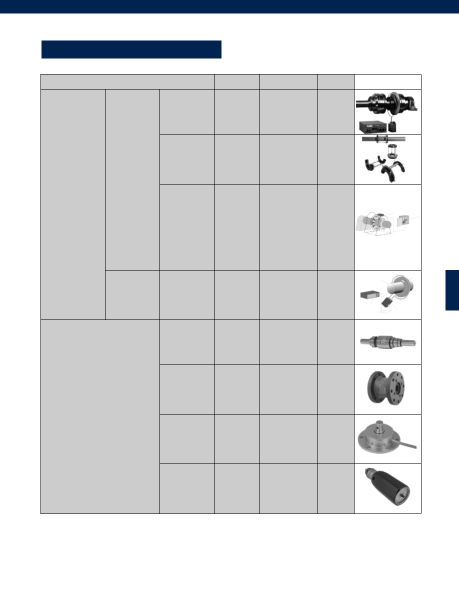
281
TORQUE
Potential Application
Model
Order Code
Page
Rotary Torque
Wireless
Telemetry Based
Flange Drive
RTC
6200
BT211
BT212
282
285
Clamp on Collar
9300
BT213
287
Special
Applications
1211D
1602A
1603A
1605A
1642
2100 Series
2120
2126A
2145
2175
1000-1211
WM1000,WM1100
WM1200,WM1300
WM1400
1000-1642
WN1100-WN1600
1000-2120
1000-2126
1000-2145
1000-2175
289
290
292
294
296
297
299
300
301
302
Rotary
Transformer
Based
Shaft Drive
1202B
1205B
TMS9000
WI1000
WI1100
see datasheet
303
305
316
Reaction Torque
Shaft Drive
QSFK-9
BT111
307
Flange Drive
QFFH-9
BT121
309
Miniature
QWFK-8M
QWLC-8M
BT311
BT312
311
313
Handheld
Torque Watch
see datasheet
315
www.honeywell.com/sensotec
1-888-282-9891
Courtesy of Steven Engineering, Inc.-230 Ryan Way, South San Francisco, CA 94080-6370-Main Office: (650) 588-9200-Outside Local Area: (800) 258-9200-www.stevenengineering.com
Sensotec Sensors Full Line Catalog-html.html
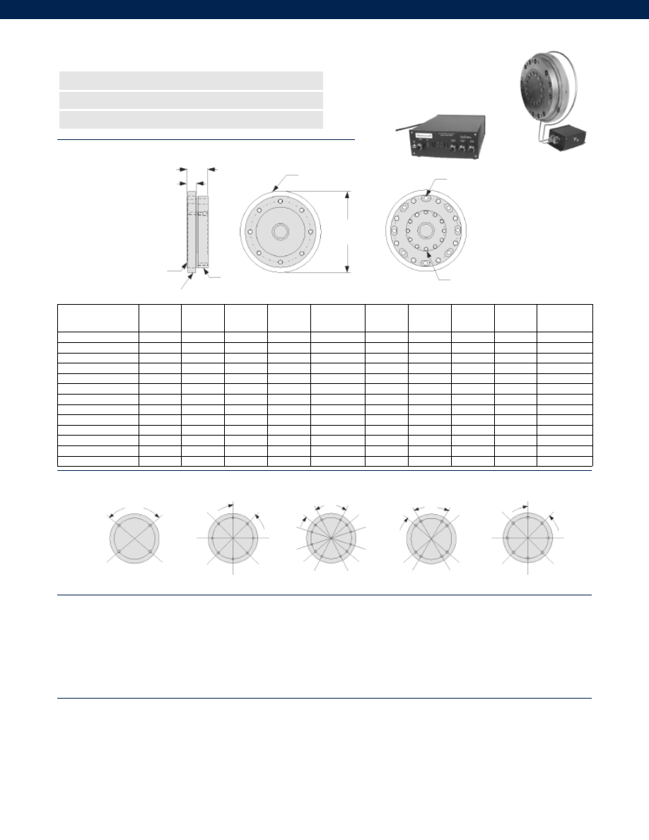
282
Max. Rated
Capacity (lb.-in.)
A (in.)
B (in.)
C (in.)
D (in.)
E (in.)
F
G (in.)
H (in.)
I
Bolt Pattern
Style
1,500
5.90
0.95
1.75
3.750
7/16-20
4
1.86
5/16-24
6
SAE #1
3,000
5.90
0.95
1.75
3.750
7/16-20
4
1.86
5/16-24
6
SAE #1
6,000
7.00
0.95
1.75
4.750
1/2-20
4
2.28
7/16-20
10
SAE #1
10,000
8.20
1.01
2.00
6.125
3/8-24
8
3.40
7/16-20
12
SAE #2
15,000
9.30
1.25
2.37
7.250
3/8-24
8
4.85
3/8-24
12
SAE #2
30,000
9.40
0.96
1.95
7.250
7/16-20
12
4.00
7/16-20
16
SAE #3
70,000
10.70
0.96
1.95
8.250
5/8-18
8
5.38
5/8-18
14
SAE #4
10,000
7.30
0.95
1.75
5.118
12mm-1.75
8
2.75
7/16-20
13
DIN #3
15,000
8.50
0.95
1.75
6.122
14mm-2.0
8
3.38
1/2-20
12
DIN #3
42,000
10.20
1.00
2.00
7.717
16mm-2.0
8
5.00
1/2-20
18
DIN #3
92,000
11.20
1.00
2.00
8.583
18mm-2.5
8
5.52
5/8-18
16
DIN #3
128,000
12.25
1.25
2.25
9.646
20mm-2.5
8
6.37
3/4-16
16
DIN #3
170,000
14.00
1.25
2.25
11.024
22mm-2.5
8
7.30
3/4-16
16
DIN #3
Dimensions
Bolt Pattern Style
Performance
Environmental
n
1,500 to 170,000 lb.-in. Range
n
Non Contacting Wireless Telemetry
n
Frictionless
B
C
F x Thru Holes for Size
E Bolts on øD
I x Size H Bolts
on øG
Antenna
Antenna
Torque
Transducer
Adapter Plate
Torque Ranges................1,500 to 170,000 lb.-in.
Linearity................+/- 0.25% Full Scale
Hysteresis................+/- 0.25% Full Scale
Non-Repeatability................+/- 0.05% Full Scale
Frequency Response................DC to 1,000 Hz
Sensitivity (Transmitter)................175 microstrain (0.5mV/V)
Number of channels................1
Sampling Rate................10 kHz
Receiver Readout Display Type................3.5 digit 7 segment LED
Temperature, Operating (Transmitter)................-67° to 257° F
Temperature, Operating (Receiver/ IPS/ PSU)................5° to 149°F
Temperature, Compensated (Transmitter)................32° to 167°F
Temperature, Compensated (Receiver)................32° to 127°F
Static G Force (Rotating components)................15,000 G’s
RPM Limits (Rotating components)................See Graph - depends on shaft diameter
Vibration (Rotating components)................100 G to 1 kHz
Collar Weight................varies with shaft diameter
Electronics Weight (not including cables)................Receiver and IPS 7.5 lb.
øA
100°
45°
45°
22.5°
19°
62°
45°
SAE #1
SAE #2
SAE #3
SAE #4
DIN #3
Model RTC Thin Profile In-Line Rotary Torque Transducer System
Order Code BT211 (Transducer)
www.honeywell.com/sensotec
1-888-282-9891
Courtesy of Steven Engineering, Inc.-230 Ryan Way, South San Francisco, CA 94080-6370-Main Office: (650) 588-9200-Outside Local Area: (800) 258-9200-www.stevenengineering.com
Sensotec Sensors Full Line Catalog-html.html
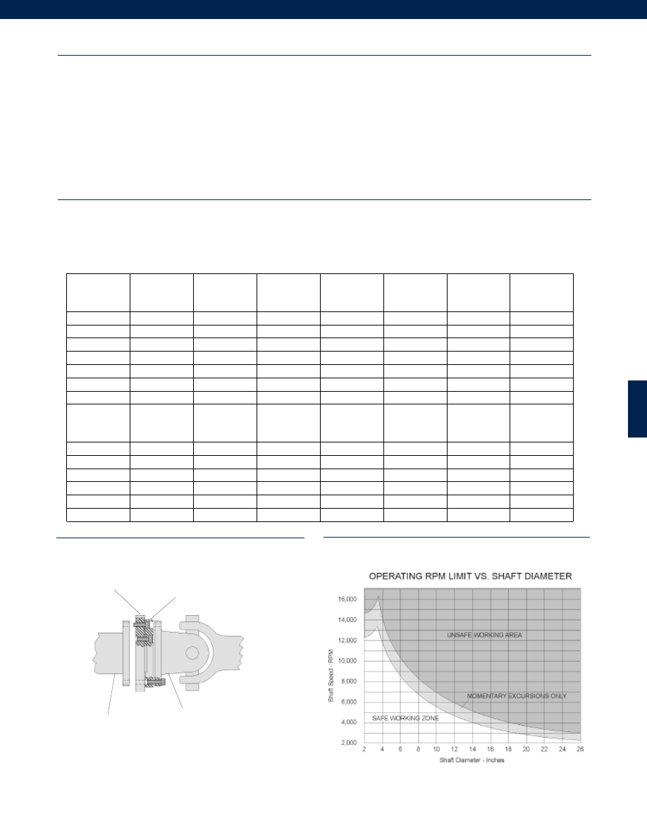
283
Typical Mounting Diagram
RPM Limits Graph
Electrical
Mechanical
Model RTC
Induction Power Source................160 kHz +/- 6%
Cable Length (IPS to Receiver)................15 ft. std. (note 1)
Max. Cable Length (IPS to Receiver)................100 ft.
Power Supply Voltage (Receiver)................120/ 240 VAC user-selectable
Power Consumption (Receiver)................200 VA max.
RF Operating Frequency................Factory set, 13-22 MHz, 1MHz steps
RF Modulation Type................PWM
Signal Strength Indicator (Receiver)................LED Bargraph
Analog Output (Receiver)................+/- 10 VDC @ 1mA max.
Output Impedance (Receiver)................< 1 Ohm
Electrical Termination (Receiver Output)................BNC female
Mating Connector (Receiver Output)................BNC male
Output Filter Capability (Receiver)................user selectable 1,000, 500,200,100, 1 Hz
Dimensions (Collar Cross Section)................1.25” x 1.25” Typical (6” OD min.)
Dimensions (Receiver)................11.5” L x 8.6” W x 3.5” H
Dimensions (IPS)................6” L x 4” W x 2.5” H
Shaft Diameter Limits (Collar)................2” to 42”
Collar Material................Type G-11 Glass epoxy
Flange Style
SAE
Max. Rated
Capacity
(in.-lb.)
Max Speed
(RPM)
(note 2)
Torsional
Stiffness x 106
(in.-lb./rad)
Rotating
Inertia
(lb.-in.2)
Max. Thrust
(lb.)
Max. Shear
(Sideload)
(lb.)
Max. Bending
(in.-lb.)
37-41
1,500
16,000
11
10.5
750
700
600
37-41
3,000
16,000
23
10.5
2,000
1,400
1,200
48-55
6,000
15,000
57
24
3,000
2,000
2,500
61
10,000
13,000
136
51
3,500
2,000
6,000
71
15,000
11,000
246
94
3,500
2,000
9,500
81
30,000
11,000
485
98
7,000
4,000
15,000
88-91
70,000
9,000
1258
178
10,000
6,000
25,000
Flange Style
DIN
Max. Rated
Capacity
(in.-lb.)
Max Speed
(RPM)
(note 2)
Torsional
Stiffness x 106
(in.-lb./rad)
Rotating
Inertia
(lb.-in.2)
Max. Thrust
(lb.)
Max. Shear
(Sideload)
(lb.)
Max. Bending
(in.-lb.)
150
10,000
13,000
115
30
5,000
3,000
6,000
180
15,000
11,000
180
61
6,000
4,500
9,000
225
42,000
9,000
660
141
10,000
6,000
25,000
250
92,000
8,000
1610
219
13,000
8,000
8,000
285
128,000
7,000
2540
330
16,000
10,000
65,000
315
170,000
6,000
3870
608
20,000
12,000
75,000
Input Torque Shaft
Transmission Joint
Adaptor
Torque Sensor
www.honeywell.com/sensotec
1-888-282-9891
Courtesy of Steven Engineering, Inc.-230 Ryan Way, South San Francisco, CA 94080-6370-Main Office: (650) 588-9200-Outside Local Area: (800) 258-9200-www.stevenengineering.com
Sensotec Sensors Full Line Catalog-html.html
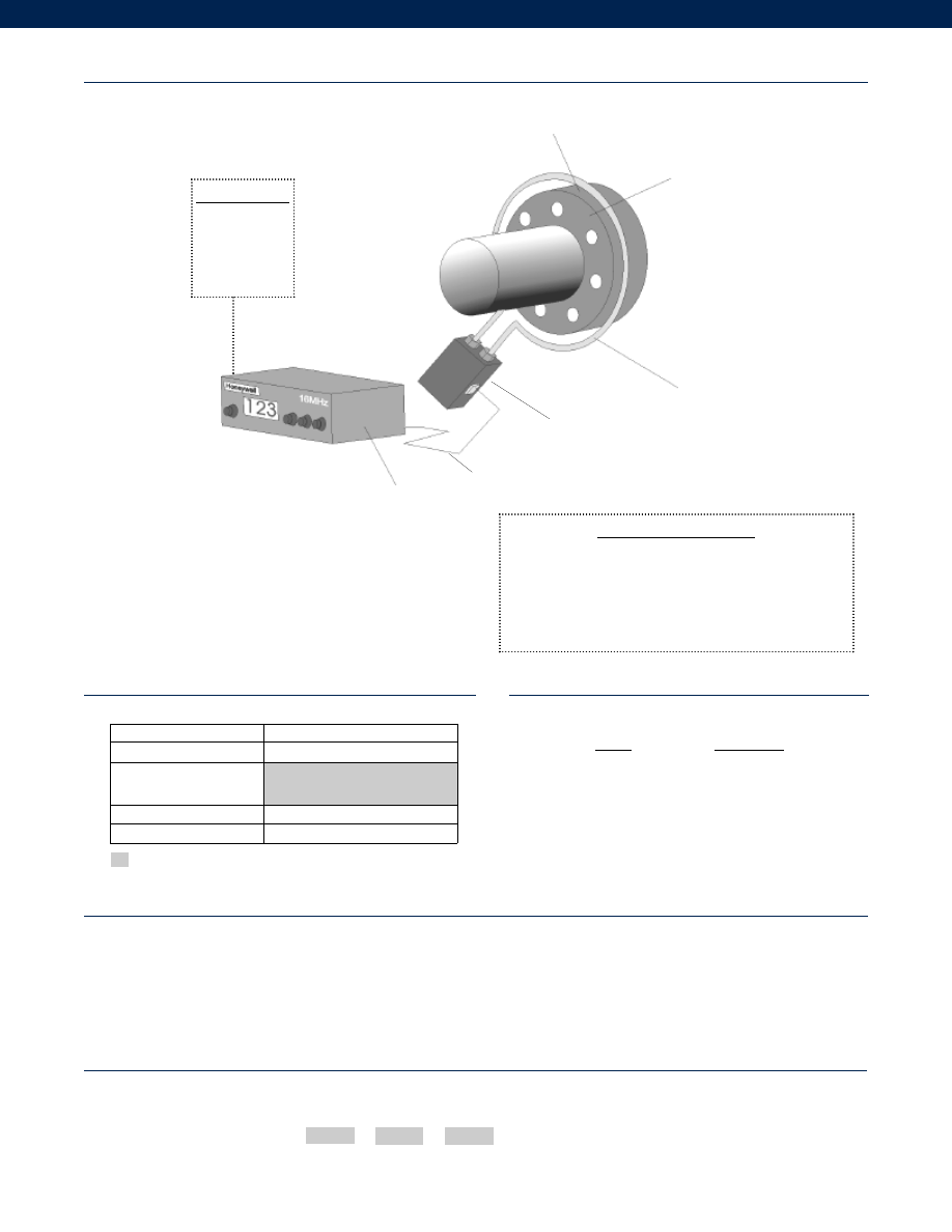
284
Range
Range Code
1,500 in.-lb.
TQ
3,000 in.-lb.
TR
6,000 in.-lb.
TT
12,000 in.-lb.
TV
24,000 in.-lb.
TW
Supplied as standard
Options
Notes
Typical System Diagram
(note 3)
Range Codes
How to Order
The order code consists of the product model, the desired range code and the available options.
Model Code
Range Code
Options
Sample Code:
BT211
TT
62h
Built to Order
Torque Range
1,500 to 170,000 in.-lb.
Available Frequencies
(note 4)
16MHz
Environmental Protection IPS 62h. Nema IPS
Receiver Power Supply
62v. DC (specify 12 VDC or 24 VDC)
Model RTC
1. Consult factory for other cable lengths.
2. Consult factory for higher maximum speeds.
3. See Model 2100 datasheet for further information on the typical system setup.
4. Consult factory for other frequencies.
Customer Supplied
Chart Recorder
Alarm Panel
Data Acquisition
Computer
PLC
Electronics Completion Package
(Part #060-G834-01)
Includes:
Induction Power Supply
Model 2175A
Cable Assembly
Part #90845-091
RF Receiver
Model 2145AC
Manual
Part #54749-010
0.25” to 0.5” air gap
Stationary Loop Antenna
Model 2175A
Induction Power Supply (IPS)
Model RTC with
2120B Transmitter
Model 2145AC Receiver
Cable Assembly
www.honeywell.com/sensotec
1-888-282-9891
Courtesy of Steven Engineering, Inc.-230 Ryan Way, South San Francisco, CA 94080-6370-Main Office: (650) 588-9200-Outside Local Area: (800) 258-9200-www.stevenengineering.com
Sensotec Sensors Full Line Catalog-html.html
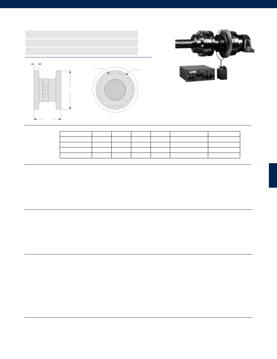
285
Dimensions
Performance
Environmental
Electrical
Mechanical
n
2000 to 100,000 lb.-in. Range
n
Non Contacting
n
Frictionless
W
A
øC B.C.
øD
Torque Ranges................2,000 to 100,000 lb.-in.
Linearity................+/- 0.25% Full Scale
Hysteresis................+/- 0.25% Full Scale
Non-Repeatability................+/- 0.03% Full Scale
Frequency Response................DC to 1,000 Hz
Sensitivity (Transmitter)................175 microstrain (0.5mV/V)
Number of channels................1
Sampling Rate................10 kHz
Receiver Readout Display Type................3.5 digit 7 segment LED
Temperature, Operating (Transmitter)................-67° to 257° F
Temperature, Operating (Receiver/ IPS/ PSU)................5° to 149°F
Temperature, Compensated (Transmitter)................32° to 167°F
Temperature, Compensated (Receiver)................32° to 127°F
Static G Force (Rotating components)................15,000 G’s
RPM Limits (Rotating components)................See Graph - depends on shaft diameter
Vibration (Rotating components)................100 G to 1 kHz
Collar Weight................varies with shaft diameter
Electronics Weight (not including cables)................Receiver and IPS 7.5 lb.
Induction Power Source................160 kHz +/- 6%
Cable Length (IPS to Receiver)................15 ft. std. (note 1)
Max. Cable Length (IPS to Receiver)................100 ft.
Power Supply Voltage (Receiver)................120/ 240 VAC user-selectable
Power Consumption (Receiver)................200 VA max.
RF Operating Frequency................Factory set, 16 MHz Standard
RF Modulation Type................PWM
Signal Strength Indicator (Receiver)................LED Bargraph
Analog Output (Receiver)................+/- 10 VDC @ 1mA max.
Output Impedance (Receiver)................< 1 Ohm
Electrical Termination (Receiver Output)................BNC female
Mating Connector (Receiver Output)................BNC male
Output Filter Capability (Receiver)................user selectable 1,000, 500,200,100, 1 Hz
Dimensions (Receiver)................11.5” L x 8.6” W x 3.5” H
Dimensions (IPS)................6” L x 4” W x 2.5” H
Shaft Diameter Limits (Collar)................2” to 42”
Collar Material................Type G-11 Glass epoxy
Model 6200 In-Line Rotary Torque Transducer System
Order Code BT212 (Transducer)
Torque (lb.-in.)
øD (in.)
W (in.)
A (in.)
X Holes
Bolt Circle C (in.)
Dia. Thru E (in.)
2000 to 10,000
5.00
3.50
0.63
8
4.25
0.39
15,000 to 30,000
6.25
5.00
0.75
10
5.25
0.65
35,000 to 50,000
8.00
6.00
1.00
10
6.50
0.78
75,000 to 100,000
10.00
8.00
1.25
10
8.25
0.90
X holes with øE
equally spaced
www.honeywell.com/sensotec
1-888-282-9891
Courtesy of Steven Engineering, Inc.-230 Ryan Way, South San Francisco, CA 94080-6370-Main Office: (650) 588-9200-Outside Local Area: (800) 258-9200-www.stevenengineering.com
Sensotec Sensors Full Line Catalog-html.html
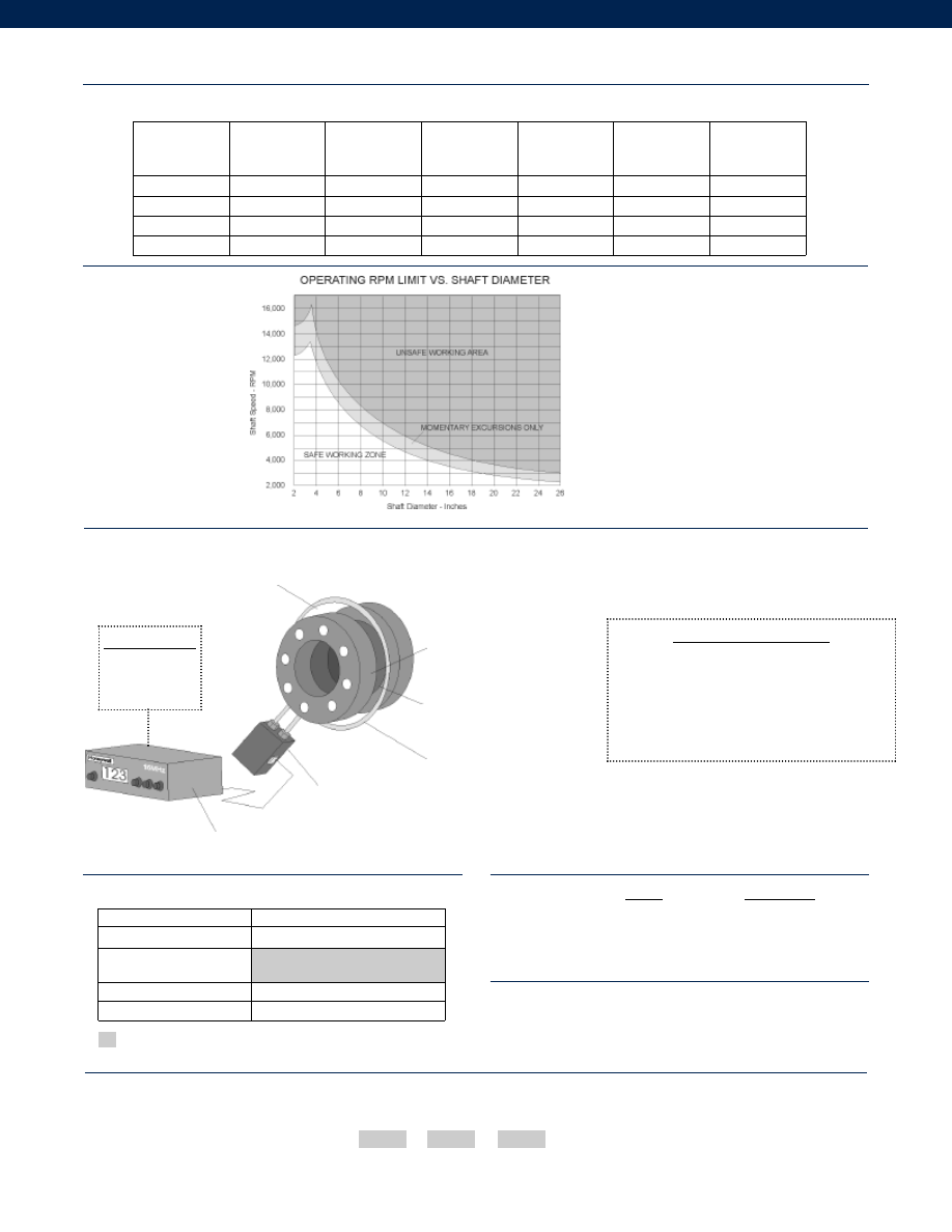
286
Range
Range Code
3,000 lb.-in.
TR
6,000 lb.-in.
TT
12,000 lb.-in.
TV
24,000 lb.-in.
TW
Options
Range Codes
How to Order
The order code consists of the product model, the desired range code and the available options.
Model Code
Range Code
Options
Sample Code:
BT212
TT
62h
RPM Limits Graph
Model 6200
Mechanical (continued)
Notes
Max. Rated
Capacity
(in.-lb.)
Max. Speed
(RPM)
Torsional
Stiffness x 106
(in.-lb./ Rad)
Rotating Inertia
(lb.-in.2)
Max. Thrust
(lb.)
Max. Shear
(sideload)
(lb.)
Max. Bending
(in.-lb.)
10,000
12,000
10.45
25
10,000
2,500
5,000
30,000
10,000
25.42
70
17,000
5,000
15,000
50,000
8,500
52.70
250
30,000
7,500
25,000
100,000
7,000
93.19
700
40,000
12,000
50,000
Typical System Diagram
(note 2)
Built to Order
Torque Range
2,000 to 100,000 in.-lb.
Available Frequencies
(note 3)
16 MHz
Environmental Protection IPS 62h. Nema IPS
Receiver Power Supply
62v. DC (specify 12 VDC or 24 VDC)
Customer Supplied
Chart Recorder
Data Acquisition
0.25” to 0.5” air gap
Stationary Loop Antenna
Model 2175A
Induction Power Supply
Cable Assembly
Model 6200 with
2120B Transmitter inside
Antenna Collar attached
to Model 6200
Model 2145AC Receiver
1. Consult factory for other cable lengths.
2. See Model 2100 datasheet for further information on the typical system setup.
3. Consult factory for other frequencies.
Electronics Completion Package
(Part #060-G834-01)
Includes:
Induction Power Supply
Model 2175A
Cable Assembly
Part #90845-091
RF Receiver
Model 2145AC
Manual
Part #54749-010
Supplied as standard
www.honeywell.com/sensotec
1-888-282-9891
Courtesy of Steven Engineering, Inc.-230 Ryan Way, South San Francisco, CA 94080-6370-Main Office: (650) 588-9200-Outside Local Area: (800) 258-9200-www.stevenengineering.com
Sensotec Sensors Full Line Catalog-html.html
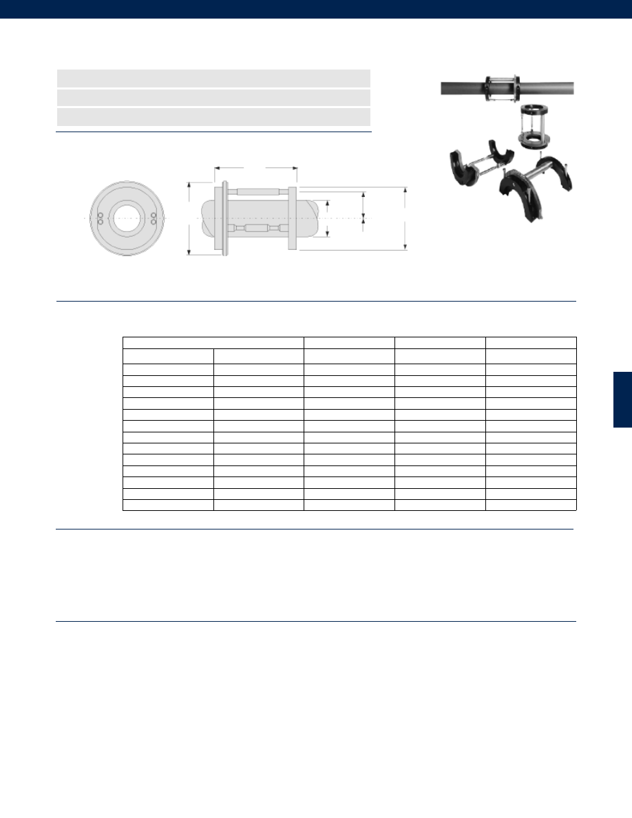
287
Shaft Diameter
Sensor Radius
Antenna Diameter
Collar Diameter
DS (in.) (ID)
DS (in.) (OD)
R (in.)
DA (in.)
DC (in.)
2.5
3.44
2.4
7.00
5.88
3.44
4.44
2.9
8.00
6.88
4.44
5.44
3.4
9.00
7.88
5.44
6.44
3.9
10.00
8.88
6.44
7.44
4.4
11.00
9.88
7.44
8.44
4.9
12.00
10.88
8.44
9.44
5.4
13.00
11.88
9.44
10.44
5.9
14.00
12.88
10.44
11.44
6.4
15.00
13.88
11.44
12.44
6.9
16.00
14.88
12.44
13.44
7.4
17.00
15.88
13.44
14.44
7.9
18.00
16.88
14.44
15.44
8.4
19.00
17.88
Dimensions
Performance
Environmental
n
Ideal for Short Term Testing
n
Converts Your Shaft into a Torque Transducer
n
Shaft Sizes From 2.5” to 15.4”
9 in.
øDS
øDC
Sensor
Radius R
Model 9300 Clamp on Rotary Torque Transducer System
Order Code BT213 (Clamp on Assembly)
øDA
Torque Ranges................Varies on application; consult factory
Linearity................+/- 0.15% Full Scale
Non-Repeatability................+/- 0.05% Full Scale
Frequency Response................DC to 1,000 Hz
Sensitivity (Transmitter)................300 microstrain
Number of channels................1
Sampling Rate................5 kHz
Receiver Readout Display Type................3.5 digit 7 segment LED
Temperature, Operating (Transmitter)................16° to 167° F
Temperature, Operating (Receiver/ IPS/ PSU)................40° to 140°F
Temperature, Compensated (Transmitter)................32° to 167°F
Temperature, Compensated (Receiver)................32° to 127°F
Temperature Effects
Zero (max.)................+/- 0.01% Full Scale
Span (max.)................+/- 0.005% Full Scale
Static G Force (Rotating components)................100 G
RPM Limits (Rotating components)................See Graph - depends on shaft diameter
Vibration (Rotating components)................10 G to 1 kHz
Collar Weight................varies with shaft diameter
Electronics Weight (not including cables)................Receiver and IPS 7.5 lb.
www.honeywell.com/sensotec
1-888-282-9891
Courtesy of Steven Engineering, Inc.-230 Ryan Way, South San Francisco, CA 94080-6370-Main Office: (650) 588-9200-Outside Local Area: (800) 258-9200-www.stevenengineering.com
Sensotec Sensors Full Line Catalog-html.html
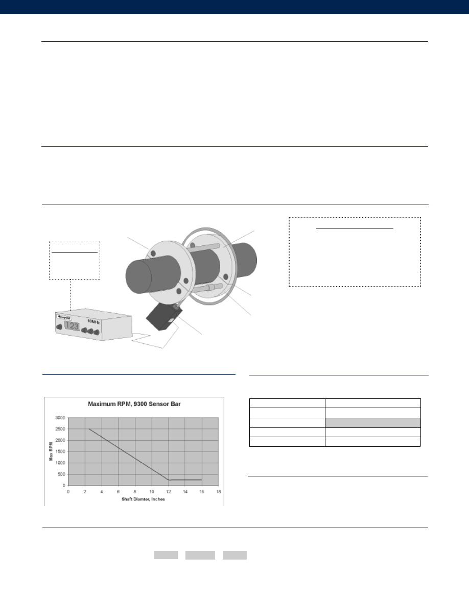
288
Typical System Diagram
Options
How to Order
The order code consists of the product model, the desired range and the available options.
Model Code
Range
Options
Sample Code:
BT213 3000lb.-in.
62h
Electrical
Mechanical
RPM Limits Graph
(note 2)
Customer Supplied
Chart Recorder
Data Acquisition
Built to Order
Torque Range
Varies on application; consult factory
Available Frequencies
16 MHz
Environmental Protection
62h. Nema IPS
Receiver Power Supply
62v. DC (specify 12 VDC or 24 VDC)
Model 9300
Induction Power Source................160 kHz +/- 6%
Cable Length (IPS to Receiver)................15 ft. std. (note 1)
Max. Cable Length (IPS to Receiver)................100 ft.
Power Supply Voltage (Receiver)................120/ 240 VAC user-selectable
Power Consumption (Receiver)................200 VA max.
RF Operating Frequency................Factory set, 16 MHz standard
RF Modulation Type................PWM
Signal Strength Indicator (Receiver)................LED Bargraph
Analog Output (Receiver)................+/- 10 VDC @ 1mA max.
Output Impedance (Receiver)................< 1 Ohm
Electrical Termination (Receiver Output)................BNC female
Mating Connector (Receiver Output)................BNC male
Output Filter Capability (Receiver)................user selectable 1,000; 500; 200; 100; 1 Hz
Dimensions (Collar Cross Section)................Varies with shaft diameter
Dimensions (Receiver)................11.5” L x 8.6” W x 3.5” H
Dimensions (IPS)................6” L x 4” W x 2.5” H
Rotational Clearance (Collar)................2.5” all around
Shaft Diameter Limits (Collar)................2.5” to 15.4”
Collar Material................Phenolic, Steel
Notes
1. Consult factory for other cable lengths.
2. Consult factory for higher RPM speeds.
Clamp on Collar
Stationary Loop Antenna
Model 2175A
Induction Power Supply
Model 9300
Antenna Collar
attached to Model 9300
Model 2145AC Receiver
Cable Assembly
Electronics Completion Package
(Part #060-G834-03)
Includes:
Induction Power Supply
Model 2175A
Cable Assembly
Part #90845-091
RF Receiver
Model 2145A
Manual
Part #55489-011
www.honeywell.com/sensotec
1-888-282-9891
(0.25” to 0.5” air gap)
Courtesy of Steven Engineering, Inc.-230 Ryan Way, South San Francisco, CA 94080-6370-Main Office: (650) 588-9200-Outside Local Area: (800) 258-9200-www.stevenengineering.com
Sensotec Sensors Full Line Catalog-html.html
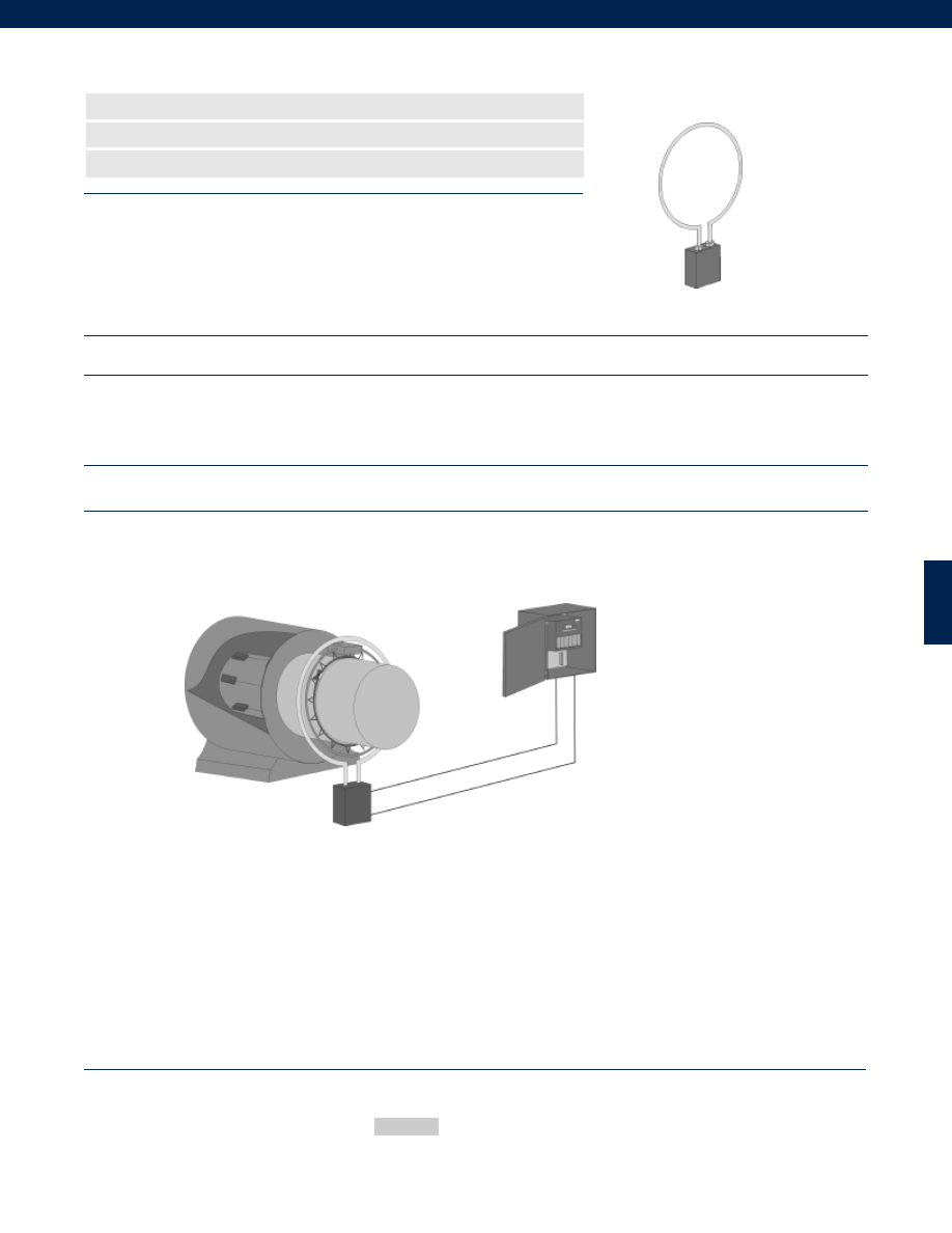
289
www.honeywell.com/sensotec
1-888-282-9891
Model 1211D Power Separation Unit
Order Code 1000-1211
n
Used by the 1200 and 1700 Series Products
n
Maximum Cable Length of 500 ft. to Receiver
n
Aluminum Case Material
Environmental
Electrical
Mechanical
Typical System Diagrams
Temperature, Operating................5° to 122° F
Weight................3 lb.
Induction Power Source................160 kHz +/- 6%
Cable Length (PSU to Receiver)................Varies on application
Max. Cable Length (PSU to Receiver)................500 ft.
Electrical Termination................BNC Female
Mating Connector................BNC Male
Dimensions................6” L x 4” W x 2” H
Case Material................Aluminum
How to Order
1211D As part of the 1700 monitoring system
The 1211D Power Separation Unit (PSU) is a flange mounted box which contains an
impedance matching transformer and resonation capacitance decade switch. This device
matches the high voltage low current 160 kHz oscillator power source to the low voltage
high current single loop stationary antenna inserted into connections of the 1211D. In
addition to transferring power to the transmitter, the antenna also receives the RF data
signal and routes it via coaxial cable to the receiver for processing.
Order Code
Enter the order code.
Sample Code
1000-1211
Courtesy of Steven Engineering, Inc.-230 Ryan Way, South San Francisco, CA 94080-6370-Main Office: (650) 588-9200-Outside Local Area: (800) 258-9200-www.stevenengineering.com
Sensotec Sensors Full Line Catalog-html.html
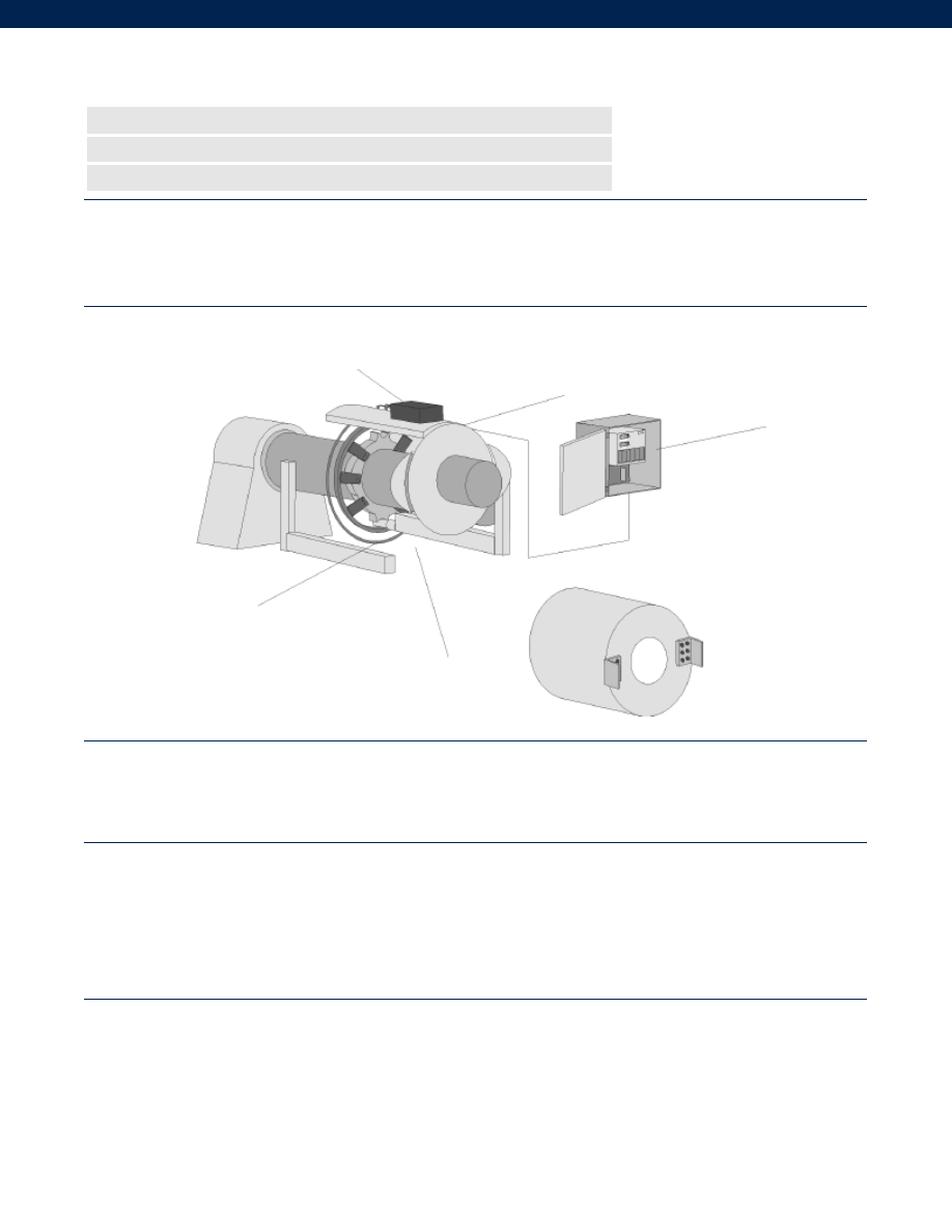
290
The 1602A Propulsion Monitoring System fits shaft sized from 15" to 30" in diameter. The system is enclosed in a strong outer cover and
has an electronics readout assembly in a water tight enclosure. These units together provide the means for measuring shaft torque and rpm.
Digital readouts are available to display torque, rpm and computed horsepower. Built-in calibration check circuitry can be activated at any
time to verify that all local displays and outputs are functional. Enhanced stability and reduced maintenance are the payback for selecting
this system. The Model 1602A/-01systems can be used in a variety of potential applications including fuel conservation programs, hull and
propeller fouling, load and balancing on twin screw vessels, power plant monitor and sea trial torsionmeter.
Model 1602A/ 1602A-01* Propulsion Monitoring Systems
Order Code WM1000(1602A)/ WM1100(1602A-01)
n
Cost Effective
n
Enhanced Stability
n
Shaft Sizes From 15” to 30”
Shaft mounted components
weight = 61 lb.
Shown with cover partly removed
Power tuning unit
RPM Probe
Model 1642A
Power and RPM Display
Typical System Diagram
Performance
Environmental
Electrical
Torque Ranges................Varies on application; consult factory
Frequency Response................DC to 1,000 Hz
Sensitivity (Transmitter)................300 microstrain
Number of channels................1 to 3 (Torque, RPM, HP)
Sampling Rate................5 kHz
Receiver Readout Display Type................3.5 digit 7 segment LED
Temperature, Operating (Transmitter)................5° to 167° F
Temperature, Operating (Receiver/ IPS/ PSU)................50° to 122° F
Temperature, Compensated (Transmitter)................40° to 140° F
Temperature, Compensated (Receiver)................50° to 122° F
Static G Force (Rotating components)................100 G’s
RPM Limits (Rotating components)................See graph- depends on shaft diameter
Vibration (Rotating components)................10 G to 1 kHz
Collar Weight................Varies with shaft diameter
Electronics Weight (not including cables)................Receiver and PSU 33 lb.
Induction Power Source................160 kHz +/- 6%
Cable Length (PSU to Receiver)................Cables NOT included
Max. Cable Length (PSU to Receiver)................100 ft.
Power Supply Voltage (Receiver)................115- 230 VAC (user-selectable)
Power Consumption (Receiver)................100 VA max.
RF Operating Frequency................16 MHz
RF Modulation Type................FSK
Max. Analog Output (Receiver)................+/- 10 VDC@ 1 mA max.
Output Impedance (Receiver)................< 1 Ohm
Electrical Termination (Receiver Output)................Screw Terminal
* 1602A and 1602A-01 are identical except that 1602A-01 is for torque measurement only.
www.honeywell.com/sensotec
1-888-282-9891
Courtesy of Steven Engineering, Inc.-230 Ryan Way, South San Francisco, CA 94080-6370-Main Office: (650) 588-9200-Outside Local Area: (800) 258-9200-www.stevenengineering.com
Sensotec Sensors Full Line Catalog-html.html
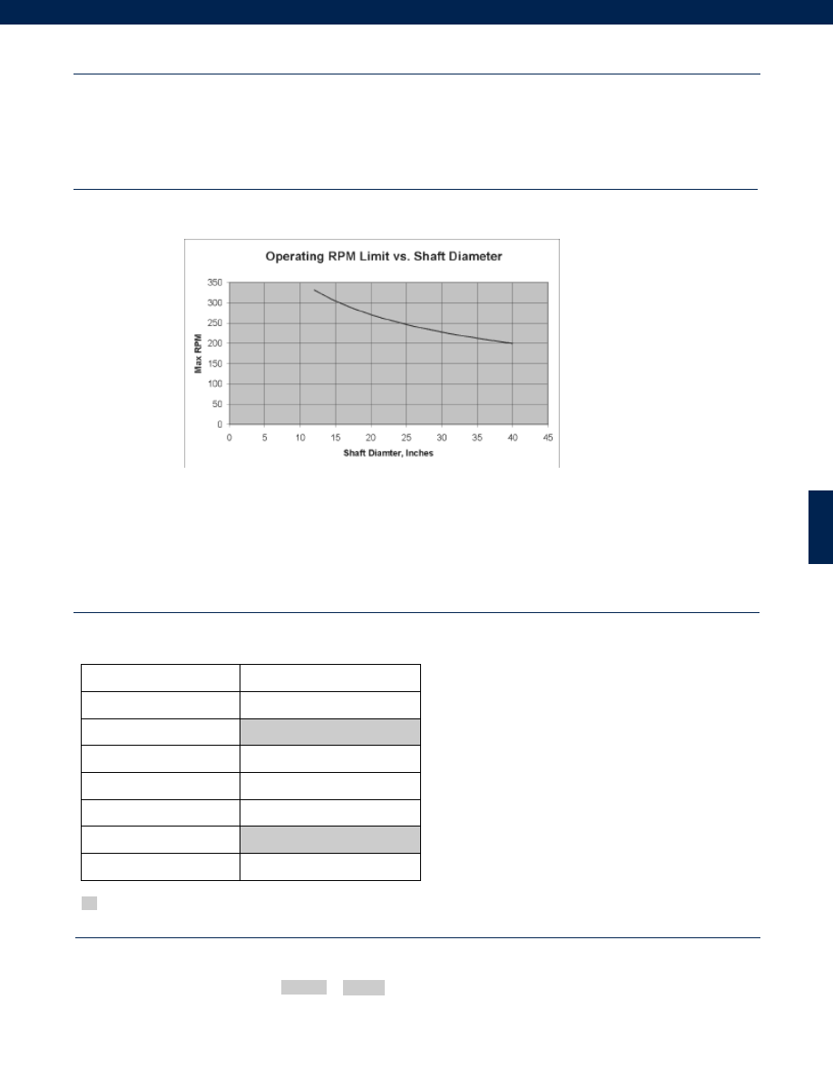
291
Mechanical
RPM Limits Graph
Model 1602A
Dimensions (Collar Cross Section)................Varies with shaft diameter
Dimensions (Receiver)................16” L x 20” W x 10” H
Dimensions (PSU)................Not Applicable (built into Shield Assembly)
Rotational Clearance (Collar)................Varies with shaft diameter
Shaft Diameter Limits (Collar)................15” to 30”
Collar Material................Zinc-Plated Steel
Built to Order
Totalizer
62a. Horsepower-hour totalizer
62b. Revolutions totalizer
RF Operating Frequency
16 MHz (note 1)
Display (Receiver)
62c. Remote display
Analog Output (Receiver)
62e. 1 Channel 4-20 mA isolated output
62f. 2 Channel 4-20 mA isolated output
Filter (Receiver)
62d. EMI filter
Collar Material
Zinc-Plated Steel (note 2)
Shock & vibration
62g. Heavy duty shield and receiver
Supplied as standard
Options Notes
How to Order
Combine the order code and the options code.
Order Code Options Code
Sample Code: WM1100 62c
1.
Other frequencies available. Consult factory.
2.
Other collar materials available. Consult factory.
www.honeywell.com/sensotec
1-888-282-9891
Courtesy of Steven Engineering, Inc.-230 Ryan Way, South San Francisco, CA 94080-6370-Main Office: (650) 588-9200-Outside Local Area: (800) 258-9200-www.stevenengineering.com
Sensotec Sensors Full Line Catalog-html.html
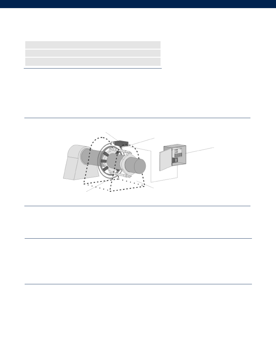
292
Typical System Diagram
Performance
Environmental
Electrical
www.honeywell.com/sensotec
n
Enhanced Stability
n
Enables Installation in Tight Spaces
n
Shaft Sizes From 2.5” to 30”
Model 1603A/ 1603A-01* Propulsion Monitoring System
(without cover)
Order Code WM1200(1603A)/ WM1300(1603A-01)
1-888-282-9891
Torque Ranges................Varies on application; consult factory.
Frequency Response................DC to 1,000 Hz
Sensitivity (Transmitter)................300 microstrain
Number of channels................1 to 3 (Torque, RPM, HP)
Sampling Rate................5 kHz
Receiver Readout Display Type................3.5 digit 7 segment red LED
Temperature, Operating (Transmitter)................5° to 167° F
Temperature, Operating (Receiver/ IPS/ PSU)................50° to 122°F
Temperature, Compensated (Transmitter)................40° to 140°F
Temperature, Compensated (Receiver)................50° to 122°F
Static G Force (Rotating components)................100 G’s
RPM Limits (Rotating components)................See Graph - depends on shaft diameter
Vibration (Rotating components)................10 G to 1 kHz
Collar Weight................varies with shaft diameter
Electronics Weight (not including cables)................Receiver and PSU 33 lb.
Induction Power Source................160 kHz +/- 6%
Cable Length (PSU to Receiver)................Cables NOT included
Max. Cable Length (PSU to Receiver)................100 ft.
Power Supply Voltage (Receiver)................115/ 230 VAC (user-selectable)
Power Consumption (Receiver)................100 VA max.
RF Operating Frequency................16 MHz
RF Modulation Type................FSK
Max. Analog Output (Receiver)................+/- 10 VDC @ 1 mA max.
Output Impedance (Receiver)................< 1 Ohm
Electrical Termination (Receiver Output)................Screw Terminal
* 1603A and 1603A-01 are identical except that 1603A-01 is for torque measurement only.
The Model 1603A/-01 Power Measurement System is identical to the Model 1602A System except for the elimination of the cover over the
shaft sensor unit which enables installation in tight spaces such as under existing covers or deck plates. The system fits shaft sizes from
2.5” to 30” in diameter. The system has an electronics readout assembly in a water tight enclosure. These units together provide means for
measuring shaft torque and rpm. Digital readouts are available to display torque, rpm and computed horsepower. Built-in calibration check
circuitry can be activated at any time to verify that all local displays and outputs are functional. Enhanced stability and reduced maintenance
are the payback for selecting this system. The Model 1603A/-01 systems can be used in a variety of potential applications including fuel
conservation programs, hull and propeller fouling, power plant monitor and sea trial torsionmeter.
Shaft mounted components
weight = 61lb.
User supplied safety cover
Model 1642A
Power and RPM display
RPM probe
Power Tuning Unit
Courtesy of Steven Engineering, Inc.-230 Ryan Way, South San Francisco, CA 94080-6370-Main Office: (650) 588-9200-Outside Local Area: (800) 258-9200-www.stevenengineering.com
Sensotec Sensors Full Line Catalog-html.html
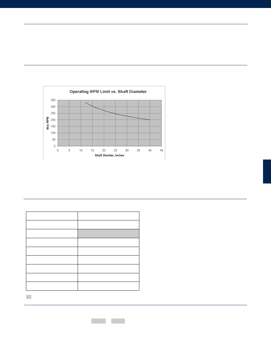
293
www.honeywell.com/sensotec
RPM Limits Graph
Mechanical
1-888-282-9891
Model 1603A
Dimensions (Collar Cross Section)................Varies with shaft diameter
Dimensions (Receiver)................16” L x 20” W x 10” H
Dimensions (PSU)................6” L x 4” W x 2” H
Rotational Clearance (Collar)................2.5” all around
Shaft Diameter Limits (Collar)................2.5” to 30”
Collar Material................Phenolic/ Aluminum or Steel
Built to Order
Totalizer
62a. Horsepower-hour totalizer
62b. Revolutions totalizer
RF Operating Frequency
16 MHz (note 1)
Display (Receiver)
62c. Remote display
Analog Output (Receiver)
62e. 1 Channel 4-20 mA isolated output
62f. 2 Channel 4-20 mA isolated output
Filter (Receiver)
62d. EMI filter
RPM Sensor
62m. Optical
62l. Magnetic
System Material
62k. Non-magnetic
Shock & vibration
62j. Vibration/Shock rated PSU
Supplied as standard
Options Notes
How to Order
Combine the order code and the options code.
Order Code Options Code
Sample Code: WM1200 62c
1.
Other frequencies available. Consult factory.
Courtesy of Steven Engineering, Inc.-230 Ryan Way, South San Francisco, CA 94080-6370-Main Office: (650) 588-9200-Outside Local Area: (800) 258-9200-www.stevenengineering.com
Sensotec Sensors Full Line Catalog-html.html
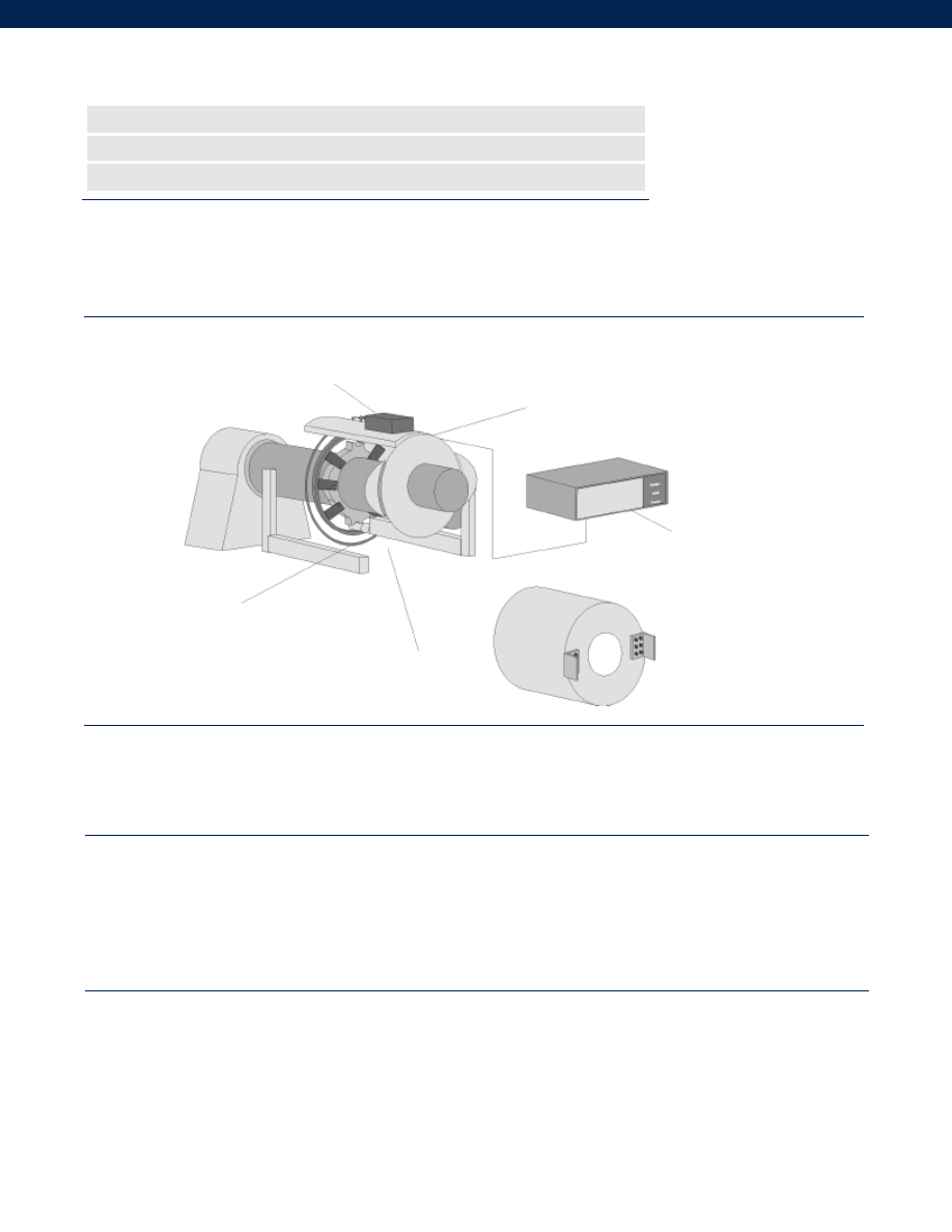
294
Typical System Diagram
Performance
Environmental
Electrical
www.honeywell.com/sensotec
n
Enhanced Stability
n
Readout can Handle all Diesel and Turbine Power Plants
n
Shaft Sizes From 15” to 30”
Model 1605A Horsepower Monitoring System
Order Code WM1400
1-888-282-9891
The Model 1605B Universal power and torque measurement system consists of bolt-on shaft sensor units for shafts between 15” and 30,”
which can handle most diesel and turbine power plants. Most ranges of rpm and power are accommodated with large over range capabili-
ty. The data band width is DC to 1000 Hz, allowing for torsional vibration measurement without a second monitoring system.
Power Tuning Unit
RPM probe
Shown with cover partly removed
Shaft mounted components
weight = 61 lb.
Model 1645B
Power and RPM display
in rack mount format
Torque Ranges................Varies on application; consult factory.
Frequency Response................DC to 1,000 Hz
Sensitivity (Transmitter)................300 microstrain
Number of channels................1 to 3 (Torque, RPM, HP)
Sampling Rate................5 kHz
Receiver Readout Display Type................3.5 digit 7 segment red LED
Temperature, Operating (Transmitter)................5° to 167° F
Temperature, Operating (Receiver/ IPS/ PSU)................50° to 122°F
Temperature, Compensated (Transmitter)................40° to 140°F
Temperature, Compensated (Receiver)................50° to 122°F
Static G Force (Rotating components)................100 G’s
RPM Limits (Rotating components)................See Graph - depends on shaft diameter
Vibration (Rotating components)................10 G to 1 kHz
Collar Weight................varies with shaft diameter
Electronics Weight (not including cables)................Receiver and PSU 33 lb.
Induction Power Source................160 kHz +/- 6%
Cable Length (PSU to Receiver)................Cables NOT included
Max. Cable Length (PSU to Receiver)................100 ft.
Power Supply Voltage (Receiver)................115/ 230 VAC (user-selectable)
Power Consumption (Receiver)................100 VA max.
RF Operating Frequency................16 MHz
RF Modulation Type................FSK
Analog Output (Receiver)................+/- 10 VDC @ 1 mA max.
Output Impedance (Receiver)................< 1 Ohm
Electrical Termination (Receiver Output)................BNC Female
Mating Connector (Receiver Output)................BNC Male
Courtesy of Steven Engineering, Inc.-230 Ryan Way, South San Francisco, CA 94080-6370-Main Office: (650) 588-9200-Outside Local Area: (800) 258-9200-www.stevenengineering.com
Sensotec Sensors Full Line Catalog-html.html
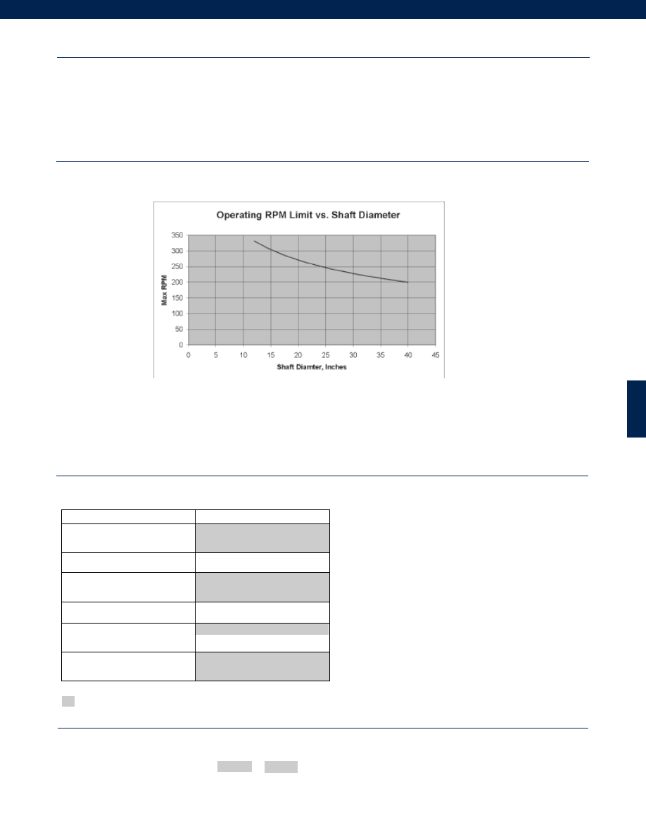
295
www.honeywell.com/sensotec
RPM Limits Graph
Mechanical
Supplied as standard
Options Notes
How to Order
Combine the order code and the options code.
Order Code Options Code
Sample Code: WM1400 62c
1-888-282-9891
Model 1605A
Dimensions (Collar Cross Section)................Varies with shaft diameter
Dimensions (Receiver)................17” L x 18” W x 5.25” H
Dimensions (PSU)................6” L x 4” W x 2” H
Rotational Clearance (Collar)................Varies with shaft diameter
Shaft Diameter Limits (Collar)................15” to 30”
Collar Material................Zinc-Plated Steel
Built to Order
RF Operating Frequency
16 MHz (note 1)
Display (Receiver)
62c. Remote display
Collar Material
Zinc-Plated Steel
Shock & Vibration (PSU)
62j. Vibration/ Shock rated PSU
Analog Output
62e. 4-20 mA isolated output
RPM Sensor
Optical RPM-multireading
+/- 10 VDC @ 1 mA max.
1.
Other frequencies available. Consult factory.
Courtesy of Steven Engineering, Inc.-230 Ryan Way, South San Francisco, CA 94080-6370-Main Office: (650) 588-9200-Outside Local Area: (800) 258-9200-www.stevenengineering.com
Sensotec Sensors Full Line Catalog-html.html
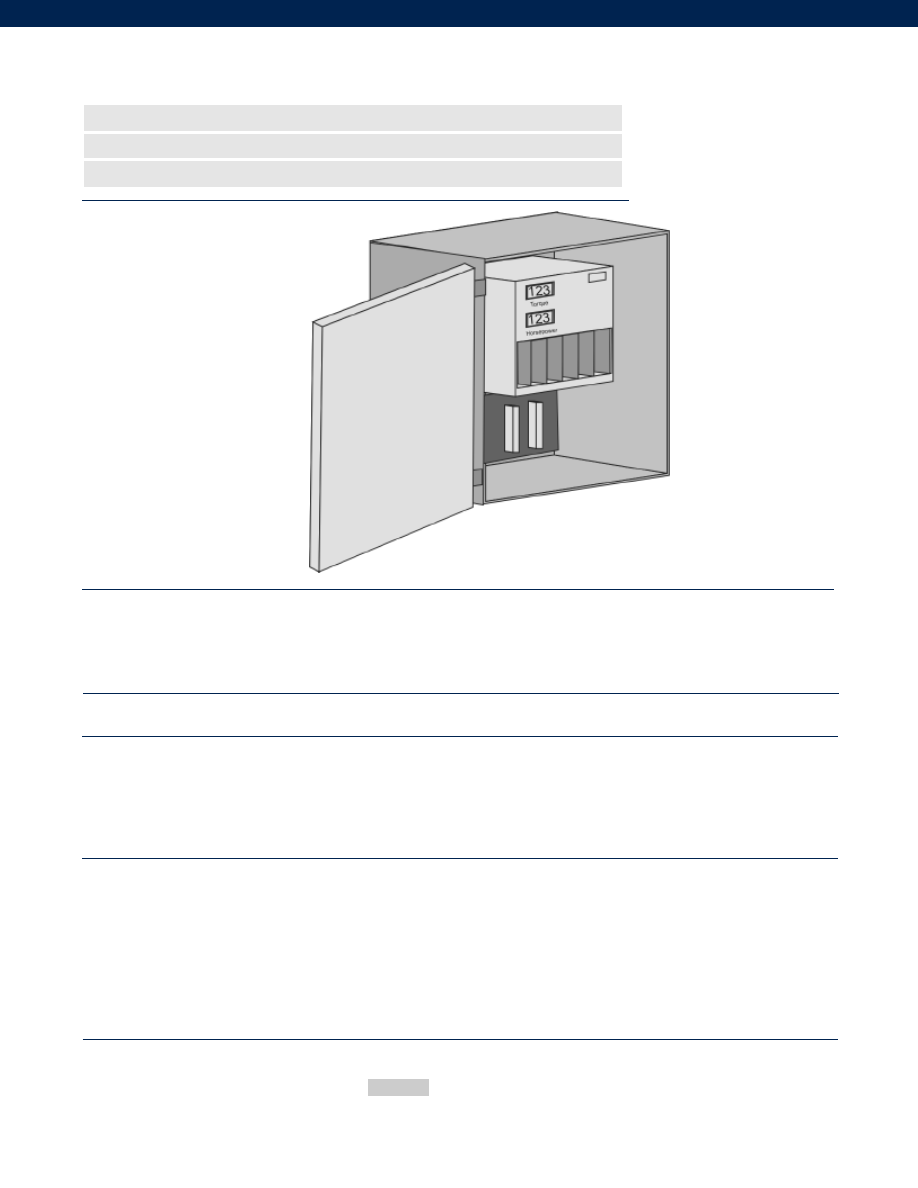
296
Performance
Environmental
Electrical
Mechanical
www.honeywell.com/sensotec
n
+/- 0.75% of Full Scale Torque Accuracy
n
+/- 1% of Full Scale Power Accuracy
n
DC to 1000 Hz Frequency Response
Model 1642 Receiver/ Display Unit
Order Code 1000-1642
1-888-282-9891
........+/- 3 1/2 digits
........DC to 1000 Hz (3-dB limit)
........+/- 0.75% of Full Scale
........+/- 0.25% of Full Scale
........+/- 1% of Full Scale
........50° to 120° F
........30 lb.
........+/- 5 V scaled (+100% overrange, HP system only)
........0-10 V scaled
........0-10 V scaled
........<1.0 Ohm resistive nominal
........115/ 230 VAC (-15% to + 10%) selectable, 50/ 60 Hz
........100 VA max.
........Aluminum NEMA type 4 (water tight) wall mounting
........16” wide by 20” high by 10” deep
........Screw terminals
Readout Unit Displays (2)
Frequency Response
Accuracy
Torque
RPM
Power
Temperature, Operating
Weight
Analog Recorder Outputs
Torque
RPM
Power
Recorder Output Impedance
Power Requirements
Power Consumption
Enclosure- type
Enclosure- size
Output and Input Connections
How to Order
Order Code
Enter the product order code
Sample Code 1000-1642
Courtesy of Steven Engineering, Inc.-230 Ryan Way, South San Francisco, CA 94080-6370-Main Office: (650) 588-9200-Outside Local Area: (800) 258-9200-www.stevenengineering.com
Sensotec Sensors Full Line Catalog-html.html
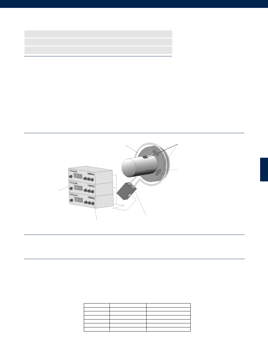
297
Up to 6 Single Channel Units
2145A
Receiver
All units running at
different frequencies
13-22 MHz in 1 MHz steps
IPS
2175-01 (1-3 Channels)
2175-02(4-6 Channels)
2147A Cable
2126A Collar
(2 to 42 in. diameter)
Note: Transducer Models
RTC, 6200 and 9300 can be
implemented into the
Model 2101System, replacing
current collar.
2120B Transmitters
Note: With one channel (2101
System) there will be only one
Transmitter and one 2145A unit;
Picture here is a three channel
system (2103 System), thus three
transmitters and three 2145A units.
The 2100 series Rotary Torque Measurement Systems are well suited for both short and long term testing and monitoring of torque or strain
on rotating applications where other measurement methods are affected by vibration, dust, moisture, high RPMs, and large axial/ radial shaft
movements. The custom machined collar assembly, stationary loop antenna, induced power supply (IPS), and receiver are pre-tested as a
set at the factory, enabling quick installation and setup of the system for the user. The collar has a preassembled antenna, embedded trans-
mitter with pins for connecting to strain gages, and high-strength bolts to clamp on just about any type of shaft. The transmitter is powered
by an AC voltage coupled from the stationary loop antenna to the antenna built into the collar. The transmitter provides a regulated excita-
tion to the strain gages and converts the resulting low-voltage signal from the strain gage to a radio frequency (RF) signal. This RF signal is
sent back to the receiver unit through the stationary antenna loop and IPS. The receiver converts the RF signal to a bipolar DC voltage that
is proportional to the amount of torque or strain. This voltage is accessible via a BNC connector on the receiver so the user can interface to
a chart recorder or Data Acquisition System. A scalable analog output and numeric display readout on the receiver provides an electrical
and visual indication of the measurement. The receiver provides controls for gain and zero adjustments, display scaling, and IPS power set-
ting. A combination of up to six transmitters and receivers operating on different frequencies will provide up to six points of measurement on
the same shaft. Please contact the factory if more than six points of measurement are required.
Because the 2100 series systems are designed for a variety of rotating applications, strain gages are not included with the system.
However, Honeywell Sensotec will custom gage your shaft or rotating component (e.g. turbine blade) to provide a complete pre-calibrated
rotary measurement system. Please contact your Honeywell Sensotec sales representative for further details.
Typical System Diagram
Performance
Environmental
www.honeywell.com/sensotec
1-888-282-9891
Frequency Response................DC to 1,000 Hz
Sensitivity (Transmitter)................175 microstrain (0.5mV/V)
Number of channels................See table below
Sampling Rate................10 kHz
Receiver Readout Display Type................3.5 digit 7 segment LED
Temperature, Operating (Transmitter)................-67° to 257° F
Temperature, Operating (Receiver/ IPS/ PSU)................5° to 149°F
Temperature, Compensated (Transmitter)................32° to 167°F
Temperature, Compensated (Receiver)................32° to 127°F
Static G Force (Rotating components)................15,000 G’s
RPM Limits (Rotating components)................See Graph - depends on shaft diameter
Vibration (Rotating components)................100 G to 1 kHz
Collar Weight................varies with shaft diameter
Electronics Weight (not including cables)................See table below
Model 2101 to 2106 Rotary Measurement Systems
1 to 6 Channel Systems
n
Quick Short Term Installation
n
1 to 6 Channels Wireless Telemetry
n
Clamp-on Collar Machined to Fit Each Application
Order Code
Number of Channels
Electronics Weight
WN1100
1
Receiver and IPS 7.5 lb.
WN1200
2
Receiver and IPS 14 lb.
WN1300
3
Receiver and IPS 20 lb.
WN1400
4
Receiver and IPS 26 lb.
WN1500
5
Receiver and IPS 32 lb.
WN1600
6
Receiver and IPS 38 lb.
0.25” to 0.5” air gap
Courtesy of Steven Engineering, Inc.-230 Ryan Way, South San Francisco, CA 94080-6370-Main Office: (650) 588-9200-Outside Local Area: (800) 258-9200-www.stevenengineering.com
Sensotec Sensors Full Line Catalog-html.html
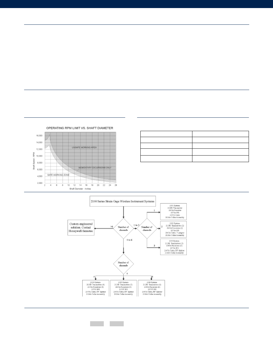
298
www.honeywell.com/sensotec
RPM Limits Graph
Options
Selection Guide
How to Order
Combine the order code and the available options.
Order Code Options Code
Sample Code WN1100 62s
1-888-282-9891
Model 2100 Series
Electrical
Mechanical
Induction Power Source................160 kHz +/- 6%
Cable Length (IPS to Receiver)................15 ft. std. (note 1)
Max. Cable Length (IPS to Receiver)................100 ft.
Power Supply Voltage (Receiver)................120/ 240 VAC user-selectable
Power Consumption (Receiver)................200 VA max.
RF Operating Frequency................Factory set, 13-22 MHz, 1MHz steps
RF Modulation Type................PWM
Signal Strength Indicator (Receiver)................LED Bargraph
Analog Output (Receiver)................+/- 10 VDC @ 1mA max.
Output Impedance (Receiver)................< 1 Ohm
Electrical Termination (Receiver Output)................BNC female
Mating Connector (Receiver Output)................BNC male
Electrical Termination (Transmitter)................9 pins, 0.025 in. diameter pins
Output Filter Capability (Receiver)................user selectable 1,000, 500,200,100, 1 Hz
Dimensions (Collar Cross Section)................1.25” x 1.25” Typical (6” OD min.)
Dimensions (Receiver)................11.5” L x 8.6” W x 3.5” H
Dimensions (IPS)................6” L x 4” W x 2.5” H
Shaft Diameter Limits (Collar)................2” to 42”
Collar Material................Type G-11 Glass epoxy
Built to Order
Max. Transmitter Temperature
62s. 100° C
Environmental Protection (IPS)
62h. Nema IPS
Receiver Power Supply
62v. DC (specify 12 VDC or 24 VDC)
Voltage Pin Access
62t. Unregulated Voltage (No Tie Pin)
Notes:
1. Consult factory for other cable lengths.
Courtesy of Steven Engineering, Inc.-230 Ryan Way, South San Francisco, CA 94080-6370-Main Office: (650) 588-9200-Outside Local Area: (800) 258-9200-www.stevenengineering.com
Sensotec Sensors Full Line Catalog-html.html
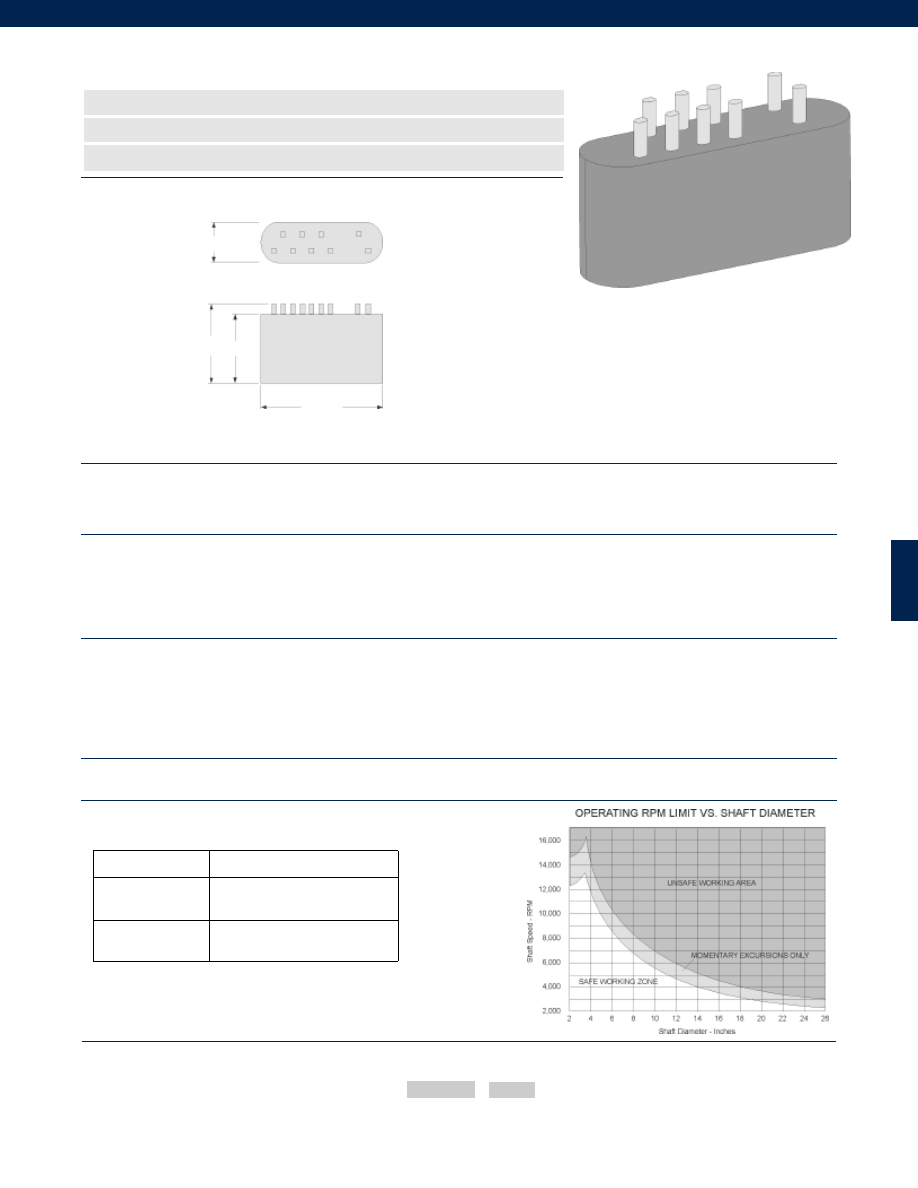
299
www.honeywell.com/sensotec
1-888-282-9891
Model 2120B/C Strain Gage Transmitter
Order Code 1000-2120
n
5 VDC Regulated Excitation
n
175 Microstrain Sensitivity
n
One Channel
Dimensions
Performance
Environmental
Electrical
Mechanical
Options
Frequency Response................DC to 1,000 Hz
Sensitivity (Transmitter)................175 microstrain (0.5 mV/V)
Number of Channels................1
Sampling Rate................10 kHz
Temperature, Operating................-67° to 257° F
Temperature, Compensated................32° to 167° F
Static G Force (Rotating Components)................15,000 G’s
RPM Limits (Rotating Components)................See graph- depends on shaft diameter
Vibration (Rotating Components)................100 G to 1 kHz
Weight................0.036 lb. typical
Induction Power Source................160 kHz +/- 6%
RF Operating Frequency................Factory set, 13-22 MHz, 1 MHz steps (specify
................frequency in Order Code
RF Modulation Type................PWM (FSK)
Bridge Excitation (Transmitter)................5 VDC @ 15 mA
Bridge Resistance (Transmitter)................350 Ohm min.
Electrical Termination................9 pins, 0.025” diameter
Dimensions................1.5” L x 0.88” W x 0.5” H (not including pins)
Case Material................Glass-Fiber DAP Resin
How to Order
0.50 in.
1.50 in.
0.85 in.
0.97 in.
Order Code Options Code
Combine the order code and option code.
Sample Code
1000-2120 62s
RPM Limits Graph
Built to Order
Extended
Temperature Range
62s. Max. 100°C Operating temp.
Pin Access
62t. Unregulated Voltage Pin
Courtesy of Steven Engineering, Inc.-230 Ryan Way, South San Francisco, CA 94080-6370-Main Office: (650) 588-9200-Outside Local Area: (800) 258-9200-www.stevenengineering.com
Sensotec Sensors Full Line Catalog-html.html
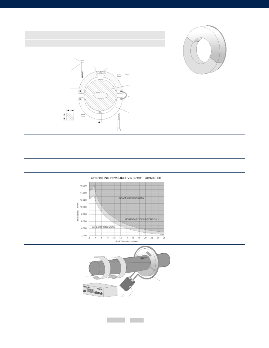
300
www.honeywell.com/sensotec
1-888-282-9891
Model 2126A Rotating Shaft Collar with Rotary Antenna
Order Code 1000-2126
n
Type G-11 Glass Epoxy Collar Material
n
Shaft Sizes From 2” to 42”
Environmental
Mechanical
RPM Limits Graph
Typical System Diagram
Temperature, Operating................-67° to 257° F
Static G Force (Rotating Components)................15,000 G’s
RPM Limits (Rotating Components)................See graph- depends on shaft diameter
Vibration (Rotating Components)................100 G to 1 kHz
Weight................Varies with shaft diameter
Shaft Diameter Limits (Collar)................2” to 42”
Collar Material................Type G-11 Glass Epoxy
How to Order
Transmitter
cavity
Hold down pan head
screw & washer
Self locking nut each side
Shaft diameter must be
specified to +/- 0.005 in.
Bus wire jumper each side
Collar density .07 lb./ in.3
Rotary antenna on opposite
side of collar
5/16” x 24 high strength
socket head bolt each side
Special washer each side
Collar material:
Glass epoxy G-11
For shafts below 3.5”
collar diameter is fixed
at 6”
1.25”
1.25”
A-A
A
A
Shaft
The 2126A as part of the 2100 System
Torque Measurement
Order Code
Shaft O.D.(in.)
Enter the order code and specify the shaft O.D. to +/- 0.005 in.
Sample Code 1000-2126 24.000
0.25” to 0.5” air gap
Courtesy of Steven Engineering, Inc.-230 Ryan Way, South San Francisco, CA 94080-6370-Main Office: (650) 588-9200-Outside Local Area: (800) 258-9200-www.stevenengineering.com
Sensotec Sensors Full Line Catalog-html.html
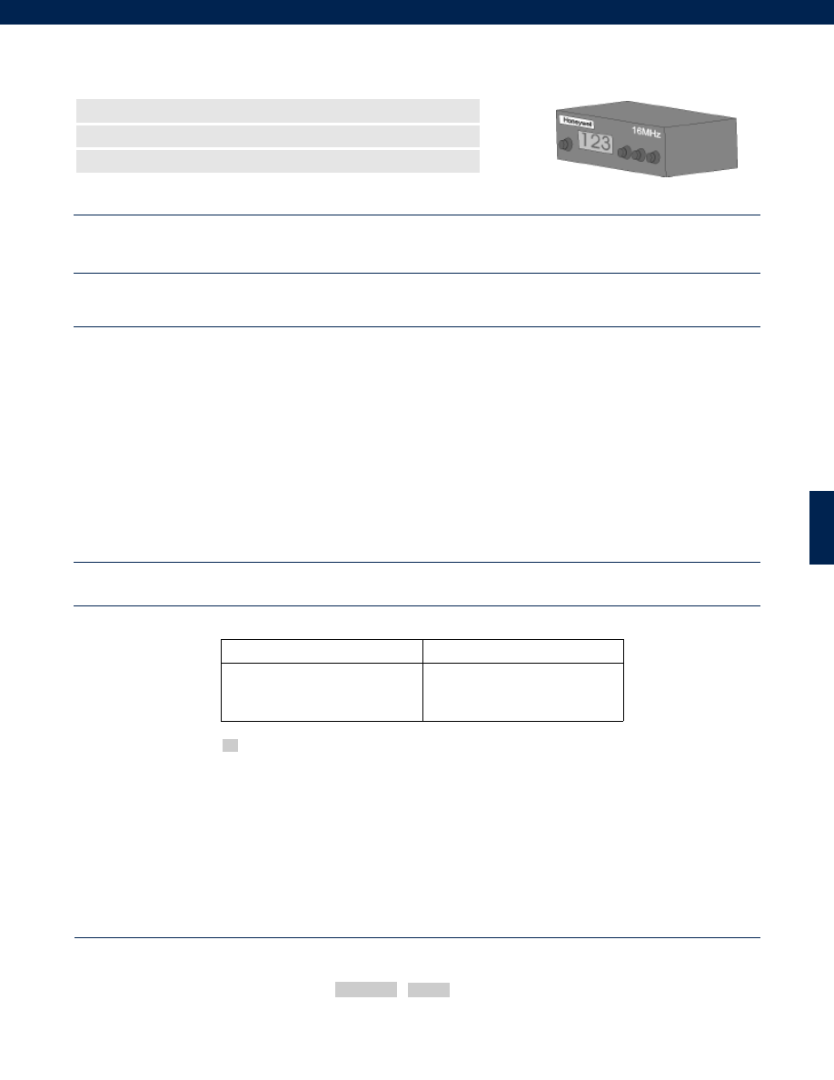
301
Model 2145AC/ DC Receiver
Order Code 1000-2145
n
Scalable +/- 10 VDC Output
n
User Selectable Output Filter
n
DC to 1,000 Hz Frequency Response
Performance
Environmental
Electrical
Mechanical
Options
Frequency Response................DC to 1,000 Hz
Number of Channels................1
Receiver Readout Display Type................3.5 digit 7-segment LED
Temperature, Operating................5° to 149° F
Temperature, Compensated................32° to 127° F
Weight................6 lb.
Induction Power Source................To IPS 7.5 to 15 VDC @ 500 mA
Cable Length (IPS/ PSU to Receiver)................15 ft. standard
Max. Cable Length (IPS/ PSU to Receiver)................100 ft.
Power Supply Voltage
2145AC................120/ 240 VAC user-selectable
2145DC................10-18 VDC or 18-32 VDC
Power Consumption
2145AC................200 VA max.
2145DC................1,500 mA @ 12 VDC, 800 mA @ 24 VDC
RF Operating Frequency................Factory set, 13-22 MHz, 1 MHz steps
RF Modulation Type................PWM (FSK)
Signal Strength Indicator (Receiver)................LED Bargraph
Analog Output (Receiver)................+/- 10 VDC @ 1 mA max.
Output Impedance (Receiver)................< 1 Ohm
Electrical Termination................BNC Female
Mating Connector................BNC Male
Output Filter Capability (Receiver)................user selectable 1,000, 500, 200, 100, 1 Hz
Dimensions................11.5” L x 8.6” W x 3.5” H
Case Material................Aluminum
Built to Order
DC Input Power
62u. Please Specify:
A. 10-18 VDC @ 1500 mA
B. 18-32 VDC @ 800 mA
Supplied as standard
Order Code Options Code
The order code consists of the order code and the available options.
How to Order
Sample Code
1000-2145 62u-A
1-888-282-9891
Courtesy of Steven Engineering, Inc.-230 Ryan Way, South San Francisco, CA 94080-6370-Main Office: (650) 588-9200-Outside Local Area: (800) 258-9200-www.stevenengineering.com
Sensotec Sensors Full Line Catalog-html.html
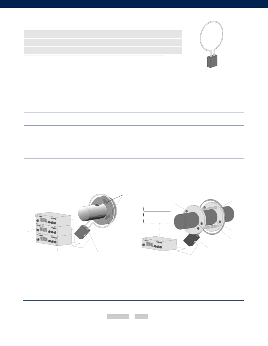
302
Up to 3 Single Channel Units (note 1)
2145A
Receiver
All units running at
different frequencies
13-22 MHz in 1 MHz steps
Model 2175
Induction Power supply
2147A Cable
2126A Collar
2120B Transmitters
Customer Supplied
Chart Recorder
Data Acquisition
Clamp on Collar
Stationary Loop
Antenna
Model 2175A
Induction Power Supply
Model 9300
Antenna Collar
attached to Model 9300
Model 2145AC Receiver
Cable Assembly
www.honeywell.com/sensotec
1-888-282-9891
Model 2175A Induced Power Supply Unit
Order Code 1000-2175
n
Used by the 2100 Series Products up to 3 Channels (note 1)
n
No Physical Contact to Rotating Components
n
User Accessible Tuning for Different Antenna Diameters
Environmental
Electrical
Mechanical
Typical System Diagrams
Notes
Temperature, Operating................5° to 149° F
Weight................1.5 lb.
Induction Power Source................160 kHz +/- 6%
Cable Length (IPS to Receiver)................15 ft. standard
Max. Cable Length (IPS to Receiver)................100 ft.
Power Supply Voltage................7.5 to 15 VDC
Power Consumption................500 mA max.
Electrical Termination................input: BNC Female
Mating Connector................BNC Male
Dimensions................6” L x 4” W x 2.5” H
Case Material................Aluminum Alloy
Order Code Diameter Code
Combine the order code and antenna diameter code.
How to Order
2175 As part of the 2100 monitoring system
2175 As part of the 9300 torque monitoring system
The 2100 Series products use the 2175A Induction Power Supply (IPS) for systems up to 3 channels
(note 1). The 2175 IPS receives variable DC power via the coaxial cable connected to the receiver.
The IPS contains an oscillator that operates at 160 kHz whose signal is fed to current amplifiers. The
current amplifiers drive a resonant transformer/ capacitor circuit through the stationary antenna. The
160 kHz power is coupled into the rotating antenna loop as in an air core transformer. The RF signal
is received from the rotation antenna loop capacitively. A toroid transformer in the IPS separates the
RF signal from the 160 kHz and places it on the coaxial cable for routing to the receiver. Internal
switches and capacitor sockets allow user to adjust IPS for best resonance at various antenna sizes.
For antenna diameters up to 12” use order code 1000-2175A-01. For antenna diameters greater than
12” use order code 1000-2175A-02.
Sample Code
1000-2175A
- 01
1.
For more than 3 channel systems consult factory.
Courtesy of Steven Engineering, Inc.-230 Ryan Way, South San Francisco, CA 94080-6370-Main Office: (650) 588-9200-Outside Local Area: (800) 258-9200-www.stevenengineering.com
Sensotec Sensors Full Line Catalog-html.html
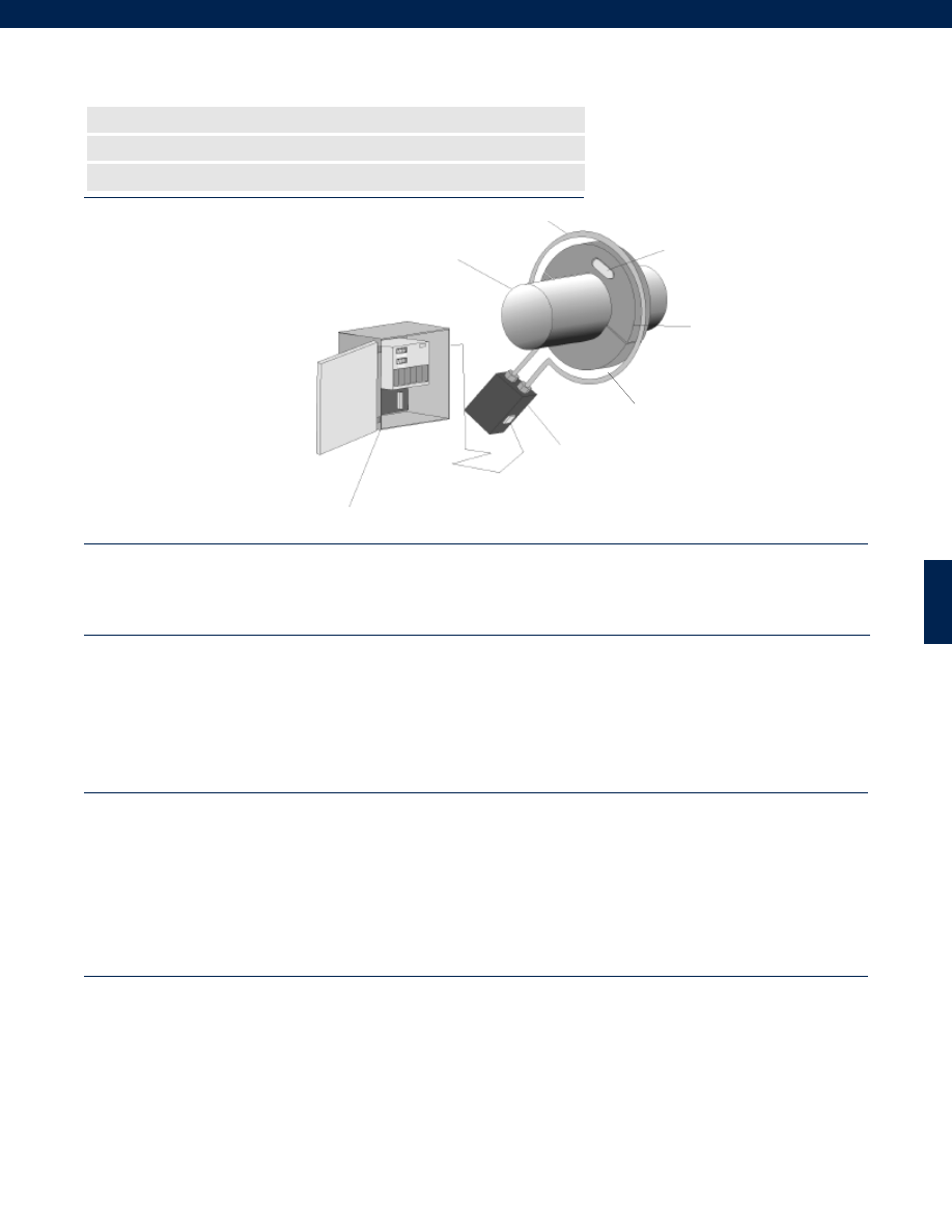
303
Performance
Environmental
Electrical
Mechanical
www.honeywell.com/sensotec
1-888-282-9891
n
DC to 1,000 Hz Frequency Response
n
1-3 Channels Wireless Telemetry
n
175 microstrain (0.5 mV/V) Transmitter Sensitivity
Frequency Response................DC to 1,000 Hz
Sensitivity (Transmitter)................175 microstrain (0.5mV/V)
Number of channels................1 to 3
Sampling Rate................10 kHz
Receiver Readout Display Type................3.5 digit 7 segment LED
Temperature, Operating (Transmitter)................-67° to 257° F
Temperature, Operating (Receiver/ IPS/ PSU)................50° to 122°F
Temperature, Compensated (Transmitter)................32° to 167°F
Temperature, Compensated (Receiver)................50° to 122°F
Static G Force (Rotating components)................15,000 G’s
RPM Limits (Rotating components)................See Graph - depends on shaft diameter
Vibration (Rotating components)................100 G to 1 kHz
Collar Weight................Varies with shaft diameter
Electronics Weight (not including cables)................Receiver and PSU 33 lb.
Induction Power Source................160 kHz +/- 6%
Cable Length (IPS to Receiver)................15 ft. std. (note 1)
Max. Cable Length (IPS to Receiver)................500 ft.
Power Supply Voltage (Receiver)................115/ 230 VAC user-selectable
Power Consumption (Receiver)................100 VA max.
RF Operating Frequency................10.7 MHz (note 2)
RF Modulation Type................FSK
Max. Analog Output (Receiver)................+/- 10 VDC @ 1mA max.
Output Impedance (Receiver)................< 1 Ohm
Electrical Termination (Receiver Output)................Screw Terminal
Electrical Termination (Transmitter)................9 pins, 0.025” diameter
Dimensions (Collar Cross Section)................1.25” x 1.25” Typical (6” OD min.)
Dimensions (Receiver)................16” L x 20” W x 10” H
Dimensions (IPS)................6” L x 4” W x 2” H
Shaft Diameter Limits (Collar)................2” to 42” (note 3)
Collar Material................Type G-11 Glass epoxy
Model 1202B Rotary Torque/ RPM/ HP Measurement System
Order Code WI1000
Typical System Diagram
1642A Receiver
1211D PSU
Customer Supplied Shaft
1226A Collar Assembly
2120B Transmitter
Stationary Antenna Loop
0.25” to 0.5” air gap
Courtesy of Steven Engineering, Inc.-230 Ryan Way, South San Francisco, CA 94080-6370-Main Office: (650) 588-9200-Outside Local Area: (800) 258-9200-www.stevenengineering.com
Sensotec Sensors Full Line Catalog-html.html
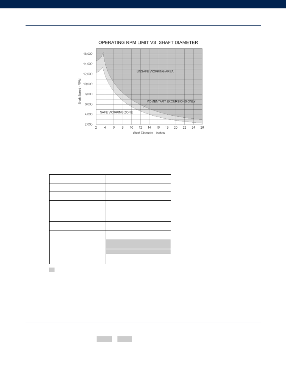
304
www.honeywell.com/sensotec
Supplied as standard
Options
RPM Limits Graph
1-888-282-9891
Model 1202B
Notes
1. 15ft. is the standard cable length, other lengths are available. Consult factory.
2. Consult factory for other frequencies.
3. 2” to 8” is standard shaft diameter, consult factory for other shaft diameters.
Built from Scratch
Max. Transmitter Temperature
62s. 100° C
Environmental Protection
62h. Nema IPS
Receiver
62a. Horsepower-hour totalizer
62b. Revolutions totalizer
Display (Receiver)
62c. Remote display
Filter (Receiver)
62d. EMI filter
Vibration & Shock (PSU)
62g. Heavy duty shield and receiver
RF Operating Frequency
10.7 MHz (note 1)
Analog Output (Receiver)
62e. 1 Channel 4-20 mA isolated output
62f. 2 Channel 4-20 mA isolated output
+/- 10 VDC @ 1 mA
How to Order
Combine the order code and the options code.
Order Code Options Code
Sample Code: WI1000 62c
Courtesy of Steven Engineering, Inc.-230 Ryan Way, South San Francisco, CA 94080-6370-Main Office: (650) 588-9200-Outside Local Area: (800) 258-9200-www.stevenengineering.com
Sensotec Sensors Full Line Catalog-html.html
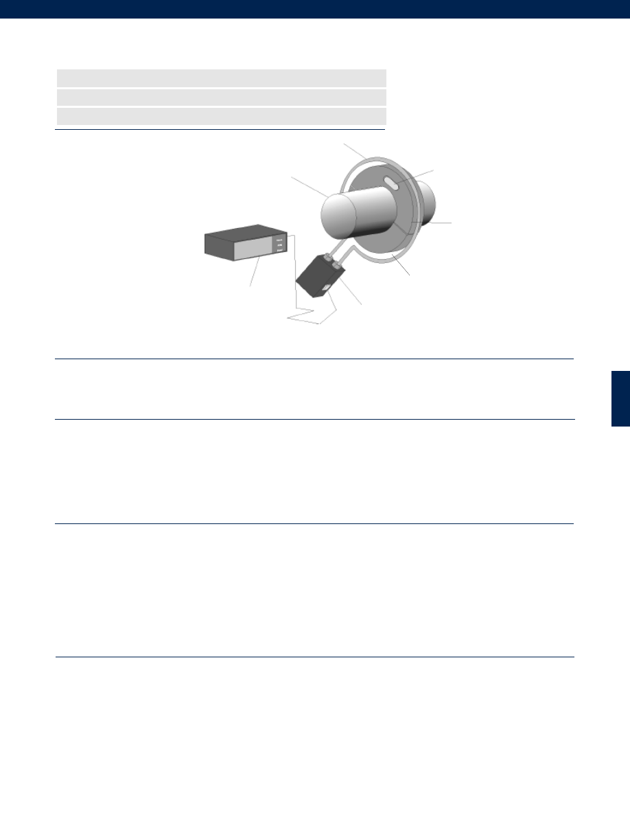
305
Performance
Environmental
Electrical
Mechanical
www.honeywell.com/sensotec
1-888-282-9891
n
DC to 1,000 Hz Frequency Response
n
1-3 Channels Wireless Telemetry
n
175 microstrain (0.5 mV/V) Transmitter Sensitivity
Frequency Response................DC to 1,000 Hz
Sensitivity (Transmitter)................175 microstrain (0.5mV/V)
Number of channels................1 to 3
Sampling Rate................10 kHz
Receiver Readout Display Type................3.5 digit 7 segment LED
Temperature, Operating (Transmitter)................-67° to 257° F
Temperature, Operating (Receiver/ IPS/ PSU)................50° to 122°F
Temperature, Compensated (Transmitter)................32° to 167°F
Temperature, Compensated (Receiver)................50° to 122°F
Static G Force (Rotating components)................15,000 G’s
RPM Limits (Rotating components)................See Graph - depends on shaft diameter
Vibration (Rotating components)................100 G to 1 kHz
Collar Weight................Varies with shaft diameter
Electronics Weight (not including cables)................Receiver and PSU 27 lb.
Induction Power Source................160 kHz +/- 6%
Cable Length (IPS to Receiver)................15 ft. std. (note 1)
Max. Cable Length (IPS to Receiver)................500 ft.
Power Supply Voltage (Receiver)................115/ 230 VAC user-selectable
Power Consumption (Receiver)................100 VA max.
RF Operating Frequency................10.7 MHz (note 2)
RF Modulation Type................FSK
Analog Output (Receiver)................+/- 10 VDC @ 5mA max.
Output Impedance (Receiver)................< 1 Ohm
Electrical Termination (Receiver Output)................BNC female
Mating Connector (Receiver output)................BNC male
Electrical Termination (Transmitter)................9 pins, 0.025” diameter
Dimensions (Collar Cross Section)................1.25” x 1.25” Typical (6” OD min.)
Dimensions (Receiver)................17” L x 18” W x 5.25” H
Dimensions (IPS)................6” L x 4” W x 2” H
Shaft Diameter Limits (Collar)................2” to 42” (note 3)
Collar Material................Type G-11 Glass epoxy
Model 1205B Rotary Torque/ RPM/ HP Measurement System
Order Code WI1100
Typical System Diagram
1645B Receiver
1211D PSU
Customer Supplied Shaft
1226A Collar Assembly
2120B Transmitter
Stationary Antenna Loop
Cable Assembly
0.25” to 0.5” air gap
Courtesy of Steven Engineering, Inc.-230 Ryan Way, South San Francisco, CA 94080-6370-Main Office: (650) 588-9200-Outside Local Area: (800) 258-9200-www.stevenengineering.com
Sensotec Sensors Full Line Catalog-html.html
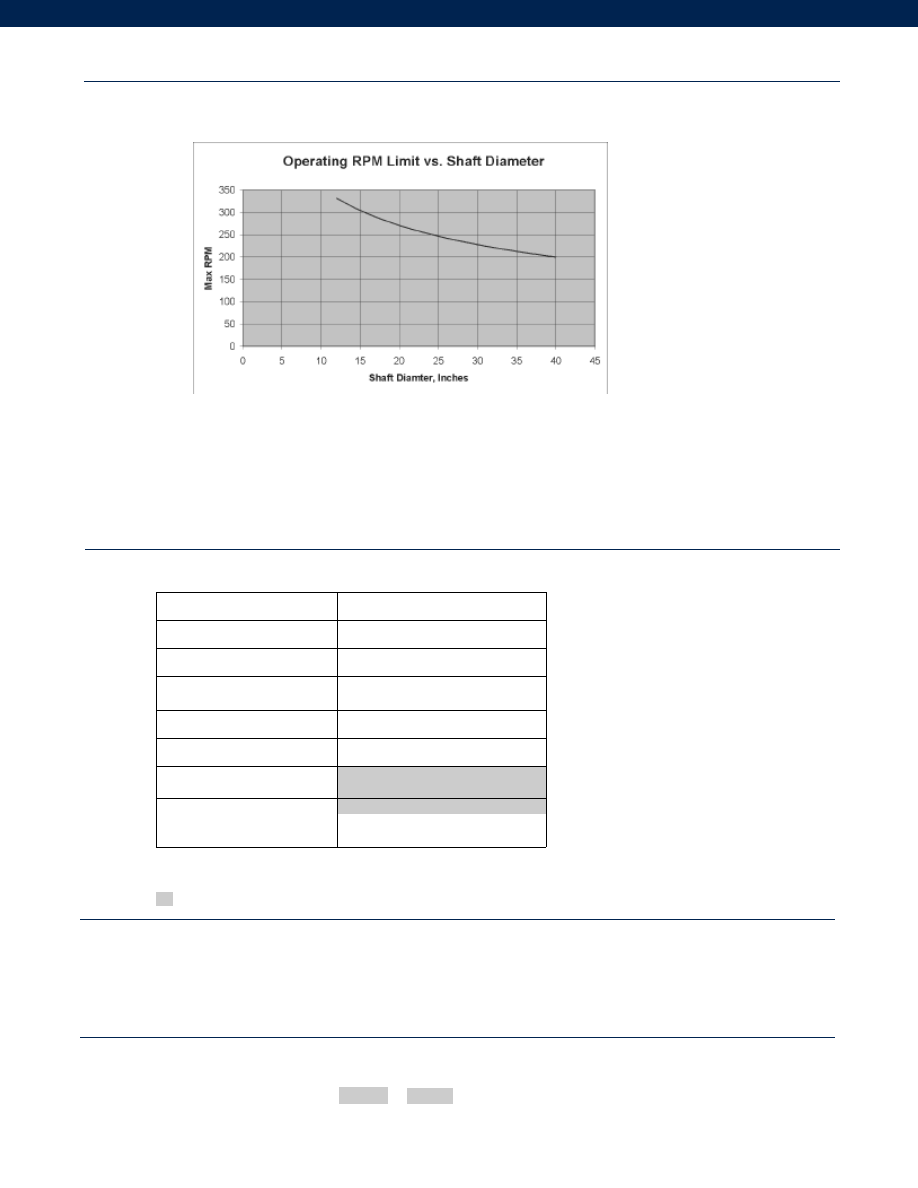
306
www.honeywell.com/sensotec
Options
RPM Limits Graph
1-888-282-9891
Model 1205B
Supplied as standard
Notes
1. 15ft. is the standard cable length, other lengths are available. Consult factory.
2. Consult factory for other frequencies.
3. 2” to 8” is standard shaft diameter, consult factory for other shaft diameters.
Built from Scratch
Max. Transmitter Temperature
62s. 100° C
Environmental Protection
62h. Nema IPS
Display (Receiver)
62c. Remote display
Filter (Receiver)
62d. EMI filter
Vibration & Shock (PSU)
62j. Vibration/Shock rated PSU
RF Operating Frequency
10.7 MHz (note 1)
Analog Output (Receiver)
62e. 1 Channel 4-20 mA isolated output
+/- 10 VDC @ 5 mA
How to Order
Combine the order code and the options code.
Order Code Options Code
Sample Code: WI1100 62c
Courtesy of Steven Engineering, Inc.-230 Ryan Way, South San Francisco, CA 94080-6370-Main Office: (650) 588-9200-Outside Local Area: (800) 258-9200-www.stevenengineering.com
Sensotec Sensors Full Line Catalog-html.html
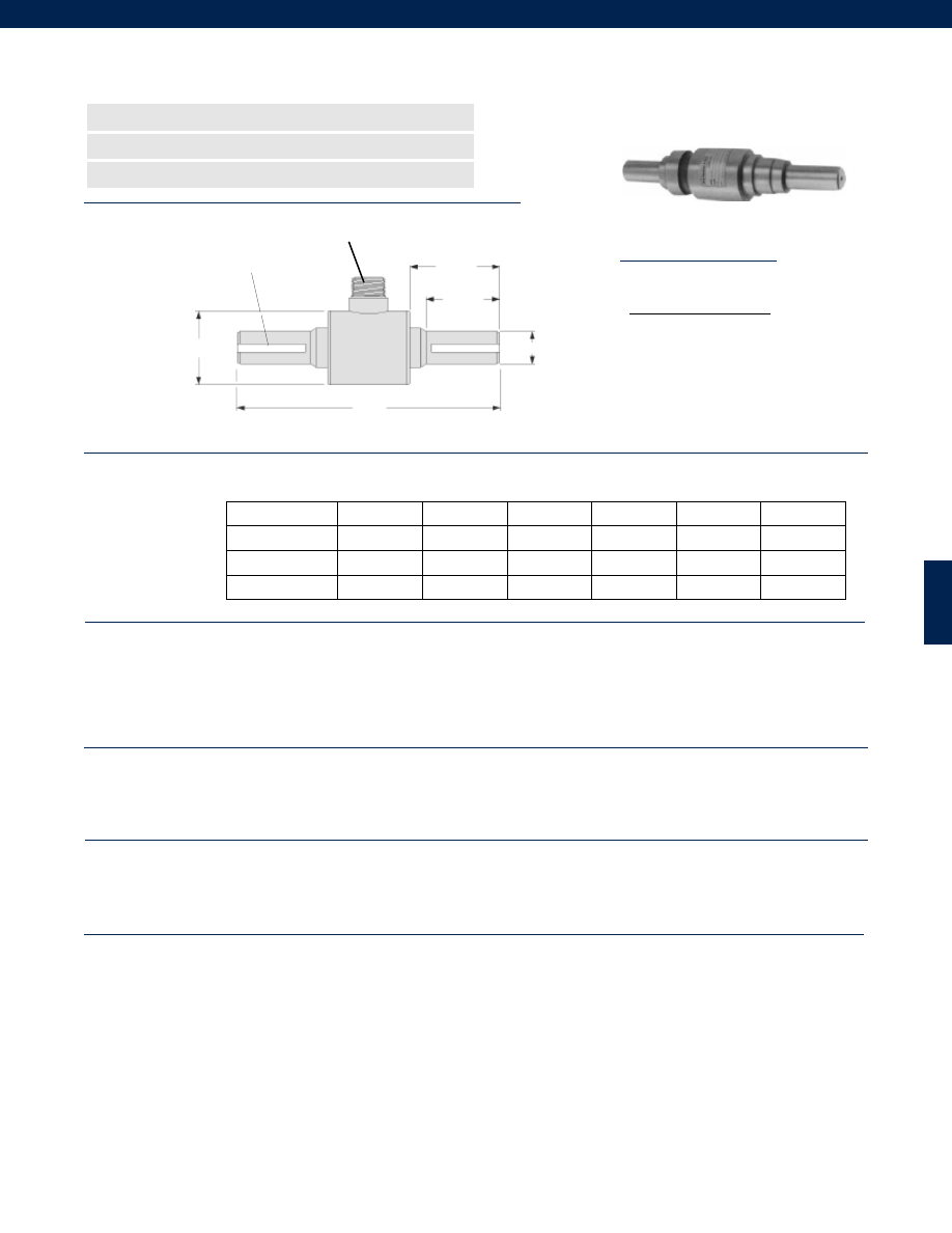
307
........100 to 24,000 in.-lb.
........+/- 0.1% Full Scale
........+/- 0.1% Full Scale
........+/- 0.1% Full Scale
........+/- 0.03% Full Scale
........2 mV/V nominal
........Infinite
........-65° to 225° F
........60° to 160° F
........0.005% Full Scale/ °F
........0.005% Reading/ °F
........Bonded Foil
........10 VDC
........350 Ohms
........MS3102A-14S-6P or equivalent
........MS3106A-14S-6S or equivalent (not included)
........50% over capacity
........Stainless Steel
Dimensions
Performance
Environmental
Electrical
Mechanical
Model QSFK-9 Shaft Type Reaction Torque Transducer
Order Code BT111
www.honeywell.com/sensotec
n
Wide Dynamic Range
n
High Frequency
n
Stainless Steel
L
A Typ.
B Typ.
K Key Size Typ.
øD1
øD2
Ranges
System Accuracy
Linearity
Hysteresis
Non-Repeatability
Output
Resolution
Temperature, Operating
Temperature, Compensated
Temperature Effect
Zero
Span
Strain Gage Type
Excitation
Bridge Resistance
Electrical Termination
Mating Connector
Static Overload Capacity
Case Material
K ( in.)
Range (in.-lb.) øD1 (in.) øD2 (in.) Key Size A (in.) B (in.) L (in.)
100
0.75
2.25
3/16
2.75
2.25
8.00
600; 1200
1.00
2.25
1/4
2.75
2.25
8.00
3000; 6000; 12,000
1.50
3.50
3/8
3.75
3.00
11.00
24,000
2.75
4.00
5/8
5.10
4.00
13.00
Wiring Codes
Connector/ Unamplified
A & B (+) Excitation
C & D
(-) Excitation
E
(-) Output
F
(+) Output
1-888-282-9891
MS3102A-14S-6P
Courtesy of Steven Engineering, Inc.-230 Ryan Way, South San Francisco, CA 94080-6370-Main Office: (650) 588-9200-Outside Local Area: (800) 258-9200-www.stevenengineering.com
Sensotec Sensors Full Line Catalog-html.html
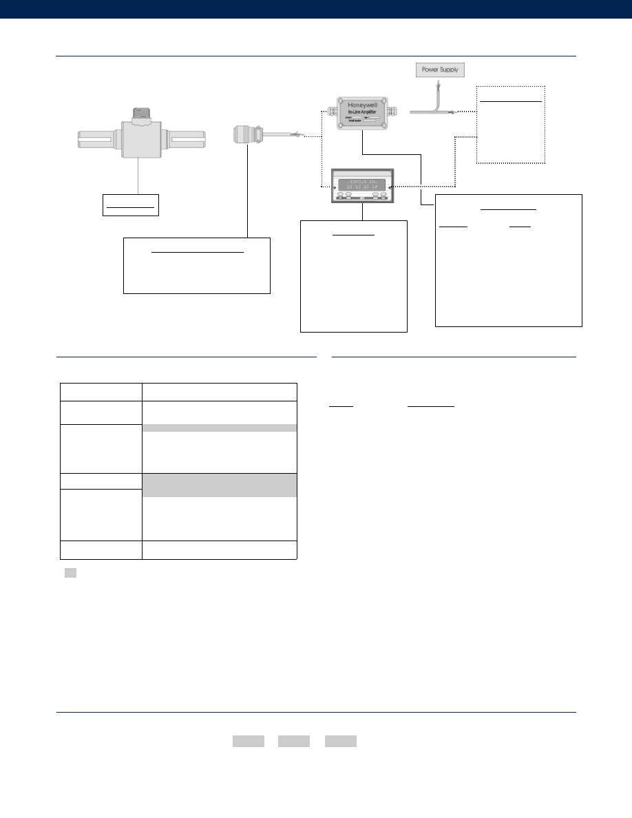
308
www.honeywell.com/sensotec
Range
Range Code
100 in.-lb.
TJ
300 in.-lb.
TL
600 in.-lb.
TN
1200 in.-lb.
TP
3000 in.-lb.
TR
6000 in.-lb.
TT
12,000 in.-lb.
TV
24,000 in.-lb.
TW
Supplied as standard
Options
Range Codes
How to Order
The order code consists of the product model, the desired range code and the available options.
Model Code
Range Code
Options Code
Sample Code:
BT111
TT
1b
1-888-282-9891
Typical System Diagram
Mating Connectors & Cables
MS3106A-14S-6S
Bendix PTIH-10-6P - 6 pin
In-Line Amplifiers
Amplifier
Output
Universal In-Line Amplifiers
UV
+/- 5 VDC
UV-10
+/- 10 VDC
UBP
0 +/- 5 VDC
U3W
4-20 mA (3 wire)
DIN rail Mount In-Line Amplifiers
DV-05
0 +/- 5 VDC (3 wire)
DA-05
4-20 mA (3 wire)
DV-10
0 +/- 10 VDC (3 wire)
Display Units
SC500
SC1000
SC2000
SC2001
SC3004
GM
NK
HH
Customer Supplied
Chart Recorder
Alarm Panel
Data Acquisition
Computer
PLC
Model QSFK-9
Built from Scratch
Torque Range
100, 300, 600, 1200, 3000, 6000, 12,000,
24,000 in.-lb.
Temperature
Compensation
1b. 30° to 130° F
1c. 0° to 185° F
1d. -20° to 130° F
1e. -20° to 200° F
1f.
70° to 250° F
Internal Amplifiers
2u. Unamplified, mV/V output
Electrical Termination
6a. Bendix PTIH-10-6P - 6 pin (max. 250°F)
6e. Integral cable: Teflon
6f.
Integral cable: PVC
6g. Integral cable: Neoprene
6h. Integral cable: Silicone
Interfaces
53e. Signature Calibration
53t. T.E.D.S. IEEE 1451.4 Module
6b. MS3102A-14S-6P or equivalent
1a. 60° to 160° F
Model QSFK-9
Courtesy of Steven Engineering, Inc.-230 Ryan Way, South San Francisco, CA 94080-6370-Main Office: (650) 588-9200-Outside Local Area: (800) 258-9200-www.stevenengineering.com
Sensotec Sensors Full Line Catalog-html.html
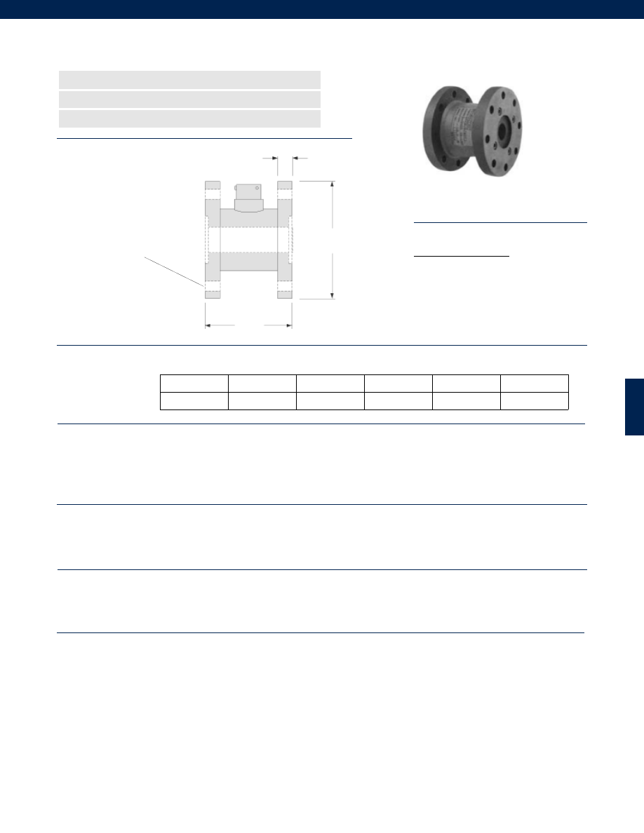
309
........3000; 6000; 12,000; 24,000 in.-lb.
........+/- 0.1% Full Scale
........+/- 0.1% Full Scale
........+/- 0.1% Full Scale
........+/- 0.03% Full Scale
........2 mV/V nominal
........Infinite
........-65° to 225° F
........60° to 160° F
........0.005% Full Scale/ °F
........0.005% Reading/ °F
........Bonded Foil
........10 VDC
........350 Ohms
........Bendix PTIH-10-6P or equivalent
........PT06A-10-6S or equivalent (not included)
........50% over capacity
........Stainless Steel
Dimensions
Performance
Environmental
Electrical
Mechanical
Model QFFH-9 Flange Type Reaction Torque Transducer
Order Code BT121
www.honeywell.com/sensotec
n
Wide Dynamic Range
n
High Frequency
n
Stainless Steel
A Typ.
W
8 Holes Equally Spaced
on ‘C’ Dia. B.C., ‘E’ Dia. Thru
Typ. Both Flanges
øD1
Ranges
System Accuracy
Linearity
Hysteresis
Non-Repeatability
Output
Resolution
Temperature, Operating
Temperature, Compensated
Temperature Effect
Zero
Span
Strain Gage Type
Excitation
Bridge Resistance
Electrical Termination
Mating Connector
Static Overload Capacity
Case Material
C ( in.) E (in.)
Range (in.-lb.) øD1 (in.) W (in.) A (in.) Dia. B.C. Dia. Thru
3000; 6000
4.00
3.00
0.50
3.25
0.33
12,000; 24,000
5.00
3.50
0.75
4.25
0.39
Wiring Codes
Connector/ Unamplified
A & B (+) Excitation
C & D
(-) Excitation
E
(-) Output
F
(+) Output
1-888-282-9891
Courtesy of Steven Engineering, Inc.-230 Ryan Way, South San Francisco, CA 94080-6370-Main Office: (650) 588-9200-Outside Local Area: (800) 258-9200-www.stevenengineering.com
Sensotec Sensors Full Line Catalog-html.html
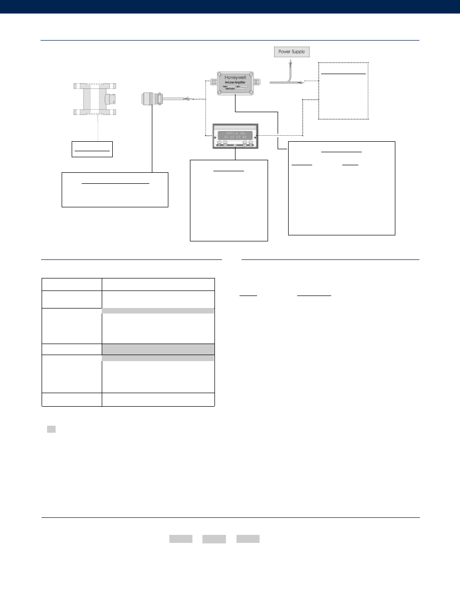
310
www.honeywell.com/sensotec
Range
Range Code
3000 in.-lb.
TR
6000 in.-lb.
TT
12,000 in.-lb.
TV
24,000 in.-lb.
TW
Supplied as standard
Options
Range Codes
How to Order
The order code consists of the product model, the desired range code and the available options.
Model Code
Range Code
Options Code
Sample Code:
BT121
TT
1b
1-888-282-9891
Typical System Diagram
Mating Connectors & Cables
PT06A-10-6S
MS3106A-14S-6S
In-Line Amplifiers
Amplifier
Output
Universal In-Line Amplifiers
UV
+/- 5 VDC
UV-10
+/- 10 VDC
UBP
0 +/- 5 VDC
U3W
4-20 mA (3 wire)
DIN rail Mount In-Line Amplifiers
DV-05
0 +/- 5 VDC (3 wire)
DA-05
4-20 mA (3 wire)
DV-10
0 +/- 10 VDC (3 wire)
Display Units
SC500
SC1000
SC2000
SC2001
SC3004
GM
NK
HH
Customer Supplied
Chart Recorder
Alarm Panel
Data Acquisition
Computer
PLC
Model QFFH-9
Model QFFH-9
Built from Scratch
Torque Range
3000, 6000, 12,000, 24,000 in.-lb
Temperature
Compensation
1b. 30° to 130° F
1c. 0° to 185° F
1d. -20° to 130° F
1e. -20° to 200° F
1f.
70° to 250° F
Internal Amplifiers
2u. Unamplified, mV/V output
Electrical Termination
6a. Bendix PTIH-10-6P - 6 pin (max. 250°F)
6e. Integral cable: Teflon
6f.
Integral cable: PVC
6g. Integral cable: Neoprene
6h. Integral cable: Silicone
Interfaces
53e. Signature Calibration
53t. T.E.D.S. IEEE 1451.4 Module
6b. MS3102A-14S-6P or equivalent
1a. 60° to 160° F
Courtesy of Steven Engineering, Inc.-230 Ryan Way, South San Francisco, CA 94080-6370-Main Office: (650) 588-9200-Outside Local Area: (800) 258-9200-www.stevenengineering.com
Sensotec Sensors Full Line Catalog-html.html
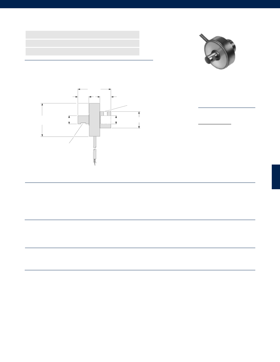
311
........25; 100; 250 in.-oz.; 50; 100; 300 in.-lb.
........+/- 0.1% Full Scale
........+/- 0.1% Full Scale
........+/- 0.1% Full Scale
........+/- 0.03% Full Scale
........2 mV/V nominal
........Infinite
........-65° to 225° F
........60° to 160° F
........0.005% Full Scale/ °F
........0.005% Reading/ °F
........Bonded Foil
........10 VDC (5 VDC if Torque Range <= 100 in.-oz.)
........350 Ohms
........Teflon Cable (5 ft.)
........50% over capacity
........Stainless Steel
........0.0027 radians
........0.00255 radians
Dimensions
Performance
Environmental
Electrical
Mechanical
Model QWFK-8M Miniature Reaction Torque Transducer
Order Code BT311
www.honeywell.com/sensotec
n
Compact Size
n
High Frequency
n
0.1% Linearity
1.50 in.
1.50 in.
0.50 in.
0.50 in.
Set Screw
Flats, 3 each
3 Tapped Holes 120° Apart for
10-32 Set Screw
ø0.375 in.
ø0.376 in.
ø0.75 in.
Ranges
System Accuracy
Linearity
Hysteresis
Non-Repeatability
Output
Resolution
Temperature, Operating
Temperature, Compensated
Temperature Effect
Zero
Span
Strain Gage Type
Excitation
Bridge Resistance
Electrical Termination
Static Overload Capacity
Case Material
Deflection Torsional
25 in.-oz. to 50 in.-lb.
100 to 300 in.-lb.
Wiring Codes
Cable/ Unamplified
Red (+) Excitation
Black (-) Excitation
Green (-) Output
White (+) Output
1-888-282-9891
Courtesy of Steven Engineering, Inc.-230 Ryan Way, South San Francisco, CA 94080-6370-Main Office: (650) 588-9200-Outside Local Area: (800) 258-9200-www.stevenengineering.com
Sensotec Sensors Full Line Catalog-html.html
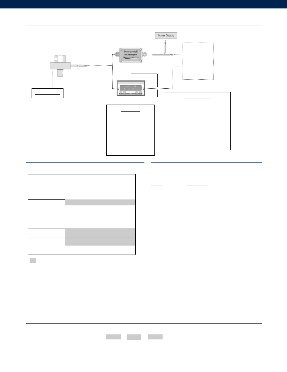
312
www.honeywell.com/sensotec
Supplied as standard
Options
Range Codes
How to Order
The order code consists of the product model, the desired range code and the available options.
Model Code
Range Code
Options Code
Sample Code:
BT311
TL
1b
1-888-282-9891
Typical System Diagram
In-Line Amplifiers
Amplifier
Output
Universal In-Line Amplifiers
UV
+/- 5 VDC
UV-10
+/- 10 VDC
UBP
0 +/- 5 VDC
U3W
4-20 mA (3 wire)
DIN rail Mount In-Line Amplifiers
DV-05
0 +/- 5 VDC (3 wire)
DA-05
4-20 mA (3 wire)
DV-10
0 +/- 10 VDC (3 wire)
Customer Supplied
Chart Recorder
Alarm Panel
Data Acquisition
Computer
PLC
Model QWFK-8M
Built from Scratch
Torque Range
25, 100, 250 in.-oz.
50, 100, 300 in.-lb.
Temperature
Compensation
1b. 30° to 130° F
1c. 0° to 185° F
1d. -20° to 130° F
1e. -20° to 200° F
1f.
70° to 250° F
Internal Amplifiers
2u. Unamplified, mV/V output
Electrical Termination
6e. Integral cable: Teflon
Interfaces
53e. Signature Calibration
53t. T.E.D.S. IEEE 1451.4 Module
1a. 60° to 160° F
Range
Range Code
25 in.-oz.
TB
100 in.-oz.
TD
250 in.-oz.
TF
50 in.-lb.
TH
100 in.-lb.
TJ
300 in.-lb.
TL
Display Units
SC500
SC1000
SC2000
SC2001
SC3004
GM
NK
HH
Model QWFK-8M
Courtesy of Steven Engineering, Inc.-230 Ryan Way, South San Francisco, CA 94080-6370-Main Office: (650) 588-9200-Outside Local Area: (800) 258-9200-www.stevenengineering.com
Sensotec Sensors Full Line Catalog-html.html
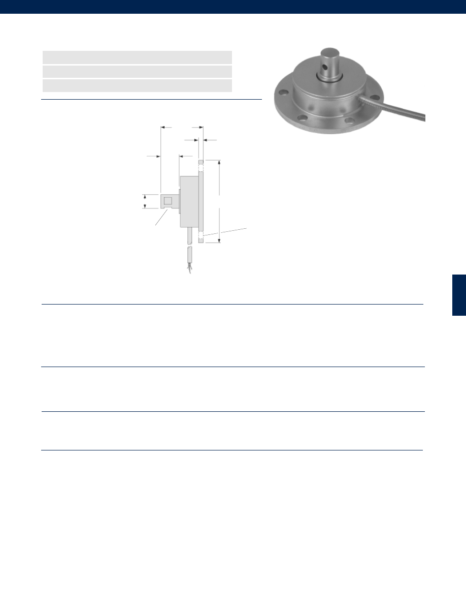
313
........25; 100; 250 in.-oz.; 50; 100; 300 in.-lb.
........+/- 0.1% Full Scale
........+/- 0.1% Full Scale
........+/- 0.1% Full Scale
........+/- 0.03% Full Scale
........2 mV/V nominal
........Infinite
........-65° to 225° F
........60° to 160° F
........0.005% Full Scale/ °F
........0.005% Reading/ °F
........Bonded Foil
........10 VDC (5 VDC if Torque Range <= 100 in.-oz.)
........350 Ohms
........Teflon Cable (5 ft.)
........50% over capacity
........Stainless Steel
........0.0027 radians
........0.00255 radians
Dimensions
Performance
Environmental
Electrical
Mechanical
Model QWLC-8M Miniature Reaction Torque Transducer
Order Code BT312
n
Compact Size
n
High Frequency
n
0.1% Linearity
1.17 in.
0.50 in.
0.13 in.
Set Screw
Flats, 3 each
6 Holes Equally Spaced
on 1.875 in. dia. B.C.,
0.20 in. dia. Thru
ø0.375 in.
ø2.25 in.
Ranges
System Accuracy
Linearity
Hysteresis
Non-Repeatability
Output
Resolution
Temperature, Operating
Temperature, Compensated
Temperature Effect
Zero
Span
Strain Gage Type
Excitation
Bridge Resistance
Electrical Termination
Static Overload Capacity
Case Material
Deflection Torsional
25 in.-oz. to 50 in.-lb.
100 to 300 in.-lb.
www.honeywell.com/sensotec
1-888-282-9891
Courtesy of Steven Engineering, Inc.-230 Ryan Way, South San Francisco, CA 94080-6370-Main Office: (650) 588-9200-Outside Local Area: (800) 258-9200-www.stevenengineering.com
Sensotec Sensors Full Line Catalog-html.html
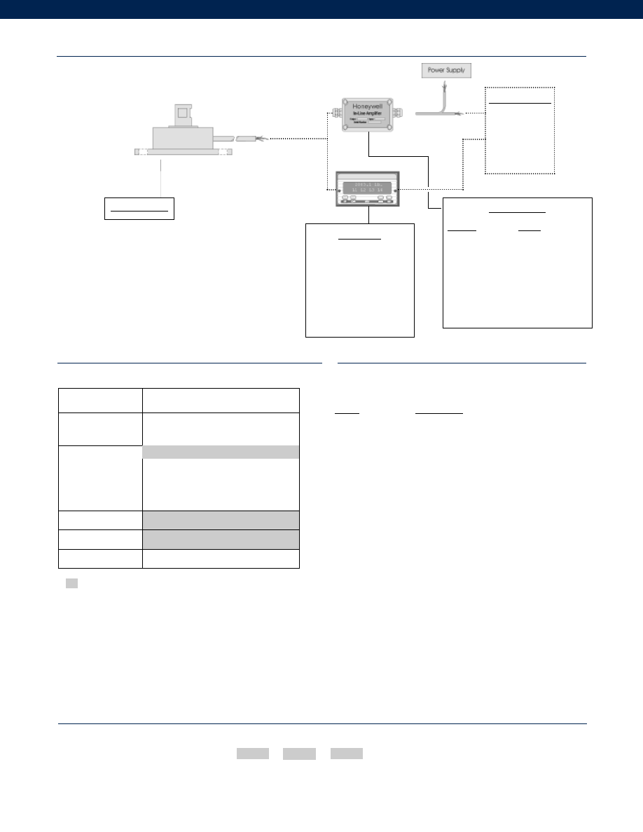
314
www.honeywell.com/sensotec
Range
Range Code
25 in.-oz.
TB
100 in.-oz.
TD
250 in.-oz.
TF
50 in.-lb.
TH
100 in.-lb.
TJ
300 in.-lb.
TL
Supplied as standard
Options
Range Codes
How to Order
The order code consists of the product model, the desired range code and the available options.
Model Code
Range Code
Options Code
Sample Code:
BT312
TL
1b
1-888-282-9891
Typical System Diagram
In-Line Amplifiers
Amplifier
Output
Universal In-Line Amplifiers
UV
+/- 5 VDC
UV-10
+/- 10 VDC
UBP
0 +/- 5 VDC
U3W
4-20 mA (3 wire)
DIN rail Mount In-Line Amplifiers
DV-05
0 +/- 5 VDC (3 wire)
DA-05
4-20 mA (3 wire)
DV-10
0 +/- 10 VDC (3 wire)
Display Units
SC500
SC1000
SC2000
SC2001
SC3004
GM
NK
HH
Customer Supplied
Chart Recorder
Alarm Panel
Data Acquisition
Computer
PLC
Model QWLC-8M
Model QWLC-8M
Built from Scratch
Torque Range
25, 100, 250 in.-oz.
50, 100, 300 in.-lb.
Temperature
Compensation
1b. 30° to 130° F
1c. 0° to 185° F
1d. -20° to 130° F
1e. -20° to 200° F
1f.
70° to 250° F
Internal Amplifiers
2u. Unamplified, mV/V output
Electrical Termination
6e. Integral cable: Teflon
Interfaces
53e. Signature Calibration
53t. T.E.D.S. IEEE 1451.4 Module
1a. 60° to 160° F
Courtesy of Steven Engineering, Inc.-230 Ryan Way, South San Francisco, CA 94080-6370-Main Office: (650) 588-9200-Outside Local Area: (800) 258-9200-www.stevenengineering.com
Sensotec Sensors Full Line Catalog-html.html
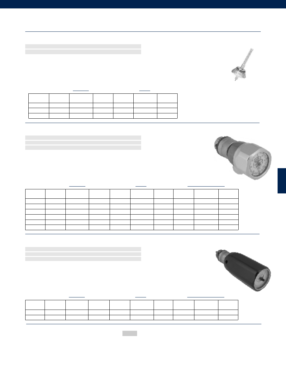
315
Models 366, 651 and 940 Torque Watch Gage Series
Order Code (see below)
The 366 Torque Watch Series accurately measures very low torque. Three miniature adapter chucks allow simple
coupling to the device being measured.
To minimize friction, a calibrated helical spring, shaft, and pointer assembly are mounted in jeweled bearings. The
unit can measure torque in either a clockwise or counterclockwise direction. A stainless steel internal rotation stop
helps prevent damage from over-torque up to three times the normal range.
n
0.003 to 0.6 in.-oz.
n
0.2 to 42 gm-cm
Low Range 366 Series
Models 366-0, 366-2, 366-3
Accuracy
Model
Order Code
in.-oz.
Model
Order Code
gm-cm
+/- 5%
366-0
TQ3660
0.06 - 0.6
366-0M
TQ3660M
6 - 42
+/- 10%
366-2
TQ3662
0.01 - 0.1
366-2M
TQ3662M
1 - 7.5
+/- 10%
366-3
TQ3663
0.003 - 0.3
366-3M
TQ3663M
0.2 - 2
Standard
Metric
The 651 Torque Watch Series provides accurate measurement of low static torque. A 1/4 inch keyed chuck
provides a simple means of coupling to the device under measurement.
The 651 Series utilizes a calibrated spring, shaft, and pointer assembly within a rugged steel and aluminum housing.
The unit can measure torque in either a clockwise or counterclockwise direction. Internal stainless steel rotation
stops help prevent damage from over-torque up to two times the normal range.
n
0.05 to 40 in.-oz.
n
2.5 to 2.8 k gm-cm
n
0.5 to 265 N-mm
Mid Range 651 Series
Models 651C-1, 651C-2, 651C-3, 651X-2, 651X-3, 651X-4
Standard
Metric
System International
Accuracy
Model
Order Code
in.-oz.
Model
Order Code
gm-cm
Model
Order Code
N-mm
+/- 2%
651C-1
TQ651C1
0.05 - 1.2
651C-1M
TQ651C1M
2.8 - 80
651C-1SI
TQ651C1SI
0.5 - 9
+/- 2%
651C-2
TQ651C2
1 - 20
651C-2M
TQ651C2M
50 - 1.2k
651C-2SI
TQ651C2SI
10 - 140
+/- 2%
651C-3
TQ651C3
2 - 40
651C-3M
TQ651C3M 150 - 2.8k 651C-3SI
TQ651C3SI
15 - 265
+/- 2%
651X-2
TQ651X2
0.1 - 2.4
651X-2M
TQ651X2M
5 - 150
651X-2SI
TQ651X2SI
1 - 18
+/- 2%
651X-3
TQ651X3
0.25 - 5
651X-3M
TQ651X3M
10 - 300
651X-3SI
TQ651X3SI
2 - 36
+/- 2%
651X-4
TQ651X4
0.5 - 10
651X-4M
TQ651X4M
25 - 600
651X-4SI
TQ651X4SI
5 - 70
The 940 Torque Watch Series accurately measures high range torque. A 3/8 inch keyed chuck and a 3/8 inch
square socket driver adapter provides a simple means of coupling to the device under measurement.
The 940 Series utilizes a calibrated spring , shaft, and pointer assembly within a rugged steel and aluminum housing.
The unit can measure torque in either a clockwise or counterclockwise direction. Internal stainless steel rotation stops
help prevent damage from over-torque up to two times the normal range.
n
15 to 200 in.-oz.
n
2.5 to 2.8 k gm-cm
n
0.1 to 1.4 N-m
Mid Range 940 Series
Models 940-1 and 940-2
Standard
Metric
System International
Accuracy
Model
Order Code
in.-oz.
Model
Order Code k gm-cm
Model
Order Code
N-m
+/- 2%
940-1
TQ9401
30 - 200
940-1M
TQ9401M
2 - 14
940-1SI
TQ9401SI
0.25 - 1.4
+/- 2%
940-2
TQ9402
15 - 100
940-2M
TQ9402M
1 - 7
940-2SI
TQ9402SI
0.1 - 0.7
www.honeywell.com/sensotec
How to Order
Model Code
Sample Code: 366-2
1-888-282-9891
Courtesy of Steven Engineering, Inc.-230 Ryan Way, South San Francisco, CA 94080-6370-Main Office: (650) 588-9200-Outside Local Area: (800) 258-9200-www.stevenengineering.com
Sensotec Sensors Full Line Catalog-html.html
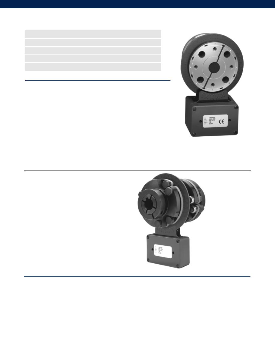
316
The TMS 9000 torque measurement system represents an advanced
generation of rotary transformer sensors designed to operate entirely in
the digital domain for enhanced accuracy and versatility. The TMS 9000
series physically integrates rotor electronics and telemetry into one ele-
ment, with all set-up and output controlled through computer software.
This digital wireless telemetry system supplies power to the rotating
sensor, supports two-way communications and provides wide testing
capabilities. More than a stand-alone sensor, the specially designed TMS
9000 is a complete torque measurement system, with standard analog,
frequency and digital outputs. Fully software driven, the durable TMS
9000 utilizes a custom 19-bit digital wireless telemetry system, which
maximizes resolution and frequency response while also being able to provide excitation power across the
wireless gap. System set-up can be changed “on-the-fly” without affecting calibration. The TMS 9000 can
be expanded for future market needs by using standard PC104 cards.
n
Standard or Custom Setup
n
Single or Multi-Channel
n
For Greater Control
n
More Versatile Potential Applications
n
Ranges to 200,000 lb.-ft.
TMS 9000 Rotary Torque Measurement System
• Transportation & Automotive
• Manufacturing & Production
• Aerospace & Military
• Medical
• Design & Engineering
• Testing & Quality
Applications
www.honeywell.com/sensotec
1-888-282-9891
Torque Ranges................Varies on application; consult factory (max. 200,000 lb.-ft.)
Linearity................+/- 0.05% F.S.
Frequency Output
Analog................5000(min.); 10,000(nom.); 15,000(max.) Hz or
................40,000(min.); 60,000(nom.); 80,000(max.) Hz
Digital................RS232-485
Resolution................0.01% - 0.001% F.S.
Measurement Frequency Range................0 - 3 kHz
Digital Filter................0.1 - 1 kHz
Sampling Rate................17.656 kHz
Performance
Courtesy of Steven Engineering, Inc.-230 Ryan Way, South San Francisco, CA 94080-6370-Main Office: (650) 588-9200-Outside Local Area: (800) 258-9200-www.stevenengineering.com
Sensotec Sensors Full Line Catalog-html.html
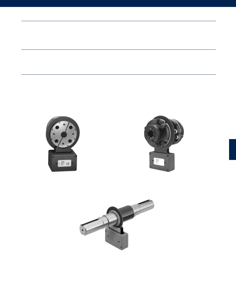
317
Temperature, Operating................-40° to 185° F
Temperature, Compensated................14° to 158°F
Temperature Effects
Zero................+/- 0.003% F.S./°F
Span................+/- 0.003% F.S./°F
RPM Limits (Rotating components)................0-30,000 rpm
Power Supply (standard, non-isolated)................12 VDC (nom.)
Output
Voltage................+/- 10 VDC
Current................4-20 mA
Load Impedance................500 Ohms (for current loop)
Model TMS 9000
Environmental
Electrical
www.honeywell.com/sensotec
1-888-282-9891
Mechanical Mating Configurations
TMS 9000 Series torque sensors perform well under tough conditions. For years sensor operators in
varied applications have acknowledged the enhanced accuracy, durability and quality built into each
sensor. TMS 9000 Series sensors can be tailored to specific applications for even greater versatility
with capacities up to 200,000 lb.-ft.
SAE-DIN Drive Shaft Yokes
Rotating Circular Keyed Shaft
Integral Coupling
Courtesy of Steven Engineering, Inc.-230 Ryan Way, South San Francisco, CA 94080-6370-Main Office: (650) 588-9200-Outside Local Area: (800) 258-9200-www.stevenengineering.com
Sensotec Sensors Full Line Catalog-html.html
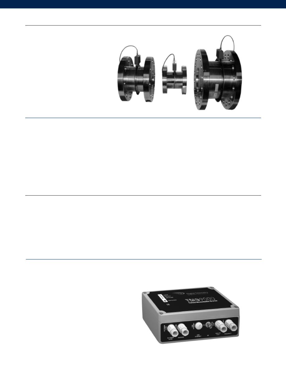
318
Dynamics of the TMS 9000
The rotor electronics module is encapsulated to enhance protection against vibration, G Force
and chemicals.
• The rotating antenna is comprised of an annular printed circuit board, peripherally or centrally
mounted on the rotor.
• Four layer construction ensures enhanced strength with no exposed tracks in the outer region.
• IP65 caliper-style coupling module with die cast aluminum casing. Provides power transmission
and signal recovery with BNC connector for coaxial cable.
• Rotor Electronics Module. This is embedded in the sensor and receives and conditions the input signal
before transmitting it to the SPM.
• Signal Processing Module (SPM). This device integrates two microprocessors to share data processing and
communications. It recovers the signal from the rotor, provides scaling and filtering, and offers a variety of
outputs, compatible with various data acquisition systems.
• PC104 expansion. This option allows the operator functionality beyond the hardware and software provided.
Electrical Features
The SPM contains two separate microprocessors to share data processing and communications. Calibration is
all digital, via RS232/485 link, eliminating potentiometers or dip switches. The durable unit has an external BNC
connector for the RF coaxial cable, internal 2-part
plug and socket connectors for output signals, digital
communication and DC power. The SPM external
housing also features a “SHUNT CAL” button and
LED’s to indicate “Power ON”, “Rotor Active” and
“SHUNT CAL Mode”. Because of these enhanced
technologies, the end result is a true advancement
in telemetry-based torque systems.
Signal Processing Module (SPM)
Model TMS 9000
www.honeywell.com/sensotec
1-888-282-9891
• No hoop antenna
• System error < 0.05% FS
• High torsional stiffness
• High overload capability
Mechanical Sensor Features
• Low rotating inertia
• Variety of mating flange designs
• Custom designs available
Courtesy of Steven Engineering, Inc.-230 Ryan Way, South San Francisco, CA 94080-6370-Main Office: (650) 588-9200-Outside Local Area: (800) 258-9200-www.stevenengineering.com
Sensotec Sensors Full Line Catalog-html.html
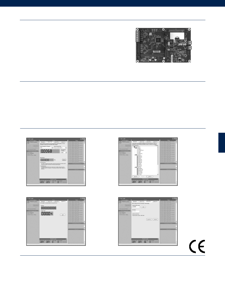
319
Model TMS 9000
www.honeywell.com/sensotec
1-888-282-9891
• Full Software Set Up
• No Potentiometers or Dip Switches
• Scalable Output “On-The-Fly”
• Nine Point Linearization Feature
• Multi-Digital Filter Feature
• Simple ASCII Communications Protocol
Toolkit Features
Additional Features
• Multiple Channels
• Multiplexing
• Custom Designs Available
Software Features
The software at the heart of the TMS 9000 system is designed to
offer flexibility and adaptability. The software puts the operator fully in
control and can be tailored to the test conditions required at the time.
Standard or custom set ups can be saved to parameter files and
recalled at any time. Input scaling and output scaling is independent,
providing a wider application advantage. The software-driven SPM
(Signal Processing Module) is offered with five standard interfaces.
Consult the factory for availability of optional interfaces such as:
CAN-open, Ethernet and USB, and PC104 expansion cards. The
software flexibility allows single or multiple sensors to share the same wireless telemetry link,
with digital output as standard, or with multi-channel digital-to-analog available as an option.
SPM Card
Test Communications
Parameters/System Setup
Software Toolkit Capabilities
Systems Quality/Test
Systems Zero/Tare
How to Order
Please consult factory for ordering information.
Courtesy of Steven Engineering, Inc.-230 Ryan Way, South San Francisco, CA 94080-6370-Main Office: (650) 588-9200-Outside Local Area: (800) 258-9200-www.stevenengineering.com
Sensotec Sensors Full Line Catalog-html.html

320
Notes
www.honeywell.com/sensotec
1-888-282-9891
Courtesy of Steven Engineering, Inc.-230 Ryan Way, South San Francisco, CA 94080-6370-Main Office: (650) 588-9200-Outside Local Area: (800) 258-9200-www.stevenengineering.com
Sensotec Sensors Full Line Catalog-html.html
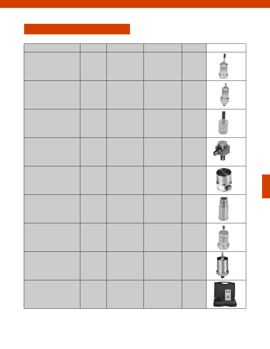
321
ACCELEROMETERS
Potential Application
Model
Order Code
Dynamic Range
Page
General Purpose
PA
MA11
MA12
AG714
AG901,AG902,AG905
AG903,AG904
+/- 5G to +/- 1000G
+/- 80G
+/- 80G
322
323
325
Miniature
MA341/342
MA21
MA23
AG922/AG923
AG913
AG914
+/- 80G
+/- 80G
+/- 10G
327
328
329
Low Frequency
MA311/312
MA321/322
JTF
AG915/AG916
AG917/AG918
AG111-AG113
+
/- 1G to +/- 50G
+/- 1G to +/- 50G
+/- 5G to +/- 500G
330
331
332
High Frequency
MAQ36
AG924
+/- 2000G
334
High Temperature
MAQ13
MAQ14
MAQ41
AG908
AG909,AG910
AG925
+/- 800G
+/- 1000G
+/- 100G
335
336
337
Velocity Output
MAV51
AG926,AG927
N/A
338
Acceleration &
Temperature
MAT53
AG930,AG931
+/- 80G
340
Built-in Signal
Conditioning
MA15
MAV52
MA331/332
AG906,AG907
AG928,AG929,AG932
AG919/AG920
+/- 50G
+/- 50G
+/- 1G to +/- 50G
342
343
345
Hand Held System
VM110/120
AG941/AG942
N/A
346
www.honeywell.com/sensotec
1-888-282-9891
Courtesy of Steven Engineering, Inc.-230 Ryan Way, South San Francisco, CA 94080-6370-Main Office: (650) 588-9200-Outside Local Area: (800) 258-9200-www.stevenengineering.com
Sensotec Sensors Full Line Catalog-html.html
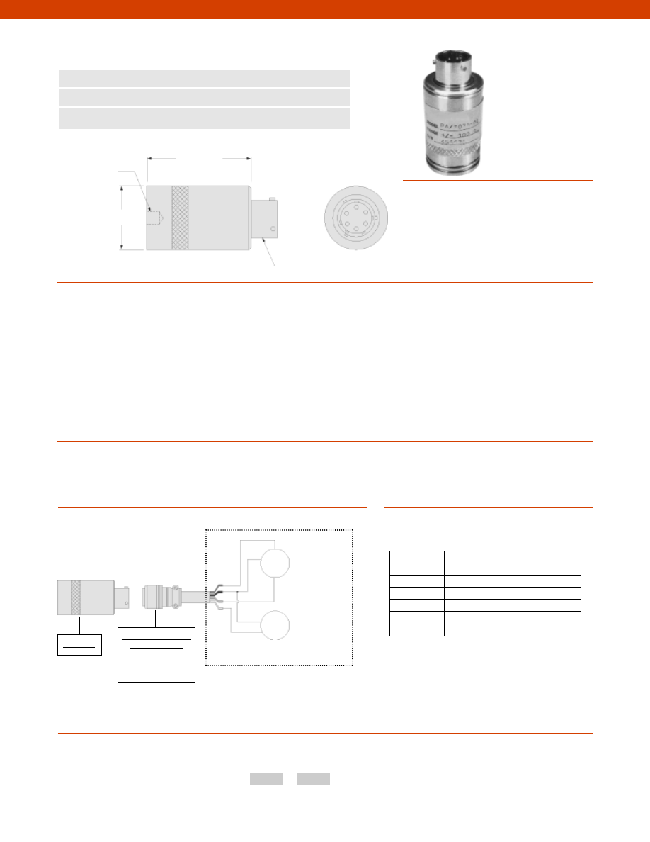
322
Dimensions
Performance
Environmental
Electrical
Mechanical
www.honeywell.com/sensotec
1-888-282-9891
1/4-28 UNF
-2Bx 0.20 in. deep
PTIH-10-6P or
equivalent
n
Enhanced Sensitivity
n
Case Isolated
n
Rugged, High Impact
Model PA Amplified Piezoelectric Accelerometer
Order Code AG714
1.00 in.
1.60 in.
(max.)
Wiring Codes
A
(+) 13.5 to 16.5 VDC
B
(-) Output/ Supply common
C
(-) 13.5 to 16.5 VDC
D
(+) Output (+/- 5 VDC)
E
Not Applicable
F
Not Applicable
Model PA
Range Codes
Typical System Diagram
How to Order
The order code consists of the product model and the desired range code.
Model Code
Range Code
Sample Code:
AG714
GJ
Dynamic Range................+/- 5 to +/- 1,000 G
Sensitivity................See table
Frequency Range................3 to 5,000 Hz
Full Scale Output................+/- 5 V
Mounted Natural Frequency................30 kHz
Transverse Sensitivity................5% of Full Scale
Shock Limits................3,000 G
Vibration Limits................2,000 G
Temperature, Operating................32° to 160° F
Input Power................+/- 13.5 to +/- 16.5 VDC
Output Impedance................100 Ohms
Connector................PTIH-10-6P
Weight................3 oz.
Case Material................316 Stainless Steel
Sealing................Welded
Power
Supply
Dual Power
Supply
Output
Customer Supplied Monitoring System
+
-
Mating Connectors &
Cable Assembly
AA111
AA165
Range (G)
Sensitivity (mV/G) Range Code
5
1,000
GJ
10
500
GK
50
100
GN
100
50
GP
500
10
GR
1,000
5
GS
0V
0V
+output
-Not RoHS Compliant
Courtesy of Steven Engineering, Inc.-230 Ryan Way, South San Francisco, CA 94080-6370-Main Office: (650) 588-9200-Outside Local Area: (800) 258-9200-www.stevenengineering.com
Sensotec Sensors Full Line Catalog-html.html
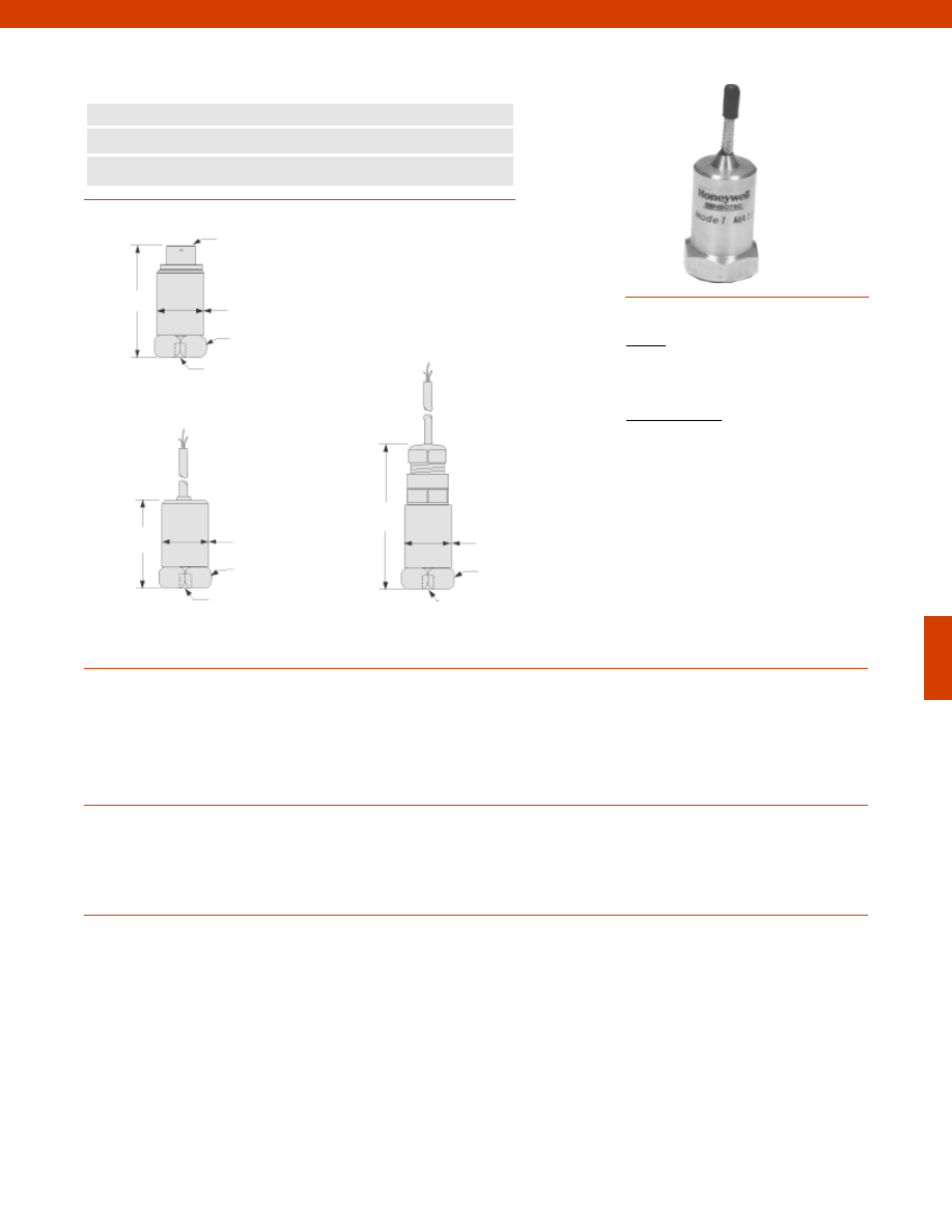
323
Dimensions
Performance
Environmental
Electrical
2 pin MS
1.97 in.
0.86 in.
1/4-28 UNF
0.98 in. A/F
Model MA11 (order code AG901)
n
General Purpose
n
2 Hz to 10 kHz Usable Frequency Range
n
IEPE Output
Model MA11 Accelerometer
Order Code AG901; AG902; AG905
Dynamic Ranges................+/- 80 G
Sensitivity................100 mV/G +/- 10%
Transverse Sensitivity................Less than 5%
Temperature Sensitivity................0.145/ °F
Frequency Range................2 Hz to 10 kHz +/- 5% 3db limits
Amplitude Linearity................Better than 1% Linearity
Mounted Base Resonance................18 kHz
Acceleration Range................+/- 80 G (dependent on sensitivity)
Temperature, Operating................-70° to 280° F
Shock Limits................2,000 G
Vibration Limits................2,000 G
Sealing
AG901 & AG902................IP67/ Nema 4
AG903................IP68/ Nema 4x
Input................Constant Current
Current Range................0.5 mA to 8 mA
Bias Voltage................12 Vdc
Cable (note 2)
AG902................S/S overbraided PTFE
AG903................PU
Standard Cable Length (note 2)
AG902................16 ft.
AG903................Specify at time of order
Electrical Noise................0.1 mG max.
Isolation................Base isolated
Mating Connector (note 1)................MH002
0.86 in.
1.5 in.
1/4-28 UNF
1.0 in. A/F
Model MA11 (order code AG902)
2.64 in.
0.86 in.
1/4-28 UNF
0.98 in. A/F
Model MA11 (order code AG905)
Wiring Codes
AG901
Pin A
(+) Supply
Pin B
Supply Return
AG902 & AG905
White
(+) Supply (+) Output
Black
Supply Return
Shield
No Connection
www.honeywell.com/sensotec
1-888-282-9891
Courtesy of Steven Engineering, Inc.-230 Ryan Way, South San Francisco, CA 94080-6370-Main Office: (650) 588-9200-Outside Local Area: (800) 258-9200-www.stevenengineering.com
Sensotec Sensors Full Line Catalog-html.html
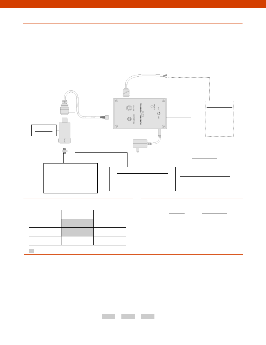
324
Mechanical
Typical System Diagram
Sensitivity
Sensitivity Code
10 mV/G
GU
100 mV/G
GH
1,000 mV/G
GG
Sensitivity Codes
Notes
Options
How to Order
The order code consists of the product model, the desired range code and the available options.
Model Code Sensitivity Code Options Code
Sample Code:
AG901
GU
17b
1. Only available with AG901.
2. Only available with AG902 & AG903.
3. AG902 & AG903 do not need mating connectors.
Model MA11
Mounting Assemblies
Mounting studs
Magnetic mounting
Quick connect mounting
Glued mounting
Mating Connectors & Cables (note 3)
MS connector to microdot cable
MS mating connector
Power Supply Unit
Model CC2 Constant
current power Supply
Customer Supplied
Chart Recorder
Alarm Panel
Data Acquisition
Computer
PLC
Design................Isolated compression in faraday cage
Weight
AG901 & AG902................3.85 oz.
AG903................5.3 oz.
Material................Stainless Steel
Mounting Torque................6 ft.-lb.
BNC Connector
Fast Track Manufacture
Built to Order
Sensitivity
100 mV/G
10mV/G; 1,000mV/G
Electrical Termination
2 pin MS (note 1)
Cable (note 2)
Mounting
Arrangement
17b. 1/4-28 UNF
17c. Quickfit Female
Supplied as standard
Model MA11
-Not RoHS Compliant
www.honeywell.com/sensotec
1-888-282-9891
Courtesy of Steven Engineering, Inc.-230 Ryan Way, South San Francisco, CA 94080-6370-Main Office: (650) 588-9200-Outside Local Area: (800) 258-9200-www.stevenengineering.com
Sensotec Sensors Full Line Catalog-html.html
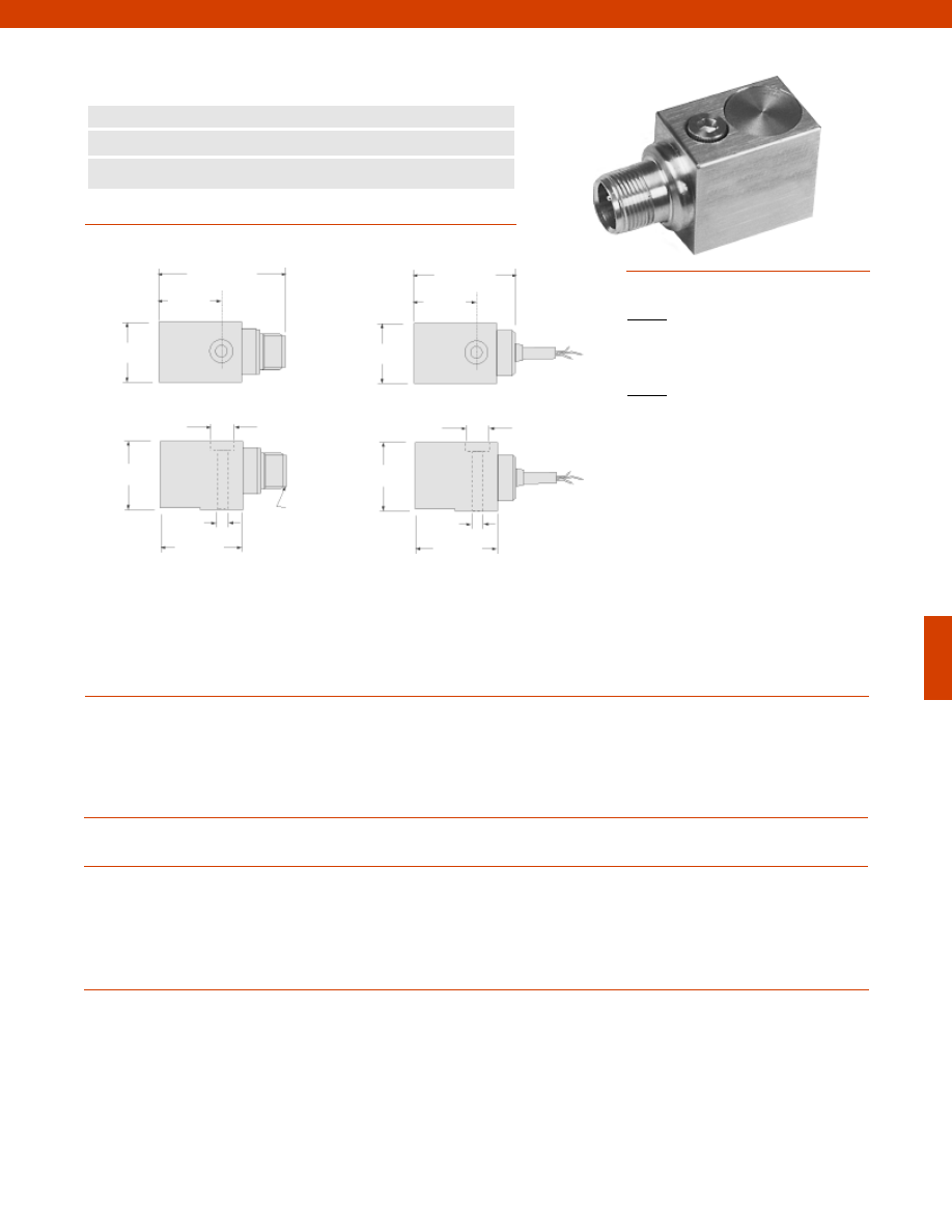
325
Dimensions
Performance
Environmental
Electrical
Mechanical
www.honeywell.com/sensotec
1-888-282-9891
2 pin MS
Connector
1.0 in.
1.02 in.
n
General Purpose
n
2 Hz to 8 kHz Usable Frequency Range
n
IEPE Output
Model MA12 Accelerometer
Order Code AG903; AG904
Dynamic Ranges................+/- 80G
Sensitivity................100 mV/G +/- 10%
Transverse Sensitivity................Less than 5%
Temperature Sensitivity................0.145/ °F
Frequency Range................2 Hz to 8 kHz
Amplitude Linearity................Better than 1% Linearity
Mounted Base Resonance................18 kHz
Temperature, Operating................-70° to 280° F
Sealing................IP67/ Nema 4
Input................Constant Current
Current Range................0.5 mA to 8 mA
Bias Voltage................12 Vdc
Cable (note 2)................S/S overbraided PTFE
Electrical Noise................0.1 mg max.
Isolation................Base isolated
Mating Connector (note 1)................MH002
Weight................6 oz.
Material................Stainless Steel
Mounting Torque................6 ft.-lb.
1.35 in.
1.14 in.
0.24 in.
0.39 in.
2.08 in.
1.0 in.
0.39 in.
1.14 in.
1.02 in.
1.89 in.
Model MA12 (order code AG903)
0.24 in.
1.35 in.
Model MA12 (order code AG904)
Wiring Codes
AG903
Pin A
(+) Supply
Pin B
Supply Return
AG904
White
(+) Supply (+) Output
Black
Supply Return
Shield
Connected to Case
Courtesy of Steven Engineering, Inc.-230 Ryan Way, South San Francisco, CA 94080-6370-Main Office: (650) 588-9200-Outside Local Area: (800) 258-9200-www.stevenengineering.com
Sensotec Sensors Full Line Catalog-html.html
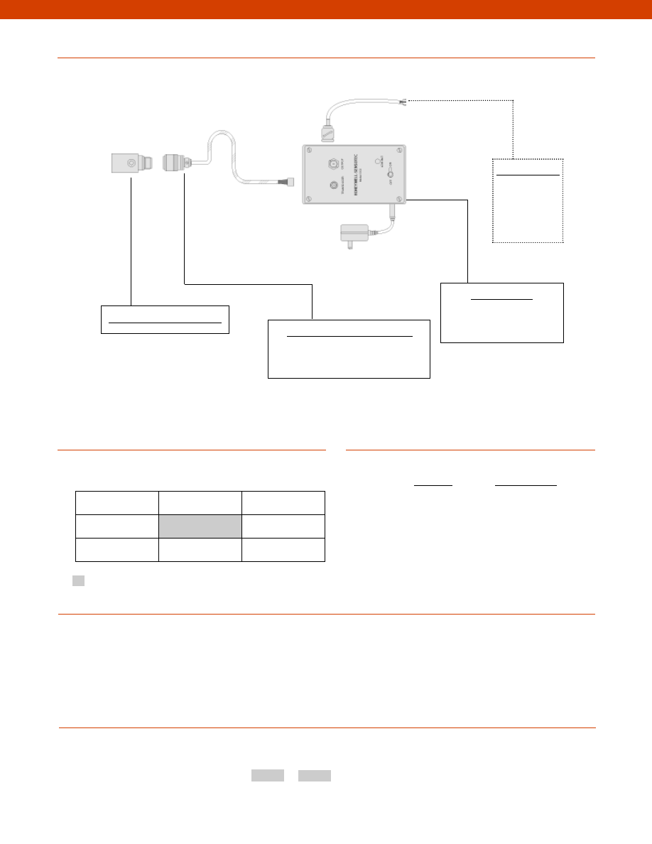
326
www.honeywell.com/sensotec
1-888-282-9891
Typical System Diagram
Sensitivity
Sensitivity Code
10 mV/G
GU
100 mV/G
GH
1,000 mV/G
GG
Sensitivity Codes
Notes
Options
How to Order
The order code consists of the product model and the desired range code.
Model Code Sensitivity Code
Sample Code:
AG903
GH
1. Not applicable for AG904.
2. Not applicable for AG903.
3. AG904 does not need mating connectors.
Model MA12 (Order Code AG903)
Mating Connectors & Cables (note 3)
MS connector to microdot cable
MS mating connector
Power Supply Unit
Model CC2 Constant
current power Supply
Customer Supplied
Chart Recorder
Alarm Panel
Data Acquisition
Computer
PLC
BNC Connector
Fast Track Delivery
Built to Order
Sensitivity
100 mV/G
10mV/G; 1,000mV/G
Electrical Termination
Cable length (Specify
at time of ordering)
Supplied as standard
Model MA12
-Not RoHS Compliant
Courtesy of Steven Engineering, Inc.-230 Ryan Way, South San Francisco, CA 94080-6370-Main Office: (650) 588-9200-Outside Local Area: (800) 258-9200-www.stevenengineering.com
Sensotec Sensors Full Line Catalog-html.html
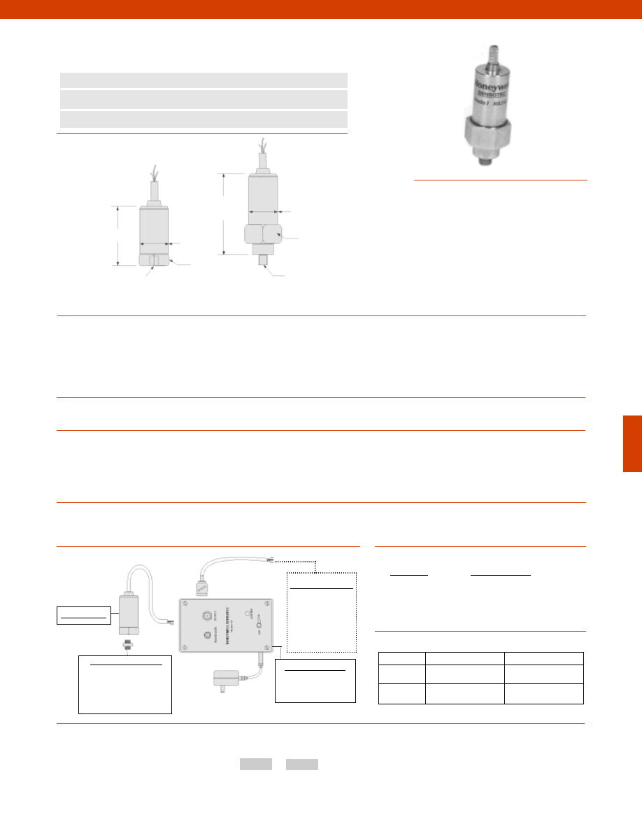
327
Dimensions
Performance
Environmental
Electrical
Mechanical
www.honeywell.com/sensotec
1-888-282-9891
1.22 in.
n
High Frequency
n
2 Hz to 15 kHz Usable Frequency Range
n
IEPE Output
Models MA341 & MA342 Accelerometers
Order Code AG922; AG923
Dynamic Ranges................+/- 80G
Sensitivity................100 mV/G +/- 10%
Transverse Sensitivity................Less than 5%
Temperature Sensitivity................0.145/ °F
Frequency Range................2 Hz to 15 kHz +/- 5%
Amplitude Linearity................Better than 1% Linearity
Mounted Base Resonance................22 kHz
Temperature, Operating................-10° to 280° F
Sealing................IP67/ Nema 4
Input................Constant Current
Current Range................0.5 mA to 8 mA
Bias Voltage................12 Vdc
Cable................S/S overbraided PTFE
Electrical Noise................0.1 mG max.
Isolation................Base isolated
Weight................1 oz.
Material................Stainless Steel
Mounting Torque................6 ft.-lb.
0.74 in. A/F
Rotating Nut
1/4-28 UNF Female
0.59 in. A/F
1.61 in.
1/4-28 UNF Male
0.59 in.
0.59 in.
Model MA341
(order code AG922)
Model MA342
(order code AG923)
Wiring Codes
Black
(+) Supply/ (+) Output
White
Supply Return
Model MA341
Power Supply Unit
Model CC2 Constant
current power Supply
Customer Supplied
Chart Recorder
Alarm Panel
Data Acquisition
Computer
PLC
BNC Connector
Sensitivity Codes
Typical System Diagram
How to Order
Mounting Assemblies
Mounting studs
Magnetic mounting
Quick connect mounting
Glued mounting
Sensitivity
Sensitivity Code
10 mV/G
GU
30 mV/G
GC
100 mV/G
GH
1,000 mV/G
GG
Options
The order code consists of the product model and the desired range code.
Model Code Sensitivity Code
Sample Code:
AG913
GH
Fast Track Delivery
Built to Order
Sensitivity
100 mV/G
10mV/G; 1,000mV/G;
30 mV/G
Electrical
Termination
Cable length (Specify
at time of order)
-Not RoHS Compliant
Courtesy of Steven Engineering, Inc.-230 Ryan Way, South San Francisco, CA 94080-6370-Main Office: (650) 588-9200-Outside Local Area: (800) 258-9200-www.stevenengineering.com
Sensotec Sensors Full Line Catalog-html.html
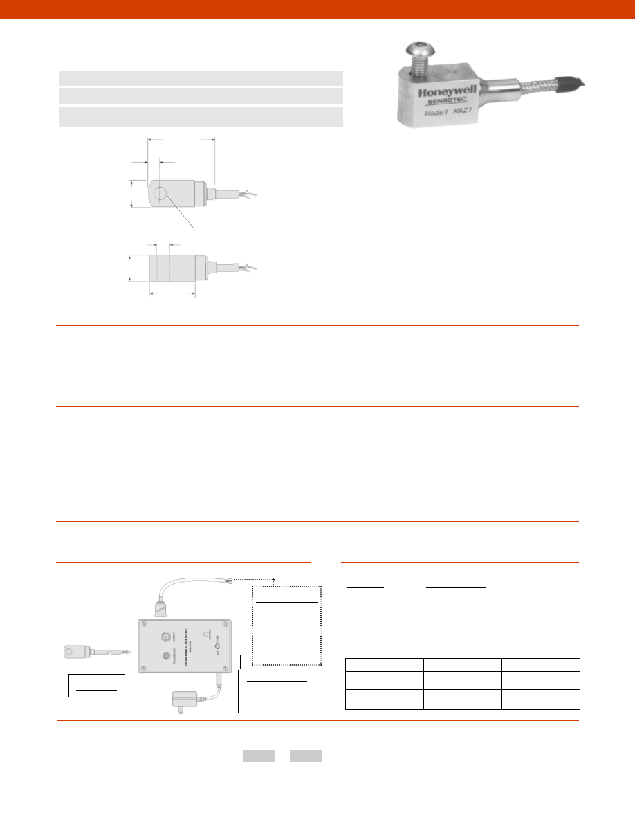
328
Dynamic Ranges................+/- 80 G
Sensitivity................100 mV/G +/- 10% @ 80 Hz
Transverse Sensitivity................Less than 5%
Temperature Sensitivity................0.145/ °F
Frequency Range................2 Hz to 9 kHz
Amplitude Linearity................Better than 1% Linearity
Mounted Base Resonance................18 kHz
Temperature, Operating................10° to 280° F
Sealing................IP67/ Nema 4
Input................Constant Current
Current Range................0.5 mA to 8 mA
Bias Voltage................12 Vdc
Cable................S/S overbraided PTFE
Standard Cable Length................16 ft.
Electrical Noise................0.1 mG max.
Isolation................Base isolated
Weight................3.90 oz.
Material................Stainless Steel
Mounting Torque................6 ft.-lb.
Model MA21
Power Supply Unit
Model CC2 Constant
current power Supply
BNC Connector
www.honeywell.com/sensotec
1-888-282-9891
0.28 in.
n
Miniature Size
n
Low Profile
n
IEPE Output
Model MA21 Accelerometer
Order Code AG913
0.67 in.
0.33 in.
Use mounting bolt
1.12 in.
1.63 in.
0.67 in.
Wiring Codes
White
(+) Supply (+) Output
Black
Supply Return
Shield
Connected to Case
Sensitivity
Sensitivity Code
10 mV/G
GU
30 mV/G
GC
100 mV/G
GH
1,000 mV/G
GG
Sensitivity Codes
Options
Typical System Diagram
How to Order
The order code consists of the product model and the desired range code.
Model Code Sensitivity Code
Sample Code:
AG913
GH
Fast Track Delivery
Built to Order
Sensitivity
100 mV/G
10mV/G; 1,000mV/G;
30 mV/G
Electrical Termination
Cable length (Specify
at time of order)
Dimensions
Performance
Environmental
Electrical
Mechanical
Customer Supplied
Chart Recorder
Alarm Panel
Data Acquisition
Computer
PLC
-Not RoHS Compliant
Courtesy of Steven Engineering, Inc.-230 Ryan Way, South San Francisco, CA 94080-6370-Main Office: (650) 588-9200-Outside Local Area: (800) 258-9200-www.stevenengineering.com
Sensotec Sensors Full Line Catalog-html.html
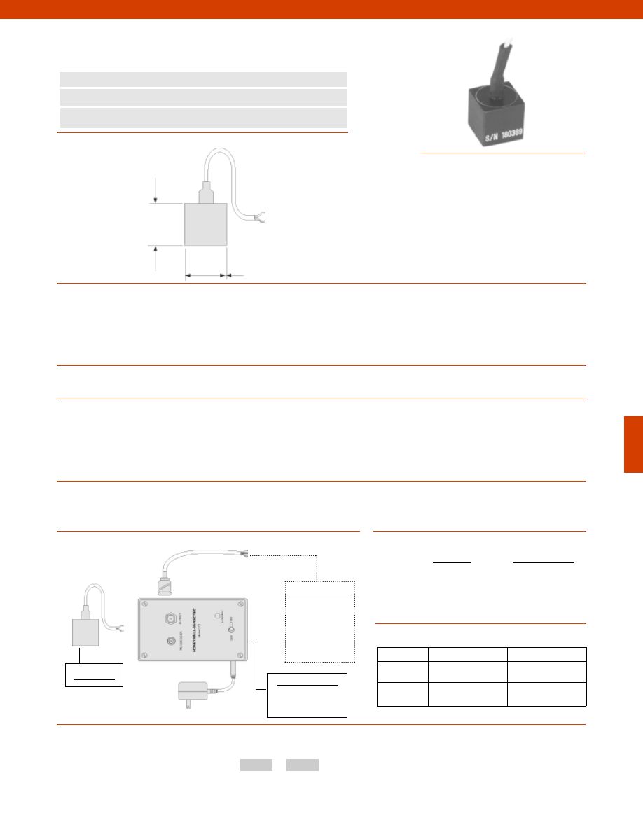
329
Dynamic Ranges................+/- 10G
Sensitivity................1V/G
Transverse Sensitivity................5% max.
Temperature Sensitivity................0.145/ °F
Frequency Range................5 Hz to 14 kHz +/- 10%
Amplitude Linearity................Better than 1% Linearity
Mounted Base Resonance................25 kHz
Temperature, Operating................-70° to 250° F
Sealing................IP65/ Nema 2
Input................Constant Current
Current Range................18-30 V
Bias Voltage................12 V
Cable................PTFE
Standard Cable Length................16 ft.
Electrical Noise................0.1 mG max.
Isolation................Base isolated
Weight................0.3 oz.
Material................HE 30 Aluminum
Mounting................Beeswax or adhesive
Model MA23
Power Supply Unit
Model CC2 Constant
current power Supply
Customer Supplied
Chart Recorder
Alarm Panel
Data Acquisition
Computer
PLC
BNC Connector
www.honeywell.com/sensotec
1-888-282-9891
n
Miniature Size
n
Low Profile
n
IEPE Output
Model MA23 Accelerometer
Order Code AG914
0.55 in.
0.55 in.
Wiring Codes
Center
(+) Supply (+) Output
Shield
Supply Return
Sensitivity
Sensitivity Code
100 mV/G
GH
1000 mV/G
GG
Sensitivity Codes
Options
Typical System Diagram
Fast Track Delivery
Built to Order
Sensitivity
1000 mV/G
100mV/G
Electrical
Termination
Cable length(Specify
at time of order)
Dimensions
Performance
Environmental
Electrical
Mechanical
How to Order
The order code consists of the product model and the desired sensitivity code.
Model Code Sensitivity Code
Sample Code:
AG914
GH
-Not RoHS Compliant
Courtesy of Steven Engineering, Inc.-230 Ryan Way, South San Francisco, CA 94080-6370-Main Office: (650) 588-9200-Outside Local Area: (800) 258-9200-www.stevenengineering.com
Sensotec Sensors Full Line Catalog-html.html
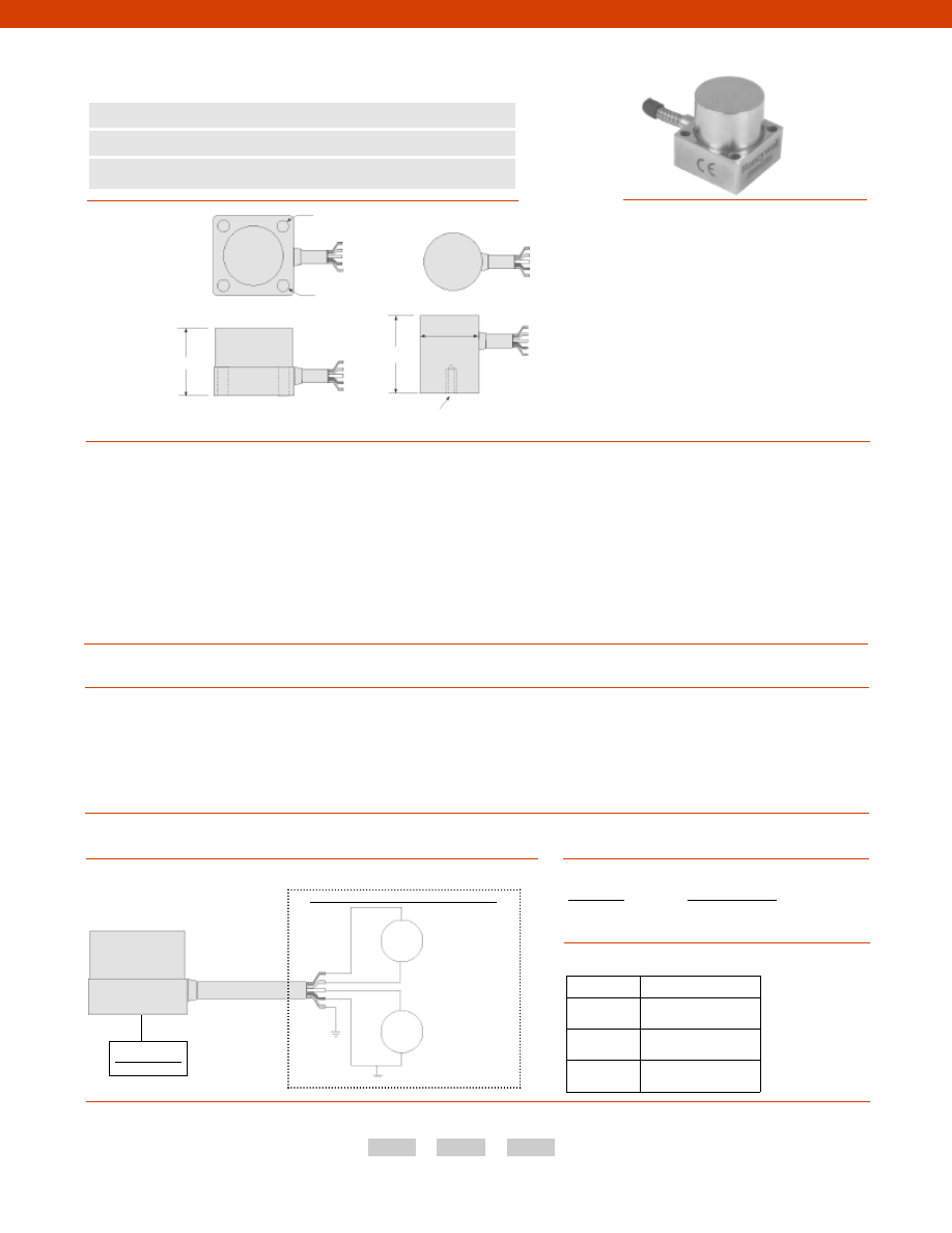
330
Dimensions
Performance
Environmental
Electrical
Mechanical
www.honeywell.com/sensotec
1-888-282-9891
4 holes for 6-40 UNF bolts
0.122 in.
n
DC Response
n
Amplified Voltage Output
n
Up to 0-1800 Hz Usable Range
Model MA311 & MA312 Accelerometer
Order Code AG915; AG916
1.0 in.
Model MA311 (order code AG915)
1.0 in.
1.30 in.
1/4-28 UNF
Model MA312 (order code AG916)
Wiring Codes
Red
(+) Supply
Blue
(-) Supply
Yellow
(+) Output
Green
(-) Output
Shield
Not Connected
Model MA311
Sensitivity
Sensitivity Code
100 mV/G
GH
Sensitivity Codes
Options
Typical System Diagram
How to Order
The order code consists of the product model, the desired range code and the available options.
Model Code Sensitivity Code Options Code
Sample Code:
AG915
GH
17c
Fast Track Delivery
Dynamic
Range
+/- 1, 2, 5, 10, 20, 50 G
Electrical
Termination
Cable length (Specify
at time of order)
Mounting
Arrangement
17b. 1/4-28 UNF
17c. Quickfit Female
Sensitivity................100 mV/G
Transverse Sensitivity................Less than 5%
Temperature Sensitivity................0.145/ °F
Frequency Range................dependent on dynamic range +/- 5% (see below)
+/- 1G & +/- 2G................DC to 250 Hz
+/- 5G................DC to 300 Hz
+/- 10G................DC to 500 Hz
+/- 20G................DC to 700 Hz
+/- 50G................DC to 1 kHz
Amplitude Linearity................Better than 1% Linearity
Mounted Base Resonance................18 kHz
Acceleration Limits................x 20 of dynamic range
Temperature, Operating................0° to 180° F
Sealing................IP65/ Nema 2
Input................Voltage
Supply Voltage................12-24V @ 7mA
Output Impedance................50 Ohms
Cable................Stainless Steel overbraided PTFE
Standard Cable Length................16 ft.
Electrical Noise................10 mG
Isolation................Base isolated
Weight................1.40 oz.
Case Material................Stainless Steel
Power
Supply
Power Supply
Isolated from
Ground
Output
Customer Supplied Monitoring System
+
-
+
-
V
-Not RoHS Compliant
Courtesy of Steven Engineering, Inc.-230 Ryan Way, South San Francisco, CA 94080-6370-Main Office: (650) 588-9200-Outside Local Area: (800) 258-9200-www.stevenengineering.com
Sensotec Sensors Full Line Catalog-html.html
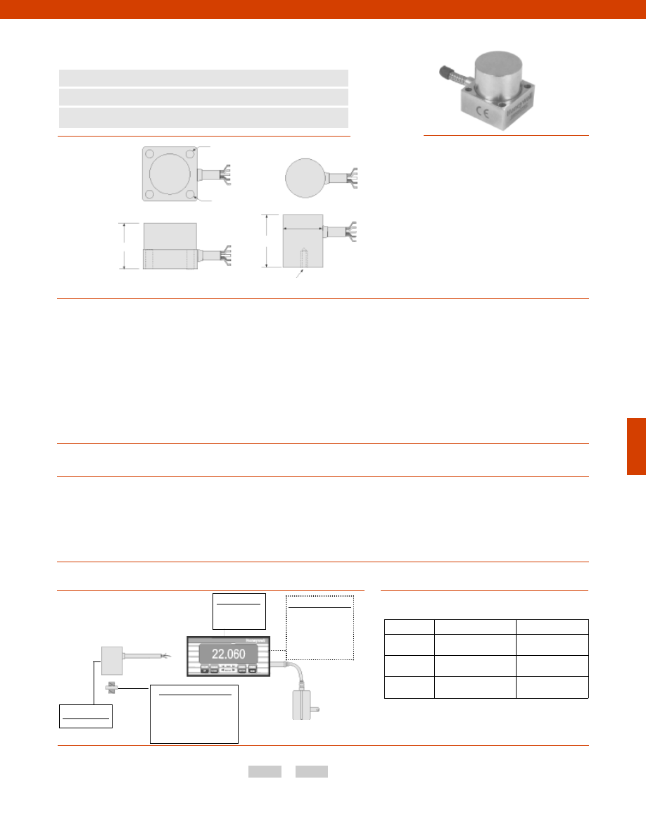
331
Dimensions
Performance
Environmental
Electrical
Mechanical
www.honeywell.com/sensotec
1-888-282-9891
4 holes for 6-40 UNF bolts
0.122 in.
n
DC Response
n
4-20 mA Output Proportional to G
n
Built-in Signal Conditioning
Model MA321 & MA322 Accelerometer
Order Code AG917; AG918
1.0 in.
Model MA321 (order code AG917)
1.0 in.
1.30 in.
1/4-28 UNF
Model MA322 (order code AG918)
Wiring Codes
Red
(+) Supply
Blue
(+) Supply
Shield
Not Connected
Model MA322
Display Units
SC500
SC2000
Customer Supplied
Chart Recorder
Alarm Panel
Data Acquisition
Computer
PLC
Options
Typical System Diagram
How to Order
The order code consists of the product model and the available options.
Model Code
Options Code
Sample Code:
AG918
17c
Mounting Assemblies
Mounting studs
Magnetic mounting
Quick connect mounting
Glued mounting
Fast Track Delivery
Built to Order
Dynamic
Range
+/- 1, 2, 5, 10, 20, 50 G
Electrical
Termination
Cable length
Mounting
Arrangement
17b. 1/4-28 UNF
17c. Quickfit Female
10-32 UNF Female
Output................4-20 mA range, 12 mA @ 0 G with sensitivity scaled to a full
range output, i.e. +/-5 G = 1.6 mA/G
Transverse Sensitivity................Less than 5%
Temperature Sensitivity................0.145/ °F
Frequency Range................dependent on dynamic range +/- 5% (see below)
+/- 1G & +/- 2G................DC to 250 Hz
+/- 5G................DC to 300 Hz
+/- 10G................DC to 500 Hz
+/- 20G................DC to 700 Hz
+/- 50G................DC to 1 kHz
Amplitude Linearity................Better than 1% Linearity
Mounted Base Resonance................18 kHz
Acceleration Limits................x 20 of dynamic range
Temperature, Operating................0° to 180° F
Sealing................IP65/ Nema 2
Input................Voltage
Supply Voltage................10 to 30V
Output Impedance................3,000 Ohms
Cable................Stainless Steel overbraided PTFE
Standard Cable Length................16 ft.
Electrical Noise................10 mG
Isolation................Base isolated
Weight................1.40 oz.
Case Material................Stainless Steel
-Not RoHS Compliant
Courtesy of Steven Engineering, Inc.-230 Ryan Way, South San Francisco, CA 94080-6370-Main Office: (650) 588-9200-Outside Local Area: (800) 258-9200-www.stevenengineering.com
Sensotec Sensors Full Line Catalog-html.html
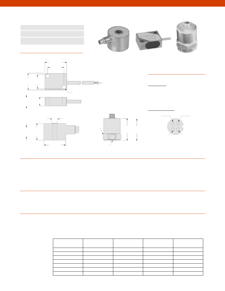
332
Dimensions
Performance
Environmental
Electrical
www.honeywell.com/sensotec
1-888-282-9891
0.77 in. 0.50 in.
0.75 in.
1.0 in.
ø1.0 in.
1.0 in.
Model JTF Screw Mount (order code AG111)
n
Zero Hertz Operation
n
Easy Calibration
n
Low Impedance
Model JTF General Purpose Accelerometer
Order Code AG111; AG112; AG113
Dynamic Ranges................+/- 5 to 500 Peak G
Sensitivity................See table
Transverse Sensitivity................Less than 5%
Frequency Range................See table
Frequency Response................+/- 5% (note 1)
Non-Linearity & Hysteresis................+/- 1% Full Scale
Mounted Base Resonance................See table
Damping Ratio (nominal)................0.7 C @ 70° F
Temperature, Operating................-40° to 250° F
Temperature, Compensated................70° to 200 ° (note 1)
Temperature Effect
Zero (max.)................0.02% Full Scale/ ° F
Sensitivity (max.)................+/- 10%
Excitation (calibration)................5 VDC
Excitation (acceptable)................Up to 10 VDC
Electrical Termination
AG111................Teflon Cable 5’
AG112 & AG113................10-32 UNF 4-pin connector
Mating Connector................10-32 UNF socket plug (note 2)
Model JTF
Model JTF
Model JTF
Bolt Mount
Screw Mount
Stud Mount
0.75 in.
Model JTF Bolt Mount (order code AG112)
0.4 in.
ø0.26 in.
ø0.16 in. typically
7/8 Hex
Sensitive
Axis
Sensitive
Axis
Sensitive
Axis
1/4-28 UNF x 1/4
Model JTF Stud Mount (order code AG113)
Wiring Codes
Screw Mount
Red
(+) Excitation
Black
(-) Excitation
Green
(-) Output
White
(+) Output
Bolt or Stud Mount
- Output
- Excitation
+ Output
+ Excitation
Available Range
(peak G)
Sensitivity Nominal
(mV/G)
Sensitivity Range
(mV/G)
Usable Frequency
Range (Hz)
Mounted Resonant
Frequency (Hz)
+/- 5
8
5.0-12
0-300
800
+/- 10
3.8
2.4-5.0
0-400
1,00
+/- 20
1.8
1.2-2.4
0-600
1,500
+/- 50
0.8
0.5-1.2
0-1,000
2,000s
+/- 100
0.38
0.24-0.5
0-1,500
3,000
+/- 200
0.18
0.12-0.24
0-2,000
4,000
+/- 500
0.08
0.05-0.12
0-2,400
5,000
Courtesy of Steven Engineering, Inc.-230 Ryan Way, South San Francisco, CA 94080-6370-Main Office: (650) 588-9200-Outside Local Area: (800) 258-9200-www.stevenengineering.com
Sensotec Sensors Full Line Catalog-html.html
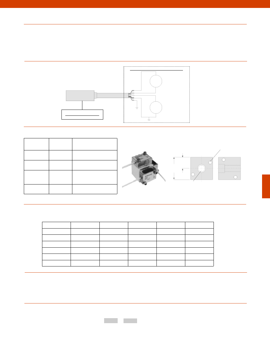
333
1.00 in.
cubic
0.500 in.
Model JTF Screw Mount
Power
Supply
Power Supply
Output
Customer Supplied Monitoring System
+
-
+
-
V
www.honeywell.com/sensotec
1-888-282-9891
Mechanical
Typical System Diagram
Notes
Options
How to Order
The order code consists of the product model and the desired range code.
Model Code
Range Code
Sample Code:
AG111
GV
1. Output voltage is proportional to input voltage.
2. Only available with AG112 & AG113.
Acceleration Limits (any direction)................20x
Weight
AG111................1 oz.
AG112 & AG113................2.1 oz.
Case Material
AG111................Anodized Aluminum
AG112 & AG113................Stainless Steel
Same Day Ship
Built to Order
AG111
Range
10, 50G
5, 20, 100, 200, 500G
AG112& AG113
Range
5, 10, 20, 50, 100, 200, 500G
#6-32 -2B UNC JTF mounting
holes, typically on three sides
Clearance for 1/4” socket head cap
screw, to secure mounting block
Triaxial Mounting Block (order code AA235) for Model AG111
GJ
+/-5
8
5.0-12
0-300
800
GK
+/-10
3.8
2.4-5.0
0-400
1000
GL
+/-20
1.8
1.2-2.4
0-600
1500
GN
+/-50
0.8
0.5-1.2
0-1000
2000
GP
+/-100
0.38
0.24-0.5
0-1500
3000
GV
+/-200
0.18
0.12-0.24
0-2000
4000
GR
+/-500
0.08
0.05-0.12
0-2400
5000
Specifications
Range Codes Available Ranges Sensitivity Usable Frequency Mounted Resonant
(peak G) Nominal (mV/G) Range (mV/G) Range (Hz) Frequency (Hz)
Model JTF
-Not RoHS Compliant
Courtesy of Steven Engineering, Inc.-230 Ryan Way, South San Francisco, CA 94080-6370-Main Office: (650) 588-9200-Outside Local Area: (800) 258-9200-www.stevenengineering.com
Sensotec Sensors Full Line Catalog-html.html
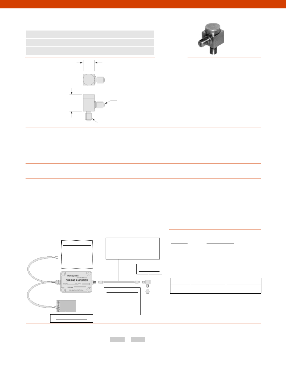
334
Dynamic Ranges................+/- 2,000 G
Sensitivity................5 pC/g +/- 10%
Transverse Sensitivity................Less than 5%
Temperature Sensitivity................0.045/ °F
Frequency Range................1 Hz to 30 kHz
Amplitude Linearity................Better than 1% Linearity
Mounted Base Resonance................45 kHz
Temperature, Operating................-70° to 480° F
Sealing................IP67/ Nema 4
Input................Self Generating
Output................Charge
Charge Amplitude Required................CA2
Mating Connector................Microdot
Capacitance................300 pf
Isolation................Base isolated
Weight................0.25 oz.
Material................Stainless Steel
Mounting Torque................2 ft.-lb.
Model MAQ36
AA957 Power Supply
Customer Supplied
Chart Recorder
Alarm Panel
Data Acquisition
Computer
PLC
www.honeywell.com/sensotec
1-888-282-9891
n
Sub-Miniature
n
Charge Output
n
45 kHz Mounted Frequency
Model MAQ36 Accelerometer
Order Code AG924
10-32 UNF Microdot Connector
0.33 in.
10-32 UNF
0.47 in.
Wiring Codes
Sensitivity
Sensitivity Code
0.5 pC/G
YA
5 pC/G
YB
50 pC/G
YF
Sensitivity Codes
Options
Typical System Diagram
How to Order
The order code consists of the product model and the desired range code.
Model Code Sensitivity Code
Sample Code:
AG924
YA
Fast Track Delivery
Built to Order
Sensitivity
5 pC/G
0.5 pC/g; 50 pC/G
Mounting Assemblies
Mounting studs
Magnetic mounting
Quick connect mounting
Glued mounting
Mating Connectors & Cables
Microdot mating connector
Dimensions
Performance
Environmental
Electrical
Mechanical
Center
(+) Output
Shield
Case Ground
-Not RoHS Compliant
Courtesy of Steven Engineering, Inc.-230 Ryan Way, South San Francisco, CA 94080-6370-Main Office: (650) 588-9200-Outside Local Area: (800) 258-9200-www.stevenengineering.com
Sensotec Sensors Full Line Catalog-html.html
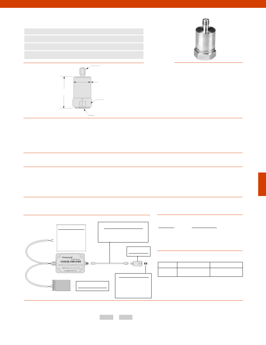
335
Dynamic Ranges................+/- 800 G
Sensitivity................10, 20, 30 pC/G
Transverse Sensitivity................Less than 5%
Temperature Sensitivity................0.145/ °F
Frequency Range................dependent on charge amplifier
Amplitude Linearity................Better than 1% Linearity
Mounted Base Resonance................30 kHz
Temperature, Operating................-70° to 480° F
Sealing................IP67/ Nema 4
Input................Self Generating
Output................Charge
Charge Amplitude Required................CA2
Mating Connector................Microdot
Capacitance................450 pf
Isolation................Base isolated
Weight................1.00 oz.
Material................Stainless Steel
Mounting Torque................2 ft.-lb.
Model MAQ13
AA957 Power Supply
Customer Supplied
Chart Recorder
Alarm Panel
Data Acquisition
Computer
PLC
www.honeywell.com/sensotec
1-888-282-9891
n
Small Size
n
Charge Output
n
30 kHz Mounted Frequency
n
General Purpose
Model MAQ13 Accelerometer
Order Code AG908
0.59 in. A/F
10-32 UNF Microdot Connector
0.55 in.
10-32 UNF
0.94 in.
Wiring Codes
Sensitivity
Sensitivity Code
10 pC/G
YC
20 pC/G
YD
30 pC/G
YE
Sensitivity Codes
Options
Typical System Diagram
Fast Track Delivery
Built to Order
Sensitivity
20 pC/G
10, 30 pC/G
Mounting Assemblies
Mounting studs
Magnetic mounting
Quick connect mounting
Glued mounting
Mating Connectors & Cables
Microdot mating connector
Dimensions
Performance
Environmental
Electrical
Mechanical
Center
(+) Output
Shield
Case Ground
How to Order
The order code consists of the product model and the desired sensitivity code.
Model Code Sensitivity Code
Sample Code:
AG908
YC
-Not RoHS Compliant
Courtesy of Steven Engineering, Inc.-230 Ryan Way, South San Francisco, CA 94080-6370-Main Office: (650) 588-9200-Outside Local Area: (800) 258-9200-www.stevenengineering.com
Sensotec Sensors Full Line Catalog-html.html
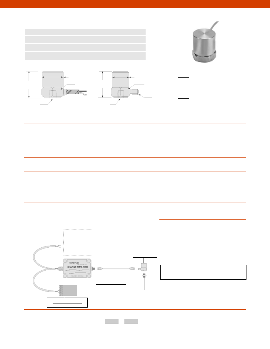
336
Model MAQ14
Customer Supplied
Chart Recorder
Alarm Panel
Data Acquisition
Computer
PLC
www.honeywell.com/sensotec
1-888-282-9891
n
Small Size
n
Charge Output
n
18 kHz Mounted Frequency
n
General Purpose
Model MAQ14 Accelerometer
Order Code AG909; AG910
0.75 in.
A/F
1/4-28 UNF
0.55 in.
0.59 in. A/F
10-32 UNF
Microdot
Connector
0.79 in.
10-32 UNF
0.75 in.
0.79 in.
Model MAQ14
(order code AG910)
Model MAQ14
(order code AG909)
Wiring Codes
AG909
Center
(+) Output
Shield
Case Ground
AG910
Center
(+) Output
Shield
Case Ground
Sensitivity
Sensitivity Code
10 pC/G
YC
30 pC/G
YE
50 pC/G
YF
Sensitivity Codes
Options
Typical System Diagram
How to Order
Fast Track Delivery
Built to Order
Sensitivity
50 pC/G
10, 30 pC/G
Mounting Assemblies
Mounting studs
Magnetic mounting
Quick connect mounting
Glued mounting
Mating Connectors & Cables
Microdot mating connector
(only for AG909)
Dimensions
Performance
Environmental
Electrical
Mechanical
AA957 Power Supply
Dynamic Ranges................1,000 G
Sensitivity................10, 30, 50 pC/G
Transverse Sensitivity................Less than 5%
Temperature Sensitivity................0.145/ °F
Frequency Range................1 Hz to 10 kHz
Amplitude Linearity................Better than 1% Linearity
Mounted Base Resonance................18 kHz
Temperature, Operating................-70° to 480° F
Sealing................IP67/ Nema 4
Input................Self Generating
Standard Cable Length................16 ft. (only AG910)
Charge Amplitude Required................CA2
Mating Connector................Microdot (only AG909)
Capacitance................450 pf
Isolation................Base isolated
Weight................1.20 oz.
Material................Stainless Steel
Mounting Torque................2 ft.-lb.
The order code consists of the product model and the desired sensitivity code.
Model Code Sensitivity Code
Sample Code:
AG909
YC
-Not RoHS Compliant
Courtesy of Steven Engineering, Inc.-230 Ryan Way, South San Francisco, CA 94080-6370-Main Office: (650) 588-9200-Outside Local Area: (800) 258-9200-www.stevenengineering.com
Sensotec Sensors Full Line Catalog-html.html
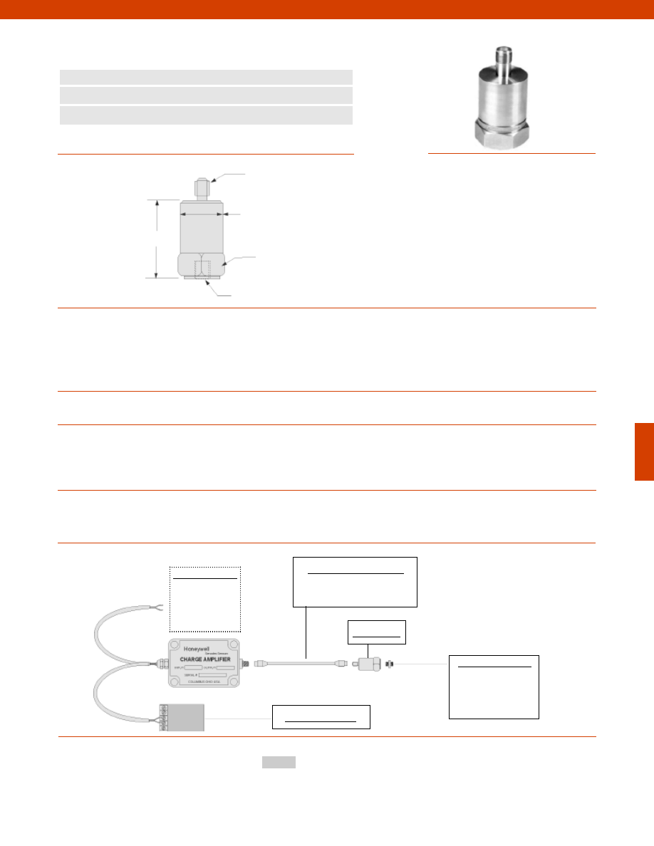
337
Dynamic Ranges................+/- 100 G
Sensitivity................1,100 pC/G +/- 10%
Transverse Sensitivity................Less than 5%
Temperature Sensitivity................0.145/ °F
Frequency Range................dependent on charge amplifier
Amplitude Linearity................Better than 1% Linearity
Mounted Base Resonance................10 kHz
Temperature, Operating................-70° to 480° F
Sealing................IP67/ Nema 4
Input................Self Generating
Charge Amplitude Required................CA2
Mating Connector................TNC
Capacitance................4,000 pf
Isolation................Non-isolated
Weight................3.50 oz.
Material................Stainless Steel
Mounting Torque................6 ft.-lb.
Model MAQ41
AA957 Power Supply
Customer Supplied
Chart Recorder
Alarm Panel
Data Acquisition
Computer
PLC
www.honeywell.com/sensotec
1-888-282-9891
n
Enhanced Output
n
Charge Output
n
10 kHz Mounted Frequency
Model MAQ41 Accelerometer
Order Code AG925
1.26 in. A/F
TNC connector
1.26 in.
1/4-28 UNF
1.65 in.
Wiring Codes
Typical System Diagram
Mounting Assemblies
Mounting studs
Magnetic mounting
Quick connect mounting
Glued mounting
Mating Connectors & Cables
TNC mating connector
Dimensions
Performance
Environmental
Electrical
Mechanical
Center
(+) Output
Shield
Case Ground
How to Order
Model Code
Sample Code:
AG925
-Not RoHS Compliant
Courtesy of Steven Engineering, Inc.-230 Ryan Way, South San Francisco, CA 94080-6370-Main Office: (650) 588-9200-Outside Local Area: (800) 258-9200-www.stevenengineering.com
Sensotec Sensors Full Line Catalog-html.html
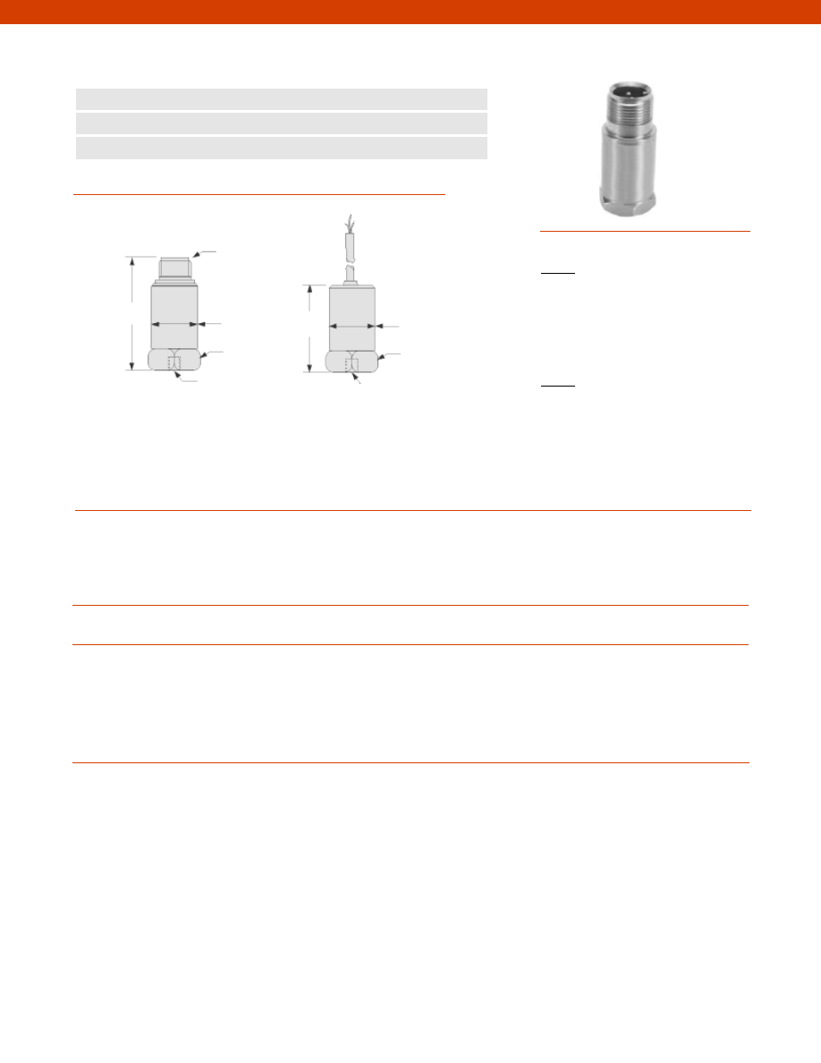
338
Dimensions
Performance
Environmental
Electrical
Mechanical
www.honeywell.com/sensotec
1-888-282-9891
2 pin MS
Connector
1.97 in.
n
Velocity Measurement
n
5 Hz to 4 kHz +/- 5% Usable Frequency Range
n
IEPE Output
Model MAV51 Accelerometer
Order Code AG926; AG927
Sensitivity................100 mV/in./sec
Transverse Sensitivity................Less than 5%
Temperature Sensitivity................0.145/ °F
Frequency Range................5 Hz to 4 kHz +/- 5%
Amplitude Linearity................Better than 1% Linearity
Mounted Base Resonance................18 kHz nominal
Temperature, Operating................-10° to 280° F
Sealing................IP67/ Nema 4
Input................Constant Current
Current Range................0.5 mA to 8 mA
Bias Voltage................12 Vdc
Cable (note 1)................S/S overbraided PTFE
Standard Cable Length (note 1)................16 ft.
Electrical Noise................0.3 mG max.
Isolation................Base isolated
Mating Connector (note 2)................MH002
Weight................3.88 oz.
Material................Stainless Steel
Mounting Torque................6 ft.-lb.
1/4-28 UNF
Female
0.86 in.
1.5 in.
1/4-28 UNF
Female
1.0 in. A/F
Model MAV51
(order code AG926)
0.98 in. A/F
0.86 in.
Model MAV51
(order code AG927)
Wiring Codes
AG926
Pin A
(+) Supply/ (+) Output
Pin B
Supply Return
AG927
White
(+) Supply (+) Output
Black
Supply Return
Shield
Not Connected
Courtesy of Steven Engineering, Inc.-230 Ryan Way, South San Francisco, CA 94080-6370-Main Office: (650) 588-9200-Outside Local Area: (800) 258-9200-www.stevenengineering.com
Sensotec Sensors Full Line Catalog-html.html
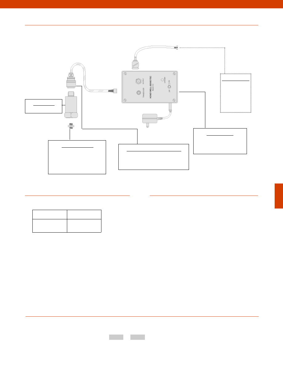
339
www.honeywell.com/sensotec
1-888-282-9891
Typical System Diagram
Notes
Options
How to Order
The order code consists of the product model and the available options.
Model Code
Options Code
Sample Code:
AG926
17c
1. Not applicable for AG926.
2. Not applicable for AG927.
Model MAV51
Mounting Assemblies
Mounting studs
Magnetic mounting
Quick connect mounting
Glued mounting
Mating Connectors & Cables (note 2)
MH002 mating connector
Power Supply Unit
Model CC2 Constant
current power Supply
Customer Supplied
Chart Recorder
Alarm Panel
Data Acquisition
Computer
PLC
BNC Connector
Fast Track Delivery
Mounting
Arrangement
17b. 1/4-28 UNF
17c. Quickfit Female
Model MAV51
-Not RoHS Compliant
Courtesy of Steven Engineering, Inc.-230 Ryan Way, South San Francisco, CA 94080-6370-Main Office: (650) 588-9200-Outside Local Area: (800) 258-9200-www.stevenengineering.com
Sensotec Sensors Full Line Catalog-html.html
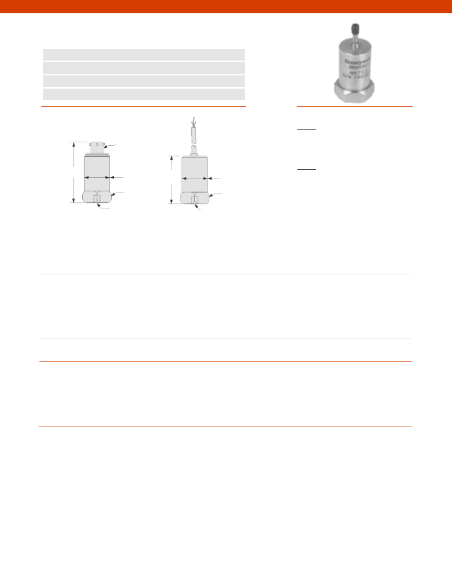
340
Dimensions
Performance
Environmental
Electrical
Mechanical
www.honeywell.com/sensotec
1-888-282-9891
3 pin 62GB
Connector
1.97 in.
n
Temperature & Vibration Output
n
2 Hz to 10 kHz Usable Frequency Range
n
IEPE Output
n
Current O/P for Temperature
Model MAT53 Accelerometer
Order Code AG930; AG931
Dynamic Ranges................+/- 80G
Sensitivity................100 mV/G +/- 10%
Temperature Range................0 - 200°F
Transverse Sensitivity................Less than 5%
Temperature Sensitivity................10 mV/ °F
Frequency Range................2 Hz to 10 kHz +/- 5%
Amplitude Linearity................Better than 1% Linearity
Mounted Base Resonance................18 kHz
Temperature, Operating................-10° to 280° F
Sealing................IP67/ Nema 4
Input................Constant Current
Current Range................0.5 mA to 8 mA
Bias Voltage................12 Vdc
Cable (note 1)................S/S overbraided PTFE
Standard Cable Length (note 1)................16 ft.
Electrical Noise................0.3 mG max.
Isolation................Base isolated
Mating Connector (note 2)................MH008
Weight................3.80 oz.
Material................Stainless Steel
Mounting Torque................6 ft.-lb.
1/4-28 UNF
Female
0.86 in.
1.5 in.
1/4-28 UNF
Female
0.98 in. A/F
Model MAT53
(order code AG930)
0.98 in. A/F
0.86 in.
Model MAT53
(order code AG931)
Wiring Codes
AG930
Pin A
(+) Supply/ (+) Output
Pin B
Supply Return
Pin C
(+) Temperature
AG931
White
(+) Supply (+) Output
Black
(+) Temperature
Shield
Supply Return
Courtesy of Steven Engineering, Inc.-230 Ryan Way, South San Francisco, CA 94080-6370-Main Office: (650) 588-9200-Outside Local Area: (800) 258-9200-www.stevenengineering.com
Sensotec Sensors Full Line Catalog-html.html
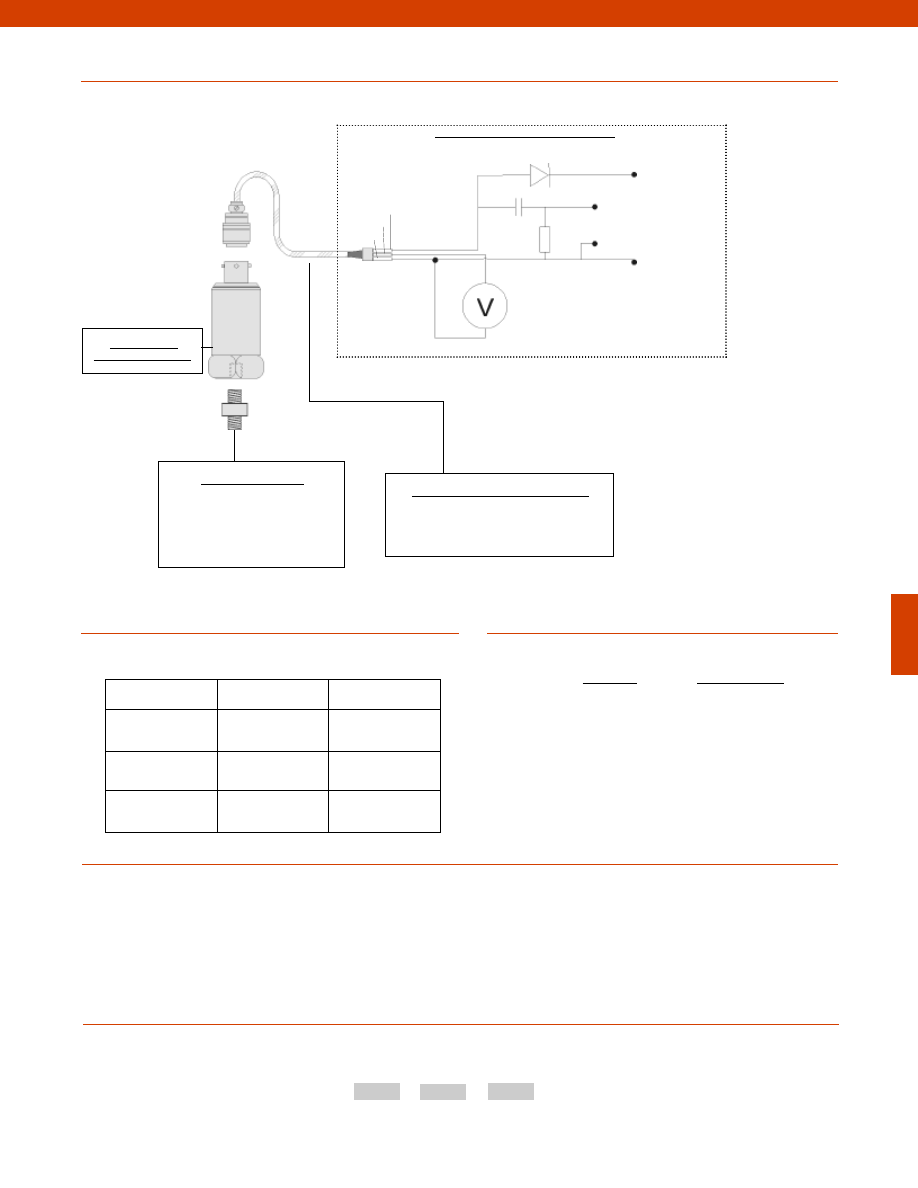
341
www.honeywell.com/sensotec
1-888-282-9891
Sensitivity
Sensitivity Code
10 mV/G
GU
30 mV/G
GB
100 mV/G
GH
1,000 mV/G
GG
Sensitivity Codes
Notes
Options
How to Order
The order code consists of the product model, the desired range code and the available options.
Model Code Sensitivity Code Options Code
Sample Code:
AG930
GH
17c
1. Not applicable for AG930.
2. Not applicable for AG931.
Fast Track Delivery
Built to Order
Sensitivity
100 mV/G
10mV/G; 1,000mV/G;
30 mV/G
Electrical Termination
Cable (note 2)
Mounting
Arrangement
17b. 1/4-28 UNF
17c. Quickfit Female
Model MAT53
Typical System Diagram
Model MAT53
(Order Code AG930)
Mounting Assemblies
Mounting studs
Magnetic mounting
Quick connect mounting
Glued mounting
Mating Connectors & Cables (note 2)
MS connector to microdot cable
MS mating connector
Pin A
Pin C
Pin B
Volts Out
A.C.
200 KOhm
0.5-8.0 mA
1F
+18 to 30 Volts
0 Volts
Customer Supplied Monitoring System
-Not RoHS Compliant
Courtesy of Steven Engineering, Inc.-230 Ryan Way, South San Francisco, CA 94080-6370-Main Office: (650) 588-9200-Outside Local Area: (800) 258-9200-www.stevenengineering.com
Sensotec Sensors Full Line Catalog-html.html
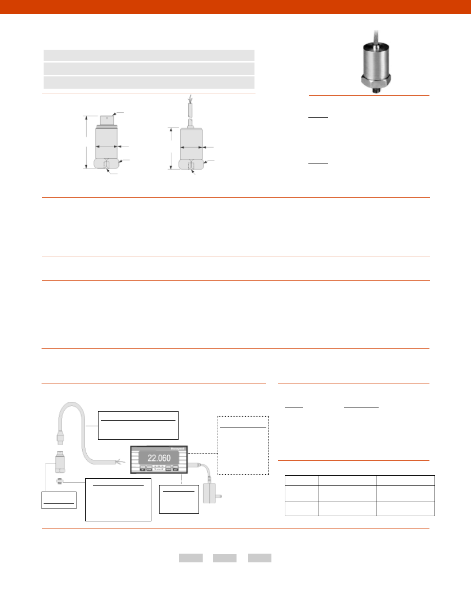
342
www.honeywell.com/sensotec
1-888-282-9891
n
General Purpose
n
4-20 mA Proportional to G
n
2 Hz to 1 kHz Usable Range
Model MA15 Accelerometer
Order Code AG906; AG907
1.10 in. A/F
1.06 in.
1/4-28 UNF
3 pin 62GB
connector
1.14 in. A/F
1/4-28 UNF
2.24 in.
1.69 in.
1.06 in.
Model MA15
(order code AG906)
Model MA15
(order code AG907)
Wiring Codes
Range
Range Code
1G
GE
2G
GF
5G
GJ
10G
GK
20G
GL
50G
GN
Range Codes
Options
How to Order
The order code consists of the product model, the desired range code and the available options.
Model Code
Range Code
Options Code
Sample Code:
AG906
GE
17c
Fast Track Delivery
Built to Order
Dynamic
50G
1, 2, 5, 10, 20G
Electrical
Termination
17b. 1/4-28 UNF
17c. Quickfit Female
Dimensions
Performance
Environmental
Electrical
Mechanical
Typical System Diagram
Dynamic Ranges................+/- 1G to +/-50 G
Range................4-20 mA for 50 G
Transverse Sensitivity................Less than 5%
Temperature Sensitivity................0.145/ °F
Frequency Range................2 Hz to 1 kHz +/- 10%
Amplitude Linearity................Better than 1% Linearity
Mounted Base Resonance................5 kHz
Temperature, Operating................-10° to 210° F
Sealing................IP67/ Nema 4
Input................Voltage
Output................4-20 mA for 50 G
Supply Voltage................12-32 V
Cable (AG907)................Stainless Steel overbraided PTFE
Standard Cable Length (AG907)................16 ft.
Mating Connector (AG906)................MH008
Electrical Noise................0.3 mG max.
Isolation................Base isolated
Weight................5 oz.
Material................Stainless Steel
Mounting Torque................6 ft.-lb.
AG906
Pin A
(+) Supply
Pin B
No Connection
Pin C
(+) Output
AG907
White
(+) Supply
Black
(+) Output
Shield
Case Ground
Model MA15
Mounting Assemblies
Mounting Studs
Magnetic Mounting
Quick Connect Mounting
Glued Mounting
Customer Supplied
Chart Recorder
Alarm Panel
Data Acquisition
Computer
PLC
Mating Connectors and Cables
MH008
Display Units
SC500
SC2000
-Not RoHS Compliant
Courtesy of Steven Engineering, Inc.-230 Ryan Way, South San Francisco, CA 94080-6370-Main Office: (650) 588-9200-Outside Local Area: (800) 258-9200-www.stevenengineering.com
Sensotec Sensors Full Line Catalog-html.html
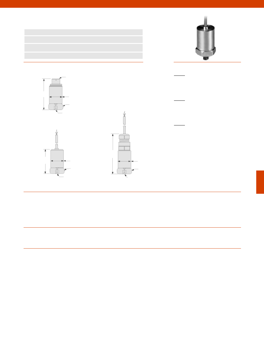
343
Dimensions
Performance
Environmental
Electrical
www.honeywell.com/sensotec
1-888-282-9891
3 pin 62GB
connector
2.24 in.
1.06 in.
1/4-28 UNF
1.14 in. A/F
Model MAV52 (order code AG928)
n
Velocity Measurement
n
2 Hz to 10 kHz Usable Frequency Range
n
4-20 mA Proportional to Velocity
n
Submersible Option
Model MAV52 Accelerometer
Order Code AG928; AG932; AG929
Dynamic Ranges................50G
Sensitivity................1 in./sec for 4-20 mA
Transverse Sensitivity................Less than 5%
Temperature Sensitivity................0.145/ °F
Frequency Range................2 Hz to 1 kHz +/- 10%
Amplitude Linearity................Better than 1% Linearity
Mounted Base Resonance................5 kHz
Temperature, Operating................-10° to 210° F
Sealing
AG928 & AG932................IP67/ Nema 4
AG929................IP68/ Nema 4x
Input................Voltage
Output................4-20 mA
Supply Voltage................12-32 V
Current Range................0.5 mA to 8 mA
Bias Voltage................12 Vdc
Cable (note 2)
AG932................Stainless Steel armored PTFE
AG929................PU
Standard Cable Length (note 2)................16 ft.
Electrical Noise................0.3 mG max.
Isolation................Base isolated
Mating Connector (note 1)................MH008
1.06 in.
1.69 in.
1/4-28 UNF
1.10 in. A/F
Model MAV52 (order code AG932)
2.87 in.
1.06 in.
1/4-28 UNF
1.14 in. A/F
Model MAV52 (order code AG929)
Wiring Codes
AG928
Pin A
(+) ve Accel.
Pin B
No Connection
Pin C
0 volts
AG932
White
(+) Supply
Black
(+) Output
Shield
Case Ground
AG929
Red
(+) Supply
Blue
(+) Output
Shield
Case Ground
Courtesy of Steven Engineering, Inc.-230 Ryan Way, South San Francisco, CA 94080-6370-Main Office: (650) 588-9200-Outside Local Area: (800) 258-9200-www.stevenengineering.com
Sensotec Sensors Full Line Catalog-html.html
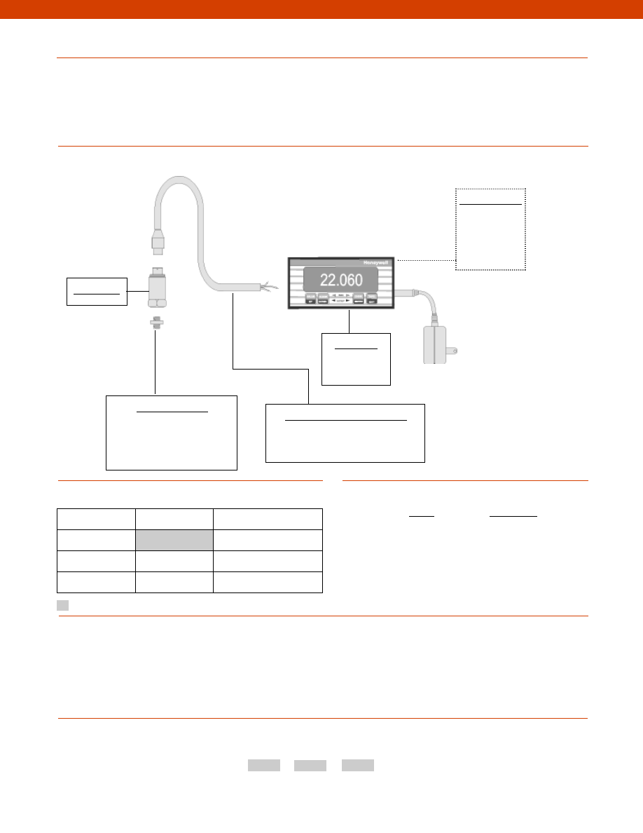
344
www.honeywell.com/sensotec
1-888-282-9891
Mechanical
Typical System Diagram
Range
Range Code
0.5 in./sec RMS
SA
1 in./sec RMS
SB
2 in./sec RMS
SC
4 in./sec RMS
SD
Range Codes
Notes
Options
How to Order
The order code consists of the product model, the desired range code and the available options.
Model Code
Range Code
Options Code
Sample Code:
AG928
SA
17b
1. Only available with AG928.
2. Only available with AG932 & AG929.
Model MAV52
Mounting Assemblies
Mounting studs
Magnetic mounting
Quick connect mounting
Glued mounting
Mating Connectors & Cables (note 1)
MH008 mating connector
Display Units
SC500
SC2000
Customer Supplied
Chart Recorder
Alarm Panel
Data Acquisition
Computer
PLC
Weight................5 oz.
Material................Stainless Steel
Mounting Torque................6 ft.-lb.
Fast Track Delivery
Built to Order
Sensitivity
1 in./sec RMS
0.5, 2, 4 in/sec RMS
Electrical Termination
Cable length (note 2)
Mounting
Arrangement
17b. 1/4-28 UNF
17c. Quickfit Female
Supplied as standard
Model MAV52
-Not RoHS Compliant
Courtesy of Steven Engineering, Inc.-230 Ryan Way, South San Francisco, CA 94080-6370-Main Office: (650) 588-9200-Outside Local Area: (800) 258-9200-www.stevenengineering.com
Sensotec Sensors Full Line Catalog-html.html

345
Dimensions
Performance
Environmental
Electrical
Mechanical
www.honeywell.com/sensotec
1-888-282-9891
4 holes for 6-40 UNF bolts
0.122 in.
n
DC Response
n
mV Output
n
For Use With Strain Gage Amps
Model MA331 & MA332 Accelerometer
Order Code AG919; AG920
1.0 in.
Model MA331 (order code AG919)
1.0 in.
1.30 in.
1/4-28 UNF
Model MA332 (order code AG920)
Wiring Codes
Red
(+) Supply
Blue
(-) Supply
Yellow
(+) Output
Green
(-) Output
Shield
Not Connected
Model MA331
Range
Range Code
1G
GE
2G
GF
5G
GJ
10G
GK
20G
GL
50G
GN
Range Codes
Options
Typical System Diagram
How to Order
The order code consists of the product model, the desired range code and the available options.
Model Code
Range Code
Options Code
Sample Code:
AG919
GE
17c
Fast Track Delivery Built to Order
Dynamic
Range
1, 2, 5, 10, 20, 50G
Electrical
Termination
Cable length
Mounting
Arrangement
17b. 1/4-28 UNF
17c. Quickfit Female
10-32 UNF
Female
Output................15-75 mV Full Scale
Transverse Sensitivity................Less than 5%
Temperature Sensitivity................0.145/ °F
Frequency Range................dependent on dynamic range +/- 5% (see below)
+/- 1G & +/- 2G................DC to 250 Hz
+/- 5G................DC to 300 Hz
+/- 10G................DC to 500 Hz
+/- 20G................DC to 700 Hz
+/- 50G................DC to 1 kHz
Amplitude Linearity................Better than 1% Linearity
Mounted Base Resonance................18 kHz
Acceleration Limits................x 20 of dynamic range
Temperature, Operating................0° to 180° F
Sealing................IP65/ Nema 2
Input................Voltage
Supply Voltage................5V @ 7mA
Output Impedance................3,000 Ohms
Cable................Stainless Steel overbraided PTFE
Standard Cable Length................16 ft.
Electrical Noise................10 mG
Isolation................Base isolated
Weight................1.40 oz.
Case Material................Stainless Steel
Power
Supply
Power Supply
Isolated from
Ground
Output
Customer Supplied Monitoring System
+
-
+
-
V
-Not RoHS Compliant
Courtesy of Steven Engineering, Inc.-230 Ryan Way, South San Francisco, CA 94080-6370-Main Office: (650) 588-9200-Outside Local Area: (800) 258-9200-www.stevenengineering.com
Sensotec Sensors Full Line Catalog-html.html
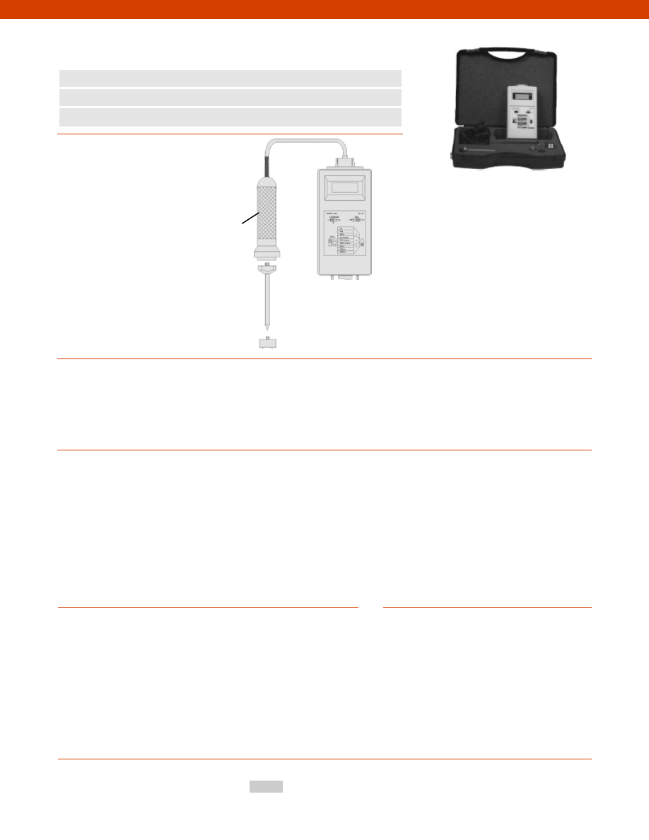
346
Acceleration................2, 20, 200 G
Ranges
Velocity................2 in./sec., 20 in./sec., 200 in./sec.
Displacement................2 thou, 20 thou, 200 thou
Upper Frequency................Selectable low pass filters of 5 kHz, 10 kHz and 20 kHz
Lower Frequency................Fixed, Acceleration: 5 Hz, Velocity: 10 Hz, Displacement: 15Hz
Detector................RMS or Peak switch selectable
Display................1/2 in., 3.5 digit LCD (3 readings per second)
Accuracy
Acceleration................1.5% RMS, 3% Peak
Velocity................2.5% RMS, 4% Peak
Displacement................3.5% RMS, 5% Peak
Noise
Acceleration................2 mG RMS; 6 mG Peak
Velocity................0.01 in./sec. RMS; 0.03 in./sec. Peak
Displacement................0.02 in. RMS; 0.06 in. Peak
Input................10 mV/G from hand held accelerometer or other MA Series via cal hood
Output................AC 200 mV, full range as selected; DC 200 mV, full range as selected
Power................(2) PP3 9-volt battery, low battery indicator on display
Battery life 15 hours approximately
Kit Contents................(1) Vibration Meter; (1) Hand held probe; (1) Magnet;
(1) 4 in. Spike; (1) Carrying case
Typical System Diagram
Performance
Electrical
www.honeywell.com/sensotec
1-888-282-9891
n
Hand Held
n
LCD Display
n
Battery Powered
Models VM110 & VM120 Vibration Meter Kit
Order Code AG941; AG942
Options
Accessories
How to Order
Model Code
Sample Code:
AG941
MTN/1100C
100 mV/G accelerometer, 5 meters integral PTFE cable
MTN/1100
100 mV/G, 2 pin MS connector
MTN/1020
100 mV/G, TNC connector
MTN/CA42
Coiled cable assembly 2 pin MS to IA110 for use with MTN/1100
MTN/CA43
Coiled cable assembly TNC to IA110 for use with MTN/1020
MTN/2100
Hand held probe
MTN/CA61
IA110 adapter for use with MTN/1100C
MTN/MM1
Magnet, 1/4” UNF mounting, 35 mm, strength 20 kg
MTN/PS1
Hand held spike, 25 mm, 1/4” UNF mounting
MTN/PS2
Hand held spike, 100 mm, 1/4” UNF mounting
MTN/PS3
Hand held spike, 150 mm, 1/4” UNF mounting
MTN/PS4
Hand held spike, 300 mm, 1/4” UNF mounting
MTN/HE1
Carrying case with foam cut outs
Other MA Series accelerometers
Built-in Accelerometer
-Not RoHS Compliant
Courtesy of Steven Engineering, Inc.-230 Ryan Way, South San Francisco, CA 94080-6370-Main Office: (650) 588-9200-Outside Local Area: (800) 258-9200-www.stevenengineering.com
Sensotec Sensors Full Line Catalog-html.html
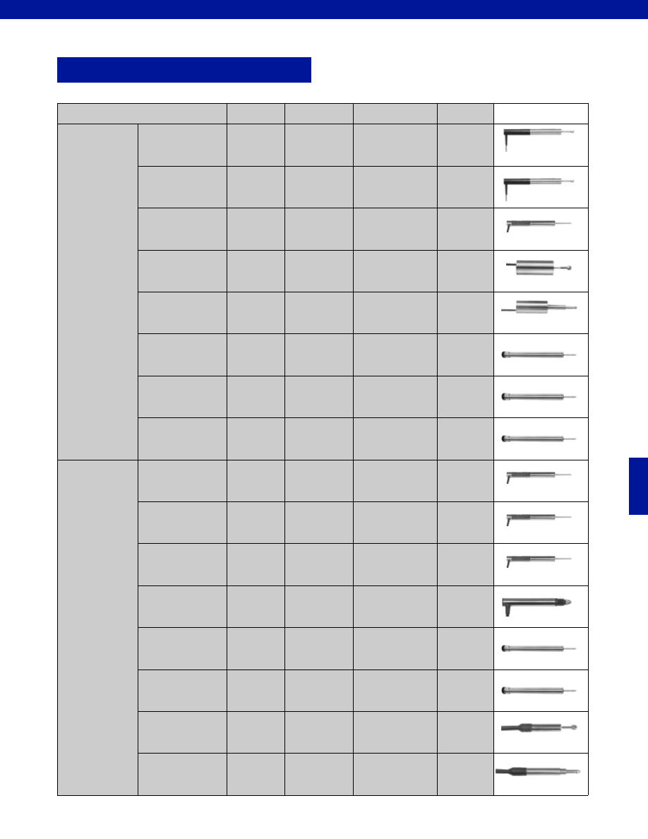
347
LVDTs
Potential Application
Model
Order Code
Stroke Range
Page
Amplified
Unguided
JEC
DLB
AY321
BY127
+/-0.5” to +/-8.0”
+/-0.5” to +/-8.0”
348
350
Captive Guided
JECC
DLE
AY323
BY128
+/-0.5” to +/-18.5”
+/-0.5” to +/-18.5”
352
354
Spring Loaded
JECAG
DLF
AY322
BY129
+/-0.5” to +/-3.0”
+/-0.5” to +/-3.0”
356
358
Miniature
Unguided
MS3
BY327
+/-0.1” to +/-0.4”
360
Miniature
Spring Loaded
S3C
BY324
+/-0.1” to +/-0.4”
362
Submersible
Unguided
DW7U
AY250
+/-0.5” to +/-4.0”
364
Submersible
Captive Guided
DW7C
AY251
+/-0.5” to +/-4.0”
366
Submersible
Spring Loaded
DW7S
SSD
AY252
AY911
+/-0.5” to +/-3.0”
+/-0.5” to +/-4.0”
368
370
Unamplified
Unguided
MVL7
BY125
+/-0.5” to +/-8.0”
372
Captive Guided
MVL7C
BY126
+/-0.5” to +/-18.5”
374
Spring Loaded
VL7A
BY122
+/-0.5” to +/-3.0”
376
Miniature
M5C
PLVX
S5
AY318
AY111
AY112
+/-0.025” to +/-0.5”
+/-0.02” to +/-0.2”
+/-0.01” to +/-0.5”
378
380
382
Submersible
Unguided
LW7U
SSA
AY200
AY910
+/-0.5” to +/-4.0”
+/-0.5” to +/-4.0”
384
386
Submersible
Spring Loaded
LW7C
LW7S
AY201
AY202
+/-0.5” to +/-4.0”
+/-0.5” to +/-3.0”
388
390
Submersible
Miniature
Unguided
MS7A
BY921
+/-0.04” to +/-0.5”
392
Submersible
Miniature
Spring Loaded
S7C
BY912
+/-0.04” to +/-0.5”
394
www.honeywell.com/sensotec
1-888-282-9891
Courtesy of Steven Engineering, Inc.-230 Ryan Way, South San Francisco, CA 94080-6370-Main Office: (650) 588-9200-Outside Local Area: (800) 258-9200-www.stevenengineering.com
Sensotec Sensors Full Line Catalog-html.html
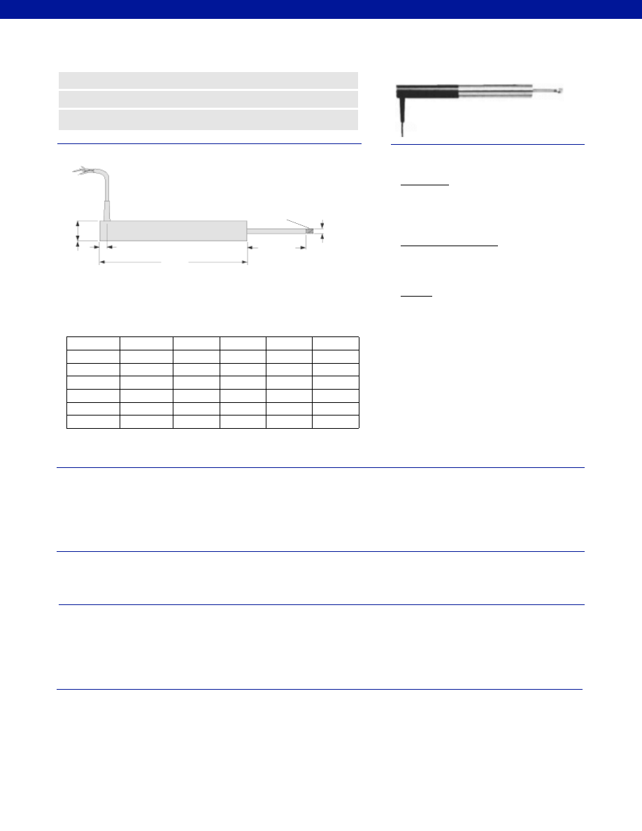
348
Dimensions
Performance
Environmental
Electrical
Mechanical
www.honeywell.com/sensotec
n
Stainless Steel
n
Voltage Regulation
n
Reverse Polarity Protected
ø 0.19 in.
ø 0.81 in.
Range
Codes
Available
Stroke
Ranges
Approx.
Body
Weight
(oz.)
L (in.)
X (in.)
Approx.
Armature
Weight
(oz.)
X Nominal
Electric
Zero Point
M5 x .08
L
0.35 in.
Model JEC DC-DC Long Stroke LVDT
Order Code AY321
HP
+/- 0.5 in.
6.9
1.7
7.5
1.0
HQ
+/- 1.0 in.
8.0
2.7
9.5
2.0
HR
+/- 2.0 in.
12.5
3.2
13.0
2.5
HS
+/- 3.0 in.
16.9
4.7
17.5
3.0
HT
+/- 4.0 in.
18.7
5.2
22.0
3.5
HU
+/- 6.0 in.
26.2
7.2
30.0
4.0
HV
+/- 8.0 in.
33.7
10.2
44.0
5.0
Wiring Code
Dual Supply
Red
+12 to +20 V Input
Blue
-12 to -20 V Input
Black
OV, I/P, O/P Common
Single Supply (*floating)
Red
+24 to +40 V Input
Blue
Supply Negative
Outputs
Yellow
0-10 Volt
Green
+/- 5 VDC
*Output common floats at voltage source/ 2
Stroke Range................+/- 0.5 to 8.0 in.
Non-Linearity (max.)................+/- 0.25% Full Scale
Output Load (min.)................2,000 Ohms with 3-wire supply, 20,000 Ohms with floating supply
Output Impedance................2 Ohms
Output Sensitivity................+/- 5 VDC or 0-10 VDC (field selectable)
Isolation................1,000 V input to output
Polarity................Output is positive for outward stroke
Temperature, Operating................-58° to 176°F
Temperature, Effect
Zero (max.)................0.006% Full Scale/°F
Span (max.)................0.017% Full Scale/°F
Element Type................DC-DC LVDT
Power Supply
Single Supply................+24 to +40 VDC @ 30 mA
Dual Supply................+/-12 to +/-24 VDC @ 30 mA
Ripple................30 mV peak to peak
Electrical Termination................Multiconductor Shielded Cable (6 ft.)
Reverse Polarity Protection................Yes
Material................Stainless Steel
Probe Material................Stainless Steel
Armature Type................Free Unguided
Probe Thread................M5 x 0.8
Weight................See Above Table
Spring Force (max.)................Not Applicable
1-888-282-9891
Courtesy of Steven Engineering, Inc.-230 Ryan Way, South San Francisco, CA 94080-6370-Main Office: (650) 588-9200-Outside Local Area: (800) 258-9200-www.stevenengineering.com
Sensotec Sensors Full Line Catalog-html.html
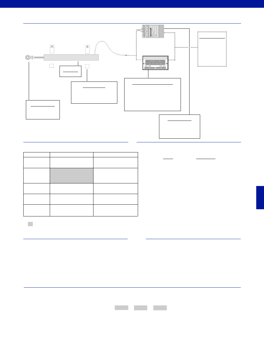
349
www.honeywell.com/sensotec
1-888-282-9891
Typical System Diagram
Range
Range Code
+/- 0.5 in.
HP
+/- 1.0 in.
HQ
+/- 2.0 in.
HR
+/- 3.0 in.
HS
+/- 4.0 in.
HT
+/- 6.0 in.
HU
+/- 8.0 in.
HV
Range Codes
Options
How to Order
The order code consists of the product model, the desired range code and the available options.
Model Code
Range Code
Options Code
Sample Code:
AY321
HQ
L10
Model JEC
High Level Input Display Units
GM-A (note 1)
SC500
SC1000
SC2000
SC3004
DC Power Supply
Required if high level input
display unit is not being
used.
Customer Supplied
Chart Recorder
Alarm Panel
Data Acquisition
Computer
PLC
Mounting Blocks
AA937
Model JEC
Supplied as standard
Mounting Options
Rod End Bearing
Fast Track Delivery
Built to Order
Stroke Ranges
+/- 0.5 to 8.0 in.
Electrical
Termination
Multiconductor Shielded Cable
(6 ft.)
TM405. Axial Bendix connector
on body Radial (side)
TM406. Bendix connector on
body
Electrical Cable
Orientation
TM49. Axial cable exit
Mounting Threads
TM511. 13/16 - 32 UNF
Improved
Linearity
L10. +/- 0.1% max. linearity
(less than or equal to +/- 4 in.)
Notes
1. GM-A should not be used with an amplified LVDT unless
using an external power supply to power the LVDT.
-Not RoHS Compliant
Special Customer Requirements
(Consult Factory)
T.E.D.S. IEEE 1451.4 module
Signature Calibration
Courtesy of Steven Engineering, Inc.-230 Ryan Way, South San Francisco, CA 94080-6370-Main Office: (650) 588-9200-Outside Local Area: (800) 258-9200-www.stevenengineering.com
Sensotec Sensors Full Line Catalog-html.html
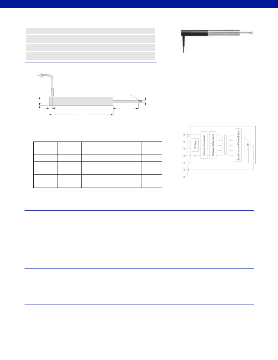
350
Dimensions
Performance
Environmental
Electrical
Mechanical
Stroke Range................+/- 0.5 to 8.0 in.
Non-Linearity (max.)................+/- 0.25% Full Scale
Output Load (min.)................2,000 Ohms
Output Impedance................2 Ohms
Output Sensitivity................+/- 2 VDC (nominal)
Isolation................1,000 V input to output
Polarity................Output positive for outward stroke
Temperature, Operating................-58° to 158°F
Temperature, Effect
Zero (max.)................0.006% Full Scale/°F
Span (max.)................0.017% Full Scale/°F
Element Type................DC-DC LVDT
Input Supply (acceptable)
Regulated................5 VDC @ 100 mA max.
Unregulated................+6 V to +18 VDC @ 100 mA max.
Ripple................30 mV peak to peak
Electrical Termination................Multiconductor Shielded Cable (6 ft.)
Reverse Polarity Protection................Yes
Case Material................Stainless Steel
Probe Material................Stainless Steel
Armature Type................Free Unguided
Probe Thread................M5 x 0.8
Weight................See Above Table
Spring Force (max.)................Not Applicable
www.honeywell.com/sensotec
n
Low Voltage Requirements
n
Easy to Operate
n
Stainless Steel
n
Reverse Polarity Protected
ø 0.19 in.
ø 0.81 in.
Range
Codes
Available
Stroke
Ranges
Approx.
Body
Weight
(oz.)
L (in.)
X (in.)
Approx.
Armature
Weight
(oz.)
X Nominal
Electric Zero
Point
M5 x .08
L
0.35 in.
Model DLB DC-DC Long Stroke LVDT
Order Code BY127
HP
+/- 0.5 in.
6.9
1.7
7.5
1.0
HQ
+/- 1.0 in.
7.9
2.7
9.5
2.0
HR
+/- 2.0 in.
12.5
3.2
13.0
2.5
HS
+/- 3.0 in.
16.9
4.7
17.5
3.0
HT
+/- 4.0 in.
18.7
5.2
22.0
3.5
HU
+/- 6.0 in.
26.2
7.2
30.0
4.0
HV
+/- 8.0 in.
33.7
10.2
44.0
5.0
Wiring Codes
Yellow
Brown
Red
Blue
Black
Green
Shield
5V Supply
Wire
6-18VDC Supply
+5V Input
Yellow
Connect to Brown
Insulate
Brown
Connect to Yellow
Insulate
Red
+6 to +18 VDC
Supply Com. (0V) Blue
Supply Com. (0V)
Output Low
Black
Output Low
Output High
Green
Output High
Instrument Ground Shield
Instrument Ground
NOTE: Incorrect connection may cause irreparable
damage, contact factory for assistance
1-888-282-9891
Courtesy of Steven Engineering, Inc.-230 Ryan Way, South San Francisco, CA 94080-6370-Main Office: (650) 588-9200-Outside Local Area: (800) 258-9200-www.stevenengineering.com
Sensotec Sensors Full Line Catalog-html.html
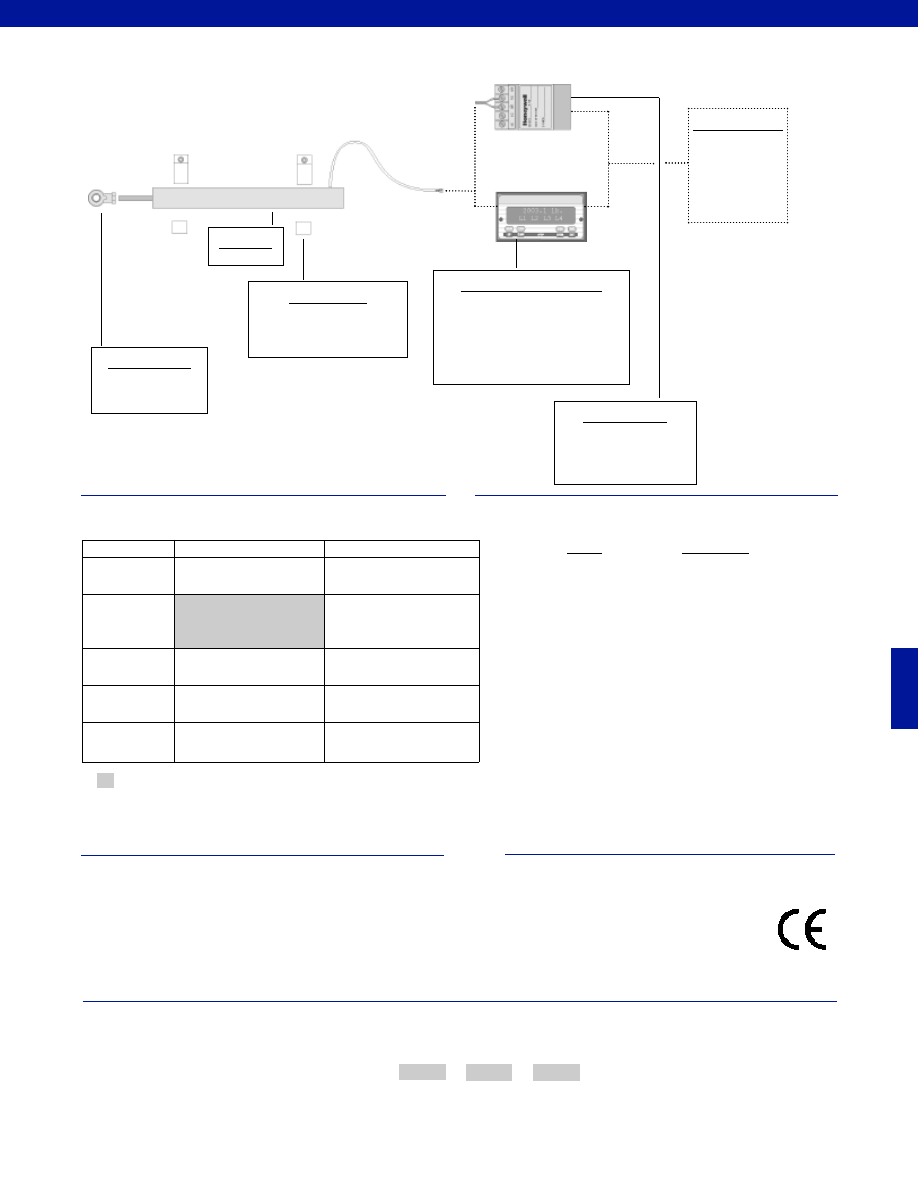
351
www.honeywell.com/sensotec
1-888-282-9891
Range
Range Code
+/- 0.5 in.
HP
+/- 1.0 in.
HQ
+/- 2.0 in.
HR
+/- 3.0 in.
HS
+/- 4.0 in.
HT
+/- 6.0 in.
HU
+/- 8.0 in.
HV
Range Codes
Options
How to Order
The order code consists of the product model, the desired range code and the available options.
Model Code
Range Code
Options Code
Sample Code:
BY127
HQ
L10
Supplied as standard
Model DLB
Typical System Diagram
Model DLB
High Level Input Display Units
GM-A (note 1)
SC500
SC1000
SC2000
SC3004
DC Power Supply
Required if high level input
display unit is not being
used.
Customer Supplied
Chart Recorder
Alarm Panel
Data Acquisition
Computer
PLC
Mounting Blocks
AA937
Mounting Options
Rod End Bearing
Fast Track Delivery
Built to Order
Stroke Ranges
+/- 0.5 to 8.0 in.
Electrical
Termination
Multiconductor Shielded Cable
(6 ft.)
TM405. Axial Bendix connector
on body Radial (side)
TM406. Bendix connector on
body
Electrical Cable
Orientation
TM49. Axial cable exit
Mounting Threads
TM511. 13/16 - 32 UNF
Improved
Linearity
L10. +/- 0.1% max. linearity
(less than or equal to +/- 4 in.)
Notes
1. GM-A should not be used with an amplified LVDT unless
using an external power supply to power the LVDT.
Approved
-Not RoHS Compliant
Special Customer Requirements
(Consult Factory)
T.E.D.S. IEEE 1451.4 module
Signature Calibration
Courtesy of Steven Engineering, Inc.-230 Ryan Way, South San Francisco, CA 94080-6370-Main Office: (650) 588-9200-Outside Local Area: (800) 258-9200-www.stevenengineering.com
Sensotec Sensors Full Line Catalog-html.html
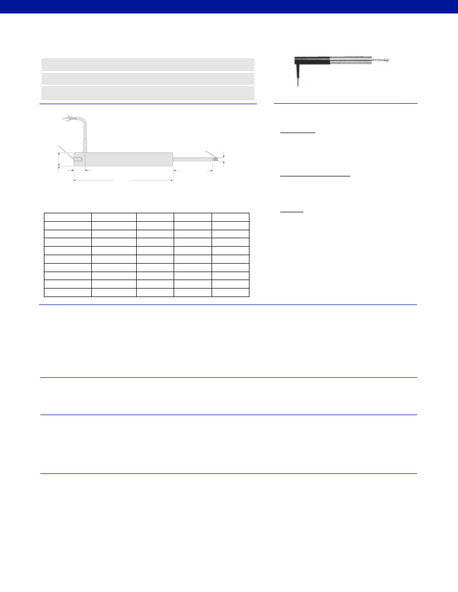
352
Dimensions
Performance
Environmental
Electrical
Mechanical
www.honeywell.com/sensotec
n
Voltage Regulation
n
Easy to Operate
n
Reverse Polarity Protection
ø 0.19 in.
M5 x 0.8
M5 x 0.8
ø 0.82 in.
Range
Codes
Available
Stroke Ranges
L (in.)
X (in.)
Approx. Unit
Weight (oz.)
X Nominal
Electric
Zero Point
L
0.91 in.
Model JEC-C DC-DC Long Stroke LVDT
Order Code AY323
HP
+/- 0.5 in.
7.65
1.5
12.0
HQ
+/- 1.0 in.
8.75
2.5
14.0
HR
+/- 2.0 in.
13.25
3.0
18.0
HS
+/- 3.0 in.
17.65
4.5
22.0
HT
+/- 4.0 in.
19.45
5.0
27.0
HU
+/- 6.0 in.
26.95
7.0
36.0
HV
+/- 8.0 in.
34.45
10.0
51.0
HW
+/- 10.0 in.
42.0
12.0
59.0
HY
+/- 15.0 in.
58.0
16.0
78.0
HZ
+/- 18.5 in.
68.5
20.0
92.0
Wiring Code
Dual Supply
Red
+12 to +20 V Input
Blue
-12 to -20 V Input
Black
OV, I/P, O/P Common
Single Supply (*floating)
Red
+24 to +40 V Input
Blue
Supply Negative
Outputs
Yellow
0-10 Volt
Green
+/- 5 VDC
* Output common floats at voltage source/2
Stroke Range................+/- 0.5 to 18.5 in.
Non-Linearity (max.)
+/- 0.5 in. to +/- 10.0 in.................+/- 0.25% Full Scale
+/- 15.0 in. to +/- 18.5 in.................+/- 0.5% Full Scale
Output Load (min.)................2,000 Ohms with 3-wire supply, 20,000 Ohms with floating supply
Output Impedance................2 Ohms
Output Sensitivity................+/- 5 VDC or 0-10 VDC (field selectable)
Isolation................1,000 V input to output
Polarity................Output positive for outward stroke
Temperature, Operating................-58° to 158°F
Temperature, Effect
Zero (max.)................0.006% Full Scale/°F
Span (max.)................0.017% Full Scale/°F
Element Type................DC-DC LVDT
Power Supply
Single Supply................+24 to +40 VDC @ 30 mA
Dual Supply................+/-12 to +/-24 VDC @ 30 mA
Ripple................30 mV peak to peak
Electrical Termination................Multiconductor Shielded Cable (6 ft.)
Reverse Polarity Protection................Yes
Material................Stainless Steel
Probe Material................Stainless Steel
Armature Type................Captive Guided
Probe Thread................M5 x 0.8
Weight................See Above Table
Spring Force (max.)................N/A
1-888-282-9891
Courtesy of Steven Engineering, Inc.-230 Ryan Way, South San Francisco, CA 94080-6370-Main Office: (650) 588-9200-Outside Local Area: (800) 258-9200-www.stevenengineering.com
Sensotec Sensors Full Line Catalog-html.html

353
www.honeywell.com/sensotec
1-888-282-9891
Range
Range Code
+/- 0.5 in.
HP
+/- 1.0 in.
HQ
+/- 2.0 in.
HR
+/- 3.0 in.
HS
+/- 4.0 in.
HT
+/- 6.0 in.
HU
+/- 8.0 in.
HV
+/- 10.0 in.
HW
+/- 15.0 in.
HY
+/- 18.5 in.
HZ
Range Codes
Options
How to Order
The order code consists of the product model, the desired range code and the available options.
Model Code
Range Code
Options Code
Sample Code:
AY323
HQ
L10
Supplied as standard
Typical System Diagram
Model JEC-C
High Level Input Display Units
GM-A (note 1)
SC500
SC1000
SC2000
SC3004
DC Power Supply
Required if high level input
display unit is not being
used.
Customer Supplied
Chart Recorder
Alarm Panel
Data Acquisition
Computer
PLC
Mounting Blocks
AA937
Mounting Options
Rod End Bearing
Fast Track Delivery
Built to Order
Stroke Ranges
+/- 0.5 to18.5 in.
Electrical
Termination
Multiconductor Shielded Cable
(6 ft.)
TM405. Axial Bendix connector
on body Radial (side)
TM406. Bendix connector on
body
Electrical Cable
Orientation
TM49. Axial cable exit
Mounting Threads
TM511. 13/16 - 32 UNF
Improved
Linearity
L10. +/- 0.1% max. linearity
(less than or equal to +/- 4 in.)
Model JEC-C
Notes
1. GM-A should not be used with an amplified LVDT unless
using an external power supply to power the LVDT.
Approved
-Not RoHS Compliant
Special Customer Requirements
(Consult Factory)
T.E.D.S. IEEE 1451.4 module
Signature Calibration
Courtesy of Steven Engineering, Inc.-230 Ryan Way, South San Francisco, CA 94080-6370-Main Office: (650) 588-9200-Outside Local Area: (800) 258-9200-www.stevenengineering.com
Sensotec Sensors Full Line Catalog-html.html
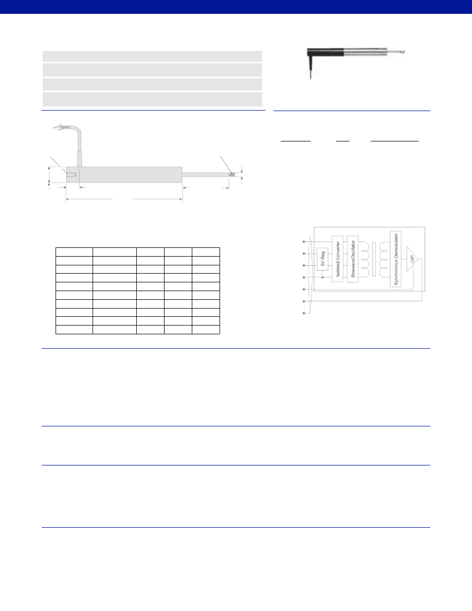
354
Dimensions
Performance
Environmental
Electrical
Mechanical
ø 0.19 in.
M5 x 0.8
M5 x 0.8
ø 0.82 in.
Range
Codes
Available
Ranges
L (in.)
X (in.)
Approx.
Weight
(oz.)
X Nominal
Electric
Zero Point
L
0.72 in.
Model DLE DC-DC Long Stroke LVDT
Order Code BY128
Stroke Range................+/- 0.5 to 18.5 in.
Non-Linearity (max.)
+/- 0.5 in. to +/- 10.0 in.................+/- 0.25% Full Scale
+/- 15.0 in. to +/- 18.5 in.................+/- 0.5% Full Scale
Output Load (min.)................2,000 Ohms
Output Impedance................2 Ohms
Output Sensitivity................+/- 2 VDC (nominal)
Isolation................1,000 V input to output
Polarity................Output positive for outward stroke
Temperature, Operating................-58° to 158°F
Temperature, Effect
Zero (max.)................0.006% Full Scale/°F
Span (max.)................0.017% Full Scale/°F
Element Type................DC-DC LVDT
Input Supply (acceptable)
Regulated................5 VDC@ 100 mA max.
Unregulated................+6 to +18 VDC @ 100 mA max.
Ripple................30 mV peak to peak
Electrical Termination................Multiconductor Shielded Cable (6 ft.)
Reverse Polarity Protection................Yes
Material................Stainless Steel
Probe Material................Stainless Steel
Armature Type................Captive Guided
Probe Thread................M5 x 0.8
Weight................See Above Table
Spring Force (max.)................Not Applicable
HP
+/- 0.5 in.
7.65
1.5
12.0
HQ
+/- 1.0 in.
8.75
2.5
14.0
HR
+/- 2.0 in.
13.25
3.0
18.0
HS
+/- 3.0 in.
17.65
4.5
22.0
HT
+/- 4.0 in.
19.45
5.0
27.0
HU
+/- 6.0 in.
26.95
7.0
36.0
HV
+/- 8.0 in.
34.45
10.0
51.0
HW
+/- 10.0 in.
42.0
12.0
59.0
HY
+/- 15.0 in.
58.0
16.0
78.0
HZ
+/- 18.5 in.
68.5
20.0
92.0
n
+/-0.5 to 18.5 in. Range
n
Captive Guided Armature
n
Stainless Steel Construction
n
Reverse Polarity Protected
Wiring Codes
Yellow
Brown
Red
Blue
Black
Green
Shield
5V Supply
Wire
6-18VDC Supply
+5V Input
Yellow
Connect to Brown
Insulate
Brown
Connect to Yellow
Insulate
Red
+6 to +18 VDC
Supply Com. (0V) Blue
Supply Com. (0V)
Output Low
Black
Output Low
Output High
Green
Output High
Instrument Ground Shield
Instrument Ground
NOTE: Incorrect connection may cause irreparable
damage, contact factory for assistance
www.honeywell.com/sensotec
1-888-282-9891
Courtesy of Steven Engineering, Inc.-230 Ryan Way, South San Francisco, CA 94080-6370-Main Office: (650) 588-9200-Outside Local Area: (800) 258-9200-www.stevenengineering.com
Sensotec Sensors Full Line Catalog-html.html

355
Range
Range Code
+/- 0.5 in.
HP
+/- 1.0 in.
HQ
+/- 2.0 in.
HR
+/- 3.0 in.
HS
+/- 4.0 in.
HT
+/- 6.0 in.
HU
+/- 8.0 in.
HV
+/- 10.0 in.
HW
+/- 15.0 in.
HY
+/- 18.5 in.
HZ
Range Codes
Options
How to Order
The order code consists of the product model, the desired range code and the available options.
Model Code
Range Code
Options Code
Sample Code:
BY128
HQ
L10
Model DLE
Supplied as standard
Typical System Diagram
Model DLE
High Level Input Display Units
GM-A (note 1)
SC500
SC1000
SC2000
SC3004
DC Power Supply
Required if high level input
display unit is not being
used.
Customer Supplied
Chart Recorder
Alarm Panel
Data Acquisition
Computer
PLC
Mounting Blocks
AA937
Mounting Options
Rod End Bearing
Fast Track Delivery
Built to Order
Stroke Ranges
+/- 0.5 to18.5 in.
Electrical
Termination
Multiconductor Shielded Cable
(6 ft.)
TM405. Axial Bendix connector
on body Radial (side)
TM406. Bendix connector on
body
Electrical Cable
Orientation
TM49. Axial cable exit
Mounting Threads
TM511. 13/16 - 32 UNF
Improved
Linearity
L10. +/- 0.1% max. linearity
(less than or equal to +/- 4 in.)
Notes
1. GM-A should not be used with an amplified LVDT unless
using an external power supply to power the LVDT.
Approved
-Not RoHS Compliant
www.honeywell.com/sensotec
1-888-282-9891
Special Customer Requirements
(Consult Factory)
T.E.D.S. IEEE 1451.4 module
Signature Calibration
Courtesy of Steven Engineering, Inc.-230 Ryan Way, South San Francisco, CA 94080-6370-Main Office: (650) 588-9200-Outside Local Area: (800) 258-9200-www.stevenengineering.com
Sensotec Sensors Full Line Catalog-html.html

356
Dimensions
Performance
Environmental
Electrical
Mechanical
Stroke Range................+/- 0.5 to 3.0 in.
Non-Linearity (max.)................+/- 0.25% Full Scale
Output Load (min.)................2,000 Ohms with 3-wire supply, 20,000 Ohms with floating supply
Output Impedance................2 Ohms
Output Sensitivity................+/- 5 VDC or 0-10 VDC (field selectable)
Isolation................1,000 V input to output
Polarity................Output positive for outward stroke
Temperature, Operating................-58° to 176°F
Temperature, Effect
Zero (max.)................0.006% Full Scale/°F
Span (max.)................0.017% Full Scale/°F
Element Type................DC-DC LVDT
Power Supply
Single Supply................+24 to +40 VDC @ 30 mA
Dual Supply................+/-12 to +/-24 VDC @ 30 mA
Ripple................30 mV peak to peak
Electrical Termination................Multiconductor Shielded Cable (6 ft.)
Reverse Polarity Protection................Yes
Material................Stainless Steel
Probe Material................Stainless Steel
Armature Type................Captive Guided Spring Return
Probe Thread................Not Applicable
Weight................See Above Table
Spring Force (max.)................4 oz./ in.
www.honeywell.com/sensotec
n
Stainless Steel
n
Voltage Regularity
n
Reverse Polarity Protected
ø 0.19 in.
ø 0.81 in.
Range
Codes
Available
Stroke
Ranges
L (in.)
X (in.)
Approx. Unit
Weight (oz.)
X
Nominal Electric Zero Point
L
0.35 in.
Model JEC-AG DC-DC Long Stroke LVDT
Order Code AY322
HP
+/- 0.5 in.
7.15
1.5
8.0
HQ
+/- 1.0 in.
8.25
2.5
10.0
HR
+/- 2.0 in.
12.75
3.0
14.0
HS
+/- 3.0 in.
17.4
4.5
18.0
Wiring Code
Dual Supply
Red
+12 to +20 V Input
Blue
-12 to -20 V Input
Black
OV, I/P, O/P Common
Single Supply (*floating)
Red
+24 to +40 V Input
Blue
Supply Negative
Outputs
Yellow
0-10 Volt
Green
+/- 5 VDC
* Output common floats at voltage source/2
1-888-282-9891
Courtesy of Steven Engineering, Inc.-230 Ryan Way, South San Francisco, CA 94080-6370-Main Office: (650) 588-9200-Outside Local Area: (800) 258-9200-www.stevenengineering.com
Sensotec Sensors Full Line Catalog-html.html
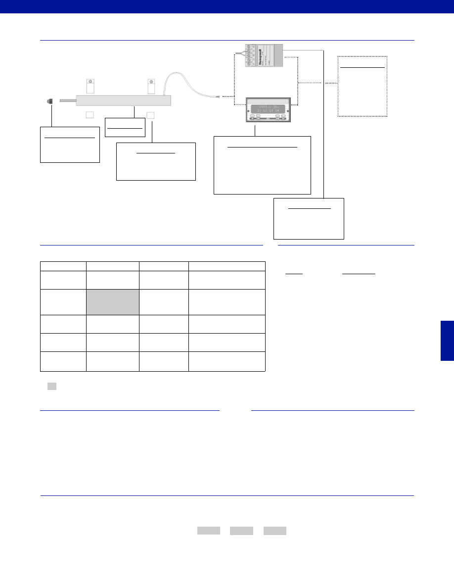
357
www.honeywell.com/sensotec
1-888-282-9891
Typical System Diagram
Range
Range Code
+/- 0.5 in.
HP
+/- 1.0 in.
HQ
+/- 2.0 in.
HR
+/- 3.0 in.
HS
Range Codes
Options
How to Order
The order code consists of the product model, the desired range code and the available options.
Model Code
Range Code
Options Code
Sample Code:
AY322
HQ
L10
Model JEC-AG
High Level Input Display Units
GM-A (note 1)
SC500
SC1000
SC2000
SC3004
DC Power Supply
Required if high level input
display unit is not being
used.
Customer Supplied
Chart Recorder
Alarm Panel
Data Acquisition
Computer
PLC
Mounting Blocks
AA937
Model JEC-AG
Supplied as standard
Probe Tip Assemblies
Radiused probe
Ball ended probe
Same Day Ship
Fast Track Delivery
Built to Order
Stroke Ranges
+/- 0.5; +/- 1.0;
+/- 2.0 in.
3.0 in.
Electrical
Termination
Multiconductor
Shielded Cable (6 ft.)
TM405. Axial Bendix connector
on body Radial (side)
TM406. Bendix connector on
body
Electrical Cable
Orientation
TM49. Axial cable exit
Mounting Threads
TM511. 13/16 - 32 UNF
Improved
Linearity
L10. +/- 0.1% max.
linearity
Notes
1. GM-A should not be used with an amplified LVDT unless
using an external power supply to power the LVDT.
-Not RoHS Compliant
Special Customer Requirements
(Consult Factory)
T.E.D.S. IEEE 1451.4 module
Signature Calibration
Courtesy of Steven Engineering, Inc.-230 Ryan Way, South San Francisco, CA 94080-6370-Main Office: (650) 588-9200-Outside Local Area: (800) 258-9200-www.stevenengineering.com
Sensotec Sensors Full Line Catalog-html.html
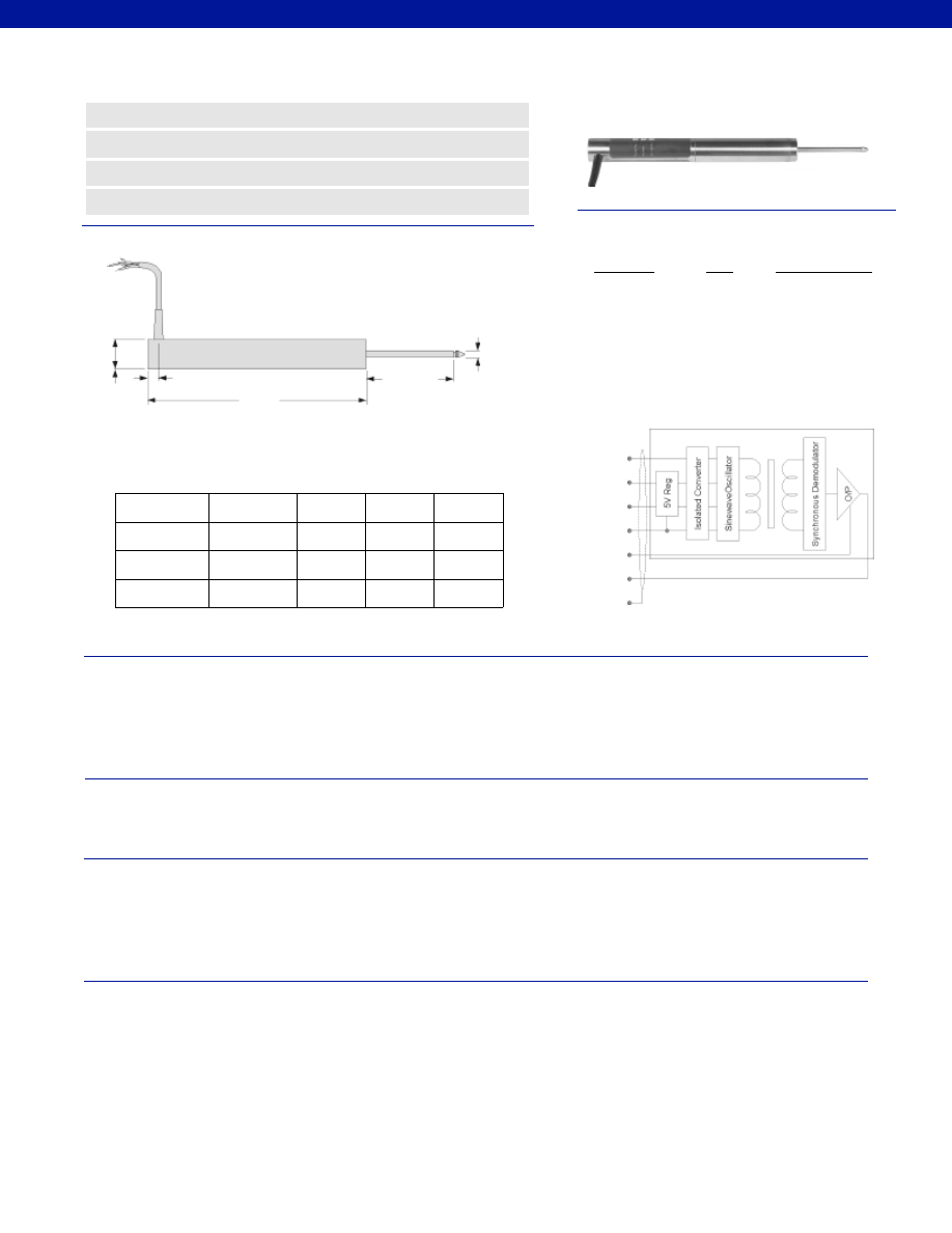
358
Dimensions
Performance
Environmental
Electrical
Mechanical
www.honeywell.com/sensotec
ø 0.19 in.
ø 0.81 in.
Range
Codes
Available
Stroke
Ranges
L (in.)
X (in.)
Approx. Unit
Weight (oz.)
X
Nominal Electric Zero Point
L
0.35 in.
Model DLF DC-DC Long Stroke LVDT
Order Code BY129
HP
+/- 0.5 in.
7.15
1.5
8.0
HQ
+/- 1.0 in.
8.25
2.5
10.0
HR
+/- 2.0 in.
12.75
3.0
14.0
HS
+/- 3.0 in.
17.4
4.5
18.0
n
Low Voltage Requirements
n
Easy to Operate
n
Stainless Steel
n
Reverse Polarity Protected
Wiring Codes
Yellow
Brown
Red
Blue
Black
Green
Shield
5V Supply
Wire
6-18VDC Supply
+5V Input
Yellow
Connect to Brown
Insulate
Brown
Connect to Yellow
Insulate
Red
+6 to +18 VDC
Supply Com. (0V) Blue
Supply Com. (0V)
Output Low
Black
Output Low
Output High
Green
Output High
Instrument Ground Shield
Instrument Ground
NOTE: Incorrect connection may cause irreparable
damage, contact factory for assistance
Stroke Range................+/- 0.5 to 3.0 in.
Non-Linearity (max.)................+/- 0.25% Full Scale
Output Load (min.)................2,000 Ohms
Output Impedance................2 Ohms
Output Sensitivity................+/- 2 VDC (nominal)
Isolation................1,000 V input to output
Polarity................Output positive for outward stroke
Temperature, Operating................-58° to 158°F
Temperature, Effect
Zero (max.)................0.006% Full Scale/°F
Span (max.)................0.017% Full Scale/°F
Element Type................DC-DC LVDT
Input Supply (acceptable)
Regulated................5 VDC @ 100 mA max.
Unregulated................+6 V to +18 VDC @ 100 mA max.
Ripple................30 mV peak to peak
Electrical Termination................Multiconductor Shielded Cable (6 ft.)
Reverse Polarity Protection................Yes
Case Material................Stainless Steel
Probe Material................Stainless Steel
Armature Type................Captive Guided Spring Return
Probe Thread................ M2.5 Female
Weight................See Above Table
Spring Force (max.)................4.0 oz./ in.
1-888-282-9891
Courtesy of Steven Engineering, Inc.-230 Ryan Way, South San Francisco, CA 94080-6370-Main Office: (650) 588-9200-Outside Local Area: (800) 258-9200-www.stevenengineering.com
Sensotec Sensors Full Line Catalog-html.html
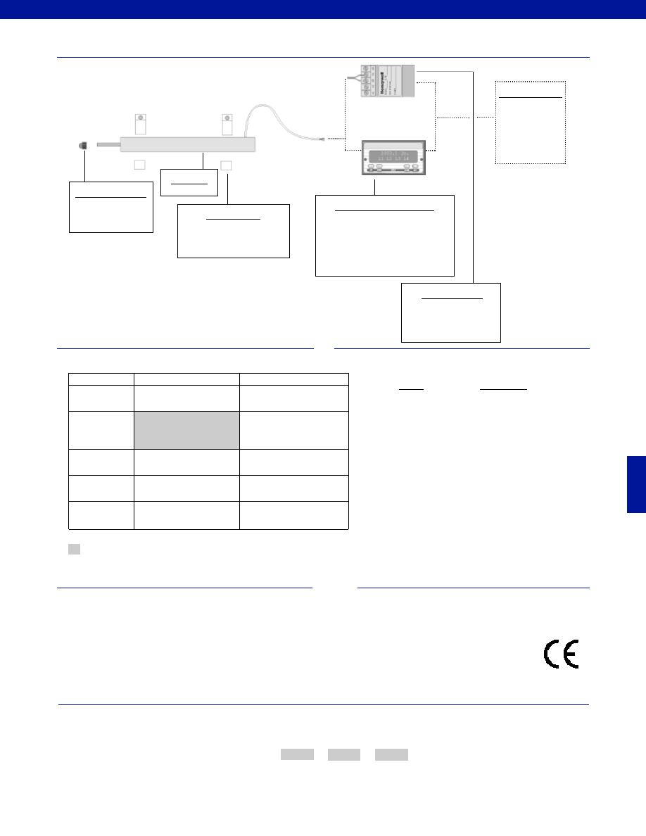
359
www.honeywell.com/sensotec
1-888-282-9891
Range
Range Code
+/- 0.5 in.
HP
+/- 1.0 in.
HQ
+/- 2.0 in.
HR
+/- 3.0 in.
HS
Range Codes
Options
How to Order
The order code consists of the product model, the desired range code and the available options.
Model Code
Range Code
Options Code
Sample Code:
BY129
HQ
L10
Model DLF
Supplied as standard
Model DLF
High Level Input Display Units
GM-A (note 1)
SC500
SC1000
SC2000
SC3004
DC Power Supply
Required if high level input
display unit is not being
used.
Customer Supplied
Chart Recorder
Alarm Panel
Data Acquisition
Computer
PLC
Mounting Blocks
AA937
Probe Tip Assemblies
Radiused probe
Ball ended probe
Fast Track Delivery
Built to Order
Stroke Ranges
+/- 0.5 to 3.0 in.
Electrical
Termination
Multiconductor Shielded Cable
(6 ft.)
TM405. Axial Bendix connector
on body Radial (side)
TM406. Bendix connector on
body
Electrical Cable
Orientation
TM49. Axial cable exit
Mounting Threads
TM511. 13/16 - 32 UNF
Improved
Linearity
L10. +/- 0.1% max. linearity
Typical System Diagram
Notes
1. GM-A should not be used with an amplified LVDT unless
using an external power supply to power the LVDT.
Approved
-Not RoHS Compliant
Special Customer Requirements
(Consult Factory)
T.E.D.S. IEEE 1451.4 module
Signature Calibration
Courtesy of Steven Engineering, Inc.-230 Ryan Way, South San Francisco, CA 94080-6370-Main Office: (650) 588-9200-Outside Local Area: (800) 258-9200-www.stevenengineering.com
Sensotec Sensors Full Line Catalog-html.html
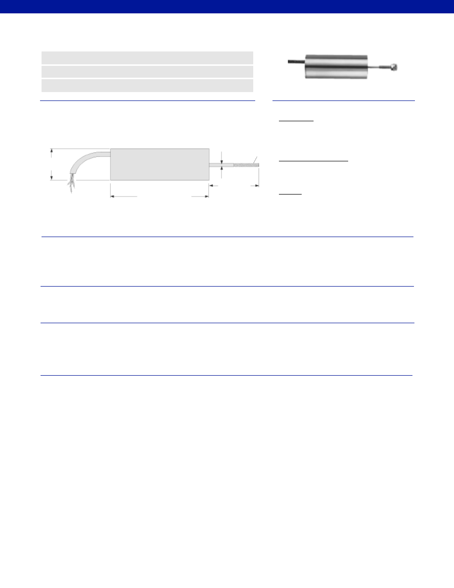
360
Stroke Range................+/- 0.1 to 0.4 in.
Non-Linearity (max.)................+/- 0.25% Full Scale
Output Impedance................2 Ohms
Output Load (min.)................2,000 Ohms
Output Sensitivity................+/- 5 VDC or 0-10 VDC (field selectable)
Resolution................Infinite
Temperature, Operating................-58° to 176°F
Temperature, Effect
Zero (max.)................0.006% Full Scale/°F
Span (max.)................0.017% Full Scale/°F
Element Type................DC-DC LVDT
Power Supply
Single Supply................+24 to +40 VDC @ 30 mA
Dual Supply................+/-12 to +/-20 VDC @ 30 mA
Noise (filtered output)................30 mV p-p
Electrical Termination................Multiconductor Shielded Cable (6 ft.)
Case Material................Stainless Steel
Probe Material................Stainless Steel
Armature Type................Free unguided
Probe Thread................M3 x 0.5
Weight................2.6 oz. (73.5 g)
M3 x 0.5
Dimensions
Performance
Environmental
Electrical
Mechanical
www.honeywell.com/sensotec
n
Miniature Design
n
Cost Effective
n
0.25% Non-Linearity
Model MS3 DC-DC Miniature LVDT
Order Code BY327
ø 0.81 in.
ø 0.079 in.
1.28 in.
2.52 in.
Wiring Code
Dual Supply
Red
+12 to +20 V Input
Blue
-12 to -20 V Input
Black
OV, I/P, O/P Common
Single Supply (*floating)
Red
+24 to +40 V Input
Blue
Supply Negative
Outputs
Yellow
0-10 Volt
Green
+/- 5 VDC
* Output common floats at voltage supply/2
1-888-282-9891
Courtesy of Steven Engineering, Inc.-230 Ryan Way, South San Francisco, CA 94080-6370-Main Office: (650) 588-9200-Outside Local Area: (800) 258-9200-www.stevenengineering.com
Sensotec Sensors Full Line Catalog-html.html
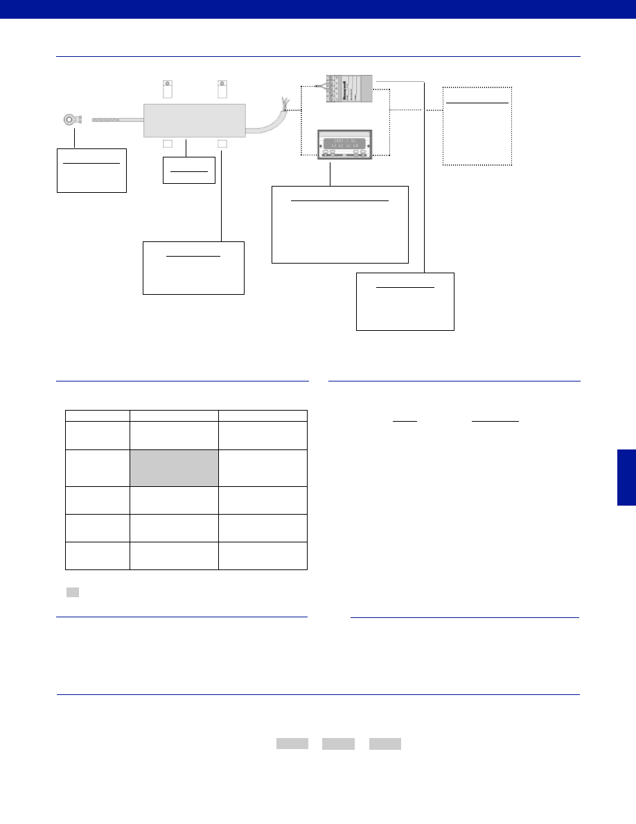
361
www.honeywell.com/sensotec
1-888-282-9891
Fast Track Delivery
Built to Order
Stroke Ranges
+/- 0.1 to 0.4 in.
Electrical
Termination
Multiconductor Shielded
Cable (6 ft.)
6a. Bendix PTIH-10-6P
Right angle Bendix
Electrical Cable
Orientation
Ra. Right angle
Mounting Threads
13a. 1/2-20 UNF
13f. 3/8-32 UNF
Improved
Linearity
L10. 0.1% on some
models
Typical System Diagram
Range
Range Code
+/- 0.1 in.
HM
+/- 0.2 in.
HN
+/- 0.3 in.
HF
+/- 0.4 in.
HG
Range Codes
Options
How to Order
The order code consists of the product model, the desired range code and the available options.
Model Code
Range Code
Options Code
Sample Code:
BY327
HN
L10
Model MS3
High Level Input Display Units
GM-A (note 1)
SC500
SC1000
SC2000
SC3004
DC Power Supply
Required if high level input
display unit is not being
used.
Customer Supplied
Chart Recorder
Alarm Panel
Data Acquisition
Computer
PLC
Mounting Blocks
AA937
Model MS3
Supplied as standard
Mounting Options
Rod End Bearing
Notes
1. GM-A should not be used with an amplified LVDT unless
using an external power supply to power the LVDT.
-Not RoHS Compliant
Special Customer Requirements
(Consult Factory)
T.E.D.S. IEEE 1451.4 module
Signature Calibration
Courtesy of Steven Engineering, Inc.-230 Ryan Way, South San Francisco, CA 94080-6370-Main Office: (650) 588-9200-Outside Local Area: (800) 258-9200-www.stevenengineering.com
Sensotec Sensors Full Line Catalog-html.html
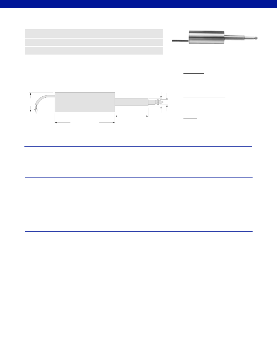
362
Stroke Range................+/- 0.1 to 0.4 in.
Non-Linearity (max.)................+/- 0.25% Full Scale
Output Impedance................2 Ohms
Output Load (min.)................2,000 Ohms
Output Sensitivity................+/- 5 VDC or 0-10 VDC (field selectable)
Resolution................Infinite
Temperature, Operating................-58° to 176°F
Temperature, Effect
Zero (max.)................0.006% Full Scale/°F
Span (max.)................0.017% Full Scale/°F
Element Type................DC-DC LVDT
Power Supply
Single Supply................+24 to +40 VDC @ 30 mA
Dual Supply................+/-12 to +/-20 VDC @ 30 mA
Noise................30 mV p-p
Electrical Termination................Multiconductor Shielded Cable (6 ft.)
Case Material................Stainless Steel
Probe Material................Stainless Steel
Armature Type................Captive guided spring return
Probe Thread................Not applicable
Weight................82.5 grams
Dimensions
Performance
Environmental
Electrical
Mechanical
www.honeywell.com/sensotec
n
Miniature Design
n
Cost Effective
n
0.25% Non-Linearity
Model S3C DC-DC Miniature LVDT
Order Code BY324
ø 0.81 in.
ø 0.19 in.
ø 0.31 in.
1.40 in.
2.52 in.
Wiring Code
Dual Supply
Red
+12 to +20 V Input
Blue
-12 to -20 V Input
Black
OV, I/P, O/P Common
Single Supply (*floating)
Red
+24 to +40 V Input
Blue
Supply Negative
Outputs
Yellow
0-10 Volt
Green
+/- 5 VDC
*Output common floats at voltage source/ 2
1-888-282-9891
Courtesy of Steven Engineering, Inc.-230 Ryan Way, South San Francisco, CA 94080-6370-Main Office: (650) 588-9200-Outside Local Area: (800) 258-9200-www.stevenengineering.com
Sensotec Sensors Full Line Catalog-html.html
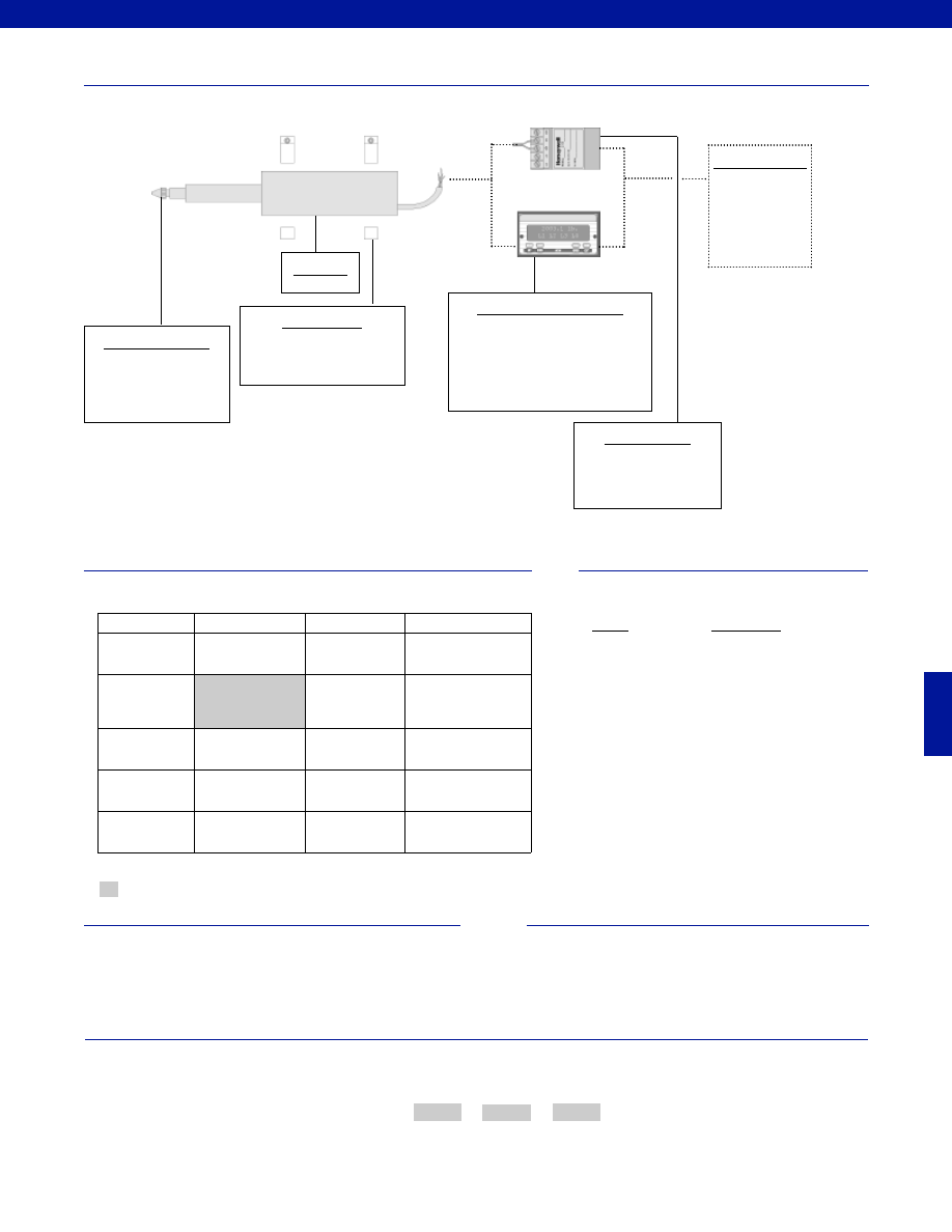
363
www.honeywell.com/sensotec
1-888-282-9891
Same Day Ship
Fast Track Delivery
Built to Order
Stroke Ranges
+/- 0.2 in.
+/- 0.1; +/- 0.3;
+/- 0.4 in.
Electrical
Termination
Multiconductor
Shielded Cable (6 ft.)
6a. Bendix PTIH-10-6P
Right angle Bendix
Electrical Cable
Orientation
Ra. Right angle
Mounting Threads
13a.1/2-20 UNF
13f. 3/8-32 UNF
Improved
Linearity
L10 0.1% on
some models
Typical System Diagram
Range
Range Code
+/- 0.1 in.
HM
+/- 0.2 in.
HN
+/- 0.3 in.
HF
+/- 0.4 in.
HG
Range Codes
Options
How to Order
The order code consists of the product model, the desired range code and the available options.
Model Code
Range Code
Options Code
Sample Code:
BY324
HN
13f
Model S3C
High Level Input Display Units
GM-A (note 1)
SC500
SC1000
SC2000
SC3004
DC Power Supply
Required if high level input
display unit is not being
used.
Customer Supplied
Chart Recorder
Alarm Panel
Data Acquisition
Computer
PLC
Mounting Blocks
AA937
Model S3C
Supplied as standard
Probe Tip Assemblies
Radiused probe
Ball ended probe
Notes
1. GM-A should not be used with an amplified LVDT unless
using an external power supply to power the LVDT.
-Not RoHS Compliant
Special Customer Requirements
(Consult Factory)
T.E.D.S. IEEE 1451.4 module
Signature Calibration
Courtesy of Steven Engineering, Inc.-230 Ryan Way, South San Francisco, CA 94080-6370-Main Office: (650) 588-9200-Outside Local Area: (800) 258-9200-www.stevenengineering.com
Sensotec Sensors Full Line Catalog-html.html
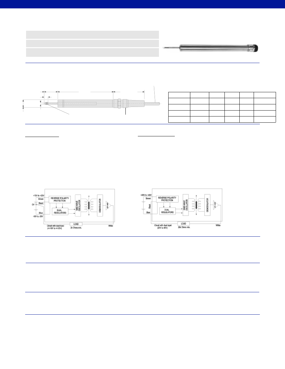
364
Stroke Range................+/- 0.5 to 4.0 in.
Non-Linearity (max.)................+/- 0.25% Full Scale
Output Sensitivity................See table above
Noise................30 mV p-p
Temperature, Operating................-40° to 158°F
Temperature, Effect
Zero (max.)................0.005% Full Scale/°F
Span (max.)................0.015% Full Scale/°F
Pressure Rating, Std.................150 psi, up to 3,000 psi with cable options
Element Type................DC-DC LVDT
Input Supply (acceptable)................+/- 10 to 20 VDC unregulated (45 mA max.)
or 20 to 40 VDC unregulated (45 mA max.)
Electrical Termination................Submersible mating connector with 16.5’ cable
Material................Stainless Steel
Probe Material................Stainless Steel
Armature Type................Free Unguided
Probe Thread................M5 x 0.8”
Spring Force (max.)................Not Applicable
Dimensions
Performance
Environmental
Electrical
Mechanical
www.honeywell.com/sensotec
n
Submersible
n
Stainless Steel
n
+/- 0.5 to +/- 4.0 in. Range
Model DW7U DC-DC Submersible* LVDT
Order Code AY250
*Not recommended for salt water use. Consult Factory for saltwater submersible applications.
Range
Codes
Available
Stroke
Ranges
L (in.)
X (in.)
Weight
Armature
(oz.)
Typical
F.S.
Output
HP
+/- 0.5 in.
8.00
1.5
0.75
+/- 5 VDC
HQ
+/- 1.0 in.
9.10
2.5
1.0
+/- 5 VDC
HR
+/- 2.0 in. 13.95
3.0
1.5
+/- 5 VDC
HS
+/- 3.0 in.
18.52
4.5
3.0
+/- 5 VDC
HT
+/- 4.0 in.
19.80
5.0
3.7
+/- 5 VDC
2.44 in.
ø 0.812 in.
ø 0.187 in.
0.6 in.
X Nominal
Electric
Zero Point
Submersible Connector
2-Nuts & 2-Washers
Supplied
4-Conductor,
Cable 16.5ft. long
L
1-888-282-9891
Wiring Codes
Dual Power Supply
Brown
(+) Supply (+10 to +20 VDC)
Blue
(-) Supply (-10 to -20 VDC)
Black
(-) Output Common/ Supply Return
White
(+) Output +/-5 VDC
(min. 2k Ohm across Black and White)
Reverse polarity protected with voltage regulator.
Cable shield is not connected to transducer.
Single Power Supply
Brown
(+) Supply (+20 to +40 VDC)
Blue
Supply Return
Black
(-) Output
White
(+) Output +/-5 VDC
(min. Ohm across Black and White)
Reverse polarity protected with voltage regulator.
Cable shield is not connected to transducer.
Either black or blue must float. If both are grounded
or connected together, the unit will be destroyed.
Courtesy of Steven Engineering, Inc.-230 Ryan Way, South San Francisco, CA 94080-6370-Main Office: (650) 588-9200-Outside Local Area: (800) 258-9200-www.stevenengineering.com
Sensotec Sensors Full Line Catalog-html.html
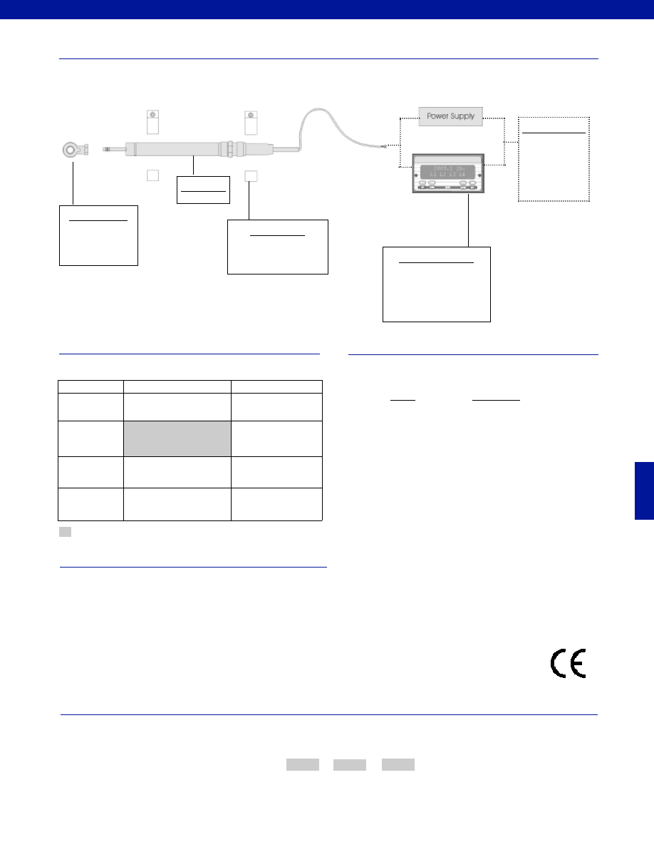
365
www.honeywell.com/sensotec
1-888-282-9891
Typical System Diagram
Range
Range Code
+/- 0.5 in.
HP
+/- 1.0 in.
HQ
+/- 2.0 in.
HR
+/- 3.0 in.
HS
+/- 4.0 in.
HT
Range Codes
Special Customer Requirements
(Consult Factory)
Options
How to Order
The order code consists of the product model, the desired range code and the available options.
Model Code
Range Code
Options Code
Sample Code:
AY250
HQ
L10
Mineral insulated welded stainless steel sheathed cable
0.12” diameter cable
1 to 164 ft. lengths available
-67° to 390° F
3,000 psi
Output options of 0-10 or 4-20 mA available
T.E.D.S. IEEE 1451.4 module
Signature Calibration
Model DW7U
Supplied as standard
Model DW7U
Fast Track Delivery
Built to Order
Stroke Ranges
+/- 0.5 to 4.0 in.
Electrical
Termination
Submersible mating connector
with 16.5’ cable
OPT1. No connector or
cable, terminated with
soldier pins
Electrical Cable
Orientation
OPT7. Radial outlet sub-
mersible connector with
16.5’ cable
Improved
Linearity
L10. +/- 0.1% max. linearity
(less than or equal to +/- 4 in.)
AC Input Display Units
SC500
SC1000
SC2000
SC3004
Customer Supplied
Chart Recorder
Alarm Panel
Data Acquisition
Computer
PLC
Mounting Blocks
AA937
Mounting Options
Rod End Bearing
Approved
-Not RoHS Compliant
Courtesy of Steven Engineering, Inc.-230 Ryan Way, South San Francisco, CA 94080-6370-Main Office: (650) 588-9200-Outside Local Area: (800) 258-9200-www.stevenengineering.com
Sensotec Sensors Full Line Catalog-html.html
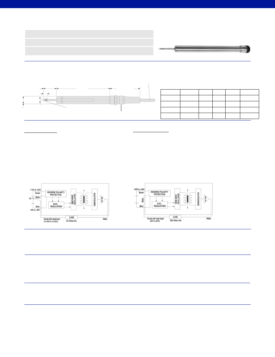
366
Stroke Range................+/- 0.5 to 4.0 in.
Non-Linearity (max.)................+/- 0.25% Full Scale
Output Sensitivity................See table above
Noise................30 mV p-p
Temperature, Operating................-40° to 158°F
Temperature, Effect
Zero (max.)................0.005% Full Scale/°F
Span (max.)................0.015% Full Scale/°F
Pressure Rating, Std.................150 psi, up to 3,000 psi with cable options
Element Type................DC-DC LVDT
Input Supply (acceptable)................+/- 10 to 20 VDC unregulated (45 mA max.)
or 20 to 40 VDC unregulated (45 mA max.)
Electrical Termination................Submersible mating connector with 16.5’ cable
Material................Stainless Steel
Probe Material................Stainless Steel
Armature Type................Captive Guided
Probe Thread................M5 x 0.8”
Spring Force (max.)................Not Applicable
Dimensions
Performance
Environmental
Electrical
Mechanical
www.honeywell.com/sensotec
n
Submersible
n
Stainless Steel
n
+/- 0.5 to +/- 4.0 in. Range
Model DW7C DC-DC Submersible* LVDT
Order Code AY251
*Not recommended for salt water use. Consult Factory for saltwater submersible applications.
Range
Codes
Available
Stroke
Ranges
L (in.) X (in.)
Weight
Armature
(oz.)
Typical
F.S.
Output
HP
+/- 0.5 in.
8.00
1.5
0.75
+/- 5 VDC
HQ
+/- 1.0 in.
9.10
2.5
1.0
+/- 5 VDC
HR
+/- 2.0 in. 13.95
3.0
1.5
+/- 5 VDC
HS
+/- 3.0 in. 18.52
4.5
3.0
+/- 5 VDC
HT
+/- 4.0 in. 19.80
5.0
3.7
+/- 5 VDC
2.44 in.
ø 0.812 in.
ø 0.187 in.
0.6 in.
X Nominal
Electric
Zero Point
Submersible Connector
2-Nuts & 2-Washers
Supplied
4-Conductor,
Cable 16.5ft. long
L
1-888-282-9891
Wiring Codes
Dual Power Supply
Brown
(+) Supply (+10 to +20 VDC)
Blue
(-) Supply (-10 to -20 VDC)
Black
(-) Output Common/ Supply Return
White
(+) Output +/-5 VDC
(min. 2k Ohm across Black and White)
Reverse polarity protected with voltage regulator.
Cable shield is not connected to transducer.
Single Power Supply
Brown
(+) Supply (+20 to +40 VDC)
Blue
Supply Return
Black
(-) Output
White
(+) Output +/-5 VDC
(min. Ohm across Black and White)
Reverse polarity protected with voltage regulator.
Cable shield is not connected to transducer.
Either black or blue must float. If both are grounded
or connected together, the unit will be destroyed.
Courtesy of Steven Engineering, Inc.-230 Ryan Way, South San Francisco, CA 94080-6370-Main Office: (650) 588-9200-Outside Local Area: (800) 258-9200-www.stevenengineering.com
Sensotec Sensors Full Line Catalog-html.html

367
www.honeywell.com/sensotec
1-888-282-9891
Special Customer Requirements
(Consult Factory)
How to Order
The order code consists of the product model, the desired range code and the available options.
Model Code
Range Code
Options Code
Sample Code:
AY251
HQ
L10
Mineral insulated welded stainless steel sheathed cable
0.12” diameter cable
1 to 164 ft. lengths available
-67° to 390° F
3,000 psi
Output options of 0-10 or 4-20 mA available
T.E.D.S. IEEE 1451.4 module
Signature Calibration
Supplied as standard
Model DW7C
Typical System Diagram
Range
Range Code
+/- 0.5 in.
HP
+/- 1.0 in.
HQ
+/- 2.0 in.
HR
+/- 3.0 in.
HS
+/- 4.0 in.
HT
Range Codes
Options
Model DW7C
AC Input Display Units
SC500
SC1000
SC2000
SC3004
Customer Supplied
Chart Recorder
Alarm Panel
Data Acquisition
Computer
PLC
Mounting Blocks
AA937
Mounting Options
Rod End Bearing
Fast Track Delivery
Built to Order
Stroke Ranges
+/- 0.5 to 4.0 in.
Electrical
Termination
Submersible mating connector
with 16.5’ cable
OPT1. No connector or
cable, terminated with
soldier pins
Electrical Cable
Orientation
OPT7. Radial outlet sub-
mersible connector with
16.5’ cable
Improved
Linearity
L10. +/- 0.1% max. linearity
(less than or equal to +/- 4 in.)
Approved
-Not RoHS Compliant
Courtesy of Steven Engineering, Inc.-230 Ryan Way, South San Francisco, CA 94080-6370-Main Office: (650) 588-9200-Outside Local Area: (800) 258-9200-www.stevenengineering.com
Sensotec Sensors Full Line Catalog-html.html
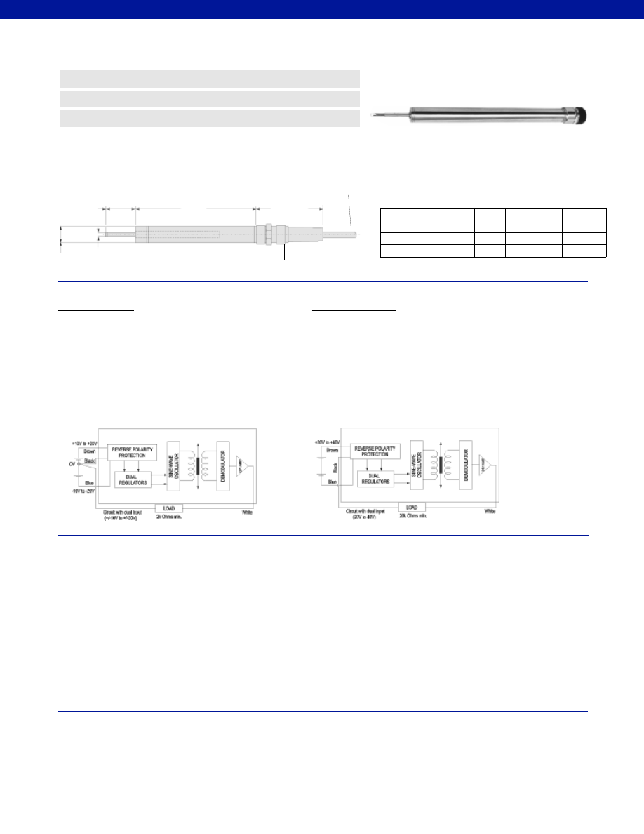
368
Stroke Range................+/- 0.5 to 3.0 in.
Non-Linearity (max.)................+/- 0.25% Full Scale
Non-Repeatability (max.)................<20 microinches
Output Sensitivity................See table above
Noise................30 mV p-p
Temperature, Operating................-40° to 158°F
Temperature, Effect
Zero (max.)................0.005% Full Scale/°F
Span (max.)................0.015% Full Scale/°F
Pressure Rating, Std.................150 psi, up to 3,000 psi with cable options
Element Type................DC-DC LVDT
Input Supply (acceptable)................+/- 10 to 20 VDC unregulated (45 mA max.)
or 20 to 40 VDC unregulated (45 mA max.)
Electrical Termination................Submersible mating connector with 16.5’ cable
Material................Stainless Steel
Probe Material................Stainless Steel
Armature Type................Captive Guided Spring Return
Probe Thread................Not Applicable
Spring Force (max.)................4 oz./ in.
Dimensions
Performance
Environmental
Electrical
Mechanical
www.honeywell.com/sensotec
n
Submersible
n
Stainless Steel
n
+/- 0.5 to +/- 3.0 in. Range
Model DW7S DC-DC Submersible* LVDT
Order Code AY252
*Not recommended for salt water use. Consult Factory for saltwater submersible applications.
Range
Codes
Available
Stroke
Ranges
L (in.) X (in.)
Spring
Force
(oz./ in.)
Typical
F.S.
Output
2.44 in.
ø 0.812 in.
ø 0.187 in.
X Nominal
Electric
Zero Point
Submersible Connector
4-Conductor,
Cable 16.5ft. long
L
1-888-282-9891
Wiring Codes
Dual Power Supply
Brown
(+) Supply (+10 to +20 VDC)
Blue
(-) Supply (-10 to -20 VDC)
Black
(-) Output Common/ Supply Return
White
(+) Output +/-5 VDC
(min. 2k Ohm across Black and White)
Reverse polarity protected with voltage regulator.
Cable shield is not connected to transducer.
Single Power Supply
Brown
(+) Supply (+20 to +40 VDC)
Blue
Supply Return
Black
(-) Output
White
(+) Output +/-5 VDC
(min. 20k Ohm across Black and White)
Reverse polarity protected with voltage regulator.
Cable shield is not connected to transducer.
Either black or blue must float. If both are grounded
or connected together, the unit will be destroyed.
HP
+/- 0.5 in.
8.00
1.5
4
+/- 5 VDC
HQ
+/- 1.0 in.
9.10
2.5
4
+/- 5 VDC
HR
+/- 2.0 in. 13.95
3.0
4
+/- 5 VDC
HS
+/- 3.0 in. 18.52
4.5
4
+/- 5 VDC
Courtesy of Steven Engineering, Inc.-230 Ryan Way, South San Francisco, CA 94080-6370-Main Office: (650) 588-9200-Outside Local Area: (800) 258-9200-www.stevenengineering.com
Sensotec Sensors Full Line Catalog-html.html
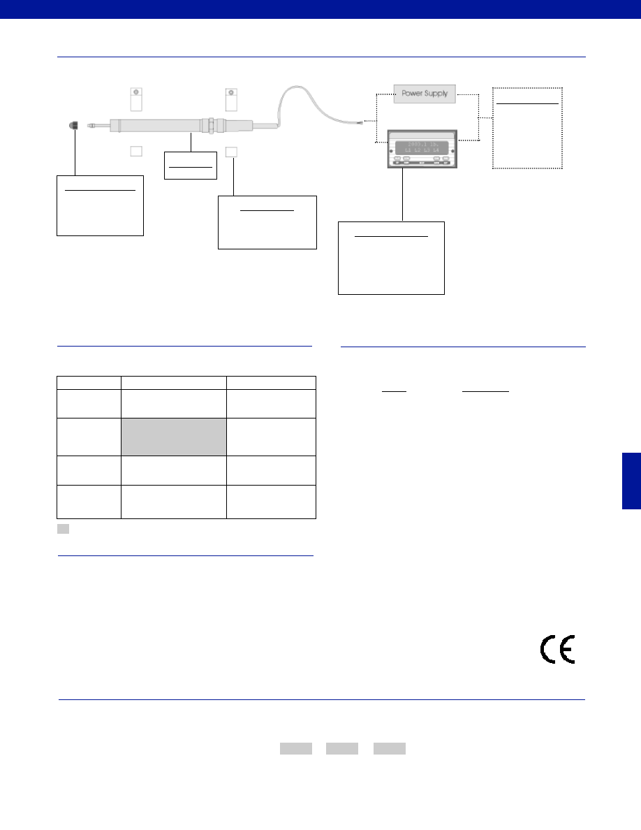
369
www.honeywell.com/sensotec
1-888-282-9891
Typical System Diagram
Range
Range Code
+/- 0.5 in.
HP
+/- 1.0 in.
HQ
+/- 2.0 in.
HR
+/- 3.0 in.
HS
Range Codes
Special Customer Requirements
(Consult Factory)
Options
How to Order
The order code consists of the product model, the desired range code and the available options.
Model Code
Range Code
Options Code
Sample Code:
AY252
HQ
L10
Mineral insulated welded stainless steel sheathed cable
0.12” diameter cable
1 to 164 ft. lengths available
-67° to 390° F
3,000 psi
Output options of 0-10 VDC or 4-20 mA available
T.E.D.S. IEEE 1451.4 module
Signature Calibration
Model DW7S
AC Input Display Units
SC500
SC1000
SC2000
SC3004
Customer Supplied
Chart Recorder
Alarm Panel
Data Acquisition
Computer
PLC
Mounting Blocks
AA937
Supplied as standard
Model DW7S
Probe Tip Assemblies
Radiused probe
Ball ended probe
Fast Track Delivery
Built to Order
Stroke Ranges
+/- 0.5 to3.0 in.
Electrical
Termination
Submersible mating connector
with 16.5’ cable
OPT1. No connector or
cable, terminated with
soldier pins
Electrical Cable
Orientation
OPT7. Radial outlet sub-
mersible connector with
16.5’ cable
Improved
Linearity
L10. +/- 0.1% max. linearity
Approved
-Not RoHS Compliant
Courtesy of Steven Engineering, Inc.-230 Ryan Way, South San Francisco, CA 94080-6370-Main Office: (650) 588-9200-Outside Local Area: (800) 258-9200-www.stevenengineering.com
Sensotec Sensors Full Line Catalog-html.html
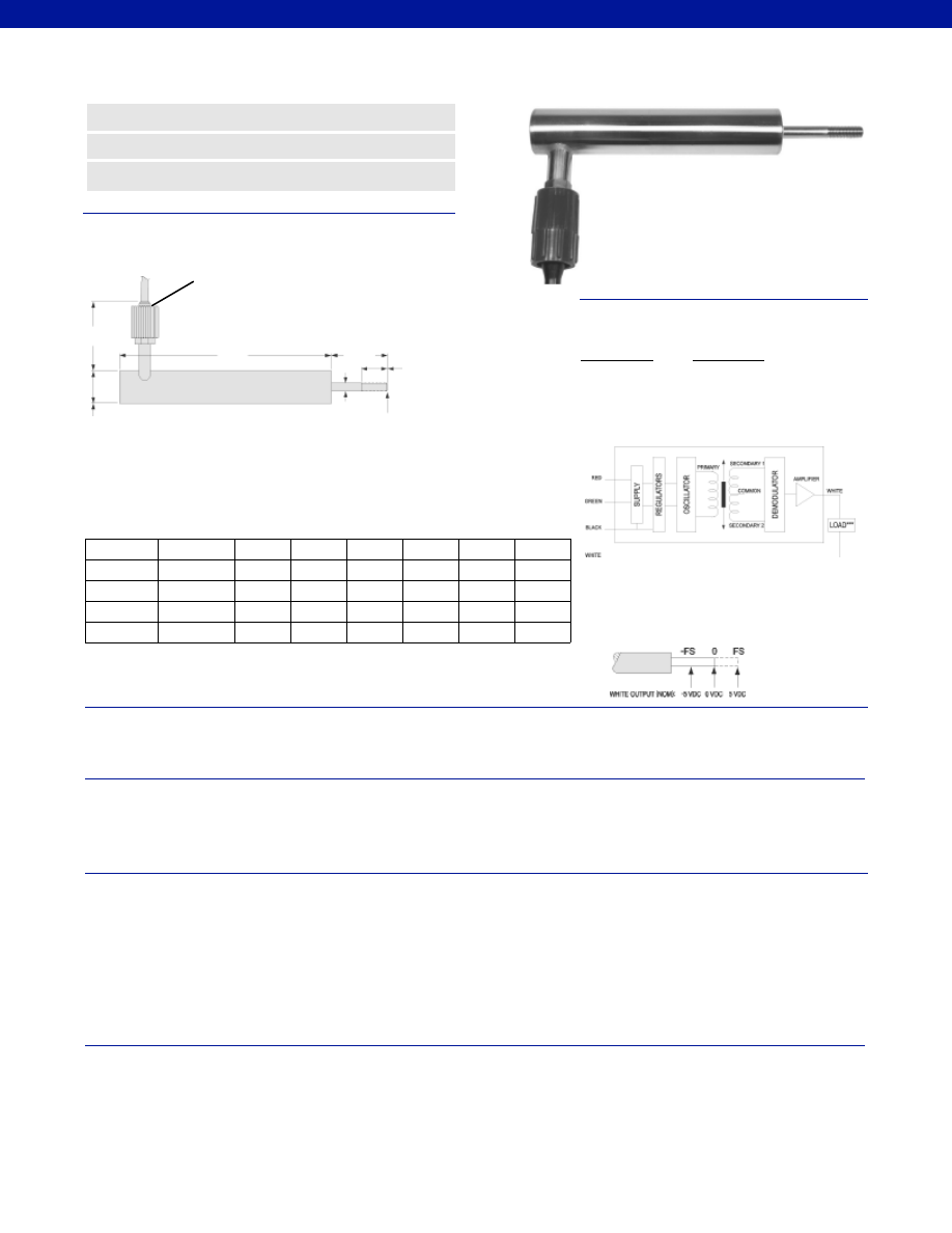
370
Stroke Range................+/- 0.5 to 4.0 in.
Non-Linearity (max.)................+/- 0.5% Full Scale
Output Sensitivity................+/- 5 VDC
Resolution................Infinite
Temperature, Operating................-40° to 140°F (Note: +15° to +140° F on 4-20 mA)
Temperature, Effect
Zero (max.)................0.005% Full Scale/°F
Span (max.)................0.015% Full Scale/°F
Operating Pressure................3,500 psi
Element Type................DC-DC LVDT
Input Supply (acceptable)
Single Floating Supply................+20 to 40 VDC @ 25 mA
Dual Supply................+/- 10 to 20 VDC @ 25 mA
Ripple................30 mV peak to peak
Electrical Termination................Includes a submersible, neoprene and nickel-aluminum bronze
connector molded to 6 ft. of neoprene jacketed 0.40 in. diameter
cable. The electrical connector may be mated under water up to
500 psi or 1100 ft. Longer cable lengths are available up to 3,250 ft.
Contact factory for information.
Case Material................316 Stainless Steel with all welded construction
Probe Material................316 Stainless Steel with all welded construction
Probe Thread................M10 x 1.5
M10 x 1.5
Dimensions
Performance
Environmental
Electrical
Mechanical
www.honeywell.com/sensotec
n
All-Welded 316 Stainless Steel
n
Up to 7,500 ft. Depth
n
+/- 0.5 in. to +/- 4.0 in. Range
Model SSD DC-DC Sub-Sea Displacement Sensor
Order Code AY911
ø D1
ø D2
Range
Codes
Available
Stroke
Ranges
L (in.)
D1 (in.) D2 (in.)
A (in.)
B (in.)
X (in.)
L
A
B
X
HP
+/- 0.5 in.
8.8
2.1
1.5
0.39
3.6
1.2
HQ
+/- 1.0 in.
9.9
2.6
1.5
0.39
3.6
1.2
HR
+/- 2.0 in.
13.6
3.6
1.5
0.39
3.6
1.2
HS
+/- 3.0 in.
17.1
4.6
1.5
0.39
3.6
1.2
HT
+/- 4.0 in.
21.1
5.6
1.5
0.39
3.6
1.2
Wiring Codes
Color or Pin
Designation
Single Supply*
Dual Supply
Red or A
20 to 40 V
+10 to +20 V
Green or B
Supply Common
-10 to -20 V
Black or C
Output Common** 0 V Common
White or D
Output
Output
* Supply must be fully floating
** Output common floats at V supply/ 2
*** Min 2,000 Ohms with dual supply, 20,000
Ohms with single supply
1-888-282-9891
Wetcon connect plug IL-4MP
socket BH-4-FS with locking
sleeve DLSA-M
Courtesy of Steven Engineering, Inc.-230 Ryan Way, South San Francisco, CA 94080-6370-Main Office: (650) 588-9200-Outside Local Area: (800) 258-9200-www.stevenengineering.com
Sensotec Sensors Full Line Catalog-html.html
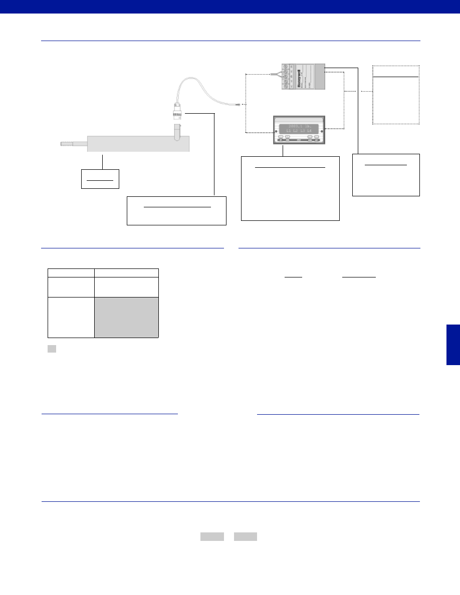
371
www.honeywell.com/sensotec
1-888-282-9891
Fast Track Delivery
Stroke Ranges
+/- 0.5 to 4.0 in.
Electrical
Termination
Submersible, neoprene
and nickel-aluminum
bronze connector molded
to 6 ft. of neoprene
jacketed cable
Typical System Diagram
Range
Range Code
+/- 0.5 in.
HP
+/- 1.0 in.
HQ
+/- 2.0 in.
HR
+/- 3.0 in.
HS
+/- 4.0 in.
HT
Range Codes
Special Customer Requirements
(Consult Factory)
4-20mA or 0-10VDC output
T.E.D.S. IEEE 1451.4 module
Signature Calibration
Options
How to Order
The order code consists of the product model and the desired range code.
Model Code
Range Code
Sample Code:
AY911
HQ
Mating Connectors & Cables
Model SSD
High Level Input Display Units
GM-A (note 1)
SC500
SC1000
SC2000
SC3004
DC Power Supply
Required if high level input
display unit is not being
used.
Customer Supplied
Chart Recorder
Alarm Panel
Data Acquisition
Computer
PLC
Model SSD
Supplied as standard
Notes
1. GM-A should not be used with an amplified LVDT unless
using an external power supply to power the LVDT.
-Not RoHS Compliant
Courtesy of Steven Engineering, Inc.-230 Ryan Way, South San Francisco, CA 94080-6370-Main Office: (650) 588-9200-Outside Local Area: (800) 258-9200-www.stevenengineering.com
Sensotec Sensors Full Line Catalog-html.html
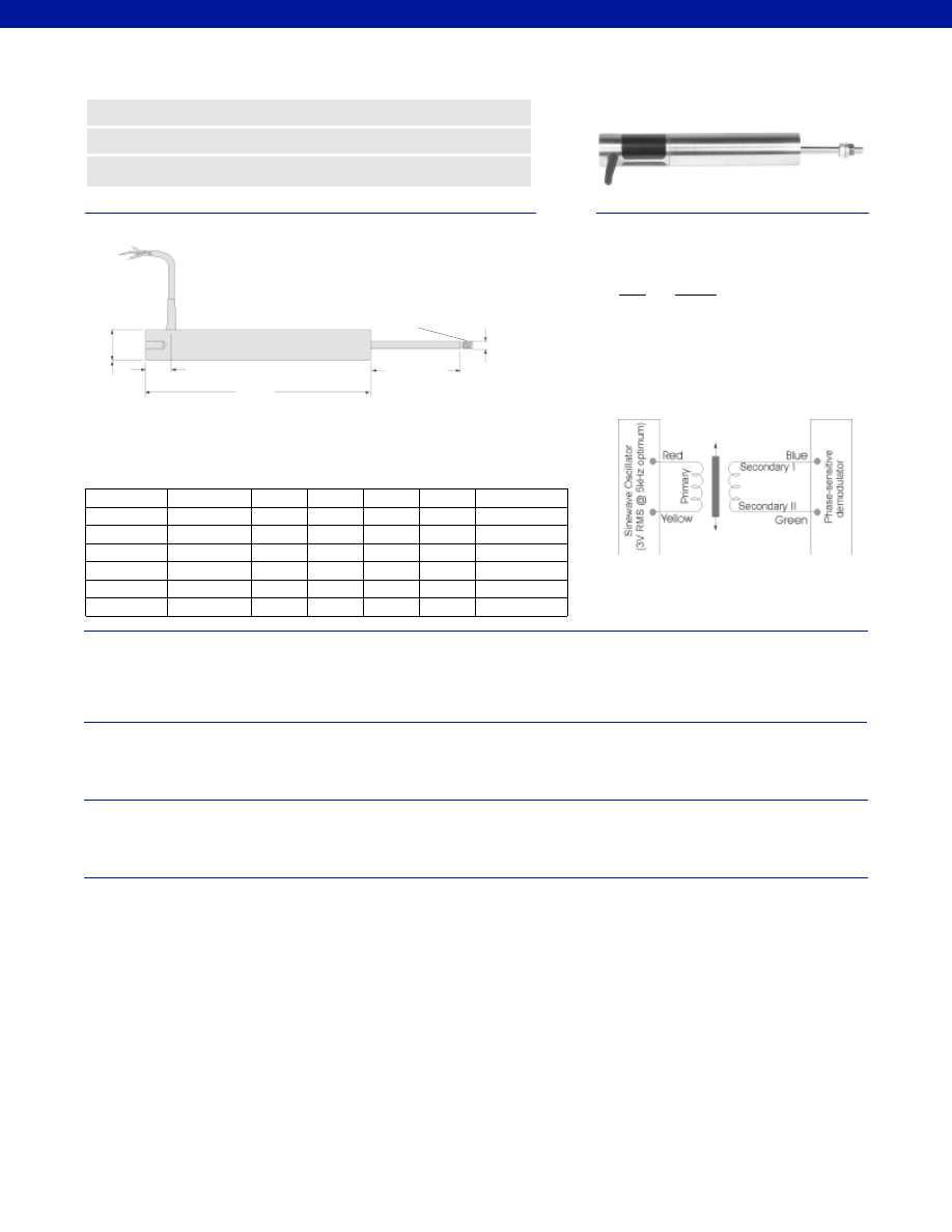
372
Dimensions
Performance
Environmental
Electrical
Mechanical
www.honeywell.com/sensotec
n
0.25% Non-Linearity
n
Stainless Steel
n
0.5 to 8.0 in. Ranges
ø 0.19 in.
ø 0.81 in.
Range
Codes
Available
Stroke
Ranges
Approx.
Body
Weight
(oz.)
L (in.)
X (in.)
Approx.
Armature
Weight
(oz.)
Typical F.S.
Output at 3V
RMS
X Nominal
Electric Zero Point
M5 x .08
L
0.35 in.
Model MVL7 AC-AC Long Stroke LVDT
Order Code BY125
HP
+/- 0.5 in.
5.0
1.7
6
1.25
2.4V RMS
HQ
+/- 1.0 in.
6.0
2.7
8
1.75
3.0V RMS
HR
+/- 2.0 in.
10.6
3.2
13
2.0
4.8V RMS
HS
+/- 3.0 in.
15.0
4.7
16
2.2
4.5V RMS
HT
+/- 4.0 in.
16.75
5.2
20
2.5
9.5V RMS
HU
+/- 6.0 in.
24.25
7.2
29
4.0
7.2V RMS
HV
+/- 8.0 in.
31.75
10.2
42
5.1
4.8V RMS
Wiring Codes
Wire
Supply
Red
(+) Supply (Calibrated @ 3V RMS 5 kHz)
Yellow
Supply Return
Blue
Output
Green
Output Return
Black
Secondary Center Tap
(normally not connected)
Stroke Range................+/- 0.5 to 8.0 in.
Non-Linearity (max.)................+/- 0.25% Full Scale
Non-Repeatability (max.)................Not Applicable
Output Sensitivity................See table above
Resolution................Infinite
Temperature, Operating................-58° to 257°F
Temperature, Effect
Zero (max.)................0.006% Full Scale/°F
Span (max.)................0.006% Full Scale/°F
Element Type................AC-AC LVDT
Input Supply (calibrated)................3 V RMS @ 5 kHz
Input Supply (acceptable)................1-7 V RMS @ 2-10 kHz
Electrical Termination................Multiconductor shielded cable
Material................Stainless Steel
Probe Material................Stainless Steel
Armature Type................Free Unguided
Probe Thread................M5 x 0.8
Weight................See table above
Spring Force (max.)................Not Applicable
1-888-282-9891
Courtesy of Steven Engineering, Inc.-230 Ryan Way, South San Francisco, CA 94080-6370-Main Office: (650) 588-9200-Outside Local Area: (800) 258-9200-www.stevenengineering.com
Sensotec Sensors Full Line Catalog-html.html

373
www.honeywell.com/sensotec
1-888-282-9891
Typical System Diagram
Range
Range Code
+/- 0.5 in.
HP
+/- 1.0 in.
HQ
+/- 2.0 in.
HR
+/- 3.0 in.
HS
+/- 4.0 in.
HT
+/- 6.0 in.
HU
+/- 8.0 in.
HV
Range Codes
Special Customer Requirements
(Consult Factory)
Options
How to Order
The order code consists of the product model, the desired range code and the available options.
Model Code
Range Code
Options Code
Sample Code:
BY125
HQ
L10
Moisture resistant
Radiation resistance 100M rads
Longer cable length, limited on certain models
Threaded body
T.E.D.S. IEEE 1451.4 module
Signature Calibration
Model MVL7
AC Input Display Units
DM
SC500
SC1000
SC2000
SC3004
In-Line Amplifiers
DLD-VH
DLD-CH
(Required for AC LVDT’s
and if AC input display units
are not being used)
Customer Supplied
Chart Recorder
Alarm Panel
Data Acquisition
Computer
PLC
Mounting Blocks
AA937 Mounting Block
Supplied as standard
Model MVL7
Fast Track Delivery
Built to Order
Stroke Ranges
+/- 0.5 to 8.0 in.
Electrical
Termination
Multiconductor Shielded Cable
(6 ft.)
TM405. Axial Bendix connector
on body Radial (side)
TM406. Bendix connector on
body
Electrical Cable
Orientation
TM49. Axial cable exit
Mounting Threads
TM511. 13/16 - 32 UNF
Improved
Linearity
L10. +/- 0.1% max. linearity
(less than or equal to +/- 4 in.)
Higher
Temperature
TM315. 400° F up to +/- 4.0 in.
Mounting Options
Rod End Bearing
-Not RoHS Compliant
Courtesy of Steven Engineering, Inc.-230 Ryan Way, South San Francisco, CA 94080-6370-Main Office: (650) 588-9200-Outside Local Area: (800) 258-9200-www.stevenengineering.com
Sensotec Sensors Full Line Catalog-html.html
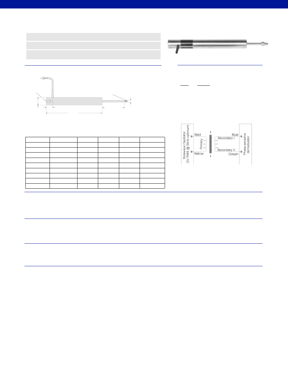
374
Dimensions
Performance
Environmental
Electrical
Mechanical
www.honeywell.com/sensotec
n
0.25% Non-Linearity
n
Stainless Steel
n
0.5 to 18.5 in. Ranges
ø 0.19 in.
M5 x 0.8
M5 x 0.8
ø 0.82 in.
Range
Codes
Available
Stroke Ranges
L (in.)
X (in.)
Approx.
Unit
Weight
(oz.)
Typical F.S.
Output at
3V RMS
X
Nominal Electric Zero Point
L
0.72 in.
Model MVL7C AC-AC Long Stroke LVDT
Order Code BY126
HP
+/- 0.5 in.
6.0
1.5
10
2.4V RMS
HQ
+/- 1.0 in.
7.0
2.5
12
3.0V RMS
HR
+/- 2.0 in.
11.6
3.0
18
4.8V RMS
HS
+/- 3.0 in.
16.0
4.5
23
4.5V RMS
HT
+/- 4.0 in.
17.8
5.0
25
9.6V RMS
HU
+/- 6.0 in.
25.3
7.0
36
7.2V RMS
HV
+/- 8.0 in.
32.8
10.0
50
4.8V RMS
HW
+/- 10.0 in.
40.5
12.0
56
6.0V RMS
HY
+/- 15.0 in.
56.5
16.0
75
9.0V RMS
HZ
+/- 18.5 in.
67.0
20.0
89
11.1V RMS
Wiring Codes
Wire
Supply
Red
(+) Supply (Calibrated @ 3V RMS @ 5 kHz)
Yellow
Supply Return
Blue
Output
Green
Output Return
Black
Secondary Center Tap
(normally not connected)
Stroke Range................+/- 0.5 to 18.5 in.
Non-Linearity (max.)
+/- 0.5 in. to +/-10.0 in.................+/- 0.25% Full Scale
+/- 15.0 in. to +/- 18.5 in.................+/- 0.5% Full Scale
Resolution................Infinite
Temperature, Operating................-58° to 257°F
Temperature, Effect
Zero (max.)................0.006% Full Scale/°F
Span (max.)................0.006% Full Scale/°F
Element Type................AC-AC LVDT
Input Supply (calibrated)................3 V RMS @ 5 kHz
Input Supply (acceptable)................1-7 V RMS @ 2-10 kHz
Electrical Termination................Multiconductor shielded cable
Material................Stainless Steel
Probe Material................Stainless Steel
Armature Type................Captive Guided
Probe Thread................M5 x 0.8
Weight................See table above
Spring Force (max.)................Not Applicable
1-888-282-9891
Courtesy of Steven Engineering, Inc.-230 Ryan Way, South San Francisco, CA 94080-6370-Main Office: (650) 588-9200-Outside Local Area: (800) 258-9200-www.stevenengineering.com
Sensotec Sensors Full Line Catalog-html.html

375
www.honeywell.com/sensotec
1-888-282-9891
Range
Range Code
+/- 0.5 in.
HP
+/- 1.0 in.
HQ
+/- 2.0 in.
HR
+/- 3.0 in.
HS
+/- 4.0 in.
HT
+/- 6.0 in.
HU
+/- 8.0 in.
HV
+/- 10.0 in.
HW
+/- 15.0 in.
HY
+/- 18.5 in.
HZ
Range Codes
Special Customer Requirements
(Consult Factory)
Options
How to Order
The order code consists of the product model, the desired range code and the available options.
Model Code
Range Code
Options Code
Sample Code:
BY126
HQ
L10
Moisture resistant
Radiation resistance 100M rads (up to +/- 4.0 in.)
Longer cable length, limited on certain models
Threaded body
T.E.D.S. IEEE 1451.4 module
Signature Calibration
Supplied as standard
Model MVL7C
Typical System Diagram
Model MVL7C
AC Input Display Units
DM
SC500
SC1000
SC2000
SC3004
In-Line Amplifiers
DLD-VH
DLD-CH
(Required for AC LVDT’s
and if AC input display units
are not being used)
Customer Supplied
Chart Recorder
Alarm Panel
Data Acquisition
Computer
PLC
Mounting Blocks
AA937 Mounting Block
Fast Track Delivery
Built to Order
Stroke Ranges
+/- 0.5 to 18.5 in.
Electrical
Termination
Multiconductor Shielded Cable
(6 ft.)
TM405. Axial Bendix connector
on body Radial (side)
TM406. Bendix connector on
body
Electrical Cable
Orientation
TM49. Axial cable exit
Mounting Threads
TM511. 13/16 - 32 UNF
Improved
Linearity
L10. +/- 0.1% max. linearity
(less than or equal to +/- 4 in.)
Higher
Temperature
TM315. 400° F up to +/- 4.0 in.
Mounting Options
Rod End Bearing
-Not RoHS Compliant
Courtesy of Steven Engineering, Inc.-230 Ryan Way, South San Francisco, CA 94080-6370-Main Office: (650) 588-9200-Outside Local Area: (800) 258-9200-www.stevenengineering.com
Sensotec Sensors Full Line Catalog-html.html
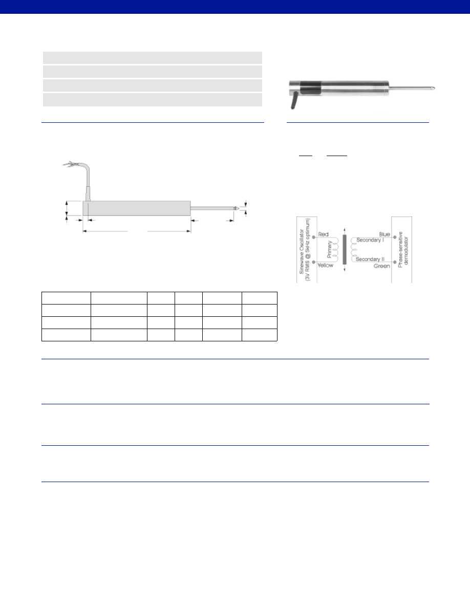
376
Dimensions
Performance
Environmental
Electrical
Mechanical
www.honeywell.com/sensotec
n
+/- 0.5 to 3.0 in. Ranges
n
Stainless Steel Construction
n
0.25% Non-Linearity
n
Spring Return
ø 0.19 in.
ø 0.81 in.
Order Code with
Ranges
Available
Ranges
L (in.)
X (in.)
Approx.
Unit
Weight (oz.)
Typical F.S.
Output
@ 3V RMS
X Nominal
Electric Zero Point
L
0.35 in.
Model VL7A AC-AC Long Stroke LVDT
Order Code BY122
Stroke Range................+/- 0.5 to 3.0 in.
Non-Linearity (max.)................+/- 0.25% Full Scale
Non-Repeatability (max.)................<20 microinches
Output Sensitivity................See table above
Resolution................Infinite
Temperature, Operating................-58° to 257°F
Temperature, Effect
Zero (max.)................0.006% Full Scale/°F
Span (max.)................0.006% Full Scale/°F
Element Type................AC-AC LVDT
Input Supply (calibrated)................3 V RMS @ 5 kHz
Input Supply (acceptable)................1-7 V RMS @ 2-10 kHz
Electrical Termination................Multiconductor shielded cable
Material................Stainless Steel
Probe Material................Stainless Steel
Armature Type................Captive Guided Spring Return
Probe Thread................Not Applicable
Weight................See table above
Spring Force (max.)................4 oz./ in.
BY122HP
+/- 0.5 in.
5.35
1.5
6.5
2.4V RMS
BY122HQ
+/- 1.0 in.
6.35
2.5
8.0
3.0V RMS
BY122HR
+/- 2.0 in.
11.0
3.0
14.0
4.8V RMS
BY122HS
+/- 3.0 in.
15.35
4.5
17.0
4.5V RMS
Wiring Codes
Wire
Supply
Red
(+) Supply (Calibrated @ 3V RMS 5 kHz)
Yellow
Supply Return
Blue
Output
Green
Output Return
Black
Secondary Center Tap
(normally not connected)
1-888-282-9891
Courtesy of Steven Engineering, Inc.-230 Ryan Way, South San Francisco, CA 94080-6370-Main Office: (650) 588-9200-Outside Local Area: (800) 258-9200-www.stevenengineering.com
Sensotec Sensors Full Line Catalog-html.html

377
Typical System Diagram
Range
Range Code
+/- 0.5 in.
HP
+/- 1.0 in.
HQ
+/- 2.0 in.
HR
+/- 3.0 in.
HS
Range Codes
Special Customer Requirements
(Consult Factory)
Options
How to Order
The order code consists of the product model, the desired range code and the available options.
Model Code
Range Code
Options Code
Sample Code:
BY122
HQ
L10
Moisture resistant
Radiation resistance 100M rads
Longer cable length, limited on certain models
Threaded body
Spring retract
Optional tips
T.E.D.S. IEEE 1451.4 module
Signature Calibration
Model VL7A
AC Input Display Units
DM
SC500
SC1000
SC2000
SC3004
In-Line Amplifiers
DLD-VH
DLD-CH
(Required for AC LVDT’s
and if AC input display units
are not being used)
Customer Supplied
Chart Recorder
Alarm Panel
Data Acquisition
Computer
PLC
Mounting Blocks
AA945 Mounting Block
Probe Tip Assemblies
Radiused probe
Ball ended probe
Supplied as standard
Model VL7A
Same Day Ship
Fast Track Delivery
Built to Order
Stroke Ranges
+/- 0.5 to +/- 2.0 in.
+/-3.0 in.
Electrical
Termination
Multiconductor
Shielded Cable (6 ft.)
TM405. Axial Bendix connector
on body Radial (side)
TM406. Bendix connector on
body
Electrical Cable
Orientation
TM49. Axial cable exit
Mounting Threads
TM511. 13/16 - 32 UNF
Improved
Linearity
L10. +/- 0.1% max.
linearity (less than
or equal to +/- 4 in.)
Higher
Temperature
TM315. 400° F
-Not RoHS Compliant
www.honeywell.com/sensotec
1-888-282-9891
Courtesy of Steven Engineering, Inc.-230 Ryan Way, South San Francisco, CA 94080-6370-Main Office: (650) 588-9200-Outside Local Area: (800) 258-9200-www.stevenengineering.com
Sensotec Sensors Full Line Catalog-html.html
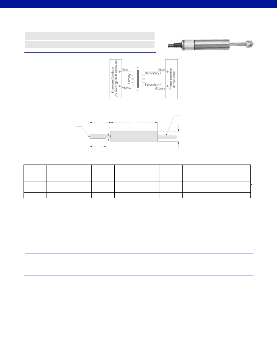
378
Stroke Range................+/- 0.10 to 0.50 in.
Non-Linearity (max.)................+/- 0.25% Full Scale
Non-repeatability................Not measurable
Output Sensitivity................See table
Output Load (min.)................100 Ohms
Resolution................Infinite
Phase Shift................< 10° @ 5 kHz
Temperature, Operating................-4° to 257°F
Temperature, Effect
Zero (max.)................0.006% Full Scale/°F
Span (max.)................0.006% Full Scale/°F
Element Type................AC-AC LVDT
Input Supply (calibrated)................3 V RMS @ 5 kHz
Input Supply (acceptable)................1-7V RMS @ 2-10 kHz
Electrical Termination................Multiconductor shielded cable (6 ft.)
Case Material................Stainless Steel
Probe Material................Stainless Steel
Armature Type................Free Unguided
Probe Thread................M3 x 0.5
Weight................See table
Wiring Codes
Dimensions
Performance
Environmental
Electrical
Mechanical
www.honeywell.com/sensotec
n
Miniature Design
n
Rugged, High Accuracy
Model M-5C AC-AC Miniature LVDT
Order Code AY318
øD
øD1
T
Order Code
with
Ranges
Available
Stroke
Ranges
L (in.)
X (in.)
T (in.)
D (in.)
D1 (in.)
Output
Sensitivity
mV/V/0.001 in.
Total
Weight
Armature
Weight
L
X
@ Zero Point
AY318HJ
+/-0.025 in.
1.38
1.1
0.375
0.075
0.75
0.5 oz.
0.045 oz.
2
AY318HM
+/- 0.1 in.
1.69
0.75
0.375
0.09
0.59
0.56 oz.
0.05 oz.
4
AY318HN
+/- 0.2 in.
2.2*
1
0.375
0.08
0.71
0.63 oz.
0.07 oz.
4*
AY318HF
+/- 0.3 in.
2.28
1.18
0.375
0.08
0.71
0.78 oz.
0.078 oz.
2
AY318HG
+/- 0.4 in.
2.48
1.28
0.375
0.08
0.71
0.99 oz.
0.067 oz.
2
AY318HP
+/- 0.5 in.
3.11
1.37
0.375
0.08
0.71
1.27 oz.
0.081 oz.
2
6-Core Screened Cable
6 ft. long
Armature Thread
M3 x 0.5
1-888-282-9891
Connections
Red
Supply (calibrated @ 3V RMS 5 kHz)
Yellow
Supply Return
Blue
Output
Green Output
Return
Black
Secondary Center Tap
(normally not connected)
Cable shield is not connected to transducer
* New L dimension and Output Sensitivity for +/- 0.2 in. range. For old L dimension and Output Sensitivity, consult factory.
Courtesy of Steven Engineering, Inc.-230 Ryan Way, South San Francisco, CA 94080-6370-Main Office: (650) 588-9200-Outside Local Area: (800) 258-9200-www.stevenengineering.com
Sensotec Sensors Full Line Catalog-html.html
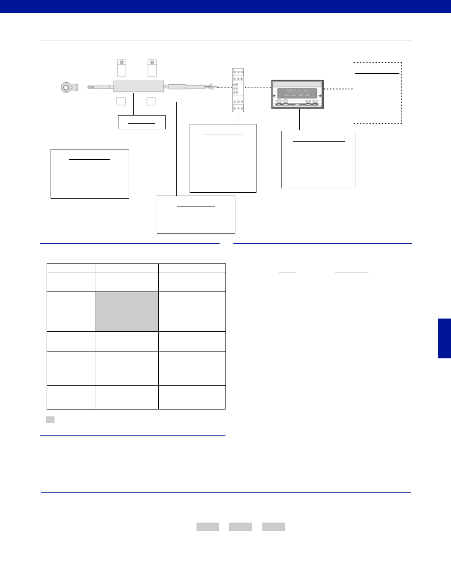
379
www.honeywell.com/sensotec
1-888-282-9891
Fast Track Delivery
Built to Order
Stroke Ranges
+/- 0.10 to 0.50 in.
Electrical
Termination
Multiconductor Shielded
Cable (6 ft.)
Electrical Cable
Orientation
Ra. Right angle cable exit
Mounting Threads
13g. 1/8” BSP
Improved
Linearity
L10. 0.1% Linearity (only
for +/-0.1 in. to +/-0.3 in.)
Typical System Diagram
Range
Range Code
+/- 0.10 in.
HM
+/- 0.20 in.
HN
+/- 0.30 in.
HF
+/- 0.40 in.
HG
+/- 0.50 in.
HP
Range Codes
Options
How to Order
The order code consists of the product model, the desired range code and the available options.
Model Code
Range Code
Options Code
Sample Code:
AY918
HP
13g
Model M5C
Customer Supplied
Chart Recorder
Alarm Panel
Data Acquisition
Computer
PLC
Mounting Options
Rod End Bearing
Model M5C
Supplied as standard
AC Input Display Units
DM
SC500
SC1000
SC2000
SC3004
In-Line Amplifiers
DLD-VH
DLD-CH
(Required for AC LVDT’s
and if AC input display units
are not being used)
Mounting Blocks
AA945
-Not RoHS Compliant
Special Customer Requirements
(Consult Factory)
T.E.D.S. IEEE 1451.4 module
Signature Calibration
Courtesy of Steven Engineering, Inc.-230 Ryan Way, South San Francisco, CA 94080-6370-Main Office: (650) 588-9200-Outside Local Area: (800) 258-9200-www.stevenengineering.com
Sensotec Sensors Full Line Catalog-html.html
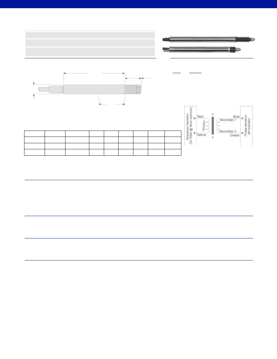
380
Dimensions
Performance
Environmental
Electrical
Mechanical
www.honeywell.com/sensotec
n
0.25% Non-Linearity
n
Non-Rotating Probe
n
Stainless Steel
øD
N
Range
Codes
Available
Stroke
Ranges
Output
Sensitivity
mV/V/0.001 in. L (in.)
N (in.)
D (in.)
X (in.)
Approx.
Unit
Wt. (oz.)
Max.
Spring
Force
(oz.)
X
L
Model PLVX AC-AC Ultra Precision LVDT
Order Code AY111
Wiring Codes
Wire
Supply
Red
(+) Supply (Calibrated @ 3V RMS 5 kHz)
Yellow
Supply Return
Blue
Output
Green
Output Return
Black
Secondary Center Tap
(normally not connected)
Stroke Range................+/- 0.02 to 0.2 in.
Non-Linearity (max.)................+/- 0.25% Full Scale
Non-Repeatability (max.)................6 microinches
Output Sensitivity................See table above
Output Load (min.)................100,000 Ohms
Resolution................Infinite
Phase Shift................< 10° @ 5 kHz
Temperature, Operating................-40° to 212°F
Temperature, Effect
Zero (max.)................0.005% Full Scale/°F
Span (max.)................0.005% Full Scale/°F
Element Type................AC-AC LVDT
Input Supply (calibrated)................3 V RMS @ 5 kHz
Input Supply (acceptable)................1-7 V RMS @ 2-10 kHz
Electrical Termination................Multiconductor shielded cable
Material................Stainless Steel
Probe Material................Stainless Steel
Armature Type................Captive Guided Spring Return
Weight................See table above
Spring Force (max.)................See table above
1-888-282-9891
HI
+/- 0.02 in.
6
1.02
0.22
0.315
0.30
0.45
3.5
HK
+/- 0.04 in.
4
2.09
0.55
0.315
0.55
0.56
3.56
HM
+/- 0.1 in.
4
2.24
.071
0.315
0.79
0.63
4.16
HN
+/- 0.2 in.
4*
3.41*
1.18
0.315
0.87
0.78
5.29
* New L dimension and Output Sensitivity for +/- 0.2 in. range. For old L dimension and Output
Sensitivity, consult factory.
Courtesy of Steven Engineering, Inc.-230 Ryan Way, South San Francisco, CA 94080-6370-Main Office: (650) 588-9200-Outside Local Area: (800) 258-9200-www.stevenengineering.com
Sensotec Sensors Full Line Catalog-html.html
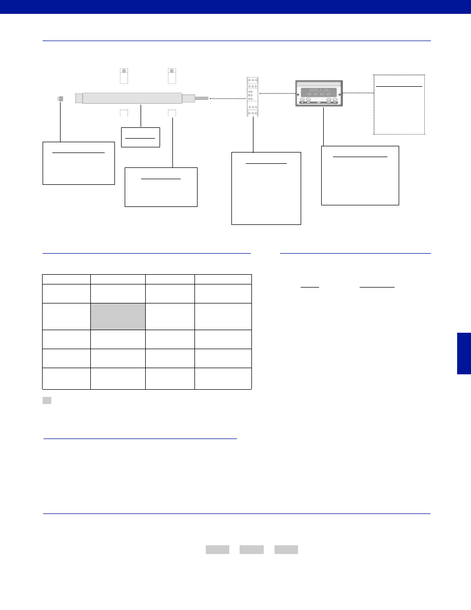
381
www.honeywell.com/sensotec
1-888-282-9891
Typical System Diagram
Range
Range Code
+/- 0.02 in.
HI
+/- 0.04 in.
HK
+/- 0.1 in.
HM
+/- 0.2 in.
HN
Range Codes
Options
How to Order
The order code consists of the product model, the desired range code and the available options.
Model Code
Range Code
Options Code
Sample Code:
AY111
HK
Ra
Model PLVX
AC Input Display Units
DM
SC500
SC1000
SC2000
SC3004
In-Line Amplifiers
DLD-VH
DLD-CH
(Required for AC LVDT’s
and if AC input display units
are not being used)
Customer Supplied
Chart Recorder
Alarm Panel
Data Acquisition
Computer
PLC
Mounting Blocks
AA945 Mounting Blocks
Probe Tip Assemblies
Radiused probe
Ball ended probe
Supplied as standard
Model PLVX
Same Day Ship
Fast Track Delivery
Built to Order
Stroke Ranges
+/- 0.1 in.
+/- 0.02; +/- 0.04;
+/- 0.01 in.
Electrical
Termination
Multiconductor
Shielded Cable (6 ft.)
Electrical Cable
Orientation
Ra. Right angle cable
exit
Mounting Threads
TM392. 3/8-32 UNF
Thread Sleeve
Improved
Linearity
L10. 0.1% Linearity*
(only for +/- 0.04 in. to
+/- 0.2 in.)
*Air activated models.
-Not RoHS Compliant
Special Customer Requirements
(Consult Factory)
T.E.D.S. IEEE 1451.4 module
Signature Calibration
Courtesy of Steven Engineering, Inc.-230 Ryan Way, South San Francisco, CA 94080-6370-Main Office: (650) 588-9200-Outside Local Area: (800) 258-9200-www.stevenengineering.com
Sensotec Sensors Full Line Catalog-html.html
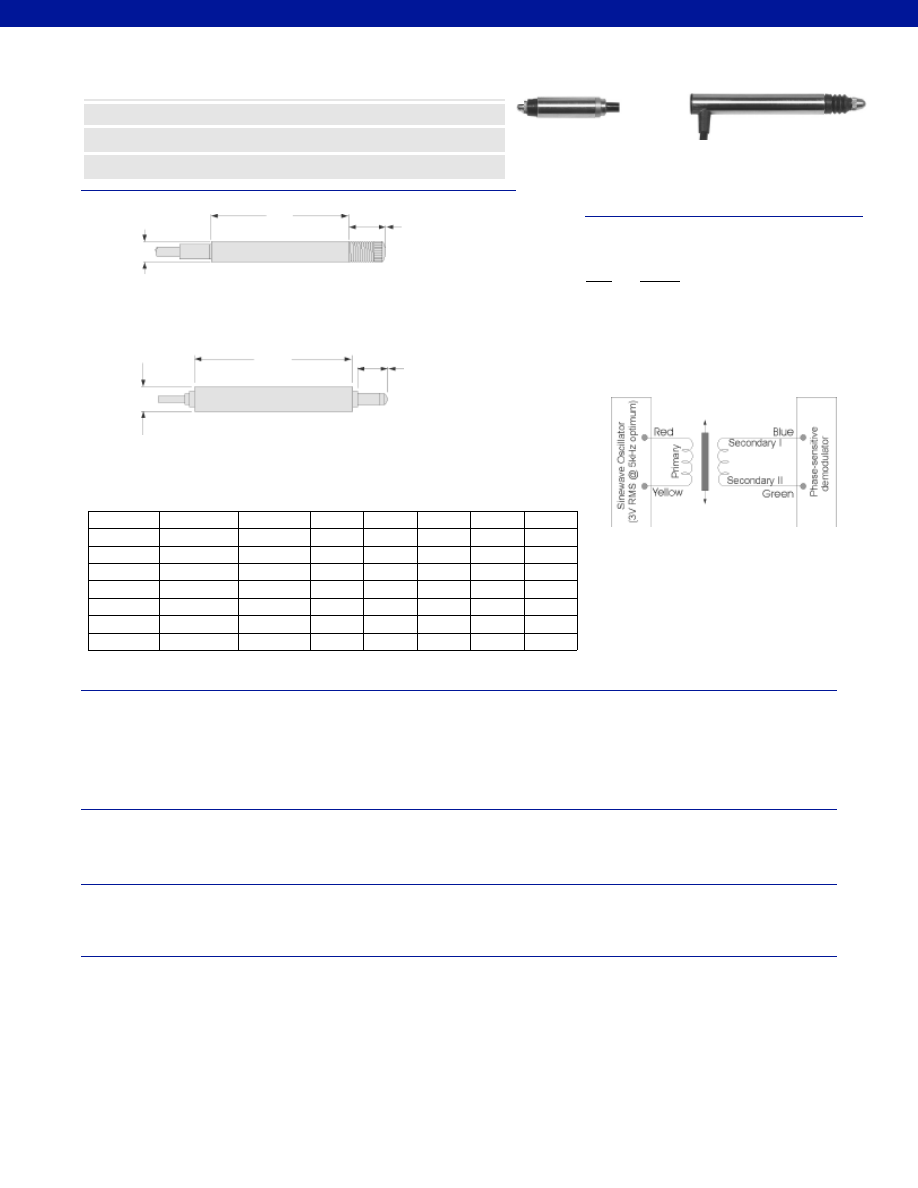
382
Dimensions
Performance
Environmental
Electrical
Mechanical
www.honeywell.com/sensotec
n
0.25% Non-Linearity
n
Non-Rotating Probe
n
Stainless Steel
øD
øD
Range
Codes
Available
Stroke
Ranges
Output
Sensitivity
mV/V/0.001 in. L (in.)
D (in.)
X (in.)
Approx.
Unit
Wt. (oz.)
Max.
Spring
Force
(oz.)
X
X
L
L
Model S5 AC-AC Ultra Precision LVDT
Order Code AY112
0.1 to 0.5 in.
0.01 to 0.04 in.
0.1 to 0.5 in.
0.01 to 0.04 in.
HH
+/- 0.01 in.
4
1.89
0.31
0.43
14
7.5
HI
+/- 0.02 in.
4
1.89
0.31
0.43
14
7.5
HK
+/- 0.04 in.
4
2.01
0.31
0.51
18
7.5
HM
+/- 0.1 in.
4
2.40
0.37
0.45
22
4.23
HN
+/- 0.2 in.
4*
3.07*
0.37
0.45
26
4.58
HF
+/- 0.3 in.
2
3.46
0.37
0.60
30
8.64
HG
+/- 0.4 in.
2
3.90
0.37
0.75
34
7.40
HP
+/- 0.5 in.
2
4.76
0.37
0.85
42
7.58
Wiring Codes
Wire
Supply
Red
(+) Supply (Calibrated @ 3V RMS 5 kHz)
Yellow
Supply Return
Blue
Output
Green
Output Return
Black
Secondary Center Tap
(normally not connected)
Stroke Range................+/- 0.01 to 0.5 in.
Non-Linearity (max.)................+/- 0.25% Full Scale
Non-Repeatability (max.)................<20 microinches
Output Sensitivity................See table above
Output Load (min.)................100,000 Ohms
Resolution................Infinite
Phase Shift................< 10° @ 5 kHz
Temperature, Operating................-4° to 257°F
Temperature, Effect
Zero (max.)................0.006% Full Scale/°F
Span (max.)................0.006% Full Scale/°F
Element Type................AC-AC LVDT
Input Supply (calibrated)................3 V RMS @ 5 kHz
Input Supply (acceptable)................1-7 V RMS @ 2-10 kHz
Electrical Termination................Multiconductor shielded cable
Material................Stainless Steel
Probe Material................Stainless Steel
Armature Type................Captive Guided Spring Return
Weight................See table above
Spring Force (max.)................See table above
1-888-282-9891
* New L dimension and Output Sensitivity for +/- 0.2 in. range. For old L dimension and Output
Sensitivity, consult factory.
Courtesy of Steven Engineering, Inc.-230 Ryan Way, South San Francisco, CA 94080-6370-Main Office: (650) 588-9200-Outside Local Area: (800) 258-9200-www.stevenengineering.com
Sensotec Sensors Full Line Catalog-html.html
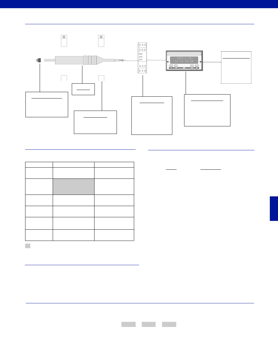
383
www.honeywell.com/sensotec
1-888-282-9891
Typical System Diagram
Range
Range Code
+/- 0.01 in.
HH
+/- 0.02 in.
HI
+/- 0.04 in.
HK
+/- 0.1 in.
HM
+/- 0.2 in.
HN
+/- 0.3 in.
HF
+/- 0.4 in.
HG
+/- 0.5 in.
HP
Range Codes
Options
How to Order
The order code consists of the product model, the desired range code and the available options.
Model Code
Range Code
Options Code
Sample Code:
AY112
HG
Ra
Supplied as standard
Model S5
Fast Track Delivery
Built to Order
Stroke Ranges
+/- 0.01 to 0.5 in.
Electrical
Termination
Multiconductor Shielded
Cable (6 ft.)
Electrical Cable
Orientation
Ra. Right angle cable exit
Mounting Threads
TM392. 3/8-32 UNF
Thread Sleeve
Improved
Linearity
L10. 0.1% Linearity*
(only for +/- 0.040 in. to
+/- 0.2 in.)
Higher
Temperature
TM315. 400° F
Model S5
AC Input Display Units
DM
SC500
SC1000
SC2000
SC3004
In-Line Amplifiers
DLD-VH
DLD-CH
(Required for AC LVDT’s
and if AC input display units
are not being used)
Customer Supplied
Chart Recorder
Alarm Panel
Data Acquisition
Computer
PLC
Mounting Blocks
AA945 Mounting Blocks
Probe Tip Assemblies
Radiused probe
Ball ended probe
-Not RoHS Compliant
Special Customer Requirements
(Consult Factory)
T.E.D.S. IEEE 1451.4 module
Signature Calibration
Courtesy of Steven Engineering, Inc.-230 Ryan Way, South San Francisco, CA 94080-6370-Main Office: (650) 588-9200-Outside Local Area: (800) 258-9200-www.stevenengineering.com
Sensotec Sensors Full Line Catalog-html.html
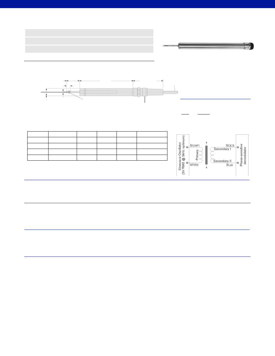
384
Dimensions
Performance
Environmental
Electrical
Mechanical
www.honeywell.com/sensotec
n
Submersible
n
Stainless Steel
n
+/- 0.5 to +/-4.0 in. Range
2.44 in.
ø 0.812 in.
ø 0.187 in.
Range
Codes
Available
Stroke Ranges
L (in.)
X (in.)
Weight
Armature
(oz.)
Typical F.S.
Output at
5V RMS
X Nominal
Electric Zero Point
M5 x 0.8
2-Nuts & 2-Washers
Supplied
Submersible Connector
4-Conductor,
Cable 16.5ft. long
L
0.06 in.
Model LW7U AC-AC Submersible* LVDT
Order Code AY200
HP
+/- 0.5 in.
6.02
1.5
0.75
3.5V RMS
HQ
+/- 1.0 in.
7.12
2.5
1.0
4.5V RMS
HR
+/- 2.0 in.
11.97
3.0
1.5
7.6V RMS
HS
+/- 3.0 in.
16.53
4.5
3.0
7.5V RMS
HT
+/- 4.0 in.
17.83
5.0
3.7
16.05V RMS
*Not recommended for salt water use. Consult Factory for saltwater submersible applications.
Wiring Codes
Wire
Supply
Brown
Supply
White
Supply Return
Blue
Output
Black
Output Return
Stroke Range................+/- 0.5 to 4.0 in.
Non-Linearity (max.)................+/- 0.25% Full Scale
Output Sensitivity................See table above
Resolution................Infinite
Temperature, Operating................-40° to 194°F
Temperature, Effect
Zero (max.)................0.005% Full Scale/°F
Span (max.)................0.005% Full Scale/°F
Pressure Rating, Std.................150 psi, up to 3,000 psi with cable options
Element Type................AC-AC LVDT
Input Supply (calibrated)................3 V RMS @ 5 kHz
Input Supply (acceptable)................1-7 V RMS @ 5 kHz
Output Load (min.)................100,000 Ohms
Electrical Termination................Submersible mating connector with 16.5’ cable
Material................Stainless Steel
Probe Material................Stainless Steel
Armature Type................Free Unguided
Probe Thread................M5 x 0.8
Spring Force (max.)................Not Applicable
1-888-282-9891
Courtesy of Steven Engineering, Inc.-230 Ryan Way, South San Francisco, CA 94080-6370-Main Office: (650) 588-9200-Outside Local Area: (800) 258-9200-www.stevenengineering.com
Sensotec Sensors Full Line Catalog-html.html

385
www.honeywell.com/sensotec
1-888-282-9891
Typical System Diagram
Range
Range Code
+/- 0.5 in.
HP
+/- 1.0 in.
HQ
+/- 2.0 in.
HR
+/- 3.0 in.
HS
+/- 4.0 in.
HT
Range Codes
Special Customer Requirements
(Consult Factory)
Options
How to Order
The order code consists of the product model, the desired range code and the available options.
Model Code
Range Code
Options Code
Sample Code:
AY200
HQ
L10
Mineral insulated welded stainless steel sheathed cable
0.12” diameter cable
1 to 164 ft. lengths available
-67° to 390° F
3,000 psi
T.E.D.S. IEEE 1451.4 module
Signature Calibration
Model LW7U
AC Input Display Units
DM
SC500
SC1000
SC2000
SC3004
In-Line Amplifiers
DLD-VH
DLD-CH
(Required for AC LVDT’s
and if AC input display units
are not being used)
Customer Supplied
Chart Recorder
Alarm Panel
Data Acquisition
Computer
PLC
Mounting Blocks
AA937
Supplied as standard
Model LW7U
Fast Track Delivery
Built to Order
Stroke Ranges
+/- 0.5 to 4.0 in.
Electrical
Termination
Multiconductor
Shielded Cable (6 ft.)
OPT1. No connector or
cable, terminated with
soldier pins
Electrical Cable
Orientation
OPT7. Radial outlet sub-
mersible connector with
16.5’ cable
Improved
Linearity
L10. +/- 0.1% max. linearity
(less than or equal to +/- 4 in.)
Higher
Temperature
TM315. 400° F (less than
or equal to +/- 4 In)
Mounting Options
Rod End Bearing
-Not RoHS Compliant
Courtesy of Steven Engineering, Inc.-230 Ryan Way, South San Francisco, CA 94080-6370-Main Office: (650) 588-9200-Outside Local Area: (800) 258-9200-www.stevenengineering.com
Sensotec Sensors Full Line Catalog-html.html
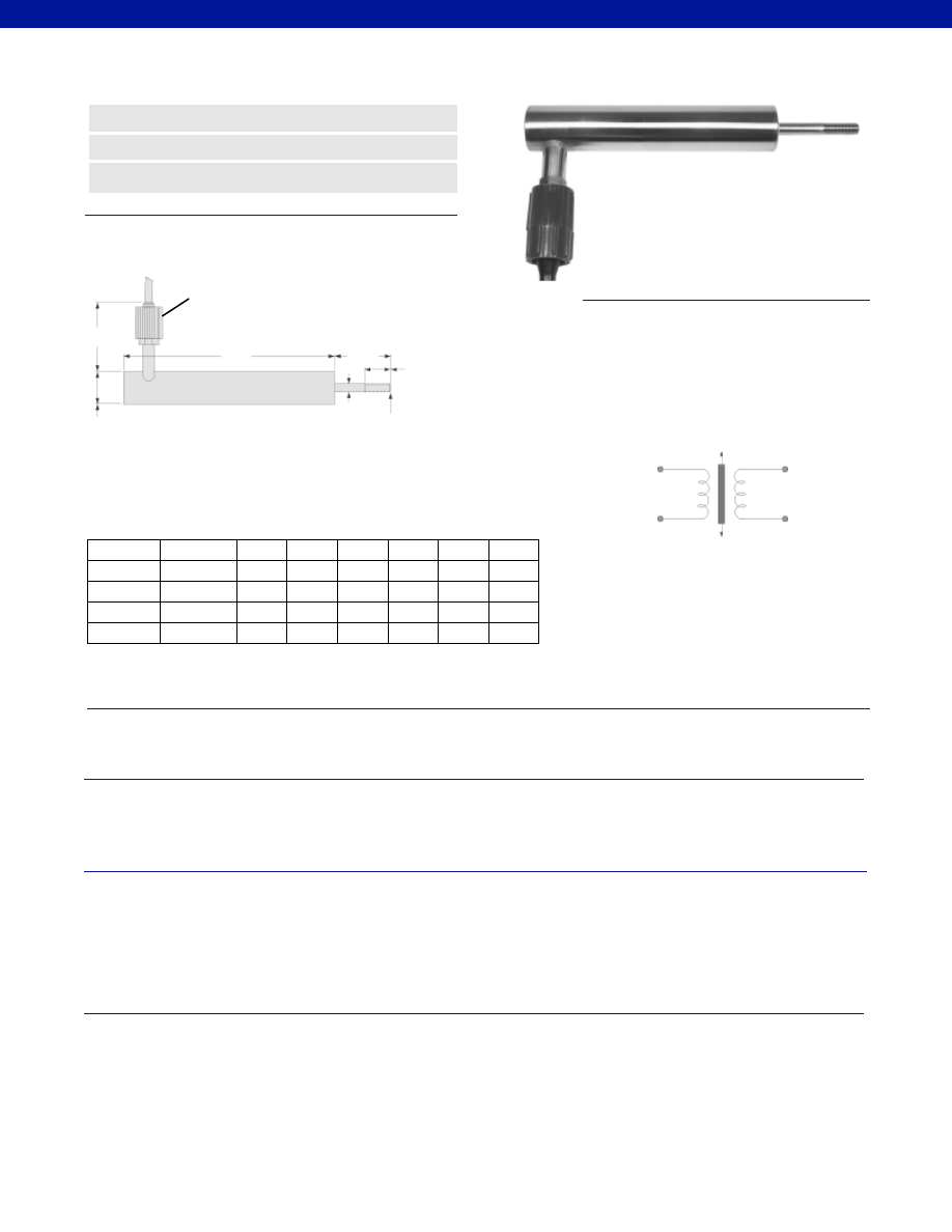
386
Stroke Range................+/- 0.5 to 4.0 in.
Non-Linearity (max.)................+/- 0.5% Full Scale
Output Sensitivity................Contact factory; 0.3 to 3 V RMS range dependent
Resolution................Infinite
Temperature, Operating................-40° to 140°F
Temperature, Effect
Zero (max.)................0.005% Full Scale/°F
Span (max.)................0.005% Full Scale/°F
Operating Pressure................3,500 psi
Element Type................AC-AC LVDT
Input Supply (acceptable)................0.5 to 7 V RMS @ 5 kHz
Ripple................Not Applicable
Electrical Termination................Includes a submersible, neoprene and nickel-aluminum bronze
connector molded to 6 ft. of neoprene jacketed 0.40 in. diameter
cable. The electrical connector may be mated uder water up to
500 psi or 1100 ft. Longer cable lengths are available up to 3,250 ft.
Contact factory for information.
Case Material................316 Stainless Steel with all welded construction
Probe Material................316 Stainless Steel with all welded construction
Probe Thread................M10 x 1.5
M10 x 1.5
Dimensions
Performance
Environmental
Electrical
Mechanical
www.honeywell.com/sensotec
n
All-Welded 316 Stainless Steel
n
Up to 7,500 ft. Depth
n
+/- 0.5 in. to +/- 4.0 in. Range
Model SSA AC-AC Sub-Sea Displacement Sensor
Order Code AY910
ø D1
ø D2
Range
Codes
Available
Stroke
Ranges
L (in.)
D1 (in.) D2 (in.) A (in.) B (in.)
X (in.)
L
A
B
X
HP
+/- 0.5 in.
8.8
2.1
1.5
0.39
3.6
1.2
HQ
+/- 1.0 in.
9.9
2.6
1.5
0.39
3.6
1.2
HR
+/- 2.0 in.
13.6
3.6
1.5
0.39
3.6
1.2
HS
+/- 3.0 in.
17.1
4.6
1.5
0.39
3.6
1.2
HT
+/- 4.0 in.
21.1
5.6
1.5
0.39
3.6
1.2
Wiring Codes
1-888-282-9891
Black
Excitation High
White
Excitation Low
Red
Signal High
Green
Signal Low
Primary Input 1
Secondary Output1
(Excitation High)
(Signal High)
Primary Coil
Secondary Coil
Primary Input 2
Secondary Output 2
(Excitation Low)
(Signal Low)
Phasing: Output is in phase with supply when the armature
is outward of th electrical zero position.
Seacon
Connector
Courtesy of Steven Engineering, Inc.-230 Ryan Way, South San Francisco, CA 94080-6370-Main Office: (650) 588-9200-Outside Local Area: (800) 258-9200-www.stevenengineering.com
Sensotec Sensors Full Line Catalog-html.html
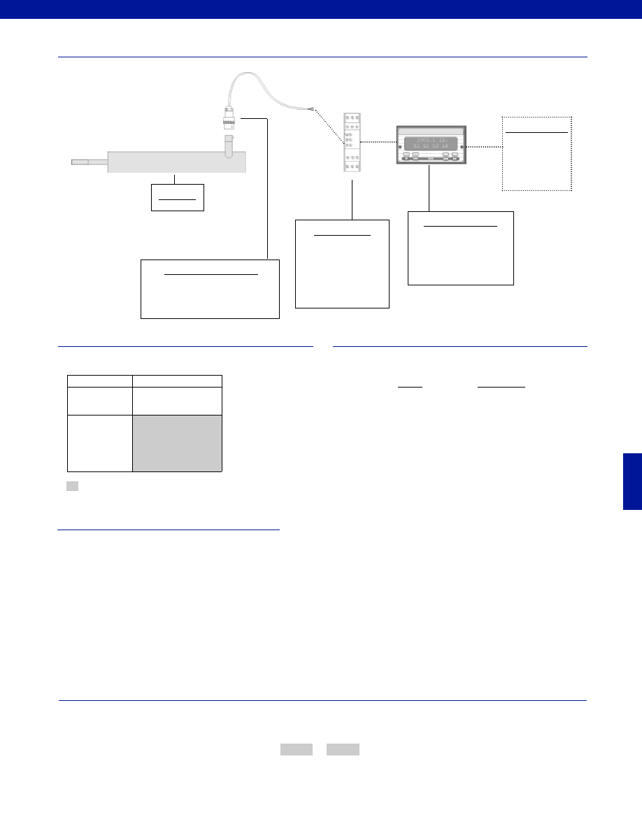
387
www.honeywell.com/sensotec
1-888-282-9891
Fast Track Delivery
Stroke Ranges
+/- 0.5 to 4.0 in.
Electrical
Termination
Submersible, neoprene
and nickel-aluminum
bronze connector molded
to 6 ft. of neoprene
jacketed cable
Typical System Diagram
Range
Range Code
+/- 0.5 in.
HP
+/- 1.0 in.
HQ
+/- 2.0 in.
HR
+/- 3.0 in.
HS
+/- 4.0 in.
HT
Range Codes
Options
How to Order
The order code consists of the product model, and the desired range code.
Model Code
Range Code
Sample Code:
AY910
HQ
Mating Connectors & Cables
Consult Factory
Model SSA
Customer Supplied
Chart Recorder
Alarm Panel
Data Acquisition
Computer
PLC
Model SSA
Supplied as standard
AC Input Display Units
DM
SC500
SC1000
SC2000
SC3004
In-Line Amplifiers
DLD-VH
DLD-CH
(Required for AC LVDT’s
and if AC input display units
are not being used)
-Not RoHS Compliant
Special Customer Requirements
(Consult Factory)
T.E.D.S. IEEE 1451.4 module
Signature Calibration
Courtesy of Steven Engineering, Inc.-230 Ryan Way, South San Francisco, CA 94080-6370-Main Office: (650) 588-9200-Outside Local Area: (800) 258-9200-www.stevenengineering.com
Sensotec Sensors Full Line Catalog-html.html
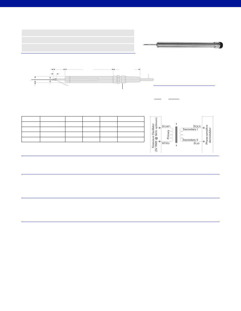
388
Dimensions
Performance
Environmental
Electrical
Mechanical
www.honeywell.com/sensotec
n
Submersible
n
Stainless Steel
n
3 Armature Designs
Model LW7C AC-AC Submersible* LVDT
Order Code AY201
*Not recommended for salt water use. Consult Factory for saltwater submersible applications.
2.44 in.
ø 0.812 in.
ø 0.187 in.
Range
Codes
Available
Stroke Ranges
L (in.)
X (in.)
Weight
Armature
(oz.)
Typical F.S.
Output at
5V RMS
X Nominal
Electric Zero Point
M5 x 0.8
2-Nuts & 2-Washers
Supplied
Submersible Connector
4-Conductor,
Cable 16.5ft. long
L
0.06 in.
HP
+/- 0.5 in.
6.02
1.5
0.75
3.5V RMS
HQ
+/- 1.0 in.
7.12
2.5
1.0
4.5V RMS
HR
+/- 2.0 in.
11.97
3.0
1.5
7.6V RMS
HS
+/- 3.0 in.
16.53
4.5
3.0
7.5V RMS
HT
+/- 4.0 in.
17.83
5.0
3.7
16.05V RMS
Wiring Codes
Wire
Supply
Brown
Supply
White
Supply Return
Blue
Output
Black
Output Return
Stroke Range................+/- 0.5 to 4.0 in.
Non-Linearity (max.)................+/- 0.25% Full Scale
Output Sensitivity................See table above
Resolution................Infinite
Temperature, Operating................-40° to 194°F
Temperature, Effect
Zero (max.)................0.005% Full Scale/°F
Span (max.)................0.005% Full Scale/°F
Pressure Rating, Std.................150 psi, up to 3,000 psi with cable options
Element Type................AC-AC LVDT
Input Supply (calibrated)................3 V RMS @ 5 kHz
Input Supply (acceptable)................1-7 V RMS @ 5 kHz
Output Load (min.)................100,000 Ohms
Electrical Termination................Submersible mating connector with 16.5’ cable
Material................Stainless Steel
Probe Material................Stainless Steel
Armature Type................Captive Guided
Probe Thread................M5 x 0.8
Spring Force (max.)................Not Applicable
1-888-282-9891
Courtesy of Steven Engineering, Inc.-230 Ryan Way, South San Francisco, CA 94080-6370-Main Office: (650) 588-9200-Outside Local Area: (800) 258-9200-www.stevenengineering.com
Sensotec Sensors Full Line Catalog-html.html
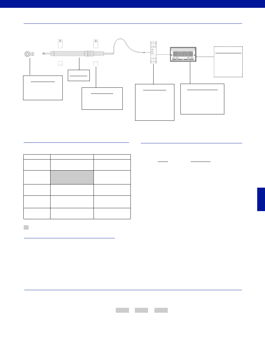
389
www.honeywell.com/sensotec
1-888-282-9891
Special Customer Requirements
(Consult Factory)
How to Order
The order code consists of the product model, the desired range code and the available options.
Model Code
Range Code
Options Code
Sample Code:
AY201
HQ
L10
Mineral insulated welded stainless steel sheathed cable
0.12” diameter cable
1 to 164 ft. lengths available
-67° to 390° F
3,000 psi
T.E.D.S. IEEE 1451.4 module
Signature Calibration
Supplied as standard
Model LW7C
Typical System Diagram
Range
Range Code
+/- 0.5 in.
HP
+/- 1.0 in.
HQ
+/- 2.0 in.
HR
+/- 3.0 in.
HS
+/- 4.0 in.
HT
Range Codes
Options
Model LW7C
AC Input Display Units
DM
SC500
SC1000
SC2000
SC3004
In-Line Amplifiers
DLD-VH
DLD-CH
(Required for AC LVDT’s
and if AC input display units
are not being used)
Customer Supplied
Chart Recorder
Alarm Panel
Data Acquisition
Computer
PLC
Mounting Blocks
AA937
Fast Track Delivery
Built to Order
Stroke Ranges
+/- 0.5 to 4.0 in.
Electrical
Termination
Multiconductor
Shielded Cable (6 ft.)
OPT1. No connector or
cable, terminated with
soldier pins
Electrical Cable
Orientation
OPT7. Radial outlet sub-
mersible connector with
16.5’ cable
Improved
Linearity
L10. +/- 0.1% max. linearity
(less than or equal to +/- 4 in.)
Higher
Temperature
TM315. 400° F (less than
or equal to +/- 4 In)
Mounting Options
Rod End Bearing
-Not RoHS Compliant
Courtesy of Steven Engineering, Inc.-230 Ryan Way, South San Francisco, CA 94080-6370-Main Office: (650) 588-9200-Outside Local Area: (800) 258-9200-www.stevenengineering.com
Sensotec Sensors Full Line Catalog-html.html
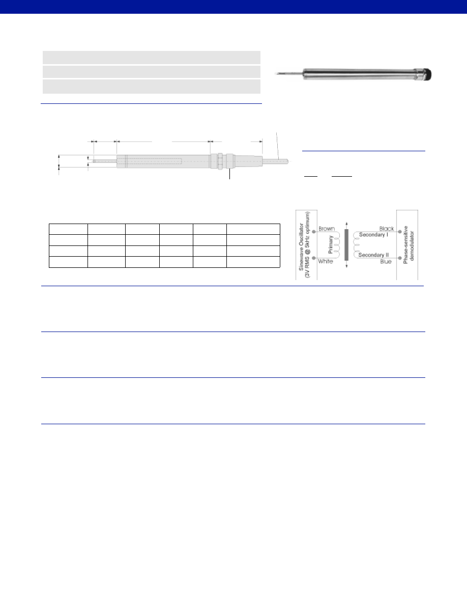
390
Dimensions
Performance
Environmental
Electrical
Mechanical
www.honeywell.com/sensotec
n
Submersible
n
Stainless Steel
n
+/- 0.5 to +/- 3.0 in. Range
2.44 in.
ø 0.812 in. ø 0.187 in.
Range
Codes
Available
Stroke
Ranges
L (in.)
X (in.)
Spring
Force
(oz.-in.)
Typical F.S.
Output at 5V RMS
X Nominal
Electric Zero Point
Submersible Connector
4-Conductor,
Cable 16.5ft. long
L
Model LW7S AC-AC Submersible* LVDT
Order Code AY202
*Not recommended for salt water use. Consult Factory for saltwater submersible applications.
HP
+/- 0.5 in.
6.02
1.5
4
3.5V RMS
HQ
+/- 1.0 in.
7.12
2.5
4
4.5V RMS
HR
+/- 2.0 in.
11.97
3.0
4
7.6V RMS
HS
+/- 3.0 in.
16.53
4.5
4
7.5V RMS
Wiring Codes
Wire
Supply
Brown
Supply
White
Supply Return
Blue
Output
Black
Output Return
Stroke Range................+/- 0.5 to 3.0 in.
Non-Linearity (max.)................+/- 0.25% Full Scale
Non-Repeatability (max.)................<20 microinches
Output Sensitivity................See table above
Resolution................Infinite
Temperature, Operating................-40° to 194°F
Temperature, Effect
Zero (max.)................0.005% Full Scale/°F
Span (max.)................0.005% Full Scale/°F
Pressure Rating, Std.................150 psi, up to 3,000 psi with cable options
Element Type................AC-AC LVDT
Input Supply (calibrated)................3 V RMS @ 5 kHz
Input Supply (acceptable)................1-7 V RMS @ 5 kHz
Output Load (min.)................100,000 Ohms
Electrical Termination................Submersible mating connector with 16.5’ cable
Material................Stainless Steel
Probe Material................Stainless Steel
Armature Type................Captive Guided Spring Return
Probe Thread................Not Applicable
Spring Force (max.)................4 oz./ in.
1-888-282-9891
Courtesy of Steven Engineering, Inc.-230 Ryan Way, South San Francisco, CA 94080-6370-Main Office: (650) 588-9200-Outside Local Area: (800) 258-9200-www.stevenengineering.com
Sensotec Sensors Full Line Catalog-html.html

391
www.honeywell.com/sensotec
1-888-282-9891
Typical System Diagram
Range
Range Code
+/- 0.5 in.
HP
+/- 1.0 in.
HQ
+/- 2.0 in.
HR
+/- 3.0 in.
HS
Range Codes
Special Customer Requirements
(Consult Factory)
Options
How to Order
The order code consists of the product model, the desired range code and the available options.
Model Code
Range Code
Options Code
Sample Code:
AY202
HQ
L10
Mineral insulated welded stainless steel sheathed cable
0.12” diameter cable
1 to 164 ft. lengths available
-67° to 390° F
3,000 psi
T.E.D.S. IEEE 1451.4 module
Signature Calibration
Model LW7S
AC Input Display Units
DM
SC500
SC1000
SC2000
SC3004
In-Line Amplifiers
DLD-VH
DLD-CH
(Required for AC LVDT’s
and if AC input display units
are not being used)
Customer Supplied
Chart Recorder
Alarm Panel
Data Acquisition
Computer
PLC
Mounting Blocks
AA937
Supplied as standard
Model LW7S
Probe Tip Assemblies
Radiused probe
Ball ended probe
Fast Track Delivery
Built to Order
Stroke Ranges
+/- 0.5 to 3.0 in.
Electrical
Termination
Multiconductor
Shielded Cable (6 ft.)
OPT1. No connector or
cable, terminated with
soldier pins
Electrical Cable
Orientation
OPT7. Radial outlet sub-
mersible connector with
16.5’ cable
Improved
Linearity
L10. +/- 0.1% max. linearity
(less than or equal to +/- 4 in.)
Higher
Temperature
TM315. 400° F
-Not RoHS Compliant
Courtesy of Steven Engineering, Inc.-230 Ryan Way, South San Francisco, CA 94080-6370-Main Office: (650) 588-9200-Outside Local Area: (800) 258-9200-www.stevenengineering.com
Sensotec Sensors Full Line Catalog-html.html
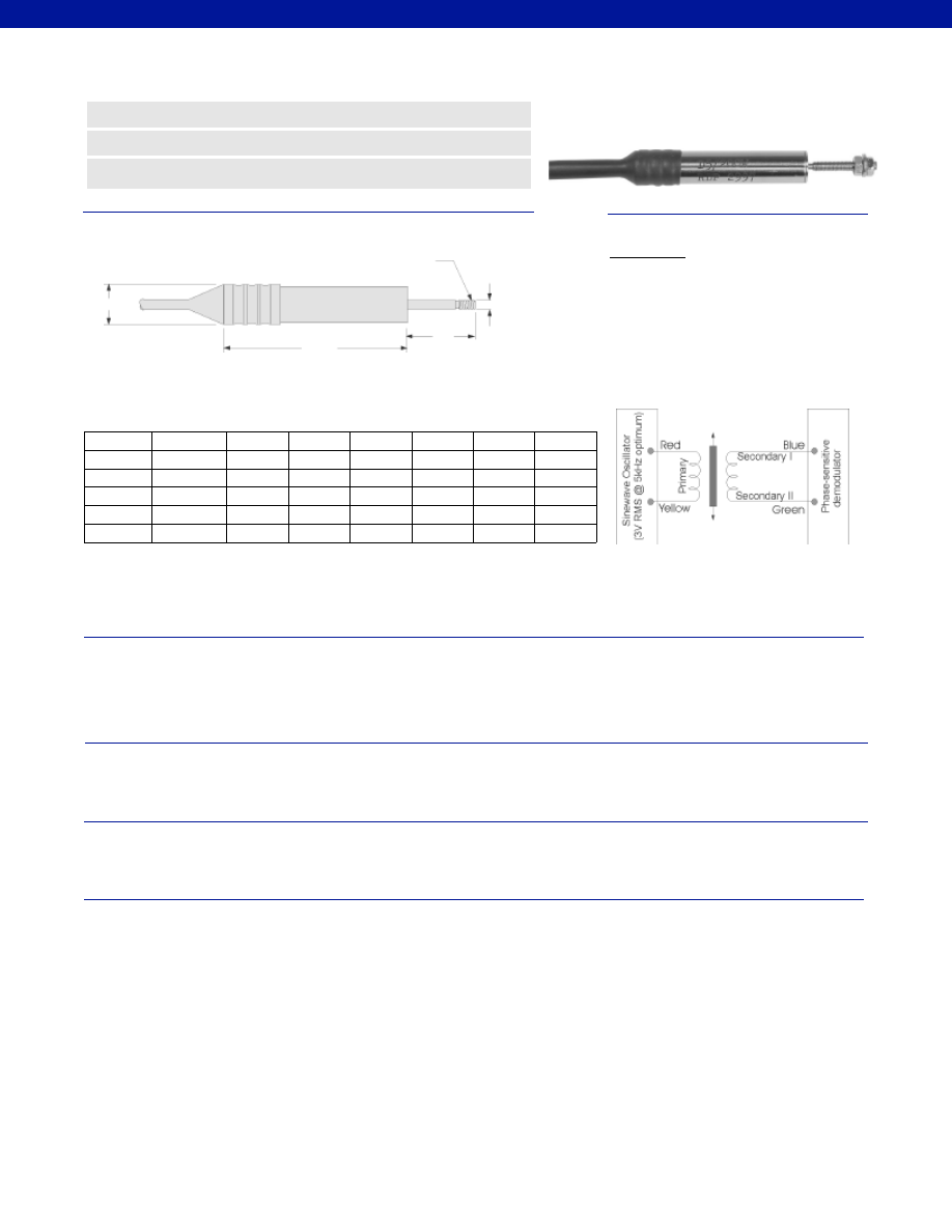
392
Stroke Range................+/- 0.04 to 0.50 in.
Non-Linearity (max.)................+/- 0.25% Full Scale
Non-repeatability................< 10 microinches
Output Sensitivity................2 mV/V/ 0.001”
Output Load (min.)................100,000 Ohm
Resolution................Infinite
Temperature, Operating................-4° to 257°F
Temperature, Effect
Zero (max.)................0.006% Full Scale/°F
Span (max.)................0.006% Full Scale/°F
Element Type................AC-AC LVDT
Input Supply (calibrated)................5V RMS @ 5 kHz
Input Supply (acceptable)................1-7V RMS @ 2-10 kHz
Electrical Termination................Hermetically sealed waterproof cable (6 ft.)
Case Material................Stainless Steel
Probe Material................Stainless Steel
Armature Type................Free Unguided
Probe Thread................M3 x 0.5
Dimensions
Performance
Environmental
Electrical
Mechanical
www.honeywell.com/sensotec
n
Waterproof Design
n
Withstands 250 psi
n
+/- 0.04 to +/- 0.50 in. Range
Model MS7A AC-AC Submersible* LVDT
Order Code BY921
* Not recommended for salt water use.
** Dimensions at “X” at nominal electrical zero
*** Excluding cable
øD
ø D1
Range
Codes
Available
Stroke
Ranges
L (in.)
X (in.)**
D (in.)
D1 (in.)
Weight
Armature
(oz.)
Total
Weight***
M3 x 0.5
L
X
HK
+/- 0.04 in.
1.61
0.315
0.669
0.092
0.90 oz.
0.13
HM
+/- 0.10 in.
1.85
0.375
0.708
0.092
1.00 oz.
0.20
HN
+/- 0.20 in.
1.98
0.375
0.900
0.092
1.15 oz.
0.25
HF
+/- 0.30 in.
2.75
0.375
1.150
0.092
1.60 oz.
0.35
HG
+/- 0.40 in.
2.91
0.375
1.280
0.092
1.70 oz.
0.37
HP
+/- 0.50 in.
3.54
0.375
1.375
0.092
2.10 oz.
0.45
Wiring Codes
Connections
Red
Supply (calibrated @ 3V RMS 5 kHz)
Yellow
Supply Return
Blue
Output
Green Output
Return
Black
Secondary Center Tap
(normally not connected)
Cable shield is not connected to transducer
1-888-282-9891
Courtesy of Steven Engineering, Inc.-230 Ryan Way, South San Francisco, CA 94080-6370-Main Office: (650) 588-9200-Outside Local Area: (800) 258-9200-www.stevenengineering.com
Sensotec Sensors Full Line Catalog-html.html
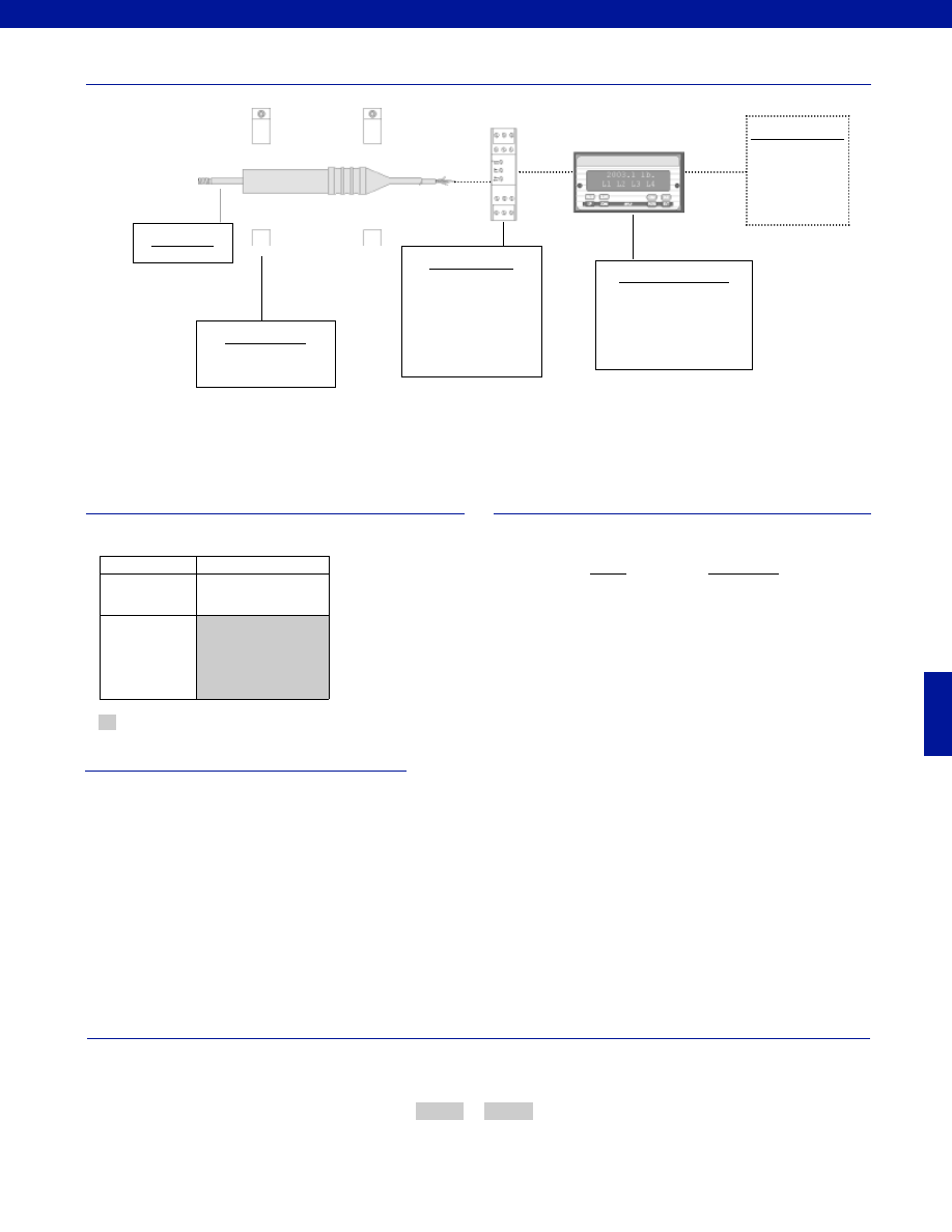
393
www.honeywell.com/sensotec
1-888-282-9891
Fast Track Delivery
Stroke Ranges
+/- 0.04 to 0.50 in.
Electrical
Termination
Hermetically sealed
waterproof cable (6 ft.)
Typical System Diagram
Range
Range Code
+/- 0.04 in.
HK
+/- 0.10 in.
HM
+/- 0.20 in.
HN
+/- 0.30 in.
HF
+/- 0.40 in.
HG
+/- 0.50 in.
HP
Range Codes
Options
How to Order
The order code consists of the product model and the desired range code.
Model Code
Range Code
Sample Code:
BY921
HP
Model MS7A
Customer Supplied
Chart Recorder
Alarm Panel
Data Acquisition
Computer
PLC
Mounting Blocks
AA945
Model MS7A
Supplied as standard
AC Input Display Units
DM
SC500
SC1000
SC2000
SC3004
In-Line Amplifiers
DLD-VH
DLD-CH
(Required for AC LVDT’s
and if AC input display units
are not being used)
-Not RoHS Compliant
Special Customer Requirements
(Consult Factory)
T.E.D.S. IEEE 1451.4 module
Signature Calibration
Courtesy of Steven Engineering, Inc.-230 Ryan Way, South San Francisco, CA 94080-6370-Main Office: (650) 588-9200-Outside Local Area: (800) 258-9200-www.stevenengineering.com
Sensotec Sensors Full Line Catalog-html.html
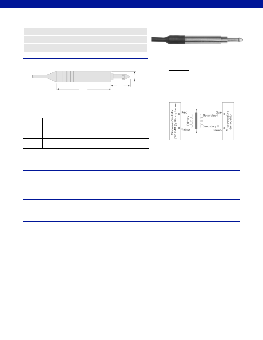
394
Stroke Range................+/- 0.04 to 0.50 in.
Non-Linearity (max.)................+/- 0.25% Full Scale
Non-repeatability................< 10 microinches
Output Sensitivity................2 mV/V/ 0.001”
Output Load................100,000 Ohm
Resolution................Infinite
Temperature, Operating................-4° to 257°F
Temperature, Effect
Zero (max.)................0.006% Full Scale/°F
Span (max.)................0.006% Full Scale/°F
Element Type................AC-AC LVDT
Input Supply (calibrated)................5V RMS @ 5 kHz
Input Supply (acceptable)................1-7V RMS @ 2-10 kHz
Electrical Termination................Hermetically sealed waterproof cable (6 ft.)
Case Material................Stainless Steel
Probe Material................Stainless Steel
Armature Type................Captive Guided Spring Return
Probe Thread................Not Applicable
Dimensions
Performance
Environmental
Electrical
Mechanical
www.honeywell.com/sensotec
n
Waterproof Design
n
Withstands 250 psi
n
+/- 0.04 to +/- 0.50 in. Range
Model S7C AC-AC Submersible* LVDT
Order Code BY912
*
Not recommended for salt water use.
** Dimensions at “X” at nominal electrical zero
*** Excluding cable
øD
Range
Codes
Available
Stroke
Ranges
L (in.)
X (in.)**
D (in.)
Maximum
Spring
Force
Total
Weight***
L
X
HK
+/- 0.04 in.
2.00
0.315
0.45
1.8 oz.
7.5 oz.
HM
+/- 0.10 in.
2.52
0.375
0.46
2.9 oz.
5.0 oz.
HN
+/- 0.20 in.
2.75
0.375
0.48
2.9 oz.
5.0 oz.
HF
+/- 0.30 in.
3.75
0.375
0.72
3.9 oz.
5.0 oz.
HG
+/- 0.40 in.
4.19
0.375
0.87
4.4 oz.
5.0 oz.
HP
+/- 0.50 in.
5.08
0.375
0.97
5.4 oz.
5.0 oz.
Wiring Codes
Connections
Red
Supply (calibrated @ 3V RMS 5 kHz)
Yellow
Supply Return
Blue
Output
Green Output
Return
Black
Secondary Center Tap
(normally not connected)
Cable shield is not connected to transducer
1-888-282-9891
Courtesy of Steven Engineering, Inc.-230 Ryan Way, South San Francisco, CA 94080-6370-Main Office: (650) 588-9200-Outside Local Area: (800) 258-9200-www.stevenengineering.com
Sensotec Sensors Full Line Catalog-html.html

395
www.honeywell.com/sensotec
1-888-282-9891
Fast Track Delivery
Stroke Ranges
+/- 0.04 to 0.50 in.
Electrical
Termination
Hermetically sealed
waterproof cable (6 ft.)
Typical System Diagram
Range
Range Code
+/- 0.04 in.
HK
+/- 0.10 in.
HM
+/- 0.20 in.
HN
+/- 0.30 in.
HF
+/- 0.40 in.
HG
+/- 0.50 in.
HP
Range Codes
Options
How to Order
The order code consists of the product model, the desired range code and the available options.
Model Code
Range Code
Sample Code:
BY912
HP
Model S7C
Customer Supplied
Chart Recorder
Alarm Panel
Data Acquisition
Computer
PLC
Model S7C
Supplied as standard
AC Input Display Units
DM
SC500
SC1000
SC2000
SC3004
In-Line Amplifiers
DLD-VH
DLD-CH
(Required for AC LVDT’s
and if AC input display units
are not being used)
Probe Tip Assemblies
Radiused probe
Ball ended probe
Mounting Blocks
AA945
-Not RoHS Compliant
Special Customer Requirements
(Consult Factory)
T.E.D.S. IEEE 1451.4 module
Signature Calibration
Courtesy of Steven Engineering, Inc.-230 Ryan Way, South San Francisco, CA 94080-6370-Main Office: (650) 588-9200-Outside Local Area: (800) 258-9200-www.stevenengineering.com
Sensotec Sensors Full Line Catalog-html.html

396
www.honeywell.com/sensotec
1-888-282-9891
The following factors should be considered when selecting an LVDT:
1. Measurement range.
2. Armature type.
3. AC-AC vs. DC-DC.
4. Environment.
LVDTs are available with ranges from ±.01" to ±18.5". An LVDT with a ±18.5" range can be
used in one direction to measure up to 37". If accuracy is important, the range selected
should not be any larger than necessary.
Three armature types are available: free unguided armatures, captive guided spring return
armatures, and captive guided armatures.
Free unguided armatures are recommended for applications in which the target being
measured moves parallel to the transducer body as well as those which require frequent or
continuous measurements. This armature type is well suited for dynamic applications.
When using a free unguided armature, the armature and the LVDT body must be mounted
so that their correct relative positions are maintained. This type of LVDT features an
armature/threaded push rod assembly which is completely separable from the LVDT body.
Since the free unguided armature involves no mechanical coupling between the armature
and the LVDT body, there are no springs or bearings to fatigue. This unit often has a
virtually unlimited fatigue life.
Captive guided spring return armatures are often well suited for those applications requiring
the measurement of multiple targets or applications in which the target moves transverse to
the armature and changes in a structure’s surface are being measured. In this type of
LVDT, the armature moves over bearings in the LVDT body. The armature is biased by an
internal spring so that the ball-ended probe bears against the surface of the target whose
displacement is being measured. The LVDT is held in position by clamping the body alone.
The armature is not attached to the target being measured.
Captive guided armatures are designed for applications requiring a longer working range.
The armature moves freely over machined bearings but cannot be removed from the body.
The LVDT body has a threaded mounting hole and the armature is attached to the structure
being measured. The armature end is threaded so that special adapters such as spherical
bearings or rollers can be attached.
The major advantages of DC-DC LVDTs are the ease of installation, the ability to operate
from dry cell batteries in remote locations, and lower system cost, which AC-AC LVDT
advantages include enhanced accuracy and a smaller body size.
An AC-AC LVDT can be equipped with more sophisticated electronics such as Sensotec’s
SC instrumentation. The SC instrument provides an AC power supply, a phase sensitive
demodulator, a scaling amplifier and DC output. The AC-AC LVDT system has less residual
noise at minimum readings that DC-DC units which utilize internal electronics.
For applications involving very high humidity or requiring submersion of the LVDT, a
submersible LVDT is required. Submersible units are available for either AC-AC or DC-DC
operation and with free unguided or captive spring return armatures.
The unit selected should also operate and survive at the temperatures dictated by the
application. Note that AC-AC units will operate at higher temperatures (up to 257°F) than
the DC-DC units (up to 158°F) which have internal electronics.
Side loads must be kept to a minimum since they will cause rubbing between the armature
and the LVDT body. This friction will cause excessive wear of bearings and parts and in
extreme cases, the armature may bend. At a minimum, side loads will reduce the unit’s life
and accuracy.
Mounting blocks come in two sizes. The large size (Order Code AA937) accomodates LVDTs
with an outside diameter of 0.80” (20.6mm). The small size (Order Code AA945) is for units
with outside diameters of 0.37” (9.5mm) or 0.32” (8mm). The mounting blocks are designed
to be bolted to a flat surface. The sensor is clamped with a captive cap head screw. Two
mounting cap screws are furnished. Both units are made from glass filled nylon and have an
operating temperature of -20° to 230°F. Strokes up to 0.4” require 1 mounting block, strokes
over 0.5” require 2 mounting blocks. See Accessories section of Appendix for outline and
dimensional drawings.
LVDT Selection Considerations
Measurement Range
Armature Type
AC-AC vs. DC-DC
Environment
Side Loads
Mounting Block
Courtesy of Steven Engineering, Inc.-230 Ryan Way, South San Francisco, CA 94080-6370-Main Office: (650) 588-9200-Outside Local Area: (800) 258-9200-www.stevenengineering.com
Sensotec Sensors Full Line Catalog-html.html
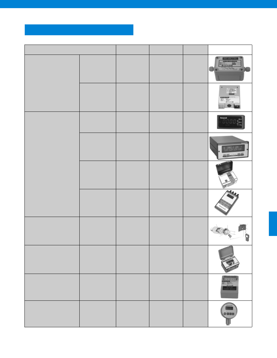
397
INSTRUMENTS
Potential Application
Model
Order Code
Page
In-Line Amplifiers
Plastic or Die Cast
UV
UV-10
UBP
U3W
U2W
CA2/CA3
BE124
BE127
BE123
BE125
BE128
AE411/AE413
398
399
400
401
402
403
DIN Rail Mount
DV-05
DA-05
DV-10
DLD-VH
DLD-CH
BE151
BE153
BE155
BE152
BE154
404
406
408
410
411
Display &
Conditioning Units
Single Channel
DM
GM
GM-A
SC500
AE214
AE213
AE216
AE236-AE238
412
414
417
419
Multi-Channel
SC1000
SC2000
SC3004
see datasheet
see datasheet
see datasheet
423
423
428
Portable
SC2001
NK
see datasheet
AE221
433
434
Hand Held
HH
AE222
436
Temperature
Monitoring Systems
1400 Series
1700 Series
WK1000,WK1100
see datasheet
438
439
Diagnostic &
Calibration
TS
AE415
443
Power Supplies
CC2
DC Power Supply
AE412
AA951-AA957
444
445
Digital Gages
JK
LK
see datasheet
see datasheet
446
447
www.honeywell.com/sensotec
1-888-282-9891
Courtesy of Steven Engineering, Inc.-230 Ryan Way, South San Francisco, CA 94080-6370-Main Office: (650) 588-9200-Outside Local Area: (800) 258-9200-www.stevenengineering.com
Sensotec Sensors Full Line Catalog-html.html
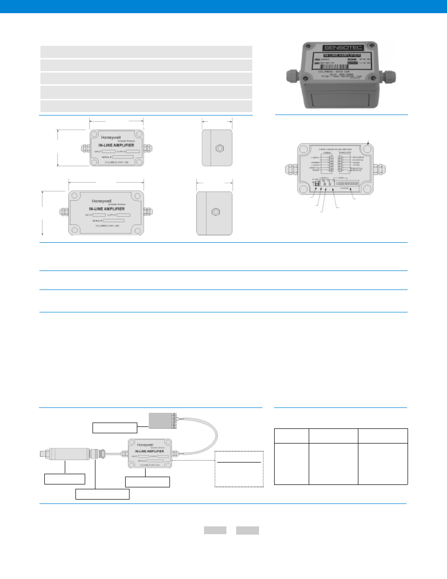
398
www.honeywell.com/sensotec
1-888-282-9891
Model UV Bridge Based Sensor In-Line Amplifier
Order Code BE124
n
Strain Gage Sensor Amplifier
n
11-28 VDC Supply Voltage
n
NEMA 4 Housing
n
Selectable Excitation Voltages
n
+/-5 VDC 3 Wire Output
Dimensions
General
Environmental
Transducer Interface
Amplifier Characteristics
Typical System Diagrams
Number of Channels................1
Case Material................Plastic or Painted Aluminum
Mounting................Use #6 or #8 Screws
Temperature, Operating................5° to 122° F
Sealing................IP-66 or NEMA-4
Transducer Type................Bridge based sensor
Transducer Excitation................3 or 5 VDC @ 70 mA
Supply Voltage................11-28 VDC
Current Draw................70 mA
Frequency Response (-3db)................DC to 5,000 Hz
Zero Adjustment Range
Coarse................+/- 50%
Fine................+/- 15%
Spand Adjustment Range................0.5 - 5 mV/V +/- 25% fine adjustment
Linearity................0.02% of Full Scale
Shunt Calibration................Solid state relay on board
Output................+/- 5VDC
Output Current................2 mA max.
Signal to Noise Ratio................65 db
DC Power Supply Rejection Ration................> 110 db
Model Code
Filter Setting
The order code consists of the product model and the available filter setting.
How to Order
3.0 in.
To Readout
To Transducer
Panel Mounting Holes
Use #6 or # 6 Screws
5.0 in.
2.5 in.
Excitation Selector
Coarse Zero
Fine Zero
Fine Gain
Coarse Gain
3.75 in.
2.5 in.
2.1 in.
2 Pole Active
Filter
Built to Order
Built from Scratch
Filter Setting
1 Hz
50 Hz
3 Hz
100 Hz
5 Hz
300 Hz
10 Hz
500 Hz
20 Hz
1,000 Hz
30 Hz
User Specified
Sample Code
BE124 30Hz
Customer Supplied
Chart Recorder
Data Acquisition
Power Source
Model UV
Mating Connector
Sensor
Options
Plastic
Aluminum
-Not RoHS Compliant
Courtesy of Steven Engineering, Inc.-230 Ryan Way, South San Francisco, CA 94080-6370-Main Office: (650) 588-9200-Outside Local Area: (800) 258-9200-www.stevenengineering.com
Sensotec Sensors Full Line Catalog-html.html
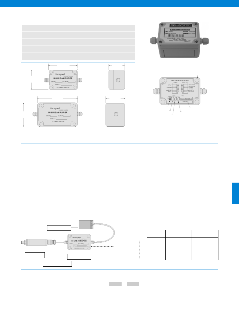
399
www.honeywell.com/sensotec
1-888-282-9891
Model UV-10 Bridge Based Sensor In-Line Amplifier
Order Code BE127
n
Strain Gage Sensor Amplifier
n
18-32 VDC Supply Voltage
n
NEMA 4 Housing
n
Selectable Excitation Voltages
n
+/-10 VDC 3 Wire Output
Dimensions
General
Environmental
Transducer Interface
Amplifier Characteristics
Typical System Diagrams
Number of Channels................1
Case Material................Plastic or Painted Aluminum
Mounting................Use #6 or #8 Screws
Temperature, Operating................5° to 122° F
Sealing................IP-66 or NEMA-4
Transducer Type................Bridge based sensor
Transducer Excitation................3, 5 or 10 VDC @ 50 mA
Supply Voltage................18-32 VDC
Current Draw................50 mA
Frequency Response (-3db)................DC to 5,000 Hz
Zero Adjustment Range
Coarse................+/- 25%
Fine................+/- 10%
Spand Adjustment Range................1 - 20 mV/V
Linearity................0.02% of Full Scale
Shunt Calibration................Solid state relay on board
Output................+/- 10VDC
Output Current................2.5 mA
Signal to Noise Ratio................65 db
DC Power Supply Rejection Ration................> 110 db
Model Code
Filter Setting
The order code consists of the product model and the available filter setting.
How to Order
Plastic
Aluminum
3.0 in.
To Readout
To Transducer
Panel Mounting Holes
Use #6 or # 6 Screws
5.0 in.
2.5 in.
Excitation Selector
Coarse Zero
Fine Zero
Fine Gain
Coarse Gain
3.75 in.
2.5 in.
2.1 in.
2 Pole Active
Filter
Built to Order
Built from Scratch
Filter Setting
1 Hz
50 Hz
3 Hz
100 Hz
5 Hz
300 Hz
10 Hz
500 Hz
20 Hz
1,000 Hz
30 Hz
User Specified
Sample Code
BE127 30 Hz
Customer Supplied
Chart Recorder
Data Acquisition
Power Source
Model UV-10
Mating Connector
Sensor
Options
-Not RoHS Compliant
Courtesy of Steven Engineering, Inc.-230 Ryan Way, South San Francisco, CA 94080-6370-Main Office: (650) 588-9200-Outside Local Area: (800) 258-9200-www.stevenengineering.com
Sensotec Sensors Full Line Catalog-html.html
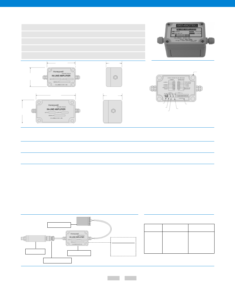
400
www.honeywell.com/sensotec
1-888-282-9891
Model UBP Universal Bi-Polar In-Line Amplifier
Order Code BE123
n
For Replacement Only, Not to be Used in New Design
n
+/- 15 VDC Supply Voltage
n
NEMA 4 Housing
n
Selectable Excitation Voltages
n
+/-5 VDC Output
Dimensions
General
Environmental
Transducer Interface
Amplifier Characteristics
Typical System Diagrams
Number of Channels................1
Case Material................Plastic or Painted Aluminum
Mounting................Use #6 or #8 Screws
Temperature, Operating................-20° to 158° F
Sealing................IP-66 or NEMA-4
Transducer Type................Bridge based sensor
Transducer Excitation................3, 5 or 10 VDC @ 70 mA
Supply Voltage................+/- 15 VDC
Current Draw................70 mA
Frequency Response (-3db)................DC to 5,000 Hz
Zero Adjustment Range
Coarse................+/- 50%
Fine................+/- 15%
Span Adjustment Range................0.5 - 10 mV/V
Linearity................0.01% of Full Scale
Shunt Calibration................Solid state relay on board
Signal Output................+/- 5 VDC
Output Current................1 mA max.
Signal to Noise Ratio................65 db
DC Power Supply Rejection Ratio................> 110 db
Model Code
Filter Setting
The order code consists of the product model and the available filter setting.
How to Order
Plastic
Aluminum
3.0 in.
To Readout
To Transducer
Panel Mounting Holes
Use #6 or #8 Screws
5.0 in.
2.5 in.
Excitation Selector
Coarse Zero
Fine Zero
Fine Gain
Coarse Gain
3.75 in.
2.5 in.
2.1 in.
2 Pole Active
Filter
Built to Order
Built from Scratch
Filter Setting
3 Hz
50 Hz
5 Hz
100 Hz
10 Hz
300 Hz
20 Hz
500 Hz
30 Hz
1,000 Hz
User Specified
Sample Code
BE123 30Hz
Customer Supplied
Chart Recorder
Data Acquisition
Power Source
Model UBP
Mating Connector
Sensor
Options
-Not RoHS Compliant
Courtesy of Steven Engineering, Inc.-230 Ryan Way, South San Francisco, CA 94080-6370-Main Office: (650) 588-9200-Outside Local Area: (800) 258-9200-www.stevenengineering.com
Sensotec Sensors Full Line Catalog-html.html

401
www.honeywell.com/sensotec
1-888-282-9891
Model U3W Bridge Based Sensor In-Line Amplifier
Order Code BE125
n
Strain Gage Sensor Amplifier
n
18-32 VDC Supply Voltage
n
NEMA 4 Housing
n
Selectable Excitation Voltages
n
4-20 mA Analog Output
Dimensions
General
Environmental
Transducer Interface
Amplifier Characteristics
Typical System Diagram
Number of Channels................1
Case Material................Plastic or Painted Aluminum
Mounting................Use #6 or #8 Screws
Temperature, Operating................5° to 122° F
Sealing................IP-66 or NEMA-4
Transducer Type................Bridge based sensor
Transducer Excitation................3 or 5 VDC @ 70 mA
Supply Voltage................18-32 VDC
Current Draw................70 mA
Frequency Response (-3db)................DC to 5,000 Hz
Zero Adjustment Range
Coarse................+/- 70%
Fine................+/- 25%
Span Adjustment Range................0.5 - 6.6 mV/V +/- 25% fine adjustment
Linearity................0.02% of Full Scale
Shunt Calibration................Solid state relay on board
Signal Output................4-20 mA (3 wire)
Signal to Noise Ratio................65 db
DC Power Supply Rejection Ratio................> 110 db
Model Code
Filter Setting
The order code consists of the product model and the available filter setting.
How to Order
Plastic
Aluminum
3.0 in.
To Readout
To Transducer
Panel Mounting Holes
Use #6 or #8 Screws
5.0 in.
2.5 in.
Excitation Selector
Coarse Zero
Fine Zero
Fine Gain
Coarse Gain
3.75 in.
2.5 in.
2.1 in.
2 Pole Active
Filter
Built to Order
Built from Scratch
Filter Setting
3 Hz
50 Hz
5 Hz
100 Hz
10 Hz
300 Hz
20 Hz
500 Hz
30 Hz
1,000 Hz
User Specified
Sample Code
BE125 30Hz
Customer Supplied
Chart Recorder
Data Acquisition
Power Source
Model U3W
Mating Connector
Sensor
Options
-Not RoHS Compliant
Courtesy of Steven Engineering, Inc.-230 Ryan Way, South San Francisco, CA 94080-6370-Main Office: (650) 588-9200-Outside Local Area: (800) 258-9200-www.stevenengineering.com
Sensotec Sensors Full Line Catalog-html.html
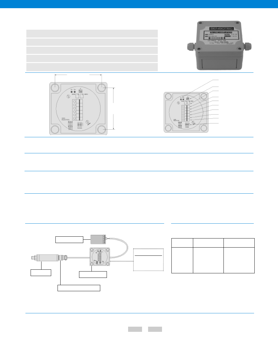
402
3.11 in.
3.11 in.
.04 volts = 4 mA
Test Points
.02 volts = 20 mA
Excitation type select
Span and zero fine adjust
+Output (4-20 mA)
+ Power supply (8-32 volts)
- Excitation (Black)
+ Excitation (Red)
- Input (Green)
+ Input (White)
Earth Ground
Coarse gain jumper
www.honeywell.com/sensotec
1-888-282-9891
Model U2W Bridge Based Sensor In-Line Amplifier
Order Code BE128
n
Strain Gage Sensor Amplifier
n
8-32 VDC Supply Voltage
n
NEMA 4 or IP-66 Housing
n
Lightning Protection
n
4-20 mA Analog Output
Dimensions
General
Environmental
Transducer Interface
Amplifier Characteristics
Typical System Diagrams
Number of Channels................1
Case Material................Plastic or Painted Aluminum
Mounting................Use #6 or #8 Screws
Temperature, Operating................-20° to 158° F
Sealing................IP-66 or NEMA-4
Lightning Protection................Yes
Transducer Type................Bridge based sensor
Transducer Bridge Excitation & Resistance
Constant Voltage Mode................5 VDC @ 2 mA max.; 3k to 10 k Ohms
Constant Current Mode................0.5 mA with 3 V compliance; 2k to 6k Ohms
Supply Voltage................8-32 VDC
Frequency Response................1 kHz @ 2mV/V
Zero Adjustment Range................+/- 15% fine
Span Adjustment Range................Jumper selectable and +/- 20% fine adustment
Shunt Calibration................Solid state relay on board
Signal Output................4-20 mA (2 wire)
Model Code
Filter Setting
The order code consists of the product model and the available filter setting.
How to Order
2 Pole Active
Filter
Built to Order
Built from Scratch
Filter Setting
3 Hz
50 Hz
5 Hz
100 Hz
10 Hz
300 Hz
20 Hz
500 Hz
30 Hz
1,000 Hz
User Specified
Sample Code
BE128 30Hz
Customer Supplied
Chart Recorder
Data Acquisition
Power Source
Model U2W
Mating Connector
Sensor
Options
-Not RoHS Compliant
Courtesy of Steven Engineering, Inc.-230 Ryan Way, South San Francisco, CA 94080-6370-Main Office: (650) 588-9200-Outside Local Area: (800) 258-9200-www.stevenengineering.com
Sensotec Sensors Full Line Catalog-html.html
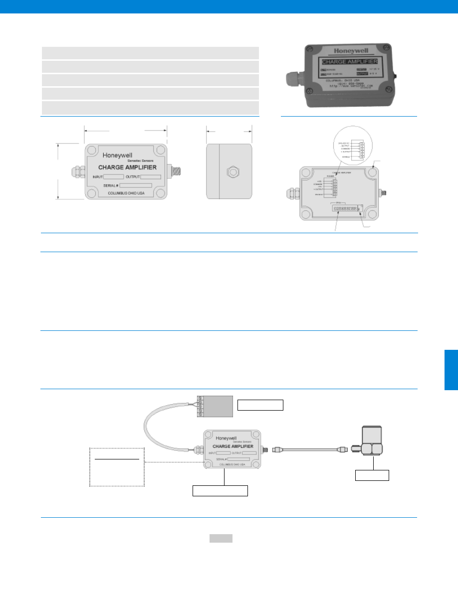
403
www.honeywell.com/sensotec
1-888-282-9891
Model CA2/ CA3 Charge Amplifier
Order Code AE411 & AE413
n
Piezo-Electric Accelerometer Amplifier
n
+/- 15 VDC or 24-32 VDC Supply
n
NEMA 4 Housing
n
Programmable Sensitivity
n
+/- 5 V Output
Dimensions
Power Requirements
Amplifier Characteristics
Physical Characteristics
Typical System Diagrams
Input Voltage................+/- 15 VDC or 24-32 VDC
Input Current................20 milliamperes
Sensitivity................Programmable (0.05 mV/pc to 6.4 mV/pc)
Input Range................780 pc to 100,000 pc
Output................+/- 5V RMS max.
Frequency Response
Model CA2................3 Hz to 30 kHz (-3db)
Model CA3................DC to 30 kHz
Time Constant
Model CA2................50 milliseconds
Model CA3................2000 seconds
Short Circuit Protected................+Output to -Output
Size................3.8” L x 2.5” W x 2.2” H
Temperature, Operating................32° to 180° F
Environmental Protection................Moisture and dust resistant painted aluminum box
Method of Connection
Input................Terminal strip inside of box
Sensor Connection................Miniature coaxial connnector
Mounting................Precessed screws, outside of the sealed volume
Model Code
Enter the order code.
How to Order
2.1 in.
2.5 in.
3.75 in.
Sample Code
AE411
Customer Supplied
Chart Recorder
Data Acquisition
Model CA2 & CA3
Power Supply
To Readout
Coarse Gain
Fine Gain
24 to 32 VDC
Power
Panel Mounting
Holes Use #6 or
#8 Screws
To Transducer
-Not RoHS Compliant
Sensor
Courtesy of Steven Engineering, Inc.-230 Ryan Way, South San Francisco, CA 94080-6370-Main Office: (650) 588-9200-Outside Local Area: (800) 258-9200-www.stevenengineering.com
Sensotec Sensors Full Line Catalog-html.html

404
Dimensions
General
Environmental
Transducer Interface
Amplifier Characteristics
www.honeywell.com/sensotec
n
DIN Rail Mount
n
Unamplified Transducer Input
n
Bridge Based Transducer Input
n
0 to +/-5V 3-Wire Output
n
RFI, ESD Protected CE
0.9 in.
4.3 in.
2.9 in.
Number of Channels................One
Case Material................Plastic
Mounting................35 mm DIN
Certification................CE Approved
Temperature, Operating................-40° to 200° F
Temperature, Storage................-40° to 200° F
Transducer Type................Bridge based sensor
Transducer Excitation................3 or 5 VDC @ 30 mA (Short circuit protection)
Supply Voltage................11-28 VDC
Current Draw................60 mA
Zero Adjustment Range................+/- 60% coarse adjustment
................+/- 10% fine adjustment
Span Adjustment Range................Switch selectable 0.5 to 13.3 mV/V
................+/- 20% fine adjustment
Linearity................+/- 0.01%
Output................+/- 5 VDC
Output Current................2 mA
Frequency Response (-3 db)................DC-7,000 Hz with 350 Ohm bridge
................DC-2,500 Hz with 5,000 Ohm bridge
Rise Time (0 to 90%)................56 µs with 350 Ohm bridge
................145 µs with 5,000 Ohm bridge
Signal to Noise Ratio................66 db
DC Power Supply Rejection Ratio................Greater than 110 db
Model DV-05 DIN Rail Mount In-Line Amplifiers
Order Code BE151
1-888-282-9891
Courtesy of Steven Engineering, Inc.-230 Ryan Way, South San Francisco, CA 94080-6370-Main Office: (650) 588-9200-Outside Local Area: (800) 258-9200-www.stevenengineering.com
Sensotec Sensors Full Line Catalog-html.html
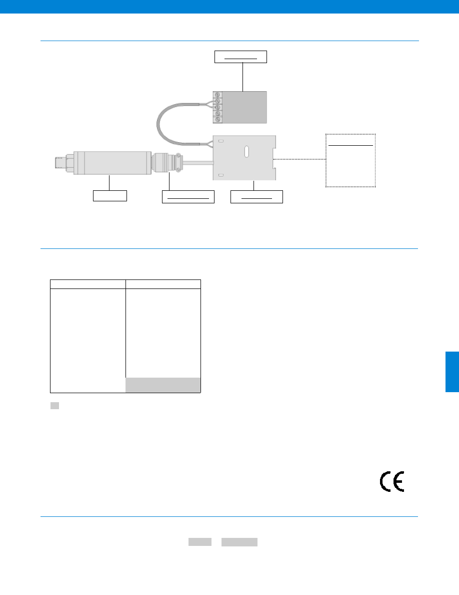
405
Customer Supplied
Chart Recorder
Alarm Panel
Data Acquisition
Computer
PLC
Power Supply
Model DV-05
Mating Connector
www.honeywell.com/sensotec
Typical System Diagram
1-888-282-9891
Model DV-05
Options
How to Order
Combine the order code, the options code and the filter frequency.
Order Code
Filter with Frequency
Sample Code:
BE151 58e, 50 Hz
Built to Order
58e, 2 Pole Filter Option
1 Hz
3 Hz
5 Hz
10 Hz
20 Hz
30 Hz
50 Hz
100 Hz
300 Hz
500 Hz
1,000 Hz
2,500 Hz (350 Ohm bridge)
7,000 Hz (5,000 Ohm bridge)
Supplied as standard
-Not RoHS Compliant
Sensor
Approved
Courtesy of Steven Engineering, Inc.-230 Ryan Way, South San Francisco, CA 94080-6370-Main Office: (650) 588-9200-Outside Local Area: (800) 258-9200-www.stevenengineering.com
Sensotec Sensors Full Line Catalog-html.html
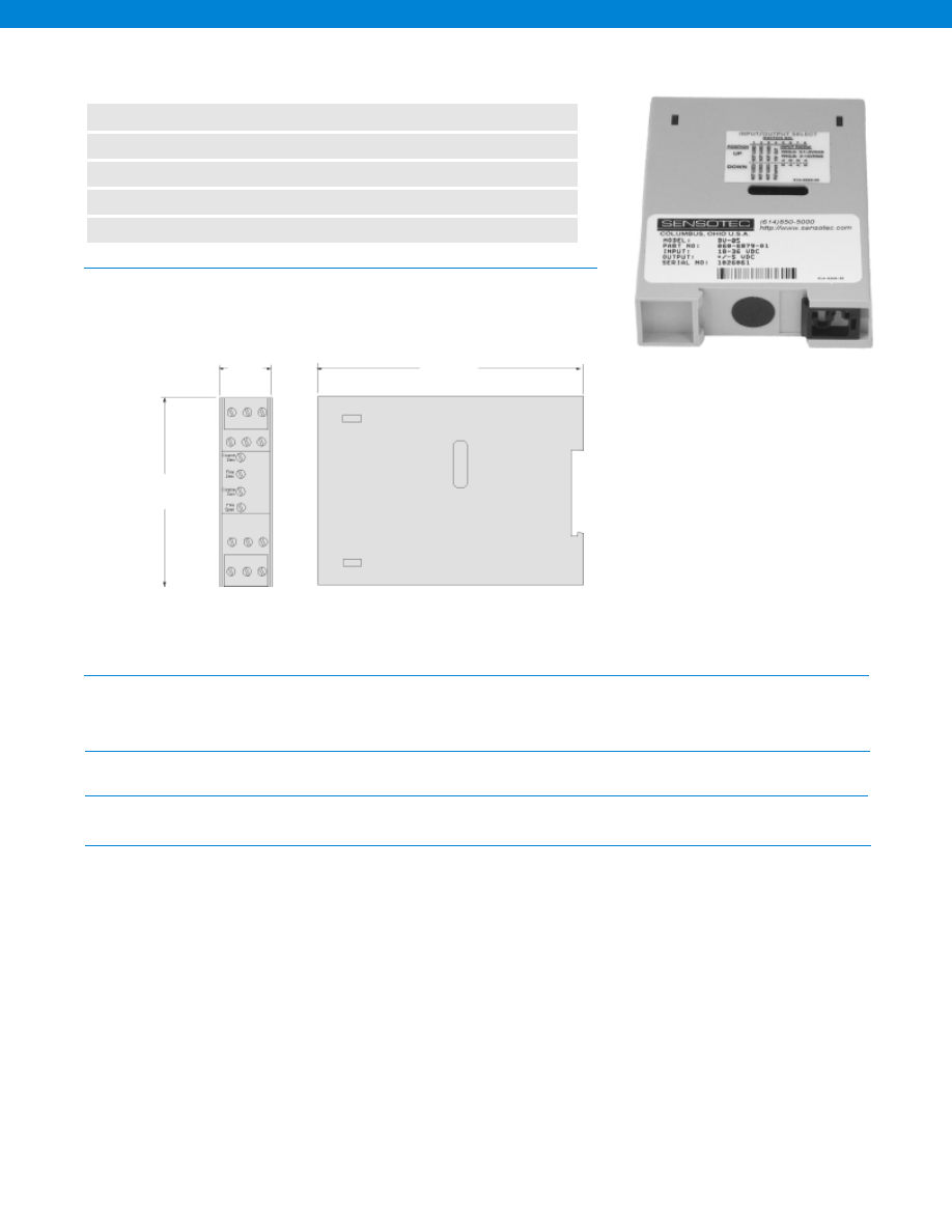
406
Dimensions
General
Environmental
Transducer Interface
Amplifier Characteristics
www.honeywell.com/sensotec
n
DIN Rail Mount
n
Strain Gage Transducer Input
n
Bridge Based Transducer Input
n
4-20 mA 3-Wire Output
n
RFI, ESD Protected CE
0.9 in.
4.3 in.
2.9 in.
Model DA-05 DIN Rail Mount In-Line Amplifier
Order Code BE153
1-888-282-9891
Number of Channels................One
Case Material................Plastic
Mounting................35 mm DIN
Certification................CE Approved
Temperature, Operating................-40° to 200° F
Temperature, Storage................-40° to 200° F
Transducer Type................Bridge based sensor
Transducer Excitation................3 or 5 VDC @ 30 mA (Short circuit protection)
Supply Voltage................13.5-28 VDC
Current Draw................60 mA
Zero Adjustment Range................+/- 60% coarse adjustment
................+/- 10% fine adjustment
Span Adjustment Range................Switch selectable 0.5 to 13.3 mV/V
................+/- 20% fine adjustment
Linearity................+/- 0.01%
Output................4-20 mA 3 wire
Frequency Response (-3 db)................DC-6,200 Hz with 350 Ohm bridge
................DC-2,300 Hz with 5,000 Ohm bridge
Rise Time (0 to 90%)................63 µs with 350 Ohm bridge
................160 µs with 5,000 Ohm bridge
Signal to Noise Ratio................70 db
DC Power Supply Rejection Ratio................90 db
Courtesy of Steven Engineering, Inc.-230 Ryan Way, South San Francisco, CA 94080-6370-Main Office: (650) 588-9200-Outside Local Area: (800) 258-9200-www.stevenengineering.com
Sensotec Sensors Full Line Catalog-html.html
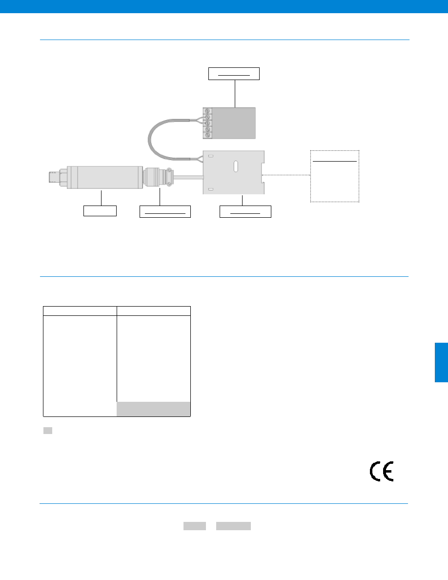
407
Customer Supplied
Chart Recorder
Alarm Panel
Data Acquisition
Computer
PLC
Power Supply
Model DA-05
Mating Connector
www.honeywell.com/sensotec
Typical System Diagram
1-888-282-9891
Model DA-05
Options
How to Order
Combine the order code, the options code and the filter frequency.
Order Code
Filter with Frequency
Sample Code:
BE153 58e, 50 Hz
Built to Order
58e, 2 Pole Filter Option
1 Hz
3 Hz
5 Hz
10 Hz
20 Hz
30 Hz
50 Hz
100 Hz
300 Hz
500 Hz
1,000 Hz
6200 Hz (350 Ohm bridge)
2300 Hz (5,000 Ohm bridge)
Supplied as standard
-Not RoHS Compliant
Sensor
Approved
Courtesy of Steven Engineering, Inc.-230 Ryan Way, South San Francisco, CA 94080-6370-Main Office: (650) 588-9200-Outside Local Area: (800) 258-9200-www.stevenengineering.com
Sensotec Sensors Full Line Catalog-html.html
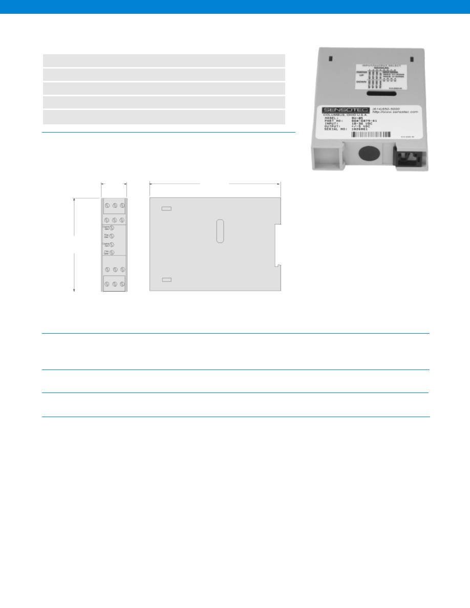
408
Dimensions
General
Environmental
Transducer Interface
Amplifier Characteristics
www.honeywell.com/sensotec
n
DIN Rail Mount
n
Unamplified Transducer Input
n
Bridge Based Transducer Input
n
0 to +/-10V 3-Wire Output
n
RFI, ESD Protected CE
0.9 in.
4.3 in.
2.9 in.
Number of Channels................One
Case Material................Plastic
Mounting................35 mm DIN
Certification................CE Approved
Temperature, Operating................-40° to 200° F
Temperature, Storage................-40° to 200° F
Transducer Type................Bridge based sensor
Transducer Excitation................5.4 or 9 VDC @ 30 mA (Short circuit protection)
Supply Voltage................15-28 VDC
Current Draw................60 mA
Zero Adjustment Range................+/- 30% coarse adjustment
................+/- 5% fine adjustment
Span Adjustment Range................Switch selectable 1.75 to 13.3 mV/V
................-8 to +20 fine adjustment
Linearity................+/- 0.01%
Output................+/- 10 VDC (3 wire)
Output Current................2 mA
Frequency Response................DC- 5,000 Hz
Model DV-10 DIN Rail Mount In-Line Amplifiers
Order Code BE155
1-888-282-9891
Courtesy of Steven Engineering, Inc.-230 Ryan Way, South San Francisco, CA 94080-6370-Main Office: (650) 588-9200-Outside Local Area: (800) 258-9200-www.stevenengineering.com
Sensotec Sensors Full Line Catalog-html.html
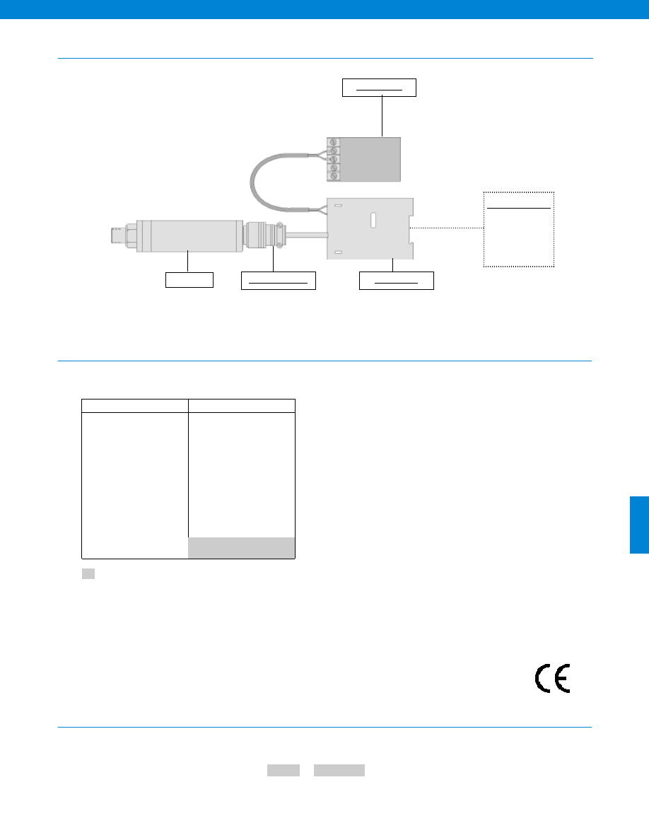
409
Model DV-10
Customer Supplied
Chart Recorder
Alarm Panel
Data Acquisition
Computer
PLC
Power Supply
Model DV-10
Mating Connector
www.honeywell.com/sensotec
Typical System Diagram
1-888-282-9891
Options
How to Order
Combine the order code, the options code and the filter frequency.
Built to Order
58e, 2 Pole Filter Option
1 Hz
3 Hz
5 Hz
10 Hz
20 Hz
30 Hz
50 Hz
100 Hz
300 Hz
500 Hz
1,000 Hz
Order Code
Filter with Frequency
Sample Code:
BE155 58e, 50 Hz
2,500 Hz (350 Ohm bridge)
7,000 Hz (5,000 Ohm bridge)
Supplied as standard
-Not RoHS Compliant
Sensor
Approved
Courtesy of Steven Engineering, Inc.-230 Ryan Way, South San Francisco, CA 94080-6370-Main Office: (650) 588-9200-Outside Local Area: (800) 258-9200-www.stevenengineering.com
Sensotec Sensors Full Line Catalog-html.html
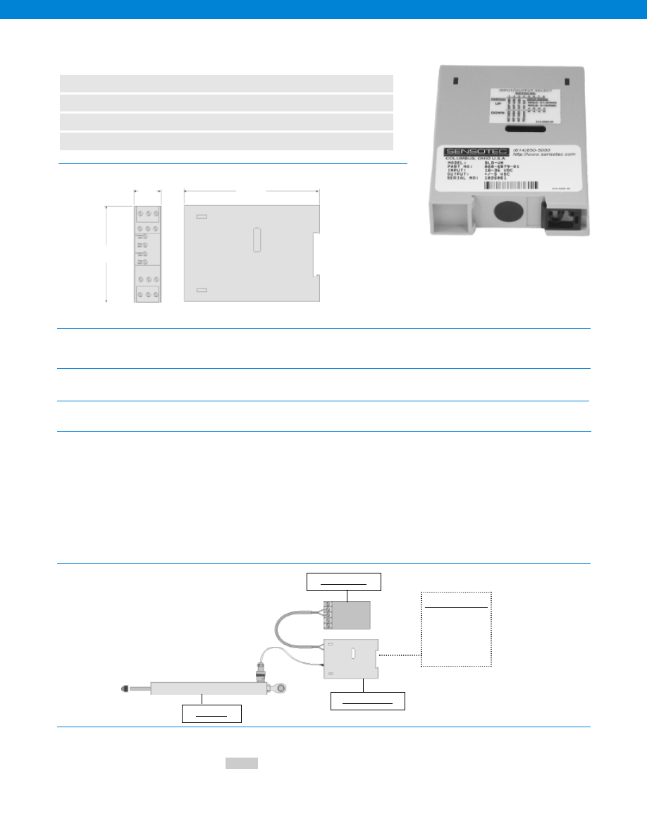
410
Dimensions
General
Environmental
Transducer Interface
Amplifier Characteristics
Typical System Diagram
How to Order
www.honeywell.com/sensotec
n
DIN Rail Mount
n
AC LVDT Input
n
0+/-5 or 0+/-10VDC, Field Selectable
n
RFI, ESD Protected
0.9 in.
4.3 in.
2.9 in.
Number of Channels................One
Case Material................Plastic
Mounting................35 mm DIN
Temperature, Operating................-20° to 140° F
Temperature, Storage................-40° to 200° F
Transducer Type................AC LVDTs
Transducer Excitation................3 volts RMS @ 5 kHz
Supply Voltage................18-36 VDC
Power Supply Isolation ................500 V
Current Draw................70 mA
Zero Adjustment Range................+/- 100% coarse adjustment
+/- 20% fine adjustment
Span Adjustment Range................Switch selectable 0.1 to 15 VRMS input range
+/- 10% fine adjustment
Linearity................+/- 0.05%
Output................0 +/- 5 or 0 +/- 10 VDC (field selectable)
Frequency Response................300 Hz (-3 db)
DC Power Supply Rejection Ratio................85 db
Model DLD-VH DIN Rail Mount In-Line Amplifiers
Order Code BE152
1-888-282-9891
Customer Supplied
Chart Recorder
Alarm Panel
Data Acquisition
Computer
PLC
Power Supply
Model DLD-VH
AC LVDT
Enter the order code
Order Code
Sample Code:
BE152
-Not RoHS Compliant
Courtesy of Steven Engineering, Inc.-230 Ryan Way, South San Francisco, CA 94080-6370-Main Office: (650) 588-9200-Outside Local Area: (800) 258-9200-www.stevenengineering.com
Sensotec Sensors Full Line Catalog-html.html
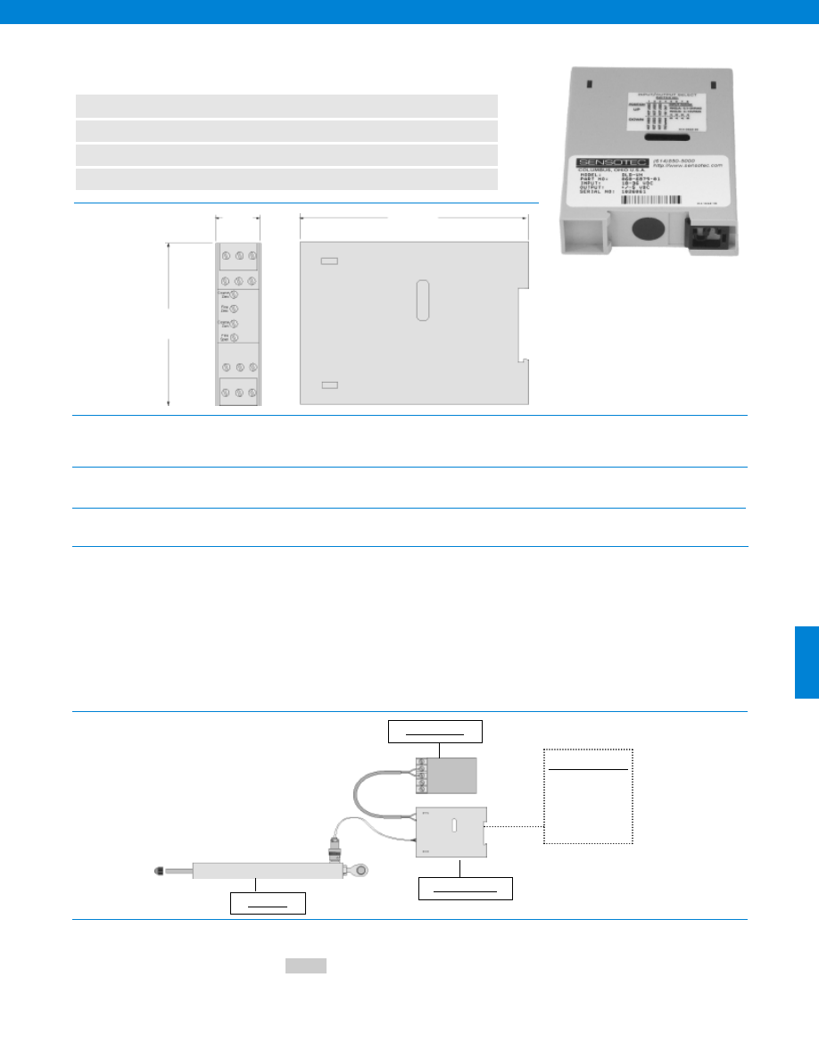
411
Dimensions
General
Environmental
Transducer Interface
Amplifier Characteristics
Typical System Diagram
How to Order
www.honeywell.com/sensotec
n
DIN Rail Mount
n
AC LVDT Input
n
4-20 mA Output
n
RFI, ESD Protected
0.9 in.
4.3 in.
2.9 in.
Number of Channels................One
Case Material................Plastic
Mounting................35 mm DIN
Temperature, Operating................-20° to 140° F
Temperature, Storage................-40° to 200° F
Transducer Type................AC LVDTs
Transducer Excitation................3 volts RMS @ 5 kHz
Supply Voltage................18-36 VDC
Power Supply Isolation ................500 V
Current Draw................90 mA
Zero Adjustment Range................+/- 100% coarse adjustment
+/- 20% fine adjustment
Span Adjustment Range................Switch selectable 0.1 to 15 VRMS input range
+/- 10% fine adjustment
Linearity................+/- 0.05%
Output................4-20 mA
Frequency Response................300 Hz (-3 db)
DC Power Supply Rejection Ratio................85 db
Model DLD-CH DIN Rail Mount In-Line Amplifiers
Order Code BE154
1-888-282-9891
Customer Supplied
Chart Recorder
Alarm Panel
Data Acquisition
Computer
PLC
Power Supply
Model DLD-CH
AC LVDT
Enter the order code
Order Code
Sample Code:
BE154
-Not RoHS Compliant
Courtesy of Steven Engineering, Inc.-230 Ryan Way, South San Francisco, CA 94080-6370-Main Office: (650) 588-9200-Outside Local Area: (800) 258-9200-www.stevenengineering.com
Sensotec Sensors Full Line Catalog-html.html
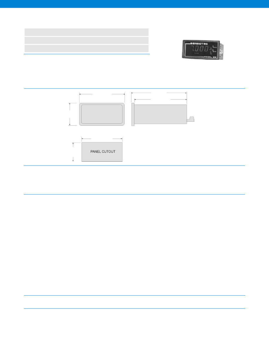
412
www.honeywell.com/sensotec
1-888-282-9891
Model DM, for carrier transducers, is a low-cost bench, panel or rack-mounted
instrument which contains a power supply, signal conditioner, amplifier (Bipolar
5 Volt output),and digitizer. The 4 1/2-digit LED display features bright, easy-
to-read 0.56” high characters. The compact 1/8 DIN size case measures 3.8”
W x 1.9” H x 5.2” D. Wires easily attach to the rear connecor using screw
terminals. The model DM features a 5 kHz. drive supply for the transducer, a
stable signal amplifier and a novel demodulation technique that
produces an enhanced accuracy result.
n
Used With LVDTs
n
4 1/2 Digit LED Display
n
3 Conversions Per Second
Model DM Demodulator for AC Transducers
Order Code AE214
Dimensions
Transducer Interface
Electrical
Environmental
Physical
1.9 in.
3.75 in.
5.2 in.
4.9 in.
1.730 in.
1.740 in.
3.580 in.
3.590 in.
Transducer Excitation................1-2 VRMS @ 5 kHz.
Type of Inputs Accepted................AC, LVDT, VRT
Input Gain Range................< 1 to 300
Calibration Methods................Manual displacement
Noise & Ripple................< 300 microvolts
Transducer Minumum Impedance................7 Ohms
Number of Characters Displayed................4 1/2
Conversions per Second................3
Power Requirements
Standard................115 VAC @ 5 Watts
Optional................220 VAC, 12 VDC
Scaling................0-19,999
Scaling Method................Potentiometer
Polarity Indication................Yes
Decimal Point Selection................Jumper (non-solder)
Display Size................0.56 in.
Overrange Indication................Flashing Display
Display Resolution................1/ 20,000 max.
Digital Display................LED
Analog Output................+/-5 VDC
Amplifier Output Impedance................< 2 Ohms
Accuracy................+/- 0.2% Full Scale
Amplifier Frequency Response................300 Hz
Common Mode Rejection................60 db
Fine Scan Adjust................> +/- 15%
Coarse Scan Adjust................> +/- 80%
Fine Zero Adjust................> +/- 5%
Coarse Zero Adjust................> +/- 20%
Short Circuit Protected................Yes
Temperature, Storage................-20° to 200° F
Temperature, Operating................32° to 130° F
Weight................2 lb.
Mounting................Bench, Rack or Panel
Case Size (std.)................1/8 DIN
Case Material................Noryl plastic
Input/ Output Connector................Removable with screw terminals
Courtesy of Steven Engineering, Inc.-230 Ryan Way, South San Francisco, CA 94080-6370-Main Office: (650) 588-9200-Outside Local Area: (800) 258-9200-www.stevenengineering.com
Sensotec Sensors Full Line Catalog-html.html
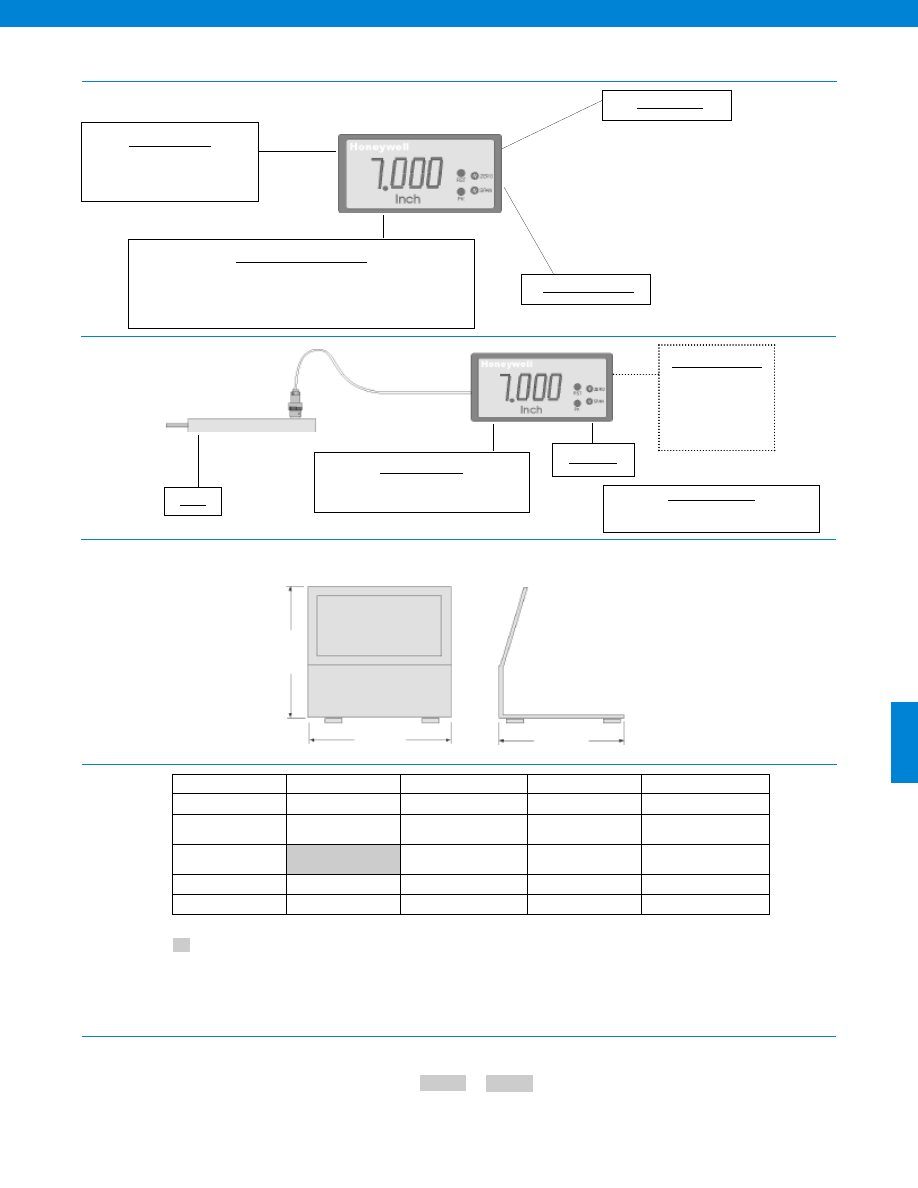
413
www.honeywell.com/sensotec
1-888-282-9891
Flexible Platform
Typical System Diagram
Mounting Options
Panel Mount (standard)
Bench Mount Bracket (AA924)
Peak/ Hold Feature
Reset Feature
Signal Conditioning Options
(58c. option) Peak/ Hold (not available with alarm or track/ hold option)
(60a. option) 220 VAC
(60c. option) 12 VDC Powered
Customer Supplied
Chart Recorder
Alarm Panel
Data Acquisition
Computer
PLC
LVDT
Model DM
Mounting Options
(AA924) Bench Mount Bracket
Cable Accessories
Mating Connector and Power Cord (AA154)
Model DM
Same Day Stock
Configured to Order
Assembled to Order
Built to Order
Alarm Outputs
58a. Hi-Lo limits
Display Options
58c. Peak/ hold
58d. Track/ hold
Power Supply
110 VAC
60a. 220 VAC
60c. Battery Powered
(12 VDC)
Front Panel
51d. Custom front panel
Mounting Options
51a. Rack mount adapter
Supplied as standard
3.75 in.
3.8 in.
3.75 in.
AA924 Bench Mount Bracket
Accessories and Options Dimensions
Options
Model Code
Options Code
The order code consists of the product model and the available options.
How to Order
Sample Code
AE216
58c
-Not RoHS Compliant
Courtesy of Steven Engineering, Inc.-230 Ryan Way, South San Francisco, CA 94080-6370-Main Office: (650) 588-9200-Outside Local Area: (800) 258-9200-www.stevenengineering.com
Sensotec Sensors Full Line Catalog-html.html
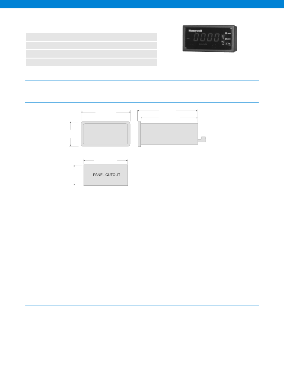
414
The GM is a versatile full function signal conditioner, amplifier and power supply that works with unamplified mV/V transducers. It also pro-
vides shunt calibration (R-cal) which enables the system to be setup without using an expensive primary stimulus (done at no extra charge
at the factory if the readout and transducer are purchased at the same time). A full range of options like peak/ hold, track/ hold and dual lim-
its are available.
n
Bridge Based Transducer Input
n
4 1/2 Digit LED Display
n
Large 0.56” Readout
n
High Speed Analog Output (up to 27 kHz)
Model GM Digital Display/ Signal Conditioner
Order Code AE213
Dimensions
Electrical
Environmental
Physical
Input Signal................1 to 5 mV/V or 5 to 50 mV/V (optional)
Number of Characters Displayed................4 1/2
Power Requirements
Standard................115 VAC @ 5 Watts
Optional................12 VDC, 220 VAC
Conversions per Second................3
Scaling Method................Potentiometer
Polarity Indication................Yes
Decimal Point Selection................Jumper (non-solder)
Display Size................0.56 in.
Overrange Indication................Flashing Display
Display Resolution................1/ 20,000 max.
Digital Display................LED
Analog Output................+/-5 VDC or 4-20 mA (optional)
Amplifier Output Impedance................< 2 Ohms
Accuracy................35mm DIN
Amplifier Frequency Response................DC to 250 Hz
Common Mode Rejection................80 db
Fine Scan Adjust................< +/- 15%
Coarse Scan Adjust................> 80%
Fine Zero Adjust................< +/- 15%
Coarse Zero Adjust................> 80%
Temperature, Storage................-20° to 200° F
Temperature, Operating................32° to 130° F
Weight................2.25 lb.
Mounting................Bench, Rack or Panel (Panel mount included with unit)
Case Size (std.)................1/8 DIN
Case Material................Noryl plastic
Input/ Output Connector................Removable with screw terminals
1.9 in.
3.75 in.
5.2 in.
4.9 in.
1.730 in.
1.740 in.
3.580 in.
3.590 in.
Model GM 1/4 DIN Format (Order Code AE213)
www.honeywell.com/sensotec
1-888-282-9891
Courtesy of Steven Engineering, Inc.-230 Ryan Way, South San Francisco, CA 94080-6370-Main Office: (650) 588-9200-Outside Local Area: (800) 258-9200-www.stevenengineering.com
Sensotec Sensors Full Line Catalog-html.html
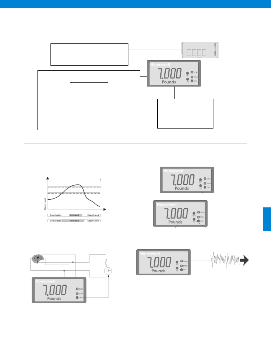
415
Flexible Platform
Comprehensive Signal Conditioning
Relay Card Options
( 58a. option) Hi-Low Limits
(not available with track/ hold or peak/ hold option)
Mounting Options
Panel Mount (standard)
Bench Mount Bracket (AA924)
19” Rack Mount Adaptor (51a. option)
Signal Conditioning Options
(51d. option) Custom Front Panel
(56a. option) 4-20 mA Output (requires 1/4 DIN format)
(58c. option) Peak/ Hold (not available with alarm or track/ hold option)
(58d. option) Track/ Hold (not available with alarm or peak/ hold option)
(60a. option) 220 VAC
(60c. option) 12 VDC Powered
(52c. option) 5 mV/V to 50 mV/V Input Range (user selectable)
(58t. option) Low pass filter setting
10 V or 5 V Excitation (user selectable)
Alarm Configuration
Display Options
Shunt Calibration Feature
High Speed Analog
Shunt Calibration
Alarm 2
Alarm on when setpoint exceeded
Peak/ Hold Feature and Track/ Hold Feature
Light Bar & Scaling Decal with Light Bar
Alarm Indication
User Selectable rising or
falling hysteresis (1%)
Non Latching Alarms
Alarm 1
Alarm 1
Alarm 2
R-Cal
Model GM
www.honeywell.com/sensotec
1-888-282-9891
Courtesy of Steven Engineering, Inc.-230 Ryan Way, South San Francisco, CA 94080-6370-Main Office: (650) 588-9200-Outside Local Area: (800) 258-9200-www.stevenengineering.com
Sensotec Sensors Full Line Catalog-html.html
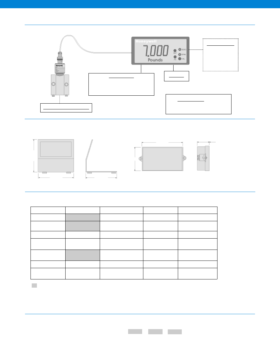
416
Model Code
Option Code Filter Setting
The order code consists of the product model, the available options and the filter setting.
How to Order
Sample Code
AE213
60a
30Hz
Customer Supplied
Chart Recorder
Alarm Panel
Data Acquisition
Computer
PLC
Any mV/V Bridge Based Sensor
Model GM
Mounting Options
(AA923) NEMA-4 Splash Proof Front Cover
(AA924) Bench Mount Bracket
Cable Accessories (standard)
Mating Connector and Power Cord (AA154)
Same Day Stock
Configured to Order
Assembled to Order
Built to Order
Input Range
0.5 to 5 mV/V
52c. 5 to 50 mV/V
Analog Output
Filter setting 260 Hz
58t. Optional Filter setting
(10Hz, 30Hz, 10kHz, 27kHz)
Alarm Outputs
58a. Hi-Lo limits
Display Options
58c. Peak/ hold
58d. Track/ hold
Power Supply
110 VAC
60a. 220 VAC
60c. Battery Powered
(12 VDC)
56a. 4-20 mA output
Front Panel
51d. Custom front panel
Mounting Options
51a. Rack mount adapter
51c. NEMA Enclosure
Supplied as standard
Model GM
3.75 in.
3.8 in.
3.75 in.
AA924 Bench Mount Bracket
AA923 NEMA 4 Splash Proof Cover
2.4 in.
4.3 in.
0.73 in.
Typical System Diagram
Accessories and Options Dimensions
Options
www.honeywell.com/sensotec
1-888-282-9891
-Not RoHS Compliant
Courtesy of Steven Engineering, Inc.-230 Ryan Way, South San Francisco, CA 94080-6370-Main Office: (650) 588-9200-Outside Local Area: (800) 258-9200-www.stevenengineering.com
Sensotec Sensors Full Line Catalog-html.html
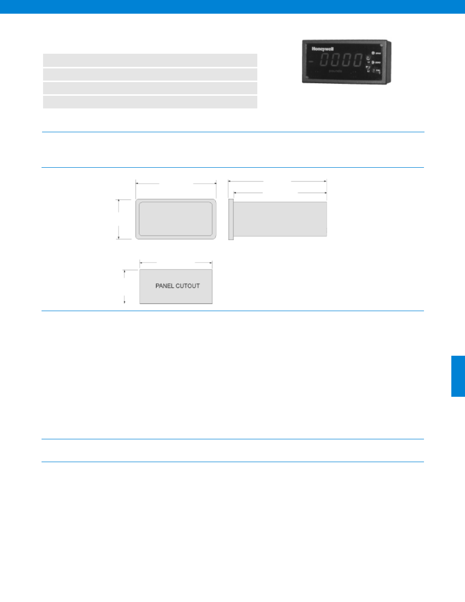
417
www.honeywell.com/sensotec
1-888-282-9891
The GM-A is a low cost digital readout that works with amplified (0-5 V or 4-20 mA) transducers or transmitters. This unit supplies power
to the sensors. Two wire current is user jumper selectable for use with two wire current transducers. Separate power supply required for
3-wire use. Not for use with intrinsically safe applications utilizing a barrier.
n
High Level (Amplified) Transducer Input
n
4 1/2 Digit LED Display
n
Large 0.56” Readout
n
High Speed Analog Output
Model GM-A Digital Display/ Signal Conditioner
Order Code AE216
Dimensions
Electrical
Environmental
Physical
Number of Characters Displayed................4 1/2
Power Requirements
Standard................115 VAC @ 5 Watts
Optional................220 VAC
Conversions per Second................3
Scaling Method................Potentiometer
Polarity Indication................Yes
Decimal Point Selection................Jumper (non-solder)
Display Size................0.56 in.
Overrange Indication................Flashing Display
Display Resolution................1/ 20,000 max.
Digital Display................LED
Analog Output................+/-5 VDC
Amplifier Output Impedance................< 2 Ohms
Accuracy................+/- 0.03%
Amplifier Frequency Response................DC to 1 kHz
Coarse Zero Adjust................40%
Temperature, Storage................-20° to 200° F
Temperature, Operating................32° to 130° F
Weight................2.25 lb.
Mounting................Bench, Rack or Panel (Panel mount included with unit)
Case Size (std.)................1/8 DIN
Case Material................Noryl plastic
Input/ Output Connector................Removable with screw terminal
1.9 in.
3.75 in.
5.2 in.
4.9 in.
1.730 in.
1.740 in.
3.580 in.
3.590 in.
Courtesy of Steven Engineering, Inc.-230 Ryan Way, South San Francisco, CA 94080-6370-Main Office: (650) 588-9200-Outside Local Area: (800) 258-9200-www.stevenengineering.com
Sensotec Sensors Full Line Catalog-html.html
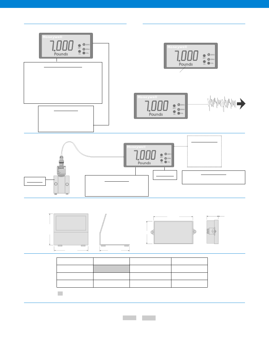
418
www.honeywell.com/sensotec
1-888-282-9891
Flexible Platform
Typical System Diagram
Accessories and Options Dimensions
Options
Mounting Options
Panel Mount (standard)
Bench Mount Bracket (AA924)
NEMA Enclosure (51c. option)
19” Rack Mount Adaptor (51a. option)
Signal Conditioning Options
(51d. option) Custom Front Panel
(56a. option) 4-20 mA Output (requires 1/4 DIN format)
(60a. option) 220 VAC
0-2 V Input Range
0-5 V Input Range
4-20 mA Input Range
(transducer must be powered separately)
10 V +/- 15 V Excitation (user selectable)
Model Code
Option Code
The order code consists of the product model and the available options.
How to Order
Sample Code
AE216
51a
Customer Supplied
Chart Recorder
Alarm Panel
Data Acquisition
Computer
PLC
Transducer
Model GM-A
Mounting Options
(AA923) NEMA-4 Splash Proof Front Cover
(AA924) Bench Mount Bracket
Cable Accessories
Mating Connector and Power Cord (AA154)
3.75 in.
3.8 in.
3.75 in.
AA924 Bench Mount Bracket
AA923 NEMA 4 Splash Proof Cover
2.4 in.
4.3 in.
0.73 in.
Supplied as standard
Display Options
High Speed Analog
Light Bar & Scaling Decal with Light Bar
Comprehensive Signal Conditioning
Same Day Stock
Built to Order
Built From Scratch
Power Supply
110 VAC
60a. 220 VAC
Front Panel
51d. Custom front panel
Mounting Options
51a. Rack mount adaptor
51c. NEMA Enclosure
Model GM-A
-Not RoHS Compliant
Courtesy of Steven Engineering, Inc.-230 Ryan Way, South San Francisco, CA 94080-6370-Main Office: (650) 588-9200-Outside Local Area: (800) 258-9200-www.stevenengineering.com
Sensotec Sensors Full Line Catalog-html.html
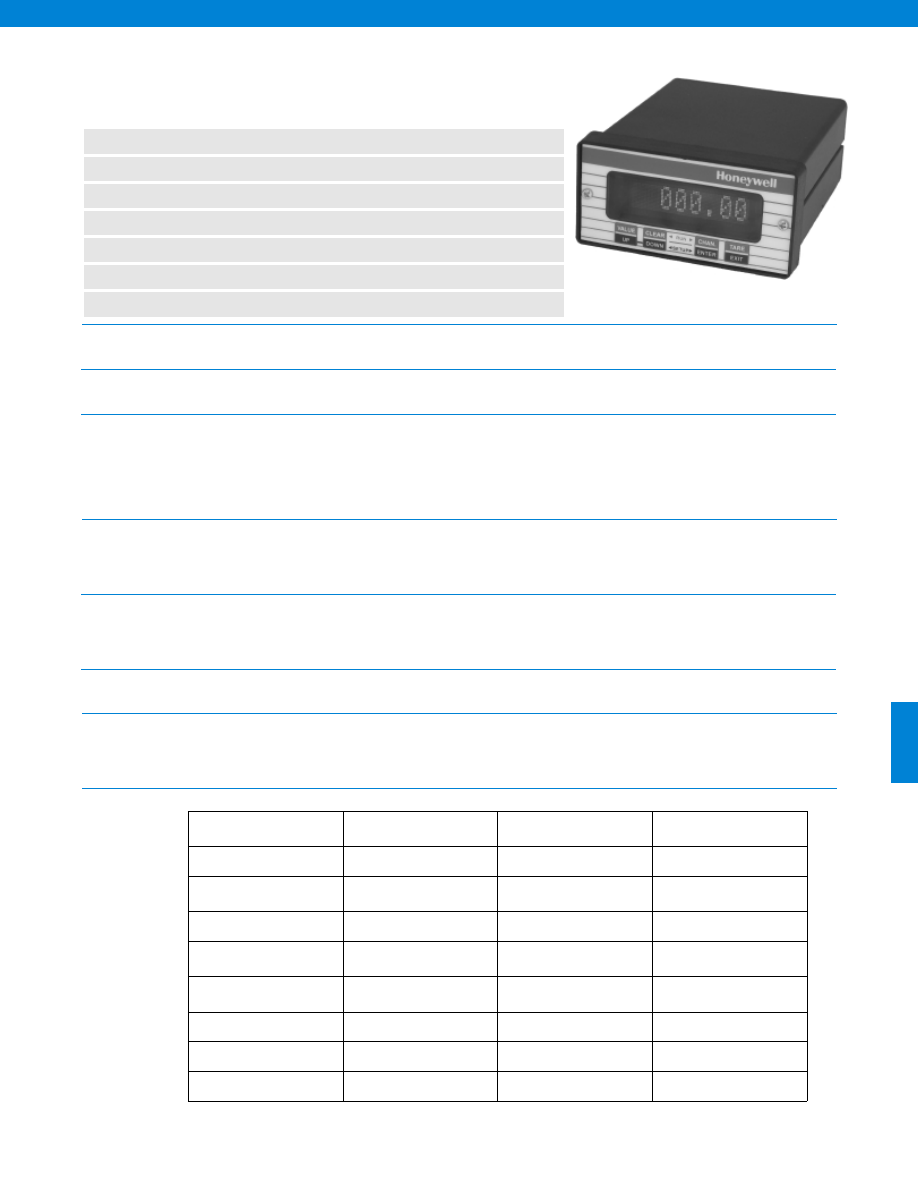
419
Physical
Environmental
Display
Power
Analog Output (optional)
Communications Output
(optional)
Limits Output (optional)
Input
n
Choice of Transducer Inputs
n
Small 1/8 DIN Form Factor
n
Automatic Setup, Calibration via Sig Cal
n
Shunt-Cal, mV/V or Known Load Calibration
n
Peak/ Valley Capture
n
Optional Analog Output and RS-232/ RS-485
n
Field Selectable Frequency Response and Calibration
Model SC500 Programmable Single-Channel Transducer
Indicator/ Conditioner
Order Code (See below)
Form Factor................1/8 DIN
Case Material................Aluminum
Temperature, Operating................40° to 105°F (5° to 40°C)
Temperature, Storage................-40° to 195°F (-30° to 90°C)
Display Type................Vacuum fluorescent
Numeric Display Format................+999,999 to -999,999 (0, 1, 2, 3, 4, 5 decimal places)
Digit Size (Normal Mode)................0.2” H x 0.1” W (5mm H x 2.5mm W) (with engineering units)
Digit Size (Large Mode)................0.4” H x 0.2” W (10mm H x 5mm W) (no engineering units)
Engineering Units Display................4 characters, available in normal mode only
Display Update Per Second................4
Power Supply Type................AC (with included wall-mount adapter) or DC
DC Power Supply Requirements................10 - 26 VDC @ 1A
AC Wall-Mount Adapter (included)................Interchangeable plugs for use in the Americas, Europe,
the United Kingdom and Australia (100 - 240 VAC)
Voltage Range................5, +/-5, 10 or +/-10 VDC (field selectable)
Isolation................500 V
Digital-to-Analog Resolution................15 bits
Frequency Response................Same as input
Serial Setup & Output................Isolated RS-232 or RS-485 (factory option)
Max. Baud Rate................38400 Baud
Quantity................2 Form C or 3 Form A (factory option)
Response Time................Same as input
Relay Engergized when Signal is................less than, greater than, inside or outside set points
Contact Ratings................1A @ 30 VDC, 0.5 A @ 50 VAC
Strain Gage
Millivolts
High Level
Volts/ mA
AC/AC LVDT
Order Code
AE236
AE237
AE238
Transducer Type
unamplified
pressure or load
amplified pressure or load,
DC/DC LVDT
LVDT
Range
0.5 to 21 mV/V
+/-5 or +/-10 VDC, 4-20 mA
0.1 to 15 VRMS
Frequency Response &
Resolution
See table on next page
See table on next page
See table on next page
Calibration Type
(Field Selectable)
Shunt, mV/V,
2-, 3-or 5-point known load
Shunt,
2-, 3-or 5-point known load
2-, 3-or 5-point known load
Transducer Excitation
5 VDC @ 60 mA max.
+12 VDC, +/-15 VDC,
+28 VDC
3 VAC @ 5 kHz
Push-button 100% Tare
Yes
Yes
Yes
Push-button Shunt Test
Yes
Yes
No
www.honeywell.com/sensotec
1-888-282-9891
Courtesy of Steven Engineering, Inc.-230 Ryan Way, South San Francisco, CA 94080-6370-Main Office: (650) 588-9200-Outside Local Area: (800) 258-9200-www.stevenengineering.com
Sensotec Sensors Full Line Catalog-html.html
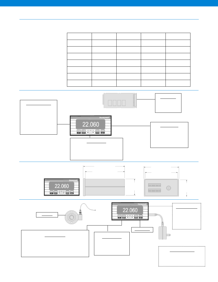
420
Input (continued)
Flexible and Expandable Platform
Dimensions
Typical System Diagram
Channel Card Options
• Strain Gage Input
• High Level Volt/ mA
• AC LVDT
Note:
Specify voltage or current
O/P on each card
Chassis Options
• Math Channel
• Split Display Virtual Channel
• AC or Vehicle Power Supply
• RS232 or RS485 Output
• Additional Analog O/P Card
Relay Options
• 2 Form C Relay
• 3 Form A Relay
Mounting Options
• Bench Mount stand (AA924)
• Panel Mount (AA943)
• 19” Rack mount for 1 meter (056-0062-00)
• 19” Rack mount for 4 meter (023-0066-00)
2 (fast mode)
40
+/- 50,000
+/- 50,000
+/- 25,000
2
440
+/- 50,000
+/- 50,000
+/- 25,000
8
110
+/- 25,000
+/- 25,000
+/- 15,000
16
55
+/- 20,000
+/- 25,000
+/- 10,000
32
28
+/- 10,000
+/- 20,000
+/- 10,000
50
16
+/- 5,000
+/- 15,000
+/- 5,000
100
8
+/- 5,000
+/- 10,000
+/- 5,000
250
3
+/- 2,000
+/- 10,000
+/- 2,000
Frequency
Response (Hz)
(Field Selectable)
Step Response
(ms) (typical)
Strain Gage
High Level
AC/AC LVDT
Resolution (counts)
(not including min. 10% overrange/ underrange capability)
4.66” (118 mm)
3.16” (106 mm)
3.78” (96 mm)
3.55” (90 mm)
1.72”
(44 mm)
1.89”
(48 mm)
Model SC500
Load Cell
Mounting Options
Bench Mount
Panel Mount (AA928)
Portable (see Model SC2001)
Cable Accessories
RS232 cable assy with 9 pin D sub connector (6ft.) (AA145)
Mating connector for DC power jack (023-0769-01)
Relay/ digital output connector/ cable assy (AA144)
Replacement wall-mount AC power supply (AA961)
Supplied with Instrument
Customer Supplied
Chart Recorder
Alarm Panel
Data Acquisition
Computer
PLC
Software Accessories
SensoCom Instrument Ultility Software
for Windows 98/ NT/ 2000
(AA183)
Model SC500
www.honeywell.com/sensotec
1-888-282-9891
Courtesy of Steven Engineering, Inc.-230 Ryan Way, South San Francisco, CA 94080-6370-Main Office: (650) 588-9200-Outside Local Area: (800) 258-9200-www.stevenengineering.com
Sensotec Sensors Full Line Catalog-html.html
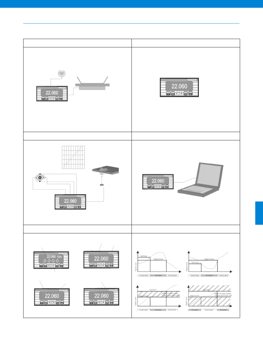
421
SC500 Capabilities
Number of decimal places
Serial communications (optional)
Update signature module
mV/V Calibration
Shunt Calibration
Shows status of alarms
User selected decimal point
6 digit display
Alarm on when setpoint
exceeded and until return
point is reached
Alarm on when below
setpoint and until return
point is reached
Large Display Mode
Valley tracking
Peak tracking
Dual line display
User selected
units
2, 3 or 5 point calibration
for applied load, pressure,
speed, etc.
Display averaging
Output voltage (optional)
Alarm outputs (optional)
Engineering units
Front Panel or Remote Tare
Flexible User Setup
mV/V or Shunt Calibration or 5 Point Calibration
Remote Setup
User Selectable Display Options
Different Alarm Configurations (optional)
Model SC500
www.honeywell.com/sensotec
1-888-282-9891
Courtesy of Steven Engineering, Inc.-230 Ryan Way, South San Francisco, CA 94080-6370-Main Office: (650) 588-9200-Outside Local Area: (800) 258-9200-www.stevenengineering.com
Sensotec Sensors Full Line Catalog-html.html
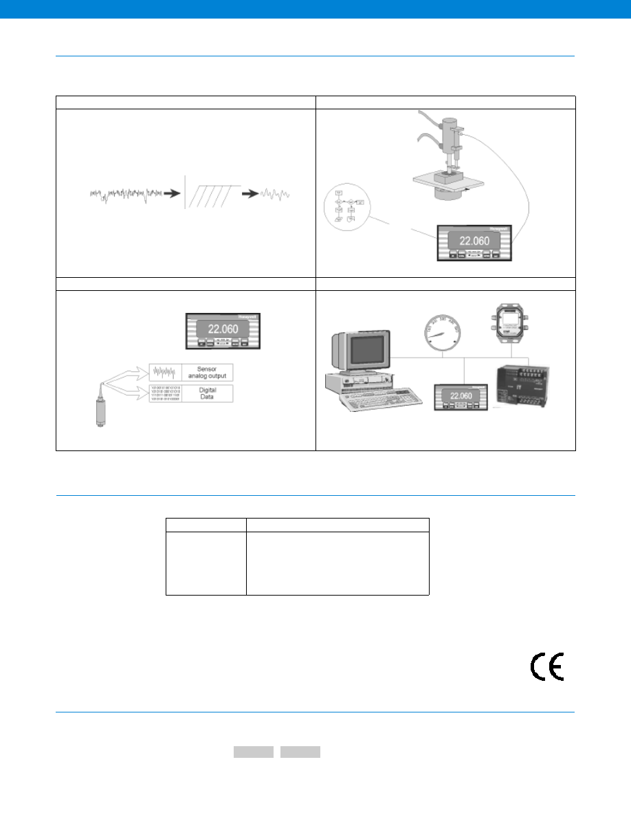
422
SC500 Capabilities (continued)
Options
How to Order
User Selectable Filtering
Math Channel (OPtional) Can Act Like PLC
Sig Cal Auto Set Up
Analog & Digital Outputs (Optional)
User Selectable
Filtering
Math Processing
Auto Setup
Retrieves Calibration Data
Sets up the Correct
Engineering Units
Sets the Specific Range
Sets up the Correct Calibration
Scales Analog Output
PC
Analog Meter
Data Logger
PLC
The order code consists of the product model and the available options.
Model Code
Options Code
Sample Code: AE236
58h
Model SC500
Built to Order
Output Options
53a. RS-232 (not available with 53d)
53d. RS-485 (not available with 53a)
58a. 2 limit set-points with Form C contact relays
(not available with 58h)
58h. 3 limit set-points with Form A contact relays
(not available with 58a)
58i. Isolated digital-to-analog (DAC) voltage
Approved
www.honeywell.com/sensotec
1-888-282-9891
-Not RoHS Compliant
Courtesy of Steven Engineering, Inc.-230 Ryan Way, South San Francisco, CA 94080-6370-Main Office: (650) 588-9200-Outside Local Area: (800) 258-9200-www.stevenengineering.com
Sensotec Sensors Full Line Catalog-html.html
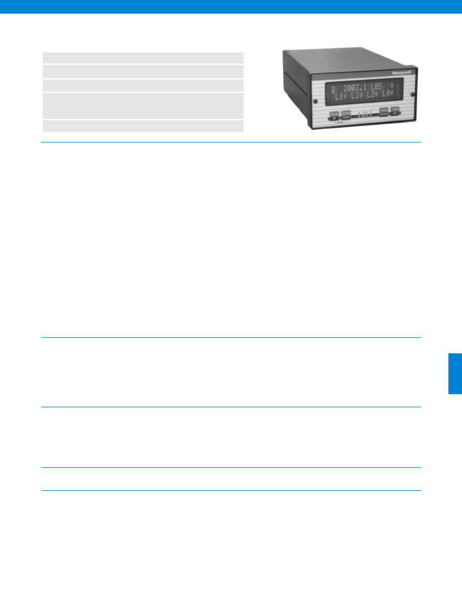
n
1 to 4 Channels
n
+/- 6 Digit Display
n
“Sig Cal” Auto Set Up
n
Pressure, Load, LVDT, Voltage, Current,
Strain Gage based Sensor Input
n
Alarm Outputs
423
General
Display
Environmental
Special Features
(for SC2000 only)
The SC series models are self-calibrating microprocessor-based Transducer Signal Conditioners when used with Sig Mod eqipped
transducers. Indicators are available with several different types of input channels and output channels. When used with unamplified
strain gage transducers that have the Sensotec
Signature Calibration Module
installed, these instruments will completely self calibrate
zero, span, decimal point, and engineering units automatically.
Input channels are available for a variety of transducers. Each input channel includes an excitation power supply and either an isolated
voltage or isolated current analog output.
• Unamplified pressure or load
• AC/AC LVDT
• Pressure or load with internal voltage amplifiers
• DC/DC LVDT
• Pressure or load with internal or external
• RTD Temperature probes (Pt100)
2-wire current amplifiers
Available output channels for the Model SC2000 include:
• Contact relays for the 4 standard limits or additional limits (max. 16 limits/ chassis)
• Isolated digital-to-analog voltage (+/- 5 or 0-10 VDC) or current (4-20 mA)
In addition to the physical input and output channels, up to 8 virtual channels can be configured to assist in many applications:
• Summation for weighing
• Conditional programs
• Floating-point mathematics
• Timer applications
• Split screen display
• Units conversion
Four Channel Chassis
The models SC1000 and SC2000 can hold up to 4 physical channels in their 3/8 DIN aluminum bench-top chassis. A bright, dual-line
16-character display can display 5, 6 or 7 numeric digits; simply press a button to select the next channel to be viewed. If configured
for split-screen operation, up to 4 channel values can be displayed at the same time. The SC2000 includes 4 open collector limit
(alarm) outputs plus peak and valley detection.
Model SC1000/ SC2000 Transducer Display & Signal
Conditioning Unit
Model................SC1000/ SC2000
Number of Physical Channels................1 to 4
Number of Virtual Channels................1 to 8
Case Material................Aluminum
Form factor................3/8 DIN
Mounting................Bench (std.)
Size................5.6” W x 2.8” H x 8.75” D
Weight................4 lb.
Number of Displays................1
Number of Lines/ Display................2
Number of Characters/ Line................16
Scaling................Automatic or manual setup
Max. Display Count................9,999,999
Decimal Point Selection................0 to 5
Display Type................Vacuum/ Fluorescent
Temperature, Storage................-20° to 200°F
Temperature, Operating................40° to 105° F
Limits Setup................Front panel
Limits Output (std.)................Open-collector
Limits Output (Relay Output Channel)................Contact relays
Limits Quantity................4 std., 16 max. (contact relays)
Peak/ Valley Hold on Input Channels................Yes
Digital, Isolated Control Inputs................4
Approvals................CE approved (except vehicle powered unit)
Interfaces................Signature Calibration
www.honeywell.com/sensotec
1-888-282-9891
Courtesy of Steven Engineering, Inc.-230 Ryan Way, South San Francisco, CA 94080-6370-Main Office: (650) 588-9200-Outside Local Area: (800) 258-9200-www.stevenengineering.com
Sensotec Sensors Full Line Catalog-html.html
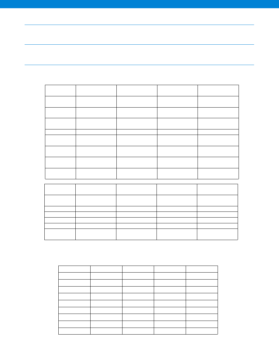
424
Communications
Power
Input Amplifier Cards
Serial Setup & Output................RS-232/ RS-485
Isolation................500 V
Max. Baud Rate................38400
Power Consumption................max. 200 VA (at startup)
Standard AC Powered................100 to 230 VAC, 47 to 63 Hz
Excitation Drive................120 mA max.
All input cards include non-isolated open-collector control inputs that can be field configured for any one of the
following functions: • Track hold • Peak/ Valley hold • Tare on • Tare off
2 (fast mode)
40
+/- 50,000
+/- 50,000
+/- 25,000
2
440
+/- 50,000
+/- 50,000
+/- 25,000
8
110
+/- 25,000
+/- 25,000
+/- 15,000
16
55
+/- 20,000
+/- 25,000
+/- 10,000
32
28
+/- 10,000
+/- 20,000
+/- 10,000
50
16
+/- 5,000
+/- 15,000
+/- 5,000
100
8
+/- 5,000
+/- 10,000
+/- 5,000
250
3
+/- 2,000
+/- 10,000
+/- 2,000
500
2
+/- 2,000
+/- 4,000
+/- 2,000
800
2
+/- 2,000
+/- 2,500
+/- 2,000
Frequency
Response (Hz)
(Field Selectable)
Step Response
(ms) (typical)
Resolution (counts)
(not including minimum 10% overrange/ underrange capacity)
Strain Gage/ RTD
High Level
AC/AC LVDT
*Ranges are field-programmable, except for RTD input
Model SC1000/ SC2000
Input
Strain Gage
Millivolts
High Level
Volts/ mA
RTD
Millivolts
AC/AC LVDT
Transducer Types
unamplified sensors
amplified pressure or
load, DC/DC LVDT
platinum 100 Ohm,
alpha = 0.00985
AC/AC LVDT
Ranges*
0.5 to 11 mV/V @ 5V
0.5 to 5.5 mV/V @ 10V
+/-5 or +/-10 VDC
4-20 mA
-328° to 1472°F
0.1 to 15 VRMS
Frequency
Response
See table below
See table below
See table below
See table below
Resolution
See table below
See table below
See table below
See table below
Calibration type
shunt; mV/V;
2-, 3- or 5- point
shunt; 2-, 3- or 5-point
known load
2-, 3- or 5- point
known load
2-, 3- or 5- point
known load
Transducer
Excitation
5 or 10 VDCw/ sense
+/- 15 VDC, +28 VDC
or +12 VDC
10 VDC
3VAC @ 3kHz
Push-button
100% tare
yes
yes
N/A
yes
Push-button
Shunt Test
yes
yes
N/A
yes
Output
Strain Gage
Millivolts
High Level
Volts/ mA
RTD
Millivolts
AC/AC LVDT
Voltage Range
(Field Selectable)
5, +/-5, 10, +/-10 VDC
5, +/-5, 10, +/-10 VDC
5, +/-5, 10, +/-10 VDC
5, +/-5, 10, +/-10 VDC
Current Range
4-20 mA
4-20 mA
4-20 mA
4-20 mA
Source
any channel
any channel
any channel
any channel
Isolation
500V
500V
500V
500V
Resolution
13 bits
13 bits
13 bits
13 bits
Frequency
Response
same as input
same as input
same as input
same as input
www.honeywell.com/sensotec
1-888-282-9891
Courtesy of Steven Engineering, Inc.-230 Ryan Way, South San Francisco, CA 94080-6370-Main Office: (650) 588-9200-Outside Local Area: (800) 258-9200-www.stevenengineering.com
Sensotec Sensors Full Line Catalog-html.html
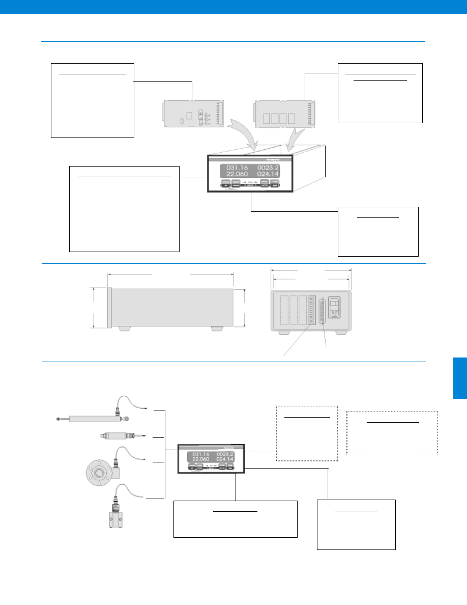
425
2.8 in.
8.6 in.
2.6 in.
5.6 in.
5.3 in.
25 Pin System Connector
12 Pin Channel Connector
Flexible and Expandable Platform Options
Dimensions
Typical System Diagram
Input Channel Card Options
• Strain Gage Input
• High Level Volt/ mA
• RTD (Platinum) mV
• AC LVDT
Note:
Specify voltage or current
O/P on each card
Chassis & Signal Conditioning Options
• Number of Channels (1-4)
• Number of Virtual Channels (1-8)
• Split Display Virtual Channel
• Mathematics Virtual Channel
• AC or Vehicle Power Supply (note 1)
• RS232 or RS485 Output
• Limited Features Option (Model SC1000):
No Alarm
No Display of Peak & Valley
No Open Collector Outputs
Output Channel Card Options
(Model SC20000 only)
• Up to 4 Relay Cards
• Additional Analog O/P Card
Note:
These cards occupy spare
channel card slots
Mounting Options
• Bench Mount
• Panel Mount (AA928)
• Carry Handle (AA926)
• Portable (see Model SC2001)
Mounting Options
Bench Mount
Panel Mount (AA928)
Carry Handle (AA926)
Portable (see Model SC2001)
Customer Supplied
Chart Recorder
Alarm Panel
Data Acquisition
Computer
PLC
Model SC1000/ SC2000
Total of
Four Slots
Note:
1. Vehicle power supply is not CE certified.
Cable Accessories
25 Pin D-Sub Connector (to SC Series)
to 9 Pin D-Sub Connector (to Computer) (AA178)
Software Accessories
SensoCom Instrument Ultility
Software for Windows 98/ NT/ 2000
(AA183)
www.honeywell.com/sensotec
1-888-282-9891
Courtesy of Steven Engineering, Inc.-230 Ryan Way, South San Francisco, CA 94080-6370-Main Office: (650) 588-9200-Outside Local Area: (800) 258-9200-www.stevenengineering.com
Sensotec Sensors Full Line Catalog-html.html
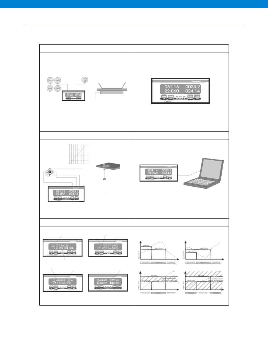
426
SC2000 Capabilities
Number of decimal places
Number of channels for display
Serial communications
Update signature module
mV/V Calibration
Shunt Calibration
Shows channel on display
Shows status of alarms
User selected decimal point
6 digit display
Alarm on when setpoint
exceeded and until return
point is reached
Alarm on when below
setpoint and until return
point is reached
4 channel display
Valley tracking
Peak tracking
User selected units
2, 3 or 5 point calibration for
applied load, pressure, speed,
etc.
Calibration data
Display averaging
Output voltage
Alarm outputs
Engineering units
Front Panel or Remote Tare
Flexible User Setup
mV/V or Shunt Calibration or 5 Point Calibration
Remote Setup
User Selectable Display Options
Different Alarm Configurations
Model SC1000/ SC2000
www.honeywell.com/sensotec
1-888-282-9891
Courtesy of Steven Engineering, Inc.-230 Ryan Way, South San Francisco, CA 94080-6370-Main Office: (650) 588-9200-Outside Local Area: (800) 258-9200-www.stevenengineering.com
Sensotec Sensors Full Line Catalog-html.html
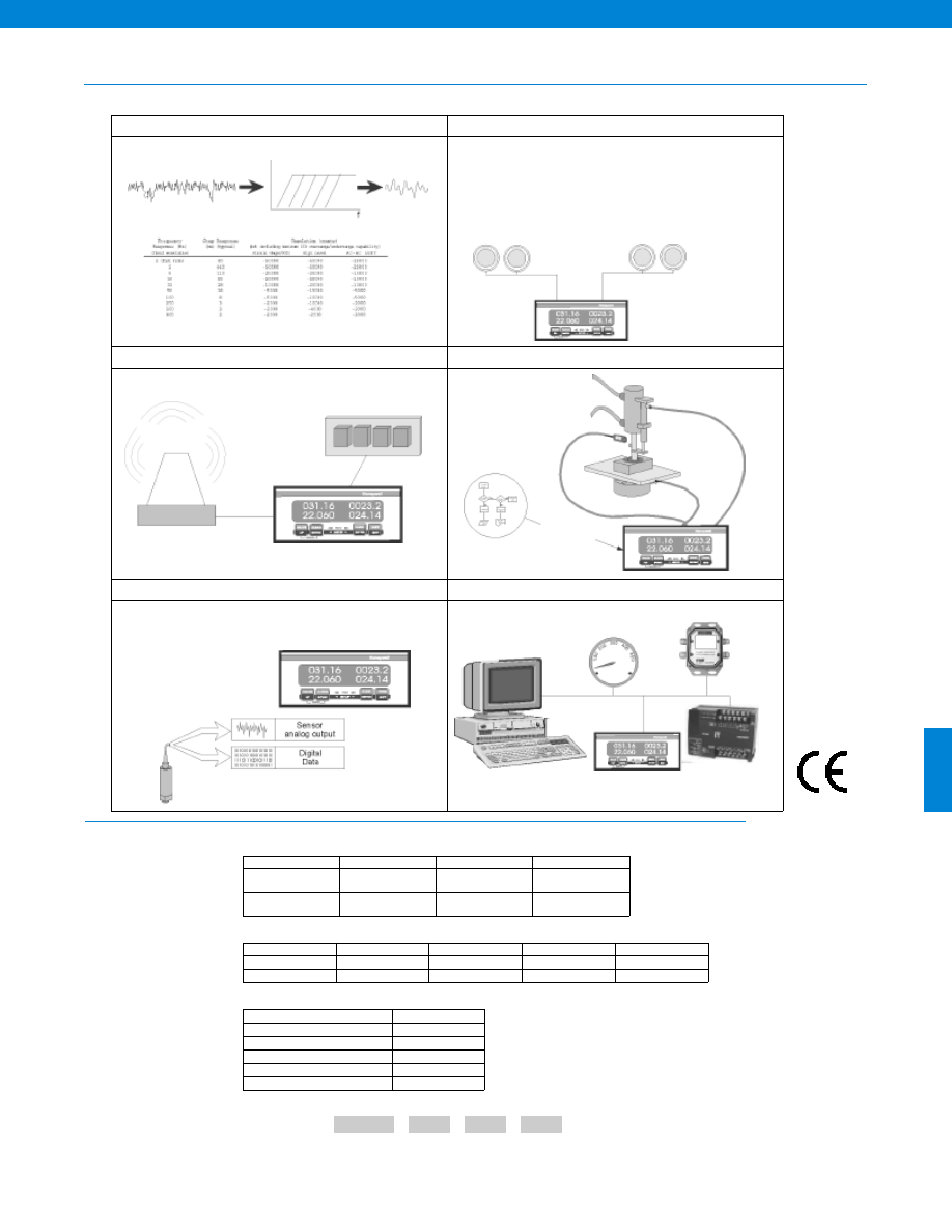
427
SC2000 Capabilities
How to Order
User Selectable Filtering
Group and Individual Channel Remote Inputs
Open Collector Alarms or via Optional Four-Relay Cards
Optional Math Channel Can Act Like PLC
Sig Cal Auto Set Up
Analog & Digital Outputs
User Selectable
Filtering
System Remote
Switch Inputs:
Peak/ Valley clear
Tare on
Tare off
Channel Specific Remote Commands;
Each channel can have any two:
Track hold
Peak/ Valley hold
Peak/ Valley clear
Tare on
Tare off
Math Processing
Auto Setup
Retrieves Calibration Data
Sets up the Correct
Engineering Units
Sets the Specific Range
Sets up the Correct Calibration
Scales Analog Output
PC
Analog Meter
Data Logger
PLC
Combine the Chassis code, the Channel codes and all other options (with quantities) in alphabetical order.
For example, order code AE617,A2,R1,S1 specifies SC2000 instrument with RS485 output, 2 strain gage input channels, 1 relay
output card and 1 math channel. Note the options codes are listed in alphabetical order.
First, select the order code for the chassis of your instrument.
Next, select the Channet Input Option Codes and their quantities.
Chassis Code
Channel Option Codes with Quantites
Sample Code: AE617
A2
R1 S1
Readout
Output
SC1000
SC2000
1 Display
RS-232
RS-485
AE600
AE616
AE601
AE617
1 Display
Vehicle Power
RS-232
RS-485
AE632
AE648
AE633
AE649
Strain Gage
High Level
RTD
AC/AC LVDT
Voltage Output
A
C
E
G
Current Output
B
D
F
H
Model SC1000/ SC2000
Then select any additional Option Codes and their quantities.
Option Code
Relay Output Channel
R
Voltage DAC Output Channel
O
Current DAC Output Channel
P
Split Display Virtual Channel
T
Mathematics Virtual Channel
S
(SC2000 only)
(SC2000 only)
(SC2000 only)
www.honeywell.com/sensotec
1-888-282-9891
-Not RoHS Compliant
Approved
Courtesy of Steven Engineering, Inc.-230 Ryan Way, South San Francisco, CA 94080-6370-Main Office: (650) 588-9200-Outside Local Area: (800) 258-9200-www.stevenengineering.com
Sensotec Sensors Full Line Catalog-html.html
428
General
Display
Environmental
Special Features
The SC series models are self-calibrating microprocessor-based Transducer Signal Conditioners. Indicators are available with several differ-
ent types of input channels and output channels. When used with unamplified strain gage transducers that have the Sensotec
Signature
Calibration Module
installed, these instruments will completely self calibrate zero, span, decimal point, and engineering units automatically.
Input channels are available for a variety of transducers. Each input channel includes an excitation power supply and either an isolated
voltage or isolated current analog output.
• Unamplified pressure or load
• AC/AC LVDT
• Pressure or load with internal voltage amplifiers
• DC/DC LVDT
• Pressure or load with internal or external
• RTD Temperature probes (Pt100)
2-wire current amplifiers
Available output channels for the Model SC3004 include:
• Contact relays for the 4 standard limits or an additional 4 limits per card up to 16 limits
• Isolated digital-to-analog voltage (+/- 5 or 0-10 VDC) or current (4-20 mA)
In addition to the physical input and output channels, up to 8 virtual channels can be configured to assist in many applications:
• Summation for weighing
• Conditional programs
• Floating-point mathematics
• Timer applications
• Split screen display
Fourteen Channel Chassis
Model SC3004 can hold up to 14 physical channels in its 19”, 2U rack-mount enclosure. Up to three quad-line displays can be installed
which will display the values of up to 12 channels. Split displays can increase display capacity.
n
1 to 14 Channels
n
+/- 6 Digit Display
n
“Sig Cal” Auto Set Up
n
Pressure, Load, LVDT, Voltage, Current,
Strain Gage based Sensor Input
n
Alarm Outputs
Model SC3004 Transducer Display & Signal Conditioning Unit
Model................SC3004
Number of Physical Channels................1 to 14
Number of Virtual Channels................8
Case Material................Aluminum
Form factor................2U rack
Mounting................rack or bench with included rubber feet
Size................19” W x 3.5” H x 8.75” D
Weight................11 lb.
Number of Characters/ Lines................20
Number of Line/ Display................4
Number of Displays................1, 2 or 3 (max. 12 Channel display)
Scaling................Automatic or manual setup
Max. Display Count................9,999,999
Decimal Point Selection................0 to 5
Display Type................Vacuum/ Fluorescent
Temperature, Storage................-20° to 200°F
Temperature, Operating................40° to 105° F
Limits Setup................Front panel
Limits Output (std.)................Open-collector
Limits Output (Relay Output Channel)................Contact relays
Limits Quantity................4 std., 16 max. (contact relays)
Peak/ Valley Hold on Input Channels................Yes
Digital, Isolated Control Inputs................4
Approvals................CE approved
www.honeywell.com/sensotec
1-888-282-9891
Courtesy of Steven Engineering, Inc.-230 Ryan Way, South San Francisco, CA 94080-6370-Main Office: (650) 588-9200-Outside Local Area: (800) 258-9200-www.stevenengineering.com
Sensotec Sensors Full Line Catalog-html.html
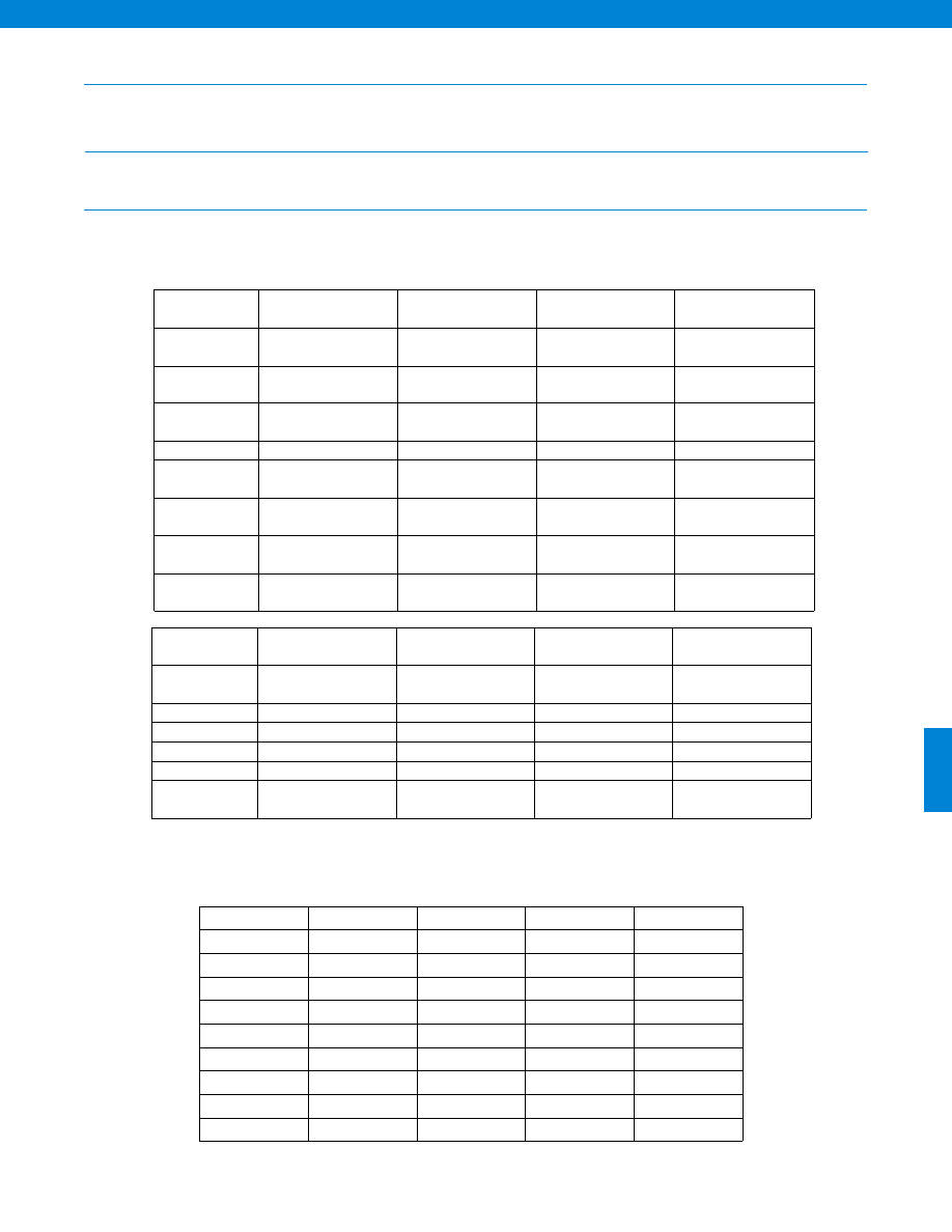
429
Communications
Power
Input Amplifier Cards
Serial Setup & Output................RS-232/ RS-485
Isolation................500 V
Max. Baud Rate................38400
Power Consumption................max. 230 VA
Standard AC Powered................100 to 230 VAC, 47 to 63 Hz
Excitation Drive................400 mA max.
All input cards include non-isolated open-collector control inputs that can be field configured for any one of the
following functions: • Track hold • Peak/ Valley hold • Tare on • Tare off
2 (fast mode)
40
+/- 50,000
+/- 50,000
+/- 25,000
2
440
+/- 50,000
+/- 50,000
+/- 25,000
8
110
+/- 25,000
+/- 25,000
+/- 15,000
16
55
+/- 20,000
+/- 25,000
+/- 10,000
32
28
+/- 10,000
+/- 20,000
+/- 10,000
50
16
+/- 5,000
+/- 15,000
+/- 5,000
100
8
+/- 5,000
+/- 10,000
+/- 5,000
250
3
+/- 2,000
+/- 10,000
+/- 2,000
500
2
+/- 2,000
+/- 4,000
+/- 2,000
800
2
+/- 2,000
+/- 2,500
+/- 2,000
Frequency
Response (Hz)
(Field Selectable)
Step Response
(ms) (typical)
Resolution (counts)
(not including minimum 10% overrange/ underrange capacity)
Strain Gage/ RTD
High Level
AC/AC LVDT
*Ranges are field-programmable, except for RTD input
Model SC3004
Input
Strain Gage
Millivolts
High Level
Volts/ mA
RTD
Millivolts
AC/AC LVDT
Transducer Types
unamplified pressure or
load sensors
amplified pressure or
load, DC/DC LVDT
platinum 100 Ohm,
alpha = 0.00985
AC/AC LVDT
Ranges*
0.5 to 11 mV/V @ 5V
0.5 to 5.5 mV/V @ 10V
+/-5 or +/-10 VDC
4-20 mA
-328° to 1472°F
0.1 to 15 VRMS
Frequency
Response
See table below
See table below
See table below
See table below
Resolution
See table below
See table below
See table below
See table below
Calibration type
shunt; mV/V;
2-, 3- or 5- point
shunt; 2-, 3- or 5-point
known load
2-, 3- or 5- point
known load
2-, 3- or 5- point
known load
Transducer
Excitation
5 or 10 VDCw/ sense
+/- 15 VDC, +28 VDC
or +12 VDC
10 VDC
3VAC @ 3kHz
Push-button
100% tare
yes
yes
N/A
yes
Push-button
Shunt Test
yes
yes
N/A
yes
Output
Strain Gage
Millivolts
High Level
Volts/ mA
RTD
Millivolts
AC/AC LVDT
Voltage Range
(Field Selectable)
5, +/-5, 10, +/-10 VDC
5, +/-5, 10, +/-10 VDC
5, +/-5, 10, +/-10 VDC
5, +/-5, 10, +/-10 VDC
Current Range
4-20 mA
4-20 mA
4-20 mA
4-20 mA
Source
any channel
any channel
any channel
any channel
Isolation
500V
500V
500V
500V
Resolution
13 bits
13 bits
13 bits
13 bits
Frequency
Response
same as input
same as input
same as input
same as input
www.honeywell.com/sensotec
1-888-282-9891
Courtesy of Steven Engineering, Inc.-230 Ryan Way, South San Francisco, CA 94080-6370-Main Office: (650) 588-9200-Outside Local Area: (800) 258-9200-www.stevenengineering.com
Sensotec Sensors Full Line Catalog-html.html
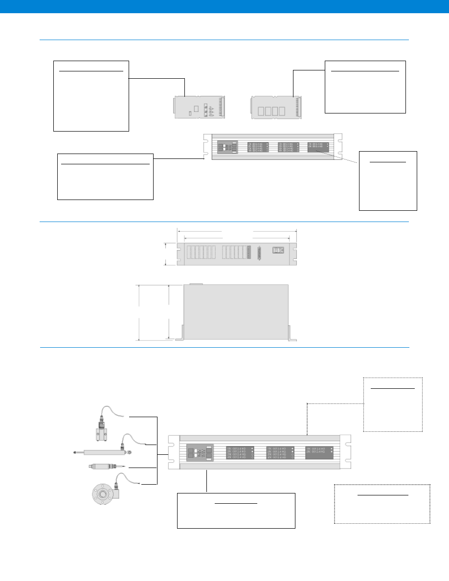
430
9.125 in.
8.875 in.
3.5 in.
19 in.
17 in.
Flexible and Expandable Platform
Dimensions
Typical System Diagram
Input Channel Card Options
• Strain Gage Input
• High Level Volt/ mA
• RTD (Platinum) mV
• AC LVDT
Note:
Specify voltage or current
O/P on each card
Chassis & Signal Conditioning Options
• Number of Channels (1-14)
• Math Channel
• Split Display Virtual Channel
• RS232 or RS485 Output
Output Channel Card Options
• 4 Relay Cards
• Additional Analog O/P Card
Note:
These cards occupy spare
channel card slots.
Display Options
• 1 Display (std.)
• 2 Display
• 3 Display
Note:
Only 12 channels
of display.
Cable Accessories
25 Pin D-Sub Connector (to SC Series)
to 9 Pin D-Sub Connector (to Computer) (AA178)
Customer Supplied
Chart Recorder
Alarm Panel
Data Acquisition
Computer
PLC
Software Accessories
SensoCom Instrument Ultility Software
for Windows 98/ NT/ 2000
(AA183)
Model SC3004
Up to 14 Channels
www.honeywell.com/sensotec
1-888-282-9891
Courtesy of Steven Engineering, Inc.-230 Ryan Way, South San Francisco, CA 94080-6370-Main Office: (650) 588-9200-Outside Local Area: (800) 258-9200-www.stevenengineering.com
Sensotec Sensors Full Line Catalog-html.html
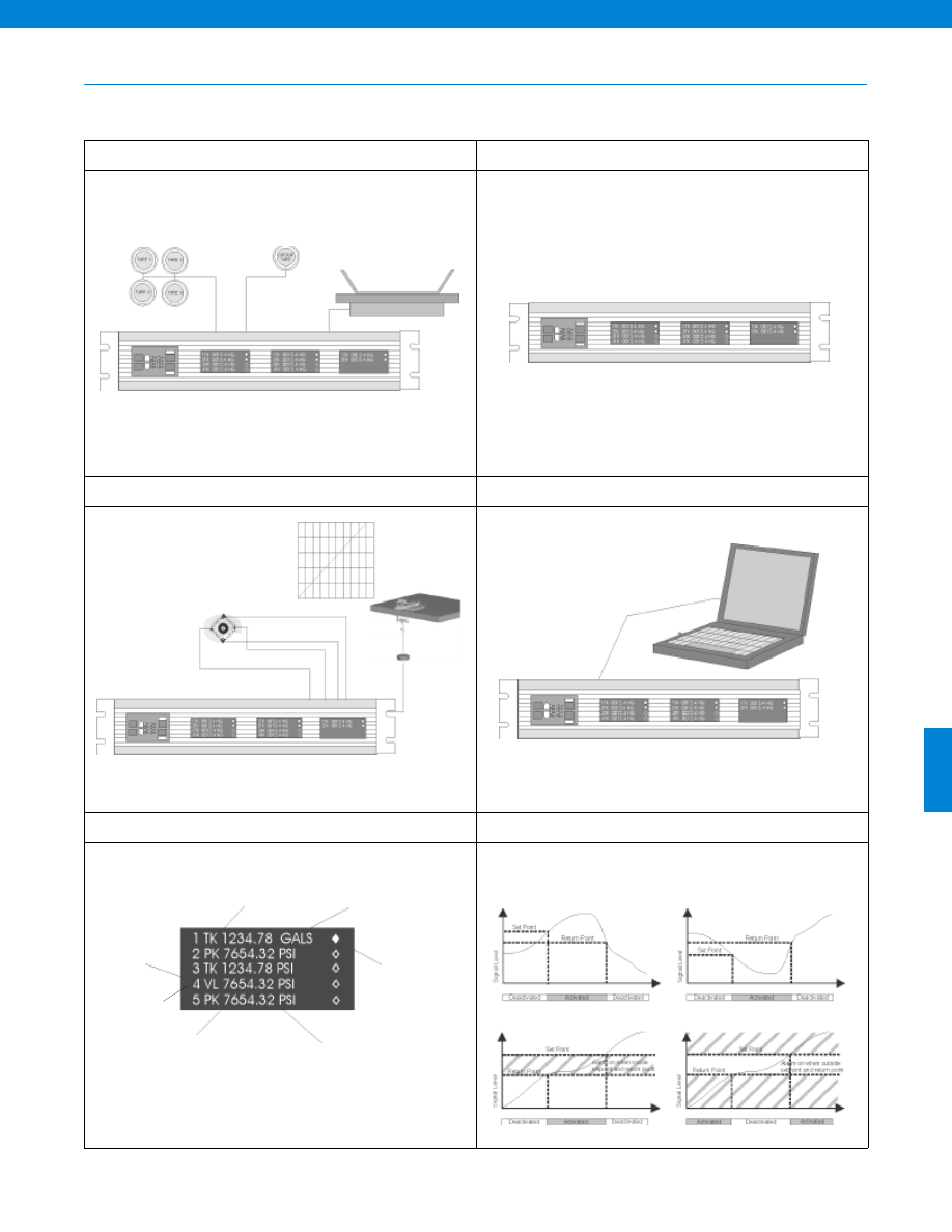
431
SC3004 Capabilities
Number of decimal places
Number of channels for display
Serial communications
Update signature module
mV/V Calibration
Shunt Calibration
Shows status
of alarms
User selected decimal point
6 digit display
Alarm on when setpoint
exceeded and until return
point is reached
Alarm on when below
setpoint and until return
point is reached
Valley reading
Track reading
Peak tracking
User selected units
5 point applied load,
pressure, speed, etc.
calibration
Calibration data
Display averaging
Output voltage
Alarm outputs
Engineering units
Front Panel or Remote Tare
Flexible User Setup
mV/V or Shunt Calibration or 5 Point Calibration
Remote Setup
User Selectable Display Options
Different Alarm Configurations
Model SC3004
www.honeywell.com/sensotec
1-888-282-9891
Courtesy of Steven Engineering, Inc.-230 Ryan Way, South San Francisco, CA 94080-6370-Main Office: (650) 588-9200-Outside Local Area: (800) 258-9200-www.stevenengineering.com
Sensotec Sensors Full Line Catalog-html.html
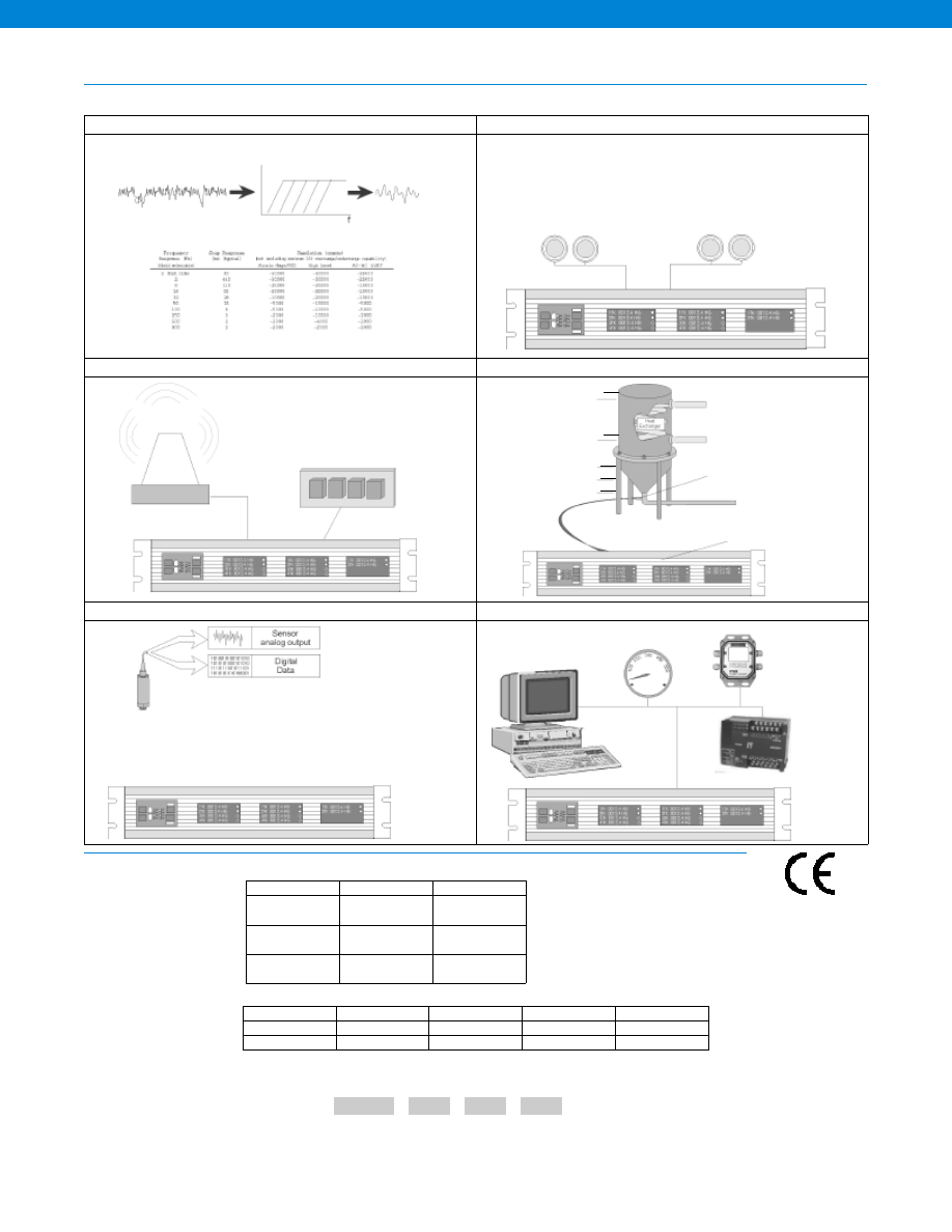
432
SC3004 Capabilities
How to Order
User Selectable Filtering
Group and Individual Channel Remote Inputs
Open Collector Alarms or via Optional Four-Relay Cards
Optional Math Channel Can Act Like PLC
Sig Cal Auto Set Up
Analog & Digital Outputs
User Selectable
Filtering
System Remote
Switch Inputs:
Peak/ Valley clear
Tare on
Tare off
Channel Specific Remote Commands;
Each channel can have any one:
Track hold
Peak/ Valley hold
Peak/ Valley clear
Tare on
Tare off
Math Processing
to convert linearity points
Sensotec Model CIP liquid
level sensor
Linearity points
5
4
3
2
1
Auto Setup
Retrieves Calibration Data
Sets up the Correct
Engineering Units
Sets the Specific Range
Sets up the Correct Calibration
Scales Analog Output
PC
Analog Meter
Data Logger
PLC
Combine the Chassis code, the Channel codes and all other options (with quantities) in alphabetical order.
For example, order code AE606,A4,R2,S1 specifies SC3004 instrument with a single display, RS232 output, 4 strain gage input
channels, 2 relay output cards and 1 math channel. Note the options codes are listed in alphabetical order.
First, select the order code for the chassis of our instrument.
Next, select the Channet Input Option Codes and their quantities.
Chassis Code
Channel Option Codes with Quantites
Sample Code: AE606
A4
R2 S1
Strain Gage
High Level
RTD
AC/AC LVDT
Voltage Output
A
C
E
G
Current Output
B
D
F
H
Model SC3004
Readout
Output
Order Code
1 Display
RS-232
RS-485
AE606
AE622
2 Display
RS-232
RS-485
AE607
AE623
3 Display
RS-232
RS-485
AE608
AE624
www.honeywell.com/sensotec
1-888-282-9891
-Not RoHS Compliant
Approved
Courtesy of Steven Engineering, Inc.-230 Ryan Way, South San Francisco, CA 94080-6370-Main Office: (650) 588-9200-Outside Local Area: (800) 258-9200-www.stevenengineering.com
Sensotec Sensors Full Line Catalog-html.html
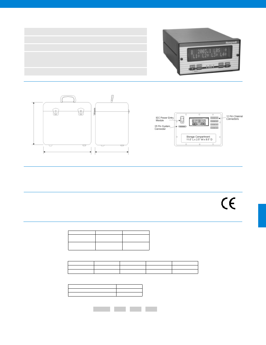
433
n
Portable Mounting for SC2000
n
Vehicle Power or AC Power Input
n
Easy Hook up of Sensors
n
Pressure, Load, LVDT Voltage Current,
Strain Gage Based Sensor Input
n
Convenient Cable Storage
Model SC2001 Transducer Display & Signal Conditioning Unit
Model................SC2001
Case Material................Aluminum
Form factor................Suitcase
Mounting................Portable
Size................13.25” W x 11.5” H x 9.2” D
See SC2000 Datasheet
Dimensions
General
Display, Environmental, Special
Features
,
Communications, Power,
Input Amplifier Cards, Capabilities,
Options, System Diagram
How to Order
Combine the Chassis code, the Channel codes and all other options (with quantities) in alphabetical order.
For example, order code AE618,A2,S1,T1 specifies SC2001 instrument with RS485 output, 2 strain gage input channels, 1 math
channel and 1 split display channel. Note the options codes are listed in alphabetical order.
First, select the order code for the chassis of your instrument.
Next, select the Channet Input Option Codes and their quantities.
Chassis Code
Channel Option Codes with Quantites
Sample Code: AE618
A2
S1 T1
Readout
Output
SC2001
1 Display
RS-232
RS-485
AE602
AE618
1 Display
Vehicle Power
RS-232
RS-485
AE634
AE650
Strain Gage
High Level
RTD
AC/AC LVDT
Voltage Output
A
C
E
G
Current Output
B
D
F
H
Then select any additional Option Codes and their quantities.
Option Code
Split Display Virtual Channel
T
Mathematics Virtual Channel
S
11.5 in.
9.2 in.
13.25 in.
www.honeywell.com/sensotec
1-888-282-9891
-Not RoHS Compliant
Approved
Courtesy of Steven Engineering, Inc.-230 Ryan Way, South San Francisco, CA 94080-6370-Main Office: (650) 588-9200-Outside Local Area: (800) 258-9200-www.stevenengineering.com
Sensotec Sensors Full Line Catalog-html.html
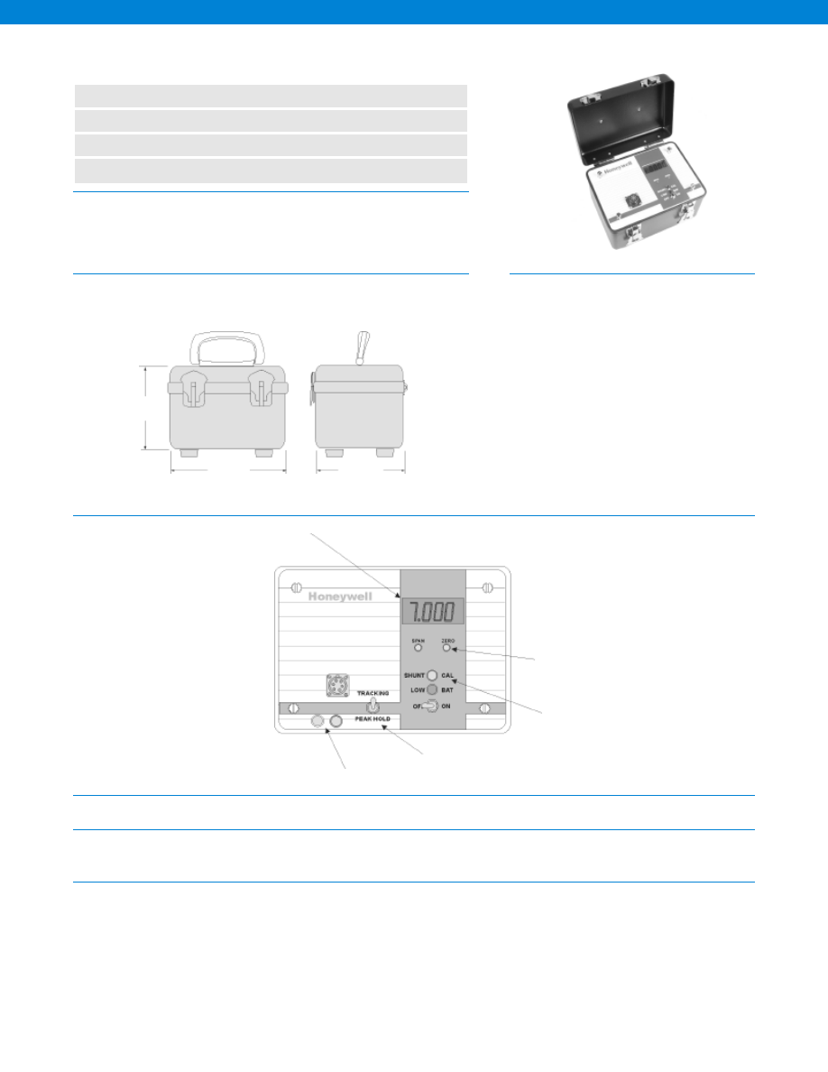
434
www.honeywell.com/sensotec
1-888-282-9891
Model NK Portable Display/ Signal Conditioner
Order Code AE221
n
Bridge Based Transducer Input
n
4-1/2 Digit LED Display
n
Battery Powered
n
Analog Output Option
Dimensions
Features
General
Environmental
Transducer Interface
Number of Channels................1
Material................Deep drawn aluminum case
Temperature, Operating................32° to 130° F
Temperature, Storage................-20° to 150° F
Power Requirement................Batteries- 4 “D” cells
Transducer Excitation................4 VDC
Types of Inputs Accepted................0.5 to 4 mV/V
Transducer Bridge Range................350 Ohms
Pushbutton Shunt Cal................Yes
Calibration Method................Manual
Electrical Connection Type................PT02A-10-6S (note 1)
Zero Balance................+/- 15% of Full Scale (min.)
Noise & Ripple................30 microvolts
5.00 in.
5.00 in.
7.00 in.
Wiring Code
A
(+) Excitation
B
(+) Sense
C
(-) Excitation
D
(-) Sense
E
(-) Input
F
(+) Input
Notes:
1. PT06A-10-6P (SR) mating connector, order code AA119
4 1/2 Digit Display
Zero & Gain Pots
Shunt Calibration
Peak/ Hold Tracking (58c. Option)
0-1V Analog Output (56e. Option)
The Model NK portable instrument features a full 4 1/2 digit display and is
designed for use in remote field operations as a portable calibrator or readout
device. Shunt calibration offers the operator quick field setup with a minimum of
warm-up. A peak/ hold feature is optional.
Courtesy of Steven Engineering, Inc.-230 Ryan Way, South San Francisco, CA 94080-6370-Main Office: (650) 588-9200-Outside Local Area: (800) 258-9200-www.stevenengineering.com
Sensotec Sensors Full Line Catalog-html.html
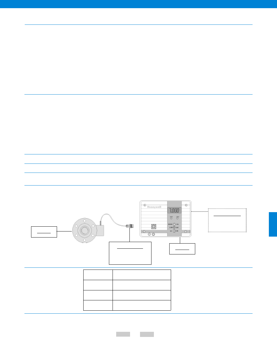
435
www.honeywell.com/sensotec
1-888-282-9891
Amplifier Characteristics
Digital Display
Characteristics
Physical Characteristics
Power Supply
Front Panel
Typical System Diagram
Options
Full Scale Outputs Available................0-1V (optional)
Output Impedance................< 1 Ohm (optional)
Non-linearity................+/- 0.02% of Full Scale (max.)
Drift
Zero................+/- 5 mV (max.)
Span................+/- 5 mV (max.)
Stability
Zero................0.1% of Full Scale/ year
Span................0.1% of Full Scale/ year
Frequency Response................1,000 Hz
Fine Span Adjustment................+/- 15% of Range
Coarse Span Adjustment................100% of Range
Fine Zero Adjustment................+/- 15% of Range
Coarse Zero Adjustment................100% of Range
Short Circuit Protection................Yes
Number of Display Characters................4-1/2
Conversion/ second................1.5
Scaling................0-19,999
Scaling Method................Potentiometer
Maximum Display Count................19,999
Polarity Indications................Yes
Programmable Decimal Points................Yes
Display Size................0.4 in.
Overrange Indication................Yes
Resolution................1/20,000
Type................LCD
Maximum Sensitivity.................1 microvolt/ count
Peak/ Hold................Yes (optional)
Weight................3 lb.
Power Requirements................4 “D” cells
Digital Display................4-1/2 digits LCD
Environmentally Sealed................Weatherproof case
Built to Order
Input
52c. 0-4.5 mV/V to 0-40 mV/V
Outputs
56e. 0-1 VDC
Special Features
58c. Peak/ Hold
58m.Knob Potentiometer Adjustments
Model Code
Options Code
The order code consists of the product model and the available options.
How to Order
Sample Code
AE221
56e
Cable Accessories
PT06A-10-6P (SR) Mating
Connector (AA119)
Model NK
Load Cell
Customer Supplied
Chart Recorder
Data Acquisition
Model NK
-Not RoHS Compliant
Courtesy of Steven Engineering, Inc.-230 Ryan Way, South San Francisco, CA 94080-6370-Main Office: (650) 588-9200-Outside Local Area: (800) 258-9200-www.stevenengineering.com
Sensotec Sensors Full Line Catalog-html.html
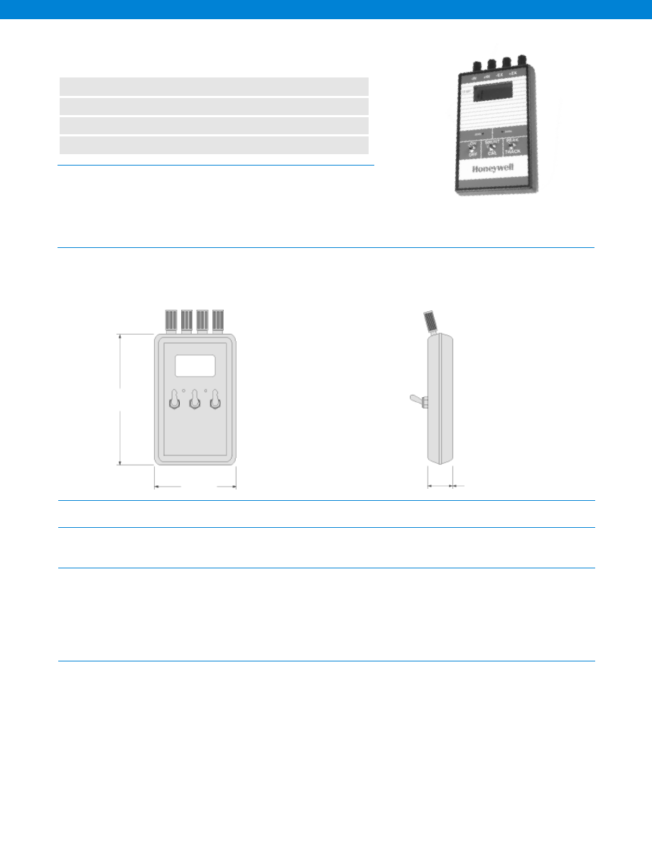
436
www.honeywell.com/sensotec
1-888-282-9891
Model HH Portable Display/ Signal Conditioner
Order Code AE222
n
Bridge Based Transducer Input
n
3-1/2 Digit LED Display
n
Battery Powered
n
Peak Hold & Shunt Cal Features
Dimensions
General
Environmental
Transducer Interface
Amplifier Characteristics
Number of Channels................1
Material................Hand-held plastic case
Temperature, Operating................32° to 130° F
Temperature, Storage................-20° to 150° F
Power Requirement................Battery - one 9V cell
Transducer Excitation................2.5 VDC
Types of Inputs Accepted................0.5 to 8 mV/V
Transducer Bridge................120 Ohms min.
Pushbutton Shunt Cal................Yes
Calibration Method................Manual
Electrical Connection Type................4 banana jacks
Zero Balance................+/- 15% of Full Scale (min.)
Noise & Ripple................30 microvolts
Non-linearity................+/- 0.1% of Full Scale (max.)
Drift
Zero................+/- 50 mV (max.)
Span................+/- 50 mV (max.)
Stability
Zero................1.0% of Full Scale/ year
Span................1.0% of Full Scale/ year
Frequency Response................5 Hz
Fine Span Adjustment................+/- 15% of Range
Fine Zero Adjustment................+/- 15% of Range
Short Circuit Protection................Yes
5.8 in.
1.1 in.
3.6 in.
2.5 VDC Transducer Excitation
Peak Hold
Tracking
Shunt Calibration
Zero & Gain Pots
3 1/2 Digit Display
The Model HH handheld instrument features a full 3 1/2 digit display and is
designed for use in remote field operations as a portable calibrator or readout
device. Shunt calibration offers the operator quick field setup with a minimum of
warm-up. A peak/ hold feature is standard.
Courtesy of Steven Engineering, Inc.-230 Ryan Way, South San Francisco, CA 94080-6370-Main Office: (650) 588-9200-Outside Local Area: (800) 258-9200-www.stevenengineering.com
Sensotec Sensors Full Line Catalog-html.html
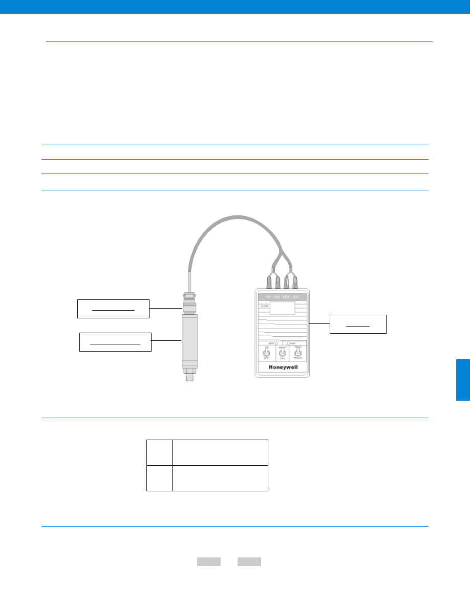
437
www.honeywell.com/sensotec
1-888-282-9891
Digital Display
Characteristics
Physical Characteristics
Power Supply
Front Panel
Typical System Diagram
Options
Model Code
Options Code
The order code consists of the product model and the available options.
How to Order
Sample Code
AE222
52c
Pressure Transducer
Model HH
Mating Connector
Number of Display Characters................3-1/2
Conversion/ second................1.5
Scaling................0-1,999
Scaling Method................Potentiometer
Maximum Display Count................1,999
Polarity Indications................Yes
Programmable Decimal Points................Yes
Display Size................0.4 in.
Overrange Indication................Yes
Resolution................1/2,000
Type................LCD
Maximum Sensitivity.................0.1 microvolt/ count
Peak/ Hold................Yes
Weight................1 lb.
Power Requirements................One 9V cell
Digital Display................3-1/2 digits LCD
Built to Order
Input
52c.
0-4.5 mV/V to 0-40 mV/V
Model HH
-Not RoHS Compliant
Courtesy of Steven Engineering, Inc.-230 Ryan Way, South San Francisco, CA 94080-6370-Main Office: (650) 588-9200-Outside Local Area: (800) 258-9200-www.stevenengineering.com
Sensotec Sensors Full Line Catalog-html.html
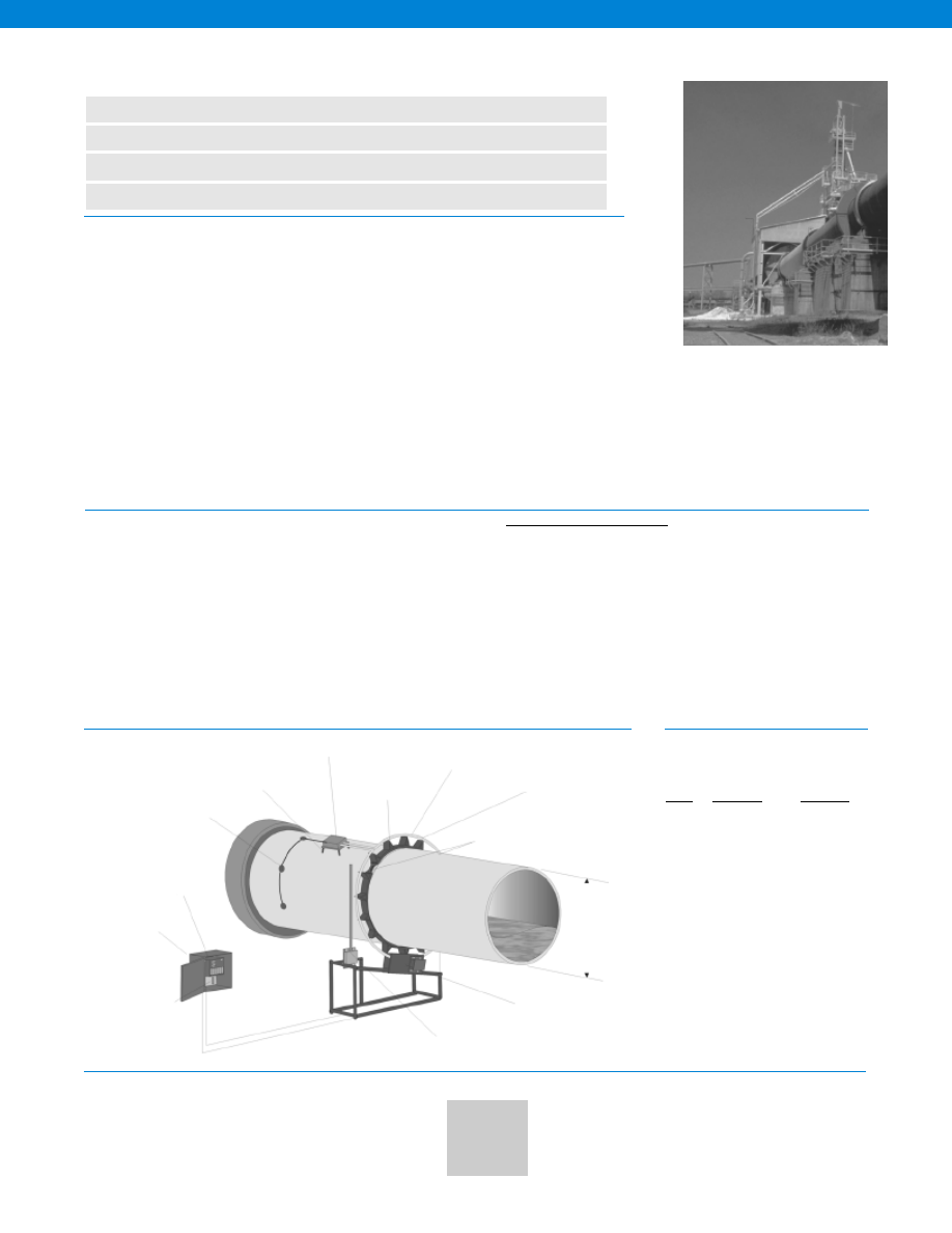
438
www.honeywell.com/sensotec
1-888-282-9891
Model 1400B/1401 Digital Temperature Monitoring System
Order Code WK1000 (1400B); WK1100 (1401B)
n
Non-Contact
n
Rugged & Reliable
n
Save Energy
n
Protect Internal Structures
Typical System Diagram
Inputs
How to Order
Strap on Collar
The Models 1400B and 1401B digital temperature monitoring systems are often ideal for use with internally-
fired lime recovery, cement and alumina kilns as well as industrial dryers and incinerators for hazardous
waste disposal. They are designed to provide internal temperature data that can be vital in a variety of
applications. The 1400 series features a digital transmitter mounted on the exterior of the rotating surface to
constantly monitor and transmit data from isolated thermocouples mounted inside or on the skin of the kiln.
The system uses inductive power so that temperatures can be obtained continuously from rotating equip-
ment without the use of wires or batteries. The 1401B is used for kiln diameters up to 6 ft, and the 1400B is
used for kiln diameters of greater than 6 ft. Consult factory for custom options (special ranges, etc).
ACCURATE Thermocouples provide direct internal temperature readings from process materials inside the kiln. Typically +/-1.7°C over the
measurement range for a Type K thermocouple.
TELEMETRY-BASED Non-contact technology transmits thermocouple data to a receiver. There, it is converted to voltage or current signals.
The system is not generally affected by hand-held communication transmitters.
RELIABLE The 1400 series uses digitally coded telemetry transmissions that have high signal-to-noise ratios compared to analog methods.
Only valid data is accepted and processed.
RUGGED This system generally is unaffected by the electrical noise of other equipment. Enclosures are all water and dust tight (NEMA 4).
The system operates reliably in the harsh, hot industrial environments of kilns, dryers, and incinerators.
FIELD PROVEN The 1400 series is a third generation design built on years of experience. It can be a reliable method for obtaining accurate
internal temperature measurements from difficult-to-access center locations away from either end of the kiln.
WK1000
B (3)
0-10 V
10ft.
0-50mV input
Please Specify:
Order Code
Thermocouple Type(s)
System Outputs
Kiln Diameter (approx.)
Special Options
Sample Order:
Up to 6 Thermocouples
(Customer Installed)
Customer Supplied
Thermal Standoffs
(If req’d)
1418B Temperature
Transmitter
Nema 4 Cabinet
Model 1408A Stationary
Antenna Module
Up to 15 ft.
Diameter
Model 1420A Power Supply Unit
(>6 ft. diameter)
Model 1211D Power Supply Unit
(<6 ft. diameter)
Performance
Accuracy................
25µV
+/-1.0°C +/- 0.1°C
T/C outputs @ 25°C -- µV/°C
(+/-1.7°C for Type K thermocouple)
Power Requirements................115/230 VAC; 60/60 Hz; 200 VA
Output
Current................4-20 mA; 0-20 mA (max loop resistance: 600 Ohms)
Voltage................0-5 V; 10 V or 1-5V; 10V
Display................LCD (Alphanumeric - displays system status and
sensor outputs with error messages)
Sampling Rate................32/sec/channel
Input channels per system................3 (std., expandable to 6)
All wiring enclosures................Nema 4 type
Size................46”L x 32”W x 43”H
Weight (approximate)................175 lb (80Kg)
Brass Rod
Antenna
Model 1427A
Rotating Antenna Kit
Springs
Standard with 3
Isolated Outputs
Installed
Model 1442B
Reciever Unit
Any isolated T/C Type, any input channel
Type
Range°C
Range°F
B
+200 to 1,820 +392 to 3,308
E
-95 to 1,000
-139 to 1,832
J
-109 to 1,000
-139 to 1,832
K
-154 to 1,370
-245 to 2,498
R
-167 to 1,665
-269 to 3,029
S
-167 to 1,665
-269 to 3,029
T
-157 to 400
-251 to 752
-Not RoHS Compliant
Courtesy of Steven Engineering, Inc.-230 Ryan Way, South San Francisco, CA 94080-6370-Main Office: (650) 588-9200-Outside Local Area: (800) 258-9200-www.stevenengineering.com
Sensotec Sensors Full Line Catalog-html.html
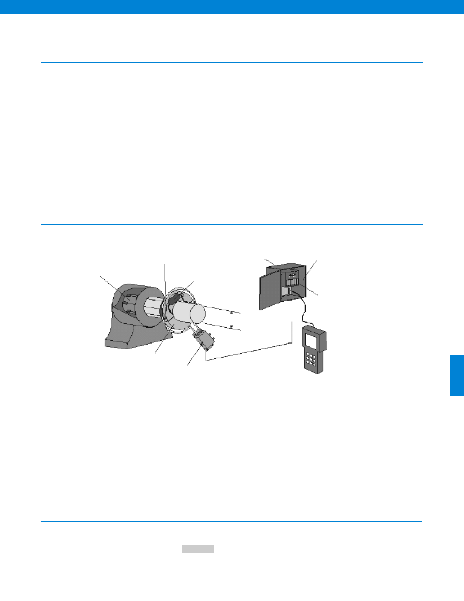
439
www.honeywell.com/sensotec
1-888-282-9891
Model 1700A 6 Channel Temperature Monitoring System
(RTD Based - Clamp On Collar)
Order Code WE1000
Typical System Diagram
How to Order
Aluminum Collar
The 1700 Systems are designed as safety instruments for large motors (350 HP and larger). The Systems
monitor 6 customer set temperature points, using 100 Ohm platinum RTDs (see Models 1705 and 1706
for Thermocouples) and provide an alarm for over-temperature conditions. The system can be configured
to shut down the motors. With modification the systems can monitor ground fault and/or diode fault.
The Model 1700 System scans multiple Resistance Temperature Devices (RTDs) installed within the rotor
windings or the starter bars providing data on minute changes in thermal condition of the motor. Reliable
temperature monitoring of the windings is key to smooth operation. Overheating is a clear signal of an
impending problem.
This system monitors 6 rotor winding temperatures simultaneously, provides all 6 analog outputs
simultaneously and will indicate any channel with a temperature greater than a programmable alarm set
point. The alarm feature has a relay output. The non-contact transmission method means no-fault path
from the rotor to ground exists.
Order Code
Enter the order code.
Sample Code
WE1000
Model 1730A Collar
and RTD Transmitter
Assembly
Model 1742A
Nema 12 box
Optional 4-20mA
output board
Clamp on collar
for up to 16”
90888-004
Hand held
programmer
(1 req’d per
customer site)
Model 1211D
Power Seperation
Unit and Receiver
Antenna
Up to 6 RTD Channels
specify -20 to 160° C
or 20 to 600° C
Model 1772A
RTD Driver Module
-Not RoHS Compliant
Courtesy of Steven Engineering, Inc.-230 Ryan Way, South San Francisco, CA 94080-6370-Main Office: (650) 588-9200-Outside Local Area: (800) 258-9200-www.stevenengineering.com
Sensotec Sensors Full Line Catalog-html.html
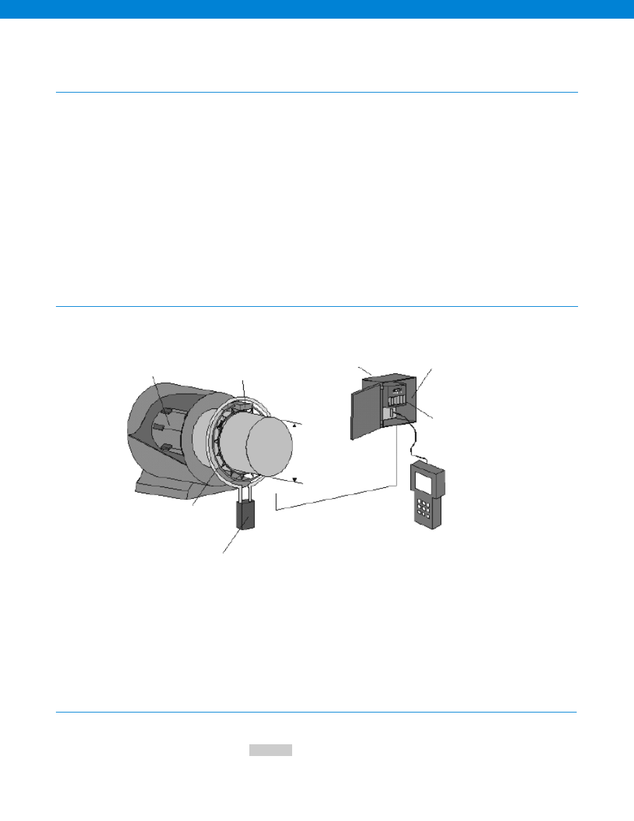
440
www.honeywell.com/sensotec
1-888-282-9891
Model 1701A 6 Channel Temperature Monitoring System
(RTD Based - Strap On Collar)
Order Code WE1100
Typical System Diagram
How to Order
Strap on collar to mount
transmitter and antenna
The 1701 Systems are designed as safety instruments for large motors (350 HP and larger). The Systems
monitor 6 customer set temperature points, using 100 Ohm platinum RTDs (see Models 1705 and 1706
for thermocouples) and provide an alarm for over-temperature conditions. The system can be configured
to shut down the motors. With modification the systems can monitor ground fault and/or diode fault.
The Model 1701 System scans multiple Resistance Temperature Devices (RTD’s) installed within the rotor
windings or the starter bars providing data on minute changes in thermal condition of the motor. Reliable
temperature monitoring of the windings is key to smooth operation. Overheating is a clear signal of an
impending problem.
This system monitors 6 rotor winding temperatures simultaneously, provides all 6 analog outputs
simultaneously and will indicate any channel with a temperature greater than a programmable alarm set
point. The alarm feature has a relay output. The non-contact transmission method means no-fault path
from the rotor to ground exists.
Order Code
Enter the order code.
Sample Code
WE1100
Up to 6 RTD Channels
specify -20 to 160° C
or 20 to 600° C
Model 1731A RTD
Transmitter module and
collar assembly (counter
balanced other side)
Model 1742A
Nema 12 box
Optional 4-20mA
output board
Strap on collar
for up to 60”
and speeds
below 500 rpm
90888-004
Hand held
programmer
(1 req’d per
customer site)
Model 1711A
Antenna PSU unit
-Not RoHS Compliant
Courtesy of Steven Engineering, Inc.-230 Ryan Way, South San Francisco, CA 94080-6370-Main Office: (650) 588-9200-Outside Local Area: (800) 258-9200-www.stevenengineering.com
Sensotec Sensors Full Line Catalog-html.html
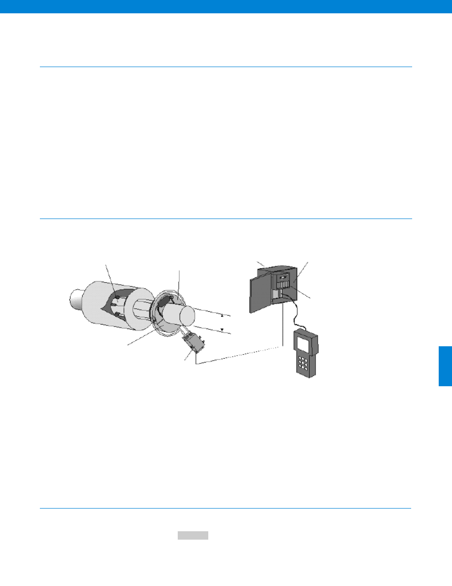
441
www.honeywell.com/sensotec
1-888-282-9891
Model 1705A 6 Channel Temperature Monitoring System
(Thermocouple Based - Clamp On Collar)
Order Code WE1300
Typical System Diagram
How to Order
Aluminum Collar
The 1705 Systems are designed as safety instruments for large motors (350 HP and larger). The Systems
monitor 6 customer set temperature points, using isolated Thermocouples (see 1700 and 1701 for RTD’s)
and provide an alarm for over-temperature conditions. The system can be configured to shut down the
motors. With modification the systems can monitor ground fault and/or diode fault.
The Model 1705 System scans multiple thermocouples installed within the rotor windings or the starter
bars providing data on minute changes in thermal condition of the motor. Reliable temperature monitoring
of the windings is key to smooth operation. Overheating is a clear signal of an impending problem.
This system monitors 6 rotor winding temperatures simultaneously, provides all 6 analog outputs
simultaneously and will indicate any channel with a temperature greater than a programmable alarm set
point. The alarm feature has a relay output. The non-contact transmission method means no-fault path
from the rotor to ground exists.
Order Code
Enter the order code.
Sample Code
WE1300
Up to 6 Channels of
Thermocouple
Model 1735A Collar
and Thermocouple
Transmitter Assembly
Model 1742A
Nema 12 box
Optional 4-20mA
output board
Clamp on collar
for up to 10”
90888-004
Hand held
programmer
(1 req’d per
customer site)
Model 1211D
Power Seperation
Unit and Receiver
Antenna
-Not RoHS Compliant
Courtesy of Steven Engineering, Inc.-230 Ryan Way, South San Francisco, CA 94080-6370-Main Office: (650) 588-9200-Outside Local Area: (800) 258-9200-www.stevenengineering.com
Sensotec Sensors Full Line Catalog-html.html

442
www.honeywell.com/sensotec
1-888-282-9891
Model 1706A 6 Channel Temperature Monitoring System
(Thermocouple Based - Strap On Collar)
Order Code WE1400
Typical System Diagram
How to Order
Strap on collar to mount
transmitter and antenna
The 1706 Systems are designed as safety instruments for large motors (350 HP and larger). The Systems
monitor 6 customer set temperature points, using isolated Thermocouples (see 1700 and 1701 for RTD’s)
and provide an alarm for over-temperature conditions. The system can be configured to shut down the
motors. With modification the systems can monitor ground fault and/or diode fault.
The Model 1706 System scans multiple thermocouples installed within the rotor windings or the starter
bars providing data on minute changes in thermal condition of the motor. Reliable temperature monitoring
of the windings is key to smooth operation. Overheating is a clear signal of an impending problem.
This system monitors 6 rotor winding temperatures simultaneously, provides all 6 analog outputs
simultaneously and will indicate any channel with a temperature greater than a programmable alarm set
point. The alarm feature has a relay output. The non-contact transmission method means no-fault path
from the rotor to ground exists.
Order Code
Enter the order code.
Sample Code
WE1400
Up to 6 Channels of
Thermocouple
Model 1736A Thermocouple
Transmitter module and
collar assembly (counter
balanced other side)
Model 1742A
Nema 12 box
Optional 4-20mA
output board
Strap on collar
for speeds
below 500 rpm
90888-004
Hand held
programmer
(1 req’d per
customer site)
Model 1711A
Antenna PSU unit
-Not RoHS Compliant
Courtesy of Steven Engineering, Inc.-230 Ryan Way, South San Francisco, CA 94080-6370-Main Office: (650) 588-9200-Outside Local Area: (800) 258-9200-www.stevenengineering.com
Sensotec Sensors Full Line Catalog-html.html
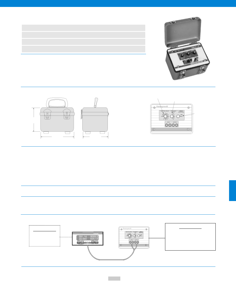
443
www.honeywell.com/sensotec
1-888-282-9891
Model TS Strain Gage Transducer Simulator
Order Code AE415
n
Easy to Use
n
Simulates Either 350 or 5,000 Ohm Transducer Bridge
n
Rugged, Weatherproof Case
n
Precision Wire-Wound Resistors
Dimensions
Electrical
Environmental
Physical
Typical System Diagrams
Input Excitation Requirements................4.5 to 12 VDC, constant voltage only
Input Resistance................350 or 5,000 Ohms
Full-Scale Output Ranges................0.5, 1, 2, 5 and 10 mV/V
Output Adjustment................0% to 100% in 10% steps
Output Linearity and Hysteresis
Typical................+/- 0.05% of Full Scale
Maximum................+/- 0.10% of Full Scale
Output Zero Balance
350 Ohm Resistance................+/- 100 microvolts max.
5,000 Ohm Resistance................0.01% of Full Scale max.
Temperature, Operating................40° to 100° F
Temperature, Storage................-20° to 195° F
Connections................Binding posts for use with wire or banana jackets
Case Size................7” W x 5” H x 5” D
Case Material................Aluminum
Weight................2.5 lb.
Model Code
Enter the order code.
How to Order
5.00 in.
Selectable bridge
resistance
Selectable output ranges
Selectable % of full scale
5.00 in.
7.00 in.
Sample Code
AE415
Cable Accessories
023-0819-00 mating black
Double banana plug
043-0307-00 Connector
Cable assy double banana plug to 3ft. of
2 conductor cable
Customer Supplied
Chart Recorder
Data Acquisition
Signal Conditioning Unit
The Model TS is a strain gage transducer simulator for use in calibration or testing pressure,
force, torque or weigh systems indicators and signal conditioning amplifiers. It greatly assists
in trouble shooting, and testing of systems that use strain gage transducers. The Model TS
simulates either a 350 Ohm or 5,000 Ohm strain gage transducer bridge with precise
adjustments for transducer sensitivities in five ranges in 0.5 to 10 millivolts per volt. The
output adjustments are in 10% increments from 0 to 100 % of each of the above ranges. No
batteries to replace as the excitation voltage is supplied by the instrument to be calibrated.
-Not RoHS Compliant
Courtesy of Steven Engineering, Inc.-230 Ryan Way, South San Francisco, CA 94080-6370-Main Office: (650) 588-9200-Outside Local Area: (800) 258-9200-www.stevenengineering.com
Sensotec Sensors Full Line Catalog-html.html
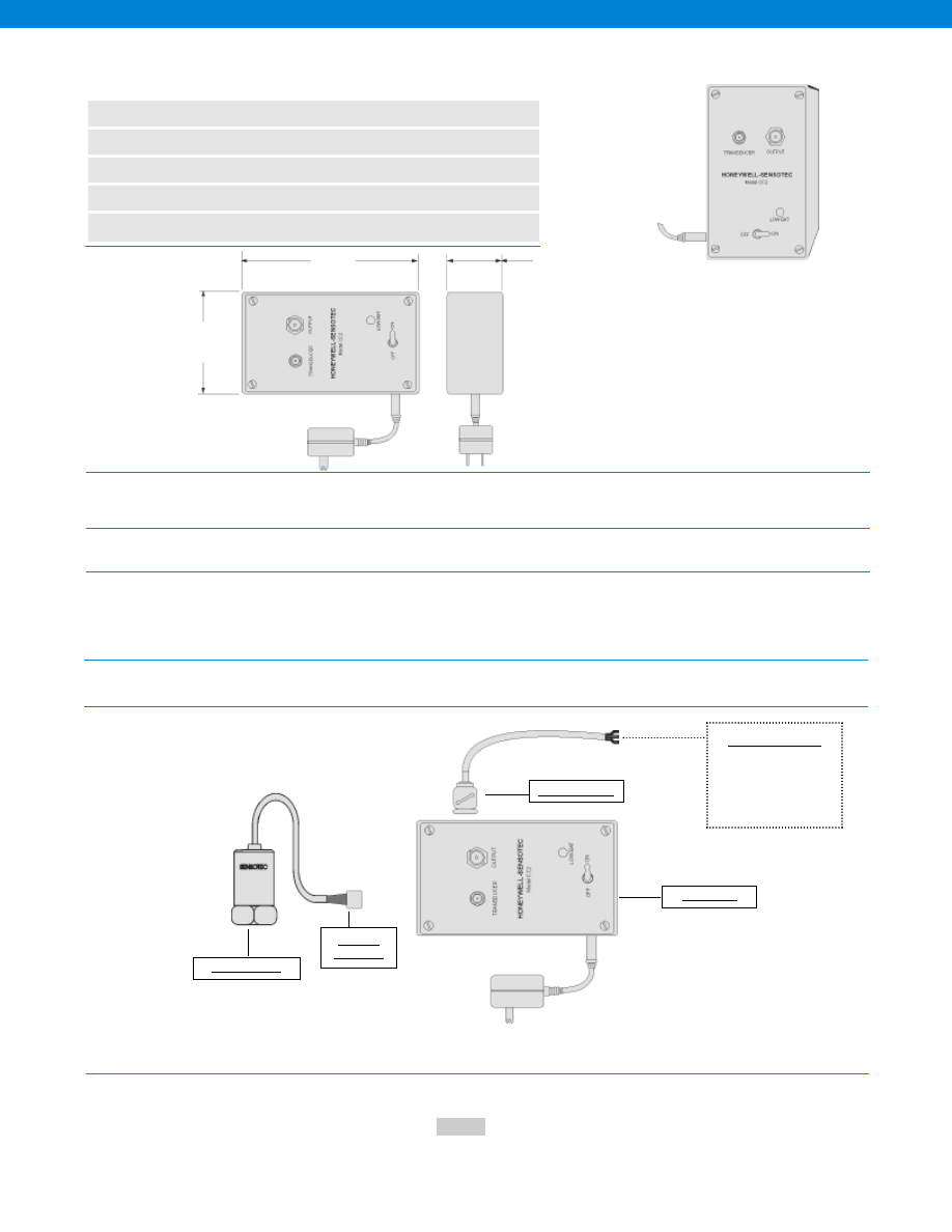
444
www.honeywell.com/sensotec
1-888-282-9891
Model CC2 IEPE Accelerometer Power Supply
Order Code AE412
n
Constant Current Power Supply
n
Used with IEPE Accelerometers
n
Adjustable Drive Current
n
Battery or AC Powered
n
10 V Output
Dimensions
Power Requirements
Input Characteristics
Output Characteristics
Physical Characteristics
Typical System Diagrams
Batteries................9V alkaline (3)
Battery Life................110 hrs @ 2 mA
Low Battery Indicator................LED lights at approximately 17.5V
Current to Transducer................Adjustable 1.5 - 10 mA
Input Connector................Miniature coaxial
Gain................Unity
Coupling Time Constant................2 seconds (1 Megohm Load)
Load Impedance................> 100K
Output Connector................BNC
Output................10V peak to peak max.
Size................5.12” L x 3.7” W x 2.24” H
Temperature................32° to 150° F
Model Code
Enter the order code.
How to Order
1.97 in.
3.54 in.
6.1 in.
Sample Code
AE412
Customer Supplied
BNC Connector & Cable
Chart Recorder
Data Acquisition
Computer
Model CC2
BNC Connector
Microdot
Connector
Accelerometer
-Not RoHS Compliant
Courtesy of Steven Engineering, Inc.-230 Ryan Way, South San Francisco, CA 94080-6370-Main Office: (650) 588-9200-Outside Local Area: (800) 258-9200-www.stevenengineering.com
Sensotec Sensors Full Line Catalog-html.html
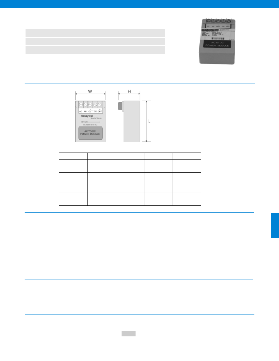
445
Dimensions
Performance
Environmental
www.honeywell.com/sensotec
n
Regulated
n
Miniature Size
n
Terminal-Strip Connection
DC Power Supply for Amplified Transducers
Order Codes (see chart)
1-888-282-9891
Input Voltage................105-125 VAC, 47-420Hz, Single Phase
Output Specifications................see table below
Output Voltage Trim Adjustment................Outputs are factory set to +/-1% of nominal output voltage.
Single output models may be trimmed to the nominal output
voltage with an external trim resistor.
Polarity................Either positive or negative terminal of a single output module
may be grounded. Dual output modules have a
positive/common/negative output terminal configuration.
Impedence................0.07 Ohms at 1 kHz (approx.)
................0.2 Ohms at 10 kHz (approx.)
Regulation (Line)................+/- 0.05%
Regulation (Load)................+/- 0.1%
Ripple................1mV RMS
Optional 230 VAC input................For operation on an input of 230 VAC, 46-420Hz.
Ambient Operating Temperature................0° to 150°F
Storage Temperature................-67° to 185°F
Temperature Error................0.008% F.S./°F nominal
Provides regulated voltages ranging from 10 to 28 VDC and output currents to 600 milliamps. Terminal strip connections
eliminate soldering. Features include short-circuit protection, encapsulated construction and conservative design aimed at
providing long-term stability. Power supplies may be used in series. No derating or heat sinking required.
How to Order
Model Code
Sample Code:
AA951
Order Code
Output Voltage
Output Current
Height H
L x W
AA951
10 VDC
240mA max
1.4
2.5 x 3.5
AA952
24VDC
600mA max
2.375
3.5 x 2.5
AA953
+/-15 VDC
100mA max
1.375
3.5 x 2.5
AA954
28VDC
500mA max
2.375
3.5 x 2.5
AA955
28VDC
300mA max
1.625
3.5 x 2.5
AA956
28VDC
150mA max
1.375
3.5 x 2.5
AA957
28VDC
80mA max
1.375
3.5 x 2.5
Power Supplies for in-line amplifiers or internally amplified transducers and transmitters:
Enter the order code.
-Not RoHS Compliant
Courtesy of Steven Engineering, Inc.-230 Ryan Way, South San Francisco, CA 94080-6370-Main Office: (650) 588-9200-Outside Local Area: (800) 258-9200-www.stevenengineering.com
Sensotec Sensors Full Line Catalog-html.html
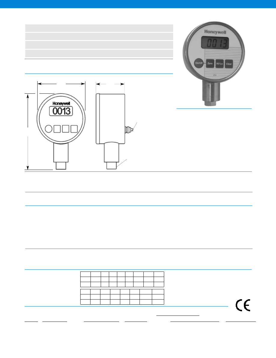
446
1
5
15
30
50
100
200
300
500
10
25
75
150 250 500 1000 1200 1500
0.001 0.005 0.01 0.02 0.05 0.1
0.1
0.2
0.5
Ordering Information
EXAMPLE ORDER CODE
JK W 1000 G Z 4
Notes
Ranges................1; 5; 15; 30; 50; 100; 200; 300; 500; 750; 1000; 1500; 2000; 3000; 5000;
................7500; 10,000 psi
Accuracy................0.2% (note 1)
Update speed................3 per second
Temperature, Operating................30°F to 160°F (0°F to 180°F with optional NEMA 4 rating)
Rating................NEMA 2, std. (NEMA 4 optional except Model JKT)
Display................LCD, 4 1/2-digit, 0.5” high
Power supply
Model JKW................1 or 2 9-Volt Batteries (included)
Model JKT................110 Volt AC adaptor @ 60 Hz (included)
Model JKV................11 to 32 VDC @ 100 mA
Electrical Connection................3 ft. cable (std.) for Model JKV
Low Battery Indication................Standard on Model JKW
Calibration Data................Stored on memory chip
High and Low Capture................Standard
Pressure Port................9/16- 18 UNF- 2B Female Straight Thread with
SAE Spec J514 O-Ring Boss
Case Material................Stainless Steel
Wetted parts................316 Stainless Steel
Performance
Environmental
Electrical
Mechanical
1. Accuracies stated are for Best Fit Straight Line for all errors including
linearity, hysteresis and repeatability through zero.
2. Consult factory for optional units of measure.
3. Consult factory for optional electrical connectors and cable lengths.
4. 0°F to 180°F Operating Temperature only with optional NEMA 4 rating.
Field Selectable Standard Units
of Measure
(note 2)
psi is standard
Bar = Bar
mBar = Millibar
kPa = Kilopascals
MPa = Megapascals
Ft H20 = Feet of water
In H20 = Inches of water
In Hg = Inches of mercury
mmHg = Millimeters of mercury
Model JK Digital Pressure Gauge
www.honeywell.com/sensotec
n
Ranges to 10,000 psi
n
0.2% Accuracy
n
Field Selectable Engineering Units
n
Available 0° to 180°F Operating Temperature (note 4)
1-888-282-9891
Dimensions
5.6
2.2
9/16- 18 UNF- 2B
Female Straight Thread with
SAE Spec J514 O-Ring Boss
3 ft. Cable
(not applicable for
battery powered or
AC powered model)
Request certified drawing before designing mountings or fixtures.
Specifications subject to change without notice.
3.7
• Stainless Steel Construction
• High/Low Capture & Store
• 9 Volt Battery Power
• On/Off Switch
• Visit www.sensotec.com/dct for more digital gages
Pressure Range (psi)
Maximum Safe Over Pressure (psi)
Incremental Display Steps
SERIES
JK
MODEL CODE
W = Battery
V = Vehicle powered
T = AC adaptor included
PRESSURE RANGE
(note 2)
Pressure range in PSI
REFERENCE
G = Gage
A = Absolute
V = Vacuum
C = Compound (reads
+/- vacuum pressure)
ELECTRICAL TERMINATION
(note 3)
Z = No connector
C = Cable exit
T = AC adaptor
OTHER OPTIONS
4 = NEMA 4 rating
Enter the following information:
750
1000 1500 2000 3000 5000
7500
10,000
1500 2000 3000 4000 6000 7500 12,000 15,000
0.5
1
1
1
2
5
5
5
Pressure Range (psi)
Maximum Safe Over Pressure (psi)
Incremental Display Steps
Approved
Courtesy of Steven Engineering, Inc.-230 Ryan Way, South San Francisco, CA 94080-6370-Main Office: (650) 588-9200-Outside Local Area: (800) 258-9200-www.stevenengineering.com
Sensotec Sensors Full Line Catalog-html.html
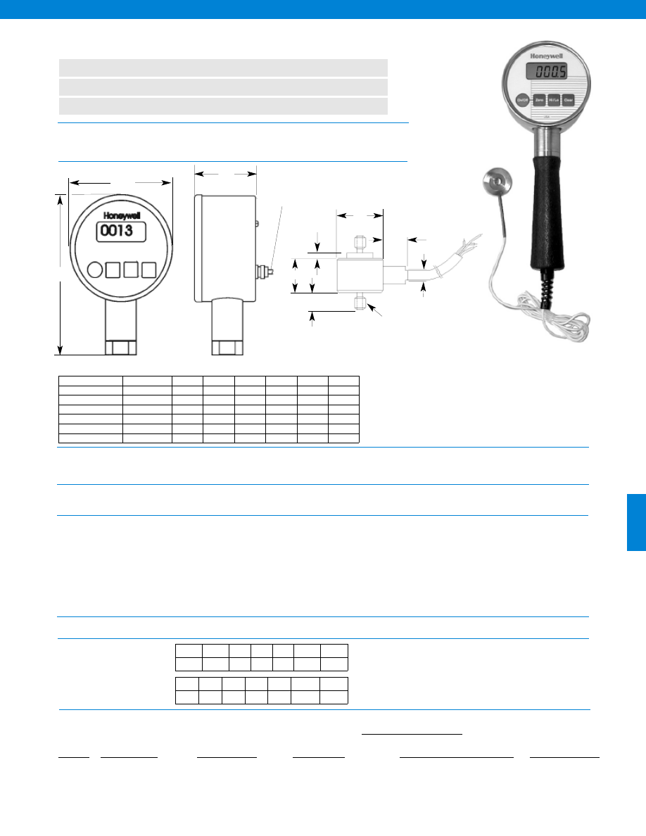
447
Ranges................1; 5; 10; 25; 50; 100; 250; 500; 1000; 2000; 3000; 4000; 5000; 7500; 10,000 lb.
Repeatability................0.2% (note 1)
Update speed................3 per second
Temperature, Operating................30°F to 160°F
Rating................NEMA 2 (NEMA 4 optional except Model LKT)
Display................LCD, 4 1/2-digit, 0.5” high
Power supply
Model LKW................1 or 2 9-Volt Batteries (included)
Model LKT................110 Volt AC adaptor @ 60 Hz (included)
Model LKV................11 to 32 VDC @ 100 mA
Electrical Connection................3 ft. cable (std.) for Model LKV
Low Battery Indication................Standard on Model LKW
Calibration Data................Stored on memory chip
Zero and span adjustment................Standard
Case Material................Stainless Steel
Performance
Environmental
Electrical
Mechanical
www.honeywell.com/sensotec
n
Ranges to 10,000 lbs.
n
Tension and Compression Measurement
n
High & Low Force Capture
1-888-282-9891
Dimensions
Model LK Digital Force Indicator
5.5
2.2
3 ft. Cable
(not applicable for
battery powered or
AC powered model)
*Request certified drawing before designing mountings or fixtures.
Specifications subject to change without notice.
3.7
øD
øB
H
F
A
2 X “T”
2 X “C”
Ranges (lb.) T D (in) H (in.) C (in.) F (in.) A (in.) B (in.)
1 lb
#6-32 UNC
1.00
0.75
0.25
0.11
0.50
0.38
5 to 10 lb.
#6-32 UNC
1.00
0.45
0.25
0.05
0.31
0.19
25 to 100 lb.
#10-32 UNF
1.00
0.52
0.25
0.03
0.50
0.25
250 to 1000 lb.
1/4”-28 UNF
1.00
0.52
0.38
0.03
0.50
0.25
2000 to 3000 lb.
3/8”-24 UNF
1.00
0.72
0.50
0.03
0.50
0.38
4000 to 5000 lb.
1/2”-20 UNF
1.25
0.94
0.63
0.03
0.50
0.38
7500 to 10,000 lb. 3/4”-16 UNF
1.38
1.10
0.88
0.03
0.50
0.38
Model LK shown with optional handle. Visit our
website for more information on optional handles.
• Zero Offset/Tare
• Field Selectable Engineering Units (lb., N, kN, g, kg)
• NIST Statement
• Customer Recalibration
• Visit www.sensotec.com/dct for more digital gages
Field Selectable Standard Units of Measure
(note 2)
lb. is standard
N = Newton
g = Grams
kN = Kilonewton
kg = Kilograms
1
5
25
50
100
250
500
0.001
0.005 0.02 0.01 0.02
0.05
0.1
Ordering Information
EXAMPLE ORDER CODE
LK W 1000 K Z 4
Notes
1. Accuracies stated are for Best Fit Straight Line for all errors including
linearity, hysteresis and repeatability through zero.
2. Consult factory for optional units of measure.
3. Consult factory for optional electrical connectors and cable lengths.
Range (lb.)
Incremental Display Steps
SERIES
LK
MODEL CODE
W = Battery
V = Vehicle powered
T = AC adaptor included
LOAD RANGE
(note 2)
Load range in lb.
REFERENCE
K = Compression
T = Tension
C = Compound
ELECTRICAL TERMINATION
(note 3)
Z = No connector
C = Cable exit
T = AC adaptor
OTHER OPTIONS
4 = NEMA 4 rating
Enter the following information:
1000 2000 3000 4000 5000
7500
10,000
0.2
0.5
2
2
1
2
2
Range (lb.)
Incremental Display Steps
Courtesy of Steven Engineering, Inc.-230 Ryan Way, South San Francisco, CA 94080-6370-Main Office: (650) 588-9200-Outside Local Area: (800) 258-9200-www.stevenengineering.com
Sensotec Sensors Full Line Catalog-html.html

448
Notes
www.honeywell.com/sensotec
1-888-282-9891
Courtesy of Steven Engineering, Inc.-230 Ryan Way, South San Francisco, CA 94080-6370-Main Office: (650) 588-9200-Outside Local Area: (800) 258-9200-www.stevenengineering.com
Sensotec Sensors Full Line Catalog-html.html
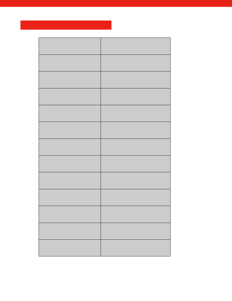
449
APPENDIX
www.honeywell.com/sensotec
1-888-282-9891
Accessories
450
Internal Amplifiers
461
Wiring Codes
463
Setup Instructions
467
Conversion Tables
469
Terminology
470
How To Order
473
Options
474
Range Codes
476
Sample Purchase Order
479
Plug And Play
480
Troubleshooting Guide
Inside Back Cover
Warranty/ Remedy
Back Cover
Courtesy of Steven Engineering, Inc.-230 Ryan Way, South San Francisco, CA 94080-6370-Main Office: (650) 588-9200-Outside Local Area: (800) 258-9200-www.stevenengineering.com
Sensotec Sensors Full Line Catalog-html.html
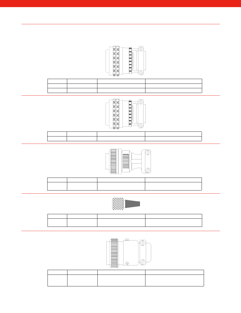
450
Accessories
Mating Connectors and
Connector/Cable Assemblies
Order Code Model
Description
Mating Connector for
AA111
PT06A-10-6S
Mating connector
Sensors with PT1H-10-6P connector
AA118
PT06E-10-6S
Environmental mating connector Sensors with PT1H-10-6P connector
Order Code Model
Description
Mating Connector for
AA119
PT06A-10-6P (SR) Mating connector
Model NK portable instruments
Order Code Model
Description
Mating Connector for
AA121
MS3106A-14S-6S
Mating connector
Sensors with MS3102E-14S-6P
connector
Order Code Model
Description
Mating Connector for
AA141
DP-4S-1
Mating connector
Miniature sensors with Microtec type
connectors
Order Code Model
Description
Mating Connector for
AA151
MS3476L10-6S
Mating connector
Sensors with PTIH-10-6P connectors
and high temperature (250° F to 400° F)
specifications
www.honeywell.com/sensotec
1-888-282-9891
Courtesy of Steven Engineering, Inc.-230 Ryan Way, South San Francisco, CA 94080-6370-Main Office: (650) 588-9200-Outside Local Area: (800) 258-9200-www.stevenengineering.com
Sensotec Sensors Full Line Catalog-html.html
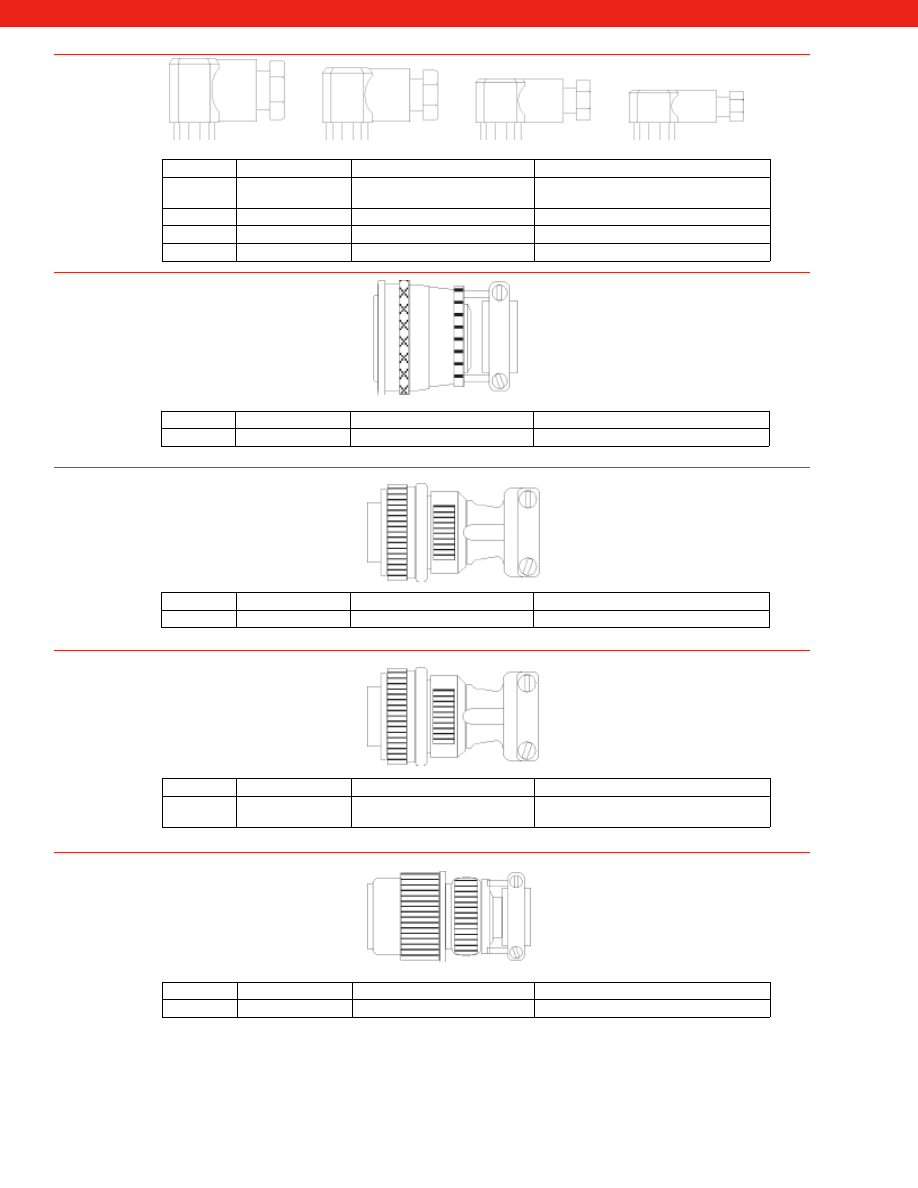
451
www.honeywell.com/sensotec
1-888-282-9891
Order Code Model
Description
Mating Connector for
AA155
DIN43650
Mating connector 1/2” NPTF
conduit fitting
Model 440 Pressure Sensors
AA156
DIN43650
PG9 Socket for 4.5-7 mm cable
Model 440 Pressure Sensors
AA157
DIN43650
PG11 Socket for 6-10 mm cable Model 440 Pressure Sensors
AA161
DIN40050
PG7 Socket for 3.5-6 mm cable
Model FP2000 Pressure Sensors
Order Code Model
Description
Mating Connector for
AA162
PC06A-10-6S
Mating connector
Model 45 & 47
Order Code Model
Description
Mating Connector for
AA174
MS3106F-10SL-3S Mating connector
Model PEI & PEL
Order Code Model
Description
Mating Connector for
MH002
2 Pin MS Type
Connector
Mating connector
MA11, MA12 and MAV51 accelerometers
Order Code Model
Description
Mating Connector for
MH008
62GB Connector
Mating connector
MA15, MAT53 and MAV52 accelerometers
Courtesy of Steven Engineering, Inc.-230 Ryan Way, South San Francisco, CA 94080-6370-Main Office: (650) 588-9200-Outside Local Area: (800) 258-9200-www.stevenengineering.com
Sensotec Sensors Full Line Catalog-html.html
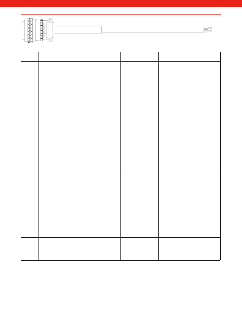
452
www.honeywell.com/sensotec
1-888-282-9891
Order
Code
Model
Description
Connector Wiring
Code
Cable Wiring Code
For Use with
AA112
PT06A-10-6S Mating connector
with 15 ft. of 6
conductor PVC
cable
A (+) Excitation
B (+) Sense/sig mod
C (-) Excitation
D (-) Sense/sig mod
E (-) Output
F (+) Output
Red (+) Excitation
Black (-) Excitation
Green (-) Output
White (+) Output
Blue (-) Sense/sig mod
Brown (+) Sense/sig mod
Unamplified units with PT1H-10-6P con-
nector, sense leads or Sug Mod, but no
shunt cal
AA113
PT06A-10-6S Mating connector
with 15 ft. of 4
conductor PVC
cable
A & B (+) Excitation
C & D (-) Excitation
E
(-) Output
F
(+) Output
Red (+) Excitation
Black (-) Excitation
Green (-) Output
White (+) Output
Unamplified units with PT1H-10-6P con-
nector
AA114
PT06A-10-6S Mating connector
with 15 ft. of 6
conductor PVC
cable
A (+) Supply
B (-) Supply Return
C (-) Supply
D (+) Output
E (-) Shunt cal 1
F (+) Shunt cal 2
Red (+) Supply
Black (-) Supply Return
Green (-) Output
White (+) Output
Blue (-) Shunt cal 1
Brown (+) Shunt cal 2
All amplified units with PT1H-10-6P con-
nector and with the 2a or 2b amplifier
AA115
PT06A-10-6S Mating connector
with 15 ft. of 5
conductor PVC
cable
A
(+) Supply
B & C (-) o/p common
D
(+) Output
E
(-) Shunt cal 1
F
(+) Shunt cal 2
Red (+) Supply
Black (-) Output common
White (+) Output
Blue (-) Shunt cal 1
Brown (+) Shunt cal 2
All amplified units with PT1H-10-6P con-
nector and with the 2c, 2t or 2j amplifier
AA116
PT06A-10-6S Mating connector
with 15 ft. of 3
conductor PVC
cable
A
(+) Supply
B
N/C
C
N/C
D
(+) Output
E
Ground
F
N/C
Red (+) Supply
Black (+) Output
White Case Ground
All amplified units with PT1H-10-6P con-
nector and with the 2k, 2p, 2y or 2n (2N)
amplifier
AA513
PT06A-10-6S
Mating connector
with 15 ft. of 5
conductor PVC
cable
A
(+) Excitation
B
(-) Excitation
C
(+) Output
D
(-) Output
E
N/C
F
Shunt Cal
Red (+) Excitation
Black (-) Excitation
White (+) Output
Green (-) Output
Brown Shunt Cal
FP2000 with option 2u and 3d
AA516
PT06A-10-6S
Mating connector
with 15 ft. of 3
conductor PVC
cable
A
(+) Supply
B
N/C
C
N/C
D
(+) Output
E
N/C
F
Shunt Cal
Red (+) Supply
White (+) Output
Black Shunt Cal
FP2000 with option 2n (2N) or 2y and 3d
AA517
PT06A-10-6S
Mating connector
with 15 ft. of 5
conductor PVC
cable
A
(+) Supply
B
Supply Return
C
(-) Output
D
(+) Output
E
N/C
F
Shunt Cal
Red (+) Supply
Black Supply Return
Green (-) Output
White (+) Output
Blue Shunt Cal
FP2000 with option 2e or 2f and 3d
AA117
PT06A-10-6S
Mating connector
with 15 ft. of 4
conductor PVC
cable
A
(+) Supply
B
Supply Return
C
(-) Output
D
(+) Output
E
N/C
F
N/C
Red (+) Supply
Black Supply Return
Green (-) Output
White (+) Output
FP2000 with option 2d or 2g
Note: Standard cable length is 15 ft. Other cable lengths and cable materials are available.
Where a distance of 35 feet or more separates the readout device and the
transducer, remote voltage sensing is recommended (Model NK or SC).
Use 6 conductor cable in this case.
Courtesy of Steven Engineering, Inc.-230 Ryan Way, South San Francisco, CA 94080-6370-Main Office: (650) 588-9200-Outside Local Area: (800) 258-9200-www.stevenengineering.com
Sensotec Sensors Full Line Catalog-html.html
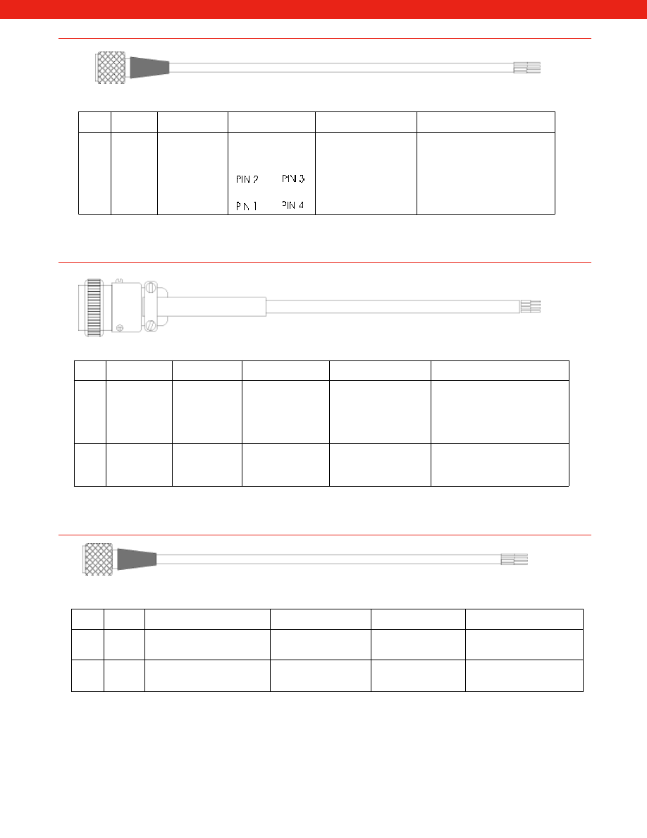
453
www.honeywell.com/sensotec
1-888-282-9891
Order
Code
Model
Description
Connector Wiring
Code
Cable Wiring Code
For Use with
AA143 DP-4S-1
Mating connector
with 15 ft. of 4
conductor Teflon
cable
Pin1 (+) Excitation
Pin2 (+) Output
Pin3 (-) Output
Pin4 (-) Excitation
Red (+) Excitation
Black (-) Excitation
Green (-) Output
White (+) Output
Miniature sensors with Microtec
type connector
Note: Standard cable length is 15 ft. Other cable lengths and cable materials are available.
Order
Code
Model
Description
Connector Wiring
Code
Cable Wiring Code
For Use with
AA152 MS3476L10-6S Mating connector
with 15 ft. of 6
conductor Teflon
cable
A (+) Excitation
B (+) Sense
C (-) Excitation
D (-) Sense
E (-) Output
F (+) Output
Red (+) Excitation
Black (-) Excitation
Green (-) Output
White (+) Output
Blue (-) Sense
Brown (+) Sense
All unamplified units with high tem-
perature option (250° F to 450° F)
and sense leads but no shunt cal
AA153 MS3476L10-6S Mating connector
with 15 ft. of 4
conductor Teflon
cable
A & B (+) Excitation
C & D (-) Excitation
E
(-) Output
F
(+) Output
Red (+) Excitation
Black (-) Excitation
Green (-) Output
White (+) Output
All unamplified units with high tem-
perature option (250° F to 450° F)
and no shunt cal or sense leads
Note: Standard cable length is 15 ft. Other cable lengths and cable materials are available.
Note: Standard cable length is 15 ft. Other cable lengths and cable materials are available.
Order
Code
Model
Description
Connector Wiring Code Cable Wiring Code
For Use with
AA158 064-0435 Mating connector with 5 ft. low
noise miniature coaxial cable
Center (+) Signal
Case Supply Return
Center (+) Signal
Case Supply Return
Piezo-electric accelerometers
with pc/g output
AA160 064-0567 Mating connector with 5 ft. low
noise miniature coaxial cable
Center (+) Signal
Case Supply Return
Center (+) Signal
Case Supply Return
Piezo-electric accelerometers
with pc/g output
Courtesy of Steven Engineering, Inc.-230 Ryan Way, South San Francisco, CA 94080-6370-Main Office: (650) 588-9200-Outside Local Area: (800) 258-9200-www.stevenengineering.com
Sensotec Sensors Full Line Catalog-html.html
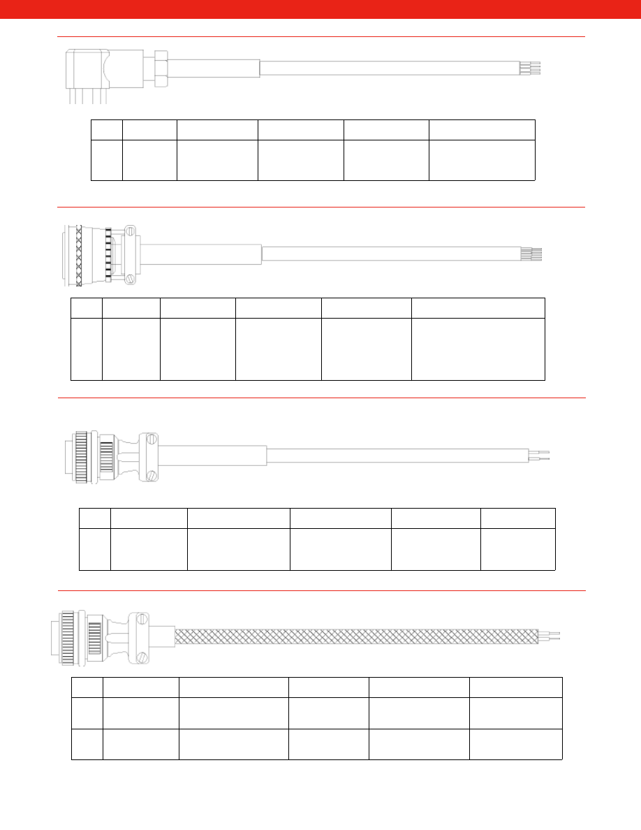
454
www.honeywell.com/sensotec
1-888-282-9891
Order
Code
Model
Description
Connector Wiring
Code
Cable Wiring Code
For Use with
AA159 060-0603-68 Mating connector
with 15 ft. of 4 con-
ductor polyurethane
cable
Pin1 (+) Supply
Pin2 (+) Output
Pin3 N/C
GND Case Ground
Pin1 Red
Pin2 White
Pin3 Green
GND Black
Model 440 or Model
FP2000 with option 6m
Note: Standard cable length is 15 ft. Other cable lengths and cable materials are available.
Order
Code
Model
Description
Connector Wiring
Code
Cable Wiring Code
For Use with
AA163 PC06A-10-6S Mating connector
with 15 ft. of 6
conductor shielded
Neoprene cable
A (+) Excitation
B (+) Output
C (-) Output
D (-) Excitation
E Sense/Sig Mod
F Sense/Sig Mod
Red (+) Excitation
Black (-) Excitation
Green (-) Output
White (+) Output
Blue N/C
Brown N/C
All unamplified Model 45 & 47
units with sense leads or Sig Mod
but no shunt cal
Note: Standard cable length is 15 ft. Other cable lengths and cable materials are available.
Order
Code
Model
Description
Connector Wiring Code Cable Wiring Code
For Use with
AA170 MS3106F-14S-2S
Mating connector with
15 ft. of 2 conductor PVC
cable
A
N/C
B
(+) Output
C
(+) Supply
D
Case Ground
N/C
Black
(+) Output
Red
(+) Supply
White
Case Ground
Model 424 & 425
Pressure Sensors
Where a distance of 35 feet or more separates the readout device and the
transducer, remote voltage sensing is recommended (Model NK or SC).
Note: Standard cable length is 15 ft. Other cable lengths and cable materials are available.
Order
Code
Model
Description
Connector Wiring
Code
Cable Wiring Code
For Use with
CA052 MS3106F-10SL-3S Mating connector with 5m of
2 conductor PVC cable
stainless steel overbraided
A (+) Excitation
B (-) Excitation
White (+) Supply (+) o/p
Black (-) Supply Return
Shield Not connected
MA11, MA12 and
MAV51 accelerometers
CA053 MS3106F-10SL-3S Mating connector with 5m of
2 conductor PTFE cable
stainless steel overbraided
A (+) Excitation
B (-) Excitation
White (+) Supply (+) o/p
Black (-) Supply Return
Shield Not connected
MA11, MA12 and
MAV51 accelerometers
Note: Standard cable length is 5m. Other cable lengths and cable materials are available.
Note: Wiring Code is for 2-wire output. Other amplifier options and wiring codes are available.
Courtesy of Steven Engineering, Inc.-230 Ryan Way, South San Francisco, CA 94080-6370-Main Office: (650) 588-9200-Outside Local Area: (800) 258-9200-www.stevenengineering.com
Sensotec Sensors Full Line Catalog-html.html
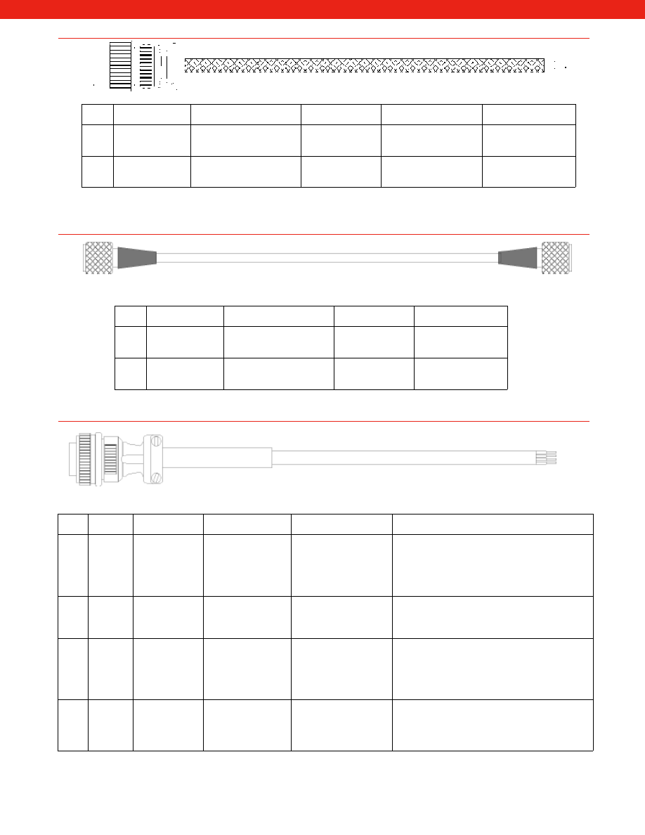
455
www.honeywell.com/sensotec
1-888-282-9891
Order
Code
Model
Description
Connector Wiring
Code
Cable Wiring Code
For Use with
CA108 62GB Connector
Mating connector with 5m of
2 conductor PVC cable
stainless steel overbraided
A (+) Supply
B Not Connected
C (+) Output
White (+) Supply (+) o/p
Black (-) Supply Return
Shield Not connected
MA15, MAT53 and
MAV52 accelerometers
CA137 62GB Connector
Mating connector with 5m of
2 conductor PTFE cable
stainless steel overbraided
A (+) Supply
B Not Connected
C (+) Output
White (+) Supply (+) o/p
Black (-) Supply Return
Shield Not connected
MA15, MAT53 and
MAV52 accelerometers
Note: Standard cable length is 5m. Other cable lengths and cable materials are available.
Order
Code
Model
Description
Connector Wiring
Code
For Use with
CA051 Microdot
Microdot to microdot con-
nector with 15 ft. of PVC
cable
Center (+) Output
Case Ground
PEC, PEC-S, MAQ13,
MAQ36, MAQ41
accelerometers
CA338 Microdot
Microdot to microdot con-
nector with 15 ft. of PTFE
overbraided cable
Center (+) Output
Case Ground
PEC, PEC-S, MAQ13,
MAQ36, MAQ41
accelerometers
Note: Standard cable length is 15 ft. Other cable lengths and cable materials are available.
Order
Code
Model
Description
Connector Wiring
Code
Cable Wiring Code
For Use with
AA122 MS3106A-
14S-6S
Mating connector
with 15 ft. of 6
conductor PVC
cable
A (+) Excitation
B (+) Sense/sig mod
C (-) Excitation
D (-) Sense/sig mod
E (-) Output
F (+) Output
Red (+) Excitation
Black (-) Excitation
Green (-) Output
White (+) Output
Blue (-) Sense/sig mod
Brown (+) Sense/sig mod
Unamplified units with MS3102E-14S-6P connector,
sense leads or Sig Mod but no shunt cal (Model UG,
WG, MPB and high capacity ranges for Model 41,
43, 73, 75)
AA123 MS3106A-
14S-6S
Mating connector
with 15 ft. of 4
conductor PVC
cable
A & B (+) Excitation
C & D (-) Excitation
E
(-) Output
F
(+) Output
Red (+) Excitation
Black (-) Excitation
Green (-) Output
White (+) Output
Unamplified units with MS3102E-14S-6P connector,
without sense leads or Sig Mod and without shunt
cal (Model UG, WG, MPB and high capacity ranges
for Model 41, 43, 73, 75)
AA124 MS3106A-
14S-6S
Mating connector
with 15 ft. of 6
conductor PVC
cable
A (+) Supply
B (-) Supply Return
C (-) Supply
D (+) Output
E (-) Shunt cal 1
F (+) Shunt cal 2
Red (+) Supply
Black (-) Supply Return
Green (-) Output
White (+) Output
Blue (-) Shunt cal 1
Brown (+) Shunt cal 2
Amplified units with MS3102E-14S-6P connector
and with the 2a or 2b amplifier (Model UG, WG,
MPB and high capacity ranges for Model 41, 43, 73,
75)
AA125 MS3106A-
14S-6S
Mating connector
with 15 ft. of 5
conductor PVC
cable
A
(+) Supply
B & C (-) o/p common
D
(+) Output
E
(-) Shunt cal 1
F
(+) Shunt cal 2
Red (+) Supply
Black (-) Output common
White (+) Output
Blue (-) Shunt cal 1
Brown (+) Shunt cal 2
Amplified units with MS3102E-14S-6P connector
and with the 2c, 2t or 2j amplifier (Model UG, WG,
MPB and high capacity ranges for Model 41, 43, 73,
75)
Note: Standard cable length is 15 ft. Other cable lengths and cable materials are available.
Where a distance of 35 feet or more separates the readout device and the
transducer, remote voltage sensing is recommended (Model NK or SC).
Use 6 conductor cable in this case.
Courtesy of Steven Engineering, Inc.-230 Ryan Way, South San Francisco, CA 94080-6370-Main Office: (650) 588-9200-Outside Local Area: (800) 258-9200-www.stevenengineering.com
Sensotec Sensors Full Line Catalog-html.html
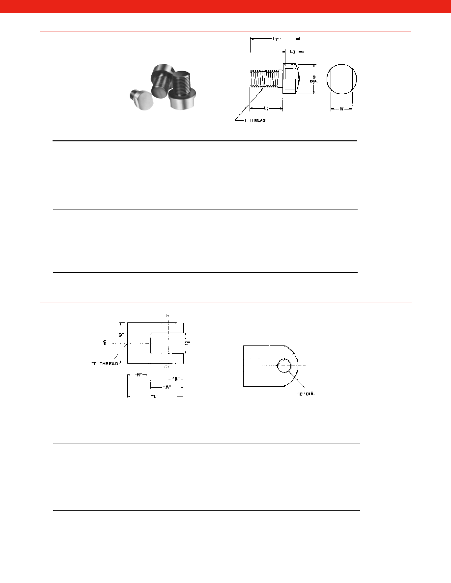
456
Order
Model UG
T
L1"
L2"
L3"
D"
W"
Code
Range in lbs.
AA251
50 to 500
3/8-24 UNF-2B
0.750
0.375
0.250
0.750
0.625
AA252
1K to 4K
1/2-20 UNF
1.000
0.500
0.375
0.750
0.625
AA253
5K to 10K
1-14 UNS
1.750
1.000
0.562
1.500
1.250
AA254
15K to 30K
1 1/2-12 UNF
2.500
1.500
0.750
2.250
2.000
AA255
50K to 75K
2-12 UN
3.125
2.000
0.938
3.000
2.750
AA256
100K to 150K
3-8 UN
5.000
3.000
1.500
4.500
4.000
AA257
200K
4-8 UN
6.000
4.000
1.500
5.500
5.000
Order
Models 45 & 47
T
L1"
L2"
L3"
D"
W"
Code
Range in lbs.
AA290
250; 500; 1K; 2.5K; 5K
5/8-18 UNF-3A
1.28
1.00
0.28
1.06
0.94
AA291
12.5K; 25K
1-1/4-12 UNF-3A
1.56
0.69
1.49
1.75
1.25
AA292
50K
1-3/4-12 UNF-3A
3.75
2.12
1.63
2.50
1.75
AA293
100K
2-3/4-8 UNF-3A
5.00
3.12
1.88
4.00
2.75
Load Buttons
Order
Models 41 & 42
Model 75
T
L1"
L2"
L3"
D"
W"
Code
Range in lbs.
Range in lbs.
AA241
5 to 25
N/A
1/4-28 UNF-2B
1.125
0.750
0.250
0.500
0.375
AA242
50 to 1K
50 to 100
3/8-24 UNF-2B
1.250
0.875
0.250
0.750
0.625
AA243
2K to 5K
1K to 2K
1/2-20 UNF
1.375
0.875
0.375
0.750
0.625
AA244
7500 to 15K
3K to 7500
1-14 UNS
2.375
1.625
0.562
1.500
1.250
AA245
20K to 50K
10K to 20K
1 1/2-12 UNF
2.625
1.625
0.750
2.250
2.000
AA246
75K to 100K
30K to 50K
2-12 UN
3.000
1.875
0.938
3.000
2.750
AA247
150K to 200K
75K to 100K
2 1/2-12 UN
4.250
2.500
1.125
3.500
3.250
AA248
300K to 500K
150K to 200K
3 1/2-8 UN
6.000
4.000
1.500
6.000
5.000
www.honeywell.com/sensotec
1-888-282-9891
(For Models RM and 31 only)
(STAINLESS STEEL)
Static
Order Load
“T”
“D”
“E”
“L”
Code
Rating*
Thread
“A”
“B”
“C”
Dia.
Dia.
Length
“H”
AA360
100,000 lb
2 1/2-8 UN-2B
6.50"
3.00"
3.04"
6.00"
3.01"
10.25"
3.50"
AA361
100,000 lb
2 1/2-12 UN-2B
6.50"
3.00"
3.04"
6.00"
3.01"
10.25"
3.50"
AA362
50,000 lb
1 1/2-12UNF-2B
4.35"
1.81"
2.54"
5.00"
1.76"
7.00"
2.25"
AA363
20,000 lb
1-14 UNF-2B
2.42"
1.11"
1.52"
3.00"
1.01"
4.25"
1.50"
AA364
10,000 lb
3/4-16 UNF-2B
1.94"
0.94"
1.28"
2.50"
0.76"
3.50"
1.25"
AA365
5,000 lb
1/2-20 UNF-2B
1.30"
0.55"
0.78"
1.75"
0.51"
2.00"
0.70"
(CARBON STEEL)
Static
Order Load
“T”
“D”
“E”
“L”
Code
Rating*
Thread
“A”
“B”
“C”
Dia.
Dia.
Length
“H”
AA370
120,000 lb
2 1/2-12 UN-2B
6.00"
2.75"
3.00"
6.00"
3.00"
9.50"
3.50"
AA371
45,600 lb
1 1/2-12 UNF-2B
4.00"
1.75"
2.50"
5.00"
1.75"
6.25"
2.25"
AA372
21,700 lb
1-14 UNF-2B
2.31"
1.00"
1.50"
3.00"
1.00"
3.94"
1.63"
AA373
11,2000 lb
3/4-16 UNF-2B
1.75"
0.75"
1.25"
2.50"
0.75"
2.88"
1.13"
AA374
4,900 lb
1/2-20 UNF-2B
1.25"
0.50"
0.75"
1.75"
0.50"
2.00"
0.75”
*The static load rating is the maximum capacity in lbs. for that part based on a 4:1 load factor (in tension).
Yoke Shackle
Courtesy of Steven Engineering, Inc.-230 Ryan Way, South San Francisco, CA 94080-6370-Main Office: (650) 588-9200-Outside Local Area: (800) 258-9200-www.stevenengineering.com
Sensotec Sensors Full Line Catalog-html.html
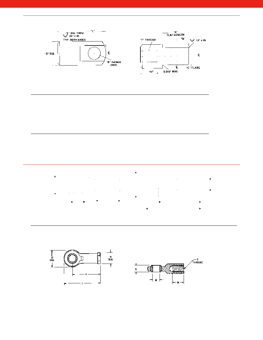
457
(For Models RM and 31 only)
(STAINLESS STEEL)
Static
“A”
Order Load
“T”
Flat
“C”
“D”
“E”
“L”
Code
Rating*
Thread
Length
“B”
Flats
Dia.
Dia.
Length
“H”
AA380
100,000 lb
2 1/2-8 UN-2B
6.38"
3.00"
3.00"
4.50"
3.01"
9.75"
3.56"
AA381
100,000 lb
2 1/2-12 UN-2B
6.38"
3.00"
3.00"
4.50"
3.01"
9.75"
3.56"
AA382
50,000 lb
1 1/2-12 UNF-2B
4.22"
2.03"
2.50"
3.00"
1.76"
7.00"
2.62"
AA383
20,000 lb
1-14 UNF-2B
2.54"
1.16"
1.50"
2.00"
1.01"
4.00"
1.25"
AA384
10,000 lb
3/4-16 UNF-2B
2.07"
0.94"
1.25"
1.50"
0.76"
3.25"
1.31"
AA385
5,000 lb
1/2-20 UNF-2B
1.30"
0.55"
0.75"
1.00"
0.51"
2.00"
0.70"
(CARBON STEEL)
Static
“A”
Order Load
“T”
Flat
“C”
“W”
“E”
“L”
Code
Rating*
Thread
Lengths
“B”
Flats
Width
Dia.
Length
“H”
AA390
110,000 lb
2 1/2-12 UN-2B
9.13"
3.00"
3.00"
6.00"
3.00"
9.13"
3.50"
AA391
45,000 lb
1 1/2-12 UNF-2B
5.75"
1.75"
2.50"
3.50"
1.75"
5.75"
2.25"
AA392
21,700 lb
1-14 UNF-2B
3.81"
1.00"
1.50"
2.00"
1.00:
3.81"
1.63"
AA393
12,000 lb
3/4-16 UNF-2B
2.81"
0.75"
1.25"
1.50"
0.75"
2.81"
1.13"
AA394
5,700 lb
1/2-20 UNF-2B
2.00"
0.50"
0.75"
1.00"
0.50"
2.00"
0.75"
*The static load rating is the maximum capacity in lbs. for that part based on a 4:1 load factor (in tension).
Tongue Shackle
www.honeywell.com/sensotec
1-888-282-9891
Order
A"
B"
C"
D"
E"
F"
L"
T
Approx.
Static Load Rating
Code
Dia.
Dia.
Thread
Wt (lbs)
(based on 3:1 load factor)
AA271
0.250
0.687
0.375
0.750
0.500
1.312
1.687
1/4-28 UNF
0.05
2300 lb
AA272
0.375
0.812
0.500
1.000
0.687
1.625
2.125
3/8-24 UNF
0.13
3600 lb
AA273
0.500
1.062
0.625
1.312
0.875
2.125
2.781
1/2-20 UNF
0.29
6300 lb
AA274
0.750
1.562
0.875
1.750
1.125
2.875
3.750
3/4-16 UNF
0.63
10000 lb
AW900** 0.196
0.55
0.31
0.63
0.24
1.06
1.38 M5 x 0.8 (female) N/A
N/A
C
A
B
T
D
L
F
E
Order
A"
B"
C"
D"
E"
F"
L"
T
Approx.
Static Load Rating
Code
Dia.
Dia.
Thread
Wt (lbs)
(based on 3:1 load factor)
AA275
0.250
1.000
0.375
0.750
0.250
1.562
1.937
1/4-28 UNF
0.043
1700 lb
AA276
0.375
1.250
0.500
1.000
0.375
1.938
2.438
3/8-24 UNF
0.112
3100 lb
AA277
0.500
1.500
0.625
1.312
0.500
2.438
3.094
1/2-20 UNF
0.249
5400 lb
AA278
0.750
1.750
0.875
1.750
0.750
2.875
3.750
3/4-16 UNF
0.602
9300 lb
AW900** 0.196
0.79
0.31
0.63
0.24
1.3
1.62
M5 x 0.8 (male)
N/A
N/A
**The AW900 is a kit containing both the male and female LVDT rod end bearings
Male
Female
Rod End Bearings
Courtesy of Steven Engineering, Inc.-230 Ryan Way, South San Francisco, CA 94080-6370-Main Office: (650) 588-9200-Outside Local Area: (800) 258-9200-www.stevenengineering.com
Sensotec Sensors Full Line Catalog-html.html
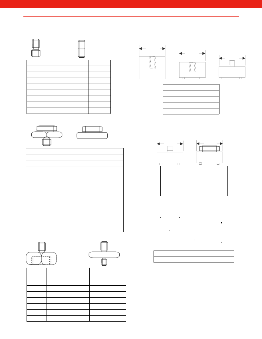
458
www.honeywell.com/sensotec
1-888-282-9891
Accelerometer Mounting Studs and Adapters
Order Code
MS028
10-32 UNF
to M8
MS036
1/4” - 28 UNF
to M6
MS039
1/4” - 28 UNF
to 10-32 UNF
MS065
10-32 UNF
to M6
MS067
1/4” - 28 UNF
to M8
MS068
1/4” - 28 UNF
to 1/4” - 28 UNF
MS124
1/4” - 28 UNF
to M10
MS132
1/4” - 28 UNF
to M12
Order Code
MM001
1/4” - 28 UNF Male
MM004
10-32 UNF Male
MM005
(Uses MS005 Adapter)
MM023
1/4” - 28 UNF Female
Order Code
MS001
Q/F Male
to Glue Base
MS002
Q/F Male
to M8 Male
MS003
Q/F Male
to M10 Male
MS004
Q/F Male
to 1/4” - 28 UNF Male
MS005
Q/F Male
to 1/4” - 28 UNF Female
MS006
Q/F Male
to M6 Male
MS007
Q/F Male
to 10-32 UNF Female
MS008
Q/F Male
to M8 Female
MS010
MA35 Q/F Male
to Glue Base
MS055
MA35 Q/F Male
to M8 Male
MS072
MA35 Q/F Male
to M6 Male
MS106
Q/F Male
to M10 Female
MS117
MA35 Q/F Male
to 1/4” - 28 UNF Male
Order Code
MS011
1/4” - 28 UNF
to Q/F Female
MS013
1/4” - 28 UNF
to Glue Base
MS033
1/4” - 28 UNF
to Q/F Female
MS034
1/4” - 28 UNF
to 1/4” - 28 UNF Female
MS061
1/4” - 28 UNF
to 10-32 UNF Male
MS079
1/4” - 28 UNF
to Q/F Female
MS093
M6 Male
to M6 Female
MS102
MA35 Q/F Female
to 10-32 UNF Male
Order Code
MM008
1/4” - 28 UNF Male
MM009
10-32 UNF Male
MM010
(Uses MS005 Adapter)
MM013
Quick Fit Large Thread
Quick Fit Adapters
Male Stud
Set Screw
Glue Type
Magnetic Adapters
Other Adapters
Stud to Q/F Female
Isolated Stud
Magnetic Adapters
Mounting Block
Order Code
AA235
Triaxial mounting block for Model JTF
1.0
1.0
1.0
1.0
1.38
1.38
1.38
Courtesy of Steven Engineering, Inc.-230 Ryan Way, South San Francisco, CA 94080-6370-Main Office: (650) 588-9200-Outside Local Area: (800) 258-9200-www.stevenengineering.com
Sensotec Sensors Full Line Catalog-html.html
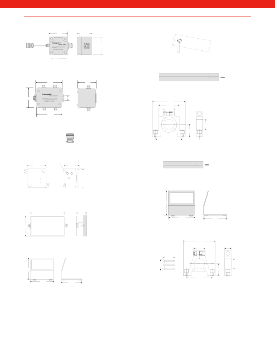
459
Miscellaneous
www.honeywell.com/sensotec
1-888-282-9891
AA180 Signature Calibration Module (In-Line)
AA912 Set of 5 Mating Connectors for AA911 Summing
Junction Box
AA911 4 Transducer (maximum) Summing Junction Box
AA921 Explosion Proof Enclosure (Gage or Absolute Pressure)
AA922 Explosion Proof Enclosure (Differential Pressure)
AA923 GM NEMA-4 Splashguard for all DIN
AA924 GM Bench Mount Adapter
AA926 Bench Top/Handle (3/8 DIN)
AA928 Panel Mount Adapter (3/8 DIN)
AA937 LVDT mounting block (DC/DC only)
AA943 Panel Mount Adapter (1/8 DIN)
AA944 Bench Mount Kit for 1/8 DIN
AA945 Miniature LVDT mounting block
2.5
2.5
2.25
5.5
7.75
7.75
4.3
0.73
2.4
3.8
3.75
3.75
1.57
2.52
0.9
2.05
0.93
0.81
3.8
3.75
3.75
0.45
0.32
1/2-14NPT Female
1.2
0.5
0.5
0.9
0.4
0.375
5.1
4.5
5.00
1.13
3.0
Courtesy of Steven Engineering, Inc.-230 Ryan Way, South San Francisco, CA 94080-6370-Main Office: (650) 588-9200-Outside Local Area: (800) 258-9200-www.stevenengineering.com
Sensotec Sensors Full Line Catalog-html.html
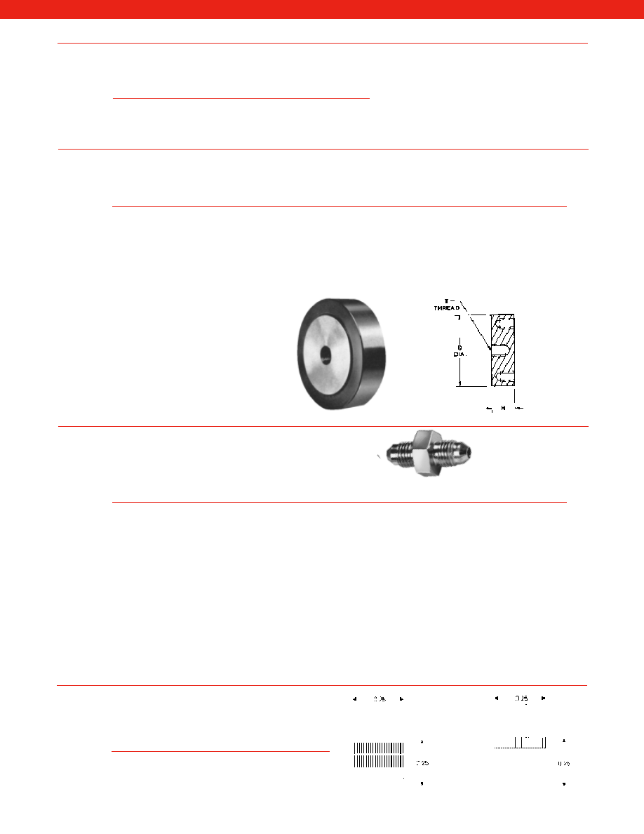
460
www.honeywell.com/sensotec
1-888-282-9891
Used w/Models
#
Order
41 and 42
Used w/Model 75
T"
D"
H
Bolt
Code
(Range in lbs.)
(Range in lbs.)
Thread
Dia.
Holes
Size
Depth
AA221
5 to 25
N/A
1/4-28 UNF-2B
2.50
0.75
6
8-32
0.50
AA222
50 to 1000
50 to 500
3/8-24 UNF-2B
3.00
1.00
6
1/4-28
0.50
AA223
2K to 5K
1K to 2K
1/2-20 UNF
3.50
1.00
6
5/16-24
0.50
AA224
7500 to 15K
3K to 7500
1-14 UNS
5.50
1.50
8
3/8-24
0.75
AA225
20K to 50K
10K to 20K
1 1/2-12 UNF
6.00
1.80
8
1/2-13
1.00
AA233
N/A
30K to 50K
2-12 UNC
7.50
2.50
8
3/4-16
1.75
AA234
N/A
75K to 100K
2 1/2-12 UNC
9.00
3.00
12
5/8-18
1.00
AA226
75K to 100K
N/A
2-12 UNC
9.00
3.00
12
5/8-18
1.00
AA227
150K to 200K
N/A
2 1/2-12 UN
11.00
3.50
12
3/4-16
1.00
AA228
300K to 500K
150K to 200K
3 1/2-8
14.00
4.25
12
1-8
2.25
Note:
Mounting
bolts included
with pull plates.
(STAINLESS STEEL)
Order Code
Pressure Port A
Pressure Port B
AA310
9/16 - 18 UNF Male
1/4 - 18 NPT Male
AA311
1/4 - 18 NPT Female
1/8 - 27 NPT Female
AA312
1/4 - 18 NPT Female
7/16 - 20 UNF Female (MS33649-04)
AA313
1/4 - 18 NPT Female
7/16 - 20 UNF Male (MS33656-E4)
AA314
1/4 - 18 NPT Male
1/8 - 27 NPT Female
AA315
1/4 - 18 NPT Male
7/16 - 20 UNF Female (MS33649-04)
AA316
1/4 - 18 NPT Male
7/16 - 20 UNF Male (MS33656-E4)
AA317
1/8 - 27 NPT Male
7/16 - 20 UNF Male (MS33656-E4)
AA318*
1/4 - 18 NPT Male
1/4 - 18 NPT Male
AA319
1/4 - 18 NPT Female
1/4 - 18 NPT Female
AA333
1/8 - 27 NPT Male
1/8 - 27 NPT Male
AA334
1/8 - 27 NPT Female
7/16 - 20 UNF Male (MS33656-E4)
AA335
1/8 - 27 NPT Male
7/16 - 20 UNF Male (MS33656-E4)
AA336
1/8 - 27 NPT Male
1/4 - 18 NPT Male
AA337
1/4 BSP Female
1/4 - 18 NPT Male
AA338
1/4 - 18 NPT Female
1/4 - 18 NPT Female
* Maximum pressure range is 6000 psi.
The pressure ports indicated describe the adapter, which may be installed in either direction.
PORT A
PORT B
Adapter
Order
Calibration
Code
Resistance
AA211
59,000 Ohm for 1.6 to 3 mV/V output
AA212
90,000 Ohm for 1 to 1.5 mV/V output
AA213
200,000 Ohm for less than 1 mV/V output
Order
Code
Description
AA946
Domed Tip
AA947
Rolling Tip
Shunt Calibration Resistors
Pull Plates
Pressure Port Adapters
LVDT Tips
Courtesy of Steven Engineering, Inc.-230 Ryan Way, South San Francisco, CA 94080-6370-Main Office: (650) 588-9200-Outside Local Area: (800) 258-9200-www.stevenengineering.com
Sensotec Sensors Full Line Catalog-html.html
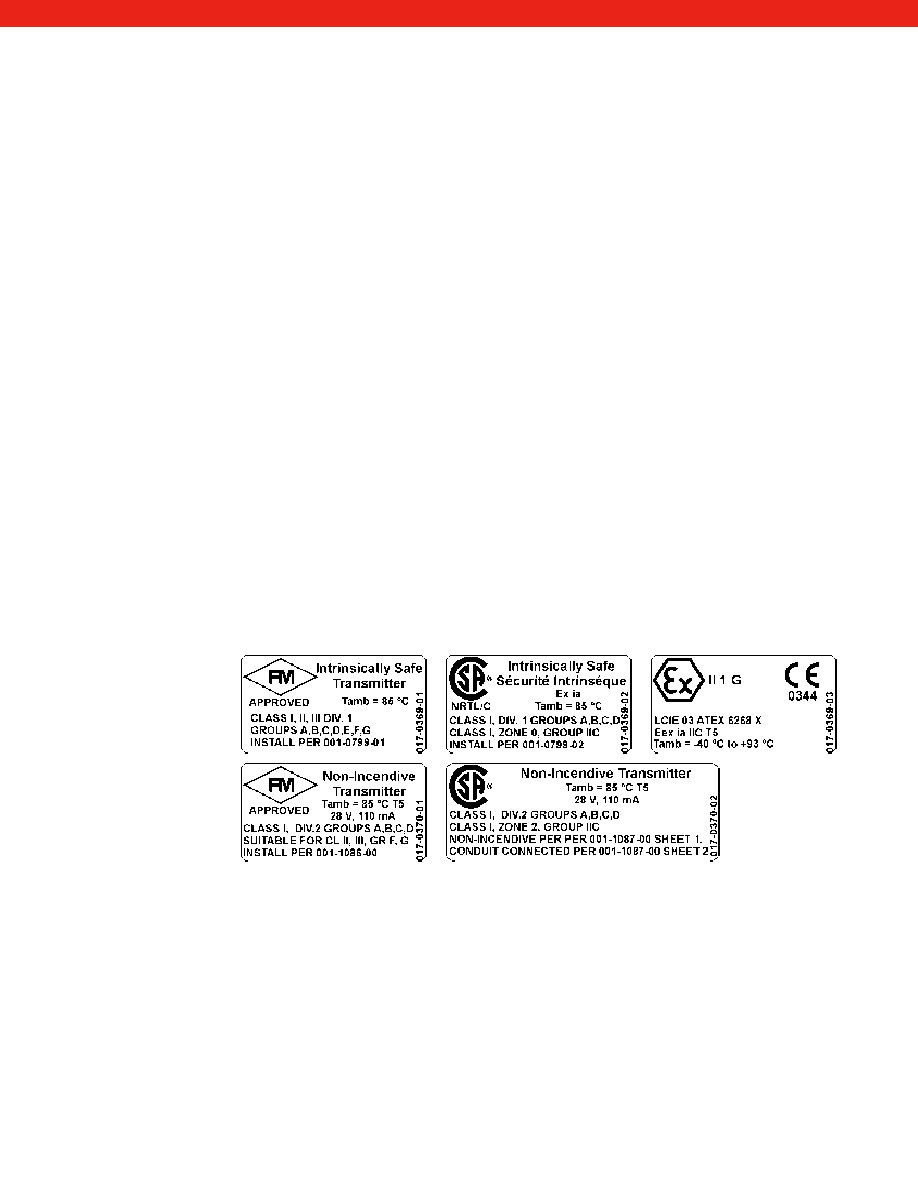
461
Connect ± 15 vdc power input to get non-floating output. This amplifier is used when only positive output
is required. (ie: gage or absolute pressure transducers, compression-only load cells, etc.) Use wiring
code 11, 12, or 13 depending on electrical termination (Reference application sheet #008-0356-00).*
Connect ± 15 vdc power input to get non-floating output. This amplifier is used when both positive and
negative output are required. (ie: differential pressure transducers, tension/compression load cells,
accelerometers.) Use wiring code 11, 12, or 13 depending on electrical termination (Reference
application sheet #008-0356-00).*
Connect with power pack or vehicle battery power for field use. This amplifier has a high degree of
regulation to accept battery voltage changes plus transient protection. It can drive loads of up to
5 milliamperes at full output. Use wiring code 14, 15, or 16 depending on electrical termination.
(Reference application sheet #008-0357-00).
Connect with any power supply from 15 to 28 VDC to get output of 0-10 VDC or ±10 VDC, with respect
to the (-) power supply terminal. Can drive loads up to 2.5 mA at 10 V output. (Reference application
sheet #008-0360-00).
This amplifier has inherent protection against shorting any combination of pins to ground. Applying
32 volts on output will not harm amplifier. Maximum load resistance is 500 ohms. Long lead wires
reduce loss in accuracy. Use wiring code 19, 20, or 21 depending on electrical termination. (Reference
application sheet #008-0361-00).
This amplifier is often ideal for unregulated power supplies in rugged industrial locations, fits two-wire
4-20ma current loops, and is often useable and accurate over great distances. (not available on all
transducer models, 5000 ohm bridge required.) Use wiring code 22 or 23 depending on electrical
termination (Reference application sheet #008-0358-00).
Honeywell Sensotec products configured with a 4-20 mA, 2-wire output using option code 2n or 2N are
marked as follows:
Internal Amplifiers
Voltage Amp
(Option 2a)
Bipolar Voltage Amp
(Option 2b)
Vehicle Powered
Voltage Amp
(Option 2c)
Voltage Amp 3-Wire
0-10 or ±10V (Option 2t)
Current Amp 3-Wire
(Option 2j)
Current Amp 3-Wire
(Option 2k)
Current Amp 2-Wire
Intrinsically Safe
(Option 2n or 2N)
www.honeywell.com/sensotec
1-888-282-9891
Internal amplifiers are practical if temperatures at the transducer are in the range of 0° F to 185° F. When temperatures
are beyond these levels, in-line amplifiers can be used to amplify the transducer output. Our internal transducer
electronics condition and amplify the strain gage millivolt signal to a standard output range of 0-5 vdc or 4-20mA.
The amplifier is constructed as an integral part of the electrical connector end of the pressure transducer or load cell.
Potentiometer adjustments for the zero and span (gain), accessible through two small holes in the transducer body, are
usually provided. (Potentiometers may not be available on units with conduit or cable exit.) These holes are covered with
O-ring sealed screws to provide environmental protection. The range of zero and span adjustments are +/– 15% min. of
full scale.
With the exception of the 2-wire current amp, the internal amplifiers listed below include an internal
shunt calibration resistor as a standard feature.
Connection options: Products with option code 2n or 2N feature a standard welded, stainless steel electrical connector.
Products with permanent integral cable and CSA or ATEX approval are limited to 30.5m (100ft.) of cable.
Honeywell Sensotec document #008-0547-00, available from our web site, contains up-to-date information regarding:
Intrinsically Safe installation
Entity Parameters
CSA Certificate of Conformity
ATEX Declaration of Conformity
Non-Incendive installation
Explosion-proof transmitters Models 811 and 911 are NOT intrinsically safe and thus do not use option code 2n or 2N.
Power is the input voltage required to drive the transducer bridge including the built-in electronics. When the illustration shows
a voltage input of, for example, 26-32 vdc, this means that the amplified transducer will run on any input voltage between
26-32 volts. Slow variation in input voltage will not have any effect on the output because the internal electronics have built-in
voltage regulation. The specification for output means the transducer is calibrated at the factory for the specified output at full
range. For example, for a 100 psia pressure transducer, the output would be 5 volts DC when 100 psia pressure is applied to
the transducer.
* Not for new design, for replacement only.
Courtesy of Steven Engineering, Inc.-230 Ryan Way, South San Francisco, CA 94080-6370-Main Office: (650) 588-9200-Outside Local Area: (800) 258-9200-www.stevenengineering.com
Sensotec Sensors Full Line Catalog-html.html
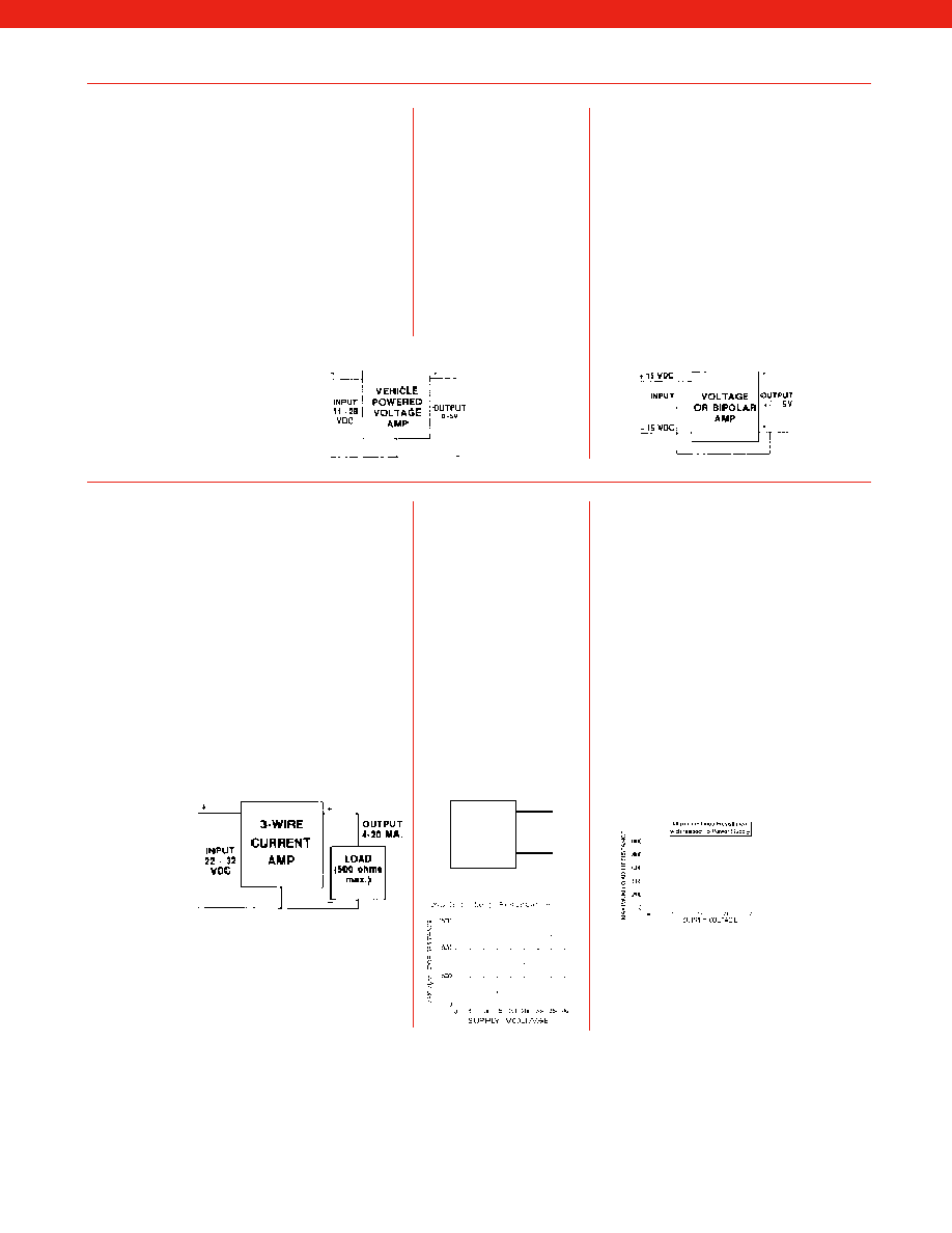
462
Specifications
Voltage Output
Voltage Output
Voltage Output
Option 2c
Option 2t
Option 2b
Input Power (Voltage)
11-28 VDC
15-28 VDC
+ / – 15 VDC
Input Power (Current)
40 mA
40 mA
45 mA
Output Signal
0-5V or + / – 5 @ 5 mA 0-10 V or + / –10V @ 5mA
+ / – 5V @ 2.5 mA
Frequency Response
3000 Hz
3000 Hz
3000 Hz
Power Supply Rejection
60db
60db
80 db w. + / – 15V pwr.
60 db w. 26-32V power
Operating Temperature
-20° F to 185° F
-20° F to 185° F
0° F to 185° F
Reverse Voltage Protection:
Yes
Yes
Yes
Short Circuit Protection:
Momentary
Momentary
Output to Output Gnd.
Possible Options
Special Temp.
Special Temp.
Special Temp.
Ranges
Ranges
Ranges
Remote Buffered
Remote Buffered
Programmable Range
Shunt Calib.
Shunt Calib.
Changing
Remote Buffered
Shunt Calib.
Specifications
Current
Current
Intrinsically Safe
3-Wire
2-Wire
Amp
Option 2j
Option 2k
Option 2n (2N)
Input Power (Voltage)
22-32 VDC (depends
9-32 VDC typical
9-28 VDC
on load resistance)
(depends on
load resistance)
Input Power (Current)
65 mA
4-28 mA
4-24 mA
Output Signal
4-20 mA
4-20 mA
4-20 mA
Frequency Response
2500 Hz
300 Hz
2000 Hz
Power Supply Rejection
60db
60db
60db
Operating Temperature
0° F to 185° F
0° F to 185° F
-20° F to 200° F
Reverse Voltage Protection:
Yes
Yes
Yes
Short Circuit Protection:
Yes
Yes
Yes
Possible Options
Special Temp.
Special Temp.
Remote Buffered
Ranges
Ranges
Shunt Calib.
Remote Buffered
Remote Buffered
Shunt Calib.
Shunt Calib.
2-WIRE
CURRENT
AMP
+
Output
4-20mA
-
www.honeywell.com/sensotec
1-888-282-9891
Courtesy of Steven Engineering, Inc.-230 Ryan Way, South San Francisco, CA 94080-6370-Main Office: (650) 588-9200-Outside Local Area: (800) 258-9200-www.stevenengineering.com
Sensotec Sensors Full Line Catalog-html.html
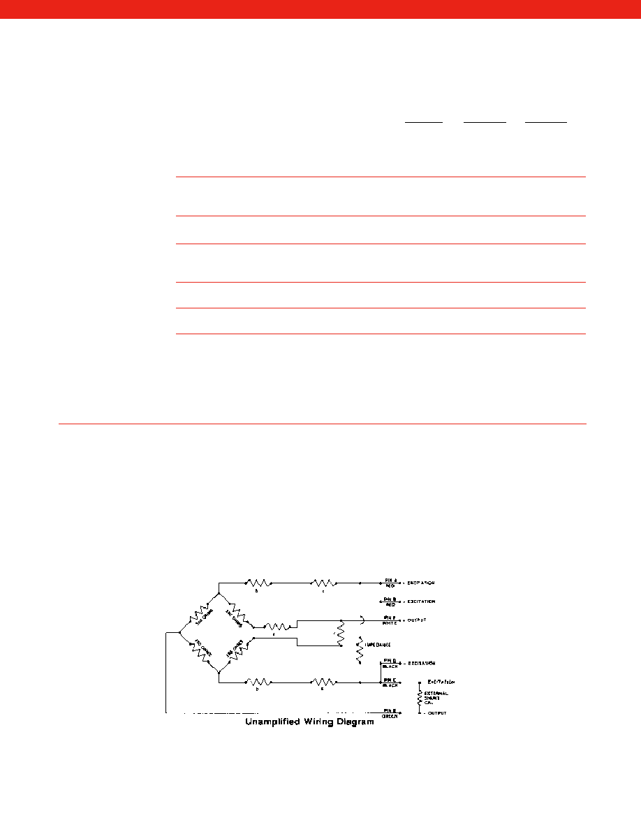
463
Wiring Codes
Standard
Standard
Submersible
Cable
Connector
Cable
Unamplified – no shunt cal.
– no shunt cal. .....................................................
#1
#2
#3
– with shunt cal. (50%)*.......................................
#4
#5
#6
– with sense leads ...............................................
#7
#8
#9
Voltage amp. (Vehicle powered)
0-5 VDC with 11-28 VDC supply @ 25mA
– with shunt cal. (80%)*.......................................
#14
#15
#16
Voltage amp. 0-10 VDC with 15-28 VDC supply @ 40mA
– with shunt cal. (80%) ........................................
#46
#47
#48
Current amp. (3wire, 4-20mA) with 22-32 VDC supply @ 65mA
– no shunt cal. .....................................................
#17
#29
#18
– with shunt cal. (75%)*.......................................
#19
#20
#21
Current amp. (2-wire, 4-20mA), Not FM approved
– no shunt cal. .....................................................
#22
#23
S
Current amp. (2-wire, 4-20mA), FM approved
– no shunt cal**....................................................
#22
#23
S
* Interconnecting shunt cal. 1 terminal with shunt cal. 2 terminal (see wiring code) provides 50%
(unamplified units) or 75% (4-20mA 3 wire only), 80% (voltage amp) of full scale output for
quick calibration.
** Relay buffered shunt cal is optional, consult factory.
S Special (consult factory)
Option 2c
Option 2j
Option 2k
Option 2n (2N)
Option 2t
Supply:
Positive lead of source (power supply) used to drive amplified transducer.
Supply Return:
Negative lead of source (power supply) used to drive amplified transducer.
+ Output or Output:
Signal side of output.
– Output or Output Return:
Reference side of output signal.
Supply Common:
Center terminal if bipolar supplies (i.e. ±15VDC) are used.
+ Excitation:
Positive lead of source (power supply) used to drive unamplified transducer.
– Excitation:
Negative lead of source (power supply) used to drive unamplified transducer.
+ Sense:
Positive lead used for sensing bridge excitation with long cables.
– Sense:
Negative lead used for sensing bridge excitation with long cables.
a - Zero temperature compensation resistor
b - Span temperature compensation resistors
c - Trim resistors for output standardization
d - Zero balance trim resistors
www.honeywell.com/sensotec
1-888-282-9891
Option 2u
Standard Wiring Codes
Definitions
Courtesy of Steven Engineering, Inc.-230 Ryan Way, South San Francisco, CA 94080-6370-Main Office: (650) 588-9200-Outside Local Area: (800) 258-9200-www.stevenengineering.com
Sensotec Sensors Full Line Catalog-html.html

464
#1
Cable/Unamplified
Red
(+) Excitation
Black
(-) Excitation
Green
(-) Output
White
(+) Output
#2
Connector/Unamplified
A & B
(+) Excitation
C & D
(-) Excitation
E
(-) Output
F
(+) Output
#3
Cable/Unamplified/Submersible
Red
(+) Excitation
Brown
(-) Excitation
Yellow
(-) Output
Orange (+) Output
#4
Cable/Unamplified/Int. Shunt Cal
Red
(+) Excitation
Black
(-) Excitation
Green
(-) Output
White
(+) Output
Blue
Shunt Cal 1*
Brown
Shunt Cal 2*
#5
Connector/Unamplified/Int. Shunt Cal
A
(+) Excitation
B
(-) Excitation
C
(+) Output
D
(-) Output
E
Shunt Cal 1*
F
Shunt Cal 2*
#6
Cable/Unamplified/Int. Shunt Cal/ Submersible
Red
(+) Excitation
Blue
(-) Excitation
Orange (+) Output
Green
(-) Output
Brown
Shunt Cal 1*
Yellow
Shunt Cal 2*
#7
Cable/Unamplified/Sense Leads
Red
(+) Excitation
Black
(-) Excitation
Green
(-) Output
White
(+) Output
Blue
(-) Sense
Brown
(+) Sense
#8
Connector/Unamplified/Sense Leads
A
(+) Excitation
B
(+) Sense
C
(-) Excitation
D
(-) Sense
E
(-) Output
F
(+) Output
#9
Cable/Unamplified/Sense/Leads/Submersible
Red
(+) Excitation
Blue
(-) Excitation
Orange (+) Output
Green
(-) Output
Brown
(+) Sense
Yellow
(-) Sense
#10 Cable/Voltage (+/-5VDC Output with +/-15VDC supply)
/Submersible
+/–15VDC Supply
Wire
(+) Supply (+15VDC)
Red
(-) Supply (-15VDC)
Orange
(+) Output (+/-5VDC)
Yellow
(-) Output/Supply Com. Brown
#11 Cable/Voltage (+/-5VDC Output with +/-15VDC supply)
/Int. Shunt Cal
+/–15VDC Supply
Wire
(+) Supply (+15VDC)
Red
(-) Supply (-15VDC)
Black
(-) Output/Supply com. Green
(+) Output (+/-5VDC)
White
Shunt cal 1*
Blue
Shunt cal 2*
Brown
#12 Connector/Voltage (+/-5VDC Output with +/-15VDC
/Int. Shunt Cal
+/–15VDC Supply
Pin
(+) Supply (+15VDC)
A
(-) Output/Supply com. B
(-) Supply (-15VDC)
C
(+) Output (+/-5VDC)
D
Shunt cal 1*
E
Shunt cal 2*
F
#13 Cable/Voltage (+/-5VDC Output with +/-15VDC
/Int. Shunt Cal/Submersible
+/–15VDC Supply
Wire
(+) Supply (+15VDC)
Red
(-) Supply (-15VDC)
Brown
(-) Output/Supply com. Orange
(+) Output (+/-5VDC)
Green
Shunt cal 1*
Blue
Shunt cal 2*
Yellow
#14 Cable/Vehicle Voltage 0-5VDC
Supply/Internal Shunt Cal
Red
(+) Supply (+11-26VDC)
Black, Green Output Common/Supply Return
(Internal Connection)
White
(+) Output (0-5VDC)
Blue
Shunt Cal 1*
Brown
Shunt Cal 2*
#15 Connector/Vehicle Voltage 0-5VDC
w/11-26VDC Supply/Internal Shunt Cal
A
(+) Supply (+11-26VDC)
B, C
Output Common/Supply Return
(Internal Connection)
D
(+) Output (0-5VDC)
E
Shunt Cal 1*
F
Shunt Cal 2*
#16 Cable/Vehicle Voltage 0-5VDC
w/11-26VDC Supply/Internal Shunt Cal/Submersible
Red
(+) Supply (+11-26VDC)
Brown, Orange Output Common/Supply Return
(Internal Connection)
Green
(+) Output (0-5VDC)
Blue
Shunt Cal 1*
Yellow
Shunt Cal 2*
#17 Cable/3 wire current
Red
(+) Supply
Black
Output common/
Green
Supply return (Internal Connection)
White
(+) Output
#18 Cable/3 wire current, 4-20mA/Submersible
Red
(+) Supply
Brown,
Output common/
Yellow
Supply return (Internal Connection)
Green
for outputs
Orange (+) Output (4-20mA)
#19 Cable/3 wire current, 4-20mA/Shunt Cal
Red
(+) Supply
Black,
Output common/
Green
Supply return (Internal Connection)
White
(+) Output (4-20mA)
Blue
Shunt Cal 1*
Brown
Shunt Cal 2*
#20 Connector/3 wire current, 4-20mA/Shunt Cal
A
(+) Supply
B, C
Output common/Supply return
(Internal connection)
D
(+) Output (4-20mA)
E
Shunt Cal 1*
F
Shunt Cal 2*
www.honeywell.com/sensotec
1-888-282-9891
Courtesy of Steven Engineering, Inc.-230 Ryan Way, South San Francisco, CA 94080-6370-Main Office: (650) 588-9200-Outside Local Area: (800) 258-9200-www.stevenengineering.com
Sensotec Sensors Full Line Catalog-html.html
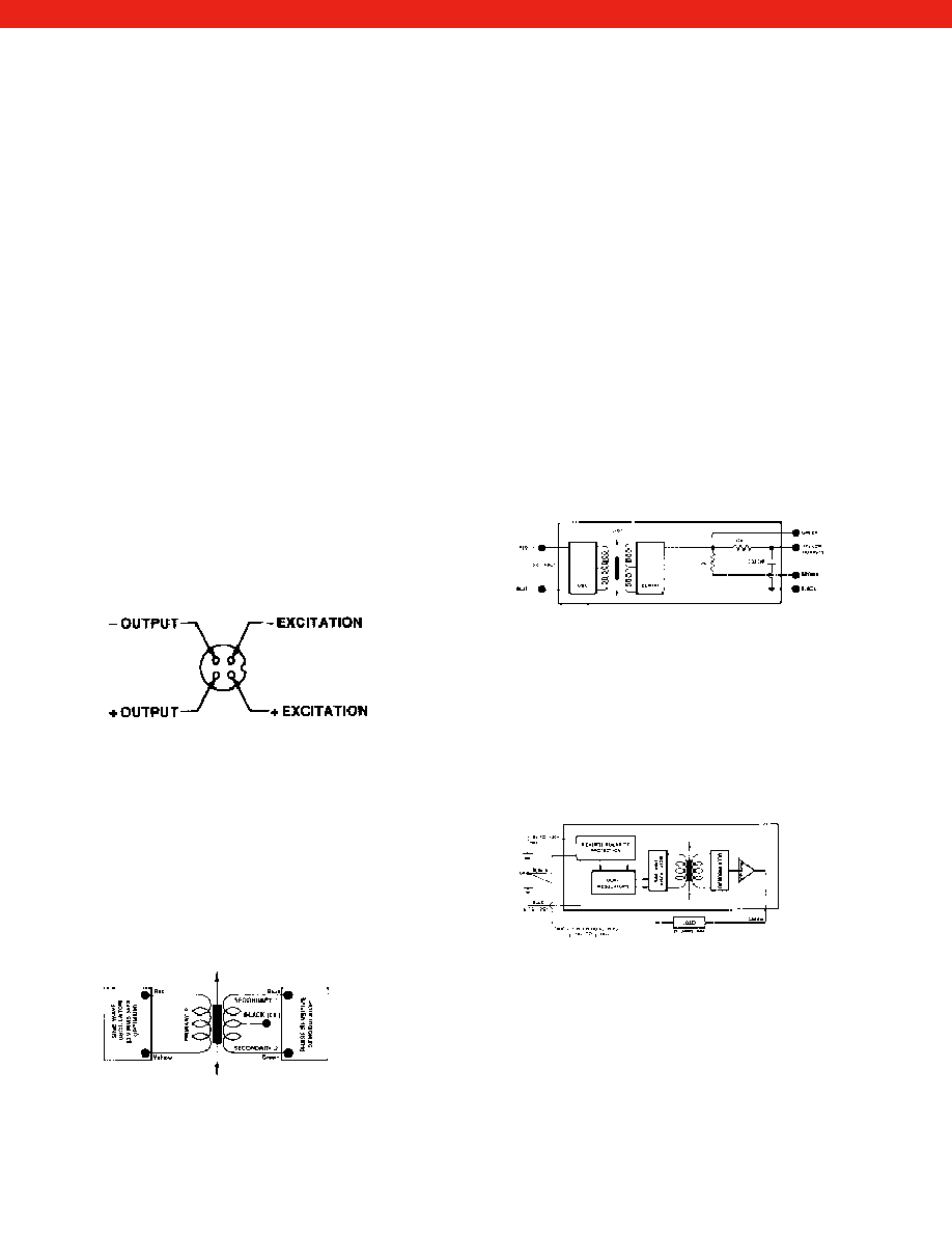
465
#21 Cable/3 wire current, 4-20mA/
Int. Shunt Cal/Submersible
Red
(+) Supply
Brown,
Output common/
Green
Supply return (Internal Connection)
Orange (+) Output (4-20mA)
Blue
Shunt Cal 1*
Yellow
Shunt Cal 2*
#22 Cable/2 wire current, 4-20mA
Red
(+) Supply
Black
(+) Output (4-20mA)
White
Case Ground
#23 Connector/2 wire current, 4-20mA
A
(+) Supply
B, C & F No Connection
D
(+) Output (4-20mA)
E
Case Ground
#24 Cable/Frequency Output/
Internal Shunt Cal
Red
(+) Supply
Black,
Output common/
Green
Supply return (Internal Connection)
White
(+) Output
Blue
Shunt Cal 1*
Brown
Shunt Cal 2*
#25 Connector/Frequency Output/
Internal Shunt Cal
A
(+) Supply
B, C
Output common/Supply return
(Internal Connection)
D
(+) Output
E
Shunt Cal 1*
F
Shunt Cal 2*
#27 Microtech Connector
#28 Consult factory
#29 Connector/3 wire current, 4-20mA/w/22-32VDC Supply
A
(+) Supply (+22-32VDC)
B, C
Output common/Supply return
(Internal Connection)
D
(+) Output (4-20mA)
E & F
No Connection
#30 AC/AC LVDT
Red
Supply (Calibrated @ 3V RMS 5 kHz)
Yellow
Supply return
Blue
Output
Green
Output return
Black
Secondary Center Tap (normally not connected)
Cable shield is not connected to transducer.
www.honeywell.com/sensotec
1-888-282-9891
#31 DC/DC LVDT (single power supply)
Reverse polarity protected w/voltage regulator
Dual Supply
Red
+12 to +20V input
Blue
-12 to -20V input
Black
OV common
Single Supply
Red
+24 to 40V input
Blue
Supply negative
Outputs
Yellow
0-5-10 Volt
Green
±5 VDC
* Must be floating output common =
1
/
2
supply voltage
#32 DC/DC LVDT (single power supply) without reverse
polarity protection or voltage regulation
Red
(+) Supply (+6 to +12VDC)
Blue
Supply return
Yellow
Note: See below
Green
for outputs
Black
Brown
– Short Black and Brown for internal
10,000 ohm load
– Filtered output – Yellow and Black/Brown
– Unfiltered output – Green and Black/Brown
Cable shield is not connected to transducer.
#35 DC/DC LVDT (single power supply)
Reverse polarity protected w/voltage regulator
Yellow
+5V, Regulated Input
Brown
+5V, Regulated Output
Red
+6V to 18V, Unregulated
Blue
OV, supply common/ground
Black
Output (lo)
Green
Output (hi)
Shield
Connect to Instrument ground
Link the Yellow and Brown wires together when using the
+6V./+18V. Input Option. Ensure the Red and Brown wires
are disconnected when using the 5V. The D.C. Output sig-
nal is electrically isolated from the Input voltage.
#36 Connector/2 wire current, 4-20 mA
1
+ Supply
2
+ Output
3
N/C
Case Ground
Courtesy of Steven Engineering, Inc.-230 Ryan Way, South San Francisco, CA 94080-6370-Main Office: (650) 588-9200-Outside Local Area: (800) 258-9200-www.stevenengineering.com
Sensotec Sensors Full Line Catalog-html.html

466
#37 Connector/Unamplified
1
+ Excitation
2
+ Output
3
– Output
– Excitation
#38 Connector/Voltage
1
+ Supply
2
+ Output
3
Supply/Output Common
N/C to Case
#39 Connector/Unamplified
A
+ Excitation
B
+ Output
C
– Output
D
– Excitation
#40 Unamplified, 6 pin Connector with Signature Module
A
(+)Excitation
B
(+)Signature
C
(–) Excitation
D
(–) Signature
E
(–) Output
F
(+)Output
#41 Unamplified, 6 Conductor for Signature Module
Red
(+)Excitation
Black
(–) Excitation
Green
(–) Output
White
(+)Output
Blue
(–) Signature (Memory –)
Brown
(+)Signature (Memory +)
#44 Cable, 4-20mA out
Red
(+)Supply
Black
(+)Output (4-20mA)
White
Case Ground
#45 Unamplified, 6 pin header for coil connections on LVDT
1 & 6
Primary Coil
2 & 5
Secondary Coils
3 or 4
Secondary Centre Tap (whichever is longer)
#46 Vehicle amplifier 0-10VDC
Red
(+)Supply
Black
Supply return
Green
(–) Output
White
(+)Output (0-10VDC)
Blue
Shunt Cal 1
Brown
Shunt Cal 2
#47 Vehicle amplifier 0-10VDC
A
(+)Supply
B
(–) Output
C
Supply return
D
(+)Output (0-10VDC)
E
Shunt Cal 1
F
Shunt Cal 2
#48 Vehicle amplifier 0-10VDC/
Submersible Cable
Red
(+)Supply
Brown
(–) Output
Orange Supply return
Green
(+)Output (0-10VDC)
Blue
Shunt Cal 1
Yellow
Shunt Cal 2
#49 FP2000, current output, Bendix connector
A
(+)Supply 9-28VDC (red)
B
N/C
C
N/C
D
(+) Output 4-20 (black)
E
N/C
F
N/C
#50 FP2000, voltage output, Bendix connector
A
(+) Supply 9-28VDC (red)
B
(-) Supply return
(black)
C
(-) Output
(green)
D
(+) Output 0-5VDC (white)
E
N/C
F
N/C
#51 FP2000, current output, cable exit
(+) Supply 9-28VDC (red)
(-) Output 4-20 mA
(black)
#52 FP2000, voltage output, cable exit
(+) Supply 9-28VDC (red)
Supply return
(black)
(-)
output
(green)
(+)
output (0-5 VDC) (white)
#53 FP2000, current output, I.S., DIN connector, opt 2N
1
(+) Supply
2
(+) Output
3
Case ground
#54 FP2000 current output DIN connector, option 2p
1
+ supply
2
+ output 4-20 mA
3
No connection
GND
No connection
#55 FP2000 current output DIN connector, option 2y
with shunt cal.
1
+ supply
2
+ output 4-20 mA
3
N/C
GND
Shunt Cal
#56 FP2000 voltage output pin conn opt. 2e/2f
with shunt calibration
1
+ supply
2
+ output
3
Supply ret/-output
GND
Shunt Cal
#57 FP2000 Millivolt output Bendix conn opt. 2u
A
+ excitation
B
- excitation
C
+ output
D
- output
E
N/C
F
Shunt Cal
#58 FP2000 current output Bendix conn opt. 2y
A
+ supply
B
N/C
C
N/C
D
+ output (4-20mA)
E
N/C
F
Shunt Cal
#59 FP2000 current output Bendix connector shunt cal
opt. 2N IS
A
+ supply
B
N/C
C
N/C
D
+ output (4-20mA)
E
Case ground
F
Shunt Cal
#60 Voltage output with shunt cal Bendix conn. opts. 2e/2f
A
+ supply
B
- supply return
C
- output
D
+ output
E
N/C
F
Shunt Cal
#61 Current output w/ shunt cal & integral cable opt. 2y/6r/6q
Red
+ supply
Black
+ output
Green
Shunt Cal
#62 Current output with shunt cal & integral cable
opt. 2N IS/6r/6q
Red
+ supply
Black
+ output (4-20mA IS)
Green
Shunt
White
Case ground
#63 Voltage output with shunt cal & integral cable opt.
2e/2f/6r/6q
Red
+ supply
Black
- supply return
Green
Shunt Cal
White
+ output
#64 Current output 2N is with shunt cal & DIN connector
1
+ supply
2
+ output (4-20mA)
3
Case ground
GND
Shunt Cal
www.honeywell.com/sensotec
1-888-282-9891
Courtesy of Steven Engineering, Inc.-230 Ryan Way, South San Francisco, CA 94080-6370-Main Office: (650) 588-9200-Outside Local Area: (800) 258-9200-www.stevenengineering.com
Sensotec Sensors Full Line Catalog-html.html
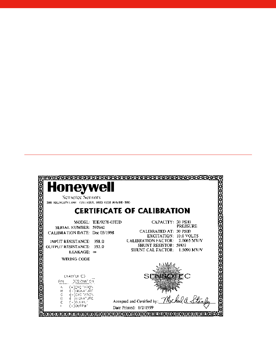
467
The most common method for quick field calibration is the “shunt calibration” technique. This method applies a known,
accurate resistance across one leg of the transducer, which simulates an actual physical stimulus when one is not pres-
ent. Upon application of this resistance, the output of the transducer changes exactly as it would if a known pressure or
load were applied.
In performing shunt calibration, the transducer should have no pressure or load applied, so that it is at “zero” initially. The
data instrument’s ZERO control can then be adjusted to give a zero output on its indicator, or a zero voltage on its output
terminals. (In the case of 4-20 milliampere outputs, this value would be a 4 milliamperes.) The shunt calibration circuitry
may then be activated by use of the front-panel SHUNT CAL button. A step change in amplifier out put or reading will
occur. If the amount of the step change does not agree with the expected change as indicated by the Transducer
Calibration Data sheet, adjust the SPAN or GAIN control until it does. This will insure that the amplification given by the
data device will be correct, so that an actual stimulus will give correct readings.
It is advisable to recheck the zero when the shunt calibration resistance is removed, since there may be some interaction
if the GAIN or SPAN control adjustments were large.
Strain gage transducers with internal amplifiers usually have a shunt calibration resistor installed. The shunt calibration
resistor may be activated by interconnecting two terminals on the connector. The wiring code section of the Transducer
Calibration Data sheet will indicate which terminals are to be interconnected to activate the shunt calibration. For current
output units (4-20 milliamperes), several full cycles of adjusting the ZERO and SPAN controls may be required, since
these controls interact greatly in such units.
Shown is a typical Transducer Calibration Data sheet. This sheet will be used as an example to illustrate the setup proce-
dure for both unamplified transducers, as well as instruments with an amplified output. The calibration record for ampli-
fied transducers includes the “amplified” shunt cal value so no calculation is required.
Field Set-up of Transducer and Instrument
Calibration Data Sheet
www.honeywell.com/sensotec
1-888-282-9891
Courtesy of Steven Engineering, Inc.-230 Ryan Way, South San Francisco, CA 94080-6370-Main Office: (650) 588-9200-Outside Local Area: (800) 258-9200-www.stevenengineering.com
Sensotec Sensors Full Line Catalog-html.html

468
1. Make all required connections between the transducer and the instrument.
2. Apply power and allow 10 to 20 minutes for stabilization.
3. Turn the ZERO adjustment so that the indicator reads zero. (If you are working with a PSIA
transducer, the transducer must be evacuated to get zero. However, the unit can be shunt cali-
brated at atmosphere, and the atmospheric reading added to the shunt calibration reading.)
4. From the Transducer Calibration Data sheet, obtain the transducer full scale output in millivolts
per volt, and the shunt calibration output in millivolts per volt.
5. Select and perform the proper calculation from the discussion below.
6. Depress the SHUNT CAL switch and turn the SPAN or GAIN adjustment to obtain the value
calculated in step 5.
Transducers with millivolt outputs usually do not have internal shunt calibration circuitry, but the
effect of a known shunt calibration resistor being connected across the leads will be noted on the
Transducer Calibration Data sheet. To determine the output of an unamplified transducer under
shunt calibration conditions, perform the following calculation:
(Shunt Cal Factor in mV/V) x Excitation Voltage = Output Voltage
Substituting the values from the sample Transducer Calibration Data sheet into the above equation
provides the following:
(1.5090 mv/v) x (10 V) = 15.090 millivolts
Consider next an amplified transducer with a 0 to 5 volt output, or an instrument which has been
factory calibrated with a transducer. Determining the output under shunt calibration conditions is
done with the following equation:
Shunt Cal Factor in mV/V
Full-Scale Output in mV/V x Full-Scale Output = Output Voltage
Using the same data sheet as before, and assuming an amplified transducer with a 5 volt full scale
provides:
(1.5090 mV/V)
(3.0057 mV/V x 5 volts = 2.510 volts
Consider next the case of a 4-20 milliampere output from an amplified transducer. Notice that this
represents a span of 16 milliamperes, offset upward by 4 milliamperes. To calculate the shunt cal
output, use the following equation:
Shunt Cal Output in mV/V
Full-Scale Output in mV/V x 16 mA. + 4 mA. = Output Current
Using the same data sheet again, and assuming a 4-20 mA. case,
(1.5090 mV/V)
(3.0057 mV/V) x 16 mA. + 4 mA. = 12.033 mA.
The following equation applies to instruments with a display:
Shunt Cal Factor in mV/V
Full-Scale Display
Shunt Cal Display
Full-Scale Output in mV/V x
Value
=
Value
Since the transducer shown on the Transducer Calibration Data sheet is a 1,000-pound unit, the
display should read:
(1.5090 mV/V)
(3.0057 mV/V) x 1,000 lbs. = 502 lbs.
Step-by-Step
Procedure for
Shunt Cal
Unamplified
Transducers
Instrument with
0 to 5 Volt Output
Instrument with
4-20 Milliampere
Output
Instrument Display
www.honeywell.com/sensotec
1-888-282-9891
Courtesy of Steven Engineering, Inc.-230 Ryan Way, South San Francisco, CA 94080-6370-Main Office: (650) 588-9200-Outside Local Area: (800) 258-9200-www.stevenengineering.com
Sensotec Sensors Full Line Catalog-html.html
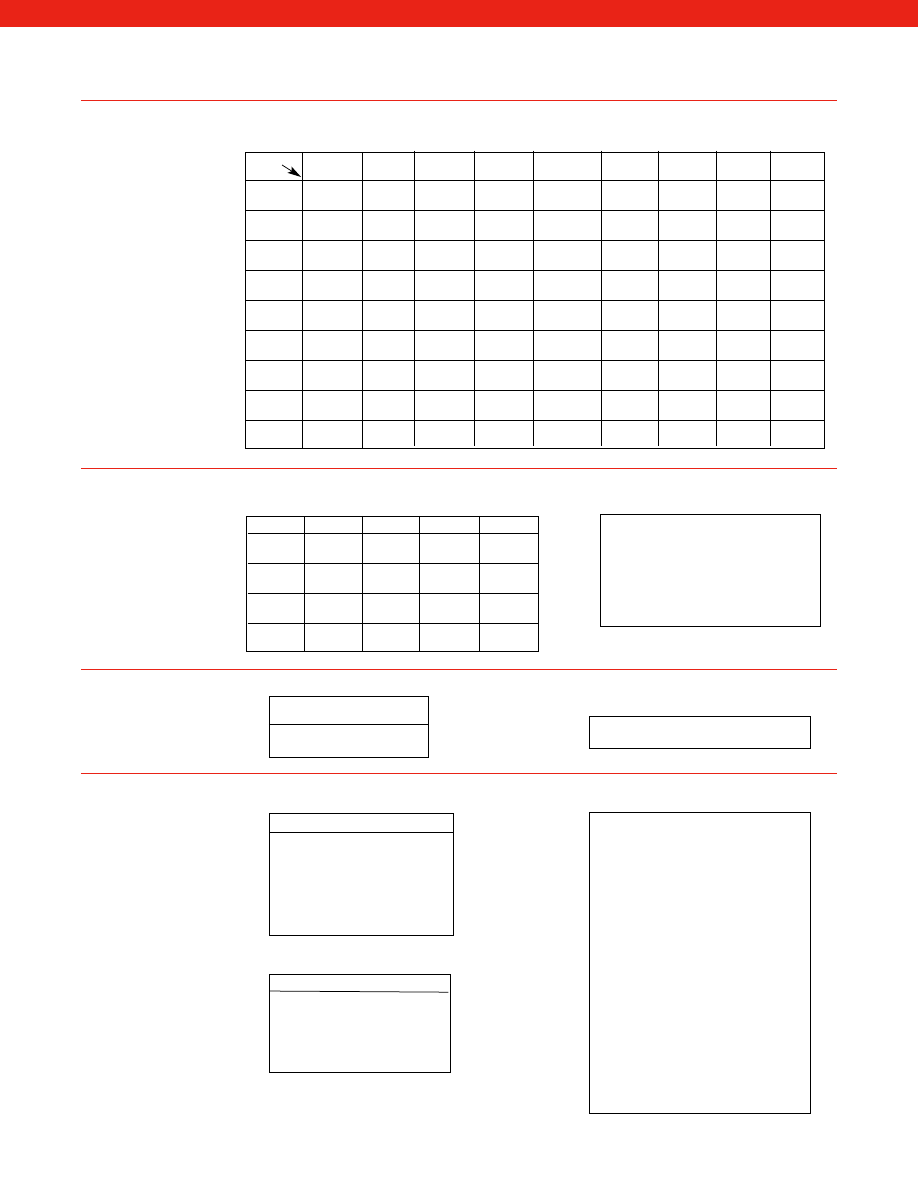
469
Multiply Number of
by
Pound
Grams
Newton
Dyne
Pound
1
2.205
.2248
2.248
X 10
-3
X 10
-6
Grams
453.6
1
102.0
1.020
X 10
-3
Newton
4.448
9.807
1
1.0
X 10
-3
X 10
-5
Dyne
4.448222
980.665
1.0
1
X 10
5
X 10
5
Conversion Tables
(‘FROM’) Multiply Number of
by
lb/in
2
Bars
In of H
2
O
In of Hg
mm of Hg
pascals
Atmos
Dynes/
Kgrams/
(psi)
(4° C)
(0° C)
torr
cm
2
meter
2
lb/in
2
1
14.504
3.6127
0.4912
1.934
1.4503
14.6956
1.4504
1.423
(psi)
X 10
-2
X 10
-2
X 10
-4
X 10
-5
X 10
-3
Bars
6.8948
1
2.491
3.3864
1.333
10-5
1.01325
10-6
9.0867
X 10
-2
X 10
-3
X 10
-2
X 10
-3
X 10
-5
In of H
2
O
27.68
401.48
1
13.60
0.5354
4.014
406.8
4.0148
3.937
(4° C)
X 10
-3
X 10
-4
X 10
-2
In of Hg
2.036
29.53
7.355
1
3.937
2.953
29.9213
2.953
2.896
(0° C)
X 10
-2
X 10
-2
X 10
-4
X 10
-5
X 10
-3
mm of Hg
51.715
750.06
1.868
25.4
1
7.502
760
7.5006
7.3558
torr
X 10
-3
X 10
-4
X 10
-2
Pascals
6.8948
1 X 10
5
2.491
3.386
1.333
1
1.01325
10
-1
9.8067
X 10
3
X 10
2
X 10
3
X 10
2
X 10
5
Atmos
0.068046
9.86923
2.458
3.34207
1.316
9.869
1
9.86923
9.678
X 10
-1
X 10
-3
X 10
-2
X 10
-3
X 10
-6
X 10
-7
X 10
-5
Dynes/
6.8948
10
6
2.491
3.386
1.333
10
1.01325
1
98.067
cm
2
X 10
4
X 10
3
X 10
4
X 10
3
X 10
6
Kg/
7.0306
1.0197
25.40
345.3
13.59
1.019
1.033227 1.0197
1
meter
2
X 10
2
X 10
4
X 10
-1
X 10
4
X 10
-2
N-m
1 oz-in
7.06 X 10⁻³
1 lb-in
0.113
1 lb-ft
1.3558
1 kg-m
9.806
1 dyne-cm
1.00 X 10⁻⁷
1g = 9.806650 m/s
2
= 9.81 ¤ 10
inch
SI unit
0.01
0.254 mm
0.1
2.54 mm
1.0
2.54 cm
1.0
25.4 mm
2.0
50.8 mm
3.0
76.2 mm
4.0
101.6 mm
5.0
127.0 mm
6.0
152.4 mm
7.0
177.8 mm
8.0
203.2 mm
9.0
228.6 mm
10.0
254.0 mm
1 ft
0.3048 m
1 yd
0.9144 m
°C = (°F -32)/1.8
°F = (1.8 x °C) + 32
LINEAR MEASURE
1 centimeter
0.3937 inch
1 inch
2.54 centimeters
1 foot
0.3048 meter
1 meter 38.37 inches…1.0936 yds.
1 yard
0.9144 meter
1 rod
5.029 meters
1 kilometer
0.621 mile
1 miles
1.609 kilometers
WEIGHTS
1 gram
0.03527 ounce
1 ounce
28.35 grams
1 kilogram
2.2046 pounds
1 pound
0.4536 kilogram
1 metric ton
0.98421 English ton
1 English ton
1.016 metric ton
Pressure
Load
Temperature
(‘TO’) To Obtain
To Obtain
www.honeywell.com/sensotec
1-888-282-9891
Torque
Accelleration
Linear Displacement
Metric Equivalents
Courtesy of Steven Engineering, Inc.-230 Ryan Way, South San Francisco, CA 94080-6370-Main Office: (650) 588-9200-Outside Local Area: (800) 258-9200-www.stevenengineering.com
Sensotec Sensors Full Line Catalog-html.html

470
ABSOLUTE PRESSURE TRANSDUCER:
A transducer that has an internal reference chamber sealed at or close to 0
psia (full vacuum) and normally provides increasing output voltage for increases in pressure.
ACCURACY:
The combined error of nonlinearity, repeatability, and hysteresis expressed as a percent of full scale output.
AXIAL LOAD:
A load applied along or parallel to and concentric with the primary axis.
BFSL:
Best fit straight line. The sensitivity of a sensor is ideally a straight line but is often has some small non-linearity
associated with it. BFSL takes all the data points from the curve and describes a straight line through these data points
such that the deviation (and hence the error) between the curve and the straight line is at a minimum.
BRIDGE:
A Wheatstone bridge configuration utilizing four active strain gages.
BRIDGE RESISTANCE:
The nominal value of the individual legs that make up a complete Wheatstone bridge.
CALIBRATION:
The comparison of transducer voltage outputs against the outputs of a reference standard.
DAMPING:
The reduction of response at the resonant frequency through the use of a damping media such as oil. Usually
specified as the ratio of critical damping.
DEAD VOLUME:
The volume inside the pressure port of a transducer at room temperature and barometric pressure.
DEFLECTION:
The change in length along the primary axis or distance a diaphragm moves at the center between no-load
and rated load conditions.
DIAPHRAGM:
The sensing membrane which is deformed when pressure is applied.
EXCITATION, ELECTRICAL:
The voltage or current applied to the input terminals of the transducer.
FLUSH DIAPHRAGM:
Sensing element is located on the very tip of the transducer (No pressure port).
FREQUENCY RESPONSE:
The range of frequencies over which the transducer voltage output will follow the sinusoidally
varying mechanical input within specified limits.
FULL SCALE:
See Rated Capacity.
FULL SCALE OUTPUT:
The algebraic difference between the minimum output (normally zero) and the rated capacity.
GAGE PRESSURE:
The pressure above (or below) atmospheric. Represents positive difference between measured pres-
sure and existing atmospheric pressure. Can be converted to absolute by adding actual atmospheric pressure value.
GAGE PRESSURE TRANSDUCER:
A transducer which measures pressure relative to the atmospheric pressure.
HYSTERESIS:
the maximum difference between output readings for the same measured point, one point obtained while
increasing from zero and the other while decreasing from full scale. The points are taken on the same continuous cycle.
The deviation is expressed as a percent of full scale.
IEEE 1451.4:
IEEE1451.4 specifies a table of self-identifying parameters that are stored within the sensor in the form of a
TEDS (Transducer Electronic Datasheet). This standard directs its attention to only the TEDS part of the sensor and signal
conditioning system. (As opposed to IEEE1451.2 which is for 'smart sensors'.)
INPUT IMPEDANCE:
The resistance measured across the excitation terminals of a transducer at room temperature, with
no load applied, and with the output terminals open-circuited.
INSULATION (Isolation) RESISTANCE:
The DC resistance expressed in ohms measured between any electrical connec-
tor pin or lead wire and the transducer body or case. Normally measured at 50 VDC.
LINEARITY:
The maximum deviation of the calibration curve from a straight line between zero and full scale, expressed as
a percent of full scale output and measured on increasing measured only.
LINE PRESSURE:
The maximum pressure in the pressure vessel or pipe for differential pressure measurement.
www.honeywell.com/sensotec
1-888-282-9891
Technical Definitions of Terminology
Courtesy of Steven Engineering, Inc.-230 Ryan Way, South San Francisco, CA 94080-6370-Main Office: (650) 588-9200-Outside Local Area: (800) 258-9200-www.stevenengineering.com
Sensotec Sensors Full Line Catalog-html.html

471
LOAD:
The weight, torque, or force applied to the transducer.
LOAD BUTTONS:
The spherical shape of the top surface of a load cell where the load is applied.
MEASURED MEDIA:
The physical quantity, property, or condition which is measured. (eg: pressure, load, weight,
acceleration).
MOUNTED RESONANT FREQUENCY:
the frequency at which the internal spring/mass system of an accelerometer
resonates, producing a 90° phase shift in output signal vs. applied acceleration.
OUTPUT:
The electrical signal measured at the output terminals which is produced by an applied input to a transducer.
OUTPUT IMPEDANCE:
The resistance as measured on the output terminals of a transducer at standard temperature,
with no measured applied, and with the excitation terminals open-circuited.
OVERRANGE, SAFE:
the maximum pressure or load which may be applied to the transducer without causing a
permanent change in the performance specifications.
PHASE SHIFT:
The phase angle between the output signal and the applied acceleration.
PRIMARY AXIS:
The axis along which the transducer is designed to be loaded; normally its geometric centerline.
PSI
: Pounds per square inch.
PSIA:
Pounds per square inch absolute.
PSID:
Pounds per square inch differential.
PSIG:
Pounds per square inch gage.
PULL PLATE:
Load cell attachment which allows tension or compression force to be directed at the center line of a load
cell through a threaded center hole.
RANGE:
the measured values, over which a transducer is intended to measure specified by their upper and lower limits.
RATED CAPACITY:
The maximum measured that a transducer is designed to measure within its specification.
REPEATABILITY:
The ability of a transducer to reproduce output readings when the same measured value is applied to it
consecutively, under the same conditions and in the same direction. Repeatability is expressed as the maximum dif-
ference between output readings as a percent of full scale.
RESOLUTION:
The smallest change in mechanical input which produces a detectable change in the output signal.
SENSING ELEMENT:
The part of the transducer which reacts directly in response to the measured.
SENSITIVITY:
The ratio of change in transducer output to a change in the value of the measured.
SHUNT CAL (R-CAL):
The change in electrical output caused by placing a fixed resistor between the appropriate
transducer terminals. Used “in the field” for quick calibration.
SPAN:
The algebraic difference between the limits of the range from zero to full scale.
SPECIFICATIONS:
The group of error limits within which each device will operate.
STRAIN GAGE:
A measuring element for converting force, pressure, tension, etc., into an electrical signal.
TEDS:
Transducer Electronic Datasheet. An electronic table of parameters that identify a transducer and are stored within
the transducer on an EEprom for interrogation by external electronics. TEDS is the data contained on a sensor as defined
by IEEE1451.4.
www.honeywell.com/sensotec
1-888-282-9891
Technical Definitions of Terminology
Courtesy of Steven Engineering, Inc.-230 Ryan Way, South San Francisco, CA 94080-6370-Main Office: (650) 588-9200-Outside Local Area: (800) 258-9200-www.stevenengineering.com
Sensotec Sensors Full Line Catalog-html.html

472
TEMPERATURE, COMPENSATED:
The range of temperature over which a transducer can operate up to full scale and
still meet all specifications.
TEMPERATURE COMPENSATION:
The utilization of supplementary devices, materials, or components within the bridge
to minimize sources of error caused by changing temperature.
TEMPERATURE, OPERATING:
The range of temperature over which a transducer may be safely operated up to full scale
without causing failure, but specifications may not be met.
TEMPERATURE EFFECT ON SPAN:
The change in rated output due to a exchange in ambient temperature. Usually
expressed as +/- a percentage change in rated output per degree F change in ambient temperature, over the compensat-
ed temperature range.
TEMPERATURE EFFECT ON ZERO:
The change in zero balance due to a change in ambient temperature. Usually
expressed as +/- a percentage change in rated output per degree F change in ambient temperature over the compensated
temperature range.
TRANSDUCER:
A device (or medium) that converts energy from one form to another. The term is generally applied to
devices that take physical phenomenon (pressure, temperature, humidity, flow, etc.) and convert it to an electrical signal.
TRANSMITTER:
A transducer that has a 4-20 mA two-wire output.
TRANSVERSE SENSITIVITY:
Signal output as a result of acceleration perpendicular to the sensitive axis. Specified as a
percentage of sensitive axis output for equivalent right angle acceleration or as a decimal fraction.
TRUE GAGE:
A true gage transducer differs from a standard gage because it has a second diaphragm. The additional
diaphragm seals the strain gages and element in a hermetic chamber, keeping moisture and potentially corrosive gasses
out. Wet or dry atmospheric pressure is vented to the back side of the second diaphragm to reference barometric changes
on the sensing element. Higher range units (750 psi and above) are sealed at atmospheric pressure.
VIBRATION ERROR:
the maximum change in output of a transducer when a specific amplitude and range of frequencies
are applied to a specific axis at room temperature.
WET/DRY DIFFERENTIAL:
A differential pressure transducer or transmitter that uses a metal diaphragm at the wet port
where fluids can be applied, and no diaphragm at the dry port. The dry port exposes the internal circuitry to the medium,
so only clean dry gas can be applied to this port.
WET/WET DIFFERENTIAL:
A differential pressure transducer or transmitter that has a metal diaphragm in each pressure
port to permit fluid into both ports.
WETTED PARTS:
the diaphragm and pressure port material that comes in direct contact with the medium (gas, liquid).
ZERO ADJUSTMENTS:
Used when “setting up” a transducer to adjust the output signal to zero when zero load/pressure
is applied.
ZERO BALANCE:
The output signal of the transducer with rated excitation and with no-load applied, usually expressed as
a percent of rated output.
ZERO RETURN:
The difference in zero balance measured immediately before rated load application of specified duration
and measured after removal of the load, and when the output has stabilized.
Technical Definitions of Terminology
www.honeywell.com/sensotec
1-888-282-9891
Courtesy of Steven Engineering, Inc.-230 Ryan Way, South San Francisco, CA 94080-6370-Main Office: (650) 588-9200-Outside Local Area: (800) 258-9200-www.stevenengineering.com
Sensotec Sensors Full Line Catalog-html.html

473
After selecting the appropriate product model, identify the desired range and the available options, if any, that you require,
and build an appropriate order code. The order code consists of a series of numbers and letters which identify the specific
characteristics of the unit you select.
How To Create An Order Code
The Order Code has three basic sections:
1. The first 5 characters
of the Order Code identify the
specific product
and are located
directly above the product specifications on each product page. (eg. AP131, BD141).
2. The next 2 characters
of the Order Code identify the product’s
operating range
(pressure,
load, etc.). Available ranges for each model are listed in the dimensions section on each prod-
uct page and on page AP-20. Select an available range and insert its range code (eg. BR, ET)
as the next 2 characters of the order code string.
3. The remaining characters
of the Order Code identify the
options
, if any, which you select.
(Note that options and premium options are provided at an additional charge and may
increase delivery time). Available options for each model are identified via option codes on
each product page. Flip out the back insert (page AP-18) for a description of the options.
Insert the option code for each option selected at the end of the order code string.
AP131BR, 1c, 2c
is a Model Z, 100 psi gage pressure transducer, which is temperature
compensated from 0° F to 185° F, and has an internal voltage amplifier which provides an output
of 0-5VDC.
After building a complete order code string, prepare a purchase order like the example on page
AP-23), including the order code and a detailed description of the product and options. Please
provide a name and telephone number for both a purchasing and a technical contact at your com-
pany for the order. When purchasing sensors and instruments as a system, specify which sensor
is to be calibrated with each instrument or each instrument channel.
If you require assistance in selecting the proper sensor or require options that aren’t listed as
available, call Customer Service or your local Honeywell Sensotec Sales Representative and be
prepared to provide the following minimum information about your application: accuracy require-
ments; dimensional limitation; environmental conditions including temperature, humidity, or corro-
sion factors; normal and maximum operating ranges; output requirements; power limitations; cycle
rate; and delivery requirements.
Since 1973, we have designed thousands of different transducers. One of these designs is likely
to meet your requirements. If not, our engineers will be happy to design a unit to meet your unique
requirements. Special modifications are available on some models for large orders. These modifi-
cations include special temperature compensated ranges, special internal amplifiers, overload
stops, special pressure ports, special electrical terminations, special wetted diaphragm and casing
materials, special calibration, explosion proof enclosures, special testing, and extended tempera-
ture ranges, to name a few.
AP131
1
Model
Order Code
from
Product Page
BR
2
Range
Code
from page
AP-22
1c, 2a
3
Option
Codes
from pages
AP-20, 21
Sample
Order Code
Order Code Example
Special Requirements
{
{
{
www.honeywell.com/sensotec
1-888-282-9891
Courtesy of Steven Engineering, Inc.-230 Ryan Way, South San Francisco, CA 94080-6370-Main Office: (650) 588-9200-Outside Local Area: (800) 258-9200-www.stevenengineering.com
Sensotec Sensors Full Line Catalog-html.html

474
Options and premium options are available at an additional charge. Consult the options section of
product specification page(s) for information on availability/restrictions. Certain options may affect
the performance characteristics on some models.
GENERAL
1a.
60° to 160° F
1e.
-20° to 200° F
1i.
-65° to 250° F
1b.
30° to 130° F
1f.
70° to 250° F
1j.
0° C to 50° C
1c.
0° to 185° F
1g.
70° to 325° F
1k.
-20° C to 85° C
1d.
-20° to 130° F
1h.
70° to 400° F
1m.
-25° C to 110° C
(Also available as In-Line units) – See Internal Amplifier section for details. Note that all internal
amplifiers listed below already include a precision internal shunt calibration resistor (except 2-wire
amplifiers, option 2k) and have an operating temperature range of 0° F to 185° F.
2c. Voltage Amp Vehicle Powered:
0-5VDC output with 11-28VDC supply at 25ma.
2t. Voltage Amp:
0-10VDC output with 15-28VDC supply.
2j. Current Amp:
4-20ma (3-wire) output with 22-32VDC supply @ 65ma.
2k. Current Amp:
4-20ma (2-wire) output with 9-32 VDC typical supply.
2n. (Also 2N) Current amp:
4-20mA (2-wire) out, 9-28 VDC supply. Intrinsically safe with pots
and shunt cal.
For replacement purposes only - not for new designs:
2a. Voltage Amp:
4 wire 0-5VDC output with +/-15VDC @ 45ma. (Used with gage and absolute
pressure transducers and compression-only or tension-only load cells.)
2b. Bipolar Voltage Amp:
4 wire +/-5VDC output with +/-15VDC @ 45ma. (Used with differential pres-
sure transducers and tension/compression load cells.
3a.
Input/output isolation.
3d. (Also 3D) Remote Buffered Shunt Calibration:
Available with all internal amplifiers. Allows
user to recalibrate a transducer using the internal relay circuit, thereby removing the effects
of cable length in long-cable installations.
4a.
Overload stops.
5a.
1/4” - 18 NPT Female
5r.
9/16 - 18 2A Male - SAE straight thread
5b.
1/4” - 18 NPT Male
5s.
9/16 - 18 2A Female - SAE straight thread
5c.
7/16” - 20 UNF Female (per MS33649-4)
5t.
G 1/2 Male
5d.
7/16” - 20 UNF Male (per MS33656E4)
5u.
9/16-18 Autoclave F-250-C
5f.
G 1/4 British Pipe Female
5w.
VCR Male
5g.
G 1/4 Male
5z.
VCR Female
5h.
1/8”-27 Female
5i.
1/8”-27 Male
Connectors and cable attached to transducer.
6a.
Bendix PTIH-10-6P – (or equivalent) 6 pin (max. 250° F)
6b.*
MS type connector mates with MS3106-14S 6 pin (max. 160° F)
6c.
Cannon WK6-325 Series connector 6 pin (max. 160° F). Special Wiring Code.
6d.
Microtec DR-4S-4H 4 pin (max. 250° F)
6e.
Integral cable: Teflon (-65 to 475° F)
6f.
Integral cable: PVC (-20 to 160° F)
6g.*
Integral cable: Neoprene (0 to 180° F)
6h.
Integral cable: Silicone (-65 to 300° F)
6i.*
Integral underwater cable (max. 180° F)
6j.
1/2-14 conduit fitting with 5’ of 4 conductor PVC cable (may be used with 6e-i)
6m.
DIN 43650
6n.
DIN 40050
6q.*
Molded Integral Cable: Polyurethane (max. 180°F)
6r.
Solder pins (hermetic)
6s.
G 1/2 conduit (British Pipe Thread)
6t.
Integral Cable with Heyco Spring Strain relief (5 ft.)
6v.
Phoenix connector on end of cable.
8a.
Precision Internal Resistor (max. 250° F)
9a.
10 point (5 up/5 down) 20% increments @ 70° F
9b.
20 point (10 up/10 down) 10% increments @ 70° F
9c.
A.S.T.M. E-74 calibration
9e.
CE mark
10a.
316 Stainless steel
10b.
Crucible A-286
10c.
Hastelloy-C
10d.
Monel K-500
10e.
Inconel X-750
Options List
Electrical
Termination
*
Not available with option 1c, 1e, 1f, 1g, 1h, or 1i.
Wetted Diaphragm
Special Calibration
(Subject to available
calibration levels)
Shunt Calibration
Pressure Ports
Overload Stops
Internal Amplifiers
Temperature
Compensated Range
IMPORTANT
Internal Amplifier
Enhancements
www.honeywell.com/sensotec
1-888-282-9891
Courtesy of Steven Engineering, Inc.-230 Ryan Way, South San Francisco, CA 94080-6370-Main Office: (650) 588-9200-Outside Local Area: (800) 258-9200-www.stevenengineering.com
Sensotec Sensors Full Line Catalog-html.html

475
Bridge Type
Bridge Resistance
Thread Option
(Specify M or F)
Potentiometers
Electrical Connector
Orientation
CIP Flanges
High Line
Pressure
O-Ring Seals
Special Calibration
Metric Threads
Shock and Vibration
Mounting and
Packaging
Inputs Accepted
Interfaces
Outputs
Special Features
Electrical Connection
Power
11a.
Square bridge.
11b.
Symmetrical bridge.
11c.
Square & symmetrical bridge.
12a.
1,000 ohm (foil) (max. 400° F)
12b.
5,000 ohm (foil) (max. 250° F)
13a.
1/2"-20 (Load Cell)
13f.
3/8”-32 UNEF (LVDT body thread)
13b.
3/4"-16
(Load Cell)
13g.
1/8” BSP (LVDT body thread)
13c.
7/8"-14
(Load Cell)
13h.
M-10 (LVDT body thread)
13d.
1"-14
(Load Cell)
13s.
2-1/2” - 12
13e.
1-1/2"-12
(Load Cell)
13t.
2-1/2” - 8
14a.
No access to pots.
14b.
Top access to pots
14c.
Side access to pots
15a.
Horizontal Electrical Exit Port Orientation (models RM, RF, RGM, RGH, & RGF)
15b.
Vertical Electrical Exit Port Orientation (Models RM, RF, RGM, RGH, & RGF)
15c.
Radial Electrical Exit Port Orientation ( Models RM, RF, RGM, RGH, & RGF)
15d.
Connector on end of cable.
16b.
1.5" Tri-Clover
16f.
1.5" Cherry Burrell
16c.
2.0" Tri-Clover
16g.
2.0" Cherry Burrell
16d.
2.5" Tri-Clover
16h.
2.5" Cherry Burrell
16e.
3.0" Tri-Clover
16i.
3.0" Cherry Burrell
DIFFERENTIAL PRESSURE TRANSDUCERS ONLY
25a.
2,000 psi line pressure
25b.
3,000 psi line pressure
25c.
5,000 psi line pressure
26a.
Metal
26b.
Vi-ton
26c.
Teflon
LOAD CELLS ONLY
Load cells which operate in tension and compression are
calibrated in tension only unless one of the following options is specified
.
30a.
Compression only (+) output
30b.
Tension and Compression (+,-) output
30c.
Compression only (–) output
31a.
Dual bridge.
32a.
M3 x 0.5
32j.
M24 x 1.5
32b.
M4 x 0.7
32k.
M27 x 1.5
32c.
M5 x 0.8
32l.
M36 x 3.0
32d.
M6 x 1.0
32m.
M39 x 1.5
32e.
M10 x 1.0
32n.
M52 x 3.0
32f.
M10 x 1.5
32p.
M64 x 2.0
32g.
M12 x 1.5
32q.
M90 x 4.0
32h.
M12 x 1.75
32r.
M14 x 1.5 male
32i.
M20 x 1.5
32s.
M15 x 1.5 female
44a.
Shock and vibration resistance.
AMPLIFIERS AND INSTRUMENTS ONLY
51a.
Rack mount adapter (GM) 19”
51k.
Metal enclosure In-Line Amplifiers
51d.
Custom front panel or logo
52a.
0-5VDC
52b.
4-20ma
52c.
0-4.5mv/v to 0-40mv/v
53d.
RS-485 interface
53e.
Signature Calibration (Temp. range -20 to 160° F only) (Wiring Code # 40)
53t.
T.E.D.S. IEEE 1451.4 Module
53s.
Phoenix with signature module cable termination.
56a.
4-20ma
56c.
0-20ma
56e.
0-1VDC
58a.
Hi/Lo limits (dual)
58c.
Peak/Hold
58d.
Track/Hold
59e.
Turck connectors (In-Line amplifiers)
60a.
220VAC
60c.
Battery power (12VDC)
www.honeywell.com/sensotec
1-888-282-9891
Courtesy of Steven Engineering, Inc.-230 Ryan Way, South San Francisco, CA 94080-6370-Main Office: (650) 588-9200-Outside Local Area: (800) 258-9200-www.stevenengineering.com
Sensotec Sensors Full Line Catalog-html.html

476
Range Codes
Use these codes to specify the desired range when ordering.
Range
Gage/Absolute
Differential
Code
Pressure
Pressure
Load
AF
N/A
N/A
10 gm.
AH
N/A
N/A
25 gm.
AJ
N/A
N/A
50 gm.
AL
N/A
N/A
150 gm.
AN
.5 psi
.5 psid
250 gm.
AP
1 psi
1 psid
500 gm.
AR
2 psi
2 psid
1000 gm.
AS
2.5 psi
2.5 psid
2.5 lbs.
AT
5 psi
5 psid
5 lbs.
AV
10 psi
10 psid
10 lbs.
BJ
15 psi
15 psid
N/A
BL
25 psi
25 psid
25 lbs.
BM
30 psi
30 psid
30 lbs.
BN
50 psi
50 psid
50 lbs.
BP
75 psi
75 psid
N/A
BR
100 psi
100 psid
100 lbs.
CJ
150 psi
150 psid
N/A
CL
200 psi
200 psid
N/A
CN
250 psi
250 psi
250 lbs.
CP
300 psi
300 psid
N/A
CQ
400 psi
400 psid
400 lbs.
CR
500 psi
500 psid
500 lbs.
CS
600 psi
600 psid
600 lbs.
CT
750 psi
750 psid
N/A
CV
1,000 psi
1,000 psid
1,000 lbs.
DJ
1,500 psi
N/A
N/A
DL
2,000 psi
2,000 psid
2,000 lbs.
DM
2,500 psi
2,500 psid
2,500 lbs.
DN
3,000 psi
3,000 psid
3,000 lbs.
DP
N/A
N/A
4,000 lbs.
DR
5,000 psi
5,000 psid
5,000 lbs.
DS
6,000 psi
6,000 psid
6,000 lbs.
DT
7,500 psi
7,500 psid
7,500 lbs.
DV
10,000 psi
10,000 psid
10,000 lbs.
EJ
15,000 psi
N/A
15,000 lbs.
EL
20,000 psi
N/A
20,000 lbs.
EM
25,000 psi
N/A
25,000 lbs.
EN
30,000 psi
N/A
30,000 lbs.
EP
50,000 psi
N/A
50,000 lbs.
ER
75,000 psi
N/A
75,000 lbs.
ES
60,000 psi
N/A
60,000 lbs
ET
100,000 psi
N/A
100,000 lbs.
FJ
150,000 psi
N/A
150,000 lbs.
FK
175,000 psi
N/A
175,000 lbs.
FL
200,000 psi
N/A
200,000 lbs.
FN
N/A
N/A
300,000 lbs.
FP
N/A
N/A
400,000 lbs.
FU
N/A
N/A
1,500,000 lbs.
www.honeywell.com/sensotec
1-888-282-9891
Courtesy of Steven Engineering, Inc.-230 Ryan Way, South San Francisco, CA 94080-6370-Main Office: (650) 588-9200-Outside Local Area: (800) 258-9200-www.stevenengineering.com
Sensotec Sensors Full Line Catalog-html.html

477
LOAD CELL, HIGH RANGE
Code
Range
RA
1 Metric Ton
RB
3 Metric Ton
RC
5 Metric Ton
RD
10 Metric Ton
RE
20 Metric Ton
RF 30
Metric
Ton
RG 50
Metric
Ton
RH
100 Metric Ton
RI
200 Metric Ton
TORQUE
Code
Range
TA
10 in. ozs.
TB
25 in. ozs.
TD
100 in. ozs.
TF
250 in. ozs.
TH
50 in. lbs.
TJ
100 in. lbs.
TL
300 in. lbs.
TN
600 in. lbs.
TP
1,200 in. lbs.
TR
3,000 in. lbs.
TT
6,000 in. lbs.
TV
12,000 in. lbs.
TW
24,000 in. lbs.
TX
Special
LIQUID PRESSURE
Inches Hg (mercury)
Code
Range
UB
1" Hg
UD
2" Hg
UF
5" Hg
UA
10" Hg
UC
15" Hg
UE
20" Hg
UG
30" Hg
UI
50" Hg
UK
60" Hg
UM
80" Hg
UP
100" Hg
UH
200" Hg
UJ
300" Hg
UL
500" Hg
UN
1,000" Hg
UQ
16"-32" Hg
UR
26"-32" Hg
US
0"-32" Hg
LIQUID PRESSURE
mm Hg (mercury)
Code
Range
VA
15mm Hg
VB
50mm Hg
VC
135mm Hg
VD
250mm Hg
VE
750mm Hg
VF
1,500mm Hg
LIQUID PRESSURE
Inches H
2
O (water)
Code
Range
WA
10" H
2
O
WC
20" H
2
O
WE
30" H
2
O
WG
50" H
2
O
WI
100" H
2
O
WK
120" H
2
O
WM
150" H
2
O
WP
200" H
2
O
WR
300" H
2
O
WS
500" H
2
O
Range Codes
ACCELERATION
Code
Range
GJ
5g
GK
10g
GL
20g
GN
50g
GP
100g
GR
500g
TORR
Code
Range
HA
15
HB
50
HC
135
HD
250
HE
750
HF
1500
mBAR
Code
Range
JA
35
JB
70
JC
175
JD
350
JE
700
JF
750
JG
1,000
JH
3,500
JI
7,000
JK
10,000
KPa
Code
Range
KA
2
KB
7
KC
15
KD
35
KE
70
KF
100
KG
200
KH
300
KJ
700
KL
1,000
KM
1,500
KN
1,700
KP
2,000
KQ
3,000
KR
5,000
KS
7,000
KT
10,000
KU
15,000
KV
20,000
KW
35,000
KY
50,000
KZ
70,000
www.honeywell.com/sensotec
1-888-282-9891
Courtesy of Steven Engineering, Inc.-230 Ryan Way, South San Francisco, CA 94080-6370-Main Office: (650) 588-9200-Outside Local Area: (800) 258-9200-www.stevenengineering.com
Sensotec Sensors Full Line Catalog-html.html

478
Range
Gage,Absolute &
Code
Differential Pressure
Load
MA
.035 bar
N/A
N/A
N/A
MB
.1 bar
1.45 psi
.1 Newton
N/A
MC
.2 bar
2.9 psi
.2 Newton
N/A
MD
.5 bar
7.25 psi
.5 Newton
50.9 gm
ME
1 bar
14.5 psi
1 Newton
101.8 gm
MF
2 bar
29 psi
2 Newton
203.6 gm
NA
3.5 bar
50.75 psi
MG
5 bar
72.5 psi
5 Newton
1.12 gm
NB
7 bar
101.5 psi
MH
10 bar
145 psi
10 Newton
2.2 lbs
MI
20 bar
290 psi
20 Newton
4.496 lbs
MJ
30 bar
435 psi
30 Newton
N/A
NC
35 bar
507.5 psi
MK
50 bar
725 psi
50 Newton
11.24 lbs
ND
70 bar
ML
100 bar
1,450 psi
100 Newton
22.48 lbs
NE
135 bar
MY
200 bar
2,900 psi
500 Newton
112.4 lbs
NG
350 bar
MM
500 bar
7,250 psi
200 Newton
44.96 lbs
NH
700 bar
MN
1,000 bar
14,500 psi
1,000 Newton
224.8 lbs
MO
2,000 bar
29,000 psi
2,000 Newton
449 lbs
MP
3,000 bar
43,500 psi
3,000 Newton
674.4 lbs
MQ
5,000 bar
72,500 psi
5,000 Newton
1,124 lbs
MR
10,000 bar
N/A
10,000 Newton
2,248 lbs
MS
N/A
N/A
20,000 Newton
4,496 lbs
MT
N/A
N/A
50,000 Newton
11,240 lbs
MU
N/A
N/A
100,000 Newton
22,480 lbs
MV
N/A
N/A
200,000 Newton
44,960 lbs
METRIC THREADS
Code
Range
32a
M3 x 0,5
32b
M4 x 0,7
32c
M5 x 0,8
32d
M6 x 1,0
32e
M10 x 1,0
32f
M10 x 1,5
32g
M12 x 1,5
32h
M12 x 1,75
32i
M20 x 1,5
32j
M24 x 1,5
32k
M27 x 1,5
32l
M36 x 3,0
32m
M39 x 1,5
32n
M52 x 3,0
32p
M64 x 2,0
Range Codes
www.honeywell.com/sensotec
1-888-282-9891
Courtesy of Steven Engineering, Inc.-230 Ryan Way, South San Francisco, CA 94080-6370-Main Office: (650) 588-9200-Outside Local Area: (800) 258-9200-www.stevenengineering.com
Sensotec Sensors Full Line Catalog-html.html
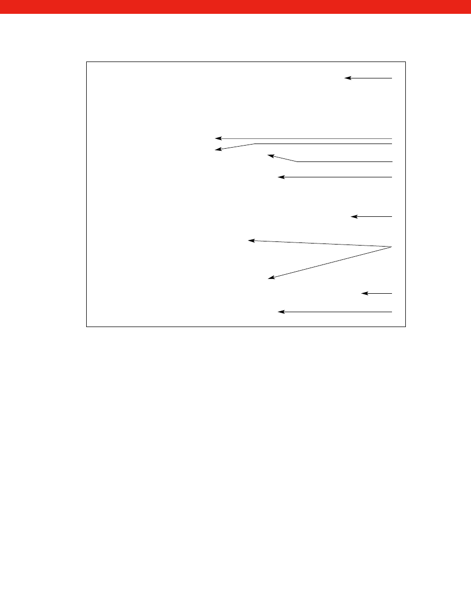
479
Sample Purchase Order
TO: HONEYWELL
Purchase Order #: ABC123
Sensotec Sensors
Customer #: XXXX
2080 Arlingate Lane
Date: 1/1/03
Columbus, Ohio 43228
Bill To: ABC, Inc.
Ship to: ABC, Inc.
P.O. Box 123
123 Anyplace Dr.
New York, NY 10001
New York,NY 10001
Attn: Accounts Payable
Attn: John Doe
Ship Via: United Parcel Service (UPS)
Item
Qty
Model/Description
Unit Price
1
2
AP122CV, 1c, 5d, (P/N 060-1495-25)
XXX.XX
Model TJE Absolute pressure trans-
ducer; 0-1000 psia range; 0.1%
accuracy. Options: Temperature
compensated from 0° F to 185° F;
and a 7/16" -20 UNF male pressure
port.
2
1
AE221, 53a, 58c Model 450D
XXX.XX
instrument. Options: RS232
serial output and peak/hold.
Item 2 to be used with item 1.
3
1
AA112 PT06A-10-6S
XXX.XX
Mating connector/cable assembly
with 50 ft. of 6 conductor
cable to be used with items 1 and 2.
Ship Date:
XX/XX/XX
Purchasing Contact: Jane Smith (212) 646-1000 X 211
}
Technical Contact: John Doe (212) 646-1000 X 315
A
B
C
D
E
F
G
H
I
}
A
Existing customers have an established customer number for specific bill to and ship to locations.
B
Unless otherwise specified, Honeywell Sensotec will ship your product UPS. Other means of shipment such as Emery,
Federal Express, UPS next day, etc. are available. Terms: FOB Honeywell Sensotec plant.
C
Order Code identifies product model, range, and options.
D
If you wish to reorder an exact duplicate of a product ordered previously, you can use the part number (ie: part number
060-1495-25 would appear as TJE/1495-25 on the product label) when ordering. Otherwise, leave this space blank.
E
It is important to include a full description of the product after the order code. By providing both the order code and a
full description, you reduce the possibility of an order error and avoid unnecessary delays in shipment.
F
Unit price includes the list price for the model/range you select, plus any additional charges for options specified, less
any quantity or GSA discount.
G
By specifying which items will be used together, you help insure that compatible products will be shipped. When you
purchase both the transducer and instrument from Honeywell Sensotec and specify that they will be used together, we
calibrate the two units as a system, free of charge.
H
Ship dates should be confirmed by the Customer Service Department. Items with different ship dates should be listed
separately. Unless otherwise specified on the order, Honeywell Sensotec assumes that early and/or partial shipments
are acceptable. When ordering products from the stocking program, specify “Ship From Stock” on the order.
I
The name and telephone number of both a purchasing and a technical contact should be provided so that questions
concerning the order can be easily resolved without unnecessarily delaying processing and shipment.
www.honeywell.com/sensotec
1-888-282-9891
Courtesy of Steven Engineering, Inc.-230 Ryan Way, South San Francisco, CA 94080-6370-Main Office: (650) 588-9200-Outside Local Area: (800) 258-9200-www.stevenengineering.com
Sensotec Sensors Full Line Catalog-html.html
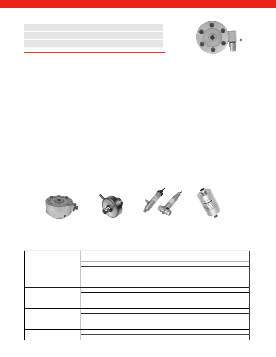
Unamplified
Amplified
480
Sensotec can supply your sensor with Sig Cal or IEEE1451.4 plug and play technology. These are two different protocols. Sig
Cal conforms to the Sensotec standard, and IEEE1451.4 conforms to the IEEE standard. The plug and play technology for both
protocols consists of adding a memory chip to the sensor and having software (Sig Cal is standard on the SC2000) to interpret
the data that then automatically sets up and calibrates your system so that you are ready to take data. Its as easy as 1-2-3.
The transducer electronic data sheet (T.E.D.S), common for Sig Cal or IEEE1451.4, contains sensor specifications, calibration
data and user defined location information and is stored in the sensor. When connected to the SC2000 the Sig Cal sensor is
interrogated for the TEDS information and automatically sets up and calibrates the signal conditioning with the sensor.
No More Paper.
Plug and play eliminates the need to read and enter data from a paper calibration sheet. You don’t have to
endure the hassle of having the sheet filed in one location while the sensor is used in another or worst of all, that the calibra-
tion sheet will get misplaced or lost.
Labeling and Cabling Made Easy.
Sensor users often find themselves with a bundle of cables, trying to figure out which
cable goes with which sensor so they can make the proper connections to their signal conditioner. Plug and play technology
introduces the potential for enabling the signal conditioner to read not only a sensor’s type and calibration information but also
its location.
Swapping Made Easy.
Even a rugged sensor can be damaged in an industrial testing situation. When that happens, you
want to change sensors and get your test back up and running as soon as possible. With a TEDS sensor that automatically
provides calibration data to an active signal conditioner, often a technician unfamiliar with calibration procedures can swap
sensors quickly without jeopardizing the integrity of system operations.
Plug and Play Inventory Control.
Burning location data onto each sensor’s TEDS will also help you inventory your sensors.
Plug and Play Sensors and Signal Conditioning
TEDS
Chip
www.honeywell.com/sensotec
1-888-282-9891
n
IEEE 1451.4 or Sensotec “Sig Cal” Protocol
n
Built In As New, Retrofittable or Virtual
n
Cal Data Stored on Sensor for Automatic Setup
IEEE 1451.4 TEDS or Sensotec “Sig Cal” sensors are available in most strain gage based sensors with 4 wire unamplified,
amplified voltage or current outputs. TEDS uses two wires so a 6 pin connector or 6 wire cable is fitted to these
sensors. Miniature sensors require the TEDS chip to be mounted as an in-line module or mounted in the connector.
Plug and Play Supplied With Your Sensor
Pressure
General Purpose
Available
Consult Factory
Miniature
Integral Cable Units Only
Consult Factory
Subminiature
Integral Cable Units Only
Consult Factory
Differential
Available
Consult Factory
Load
General Purpose
Available
Consult Factory
Miniature
Integral Cable Units Only
Consult Factory
Subminiature
Available
Consult Factory
Torque
Reaction
Available
Consult Factory
Rotary Transformer Based
Custom Only
Consult Factory
Slip Ring Based
Custom Only
Consult Factory
Wireless Telemetry Based
Not Available
Not Available
LVDTs
AC-AC
Not Available
N/A
DC-DC
N/A
Consult Factory
Accelerometers
Not Available
Not Available
Digital Gages
N/A
Not Available
Instruments
SC2000
Sig Cal Only
Sig Cal Only
Other Units
Not Available
Not Available
TEDS Availability
Courtesy of Steven Engineering, Inc.-230 Ryan Way, South San Francisco, CA 94080-6370-Main Office: (650) 588-9200-Outside Local Area: (800) 258-9200-www.stevenengineering.com
Sensotec Sensors Full Line Catalog-html.html

www.honeywell.com/sensotec
1-888-282-9891
Troubleshooting Guide
Action/Troubleshooting
Verify correct wiring
Verify excitation per calibration sheet.
Make sure pressure, load, etc. is being applied.
Check strain gage bridge for continuity per calibration sheet.
Check electrical connections for discontinuity or damage.
Check for isolation resistance between bridge wiring and transducer body.
Make sure pressure, load, etc. is constant.
Check stability of excitation power supply.
Check millivolt output with volt meter.
Check for RFI/EMI interference.
Make sure there are no rapid changes in temperature.
Check actual input and output resistance against calibration sheet data for possible
change or open bridge.
Check Zero offset to see if high.
Usually indicates transducer was overranged beyond specifications. Overranged
transducers should be recalibrated.
Check actual input and output resistance measurements against calibration sheet for pos-
sible changes or open bridge.
Check for possible mechanical preload or damping on transducer body.
Action/Troubleshooting
Make sure power supply voltage meets transducer requirements.
Check wiring connections and wiring code.
Check transducer specifications for type of output provided (i.e. voltage, frequency, etc.)
Make sure pressure, load, etc. is being applied.
Make sure that the output load is not shorted.
Check for pre-load on transducer.
Adjust zero or balance control.
For load cells check mounting fixture bias.
For pressure transducers, check for orientation bias.
Make sure pressure, load, etc. is constant.
Make sure power supply remains within specifications.
Check for RFI interference.
Make sure there are no rapid changes in temperature.
Check electrical connections for discontinuity or damage.
Check output with volt meter.
Check for insulation resistance between amplifier wiring and transducer shell.
Check “shunt” calibration output value against calibration sheet and adjust span control
per instructions.
Verify that transducer is being operated within its temperature compensated range.
Check transducer range on label.
Check for insulation resistance between amplifier wiring and transducer shell.
Action/Troubleshooting
Check electrical connections for continuity and wiring code for pin layout.
Check powerline fuse per instrument instructions.
Indicated overload; make sure wires are all connected, and transducer is within its range.
Check transducer range on label.
Verify that system was set-up per instructions. Review set-up procedure.
Refer to transducer troubleshooting guide and verify that transducer operates properly.
Use Shunt-Cal to verify calibration.
Unamplified Transducers
Symptom/Problem
No Output
Erratic/Intermittent
Output or Zero Drift
Incorrect Output
High Zero Offset
Amplified Transducers
Symptom/Problem
No Output
Incorrect Zero Level
Erratic/Intermittent
Output or Zero Drift
Incorrect Output
Symptom/Problem
Erratic Display
No Display/No Output Voltage
Blinking Display
Incorrect Readout Value
Transducers with Instrument Readout
Courtesy of Steven Engineering, Inc.-230 Ryan Way, South San Francisco, CA 94080-6370-Main Office: (650) 588-9200-Outside Local Area: (800) 258-9200-www.stevenengineering.com
Sensotec Sensors Full Line Catalog-html.html

Honeywell
Sensotec Sensors
2080 Arlingate Lane
Columbus, Ohio 43228, USA
CAT010610.0
January 2006
Copyright 2006 Honeywell International Inc. All rights reserved.
Warranty/Remedy
Honeywell warrants goods of its
manufacture as being free of defective
materials and faulty workmanship.
Honeywell's standard product warranty
applies unless agreed to otherwise by
Honeywell in writing; please refer to
your order acknowledgement or consult
your local sales office for specific
warranty details. Honeywell warrants
goods of its manufacture as being free
of defective materials and faulty
workmanship. If warranted goods are
returned to Honeywell during the
period of coverage, Honeywell will
repair or replace, at its option, without
charge those items it finds defective.
The foregoing is buyer's sole remedy
and is in lieu of all warranties,
expressed or implied, including
those of merchantability and fitness
for a particular purpose. In no event
shall Honeywell be liable for
consequential, special, or indirect
damages.
While we provide application
assistance personally, through our
literature and the Honeywell web site,
it is up to the customer to determine
the suitability of the product in the
application.
Specifications may change without
notice. The information we supply is
believed to be accurate and reliable
as of this printing. However, we
assume no responsibility for its use.
Honeywell Sensing and Control designs,
manufactures and markets one of the
industry’s most extensive lines of sensing
and control technologies available from a
single switch or sensor manufacturer.
Honeywell aims to develop the right
products that are delivered on time and
work right.
Phone and Fax:
Tel: 614-850-5000
Fax: 614-850-1111
E-Mail:
sales@sensotec.com
Internet:
www.honeywell.com/sensotec
Worldwide customer support
At Honeywell, products are
based upon technology provid-
ing you with enhanced quality
and reliability. When service is
needed, our customer support
engineers and service centers
are strategically located around
the world to provide efficient and
responsive support.
Courtesy of Steven Engineering, Inc.-230 Ryan Way, South San Francisco, CA 94080-6370-Main Office: (650) 588-9200-Outside Local Area: (800) 258-9200-www.stevenengineering.com