For product data sheets, visit www.cooperbussmann.com/datasheets/ulcsa
High Speed Fuses
114
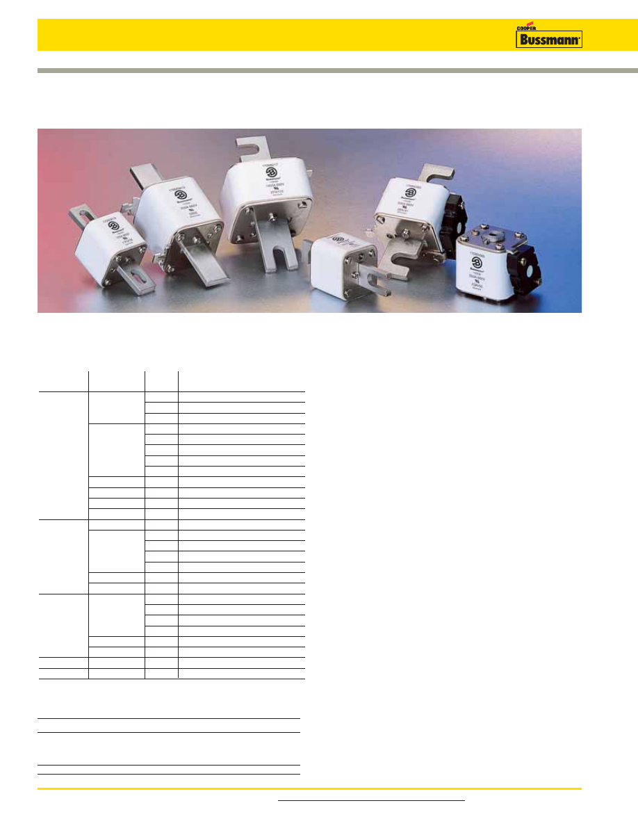
Square Body Fuses
General Information
Designed and tested to:
• IEC 60269: Part 4
• UL Recognized
Cooper Bussmann offers a complete range of square body
style fuses and accessories. Their unique design and
construction provide:
• Minimal energy let-through (I
2
t)
• Low operating temperature
• Low watts loss
Square body style fuses are a very attractive solution for high
power applications which require a compact design with
superior performance. The construction and design of square
body style fuses make it easy for Cooper Bussmann to
manufacture custom products. Our cataloged offering
provides only a sample of the wide variety of product which
is available.
Each square body style fuse is available with a number of
different end fittings. Options include:
• DIN 43 653
• DIN 43 620
• Flush End (Metric/US)
• French Style
• US Style
Voltage Rating
All Cooper Bussmann square body style fuses are tested to
IEC 60269: Part 4. This standard requires a test voltage
which is 5% higher than the rated voltage. In North America,
fuses are required to clear only their rated voltage.
Accessories
Square Body style fuses are available with three different
open fuse indicator systems. Options include visual
indication and indication utilizing a microswitch. Fuse
blocks are also available for most applications.
Introduction
Square Body Contents
Page
Application Information
115-116
Accessories
Page
Indicator System
185
Fuse Bases
186
Square Body Fuse Ranges
Amps
Volts
AC
DC
10-7500
690
X
—
50-1400
1250
X
—
Volts
(IEC/UL)
Size
Class
Fuse Style
Page
aR
DIN 43 653
117-119
000,00
aR
Flush End Contact
117-119
aR
DIN 43 620
120-121
aR
DIN 43 653
122-123
aR
Flush End Contact
124-125
690/700
1*, 1, 2, 3
aR
US Style
126-127
aR
French Style
128-129
aR
Fuse Curves
130-131
1*, 2, 3
aR
DIN 43 620
132-134
4
aR
Flush End Contact
135-136
23, 24
aR
Flush End Contact
137-139
00, 1, 2, 3
aR
DIN 43 620
140-143
00
aR
DIN 43 653
144-145
aR
DIN 43 653
146-147
1*, 1, 2, 3
aR
Flush End Contact
148-149
1000
aR
US Style
150-151
aR
Fuse Curves
152-153
4
aR
Flush End Contact
154-156
24
aR
Flush End Contact
157-159
aR
DIN 43 653
160-161
1*, 1, 2, 3
aR
Flush End Contact
162-163
aR
US Style
164-165
1250/1300
aR
Fuse Curves
166-167
4
aR
Flush End Contact
168-170
23
aR
Flush End Contact
171-172
1000-2000
5
aR
Flush End Contact
173
DC Fuses
174-184