
ABOUT SWITCHCRAFT, INC.
Switchcraft, Inc. was established in 1946 to manufacture
jacks, plugs and switches, from its original plant located
on West Diversey Street in Chicago. The company moved
to a larger facility at 1328 North Halsted Street in 1948, and
in 1958, the operation moved to 5555 North Elston Avenue,
which is still the headquarters of the corporation.
Switchcraft is a leading supplier of a broad line of components
for the audio/video, broadcast, telecommunication,
computer, medical, military, appliance, transportation and
instrumentation industries.
In the 185,000-square-foot Chicago facility, Switchcraft
manufactures electronic and elecromechanical compo-
nents, including:
• Jacks
• Plugs
• Connectors
• Jackfields
• Patch Panels
• Patch Cords
• Switches
• EAC Power
• Molded Cable Assemblies
Receptacles
With a basic line of over 5,000 standard products and
thousands of variations, Switchcraft is proud to offer a
limited lifetime warranty on all products.
Switchcraft markets products both domestically and
internationally through a network of manufacturers’
representatives and independent distributors.
In 1999, Switchcraft acquired the Conxall Corporation
located in Villa Park, Illinois. Conxall was founded in 1971
as a manufacturer of sealed connectors for the marine
industry. Today, the company offers a broad line of custom
cable assemblies and connectors used in marine, industrial,
sensor, communications and transportation applications.
For more information contact Conxall at (630) 834-7504, or
visit their website at www.conxall.com.
LIMITED LIFETIME WARRANTY
Switchcraft warrants all of its products to be of sound
design, good materials and workmanship at the time of
manufacture.
Switchcraft will repair or replace at its discretion any product
proven to be defective under normal use.
Switchcraft’s liabilty under the terms of this warranty is limited
to the repair or replacement of defective products which
have not been damaged through accident, abuse, misuse
or unauthorized repair. Switchcraft shall in no case be liable
for special or consequential damages of any nature.
Switchcraft
®
. . .
Consistently Excellent Since 1946
sm
ABOUT
CATALOG SECTIONS
Connectors . . . . . . . . . . . 1-78
Jacks & Plugs . . . . . . . . . 79-162
Jack Panels . . . . . . . . . . . 163-238
Patch Cords and
Molded Cable
Assemblies . . . . . . . . . . . 239-268
Switches . . . . . . . . . . . . . 269-318
Index by Part Number . . . 319-328
Visit us on the net:
www.switchcraft.com
* Please visit the product pages on our website for the most up-to-date product information

w w w . s w i t c h c r a f t . c o m
® Registered trademark of Switchcraft, Inc.
Note: Contact your Switchcraft Representative for price and delivery
PHONE: 773 792-2700
TABLE
OF
CONTENTS
i
CONNECTORS AND RECEPTACLES
Q-G® XLR CONNECTORS.........................................................1-30
Q-G® Connector Part Numbering System....................................2
Professional Series Q-G® Connector Part Numbering System .......2
Q-G® Audio Connectors A, AA, AND QGP Series....................3-4
Part Numbers - Male Cord Plugs/Female Cord Plugs ..................4
Q-G® Color Flex Reliefs/Flex Relief .............................................5
AAA XLR Connectors ................................................................6-7
P(*)M Gooseneck Plug, P(*)F Microphone Plug,
R(*)MZ Cord Plug, R(*)FZ Cord Plug ...........................................8
D(*)M, D(*)F and D(*)FD Receptacles ..........................................9
T(*)F and T(*)FM Cord Plug With On-Off Switch ..........................9
B(*)F Receptacle, C(*)F Receptacle, B(*)M Receptacle,
C(*)M Receptacle ........................................................................10
E Series Receptacles.............................................................11-15
EH Series Receptacles ...............................................................16
PQG® Receptacles................................................................17-18
PD Series - Plastic Panel Mount ...........................................19-21
Y3F, Y3FPC, Y3FDPC and Y3MPC Receptacles ........................22
F Series Receptacles ............................................................23-24
Q-G® Adapters, Accessories .....................................................25
Q-G® Wall Plate Receptacles ....................................................26
Q-G® Connector-Adapters.....................................................27-28
S*FM Audio Connector-Adapter .................................................28
Audio “Y” Adapters .....................................................................28
DMX Adapter ..............................................................................29
Q-G® Connector-Adapter Receptacles ......................................30
Z Matching Transformers, Series M(*)M, Series L(*)MN ............30
TINI Q-G® MINIATURE CONNECTORS .................................31-37
Tini Q-G® Audio Adapters ..........................................................31
TB(*)M AND TB(*)MB Receptacle,TLP(*) Looping Plug, Straight
Female Looping Plug, Reverse Gender TQG Series .................33
TRA(*)M PC Mount Male Receptacle ........................................34
TRASM*M, TRAPC*M Series ...............................................34-36
TY(*)F and TY(*)FPC Receptacles,TYEF Escutcheons,
TQG(*)F and TQG(*)M Connector Inserts, TBA(**)
Audio Adapter .............................................................................37
HPC HIGH POWER AUDIO CONNECTORS ...........................38-40
EN3TMini WEATHERTIGHT CONNECTOR SERIES ..............41-45
2 - 8 pin Cord Connector, 9 - 18 pin Cord Connector ................43
2 - 8 pin Panel Connector, 9 - 18 pin Panel Connector .............44
2 - 8 pin Inline Connector, 2 - 8 pin Overmolded Cord
and Inline Connector ..................................................................45
DIN CONNECTORS .................................................................46-55
Plugs .....................................................................................46-48
Panel Mount Receptacles .....................................................48-50
Right Angle PC Mount Receptacles .....................................51-52
Mini-DIN Right-Angle Receptacles, Right-Angle, PC Mount
Receptacles ..........................................................................47-53
SMD Series ................................................................................54
DMD Series ................................................................................55
USB CONNECTORS ................................................................56-57
IEEE 1394 FIREWIRE CONNECTORS ...................................58-59
SLIM-LINE CONNECTORS ......................................................60-64
Cord Plugs .................................................................................60
Slim-Line Connector Part Numbering System, Cable Clamp and
Strain Relief ................................................................................61
SL40-SL41 Male/Female Cord Plugs .........................................62
SL10-SL17 Male/Female Receptacles .......................................63
SL18 Male/Female Receptacles ................................................64
CB CONNECTORS MICROPHONE CONNECTORS,
MINI-CON MINIATURE CONNECTORS .......................................65
HP75BNC SERIES BNC CONNECTORS ................................66-67
EAC RECEPTACLES ...............................................................68-77
RAPC322 POWER INLET SOCKET .............................................78
JACKS AND PLUGS
JACK SCHEMATICS ................................................................79-80
1/4" LONG FRAME TELEPHONE JACKS ...............................81-85
1/4" Jack Blocks .........................................................................86
BANTAM TYPE® JACKS ..........................................................87-90
TT-JAX® (.173") Telephone Jacks Bantam Type® ................87-88
TT-JAX® (.173") Telephone Twin Jacks Bantam Type® .............89
TT-JAX® (.173") Telephone Triple Jacks Bantam Type® ............90
RTT Series Miniature Telephone Jacks,
Right Angle, PC Mount .........................................................91-92
.177" Enclosed Jacks .................................................................93
LITTEL JAX® 2- AND 3-CONDUCTOR,
1/4" PHONE JACKS ...............................................................94-109
Hi-D Jax® 2- and 3-Conductor .............................................96-99
Spring Lock PC Terminals for Hi-D Jax® .................................100
SN Series, RA Series Right-Angle Phone Jacks ..............101-105
500 Series Jack Covers ...........................................................106
Series E (Locking) and Thick Panel Phone Jacks ...................107
1/4" Extension Jacks and 1/4" Speaker Jacks .........................108
1/4" Shielded Phone Jacks, SF-Jax®
Short Frame Jacks ...................................................................109
.141" MINIATURE PHONO JACKS .......................................109-111
3.5MM DUAL STEREO JACK ...............................................112-113
3.5MM SINGLE MONO AND STEREO JACKS ...................114-118
3.5MM SINGLE MONO JACKS ...................................................119
2.5MM SINGLE MONO AND STEREO JACKS ..........................120
.101" SUBMINIATURE PHONE JACKS ...............................121-122
RCA PHONO JACKS AND PHONO JACK SETS ................123-129
RIGHT ANGLE MINIATURE POWER JACKS ......................130-133
STRAIGHT MINIATURE POWER JACKS ............................134-135
VJ SERIES VIDEO JACKS ..........................................................136
MVJ SERIES VIDEO JACKS .......................................................137
MIL-TYPE 1/4" PHONE PLUGS ...........................................138-141
Littel Plug® Phone Plugs .........................................................139
MIL-TYPE 1/4" EXTENSION JACKS ...........................................142
* Please visit the product pages on our website for the most up-to-date product information

SWITCHCRAFT, INC. 5555 N. Elston Ave. • Chicago, IL 60630
ii
FAX: 773 792-2129
TABLE OF
CONTENTS
TELEPHONE PATCH ADAPTERS ..............................................142
BANTAM TYPE MINIATURE TELEPHONE PLUGS ............143-144
1/4" COMMERCIAL PHONE PLUGS -
LITTEL-PLUG® PLUGS .......................................................145-147
Silent-Plug And Lug® Phone Plugs .........................................148
Audio Loudspeaker and Heavy Duty 1/4"
Commercial Phone Plugs .................................................149-150
.206" Commercial Phone Plugs ...............................................151
1/4" Miti-Plug® Audio Plugs .....................................................152
1/4" Flat Plug Phone Plugs ......................................................153
Right-Angle Phone Plugs .........................................................154
1/4" Lock-Extension Jacks And Plugs ......................................155
3.5MM HEAVY DUTY STEREO PLUGS .....................................156
.141" MINIATURE PHONE PLUGS .............................................157
.097" SUBMINIATURE PHONE PLUGS ......................................158
AUDIO ADAPTERS .....................................................................159
RCA PHONO PLUGS ...........................................................160-161
MINIATURE POWER PLUGS ......................................................162
JACK PANELS, PATCH PANELS, PATCH KITS AND
JACKFIELDS
AUDIO PATCHBAYS .............................................................163-190
Professional Punchdown Terminal (PPT) ..................................163
Front Access MTPFA/TTPFA Series ..................................164-165
MTP48K Wired Audio Series .............................................166-167
TTP96K Wired Audio Series ..............................................168-169
MTPH/TTPH Harness Audio Series...................................170-173
MTPBP/TTPBP Backpanel Series .....................................174-175
EZ NORM Patchbay Series ...............................................176-177
TT96 EDAC Series.............................................................178-179
TTP96K Patchkit Series ....................................................180-181
MT48K/MT52K Patchkit Series ..........................................182-183
MT48/MT52 Patchbay Series.............................................184-185
TTP96AS Patchbay Series ................................................186-187
Q-G®XLR Patchbay Series................................................188-189
HPC Patchbay Series................................................................190
RS 422 DATA PATCHBAY SERIES ......................................191-192
VIDEO PATCHBAYS .............................................................193-201
VPP Video Patchbay Series ..............................................193-195
MVP Midsize Video Patchbay Series ................................196-198
VAP Video/Audio Patchbay Series ....................................199-200
MBPK Video/Audio Patchbay Series ........................................201
TELECOM TYPE JACK PANELS .........................................202-238
Long Frame (1/4")Single Row Telephone Jack Panels ....202- 203
Long Frame (1/4") Twin Row Jack Panels ........................204-205
Long Frame (1/4") Modular Twin Row Jack Panels ..........206-209
Long Frame (1/4") Modular 3 Row Jack Panels .......................210
TT-Jax® (.173") Jack Panel Series 1600, A1600,
B1600, C1600 ...................................................................211-214
Modular TT-JAX® (.173") Panels -
Blank Series TT51, TT53, TT56, TT59 .....................................215
TT Module Inserts - Series TT91, TT92 And TT93 ..................216
Modular TT-Jax® (.173") Jack Panels -Series TT5102000,
TT5202000, TT5502000, TT5602000 ...............................217-218
TT-Jax® (.173") Twin Row and Three Row Jack Panels ....219-220
TT-Jax® (.173") Connectorized Jackfields - Series TT,
2-wire, 4-wire, 6-wire .........................................................221-229
TT® Lamps and Jewel Assemblies ..........................................230
Longframe Switchboard Switches ............................................231
Dummy Plugs and Hole Plugs .................................................232
TT® (Bantam) Circuit Guard Plugs ..........................................233
Miniature, Dummy Plugs, Hole Plugs .......................................234
Designation Strips .............................................................235-236
Kwik-Change® Designation Strips (Double Height) .................237
X-Wide® Vertical Designation Strips ........................................238
PATCH CORDS AND
MOLDED CABLE ASSEMBLIES
MOLDED CABLE ASSEMBLIES ..........................................239-261
Design Materials and Features ................................................239
3.5MM Molded Cables .............................................................240
Power-Plug Battery Charger Plugs and Jacks .........................241
Power Plugs and Jacks Part Numbering System .....................242
EN3T MINI Weathertight Overmolded Cable Assemblies ........243
Cordette® and Cord Switch Assemblies ....................................44
Cordette® Switches .................................................................245
DIN Plugs ..........................................................................246-248
MIDI Cables ..............................................................................249
Miniature, Shielded, Molded Tini Q-G® Plugs .........................250
Molded Cable Assemblies for Multi-Pin Interconnection
Part Numbering System ...........................................................251
Standard Multi-Pin Interconnection Cables ..............................252
Micro Plug® Subminiature Phone Plugs ..................................253
Tini Plug® Miniature Phone Plugs ...........................................254
Phono Plugs and Phono Extension Jacks ...............................255
Tini-Extension® Jacks ..............................................................256
Littel Plug® Phone Plugs ..................................................256-257
Extension Jax® Phone Jacks ...................................................257
Cable Clamp Bands, “Y” Junctions ..........................................258
Part Numbering System ...........................................................259
Standard Cable Guide ..............................................................260
Cross Reference Guide ............................................................261
AUDIO/VIDEO PATCHCORDS ............................................262- 267
1/4" Longframe Telephone Patch Cords, MIL Type 1/4" Patch
Cords ........................................................................................262
Combination Patch Cords and MIL Type
1/4" Twin Patch Cords .............................................................263
Miniature TT® Braided Patch Cords .......................................264
Miniature TT® Molded Patch Cords
and Telephone Couplers ..........................................................265
Video Patch Cords ...................................................................266
Broadcast Series 3-Conductor Bantam TT Patch Cords,
Analog-AES/EBU Audio, and RS422 Patching ........................267
SWITCHES
PUSHBUTTON SWITCHES
IBS Series Miniature Keyboard Switches .................................269
IBS Keyboard Switch Pushbuttons ...........................................270
US Series Uniswitch® Switches ...............................................271
BXR Series Box Switch® Switches ..........................................272
Button-Switch® Switches, Tini-Switch® Switches ...................273
Littel-Switch® Switches ............................................................274
Hi-D Switch® PC Mount Switches, DA-Switch Switches .........275
Cord-Switch® Cord Switches, Cordette® Cord Switches ........276
* Please visit the product pages on our website for the most up-to-date product information

w w w . s w i t c h c r a f t . c o m
® Registered trademark of Switchcraft, Inc.
Note: Contact your Switchcraft Representative for price and delivery
PHONE: 773 792-2700
TABLE
OF
CONTENTS
iii
Push-Lite® Switches and Indicators .................................277-281
Series PL9000 - PL® Indicators, Pushbutton/Indicator
Screens, Color Filter Snap-Insserts, Optional
Mounting Barriers, Light Divider ...............................................278
Part Numbering System ...........................................................279
Outline Dimensions ...........................................................280-281
SLIDE SWITCHES ...............................................................282-290
General Purpose Slide Switches ......................................284-287
Miniature Slide Switches ...................................................288-290
Side-Slide®/Miniature Slide Switches ......................................290
European Line Voltage Selector Switches ........................291-293
LEVER SWITCHES ..............................................................294-298
GENERAL PURPOSE STACK SWITCHES .........................299-300
MULTIPLE STATION SWITCHES .........................................301-302
Littel® Multi Switch ............................................................303-308
DW Multi-Switch ................................................................309-311
Tini® DW Multi-Switch ......................................................312-313
IBS Multi-Switch - Series IBS ...........................................314-315
Multi-Switch Pushbuttons ..................................................316-317
INDEX BY PART NUMBER ...................................................319-328
* Please visit the product pages on our website for the most up-to-date product information
Field-proven Switchcraft Q-G
®
(Quick-Ground) 3- through
7-contact audio connectors with ground terminal and ground
contactors are available in a wide range of plugs and
receptacles for microphones, test equipment, instrumentation,
computers, video cameras, mixing consoles, tape recorders,
PA and sound reinforcement, stereo systems and many more
applications.
Switchcraft Q-G
®
connectors feature a separate ground-terminal
electrically integral with connector shell. Ground continuity
between mating plugs is automatically accomplished through
exclusive “Dual Point” grounding system. Socket and pin
assemblies utilize “wedge-action” to insure firm, reliable
positioning in connector shell. Inserts are easily removable for
wiring and soldering. High-impact thermoplastic insures long
reliable insert assembly life. Female connectors have latch lock
feature to hold connectors firmly together. Plugs and receptacles
are mechanically keyed for proper mating. Q-G (*) Series 3-,
4-, 5-, 6-, and 7-pin/contact connectors offer 4-,
5-, 6-, 7-, and 8-pin contact versatility when ground-terminal is
used. Switchcraft QGP connectors; are compatible with
3- and 4-contact (Neutrik, Amphenol 91-850 and Excellite
91-450 Series, and Cannon XLR-3, XLR-4): 5-contact (Neutrik,
Cannon XLR-5 and Amphenol Excellite 91-450 Series).
Q-G
®
CONNECTORS
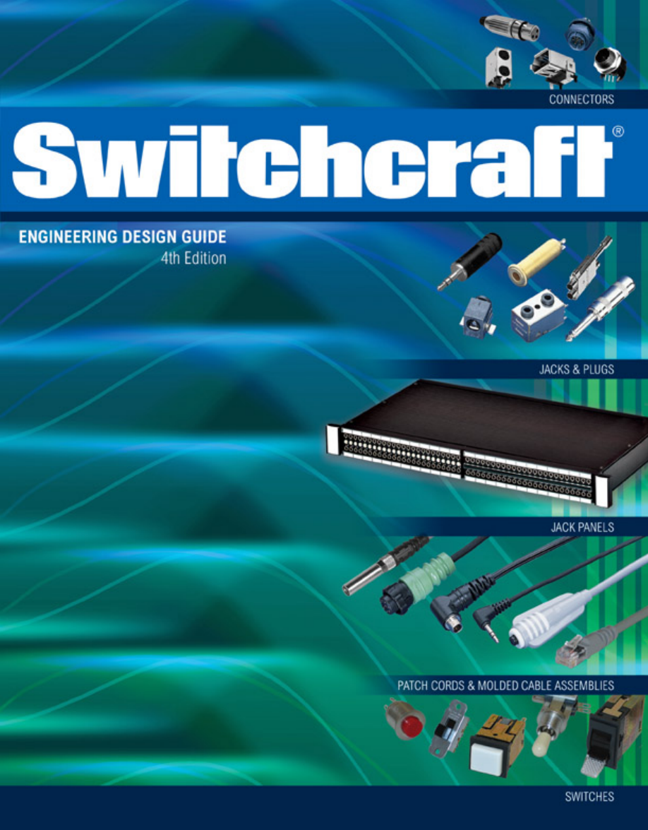
Insert screw engages as any conventional screw, except it is
lefthand threaded. To disassemble the connector, turn screw
counterclockwise down into insert (see illustration).
DESIGN FEATURES
CONSTRUCTION: Sturdy, die-cast zinc with satin nickel
finish or Black-Velvet
®
finish to withstand hard use – even
abuse. Vel-Tone non-reflective finish on QGP connectors only.
INSERT INSULATION: High-impact, molded thermoplastic
provides high dielectric strength, and superior insulation
resistance.
LOCKING: Latchlock on female plugs and receptacles locks
into groove in mating male connector to prevent accidental
disconnect. Manual release of latchlock is required to
separate connectors. Q-G connectors are also available with
FAS-DISCONNECT detent in place of latchlock. QGP has die-
cast latchlock.
FAS-DISCONNECT: FAS-DISCONNECT detent permits
immediate disconnect of locked connectors with a 4-pound
(1.8 kg) force. FAS-DISCONNECT connectors are not
recommended for use in situations where strong or violent
pulls on cable may occur and cause accidental disconnect.
Available on Q-G connectors only.
DUAL PRESSURE PLATES: A*F and A*M Series provides
secure cable lock and strain relief for all standard size cables.
FLEX RELIEF: TPR cable flex relief bushings on cord plugs
are keyed to shell. Standard bushing opening accepts cables
from .21" to .3" diameter Bushings with other openings
accommodate cables from .105" to .205" diameter and from
.3" to .328" diameter.
CONTACTS: Q-G
female connectors are copper alloy,
silver-plated, tarnish-resistant; male contacts are copper alloy,
silver-plated, tarnish-resistant. Gold-plated female contacts
are copper alloy. Male contacts are gold-plated.
WIRING: Large, unique design solder cups make wiring fast
and easy. Certain receptacles are also available with PC
terminals for use with printed circuit boards.
Grounding and Shielding
Tightening the insert screw establishes continuity between
ground terminal, ground contactors and connector housing.
Upon engagement with a mating plug or receptacle, the
ground circuit is automatically connected to the mating shell
through the ground contactor. Any pin or contact can be
grounded by “jumping” it to the ground terminal. Contact
1 engages before all other contacts and disengages after all
other contacts.
Captive Design
®
Insert Screws
Insert assembly is now readily removed from shell. Note
“Ground Terminal” area – large soldering cups make cable
installation fast and easy. Unitized 1-piece insert eliminates
possible loss of latchlock and spring.
To reassemble, replace insert assembly into shell, align insert
screw under hole in shell and secure insert by turning insert
screw clockwise. This “wedges” insert against interior of shell
providing a rigid connector assembly and positive electrical
continuity between ground terminal and shell (see illustration).
SECTIONALIZED VIEW - A3F Plug to B3M Receptacle
MALE RECEPTACLE
FEMALE CONNECTOR
Panel
Pin
Ground Terminal
Ground Terminal
Cable Clamp
Insert
Shell
Strain Relief
Insert set screw
(Shell ground)
Latch Lock
Q-G CONNECTORS
Q-G CONNECTORS
®
®
SWITCHCRAFT, INC. 5555 N. Elston Ave. • Chicago, IL 60630
1
CONNECTORS & RECEPTACLES
FAX: 773 792-2129
CONNECTORS & RECEPT
ACLES
DIMENSIONS ARE FOR REFERENCE ONLY
Inch
(mm)
* Please visit the product pages on our website for the most up-to-date product information
QG
®
PART NUMBERING SYSTEM
QG
®
PART NUMBERING SYSTEM
Q-G
®
CONNECTOR PART NUMBERING
PROFESSIONAL SERIES Q-G
®
CONNECTOR PART NUMBERING SYSTEM
Number of
Series
Contacts
Gender
Options
A
CORD PLUG WITH SCREW CABLE CLAMP
3-7
M MALE
D
FAS-DISCONNECT (FEMALE CONNECTORS)
AA
CORD PLUG WITH CRIMP CABLE CLAMP
F FEMALE
B
BLACK EPOXY FINISH
AAA
CORD PLUG WITH TWIST ON HANDLE
B
FRONT PANEL MOUNT USING NUT
FM BOTH
ST
STRAIGHT PC TAILS
(S SERIES)
C
FRONT PANEL MOUNT - CIRCULAR
RA
RIGHT ANGLE PC TAILS
D
FRONT PANEL MOUNT - RECTANGULAR
M
MOMENTARY SWITCH ACTION
(T SERIES ONLY)
E
MODULAR FRONT PANEL MOUNT
PC
PC TERMINALS (Y SERIES ONLY)
G
WALL PLATE - 1 B SERIES MALE
N
KNURLED COUPLING NUT (L SERIES ONLY)
H
WALL PLATE - 2 B SERIES MALES
L
FLEX RELIEF FOR .250" TO .328" CABLE O.D.
J
WALL PLATE - 1 D SERIES FEMALE
S
SEE NOTE 1.
K
WALL PLATE - 2 D SERIES FEMALE
AU
GOLD CONTACTS
L
MICROPHONE ADAPTER - INTERNAL THREAD
H
HOUSING ONLY
M
MICROPHONE ADAPTER - EXTERNAL THREAD
OPTIONS SHOWN IN ORDER OF APPEARANCE
N
CAP PLUG
Z
SCREWLESS STRAIN RELIEF
P
GOOSENECK MOUNT
QG
CONNECTOR INSERT
R
RIGHT-ANGLE CORD PLUG
S
MALE/FEMALE BARREL ADAPTER
T
CORD PLUG WITH ON-OFF SWITCH
W
RIGHT-ANGLE PANEL MOUNT
Y
REAR PANEL MOUNT
NOTE 1: S HAS DIFFERENT DESIGNATIONS DEPENDING ON THE SERIES.
FOR A, AA, AND T SERIES: SMALL FLEX RELIEF FOR .105" TO .205" CABLE OUTSIDE DIAMETER
FOR B, C, AND D SERIES: SANDED FRONT FACE FINISH
FOR G, H, J, AND K SERIES: STAINLESS STEEL WALL PLATE (STANDARD)
FOR N SERIES: SHORTING WIRING INSTALLED
NOTE 2: J, K AND T SERIES AVAILABLE IN FEMALE GENDER ONLY.
G, H, L, M, N, AND W SERIES AVAILABLE IN MALE GENDER ONLY.
Number Of
Series
Contacts
Model
PROFESSIONAL SERIES
3
22
FEMALE CORD PLUGS
PROFESSIONAL SERIES CORD PLUG
23
MALE CORD PLUGS
WITH CRIMP CABLE CLAMP
62
RECTANGULAR FEMALE PANEL MOUNT
63
RECTANGULAR MALE PANEL MOUNT
QGP
AQGP
CONNECTORS & RECEPTACLES
2
w w w . s w i t c h c r a f t . c o m
® Registered trademark of Switchcraft, Inc.
Note: Contact your Switchcraft Representative for price and delivery
PHONE: 773 792-2700
CONNECTORS & RECEPT
ACLES
DIMENSIONS ARE FOR REFERENCE ONLY
Inch
(mm)
* Please visit the product pages on our website for the most up-to-date product information
Q-G
®
AUDIO CONNECTORS A, AA, AND QGP SERIES
Q-G
®
CORD PLUG CONNECTORS (continued)
QGP connectors (3 contacts only) feature Vel-Tone
®
non-reflective finish, gray TPR flex relief and plated
pins/contacts for the most demanding applications.
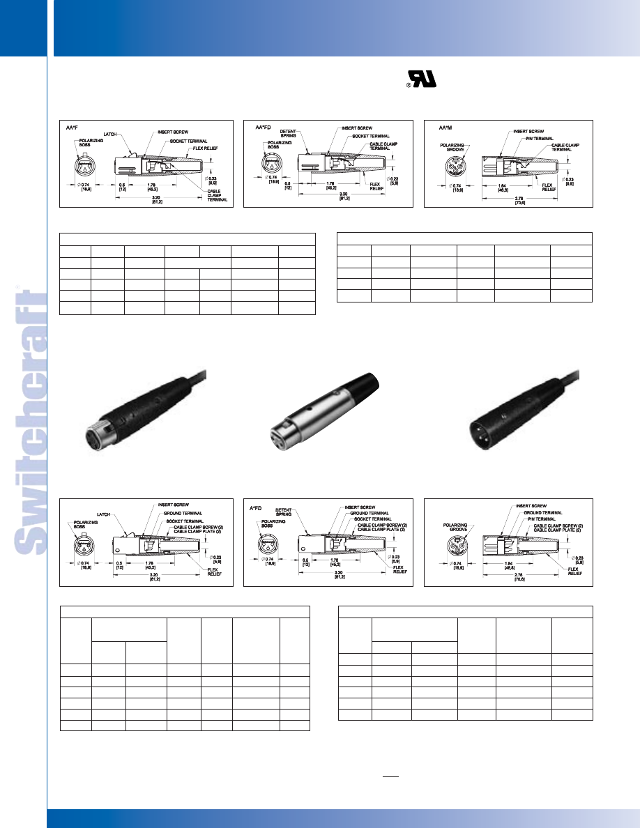
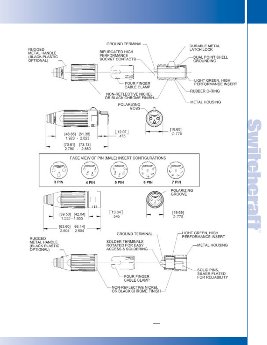
Preferred by audio professionals the world over, Switchcraft
®
QG
®
connectors feature unsurpassed durability and a choice
of finishes and contact platings. Features include:
• High performance inserts in traditional Switchcraft
®
green
or black.
• Solder terminals rotated for easier access and soldering.
• All metal housing.
AA Series Only
• Rugged 1-piece cable clamp to relieve pulling and twisting
stresses on terminations.
• No Screws flex relief retention system.
• Integral bump shell grounding system.
SPECIFICATIONS
ELECTRICAL
Contact Resistance: 50 milliohm maximum, per pole.
Current Rating: 3 pole – 15A, 4 pole - 10A, 5 and 6
pole – 7.5A, 7 pole – 5A @ 125VAC.
Insulation Resistance: 1,000 M
Ω
, minimum.
Dielectric Withstanding Voltage: 1,000 V (rms).
Capacitance: 2 pF between pins and 4 pF between pins
and shell, maximum (AA3M and AA3F).
MECHANICAL
Insertion/Withdrawal Forces: 7 pound maximum,
5 pound nominal, insertion; 7 pound maximum,
5 pound nominal, withdrawal.
Wire Size: #12 wire gauge solid; #14 wire gauge stranded
(3 contact). #14 wire gauge solid; #16 wire gauge stranded
(4 contact). #16 wire gauge solid; #18 wire gauge stranded
(5 and 6 contact). #18 wire gauge solid; #20 stranded
(7 contact). (Q-G and QGP).
MATERIAL
Q-G CONNECTORS (A AND AA SERIES)
Shell: Die-cast zinc. Satin nickel finish, black velvet.
Insert Insulation: Molded thermoplastic.
Socket Contacts: Silver-plated copper alloy tarnish-resistant;
bifurcated on 3-contact type. Gold is available
Pin Contacts: Silver-plated copper alloy. Resists tarnishing,
and provide excellent electrical conductivity. Gold is available.
Latchlock: High-strength die-cast zinc.
Latch Release: Steel, nickel-plated.
Latch Detent: Formed stainless steel.
Insert Screw: Stainless steel.
Flex Relief: TPR (thermoplastic rubber).
QGP CONNECTORS
Shell: Die-cast zinc, non-reflective gray Vel-Tone
®
finish.
Socket Contacts: Gold-plated copper alloy
Pin Contact: Gold-plated copper alloy
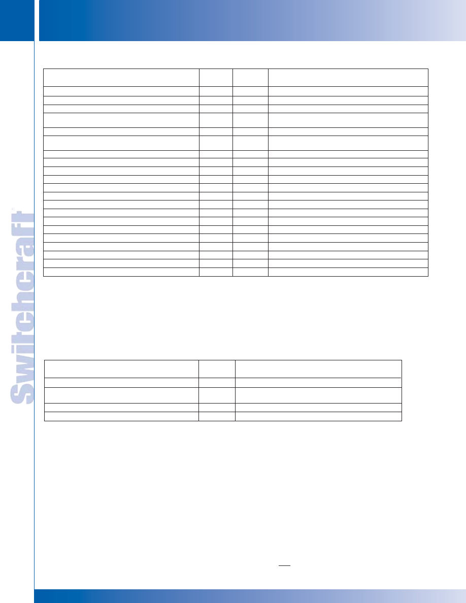
Easy change
flex relief for
color coding
“No screws”
retention
system
Solder terminals
rotated for easy
access & soldering
Light green, high
performance insert
“Dual-point
shell grounding”
“No screws”
retention
system
Easy change
flex relief for
color coding
Sleek, stream-
lined shell
Cable
clamp
Solid pins,
silver plated
for reliability
Bifurcated high
performance
socket contacts
Durable
metal latch
lock
Rugged cable
clamp to ground
(no screws)
Rugged
metal shell
Standard nickel
or black finish
Q-G
®
CORD PLUG CONNECTOR – A, AA AND QGP SERIES
Q-G
®
CORD PLUG CONNECTOR – A, AA AND QGP SERIES
SWITCHCRAFT, INC. 5555 N. Elston Ave. • Chicago, IL 60630
3
CONNECTORS & RECEPTACLES
FAX: 773 792-2129
CONNECTORS & RECEPT
ACLES
DIMENSIONS ARE FOR REFERENCE ONLY
Inch
(mm)
* Please visit the product pages on our website for the most up-to-date product information
QG
®
CORD PLUGS – A AND QGP SERIES
QG
®
CORD PLUGS – A AND QGP SERIES
Standard Q-G
®
Cord Plugs, Series A(*)F and QGP
Satin
Fas-
Large
Nickel
Black Finish
Dis-
Flex
Insert
Finish
Silver
1
Gold
1
Connect
Relief
2
QGP Series
n
Contacts
A3F
A3FB
A3FBAU
◊
A3FD
A3FL
QGP322
3
A3FS
3
—
—
—
—
—
3
A4F
A4FB
A4FBAU
◊
A4FD
A4FL
—
4
A5F
A5FB
A5FBAU
◊
A5FD
◊
A5FL
—
5
A6F
A6FB
A6FBAU
—
—
—
6
A7F
A7FB
A7FBAU
—
—
—
7
Straight female cord plug with
FAS-DIS-CONNECT detent.
Straight male cord plug.
A(*)F CORD PLUG
A(*)FD CORD PLUG
A(*)M CORD PLUG
PART NUMBERS - FEMALE CORD PLUGS
Standard Q-G
®
Cord Plugs, Series A(*)M and QGP
Satin
Large
Nickel
Black Finish
Flex
Insert
Finish
Silver
1
Gold
1
Relief
2
QGP Series
Contacts
A3M
A3MB
A3MBAU
A3ML
QGP323
3
A3MS
3
—
—
—
—
3
A4M
A4MB
A4MBAU
A4ML
—
4
A5M
A5MB
A5MBAU
◊
A5ML
—
5
A6M
—
A6MBAU
—
—
6
A7M
—
A7MBAU
—
—
7
PART NUMBERS - MALE CORD PLUGS
All above part numbers have black flex relief installed. Contact Switchcraft for
color flex relief.
◊
Available on special order only; contact Switchcraft for price and delivery.
*Number of insert contacts or pins must be specified to complete part number.
1. Contact plating.
2. Accepts cables from .25" (6.35 mm) to .328" (8.33 mm) diameter
3. Accepts cables from .105" (2.7 mm) to .205" (5.2 mm)
◊
Available on special order only; contact Switchcraft for price and delivery.
AA(*)F CORD PLUG
AA(*)FD CORD PLUG
AA(*)M CORD PLUG
Q-G
®
CORD PLUG CONNECTORS (continued)
Straight female cord plug with
standard latchlock. Available in
3-7 pin versions.
Advanced Q-G
®
Cord Plugs, Series AA(*)F and AQGP
AA3F
AA3FB
◊
AA3FBAU
◊
AA3FD
◊
AA3FL
◊
AQGP322
3
—
—
—
AA3FLD
—
3
◊
AA4F
◊
AA4FB
—
◊
AA4FD
◊
AA4FL
—
4
◊
AA5F
◊
AA5FB
—
◊
AA5FD
◊
AA5FL
—
5
◊
AA6F
◊
AA6FB
—
◊
AA6FD
◊
AA6FL
—
6
◊
AA7F
◊
AA7FB
—
◊
AA7FD
◊
AA7FL
—
7
PART NUMBERS - FEMALE CORD PLUGS
Advanced Q-G
®
Cord Plugs, Series AA(*)M and AQGP
AA3M
AA3MB
◊
AA3MBAU
◊
AA3ML
◊
AQGP323
3
◊
AA4M
—
—
◊
AA4ML
—
4
◊
AA5M
◊
AA5MB
—
◊
AA5ML
—
5
◊
AA6M
—
—
◊
AA6ML
—
6
◊
AA7M
—
—
◊
AA7ML
—
7
PART NUMBERS - MALE CORD PLUGS
All above part numbers have black flex relief installed. Contact Switchcraft for
color flex relief.
◊
Available on special order only; contact Switchcraft for price and delivery.
CONNECTORS & RECEPTACLES
4
w w w . s w i t c h c r a f t . c o m
® Registered trademark of Switchcraft, Inc.
Note: Contact your Switchcraft Representative for price and delivery
PHONE: 773 792-2700
CONNECTORS & RECEPT
ACLES
DIMENSIONS ARE FOR REFERENCE ONLY
Inch
(mm)
* Please visit the product pages on our website for the most up-to-date product information
Q-G
®
COLOR FLEX RELIEFS
Rainbow color cable strain relief bushings can be specified
to match or complement equipment decors or code individual
or grouped connections for quick recognition. On special
order, tan, pink and dark blue are available. Bushings
accommodate cables from .21" to .30" diameter.
Prepackaged, 25 per bag.
Part Numbers
Flex
Flex
3 Pins/Contacts
Relief
Relief
Female
Male
Color
Only
A3F
A3M
Black
SR00
◊
A3F01
◊
A3M01
Brown
SR01
◊
A3F02
◊
A3M02
Red
SR02
◊
A3F03
◊
A3M03
Orange
SR03
◊
A3F04
◊
A3M04
Yellow
SR04
◊
A3F05
◊
A3M05
Green
SR05
◊
A3F06
◊
A3M06
Blue
SR06
◊
A3F07
◊
A3M07
Violet
SR07
◊
A3F08
◊
A3M08
Gray
SR08
◊
A3F09
◊
A3M09
White
SR09
◊
Special order only; contact Switchcraft for price and delivery.
Flex relief bushing with small opening accommodates
cables from .105" (2.7 mm) to .205" (5.2 mm). Standard
size bushing accepts cables from .210" (5.3 mm) to .300"
(7.6 mm) outside diameter. Bushing with large opening
accommodates cables from .300" (7.6 mm) to .328" (8.3
mm). Larger cables are often needed for multiple-conductor
instrumentation. Code letter “L” in last or second to last digit
in part number indicates plug with large bushing. Code
letter “S” in last or second to last digit in part number
indicates plug with smaller bushing.
SWITCHCRAFT PART NUMBER
◊
K255
Package of 100 cable clamp screws.
◊
Special order only; contact Switchcraft for price and delivery.
Q-G
®
FLEX RELIEF
Q-G
®
CONNECTORS (continued)
Small Cables
.105 to .205
(2.7)
(5.2)
Standard Cables
.210 to .300
(5.3)
(7.6)
Large Cables
.300 to .328
(7.6)
(8.3)
Q-G
®
FLEX RELIEF
Q-G
®
FLEX RELIEF
SWITCHCRAFT, INC. 5555 N. Elston Ave. • Chicago, IL 60630
5
CONNECTORS & RECEPTACLES
FAX: 773 792-2129
CONNECTORS & RECEPT
ACLES
DIMENSIONS ARE FOR REFERENCE ONLY
Inch
(mm)
* Please visit the product pages on our website for the most up-to-date product information
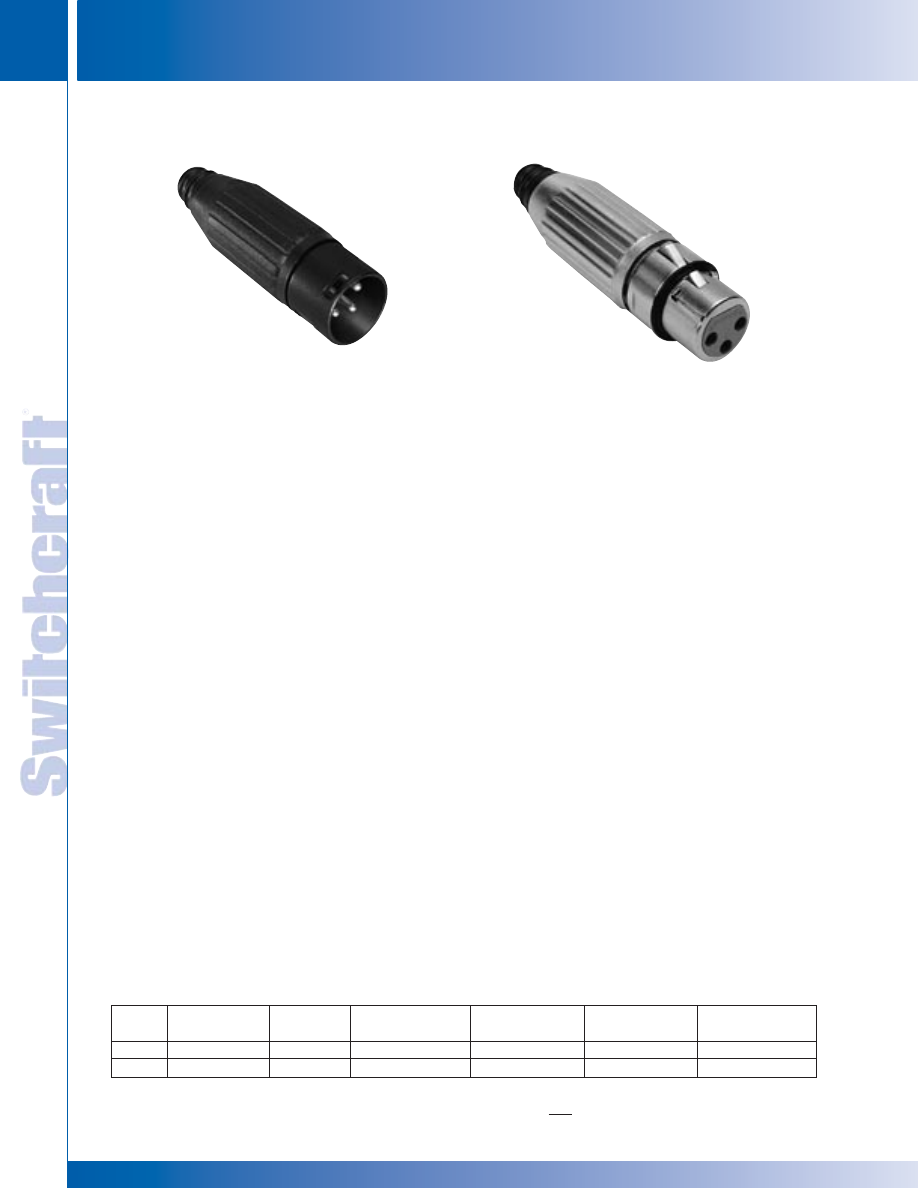
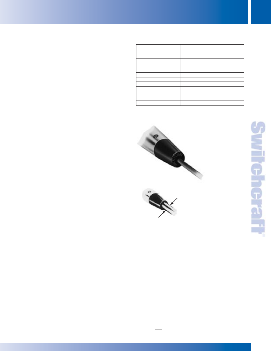
AAA SERIES Q-G
®
TWIST CONNECTOR
Switchcraft introduces the AAA Series or Q-G
®
Twist XLR
connectors.The Q-G
®
Twist Series is available in male or female cord
plug, 3 through 7 pins or contacts. The unique features are the easy
twist on combination handle/strain relief, and the reduced number of
parts to assemble. With the insert built into the front shell, and the
strain relief preloaded into the handle, the end user has only two
parts to assemble – slide the handle onto the cable, solder the
terminations, and twist on the handle. As the handle is tightened, the
strain relief tightens around the outer jacket of the cable. A ramp on
the strain relief keeps it from rotating around the cable jacket and
twisting the cable. The strain relief was designed to accommodate
the most popular cable sizes. A rugged die-cast metal handle insures
optimum protection, and increases signal shielding. Popular options
include black and gold finishes, as well as a lower cost plastic
handle version.
FEATURES AND BENEFITS
• Only two pieces to assemble
• Easy twist on handle reduces assembly time
• Rugged die-cast metal handle
• Accepts cable OD’s (.100" – .285")
• Black finish available
• Gold-plated pins/contacts available
• Lower cost plastic handle version available
APPLICATIONS
• Audio
• Medical
• Instrumentation
• Process Controls
SPECIFICATIONS
ELECTRICAL
Contact Resistance: 50 milliohm maximum, per pole.
Current Rating @ 125VAC:
3 pole – 15A
4 pole –10A
5 & 6 pole – 7.5A
7 pole – 5A
Insulation Resistance: 1,000 M
Ω
, minimum.
Dielectric Withstanding Voltage: 1,000 V (rms)
Capacitance:
≤
3 pF between pins and
≤
6 pF
between pins and shell, maximum
MECHANICAL
Insertion/Withdrawal Forces: 10 lbs. maximum,
8 lbs. nominal / 7 lbs. maximum, 5 pounds nominal.
Wire Size:
3 Contact
#12 wire gauge solid
#14 wire gauge stranded
4 Contact
#14 wire gauge solid
#16 wire gauge stranded
5 & 6 Contact
#16 wire gauge solid
#18 wire gauge stranded
7 Contact
#18 wire gauge solid
#20 wire gauge stranded
MATERIAL
Shell: Die-Cast zinc with nickel finish or black chrome.
Handle: Die cast with nickel finish or black chrome.
Also black thermoplastic handle available.
O Ring: TPR (Thermoplastic rubber).
Insert Insulation: Molded thermoplastic.
Socket Contacts: Silver plated copper alloy tarnish resistant;
bifurcated on 3 and 4 contact types. Gold is available.
Pin Contacts: Silver plated copper alloy. Resists tarnishing,
and provides excellent electrical conductivity. Gold is available.
Latch lock: High strength die cast zinc.
Strain Relief: TPR
Flex Relief: TPR (Thermoplastic rubber)
AAA CONNECTORS
AAA CONNECTORS
AAA CONNECTORS
Series
Pins/Contacts
Gender
Handle Material
Housing
Terminal
Z
Finish
Finish
AAA
3 -7 pins
F: Female
P: Plastic
B: Black
AU: Gold
New Strain Relief
3 -7 pins
M: Male
Blank: Metal
Blank: Nickel
Blank: Silver
CONNECTOR PART NUMBER SCHEME
CONNECTORS & RECEPTACLES
6
w w w . s w i t c h c r a f t . c o m
® Registered trademark of Switchcraft, Inc.
Note: Contact your Switchcraft Representative for price and delivery
PHONE: 773 792-2700
CONNECTORS & RECEPT
ACLES
DIMENSIONS ARE FOR REFERENCE ONLY
Inch
(mm)
* Please visit the product pages on our website for the most up-to-date product information
AAA CONNECTORS (continued)
AAA CONNECTORS
AAA CONNECTORS
SWITCHCRAFT, INC. 5555 N. Elston Ave. • Chicago, IL 60630
7
CONNECTORS & RECEPTACLES
FAX: 773 792-2129
DIMENSIONS ARE FOR REFERENCE ONLY
Inch
(mm)
CONNECTORS & RECEPT
ACLES
* Please visit the product pages on our website for the most up-to-date product information
Q-G
®
CONNECTORS (continued)
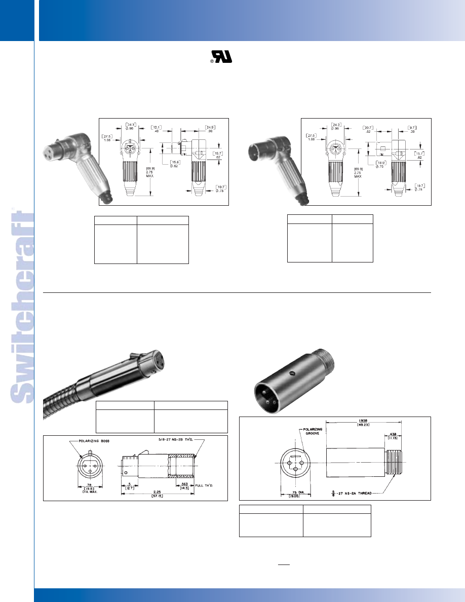
R(*)FZ CORD PLUG
R(*)MZ CORD PLUG
P(*)F MICROPHONE PLUG
P(*)M GOOSENECK PLUG
Part Number
Insert Contacts
R3FZ
3
R4FZ
4
R5FZ
5
R6FZ
6
R7FZ
7
Part Number
Insert Pins
R3MZ
3
R4MZ
4
R5MZ
5
R6MZ
6
R7MZ
7
Part Number
1
Insert Contacts
◊
P3F
3
◊
P4F
4
◊
P5F
5
Part Number
1
Insert Pins
◊
P3M
3
◊
P4M
4
◊
P5M
5
1. Satin Nickel Finish. (standard)
2. Large flex relief accepts cable from .25" to .328" diameter. (optional)
3. Gold-plated contacts. (optional)
◊
Available on special order only; contact Switchcraft for price and delivery.
Right angle, female cord mount plug, latching. New style
incorporates an insert that can rotate every 45° for added
flexibility in tight applications. Also utilizes the new strain relief
system with twist-on handle.
Accepts cable O.D.'s .100"–.285"
For black finish, add "B" suffix.
For black/gold finish, add "BAU" suffix.
Right angle, male cord mount plug, latching. New style
incorporates an insert that can be rotated every 45° for added
flexibility in tight applications. Also utilizes the new strain relief
system with twist-on handle.
Female microphone plug for gooseneck mount. Fits standard
gooseneck with external 5/8-27 thread. Microphone plugs
directly into connector. (Gooseneck not supplied.)
Male plug for gooseneck mount. Fits standard gooseneck with
internal 5/8-27 thread. Use on gooseneck with microphone
plug on opposite end. Plugs directly into female receptacle.
(Gooseneck not supplied.)
Q-G CORD PLUG CONNECTORS
Q-G CORD PLUG CONNECTORS
®
®
Accepts cable O.D.'s .100"–.285"
For black finish, add "B" suffix.
For black/gold finish, add "BAU" suffix.
CONNECTORS & RECEPTACLES
8
w w w . s w i t c h c r a f t . c o m
® Registered trademark of Switchcraft, Inc.
Note: Contact your Switchcraft Representative for price and delivery
PHONE: 773 792-2700
CONNECTORS & RECEPT
ACLES
DIMENSIONS ARE FOR REFERENCE ONLY
Inch
(mm)
* Please visit the product pages on our website for the most up-to-date product information
* Number of insert contact or pins must be specified to complete part number.
◊
Available on special order only; contact Switchcraft for price and delivery.
1 Non-reflective gray finish, gold-plated pins.
Q-G
®
CORD PLUG CONNECTORS AND RECEPTACLES
Part Number
Part Number
Insert Contacts
◊
T3F
◊
T3FL
3
◊
T3FM
◊
T3FLM
3
◊
T4F
◊
T4FL
4
◊
T4FM
◊
T4FLM
4
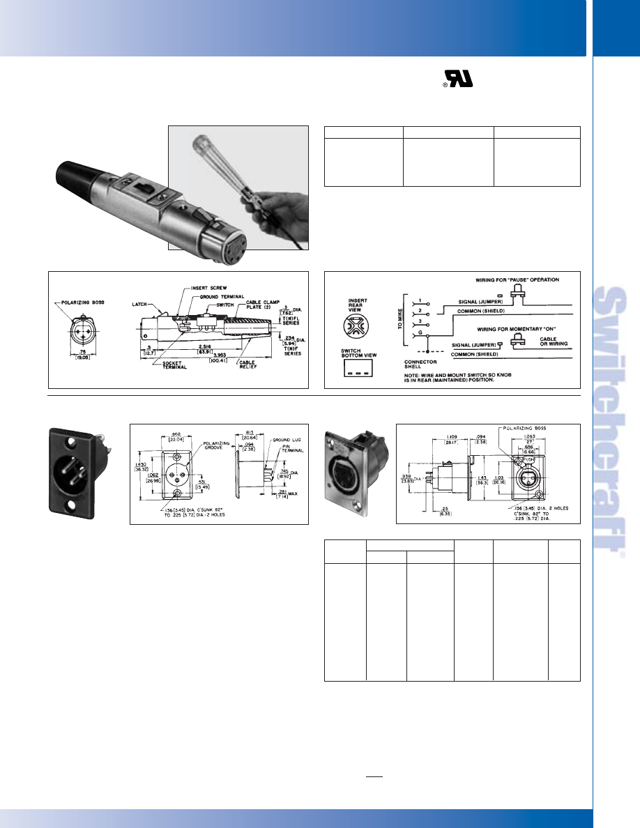
T(*)F Straight female cord plug with DPDT (2-C) locking
on-off switch; standard latchlock.
T(*)FM Straight female cord plug with SPDT (1-C)
momentary on-off switch; standard latchlock.
Slide switches rated 500 mA, 125V (AC or DC). Mounting
screws are supplied.
T(*)F AND T(*)FM CORD PLUG WITH ON-OFF SWITCH
D(*)M, D(*)F AND D(*)FD RECEPTACLES
Nickel
Black Finish
Finish
Silver
Gold
Detent
QGP Series
1
Pins
D3M
D3MB
D3MBAU
—
QGP363
3
D4M
D4MB
D4MBAU
—
—
4
D5M
D5MB
D5MBAU
—
—
5
D6M
D6MB
D6MBAU
—
—
6
D7M
D7MB
D7MBAU
—
—
7
D3F
D3FB
D3FBAU
D3FD
QGP362
3
D4F
D4FB
D4FBAU
◊
D3FDB
—
4
D5F
D5FB
D5FBAU
—
—
5
D6F
D6FB
D6FBAU
◊
D6FDB
—
6
D7F
D7FB
D7FBAU
—
—
7
Q-G CORD PLUG CONNECTORS AND RECEPTACLES
Q-G CORD PLUG CONNECTORS AND RECEPTACLES
®
®
Studio quality black and gold Q-G
®
receptacle with black
housing and gold contacts is designed for low/stable contact
resistance and withstands corrosion where highest quality is
required for recording and broadcast studio equipment,
consoles, and other applications.
D(*)M SERIES – Male receptacle for panel or chassis
mounting. Special rectangular flange permits close spacing on
crowded panels, has two .136" (3.45mm) diameter
countersunk holes for #5-40 flat head mounting screws (not
supplied). Mounts from front of panel or chassis in .766"
(19.45) diameter hole. Satin nickel finish (Series D*M) or black
finish (Series D*MB, or D*MBAU).
D(*)F SERIES – Female receptacle for panel or chassis
mounting. Flange has two .136" (3.45 mm) diameter
countersunk holes for #5-40 flat head mounting screws (not
supplied). Mounts from front of panel or chassis in .953" (24.21
mm) diameter hole. Series D(*)F has standard latchlock; Series
D(*)FD has FAS-DISCONNECT detent. Satin nickel finish
(Series D*F and D*FD) and “Black-Velvet” finish (Series
D*FBAU).
SWITCHCRAFT, INC. 5555 N. Elston Ave. • Chicago, IL 60630
9
CONNECTORS & RECEPTACLES
FAX: 773 792-2129
CONNECTORS & RECEPT
ACLES
DIMENSIONS ARE FOR REFERENCE ONLY
Inch
(mm)
* Please visit the product pages on our website for the most up-to-date product information
Q-G RECEPTACLES
Q-G RECEPTACLES
Q-G
®
RECEPTACLES (continued)
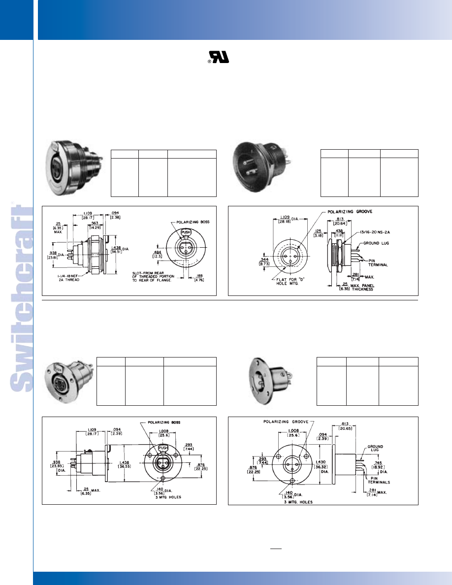
C(*)M RECEPTACLE
Male receptacle for panel or chassis mounting. Flange has three
.140" (3.57 mm) diameter holes for #5-40 mounting screws (not
supplied). Mounts from front of panel or chassis in .766" (19.45
mm) diameter hole.
Part No.
1
Part No.
5
Insert Pins
C3M
◊
QGP327
3
C4M
—
4
C5M
—
5
C6M
—
6
C7M
—
7
1. Satin nickel finish. (standard) 2. “Black-Velvet” finish. (optional) 3. Gold-plated contacts. (optional) 4. Fas-disconnect detent. (optional)
5. Non-reflective gray finish, gold-plated pins. (standard)
Panel-mount female receptacle. Mounts with spanner nut
from front of panels up to .4375" (11.11 mm) thick. Slot in
threaded part of housing permits non-turn mounting.
Requires 1.25" (31.75 mm) diameter minimum mounting
hole. Spanner nut is die-cast zinc with satin nickel finish
(Series B*F) or black finish (Series B*FB).
Part No.
1
Part No.
2
Insert Contacts
B3F
B3FB
3
B4F
—
4
B5F
—
5
B6F
—
6
B7F
—
7
B(*)M RECEPTACLE
Part No.
1
Part No.
2
Insert Pins
B3M
B3MB
3
B4M
—
4
B5M
—
5
B6M
—
6
B7M
—
7
C(*)F RECEPTACLE
Female receptacle for panel or chassis mounting. Flange has
three .140" (3.57 mm) diameter holes for #5-40 mounting
screws (not supplied). Mounts from front of panel or chassis
in 0.953" (24.21 mm) diameter hole.
Part No.
1
Part No.
5
Insert Contacts
C3F
◊
QGP326
3
C4F
—
4
C5F
—
5
C6F
—
6
C7F
—
7
B(*)F RECEPTACLE
◊
Special order only. Contact Switchcraft.
Panel-mount male receptacle. Mounts with locknut from front of
panels up to .250" (6.35 mm) thick. Requires .812" (20.64 mm)
diameter mounting hole. For non-turning mounting, can be keyed
to “D” shaped panel hole, or S3519 mounting adapter can be used.
Satin nickel finish (Series B*M) or black finish (Series B*MB).
®
®
CONNECTORS & RECEPTACLES
10
w w w . s w i t c h c r a f t . c o m
® Registered trademark of Switchcraft, Inc.
Note: Contact your Switchcraft Representative for price and delivery
PHONE: 773 792-2700
CONNECTORS & RECEPT
ACLES
DIMENSIONS ARE FOR REFERENCE ONLY
Inch
(mm)
* Please visit the product pages on our website for the most up-to-date product information
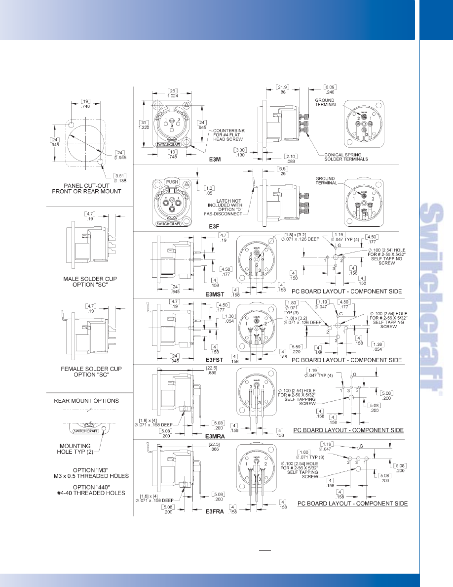
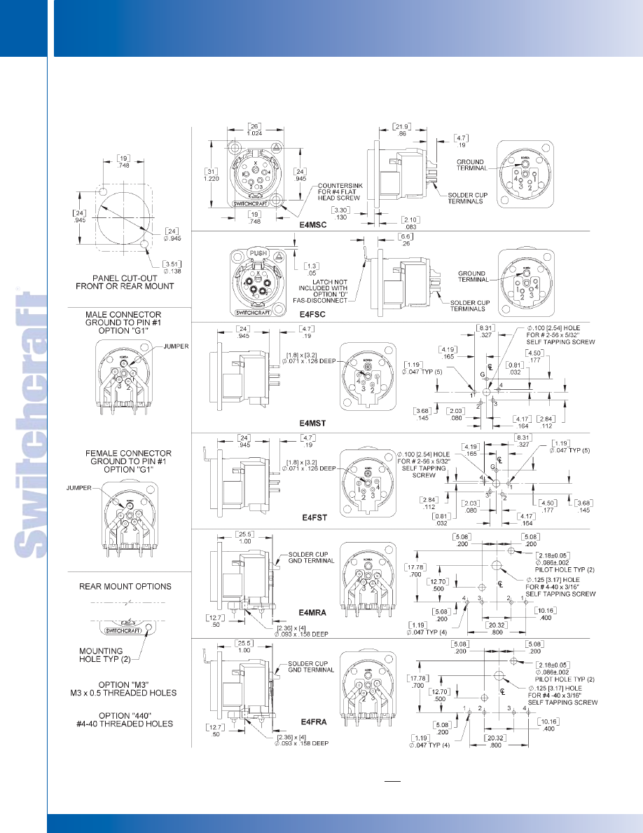
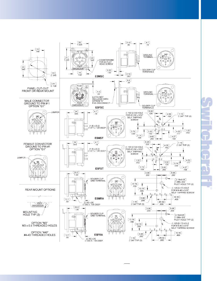
E Series Q-G
®
Receptacles are available with quick release
inserts. Quick insert release is accomplished by turning
screw lock from front of insert. Insert can then be removed
from the rear. For PC board applications, insert can be
removed/assembled to the housing while soldered to
the PC board.
E Series receptacles can be specified as complete assemblies,
or as separate inserts and housings. Stocking separate
inserts and housings offer considerable cost and time sav-
ings by minimizing inventory and maximizing configuration
possibilities.
FEATURES
• Replaces Neutrik D Series
• 3-pin contact; male and female types
• Both male and female fit in same panel cutout
• Choice of 4 terminations; solder cups, conical springs,
straight or right angle PC terminals.
• Inserts and housings can be specified separately
• Quick release inserts for ease of removal
• Locking receptacles
• Protected ground clip minimizes scooping damage
• Insert lock detent resists disassembly from shock or
vibration during normal handling and transportation
• Silver and gold-plated contacts available
• Rugged metal shells; black or satin nickel finishes
• Through-the-shell ground connection and all-metal
shells for greater shielding effectiveness
• Compatible with Switchcraft Q-G
®
, QGP and other
connectors with similar configurations
QUICK RELEASE INSERT
In two simple steps, inserts can be released while
housing stays fastened to the panel.
1. With a small screwdriver, twist insert locking screw
from front of insert.
2. Remove insert from the rear of the housing.
TERMINALS
Four terminations are available on E Series receptacles:
1. Conical Spring Solder terminals – conical spring on
each pin holds wire in place providing constant pressure
during soldering process. This effectively acts as a third
hand, assuring a high quality solder termination.
Housing mounts to panel.
2. Straight PC terminals – direct termination to PC
board. Housing mounts to panel.
3. Right-angle PC terminals - direct termination to PC
board at a right-angle. Housing mounts to panel.
4. SC - Solder cup
SPECIFICATIONS
ELECTRICAL
Contact Resistance: 50 milliohms maximum, per pole.
Current Rating: 15A
Insulation Resistance: 2 X 10
6
M
Ω
Dielectric Resistance: 1,000 V rms
Capacitance: 10 pF
MECHANICAL
Insertion/Withdrawal Forces: 7 pounds maximum /
5 pounds nominal insertion; 7 pounds maximum /
5 pounds nominal withdrawal.
Life: 10,000 operations (minimum).
ENVIRONMENTAL
Thermal Range: -55° C to +85° C
Humidity: Meets MIL-STD-202F, method 106E.
Thermal Shock: Meets MIL-STD-202F, method 107D.
Salt Spray: Meets MIL-STD-202F, method 101D.
MATERIAL
Shells: Die-cast; satin-nickel or Black Velvet.
Inserts: Glass-filled thermoplastic.
Socket Contacts: Copper alloy, silver- or gold-plated.
Pin Contacts: Copper alloy, silver- or gold-plated.
Latch Release: Steel, nickel-plated.
Insert Locking Cam: Die-cast zinc.
Conical Spring
Solder Terminals
Straight PC
Terminals
Solder cup
E Series
Receptacles
E SERIES RECEPTACLES
Right Angle
PC Terminals
E SERIES Q-G
®
RECEPTACLES
E SERIES Q-G
®
RECEPTACLES
SWITCHCRAFT, INC. 5555 N. Elston Ave. • Chicago, IL 60630
11
CONNECTORS & RECEPTACLES
FAX: 773 792-2129
CONNECTORS & RECEPT
ACLES
DIMENSIONS ARE FOR REFERENCE ONLY
Inch
(mm)
* Please visit the product pages on our website for the most up-to-date product information
E SERIES PART NUMBERING SYSTEM
E SERIES PART NUMBERING SYSTEM
E SERIES PART NUMBERING SYSTEM
HOUSING ONLY PART NUMBER SCHEME
INSERT ONLY PART NUMBER SCHEME
Series
Pins/
Gender
Fas-disconnect Termination
Housing
Terminal
Contacts
Option
Style
Finish
Finish
E
3-5 pins
F: Female
D: Fas-disconnect
ST: Straight PC terminals
AU: Gold
M: Male
Blank: Standard locking
RA: Right angle PC terminals
Blank: Silver
SC: Solder cups
Blank: Conical springs*
Series
Pins/
Housing
Mounting Hole
Contacts
Finish
Options
E
F: Female
B: Black
M3: M3 x 0.5 thread
M: Male
Blank: Nickel
440: #4-40 thread
Blank: Counter-sunk hole
Series Pins/
Gender
Fas-disconnect Termination
Housing
Terminal Mounting Hole
Contacts
Option
Style
Finish
Finish
Options
E
3-5 pins
F: Female D: Fas-disconnect ST: Straight PC terminals
B: Black
AU: Gold
M3: M3 x 0.5 thread
M: Male
Blank: Standard RA: Right angle PC terminals Blank: Nickel Blank: Silver 440: #4-40 thread
locking
SC: Solder cups
Blank: Counter-
Blank: Conical springs*
sunk hole
CONNECTOR PART NUMBER SCHEME
*3-pin only
CONNECTORS & RECEPTACLES
12
w w w . s w i t c h c r a f t . c o m
® Registered trademark of Switchcraft, Inc.
Note: Contact your Switchcraft Representative for price and delivery
PHONE: 773 792-2700
CONNECTORS & RECEPT
ACLES
DIMENSIONS ARE FOR REFERENCE ONLY
Inch
(mm)
* Please visit the product pages on our website for the most up-to-date product information
E SERIES
E SERIES
E SERIES
SWITCHCRAFT, INC. 5555 N. Elston Ave. • Chicago, IL 60630
13
CONNECTORS & RECEPTACLES
FAX: 773 792-2129
CONNECTORS & RECEPT
ACLES
DIMENSIONS ARE FOR REFERENCE ONLY
Inch
(mm)
* Please visit the product pages on our website for the most up-to-date product information
E SERIES (continued)
CONNECTORS & RECEPTACLES
14
w w w . s w i t c h c r a f t . c o m
® Registered trademark of Switchcraft, Inc.
Note: Contact your Switchcraft Representative for price and delivery
PHONE: 773 792-2700
CONNECTORS & RECEPT
ACLES
DIMENSIONS ARE FOR REFERENCE ONLY
Inch
(mm)
E SERIES
E SERIES
* Please visit the product pages on our website for the most up-to-date product information
E SERIES (continued)
SWITCHCRAFT, INC. 5555 N. Elston Ave. • Chicago, IL 60630
15
CONNECTORS & RECEPTACLES
FAX: 773 792-2129
CONNECTORS & RECEPT
ACLES
DIMENSIONS ARE FOR REFERENCE ONLY
Inch
(mm)
E SERIES
E SERIES
* Please visit the product pages on our website for the most up-to-date product information
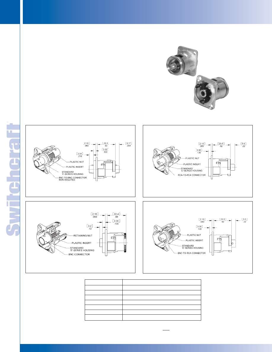
Part Number
Description
EHBNC2
BNC to BNC
EHBNCSC
BNC to solder cup
EHRCA2
RCA to RCA
EHRCABNC
RCA to BNC
EHUSB2
USB to USB
EH13942
IEEE1394 to IEEE1394
EHCAT62
Cat6 to Cat6
The EH Series consist of different styles of popular connectors in
our E Series housing. This allows the end user to punch one single
hole size and populate wall plates, gang assemblies with different
types of connectors. Connector styles include BNC feed-throughs,
RCA feed-throughs, USB feed-throughs, IEEE 1394 Firewire
feed-throughs, BNC to solder cup, and RCA to BNC.
FEATURES
• Utilizes same panel cut-out as E Series QG connectors
• Rugged metal shells
• Available with a wide variety of popular feed-through connectors
EH SERIES RECEPTACLES
EH SERIES RECEPTACLES
EH SERIES RECEPTACLES
EHBNC2
EHBNC2
EHRCA2
EHRCA2
EHRCABNC
EHBNCSC
CONNECTORS & RECEPTACLES
16
w w w . s w i t c h c r a f t . c o m
® Registered trademark of Switchcraft, Inc.
Note: Contact your Switchcraft Representative for price and delivery
PHONE: 773 792-2700
CONNECTORS & RECEPT
ACLES
DIMENSIONS ARE FOR REFERENCE ONLY
Inch
(mm)
* Please visit the product pages on our website for the most up-to-date product information
PQG
®
RECEPTACLES
PQG
®
RECEPTACLES
Q-G
®
3 pin/contact PC receptacles offer economy, reliability
and performance in amplifiers, audio mixing boards, and
other outboard gear. Choose receptacles with just the right
combination of standard and optional bonus features to tailor
the PQG series to your exact needs.
PQG
®
RECEPTACLES
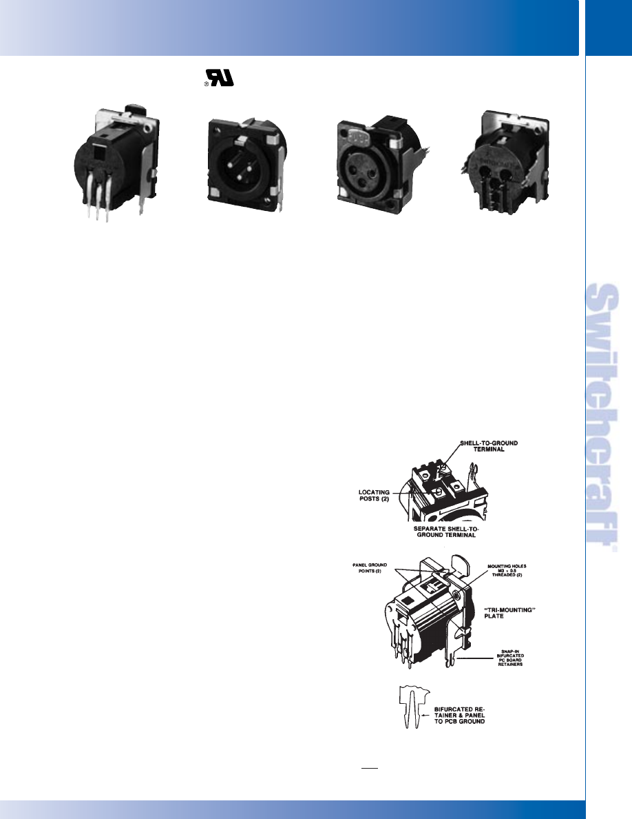
STANDARD FEATURES
• UL 94V-0 plastic materials.
• Circuit #1 “makes” first and “breaks” last during
connect/disconnect.
• Positive mechanical polarization.
• Minimum PC board space required.
• Integral PC board locating posts.
• Mating/unmating cycles in excess of 10,000.
• Mates with Switchcraft Q-G and other compatible
connectors.
OPTIONAL FEATURES
• Positive latch lock or FasDisconnect (female only).
• Shell-to-ground terminal.
• Mounting Plates:
A. Backup Mounting Plate with two, M3 x 0.5 threaded
holes for faster, more rugged mounting to equipment
panel/chassis.
B. “Tri-Mounting” Plate...plus two bifurcated pcb
retainers with snap-in terminals which perform
three valuable functions:
1. Provide ground connection from panel to PCB.
2. Hold connector securely to PCB during wave-soldering.
3. Add strength between panel/chassis and PCB during
soldering by “wicking” solder through the PCB and up
sides of retainers to assure continuity.
C. Two panel grounds are integral with mounting plate.
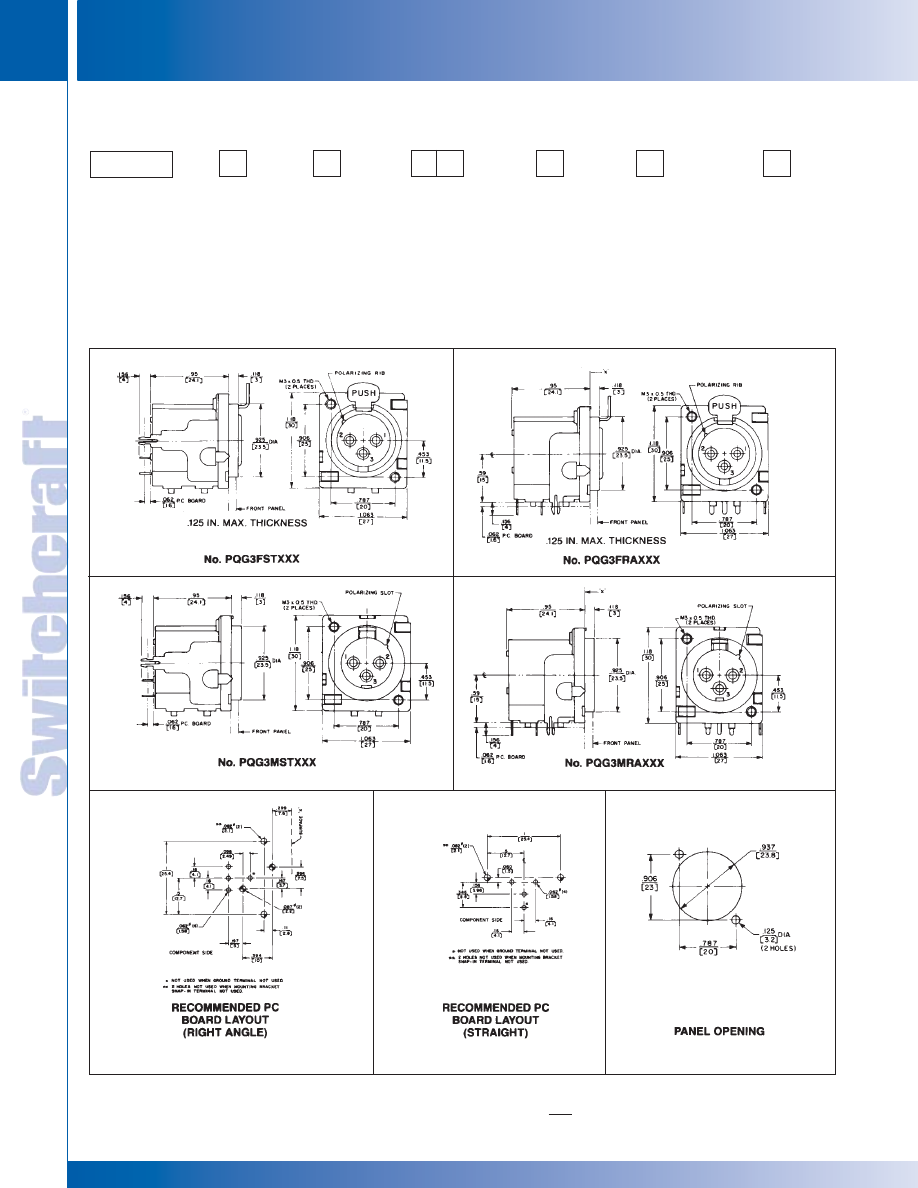
PQG3FRA112
PQG3MRA112
PQG3FST112
PQG3MST112
SPECIFICATIONS
Housing: Black, glass-filled thermoplastic, UL 94V-0.
Flange mounting holes are .128 inch diameter
Socket Contacts: Copper alloy, electrotinned.
Pin Contacts: Copper alloy, electrotinned.
Latch Release: Steel, nickel-plated.
Mounting Plate: Copper alloy.
Shell-to-Ground Terminals: Copper alloy, electrotinned.
Latches: Copper alloy, nickel-plated.
Insertion/Withdrawal Forces: 2 pound (nominal).
Contact Resistance: .05 ohms per pole (maximum).
Dielectric Withstanding Voltage: 1,000 V rms for 1 minute.
Insulation Resistance: 10
4
M
Ω
@ 500 V DC.
Current Capacity: 10A maximum (carry only).
Operating Temperature: -30°F to 185°F (-34°C to 85°C).
Mechanical Life: 10,000 cycles @ 10 cpm.
SWITCHCRAFT, INC. 5555 N. Elston Ave. • Chicago, IL 60630
17
CONNECTORS & RECEPTACLES
FAX: 773 792-2129
CONNECTORS & RECEPT
ACLES
DIMENSIONS ARE FOR REFERENCE ONLY
Inch
(mm)
* Please visit the product pages on our website for the most up-to-date product information
PQG
®
SERIES PART NUMBERING SYSTEM
PQG
®
SERIES PART NUMBERING SYSTEM
PQG
®
SERIES PART NUMBERING SYSTEM
G
Q
P
SERIES
PQG-
Composite QG
PC
TERMINALS
RA - Right Angle,
Bottom Exit
ST - Straight
Rear Exit
GROUND
TERMINAL
0 - None
1 - Installed
MOUNTING PLATE
0 - None
1 - Plate with two,
M3 x 0.5 threaded
holes
2 - Plate with two,
M3 x 0.5 threaded
holes, panel grounds
and PCB retainers
PINS/
CONTACTS
3
LATCHING
0 - None
1 - Latch Lock
2 - Fas-
Disconnect
(female
only)
GENDER
F - Female
M - Male
3
CONNECTORS & RECEPTACLES
18
w w w . s w i t c h c r a f t . c o m
® Registered trademark of Switchcraft, Inc.
Note: Contact your Switchcraft Representative for price and delivery
PHONE: 773 792-2700
CONNECTORS & RECEPT
ACLES
DIMENSIONS ARE FOR REFERENCE ONLY
Inch
(mm)
* Please visit the product pages on our website for the most up-to-date product information
Q-G
®
AUDIO RECEPTACLES FOR PC/PANEL MOUNT
Q-G
®
AUDIO RECEPTACLES FOR PC/PANEL MOUNT
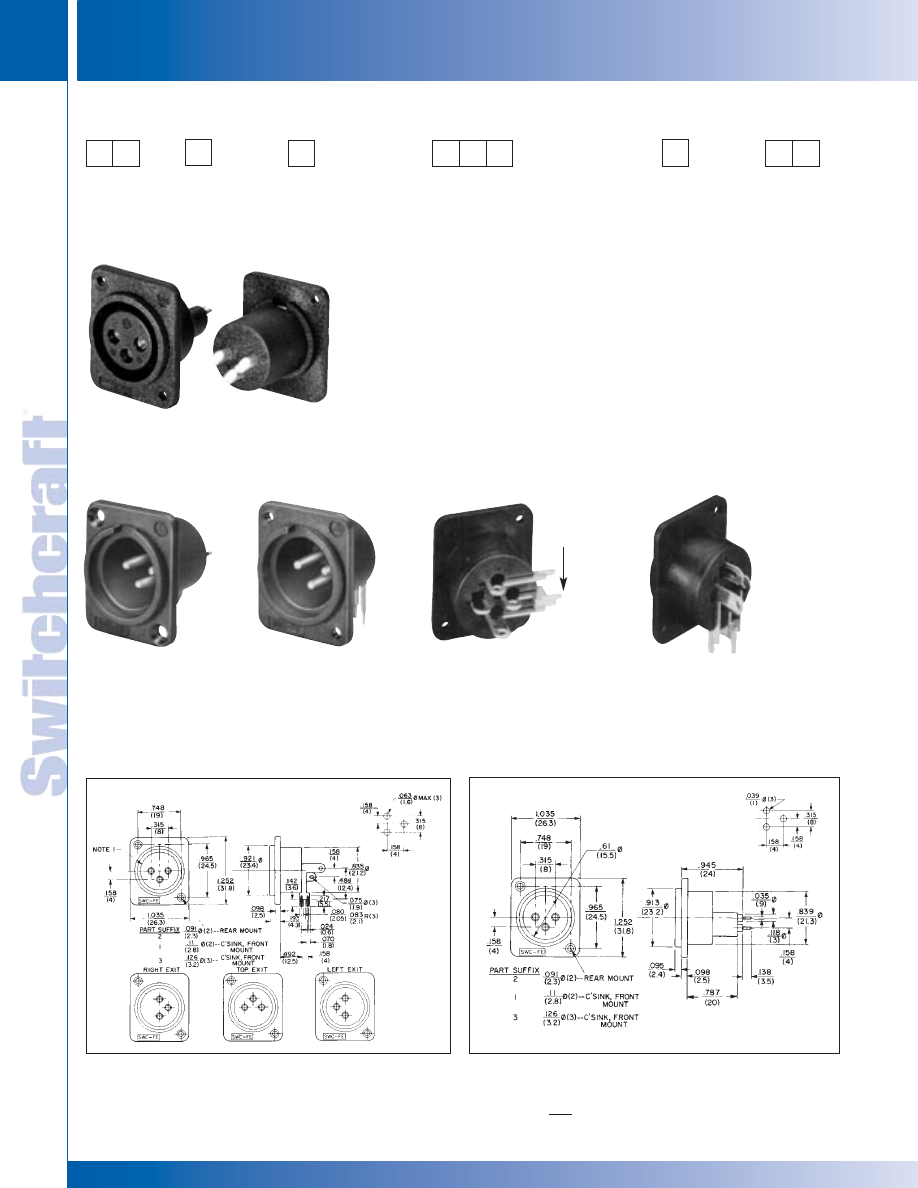
PD SERIES - PLASTIC PANEL MOUNT
Q-G
®
AUDIO RECEPTACLES FOR PC/PANEL MOUNT
Switchcraft offers the PD Series (plastic panel mount) audio
connectors with a wide variety of 3-pin/contact, male and
female types and many terminals for combined PC/panel
mount. Female types offer larger contact area for higher ratings
and longer life. Panel mounting may be at users option, either
front or rear. New PD series connectors mate with Switchcraft
Q-G and other compatible types.
PD SERIES FEATURES
• 3 pins/contacts
• Male and female
• Straight and right-angle terminals
• PC or PC/panel mount
• Front or rear panel mount
• Special PC/solder terminal type with exits at 0° (down,
90° (right), 180° (top), and 270° (left)
• Rugged molded black glass-filled thermoplastic housings.
SPECIFICATIONS
Housing: Black molded thermoplastic, glass-filled.
Ground Pin: Copper alloy.
Stamped Terminals/Contacts: Copper alloy, electrotinned.
Screw Machine Terminals/Pins: Copper alloy, silver-plated.
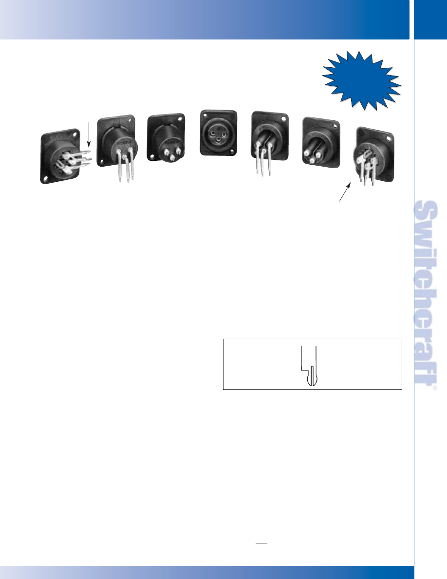
BIFURCATED PC TERMINALS
Bifurcation configuration for PC terminals on selected
connectors offers these advantages.
1. Provides convenient snap-in retention for mounting.
2. Holds connector securely to PCB during wavesoldering.
3. Adds strength to all terminal connections by solder
“wicking” through PCB and up sides of terminals.
BIFURCATED HOLD-DOWN FEATURE
FOR ALL PC TERMINALS
PD3FRL1
PD3MRML1
PD3FS2
PD3MS1
PD3FRML1
PD3FRA1
PD3FS2
NEW
Bifurcated
PCB Terminals
Bifurcated
PCB Terminals
See Next Page
for New Solder
Cup Option
SWITCHCRAFT, INC. 5555 N. Elston Ave. • Chicago, IL 60630
19
CONNECTORS & RECEPTACLES
FAX: 773 792-2129
CONNECTORS & RECEPT
ACLES
DIMENSIONS ARE FOR REFERENCE ONLY
Inch
(mm)
* Please visit the product pages on our website for the most up-to-date product information
PD SERIES PART NUMBERING SYSTEM
PD SERIES PART NUMBERING SYSTEM
PD SERIES PART NUMBERING SYSTEM
D
P
SERIES
PD
GENDER
FEMALE
MALE
RA
- Right-angle, RML - Right-angle,
Bottom Exit
Bottom Exit,
RL
- Right-angle,
Long Screw
Left exit
Mach. Term.
RR
- Right-angle,
RMS - Right-angle,
Right Exit
Bottom Exit,
RU
- Right-angle,
Short Screw
Top Exit
Mach. Term.
RML - Right-angle,
S
- Straight,
Bottom Exit,
Rear Exit
Long Screw
SC
- Solder Cup
Mach. Term.
RMS - Right-angle,
Bottom Exit,
Short Screw
Mach. Term.
S
- Straight,
Rear Exit
SC
- Solder Cup
HOUSING
1 - Front Mount
.11" (2.8 mm)
diameter flange
mounting holes
2 - Rear Mount
.091" (2.3 mm)
diameter flange
mounting holes
3 - Front Mount
.126" (3.2 mm)
diameter flange
mounting holes
PINS/
CONTACTS
GENDER
F - Female
M - Male
3
PD3MS1
3-pin male,
straight (rear exit)
PC terminals.
Front mount.
PD3MRML2
3-pin male, right
angle (bottom exit)
long screw machine
terminals. Panel
mount holes not
countersunk.
PD3FRL1
3-contact female,
right-angle (left exit)
PC/solder terminals.
Ground lug. Front
panel mount.
PD3FRA1
3-contact female,
right-angle (bottom
exit) PC/solder
terminals. Ground
lug. Front panel
mount.
RECOMMENDED PC
BOARD LAYOUT
(Component Side)
RECOMMENDED PC BOARD
LAYOUT (Component Side)
Numbers PD3FRA1, 2, and 3; PD3FRL1, 2, and 3;
PD3FRR1, 2 and 3; PD3FRU1, 2 and 3 (Typical)
Numbers PD3FS1, 2, and 3 (Typical)
Bifurcated
PCB Terminals
Bifurcated
PCB Terminals
TERMINALS
Blank=
Silver
terminals
AU=
Gold
terminals
Note: New solder cup
option shown.
CONNECTORS & RECEPTACLES
20
w w w . s w i t c h c r a f t . c o m
® Registered trademark of Switchcraft, Inc.
Note: Contact your Switchcraft Representative for price and delivery
PHONE: 773 792-2700
CONNECTORS & RECEPT
ACLES
DIMENSIONS ARE FOR REFERENCE ONLY
Inch
(mm)
* Please visit the product pages on our website for the most up-to-date product information
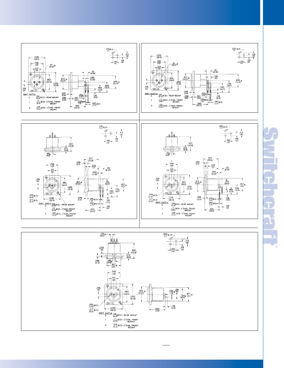
PD SERIES
PD SERIES
RECOMMENDED PC
BOARD LAYOUT
(Component Side)
RECOMMENDED PC
BOARD LAYOUT
(Component Side)
RECOMMENDED PC
BOARD LAYOUT
(Component Side)
RECOMMENDED PC
BOARD LAYOUT
(Component Side)
RECOMMENDED PC
BOARD LAYOUT
(Component Side)
Numbers PD3FRMS1, 2, and 3 (Typical)
Numbers PD3FRML1, 2, and 3 (Typical)
Numbers PD3MRML1, 2, and 3 (Typical)
Numbers PD3MRMS1, 2, and 3 (Typical)
Numbers PD3MS1, 2, and 3 (Typical)
PD SERIES (continued)
SWITCHCRAFT, INC. 5555 N. Elston Ave. • Chicago, IL 60630
21
CONNECTORS & RECEPTACLES
FAX: 773 792-2129
CONNECTORS & RECEPT
ACLES
DIMENSIONS ARE FOR REFERENCE ONLY
Inch
(mm)
* Please visit the product pages on our website for the most up-to-date product information
CONNECTORS & RECEPTACLES
22
w w w . s w i t c h c r a f t . c o m
® Registered trademark of Switchcraft, Inc.
Note: Contact your Switchcraft Representative for price and delivery
PHONE: 773 792-2700
CONNECTORS & RECEPT
ACLES
DIMENSIONS ARE FOR REFERENCE ONLY
Inch
(mm)
Series Y(*)MPC. Male receptacle for panel or chassis
mounting escutcheon. PC terminals and standoffs. Rear of
panel mount in .750 inch diameter hole. Maximum panel
thickness: 25 inches (6.35 mm); .156 inches (3.96 mm) if YEM
escutcheon is used.
Series Y(*)FPC. Female receptacle for panel or chassis
mounting. PC Terminal and standoffs. Rear of panel mount in
.875 inch (22.22 mm) diameter hole.
Series Y(*)F. Female receptacle for panel or chassis mounting.
Rear of panel mount in .875 inch (22.22 mm) diameter hole.
Series Y(*)FD, Y(*)FDPC. Female receptacles. Same as Y(*)F
and Y(*)FPC, respectively, except with FAS-DISCONNECT
detent.
Series YEF Escutcheons. Trim escutcheons provide
distinctive panel appearance and can also color code
connections. Available in black (standard), red, green, white,
and yellow. Other colors possible on special order where
production quantities warrant.
ASSEMBLY/MOUNTING
AII receptacles are rear-of-panel mount (units with PC
terminals also mount/terminate to PC board). Flange fastens
to chassis/panel with two #4-40 machine screws (not supplied).
Use of escutcheons is optional.
Install latch release lever (Series Y(*)F and Y(*)FPC) after
receptacle is fastened to chassis/panel. Insert lever in slot from
front and press inward until it locks (snaps) into place. To
remove lever, depress rear of lever (with screwdriver) through
opening at top rear of housing and pull lever straight out.
SERIES Y(*)F, Y(3)FPC, Y(*)FD, Y(3)FDPC AND Y(3)MPC RECEPTACLES
Q-G
®
RECEPTACLES
Part Numbers
Female
Female
Insert
Part Number
Insert
Latchlock
†
Detent
†
Contacts
Male
†
Pins
Y3F
Y3FD
3
Y3MPC
3
RECEPTACLES
Part Number
Color
Part Number
Color
◊
YEF01
Red
◊
YEF04
Blue
◊
YEF02
Black
◊
YEF05
White
◊
YEF03
Green
◊
YEF08
Yellow
ESCUTCHEONS
†Suffix letters “PC” indicate PC terminals; all others have solder lugs.
SPECIFYING NOTE: YEM02 escutcheon can be ordered on special order; contact
Switchcraft.
Y3MPC
Y3FPC
YEF02
ESCUTCHEONS
Q-G RECEPTACLES
Q-G RECEPTACLES
®
®
* Please visit the product pages on our website for the most up-to-date product information
SWITCHCRAFT, INC. 5555 N. Elston Ave. • Chicago, IL 60630
23
CONNECTORS & RECEPTACLES
FAX: 773 792-2129
CONNECTORS & RECEPT
ACLES
DIMENSIONS ARE FOR REFERENCE ONLY
Inch
(mm)
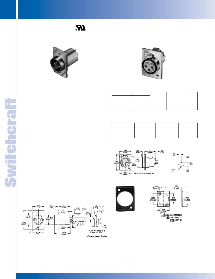
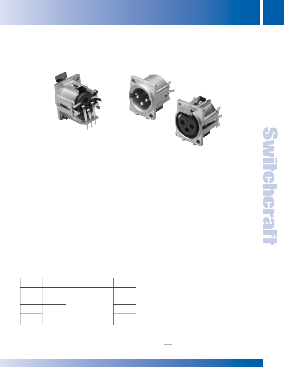
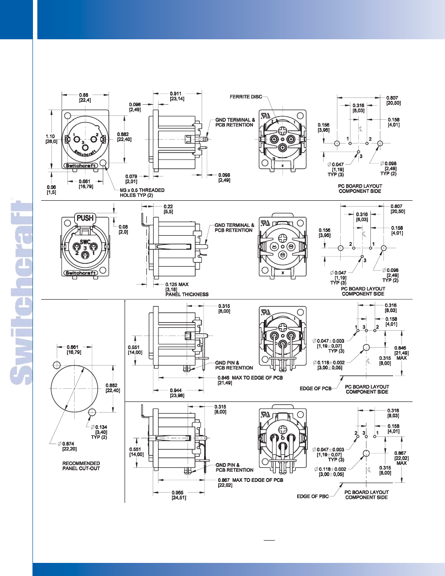
Switchcraft now offers the F Series. Available in male and
female, the receptacles can be mounted from the rear of the
panel. Features include an all metal housing with a ferrite
disk for added EMI/RMI shielding. Both male and female
connectors can be mounted vertical or horizontal to the PC
board. All connectors have a PC-board retention feature to
hold the connectors firmly to the PC board prior to soldering.
See the chart below for part numbers.
F SERIES FEATURES
• Replaces Cannon XLM-Series
• 3-pin contact; male and female types
• Both male and female fit in same panel cutout
• Locking receptacles
• Silver-plated contacts
• Rugged metal shells; satin nickel finishes
• Through-the-shell ground connection and all-metal shells
for greater shielding effectiveness
• Compatible with Switchcraft Q-G
®
, QGP and other
connectors with similar configurations
• Added EMI/RFI ferrite shield
SPECIFICATIONS:
ELECTRICAL
Contact Resistance: 50 milliohms maximum, per pole.
Current Rating: 15A
Insulation Resistance: 1,000 M
Ω
Dielectric Resistance: 1,000 V rms
Capacitance: 2 to 4 pF
MECHANICAL
Insertion/Withdrawal Forces: 7 pounds maximum/nominal
Insertion: 7 pounds maximum withdrawal.
Life: 10,000 operations (minimum).
ENVIRONMENTAL
Thermal Range: -55° C to +85° C
Thermal Shock: Meets MIL-STD-202F, method 107D
Salt Spray: Meets MIL-STD-202F, method 101D (for 16 hrs.)
MATERIAL
Shells: Die-cast; satin-nickel plated
Inserts: Glass-filled thermoplastic.
Socket Contacts: Copper alloy, silver-plated.
Pin Contacts: Copper alloy, silver-plated.
Latch Release: Steel, nickel-plated.
TERMINALS
Two terminations are available on F-Series receptacles:
1. Straight PC-terminals – direct termination to PC-board.
Housing mounts to panel.
2. Right Angle PC terminals – direct termination to
PC-board at right angle. Housing mounts to panel.
Part
Terminals
Contacts
Housing
Type
Number
F3MSTF
Straight
M
F3FSTF
F
Silver
Satin Nickel
F3MRAF
Right Angle
M
F3FRAF
F
F SERIES RECEPTACLES
F SERIES RECEPTACLES
F SERIES RECEPTACLES
F3FRAF
F3MSTF
F3FSTF
* Please visit the product pages on our website for the most up-to-date product information
CONNECTORS & RECEPTACLES
24
w w w . s w i t c h c r a f t . c o m
® Registered trademark of Switchcraft, Inc.
Note: Contact your Switchcraft Representative for price and delivery
PHONE: 773 792-2700
CONNECTORS & RECEPT
ACLES
DIMENSIONS ARE FOR REFERENCE ONLY
Inch
(mm)
F SERIES RECEPTACLES
F SERIES RECEPTACLES
F SERIES RECEPTACLES (continued)
F3MSTF
F3FSTF
F3MRAF
F3FRAF
* Please visit the product pages on our website for the most up-to-date product information
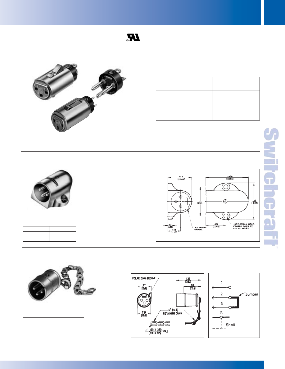
SWITCHCRAFT, INC. 5555 N. Elston Ave. • Chicago, IL 60630
25
CONNECTORS & RECEPTACLES
FAX: 773 792-2129
CONNECTORS & RECEPT
ACLES
DIMENSIONS ARE FOR REFERENCE ONLY
Inch
(mm)
Q-G ADAPTERS, ACCESSORIES
Q-G ADAPTERS, ACCESSORIES
◊
Available on special order only; contact
Switchcraft for price and delivery.
Male and female Q-G
®
inserts with 3-7 pins/contacts, fit
appropriate plug and receptacle housings. Female
inserts available with standard latchlock or
FAS-DISCONNECT detent mating, and with solder or
PC terminals. Intended for replacement, or building into
equipment such as microphones and transducers.
Q-G
®
CONNECTOR INSERTS
SHORTING PLUG
Q-G
®
ADAPTERS, ACCESSORIES
Insert
Standard
FAS-*
Male
Pins/
Latchlock
DISCONNECT
Inserts
Contacts
—
◊
QG3FDPC
—
3
QG3F
QG3FD
QG3M
3
QG4F
QG4FD
QG4M
4
QG5F
QG5FD
QG5M
5
QG6F
QG6FD
QG6M
6
QG7F
QG7FD
QG7M
7
*Suffix letters “PC” indicate PC terminals; all others (except “S”)
have solder lugs.
**Suffix letter “S” indicates locking PC terminal and plastic housing.
◊
Special order only. Contact Switchcraft.
3-pin plug shorts out unused hi-Z microphone inputs or other sensitive
circuits (shorting jumper installed between pins 2 and 3). 6" (152.4 mm)
chain fastened to end pin to prevent plug loss. Switchcraft can install
special wiring for a nominal extra charge.
Part Number
Insert Pins
◊
N3MS
3
W(*)M RECEPTACLE
Part Number
Insert Pins
W3M
3
W4M
4
Right-angle male panel receptacle.
Mounts with two, #5-40 machine screws.
Note: Add suffix “BAU” for black insert with gold-plated contacts.
®
®
* Please visit the product pages on our website for the most up-to-date product information
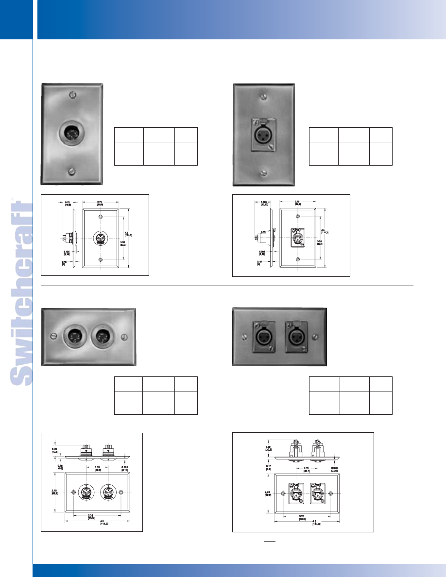
CONNECTORS & RECEPTACLES
26
w w w . s w i t c h c r a f t . c o m
® Registered trademark of Switchcraft, Inc.
Note: Contact your Switchcraft Representative for price and delivery
PHONE: 773 792-2700
CONNECTORS & RECEPT
ACLES
DIMENSIONS ARE FOR REFERENCE ONLY
Inch
(mm)
G(*)M WALL PLATE RECEPTACLE
H(*)M WALL PLATE RECEPTACLE
J(*)F WALL PLATE RECEPTACLE
K(*)F WALL PLATE RECEPTACLE
Q-G
®
WALL PLATE RECEPTACLES
Part
Insert
Number
Finish
Pins
◊
G3MS
Stainless
Steel
3
◊
G4MS
4
Part
Insert
Number
Finish
Pins
◊
J3FS
Stainless
Steel
3
◊
J4MS
4
Wall plate with one B3M or B4M male
receptacle mounted (in “D”-shaped
hole to prevent turning) on standard
single electrical outlet box. Cover
mounting screws included.
Wall plate with two, B3M
or B4M male receptacles
mounted (in “D”-shaped
holes to prevent turning)
on standard single
electrical outlet box. Cover
mounting screws included.
Wall plate with one, D3F or D4F female
receptacle. Mounts on standard single
electrical outlet box. Cover mounting
screws included.
Wall plate with two, D3F or
D4F female receptacles.
Mounts on standard single
electrical outlet box. Cover
mounting screws included.
Part
Insert
Number
Finish
Pins
◊
H3MS
Stainless
Steel
3
◊
H4MS
4
Part
Insert
Number
Finish
Pins
K3FS
Stainless
Steel
3
◊
K4FS
4
Q-G WALL PLATE RECEPTACLES
Q-G WALL PLATE RECEPTACLES
®
®
◊
Special order only. Contact Switchcraft.
◊
Special order only. Contact Switchcraft.
◊
Special order only. Contact Switchcraft.
◊
Special order only. Contact Switchcraft.
* Please visit the product pages on our website for the most up-to-date product information
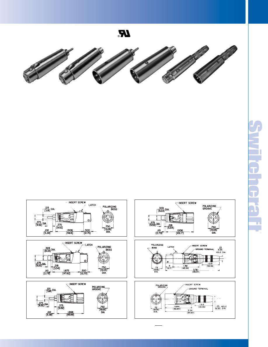
SWITCHCRAFT, INC. 5555 N. Elston Ave. • Chicago, IL 60630
27
CONNECTORS & RECEPTACLES
FAX: 773 792-2129
CONNECTORS & RECEPT
ACLES
DIMENSIONS ARE FOR REFERENCE ONLY
Inch
(mm)
Q-G CONNECTOR-ADAPTERS
Q-G CONNECTOR-ADAPTERS
Switchcraft Q-G
®
Connector-Adapters, designed to solve
common interconnection problems, are ideally suited to the
interconnection of microphones, mixers, amplifiers, public
address and sound reinforcement equipment, broadcast
equipment, and any other component that does not have an
appropriate mating connector. All are completely shielded,
and incorporate the high quality and outstanding design features
of the Switchcraft line of Q-G Audio Connectors, including:
1. Separate ground terminal.
2. Ground Contactors.
3. Captive Design
®
Insert Screw
4. High impact Thermoplastic Insulation.
MATERIAL SPECIFICATIONS
PHONE JACK AND PLUG TERMINATIONS
Shell: Copper alloy, nickel-plated.
Insulation: Paper-base phenolic.
Plug Tip and Sleeve: Copper alloy, nickel-plated.
Phone Pin and Plug Housing: Copper alloy, nickel-plated.
Phono Plug Insulation: Rigid plastic.
Phono Jack Housing: Steel, copper alloy-plated,
tarnish-resistant.
Phono Jack Pin Receptacle: Brass, silver-plated,
copper alloy.
Phono Jack Insulation: Thermoplastic.
321. Phono plug to 3-contact female audio-connector
(Switchcraft
®
A3F).
322. Phono jack to 3-contact female audio-connector
(Switchcraft
®
A3F).
323. Phono plug to 3-pin male audio-connector
(Switchcraft A3M).
324. Phono jack to 3-pin male audio-connector
(Switchcraft
®
A3M).
383A. Three-contact female audio-connector
(Switchcraft
®
A3F) to standard .250" (6.35 mm)
diameter 3-conductor extension phone jack.
384A. Three-pin male audio connector
(Switchcraft
®
A3M) to standard .250" (6.35 mm)
diameter 3-conductor extension phone jack.
Q-G
®
CONNECTOR-ADAPTERS
321
322
323
324
383A
384A
321
322
323
324
383A
384A
®
®
* Please visit the product pages on our website for the most up-to-date product information
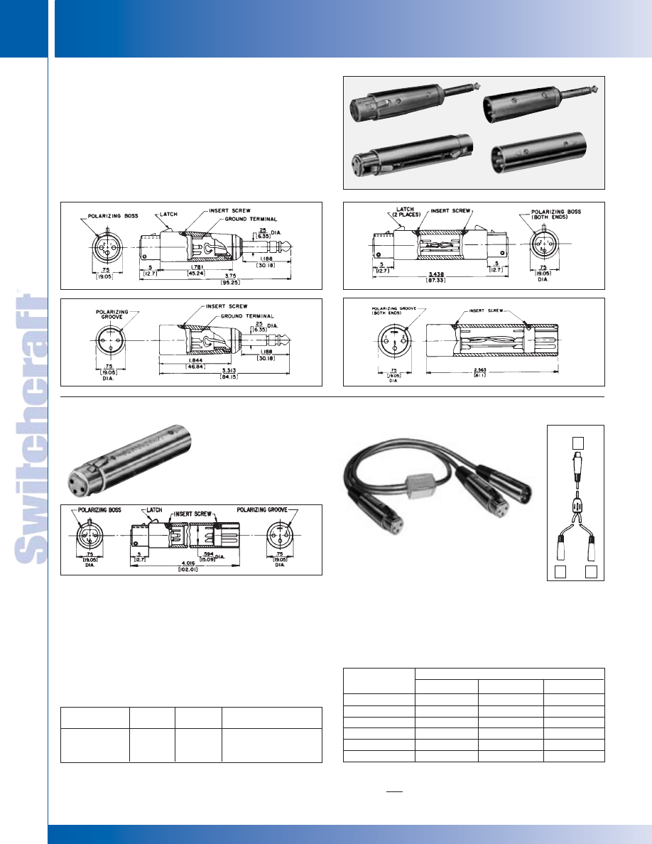
CONNECTORS & RECEPTACLES
28
w w w . s w i t c h c r a f t . c o m
® Registered trademark of Switchcraft, Inc.
Note: Contact your Switchcraft Representative for price and delivery
PHONE: 773 792-2700
CONNECTORS & RECEPT
ACLES
DIMENSIONS ARE FOR REFERENCE ONLY
Inch
(mm)
Male-female connector conversion has male Q-G
®
insert at one
end and corresponding female Q-G
®
insert at the other. Designed
to accept internally connected transformer, attenuator, or other
circuitry inline with microphone input. Includes 1.50" (38.1 mm)
long x .594" (15.08 mm) diameter of usable internal volume.
Series 391Q Y-Adapters can combine or split typical audio
signals using a combination of Switchcraft Q-G
®
A3F and A3M
cord plugs. Outputs of two microphones can conveniently be
connected in parallel and connected to a single input using a
391Q23 Y-Adapter. Cabling is 2-conductor shielded, 2-foot long
gray jacket with molded Y-junction at center point. Mates with
Switchcraft Q-G
®
and QGP
®
connectors.
Female
Male
Insert
Part Number
Insert
Insert
Pins/Contacts
◊
S3FM
QG3F
QG3M
3
◊
S4FM
QG4F
QG4M
4
◊
S5FM
QG5F
QG5M
5
Q-G
®
Cord Plug Part Numbers
Part Number
Plug A
Plug B
Plug C
◊
391Q13
A3F
A3M
A3M
◊
391Q23
A3F
A3M
A3F
◊
391Q33
A3F
A3F
A3F
◊
391Q43
A3M
A3F
A3F
◊
391Q53
A3M
A3F
A3M
◊
391Q63
A3M
A3M
A3M
Note: “Y” adapters may use either series A(*) or AA(*) plugs.
◊
Available on special order only; contact Switchcraft for price and delivery.
S*FM AUDIO CONNECTOR-ADAPTER
AUDIO “Y” ADAPTERS
Q-G
®
AUDIO CONNECTOR-ADAPTERS
◊
Available on special order only; contact Switchcraft for price and delivery.
386A: Three-contact female audio connector (Switchcraft
®
A3F)
to standard .250" (6.35 mm) diameter 3-conductor phone plug.
387A: Three-pin male audio connector (Switchcraft
®
A3M) to
standard .250" (6.35 mm) diameter 3-conductor phone plug.
389: Three-contact female audio connector (Switchcraft
®
A3F)
at both ends. Pre-wired contacts: 1 to 1, 2 to 2, 3 to 3.
390: Three-pin male audio connector (Switchcraft
®
A3M)
at both ends. Prewired pins: 1 to 1, 2 to 2, 3 to 3.
386A
387A
389
390
QG AUDIO CONNECTOR ADAPTERS
QG AUDIO CONNECTOR ADAPTERS
®
®
A
B
C
* Please visit the product pages on our website for the most up-to-date product information
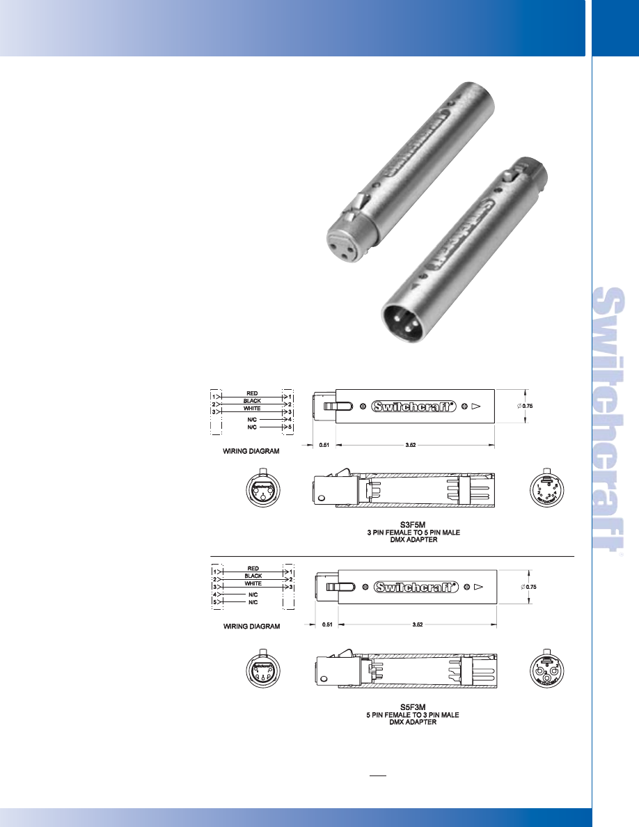
SWITCHCRAFT, INC. 5555 N. Elston Ave. • Chicago, IL 60630
29
CONNECTORS & RECEPTACLES
FAX: 773 792-2129
CONNECTORS & RECEPT
ACLES
DIMENSIONS ARE FOR REFERENCE ONLY
Inch
(mm)
DMX ADAPTER
Switchcraft introduces our new series of DMX adapters. The DMX
adapters were developed for use in the theater lighting industry. The
adapters allow the end user to use standard 3 pin XLR cable
assemblies in connecting DMX equipment. The adapters are available
in 3 pin male to 5 pin female and 5 pin male to 3 pin female. All are
wired “straight through.”
FEATURES AND BENEFITS
• Nickel-plated die-cast housing increases durability
• Pre-wired for immediate use
• Available in two configurations
APPLICATIONS
• Theater lighting
• Any DMX application
SPECIFICATIONS
Shell: Die-cast zinc, satin nickel finish
Insert Insulation: Molded thermoplastic
Socket contacts: Silver-plated copper
alloy, tarnish-resistant
Pin contacts: Sliver-plated copper
alloy, tarnish-resistant
ORDERING INFORMATION
S3F5M
3 pin female to 5 pin male
S5F3M
5 pin female to 3 pin male
S3F5M
S5F3M
DMX ADAPTER
DMX ADAPTER
* Please visit the product pages on our website for the most up-to-date product information
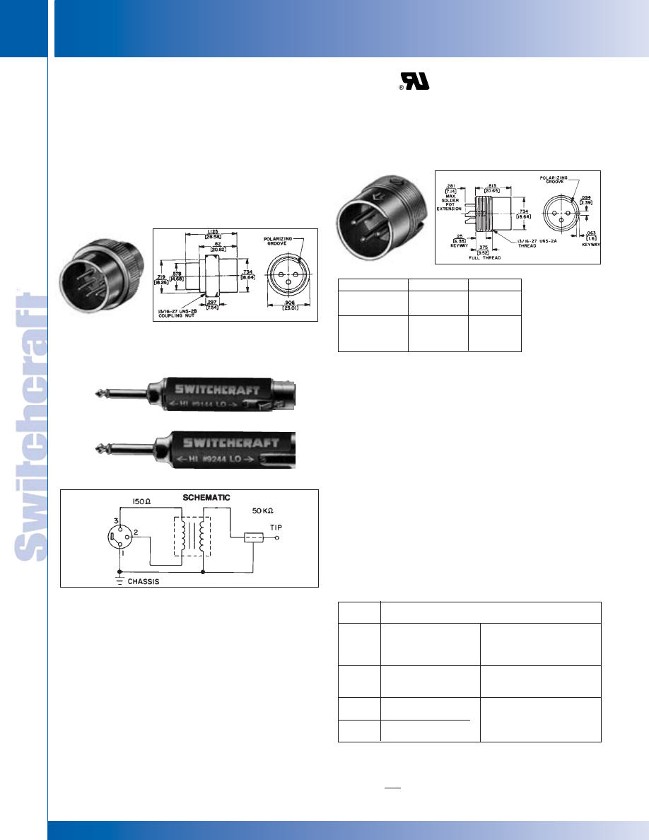
CONNECTORS & RECEPTACLES
30
w w w . s w i t c h c r a f t . c o m
® Registered trademark of Switchcraft, Inc.
Note: Contact your Switchcraft Representative for price and delivery
PHONE: 773 792-2700
CONNECTORS & RECEPT
ACLES
DIMENSIONS ARE FOR REFERENCE ONLY
Inch
(mm)
Hi Z:
2-conductor phone plug,
1⁄4" finger diameter
Part
Number
Switchcraft Connector
◊
9115
Lo Z:
3-contact Q-G
®
Hi Z:
2-conductor phone plug,
female, A3F
1/4" finger diameter, right
angle handle, 4" extension
(shielded) cable
◊
9129
Lo Z:
3-contact Q-G
®
Hi Z:
2-conductor phono plug, right
female, A3F
angle handle, 4 inch extension
(shielded) cable
9144
Lo Z:
3-contact Q-G
®
female, A3F
9244
Lo Z:
3-pin Q-G
®
male, A3M
Q-G CONNECTOR-ADAPTER RECEPTACLES
Q-G CONNECTOR-ADAPTER RECEPTACLES
◊
Available on special order only; contact Switchcraft for price and delivery.
Adapter receptacles mount directly to microphones or
similar equipment to provide highly reliable 3-, 4- and 5-pin
Switchcraft Q-G
®
connections. Adapter shell and coupling nut
are brass, satin nickel finish.
SERIES L(*)MN
Male has plain cylindrical shell with knurled, internally
threaded collar to engage external 13/16-27 threads on
microphone body.
SERIES M(*)M
Male with shell having 13/16-27 external threads to engage
equipment with internally threaded body. Terminals extend out
rear (threaded end) to permit wiring without disassembly.
Q-G
®
CONNECTOR-ADAPTER RECEPTACLES
Series 9000 Line Matching Transformers offer low-loss
interconnections between high and low impedance equipment.
Exclusive mu-metal shielding protects against spurious
electrostatic and RF fields. Units are bi-directional and can be
used as follows:
• Low to hi, such as professional low impedance microphones
to high impedance amplifiers. Stereos, cassette recorders,
public address systems, and mixers.
• Hi to low, such as high impedance microphones or electronic
instruments to low impedance amplifiers or mixers.
Designed to mate with Switchcraft Q-G
®
connectors.
Available with various terminations; see chart.
SPECIFYING FEATURES
• Plug-in impedance changes
• Fully wired
• Connections bi-directional (low to high impedance or
high to low impedance)
• Rugged die-cast housings
• Mu-metal shielding
MATERIAL SPECIFICATIONS
Shell: Die-cast zinc shell, nickel-plated with black
non-glare metalized foil label.
Shielding: Mu-metal.
Dimensions: Diameter–.75" (19.05 mm) nominal Length –
3" (76.2 mm) nominal (Part Number 92XX); 3.375" (85.73 mm)
nominal (Part Number 91XX).
ELECTRICAL SPECIFICATIONS
Frequency Response: Flat–20 Hz to 20 kHz ± 2 decibels
Impedance: High–50 K ohms (nominal); Low–150 ohms (nominal)
Voltage Step Ratio (Input Power Level); Low to High:
+29 decibels (typical); high to low: -29 decibels (typical)
Z MATCHING TRANSFORMERS
Part Numbers
Series
Series
Insert
L(*)MN
M(*)M
Pins
◊
L3MN
◊
M3M
3
◊
L4MN
◊
M4M
4
◊
L5MN
◊
M5M
5
9144
9244
®
®
* Please visit the product pages on our website for the most up-to-date product information
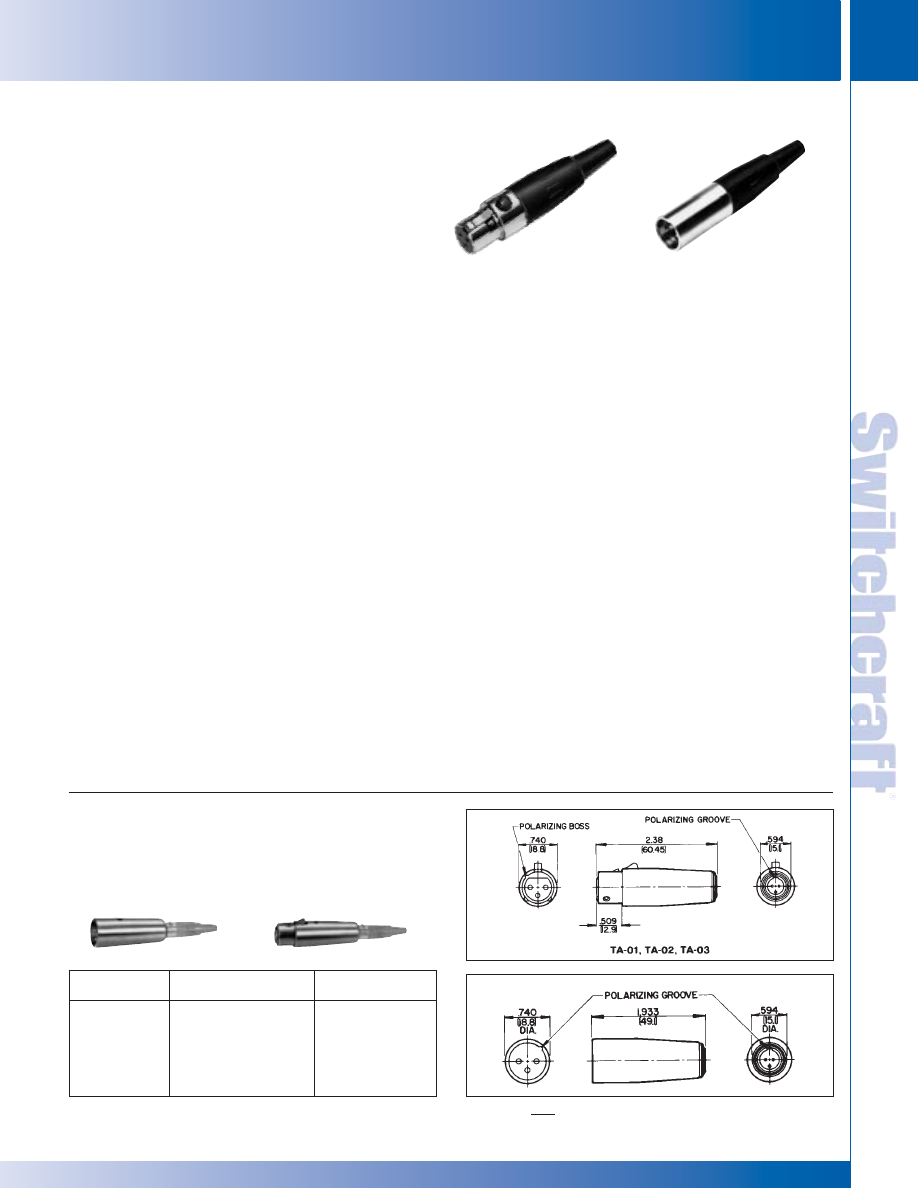
SWITCHCRAFT, INC. 5555 N. Elston Ave. • Chicago, IL 60630
31
CONNECTORS & RECEPTACLES
FAX: 773 792-2129
CONNECTORS & RECEPT
ACLES
DIMENSIONS ARE FOR REFERENCE ONLY
Inch
(mm)
Series TA Tini Q-G
®
audio adapters have been designed to
adapt Tini Q-G
®
connections to standard audio connectors.
Tini Q-G
®
adapters convert to Switchcraft Q-G
®
and QGP
connectors and similar full-size connectors.
TINI Q-G
®
AUDIO ADAPTERS
Tini Q-G
®
End
Q-G
®
End
Part Number
Mates With
Mates With
◊
TA01
TA3F
A3M
◊
TA02
TA4F
A4M
◊
TA03
TA5F
A5M
◊
TA04
TA3F
A3F
◊
TA05
TA4F
A4F
◊
TA06
TA5F
A5F
TINI Q-G MINIATURE CONNECTORS
TINI Q-G MINIATURE CONNECTORS
TINI Q-G
®
MINIATURE CONNECTORS
DESIGN FEATURES
STYLE – Streamlined, miniaturized with nickel-plated metal
and contrasting black plastic parts. Designed for light weight
and unobtrusiveness. Also available in conductive black
chrome finish.
CONSTRUCTION – Metal parts are rugged die-cast or
precision machined with nickel-plating; plastic parts are molded
of high dimensional-stability thermoplastic. Advanced design
assures minimum weight consistent with strength and
durability of cord plug housings of .413" (10.5 mm) diameter
Weight: Series TA(*)F plug = .25 ounce (7 g); Series TA(*)M =
.3 ounce (8.5 g).
INSERTS – Precision molded of thermoplastic for high
mechanical and dielectric strength. Contacts and terminals
are precision formed and plated for intimate contact and low
resistance connections. Terminal numbers are molded on rear
of male insert and on face of female insert for easy
identification (except 6-pin male insert). Inserts can be supplied
for OEM installation in microphones and instrumentation for
optimum connecting reliability. For cord plugs, inserts can also
be supplied for replacements.
LATCHLOCK – Positive latch system assures high integrity,
vibration-resistant mating and transfer of shielding connection
between housing, combined with simple, easy fingertip release.
STRAIN RELIEF – Rugged internal clamp holds cable tightly,
while making a secure, low resistance connection between
cable shield and housing.
FLEX RELIEF – Protects by minimizing cable bending stress
at point of cable entry. Maximum recommended cable diameter
is .115" (2.92 mm) when flex relief is used. By omitting
flex relief (Series T(*)FL and T(*)ML only), cable up to .170"
(4.32 mm) diameter can be used.
ASSEMBLY – Connector parts are mechanically keyed for
simple assembly.
POLARIZATION – Mating male and female connectors are
also mechanically keyed (latch and groove) so that it is impossible
to mate them incorrectly.
“SCOOP-PROOF” FEATURE – Fully recessed pins on male
plugs and receptacles cannot be “scooped”, bent or damaged
by accidental mismating with mating connector.
COLOR ESCUTCHEONS – Attractive color escutcheons,
Series TYEF, are recommended for use with Series TY(*)F and
TY(*)FPC receptacles (when rear mounted) for attractive panel
trim, as well as color coding one or more connectors. Colors
are: red, black, gray, green, blue, white and yellow.
CUSTOM Tini Q-G
®
CABLE ASSEMBLIES – On special
order where production quantities warrant, Switchcraft can
supply assembled and tested Tini Q-G
®
cables.
MOUNTING
Panel/Chassis Thickness:
Series TB(*)M: .25" (6.35 mm) maximum
Series TY(*)F:
Front—.375" (9.5 mm) maximum
Rear—.093" (2.3 mm) maximum
Series TY(*)FPC:
Front—.312" (7.9 mm) maximum
Rear—.093" (2.3 mm) maximum
®
®
Series TA(*)F, TA(*)FB, TA(*)FL and TA(*)FLB –
Straight female cord plug
Series TA(*)M, TA(*)MB, TA(*)ML and TA(*)MLB –
Straight male cord plug
Series TB(*)M and TB(*)MB – Chassis/panel mount
male receptacle
Series TY(*)F and TY(*)FPC – Chassis/panel, female
receptacle, choice of solder lugs or P.C. terminations.
Series TLP – Looping Plugs
Series TBA(* *) – Audio Adapters
Series TRA(*)M – PC Mount Male Receptacles
Series TRG(*) – Reverse Gender Panel Mount, Cord Mount
TA3M
TA3F
* Please visit the product pages on our website for the most up-to-date product information

CONNECTORS & RECEPTACLES
32
w w w . s w i t c h c r a f t . c o m
® Registered trademark of Switchcraft, Inc.
Note: Contact your Switchcraft Representative for price and delivery
PHONE: 773 792-2700
CONNECTORS & RECEPT
ACLES
DIMENSIONS ARE FOR REFERENCE ONLY
Inch
(mm)
Part
Insert Part
Insert
Number Pins
Number Pins
TA3M
3
◊
TA5M
5
TA3MB*
3
◊
TA5ML
5
TA3ML
3
TA5MLB*
5
TA4M
4
TA6ML
1
6
TA4MB*
4
TA7ML
7
TA4ML
1
4
TA8ML
7
STRAIGHT MALE CORD PLUG
Part Insert Part Insert
Number
Contacts Number
Contacts
2
TA3F
3
TA4FLB
*
4
TA3FB*
3
TA5F
5
TA3FL
1
3
TA5FL
1
5
TA3FLB*
3
TA5FLB*
5
TA4F
4
TA6FL
1
6
TA4FB*
4
TA7FL
7
TA4FL
1
4
TA8FL
8
STRAIGHT FEMALE CORD PLUG
1 Flex relief omitted for larger diameter cable
2. Add AU to Part Number for Gold Contacts.
* B indicates black housing
1. Add AU to Part Number for Gold Contacts.
* B indicates black housing
TINI Q-G MINIATURE CONNECTORS
TINI Q-G MINIATURE CONNECTORS
SPECIFICATIONS: (3 – 5 CORD MOUNT ONLY)
ELECTRICAL
Contact Resistance: .010 ohms maximum after life
(and after salt spray).
Current Rating (Carry Only): 5 A, 125 V AC (4 A, 125 V AC
on 5 circuit) based on 30°C maximum.
Insulation Resistance: 510,000 megohms minimum @ 500 V
DC (initial); 10,000 megohms minimum (after humidity test).
Dielectric Strength: 1,000 V (rms).
MECHANICAL
Life: 5,000 operations minimum
Insertion/Withdrawal Forces (after life): 6.1 lb./2.77 kg after
life, insertion; 5.6 lb/2.54 kg, withdrawal.
Solderability Standard: Meets EIA RS-186-9E.
Mechanical Shock: Meets MIL-STD-202, method 213B.
Vibration: Meets MIL-STD-202, method 201A.
Wire Size: #22 wire gauge solid; #24 wire gauge stranded.
ENVIRONMENTAL
Thermal Range: -55°C to + 85°C.
Humidity: Meets MIL-STD-202, method 106D.
Thermal Shock: Meets MIL-STD-202, method 107D.
Salt Spray: Meets MlL-STD-202, method 101.
MATERIAL
Housing, Plugs and Male Receptacles: Copper alloy,
nickel-plated. Female Receptacle–Die-cast zinc, nickel-plated.
Black Tini Q-G
®
Housing: Copper alloy, black chrome-plated.
Pin and Socket Contacts: Copper alloy, silver-plated.
Flex Relief: Molded black thermoplastic elastomer.
Latch Button: Molded black thermoplastic.
Release Lever and Mounting Washer: Steel, nickel-plated.
Standoff/Ground Terminal and Cable Clamp:
Steel, electrotinned.
Inserts and Insulating Spacer: Molded, high strength
thermoplastic.
Latch (Female): Copper alloy, nickel-plated.
Mounting Nut: Copper alloy, nickel-plated.
SPECIFICATIONS:
(
6 – 8 Cord Mount and all Receptacles and Adapters)
ELECTRICAL
Contact Resistance: .010 ohm maximum after life.
Current Rating (Carry only): 1.5A, 125 VAC, based
on 30° maximum
Insulation Resistance: 510,000 M
Ω
minimum
@ 500 VDC (initial).
Dielectric Strength: 250 V rms.
MECHANICAL
Life: 2,000 operations
Insertion/Withdrawal Forces (after life): –13 pound
insertion; –13 pound maximum withdrawal
Solderability Standard: Meets EIA RS-186-9E.
Wire Size: 28 wire gauge stranded.
MATERIAL
Housings, Plugs and Male Receptacles: Copper alloy,
nickel-plated.
Socket Contacts: Copper alloy, silver-plated.
Pin Contacts: Copper alloy, electrotinned.
Flex Relief and Latch Button: Molded thermoplastic.
Ground Terminal: Copper alloy, electrotinned.
Inserts and Insulating Spacer: Molded high strength
thermoplastic, UL 94 V-0.
Latch (Female): Copper alloy, nickel-plated.
Mounting Nut: Copper alloy, nickel-plated.
Ferrite: 43 material, shielded head.
Frame: Molded thermoplastic, UL 94 V-0.
TINI Q-G
®
MINIATURE CONNECTORS (continued)
◊
Available on special order only; contact Switchcraft for price and delivery.
®
®
* Please visit the product pages on our website for the most up-to-date product information
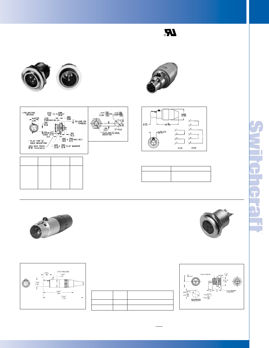
SWITCHCRAFT, INC. 5555 N. Elston Ave. • Chicago, IL 60630
33
CONNECTORS & RECEPTACLES
FAX: 773 792-2129
CONNECTORS & RECEPT
ACLES
DIMENSIONS ARE FOR REFERENCE ONLY
Inch
(mm)
TINI Q-G MINIATURE CONNECTORS
TINI Q-G MINIATURE CONNECTORS
Male receptacle for
chassis/panel mounting.
Specially designed
flange permits close
(front) mount on crowded
p a n e l s . M o u n t i n g
hardware supplied.
Available with PC
terminals. Call factory
for details.
TB(*)M AND TB(*)MB RECEPTACLE
Looping plug is designed for
circuit testing. Other inserts
and wiring patterns are
possible; contact Switchcraft.
STRAIGHT FEMALE LOOPING PLUG
Part Number
Insert Contacts
◊
TLP4
4
◊
TLP6
6
Part
Insert Description
Number Pins
TRGS4F
4
Panel mount female
TRG4M
4
Cord mount male w/latch
Part Insert Part
Insert
Number Pins
Number
Pins
TB3M
3
TB5MB*
5
TB3MB*
3
TB6M
6
TB4M
4
TB7M
7
TB4MB*
4
TB8M
8
TB5M
5
* B indicates black housing
◊
Available on special order only; contact Switchcraft for price and delivery.
* Number of insert contacts or pins must be specified to complete Part Number.
TINI Q-G
®
MINIATURE CONNECTORS (continued)
®
®
TLP(*) LOOPING PLUG
TRG4M
TRGS4F
REVERSE GENDER TQG SERIES
Same specifications as the original
TQG Series, however, the latch is on
the male cord mount. Available in 4
pin only.
* Please visit the product pages on our website for the most up-to-date product information
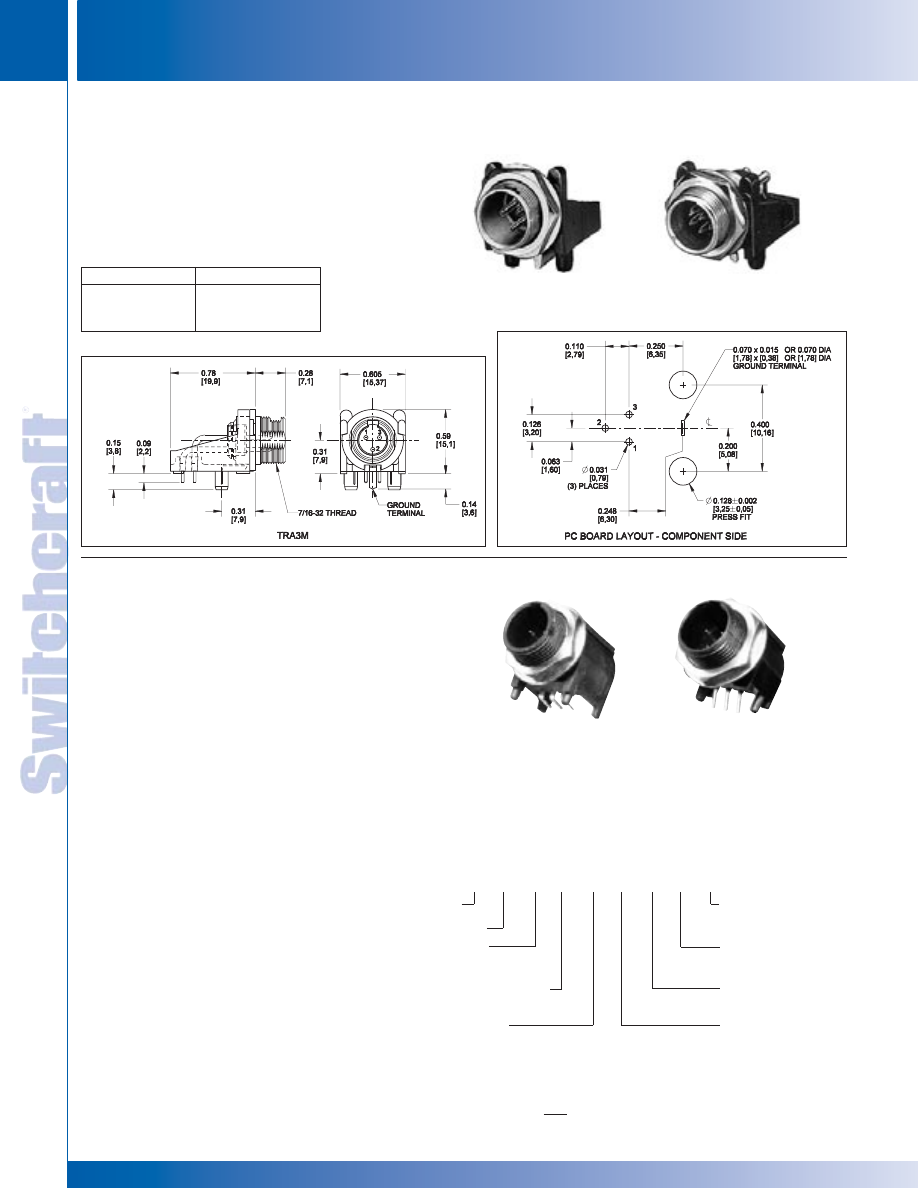
CONNECTORS & RECEPTACLES
34
w w w . s w i t c h c r a f t . c o m
® Registered trademark of Switchcraft, Inc.
Note: Contact your Switchcraft Representative for price and delivery
PHONE: 773 792-2700
CONNECTORS & RECEPT
ACLES
DIMENSIONS ARE FOR REFERENCE ONLY
Inch
(mm)
TINI Q-G MINIATURE CONNECTORS
TINI Q-G MINIATURE CONNECTORS
TINI Q-G
®
MINIATURE CONNECTORS (continued)
Part Number
Insert Pins
TRA3M
3
TRA6M
6
TRA6MF*
6
TRA(*)M PC MOUNT MALE RECEPTACLE
The TRA(*)M low profile male receptacles mount in
minimum space from the rear of panel or chassis, and
feature space-saving right-angle construction and PC type
terminals. The TRA3M is a cost-effective choice for audio
equipment, medical instrumentation, computer equipment and
test/measurement applications. Also available with 6 pins.
*F designates ferrite shielding.
TRA6M
TRA3M
®
®
TRASM*M, TRAPC*M SERIES
Switchcraft introduces an expansion of its popular TQG Series of
connectors.The TRASM*M and TRAPC*M offers low profile, right
angle PC board mount connectors. The TRASM*M versions are
true surface mount connectors, while the TRAPC*M versions are
through-hole PC mount connectors. Both versions are available
in 3-8 pins. All plastic connectors, the TRASM*M and TRAPC*M
series have flats on the top of the connectors to facilitate pick and
place assembly. As an added option, a non-threaded bushing
version is also available.
FEATURES AND BENEFITS
• Low profile, compact design reduces PC board space
• Mates with TQG female cord plugs
• Rated at 5A for 3-6 pins, 3A for 7 and 8 pin versions
MARKETS
• Wireless microphone systems
• Medical Instrumentation
• Test Instrumentation
SPECIFICATIONS
MATERIALS
Housing: Thermoplastic
Contacts: Brass, tin-plated
Nut and Washer: Brass, nickel-plated
ELECTRICAL
Current Rating: 5A for 3-5 pins, 1.5A for 6-8
Contact Resistance: 10 m Ohm max
Insulation Resistance: 100 m Ohm min
Dielectric Withstanding Voltage: 250VAC
Mechanical Life: 2,000 cycles
TRASM3M
TRAPC3MS
See next pages for drawings
TINI Q-G
®
CONNECTORS ORDERING INFORMATION
___ ___ ___ ___ ___ ___ ___ ___ ___
Reel Size
15" reel, standard tape
and reel size
Optional Packaging
TR - Tape and Reel
(std packaging - bulk)
Optional Modifier
1 - no thread
Optional Modifier
S -small Profile (available
in configurations 3&4 only)
T
RA
M
Tini QG
Right Angle
Termination
PC - Thru Hole
SM - Surface Mount
Contacts Configuration
3 - 8
Contact Gender
M - Male
* Please visit the product pages on our website for the most up-to-date product information
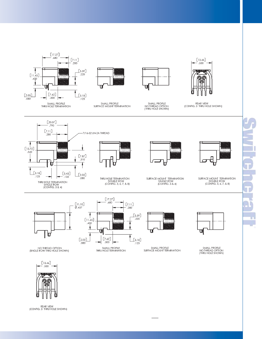
SWITCHCRAFT, INC. 5555 N. Elston Ave. • Chicago, IL 60630
35
CONNECTORS & RECEPTACLES
FAX: 773 792-2129
CONNECTORS & RECEPT
ACLES
DIMENSIONS ARE FOR REFERENCE ONLY
Inch
(mm)
TWIN Q-G MINIATURE CONNECTORS
TWIN Q-G MINIATURE CONNECTORS
TINI Q-G
®
MINIATURE CONNECTORS (continued)
®
®
TRASM*M, TRAPC*M SERIES
* Please visit the product pages on our website for the most up-to-date product information
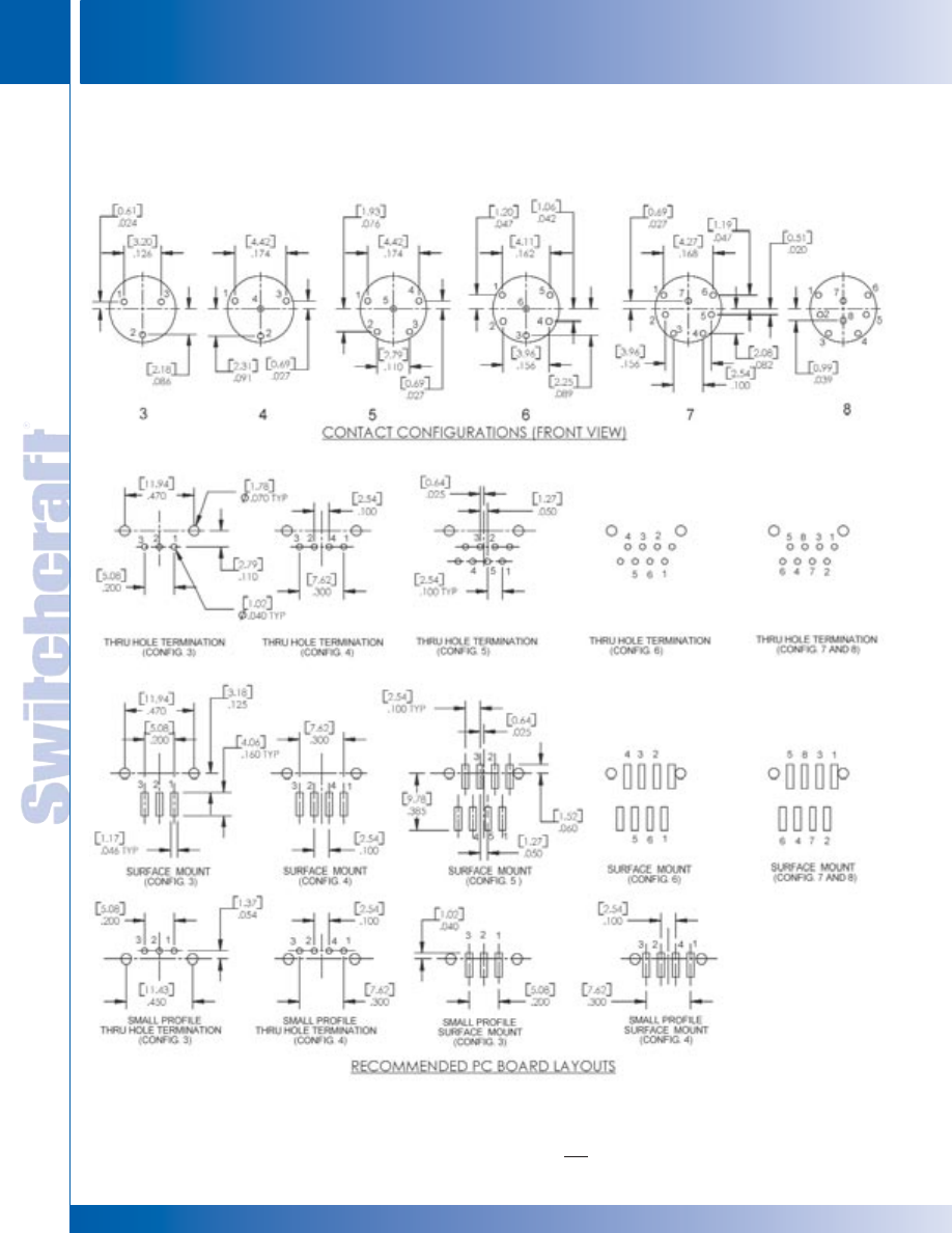
CONNECTORS & RECEPTACLES
36
w w w . s w i t c h c r a f t . c o m
® Registered trademark of Switchcraft, Inc.
Note: Contact your Switchcraft Representative for price and delivery
PHONE: 773 792-2700
CONNECTORS & RECEPT
ACLES
DIMENSIONS ARE FOR REFERENCE ONLY
Inch
(mm)
TINI Q-G MINIATURE CONNECTORS
TINI Q-G MINIATURE CONNECTORS
®
®
TINI Q-G
®
MINIATURE CONNECTORS (continued)
TRASM*M, TRAPC*M SERIES
* Please visit the product pages on our website for the most up-to-date product information
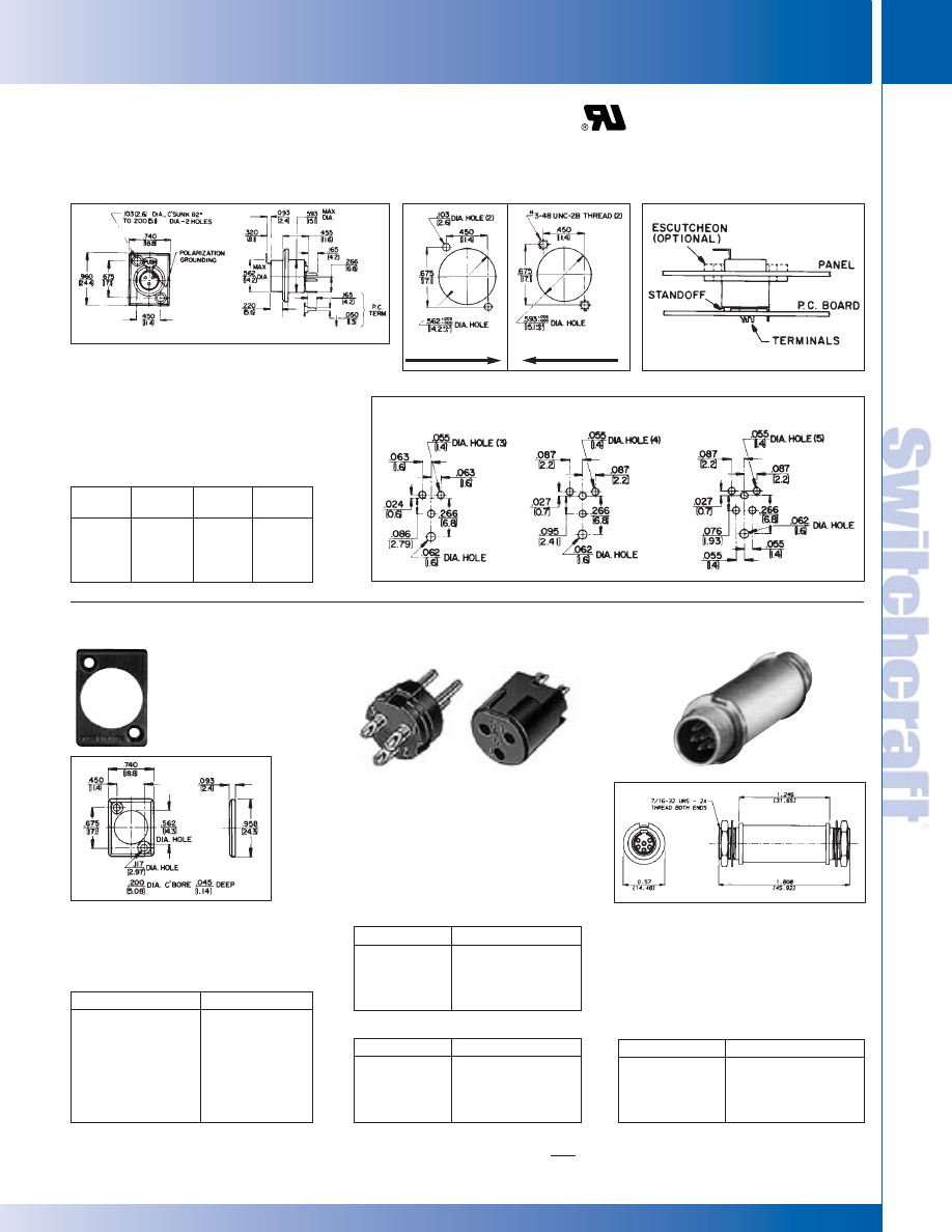
SWITCHCRAFT, INC. 5555 N. Elston Ave. • Chicago, IL 60630
37
CONNECTORS & RECEPTACLES
FAX: 773 792-2129
CONNECTORS & RECEPT
ACLES
DIMENSIONS ARE FOR REFERENCE ONLY
Inch
(mm)
◊
Available on special order only; contact Switchcraft for price and delivery.
TINI Q-G
®
MINIATURE CONNECTORS (continued)
Female receptacle mounts in minimum
space from front or rear panel or chassis.
Terminals are solder lugs, Series
TY(*)F, or P.C., Series TY(*)FPC. All
receptacles have separate ground lug.
Trim escutcheons in seven colors for
use with Series TY(*)F and TY(*)FPC
receptacles, are recommended for rear
mount receptacles. Escutcheons must
be ordered separately.
TY(*)F AND TY(*)FPC RECEPTACLES
MOUNTING HOLE DETAIL
SERIES TY(*)F, TY(*)FPC
RECOMMENDED P.C. BOARD LAYOUT
TYEF ESCUTCHEONS
COMBINED P.C. /PANEL
MOUNTING
Part
Insert Part
Insert
Number
Contacts
Number
Contacts
TY3F
3
TY5F
5
TY3FPC
3
TY5FPC
5
TY4F
4
TY4FPC
4
Part Number
Color
◊
TYEF01
Red
◊
TYEF02
Black
◊
TYEF03
Green
◊
TYEF04
Blue
◊
TYEF05
White
◊
TYEF08
Yellow
◊
TYEF11
Gray
Male and female inserts with 3, 4, 5
or 6 pins/ contacts. For replacement
(cord plugs only) or build-into
equipment, such as microphones,
transducers and instruments.
TQG(*)F AND TQG(*)M
CONNECTOR INSERTS
3–6 pin male-to-male adapter is designed
for through-bulkhead or cable expansion
usage. Adapter is prewired pin 1 to pin 1,
pin 2 to pin 2, etc. Mounting nuts are
supplied for each threaded end. Panel
hole diameter required is .45"; maximum
panel thickness is .25" (6.35 mm).
TBA(**) AUDIO ADAPTER
Part Number
Insert Pins
◊
TBA03
3
◊
TBA04
4
◊
TBA05
5
◊
TBA06
6
Part Number
Insert Contacts
◊
TQG3F
3
◊
TQG4F
4
◊
TQG5F
5
◊
TQG6F
6
Part Number
Insert Pins
◊
TQG3M
3
◊
TQG4M
4
◊
TQG5M
5
◊
TQG6M
6
Female Inserts
Male Inserts
REAR
MOUNTING
FRONT
MOUNTING
TINI Q-G MINIATURE CONNECTORS
TINI Q-G MINIATURE CONNECTORS
®
®
* Please visit the product pages on our website for the most up-to-date product information
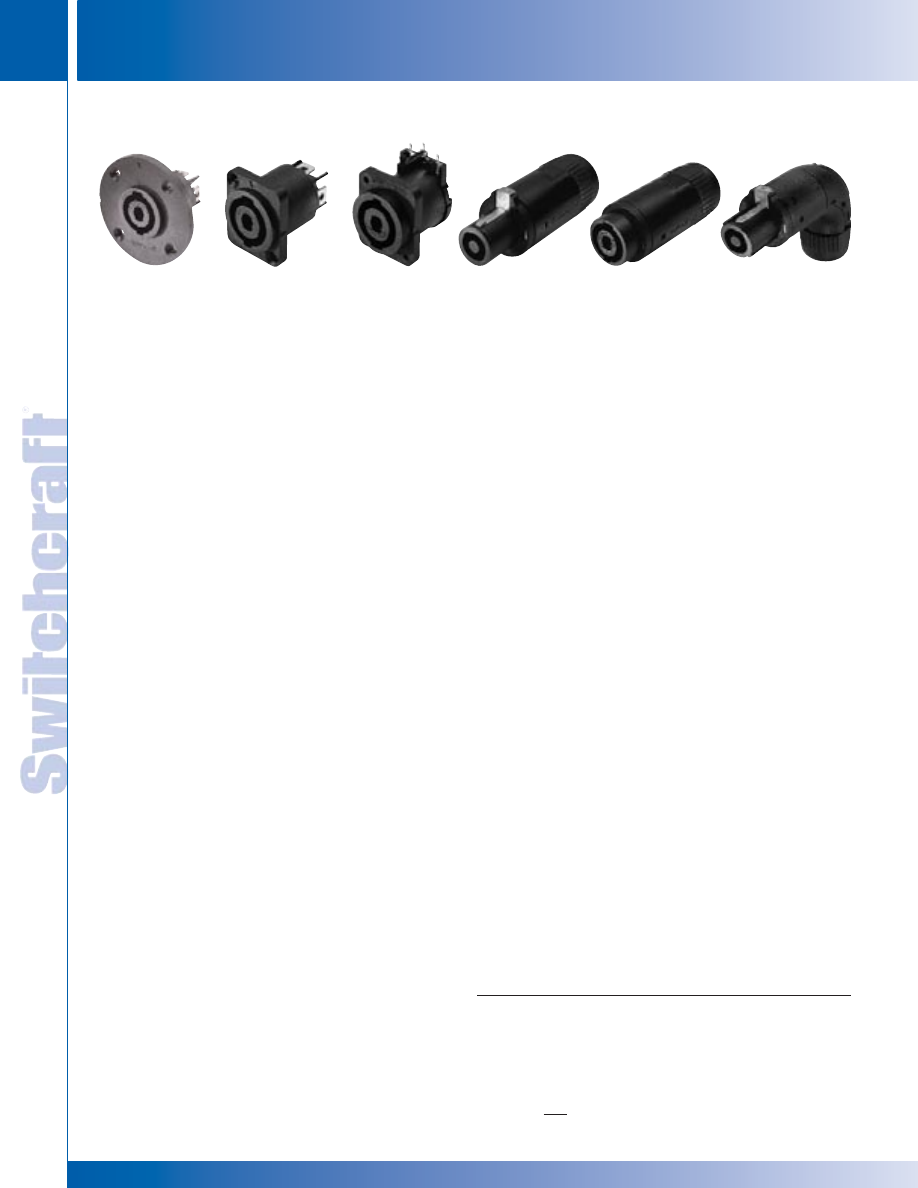
CONNECTORS & RECEPTACLES
38
w w w . s w i t c h c r a f t . c o m
® Registered trademark of Switchcraft, Inc.
Note: Contact your Switchcraft Representative for price and delivery
PHONE: 773 792-2700
CONNECTORS & RECEPT
ACLES
DIMENSIONS ARE FOR REFERENCE ONLY
Inch
(mm)
HPC SERIES
Switchcraft recently introduced a complete line of panel mount
speaker connectors that are completely compatible with the
Neutrik
®
Speakon
®
4 pole series. We are now introducing a
complete line of cable mounts as well. The complete HPC
Series offers both panel mount and cord mount connectors.
The HPC panel mounts have been updated with new
silver-plated contact materials that boost the contact ratings to
30A per UL 1977 on PC mount versions, 50A per UL 1977 on
Faston
®
versions. They are still available with either 0.100"
depth flanges or 0.200" depth flanges. The 0.200" depth flange
allows for rear mounting of the HPC Series, and proper mating
of all cord plugs. The panel mount versions are available with
either 0.187" or 0.250" Faston
®
terminals, and either straight or
right angle PC mount terminals. The right angle PC mount
version also has, as an option, a mounting post which allows
the connector to snap onto the PC board for wave soldering.
The HPC cord plugs are available in either straight, right
angle, or as an in-line. The in-line version mates with either the
straight or right angle cord plug, allowing the end user to extend
cable runs. All cord plugs are compatible with Speakon
®
panel
mounts. The in-line mates with our HPC cord plugs, as well as
Speakon
®
cord plugs. The unique feature of the HPC series
cord plugs are the “push to lock” feature, similar to the
connection of an XLR connector. The HPC cord plugs, when
mated to either HPC panel mounts or Speakon
®
panel mounts
do not require a 1/4" turn to engage. Simply push the connector
in until it locks. To disengage, push forward on the latch lever
and pull the connector out. This feature eliminates the need to
remember to turn the connector to make contact. All HPC cord
plugs utilize 0.250" Faston
®
terminals, which allow for easy
assembly, and make it easy to change cord plugs. To change
from a straight cord plug to an in-line cord plug, back off the
strain relief nut, twist off the handle, disconnect the Faston
®
terminals, fasten the new cord connector, twist on the handle
and the strain relief. Barbs on the handle keep the handle from
vibrating loose from the front shell.
Both HPC panel mounts and cord plugs incorporate a built-in
gasket, which allows them to meet IP 25 harsh environment
ratings, as well as IEC 529 and IEC 1010-1 safety ratings.
FEATURES AND BENEFITS
• Completely compatible with Neutrik
®
Speakon
®
4 pole connectors
• 30A rating per UL 1977 on PC mount versions
• 50A rating per UL 1977 on Faston
®
versions
• Panel mounts have two different Faston
®
terminal sizes,
0.187" and 0.250"
• Panel mounts offered with two different flange depths,
0.100" and 0.200"
• 0.200" depth flange offers easy rear mounting
• Right angle or straight PC board terminals on panel mounts
• Built in gasket gives all HPC connectors IP 25
environmental ratings
• All HPC Series meet IEC 529 and IEC 1010-1 safety ratings
• Cord plug versions offer “push to lock” design,
no 1/4" turn to engage
• Cord plug versions accept 10 AWG wire,
0.560" cable OD max
APPLICATIONS
• Loudspeakers
• Power audio amplifiers
SPECIFICATIONS
Materials
Housings: Thermoplastic UL 94V-O rated
Seal Rings: Thermoplastic rubber
Contacts: Silver-plated over copper alloy
ELECTRICAL
PC Terminals Current Rating: 30A per UL 1977
Faston
®
Terminals Current Rating: 50A RMS w/10AWG
wire, normal ambient, per UL 1977
Voltage Rating: 1,500 AC RMS, Per Mil-Std 202 Method 301
Insulation Resistance: > 2T Ohms
Contact Resistance: 1m Ohm, 1.5mOhm after 1,000
insertion/withdrawals
MECHANICAL
Shock: Mil-Std 202, Method 213B Cond.K
Vibration: Mil-Std 202, Method 201A
Life: 1,000 insertion/withdrawals
Cable Range: 0.560” OD max
ENVIRONMENTAL
Salt Spray: Mil-Std 202, Method 101D Cond. B
Thermal Shock: Mil-Std 202, Method 107G
Temperature Limits: -55 C to +85 C
Moisture Resistance: Mil-Std 202, Method 106E
Life@Ambient Temperature: Mil-Std 202, Method 108A
Touch Proof: IEC 65 and 1010-1
Weather Tightness: IEC 529, IP 25
CORD MOUNT ORDERING INFORMATION
Part Number
Description
HPCC4F
Straight Cord Plug
HPCI4F
Inline Cord Plug
HPCC4RAF
Right Angle Cord Plug
HPC SERIES PANEL MOUNTS AND CORD PLUGS
HPCPR41F
HPCP41F
HPCP410RA
HPCI4F
HPCC4F
HPCC4RAF
HIGH POWER CONNECTORS
HIGH POWER CONNECTORS
* Please visit the product pages on our website for the most up-to-date product information
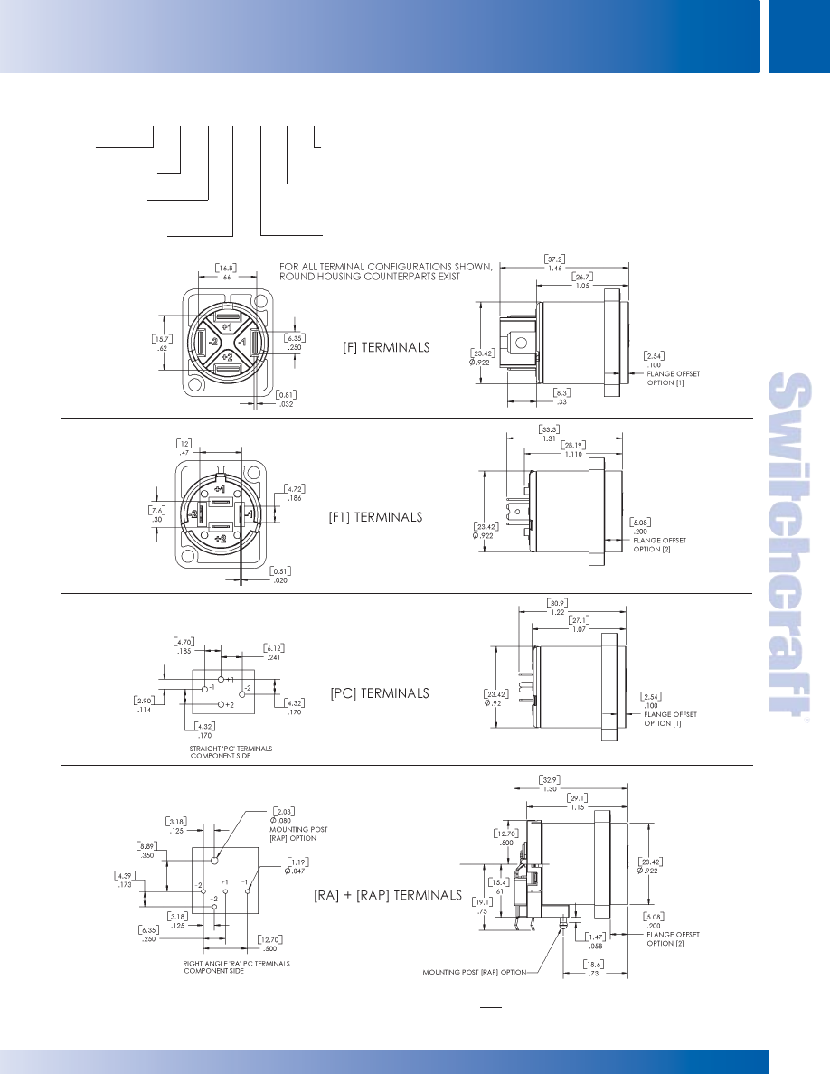
SWITCHCRAFT, INC. 5555 N. Elston Ave. • Chicago, IL 60630
39
CONNECTORS & RECEPTACLES
FAX: 773 792-2129
CONNECTORS & RECEPT
ACLES
DIMENSIONS ARE FOR REFERENCE ONLY
Inch
(mm)
PANEL MOUNT ORDERING INFORMATION
___ ___ ___ ___ ___ ___ ___
Series
High Power Connector
Type of Connector
P - Panel
Type of Housing
Blank - rectangle
R - round
Number of Contacts
4
Termination
F - .250" Faston
®
; F1 - .187" Faston
®
; PC - Printed Circuit
RA - Right angle PC; RAP - Right angle PC with mounting post
Mounting Holes
Blank - Rectangle: .140” dia. w/Countersink Hole
Blank - Round: .152” dia. w/Countersink Hole
0 - Rec./ Round: .093” Dia. Hole
Recessed Flange (Dim. “A”)
1 - .100”; 2 - .200”
HPC
P
4
HIGH POWER CONNECTORS
HIGH POWER CONNECTORS
* Please visit the product pages on our website for the most up-to-date product information
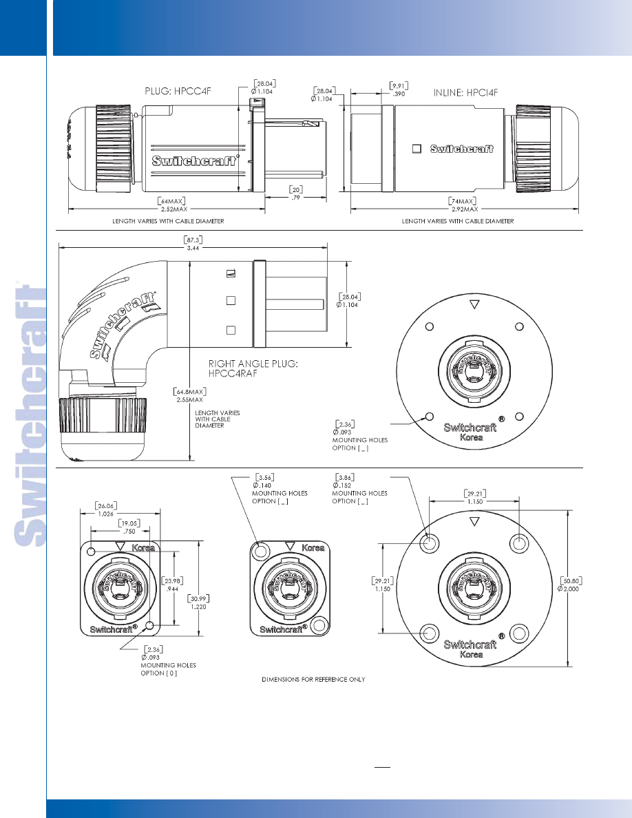
CONNECTORS & RECEPTACLES
40
w w w . s w i t c h c r a f t . c o m
® Registered trademark of Switchcraft, Inc.
Note: Contact your Switchcraft Representative for price and delivery
PHONE: 773 792-2700
CONNECTORS & RECEPT
ACLES
DIMENSIONS ARE FOR REFERENCE ONLY
Inch
(mm)
HPCP*4
HIGH POWER CONNECTORS
HIGH POWER CONNECTORS
* Please visit the product pages on our website for the most up-to-date product information
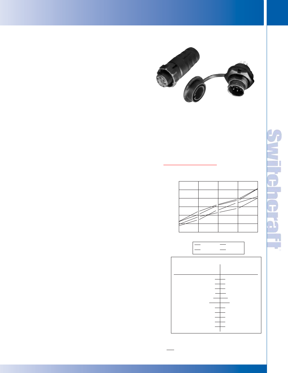
SWITCHCRAFT, INC. 5555 N. Elston Ave. • Chicago, IL 60630
41
CONNECTORS & RECEPTACLES
FAX: 773 792-2129
CONNECTORS & RECEPT
ACLES
DIMENSIONS ARE FOR REFERENCE ONLY
Inch
(mm)
GENERAL FEATURES AND BENEFITS
• Great all-purpose connector “weather” or not sealing feature is required.
• Superior leakage protection. Contact area is double-sealed for
excellent moisture and chemical resistance when mated to
Switchcraft’s connectors.
• Integral O-ring and gasket. O-ring is molded onto cord housing
assembly and gasket is molded onto panel housing assembly
to prevent leakage and eliminate need for additional O-rings
and gaskets.
• Reduced part count for reduced labor to assemble.
• No Grommets. Cable clamp assembly features living hinges,
which snap easily onto and support the cable.
• Thermoplastic rubber body simulates closed entry contact
system to prevent probe damage or accidental loss of
spring retention due to misaligned or bent pins.
• Abrasion-resistant thermoplastic boot provides strain relief
and accepts cable diameter .195" to .265".
• Housing rated UL 94V-O against flammability.
• Panel connector shell features a positioning keyway to prevent
misalignments and a polarizing single “D” design for proper panel
mounting and to prevent rotational movement.
• 2-18 pins.
• Exceeds Coast Guard specifications for water tightness
(CFR 46 Part 110.20).
• Optional cap covers panel housing assembly when not in use.
• Exceeds enclosure rating IP16/IP18 when not mated or
covered and IP66/IP68 when mated or covered (IEC 529).
• Exceeds enclosure rating 6P at 1000V when mated or covered (NEMA 250).
MATING INSTRUCTIONS FOR A CORD CONNECTOR TO A
PANEL MOUNT OR IN-LINE CONNECTOR
First, align the notched keyway on both the panel mount or in-line and
cord connector. Then, push the cord connector onto the mating connector.
Grasp the coupling ring between the slots, push it toward the panel
mount connector and rotate it clockwise nearly one half a turn. Continue
rotating until you feel the coupling ring ride over the locking “bump”. This
is the locked position. The cord connector is not securely in place unless
this procedure is followed.
APPLICATIONS
Process Control
Communications
Marine Electronics
Transportation
Medical Instrumentation
General Industrial Electronics
Geothermal Instrumentation
Harsh Environments
MATERIALS
Cord and panel connector shells, contact locking disk,
and cable clamp assembly: Thermoplastic polymer glass
fiber, flame retardant
Coupling ring: Nylon
Rear boot and connector shell interior: Thermoplastic rubber
Contacts: Copper base alloy gold-plated over nickel underplate
SPECIFICATIONS
MECHANICAL
Shock: Mil-Std 202 Method 213B, condition K
Vibration: Mil-Std 202 Method 201
Life: 600 insertion/withdrawal cycles (minimum)
ELECTRICAL
Voltage Rating (sea level): Tested at 600 VRMS
Insulation Resistance: 100 megohms (minimum) at 77° F
Contact Resistance: 5 milliohms (maximum)
Current Rating: 3.0 Amps (#26 contact)– 9 through 18pin
6.5 Amps (#20 contact)– 7 and 8 pin
7.5 Amps (#20 contact)– 2 through 6 pin
13.0 Amps (#16 contact)– 2 and 3 pin
7
10
12
13 15
50.00
40.00
30.00
20.00
10.00
0.00
EN3
™
Weathertight Connector Current Carry Capability
(per UL 498 Standard)
Current (Amps) - w/14 AWG Wire
T
emp Rise (Centigrade)
▲
▲
▲
▲
■
■
■
■
■
◆
◆
◆
◆
◆
✖
✖
✖
✖
✖
▲
Female 3 pin
Male 3 pin
Female 8 pin
Male 8 pin
◆
■
▲
✖
Contact size/
number of contacts
#20-2
#20-4
#20-3
#16-2
#20-7, #20-8
#20-5, #20-6
#16-3
2000
1000
3000
Voltage
Dielectric Withstanding Voltage
ENVIRONMENTAL
Temperature Limits: -40°C to +65°C (non-operating)
Moisture Resistance: Mil-Std 202 Method 106F
Insulation Resistance: Mil-Std 202 Method 302
condition B
Thermal Shock: Mil-Std 202 Method 107G
Salt Spray: Mil-Std 202 Method 101D condition B
RATINGS
IP16/IP18
CFR 46 Part 110.20
IP66/IP68
UL 94V-O
NEMA 250 (6P)
Patent 5,485,673 File 36049
Cord
Connector
Panel
Connector
EN3 MINI WEATHERTIGHT CONNECTOR SERIES
EN3 MINI WEATHERTIGHT CONNECTOR SERIES
™
™
EN3
™
MINI WEATHERTIGHT CONNECTOR SERIES
* Please visit the product pages on our website for the most up-to-date product information
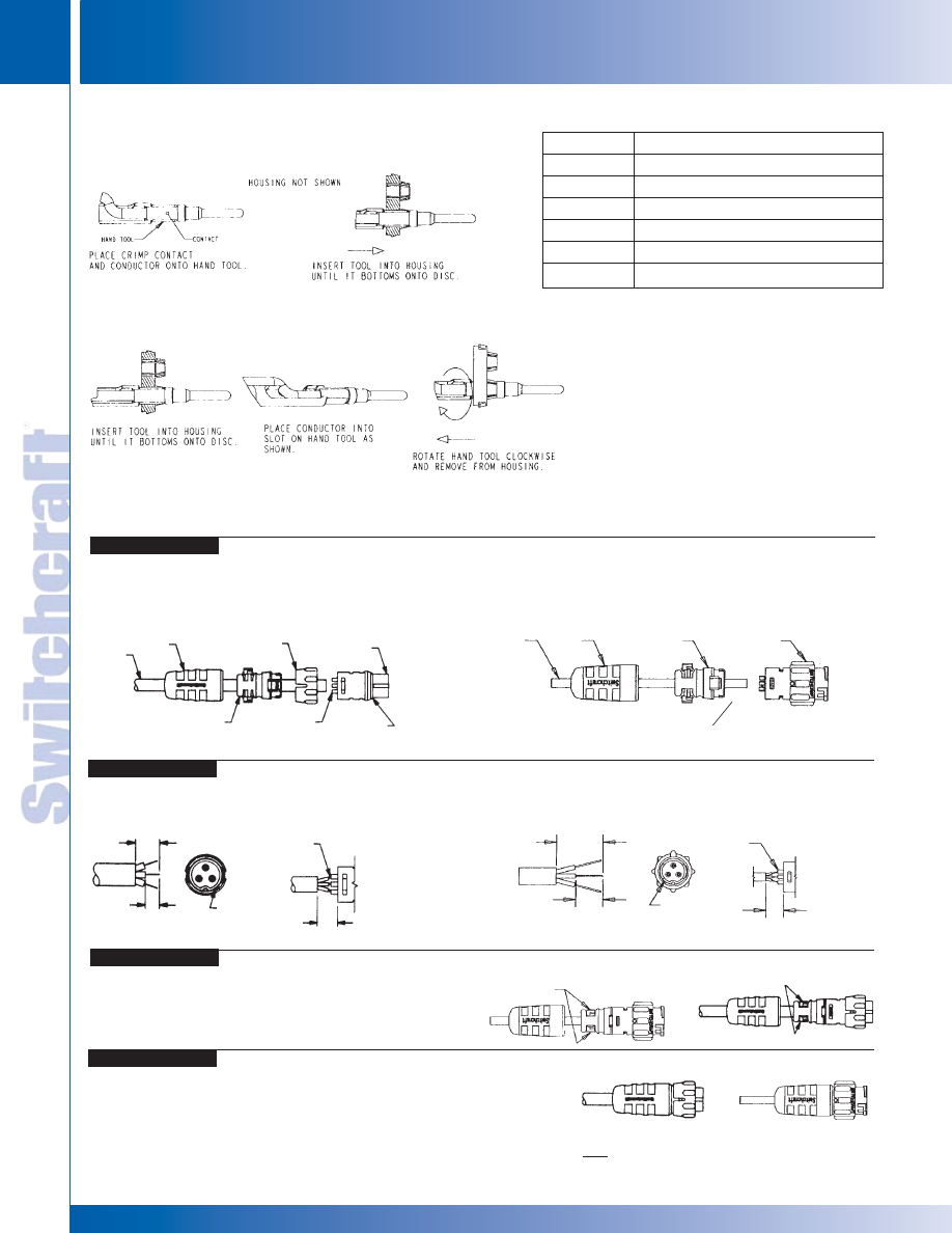
CONNECTORS & RECEPTACLES
42
w w w . s w i t c h c r a f t . c o m
® Registered trademark of Switchcraft, Inc.
Note: Contact your Switchcraft Representative for price and delivery
PHONE: 773 792-2700
CONNECTORS & RECEPT
ACLES
DIMENSIONS ARE FOR REFERENCE ONLY
Inch
(mm)
CORD CONNECTOR ASSEMBLY INSTRUCTIONS
CABLE
BOOT
COUPLING
RING
CABLE CLAMP
HOUSING
CONTACT PINS
O-RING
(MOLDED ONTO
CORD CONNECTOR)
3/8"
MAX.
7/32"
9/32"
NOTCH (PIN #1
INDICATOR)
SOLDER
CORD CONNECTOR
IN-LINE CONNECTOR
CORD CONNECTOR
IN-LINE CONNECTOR
CORD
CONNECTOR
IN-LINE
CONNECTOR
Cord Connector: To assemble the three-part cord connector, first feed the end of the cable through the boot, cable clamp
housing, and coupling ring in that order and position as shown in the figure below. NOTE: The coupling ring can also be
inserted onto the cord connector from the front. In-line Connector: Feed the end of the cable through the boot and cable
clamp housing in the order and position shown.
Next, strip the cable .218" as shown and begin soldering conductors to pins, or insert contacts crimped on wire starting
with contact #1 next to the "notch" and following with the remaining conductors counter-clockwise with #6 or #8 conductor
in the center.
Push the cable clamp housing forward until it locks
into the connector body and snap the two clamps
into their compartments.
Finally, push the boot all the way forward to seat tightly
onto the cable clamp housing.
Remember: Cord connectors will not mate with each other. For cord-to-cord connection,
your customer must order a cord connector plus an in-line connector.
CABLE
CONTACT PINS
3/8"
MAX.
7/32"
9/32"
SOLDER
CABLE CLAMPS
CABLE CLAMP
HOUSING
IN-LINE
CONNECTOR
NOTCH (PIN #1
INDICATOR)
CRIMP CONTACT
INSERTION INSTRUCTIONS
CRIMP CONTACT
EXTRACTION INSTRUCTIONS
STEP 4
STEP 3
STEP 2
STEP 1
BOOT
CORD
CONNECTOR
Note: Solder and PC contacts are factory assembled
CRIMP TOOLS
Part Number
EN3INS16
EN3INS20
EN3CR
EN3CRAUTO
EN3POS16
EN3POS20
Tool Description
Insertion/Extraction Tool for 16 AWG
Insertion/Extraction Tool for 20 AWG
Crimp Hand Tool
Pneumatic Crimp Tool
Positioner for 16 AWG contacts and pins
Positioner for 20 AWG contacts and pins
NOTE: A positioner must be used with the
EN3CR and EN3CRAUTO.
CABLE CLAMPS
EN3 MINI WEATHERTIGHT CONNECTOR SERIES
EN3 MINI WEATHERTIGHT CONNECTOR SERIES
™
™
* Please visit the product pages on our website for the most up-to-date product information
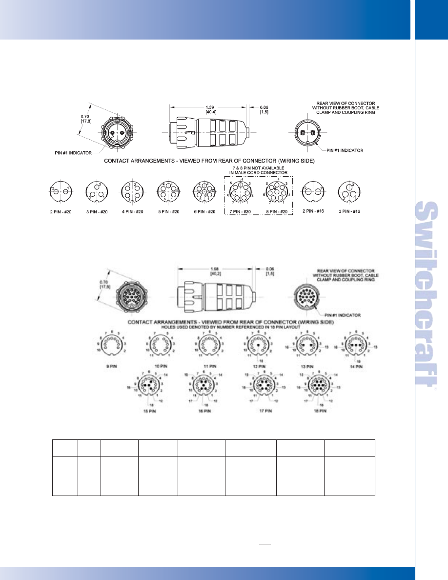
SWITCHCRAFT, INC. 5555 N. Elston Ave. • Chicago, IL 60630
43
CONNECTORS & RECEPTACLES
FAX: 773 792-2129
CONNECTORS & RECEPT
ACLES
DIMENSIONS ARE FOR REFERENCE ONLY
Inch
(mm)
EN3 MINI WEATHERTIGHT CONNECTOR SERIES
EN3 MINI WEATHERTIGHT CONNECTOR SERIES
™
™
EN3
™
MINI WEATHERTIGHT CONNECTOR SERIES (continued)
2 – 8 PIN CORD CONNECTOR
9 – 18 PIN CORD CONNECTOR
EN3 Cord Connector Part Number Scheme
Notes:
7 & 8 pin not available in cord male
9-18 pin available in either staggered solder or straight solder only
9-18 pin available only with # 26 terminals
AG: Silver plating special order
#16 contact available in 2 & 3 pins only
Series
Style
Pins/
Gender
Contact Contact Contact Packaging
Contacts
Size
Style
Plating
EN3
C
2-18
F: Female
16: #16
C: Crimp
AG: Silver
K: Kit
M: Male
Leave blank
P: PC
Leave blank
Leave blank
for #20
S: Staggered
for gold
for bulk
26: for 9-18
Leave blank
packaging
only
for solder
* Please visit the product pages on our website for the most up-to-date product information
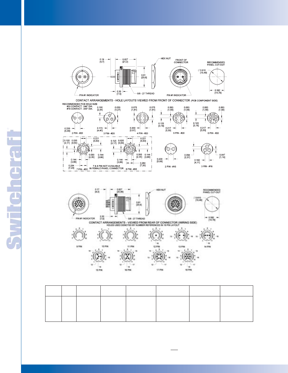
CONNECTORS & RECEPTACLES
44
w w w . s w i t c h c r a f t . c o m
® Registered trademark of Switchcraft, Inc.
Note: Contact your Switchcraft Representative for price and delivery
PHONE: 773 792-2700
CONNECTORS & RECEPT
ACLES
DIMENSIONS ARE FOR REFERENCE ONLY
Inch
(mm)
EN3 MINI WEATHERTIGHT CONNECTOR SERIES
EN3 MINI WEATHERTIGHT CONNECTOR SERIES
™
™
2 – 8 PIN PANEL CONNECTOR
9 – 18 PIN PANEL CONNECTOR
EN3
™
MINI WEATHERTIGHT CONNECTOR SERIES (continued)
EN3 Panel Connector Part Number Scheme
Series Style
Pins/
Gender
Contact Contact Contact Packaging
Contacts
Size
Style
Plating
EN3
P
2-18
F: Female
16: #16
C: Crimp
AG: Silver
K: Kit
M: Male
Leave blank
P: PC
Leave blank
Leave blank
for #20
S: Staggered
for gold
for bulk
26: for 9-18
Leave blank
packaging
only
for solder
Notes:
7 & 8 pin not available in panel female
9-18 pin available in either staggered solder or straight solder only
9-18 pin available only with # 26 terminals
AG: Silver plating special order
#16 contact available in 2 & 3 pins only
* Please visit the product pages on our website for the most up-to-date product information
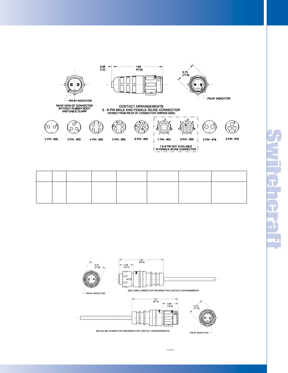
SWITCHCRAFT, INC. 5555 N. Elston Ave. • Chicago, IL 60630
45
CONNECTORS & RECEPTACLES
FAX: 773 792-2129
CONNECTORS & RECEPT
ACLES
DIMENSIONS ARE FOR REFERENCE ONLY
Inch
(mm)
EN3 MINI WEATHERTIGHT CONNECTOR SERIES
EN3 MINI WEATHERTIGHT CONNECTOR SERIES
™
™
EN3
™
MINI WEATHERTIGHT CONNECTOR SERIES (continued)
2 – 8 PIN INLINE CONNECTOR
2 – 8 PIN OVERMOLDED CORD AND INLINE CONNECTOR
(See Cable Section for More Details.)
Notes:
7 & 8 pin not available in inline female
#16 contact available in 2 & 3 pins only
AG: Silver plating special order
Series Style
Pins/
Gender
Contact Contact Contact Packaging
Contacts
Size
Style
Plating
EN3
I
2-8
F: Female
16: #16
C: Crimp
AG: Silver
K: Kit
M: Male
Leave blank
P: PC
Leave blank
Leave blank
for #20
Leave blank
for gold
for bulk
for solder
packaging
EN3 Inline Connector Part Number Scheme
* Please visit the product pages on our website for the most up-to-date product information
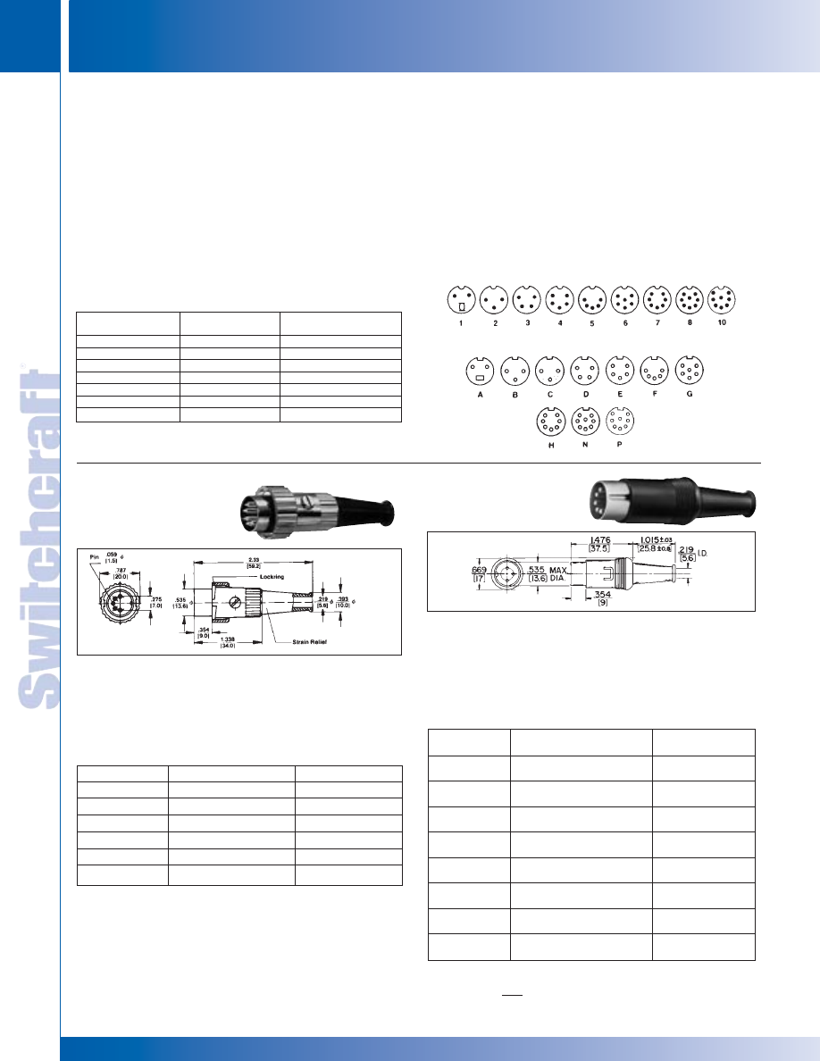
CONNECTORS & RECEPTACLES
46
w w w . s w i t c h c r a f t . c o m
® Registered trademark of Switchcraft, Inc.
Note: Contact your Switchcraft Representative for price and delivery
PHONE: 773 792-2700
CONNECTORS & RECEPT
ACLES
DIMENSIONS ARE FOR REFERENCE ONLY
Inch
(mm)
DIN CONNECTORS AND PLUGS
DIN CONNECTORS AND PLUGS
SPECIFICATIONS
ELECTRICAL
Contact Resistance: Cord Plugs and Receptacles;
.010 ohms, contact spring/pin .030 ohms, ground clip/shell.
Control and Switching Receptacles; .015 ohms, contact
spring/pin; .020 ohms, switch contacts.
Dielectric Withstanding Voltage: 500 V (rms)
Contact Rating: 5-pin; 3A, 34 V DC
Leakage Resistance: 10
5
M
Ω
Recommended Wire Size: 22 wire gauge maximum
MECHANICAL
INSERTION/WITHDRAWAL FORCES:
MATERIAL
Shell: Die-cast zinc alloy, nickel-plated.
Receptacle Mounting Flange: Steel.
Receptacle Body: Plastic.
Insert Material: Plastic.
Socket Contacts: Tin-plated.
Pin Contacts: Tin-plated.
Switching Contacts: Silver-plated.
Cable Relief Bushing: Soft plastic.
DIN CONNECTORS
DIN PLUGS
STRAIGHT
CORD PLUG
with 30° lock ring
STRAIGHT
CORD PLUG
with Shielded Barrel
Type 05CL5M – typical Male plug with ground key-rib.
Unique 30° turn lockring securely fastens two halves of
connector. Mates with lock flange female connectors and
receptacles. Insert screw holds insert assembly in shell and
also retains lockring on shell. Flexible black strain relief with
7/32" diameter cable entry. Heavy duty clamp.
Type 15GM7M – typical: Male cord plug with shielded barrel
and insulated snaplock plastic body. Two piece metal barrel
surrounds pin insert to form an electrical shield. The entire
insert assembly is held together by snapping the insulated
plastic shell over the assembly. The barrel’s special metal tab
locks the shell in place. Standard color of plastic shell is gray.
All-purpose cable clamp.
PIN ARRANGEMENTS
CONTACT ARRANGEMENTS
Part Number
Description
Pin Arrangement
◊
05CL3M
3 pins at 180°
2
05CL5M
5 pins at 180°
5
◊
09CL4M
4 pins at 210°
3
◊
12CL5M
5 pins at 240°
4
◊
15CL7M
7 pins at 270°
7
◊
15CL8M
8 pins at 270°
9
Pin
Part Number
Description
Arrangement
◊
05GM3M
3 pins at 180°
2
Gray body and strain relief.
05GM5M
5 pins at 180°
5
Gray body and strain relief
◊
09GM4M
4 pins at 210°
3
Gray body and strain relief
◊
12GM5M
5 pins at 240°
4
Gray body and strain relief
◊
12GM6M
6 pins at 240°
6
Gray body and strain relief
◊
15GM7M
7 pins at 270°
7
Gray body and strain relief
◊
15GM8M
8 pins at 270°
9
Gray body and strain relief
◊
20GM8M
8 pins at 262°
10
Gray body and strain relief
SPECIFYING NOTE: Use letter “JL” in place of “GM” to order same part number
with black housing.
◊
Available on special order only; contact Switchcraft for price and delivery.
ORDERING INFORMATION
ORDERING INFORMATION
Number of
Insertion Force
Withdrawal Force
Contacts
pound/N
pound/N
2
3.6/(16)
.45- 2.7/(2-12)
3
5.4/(24)
.67- 4.1/(3-18)
4
7.2/(32)
.90- 5.4/(4-24)
5
9.0/(40)
1.24- 6.8/(5.5-30)
6
10.8/(48)
1.46- 8.1/(6.5-36)
7
12.6/(56)
1.68- 9.5/(7.5-42)
8
14.4/(64)
1.90-10.8/(8.5-48)
NOTE: All connectors meet DIN specifications #41524. Din specification
numbers (except for 4-pin, 5-pin @ 240°, and 8-pin @ 262°)
* Please visit the product pages on our website for the most up-to-date product information
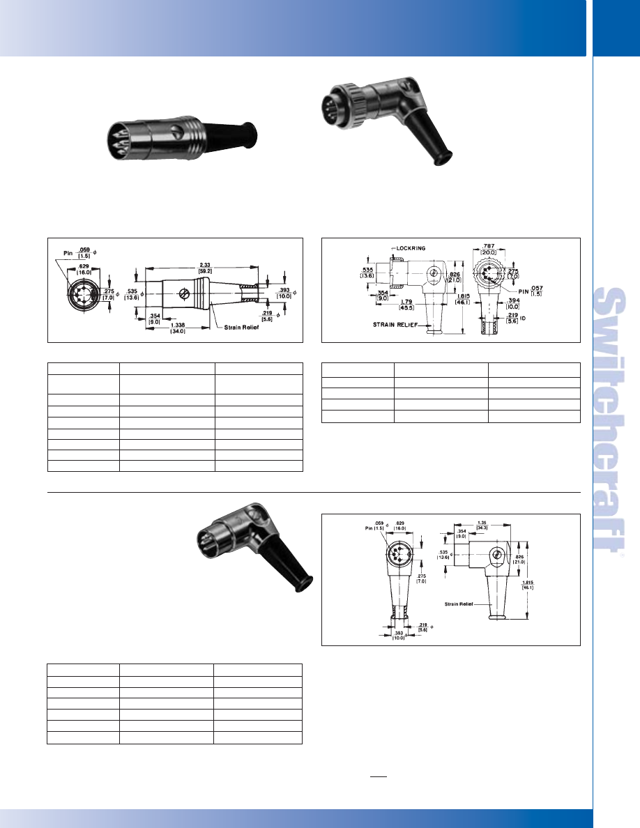
SWITCHCRAFT, INC. 5555 N. Elston Ave. • Chicago, IL 60630
47
CONNECTORS & RECEPTACLES
FAX: 773 792-2129
CONNECTORS & RECEPT
ACLES
DIMENSIONS ARE FOR REFERENCE ONLY
Inch
(mm)
DIN PLUGS AND RECEPTACLES
DIN PLUGS AND RECEPTACLES
TYPE 12BL6M – TYPICAL
Male plug with ground key-rib. Nickel-plated diecast handle.
Contact friction coupling. Flexible black strain relief. Heavy
duty cable clamp.
STRAIGHT CORD PLUG
with Extended Barrel
RIGHT-ANGLE CORD PLUG
with 8 Position Barrel
RIGHT-ANGLE CORD PLUG
with 8 Position Barrel and 30°
Lockring
DIN PLUGS AND RECEPTACLES
TYPE 05DL5M – TYPICAL
Right-angle chassis hugging, male plug with flexible black
rubber strain relief. Unique 8-position barrel offers a choice of
eight different cable entry angles.
TYPE 05YL5M – TYPICAL
Right-angle chassis hugging, male plug with flexible strain
relief. Unique 8-position barrel gives you a choice of any one
of eight different cable entry angles. ground key rib 30° turn
lockring securely fastens two halves of connector.
Part Number
Description
Pin Arrangement
◊
03BL2M
2 pins with insulated
1
switch actuator
◊
05BL3M
3 pins at 180°
2
◊
05BL5M
5 pins at 180°
5
◊
09BL4M
4 pins at 210°
3
12BL5M
5 pins at 240°
4
◊
12BL6M
6 pins at 240°
6
◊
15BL7M
7 pins at 270°
7
◊
15BL8M
8 pins at 270°
8
Part Number
Description
Pin Arrangement
◊
05YL3M
3 pins at 180°
2
◊
05YL5M
5 pins at 180°
5
◊
09YL4M
4 pins at 210°
3
◊
12YL5M
5 pins at 240°
4
Part Number
Description
Pin Arrangement
◊
05DL3M
3 pins at 180°
2
◊
05DL5M
5 pins at 180°
5
◊
09DL4M
4 pins at 210°
3
◊
12DL5M
5 pins at 240°
4
◊
12DL6M
6 pins at 240°
6
◊
15DL7M
7 pins at 270°
7
◊
Available on special order only; contact Switchcraft for price and delivery.
05DL5M shown
ORDERING INFORMATION
ORDERING INFORMATION
ORDERING INFORMATION
* Please visit the product pages on our website for the most up-to-date product information
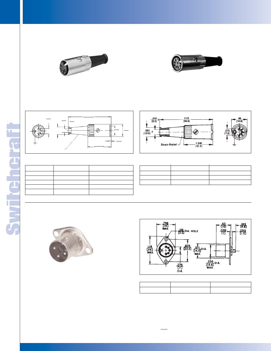
CONNECTORS & RECEPTACLES
48
w w w . s w i t c h c r a f t . c o m
® Registered trademark of Switchcraft, Inc.
Note: Contact your Switchcraft Representative for price and delivery
PHONE: 773 792-2700
CONNECTORS & RECEPT
ACLES
DIMENSIONS ARE FOR REFERENCE ONLY
Inch
(mm)
TYPE 06AL5F – TYPICAL
Female plug with ground contact. Diecast metal shell,
nickel-plated. Two contact plug, Part number 04AL2F includes
a break circuit switch (1-B) which is opened by engaging the
insulated switch actuator of the mating plug or receptacle.
Flexible black strain relief.
STRAIGHT CORD PLUG
with Flush Socket Insert
STRAIGHT CORD PLUG
with Lock Flange
DIN PLUGS AND RECEPTACLES (continued)
TYPE 06EL5F – TYPICAL
Female plug with ground contact. Lock flange designed to
accept 30° lockring. Insert screw firmly holds insert assembly in
shell. Flexible black strain relief with 7/32" diameter cable entry.
Heavy duty cable clamp.
Part Number
Description
Contact Arrangement
◊
06AL5F
5 contacts at 180°
F
◊
13AL5F
5 contacts at 240°
E
◊
13AL6F
6 contacts at 240°
G
◊
15AL7F
7 contacts at 270°
H
◊
15AL8F
8 contacts at 270°
N
Part Number
Description
Contact Arrangement
◊
◊
06EL5F
5 contacts at 180°
F
13EL5F
5 contacts at 240°
E
◊
15EL8F
8 contacts at 270°
N
RECEPTACLE
with Extended Shell
TYPE 57KD3M – TYPICAL
Male receptacle, 3 pins, with ground key-rib. Diecast
extended shell and flange for chassis or panel mounting.
Turret terminals.
Part Number
Description
Pin Arrangement
57KD3M
3 pins at 180°
2
◊
Available on special order only; contact Switchcraft for price and delivery.
ORDERING INFORMATION
ORDERING INFORMATION
ORDERING INFORMATION
Stain Relief
.216
5.5
.216
5.5
2.24
57.0
.456
11.6
.622
15.8
1.22
31.0
0.51
1.3
.393
10.0
DIN PLUGS AND RECEPTACLES
DIN PLUGS AND RECEPTACLES
* Please visit the product pages on our website for the most up-to-date product information
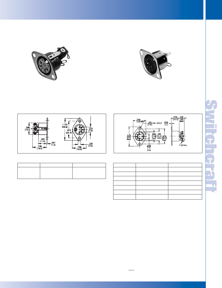
SWITCHCRAFT, INC. 5555 N. Elston Ave. • Chicago, IL 60630
49
CONNECTORS & RECEPTACLES
FAX: 773 792-2129
CONNECTORS & RECEPT
ACLES
DIMENSIONS ARE FOR REFERENCE ONLY
Inch
(mm)
DIN RECEPTACLES
DIN RECEPTACLES
TYPE 59GB3F – TYPICAL
Unique 3 and 5 contact receptacles include a 1-B (closed
circuit) switch which is mounted to drawn metal shell. Switch
is actuated by the shell of the mating plug. Receptacles also
provide complete shielding through the ground contact.
Flared solder terminals.
RECEPTACLE
with Closed Circuit Switch
RECEPTACLE
for Chassis or Panel Mounting
For shielded and extended barrel plugs
DIN RECEPTACLES (continued)
Part Number
Description
Contact Arrangement
◊
59GB3F
3 contacts at 180° plus
B
closed-circuit switch
(Schematic #5)
TYPE 57GB5F – TYPICAL – FLARED SOLDER
TERMINALS
Drawn metal recessed shell with mounting flange and ground
contact. Available flared solder terminals. Part Number
58GB3F features two extra blanks in insert for proper mating
(5 pins at 180°) plug where applications may require greater
connector flexibility. Flared solder terminals standard.
Part Number
Descriptions
Contact Arrangement
◊
57GB3F
3 contacts at 180°
B
◊
57GB5F
5 contacts at 180°
F
◊
60GB4F
4 contacts at 210°
D
◊
61GB5F
5 contacts at 240°
E
◊
61GB6F
6 contacts at 240°
G
◊
62GB7F
7 contacts at 270°
H
◊
62GB8F
8 contacts at 270°
N
◊
Available on special order only; contact Switchcraft for price and delivery.
◊
Available on special order only; contact Switchcraft for price and delivery.
ORDERING INFORMATION
ORDERING INFORMATION
* Please visit the product pages on our website for the most up-to-date product information
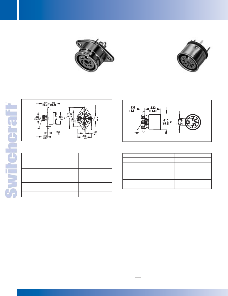
CONNECTORS & RECEPTACLES
50
w w w . s w i t c h c r a f t . c o m
® Registered trademark of Switchcraft, Inc.
Note: Contact your Switchcraft Representative for price and delivery
PHONE: 773 792-2700
CONNECTORS & RECEPT
ACLES
DIMENSIONS ARE FOR REFERENCE ONLY
Inch
(mm)
DIN RECEPTACLES
DIN RECEPTACLES
RECEPTACLE
for Lockring Plug
Flared solder terminals on
Part Number 57HB5F
RECEPTACLE
for Printed Circuit Board
Mounting
DIN RECEPTACLES (continued)
TYPE 57NC5F – TYPICAL
Mounts to printed circuit boards. Special PC type terminals
“snap-in” precut boards. See drawing. Tubular metal shell
with ground contact. Part Number 58NC3F mates with
either 3 pin or 5 pin (at 180°) plugs because of its 2 extra
blanks in the contact insert.
Part Number
Description
Contact Arrangement
◊
57NC5F
5 contacts at 180°
F
◊
58NC3F
3 contacts at 180°
C
2 extra blanks
◊
60NC4F
4 contacts at 210°
D
◊
61NC5F
5 contacts at 240°
E
◊
62NC7F
7 contacts at 270°
H
◊
62NC8F
8 contacts at 270°
N
Part Number
Description
Pin Arrangement
◊
55HA2F
2 contacts with
A
closed-circuit switch
(Schematic #4)
57HB3F*
3 contacts at 180°
B
57HB5F*
5 contacts at 180°
F
60HA4F
4 contacts at 210°
D
61HA5F
5 contacts at 240°
E
62HB7F*
7 contacts at 270°
H
62HB8F*
8 contacts at 270°
N
“C” in part number indicates PC terminals.
◊
Available on special order only; contact Switchcraft for price and delivery.
*Flared solder terminals
“A” in part number indicates straight terminal. (solder lug).
◊
Available on special order only; contact Switchcraft for price and delivery.
ORDERING INFORMATION
ORDERING INFORMATION
TYPE 61HA5F – TYPICAL
Female receptacle with ground contact. Chassis or panel
mount. Diecast bayonet extension shell with mounting flange.
Mates with all lockring plugs. such as Part Number 12CL5M.
Part Number 55HA2F includes closed-circuit switch (1-B). All
receptacles have straight solder terminals, except as noted.
* Please visit the product pages on our website for the most up-to-date product information
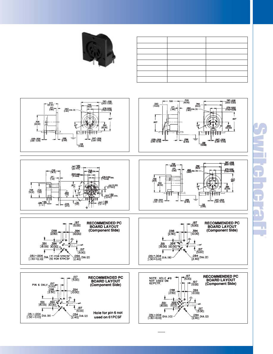
SWITCHCRAFT, INC. 5555 N. Elston Ave. • Chicago, IL 60630
51
CONNECTORS & RECEPTACLES
FAX: 773 792-2129
CONNECTORS & RECEPT
ACLES
DIMENSIONS ARE FOR REFERENCE ONLY
Inch
(mm)
DIN RECEPTACLES
DIN RECEPTACLES
TYPE 57PC5F–TYPICAL
Mounts to PC boards. Plugs connect at right-angle to mounting
surface. Part Number 57PC3F mates with either 3 or 5 pin
(at 180°) plugs because of two extra blanks in contact insert.
ground contact provides complete shielding through receptacles.
RIGHT-ANGLE
RECEPTACLE
for Printed Circuit
Board Mounting
Part Number
Description
Contact Arrangement
◊
57PC3F
3 contacts at 180°
B
◊
57PC5F
5 contacts at 180°
F
◊
60PC4F
4 contacts at 210°
D
◊
61PC5F
5 contacts at 240°
E
◊
61PC6F
6 contacts at 240°
G
◊
62PC7F
7 contacts at 270°
H
◊
62PC8F
8 contacts at 270°
N
◊
Available on special order only; contact Switchcraft for price and delivery.
ORDERING INFORMATION
.709
61PC5F, 61PC6F
* Please visit the product pages on our website for the most up-to-date product information
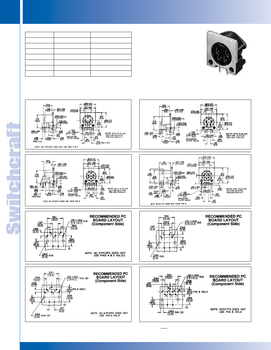
CONNECTORS & RECEPTACLES
52
w w w . s w i t c h c r a f t . c o m
® Registered trademark of Switchcraft, Inc.
Note: Contact your Switchcraft Representative for price and delivery
PHONE: 773 792-2700
CONNECTORS & RECEPT
ACLES
DIMENSIONS ARE FOR REFERENCE ONLY
Inch
(mm)
DIN RECEPTACLES
DIN RECEPTACLES
RIGHT-ANGLE
SHIELDED RECEPTACLE
for printed circuit board
mounting
TYPE 60PC4FS–TYPICAL
Similar to 57PC5F – Typical, except flange surrounding face
of insert is metal to provide through-grounding between plug
and receptacle and to potential panel/chassis for common
grounding.
Part Number
Description
Contact Arrangement
◊
57PC3FS
3 contacts at 180°
B
◊
57PC5FS
5 contacts at 180°
F
◊
60PC4FS
4 contacts at 210°
D
◊
61PC5FS
5 contacts at 240°
E
◊
61PC6FS
6 contacts at 240°
G
◊
62PC7FS
7 contacts at 270°
H
◊
62PC8FS
8 contacts at 270°
N
SPECIFYING NOTE: Another series of receptacles with a trimmed metal flange
.052" (1.32 mm) below housing top is available. Replace suffix “S” with “T” in
part numbers above to specify these receptacles or contact Switchcraft.
Mounting: #2 or #3 self-tapping screw.
◊
Available on special order only; contact Switchcraft for price and delivery.
* Please visit the product pages on our website for the most up-to-date product information
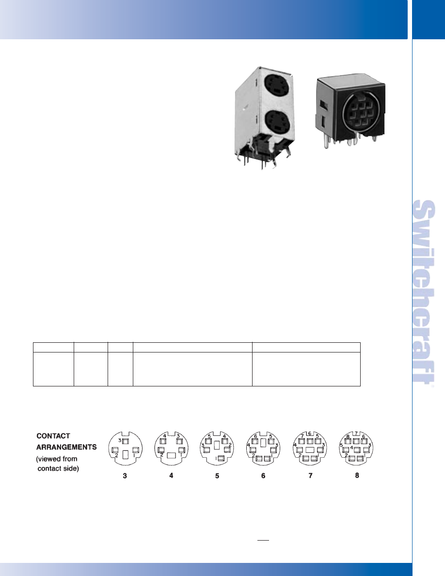
SWITCHCRAFT, INC. 5555 N. Elston Ave. • Chicago, IL 60630
53
CONNECTORS & RECEPTACLES
FAX: 773 792-2129
CONNECTORS & RECEPT
ACLES
DIMENSIONS ARE FOR REFERENCE ONLY
Inch
(mm)
MINI-DIN RECEPTACLES
MINI-DIN RECEPTACLES
Miniature DIN right-angle connectors are designed for
personal computer, video and data communications, medical
and instrumentation equipment and systems.
RIGHT-ANGLE, PC MOUNT RECEPTACLES
Available with 3 through 8 contacts, female only, receptacles
also have a standard (and separate) ground contact system.
Ground terminal can be straight or snap-in type. Snap-in
terminals are bifurcated to assure tight hold down on PC
board before, during and after soldering. Solder wicking
around the terminal strengthens the connection. Additionally,
PC terminals are staggered to assure more “hold down”
capability during soldering.
Receptacle/plug retention is “friction” type, and a separate
outer shield can be specified.
Series SMD*FRAX10: 3 through 8 contacts, female,
right-angle PC mount, straight ground terminal, and
no outer shield.
Series SMD*FRAX20: Same as SMD*FRAX10, except
with bifurcated snap-in ground terminal.
Series SMD*FRAX11: 3 through 8 contacts, female,
right-angle PC mount, straight ground terminal, and
outer shield.
Series SMD*FRAX21: Same as SMD*FRAX11, except
with snap-in ground terminal.
Series DMD*FRAX111: Dual stacked miniature DIN
connectors, available in 4, 5, 6, and 8 contacts. Shielded
and non-shielded versions available.
Dimensions: .552" (14 mm) wide x .502"
(12.8 mm maximum depth x .642" (16.3 mm) height,
including terminals.
SPECIFICATIONS
Ratings: 1A, 100 VAC; 2A, 12 VDC.
Insulation Resistance: 50 M
Ω
minimum
Dielectric Strength: 250 VDC for 1 minute.
Contact Resistance: 30 m
Ω
maximum
Insertion/Withdrawal Force: 0.8 to 5 kilograms
Withdrawal Force: 0.8 to 4 kilograms
Contacts/Terminals: Copper alloy, silver or gold-plated
Ground Terminal: Copper alloy, nickel-plated.
External Shield: Copper alloy, solder-coated.
Body: Black molded thermoplastic, UL 94V-0.
MINI-DIN RIGHT-ANGLE RECEPTACLES
DIN RECEPTACLES (continued)
MINI-DIN RIGHT-ANGLE RECEPTACLES PART NUMBER SCHEME
Series
Contacts
Style
Shield/Ground
Optional Mounting Screw Hole
SMD-Single Insert #:
FRA
110: Unshielded, no snap-in ground
A: Adds screw hole
DMD-Dual
3-8
111: Shielded, no snap-in ground
Blank: None
120: Unshielded, snap-in ground
121: Shielded, snap-in ground
Note: Dual available in 4,5,6, and 8 only
Note: Snap-in ground available on single only
Note: Optional mounting screw hole available on dual only
Note: Special order only, contact factory for details
* Please visit the product pages on our website for the most up-to-date product information
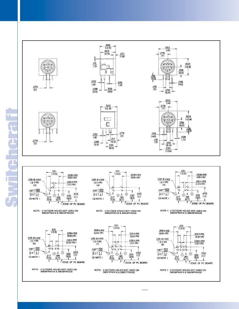
CONNECTORS & RECEPTACLES
54
w w w . s w i t c h c r a f t . c o m
® Registered trademark of Switchcraft, Inc.
Note: Contact your Switchcraft Representative for price and delivery
PHONE: 773 792-2700
CONNECTORS & RECEPT
ACLES
DIMENSIONS ARE FOR REFERENCE ONLY
Inch
(mm)
RECOMMENDED PC BOARD LAYOUTS (Viewed from component side)
SMD SERIES
DIN RECEPTACLES (continued)
MINI-DIN RECEPTACLES
MINI-DIN RECEPTACLES
* Please visit the product pages on our website for the most up-to-date product information
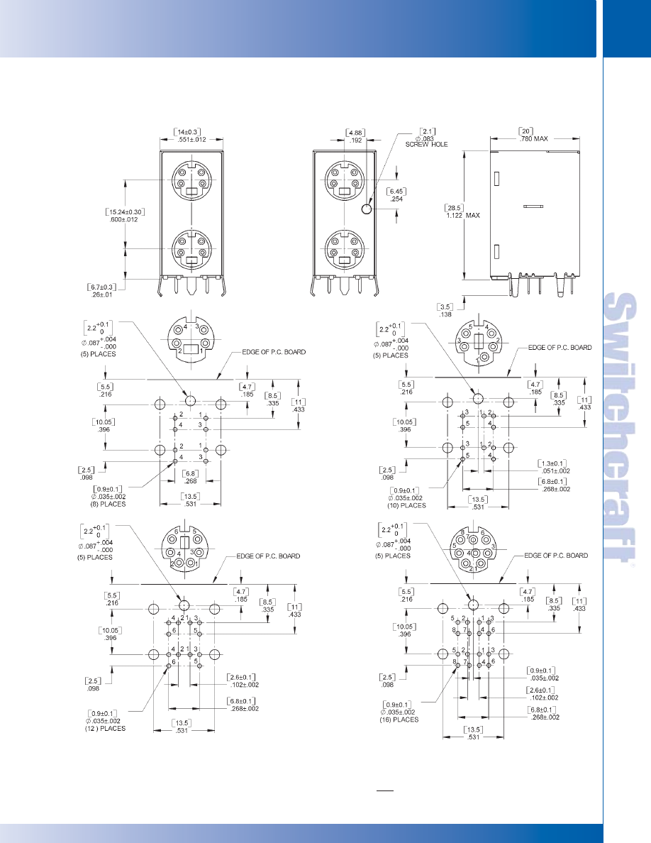
SWITCHCRAFT, INC. 5555 N. Elston Ave. • Chicago, IL 60630
55
CONNECTORS & RECEPTACLES
FAX: 773 792-2129
CONNECTORS & RECEPT
ACLES
DIMENSIONS ARE FOR REFERENCE ONLY
Inch
(mm)
DMD SERIES
DIN RECEPTACLES (continued)
MINI-DIN RECEPTACLES
MINI-DIN RECEPTACLES
* Please visit the product pages on our website for the most up-to-date product information
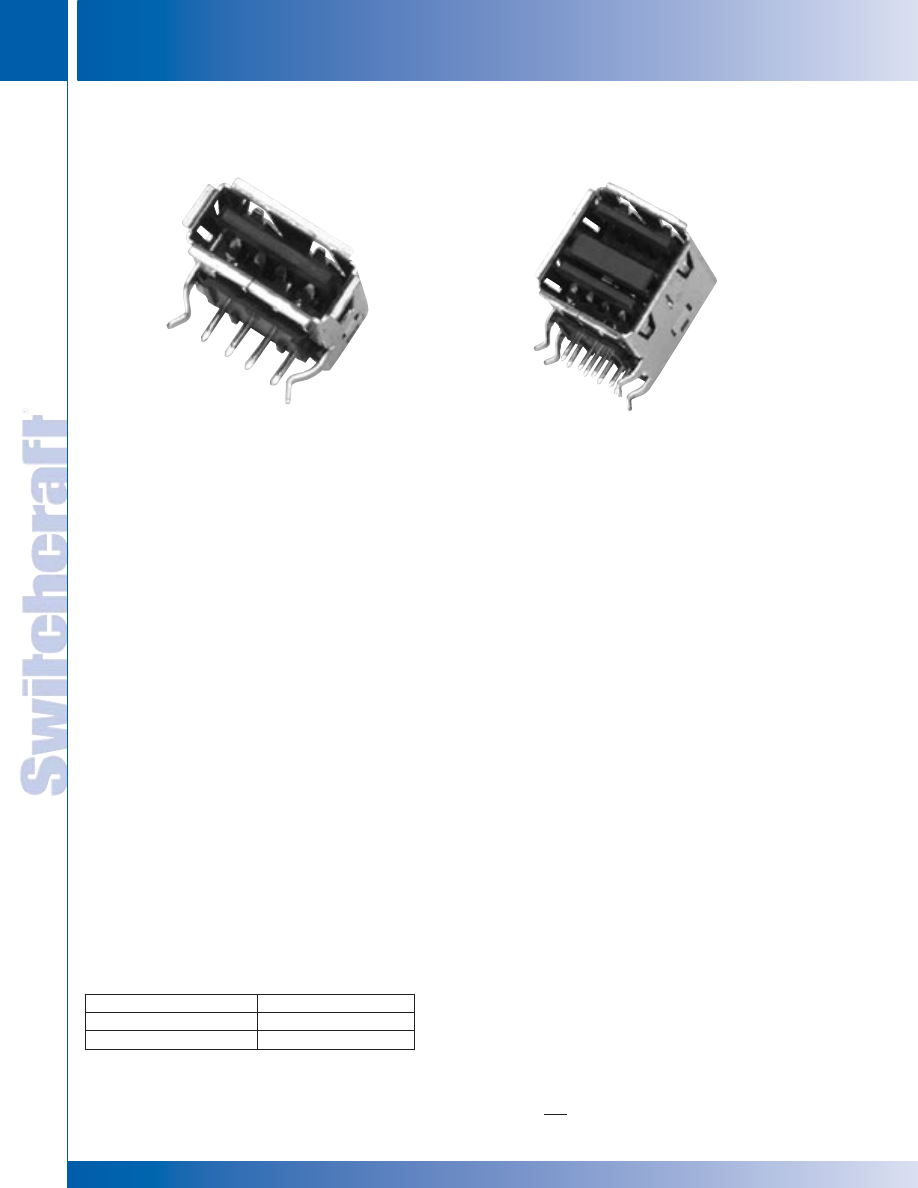
CONNECTORS & RECEPTACLES
56
w w w . s w i t c h c r a f t . c o m
® Registered trademark of Switchcraft, Inc.
Note: Contact your Switchcraft Representative for price and delivery
PHONE: 773 792-2700
CONNECTORS & RECEPT
ACLES
DIMENSIONS ARE FOR REFERENCE ONLY
Inch
(mm)
SINGLE AND DUAL STACKED USB CONNECTORS
SINGLE AND DUAL STACKED USB CONNECTORS
Switchcraft introduces single and dual USB connectors. The USB
connectors are fast becoming the industry standard for plug and
play connectivity between PCs and their peripherals. The DUSB
and USB connectors are RAPC mounted, with kinked terminals for
snap-in placement to the PC board. Both meet all Universal Serial
Bus standards.
FEATURES AND BENEFITS
• Snap-in terminals facilitate wave soldering
• Shielded for reduced EMI/RFI emissions
• Dual stacked version increases PC board density
APPLICATIONS
• Personal Computer
• Data Communications
• Medical Equipment
• Test Equipment
• Instrumentation
SPECIFICATIONS
GENERAL
Voltage Rating: 30 VAC (rms) Max.
Current Rating: Signal application only, 1A Max. per contact
Contact Resistance: 25m ohms Max. initial
Temperature Rating: 32°F to 104°F (0°C to 40°C)
Insertion Force: 7.7 lbs Max. (3.5 kg Max.)
Withdrawal Force: 0.8 lb Min. (0.4 kg Min.)
Life: 1500 cycles
MATERIALS
Body: Black, molded thermoplastic, UL 94V-0
Shell: Copper alloy, tin plated
Contact Terminal: Copper alloy, gold plating in mating area,
tin plating on solder tails, all over nickel plating.
Part Number Description
SUSB Single USB
Connector
DUSB Dual Stacked
USB Connector
SINGLE AND DUAL STACKED USB CONNECTORS
Note: Special order only, contact factory for details.
SUSB
DUSB
* Please visit the product pages on our website for the most up-to-date product information
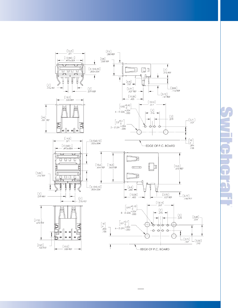
SWITCHCRAFT, INC. 5555 N. Elston Ave. • Chicago, IL 60630
57
CONNECTORS & RECEPTACLES
FAX: 773 792-2129
CONNECTORS & RECEPT
ACLES
DIMENSIONS ARE FOR REFERENCE ONLY
Inch
(mm)
SINGLE AND DUAL STACKED USB CONNECTORS
SINGLE AND DUAL STACKED USB CONNECTORS
SINGLE AND DUAL STACKED USB CONNECTORS (continued)
* Please visit the product pages on our website for the most up-to-date product information
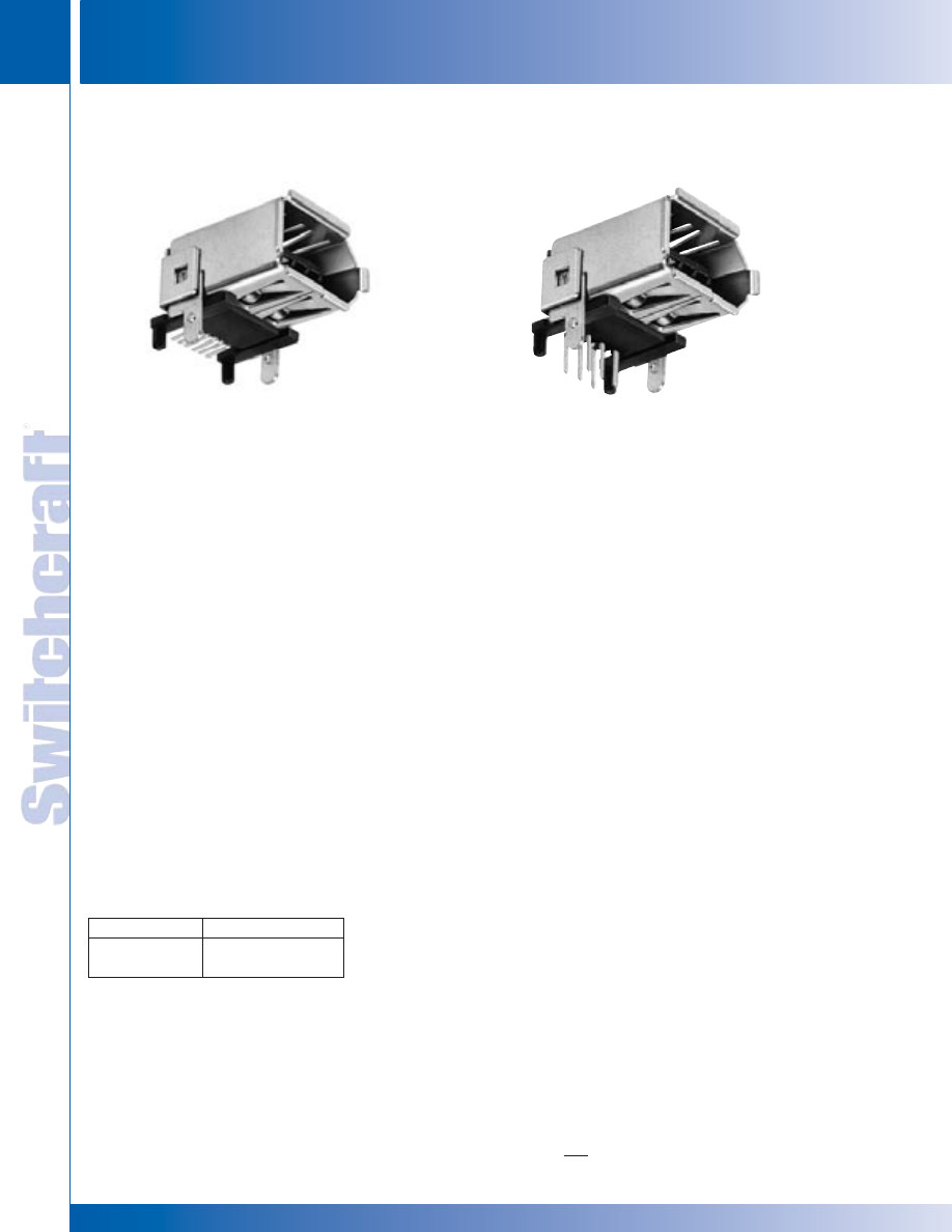
CONNECTORS & RECEPTACLES
58
w w w . s w i t c h c r a f t . c o m
® Registered trademark of Switchcraft, Inc.
Note: Contact your Switchcraft Representative for price and delivery
PHONE: 773 792-2700
CONNECTORS & RECEPT
ACLES
DIMENSIONS ARE FOR REFERENCE ONLY
Inch
(mm)
IEEE 1394 FIREWIRE CONNECTORS
IEEE 1394 FIREWIRE CONNECTORS
1394RAPC
1394SMT
Switchcraft introduces both right angle PC and surface
mount versions of IEEE 1394 Firewire connectors. The
Firewire connectors are becoming another connector
standard used in the upcoming multimedia/computer
market. The connectors meet IEEE 1394R-4006N Series
standards.
FEATURES AND BENEFITS
• Shielded housings to reduce EMI/RFI emissions
• Mounting posts add stability for wave soldering
• Low profile requires less space
APPLICATIONS
• Multimedia
• Video
• Personal Computers
• Computer Peripherals
SPECIFICATIONS
GENERAL
Voltage Rating: 40 VAC
Current Rating: 1.5A
Contact Resistance: 30m Ohms Max.
Temperature Rating: -55°C to +105°C
Insertion Force: 6.0 lbs. Max.
Withdrawal Force: 4.4 lbs. Min.
Lifecycles: 1,500 Min.
IEEE 1394 FIREWIRE CONNECTORS
Part Number Description
1394RAPC
IEEE 1394 RAPC
1394SMT
IEEE 1394 SMT
Note: Special order only, contact factory for details.
* Please visit the product pages on our website for the most up-to-date product information
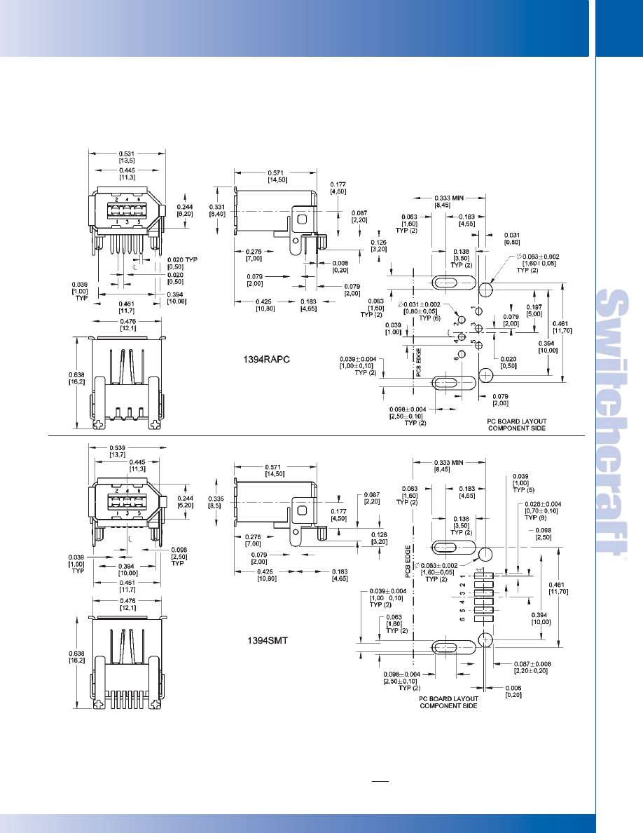
SWITCHCRAFT, INC. 5555 N. Elston Ave. • Chicago, IL 60630
59
CONNECTORS & RECEPTACLES
FAX: 773 792-2129
CONNECTORS & RECEPT
ACLES
DIMENSIONS ARE FOR REFERENCE ONLY
Inch
(mm)
IEEE 1394 FIREWIRE CONNECTORS (continued)
IEEE 1394 FIREWIRE CONNECTORS
IEEE 1394 FIREWIRE CONNECTORS
* Please visit the product pages on our website for the most up-to-date product information
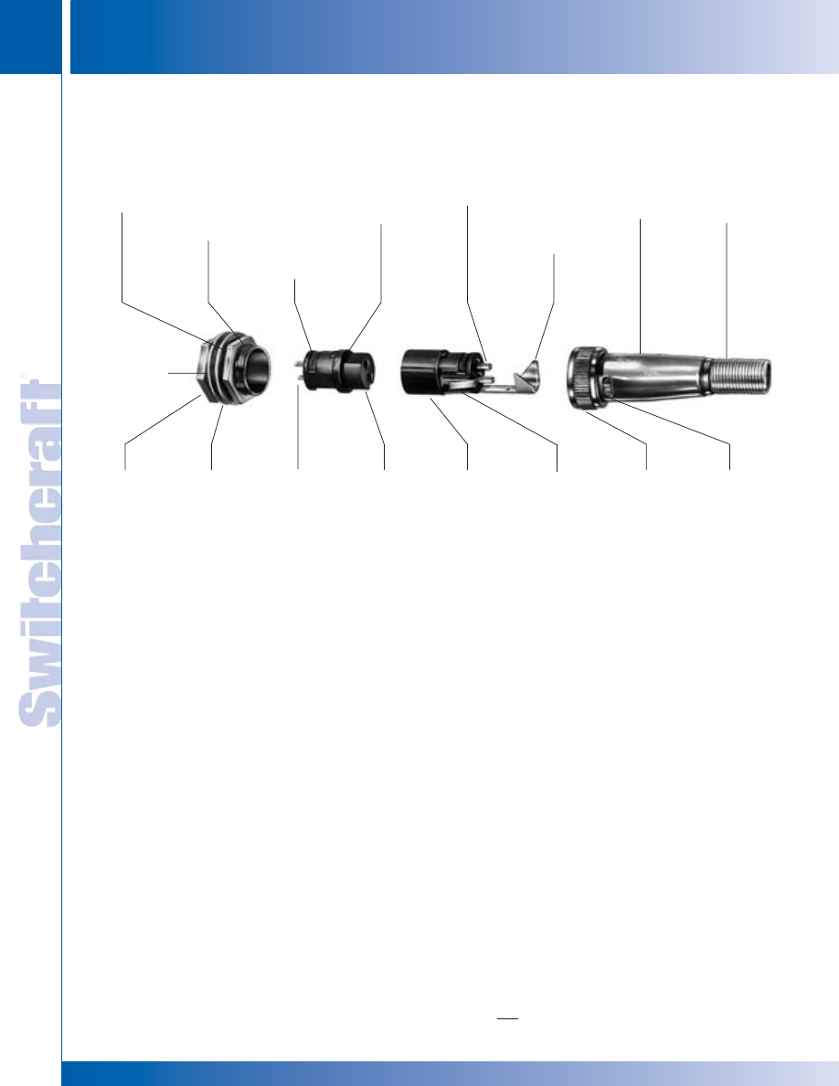
CONNECTORS & RECEPTACLES
60
w w w . s w i t c h c r a f t . c o m
® Registered trademark of Switchcraft, Inc.
Note: Contact your Switchcraft Representative for price and delivery
PHONE: 773 792-2700
CONNECTORS & RECEPT
ACLES
DIMENSIONS ARE FOR REFERENCE ONLY
Inch
(mm)
DESIGN FEATURES
Slim-Line
®
Audio Connectors are a unique series of premium
quality connectors featuring interchangeable inserts which
allow any plug or receptacle to be male or female. This
versatility is valuable in a wide variety of applications:
microphones, public address systems, 2-way, CB, ham, and
marine radios, audio-visual systems, industrial control and
instrumentation, broadcast, security and medical electronics.
APPLICATIONS
Retrofit/Replacement; Slim Line Cord Plug (SL405M) and
Receptacle (SL105F) are recommended as a possible choice
to replace Switchcraft/DIN plug (12CL5M) and receptacle
(55HA5F). Receptacle SL105F fits the same mounting holes
as the Switchcraft/DIN receptacle.
Four pin/contact Slim-Line plugs and receptacles are
recommended as direct replacements for the original
Slim-Line connectors, Series 2504, and for the molded
version of the Slim-Line connector, Style ST34.
RECEPTACLES
Three types of receptacles can be specified:
1. Flange mount (Series SL10)
2. Rear of panel mount (Series SL17)
SLIM-LINE CONNECTORS
HEX NUT
Used in mounting
rear or front of
panel receptacles
(supplied standard).
THREADED
BUSHING
Coupler ring on
mating plug threads
onto bushing and
keeps plug/receptacle
from working loose.
FEMALE INSERT*
Rugged molded
black plastic barrel
construction;
positively keyed to
housing.
LOCK WASHER
Prevents rear
or front of panel
receptacle from
working loose
when installed
(supplied standard).
REAR OF
PANEL MOUNT
RECEPTACLE
Tough, plated
diecast housing
with non-reflecting
matte finish. Mounts
in D-shape (self-
keyed) hole. Other
receptacle types
are: Front of Panel
Mount and Flange
Mount.
FLAT WASHER
Used in mounting
rear and front of
panel receptacles
(supplied standard).
CONTACT
TERMINALS
Rugged solder lug
type; copper alloy
plated
CONTACTS
Held captive in
insert. Excellent pin
retention force.
Copper alloy plated.
MALE INSERT*
Rugged black
plastic; keyed to
housing. Durable
plated copper alloy
pins are 100%
molded-in.
*NOTE: Insert
fits both plug
and receptacle
housings; can be
interchanged at
any time.
LATCH SPRING
Captive spring locks
insert to housing
COUPLER RING
Held captive on plug;
non-reflective matte
finish. Threads onto
receptacle bushing
(or mating plug) to
hold connector
halves secure
from accidental
separation.
LATCH DETENT
Latch spring on
insert seats in
detent to hold insert
firmly in housing.
FLATTED BARREL
Keys to inside flat
on male insert.
Polarizes the con-
nection. Correct
mating every time.
PIN TERMINALS
Large, rugged plated
copper alloy; solder
cup type.
CABLE CLAMP
Extra large and
rugged clamp pro-
tects soldered ter-
minations (also
facilitates grounding/
shielding feature
when used on
receptacle insert).
CORD PLUG
HOUSING
Precision-drawn,
plated copper alloy
with non-glare
matte finish.
STRAIN RELIEF
SPRING
Provides positive
relief from cable
wear at opening in
plug housing.
Receptacles can be specified with same male and female insert
combinations as cord plugs. For rear and front of panel
mounting types, hex nuts, lock washers, and flat washers are
supplied. For flange mount receptacles, mounting holes in flange
accept #4 machine screw or .125" (3.18 mm) diameter rivet.
CORD PLUGS
Miniature Cord Plugs feature nickel-plated copper alloy
housings with matte finish on exterior parts. Plugs may be
specified with inserts having 2-, 3-, 4- and 5-pins (male) or
contacts (female), or 2-, 3-, or 4-contact receptacles having
shunts (N.C.) on two contacts (special order only). Extra large
cable clamp protects against pulling and twisting strains on
terminations. Strain relief spring protects against excess cable
wear at entry point at rear of housing. Cord plugs accept cables
up to .281" (7.14 mm) diameter. Captive coupler ring feature
(Series SL40) provides secure mechanical connection and
protection against shock and vibration between cord plugs and
mating plug (Series SL41) or receptacle.
TYPICAL SL172F REAR MOUNT RECEPTACLE
TYPICAL SL402M CORD PLUG
SLIM-LINE CONNECTORS
SLIM-LINE CONNECTORS
* Please visit the product pages on our website for the most up-to-date product information
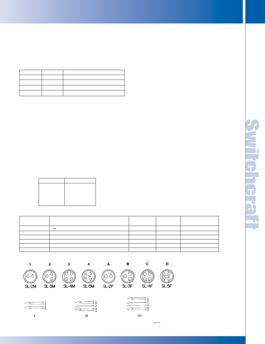
SWITCHCRAFT, INC. 5555 N. Elston Ave. • Chicago, IL 60630
61
CONNECTORS & RECEPTACLES
FAX: 773 792-2129
CONNECTORS & RECEPT
ACLES
DIMENSIONS ARE FOR REFERENCE ONLY
Inch
(mm)
SLIM-LINE CONNECTORS
SLIM-LINE CONNECTORS
Insert is installed from front, and the captive latch spring locks
insert to housing. To remove insert from receptacle, depress
latch spring and apply pressure to rear of insert (DO NOT
APPLY PRESSURE TO TERMINALS). On cord plugs, depress
latch spring and press in on strain relief to free the insert.
GROUNDING/SHIELDING
Housings shield internal connections and provide ground
(common) connections without using a pin/contact. On cord
plugs, ground lead (or shield) is connected to cable clamp. For
receptacles Cable Clamp, SL04 is ordered separately as a
special and installed. If desired, ground/shield connection may
then be made to clamp. When mated, a continuous, shielded,
low resistance path is made through the connector.
SPECIFICATIONS
MATERIALS
Receptacle Housings: Die-cast zinc, nickel-plated.
Cord Plug Housings: Copper alloy, nickel-plated.
Inserts: Glass-reinforced thermoplastic. UL 94 V-0.
Female Contacts: Copper alloy, silver-plated, solder lug type.
Pins: Copper alloy, silver-plated, solder cup type.
Cable Clamp, Strain Relief, and Mounting Hardware:
Steel, plated. Latch: Steel, plated.
ELECTRICAL
Current Rating: 5 Amps carry only.
MOUNTING
Cord Plugs: Plugs accept cables up to .281" (7.14 mm) diameter.
Receptacles: Flange mount type mounts in panels or chassis
up to .188" (4.78 mm) thick. .125" (3.18 mm) diameter holes
accept #4 machine screws or .125" (3.18 mm) diameter rivets.
Rear and front of panel types mount in “D”-shaped hole in panels
or chassis up to .219" (5.56 mm) thick. Hex nut (SL01), lockwasher
(SL02), and flat washer (SL03) are supplied for mounting.
CABLE CLAMP AND STRAIN RELIEF
Cord Plugs: Plugs are supplied with rugged cable clamps and
strain relief springs. Cable clamp serves two valuable functions: to
firmly hold cable to prevent pulling or twisting strains on soldered
terminations, and as a connecting point for ground (common) or
shield when grounding/shielding through the connector is
required.
Receptacles: Receptacles are not supplied standard with
cable clamp for strain relief. If grounding/shielding feature is
desired, separate Cable Clamp, SL04, is installed on receptacle
insert.
MOUNTING HARDWARE
(Supplied with Series SL17 and SL18 receptacles)
INSERTS
Inserts are molded of high-strength plastic, and are
completely interchangeable between plug and receptacle
housings at any time. Inserts are keyed to housings, and male
and female inserts are polarized to prevent mismating.
Part Number
Item
◊
SL01
Hex Nut
◊
SL02
Lockwasher
◊
SL03
Flat Washer
◊
SL04
Cable Clamp
◊
SL05
Strain Relief Spring
Pins
2
3
4
5
Contacts
2
3
4
5
Contacts (Shunts)
2 (N.C. Shunt on each contact)
3 (N.C. Shunts on contacts 1 and 3)
4 (N.C. Shunts on contacts 1 and 4)
_
PIN/CONTACT CONFIGURATIONS:
◊
Add an “S” to end of part number for shunts. Special order only.
SLIM-LINE CONNECTORS (continued)
PIN AND CONTACT ARRANGEMENTS
SCHEMATIC CIRCUITS
SLIM-LINE CONNECTOR PART NUMBERING SYSTEM
Number of
SERIES
HOUSING TYPE
Contacts
Gender
Options
SL SLIM-LINE
NONE
2
M MALE
S
WITH SHUNTS
10
RECEPTACLE, FLANGE MOUNT
3
F
FEMALE
17
RECEPTACLE, REAR MOUNT
4
18
RECEPTACLE, FRONT MOUNT
5
40
CORD PLUG WITH COUPLING RING
41
CORD PLUG WITHOUT COUPLING RING
* Please visit the product pages on our website for the most up-to-date product information
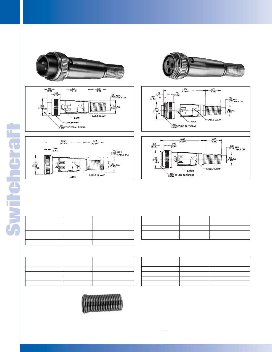
CONNECTORS & RECEPTACLES
62
w w w . s w i t c h c r a f t . c o m
® Registered trademark of Switchcraft, Inc.
Note: Contact your Switchcraft Representative for price and delivery
PHONE: 773 792-2700
CONNECTORS & RECEPT
ACLES
DIMENSIONS ARE FOR REFERENCE ONLY
Inch
(mm)
SLIM-LINE CONNECTORS
SLIM-LINE CONNECTORS
◊
Available on special order only; contact Switchcraft for price and delivery.
Non-reflective metal shell; coupling ring; 2 through 5 pins
(male) or 2 through 5 contacts (female). Also 2-, 3- and
4-contact inserts with two shunted (N.C.) contacts. Efficient
cable clamp and strain relief.
Non-reflective metal shell; 2 through 5 pins (male) or
2 through 5 contacts (female). Also 2-, 3- and 4-contact inserts with
two shunted (N.C.) contacts. Efficient cable clamp and strain relief.
SL40 CORD PLUG
with Coupler Ring
SL41 CORD PLUG
without Coupler Ring
SLIM-LINE CONNECTORS (continued)
SL MALE CORD PLUGS
SL FEMALE CORD PLUGS
SL MALE CORD PLUGS
SL FEMALE CORD PLUGS
STRAIN RELIEF SPRING
Strain Relief Spring
Part Number SL05
Pin
Part Number
Pins
Arrangements
SL402M
2
1
SL403M
3
2
SL404M
4
3
SL405M
5
4
Pin
Part Number
Pins
Arrangements
SL413M
3
2
SL414M
4
3
SL415M
5
4
Contact
Part Number
Contacts
Arrangements
SL412F
2
A
SL413F
3
B
SL414F
4
C
SL415F
5
D
Contact
Part Number
Contact
Arrangements
SL402F
2
A
SL403F
3
B
SL404F
4
C
SL405F
5
D
SL402M (typical)
SL413F (typical)
* Please visit the product pages on our website for the most up-to-date product information
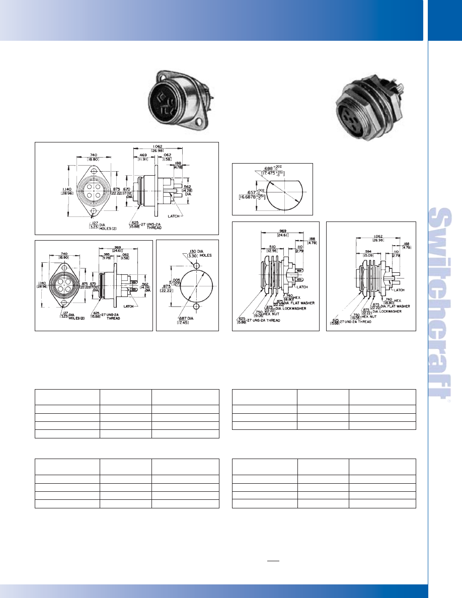
SWITCHCRAFT, INC. 5555 N. Elston Ave. • Chicago, IL 60630
63
CONNECTORS & RECEPTACLES
FAX: 773 792-2129
CONNECTORS & RECEPT
ACLES
DIMENSIONS ARE FOR REFERENCE ONLY
Inch
(mm)
Flange mounted; 2 through 5 pins (male) or 2 through 5 contacts
(female). Also 2-, 3- and 4-contact inserts with 2 shunted (N.C.)
contacts.
Rear of panel mount; 2 through 5 pins (male) or 2 through
5 contacts (female). Also 2-, 3- and 4-contact inserts with
2 shunted (N.C.) contacts. Mounting locknut (Part Number
SL01), lock washer (Part Number SL02), and flat washer
(Part Number SL03) supplied.
SL10 RECEPTACLES
Flange Mount
SL17 RECEPTACLES
Rear of Panel Mount
SL MALE RECEPTACLES
SL FEMALE RECEPTACLES
SL MALE RECEPTACLES
SL FEMALE RECEPTACLES
Pin
Part Number
Pins
Arrangements
SL102M
2
1
SL103M
3
2
SL104M
4
3
SL105M
5
4
Pin
Part Number
Pins
Arrangements
SL173M
3
2
SL174M
4
3
SL175M
5
4
Contact
Part Number
Contacts
Arrangements
SL172F
2
A
SL173F
3
B
SL174F
4
C
SL175F
5
D
Contact
Part Number
Contacts
Arrangements
SL102F
2
A
SL103F
3
B
SL104F
4
C
SL105F
5
D
SL175F (typical)
SL104F (typical)
SLIM-LINE CONNECTORS (continued)
◊
Available on special order only; contact Switchcraft for price and delivery.
SL17 and SL18 Receptacles
Non-turn panel cut-out
SLIM-LINE CONNECTORS
SLIM-LINE CONNECTORS
* Please visit the product pages on our website for the most up-to-date product information
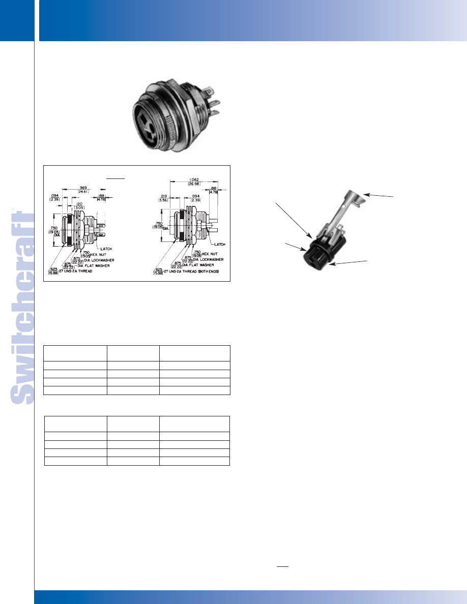
CONNECTORS & RECEPTACLES
64
w w w . s w i t c h c r a f t . c o m
® Registered trademark of Switchcraft, Inc.
Note: Contact your Switchcraft Representative for price and delivery
PHONE: 773 792-2700
CONNECTORS & RECEPT
ACLES
DIMENSIONS ARE FOR REFERENCE ONLY
Inch
(mm)
SLIM-LINE CONNECTORS (continued)
Front of panel mount; 2 through 5 pins (male) or 2 through
5 contacts (female). Also 2-, 3- and 4-contact insert with
3 shunted (N.C.) contacts. Mounting locknut (Part Number
SL01), lockwasher (Part Number SL02), and flat washer
(Part Number SL03) supplied.
SL18 RECEPTACLES
Front of Panel Mount
INSTALLING CABLE CLAMP ON INSERT
To install cable clamp on any insert:
1. Position insert approximately as shown in the diagram.
2. Hold clamp at approximately 30° angle (as shown). Place
tip of clamp center finger into slot under molded ring “A”.
Note position of notch on insert in relation to slot.
3. Press center finger forward into slot and reduce angle of
clamp until clamp shoulders seat just ahead of molded
barrier on rear of insert “B”.
SL MALE RECEPTACLES
SL FEMALE RECEPTACLES
Pin
Part Number
Pins
Arrangements
SL182M
2
1
SL183M
3
2
SL184M
4
3
SL185M
5
4
Contact
Part Number
Contacts
Arrangements
SL182F
2
A
SL183F
3
B
SL184F
4
C
SL185F
5
D
SL183FS (typical)
PANEL HOLE
.696
(17.7)
Cable Clamp SL04
MOLDED
RING
“A”
NOTCH
ON
INSERT
INSERT
“B”
CABLE
CLAMP
SLIM-LINE CONNECTORS
SLIM-LINE CONNECTORS
* Please visit the product pages on our website for the most up-to-date product information
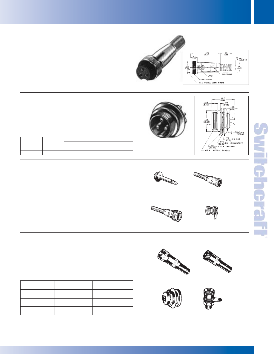
SWITCHCRAFT, INC. 5555 N. Elston Ave. • Chicago, IL 60630
65
CONNECTORS & RECEPTACLES
FAX: 773 792-2129
CONNECTORS & RECEPT
ACLES
DIMENSIONS ARE FOR REFERENCE ONLY
Inch
(mm)
AUDIO CONNECTORS
AUDIO CONNECTORS
CB-3F 3-contact female cord plug. Knurled coupling ring has
internal metric M16x1 thread. Solder lug terminals accept wires
up to #18 AWG. Accommodates cables up to .281" (7.14 mm)
diameter.
CB-4F Same as CB-3F. except 4 contacts.
CB-3M 3-pin male receptacle. Housing keys insert of mating plug;
bushing with external M16x1 metric thread mates with coupling ring
on plug. Cup-type terminals accept wires up to #16 AWG. Mounts
in .64" (16.26 mm) diameter hole from front of panels up to .125"
(3.18 mm) thick, using washer and locknut supplied. Can also be
“D”-hole mounted for non-turn mounting (see drawing).
Pin diameter. is .093".
CB-4M Same as CB-3M, except 4 pin.
Connectors with 5/8-27 threads are designed for use with single
conductor microphone cable with .281" (7.14 mm) maximum
outside diameter. 44 adapts 2501F to fit standard 2-conductor
phone jack. Coupling ring on 2501F is removable for fast change
from female to male type. Spring assembled into body, cable braid
and spring clamped by hollow set screws .281" (7.14 mm)
maximum cable diameter. 2501MP mounts in .390" (9.92 mm)
diameter hole.
Approximately 1/2 the size of standard microphone connectors.
Ideal for miniature lapel microphones, musical instruments and
wherever small cable is used. Accepts single-conductor shielded
cable up to .187" (4.76 mm) diameter Coupling ring on 5501F
removable for quick change of female to male type. Cable is braid
spring clamped to body by hollow point set screw.
Miniature 3 and 4 circuit connectors for microphone connections in
mobile/communications equipment. Cord plug has silver-plated
copper alloy contacts, large cable clamp, and strain relief spring.
CB CONNECTORS
MICROPHONE CONNECTORS
MINI-CON MINIATURE CONNECTORS
CB-3F
CB-3M
Insert
Dimensions, In. (mm)
Part No.
Contacts
Length
Diameter
CB3F
3
1.594 (40.49)
.703 (17.86)
CB3M
3
.781 (19.84)
.705 (19.05)
44
2501M
2501F
5501F
5501M
5501MF
5501MP
2501MP
Mounting Hole,
Part Number
Description
Inches (mm)
5501F
Female Plug
—
◊
5501M
Male Plug
—
.375 (9.52)
◊
5501MF
Receptacle
(Front of panel)
.375 (9.52)
5501MP
Receptacle
(Front of panel)
◊
Available on special order; contact Switchcraft for price and delivery.
* Please visit the product pages on our website for the most up-to-date product information
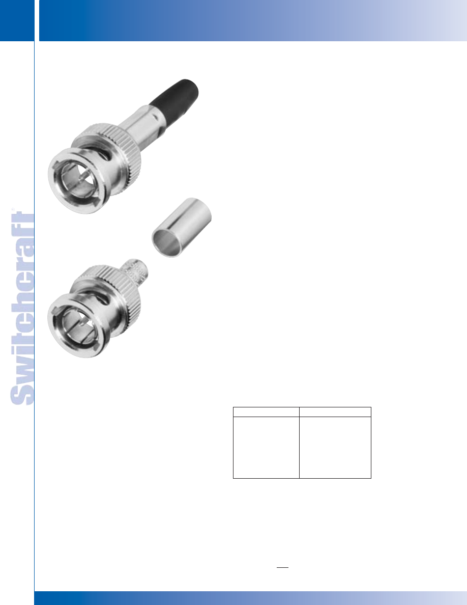
CONNECTORS & RECEPTACLES
66
w w w . s w i t c h c r a f t . c o m
® Registered trademark of Switchcraft, Inc.
Note: Contact your Switchcraft Representative for price and delivery
PHONE: 773 792-2700
CONNECTORS & RECEPT
ACLES
DIMENSIONS ARE FOR REFERENCE ONLY
Inch
(mm)
BNC CONNECTORS
BNC CONNECTORS
Switchcraft Inc. introduces a complete line of true 75 Ohm BNC cable
mount connectors. This new series was developed for the broadcast
industry, or wherever true 75 Ohm impedance BNC's are used. The
HP75BNC Series is available in a wide range of styles, to
accommodate the most popular types of coaxial cables. All are crimp
terminated using standard crimping tools.
FEATURES AND BENEFITS
• True 75 Ohm impedance
• Gold-plated center pins for increased life
• Available for a wide range of cable types
• Outstanding electrical performance
• Rugged nickel-plated, machined shells
SPECIFICATIONS
Electrical
Characteristic Impedance: 75 Ohms
Voltage Rating: 500 Volts RMS
Return Loss: Less than -25 db at 3 GHz
Insulation Resistance: 5000 Megohms min
MECHANICAL
Lifecycles: 500 min
Center Contact Retention: 6 lbs. min
Coupling Mechanism: 100 lbs. min
Force to Engage: 2.5 lbs. max
ENVIRONMENTAL
Thermal Shock: -65° C to 165° C
Moisture Resistance: Mil Std 202
Corrosion: Mil Std 202
Flammability: UL 94-VO
Vibration: Mil Std 202
Solvent Resistance: Mil Std 202
FINISH
Body/Bayonet: Nickel-plated copper alloy
Center Conductor: 50 mi gold-plated copper alloy
HP75BNC SERIES BNC CONNECTORS
Part Number
Cable Type
HP75BNC1
Belden #8241
HP75BNC2
Belden #8281B
HP75BNC6
Belden #1695A
HP75BNC7
Belden #1694A
HP75BNC9
Belden #1505A
HP75BNC10
Belden #1506A
HP75BNC12
Belden #1855A
ORDERING INFORMATION
HP75BNC9
* Please visit the product pages on our website for the most up-to-date product information
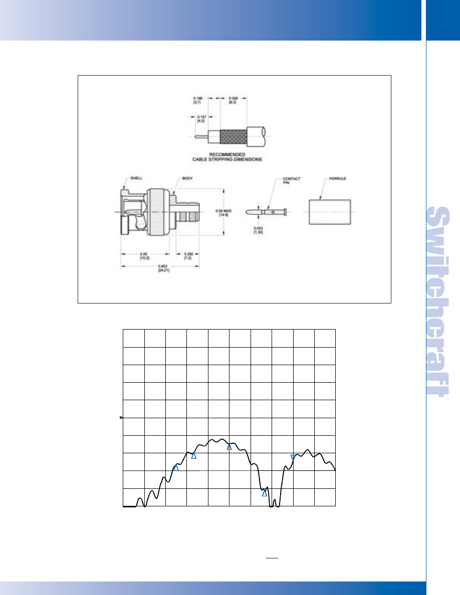
SWITCHCRAFT, INC. 5555 N. Elston Ave. • Chicago, IL 60630
67
CONNECTORS & RECEPTACLES
FAX: 773 792-2129
CONNECTORS & RECEPT
ACLES
DIMENSIONS ARE FOR REFERENCE ONLY
Inch
(mm)
BNC CONNECTORS
BNC CONNECTORS
S
11
log MAG
5 dB / DIV
REF -15 dB
.30
MHz
3.0
GHz
1.5
GHz
RETURN LOSS
HP75BNC SERIES BNC CONNECTORS (continued)
* Please visit the product pages on our website for the most up-to-date product information
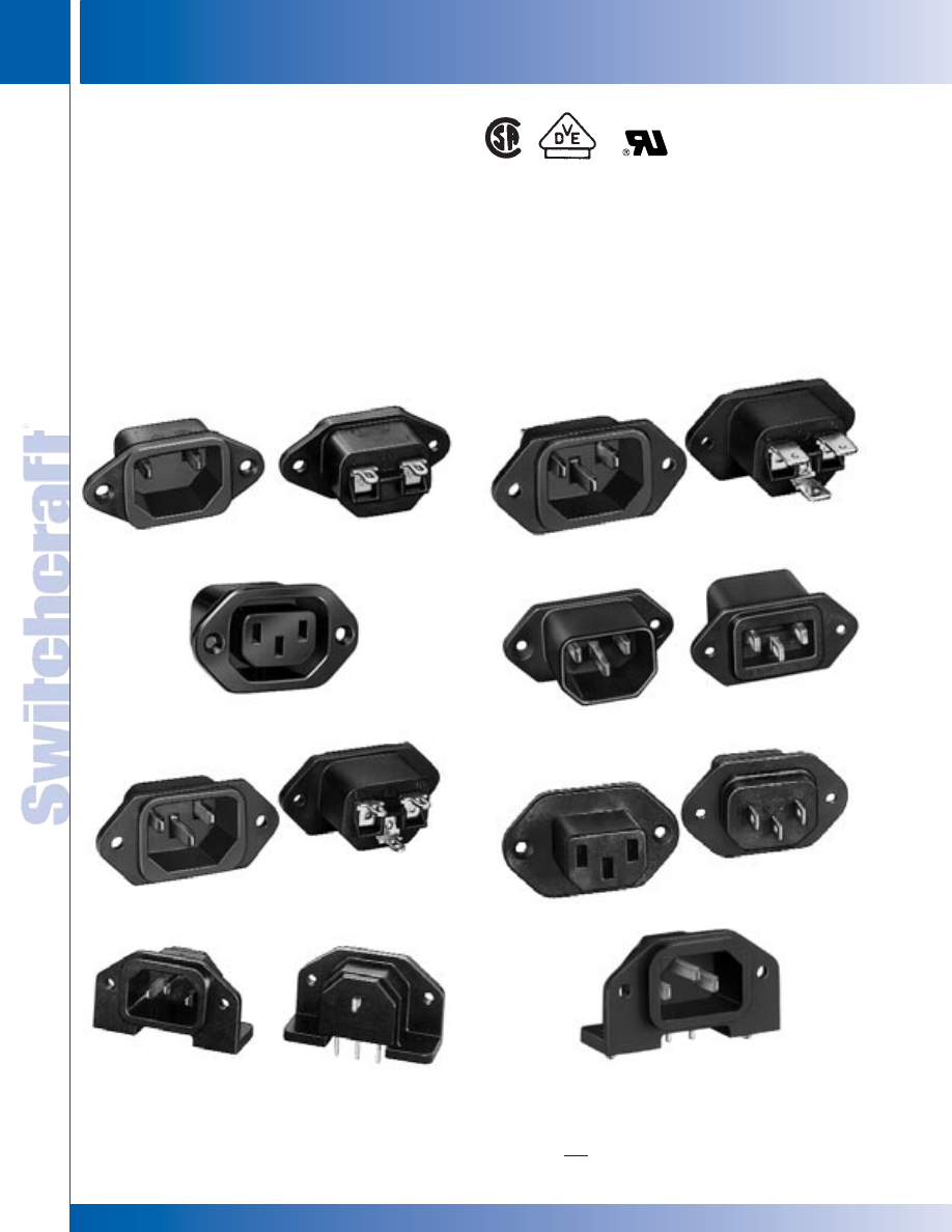
CONNECTORS & RECEPTACLES
68
w w w . s w i t c h c r a f t . c o m
® Registered trademark of Switchcraft, Inc.
Note: Contact your Switchcraft Representative for price and delivery
PHONE: 773 792-2700
CONNECTORS & RECEPT
ACLES
DIMENSIONS ARE FOR REFERENCE ONLY
Inch
(mm)
EAC RECEPTACLES
EAC RECEPTACLES
EAC333
EAC333S
Receptacles are designed for use in European and domestic
instrumentation, power rack mounted devices, test equipment
and appliances. Three-pin male receptacles have .125" (3.18
mm) longer center (ground) pin. Ground circuit is established
before power circuits “make”, and is maintained until after power
circuits “break”.
SERIES EAC
Two and three-pin/contact grounding primary power
receptacles are designed to meet EN 60 320, as well as
applicable UL, CSA, VDE and other specifications.
Receptacles feature choice of short, standard or long solder
lugs or FASTON ® terminals. Receptacles snap-in or screw
mount from the front or rear of panel. Receptacles have
orbitally riveted lugs (except EAC233, EAC305, EAC323
EAC325, EAC333, EAC405) for superior mechanical/electri-
cal connections. Extended socket versions permit minimum
behind-panel depth.
EAC RECEPTACLES
EAC227
EAC305
EAC309
EAC311
EAC323
EAC325
* Please visit the product pages on our website for the most up-to-date product information
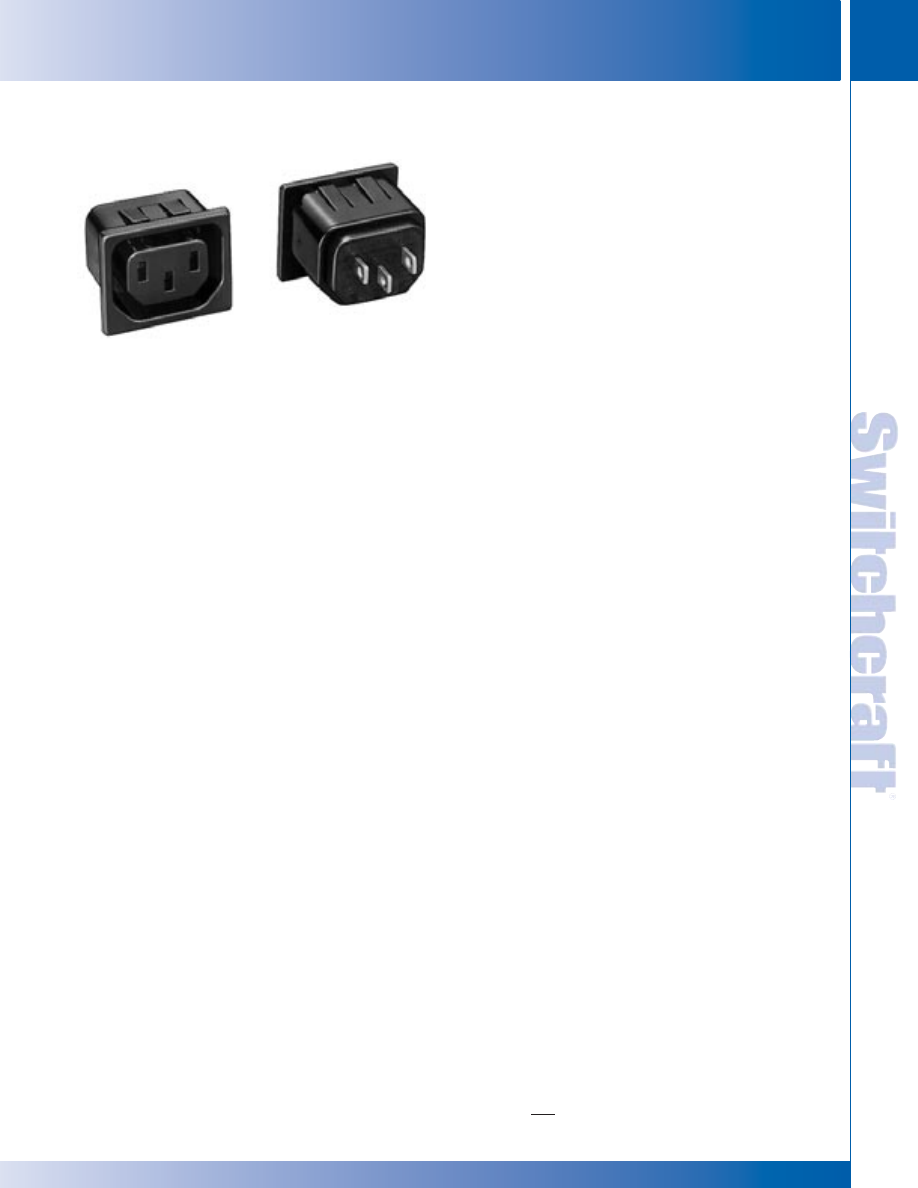
SWITCHCRAFT, INC. 5555 N. Elston Ave. • Chicago, IL 60630
69
CONNECTORS & RECEPTACLES
FAX: 773 792-2129
CONNECTORS & RECEPT
ACLES
DIMENSIONS ARE FOR REFERENCE ONLY
Inch
(mm)
EAC305—3-contact female receptacle. Front mount with
two, #4 screws or .094" (2.38 mm) diameter rivets
(not supplied).
EAC309—3-pin male receptacle with standard lug terminals.
Mounts from front or rear of panel with two, #5 screws or
.125 " (3.18 mm) diameter rivets (not supplied).
EAC311—3-pin male receptacle with FASTON
®
terminals.
Mounts from front or rear of panel with two, #5 screws or
.125 " (3.18 mm) diameter rivets (not supplied).
◊
EAC315—3-pin male receptacle with long solder lug terminals.
Mounts from front or rear of panel with two, #5 screws or .125"
(3.18 mm) diameter rivets (not supplied).
◊
EAC319—3-pin male receptacle with short solder lug
terminals. Mounts from front or rear of panel with two,
#5 screws or .125" (3.18 mm) diameter rivets (not supplied).
◊
EAC323—3-pin male receptacle with short solder lug terminals.
Extended socket housing (mounting flange on rear of receptacle)
provides more behind panel clearance. Mounts with two,
#4 screws or .094" (2.38 mm) diameter rivets (not supplied).
EAC325—3-contact female receptacle with short solder lug
terminals. Extended housing (mounting flange on rear of
receptacle) provides more behind panel depth. Mounts with two,
#4 screws or .094" (2.38 mm) diameter rivets (not supplied).
EAC327—3-pin male receptacle, similar to EAC319 except
with standard solder lugs.
EAC333—3-pin, 10A, 250V male receptacle with right-angle
housing for PC mount. PC terminal and hole mounting details
are the same as for EAC233. Ground pin is integral with
ground solder lug on rear of receptacle.
◊
EAC333S—Similar to EAC333, but with two, snap-in
retainers through mounting flanges for PC mount.
◊
EAC405—3-contact female receptacle with standard solder
lug terminals. Snap-in panel mounting.
EAC409—3-pin male receptacle with standard solder lug
terminals. Snap-in panel mounting.
EAC411—3-pin male receptacle with FASTON terminals.
Snap-in panel mounting.
EAC413—3-pin male receptacle with FASTON terminals on
LINE and NEUTRAL and a solder lug on EARTH GROUND.
Snap-in panel mounting.
EAC451—3-contact female receptacle with straight PC
terminals for use in “HOT” applications. Snap-in panel mounting.
EAC453—Same as EAC451 except with solder lug
terminations.
EAC455—Same as EAC451 except with FASTON
terminations.
EAC457—Same as EAC451 except with FASTON power
terminations and solder lug ground termination.
◊
Available on special order only; contact Switchcraft for price and delivery.
SERIES EAC
EAC RECEPTACLES (continued)
SPECIFICATIONS
ELECTRICAL
Insulation Resistance: 2 million megohms @ 500 V DC.
Dielectric Strength: 1500 V (rms).
Arcing Test: Meets UL 498 Standard.
MECHANICAL
Solderability Standard: Meets MIL-STD-202, method 208,
EIA RS-186-9E.
ENVIRONMENTAL
Thermal Range: -55° C to +65° C (except EAC45x series).
Salt Spray: Meets MIL-STD-202, method 101; EIA-RS-186-5E,
method 5.
MATERIAL
Shell: EAC307 through EAC327. Black polyester. EAC303,
EAC307 through EAC315. UL flammability rating of UL94 V-0,
yellow card #E45575.
EAC309 through EAC327, EAC333. Black polyester, UL
flammability rating of UL94 V-0, yellow card #E45575.
EAC233, EAC233S, EAC305, EAC325, and EAC333S. Black
polycarbonate, UL flammability rating of UL94 V-0, yellow
card #E45329.
EAC323, EAC409 through EAC411 Black polycarbonate, UL
flammability rating, or equivalent UL94 V-0, yellow card
#E33640, or equivalent.
Pins, Contacts and Terminals: Plated copper alloy.
◊
EAC227—2-pin male receptacle with standard solder lug
terminals, similar to EAC327.
◊
EAC233—2-pin, male receptacle with right-angle housing
for PC mount. PC terminals project .130" (3.3 mm) to extend
through PC board. Rear of panel mount. Two, .136 " (3.45
mm) diameter holes permit fastening to PC board; two
additional .136" (3.45 mm) holes are for fastening to panel or
chassis, if required.
◊
EAC233S—Similar to EAC233, but with two, snap-in
retainers through mounting flanges for PC mount.
EAC405
EAC RECEPTACLES
EAC RECEPTACLES
* Please visit the product pages on our website for the most up-to-date product information
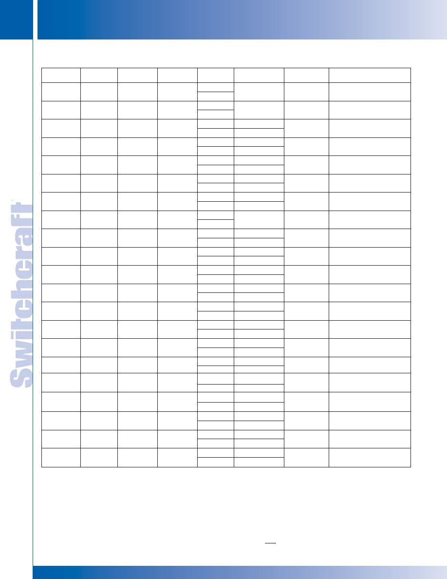
CONNECTORS & RECEPTACLES
70
w w w . s w i t c h c r a f t . c o m
® Registered trademark of Switchcraft, Inc.
Note: Contact your Switchcraft Representative for price and delivery
PHONE: 773 792-2700
CONNECTORS & RECEPT
ACLES
DIMENSIONS ARE FOR REFERENCE ONLY
Inch
(mm)
Pins/
Switchcraft
Part Number
Contacts
1
Mounting
2
Terminals
Listings
Ratings
Mating Number
3
Comments
4
◊
EAC227
M
Front or Rear
Solder Lug
UL
15 A, 250 V AC
P2392
—
CSA
◊
EAC233
M
Rear
PC
UL, CSA,
15 A, 250V AC
P2392
Semko, Demko, Nemko,
VDE
10 A, 250 V AC
SETI, and SEV Approved
◊
EAC233S
M
Rear
PC
UL, CSA,
15 A, 250 V AC
P2392
Semko, Demko, Nemko,
VDE
10 A 250 V AC
SETI, and SEV Approved
◊
EAC305
F
Front
Solder Lug
UL & VDE
15 A, 250 V AC
—
Semko, and SEV Approved
VDE
10 A, 250 V AC
◊
EAC309
M
Front or Rear
Solder Lug
UL & CSA
15 A, 250 V AC
P2392
Demko, Semko, Nemko,
VDE
10 A, 250 V AC
SETI and SEV Approved
◊
EAC311
M
Front or Rear
FASTON
UL & CSA
15 A, 250 V AC
P2392
VDE
10 A, 250 V AC
◊
EAC315
M
Front or Rear
Solder Lug
UL & CSA
15 A, 250 V AC
P2392
(Long)
VDE
10 A, 250 V AC
◊
EAC319
M
Front or Rear
Solder Lug
UL & CSA
15 A, 250 V AC
P2392
—
(Short)
VDE
◊
EAC323
M
Front or Rear
Solder Lug
UL & CSA
15 A, 250 V AC
P2392
Mounting flange on rear
(Short)
VDE
10 A, 250 V AC
Semko, Nemko, SETI Approved
◊
EAC325
F
Rear
Solder Lug
UL & CSA
15 A, 250 V AC
—
Mounting flange on rear
(Short)
VDE
10 A, 250 V AC
◊
EAC327
M
Front or Rear
Solder Lug
UL & CSA
15 A, 250 V AC
P2392
Demko, Semko, Nemko
VDE
10 A, 250 V AC
SETI and SEV Approved
◊
EAC333
M
Rear
PC
UL, & VDE
15 A, 250 V AC
P2392
CSA
10 A, 250 V AC
◊
EAC333S
M
Rear
PC
UL & VDE
15 A, 250 V AC
P2392
CSA
10 A, 250 V AC
◊
EAC405
5
F
Snap-In
Solder Lug
UL & CSA
15 A, 250 V AC
—
—
VDE
10 A, 250 V AC
◊
EAC409
5
M
Snap-In
Solder Lug
UL, & CSA
15 A, 250 V AC
P2392
Demko, Semko, Nemko,
VDE
10 A, 250 V AC
SETI and SEV Approved
◊
EAC411
5
M
Snap-In
FASTON
UL, CSA
15 A, 250 V AC
P2392
Semko, Demko, Nemko,
VDE
10 A, 250 V AC
SETI and SEV Approved
◊
EAC413
5
M
Snap-In
Solder Lug/
UL, CSA
15 A, 250 V AC
P2392
Semko, Demko, Nemko,
FASTON
VDE
10 A, 250 V AC
SETI and SEV Approved
◊
EAC451
6
F
Snap-In
6
PC
UL, & CSA
15 A, 250 V AC
—
Rated for use up to 120°C
VDE
10 A, 250 V AC
◊
EAC453
6
F
Snap-In
6
Solder Lug
UL, & CSA
15 A, 250 V AC
—
Rated for use up to 120°C
VDE
10 A, 250 V AC
◊
EAC455
6
F
Snap-In
6
FASTON
UL, & CSA
15 A, 250 V AC
—
Rated for use up to 120°C
VDE
10 A, 250 V AC
◊
EAC457
6
F
Snap-In
6
Solder Lug/
UL, & CSA
15 A, 250 V AC
—
Rated for use up to 120°C
FASTON
VDE
10 A, 250 V AC
Semko, Demko, Nemko,
SETI and SEV Approved
Semko, Demko, Nemko,
SETI and SEV Approved
Semko, Demko, Nemko,
SETI, SEV Approved
Semko, Demko, Nemko,
SETI, SEV Approved
SERIES EAC (continued)
1 M = Male; F = Female.
2 F = Front; R = Rear. See mounting drawings for mounting details.
3 Also mates with Belden and other standard cords.
4 Semko (Sweden), Demko (Denmark), Nemko (Norway), SETI (Finland), SEV (Switzerland).
5 Receptacles are snap-in mount, and can be ordered to accommodate
.030, .040, .050 and .060 inch panel thickness. For snug fit in panel or
for other specifying assistance, contact Switchcraft.
6 Available only for .050 inch and .060 inch panel thickness
◊
Available on special order only; contact Switchcraft for price and delivery.
UL No. E38829—EAC-309 thru -327 UL No. E65081—EAC-305
CSA Guide 365-E-1, Class 6233, File Card No. LR27474
VDE Certificate of Compliance No. 731 (EAC-305, -325, -405),
all others VDE approval No. 3181.
If you have been using a 15 amp rated Switchcraft EAC connector
ending in an even number, you can now buy an identical part number
that has a 10 amp European rating in addition to the 15 amp UL and
CSA approval. The part number for the new dual rated part is one
less than the old part number (eg. EAC310 becomes EAC309,
EAC412040 becomes EAC411040, EAC234 becomes EAC233,
EAC458050 becomes EAC457050, etc.)
EAC RECEPTACLES
EAC RECEPTACLES
* Please visit the product pages on our website for the most up-to-date product information
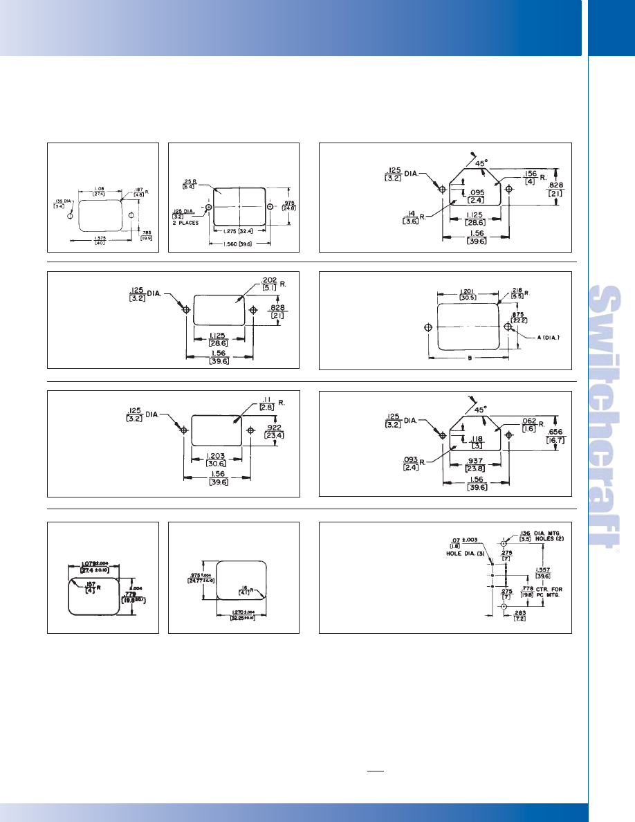
SWITCHCRAFT, INC. 5555 N. Elston Ave. • Chicago, IL 60630
71
CONNECTORS & RECEPTACLES
FAX: 773 792-2129
CONNECTORS & RECEPT
ACLES
DIMENSIONS ARE FOR REFERENCE ONLY
Inch
(mm)
SERIES EAC
EAC RECEPTACLES (continued)
Note: Unless otherwise specified, all dimension tolerances are ± .01" (+0.25 mm)
Front Mount
EAC227, EAC309,
EAC311, EAC315,
EAC319, EAC327
Front Mount
EAC225
Figure 5
Front Mount
EAC305
Figure 2
Front Mount
EAC323
Figure 4
Snap-in Mount
EAC405, EAC451, EAC453,
EAC455, EAC457
Snap-in Mount
EAC409, EAC411
Rear Mount
EAC325
Figure 9
Rear Mount
EAC323
Figure 6
EAC233, EAC309,
EAC311, EAC315,
EAC319, EAC327,
EAC333
Figure 7
Recommended
PC Board Layout
EAC233, EAC333
Figure 10
Note: Center .07 inch diameter
hole not used for 233, 234
EAC RECEPTACLES
EAC RECEPTACLES
* Please visit the product pages on our website for the most up-to-date product information
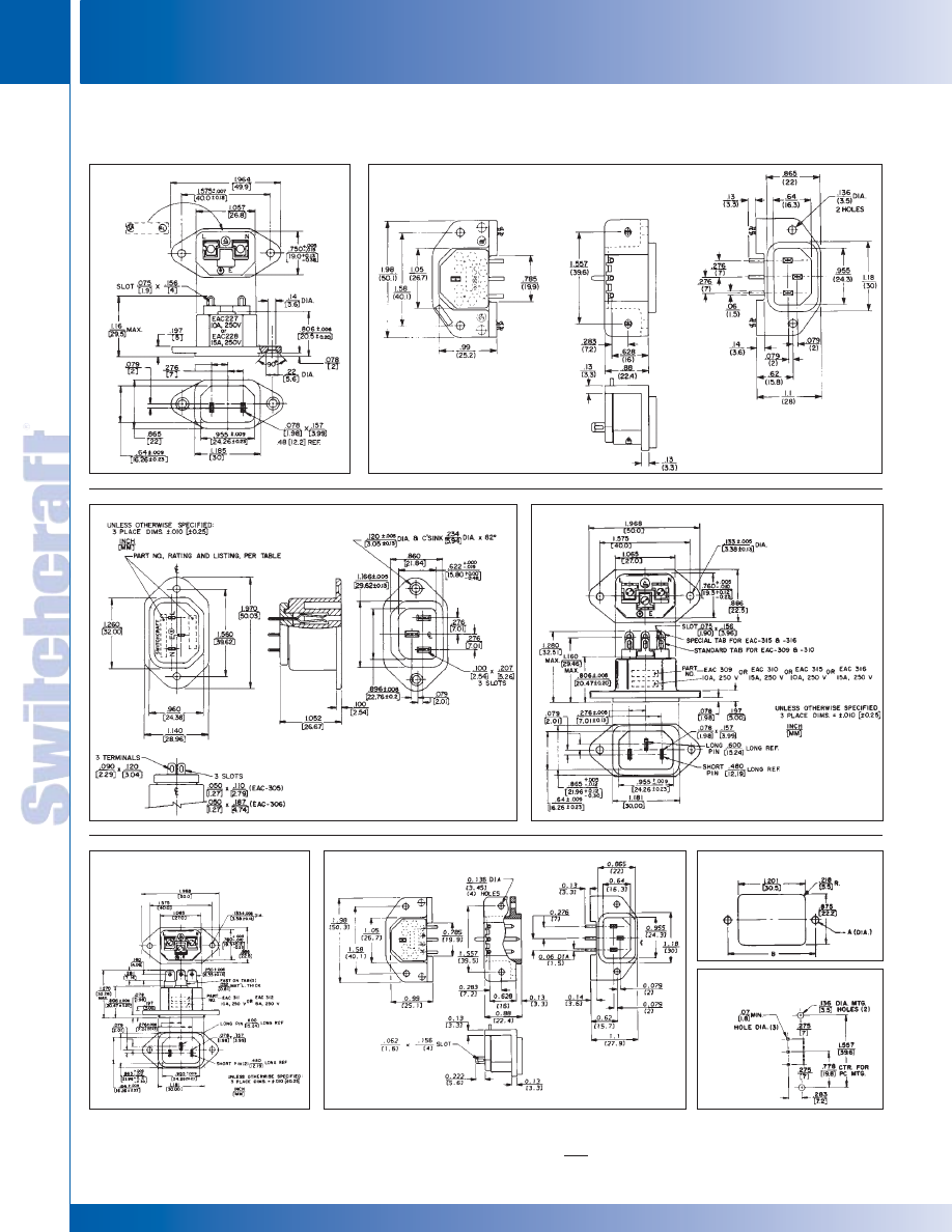
CONNECTORS & RECEPTACLES
72
w w w . s w i t c h c r a f t . c o m
® Registered trademark of Switchcraft, Inc.
Note: Contact your Switchcraft Representative for price and delivery
PHONE: 773 792-2700
CONNECTORS & RECEPT
ACLES
DIMENSIONS ARE FOR REFERENCE ONLY
Inch
(mm)
Note: Unless otherwise specified, all dimension tolerances are ± .01" (+0.25 mm)
EAC227
EAC233S, EAC333S
Note: Center PIN/Terminals
not used on EAC233S
EAC327
EAC309, EAC315
EAC233, EAC333
EAC311
Note: Center
PIN/Terminals not
used on EAC233
Chassis/Panel Opening
Recommended PC Board
Layout (Component Side)
Note: Center
.07 inch dia.
hole not
used on
EAC233
EAC RECEPTACLES (continued)
SERIES EAC
EAC RECEPTACLES
EAC RECEPTACLES
* Please visit the product pages on our website for the most up-to-date product information
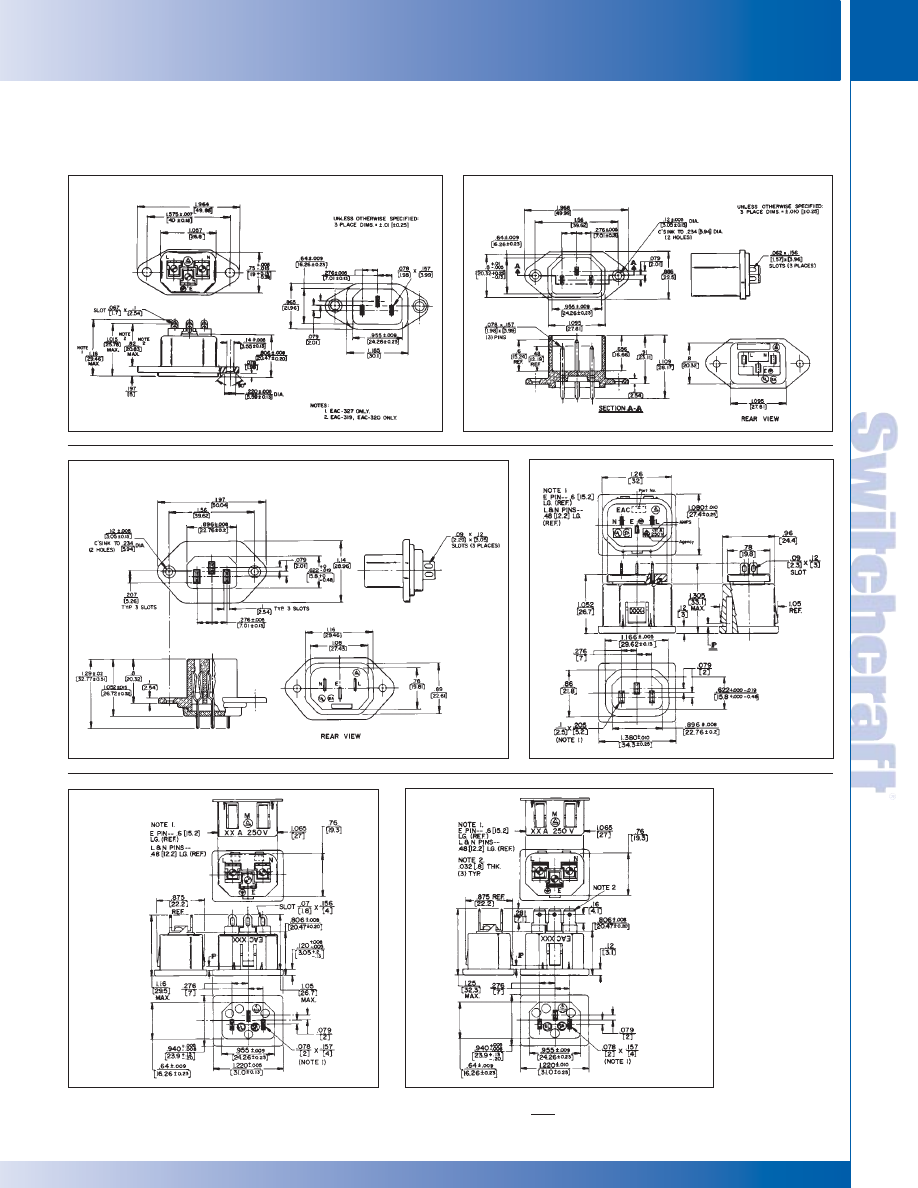
SWITCHCRAFT, INC. 5555 N. Elston Ave. • Chicago, IL 60630
73
CONNECTORS & RECEPTACLES
FAX: 773 792-2129
CONNECTORS & RECEPT
ACLES
DIMENSIONS ARE FOR REFERENCE ONLY
Inch
(mm)
SERIES EAC
EAC RECEPTACLES (continued)
EAC319, EAC327
EAC323
EAC325
EAC405
EAC409
EAC411
EAC RECEPTACLES
EAC RECEPTACLES
* Please visit the product pages on our website for the most up-to-date product information
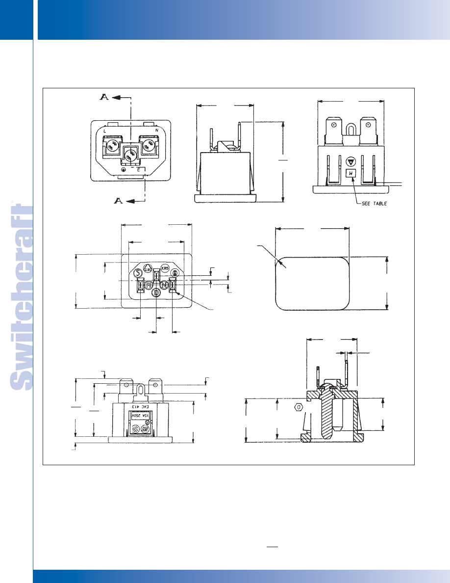
CONNECTORS & RECEPTACLES
74
w w w . s w i t c h c r a f t . c o m
® Registered trademark of Switchcraft, Inc.
Note: Contact your Switchcraft Representative for price and delivery
PHONE: 773 792-2700
CONNECTORS & RECEPT
ACLES
DIMENSIONS ARE FOR REFERENCE ONLY
Inch
(mm)
EAC413
0.875
REF
[22.23]
1.065
[27.05]
1.079
± .004
[27.41 ± .10]
+ .008
0.120
- .005
+ .20
[
3.05
]
- .12
+ .005
0.940
- .008
+ .12
[
23.88
]
- .20
0.779
± .004
[19.79 ± .10]
0.806
± .008
[20.47 ± .20]
0.610REF
“E”
[15.49]
0.157R
[3.99]
0.079
[2.01]
0.079
[2.01]
0.276
[7.01]
0.276
[7.01]
0.760
[19.30]
0.656
[16.66]
0.160
[4.06]
0.281
[7.14]
0.032
[0.81]
0.490
[12.45]
1.260
MAX
[32.00]
1.130
MAX
[28.70]
1.030
MAX
[26.16]
1.220
± .010
[30.99 ± .25]
0.955
± .008
[24.26 ± .20]
0.640
± .009
[16.26 ± .22]
.078 x .157
[1.98 x 3.99]
SERIES EAC
EAC RECEPTACLES (continued)
EAC RECEPTACLES
EAC RECEPTACLES
* Please visit the product pages on our website for the most up-to-date product information
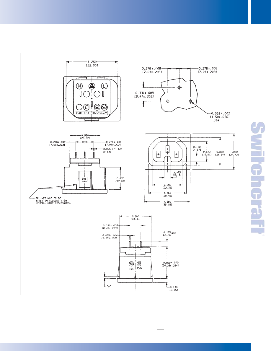
SWITCHCRAFT, INC. 5555 N. Elston Ave. • Chicago, IL 60630
75
CONNECTORS & RECEPTACLES
FAX: 773 792-2129
CONNECTORS & RECEPT
ACLES
DIMENSIONS ARE FOR REFERENCE ONLY
Inch
(mm)
EAC451
RECOMMENDED P.C. BOARD LAYOUT
SERIES EAC
EAC RECEPTACLES (continued)
EAC RECEPTACLES
EAC RECEPTACLES
* Please visit the product pages on our website for the most up-to-date product information
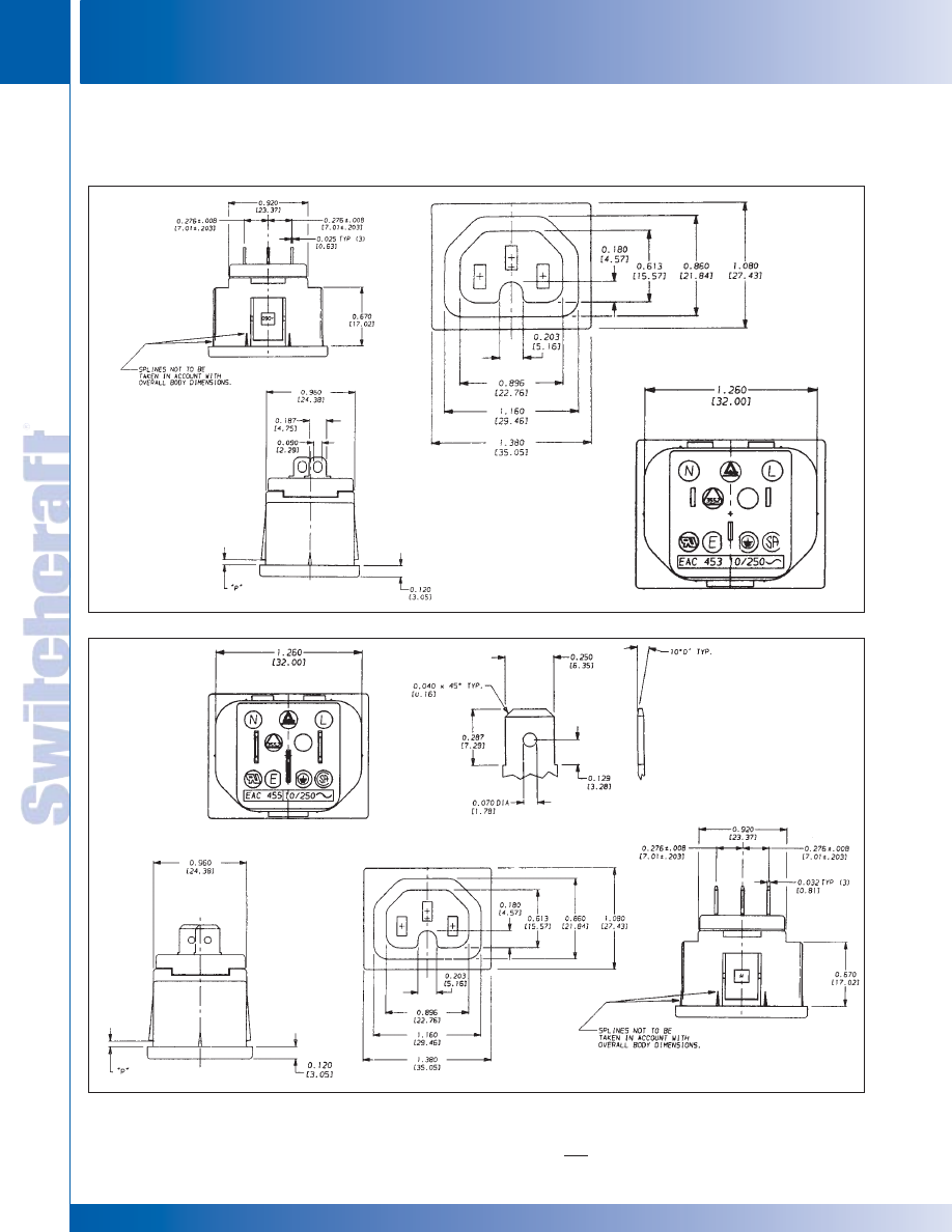
CONNECTORS & RECEPTACLES
76
w w w . s w i t c h c r a f t . c o m
® Registered trademark of Switchcraft, Inc.
Note: Contact your Switchcraft Representative for price and delivery
PHONE: 773 792-2700
CONNECTORS & RECEPT
ACLES
DIMENSIONS ARE FOR REFERENCE ONLY
Inch
(mm)
EAC453
EAC455
FAST-ON TERMINAL
SERIES EAC
EAC RECEPTACLES (continued)
EAC RECEPTACLES
EAC RECEPTACLES
* Please visit the product pages on our website for the most up-to-date product information
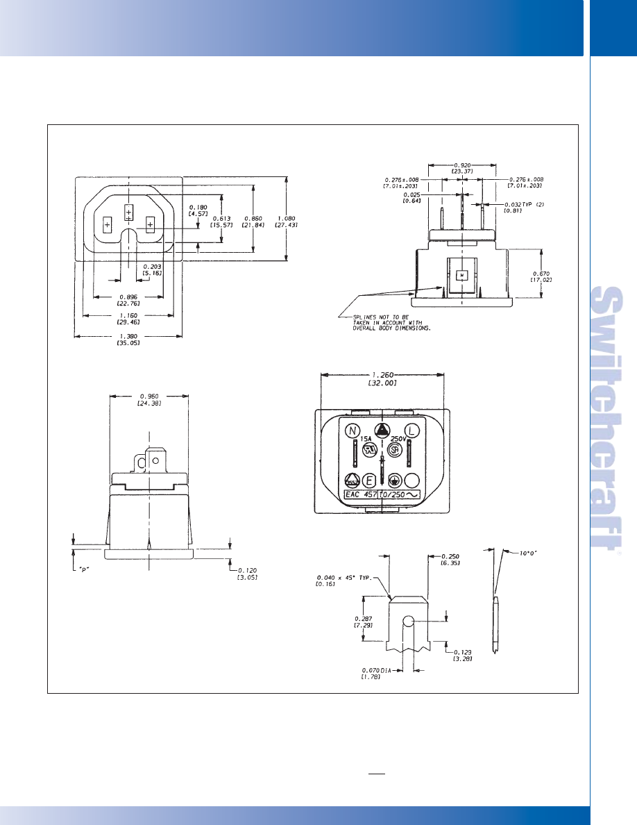
SWITCHCRAFT, INC. 5555 N. Elston Ave. • Chicago, IL 60630
77
CONNECTORS & RECEPTACLES
FAX: 773 792-2129
CONNECTORS & RECEPT
ACLES
DIMENSIONS ARE FOR REFERENCE ONLY
Inch
(mm)
EAC457
SERIES EAC
EAC RECEPTACLES (continued)
EAC RECEPTACLES
EAC RECEPTACLES
* Please visit the product pages on our website for the most up-to-date product information
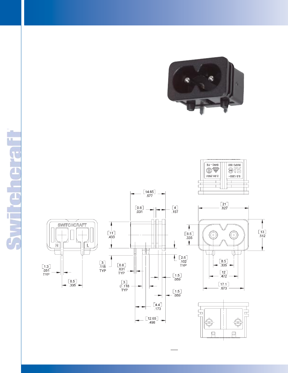
CONNECTORS & RECEPTACLES
78
w w w . s w i t c h c r a f t . c o m
® Registered trademark of Switchcraft, Inc.
Note: Contact your Switchcraft Representative for price and delivery
PHONE: 773 792-2700
CONNECTORS & RECEPT
ACLES
DIMENSIONS ARE FOR REFERENCE ONLY
Inch
(mm)
POWER INLET SOCKET
POWER INLET SOCKET
Switchcraft introduces the RAPC322, an IEC320 inlet
developed as a low power interconnect used in a variety
of applications. The RAPC322 is molded from 94-VO
rated material, is UL recognized, and meets a wide variety
of approvals including CSA and VDE. The RAPC is rated
at 2.5A at 250V. Applications for the RAPC322 include
notebook computers, medical devices, and data
communications products.
FEATURES AND BENEFITS
• Snap-in feet facilitate wave soldering
• Top and side slots allow chassis to captivate connector
• Conforms to EN 60320-1/2
APPLICATIONS
• Appliance Inlet
• Personal Computer
• Data Communications
• Medical Equipment
• Test Equipment
• Instrumentation
SPECIFICATIONS
GENERAL
Current Rating: 5A, UL and CSA 2.5A, VDE and
SEMKO
Nominal Voltage: 250V
Temperature Range: - 55°C to 65°C
Dielectric Strength: 2000V @ 1 minute
MATERIALS
Housing: Black, molded thermoplastic, UL 94V-0
Male Pins: Copper alloy, nickel plated
PC Terminals: Copper alloy, tin plated
RAPC322 POWER INLET SOCKET
* Please visit the product pages on our website for the most up-to-date product information
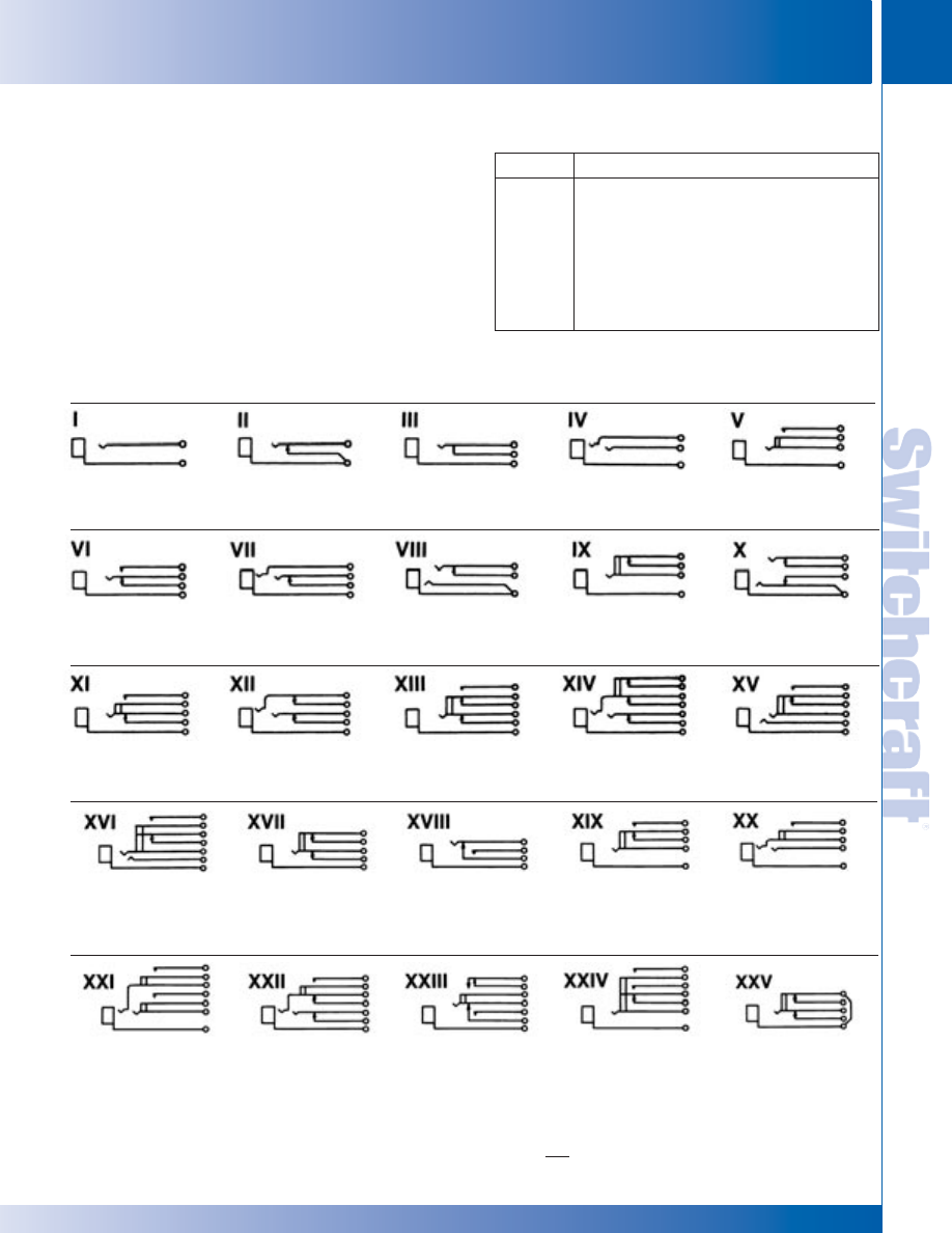
SWITCHCRAFT, INC. 5555 N. Elston Ave. • Chicago, IL 60630
79
JACKS AND PLUGS
FAX: 773 792-2129
JACKS AND
PLUGS
DIMENSIONS ARE FOR REFERENCE ONLY
Inch
(mm)
JACK SCHEMATICS
JACK SCHEMATICS
Circuit Types: Jacks normally have through circuits, shunt
circuits, and/or isolated switching circuits, either individually or
in various combinations. The chart below shows schematics of
39 common jacks - many more combinations are possible, but
these are the most commonly used. A basic description of the
switching action of each jack accompanies each schematic.
Military Identification: Military specifications covering phone
jacks use a special code to describe jack functions. Jack
schematic descriptions are coded J-1 through J-13 (as
appropriate) to coincide with Federal Item Identification
Guides for Supply Cataloging. One or more groups of suffix
numbers/letters identify isolated switching circuits used.
Suffixes identify the switching by industry recognized notation,
i.e., 1-A, 1-B, 1-C, 1-D, etc. See chart below.
JACK SCHEMATICS
Notation
Meaning
1-A
One, SPST switching circuit. Also known as NO
(normally open) or “make” circuit.
1-B
One, SPST switching circuit. Also known as NC
(normally closed) or “break” circuit.
1-C
One, SPDT switching circuit. Also known as transfer
or “break” before “make” circuit.
1-D
One, SPDT switching circuit. Also known as “make”
before “break” circuit.
Single open circuit. (J1.)
Single closed circuit,
Single closed circuit. (J4).
Double open circuit. (J2).
Single open circuit.
sleeve common. (J3).
Isolated switching
“make” circuit. (J1-1-A).
Transfer circuit. (J5).
Tip closed, ring
Tip closed, ring open
Single open circuit.
Double closed circuit,
open. (J10).
(common to sleeve). (J6).
Isolated switching
ring common to
“break” circuit. (J1-1B).
sleeve. (J13).
Single closed. Isolated
Double closed
Single closed circuit.
Double closed circuit.
Double open circuit.
switching “make”
circuit. (J7).
Isolated switching
Isolated switching
Isolated switching
circuit. (J4-1A).
transfer circuit. (J4-1C).
“break” circuit. (J7-1B).
transfer circuit. (J2-1C).
NOTE: Number indicates the quantity of circuit - 2-A means 2, A circuits.
Terminals locations shown on jack schematics do not necessarily coincide
with physical locations on jacks. Not all circuit types available on all jacks.
Double open circuit.
Single closed circuit
Single closed circuit–
Single open circuit.
Double open circuit.
Isolated switching–
Isolated switching
“make” before
Isolated switching
Isolated switching
separate “break” and
“break” circuit. (J4-1B).
“break”. (J8).
transfer circuit. (J1-1C).
“make” circuit.
make circuits (J2-1A-1B).
(J2-1A).
Double open circuit.
Double closed circuit.
Single closed circuit
Single open circuit.
Single closed circuit.
Isolated switching–
Isolated switching
plus “make” before
Isolated switching–
Isolated switching
separate “make”
“make” circuit on ring
“break”. Isolated
separate transfer and
“break” circuit. Sleeve
circuits on both tip and
spring. (J7-1A).
switching–“make”
“make” circuits.
common to isolated
ring. (J2-2A).
before “break”
(J1-1A-1C).
switching circuit throw.
circuit. (J8-1D).
(J4-1B).
* Please visit the product pages on our website for the most up-to-date product information
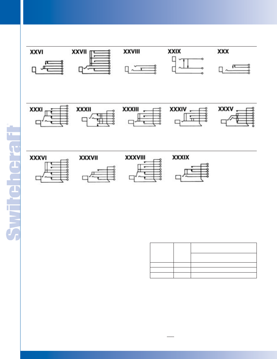
JACKS AND PLUGS
80
w w w . s w i t c h c r a f t . c o m
® Registered trademark of Switchcraft, Inc.
Note: Contact your Switchcraft Representative for price and delivery
PHONE: 773 792-2700
JACKS AND PLUGS
DIMENSIONS ARE FOR REFERENCE ONLY
Inch
(mm)
JACK SCHEMATICS
JACK SCHEMATICS
Single closed circuit.
Tip closed; ring open
Single open (tip)
Double jack,
Single open circuit–
Isolated switching–
circuits. Isolated
circuit and single closed
2-conductors on each
“make” before
“make” before “break”
switching–two “make”
(ring) circuit. (J9).
side. Tip circuits cross
“break”. (J11).
circuit. (J4-1D).
circuits and one “break”
shunted; common
circuit. (J10-2A-1B).
sleeve. (J12).
Tip closed; ring closed
Double closed circuit.
Single closed circuit.
Single open circuit.
Double open circuit.
circuits. Isolated
Separate sleeve
Isolated switching–
Isolated switching–
Isolated switching–
switching–“break”
“break” circuit.
Two “make” circuits.
Two “make” circuits.
One “make” and one
before “make” circuit.
“break” circuit.
Double closed circuit.
Tip closed; ring open
Double closed circuit.
Double open circuit.
Isolated switching–
circuits. Isolated
Isolated switching–
Isolated switching–
One “make” and one
switching–One
Two “make” circuits.
“break” before
“break” circuit.
“make” circuit.
“make” circuit.
JACK MATING DATA
NOTE: See tables for jack/plug mating data
SPECIFYING NOTE: Due to assembly variations containing components
(solder lugs, wire-wrapping terminals, or both), these Jack Panel
Assemblies are available on special order only. Contact Switchcraft.
Switchcraft can build complete Jack Panel Assemblies with
jacks, lamp jacks and switches with wire-wrapping terminals. If
desired, components with solder lugs and wire-wrapping
terminals can be installed in the same assembly.
WIRE-WRAPPING TERMINAL DESIGN
Jack springs with integral wire-wrapping terminals are made of
special copper alloy for maximum work-life with excellent
resistance to corrosion. Shank of terminal accommodates a
maximum of three wire connections. Tini-Telephone
®
phone
jacks, lamp jacks and switches with wire-wrapping terminals
have slightly higher stack due to greater spacing required for
wrapping tool access. Actuator springs and ground lug
terminals are .704" long by .060" wide.
WIRE-WRAPPING TERMINATIONS
WIRE-WRAPPING CONNECTIONS
Use the chart below as a guide to recommended tools to
be used with varying terminal thickness and wire gauges.
Recommended Wire-Wrapping Tool
Terminal
(Gardner-Denver Co. Part Numbers)
Thickness
Wire
Use with 14B1-A
Wrapping Tool
(Inches)
Gauge
Wrapping Bit
Sleeve
.020 thru .032
22 & 24
500131
18840
.016
24
500131
18840
.016 thru .032
26
37006
17611-2
JACK SCHEMATICS
* Please visit the product pages on our website for the most up-to-date product information
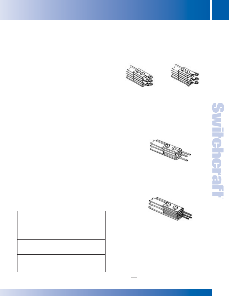
SWITCHCRAFT, INC. 5555 N. Elston Ave. • Chicago, IL 60630
81
JACKS AND PLUGS
FAX: 773 792-2129
JACKS AND
PLUGS
DIMENSIONS ARE FOR REFERENCE ONLY
Inch
(mm)
LONG FRAME TELEPHONE JACKS
LONG FRAME TELEPHONE JACKS
JACK MATERIALS
The complete Switchcraft line of standard size panels,
jacks, plugs, switches and accessories are rugged, premium
quality devices...hand-crafted by experts...100% inspected...
and carefully adjusted to meet the traditionally high quality
demands of the telephone industry and the military. Tightly
controlled incoming inspection, manufacturing methods,
and QC procedures assure you of long-life, reliable components.
Typical applications where Switchcraft components have
been specified for more than five decades are: telephone
central office equipment, switchboards, jackfields, test
and patch panels, and station equipment; TV and radio
broadcasting consoles; PA and communication consoles;
telegraph systems and apparatus; multichannel video and
audio patching; and data processing equipment, such as
computers, telemetry, I/O devices and facsimile.
FRAMES –
Jack frames are heavy steel, formed and
press welded for added strength. Side member adds to
frame rigidity and resistance to shock and vibration. Both
“A” and “C” type frames can be supplied. (See next page.)
SPRINGS –
A special copper alloy is used for leaf springs
because it offers excellent mechanical and electrical
characteristics, and good corrosion resistance. The spring
alloy has special hardness and ductility, and springs are
produced from custom-designed dies. Although normally
adjusted to mate with telephone (and MIL-type) plugs, springs
can be adjusted to mate with commercial phone plugs.
BUSHINGS –
Bushings are copper alloy (except insulated
jacks), drilled to accept either a standard (.250" diameter
finger) plug or a popular smaller (.206" diameter finger)
plug. Series M Hi-D Jax
®
have a threaded brass bushing, or a
molded thermoplastic bushing for insulated mounting.
CONTACTS –
Jack design includes “wiping” action of
contacts for low resistance connections. The contacts
supplied depend on the jack selected. Gold or silver plating is
normally offered as an option on tip, ring and/or sleeve springs.
Several precious metals and shapes are used on jacks.
SOLDER LUGS TERMINALS –
Lugs project out directly
from rear of jack and are solder-coated for easy wiring and
soldering. Offset lugs can be supplied on special order (except
standard on MT-Jax
®
). Jacks with offset ground lugs are
par ticular ly suitable for bussing connections on jack
panels. Contact Switchcraft for special order lug requirements.
WIRE-WRAPPING TERMINALS –
Wire-wrapping
eliminates the need for soldering. Each terminal accepts up to
three wrapped wires (22 or 24 gauge, 5 wraps each), applied
with standard wire-wrapping tools. Terminal base has
standoff shoulder which prevents first wrapped wire from
accidentally sliding down and shorting against another
terminal or adjacent spring. Terminal tips are radiused to facilitate
positioning of wire-wrapping tool over terminals. See page 80 for
wire-wrapping data.
PRINTED CIRCUIT TERMINALS –
Components can be
supplied with printed circuit terminals on special order. Terminals
can be specified in various lengths to accommodate different
thicknesses of single and double sided boards, as well as
multilayers, and flat flexible cable and circuitry.
OTHER TERMINALS –
Many other special terminal styles are
possible. For example, where mounting permits, jacks can be
supplied with stacks having right-angle terminals. Contact
Switchcraft for special terminals.
CUSTOM COMPONENTS
Only the most popular types of jacks are listed.
1/4" LONG FRAME TELEPHONE JACKS
STRAIGHT
SOLDER LUGS
OFFSET
SOLDER LUGS
WIRE-WRAPPING
TERMINALS
PRINTED CIRCUIT
TERMINALS
(SPECIAL)
Material
Shape
Description
Palladium
Welded
Best overall combination of life,
Crossbar
current carrying, and resistance
to environment. Also known as
WEco #2.
Fine silver
Riveted,
Carries higher current than
button-type
palladium.
Gold alloy
Welded
Recommended for dry circuit
Crossbar
switching.
Excellent resistance to
corrosion and contamination.
Also known as WEco #1.
Fine silver
Riveted,
Heavy currents.
(Large)
button-type
Gold or
Plating
For lower contact resistance
Silver
(used on through circuit springs).
* Please visit the product pages on our website for the most up-to-date product information
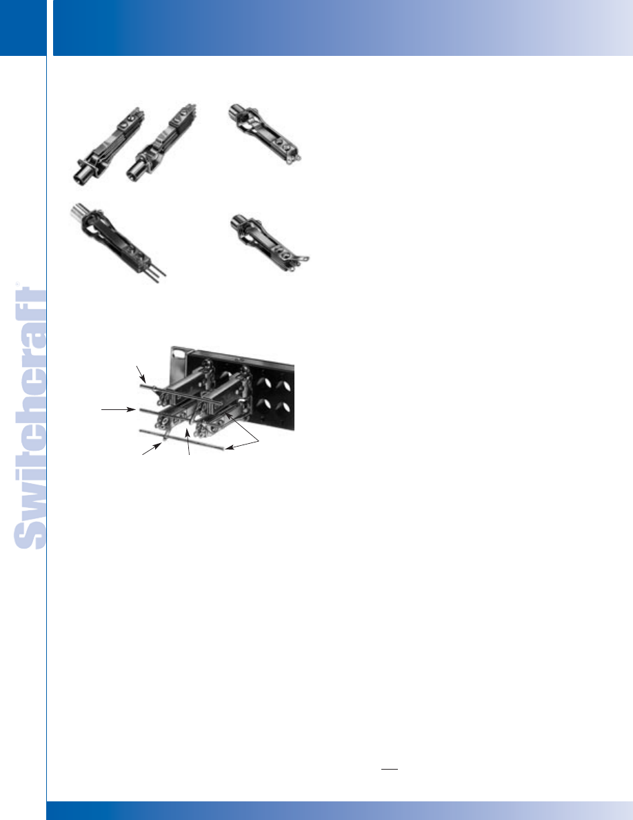
JACKS AND PLUGS
82
w w w . s w i t c h c r a f t . c o m
® Registered trademark of Switchcraft, Inc.
Note: Contact your Switchcraft Representative for price and delivery
PHONE: 773 792-2700
JACKS AND PLUGS
DIMENSIONS ARE FOR REFERENCE ONLY
Inch
(mm)
LONG FRAME TELEPHONE JACKS
LONG FRAME TELEPHONE JACKS
LONG FRAME TELEPHONE JACKS
MT-Jax
®
(“A” Frame)
WMT-Jax
®
, Number
WMT-332B
YMT-Jax
®
, Number
YMT-332B
Ground Lug “Toward”
Frame (Y Offset)
Buss Wire
Between
Rows
Ground Lug
“Toward” Frame
Ground Lug “Away”
from Frame (X Offset)
Buss Wire
Outside of
Rows
Long frame jacks are designed especially for high quality
communication equipment, and to meet exacting MIL
specifications, as well as telephone and communication systems.
Many jacks have WEco equivalent types. MT-Jax
®
phone jacks are
offered in four styles: MT-Jax
®
, WMT-Jax
®
, XMT-Jax
®
and YMT-Jax
®
.
Rugged steel frames are produced in specially designed dies,
press welded to provide rigidity and dimensional stability required
by telephone and communication jack panels - and to meet MIL
frame strength tests. “A” and “C” frame styles are available.
TERMINALS –
Solder Lug: All MT-Jax
®
have solder lug termi-
nals. Wire-Wrapping Terminals: WMT-Jax
®
have wire-wrapping ter-
minals. Offset Ground Lugs: XMT-Jax
®
and YMT-Jax
®
have ground
lugs, which simplify production line wiring time. A single row of
jacks can be installed with a single buss wire connected to all
ground lugs in a row, or when double rows are mounted on .625"
vertical centers with lugs oriented between rows, holes in ground
lugs line up so a single buss wire provides connections for both
rows. XMT-Jax
®
have ground lugs oriented away and YMT-Jax
®
are
oriented toward jack frame. See illustration.
MIL STANDARDIZATION –
MIL jack types listed have been
adjusted for use with plugs specified in Amendment No.1, MIL-P-642,
usually M642/1-1, M642/1-2, M642/2-1, M642/2-2, M642/4-1 or
M642/4-2. When applicable, specify the plug you will use; we will
adjust with that plug where the item is not a MIL-type. NOTE:
Details of Typical Buss Wiring of Jacks
with Offset Ground Lugs
MT-Jax
®
jacks Numbers
◊
MT-342B and
◊
MT-344B have
shorter bushings, 0.5" long with a hold inside diameter of
.21". They will mate with MIL plug M642/5-1 or M642/8-1.
M642/5-1 plug (Switchcraft 480) cannot be used with
◊
MT-342B or
◊
MT-344B if these jacks are mounted on standard
.625" thick panels. The short jack bushings are recessed
.125", and the M642/5-1 is too wide to fit in the panel recess.
Use plug M642/8-1 (Switchcraft 484) with a narrower
diameter to fit in the recess and mate properly.
CONTACTS –
Contacts on shuts and isolated switching
circuits are welded crossbar palladium. Welded crossbar gold
alloy contacts (WEco #1) are available on special order for dry
circuit applications.
SPECIFICATIONS
Frame and Stack Screws: Plated steel, with iridescent
iridite finish.
Springs: Copper alloy, spring tempered. Solder lugs are tinned.
Bushings: Plated copper alloy standard. Natural brass finish
optional.
Insulation: Rigid plastic spacers (MIL-type PBE-P per
Specification LP-513). One piece molded through stack.
Contacts: Welded crossbar palladium contacts in shunt and
isolated switching circuits are standard. Gold alloy (WEco #1)
and fine silver are available on special order.
MECHANICAL
Life: Commercial jacks: 10,000 insertion/withdrawal cycles, minimum.
Military Jacks: 20,000 insertion/withdrawal cycles, minimum.
Mechanical Shock: Military Jacks – Per MIL-STD-202,
method 213, Test Condition H (75g).
Vibration: Military Jacks – Per MIL-STD-202, method 213, (10-55 Hz).
ELECTRICAL
Contact Resistance: Commercial Jacks – .030 ohms
maximum (initial), .050 ohms maximum (after humidity, durability
exposure). Military Jacks – .010 ohms maximum (initial), .020
ohms maximum (after life), .10 ohms maximum (after salt spray).
Insulation Resistance: Commercial Jacks – 10,000 M
Ω
minimum (initial), 1,000 M
Ω
minimum (after humidity). Military
Jacks – 10,000 M
Ω
minimum (initial), 1,000 M
Ω
minimum (after
humidity, durability exposure).
Dielectric Withstanding Voltage: 500 V, 60 Hz (rms) AC.
ENVIRONMENTAL
Thermal Range: Commercial Jacks – -55°C to +85°C
(non-operating); -20°C to +65°C (operating). Military Jacks -
-55°C to +85°C (non operating); -40°C to +65°C (operating).
Thermal Shock: Commercial Jacks – Per MIL-STD-202,
method 107. Military Jacks – Per MIL-STD-202, method 107.
Humidity: Commercial Jacks – Per MIL-STD-202, method
106. Military Jacks – 0% to 95% operating and non-operating.
Salt Spray: Commercial Jacks – Per MIL-STD-202, method
101. Military Jacks – Per MIL-STD-202, method 101 (48 hours).
Moisture Resistance: Military Jacks – Per MIL-STD-202,
method 106 (240 hours).
ORDERING –
Order jacks by part number. Additional variations
in jacks are available on special order. Special circuitry, frames,
contacts, natural brass bushings, as other terminals are available.
XMT-Jax
®
, Number
XMT-332A
MT-Jax
®
(“C” Frame)
* Please visit the product pages on our website for the most up-to-date product information
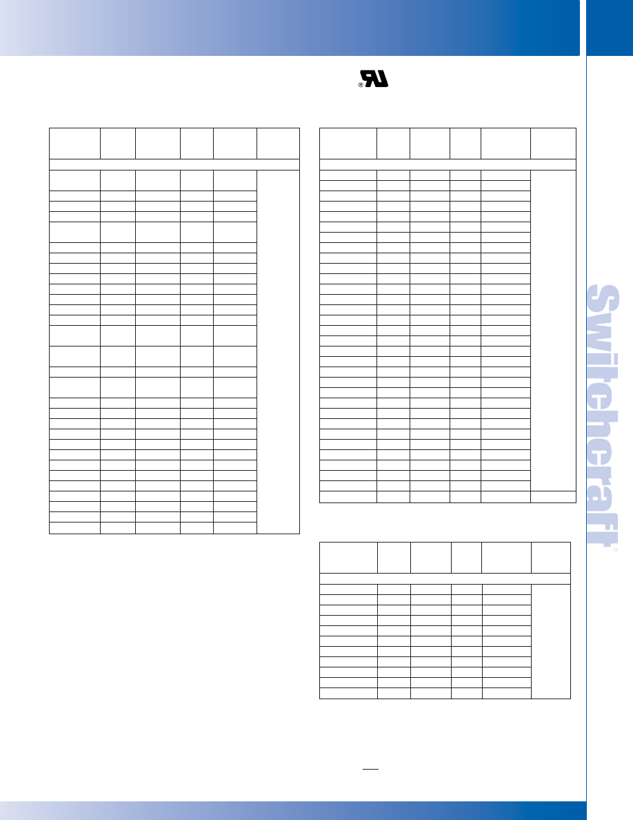
SWITCHCRAFT, INC. 5555 N. Elston Ave. • Chicago, IL 60630
83
JACKS AND PLUGS
FAX: 773 792-2129
JACKS AND
PLUGS
DIMENSIONS ARE FOR REFERENCE ONLY
Inch
(mm)
Sche-
Dim. “X”
Switchcraft
WEco
MIL
matic
maximum
Mating
Part Number
Equiv.
Type1
Circuit*
Inch (mm)
Plug3
2-CONDUCTOR 2
MT331
233A,
221E3
M641/2-8
I
.438 (11.1)
◊
CMT331
223C
–
I
.438 (11.1)
◊
WMT331
223AM
–
I
.438 (11.1)
◊
WCMT331
223CM
–
I
.438 (11.1)
◊
MT332
232A,
544A4
–
II
.5 (12.7)
◊
CMT332
232C
–
II
.5 (12.7)
MT332A
218A
M641/2-3
III
.5 (12.7)
◊
CMT332A
218C
–
III
.5 (12.7)
◊
MT332C
303A
M641/2-1
XVIII
.562 (14.3)
MT333
215A
M641/2-6
V
.469 (11.9)
◊
CMT333
215C
–
V
.469 (11.9)
◊
MT333E
237A
–
IX
.625 (15.9)
◊
CMT333A
237C
–
IX
.625 (15.9)
MT334A
225A,
234A
–
XI
.562 (14.3)
◊
CMT334A
225C,
234C
–
XI
.562 (14.3)
MT334C
216A
M641/2-5
XVII
.625 (15.9)
◊
CMT334C
216C,
484C5
–
XVII
.625 (15.9)
MT334E
217A
M641/2-7
XXV
.562 (14.3)
◊
CMT334E
217C
–
XXV
.562 (14.3)
◊
MT334F
226A
M641/2-4
XIX
.562 (14.3)
◊
CMT334F
226C
–
XIX
.562 (14.3)
◊
MT335
236A
–
XIII
.562 (14.3)
◊
CMT335
236C
–
XIII
.562 (14.3)
◊
MT336E
10
438A
–
XXIII
.75 (19.0)
CMT336E
438C
M641/1-2
XXIII
.75 (19.0)
◊
MT337
10
411A
M641/2-9
XXIV
.75 (19.0)
◊
CMT337
411C
M641/1-1
XXIV
.75 (19.0)
◊
CMT351C
394C
–
XXXIII
.812 (20.6)
◊
MT352A
218J
–
III
.5 (12.7)
◊
CMT354F
361C
–
XXXIV
.75 (19.0)
MT-JAX
®
(with WEco Equivalent Jacks)
2
1/4" LONG FRAME TELEPHONE JACKS
Sche-
Dim. “X”
Switchcraft
WEco
MIL
matic
maximum
Mating
Part Number
Equiv.
Type
1
Circuit*
Inch (mm)
Plug
3
3-CONDUCTOR
MT332B
238A
M641/3-1
IV
.562 (14.3)
◊
CMT332B
238C
–
IV
.562 (14.3)
WMT332B
238AM
–
IV
.562(14.3)
◊
WCMT332B
238CM
–
IV
.562 (14.3)
MT333B
300A
–
VII
.562 (14.3)
◊
MT334B
239A
M641/3-2
XII
.562 (14.3)
◊
CMT334-B
239C
–
XII
.562 (14.3)
WMT334B
239AM
–
XII
.578 (14.7)
◊
WCMT334B
239CM
–
XII
.578 (14.7)
◊
MT336
241A
M641/3-4
XX
.562 (14.3)
◊
CMT336
241C
–
XX
.562 (14.3)
◊
WMT336
10
241AM
–
XX
.625 (15.9)
◊
WCMT336
241CM
–
XX
.625 (15.9)
◊
MT336A
10
242A
M641/5-5
XIV
.688 (17.5)
◊
CMT336A
242C
–
XIV
.688 17.5)
◊
WMT336A
242AM
–
XIV
.75 (19.0)
◊
WCMT336A
242CM
–
XIV
.75 (19.0)
◊
MT336B
10
285A
M641/3-6
XXI
.812 (20.6)
◊
CMT336B
285C
–
XXI
.812 (20.6)
MT336C
10
240A
M641/3-3
XXII
.688 (17.5)
◊
CMT336C
240C
–
XXII
.688 (17.5)
◊
WMT336C
10
240AM
–
XXII
.75 (19.0)
◊
WCMT336C
240CM
–
XXII
.75 (19.0)
◊
MT336D
10
280A
–
XXXI
.75 (19.0)
◊
CMT336D
280C
–
XXXI
.75 (19.0)
◊
WMT336D
10
280AM
–
XXXI
.938 (23.8)
◊
WCMT336D
280CM
–
XXXI
.938 (23.8)
◊
MT338
267A
–
XXXII
.562 (14.3)
◊
CMT338
267C
–
XXXII
.562 (14.3)
◊
MT339
10
284A6
M641/3-7
XXVII
.967 (24.6)
◊
CMT339
384C6
–
XXVII
.967 (24.6)
◊
MT342B
246A
–
IV
.563 (14.3)
M642/5-1
*Refer to page 79 and 80 for schematics.
◊
Special order only; contact Switchcraft.
1. Many jacks are offered with MIL specifications. Other jacks are made of
MIL-spec materials but do not have MIL approval because no MIL type
numbers have been assigned.
2. MT-Jax have nickel-plated copper alloy bushing. WEco equivalent jacks
have plain copper alloy bushings (except WEco Number 221E, which
has nickel-plated copper alloy bushing).
3. Mating plugs and patch cords are contained in the catalog.
4. Adjust non-short tip-ring.
5. Adjusted for plug M642/1-1 or M642/1-2.
6. Actuates differently (insulated “A” off ring instead of tip).
7. Same as MIL type M641/2-3 except with offset ground lug.
8. Same as MIL type M641/3-1 except with offset ground lug.
9. Same as MIL type M641/3-2 except with offset ground lug.
10. When mounted on “A” frames, stacks are too high to fit in standard
panels with .625" horizontal space add prefix “C” to part number
to order jacks with “C” frame.
M642/4-1
M642/4-2
or
M642/4-3
M642/2-1
or
M642/2-2
Sche-
Dim. “X”
Switchcraft
WEco
MIL
matic
maximum
Mating
Part Number
Equiv.
Type
1
Circuit*
Inch (mm)
Plug
3
3-CONDUCTOR 2
◊
WMT342B
246 AM
–
IV
.562 (14.3)
MT344B
248A
–
XII
.625 (15.9)
◊
MT346
249A
–
XX
.562 (14.3)
◊
CMT346
249C
–
XX
.562 (14.3)
◊
MT354B
248E
–
XII
.625 (15.9)
◊
MT355
10
243C
–
XXXV
.812 (20.6)10
◊
MT356C
10
245A
–
XXXVI
.938 (23.8)10
◊
CMT356C
245C
–
XXXVI
.938 (23.8)
◊
MT357
10
363A
–
XXXVII
.75 (19.0)10
◊
CMT358
290C
–
XXXVIII
.875 (22.2)
◊
CMT359
326C
–
XXXIX
.75 (19.0)
M642/5-1
or
M642/2-2
MT-JAX (WITH WECO EQUIVALENT JACKS)
2
M642/5-1
LONG FRAME TELEPHONE JACKS
LONG FRAME TELEPHONE JACKS
* Please visit the product pages on our website for the most up-to-date product information
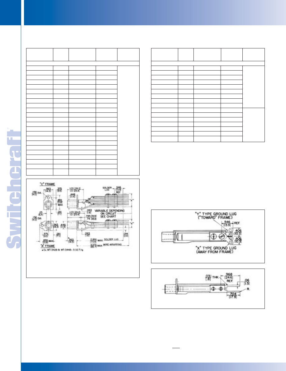
JACKS AND PLUGS
84
w w w . s w i t c h c r a f t . c o m
® Registered trademark of Switchcraft, Inc.
Note: Contact your Switchcraft Representative for price and delivery
PHONE: 773 792-2700
JACKS AND PLUGS
DIMENSIONS ARE FOR REFERENCE ONLY
Inch
(mm)
LONG FRAME TELEPHONE JACKS
LONG FRAME TELEPHONE JACKS
MT-JAX
®
(Industry Standard – No WEco Equivalent)
MT-JAX
®
(Industry Standard – No WEco Equivalent)
MT-Jax
®
and WMT-Jax
®
MT-Jax
®
,Wire-Wrapping Detail
MT-Jax
®
, Offset Lugs
*Refer to pages 79 and 80.
◊
Special order only; contact Switchcraft.
1. Many jacks are offered with MIL specifications. Other jacks
are made of MIL-spec materials but do not have MIL approval
because no MIL type numbers have been assigned.
2. MT-Jax have nickel plated copper alloy bushing. WEco equiv. jacks
have plain copper alloy bushings (except WEco No. 221E, which has
nickel plated copper alloy bushing).
3. Mating plugs and patch cords are contained in this catalog.
7. Same as MIL type M641/2-3 except with offset ground lug.
8. Same as MIL type M641/3-1 except with offset ground lug.
9. Same as MIL type M641/3-2 except with offset ground lug.
10. When mounted on “A” frames, stacks are too high to fit in standard
panes with .625" horizontal space add prefix “C” to part number
to order jacks with “C” frame.
Dim. “X”
Switchcraft
MIL
Schematic
maximum
Mating
Part Number
Type
1
Circuit*
Inch (mm)
Plug
3
2-CONDUCTOR
2
◊
WMT332A
–
III
.5 (12.7)
◊
WCMT332A
–
III
.5 (12.7)
XMT332A
–
III
.5 (12.7)
◊
YMT332A
–
III
.5 (12.7)
◊
CMT332C
–
XVIII
.562 (14.3)
◊
WMT332C
–
XVIII
.5 (12.7)
◊
WMT333
–
V
.469 (11.9)
◊
WCMT333
–
V
.469 (11.9)
◊
MT333A
–
VI
.967 (24.6)
◊
WMT333E
–
IX
.625 (15.9)
◊
WMT334A
–
XI
.562 (14.3)
◊
WMT334C
–
XVII
.562 (14.3)
◊
WMT334E
–
XXV
.562 (14.3)
◊
WMT334F
–
XIX
.641 (16.3)
◊
WMT335
10
–
XIII
.688 (17.5)
◊
WCMT335
–
XIII
.688 (17.5)
MT335A
10
M641/2-2
XXVI
.75 (19.0)
◊
CMT335A
–
XXVI
.75 (19.0)
◊
WMT335A
–
XXVI
.75 (19.0)
◊
WCMT335A
–
XXVI
.75 (19.0)
◊
WMT336E
10
–
XXIII
.875 (22.2)
◊
WCMT336E
–
XXIII
.875 (22.2)
◊
CMT341
–
I
.438 (11.1)
M642/4-1
M642/4-2
or
M642/4-3
Dim. “X”
Switchcraft
MIL
Schematic
maximum
Mating
Part Number
Type
1
Circuit*
Inch (mm)
Plug
3
3-CONDUCTOR
2
XMT332B
–
IV
.562 (14.3)
◊
YMT332B
–
IV
.562 (14.3)
◊
CMT333B
–
VII
.562 (14.3)
◊
WMT333B
–
VII
.562 (14.3)
XMT334B
–
XII
.562 (14.3)
◊
YMT334B
10
–
XII
.562 (14.3)
◊
WMT336B
–
XXI
.812 (20.6)
◊
WCMT336B
–
XXI
.812 (20.6)
◊
MT343B
–
VII
.5 (12.7)
◊
CMT342B
–
IV
.562 (14.3)
◊
CMT344B
–
XII
.625 (15.9)
◊
WMT344B
–
XII
.625 (15.9)
◊
MT346A
10
–
XIV
.688 (17.5)
◊
MT346B
10
–
XXI
.812 (20.6)
◊
MT346C
10
–
XXII
.688 (17.5)
◊
CMT346C
–
XXII
.688 (17.5)
M642/2-1
or
M642/2-2
M642/5-1
M642/5-1
or
M642/2-2
1
* Please visit the product pages on our website for the most up-to-date product information
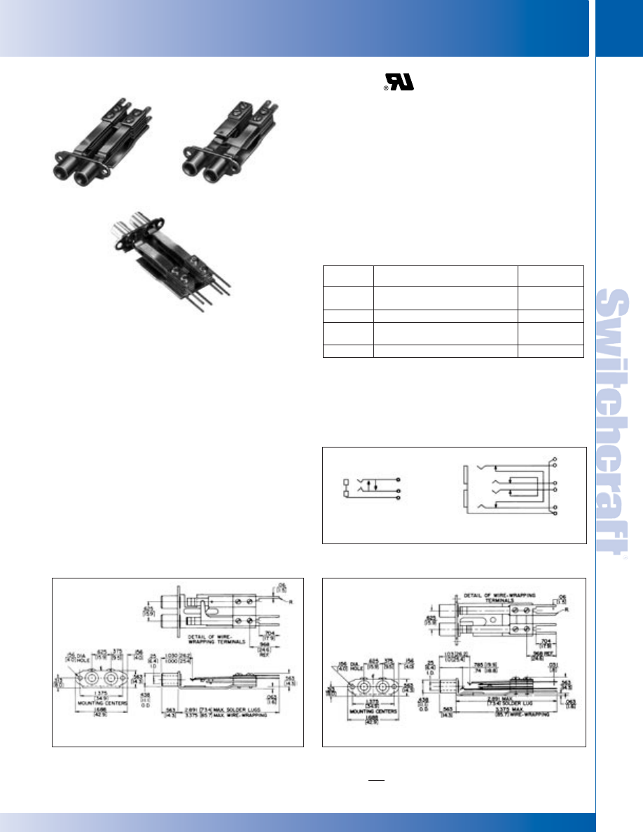
SWITCHCRAFT, INC. 5555 N. Elston Ave. • Chicago, IL 60630
85
JACKS AND PLUGS
FAX: 773 792-2129
JACKS AND
PLUGS
DIMENSIONS ARE FOR REFERENCE ONLY
Inch
(mm)
LONG FRAME TELEPHONE TWIN JACKS
LONG FRAME TELEPHONE TWIN JACKS
High quality telephone jacks are essentially doubled versions
of MT-Jax
®
. Twin-Jax
®
are used in Switchcraft Series 2400,
2600 and JP
®
Jack Panels and other standard jack panels.
Twin-Jax
®
have direct WEco equivalents.
MT388 AND WMT388
Frame mounting ears are on 1.375" centers, and bushings
are on .625" centers. Jacks are double, 2-conductor type with
a crossover wiring feature. If a mating plug is inserted in
either bushing, crossover contacts are opened (see
schematic). MT388 (solder lugs) is equivalent to WEco jack
410A, 410C and 410D. WMT388 (wire-wrapping) is equivalent
to WEco 410AM.
MT389 AND WMT389
Double, 3-conductor jacks with both the tip and ring circuits
interconnected (crossover wired) so if a plug is inserted in
either jack, common circuits are opened (see schematic).
MT-389 (solder lugs) is equivalent to WEco 482A. WMT389
(wire-wrapping) is equivalent to WEco 482AM and 482BM.
SPECIFICATIONS
Frame and Stack Screws: Steel, plated with iridescent
iridite finish.
Springs: Copper alloy, spring tempered. Solder lugs are
solder coated.
Bushings: Nickel-plated copper alloy.
Contacts: Welded crossbar palladium in shunt circuits.
Insulation: Rigid plastic (MIL-type PBE-P, per MIL
Specification LP-513C). Extruded plastic insulating tubing
through stack.
ORDERING
Order by part number from table.
1/4" LONG FRAME TELEPHONE TWIN JACKS
Part
Dim. “X” max.
Number
1
Adjusted for Plug
Inch (mm)
MT388
WEco types 298B and 347B
.562 (14.3)
MIL types M642/9-1 and M642/1-1
◊
WMT388
Switchcraft types 411, 412, 413, 420
.562 (14.3)
MT389
WEco type 310
.594 (15.1)
MIL types M642/2-1 and M642/2-2
WMT389
Switchcraft types 414 and 482
.562 (14.3)
◊
Special Order only; contact Switchcraft.
1. Number MT388 is equivalent to MIL-type M641/11-1
2. Complete data for telephone and MIL-type plugs are contained in this section.
Mounting Screws: #6-32, Part Number P10725, can be ordered separately.
Contact Switchcraft. (Screws not supplied with jacks).
SCHEMATIC CIRCUITS
MT388 and
WMT388
MT389 and WMT389
MT388 and WMT388
MT389 and WMT389
MT389
WMT389
MT388
* Please visit the product pages on our website for the most up-to-date product information
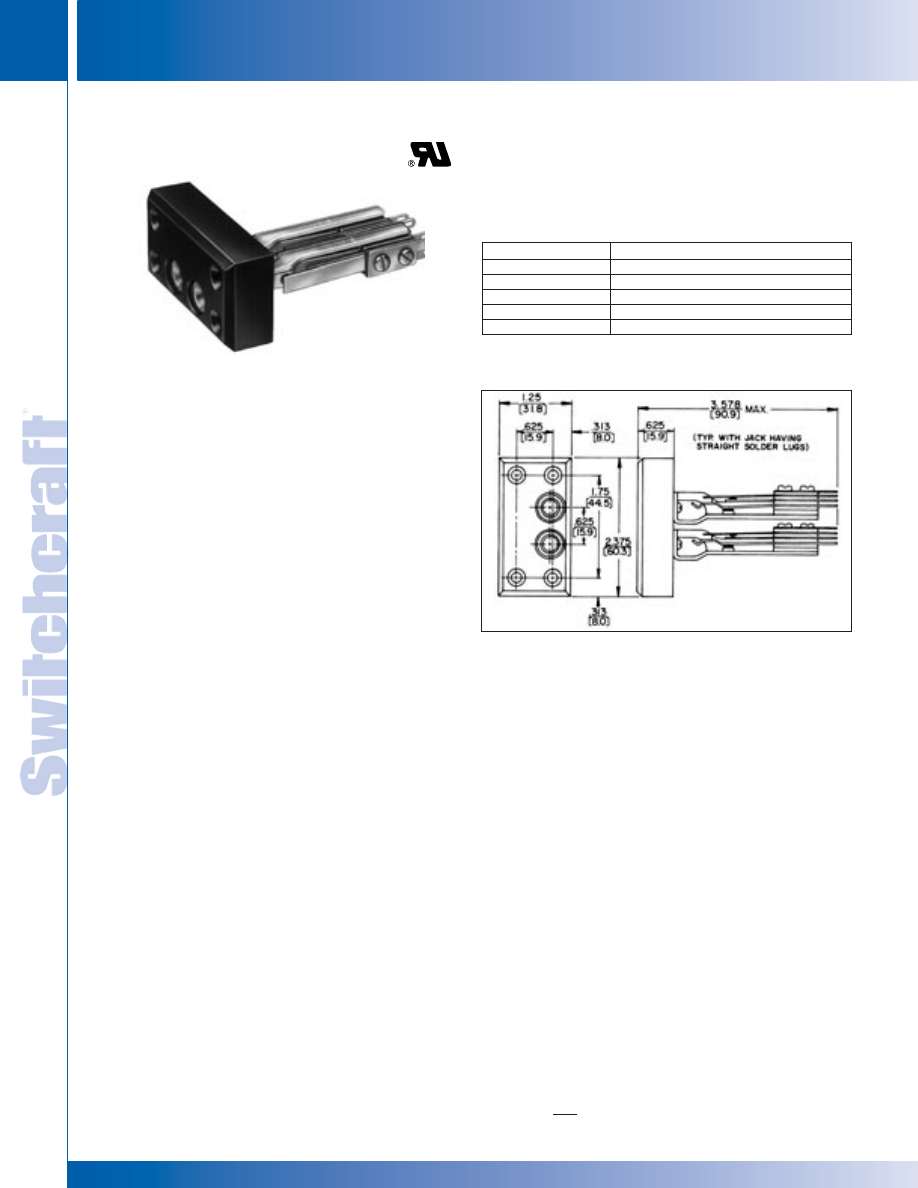
JACKS AND PLUGS
86
w w w . s w i t c h c r a f t . c o m
® Registered trademark of Switchcraft, Inc.
Note: Contact your Switchcraft Representative for price and delivery
PHONE: 773 792-2700
JACKS AND PLUGS
DIMENSIONS ARE FOR REFERENCE ONLY
Inch
(mm)
JACK BLOCKS
JACK BLOCKS
Dual-Jax Blocks are ideal where limited jack connections are
needed but larger jack panels are not required. Designed for
broadcasting, intercom and PA systems, switchboards, and
commercial, industrial and military communications equipment.
Dual-Jax Blocks mount in panels or chassis, either singularly
or in multiples. Four countersunk holes accommodate four
#8-32 screws (not supplied) for block mounting. Blocks can be
supplied without jacks, or with MT-Jax
®
installed. Many other
jacks including, T-Jax
®
, T-Switch
®
switches and lamp jacks can
be installed. Jacks with wire-wrapping terminals or offset lugs
can also be supplied. By drilling additional holes, Twin-Jax
®
may also be used. Contact Switchcraft for any special order items.
SPECIFICATIONS
Block: Molded black thermoplastic.
Screws: #6-20 plated steel, QQ-P-416, Type II,
Class 2 (for jack mounting).
ORDERING
Order by part number from table.
Part Number
Description
2300
Block, without jacks.
2331
Two, MT331 MT-Jax installed.
2332A
Two, MT332A MT-Jax installed.
2332B
Two, MT332B MT-Jax installed.
◊
2333
Two, MT333 MT-Jax installed.
1/4" JACK BLOCKS
◊
Special order only; contact Switchcraft for price and delivery.
Mounting Screws: #6-20, P1544, can be ordered separately,
contact Switchcraft.
DUAL-JAX BLOCK
®
SERIES 2300
* Please visit the product pages on our website for the most up-to-date product information
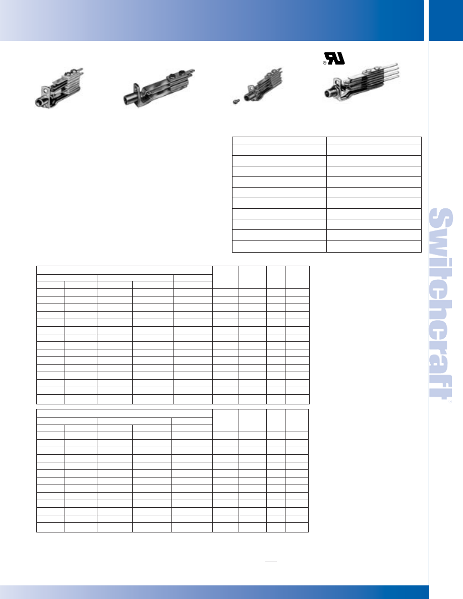
SWITCHCRAFT, INC. 5555 N. Elston Ave. • Chicago, IL 60630
87
JACKS AND PLUGS
FAX: 773 792-2129
JACKS AND
PLUGS
DIMENSIONS ARE FOR REFERENCE ONLY
Inch
(mm)
BANTAM TYPE JACKS
BANTAM TYPE JACKS
FEATURES
• Steel (standard) or die-cast frames (special order).
• 2-or 3-conductors.
• Palladium crossbar welded contacts are standard in
switching circuits. Fine silver or gold alloy contacts are
available on special order.
• Series TT30, TT30FM and TT600 - solder lugs; Series
WTT-30, WTT30FM and WTT600FM -wire-wrapping terminals.
Bussing solder lugs are available on special order.
• Series TT30 and WTT30 jacks mounts in Series 1600,
A1600, B1600 and C1600 jacks panels.
• Series TT30FM and WTT30FM jacks mount in Series
TT51, TT52, TT55 and TT56 jack panels.
• Series TT600 and WTT600 jacks mount in .25" diameter
holes in panels up to .281" thick. Mounting centers: .438".
• Add “N” for nickel-plated frame and “Y” or for offset solder lugs.
SWITCHCRAFT VS. MIL NUMBERS
TT-JAX
®
(.173") TELEPHONE JACKS BANTAM TYPE
®
Jack Number
MIL Spec. Number
TT32B
641/19-2
TT32BFM
641/19-6
TT34B
641/19-4
TT34BFM
641/19-8
TT36C
641/19-10
WTT32B
641/19-1
WTT32BFM
641/19-5
WTT34B
641/19-3
WTT34BFM
641/19-7
WTT36C
641/19-9
Part Numbers, Jack with Wire Wrapping Terminals
Dim. “X”
Typical
Series WTT30
Series WTT30FM
Series WTT600
Max.
Mating
Steel
Die Cast
Steel
Die Cast
Steel
Schem.
1
In (mm)
2
Cond.
Plug
3
WTT31
◊
WTT31DC
WTT31FM
◊
WTT31FMDC
WTT631
I
.422 (10.7)
2
TT251
WTT32A
◊
WTT32ADC
WTT32AFM
◊
WTT32AFMDC
WTT632A
III
.406 (10.3)
2
TT251
WTT32B
◊
WTT32BDC
WTT32BFM
◊
WTT32BFMDC
WTT632B
IV
.578 (14.68)
3
TT253
◊
WTT32C
◊
WTT32CDC
◊
WTT32CFM
◊
WTT32CFMDC
◊
WTT632C
XVIII
.422 (10.7)
2
TT251
WTT33
◊
WTT33DC
WTT33FM
◊
WTT33FMDC
◊
WTT633
V
.578 (14.7)
2
TT251
◊
WTT33B
◊
WTT33BDC
◊
WTT33BFM
◊
WTT33BFMDC
◊
WTT633B
VII
.484 (12.3)
3
TT253
◊
WTT34A
◊
WTT34ADC
◊
WTT34AFM
◊
WTT34AFMDC
◊
WTT634A
XI
.547 (13.9)
2
TT251
WTT34B
◊
WTT34BDC
WTT34BFM
◊
WTT34BFMDC
WTT634B
XII
.578 (14.68)
3
TT253
–
–
–
–
◊
WTT634C
XVII
.547 (13.9)
2
TT251
◊
WTT35
◊
WTT35DC
◊
WTT35FM
◊
WTT35FMDC
◊
WTT635
XIII
.609 (15.5)
2
TT251
◊
WTT36
◊
WTT36DC
◊
WTT36FM
◊
WTT36FMDC
◊
WTT636
XX
.609 (15.5)
3
TT253
◊
WTT36A
◊
WTT36ADC
◊
WTT36AFM
◊
WTT36AFMDC
◊
WTT636A
XIV
.625 (15.9)
3
TT253
WTT36C
◊
WTT36CDC
WTT36CFM
◊
WTT36CFMDC
◊
WTT636C
XXII
.625 (15.9)
3
TT253
◊
Special order only.
1. See schematic diagrams.
2. “X” dimension of die cast frame jacks may be slightly greater.
3. See Mating Plugs Section.
TT36
STEEL FRAME
TT32BDC
DIE-CAST FRAME
TT36FM
FRONT MOUNT
WTT636C
THREADED BUSHING
(special order only)
Part Numbers, Jack with Solder Lugs
Dim. “X”
Typical
Series TT30
Series TT30FM
Series TT600
Max.
Mating
Steel
Die Cast
Steel
Die Cast
Steel
Schem.
1
In (mm)
2
Cond.
Plug
3
TT31
◊
TT31DC
TT31FM
◊
TT31FMDC
TT631
I
.422 (10.7)
2
TT251
TT32A
◊
TT32ADC
TT32AFM
◊
TT32AFMDC
TT632A
III
.406 (10.3)
2
TT251
TT32B
◊
TT32BDC
TT32BFM
◊
TT32BFMDC
◊
TT632B
IV
.578 (14.68)
3
TT253
TT32C
◊
TT32CDC
◊
TT32CFM
◊
TT32CFMDC
◊
TT632C
XVIII
.422 (10.7)
2
TT251
TT33
◊
TT33DC
TT33FM
◊
TT33FMDC
◊
TT633
V
.578 (14.7)
2
TT251
◊
TT33B
◊
TT33BDC
◊
TT33BFM
◊
TT33BFMDC
◊
TT633B
VII
.484 (12.3)
3
TT253
TT34A
◊
TT34ADC
◊
TT34AFM
◊
TT34AFMDC
◊
TT634A
XI
.547 (13.9)
2
TT251
TT34B
◊
TT34BDC
TT34BFM
◊
TT34BFMDC
TT634B
XII
.578 (14.68)
3
TT253
TT34C
◊
TT34CDC
TT34CFM
◊
TT34CFMDC
◊
TT634C
XVII
.547 (13.9)
2
TT251
TT34F
◊
TT34FDC
–
–
–
XIX
.609 (15.5)
2
TT251
TT35
◊
TT35DC
◊
TT35FM
◊
TT35FMDC
◊
TT635
XIII
.609 (15.5)
2
TT251
TT36
◊
TT36DC
◊
TT36FM
◊
TT36FMDC
◊
TT636
XX
.609 (15.5)
3
TT253
TT36A
◊
TT36ADC
TT36AFM
◊
TT36AFMDC
TT636A
XIV
.625 (15.9)
3
TT253
TT36B
◊
TT36BDC
–
–
–
XXI
.703 (17.9)
3
TT253
TT36C
◊
TT36CDC
TT36CFM
◊
TT36CFMDC
◊
TT636C
XXII
.625 (15.9)
3
TT253
®
®
* Please visit the product pages on our website for the most up-to-date product information
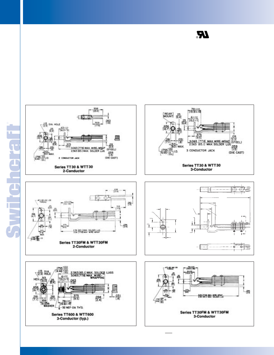
JACKS AND PLUGS
88
w w w . s w i t c h c r a f t . c o m
® Registered trademark of Switchcraft, Inc.
Note: Contact your Switchcraft Representative for price and delivery
PHONE: 773 792-2700
JACKS AND PLUGS
DIMENSIONS ARE FOR REFERENCE ONLY
Inch
(mm)
BANTAM TYPE JACKS
BANTAM TYPE JACKS
SPECIFICATIONS
Frame: Plated (steel or zinc diecast).
Stack Screws: Steel plated.
Bushing: Plated (brass or steel).
Tip and Ring Springs: Copper alloy.
Contact Spring: Copper alloy.
Contacts: Welded crossbar palladium. Other alloys in
various sizes available on special order.
Insulation: Rigid plastic with plastic tubing through
stack assembly.
MOUNTING HARDWARE
Series TT30: #3-48 x 1/4"; mounting screws, P10834,
can be ordered separately.
Series TT30FM: Supplied with one #3-48 x 1⁄4" fil.
head machine screw, steel-plated.
Series TT600: Supplied with one P1975, nickel-plated cop-
per alloy locknut, and one S3997, steel, nickel-plated wash-
er.
NOTE: Dimensional drawings show panels with steel frame
jacks. Overall dimensions for steel or die-cast frame jacks
are the same, except as noted.
Series TT32B
TT-JAX
®
(.173") TELEPHONE JACKS BANTAM TYPE
®
B0.115
[2.9]
REF
B0.176
[4.46]
REF
B0.251
[6.4]
REF
0.250
[6.4]
REF
0.279
[7.1]
REF
0.281
[7.1]
REF
0.650
[16.51]
REF
0.035
[.79]
REF
0.375
[9.5]
REF
2-17/32
[64.3]
REF
0.590 5.015
[14.9]
REF
0.780 5.015
[19.8]
REF
®
®
* Please visit the product pages on our website for the most up-to-date product information
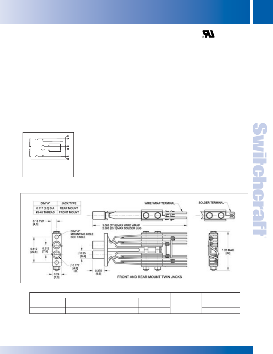
SWITCHCRAFT, INC. 5555 N. Elston Ave. • Chicago, IL 60630
89
JACKS AND PLUGS
FAX: 773 792-2129
JACKS AND
PLUGS
DIMENSIONS ARE FOR REFERENCE ONLY
Inch
(mm)
FEATURES
• Steel or die-cast frames. (Special order only).
• Twin, 3-conductor jacks on .312" centers, inter-connected
so circuit is opened when a mating plug is inserted in one
side of the jack. Palladium welded crossbar contacts are
standard in switching circuits.
• Solder lugs or wire-wrapping terminals.
• TT89, TT89C, WTT89 and WTT89DC jacks mount in
Series 1700 jack panels.
• TT89FM, TT89FMDC, WTT89FM and WTT89FMDC
jacks mount in Series TT59, TT60, TT61 and TT62
jack panels.
SPECIFICATIONS
Frame: Plated (steel or diecast zinc).
Stack Screws: Steel-plated.
Bushing: Plated (steel or copper alloy).
Tip, Ring and Contact Springs: Copper alloy.
Contacts: Welded crossbar palladium. Other alloys in
various sizes available on special order.
Insulation: Rigid plastic with plastic tubing through
stack assembly.
Mounting Hardware: #3-48 x 1/4" mounting
screws, P10834, can be ordered separately for TT89,
TT89DC, WTT89 and WTT89DC jacks. Two mounting
screws, P25424, are supplied with TT89FM, TT89MDC,
WTTFM and WTT89FMDC jacks.
NOTE: Dimensional drawings show panels with steel
frame jacks. Overall dimensions for steel or die-cast
frame jacks are the same.
TT-JAX
®
(.173") TELEPHONE TWIN JACKS BANTAM TYPE
®
Solder Lugs
Wire-Wrapping Terminals
Typical Mating
Steel
Die Cast
Steel
Die Cast
Conductors
Plug
1
TT89
◊
TT89DC
WTT89
◊
WTT89DC
TT263
TT89FM
◊
TT89FMDC
WTT89FM
◊
WTT89FMDC
TT263
1. See Mating Plugs Section.
◊
Special order only
TT89
SCHEMATIC
Twin
3-conductor
BANTAM TYPE JACKS
BANTAM TYPE JACKS
®
®
* Please visit the product pages on our website for the most up-to-date product information
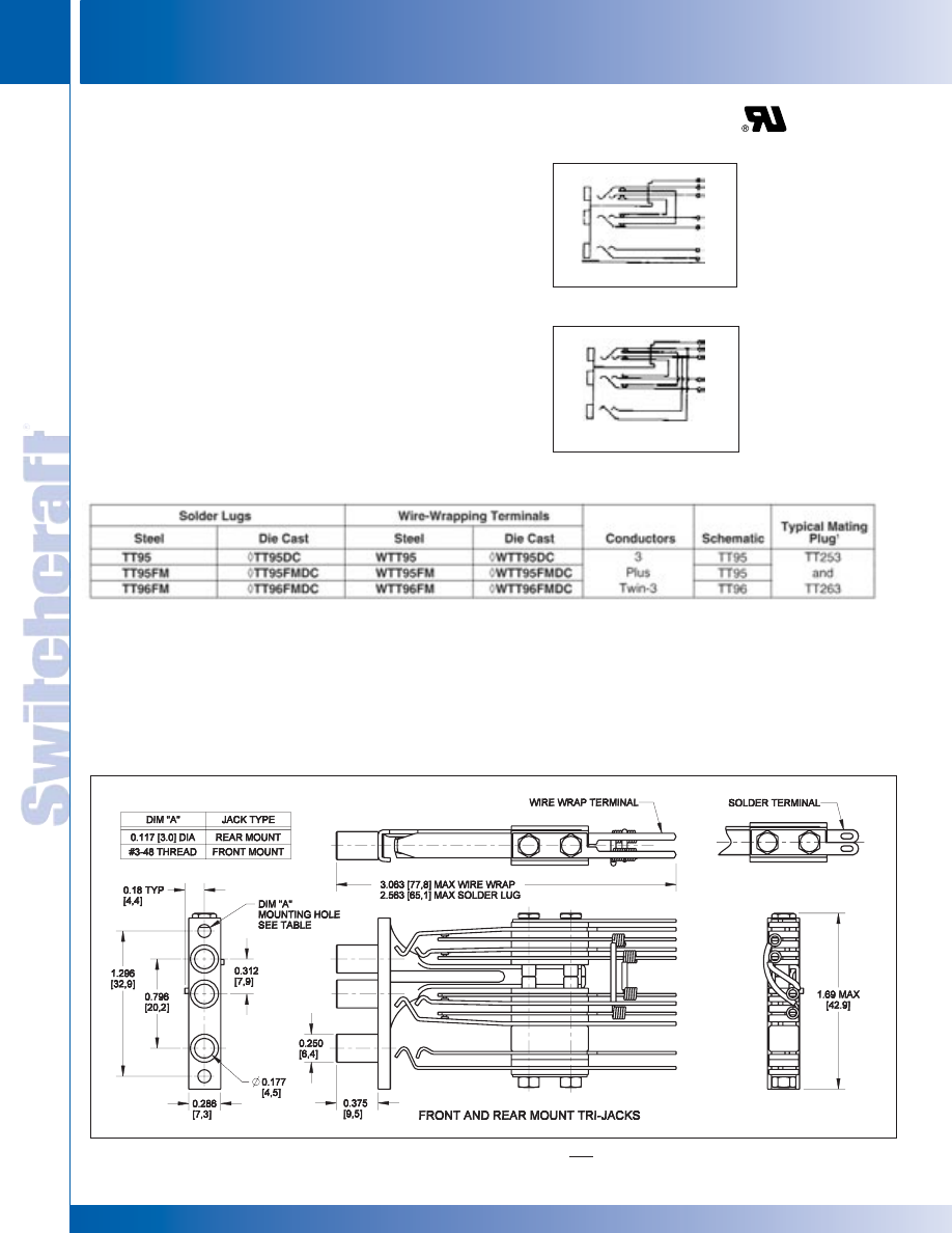
TT95 TT95FM TT96FM
TT95DC TT95FMDC TT96FMDC
WTT95 WTT95FM WTT96FM
WTT95DC WTT95FMDC WTT96FMDC
TT253 TT263
JACKS AND PLUGS
90
w w w . s w i t c h c r a f t . c o m
® Registered trademark of Switchcraft, Inc.
Note: Contact your Switchcraft Representative for price and delivery
PHONE: 773 792-2700
JACKS AND PLUGS
DIMENSIONS ARE FOR REFERENCE ONLY
Inch
(mm)
BANTAM TYPE JACKS
BANTAM TYPE JACKS
®
®
TT95 SCHEMATIC
FEATURES
• Steel or die-cast frames.
• TT95 Tri-Jax
®
Jacks: three, 3-conductor jacks on one
frame. Twin jacks, (on .312" centers, LINE & EQUIPMENT
functions), have strapped shunts installed. The third jack
(MONITOR) is unwired. See TT95 schematic.
• TT96 Tri-Jax Jacks: Same as TT95 jacks, except third
jack (MONITOR) has tip and ring springs, respectively,
jumpered to tip and ring springs of top (LINE) jack.
• Selection of solder lugs or wire-wrapping terminals.
• Palladium welded crossbar contact are standard in
switching circuits.
• TT95, TT95DC, WTT95 and WTT95DC jacks mount in
Series B1700 jack panels.
• TT95FM, TT95FMDC, TT96FM, TT96FMDC and
wire-wrapping versions mount in Series TT53, TT54,
TT57 and TT58 jack panels.
TT-JAX
®
(.173") TELEPHONE TRIPLE JACKS BANTAM TYPE
®
SPECIFICATIONS
Frame: Plated (steel or diecast)
Stack Screws: Stainless Steel Plated.
Bushings: Plated (steel or copper alloy).
Contact Springs: Copper alloy.
Contacts: Welded crossbar palladium. Other precious metal
alloys in various sizes available on special order.
Mounting Hardware: #3-48 x 1/4" mounting screws,
P10834, can be ordered separately for rear mount jacks.
Two mounting screws, P25424, are supplied with front
mount jacks.
◊
Special order only
TT96 SCHEMATIC
* Please visit the product pages on our website for the most up-to-date product information
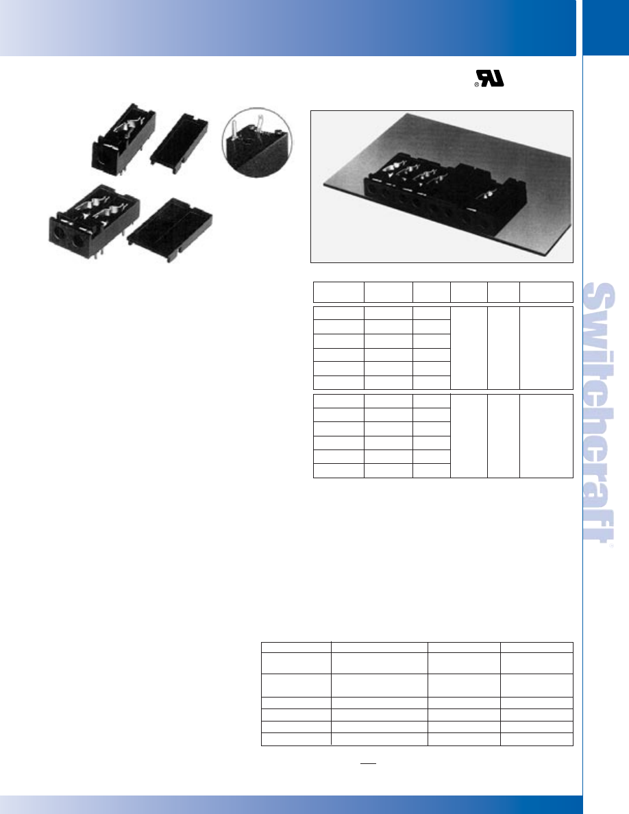
SWITCHCRAFT, INC. 5555 N. Elston Ave. • Chicago, IL 60630
91
JACKS AND PLUGS
FAX: 773 792-2129
JACKS AND
PLUGS
DIMENSIONS ARE FOR REFERENCE ONLY
Inch
(mm)
MINIATURE TELEPHONE JACKS
MINIATURE TELEPHONE JACKS
Right-angle miniature phone jacks provide low-profile
packaging. Single and twin 3-conductor jacks provide
plug-jack access to communication circuits for patching
and/or testing. Tips and rings are shunted. These jacks
mate with Switchcraft miniature TT
®
plugs and patch cords.
Jacks are designed for right-angle mounting on .062"
(1.6 mm) maximum thickness PC boards. Snap-on covers in
colors are available and can be installed or removed in the
field without special tools. Covers and jacks may be
ordered in different colors for color coded circuits.
SPECIFICATIONS
ELECTRICAL
Dielectric Withstanding Voltage: 500 V AC
Contact Resistance: .020
Ω
maximum (initial),
.030
Ω
maximum (after life test).
Insulation Resistance: 10
10
Ω
at 500 V DC (initial).
MECHANICAL
Shock: MIL-STD 202 Method 213.
Vibration: MIL-STD 202 Method 201.
Insertion Force: 7 pounds maximum (31.14 N).
Withdrawal Force: 1.5 pounds minimum (6.67 N).
Life: 10,000 cycles.
MATERIALS
Housing: Thermoplastic UL 94V-0.
Springs: Copper alloy, plated.
Contacts: Gold alloy (WEco #1) crossbar.
ENVIRONMENTAL
Temperature Limits: -55°C to +85°C
(non-operating).
Thermal Shock: MIL-STD 202 Method 107.
Salt Spray: MIL-STD 202 Method 101.
Humidity: MIL-STD 202 Method 106, less
steps 7A and 7B.
MINIATURE TELEPHONE JACKS, RIGHT ANGLE, PC MOUNT
1. See schematic diagrams on pages 79 and 80.
2. See Mating Plugs Section.
◊
Special order only; contact Switchcraft for price and delivery.
LOW SILHOUETTE
PERMITS CRITICAL
SPACE-SAVING HIGH
DENSITY PACKAGING
ORDERING
1. Order jacks and covers separately from table.
2. Covers can be ordered assembled on special order.
3. To order RTT jack with cover installed, add the letter C
after RTT in part number. Special order only.
4. To order RTT jack with Snap-in terminals, add the
letter S to the end of the part number. Special order only.
5. For all special orders items, contact Switchcraft.
RTT8702
COVER P286402
RTT34B02
COVER P286302
CLOSE-UP OF
“Snap-In”
TERMINAL
ORDERING INFORMATION
RTT JACK PART NUMBERING SYSTEM
Jack
Cover
Typical
Part No.
Part No.
Color
Schem.
Cond.
Mating Plug
2
RTT34B01
◊
P286301
Red
RTT34B02
P286302
Black
RTT34B04
◊
P286304
Blue
RTT34B05
P286305
White
XII
3
TT-253
◊
RTT34B07
◊
P286307
Orange
◊
RTT34B08
◊
P286308
Yellow
RTT8701
◊
P286401
Red
RTT8702
P286402
Black
RTT8704
◊
P286404
Blue
Twin
Twin
RTT8705
P286405
White
XII
3
TT-263
◊
RTT8707
◊
P286407
Orange
◊
RTT8708
◊
P286408
Yellow
Series
Cover Option
Circuitry
Jack Color
RTT Right
Blank-
No Cover
Angle TT Jack
Standard
34B-
XII
01-
Red
C- Cover
Supplied
87-
Two XII
02-
Black
Circuits
04-
Blue
05-
White
07-
Orange
08-
Yellow
* Please visit the product pages on our website for the most up-to-date product information
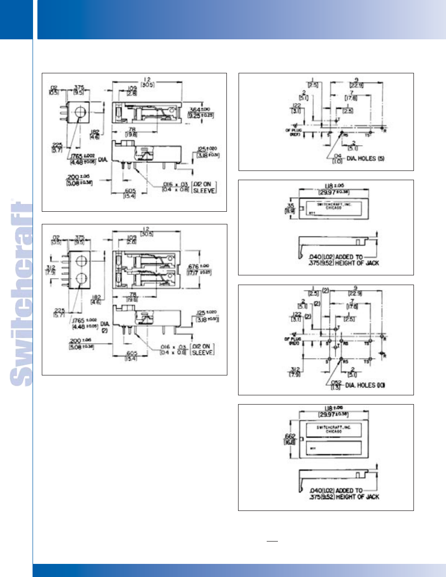
JACKS AND PLUGS
92
w w w . s w i t c h c r a f t . c o m
® Registered trademark of Switchcraft, Inc.
Note: Contact your Switchcraft Representative for price and delivery
PHONE: 773 792-2700
JACKS AND PLUGS
DIMENSIONS ARE FOR REFERENCE ONLY
Inch
(mm)
MINIATURE TELEPHONE JACKS
MINIATURE TELEPHONE JACKS
MINIATURE TELEPHONE JACKS, RIGHT ANGLE, PC MOUNT (continued)
No. P2864 Cover
RECOMMENDED
PC BOARD LAYOUT
RECOMMENDED
PCBOARD LAYOUT
No. P2863 Cover
No. RTT34B (Less cover)
No. RTT87 (Less cover)
* Please visit the product pages on our website for the most up-to-date product information
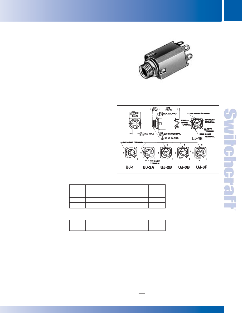
SWITCHCRAFT, INC. 5555 N. Elston Ave. • Chicago, IL 60630
93
JACKS AND PLUGS
FAX: 773 792-2129
JACKS AND
PLUGS
DIMENSIONS ARE FOR REFERENCE ONLY
Inch
(mm)
ENCLOSED JACKS
ENCLOSED JACKS
Two- and 3-conductor Unijax
®
jacks have advanced features
of Hi-D Jax
®
jacks including chassis/panel and PC mounting
and .177" bushing that mates with a variety of tini-telephone
®
plugs and patchcords. Bushing diameter is .281" inside
diameter; panel thickness is .125". Mounts in rows or arrays
on .469" centers.
SPECIFICATIONS
MECHANICAL
Insertion/Withdrawal: 2-conductor, 1.25 pounds nominal,
3 pounds maximum insertion. 3-conductor, 1.5 pounds nominal,
3 pounds maximum insertion. 2-conductor, 3 pounds nominal,
1.5 pounds minimum withdrawal. 3-conductor, 3 pound nominal,
1.5 pounds minimum withdrawal.
Life: 10,000 insertion/withdrawal cycles minimum.
ELECTRICAL
Contact Resistance: .10 ohms maximum.
Insulation Resistance: 1,000 M
Ω
minimum.
Dielectric Withstanding Voltage: 500 V AC maximum.
MATERIAL
Housing: Thermoplastic.
Mounting Bushing: Nickel-plated copper alloy.
Tip and Ring Springs: Copper alloy, silver-plated.
Integral contacts.
Shunt Springs: Copper alloy, silver-plated
integral contacts.
Sleeve Terminal: Steel, tin-plated.
Hardware: Supplied with one, Number P2060
nickel-plated copper alloy locknut, and one,
Number P2061 nickel-plated copper alloy washer.
.177" ENCLOSED JACKS
Part
Number
UJ1
UJ2A
Description
Open circuit
Single closed circuit
Jack
Schematic
1
I
III
Typical
Mating
Plug
2
TT251
TT251
TWO CONDUCTOR PART NUMBERS
UJ2B
UJ4B
Double Open circuit
Double closed circuit
IV
XII
TT253
TT253
THREE CONDUCTOR PART NUMBERS
1. See jack schematics on pages 79 and 80.
2. See Mating Plugs Section.
UJ4B
* Please visit the product pages on our website for the most up-to-date product information
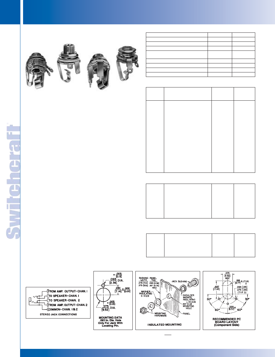
JACKS AND PLUGS
94
w w w . s w i t c h c r a f t . c o m
® Registered trademark of Switchcraft, Inc.
Note: Contact your Switchcraft Representative for price and delivery
PHONE: 773 792-2700
JACKS AND PLUGS
DIMENSIONS ARE FOR REFERENCE ONLY
Inch
(mm)
LITTEL-JAX 2- AND 3- CONDUCTOR
LITTEL-JAX 2- AND 3- CONDUCTOR
LITTEL-JAX
®
COMMERCIAL PHONE JACKS
2- AND 3-CONDUCTOR
Littel-Jax phone jacks mate with standard commercial phone
plugs and are available with .25" and .21" inside diameter
bushings.
MIL LITTEL-JAX
®
PHONE JACKS
2- AND 3-CONDUCTOR MIL-SPEC, MIL-J-641 (E)
MIL jacks mate with MIL-type phone plugs with .25" (6.35mm)
or .21" (5.34mm) diameter bushings. Numbers C11 and C12B
have a non-turn locating pin which keys the jack to the
mounting surface. For low contact resistance applications,
jack number C12A has fine silver contacts on shunts and
tip springs.
MOUNTING
Chassis/Panel: See Mounting Data drawing below;
smallhole is required only for jacks numbers C11 and C12B
with non-turn locating pin.
Maximum Panel Thickness: .156" (4mm) for standard
.276" (7mm) long bushing; .25" (6.35mm) for .375" (9.5mm)
long bushing.
NOTE: For panels thicker than .25" see Thick Panel Phone Jax.
Insulated Mount: See drawing. S1028 flatwasher and
Part Number S1029 shoulder washer must be ordered
separately for mounting in .437" diameter hole.
NOTE: See Hi-D Jax
®
for jack specifically designed for
insulated mounting without additional washers.
PC Board Mounting: See Recommended PC Board Layout
drawing below for jacks with PC terminals. Recommended
PC board thickness is .062".
Mounting Centers: 1.188" (30mm) recommended. Centers
may vary with jack selected, for example, Number
11 mounts on .813" (20.6mm) and 14B mounts on
1.125" (28.6mm) minimum centers.
Part
Number
11
C11
FA11
FAL11
L11
12A
C12A
L12A
PC12A
13
13A
13E
Description
Open circuit
MIL Number M641/6-1
.205 inch FASTON terminal
.375 inch long bushing
.205 FASTON terminal
.375 inch long bushing
Tip shunt
MILNumber M641/12-1
.375 inch long bushing
PC board mount
Isolated “make” circuit
Transfer circuit
Isolated “break” circuit
Jack
Schematic
1
I
I
I
I
I
III
III
III
III
V
VI
IX
Typical
Mating
Plug
250
440
250
250
250
250
440
250
250
250
250
250
1/4" PHONE JACKS
TWO CONDUCTOR PART NUMBERS
12B
L12B
C12B
13B
14B
Double open circuit
.375 inch long bushing
MIL number M641/5-1,
.250 inch inside diameter
Tip shunt
Double closed circuit
IV
IV
IV
VII
XII
267
267
480
267
267
THREE CONDUCTOR PART NUMBERS
S11
S12A
S12B
S13B
2 conductor
2 conductor
3 conductor
3 conductor
I
III
IV
VII
S250
S250
S267
S267
PART NUMBERS
(.210" INSIDE DIAMETER BUSHING)
1. Refer to jack schematics on pages 79 and 80. Other circuits are available;
contact factory.
14B
PC-12A
FAL-11
.205 FASTON
TERMINAL
11
STEREO JACK
CONNECTIONS
PREFIX OPTIONS
SERIES
CIRCUITRY
Blank- 1/4" Commercial Jack
1-Littel Jax
®
1-
I
C-
Accepts Mill Plug
2A-
III
FA-
.205" Faston Terminals
2B-
IV
FAL-
.205" Faston Terminals
3-
V
and .375" Long Bushing
L-
.375" Long Bushing
3A-
VI
PC-
PC Terminals
3B-
VII
S-
Accepts .206 Diameter Plugs
3E-
IX
4B-
XII
®
®
* Please visit the product pages on our website for the most up-to-date product information
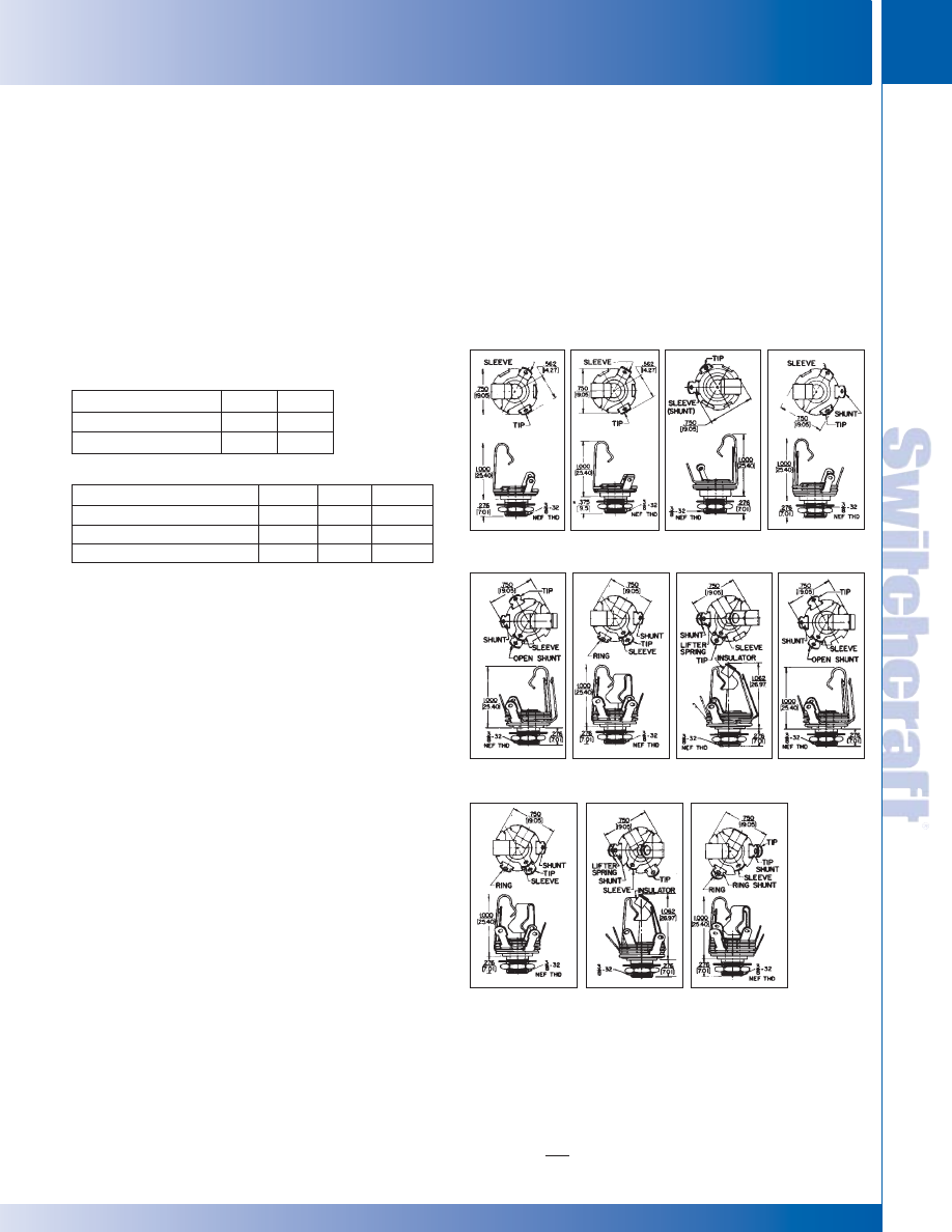
SWITCHCRAFT, INC. 5555 N. Elston Ave. • Chicago, IL 60630
95
JACKS AND PLUGS
FAX: 773 792-2129
JACKS AND
PLUGS
DIMENSIONS ARE FOR REFERENCE ONLY
Inch
(mm)
LITTEL-JAX 2- AND 3- CONDUCTOR
LITTEL-JAX 2- AND 3- CONDUCTOR
SPECIFICATIONS
MECHANICAL
Life: Commercial Jacks: 10,000 insertion/withdrawal
cycles, minimum. Military Jacks: 20,000 insertions/
withdrawals, minimum.
Mechanical Shock: Military Jacks: Per MIL-STD 202,
method 213, Test Condition H (75g).
Vibration: Military Jacks: Per MIL-STD-202,
method 213, (10-55 Hz).
Insertion/Withdrawal Forces: (see charts below)
Sleeve Terminal: Copper alloy.
Hardware: Supplied with one Number P10001 copper alloy
nickel-plated hex nut, and one Number 51022 steel nickel-plated
washer - except copper alloy nickel-plated washer Number
S10451 supplied on C11, C12A and C12B.
*Commercial jacks feature integral contacts. Integral contacts should
not be used where low contact resistance is a requirement.
LITTEL-JAX
®
COMMERCIAL PHONE JACKS - 2- AND 3-CONDUCTOR AND
MIL LITTEL-JAX
®
PHONE JACKS - 2- AND 3-CONDUCTOR MIL-SPEC, MIL-J-641 (E)
1/4" PHONE JACKS (continued)
COMMERCIAL JACKS
Plug Diameter (inches)
Insertion (maximum)
Withdrawal (minimum)
.210
7 lb.
1 lb.
.250
7 lb.
1 lb.
MILITARY JACKS
Part Number
Insertion (maximum)
Withdrawal (minimum)
Withdrawal (maximum)
C11
6 lb.
2 lb.
7 lb.
C12A
7 lb.
3 lb.
7 lb.
C12B
6 lb.
1.5 lb.
5 lb.
ELECTRICAL
Contact Resistance: Commercial Jacks - .030 ohms
maximum (initial), .050 ohms maximum (after humidity,
durability exposure). Per MIL-STD-202E. Military Jacks -
.010 ohms maximum (initial), .020 ohms maximum (after life),
.10 ohms maximum (after salt spray).
Insulation Resistance: Commercial Jacks - 10,000 M
Ω
minimum (initial), 1,000 M
Ω
minimum (after humidity). Military
Jacks - 10,000 M
Ω
minimum (initial), 1,000 M
Ω
minimum
(after humidity, durability exposure).
Dielectric Withstanding Voltage: 500 V, 60 Hz (rms) AC.
Contact Rating: 1 A, 25 V DC.
ENVIRONMENTAL
Thermal Range: Commercial Jacks; -55°C to +85°C
(non-operating); -20°C to +65°C (operating). Military Jacks; -
55°C to +85°C (non-operating); -40°C to+65°C (operating).
Thermal Shock: Commercial Jacks - Per MIL-STD 202,
method 107. Military Jacks - Per MIL-STD 202, method 107.
Humidity: Commercial Jacks - Per MIL-STD 202, method
106. Military Jacks - 0% to 95% operating and non-operating.
Salt Spray: Commercial Jacks - Per MIL-STD 202, method
101. Military Jacks - Per MIL-STD 202, method 101 (48 hours).
Moisture Resistance: Military Jacks - Per MIL-STD 202,
method 106 (240 hours).
MATERIAL
Mounting Bushing: Nickel-plated copper alloy.
Insulation: Rigid plastic.
Springs: Special copper alloy. Integral contacts are standard
in the isolated switching circuits; fine silver contacts
in C12A switching circuit.
Littel Jax
®
Jacks
11, L-11, C-11, S-11 FA-11, FAL-11
12
12-A, L-12A
12A, L-12A
*.276" for No. FA-11
S-12A, SC-12A
S-12A, SC-12A
PC-12A 12B, C12B
13
13A
S-12B, SC-12B
13B, S-13B 13E
14B
®
®
* Please visit the product pages on our website for the most up-to-date product information
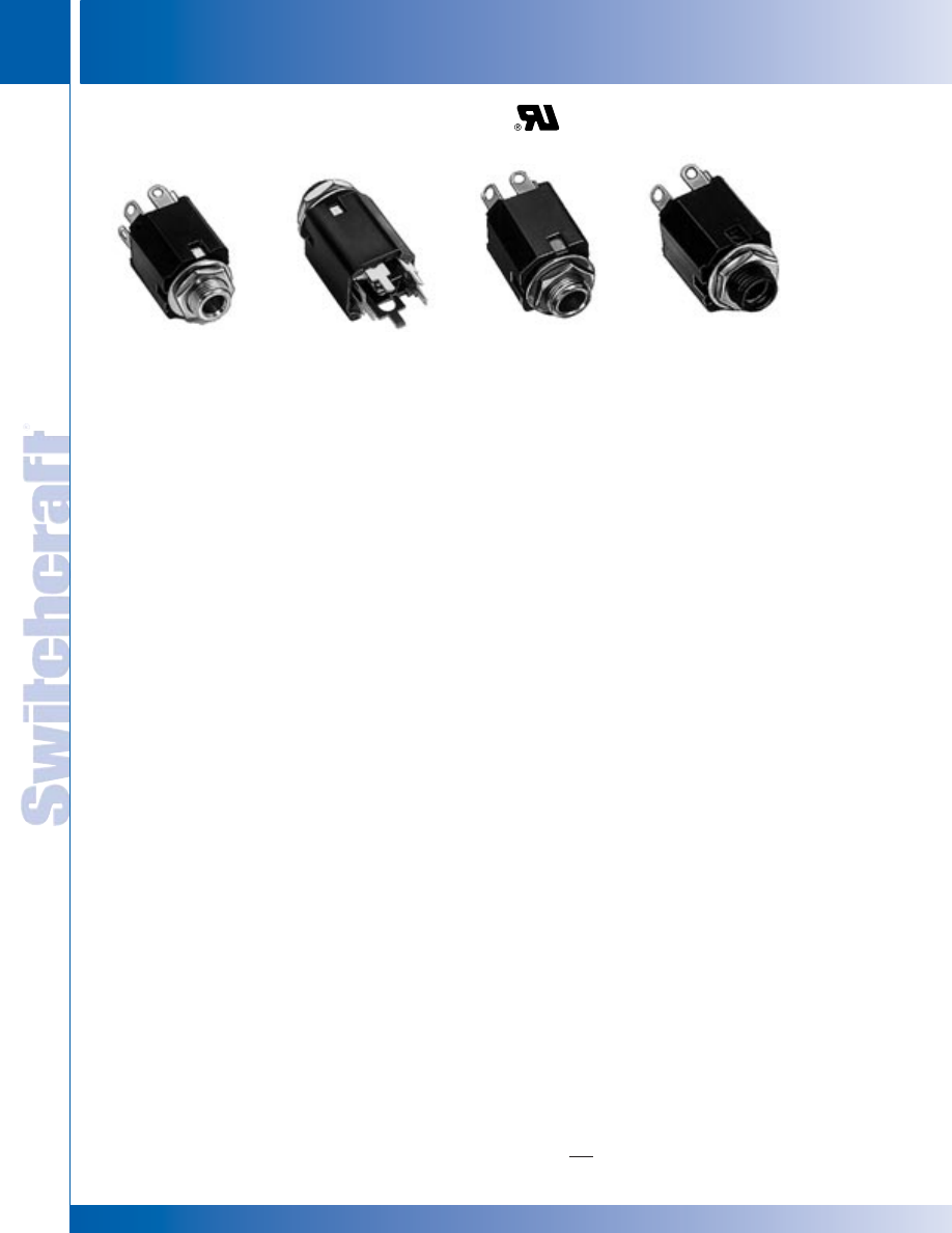
JACKS AND PLUGS
96
w w w . s w i t c h c r a f t . c o m
® Registered trademark of Switchcraft, Inc.
Note: Contact your Switchcraft Representative for price and delivery
PHONE: 773 792-2700
JACKS AND PLUGS
DIMENSIONS ARE FOR REFERENCE ONLY
Inch
(mm)
ENCLOSED JACKS
ENCLOSED JACKS
Compactly constructed jacks permit direct cross-patching
with Switchcraft, WEco and MIL-type telephone plugs and
patch cords. Series M Hi-D Jax
®
offer a choice of solder lugs
or PC terminals. Both insulated and metal bushings can be
specified, as well as .21" inside diameter sleeves for narrow
plug fingers. Maximum contact resistance is .1 ohm. Springs
are made of a special gold-plated copper alloy. Welded cross
bar gold alloy contacts are available on special order.
SERIES M-11* HI-D JAX
®
Two- and 3-conductor type mate with .25" diameter finger
plugs. Tip and ring springs are gold-plated. Shunts (if used)
have welded crossbar palladium contacts. Ring springs
(where used with shunts) have welded crossbar palladium
contacts. Tip springs (when used) do not have a contact
welded to the spring. Bushing has 3/8-32-NEF-2 thread;
locknut and flat washer for mounting are supplied.
SERIES MN-11* HI-D JAX
®
Same as Series M-11* except threaded bushing is molded
thermoplastic for insulated mounting. Continuous sleeve
contact assures positive sleeve connection without exposed
metal on front of panel.
SERIES M113 AND M114 HI-D JAX
®
The versatile 3-conductor M113 and M114 feature springs
which accept a wide variety of 1/4" plug designs. Self-aligning
PC terminals allow for easier insertion into a printed circuit
board. Also feature a metric thread mounting.
SPECIFICATIONS
MATERIALS
Mounting Bushing: Series M11*, MS11* - Nickel-plated
copper alloy. Series MN11*, MNS11* - Molded thermoplastic.
Housing: Molded thermoplastic, UL 94V-0.
Springs: Copper alloy.
Contacts (mil-type): Tip and Ring Springs are gold-plated.
Shuntsprings (where used) are welded crossbar palladium.
Welded crossbar gold alloy contacts are available on
special order.
Contacts (commercial): Tin-plated integral contacts.
Sleeve Terminal: Steel, tin-plated.
Hardware: Supplied with one P10001 copper alloy,
nickel-plated locknut and one S10221 steel,
nickel-plated washer.
1/4" ENCLOSED TELEPHONE JACKS
Series M11*
Series MNS11*
Series MS11*
Series MN11*
MECHANICAL
Life: 10,000 insertion/withdrawal cycles, minimum.
Insertion/Withdrawal Forces: Nominal plug retention on
2-conductor jack is .75 pounds with .5 pounds minimum.
Nominal plug retention on 3-conductor jack is 2 pounds with
1.5 pounds minimum. With double tips, the nominal is
1.5 pounds and 1 pound minimum.
Maximum Recommended Mounting Torque: 6" -lb. for
thermoplastic bushing.
Mounting Torque (for Spring Lock PC Terminal):
8" -pound for thermoplastic bushings.
ELECTRICAL
Contact Resistance: .020 ohms maximum (initial),
.050 ohms maximum (after humidity, durability exposure).
Per MIL-STD-202E.
Insulation Resistance: 10,000 M
Ω
minimum (initial),
1,000 M
Ω
minimum (after humidity).
Dielectric Withstanding Voltage: 500 V, 60 Hz (rms) AC.
Contact Rating: 0.25, 48 VDC make and break, 3A carry only.
ENVIRONMENTAL
Thermal Range: -55°C to +85°C (non-operating);
-20°C to +65°C (operating).
Thermal Shock: Per MIL-STD 202, method 107.
Humidity: Per MIL-STD 202, method 106.
Salt Spray: Per MIL-STD 202, method 101.
* Please visit the product pages on our website for the most up-to-date product information
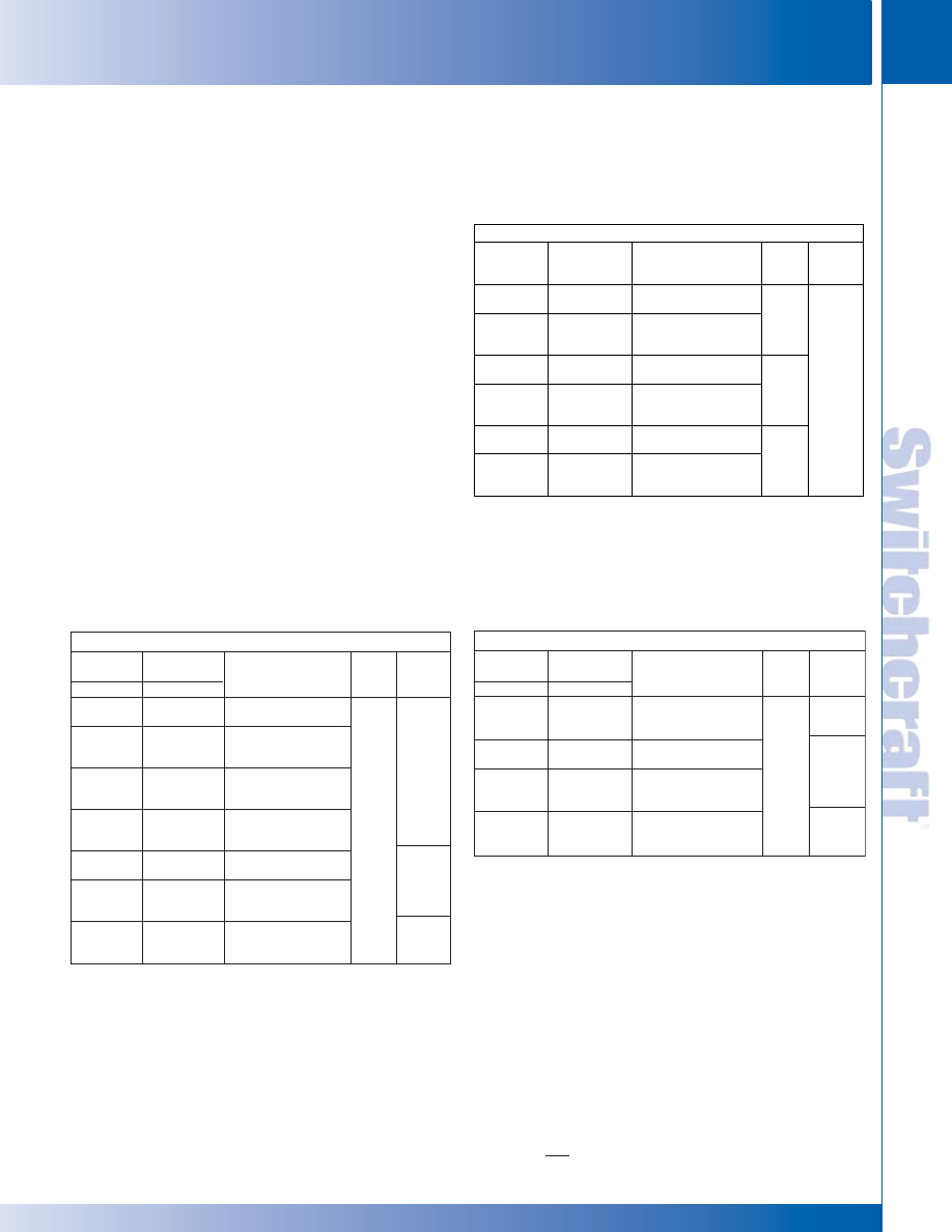
M111 MN111
M112A
M112APC
MN112A
MN112APC
M113E
MN113E
M112B ML112B MN112B M113B
MN113B M112BPC MN112BPC
MN113BPC M113PPC1M
MNL113B MNL112B M114B
M114BPC M114BPC1M MN114B
MN114BPC
3-CONDUCTOR
Part
Part
Typical
Number
Number
Sche-
Mating
Solder Lugs
PC Terms
Description
matic
1
Plug
2
M112B
⋅
M112BPC
.25" inch I.D. sleeve,
metal bushing.
ML112B
–
.25" inch I.D. sleeve,
.375 inch long
metal bushing.
MN112B
⋅
MN112BPC
.25 inch I.D. sleeve,
482
molded thermoplastic
bushing.
IV
MNL112B
–
.25 inch I.D. sleeve,
.375 inch long
metal bushing.
M113B
–
.25 inch I.D. sleeve,
metal bushing.
MN113B
MN113BPC
.25 inch I.D. sleeve,
482
molded thermoplastic
VII
bushing.
M113BPC1M
.25 inch I.D. sleeve,
molded thermoplastic
482
bushing, metric hardware
SWITCHCRAFT, INC. 5555 N. Elston Ave. • Chicago, IL 60630
97
JACKS AND PLUGS
FAX: 773 792-2129
JACKS AND
PLUGS
DIMENSIONS ARE FOR REFERENCE ONLY
Inch
(mm)
ENCLOSED JACKS
ENCLOSED JACKS
1/4" ENCLOSED TELEPHONE JACKS (CONTINUED)
◊
Special Order only; contact Switchcraft.
* Other mating plugs are contained in this plug section.
** See pages 79 and 80.
2-CONDUCTOR
Part
Part
Typical
Number
Number
Sche-
Mating
Solder Lugs
PC Terms
Description
matic**
Plug*
M111
–
.25 inch I.D. sleeve,
metal bushing.
MN111
–
.25 inch I.D. sleeve,
I
molded thermoplastic
bushing.
◊
M112A
◊
M112APC
.25 inch I.D. sleeve,
metal bushing.
MN112A
◊
MN112APC
.25 inch I.D. sleeve,
III
420
molded thermoplastic
bushing.
M113E
–
.25 inch I.D. sleeve,
metal bushing.
MN113E
–
.25 inch I.D. sleeve,
IX
molded thermoplastic
bushing.
ORDERING INFORMATION
Order by part number from table.
SERIES MS11* HI-D JAX
®
3-conductor with .21" inside diameter sleeve. Mates with plugs
having .206" diameter finger. Protects against accidental
insertion of .25" diameter finger plugs. Gold-plated tip and
ring springs. Welded crossbar palladium contacts on shunt
springs standard. Bushing has 3/8-32-NEF-2 thread; locknut
and flat washer for mounting are supplied.
◊
SERIES MNS11* HI-D JAX
®
Same as Series MS11* except bushing is molded
thermoplastic.
◊
TWIN M11* HI-D JAX
®
Two Series M11* Hi-D Jax strapped on .625" centers. Mates
with Switchcraft
®
Twin Plugs. 411, 412 and 413. MIL-type
Littel-Plug
®
phone plugs, 420, 430 and 440 (2-conductor)
and 482 and 483 (3-conductor) are also recommended for
mating with this series.
3-CONDUCTOR
Part
Part
Typical
Number
Number
Sche-
Mating
Solder Lugs
PC Terms
Description
matic
1
Plug
2
MNL113B
–
.25 inch I.D. sleeve,
.375 inch long
482
metal bushing.
VII
M114B
⋅
M114BPC
.25 inch I.D. sleeve,
metal bushing.
M114BPC1M
.25 inch I.D. sleeve,
482
metal bushing,
metric hardware.
MN114B
⋅
MN114BPC
.25 inch I.D. sleeve,
XII
molded thermoplastic
bushing.
480,
484
◊
Special order only; contact Switchcraft for price and delivery.
1 See schematics, pages 79 and 80.
2 Number(s) specified are not necessarily the only mating plug(s).
See Plugs Section.
.25" I.D. sleeve,
.25" I.D. sleeve,
.25" I.D. sleeve,
.25" I.D. sleeve,
.25" I.D. sleeve,
.25" I.D. sleeve,
* Please visit the product pages on our website for the most up-to-date product information
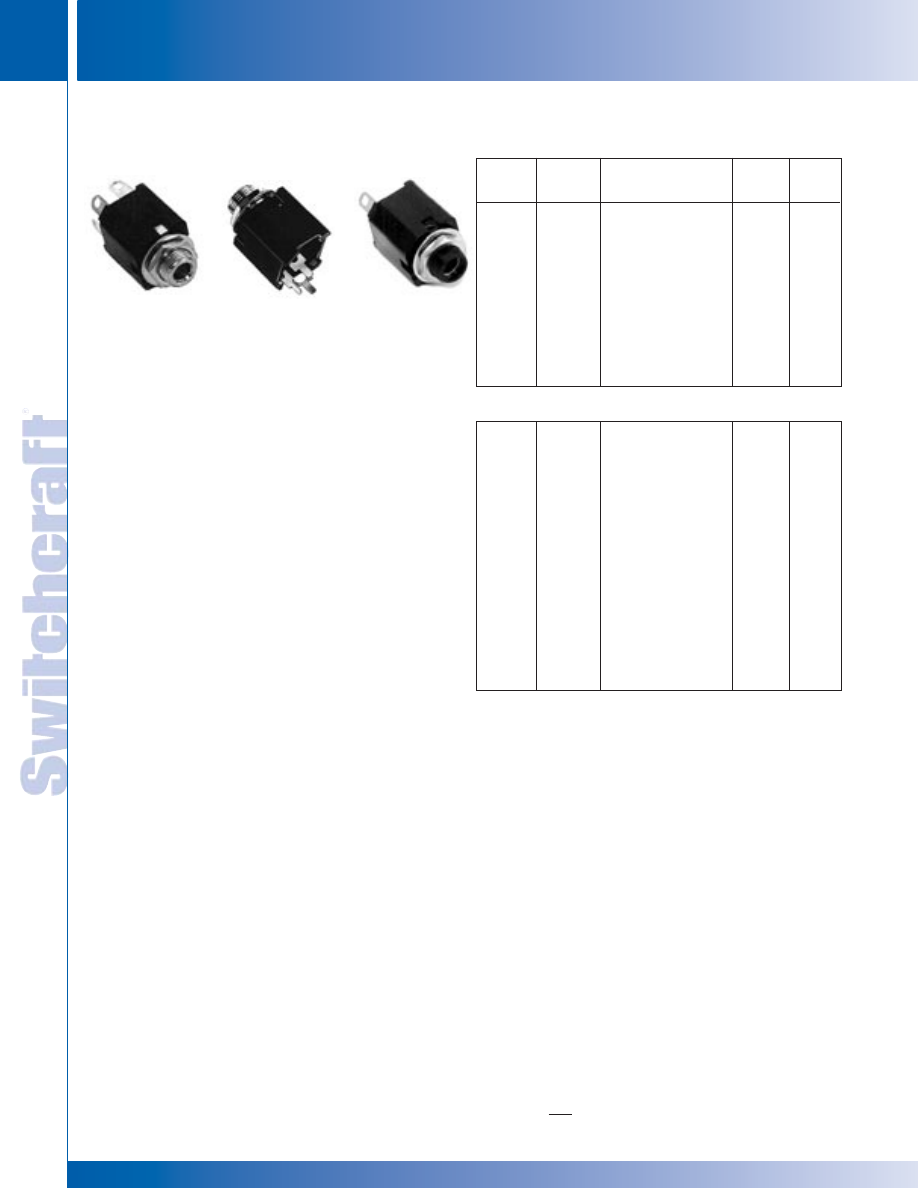
JACKS AND PLUGS
98
w w w . s w i t c h c r a f t . c o m
® Registered trademark of Switchcraft, Inc.
Note: Contact your Switchcraft Representative for price and delivery
PHONE: 773 792-2700
JACKS AND PLUGS
DIMENSIONS ARE FOR REFERENCE ONLY
Inch
(mm)
HI-D JAX 2- AND 3-CONDUCTOR
HI-D JAX 2- AND 3-CONDUCTOR
Hi-D Jax
®
2- and 3-conductor enclosed phone jacks are ideal
for panel/chassis and PC board mounting. Unitized molded
housing protects springs, provides mechanical and electrical
reliability, minimizes leakage and provides low capacity
between springs. Mounts on .625" minimum centers in rows
or arrays. .25" or .21" inside diameter bushing types, metal or
thermoplastic bushings (for insulated mounting). Insulated
Hi-D Jax
®
jacks are specifically designed for in-circuit
(insulated) mounting from mounting surface and have fully
protected enclosed internal sleeve feature. Solder lugs or
PC terminals may be selected.
MOUNTING
Jacks mount in a single .375" diameter hole on .625"
minimum centers. Series 11*, N11*, NS11* and S11* mount
in panels up to .156" thick. Series L11* and NL11* (long
bushing) mount in panels up to .25" thick. Jacks with PC
terminals mount on PC boards up to .094" thick. Formed
“shoulders” on each terminal provide stable stand-off mount.
Threaded bushing permits mechanical connection to
equipment panel. Mounting hardware is supplied. Also
available is a grounding spur bushing, which allows for
positive grounding of the bushing to the chassis. Contact
factory for details.
SERIES 11* -
2- and 3-conductor types, threaded metal
bushing .276" long. .25" inside diameter bushings.
SERIES L11* -
Same as Series 11*, except bushing is
.375" long for mounting in panels up to .25" thick.
SERIES N11* - Same as Series 11*, except bushing is
molded thermoplastic for insulated mounting.
SERIES NL11* - Same as Series N11*, except bushing is
.375" long for insulated mounting in panels up to .25" thick.
SERIES S11* - Same as Series 11*, except bushing has
.21" inside diameter. Smaller diameter protects against
accidental insertion of plugs with .25" diameter fingers.
◊
SERIES NS11* - (SPECIAL ORDER ONLY) - Same as
Series N11*, except bushing is .21" inside diameter.
113BPC1M AND 114BPC1M - Versatile, 3-conductor
113BPC1M and 114BPC1M feature springs which accept
a wide variety of 1/4" plug designs. Self-aligning PC terminals
allow for easier insertion into a printed circuit board. Also
feature a metric thread mounting.
HI-D
®
JAX 2- AND 3-CONDUCTOR
1/4" ENCLOSED PHONE JACKS (continued)
Solder Lug
Part
Number
111
N111
NL111
112A
L112A
N112A
NL112A
113
N113
◊
113D
113E
PC Terminals
Part Number
111PC
N111PC
-
112APC
◊
L112APC
N112APC
-
113PC
-
◊
113DPC
113EPC
Description
Open circuit
Insulated bushing
.375 " long insulated bushing
Single closed circuit
.375" long bushing
Insulated bushing
.375" long insulated bushing
Isolated "make" circuit
Insulated bushing
Transfer circuit (1-C)
Isolated "break" circuit
Jack
Schematic
1
I
I
I
III
III
III
III
V
V
VI
3
IX
Typical
Mating
Plug
2
250
250
250
250
250
250
250
250
250
250
250
TWO CONDUCTOR PART NUMBERS
112B
L112B
N112B
NL112B
-
113B
-
L113B
N113B
NL113B
113F
114B
L114B
N114B
NL114B
112BPC
-
N112BPC
-
S112BPC
113BPC
113BPC1M
-
N113BPC
-
113FPC
114BPC
114BPC1M
◊
L114BPC
N114BPC
NL114BPC
Double open circuit
.375" long bushing
Insulated bushing
.375" long bushing
.210" inside diameter bushing
Single closed circuit
Single closed circuit
.375" long bushing
Insulated bushing
.375" long bushing
Ring circuit closed
Double closed circuit
Double closed circuit
.375" long bushing
Insulated bushing
.375" long bushing
IV
IV
IV
IV
IV
VII
VII
VII
VII
VII
XXVIII
XII
XII
XII
XII
XII
267
267
267
267
S-267
267
-
267
267
267
267
267
-
267
267
267
THREE CONDUCTOR PART NUMBERS
1 Other circuits available; contact factory. Schematics pages 79 and 80.
2 See Plug Section for other options.
3 Two tip springs.
◊
Special order only. Contact Switchcraft.
SPECIFYING NOTE: Unless otherwise shown in
“Description”, jacks have .276" long threaded bushings
with .25" inside diameter.
SERIES 11*
PC TERMINAL VIEW
SERIES N11*
®
®
SPECIFICATIONS
MATERIAL
Mounting Bushing: Series 11*, L11*, S11* -
Nickel-plated copper alloy.
Series N11*, NL11*, NS11* - Molded thermoplastic
over nickel-plated copper alloy sleeve.
* Please visit the product pages on our website for the most up-to-date product information
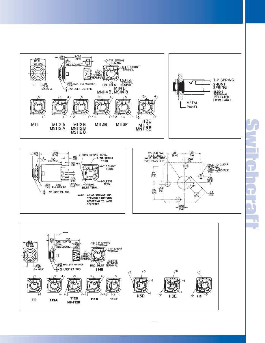
SWITCHCRAFT, INC. 5555 N. Elston Ave. • Chicago, IL 60630
99
JACKS AND PLUGS
FAX: 773 792-2129
JACKS AND
PLUGS
DIMENSIONS ARE FOR REFERENCE ONLY
Inch
(mm)
HI-D JAX 2- AND 3-CONDUCTOR
HI-D JAX 2- AND 3-CONDUCTOR
HI-D JAX
®
2- AND 3-CONDUCTOR
1/4" ENCLOSED PHONE JACKS (continued)
.375 (long bushing only)
[9.53]
Standard (Solder lugs)
®
®
M Series
Hi-D Jax
®
with Insulated Bushing
Hi-D Jax
®
with PC Terminals
Recommended
PCBoard Layout
* Please visit the product pages on our website for the most up-to-date product information
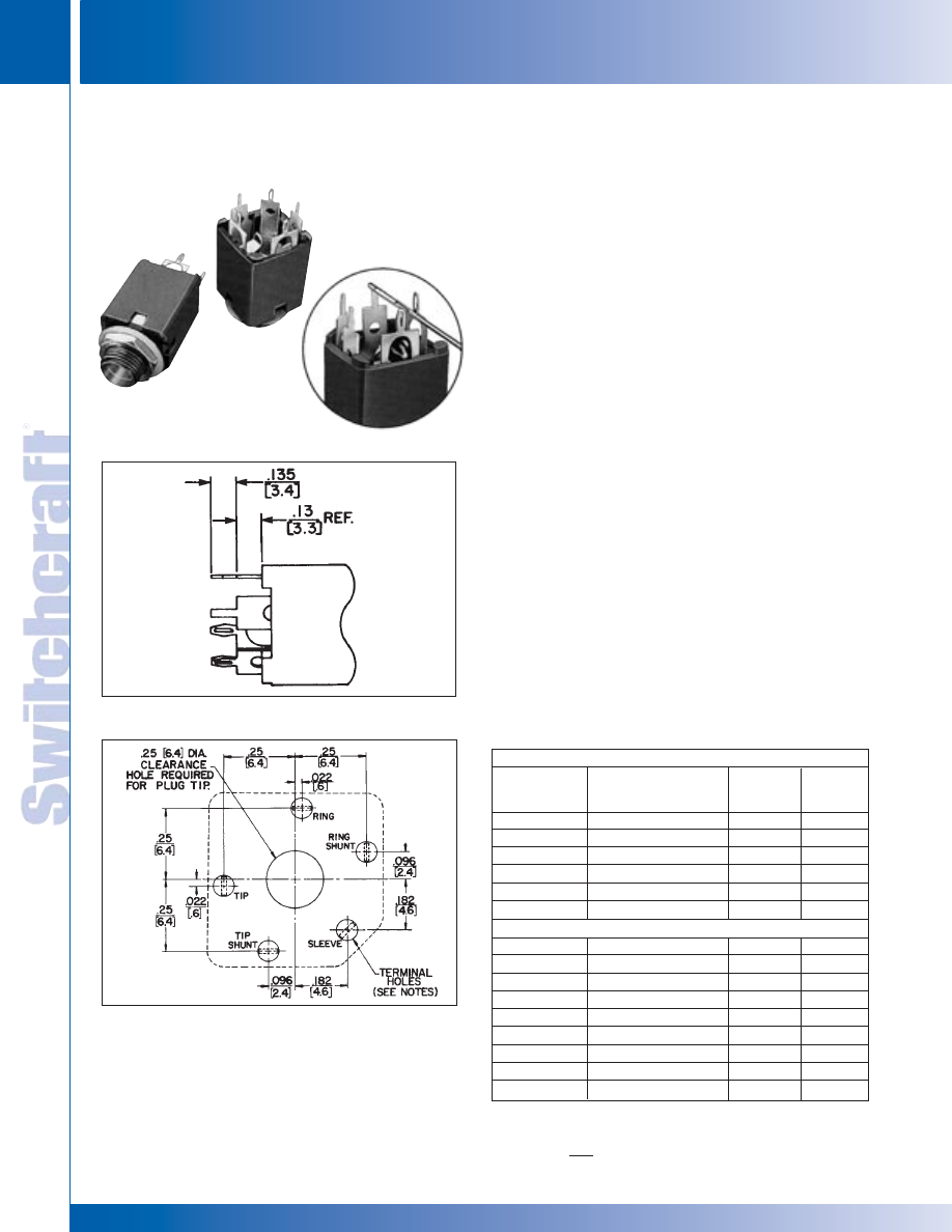
JACKS AND PLUGS
100
w w w . s w i t c h c r a f t . c o m
® Registered trademark of Switchcraft, Inc.
Note: Contact your Switchcraft Representative for price and delivery
PHONE: 773 792-2700
JACKS AND PLUGS
DIMENSIONS ARE FOR REFERENCE ONLY
Inch
(mm)
HI-D JAX 2- AND 3-CONDUCTOR
HI-D JAX 2- AND 3-CONDUCTOR
Hi-D Jax
®
enclosed 1/4" phone jacks offer spring lock PC
terminals which close during insertion into PC board. Upon
completed insertion, the terminals reopen to securely hold the
jack to the PC board during soldering. Solder “fills” the terminals
which provides an additional security from loosening.
The spring lock terminal is available on all Hi-D Jax
®
which
currently offer PC terminals.
NOTE: Tip and ground terminals can be specified with spring
lock terminals (also ring terminal on 3-conductor jacks).
MOUNTING
Jacks mount in a single .375" diameter hole on .625" minimum
centers. Series 11*, N11* and S11* mount in panels up to
.156 " thick. Series NL11* (long bushing) mount in panels up to
.250 " thick. Jacks with PC terminals mount on PC boards up to
.094 " thick. Spring lock PC terminals hold jack securely to PC
board. Threaded bushing permits mechanical connection to
equipment panel. Mounting hardware is supplied. See
“RECOMMENDED PC BOARD LAYOUT” for further details.
SERIES 11* - 2- and 3-conductor types, threaded metal
bushing .276" long. .250 inch inside diameter bushings.
SERIES N11* - Same as Series 11* except bushing is
molded thermoplastic for insulated mounting.
SERIES NL-11* - Same as Series N11* except bushing is .375"
long for insulated mounting in panels up to .250" thick.
SERIES S11* - Same as Series 11* except bushing has .210"
inside diameter Smaller diameter protects against accidental
insertion of plugs with .250" diameter fingers.
SPECIFICATIONS
MATERIAL
Mounting Bushing: Series 11*, S11*: Nickel-plated copper
alloy. Series N11*, NL11*: Molded thermoplastic over plated
copper alloy sleeve.
SPRING LOCK PC TERMINALS FOR HI-D JAX
®
CLOSE-UP VIEW OF
SPRING LOCK TERMINALS
RECOMMENDED PC BOARD LAYOUT SPRING LOCK
TERMINALS (COMPONENT SIDE)
HI-D JAX
®
SHOWING SPRING
LOCK PC TERMINALS
TWO CONDUCTOR PART NUMBERS
Typical
Jack
Mating
Part Number
Description
Schematic
Plug
1
◊
111PCS
Open circuit
I
250
◊
N111PCS
Insulated bushing
I
250
◊
112APCS
Single closed circuit
III
250
◊
N112APCS
Insulated bushing
III
250
◊
113PCS
Isolated “make” circuit
V
250
◊
113EPCS
Isolated “break” circuit
IX
250
THREE CONDUCTOR PART NUMBERS
◊
112BPCS
Double open circuit
IV
267
◊
N112BPCS
Insulated bushing
IV
267
◊
S112BPCS
.210" I.D. bushing
IV
S267
◊
113BPCS
Single closed circuit
VII
267
◊
N113BPCS
Insulated bushing
VII
267
◊
113FPCS
Ring closed circuit
XXVIII
267
◊
114BPCS
Double closed circuit
XII
267
◊
N114BPCS
Insulated bushing
XII
267
◊
NL114BPCS
.375" long bushing
XII
267
1 See Jack Section for other mating plugs.
◊
Special order only. Contact Switchcraft.
ORDERING INFORMATION
®
®
NOTES:
1. SERIES 110PC––ALL HOLES TO CLEAR .078" X .016" TERMINAL.
2. SERIES 110PCS––TIP, RING & SLEEVE HOLES TO BE .055" DIA. RING SHUNT &
TIP SHUNT HOLES TO CLEAR .078" X .016" TERMINAL.
PARTIAL VIEW SHOWING SPRING LOCK TERMINALS
Tip, ring and sleeve terminals are spring lock type.
* Please visit the product pages on our website for the most up-to-date product information
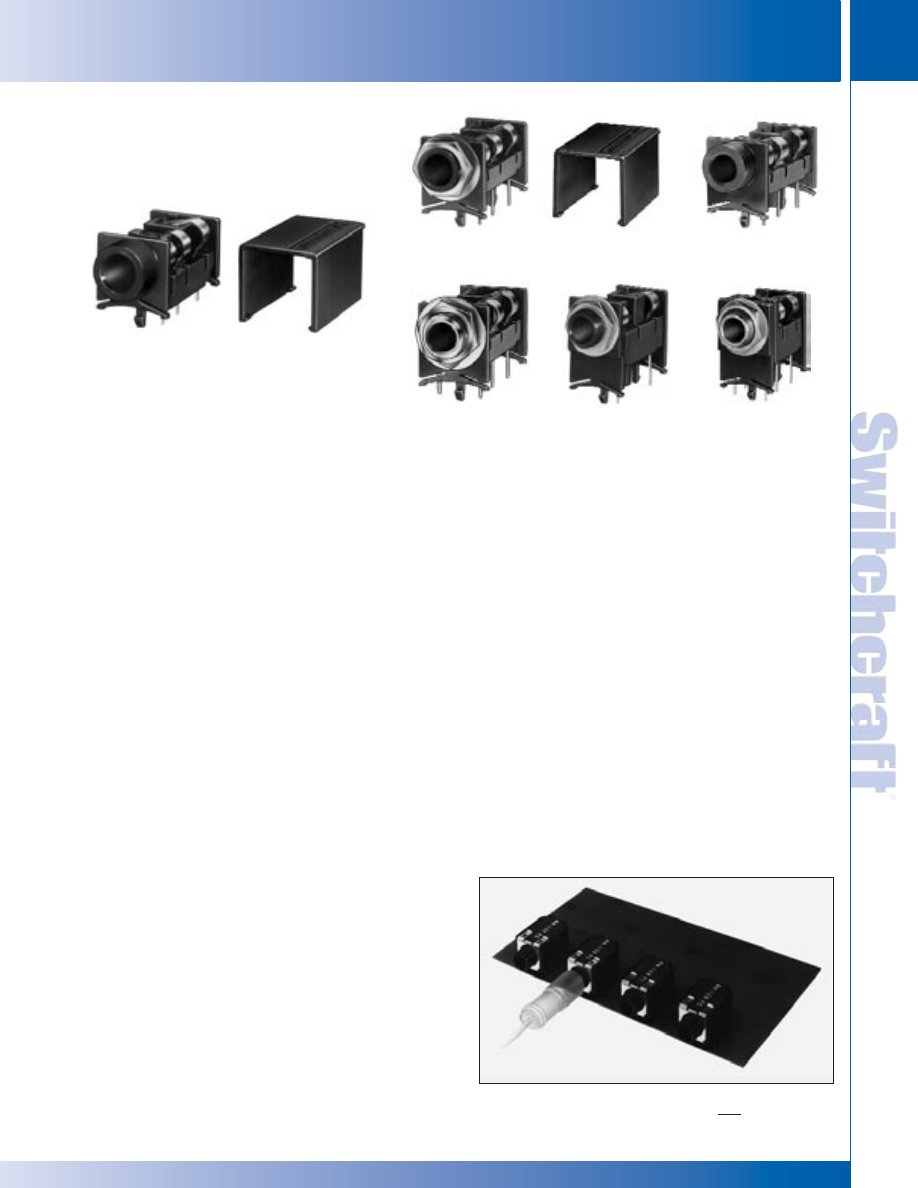
SWITCHCRAFT, INC. 5555 N. Elston Ave. • Chicago, IL 60630
101
JACKS AND PLUGS
FAX: 773 792-2129
JACKS AND
PLUGS
DIMENSIONS ARE FOR REFERENCE ONLY
Inch
(mm)
RIGHT-ANGLE PHONE JACKS
RIGHT-ANGLE PHONE JACKS
These low-profile phone jacks have “snap-in” PC mounting,
right-angle plug insertion and available with 2- and 3-conductor
circuits and plastic or metal bushings. Ideal for telecommunications,
data processing and other high quality audio connecting
applications.
SERIES SN37A - Right-angle PC mount phone jack with molded
plastic housing. Only .375" high, this jack features a plain
(non-threaded) bushing and accepts commercial standard phone
plugs with .25" diameter finger.
Jack circuit selection:
2-conductor • Single open circuit • Shunted tip
3-conductor • Double open circuit • Shunted tip and ring
Jack housing snaps into PC boards (.062" thick) and features
molded tension fingers to provide stable mount. Location pin
polarizes mounting for correct insertion every time. Clearance
between housing facilitates board cleaning without disturbing
internal springs. SN37 without tension fingers available on
special order.
Molded housing protects internal parts and allows high density
packaging. Supplied with “Snap-On” cover.
SERIES SN49A - Similar to Series SN37A, except .492" high and
insulated/plain (non-threaded) bushing. “Snap-On” cover available
on special order only.
SERIES SN49B - Similar to Series SN37A, except .492" high and
insulated threaded bushing. Washer and hex nut for bushing
mount supplied. “Snap-On” cover available on special order only.
SERIES SN49C - Similar to Series SN37A, except .492" high and
threaded metal bushing. Washer and hex nut for bushing mount
supplied. “Snap-On” cover available on special order only.
SERIES SN70B - This series features threaded/insulated
bushing and .708" in height. Circuit selection and housing features
are same as Series SN49B. “Snap-On” cover not available.
SERIES SN70C - Same as Series SN70B, except bushing is
threaded metal type.
SPECIFICATIONS
MECHANICAL
Shock: Per MIL-STD-202, method 213.
Vibration: Per MIL-STD-202, method 201.
Insertion Force: 8 pounds maximum.
Withdrawal Force: 1.5 pounds minimum.
Life: 10,000 cycles minimum.
ELECTRICAL
Insulation Resistance: 2 x 10⁶ M
Ω
at 500 V DC per
MIL-STD-202, method 302 (initial).
Dielectric Withstanding Voltage: 500 V AC.
ENVIRONMENTAL
Thermal Range: -55°C (-67°F) to +85°C (+185°F) Non
operating. -20°C to + 65°C Operating.
Thermal Shock: Per MIL-STD-202d, method 107.
Humidity: Per MIL-STD-202, method 106, less steps 7A and 7B.
Salt Spray: Per MIL-STD-202, method 101.
MATERIAL
Housing and Cover: Black thermoplastic, UL 94V-O.
Contact Springs: Copper alloy with tin-plated terminals.
Hardware: Nickel-plated copper alloy.
Metal Bushing: Nickel-plated copper alloy.
ORDERING
1. Order jacks from tables on page 103.
2. For all special order items, contact Switchcraft.
SERIES SN37, SN49 AND SN70
1/4" RIGHT-ANGLE PHONE JACKS
SN37A14B with cover Number P2993
SN49B12B with cover Number P2994
SN49A12B
SN49C12B
SN70B12A
SN70C14B
* Please visit the product pages on our website for the most up-to-date product information
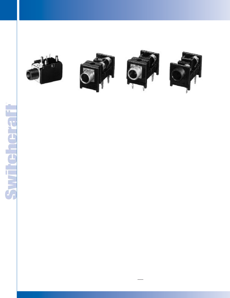
JACKS AND PLUGS
102
w w w . s w i t c h c r a f t . c o m
® Registered trademark of Switchcraft, Inc.
Note: Contact your Switchcraft Representative for price and delivery
PHONE: 773 792-2700
JACKS AND PLUGS
DIMENSIONS ARE FOR REFERENCE ONLY
Inch
(mm)
SERIES RA - 2- and 3-conductor RA Jax
®
are designed with
split terminals which provide two distinct advantages over
contemporary jacks:
1. Positive retention of jack in PC board during wave soldering.
2. Split terminal permits additional solder flow paths up the
terminal for better mechanical/electrical connection
Tip spring design facilitates positive retention of differing mating
plug tip shapes (industry standard and others).
SERIES RN - Right-angle Hi-D Jax
®
permits space-saving
mounting on PC boards. Available in 2- and 3-conductor
types with or without shunt circuits, which can mate with .25"
diameter COMMERCIAL or TELEPHONE/MIL plug fingers.
Right-angle jack permits tip of mating plug to be inserted
parallel with PC board. Can be mounted on PC boards or
combined PC board and panel/chassis.
Mounted through .375" diameter holes (locknut and washer
supplied) in panels and chassis up to .141" thick. Minimum
mounting centers are .625". If insulated mount is desired,
mounting with flat, non-conductive washer (not supplied) is
recommended.
PC terminals mount on boards up to .125" thick, and hand dip
or wave soldering, is recommended. Three separate standoffs
fit through board to provide stable mounting.Threaded bushing
permits optional fastening to panel or chassis.
SERIES RN110 - 2- and 3-conductor right-angle types mount
in PC boards or panel/chassis. Bushing is .278" long.
SERIES - RA and RN
1/4" RIGHT-ANGLE PHONE JACKS (continued)
Series RN110
Series RA
SPECIFICATIONS
Housing: Thermoplastic.
Bushing: Integral with housing.
Springs: Copper alloy, silver-plated (also available with selectively
gold-plated contact points and selectively tin-plated terminals).
Contacts: Integral, part of shunt springs.
NOTE: Specifications for Mechanical, Electrical and Environmental
are the same for Hi-D
®
Jax. (page 98)
RIGHT-ANGLE PHONE JACKS
RIGHT-ANGLE PHONE JACKS
* Please visit the product pages on our website for the most up-to-date product information
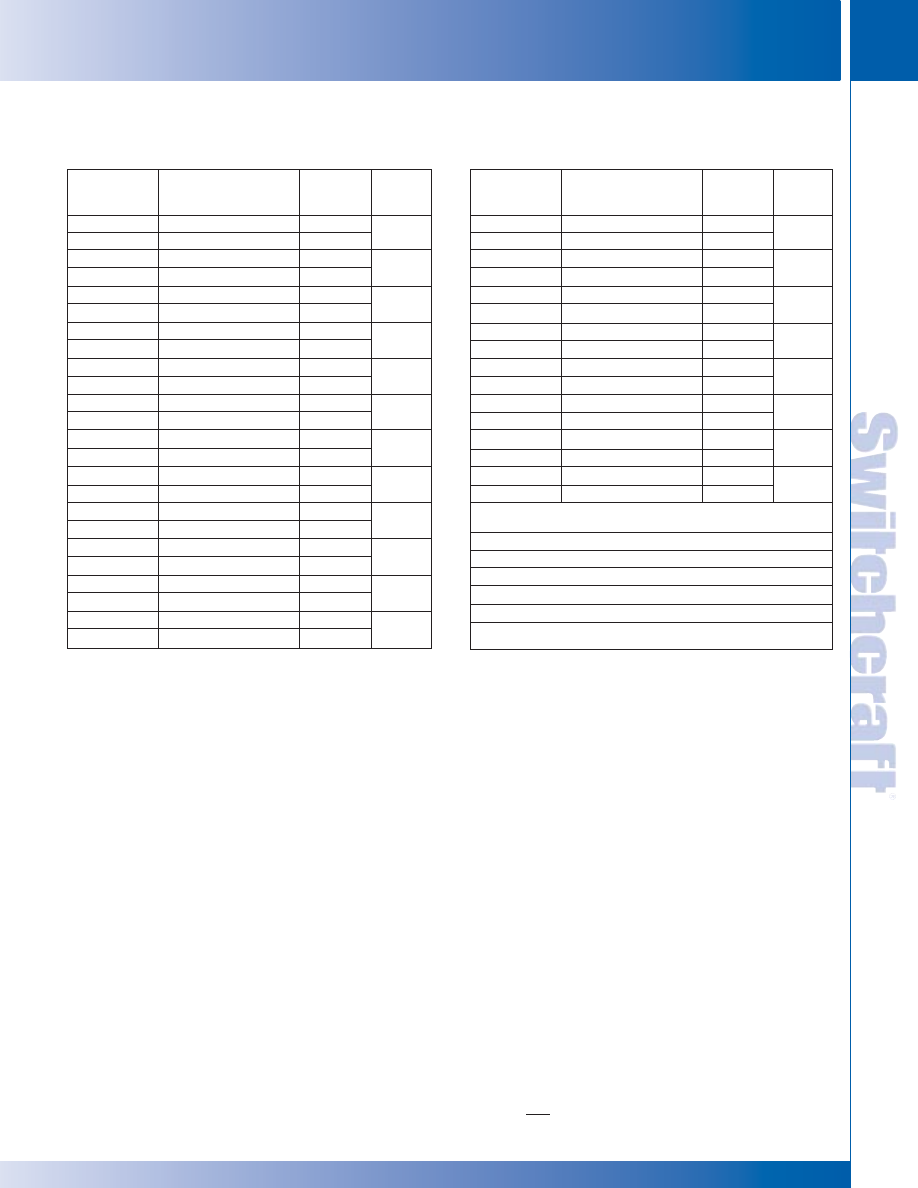
SWITCHCRAFT, INC. 5555 N. Elston Ave. • Chicago, IL 60630
103
JACKS AND PLUGS
FAX: 773 792-2129
JACKS AND
PLUGS
DIMENSIONS ARE FOR REFERENCE ONLY
Inch
(mm)
RIGHT-ANGLE PHONE JACKS – SERIES RA, RN AND SN
RIGHT-ANGLE PHONE JACKS – SERIES RA, RN AND SN
1/4" RIGHT-ANGLE PHONE JACKS (continued)
SERIES SN
Part Numbers
SN37A11
1
SN37A12A
1
SN37A12B
1
SN37A14B
1
SN49A11
1
SN49A12A
1
SN49A12B
1
SN49A14B
1
SN49B11
1
SN49B12A
1
SN49B12B
1
SN49B14B
1
SN49C11
SN49C12A
SN49C12B
SN49C14B
SN70B11
SN70B12A
SN70B12B
SN70B14B
SN70C11
SN70C12A
SN70C12B
SN70C14B
Description
2-cond., open circuit
2-cond., single closed circuit
3-cond., double open circuit
3-cond., double closed circuit
2-cond., open circuit
2-cond., single closed circuit
3-cond., double open circuit
3-cond., double closed circuit
2-cond., open circuit
2-cond., single closed circuit
3-cond., double open circuit
3-cond., double closed circuit
2-cond., open circuit
2-cond., single closed circuit
3-cond., double open circuit
3-cond., double closed circuit
2-cond., open circuit
2-cond., single closed circuit
3-cond., double open circuit
3-cond., double closed circuit
2-cond., open circuit
2-cond., single closed circuit
3-cond., double open circuit
3-cond., double closed circuit
Jack
2
Schematic
I
III
IV
XII
I
III
IV
XII
I
III
IV
XII
I
III
IV
XII
I
III
IV
XII
I
III
IV
XII
Typical
Mating
Plug
3
250
267
250
267
250
267
250
267
250
267
250
267
SERIES RA
Part Numbers
RA49B11
RA49B12A
RA49B12B
RA49B14B
RA49C11
RA49C12A
RA49C12B
RA49C14B
RA70B11
RA70B12A
RA70B12B
RA70B14B
RA70C11
RA70C12A
RA70C12B
RA70C14B
SERIES RN
Part Numbers
RN111PC
RN112APC
RN112BPC
RN113BPC
◊
RN113FPC
RN114BPC
Description
2-cond., open circuit
2-cond., single closed circuit
3-cond., double open circuit
3-cond., double closed circuit
2-cond., open circuit
2-cond., single closed circuit
3-cond., double open circuit
3-cond., double closed circuit
2-cond., open circuit
2-cond., single closed circuit
3-cond., double open circuit
3-cond., double closed circuit
2-cond., open circuit
2-cond., single closed circuit
3-cond., double open circuit
3-cond., double closed circuit
2-cond., single open circuit
2-cond., single closed circuit
3-cond., double open circuit
3-cond., tip closed, ring open
3-cond., tip open, ring closed
3-cond., double closed circuit
Jack
2
Schematic
I
III
IV
XII
I
III
IV
XII
I
III
IV
XII
I
III
IV
XII
I
III
IV
VII
XXVIII
XII
Typical
Mating
Plug
3
250
267
250
267
250
267
250
267
250
250
267
267
267
267
1 Series SN37A supplied with Part Number P2993 cover. Series SN49A and SN49B can
be supplied with Part Number P2994 cover on special order. Contact Switchcraft.
2 See pages 79 and 80.
3 Other mating plugs are available.
◊
Special order only. Contact Switchcraft.
ORDERING INFORMATION
ORDERING INFORMATION
* Please visit the product pages on our website for the most up-to-date product information
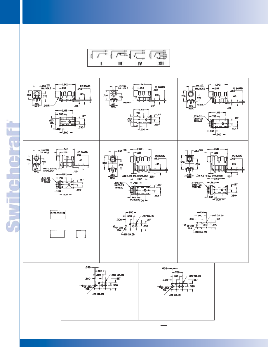
JACKS AND PLUGS
104
w w w . s w i t c h c r a f t . c o m
® Registered trademark of Switchcraft, Inc.
Note: Contact your Switchcraft Representative for price and delivery
PHONE: 773 792-2700
JACKS AND PLUGS
DIMENSIONS ARE FOR REFERENCE ONLY
Inch
(mm)
JACK SCHEMATICS
RIGHT-ANGLE PHONE JACKS – SERIES SN
RIGHT-ANGLE PHONE JACKS – SERIES SN
SERIES
SN37A
SERIES
SN49A
SERIES
SN49B
SERIES
SN49C
SERIES
SN70B
SERIES
SN70C
COVERS, PART NO. P-293 & P-2994
(No. P-2994, special order only)
RECOMMENDED PC
BOARD LAYOUT
SERIES SN37A, SN49A & SN49B
(Component Side)
RECOMMENDED PC
BOARD LAYOUT
SERIES SN49C
(Component Side)
SERIES SN
1/4" RIGHT-ANGLE PHONE JACKS (continued)
RECOMMENDED PC
BOARD LAYOUT
SERIES SN70B
(Component Side)
RECOMMENDED PC
BOARD LAYOUT
SERIES SN70C
(Component Side)
* Please visit the product pages on our website for the most up-to-date product information
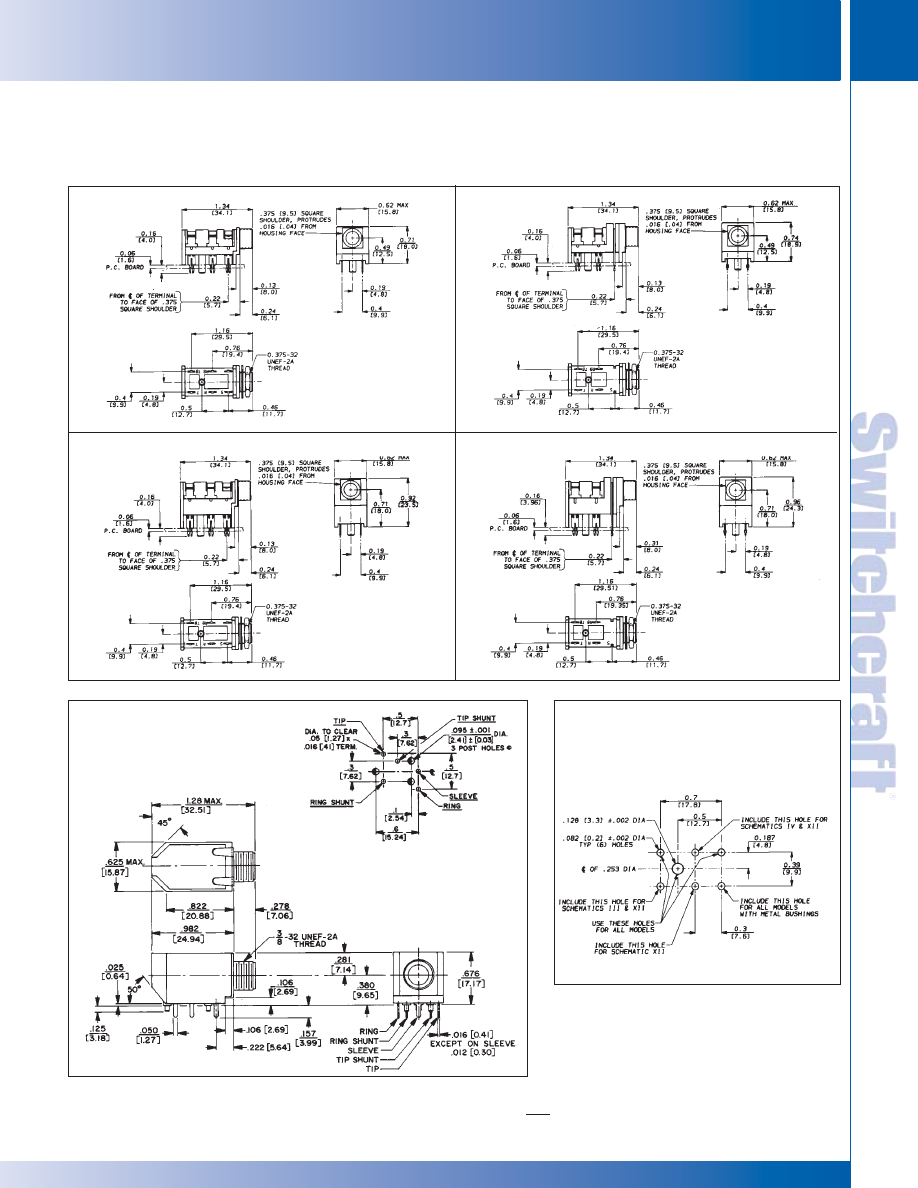
SWITCHCRAFT, INC. 5555 N. Elston Ave. • Chicago, IL 60630
105
JACKS AND PLUGS
FAX: 773 792-2129
JACKS AND
PLUGS
DIMENSIONS ARE FOR REFERENCE ONLY
Inch
(mm)
1/4" RIGHT-ANGLE PHONE JACKS – SERIES RA AND RN
1/4" RIGHT-ANGLE PHONE JACKS – SERIES RA AND RN
SERIES RA and RN
1/4" RIGHT-ANGLE PHONE JACKS (continued)
RECOMMENDED PC
BOARD LAYOUT
(Component Side)
RECOMMENDED PC
BOARD LAYOUT
(Component Side)
RN SERIES
DIMENSIONS
SERIES RA49B
SERIES RA49C
SERIES RA70B
SERIES RA70C
* Please visit the product pages on our website for the most up-to-date product information
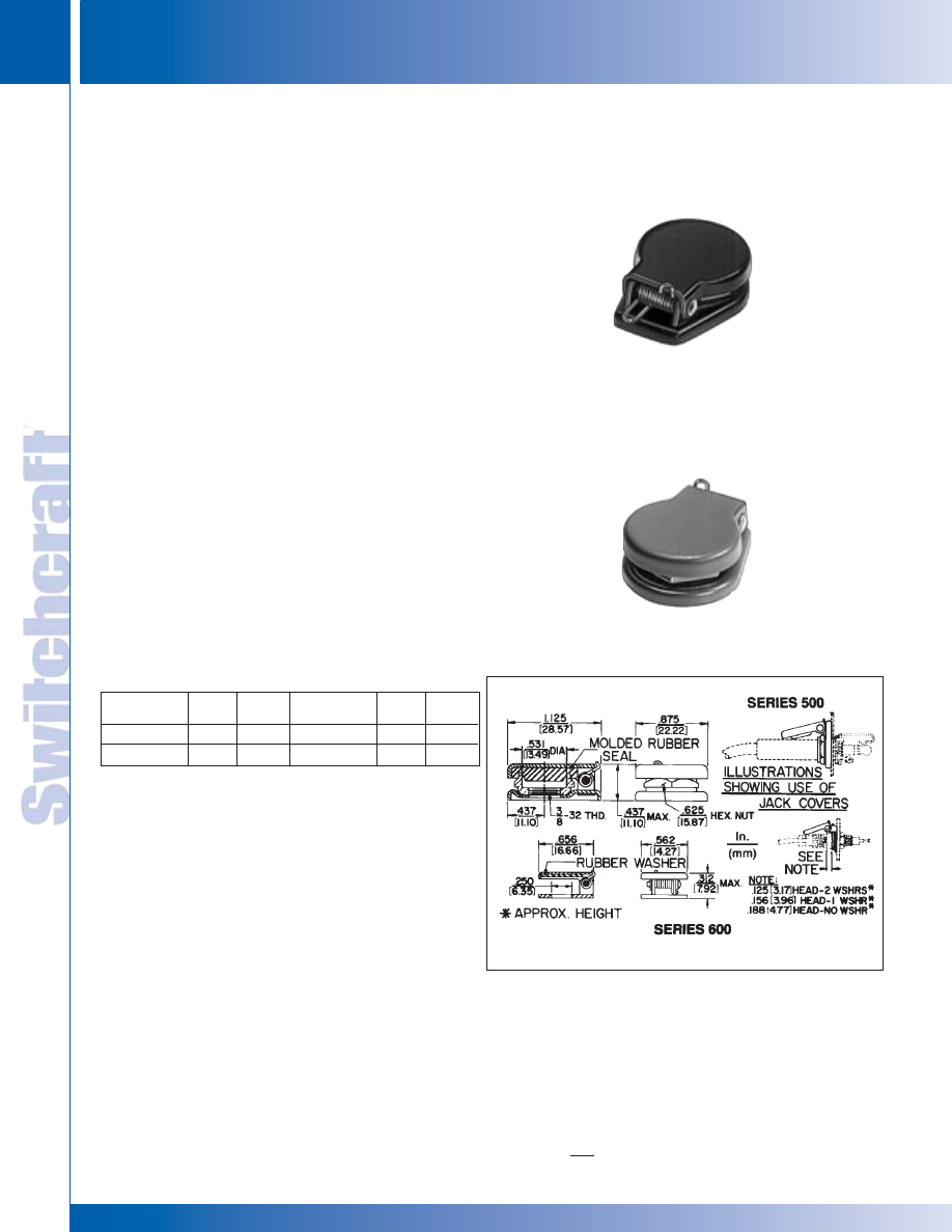
JACKS AND PLUGS
106
w w w . s w i t c h c r a f t . c o m
® Registered trademark of Switchcraft, Inc.
Note: Contact your Switchcraft Representative for price and delivery
PHONE: 773 792-2700
JACKS AND PLUGS
DIMENSIONS ARE FOR REFERENCE ONLY
Inch
(mm)
JACK COVERS
JACK COVERS
JACK COVERS
520
515
Reliable, spring-loaded covers effectively seal front panel
bushing openings from dust and dirt when mating plugs are
not connected to jack. Series 500 is mounted with conventional
threaded bushing jacks. Special locknut (comes with Series
500 jack covers) seals tightly against rubber washer when
cover is closed. Series 600 is used with certain type tip jacks.
Due to variable jack dimensions, two .031" washers are supplied.
SPECIFICATIONS
MATERIAL
Base and Cover: Steel per QQ-S-698; finish per
MIL-F-14072 (Sig. C), enamel, semi-gloss.
Axle: Copper alloy per QQ-W-321, Type 321,
composition B. Plated per QQ-P-416, Type II, Class 3.
Spring: Stainless steel per QQ-W-432, Type 302.
Hex Nut: Copper alloy per QQ-B-626, composition 22.
Same plating as axle.
Gasket: Synthetic rubber per MIL-R-6855, Type II,
35-40 Durometer.
Washer (600 only): Steel per QQ-S-698; plated per
QQ-P-416, Type II, Class 3.
Additional Specifications for Numbers 512 and 612:
Same as above, except rivet, base, cover and hex nut
and washer (Number 612 only) are nickel-plated
per QG-N-290.
Color
Olive Drab
Bright Nickel
Part
No.
510
512
Part
No.
◊
610
612
Color
Black
Navy Gray
Part
No.
515
520
Part
No.
615
◊
620
◊
Special order only. Contact Switchcraft.
* Please visit the product pages on our website for the most up-to-date product information
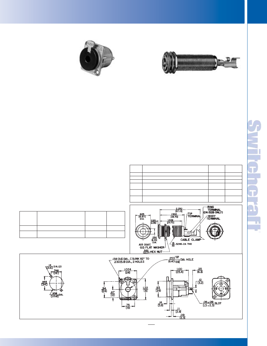
SWITCHCRAFT, INC. 5555 N. Elston Ave. • Chicago, IL 60630
107
JACKS AND PLUGS
FAX: 773 792-2129
JACKS AND
PLUGS
DIMENSIONS ARE FOR REFERENCE ONLY
Inch
(mm)
Series E jacks provide stable, secure connections in panels where
shock/vibration or accidental disconnect may occur. Plug locks-in
automatically upon insertion; press “PUSH” tab to unlock and
remove plug. Series E jacks have the same front panel
appearance as Series E Q-G
®
audio connectors.
SPECIFICATIONS
MECHANICAL
Life: 10,000 cycles minimum.
ELECTRICAL
Insulation Resistance: 2 x 10⁶ M
Ω
at 500 V DC per
MIL-STD-202, method 302 (initial).
Dielectric Withstanding Voltage: 1,000 V AC (rms).
ENVIRONMENTAL
Thermal Range: -55°C to +85°C (non-operating);
-20°C to +65°C (operating).
Thermal Shock: Per MIL-STD-202, method 107.
Humidity: Per MIL-STD-202, method 106.
Salt Spray: Per MIL-STD-202, method 101.
MATERIAL
Shell: Die-cast zinc, with satin nickel-plating. Black chrome over
nickel-plating on special order.
Insert and Latch: Thermoplastic, UL 94V-O.
Latch Release: Nickel-plated die-cast zinc.
Contact Springs: Tin-plated copper alloy.
LOCKING
PHONE JACKS
1/4" PHONE JACKS (continued)
Part
Number
E111L
E112BL
Description
2-cond., open circuit
3-cond., double open circuit
Jack
Schematic
1
I
IV
Typical
Mating
Plug
2
250
267
1. See Jack Schematics, pages 79 and 80
2. See Plugs Section
THICK PANEL PHONE JACKS
1/4" PHONE JACKS – SERIES E
(
LOCKING
)
AND THICK PANEL PHONE JACKS
1/4" PHONE JACKS – SERIES E
(
LOCKING
)
AND THICK PANEL PHONE JACKS
Jacks are standard 2- and 3-conductor phone jacks with extra long
threaded bushing for mounting in panels/chassis up to 1.25" thick.
Metal bushing virtually eliminates hum pick-up, and is ideal for electric
guitar and speaker connections. Jacks mate with standard
commercial phone plugs. See plug section for mating plugs. Jacks
mount in a single .469" diameter hole. Rugged cable clamp protects
connections from twisting and pulling stresses.
SPECIFICATIONS
MATERIAL
Mounting Bushing: Nickel-plated copper alloy with knurled flange.
Insulating Spacer: Rigid plastic.
Insulator/Spring Mount: Thermoplastic.
Springs: Copper alloy.
Terminals: Tip: Copper alloy. Ring: (Number 152B only) copper alloy.
Sleeve: Steel, tin-plated.
Hardware: Supplied with one, Number P10531 nickel-plated copper alloy
hex nut, and one, Number P14761 nickel-plated copper alloy flat washer.
RECOMMENDED
PANEL CUTOUT
LOCKING PHONE JACKS, SERIES E
THICK PANEL PHONE JACKS
SERIES E
151
Part
Jack Typical
Number
Description
Schematic
Mating Plug
151
2-conductor, open circuit, nickel finish
I
280
152
2-conductor, open circuit, brass finish
I
280
152B
3-conductor, double open circuit, nickel finish
IV
297
153
2-conductor, open circuit, gold-plated springs,
I
280
electro-polish brass finish, 9/16-12 UNC wood threads
154
3-conductor, double open circuit, gold finish,
IV
297
no cable clamp
155
3-conductor, double open circuit, black satin finish,
IV
no cable clamp
* Please visit the product pages on our website for the most up-to-date product information
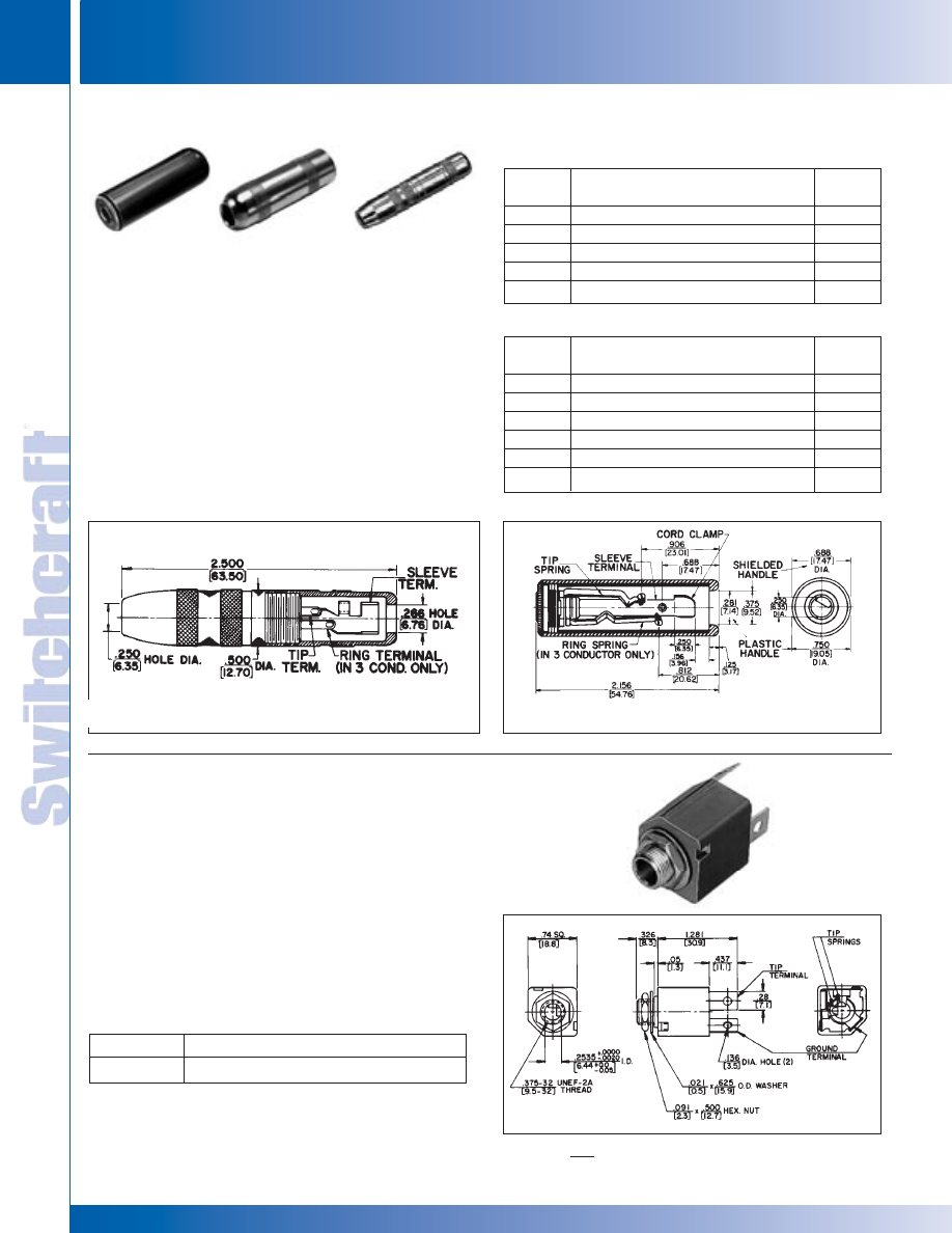
JACKS AND PLUGS
108
w w w . s w i t c h c r a f t . c o m
® Registered trademark of Switchcraft, Inc.
Note: Contact your Switchcraft Representative for price and delivery
PHONE: 773 792-2700
JACKS AND PLUGS
DIMENSIONS ARE FOR REFERENCE ONLY
Inch
(mm)
EXTENSION JACKS AND 1/4" SPEAKER JACKS
EXTENSION JACKS AND 1/4" SPEAKER JACKS
Extension Jax
®
jacks are connected to the end of a cable.
2- and 3-conductor jacks mate with standard commercial
phone plugs, and have a sturdy cable clamp strain relief,
knurled shielded or molded black plastic handles, and a
screw type solder terminal. All internal parts are interlocked.
Note: See locking phone plugs section.
SPECIFICATIONS
MATERIAL
Body, Sleeve and Shielded Handle: Nickel-plated
copper alloy.
Plastic Handles: Molded black thermoplastic.
Springs: Special copper alloy.
Bushing and Flange: Plated copper alloy.
Insulation: Thermoplastic.
Clamp Terminals: Tin-plated copper alloy.
High power 2-conductor speaker jack carries 15A (continuous)
audio speaker current levels. Jack Number Z15J has positive
detent for plug retention. Terminations are solder lug; wires
accepted are up to 10 AWG. Red housing indicates high current
rating. Recommended mating plugs: 70, 184, 187 series.
SPECIFICATIONS
Housing: Glass reinforced thermoplastic, UL 94V-O.
Tip Spring and Ground Terminals: Copper alloy.
Bushing and Hardware: Nickel-plated copper alloy
(hardware supplied).
Heat Rise: 30°C with 15 A continuous carry.
Life: 10,000 (minimum) with proper plug.
1/4" EXTENSION JACKS (IN-LINE)
1/4" SPEAKER JACKS
Part Number
Z15J
Description
High power speaker jack
Part
Number
80
88
120
121
128
Description
Black handle; screw terminals
Black handle; solder lugs
Shielded handle; screw terminals
Shielded handle; solder lugs; cable clamp
Shielded handle; solder lugs
Mating
Plug
1
250
250
250
250
250
TWO-CONDUCTOR PART NUMBERS
Part
Number
131
830
S830
838
1230
1238
Description
Shielded handle; solder lugs
Black handle; screw terminals
Similar to No. 830 except, .21" I.D. sleeve
Black handle; solder lugs
Shielded handle; screw terminals
Shielded handle; solder lugs
Mating
Plug
1
267
267
480
267
267
267
THREE-CONDUCTOR PART NUMBERS
80
120
121, 131
Z15J
Z15J
121, 131
1. Other mating plugs are available.
* Please visit the product pages on our website for the most up-to-date product information
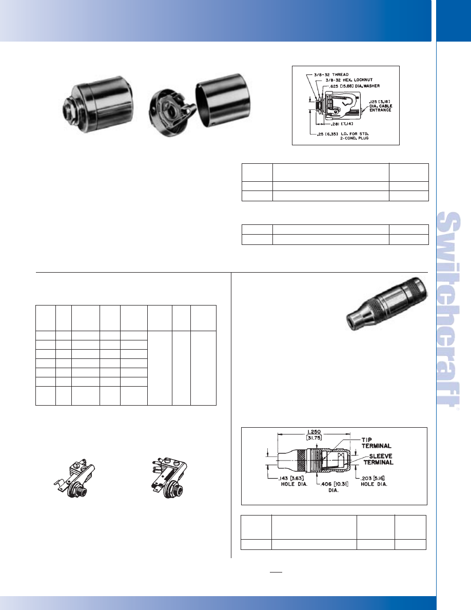
SWITCHCRAFT, INC. 5555 N. Elston Ave. • Chicago, IL 60630
109
JACKS AND PLUGS
FAX: 773 792-2129
JACKS AND
PLUGS
DIMENSIONS ARE FOR REFERENCE ONLY
Inch
(mm)
SHIELDED PHONE JACKS, SF-JACKS SHORT FRAME JACKS, MINI PHONE JACKS
SHIELDED PHONE JACKS, SF-JACKS SHORT FRAME JACKS, MINI PHONE JACKS
.141" MINIATURE
PHONE JACKS
Shield is assembled as part of the jack; cover “snaps” into
place. Shield is designed for Hi Z circuits. Mounting is
through a 3/8" diameter hole in chassis/panel up to
.156" thick with hex nut and flat washer (supplied).
On special order, jacks with .21 inch inside diameter
bushing are available.
SPECIFICATIONS
MATERIAL
Cover and Shield: Copper alloy, nickel-plated.
Cable Entry Insulation: Thermoplastic.
1/4" SHIELDED PHONE JACKS
Part
Number
◊
CN11
◊
CN12A
Description
Uses Number 11 Littel-Jax
®
jacks
Uses Number 12A Littel-Jax
®
jacks
Jack
Schematic
1
I
III
TWO CONDUCTOR PART NUMBERS
◊
CN12B
◊
CN13B
Uses Number 12B Littel-Jax
®
jacks
Uses Number 13B Littel-Jax
®
jacks
IV
VII
THREE CONDUCTOR PART NUMBERS
1 See jack schematics on pages 79 and 80.
2 See Plug Section for mating information.
◊
Special order only. Contact Switchcraft.
CN12A
125
SF-JAX
®
SHORT FRAME JACKS
Long spring design reliability with minimum behind-panel
depth. Series 50 same as Series 20, except solder lug
location requires more depth, but less panel space.
Number C55B has MIL type insulation and finish.
SERIES 20
SERIES 50
Typical
Part
Schematic Mating
Mounting
No.
Cond. Number
Plug
MIL Type Contacts Rating In. (mm)
24B
3
XII
267
-----
25
2
XIII
250
-----
◊
53B
3
VII
267
-----
◊
54A
2
XI
250
-----
◊
54B
3
XII
267
-----
◊
55
2
XIII
250
-----
◊
C-55B
3
XV
482
JJ-095,
M641/14-1
Fine
Silver
3A
125V
AC
.375 (9.52)
hole,
mounts in
panels up
to .156
(3.96) thick
◊
Special order only. Contact Switchcraft.
Part
Number
125
Description
Extension Jack
Jack
Schematic
I
Typical
Mating
Plug
750
MINIATURE EXTENSION JACK,
PHONE JACK NUMBER 125 (EIA STANDARD)
Cable-mounted Tini-Extension Jax
®
2-conductor single open
circuit jack has built in cable clamp/sleeve terminal. Mates with
Tini-Plug
®
phone plugs and other plugs with .141" diameter
fingers and compatible tip shape. Shielded housing/handle is
knurled for positive fingertip grip; solder lug terminals.
Body and handle: Nickel-plated copper alloy.
Insulation: Rigid plastic.
Springs: Plated copper alloy.
TINI-EXTENSION JAX JACK
®
®
24B
25
53B
54A
54B
55
C55B
* Please visit the product pages on our website for the most up-to-date product information
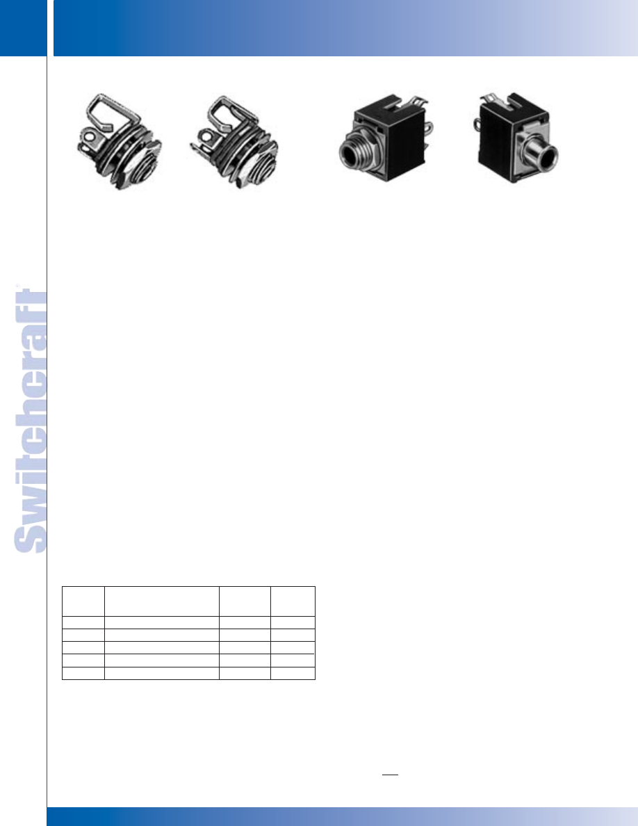
JACKS AND PLUGS
110
w w w . s w i t c h c r a f t . c o m
® Registered trademark of Switchcraft, Inc.
Note: Contact your Switchcraft Representative for price and delivery
PHONE: 773 792-2700
JACKS AND PLUGS
DIMENSIONS ARE FOR REFERENCE ONLY
Inch
(mm)
MINIATURE PHONE JACKS
MINIATURE PHONE JACKS
.141" MINIATURE PHONE JACKS
TINI-JAX
®
MINIATURE PHONE JACKS,
NUMBERS 41, 42A, 43A
Tini-Jax 2-conductor phone jacks, (for limited space
connecting, mate with miniature phone plugs having .141 "
diameter fingers and compatible tip shape) are 1/3 the size of
Littel-Jax
®
and weigh less than 1/8 ounce. Notched insulators
interlock internal parts. Unique tip spring shape mates with
Switchcraft Tini-Plug
®
phone plugs. Mounting hole: .250"
diameter in panels up to .125" thick (mounting hardware
supplied). For insulated mount, order two washers separately,
Number S1564 (swedged fiber washer .312" diameter
mounting hole) and number S2207 (flat phenolic washer).
SPECIFICATIONS
MECHANICAL
Life: 5,000 insertion/withdrawal cycles, minimum.
ELECTRICAL
Contact Resistance: .075 ohms maximum.
Insulation Resistance: 5,000 M
Ω
minimum.
Dielectric Withstanding Voltage: 250 V AC maximum.
Contact Rating: .25A, 48 V DC.
MATERIAL
Mounting Bushing: Nickel-plated copper alloy.
Insulating Spacers: Rigid plastic.
Springs: Special copper alloy.
Sleeve Terminal: Tin-plated copper alloy.
Hardware: Supplied with one, Number P11501
nickel-plated copper alloy locknut, and one,
Number S17901 nickel-plated steel flat washer.
TINI-D-JAX
®
MINIATURE ENCLOSED
PHONE JACKS, NUMBERS 142A, PC142A
Tini-D Jax uses Hi-D Jax
®
construction and mounts on .375"
centers. Weight: 3.6 grams. Number 142A mounts through .25"
diameter hole in chassis/panel up to .125" thick. Four standoff
dimples can be molded into housing to reduce
effective length of bushing to .187" (special order).
Number PC142A has special spring terminals for “snap-in”
mounting to PC boards up to .125" thick - ready for hand,
wave or dip-soldering.
SPECIFICATIONS
MECHANICAL
Life: 5,000 insertion/withdrawal cycles, minimum.
Insertion/Withdrawal: 15 ounce minimum,
40 ounce maximum, insertion. 12 ounce minimum,
25 ounce maximum, withdrawal.
ELECTRICAL
Contact Resistance: .10 ohms maximum.
Dielectric Withstanding Voltage: 250 V AC maximum.
Shunt Tension: 100 grams minimum.
MATERIAL
Housing: Molded plastic.
Mounting Bushing: Plated copper alloy.
Tip Spring: Plated copper alloy, bifurcated.
Shunt Springs: Plated copper alloy.
Sleeve Bracket: Plated steel.
Insulator: Rigid plastic.
Hardware: Number 142A supplied with one, Number P1975
nickel-plated copper alloy locknut, and one, Number S3997
nickel-plated steel flat washer.
Part
Number
41
42A
43A
142A
PC142A
Description
Open circuit
Shunted (closed circuit)
Special transfer circuit
Shunted (closed circuit)
Shunted (closed circuit)
Jack
Schematic
1
I
III
Note 3
III
III
Typical
Mating
Plug
2
750
750
750
750
750
1. See jack schematics, pages 79 and 80.
2. See Plugs Section for mating information.
3. When inserted, plug tip contacts “make” tip spring. Further insertion allows
tip to short “make” tip spring and tip spring together. Full insertion opens
tip shunt circuit.
41
42A
142A
PC142A
* Please visit the product pages on our website for the most up-to-date product information
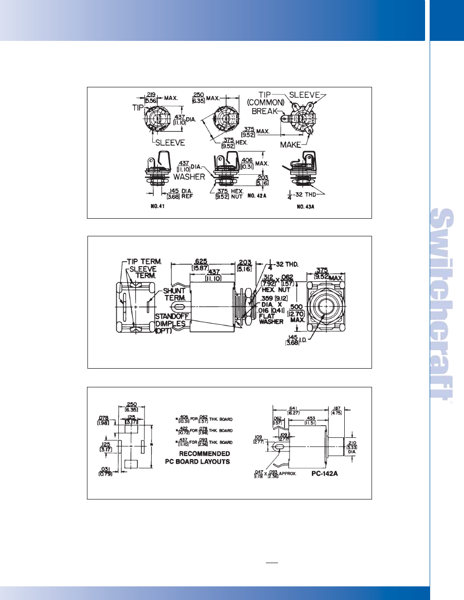
SWITCHCRAFT, INC. 5555 N. Elston Ave. • Chicago, IL 60630
111
JACKS AND PLUGS
FAX: 773 792-2129
JACKS AND
PLUGS
DIMENSIONS ARE FOR REFERENCE ONLY
Inch
(mm)
MINIATURE PHONE JACKS
MINIATURE PHONE JACKS
.141" MINIATURE PHONE JACKS (continued)
“TINI-JAX” JACKS
142A
“TINI-D” JACKS
* Please visit the product pages on our website for the most up-to-date product information
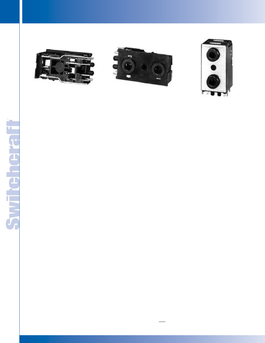
JACKS AND PLUGS
112
w w w . s w i t c h c r a f t . c o m
® Registered trademark of Switchcraft, Inc.
Note: Contact your Switchcraft Representative for price and delivery
PHONE: 773 792-2700
JACKS AND PLUGS
DIMENSIONS ARE FOR REFERENCE ONLY
Inch
(mm)
FEATURES
• 3-conductor, miniature phone jack mates with 3.5 mm
finger plugs.
• Saves board space...two jacks in a single vertical
mount footprint.
• Ideally suited for infra-red and convection oven
soldering 235°C (455°F).
• Board retention pins accommodate PC board thickness
range of .050" to .080".
• Single-screw panel mounting hole is standard.
• EMI-RFI shield, optional.
• Housing UL 94V-0 rated against flammability.
APPLICATIONS
• Multi-media workstations
• Headphones/microphone sets
• Interactive TV
• Audio
• Telecommunications
• Medical
• Computer
• Instrumentation
MATERIALS
Housing: Thermoplastic.
Tip and Ring Springs: Silver-plated copper alloy.
Shunt Terminals: Silver-plated copper alloy.
Sleeve Terminals: Silver-plated copper alloy.
Shield: Pre-tinned copper alloy.
PERFORMANCE SPECIFICATIONS
Insertion/Extraction Forces, initial: 0.8 to 6 pounds.
Dielectric Withstanding Voltage: 500 VAC.
Insulation Resistance, initial: 100 Megaohms, min.
Contact Resistance: Between plug and jack:
50 milliohms, maximum Between springs and shunts:
30 milliohms, maximum.
Life: 5000 cycles, minimum.
ORDERING INFORMATION
Part Number:
Shielded - 35RAPC7JS
Unshielded - 35RAPC7J
1. Order by part number.
2. Contact Switchcraft for special order information.
3.5MM DUAL STEREO JACK
UNSHIELDED - 35RAPC7J
SHIELDED - 35RAPC7JS
3.5MM DUAL STEREO JACK
3.5MM DUAL STEREO JACK
* Please visit the product pages on our website for the most up-to-date product information
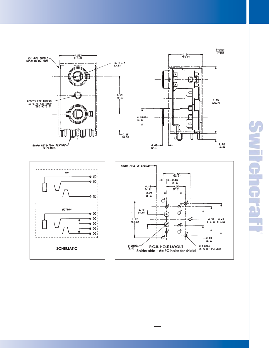
SWITCHCRAFT, INC. 5555 N. Elston Ave. • Chicago, IL 60630
113
JACKS AND PLUGS
FAX: 773 792-2129
JACKS AND
PLUGS
DIMENSIONS ARE FOR REFERENCE ONLY
Inch
(mm)
3.5MM DUAL STEREO JACK
3.5MM DUAL STEREO JACK
NOTES:
1. Shield isolated from terminals 1 and 6.
2. Width of all terminals = 0.032" (0.814 mm).
3. Use Camcar Textron S25 T8 TORX pan head “Duro-PT”
thread cutting fastener of appropriate length or equivalent.
3.5MM DUAL STEREO JACK (continued)
* Please visit the product pages on our website for the most up-to-date product information
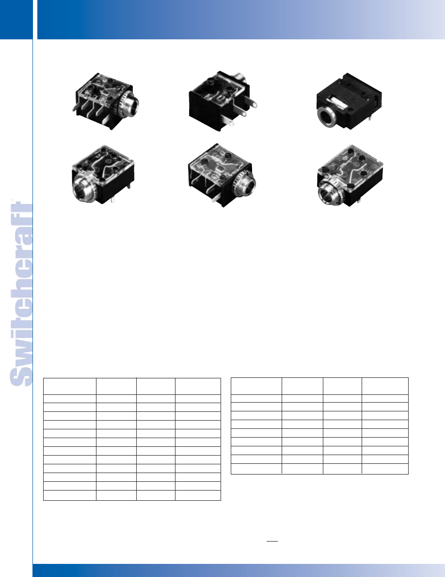
JACKS AND PLUGS
114
w w w . s w i t c h c r a f t . c o m
® Registered trademark of Switchcraft, Inc.
Note: Contact your Switchcraft Representative for price and delivery
PHONE: 773 792-2700
JACKS AND PLUGS
DIMENSIONS ARE FOR REFERENCE ONLY
Inch
(mm)
3.5MM SINGLE MONO AND STEREO JACKS
3.5MM SINGLE MONO AND STEREO JACKS
3.5MM SINGLE MONO AND STEREO JACKS
FEATURES
• 2 and 3 conductor 3.5mm phone jacks
• Right angle PC mount, true SMT
versions, and open frame panel mounts
• Wide variety of circuits available
• Mates with all 3.5mm plugs Right angle
PC mount available in low profile,
horizontal styles
MATERIALS
Housing: Thermoplastic, UL94V-1
Terminals: Silver-plated, copper alloy
Bushing: Nickel-plated, copper alloy
Performance Specifications:
Contact Resistance: < 50 milliohms
Insulation Resistance: 100 milliohms min.
Dielectric Withstanding Voltage: 250
VAC (35RAPC2BHN2- 500 VAC)
Open Frame Versions Materials:
Housing (35PM2BV2):
Thermoplastic, 94V-1
Life: 5000 cycles, min.
Bushing: Nickel-plated, copper alloy
Insulating Washers: Rigid Plastic
Springs: Copper alloy
Sleeve Terminal: Tin-plated, copper alloy
Hardware: Supplied with one, P11501
nickel-plated brass locknut, and one,
S17901 nickel-plated steel flat washer
Performance Specifications:
Contact Resistance: .075 ohms max.
Insulation Resistance: 5,000 Mohms
min
Dielectric Withstanding Voltage:
250 VAC Life: 5000 cycles, min
35RAPC2BHN2
35RAPC2AV
35RAPC4BV4
35RAPC4BH3
35RAPC2BV4
35RAPC2BH3
Height vs.
Part Number
Description
Width
Bushing
35RAPC2AV
mono
vertical
threaded
3
35RAPC2AHN2
mono
horizontal
non-threaded
35RAPC2AHN3
mono
horizontal
non-threaded
35RAPC2BHN2
stereo
horizontal
non-threaded
35RAPC2BHN3
stereo
horizontal
non-threaded
35RAPC3BHN2
stereo
horizontal
non-threaded
35RAPC3BHN3
stereo
horizontal
non-threaded
35RAPC4BHN2
stereo
horizontal
non-threaded
35RAPC4BHN3
stereo
horizontal
non-threaded
35RAPC2AH3
mono
horizontal
threaded
3
35RAPC2BH3
stereo
horizontal
threaded
3
35RAPC3BH3
stereo
horizontal
threaded
3
Height vs.
Part Number
Description
Width
Bushing
35RAPC4BH3
stereo
horizontal
threaded
3
35RAPC2AV4
mono
vertical
threaded
3
35RAPC2BV4
stereo
vertical
threaded
3
35RAPC3BV4
stereo
vertical
threaded
3
35RAPC4BV4
stereo
vertical
threaded
3
35RAPC2AVN4
mono
vertical
non-threaded
35RAPC2BVN4
stereo
vertical
non-threaded
35RAPC3BVN4
stereo
vertical
non-threaded
35RAPC4BVN4
stereo
vertical
non-threaded
1. Order by part number
2. Contact Switchcraft for special ordering information
3. Mounting hardware included.
Replacement Knurl Nut P3345
Part numbers which include the letter “N” designate non-threaded bushings.
Part numbers without the letter “N” designate threaded bushing.
ORDERING INFORMATION
* Please visit the product pages on our website for the most up-to-date product information
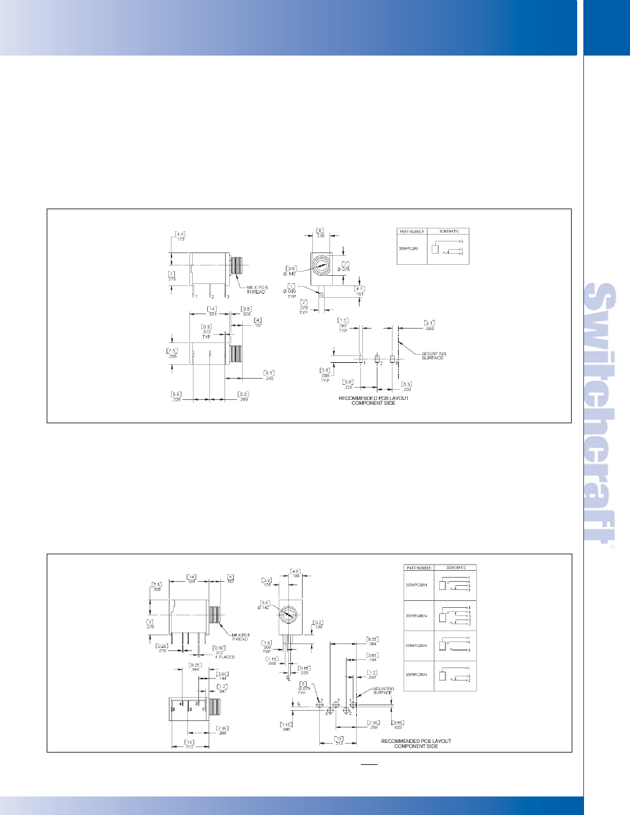
SWITCHCRAFT, INC. 5555 N. Elston Ave. • Chicago, IL 60630
115
JACKS AND PLUGS
FAX: 773 792-2129
JACKS AND
PLUGS
DIMENSIONS ARE FOR REFERENCE ONLY
Inch
(mm)
3.5MM SINGLE MONO AND STEREO JACKS
3.5MM SINGLE MONO AND STEREO JACKS
3.5MM SINGLE, MONO AND STEREO JACKS (continued)
35RAPC2AV – MONO, VERTICAL, THREADED
MATERIALS
Coil Spring: Steel wire.
Bushing: Nickel-plated copper alloy.
Terminal: Silver-plated copper alloy.
Tip Spring: Silver-plated copper alloy.
Shunt Terminal: Plated copper alloy.
Cover: Thermoplastic, transparent UL 94V-2.
Body: Thermoplastic, UL 94V-1 black color.
PERFORMANCE SPECIFICATIONS
Contact Resistance: 20 milliohms maximum.
Insulation Resistance:
100 milliohms minimum at 250V DC.
Dielectric Withstanding Voltage: 250V AC.
Life: 5000 cycles, minimum.
Insertion Force: 0.88 pounds - 3.5 pounds.
Withdrawal Force: 0.88 pounds - 2.64 pounds.
MATERIALS
Coil Springs: Steel Wire.
Ring Spring: Copper alloy strip, tin alloy plating.
Ground Terminal: Copper alloy strip, tin alloy plating.
Bushing: Nickel-plated copper alloy.
Cover: Thermoplastic, UL 94V-0 black color.
Body: Thermoplastic, UL 94V-0 black color.
PERFORMANCE SPECIFICATIONS
Contact Resistance: 20 milliohms maximum ,
initial 50 milliohms maximum , after life.
Insulation Resistance: 50 megohms minimum at 500V DC.
Dielectric Withstanding Voltage: 250V AC.
Life: 5 ,000 cycles, minimum.
Insertion Force: 0.88 lbs. to 3.50 lbs.
Withdrawal Force: 0.88 lbs. to 3.10 lbs.
35RAPC2AV4, 35RAPC2BV4, 35RAPC3BV4, 35RAPC4BV4 - STEREO, VERTICAL, THREADED
* Please visit the product pages on our website for the most up-to-date product information
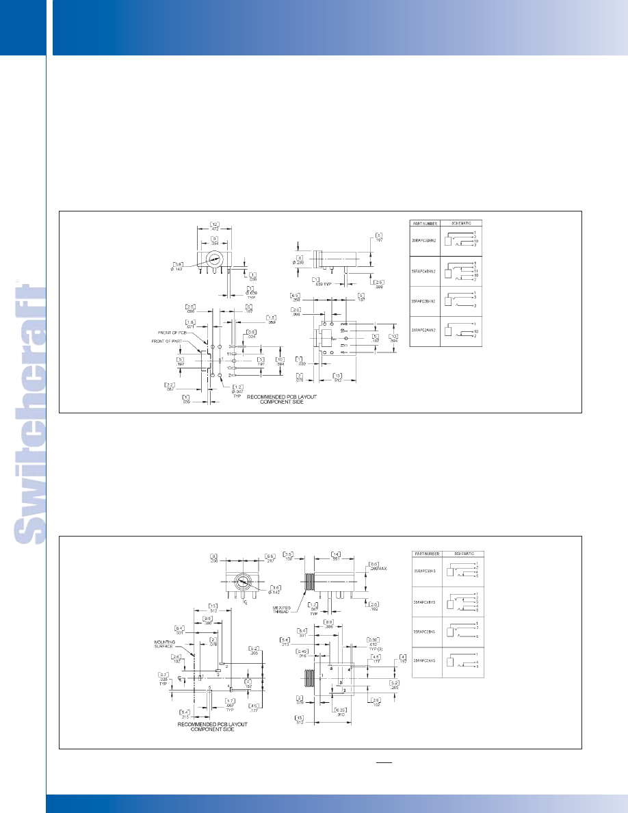
JACKS AND PLUGS
116
w w w . s w i t c h c r a f t . c o m
® Registered trademark of Switchcraft, Inc.
Note: Contact your Switchcraft Representative for price and delivery
PHONE: 773 792-2700
JACKS AND PLUGS
DIMENSIONS ARE FOR REFERENCE ONLY
Inch
(mm)
3.5MM SINGLE, MONO AND STEREO JACKS (continued)
MATERIALS
Cover: Thermoplastic, UL 94V-1 black color.
Ring Spring: Copper alloy.
Tip Spring: Silver-plated copper alloy.
Ground Terminal: Silver-plated copper alloy.
Metal: Copper alloy, nickel plating.
Body: Thermoplastic, UL 94V-0 black color.
PERFORMANCE SPECIFICATIONS
Contact Resistance: 30 milliohms maximum, initial
100 milliohms maximum, after life.
Insulation Resistance: 100 megohms minimum
at 500V DC.
Dielectric Withstanding Voltage: 500V AC.
Life: 5000 cycles, minimum.
Insertion Force: 0.88 pounds - 6.6 pounds.
Withdrawal Force: 0.88 pounds - 6.6 pounds.
MATERIALS
Coil Springs: Steel wire.
Tip Spring: Silver-plated copper alloy.
Ring Spring: Silver-plated copper alloy.
Ground Terminal: Silver-plated copper alloy.
Bushing: Nickel-plated copper alloy.
Cover: Thermoplastic, transparent UL 94V-2.
Body: Thermoplastic, UL 94V-1 black color.
PERFORMANCE SPECIFICATIONS
Contact Resistance: 20 milliohms maximum, initial
100 milliohms maximum, after life.
Insulation Resistance: 100 megohms minimum.
Dielectric Withstanding Voltage: 250V AC.
Life: 5000 cycles, minimum.
Insertion Force: 0.88
lbs. - 3.50 lbs.
Withdrawal Force: 0.88
lbs. - 3.10 lbs.
35RAPC2AHN2, 35RAPC2BHN2, 35RAPC3BHN2, 35RAPC4BHN2 - STEREO, HORIZONTAL, NON-THREADED
35RAPC2AH3, 35RAPC2BH3, 35RAPC3BH3, 35RAPC4BH3 - STEREO, HORIZONTAL, THREADED
3.5MM SINGLE MONO AND STEREO JACKS
3.5MM SINGLE MONO AND STEREO JACKS
**Same drawing for jack with non-threaded bushing.
* Please visit the product pages on our website for the most up-to-date product information
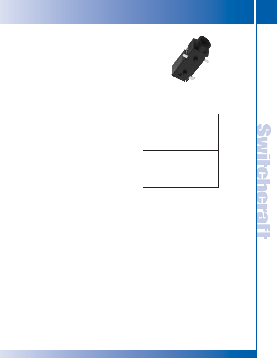
SWITCHCRAFT, INC. 5555 N. Elston Ave. • Chicago, IL 60630
117
JACKS AND PLUGS
FAX: 773 792-2129
JACKS AND
PLUGS
DIMENSIONS ARE FOR REFERENCE ONLY
Inch
(mm)
Switchcraft introduces a new series of 3.5mm jacks. These
low profile jacks come in a wide variety of circuits, both
2 and 3 conductor versions. Circuits include mono closed,
stereo open, stereo tip closed and ring open, and stereo
closed. The 35RASMT Series is available on tape and reel
only. Contact Switchcraft for exact dimensions of the reels.
They’re designed for use in today’s electronic equipment
that features remote speakers, headsets, and headphones.
While they are more compact than commonly used PC
mount phone jacks, they are still extremely durable. Jacks
come on tape and reel, 1K per reel.
FEATURES AND BENEFITS
• SMT mounting
• Tape and reel packaging
• Wide variety of circuits
APPLICATIONS
• Computer
• Video Cameras
• Personal/Portable Audio Devices
• Multimedia
SPECIFICATIONS
Electrical Current Rating: 3A
Contact Resistance: <50 mohms
Insulation Resistance: 100 mohms (min.)
Dielectric Withstanding Voltage: 250VAC @ 1 minute
MECHANICAL
Lifecycles: 5,000
Operating Temperature: -25°C to +85°C
MATERIAL
Housing: Black thermoplastic
Sleeve, Ring and Tip Terminals:
Copper Alloy, silver-plated
Shunt Terminal: Copper Alloy, Silver-plated
Part Number/Description
35RASMT2AHNTR
Mono, closed circuit, on tape and reel
35RASMT2BHNTR
Stereo, dual open circuit,
on tape and reel
35RASMT3BHNTR
Stereo, tip closed and ring open
circuit, on tape and reel
35RASMT4BHNTR
Stereo, dual closed circuit,
on tape and reel
3.5MM SINGLE MONO
AND STEREO JACKS
35RASMT
3.5MM SINGLE MONO AND STEREO JACKS
3.5MM SINGLE MONO AND STEREO JACKS
3.5MM SINGLE MONO AND STEREO JACKS
(See next page for drawings.)
* Please visit the product pages on our website for the most up-to-date product information
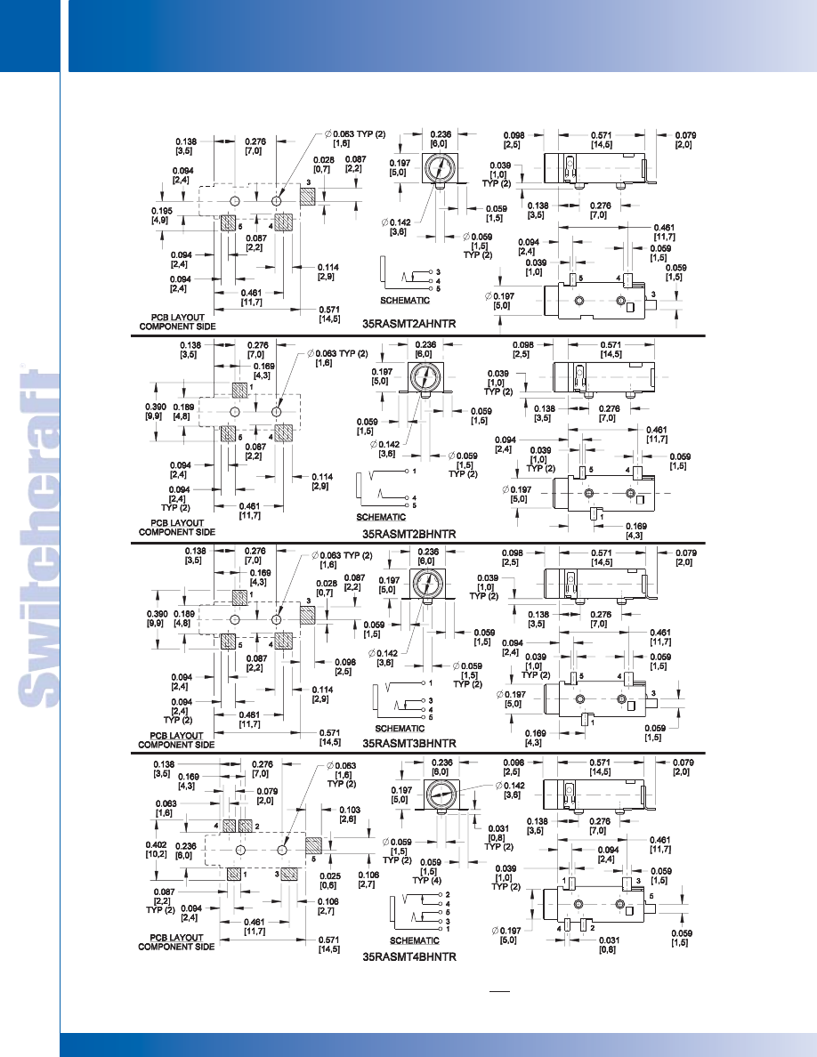
JACKS AND PLUGS
118
w w w . s w i t c h c r a f t . c o m
® Registered trademark of Switchcraft, Inc.
Note: Contact your Switchcraft Representative for price and delivery
PHONE: 773 792-2700
JACKS AND PLUGS
DIMENSIONS ARE FOR REFERENCE ONLY
Inch
(mm)
3.5MM SINGLE MONO AND STEREO JACKS (continued)
3.5MM SINGLE MONO AND STEREO JACKS
3.5MM SINGLE MONO AND STEREO JACKS
* Please visit the product pages on our website for the most up-to-date product information
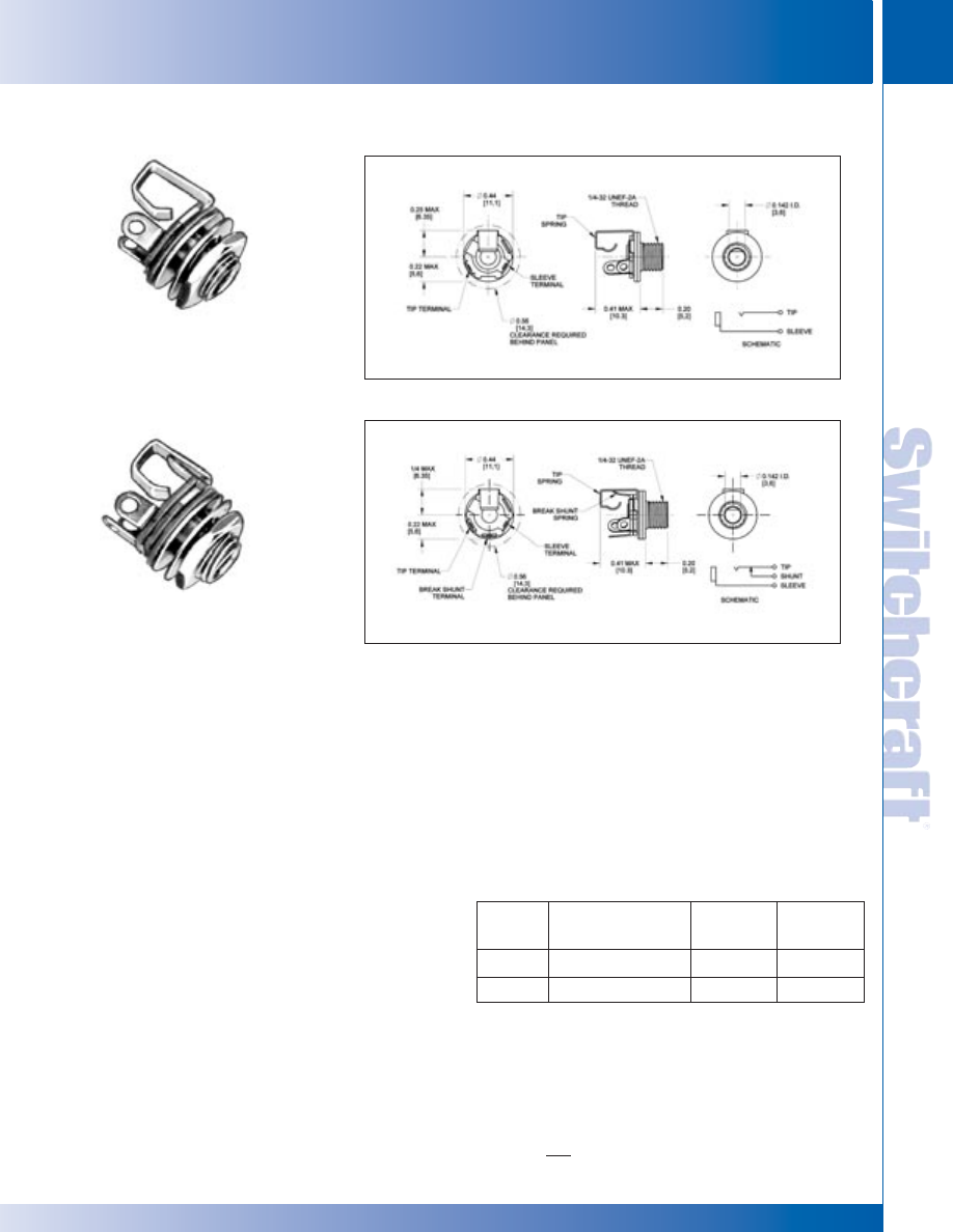
SWITCHCRAFT, INC. 5555 N. Elston Ave. • Chicago, IL 60630
119
JACKS AND PLUGS
FAX: 773 792-2129
JACKS AND
PLUGS
DIMENSIONS ARE FOR REFERENCE ONLY
Inch
(mm)
3.5 mm SINGLE MONO JACKS
FEATURES
• 2-conductor phone jacks similar to Littel-Jax
®
phone jacks, but smaller.
• For connecting in limited space
• Mate with 3.5 mm phone plugs
• Notched insulators interlock internal parts
• Mounting hole: .250" diameter in panels up to .125" thick
(mounting hardware supplied)
• For insulated mount, order two washers separately,
Number S1564 (swedged fiber washer .312" diameter
mounting hole) and number S2207 (flat phenolic washer)
SPECIFICATIONS
MECHANICAL
Life: 5,000 insertion/withdrawal cycles, minimum
ELECTRICAL
Contact Resistance: .075 ohms maximum
Insulation Resistance: 5,000 M
Ω
minimum
Dielectric Withstanding Voltage: 250V AC maximum
Contact Rating: .25A, 48V DC
TYPICAL
PART
JACK
MATING
NUMBER
DESCRIPTION
SCHEMATIC
1
PLUG
35PM1
Open circuit
I
750
35PM2A
Shunted (closed circuit)
III
750
1. See jack schematics on pages 79 and 80.
35PM2A
35PM1
ORDERING INFORMATION
1. Order by part number.
2. Contact Switchcraft for more information.
MATERIAL
Mounting Bushing: Nickel-plated copper alloy.
Insulating Spacers: Rigid plastic.
Springs: Copper alloy.
Sleeve Terminal: Tin-plated copper alloy.
Hardware: Supplied with one, Number P11501
nickel-plated brass locknut, and one, Number S17901
nickel-plated steel flat washer.
3.5MM SINGLE MONO JACKS
3.5MM SINGLE MONO JACKS
* Please visit the product pages on our website for the most up-to-date product information
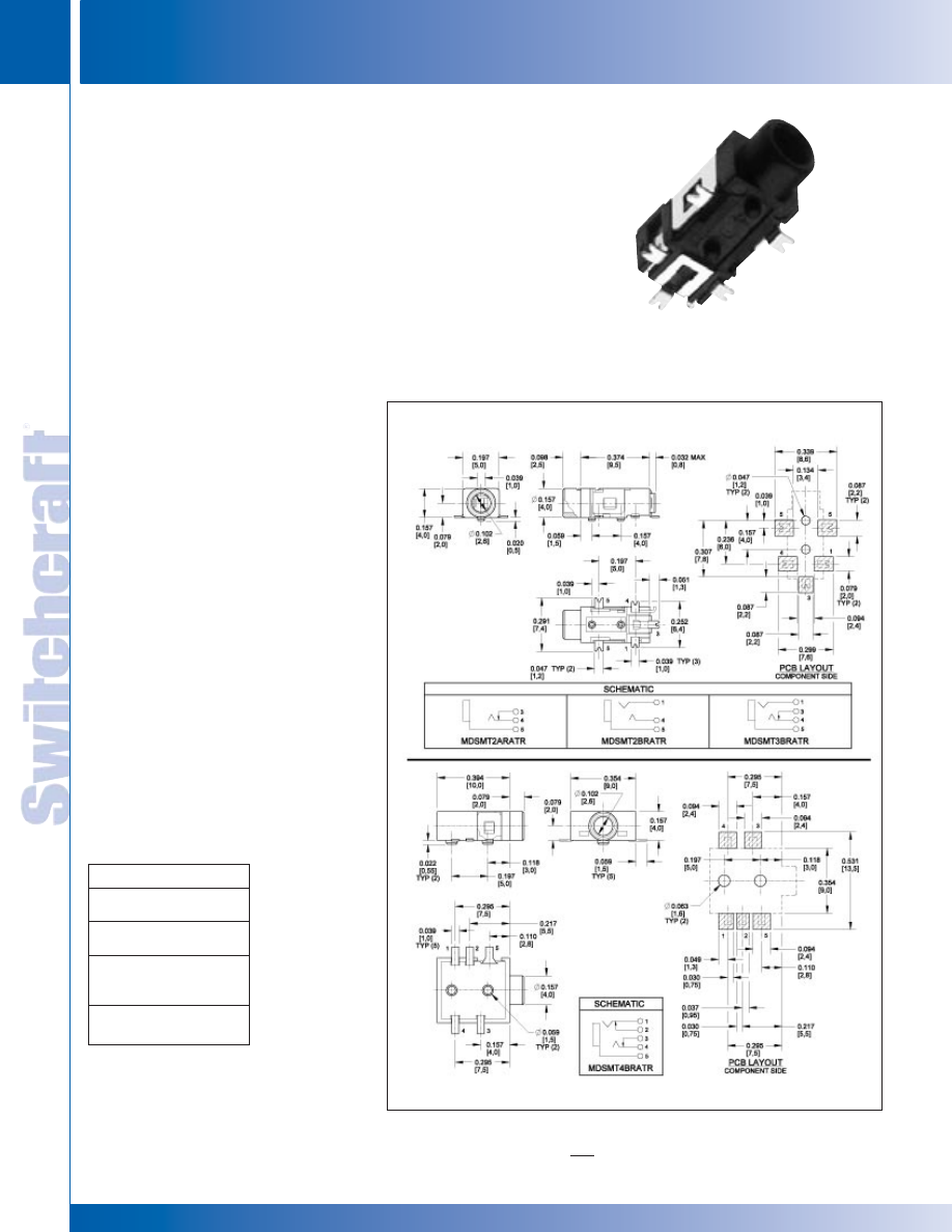
JACKS AND PLUGS
120
w w w . s w i t c h c r a f t . c o m
® Registered trademark of Switchcraft, Inc.
Note: Contact your Switchcraft Representative for price and delivery
PHONE: 773 792-2700
JACKS AND PLUGS
DIMENSIONS ARE FOR REFERENCE ONLY
Inch
(mm)
MDSMT4BRATR
Switchcraft introduces a new series of 2.5mm jacks. These low
profile jacks come in a wide variety of circuits, both 2 and
3 conductor versions. Circuits include mono closed, stereo open,
stereo tip closed and ring open, and stereo closed. The MDSMT
Series is available on tape and reel only. Contact Switchcraft for
exact dimensions of the reels. They’re designed for use in today’s
electronic equipment that features remote speakers, headsets, and
headphones. While they are more compact than commonly used
PC mount phone jacks, they are still extremely durable.
FEATURES AND BENEFITS
• SMT mounting
• Tape and reel packaging
• Wide variety of circuits
APPLICATIONS
• Computer
• Video Cameras
• Personal/Portable Audio Devices
• Multimedia
SPECIFICATIONS
Electrical Current Rating: 3A
Contact Resistance: <50 mohms
Insulation Resistance: 100 mohms (min.)
Dielectric Withstanding Voltage:
250VAC @ 1 minute
MECHANICAL
Lifecycles: 5,000
Operating Temperature: -25°C to +85°C
MATERIAL
Housing: Black thermoplastic
Sleeve, Ring and Tip Terminals:
Copper Alloy, silver-plated
Shunt Terminal: Copper Alloy, Silver-plated
2.5MM SINGLE MONO AND STEREO JACKS
Part Number/Description
MDSMT2BRATR
Stereo, dual open circuit
MDSMT2ARATR
Mono, closed circuit
MDSMT3BRATR
Stereo, tip closed and
ring open circuit
MDSMT4BRATR
Stereo, dual closed circuit
2.5MM SINGLE MONO
AND STEREO JACKS
2.5MM SINGLE MONO AND STEREO JACKS
2.5MM SINGLE MONO AND STEREO JACKS
* Please visit the product pages on our website for the most up-to-date product information
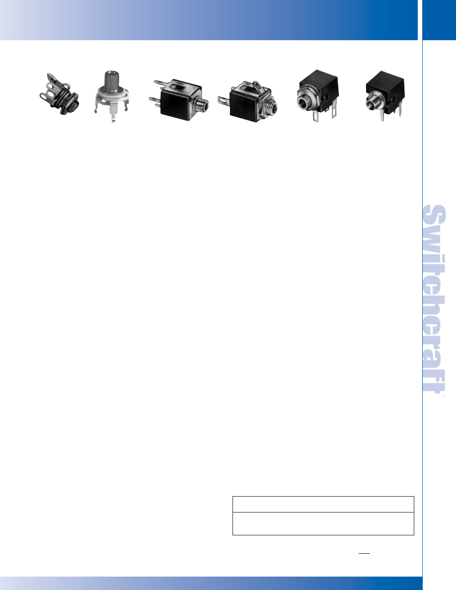
SWITCHCRAFT, INC. 5555 N. Elston Ave. • Chicago, IL 60630
121
JACKS AND PLUGS
FAX: 773 792-2129
JACKS AND
PLUGS
DIMENSIONS ARE FOR REFERENCE ONLY
Inch
(mm)
SUBMINIATURE PHONE JACKS
SUBMINIATURE PHONE JACKS
SUBMINIATURE PHONE JACKS, TR2A AND TR1PC
Extremely small, rugged, shunted Micro-Jax
®
2-conductor jack is 1/4 the
size of a standard phone jack and weighs less than 1/20 ounce. Can be
wired for open or closed circuit operation. Internally keyed insulators
interlock all parts and tip springs grip mating plugs positively. Mates
with Switchcraft Micro-Plug
®
phone plugs. Jacks mount through
.190" diameter hole in chassis/panels up to .093" thick. For insulated
mounting, a .281" diameter hole and .050" maximum panel thickness
applies. Order insulating washer separately. Number P1617
(flat phenolic washer) and Number P1618 (swedged fiber washer).
Number TR1PC: 2-conductor closed circuit jack with PC
terminals. Open frame and enclosed versions available. Mates with
Switchcraft
®
Micro Plug
®
numbers 850, 855, and 880.
SUBMINIATURE ENCLOSED PHONE JACKS
Micro-D Jax
®
2-conductor jacks have insulated box construction and
subminiature size.
Number MDPC2A: 2-conductor closed circuit jack with PC
terminals. Mounts to single-, double-sided or multilayer boards either
singly or in rows as close as .344" centers (+/- .01 inches). Bushing is
.10" inside diameter.
Number MDSL2A: Same as MDPC2A except, 1. solder lugs, 2.
bushing is #10-48 threaded (nut and washer supplied), and 3. mount
ing centers are .35" or .313". When mounted on .313" centers, sleeves
or adjacent jacks may be in intimate contact. Mounts through a .203"
diameter hole in chassis/panels up to .063" thick.
SUBMINIATURE RIGHT-ANGLE PHONE JACKS
2-conductor jacks have molded housing which protects all internal
parts. Panel/chassis or PC boards mounting in rows, if desired, on
.351" centers. PC terminals need only .382" behind-panel clearance.
Number MDPC2ARA: PC terminals mount/terminate directly to PC
or multilayer boards. Bushing clears a .156" diameter panel hole.
Number MDSL2ARA: Right-angle solder lugs and #10-48 threaded
bushing for chassis/panel mount. Mounts in .203" diameter hole in
chassis/panels up to .063" thick.
SPECIFICATIONS - MICRO-JAX
®
ELECTRICAL:
Contact Resistance: .10 ohms maximum (spring to plug).
Shunt Resistance: .10 ohms maximum.
Dielectric Withstanding Voltage: 250 V AC.
Shunt Tension: 60 grams minimum.
MATERIAL:
Mounting Bushing: Nickel-plated copper alloy.
Insulating Spacers: Rigid plastic.
Springs: Nickel-plated copper alloy. Integral contacts are plated.
Tip, Shunt and Sleeve Terminals: Silver-plated copper alloy.
Hardware: Supplied with one, P15331 nickel-plated copper alloy
hex nut, and one S29571 nickel-plated copper alloy flat washer.
MATERIAL - TR1PC
Threaded Bushing: Nickel-plated copper alloy.
Tip Spring: Copper alloy.
Sleeve/Ground Terminal: Copper alloy tin-lead with nickel underplate.
MECHANICAL - TR1PC:
Life: 10,000 insertion/withdrawal cycles, minimum.
Insertion/Withdrawal Forces: 11 ounces insertion,
11 ounce minimum withdrawal.
ENVIRONMENTAL - TR1PC:
Thermal Range: -55°C to +85°C (non-operating);
-20°C to +65°C (operating).
Thermal Shock: Per MIL-STD-202, method 107.
Humidity: Per MIL-STD-202, method 106.
Salt Spray: Per MIL-STD-202, method 101.
SPECIFICATIONS - MICRO-D JAX
MECHANICAL:
Life: 10,000 insertion/withdrawal cycles minimum.
Insertion/Withdrawal Forces: 11 ounce insertion,
11 ounce minimum withdrawal.
ELECTRICAL:
Contact Resistance: .010 ohms maximum (initial), .020 ohms
maximum (after humidity, durability exposure), .10 ohms
maximum (after salt spray).
Insulation Resistance: 10,000 M
Ω
minimum (initial),
1,000 M
Ω
minimum (after humidity, durability exposure).
Dielectric Withstanding Voltage: 500 V AC maximum.
Contact Rating: .125 A, 125 V AC.
ENVIRONMENTAL:
Thermal Range: -55°C to +85°C (non-operating);
-20°C to +65°C (operating).
Thermal Shock: Per MIL-STD-202, method 107.
Humidity: Per MIL-STD-202, method 106.
Salt Spray: Per MIL-STD-202, method 101.
MATERIAL:
Housing: Glass reinforced plastic. Insulation: Rigid plastic.
Mounting Bushing (Micro-D): Nickel-plated copper alloy.
Mounting Bracket (Right-Angle Micro-D):
Nickel-plated copper alloy.
Tip Spring: Silver-plated copper alloy.
Shunt Terminal: Silver-plated copper alloy.
Sleeve Terminal (Micro-D): Steel, tin-plated.
Sleeve Terminal (Right-Angle Micro-D): Silver-plated
copper alloy.
Hardware (Micro-D): Same as Micro-Jax (MDSL2A).
Hardware (Right-Angle Micro-D): Hex nut, nickel-plated
copper alloy, Number P15331; flat washer, nickel-plated
copper alloy S29571; not supplied with MDPC2A.
All are 2-Conductor (closed circuit). Note 1.: See Jack Schematics page 79
and 80. Note 2.: See Plugs Section for mating information.
.101" SUBMINIATURE PHONE JACKS
TR2A TR1PC
MDPC2A
MDSL2A MDSL2ARA
MDPC2ARA
Part
Jack
Typical
Part
Jack
Typical
No.
Schem.
1
Mating Plug
2
No.
Schem.
1
Mating Plug
2
TR2A
MDSL2A
TR1PC
}
III
850
MDPC2ARA
}
III
850
MDPC2A
MDSL2ARA
* Please visit the product pages on our website for the most up-to-date product information
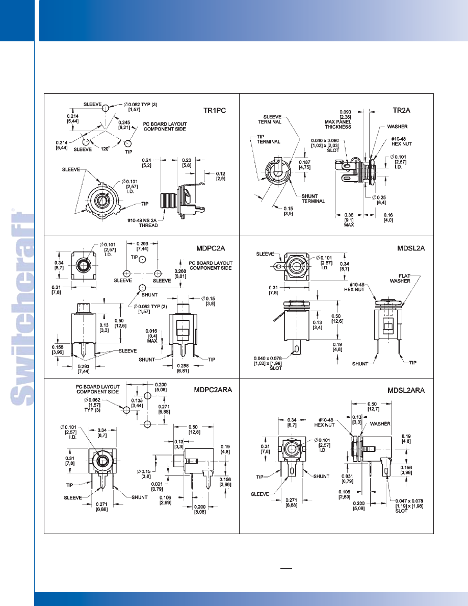
JACKS AND PLUGS
122
w w w . s w i t c h c r a f t . c o m
® Registered trademark of Switchcraft, Inc.
Note: Contact your Switchcraft Representative for price and delivery
PHONE: 773 792-2700
JACKS AND PLUGS
DIMENSIONS ARE FOR REFERENCE ONLY
Inch
(mm)
SUBMINIATURE PHONE JACKS
SUBMINIATURE PHONE JACKS
.101" SUBMINIATURE PHONE JACKS
* Please visit the product pages on our website for the most up-to-date product information
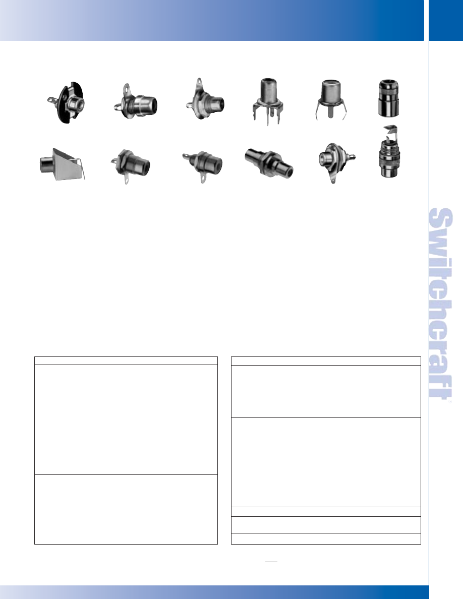
SWITCHCRAFT, INC. 5555 N. Elston Ave. • Chicago, IL 60630
123
JACKS AND PLUGS
FAX: 773 792-2129
JACKS AND
PLUGS
DIMENSIONS ARE FOR REFERENCE ONLY
Inch
(mm)
PHONO JACKS
PHONO JACKS
Part Number
Description
BPJR01
Rear mount, black insulator
BPJR01AU
Rear mount, black insulator, gold plated
BPJR02
Rear mount, red insulator
BPJR02AU
Rear mount, red insulator, gold plated
BPJR03
Rear mount, white insulator
BPJR03AU
Rear mount, white insulator, gold plated
BPJR04
Rear mount, yellow insulator
BPJR04AU
Rear mount, yellow insulator, gold plated
BPJR05
Rear mount, blue insulator
BPJR05AU
Rear mount, blue insulator, gold plated
BPJR06
Rear mount, green insulator
BPJR06AU
Rear mount, green insulator, gold plated
3501F
Rear mount, rigid plastic mounting flange
3501FR
Rear mount, natural insulator
For insulated mounting, order S1028 and S1029 insulating washers
BPJF01
Front mount, black insulator
BPJF01AU
Front mount, black insulator, gold plated
BPJF02
Front mount, red insulator
BPJF02AU
Front mount, red insulator, gold plated
BPJF03
Front mount, white insulator
BPJF03AU
Front mount, white insulator, gold plated
BPJF04
Front mount, yellow insulator
BPJF04AU
Front mount, yellow insulator, gold plated
Part Number
Description
BPJF05
Front mount, blue insulator
BPJF05AU
Front mount, blue insulator, gold plated
BPJF06
Front mount, green insulator
BPJF06AU
Front mount, green insulator, gold plated
3501FP
Front Mount, natural insulator
3505F
RF version, uses low-loss nylon insulation
For insulated mounting, order S2207 and S1564 insulating washers
BPJJ01
Feed through, black insulator
BPJJ01AU
Feed through, black insulator, gold plated
BPJJ02
Feed through, red insulator
BPJJ02AU
Feed through, red insulator, gold plated
BPJJ03
Feed through, white insulator
BPJJ03AU
Feed through, white insulator, gold plated
BPJJ04
Feed through, yellow insulator
BPJJ04AU
Feed through, yellow insulator, gold plated
BPJJ05
Feed through, blue insulator
BPJJ05AU
Feed through, blue insulator, gold plated
BPJJ06
Feed through, green insulator
BPJJ06AU
Feed through, green insulator, gold plated
3503
Extension jack, shielded handle
3514PC
Vertical PC mount, nickel plated steel bushing
3515PC
Vertical PC mount, ceramic bushing
3517PC
Horizontal PC mount, nickel plated steel bushing
BULKHEAD PHONO JACKS
FEATURES AND BENEFITS
• Front or rear mount configurations
• Durable plated machined brass construction
• All mounting hardware is included
APPLICATIONS
• Audio
• Video
• General Purpose Electronics
OPTIONS
• Front or rear mount solder type receptacles
• Jack to jack bulkhead configuration
• Insulator colors
• Gold or nickel plating
SPECIFICATIONS
Material and Platings Housing:
Nickel or Gold-plated Brass
Contact: Nickel-plated Brass Insulator: ABS
Hardware: Nickel-plated Brass. Switchcraft introduces a
complete line of bulkheadmount phono (RCA) jacks to meet the
most critical audio, audio/video, and general-purpose electronic
applications. These jacks are offered in front and rear mount
solder type as well as jack to jack bulkhead configurations.
These jacks are available with black, white, blue, green, red,
and yellow insulators and nickel or gold plated bodies. All
mounting hardware is included.
Housing: Nickel or gold plated, copper alloy
(3514PC, 3515PC, 3517PC: Nickel plated, steel)
Terminals: Nickel plated, copper alloy (3515PC: Tin plated,
copper alloy)
Bushing: Nickel-plated, copper alloy (3515PC: Ceramic)
Insulators: Thermoplastic
(3517PC: Ceramic and glass filled thermoplastic)
3517PC BPJR01
BPJF01
BPJJ01
3505F
3503
3501F
3501FP
3501FR
3514PC
3515PC
(See next page for drawings.)
* Please visit the product pages on our website for the most up-to-date product information
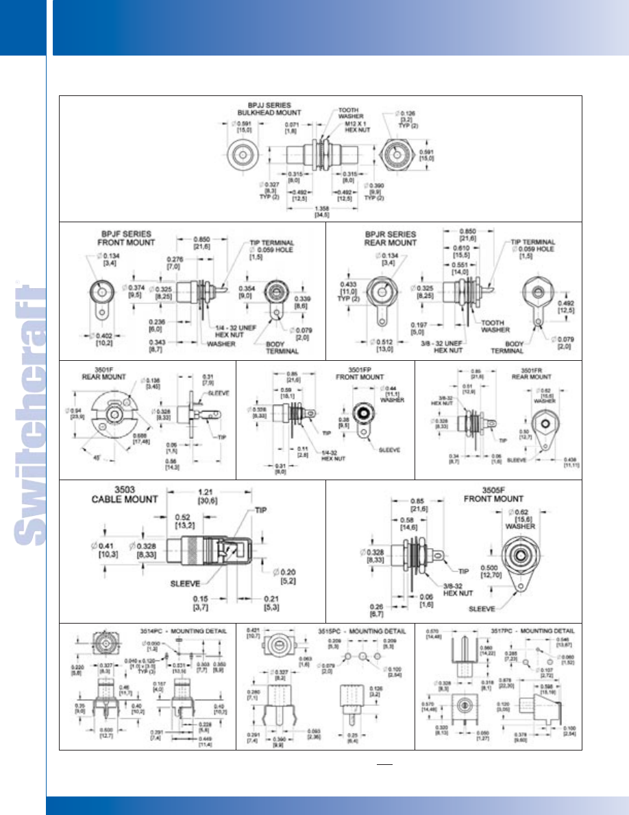
JACKS AND PLUGS
124
w w w . s w i t c h c r a f t . c o m
® Registered trademark of Switchcraft, Inc.
Note: Contact your Switchcraft Representative for price and delivery
PHONE: 773 792-2700
JACKS AND PLUGS
DIMENSIONS ARE FOR REFERENCE ONLY
Inch
(mm)
PHONO JACKS (continued)
PHONO JACKS
PHONO JACKS
* Please visit the product pages on our website for the most up-to-date product information
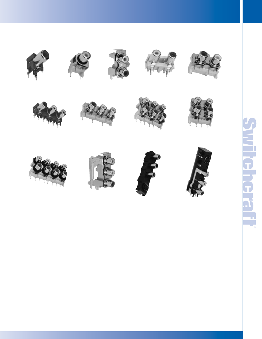
SWITCHCRAFT, INC. 5555 N. Elston Ave. • Chicago, IL 60630
125
JACKS AND PLUGS
FAX: 773 792-2129
JACKS AND
PLUGS
PHONO JACKS AND PHONO JACK SETS
PHONO JACKS AND PHONO JACK SETS
PJRAN1X1U03
PJRAN2X1U02
PJRAS2X1S01
PJRAS2X2S01
PJRAS3X1S01
PJRAS3X2S01
PJRAS4X2U01
PJRAS1X2S02
PJRAS1X3S01
PJRAS1X3U01
PJRAN3X1U02
PJRAN3X1U03
PJRAS1X1S04
Switchcraft, the industry recognized leader in audio-video
connectivity, introduces the addition of a comprehensive line of
PCB Mount RCA Jacks and Jack Sets. Switchcraft’s newest
product family addresses the requirements of the most critical
audio and audio/video applications. 1, 2, 3, 4, 6, and 8 position
jack sets are offered in a variety of color combinations with
numerous plating, grounding, shielding, mounting, and
justification options.
FEATURES AND BENEFITS
• High temperature plastic housings and long life contacts
• Snap fit PCB contacts and housings
• Low profile footprint
• Numerous options and configurations
APPLICATIONS
• Audio
• Video
• General Purpose Electronics
OPTIONS
• Right angle and straight PCB mount
• Horizontal and vertical justification
• Shielding and grounding
• Bulkhead mounting screw
• Colors
• Plating
SPECIFICATIONS
ELECTRICAL
Temperature Range: -25 to +80°C
Rated Voltage: 34V DC or AC
Withstand Voltage: 500V
Rated Current: 2A DC or AC
Dielectric Strength: 500V AC @ 1 minute
Contact Resistance: <30 mohms
Insertion Force*: <29.4N
Extraction Force*: 1N to 29.4N
* Depends Upon Mating Plug
MATERIAL AND PLATINGS
Housing: UL94-HB Rated, ABS
Insulators: ABS
Ground Shell and Terminal: Nickel or Gold Plated, Copper Alloy
Terminals: Tin Plated Copper Alloy
PHONO JACKS AND PHONO JACK SETS
DIMENSIONS ARE FOR REFERENCE ONLY
Inch
(mm)
* Please visit the product pages on our website for the most up-to-date product information
JACKS AND PLUGS
126
w w w . s w i t c h c r a f t . c o m
® Registered trademark of Switchcraft, Inc.
Note: Contact your Switchcraft Representative for price and delivery
PHONE: 773 792-2700
JACKS AND PLUGS
PHONO JACKS AND PHONO JACK SETS
PHONO JACKS AND PHONO JACK SETS
Part Number Color
PJRAN1X1U01
Black
PJRAN1X1U02
White
PJRAN1X1U03
Red
PJRAN1X1U04
Yellow
Call factory
Green
Call factory
Blue
PJRAS1X1S01
Black
PJRAS1X1S02
White
PJRAS1X1S03
Red
PJRAS1X1S04
Yellow
Call factory
Green
Call factory
Blue
Part Number Color
PJRAN2X1U01
Red/White
PJRAN2X1U02
White/Red
PJRAS2X1S01
Red/White
PJRAS2X1S02
White/Red
PJRAS1X2S01
Red
White
PJRAS1X2S02
White
Red
Part Number Color
PJRAN3X1U01
Red/Yellow/White
PJRAN3X1U02
Red/Green/Blue
PJRAS3X1S01
Red/White/Yellow
PJRAS3X1U03
Red/Green/Blue
PJRAS1X3S01
Red
White
Yellow
PJRAS1X3S02
Green
Blue
Red
Part Number Color
PJRAN3X1U02
Red/White/Yellow
PJRAS1X3U01
Yellow
White
Red
1 POSITION PCB MOUNT
2 POSITION PCB MOUNT
3 POSITION PCB MOUNT
4, 6, & 8 POSITION PCB MOUNT
COMBINATION PHONO AND S-VIDEO PCB MOUNT
Part Number Color
PJRAS2X2S01
White x 2
Red x 2
PJRAS3X2S01
White x 3
Red x 3
PJRAS3X2S02
Red/White/Yellow
Red/White/Yellow
PJRAS4X2U01
White x 4
Red x 4
Ordering Information (Contact factory for color, shielding, grounding, justification options.)
PJ
RA S # X # S 01
AU
Ground Shell Plating
V
ersion
Shielding
P
ositions V
er
tical
P
ositions Hor
iz
ontal
Mounting
J
ustification
Product T
ype
Phono Jack
RA - Right Angle
S - Screw(s)
1,2,3, or 4
By
1,2, or 3
S - Shielded
AU/Gold
ST - Straight
N - No Screws
U - Unshielded
PHONO JACKS AND PHONO JACK SETS (continued)
DIMENSIONS ARE FOR REFERENCE ONLY
Inch
(mm)
* Please visit the product pages on our website for the most up-to-date product information
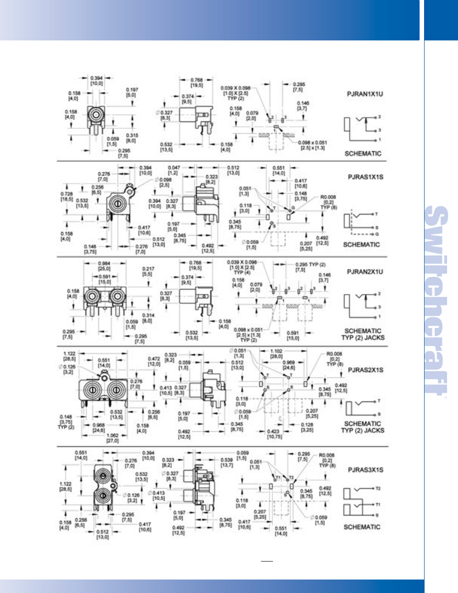
SWITCHCRAFT, INC. 5555 N. Elston Ave. • Chicago, IL 60630
127
JACKS AND PLUGS
FAX: 773 792-2129
JACKS AND
PLUGS
PHONO JACKS AND PHONO JACK SETS
PHONO JACKS AND PHONO JACK SETS
PHONO JACKS AND PHONO JACK SETS (continued)
DIMENSIONS ARE FOR REFERENCE ONLY
Inch
(mm)
* Please visit the product pages on our website for the most up-to-date product information
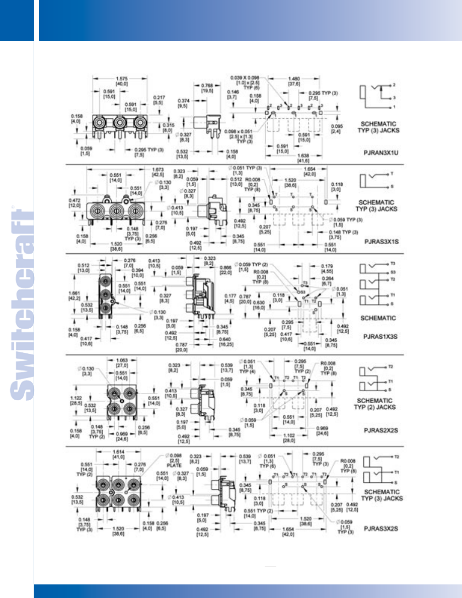
JACKS AND PLUGS
128
w w w . s w i t c h c r a f t . c o m
® Registered trademark of Switchcraft, Inc.
Note: Contact your Switchcraft Representative for price and delivery
PHONE: 773 792-2700
JACKS AND PLUGS
PHONO JACKS AND PHONO JACK SETS
PHONO JACKS AND PHONO JACK SETS
PHONO JACKS AND PHONO JACK SETS (continued)
DIMENSIONS ARE FOR REFERENCE ONLY
Inch
(mm)
* Please visit the product pages on our website for the most up-to-date product information
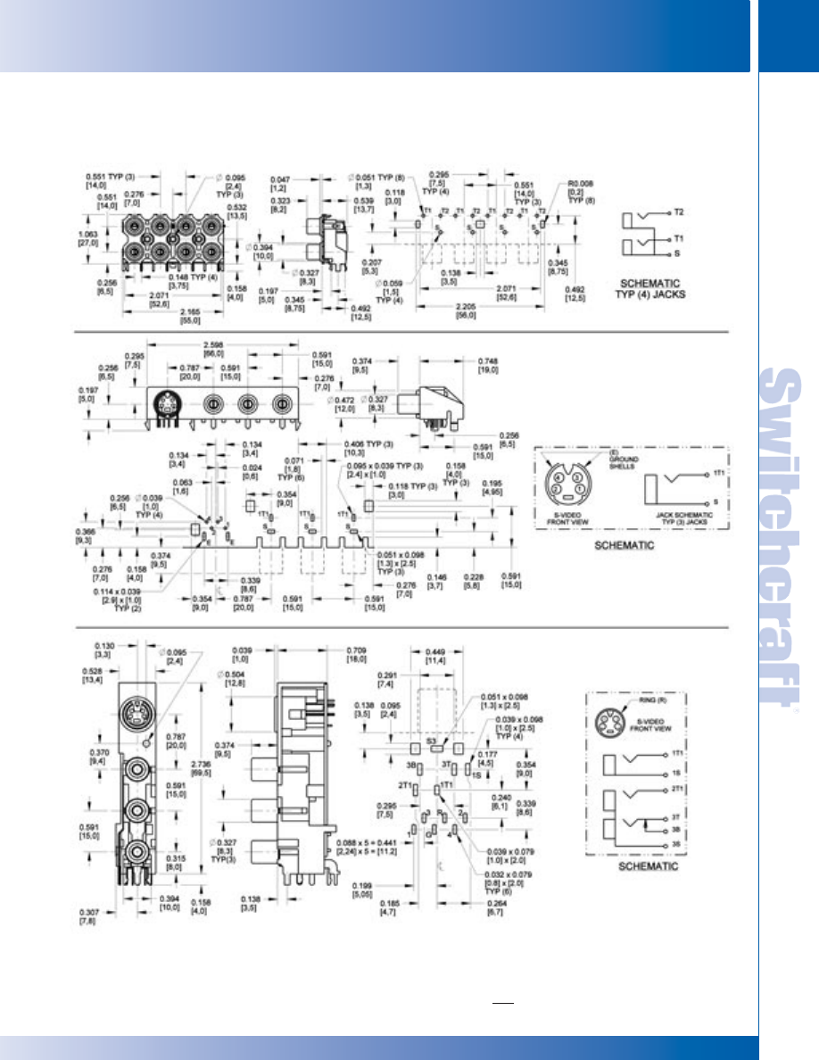
SWITCHCRAFT, INC. 5555 N. Elston Ave. • Chicago, IL 60630
129
JACKS AND PLUGS
FAX: 773 792-2129
JACKS AND
PLUGS
PHONO JACKS AND PHONO JACK SETS (continued)
DIMENSIONS ARE FOR REFERENCE ONLY
Inch
(mm)
PHONO JACKS AND PHONO JACK SETS
PHONO JACKS AND PHONO JACK SETS
* Please visit the product pages on our website for the most up-to-date product information
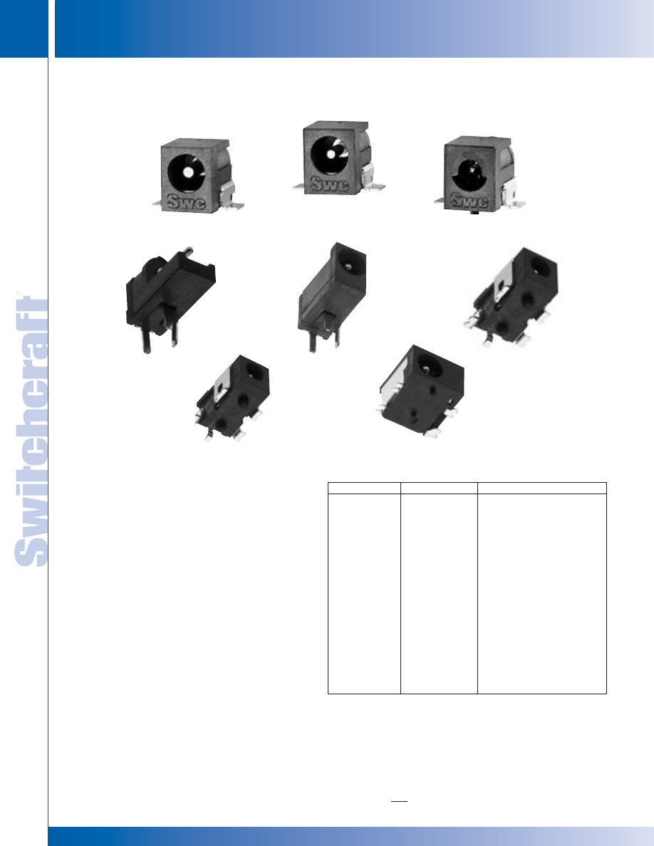
JACKS AND PLUGS
130
w w w . s w i t c h c r a f t . c o m
® Registered trademark of Switchcraft, Inc.
Note: Contact your Switchcraft Representative for price and delivery
PHONE: 773 792-2700
JACKS AND PLUGS
RIGHT ANGLE MINIATURE POWER JACKS
RIGHT ANGLE MINIATURE POWER JACKS
RIGHT ANGLE MINIATURE POWER JACKS
SPECIFICATIONS:
Materials: Housing: Thermoplastic
Terminals:
RAPC700:
Sleeve: Silver plated copper alloy
Tip: Nickel plated, copper alloy
RAPC742, RASM742TR, RAPC732OF, RAPC742OF,
RAPC752, RAPC752S, RASM752TR, RASM752STR:
Sleeve and tip: Silver plated tin
Shunt: Silver plated copper alloy
RASM700, RASH700:
Sleeve: Tin plated copper alloy
Tip: Nickel plated copper alloy)
ELECTRICAL
Current Rating: 3A
(RAPC700, RASH700, RASM700: 5A)
Contact Resistance: <50 mohms
Insulation Resistance: 100 mohms min.
(RAPC700, RASH700, RASM700: 30 megohms
@100V DC)
Dielectric Withstanding Voltage: 250 VAC@ 1 minute
MECHANICAL:
Lifecycles: 5,000 min.
Note: Contact factory for specific information on tape and reel options. *Pin Size
(in/mm) 1. Open Frame 2. Tape and Reel. 3. Shielded 4. Tape and Reel, Shielded.
Note: Available with P locating post as an option.
Note: Available with tin-plating as a special order.
Note: Available with Hi-temp material, contact factory for details.
RAPC732OF
RAPC742
RASM742TR
RASM752TR
DIMENSIONS ARE FOR REFERENCE ONLY
Inch
(mm)
Part Number
Pin Size*
Description
RAPC712
0.100"/2.5mm
Right Angle, PC mount
RASH712
0.100"/2.5mm
Right Angle, hybrid mount
RASM712
0.100"/2.5mm
Right Angle, SMT mount
RAPC722
0.080"/2.0mm
Right Angle, PC mount
RASH722
0.080"/2.0mm
Right Angle, hybrid mount
RASM722
0.080"/2.0mm
Right Angle, SMT mount
RAPC732
0.050"/1.3mm
Right Angle, PC mount
RAPC732OF
0.050"/1.3mm
Right Angle, PC mount
1
RASH732
0.050"/1.3mm
Right Angle, SMT mount
RASM732
0.050"/1.3mm
Right Angle, hybrid mount
RAPC742
0.040"/1.0mm
Right Angle, PC mount
RAPC742OF
0.040"/1.0mm
Right Angle, PC mount
1
RASM742TR
0.040"/1.0mm
Right Angle, SMT mount
2
RAPC752
0.025"/0.65mm
Right Angle, PC mount
RAPC752S
0.025"/0.65mm
Right Angle, PC mount
3
RASM752TR
0.025"/0.65mm
Right Angle, SMT mount
2
RASM752STR
0.025"/0.65mm
Right Angle, SMT mount
4
RASM752STR
RASM 712
RASM 722
RASM 732P
* Please visit the product pages on our website for the most up-to-date product information
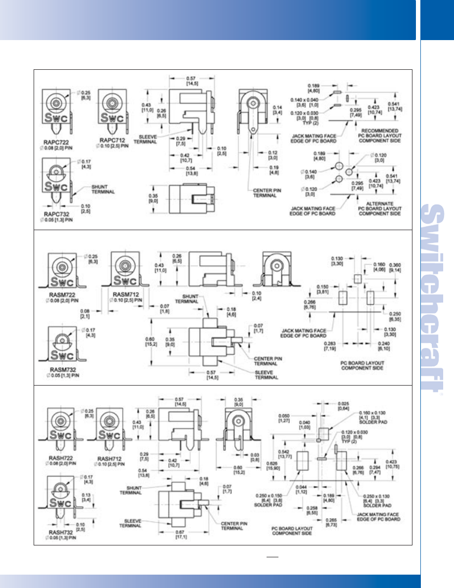
SWITCHCRAFT, INC. 5555 N. Elston Ave. • Chicago, IL 60630
131
JACKS AND PLUGS
FAX: 773 792-2129
JACKS AND
PLUGS
DIMENSIONS ARE FOR REFERENCE ONLY
Inch
(mm)
RAPC 712/722/732
RASM 712/722/732
RASH 712/722/732
RIGHT ANGLE MINIATURE POWER JACKS (continued)
RIGHT ANGLE MINIATURE POWER JACKS
RIGHT ANGLE MINIATURE POWER JACKS
* Please visit the product pages on our website for the most up-to-date product information
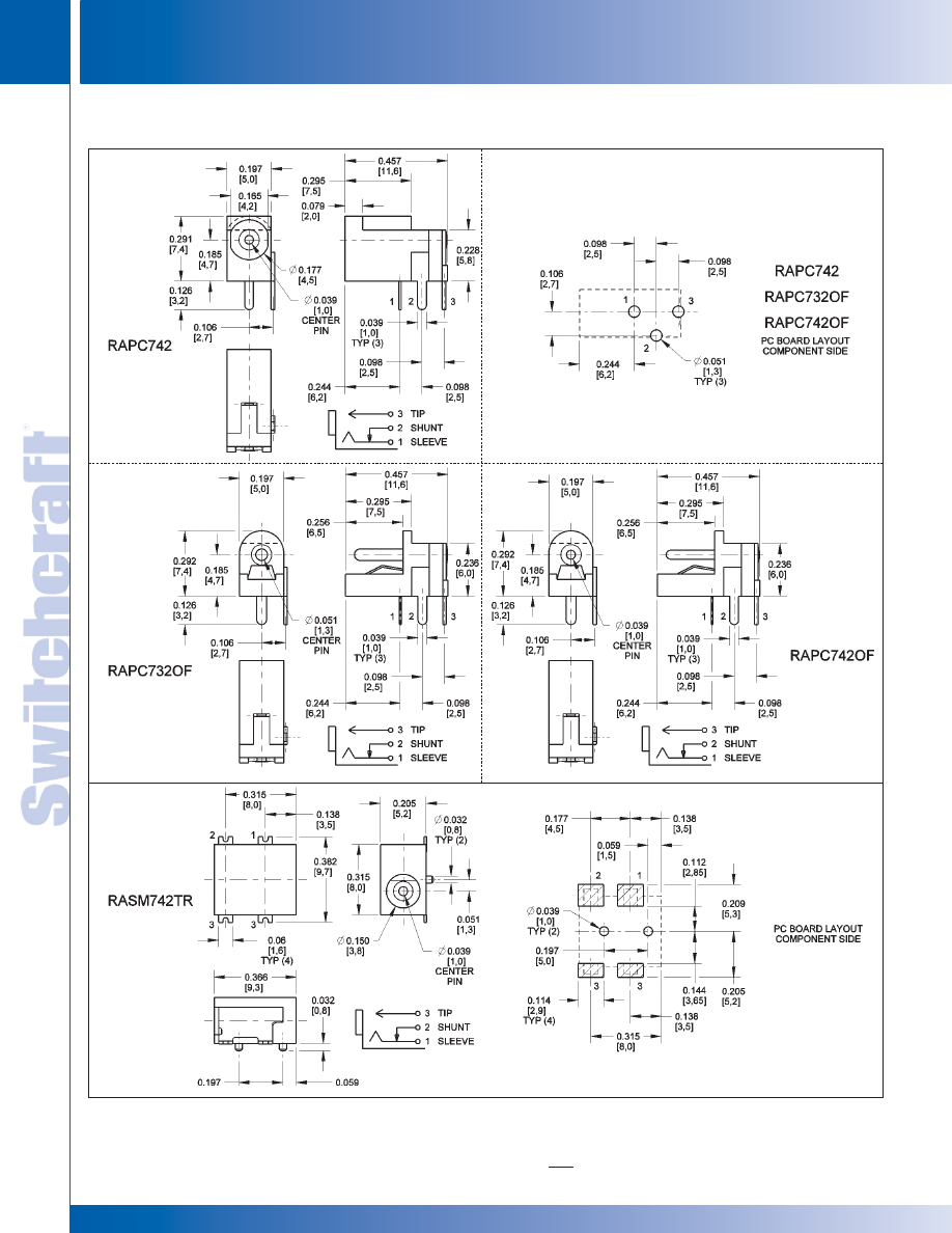
JACKS AND PLUGS
132
w w w . s w i t c h c r a f t . c o m
® Registered trademark of Switchcraft, Inc.
Note: Contact your Switchcraft Representative for price and delivery
PHONE: 773 792-2700
JACKS AND PLUGS
RIGHT ANGLE MINIATURE POWER JACKS
RIGHT ANGLE MINIATURE POWER JACKS
RIGHT ANGLE MINIATURE POWER JACKS (continued)
DIMENSIONS ARE FOR REFERENCE ONLY
Inch
(mm)
* Please visit the product pages on our website for the most up-to-date product information
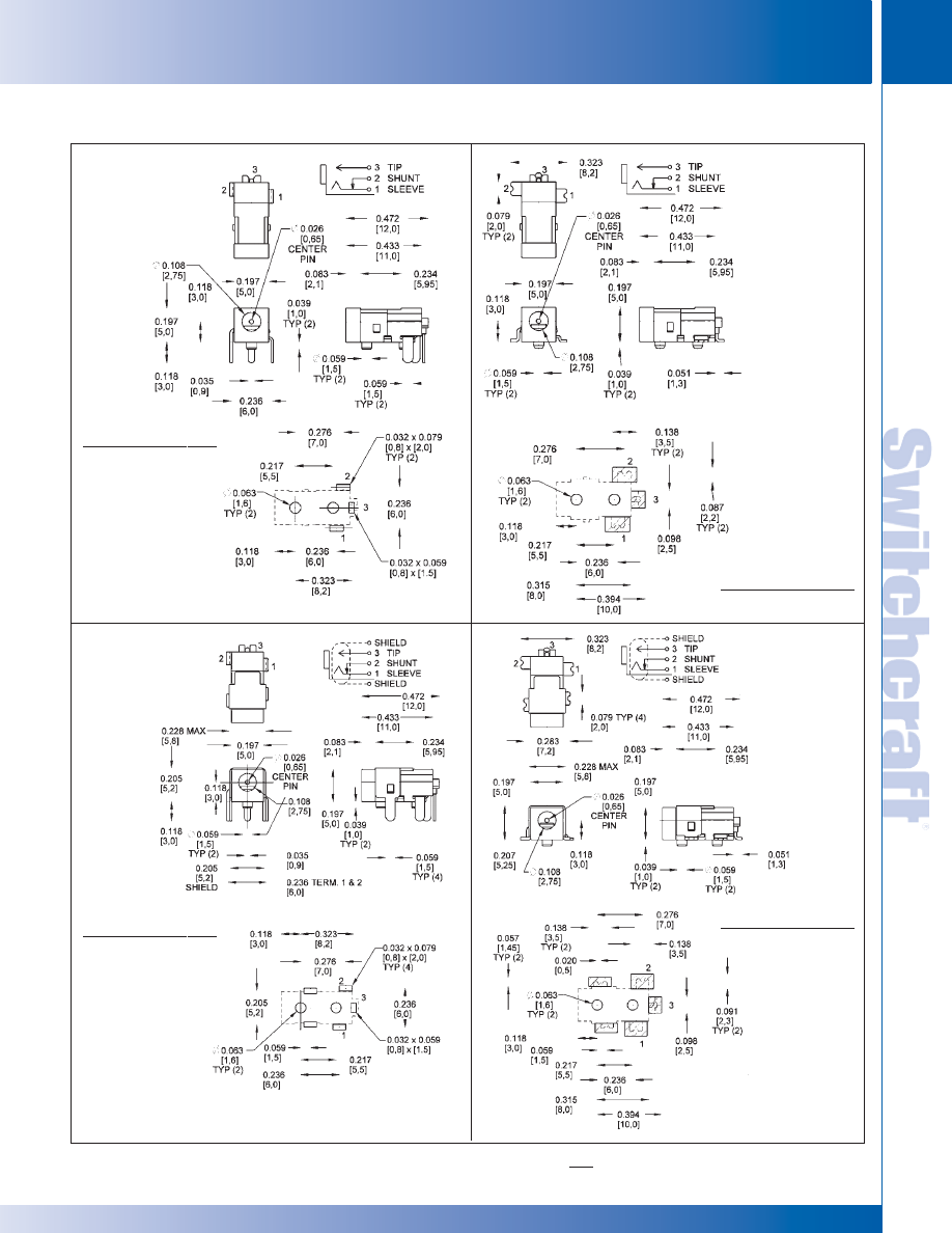
SWITCHCRAFT, INC. 5555 N. Elston Ave. • Chicago, IL 60630
133
JACKS AND PLUGS
FAX: 773 792-2129
JACKS AND
PLUGS
RIGHT ANGLE MINIATURE POWER JACKS (continued)
DIMENSIONS ARE FOR REFERENCE ONLY
Inch
(mm)
RAPC752
RAPC752S
RASM752STR
RASM752TR
PC BOARD LAYOUT
COMPONENT SIDE
PC BOARD LAYOUT
COMPONENT SIDE
PC BOARD LAYOUT
COMPONENT SIDE
PC BOARD LAYOUT
COMPONENT SIDE
RIGHT ANGLE MINIATURE POWER JACKS
RIGHT ANGLE MINIATURE POWER JACKS
* Please visit the product pages on our website for the most up-to-date product information
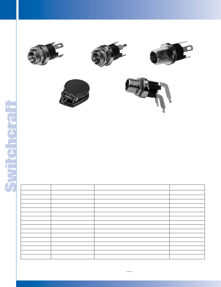
JACKS AND PLUGS
134
w w w . s w i t c h c r a f t . c o m
® Registered trademark of Switchcraft, Inc.
Note: Contact your Switchcraft Representative for price and delivery
PHONE: 773 792-2700
JACKS AND PLUGS
STRAIGHT MINIATURE POWER JACKS
STRAIGHT MINIATURE POWER JACKS
STRAIGHT MINIATURE POWER JACKS
FEATURES:
• Automatic switch over from AC to DC
permitted by sleeve shunt spring.
• Split center pin shaped to hold mating plug firmly.
• Bushing length available as 0.219" or extended
0.319" to permit use in thicker panels.
• Non-turn mounting possible using standard
“D” shape bushing.
• Insulated mounting hardware available.
• Right angle versions offer “kinked” PC
terminals for added board retention.
MATERIALS:
Housing: Thermoplastic
Bushing: Plated copper alloy
Terminals: Plated copper alloy
Insulators: Rigid Plastic
Hardware: Supplied with one P2439 nickel plated copper
alloy hex nut, and one P2441 nickel plated steel flat washer
ELECTRICAL:
Current Rating: 5A, 12V DC resistive
Contact Resistance: 0.01 Ohms max. (initial),
0.02 Ohms max. (after humidity, durability exposure),
0.10 Ohms max. (after salt spray)
Insulation Resistance: 10,000 Mohms min. (initial),
1,000 Mohms min. (after humidity, durability exposure)
Dielectric Withstanding Voltage: 500 VAC max.
MECHANICAL:
Lifecycles: 10,000 cycles min.
Part Number
Pin Size*
Description
Typical Mating Plug
712A
0.100"/2.5mm
Solder lugs
760
712RA
0.100"/2.5mm
Right angle PC terminals
760
L712A
0.100"/2.5mm
Solder lugs , long bushing
761K
L712RA
0.100"/2.5mm
Right angle PC terminals , long bushing
761K
PC712A
0.100"/2.5mm
Straight PC terminals
760
PCL712A
0.100"/2.5mm
Straight PC terminals, long bushing
761K
722A
0.080"/2.0mm
Solder lugs
S760
722RA
0.080"/2.0mm
Right angle PC terminals, long bushing
S760
L722A
0.080"/2.0mm
Solder lugs , long bushing
S761K
L722RA
0.080"/2.0mm
Right angle PC terminals , long bushing
S761K
PC722A
0.080"/2.0mm
Straight PC terminals
S760
PCL722A
0.080"/2.0mm
Straight PC terminals , long bushing
S761K
732A
0.050"/1.3mm
Solder lugs
860
732RA
0.050"/1.3mm
Right angle PC terminals
860
PC732A
0.050"/1.3mm
Straight PC terminals
860
2C1072
Jack covers for 712A and 722A
712A
PC712A
2C1072
L722A
L712RA
Note: For insulated mounting order P2442 phenolic flat washer and S4263 swedged fiber washer.
DIMENSIONS ARE FOR REFERENCE ONLY
Inch
(mm)
* Please visit the product pages on our website for the most up-to-date product information
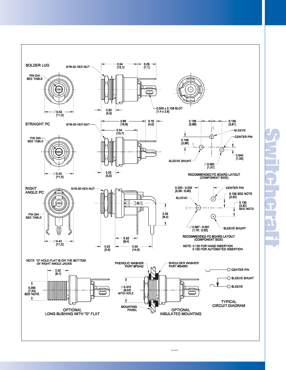
SWITCHCRAFT, INC. 5555 N. Elston Ave. • Chicago, IL 60630
135
JACKS AND PLUGS
FAX: 773 792-2129
JACKS AND
PLUGS
STRAIGHT MINIATURE POWER JACKS (continued)
DIMENSIONS ARE FOR REFERENCE ONLY
Inch
(mm)
STRAIGHT MINIATURE POWER JACKS
STRAIGHT MINIATURE POWER JACKS
* Please visit the product pages on our website for the most up-to-date product information
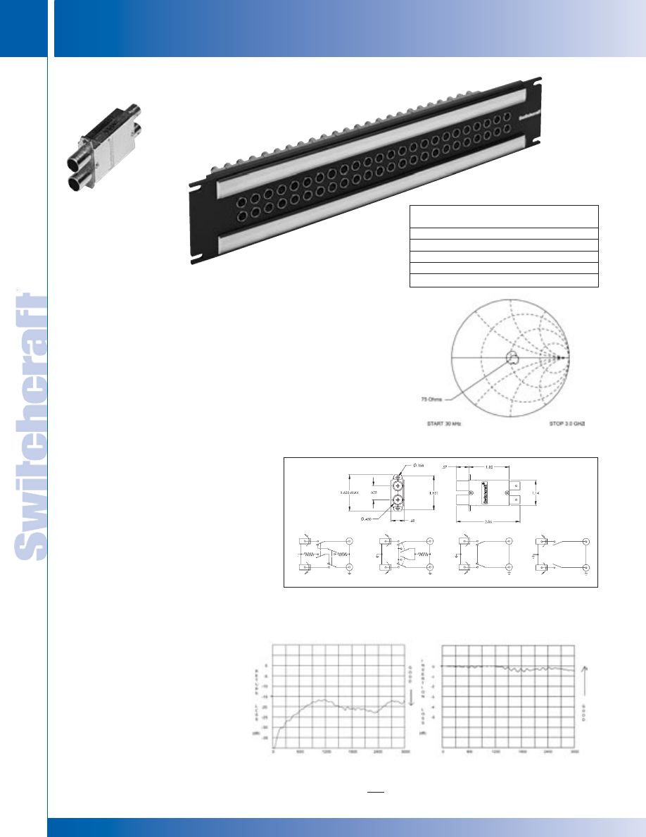
JACKS AND PLUGS
136
w w w . s w i t c h c r a f t . c o m
® Registered trademark of Switchcraft, Inc.
Note: Contact your Switchcraft Representative for price and delivery
PHONE: 773 792-2700
JACKS AND PLUGS
VJ SERIES
VJ SERIES
DIMENSIONS ARE FOR REFERENCE ONLY
Inch
(mm)
FEATURES AND BENEFITS
• HD Series meets SMPTE 292M Specifications
• SD Series has a bandwidth from DC to 1.75GHz
• Jacks feature rugged heavy duty housings
VIDEO JACK SPECIFICATIONS
ELECTRICAL
Rated Bandwidth: 2.4 GHz (HD), 1.75 GHz (SD)
Characteristic Impedance: 75 ohms
Return Loss: Better than –15 dB
Insertion Loss: Better than –.5 dB
Contact Resistance: Less than 20 milliohms
Termination Resistance: 75 W, ±1%
Center Conductor: Accepts .090 pin diameter
MECHANICAL
Mechanical Shock: Per MIL-STD-202,
Method 213, Test condition I
Vibration: Per MIL-STD-202, Method 201
Insertion Force: 12 lbs. maximum
Withdrawal Force: 3 lbs. minimum
Life Cycle: 30,000
MATERIAL
Housing: Zinc alloy, nickel plated
Center Contacts: Copper alloy, gold plated
Switching Springs: Copper alloy, gold plated
Grounding Contacts:
HD Series - Copper alloy, gold plated
SD Series - Copper alloy, nickel plated
Insulators: Thermoplastic, UL 94V-0 rated
ENVIRONMENTAL
Operating Temperature: – 40ºC to 65ºC
Storage Temperature: – 55ºC to 85ºC
Thermal Shock: Per MIL-STD-202,
Method 107
Moisture and Humidity:
Per MIL-STD-202, Method 106.
The HD Series meets SMPTE 292M
specifications for high definition video
signaling, covering a bandwidth range
from DC to 2.4GHz. The SD Series is
perfect for serial digital, with a bandwidth
from DC to 1.75GHZ.
VPP24K3HD75T
See page 193 for Patch panel information.
VJHD*75TX
VJ SERIES
NORMALLED
NON-NORMALLED
NON-TERMINATED NON-TERMINATED
NON-NORMALLED NORMALLED
TERMINATED
TERMINATED
Ordering–Individual Jacks
Part Number
Type
Description
VJHD*75TX
HD
Terminated
VJHD*NTX
HD
Non-terminated
VJSD*75TX
SD
Terminated
VJSD*NTX
SD
Non-terminated
*Add “N” for non-normalled version
FREQUENCY (MHz)
FREQUENCY (MHz)
SMITH CHART
(TYPICAL)
* Please visit the product pages on our website for the most up-to-date product information
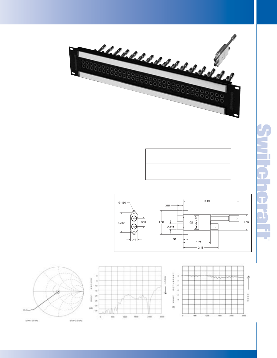
SWITCHCRAFT, INC. 5555 N. Elston Ave. • Chicago, IL 60630
137
JACKS AND PLUGS
FAX: 773 792-2129
JACKS AND
PLUGS
MVJ SERIES
MVJ SERIES
DIMENSIONS ARE FOR REFERENCE ONLY
Inch
(mm)
MVP32K3*75T
MVJ*75T
MVJ SERIES
SMITH CHART (TYPICAL)
RETURN LOSS (TYPICAL)
RETURN LOSS (TYPICAL)
FREQUENCY (MHz)
FREQUENCY (MHz)
FEATURES AND BENEFITS
• Midsize video jacks rated from DC to 3 GHz
• Available in terminated or non-terminated configurations
MIDSIZE VIDEO JACK SPECIFICATIONS
ELECTRICAL
Rated Bandwidth: 3.0 GHz
Characteristic Impedance: 75 ohms
Return Loss: See Typical Return Loss Chart
Insertion Loss: See Typical Insertion Loss Chart
Contact Resistance: Less than 20 milliohms
Termination Resistance: 75 W, ±1%
Center Conductor: Accepts .048 pin diameter
MECHANICAL
Mechanical Shock: Per MIL-STD-202,
Method 213, Test condition I
Vibration: Per MIL-STD-202, Method 201
Insertion Force: 12 lbs. maximum
Withdrawal Force: 3 lbs. minimum
Life Cycle: 30,000
MATERIAL
Housing: Zinc alloy, nickel plated
Center Contacts: Copper alloy, gold plated
Switching Springs: Copper alloy, gold plated
Grounding Contacts: Copper alloy,
gold plated
BNC Insulators: Teflon
Actuators: Thermoplastic, UL94V-0 rated
ENVIRONMENTAL
Operating Temperature: – 40ºC to 65ºC
Storage Temperature: – 55ºC to 85ºC
Thermal Shock: Per MIL-STD-202,
Method 107
Moisture and Humidity:
Per MIL-STD-202, Method 106
See page 196 for Patch panel information.
Ordering Information
Part
Number
Jack
Description
MVJ*75T
HD
Terminated
MVJ*NT
HD
Non-terminated
*Add “N” for non-normalled version
* Please visit the product pages on our website for the most up-to-date product information
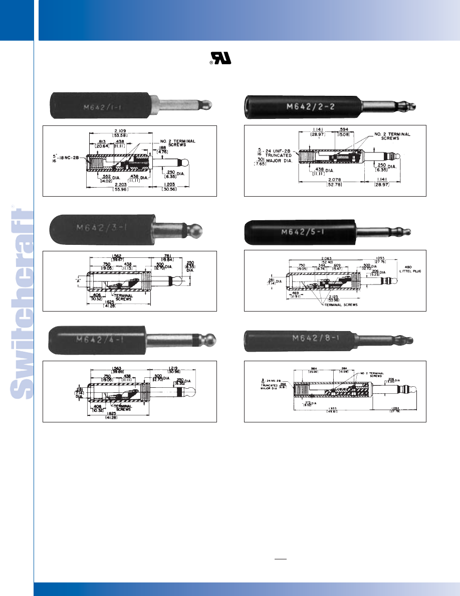
JACKS AND PLUGS
138
w w w . s w i t c h c r a f t . c o m
® Registered trademark of Switchcraft, Inc.
Note: Contact your Switchcraft Representative for price and delivery
PHONE: 773 792-2700
JACKS AND PLUGS
DIMENSIONS ARE FOR REFERENCE ONLY
Inch
(mm)
MIL-TYPE 1/4" PHONE PLUGS
MIL-TYPE 1/4" PHONE PLUGS
FEATURES
Designed for high quality communication equipment to meet
military requirements, This series features one-piece tip rod
and one-piece sleeve and plug body, assembled together into
a mode as inserts, providing a finished plug with complete
continuity of thermoplastic insulation between top rod and
plug sleeve. Internal (invisible externally) interlock mechanically
engages the metal and plastic components providing a
realistic lock to prevent parts shifting. Design and material in
accordance with MIL-P-642(A), MIL part number molded or
stamped on handle, manufacturer’s trademark (as required
by MIL specification) appears on plug body.
SPECIFICATIONS
Tip Rod, Body and Screws: Copper alloy, natural finish.
Terminals: Tinned copper alloy.
Insulation: Thermoplastic, per MIL-P-22985, Type II, Class 1.
Handles: Thermoplastic, Type 6, per MIL-M-20693, Type II.
Shielded; machined from copper alloy, nickel-plated.
STRAIN RELIEF CLAMP
For MIL-type Littel-Plug phone plugs. P2380 conforms to
Specification SC-A-7674-F - supplied with Plug Numbers 430, 440,
445 and 470. P2381 meets Specification MS-35762 - supplied with
Plug Number 480 and Extension-Jax
®
phone jack, Number 820.
MIL-TYPE 1/4" PHONE PLUGS
420, 425
430
480 (.206")
440, 445
484 (.206")
2-CONDUCTOR
3-CONDUCTOR
482, 483
* Please visit the product pages on our website for the most up-to-date product information
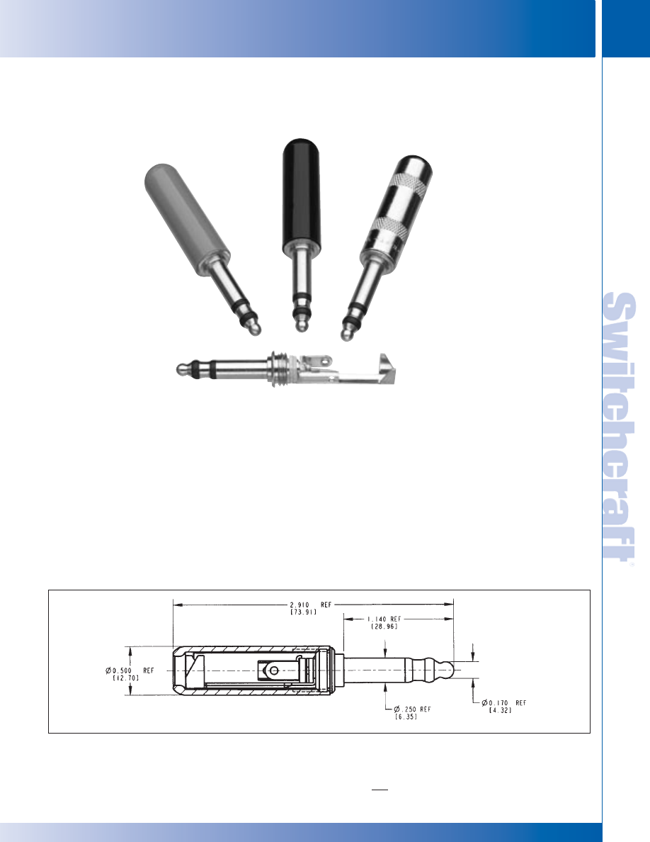
SWITCHCRAFT, INC. 5555 N. Elston Ave. • Chicago, IL 60630
139
JACKS AND PLUGS
FAX: 773 792-2129
JACKS AND
PLUGS
DIMENSIONS ARE FOR REFERENCE ONLY
Inch
(mm)
LITTEL PLUG PHONE PLUGS
LITTEL PLUG PHONE PLUGS
FEATURES AND BENEFITS
• 3 conductor plug
• Designed for high quality communication
equipment
• One-piece tip rod ensures electrical continuity
• Brass plug finger versions meet MIL specifications
• ‘N’ and ‘NC’ suffix versions have nickel-plated
plug fingers, excellent for audio applications
• ‘NC’’ suffix option has rugged, heavy duty
cable clamp, solder terminals for easier
solderability and assembly. Metal shielded handle
• ‘NCP” - plastic handle
SPECIFICATIONS
Plug Finger: Brass, natural finish or nickel-plated
Terminals: Brass, electro-tinned
Insulation: Ethyl cellulose, per MIL-P-22835, Type II,
Class 1, or acetal resin
Handles: Plastic-nylon molding plastic, Type 6,
per MIL-M-20693, Type II. Shielded metal handle with red,
black or nickel finish
ORDERING INFORMATION
1. Order by part number.
2. Contact Switchcraft for more information.
3. Mating jacks available.
Number
482NCP
Number
483NCP
Number
485NC
LITTEL PLUG
®
PHONE PLUGS
PART NO. 482NC, 482NCP, 483NC, 483NCP, 485NC
®
®
* Please visit the product pages on our website for the most up-to-date product information
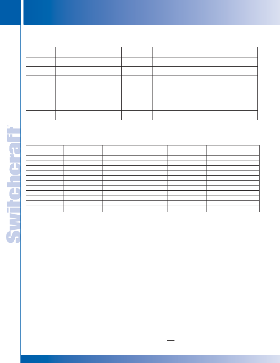
JACKS AND PLUGS
140
w w w . s w i t c h c r a f t . c o m
® Registered trademark of Switchcraft, Inc.
Note: Contact your Switchcraft Representative for price and delivery
PHONE: 773 792-2700
JACKS AND PLUGS
DIMENSIONS ARE FOR REFERENCE ONLY
Inch
(mm)
MIL
Part Number
Conductors
Terminals
Handle
Part Number
Notes
482N
3
Screw
Red
None
Plastic handle, nickel
plated plug finger
482NC
3
Cable Clamp
Shielded
None
Red metal handle, nickel
plated plug finger
482NCP
3
Cable Clamp
Red
None
Plastic handle,nickel
plated plug finger
483N
3
Screw
Black
None
Plastic handle, nickel
plated plug finger
483NC
3
Cable Clamp
Shielded
None
Black metal handle,nickel
plate plug finger
483NCP
3
Cable Clamp
Black
None
Black plastic handle, nickel
plated plug finger
485NC
3
Cable Clamp
Shielded
None
Nickel plated handle,nickel
plated plug finger
480 SERIES PART NUMBERING CHART
LITTEL PLUG
®
PHONE PLUGS
LITTEL PLUG PHONE PLUGS
LITTEL PLUG PHONE PLUGS
Part
206" dia.
1/4" dia.
Brass
Nickel
Handle
Red
Black
Nickel
Standard
Large
number
finger
finger
finger
finger
Material
handle
handle
handle
cable clamp
cable clamp
480
•
•
Plastic
•
•
482
•
•
Plastic
•
•
482N
•
•
Plastic
•
•
482NC
•
•
Metal
•
•
482NCP
•
•
Plastic
•
•
483
•
•
Plastic
•
•
483N
•
•
Plastic
•
•
483NC
•
•
Metal
•
•
483NCP
•
•
Plastic
•
•
484
•
•
Plastic
•
•
485NC
•
•
Metal
•
•
®
®
* Please visit the product pages on our website for the most up-to-date product information
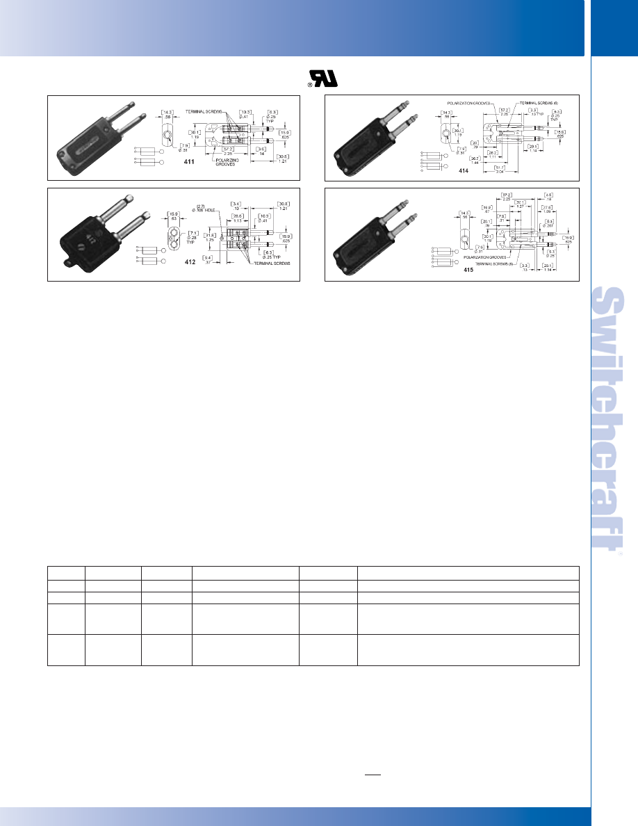
SWITCHCRAFT, INC. 5555 N. Elston Ave. • Chicago, IL 60630
141
JACKS AND PLUGS
FAX: 773 792-2129
JACKS AND
PLUGS
DIMENSIONS ARE FOR REFERENCE ONLY
Inch
(mm)
MIL-TYPE 1/4" PHONE PLUGS
MIL-TYPE 1/4" PHONE PLUGS
FEATURES
Design and material strictly in accordance with Specification
MIL-P-642(A), MIL part number molded or stamped on
handle, manufacturer’s trademark (as required in MIL
Specification) appears on plug body. Ideal for use in broadcast
and recording studios, military, industrial and telephone
switchboard applications, instrumentation and telemetry.
Individual plugs, featuring one-piece tip rod and one-piece
sleeve and plug body, with complete continuity of
thermoplastic insulation between plug elements, are placed
into handles to provide a double Twin-Plug
®
plug (two
electrically-independent 2-conductor plugs spaced .625"
center-to-center, with self-alignment feature). 411, 414 and
415 Twin-Plug plugs have provision for use of Cord Clamp
Number S2674. 412 Twin-Plug has external Cord Anchor.
6-conductor Twin-Plug, 414 and 415, provide two
electrically-independent 3-conductor plug fingers spaced on
.625" centers. Fingers are insulated from each other and each
provides tip, ring and sleeve connections. Black plastic handle
is notched to indicate polarity. Accepts standard 6-conductor
cables. Handle has provision for use of Cord Clamp, S2674.
Fingers of 414 are .25" diameter and mate with Switchcraft
type MT389 Twin-Jax
®
, MT333B, MT336 MT-Jax
®
, and other
jacks having .25" inside diameter sleeves and mounted
on .625" centers. 415 has a .25" diameter finger and a .206"
diameter finger to provide automatic polarization. Fingers mate
with Switchcraft MT332B and MT342B MT-Jax, respectively.
STRAIN RELIEF CLAMP
Natural brass. For use only with 411, 414, 415 Twin-Plug,
S2674.
SPECIFICATIONS
Tip, Rod, Ring Sleeve, Body, Screws: Copper alloy, natural
finish. Number 412 Handle Screws - iridescent iridite overplating.
Terminals: Tinned copper alloy. (Latest MIL Specifications
no longer specify terminals; terminal furnished is the type
referenced as TM-89).
Insulation: Thermoplastic; per MIL-P-22985, Type II, Class 1.
Handle: Thermoplastic on 411, 412, 414 and 415, per
MIL-P-22985, Type II, Class 4. Molded black thermoset
plastic per MIL-M-14F.
MIL-TYPE 1/4" TWIN PHONE PLUGS
Number 415
Number 412
Number 411
Number 414
Part No. Conductors
Terminals
"Typical Mating Jack1"
Mil No.
Notes
411
2
Screw
MT388
M642/9-1
Provision for internal cord clamp (not included)
412
2
Screw
MT388
---
MILPJ289. Similar to WECo289B
414
3
Screw
MT389
---
6-circuit plug, 2 electrically-independent 3 conductor
fingers, .25" fingers. Provision for internal cord clamp
(not included) Similar to WECo 338A. 425A-3
415
3
Screw
MT332B &1, MT342B
---
6-circuit plug, 2 electrically-independent 3 conductor
fingers, one .25" finger, one .206" finger. Provision for
internal cord clamp (not included)
1. Switchcraft Part Numbers. See Jacks Section for other mating jacks.
* Please visit the product pages on our website for the most up-to-date product information

JACKS AND PLUGS
142
w w w . s w i t c h c r a f t . c o m
® Registered trademark of Switchcraft, Inc.
Note: Contact your Switchcraft Representative for price and delivery
PHONE: 773 792-2700
JACKS AND PLUGS
DIMENSIONS ARE FOR REFERENCE ONLY
Inch
(mm)
MIL-TYPE 1/4" EXTENSION JACKS AND TELEPHONE PATCH ADAPTERS
MIL-TYPE 1/4" EXTENSION JACKS AND TELEPHONE PATCH ADAPTERS
FEATURES
Cable jack meets requirements of Specification MIL-J-641(A), Type
Number JJ-026. Mates only with MIL-type plugs PJ-054 and PJ-540.
Switchcraft 430.
SPECIFICATIONS
Body and Terminal Screws: Copper alloy, natural finish.
Springs: Punched from special copper alloy.
Stack Insulation: Rigid plastic spacers Rigid plastic tubing.
Handle: Same as plug handle above.
Stack Screws: Stainless steel.
FEATURES
Compact patch adapters convert standard full-size phone jacks to
standard miniature phone jack connections with maximum
convenience and reliability at a minimum cost. Eliminates
cross-patching problems and need for combination patch cords with
standard phone plug on one end and a miniature phone plug on the
other.
Adapters are 100% compatible with Switchcraft
®
telephone type and military phone jacks and miniaturized
tini-telephone patching system components, as well as equivalent
industry standard phone plugs.
TAD2 – 2-conductor adapter. Plug finger meets specifications for
MIL plug PJ-047 (MIL-P-642). Fits Switchcraft T-Jax
®
, M-Jax
®
,
MIL-approved MT-Jax
®
, and other industry-standard phone jacks
with .250" inside diameter sleeves. The .552" diameter handle
accommodates jacks on .625" centers. For quick identification,
TAD-2 is stamped on the blue handle - will not wear off with
constant use. Miniature 2-conductor jack built into plug body,
accepts miniature phone plugs with .173" diameter fingers, such
as Switchcraft tini-telephone
®
plugs, Series TT200 and TT250,
and other standard miniature telephone plugs. TAD3 is a
3-conductor version of TAD2. Finger configuration meets
requirements of PJ-051 (MIL-P-642). Finger incorporates dead
ring to minimize plug and jack wear. Blue handle has diameter
of .444".
MIL-TYPE 1/4" EXTENSION JACKS
Part
Typical Mating
Handle
MIL
Number
Conductors
Terminals
Plug
1
Handle
Part Number
Part Number
820
2
Screw
2, 3
430
Black
M1015
M641/4-1
1. Switchcraft Part Number See Jacks Section for mating jacks. 2. Switchcraft replacement screw. P1070, Terminal P1069 (2 each required)
3. See previous page for strain relief clamp.
TELEPHONE PATCH ADAPTERS
SPECIFICATIONS
Tip Rod, Ring, Sleeve Body and Screws: Copper alloy,
natural finish.
Insulation: Injection-molded plastic.
Jack Springs: Formed copper alloy.
Screw, Spring Retaining:
TAD2 - #2-64, steel. Part Number P1616 (one required).
TAD3 - #2-64, brass. Part Number P1070 (two required).
Ring Insulations (TAD3 only): Kraft paper sleeve.
Handle: Molded blue thermoplastic with die-stamped
identification legend. TAD2 Handle, (Part Number M1487),
and Retaining Screw, (Part Number T1677), one required.
TAD3 Handle, (Part Number M1488), and Retaining Screw,
(Part Number T1990), one required.
TAD2
2-conductor
TAD3
3-conductor
Number 820
* Please visit the product pages on our website for the most up-to-date product information
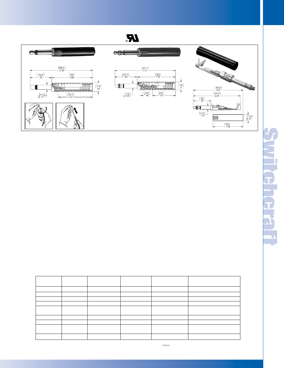
SWITCHCRAFT, INC. 5555 N. Elston Ave. • Chicago, IL 60630
143
JACKS AND PLUGS
FAX: 773 792-2129
JACKS AND
PLUGS
DIMENSIONS ARE FOR REFERENCE ONLY
Inch
(mm)
MINIATURE TELEPHONE PLUGS
MINIATURE TELEPHONE PLUGS
.173" MINIATURE PHONE PLUGS FEATURES
2- and 3-conductor miniature non-shorting telephone plugs
designed for use with TT-Jax
®
, Unijax
®
, and other phone jacks
with a .176" inside diameter bushing. Approximately 1/2 the
size of standard phone plugs, yet retains the uniformity,
dependability and quality of MIL-type phone plugs.
TT-Plug
®
Miniature Telephone Plugs are the first to offer
2- and 3-conductors in an attachable type with twist handles
for quick assembly. Series TT250 phone plug is available with
red or black handles. Other color handles available on special
order. Also available with nickel-plated plug fingers. (Add “N” to
part number: 253N, 254N).
The TT253NC and TT254NC offer the same nickel-plated plug
fingers as the ‘N’ versions, but also includes cable clamps and
solder terminals for easy assembly.
Plugs feature a one-piece tip rod, ring and a one-piece sleeve
with integral plug body, assembled together into a mold as
inserts. Providing complete continuity of thermoplastic insula-
tion between tip rod, ring and sleeve. Internal interlock of all
parts prevents shifting and shorting under extreme rugged
usage.
Internal 12-24 threads in end of plug body are intended for
threading over outer jacket of a patch cord to provide a supe-
rior cable anchor.
Patch cords such as Switchcraft Series TT700 (or other .216"
diameter cable) are easily attached to Series TT250 by screw
terminals.
FEATURES AND BENEFITS
• Designed for pro audio applications
• 3 Conductor
• .173" (4.40mm) plug finger diameter
• One-piece tip rod ensures high reliability
• Complete continuity of thermoplastic insulation
between conductors
• Internal keying of all parts preventing shifting
and shorting
• Solder terminals for easier termination and assembly
• Large cable clamp for shield termination and strain relief
• Black or red handles
SPECIFICATIONS
Tip Rod, Ring, Sleeve and Body: Copper alloy,
natural finish.
Terminals and Terminal Screws: Copper alloy,
natural finish.
Insulation: Thermoplastic. Handle: Molded plastic
MINIATURE TELEPHONE PLUGS
TT253NC
TT251 and TT252
TT253 and TT254
Removing handle from plug body can be
easily accomplished by lightly squeezing
the knurled area of the handle and
twisting 30° counter-clockwise.
Part
Handle
Handle
Number
Conductors
Terminals
Color
Part Number
Description
TT251
2
Screw
Black
T2302
TT252
2
Screw
Red
T2315
TT253
3
Screw
Black
T2307
Mil-type M642/13-1
TT253N
3
Screw
Black
T2324
Nickel-plated plug
TT253NC
3
Solder
Black
T2324
Nickel-plated plug,
tinned solder terminals
TT254
3
Screw
Red
T2301
Mil-type M642/13-2
TT254N
3
Screw
Red
T2325
Nickel-plated plug
TT254NC
3
Solder
Red
T2325
Nickel-plated plug,
tinned solder terminals
2P2003
3
Screw
None
None
* Please visit the product pages on our website for the most up-to-date product information
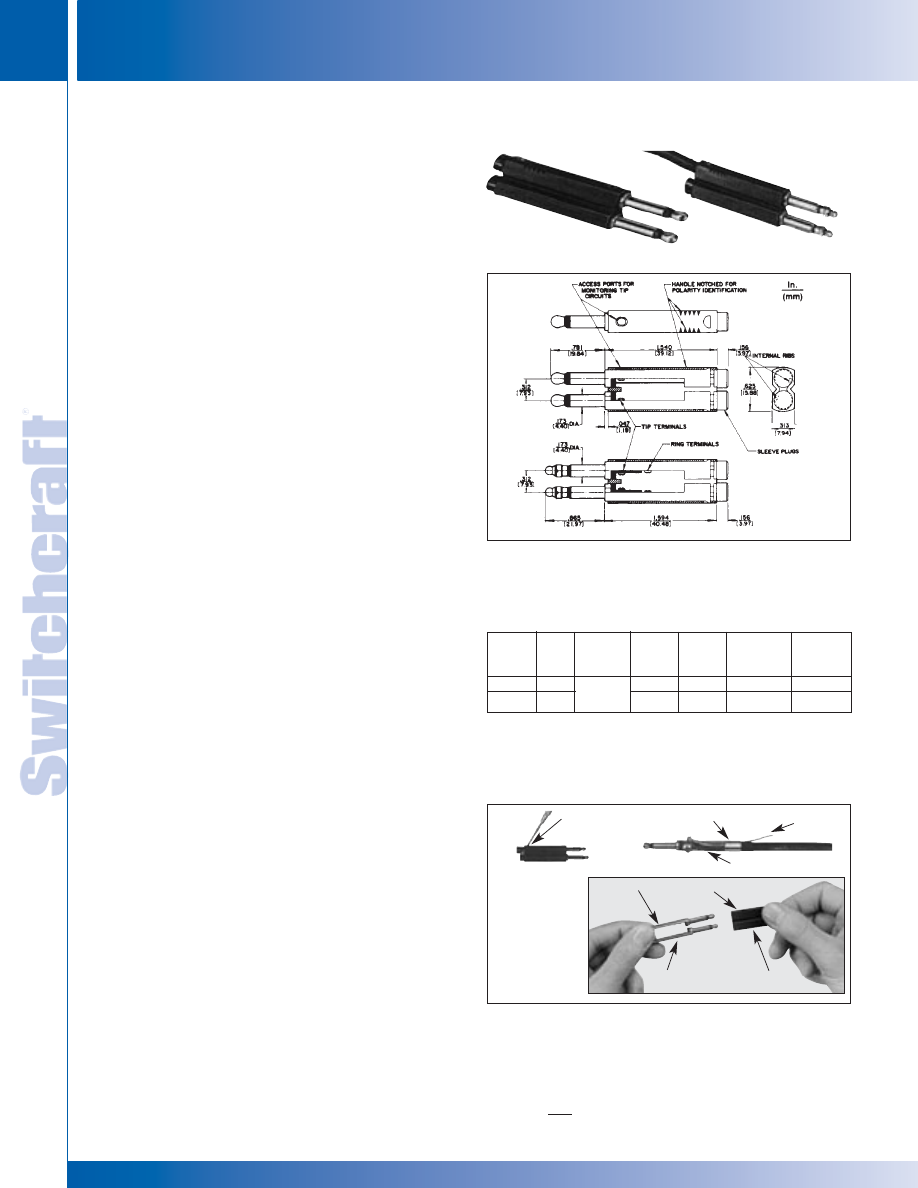
JACKS AND PLUGS
144
w w w . s w i t c h c r a f t . c o m
® Registered trademark of Switchcraft, Inc.
Note: Contact your Switchcraft Representative for price and delivery
PHONE: 773 792-2700
JACKS AND PLUGS
DIMENSIONS ARE FOR REFERENCE ONLY
Inch
(mm)
.173" MINIATURE TELEPHONE PLUGS BANTAM TYPE
.173" MINIATURE TELEPHONE PLUGS BANTAM TYPE
FEATURES
Miniature telephone twin plugs with two 2-conductor or two
3-conductor fingers, designed to mate with TT Twin-Jax
®
,
TT-Jax
®
, and other phone jacks with a .176" inside diameter
bushing and compatible tip and ring springs. Approximately
1/2 the size of standard phone plugs; yet retains uniformity,
dependability of high-quality phone plugs. The phone plugs
are exceptionally light, small and rugged. Plug fingers can
easily be removed and replaced.
• Minimum Space: Plugs fit .313" centers, horizontally
or vertically.
• Self-Aligning: Plug fingers compensate for minor
variations in jack spacing.
• Polarizing: Handle notches identify location of each finger.
• Tip Monitoring: Handle ports permit probe insertion to
monitor tip circuits.
• Terminating and Looping Plugs: OEMs can fabricate
cross-wired plugs, i.e., tip-to-sleeve, tip-to-ring, etc.,
according to individual requirements. OEMs can also
wire-in resistors, RCL networks, etc. for standard and
special terminating applications. Switchcraft will build
looping and terminating TT-Twin Plugs on special order,
where quantities warrant.
• Sleeve Plugs: For looping, terminating and single cable
applications, sleeve plugs seal off unused handle open-ing(s).
Sleeve plugs also make a bridged (common) sleeve
connection by holding braided shield in place in second
plug.On special order, TT-Twin Plugs can be supplied
with one 2-conductor finger and one 3-conductor finger.
• Ease of Assembly/Disassembly: Refer to illustration below
for assembly/disassembly procedure; no handle retaining
screws required. Tip and ring terminations are screw-type
screws supplied).
SPECIFICATIONS
Tip Rod, Ring, Sleeve and Body: Copper alloy,
natural finish.
Terminals and Terminal Screws: Copper alloy,
natural finish.
Insulation: Thermoplastic.
Handle, Sleeve Plugs: Molded plastic.
1. DISASSEMBLY: Place plug on edge as shown. Push down
and back on metal lip on finger (inside notch) with small
screwdriver and slip plug finger out of handle. Turn plug
over and repeat for other finger.
2. CABLE INSTALLATION: Fold braided shield on cable back
over insulation. Insert leads through rear of plug finger, and
screw finger (clockwise) onto cable with twisting motion
until lead terminations lineup with threaded tip and/or ring
openings. Fasten terminals on both fingers with screws
provided.
3. To bridge sleeves (common connection), place free end of
braided shield in remaining finger sleeve opening. Press
sleeve plug firmly in place.
TT261: Two electrically-independent 2-conductor fingers in a black
handle. Can be used with single or dual cables for independent tip
circuits with common sleeve or separate sleeve circuits.
Typical
Handle
Part
Mating
Part
MIL Type
Number
1
Cond. Terminals Jack
2
Handle
Number
Number
TT261
2
TT31
Black
T2300-2
–
TT263
3
TT32B
Black
T2316
M642/13-3
Screw
3
1. TT-Twin Plug plugs can be supplied with one, 2-conductor plug finger and
one, 3-conductor plug finger in the same handle (on special order).
2. Switchcraft Part Numbers. See additional mating jacks in this section.
3. Switchcraft Replacement screw P2240, Terminal P2642. 2 each required
with 2-conductor twin plugs; 4 each required with 3-conductor twin plugs.
4. Replacement Hole Plug Switchcraft T2318 (Black) T2319 (Red).
TT261
TT261
TT263
NOTCH
BRAIDED
SHIELD
LIP
FINGER
NOTCH
LIP ON
FINGER
GROOVE
INTERNAL RIB
4. ASSEMBLY: Align grooves in fingers with internal handle
ribs and insert fingers into rear of handle. Push fingers in
until lips or rear of fingers snap into notches on handle.
.173" MINIATURE TELEPHONE PLUGS BANTAM TYPE
TT263: 6-circuit plug consists of two electrically-independent
3-conductor fingers with black handle. Can use single or dual
cables for two electrically-independent 3-conductor fingers or
common tip, ring and/or sleeve circuits.
TT263
1.
2. & 3.
4.
* Please visit the product pages on our website for the most up-to-date product information
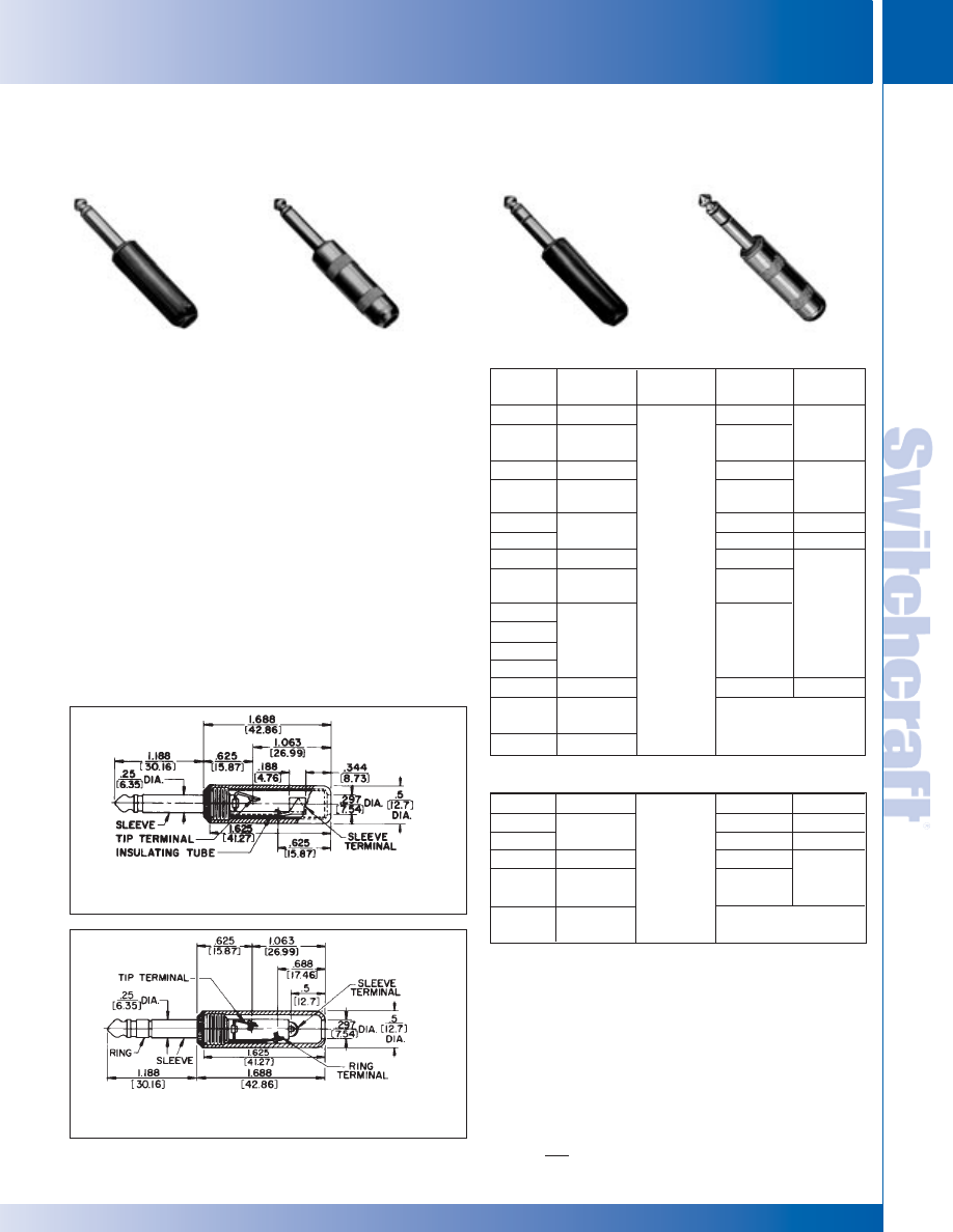
SWITCHCRAFT, INC. 5555 N. Elston Ave. • Chicago, IL 60630
145
JACKS AND PLUGS
FAX: 773 792-2129
JACKS AND
PLUGS
DIMENSIONS ARE FOR REFERENCE ONLY
Inch
(mm)
1/4" COMMERCIAL PHONE PLUGS
2-CONDUCTOR PLUGS PART NUMBERS
Part
Number
240
◊
C240
245
◊
C245
250
255
270
◊
C270
280
281
285
288
285L
2P1298
◊
2P1495
Terminals
Screw
3
Screw
3
with
Cable Clamp
Screw
3
Screw
3
with
Cable Clamp
Solder Lug &
Cable Clamp
Screw
3
Screw
3
with
Cable Clamp
Solder Lug &
Cable Clamp
Solder Lug &
Cable Clamp
Screw
3
Typical
Mating Jack
2
11
Handle*
Black
Black
Red
Red
Black
Red
Shielded
Shielded
Shielded
1
Shielded
4
Shielded
4, 5
Shielded
1
Shielded
4, 5, 6
Handle Part
Number
◊
M1002
◊
M1003
◊
M1002
◊
M1003
Handle:
T10581
Insulator:
A10071
T2323
3-CONDUCTOR PLUGS PART NUMBERS
260
267
269
290
297
◊
2P1248
Screw
Solder Lug &
Cable Clamp
Screw
3
Solder Lug &
Cable Clamp
Solder Lug &
Cable Clamp
12B
Black
Black
Red
Shielded
Shielded
◊
M1002
◊
M1002
◊
M1003
Handle:
T10581
Insulator:
A10071
* Additional plug handle colors available (P2714) green, (M1111) blue,
(M1235) gray. Fits any plug on which Numbers M1002, M1003 are standard.
1. Wide insulator between tip and sleeve allows use of 2-conductor plug in
3-conductor jack without shorting.
2. Switchcraft Part Numbers. See Mating Jacks Section.
3. Replacement Screw Part Number P10292 (2-conductor plugs require
2 screws; 3-conductor plugs require 3 screws).
4. Unassembled.
5. Larger cable clamp to accommodate larger diameter cables.
6. Handle has .375" (9.53mm) diameter hole to accommodate larger
diameter cables.
◊
Special order only. Contact Switchcraft.
2-CONDUCTOR LITTEL-PLUG
®
PLUGS
3-CONDUCTOR LITTEL-PLUG
®
PLUGS
Numbers 240, 245,
250, 255 (typical)
Numbers 280, 281,
285, 285L, 288 (typical)
Number 260 (typical)
Without Handle
Without Handle
Number 290 (typical)
1/4" COMMERCIAL PHONE PLUGS – LITTEL-PLUG PLUGS
1/4" COMMERCIAL PHONE PLUGS – LITTEL-PLUG PLUGS
®
®
FEATURES
• Heavy duty machined copper alloy handle (shielded
versions), tip and body for unsurpassed ruggedness.
• Bright nickel plating on exterior surfaces will not chip
or corrode.
• Solder terminals are tin electroplated for ease of soldering.
• One-piece tip rod staked into tip terminal ensures
electrical continuity
• Heavy duty cable clamp provides secure strain relief.
• The proven industry standard phone plug for audio
applications. Beware of imitations!
• Shielded handle versions recommended for applications
where electromagnetic interference and physical abuse
may occur.
SPECIFICATIONS
Sleeve, Tip and Body: Nickel-plated copper alloy.
Terminals: Solder lug - Tinned copper alloy.
Screw: Tin-plated (screws size 3-48).
Handles: Molded - black or red plastic. Shielded - machined
Nickel-plated copper alloy. Tubular insulator inside handle.
No. 280 typical – shown with solder lug terminals,
cord clamp and shielded handle.
No. 280 typical – shown with screw-type terminals,
plastic handle.
* Please visit the product pages on our website for the most up-to-date product information
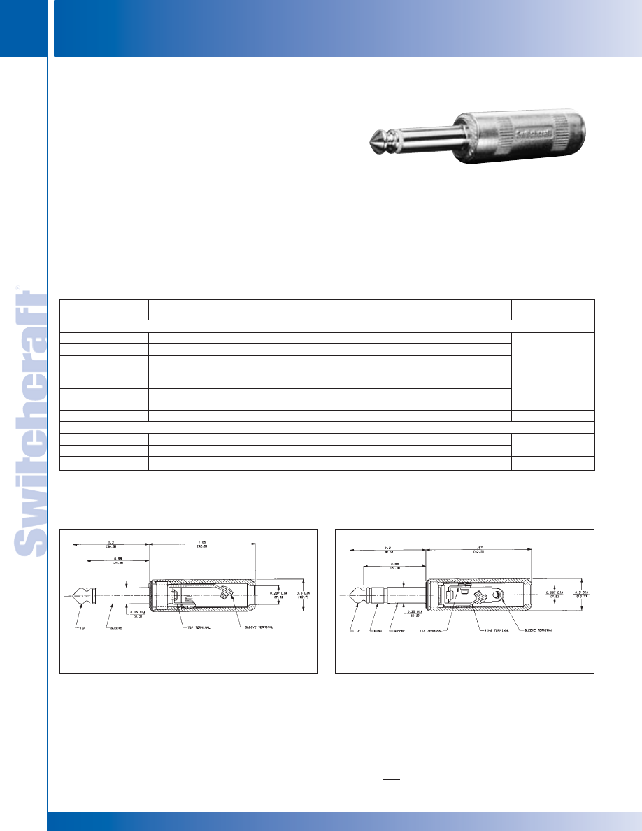
JACKS AND PLUGS
146
w w w . s w i t c h c r a f t . c o m
® Registered trademark of Switchcraft, Inc.
Note: Contact your Switchcraft Representative for price and delivery
PHONE: 773 792-2700
JACKS AND PLUGS
DIMENSIONS ARE FOR REFERENCE ONLY
Inch
(mm)
1/4" COMMERCIAL PHONE PLUGS
1/4" COMMERCIAL PHONE PLUGS
Switchcraft
®
commercial 2- and 3-conductor phone plugs are
available with a logo handle in addition to the plain handle. The
Switchcraft
®
name appears prominently on the shielded handle
so the plugs can no longer be easily confused with “copycat”
plugs found on the market today. Knurling on handles provides a
convenient, positive fingertip grip for connect and disconnect.
Plugs are available in the following popular variations:
1. 1/4" diameter finger, 2-conductors.
2. 1/4" diameter finger, 3-conductors.
3. .206" diameter finger, 2-conductors.
Plug handles accept cable up to .290" diameter.
SPECIFICATIONS
Sleeve: Tip and Body: Plated copper alloy.
Terminals: Solder lug: Copper alloy, electro-tinned;
Screw: Tin-plated (screw size #3-48).
Handles: Nickel-plated zinc (tubular insulator inside handle).
1/4" COMMERCIAL PHONE PLUGS (continued)
PART NUMBERS
NOTE: Plugs have 1/4" finger diameter unless otherwise specified.
1. Other mating plugs are available.
2. Replacement screw, Part Number P10292 (2-conductor requires 2 screws; 3-conductor requires 3 screws).
No. 570 (Typical)
No. 590 (Typical)
Logo
Plain
Typical
Handle
Handle
Description
Mating Jack
2-CONDUCTORS
570
270
Screw terminals. Shielded handle.
580
280
Solder lug & cable clamp. Shielded handle.
581
281
Solder lug & cable clamp. Shielded handle. Unassembled.
585
285
Solder lug & cable clamp. Shielded handle. Unassembled. Larger cable clamp
11
accommodates larger cables.
588
288
Solder lug & cable clamp. Shielded handle. Wide insulator between tip and sleeve
makes possible use as a 2-conductor plug in 3-conductor jack without shorting.
S580
S280
Solder lug & cable clamp. Shielded handle. Plug finger has .206" diameter.
S11
3-CONDUCTORS
590
290
Screw terminals. Shielded handle.
12B
597
297
Solder lug & cable clamp. Shielded handle.
598
298
Solder lug & cable clamp. Shielded handle. Locking feature.
12B, 133
* Please visit the product pages on our website for the most up-to-date product information
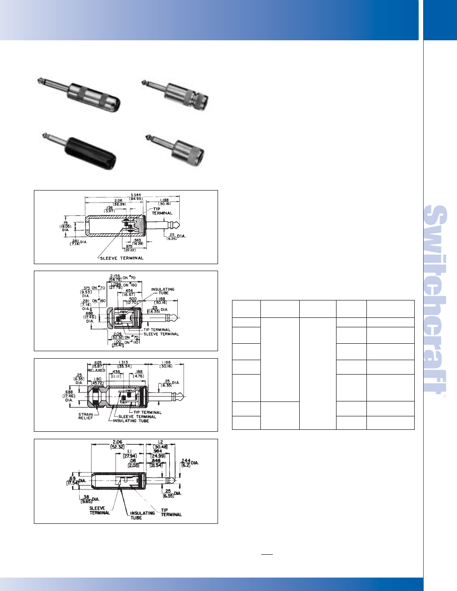
SWITCHCRAFT, INC. 5555 N. Elston Ave. • Chicago, IL 60630
147
JACKS AND PLUGS
FAX: 773 792-2129
JACKS AND
PLUGS
DIMENSIONS ARE FOR REFERENCE ONLY
Inch
(mm)
1/4" COMMERCIAL PHONE PLUGS (continued)
Popular general purpose plug fits all standard jacks. Available
in both 2- and 3-conductor types. Two-conductor plugs
available with black or red molded plastic, or 3 different
lengths of brass nickel-plated (shielded) handles. 2-Conductor
Special Military Plugs are also available.
FEATURES
• 1-piece tip rod staked into tip terminal insures tightness
of plug.
• All essential conducting members are brass with external
parts nickel-plated.
• Terminal screws: broad-headed. In production quantities,
screws may be eliminated and terminals hot-tinned for
easier soldering of wire leads to terminals (special order).
• Screw terminals have grooves which accommodate
1 or 2 cord tips.
• Thermoplastic handle insert for greater insulation.
• Plugs accept up to .25" maximum diameter cable
(parallel or shielded cable).
SPECIFICATIONS
Sleeve, Tip and Body: Nickel-plated copper alloy.
Terminals: Solder lug: copper alloy, electro-tinned.
Screw: steel, tin-plated.
Handles: Shielded: Nickel-plated copper alloy.
Molded: black or red plastic.
2-CONDUCTOR/PLASTIC OR
SHIELDED HANDLES
Part
Number
40
70
3
160
◊
2P1251
170
1
182QB
182QBD
184
3
184L
4
Terminals
Screw
(Replacement
Screw Part No.
P10013)
2 required
Solder Lug &
Cable Clamp
Typical
Mating Jack
2
11 or
Z15J
Handle
Black
Shielded
Shielded
Without
Handle
Shielded
Shielded
Shielded
Handle Part
Number
M1001
Handle: T10141
Insulator: A10063
Handle: T10451
Insulator: A10061
_
Handle: T11231
1
Insulator: A10064
Handle: T10141
Insulator: A11372
T2322
1. 2-piece shielded handle with built-in cable clamp for .25" diameter cable.
Handles: Number T11231, handle; Number T11241, cap; see above for
insulating tube; Number T1125, rubber washer.
2. Other mating plugs are available.
3. Handle has .380" (9.65mm) diameter hole to accommodate
.375" diameter cable.
4. Handle has .451" (11.51mm) diameter hole to accommodate
larger diameter cables.
Number 170, 181
Numbers 70, 184
Number 160
Number 40
Number 184
Number 170
Number 160
Number 40
1/4" COMMERCIAL PHONE PLUGS
1/4" COMMERCIAL PHONE PLUGS
* Please visit the product pages on our website for the most up-to-date product information
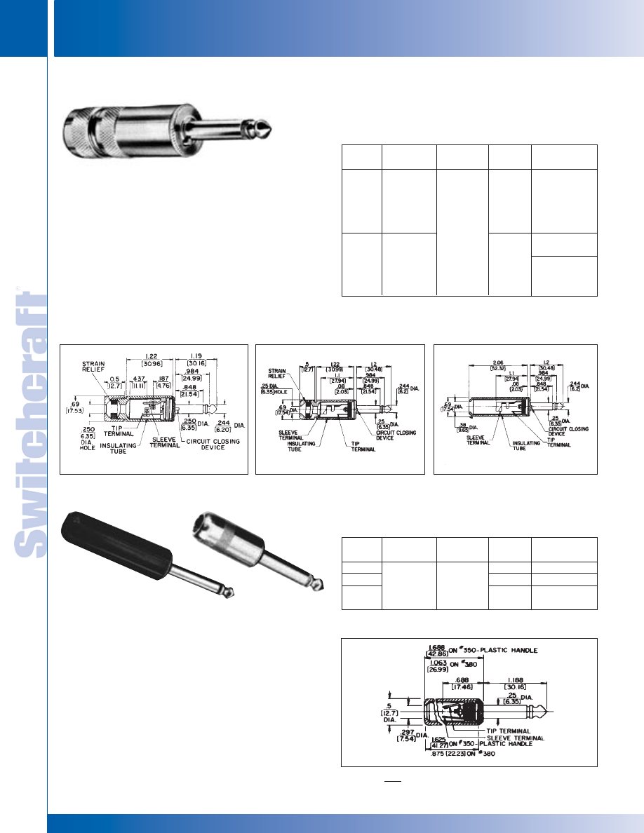
JACKS AND PLUGS
148
w w w . s w i t c h c r a f t . c o m
® Registered trademark of Switchcraft, Inc.
Note: Contact your Switchcraft Representative for price and delivery
PHONE: 773 792-2700
JACKS AND PLUGS
DIMENSIONS ARE FOR REFERENCE ONLY
Inch
(mm)
SILENT-PLUG AND LUG PLUG PHONE PLUGS
SILENT-PLUG AND LUG PLUG PHONE PLUGS
Silent-Plug plugs have unique circuit-closing device—
stops hums, squeals and pops when plug is removed
from jack. One-piece tip rod assembly insures plug
quality. Utilizes cables up to .25" diameter (parallel or
shielded cable). U.S. Patent No. 2,664,475.
SPECIFICATIONS
Sleeve, Tip and Body: Nickel-plated copper alloy.
Terminals: Copper alloy, tin-plated.
Screw: Cadmium plated (screws size 3-48).
Handles: Shielded machined copper alloy nickel-plated.
Tubular insulator inside handle.
Similar to Littel-Plug phone plug. Same molded handles as
used on Littel-Plug; metal handle, bright nickel-plated, only
1" long. Fits all standard jacks. See drawing for details.
SPECIFICATIONS
Sleeve, Tip and Body: Nickel-plated copper alloy.
Terminals: Solder lug: copper alloy, tin-plated.
Screw: plated steel.
Handles: Shielded: Nickel-plated copper alloy.
Molded: black or red plastic.
SILENT-PLUG PHONE PLUGS
LUG
®
-PLUG PHONE PLUGS
Part
Number
172
181
182
Terminals
Screw
(Replacement
Screw Part No.
P-1011-3)
2 required
Solder Lug and
Cable Clamp
Typical
Mating Jack
11
Handle
Shielded
Shielded
2
Handle Part
Number
Two-Piece
1
Ins.
Tube A-1006-3
Two-piece
1
Ins.
Tube A-1137-1
T-1014-1 Handle,
A-1137-2 Ins. Tube
1. 2-piece shielded handle with built-in cable clamp for .25" diameter
cable. Handles: Number T1123-1, handle; Number T1124-1, cap; Number
T-1125, rubber washer. 2. Mylar tube insulation for greater protection.
No. 172
2-CONDUCTOR PLUGS
Part
Number
350
2P-1216
380
Terminals
Solder Lug
Typical
Mating Jack
1
11
Handle
Black
Shielded
Handle Part
Number
M-1002
Handle: T-1060-1
Insulator: A-1007-2
1 Switchcraft part numbers. See Jacks Section for additional mating jacks.
2-CONDUCTOR PLUGS
Nos. 350, 351, 355
No. 380
INSULATING
TUBE ON #380
®
®
2-Conductor “Silent Plug”, No. 172
No. 181
No. 182
* Please visit the product pages on our website for the most up-to-date product information
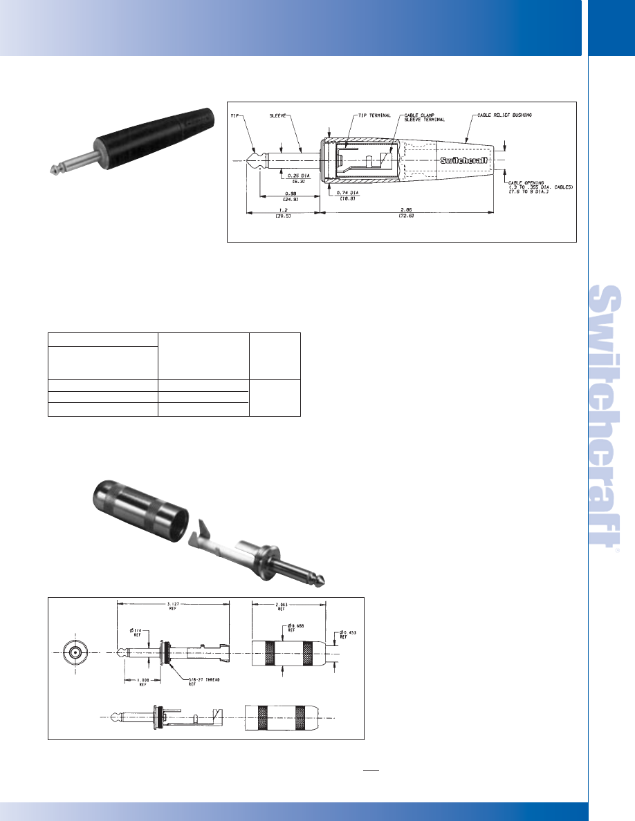
SWITCHCRAFT, INC. 5555 N. Elston Ave. • Chicago, IL 60630
149
JACKS AND PLUGS
FAX: 773 792-2129
JACKS AND
PLUGS
DIMENSIONS ARE FOR REFERENCE ONLY
Inch
(mm)
AUDIO LOUDSPEAKER PLUGS AND HEAVY DUTY 1/4" PHONE PLUGS
AUDIO LOUDSPEAKER PLUGS AND HEAVY DUTY 1/4" PHONE PLUGS
The 187 series 1/4" phone plugs are similar to the
Switchcraft
®
184 plugs, except that they offer an attractive
tapered handle with a snap-in flex relief. Other features include:
• Larger tip terminal to accommodate wire sizes up to 14 AWG.
• Choice of Satin nickel or black finish.
• Black flex relief bushing can be specified in three different
cable diameter openings for maximum reliability of cable.
• Plug is rated at 15A rms (maximum) for use with audio
loudspeaker applications.
SPECIFICATIONS
Sleeve, Tip and Body: Nickel-plated copper alloy.
Terminals: Solder lugs: tinned copper alloy;
Screw: tin-plated.
Handles: Die-cast zinc. Satin nickel or black finish.
Cable Relief Bushing: Black (thermoplastic elastomer).
AUDIO LOUDSPEAKER PLUGS
1. Other mating plugs are available. See Jacks Section.
• Switchcraft’s 188 is more heavy-duty than
our competitor's biggest 1/4" commercial
phone plugs.
• Large curved tip solder terminal makes it
easier to solder to heavy gauge wires.
• Longer sleeve terminal allows more room
to make sleeve solder connections.
• Extra-large cable clamp securely grips
cable of up to .450" in diameter.
• Will easily accommodate some varieties of
four conductor 14 gauge wire and parallel
two conductor 12 gauge wire.
• Bendable tab on sleeve terminal makes
termination easier by holding down cable
while soldering. In addition, such mechanical
retention makes for a superior solder
connection.
• Will handle up to 15 A. rms (maximum).
(continued on next page)
SERIES 187
Number 187BL (Typical)
HEAVY DUTY 1/4" COMMERCIAL PHONE PLUGS
SERIES 188 Plug
Part Number
Cable
Relief
Typical
Nickel
Black
Bushing
Mating
Finish
Finish
diameter (inch)
Jack
1
187
187B
.3 to .33 (regular)
187L
187BL
.3 to .355 (large)
11 or Z15J
187D
187BD
.2 to .30 (small)
* Please visit the product pages on our website for the most up-to-date product information
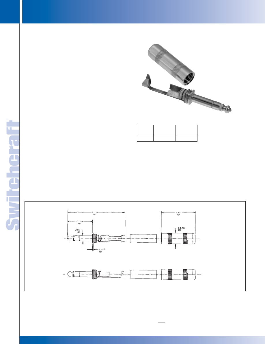
JACKS AND PLUGS
150
w w w . s w i t c h c r a f t . c o m
® Registered trademark of Switchcraft, Inc.
Note: Contact your Switchcraft Representative for price and delivery
PHONE: 773 792-2700
JACKS AND PLUGS
DIMENSIONS ARE FOR REFERENCE ONLY
Inch
(mm)
HEAVY DUTY 1/4" COMMERCIAL PHONE PLUGS
HEAVY DUTY 1/4" COMMERCIAL PHONE PLUGS
SPECIFICATIONS
Contact Resistance (typical *D.O.M.J.):< 0.020 ohms.
Dielectric Withstand Voltage: 500 VAC (minimum).
Insulation Resistance @ 500 VDC: 2,000 megohms
(minimum).
Insulation Resistance (after MIL-STD-202 Salt Spray):
1,000 megohms (minimum).
Working Voltage: 250 VAC, 140 VDC.
Current Carry @ Working Voltage For 188 Plug
(typical *D.O.M.J.): 15.0 AMPS.
Current Carry @ Working Voltage For 299 Plug
(typical *D.O.M.J.): 6.0 AMPS.
Insert/Withdrawal Force: *D.O.M.J..
Soldering Requirement: ANSI/J-STD-001.
Temperature Range: -40° to + 85° Centigrade
U.L. Component Recognition File No.: E118169.
Life: *D.O.M.J.
Maximum Cable Size For 188 Plug:
12 AWG stranded, up to .450" diameter.
Maximum Cable Size For 299 Plug: .290" diameter.
MATERIALS
Tip: Nickel-plated copper alloy.
Sleeve: Nickel-plated copper alloy.
Handle: Nickel-plated copper alloy.
Tip Terminal: Copper alloy, electro tin-plated.
Cable Clamp: Copper alloy, electro tin-plated.
Insulators For 188 Plug: Thermojet plastic,
thermoplastic, thermoplastic film, P.P.O.
Insulators For 299 Plug: Thermoplastic,
thermoplastic film, glass epoxy.
HEAVY DUTY 1/4" COMMERCIAL PHONE PLUGS (continued)
SERIES 299 PLUG
*D.O.M.J. – Dependent On Mating Jack
Part
Number
299
Maximum
Cable Size
.290" Diameter
Mating
Jack
Z15J
* Please visit the product pages on our website for the most up-to-date product information
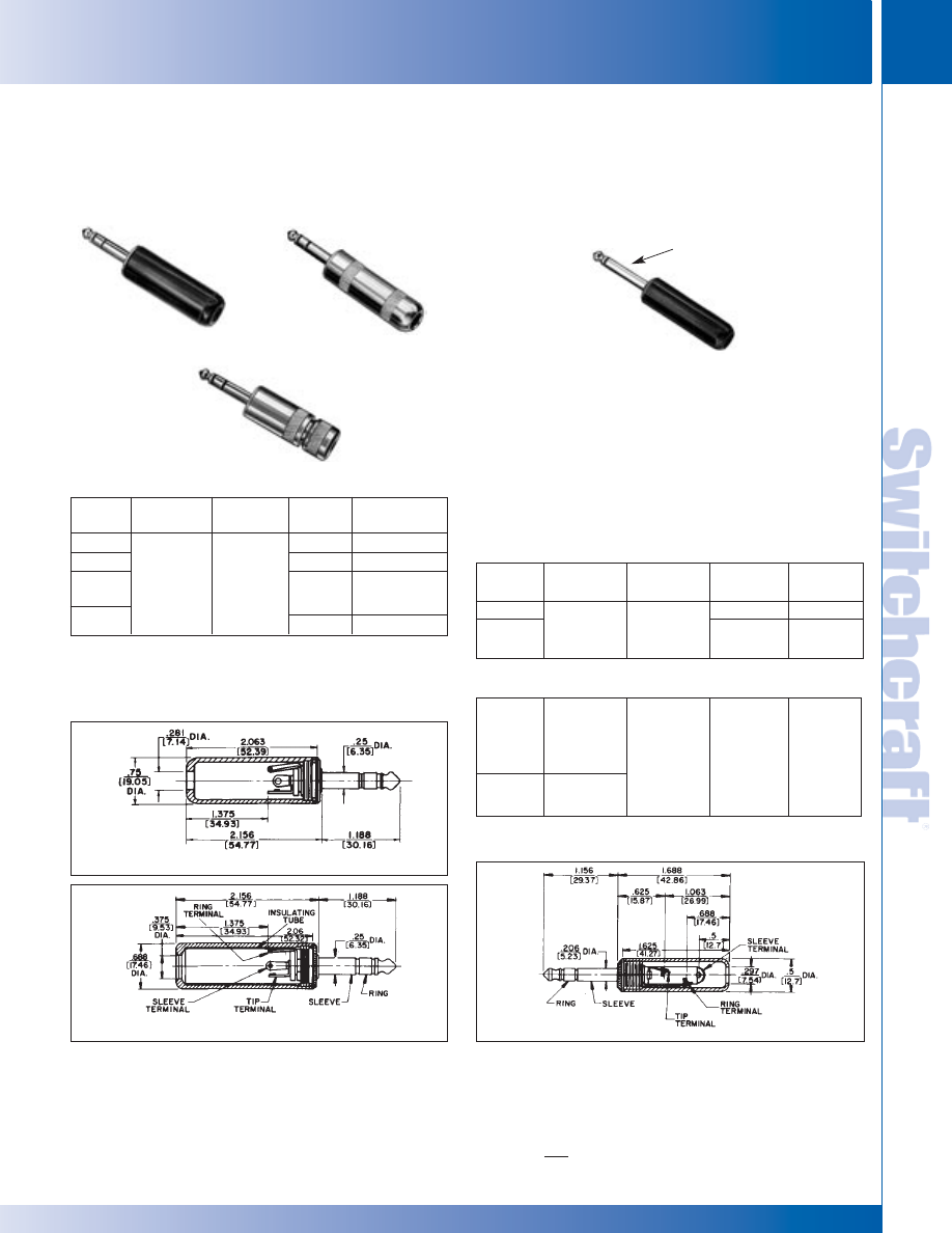
SWITCHCRAFT, INC. 5555 N. Elston Ave. • Chicago, IL 60630
151
JACKS AND PLUGS
FAX: 773 792-2129
JACKS AND
PLUGS
DIMENSIONS ARE FOR REFERENCE ONLY
Inch
(mm)
1/4" AND .206" COMMERCIAL PHONE PLUGS
1/4" AND .206" COMMERCIAL PHONE PLUGS
FEATURES
For applications requiring polarization (use of plugs of different
sizes) to prevent insertion of incorrect equipment Littel-Plug
®
phone plugs featuring a sleeve and tip diameter of .206" are
available. Mate with Number S128 Extension Jax
®
and S11
Littel Jax
®
jacks. Number S260 used interchangeable with
Military Type M642/51 (Switchcraft Number 480) plugs. Mate
with jacks S12B, S13B, M444, MT342B, MT344B and others.
3-CONDUCTOR/PLASTIC OR
SHIELDED HANDLES
PHONE PLUGS FOR
POLARIZED CONNECTIONS
1/4" COMMERCIAL PHONE
PLUGS (continued)
.206" COMMERCIAL
PHONE PLUGS
Number 190
Number 60
Part
Number
◊
60
◊
90
190
190A,190B
& 190BL
Terminals
Solder Lug
Typical
Mating Jack
2
12B
Handle
Black
Shielded
Shielded
Shielded
Handle Part
Number
M1001
T10451
Handle: T10141
Insulator: A10063
2-piece
1
2-CONDUCTOR PLUGS PART NUMBERS
Part
Number
S250
S280
Terminals
Solder Lug &
Cable Clamp
Typical Mating
Jack
1
S11
Handle
Black
Shielded
Handle Part
Number
M1002
T10581
A10071
3-CONDUCTOR PLUGS PART NUMBERS
S260
S267
Screw
(Replacement
Screw Part No.
P10292)
2 required
Solder Lug &
Cable Clamp
S12B
Black
M1002
1. Switchcraft
®
mating jacks.
Numbers S250, S255
1. 2-piece shielded handle with built-in cable clamp for .25" diameter cable.
Handles: Number T11231, handle; Number T11241, cap; Number
A10064, insulating tube; Number T1125, rubber washer.
2. Other Mating Plugs are available.
◊
Special order only. Contact Switchcraft.
Number 60
Number 90
Number S260
Number 190A
.206" Diameter
* Please visit the product pages on our website for the most up-to-date product information
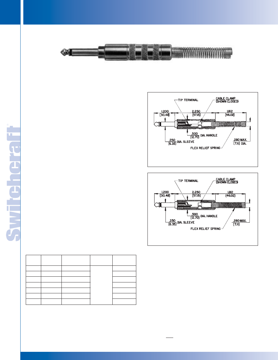
JACKS AND PLUGS
152
w w w . s w i t c h c r a f t . c o m
® Registered trademark of Switchcraft, Inc.
Note: Contact your Switchcraft Representative for price and delivery
PHONE: 773 792-2700
JACKS AND PLUGS
DIMENSIONS ARE FOR REFERENCE ONLY
Inch
(mm)
1/4" MITI-PLUG
®
AUDIO PLUGS
1/4" MITI-PLUG
®
AUDIO PLUGS
FEATURES
• 2-conductor phone plug with full shielding and resistance to
extremely rough usage for electrified audio instruments such
as amplifiers, synthesizers power heads and speaker systems
requiring high-quality audio plugs.
• 3-WAY CABLE STRAIN/STRESS RELIEF: For hours of
trouble-free operation under heavy and abusive use. Plug body
internally threaded for screw-on strain relief for cables from .29"
to .30" diameter, and an additional clamp for additional relief
(and for smaller cables). A heavy copper alloy-plated steel
spring at point of entry to plug keeps cable from folding and
pinching. Flex relief spring recommended for cables with
diameters of .265" maximum only.
• TERMINATING: Tip wire soldered to tip–braid folded back
and secured with cable clamp.
• IDENTIFICATION: Customer or OEM name of logo can be
applied to plastic handles for a minimal charge for personalization.
(Contact Switchcraft for details).
• SPECIAL HANDLE COLORS: Plastic handles molded in
custom colors on special order. Contact Switchcraft for details.
SPECIFICATIONS
Tip Rod & Body: Copper alloy.
Handle: Copper alloy or plastic (black).
Flex Relief Spring: Plated spring steel.
(Part No. P2848).
Strain Relief Clamp: Plated steel.
(Part No. P2380).
Insulation: Thermoplastic, glass reinforced.
1/4" MITI-PLUG
®
AUDIO PLUGS
Part
Number
◊
173
◊
174S
◊
175
◊
176S
◊
177S
◊
178
◊
179
Handle
Black plastic
Copper Alloy
Copper Alloy
Black Plastic
Red Plastic
Black Plastic
Red Plastic
Flex Relief
U-Clamp
Spring
None
Spring
Spring
None
None
11
Handle Part
Number
M1483
T2313
T2313
M1483
M1483
1. Other mating plugs are available.
◊
Special order only. Contact Switchcraft.
2-CONDUCTOR PLUGS
Number 174S
Typical
Mating Jack
1
No. 174S
No. 176S
* Please visit the product pages on our website for the most up-to-date product information
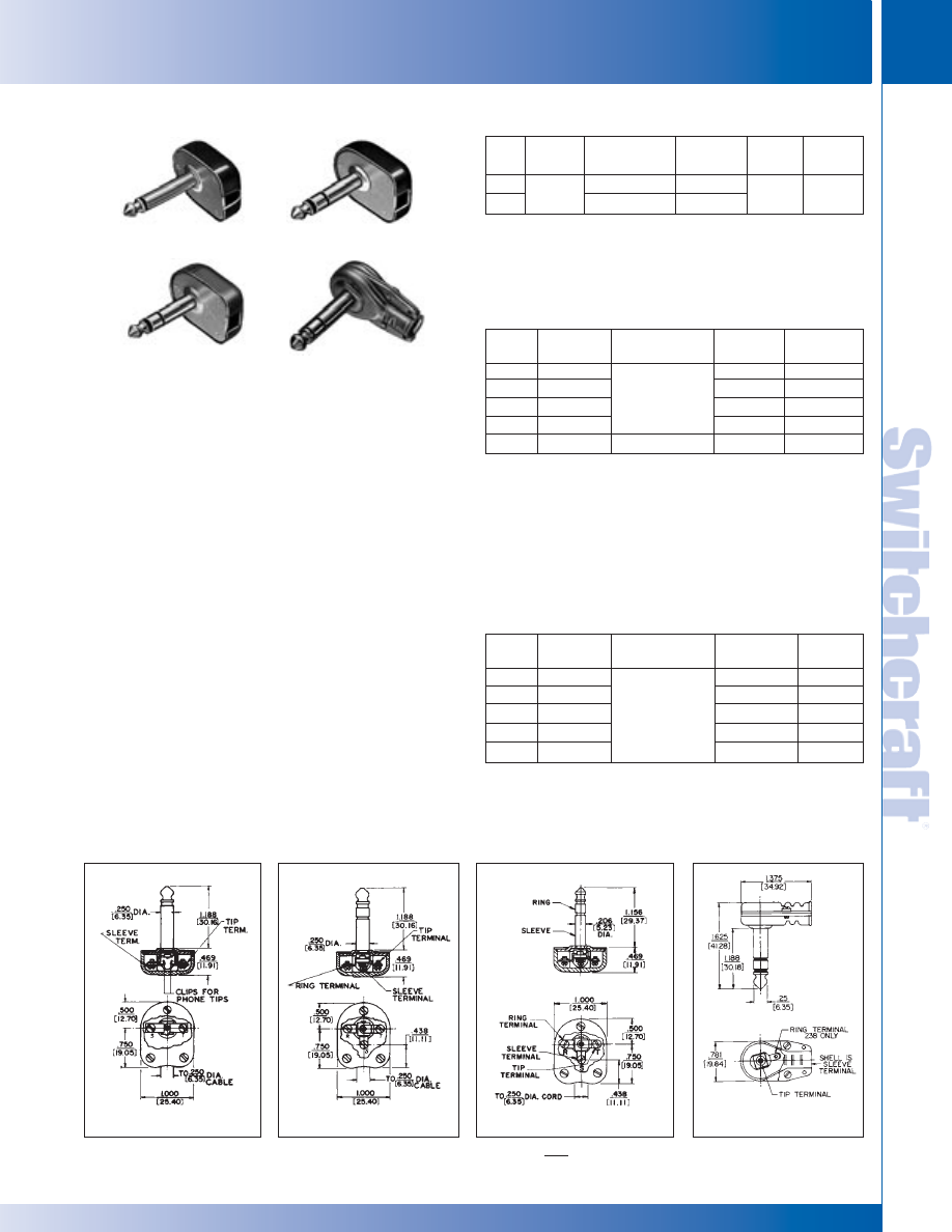
SWITCHCRAFT, INC. 5555 N. Elston Ave. • Chicago, IL 60630
153
JACKS AND PLUGS
FAX: 773 792-2129
JACKS AND
PLUGS
1/4" FLAT PLUG PHONE PLUGS
Part
Typical
Handle
No.
Terminals
Mating Jack
1
Handle
Part No.
3
220
Screw
Black
M1005
225
Screw
Red
M1006
227
Solder Lug
Black
M1005
229
Solder Lug
Red
M1006
2P1509 Screw
Less Handle
–
FEATURES
• Ideal where conventional long handled plugs are not
suited to design of equipment. “Chassis-hugging” phone
plugs allow cables to be brought out at right angles to
equipment.
• Removable plastic cap for easy assembly of wire leads
to either screw or solder lug terminals. Adapter clips on
types 220 and 225 make it convenient to clamp standard
phone tips to terminals.
• Terminals and body of plug mechanically interlocked,
eliminating probability of any shifting.
• Cover is black or red plastic; plug body is a rugged
assembly of all metal parts.
• One-piece tip rod staked into tip terminal to insure
tightness, no disassembly of tip during use of plug.
• High grade insulation.
• Terminal identification permanently stamped into base
plate adjacent to each terminal. Letter “T” denotes tip
connection; “R” denotes ring sleeve; “S” terminal is the
sleeve or body connection (no identification on types
228, 238).
• Cover molds designed so customer’s name or trademark
inserts can be added. Call for details.
SPECIFICATIONS
Tip Rod and Sleeve: Nickel-plated copper alloy.
Terminals: Tinned copper alloy.
Handle: Black or red plastic. Numbers 228 and 238,
steel,nickel-plated.
Part
Typical
Handle
No.
Terminal Mating Jack
1, 2
Conductor
Handle Part No.
228
Solder
11
2
238
Lug
12B
3
1/4" FLAT PLUG PHONE PLUGS
11
2- OR 3-CONDUCTOR/SHIELDED HANDLE
1. Switchcraft Part Number; see jack section for additional mating jacks.
2. Switchcraft replacement Part Number P10292. 2 screws required per plug.
Clips for phone tips. Part Number S1832.
3. Three screws (Number P1039) required to mount handle.
Shielded
S3067
1. Nickel plated steel handle. Two screws (Part Number P15823) required to
mount handle.
2. Other mating plugs are available.
3. Accommodates cables from .219" outside diameter to .250" outside
diameter Ideal for music equipment use.
Part
Typical
Handle
No.
Terminals
Mating Jacks
1
Handle
Part No.
4
◊
230
Screw
3
Black
M1005
◊
235
Screw
Red
◊
237
Solder
Black
M1005
◊
239
Solder
Red
◊
S230
Screw
3
S12B
2
Black
M1005
3-CONDUCTOR/PLASTIC HANDLE
.206" DIAMETER SLEEVE AND TIP
1. Switchcraft Part Number Other mating plugs are available.
2. Part Number S230 is the commercial version of military Type PJ068
(Switchcraft Number 480) plug. Mates with S12B, S13B, M444, MT342B,
MT344B Jacks and others. Other mating plugs are available.
For applications where it is desirable to polarize, use plugs of different sizes
to prevent insertion of incorrect equipment. Sleeve and tip diameter of these
plugs is .206" Mates with S830, S1230 Extension-Jax
®
jacks and S12B,
S13B Littel-Jax
®
phone jacks.
3. Switchcraft Replacement Part Number P10292. 3 screws required.
4. Three screws (Number P1039) required to mount handle.
◊
Special order only. Contact Switchcraft.
Series 220
Series 230
Series S230
No. 238
12B
1/4" FLAT PLUG PHONE PLUGS
Series 220
Series 230
No. S-230
No. 238 (typical)
2-CONDUCTOR/PLASTIC HANDLE
DIMENSIONS ARE FOR REFERENCE ONLY
Inch
(mm)
* Please visit the product pages on our website for the most up-to-date product information
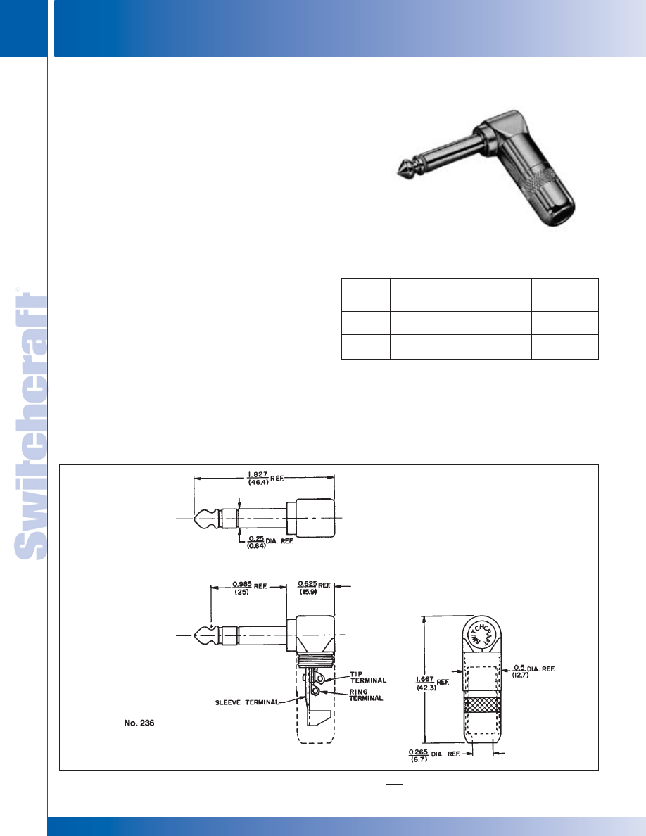
JACKS AND PLUGS
154
w w w . s w i t c h c r a f t . c o m
® Registered trademark of Switchcraft, Inc.
Note: Contact your Switchcraft Representative for price and delivery
PHONE: 773 792-2700
JACKS AND PLUGS
DIMENSIONS ARE FOR REFERENCE ONLY
Inch
(mm)
RIGHT-ANGLE AUDIO PHONE PLUGS
RIGHT-ANGLE AUDIO PHONE PLUGS
RIGHT-ANGLE AUDIO PHONE PLUG
Typical
Part
Mating
Number
Description
Jack
236
3-conductor 1/4" right-angle
12B, 13B
commercial plug.
112B, 113B
226
2-conductor 1/4" right-angle
11, 12A
commercial plug
111, 112A
FEATURING 3-PIECE CONSTRUCTION
AND FAST TERMINATION/ASSEMBLY
Switchcraft's 2- or 3-conductor right-angle audio phone plugs
are designed for OEMs and users of commercial phone plugs.
The plugs offer large terminals for easy wiring, and only three
pieces to assemble - handle, insulator and finger/housing
assembly and rugged reliability for stable, long-term,
trouble-free operation.
FEATURES
• Easy Termination: Large terminals accept up to 16 AWG
wiring (cables up to .25 inch diameter)
• 3-Piece Assembly: Screw on the handle for quick and
easy assembly; minimizes labor costs.
• Rugged: All metal exterior construction.
• Low Profile: Only 1/2 inch wide. Ideal for crowded,
multi-channel panels. Right-angle handle minimizes
space required behind equipment.
• Knurled Handles: Positive grip during connect/disconnect.
• Rugged Cable Clamp: Isolates pulling and twisting strains.
SPECIFICATIONS
Tip, Rod and Handle: Nickel-plated copper alloy.
Housing/Sleeve: Nickel-plated.
Tip Terminal: Tin-plated copper alloy.
Sleeve (Clamp) Terminal: Tin-plated steel.
Insulation: Thermoplastic.
Dielectric Withstanding Voltage: 500 Vac.
Insulation Resistance: 50,000 Megaohms minimum (initial).
Operating Temperature: -20°C to +65°C.
226
No. 236
* Please visit the product pages on our website for the most up-to-date product information
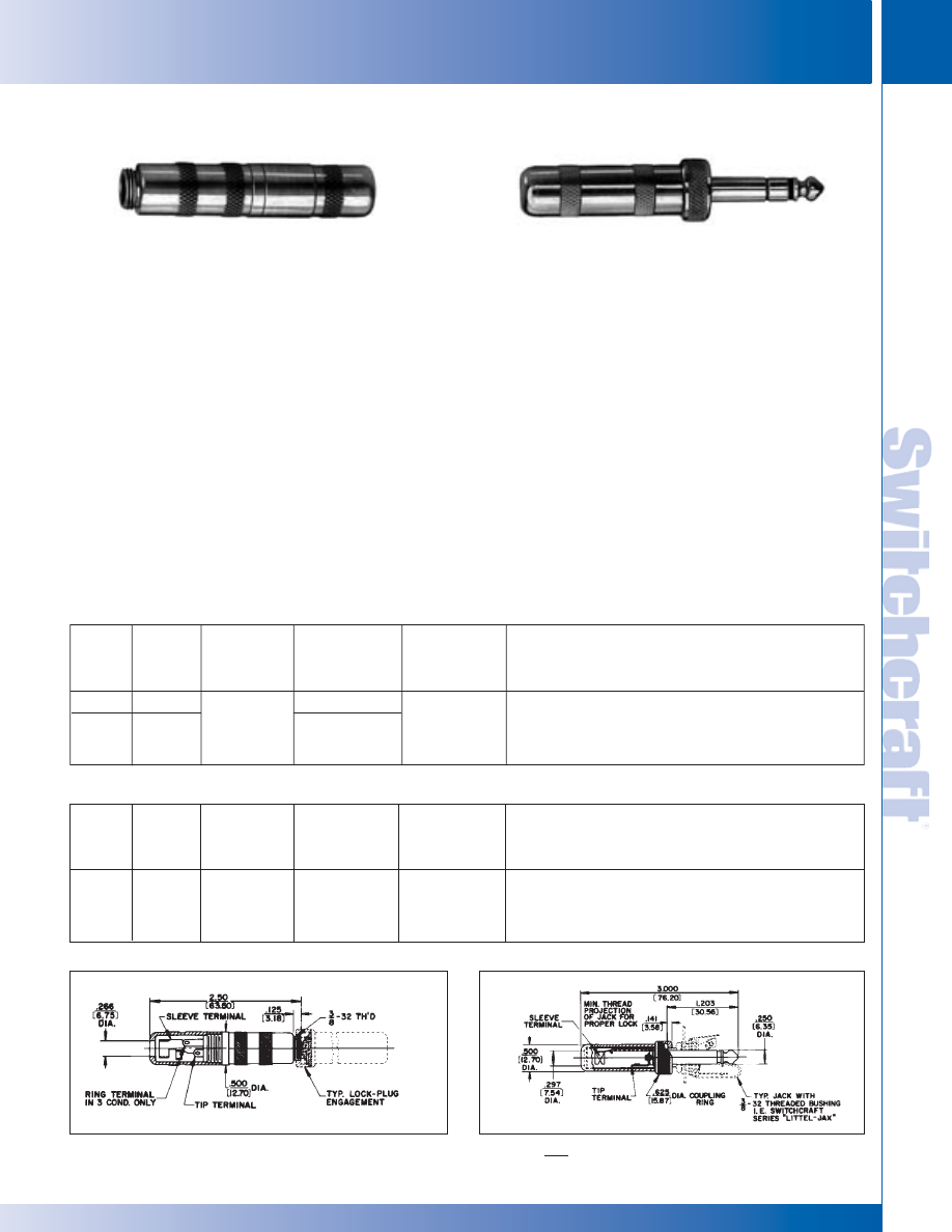
SWITCHCRAFT, INC. 5555 N. Elston Ave. • Chicago, IL 60630
155
JACKS AND PLUGS
FAX: 773 792-2129
JACKS AND
PLUGS
DIMENSIONS ARE FOR REFERENCE ONLY
Inch
(mm)
1/4" LOCK-EXTENSION JACKS AND PLUGS
1/4" LOCK-EXTENSION JACKS AND PLUGS
FEATURES
Modified Littel-Plug
®
phone plug, 2- or 3-conductor, with
coupling ring that can be threaded to thread projection of
mating panel jack or to threaded end of the Lock-Extension
Jax
®
. Locks connection after plug has been fully inserted
into its mating panel jack or Extension Jax
®
.
Lock-Plug
®
makes proper contact to mating jack without
tightening or attaching coupling ring, when rapid disconnect
may be desired. Lock-Plug fits any standard jack with 3/8".-32
thread bushing with .094" of the bushing exposed. Lock-
Extension Jax also will mate properly with standard phone
plugs, where no “lock” requirement exists.
SPECIFICATIONS
Lock-Plug Tip Rod, Body, Handle and Coupling Ring:
Nickel-plated copper alloy.
Terminals: Brass, electro-tinned. Solder lug design,
cable clamp part of sleeve terminal.
Insulation: Rigid plastic.
LOCK-EXTENSION JAX
®
Housing (or Sleeve) and Handle:
Nickel-plated copper alloy.
TERMINALS:
Sleeve: Plated steel. Tip and Ring:
integral part of tip and ring springs.
Springs: Spring tempered copper alloy.
Insulation: Molded thermoplastic insert.
Rigid plastic terminal washer.
1/4" LOCK-EXTENSION JACKS AND PLUGS
Typical
Part
Mating
Handle
Number
Cond.
Terminals
Jack
Part Number
Notes
282
2
Solder
12A
Lug &
T10581
Similar to Switchcraft Number 297 Littel-Plug
298
3
Cable
12B, 133
A10071
except with coupling ring.
Clamp
Typical
Part
Mating
Handle
Number
Cond.
Terminals
Plug
Part Number
Notes
Solder
Lug &
Sleeve terminal has cable clamp. Similar to
133
3
Cable
298
T1485
Switchcraft
®
Number 131 Extension-Jax
®
.
Clamp
LOCK-EXTENSION JAX
®
LOCK-PLUG
Number 133
Number 298
282
133
* Please visit the product pages on our website for the most up-to-date product information
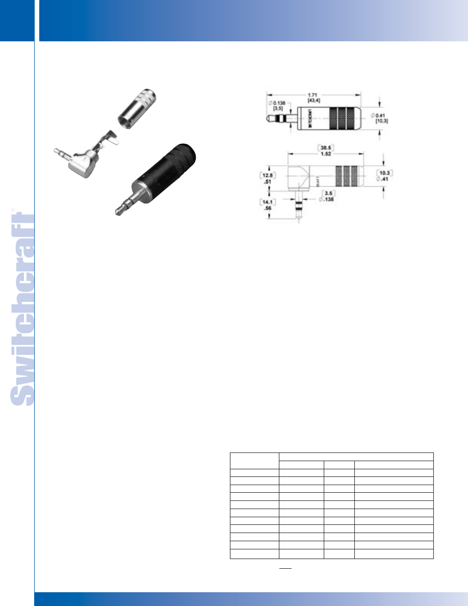
JACKS AND PLUGS
156
w w w . s w i t c h c r a f t . c o m
® Registered trademark of Switchcraft, Inc.
Note: Contact your Switchcraft Representative for price and delivery
PHONE: 773 792-2700
JACKS AND PLUGS
DIMENSIONS ARE FOR REFERENCE ONLY
Inch
(mm)
3.5MM HEAVY DUTY STEREO PLUG
3.5MM HEAVY DUTY STEREO PLUG
3.5MM STEREO PLUGS
FEATURES
• Heavy duty 3.5mm plugs for audio, instrument,
other applications.
• Large cable clamps for rugged use.
• Available in straight or right angle.
• One piece tip rods for added durability.
• Available in nickel, gold, and black finishes.
• Large solder terminals for easy assembly.
• Standard handle accommodates cable sizes up to 0.290"
Optional ‘S’ versions accommodate cable sizes up to 0.175"
35HDBN - Black Handle, Nickel Plug
35HDBAU - Black Handle, Gold Plug
35HDNAU - Nickel Handle, Gold Plug
35HDNN - Nickel Handle, Nickel Plug
BENEFITS
• One piece tip rod with flat for easy solderability.
• Compliments current line of 3.5 mm jacks.
• Insert molded plug finger.
• Heavy Duty cable clamp provides better strain relief
for larger cables
• Longer cable clamp for easier plug assembly and more
room for solder connections
• Knurl on the back of handle provides ergonomic gripping
surface to tighten plug
• Tubular insulator included to prevent solder joints
from contacting handle
• Longer handle for improved gripping surface
and easy plug withdrawal from jack
• Large solder terminal for easy solderability
MARKETS
• Audio
• Consumer electronic equipment
• Broadcast studios
• Home recording equipment
• Audio cable assembly manufacturers
• Instrumentation
• Test equipment
SPECIFICATIONS
Contact Resistance: <0.020 ohms
Dielectric Withstand Voltage: - 250 VAC (min.)
Insulation Resistance @ 500 VDC: 2,000 megohms (min.)
Working Voltage: - 250 VAC, 140 VDC
Current Carry @ Working Voltage: 4 AMPS
Insert/Withdrawal Force: - Typical 2.5/2 pounds
Temperature Range: 0° to 66° Centigrade (operating)
Passed MIL-STD-202F Method 107G (Thermal Shock), and
Method 201 (Vibration)
Life: - 5000 cycles
Maximum Cable Size: - .250? dia.
MATERIALS
Tip Rod: Copper alloy, tin, or gold-plated
Ring: Copper alloy, nickel, or gold-plated
Sleeve: - Copper alloy, nickel, or gold-plated
Handle: Copper alloy, nickel, or gold-plated
Cable Clamp: - C.R.S., tin-plated
Solder Terminal: Copper alloy, tin-plated
Tubular Insulator: Clear plastic
ORDERING INFORMATION
1. Order by part number
2. Contact Switchcraft for more information
3.5 MM HEAVY DUTY STEREO PLUGS
Part
Description
Number
Plug Finger
Handle
Notes
35HDNN
Nickel
Nickel
35HDNNS
Nickel
Nickel
0.175" handle opening
35HDBN
Nickel
Black
35HDBNS
Nickel
Black
0.175" handle opening
35HDNAU
Gold
Nickel
35HDNAUS
Gold
Nickel
0.175" handle opening
35HDBAU
Gold
Black
35HDBAUS
Gold
Black
0.175" handle opening
35HDRANN
Nickel
Nickel
Right angle
35HDRABAU Gold
Black
Right angle
35HDRAAU
Gold
Nickel
Right angle
RIGHT ANGLE
35HDBAU
* Please visit the product pages on our website for the most up-to-date product information
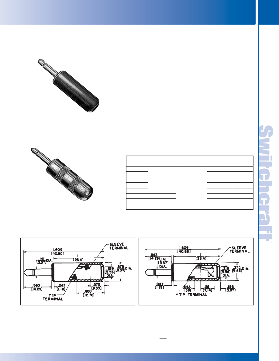
SWITCHCRAFT, INC. 5555 N. Elston Ave. • Chicago, IL 60630
157
JACKS AND PLUGS
FAX: 773 792-2129
JACKS AND
PLUGS
DIMENSIONS ARE FOR REFERENCE ONLY
Inch
(mm)
.141" MINIATURE PHONE PLUGS
.141" MINIATURE PHONE PLUGS
FEATURES
• Miniature 2-conductor Phone Plug for use with Switchcraft
Tini-Jax
®
miniature phone jacks. About 1/2 the size of
Switchcraft Littel-Plug
®
phone plug. Average net weight,
1/8 ounce.
• Various terminal combinations: (a) Dual purpose sleeve
terminal may be clamped over metal braid or shielded
cables; provides cable anchor. Easily soldered for perfect
electrical connection. (b) Screw terminal design (no cable
clamp) for cable. Terminals that can be more suitably
connected by screws.
• 1-piece tip rod staked into mating terminals; no disassembly
of tip during use of plug. Terminals and body of plug
interlocked mechanically.
• Available in black or red plastic handles or brass nickel-
plated handles for shielding. Can be used with cables up
to .188" outside diameter.
SPECIFICATIONS
Sleeve, Tip and Body: Nickel-plated copper alloy.
Terminals: Copper alloy, electro-tinned. Solder lug or
screw type (Screws #0-80).
Handle: Molded black or red plastic.
Copper alloy, nickel-plated.
.141" MINIATURE PHONE PLUGS
1. Other mating plugs are available.
2. Switchcraft replacement Part Number P1153. 2 screws required per plug.
Number 780
Number 750
Part
Typical
Number
Terminals
Mating Jack
1
Handle
Part No.
740
Black
M1055
745
Screw
2
Red
M1056
750
Black
M1055
755
Solder Lug &
41
Red
M1056
2P1384
Cable Clamp
Less Handle
–
770
Screw
2
Shielded
T13631
780
Solder Lug &
Shielded
T13631
Cable Clamp
No. 740
No. 750
* Please visit the product pages on our website for the most up-to-date product information
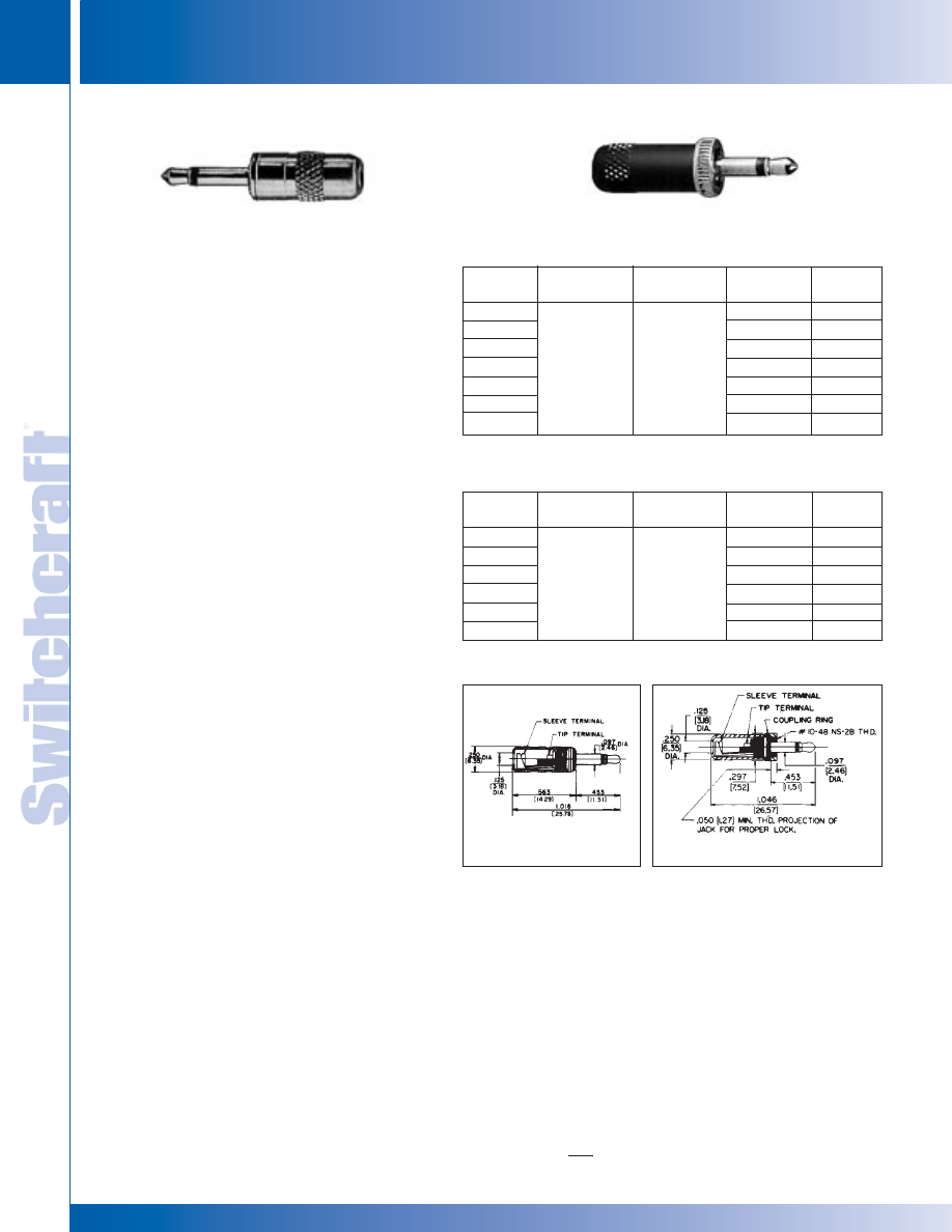
JACKS AND PLUGS
158
w w w . s w i t c h c r a f t . c o m
® Registered trademark of Switchcraft, Inc.
Note: Contact your Switchcraft Representative for price and delivery
PHONE: 773 792-2700
JACKS AND PLUGS
DIMENSIONS ARE FOR REFERENCE ONLY
Inch
(mm)
.097" SUBMINIATURE PHONE PLUGS
.097" SUBMINIATURE PHONE PLUGS
.097" SUBMINIATURE PHONE PLUGS
FEATURES
• Subminiature, 2-conductor phone plugs are 1/3 the size
of standard phone plugs, with the uniformity,
dependability, and quality construction of Switchcraft
Littel-Plug
®
and Tini Plug
®
phone plugs. 50 W soldering
with 60/40 solder recommended for terminating.
• Switchcraft’s 852, 853, 857, 858, 882 and 883 have a
wider insulator between the tip and the sleeve. The wide
insulator prevents the tip of the plug from shorting out
between the tip spring and the sleeve of the jack
during insertion.
Micro-Plug
®
PLUG - Sleeve terminal incorporates cable
clamp. May be clamped over mated braid to anchor
shielded cable; solders readily for perfect electrical
connection. Terminals and plug body interlocked
mechanically.
Accommodates cable up to .125"
Combined length, handle and tip: 1.106" outside diameter,
.250" outside diameter handle.
LOCK Micro-Plug
®
PLUG - Similar to Micro-Plug plug,
with addition of integral threaded collar that fastens to
bushing of mating jack to prevent accidental disconnect.
Requires at least .05" of exposed and usable thread on
jack bushing to lock securely. Ideal for secure connections
in critical medical and sensitive scientific instruments.
Combined length, handle and tip: 1.046". Various molded
cable assemblies incorporating Micro-Plug Subminiature
phone plugs with plastic handles are available.
SPECIFICATIONS
MATERIALS
Tip, Rod and Body (also integral Coupling Collar on
Lock Micro-Plug): Nickel-plated copper alloy.
Insulation: Molded thermoplastic.
Sleeve Termination and Cable Clamp:
Tinned copper alloy.
Handle: Anodized aluminum; red, black or natural finish.
MECHANICAL
Life rating: 5,000 insertion/withdrawals.
Insertion/Withdrawal Force: 1 pound (depending on
mating jack).
ELECTRICAL
Insulation Resistance: > 100 megohms
Dielectric Withstanding Voltage: 250V AC.
ENVIRONMENTAL
Thermal Range: -55°C to +85°C (non-operating);
-20°C to 65°C (operating).
Thermal Shock: Mil-Std 202, Method 107.
Humidity: Mil-Std 202, Method 106.
Salt Spray: Mil-Std 202, Method 101.
MICRO-PLUG
LOCK MICRO-PLUG
1. Switchcraft Part Numbers. Other mating plugs are available.
Numbers 850, 880
No. 850 (typical)
Number 851
Part
Mating Handle
Number
Terminals
Jacks
1
Handle
Part No.
850
Black
T18623
852
Black
T18623
855
Red
T18622
857
Solder Lug
TR2A
Red
T18622
880
Natural
T18621
882
Natural
T18621
2P1419
Less Handle
–
Part
Mating Handle
Number
Terminals
Jacks
1
Handle
Part No.
851
Black
T23123
853
Black
T23123
856
Red
T23122
858
Solder Lug
TR2A
Red
T23122
881
Natural
T23121
883
Natural
T23121
No. 851 (typical)
* Please visit the product pages on our website for the most up-to-date product information
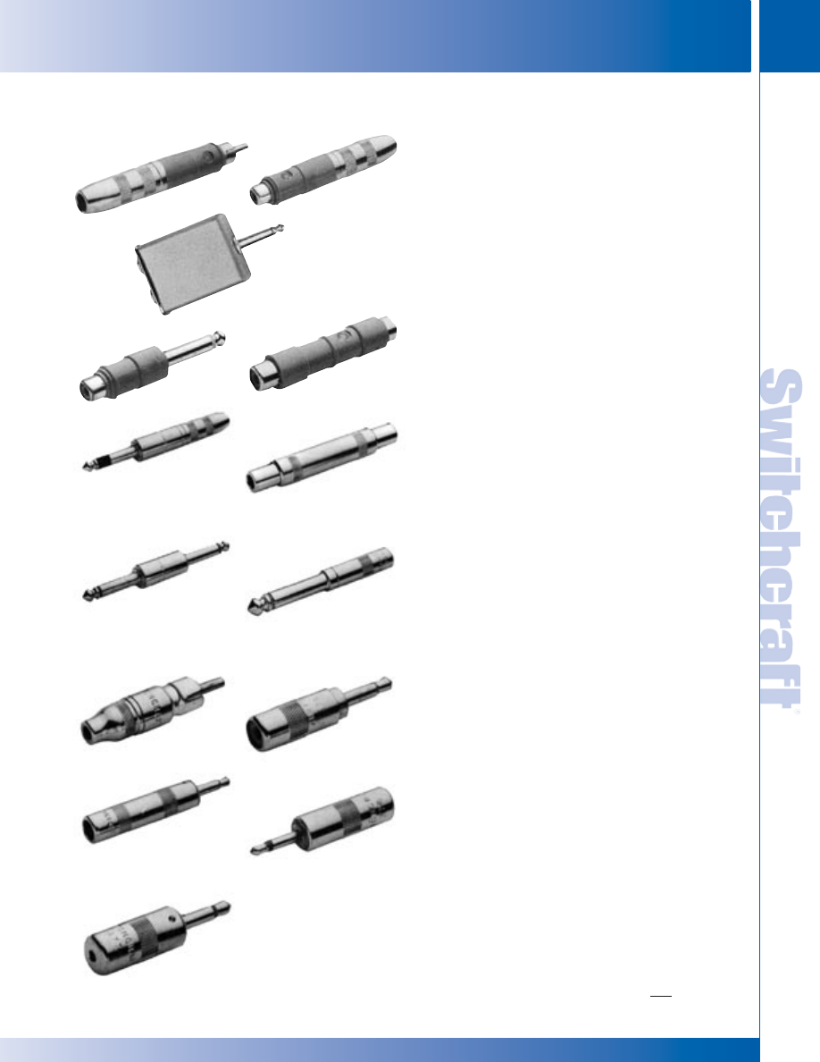
SWITCHCRAFT, INC. 5555 N. Elston Ave. • Chicago, IL 60630
159
JACKS AND PLUGS
FAX: 773 792-2129
JACKS AND
PLUGS
DIMENSIONS ARE FOR REFERENCE ONLY
Inch
(mm)
AUDIO ADAPTERS
AUDIO ADAPTERS
Part Number 332A (Not shown): 2-cond. phone jack input
to old MC1M-style microphone connector output. Coupling
ring can be screwed back to convert female microphone
connector to male type. Shielded.
Part Number 336A: 2-conductor phone jack input to a
phono plug output. Shielded.
Part Number 336B: 2-conductor phone jack input to phono
jack output. Shielded.
Part Number 340: Two 2-conductor phone jack inputs
connected in parallel to a 2-conductor phone plug output.
Shielded.
Part Number 345A: Phono plug input to a standard
2-conductor phone plug output. Shielded.
Part Number 349A: Phono plug coupler. Phono Extension
Jax
®
input to phono Extension Jax output. Shielded.
◊
Part Number 352A: Stereo to monaural adapter.
3-conductor phone jack input to 2-conductor phone plug
output. Extra-wide insulator prevents accidental damage
should wrong connection be made. Shielded.
Part Number 361A: Phone plug coupler. Standard 1/4"
inside diameter phone jack input to standard 1/4" inside
diameter phone jack output.
Ideal for connecting two
cables terminated with 2-conductor phone plugs. Shielded.
Part Number 362A (Not shown): Phone plug coupler.
Standard 3-cond. phone jack input to standard 3-cond.
phone jack output. Ideal for connecting two cables terminated
with 3-conductor phone jacks. Shielded.
Part Number 363: Phone jack coupler. Standard 1/4"
2-conductor phone plugs at each end to connect two
cables terminated with phone Extension Jax. Shielded.
Part Number 364A: EIA Standard 2-conductor Tini-Jax
®
phone jack input to a standard 1/4" 2-conductor phone
plug output. Shielded.
Part Number 365: EIA Standard 2-conductor Tini-Jax
®
phone jack input to a phono plug output. Shielded.
Part Number 370A: 2-conductor EIA Standard Tini-Plug
®
phone plug (.141" diameter finger) output to phono jack
input. Adapts standard phono plug to small Tini-Plug.
Shielded.
Part Number 374: 2-conductor phone jack input to a
2-conductor EIA Standard Tini-Plug (.141" diameter finger)
phone plug output. Adapts standard phone plug to small
Tini-Plug.
Part Number 376: EIA Standard Tini-Jax phone jack input
to a 2-conductor Micro-Plug (.097" diameter finger) phone
plug output. Adapts a Tini-Plug phone plug to a Micro-Plug
phone plug.
Part Number 377: Micro-Jax phone jack input to a
2-conductor EIA Standard Tini-Plug (.141" diameter
finger) phone plug output. Adapts a Micro-Plug phone plug
to a Tini-Plug phone plug.
◊
Special order only. Contact Switchcraft.
336A
336B
345A
349A
340
AUDIO ADAPTERS
352A
361A
363
364A
365
370A
376
377
374
* Please visit the product pages on our website for the most up-to-date product information
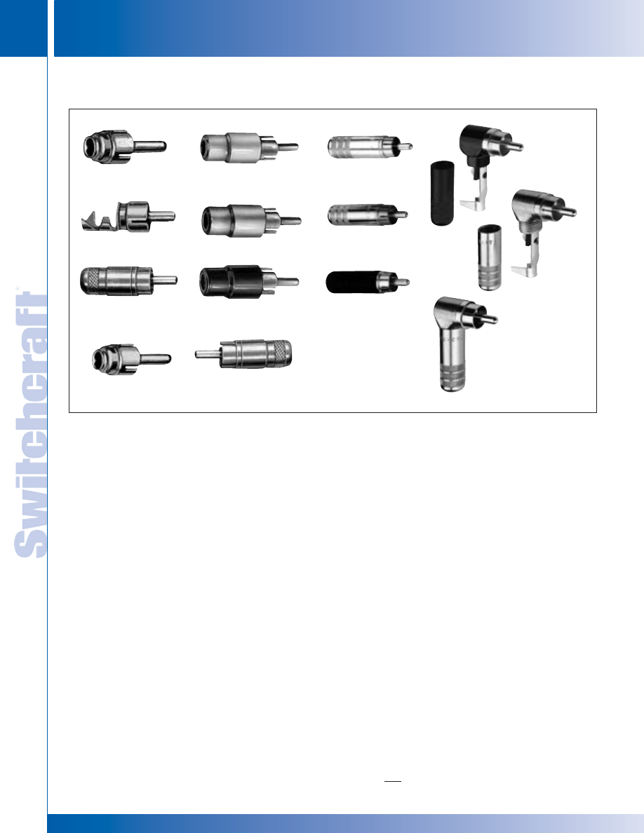
JACKS AND PLUGS
160
w w w . s w i t c h c r a f t . c o m
® Registered trademark of Switchcraft, Inc.
Note: Contact your Switchcraft Representative for price and delivery
PHONE: 773 792-2700
JACKS AND PLUGS
DIMENSIONS ARE FOR REFERENCE ONLY
Inch
(mm)
PHONO PLUGS
PHONO PLUGS
PHONO PLUGS
3502AAU
3502ABAU
3502A
FEATURES
• Wide variety of styles for a wide range of applications.
• 3502A and 3502RA Series offer solid pin, large solder cups.
• 3558 Series utilize plastic handles for low cost applications.
• 3507 and 3504M have low-loss nylon insulators for
RF applications. Can be used at 1 kW at 30 MHz.
• 3501M and 3501MC have the handle removed for tight spaces
• Options include nickel and gold plated, or black epoxy finishes.
SPECIFICATIONS
MATERIALS
Pin: Nickel or gold plated, copper alloy
Sleeve: Nickel or gold plated, copper alloy
Handle: Nickel or gold plated, or black epoxy finish, copper alloy
(3558 Series: Thermoplastic)
Cable Clamp: Tin, copper alloy
Insulator: Rigid Plastic
ELECTRICAL
Current Carry @ Working Voltage (typical *D.O.M.J.): 6A
Contact Resistance (typical *D.O.M.J.): < 0.20 Ohms
Dielectric Withstanding Voltage: 500 VAC min.
Insulation Resistance @ 500VDC: 2,000 megohms min
Working Voltage: 250VAC, 140VDC
MECHANICAL
Life: *D.M.O.J
Temperature Range: -40
∞
C to +85
∞
C
*D.M.O.J. –Dependent On Mating Jack
3501MC
3502
35581
35582
35585
3504M
3507
3502RA
3502RAAU
3502RABAU
3501M
* Please visit the product pages on our website for the most up-to-date product information
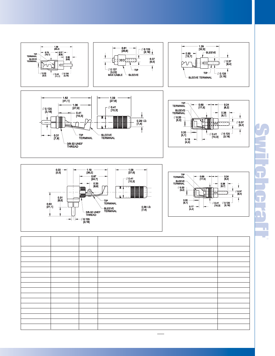
SWITCHCRAFT, INC. 5555 N. Elston Ave. • Chicago, IL 60630
161
JACKS AND PLUGS
FAX: 773 792-2129
DIMENSIONS ARE FOR REFERENCE ONLY
Inch
(mm)
PHONO PLUGS
PHONO PLUGS
PHONO PLUGS (continued)
Part
Description
Typical
Number
Pin
Handle
Notes
Mating Jack
3502A
Nickel
Nickel
BP Series
3502AAU
Gold
Nickel
BP Series
3502ABAU
Gold
Black
BP Series
3502RA
Nickel
Nickel
Right angle
BP Series
3502RABAU
Gold
Black
Right angle
BP Series
3502RAAU
Gold
Nickel
Right angle
BP Series
35581
Nickel
Plastic
Red handle
BP Series
35582
Nickel
Plastic
Black handle
BP Series
35585
Nickel
Plastic
White handle
BP Series
3502
Nickel
Nickel
BP Series
3501M
Nickel
BP Series
3501MC
Nickel
Same as 3501M except with cable clamp
BP Series
3504M
Nickel
Same as 3507 less cable clamp and handle
3505F
3507
Nickel
Nickel
For RF applications
3505F
330F1
Nickel
2 inline jacks to 1 male plug, 4" gray shielded cable
BP Series
330F2
Nickel
1 inline jack, 1 male plug to 1 male plug, 4" gray shielded cable
BP Series
3507
3502RA
3502A
3501M & 3504M
35581, 33582, 33585
3502
3501MC
JACKS AND
PLUGS
* Please visit the product pages on our website for the most up-to-date product information
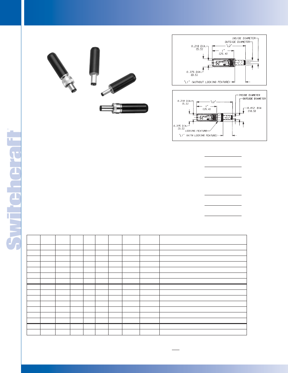
JACKS AND PLUGS
162
w w w . s w i t c h c r a f t . c o m
® Registered trademark of Switchcraft, Inc.
Note: Contact your Switchcraft Representative for price and delivery
PHONE: 773 792-2700
JACKS AND PLUGS
DIMENSIONS ARE FOR REFERENCE ONLY
Inch
(mm)
MINIATURE POWER PLUGS
MINIATURE POWER PLUGS
PART NUMBERING and MATING CHART (Power plugs/Power jacks)
Part
Number
760
765
760K
761K
765K
766K
◊
2P1515
S760
S765
S760K
S761K
S765K
S766K
2P1624
860
865
Inside
Diameter
.100"
.100"
.100"
.100"
.100"
.100"
.100"
.080"
.080"
.080"
.080"
.080"
.080"
.080"
.050"
.050"
Outside
Diameter
.218"
.218"
.218"
.218"
.218"
.218"
.218"
.218"
.218"
.218"
.218"
.218"
.218"
.218"
.150"
.150"
Length
“L1”
.375"
.375"
.375"
.475"
.375"
.475"
.375"
.375"
.375"
.375"
.475"
.375"
.475"
.375"
.375"
.375"
Length
“L2”
1.42
1.42
1.7
1.8
1.7
1.8
1.42
1.42
1.42
1.7
1.8
1.7
1.8
1.42
1.42
1.42
Locking
Feature
No
No
Yes
Yes
Yes
Yes
No
No
No
Yes
Yes
Yes
Yes
No
No
No
Tip
Insulator
Black
Black
Black
Black
Black
Black
Black
White
White
Black
Black
Black
Black
White
Black
Black
Handle
Color
Black
Red
Black
Black
Red
Red
No Handle
Black
Red
Black
Black
Red
Red
No Handle
Black
Red
Handle
Part Number
M1055
M1056
M1055
M1055
M1056
M1056
No Handle
M1055
M1056
M1055
M1055
M1056
M1056
No Handle
M1055
M1056
Switchcraft
®
Mating Jack
1
712A, RAPC712, RASH712, RASM712, PC712A, RA712A
712A, RAPC712, RASH712, RASM712, PC712A, RA712A
712A, PC712A
L712A, PCL712A
712A, PC712A
L712A, PCL712A
712A, PC712A
722A, RAPC722, RASH722, RASM722, PC722A, RA722A
722A, RAPC722, RASH722, RASM722, PC722A, RA722A
722A, PC722A
L722A, PCL722A
722A, PC722A
L722A, PCL722A
722A, PC722A
RAPC 732, RASH 732, RASM 732
RAPC 732, RASH 732, RASM 732
760K
S760K
760
860
MINIATURE POWER PLUGS
FEATURES AND BENEFITS
• 2-conductor power jacks.
• Hollow center pin available in 3 pin diameters and 2 finger lengths
(See chart below).
• Locking option available for added security in critical applications.
• Molded plastic handles available in black or red.
• Sleeve terminal serves as cord clamp.
SPECIFICATIONS
Plug Sleeve and Pin: Nickel-plated copper alloy.
Lockring: Nickel-plated copper alloy.
Lockring Thread Size: 5/16 - 32 UNEF 2B.
Finger Insulator: Molded plastic.
Insulating Washers: Rigid plastic.
Sleeve Terminal: Copper alloy, electro-tinned.
Handle: Molded plastic.
Handle Thread Size: 5/16 - 24 UNF 2B.
Electrical: Current (Carry): 5 amps.
ORDERING INFORMATION
1. Order by part number. 2. Contact Switchcraft for more information.
3.
◊
Indicates “special order” only.
1
See pages 130-134.
761K
INSIDE DIAMETER TOLERANCES (PLUGS)
.050" (.050 - .053)
860/865:
1.27mm (1.27 - 1.35)
.080" (.080 - .084)
S760/S765*:
2mm (2.03 - 2.13)
.100" (.099 - .103)
760/765*:
2.5mm (2.52 - 2.61)
OUTSIDE DIAMETER TOLERANCES (PLUGS)
.150" (.149 - .153)
860/865:
3.81mm (3.78 - 3.89)
.218" (.217 - .221)
S760/S765*:
5.5mm (5.51 - 5.61)
.218" (.217 - .221)
760/765*:
5.5mm (5.51 - 5.61)
*includes locking (k) versions
* Please visit the product pages on our website for the most up-to-date product information
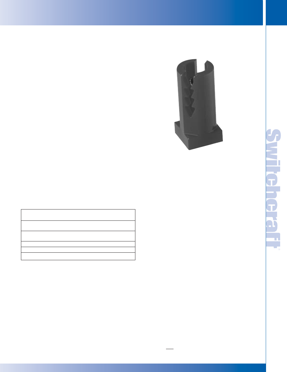
SWITCHCRAFT, INC. 5555 N. Elston Ave. • Chicago, IL 60630
163
JACK PANELS
FAX: 773 792-2129
JACK P
ANELS
DIMENSIONS ARE FOR REFERENCE ONLY
Inch
(mm)
PROFESSIONAL PUNCHDOWN TERMINAL
PROFESSIONAL PUNCHDOWN TERMINAL
PROFESSIONAL PUNCHDOWN TERMINAL (PPT)
Our Patchbays Now Feature the New Professional
Punchdown Terminal (PPT) Our Patchbays Have Just
Rounded A New Corner
Actually, the corners we rounded belong to our patchbays’
revolutionary, new Professional Punchdown Terminal (PPT),
making it perfectly compatible with the industry standard. We
realized that achieving a new industry standard meant we
couldn’t cut any corners to get there.
The PPT design incorporates a split-barrel design and a more
rugged, thicker housing to minimize the impact of repeated
punchdowns. The split-barrel design eliminates the problems
associated with the old “V-shaped” terminal designs. The PPT
design distributes pressure evenly across both sides of the
terminated wire, causing improved wire retention plus more
reliable connections. The serrated teeth in the plastic housing
firmly grip the wires, which also greatly improves wire
retention. With the PPT, multiple wires can be terminated to a
single contact, and a wide range of wire gauges can be used.
Look for Switchcraft’s PPT in our MTP and TTP Series of
audio patchbays, and in our new Backpanel Series.
All Switchcraft audio patchbays incorporate heavy gauge
materials and our high quality nickel-plated, steel framed
jacks. Gold-plated, crossbar contacts come standard!
MATERIALS
Housing: Thermoplastic (UL 94V-0)
Contacts: High strength copper alloy, tin plated
Wire size: Accommodates #22, 24, or 26 AWG,
stranded or solid
Accessories
Part Number
Description
K459
PPT replacement kit consists of
15 of each color* (IDC/IDC)
K460
PPT replacement kit consists of
15 of each color (IDC/wirewrap)
PT1LA
PPT impact punchdown tool
PT2B
Replacement bit for PT1LA tool
*Colors consist of red, black, white, yellow, blue, and orange.
* Please visit the product pages on our website for the most up-to-date product information
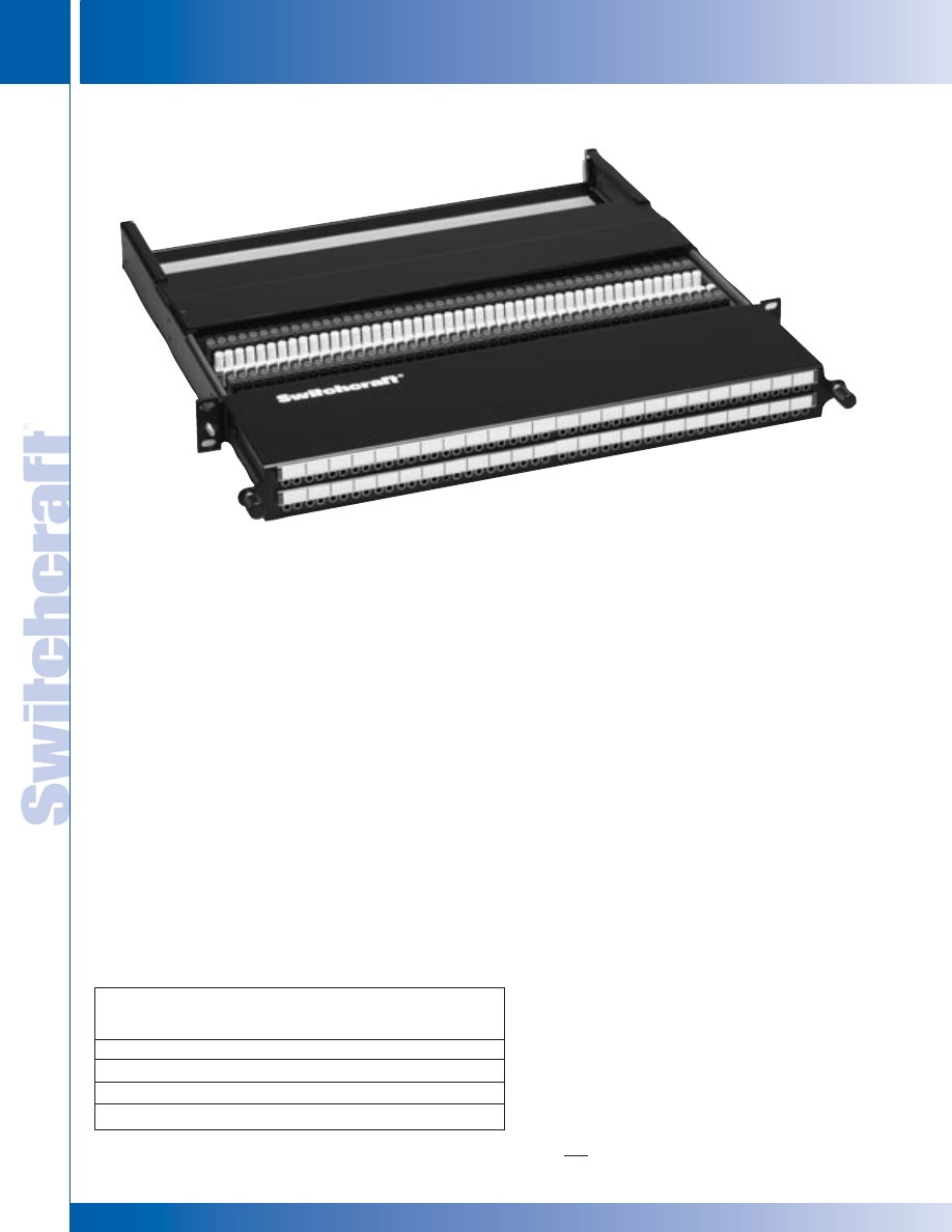
JACK PANELS
164
w w w . s w i t c h c r a f t . c o m
® Registered trademark of Switchcraft, Inc.
Note: Contact your Switchcraft Representative for price and delivery
PHONE: 773 792-2700
JACK P
ANELS
DIMENSIONS ARE FOR REFERENCE ONLY
Inch
(mm)
FRONT ACCESS MTPFA/TTPFA SERIES
FRONT ACCESS MTPFA/TTPFA SERIES
FRONT ACCESS MTPFA/TTPFA SERIES
The Front Access Series offers the end user the ease of
re-terminating patchpoints from the front of the rack as
opposed to the back. A slide out tray allows the user to slide
out the punchdown terminals, and reconfigure the unit. An
easy release mechanism on either side of the unit allows it to
be pushed back into place and easy to grip locking nuts tighten
the unit in place.
FEATURES AND BENEFITS
• Easy slide-out tray slides forward for
easy re-termination from the front of the rack
• Available with either 48 MT style or 96 TT style
jacks in a 1RU space
• Attractive, corrosion resistant nickel-plated,
steel frame jacks
• Gold-plated switching contacts reduce
contact resistance, improves reliability
• Extra wide designation strips for easy channel
identification
• Rugged, attractive black epoxy-finished
steel chassis
• Configurations available include normals
strapped and normals brought out
SPECIFICATIONS
MATERIALS (JACKS)
Frame: Nickel-plated steel
Bushing: Nickel-plated brass
Tip, Ring and Shunt Springs: Nickel silver with welded contacts
Assembly Screws: Nickel-plated steel
Welded Contacts: Gold alloy
PANEL
Frame: C.R.S. black epoxy painted
Designation Strips: Black polycarbonate 94V-0
Designation Strip Covers: Clear polycarbonate
Jack Inserts: Thermoplastic 94V-0
MECHANICAL
Life: 30,000 cycles
Insertion Force: 7 lbs. maximum
Withdrawal Force: 1 lb. minimum
Operating: -20°C to +65°C
ELECTRICAL
Jack Contact Resistance: 30 milliohms
initial maximum; 50 milliohms after life
Jack Insulation Resistance: 10,000 megohms maximum
Dielectric Withstanding Voltage: 500V at 60 Hz AC
Working Voltage: 100 milliamps or less; maximum 56.5 VDC
Ordering Information
Part
Type of No. of
Number
Jack
Jacks Description
TTPFA96K1NS
TT
96
1.75" High, normals strapped
TTPFA96K1NO
TT
96
1.75" High, normals brought out
MTPFA48K1NS MT
48
1.75" High, normals strapped
MTPFA48K1NO MT
48
1.75" High, normals brought out
TTPFA96K1NS
* Please visit the product pages on our website for the most up-to-date product information
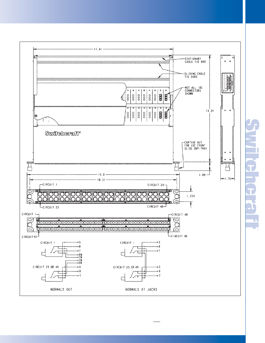
SWITCHCRAFT, INC. 5555 N. Elston Ave. • Chicago, IL 60630
165
JACK PANELS
FAX: 773 792-2129
JACK P
ANELS
DIMENSIONS ARE FOR REFERENCE ONLY
Inch
(mm)
FRONT ACCESS MTPFA/TTPFA SERIES
FRONT ACCESS MTPFA/TTPFA SERIES
FRONT ACCESS MTPFA/TTPFA SERIES (continued)
* Please visit the product pages on our website for the most up-to-date product information
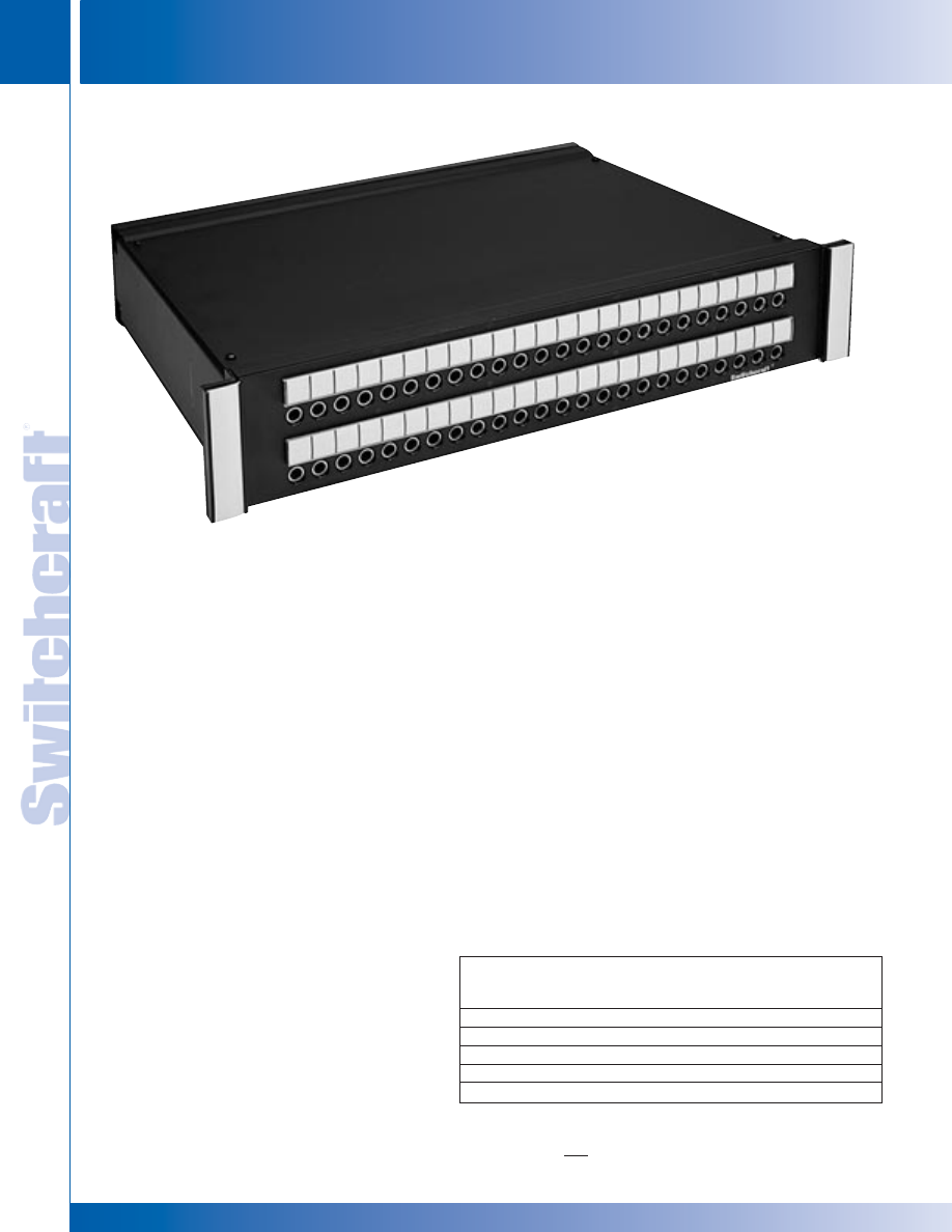
JACK PANELS
166
w w w . s w i t c h c r a f t . c o m
® Registered trademark of Switchcraft, Inc.
Note: Contact your Switchcraft Representative for price and delivery
PHONE: 773 792-2700
JACK P
ANELS
DIMENSIONS ARE FOR REFERENCE ONLY
Inch
(mm)
MTP48K WIRED AUDIO SERIES
MTP48K WIRED AUDIO SERIES
FEATURES AND BENEFITS
• Unit features 48 MT style jacks in either
1RU (1.75"H) or 2RU (3.5"H) spaces
• All versions utilize AES/EBU wiring for
complete digital compatibility
• Attractive, corrosion resistant nickel-plated,
steel frame jacks
• Gold-plated switching contacts reduce
contact resistance, improve reliability
• Rugged, attractive black epoxy-finished
steel chassis
• Extra wide designation strips for easy
channel identification
• 1RU version configurations include normals
strapped and normals brought out
• 2RU version configurations include normals
strapped, normals brought out, and sleeve
normals brought out
SPECIFICATIONS
MATERIALS
JACKS
Frame: Nickel-plated steel
Bushing: Nickel-plated brass
Tip, Ring and Shunt Springs: Nickel silver
with welded contacts
Assembly Screws: Zinc-plated steel
Welded Contacts: Gold alloy
PANEL
Front Channel: Black anodized aluminum
Frame: C.R.S. black epoxy painted
Designation Strips: Black polycarbonate 94V-0
Designation Strip Covers: Clear polycarbonate
Jack Inserts: Thermoplastic polyester
MECHANICAL
Life: 30,000 cycles
Insertion Force: 7 lbs. maximum
Withdrawal Force: 1 lb. minimum
Environmental: O°C to +50°C
ELECTRICAL
Contact Resistance: 30 milliohms maximum initial
Insulation Resistance: 10,000 megohms maximum
Dielectric Withstanding Voltage: 500 VAC at 60 Hz
Working Voltage: 140 VDC maximum
Current Rating: 100 milliamps
The MTP Series were developed with the AES/EBU digital
standard in mind. All versions are made with 110 Ohm cabling
inside as a standard. Available in a wide variety of configurations.
Ordering Information
Part
Type of No. of
Number
Jack
Jacks
Description
MTP48K1NS
MT
48
1.75" High, normals strapped
MTP48K3NS
MT
48
3.5" High, normals strapped
MTP48K1NO
MT
48
1.75" High, normals brought out
MTP48K3NO
MT
48
3.5" High, normals brought out
MTP48K3SNO
MT
48
3.5" High, sleeve normals out
MTP48K WIRED AUDIO SERIES
MTP48K3NO
* Please visit the product pages on our website for the most up-to-date product information
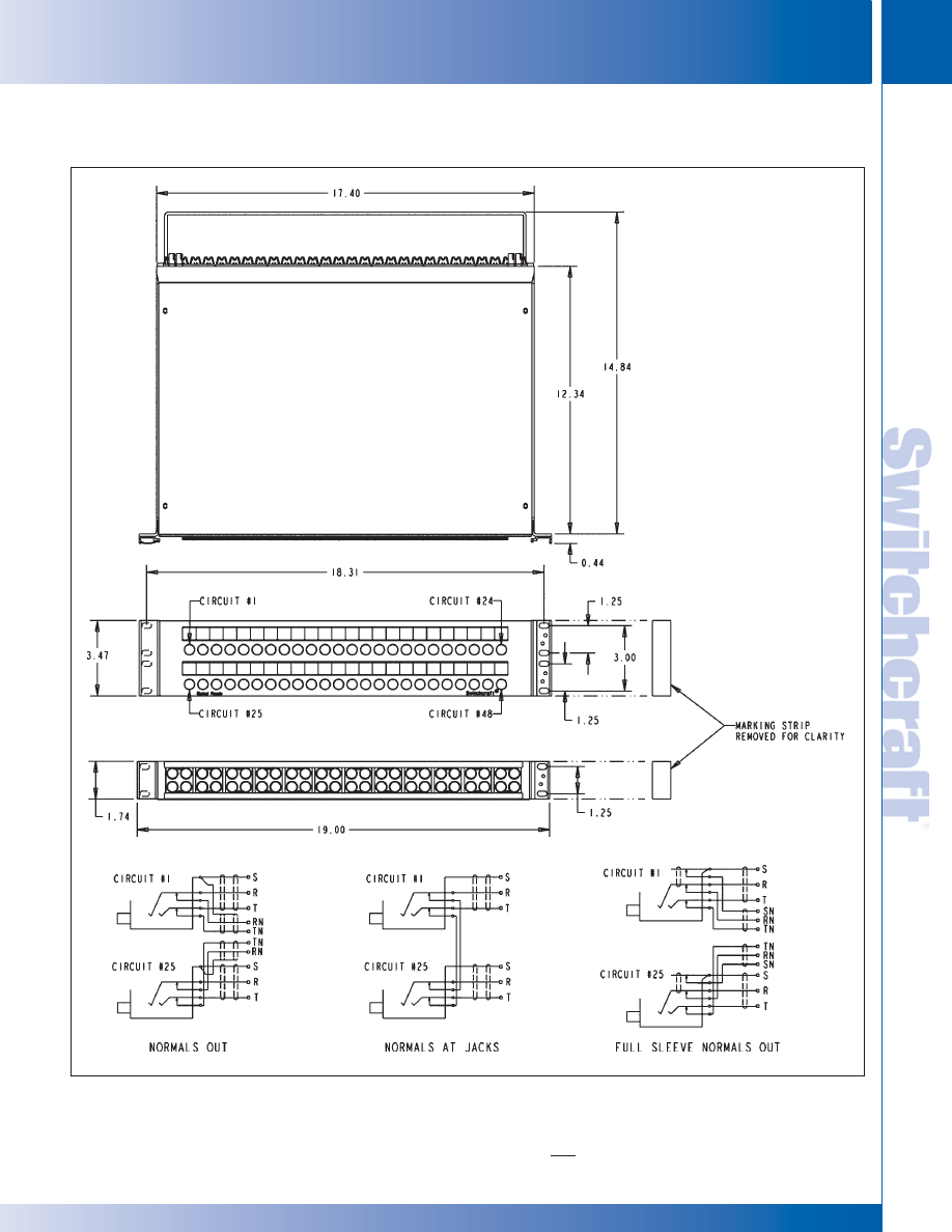
SWITCHCRAFT, INC. 5555 N. Elston Ave. • Chicago, IL 60630
167
JACK PANELS
FAX: 773 792-2129
JACK P
ANELS
DIMENSIONS ARE FOR REFERENCE ONLY
Inch
(mm)
MTP48K WIRED AUDIO SERIES
MTP48K WIRED AUDIO SERIES
MTP48K WIRED AUDIO SERIES (continued)
* Please visit the product pages on our website for the most up-to-date product information
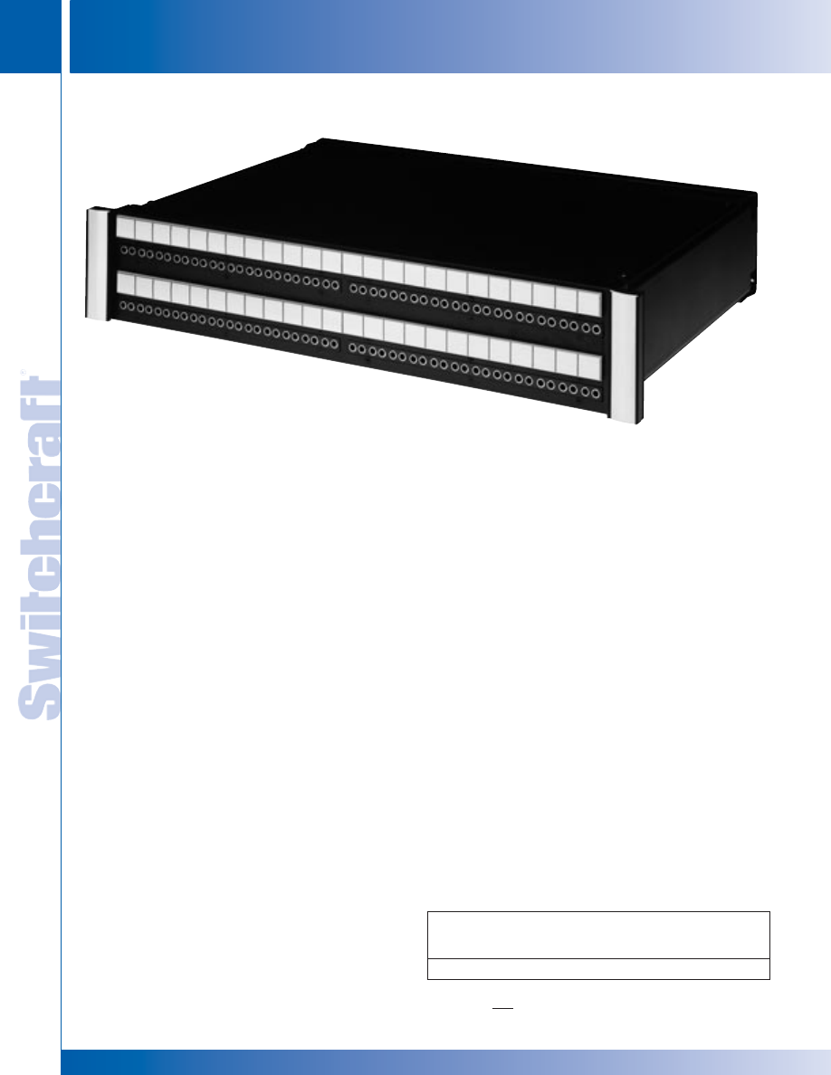
JACK PANELS
168
w w w . s w i t c h c r a f t . c o m
® Registered trademark of Switchcraft, Inc.
Note: Contact your Switchcraft Representative for price and delivery
PHONE: 773 792-2700
JACK P
ANELS
DIMENSIONS ARE FOR REFERENCE ONLY
Inch
(mm)
TTP96K WIRED AUDIO SERIES
FEATURES AND BENEFITS
• Unit features 96 TT style jacks in 2RU
(3.5"H) space
• Utilizes AES/EBU wiring for complete
digital compatibility
• Attractive, corrosion resistant nickel-plated,
steel frame jacks
• Gold-plated switching contacts reduce
contact resistance, improve reliability
• Rugged, attractive black epoxy-finished
steel chassis
• Extra wide designation strips for easy
channel identification
SPECIFICATIONS
MATERIALS
JACKS
Frame: Nickel-plated steel
Bushing: Nickel-plated brass
Tip, Ring and Shunt Springs: Nickel silver with
welded contacts
Assembly Screws: Zinc-plated steel
Welded Contacts: Gold alloy
PANEL
Front Channel: Black anodized aluminum
Frame: C.R.S. black epoxy painted
Designation Strips: Black polycarbonate 94V-0
Designation Strip Covers: Clear polycarbonate
Jack Inserts: Thermoplastic polyester
MECHANICAL
Life: 30,000 cycles
Insertion Force: 7 lbs. maximum
Withdrawal Force: 1 lb. minimum
Environmental: O°C to +50°C
ELECTRICAL
Contact Resistance: 30 milliohms maximum initial
Insulation Resistance: 10,000 megohms maximum
Dielectric Withstanding Voltage: 500 VAC at 60 Hz
Working Voltage: 140 VDC maximum
Current Rating: 100 milliamps
The TTP96K Series was developed with the AES/EBU
digital standard in mind. As a standard the TTP96K utilizes
110 Ohm cabling inside.
Ordering Information
Part
Type of No. of
Number
Jack
Jacks
Description
TTP96K3NS
TT
96
3.5" High, normals strapped
TTP96K WIRED AUDIO SERIES
TTP96K WIRED AUDIO SERIES
TT96K3NS
* Please visit the product pages on our website for the most up-to-date product information
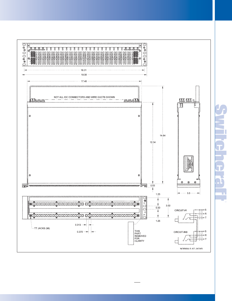
SWITCHCRAFT, INC. 5555 N. Elston Ave. • Chicago, IL 60630
169
JACK PANELS
FAX: 773 792-2129
JACK P
ANELS
DIMENSIONS ARE FOR REFERENCE ONLY
Inch
(mm)
TTP96K WIRED AUDIO SERIES (continued)
TTP96K WIRED AUDIO SERIES
TTP96K WIRED AUDIO SERIES
* Please visit the product pages on our website for the most up-to-date product information
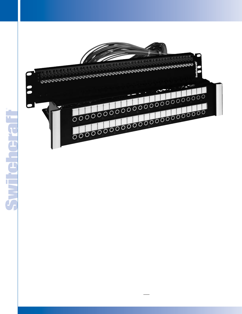
JACK PANELS
170
w w w . s w i t c h c r a f t . c o m
® Registered trademark of Switchcraft, Inc.
Note: Contact your Switchcraft Representative for price and delivery
PHONE: 773 792-2700
JACK P
ANELS
DIMENSIONS ARE FOR REFERENCE ONLY
Inch
(mm)
MTPH/TTPH HARNESS AUDIO SERIES
MTPH/TTPH HARNESS AUDIO SERIES
FEATURES AND BENEFITS
• Units feature either 48 MT style jacks or 96 TT style jacks on
the front panels, to a 4 foot harness, out to a backpanel with
PPT’s
• All versions utilize AES/EBU wiring for complete digital compati-
bility
• Attractive, corrosion resistant nickel-plated, steel frame jacks
• Gold-plated switching contacts reduce contact resistance,
improve reliability
• Rugged, attractive black epoxy-finished steel frame chassis
• Extra wide designation strips for easy channel identification
SPECIFICATIONS
MATERIALS
JACKS
Frame: Nickel-plated steel
Bushing: Nickel-plated brass
Tip, Ring and Shunt Springs: Nickel silver with
welded contacts
Assembly Screws: Zinc-plated steel
Welded Contacts: Gold alloy
PANEL
Front Channel: Black anodized aluminum
Frame: C.R.S. black epoxy painted
Designation Strips: Black polycarbonate 94V-0
Designation Strip Covers: Clear polycarbonate
Jack Inserts: Thermoplastic polyester
MECHANICAL
Life: 30,000 cycles
Insertion Force: 7 lbs. maximum
Withdrawal Force: 1 lb. minimum
Environmental: O°C to +50°C
ELECTRICAL
Contact Resistance: 30 milliohms maximum initial
Insulation Resistance: 10,000 megohms maximum
Dielectric Withstanding Voltage: 500 VAC at 60 Hz
Working Voltage: 140 VDC maximum
Current Rating: 100 milliamps
The MTPH and TTPH Harness Series utilize
standard front panel assemblies, a 4 foot cable
harness, and our standard back panel assemblies.
Available in a wide variety of configurations, all
are terminated to our PPT’s on the back panel.
Primarily used where the back panels must either
be mounted into a rack, or brought back to the
front for easier access. Custom cable lengths can
also be supplied. Contact the factory for details.
MTPH/TTPH HARNESS AUDIO SERIES
MTPH48K3NO
* Please visit the product pages on our website for the most up-to-date product information
SWITCHCRAFT, INC. 5555 N. Elston Ave. • Chicago, IL 60630
171
JACK PANELS
FAX: 773 792-2129
JACK P
ANELS
DIMENSIONS ARE FOR REFERENCE ONLY
Inch
(mm)
MTPH/TTPH HARNESS AUDIO SERIES (continued)
MTPH/TTPH HARNESS AUDIO SERIES
MTPH/TTPH HARNESS AUDIO SERIES
Ordering Information
Part Number
Type of Jack
No. of Jacks
Description
MTPH48K1NS
MT
48
1.75" High front panel, 4' Harness,
3.5" High back panel, normals strapped
MTPH48K1NO
MT
48
1.75" High front panel, 4' Harness,
3.5" High back panel, normals brought out
MTPH48K3NS
MT
48
3.5" High front panel, 4' Harness,
3.5" High back panel, normals strapped
MTPH48K3NO
MT
48
3.5" High front panel, 4' Harness,
3.5" High back panel, normals brought out
MTPH48K3SNO
MT
48
3.5" High front panel, 4' Harness,
3.5" High back panel, sleeve normals brought out
TTPH96K1NS
TT
96
1.75" High front panel, 4' Harness,
3.5" High back panel, normals strapped
TTPH96K1NO
TT
96
1.75" High front panel, 4' Harness,
5.25" High back panel, normals brought out
TTPH96K3NS
TT
96
3.5" High front panel, 4' Harness,
3.5" High back panel, normals strapped
TTPH96K3NO
TT
96
3.5" High front panel, 4' Harness,
5.25" High back panel, normals brought out
See Page 172 for Mechanical Drawings
* Please visit the product pages on our website for the most up-to-date product information
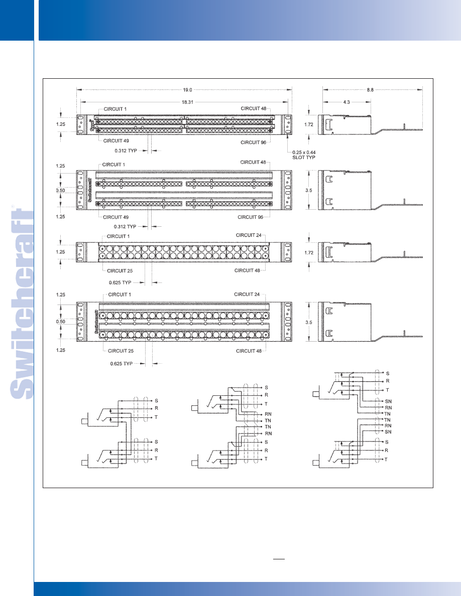
JACK PANELS
172
w w w . s w i t c h c r a f t . c o m
® Registered trademark of Switchcraft, Inc.
Note: Contact your Switchcraft Representative for price and delivery
PHONE: 773 792-2700
JACK P
ANELS
DIMENSIONS ARE FOR REFERENCE ONLY
Inch
(mm)
MTPH/TTPH HARNESS AUDIO SERIES (continued)
MTPH/TTPH HARNESS AUDIO SERIES
MTPH/TTPH HARNESS AUDIO SERIES
TTPH96K1 SERIES
FRONT VIEW
TTPH96K3 SERIES
FRONT VIEW
MTPH48K1 SERIES
FRONT VIEW
MTPH48K3 SERIES
FRONT VIEW
TOP ROW
TOP ROW
TOP ROW
BOTTOM ROW
NORMALS AT JACKS
NORMALS OUT
FULL SLEEVE NORMALS OUT
BOTTOM ROW
BOTTOM ROW
* Please visit the product pages on our website for the most up-to-date product information
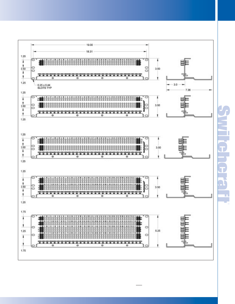
SWITCHCRAFT, INC. 5555 N. Elston Ave. • Chicago, IL 60630
173
JACK PANELS
FAX: 773 792-2129
JACK P
ANELS
DIMENSIONS ARE FOR REFERENCE ONLY
Inch
(mm)
MTPH/TTPH HARNESS AUDIO SERIES (continued)
MTPH/TTPH HARNESS AUDIO SERIES
MTPH/TTPH HARNESS AUDIO SERIES
MTPH48K1NS & MTPH48K3NS
REAR VIEW
MTPH48K1NO & MTPHK3NO
REAR VIEW
MTPH48K1SNO & MTPH48K3SNO
REAR VIEW
TTPH96K1NS & TTPH96K3NS SERIES
REAR VIEW
TTPH96K1NO & TTPH96K3NO SERIES
REAR VIEW
* Please visit the product pages on our website for the most up-to-date product information
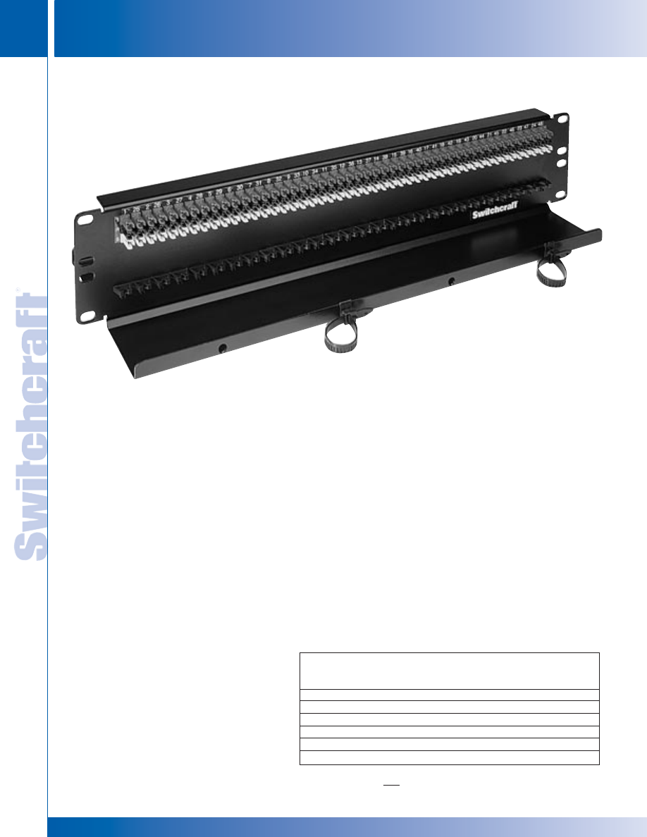
JACK PANELS
174
w w w . s w i t c h c r a f t . c o m
® Registered trademark of Switchcraft, Inc.
Note: Contact your Switchcraft Representative for price and delivery
PHONE: 773 792-2700
JACK P
ANELS
DIMENSIONS ARE FOR REFERENCE ONLY
Inch
(mm)
FEATURES AND BENEFITS
• Allows for custom patchbay configurations
or central patching points
• PPTs have IDCs on both sides for easy
installation
• Rugged, attractive black epoxy-finished
steel chassis
• Cable trays allow for mounting and
securing terminated cable
SPECIFICATIONS
Panel thickness: .093"
Mounting hole diameter: .187"
Mounting hole spacing (48 IDCs/row):
.340" (Horizontal) x .275" (Vertical)
Mounting hole spacing (52 IDCs/row):
.320" (Horizontal) x .275" (Vertical)
Wire size: #22, 24, 26 AWG Stranded
or Solid (IDC termination)
MATERIALS
Housing: Thermoplastic (UL 94V-0)
Contacts: High strength copper alloy
Backpanels: Black Epoxy coated C.R.S.
Cable Tray: Black Epoxy coated C.R.S.
The Backpanel Series offers the end user the flexibility of configuring
their own patchbay, or to use as a central patchpoint location.
The backpanels utilize the PPT punchdown and come with
a rugged cable tray.
Ordering Information
Part
Sets of
Number
PPT Terminals
Height
Description
MTP48K3BPNS
48
3.5"
T, R, S
MTP48K3PBNO
48
3.5"
T, R, S, TN, RN
MTP52K3BPNO
52
3.5"
T, R, S, TN, RN
MTP24K7
24 x 2
7.0"
+, -, S
TTP96K3BPNS
96
3.5"
T, R, S
TTP96K5BPNS
96 x 2
5.25"
T, R, S, TN, RN
MTPBP/TTPBP BACKPANEL SERIES
MTPBP/TTPBP BACKPANEL SERIES
MTPBP/TTPBP BACKPANEL SERIES
MTPH48K3BPNS
* Please visit the product pages on our website for the most up-to-date product information

SWITCHCRAFT, INC. 5555 N. Elston Ave. • Chicago, IL 60630
175
JACK PANELS
FAX: 773 792-2129
JACK P
ANELS
DIMENSIONS ARE FOR REFERENCE ONLY
Inch
(mm)
MTPBP/TTPBP BACKPANEL SERIES
MTPBP/TTPBP BACKPANEL SERIES (continued)
MTPBP/TTPBP BACKPANEL SERIES
FIGURE A
(MTP48K3BPNN SHOWN)
FIGURE B
(TTP96K5BPNO SHOWN)
NOT ALL IDC CONNECTORS SHOWN
NOT ALL IDC CONNECTORS SHOWN
* Please visit the product pages on our website for the most up-to-date product information
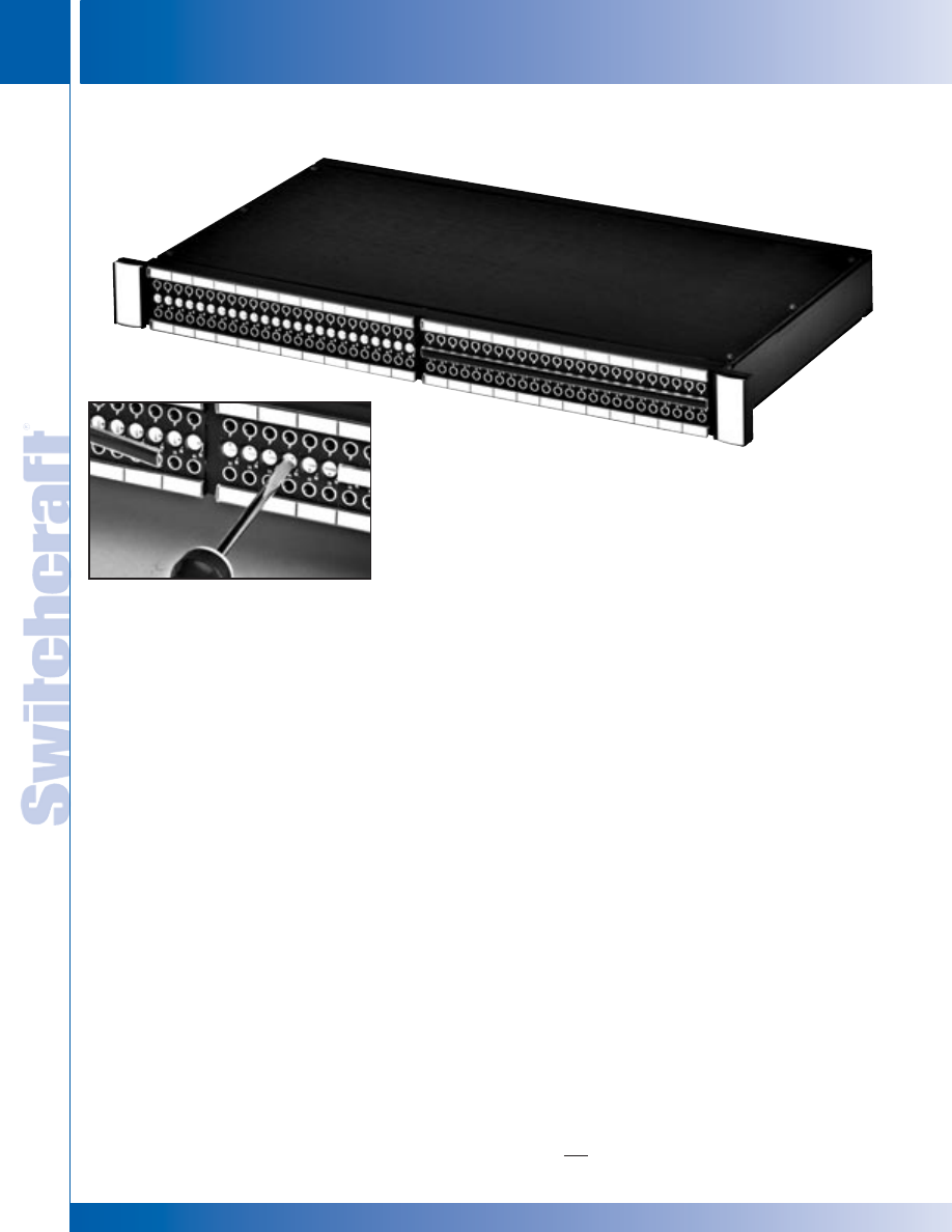
JACK PANELS
176
w w w . s w i t c h c r a f t . c o m
® Registered trademark of Switchcraft, Inc.
Note: Contact your Switchcraft Representative for price and delivery
PHONE: 773 792-2700
JACK P
ANELS
DIMENSIONS ARE FOR REFERENCE ONLY
Inch
(mm)
EZ NORM PATCHBAY SERIES
EZ NORM PATCHBAY SERIES
The EZ Norm offers a simplified method for setting up and
changing normals to a Bantam/TT patchbay. Simply remove
the middle designation strip, and rotate the center cam, using
a standard screwdriver. An audible”click” can be heard as
you rotate from full normals to no normals to half normals.
An opaque marking strip is included to conceal the normal
position, if needed.
EZ NORM JACK SPECIFICATIONS
MATERIALS:
Housing & Cover: 94V-0 rated thermoplastic
Sleeve Collar: Nickel plated copper alloy
Tip, Ring, Shunt, & Sleeve Springs: Nickel Silver with
welded contacts
Welded Contacts: Gold
Cam Switching Springs: Silver plated copper alloy
Cam Switching Contacts: Silver plated copper alloy
MECHANICAL
Jack Mechanical Life: 30,000 cycles
Cam Contact Mechanical Life: 30,000 cycles
Insertion - Withdrawal Forces: 1 - 4 lbs.
Moisture resistance: MIL-STD 202 Method 106
Thermal shock: MIL-STD 202 Method 107
Salt spray: MIL-STD Method 101 (48 hrs.)
Vibration: MIL-STD 202 Method 213
ELECTRICAL:
Jack Spring Contact Resistance: 30 milliohm Maximum
Cam Switch Contact Resistance: 30 milliohm Maximum
Insulation Resistance: 10,000 Megaohms
Dielectric Withstanding Voltage:
500 VAC (rms) at 60 Hz
Insertion Loss: -0.5dB up to 10 MHz
EZ NORM PATCHBAY OPTIONS
• 1RU can be terminated to EDAC or Cannon DL,
solder terminals, or wire-wrap terminals
• 1.5RU can be terminated to EDAC/Cannon DL, solder
terminals, wire-wrap terminals, plus 3 pin connectors,
or our own PPT Professional Punchdown Terminal
• 2RU Same as above
• All units will be offered with or w/o docking connector
• Unwired units will be offered with either cable tie bar
or cable tray
EZ NORM PATCHBAY SERIES
Center Strip Removes For
Normalling Access
Easily Normal The
Jacks By Rotating To
“Full”, “Non”, Or “Half”
Positions
* Please visit the product pages on our website for the most up-to-date product information
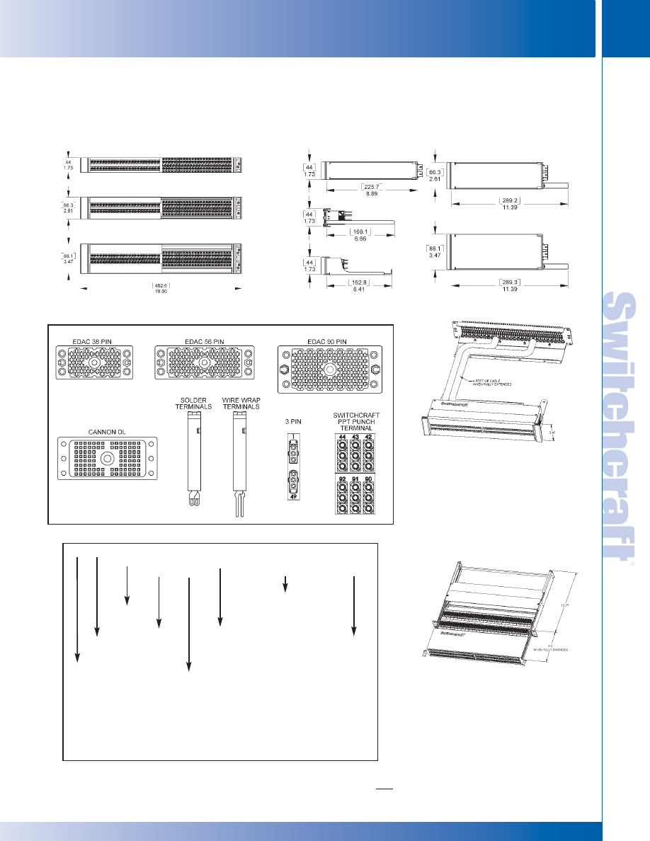
SWITCHCRAFT, INC. 5555 N. Elston Ave. • Chicago, IL 60630
177
JACK PANELS
FAX: 773 792-2129
JACK P
ANELS
DIMENSIONS ARE FOR REFERENCE ONLY
Inch
(mm)
EZ NORM PATCHBAY SERIES
EZ NORM PATCHBAY SERIES
EZ NORM PATCHBAY SERIES (continued)
TT
TT SIZE J
A
CKS
EZN
EZ-NORM CAM J
A
CKS
_ REGULAR
UNIT
H
HARNESS UNIT (UMBILICAL)
10
1 RA
CK UNIT HEIGHT
15
1.5 RA
CK UNIT HEIGHT
20
2 RA
CK UNIT HEIGHT
_
UNWIRED
P PRE
WIRED
_ NO
DOCKING
D DOCKING
CONNECT
OR
E90
ED
A
C/ELCO 90 PIN CONNECT
OR
E56
ED
A
C/ELCO 56 PIN CONNECT
OR
E38
ED
A
C/ELCO 38 PIN CONNECT
OR
IDC IDC
PPT
TERMINALS
3PIN
3 PIN CONNECT
ORS
WW
WIRE WRAP
PINS
SL SOLDER
LUGS
CDL
CANNON DL 96 PIN CONNECT
ORS
FA
FR
ONT A
CCESS
WITH PPT
_
NO REAR SUPPOR
T
T CABLE
TRA
Y
B CABLE
BAR
}
}
}
}
}
}
UNWIRED ONL
Y
Harness Assembly
Front Access
Racks
The EZ Norm comes in 3 different rack heights, 1RU, 1.5RU, and 2 RU.
The Front Access option offers a
slide-out tray, allowing the end
user to re-terminate the patchbay
from the front of the rack.
The EZ Norm is also offered as a
harness assembly, with a standard
harness of 4 ft. Custom lengths are
available, call Switchcraft
®
for details.
TT
EZN
_
10
_
_
E90 IDC
SL
_
H
15
P
D
E56
3PIN
CDL
T
20
E38
WW
FA
B
* Please visit the product pages on our website for the most up-to-date product information
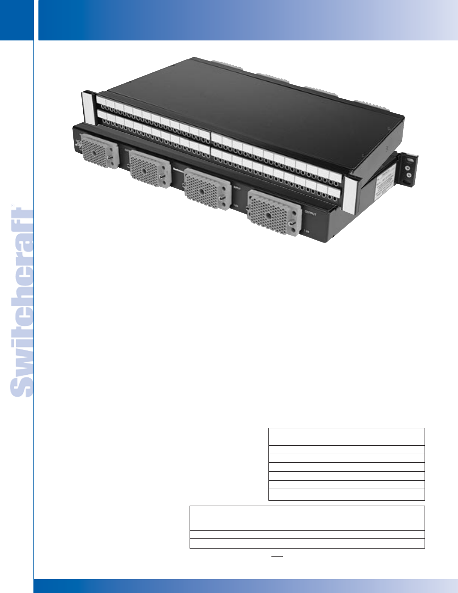
JACK PANELS
178
w w w . s w i t c h c r a f t . c o m
® Registered trademark of Switchcraft, Inc.
Note: Contact your Switchcraft Representative for price and delivery
PHONE: 773 792-2700
JACK P
ANELS
DIMENSIONS ARE FOR REFERENCE ONLY
Inch
(mm)
TT96 EDAC SERIES
TT96 EDAC SERIES
FEATURES AND BENEFITS
• Attractive, corrosion-resistant, nickel-plated jacks
• Steel frame jacks for superior jack life
• Extra wide labeling strips provide maximum space
and two vertical strips, one at each side
• Rugged, attractive black anodized
aluminum face will not break
• Two configurations available:
- Normals brought out
- Normalled at jacks
• Gold switching contacts for long-term reliability
• Jacks paired for easy identification of left and
right channels
• Connectorized by EDAC
®
connectors for ease of
termination by customer
SPECIFICATIONS
MATERIALS
JACKS
Frame: Nickel-plated steel
Bushing: Nickel-plated brass
Tip, Ring and Shunt Springs:
Nickel silver with welded contacts
Assembly Screws: Zinc-plated steel
Welded Contacts: Gold alloy
PANEL
Front Channel: Black anodized aluminum
Frame & Cover: C.R.S. black epoxy painted
Designation Strips: Black
polycarbonate 94V-0
Designation Strip Covers: Clear
polycarbonate
Jack Inserts: Polyester
EDAC CONNECTOR
Housing: Thermoplastic, UL94V-0
Contacts: Gold plated phosphor bronze
MECHANICAL
Life: 30,000 cycles
Insertion Force: 7 lbs. maximum
Withdrawal Force: 1 lb. minimum
Operating: -20°C to +65°C
ELECTRICAL
Contact Resistance: 30 milliohms maximum initial
Insulation Resistance:10,000 megohms
Dielectric Withstanding Voltage: 500VAC at 60 Hz
Working Voltage: 140VDC
Current Rating: 100 milliamps
The TT96EDAC Series offers the convenience of EDAC
®
connectors on
the back of the panel for easy installation. Available in normals strapped
and normals brought out, both wired to the SAC code of wiring. We also
offer custom wiring configurations. Contact the factory for details.
EDAC Mating Plugs
Part Number
Description
516-090-000-301
90 Pin male w/screw
516-090-000-302
90 Pin male w/nut
516-120-000-101
120 Pin male w/screw
516-120-000-102
120 Pin male w/nut
516-290-500
Terminal solder-style
516-290-590
Terminal crimp-style
Ordering Information
Part
Type of
No. of
Number
Jack
Jacks
Description
TT96EDACNO
TT
96
Normals Brought Out (120 pin EDAC)
TT96EDACNS
TT
96
Normals Strapped (90 pin EDAC)
TT96EDACNS
TT96 EDAC SERIES
* Please visit the product pages on our website for the most up-to-date product information
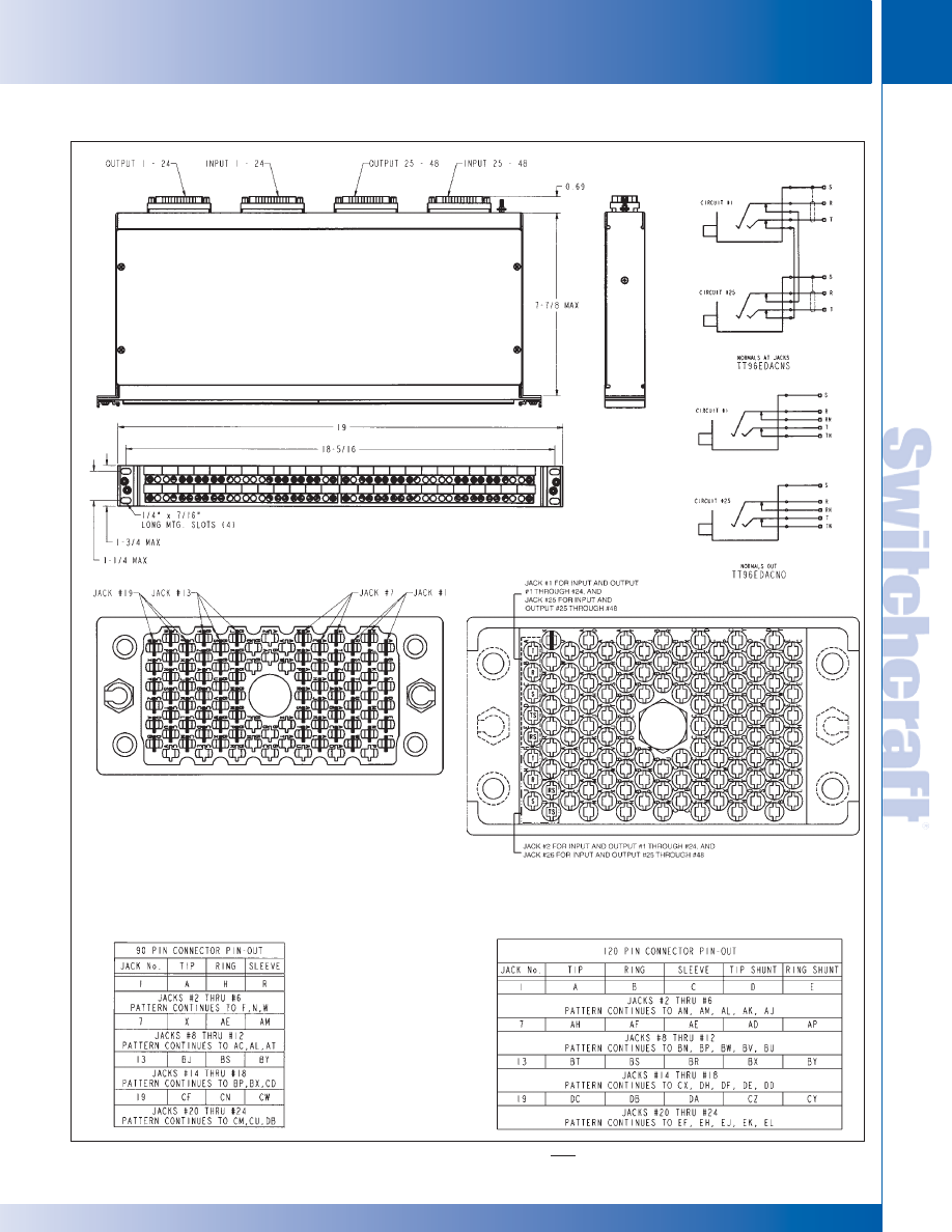
SWITCHCRAFT, INC. 5555 N. Elston Ave. • Chicago, IL 60630
179
JACK PANELS
FAX: 773 792-2129
JACK P
ANELS
DIMENSIONS ARE FOR REFERENCE ONLY
Inch
(mm)
TT96 EDAC SERIES (continued)
TT96 EDAC SERIES
TT96 EDAC SERIES
Standard Audio Configuration Wiring (S.A.C.)
90 Pin Plug Connector
(Normals at jacks)
Standard Audio Configuration Wiring (S.A.C.)
120 Pin Plug Connector
(Normals brought out)
* Please visit the product pages on our website for the most up-to-date product information
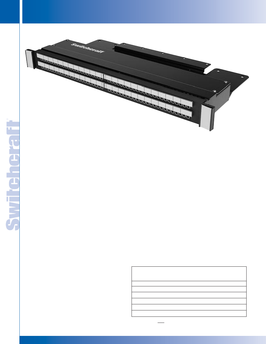
JACK PANELS
180
w w w . s w i t c h c r a f t . c o m
® Registered trademark of Switchcraft, Inc.
Note: Contact your Switchcraft Representative for price and delivery
PHONE: 773 792-2700
JACK P
ANELS
DIMENSIONS ARE FOR REFERENCE ONLY
Inch
(mm)
TT96K PATCHKIT SERIES
TT96K PATCHKIT SERIES
TTP96K PATCHKIT SERIES
FEATURES AND BENEFITS
• Kit features 96 TT jacks in one rack space
(1.75" high) or two rack spaces (3.5" high)
• Jack blocks can be removed from the front
for easy soldering
• Dust tray limits dirt, dust and contamination
of jack terminals
• Wire management straps are adjustable and reusable
• Attractive, corrosion resistant nickel-plated jacks
• Steel frame jack for superior jack life
• Extra wide labeling strips provide maximum space
• Rugged, attractive black anodized aluminum
face will not break or rust
• Three jack configurations available for the exact
switching arrangement you need: full normal,
half normal, and non-normal (open circuit)
• Fanned solder terminals for easier solder
connections
• Gold switching contacts for long-term reliability
in normal-through connections
SPECIFICATIONS
MATERIALS
JACKS
Frame: Nickel-plated steel
Bushing: Nickel-plated brass
Tip, Ring and Shunt Springs: Nickel silver
with welded contacts
Assembly Screws: Nickel-plated steel
Welded Contacts: Gold alloy
PANEL
Front Channel: Black anodized aluminum
Frame: C.R.S. black epoxy painted
Designation Strips: Black polycarbonate 94V-0
Designation Strip Covers: Clear polycarbonate
Jack Inserts: Thermoplastic polyester
MECHANICAL
Life: 30,000 cycles
Insertion Force: 7 lbs. maximum
Withdrawal Force: 1 lb. minimum
Environmental: 0°C to +50°C
ELECTRICAL
Contact Resistance: 30 milliohms maximum initial
Insulation Resistance: 10,000 megohms maximum
Dielectric Withstanding Voltage: 500VAC at 60 Hz
Working Voltage: 140VDC maximum
Current Rating: 100 milliamps
Ordering Information
Part
Type of
No. of
Number
Jack
Jacks
Description
TTP96K1FN
TT
96
1.75" High, full normals
TTP96K1HN
TT
96
1.75" High, half normal
TTP96K1NN
TT
96
1.75" High, no normals
TTP96K3FN
TT
96
3.5" High, full normals
TTP96K3HN
TT
96
3.5" High, half normals
TTP96K3NN
TT
96
3.5" High, no normals
The TTP96K Patchkit Series offers the end user a rugged cable tray
to support rear cabling. Heavy duty construction takes weight off the
back of the jacks for increased reliability. Available in 1.75" or 3.5"
height versions.
TTP96K1FN
* Please visit the product pages on our website for the most up-to-date product information
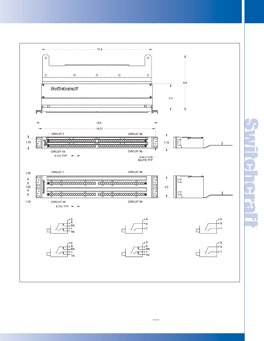
SWITCHCRAFT, INC. 5555 N. Elston Ave. • Chicago, IL 60630
181
JACK PANELS
FAX: 773 792-2129
JACK P
ANELS
DIMENSIONS ARE FOR REFERENCE ONLY
Inch
(mm)
TT96K PATCHKIT SERIES
TT96K PATCHKIT SERIES
TTP96K PATCHKIT SERIES (continued)
TTP96K1 SERIES
TTP96K3 SERIES
TOP ROW
BOTTOM ROW
TTP96K1FN
TTP96K3FN
TTP96K1HN
TTP96K3HN
TTP96K1NN
TTP96K3NN
BOTTOM ROW
BOTTOM ROW
TOP ROW
TOP ROW
* Please visit the product pages on our website for the most up-to-date product information
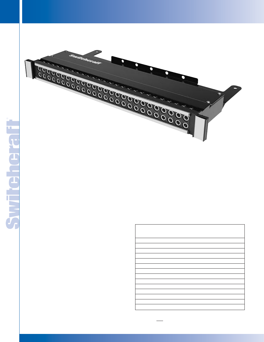
JACK PANELS
182
w w w . s w i t c h c r a f t . c o m
® Registered trademark of Switchcraft, Inc.
Note: Contact your Switchcraft Representative for price and delivery
PHONE: 773 792-2700
JACK P
ANELS
DIMENSIONS ARE FOR REFERENCE ONLY
Inch
(mm)
MT48K/MT52K PATCHKIT SERIES
MT48K/MT52K PATCHKIT SERIES
MT48K/MT52K PATCHKIT SERIES
FEATURES AND BENEFITS
• Kit features 48 1/4" longframe jacks in one rack
space (1.75" high) or in two rack spaces (3.5" high) or
52 1/4" longframe jacks in one rack space (1.75" high)
• Allows user to add cable and termination panel
• Removable jack panel from the front allows
easy soldering of wire connections
• Jacks have gold switching contacts
• Fanned solder terminals for easier soldering
• Offset ground lugs allow easy bussing of
ground with one wire
• Jacks have a nickel-plated frame and
assembly screws
• Wire management straps are reusable and adjustable
SPECIFICATIONS
MATERIALS
JACKS
Frame: Stamped nickel-plated steel
Bushing: Nickel-plated brass
Tip, Ring and Shunt Springs:
Nickel silver with welded contacts
Assembly Screws: Nickel-plated steel
Welded Contacts: Gold alloy
PANEL
Front Panel: Thermoplastic
Frame: C.R.S. black epoxy paint
Designation Strips: Black
polycarbonate 94V-0
Designation Strip Covers:
Clear polycarbonate
MECHANICAL
Life: 30,000 cycles
Insertion Force: 7 lbs. maximum
Withdrawal Force: 1 lb. minimum
Operating: 0°C to +50°C
ELECTRICAL
Contact Resistance: 30 milliohms maximum initial
Insulation Resistance: 10,000 megohms maximum
Dielectric Withstanding Voltage: 500VAC at 60 Hz
Working Voltage: 140VDC maximum
Current Rating: 100 milliamps
The MT48/52K Patchkit Series offers the end user a rugged
cable tray to support rear cabling. Heavy duty construction
takes weight off the back of the jacks for increased reliability.
Available in 1.75" or 3.5" height versions.
Ordering Information
Part
Type of No. of
Number
Jack
Jacks
Height
Description
MT48K1NS
MT
48 1.75"
Normals
strapped
MT48K1FN
MT
48 1.75"
Full
normals
MT48K1HN
MT
48
1.75"
Half normals
MT48K1NN
MT
48
1.75"
No normals
MT52K1NS
MT
52 1.75"
Normals
strapped
MT52K1FN
MT
52
1.75"
Full normals
MT52K1HN
MT
52
1.75"
Half normals
MT52K1NN
MT
52
1.75"
No normals
MT48K3FN
MT
48
3.5"
Full normals
MT48K3HN
MT
48
3.5"
Half normals
MT48K3NN
MT
48
3.5"
No normals
MT52K3FN
MT
52
3.5"
Full normals
MT52K3HN
MT
52
3.5"
Half normals
MT52K3NN
MT
52
3.5"
No normals
MT52K1FN
* Please visit the product pages on our website for the most up-to-date product information
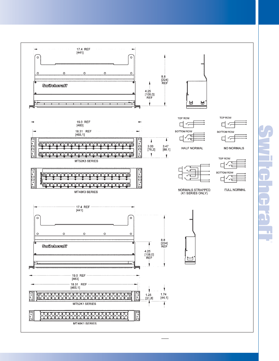
SWITCHCRAFT, INC. 5555 N. Elston Ave. • Chicago, IL 60630
183
JACK PANELS
FAX: 773 792-2129
JACK P
ANELS
DIMENSIONS ARE FOR REFERENCE ONLY
Inch
(mm)
MT48K/MT52K PATCHKIT SERIES (continued)
MT48K/MT52K PATCHKIT SERIES
MT48K/MT52K PATCHKIT SERIES
* Please visit the product pages on our website for the most up-to-date product information
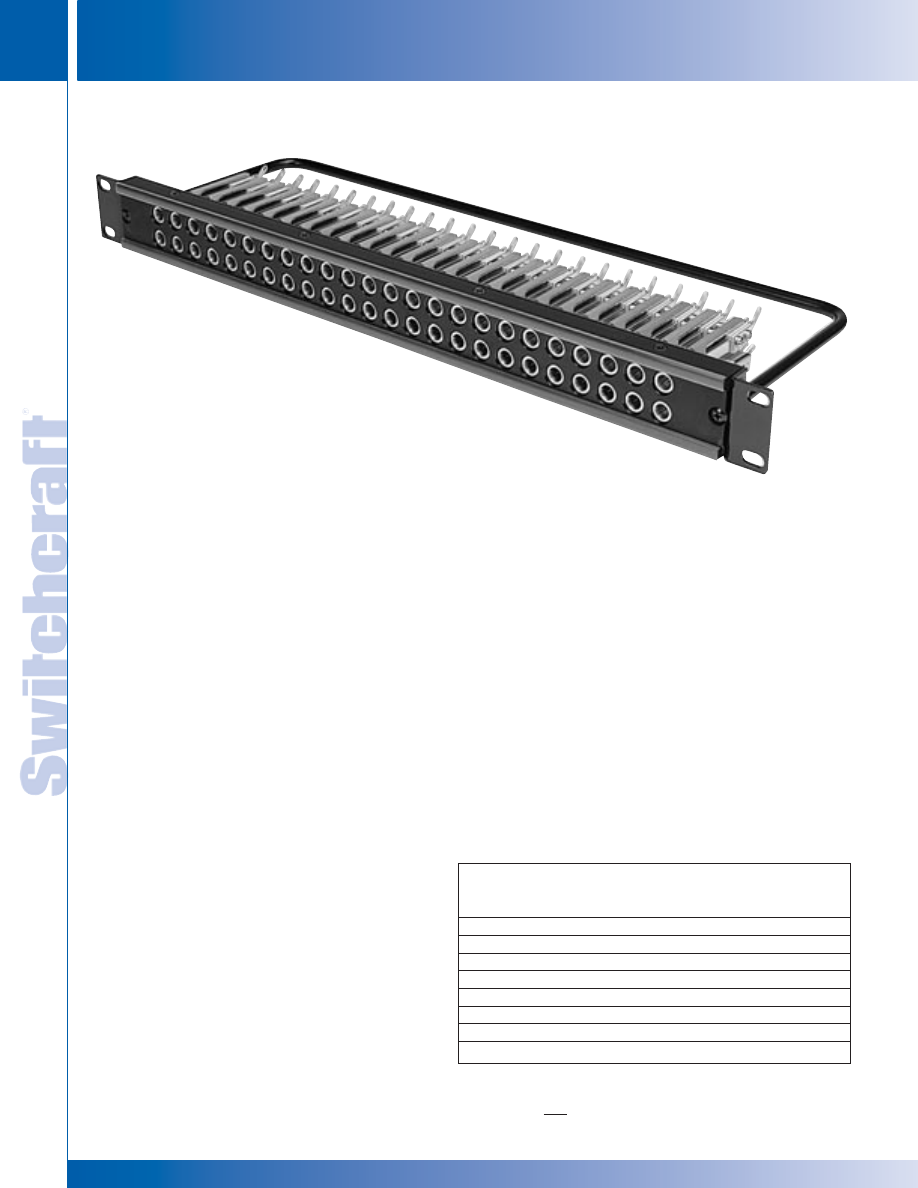
JACK PANELS
184
w w w . s w i t c h c r a f t . c o m
® Registered trademark of Switchcraft, Inc.
Note: Contact your Switchcraft Representative for price and delivery
PHONE: 773 792-2700
JACK P
ANELS
DIMENSIONS ARE FOR REFERENCE ONLY
Inch
(mm)
MT48/MT52 PATCHBAY SERIES
MT48/MT52 PATCHBAY SERIES
MT48/MT52 PATCHBAY SERIES
MT48FN
The MT48/52 Series patchbays offer a rugged cable tie bar
to support rear cabling. Also available is the normals strapped
configuration which has the shunts or normals tied together, top
to bottom jacks.
FEATURES AND BENEFITS
• Units feature either 48 or 52
MT Jax®
• Steel frame jacks for superior jack life
• Attractive, corrosion resistant nickel-plated jacks
• Gold switching contacts for long-term reliability in normal-
through connections
• Offset ground terminal for ease in making common ground
buss connections
• Fanned solder terminals for
easier solder connections
• Cable tie bar takes the weight
of cables off the jacks
• Four jack configurations
available for the exact switching arrangement: full normal,
half normal, non-normal, and normals strapped
SPECIFICATIONS
MATERIALS
JACKS
Frame: Steel, nickel-plated
Bushing: Brass, nickel-plated
Springs: Nickel silver, solder lugs
Ground Terminal: Nickel silver,
solder lugs
Switching Contacts: Welded, gold alloy
Insulation: Phenolic spacers, rigid PVC tubing through stack
Screws: Steel, nickel-plated
PANEL
Jack Panel: Thermoplastic
Cable Support Bracket: 5/16”
diameter black epoxy painted steel rod
Screws (designation strip): Steel, black zinc-plated
Screws (mounting jack): Steel, nickel plated
Kwik-change® Designation Strip: Extruded aluminum, black
anodized
Marking Strip:
White plastic, matte finish
Marking Strip Cover:
Clear, extruded plastic
MECHANICAL
Life: 30,000 cycles
Insertion Force: 7 lbs. maximum
Withdrawal Force: 1 lb. minimum
Operating: 0˚C to +50˚C
ELECTRICAL
Contact Resistance: 30 milliohms maximum initial
Insulation Resistance: 10,000 megohms maximum
Dielectric Withstanding Voltage: 500VAC at 60 Hz
Working Voltage: 140VDC
maximum
Current Rating: 100 milliamps
Ordering Information
Part
Type of
No. of
Number
Jack
Jacks
Description
MT48FN
MT
48
Full normals
MT48HN
MT
48
Half normals
MT48NN
MT
48
No normals
MT48NS
MT
48
Normals strapped
MT52FN
MT
52
Full normals
MT52HN
MT
52
Half normals
MT52NN
MT
52
No normals
MT52NS
MT
52
Normals strapped
* Please visit the product pages on our website for the most up-to-date product information
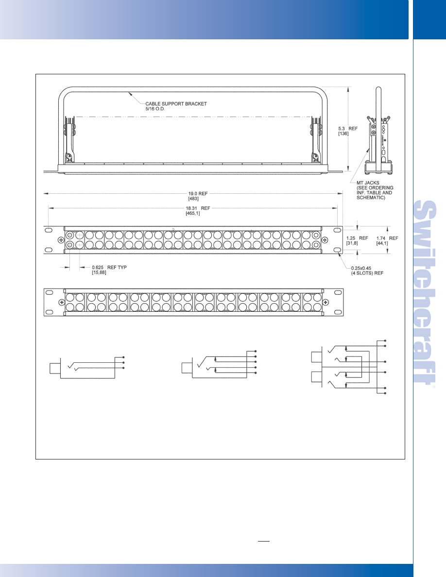
SWITCHCRAFT, INC. 5555 N. Elston Ave. • Chicago, IL 60630
185
JACK PANELS
FAX: 773 792-2129
JACK P
ANELS
DIMENSIONS ARE FOR REFERENCE ONLY
Inch
(mm)
MT48/MT52 PATCHBAY SERIES (continued)
MT48/MT52 PATCHBAY SERIES
MT48/MT52 PATCHBAY SERIES
MT52 SERIES
MT48 SERIES
YMT332BN
YMT334BN
YMT389N
JACK SCHEMATICS
“N” SUFFIX DENOTES WELDED GOLD CONTACTS
AND NICKEL-PLATED FRAME
* Please visit the product pages on our website for the most up-to-date product information
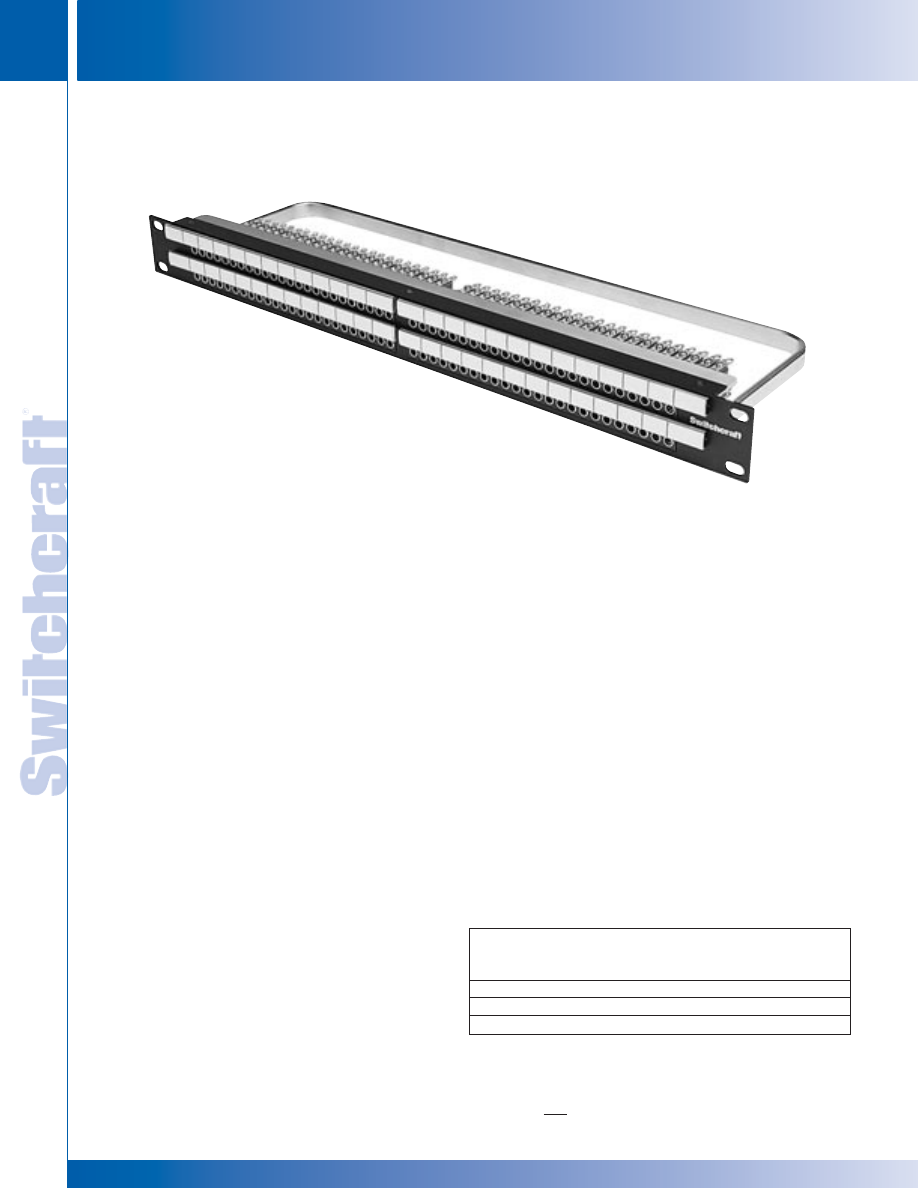
JACK PANELS
186
w w w . s w i t c h c r a f t . c o m
® Registered trademark of Switchcraft, Inc.
Note: Contact your Switchcraft Representative for price and delivery
PHONE: 773 792-2700
JACK P
ANELS
DIMENSIONS ARE FOR REFERENCE ONLY
Inch
(mm)
TTP96AS PATCHBAY SERIES
FEATURES AND BENEFITS
• Unit features 96 TT jacks
• Attractive, corrosion resistant nickel-plated jacks
• Steel frame jack for superior jack life
• Extra wide labeling strips provide maximum space
• Rugged cable tie bar takes the weight of
cables off the jacks
• Rugged, attractive black anodized aluminum
face will not break
• Three jack configurations available for the exact
switching arrangement you need: full normal,
half normal, and open circuit panel
• Fanned solder terminals for easier solder
connections
• Offset ground terminal for ease in making
common ground buss connections
• Gold switching contacts for long-term reliability
in normal-through connections
SPECIFICATIONS
MATERIALS
JACKS
Frame: Steel, nickel-plated
Bushing: Nickel-plated copper alloy
Springs: Copper alloy solder lugs
Ground Terminal: Steel, tin electrodeposited
Switching Contacts: Welded, gold alloy inlay
over palladium base
Insulation: Rigid plastic spacers, rigid PVC
tubing through stack
Screws: Steel, plated
PANEL
Frame: Black anodized aluminum
Inserts: Polyester, glass filled, 94V-0
Cable Support Bar: Cold rolled steel, nickel-plated
Designation Strips: Thermoplastic, 94V-0
Designation Strip Covers:
Clear thermoplastic, SE-1
Marking Strip: Rigid vinylite
Jack Mounting Screws: Steel, plated
Screws: Steel, black plated
MECHANICAL
Life: 30,000 cycles
Insertion Force: 7 lbs. maximum
Withdrawal Force: 1 lbs. minimum
Environmental: 0°C to +50°C
ELECTRICAL
Contact Resistance: 30 milliohms maximum initial
Insulation Resistance: 10,000 megohms maximum
Dielectric Withstanding Voltage: 500VAC at 60 Hz
Working Voltage: 140VDC maximum
Current Rating: 100 milliamps
The TTP96AS Series of patchbays offer a rugged
cable tie bar to support rear cabling.
Ordering Information
Part
Type of
No. of
Number
Jack
Jacks
Description
TTP96ASFN
TT
96
Full normals
TTP96ASHN
TT
96
Half normals
TTP96ASNN
TT
96
No normals
TTP96AS PATCHBAY SERIES
TTP96AS PATCHBAY SERIES
TTP96AS
* Please visit the product pages on our website for the most up-to-date product information
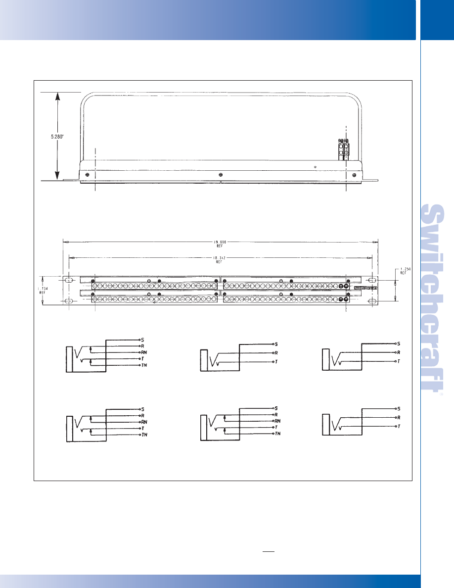
SWITCHCRAFT, INC. 5555 N. Elston Ave. • Chicago, IL 60630
187
JACK PANELS
FAX: 773 792-2129
JACK P
ANELS
DIMENSIONS ARE FOR REFERENCE ONLY
Inch
(mm)
TTP96AS PATCHBAY SERIES
TTP96AS PATCHBAY SERIES
TTP96AS PATCHBAY SERIES (continued)
TOP ROW
BOTTOM
ROW
BOTTOM
ROW
BOTTOM
ROW
TTP96ASFN
TTP96ASHN
TTP96ASNN
TOP ROW
TOP ROW
* Please visit the product pages on our website for the most up-to-date product information
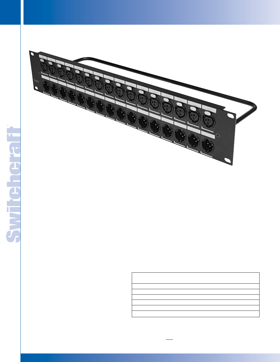
JACK PANELS
188
w w w . s w i t c h c r a f t . c o m
® Registered trademark of Switchcraft, Inc.
Note: Contact your Switchcraft Representative for price and delivery
PHONE: 773 792-2700
JACK P
ANELS
DIMENSIONS ARE FOR REFERENCE ONLY
Inch
(mm)
Q-G
®
PATCHBAY SERIES
Q-G
®
PATCHBAY SERIES
Q-G
®
PATCHBAY SERIES
FEATURES AND BENEFITS
• Available in 1RU or 2RU versions
• Available with or without the connectors
• E Series connectors are silver-plated,
3 pins/contacts with black finish
• Cable tie bar takes the weight of the cables off
the solder terminations
• Rugged aluminum channel
increases durability
• Silk-screen designation area makes
it easy to re-label channels
SPECIFICATIONS
MATERIALS
CONNECTORS
Housing: Die-cast, black velvet finish
Inserts: Glass-filled thermoplastic
Pin/Contacts: Copper alloy, silver-plated
Latch Release: Steel, nickel-plated
Insert Locking Cam: Die-cast zinc
FRAME
Aluminum, black anodized
CABLE TIE BAR
Steel, black epoxy
The QG Patchbay features a 19" rack unit loaded with E Series QG
connectors. These XLR’s have the same panel cut-out, male or female,
silver-plated pins or contacts, and a black finish. All connectors have
solder cup terminals for easy soldering and the inserts are removable
from the back, allowing for easy changes. The one rack unit height
version comes with 16 male, or 16 female, or 8 male and 8 female
connectors. The two rack unit version comes with 16 male and
16 female connectors. We also offer the unit without connectors, but with
the panel cut-outs already punched out. All versions have
a rugged cable tie bar, which takes the weight of the cabling away
from the solder connections.
Ordering Information
Part Number
Height
Description
QGPK116FB
1.75"
16 female
QGPK116MB
1.75"
16 male
QGPK18M8FB
1.75"
8 male, 8 female
QGPK332MFB
3.5"
16 female( top), 16 male (bottom)
QGPK1B
1.75"
Blank panel
QGPK3B
3.5"
Blank panel
QGPK332MFB
* Please visit the product pages on our website for the most up-to-date product information
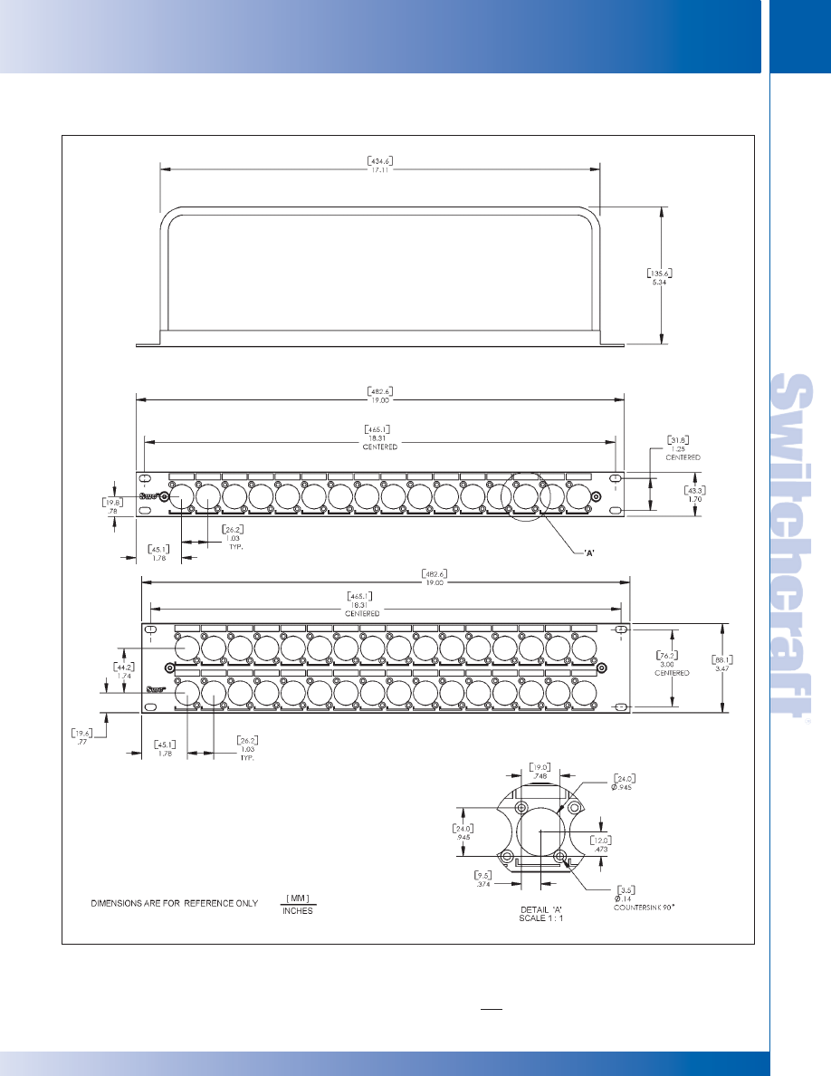
SWITCHCRAFT, INC. 5555 N. Elston Ave. • Chicago, IL 60630
189
JACK PANELS
FAX: 773 792-2129
JACK P
ANELS
DIMENSIONS ARE FOR REFERENCE ONLY
Inch
(mm)
Q-G
®
PATCHBAY SERIES
Q-G
®
PATCHBAY SERIES
Q-G
®
PATCHBAY SERIES (continued)
* Please visit the product pages on our website for the most up-to-date product information
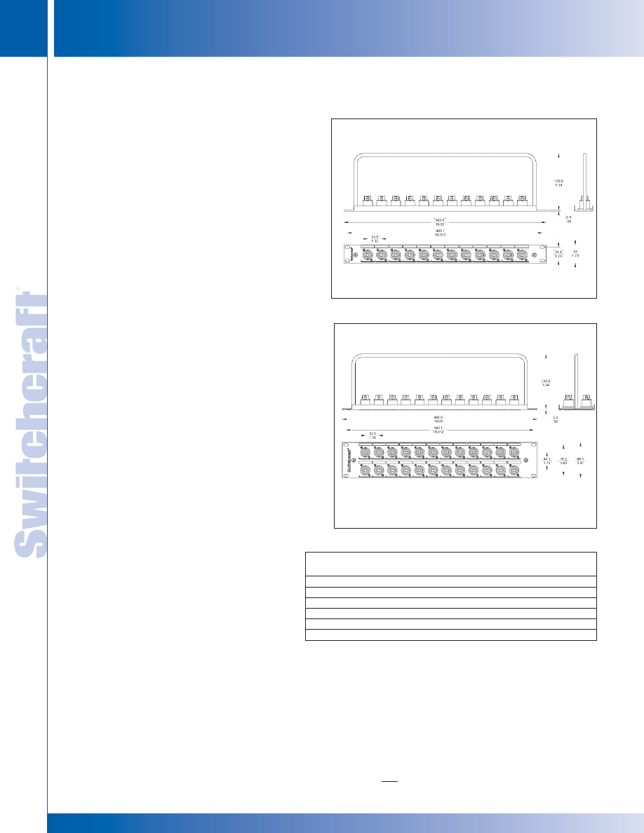
JACK PANELS
190
w w w . s w i t c h c r a f t . c o m
® Registered trademark of Neutrik
Note: Contact your Switchcraft Representative for price and delivery
PHONE: 773 792-2700
JACK P
ANELS
DIMENSIONS ARE FOR REFERENCE ONLY
Inch
(mm)
HPC PATCHBAY SERIES
The HPC Patchbay features a 19” rack unit loaded with HPC
Series connectors. Available with either 0.250” Faston terminals
or 0.187” Faston terminals. One rack unit height versions come
with 12 HPC connectors, two rack unit height versions come
with 24 HPC connectors. All versions have a rugged cable
tie bar, which takes the weight of the cabling away from the
connections.
FEATURES AND BENEFITS
• Available in 1RU or 2RU versions
• Available with or without connectors
• HPC Series connectors are compatible with Neutrik
Speakon
®
connectors
• Cable tie bar takes weight of the cables off the terminations
• Rugged aluminum channel
• Silk-screen designation area makes it easy to re-label chan-
nels
HP CONNECTOR SPECIFICATIONS
See page 38 for details
MATERIALS
Housing: Thermoplastic UL 94V-O rated
Contacts: Silver-plated over copper alloy
FRAME
Aluminum, black anodized
CABLE TIE BAR
Steel, black epoxy
Part
Number
Height
Description
HPCPK112F
1.75"
12 connectors, 0.250" Fastons
HPCPK112F1
1.75"
12 connectors, 0.187" Fastons
HPCPK1B
1.75"
Blank panel
HPCPK324F
3.50"
24 connectors, 0.250" Fastons
HPCPK324F1
3.50"
24 connectors, 0.187" Fastons
HPCPK3B
3.50"
Blank panel
HPC PATCHBAY SERIES
HPC PATCHBAY SERIES
* Please visit the product pages on our website for the most up-to-date product information
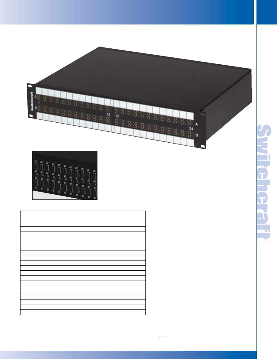
SWITCHCRAFT, INC. 5555 N. Elston Ave. • Chicago, IL 60630
191
JACK PANELS
FAX: 773 792-2129
JACK P
ANELS
DIMENSIONS ARE FOR REFERENCE ONLY
Inch
(mm)
DATA PATCHBAY SERIES
DATA PATCHBAY SERIES
FEATURES AND BENEFITS
• Unit Features either 8,16, 24, or 32 TT style
jacks on the front Panels, to a 9 pin D-Sub
or PPT back Plane.
• All version utilize low capacitance internal wiring
for maximum performance of transferring data
• All standard units are available 1 or 2 rack
units high (1.5 RU available by request)
• Rugged, attractive black epoxyfinished steel
frame chassis
Our standard RS data jackfield series offer a
multiple combination of ports, rack heights, and
back panel terminations which will easily fit into
any television broadcast or video production
where custom data patching is required. Custom
ports and rack height combinations can be
supplied. Contact the factory for details.
SPECIFICATIONS
ELECTRICAL
Internal Wiring:
24 AWG Solid TC, foils shield
Nom Capacitance: 11.5 pF/ft between conductors
21.3 pF/ft between one conductor and conductor
connected to the shield
Nom. Impedance: 110 Ohms
RS422 Ordering Information
Part
No. of Front
Panel
Back
Rack
Number*
Jacks
Layout
Plane
Height
RS422H48N081
2 x 8
Horizontal
9 Pin D-Sub
1
RS422V4N081
2 x 8
Vertical
9 Pin D-Sub
1
RS422H4N161
2 x 16
Horizontal
9 Pin D-Sub
1
RS422H4N162
2 x 16
Horizontal
9 Pin D-Sub
2
RS422V4N161
2 x 16
Vertical
9 Pin D-Sub
1
RS422V4N162
2 x 16
Vertical
9 Pin D-Sub
2
RS422H4N242
2 x 24
Horizontal
9 Pin D-Sub
2
RS422V4N242
2 x 24
Vertical
9 Pin D-Sub
2
RS422V4N322
2 x 32
Vertical
9 Pin D-Sub
2
RS422PH4N081
2 x 8
Horizontal
PPT Punchdown
1
RS422PV4N081
2 x 8
Vertical
PPT Punchdown
1
RS422PH4N161
2 x 16
Horizontal
PPT Punchdown
1
RS422PH4N162
2 x 16
Horizontal
PPT Punchdown
2
RS422PV4N161
2 x 16
Vertical
PPT Punchdown
1
RS422PV4N162
2 x 16
Vertical
PPT Punchdown
2
RS422PH4N242
2 x 24
Horizontal
PPT Punchdown
2
RS422PV4N242
2 x 24
Vertical
PPT Punchdown
2
RS422PV4N322
2 x 32
Vertical
PPT Punchdown
2
RS 422 DATA PATCHBAY SERIES
*Add "N" for non-normalled version
See Page 267 for Patchcord Information
* Please visit the product pages on our website for the most up-to-date product information
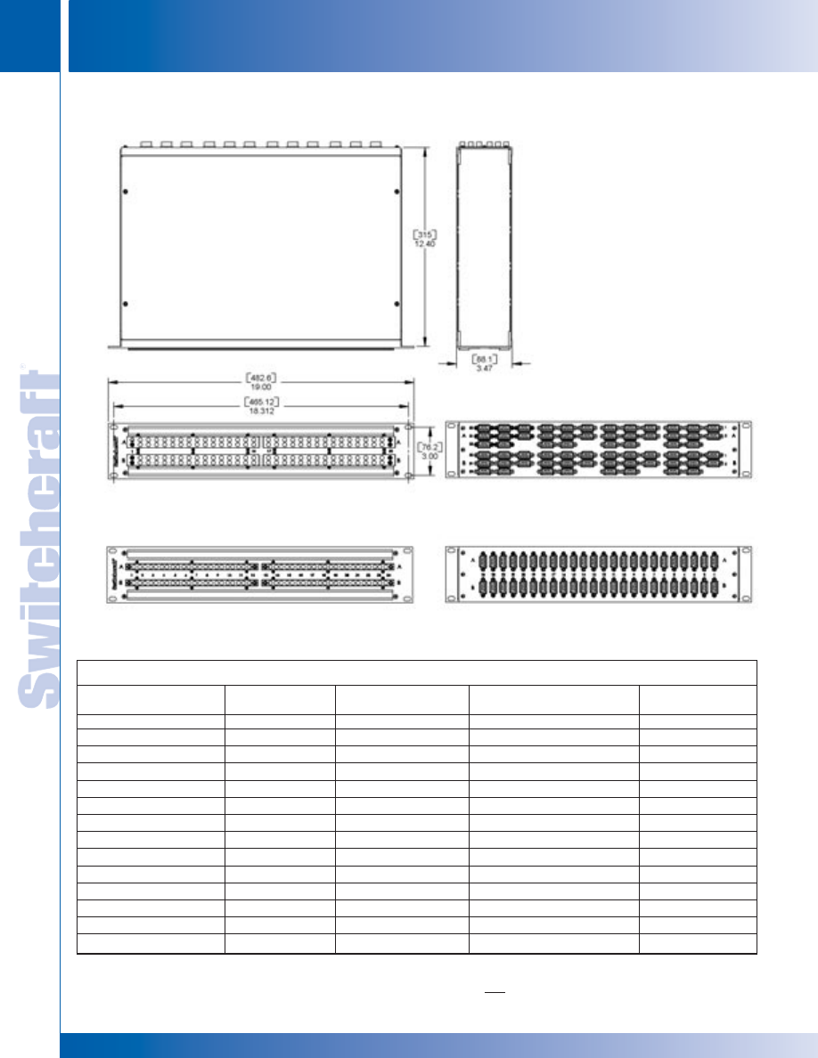
JACK PANELS
192
w w w . s w i t c h c r a f t . c o m
® Registered trademark of Switchcraft, Inc.
Note: Contact your Switchcraft Representative for price and delivery
PHONE: 773 792-2700
JACK P
ANELS
DIMENSIONS ARE FOR REFERENCE ONLY
Inch
(mm)
DATA PATCHBAY SERIES
DATA PATCHBAY SERIES
RS 422 DATA PATCHBAY SERIES
Ordering Information
Part No.
of
Front
Panel
Back
Rack
Number
Jacks Layout
Plane
Height
RS422H4N081
2 x 8
Horizontal
9 Pin D-Sub
1
RS422V4N081
2 x 8
Vertical
9 Pin D-Sub
1
RS422H4N162
2 x 16
Horizontal
9 Pin D-Sub
1, 2
RS422V4N162
2 x 16
Vertical
9 Pin D-Sub
1, 2
RS422H4N242
2 x 24
Horizontal
9 Pin D-Sub
2
RS422V4N242
2 x 24
Vertical
9 Pin D-Sub
2
RS422V4N322
2 x 32
Vertical
9 Pin D-Sub
2
RS422PH4N081
2 x 8
Horizontal
PPT Punchdown
1
RS422PV4N081
2 x 8
Vertical
PPT Punchdown
1
RS422PH4N162
2 x 16
Horizontal
PPT Punchdown
1, 2
RS422PV4N162
2 x 16
Vertical
PPT Punchdown
1, 2
RS422PH4N242
2 x 24
Horizontal
PPT Punchdown
2
RS422PV4N242
2 x 24
Vertical
PPT Punchdown
2
RS422PV4N322
2 x 32
Vertical
PPT Punchdown
2
RS422V4N322
32 Vertical Paired Jacks
Front and Back Views
RS422H4N242
24 Horizontal Paired Jacks
Front and Back Views
* Please visit the product pages on our website for the most up-to-date product information
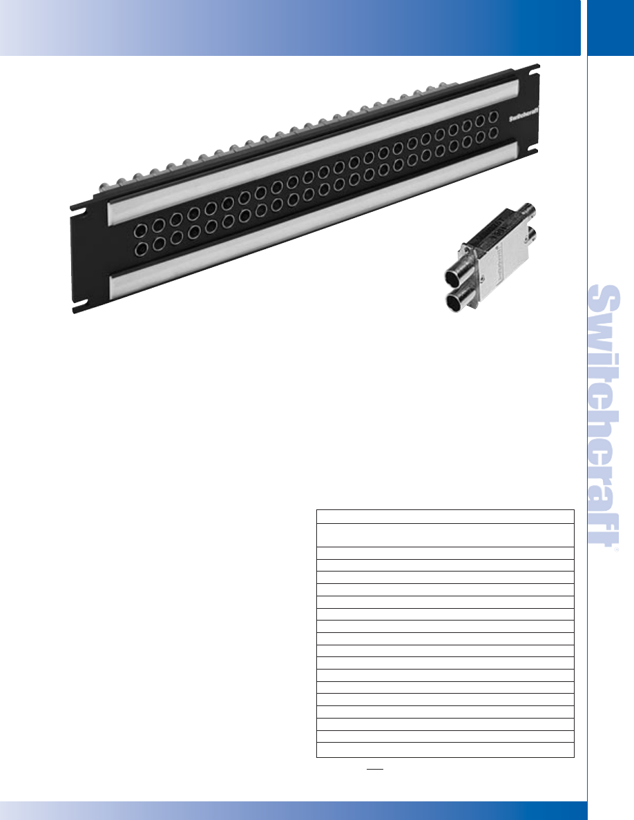
SWITCHCRAFT, INC. 5555 N. Elston Ave. • Chicago, IL 60630
193
JACK PANELS
FAX: 773 792-2129
JACK P
ANELS
DIMENSIONS ARE FOR REFERENCE ONLY
Inch
(mm)
VPP VIDEO PATCHBAY SERIES
FEATURES AND BENEFITS
• HD Series meets SMPTE 292M Specifications
• SD Series has a bandwidth from DC to 1.75GHz
• Black thermoplastic modules insulate
jacks from chassis
• Jacks feature rugged heavy duty housings
VIDEO JACK SPECIFICATIONS
ELECTRICAL
Rated Bandwidth: 2.4 GHz (HD), 1.75 GHz (SD)
Characteristic Impedance: 75 ohms
Return Loss: Better than –15 dB
Insertion Loss: Better than –.5 dB
Contact Resistance: Less than 20 milliohms
Termination Resistance: 75 W, ±1%
Center Conductor: Accepts .090 pin diameter
MECHANICAL
Mechanical Shock: Per MIL-STD-202, Method 213,
Test condition I
Vibration: Per MIL-STD-202, Method 201
Insertion Force: 12 lbs. maximum
Withdrawal Force: 3 lbs. minimum
Life Cycle: 30,000
MATERIAL
Housing: Zinc alloy, nickel plated
Center Contacts: Copper alloy, gold plated
Switching Springs: Copper alloy, gold plated
Grounding Contacts:
HD Series - Copper alloy, gold plated
SD Series - Copper alloy, nickel plated
Insulators: Thermoplastic, UL 94V-0 rated
ENVIRONMENTAL
Operating Temperature: – 40ºC to 65ºC
Storage Temperature: – 55ºC to 85ºC
Thermal Shock: Per MIL-STD-202, Method 107
Moisture and Humidity:
Per MIL-STD-202, Method 106
The VPP Series video patchbays offer a wide variety of options for video patching.
The HD Series meets SMPTE 292M specifications for high definition video signaling,
covering a bandwidth range from DC to 2.4GHz. The SD Series is perfect for serial
digital, with a bandwidth from DC to 1.75GHZ. Both come in either terminated or
non-terminated, 24 or 26 jacks, 1.75" or 3.5" heights.
Ordering Information
Part
Type of No. of
Number
Jack
Jacks Height
Description
VPP24K1HD*75T
HD
24
1.75"
Terminated
VPP24K1HD*NT
HD
24
1.75"
Non-term
VPP24K1SD*75T
SD
24
1.75"
Terminated
VPP24K1SD*NT
SD
24
1.75"
Non-term
VPP26K1HD*75T
HD
26
1.75"
Terminated
VPP26K1HD*NT
HD
26
1.75"
Non-term
VPP26K1SD*75T
SD
26
1.75"
Terminated
VPP26K1SD*NT
SD
26
1.75"
Non-term
VPP24K3HD*75T
HD
24
3.5"
Terminated
VPP24K3HD*NT
HD
24
3.5"
Non-term
VPP24K3SD*75T
SD
24
3.5"
Terminated
VPP24K3SD*NT
SD
24
3.5"
Non-term
VPP26K3HD*75T
HD
26
3.5"
Terminated
VPP26K3HD*NT
HD
26
3.5"
Non-term
VPP26K3SD*75T
SD
26
3.5"
Terminated
VPP26K3SD*NT
SD
26
3.5"
Non-term
*Add “N” for non-normalled version
VPP VIDEO PATCHBAY SERIES
VPP24K3HD75T
VJHD*75TX
VPP VIDEO PATCHBAY SERIES
* Please visit the product pages on our website for the most up-to-date product information
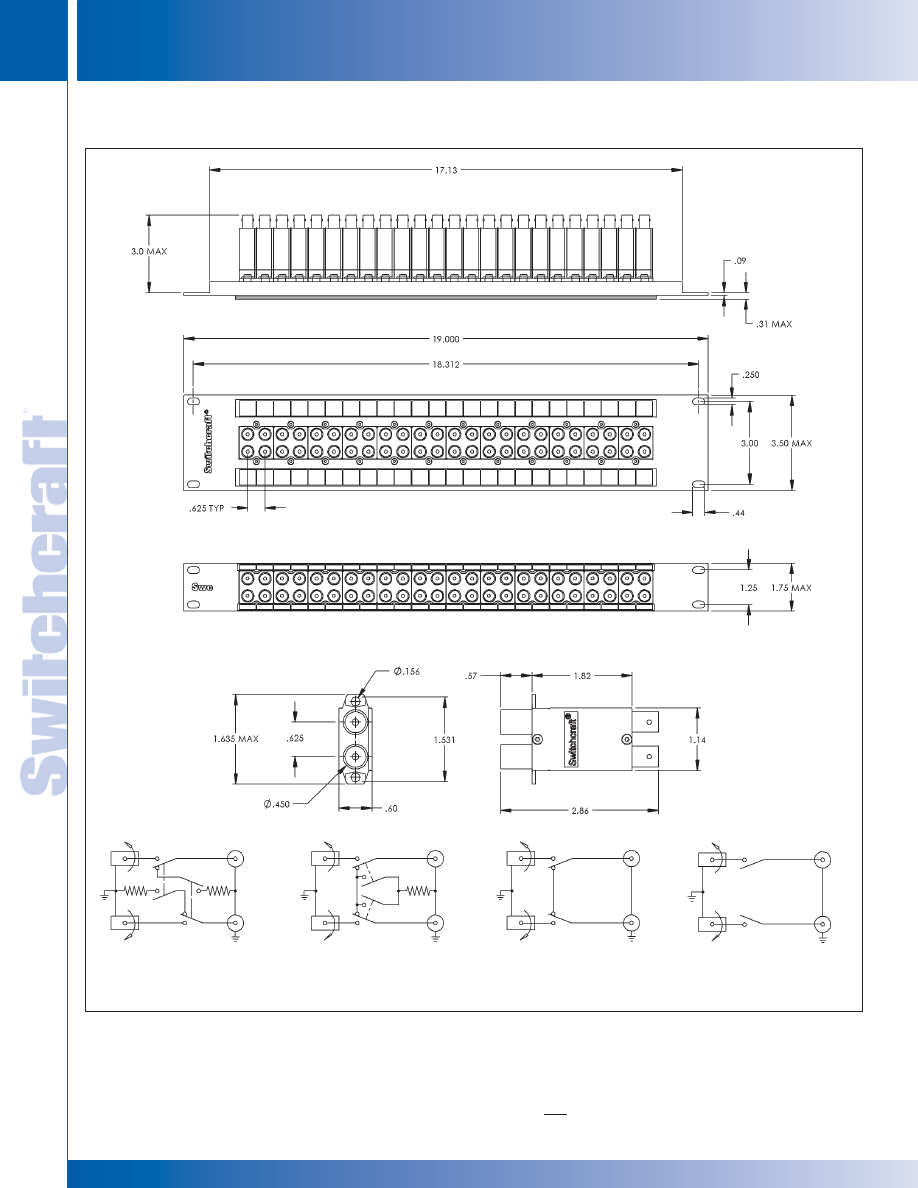
JACK PANELS
194
w w w . s w i t c h c r a f t . c o m
® Registered trademark of Switchcraft, Inc.
Note: Contact your Switchcraft Representative for price and delivery
PHONE: 773 792-2700
JACK P
ANELS
DIMENSIONS ARE FOR REFERENCE ONLY
Inch
(mm)
VPP VIDEO PATCHBAY SERIES (continued)
VPP VIDEO PATCHBAY SERIES
VPP VIDEO PATCHBAY SERIES
NON-NORMALLED
NORMALLED
NORMALLED
NON-NORMALLED
TERMINATED
TERMINATED
NON-TERMINATED
NON-TERMINATED
* Please visit the product pages on our website for the most up-to-date product information
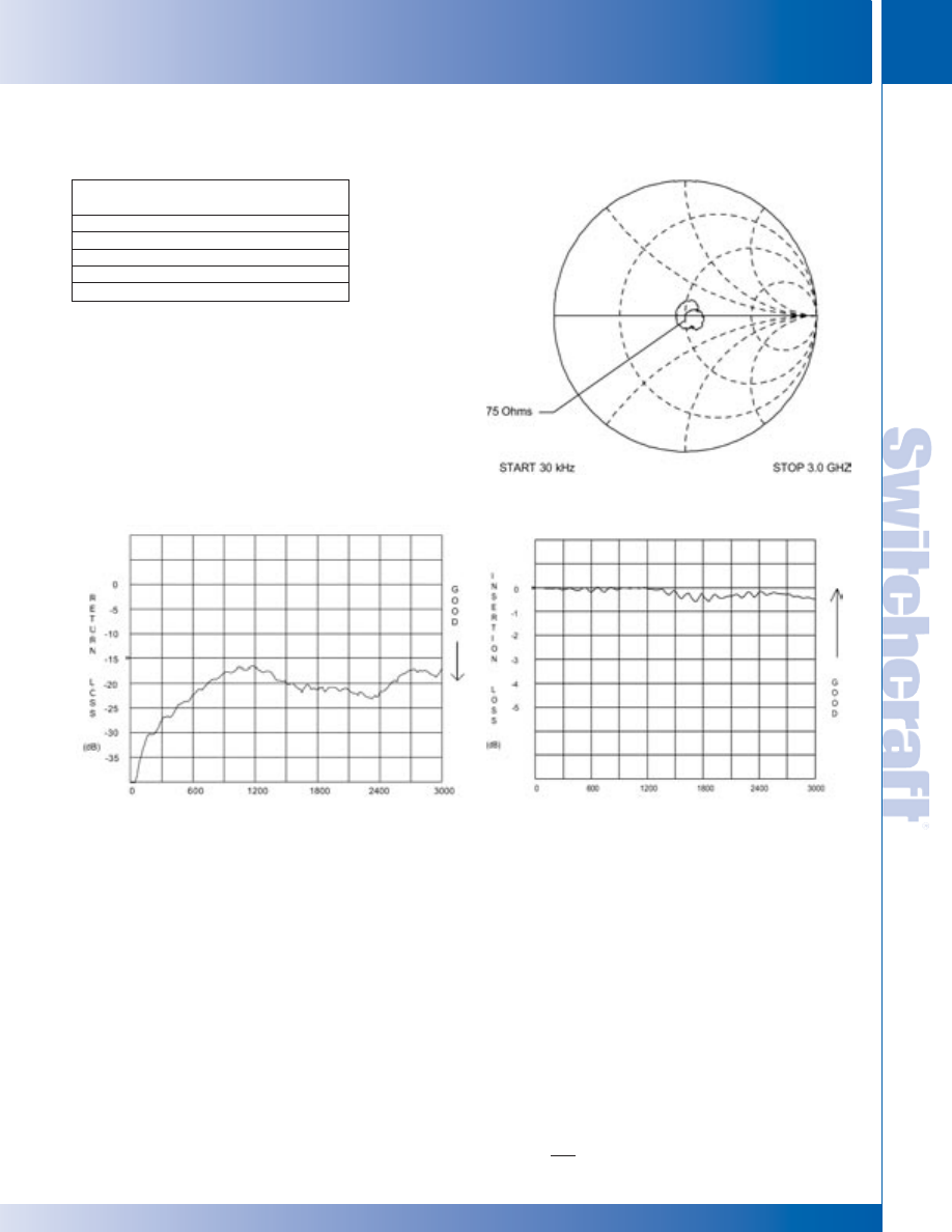
SWITCHCRAFT, INC. 5555 N. Elston Ave. • Chicago, IL 60630
195
JACK PANELS
FAX: 773 792-2129
JACK P
ANELS
DIMENSIONS ARE FOR REFERENCE ONLY
Inch
(mm)
VPP VIDEO PATCHBAY SERIES
VPP VIDEO PATCHBAY SERIES
FREQUENCY (MHz)
FREQUENCY (MHz)
SMITH CHART
(TYPICAL)
Ordering–Individual Jacks
Part Number
Type
Description
VJHD*75TX
HD
Terminated
VJHD*NTX
HD
Non-terminated
VJSD*75TX
SD
Terminated
VJSD*NTX
SD
Non-terminated
*Add “N” for non-normalled version
VPP VIDEO PATCHBAY SERIES (continued)
* Please visit the product pages on our website for the most up-to-date product information
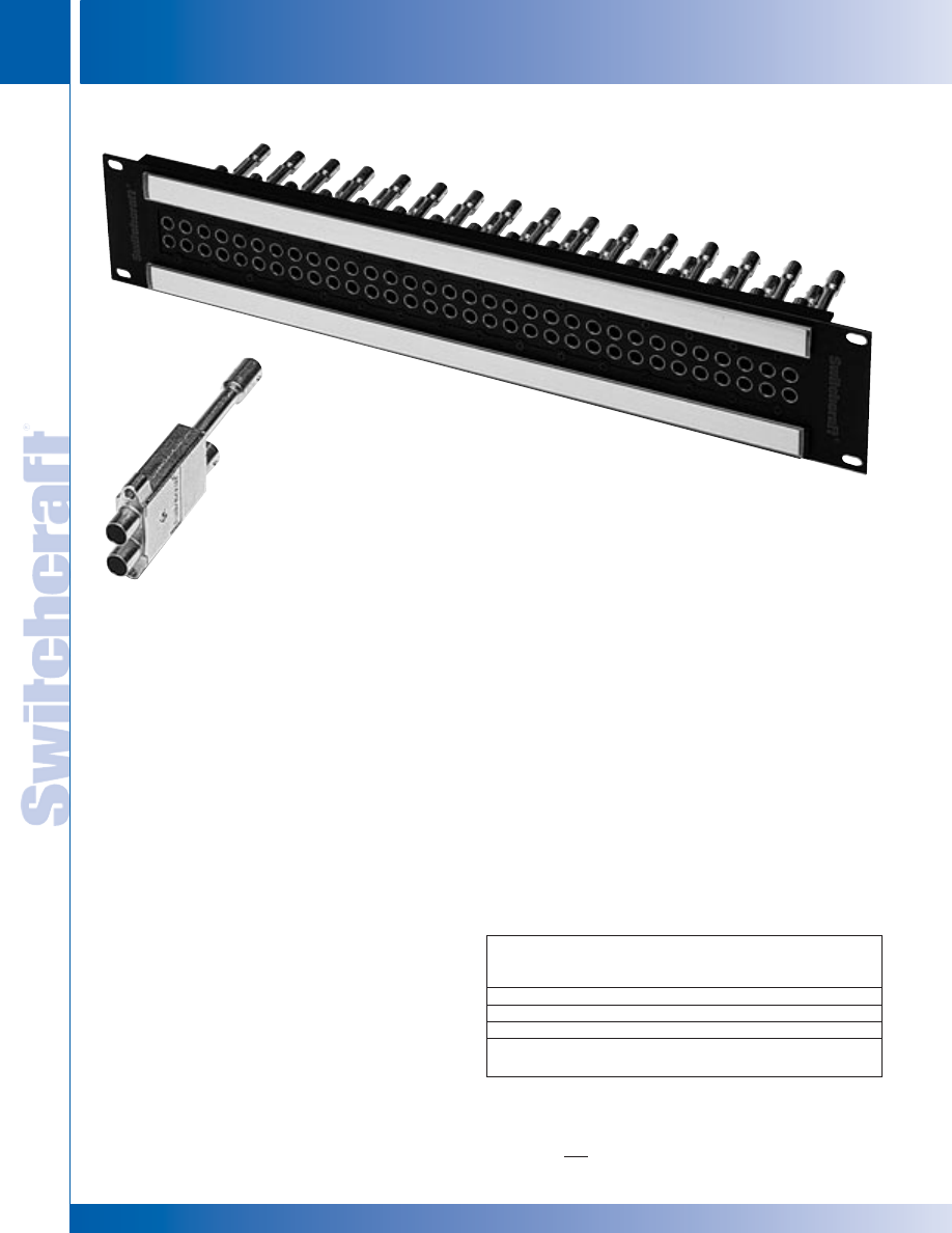
JACK PANELS
196
w w w . s w i t c h c r a f t . c o m
® Registered trademark of Switchcraft, Inc.
Note: Contact your Switchcraft Representative for price and delivery
PHONE: 773 792-2700
JACK P
ANELS
DIMENSIONS ARE FOR REFERENCE ONLY
Inch
(mm)
MVP MIDSIZE VIDEO PATCHBAY SERIES
MVP MIDSIZE VIDEO PATCHBAY SERIES
The MVP Series video patchbays offer outstanding
performance and high density. Patchbays consist of
32 jacks in either 1RU or 2RU heights, jacks come either
terminated or non-terminated. These jacks are rated
from DC to 3 GHz, and are rated at 30,000 lifecycles.
MVP32K3*75T
MVJ*75T
FEATURES AND BENEFITS
• Midsize video jacks rated from DC to 3 GHz
• 32 midsize jacks mounted either 1RU, 1.5RU or 2RU panel
• Available in terminated or non-terminated configurations
SPECIFICATIONS
MATERIAL
Frame: Aluminum, black anodized
Designation Strips: Vinylite, white
Designation Strip Covers: Lexan, transparent
Jack Inserts: Thermoplastic, UL 94V-0 rated
MIDSIZE VIDEO JACK SPECIFICATIONS
ELECTRICAL
Rated Bandwidth: 3.0 GHz
Characteristic Impedance: 75 ohms
Return Loss: See Typical Return Loss Chart
Insertion Loss: See Typical Insertion Loss Chart
Contact Resistance: Less than 20 milliohms
Termination Resistance: 75 W, ±1%
Center Conductor: Accepts .048 pin diameter
MECHANICAL
Mechanical Shock: Per MIL-STD-202,
Method 213, Test condition I
Vibration: Per MIL-STD-202, Method 201
Insertion Force: 12 lbs. maximum
Withdrawal Force: 3 lbs. minimum
Life Cycle: 30,000
MATERIAL
Housing: Zinc alloy, nickel plated
Center Contacts: Copper alloy, gold plated
Switching Springs: Copper alloy, gold plated
Grounding Contacts: Copper alloy, gold plated
BNC Insulators: Teflon
Actuators: Thermoplastic, UL94V-0 rated
ENVIRONMENTAL
Operating Temperature: – 40ºC to 65ºC
Storage Temperature: – 55ºC to 85ºC
Thermal Shock: Per MIL-STD-202, Method 107
Moisture and Humidity: Per MIL-STD-202, Method 106
MVP MIDSIZE VIDEO PATCHBAY SERIES
Ordering Information
Part
Type
Number
of Jack
Height
Description
MVP32K1*75T
Midsize
1.75"
Terminated
MVP32K1*NT
Midsize
1.75"
Non-terminated
MVP32K3*75T
Midsize
3.5"
Terminated
MVP32K3*NT
Midsize
3.5"
Non-terminated
* Add “N” for non-normalled version
Note: For 1.5RU (2.62" height), use K2
* Please visit the product pages on our website for the most up-to-date product information
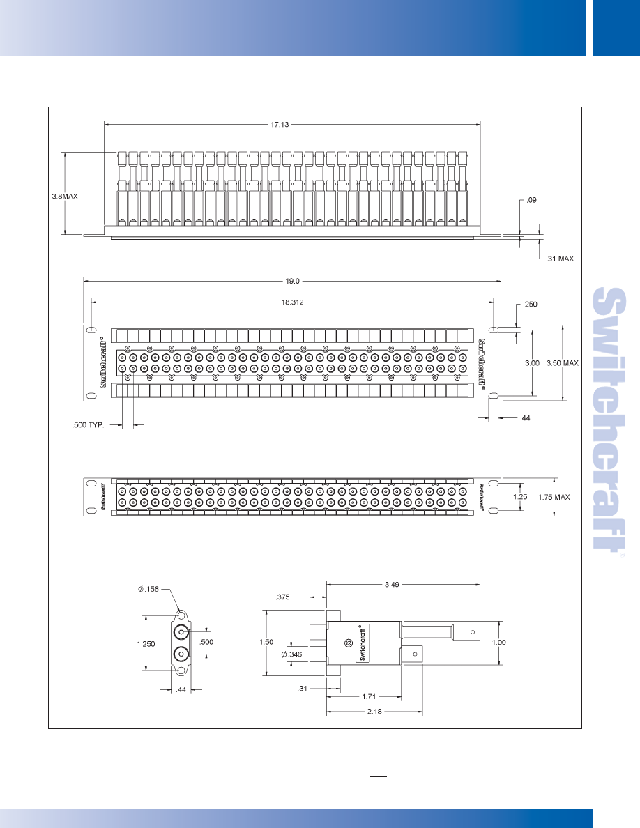
SWITCHCRAFT, INC. 5555 N. Elston Ave. • Chicago, IL 60630
197
JACK PANELS
FAX: 773 792-2129
JACK P
ANELS
DIMENSIONS ARE FOR REFERENCE ONLY
Inch
(mm)
MVP MIDSIZE VIDEO PATCHBAY SERIES (continued)
MVP MIDSIZE VIDEO PATCHBAY SERIES
MVP MIDSIZE VIDEO PATCHBAY SERIES
* Please visit the product pages on our website for the most up-to-date product information
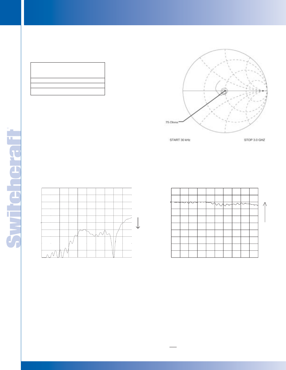
JACK PANELS
198
w w w . s w i t c h c r a f t . c o m
® Registered trademark of Switchcraft, Inc.
Note: Contact your Switchcraft Representative for price and delivery
PHONE: 773 792-2700
JACK P
ANELS
DIMENSIONS ARE FOR REFERENCE ONLY
Inch
(mm)
MVP MIDSIZE VIDEO PATCHBAY SERIES
MVP MIDSIZE VIDEO PATCHBAY SERIES
SMITH CHART (TYPICAL)
RETURN LOSS (TYPICAL)
RETURN LOSS (TYPICAL)
MVP MIDSIZE VIDEO PATCHBAY SERIES (continued)
R
E
T
U
R
N
L
O
S
S
(dB)
0
-5
-10
-15
-20
-25
-30
-35
0
-1
-2
-3
-4
-5
I
N
S
E
R
T
I
O
N
L
O
S
S
(dB)
G
O
O
D
G
O
O
D
0
600
1200
1800
2400
3000
0
600
1200
1800
2400
3000
Ordering Information
Part
Number Description
MVJ*75TX
Terminated
MVJ*NTX
Non-terminated
*Add “N” for non-normalled version
* Please visit the product pages on our website for the most up-to-date product information
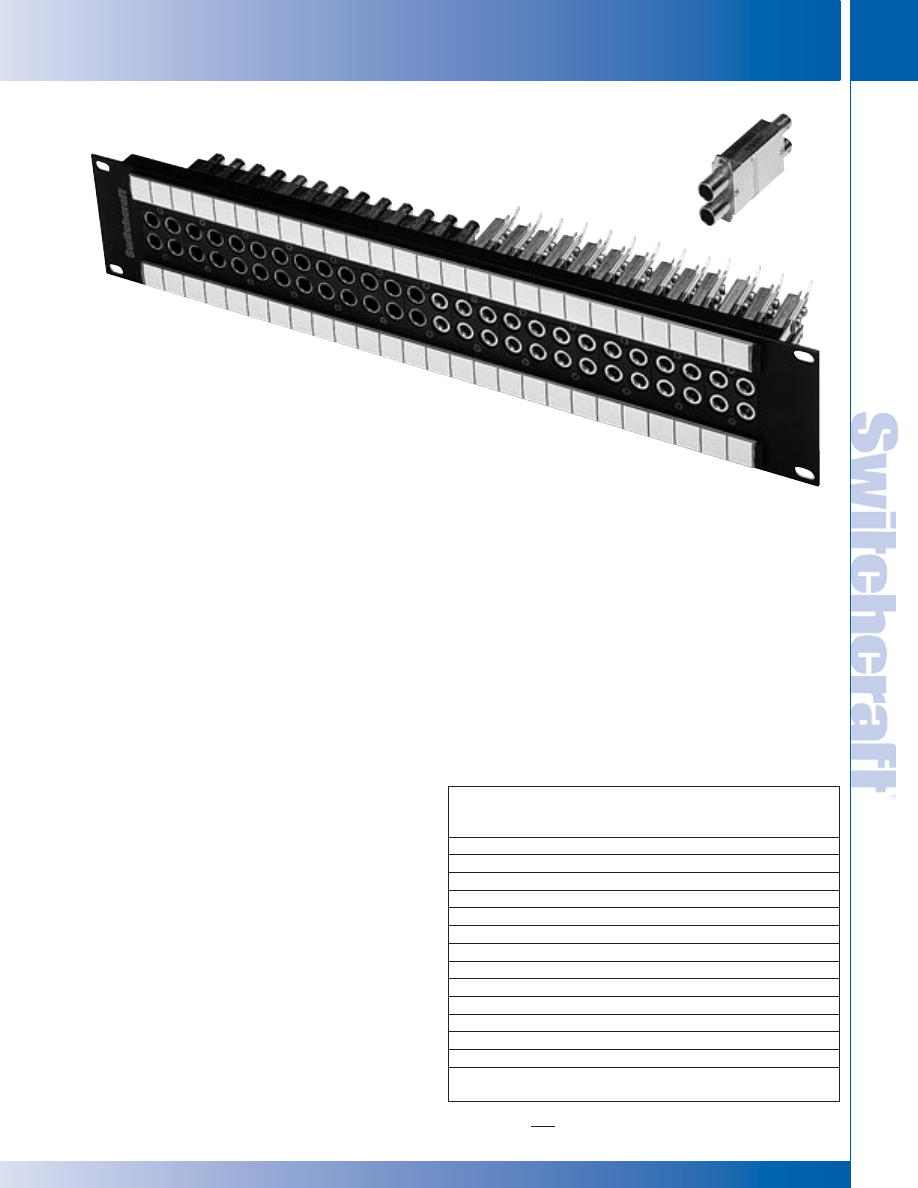
SWITCHCRAFT, INC. 5555 N. Elston Ave. • Chicago, IL 60630
199
JACK PANELS
FAX: 773 792-2129
JACK P
ANELS
DIMENSIONS ARE FOR REFERENCE ONLY
Inch
(mm)
VAP VIDEO/AUDIO PATCHBAY SERIES
VAP VIDEO/AUDIO PATCHBAY SERIES
VAP VIDEO/AUDIO PATCHBAY SERIES
FEATURES AND BENEFITS
• Combines 13 video jacks and 26 long-frame
audio jacks into one patchbay
• Available with either HD Series or SD Series
video jacks
• All audio jacks are nickel-plated with steel frames
and gold-plated switching contacts
• Audio modules consist of 4 YMT334BN jacks,
video modules consist of 2 dual video jacks
VIDEO JACK SPECIFICATIONS
ELECTRICAL
Rated Bandwidth: 2.4 GHz (HD), 1.75 GHz (SD)
Characteristic Impedance: 75 ohms
Return Loss: Better than –15 dB
Insertion Loss: Better than –.5 dB
Contact Resistance: Less than 20 milliohms
Termination Resistance: 75 W, ±1%
Center Conductor: Accepts .090 pin diameter
MECHANICAL
Mechanical Shock: Per MIL-STD-202,
Method 213, Test condition I
Vibration: Per MIL-STD-202, Method 201
Insertion Force: 12 lbs. maximum
Withdrawal Force: 3 lbs. minimum
Life Cycle: 30,000
MATERIAL
Housing: Zinc alloy, nickel plated
Center Contacts: Copper alloy, gold plated
Switching Springs: Copper alloy, gold plated
Grounding Contacts:
HD Series - Copper alloy, gold plated
SD Series - Copper alloy, nickel plated
Insulators: Thermoplastic, UL 94V-0 rated
ENVIRONMENTAL
Operating Temperature: – 40ºC to 65ºC
Storage Temperature: – 55ºC to 85ºC
Thermal Shock: Per MIL-STD-202, Method 107
Moisture and Humidity: Per MIL-STD-202, Method 106
The VAP Series combines audio and video in one convenient
patchbay. Standard versions consist of 13 video jacks and 26
long-frame audio jacks into one unit. Options include HD Series
video jacks which are rated from DC to 2.4GHz or SD Series
rated from DC to 1.5GHz. Both come in either terminated or
non-terminated jacks. The MT Style audio jacks all have
nickel-plated steel frames and gold-plated switching contacts.
Flared terminals make soldering easier. All audio jacks are
T,R,S, TN, and RN. Individual modules are useful for custom
configurations.
Ordering Information
Part
Type of
Number
Jack
Height
Description
VAPK1HD*75T
HD
1.75"
Terminated
VAPK1HD*NT
HD
1.75"
Non-terminated
VAPK1SD*75T
SD
1.75"
Terminated
VAPK1SD*NT
SD
1.75"
Non-terminated
VAPK3HD*75T
HD
3.5"
Terminated
VAPK3HD*NT
HD
3.5"
Non-terminated
VAPK3SD*75T
SD
3.5"
Terminated
VAPK3SD*NT
SD
3.5”
Non-terminated
Modules
VMAFN
MT
4- YMT334BN jacks
VMVHD*75T
HD
2- HD terminated jacks
VMVHD*NT
HD
2- HD non-terminated jacks
VMVSD*75T
SD
2- SD terminated jacks
VMVSD*NT
SD
2-SD non-terminated jacks
*Add “N” for non-normalled version
VJHD*75TX
VAPK3HD*75T
* Please visit the product pages on our website for the most up-to-date product information
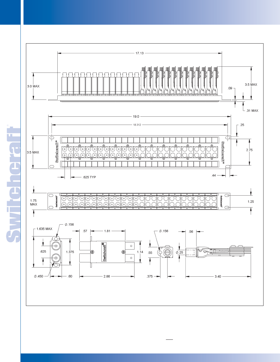
JACK PANELS
200
w w w . s w i t c h c r a f t . c o m
® Registered trademark of Switchcraft, Inc.
Note: Contact your Switchcraft Representative for price and delivery
PHONE: 773 792-2700
JACK P
ANELS
DIMENSIONS ARE FOR REFERENCE ONLY
Inch
(mm)
VAP VIDEO/AUDIO PATCHBAY SERIES (continued)
VAP VIDEO/AUDIO PATCHBAY SERIES
VAP VIDEO/AUDIO PATCHBAY SERIES
VAPK3HD*75T
VAPK1HD*75T
VJ SERIES
MT SERIES
* Please visit the product pages on our website for the most up-to-date product information
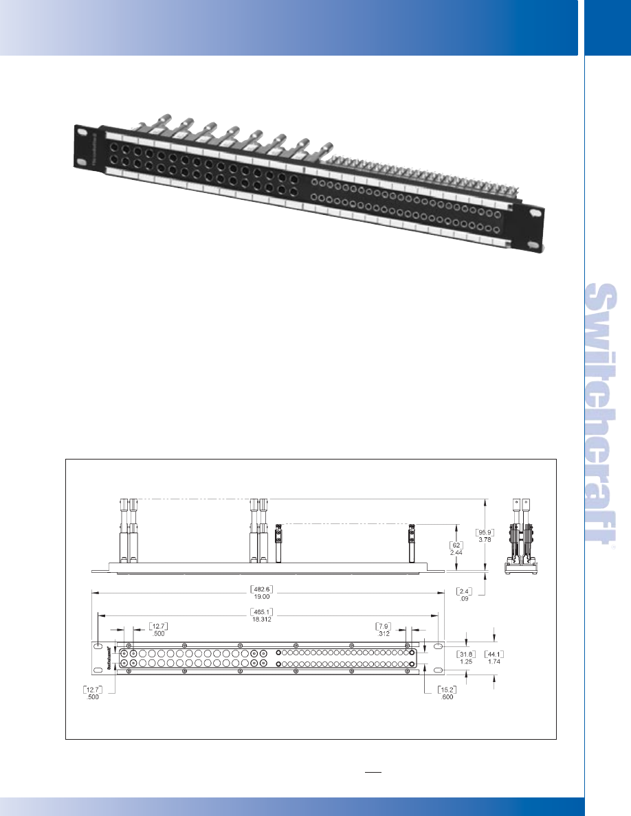
SWITCHCRAFT, INC. 5555 N. Elston Ave. • Chicago, IL 60630
201
JACK PANELS
FAX: 773 792-2129
JACK P
ANELS
DIMENSIONS ARE FOR REFERENCE ONLY
Inch
(mm)
The MBPK Series combines audio and video in one
convenient patchbay. The patchbay consists of 16 midsize
video jacks and 48 TT bantam jacks. Options include 75 Ohm
terminated or non-terminated video jacks. All TT bantam jacks
have T, R, S, TN and RN solder terminals. Audio jacks have
nickel-plated steel frames, gold-plated crossbar switching
contacts and flared terminals for easier soldering.
FEATURES AND BENEFITS
Combines 16 midsize video jacks and
48 TT bantam audio jacks
Video jacks are rated from DC to 3.0 GHZ
All audio jacks are nickel-plated with steel frames and gold-
plated crossbar switching contacts
For non-terminated version, use part no. MBPK1NT
VIDEO JACK SPECIFICATIONS
See page 196 for details
AUDIO JACK SPECIFICATIONS
See page 164 for details
MATERIALS
FRAME
Aluminum, black anodized
MBPK VIDEO/AUDIO PATCHBAY SERIES
MBPK VIDEO/AUDIO PATCHBAY SERIES
MBPK VIDEO/AUDIO PATCHBAY SERIES
MBPK175T
* Please visit the product pages on our website for the most up-to-date product information

JACK PANELS
202
w w w . s w i t c h c r a f t . c o m
® Registered trademark of Switchcraft, Inc.
Note: Contact your Switchcraft Representative for price and delivery
PHONE: 773 792-2700
JACK P
ANELS
DIMENSIONS ARE FOR REFERENCE ONLY
Inch
(mm)
SERIES 1200
Panels accomodate 24 T-Jax
®
jacks in standard 1.75 inch x
19 inch racks. Jack openings are on alternate .625 inch and
.750 inch spacing; twin plugs cannot be cross-connected
between adjacent jack pairs. Includes designation strips
(marking strips and transparent plastic covers).
SERIES 1300
Same as Series 1200, except MT-Jax
®
are used in panel
assemblies.
SERIES 1400
Mounts 26 T-Jax
®
. Openings are on continuous .625 inch
centers. Twin plug can be used on any two adjacent jacks.
Single designation strip (marking strip, and plastic cover).
WEco equivalent is 230B.
SERIES 1400300
Same as Series 1400, except designation strip is
Kwik-Change
®
type which is easier to install and remove and
provides larger vertical designation marking area. Strip holder
is recessed into top of panel for additional panel strength.
1400301 has single height Kwik-Change
®
designation strip.
1400315 has a single height Kwik- Change
®
designation strip
along bottom of panel and double height strips above jacks.
Top designation strip has .188 inch overhang above 1.75 inch
panel height, to help seal small opening between adjacent
panels. CAUTION: Because of this overhang, 1400315
cannot be mounted one above another in a rack.
SERIES 1500
Same as Series 1400 except MT-Jax
®
are used in panel
assemblies.
SPECIFICATIONS
Jack Panel: General purpose black phenolic resin
Frame (except 1400300): Plated, steel
End Bracket and Side Strip (1400300 only): Cold rolled
plated steel
Designation Strip (except 1400300): Clear plastic.
"Kwik-Change" Designation Strip (1400300): Extruded
aluminum, black anodized and black thermoplastic
UL 94V-0.
Marking Strip: White plastic, matte finish.
Marking Strip Cover: Clear extruded plastic.
Screws: #6-32 x .25 inch phillips RHMS (for mounting jacks).
ORDERING
Part number table lists blank panels and popular jack panel
assemblies. If you wish to mount components on basic panels,
order jacks, lamp jacks, and switches separately. (See
appropriate section in this catalog.) For other panel assemblies,
provide complete details with your inquiry or order. Switchcraft
can build special assemblies to your requirements in small
or large quantities. See wire wrapping data. Series 1200
and 1400 are available with holes pre-drilled for vertical
designation strips (Series DS320). Add prefix "D" to part
numbers for pre-drilled panels: D1200, D1400301, etc.
STANDARD SINGLE ROW JACK PANELS
SERIES 1200 AND 1400
LONG FRAME (1/4") TELEPHONE JACK PANELS
Series 1200
*Shown with optional
jacks. See next page for
specific part numbers.
Series 1400
*Shown with optional
jacks. See next page for
specific part numbers.
1400301
*Shown with optional
jacks. See next page for
specific part numbers.
1400315
*Shown with optional
jacks. See next page for
specific part numbers.
LONG FRAME 1/4" TELEPHONE JACK PANELS
LONG FRAME 1/4" TELEPHONE JACK PANELS
* Please visit the product pages on our website for the most up-to-date product information
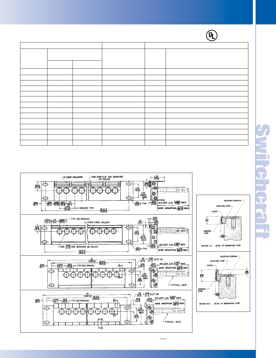
SWITCHCRAFT, INC. 5555 N. Elston Ave. • Chicago, IL 60630
203
JACK PANELS
FAX: 773 792-2129
JACK P
ANELS
DIMENSIONS ARE FOR REFERENCE ONLY
Inch
(mm)
LONG FRAME (1/4") TELEPHONE JACK PANELS (continued)
Part Numbers
Assembly with Jacks
With Solder Lugs
Assembly with Jacks
With Wire-Wrapping
Terminals
Part Numbers
Number
of Jacks
Type of
Jacks Installed
Description
Panel Only
1200
-
-
-
1400
1400301
◊
1400315
-
-
-
-
-
-
-
Offset
-
◊
X1332A
◊
X1332B
◊
X1334B
-
-
-
X1532A
-
-
◊
X1532B301
◊
X1534B
-
◊
X1542B315
-
◊
W1332A
-
◊
W1334B
-
-
-
-
◊
W1532A301
-
◊
W1532B301
◊
W1534B
◊
W1534B301
-
None
24
MT332A , XMT332A or WMT332A MT-Jax
®
24
MT332B or XMT332B MT-Jax
®
24
MT334B,XMT334B or WMT334B MT-Jax
®
None
None
None
26
MT332A or XMT332A MT-Jax
®
26
MT332A or WMT332A MT-Jax
®
26
MT332B MT-Jax
®
26
MT332B, XMT332B or WMT332B MT-Jax
®
26
MT334B, XMT334B or WMT334B MT-Jax
®
26
WMT334B MT-Jax
®
26
XMT342B MT-Jax
®
Straight
-
1332A
◊
1332B
◊
1334B
-
-
-
1532A
◊
1532A301
◊
1532B
◊
1532B301
◊
1534B
-
-
◊
Special order only; contact factory for price and delivery.
1. Prefix “X” denotes offset lugs for buss wiring.
Jack Mounting Screws: #6-32, P10725, can be ordered separately.
Contact Switchcraft.
Legend Cards (Series 1200, 1300) - A1029
Legend Windows (Series 1200, 1300) - A1030
Series 1200
Series 1400
Series 1400-301
Series 1400-315
LONG FRAME 1/4" TELEPHONE JACK PANELS
LONG FRAME 1/4" TELEPHONE JACK PANELS
* Please visit the product pages on our website for the most up-to-date product information
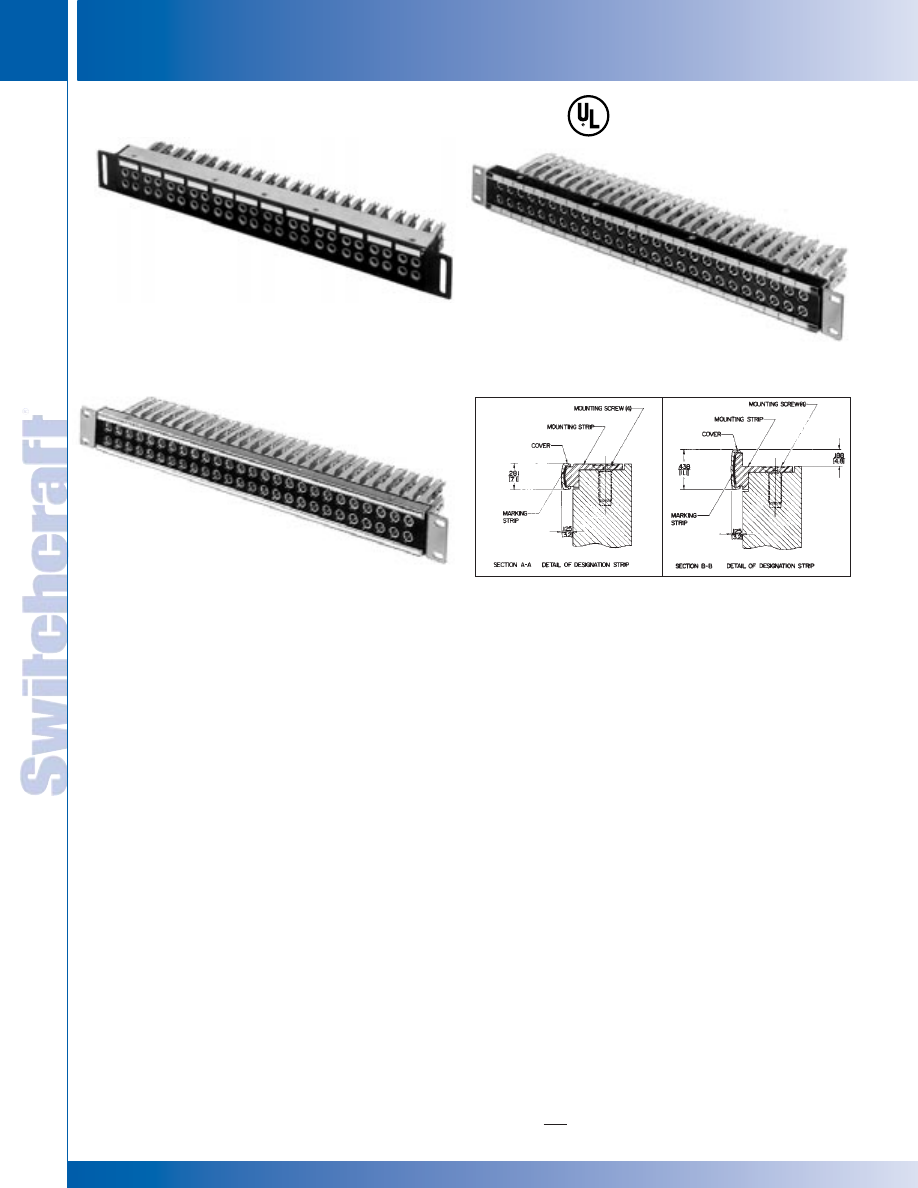
JACK PANELS
204
w w w . s w i t c h c r a f t . c o m
® Registered trademark of Switchcraft, Inc.
Note: Contact your Switchcraft Representative for price and delivery
PHONE: 773 792-2700
JACK P
ANELS
DIMENSIONS ARE FOR REFERENCE ONLY
Inch
(mm)
LONG FRAME 1/4" TWIN ROW JACK PANELS
STANDARD TWIN ROW JACK PANELS
SERIES 2400, 2600, 2600300, 2700300 – PHENOLIC
Twin row jack panels offer greater jack density - up to 52 jacks
per panel. All panels fit standard 19" wide racks. Blank panels
or standard assemblies can be ordered from Switchcraft.
Series 2600 panels are direct equivalent to WEco #230A.
SERIES 2400
Twin row panel accommodates 48 T-Jax
®
. Openings are on
alternate .625" and .75" centers. Panel is 2.125" high and fits
standard 19" racks. Twin plug cannot be cross-connected
between jacks in adjacent quads, but may be connected either
horizontally or vertically in the same quad. Single designation
strip.
SERIES 2500
Same as Series 2400 except MT-Jax
®
are used.
SERIES 2600
Twin row panel accommodates 52 T-Jax
®
in standard 1.75" x
19" racks. Jack openings are on continuous centers. Twin plug
can be connected to any two adjacent jacks, either horizontally
or vertically. Two designation strips. WEco equivalent is #230A.
SERIES 2600300
Same as Series 2600, except designation strips are
Kwik-Change
®
type, providing larger vertical marking area. Top
strip holder is recessed into top of panel to provide additional
strength. 2600301 has single height designation strips (one
above and below each row of jacks).
2600310
Has a double height strip above top row and a steel reinforcing
strip below bottom row. Top strip has .188" overhang above
1.75" panel height, helping seal the small opening between
adjacent panels. Note: overhang prevents mounting panel one
above another in a rack.
SERIES 2700
Same as Series 2600 except MT-Jax
®
are used in panel
assemblies. The series is available with cable tie bar.
ORDERING
1. Order basic panels and popular assemblies by part number
from table.
2. For special panels provide complete details with your inquiry
or order.
3. Series 2600 is available with hole pre-drilled for vertical
designation strips, Series DS320. Add prefix “D” to part
number (D2600301, etc.).
4. Jack Mounting Screws: #6-32, P10725, can be ordered
separately. Contact Switchcraft.
LONG FRAME (1/4") TWIN ROW JACK PANELS
Series 2400
*Shown with optional jacks,
See next page for specific
part numbers.
Series 2600
*Shown with optional jacks,
See next page for specific
part numbers.
Series 2600301
*Shown with optional jacks,
See next page for specific
part numbers.
LONG FRAME 1/4" TWIN ROW JACK PANELS
* Please visit the product pages on our website for the most up-to-date product information
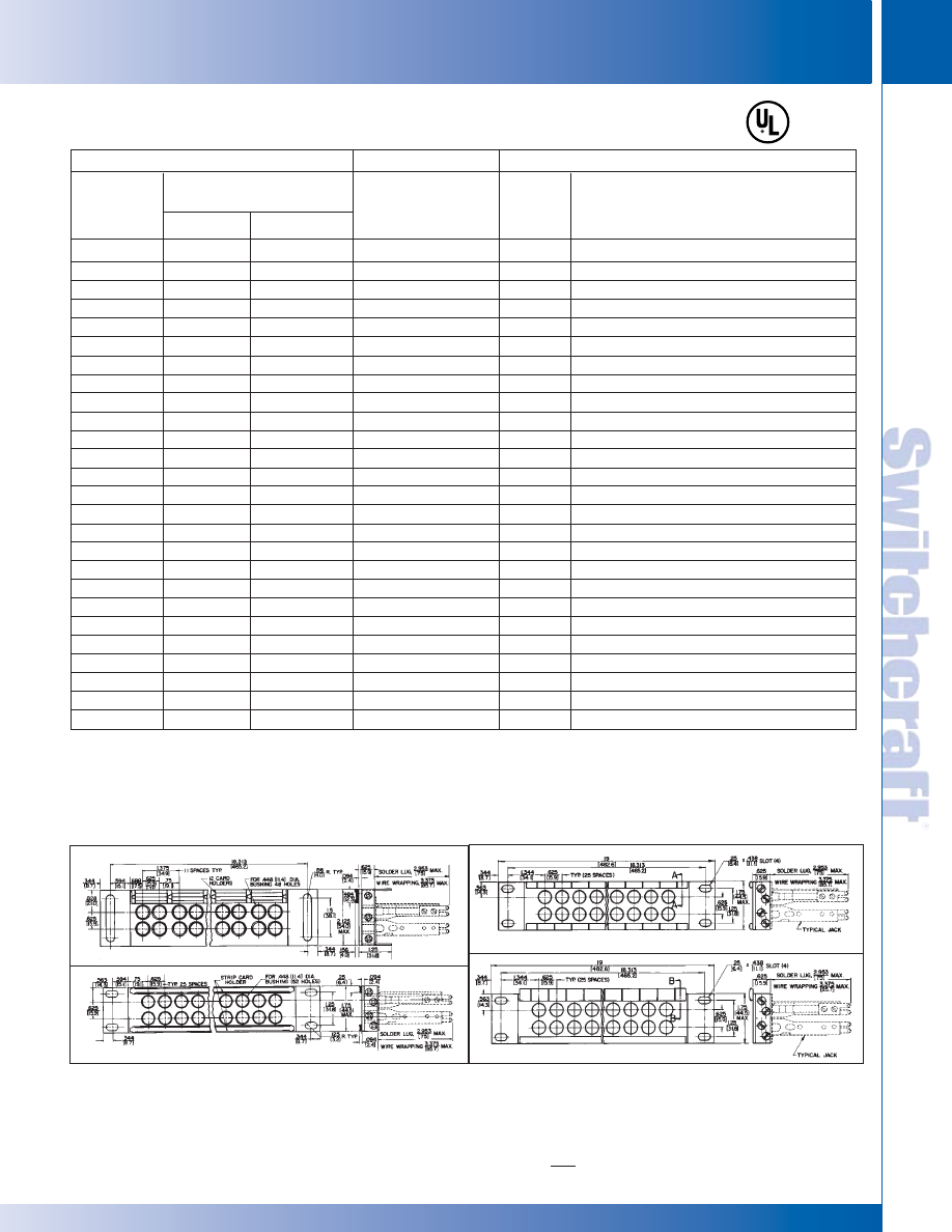
SWITCHCRAFT, INC. 5555 N. Elston Ave. • Chicago, IL 60630
205
JACK PANELS
FAX: 773 792-2129
JACK P
ANELS
DIMENSIONS ARE FOR REFERENCE ONLY
Inch
(mm)
LONG FRAME 1/4" TWIN ROW JACK PANELS – PART NUMBERS
LONG FRAME 1/4" TWIN ROW JACK PANELS – PART NUMBERS
LONG FRAME (1/4") TWIN ROW JACK PANELS (continued)
Part Numbers
Assembly with Jacks Having
Solder Lugs
Assembly with Jacks
Having Wire-
Wrapping Terminals
Number
of Jacks
Type of Jack Installed
Part Numbers
Description
Panel Only
2400
-
-
-
-
-
-
-
-
-
-
-
-
2600
2600301
2600310
-
-
-
-
-
-
-
-
-
-
Offset
1
-
◊
X2432A
◊
X2432B
◊
X2434B
◊
X2532A
◊
X2532B
-
-
X2534B
-
-
-
-
-
-
-
◊
X2732A
◊
X2732A301
◊
X2732B
◊
X2732B301
-
◊
X2734B
◊
X2734B301
-
◊
X2832A
◊
X2932A
-
-
-
-
◊
W2532A
-
-
◊
W2533B
-
-
-
-
-
-
-
-
-
◊
W2732A301
◊
W2732B
◊
W2732B301
-
-
◊
W2734B301
◊
W2789
-
-
None
48
T332A
48
T332B
48
T334B or XMT334B T-Jax
®
48
MT332A, XMT332A or WMT332A MT-Jax
®
48
MT332B or XMT332B MT-Jax
®
48
MT333 MT-Jax
®
48
MT333B or WMT333B MT-Jax
®
48
MT334B or XMT334B MT-Jax
®
48
MT342B MT-Jax
®
48
MT344B, MT-Jax
®
24
MT388, Twin MT-Jax
®
24
MT389 Twin MT-Jax
®
None
None
(WEco equivalent #230A)
None
52
MT332A or XMT332A MT-Jax
®
52
MT332A, XMT332A or WMT332A MT-Jax
®
52
MT332B, XMT332B or WMT332B MT-Jax
®
52
MT332B, XMT332B or WMT332B MT-Jax
®
52
MT333B, MT-Jax
®
52
MT334B or XMT334B MT-Jax
®
52
MT334B, XMT334B or WMT334B MT-Jax
®
26
MT389 or WMT389 Twin MT-Jax
®
48
XT332A
48
XMT332A
Straight
-
◊
2432A
◊
2432B
◊
2434B
◊
2532A
◊
2532B
◊
2533
◊
2533B
◊
2534B
◊
2542B
◊
2544B
◊
2588
◊
2589
-
-
-
◊
2732A
◊
2732A301
◊
2732B
◊
2732B301
◊
2733B
◊
2734B
◊
2734B301
◊
2789
-
-
1. Prefix “X” denotes offset lugs for buss wiring.
◊
Special order only; contact factory for price and delivery.
Series 2400 and 2500
Series 2600 and 2700
Series 2600300 and 2700301
Series 2600310 and 2700310
* Please visit the product pages on our website for the most up-to-date product information
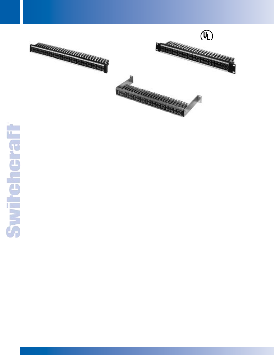
JACK PANELS
206
w w w . s w i t c h c r a f t . c o m
® Registered trademark of Switchcraft, Inc.
Note: Contact your Switchcraft Representative for price and delivery
PHONE: 773 792-2700
JACK P
ANELS
DIMENSIONS ARE FOR REFERENCE ONLY
Inch
(mm)
LONG FRAME 1/4" MODULAR TWIN ROW JACK PANELS
SERIES JP052000
Same as JP012000, except designed for flush mounting or standoff
mounting. Switchcraft Bracket Kit K107; Contact Switchcraft.
SERIES JP062000
Same as JP052000, except 23" wide (includes 14 inserts
which accommodate 56 MT-Jax
®
).
SERIES JP072000
Same as JP012000, except mounts 52 MT-Jax
®
and includes
13 black module inserts. Modular equivalent of WEco #230A.
SERIES JP082000
Same as JP072000, except 23" wide (includes 16 inserts which
accommodate 64 MT-Jax
®
). Modular equivalent to WEco #231A.
SERIES JP092000
Same as JP072000, except with 5.375" extension brackets
which permit access to rear of jacks from front of panel.
Brackets are supplied mounted to panel.
SERIES JP102000
Same as JP092000, except 23" wide (includes 16 inserts
which accommodate 64 MT-Jax
®
).
SERIES JP112000
Same as JP072000, except designed for flush mounting or standoff
mounting. Switchcraft Bracket Kit K107; Contact Switchcraft.
SERIES JP122000
Same as JP112000, except 23" wide (includes 16 inserts
which accommodate 64 MT-Jax
®
).
SPECIFICATIONS
Panel and Integral Designation Mounting Strips:
Aluminum alloy, extruded. Black anodized per MIL-A-8625
Module Insert: Molded plastic, matte finish. Black standard;
white, red, green, blue or yellow available on special order
Marking Strip: White matte finish plastic
Designation Strip Cover: Extruded clear plastic
Screws: #6-32 x 5/15", PHMS, for jack mounting;
#4-40 x 1/2" phillips PHMS, for module insert mounting
Brackets: 5.375", aluminum alloy black anodized finish
(JP032000, JP042000, JP092000, JP102000)
Screws, Mounting Bracket: #6-32, self-tapping supplied.
LONG FRAME 1/4" MODULAR TWIN ROW JACK PANELS
LONG FRAME (1/4") MODULAR TWIN ROW JACK PANELS
SERIES JP122S34B
*Shown with optional jacks, See next page
for specific part numbers.
SERIES JP072S32A
*Shown with optional jacks, See next
page for specific part numbers.
SERIES JP032S32B
*Shown with optional jacks, See next page
for specific part numbers.
SERIES JP012000 THROUGH JP122000
Series JP
®
Modular Jack Panels feature a modular packaging
concept. Jacks are mounted on inserts then complete
modular insert assemblies are mounted to the panel from the
rear. Mounting and wiring are quick and easy. Individual jacks
or complete inserts can be removed from the panel with
minimum disturbance to wiring and adjacent jacks. JP panels
offer three mounting styles (standard rack mount, flush
mount, and extension mount), staggered or continuous-center
panel openings, two panel lengths (19" and 23"), WEco
equivalents, Kwik-Change
®
designation strips, precision
manufactured modular parts, rugged black anodized
aluminum frames and quick and easy module or jack
removal/installation.
Each module insert has four holes which mount four MT-Jax
®
or two Twin-Jax
®
. Each modular jack panel is supplied with
two Kwik-Change
®
designation strips. Mounting strips are
integral with panel, and marking strips and clear covers snap
into place quickly and easily.
SERIES JP012000
Standard 1.75" x 19" size for console, rack or control panel
mounting. Mounts 48 MT-Jax
®
. Openings are on alternate
.625" and .75" centers in each row. A twin plug fits jacks
horizontally or vertically in the same quad, but cross-connecting
between quads is not possible. Includes 12 black module
inserts, insert mounting screws and two Kwik-Change
®
designation strips.
SERIES JP022000
Same as JP012000, except 23" wide (includes 14 inserts
which accommodate 56 MT-Jax
®
).
SERIES JP032000
Same as JP012000, except with 5.375" extension brackets
which permit access to rear of jacks from front of panel.
Brackets are supplied mounted to panel.
SERIES JP042000
Same as JP032000, except 23" wide (includes 14 inserts
which accommodate 56 MT-Jax
®
).
* Please visit the product pages on our website for the most up-to-date product information
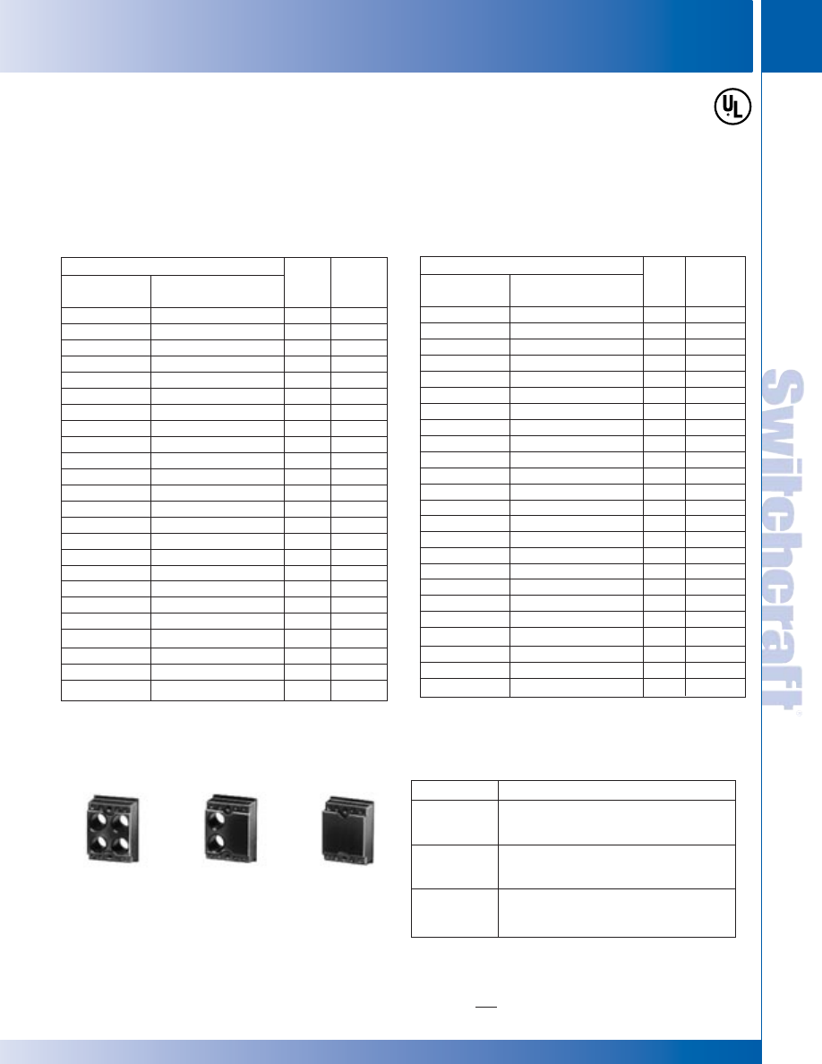
SWITCHCRAFT, INC. 5555 N. Elston Ave. • Chicago, IL 60630
207
JACK PANELS
FAX: 773 792-2129
JACK P
ANELS
DIMENSIONS ARE FOR REFERENCE ONLY
Inch
(mm)
LONG FRAME 1/4" MODULAR TWIN ROW JACK PANELS
LONG FRAME 1/4" MODULAR TWIN ROW JACK PANELS
ORDERING
Order popular assemblies by part number from table. If you
wish to mount components on the panels, order blank panels
and refer to MODULE INSERTS below. On special order,
various combinations of colored inserts mounted in basic
panels, as well as many different types of complete
assemblies are possible. Provide complete details with your
inquiry or order. Standard mount panels are available with holes
pre-drilled for vertical designation strips, Series DS320. Add
prefix “D”
to part number (JPD012000, JPD022000,
JPD072000, JPD082000, etc.).
LONG FRAME (1/4") MODULAR TWIN ROW JACK PANELS (continued)
Part Numbers*
Panel Only
JP012000
-
-
-
◊
JP022000
-
-
-
◊
JP032000
-
-
-
◊
JP042000
-
-
-
JP052000
-
-
-
◊
JP062000
-
-
-
Assembly with Jacks
Having Solder Lugs
-
◊
JP012S32A
◊
JP012S32B
1
JP012S34B
1
-
◊
JP022S32A
◊
JP022S32B
◊
JP022S34B
-
◊
JP032S32A
◊
JP032S32B
◊
JP032S34B
-
◊
JP042S32A
◊
JP042S32B
◊
JP042S34B
-
◊
JP052S32A
◊
JP052S32B
◊
JP052S34B
-
◊
JP062S32A
◊
JP062S32B
◊
JP062S34B
None
48 MT332A
48 MT332B
48 MT334B
None
56 MT332A
56 MT332B
56 MT334B
None
48 MT332A
48 MT332B
48 MT334B
None
56 MT332A
56 MT332B
56 MT334B
None
48 MT332A
48 MT332B
48 MT334B
None
56 MT332A
56 MT332B
56 MT334B
Part Numbers*
Panel Only
◊
JP072000
-
-
-
◊
JP082000
-
-
-
◊
JP092000
-
-
-
◊
JP102000
-
-
-
◊
JP112000
-
-
-
◊
JP122000
-
-
-
Assembly with Jacks
Having Solder Lugs
-
◊
JP072S32A
◊
JP072S32B
JP072S34B
-
◊
JP082S32A
◊
JP082S32B
◊
JP082S34B
-
◊
JP092S32A
◊
JP092S32B
◊
JP092S34B
-
◊
JP102S32A
◊
JP102S32B
◊
JP102S34B
-
◊
JP112S32A
◊
JP112S32B
◊
JP112S34B
-
◊
JP122S32A
◊
JP122S32B
◊
JP122S34B
None
1
52 MT332A
52 MT332B
52 MT334B
None
2
64 MT332A
64 MT332B
64 MT334B
None
52 MT332A
52 MT332B
52 MT334B
None
64 MT332A
64 MT332B
64 MT334B
None
52 MT332A
52 MT332B
52 MT334B
None
64 MT332A
64 MT332B
64 MT334B
1. Add a “1” to the part number to specify a cable tie bar.
Mounting Screws: #6-32, P10725 for jack mounting and #4-40,
P2435 for insert mounting, can be ordered separately.
◊
Special order only; contact Switchcraft.
* Panels with jacks having wire-wrapping terminals are approximately 10%
higher in price. Contact Switchcraft.
1. Non-modularized equivalent is WEco #230A.
2. Non-modularized equivalent is WEco #231A.
Standard color is black, matte finish plastic. Contact
Switchcraft. Inserts are ideal for mounting directly in control
panels and chassis where convenient jack connections are
required. Applications include test outlets, remote equipment
connections and headsets such as those used in telephone
and telecommunications equipment.
Part Number
JP9942
JP9922
JP9902
Description
Black module insert with four jack openings
(less jacks). Includes two, #4-40 machine
screws for mounting.
Black module insert with two jack openings
(less jacks). Includes two, #4-40 machine
screws for mounting.
Black module insert without holes. Includes
two, #4-40 machine screws for mounting.
Used where no jacks are needed.
MODULE INSERTS
JP9942
JP9922
JP9902
MT-Jax
®
Installed
# of
Jacks
MT-Jax
®
Installed
# of
Jacks
* Please visit the product pages on our website for the most up-to-date product information
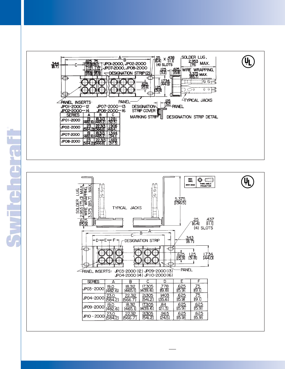
JACK PANELS
208
w w w . s w i t c h c r a f t . c o m
® Registered trademark of Switchcraft, Inc.
Note: Contact your Switchcraft Representative for price and delivery
PHONE: 773 792-2700
JACK P
ANELS
DIMENSIONS ARE FOR REFERENCE ONLY
Inch
(mm)
LONG FRAME (1/4") MODULAR TWIN ROW JACK PANELS (continued)
LONG FRAME
(
1/4"
)
MODULAR TWIN ROW JACK PANELS
LONG FRAME
(
1/4"
)
MODULAR TWIN ROW JACK PANELS
Series JP01-2000, JP02-2000, JP07-2000, JP08-2000
Series JP03-2000, JP04-2000, JP09-2000, JP010-2000
* Please visit the product pages on our website for the most up-to-date product information
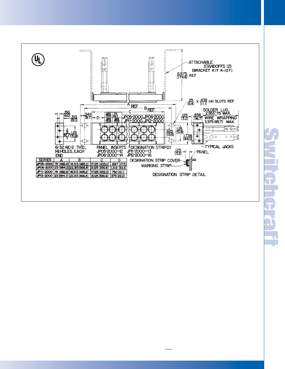
SWITCHCRAFT, INC. 5555 N. Elston Ave. • Chicago, IL 60630
209
JACK PANELS
FAX: 773 792-2129
JACK P
ANELS
DIMENSIONS ARE FOR REFERENCE ONLY
Inch
(mm)
LONG FRAME 1/4" MODULAR TWIN ROW JACK PANELS
LONG FRAME 1/4" MODULAR TWIN ROW JACK PANELS
LONG FRAME (1/4") MODULAR TWIN ROW JACK PANELS (continued)
Series JP052000, JP062000, JP112000, JP122000
* Please visit the product pages on our website for the most up-to-date product information
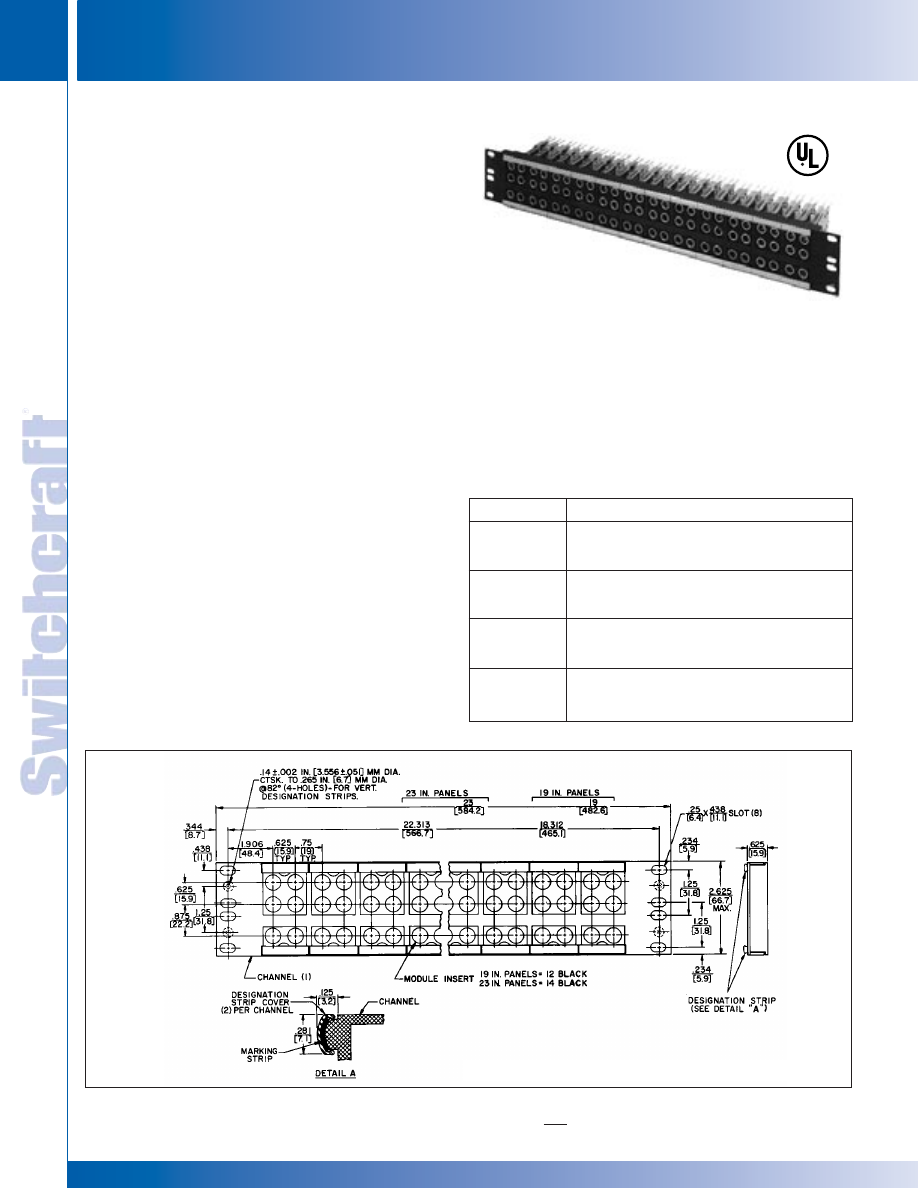
JACK PANELS
210
w w w . s w i t c h c r a f t . c o m
® Registered trademark of Switchcraft, Inc.
Note: Contact your Switchcraft Representative for price and delivery
PHONE: 773 792-2700
JACK P
ANELS
DIMENSIONS ARE FOR REFERENCE ONLY
Inch
(mm)
LONG FRAME
(
1/4"
)
MODULAR 3 ROW JACK PANELS
LONG FRAME
(
1/4"
)
MODULAR 3 ROW JACK PANELS
Four series of cross-connect jack panels are available in 19"
and 23" widths. Individual modules are easily dismounted
from the front. On special order, panels can be supplied with
a variety of standard telephone jacks.
SERIES JP312000 AND JPD312000
2.655" x 19" size for console, rack or control panel mounting.
Mounts 24 twin jacks and 24 single jacks. Openings are on
.625" centers in each row. A twin plug fits jacks horizontally
or vertically in same quad. Bottom row has 24 single jacks.
Two Kwik
®
-Change designation strips are supplied. Series
JPD31 has pre-drilled and countersunk holes for mounting
vertical designation strips. See “ORDERING”.
SERIES JP322000 AND JPD322000
Same as JP312000 and JPD312000, except 23" wide
(includes 14 inserts which accommodate 28 twin jacks and
28 single jacks).
MODULE INSERTS
Available with 6 holes or blank faces. See “ORDERING”
for colored modules.
ORDERING
Order basic assemblies by part number from table. On
special order, various combinations of colored inserts
mounted in basic panels, as well as many types of
complete assemblies are possible. Provide complete
details with your inquiry or order.
Standard mount panels are available with holes pre-drilled
for vertical designation strips, Series DS320. Add prefix “D”
to part number (JPD312000, JPD322000, etc.). Refer to
“DESIGNATION STRIPS”.
LONG FRAME (1/4") MODULAR 3 ROW JACK PANELS
Part Number
JP312000
JPD312000
JP322000
JPD322000
Description
19" wide x 2.625" high panel with 12 black modules
installed. Two, full width Kwik
®
-Change designation
strips are included.
Same as JP312000, except holes pre-drilled for
mounting vertical designation strips at each side.
23" wide x 2.625" high panel with 14 black modules
installed. Two, full width Kwik
®
-Change designation
strips are included.
Same as JP322000, except holes pre-drilled for
mounting vertical designation strips at each side.
Mounting Screws: #6-32 P10725 for jack mounting and
#4-40 P2435 for insert mounting can also be ordered
separately. Contact Switchcraft.
Series JP312000, JPD312000, JP322000, JPD322000
SPECIFICATIONS
Panel and Designation Strips: Aluminum alloy,
extruded. Black anodized per MIL-A-8625.
Module Insert: Molded plastic, matte finish. Black standard;
white, red, green, blue or yellow available on special order.
Marking Strip: White matte finish plastic.
Designation Strip Cover: Extruded clear plastic.
Screws: #6-32 x 5/16" PHMS, for jack mounting;
#4-40 x 1/2" phillips FHMS, for module insert mounting.
* Please visit the product pages on our website for the most up-to-date product information
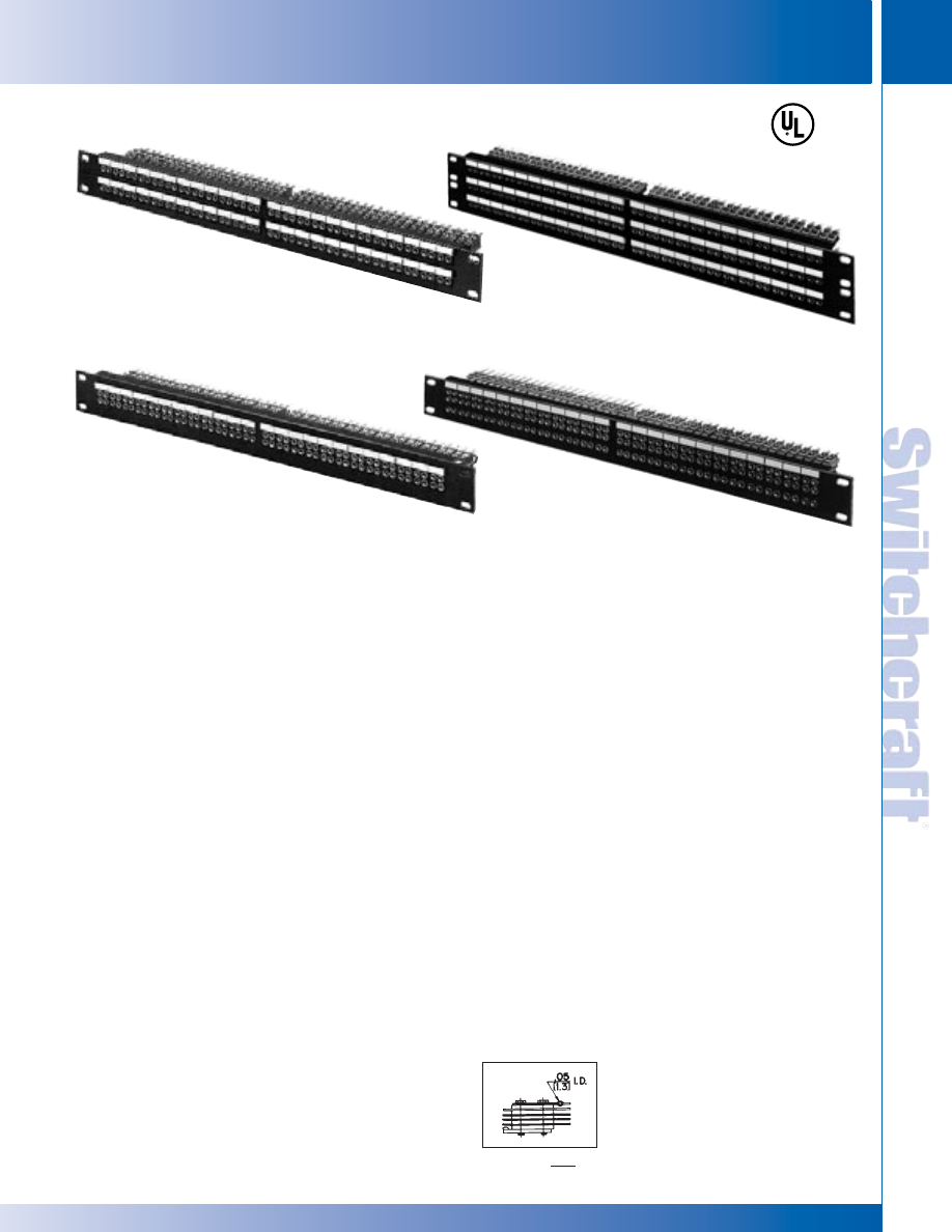
SWITCHCRAFT, INC. 5555 N. Elston Ave. • Chicago, IL 60630
211
JACK PANELS
FAX: 773 792-2129
JACK P
ANELS
DIMENSIONS ARE FOR REFERENCE ONLY
Inch
(mm)
TT-JAX
(
.173"
)
JACK PANELS
TT-JAX
(
.173"
)
JACK PANELS
TT-JAX
®
(.173") JACK PANELS SERIES 1600, A1600, B1600, C1600
SERIES 1700
Jack Panel
with optional jacks.
(See next page for specific part numbers.)
SERIES B1600 and C1600
Jack Panels with optional jacks.
(See next page for specific part numbers.)
SERIES 1600 and A1600
Jack Panels with optional jacks.
(See next page for specific part numbers.)
Series B1700
Jack Panel
with optional jacks.
(See next page for specific part numbers.)
®
®
SERIES 1600 DOUBLE ROW JACK PANELS
Black anodized panel has four inserts (24 single jacks). Double
row configuration accommodates 96 total jacks (48 pairs). Jack
spacing eliminates cross-patching of adjacent circuits when
twin plugs are used. Panel size: 1.75" x 19". Four, Kwik-
Change
®
designation strips for circuit identification supplied.
SERIES A1600 DOUBLE ROW JACK PANELS
Similar to Series 1600, except mounts 104 jacks. Jacks
are spaced on .312" centers for maximum jack density. Four,
Kwik-Change
®
designation strips supplied.
SERIES B1600 THREE ROW JACK PANELS
2.625" x 19" panel size yields high density (144 jacks). Jacks
are paired for single or twin plugs without cross-patching. Six,
Kwik-Change
®
designation strips supplied.
SERIES C1600 THREE ROW JACK PANELS
Similar to B1600, except maximum jack density (156 jacks).
Six, Kwik-Change
®
designation strips supplied.
SERIES 1700 TWIN ROW JACK PANELS
Standard 1.75" x 19" panel accepts 48 TT-Twin-Jax
®
jacks.
Two, Kwik-Change
®
designation strips supplied.
SERIES B1700 THREE ROW JACK PANELS
Accepts 48 Tri-Jax
®
with alternate mounting centers to
eliminate cross-patching between adjacent circuits. Panel size:
1.75" x 19". Two, Kwik-Change
®
designation strips supplied.
SPECIFICATIONS
SERIES 1600, A1600, B1600, 1700, B1700
Panel and Designation Strip: Aluminum alloy, extruded.
Per QQ-A-200/8.
Black anodized per MIL-A-8625C.
Black thermoplastic UL 94V-0.
Panel Insert: Thermoplastic polyester, UL 94V-0.
Marking Strip: White matte finish plastic.
Designation Strip Cover: Extruded clear plastic.
ORDERING
1. Part number tables list jack panels with the most commonly
used jack circuits. Custom jack panels can be built on
special order to OEM requirements. Typical special
order features are:
• Lamp jack with incandescent or LED lamps.
• Solder lug or wire-wrapping terminals.
• Pre-printed designation strips.
• TT-Switch® switches with wide switching selection.
2. Contact Switchcraft for all special order items.
SPECIFYING NOTE:
Prefix letter “D” on part number indicates panels are drilled for
mounting vertical designation strips on both ends. EXAMPLE -
D1600, AD1632B, WCD1634B (vertical designation strips not
included). Order DS321 for 1.734" high panels; DS350 for
2.069" high panels. See “Designation Strips” section.
The most commonly-used combinations of panels and jacks
are listed on following page. 1600, A1600, B1600, C1600 panels
can be assembled with many different “bantam type” jacks.
Bussing type terminals which allow
you to buss jacks quickly and easily
are available on special order.
* Please visit the product pages on our website for the most up-to-date product information
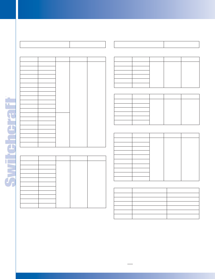
JACK PANELS
212
w w w . s w i t c h c r a f t . c o m
® Registered trademark of Switchcraft, Inc.
Note: Contact your Switchcraft Representative for price and delivery
PHONE: 773 792-2700
JACK P
ANELS
DIMENSIONS ARE FOR REFERENCE ONLY
Inch
(mm)
TT-JAX
®
(.173") JACK PANELS – SERIES 1600, A1600, B1600, C1600
(continued)
Jack Data
1
Panel Data
Part Number
1600
D1600
1632A
D1632A
1632B
D1632B
W1632B
WD1632B
1634B
D1634B
W1634B
WD1634B
A1600
AD1600
A1632B
AD1632B
A1634B
AD1634B
WA1634B
WAD1634B
Part Number
w/o Jacks
1
w/o Jacks
1
TT32A
TT32A
TT32B
TT32B
WTT32B
WTT32B
TT34B
TT34B
WTT34B
WTT34B
w/o Jacks
1
w/o Jacks
1
TT32B
TT32B
TT34B
TT34B
WTT34B
WTT34B
Quantity
96
104
Dimensions
19"
x
1.734"
Mount
Standard
SERIES 1600 AND A1600
Part Number
B1600
BD1600
B1632B
BD1632B
B1634B
BD1634B
WBD1634B
B1650
BD1650
WB1650
WBD1650
Part Number
w/o Jacks
1
w/o Jacks
1
TT32B
TT32B
TT34B
TT34B
WTT34B
Note 2
Note 2
Note 3
Note 3
Quantity
144
Dimensions
19"
x
2.609"
Mount
Standard
SERIES B1600
Part Number
C1600
CD1600
C1634B
CD1634B
WC1634B
WCD1634B
Part Number
w/o Jacks
1
w/o Jacks
1
TT34B
TT34B
WTT34B
WTT34B
Quantity
156
Dimensions
19"
x
2.609"
Mount
Standard
SERIES C1600
Part Number
1700
D1700
1789
D1789
W1789
WD1789
Part Number
w/o Jacks
4
w/o Jacks
4
TT89
TT89
WTT89
WTT89
Quantity
48
Twin-Jax
®
Dimensions
19"
x
1.734"
Mount
Standard
SERIES 1700
Part Number
B1700
BD1700
B1795
BD1795
WB1795
WBD1795
B1796
BD1796
WB1796
WBD1796
Part Number
w/o Jacks
5
w/o Jacks
5
TT95
TT95
WTT95
WTT95
TT96
TT96
WTT96
WTT96
Quantity
48 Tri-Jax
®
Dimensions
19"
x
1.734"
Mount
Standard
SERIES B1700
Part Number
TT505
◊
TT506
◊
TT507
◊
TT508
◊
TT509
◊
TT511
Insert Description
Without jacks, 24 holes
Blank
Without jacks, 48 holes
Blank
Without jacks, 26 holes
Without jacks, 72 holes
For Panels
A1600, B1600
1600, B1600, C1600
1700
1700
A1600, C1600
B1700
PANEL INSERTS
Jack Data
Panel Data
1. Accepts indicated number of single TT-Jax
®
, TT-Switches
®
,
TT-Lamp-Jax
®
or any combination.
2. Three-row panel assembly with 96 TT34B Jax (top 2 rows);
and 48 TT32B Jax (bottom row).
3. Same as Note 2 above, except jacks have wire-wrapping terminals.
4. Accepts 48 TT Twin-Jax
®
.
5. Accepts 48 TT Tri-Jax
®
.
◊
Special order only; contact Switchcraft.
TT-JAX
(
.173"
)
JACK PANELS
TT-JAX
(
.173"
)
JACK PANELS
®
®
* Please visit the product pages on our website for the most up-to-date product information
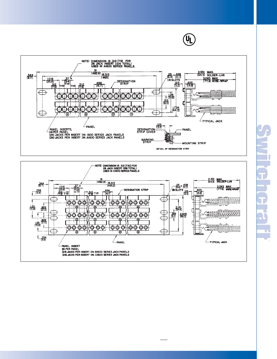
SWITCHCRAFT, INC. 5555 N. Elston Ave. • Chicago, IL 60630
213
JACK PANELS
FAX: 773 792-2129
JACK P
ANELS
DIMENSIONS ARE FOR REFERENCE ONLY
Inch
(mm)
TT-JAX
(
.173"
)
JACK PANELS
TT-JAX
(
.173"
)
JACK PANELS
TT-JAX
®
(.173") JACK PANELS –SERIES 1600, A1600,
B1600, C1600 (continued)
®
®
Series 1600 & A1600
Series B1600 & C1600
* Please visit the product pages on our website for the most up-to-date product information
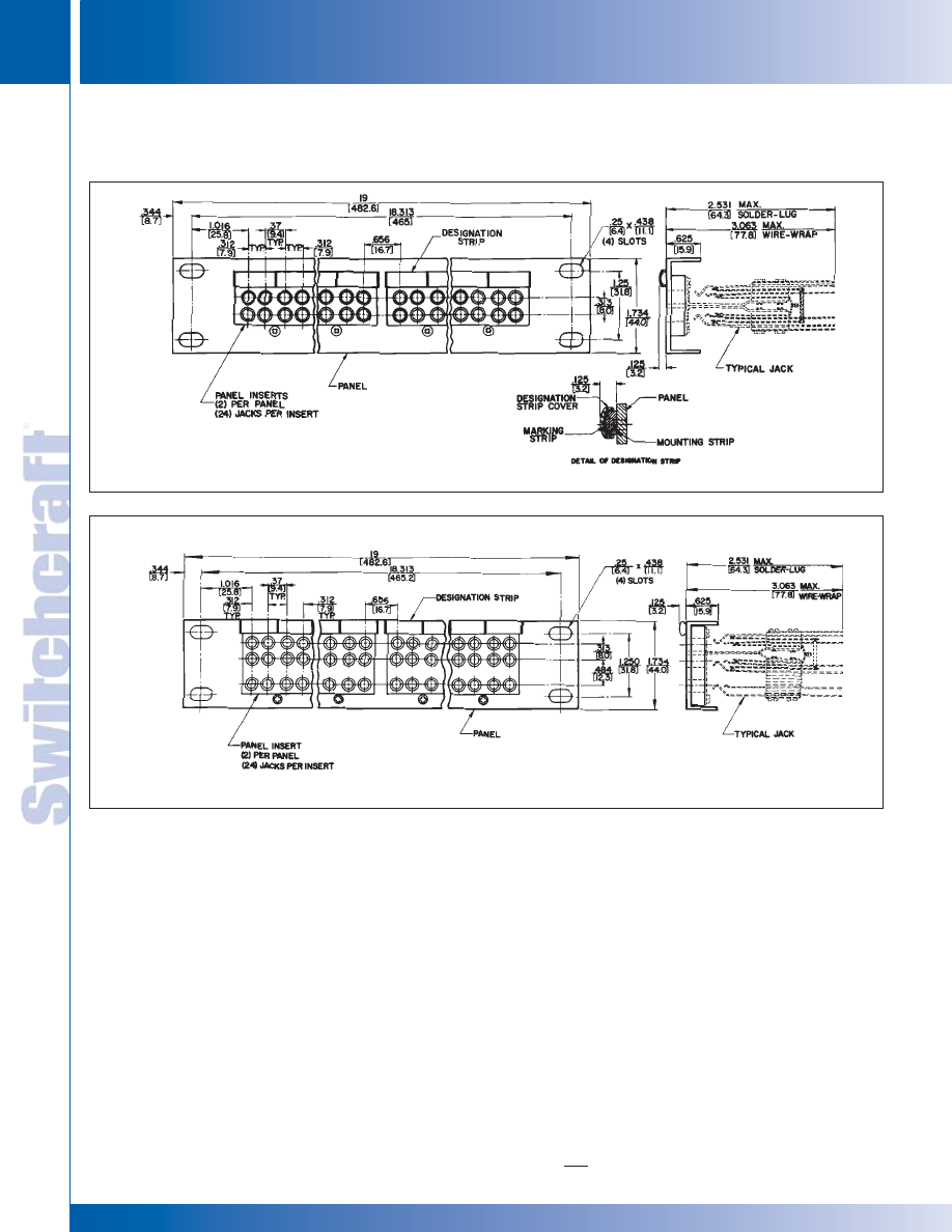
JACK PANELS
214
w w w . s w i t c h c r a f t . c o m
® Registered trademark of Switchcraft, Inc.
Note: Contact your Switchcraft Representative for price and delivery
PHONE: 773 792-2700
JACK P
ANELS
DIMENSIONS ARE FOR REFERENCE ONLY
Inch
(mm)
TT-JAX
(
.173"
)
JACK PANELS
TT-JAX
(
.173"
)
JACK PANELS
TT-JAX
®
(.173") JACK PANELS – SERIES 1600, A1600,
B1600, C1600 (continued)
Series 1700
Series B1700
®
®
* Please visit the product pages on our website for the most up-to-date product information
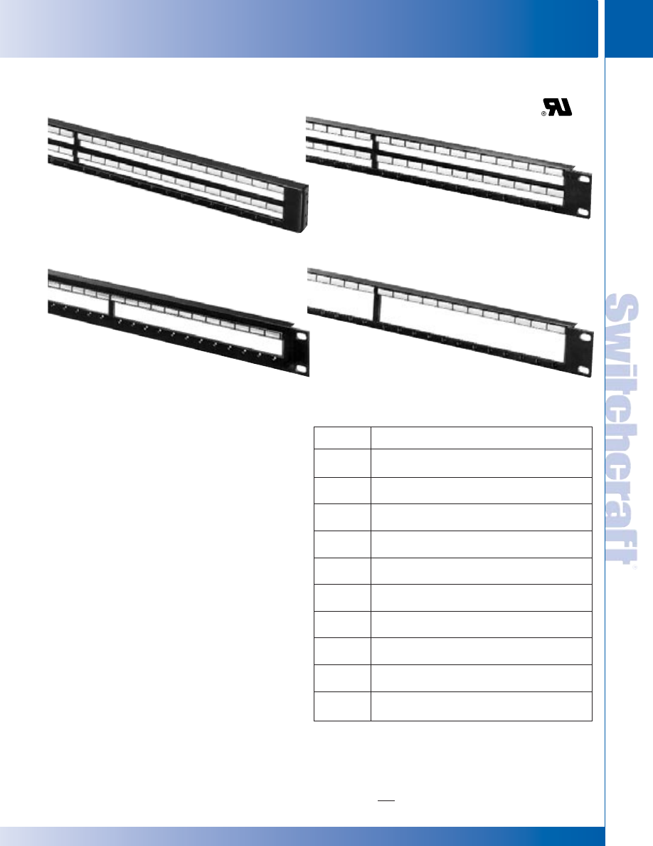
SWITCHCRAFT, INC. 5555 N. Elston Ave. • Chicago, IL 60630
215
JACK PANELS
FAX: 773 792-2129
JACK P
ANELS
DIMENSIONS ARE FOR REFERENCE ONLY
Inch
(mm)
MODULAR TT-JAX
(
.173"
)
PANELS
MODULAR TT-JAX
(
.173"
)
PANELS
Ten series of blank panels are available in 19" and 23"
widths, standard or flush mounting, and double, twin or three
row configurations. OEM’s can order blank components and
individual modules, jacks, switches and lamp jacks for
production line assembly according to standard or special
front panel configurations. Kwik-Change
®
designation strips
are supplied with panels for custom legend marking.
Flush mounting styles can use extension legs (on special
order), for stand-off mounting from front of rack. Contact
Switchcraft for Mounting Bracket Kit K107.
SPECIFICATIONS
Panel and Designation Mounting Strip: Aluminum alloy,
extruded per QQ-A-200/8. Black anodized per MIL-A-8265C.
Marking Strip: Matte finish white plastic.
Designation Strip Cover: Extruded clear plastic.
SPECIFYING NOTE: Part numbers in table are for
blank panels only.
ORDERING
1. Order by part number from table
2. Refer to jack section to specify other jacks
and components.
Series
Number
1
Description
2
TT51
19" double row standard mount panel. Mounts 96 single
jacks on 24 modules.
TT53
19" three row standard mount panel. Mounts 48 Tri-Jax
®
jacks on 24 modules.
TT54
23" three row standard mount panel. Mounts 56 Tri-Jax
®
jacks on 28 modules.
TT55
19" double row flush mount panel. Mounts 96 single
jacks on 24 modules.
TT56
23" double row flush mount panel. Mounts 112 single
jacks on 28 modules.
TT58
23" three row flush mount panel. Mounts 56 Tri-Jax
®
jacks on 28 modules.
TT59
19" twin row standard mount panel. Mounts 48 TT
Twin-Jax
®
jacks on 24 modules.
TT60
23" twin row standard mount panel. Mounts 56 TT
Twin-Jax
®
jacks on 28 modules.
TT61
19" twin row flush mount panel. Mounts 48 TT
Twin-Jax
®
jacks on 24 modules.
TT62
23" twin row flush mount panel. Mounts 56 TT
Twin-Jax
®
jacks on 28 modules.
MODULAR TT-JAX
®
(.173") PANELS - BLANK SERIES TT51, TT53, TT56, TT59
◊
Special order only. Contact Switchcraft.
1. Prefix TTD for standard mounting panels indicates predrilled holes for
mounting “X Wide” vertical designation strips. See “Designation Strips” section.
2. Each panel includes integral designation mounting strip, marking strips
and clear plastic covers.
3. Contact Switchcraft for any special order items.
SERIES TT53
SERIES TT56
SERIES TT59
®
®
SERIES TT51
* Please visit the product pages on our website for the most up-to-date product information
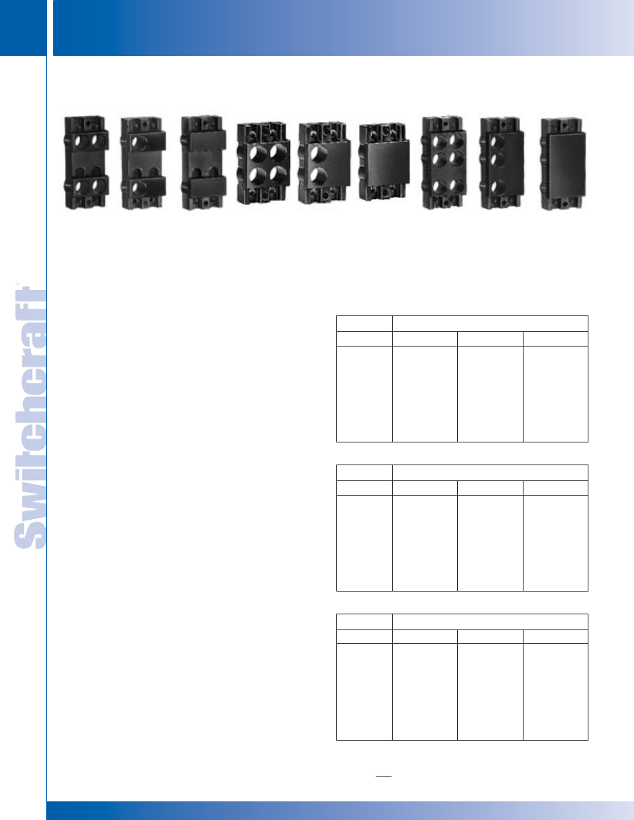
JACK PANELS
216
w w w . s w i t c h c r a f t . c o m
® Registered trademark of Switchcraft, Inc.
Note: Contact your Switchcraft Representative for price and delivery
PHONE: 773 792-2700
JACK P
ANELS
DIMENSIONS ARE FOR REFERENCE ONLY
Inch
(mm)
TT MODULE INSERTS
TT MODULE INSERTS
Module colors are black or gray (standard); red, green, blue,
white and yellow available on special order. Each module has
a matte finish front surface and includes two mounting screws
(Switchcraft P2348).
SERIES TT91
Choice of blank, two- or four-hole modules for double row
panels Series TT51, TT55 and TT56. The following
components are used with Series TT91 modules:
1. Front mount TT-Jax
®
jacks.
2. Front mount TT-Switch
®
switches Series TT300FM
and WTT420FM.
3. Front mount TT Lamp Jax
®
lamp jacks TT420FM
and WTT420FM.
SERIES TT92
Blank, two- or four-hole modules for twin row panels Series
TT59, TT60, TT61 and TT62. TT Twin-Jax
®
jacks are used
with these modules.
SERIES TT93
Blank, three- or six-hole modules for three row panels
Series TT53, TT54, TT57 and TT58. Tri-Jax
®
jacks are
used with these modules.
SPECIFICATIONS
Module: Precision molded thermosetting plastic in colors.
Mounting Screws: Black zinc, #3-48 x .312" flat head
machine screws.
ORDERING
1. Order by part number from tables.
2. Contact Switchcraft for any special order items.
SPECIFYING NOTE:
The part numbers listed on this
page are for modules only. Refer to following page for
specifying panel assemblies with components installed.
Red
Black
Green
Blue
White
Yellow
Gray
4
◊
TT91401
◊
TT91402
◊
TT91403
◊
TT91404
◊
TT91405
◊
TT91408
◊
TT91411
2
◊
TT91201
◊
TT91202
◊
TT91203
◊
TT91204
◊
TT91205
◊
TT91208
TT91211
Blank
◊
TT91001
◊
TT91002
◊
TT91003
◊
TT91004
◊
TT91005
◊
TT91008
◊
TT91011
SERIES TT91
SERIES TT92
TT MODULE INSERTS – SERIES TT91, TT92 AND TT93
Openings
SERIES TT91 (For Double Row Panels)
Red
Black
Green
Blue
White
Yellow
Gray
4
◊
TT92401
◊
TT92402
◊
TT92403
◊
TT92404
◊
TT92405
◊
TT92408
◊
TT92411
2
◊
TT92201
TT92202
◊
TT92203
◊
TT92204
◊
TT92205
◊
TT92208
TT92211
Blank
◊
TT92001
◊
TT92002
◊
TT92003
◊
TT92004
◊
TT92005
◊
TT92008
◊
TT92011
Openings
SERIES TT92 (For Twin Row Panels)
Red
Black
Green
Blue
White
Yellow
Gray
4
TT93601
TT93602
TT93603
TT93604
TT93605
TT93608
TT93611
2
◊
TT93301
TT93302
◊
TT93303
◊
TT93304
◊
TT93305
◊
TT93308
TT93311
Blank
TT93001
TT93002
TT93003
TT93004
TT93005
TT93008
TT93011
Openings
SERIES TT93 (For Three Row Panels)
◊
Special order only; contact factory for price and delivery.
TT91402
(black, 4 hole)
TT91202
(black, 2 hole)
TT91002
(black, blank)
TT92402
(black, 4 hole)
TT92202
(black, 2 hole)
TT93002
(black, blank)
TT93302
(black, 3 hole)
TT93602
(black, 6 hole)
TT92002
(black, blank)
Color
Color
Color
SERIES TT-93
* Please visit the product pages on our website for the most up-to-date product information
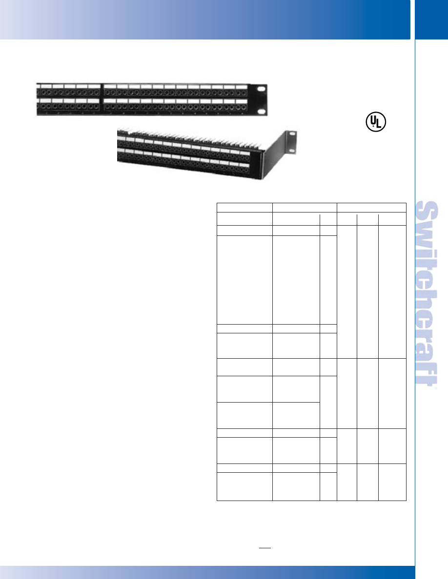
SWITCHCRAFT, INC. 5555 N. Elston Ave. • Chicago, IL 60630
217
JACK PANELS
FAX: 773 792-2129
JACK P
ANELS
DIMENSIONS ARE FOR REFERENCE ONLY
Inch
(mm)
SERIES TT5102000*
Modular double row, 1.75" high x 19" wide, standard mount.
Supplied with 24 black modules, designation strips, and
covers. Mounts 96 TT-Jax
®
single jacks, lamp jacks and/or
switches.
SERIES TT51020001*
Modular double row, 1.75" high x 19" wide, standard mount.
Supplied with 24 black modules, designation strips, and
covers. Mounts 96 TT-Jax
®
single jacks, lamp jacks and/or
switches. Comes supplied with cable tie bar.
SERIES TT5202000*
Similar to TT5102000, except 23" wide. Supplied with 28
black modules, designation strips, and covers. Mounts 112
TT-Jax
®
single jacks, jack lamps and/or switches.
SERIES TT5502000
Modular double row, 1.75" high x 19" wide, flush mount.
Supplied with 24 black modules, designation strips, and
covers. Panels can be mounted flush with rack/control panel
surface, or use with extension legs for standoff mounting with
easy access to rear of jacks for testing/monitoring. Mounts
96 TT-Jax
®
single jacks, lamp jacks and/or switches.
SERIES TT5602000
Similar to TT5502000, except 23" wide. Supplied with 28
black modules, designation strips, and covers. Mounts 112
TT-Jax
®
single jacks, jack lamps and/or switches.
ORDERING
1. Order part number from table
2. Contact Switchcraft for any special order items.
3. Separate components can be ordered.
* Prefix TTD indicates panel is pre-drilled with countersunk
holes for mounting “X-Wide” vertical designation strips.
See “DESIGNATION STRIPS” section.
Part Number
TT5102000
◊
TT5102S31
◊
TT5102W31
TT5102S32A
TT5102W32A
TT5102S32B
2
TT5102W32B
◊
TT5102S33B
◊
TT5102W33B
TT5102S34B
2
TT5102W34B
TTD5102000
TTD5102S31
Through
TTD5102W34B
TT5202000
TTD5202000
TT5202S31
Through
TT5202W34B
TTD520231
Through
TTD5202W34B
TT552000
TT5502S31
Through
TT5502W34B
TT5602000
TT5602S31
Through
TT5602W34B
Part Number
without jacks
TT31FM
WTT31FM
TT32AFM
WTT32AFM
TT32BFM
WTT32BFM
TT33BFM
WTT33BFM
TT34BFM
WTT34BFM
without jacks
Note
1
without jacks
Note
1
Note
1
without jacks
Note
1
without jacks
Note
1
Qty.
0
96
0
96
0
112
0
96
0
112
Width
19"
23"
19"
23"
Mount
Stan-
dard
Stan-
dard
Flush
Flush
Modules
24
(Black)
28
(Black)
24
(Black)
28
(Black)
MODULAR TT-JAX
®
(.173") JACK PANELS –
SERIES TT5102000, TT5202000, TT5502000, TT5602000
Jack Data
Panel Data
◊
Special order only; contact Switchcraft for price and delivery.
1 Complete panel part number with jacks installed can be constructed as
shown for Series TT51.
2. Add a “1” to part number to specify cable tie bar.
Series TT5102000,
TT5202000 (Typical)
Series TT5502000,
TT5602000 (Typical)
Shown w/mounting bracket K107
(not supplied).
MODULAR TT-JAX
(
.173"
)
JACK PANELS
MODULAR TT-JAX
(
.173"
)
JACK PANELS
®
®
* Please visit the product pages on our website for the most up-to-date product information
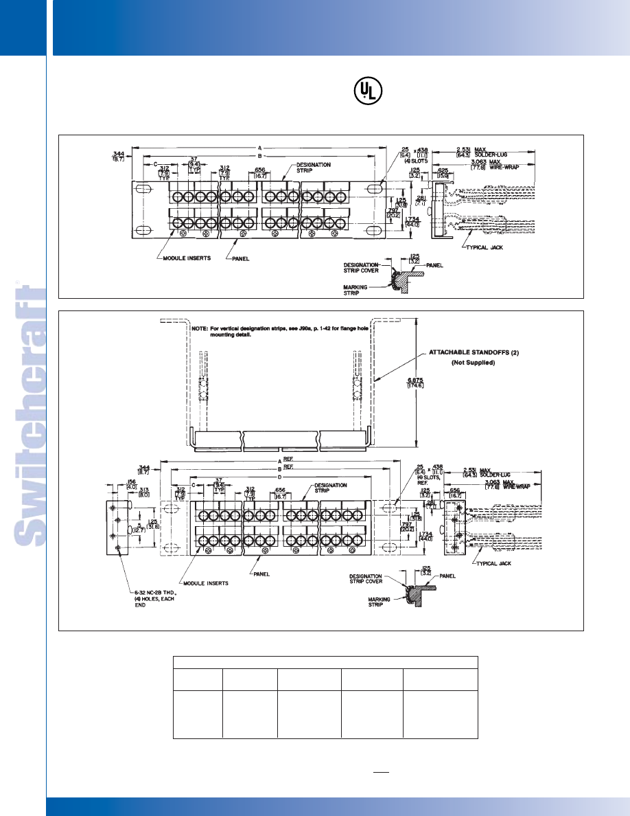
JACK PANELS
218
w w w . s w i t c h c r a f t . c o m
® Registered trademark of Switchcraft, Inc.
Note: Contact your Switchcraft Representative for price and delivery
PHONE: 773 792-2700
JACK P
ANELS
DIMENSIONS ARE FOR REFERENCE ONLY
Inch
(mm)
MODULAR TT-JAX
®
(.173") JACK PANELS –
SERIES TT5102000, TT5202000,
TT5502000, TT56020000 (continued)
MODULAR TT-JAX
(
.173"
)
JACK PANELS
MODULAR TT-JAX
(
.173"
)
JACK PANELS
®
®
Series TT51-02000, TT52-02000 (Typical)
Series TT55-02000, TT56-02000 (Typical)
Jack Panel Dimensions - inch (mm)
Series
Number
A
B
C
D
TT51
19 (482.6)
18.3 (465.1)
1.013 (25.7)
-
◊
TT52
23 (584.2)
22.3 (566.7)
1.648 (41.9)
-
TT55
19 (482.6)
18.3 (465.1)
1.013 (25.7)
17.125 (435)
TT56
23 (584.2)
22.3 (566.7)
1.648 (41.9)
21.125 (536.6)
◊
Special order only; contact Switchcraft for price and delivery.
* Please visit the product pages on our website for the most up-to-date product information
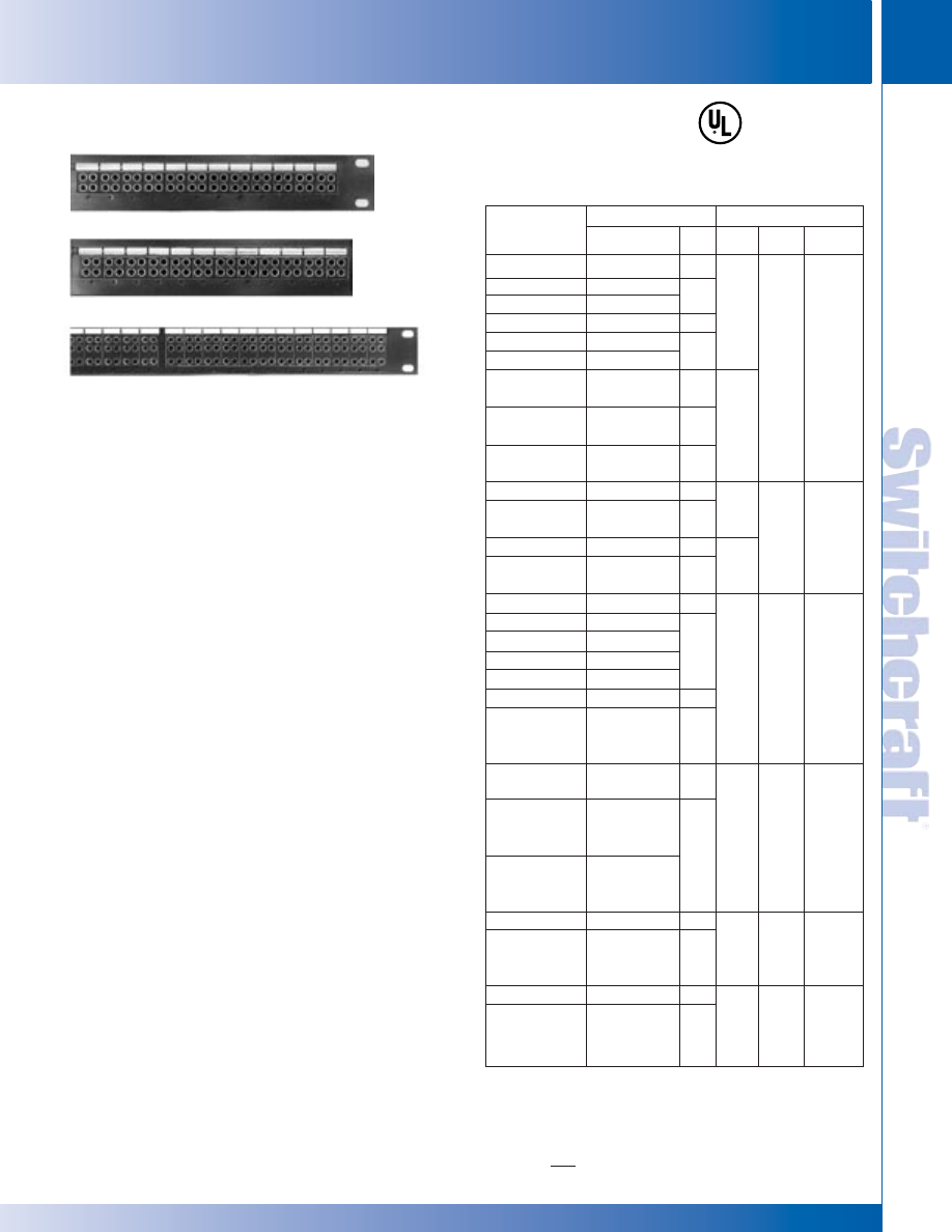
SWITCHCRAFT, INC. 5555 N. Elston Ave. • Chicago, IL 60630
219
JACK PANELS
FAX: 773 792-2129
JACK P
ANELS
DIMENSIONS ARE FOR REFERENCE ONLY
Inch
(mm)
TT-JAX
(
.173"
)
TWIN ROW AND THREE ROW JACK PANELS
TT-JAX
(
.173"
)
TWIN ROW AND THREE ROW JACK PANELS
SERIES TT5902000*
Modular twin row, 1.75" high x 19" wide, standard mount.
Supplied with 24 black modules, designation strips, and
covers. Mounts 48 TT Twin-Jax
®
twin jacks.
SERIES TT6002000*
Similar to TT5902000, except 23" wide. Supplied with 28
black modules, designation strips, and covers. Mounts 56 TT
Twin-Jax
®
twin jacks.
SERIES TT6102000
Modular twin row, 1.75" high x 19" wide, flush or standoff
mount. Supplied with 24 black modules, designation strips,
and covers. Mounts 48 TT Twin-Jax
®
twin jacks.
SERIES TT6202000
Similar to TT6102000, except 23" wide. Supplied with 28
black modules, designation strips, and covers. Mounts 56 TT
Twin-Jax
®
twin jacks.
SERIES TT5302000*
Modular three row, 1.75" high x 19" wide, standard mount.
Supplied with 24 black modules, designation strips, and
covers. Designed for LINE, EQUIP and MONITOR patch
connections. Mounts 48 Tri-Jax
®
triple jacks.
SERIES TT5402000*
Similar to TT5302000, except 23" wide. Supplied with
28 black modules, designation strips, and covers. Mounts 56
Tri-Jax
®
triple jacks.
SERIES TT5702000
Modular three row, 1.75" high x 19" wide, flush or standoff
mount. Supplied with 24 black modules, designation strips,
and covers. Mounts 48 Tri-Jax
®
triple jacks.
SERIES TT5802000
Similar to TT5702000, except 23" wide. Supplied with
28 black modules, designation strips, and covers. Mounts
56 Tri-Jax
®
triple jacks.
ORDERING
1. Order part number from table
2. Contact Switchcraft for any special order items.
*Prefix TTD indicates panel is pre-drilled with countersunk
holes for mounting “X-Wide” vertical designation strips.
See “DESIGNATION STRIPS” section.
TT-JAX
®
(.173") TWIN ROW AND THREE ROW JACK PANELS
Part Number
TT5902000
TT5902S89
TT5902W89
TTD5902000
TTD5902S89
TTD5902W89
TT6002000
TTD6002000
TT6002S89
TT6002W89
TTD6002S89
TTD6002W89
TT6102000
TT6102S89
TT6102W89
TT6202000
TT6202S89
TT6202W89
TT5302000
◊
TT5302S95
TT5302W95
◊
TT5302S96
TT5302W96
TTD5302000
TTD5302S95
Through
TTD5302W96
TT5402000
TTD5402000
TT5402S95
Through
TT5402W96
TTD5402S95
Through
TTD5402W96
TT5702000
TT5702S95
Through
TT5702W96
TT5802000
TT5802S95
Through
TT5802W96
Part Number
without jacks
TT89FM
WTT89FM
without jacks
TT89FM
WTT89FM
without jacks
Note
1
Note
1
None
Note
1
without jacks
Note
1
without jacks
TT95FM
WTT95FM
TT96FM
WTT96FM
without jacks
Note
2
without jacks
Note
2
Note
2
without jacks
Note
2
without jacks
Note
2
Qty.
0
48
0
48
0
56
56
0
48
0
56
0
48
0
48
0
56
0
48
0
56
Width
19"
23"
19"
23"
19"
23"
19"
23"
Mount
Stan-
dard
Flush
Stan-
dard
Stan-
dard
Flush
Flush
Modules
24
(Black)
28
(Black)
24
(Black)
28
(Black)
24
(Black)
28
(Black)
Jack Data
Panel Data
◊
Special order only; contact Switchcraft for price and delivery.
1. Complete panel part number with jacks installed can be constructed as
shown for Series TT59 or TTD59.
2. Complete panel part number with jacks installed can be constructed as
shown for series TT53.
Series TT5302000, TT5402000 (Typical)
Series TT5902000
Series TT6102000
®
®
* Please visit the product pages on our website for the most up-to-date product information
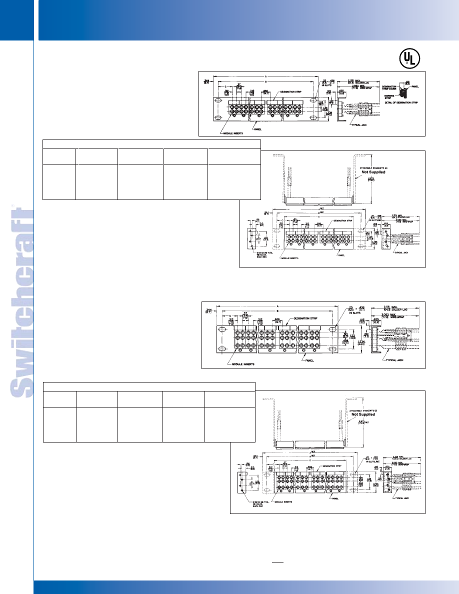
JACK PANELS
220
w w w . s w i t c h c r a f t . c o m
® Registered trademark of Switchcraft, Inc.
Note: Contact your Switchcraft Representative for price and delivery
PHONE: 773 792-2700
JACK P
ANELS
DIMENSIONS ARE FOR REFERENCE ONLY
Inch
(mm)
TT-JAX
®
(.173") TWIN ROW AND THREE ROW JACK PANELS (continued)
Series TT5902000 and
TT6002000 (Typical)
Series TT6102000 and
TT6202000 (Typical)
Series TT5302000 and
TT5402000 (Typical)
Series TT5702000 and
TT5802000 (Typical)
Series TT5702000 and
TT5802000 (Typical)
TT-JAX
(
.173"
)
TWIN ROW AND THREE ROW JACK PANELS
TT-JAX
(
.173"
)
TWIN ROW AND THREE ROW JACK PANELS
Jack Panel Dimensions - inch (mm)
Series
Number
A
B
C
D
TT59
19 (482.6)
18.3 (465.1)
1.013 (25.7)
-
TT60
23 (584.2)
22.3 (566.7)
1.648 (41.9)
-
TT61
19 (482.6)
22.3 (566.7)
1.013 (25.7)
17.125 (435)
TT62
23 (584.2)
22.3 (566.7)
1.648 (41.9)
21.125 (536.6)
Jack Panel Dimensions - inch (mm)
Series
Number
A
B
C
D
TT53
19 (482.6)
18.3 (465.1)
1.013 (25.7)
-
TT54
23 (584.2)
22.3 (566.7)
1.648 (41.9)
-
TT57
19 (482.6)
22.3 (566.7)
1.013 (25.7)
17.125 (435)
◊
TT58
23 (584.2)
22.3 (566.7)
1.648 (41.9) 21.125 (536.6)
®
®
* Please visit the product pages on our website for the most up-to-date product information
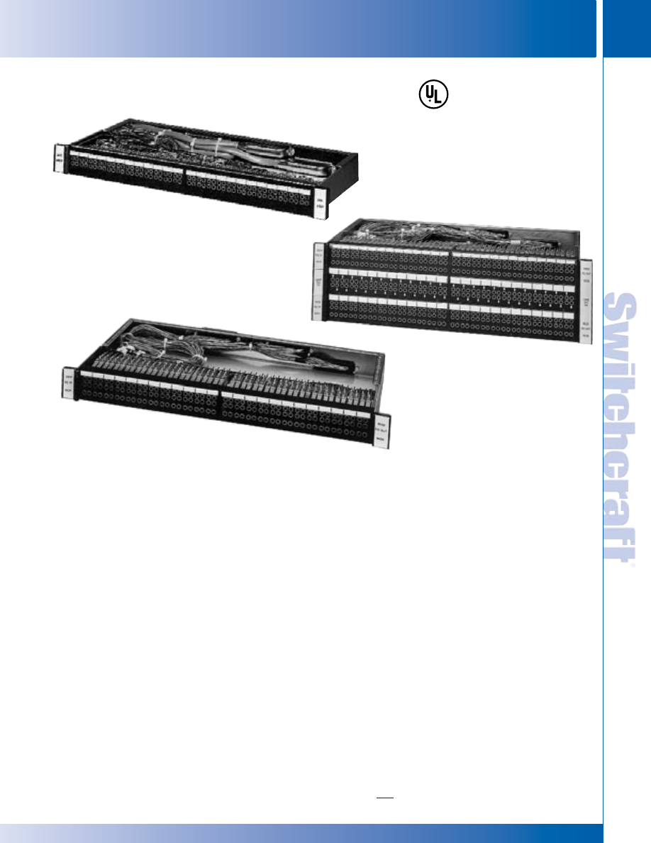
SWITCHCRAFT, INC. 5555 N. Elston Ave. • Chicago, IL 60630
221
JACK PANELS
FAX: 773 792-2129
JACK P
ANELS
DIMENSIONS ARE FOR REFERENCE ONLY
Inch
(mm)
TT-JAX
®
(.173") CONNECTORIZED JACKFIELDS –
SERIES TT, 2-WIRE, 4-WIRE, 6-WIRE
2-wire TT-Connectorized Jackfield
TT2W48VCF1
4-wire TT-Connectorized Jackfield
TT4W24MCF1
6-wire TT-Connectorized Jackfield
TT-JAX
(
.173"
)
CONNECTORIZED JACKFIELDS
TT-JAX
(
.173"
)
CONNECTORIZED JACKFIELDS
®
®
2-WIRE TT-CONNECTORIZED JACKFIELDS, SERIES TT
Contains 48, 2-wire circuits.
Arrangements include:
LINE-DROP or Signal E/M, or LINE-DROP-MON. Available
with MONITOR jack row. On rear panel, LINE connectors are
receptacles and DROP connectors are plugs. LINE and DROP
circuits may be isolated from each other for separate monitoring.
On special order, 48 circuits LINE/COMBINATION DROP/MON
or 96 circuits, LINE/DROP or Signal E/M may be specified.
2-WIRE TT-CONNECTORIZED PC JACKFIELD,
SERIES TTPC
Same as 2-Wire TT-connectorized jackfields above, except all
connections are machine-soldered on a double-sided PC
board instead of hand wired.
4-WIRE TT-CONNECTORIZED JACKFIELDS,
SERIES TT
4-Wire jackfields have 24, 4-wire circuits for MOD-DEM/EQ
IN-EQ OUT/MON patching, or may be used for other 4-wire
patching applications. Can be supplied with or without
MONITOR jack row. On rear panel, MOD AND EQ IN
connectors are receptacles and DEM and EQ OUT
connectors are plugs.
6-WIRE TT-CONNECTORIZED JACKFIELDS,
SERIES TT
6-Wire jackfields contain 48, 6-wire circuits for MOD-DEM/EQ
IN EQ OUT/MON/SIG LINE/SIG EQ patching with toll test
boards. Available with or without MONITOR jack row. On rear
panel, MOD, EQ IN and SIG LINE connectors are receptacles
and DEM, EQ OUT and SIG EQ connectors are plugs. The
following can be specified on special order: 12 circuits,
DEM-MOD/EQ IN-EQ OUT/MON/SIG E/M; 48 circuits, signal
E/M leads separated; 48 circuits for D3 channel banks.
ORDERING
1. Order by part number from tables.
2. Contact Switchcraft for any special order items.
* Please visit the product pages on our website for the most up-to-date product information
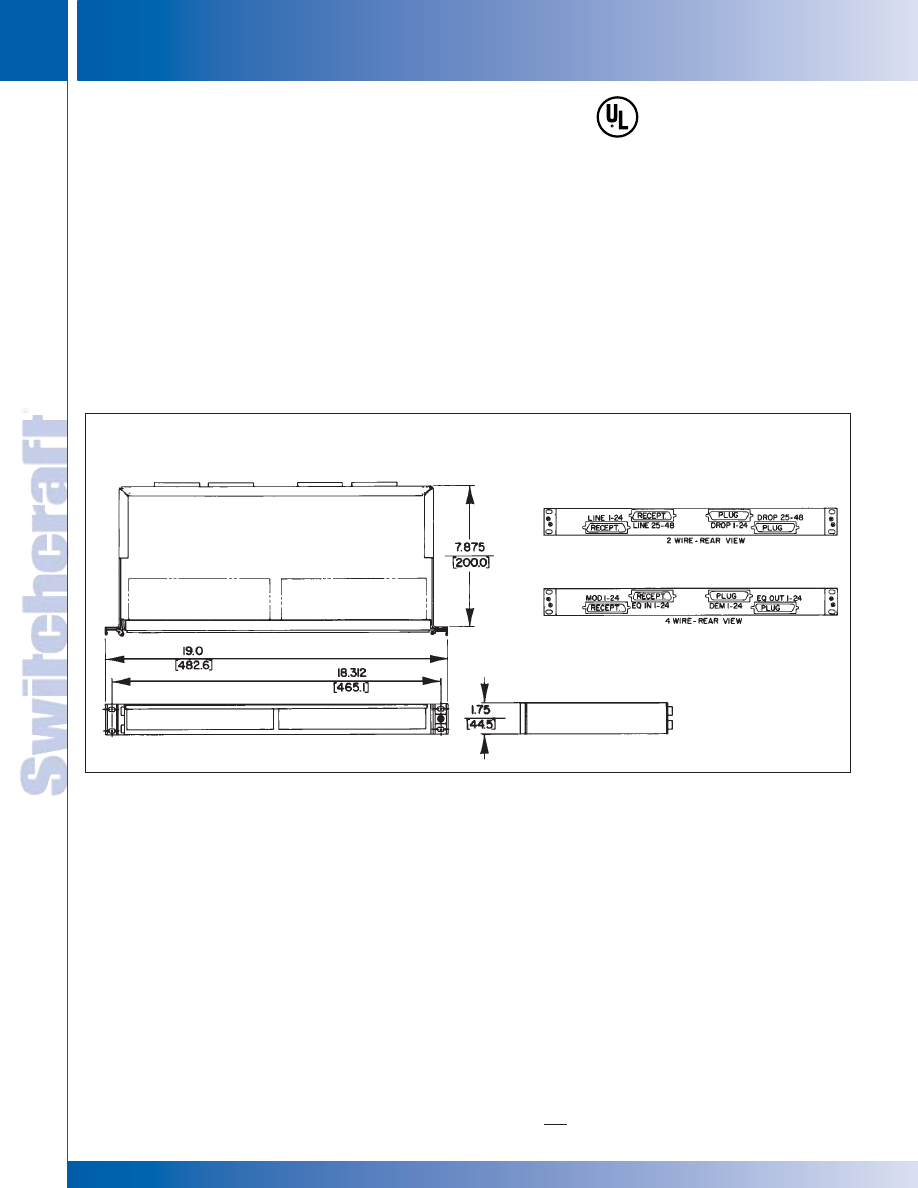
JACK PANELS
222
w w w . s w i t c h c r a f t . c o m
® Registered trademark of Switchcraft, Inc.
Note: Contact your Switchcraft Representative for price and delivery
PHONE: 773 792-2700
JACK P
ANELS
DIMENSIONS ARE FOR REFERENCE ONLY
Inch
(mm)
TT-JAX
(
.173"
)
CONNECTORIZED JACKFIELDS
SPECIFICATIONS
Panel and Integral Designation Strip: Aluminum alloy,
extruded per QQ-A-200/8. Black anodized per MIL-A-8265.
Modules: Precision-molded thermosetting plastic. Black
standard. Other colors on special order.
Mounting Screws: Black zinc, #3-48 x 312" flat head
machine screw.
TT-Jax
®
Jacks: See jacks section for TT-Jax
®
specifications.
Marking Strip: Matte finish white plastic.
Vertical Designation Strip: Extruded aluminum, black
anodized.
Back Frames: Cold rolled steel, zinc-plated with iridescent
tarnish-resistant finish.
Screws, Nuts and Lockwashers: Steel, clear iridite
tarnish-resistant finish over zinc-plating.
Connectors: 50-pin micro/pierce plugs and receptacles.
Cable Tie Bar: Aluminum hexagon alloy. 6061-T6, clear iridite
finish per MIL-C-5541 (not hinged versions only).
Cables: 25 pair, 24 AWG solid copper wire, tinned and
annealed, covered with insulating grade thermoplastic jacket.
Cable Ties: Thermoplastic, locking-non-releaseable,
30 pounds minimum loop tensile strength.
TT-JAX
®
(.173") CONNECTORIZED JACKFIELDS –
SERIES TT, 2-WIRE, 4-WIRE, 6-WIRE (continued)
TT-JAX
(
.173"
)
CONNECTORIZED JACKFIELDS
®
®
2- & 4-Wire Connectorized Jackfields
(4-Wire Style Shown)
* Please visit the product pages on our website for the most up-to-date product information
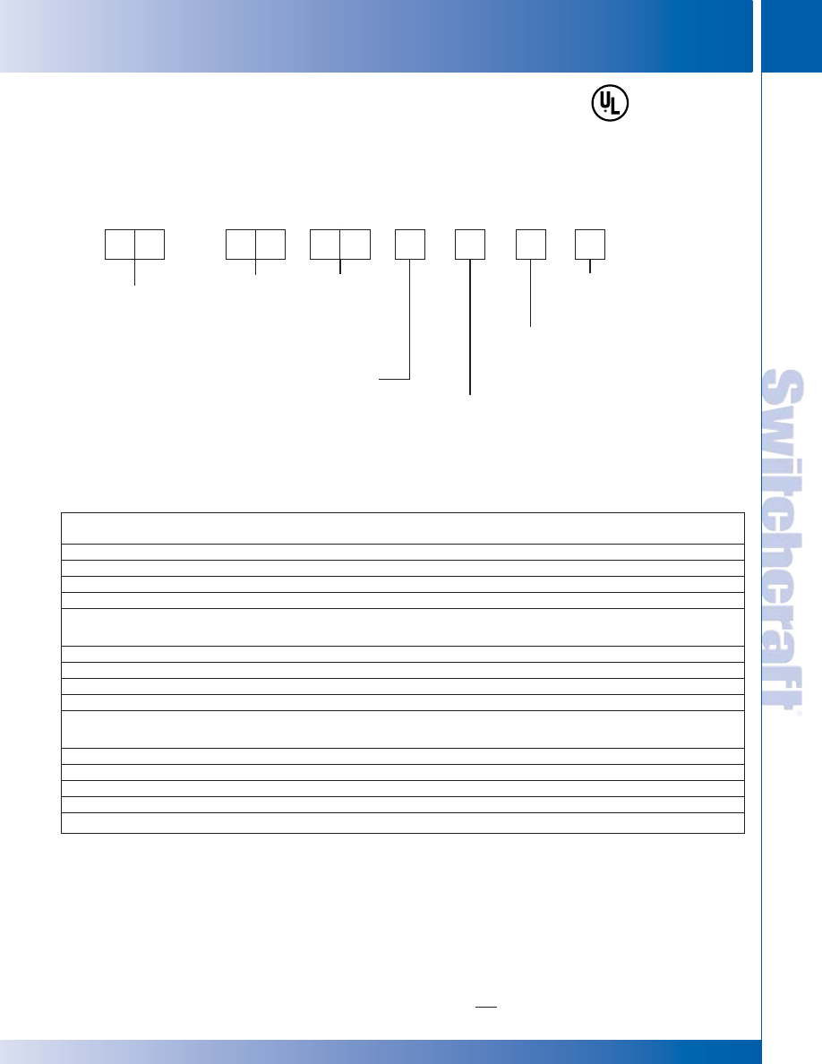
SWITCHCRAFT, INC. 5555 N. Elston Ave. • Chicago, IL 60630
223
JACK PANELS
FAX: 773 792-2129
JACK P
ANELS
DIMENSIONS ARE FOR REFERENCE ONLY
Inch
(mm)
1. Compose part numbers from data below to specify your
jackfield...or use the table to order popular jackfields.
SPECIFYING NOTE: Any jackfield can be manufactured
with AMP CHAMP connectors. Contact Switchcraft.
PART NUMBERS
TT-JAX
®
(.173") CONNECTORIZED JACKFIELDS (continued)
T
T
2
W
2
4
C
V
1
F
JACK TYPE
TT - .173"
JP - LONG FRAME (1/4")
MONITOR JACK
V - WITHOUT
M - WITH
RACK MOUNTING
1 - 19 inch
2 - 23 inch
TYPE OF HINGE
F - FRONT PANEL HINGED
R - REAR PANEL HINGED
N - NON-HINGED
WIRE TERMINATION
C - AMPHENOL BLUE RIBBON
B - AMP CHAMP
W - TERMINAL BLOCK
UNIT TYPE
2W - 2 WIRE
4W - 4 WIRE
6W - 6 WIRE
NUMBER OF
CIRCUITS
12
24
48
96
TYPICAL PART NUMBERS
TT-JAX
(
.173"
)
CONNECTORIZED JACKFIELDS – PART NUMBERS
TT-JAX
(
.173"
)
CONNECTORIZED JACKFIELDS – PART NUMBERS
®
®
2-WIRE JACKFIELDS
Part Number Description
TT2W48VCF1
Hinged front panel.
TT2W48VCN1
Front panel NOT hinged.
TT2W48MCF1
Same as TT2W48VCF1, except with MONITOR jack row.
TT2W48MCN1
Same as TT2W48VCN1, except with MONITOR jack row.
4-WIRE JACKFIELDS
Part Number
Description
TT4W24MCF1
Hinged front panel with MONITOR jack row.
TT4W24MCN1
Front panel NOT hinged with MONITOR jack row.
TT4W24VCF1
Same as TT4W24MCF1, except no MONITOR jack row.
TT4W24VCN1
Same as TT4W24MCN1, except no MONITOR jack row.
6-WIRE JACKFIELDS
Part Number
Description
TT6W48MCF1
Hinged front panel with MONITOR jack row.
16J1055
Hinged front panel with MONITOR jack row.
TT6W48MCN1
Front panel NOT hinged with MONITOR jack row.
TT6W48VCF1
Same as TT6W48MCF1, except no MONITOR jack row.
TT6W48VCN1
Same as TT6W48MCN1, except no MONITOR jack row.
* Please visit the product pages on our website for the most up-to-date product information
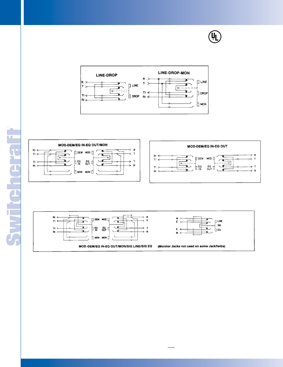
JACK PANELS
224
w w w . s w i t c h c r a f t . c o m
® Registered trademark of Switchcraft, Inc.
Note: Contact your Switchcraft Representative for price and delivery
PHONE: 773 792-2700
JACK P
ANELS
DIMENSIONS ARE FOR REFERENCE ONLY
Inch
(mm)
TYPICAL CIRCUIT ARRANGEMENTS - 2-WIRE
TYPICAL CIRCUIT ARRANGEMENTS - 4-WIRE
TYPICAL CIRCUIT ARRANGEMENTS - 6-WIRE
TT-JAX
®
(.173") CONNECTORIZED JACKFIELDS (continued)
TT-JAX
(
.173"
)
CONNECTORIZED JACKFIELDS SCHEMATICS
TT-JAX
(
.173"
)
CONNECTORIZED JACKFIELDS SCHEMATICS
®
®
* Please visit the product pages on our website for the most up-to-date product information
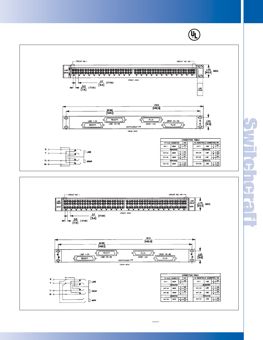
SWITCHCRAFT, INC. 5555 N. Elston Ave. • Chicago, IL 60630
225
JACK PANELS
FAX: 773 792-2129
JACK P
ANELS
DIMENSIONS ARE FOR REFERENCE ONLY
Inch
(mm)
TT-JAX
®
(.173") CONNECTORIZED JACKFIELDS (continued)
TT-JAX
(
.173"
)
CONNECTORIZED JACKFIELDS SCHEMATICS
TT-JAX
(
.173"
)
CONNECTORIZED JACKFIELDS SCHEMATICS
No. TT2W48VCF1 (hinged)
No. TT2W48VCN1 (not hinged)
(Hinged version shown)
TYPICAL CIRCUIT ARRANGEMENT
TYPICAL CIRCUIT ARRANGEMENT
No. TT2W48MCF1 (hinged)
No. TT2W48MCN1 (not hinged)
(Non-Hinged version shown)
®
®
* Please visit the product pages on our website for the most up-to-date product information
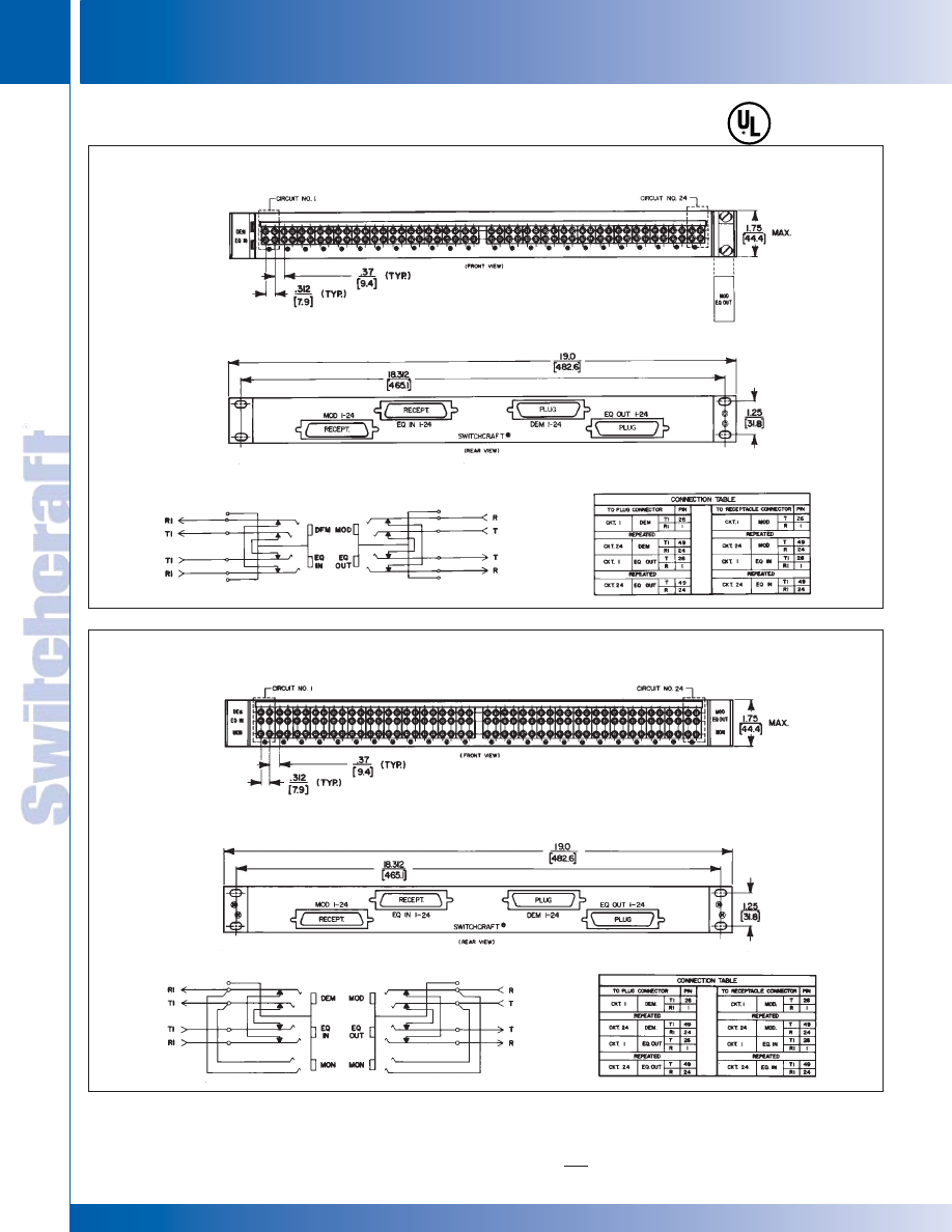
JACK PANELS
226
w w w . s w i t c h c r a f t . c o m
® Registered trademark of Switchcraft, Inc.
Note: Contact your Switchcraft Representative for price and delivery
PHONE: 773 792-2700
JACK P
ANELS
DIMENSIONS ARE FOR REFERENCE ONLY
Inch
(mm)
TT-JAX
(
.173"
)
CONNECTORIZED JACKFIELDS SCHEMATICS
TT-JAX
(
.173"
)
CONNECTORIZED JACKFIELDS SCHEMATICS
TT-JAX
®
(.173") CONNECTORIZED JACKFIELDS (continued)
No. TT4W24VCF1 (hinged)
No. TT4W24VCN1 (not hinged)
(Hinged version shown)
TYPICAL CIRCUIT ARRANGEMENT
TYPICAL CIRCUIT ARRANGEMENT
No. TT4W24MCF1 (hinged)
No. TT4W24MCN1 (not hinged)
(Non-Hinged version shown)
®
®
* Please visit the product pages on our website for the most up-to-date product information
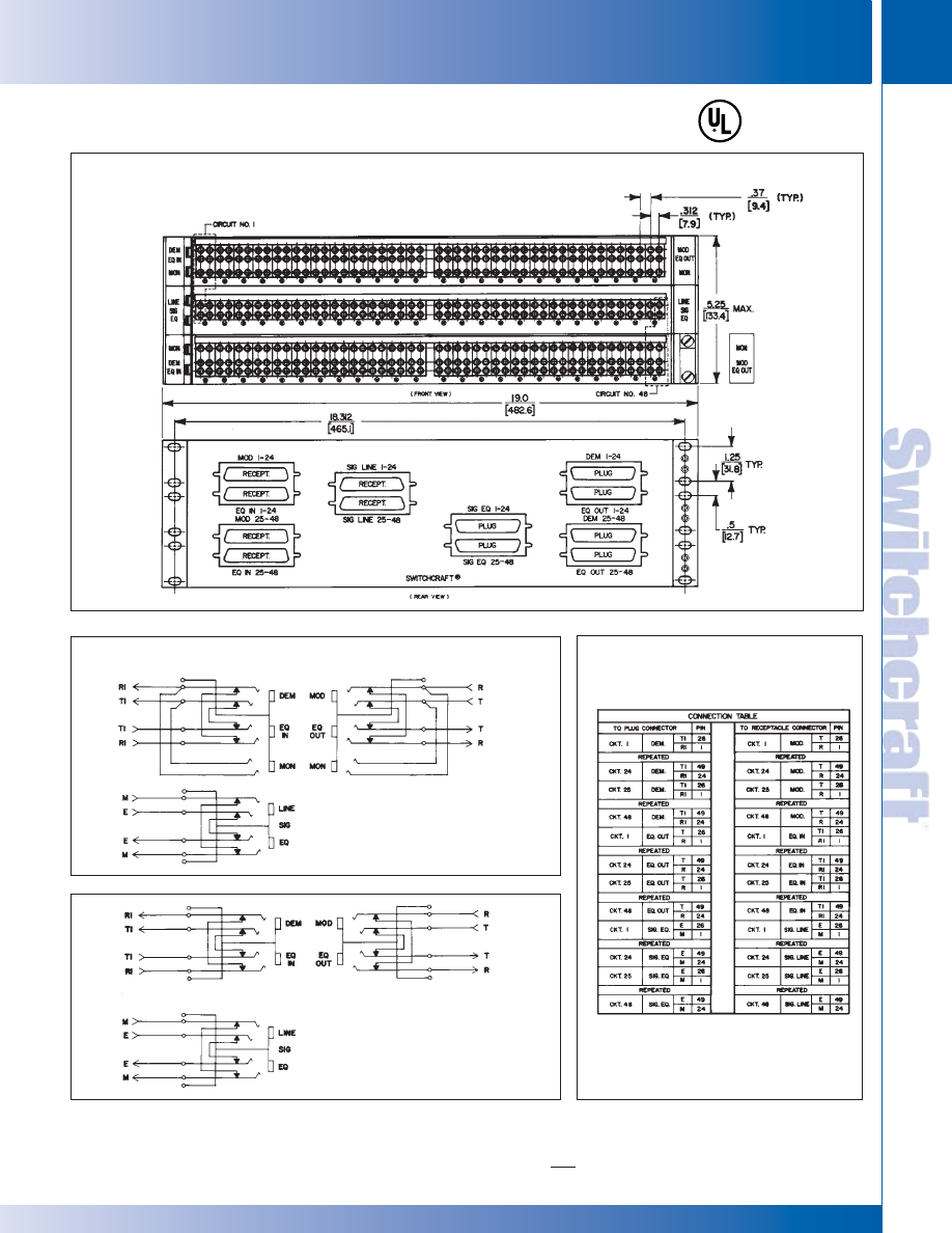
SWITCHCRAFT, INC. 5555 N. Elston Ave. • Chicago, IL 60630
227
JACK PANELS
FAX: 773 792-2129
JACK P
ANELS
DIMENSIONS ARE FOR REFERENCE ONLY
Inch
(mm)
TT-JAX
®
(.173") CONNECTORIZED JACKFIELDS (continued)
TT-JAX
(
.173"
)
CONNECTORIZED JACKFIELDS SCHEMATICS
TT-JAX
(
.173"
)
CONNECTORIZED JACKFIELDS SCHEMATICS
®
®
No. TT6W48MCF1 (hinged)
No. TT6W48VCF1 (hinged)
No. TT6W48MCN1 (not hinged)
No. TT6W48VCN1 (not hinged)
(Hinged version shown)
TYPICAL CIRCUIT ARRANGEMENT
No. TT6W48MCF1 (hinged)
No. TT6W48MCN1 (not hinged)
(with Monitor Jacks)
No. TT6W48VCF1 (hinged)
No. TT6W48VCN1 (not hinged)
(no Monitor Jacks)
* Please visit the product pages on our website for the most up-to-date product information
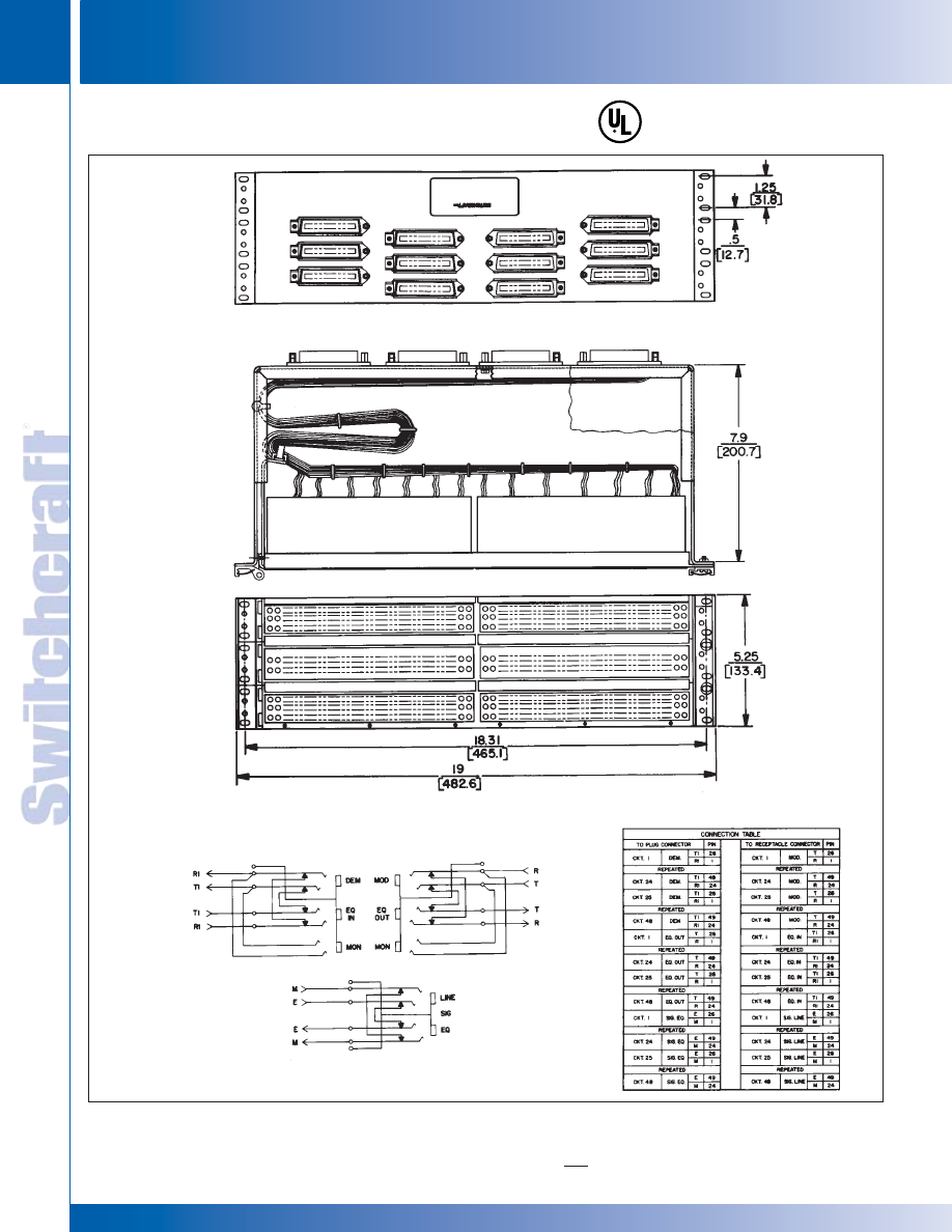
JACK PANELS
228
w w w . s w i t c h c r a f t . c o m
® Registered trademark of Switchcraft, Inc.
Note: Contact your Switchcraft Representative for price and delivery
PHONE: 773 792-2700
JACK P
ANELS
DIMENSIONS ARE FOR REFERENCE ONLY
Inch
(mm)
TT-JAX
®
(.173") CONNECTORIZED JACKFIELDS
TT-JAX
(
.173"
)
CONNECTORIZED JACKFIELDS SCHEMATICS
TT-JAX
(
.173"
)
CONNECTORIZED JACKFIELDS SCHEMATICS
®
®
REAR VIEW —ROTATED
TYPICAL CIRCUIT ARRANGEMENTS
No. 16J-1055
* Please visit the product pages on our website for the most up-to-date product information
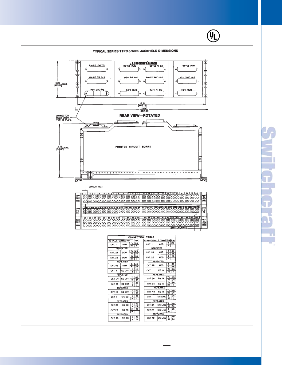
SWITCHCRAFT, INC. 5555 N. Elston Ave. • Chicago, IL 60630
229
JACK PANELS
FAX: 773 792-2129
JACK P
ANELS
DIMENSIONS ARE FOR REFERENCE ONLY
Inch
(mm)
TT-Jax
®
(.173") CONNECTORIZED JACKFIELDS
TT-JAX
®
(.173”) CONNECTORIZED JACKFIELDS
TT-JAX
®
(.173”) CONNECTORIZED JACKFIELDS
* Please visit the product pages on our website for the most up-to-date product information
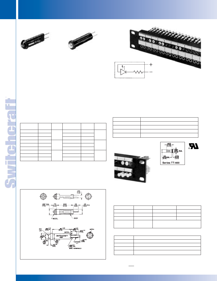
TT45106 TT45124 TT45148 TT45206 TT45224
TT45248 TT45306 TT45324 TT45348
TT45406 TT45424 TT45448 TT4506 TT45524
TT45548 TT45806 TT45824 TT45848
JACK PANELS
230
w w w . s w i t c h c r a f t . c o m
® Registered trademark of Switchcraft, Inc.
Note: Contact your Switchcraft Representative for price and delivery
PHONE: 773 792-2700
JACK P
ANELS
DIMENSIONS ARE FOR REFERENCE ONLY
Inch
(mm)
TT LAMPS AND JEWEL ASSEMBLIES
TT LAMPS AND JEWEL ASSEMBLIES
SERIES TT-450 LAMPS
Red LED and series dropping resistor are molded into
compact cartridge with bi-pin terminals for use with TT
Lamp-Jax
®
lamp jacks. Colored bezels are molded in for color
coding of functions; colors are black, red, green, white and
yellow. On special order, blue or other colors are available.
Standard voltages are 6, 24 and 48 V (DC only). No tools are
required for lamping/relamping. Simply slip TT-LED into lamp
jack with (+) terminal up. If it doesn’t light, remove it, rotate it
180°, and reinsert it into jack.
SPECIFICATIONS
Housing: Molded black plastic.
Bezel: Molded plastic in colors.
LED: Red illumination.
Pins: T-1 3/4 bi-pin configuration.
FLASHING/STEADY ON LEDS
Yellow, green and red LEDs are 2-pin cartridge plug-ins which
operate from a 48 VDC supply. When 48 V is applied, LED
flashes for 30 seconds, then changes to steady “On” condition.
SPECIFICATIONS
Body: Thermoplastic, UL 94V-0 rated.
LED Colors: Yellow, green or red.
TT
®
LAMPS AND JEWEL ASSEMBLIES
ORDERING
1. Order by part number from table.
2. For special order items, such as other LED colors,
voltages, lamps with 25% reduced power consumption,
etc., contact Switchcraft.
Part Number
Description
15J9068
Red flashing/continuous
15J9076
Yellow flashing/continuous
15J9077
Green flashing/continuous
15J9078
Amber flashing/continuous
SCHEMATIC
TT-JEWEL ASSEMBLY
Jewel assemblies use bi-pin lamp and act as lighted jewel and
lamping/relamping tool. Simply slip bi-pin lamp in brass collar
and insert lamp with pins in vertical plane. Lamp automatically
seats properly. Jewel is molded plastic in colors; sleeve is brass.
Part Number
Color
Part Number
Color
TT401
Red
TT408
Yellow
TT403
Green
TT413
Amber
TT404
Blue
TT510
Black*
TT405
White
*Used as hole plug where
no jack is installed.
LAMPS
Part Number
Description
P2290
6.3 V, GE No. 7377.
P2315
6.3 V, GE No. 7381. Avg. life: 50K hrs. @ 200 mA.
P2316
28 V, GE No. 7387. Avg. life: 25K hrs. @ 40 mA.
P2456
24 V, GE No. 7001.
Panel with TT-Jewel Assemblies
and TT-Switches installed
Steady “On” Lamp
Series TT450
Blinking/Steady
“On” Lamp
TT-LED Lamps
Installed
Part
Bezel
Part
Bezel
Number
Voltage
Color
Number
Voltage
Color
TT45106
6
◊
TT45406
6
TT45124
24
◊
TT45424
24
TT45148
48
◊
TT45448
48
TT45206
6
TT45506
6
TT45224
24
TT45524
24
TT45248
48
TT45548
48
TT45306
6
TT45806
6
TT45324
24
TT45824
24
TT45348
48
TT45848
48
Red
Black
Green
Blue
White
Yellow
®
®
Series TT-450 TT-LED Lamps
Flashing/Steady “On” Lamps
* Please visit the product pages on our website for the most up-to-date product information
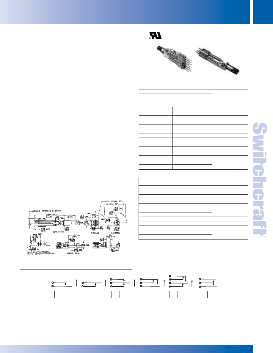
SWITCHCRAFT, INC. 5555 N. Elston Ave. • Chicago, IL 60630
231
JACK PANELS
FAX: 773 792-2129
JACK P
ANELS
DIMENSIONS ARE FOR REFERENCE ONLY
Inch
(mm)
LONGFRAME SWITCHBOARD SWITCHES
LONGFRAME SWITCHBOARD SWITCHES
Premium quality, long frame switches, designed especially for
jack panel mounted switching. Standard actuations are
push-lock/pull-release, 2-position turn button and 3 position turn
button. Many contact forms available. Mounts in Switchcraft
Jack Panels Series 1200, 1400, 2400, 2600, 2800, modular JP
®
jack panels, and other standard telephone jack panels. Part
numbers in table indicate “A” frame. For same switch with “C”
frame, add prefix “C” to part number. Many circuit forms not
shown in tables are available on special order. Long leaf springs
have no forms at point of flexing, which insures long life. Welded
crossbar palladium contacts rated at 2A 200W maximum are
standard. Fine silver (for higher currents) or gold alloy (dry circuit
to 1A) contacts are available on special order. Contact Switchcraft.
SPECIFICATIONS
Frame, Screws and Twin Nut: Steel, plated.
Springs, Pressure Plate and Terminals: Copper alloy.
Solder lugs are tin-dipped.
Contacts: Welded crossbar palladium are standard. Fine sil-
ver or gold alloy are available on special order.
Insulation: Rigid plastic. Extruded plastic tubing through
stack.
Knob: Molded black plastic. Turn-key type faced with white
arrow.
Bushing: Copper alloy, nickel-plated.
ORDERING
1. Order by part number from table.
2. For special order items, contact Switchcraft.
LONGFRAME SWITCHBOARD SWITCHES
◊
11201L
◊
11201
1-A
◊
11202L
◊
11202
1-B
11203L
11203
1-C
◊
W11203L
◊
W11203
◊
11203DL
◊
11203D
1-D
◊
11204L
◊
11204
2-A
◊
11205L
◊
11205
2-B
11206L
11206
2-C
◊
W11206L
◊
W11206
◊
11206DL
◊
11206D
2-D
◊
11208L
◊
11208
4-A
◊
11209L
◊
11209
3-C
◊
11212L
11212
4-C
◊
W11212L
◊
W11212
TURN BUTTONS - SERIES 11200
Part Numbers
Locking
Momentary
Circuit
◊
11001L
◊
11001
1-A
◊
11002L
◊
11002
1-B
11003L
11003
1-C
◊
W11003L
◊
W11003
◊
11003DL
◊
11003D
1-D
◊
11004L
◊
11004
2-A
◊
11005L
◊
11005
2-B
11006L
11006
2-C
◊
W11006L
◊
W11006
◊
11006DL
◊
11006D
2-D
◊
11008L
◊
11008
4-A
◊
11009L
◊
11009
3-C
◊
11012L
11012
4-C
◊
W11012L
◊
W11012
PUSHBUTTONS - SERIES 11000
◊
Special order only; contact Switchcraft.
Mounting Screws: #6-32, P10725, can be ordered separately.
Contact Switchcraft. (Screws not supplied with switches.)
SERIES 11000 and 11200
W11012L
11206L
“T-Switch” Switches
Basic Schematic Circuits
A
B
C
D
E
F
* Please visit the product pages on our website for the most up-to-date product information
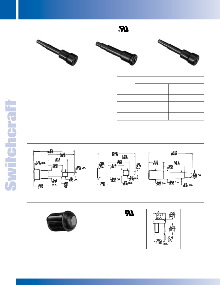
JACK PANELS
232
w w w . s w i t c h c r a f t . c o m
® Registered trademark of Switchcraft, Inc.
Note: Contact your Switchcraft Representative for price and delivery
PHONE: 773 792-2700
JACK P
ANELS
DIMENSIONS ARE FOR REFERENCE ONLY
Inch
(mm)
DUMMY PLUGS AND HOLE PLUGS
DUMMY PLUGS AND HOLE PLUGS
When inserted into a standard size telephone jack, the dummy
plug actuates springs like a normal plug, except no signal is
conducted through since the plug is made of non-conducting
plastic. Dummy plugs can also be used to plug-up unused jacks
to prevent accidental insertion of an incorrect plug.
SERIES 491: 3-conductor with .206" diameter finger. Mates
with MT342B and MT344B MT-Jax
®
, Series M Hi-D Jax
®
, and
other standard telephone jacks having .21" inside diameter
sleeves.
SERIES 492: 3-conductor with .25" diameter finger. Mates with
3-conductor MT-Jax
®
and Series M Hi-D Jax
®
, and other
standard telephone jacks have .25" inside diameter sleeves.
SERIES 493: 2-conductor with .25" diameter finger. Mates with
2-conductor MT-Jax
®
, Series M Hi-D Jax
®
, and other standard
telephone jacks having .25" inside diameter sleeves.
DUMMY PLUGS AND HOLE PLUGS
Description
Interchangeable
with
Part No.
Conductors
Color
WEco
Trimm
49101
3
Red
–
–
49102
3
Black
–
–
49105
3
White
–
–
49201
3
Red
258F
558D
49202
3
Black
258C
558C
49205
3
White
258E
558E
49301
2
Red
165F
556D
49302
2
Black
165C
556C
49305
2
White
165E
–
Used to seal off unused holes in jack
panels, Series 1200, 1400, 2400, 2600
and JP012000 through JP122000.
Constructed of dimensionally stable
molded black plastic.
PLASTIC HOLE PLUG
Hole Plug P1801
Part
Number
491
492
493
No. 491
No. 492
No. 493
* Please visit the product pages on our website for the most up-to-date product information
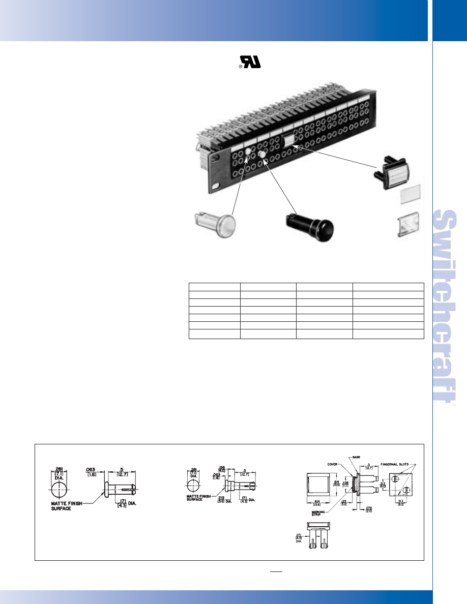
SWITCHCRAFT, INC. 5555 N. Elston Ave. • Chicago, IL 60630
233
JACK PANELS
FAX: 773 792-2129
JACK P
ANELS
DIMENSIONS ARE FOR REFERENCE ONLY
Inch
(mm)
TT
(
BANTAM
)
CIRCUIT GUARD PLUGS
TT
(
BANTAM
)
CIRCUIT GUARD PLUGS
TT
®
(BANTAM) CIRCUIT GUARD PLUGS
Part Number
Part Number
Part Number
Color
TT5121
TT5131
TT5141*
Red
TT5122
TT5132
TT5142*
Black
TT5123
TT5133
TT5143*
Green
TT5124
TT5134
TT5144*
Blue
TT5125
TT5135
TT5145*
White
TT5128
TT5138
TT5148*
Yellow
*Includes base, marking strip & cover.
Cover
Series
514
Series TT512
Series TT513
Base
APPLICATION
Circuit guard plugs snap into TT-Jax
®
(bantam)
jacks eliminating accidental or unauthorized
insertion of a plug into a critical circuit. The circuit
guards plugs do not actuate the jack springs.
These plugs seal the jack bushing and provide
an additional means of circuit identification.
Circuit guard plugs are available in three
different designs: Series TT512, Series TT513
and Series TT514. All three designs are molded
thermoplastic and are available in the following
colors: red, black, green, blue, white or yellow.
SERIES TT512
TT512 circuit guard plugs cover an individual
jack opening and insert to an virtually flush
position with the front panel.
SERIES TT513
TT513 circuit guard plugs are similar to the
Series TT512 except the button extends
.219" from the front of the panel for easier
removal.
SERIES TT514
TT514 circuit guard plugs cover both the IN and
OUT jacks of two adjoining circuits while leaving
the monitor jacks exposed for circuit testing.
The four jack circuit guard plugs also include a
matte finish white plastic marking strip and
a clear extruded plastic window for additional
designation.
SPECIFICATIONS
TT512 and TT513: Molded thermoplastic in colors.
TT514: Base: Molded thermoplastic in colors.
Marking Strip: Matte finish white plastic.
Cover: Clear extruded plastic.
ORDERING
1. Order by part number from table.
2. Contact Switchcraft for any special order items.
Marking Strip
Series TT-512
Series TT-513
Series TT-514
®
®
* Please visit the product pages on our website for the most up-to-date product information
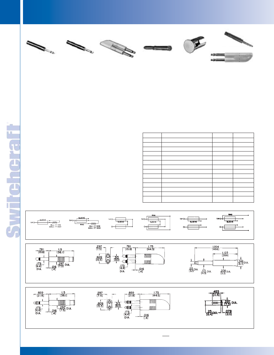
JACK PANELS
234
w w w . s w i t c h c r a f t . c o m
® Registered trademark of Switchcraft, Inc.
Note: Contact your Switchcraft Representative for price and delivery
PHONE: 773 792-2700
JACK P
ANELS
DIMENSIONS ARE FOR REFERENCE ONLY
Inch
(mm)
MINIATURE, DUMMY PLUGS, HOLE PLUGS
MINIATURE, DUMMY PLUGS, HOLE PLUGS
Terminating, dummy and looping plugs are designed for
use with Tini-Telephone
®
Jacks. TT-Phone Plugs are also
recommended for use on other miniature telephone jacks
with same bushing inside diameter and compatible tip
and/or ring spring configurations.
TT-TERMINATING PLUGS
TT-Phone Plug terminating plugs are used to terminate a
circuit with a specific resistive load. A precision 1/2 watt, ± 1%
resistor is molded into the handle of each terminating plug.
See “PLUG SCHEMATICS” for resistor wiring. Resistance
value is marked on plug handle. Other resistance values are
available on special order.
TT-DUMMY PLUGS
TT-Phone Plug dummy plugs are designed to be inserted into
phone jacks to actuate shunt and isolated switching circuits.
TT-LOOPING PLUGS
TT-Phone Plug looping plugs are used to loop or patch
adjacent jack circuits. See “PLUG SCHEMATICS” for wiring.
TT-HOLE PLUG
TT-Hole Plugs are used to close off unused openings in all
Switchcraft TT-Jack Panels. Molded of black plastic with brass
sleeve.
ORDERING
1. Order by part number from table.
2. Contact Switchcraft for any special order items.
SPECIFICATIONS
Series TT200 Tip Rod, Ring and Sleeve:
Brass per QQ-B-626.
Handle: Molded PVC, ivory or black.
Series TT515: Molded of dimensionally stable plastic
in black, red or white.
MINIATURE, DUMMY PLUGS, HOLE PLUGS
Part No.
Description
Schematic
Color
◊
TT201
2-conductor terminating-135
Ω
1
Gray
◊
TT202
2-conductor terminating-600
Ω
1
Gray
TT203
3-conductor terminating-135
Ω
2
Gray
TT204
3-conductor terminating-600
Ω
2
Gray
TT205
2-conductor dummy
5
Gray
TT206
3-conductor dummy
6
Gray
◊
TT207
2-conductor twin looping
3
Gray
TT208
3-conductor twin looping
4
Gray
TT209
2-conductor twin dummy
5
Ivory
TT210
3-conductor twin dummy
6
Ivory
TT510
Hole Plug
–
Black
TT5151
2- or 3-conductor dummy
–
Red
TT5152
2- or 3-conductor dummy
–
Black
TT5155
2- or 3-conductor dummy
–
White
◊
Special order only; contact Switchcraft for price and delivery.
TT203
TT-Terminating
Plug
TT205
TT-Dummy
Plug
TT207 TT-Twin
Looping Plug
TT515
TT-Dummy
Plugs
TT510
Hole
Plug
TT5152 or TT206
TT210
Plug Schematics
Nos. TT-201, TT-202, TT-205
Nos. TT-207, TT-209
Nos. TT-515-1, -2
Nos. TT-203, TT-204, TT-206
Nos. TT-208, TT-210
Nos. TT-510
1
2
3
4
5
6
* Please visit the product pages on our website for the most up-to-date product information
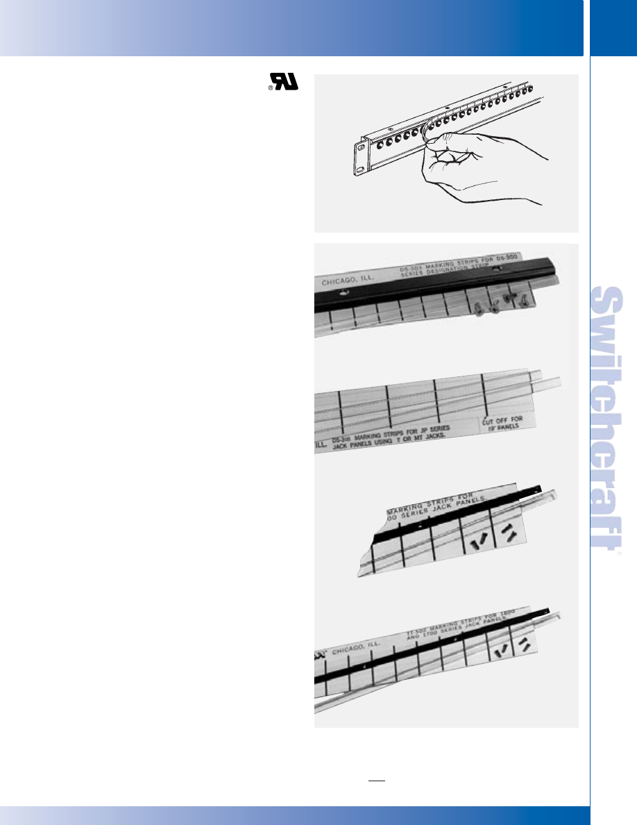
SWITCHCRAFT, INC. 5555 N. Elston Ave. • Chicago, IL 60630
235
JACK PANELS
FAX: 773 792-2129
JACK P
ANELS
DIMENSIONS ARE FOR REFERENCE ONLY
Inch
(mm)
DESTINATION STRIPS
DESTINATION STRIPS
Designation strips with protective covers are supplied with all
tini-telephone
®
jack panels, jackfields and certain standard
jack panels. Replacement kits and individual parts are also
available. Legends can be marked in pencil, ink, or lettering
transfers. Kwik-Change
®
is the name of all horizontal strips.
See illustration.
Three types of designation strips are available as accessories:
1. Kwik-Change single height.
2. Kwik-Change double height.
3. X-Wide vertical.
KWIK-CHANGE
®
DESIGNATION STRIPS
(SINGLE HEIGHT)
Two types of single height designation strips are available:
1. SERIES 1600, A1600, B1600, C1600, 1700, B1700,
1400300, 2600300, JP012000 through JP122000
• Extruded aluminum mounting strip
• Four mounting screws
• Marking strips
• Clear plastic strip covers
Mounting strips are fastened with four mounting screws
provided. Marking strip slides into the clear plastic cover, and
cover is snapped into place on the mounting strip. Legends
can be marked in pencil, ink, lettering transfers, typewriter, etc.
SPECIFICATIONS
(Used on panels 1600, A1600, B1600, C1600, 1700, B1700)
Mounting Strip: Extruded aluminum black anodized
Cover: Clear extruded plastic.
Marking Strip: White matte finish plastic.
Screws: Copper alloy, plated.
(Used on panels 1400300, 1600300)
Mounting Strip: Aluminum alloy, extruded, black anodized.
Cover: Clear extruded plastic.
Marking Strip: White matte finish plastic.
Screws: Steel, plated.
SERIES TT51 through TT62, TT-Connectorized (2-, 4- and
6-Wire), JP012000 through JP122000, TTPC and DSX
panels. Mounting strips are extruded as part of the panel.
Otherwise, use is the same as above.
ORDERING
Order by part number from table.
DESIGNATION STRIPS
Kwik-Change Designation Strip
Kit Number DS301 (single height)
Kwik-Change Designation Strip
Kit Number DS318 (single height)
Kwik-Change Designation Strip
Kit Number TT501 (single height)
Kwik-Change Designation Strip
Kit Number TT516 (single height)
* Please visit the product pages on our website for the most up-to-date product information
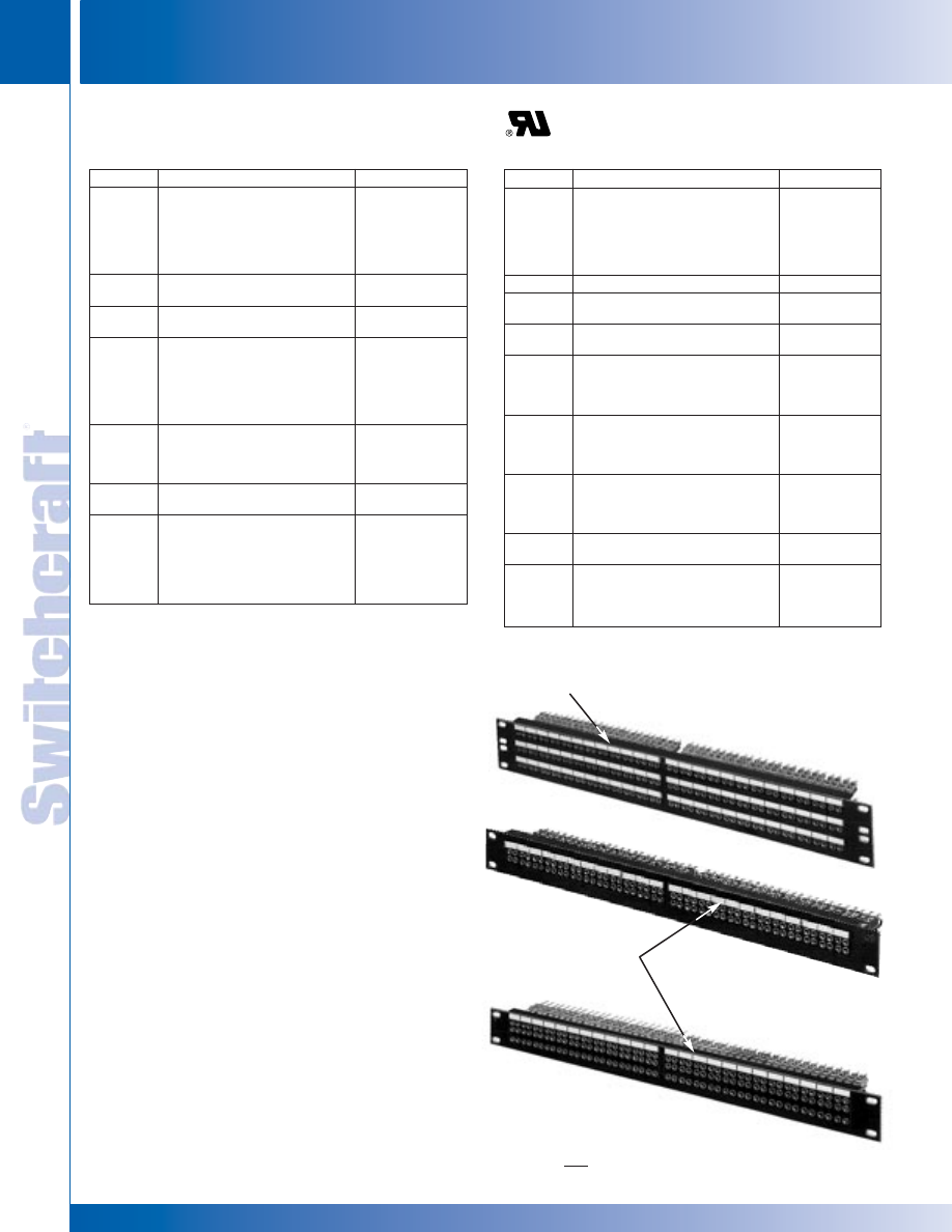
JACK PANELS
236
w w w . s w i t c h c r a f t . c o m
® Registered trademark of Switchcraft, Inc.
Note: Contact your Switchcraft Representative for price and delivery
PHONE: 773 792-2700
JACK P
ANELS
DIMENSIONS ARE FOR REFERENCE ONLY
Inch
(mm)
DESIGNATION STRIPS
DESIGNATION STRIPS
KWIK-CHANGE
®
DESIGNATION STRIPS
(DOUBLE HEIGHT)
Double height strips allow larger legends. Can be factory
installed on Series 1600, B1600, 1700 and B1700 panels, or
may be ordered separately for customer installation.
• Series 1600/B1600: Four strips can be mounted, two
above each row of jack openings.
• Series 1700: Two strips can be mounted, two above or
two below (special order) the double row of jack openings.
• Series B1700: Two strips can be mounted (side-by-side)
above top row of jacks.
NOTE: When TT516 kits are mounted above top row of jacks on
Series 1600, B1600 and B1700, strips will overhang top edge
of panel by .156 inches For most applications, the strips help
seal the normal opening between adjacent panels. Series
B1700 panel mounting screws may have to be loosened to
facilitate removal of the panel above it in this type of installation.
SPECIFICATIONS
Mounting Strip: Black thermoplastic UL 94V-0.
Cover: Clear plastic.
Marking Strip: Matte finish white plastic.
Mounting Screws: Copper alloy, plated.
ORDERING
1. Order by part number from table.
2. To order double height strips installed on panels,
contact Switchcraft.
SINGLE HEIGHT DESIGNATION STRIPS
Part No.
Description
For Panels
DS301
Kit (single height) includes:
1400301,
1-mounting strip (17" long)
2600301
1-cover
1-marking strip sheet
(5 strips per sheet)
4-mounting screws
DS302
Cover (used with Kit DS301)
–
DS303
Marking strip sheet (used with
Kit DS301 and DS316).
–
DS306
Marking strip sheet (used with
–
Kit DS307 and DS308).
DS307
Kit (single height) includes:
JP012000,
2-covers (16.5" long)
JP032000,
1-marking strip sheet
JP052000
(5 strips per sheet)
DS308
Kit (single height) includes:
JP022000,
2-covers (19.5" long)
JP042000,
1-marking strip sheet
JP062000
(5 strips per sheet)
DS316
Kit (single height) includes:
JP072000
2-covers (16.25" long)
JP092000,
1- marking strip sheet
JP112000
(5 strips per sheet)
DS317
Marking strip sheet (used with
–
Kit DS318).
DS318
Kit (single height) includes:
JP082000
2-covers (20" long)
JP102000,
1- marking strip sheet
JP122000
(5 strips per sheet)
Part No.
Description
For Panels
TT501
Kits (single height) includes:
1600, 1700
1-mounting strip (8.375" long)
(Alternate
1-cover
spacing)
1-marking strip sheet
(5 strips per sheet)
4-mounting screws
TT502
Marking Strip sheet (used with
–
Kit TT501 & TT521)
TT503
Cover (used with Kit
–
TT501 and TT504)
TT504
Kits (single height) includes:
A1600, C1600
1-mounting strip (8.375" long)
(Continuous
1-cover
spacing)
1-marking strip sheet
(5 strips per sheet)
4-mounting screws
TT519
Kit (single height) includes:
TT52, TT54
2-covers (9.61" long)
TT56, TT58
1- marking strip sheet
TT60, TT62
(5 strips per sheet)
(23" Panels)
TT520
Marking strip sheet (used with
–
Kit TT519)
TT521
Kit (single height) includes:
TT51, TT53
2-covers (8.25" long)
TT55, TT57
1- marking strip sheet
TT59, TT61,
(5 strips per sheet)
Connectorized
Jackfields
(2-, 4- and 6 wire)
Single Height Kwik-Change
®
Designation Strip, TT501
DESIGNATION STRIPS (continued)
Series B1600
Double Height Kwik-
Change Designation
Strip, TT516
Series 1700
Series B1700
* Please visit the product pages on our website for the most up-to-date product information
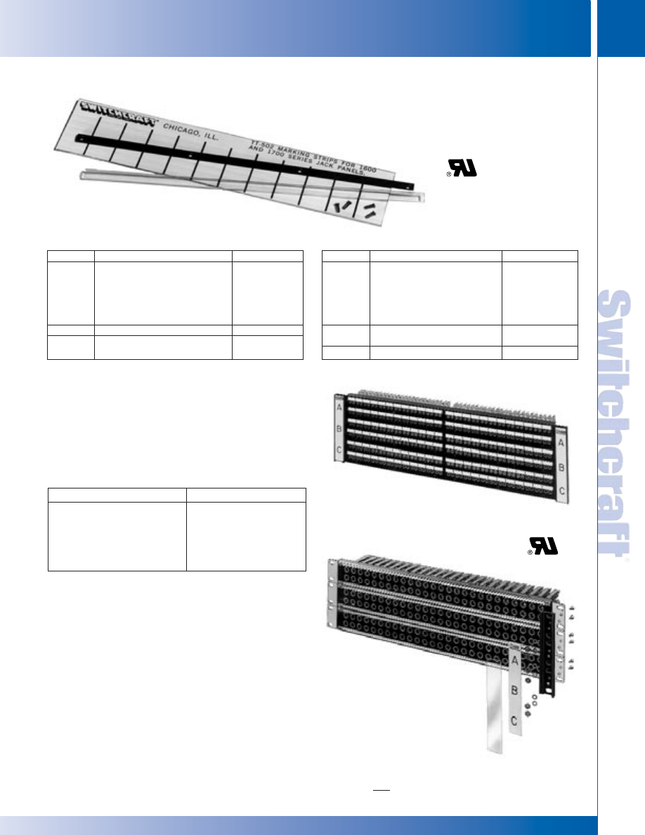
SWITCHCRAFT, INC. 5555 N. Elston Ave. • Chicago, IL 60630
237
JACK PANELS
FAX: 773 792-2129
JACK P
ANELS
DIMENSIONS ARE FOR REFERENCE ONLY
Inch
(mm)
KWIK-CHARGE DESIGNATION STRIPS – DOUBLE HEIGHT
KWIK-CHARGE DESIGNATION STRIPS – DOUBLE HEIGHT
®
®
X-WIDE
®
VERTICAL DESIGNATION STRIPS
X-Wide designation strips mount on either side (or both) of
standard 19" and 23" wide panels and do not interfere with
horizontally mounted strips. Each kit contains two mounting
brackets which easily fasten with mounting screws provided.
Marking strips and clear plastic covers slide into place. Each
kit fits onto both sides of a jack panel. X-Wide strips are used
on the following panels:
Part No.
Description
For Panels
DS311
Kit (double height) includes:
2600310,
1-mounting strip (17" long)
1400315
1-cover
1-marking strip sheet
(3 strips per sheet)
4-mounting screws
DS312
Cover (used with Kit DS311)
–
DS313
Marking strip sheet (used with
–
Kit DS311)
DOUBLE HEIGHT DESIGNATION STRIPS
Part No.
Description
For Panels
TT516
Kit (double height) includes:
1600, B1600,
1-mounting strip (8.375" long)
1700, B1700
1-cover
1-marking strip sheet
(3 strips per sheet)
4-mounting screws
TT517
Marking strip sheet (used with
–
Kit TT516)
TT518
Cover (used with Kit TT516)
–
Kwik-Change
®
Designation Strip
DS311 (double height)
UNDRILLED
PREDRILLED
1600, A1600, 1700 B1700, TT51
D1600, D1700, BD1700,
through TT62, 2-, 4- & 6-Wire
TTD51 through TTD62, 2- 4 &
TT-Connectorized Jackfields, 2- &
6-Wire TT-Connectorized
4-Wire TTPC Connectorized
Jackfields, 2 & 4-Wire TTPC
Jackfields, 1200, 1400, 1400320,
Connectorized Jackfields.
2600,and 2600320.
SPECIFYING NOTES: Each kit fits both sides of a jack panel (Standard
height 1.75". Also available in 3.5 inch and 5.25 inch heights.
Prefix letter“D” indicates panels have been predrilled countersunk holes to
facilitate mounting X-Wide strips. Series 1200, 1400, & 2600 can be predrilled
on special order.
3-row Jack Panels Assembly
with DS323 X-Wide
Designation Strip installed
Assembly sequence
of DS323 X-Wide
Designation Strip
KWIK-CHANGE
®
DESIGNATION STRIPS (DOUBLE HEIGHT)
* Please visit the product pages on our website for the most up-to-date product information
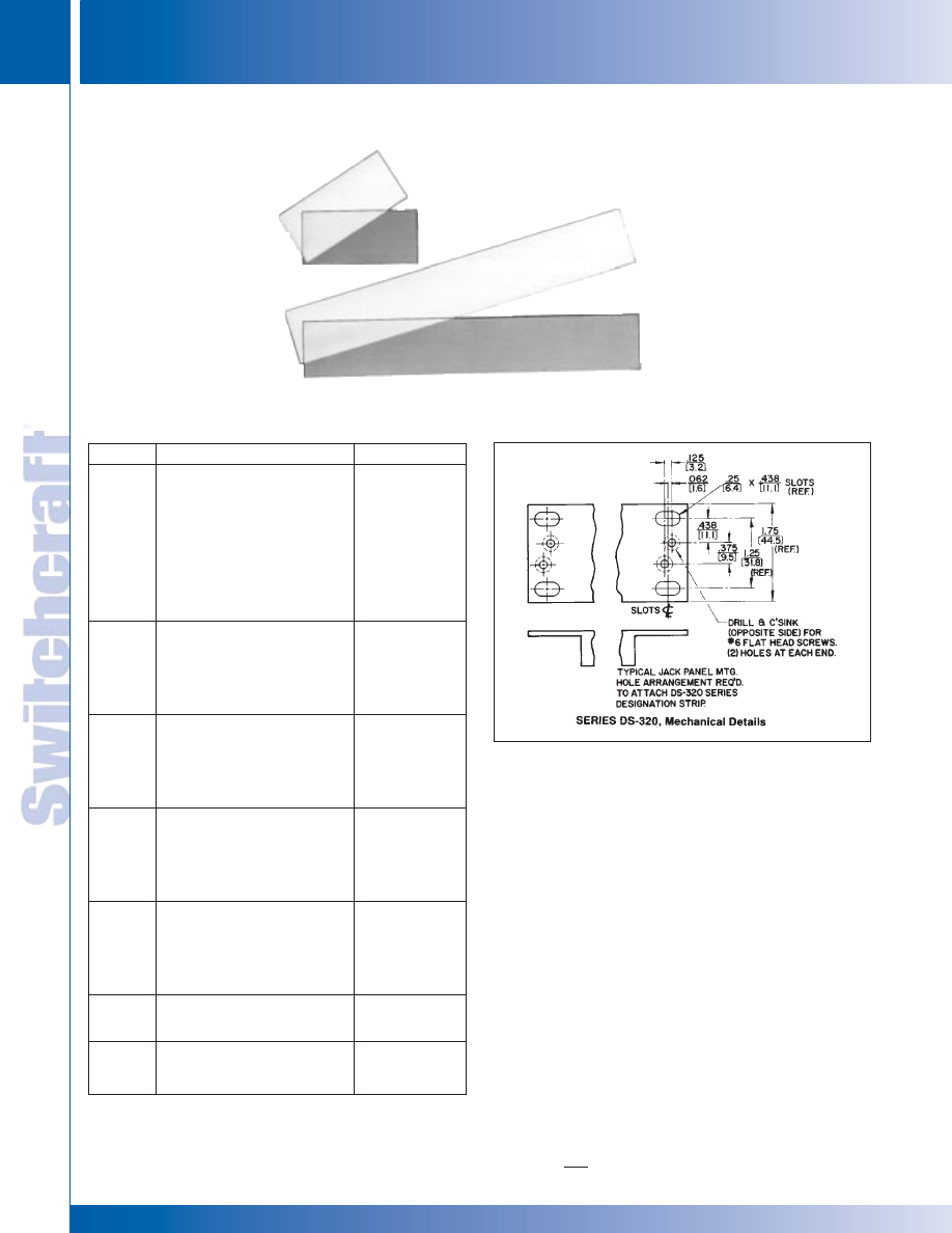
JACK PANELS
238
w w w . s w i t c h c r a f t . c o m
® Registered trademark of Switchcraft, Inc.
Note: Contact your Switchcraft Representative for price and delivery
PHONE: 773 792-2700
JACK P
ANELS
DIMENSIONS ARE FOR REFERENCE ONLY
Inch
(mm)
ORDERING
1. Order by part number from table.
2. To order X-Wide
®
strips installed on panels,
contact Switchcraft.
Part No.
Description
For Panels
DS321
Kit (.75 x 1.75 inches) includes:
1600, A1600
2-mounting brackets
1700, B1700
2-marking strips
TT51 thu TT54,
2-covers
TT59 thru TT62,
4-mounting screws, nuts and
2- & 4-Wire
lockwashers
TTConnectorized
Jackfields, 2-, 4-
& 6-Wire TTPC
Conntectorized
Jackfields
DS322
Kit (.75 x 3.5 inches) includes:
Same as DS321
2-mounting brackets
(Mounted in
2-marking strips
pairs)
2-covers
8-mounting screws, nuts and
lockwashers
DS323
Kit (.75 x 5.25 inches) includes:
6-Wire TT-
2-mounting brackets
Connectorized
2-marking strips
and panels for
2-covers
DS321
12-mounting screws, nuts and
lockwashers
DS350
Kit (.75 x 2.265 inches) includes:
B1600, C1600
2-mounting brackets
2-marking strips
2-covers
4-mounting screws, nuts and
lockwashers
DS351
Kit (.75 x 1.75 inches) includes:
2-, 4- & 6-Wire
1-marking strip
Connectorized
1-cover
Jackfields, TTPC
(Used on all 1.75 inch height
Connectorized
connectorized jackfields
Jackfields
except next to hinge)
DS352
Kit same as DS351except
Same as DS351
narrow width. To be used next
to hinge.
DS353
Kit (.75 x 5.25 inches) includes:
6-Wire TT-
1-marking strip
Connectorized
1-cover
Jackfields
X-WIDE VERTICAL DESIGNATION STRIPS
X-WIDE
®
VERTICAL DESIGNATION STRIPS
DS353
DS351
X-WIDE VERTICAL DESIGNATION STRIPS
X-WIDE VERTICAL DESIGNATION STRIPS
®
®
* Please visit the product pages on our website for the most up-to-date product information
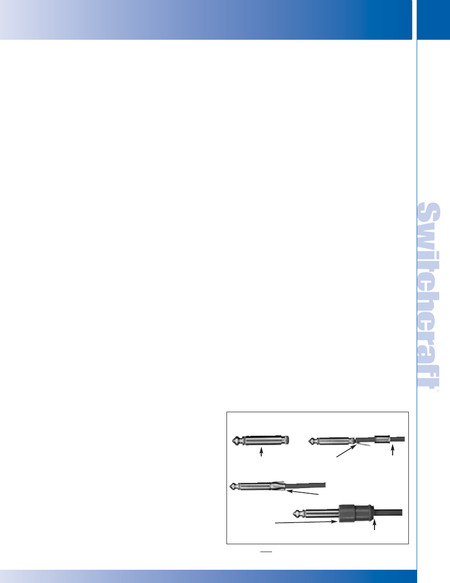
SWITCHCRAFT, INC. 5555 N. Elston Ave. • Chicago, IL 60630
239
PATCH CORDS & MOLDED CABLE ASSEMBLIES
FAX: 773 792-2129
PA
TCH CORDS &
MOLDED CABLE ASSEMBLIES
DIMENSIONS ARE FOR REFERENCE ONLY
Inch
(mm)
MOLDED CABLE ASSEMBLIES
MOLDED CABLE ASSEMBLIES
WIRE AND CABLE
Switchcraft provides over 100 types of wire and cable from
which molded cable assemblies are manufactured. Basically,
30 different cables are used for standard tooling. There are no
additional charges where standard tooling exists.
Tooling is designed so cable entry openings on molded plastic
handles fit tightly to the outside diameter of the cable. The
tighter fit holds cable secure and is more resistant to abuse
than if a larger opening were used.
DESIGN AND FABRICATING TECHNIQUES
Switchcraft’s engineering staff is supported by a complete tool
and die making facility, as well as a fully equipped and staffed
molding department to fill all of Switchcraft’s plastic molding
requirements.
The molding department uses injection molders of
semi-automatic, multiple-cavity type to obtain high production
rates.
MANUFACTURING SEQUENCE (EXAMPLE)
Step 1: The 1-piece tip rod is firmly staked into the phone plug
finger assembly, making a complete and mechanically secure
assembly. (Refer to Figure 1) The staking process, using precision
manufactured parts, keeps the tip rod assembly from working
loose and causing mechanical and electrical problems later.
Step 2: Cable center conductor is soldered to tip rod; then the
tubular bridge sleeve is slid forward, bringing the cable shield in
contact with the circular notch around rear of tip rod assembly.
Step 3: Bridge sleeve is crimped tightly to tip rod assembly and
cable. Center conductor is completely isolated from potential
pulling strains, and shield makes a firm, low resistance
connection with plug sleeve.
Step 4: A dimensionally stable plastic handle/body of the
proper color, size and shape is molded into place. Features are
depressions for finger grip, cable entry opening customized to
cable diameter to minimize wear on cable, and handle/body
molded in one place.
From start to finish, Switchcraft’s molded cables are designed
and built with maximum quality and reliability. There is virtually
no limit to the type and characteristics of special molded cables
that Switchcraft can build to special order. For all special
orders, consult Switchcraft.
Molded cable assemblies offer many advantages over
conventionally-fabricated cables:
• Improved wiring strain relief.
• Proper match of cable diameter to handle.
• Sealed junction: Less exposed area; less contamination
due to moisture, dust, dirt.
• Lower weight and smaller size.
• 100% shielding on selected types.
• Color to match/complement equipment decor.
• Legends, color codes, ribs, dot, customer logo/indicia
can be added.
• All molded cables are 100% tested for continuity, shorts
and voltage breakdown (250 or 500V).
• All Switchcraft
®
molded assemblies are UL recognized.
OEM COST SAVINGS
Molded cable assemblies generally cost less than your
in-house conventionally-fabricated assemblies. Specific
advantages are elimination of:
1. Your evaluation, ordering, incoming inspection, and
stocking of individual parts.
2. Your plant/equipment needs for in-house fabrication.
3. Your tooling/labor costs
4. Your production line QA/QC.
MOLDED CABLE RELIABILITY
In a series of OEM-conducted tests of Switchcraft versus
non-molded, fabricated cables, Switchcraft cables were shown
to be superior.
1. Fabricated cables broke at lower pull forces: OEM types – 24
to 34 pounds, molded cables – 37.5 to 41 pounds
(molded cables did not break at terminations; the cable itself
broke about one to two feet back from the connector).
2. Fabricated cables suffered broken wires at low pull-out force
limits. Molded cables had cable breaks before cable pulled
out of the handle, in most instances. And this failure
occurred, as previously noted, at higher pull-out forces.
Strengthened molded cable assemblies out-performed
fabricated assemblies, and in fact, the crimp molding process
makes it stronger than the wire itself.
SPECIAL ORDER ITEMS
• Customer Iogo
• Panel Relief Bushing. Specify panel thickness and exact
point on cable where bushing is to be installed. Standard
panel opening is .50" (12.7 mm) diameter. Double
flatted in panels up to .125" (3.18 mm) thick.
• Molded Cable Clamp Bands or Y-Junctions.
(Refer to page 258.)
• Special Termination (see separate chart). Contact
Switchcraft for specials and provide complete details.
TYPES OF PLASTICS
Thermoplastics used for molded cable assemblies, have
excellent electrical and mechanical properties, are economical,
convenient for molding, and can be provided in an array of
colors. They have electrical characteristics far higher than
required, and provide dimensional stability, abrasion and
abuse resistance, and can be molded with a smooth mirror-like
finish or matte or semi-matte finishes.
DESIGN MATERIALS AND FEATURES
FIGURE 1: MOLDED CABLE MANUFACTURING STEPS
FOR 1/4" LITTEL PLUG
®
1. One Pc. Tip Rod
Assembly
3. Crimped Bridge Sleeve
2. Center Bridge
Conductor Sleeve
Termination
Cable Entry Opening - Custom
Selected to fit Cable Used
4. Complete
Body/Handle
Molded in Place
* Please visit the product pages on our website for the most up-to-date product information
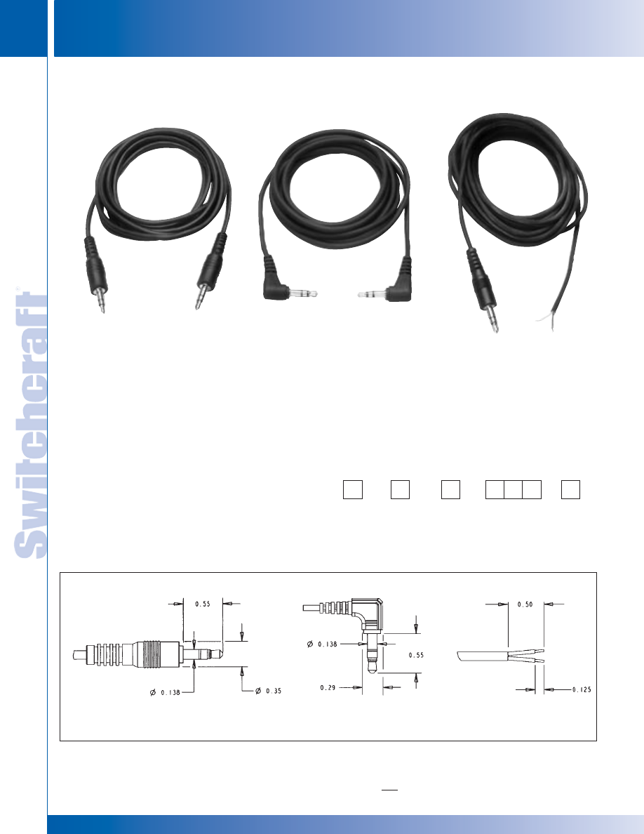
PATCH CORDS & MOLDED CABLE ASSEMBLIES
240
w w w . s w i t c h c r a f t . c o m
® Registered trademark of Switchcraft, Inc.
Note: Contact your Switchcraft Representative for price and delivery
PHONE: 773 792-2700
PA
TCH CORDS &
MOLDED CABLE ASSEMBLIES
DIMENSIONS ARE FOR REFERENCE ONLY
Inch
(mm)
3.5MM MOLDED CABLE ASSEMBLIES
3.5MM MOLDED CABLE ASSEMBLIES
3.5MM MOLDED CABLES
FEATURES AND BENEFITS
• Choose plug-to-plug or plug-to-stripped and tinned leads
• 3.5 mm plugs available as straight or right-angle
• Available in mono and stereo
• NOM.29 GA jacketed conductors (red and white)
with copper spiral shield
• Cable O.D. 3.0 mm nom./.118" nom.
• Black cable
ORDERING INFORMATION
1. Order by part number.
2. Contact Switchcraft for custom requirements.
PART NUMBERING SYSTEM
32 - Mono
33 - RA Mono
35 - Stereo
36 - RA Stereo
H - Black
R - 3.0 mm nom.
2-conductor wire
with spiral copper
shield
Length (feet)
036 (3)
072 (6)
144 (12)
32 - Mono
33 - RA Mono
35 - Stereo
36 - RA Stereo
84 - Stripped
and tinned
90 - Straight
Cut Off
SPECIFICATIONS
PLUGS
Tip, Ring and Sleeve: Brass with nickel-plate
Flex Life: 5000 cycles minimum
Plug Insulator: ACETAL
END CODE: 35
3.5 mm STRAIGHT PLUG
END CODE: 84
STRIP and TIN
END CODE: 36
3.5 mm RIGHT-ANGLE PLUG
35HRXXX35
36HRXXX36 35HRXXX84
* Please visit the product pages on our website for the most up-to-date product information
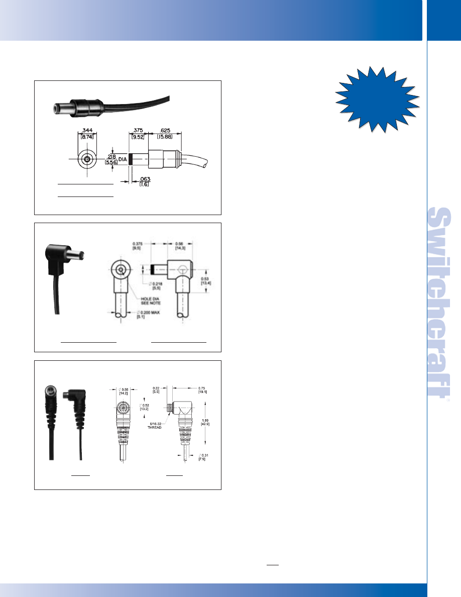
SWITCHCRAFT, INC. 5555 N. Elston Ave. • Chicago, IL 60630
241
PATCH CORDS & MOLDED CABLE ASSEMBLIES
FAX: 773 792-2129
PA
TCH CORDS &
MOLDED CABLE ASSEMBLIES
DIMENSIONS ARE FOR REFERENCE ONLY
Inch
(mm)
POWER PLUGS AND JACKS
POWER PLUGS AND JACKS
MOLDED CABLE ASSEMBLIES
With Power-Plug Battery Charger Plugs and Jacks
SPECIFICATIONS
PLUG
Sleeve: Copper alloy, nickel-plated.
Pin: Silver-plated copper alloy.
Finger Insulator: Plastic.
Insulating Washers: Rigid plastic.
Sleeve Terminal: Steel, tin-plated.
Molded Handle: Plastic.
JACK
Bushing: Brass, nickel-plated copper alloy.
Washers: Rigid plastic.
Pin, Springs, and Terminals: Plated copper alloy.
Housings: Thermoplastic.
CABLE
We will build assemblies on cable furnished by you,
.156" (3.96 mm) outside diameter, or on cable we purchase to
your specifications. Jacket must have temperature rating of
60° C minimum. Optional mold available for larger cable; order
as ST760L or ST765L.
DESIGN FEATURES
• ST760, ST760L, RA760 – accepts .08" (2.03 mm)
diameter pin.
• ST765, ST765L, RA765 – accepts .099" (2.54 mm)
diameter pin.
• RA712A:
• Mates with ST765, ST765L, and RA765.
• 2 conductor.
• Mounts in .313" diameter hole in panels up to .125" thick.
• Pin outside diameter is .108" - .112" split pin.
• Automatic switchover from AC to DC.
• RA722A:
• Mates with ST760, ST760L, and RA760.
• Pin outside diameter is .086" - .090" split pin.
• Molded-in cable clamp sleeve terminal (RA plugs only).
• For use with sockets similar to those used on portable
radios, tape recorders, television receivers and appliances
which feature AC adapters and/or battery chargers.
• Available with terminations of another ST760, RA760
stripped and tinned ends, spade lugs, alligator clips, and
more on special order.
• Jacks available with extended bushing for use with
Switchcraft locking power plugs 761K, 766K, S761K,
and S766K on special order.
See ordering guide on next page.
ST760, ST765 – Termination Code: 47, 48
RA760, RA765 – Termination Code: 52, 53
NOTE: ST760 is a molded version of S760; ST765 is a molded version of 765.
RA712A and RA722A
Termination Code: 71, 72
.080-.084 DIA x .328 DEEP
ST-760
(2.03-2.13) DIA x (8.33) DEEP
.099-.103 DIA x .328 DEEP
ST-765
(2.52-2.61) DIA x (8.33) DEEP
Ask About
Our Locking
Power Plugs
.099-.103 DIA x .328 DEEP
RA-765
.(2.52-2.61) DIA x (8.33) DEEP
.080-.084 DIA x .328 DEEP
RA-760
.(2.03-2.13) DIA x (8.33) DEEP
RA722A
.086" -.090" Split Pin
Collapses to fit .08" Diameter Pin
*RA712A
.108" -.112" Split Pin
Collapses to fit .10" Diameter Pin
* Please visit the product pages on our website for the most up-to-date product information
PATCH CORDS & MOLDED CABLE ASSEMBLIES
242
w w w . s w i t c h c r a f t . c o m
® Registered trademark of Switchcraft, Inc.
Note: Contact your Switchcraft Representative for price and delivery
PHONE: 773 792-2700
PA
TCH CORDS &
MOLDED CABLE ASSEMBLIES
DIMENSIONS ARE FOR REFERENCE ONLY
Inch
(mm)
ORDERING GUIDE
ORDERING GUIDE
MOLDED CABLE ASSEMBLIES WITH POWER PLUGS AND JACKS
PART NUMBERING SYSTEM
TO CREATE A PART NUMBER
1. Identify Terminations (both ends)
2. Indicate Color and Type of Cable
3. Select the Length of Assembly
DC POWER CABLE ASSEMBLIES
*See “Cable Types” chart on page 260. Note: Some configurations will be special orders. Contact Switchcraft.
STRAIGHT 2-CONDUCTOR .100 PIN POWER PLUG (#48) TO:
Termination (other end)
Cable
Length (feet)
Part Number
1
(power plug) #48
C
6
48HC07248
(stripped wires) #84
C
6
48HC07284
(blunt cut) #90
C
6
48HC07290
(power jack .100 pin) #71
K
6
48HK07271
Type
Termination
Color
Cable*
Length (feet)
Termination
ST760
4
7
G-Gray
C
0
1
8 (1.5)
4
7
ST765
4
8
H-Black
K
0
2
4 (2)
4
8
ST760L
5
7
5
7
ST765L
5
8
5
8
ST760K
7
3
7
3
ST765K
7
4
7
4
RA760
5
2
Y
0
3
6 (3)
5
2
RA765
5
3
Z
0
4
8 (4)
5
3
RA712A
7
1
0
7
2 (6)
7
1
RA722A
7
2
1
2
0 (10)
7
2
8
4
9
0
TYPICAL STANDARD PART NUMBERS
1. All cables listed here are black.
* Please visit the product pages on our website for the most up-to-date product information
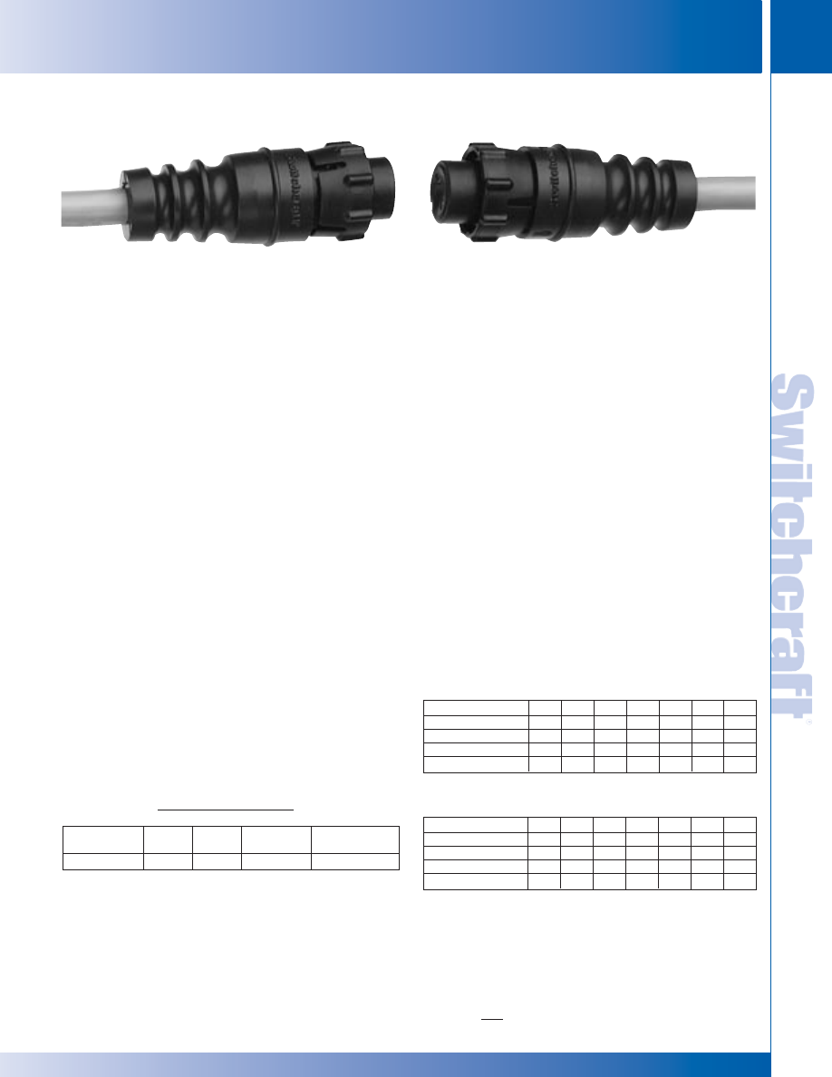
SWITCHCRAFT, INC. 5555 N. Elston Ave. • Chicago, IL 60630
243
PATCH CORDS & MOLDED CABLE ASSEMBLIES
FAX: 773 792-2129
PA
TCH CORDS &
MOLDED CABLE ASSEMBLIES
DIMENSIONS ARE FOR REFERENCE ONLY
Inch
(mm)
EN3™ MOLDED CABLE ASSEMBLIES
EN3™ MOLDED CABLE ASSEMBLIES
FEATURES AND BENEFITS
• Dual purpose handle provides flex relief and finger grip
design for easy insertion and withdrawal.
• Available in both cord and in-line versions.
• 2 through 8 pin configurations.
• Superior leakage protection. Contact area is double-sealed
for excellent moisture and chemical resistance.
• Integral O-ring and gasket. O-ring is molded onto cord
housing assembly and gasket is molded onto panel
housing assembly to prevent leakage and eliminate
need for additional copper case o-rings and gaskets.
• Thermoplastic rubber body simulates closed entry contact
system to prevent probe damage or accidental loss of
spring retention due to misaligned or bent pins.
• Housing rated UL 94V-O against flammability.
• Exceeds Coast Guard specifications for water tightness
(CFR 46 Part 110.20).
• Exceeds enclosure rating IP16/IP18 when not mated or
covered and IP66/IP68 when mated or covered (IEC 529).
• Exceeds enclosure rating 6P at 1000V when mated
or covered (NEMA 250).
APPLICATIONS
• Process Control
• Communications
• Marine Electronics
• Transportation
• Medical Instrumentation
• General Industrial Electronics
• Geothermal Instrumentation
MATERIALS
Connector shells, contact locking disk:
Thermoplastic polymer glass fiber, flame retardant
Coupling ring: Nylon
Connector shell interior: Thermoplastic rubber
Contacts: Copper base alloy gold-plated over
nickel underplate
EN3
™
MINI WEATHERTIGHT OVERMOLDED CABLE ASSEMBLIES
SPECIFICATIONS
MECHANICAL
Shock: Mil-Std 202 Method 213B, condition K
Vibration: Mil-Std 202 Method 201
Life: 600 insertion/withdrawal cycles (minimum)
ELECTRICAL
Voltage Rating (sea level): Tested at 600 VRMS
Insulation Resistance: 100 megohms (minimum) at 77° F
Contact Resistance: 5 milliohms (maximum)
Current Rating: 7.5 Amps (#20 contact);
13.0 Amps (#16 contact)
ENVIRONMENTAL
Temperature Limits: -40°C to +65°C (non-operating)
Moisture Resistance: Mil-Std 202 Method 106F
Insulation Resistance: Mil-Std 202 Method 302 condition B
Thermal Shock: Mil-Std 202 Method 107G
Salt Spray: Mil-Std 202 Method 101D condition B
RATINGS
IP16/IP18
IP66/IP68
NEMA 250 (6P)
CFR 46 Part 110.20
UL 94V-O
Patent 5,485,673 File 36049
OVERMOLDED STYLE NUMBER
#20 CONTACT SIZE
Number of Pins
2
3
4
5
6
7
8
Male Cord
502
503
504
505
506
—
—
Female Cord
512
513
514
515
516
517
518
Male Inline
522
523
524
525
526
527
528
Female Inline
532
533
534
535
536
—
—
OVERMOLDED STYLE NUMBER
#16 CONTACT SIZE
Number of Pins
2
3
4
5
6
7
8
Male Cord
552
553
—
—
—
—
—
Female Cord
562
563
—
—
—
—
—
Male Inline
572
573
—
—
—
—
—
Female Inline
582
583
—
—
—
—
—
PART NUMBERING GUIDE*
Example:
1st
Length
2nd
Termination
Color
Cable
in Inches
Termination
503
H
A
072
184
*In most instances the multi-conductor cable will be used – found on page 252.
The overmolded EN3
™
cable can accept nominal cable
O.D.’s up to .300.
Tooling charges may apply for customer specified cable.
Note: 9-18 versions can also be molded. Contact factory for details.
* Please visit the product pages on our website for the most up-to-date product information
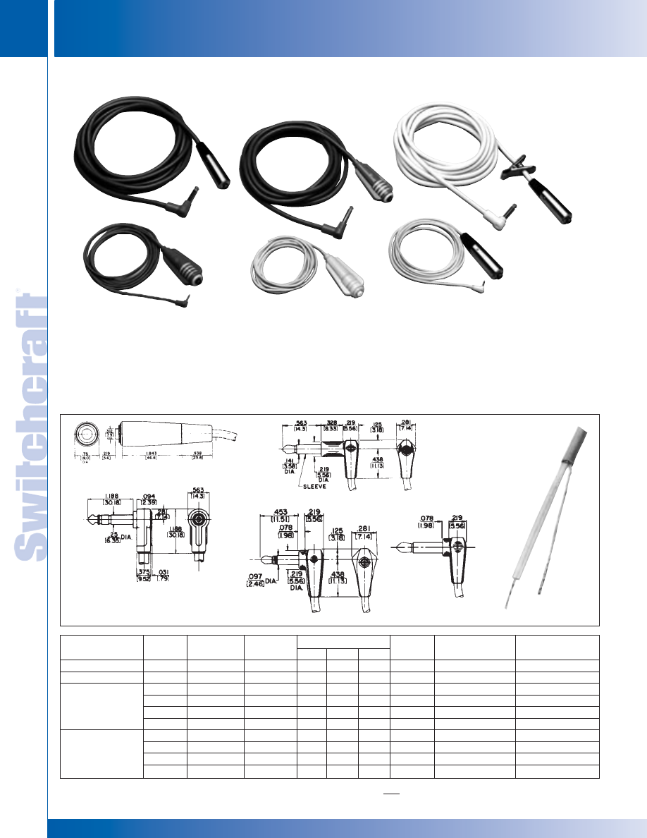
PATCH CORDS & MOLDED CABLE ASSEMBLIES
244
w w w . s w i t c h c r a f t . c o m
® Registered trademark of Switchcraft, Inc.
Note: Contact your Switchcraft Representative for price and delivery
PHONE: 773 792-2700
PA
TCH CORDS &
MOLDED CABLE ASSEMBLIES
DIMENSIONS ARE FOR REFERENCE ONLY
Inch
(mm)
MOLDED CABLE ASSEMBLIES
MOLDED CABLE ASSEMBLIES
97GVXXX06
99GVXXX04
97WVXXX06
(shown with
optional clip)
Also available
with 3.5 mm plug
finger termination.
99GD07261
99WD07284
97WDXXX61
CORDETTE
®
AND CORD SWITCH ASSEMBLIES
DESCRIPTION
1st Term
Housing &
CABLE
Cable Length (In.)
2nd Term
Circuitry
Button Color
Example:
Code
Cable Color
CODE
X
X
X
Code
Std. Cordette (921K)
99
G
V
0
7
7
84
Std. - 1A (No Code)
Std. Black (No Code)
ED903 Series
97
1 - 1B
H - Black
Standard Cable
G-Gray
V (W1230-1)
.250"
PVC
18GA
06
2 - 1C
R - Red
Type for 1/4" Plugs
H-Black
V (W1230-2)
.250"
PVC
18GA
07
3 - AB
W - White
B-Beige
V (W1230-4)
.250"
PVC
18GA
W-White
V (W1230-5)
.250"
PVC
18GA
Standard Cable
G-Gray
D (W1032-1)
.109"
PVC
25GA
61
Types for Tini
®
and
H-Black
D (W1032-2)
.109"
PVC
25GA
50
Micro Plugs
W-White
D (W1032-3)
.109"
PVC
25GA
51
H-Black
E (W1065-2)
.100"
PVC
26GA
FEATURES AND BENEFITS
• Momentary, 0.5 A switching combined with
1-piece molded plastic body qualifies Cordette for all types
of commercial and industrial usage.
• Available with molded-on Cordette switch or assembled
Cord switch (ED series).
• Cable features PVC outer jacket and withstands rugged use.
SPECIFICATIONS STYLE 97
Body: Series ED900
Housing: Die-cast zinc, satin nickel-plated.
Switch Body and Insert Bushing: H.H. Brass, nickel-plated.
Insulation: XXXP paper-base phenolic.
Cable Relief Bushing: Black neoprene.
Pressure Plates: Stainless steel.
Cable Relief Screws: Steel, nickel-plated.
SERIES ED900
TERMINATION CODE: 06 , 07
(06 - 2 conductor not shown)
TERMINATION CODE: 51
TERMINATION
CODE: 84
TERMINATION CODE: 61
TERMINATION
CODE: 50
* Please visit the product pages on our website for the most up-to-date product information
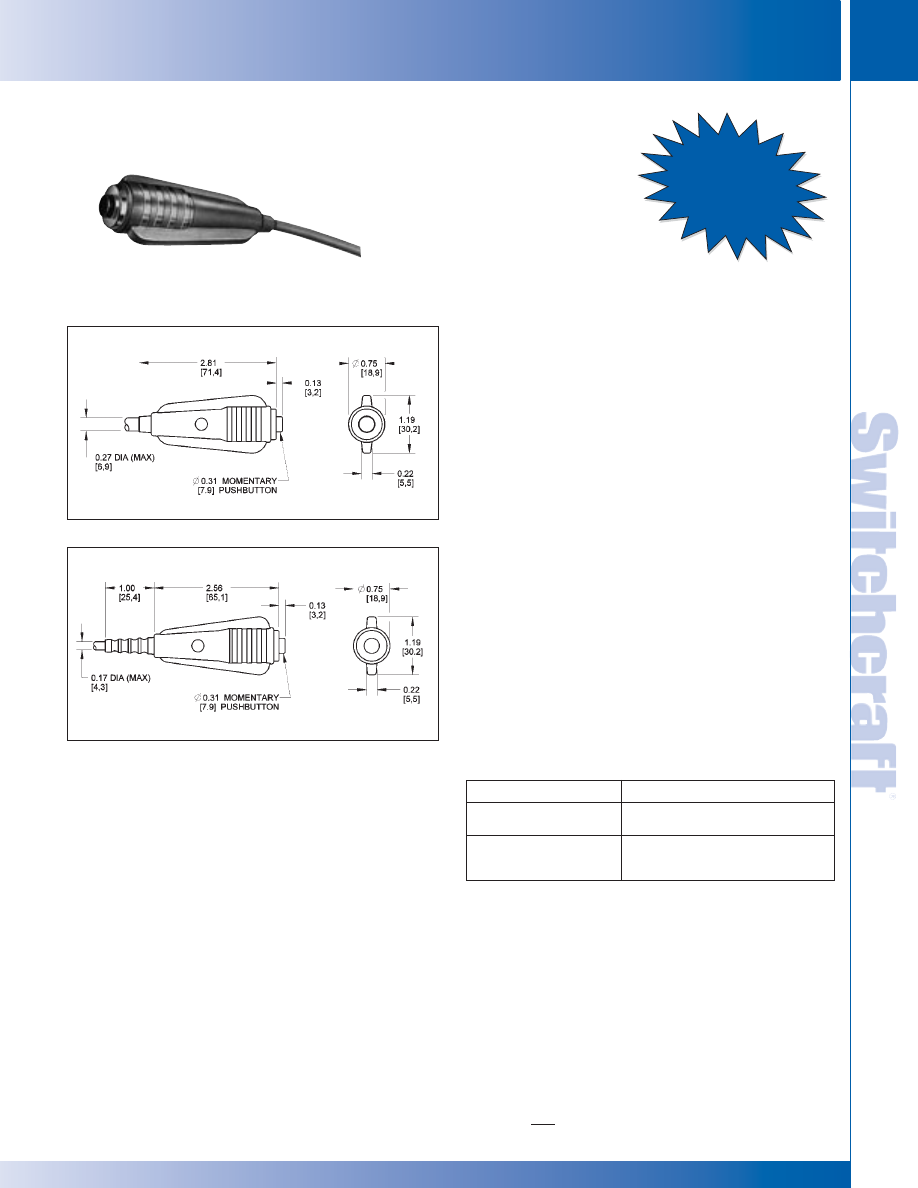
SWITCHCRAFT, INC. 5555 N. Elston Ave. • Chicago, IL 60630
245
PATCH CORDS & MOLDED CABLE ASSEMBLIES
FAX: 773 792-2129
PA
TCH CORDS &
MOLDED CABLE ASSEMBLIES
DIMENSIONS ARE FOR REFERENCE ONLY
Inch
(mm)
CORDETTE
®
SWITCHES
CORDETTE
®
SWITCHES
SPECIFICATIONS
SWITCH
Housing: White plastic (standard).
Molded Body: Gray plastic (standard) with contrasting trim
and gray pushbutton.
Contacts: Integral, copper alloy, hard gold-plated form 1-A, 0.5
A, 50 W maximum, AC, non-inductive load. Not recommended
for high voltage circuits.
Insulation: Thermoplastic UL 94V-0.
Button Color: Black (standard). Other colors available on
special order.
CABLE
Standard Unshielded—Type W-1230.
Note: See Standard Cable Chart on page 260 for details.
We will build assemblies on cable furnished by you, .27" (6.68
mm) outside diameter, or on cable we purchase to your
specifications. Jacket must have temperature of 60° C minimum.
ST900 (#99)
Button stroke only .063" (1.6 mm). Cable leads soldered
directly to switch terminals. Standard button is with 1-A switching.
Use termination number “99” with all cable numbering charts
except multi-pin interconnection. Use code “198” for multi-pin
interconnections.
See Switch Section of Switchcraft’s Engineering Design Guide
for more details on the ST900.
MOLDED CABLE ASSEMBLIES
WITH CORDETTE
®
SWITCHES
ST900
Termination Code: 99
ST900
ST900F
Part Number
Description
Cordette Switch,
921
phone jack termination
Same as 921, plus 6-foot,
921K
2 conductor cable with stripped
and tinned leads.
Ask About
Our New Sealed
Cordette
®
ST901
Code: 98
SPECIAL ORDER FEATURES
• 1-B, 1-C, or 1-A + 1-B switching.
• Red, green, blue, white or yellow pushbuttons.
• Legends
• Other body colors
• ST-900 - Custom-molded to any of a large selection of
cables. Also many cable terminations, i.e., phone plugs,
extension jacks, phono plugs, spade lugs, alligator clips,
stripped and tinned leads, etc.
* Please visit the product pages on our website for the most up-to-date product information
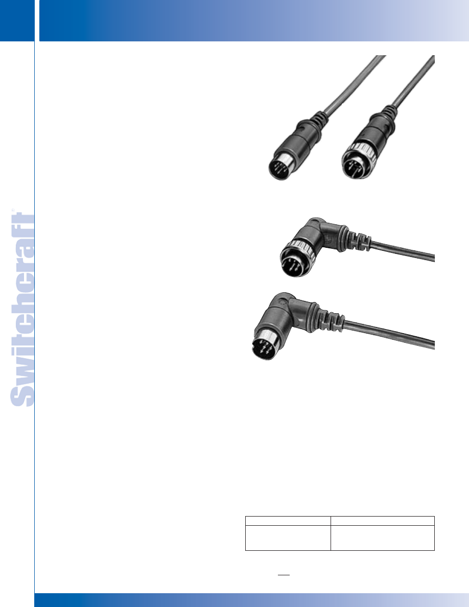
PATCH CORDS & MOLDED CABLE ASSEMBLIES
246
w w w . s w i t c h c r a f t . c o m
® Registered trademark of Switchcraft, Inc.
Note: Contact your Switchcraft Representative for price and delivery
PHONE: 773 792-2700
PA
TCH CORDS &
MOLDED CABLE ASSEMBLIES
DIMENSIONS ARE FOR REFERENCE ONLY
Inch
(mm)
MULTIPIN INTERCONNECTORS
MULTIPIN INTERCONNECTORS
Switchcraft DIN molded cable assemblies meet increased
demand for modern, field-tested connections for a wide range
of electrical/electronic applications. Connectors are DIN
(Deutsche Industrie Norm) circular type, male or female (lock-
ing or non-locking) with 3 to 8 pins/contacts. Units are molded
and protected with a rugged handle, and are fully shielded and
equipped with advance design cable relief. Switchcraft cable
assemblies and mating receptacles adhere to strict
requirements of FCC Docket 20780 and offer fully shielded
links for data and instrumentation applications of all kinds.
SHIELDING EFFECTIVENESS
Effectiveness of shielding is frequency-dependent;
as
frequency increases, more shielding is required to maintain
comparable shielding effectiveness.
The chart below
delineates shielding effectiveness with molded cable assemblies
with 100% foil shield cables and shielded DIN connectors.
Frequency Range MHz
Shielding Effectiveness, dB
30-500
-30
60-400
-20
500-800
-10
MOLDED CABLE ASSEMBLIES WITH DIN PLUGS
Style ST307
Termination Code: 307
Style ST324
Termination Code: 324
Style RA374
Termination Code: 374
Style RA356
Termination Code: 356
STYLES RA300 AND ST300
APPLICATIONS
• Computer
• Data Communications
• Instrumentation
• Medical Systems
• Process Controls
• MIDI (Musical Instrument Digital Interface)
FEATURES
• Long life
• 7 different pin configurations: versatile circuitry
• Fully molded plugs sealed against contamination
(moisture, dust, dirt)
• Fully shielded: plugs with interference
protection/ common ground-shield
• Strain relief: protects internal wire connections
• Flex relief: molded integral with handle
for extra protection. No exit stress failures
• Locking: 30° twist locking for anti-vibration
protection and ease of engagement
• Straight and coil cords: stock and custom styles,
colors, lengths
• Shielded or unshielded cables: stock and custom
styles, colors, lengths
• Molded through-panel cable relief: extra
cable protection
• Custom wiring/ keying: gives extra choice in
mounting and circuit selection
• Custom contact plating: precious and other metals
• Custom logo: your identification on molded plugs
• 100% tested for continuity, shorts, appearance,
voltage breakdown (250 or 500 V)
COMPLETE SHIELDING SYSTEMS
Switchcraft also offers shielded DIN receptacles for use with
shielded molded cable assemblies. Together they provide a
valuable design tool to suppress EMI interference to permit
you to meet strict requirements of FCC Docket 20780.
ORDERING
1. Order by part number from guide on page 251.
2. For special order items, contact Switchcraft with details.
SPECIFYING NOTE: See Connector Section of Switchcraft’s
Engineering Design Guide for mating receptacles.
* Please visit the product pages on our website for the most up-to-date product information

SWITCHCRAFT, INC. 5555 N. Elston Ave. • Chicago, IL 60630
247
PATCH CORDS & MOLDED CABLE ASSEMBLIES
FAX: 773 792-2129
PA
TCH CORDS &
MOLDED CABLE ASSEMBLIES
DIMENSIONS ARE FOR REFERENCE ONLY
Inch
(mm)
MULTIPIN INTERCONNECTIONS
MULTIPIN INTERCONNECTIONS
Insertion/Withdrawal Forces:
Number of
Insertion Force
Withdrawal Force
Contacts
pound/N
pound/N
2
3.6/(16)
.45–2.7/ (2–12)
3
5.4/(24)
.67–4.1/ (3–18)
4
7.2/(32)
.90–5.4/ (4–24)
5
9.0/(40)
1.24–6.8/ (5.5–30)
6
10.8/(48)
1.46–8.1/ (6.5–36)
7
12.6/(56)
1.68–9.5/ (7.5–42)
8
14.4/(64)
1.90–10.8/ (8.5–48)
STYLES RA300 AND ST300
SPECIFICATIONS
ELECTRICAL
Contact Resistance: Cord Plugs and Receptacles.
.010 ohms, contact spring/pin; .030 ohms, ground clip/shell.
Control and Switching Receptacles: .015 ohms,
contact spring/pin; .020 ohms, switch contacts.
Dielectric Withstanding Voltage: 500 V (rms).
Leakage Resistance: 10
5
M
Ω
MECHANICAL
Life: 5000 cycles
MOLDED CABLE ASSEMBLIES WITH DIN PLUGS (continued)
Part Numbers-Male (pins)
3@180°
4@210°
5@180°
5@240°
6@240°
7@270°
8@270°
Pin Arrangements
B
D
F
E
G
H
N
Description
Straight handle.
ST303
ST309
ST305
ST304
ST306
ST307
ST308
Straight handle. 30° twist
lock ring fastening, mates with
ST323
ST329
ST325
ST324
ST326
ST327
ST328
lock flange plugs and receptacles.
Right-angle handle.
RA353
RA359
RA355
RA354
RA356
RA357
RA358
Right-angle handle. 30° twist
lock ring fastening, mates with
RA373
RA379
RA375
RA374
RA376
RA377
RA378
lock flange plugs and receptacles.
1. See next page for Pin/Contact arrangements.
PLUG MATERIALS
Pin Contacts: Silver-plated, copper alloy.
Insulating Washer: Thermoplastic.
Locking Plug Housing: Nickel-plated, die-cast zinc alloy.
Other Housings: Plated steel.
Molded Handle: Flexible thermoplastic. Strain relief
matte finish.
NOTE: All connectors meet DIN specifications. Din
specification numbers (except for 4-pin, 5-pin 240°)
will be furnished on request.
ORDERING
1. See table below for termination descriptions. Termination
code is the same number as the plug style (e.g. termination
code for a ST305 is 305).
2. See page 251 for ordering guide.
Part Number
Color
Length, inch (mm)
W-1279-2
Black
Length must be specified.
W-1289-2
Black
Term.
Term.
Part Number
Description
A
B
◊
305KD084184
Black coil cord. 15" (381 mm)
ST305
—
retracted; 78.74" (2 m)
extended. 5 pin male with
other end stripped and tinned
on cable number W-1301-2.
◊
305HJ084184
Black cable cord. 7 feet (2.13 m)
ST305
—
in length. 5 pin male with
other end stripped and tinned
on cable number W-1279-2.
◊
306HK042306
Black cable cord. 39.37" (1 m)
ST306
ST306
in length. 6 pin male to
6 pin male on cable number
W-1289-2.
◊
306HK084306
Black cable cord. 78.74" (2 m)
ST306
ST306
in length. 6 pin male to
6 pin male on cable number
W-1289-2.
PART NUMBERS – MOLDED CABLE ASSEMBLIES
FOIL SHIELD CABLES – STRAIGHT
◊
Special order only; contact Switchcraft.
* Please visit the product pages on our website for the most up-to-date product information
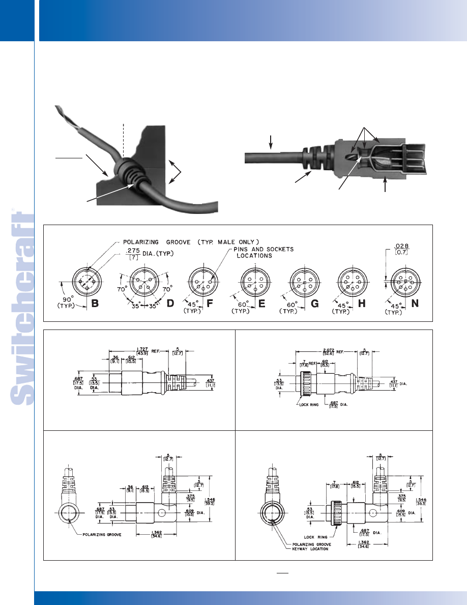
PATCH CORDS & MOLDED CABLE ASSEMBLIES
248
w w w . s w i t c h c r a f t . c o m
® Registered trademark of Switchcraft, Inc.
Note: Contact your Switchcraft Representative for price and delivery
PHONE: 773 792-2700
PA
TCH CORDS &
MOLDED CABLE ASSEMBLIES
DIMENSIONS ARE FOR REFERENCE ONLY
Inch
(mm)
MULTIPIN INTERCONNECTIONS
MULTIPIN INTERCONNECTIONS
MOLDED CABLE ASSEMBLIES WITH DIN PLUGS (continued)
STYLES RA300 AND ST300
Pin/Contact Arrangements
STYLES ST303 TO ST309
STYLES ST323 TO ST329
STYLES RA353 TO RA359
STYLES RA373 TO RA379
DOUBLE-FLATTED
HOLE
PANEL UP TO
.125"
(3.18 mm)
THICK
EXTERNAL
CABLE RELIEF
2-PIECE PANEL
RETAINS CABLE
RELIEF
CUTAWAY VIEW OF STYLE ST303
SHIELDED
CABLE
CABLE
RELIEF
CRIMP
STRAIN
RELIEF
RUGGED
COMPLETELY
MOLDED HANDLE
100% THROUGH-
CONNECTOR
SHIELDING
ST300
* Please visit the product pages on our website for the most up-to-date product information
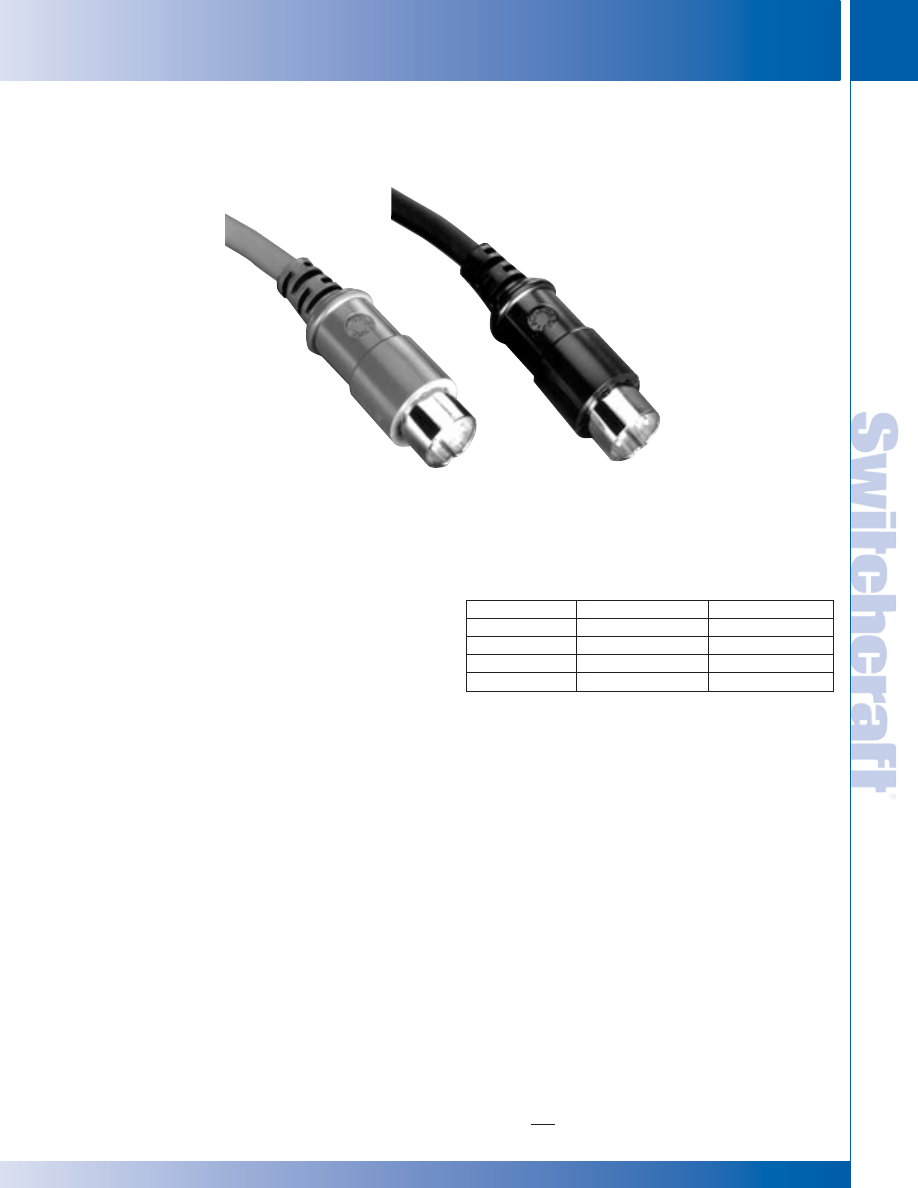
SWITCHCRAFT, INC. 5555 N. Elston Ave. • Chicago, IL 60630
249
PATCH CORDS & MOLDED CABLE ASSEMBLIES
FAX: 773 792-2129
PA
TCH CORDS &
MOLDED CABLE ASSEMBLIES
DIMENSIONS ARE FOR REFERENCE ONLY
Inch
(mm)
MIDI MOLDED CABLE ASSEMBLIES
MIDI MOLDED CABLE ASSEMBLIES
MIDI CABLES
STANDARD PRODUCT
• Silver-plated pins
• Belden Brilliance
®
24 awg, 4 conductor,
braid shielded cable
• Black cable
• Black handle
SPECIAL ORDER
• Gold-plated pins
• Other cable types
• Optional lengths
• Color cable
• Color handle
MIDI CABLES
FEATURES AND BENEFITS
• Molded connectors provide superior pull-out
retention and greater environmental protection
than assembled versions.
• All five pins wired active with high definition
Belden Brilliance
®
cable.
• Can be used with any type MIDI instrument.
SPECIFICATIONS
• Belden Brilliance
®
24 awg, 4 conductor,
braid shielded cable.
• Wiring conforms to MIDI specifications including the
clock/sync capabilities on pins 1 and 3.
• Molded 180 degree 5 pin DIN connectors.
• Standard color is black with other colors available
on special order.
• PVC molded handles and cable jackets.
• All molded cables are 100% tested for continuity,
shorts and voltage breakdown.
ORDERING INFORMATION
1. Order by part number.
2. Contact Switchcraft for more information.
Part number
MD3
MD6
MD10
MD15
Length
3 foot
6 foot
10 foot
15 foot
Color
Black
Black
Black
Black
Belden Brilliance
®
is a registered trademark of Belden Wire and Cable Company.
Standard black cable
and handle
Optional red cable
and handle
* Please visit the product pages on our website for the most up-to-date product information
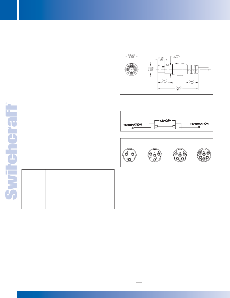
PATCH CORDS & MOLDED CABLE ASSEMBLIES
250
w w w . s w i t c h c r a f t . c o m
® Registered trademark of Switchcraft, Inc.
Note: Contact your Switchcraft Representative for price and delivery
PHONE: 773 792-2700
PA
TCH CORDS &
MOLDED CABLE ASSEMBLIES
DIMENSIONS ARE FOR REFERENCE ONLY
Inch
(mm)
MULTIPIN INTERCONNECTORS
MULTIPIN INTERCONNECTORS
STYLE ST600
MOLDED CABLE ASSEMBLIES
WITH MINIATURE, SHIELDED, MOLDED TINI Q-G
®
PLUGS
Tini Q-G
®
miniature plugs offer 3- through 6-pin/contact
connecting with full shielding, small size, RFI-protected
termination of analog/digital circuits/equipment. Typical
applications are for EIA RS-232C and RS-449 type
connections. Plugs retain all Tini Q-G
®
features, including
latchlock, strain relief, flex relief, polarization and
“scoop-proof” construction. See Connector Section for details
on features and specifications. Shielding of these plugs meets
U.S. Navy Tempest requirements with proper cable and
mating connector choice.
MOLDED CABLES WITH STRAIGHT FEMALE
Tini Q-G
®
PLUGS (Special Order Only)
Three- through 6-contact plugs are molded into a complete
cable assembly per customer requirements. Plug includes
latch for secure connection, “through-ground” provision, and
external cable flex relief. Plugs are molded onto shielded or
unshielded cables of .180" – .215" diameter Standard cable
color is gray; black, beige and other colors can also be
specified. In addition, UL 94V-0 rated cables can be specified.
Cable Length
Contact Arrangements (Contact View)
Styles ST603, ST604, ST605, ST626
Termination Codes: 603, 604, 605, 626
Note: Reverse gender molded male cable assembly available.
Call factory for details.
IMPORTANT SPECIFYING NOTE
◊
Special 3, 4 and 5 pin/contact patterns can be tooled on special order where
production quantities warrant special handling. Contact Switchcraft with your
requirements.
Plug
Mating
Style
2
Description
Receptacles
1
◊
ST603
3-contact straight
TA3M, TB3M
female plug (molded)
◊
ST604
4-contact straight
TA4M, TB4M
female plug (molded)
◊
ST605
5-contact straight
TA5M, TB5M
female plug (molded)
◊
ST626
6-contact straight
TA6ML, TB6M
female plug (molded)
1. See Connector Section of Switchcraft’s Engineering Design Guide
for other mating receptacles.
2. Termination code is the same as the numbers in the plug style (e.g. termination
code for a ST626 is 626). See multi-pin ordering guide on next page.
* Please visit the product pages on our website for the most up-to-date product information
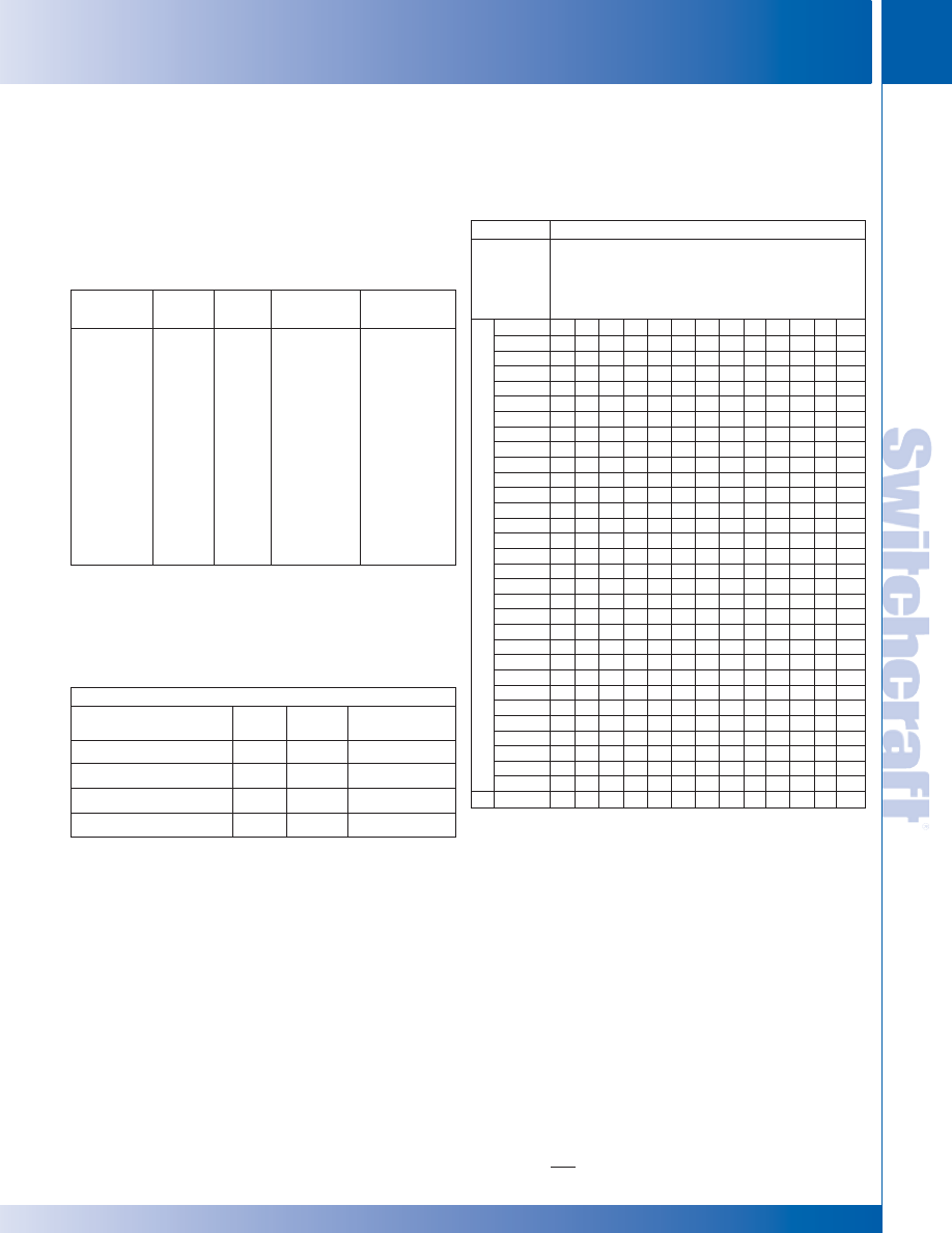
SWITCHCRAFT, INC. 5555 N. Elston Ave. • Chicago, IL 60630
251
PATCH CORDS & MOLDED CABLE ASSEMBLIES
FAX: 773 792-2129
PA
TCH CORDS &
MOLDED CABLE ASSEMBLIES
DIMENSIONS ARE FOR REFERENCE ONLY
Inch
(mm)
ORDERING GUIDE
ORDERING GUIDE
MOLDED CABLE ASSEMBLIES FOR MULTI-PIN INTERCONNECTION
PART NUMBERING SYSTEM (NOT ALL NUMBERS SHOWN)
1. Identify Terminations (both ends)*
2. Indicate Color and Type of Cable
3. Select the Length of Assembly
Termination
Color
Cable
1
Length (feet)
Termination
(examples)
303
G-Gray
A
036
(3)
3
0
3
304
H-Black
B
060
(5)
3
0
4
305
D-Beige
C
072
(6)
3
0
5
306
D
120
(10)
3
0
6
307
E
3
0
7
308
F
3
0
8
309
---
3
0
9
603
G
6
0
3
604
H
6
0
4
605
J
6
0
5
606
K
6
2
6
M
1
8
4
---
1
9
0
Q
---
U
1. See next page for cable descriptions.
* Please refer to page 243 for EN3
™
weathertight connector options.
Note:
• Other cables available on special order. Contact Switchcraft.
STRAIGHT 3-pin DIN PLUG (#303) TO:
Length
Termination (other end)
Cable
(feet)
Part Number
2
(3-pin DIN)
#303
A
5
303HA060303
(3-pin Tini Q-G
®
) #603
A
5
303HA060603
3
(Strip and tin)
#184
A
6
303HA072184
(Blunt cut)
#190
A
6
303HA072190
2. All cables listed here are black.
3. .180" diameter.
TYPICAL PART NUMBERS
MULTI-PIN CABLE ASSEMBLIES
STANDARD MULTI-PIN CABLE ASSEMBLY
TERMINATION VS. CABLE CROSS-REFERENCE
# - Indicates any number
X - Indicates that the cable in this column and the termination in this row can
be used together in a standard part number
1. - Other termination/cable combinations may be available or special order.
Cable
RA353
X
X
RA354
X
X
X
RA355
X
X
X
RA356
X
X
X
RA357
X
RA358
X
X
RA359
X
X
RA373
X
X
RA374
X
X
X
RA375
X
X
X
RA376
X
X
X
RA377
X
RA378
X
X
RA379
X
X
ST303
X
X
ST304
X
X
X
ST305
X
X
X
ST306
X
X
X
ST307
X
ST308
X
X
ST309
X
X
ST323
X
X
ST324
X
X
X
ST325
X
X
X
ST326
X
X
X
ST327
X
ST328
X
X
ST329
X
X
ST603
X
X
ST604
X
X
ST605
X
X
X
ST626
X
X
W
1
2
0
3
2
W
1
0
8
9
1
W
1
0
7
7
1
W
1
2
0
6
#
W
1
2
7
7
6
W
1
2
3
7
2
W
1
2
9
1
6
W
1
2
8
8
2
W
1
2
7
9
#
W
1
2
8
9
#
W
1
2
9
0
#
W
1
2
8
4
2
W
1
4
4
2
1
T
E
R
M
I
N
A
T
I
O
N
* Please visit the product pages on our website for the most up-to-date product information

PATCH CORDS & MOLDED CABLE ASSEMBLIES
252
w w w . s w i t c h c r a f t . c o m
® Registered trademark of Switchcraft, Inc.
Note: Contact your Switchcraft Representative for price and delivery
PHONE: 773 792-2700
PA
TCH CORDS &
MOLDED CABLE ASSEMBLIES
DIMENSIONS ARE FOR REFERENCE ONLY
Inch
(mm)
CABLE GUIDE
CABLE GUIDE
STANDARD MULTI-PIN INTERCONNECTION CABLES
FOR MOLDED CABLE ASSEMBLIES ON PAGES 243 THROUGH 251.
Cable Type
Color
Description
Cable Code
W1203-2
Black
3 conductor, 22 AWG stranded, unshielded
A
.18" (4.6 mm) outside diameter, UL style 2960
W1089-1
Gray
4 conductor, 22 AWG stranded, unshielded
B
.18" (4.6 mm) outside diameter, UL style 2960
W1077-1
Gray
5 conductor, 22 AWG stranded, unshielded
C
.20" (5.1 mm) outside diameter, UL style 2464
W1206-1
Gray
6 conductor, 22 AWG stranded, unshielded
D
W1206-2
Black
.20" (5.1 mm) outside diameter, UL style 2095
W1277-6
Beige
7 conductor, 22 AWG stranded, unshielded
E
.20" (5.1 mm) outside diameter, UL style 2095
W1237-2
Black
8 conductor, 22 AWG stranded, unshielded
F
.23" (5.8 mm) outside diameter, UL style 2464
W1291-6
Beige
3 conductor, 24 AWG stranded, foil shielded
G
.18" (4.6 mm) outside diameter
W1288-2
Black
4 conductor, 24 AWG stranded, foil shielded
H
.18" (4.7 mm) outside diameter
W1279-1
Gray
5 conductor, 24 AWG stranded, foil shielded
W1279-2
Black
.19" (4.8 mm) outside diameter
J
W1279-6
Beige
W1289-2
Black
6 conductor, 24 AWG stranded, foil shielded
K
W1289-6
Beige
.22" (5.5 mm) outside diameter
W1290-1
Gray
8 conductor, 24 AWG stranded, foil shielded
M
W1290-6
Beige
.23" (5.7 mm) outside diameter
W1284-2
Black
5 conductor, 22 AWG stranded, braid shielded
Q
.23" (5.8 mm) outside diameter
* Please visit the product pages on our website for the most up-to-date product information
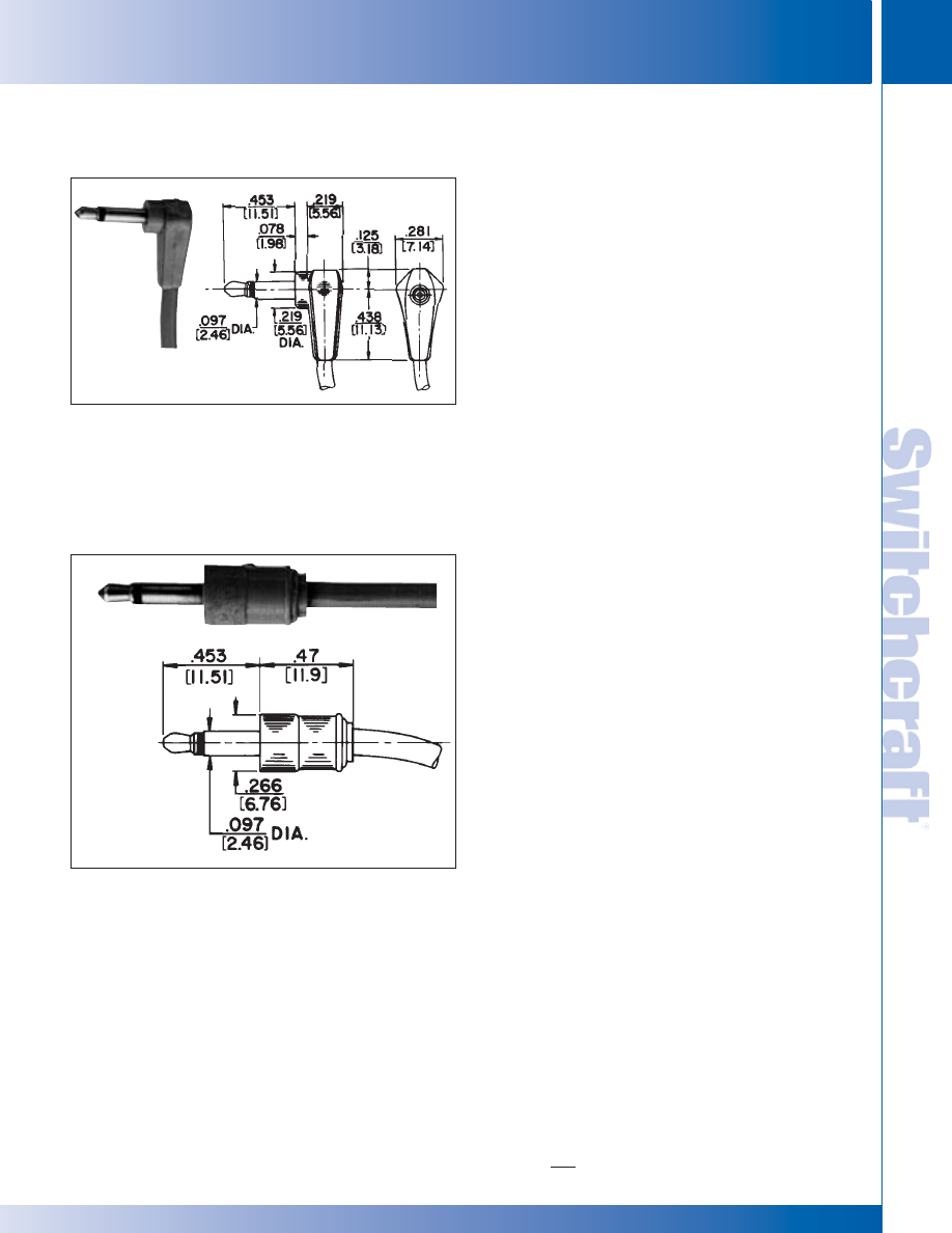
SWITCHCRAFT, INC. 5555 N. Elston Ave. • Chicago, IL 60630
253
PATCH CORDS & MOLDED CABLE ASSEMBLIES
FAX: 773 792-2129
PA
TCH CORDS &
MOLDED CABLE ASSEMBLIES
DIMENSIONS ARE FOR REFERENCE ONLY
Inch
(mm)
SUBMINIATURE PLUGS AND JACKS
SUBMINIATURE PLUGS AND JACKS
MOLDED CABLE ASSEMBLIES
With Micro Plug
®
Subminiature Phone Plugs
DESIGN FEATURES
• Thermoplastic insulation between tip and sleeve circuits.
• “Pear-shaped” one-piece tip rod.
• Cable clamp connects cable shield (or second conductor)
to plug sleeve.
SPECIFICATIONS
PLUG
Tip and Sleeve: Plated copper alloy.
Insulation: W-1032-1. Molded thermoplastic.
Sleeve Terminal: Tinned copper alloy.
Molded Handle: Plastic.
Standard Colors: Gray, white, black, brown.
Other colors available on special order.
CABLE
Standard Shielded Cable—Type W-1032-1.
NOTE: See Standard Cable Chart on page 260 for details.
Order by part number from guide on page 259.
Special Cable: We will build assemblies on cable furnished
by you, .109" (2.77 mm) diameter maximum, or on cable
we purchase to your specifications. Jacket must have
temperature rating of 60° C minimum.
RA850: Right-angle Micro-Plug
®
plug with plastic handle.
Short body extension. Molded to cables up to .109" (2.77 mm)
outside diameter.
ST850: Straight Micro-Plug
®
plug, small plastic handle, only
.47" (11.9 mm) long.
NOTE: Micro-Plug
®
molded cable assemblies mate with
Switchcraft Micro-Jax
®
TR-2A.
RA850
Termination Code: 61
ST850
Termination Code: 60
* Please visit the product pages on our website for the most up-to-date product information
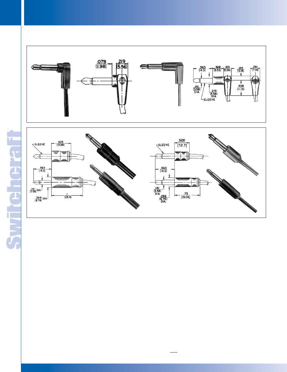
PATCH CORDS & MOLDED CABLE ASSEMBLIES
254
w w w . s w i t c h c r a f t . c o m
® Registered trademark of Switchcraft, Inc.
Note: Contact your Switchcraft Representative for price and delivery
PHONE: 773 792-2700
PA
TCH CORDS &
MOLDED CABLE ASSEMBLIES
DIMENSIONS ARE FOR REFERENCE ONLY
Inch
(mm)
MINIATURE PLUGS
MINIATURE PLUGS
SPECIFICATIONS
PLUG
Tip and Sleeve: Nickel-plated copper alloy.
Cable Clamp: Tin-plated steel.
Insulation: Rigid plastic.
Molded Handle: Plastic.
Standard Colors: Gray, white, black, brown.
Other colors available on special order.
CABLE
Shielded—Type W-1000-1 (suitable for ST740 and
ST750 due to cable Outside Diameter).
Shielded—Type W-1032-1 (suitable for all types on this page).
Standard Parallel—Type W-1041-1.
NOTE: See Standard Cable Chart on page 260 for details.
Order by part number from guide on page 259.
Special Cable: We will build assemblies on cable furnished by
you, up to .160" (4.06 mm) (for ST740 and ST750); .120" (3.05
mm) (for ST700, ST710, RA700, RA710) outside diameter, or
on cable we purchase to your specifications. Jacket must have
temperature rating of 60°C minimum.
DESIGN FEATURES
• “Pear-shaped” one-piece tip rod soldered directly
to cable conductor.
• Cable clamp connects cable shield
(or second conductor) to the plug sleeve.
RA700: Right-angle Tini Plug
®
plug with small plastic
handle. Short body extension, recommended for slightly
recessed jacks. Molded to cables up to .109" (2.77 mm)
outside diameter.
RA710: Right-angle Tini-Plug
®
plug similar to RA700,
except longer body extension where equipment jack is
deeply recessed. Molded to cables up to .109" (2.77 mm)
outside diameter.
ST700: Straight Tini-Plug
®
plug offering the shortest and
smallest handle.
ST710: Same as ST700, except with longer handle.
ST740: Straight Tini-Plug
®
with larger outside diameter
handle desirable.
ST750: Straight Tini-Plug
®
with same diameter handle
as ST740 and longer handle for easier handling.
MOLDED CABLE ASSEMBLIES With Tini Plug
®
Miniature Phone Plugs
RA700
Termination Code: 50
RA710
Termination Code: 51
ST700
Termination Code: 41
ST710
Termination Code: 40
ST740
Termination Code: 46
ST750
Termination Code: 45
* Please visit the product pages on our website for the most up-to-date product information
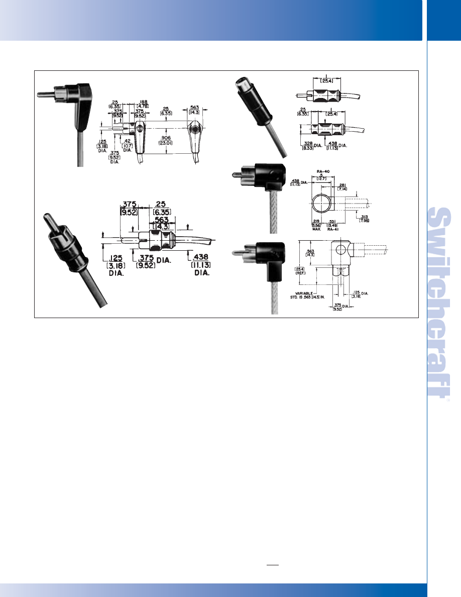
SWITCHCRAFT, INC. 5555 N. Elston Ave. • Chicago, IL 60630
255
PATCH CORDS & MOLDED CABLE ASSEMBLIES
FAX: 773 792-2129
PA
TCH CORDS &
MOLDED CABLE ASSEMBLIES
DIMENSIONS ARE FOR REFERENCE ONLY
Inch
(mm)
PHONO PLUGS AND JACKS
PHONO PLUGS AND JACKS
MOLDED CABLE ASSEMBLIES With Phono Plugs and Phono Extension Jacks
ST-35
Termination Code: 25
ST-40
Termination Code: 26
RA-40 (short handle)
Termination Code: 29
RA-41 (long handle)
Termination Code: 31
SPECIFICATIONS
PLUG
Tip (prong): Nickel-plated, copper alloy.
Sleeve Connection: Plated copper alloy.
Insulation: Rigid plastic or thermoplastic.
Molded Handle: Thermoplastic.
Standard Colors: Gray, black, brown, red, white, tan,
or blue. Other colors available on special order.
EXTENSION JAX
Tip Spring: Nickel-plated, hardened copper alloy.
Sleeve Connection: Plated steel.
Insulation: Rigid plastic.
Molded Handle (both Plug and Jack): Plastic.
Standard Colors: Gray, white, black and brown.
Other colors available on special order.
CABLES
RA35, ST35, ST40, ST60:
Standard Shielded Cable—Type W-1000-1.
Standard Parallel Cable (lamp cord)—Type W-1033-1.
RA40, RA41:
Standard Shielded Cable—Type W-1000-1 and W-1032-1.
Standard Unshielded (Parallel) Cable—Type W-1041-1.
NOTE: See Standard Cable Chart on page 260 for details.
Order by part number from guide on page 259.
Special Cable: We will build assemblies on cable furnished
by you (maximum diameter varies for types RA35, ST35,
ST40) up to .20" (5.08 mm) outside diameter for RA40 and
RA41 or on cable we purchase to your specifications. Jacket
must have a temperature rating of 60 C minimum.
◊
RA35: Right-angle phono plug with body extension for
recessed jack. Cable: .188" (4.78 mm) outside diameter
maximum. Completely shielded. (Available on special order only.)
ST35: Straight phono plug with “finger grip” handle. Handle
.438" (11.13 mm) outside diameter. Completely shielded.
ST40: Straight phono plug, similar to ST35, except with
longer handle.
ST60: Straight extension jack with “finger grip” handle. Handle
.438" (11.13 mm) outside diameter. Completely shielded.
RA40: Compact right-angle phono plug with low profile, high
quality insulation, and short .281" (7.14 mm) molded handle
for audio and RF connections where space is at a minimum.
RA41: Same as RA40, except handle is .531" (13.49 mm) long.
DESIGN FEATURES
• Can be specified with phenolic, nylon, glass-filled Teflon
or polypropylene internal insulators. Polypropylene is
recommended for RF connecting applications.
• Applications include stereo, PA and intercoms, audio-visual
and telecommunications, including RF connections in
2-way radio and paging systems.
◊
RA-35
Termination Code: Special Order
ST-60
Termination Code: 82
* Please visit the product pages on our website for the most up-to-date product information
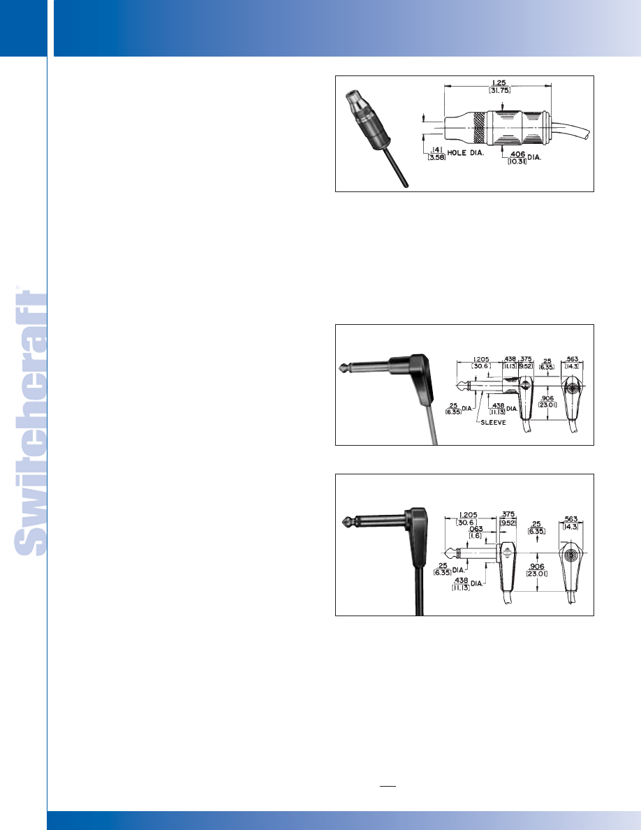
PATCH CORDS & MOLDED CABLE ASSEMBLIES
256
w w w . s w i t c h c r a f t . c o m
® Registered trademark of Switchcraft, Inc.
Note: Contact your Switchcraft Representative for price and delivery
PHONE: 773 792-2700
PA
TCH CORDS &
MOLDED CABLE ASSEMBLIES
DIMENSIONS ARE FOR REFERENCE ONLY
Inch
(mm)
EXTENSION JACKS AND LITTEL PLUGS
EXTENSION JACKS AND LITTEL PLUGS
SPECIFICATIONS
PLUG
Tip: Nickel-plated, copper alloy.
Sleeve: Plated copper alloy.
Insulation: Rigid plastic.
Internal Shield: Plated steel.
Molded Handle: Plastic.
Standard Colors: Gray, white, black and brown.
Other colors available on special order.
CABLE
FOR 2-CONDUCTOR PLUGS:
Standard Shielded Cable–Type W-1000-1.
Standard Parallel Cable (lamp cord)–Type W-1033-1.
FOR 3-CONDUCTOR PLUGS:
Standard Shielded Cable–Type W-1021-1.
NOTE: See Standard Cable Chart on page 260 for details.
Order by part number from guide on page 259.
Special Cable: We will build assemblies on cable furnished by
you, .188" (4.78 mm) diameter maximum, or on cable we
purchase to your specifications. Jacket must have a
temperature rating of 60°C minimum.
DESIGN FEATURES
• Molded cables with Littel-Plug phone plugs feature
one-piece tip rod assembly connecting tip directly
to the soldered connection of the cable conductor.
• Unusual dual-purpose clamp terminal provides completely
shielded electrical connection and a cable clamp; connects
plug sleeve to cable shield or conductor.
• Right-angle phone plugs (RA202, RA203, RA207 and
RA208) molded to cables up to .188" (4.78 mm) outside
diameter. RA202, RA203, RA207 and RA208 molded to
cables with maximum outside diameter up to .260" (6.6 mm).
MOLDED CABLE ASSEMBLIES
WITH LITTEL PLUG® PHONE PLUGS
RA200: Right-angle phone plug with plastic handle. Body
extension suitable for recessed jack. Completely shielded.
RA205: Right-angle phone plug, similar to RA200, except
short body extension and handle for flush mounted jacks.
MOLDED CABLE ASSEMBLIES
WITH TINI-EXTENSION
®
JACKS
SPECIFICATIONS
Housing (or Sleeve): Nickel-plated, copper alloy.
Handle: Molded plastic.
Sleeve Terminal: Plated steel.
Tip Spring: Copper alloy.
Insulation: Rigid plastic. Larger design also has a molded
thermoplastic insert.
Standard Colors: Gray white, black, brown. Other colors
available on special order.
CABLE
Standard Shielded: Type W-1032-1.
Standard Unshielded: Type W-1041-1.
NOTE: See Standard Cable Chart on page 260 for details.
Order by part number from guide on page 259.
Special Cable: We will build assemblies on cable furnished by
you, up to .160" (4.06 ram) outside diameter—or on cable we
purchase to your specifications. Jacket must have temperature
rating of 60° C minimum.
ST125: Straight Tini-Extension Jax jacks with same features
as ST121, on next page (shielded, 2-conductor), except with
.406" (10.31 mm) outside diameter, designed to mate with
Switchcraft Tini-Plug
®
plugs.
RA205
Termination Code: 13
ST125
Termination Code: 83
RA200
Termination Code: 15
®
®
* Please visit the product pages on our website for the most up-to-date product information
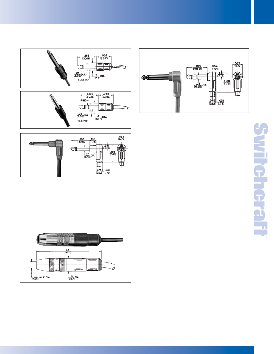
SWITCHCRAFT, INC. 5555 N. Elston Ave. • Chicago, IL 60630
257
PATCH CORDS & MOLDED CABLE ASSEMBLIES
FAX: 773 792-2129
PA
TCH CORDS &
MOLDED CABLE ASSEMBLIES
DIMENSIONS ARE FOR REFERENCE ONLY
Inch
(mm)
MOLDED CABLE ASSEMBLIES
WITH LITTEL PLUG
®
PHONE PLUGS (continued)
RA202: Right-angle phone plug with plastic handle. Body
extension suitable where jack is recessed. RA203 is similar to
RA202, except 3-conductor plug.
◊
RA207, RA208: Right-angle phone plug, similar to RA202,
except short body extension. Recommended use with
panel mounted jacks. RA208 is similar to RA207, except
3-conductor plug.
◊
RA217: Special right-angle phone plug, identical to RA200
(previous page); also featuring a unique hook for hanging
various types of equipment (such as pillow speakers).
Completely shielded. Available on special order only.
ST200: Straight phone plug with “finger grip” handle, but
short enough to fit in all equipment.
ST230: Straight 3-conductor phone plug; same features as
ST200. Completely shielded.
SPECIFICATIONS
Housing (or Sleeve): Nickel-plated, copper alloy.
Handle: Molded plastic.
Sleeve Terminal: Plated steel.
Tip and Ring Springs: Copper alloy.
Insulation: Rigid plastic. Larger design also has a molded
thermoplastic insert.
Standard Colors: Gray, white, black, brown.
Other colors available on special order.
CABLE
Standard Shielded–Type W-1000-1 (for ST121).
Type W-1021-1 (for ST131).
Standard Unshielded–Type W-1033-1 (for ST121).
NOTE: See Standard Cable Chart on page 260 for details.
Order by part number from guide on page 259.
Special Cables: We will build assemblies on cable furnished
by you, up to .260" (6.6 mm) outside diameter, or on cables we
purchase to your specifications. Jacket must have temperature
rating of 60° C minimum.
MOLDED CABLE ASSEMBLIES
WITH EXTENSION JAX
®
PHONE JACKS
ST200
Termination Code: 05
ST230
Termination Code: 10
RA202
Termination Code: 14
ST121, ST131
Termination Code: 80, 81
ST121: Straight Extension Jax
®
jack is a shielded 2-conductor
jack with .50" (12.7 mm) outside diameter. Cable clamp
connects shield or second conductor to cable. Mates with
.25" (6.35 mm) diameter Switchcraft 2-conductor plugs.
ST131: Straight Extension Jax jack, same as ST121, except
3-conductor. Mates with .25" (6.35 mm) diameter Switchcraft
3-conductor plugs.
RA208
Termination Code: 07
◊
RA207
Termination Code: 06
EXTENSION JACKS AND LITTEL PLUGS
EXTENSION JACKS AND LITTEL PLUGS
®
®
* Please visit the product pages on our website for the most up-to-date product information
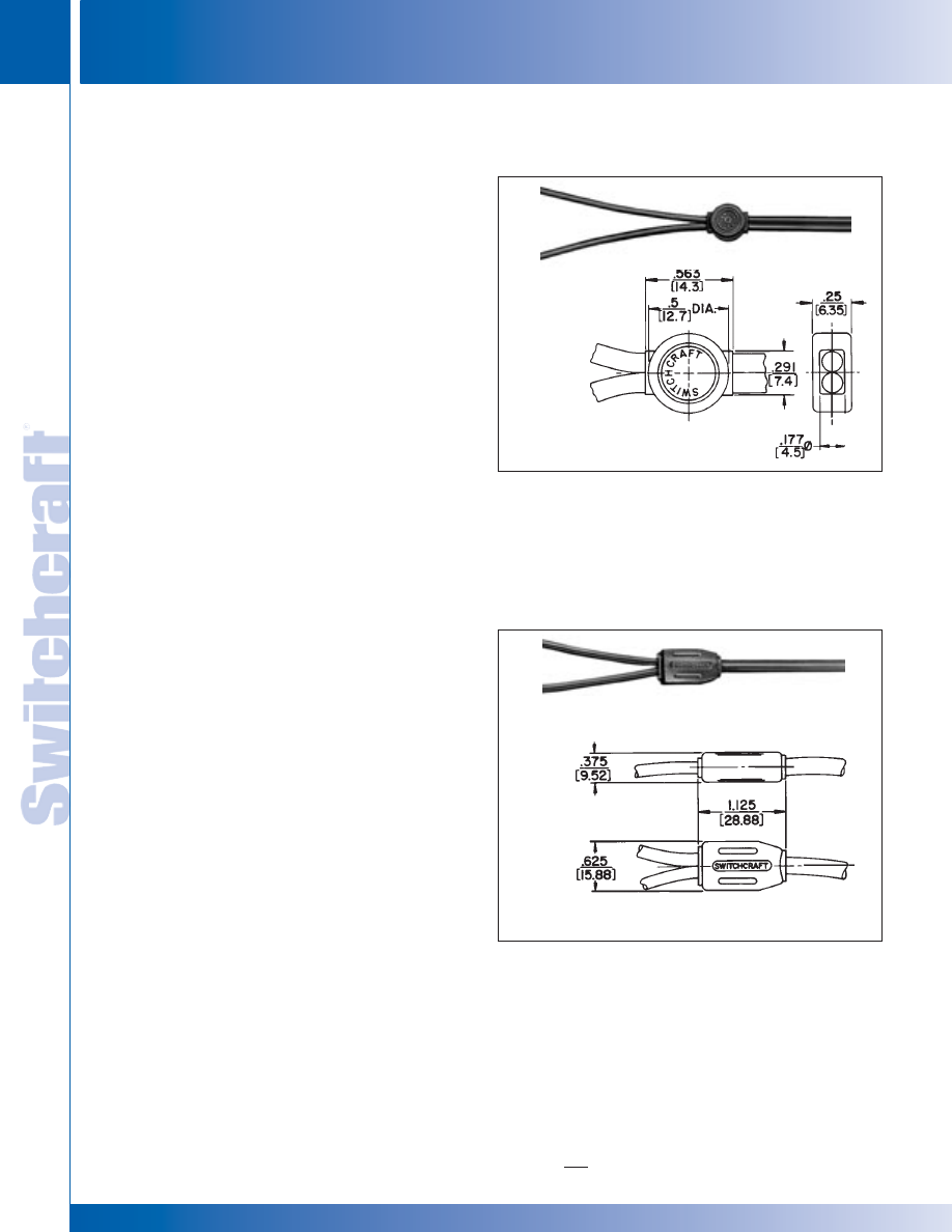
CABLE CLAMP BANDS AND Y JUNCTIONS
PATCH CORDS & MOLDED CABLE ASSEMBLIES
258
w w w . s w i t c h c r a f t . c o m
® Registered trademark of Switchcraft, Inc.
Note: Contact your Switchcraft Representative for price and delivery
PHONE: 773 792-2700
PA
TCH CORDS &
MOLDED CABLE ASSEMBLIES
DIMENSIONS ARE FOR REFERENCE ONLY
Inch
(mm)
CABLE CLAMP BANDS AND Y JUNCTIONS
ST91
Termination
Code: 94
ST90
Termination
Code: 93
SPECIFICATIONS
MOLDED BAND
Housing: Plastic. Inserts can be added to our molds to
include customer’s name or trademark. Call for details.
Standard Colors: Gray, white, black, brown. Other colors
available on special order.
CABLE*
Standard Parallel Cable (lamp cord) –Type W-1033-1.
Standard Shield Cable –Type W-1072.
ST-91 DESIGN FEATURES
• For use on stereo connecting cables and on monaural
and stereo headset cables.
• Prevents further separation of individual leads on
“Rip” type cordage.
• Can be used as “Y” junction when used with standard
shielded cable such as Switchcraft W-1072; or as a cable
clamp for general purpose with Switchcraft W-1033
and W-1050.
• Special assemblies can be built to OEM needs, using
various terminal lugs, special receptacles to phone plugs
or connectors.
MOLDED CABLE ASSEMBLIES
WITH CABLE CLAMP BANDS
MOLDED CABLE ASSEMBLIES
WITH “Y” JUNCTIONS
SPECIFICATIONS
Y JUNCTION
Housing: Molded Plastic. Inserts can be added to our molds
to include customer’s name or trademark.
Standard Colors: Gray, white, black, brown. Other colors
available on special order.
CABLE*
Standard Shielded Cable –Type W-1000-1.
Standard Shielded Cable –Type W-1021-1.
ST-90 DESIGN FEATURES
• For use on binaural and stereophonic headphones.
• Accommodates 1- and 2-conductor shielded cables.
• Durable, strain and humidity resistant.
• Special assemblies can be built to OEM needs, using
terminal lugs, special receptacles to phone plugs or
connectors.
*NOTE: See Standard Cable Chart on page 260 for details.
Special Cable: We will build assemblies on cable furnished by
you (maximum diameter varies for types) or on cables we
purchase to your specifications. Jacket must have temperature
rating of 60°C minimum.
Larger “Molded Y” available. Ask for ST94.
* Please visit the product pages on our website for the most up-to-date product information
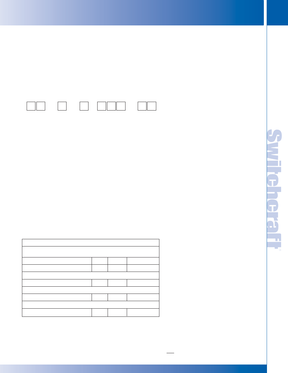
SWITCHCRAFT, INC. 5555 N. Elston Ave. • Chicago, IL 60630
259
PATCH CORDS & MOLDED CABLE ASSEMBLIES
FAX: 773 792-2129
PA
TCH CORDS &
MOLDED CABLE ASSEMBLIES
DIMENSIONS ARE FOR REFERENCE ONLY
Inch
(mm)
ORDERING GUIDE
ORDERING GUIDE
MOLDED CABLE ASSEMBLIES
PART NUMBERING SYSTEM
TO CREATE A PART NUMBER
1. Identify Terminations (both ends)
2. Indicate Color and Type of Cable
3. Select the Length of Assembly
* See “Cable Types” chart on page 260.
Notes:
• Use any 2-number codes on previous pages for
termination number.
• Some configurations will be special orders. Contact Switchcraft.
• Some configurations may not be possible.
• Larger plug (#45) will be supplied in place of #40
when used with cable “A”.
STRAIGHT 2-CONDUCTOR PHONE PLUG (#05) TO:
Length
Termination (other end)
Cable
(feet)
Part Number
1
(phono plug) #05
A
6
05HA07205
(stripped wires) #84
A
3
05HA03684
PHONO PLUGS (#25) TO:
(phono jack) #82
A
6
25HA07282
DUAL PHONO PLUGS (#25) TO:
(dual phono jacks) #82
F
10
25HF12082
3.5mm MINIATURE PLUG (#40) TO:
(3.5 mm plug) #40
D
6
40HD07240
TYPICAL STANDARD PART NUMBERS
1. All cables listed here are black.
MOLDED CABLE ASSEMBLIES (Not all numbers shown)
Termination
Color
Cable*
Length (feet)
Termination
0
5
G-Gray
A
0
1
8 (1.5)
0
5
1
5
H-Black
B
0
2
4 (2)
1
5
2
5
D-Beige
C
0
3
6 (3)
2
5
4
0
W-White
D
0
4
8 (4)
4
0
8
0
E
0
7
2 (6)
8
0
8
2
F
1
2
0 (10)
8
2
8
3
K
8
3
9
9
V
8
4
W
X
Y
Z
* Please visit the product pages on our website for the most up-to-date product information
PATCH CORDS & MOLDED CABLE ASSEMBLIES
260
w w w . s w i t c h c r a f t . c o m
® Registered trademark of Switchcraft, Inc.
Note: Contact your Switchcraft Representative for price and delivery
PHONE: 773 792-2700
PA
TCH CORDS &
MOLDED CABLE ASSEMBLIES
DIMENSIONS ARE FOR REFERENCE ONLY
Inch
(mm)
GENERAL CABLE GUIDE
GENERAL CABLE GUIDE
STANDARD CABLE GUIDE
FOR MOLDED CABLE ASSEMBLIES ON PAGE 253 THROUGH 259
Cable Type
Color
Description
Cable Code
W1000
Beige
50
Ω
coax, plastic jacket over spiral shield with 22 AWG stranded center conductor;
W1000-1
Gray
.156" (3.96 mm) outside diameter. Average capacity 31 pF/feet, UL style 1354
A
W1000-2
Black
2 conductor, plastic jacket over shield with 2, 22 AWG conductor; .20" (5.2 mm)
W1021-1
Gray
outside diameter. Average capacity 20 pF/feet between conductor; 55 pF/feet between
B
W1021-1
Black
shorted conductor to shield; 32 pF/feet each conductor to shield, UL style 2092
W1013-1
Gray
2 conductor, plastic unshielded parallel with 2, 18 AWG stranded conductor;
W1013-2
Black
.11" (2.8 mm) x .21" (5.3 mm) outside diameter, UL type SPT-1
K
W1032-1
Gray
48
Ω
coax, plastic jacket over spiral shield with 25 AWG stranded center
W1032-2
Black
conductor; .11" (2.8 mm) outside diameter. Average capacity 35 pF/feet
D
W1041-1
Gray
2 conductor, plastic unshielded tandem cable with 2, 24 AWG stranded
W1041-2
Black
conductor; .06" (1.5 mm) x .12" (2.9 mm)
Y
W1065-2
Black
50
Ω
coax, plastic jacket over braid shield with 26 AWG stranded center conductor;
.1" (2.5 mm) outside diameter. Average capacity 30 pF/feet, RG-174
E
W1072-1
Gray
2 conductor, twin coax, plastic jacket over 2 individually shielded 25 AWG parallel
conductor. Average capacity 36 pF/feet, recommended for headset applications
F
W1230-1
Gray
2 conductor,plastic unshielded with 2, 18 AWG stranded conductor;
W1230-4
Beige
.25" (6.4 mm) outside diameter, UL type SVT
V
W1230-5
White
W1243-2
Black
75
Ω
coax, plastic jacket over shield with 27 AWG stranded center conductor;
.15" (3.8 mm) outside diameter. Average capacity 20.5 pG/feet, UL style 1354 or 1436
X
W1033-1
Gray
2 conductor, plastic unshielded parallel with 2, 20 AWG stranded conductor;
W1033-2
Black
.10" (2.54 mm) x .19" (4.7 mm) outside diameter, UL style 2433
C
W1096-2
Black
2 conductor, plastic unshielded parallel with 2, 22 AWG stranded conductor;
.08" (1.9 mm) x .15" (3.8 mm) outside diameter
Z
See page 251 for Cable Assembly Termination vs. Cable Cross Reference Table.
* Please visit the product pages on our website for the most up-to-date product information
SWITCHCRAFT, INC. 5555 N. Elston Ave. • Chicago, IL 60630
261
PATCH CORDS & MOLDED CABLE ASSEMBLIES
FAX: 773 792-2129
PA
TCH CORDS &
MOLDED CABLE ASSEMBLIES
DIMENSIONS ARE FOR REFERENCE ONLY
Inch
(mm)
CROSS REFERENCE GUIDE
CROSS REFERENCE GUIDE
STANDARD CABLE ASSEMBLY TERMINATION vs.
CABLE CROSS-REFERENCE
Cable
RA40
X
X
X
1
1
2
X
X
1
RA41
X
X
1
1
1
2
X
X
1
RA200
X
X
1
1
X
2
X
1
1
RA202
X
X
1
2
X
X
1
1
RA205
X
X
1
1
X
1
RA207
X
X
1
2
X
X
1
1
RA700
X
X
X
2
RA710
X
X
X
2
RA712A
X
1
1
RA722A
X
1
1
RA760
X
X
X
1
1
2
X
X
X
X
RA765
X
X
X
1
1
2
X
X
X
X
RA850
X
X
X
2
X
X
ST35
X
X
X
X
1
X
2
X
X
1
ST40
X
X
1
1
1
2
X
X
1
ST60
X
X
1
1
1
2
X
X
1
ST121
X
X
1
1
2
X
X
X
1
ST123
X
X
X
2
3
ST125
X
X
X
X
2
X
X
ST131
X
ST200
X
X
1
1
X
2
X
X
1
1
ST230
X
ST700
X
X
X
2
X
ST710
X
X
X
2
X
ST740
X
X
1
1
1
2
X
X
X
ST750
X
X
1
1
1
2
X
X
X
ST760
X
X
1
1
2
X
X
1
ST760L
X
X
ST765
X
X
1
1
2
X
X
1
ST765L
X
X
ST850
3
3
X
X
X
2
3
3
3
ST900
X
X
X
1
1
1
X
X
X
X
W
1
0
0
0
#
T
E
R
M
I
N
A
T
I
O
N
W
1
0
2
1
1
W
1
0
1
3
#
W
1
0
3
2
#
W
1
0
4
1
#
W
1
0
6
5
2
W
1
0
7
2
1
W
1
2
3
0
#
W
1
2
4
3
2
W
1
0
3
3
#
W
1
0
9
6
2
# - Indicates any number.
X - Indicates that the cable in this column and the termination in this row can
be used together in a standard part number.
1 - These cable assemblies may use heat shrink tubing under overmolded
terminations.
2 - These cable assemblies have two of the same termination at one end.
Each termination is molded in a different color.
3 - These cable assemblies use a larger overmold than is pictured in the
Engineering Design Guide.
4 - Other termination/cable combinations may be available on special order.
CROSS REFERENCE GUIDE
* Please visit the product pages on our website for the most up-to-date product information
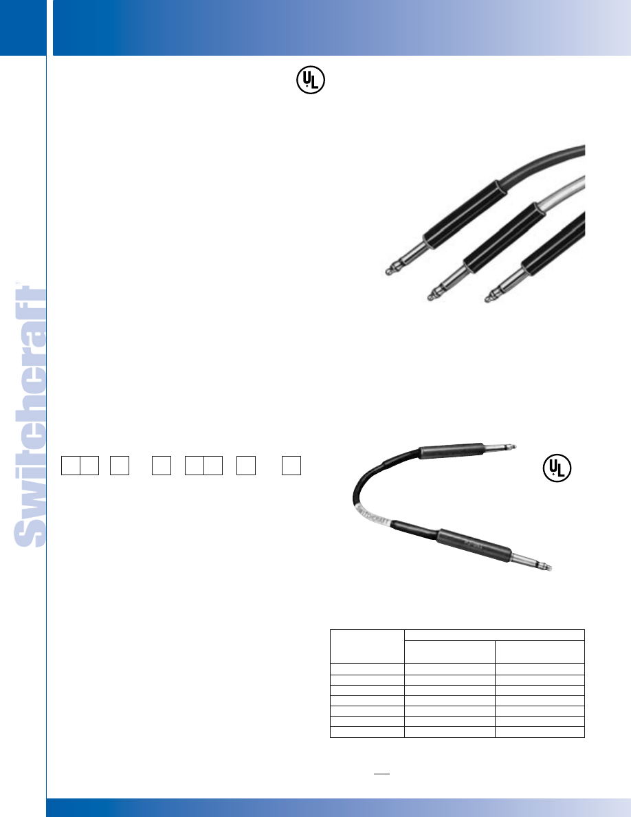
PATCH CORDS & MOLDED CABLE ASSEMBLIES
262
w w w . s w i t c h c r a f t . c o m
® Registered trademark of Switchcraft, Inc.
Note: Contact your Switchcraft Representative for price and delivery
PHONE: 773 792-2700
PA
TCH CORDS &
MOLDED CABLE ASSEMBLIES
DIMENSIONS ARE FOR REFERENCE ONLY
Inch
(mm)
1/4" TELEPHONE PATCH CORDS AND MIL TYPE 1/4" PATCH CORDS
1/4" TELEPHONE PATCH CORDS AND MIL TYPE 1/4" PATCH CORDS
Series 18Q, Plug Type 482
Length
Part
Replacement
feet (m)
Number
Cord Used
0.5
(.152)
18QA18
89QA89
1
(.305)
18QB18
89QB89
2
(.610)
18QD18
89QD89
3
(.914)
18QF18
89QF89
4
(1.219)
18QH18
89QH89
6
(1.829)
18QK18
89QK89
10
(3.048)
18QN18
––
SERIES 18Q
Red handle, brass finger
SERIES 18Q: Used in broadcasting, studio recording, sound,
and other applications where space is at a premium. Utilizes
Series 88Q 2-conductor shielded cord, with a Switchcraft 482
Littel-Plug phone plug with red handle (PJ-051) connected to
each end. Shield grounded to sleeve of both plugs, and two
leads wired tip-to-tip, ring-to-ring. Standard cord color: black.
Other lengths and colors: gray, red, green (special order).
Series 18Q provides same or greater number of circuits in a
given space than cords using “Twin-Plug” dual telephone
plugs.
Switchcraft Patch Cords are available in a variety of types to
meet requirements of communication, industrial and telephone
switchboard applications. Patch cords are constructed of high
quality bronze tinsel covered with thermoplastic insulating
material with braided shield and black thermoplastic braid
woven over the insulated conductors.
Switchcraft MIL-type Littel-Plug
®
and Twin-Plug
®
phone plugs
with brass finish are attached to these quality cords. Design
and material used in strict accordance with Specification
MIL-P-642(A). Cords have an identifying label on cord and hot
stamping on plug handle.
MIL TYPE 1/4" PATCH CORDS
2
0
Q
PLUG
3-cond.
PLUG
3-cond.
CABLE
Shielded
2-cond.
nylon-
braid
sheath
LENGTH*
D - 2'
F - 3'
H - 4'
CABLE
COLOR*
0-Black
2-Red
5-Green
6-Blue
FINGER
FINISH
N-Nickel
plated
B-Natural
brass
* Contact Switchcraft for other lengths and colors.
SERIES 20Q 3-CONDUCTOR
TELEPHONE-TYPE PATCH CORDS
1/4" diameter plug fingers, black handle, color cable
PART NUMBERING SYSTEM
2
0
1/4" TELEPHONE PATCH CORDS
Switchcraft premium 3-conductor single patch cords are
designed for rugged, noise-free performance. Nickel-plated
plugs eliminate the need for periodical cleaning which keeps
your audio signals clear. Color cords provide instant visual
identification with a choice of three lengths. All cables are fully
shielded with rugged, braided thermoplastic outer jackets. Plug
handles are black. Audio patch cords are available with other
lengths and brass plugs, if desired. Contact Switchcraft for
specifying assistance and cable length tolerances.
SERIES 20Q
* Please visit the product pages on our website for the most up-to-date product information
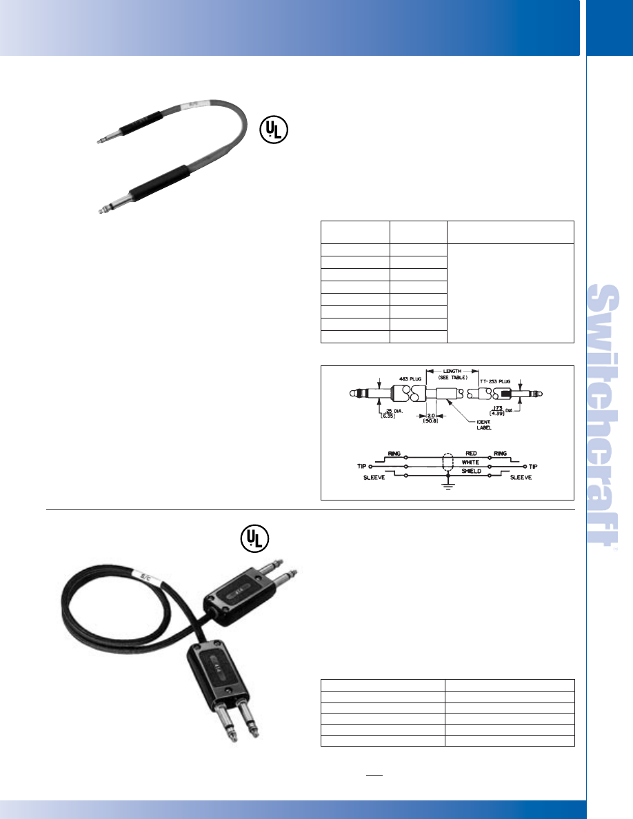
SWITCHCRAFT, INC. 5555 N. Elston Ave. • Chicago, IL 60630
263
PATCH CORDS & MOLDED CABLE ASSEMBLIES
FAX: 773 792-2129
PA
TCH CORDS &
MOLDED CABLE ASSEMBLIES
DIMENSIONS ARE FOR REFERENCE ONLY
Inch
(mm)
COMBINATION AND MIL-TYPE PATCH CORDS
COMBINATION AND MIL-TYPE PATCH CORDS
Series CPC Combination Patch Cords provide convenient
interconnections between standard telephone-type jacks
(3-conductor, .25" inside diameter sleeve) and miniature
telephone-type jacks (3-conductor, .173" inside diameter).
Series CPC cords are ideal for connection in telephone, data
processing and other telecommunication applications where
both standard and miniature jacks are available for patching.
FEATURES
1. Rugged, telephone-quality tinsel conductors, with slate gray,
braided thermoplastic jacket with flex relief reinforcements at
point of entry into each plug handle.
2. Series CPC cords, eliminates the need for a separate
adapter or field-fabricated combination cords.
3. Switchcraft (on special order) can assemble cords of any
practical length.
◊
SERIES CPC101: Standard 2-conductor, 413 Twin-Plug
(.25" outside diameter finger) on one end; miniature,
3-conductor TT253, TT Twin-Plug (.173" outside diameter
finger) on the other end. One twin plug tip to miniature plug
ring. All sleeves connected to cable shield. 6, 10, 15, 20 and
25 foot lengths.
◊
SERIES CPC103: Standard 2-conductor, 413 Twin-Plug
(.25 " outside diameter finger) on one end with cable-connected
shield to sleeve; two independent tip circuits. Other end
miniature, TT261, TT Twin-Plug (.173" outside diameter finger)
in the same wiring. 6, 10, 15, 20 and 25 foot lengths.
◊
SERIES CPC104: Standard 3-conductor, 414 Twin-Plug
(.25 " outside diameter finger) on one end; miniature
3-conductor, TT263, TT Twin-Plug on other end. Wired at
5-conductor tips-to-tips, rings-to-rings, all sleeves to cable
shield. 6, 10, 15, 20 and 25 foot lengths.
COMBINATION PATCH CORDS
SERIES 22Q: For use in telephone patching, broadcasting,
studio recording, high-quality public address systems,
telephone, telecommunications, and instrumentation systems.
Uses 4-conductor shielded cord with Switchcraft Number 414
Twin-Plug
®
connected to each end. Shield is grounded to
sleeve of each plug and individual leads wired tip-to-tip and
ring-to-ring. Twin-Plug 414 is a 6-circuit plug with electrically
independent tip circuits and ring circuits, with plug fingers
spaced on .625" center to fit standard twin jacks.
A self-aligning feature accommodates errors in jack location.
Standard lengths: 1 feet to 10 feet; standard color: black. Other
lengths and colors are available.
Part Number
Length, feet (m)
◊
22QB22
1 (.305)
◊
22QD22
2 (.610)
◊
22QF22
3 (.914)
◊
22QK22
6 (1.829)
◊
22QN22
10 (3.048)
MIL-TYPE 1/4" TWIN PATCH CORDS
Part
Number
Length
Description
◊
CPC102A
6 inches
◊
CPC102D
2 feet
◊
CPC102F
3 feet
◊
CPC102K
6 feet
◊
CPC102N
10 feet
◊
CPC102R
15 feet
◊
CPC102T
20 feet
◊
CPC102U
25 feet
Standard 3-conductor (483)
telephone plug (.25" outside
diameter finger) on one end;
miniature (253) tini-telephone
®
3-conductor (.173" outside
diameter. finger) plug on
other end.(See Schematic).
◊
Special order only; contact factory for price and delivery.
CPC102A
Series 22Q
◊
Special order only; contact factory for price and delivery.
* Please visit the product pages on our website for the most up-to-date product information
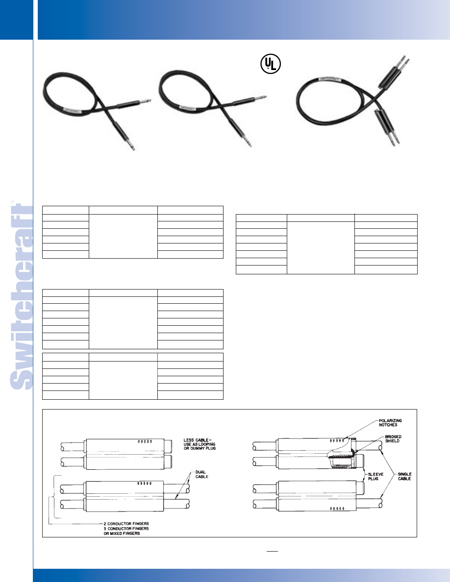
PATCH CORDS & MOLDED CABLE ASSEMBLIES
264
w w w . s w i t c h c r a f t . c o m
® Registered trademark of Switchcraft, Inc.
Note: Contact your Switchcraft Representative for price and delivery
PHONE: 773 792-2700
PA
TCH CORDS &
MOLDED CABLE ASSEMBLIES
DIMENSIONS ARE FOR REFERENCE ONLY
Inch
(mm)
MINIATURE TT BRAIDED PATCH CORDS
MINIATURE TT BRAIDED PATCH CORDS
®
®
CABLE AND PLUG FINGER COMBINATIONS
2-Conductor Patch Cord. Two-conductor Bantam-Type
®
plug,
Switchcraft TT251 at each end. Shield (75% coverage) is
grounded to each plug sleeve. Tinsel conductor is wired
tip-to-tip. Standard color: black. Other colors and lengths are
available on special order.
3-Conductor Twin Patch Cords. 5-circuit patch cords use two
3-conductor twin Bantam-Type plugs, Switchcraft TT-263, at
each end. Sleeve circuits are wired common, and tinsel
conductors are wired tip-to-tip and ring-to-ring (see schematic).
Polarizing handle notches indicated plug fingers with
interconnected tip and rings. Standard color: black. Other
colors and lengths are available on special order.
MINIATURE TT
®
BRAIDED PATCH CORDS
3-Conductor Patch Cord. 3-conductor Bantam-Type plug
(Switchcraft TT253) at each end. Wiring is the same as TT724,
except also has ring-to-ring wiring.
Part Number
Description
Length, feet (m)
◊
TT861
0.5 (.152)
◊
TT862
1 (.305)
◊
TT864
2 (.61)
◊
TT866
3 (.914)
◊
TT867
4 (1.219)
◊
TT868
5 (1.524)
◊
TT869
6 (1.829)
Part Number
Description1, 2
Length, feet (m)
◊
TT741N0
0.5 (.152)
◊
TT742N0
1 (.305)
◊
TT744N0
2 (.61)
◊
TT746N0
3 (.914)
◊
TT747N0
4 (1.219)
1. For brass fingers, substitute “B” for “N” in part number. Special order only.
2. “0” in part number denotes black handle and cord. Substitute the following
for “0” to specify other color cords:
2–Red
5–Green
6–Blue
◊
Special order only; contact Switchcraft for prices and delivery.
TT720
Single, 2-Conductor
TT740
Single, 3-Conductor
TT860
Twin, 3-Conductor
CABLE AND PLUG FINGER COMBINATIONS
Part Number
Description
Length, feet (m)
◊
TT741
0.5 (.152)
◊
TT742
1 (.305)
◊
TT744
2 (.61)
◊
TT746
3 (.914)
◊
TT747
4 (1.219)
◊
TT748
5 (1.524)
◊
TT749
6 (1.829)
Part Number
Description
Length, feet (m)
◊
TT722
1 (.305)
◊
TT724
2 (.61)
◊
TT726
3 (.914)
◊
TT727
4 (1.219)
◊
TT728
5 (1.524)
◊
TT729
6 (1.829)
2-conductor single,
brass finish on plug fingers,
black handle and cord.
Identifying label on cord.
3-conductor single,
brass finish on plug fingers,
black handle and cord.
Identifying label on cord.
3-conductor single,
nickel-plated plug fingers
(brass available) black
handles and cord.
3-conductor twin,
brass finish on plug fingers,
black handle and cord.
Identifying label on cord.
* Please visit the product pages on our website for the most up-to-date product information
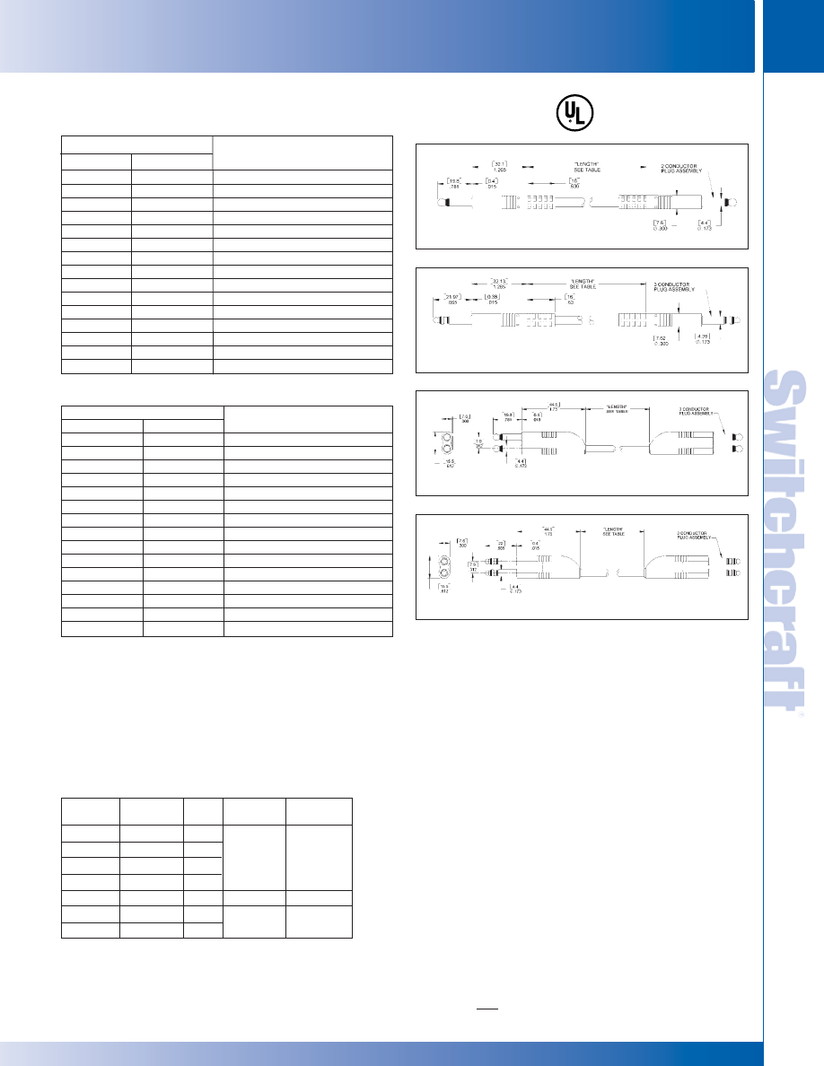
SWITCHCRAFT, INC. 5555 N. Elston Ave. • Chicago, IL 60630
265
PATCH CORDS & MOLDED CABLE ASSEMBLIES
FAX: 773 792-2129
PA
TCH CORDS &
MOLDED CABLE ASSEMBLIES
DIMENSIONS ARE FOR REFERENCE ONLY
Inch
(mm)
MINIATURE TT MOLDED PATCH CORDS AND TELEPHONE COUPLERS
MINIATURE TT MOLDED PATCH CORDS AND TELEPHONE COUPLERS
®
®
Part Numbers
Length
Series TT100
Series TT120
feet (m)
◊
TT101
◊
TT121
0.5 (.152)
◊
TT102
◊
TT122
1.0 (.305)
◊
TT103
◊
TT123
1.5 (.457)
◊
TT104
◊
TT124
2.0 (.610)
◊
TT105
◊
TT125
2.5 (.762)
◊
TT106
◊
TT126
3.0 (.914)
◊
TT107
◊
TT127
4.0 (1.219)
◊
TT108
◊
TT128
5.0 (1.524)
◊
TT109
◊
TT129
6.0 (1.829)
◊
TT110
◊
TT130
7.0 (2.134)
◊
TT111
◊
TT131
8.0 (2.438)
◊
TT112
◊
TT132
9.0 (2.743)
◊
TT113
◊
TT133
10.0 (3.05)
◊
TT114
◊
TT134
11.0 (3.353)
◊
TT115
◊
TT135
12.0 (3.658)
Part Numbers
Length
Series TT140
Series TT160
feet (m)
◊
TT141
◊
TT161
0.5 (.152)
◊
TT142
◊
TT162
1.0 (.305)
◊
TT143
◊
TT163
1.5 (.457)
◊
TT144
◊
TT164
2.0 (.610)
◊
TT145
◊
TT165
2.5 (.762)
◊
TT146
◊
TT166
3.0 (.914)
◊
TT147
◊
TT167
4.0 (1.219)
◊
TT148
◊
TT168
5.0 (1.524)
◊
TT149
◊
TT169
6.0 (1.829)
◊
TT150
◊
TT170
7.0 (2.134)
◊
TT151
◊
TT171
8.0 (2.438)
◊
TT152
◊
TT172
9.0 (2.743)
◊
TT153
◊
TT173
10.0 (3.05)
◊
TT154
◊
TT174
11.0 (3.353)
◊
TT155
◊
TT175
12.0 (3.658)
MINIATURE TT
®
MOLDED PATCH CORDS (continued)
TELEPHONE COUPLERS
AND ADAPTERS
TELEPHONE PATCH COUPLERS
TT-couplers interconnect 2- or 3-conductor patch cords
terminated with Switchcraft standard or tini-telephone
®
plugs,
also similar telephone plugs with compatible finger shape and
dimensions.
TT-REPLACEMENT CORDS
Series TT700 cords have bronze tinsel conductors covered
with thermoplastic insulation. A braided shield surrounds the
conductors, and the cord is finished with a braided black
thermoplastic jacket. Cord ends are reinforced to accept the
internal threaded end of a TT-Phone Plug
®
plug. Used as a
replacement cord for Series TT720 and TT740 patch cords,
and used on TT-Twin Plug
®
plugs, Series TT260, in dual cable
assemblies with 2- and 3-conductor (or combinations) plug
fingers requiring independent tip, ring and sleeve
circuits, and for single cable assemblies where supplementary
cross-over wiring is needed for common tip, ring and/or
sleeve circuits.
◊
TT701 - Length 6" (152.4 mm).
◊
TT709 - Length 6' (1.829 m).
TT140 SERIES
TT160 SERIES
Part
Number
◊
TT281
◊
TT282
◊
TT283
◊
TT284
◊
TT289
361A
◊
362A
Handle
Color
Black
Red
Black
Red
Metal
Metal
Metal
Cond.
2
2
3
3
3
2
3
Input ID
Inch (mm)
.175 (4.44)
.175 (4.44)
.25 (6.35)
Output ID
Inch (mm)
.175 (4.44)
.25 (6.35)
.25 (6.35)
◊
Special order only; contact factory for prices and delivery.
TT120 SERIES
TT100 SERIES
* Please visit the product pages on our website for the most up-to-date product information
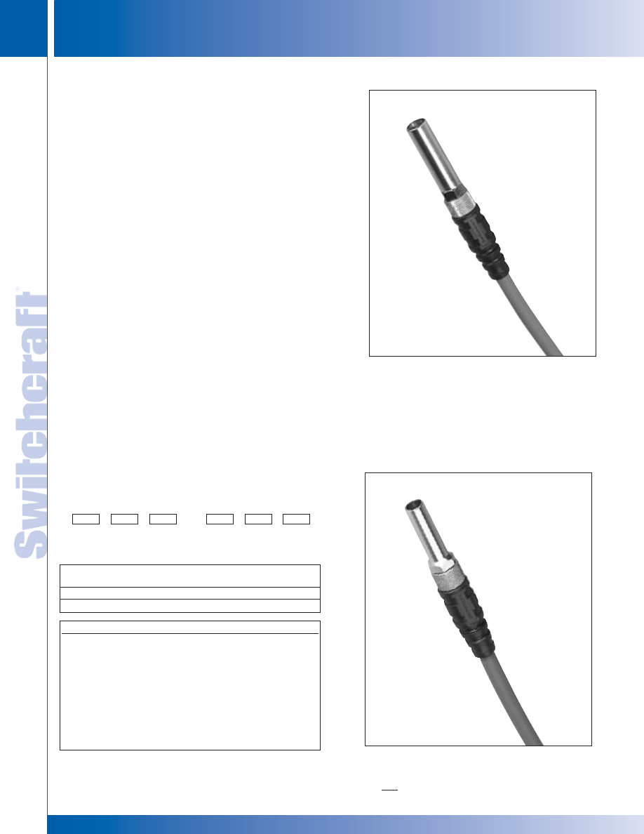
PATCH CORDS & MOLDED CABLE ASSEMBLIES
266
w w w . s w i t c h c r a f t . c o m
® Registered trademark of Switchcraft, Inc.
Note: Contact your Switchcraft Representative for price and delivery
PHONE: 773 792-2700
PA
TCH CORDS &
MOLDED CABLE ASSEMBLIES
DIMENSIONS ARE FOR REFERENCE ONLY
Inch
(mm)
VIDEO PATCH CORDS
VIDEO PATCH CORDS
FEATURES:
* Rugged nickel-plated handles knurled for positive
finger grip.
* Flexible black "boot" placed on all cable colors for
more positive grip and cable strain relief.
* Overall flexible jacket for easy coil and low retract memory.
SPECIFICATIONS:
Plug Housing:
Nickel-plated, copper alloy.
Plug Contact Pin:
Gold-plated, copper alloy.
Cable:
Conductor:
22 AWG (19 x 34)
Stranded BC
Shield:
95% BC Braid
Dielectric:
.146", 3.70mm, Cellular
(Foam) PE
Jacket:
Matte Finish PVC
Nom. Imp:
75 Ohm
VIDEO PATCH CORDS
Switchcraft new broadcast series video patch cords are
available in eight base ten color codes. Our cable is a high
performance serial digital 75 Ohm RG59 type. This unique
low-loss cable is ideal for “True” 75 Ohm HD patching as well
as conventional analog signals.
The jacket is made flexible with very low retract memory.
Colors
Color Code
Stock Lengths
1'
Black
=
BK
2'
Red
=
R
3'
Orange
=
O
4'
Yellow
=
Y
5'
Green
=
GN
6'
Blue
=
BL
7'
Purple
=
P
8'
Gray
=
GY
9'
10'
Part Numbering System
Video Patch Cords
Video Patch
Length (Feet)
Standard .090 WECO
VP
Midsize Video Patch
VMP
(Custom lengths are available by request)
Midsize Video Patch
VMP
Standard .090 WECO
VP
Video
Patch
VP
VMP
Length
(Feet)
Cable
Color
Video
Patch
Length
(Feet)
Cable
Color
* Please visit the product pages on our website for the most up-to-date product information
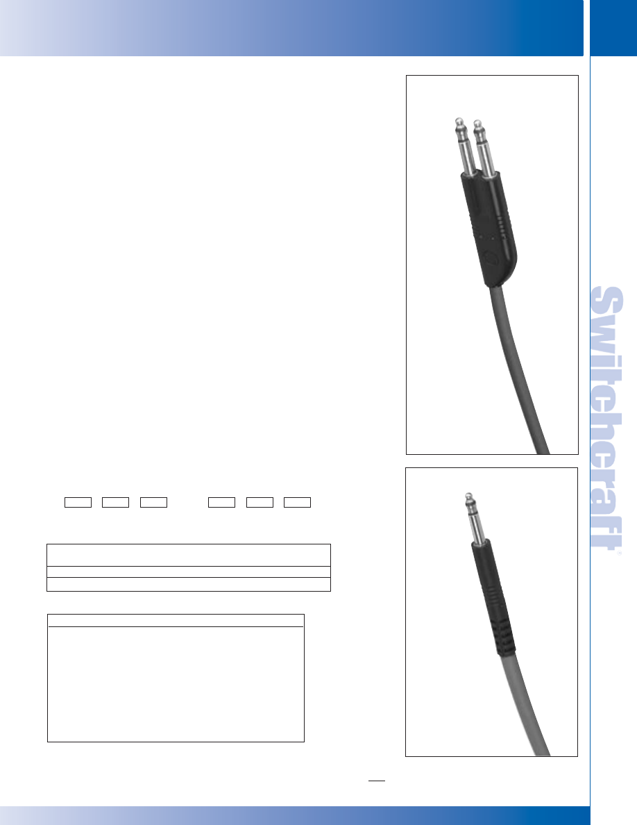
SWITCHCRAFT, INC. 5555 N. Elston Ave. • Chicago, IL 60630
267
PATCH CORDS & MOLDED CABLE ASSEMBLIES
FAX: 773 792-2129
PA
TCH CORDS &
MOLDED CABLE ASSEMBLIES
DIMENSIONS ARE FOR REFERENCE ONLY
Inch
(mm)
BROADCAST SERIES
3-CONDUCTOR TT PATCH CORDS:
ANALOG / AES/EBU AUDIO AND RS422 PATCHING
BROADCAST SERIES
SPECIFICATIONS
Standard plug terminations are single 3-conductor TT.
Plug handle is molded thermoplastic.
Plugs:
Tip Rod, Ring and Sleeve - Copper Alloy
Cable:
26 AWG (30x40) OFBC, 110 Ohm Low
Capacitance. Jacket is Matte PVC
Colors
Color Code
Stock Lengths
1'
Black
=
BK
2'
Red
=
R
3'
Orange
=
O
4'
Yellow
=
Y
5'
Green
=
GN
6'
Blue
=
BL
7'
Purple
=
P
8'
Gray
=
GY
9'
10'
Part Numbering System
Video Patch Cords
Video Patch
Length (Feet) Cable Color
Single Bantam TT
TT
Dual Bantam TT
TTD
(Custom lengths are available by request)
1 Foot (12" inches) equals 3.28 meters
Switchcraft single 3-conductor TT audio patch cords have
now been designed with a low capacitance cable which at 110
Ohms is ideal for digital audio AES/EBU and SMPTE Mtime
code patching. The overall jacket is now flexible in eight colors.
The nickel plated plugs allow for non-tarnishing and the
overmolded handle-boot reduces strain off the cable when
pulled.
Switchcraft dual 3-conductor TT patch cords have also been
redesigned with an overall flexible cable and six colors to
choose from. Like the single TT the dual plugs are nickel
plated and flexible. These cords work with all Switchcraft
TT stereo spaced bays for analog audio and RS422 data
patching.
TTD Not available in purple or gray.
Single Bantam TT
TT
Dual Bantam TT
TTD
Tiny
Telephone
TT
TTD
Length
(Feet)
Cable
Color
Tiny
Telephone
Dual
Length
(Feet)
Cable
Color
* Please visit the product pages on our website for the most up-to-date product information

NOTES
268
w w w . s w i t c h c r a f t . c o m
® Registered trademark of Switchcraft, Inc.
Note: Contact your Switchcraft Representative for price and delivery
PHONE: 773 792-2700
* Please visit the product pages on our website for the most up-to-date product information
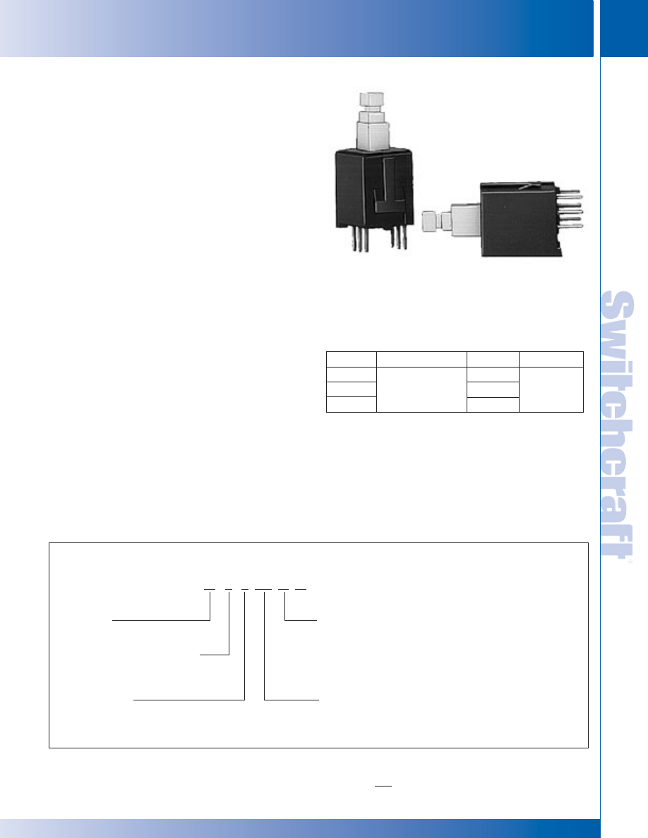
SWITCHCRAFT, INC. 5555 N. Elston Ave. • Chicago, IL 60630
269
SWITCHES
FAX: 773 792-2129
SWITCHES
DIMENSIONS ARE FOR REFERENCE ONLY
Inch
(mm)
MINIATURE KEYBOARD SWITCHES – SERIES 9800
MINIATURE KEYBOARD SWITCHES – SERIES 9800
Momentary IBS switches provide cost-effective versatility for a
wide range of electrical/electronic applications including
switching analog and digital signals in business systems,
public address, test instruments, medical, EDP (computer),
input devices and peripheral equipment, local area network,
telecommunication, digital transmission equipment, telephone
systems and attachments and calculators. Convenient
modular design allows quick assembly to PC boards. These
switches are also available in multiple station assemblies
(see page 308).
SPECIFICATIONS
MECHANICAL
Switch Actuation: Momentary
Plunger Travel: .144" (3.66 mm).
Actuation Force (Full Travel): 12-15 ounce (340-425 grams).
Life: 1 million operations.
ELECTRICAL
UL approved at .25 A @ 28V DC and .125 A @ 125V AC
MATERIALS
Housing: Molded thermoplastic UL 94V-0
Plunger: Molded thermoplastic UL 94V-0.
Contactors: Copper alloy.
Terminals: Copper alloy, solder-plated.
Contact Surfaces: Gold-plated.
MOUNTING
Switches have .157" (4 mm) long PC terminals for mounting
on single- or double-sided PC boards up to .094" (2.4 mm)
thick on 0.394" (10 mm) minimum centers in rows or arrays.
0.394" (10 mm) PC terminals available on special order.
Rugged molded-in standoff legs provide stable mounting
and clearance for PC board cleaning.
IBS MINIATURE SWITCHES
SERIES 98000R
Part No.
1
982A01R
982A03R
982A06R
Description
Momentary
Circuit
1-A
1-C
2-C
Dim. A
.157"
(4 mm)
1 Order pushbuttons separately.
ORDERING SPECIAL SWITCHES
Contact your Switchcraft representative with full
specifying details.
SPECIAL ORDER FEATURES
• Other circuitry - 1B, 2A or 2B
• Longer terminals - .394" (10 mm) long.
IBS SWITCH CATALOG NUMBERING SYSTEM
98 X X XX D R
SERIES •
98 - 98000R
MECHANICAL FUNCTIONS •
2 - Momentary
TERMINALS •
A - .157" (4 mm)
◊
B - .394" (10 mm)
◊
D - Make-Before-Break (Shorting Contacts)
(Use with 03, 06 circuits only when required.)
• CIRCUITS
01 - 1A
◊
04 - 2A
◊
02 - 1B
◊
05 - 2B
03 - 1C*
06 - 2C
MINIATURE KEYBOARD SWITCHES
◊
Special order only; contact Switchcraft for price and delivery.
* Non-shorting (break-before-make) contacts
ORDERING STANDARD SWITCHES
Order switches and pushbuttons by part numbers from table.
PART NUMBERS
* Please visit the product pages on our website for the most up-to-date product information
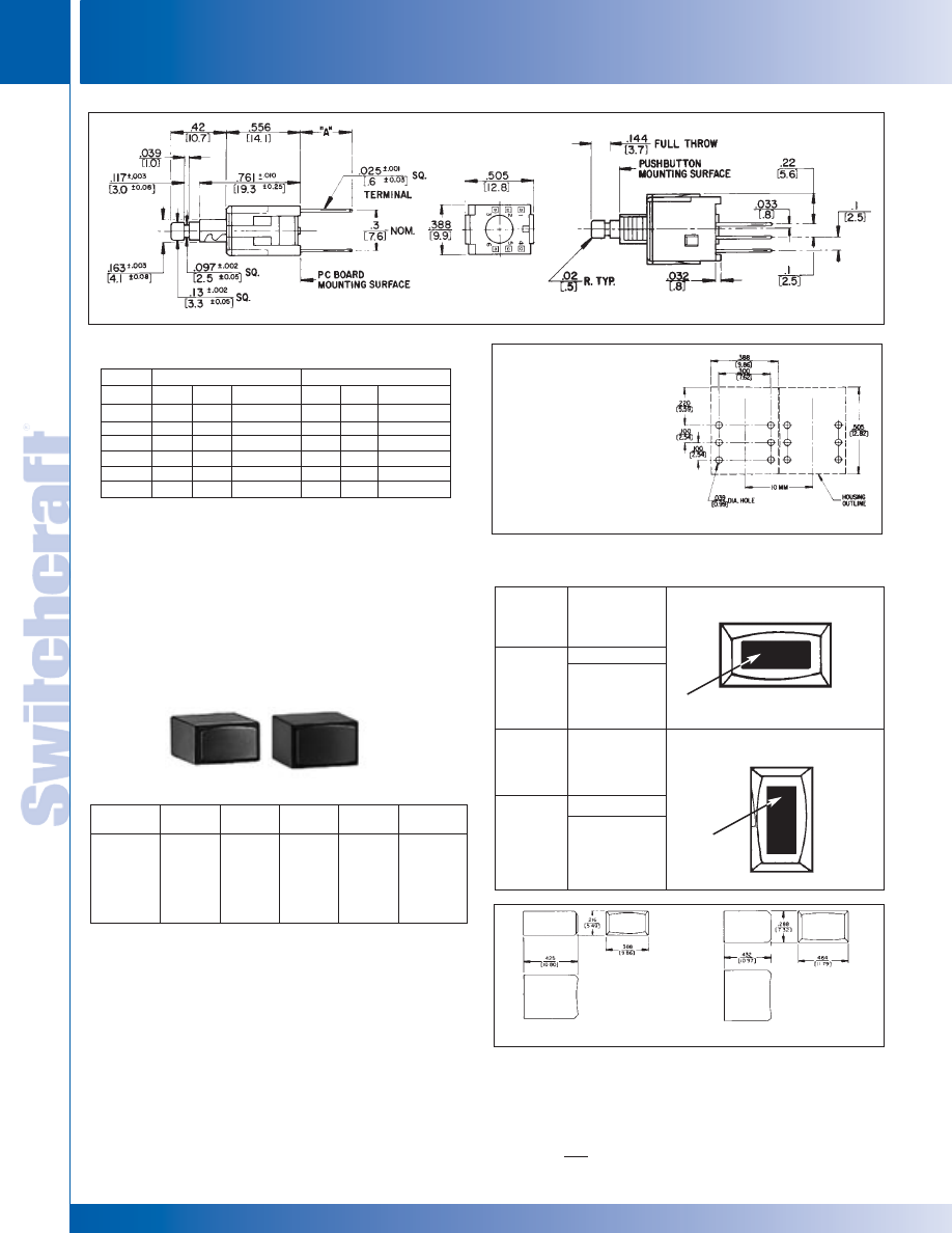
SWITCHES
270
w w w . s w i t c h c r a f t . c o m
® Registered trademark of Switchcraft, Inc.
Note: Contact your Switchcraft Representative for price and delivery
PHONE: 773 792-2700
SWITCHES
DIMENSIONS ARE FOR REFERENCE ONLY
Inch
(mm)
KEYBOARD SWITCH PUSHBUTTONS
KEYBOARD SWITCH PUSHBUTTONS
Circuit
1-A
1-B
1-C
2-A
2-B
2-C
N.O.
3
-
3
3
-
3
N.C.
-
1
1
-
1
1
Common
2
2
2
2
2
2
N.O.
-
-
-
6
-
6
N.C.
-
-
-
-
4
4
Common
5*
5*
5*
5
*
5
*
5
*
Pushbuttons designed for IBS switches are available in
white, black, red, blue, and gray. Other colors are available
on special order. Pushbutton faces are concave for operator
convenience and can be mounted either horizontally
or vertically. Pushbuttons must be ordered separately,
but may be factory installed, if desired, at extra cost.
KEYBOARD SWITCH PUSHBUTTONS
PART NUMBERS
Type I
◊
P2936
◊
P2937
◊
P2938
◊
P2939
◊
P2940
Type II
◊
P2951
◊
P2952
◊
P2953
◊
P2954
◊
P2955
Color
White
Black
Red
Yellow
Green
Type I
◊
P2941
◊
P2942
◊
P2943
–
–
Type I I
◊
P2956
◊
P2957
◊
P2958
◊
P2979
◊
P2992
Color
Blue
Gray
Brown
Cream
Tangerine
LEGENDS
Engraved letters and numbers are available on special order.
A-Z, ON and OFF in Condensed Block typeface are available.
Other custom legends may be supplied (please inquire).
Refer to drawing and chart for legend data.
Character
Height
inches (mm)
Horizontal
Mount
(Char. Max.)
1/8" (3.175)
3/32" (2.381)
5/64" (1.984)
I
3
4
4
I I
4
5
5
Character
Height
inches [mm}
Vertical
Mount
(Char. Max.)
1/8" (3.175)
3/32" (2.381)
5/64" (1.984)
I
1
2
2
I I
1
2
3
LEGEND
AREA
LEGEND
AREA
◊
Special order only; contact Switchcraft for price and delivery.
RECOMMENDED
PC BOARD LAYOUT
(.300 x .100)
(Component Side)
TYPE I
TYPE II
TYPE I PUSHBUTTON TYPE II PUSHBUTTON
VERTICAL MOUNT
HORIZONTAL MOUNT
3
2
1
6
5
4
TERMINAL FUNCTION BY TERMINAL NUMBER
First Pole
1
Second Pole
*Pin 5 is used as a support pin for switch mounting and has no electrical
connection. 1. N.O.= normally open; N.C.= normally close.
* Please visit the product pages on our website for the most up-to-date product information
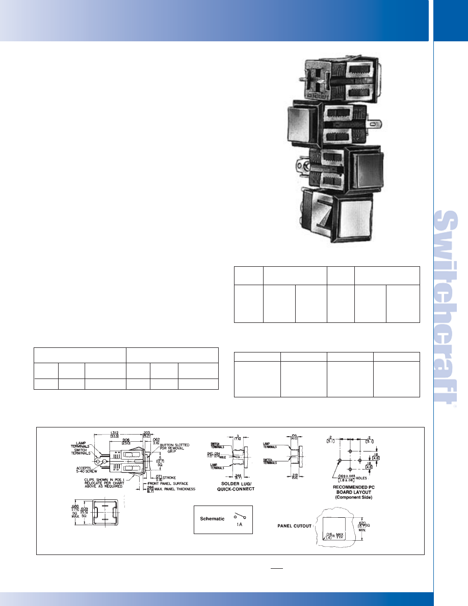
SWITCHCRAFT, INC. 5555 N. Elston Ave. • Chicago, IL 60630
271
SWITCHES
FAX: 773 792-2129
SWITCHES
DIMENSIONS ARE FOR REFERENCE ONLY
Inch
(mm)
UNISWITCH
®
SWITCHES – SERIES US & LUS
UNISWITCH
®
SWITCHES – SERIES US & LUS
UNISWITCH
®
SWITCHES
SERIES US - Non-illuminated,
SERIES LUS - Illuminated
Cost-effective Uniswitch switches are lighted or non-lighted
momentary switches featuring snap-in mounting in a single hole
and a choice of solder/screw (#5-40), solder/quick-connect (AMP
FASTON
®
110) 60967-1, or stand-off PC terminals. Molded housing
protects internal parts, and bezel functions as built-in escutcheon.
Series LUS accepts T 1-3/4 bi-pin lamps. (Lamps not included.)
®
FASTON is a registered trademark of AMP INC
.
MOUNTING
“Snap-in” mounting is in .617" (15.67 mm) minimum square hole -
for row or matrix mounting. Panel thickness: .047" (1.19 mm) to
.266" (6.76 mm) maximum. To mount, simply press switch into
panel; “Adjusto-Clip” locking tabs engage panel and hold switch
securely. Behind panel distance is 1.312" (33.32 mm) minimum.
SPECIFICATIONS
Switch Housing: Molded plastic, charcoal gray only.
“Adjusto-Clip”: Copper alloy.
Contactor: Copper alloy plated. Form 1-A rated:
250 mA, 30 W maximum, AC, non-inductive load.
Terminals: Copper alloy, silver-plated.
Pushbuttons: Molded plastic in 8 colors.
Operating Force: 12 - 16 ounce (340-454 grams).
SPECIAL ORDER FEATURES
• Other contactor platings.
• Engraved legends (See page 270).
• Other pushbutton colors.
• “Adjusto-Clips” set to positions 2, 3, 4, or 5.
Position
Number
Panel Thickness
Inch (mm)
Min.
.047 (1.2)
.094 (2.4)
.141 (3.6)
Max.
.078 (2.0)
.125 (3.2)
.172 (4.4)
Max.
.219 (5.6)
.266 (6.8)
1*
2
3
Position
Number
Panel Thickness
Inch (mm)
Min.
.188 (4.8)
.234 (6.0)
4
5
* “Adjusto-Clips” normally installed in this position unless otherwise specified.
* Extra replacement pushbuttons can be ordered separately.
“ADJUSTO-CLIP” MOUNTING
PART NUMBERS
(Order switches and pushbuttons separately)
Part Number
P23491
P23492
P23493
P23494
Color
Red
Black
Green
Blue
Part Number
◊
P23495
◊
P23497
◊
P23498
◊
P234913
Color
White
Orange
Yellow
Amber
PUSHBUTTONS*
(Pushbuttons ordered separately from switches.)
Solder/
Printed
Solder/
Solder/
Printed
Solder/
Screw
Circuit
Quick-Connect
Screw
Circuit
Quick-Connect
US001
US001PC
US001ST
LUS001 LUS001PC
LUS001ST
Terminal Type/Part Number;
Series US
Terminal Type/Part Number;
Series LUS
1
1. Lamp not included.
◊
Special order only; contact Switchcraft for price and delivery.
* Please visit the product pages on our website for the most up-to-date product information
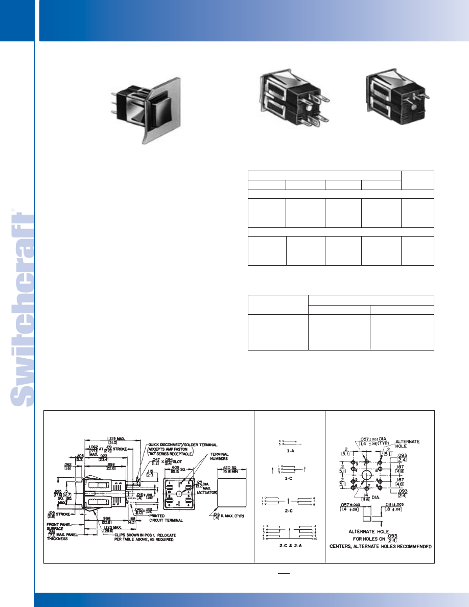
SWITCHES
272
w w w . s w i t c h c r a f t . c o m
® Registered trademark of Switchcraft, Inc.
Note: Contact your Switchcraft Representative for price and delivery
PHONE: 773 792-2700
SWITCHES
DIMENSIONS ARE FOR REFERENCE ONLY
Inch
(mm)
UNISWITCH
®
SWITCHES – SERIES BXR
UNISWITCH
®
SWITCHES – SERIES BXR
BOX SWITCH
®
SWITCHES
SERIES BXR
Economical momentary, non-illuminated switches feature
“Adjusto-Clip” snap-lock mounting and selection of switching.
Bezel trims mounting and enclosed construction protects
against dust, dirt, and physical damage. Color pushbuttons
have concave face for positive “feel”.
MOUNTING
Front mount in .620" (15.75 mm) minimum square hole.
Solder lug/quick-connect terminals accept AMP FASTON
®
110 terminals; PC terminals fit boards up to .281" (7.14 mm)
thick. “Adjusto-Clip” permits mounting in panels from .047 "
(1.19 mm) to .281" (7.14 mm) thick.
®
FASTON is a registered trademark of AMP INC.
SPECIFICATIONS
Housing: Molded plastic, charcoal gray only.
Pushbutton: Molded plastic; red, black, green, and
white standard.
“Adjusto-Clip” Mounting Frame: Copper alloy, plated.
Contact Springs: Copper alloy, plated.
Contacts: Integral, copper alloy, plated.
1-A, 1-C, 2-C, or 2-A + 2-C
Switching: 250 mA, 30 W max., AC, non-inductive load.
Terminals: Copper alloy, silver-plated.
SPECIAL ORDER FEATURES
• Other contact platings.
• Engraved legends (see page 270).
• Other pushbutton colors.
• “Adjusto-Clips” set to positions 2, 3, 4, or 5.
Pushbutton Color/Part Number
Red
Black
Green
White
Circuits
Solder Lug/Quick-Connect Terminals
BXR011
BXR013
BXR016
BXR0110
BXR021
BXR023
BXR026
◊
BXR0210
◊
BXR031
BXR033
BXR036
◊
BXR0310
BXR051
BXR053
BXR056
◊
BXR0510
1-A
1-C
2-C
2-A + 2-C
PC Terminals
◊
BXR011PC
◊
BXR013P
BXR016PC
◊
BXR0110PC
◊
BXR021PC
◊
BXR023P
BXR026PC
◊
BXR0210PC
◊
BXR031PC
◊
BXR033PC
◊
BXR036PC
◊
BXR0310PC
◊
BXR051PC
◊
BXR053PC
◊
BXR056PC
BXR0510PC
1-A
1-C
2-C
2-A + 2-C
◊
Special order only; contact factory for price and delivery.
1*
2
3
4
5
.047 (1.2)
.094 (2.4)
.141 (3.6)
.188 (4.8)
.234 (6.0)
.094 (2.4)
.141 (3.6)
.188 (4.8)
.234 (6.0)
.281 (7.1)
Position
Number
Minimum
Maximum
Panel Thickness Inch (mm)
“ADJUSTO-CLIP” MOUNTING POSITIONS
PART NUMBERS
* “Adjusto-Clips” normally installed in this position unless otherwise specified.
BXR013PC
SCHEMATIC
PANEL
CUTOUT
RECOMMENDED
PC BOARD LAYOUT
SHOWN ACTUAL SIZE
Rear view, BXR056
Solder Lug/Quick-Connect
Terminals.
Rear view, BXR013PC
PC Terminals.
* Please visit the product pages on our website for the most up-to-date product information
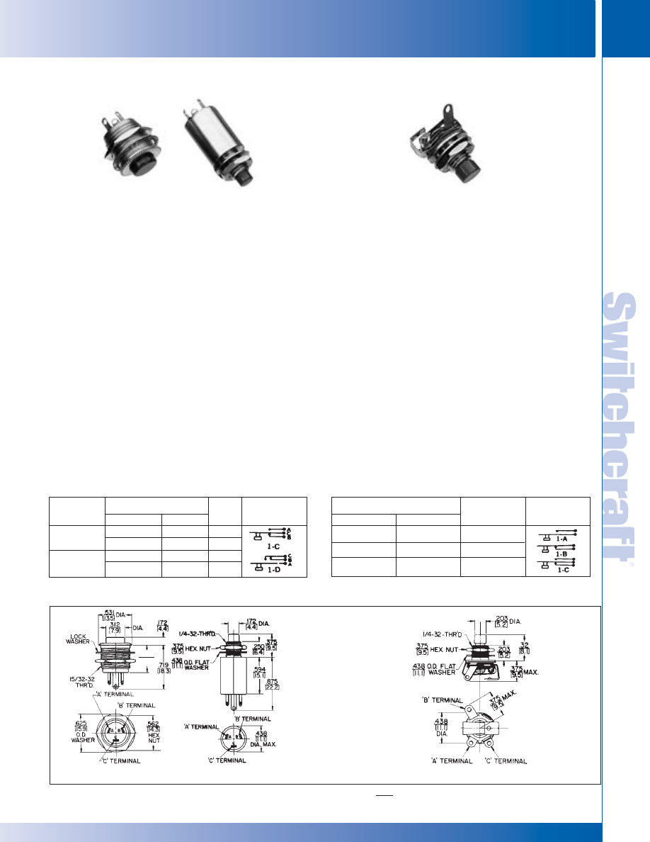
SWITCHCRAFT, INC. 5555 N. Elston Ave. • Chicago, IL 60630
273
SWITCHES
FAX: 773 792-2129
SWITCHES
BUTTON-SWITCH
®
& TINI-SWITCH
®
– SERIES 903, 913, 923, 933, 950, 960
BUTTON-SWITCH
®
& TINI-SWITCH
®
– SERIES 903, 913, 923, 933, 950, 960
TINI-SWITCH
®
SWITCHES
SERIES 950, 960
Momentary Tini-Switch
®
switches are miniaturized versions
of Littel-Switch
®
switches (see page 274 for construction
details). .25 A contacts are intended for low-power switching
where contact resistance is not critical. Red or black pushbuttons,
solder lug terminals and choice of 1-A, 1-B and 1-C switching
is standard.
MOUNTING
Switches mount from rear in .250" (6.35 mm) diameter hole in
panels up to .094" (2.39 mm) thick. Mounting washers and
locknuts are supplied.
SPECIFICATIONS
Bushing: Copper alloy, plated.
Pushbutton: Molded plastic, integral with shaft.
Insulation: Rigid plastic.
Springs: Copper alloy.
Contacts: Integral contacts are standard. .25 A, 30 W
maximum, AC, non-inductive load.
Washer: Steel, plated, S17901.
Locknut: Copper alloy, plated, P11501.
SPECIAL ORDER FEATURES
• Other pushbutton colors. • Legends.
Panel Mounting
Front
Rear
Black
913
◊
913D
933
◊
933D
Red
903
◊
903D
923
◊
923D
Schematic
1
1-C
1-D
1-C
1-D
1. Circuits C or 1-D can be wired for either 1-A or 1-B switching
◊
Special order only; contact Switchcraft for price and delivery.
PART NUMBERS
Pushbutton Color/Part Number
Black
961
◊
962
963
Red
951
◊
952
953
Circuit
Schematic
1-A, SPST, (N.O.)
1-B, SPST, (N.C.)
1-C, SPDT
◊
Special order only; contact Switchcraft for price and delivery.
PART NUMBERS
SERIES 903, 913, 923, 933
These small momentary switches are completely enclosed in
rugged metal housing. Front or rear-panel mount types offer
1-A, 1-B, 1-C, or 1-D switching. Red or black pushbuttons and
solder terminals are standard. Series 903 and 913 are front
mount in .469" (11.91 mm) diameter hole in panels up to
.297" (7.54 mm) thick. Series 923 and 933 are rear mount in
.250" (6.35 mm) diameter hole in panels up to .156" (3.96
mm) thick. Mounting hardware is supplied.
SPECIFICATIONS
Body: Copper alloy, plated.
Pushbutton: Molded red or black plastic, integral with shaft.
Insulation: Rigid plastic.
Springs: Integral contacts, plated.
Ratings: 250 mA, 30 W maximum, AC, non-inductive load.
Solder Terminals: Copper alloy, silver-plated.
Locknuts: Copper alloy, plated.
Series 903, 913: P-1053-1.
Series 923, 933: P-1150-1.
Lockwasher: Series 903, 913: Steel, P-1060-3
Flat Washer: Series 923, 933: Steel, plated, S-1790-1
SPECIAL ORDER FEATURES
• Other pushbutton colors. • Legends.
.453
(11.5)
BUTTON-SWITCH
®
SWITCHES
Series 903 & 913 Series 923 & 933 Series 950 & 960
DIMENSIONS ARE FOR REFERENCE ONLY
Inch
(mm)
Pushbutton Color/Part Number Circuit
903
923
* Please visit the product pages on our website for the most up-to-date product information
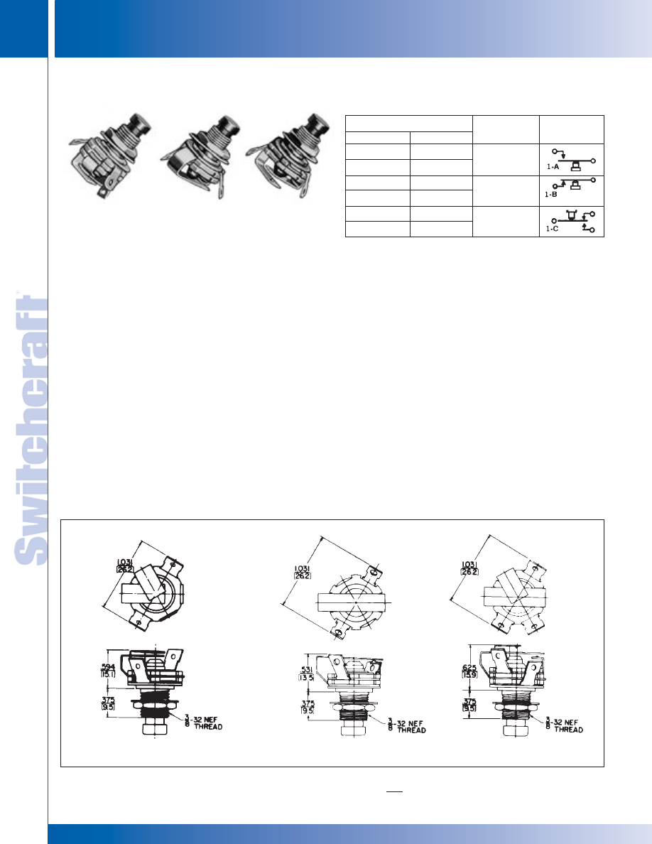
SWITCHES
274
w w w . s w i t c h c r a f t . c o m
® Registered trademark of Switchcraft, Inc.
Note: Contact your Switchcraft Representative for price and delivery
PHONE: 773 792-2700
SWITCHES
DIMENSIONS ARE FOR REFERENCE ONLY
Inch
(mm)
LITTEL-SWITCH SWITCH WS SERIES 100, 100S, 200, 200S
LITTEL-SWITCH SWITCH WS SERIES 100, 100S, 200, 200S
LITTEL-SWITCH
®
SWITCHES
SERIES 100, 100S, 200, 200S
Momentary switches feature leaf springs, insulating spacers,
notched insulating washers and plated copper alloy bushing
assembled into a rugged, reliable, long-life switch for limited
space applications. Series 100 and 200 have integral .25 A
contacts intended for low power switching where contact
resistance is not critical. Series 100S and 200S have 3 A
fine silver contact. Red and black pushbuttons, solder lug
terminals and choice of 1-A, 1-B or 1-C switching are
standard. Shaft and pushbutton molded as one piece.
Captive shaft extends through bushing, actuated leaf
springs. Notched phenolic washers insulate springs and
interlock all members, eliminating possibility of springs
shifting. All springs are insulated from bushing.
MOUNTING
Switches mount from rear in panels up to .250" (6.35 mm)
thick in .375" (9.52 mm) diameter holes. Locknuts and
washers are supplied.
SPECIFICATIONS
Bushing: Copper alloy, plated.
Pushbutton: Molded plastic, integral with shaft.
Insulation: Rigid plastic.
Springs: Copper alloy.
Contacts: Integral contacts are standard. (Series 100, 200)
.250 A, 30 W maximum, AC, non-inductive load. Riveted
silver contacts (Series 100S, 200S); 3A, 300 W maximum
AC, non-inductive load.
Washer: Steel, plated, S10221.
Locknut: Copper alloy, plated, P10001.
SPECIAL ORDER FEATURES
• Other pushbutton colors.
• Legends.
• Welded crossbar palladium contacts for dry circuit.
LEGENDS
Switchcraft offers a wide variety of engraved legends on
special order. Contact Switchcraft for details.
Pushbutton Color/Part Number
Black
201
◊
201S
202
◊
202S
203
◊
203S
Red
101
◊
101S
◊
102
◊
102S
103
◊
103S
Circuit
Schematic
1-A, SPST, (N.O.)
1-B, SPST, (N.C.)
1-C, SPDT
◊
Special order only; contact Switchcraft for price and delivery.
“S” at the end of part number indicates 3H rated fine silver contacts.
PART NUMBERS
SPST (NO) 1-A
SPST (NC) 1-B
SPDT 1-C
®
®
101
102
103
* Please visit the product pages on our website for the most up-to-date product information
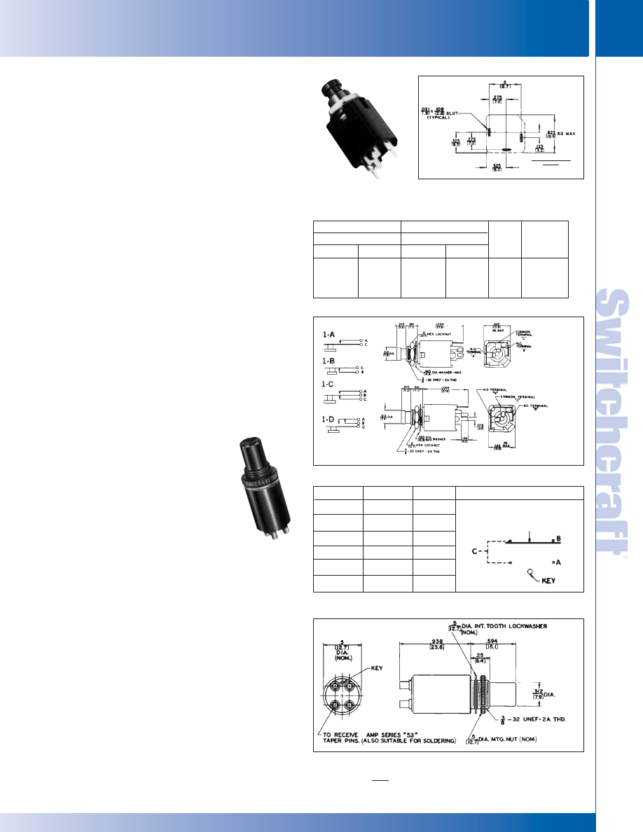
SWITCHCRAFT, INC. 5555 N. Elston Ave. • Chicago, IL 60630
275
SWITCHES
FAX: 773 792-2129
SWITCHES
DIMENSIONS ARE FOR REFERENCE ONLY
Inch
(mm)
Hi-D SWITCH SWITCHES - SERIES H-100, H-100PC, H-200, H-200PC
Hi-D SWITCH SWITCHES - SERIES H-100, H-100PC, H-200, H-200PC
Enclosed momentary pushbutton switch. Designed to meet
switching requirements of computers, data processors,
ground support systems, machine and process controls, test
equipment and intercoms. Anodized aluminum body protects
switch contacts from dirt, dust and bending during mounting.
Terminals accept AMP Series 53 taper pins. Mount in .375"
(9.5 mm) hole on .531" (13.5mm) centers. Behind panel
depth .938" (23.8mm) minimum.
SPECIFICATIONS
Housing: Aluminum, black anodized.
Button: Thermoplastic, black.
Terminal Base: Thermoset black phenolic.
Terminals: Copper alloy, gold-plated.
Contacts: Integral. 500 mA, 5 W maximum,
non-inductive load.
Contactor: Copper alloy, plated.
Hardware: Supplied with one,
◊
P1970 aluminum,
black anodized knurled mounting nut, and one,
P1971 parkerized lockwasher.
HI-D SWITCH
®
PC MOUNT SWITCHES
SERIES H-100, H-100PC, H-200, H-200PC
Compact, momentary switches mount on .625" (15.87 mm)
centers in rows or matrix arrays and are the same height and
panel size as Switchcraft’s Hi-D Jack. Rugged “box” body
protects contact springs against mechanical damage and
keys them in precise alignment. Precision springs produce
high contact pressure, smoother wear-reducing actuation,
and positive “make-break”. Recommended where contact
resistance is not critical.
MOUNTING
Rear of panel mount in .375" (15.87 mm) diameter hole in
panels up to .156" (3.96 mm) thick. Behind panel space:
1.094" (27.79 mm) minimum. Mounting hardware supplied.
Switches with PC terminals mount directly to PC boards,
and may also be panel mounted with threaded bushing.
SPECIFICATIONS
Switch Housing: Molded plastic.
Mounting Bushing: Copper alloy, plated.
Pushbutton/Actuator: Thermoplastic, red or black with
concave face.
Contact Springs: Copper alloy, silver or gold-plated.
Contacts: Integral, 1-A, 1-B, 1-C, or 1-D, 0. 25 A, 30 W
maximum, non-inductive load.
Contactor: Copper alloy, plated.
Locknut: Copper alloy, plated. P10001 (supplied).
Washer: Steel, nickel-plated. S10221 (supplied).
SPECIAL ORDER FEATURES
• Other pushbutton colors.
• Legends (see page 270).
Solder Lug Terminals
Pushbutton Color/Part Number
PC Terminals
Pushbutton Color/Part Number
Red
Black
Red
Black
Circuit
Schematic
H101
◊
H102
H103
◊
H103D
H201
◊
H202
H203
◊
H203D
◊
H101PC
◊
H102PC
H103PC
-
◊
H201PC
◊
H202PC
H203PC
-
1-A
1-B
1-C
1-D
See Below
◊
Special order only; contact factory for price and delivery.
PART NUMBERS
DA-SWITCH SWITCHES
SERIES DA
Button Color
Red
Black
Green
Blue
White
Yellow
Series DA
◊
DA013
◊
DA023
◊
DA033
◊
DA043
◊
DA053
◊
DA083
Schematic
Circuit
A-B
A-B
A-B
A-B
A-B
A-B
◊
Special order only; contact Switchcraft for price and delivery.
PART NUMBERS
A-B contacts may be externally wired to
provide a 1-C circuit as illustrated below.
SERIES H100, H200
®
®
Series
H-100PC
H-200PC
Series H-100, H-200
COMPONENT SIDE
SHOWN
* Please visit the product pages on our website for the most up-to-date product information
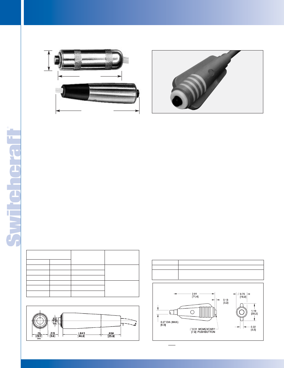
SWITCHES
276
w w w . s w i t c h c r a f t . c o m
® Registered trademark of Switchcraft, Inc.
Note: Contact your Switchcraft Representative for price and delivery
PHONE: 773 792-2700
SWITCHES
CORD-SWITCH AND CORDETTE CORD SERIES SWITCHES
CORD-SWITCH AND CORDETTE CORD SERIES SWITCHES
CORD-SWITCH
®
CORD SWITCHES
SERIES E900, ED900, EP900
Momentary cord (pendant) switches can be specified with red
or black pushbuttons, 1-C or 1-D switching, solder terminals
and metal handle (Series E900), plastic handle (Series
EP900), or metal handle with clamp and strain relief (Series
ED900).
SPECIFICATIONS
(See page 273 for switch specs.)
SERIES E900, EP900:
Housing: Series E900 - Copper alloy, plated.
Series EP900 - Molded black plastic.
Switch Bushing: Copper alloy, plated.
Insulation: Rigid plastic.
SERIES ED900:
Housing: Die-cast zinc, plated.
Switch Body and Insert Bushing: Copper alloy, plated.
Insulation: Rigid plastic.
Cable Relief Bushing: Black thermoplastic rubber.
Pressure Plates: Stainless steel.
Cable Relief Screws: Steel, plated.
SPECIAL ORDER FEATURES
• Other pushbutton colors. • Custom legends
SERIES 921
Momentary, 0.5 A switching combined with 1-piece molded plastic
body qualifies Cordette for all types of commercial and industrial
usage. The 921 has a phono jack receptacle and a phono jack
in handle to fit standard phono plugs. The 921K is molded with
6' (1.8 meter), 2-conductor cable (internal cable clamp).
SPECIFICATIONS
Body: 921 and 921K - Molded gray plastic with contrasting
trim and gray pushbutton.
Switch Contacts: Integral copper alloy, plated, form
1-A, 0.5 A, 50 W maximum, AC, non-inductive load.
Not recommended for high voltage circuits.
Insulation: Thermoplastic UL 94V-0.
Phono Jack Terminations: (921): Standard phono jack,
similar to 3501FP (see Jacks and Plugs Section).
SPECIAL ORDER FEATURES
• 1-B, 1-C, or 1-A + 1-B switching.
• Red, green, blue, white or yellow pushbuttons.
• Legends (see page 270).
• Other body colors.
• ST-900 - Custom-molded to any of a large selection of
cables (See Molded Cable Assembly Section). Also many
cable terminations, i.e., phone plugs, extension jacks,
phono plugs, spade lugs, alligator clips, stripped and tinned
leads, etc.
Black
E913
ED913
EP913
◊
E913D
◊
ED913D
◊
EP913D
.375" [9.5 mm]
.375" [9.5 mm]
.250" [6.4 mm]
.375" [9.5 mm]
.375" [9.5 mm]
.250" [6.4 mm]
Red
E903
ED903
EP903
◊
E903D
◊
ED903D
◊
EP903D
Circuit
1-C
1-D
◊
Special order only; contact Switchcraft for price and delivery.
Part Number
Description
921
Cordette switch, phono jack termination.
921K
Same as 921, except with 6' (1.8 meter), 2-conductor
cable with stripped and tinned leads.
PART NUMBERS
2.125" LONG
(53.98mm)
3" LONG (76.20mm)
E903
Series 921
HOUSING
DIA. .687"
(17.5mm)
SERIES ED900
Pushbutton
Color/Part Number
Maximum Cable
Outside Diameter
PART NUMBERS (examples)
CORDETTE
®
CORD SWITCHES
®
®
®
®
DIMENSIONS ARE FOR REFERENCE ONLY
Inch
(mm)
SERIES 921
* Please visit the product pages on our website for the most up-to-date product information
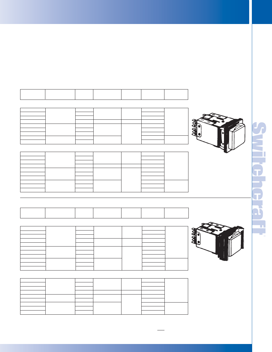
Part Number
Housing/
Pushbutton Color
Switching
AC Ratings (max.)
non-inductive
Contacts
CIrcuits
Terminals
SWITCHCRAFT, INC. 5555 N. Elston Ave. • Chicago, IL 60630
277
SWITCHES
FAX: 773 792-2129
SWITCHES
DIMENSIONS ARE FOR REFERENCE ONLY
Inch
(mm)
PUSH-LITE
®
SWITCHES AND INDICATORS
PUSH-LITE
®
SWITCHES AND INDICATORS
PUSH-LITE
®
SWITCHES AND INDICATORS
MOMENTARY
PL103205
PL106205
PL112205
◊
PL126205
◊
PL403205
◊
PL406205
◊
PL412205
◊
PL706205
◊
PL712205
Black/White
Gray/White
Black/White
SPDT
DPDT
4PDT
DPDT
SPDT
DPDT
4PDT
DPDT
4PDT
2 A, 125 V
8 A, 125V
2 A, 125V
2 A, 125 V
Palladium
Silver
Palladium
1-C
2-C
4-C
2-C
1-C
2-C
4-C
2-C
4-C
Solder Lug
PC
SINGLE LAMP
PL203205
PL206205
PL212205
◊
PL226205
◊
PL503205
◊
PL506205
◊
PL512205
◊
PL803205
◊
PL806205
◊
PL812205
Black/White
Gray/White
Black/White
SPDT
DPDT
4PDT
DPDT
SPDT
DPDT
4PDT
SPDT
DPDT
4PDT
2 A, 125 V
8 A, 125V
2 A, 125V
2 A, 125 V
Palladium
Silver
Palladium
1-C
2-C
4-C
2-C
1-C
2-C
4-C
1-C
2-C
4-C
Solder Lug
PC
TWIN LAMP
PUSH-LOCK/PUSH-RELEASE
Part Number
Housing/
Pushbutton Color
Switching
AC Ratings (max.)
non-inductive
Contacts
Circuits
Terminals
PL103705
PL106705
PL112705
◊
PL123705
◊
PL126705
◊
PL403705
◊
PL406705
◊
PL412705
◊
PL703705
◊
PL706705
◊
PL712705
Black/White
Gray/White
Black/White
SPDT
DPDT
4PDT
SPDT
DPDT
SPDT
DPDT
4PDT
SPDT
DPDT
4PDT
2 A, 125 V
8 A, 125V
2 A, 125V
2 A, 125 V
Palladium
Silver
Palladium
1-C
2-C
4-C
1-C
2-C
1-C
2-C
4-C
1-C
2-C
4-C
Solder Lug
PC
SINGLE LAMP
◊
PL203705
PL206705
PL212705
◊
PL226705
◊
PL506705
◊
PL512705
◊
PL803705
◊
PL806705
◊
PL812705
Black/White
Gray/White
Black/White
SPDT
DPDT
4PDT
DPDT
DPDT
4PDT
SPDT
DPDT
4PDT
2 A, 125 V
8 A, 125V
2 A, 125V
2 A, 125 V
Palladium
Silver
Palladium
1-C
2-C
4-C
2-C
2-C
4-C
1-C
2-C
4-C
Solder Lug
PC
TWIN LAMP
WITHOUT BARRIERS
WITH BARRIERS
◊
Special order only; contact Switchcraft for price and delivery.
Completely enclosed, lighted pushbutton switches feature
long-life, highly-reliable, leaf-springs. Available with or
without barriers, full or split-face display. Mounts with
clamp-type bracket; no screws, washers or nuts needed. Can
be mounted in vertical or horizontal rows and in matrixes.
Accepts standard T 1-3/4 flange-base lamp (lamp not
furnished with switch) in either 6 V to 28 V rating. Specify
1 lamp for single lamp type or 2 lamps for twin-lamp type
when redundant or split-face lighting is required. Barriers
and colored filter snap-inserts optional (order separately).
Mounting hole (w/o barriers): 1" (25.4 mm) x .875" (22.23
mm); (w/barriers) 1.188" (30.16 mm) x .875" (22.23 mm).
Panel thickness: .125" (3.18 mm) maximum. Behind panel
depth 1.75" (44.45 mm) (minus panel thickness).
* Please visit the product pages on our website for the most up-to-date product information
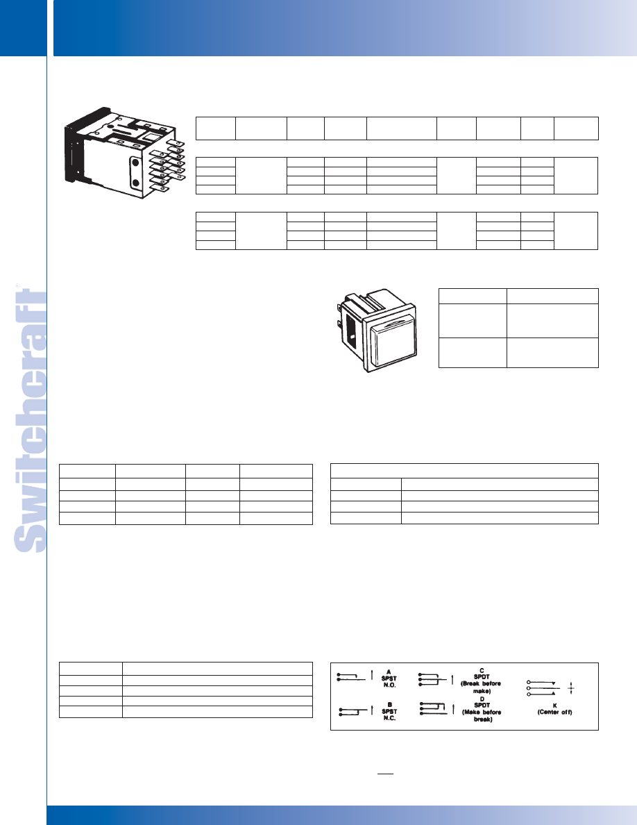
SWITCHES
278
w w w . s w i t c h c r a f t . c o m
® Registered trademark of Switchcraft, Inc.
Note: Contact your Switchcraft Representative for price and delivery
PHONE: 773 792-2700
SWITCHES
DIMENSIONS ARE FOR REFERENCE ONLY
Inch
(mm)
PUSH-LITE SWITCHES AND INDICATORS
PUSH-LITE SWITCHES AND INDICATORS
PUSH-LITE
®
SWITCHES AND INDICATORS (continued)
SERIES PL9000 - PL
®
INDICATORS
U.L. LISTED, MOMENTARY & PUSH-LOCK/PUSH-RELEASE
Part
Number
Housing/
Pushbutton
Action
1
Switching
AC Ratings (max.)
non-inductive
Contacts
Circuit
Listing
Terminals
◊
26U1003
◊
26U1004
◊
26U1007
◊
26U1008
Black/White
M
M
PL/PR
PL/PR
SPDT
DPDT
SPDT
DPDT
8 A, 125 V
8 A, 125V
8 A, 125V
8 A, 125 V
Silver
1-C
2-C
1-C
2-C
UL
UL
UL
UL
Solder Lug
SINGLE LAMP
◊
26U1005
◊
26U1006
◊
26U1009
◊
26U1010
Black/White
M
M
PL/PR
PL/PR
SPDT
DPDT
SPDT
DPDT
8 A, 125 V
8 A, 125V
8 A, 125V
8 A, 125 V
Silver
1-C
2-C
1-C
2-C
UL
UL
UL
UL
Solder Lug
TWIN LAMP
◊
Special order only; contact Switchcraft for price and delivery. NOTE: 1 M = Momentary; PL/PR = Push-Lock/Push-Release
Create unlimited combinations of rows and/or matrix arrays
with or without Push-Lite switches. A perfect match for front
panel appearance Push-Lite switches - but functions only as
a lighted indicator.
Mounts same as Push-Lite switches:
behind panel depth 1.341" (35.55mm) maximum uses
same lamp, color filter, snap inserts, light divider and
optional mounting barriers as Push-Lite
®
switches.
COLOR FILTER SNAP-INSERTS
Translucent plastic filters for special color coding in Push-Lite
switch and PL Indicators. Use with white or clear pushbuttons.
LIGHT DIVIDER
Light divider for Push-Lite switch pushbuttons and PL Indicator
screens; separates lighting from twin lamps. Order light divider for
each switch or indicator specified where split-face lighting is
desired. Order PL551.
PUSHBUTTON/INDICATOR SCREENS
Series PL500 Pushbuttons/Indicator Screens are available
separately for use with Push-Lite switches or PL Indicators for
in-the-field substitution and/or replacement.
Part Number
PL9105
◊
PL9205
Description
Black housing;
uses 1 or 2 lamps.
White screen.
Same as PL-9105
except gray housing.
Part Number
PL508
PL512
PL513
Color
Yellow
Clear
Amber
Part Number
PL501
PL503
PL504
PL505
Color
Red
Green
Blue
White
OPTIONAL MOUNTING BARRIERS
Molded plastic barriers separate Push-Lite switches, PL
Indicators, or combinations of Push-Lite switches and PL
Indicators and prevent accidental operation of adjacent
switches. Series PL100: end barrier. Series PL200: center
barrier. Two required between adjacently mounted switches.
Push-Lite switch is shown with two PL102 end barriers
installed.
Part Number
PL303
PL305
PL308
Color
Green
White
Yellow
SERIES PL300 - Full Display Color Filters
The above are strictly electrical schematics and do not necessarily indicate
relative solder lug positions.
BASIC SCHEMATIC
Switch circuitry can be described as combinations of basic schematic circuits
as shown below. N.O. means normally open; N.C. means normally closed.
Part Number
PL102
◊
PL111
PL202
◊
PL211
Description
End barrier, black
End barrier, gray
Center barrier, black
Center barrier, gray
◊
Special order only; contact Switchcraft for price and delivery.
®
®
* Please visit the product pages on our website for the most up-to-date product information
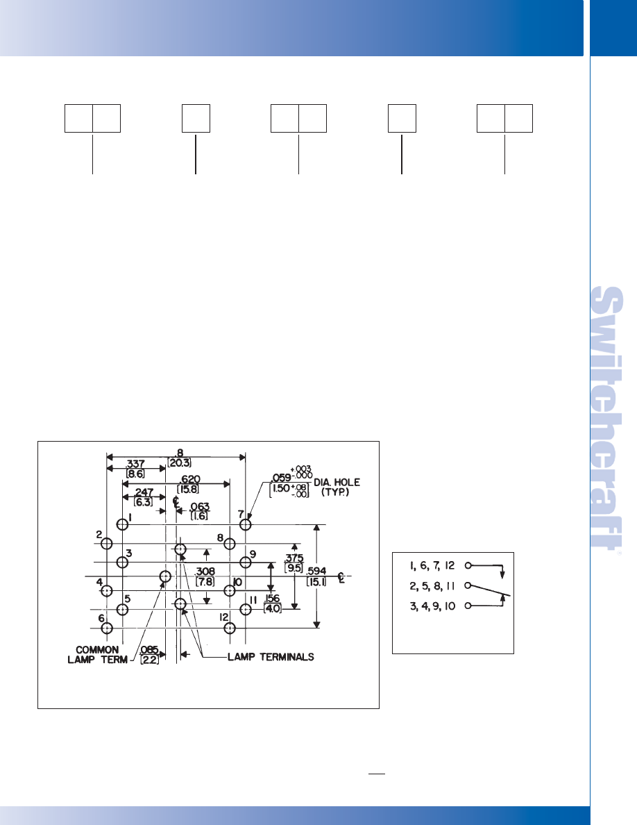
SWITCHCRAFT, INC. 5555 N. Elston Ave. • Chicago, IL 60630
279
SWITCHES
FAX: 773 792-2129
SWITCHES
DIMENSIONS ARE FOR REFERENCE ONLY
Inch
(mm)
PUSH-LITE SWITCHES PART NUMBERING SYSTEM
PUSH-LITE SWITCHES PART NUMBERING SYSTEM
PUSH-LITE
®
SWITCHES - PART NUMBERING SYSTEM
SERIES
PL
LAMP & SWITCH
HOUSING COLOR
1 - Single lamp,
Black housing
2 - Twin lamp,
Black housing
3 - Non-illuminated,
Black housing
4 - Single lamp,
Gray housing
5 - Twin lamp,
Gray housing
6 - Non-illuminated,
Gray housing
7 - Single lamp,
Black housing
(PC terminals)
8 - Twin lamp,
Black housing
(PC terminals)
CIRCUITRY
03 - 1C
06 - 2C
09 - 3C
12 - 4C
23 - 1C (8A)
26 - 2C (8A)
29 - 3C (8A)
32 - 4C (8A)
ACTION
2 - Momentary
7 - Push-Lock/
Push-
Release
9 - Momentary
Silent*
PUSHBUTTON
COLOR
01 - Red
03 - Green
04 - Blue
05 - White
08 - Yellow
12 - Clear
13 - Amber
P L
OPTIONS
Pushbutton/indicator screens, color filter snap-inserts, mounting
barriers and lighted dividers can be specified separately for sub-
stitution/replacement; order from tables. Also, engraving of leg-
ends is available; contact Switchcraft.
* Special order only. Contact Switchcraft.
®
®
RECOMMENDED PC BOARD LAYOUT
(Component Side)
SCHEMATIC
* Please visit the product pages on our website for the most up-to-date product information
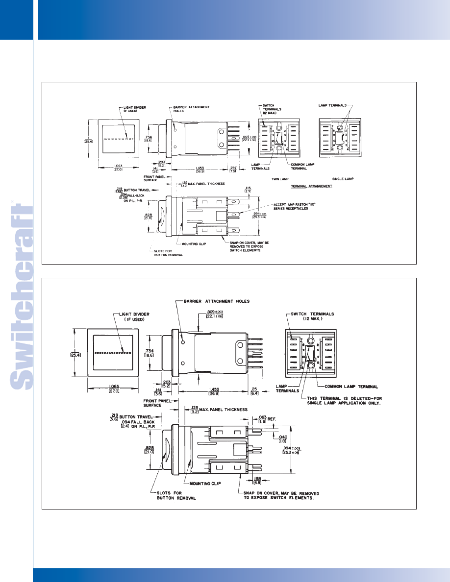
SWITCHES
280
w w w . s w i t c h c r a f t . c o m
® Registered trademark of Switchcraft, Inc.
Note: Contact your Switchcraft Representative for price and delivery
PHONE: 773 792-2700
SWITCHES
DIMENSIONS ARE FOR REFERENCE ONLY
Inch
(mm)
PUSH-LITE SWITCHES – OUTLINE DIMENSIONS
PUSH-LITE SWITCHES – OUTLINE DIMENSIONS
PUSH-LITE
®
SWITCHES AND INDICATORS (continued)
OUTLINE DIMENSIONS
PUSH-LITE SWITCHES WITH SOLDER LUGS
PUSH-LITE SWITCHES WITH PC TERMINALS
®
®
* Please visit the product pages on our website for the most up-to-date product information
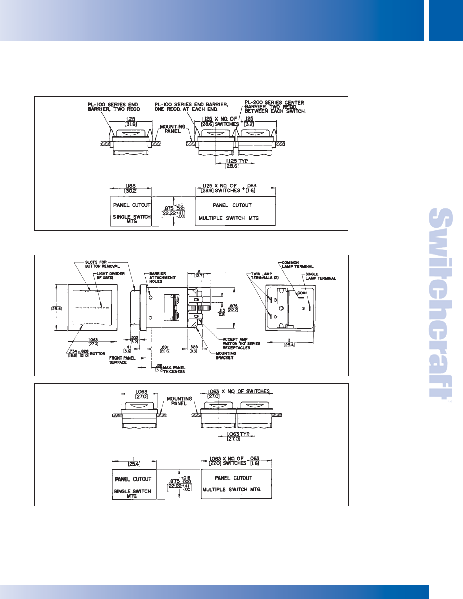
SWITCHCRAFT, INC. 5555 N. Elston Ave. • Chicago, IL 60630
281
SWITCHES
FAX: 773 792-2129
SWITCHES
DIMENSIONS ARE FOR REFERENCE ONLY
Inch
(mm)
PUSH-LITE SWITCHES – OUTLINE DIMENSIONS
PUSH-LITE SWITCHES – OUTLINE DIMENSIONS
PUSH-LITE
®
SWITCHES AND INDICATORS (continued)
OUTLINE DIMENSIONS
SWITCH AND INDICATOR MOUNTING WITH BARRIERS (See Note)
NOTE: PANEL OPENINGS FORM MULTIPLE ROW SWITCH MOUNTING
Leave .109" (2.77 mm) minimum width strip between panel-cutouts to assure secure mechanical
mounting of adjacent clamp mounting brackets.
SWITCH AND INDICATOR MOUNTING WITH BARRIERS (SEE NOTE)
®
®
* Please visit the product pages on our website for the most up-to-date product information
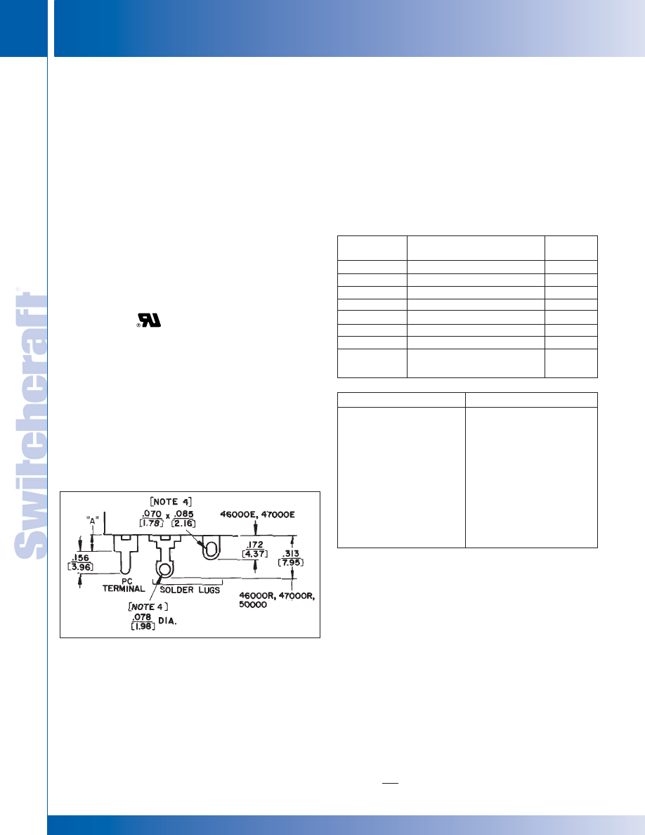
SWITCHES
282
w w w . s w i t c h c r a f t . c o m
® Registered trademark of Switchcraft, Inc.
Note: Contact your Switchcraft Representative for price and delivery
PHONE: 773 792-2700
SWITCHES
DIMENSIONS ARE FOR REFERENCE ONLY
Inch
(mm)
SLIDE SWITCHES
SLIDE SWITCHES
DESIGN FEATURES
Switchcraft slide switches are completely field tested and
proven in electrical/electronic equipment applications. They are
among the highest-quality, lowest-cost slide switches available
to “cost-to-quality ratio” conscious engineers.
Precision slide switches are designed and constructed to meet
or exceed industry standards for reliability, electrical capacity
and life characteristics.
Switchcraft’s slide action switches are ideal for use in critical
military and industrial applications such as: instrumentation,
test and ground support equipment, computers, control
devices. Their attractive styling will enhance the appearance of
modern home entertainment equipment.
SPECIAL ORDER SWITCHES FOR
CSA APPLICATIONS
The following series of switches (solder lug type) must be
assembled with a fishpaper or phenolic solder guard to be
CSA certified and stamped. Available on special order only.
Series 46000R, 47000R, 46313R, 49000L, 50000L, Solder
guards are not required on these switch series with PC
terminals. However, they can only be supplied with CSA stamp
on special order. Solder guards are not required on
UL only versions. Contact Switchcraft for details.
SLIDE SWITCHES
Series
46000
47000
49000
50000
56200, C56200
56300, C56300
C63000
EPS1, EPS2
EPS3, EPS4
Name
General Purpose Slide Switches
Tandem Slide Switches
General Purpose Slide Switches
General Purpose Slide Switches
“Tini-Slide” Slide Switches
“Tini-Slide” Slide Switches
Miniature Slide Switches
European Line Voltage
Selector Switches
Number of
Positions
2, 3
2; 2 gang
3
2
2
3
4
2
Series
46000E
46000R
47000E
47000R
49000
50000
56000, C56000
62000, C62000
C63000
EPS1, EPS2
EPS3, EPS4
Description
Note 1
Notes 1, 3
Note 1
Notes 1, 3
Note 1
Notes 1, 3
See page 288
See page 290
See page 290
See page 291
NOTES:
1. PC terminal “A” dimension is:
Standard - .078" (1.98)
Special - .109" (2.77), .141" (3.58), .160" (4.06), .180" (4.57), .203" (5.16),
.234" (5.94), .266" (6.76), .313" (7.95), .391" (9.93), .400" (10.16),
.438" (11.12), .484" (12.29), .609" (15.47), .688" (17.48), .719" (18.26),
.813" (20.65), .969" (24.61), 1.25" (31.75)
2. .078" (1.98) “A” dimension is not recommended for momentary switches
unless clearance hole for return spring is provided in PC board.
3. Accepts up to #14 AWG wire.
TERMINALS
Silver-plated terminals are standard; gold-plated terminals are
available on special order. Printed circuit terminals in varying
lengths from (“A” dimension) .078" (1.98 mm) to 1.25" (31.75
mm) are available on special order. Reference “A” on all switch
d raw i n g s i n d i c a t e s l e n g t h o f P C t e r m i n a l s. S e e
illustration and notes below for selection of terminals.
UL AND CSA SWITCHES
All slide switches in this catalog with part number suffix “E”
are stamped with both UL and CSA marks. Other standard
switches are UL recognized (except as noted) and are
stamped with the mark.
SWITCH SERIES IDENTIFICATION
* Please visit the product pages on our website for the most up-to-date product information
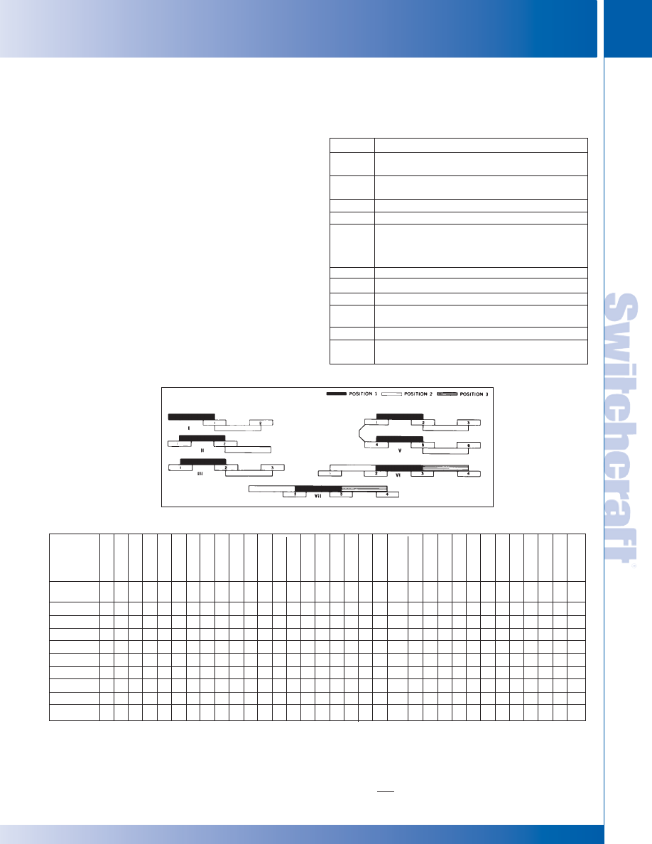
SWITCHCRAFT, INC. 5555 N. Elston Ave. • Chicago, IL 60630
283
SWITCHES
FAX: 773 792-2129
SWITCHES
DIMENSIONS ARE FOR REFERENCE ONLY
Inch
(mm)
SLIDE SWITCHES
SLIDE SWITCHES
SWITCHING
“Double-wipe” slide switches incorporate special “Sliders” to
assure wiping action of terminals. This exclusive double
wiping action reduces the possibility of oxidation or increased
contact resistance. These longer lasting, self-cleaning sliders
provide a switch with greater dependability.
The “Sliders”, which are formed with precision dies, are
U-shaped to give bifurcated contact reliability. “Sliders” are
made from a special copper alloy, plated, which assures
uniform tensile strength over the entire life of the switch.
Switch terminals are copper alloy, plated. Plating completely
encloses the contact area in a silver jacket for positive and
continuous electrical operation. A tarnish preventive lubricant
coating is applied to the sliders and terminals.
NOTE: “double-wipe” action on all switches except
Series 62000 and 46256LFR.
PART NUMBER SUFFIX LETTERS
B
C
D
E
F
L
M
P
R
S
T
Series
46000E
46000R
46300R
47000
49000
50000
56200
56300
62000 (2)
C63000
EPS (3)
*
(1)
◊
*(1)
◊
◊
*
Flush
.063 (1.6)
.087 (2.21)
.094 (2.39)
.100 (2.54)
.112 (2.84)
.125 (3.18)
.137 (3.48)
.15 (3.81)
.156 (3.96)
.187 (4.75)
.188 (4.78)
.200 (5.08)
.203 (5.16)
.219 (5.56)
.250 (6.35)
.302 (7.67)
.313 (7.95)
.315 (8)
.328 (8.33)
.344 (8.74)
.375 (9.52)
.406 (10.31)
.440 (11.18)
.453 (11.51)
.469 (11.91)
.487 (12.37)
.500 (12.7)
.531 (13.49)
.563 (14.3)
.594 (15.09)
.719 (18.26)
.750 (19.05)
Description
Special pushbutton type. Depressing (rather than
sliding) pushbutton operates the switch.
Tandem switch with 2 knobs; knobs are internally
(mechanically) coupled.
3-position switch having internal dust shield.
Molded terminal board.
Flush actuator. Screwdriver slotted. All series except
47000 series marked standard as “115/230.” Other
markings available as special order. Call
Switchcraft for details.
Locking action.
Momentary (non-lock) action.
Switch has external plunger.
Current ratings up to 3A, 125V AC. Phenolic
terminal board.
Shorting type contacts, make-before-break.
3-position switches only. One side of neutral has
locking action; the other side has momentary action.
◊
◊
◊
◊
◊
◊
◊
◊
◊
◊
◊
◊
◊
◊
*
◊
◊
◊
◊
*
*
*
◊
◊
◊
◊
◊
◊
◊
◊
◊
◊
◊
◊
◊
*
*
*(2)
◊
◊
◊
◊
◊
◊
◊
◊
◊
*
◊
◊
◊
◊
*
◊
◊
◊
◊
◊
◊
◊
◊
◊
◊
◊
◊
◊
◊
* Standard,
◊
Special order
1. Flush screwdriver actuator is standard on numbers 46206LFE, 46206LFR, 46256LFE, 46256LFR and 47227LFR.
2. Numbers 62206L and C62206L have side knob actuator (rather than top knob) standard.
3. EPS switches not available with raised knobs.
DESIGN FEATURES (continued)
KNOBS
KNOB HEIGHTS Inches (mm)
SLIDE SWITCHES (continued)
BASIC SCHEMATIC CHART
Standard arrangement is “Break” before “Make” (non-shorting).
“Make” before “Break” (shorting) is available on special order
in Series 46000R, 47000R, 49000 and 50000.
BASIC SCHEMATIC CHART
Letter
* Please visit the product pages on our website for the most up-to-date product information
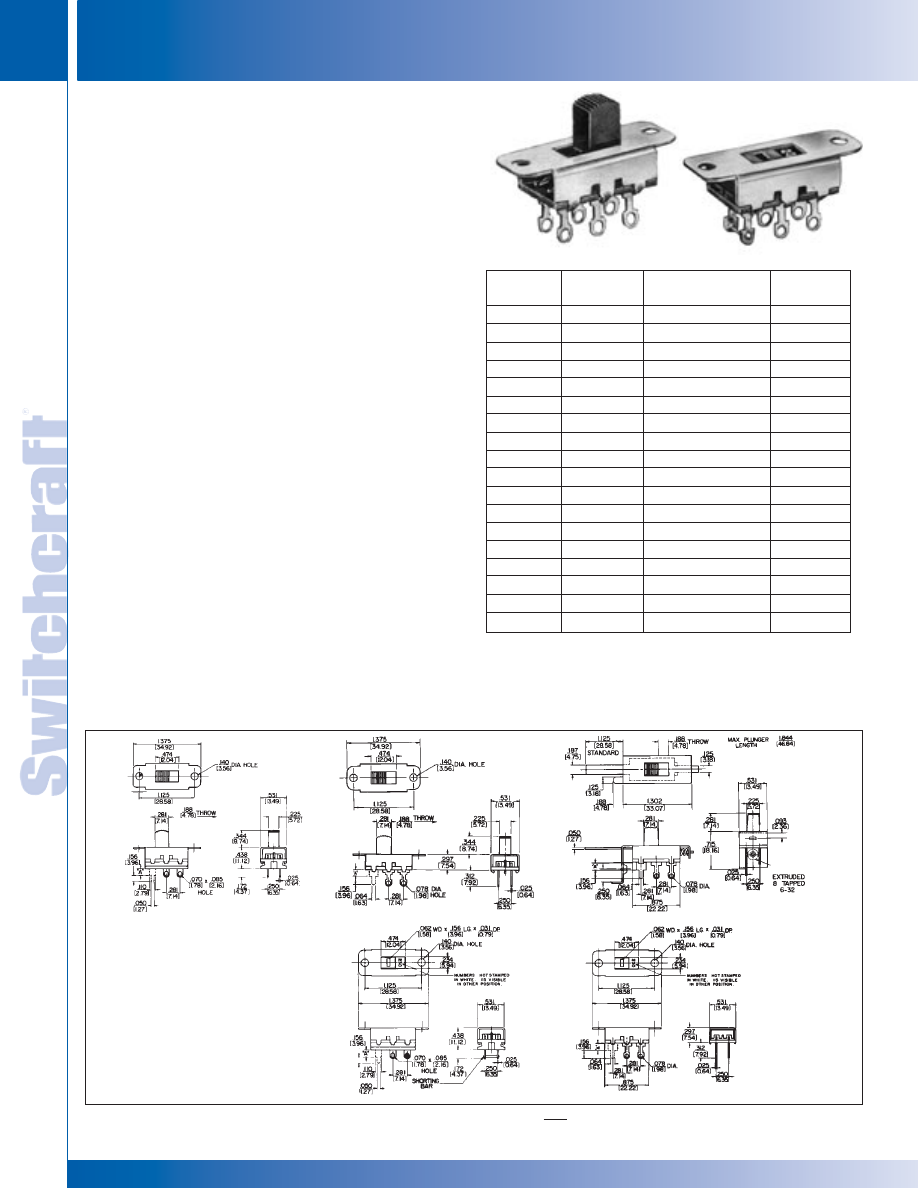
SWITCHES
284
w w w . s w i t c h c r a f t . c o m
® Registered trademark of Switchcraft, Inc.
Note: Contact your Switchcraft Representative for price and delivery
PHONE: 773 792-2700
SWITCHES
DIMENSIONS ARE FOR REFERENCE ONLY
Inch
(mm)
GENERAL PURPOSE SLIDE SWITCHES – SERIES 46000 - 2 POSITION
GENERAL PURPOSE SLIDE SWITCHES – SERIES 46000 - 2 POSITION
SERIES 46200E, 46200R - 2 POSITION
SPECIFICATIONS
Contact Ratings: 0.5A DC and 3A AC, 125V non-inductive. (Also
1.5A, 250V non-inductive for Series 46000E only).
Numbers
46206LFR and 46256LFR are not designed to switch more than
125V, and must be set to desired position before power is applied
to equipment, appliance, etc.
Listings: UL recognized and CSA certified. Series 46000R
switches are CSA marked on special order only. Ref. UL
card E40668 and CSA File 28260.
Housing: Steel, plated.
Knob: Black thermoplastic.
Terminals and Slider Contacts: Copper alloy, plated.
Insulation: Series 46000E: Thermoplastic.
Series 46000R: Rigid plastic.
Temperature Range: -4°F to +158°F (-20°C to +70°C).
Dielectric Strength: 1 kV rms @ sea level.
Insulation Resistance: 1 k M
Ω
minimum.
SPECIAL ORDER FEATURES
1. .344" (8.74 mm) high knobs are standard; other heights
available. See chart on page 283.
2. #6-32 and #4-40 tapped flanges for mounting available
(except 46204MBR and 46206MP).
3. P.C. terminals.
4. Plunger length on 46206MP - Other lengths from
.125" (3.18 mm) to 1.844" (46.84 mm) long.
5. Series 46000R switches are CSA marked on special
order only. See page 282.
46206LE
46206LR
46206MP
46256LFE
46206LFR
46206LR
46206LFR
GENERAL PURPOSE SLIDE SWITCHES
Series
46200E
◊
46201ME
◊
46202LE
◊
46202ME
46203LE
◊
46203LSE
◊
46203ME
46204LE
◊
46204ME
46206LE
46206LFE
◊
46206LSE
◊
46206ME
-
46256LFE
-
-
-
-
Series
46200R
46201MR
46202LR
◊
46202MR
46203LR
◊
46203LSR
46203MR
◊
46204LR
◊
46204MR
46206LR
46206LFR
◊
46206LSR
◊
46206MR
◊
46206MP
46256LFR
◊
C46203LR**
◊
C46204MR**
C46206LR**
C46206LFR**
Description
SPST NO, Momentary
SPST, Locking
SPST NC, Momentary
SPDT, Locking
SPDT, Locking
SPDT, Momentary
DPST, Locking
DPST NO, Momentary
DPDT, Locking
DPDT, Locking (1)
DPDT, Locking
DPDT, Momentary
DPDT, Momentary*
DPDT, Locking (1) (2)
SPDT , Locking
DPST NO, Momentary
DPDT, Locking
DPDT, Locking (1)
Schematic*
I
II
II
III
III
Shorting
III
2-I
2-I
2-III
2-III
2-III
Shorting
2-III
2-III
V
III
2-I
2-III
2-III
* Contacts are non-shorting, except as noted.
** "C" prefix specifies .078 inch (1.98) PC terminals, no mounting ears.
(1) Recommended for power selection, 115-230 legend, screwdriver slotted
actuator minimizes tampering.
(2) Shorting bars installed.
◊
Special order only; contact Switchcraft
PART NUMBERS
* Please visit the product pages on our website for the most up-to-date product information
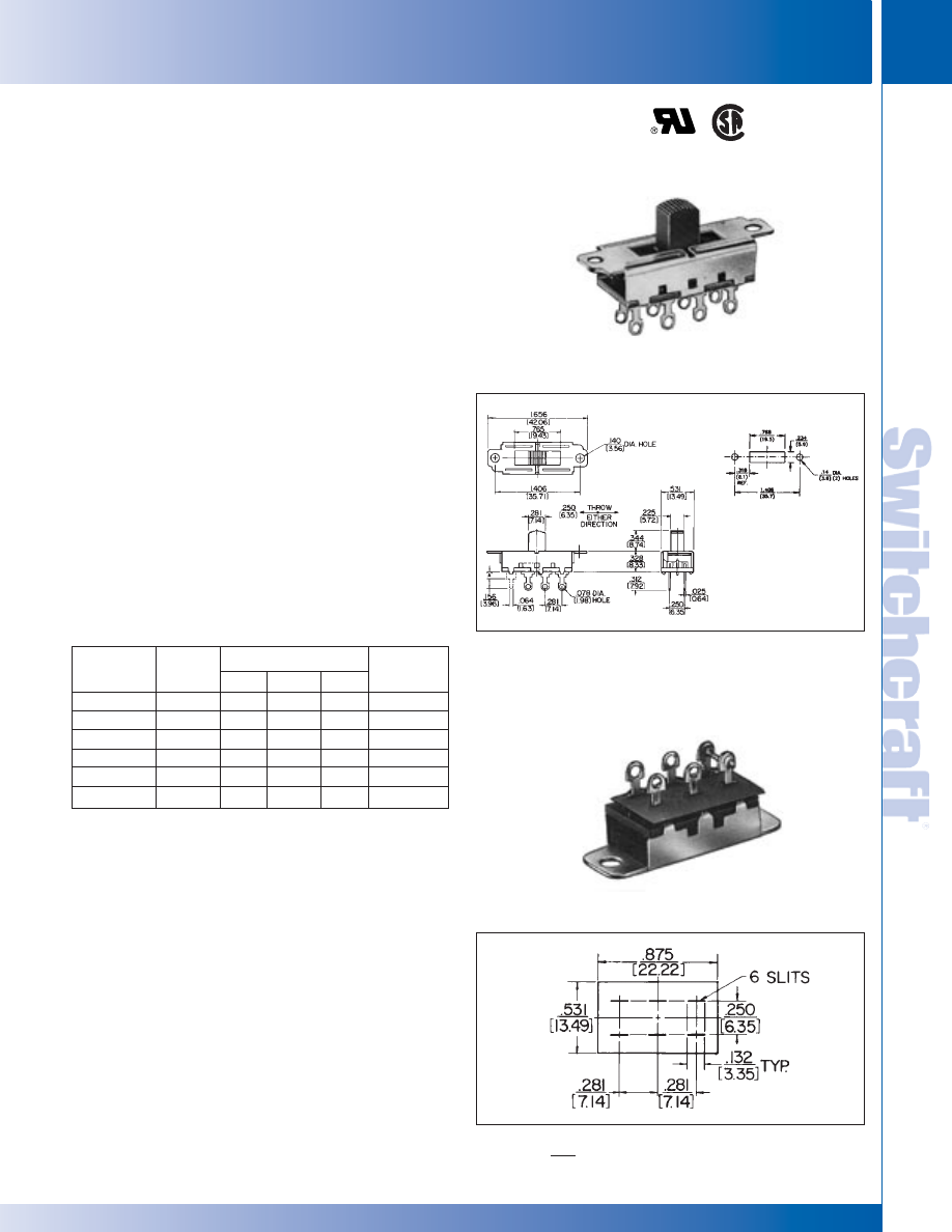
SWITCHCRAFT, INC. 5555 N. Elston Ave. • Chicago, IL 60630
285
SWITCHES
FAX: 773 792-2129
SWITCHES
DIMENSIONS ARE FOR REFERENCE ONLY
Inch
(mm)
GENERAL PURPOSE SLIDE SWITCHES – SERIES 46000 - 3 POSITION
GENERAL PURPOSE SLIDE SWITCHES – SERIES 46000 - 3 POSITION
SERIES 46300R - 3-POSITION
Three-position switches offer locking-locking, momentary-
momentary and locking-momentary action for talk-listen
applications. All switches have positive center detent and
shutter type dust cover to prevent dirt and dust from
contaminating switch contacts.
SPECIFICATIONS
Contact Ratings: 0.5A DC and 3A AC, 125V non-inductive.
Listings: UL recognized, card E40688 CSA certified
(marked) switches available on special order only.
See page 282.
Housing: Steel, plated.
Detent Spring: Music wire.
Shim: Black vulcanized fiber.
Knob: Black thermoplastic.
Terminals & Slider Contacts: Copper alloy, silver-plated.
Insulation: Phenolic.
Temperature Range: -4°F to +158°F (-20°C to +70°C).
Dielectric Strength: 1 kV rms @ sea level.
Insulation Resistance: 1 k M
Ω
minimum.
SPECIAL ORDER FEATURES:
1. .344" (8.74 mm) high knobs are standard; other heights
available. See chart on page 283.
2. Series 46000R switches are CSA marked on special
order only. See page 282.
SOLDER GUARDS
Insulating Solder Guards, P-2370 (2-position); and
◊
P-2633
(3-position); slip over solder lug terminals and prevent solder
splashes from entering interior (contact area) of switch. Made
of fishpaper .01" (.25 mm) thick, Solder Guard slips over
terminals quickly and easily. Precision punched slots lock
onto terminals, and rectangular shape conforms with
dimension of switch terminal board. Minimizes costly
production line rework.
Solder Guards can be used on:
• General Purpose, Series 46000R
• Tandem, Series 47000R.
GENERAL PURPOSE SLIDE SWITCHES (continued)
Part**
Number
46311LDR
◊
46311MDR
◊
46311TDR
46313LDR
46313MDR
46313TDR
Circuitry
SPTT
SPTT
SPTT
DPTT
DPTT
DPTT
#1
L
M
L
L
M
L
#2
L
M
M
L
M
M
Center
L
L
L
L
L
L
Schematic
VI
VI
VI
2-VI
2-VI
2-VI
PART NUMBERS
Action Positions*
◊
Special order only; contact Switchcraft for price and delivery.
* L - Locking; M - Momentary.
** "C" prefix specifies .078" (1.98) PC terminals, no mounting ears.
Series 46300R
* Please visit the product pages on our website for the most up-to-date product information
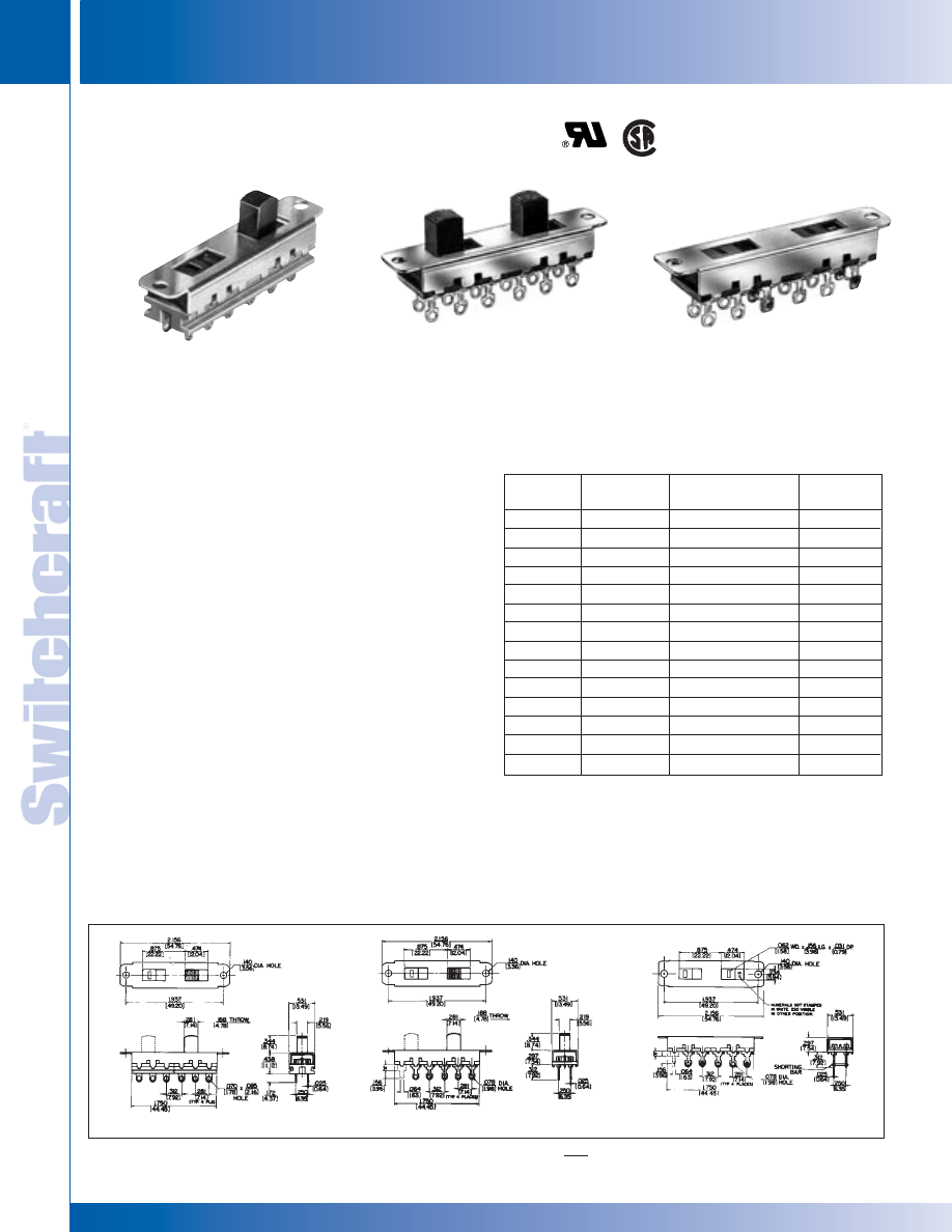
SWITCHES
286
w w w . s w i t c h c r a f t . c o m
® Registered trademark of Switchcraft, Inc.
Note: Contact your Switchcraft Representative for price and delivery
PHONE: 773 792-2700
SWITCHES
DIMENSIONS ARE FOR REFERENCE ONLY
Inch
(mm)
GENERAL PURPOSE SLIDE SWITCHES – TANDEM SERIES 4700
GENERAL PURPOSE SLIDE SWITCHES – TANDEM SERIES 4700
SERIES 47200E, 47200R - 2 POSITION
Space saving, two-gang slide switches are contained in one
housing. Switching is locking type with non-shorting contacts.
SPECIAL ORDER FEATURES
1. .344" (8.74 mm) high knobs or flush knobs are standard,
depending on switch selected; other heights available.
See chart on page 283.
2. Series 47000R switches are CSA marked on special
order only. See page 282.
SPECIFICATIONS
Contact Ratings: 0.5A DC and 3A AC, 125V non-inductive,
(Also 1.5A, 250V non-inductive for Series 47000E only.)
47227LFR switches are not designed to switch more
than 125V, and must be set to desired position before
power is applied to equipment or appliance.
Listings: UL recognized, card E40668, and CSA certified
(card 28260). Series 47000R switches are CSA certified
on special order only. See page 282.
Housing: Steel, plated.
Knob: Black thermoplastic.
Terminals and Slider Contacts: Copper alloy, silver-plated.
Insulation: Series 47000E - Thermoplastic.
Series 47000R - Rigid plastic.
Temperature Range: -4°F to +158°F (-20°C to +70°C).
Dielectric Strength: 1 kV rms @ sea level.
Insulation Resistance: 1 k M
Ω
minimum.
GENERAL PURPOSE SWITCHES - TANDEM
Series
47200E
◊
47202LE
◊
47203LE
◊
47204LE
◊
47204LCE
◊
47206LE
◊
47206LCE
-
-
-
-
-
-
Series
47200R
◊
47202LR
◊
47203LR
◊
47204LR
◊
47204LCR
◊
47206LR
◊
47206LCR
◊
47215LR
◊
47215LCR
◊
47217LR
◊
47217LCR
◊
47221LR
◊
47221LCR
◊
47227LFE
◊
47227LFR
Description
SPST - SPST
SPDT - SPDT
DPST - DPST
DPST - DPST
DPDT - DPDT
DPDT - DPDT
SPST - SPDT
SPST - SPDT
SPST - DPST
SPST - DPST
SPDT - DPST
SPDT - DPST
DPDT - DPDT
DPDT - DPDT
Schematic
II II
III III
2-I 2-I
2-I 2-I
2-III 2-III
2-III 2-III
II III
II III
II 2-II
II 2-II
III 2-II
III 2-II
2-V
2-V
NOTE: Series 47200E and 47200R - All switches have two independent
knobs, except:
• 47204LE, 47204LCR, 47206LCE and 47206LCR have one knob and
one flush actuator.
• 47227LFE and 47227LFR have internal mechanical coupling and
two flush, slotted screwdriver actuators.
◊
Special order only; contact Switchcraft
PART NUMBERS
47206LCE
47227LFR
47206LCE
47206LR
47227LFR
47206LR
* Please visit the product pages on our website for the most up-to-date product information
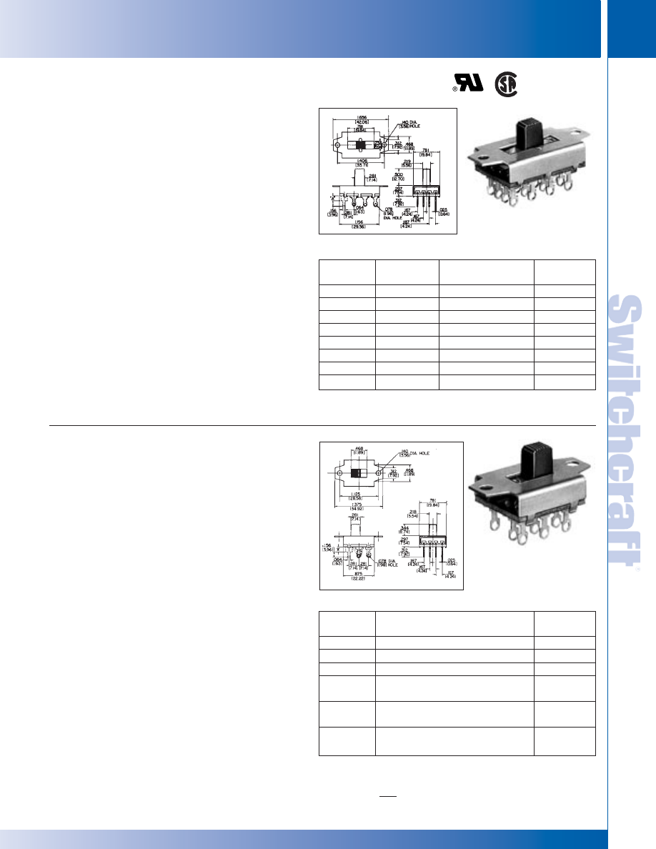
SWITCHCRAFT, INC. 5555 N. Elston Ave. • Chicago, IL 60630
287
SWITCHES
FAX: 773 792-2129
SWITCHES
DIMENSIONS ARE FOR REFERENCE ONLY
Inch
(mm)
GENERAL PURPOSE SLIDE SWITCHES –SERIES 49000 AND 50000
GENERAL PURPOSE SLIDE SWITCHES –SERIES 49000 AND 50000
SERIES 49300 - 3 POSITION
Large, heavy duty, three and four pole slide switches. Standard
mounting clearance is .141" (3.58 mm). Series 49300L,
non-shorting contacts; Series 49300LS, shorting contacts.
SPECIFICATIONS
Contact Ratings: 0.5A DC and 3A AC, 125V non-inductive.
Listings: UL recognized (card E40668); CSA certified
(marked) switches available on special order only.
See page 282.
Housing: Steel, plated.
Detent Shim: Copper alloy.
Knob: Black thermosetting plastic.
Terminals and Slider Contacts: Copper alloy, silver-plated.
Insulation: Rigid plastic.
Temperature Range: -4°F to +158°F (-20°C to +70°C).
Dielectric Strength: 1 kV rms @ sea level.
Insulation Resistance: 1 k M
Ω
minimum.
SPECIAL ORDER FEATURES
1. .5" (12.7 mm) high knobs are standard; other heights
available. See chart on page 283.
2. #4-40 extruded and tapped mounting holes available.
3. Series 49300L switches are CSA marked on special
order only. See page 282.
SERIES 50200 - 2 POSITION
A larger 2 position “double wipe” slide switch offering three
and four poles of switching and locking or momentary action.
Series 50200L and M, non-shorting; Series 50200LS and
MS, with shorting contacts.
SPECIFICATIONS
Contact Ratings: 0.5A DC and 3A AC, 125V non-inductive.
Listings: UL recognized (card E40668); CSA certified (card
28260). Series 50200L switches are CSA marked on special
order only. See page 282.
Housing: Steel, plated.
Detent Shim: Copper alloy.
Knob: Black thermosetting plastic.
Terminals and Slider Contacts: Copper alloy, plated.
Insulation: Rigid plastic.
Temperature Range: -4°F to +158°F (-20°C to +70°C).
Dielectric Strength: 1 kV rms @ sea level.
Insulation Resistance: 1 k M
Ω
minimum.
SPECIAL ORDER FEATURES
1. .344" (8.74 mm) high knobs are standard; other heights
available. See chart on page 283.
2. 50212LF available with flush, screwdriver slotted
actuator and has 4 PDT locking action.
3. Extruded and tapped 4-40 or 6-32 holes available.
4. Series 50200L switches are CSA marked on special
order only. See page 282.
GENERAL PURPOSE SLIDE SWITCHES (continued)
Part
Number
◊
49309L
◊
49309LS
◊
49329L
◊
49329LS
◊
49312L
◊
49312LS
◊
49331L
◊
49331LS
UL & CSA
Listing
Yes
No
Yes
No
Yes
No
Yes
No
Description
3-PDT, Locking*
3-PDT, Locking*
3-PTT, Locking
3-PTT, Locking
4-PDT, Locking*
4-PDT, Locking*
4-PTT, Locking
4-PTT, Locking
Schematic
3-VII
3-VII
3 -VI
3 -VI
4-VII
4-VII
4 -VI
4 -VI
* 3rd position is off.
◊
Special order only; contact Switchcraft.
PART NUMBERS
Part
Number
◊
50207L
◊
50207M
◊
50208L
50209L
◊
50209LS
◊
50209M
◊
50209MS
50212L
◊
50212LS
Description
3PST - Locking
3PST, N.O. Momentary
4PST, Locking
3PDT, Locking
3PDT, Momentary
4PDT, Locking
Schematic
3-I
3-I
4-I
3-III
3-II
4-III
◊
Special order only; contact Switchcraft.
PART NUMBERS
49331L
50209L
* Please visit the product pages on our website for the most up-to-date product information
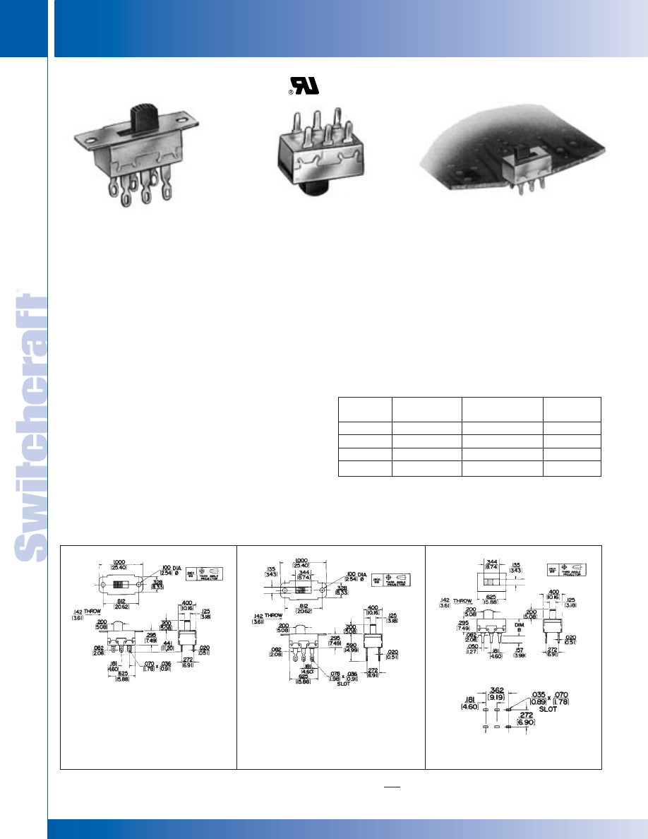
SWITCHES
288
w w w . s w i t c h c r a f t . c o m
® Registered trademark of Switchcraft, Inc.
Note: Contact your Switchcraft Representative for price and delivery
PHONE: 773 792-2700
SWITCHES
DIMENSIONS ARE FOR REFERENCE ONLY
Inch
(mm)
MINIATURE SLIDE SWITCHES – SERIES 56200 AND C56200
MINIATURE SLIDE SWITCHES – SERIES 56200 AND C56200
SERIES 56200, C56200 - 2 POSITION
“Tini-Slide” slide switches have Exclusive SNAP SLIDE lifting
and wiping action. This unique, positive action combines the
best features of “snap” and “slide” movements into the design
of a superior switch. Pitting, burning and contamination are
minimized. Contacts lift through an air gap, drop on stationary
contacts, and slide, wiping themselves clean. Subminiature
size is ideal where useable space is at a premium.
SPECIFICATIONS
Contact Ratings: 0.5A, 125V AC or DC, non-inductive.
Minimum life at rated load 6000 cycles. Resistance after
6000 cycles at rated load is 50 milliohms maximum.
Terminals: PC Type - silver-plated. Each terminal has
standoff shoulder for stable mounting and space for board
clearance.
Mounting: Flange, (56206L1 and 56206L2) - .1" (2.54 mm)
holes for screw or mounting rivet. PC - Direct mounting to PC
boards up to .093" (2.36 mm) thick.
Knob: Molded thermoplastic (UL 94V-1).
Terminal Board: Molded thermoplastic (UL 94V-0).
Terminals: Copper alloy, silver-plated.
Contact Sliders: Copper alloy.
Temperature Range: -4°F to +158°F (-20°C to +70°C).
Dielectric Strength: 1 kV rms @ sea level.
Insulation Resistance: 1 k M
Ω
minimum.
SPECIAL ORDER FEATURES
1. .2" (5.08 mm) high knobs are standard; other heights
available on special order. See page 283.
2. Red and white knobs available.
3. Mounting flanges with .1" (2.54 mm) diameter holes on
C56206L1 or C56206L2. Flange holes tapped #4-40 on
56206L1 or 56206L2 (where production quantities warrant).
4. UL stamped on special order.
MINIATURE SLIDE SWITCHES
Part
Number
56206L1
56206L2
C56206L1
C56206L2
Dimension "B"
Inch (mm)
-
-
.573 (14.55)
.352 (8.94)
Description
DPDT, Locking
DPDT, Locking
DPDT, Locking
DPDT, Locking
Schematic
2-III
2-III
2-III
2-III
PART NUMBERS
56206L1
SPECIAL ORDER
C56206L1 & 2
RECOMMENDED PC BOARD
LAYOUT (Component Side)
56206L1
56206L2
C56206L2
C56206L2
* Please visit the product pages on our website for the most up-to-date product information
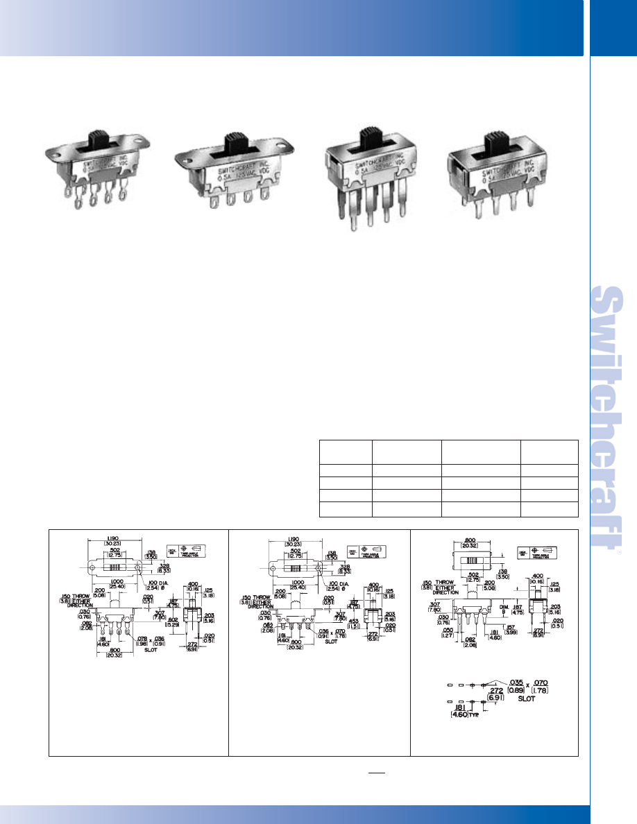
SWITCHCRAFT, INC. 5555 N. Elston Ave. • Chicago, IL 60630
289
SWITCHES
FAX: 773 792-2129
SWITCHES
DIMENSIONS ARE FOR REFERENCE ONLY
Inch
(mm)
MINIATURE SLIDE SWITCHES – SERIES 56300 AND C56300
MINIATURE SLIDE SWITCHES – SERIES 56300 AND C56300
SERIES 56300,C56300 - 3 POSITION
Series 56300 “Tini-Slide” switches provide ultra-reliable
3-position switching. They afford maximum space savings in
military, industrial and consumer applications, such as
instrumentation, test and ground support equipment,
appliances, computers, and control devices.
SPECIFICATIONS
Contact Ratings: 0.5A, 125V AC or DC, non-inductive.
Minimum switch life is 6000 cycles. Resistance after
6000 cycles at rated load is 50 milliohms maximum.
Terminals: Solder Lugs - 56313L1 with wrap around notch;
56313L2 with solder lug. PC - .585" (14.68 mm) “B”
dimension and .364" (9.24 mm) “B” dimension.
Mounting: Mounting ears for mounting to chassis of panels
with screws or rivets (not supplied). Switches with PC
terminals have stand-off shoulders for solid PC mount.
Knob: Molded thermoplastic (UL 94HB).
Terminal Board: Molded thermoplastic (UL 94V-0).
Terminals: Copper alloy, silver-plated.
Contact Sliders: Copper alloy.
Temperature Range: -4°F to +158°F (-20°C to +70°C).
Dielectric Strength: 1 kV rms @ sea level.
Insulation Resistance: 1 k M
Ω
minimum.
SPECIAL ORDER FEATURES
1. .187" (4.75 mm) high knob is standard; Other heights
available on special order. See page 283.
2. Red and white knobs available.
3. Two mounting variations:
a. Tapped #4-40 holes on mounting ears for machine
screws.
b. Mounting ears with .1" (2.54 mm) diameter holes on
switches with PC terminals.
MINIATURE SLIDE SWITCHES (continued)
Part
Number
56313L1
56313L2
C56313L1
C56313L2
Dimension “B”
Inch (mm)
-
-
.585(14.85)
.364 (9.24)
Description
DPTT, Locking
DPTT, Locking
DPTT, Locking
DPTT, Locking
Schematic
2-VI
2-VI
2-VI
2-VI
PART NUMBERS
56313L1
56313L2
56313L1 & L2
RECOMMENDED PC BOARD
LAYOUT (Component Side)
56313L1
56313L2
C56313L1
C56313L2
* Please visit the product pages on our website for the most up-to-date product information
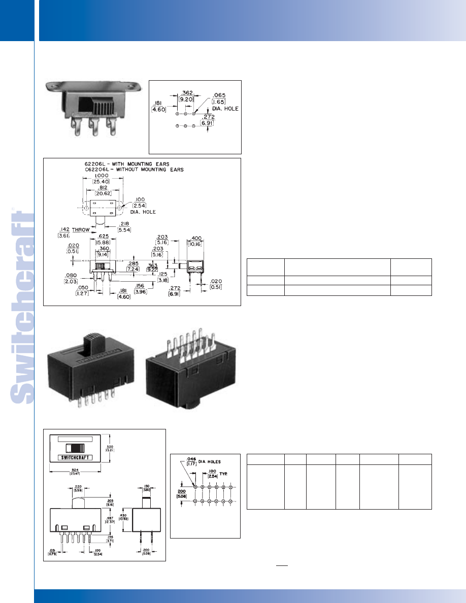
SWITCHES
290
w w w . s w i t c h c r a f t . c o m
® Registered trademark of Switchcraft, Inc.
Note: Contact your Switchcraft Representative for price and delivery
PHONE: 773 792-2700
SWITCHES
DIMENSIONS ARE FOR REFERENCE ONLY
Inch
(mm)
MINIATURE SLIDE SWITCHES
MINIATURE SLIDE SWITCHES
SERIES 62200 - 2 POSITION
2-position locking action with side knob actuator. Side
knob provides low profile, saving space on PC boards.
SPECIFICATIONS
Contact Ratings: 0.5A, 125V AC or DC.
PC Terminals: Copper alloy, silver plated.
Housing: Steel, plated.
Knob: Molded thermoplastic.
Terminal Board: Rigid plastic.
Sliders: Copper alloy, plated.
Dielectric Strength: 1000 V rms.
Insulation Resistance: 1 k M
Ω
minimum.
SPECIAL ORDER FEATURES
1. Various knob heights available on special order.
2. Various lengths available on special order.
SERIES C63200 - 2 POSITION, 4 POLE
C63200 switches designed for applications, such as:
instrumentation, test and ground support equipment, computers,
data communications and medical equipment. PC mounting on
standard industry .100" (2.54 mm) x .200" (5.08 mm) centers.
Mounts on PC boards up to .093" (2.36 mm) thick. Molded
black thermoplastic knobs. Terminals are copper alloy, gold-
plated on contact area, tinned on terminal end.
SIDE-SLIDE
®
/MINIATURE SLIDE SWITCHES
Part
Number
◊
62206L
C62206L
Description
DPDT, with mounting ears, Locking
DPDT, without mounting ears, Locking
Schematic
2-III
2-III
◊
Special order only; contact Switchcraft.
Part Number
C63212L
Action
Locking
Ratings
300mA
max.
30V AC
Switching
4PDT
Terminals
Copper alloy,
gold-plated
on contact
area, tinned
on terminal
end
Schematic
4-III
PART NUMBERS
62206L
RECOMMENDED PC BOARD
LAYOUT (Component Side)
RECOMMENDED
PC BOARD LAYOUT
(Component Side)
MINIATURE SLIDE SWITCHES
* Please visit the product pages on our website for the most up-to-date product information
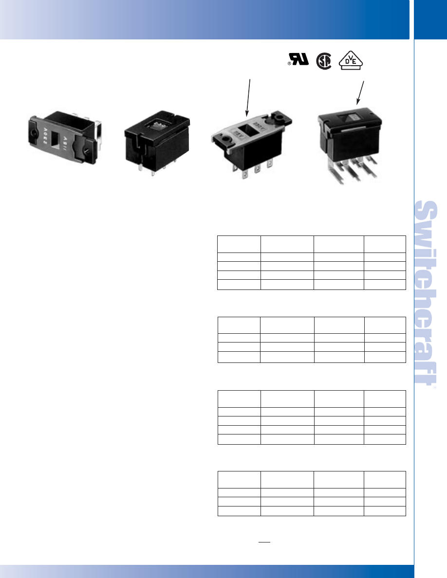
SWITCHCRAFT, INC. 5555 N. Elston Ave. • Chicago, IL 60630
291
SWITCHES
FAX: 773 792-2129
SWITCHES
DIMENSIONS ARE FOR REFERENCE ONLY
Inch
(mm)
EUROPEAN LINE VOLTAGE SELECTOR SWITCHES
EUROPEAN LINE VOLTAGE SELECTOR SWITCHES
SERIES EPS1, EPS2, EPS3, EPS4 - 2 POSITION
European Power Selector Switches are designed for quick,
easy programming/selection of 115V-230V primary power.
These switches provide OEM designers with an excellent
selection of PC and solder lug terminals and ratings up to
10A, 125V AC rating for electrical/electronic equipment and
systems headed for the INTERNATIONAL marketplace.
HOUSING AND ACTUATOR
Switches have positive, double detents for “sure” locking
into position. Screwdriver slot actuator virtually eliminates
the possibility of accidental operation and minimizes
tampering.
Molded-in legends are: 115-230V. Terminals
are staked into housing.
SPECIFICATIONS
Contact Ratings: EPS1, EPS2 - 2A, 250V AC and 4A,
125V AC. EPS3, EPS4 - UL and CSA - 10.1A, 125V; 5A,
250V. VDE - 10A, 250V.
Listings: UL and CSA recognized, UL card E40668;
CSAcard 28260. 2A, 250V AC is VDE listed, VDE #13707
(for European applications). Designed to conform to
requirements of CEE (International Commission on Rules
for the Approval of Electrical Equipment, Publication 24)
and the IEC (International Electrotechnical Commission).
Housing: Molded black glass-reinforced plastic.
Actuator and Cover: Molded thermoplastic.
Terminals: Copper alloy, silver-plated.
Slider Contacts: EPS1, EPS2 - Bi-Metal, silver on copper
alloy. EPS3, EPS4 - Copper alloy with silver cadmium
oxide inlay.
Temperature Range: -4°F to +158°F (-20°C to +70°C).
Dielectric Strength: 2kV rms @ sea level.
Insulation Resistance: 1 k M
Ω
minimum.
SPECIAL ORDER FEATURES
Series EPS actuators having legends other than
115V and 230V are available on special order.
NOTE: Contact Switchcraft for details.
EUROPEAN LINE VOLTAGE SELECTOR SWITCHES
Part
Number
◊
EPS1PC1
◊
EPS1PC2
EPS1PC3
EPS1SL1
Dimension “B”
Inch (mm)
.681 (17.297)
.719 (18.263)
-
-
Terminals
Straight PC
Straight PC
Right-Angle PC
Solder Lugs
Schematic
2-III
2-III
2-III
2-III
PART NUMBERS
Series EPS1
Part
Number
EPS2PC1
EPS2PC2
EPS2PC3
Dimension “B”
Inch (mm)
.730 (18.542)
.768 (19.507)
-
Description
Straight PC
Straight PC
Right-Angle PC
Schematic
2-III
2-III
2-III
Series EPS2
Part
Number
EPS3PC1
EPS3PC2
EPS3PC3
EPS3SL1
Dimension “B”
Inch (mm)
.681 (17.297)
.719 (18.263)
-
-
Terminals
Straight PC
Straight PC
Right-Angle PC
Solder Lugs
Schematic
2-III
2-III
2-III
2-III
Series EPS3
Part
Number
EPS4PC1
EPS4PC2
EPS4PC3
Dimension “B”
Inch (mm)
.730 (18.542)
.768 (19.507)
-
Description
Straight PC
Straight PC
Right-Angle PC
Schematic
2-III
2-III
2-III
Series EPS4
EPS1PC3 EPS2PC2 EPS3SL1 EPS4PC3
RED ACTUATOR
RED ACTUATOR
◊
Special order only; contact Switchcraft.
* Please visit the product pages on our website for the most up-to-date product information
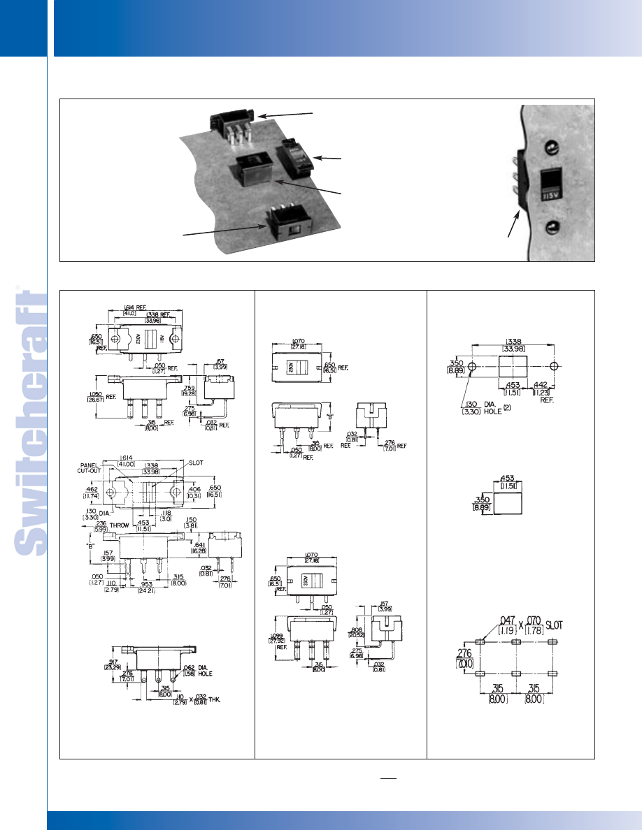
SWITCHES
292
w w w . s w i t c h c r a f t . c o m
® Registered trademark of Switchcraft, Inc.
Note: Contact your Switchcraft Representative for price and delivery
PHONE: 773 792-2700
SWITCHES
DIMENSIONS ARE FOR REFERENCE ONLY
Inch
(mm)
EUROPEAN LINE VOLTAGE SELECTOR SWITCHES
EUROPEAN LINE VOLTAGE SELECTOR SWITCHES
EUROPEAN LINE VOLTAGE SELECTOR SWITCHES (continued)
EUROPEAN
LINE VOLTAGE
SELECTOR
SWITCH
PC MOUNT
EPS2PC3 - Long, right-angle
PC terminals for combined PC
terminating and mounting.
EPS1PC3 - Long, right-angle PC
terminals and flanges for com-
bined mounting to PC board
and panel/chassis.
EPS2PC2 - Long, PC terminals for
direct mounting to PC board only.
EPS1PC1 - Short, PC terminals and
flanges for combined mounting to
PC board and panel/chassis.
EPS1SL1 - Solder lug
terminals and mounting flanges
for panel/chassis mount.
PANEL/CHASSIS
MOUNT
EPS1PC3
EPS1PC1 & PC2
EPS1SL1
EPS2PC1 & PC2
EPS2PC3
PANEL OPENING DATA
SERIES EPS1
SERIES EPS2
RECOMMENDED PC
BOARD LAYOUT
(Component Side)
* Please visit the product pages on our website for the most up-to-date product information
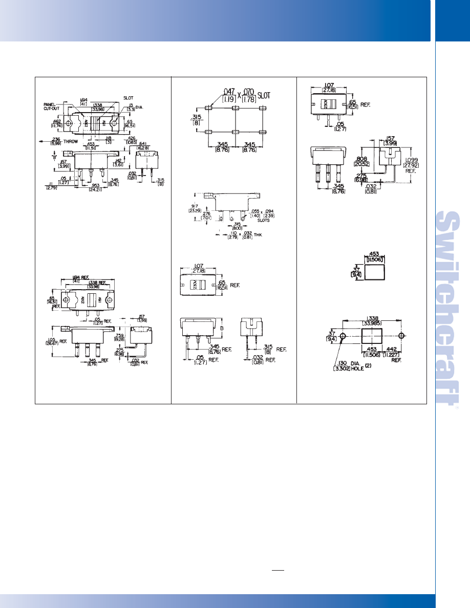
SWITCHCRAFT, INC. 5555 N. Elston Ave. • Chicago, IL 60630
293
SWITCHES
FAX: 773 792-2129
SWITCHES
DIMENSIONS ARE FOR REFERENCE ONLY
Inch
(mm)
EUROPEAN LINE VOLTAGE SELECTOR SWITCHES
EUROPEAN LINE VOLTAGE SELECTOR SWITCHES
EUROPEAN LINE VOLTAGE SELECTOR SWITCHES (continued)
EPS3PC1 & EPS3PC2
EPS4PC1 & EPS4PC2
RECOMMENDED PC
BOARD LAYOUT
(Component Side)
PANEL OPENING DATA
SERIES EPS4
EPS4PC3
SERIES EPS3
EPS3SL1
EPS3PC3
* Please visit the product pages on our website for the most up-to-date product information
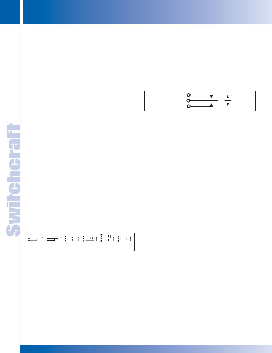
SWITCHES
294
w w w . s w i t c h c r a f t . c o m
® Registered trademark of Switchcraft, Inc.
Note: Contact your Switchcraft Representative for price and delivery
PHONE: 773 792-2700
SWITCHES
DIMENSIONS ARE FOR REFERENCE ONLY
Inch
(mm)
LEVER SWITCHES – DESIGN FEATURES
LEVER SWITCHES – DESIGN FEATURES
DESIGN FEATURES
High quality, field-proven Switchcraft
®
lever switches are available
in a wide selection of illuminated and non-illuminated versions,
2- and 3-position, locking and non-locking functions can be
provided. Switchcraft illuminated lever switches feature choice of
colors, wide selection of switching circuits, single lamp
illumination and ease of mounting and lamp replacement.
All switches utilize nickel silver springs without “form” at point
of flexing to insure long spring life. The springs are assembled
into a conventional stack assembly, insulated from each other
by phenolic spacers with plastic tubing press-fit through each
stack, insuring correct alignment of contacts and providing
high insulation resistance.
APPLICATIONS
Various front panel switching applications on computers,
telecommunications systems, industrial control equipment,
intercoms, ground support systems, medical electronics,
scientific instruments, broadcast consoles and test
instrumentation.
CONTACTS
Below are listed the basic contacts available on switches in
this catalog:
1. Fine silver contacts rated at 2A, 200W (maximum)
AC non-inductive load.
2. Welded cross bar silver contacts rated at 3A,
300W (maximum) AC non-inductive load.
3. Welded cross bar palladium contacts rated at 2A,
200W (maximum) AC non-inductive load.
4. Welded cross bar gold alloy contacts rated at up to 1A,
100W (maximum) AC non-inductive load.
(Dry circuit applications.)
BASIC CONTACT FORMS
Below are the basic contact forms available standard on all
Switchcraft Lever Switches. Specify circuits needed by
referring to the letter identification and respective location on
frame. See dimensional drawings for stack switch location.
To avoid ordering special switches it is possible to use a larger
standard circuit, providing the circuit fulfills your requirements.
Circuit Form K is widely used in talk-listen (intercom) function
applications. In normal position (neutral), switch does not
contact upper or lower contact spring. During typical
operation, lever is held in upper (momentary) position while
speaking. Releasing lever allows switch to return to neutral.
For listening, lever is moved to down (locking) position. Lever
is manually returned to neutral when finished.
ORDERING STANDARD SWITCHES
Order lever switches by part number from pages 295
through 298.
LAMP DATA
Lever-Lite
®
switches use T-1 3/4 flange base lamps which
are available from commercial sources.
ORDERING SPECIAL SWITCHES
Lever Switches
Should you desire a special version of any Switchcraft
®
lever
switch not shown here, we require the following information:
1. Switch series.
2. Number of positions.
3. Mechanical action (locking, non-locking, etc.).
4. Contact configuration for each position.
5. Type of contact material.
6. Color sequence (Lever-Lite III).
UL RECOGNIZED LEVER SWITCHES
Seven series of Switchcraft lever switches are UL recognized.
These switches are available on special order to fulfill your
switching requirements which specifically require UL listed
switching devices.
1. Series 12000
2. Series 41000
NOTE:
Refer to switch series in this catalog for full mechanical
specifications and additional standard and special features.
LEVER SWITCHES
SCHEMATIC
DIAGRAM
FORM K
A
B
C
D
E
F
* Please visit the product pages on our website for the most up-to-date product information
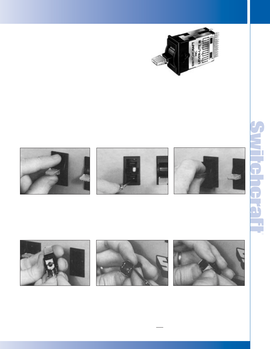
SWITCHCRAFT, INC. 5555 N. Elston Ave. • Chicago, IL 60630
295
SWITCHES
FAX: 773 792-2129
SWITCHES
DIMENSIONS ARE FOR REFERENCE ONLY
Inch
(mm)
LEVER-LITE
®
ILLUMINATED LEVER SWITCHES – SERIES 84000
LEVER-LITE
®
III
SERIES 84000 - ILLUMINATED LEVER SWITCHES
Lever-Lite
®
III illuminated lever switches are designed for
front-of-panel mounting, relamping, terminating, color
changes and removal. A minimum of time is required to install
singly, in rows, or in matrix arrays to meet a wide variety of
switching applications. 2- and 3-position types are available in
non-locking functions. Mounts on .875" (22.22 mm) horizontal
centers or 1.5" (38.1 mm) vertical centers. Talk-listen
(intercom) function is also available. Illumination technique
provides a different color for each lever position.
LAMPS
Standard T 1-3/4" midget flange-base lamps (not supplied)
are available in voltages up to 28V.
SPECIAL ORDER FEATURES
1. Talk-Listen (Intercom) function.
2. Welded cross bar gold alloy for dry circuit and silver
contacts are available. See page 294.
ILLUMINATION
A single internal lamp provides brilliant lever lighting in any
color required. Standard factory installed color filters are
provided as follows: Series 84000, Multi-Color Illumination
2-position - Amber (neutral position); green (down position).
3-position - Red (up position); amber (neutral position); green
(down position). One-color (all positions) and non-illuminated
switches can be specified on special order. Switchcraft will
install filters for non-standard illumination requirements at
nominal cost on special order.
LEVER SWITCHES (continued)
MOUNTING
RELAMPING/REPLACING
COLOR FILTERS
Grasp fingernail slots on opposite sides
of escutcheon and snap out. Next, grasp
lever and pull lever assembly free. Insert
switch into panel hole.
Lever-Lite III switches are designed for simplified lamp installation and replacement,
and color filter changes or custom installation in the field or on the OEM production
line. Lamps and filters may be changed at any time with ease and without
dismounting switch from panel or disturbing wiring.
Remove escutcheon and lever
assembly. (see “MOUNTING” above)
For relamping, pull lamp out of
retainer with finger-tip. Replace lamp.
For color filters, use fingernails or
small screwdriver to remove. Gently
lift (don’t pry) up under edge of
filter until it “pops” out.
Place new filter in position and press
until it “snaps” in. Replace lever
assembly and escutcheon.
(see “MOUNTING” above)
Turn two internal screws clockwise with
screwdriver to securely mount switch
to panel.
Replace lever assembly and “snap”
escutcheon into place. Installation
complete!
LEVER-LITE
®
ILLUMINATED LEVER SWITCHES – SERIES 84000
* Please visit the product pages on our website for the most up-to-date product information
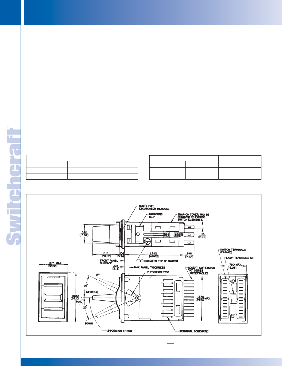
SWITCHES
296
w w w . s w i t c h c r a f t . c o m
® Registered trademark of Switchcraft, Inc.
Note: Contact your Switchcraft Representative for price and delivery
PHONE: 773 792-2700
SWITCHES
DIMENSIONS ARE FOR REFERENCE ONLY
Inch
(mm)
LEVER-LITE
®
ILLUMINATED LEVER SWITCHES – SERIES 84000
LEVER-LITE
®
ILLUMINATED LEVER SWITCHES – SERIES 84000
LEVER-LITE
®
III SERIES 84000 - ILLUMINATED
LEVER SWITCHES
SPECIFYING LEVER-LITE
®
III SWITCHES
1. Basic Switch - Refer to Part Number table for ordering
switches. For special switches, such as talk-listen
(intercom) function, special circuit forms, or
non-illuminated switches, contact factory for price
and delivery.
2. Illumination - Supplied with standard color filters installed.
Switchcraft will install other combinations at nominal
extra cost.
3. Lamps - Lamps are not supplied with switches.
SPECIFICATIONS
Mounting/Retaining Clips and Covers: Steel, plated.
Contact Ratings: Welded cross bar palladium contacts
rated at 1A, 200W maximum AC non-inductive load are
standard. Other contacts available. See “SPECIAL
ORDER FEATURES” on page 295.
Springs: Copper alloy, plated.
Lamp Terminals: Copper alloy, plated.
Lamp Socket: Zinc, plated.
Terminals: Copper alloy, plated, straight solder lugs.
Housing, Escutcheon, Knob, Actuator and
Switching Stacks Insulation: Molded plastic.
Temperature Range: -22°F to 158°F (-30°C to +70°C).
Dielectric Strength: 1 kV DC.
Leakage Resistance: 1,000 M
Ω
or greater.
K-131 COLOR FILTER KIT
Kit is available for changing or replacing color filters to meet
illumination requirements. Each kit contains 3 filters of each
color: Amber, Blue, Green, Red, White and Yellow.
SWITCHCRAFT PART NUMBER K-131
REPLACEMENT LEVERS
Number G6083 (for locking lever)
Number G6084 (for non-locking lever)
LEVER SWITCHES (continued)
Non-Locking
◊
84206
◊
84212
Locking
84206L
◊
84212L
Switching
2-C
4-C
PART NUMBERS
TWO POSITION
Part Numbers
◊
84306
◊
84312
◊
84324
84306L
84312L
84324L
Position 1
1-C
2-C
4-C
Position 2
1-C
2-C
4-C
THREE POSITION
LEVER-LITE® SERIES 84000
PANEL OPENING
.750" (19.05mm)
x 1.375" (34.92mm)
◊
Special order only; contact Switchcraft.
Part Numbers
* Please visit the product pages on our website for the most up-to-date product information
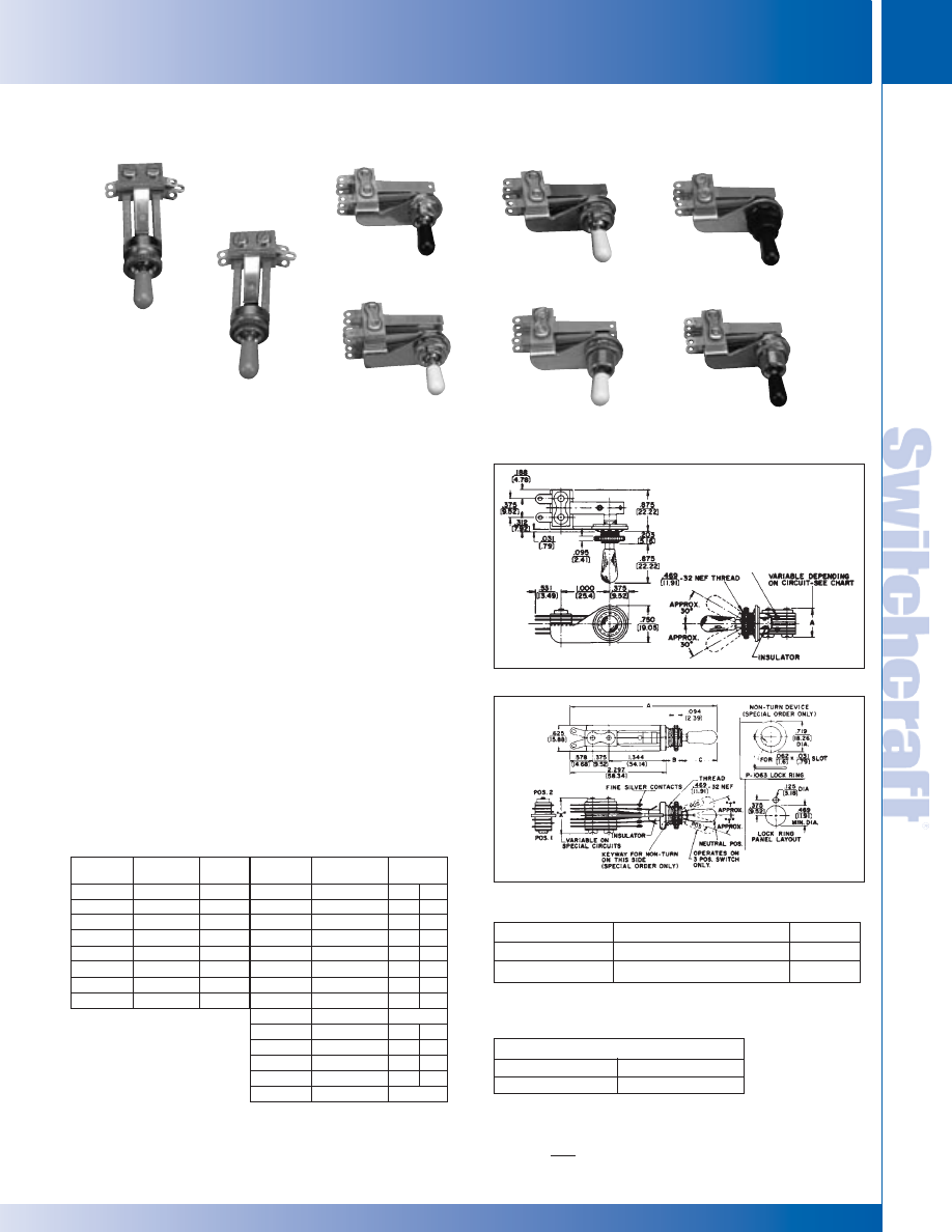
SWITCHCRAFT, INC. 5555 N. Elston Ave. • Chicago, IL 60630
297
SWITCHES
FAX: 773 792-2129
SWITCHES
DIMENSIONS ARE FOR REFERENCE ONLY
Inch
(mm)
LEV-R SWITCHES – SERIES 12000
LEV-R SWITCHES – SERIES 12000
INTERCOM SWITCHES
Part Number
◊
12033T
◊
12037T
Stack Height "X" &"Y"
.719 (18.26)
.875 (22.22)
Switching
1-K
2-K
* Add prefix “R” to part number if non-turn mounting is required. (Special order).
+ Add suffix “L” to part number if locking type is required.
◊
Special order only; contact Switchcraft.
PANEL OPENING
.469" (11.91mm) DIAMETER
MAXIMUM PANEL THICKNESS
.094" (2.39mm)
LEVER SWITCHES (CONTINUED)
12014
12011
12010
12015
12013
12016
12012
12017
Part Number
◊
12001
◊
12002
◊
12003
◊
12003D
◊
12004
◊
12005
◊
12006
◊
12006D
Stack Hgt. “X”
& “Y” (max.)
.719 (18.26)
.688 (17.48)
.750 (19.05)
.813 (20.65)
.906 (23.01)
.875 (22.22)
1.000 (25.40)
1.063 (27.00)
Switching
1-A
1-B
1-C
1-D
2-A
2-B
2-C
2-D
Part Number
◊
12010
◊
12011
◊
12012
◊
12013
◊
12014
◊
12015
◊
12016
◊
12017
◊
12033
◊
12034
◊
12035
◊
12036
◊
12036D
◊
12037
Stack Hgt. “X” &
“Y” (max.)
.703 (17.86)
.703 (17.86)
.766 (19.46)
.703 (17.86)
.703 (17.86)
1.078 (27.49)
.703 (17.86)
.703 (17.86)
.719 (18.26)
.813 (20.65)
.750 (19.05)
.875 (22.22)
1.000 (25.40)
.875 (22.22)
Switching
Pos.1 Pos. 2
1-B 1-B
1-B 1-B
1-B 1-B
1-B 1-C
1-B 1-B
2-B 2-B
1-B 1-B
1-B 1-B
1-K
1-A 1-A
1-B 1-B
1-C 1-C
1-D 1-D
2-K
THREE POSITION NON-LOCKING*
PART NUMBERS
TWO POSITION NON-LOCKING*+
®
®
LEV-R
®
®
SWITCH SERIES 12000
Electrica
l
Contact Ratings: Fine silver contacts rated at 3A, 300W
maximum AC non-inductive load standard. Other
contacts available
Leakage Resistance: 1,000 M
Ω
or greater
Dielectric Strength: 250 VDC
Material
Frame: Copper alloy, plated (3,000, 13,000); Steel,
plated (12,000)
Bushing and Shaft: Copper alloy, plated
Springs: Copper alloy
Knob: Black molded thermoplastic
Mounting Hardware: Knurled copper alloy locknut
T10711, supplied. P10531 hex locknut, special order
Insulation: Rigid plastic spacers with plastic tubing
through stack. Rigid plastic and/or thermoplastic lifters.
Thermoplastic cam on actuator end
Knobs
T12742
Black
T12745
White
T127410
Ivory
P2912
Amber
Knobs must be ordered separately.
12000 SERIES RA LEV-R SWITCHES
12000 SERIES STRAIGHT LEV-R SWITCHES
* Please visit the product pages on our website for the most up-to-date product information
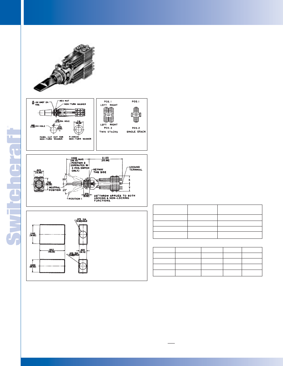
SWITCHES
298
w w w . s w i t c h c r a f t . c o m
® Registered trademark of Switchcraft, Inc.
Note: Contact your Switchcraft Representative for price and delivery
PHONE: 773 792-2700
SWITCHES
DIMENSIONS ARE FOR REFERENCE ONLY
Inch
(mm)
LT SWITCH – SERIES 4100
LT SWITCH – SERIES 4100
LT
®
SWITCH
SPECIFICATIONS
Frame: Steel, plated.
Bushing and Actuator: Copper alloy, plated.
Springs: Copper alloy.
Contact Ratings: Welded cross bar palladium contacts
rated at 2A, 200W maximum, AC non-inductive load are
standard. See “SPECIAL ORDER FEATURES”.
Terminals: Tin dipped solder lugs.
Mounting Hardware: Supplied with one copper alloy-plated
hex locknut (P10531); and one non-turn washer (P10639).
Insulation: Rigid plastic spacers with plastic tubing
through
the stack assembly. Lifters of thermoplastic.
Lifter-Roller Assembly: Molded plastic.
Knob: Supplied with a paddle style, screw-on black plastic
knob. See “SPECIAL ORDER FEATURES”.
Temperature Range: -22°F to 158°F (-30°C to +70°C).
Leakage Resistance: 1,000 M
Ω
or greater.
MOLDED DUST COVERS
Dust cover is an environment and electrical shield, protecting
and improving appearance and increasing switch dependability.
Covers enshroud complete switch, preventing build-up of
dust, dirt, contamination.
SPECIAL ORDER FEATURES
1. Talk-Listen (Intercom) function.
2. Fine silver and other alloys available for contacts.
See page 294.
3. UL recognized switches. See page 294.
Part Numbers
◊
41203
41206
◊
41208
41212
Switching
1-C
2-C
4-A
4-C
Stack Heights
Dimension “X” max.
.531 (13.49)
.531 (13.49)
.615 (15.62)
.750 (19.05)
LT
®
SWITCH PART NUMBERS
2 POSITION NON-LOCKING*
◊
41306
◊
41308
41312
41324
Position 1
1-C
2-A
2-C
4-C
Dim. “Y”
.531 (13.49)
.500 (12.7)
.531 (13.49)
.750 (19.05)
Position 2
1-C
2-A
2-C
4-C
Dim. “X”
.531 (13.49)
.500 (12.7)
.531 (13.49)
.750 (19.05)
3 POSITION NON-LOCKING*
SERIES 41000
LT
®
SWITCH
SERIES 41000
LT
®
SWITCH SERIES 41000
MOLDED DUST COVER
PANEL OPENING
.469" (11.91mm) DIAMETER
MAXIMUM PANEL THICKNESS
.25" (6.35mm)
P2360
(up to 2-C per side)
P2362
(up to 4-C per side)
*Add suffix “L” to part number for locking type.
To avoid ordering special switches, order a larger standard circuit,
providing the circuit meets your requirements.
◊
Special order only; contact Switchcraft.
LEVER SWITCHES (CONTINUED)
®
®
* Please visit the product pages on our website for the most up-to-date product information
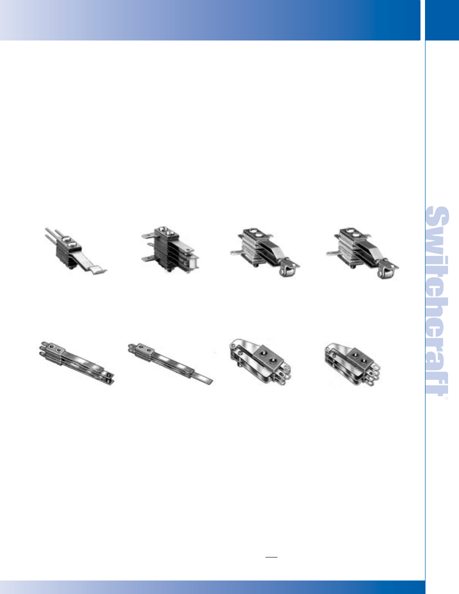
SWITCHCRAFT, INC. 5555 N. Elston Ave. • Chicago, IL 60630
299
SWITCHES
FAX: 773 792-2129
SWITCHES
DIMENSIONS ARE FOR REFERENCE ONLY
Inch
(mm)
GENERAL PURPOSE STACK SWITCHES
GENERAL PURPOSE STACK SWITCHES
TELEPHONE RELAY TYPE SWITCHES
Compact stack switches are particularly suitable for low activating
force, such as in relay and magnetic operated devices.
Contact Switchcraft for selection of contacts and ratings.
SPECIFICATIONS
Springs: Copper alloy, in thicknesses ranging from
.006" (0.15 mm) to .012" (0.30 mm).
Spacers: Rigid plastic is standard in thickness of .031"
(.79 mm), .047" (1.19 mm) and .063" (1.60 mm).
Contacts: Fine silver or welded cross bar palladium
are standard. Palladium or gold alloy are generally
recommended for “dry” circuit applications. Other contacts
available for varied customer requirements on special order.
Tubing: Thermoplastic.
Lifters: Thermoplastic.
Bracket: Steel, plated.
Mounting Hardware: Pressure plate, twin nut and screws:
Steel, plated.
Complete general purpose stack switch assemblies are
made from a pile-up of various actuator springs, contact
springs and lifters. These stack switch assemblies can be
used on manually operated control devices where switching
is operated by cams, push-buttons and other similar
mechanical devices. The stack switch assembly is made up
of an actuator spring and various contact springs. These
current carrying members are insulated from each other by
phenolic spacers with plastic tubing press fitted through the
stack; thereby insuring correct alignment of contacts and
providing high insulation resistance when mounted.
The types of General Purpose Stack Switch Components
available are:
• .375" (9.52 mm) mounting centers
• .250" (6.35 mm) mounting centers
• “Tini-Stack” Switches .188" (4.78 mm) mounting centers
• Telephone Relay Type Switches .250" (6.25 mm) mounting
centers
STACK SWITCH COMPONENTS
Switchcraft offers various stack switch components, such as
contact springs, spacers, lifters, etc., in many lengths, thicknesses,
mounting centers and other details.
Switchcraft can assemble components into innumerable different
stack switch assemblies. It is impossible to catalog every type of
stack that has been manufactured. Stack switch assemblies can be
designed to meet UL requirements, but only as part of equipment.
GENERAL PURPOSE STACK SWITCHES
(SPECIAL ORDER ONLY)
GENERAL PURPOSE STACK SWITCHES
.375" STACK SWITCHES
Thousands of switching combinations are possible. Switch
mounting centers are .375" (9.52 mm) (minimum) with
.25" (6.35 mm) wide switch parts. Practical spring length
is 2.625" (66.68 mm) (maximum). Contact Switchcraft for
selection of contacts and ratings.
.250" (6.35 MM) STACK SWITCHES
Thousands of switching combinations are possible with slightly
smaller parts. Mounting centers are .250" (6.35 mm) (minimum)
with .188" (4.78 mm) wide parts. Practical spring length
is 2.125" (53.98 mm) (maximum). Contact Switchcraft for
selection of contacts and ratings.
Many Tini-Stack
®
switching combinations are possible.
Switch mounting centers are .188" (4.78 mm) (minimum).
Practical spring length is 1.750" (44.45 mm) (maximum).
SPECIFICATIONS
Springs: Copper alloy, in most standard gauge thickness-
es ranging from .006" (0.15 mm) to .016" (0.41 mm).
Spacers: Rigid plastic, available in thickness of .015"
(0.38 mm), .032" (0.81 mm) and .046" (1.17 mm).
Contacts: Welded cross bar palladium rated at 2A, 200W
AC non-inductive load. Gold alloy generally recommended
for “dry” circuit applications.
Tubing: Thermoplastic.
Lifters: Thermoplastic.
Mounting Hardware: Pressure plate, twin nut and screws:
Steel, plated.
MINIATURE .188" (4.78MM) STACK SWITCHES
* Please visit the product pages on our website for the most up-to-date product information
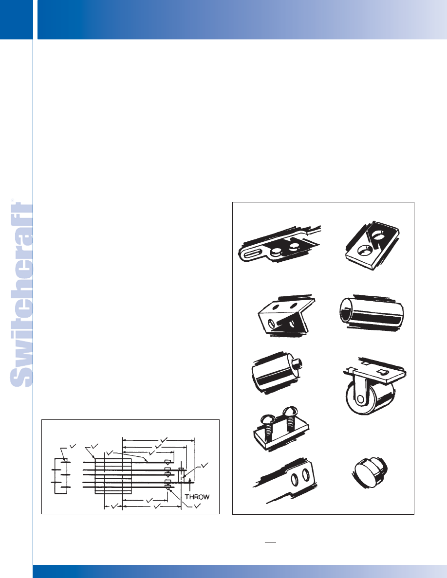
SWITCHES
300
w w w . s w i t c h c r a f t . c o m
® Registered trademark of Switchcraft, Inc.
Note: Contact your Switchcraft Representative for price and delivery
PHONE: 773 792-2700
SWITCHES
DIMENSIONS ARE FOR REFERENCE ONLY
Inch
(mm)
GENERAL PURPOSE STACK SWITCHES – COMPONENT SPECIFICATIONS
GENERAL PURPOSE STACK SWITCHES – COMPONENT SPECIFICATIONS
STACK SWITCH COMPONENT SPECIFICATIONS
1. SPRINGS - Copper alloy in most standard gauge thickness-
es of .006" (0.15 mm), .008" (0.20 mm), .010" (0.25 mm), .012"
(0.30 mm), .016" (0.40 mm) and .020" (0.50 mm), a few designs
can be made up to .031" (.079 mm) thick. All or any contact
point hole can be provided; spring can be cut at any point.
2. BRACKETS - Standard brackets are detailed on drawing.
Tools are flexible so that various lengths from same width
stock can be provided.
3. LIFTERS OR PUSHERS - .125" (3.18 mm) and .188" (4.78
mm) diameter thermoplastic in various lengths staked into
one of the contact point holds provides tandem action
between blades or to serve as an actuator.
4. MOUNTING HARDWARE - Pressure plates (S1293 and
S2300) twin nuts (S1008 and S1431) and screws available for
mounting.
5. LEAF INSULATORS - Punched in same shape as springs
in .015" (0.38 mm) thickness of fish paper or mylar.
6. SPACERS - Rigid plastic is standard in thicknesses of .015"
(0.38 mm), .032" (0.81 mm), .051" (1.30 mm) and .062" (1.57
mm). Thickness of .093" (2.36 mm) is available for .375" (9.52
mm) mounting centers only. For longer surface creepage
paths, use both large and standard sized spacers. High tem-
perature insulation also available.
7. THERMOPLASTIC TUBING - .375" (9.52 mm) mounting
centers pass #5 screw. .250" (6.35 mm) mounting centers pass
#3 screw. .188" (4.78 mm) mounting centers pass #2 screw.
8. CAM FOLLOWERS - Two roller bracket designs (G1734
and G2298) available for springs .250" (6.35 mm) wide.
Copper alloy standard. Can be furnished in various diameters
and materials. Thermoplastic rollers also available.
9. CONTACTS - Welded cross bar contacts are commonly
used for cost savings. However, riveted contacts are available.
Size and material depend on circuit requirements (supply
complete details). For low level audio circuits, we suggest gold
alloy or palladium cross bar contacts. Springs can be
bifurcated (two contacts per spring).
HOW TO ORDER STACK SWITCHES
Careful consideration of the following suggestions will help
specify the most economical and expeditious approach to your
switching needs. On initial inquiry or order, supply the following
information:
1. Simple sketch or drawing. See “Typical Stack Assembly”
drawing. Give details checked that are available.
2. Current, voltage and type of switching load (resistive or
inductive).
3. Frequency of operation; life requirements.
4. Details of actuator.
5. Maximum and minimum movement of actuator blade.
6. Any other important specifying details.
It is recommended that data indicated above be forwarded to
Switchcraft for comments and recommendations before finalizing
your design.
GENERAL PURPOSE STACK SWITCHES (continued)
TYPICAL STACK ASSEMBLY
1.
2.
3.
4.
5.
6.
7.
8.
9.
* Please visit the product pages on our website for the most up-to-date product information
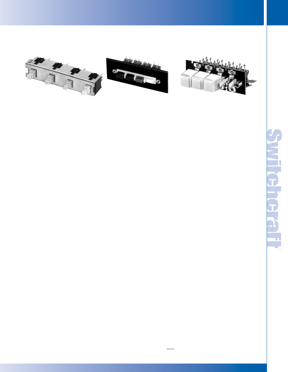
SWITCHCRAFT, INC. 5555 N. Elston Ave. • Chicago, IL 60630
301
SWITCHES
FAX: 773 792-2129
SWITCHES
DIMENSIONS ARE FOR REFERENCE ONLY
Inch
(mm)
MULTIPLE STATION SWITCHES
MULTIPLE STATION SWITCHES
FEATURES
Switches are designed to meet performance requirements of
sophisticated equipment such as: analog and digital computers,
analyzers, transmitters and receivers, intercoms, machine and
process controls, ground support systems, scientific instruments
and test measurement and instrumentation.
STANDARD MECHANICAL FUNCTIONS
INTERLOCK - actuating a button automatically restores to
normal the button previously actuated. Lock-out feature,
which prevents the mechanical operation of more than one
button at a time, is standard on all interlock switches.
NON-LOCK - each button has momentary action. No interaction
between buttons. Lock-out available on special order only.
ALL-LOCK - all buttons, except release, lock when
depressed (accumulative lock). All buttons restored to normal
by activating release button which has momentary action.
PUSH-LOCK/PUSH-RELEASE - pushbutton locks when
depressed and is released when again depressed.
LOCK-UP - built-in, electrically operated solenoid locks all
stations (in respective positions). Limited to operation of up to
12 stations only and energized from a remote position. Not
available in push-lock/push-release.
SPECIAL ORDER MECHANICAL FUNCTIONS
Mechanical functions on selected series can be intermixed on
the same frame on special order only. Contact factory for
details and availability.
Multi-Switch switches have been designed to readily
accommodate “special” functions at nominal cost. Special
functions are described at right.
Intermixed functions - the following combinations of standard
functions intermixed on the same frame are available:
• Interlock and Non-Lock
• Interlock and Push-Lock/Push-Release
• All-Lock and Non-Lock
• All-Lock and Push-Lock/Push-Release
• Push-Lock/Push-Release and Non-Lock
Lock-out function - Refer to above description under
“Interlock.”
Push-release cancelling function - Speeds programming
and reprogramming of equipment.
Momentary common release function - Permits one or more
momentary common release stations on switch to facilitate
special operating and release sequences.
“Split-interlock” function - Two separate groups of inter-lock
stations on the same frame offers exceptional design latitude and
reduces production line time.
GANGED ASSEMBLIES (Special Order)
Multiple row switching (ganged assemblies) with interaction
between rows are available on special order. Space-saving
ganged assemblies reduce production line assembly, wiring and
testing time. All features of single row switching, including all
standard and special features, are available. Contact Switchcraft
for specifying assistance.
PUSHBUTTONS
Illuminated and non-illuminated switches can be specified with
standard or special pushbuttons. See coverage on individual
series for information.
LEGENDS
Legends can be supplied on illuminated and non-illuminated
pushbuttons. Contact Switchcraft.
MULTIPLE STATION SWITCHES
SERIES IBS
SERIES 65000
DW MULTI-SWITCH
SERIES 66000, 67000
DW MULTI-SWITCH
* Please visit the product pages on our website for the most up-to-date product information
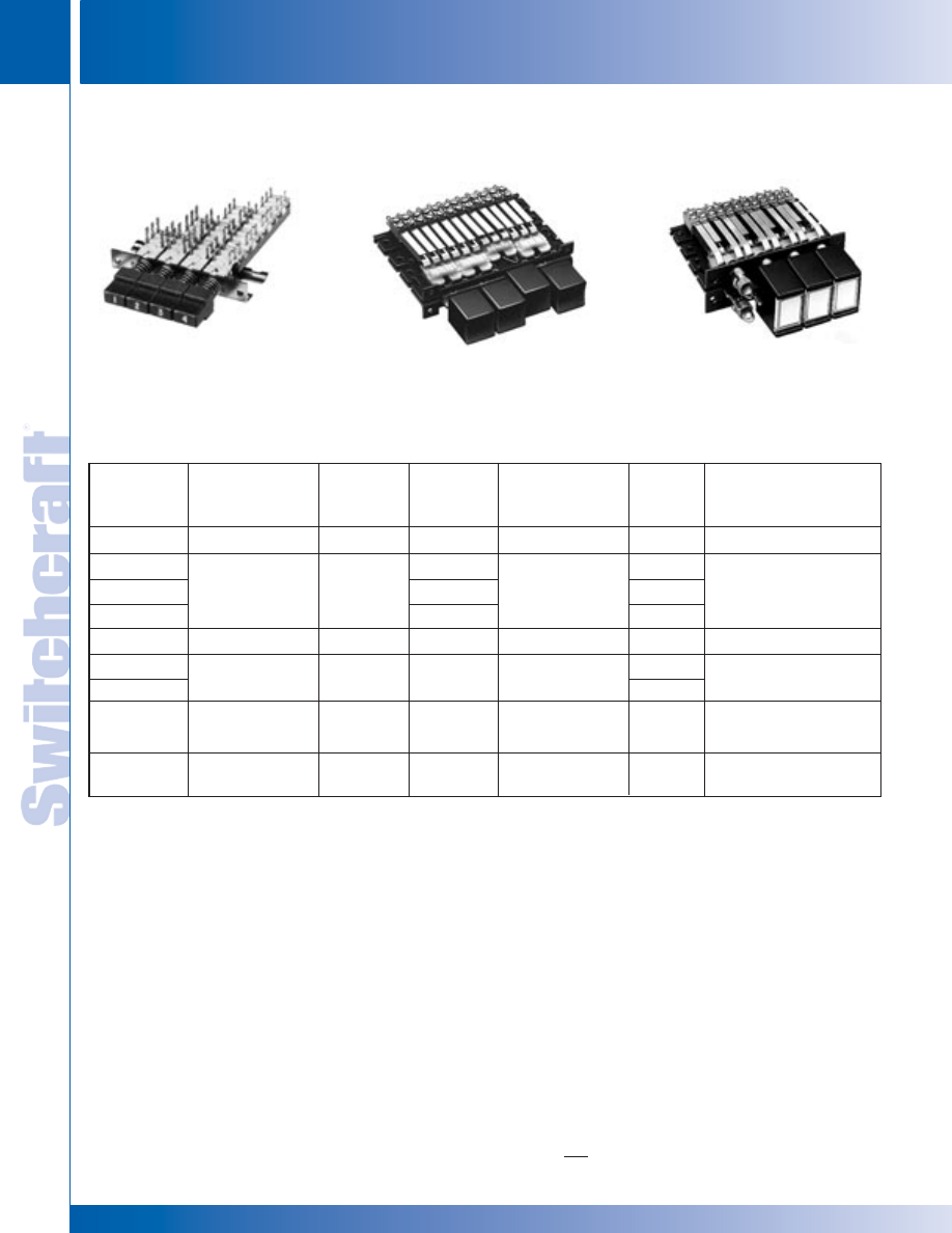
SWITCHES
302
w w w . s w i t c h c r a f t . c o m
® Registered trademark of Switchcraft, Inc.
Note: Contact your Switchcraft Representative for price and delivery
PHONE: 773 792-2700
SWITCHES
DIMENSIONS ARE FOR REFERENCE ONLY
Inch
(mm)
MULTIPLE-STATION SWITCHES
MULTIPLE-STATION SWITCHES
MULTIPLE-STATION SWITCHES (continued)
CHOOSING THE RIGHT MULTIPLE-STATION SWITCH
Switch
Series
35000
36000
37000
38000
65000
66000
67000
90000
92000
IBS
Mechanical
Functions
1
ILO, N, A, PL/PR
ILO, N, A, PL/PR
ILO, N, A, PL/PR
ILO, N, A, PL/PR
ILO, N, A
I, N
Stations
(Maximum)
18
18
18
18
12
Switching
Per Station
(Maximum)
6PDT
6PDT
4PDT
3PDT
4PDT
4PDT
8PDT
2PDT
Contact
Rating
2
2A AC, 200W
2A AC, 200W
3A AC, 0.5A DC
3A AC, 0.5A DC
0.5A 28V AC or DC
.125A, 125 VAC
or 28 VDC
Accessories
3
C, G, M, P, S, PC/WW
C, G, M, P, S,
PC/WW, LWO
C, G, M, S, PC/WW
C, G, M, S, PC/WW
M
P, M
Lighting
No
No
Yes
Yes
No
No
Yes
No
No
1. I = interlock, ILO = interlock with lockout, N = non-lock (momentary), A = all-lock (special order), PL/PR = push-lock/push-release.
2. Non-inductive load.
3. C = optional switch contact, G = ganged assemblies, M = special/mixed functions, P = optional pushbuttons, S = solenoid release, PC/WW = PC and
wire-wrapping terminals, LWO = lighting wiring options.
ORDERING
Order switches by part number in this section.
For any optional or special order feature, contact Switchcraft.
SERIES 35000
LITTEL
®
MULTI-SWITCH
SERIES 37000, 38000
LITTEL
®
MULTI-SWITCH
SERIES 90000, 920000
TINI DW MULTI-SWITCH
12 - ILO, A
18 - N, PL/PR
* Please visit the product pages on our website for the most up-to-date product information
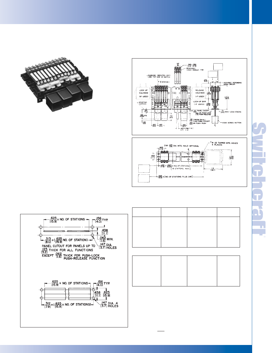
SWITCHCRAFT, INC. 5555 N. Elston Ave. • Chicago, IL 60630
303
SWITCHES
FAX: 773 792-2129
SWITCHES
DIMENSIONS ARE FOR REFERENCE ONLY
Inch
(mm)
LITTEL MULTI-SWITCH – SERIES 35000
LITTEL MULTI-SWITCH – SERIES 35000
Specify 1 to 18 stations (non-illuminated) with a large
selection of mechanical functions, choice of pushbuttons,
and up to 6 poles of switching per station. Plungers are on
.625" (15.88 mm) centers and are made from .050" (1.27
mm) x .187" (4.75 mm) steel. A square black pushbutton,
A592, is supplied with each station. A wide variety of
special mechanical functions, features and accessories
are also available.
ORDERING INFORMATION
STANDARD SWITCHES
Order by part number from tables.
SPECIAL SWITCHES
Many special mechanical functions, features and
accessories are available. Contact Switchcraft.
• Ganged Assemblies • Pushbuttons
• Special Mechanical Functions • Legends
• Switch Stacks • Accessories
• PC and Wire-Wrapping Terminals
LITTEL
®
MULTI-SWITCH
SERIES 35000
TYPICAL PANELS DIMENSIONS
SERIES 35000
MULTIPLE-STATION SWITCHES (continued)
PART NUMBERS/2-C PER STATION
1
Interlock
with Lock-Out
35021K206
35041K206
35061K206
35081K206
35101K206
35121K206
Non-Lock
◊
35022206
◊
35042206
◊
35062206
◊
35082206
◊
35102206
◊
35122206
Push-Lock/
Push-Release
◊
35027206
◊
35047206
◊
35067206
◊
35087206
◊
35107206
◊
35127206
Number of
Stations
2
2
4
6
8
10
12
PART NUMBERS/4-C PER STATION
1
◊
35021K212
◊
35041K212
◊
35061K212
◊
35081K212
◊
35101K212
◊
35121K212
◊
35022212
◊
35042212
◊
35062212
◊
35082212
◊
35102212
◊
35122212
◊
35027212
◊
35047212
◊
35067212
◊
35087212
◊
35107212
◊
35127212
2
4
6
8
10
12
1. Switches with all-lock function are available on special order. Contact
Switchcraft.
2. Odd number of stations (3, 5, 7, 9, 11) are available. Switches with
13 through 18 stations are also available. Contact Switchcraft.
◊
Special order only; Contact Switchcraft for price and delivery information.
SERIES 35000
FIGURE A - PANEL CUTOUT FOR
PLUNGER CLEARANCE ONLY
FIGURE B - PANEL CUTOUT FOR
SERIES A590 PUSHBUTTON CLEARANCE ONLY
®
®
* Please visit the product pages on our website for the most up-to-date product information
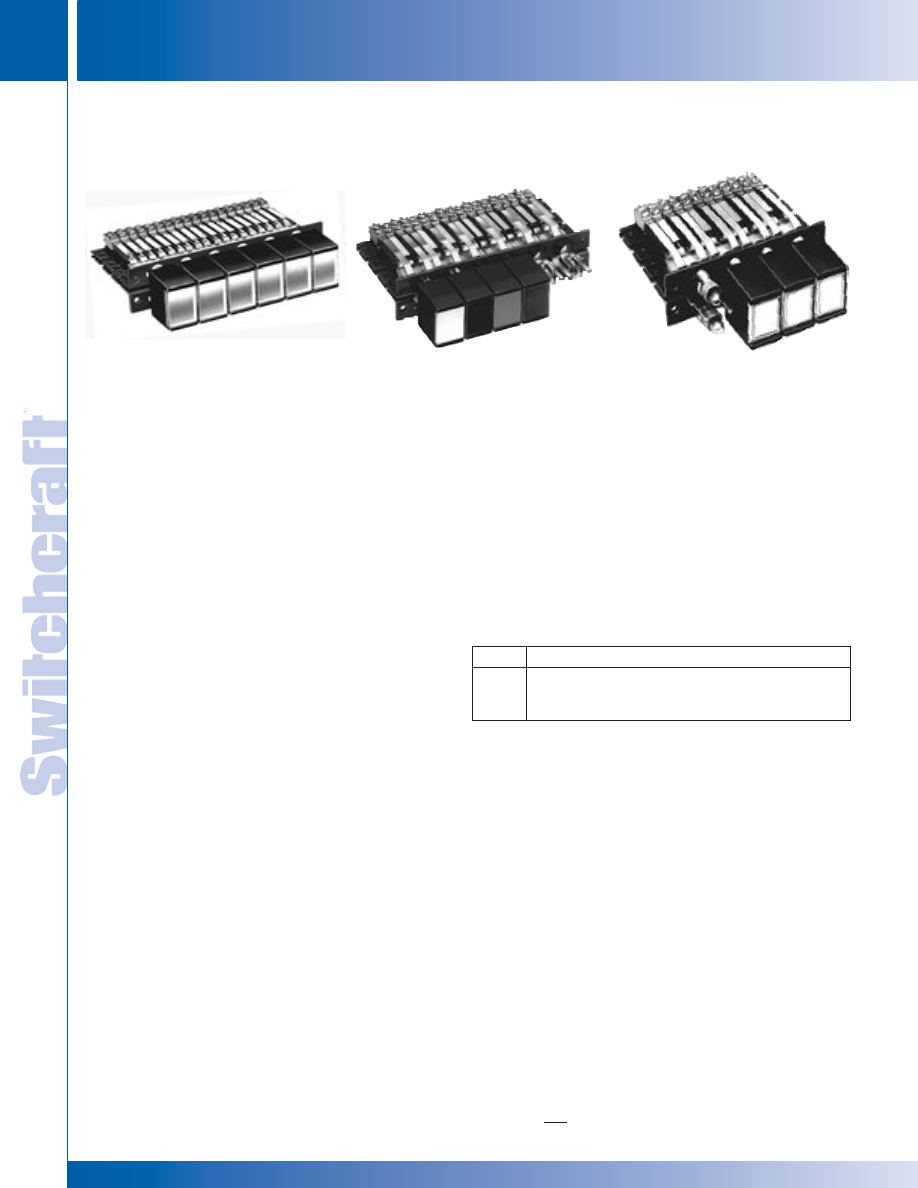
SWITCHES
304
w w w . s w i t c h c r a f t . c o m
® Registered trademark of Switchcraft, Inc.
Note: Contact your Switchcraft Representative for price and delivery
PHONE: 773 792-2700
SWITCHES
DIMENSIONS ARE FOR REFERENCE ONLY
Inch
(mm)
LITTEL MULTI-SWITCH – SERIES 36000, 37000 & 38000 FEATURES
LITTEL MULTI-SWITCH – SERIES 36000, 37000 & 38000 FEATURES
SERIES 36000
Identical to Series 37000, except non-illuminated. Pushbuttons
match Series 37000 and 38000 Switching up to 6PDT.
SERIES 37000
Same as Series 35000, but features large, rectangular face
pushbuttons, illuminated by one lamp and having large legend
area. Switching is up to 4PDT. Switch stations are on .625"
(15.88 mm) centers, and depth behind panel is 2.313" (58.75
mm). Black pushbutton housings have white translucent
inserts, white legend insert, two support inserts, and transpar-
ent display screen. Other pushbuttons and combinations are
possible; see pages 316 and 317.
On 2-C per station switches, each station includes two,
83P switch stacks and one H83P lighting stack, and one
convenience lighting spring. Contact ratings: 2A, 200W
maximum AC non-inductive load.
On 4-C per station switches, each station has 4, 83P switch
stacks, one H83P lighting stack, and one convenience lighting
spring. “L” and “M” lighting arrangements can be effected by
wiring directly to the H83P and H lighting stacks.
Each switch station uses an industry standard T 1-3/4 lamp
(not supplied). Special features such as ganged assemblies,
solenoid release, and T-1 lamp adapter are available; contact
Switchcraft. See pages 316 and 317 for special effects display
screen and inserts.
SERIES 38000
Similar to Series 37000, except features twin lamp illumination
at each station for redundant or 2-color, split-face (alternate)
lighting.
On 2-C per station switches, each station includes 3, H83P
lighting switch stacks and 1 lighting spring. This provides up to
3PDT circuitry (1 pole is needed for lighting lamps; lamps not
supplied). Contact ratings: 2A, 200W maximum AC non-induc-
tive load.
On 4-C per station switches, each station has three, H83P,
two, 83P switching stacks and one lighting spring. This offers
LITTEL
®
MULTI-SWITCHES
SERIES 36000, 37000, 38000
MULTIPLE-STATION SWITCHES (continued)
SERIES 36000 - NON-ILLUMINATED
SERIES 37000 - SINGLE LAMP
SERIES 38000 - TWIN LAMPS
5PDT circuitry (1 pole is required for lighting lamps). two, T 1-3/4
lamps per station are used (lamps are not supplied). Ganged
assemblies and solenoid releases are available;
contact Switchcraft. See pages 316 and 317 for special effects
display screens and inserts.
LIGHTING
Series 37000 and 38000 can be used in control systems where
the light is either “ON”, or “OFF” or permanently “ON”.
One or any combination of the three lighting arrangements
listed below can be specified on a switch. NOTE: Standard
switches ordered from tables can be wired for “L”, “M” or “N” type
lighting.
ORDERING
STANDARD SWITCHES
Order by part number from tables.
SPECIAL SWITCHES
Many special mechanical functions, features and accessories
are available. Contact Switchcraft for special order items.
• Ganged Assemblies • Special Mechanical Functions
• Special Color Displays • Pushbuttons
• Legends • Switch Stacks
• Wiring Lighting Options • PC and Wire-wrapping Terminals
• Accessories
®
®
TYPE
DESCRIPTION
“L”
Pushbuttons light in the “IN” position.
“M”
Pushbuttons light in the “OUT” position.
“N”
Pushbuttons light in the “IN” and “OUT” positions.
* Please visit the product pages on our website for the most up-to-date product information
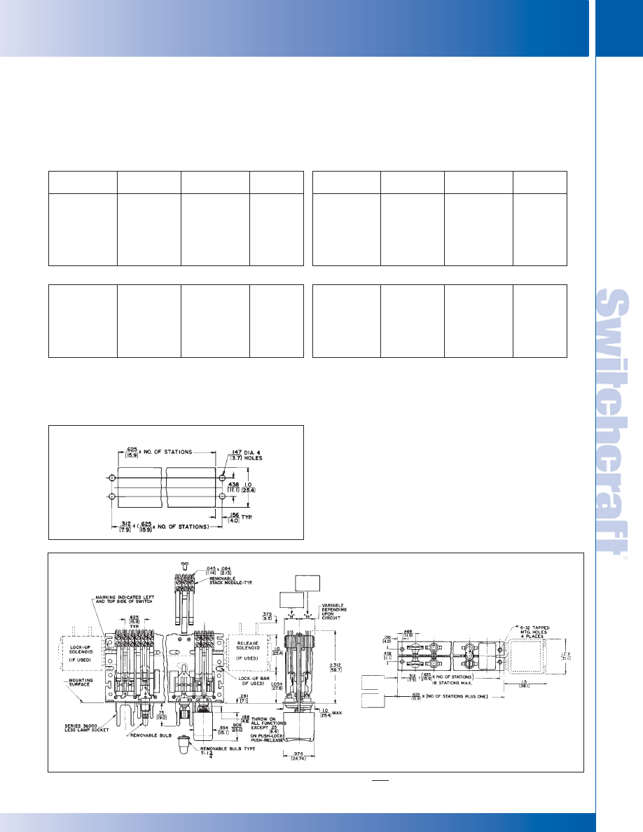
SWITCHCRAFT, INC. 5555 N. Elston Ave. • Chicago, IL 60630
305
SWITCHES
FAX: 773 792-2129
SWITCHES
DIMENSIONS ARE FOR REFERENCE ONLY
Inch
(mm)
LITTEL MULTI-SWITCH – SERIES 36000, 37000, & 38000
LITTEL MULTI-SWITCH – SERIES 36000, 37000, & 38000
MULTIPLE-STATION SWITCHES (continued)
MATERIAL SPECIFICATIONS
Frame: Steel, dry film lubricant.
Plungers, Stack Switch Mounting Brackets and Screws:
Steel, plated.
Stack Switches: Stack switch springs are made of copper
alloy. Solder lugs are hot tin-dipped.
Insulation: Stack switches: rigid plastic spacers with
plastic tubing through stack.
Lifters: Thermoplastic.
LITTEL
®
MULTI-SWITCHES
SERIES 36000, 37000, 38000 (continued)
Interlock
with Lock-Out
◊
37021K1206
◊
37041K1206
◊
37061K1206
◊
37081K1206
◊
37101K1206
◊
37121K1206
Non-Lock
◊
370221206
◊
370421206
◊
370621206
◊
370821206
◊
371021206
◊
371221206
Push-Lock/
Push-Release
◊
370271206
◊
370471206
◊
370671206
◊
370871206
◊
371071206
◊
371271206
Number of
Stations
2
2
4
6
8
10
12
PART NUMBERS / 4-C PER STATION
1
◊
37021K1212
◊
37041K1212
◊
37061K1212
◊
37081K1212
◊
37101K1212
◊
37121K1212
◊
370221212
◊
370421212
◊
370621212
◊
370821212
◊
371021212
◊
371221212
◊
370271212
◊
370471212
◊
370671212
◊
370871212
◊
371071212
◊
371271212
2
4
6
8
10
12
1. Switches with all-lock function are available on special order.
Contact Switchcraft.
2. Odd number of stations (3, 5, 7, 9, 11) are available. Switches with
13 through 18 stations also available. Contact Switchcraft.
◊
Special order only; Contact Switchcraft for price and delivery information.
PART NUMBERS / 2-C PER STATION
1
Interlock
with Lock-Out
◊
38021K1206
◊
38041K1206
◊
38061K1206
◊
38081K1206
◊
38101K1206
◊
38121K1206
Non-Lock
◊
380221206
◊
380421206
◊
380621206
◊
380821206
◊
381021206
◊
381221206
Push-Lock/
Push-Release
◊
380271206
◊
380471206
◊
380671206
◊
380871206
◊
381071206
◊
381271206
Number of
Stations
2
2
4
6
8
10
12
PART NUMBERS / 4-C PER STATION
1
◊
38021K1212
◊
38041K1212
◊
38061K1212
◊
38081K1212
◊
38101K1212
◊
38121K1212
◊
380221212
◊
380421212
◊
380621212
◊
380821212
◊
381021212
◊
381221212
◊
380271212
◊
380471212
◊
380671212
◊
380871212
◊
381071212
◊
381271212
2
4
6
8
10
12
1. Switches with all-lock function are available on special order.
Contact Switchcraft.
2. Odd number of stations (3, 5, 7, 9, 11) are available. Switches with
13 through 18 stations also available. Contact Switchcraft.
◊
Special order only; Contact Switchcraft for price and delivery information.
SERIES 37000
SERIES 38000
TYPICAL PANEL OPENING
SERIES 37000, 38000
PART NUMBERS / 2-C PER STATION
1
®
®
* Please visit the product pages on our website for the most up-to-date product information
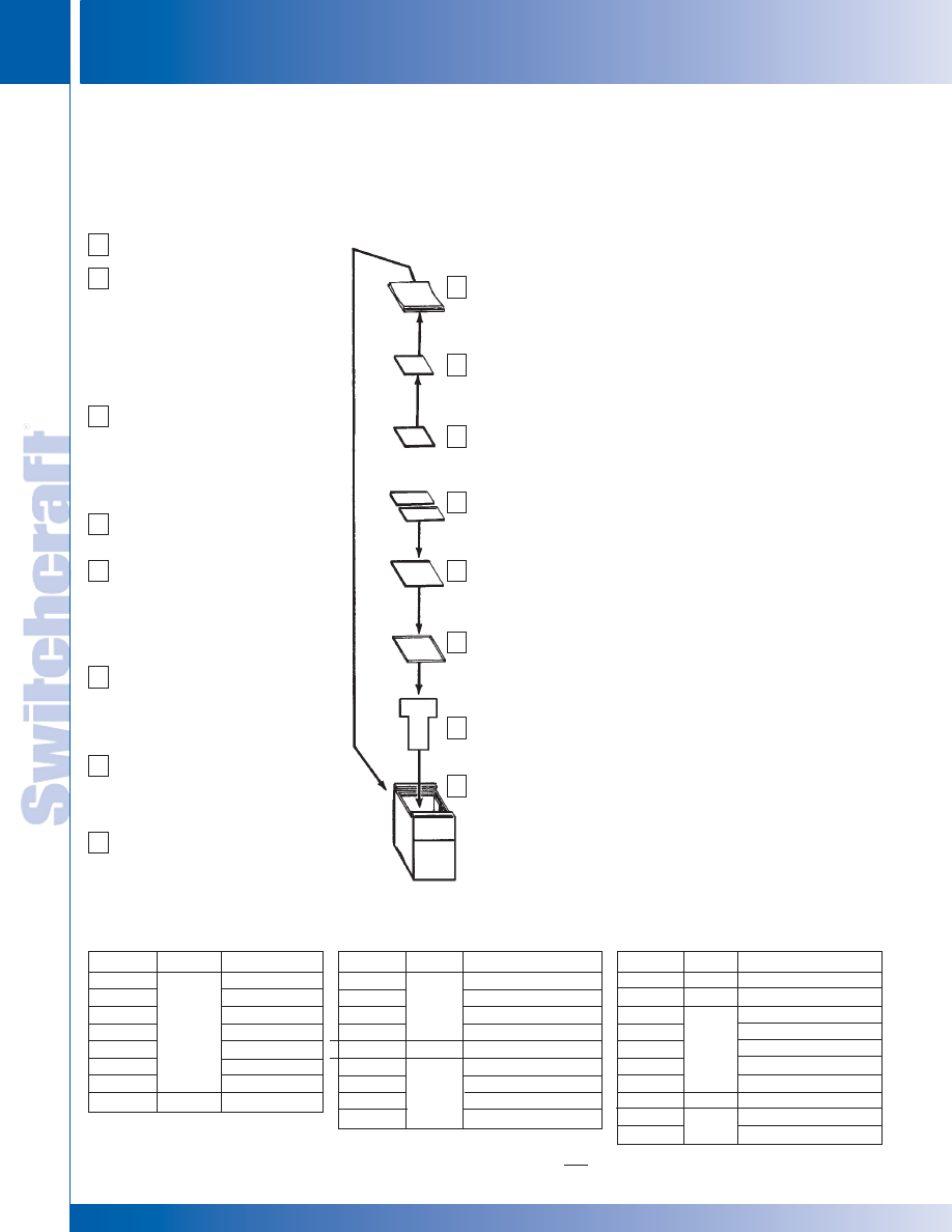
SWITCHES
306
w w w . s w i t c h c r a f t . c o m
® Registered trademark of Switchcraft, Inc.
Note: Contact your Switchcraft Representative for price and delivery
PHONE: 773 792-2700
SWITCHES
LITTEL MULTI-SWITCH – SPECIAL EFFECTS COLOR DISPLAY & INSERTS
LITTEL MULTI-SWITCH – SPECIAL EFFECTS COLOR DISPLAY & INSERTS
SPECIAL EFFECTS COLOR DISPLAY SCREENS AND INSERTS
Display screens and inserts are offered in a wide choice of colors for SERIES 37000 and 38000 Littel Multi-Switch switches. Display
screens with high-lights are useful in high ambient lighting; or display screens with soft, uniform, and diffused lighting for use under low
ambient lighting conditions. Order display screens, inserts and filters separately. See Part Number Chart below.
MULTIPLE-STATION SWITCHES (continued)
A
B
C
D
E
F
G
H
Part No.
◊
40101
◊
40103
◊
40104
◊
40105
◊
40108
◊
40112
◊
40116
◊
40401
Figure
A
B
Color
Red
Green
Blue
White
Yellow
Clear
“Black Screen”
Red
Part No.
◊
40403
◊
40404
◊
40405
◊
40408
◊
40412
◊
40201
◊
40203
◊
40204
◊
40205
Part No.
◊
40208
◊
40212
◊
40701
◊
40703
◊
40704
◊
40705
◊
40708
◊
406
40502
40505
Figure
E
F
D
G
H
Color
Green
Blue
White
Yellow
Clear (retaining insert)
Red
Green
Blue
White
Figure
B
C
E
◊
Special order only; Contact Switchcraft for
price and delivery information.
Color
Yellow
Clear (heat shield insert)
Red
Green
Blue
White
Yellow
White (light divider)
Black (housing)
White
®
®
SERIES 401 DISPLAY SCREENS – Display screens with contoured
face give a better operation “feel”. Rectangular shape provides greater
area for engraving legends and symbols. Entire screen is illuminated
by single or twin lamp indication. Various brightness and color
combinations are possible by use of legend filter and split face inserts.
SERIES 404 LEGEND INSERTS – Small translucent inserts provide
special color effects. White colored insert (40405) has a special matte
surface for in-the-field identification with ink, pencil or lettering transfers.
Special color effects can be accomplished with combination of a
colored insert with a clear display screen. IMPORTANT: Order legend
insert (40412) with every pushbutton.
SERIES 407 SPLIT-FACE INSERTS – Split-face inserts provide sepa-
rate control or indicating functions through the use of color. Ideal for
use on Series 38000 Littel Multi-Switch switches where each pushbutton
can serve as two indicator lights. Up to two lamps can be used per
display screen which are split lengthwise by 2-color split-face inserts.
Inserts may be hot-stamped. Order (406) light divider when “flip-flop”
lighting is specified; or for redundant lighting where a definite visual
indication of lamp failure is desired. A frequently used combination is
red and green. Red might indicate danger, stop, etc. Green, go, “okay”,
etc. IMPORTANT: Use (40212) clear insert with a split-face insert.
SERIES 402 FILTER INSERTS – Inserts add greater color definition.
Ideal for use under low ambient lighting conditions where brightness
of illuminated pushbuttons must be minimized. A white filter insert
(40205) is useful in cutting down the brightness of a white color insert
and a white or clear display screen. However, it is omitted when color
display screen is used. Filters also diffuse light evenly over entire
face of display screen with no “hot spots” or darkened corners.
IMPORTANT: Order clear insert (40212) for use with every color filter
insert. Clear insert snaps in button housing behind a color filter insert
and serves as a heat shield.
406 LIGHT DIVIDER – A light divider is used in the standard pushbutton
housing to separate the illumination from the twin lamps used in the
Series 38000 Littel Multi-Switch switches. Order a light divider for
every pushbutton station in the Series 38000 where split-face lighting
has been specified.
Series 405 PUSHBUTTON HOUSINGS – One-piece housing for all
37000 and 38000 switches. Accepts Series 401, 402, 404, 406 and
407 components. Standard color is black. Other colors available.
ORDERING – For variations in pushbutton configurations, contact
Switchcraft.
Series 401 Display Screen
Series 404
Legend insert recesses into display
screen. Omit when split-face
inserts are used.
Part Number 404 05
White legend insert has a matte
finish on one side suitable for
in-the-field marking.
Part Number 404 12
Retaining Insert
Clear insert snaps into display
screen from rear to retain legend
inserts. Omit when split-face
inserts are used.
Series 407 Split-Face Insert
Use with Series 38000
Series 402 Color Filter Inserts
White insert used with blue, white
and clear display screens; clear
insert used with red, green and
yellow. All color filters are omitted
where split-face insert is used.
Part Number 402 12 Heat
Shield Insert
Clear filter insert snaps into
push-button housing. Must be
used in every pushbutton assembly.
Part Number 406
Light Divider Recesses into
pushbutton housing. For use
with Series 38000.
Series 405 02 Pushbutton
Housing.
A
B
C
D
E
F
G
H
DIMENSIONS ARE FOR REFERENCE ONLY
Inch
(mm)
* Please visit the product pages on our website for the most up-to-date product information
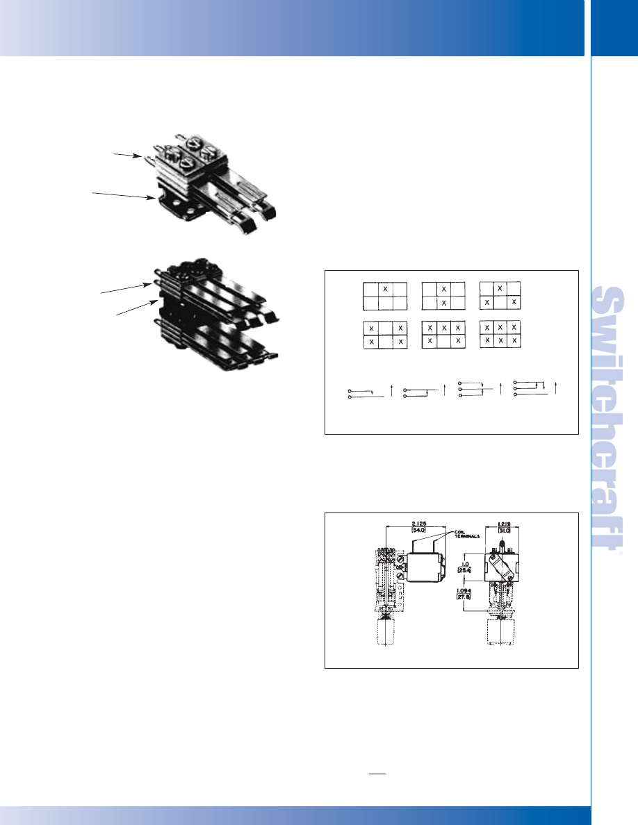
SWITCHCRAFT, INC. 5555 N. Elston Ave. • Chicago, IL 60630
307
SWITCHES
FAX: 773 792-2129
SWITCHES
DIMENSIONS ARE FOR REFERENCE ONLY
Inch
(mm)
LITTEL MULTI-SWITCH – ACCESSORIES
LITTEL MULTI-SWITCH – ACCESSORIES
“TINI-STACK” SWITCHES
Many combinations of stack switches are available on special
order. Contact Switchcraft for specifying assistance, including
clearances for stack heights.
SERIES 80P - Crossbar welded palladium contacts rated: 2A,
200W maximum, AC non-inductive load. For use where
contacts of a released station will return to normal before
contacts of a newly operated station are actuated.
Not recommended for use on push-lock/push/release function.
SERIES 800P - Same as Series 80P but can be used on
push-lock/push-release function, or on other functions where
contacts of a newly operated station must be actuated before
contacts of a released station return to normal.
SERIES 80G - Same as Series 80P, except includes
cross-bar welded gold alloy contacts rated at 1A, 100W
maximum, AC non-inductive load.
SERIES 800G - Same as Series 80G except for push-
lock/push-release and/or other functions as described for
Series 800P.
BIFURCATED “TINI-STACK” SWITCH STACKS
Double reliability through use of bifurcated switch stacks
featuring bifurcated leaf springs slotted at the contact end and
parallel to the long axis of the leaf spring. Separate crossbar
gold alloy contacts are welded to leaf springs on each side,
doubling the number of contacts on each spring.
SERIES 60BG - Similar to Series 80P, except bifurcated leaf
springs with welded crossbar gold alloy contacts rated at 1A,
100W maximum, AC non-inductive load.
SERIES 600BG - Same as Series 60BG, except for use on
push-lock/push-release function and/or functions as
described under Series 800P.
LITTEL
®
MULTI-SWITCH ACCESSORIES
MULTIPLE-STATION SWITCHES (continued)
HIGH CURRENT “TINI-STACK” SWITCH STACKS
Heavy duty switch stacks Series 60W for use in 120V, AC
power circuits are available with large, fine silver contacts
rated at 5A, non-inductive load. Stack spacer width limits
mounting to one stack/station on each side of frame and
requires special mounting bracket.
For 10 and 15A switching, contact Switchcraft.
POSITIONING SWITCH STACKS
(SERIES 80P, 800P, 80G AND 800G ONLY)
Refer to chart below for proper balancing of the switch stacks
mechanical load at each station, “X” denotes correct positioning
of the stack on the removable switch stack bracket.
SERIES NJ SOLENOID RELEASE
Solenoid assembly attaches to end of switch frame and
provides electrical release of activated stations. Instructions
and hardware furnished. Other voltages are available on
special order; contact Switchcraft.
Series 60BG
Bifurcated
Switch Stacks
Special
Mounting
Bracket
Mounting
Bracket
Basic Contact Forms
Other contact forms available on special order
Top
Bottom
TYPICAL MOUNTING
Top
Bottom
Series
80P Stacks
1
2
3
4
A
B
C
D
5
6
®
®
* Please visit the product pages on our website for the most up-to-date product information
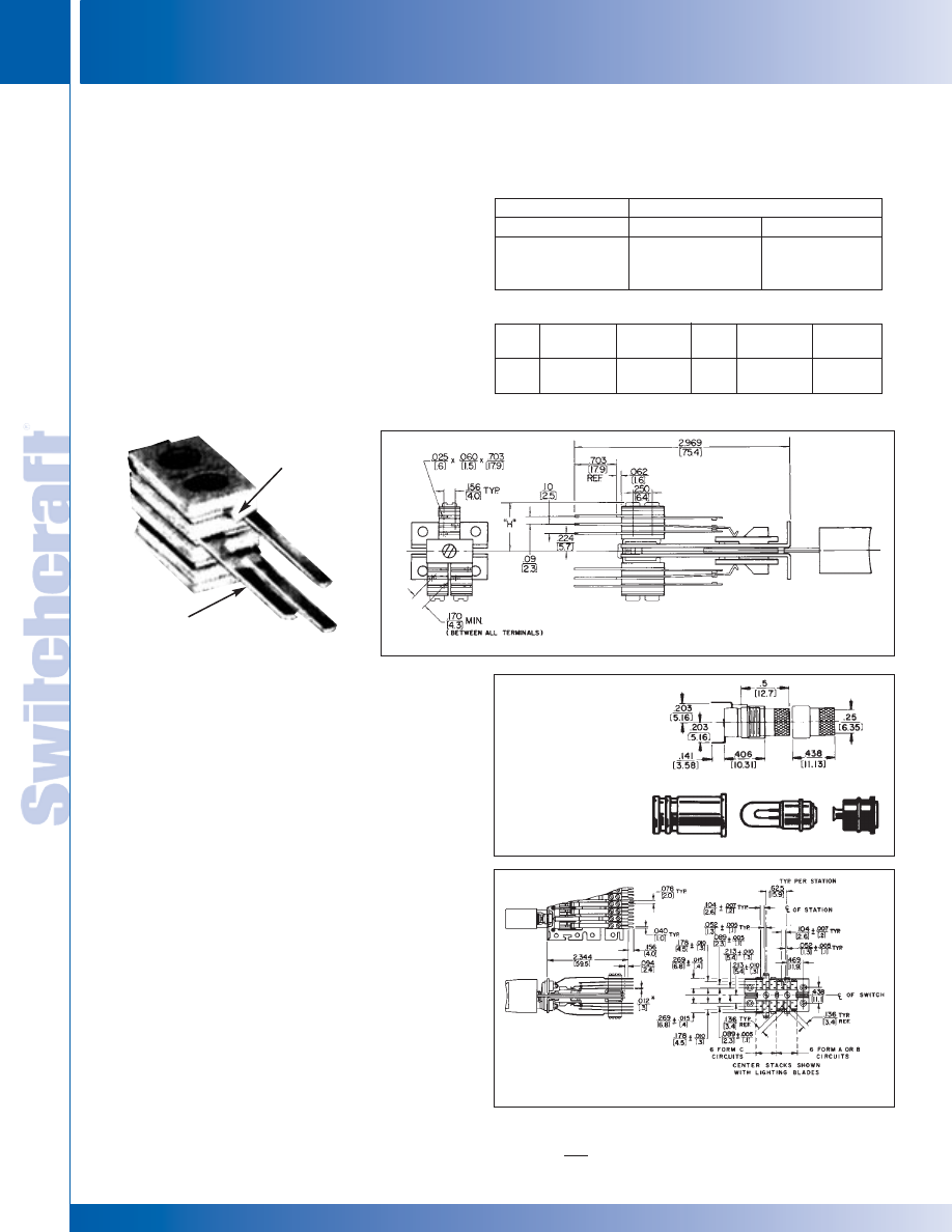
SWITCHES
308
w w w . s w i t c h c r a f t . c o m
® Registered trademark of Switchcraft, Inc.
Note: Contact your Switchcraft Representative for price and delivery
PHONE: 773 792-2700
SWITCHES
DIMENSIONS ARE FOR REFERENCE ONLY
Inch
(mm)
LITTEL MULTI-SWITCH – ACCESSORIES
LITTEL MULTI-SWITCH – ACCESSORIES
LAMP SOCKETS AND ADAPTERS
LAMP SOCKET T10
◊
Standard on Series 37000, T10 accepts standard midget
flange type T1-3/4 lamps.
LAMP SOCKET T12
◊
Standard on Series 38000, the T12 socket accepts standard
midget flange type T1-3/4 lamps.
LAMP ADAPTER T1
Converts sockets that accommodate standard T 1-3/4,
(P1593) midget flange base lamps to accept T 1 subminiature
lamps. Adapter fits T 1-3/4 lamp socket. The 2-piece adapter
holds lamp securely in place to assure positive contact of
lamp circuit in most environments. If you require extra
long-life, specify a T 1 lamp adapter for each T 1-3/4 socket.
PC TERMINALS
Copper alloy PC terminals are integral with associated leaf
spring and feature shoulders for proper clearance from PC
board and for solid mounting. Contact Switchcraft for details.
◊
Available on special order only; Contact factory for price and delivery information.
LITTEL
®
MULTI-SWITCH ACCESSORIES
MULTIPLE-STATION SWITCHES (continued)
RECOMMENDED WIRE-WRAPPING TOOLS
RECOMMENDED WIRE-WRAPPING PARAMETERS
Wire Gauge
#22 & #24
#25
#26
Wrapping Bit
500131
500131
37006
Sleeve
18840
18840
17611-2
(Gardner -Denver Co. Part Numbers)
Wire
Gauge
#22
#24
Number of
Connections
3
3
Wraps Per
Connection
4
5
Wire
Gauge
#25
#26
Number of
Connections
3
3
Wraps Per
Connection
4
5
SHOULDER
LAMP SOCKET T12
LAMP ADAPTER T1
SERIES 37000
WITH WIRE- WRAPPED
TERMINALS
SERIES 35000 WITH
WIRE- WRAP* TERMINALS
* Registered trademark of Gardner-Denver Co.
SERIES 37000 WITH PC TERMINALS
WIRE-WRAPPING TERMINALS
Special order wire-wrapping terminals optimize use of
semi-automated termination equipment to save production
line time. Terminal shoulders accommodate 1, 2 or 3 wrapped
connections per terminal and prevent wrapping tool from
“bottoming” (on first wrapped connection) and possibly
shorting against other metal parts on switch stack. 4-C
switching per station maximum.
NOTE: Stack height dimension will be greater when
wire-wrapping terminals are specified. Stack height for 1-A
and 1-B circuit is .516" (13.11 mm). For 1-C height is .594"
(15.09 mm).
ORDERING:
Contact Switchcraft for details.
®
®
* Please visit the product pages on our website for the most up-to-date product information
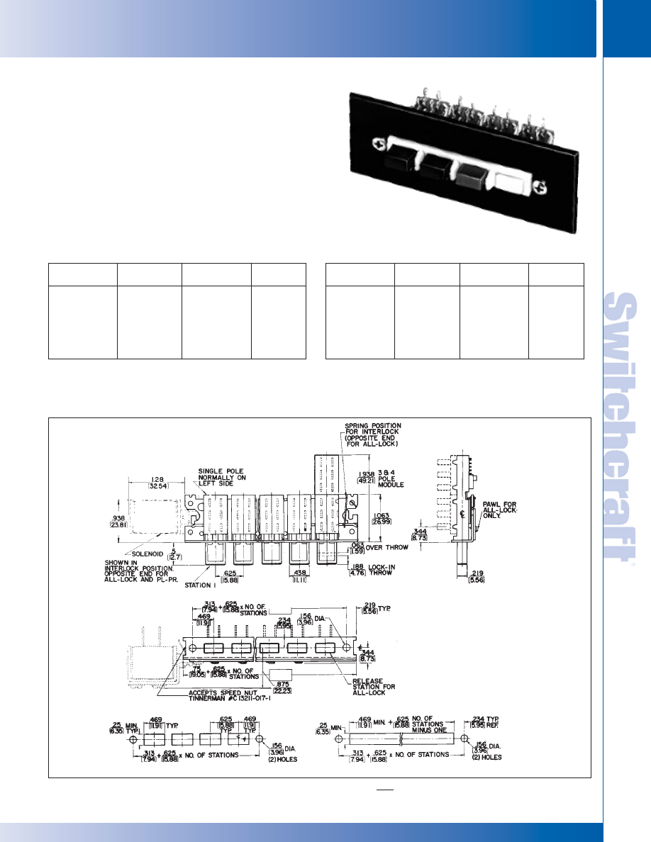
SWITCHCRAFT, INC. 5555 N. Elston Ave. • Chicago, IL 60630
309
SWITCHES
FAX: 773 792-2129
SWITCHES
DIMENSIONS ARE FOR REFERENCE ONLY
Inch
(mm)
DW MULTI-SWITCH – SERIES 65000
DW MULTI-SWITCH – SERIES 65000
DW MULTI-SWITCH
SERIES 65000
Available with up to 18 non-illuminated stations in a single row.
Maximum switching per station is 4-C (4PDT). Contacts are
rated: 3A, AC, 0.5A DC, 125V, non-inductive load. Integral
black button is supplied with each station. Switches mount with
#6 screws and nut (not furnished). Contact Switchcraft for spe-
cial assemblies, with ganged assemblies, solenoid release,
PC or wire-wrapping terminals, or escutcheon modules.
MULTIPLE-STATION SWITCHES (continued)
PART NUMBERS / 2-C PER STATION
1
Interlock
with Lock-Out
65021K206
65041K206
65061K206
65081K206
65101K206
65121K206
Non-Lock
◊
65022206
◊
65042206
◊
65062206
◊
65082206
◊
65102206
◊
65122206
Push-Lock/
Push-Release
◊
65027206
◊
65047206
◊
65067206
◊
65087206
◊
65107206
◊
65127206
Number of
Stations
2
2
4
6
8
10
12
1. Switches with all-lock function are available on special order. Contact Switchcraft.
2. Odd number of stations (3, 5, 7, 9, 11) are available. Switches with
13 through 18 stations also available. Contact Switchcraft.
◊
Special order only; Contact Switchcraft for price and delivery information.
PART NUMBERS / 4-C PER STATION
1
Interlock
with Lock-Out
◊
65021K212
◊
65041K212
◊
65061K212
◊
65081K212
◊
65101K212
◊
65121K212
Non-Lock
◊
65022212
◊
65042212
◊
65062212
◊
65082212
◊
65102212
◊
65122212
Push-Lock/
Push-Release
◊
65027212
◊
65047212
◊
65067212
◊
65087212
◊
65107212
◊
65127212
Number of
Stations
2
2
4
6
8
10
12
1. Switches with all-lock function are available on special order.
Contact Switchcraft.
2. Odd number of stations (3, 5, 7, 9, 11) are available. Switches with
13 through 18 stations also available. Contact Switchcraft.
◊
Special order only; Contact Switchcraft for price and delivery information.
SERIES 65000 - Four-station with
DW Escutcheon Modules installed
PANEL CUTOUT DIMENSIONS
* Please visit the product pages on our website for the most up-to-date product information
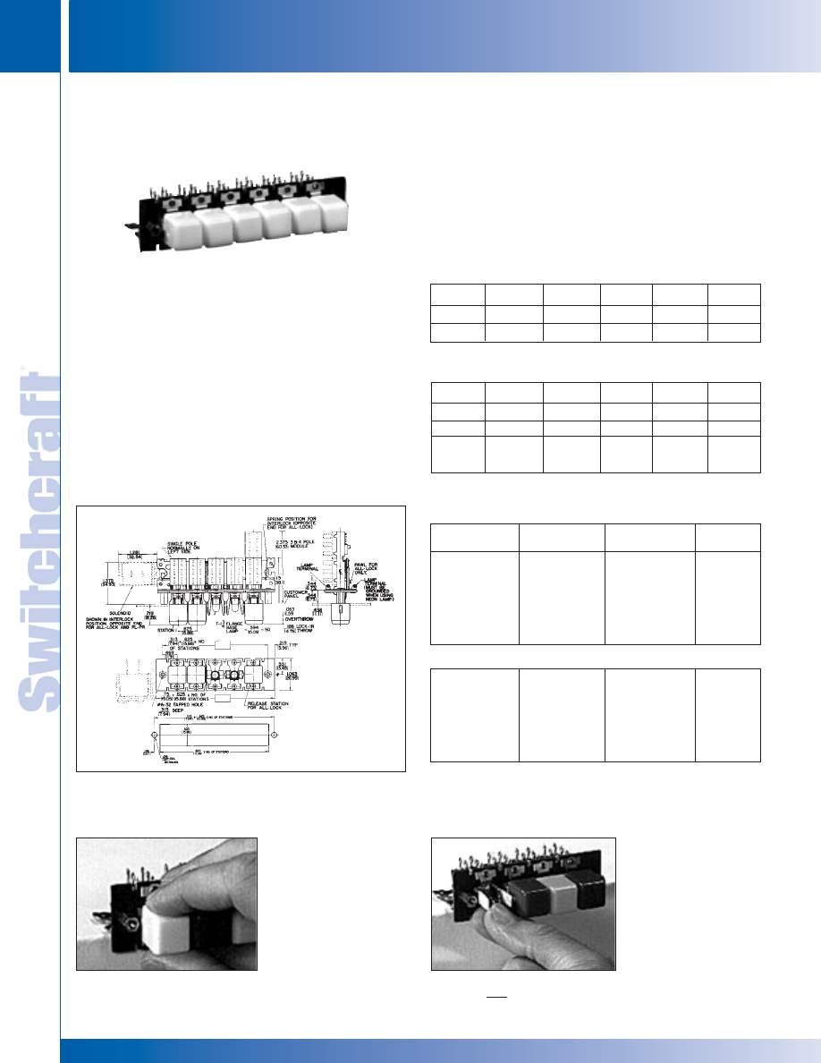
SWITCHES
310
w w w . s w i t c h c r a f t . c o m
® Registered trademark of Switchcraft, Inc.
Note: Contact your Switchcraft Representative for price and delivery
PHONE: 773 792-2700
SWITCHES
DIMENSIONS ARE FOR REFERENCE ONLY
Inch
(mm)
DW MULTI-SWITCH – SERIES 66000 & 67000
DW MULTI-SWITCH – SERIES 66000 & 67000
SERIES DW40 COLOR INSERTS
Many unusual lighting effects can be created using DW40 color
inserts. Molded from dimensionally stable, high-temperature
plastic in six standard colors, inserts slip into standard Series
DW300 pushbuttons providing unusual latitude in custom
designing color and legend effects. With no wear from finger-tips,
legend life is virtually unlimited.
MULTIPLE-STATION SWITCHES (continued)
NON-ILLUMINATED DW MULTI-SWITCH SWITCHES
Switchcraft offers DW Multi-Switch switches, Series 70000
and 71000 with crossbar plungers which accept a wide variety
of Switchcraft and industry pushbuttons. Contact Switchcraft
for specifying assistance.
PART NUMBERS/2-C PER STATION
1
Interlock
with Lock-Out
67021K506
67041K506
67061K506
67081K506
67101K506
67121K506
Non-Lock
◊
67022506
◊
67042506
◊
67062506
◊
67082506
◊
67102506
◊
67122506
Push-Lock/
Push-Release
◊
67027506
◊
67047506
◊
67067506
◊
67087506
◊
67107506
◊
67127506
Number of
Stations
2
2
4
6
8
10
12
PART NUMBERS/4-C PER STATION
1
◊
67021K512
◊
67041K512
◊
67061K512
◊
67081K512
◊
67101K512
◊
67121K512
◊
67022512
◊
67042512
◊
67062512
◊
67082512
◊
67102512
◊
67122512
◊
67027512
◊
67047512
◊
67067512
◊
67087512
◊
67107512
◊
67127512
2
4
6
8
10
12
1. Switches with all-lock function are available on special order. Contact
Switchcraft.
2. Odd number of stations (3, 5, 7, 9, 11) are available. Switches with
13 through 18 stations also available. Contact Switchcraft.
◊
Special order only; Contact Switchcraft for price and delivery information.
Part No.
◊
DW41
◊
DW43
Color
Red
Green
Part No.
◊
DW44
◊
DW45
Color
Blue
White
Part No.
◊
DW47
◊
DW48
Color
Orange
Yellow
Part No.
DW301
DW302
DW303
Color
1
Red
Black
Green
Part No.
DW304
DW305
DW308
Color
1
Blue
White
Yellow
Part No.
DW312
DW313
DW316
Color
1
Clear
Amber
“Black-
Screen”
SERIES DW300 PUSHBUTTONS (DW305 supplied standard)
1 Other colors available on special order. Buttons are 0.594 (15.09) x 0.594 (15.09)
DW MULTI-SWITCH
SERIES 66000 and 67000
Squeeze upper and
lower surfaces of
pushbutton and
pull free of
plungers.
Next, grasp lamp with
lamp removal tool or
fingertips and snap-
out. Replace lamp
and pushbutton.
Finished in seconds!
◊
Special order only; Contact Switchcraft for price and delivery information.
Series 66000 (non-illuminated) and 67000 (illuminated) can
be supplied with up to 18 stations, including a square white
pushbutton Part Number DW305 at each station. Contacts and
ratings are the same as for Series 65000. Lamp sockets
(67000) at each station accept 6V to 28V T 1-3/4 flange base
lamps (not supplied). Mounts with 2 #6-32 machine screws
(not supplied). See page 310 for pushbutton data. Accessories
include solenoid release, ganged assemblies, T1 lamp
adapter, and metal barriers (between stations). PC and
wire-wrapping terminals are also available. Contact Switchcraft.
* Please visit the product pages on our website for the most up-to-date product information
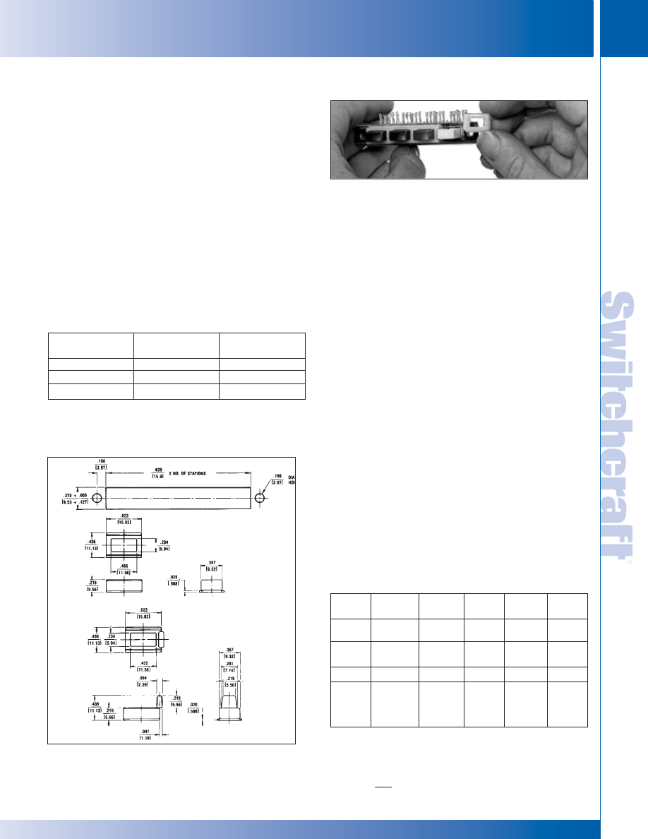
SWITCHCRAFT, INC. 5555 N. Elston Ave. • Chicago, IL 60630
311
SWITCHES
FAX: 773 792-2129
SWITCHES
DIMENSIONS ARE FOR REFERENCE ONLY
Inch
(mm)
DW SWITCH – ACCESSORIES
DW SWITCH – ACCESSORIES
SPECIAL SWITCHING FORMS
In addition to 2-C and 4-C switching, other circuit forms can
be supplied on special order. They are: 1-A, 2-A, 3-A, 4-A,
1-B, 2-B, 3-B, 4-B, 1-C, 3-C, 1-D, 2-D, 3-D, and 4-D.
BARRIERS (SERIES 67000 ONLY)
As an option, (field installable) barriers can be specified and
installed. Sturdy wire barriers fit between pushbuttons and
prevent accidental simultaneous actuation of adjacent
push-buttons. When a pushbutton is depressed, the fingertip
is guided away from adjacent pushbuttons, and all pressure is
applied to the correct pushbutton.
Switchcraft Part Number
◊
P2359 Barriers (package of 25)
SOLENOID RELEASE
Solenoids provide electromechanical assistance in releasing locked
switch stations in switches with up to 12 stations. Release can be
effected from a local or remote position. Solenoids are available for use
with switches having inter-lock, all-lock, or push-lock/push-release
mechanical functions. All solenoids are “pull-type”. When ordered
separately, solenoids are supplied with all mounting hardware. Brass
terminals accept “push-on” type clips (ARK-LES #3500M20C), or
wiring can be soldered directly to the lugs.
SPECIFICATIONS
Frame, Latch Bar, and Switch Housing: Steel, plated.
Mounting Studs (Series 66000 and 67000):
Same as frame above.
Pushbutton Actuators (Series 65000): Molded thermoplastic.
Pushbuttons (Series 66000 and 67000):
Molded thermoplastic.
Terminals: Copper alloy, silver-plated.
Contactors: Copper alloy, plated.
Terminal Board: Rigid plastic.
Lamp Socket (Series 67000): Copper alloy, plated.
DW MULTI-SWITCH ACCESSORIES
MULTIPLE-STATION SWITCHES (continued)
Series DW-100
(without barrier)
◊
DW101
DW102
DW05
Series DW-200
(with barrier)
◊
DW201
DW202
DW205
Color*
Red
Black
White
Part
Number
◊
DW1
◊
DW3
◊
DW4
◊
DW7
Mounting*
Left
Right
Left
Right
Voltage
115 AC,
60 Hz
115 AC,
60 Hz
24 DC
24 DC
Coil Res.
(Ohms)
361
130
14.2
8.96
Duty
Cycle
20%
10%
20%
10%
* Direction indicates side of switch frame solenoid is mounted on
(solenoid terminals up).
PANEL OPENING
DW100
DW200
* Other colors available on special order.
◊
Special order only; Contact Switchcraft for price and delivery information.
Switch
Function
Interlock
All-Lock
Interlock
All-Lock or
Push-
Lock/Push-
Release
ESCUTCHEON MODULES, SERIES DW100 AND DW200
Modules are available in colors to match or contrast with
Series 65000 pushbutton colors. Modules are simply slipped
over the pushbuttons before the switch is mounted on the
panel. Flanges on modules overlap the panel cutout and hold
modules securely in place while adding only 0.02" (.051 mm)
behind panel space.
One module is required for each station. Installation of the
Series DW200 Modules (with barrier) is equally simple. First,
place one Series DW100 Module over the pushbutton
actuator on one end of the row. On the adjacent actuator,
place a Series DW200 Module. Position this module so that
the barrier overlaps the edge of the Series DW100 Module.
Install the remaining Series DW200 modules in the same
manner, with the barriers overlapping. The completed
escutcheon will have barriers between adjacent pushbutton
actuators, but no barriers at the ends of the rows.
* Please visit the product pages on our website for the most up-to-date product information
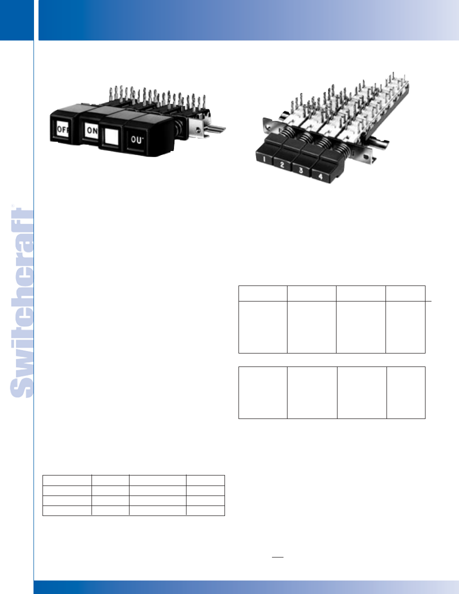
SWITCHES
312
w w w . s w i t c h c r a f t . c o m
® Registered trademark of Switchcraft, Inc.
Note: Contact your Switchcraft Representative for price and delivery
PHONE: 773 792-2700
SWITCHES
DIMENSIONS ARE FOR REFERENCE ONLY
Inch
(mm)
TINI DW MULTI-SWITCH – SERIES 90000 & 92000
TINI DW MULTI-SWITCH – SERIES 90000 & 92000
SPECIFYING NOTE:
Series 90000 Part Numbers are given in table. To order Series
92000 switches, substitute “2” for “0” for second digit of Part
Number. Example; Part Number 92024B06 in the Series
92000 version 0.590" (15mm centers) of Part Number
90024B06 0.394" (10mm centers) interlock with lock-out, 2-C
switching per station.
MULTIPLE-STATION SWITCHES (continued)
Part Number
◊
A6501
◊
A6502
◊
A6503
Color
Red
Black
Green
Color
Blue
White
Yellow
Part Number
◊
A6504
◊
A6505
◊
A6508
PART NUMBERS/2-C PER STATION
1
PUSHBUTTONS
Interlock
with Lock-Out
◊
90024B06
◊
90044B06
◊
90064B06
◊
90084B06
◊
90104B06
◊
90124B06
Non-Lock
◊
90022B06
◊
90042B06
◊
90062B06
◊
90082B06
◊
90102B06
◊
90122B06
Push-Lock/
Push-Release
◊
90027B06
◊
90047B06
◊
90067B06
◊
90087B06
◊
90117B06
◊
90127B06
Number of
Stations
2
2
4
6
8
10
12
PART NUMBERS/4-C PER STATION
1
◊
90024B12
◊
90044B12
◊
90064B12
◊
90084B12
◊
90104B12
◊
90124B12
◊
90022B12
◊
90042B12
◊
90062B12
◊
90082B12
◊
90102B12
◊
90122B12
◊
90027B12
◊
90047B12
◊
90067B12
◊
90087B12
◊
90117B12
◊
90127B12
2
4
6
8
10
12
1 Switches with all-lock function are available on special order. Contact Switchcraft.
2 Odd number of stations (3, 5, 7, 9, 11) are available. Switches with 13 through
18 stations also available. Contact Switchcraft.
◊
Special order only; Contact Switchcraft for price and delivery information.
SERIES 92000 Switch TDW-F
Flip-Flop Pushbutton Installed
SERIES 90000 with
A-650 Pushbuttons Installed
Buttons are 0.386 (9.80 mm) x 0.386 (9.80 mm).
◊
Special order only; Contact Switchcraft for price and delivery information.
TINI
®
DW MULTI-SWITCH – SERIES 90000, 92000
Subminiature, multiple station switches have pushbuttons on
0.394" (10mm), 0.590" (15mm), or 0.787" (20mm) centers.
Four mechanical functions: Interlock, Non-Lock, All-Lock and
Push-Lock/Push-Release. Switches mount in panels up to
.343" (8.71mm) thick. Switching per station is 2-C (2PDT),
4-C (4PDT), 6-C (6PDT) or 8-C (8PDT). Contact ratings: 0.5A,
28V AC or DC non-inductive. Solder lug or PC terminals.
SERIES 90000 - Up to 18 stations on 0.394" (10mm) centers
in a row. Switch mounts with 2, #3 screws (not supplied).
SERIES 92000 - 15mm station centers. Wider spacing
permits mounting Series TDWF pushbuttons.
SPECIFICATIONS
ELECTRICAL
Switching Module Rating: 0.5A, 28V AC or DC
non-inductive load.
Initial Contact Resistance: 10 milliohms.
MATERIALS
Frame Switch Housing: Steel, plated.
Latch Bar: Stainless steel on all-lock function;
zinc alloy on interlock function.
Latch Bar Return Spring: Tinned music wire.
Plunger: Molded thermoplastic.
Plunger Return Spring: Tinned music wire.
Terminals/Contacts: Copper alloy, silver-plated.
Contact Sliders: Bifurcated bimetal (silver on copper alloy).
Terminal Board: Molded thermoplastic (UL 94V-0).
Pushbuttons: Molded thermoplastic.
Pushbuttons for Tini DW Multi-Switch switches must be specified
separately, below. Refer to page 316 for data on TWDF pushbuttons.
Series A650 pushbuttons can be specified for both Series
90000 and 92000. Legends can be specified; contact
Switchcraft.
®
®
* Please visit the product pages on our website for the most up-to-date product information
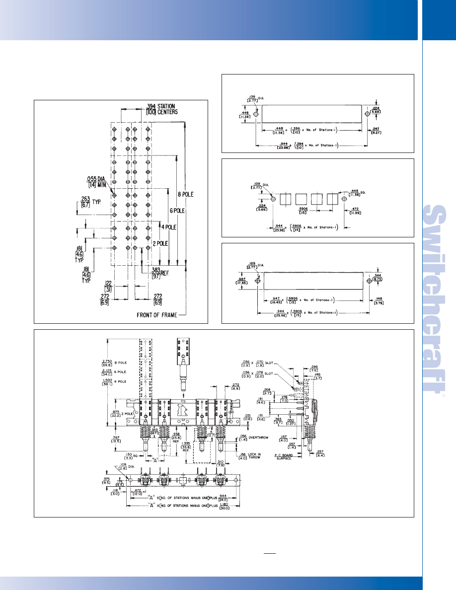
SWITCHCRAFT, INC. 5555 N. Elston Ave. • Chicago, IL 60630
313
SWITCHES
FAX: 773 792-2129
SWITCHES
DIMENSIONS ARE FOR REFERENCE ONLY
Inch
(mm)
TINI DW MULTI-SWITCH – SERIES 90000 & 92000
TINI DW MULTI-SWITCH – SERIES 90000 & 92000
TINI
®
DW MULTI-SWITCH
SERIES 90000 and 92000
MULTIPLE-STATION SWITCHES (continued)
NOTE:
For Series 90000 “A” dimension is .394" (10.0mm)
For Series 92000 “A” dimension is .590" (15.0mm)
PANEL OPENING SERIES 92000
WITH TDW-F PUSHBUTTONS
RECOMMENDED
PC BOARD LAYOUT
(Component Side)
PANEL OPENING SERIES 90000
WITH SERIES A-650 PUSHBUTTONS
PANEL OPENING SERIES 92000
WITH SERIES A-650 PUSHBUTTONS
®
®
* Please visit the product pages on our website for the most up-to-date product information
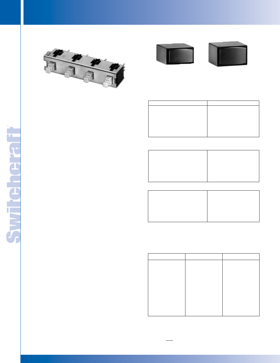
SWITCHES
314
w w w . s w i t c h c r a f t . c o m
® Registered trademark of Switchcraft, Inc.
Note: Contact your Switchcraft Representative for price and delivery
PHONE: 773 792-2700
SWITCHES
DIMENSIONS ARE FOR REFERENCE ONLY
Inch
(mm)
IBS MULTI-SWITCH – SERIES IBS
IBS MULTI-SWITCH – SERIES IBS
IBS MULTI-SWITCH SWITCHES
SERIES IBS
Series IBS miniature pushbutton switches are mounted on common
frames, up to 12 stations long with center-to-center spacing of
0.394" (10mm), 0.590" (15mm) or 0.787" (20mm). Available with
interlock, non-lock (momentary) or push-lock/push-release
mechanical functions. .130" (3.30mm) x .130" (3.30mm) square
plungers accept a full line of industry standard pushbuttons.
Switches are stocked without pushbuttons due to wide variety
that can be used. Order pushbuttons separately. Switches have
.157" (4mm) long PC terminals for mounting single- or double-
sided PC boards up to .094" (2.39mm) thick. Close stacking
(centers) permits high density within minimum front panel space.
PUSHBUTTONS
Pushbuttons designed for IBS switches are available in white,
black, red, blue and gray. Others colors are available on special
order. Pushbutton faces are concave for operator convenience
and can be mounted either horizontally or vertically.
Pushbuttons must be ordered separately, but may be factory
installed, if desired, at nominal extra cost.
SPECIFICATIONS
MECHANICAL
Switch Actuation: Momentary, interlock and push-lock/
push-release.
Plunger Travel: .144" (3.66 mm).
Actuation Force: At .135" (3.43mm) travel: 12-15 oz.
ELECTRICAL
0.125A resistive @ 125 V AC, .25 AMP at 28V DC.
MATERIALS
Housing: Thermoplastic 94V-0.
Plunger: Thermoplastic UL 94V-0.
Contactors: Copper alloy.
Terminals: Copper alloy, solder plated. Tin-dipped
available on special order.
Contact Surfaces: Plated.
Frame: Copper alloy.
Latch Bar: Thermoplastic.
MULTIPLE-STATION SWITCHES (continued)
PART NUMBERS/0.394" (10MM) CENTERS
1
Interlock
◊
IBS10B02106AR
◊
IBS10B04106AR
◊
IBS10B06106AR
◊
IBS10B08106AR
◊
IBS10B10106AR
◊
IBS10B12106AR
Number of Stations
2
2
4
6
8
10
12
PART NUMBERS/0.590" (15MM) CENTERS
1
◊
IBS15B02106AR
◊
IBS15B04106AR
◊
IBS15B06106AR
◊
IBS15B08106AR
◊
IBS15B10106AR
◊
IBS15B12106AR
2
4
6
8
10
12
1. Switches with all-lock function are available on special order.
Contact Switchcraft.
2. Odd number of stations (3, 5, 7, 9, 11) are available. Switches with
13 through 18 stations also available. Contact Switchcraft.
◊
Special order only; Contact Switchcraft for price and delivery information.
PART NUMBERS/0.787" (20MM) CENTERS
1
◊
IBS20B02106AR
◊
IBS20B04106AR
◊
IBS20B06106AR
◊
IBS20B08106AR
◊
IBS20B10106AR
◊
IBS20B12106AR
2
4
6
8
10
12
Type I
P2936
P2937
P2938
◊
P2939
◊
P2940
P2941
P2942
◊
P2943
-
-
Type II
P2951
P2952
P2953
◊
P2954
◊
P2955
P2956
P2957
◊
P2958
◊
P2979
◊
P2992
Color
White
Black
Red
Yellow
Green
Blue
Gray
Brown
Cream
Tangerine
PUSHBUTTON PART NUMBERS
◊
Available on special order only; contact Switchcraft for price and delivery.
IBS10B04106AR
TYPE I
0.388 (9.86) x 0.216 (5.49)
TYPE II
0.464 (11.79) x 0.288 (7.32)
* Please visit the product pages on our website for the most up-to-date product information
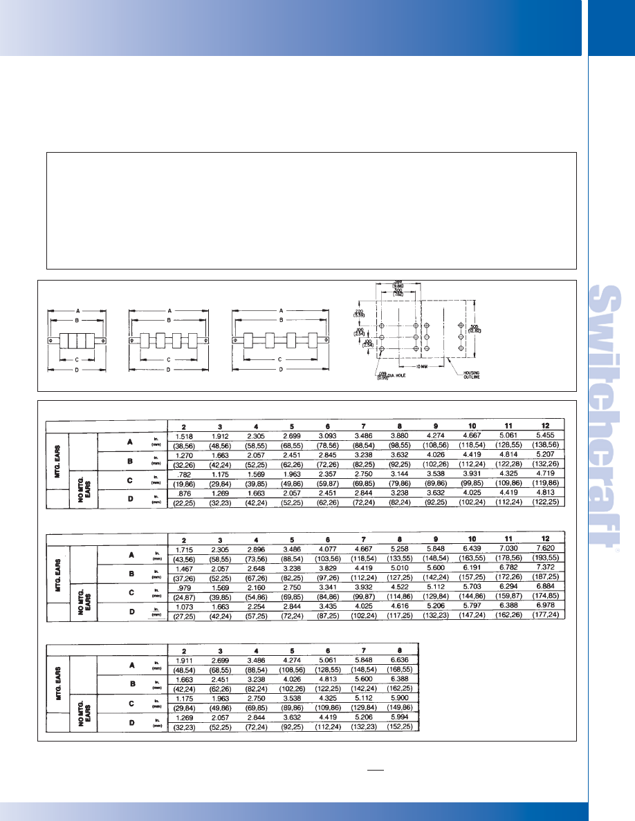
SWITCHCRAFT, INC. 5555 N. Elston Ave. • Chicago, IL 60630
315
SWITCHES
FAX: 773 792-2129
SWITCHES
DIMENSIONS ARE FOR REFERENCE ONLY
Inch
(mm)
IBS MULTI-SWITCH – SERIES IBS
IBS MULTI-SWITCH – SERIES IBS
IBS MULTI-SWITCH SWITCHES
SERIES IBS
MULTIPLE-STATION SWITCHES (continued)
IBS
XX
CENTERS
0.394" (10mm)
0.590" (15mm)
0.787" (20mm)
X
FRAME STYLE
A - Mounting Ears
B - No Mounting Ears
XX
STATIONS
01 - 12
X
MECHANICAL
FUNCTION
1 - Interlock
2 - Non-Lock
XX
1
CIRCUITS
01 - 1A
02 - 1B
03 - 1C
04 - 2A
05 - 2B
06 - 2C
X
TERMINAL
LENGTH
A - 0.157"
(4mm)
R
* 8 stations maximum on 0.787" (20mm) centers.
1. See page 269 for individual switch terminal conjunction.
STATIONS
STATIONS
STATIONS
0.394" (10mm) CENTERS
DIMENSIONS
RECOMMENDED
PC BOARD
LAYOUT
(Component Side)
(.300 x .100)
(7.62 mm) x (2.54)
0.590" (15mm) CENTERS
0.787" (20mm) CENTERS
IBS PART NUMBERING CODE
0.394" (10mm)
0.590" (15mm)
0.787" (20mm)
Dimension
Dimension
Dimension
* Please visit the product pages on our website for the most up-to-date product information
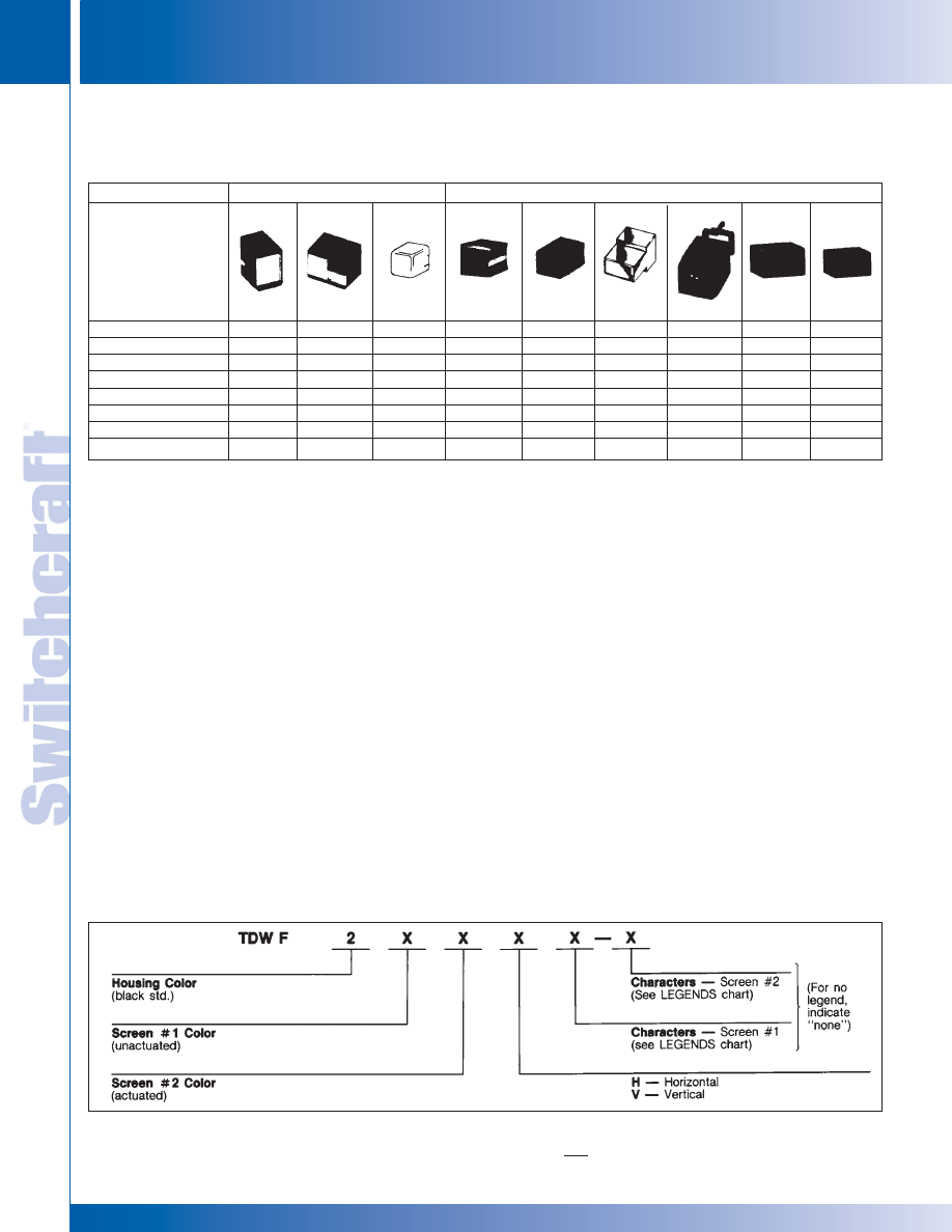
SWITCHES
316
w w w . s w i t c h c r a f t . c o m
® Registered trademark of Switchcraft, Inc.
Note: Contact your Switchcraft Representative for price and delivery
PHONE: 773 792-2700
SWITCHES
DIMENSIONS ARE FOR REFERENCE ONLY
Inch
(mm)
MULTI-SWITCH PUSHBUTTONS
MULTI-SWITCH PUSHBUTTONS
SPECIFYING NOTE:
Most pushbuttons can be specified in red, black, green, blue,
white or yellow. “Black-Screen”, amber, clear, and other colors
are also possible. Contact Switchcraft with your requirements.
Unique internal “flip-flop” mechanism permits button face to
change colors without electrical energy, lamps or wiring. When
pushbutton is operated, highly reflective panels inside housing
change position and use ambient light to give a bright illumi-
nated effect. Black pushbuttons are .59" (15mm) high x .63"
(16mm) wide. Display window is .315" (8mm) x .374" (9.5mm)
wide.
NOTE: “FLIP-FLOP” PUSHBUTTONS ARE DESIGNED
FOR USE WITH SERIES 92000 SWITCHES ONLY.
Order “flip-flop” pushbuttons with Series 92000 switches.
TDW-F “Flip-Flop” Pushbutton Part Numbering
MULTI-SWITCH PUSHBUTTONS
SERIES TDWF - “FLIP-FLOP” PUSHBUTTONS
MULTIPLE-STATION SWITCHES (continued)
1. Any pushbutton series can be specified with engraved legends.
2. Buttons are an integral part of switch assembly on Series 65000.
3. Switches stocked without pushbuttons due to wide variety that can be used.
Order buttons separately.
4. Display screens and inserts are also available in a wide choice of colors;
see “SPECIAL EFFECTS COLOR DISPLAY SCREENS AND INSERTS”.
5. Double width button
6. Colored inserts are available in a wide choice of colors;
see “SERIES DW40 COLOR INSERTS”.
TDW-F “FLIP-FLOP” PUSHBUTTON PART NUMBERING
Illuminated
Non-Illuminated
Switch Series
Fig. 1
Fig. 2
Fig. 3
Fig. 4
Fig. 5
Fig. 6
Fig. 7
Fig. 8
Fig. 9
Pushbutton Series
1
400
4
409
5
DW300
6
A-590
E-590
5
A-650
TDW-F
Type I
Type II
35000
X-(Std.)
X
37000
X (Std.)
X
38000
X (Std.)
X
65000
2
67000
X (Std.)
90000
3
X
92000
3
X
X
IBS
3
X
X
* Please visit the product pages on our website for the most up-to-date product information
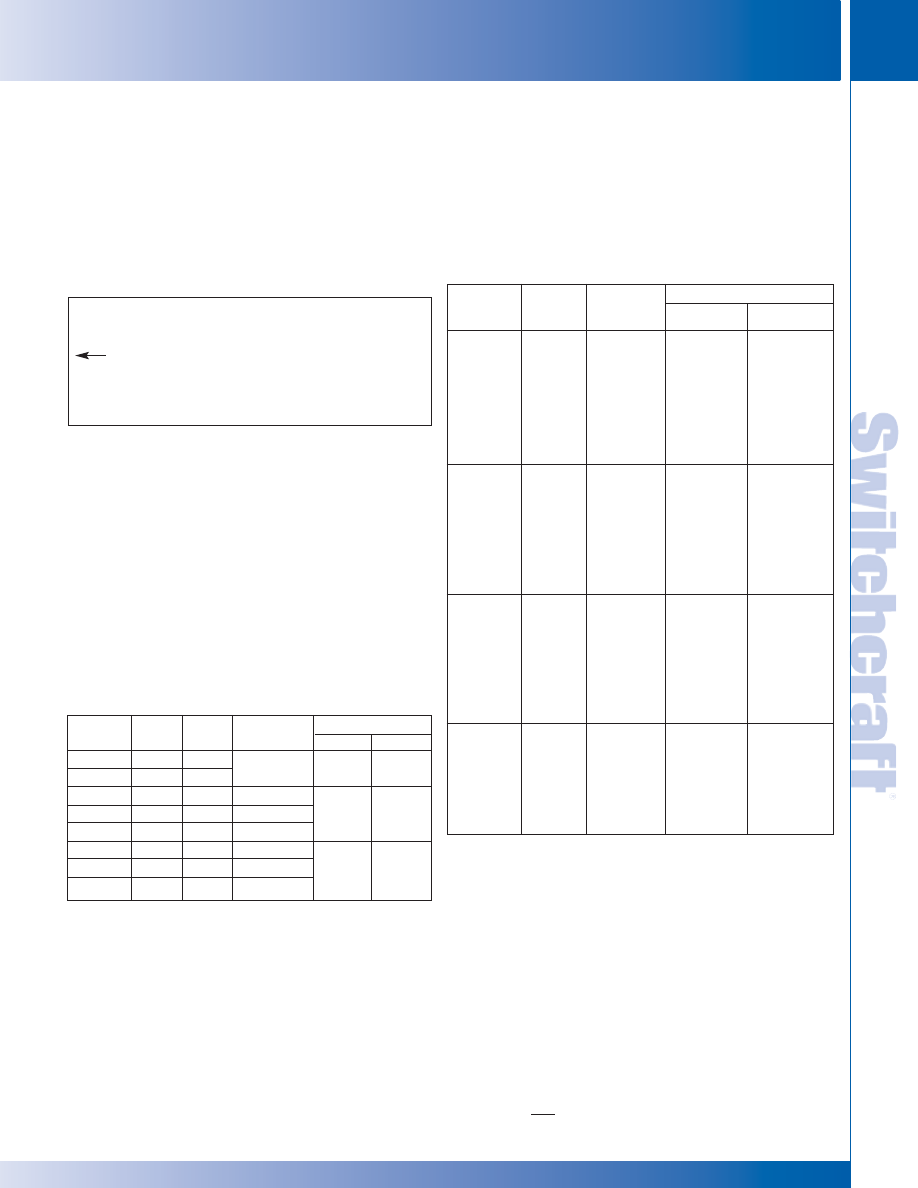
SWITCHCRAFT, INC. 5555 N. Elston Ave. • Chicago, IL 60630
317
SWITCHES
FAX: 773 792-2129
SWITCHES
DIMENSIONS ARE FOR REFERENCE ONLY
Inch
(mm)
MULTI-SWITCH PUSHBUTTONS – SERIES X, Y, & Z GLO-BUTTON
MULTI-SWITCH PUSHBUTTONS – SERIES X, Y, & Z GLO-BUTTON
SERIES X, Y AND Z “GLO-BUTTON”
Non-illuminated pushbuttons provide a clearly visible legend
like illuminated pushbuttons - without lamps, wiring or power.
With button depressed, illuminator moves up behind front
screen, and legend “lights up” by efficient reflection of exter-
nal ambient light. With button in “out” position, illuminator
retracts and legend appears non-luminous. Series X - specify
for horizontal or vertical mount switches. Series Y - legends
marked across .625" (15.88 mm) dimension. For horizontal
mount switches. Series Z - legends marked across .75"
(19.05 mm) dimension. For vertical mount switches.
Horizontally Mounted Switches: Three, .125" (3.18 mm)
high characters, each pushbutton.
Vertically Mounted Switches: Three, .125" (3.18 mm)
high characters, each pushbutton.
MULTI-SWITCH PUSHBUTTONS
TDWF PUSHBUTTON LEGENDS (special order)
MULTIPLE-STATION SWITCHES (continued)
Part
Number
X21248
◊
X51248
◊
Y21248
◊
Y28248
◊
Y51248
◊
Z21248
◊
Z28248
◊
Z51248
Figure
10
10
11
11
11
12
12
12
Screen
Color
Black
White
Black
Black
White
Black
Black
White
Illuminator
Color
Orange-Red
Orange-Red
Chartreuse
Orange-Red
Orange-Red
Chartreuse
Orange-Red
Width
.5
(12.7)
.625
(15.88)
.75
(19.05)
Height
.5
(12.7)
.75
(19.05)
.625
(15.88)
Size inches (mm)
MULTI-SWITCH PUSHBUTTON PART NUMBERS
Use the information below to specify colors of the pushbutton series
desired. Series TDWF must be specified separately (see page 316).
PART
NUMBER
◊
40001
◊
40002
◊
40003
◊
40004
40005
◊
40008
40012
◊
40901
◊
40902
◊
40903
◊
40904
◊
40905
◊
40908
◊
40912
A591
A592
◊
A593
◊
A594
A595
◊
A596
◊
A598
◊
E591
◊
E592
◊
E594
◊
E595
◊
E596
◊
E598
FIGURE
COLOR
1
2
4
1
Red
Black
Green
Blue
White
Yellow
Clear
Red
Black
Green
Blue
White
Yellow
Clear
Red
Black
Green
Blue
White
Brown
Yellow
Red
Black
Blue
White
Brown
Yellow
.
.594 (15.09)
1.219 (30.96)
.594 (15.09)
1.234 (31.34)
.
.974 (24.7)
.719 (18.26)
.594 (15.09)
.594 (15.09)
Overall Size Inch (mm)
Width
Height
◊
Available on special order only; contact Switchcraft for price and delivery.
LEGEND CHARACTERS AVAILABLE
1 through 999
.
Period
- Short Dash
Arrow
# Number or Pound
$ Dollar
| Vertical Bar
A through ZZZ
“ Quotes
-- Long Dash
& Ampersand
/ Slash
¢ Cent
NOTE: Recommended minimum standoff for switches mounted with
TDW-F pushbutton is .5" (12.7mm).
* Please visit the product pages on our website for the most up-to-date product information

NOTES
318
w w w . s w i t c h c r a f t . c o m
® Registered trademark of Switchcraft, Inc.
Note: Contact your Switchcraft Representative for price and delivery
PHONE: 773 792-2700
* Please visit the product pages on our website for the most up-to-date product information

SWITCHCRAFT, INC. 5555 N. Elston Ave. • Chicago, IL 60630
319
FAX: 773 792-2129
INDEX
03BL2M................................................47
05BL3M................................................47
05BL5M................................................47
05CL3M ...............................................46
05CL5M ...............................................46
05DL3M ...............................................47
05DL5M ...............................................47
05GM3M ..............................................46
05GM5M ..............................................46
05YL3M................................................47
05YL5M................................................47
06AL5F.................................................48
06EL5F.................................................48
09BL4M................................................47
09CL4M ...............................................46
09DL4M ...............................................47
09GM4M ..............................................46
09YL4M................................................47
101......................................................274
101S...................................................274
102......................................................274
102S...................................................274
103......................................................274
103S...................................................274
11..........................................................94
11001 .................................................231
11001L ...............................................231
11002 .................................................231
11002L ...............................................231
11003 .................................................231
11003D ..............................................231
11003DL ............................................231
11003L ...............................................231
11004 .................................................231
11004L ...............................................231
11005 .................................................231
11005L ...............................................231
11006 .................................................231
11006D ..............................................231
11006DL ............................................231
11006L ...............................................231
11008 .................................................231
11008L ...............................................231
11009 .................................................231
11009L ...............................................231
11012 .................................................231
11012L ...............................................231
111........................................................98
111PC ..................................................98
111PCS..............................................100
11201 .................................................231
11201L ...............................................231
11202 .................................................231
11202L ...............................................231
11203 .................................................231
11203D ..............................................231
11203DL ............................................231
11203L ...............................................231
11204 .................................................231
11204L ...............................................231
11205 .................................................231
11205L ...............................................231
11206 .................................................231
11206D ..............................................231
11206DL ............................................231
11206L ...............................................231
11208 .................................................231
11208L ...............................................231
11209 .................................................231
11209L ...............................................231
11212 .................................................231
11212L ...............................................231
112A .....................................................98
112APC................................................98
112APCS...........................................100
112B .....................................................98
112BPC................................................98
112BPCS...........................................100
113........................................................98
113B .....................................................98
113BPC................................................98
113BPC1M ..........................................98
113BPCS...........................................100
113D.....................................................98
113DPC ...............................................98
113E .....................................................98
113EPC................................................98
113EPCS...........................................100
113F .....................................................98
113FPC................................................98
113FPCS ...........................................100
113PC ..................................................98
113PCS..............................................100
114B .....................................................98
114BPC................................................98
114BPC1M ..........................................98
114BPCS...........................................100
120......................................................108
1200 ...................................................203
12001 .................................................297
12002 .................................................297
12003 .................................................297
12003D ..............................................297
12004 .................................................297
12005 .................................................297
12006 .................................................297
12006D ..............................................297
12010 .................................................297
12011 .................................................297
12012 .................................................297
12013 .................................................297
12014 .................................................297
12015 .................................................297
12016 .................................................297
12017 .................................................297
12033 .................................................297
12033T...............................................297
12034 .................................................297
12035 .................................................297
12036 .................................................297
12036D ..............................................297
12037 .................................................297
12037T...............................................297
121......................................................108
1230 ...................................................108
1238 ...................................................108
125......................................................109
128......................................................108
12A .......................................................94
12B .......................................................94
12BL5M................................................47
12BL6M................................................47
12CL5M ...............................................46
12DL5M ...............................................47
12DL6M ...............................................47
12GM5M ..............................................46
12GM6M ..............................................46
12YL5M................................................47
13..........................................................94
131......................................................108
133......................................................155
1332A.................................................203
1332B.................................................203
1334B.................................................203
1394RAPC...........................................58
1394SMT .............................................58
13A .......................................................94
13AL5F.................................................48
13AL6F.................................................48
13B .......................................................94
13E .......................................................94
13EL5F.................................................48
1400 ...................................................203
1400301.............................................203
1400315.............................................203
142A...................................................110
14B .......................................................94
151......................................................107
152......................................................107
152B...................................................107
153......................................................107
1532A.................................................203
1532A301 ..........................................203
1532B.................................................203
1532B301 ..........................................203
1534B.................................................203
154......................................................107
155......................................................107
15AL7F.................................................48
15AL8F.................................................48
15BL7M................................................47
15BL8M................................................47
15CL7M ...............................................46
15CL8M ...............................................46
15DL7M ...............................................47
15EL8F.................................................48
15GM7M ..............................................46
15GM8M ..............................................46
15J9068 .............................................230
15J9076 .............................................230
15J9077 .............................................230
15J9078 .............................................230
160......................................................147
1600 ...................................................212
1632A.................................................212
1632B.................................................212
1634B.................................................212
16J1055 .............................................223
170......................................................147
1700 ...................................................212
172......................................................148
173......................................................152
174S...................................................152
175......................................................152
176S...................................................152
177S...................................................152
178......................................................152
1789 ...................................................212
179......................................................152
181......................................................148
182......................................................148
182QB................................................147
182QBD .............................................147
184......................................................147
184L ...................................................147
187......................................................149
187B...................................................149
187BD ................................................149
187BL.................................................149
187D...................................................149
187L ...................................................149
188......................................................149
18QA18..............................................262
18QB18..............................................262
18QD18..............................................262
18QF18..............................................262
18QH18..............................................262
18QK18..............................................262
18QN18..............................................262
190......................................................151
190A...................................................151
190B...................................................151
190BL.................................................151
201......................................................274
201S...................................................274
202......................................................274
202S...................................................274
203......................................................274
203S...................................................274
20GM8M ..............................................46
20Q*20**............................................262
220......................................................153
225......................................................153
226......................................................154
227......................................................153
228......................................................153
229......................................................153
22QB22..............................................263
22QD22..............................................263
22QF22 ..............................................263
22QK22..............................................263
22QN22..............................................263
230......................................................153
2300......................................................86
2331......................................................86
2332A...................................................86
2332B...................................................86
2333......................................................86
235......................................................153
236......................................................154
237......................................................153
238......................................................153
239......................................................153
240......................................................145
2400 ...................................................205
2432A.................................................205
2432B.................................................205
2434B.................................................205
245......................................................145
24B .....................................................109
25........................................................109
250......................................................145
2501F ...................................................65
2501M ..................................................65
2501MP................................................65
2532A.................................................205
2532B.................................................205
2533 ...................................................205
2533B.................................................205
2534B.................................................205
2542B.................................................205
2544B.................................................205
255......................................................145
2588 ...................................................205
2589 ...................................................205
260......................................................145
2600 ...................................................205
2600301.............................................205
2600310.............................................205
267......................................................145
269......................................................145
26U1003 ............................................278
26U1004 ............................................278
26U1005 ............................................278
26U1006 ............................................278
26U1007 ............................................278
26U1008 ............................................278
26U1009 ............................................278
26U1010 ............................................278
270..............................................145-146
2732A.................................................205
2732A301 ..........................................205
2732B.................................................205
2732B301 ..........................................205
2733B.................................................205
2734B.................................................205
2734B301 ..........................................205
2789 ...................................................205
280..............................................145-146
281..............................................145-146
282......................................................155
285..............................................145-146
285L ...................................................145
288..............................................145-146
* Please visit the product pages on our website for the most up-to-date product information

320
w w w . s w i t c h c r a f t . c o m
® Registered trademark of Switchcraft, Inc.
Note: Contact your Switchcraft Representative for price and delivery
PHONE: 773 792-2700
INDEX
290..............................................145-146
297..............................................145-146
298 .............................................146, 155
299......................................................150
2BL6M..................................................47
2C1072 ..............................................134
2P-1216 .............................................148
2P1248...............................................145
2P1251...............................................147
2P1298...............................................145
2P1384...............................................157
2P1419...............................................158
2P1495...............................................145
2P1509...............................................153
2P1515...............................................162
2P1624...............................................162
2P2003...............................................143
305HJ084184....................................247
305KD084184 ...................................247
306HK042306 ...................................247
306HK084306 ...................................247
321........................................................27
322........................................................27
323........................................................27
324........................................................27
32HR***..............................................240
330F1 .................................................161
330F2 .................................................161
332A...................................................159
336A...................................................159
336B...................................................159
33HR***..............................................240
340......................................................159
345A...................................................159
349A...................................................159
350......................................................148
3501F .................................................123
3501FP ..............................................123
3501FR ..............................................123
3501M ................................................161
3501MC .............................................161
3502 ...................................................161
35021K206 ........................................303
35021K212 ........................................303
35022206...........................................303
35022212...........................................303
35027206...........................................303
35027212...........................................303
3502A.................................................161
3502AAU............................................161
3502ABAU .........................................161
3502RA..............................................161
3502RAAU.........................................161
3502RABAU ......................................161
3503 ...................................................123
35041K206 ........................................303
35041K212 ........................................303
35042206...........................................303
35042212...........................................303
35047206...........................................303
35047212...........................................303
3504M ................................................161
3505F .................................................123
35061K206 ........................................303
35061K212 ........................................303
35062206...........................................303
35062212...........................................303
35067206...........................................303
35067212...........................................303
3507 ...................................................161
35081K206 ........................................303
35081K212 ........................................303
35082206...........................................303
35082212...........................................303
35087206...........................................303
35087212...........................................303
35101K206 ........................................303
35101K212 ........................................303
35102206...........................................303
35102212...........................................303
35107206...........................................303
35107212...........................................303
35121K206 ........................................303
35121K212 ........................................303
35122206...........................................303
35122212...........................................303
35127206...........................................303
35127212...........................................303
3514PC..............................................123
3515PC..............................................123
3517PC..............................................123
352A...................................................159
35581 .................................................161
35582 .................................................161
35585 .................................................161
35HDBAU ..........................................156
35HDBAUS........................................156
35HDBN.............................................156
35HDBNS ..........................................156
35HDNAU ..........................................156
35HDNAUS .......................................156
35HDNN ............................................156
35HDNNS..........................................156
35HDRAAU .......................................156
35HDRABAU.....................................156
35HDRANN .......................................156
35HR***..............................................240
35PM1................................................119
35PM2A .............................................119
35RAPC2AH3...........................114, 116
35RAPC2AHN2........................114, 116
35RAPC2AHN3 ................................114
35RAPC2AV ..............................114-115
35RAPC2AV4 ............................114-115
35RAPC2AVN4.................................114
35RAPC2BH3...........................114, 116
35RAPC2BHN2........................114, 116
35RAPC2BHN3 ................................114
35RAPC2BV4............................114-115
35RAPC2BVN4.................................114
35RAPC3BH3...........................114, 116
35RAPC3BHN2........................114, 116
35RAPC3BHN3 ................................114
35RAPC3BV4............................114-115
35RAPC3BVN4.................................114
35RAPC4BH3...........................114, 116
35RAPC4BHN2........................114, 116
35RAPC4BHN3 ................................114
35RAPC4BV4............................114-115
35RAPC4BVN4.................................114
35RAPC7J.........................................112
35RAPC7JS ......................................112
35RASMT ..........................................117
35RASMT2AHNTR...........................117
35RASMT2BHNTR...........................117
35RASMT3BHNTR...........................117
35RASMT4BHNTR...........................117
361A ..........................................159, 265
362A...................................................265
363......................................................159
364A...................................................159
365......................................................159
36HR***..............................................240
37021K1206 ......................................305
37021K1212 ......................................305
370221206.........................................305
370221212.........................................305
370271206.........................................305
370271212.........................................305
37041K1206 ......................................305
37041K1212 ......................................305
370421206.........................................305
370421212.........................................305
370471206.........................................305
370471212.........................................305
37061K1206 ......................................305
37061K1212 ......................................305
370621206.........................................305
370621212.........................................305
370671206.........................................305
370671212.........................................305
37081K1206 ......................................305
37081K1212 ......................................305
370821206.........................................305
370821212.........................................305
370871206.........................................305
370871212.........................................305
370A...................................................159
37101K1206 ......................................305
37101K1212 ......................................305
371021206.........................................305
371021212.........................................305
371071206.........................................305
371071212.........................................305
37121K1206 ......................................305
37121K1212 ......................................305
371221206.........................................305
371221212.........................................305
371271206.........................................305
371271212.........................................305
374......................................................159
376......................................................159
377......................................................159
380......................................................148
38021K1206 ......................................305
38021K1212 ......................................305
380221206.........................................305
380221212.........................................305
380271206.........................................305
380271212.........................................305
38041K1206 ......................................305
38041K1212 ......................................305
380421206.........................................305
380421212.........................................305
380471206.........................................305
380471212.........................................305
38061K1206 ......................................305
38061K1212 ......................................305
380621206.........................................305
380621212.........................................305
380671206.........................................305
380671212.........................................305
38081K1206 ......................................305
38081K1212 ......................................305
380821206.........................................305
380821212.........................................305
380871206.........................................305
380871212.........................................305
38101K1206 ......................................305
38101K1212 ......................................305
381021206.........................................305
381021212.........................................305
381071206.........................................305
381071212.........................................305
38121K1206 ......................................305
38121K1212 ......................................305
381221206.........................................305
381221212.........................................305
381271206.........................................305
381271212.........................................305
383A .....................................................27
384A .....................................................27
386A .....................................................28
387A .....................................................28
389........................................................28
390........................................................28
391Q13 ................................................28
391Q23 ................................................28
391Q33 ................................................28
391Q43 ................................................28
391Q53 ................................................28
391Q63 ................................................28
40........................................................147
40001 .................................................317
40002 .................................................317
40003 .................................................317
40004 .................................................317
40005 .................................................317
40008 .................................................317
40012 .................................................317
40101 .................................................306
40103 .................................................306
40104 .................................................306
40105 .................................................306
40108 .................................................306
40112 .................................................306
40116 .................................................306
40201 .................................................306
40203 .................................................306
40204 .................................................306
40205 .................................................306
40208 .................................................306
40212 .................................................306
40401 .................................................306
40403 .................................................306
40404 .................................................306
40405 .................................................306
40408 .................................................306
40412 .................................................306
40502 .................................................306
40505 .................................................306
406......................................................306
40701 .................................................306
40703 .................................................306
40704 .................................................306
40705 .................................................306
40708 .................................................306
40901 .................................................317
40902 .................................................317
40903 .................................................317
40904 .................................................317
40905 .................................................317
40908 .................................................317
40912 .................................................317
41........................................................110
411......................................................141
412......................................................141
41203 .................................................298
41206 .................................................298
41208 .................................................298
41212 .................................................298
41306 .................................................298
41308 .................................................298
41312 .................................................298
41324 .................................................298
414......................................................141
415......................................................141
420......................................................138
425......................................................138
42A .....................................................110
43A .....................................................110
44..........................................................65
46201ME ...........................................284
46201MR ...........................................284
46202LE.............................................284
46202LR ............................................284
46202ME ...........................................284
46202MR ...........................................284
46203LE.............................................284
46203LR ............................................284
46203LSE..........................................284
46203LSR..........................................284
46203ME ...........................................284
46203MR ...........................................284
* Please visit the product pages on our website for the most up-to-date product information

SWITCHCRAFT, INC. 5555 N. Elston Ave. • Chicago, IL 60630
321
FAX: 773 792-2129
INDEX
46204LE.............................................284
46204LR ............................................284
46204ME ...........................................284
46204MR ...........................................284
46206LE.............................................284
46206LFE ..........................................284
46206LFR..........................................284
46206LR ............................................284
46206LSE..........................................284
46206LSR..........................................284
46206ME ...........................................284
46206MP ...........................................284
46206MR ...........................................284
46256LFR..........................................284
46311LDR..........................................285
46311MDR ........................................285
46311TDR .........................................285
46313LDR..........................................285
46313MDR ........................................285
46313TDR .........................................285
47202LE.............................................286
47202LR ............................................286
47203LE.............................................286
47203LR ............................................286
47204LCE..........................................286
47204LCR..........................................286
47204LE.............................................286
47204LR ............................................286
47206LCE..........................................286
47206LCR..........................................286
47206LE.............................................286
47206LR ............................................286
47215LCR..........................................286
47215LR ............................................286
47217LCR..........................................286
47217LR ............................................286
47221LCR..........................................286
47221LR ............................................286
47227LFE ..........................................286
47227LFR..........................................286
482......................................................140
482N...................................................140
482NC................................................140
483N...................................................140
483NC................................................140
49101 .................................................232
49102 .................................................232
49105 .................................................232
49201 .................................................232
49202 .................................................232
49205 .................................................232
49301 .................................................232
49302 .................................................232
49305 .................................................232
49309L ...............................................287
49309LS.............................................287
49312L ...............................................287
49312LS.............................................287
49329L ...............................................287
49329LS.............................................287
49331L ...............................................287
49331LS.............................................287
50207L ...............................................287
50207M ..............................................287
50208L ...............................................287
50209L ...............................................287
50209LS.............................................287
50209M ..............................................287
50209MS ...........................................287
50212L ...............................................287
50212LS.............................................287
510......................................................106
512......................................................106
515......................................................106
516-090-000-301...............................178
516-090-000-302...............................178
516-120-000-101...............................178
516-120-000-102...............................178
516-290-500 ......................................178
516-290-590 ......................................178
520......................................................106
53B .....................................................109
54A .....................................................109
54B .....................................................109
55........................................................109
5501F ...................................................65
5501M ..................................................65
5501MF................................................65
5501MP................................................65
55HA2F................................................50
56206L1.............................................288
56206L2.............................................288
56313L1.............................................289
56313L2.............................................289
570......................................................146
57GB3F................................................49
57GB5F................................................49
57HB3F................................................50
57HB5F................................................50
57KD3M ...............................................48
57NC5F................................................50
57PC3F................................................51
57PC3FS .............................................52
57PC5F................................................51
57PC5FS .............................................52
580......................................................146
581......................................................146
585......................................................146
588......................................................146
58NC3F................................................50
590......................................................146
597......................................................146
598......................................................146
59GB3F................................................49
60........................................................151
60GB4F................................................49
60HA4F................................................50
60NC4F................................................50
60PC4F................................................51
60PC4FS .............................................52
610......................................................106
612......................................................106
615......................................................106
61GB5F................................................49
61GB6F................................................49
61HA5F................................................50
61NC5F................................................50
61PC5F................................................51
61PC5FS .............................................52
61PC6F................................................51
61PC6FS .............................................52
620......................................................106
62206L ...............................................290
62GB7F................................................49
62GB8F................................................49
62HB7F................................................50
62HB8F................................................50
62NC7F................................................50
62NC8F................................................50
62PC7F................................................51
62PC7FS .............................................52
62PC8F................................................51
62PC8FS .............................................52
65021K206 ........................................309
65021K212 ........................................309
65022206...........................................309
65022212...........................................309
65027206...........................................309
65027212...........................................309
65041K206 ........................................309
65041K212 ........................................309
65042206...........................................309
65042212...........................................309
65047206...........................................309
65047212...........................................309
65061K206 ........................................309
65061K212 ........................................309
65062206...........................................309
65062212...........................................309
65067206...........................................309
65067212...........................................309
65081K206 ........................................309
65081K212 ........................................309
65082206...........................................309
65082212...........................................309
65087206...........................................309
65087212...........................................309
65101K206 ........................................309
65101K212 ........................................309
65102206...........................................309
65102212...........................................309
65107206...........................................309
65107212...........................................309
65121K206 ........................................309
65121K212 ........................................309
65122206...........................................309
65122212...........................................309
65127206...........................................309
65127212...........................................309
67021K506 ........................................310
67021K512 ........................................310
67022506...........................................310
67022512...........................................310
67027506...........................................310
67027512...........................................310
67041K506 ........................................310
67041K512 ........................................310
67042506...........................................310
67042512...........................................310
67047506...........................................310
67047512...........................................310
67061K506 ........................................310
67061K512 ........................................310
67062506...........................................310
67062512...........................................310
67067506...........................................310
67067512...........................................310
67081K506 ........................................310
67081K512 ........................................310
67082506...........................................310
67082512...........................................310
67087506...........................................310
67087512...........................................310
67101K506 ........................................310
67101K512 ........................................310
67102506...........................................310
67102512...........................................310
67107506...........................................310
67107512...........................................310
67121K506 ........................................310
67121K512 ........................................310
67122506...........................................310
67122512...........................................310
67127506...........................................310
67127512...........................................310
70........................................................147
712A...................................................134
712RA ................................................134
722A...................................................134
722RA ................................................134
732A...................................................134
732RA ................................................134
740......................................................157
745......................................................157
750......................................................157
755......................................................157
760......................................................162
760K...................................................162
761K...................................................162
765......................................................162
765K...................................................162
766K...................................................162
770......................................................157
780......................................................157
80........................................................108
820......................................................142
830......................................................108
838......................................................108
84206 .................................................296
84206L ...............................................296
84212 .................................................296
84212L ...............................................296
84306 .................................................296
84306L ...............................................296
84312 .................................................296
84312L ...............................................296
84324 .................................................296
84324L ...............................................296
850 .............................................121, 158
851......................................................158
852......................................................158
853......................................................158
855......................................................158
856......................................................158
857......................................................158
858......................................................158
860......................................................162
865......................................................162
88........................................................108
880......................................................158
881......................................................158
882......................................................158
883......................................................158
90........................................................151
90022B06 ..........................................312
90022B12 ..........................................312
90024B06 ..........................................312
90024B12 ..........................................312
90027B06 ..........................................312
90027B12 ..........................................312
90042B06 ..........................................312
90042B12 ..........................................312
90044B06 ..........................................312
90044B12 ..........................................312
90047B06 ..........................................312
90047B12 ..........................................312
90062B06 ..........................................312
90062B12 ..........................................312
90064B06 ..........................................312
90064B12 ..........................................312
90067B06 ..........................................312
90067B12 ..........................................312
90082B06 ..........................................312
90082B12 ..........................................312
90084B06 ..........................................312
90084B12 ..........................................312
90087B06 ..........................................312
90087B12 ..........................................312
90102B06 ..........................................312
90102B12 ..........................................312
90104B06 ..........................................312
90104B12 ..........................................312
90117B06 ..........................................312
90117B12 ..........................................312
90122B06 ..........................................312
90122B12 ..........................................312
90124B06 ..........................................312
90124B12 ..........................................312
90127B06 ..........................................312
90127B12 ..........................................312
903......................................................273
903D...................................................273
9115......................................................30
9129......................................................30
* Please visit the product pages on our website for the most up-to-date product information

322
w w w . s w i t c h c r a f t . c o m
® Registered trademark of Switchcraft, Inc.
Note: Contact your Switchcraft Representative for price and delivery
PHONE: 773 792-2700
INDEX
913......................................................273
913D...................................................273
9144......................................................30
921 .............................................245, 276
921K ..........................................245, 276
923......................................................273
923D...................................................273
9244......................................................30
933......................................................273
933D...................................................273
951......................................................273
952......................................................273
953......................................................273
961......................................................273
962......................................................273
963......................................................273
97GV***..............................................244
982A01R............................................269
982A03R............................................269
982A06R............................................269
99GD0726 .........................................244
99GV***..............................................244
A1600.................................................212
A1632B ..............................................212
A1634B ..............................................212
A3F......................................................4-5
A3F01.....................................................5
A3F02.....................................................5
A3F03.....................................................5
A3F04.....................................................5
A3F05.....................................................5
A3F06.....................................................5
A3F07.....................................................5
A3F08.....................................................5
A3F09.....................................................5
A3FB.......................................................4
A3FBAU .................................................4
A3FD ......................................................4
A3FL .......................................................4
A3FS.......................................................4
A3M.....................................................4-5
A3M01....................................................5
A3M02....................................................5
A3M03....................................................5
A3M04....................................................5
A3M05....................................................5
A3M06....................................................5
A3M07....................................................5
A3M08....................................................5
A3M09....................................................5
A3MB......................................................4
A3MBAU ................................................4
A3ML ......................................................4
A3MS......................................................4
A4F .........................................................4
A4FB.......................................................4
A4FBAU .................................................4
A4FD ......................................................4
A4FL .......................................................4
A4M ........................................................4
A4MB......................................................4
A4MBAU ................................................4
A4ML ......................................................4
A591...................................................317
A592...................................................317
A593...................................................317
A594...................................................317
A595...................................................317
A596...................................................317
A598...................................................317
A5F .........................................................4
A5FB.......................................................4
A5FBAU .................................................4
A5FD ......................................................4
A5FL .......................................................4
A5M ........................................................4
A5MB......................................................4
A5MBAU ................................................4
A5ML ......................................................4
A6501.................................................312
A6502.................................................312
A6503.................................................312
A6504.................................................312
A6505.................................................312
A6508.................................................312
A6F .........................................................4
A6FB.......................................................4
A6FBAU .................................................4
A6M ........................................................4
A6MBAU ................................................4
A7F .........................................................4
A7FB.......................................................4
A7FBAU .................................................4
A7M ........................................................4
A7MBAU ................................................4
AA3F.......................................................4
AA3FB....................................................4
AA3FBAU...............................................4
AA3FD....................................................4
AA3FL ....................................................4
AA3FLD..................................................4
AA3M......................................................4
AA3MB ...................................................4
AA3MBAU..............................................4
AA3ML....................................................4
AA4F.......................................................4
AA4FB....................................................4
AA4FD....................................................4
AA4FL ....................................................4
AA4M......................................................4
AA4ML....................................................4
AA5F.......................................................4
AA5FB....................................................4
AA5FD....................................................4
AA5FL ....................................................4
AA5M......................................................4
AA5MB ...................................................4
AA5ML....................................................4
AA6F.......................................................4
AA6FB....................................................4
AA6FD....................................................4
AA6FL ....................................................4
AA6M......................................................4
AA6ML....................................................4
AA7F.......................................................4
AA7FB....................................................4
AA7FD....................................................4
AA7FL ....................................................4
AA7M......................................................4
AA7ML....................................................4
AAA*F.....................................................6
AAA*M....................................................6
AD1600..............................................212
AD1632B ...........................................212
AD1634..............................................212
AQGP322...............................................4
AQGP323...............................................4
B1600.................................................212
B1632B ..............................................212
B1634B ..............................................212
B1650.................................................212
B1700.................................................212
B1795.................................................212
B1796.................................................212
B3F .......................................................10
B3FB ....................................................10
B3M ......................................................10
B3MB....................................................10
B4F .......................................................10
B4M ......................................................10
B5F .......................................................10
B5M ......................................................10
B6F .......................................................10
B6M ......................................................10
B7F .......................................................10
B7M ......................................................10
BD1600 ..............................................212
BD1632B ...........................................212
BD1634B ...........................................212
BD1650 ..............................................212
BD1700 ..............................................212
BD1795 ..............................................212
BD1796 ..............................................212
BPJF01 ..............................................123
BPJF01AU .........................................123
BPJF02 ..............................................123
BPJF02AU .........................................123
BPJF03 ..............................................123
BPJF03AU .........................................123
BPJF04 ..............................................123
BPJF04AU .........................................123
BPJF05 ..............................................123
BPJF05AU .........................................123
BPJF06 ..............................................123
BPJF06AU .........................................123
BPJJ01...............................................123
BPJJ01AU .........................................123
BPJJ02...............................................123
BPJJ02AU .........................................123
BPJJ03...............................................123
BPJJ03AU .........................................123
BPJJ04...............................................123
BPJJ04AU .........................................123
BPJJ05...............................................123
BPJJ05AU .........................................123
BPJJ06...............................................123
BPJJ06AU .........................................123
BPJR01..............................................123
BPJR01AU.........................................123
BPJR02..............................................123
BPJR02AU.........................................123
BPJR03..............................................123
BPJR03AU.........................................123
BPJR04..............................................123
BPJR04AU.........................................123
BPJR05..............................................123
BPJR05AU.........................................123
BPJR06..............................................123
BPJR06AU.........................................123
BXR011..............................................272
BXR0110 ...........................................272
BXR011PC ........................................272
BXR013..............................................272
BXR013P...........................................272
BXR016..............................................272
BXR016P...........................................272
BXR021..............................................272
BXR0210 ...........................................272
BXR021PC ........................................272
BXR023..............................................272
BXR023P...........................................272
BXR026..............................................272
BXR026PC ........................................272
BXR03................................................272
BXR0310 ...........................................272
BXR0310PC......................................272
BXR031PC ........................................272
BXR033..............................................272
BXR033PC ........................................272
BXR036..............................................272
BXR036PC ........................................272
BXR051..............................................272
BXR0510 ...........................................272
BXR051PC ........................................272
BXR053..............................................272
BXR053PC ........................................272
BXR056..............................................272
BXR056PC ........................................272
C11 .......................................................94
C12A ....................................................94
C12B ....................................................94
C1600.................................................212
C1634B ..............................................212
C240...................................................145
C245...................................................145
C270...................................................145
C3F.......................................................10
C3M......................................................10
C46203LR..........................................284
C46204MR ........................................284
C46206LFR .......................................284
C46206LR..........................................284
C4F.......................................................10
C4M......................................................10
C55B ..................................................109
C56206L1 ..........................................288
C56206L2 ..........................................288
C56313L1 ..........................................289
C56313L2 ..........................................289
C5F.......................................................10
C5M......................................................10
C62206L ............................................290
C63212L ............................................290
C6F.......................................................10
C6M......................................................10
C7F.......................................................10
C7M......................................................10
CB3F ....................................................65
CB3M ...................................................65
CD1600..............................................212
CD1634B ...........................................212
CMT331 ...............................................83
CMT332 ...............................................83
CMT332A.............................................83
CMT332B.............................................83
CMT332C ............................................84
CMT333 ...............................................83
CMT333A.............................................83
CMT333B.............................................84
CMT334-B ...........................................83
CMT334A.............................................83
CMT334C ............................................83
CMT334E.............................................83
CMT334F.............................................83
CMT335 ...............................................83
CMT335A.............................................84
CMT336 ...............................................83
CMT336A.............................................83
CMT336B.............................................83
CMT336C ............................................83
CMT336D ............................................83
CMT336E.............................................83
CMT337 ...............................................83
CMT338 ...............................................83
CMT339 ...............................................83
CMT341 ...............................................84
CMT342B.............................................84
CMT344B.............................................84
CMT346 ...............................................83
CMT346C ............................................84
CMT351C ............................................83
CMT354F.............................................83
CMT356C ............................................83
CMT358 ...............................................83
CMT359 ...............................................83
CN11 ..................................................109
CN12A ...............................................109
CN12B ...............................................109
CN13B ...............................................109
CPC102A...........................................263
CPC102D...........................................263
CPC102F...........................................263
CPC102K...........................................263
CPC102N...........................................263
* Please visit the product pages on our website for the most up-to-date product information

SWITCHCRAFT, INC. 5555 N. Elston Ave. • Chicago, IL 60630
323
FAX: 773 792-2129
INDEX
CPC102R...........................................263
CPC102T...........................................263
CPC102U...........................................263
D1600.................................................212
D1632A..............................................212
D1632B..............................................212
D1634B..............................................212
D1700.................................................212
D1789.................................................212
D3F.........................................................9
D3FB ......................................................9
D3FBAU .................................................9
D3FD ......................................................9
D3FDB....................................................9
D3M ........................................................9
D3MB .....................................................9
D3MBAU ................................................9
D4F.........................................................9
D4FB ......................................................9
D4FBAU .................................................9
D4M ........................................................9
D4MB .....................................................9
D4MBAU ................................................9
D5F.........................................................9
D5FB ......................................................9
D5FBAU .................................................9
D5M ........................................................9
D5MB .....................................................9
D5MBAU ................................................9
D6F.........................................................9
D6FB ......................................................9
D6FBAU .................................................9
D6FDB....................................................9
D6M ........................................................9
D6MB .....................................................9
D6MBAU ................................................9
D7F.........................................................9
D7FB ......................................................9
D7FBAU .................................................9
D7M ........................................................9
D7MB .....................................................9
D7MBAU ................................................9
DA013 ................................................275
DA023 ................................................275
DA033 ................................................275
DA043 ................................................275
DA053 ................................................275
DA083 ................................................275
DMD*FRA***........................................53
DS301 ................................................236
DS302 ................................................236
DS303 ................................................236
DS306 ................................................236
DS307 ................................................236
DS308 ................................................236
DS311 ................................................237
DS312 ................................................237
DS313 ................................................237
DS316 ................................................236
DS317 ................................................236
DS318 ................................................236
DS321 ................................................238
DS322 ................................................238
DS323 ................................................238
DS350 ................................................238
DS351 ................................................238
DS352 ................................................238
DS353 ................................................238
DUSB ...................................................56
DW05 .................................................311
DW1 ...................................................311
DW101 ...............................................311
DW102 ...............................................311
DW201 ...............................................311
DW202 ...............................................311
DW205 ...............................................311
DW3 ...................................................311
DW301 ...............................................310
DW302 ...............................................310
DW303 ...............................................310
DW304 ...............................................310
DW305 ...............................................310
DW308 ...............................................310
DW312 ...............................................310
DW313 ...............................................310
DW316 ...............................................310
DW4 ...................................................311
DW41 .................................................310
DW43 .................................................310
DW44 .................................................310
DW45 .................................................310
DW47 .................................................310
DW48 .................................................310
DW7 ...................................................311
E*F........................................................12
E*M.......................................................12
E111L.................................................107
E112BL ..............................................107
E591...................................................317
E592...................................................317
E594...................................................317
E595...................................................317
E596...................................................317
E598...................................................317
E903...................................................276
E903D ................................................276
E913...................................................276
E913D ................................................276
EAC225................................................71
EAC227................................................70
EAC233................................................70
EAC233S .............................................70
EAC305................................................70
EAC309................................................70
EAC311................................................70
EAC315................................................70
EAC319................................................70
EAC323................................................70
EAC325................................................70
EAC327................................................70
EAC333................................................70
EAC333S .............................................70
EAC405................................................70
EAC409................................................70
EAC411................................................70
EAC413................................................70
EAC451................................................70
EAC453................................................70
EAC455................................................70
EAC457................................................70
ED903 ................................................276
ED903D .............................................276
ED913 ................................................276
ED913D .............................................276
EH13942..............................................16
EHBNC2 ..............................................16
EHBNCSC ...........................................16
EHCAT62 .............................................16
EHRCA2 ..............................................16
EHRCABNC ........................................16
EHUSB2...............................................16
EN3C**.................................................43
EN3CR.................................................42
EN3CRAUTO ......................................42
EN3I**...................................................45
EN3INS16............................................42
EN3INS20............................................42
EN3P** .................................................44
EN3POS16 ..........................................42
EN3POS20 ..........................................42
EP903 ................................................276
EP903D..............................................276
EP913 ................................................276
EP913D..............................................276
EPS1PC1...........................................291
EPS1PC2...........................................291
EPS1PC3...........................................291
EPS1SL1 ...........................................291
EPS2PC1...........................................291
EPS2PC2...........................................291
EPS2PC3...........................................291
EPS3PC1...........................................291
EPS3PC2...........................................291
EPS3PC3...........................................291
EPS3SL1 ...........................................291
EPS4PC1...........................................291
EPS4PC2...........................................291
EPS4PC3...........................................291
F3FRAF ...............................................23
F3FSTF................................................23
F3MRAF...............................................23
F3SM3F ...............................................23
FA11 .....................................................94
FAL11 ...................................................94
G3MS ...................................................26
G4MS ...................................................26
G6083 ................................................296
G6084 ................................................296
H101...................................................275
H101PC .............................................275
H102...................................................275
H102PC .............................................275
H103...................................................275
H103D................................................275
H103PC .............................................275
H201...................................................275
H201PC .............................................275
H202...................................................275
H202PC .............................................275
H203...................................................275
H203D................................................275
H203PC .............................................275
H3MS ...................................................26
H4MS ...................................................26
HP75BNC1 ..........................................66
HP75BNC10........................................66
HP75BNC12........................................66
HP75BNC2 ..........................................66
HP75BNC6 ..........................................66
HP75BNC7 ..........................................66
HP75BNC9 ..........................................66
HPCC4F...............................................38
HPCC4FRA .........................................38
HPCI4F ................................................38
HPCP*4................................................40
HPCPK112F......................................190
HPCPK112F1....................................190
HPCPK1B..........................................190
HPCPK324F......................................190
HPCPK324F1....................................190
HPCPK3B..........................................190
IBS10B02106AR...............................314
IBS10B04106AR...............................314
IBS10B06106AR...............................314
IBS10B08106AR...............................314
IBS10B10106AR...............................314
IBS10B12106AR...............................314
IBS15B02106AR...............................314
IBS15B04106AR...............................314
IBS15B06106AR...............................314
IBS15B08106AR...............................314
IBS15B10106AR...............................314
IBS15B12106AR...............................314
IBS20B02106AR...............................314
IBS20B04106AR...............................314
IBS20B06106AR...............................314
IBS20B08106AR...............................314
IBS20B10106AR...............................314
IBS20B12106AR...............................314
J3FS .....................................................26
J4MS ....................................................26
JP012000...........................................207
JP012S32A........................................207
JP012S32B1 .....................................207
JP012S34B1 .....................................207
JP022000...........................................207
JP022S32A........................................207
JP022S32B........................................207
JP022S34B........................................207
JP032000...........................................207
JP032S32A........................................207
JP032S32B........................................207
JP032S34B........................................207
JP042000...........................................207
JP042S32A........................................207
JP042S32B........................................207
JP042S34B........................................207
JP052000...........................................207
JP052S32A........................................207
JP052S32B........................................207
JP052S34B........................................207
JP062000...........................................207
JP062S32A........................................207
JP062S32B........................................207
JP062S34B........................................207
JP072000...........................................207
JP072S32A........................................207
JP072S32B........................................207
JP072S34B........................................207
JP082000...........................................207
JP082S32A........................................207
JP082S32B........................................207
JP082S34B........................................207
JP092000...........................................207
JP092S32A........................................207
JP092S32B........................................207
JP092S34B........................................207
JP102000...........................................207
JP102S32A........................................207
JP102S32B........................................207
JP102S34B........................................207
JP112000...........................................207
JP112S32A........................................207
JP112S32B........................................207
JP112S34B........................................207
JP122000...........................................207
JP122S32A........................................207
JP122S32B........................................207
JP122S34B........................................207
JP312000...........................................210
JP322000...........................................210
JP9902...............................................207
JP9922...............................................207
JP9942...............................................207
JPD312000........................................210
JPD322000........................................210
K131...................................................296
K255 .......................................................5
K3FS ....................................................26
K459...................................................163
K460...................................................163
K4FS ....................................................26
L11........................................................94
L112A...................................................98
L112APC..............................................98
L112B...................................................98
L113B...................................................98
L114B...................................................98
L114BPC..............................................98
L12A .....................................................94
L12B .....................................................94
L3MN....................................................30
L4MN....................................................30
L5MN....................................................30
* Please visit the product pages on our website for the most up-to-date product information

324
w w w . s w i t c h c r a f t . c o m
® Registered trademark of Switchcraft, Inc.
Note: Contact your Switchcraft Representative for price and delivery
PHONE: 773 792-2700
INDEX
L712A.................................................134
L712RA..............................................134
L722A.................................................134
L722RA..............................................134
LUS001..............................................271
LUS001PC.........................................271
LUS001ST .........................................271
M111 ....................................................97
M112A..................................................97
M112APC ............................................97
M112B..................................................97
M112BPC ............................................97
M113B..................................................97
M113E..................................................97
M113PPC1M .......................................97
M114B..................................................97
M114BPC ............................................97
M114BPC1M .......................................97
M3M .....................................................30
M4M .....................................................30
M5M .....................................................30
MBPK175T ........................................201
MD10..................................................249
MD15..................................................249
MD3....................................................249
MD6....................................................249
MDPC2A............................................121
MDPC2AR.........................................121
MDPC2ARA ......................................121
MDSL2A ............................................121
MDSL2ARA .......................................121
MDSMT2ARATR...............................120
MDSMT2BRATR...............................120
MDSMT3BRATR...............................120
MDSMT4BRATR...............................120
ML112B................................................97
MN111..................................................97
MN112A ...............................................97
MN112APC..........................................97
MN112B ...............................................97
MN112BPC..........................................97
MN113B ...............................................97
MN113BPC..........................................97
MN113E ...............................................97
MN114B ...............................................97
MN114BPC..........................................97
MN122A ...............................................97
MNL112B.............................................97
MNL113B.............................................97
MT331 ..................................................83
MT332 ..................................................83
MT332A ...............................................83
MT332B ...............................................83
MT332C ...............................................83
MT333 ..................................................83
MT333A ...............................................84
MT333B ...............................................83
MT333E ...............................................83
MT334A ...............................................83
MT334B ...............................................83
MT334C ...............................................83
MT334E ...............................................83
MT334F................................................83
MT335 ..................................................83
MT335A ...............................................84
MT336 ..................................................83
MT336A ...............................................83
MT336B ...............................................83
MT336C ...............................................83
MT336D ...............................................83
MT336E ...............................................83
MT337 ..................................................83
MT338 ..................................................83
MT339 ..................................................83
MT342B ...............................................83
MT343B ...............................................84
MT344B ...............................................83
MT346 ..................................................83
MT346A ...............................................84
MT346B ...............................................84
MT346C ...............................................84
MT352A ...............................................83
MT354B ...............................................83
MT355 ..................................................83
MT356C ...............................................83
MT357 ..................................................83
MT388 ..................................................85
MT389 ..................................................85
MT48FN.............................................184
MT48HN ............................................184
MT48K1FN ........................................182
MT48K1HN........................................182
MT48K1NN........................................182
MT48K1NS........................................182
MT48K3FN ........................................182
MT48K3HN........................................182
MT48K3NN........................................182
MT48NN ............................................184
MT48NS.............................................184
MT52FN.............................................184
MT52HN ............................................184
MT52K1FN ........................................182
MT52K1HN........................................182
MT52K1NN........................................182
MT52K1NS........................................182
MT52K3FN ........................................182
MT52K3HN........................................182
MT52K3NN........................................182
MT52NN ............................................184
MT52NS.............................................184
MTP24K7...........................................174
MTP48K1NO.....................................166
MTP48K1NS .....................................166
MTP48K3BPNS ................................174
MTP48K3NO.....................................166
MTP48K3NS .....................................166
MTP48K3PBNO................................174
MTP48K3SNO ..................................166
MTP52K3BPNO................................174
MTPFA48K1NO ................................164
MTPFA48K1NS.................................164
MTPH48K1NO ..................................171
MTPH48K1NS...................................171
MTPH48K3NO ..................................171
MTPH48K3NS...................................171
MTPH48K3SNO ...............................171
MVJ*75T ............................................137
MVJ*NT..............................................137
MVP32K1*75T ..................................196
MVP32K1*NT....................................196
MVP32K3*75T ..................................196
MVP32K3*NT....................................196
N111.....................................................98
N111PC ...............................................98
N111PCS...........................................100
N112A ..................................................98
N112APC.............................................98
N112APCS ........................................100
N112B ..................................................98
N112BPC.............................................98
N112BPCS ........................................100
N113.....................................................98
N113B ..................................................98
N113BPC.............................................98
N113BPCS ........................................100
N114B ..................................................98
N114BPC.............................................98
N114BPCS ........................................100
N3MS ...................................................25
NL111...................................................98
NL112A ................................................98
NL112B ................................................98
NL113B ................................................98
NL114B ................................................98
NL114BPC...........................................98
NL114BPCS......................................100
P2290.................................................230
P2315.................................................230
P2316.................................................230
P23491...............................................271
P234913.............................................271
P23492...............................................271
P23493...............................................271
P23494...............................................271
P23495...............................................271
P23497...............................................271
P23498...............................................271
P2456.................................................230
P286301...............................................91
P286302...............................................91
P286304...............................................91
P286305...............................................91
P286307...............................................91
P286308...............................................91
P286401...............................................91
P286402...............................................91
P286404...............................................91
P286405...............................................91
P286407...............................................91
P286408...............................................91
P2912.................................................297
P2936 ........................................270, 314
P2937 ........................................270, 314
P2938 ........................................270, 314
P2939 ........................................270, 314
P2940 ........................................270, 314
P2941 ........................................270, 314
P2942 ........................................270, 314
P2943 ........................................270, 314
P2951 ........................................270, 314
P2952 ........................................270, 314
P2953 ........................................270, 314
P2954 ........................................270, 314
P2955 ........................................270, 314
P2956 ........................................270, 314
P2957 ........................................270, 314
P2958 ........................................270, 314
P2979.................................................314
P2992.................................................314
P3F .........................................................8
P3M ........................................................8
P4F .........................................................8
P4M ........................................................8
P5F .........................................................8
P5M ........................................................8
PC12A..................................................94
PC142A..............................................110
PC712A..............................................134
PC722A..............................................134
PC732A..............................................134
PCL712A ...........................................134
PCL722A ...........................................134
PD3F***................................................20
PD3M***...............................................20
PJRAN1X1U01 .................................126
PJRAN1X1U02 .................................126
PJRAN1X1U03 .................................126
PJRAN1X1U04 .................................126
PJRAN2X1U01 .................................126
PJRAN2X1U02 .................................126
PJRAN3X1U01 .................................126
PJRAN3X1U02 .................................126
PJRAS1X1S01..................................126
PJRAS1X1S02..................................126
PJRAS1X1S03..................................126
PJRAS1X1S04..................................126
PJRAS1X2S01..................................126
PJRAS1X2S02..................................126
PJRAS1X3S01..................................126
PJRAS1X3S02..................................126
PJRAS1X3U01..................................126
PJRAS2X1S01..................................126
PJRAS2X1S02..................................126
PJRAS2X2S01..................................126
PJRAS3X1S01..................................126
PJRAS3X1S02..................................126
PJRAS3X2S01..................................126
PJRAS3X2S02..................................126
PJRAS4X2U01..................................126
PL102.................................................278
PL103205 ..........................................277
PL103705 ..........................................277
PL106205 ..........................................277
PL106705 ..........................................277
PL111.................................................278
PL112205 ..........................................277
PL112705 ..........................................277
PL123705 ..........................................277
PL126205 ..........................................277
PL126705 ..........................................277
PL202.................................................278
PL203205 ..........................................277
PL203705 ..........................................277
PL206205 ..........................................277
PL206705 ..........................................277
PL211.................................................278
PL212205 ..........................................277
PL212705 ..........................................277
PL226205 ..........................................277
PL226705 ..........................................277
PL303.................................................278
PL305.................................................278
PL308.................................................278
PL403205 ..........................................277
PL403705 ..........................................277
PL406205 ..........................................277
PL406705 ..........................................277
PL412205 ..........................................277
PL412705 ..........................................277
PL501.................................................278
PL503.................................................278
PL503205 ..........................................277
PL504.................................................278
PL505.................................................278
PL506205 ..........................................277
PL506705 ..........................................277
PL508.................................................278
PL512.................................................278
PL512205 ..........................................277
PL512705 ..........................................277
PL513.................................................278
PL703705 ..........................................277
PL706205 ..........................................277
PL706705 ..........................................277
PL712205 ..........................................277
PL712705 ..........................................277
PL803205 ..........................................277
PL803705 ..........................................277
PL806205 ..........................................277
PL806705 ..........................................277
PL812205 ..........................................277
PL812705 ..........................................277
PL9105...............................................278
PL9205...............................................278
PPT ....................................................163
PQG3F***.............................................18
PQG3M***............................................18
PT1LA ................................................163
PT2B ..................................................163
QG3F....................................................25
QG3FD.................................................25
QG3FDPC ...........................................25
QG3M...................................................25
QG4F....................................................25
* Please visit the product pages on our website for the most up-to-date product information

SWITCHCRAFT, INC. 5555 N. Elston Ave. • Chicago, IL 60630
325
FAX: 773 792-2129
INDEX
QG4FD.................................................25
QG4M...................................................25
QG5F....................................................25
QG5FD.................................................25
QG5M...................................................25
QG6F....................................................25
QG6FD.................................................25
QG6M...................................................25
QG7F....................................................25
QG7FD.................................................25
QG7M...................................................25
QGP322 .................................................4
QGP323 .................................................4
QGP326 ...............................................10
QGP327 ...............................................10
QGP362 .................................................9
QGP363 .................................................9
QGPK116FB .....................................188
QGPK116MB ....................................188
QGPK18M8FB ..................................188
QGPK1B............................................188
QGPK332MFB ..................................188
QGPK3B............................................188
R3FZ.......................................................8
R3MZ......................................................8
R4FZ.......................................................8
R4MZ......................................................8
R5FZ.......................................................8
R5MZ......................................................8
R6FZ.......................................................8
R6MZ......................................................8
R7FZ.......................................................8
R7MZ......................................................8
RA200 ................................................256
RA202 ................................................257
RA205 ................................................256
RA207 ................................................257
RA208 ................................................257
RA217 ................................................257
RA35 ..................................................255
RA353 ................................................247
RA354 ................................................247
RA355 ................................................247
RA356.........................................246-247
RA357 ................................................247
RA358 ................................................247
RA359 ................................................247
RA373 ................................................247
RA374.........................................246-247
RA375 ................................................247
RA376 ................................................247
RA377 ................................................247
RA378 ................................................247
RA379 ................................................247
RA40 ..................................................255
RA41 ..................................................255
RA49B11 ...........................................103
RA49B12A.........................................103
RA49B12B.........................................103
RA49B14B.........................................103
RA49C11 ...........................................103
RA49C12A.........................................103
RA49C12B.........................................103
RA49C14B.........................................103
RA700 ................................................254
RA70B11 ...........................................103
RA70B12A.........................................103
RA70B12B.........................................103
RA70B14B.........................................103
RA70C11 ...........................................103
RA70C12A.........................................103
RA70C12B.........................................103
RA70C14B.........................................103
RA710 ................................................254
RA712A..............................................241
RA722A..............................................241
RA760 ................................................241
RA765 ................................................241
RA850 ................................................253
RAPC322.............................................78
RAPC712...........................................130
RAPC722...........................................130
RAPC732...........................................130
RAPC732OF .....................................130
RAPC742...........................................130
RAPC742OF .....................................130
RAPC752...........................................130
RAPC752S ........................................130
RASH712...........................................130
RASH722...........................................130
RASH732...........................................130
RASM712 ..........................................130
RASM722 ..........................................130
RASM732 ..........................................130
RASM742TR .....................................130
RASM752STR...................................130
RASM752TR .....................................130
RN111PC...........................................103
RN112APC........................................103
RN112BPC........................................103
RN113BPC........................................103
RN113FPC ........................................103
RN114BPC........................................103
RS422H48N081................................191
RS422H4N081..................................192
RS422H4N161..................................191
RS422H4N162 ..........................191-192
RS422H4N242 ..........................191-192
RS422PH4N081........................191-192
RS422PH4N161 ...............................191
RS422PH4N162........................191-192
RS422PH4N242........................191-192
RS422PV4N081........................191-192
RS422PV4N161................................191
RS422PV4N162........................191-192
RS422PV4N242........................191-192
RS422PV4N322........................191-192
RS422V4N081...........................191-192
RS422V4N161 ..................................191
RS422V4N162...........................191-192
RS422V4N242...........................191-192
RS422V4N322...........................191-192
RTT34B01............................................91
RTT34B02............................................91
RTT34B04............................................91
RTT34B05............................................91
RTT34B07............................................91
RTT34B08............................................91
RTT8701 ..............................................91
RTT8702 ..............................................91
RTT8704 ..............................................91
RTT8705 ..............................................91
RTT8707 ..............................................91
RTT8708 ..............................................91
S11 .......................................................94
S112BPC .............................................98
S112BPCS ........................................100
S12A.....................................................94
S12B.....................................................94
S13B.....................................................94
S230...................................................153
S250...................................................151
S260...................................................151
S267...................................................151
S280 ..........................................146, 151
S3F5M..................................................29
S3FM....................................................28
S4FM....................................................28
S580...................................................146
S5F3M..................................................29
S5FM....................................................28
S760...................................................162
S760K ................................................162
S761K ................................................162
S765...................................................162
S765K ................................................162
S766K ................................................162
S830...................................................108
SL01 .....................................................61
SL02 .....................................................61
SL03 .....................................................61
SL04 .....................................................61
SL05................................................61-62
SL102F.................................................63
SL102M................................................63
SL103F.................................................63
SL103M................................................63
SL104F.................................................63
SL104M................................................63
SL105F.................................................63
SL105M................................................63
SL172F.................................................63
SL173F.................................................63
SL173M................................................63
SL174F.................................................63
SL174M................................................63
SL175F.................................................63
SL175M................................................63
SL18 .....................................................64
SL182F.................................................64
SL182M................................................64
SL183F.................................................64
SL183M................................................64
SL184F.................................................64
SL184M................................................64
SL185F.................................................64
SL185M................................................64
SL402F.................................................62
SL402M................................................62
SL403F.................................................62
SL403M................................................62
SL404F.................................................62
SL404M................................................62
SL405F.................................................62
SL405M................................................62
SL412F.................................................62
SL413F.................................................62
SL413M................................................62
SL414F.................................................62
SL414M................................................62
SL415F.................................................62
SL415M................................................62
SMD*FRA***........................................53
SN37A11 ...........................................103
SN37A12A.........................................103
SN37A12B.........................................103
SN37A14B.........................................103
SN49A11 ...........................................103
SN49A12A.........................................103
SN49A12B.........................................103
SN49A14B.........................................103
SN49B11 ...........................................103
SN49B12A.........................................103
SN49B12B.........................................103
SN49B14B.........................................103
SN49C11 ...........................................103
SN49C12A.........................................103
SN49C12B.........................................103
SN49C14B.........................................103
SN70B11 ...........................................103
SN70B12A.........................................103
SN70B12B.........................................103
SN70B14B.........................................103
SN70C11 ...........................................103
SN70C12A.........................................103
SN70C12B.........................................103
SN70C14B.........................................103
SR00.......................................................5
SR01.......................................................5
SR02.......................................................5
SR03.......................................................5
SR04.......................................................5
SR05.......................................................5
SR06.......................................................5
SR07.......................................................5
SR08.......................................................5
SR09.......................................................5
ST121.................................................257
ST125.................................................256
ST131.................................................257
ST200.................................................257
ST230.................................................257
ST303.................................................247
ST304.................................................247
ST305.................................................247
ST306.................................................247
ST307.........................................246-247
ST308.................................................247
ST309.................................................247
ST323.................................................247
ST324.........................................246-247
ST325.................................................247
ST326.................................................247
ST327.................................................247
ST328.................................................247
ST329.................................................247
ST35...................................................255
ST40...................................................255
ST60...................................................255
ST600.................................................250
ST603.................................................250
ST604.................................................250
ST605.................................................250
ST626.................................................250
ST700.................................................254
ST710.................................................254
ST740.................................................254
ST750.................................................254
ST760.................................................241
ST765.................................................241
ST850.................................................253
ST90...................................................258
ST900.................................................245
ST900F ..............................................245
ST91...................................................258
SUSB....................................................56
T127410.............................................297
T12742...............................................297
T12745...............................................297
T3F .........................................................9
T3FL .......................................................9
T3FLM....................................................9
T3FM ......................................................9
T4F .........................................................9
T4FL .......................................................9
T4FLM....................................................9
T4FM ......................................................9
TA01 .....................................................31
TA02 .....................................................31
TA03 .....................................................31
TA04 .....................................................31
TA05 .....................................................31
TA06 .....................................................31
TA3F................................................31-32
TA3FB...................................................32
TA3FL...................................................32
TA3FLB ................................................32
TA3M...............................................31-32
TA3MB..................................................32
TA3ML ..................................................32
TA4F .....................................................32
TA4FB...................................................32
TA4FL...................................................32
TA4FLB ................................................32
* Please visit the product pages on our website for the most up-to-date product information

326
w w w . s w i t c h c r a f t . c o m
® Registered trademark of Switchcraft, Inc.
Note: Contact your Switchcraft Representative for price and delivery
PHONE: 773 792-2700
INDEX
TA4M ....................................................32
TA4MB..................................................32
TA4ML ..................................................32
TA5F .....................................................32
TA5FL...................................................32
TA5FLB ................................................32
TA5M ....................................................32
TA5ML ..................................................32
TA5MLB................................................32
TA6FL...................................................32
TA6ML ..................................................32
TA7FL...................................................32
TA7ML ..................................................32
TA8FL...................................................32
TA8ML ..................................................32
TAD2...................................................142
TAD3...................................................142
TB3M....................................................33
TB3MB .................................................33
TB4M....................................................33
TB4MB .................................................33
TB5M....................................................33
TB5MB .................................................33
TB6M....................................................33
TB7M....................................................33
TB8M....................................................33
TBA03 ..................................................37
TBA04 ..................................................37
TBA05 ..................................................37
TBA06 ..................................................37
TLP4.....................................................33
TLP6.....................................................33
TQG3F .................................................37
TQG3M ................................................37
TQG4F .................................................37
TQG4M ................................................37
TQG5F .................................................37
TQG5M ................................................37
TQG6F .................................................37
TQG6M ................................................37
TR1PC ...............................................121
TR2A ..................................................121
TRA**M ................................................34
TRA3M.................................................34
TRA6M.................................................34
TRA6MF...............................................34
TRG4M ................................................33
TRGS4F...............................................33
TT** ....................................................267
TT101.................................................265
TT102.................................................265
TT103.................................................265
TT104.................................................265
TT105.................................................265
TT106.................................................265
TT107.................................................265
TT108.................................................265
TT109.................................................265
TT110.................................................265
TT111.................................................265
TT112.................................................265
TT113.................................................265
TT114.................................................265
TT115.................................................265
TT121.................................................265
TT122.................................................265
TT123.................................................265
TT124.................................................265
TT125.................................................265
TT126.................................................265
TT127.................................................265
TT128.................................................265
TT129.................................................265
TT130.................................................265
TT131.................................................265
TT132.................................................265
TT133.................................................265
TT134.................................................265
TT135.................................................265
TT141.................................................265
TT142.................................................265
TT143.................................................265
TT144.................................................265
TT145.................................................265
TT146.................................................265
TT147.................................................265
TT148.................................................265
TT149.................................................265
TT150.................................................265
TT151.................................................265
TT152.................................................265
TT153.................................................265
TT154.................................................265
TT155.................................................265
TT161.................................................265
TT162.................................................265
TT163.................................................265
TT164.................................................265
TT165.................................................265
TT166.................................................265
TT167.................................................265
TT168.................................................265
TT169.................................................265
TT170.................................................265
TT171.................................................265
TT172.................................................265
TT173.................................................265
TT174.................................................265
TT175.................................................265
TT201.................................................234
TT202.................................................234
TT203.................................................234
TT204.................................................234
TT205.................................................234
TT206.................................................234
TT207.................................................234
TT208.................................................234
TT209.................................................234
TT210.................................................234
TT251.................................................143
TT252.................................................143
TT253 ..........................................90, 143
TT253N ..............................................143
TT253NC ...........................................143
TT254.................................................143
TT254N ..............................................143
TT254NC ...........................................143
TT261.................................................144
TT263 ..........................................90, 144
TT281.................................................265
TT282.................................................265
TT283.................................................265
TT284.................................................265
TT289.................................................265
TT2W48MCF1...................................223
TT2W48MCN1 ..................................223
TT2W48VCF1 ...................................223
TT2W48VCN1...................................223
TT30 .....................................................87
TT30FM ...............................................87
TT31 .....................................................87
TT31DC ...............................................87
TT31FM ...............................................87
TT31FMDC..........................................87
TT32A...................................................87
TT32ADC.............................................87
TT32AFM.............................................87
TT32AFMDC .......................................87
TT32B...................................................87
TT32BDC.............................................87
TT32BFM.............................................87
TT32BFMDC .......................................87
TT32C ..................................................87
TT32CDC.............................................87
TT32CFM.............................................87
TT32CFMDC .......................................87
TT33 .....................................................87
TT33B...................................................87
TT33BDC.............................................87
TT33BFM.............................................87
TT33BFMDC .......................................87
TT33DC ...............................................87
TT33FM ...............................................87
TT33FMDC..........................................87
TT34A...................................................87
TT34ADC.............................................87
TT34AFM.............................................87
TT34AFMDC .......................................87
TT34B...................................................87
TT34BDC.............................................87
TT34BFM.............................................87
TT34BFMDC .......................................87
TT34C ..................................................87
TT34CDC.............................................87
TT34CFM.............................................87
TT34CFMDC .......................................87
TT34F...................................................87
TT34FDC .............................................87
TT35 .....................................................87
TT35DC ...............................................87
TT35FM ...............................................87
TT35FMDC..........................................87
TT36 .....................................................87
TT36A...................................................87
TT36ADC.............................................87
TT36AFM.............................................87
TT36AFMDC .......................................87
TT36B...................................................87
TT36BDC.............................................87
TT36C ..................................................87
TT36CDC.............................................87
TT36CFM.............................................87
TT36CFMDC .......................................87
TT36DC ...............................................87
TT36FM ...............................................87
TT36FMDC..........................................87
TT401.................................................230
TT403.................................................230
TT404.................................................230
TT405.................................................230
TT408.................................................230
TT413.................................................230
TT4506...............................................230
TT45106.............................................230
TT45124.............................................230
TT45148.............................................230
TT45206.............................................230
TT45224.............................................230
TT45248.............................................230
TT45306.............................................230
TT45324.............................................230
TT45348.............................................230
TT45406.............................................230
TT45424.............................................230
TT45448.............................................230
TT45524.............................................230
TT45548.............................................230
TT45806.............................................230
TT45824.............................................230
TT45848.............................................230
TT4W24MCF1...................................223
TT4W24MCN1 ..................................223
TT4W24VCF1 ...................................223
TT4W24VCN1...................................223
TT501.................................................236
TT502.................................................236
TT503.................................................236
TT504.................................................236
TT505.................................................212
TT506.................................................212
TT507.................................................212
TT508.................................................212
TT509.................................................212
TT51 ..........................................215, 218
TT510 ........................................230, 234
TT5102000 ........................................217
TT5102S31........................................217
TT5102S32A .....................................217
TT5102S32B .....................................217
TT5102S33B .....................................217
TT5102S34B .....................................217
TT5102W31.......................................217
TT5102W32A ....................................217
TT5102W32B ....................................217
TT5102W33B ....................................217
TT5102W34B ....................................217
TT511.................................................212
TT5121...............................................233
TT5122...............................................233
TT5123...............................................233
TT5124...............................................233
TT5125...............................................233
TT5128...............................................233
TT5131...............................................233
TT5132...............................................233
TT5133...............................................233
TT5134...............................................233
TT5135...............................................233
TT5138...............................................233
TT5141...............................................233
TT5142...............................................233
TT5143...............................................233
TT5144...............................................233
TT5145...............................................233
TT5148...............................................233
TT5151...............................................234
TT5152...............................................234
TT5155...............................................234
TT516.................................................237
TT517.................................................237
TT518.................................................237
TT519.................................................236
TT52...................................................218
TT520.................................................236
TT5202000 ........................................217
TT5202S31........................................217
TT5202W34B ....................................217
TT521.................................................236
TT53 ..........................................215, 220
TT5302000 ........................................219
TT5302S95........................................219
TT5302S96........................................219
TT5302W95.......................................219
TT5302W96.......................................219
TT54 ..........................................215, 220
TT5402000 ........................................219
TT5402S95........................................219
TT5402W96.......................................219
TT55 ..........................................215, 218
TT5502S31........................................217
TT5502W34B ....................................217
TT552000 ..........................................217
TT56 ..........................................215, 218
TT5602000 ........................................217
TT5602S31........................................217
TT5602W34B ....................................217
TT57...................................................220
TT58 ..........................................215, 220
TT59 ..........................................215, 220
TT5902000 ........................................219
TT5902S89........................................219
TT5902W89.......................................219
TT60 ..........................................215, 220
TT6002000 ........................................219
* Please visit the product pages on our website for the most up-to-date product information

SWITCHCRAFT, INC. 5555 N. Elston Ave. • Chicago, IL 60630
327
FAX: 773 792-2129
INDEX
TT6002S89........................................219
TT6002W89.......................................219
TT61 ..........................................215, 220
TT6102000 ........................................219
TT6102S89........................................219
TT6102W89.......................................219
TT62 ..........................................215, 220
TT6202000 ........................................219
TT6202S89........................................219
TT6202W89.......................................219
TT631...................................................87
TT632A ................................................87
TT632B ................................................87
TT632C ................................................87
TT633...................................................87
TT633B ................................................87
TT634A ................................................87
TT634B ................................................87
TT634C ................................................87
TT635...................................................87
TT636...................................................87
TT636A ................................................87
TT636C ................................................87
TT6W48MCF1...................................223
TT6W48MCN1 ..................................223
TT6W48VCF1 ...................................223
TT6W48VCN1...................................223
TT722.................................................264
TT724.................................................264
TT726.................................................264
TT727.................................................264
TT728.................................................264
TT729.................................................264
TT741.................................................264
TT741N0............................................264
TT742.................................................264
TT742N0............................................264
TT744.................................................264
TT744N0............................................264
TT746.................................................264
TT746N0............................................264
TT747.................................................264
TT747N0............................................264
TT748.................................................264
TT749.................................................264
TT861.................................................264
TT862.................................................264
TT864.................................................264
TT866.................................................264
TT867.................................................264
TT868.................................................264
TT869.................................................264
TT89 .....................................................89
TT89DC ...............................................89
TT89FM ...............................................89
TT89FMDC..........................................89
TT91001.............................................216
TT91002.............................................216
TT91003.............................................216
TT91004.............................................216
TT91005.............................................216
TT91008.............................................216
TT91011.............................................216
TT91201.............................................216
TT91202.............................................216
TT91203.............................................216
TT91204.............................................216
TT91205.............................................216
TT91208.............................................216
TT91211.............................................216
TT91401.............................................216
TT91402.............................................216
TT91403.............................................216
TT91404.............................................216
TT91405.............................................216
TT91408.............................................216
TT91411.............................................216
TT92001.............................................216
TT92002.............................................216
TT92003.............................................216
TT92004.............................................216
TT92005.............................................216
TT92008.............................................216
TT92011.............................................216
TT92201.............................................216
TT92202.............................................216
TT92203.............................................216
TT92204.............................................216
TT92205.............................................216
TT92208.............................................216
TT92211.............................................216
TT92401.............................................216
TT92402.............................................216
TT92403.............................................216
TT92404.............................................216
TT92405.............................................216
TT92408.............................................216
TT92411.............................................216
TT93001.............................................216
TT93002.............................................216
TT93003.............................................216
TT93004.............................................216
TT93005.............................................216
TT93008.............................................216
TT93011.............................................216
TT93301.............................................216
TT93302.............................................216
TT93303.............................................216
TT93304.............................................216
TT93305.............................................216
TT93308.............................................216
TT93311.............................................216
TT93601.............................................216
TT93602.............................................216
TT93603.............................................216
TT93604.............................................216
TT93605.............................................216
TT93608.............................................216
TT93611.............................................216
TT95 .....................................................90
TT95DC ...............................................90
TT95FM ...............................................90
TT95FMDC..........................................90
TT96EDACNO...................................178
TT96EDACNS ...................................178
TT96FM ...............................................90
TT96FMDC..........................................90
TTD**..................................................267
TTD5102000 .....................................217
TTD5102S31.....................................217
TTD5102W34B .................................217
TTD5202000 .....................................217
TTD520231........................................217
TTD5202W34B .................................217
TTD5302000 .....................................219
TTD5302S95.....................................219
TTD5302W96....................................219
TTD5402000 .....................................219
TTD5402S95.....................................219
TTD5402W96....................................219
TTD5902000 .....................................219
TTD5902S89.....................................219
TTD5902W89....................................219
TTD6002000 .....................................219
TTD6002S89.....................................219
TTD6002W89....................................219
TTEZN*** ...........................................177
TTP96ASFN ......................................186
TTP96ASHN......................................186
TTP96ASNN......................................186
TTP96K1FN ......................................180
TTP96K1HN ......................................180
TTP96K1NN ......................................180
TTP96K3BPNS .................................174
TTP96K3FN ......................................180
TTP96K3HN ......................................180
TTP96K3NN ......................................180
TTP96K3NS ......................................168
TTP96K5BPNS .................................174
TTPFA96K1NO .................................164
TTPFA96K1NS..................................164
TTPH96K1NO...................................171
TTPH96K1NS ...................................171
TTPH96K3NO...................................171
TTPH96K3NS ...................................171
TY3F.....................................................37
TY3FPC ...............................................37
TY4F.....................................................37
TY4FPC ...............................................37
TY5F.....................................................37
TY5FPC ...............................................37
TYEF01................................................37
TYEF02................................................37
TYEF03................................................37
TYEF04................................................37
TYEF05................................................37
TYEF08................................................37
TYEF11................................................37
UJ1 .......................................................93
UJ2A.....................................................93
UJ2B.....................................................93
UJ4B.....................................................93
US001 ................................................271
US001PC...........................................271
US001ST ...........................................271
VAPK1HD*75T ..........................199-200
VAPK1HD*NT....................................199
VAPK1SD*75T ..................................199
VAPK1SD*NT....................................199
VAPK3HD*75T ..........................199-200
VAPK3HD*NT....................................199
VAPK3SD*75T ..................................199
VAPK3SD*NT....................................199
VJHD*75T..........................................136
VJHD*75TX .......................................195
VJHD*NT ...........................................136
VJHD*NTX.........................................195
VJSD*75T..........................................136
VJSD*75TX .......................................195
VJSD*NT ...........................................136
VJSD*NTX.........................................195
VMAFN ..............................................199
VMP**.................................................266
VMVHD*75T......................................199
VMVHD*NT .......................................199
VMVSD*75T ......................................199
VMVSD*NT .......................................199
VP**....................................................266
VPP24K1HD*75T .............................193
VPP24K1HD*NT...............................193
VPP24K1SD*75T..............................193
VPP24K1SD*NT ...............................193
VPP24K3HD*75T .............................193
VPP24K3HD*NT...............................193
VPP24K3SD*75T..............................193
VPP24K3SD*NT ...............................193
VPP26K1HD*75T .............................193
VPP26K1HD*NT...............................193
VPP26K1SD*75T..............................193
VPP26K1SD*NT ...............................193
VPP26K3HD*75T .............................193
VPP26K3HD*NT...............................193
VPP26K3SD*75T..............................193
VPP26K3SD*NT ...............................193
W11003..............................................231
W11003L ...........................................231
W11006..............................................231
W11006L ...........................................231
W11012..............................................231
W11012L ...........................................231
W11203..............................................231
W11203L ...........................................231
W11206..............................................231
W11206L ...........................................231
W11212..............................................231
W11212L ...........................................231
W1332A .............................................203
W1334B .............................................203
W1532A301.......................................203
W1532B301.......................................203
W1534B .............................................203
W1534B301.......................................203
W1632B .............................................212
W1634B .............................................212
W1789................................................212
W2532A .............................................205
W2533B .............................................205
W2732A301.......................................205
W2732B .............................................205
W2732B301.......................................205
W2734B301.......................................205
W2789................................................205
W3M.....................................................25
W4M.....................................................25
WA1634B...........................................212
WAD1634B........................................212
WB1650 .............................................212
WB1795 .............................................212
WB1796 .............................................212
WBD1634B........................................212
WBD1650 ..........................................212
WBD1795 ..........................................212
WC1634B ..........................................212
WCD1634B .......................................212
WCMT331............................................83
WCMT332A.........................................84
WCMT332B.........................................83
WCMT333............................................84
WCMT334B.........................................83
WCMT335............................................84
WCMT335A.........................................84
WCMT336............................................83
WCMT336A.........................................83
WCMT336B.........................................84
WCMT336C.........................................83
WCMT336D.........................................83
WCMT336E.........................................84
WD1632B ..........................................212
WD1634B ..........................................212
WD1789.............................................212
WMT331 ..............................................83
WMT332A............................................84
WMT332B............................................83
WMT332C............................................84
WMT333 ..............................................84
WMT333B............................................84
WMT333E............................................84
WMT334A............................................84
WMT334B............................................83
WMT334C............................................84
WMT334E............................................84
WMT334F............................................84
WMT335 ..............................................84
WMT335A............................................84
WMT336 ..............................................83
WMT336A............................................83
WMT336B............................................84
WMT336C............................................83
WMT336D............................................83
WMT336E............................................84
WMT342B............................................83
WMT344B............................................84
WMT388 ..............................................85
WMT389 ..............................................85
* Please visit the product pages on our website for the most up-to-date product information

328
w w w . s w i t c h c r a f t . c o m
® Registered trademark of Switchcraft, Inc.
Note: Contact your Switchcraft Representative for price and delivery
PHONE: 773 792-2700
INDEX
WTT31 .................................................87
WTT31DC............................................87
WTT31FM............................................87
WTT31FMDC ......................................87
WTT32A...............................................87
WTT32ADC .........................................87
WTT32AFM .........................................87
WTT32AFMDC....................................87
WTT32B...............................................87
WTT32BDC .........................................87
WTT32BFM .........................................87
WTT32BFMDC....................................87
WTT32C...............................................87
WTT32CDC.........................................87
WTT32CFM.........................................87
WTT32CFMDC ...................................87
WTT33 .................................................87
WTT33B...............................................87
WTT33BDC .........................................87
WTT33BFM .........................................87
WTT33BFMDC....................................87
WTT33DC............................................87
WTT33FM............................................87
WTT33FMDC ......................................87
WTT34A...............................................87
WTT34ADC .........................................87
WTT34AFM .........................................87
WTT34AFMDC....................................87
WTT34B...............................................87
WTT34BDC .........................................87
WTT34BFM .........................................87
WTT34BFMDC....................................87
WTT35 .................................................87
WTT35DC............................................87
WTT35FM............................................87
WTT35FMDC ......................................87
WTT36 .................................................87
WTT36A...............................................87
WTT36ADC .........................................87
WTT36AFM .........................................87
WTT36AFMDC....................................87
WTT36C...............................................87
WTT36CDC.........................................87
WTT36CFM.........................................87
WTT36CFMDC ...................................87
WTT36DC............................................87
WTT36FM............................................87
WTT36FMDC ......................................87
WTT631 ...............................................87
WTT632A.............................................87
WTT632B.............................................87
WTT632C ............................................87
WTT633 ...............................................87
WTT633B.............................................87
WTT634A.............................................87
WTT634B.............................................87
WTT634C ............................................87
WTT635 ...............................................87
WTT636 ...............................................87
WTT636A.............................................87
WTT636C ............................................87
WTT89 .................................................89
WTT89DC............................................89
WTT89FM............................................89
WTT89FMDC ......................................89
WTT95 .................................................90
WTT95DC............................................90
WTT95FM............................................90
WTT95FMDC ......................................90
WTT96FM............................................90
WTT96FMDC ......................................90
X1332A ..............................................203
X1332B ..............................................203
X1334B ..............................................203
X1532A ..............................................203
X1532B301........................................203
X1534B ..............................................203
X1542B315........................................203
X21248...............................................317
X2432A ..............................................205
X2432B ..............................................205
X2434B ..............................................205
X2532A ..............................................205
X2532B ..............................................205
X2534B ..............................................205
X2732A ..............................................205
X2732A301........................................205
X2732B ..............................................205
X2732B301........................................205
X2734B ..............................................205
X2734B301........................................205
X2832A ..............................................205
X2932A ..............................................205
X51248...............................................317
XMT332A.............................................84
XMT332B.............................................84
XMT334B.............................................84
Y21248...............................................317
Y28248...............................................317
Y3F .......................................................22
Y3FD ....................................................22
Y3FPC..................................................22
Y3MPC.................................................22
Y51248...............................................317
YEF01 ..................................................22
YEF02 ..................................................22
YEF03 ..................................................22
YEF04 ..................................................22
YEF05 ..................................................22
YEF08 ..................................................22
YMT332A.............................................84
YMT332B.............................................84
YMT334B.............................................84
Z15J ...................................................108
Z21248...............................................317
Z28248...............................................317
Z51248...............................................317
* Please visit the product pages on our website for the most up-to-date product information