Sales and Corporate Office
1717 Chicago Avenue
Riverside, California 92507-2364
Phone: (951) 788-1700
Fax: (951) 369-1151
Applications Engineering
17271 North Umpqua Hwy.
Roseburg, Oregon 97470-9422
Phone: (541) 496-0700
Fax: (541) 496-0408
e-mail: caddock@caddock.com • web: www.caddock.com
For Caddock Distributors listed by country see caddock.com/contact/dist.html
© 2004 Caddock Electronics, Inc.
CAD
K
DOC
6
5
4
3
2
1
7
6
5
4
3
2
1
7
6
5
4
3
2
1
7
6
5
4
3
2
1
7
Fig.
Resistance Values
Model
No.
Absolute Stability
Max. % Change in
Resistance Value
Shelf Life
Load Life
Max. Power
Rating
Watts
Total Pkg.
Maximum
Absolute
TC
ppm/
°
C
Absolute
Tolerance
%
R
A
R
B
R
C
R
D
1
2
3
4
Power Rating
Watts
R
A
R
B
R
C
R
D
1787-31
0.25
80
0.03
0.05
1.0
999.9
Ω
99.9
Ω
9.9
Ω
0.9
Ω
1
0.25
0.25
0.50
1.0
1787-312
0.10
80
0.02
0.03
1.0
999.9
Ω
99.9
Ω
9.9
Ω
0.9
Ω
1
0.25
0.25
0.50
1.0
1787-41
0.25
80
0.03
0.05
1.0
1,000
Ω
100
Ω
10
Ω
1
Ω
2
0.25
0.25
0.50
1.0
1787-412
0.10
80
0.02
0.03
1.0
1,000
Ω
100
Ω
10
Ω
1
Ω
2
0.25
0.25
0.50
1.0
1787-5
0.25
50
0.02
0.04
N/A
999
Ω
99
Ω
9
Ω
N/A
3
0.25
0.25
0.75
0.75
1787-53
0.10
50
0.01
0.02
N/A
999
Ω
99
Ω
9
Ω
N/A
3
0.25
0.25
0.75
0.75
1787-535
0.05
50
0.01
0.02
N/A
999
Ω
99
Ω
9
Ω
N/A
3
0.25
0.25
0.75
0.75
1787-6
0.25
50
0.02
0.04
N/A
1,000
Ω
100
Ω
10
Ω
N/A
4
0.25
0.25
0.75
0.75
1787-64
0.10
50
0.01
0.02
N/A
1,000
Ω
100
Ω
10
Ω
N/A
4
0.25
0.25
0.75
0.75
1787-645
0.05
50
0.01
0.02
N/A
1,000
Ω
100
Ω
10
Ω
N/A
4
0.25
0.25
0.75
0.75
1787-13
0.25
100
0.03
0.05
N/A
99.9
Ω
9.9
Ω
0.9
Ω
N/A
5
0.25
0.50
1.0
1.0
1787-132
0.10
100
0.02
0.03
N/A
99.9
Ω
9.9
Ω
0.9
Ω
N/A
5
0.25
0.50
1.0
1.0
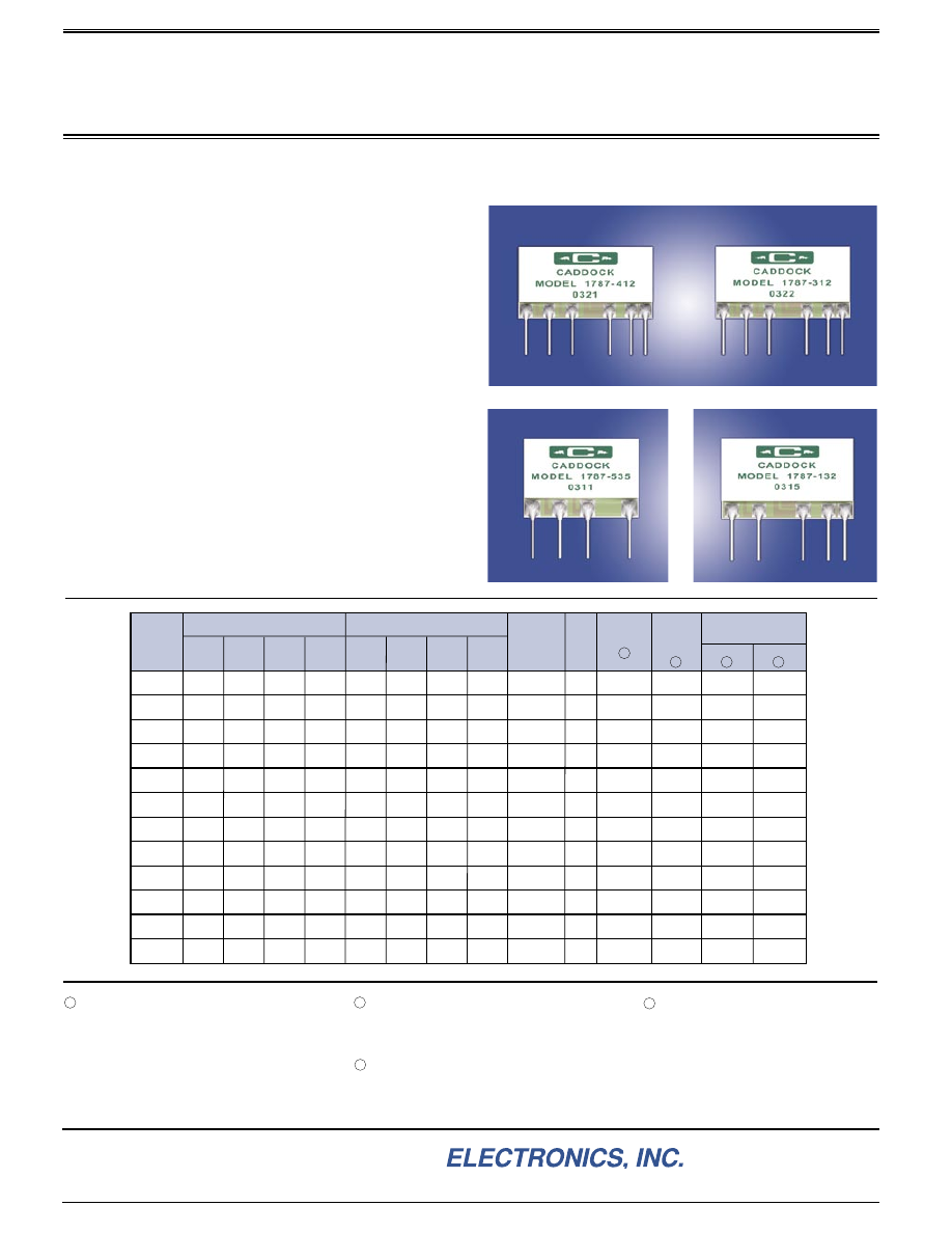
Accurate Current Sensing in Multi-Range Instrumentation
Type 1787 Current Sense Resistor Networks utilize
Caddock's Micronox
®
resistance films and advanced high
thru-put laser manufacturing capabilities to achieve many
vital advantages in precision current measurement circuits,
including laboratory and bench-type digital instrumentation:
•
The thin-profile single-package configuration replaces as
many as four discrete current sense resistors.
•
The monolithic construction and standardized lead spacing
simplify installation.
•
Caddock Micronox
®
resistance films provide exceptional
stability for improved long-term measurement accuracy.
Twelve standard models in five network arrangements
provide the specific accuracy and resistance values required
for a wide range of current measuring instruments and
circuits.
Prototype quantities of most models of the Type 1787
Current Sense Resistor Networks are available either from
stock or within 6 weeks after receipt of order.
Absolute Tolerance:
Tolerance of R
A
, R
B
, R
C,
or R
D
when
measured in accordance with proper
Figure No.
Absolute Temperature Coefficient:
Temperature coefficient of R
A
, R
B
, R
C,
or
R
D
from 0°C to +70°C, referenced to
+25°C.
Load Life:
Stability of R
A
, R
B
, R
C,
or R
D
with full power applied individually for
2,000 hours at +70°C.
Shelf Life:
Stability of R
A
, R
B
, R
C,
or R
D
for
six months at shelf conditions.
Storage Temperature:
-55°C to +85°C.
Type 1787 Current Sense Resistor Networks
Page 1 of 2
28_IL119.1004
Sales and Corporate Office
1717 Chicago Avenue
Riverside, California 92507-2364
Phone: (951) 788-1700
Fax: (951) 369-1151
Applications Engineering
17271 North Umpqua Hwy.
Roseburg, Oregon 97470-9422
Phone: (541) 496-0700
Fax: (541) 496-0408
e-mail: caddock@caddock.com • web: www.caddock.com
For Caddock Distributors listed by country see caddock.com/contact/dist.html
© 2004 Caddock Electronics, Inc.
CAD
K
DOC
.580
±
.020
(14.73
±
.51)
1.150
±
.020
(29.21
±
.51)
.025
±
.002
(.64
±
.05) DIA.
Tinned Copper
PIN 1
.250
±
.050
(6.35
±
1.27)
.400 (10.16)
.700 (17.78)
.900 (22.86)
1.000 (25.40)
.200 (5.08)
.090
(2.29)
MAX.
900
Ω
90
Ω
1
2
3
9
Ω
1
Ω
4
5
6
R
D
R
C
R
B
R
A
CADDOCK
MODEL 1787-412
0422
.075
(1.91)
DIMENSIONS IN INCHES AND (MILLIMETERS)
.580
±
.020
(14.73
±
.51)
1.150
±
.020
(29.21
±
.51)
.025
±
.002
(.64
±
.05) DIA.
Tinned Copper
PIN 1
.250
±
.050
(6.35
±
1.27)
.400 (10.16)
.700 (17.78)
.900 (22.86)
1.000 (25.40)
.200 (5.08)
.090
(2.29)
MAX.
0.1
Ω
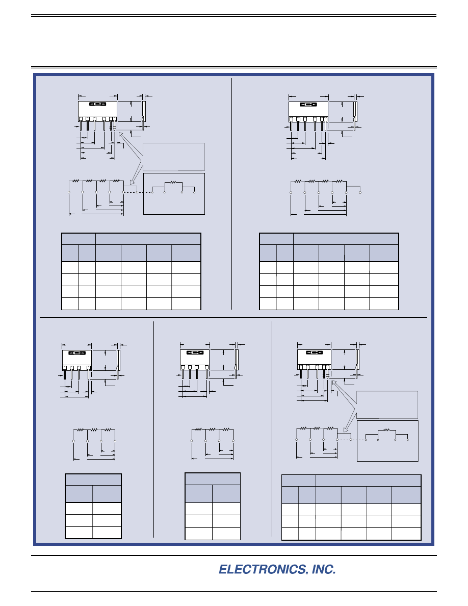
Model Nos. 1787-31 and 1787-312
are normally to be used in series
with a customer purchased 0.1
Ω
wirewound resistor with Kelvin
terminations.
Correct installation and accurate
measurement of the networks'
characteristics requires that
Pins 5 and 6 be shorted within
.100" (2.54 mm) of the body of the
network. All measurements must
be made at this point.
*
900
Ω
90
Ω
1
2
3
9
Ω
0.9
Ω
4
5
6
R
D
R
C
R
B
R
A
CADDOCK
MODEL 1787-312
0421
.075
(1.91)
.580
±
.020
(14.73
±
.51)
.850
±
.020
(21.59
±
.51)
900
Ω
1
2
90
Ω
9
Ω
3
4
R
C
R
B
R
A
.025
±
.002
(.64
±
.05) DIA.
Tinned Copper
PIN 1
.250
±
.050
(6.35
±
1.27)
.400 (10.16)
.700 (17.78)
.200 (5.08)
.090
(2.29)
MAX.
CADDOCK
MODEL 1787-5
0406
.075
(1.91)
.580
±
.020
(14.73
±
.51)
900
Ω
1
2
90
Ω
10
Ω
3
4
R
C
R
B
R
A
.025
±
.002
(.64
±
.05) DIA.
Tinned Copper
PIN 1
.250
±
.050
(6.35
±
1.27)
.400 (10.16)
.700 (17.78)
.200 (5.08)
.090
(2.29)
MAX.
CADDOCK
MODEL 1787-6
0421
.075
(1.91)
.850
±
.020
(21.59
±
.51)
.580
±
.020
(14.73
±
.51)
1.000
±
.020
(25.40
±
.51)
.025
±
.002
(.64
±
.05) DIA.
Tinned Copper
PIN 1
.250
±
.050
(6.35
±
1.27)
.500 (12.70)
.700 (17.78)
.800 (20.32)
.200 (5.08)
.090
(2.29)
MAX.
*
90
Ω
1
2
9
Ω
0.9
Ω
3
4
5
R
C
R
B
R
A
CADDOCK
MODEL 1787-132
0405
.100
(2.54)
0.1
Ω
Model Nos. 1787-13 and 1787-132
are normally to be used in series
with a customer purchased 0.1
Ω
wirewound resistor with Kelvin
terminations.
Correct installation and accurate
measurement of the networks'
characteristics requires that
Pins 4 and 5 be shorted within
.100" (2.54 mm) of the body of the
network. All measurements must
be made at this point.
Resistances
"R"
Total
Value
Sense
Lead
P
1
Kelvin Connections
Current
Lead
C
1
Current
Lead
C
2
Sense
Lead
P
2
R
A
99.9
Ω
Pin 1
Pin 1
Pin 4
*
Pin 5
*
R
B
9.9
Ω
Pin 1
Pin 2
Pin 4
*
Pin 5
*
R
C
0.9
Ω
Pin 1
Pin 3
Pin 4
*
Pin 5
*
Resistances
"R"
Total
Value
R
A
1,000
Ω
R
B
100
Ω
R
C
10
Ω
Resistances
"R"
Total
Value
R
A
999
Ω
R
B
99
Ω
R
C
9
Ω
Resistances
"R"
Total
Value
Sense
Lead
P
1
Kelvin Connections
Current
Lead
C
1
Current
Lead
C
2
Sense
Lead
P
2
R
A
1,000
Ω
Pin 1
Pin 1
Pin 5
Pin 6
R
B
100
Ω
Pin 1
Pin 2
Pin 5
Pin 6
R
C
10
Ω
Pin 1
Pin 3
Pin 5
Pin 6
R
D
1
Ω
Pin 1
Pin 4
Pin 5
Pin 6
Resistances
"R"
Total
Value
Sense
Lead
P
1
Kelvin Connections
Current
Lead
C
1
Current
Lead
C
2
Sense
Lead
P
2
R
A
999.9
Ω
Pin 1
Pin 1
Pin 5
*
Pin 6
*
R
B
99.9
Ω
Pin 1
Pin 2
Pin 5
*
Pin 6
*
R
C
9.9
Ω
Pin 1
Pin 3
Pin 5
*
Pin 6
*
R
D
0.9
Ω
Pin 1
Pin 4
Pin 5
*
Pin 6
*
Figure 1 - Model Nos. 1787-31 and 1787-312
Model Nos. 1787-31 and 1787-312 Measurement Connections
Model Nos. 1787-41 and 1787-412 Measurement Connections
Figure 2 - Model Nos. 1787-41 and 1787-412
Figure 3 - Model Nos. 1787-5,
1787-53, and 1787-535
Figure 4 - Model Nos. 1787-6,
1787-64, and 1787-645
Figure 5 - Model Nos. 1787-13 and 1787-132
Model Nos. 1787-13 and 1787-132 Measurement Connections
Type 1787 Current Sense Resistor Networks
Page 2 of 2
28_IL119.1004