Sales and Cor po rate Offi ce
1717 Chicago Av e nue
Riverside, California 92507-2364
Phone: (951) 788-1700
Fax: (951) 369-1151
Applications Engineering
17271 North Umpqua Hwy.
Roseburg, Oregon 97470-9422
Phone: (541) 496-0700
Fax: (541) 496-0408
e-mail: caddock@caddock.com • web: www.caddock.com
For Caddock Distributors listed by country see caddock.com/contact/dist.html
© 2004 Caddock Electronics, Inc.
CAD
K
DOC
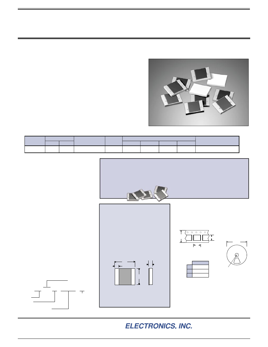
These high resistance precision chip resistors are designed for use
in extremely low signal detection / amplifi cation circuits. Applications
include: Photodiode signal amplifi cation, photomultipliers, ionization
detection, etc. These precision high resistance chip resistors can
also be ideal for use as the input resistor for high impedance voltage
division.
Style FC
- Flip Chip version for surface mount applications. This
version has solderable metallized termination pads on one side of the
substrate, the same side as the resistive element. The back side of
the substrate is bare ceramic.
Style WB
- Wire Bond versions for hybrid applications are available
on a custom basis for high quantity applications. Contact Applications
Engineering.
Type CHR High Resistance Precision Chip Resistors
Style FC - Flip Chip Version
is a surface mount version with solderable pads for
fl ip chip
soldering.
Temperature Coeffi cient:
10 Meg to 25 Meg:
25 ppm/°C -40°C to +85°C, referenced to +25°C.
Above 25 Meg:
35 ppm/°C +10°C to +40°C, referenced to +25°C.
70 ppm/°C -40°C to +85°C, referenced to +25°C.
TC is referenced to +25°C,
Δ
R taken at low
temperature and high temperature.
Load Life:
1000 hours at rated voltage
at +85°C,
Δ
R ± 0.3% max.
Momentary Overload:
1.5 times rated
voltage, for 5 seconds,
Δ
R ± 0.3% max.
Thermal Shock:
Mil-Std-202, Method 107.
-40°C to +85°C, 5 cycles,
Δ
R ± 0.3% max.
Operating Temperature:
-40°C to +85°C.
A
D
B
C
Dimensions:
Ko signifies tape thickness and dimension
12mm
0.473”
Ao
Bo
7” dia.
(178 mm)
.512” arbor hole
(13mm)
Packaging information:
Style FC
, fl ip chip resistors, are shipped with the bare ceramic
side up in the pocket, with the solderable pads facing down.
The illustration shows the orientation of the pocket. The
CHR2520FC is available only with this pocket orientation.
Full reel quantities:
1000 pieces per reel. Quantities of less than 250 will be shipped in
tape without reel and without tape leader at the option of Caddock.
Tape dimensions and materials will be consistent with EIA-481-1.
Reels will be marked with a label containing Caddock logo, part
number, resistor value, tol er ance, pack ag ing date, and quantity.
Standard Resistance Values:
Tolerance ±1% Standard.
10.0 Meg
20.0 Meg
25.0 Meg
40.0 Meg
50.0 Meg
75.0 Meg
80.0 Meg
100 Meg
Carrier Tape and pocket dimensions:
Tape is 12mm Carrier Tape (8mm pitch)
0.271” (6.88mm)
Size 2520
0.216” (5.49mm)
0.066” (1.68mm)
Ao
Bo
Ko
10 Meg to 100 Meg, 1% Tolerance, Temperature Coeffi cient to as low as 25 ppm/°C
Model
Resistance
Min.
Max.
CHR2520FC
+85
°
C
Max. Temp.
Max. Voltage Rating
150
Dimensions in inches and (millimeters)
.250
±
.007
(6.35
±
.18)
A
B
D
.200
±
.007
(5.08
±
.18)
.033 min.
(.84)
C
.027
±
.003
(.69
±
.08)
Comments
Solderable Pads
100 Meg
10 Meg
Ordering Information:
CHR 2520 FC - 10.0 Meg - 1%
Type CHR
Physical Size
2520 = 0.250” x 0.200”
Style:
FC
Resistor Value (
Ω
)
See “Standard Resistance Values”
Tolerance:
Specifi cations:
Solder attachment note:
Style FC
has a bare ceramic back
surface. The recommended solders for
fl ip chip solder attachment are
62Sn/36Pb/2Ag, 96.5Sn/3.5Ag, or
standard Sn/Ag/Cu solder alloys.
Custom resistance values and non-standard
tol er anc es can be man u fac tured for high
quantity applications. Please contact
Caddock Applications
Engineering.
• Higher Resistances up to 1,000 Meg
• Higher Voltage Ratings
• Application Optimized Tolerance and TC
• Precision Tolerance to ±0.25%
• Offset TC (such as -150 ppm/°C ±50 ppm/°C)
• Gold Wire Bondable Versions
• Aluminum Wire Bondable Versions
See table for dimensions in inches and (mil li me ters).
Custom
Type CHR Resistors
28_IL133.1004