background image

Sales and Cor po rate Offi ce

1717 Chicago Av e nue

Riverside, California  92507-2364

Phone: (951) 788-1700

Fax: (951) 369-1151

Applications Engineering

17271 North Umpqua Hwy.

Roseburg, Oregon 97470-9422

Phone: (541) 496-0700 

Fax: (541) 496-0408

e-mail: caddock@caddock.com • web: www.caddock.com

For Caddock Distributors listed by country see caddock.com/contact/dist.html

©  2004 Caddock Electronics, Inc.

CAD

K

DOC

Power Film Resistor Family with Wide Resistance Range and +275°C Maximum Temperature

    With  power  ratings  to  22  Watts  and  voltage  ratings  as 

high  as  6,000  volts  in  an  axial-lead  resistor  with  values  to 

30  Megohms,  the  Type  MS  Power  Film  Resistors  deliver 

the  performance  capabilities  that  can  simplify  circuit 

design and reduce equipment cost and complexity.
  Type MS Power Film Resistors provide all these features in  

a single resistor:

 Full power and voltage ratings, without derating:

  -  for non-inductive performance.

  -  for high resistance values that extend the critical 

    resistance value up to 10 times.

 Higher voltage ratings without the limitations of minimum

  wire size and spacing.

 Excellent long-term stability.

  Tests demonstrate typical stability of 0.05% per 1,000 

  hours over extended life.

Micronox

®

 Resistance Films

    Type  MS  performance  begins  with  Caddock's  Micronox

®


resistance  films.  Produced  exclusively  by  Caddock 

Electronics,  these  proven  complex  oxide  fi lms  have  been 

used reliably for over 30 years in Caddock's precision power 

resistor products.
    Micronox

®

  resistance  films  are  fired  directly  onto  a 

ceramic core at temperatures above 1400°F (760°C).  These 

resistance  films  have  demonstrated  outstanding  stability 

when exposed to a high ambient temperature, thermal shock 

and high power densities.
    This  unique  approach  to  precision  power  resistors  opens 

new  design  possibilities  by  providing  a  wider  resistance 

range,  precise  temperature  characteristics,  and  higher 

temperature and power handling capability.

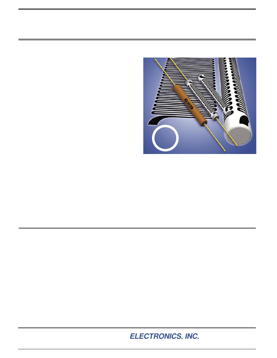
The  Serpentine  Pattern  used  in  this  patented  product 

contain  features  which  enhance  high  stability  in 

High-Power Resistor applications.

  Most  models  are  manufactured  with  Caddock's 

Non-Inductive  serpentine  resistive  pattern  that  provides  for 

neighboring  lines  to  carry  current  in  opposite  directions, 

thereby  achieving  maximum  cancellation  of  fl ux  fi elds  over 

the  entire  length  of  the  resistor.    This  effi cient  non-inductive 

construction  is  accomplished  without  derating  of  any 

performance advantages.
  The result is a truly non-inductive resistor that is about as 

inductive as a straight piece of wire the length of the resistor 

body.    This  effi cient  design  means  faster  settling  times  and 

minimum distortion in all types of high frequency circuits.

Manufacturing Control

  Type  MS  Resistors  are  produced  under  intensive 

manufacturing controls with processes which include power 

conditioning,  overvoltage  conditioning,  and  maximum 

temperature conditioning.

Quality Control

  From  the  certifi cation  and  testing  of  all  materials,  to  the 

su per vi sion  of  manufacturing  processes,  all  Caddock  Type 

MS  Power  Film  Resistors  are  produced  under  pro ce dures 

that  have  been  approved  for  conformance  to  the 

requirements  of  Mil-I-45208  in  many  recent  surveys  as 

described on page 8.

Reliability Verifi cation

  Type  MS  resistors  are  included  in  the  Caddock  Reliability 

Testing  Program.    Conformance  to  specifi cation  parameters 

including  Extended  Life,  Shock,  Vibration,  and  Humidity  are 

verifi ed  on  a  periodic  basis.    Data  from  Type  MS  resistors 

can  be  compared  by  similarity  to  other  Caddock  resistor 

types, since  Type ML, MM, MS, MP, MG,  and  MK  represent 

an  identical  combination  of  materials  -  aluminum  oxide 

substrate,  Micronox

®

  resistance  fi lm,  and  silicone  insulating 

coating.

Carefully Controlled Manufacturing and Test Procedures Assure Compliance with 

Strict Quality Control Requirements.

N

Caddock's

Non-Inductive

Design

Type MS Power Film Resistors

Certain products shown in this catalog are covered by one or more patents, there are also patents pending.

Page 1 of 2

28_IL108.1004

TypeMS-html.html
background image

Sales and Cor po rate Offi ce

1717 Chicago Av e nue

Riverside, California  92507-2364

Phone: (951) 788-1700

Fax: (951) 369-1151

Applications Engineering

17271 North Umpqua Hwy.

Roseburg, Oregon 97470-9422

Phone: (541) 496-0700 

Fax: (541) 496-0408

e-mail: caddock@caddock.com • web: www.caddock.com

For Caddock Distributors listed by country see caddock.com/contact/dist.html

©  2004 Caddock Electronics, Inc.

CAD

K

DOC

Specifi cations:

Resistance  Tolerance:

    ±1%  (tolerances  to  0.1%  on 

special order).

Temperature  Coeffi cient:

    50  ppm/°C.    TC  referenced 

to +25°C, 

Δ

R taken at -15°C and +105°C.

Insulation Resistance:  

10,000 Megohms, min.

Overload/Overvoltage:   

5  times  rated  power with  applied 

voltage not to exceed 1.5 times maximum continuous oper-

ating  voltage  for  5  seconds. 

Δ

R  0.5%  max.  or  0.5  ohm 

max., whichever is greater.

Thermal  Shock:   

Mil-Std-202,  Method  107,    Cond.  C, 

Δ

0.5% max. or 0.5 ohm max., whichever is greater.

Moisture Resistance:  

Mil-Std-202, Method 106, 

Δ

R 0.5% 

max. or 0.5 ohm max., whichever is greater.

Load  Life:   

1,000  hours  at  rated  power  at  +25°C  or 

+125°C  (see  derating  curve),  not  to  exceed  rated  voltage, 

Δ

R 0.5% max. or 0.5 ohm max., whichever is greater.

Maximum Operating Temperature: 

+275°C.

Encapsulation: 

High Temperature Silicone Conformal.

MS313, MS315

MS310

MS281

MS260

MS245

MS244

MS223

MS221

MS220

MS214

MS176, MS210

MS151, MS175

MS126, MS150

*

Limited by power rating

.

Models with Caddock's Non-Inductive Resistance Pattern are in non-shaded areas.

Models with low inductance construction are in shaded areas.

Ordering  Information

:

MS220 -100K - 1%

Model Number:

Resistor Value:

Tolerance

RATED POWER OR

RATED VOLTAGE, %

AMBIENT TEMPERATURE, 

°

C

100

80
60
40
20

0

25

75

125

175

225 275

A

B

A - all MS models

      except MS126,

      MS151, MS176
B - MS126, MS151,

      MS176

Derating Curve:

1.500 

±

 .125

(38.10 

±

 3.18)

A

B

C

DIMENSIONS IN INCHES AND (MILLIMETERS)

MS322

Dielect.

Strength

Model

No.

C

Dimensions in inches and (millimeters)

Resistance

Min.

Max.

Max.

Voltage

B

A

.020 

±

.002

(.51 

±

.05)

  .070 

±

.015

(1.78 

±

.38)

  .188 

±

.020

(4.78 

±

.51)

MS126   0.25

   500

20 

1 Meg

   200

.020 

±

.002

(.51 

±

.05)

  .070 

±

.015

(1.78 

±

.38)

  .188 

±

.020

(4.78 

±

.51)

MS150   0.50

   500

20 

2 K

.025 

±

.002

(.64 

±

.05)

  .094 

±

.015

(2.39 

±

.38)

  .250 

±

.020

(6.35 

±

.51)

MS151   0.50

   750

20 

2 Meg

   300

.025 

±

.002

(.64 

±

.05)

  .094 

±

.015

(2.39 

±

.38)

  .250 

±

.020

(6.35 

±

.51)

MS175  0.75

   750

20 

2 K

.025 

±

.002

(.64 

±

.05)

  .094 

±

.015

(2.39 

±

.38)

  .313 

±

.020

(7.95 

±

.51)

MS176   0.75

   750

45 

5 Meg

   500

.025 

±

.002

(.64 

±

.05)

  .094 

±

.015

(2.39 

±

.38)

  .313 

±

.020

(7.95 

±

.51)

MS210   1.0

   750

45 

3 K

.025 

±

.002

(.64 

±

.05)

  .109 

±

.025

(2.77 

±

.64)

  .313 

±

.030

(7.95 

±

.76)

MS214   1.0

   750

45 

5 Meg

   500

.025 

±

.002

(.64 

±

.05)

  .140 

±

.030

(3.56 

±

.76)

  .400 

±

.060

(10.16 

±

1.52)

MS220   2.0

   800

20 

10 Meg

1,000

.032 

±

.002

(.81 

±

.05)

  .165 

±

.030

(4.19 

±

.76)

  .575 

±

.050

(14.61 

±

1.27)

MS221   3.0

   800

45 

10 Meg

1,000

  .040 

±

.002

(1.02 

±

.05)

  .230 

±

.030

(5.84 

±

.76)

  .480 

±

.060

(12.19 

±

1.52)

MS223   3.0

1,000

20 

4 Meg

   800

  .040 

±

.002

(1.02 

±

.05)

  .230 

±

.030

(5.84 

±

.76)

  .950 

±

.060

(24.13 

±

1.52)

MS244   4.0

1,000

45 

15 Meg

2,000

  .040 

±

.002

(1.02 

±

.05)

  .300 

±

.030

(7.62 

±

.76)

  .570 

±

.060

(14.48 

±

1.52)

MS245   4.0

1,000

20 

6 Meg

   800

  .040 

±

.002

(1.02 

±

.05)

  .300 

±

.030

(7.62 

±

.76)

  .970 

±

.060

(24.64 

±

1.52)

MS260   6.0

1,000

45 

15 Meg

2,000

  .040 

±

.002

(1.02 

±

.05)

.350 

±

.040

(8.89 

±

1.02)

  .910 

±

.060

(23.11 

±

1.52)

MS281   8.0

1,000

45 

8 Meg

2,000

  .040 

±

.002

(1.02 

±

.05)

.350 

±

.040

(8.89 

±

1.02)

1.250 

±

.070

(31.75 

±

1.78)

MS310 10.0

1,000

45 

20 Meg

4,500

  .040 

±

.002

(1.02 

±

.05)

.350 

±

.040

(8.89 

±

1.02)

2.000 

±

.080

(50.80 

±

2.03)

MS313 12.5

1,000

50 

30 Meg

6,000

  .040 

±

.002

(1.02 

±

.05)

.350 

±

.040

(8.89 

±

1.02)

2.000 

±

.080

(50.80 

±

2.03)

MS315 15.0

1,000

50 

1 Meg

*

*

*

*

Watt-

age at

+125

°

C

Watt-

age at

+25

°

C

  0.25

  0.50

  0.75

  0.30

  0.45

0.60

0.60

1.2

1.8

1.8

2.4

2.4

3.6

4.8

6.0

7.5

9.0

  .040 

±

.002

(1.02 

±

.05)

.350 

±

.040

(8.89 

±

1.02)

3.000 

±

.090

(76.20 

±

2.29)

MS322 22.0

1,000

100 

1.5 Meg

*

13.2

Construction:

The Type MS Power 

Film


Resistor


is constructed 

with Micronox

®


resistance fi lms 

bonded to a high strength solid 

ceramic core.  Nickel alloy end caps 

and  axial  leads  complete  the  assembly.  

Encapsulation  is  provided  by  a  high 

temperature silicone conformal coating.

Type  MS:

  Lead  material  is  Nickel  Clad  Copper 

with thin Gold Plate, solderable.
For  welding  applications,  optional  pure  nickel 

leads  are  available  on  Models  MS126,  MS150, 

MS151,  MS175,  MS176,  MS210.  Contact 

Caddock Applications Engineering.

Type MS Power Film Resistors

Page 2 of 2

28_IL108.1004