Sales and Cor po rate Offi ce
1717 Chicago Av e nue
Riverside, California 92507-2364
Phone: (951) 788-1700
Fax: (951) 369-1151
Applications Engineering
17271 North Umpqua Hwy.
Roseburg, Oregon 97470-9422
Phone: (541) 496-0700
Fax: (541) 496-0408
e-mail: caddock@caddock.com • web: www.caddock.com
For Caddock Distributors listed by country see caddock.com/contact/dist.html
© 2004 Caddock Electronics, Inc.
CAD
K
DOC
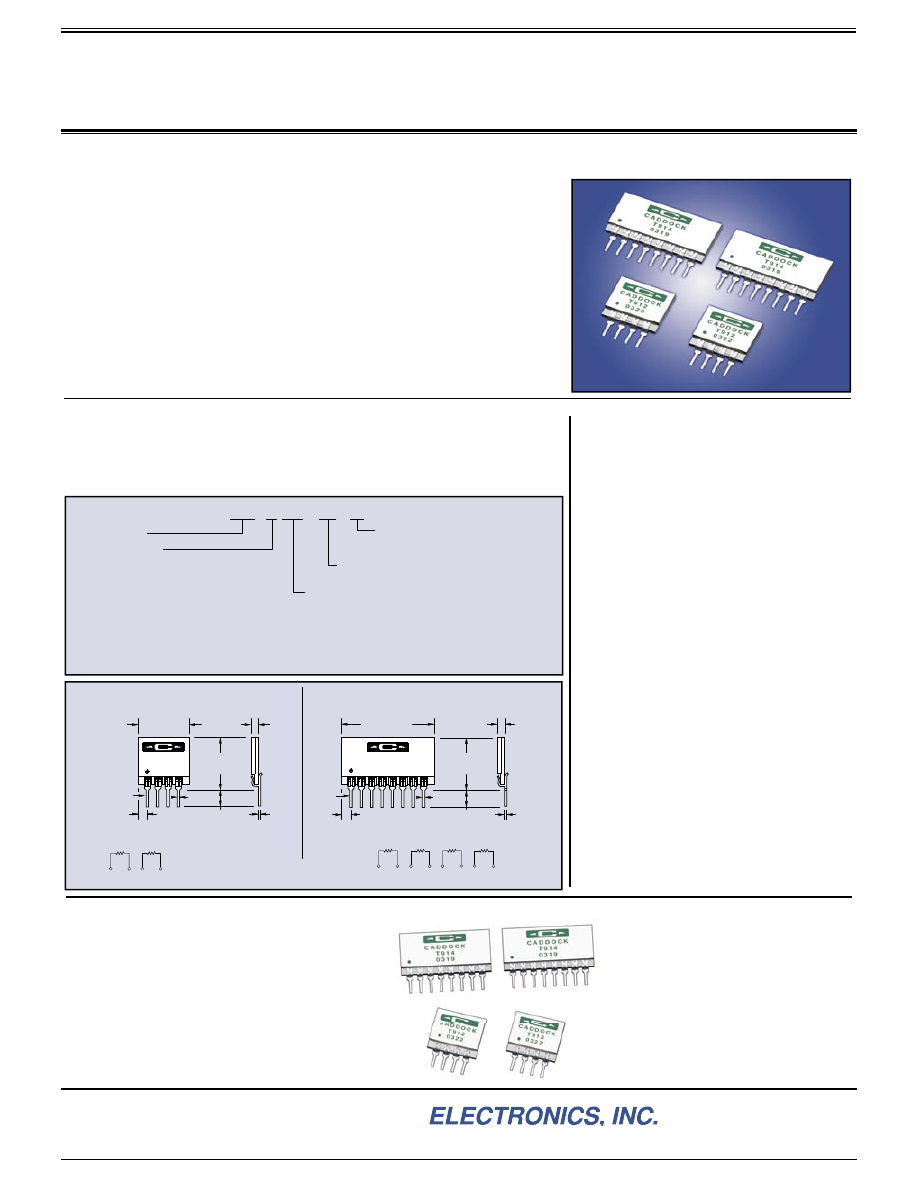
Resistor Pairs and Quads with Ratio Characteristics for Precision Analog Circuits
Type T912 and T914 Precision Resistor Networks are constructed with
Cad dock Tetrinox
®
resistance fi lms to achieve the precise ratio performance
and stability required by highly accurate amplifi er circuits, voltage reference
circuits, and precision bridge circuits.
•
Ratio Tolerance
- from 0.1% to 0.01%.
•
Ratio Temperature Coeffi cient
- 10 ppm/°C, 5 ppm/°C or 2 ppm/°C.
•
Absolute Temperature Coeffi cient
- 25 ppm/°C.
•
Ratio Stability of Resistance at Full Load for 2,000 hours
- within 0.01%.
•
Shelf Life Stability of Ratio for 6 Months
- within 0.005%.
Both the T912 and the T914 are available in 14 standard resistance values
between 1K and 1 Megohm. Caddock's high thru-put manufacturing capabil-
ity assures that prototype and large-volume production quantities are available
either from stock or within 6 weeks after receipt of order.
Specifi cations:
Absolute Tolerance:
±0.1% for all resistors.
Absolute Temperature Coeffi cient:
25 ppm/°C
referenced to +25°C,
Δ
R taken at 0°C and +70°C.
Ratio Tolerance:
Options for ratio tolerance are
provided as shown in the Ordering Information
panel.
Ratio Temperature Coeffi cient:
Options for
ratio temperature coefficient are provided as
shown in the Ordering Information panel.
Voltage Rating:
30 volts DC or RMS AC
ap plied to R
1
, R
2
, R
3
and R
4
.
Power Rating:
0.10 watt applied to R
1
, R
2
, R
3
and R
4
(not to exceed rated voltage).
Package Power Rating:
Type T912, 0.20 watt.
Type T914, 0.40 watt.
Storage Temperature:
-55°C to +105°C.
Insulation Resistance Between Isolated Pins:
Pin 2 to Pin 3, Pin 4 to Pin 5, or Pin 6 to Pin 7,
1,000 Megohms, minimum.
Dielectric Strength Between Isolated Pins:
50 volts RMS AC.
Custom Model T912 and T914 Precision Resistor Networks
For applications requiring non-standard
resistance values, the T912 and T914 custom
confi gurations can include these special features:
•
Mixed resistance values with a maximum ratio
of 250-to-1. (Example: 1 Megohm and 4 K)
•
Absolute TC as low as 15 ppm/°C.
•
Ratio TC as low as 2 ppm/°C.
•
Custom voltage ratings.
•
Matched resistors of any special value
between 1 K and 2 Megohms.
Contact our Applications
Engineering for performance,
price, and availability of these
custom resistor networks.
Standard Type T912 and Type T914 Precision Resistor Networks
In addition to the 14 standard
equal value
models of the Type T912 and T914,
the Type T912 can also be ordered with:
•
10:1 Resistance Ratio
- for use in amplifi er gain-setting.
•
9:1 Resistance Ratio
- for use in voltage reference dividers.
Type T912 and T914 Precision Resistor Networks
Ordering Information:
.500
±
.020
(12.70
±
.51)
.095 (2.41)
MAX.
PIN 1
CADDOCK
T914
0429
.010
(.26)
.020
(.51)
.150
±
.040
(3.81
±
1.02)
.100
(2.54)
.900
±
.020
(22.86
±
.51)
8 PINS ON .100 (2.54) CENTERS
R
1
R
2
1
2 3
4
R
3
R
4
5
6 7
8
R
1
R
2
1
2 3
4
Type T914
Ratios Available: 1:1 and Custom.
Type T912
Ratios Available: 1:1, 9:1, 10:1, and Custom.
R
1
= R
2
= R
3
= R
4
DIMENSIONS IN INCHES
AND (MILLIMETERS)
.010
(.26)
.500
±
.020
(12.70
±
.51)
.020
(.51)
CADDOCK
T912
0402
PIN 1
.150
±
.040
(3.81
±
1.02)
.100
(2.54)
.500
±
.020
(12.70
±
.51)
4 PINS ON .100 (2.54) CENTERS
.095 (2.41)
MAX.
Ratio Code Letter:
A
- T912 with R
1
: R
2
where R
2
= 10R
1
1K:10K 10K:100K 40K:400K
2K:20K 20K:200K 50K:500K
5K:50K 25K:250K 100K:1 Meg
B
- T912 with R
1
: R
2
where R
2
= 9R
1
1K:9K 10K:90K 40K:360K
2K:18K 20K:180K 50K:450K
5K:45K 25K:225K 100K:900K
Model Number
Ratio Tolerance:
-100 = 0.10% -020 = 0.02%
-050 = 0.05% -010 = 0.01%
Standard Resistance Values:
(R
1
)
1K 10K 40K 200K 500K
2K 20K 50K 250K 1 Meg
5K 25K 100K 400K
Ratio Temperature Track (0
°
C to +70
°
C):
-10 = 10 ppm/
°
C -05 = 5 ppm/
°
C
-02 = 2 ppm/
°
C
T912 - A 10K - 010 - 02
Special or mixed resistance values are available as custom networks.
See the custom section at the bottom of this page.
(This information appears on the back side of the network)
No Letter
- T912 with R
1
= R
2
No Letter
- T914 with R
1
= R
2
= R
3
= R
4
*
*
*
*
*
28_IL117.1004