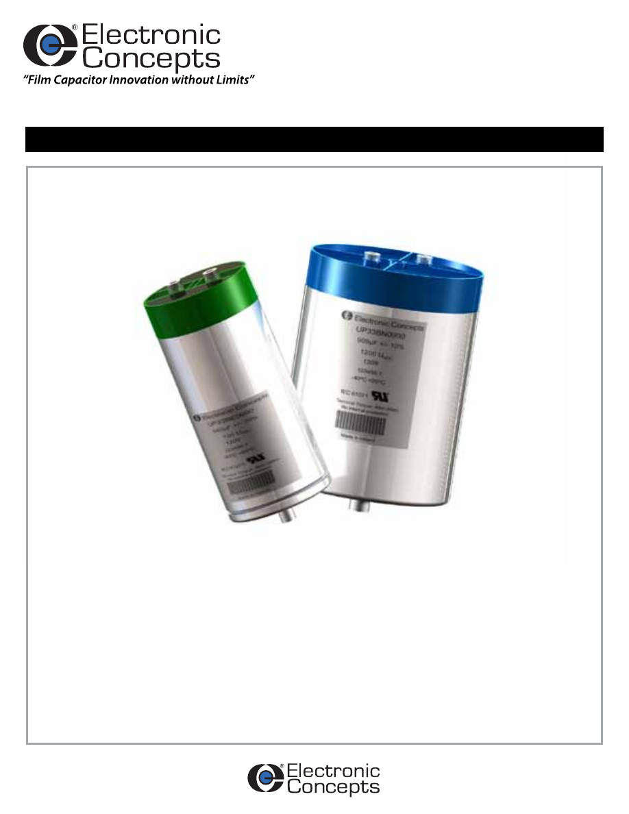
UP3
SERIES
Unlytic
®
Polypropylene
Rev. 6
Medium Power DC Link Filter Capacitor
Proven replacements for electrolytic capacitor banks. Dry “self-healing” metallized
polypropylene film capacitors.
FEATURES
- UL Recognized
- Long Life: > 100,000 Hours
- Low ESL & ESR
- High RMS Current Capability
- High Surge Voltage Capability: 1.5 x VDC
- Surge Current: 1.5 x Ipk
- Cost Effective Design
- Ground Test: 5 kVDC for 10s
- Reference MIL-STD 202 & IEC 61071
- Flexible, Dry Film Fully Encapsulated
Construction
- RoHS compliant
STANDARD CONFIGURATION
- Female Terminals (Male terminals are
optional)
- UP33 Bolt Mount Package
- UP30 Package Without Bolt Mount
UP3-Full-html.html
Rev. 6
Parameter
Method
Condition
Vibration
204
D
Shock
213
I
Humidity
106
-
Thermal Shock
107
A
Life
108
F
Complies with IEC 61071
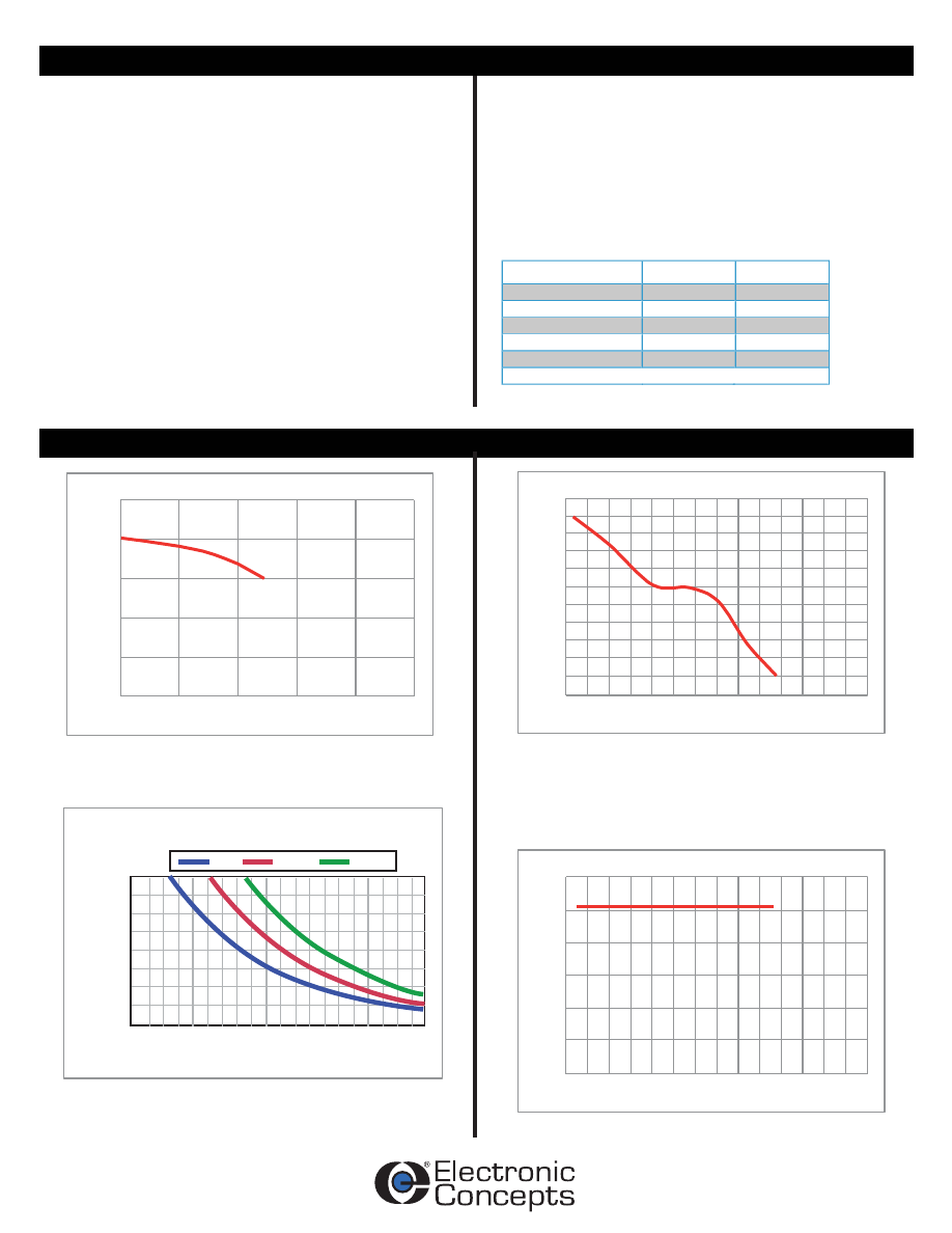
Insulation Resistance vs. Temperature
In
su
la
tio
n
R
es
is
ta
nc
e
(M
Ω
x
μ
F
)
Temperature (C)
1
10
100
1,000
10,000
100,000
25
50
75
100
125
150
Capacitance Change at 1kHz vs. Temperature
C
ap
ac
ita
nc
e
C
ha
ng
e
(%
)
Temperature (C)
-2.5%
-3.0%
-2.0%
-1.5%
-1.0%
-0.5%
0.0%
0.5%
1.0%
1.5%
2.0%
2.5%
-60 -45 -30 -15
0
15
30
45
60
75
90 105 120 135 150
Dissipation Factor at 1kHz vs. Temperature
D
is
si
pa
tio
n
Fa
ct
or
(%
)
Temperature (C)
-60 -45 -30 -15 0
15 30 45 60 75 90 105 120 135 150
0.20%
0.00%
0.40%
0.60%
0.80%
1.00%
1.20%
Vr
PROJECTED LIFE vs INTERNAL HOT SPOT
AND VOLTAGE RATIO
HOT SPOT (HS)
TEMPERATURE (°C)
HOURS
47
45
49 51 53 55 57 59 61 63 65 67 69 71 73 75 77 79 81 83 85
400,000
350,000
300,000
250,000
200,000
150,000
100,000
50,000
-
0.9 Vr*
0.8 Vr*
Specification Summary
Characteristics
Dissipation Factor
Polypropylene has an intrinsic dissipation factor of
less than 0.00021 over the operating temperature
range and frequencies to 1MHz.
Capacitance Range
25μF to 2100μF
Capacitance Tolerance
Standard capacitance tolerance is ±10%.
(Other tolerances available on request.)
Operating Temperature Range
-40°C to +85°C (+105°C upon special request)
Hot Spot Temperature Calculation: H.S. = Tamb +(I
2
x ESR) x Rth.
Failure Rate: 100FIT
Enclosure/Construction
Aluminum housing with brass terminals, encased in a plastic cover
Voltage Rating
600 VDC to 3000 VDC
Environmental
Quality Control
Capacitors are tested 100% for:
• Capacitance
• Tolerance
• Dissipation Factor
• Dielectric withstanding voltage
• Insulation Resistance
• Equivalent Series Resistance (ESR)
Process and inspection data are maintained on file and available
upon special request.
UP3-Full-html.html
Rev. 6
UP3_BC0375
UP3_BC0700
UP3_BE0660
UP3_BE1000
UP3_BE1250
UP3_BE1850
UP3_BJ0250
UP3_BJ0450
UP3_BJ0620
UP3_BJ0750
UP3_BJ1140
UP3_BJ1500
UP3_BJ1050
UP3_BJ1600
UP3_BJ2100
UP3_BM0420
UP3_BM0510
UP3_BM0760
UP3_BM1020
UP3_BM0710
UP3_BM1080
UP3_BM1420
UP3_BN0175
UP3_BN0300
UP3_BN0340
UP3_BN0420
UP3_BN0640
UP3_BN0840
UP3_BN0600
UP3_BN0900
UP3_BN1200
UP3_BR0125
UP3_BR0175
UP3_BR0225
UP3_BT0125
UP3_BT0175
UP3_BT0230
UP3_BT0460
UP3_BT0210
UP3_BT0500
UP3_BT0660
UP3_CA0150
UP3_CA0300
UP3_CA0210
UP3_CA0320
UP3_CA0420
UP3_CD0025
UP3_CD0035
UP3_CD0045
UP3_CD0065
UP3_CD0130
UP3_CD0095
UP3_CD0145
UP3_CD0190
600
600
700
700
700
700
900
900
900
900
900
900
900
900
900
1100
1100
1100
1100
1100
1100
1100
1200
1200
1200
1200
1200
1200
1200
1200
1200
1400
1400
1400
1600
1600
1600
1600
1600
1600
1600
2000
2000
2000
2000
2000
3000
3000
3000
3000
3000
3000
3000
3000
90
90
85
85
116
116
90
90
85
116
116
116
136
136
136
85
116
116
116
136
136
136
90
90
85
116
116
116
136
136
136
90
90
90
90
90
116
116
136
136
136
116
116
136
136
136
90
90
90
116
116
136
136
136
375
700
660
1000
1250
1850
250
450
620
750
1140
1500
1050
1600
2100
420
510
760
1020
710
1080
1420
175
300
340
420
640
840
600
900
1200
125
175
225
125
175
230
460
210
500
660
150
300
210
320
420
25
35
45
65
130
95
145
190
110
160
135
190
135
190
110
160
190
135
190
235
135
190
235
190
135
190
235
135
190
235
110
160
190
135
190
235
135
190
235
110
135
160
135
160
135
235
135
190
235
135
235
135
190
235
110
135
160
135
235
135
190
235
2.5
4.0
2.5
1.0
1.4
0.6
3.0
5.0
1.3
1.7
0.8
0.9
1.3
0.6
0.7
1.6
2.2
0.9
1.1
1.5
0.7
0.9
3.6
6.2
1.8
2.4
1.0
1.2
1.7
0.7
0.9
4.3
5.7
7.1
7.0
8.0
3.4
1.7
2.3
1.0
1.2
4.0
2.0
2.9
1.2
1.5
10.0
12.0
14.0
6.5
3.2
4.3
1.8
2.2
0.80
1.10
0.95
1.30
1.70
2.30
0.80
1.10
1.30
1.70
2.30
2.80
2.20
3.10
3.80
1.30
1.70
2.30
2.80
2.20
3.10
3.80
0.80
1.10
1.30
1.70
2.30
2.80
2.20
3.10
3.80
0.80
0.90
1.10
0.90
1.10
1.70
2.80
2.20
3.10
3.80
1.70
2.80
2.20
3.10
3.80
0.80
0.90
1.10
1.70
2.80
2.20
3.10
3.80
FIG. 2
FIG. 2
FIG. 1
FIG. 1
FIG. 1
FIG. 1
FIG. 2
FIG. 2
FIG. 1
FIG. 1
FIG. 1
FIG. 1
FIG. 1
FIG. 1
FIG. 1
FIG. 1
FIG. 1
FIG. 1
FIG. 1
FIG. 1
FIG. 1
FIG. 1
FIG. 2
FIG. 2
FIG. 1
FIG. 1
FIG. 1
FIG. 1
FIG. 1
FIG. 1
FIG. 1
FIG. 2
FIG. 2
FIG. 2
FIG. 2
FIG. 2
FIG. 1
FIG. 1
FIG. 1
FIG. 1
FIG. 1
FIG. 1
FIG. 1
FIG. 1
FIG. 1
FIG. 1
FIG. 2
FIG. 2
FIG. 2
FIG. 1
FIG. 1
FIG. 1
FIG. 1
FIG. 1
5.6
5.2
4.6
2.8
3.1
1.9
5.5
5.2
2.7
3.1
1.8
1.6
2.5
1.4
1.3
2.7
3.1
1.8
1.5
2.4
1.4
1.3
5.5
5.5
2.8
3.1
1.8
1.6
2.5
1.5
1.2
5.5
4.5
5.3
4.6
5.2
3.2
1.6
2.5
1.5
1.3
3.1
1.6
2.5
1.3
1.3
8.1
6.6
5.6
3.7
1.9
2.9
1.7
1.5
15.0
20.0
9.5
13.0
9.5
13.0
19.0
11.0
16.0
12.0
16.0
12.0
12.0
16.0
12.0
20.0
16.0
20.0
15.0
15.5
20.0
15.0
23.0
13.0
21.0
17.0
22.0
17.0
17.0
22.0
17.0
27.0
19.0
15.0
22.0
17.0
22.0
22.0
22.0
29.0
22.0
27.0
27.0
27.5
36.0
28.0
57.0
42.0
33.0
41.5
41.5
40.0
52.0
40.0
5700
6100
6300
12800
12000
23600
4700
4900
10000
9200
18400
18400
13000
26000
26000
8400
7600
15200
15200
11000
21600
21600
4000
3900
7200
7000
14000
14000
10000
19600
20000
3400
3400
3400
2800
3000
5000
10000
7200
14400
14400
4000
8000
5800
11600
11600
1400
1400
1400
2700
5400
3800
7600
7600
36.7
20.0
18.7
24.9
13.6
18.3
45.0
25.0
31.6
17.5
23.3
17.5
14.8
19.7
14.8
38.4
21.3
28.5
21.3
17.8
23.9
18.0
53.8
30.6
42.6
23.4
31.1
23.4
19.6
26.2
16.6
63.2
45.5
35.4
53.4
40.1
31.7
31.7
26.4
35.2
26.4
39.2
39.2
33.1
44.0
33.1
142.4
102.0
79.0
98.7
57.0
81.6
59.0
47.0
50
90
40
50
40
50
50
90
60
40
50
60
40
50
60
60
40
50
60
40
50
60
50
90
60
40
50
60
40
50
60
50
70
90
70
90
40
60
40
50
60
40
60
40
50
60
50
70
90
40
60
40
50
60
50
50
32
32
50
50
50
50
32
50
50
50
50
50
50
32
50
50
50
50
50
50
50
50
32
50
50
50
50
50
50
50
50
50
50
50
50
50
50
50
50
50
50
50
50
50
50
50
50
50
50
50
50
50
35
30
30
60
60
100
30
25
60
50
100
100
60
100
100
60
45
100
100
60
100
100
30
25
50
45
90
80
60
100
100
25
25
20
25
20
35
70
50
100
100
30
65
40
90
90
15
15
14
25
50
35
70
70
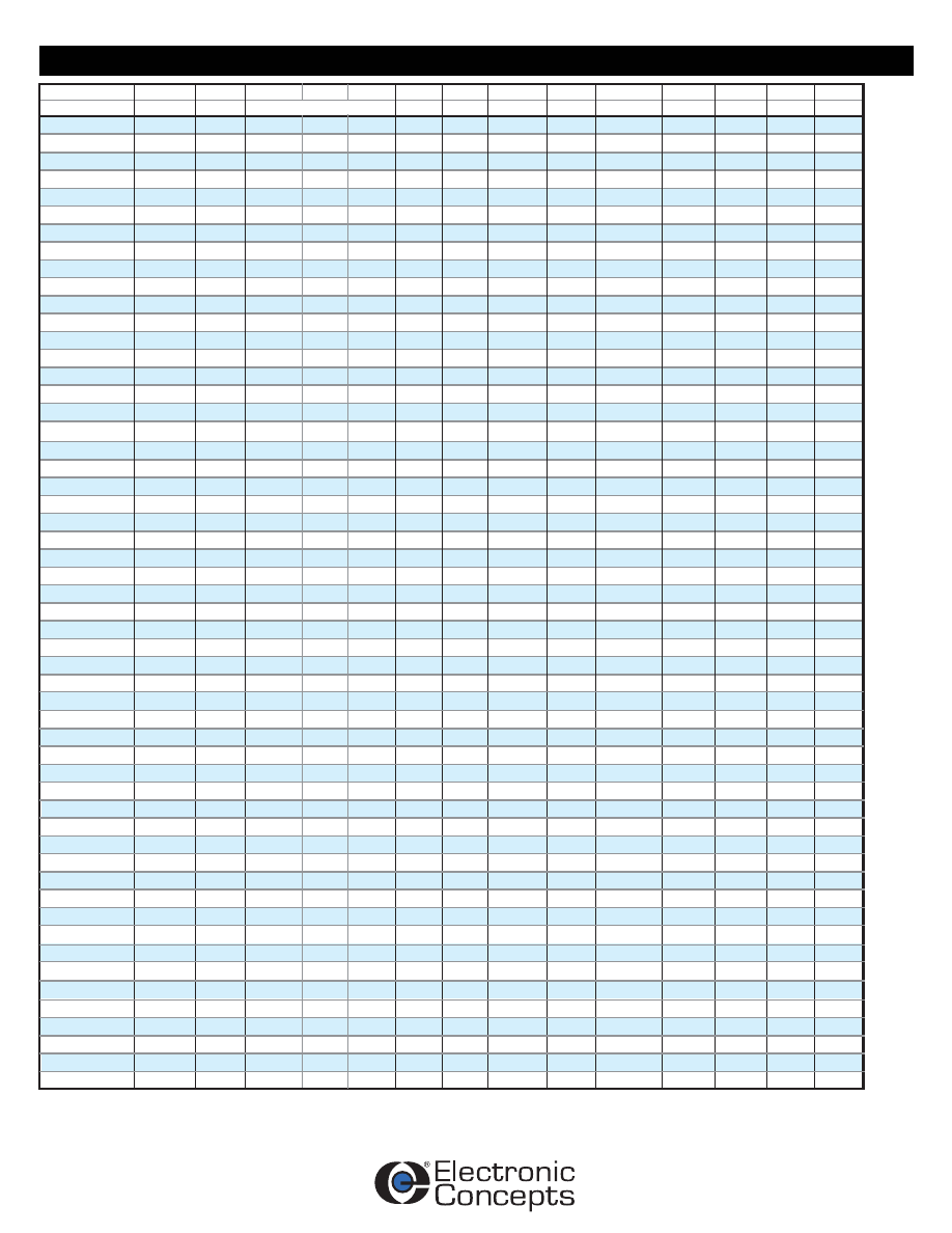
PART NUMBER VOLTAGE
VDC
CAP
µF
“D”
"H”
ESR
mOhms
“TS”
ESL
nH
Fres
kHz
I PEAK
AMPS
I MAX
70°C
dv/dt
V/µs
Rth
°C/W
WT
KG
STYLE
REF.
(mm)
NOTE: The 4th character of the part number represents the STYLE: ‘3’ - Bolt Mount Package; ‘0’ - Package without Bolt Mount.
Detail Data
UP3-Full-html.html
Rev. 6
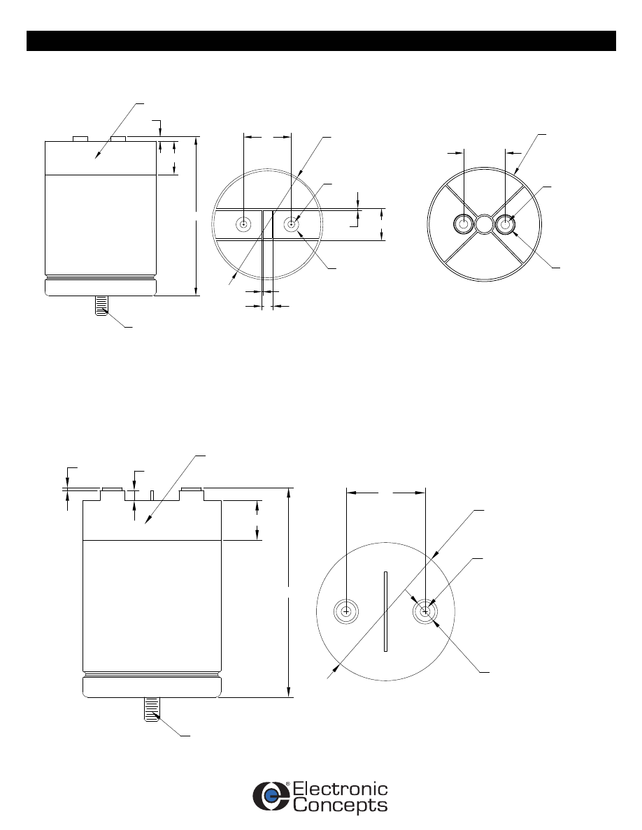
FIGURE - 1
FIGURE - 2
26
1.5
8
3
6
136mm
LID STYLE
27.5
PLASTIC LID
UL94V-0
M12 X 1.75
16 LONG
7 Nm
TS
Ø12.7
M6 X 1.0 INTERNAL
9mm DEEP MIN.
4 Nm
H
TOLERANCES: +/-0.5mm
D
TS
85mm & 116mm
LID STYLE
D
2
D
Ø12.7
TS
TOLERANCES: +/-0.5mm
M6 X 1.0 INTERNAL
9mm DEEP MIN.
4 Nm
25.4
PLASTIC LID
UL94V-0
M12 X 1.75
16 LONG
7 Nm
H
6
Ø12.7
M6 X 1.0 INTERNAL
9mm DEEP MIN.
4 Nm
STYLE
UP3-Full-html.html
Rev. 6
TYPE
Metallized Polypropylene
STYLE
‘3’ Bolt Mount Package : ‘0’ Flat Mount (no bolt)
UP3
0
BC
0700
VOLTAGE
DC Voltage Rating: BC=600VDC, BE=700VDC, BJ=900VDC, BM=1100VDC,
BN=1200VDC, BR=1400VDC, BT=1600VDC, CA=2000VDC, CD=3000VDC
CAPACITANCE IN MICROFARADS
Capacitance in µF (e.g. 0700 = 700µF)
Marking And Date Code
All capacitors are marked with company initials "EC", corporate logo or EC trademark—in addition to type UP3, capacitance, tolerance, rated
DC working voltage and date code. The first two digits of the date code represent the year, the second two digits the week, i.e., 1252 is the
52nd week of 2012, 1202 is the second week of 2012.
Quality Assurance
Major emphasis is placed on quality assurance. EC is an ISO 9001 and AS9100 Certified Company. Raw material inspection and the use of
SPC manufacturing procedures assure the highest quality standards. Procedures are fully described in the EC Quality Control Manual.
Electronic Concepts will continue to advance the state-of-the-art by utilizing leading edge technology, compact capacitor designs and
establishing reliability procedures.
The UP3 capacitor series further enhances the existing UL30 product offering. The UP3 incorporates the established
UNLYTIC
®
film technology with new cost effective packaging, which provides higher storage capacity and voltage creepage
protection. The solid plastic top adds more than a one inch gap between the case and terminal connections. The capacitor
is isolated from the outer case, allowing for simple package and connection mounting. The product series is well suited for
bulk DC storage, especially useful in DC link converter/inverter applications.
United States Headquarters
Electronic Concepts, Inc.
526 Industrial Way West
Eatontown, NJ 07724
Tel: 732-542-7880
Fax: 732-542-0524
email: sales@ecicaps.com
website:www.ecicaps.com
European Headquarters
Electronic Concepts Europe LTD
IDA Estate
Oughterard
Co. Galway
Ireland
tel: +353-91-552385,552432
fax: +353-91-552387
email: sales@ecicaps.ie
website:www.electronicconcepts.ie
Distribution Center
Elcon Sales
542 Industrial Way West
Eatontown, NJ 07724
Tel: 732-380-0405
Fax: 732-380-0409
email: sales@elconsales.com
How to Order
Sales Offices
Additional Information