Separable Connectors and Kits
Important Notice
While Woer has made every effort to ensure the accuracy of the information
in this catalog, Woer does not guarantee that it is errorless. Nor does Woer
make any other warranty or guarantee that the information is accurate,
reliable or current. Before using our products, you must evaluate them and
determine if they are suitable for your intended application. Woer reserves
all the rights to make any adjustments to the information contained at any
time without notice.
Woer mansion,North Lanjing Rd,Pingshan,Shenzhen P.R.CHINA
Tel:86-755-28299160,26620597
Fax:86-755-28299160
Email:woer@woer.com
Http://en.woer.com
WOER-Separable-Connectors-and-Kits-html.html
WOER-Separable-Connectors-and-Kits-html.html

Separable Connectors Mated
with EN50180&50181
Busbar Connecting System
Separable Connectors Mated
with IEEE 386
Inner Cone Plug-in Serial
up to 42kV
Accessories
Test Report
250A Serial Deadbreak
.........................
Apparatus Bushing ......................................
Elbow Connector .........................................
Straight Connector ......................................
630A Serial Deadbreak
..........................
Apparatus Bushing ......................................
Tee Connector .............................................
Surge Arrester .............................................
Patent Tee Connector ...................................
Insulated Cap ..............................................
200A Serial Loadbreak
........................
Bushing Insert ............................................
Feed-thru Bushing Insert .............................
Bushing Well ..............................................
Junction .....................................................
Elbow Connector ........................................
Insulated Cap .............................................
Surge Arrester ............................................
600A Serial Deadbreak
........................
Bushing/Junction ........................................
Tee Connector .............................................
Connecting Plug ..........................................
Reducing Tap Plug .......................................
Reducing Tap Plug with Bushing Extender......
Insulated Cap ..............................................
Termination ................................................
Insulated Bushing ................................
...........................................
.......
Insulated Insert
Busbar
Connector ..................................
..
Inner Cone Busbar Kits .........................
...
...
...
02
32
34
16
03
33
37
17
04
38
18
05
19
06
20
07
21
27
08
23
28
11
24
28
13
25
29
14
26
30
01
31
32
34
39
15
WOER-Separable-Connectors-and-Kits-html.html
Separable Connectors Mated with
EN50180&50181
Woer produces a range of separable Elbow, Straight and Tee connector kits.
Our separable connectors are widely used in switchgears, transformers, cabinets
and other electrical equipments. It is made of EPDM or silicone rubber with
integrated field control. Woer adopts advanced triple-layer (a conductive inner
layer, an insulation layer and a conductive outer layer) injection technique to
guarantee the interface property to avoid gaps between layers and decrease partial
discharge maximally. Our separable connectors are mainly delivered in 3-phase kit. Each
kit contains all the necessary accessories.
Woer products have been designed and tested per IEC and other industry standard
including:
Brief instruction for bushing interface according to EN50180&50181
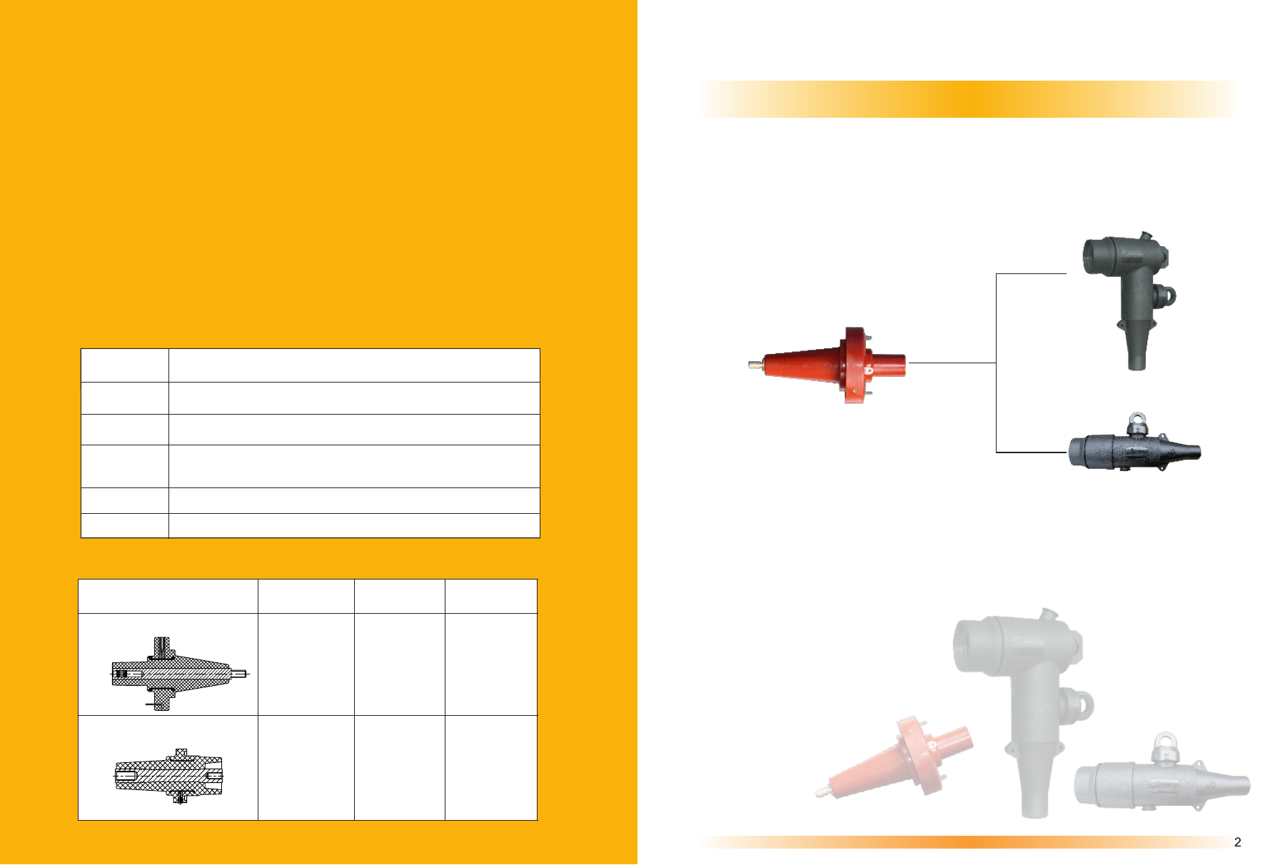
Apparatus Bushing
Typical Components of 250A Deadbreak Separable Insulated Connector System
Elbow Connector
Straight Connector
en.woer.com
250A Serial Deadbreak
250A Serial Deadbreak
Bushing Interface
Voltage Class
Interface
Description
Standard
250A Series Apparatus Bushing
15kV,24kV
250A
Sliding
EN50180&50181
Interface type A
EN50180&50181
Interface type C
630A
Bolted
15kV,24kV
630A Series
Bushing
Apparatus
Plug-in type bushings above 1kV up to 52kV and from 250A to 2.5kA for
equipment other than liquid filled transformers
bushings above 1kV up to 36kV and from 250A to 3.15kA for liquid filled
transformers
Metal oxide surge arresters without gaps for a.c. systems
Polymer-housed metal oxide surge arresters without gaps for a.c. systems
power cable with extruded insulation and their accessories for rated
voltages from 1kV(U=1.2kV) up to 30kV(U=36kV)-part 4: test requirements
on accessories for cable with rated voltages from 6kV up to 30kV(U=36kV)
Description
Standard
EN 50181
EN 50180
IEC 60502.4
IEC 60099
JB/T 8952
WOER-Separable-Connectors-and-Kits-html.html
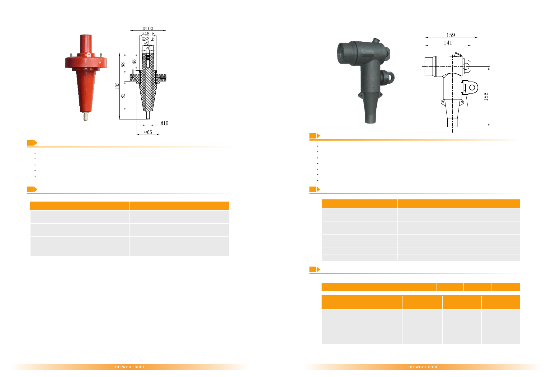
250A Deadbreak Elbow Connector (WEZT 15/250 or WEZT 24/250)
250A Apparatus Bushing (WETGZ-24/250)
Technical Data
Technical Data
Ordering Information and Designation
Description
Description
Made of high quality epoxy resin
Made of high quality EPDM rubber, providing a fully screened and submersible separable connection
Meeting requirements of EN 50180 & EN 50181 type A
Mating with bushings according to EN 50180 & EN 50181 type A
100% factory tested
Built-in capacitive test point to determine the circuit status or install a fault indicator
Voltage class: 24 kV
100% factory tested and compact design
2
Cable cross-section: 35-120 mm
Tested in compliance with GB/T 4109 (
IEC60137 6.0
)
Voltage class: 15 kV, 24 kV
Tested in compliance with IEC 60502.4
F
or
example
: WEZT 15/250A02C3
Note: The bushing interface is identical to the 200A deadbreak interface of IEEE 386 standard.
Dimension: mm
Voltage Class
24kV
Continuous Current
Bushing Interface
AC Withstand Voltage
Partial Discharge
Impulse Withstand Voltage
(10 times for each polarity)
Overload Current (8 hrs Max)
250A
EN 50181&50180 type A
65kV for 1min
20kV,
≤
10pC
125kV
300A
Voltage Class 15kV
24kV
Continuous Current
Appliance Bushing
AC Withstand Voltage
Partial Discharge
Impulse Withstand Voltage
(10 times for each polarity)
Overload Current (8 hrs Max)
Screen Resistance
250A
EN 50181&50180 type A
39kV for 5min
15kV,
≤
10pC
95kV
300A
≤
5000Ω
250A
EN 50181
type A
&50180
54kV for 5min
20kV,
≤
10pC
125kV
300A
≤
5000Ω
3
4
Dimension: mm
WEZT
1
Rated Voltage
:
15: 8.7/15kV
24: 12/20kV
A:Ø17-Ø22
B:Ø20-Ø25
C:Ø23-Ø28
02:35
03:50
04:70
05:95
06:120
C: Cu
A: Al
3: 3pcs/kit
1: 1pc/kit
2: Diameter over
Insulation /mm
3: Cable Cross-
2
section /mm
4: Material of Lug
5: Kit
/
250
1
2
3
4
5
Test
Point
WOER-Separable-Connectors-and-Kits-html.html
630A Serial Deadbreak
630A Serial Deadbreak
250A Deadbreak Straight Connector (WEZC 15/250 or WEZC 24/250)
Technical Data
Description
Made of
EPDM rubber, providing a fully screened and submersible separable connection
high quality
Mating with A-type bushings as per EN 50180 & EN 50181
Built-in capacitive test point allows for an easy check of the circuit status or installation of a fault indicator
100% factory tested,Compact design
Voltage class: 15 kV, 24 kV
2
Cable cross-section: 35-120 mm
Tested in compliance with IEC 60502.4
Apparatus Bushing
Apparatus Bushing in Air
Feed-thru Apparatus
Bushing
Apparatus Bushing With
Skirt
Tee Connector Rated 15kV
Tee Connector Rated 24kV
Rear Connector
Insulated Cap
Typical
Components of 630A Deadbreak Separable Insulated Connector System
Rear Connector
Rear Connector
with
Surge Arrester
Rear Connector
with
Surge Arrester
Rear Connector
with
Surge Arrester
Rear Connector
with
Surge Arrester
Dimension: mm
Voltage Class 15kV
24kV
Continuous Current
Appliance Bushing
AC Withstand Voltage
Partial Discharge
Impulse Withstand Voltage
(10 times for each polarity)
Overload Current (8 hrs Max)
Screen Resistance
Cable Cross-section
250A
EN 50181&50180 type A
39kV for 5min
15kV,
≤
10pC
95kV
300A
≤
5000Ω
2
35-120mm
250A
EN 50181
type A
&50180
54kV for 5min
20kV,
≤
10pC
125kV
300A
≤
5000Ω
2
35-120mm
5
6
Ordering Information and Designation
WEZC
/
250
1
2
3
4
5
1
Rated Voltage
:
15: 8.7/15kV
24: 12/20kV
A:Ø17-Ø22
B:Ø20-Ø25
C:Ø23-Ø28
02:35
03:50
04:70
05:95
06:120
C: Cu
A: Al
3: 3pcs/kit
1: 1pc/kit
2: Diameter over
Insulation /mm
3: Cable Cross-
2
section /mm
4: Material of Lug
5: Kit
F
or example: WEZC 15/250A04C3
Test
Point
WOER-Separable-Connectors-and-Kits-html.html
630A Apparatus Bushing
630A Deadbreak Tee Connector (WEB
Ⅲ
15/630 or WEBK
Ⅲ
(
15/630)
Technical Data
Description
Made of high quality epoxy resin
Meeting requirements of EN 50180 & EN 50181 type C
100% factory tested
Voltage class: 15 kV, 24 kV
In compliance with GB/T 4109 (
IEC60137 6.0
)
Interface Dimension: mm
Dimension: mm
Apparatus Bushing
Part No. WECTG-DB
Feed-thru Apparatus Bushing
Part No. WECTG-ST
Apparatus Bushing With Skirt
Part No. WECTG-DS2
Apparatus Bushing in Air
Part No. WECTG-CQ
Description
Made of
EPDM rubber, providing a fully screened and submersible separable connection
high quality
Mating with C-type bushings and plugs complying with EN 50180 & EN 50181
Compact design
100% factory tested
Voltage class: 15 kV, 24kV
Tested in compliance with IEC 60502.4
Dimension: mm
Rated 15kV
Rated 24kV
Tee Connector Rear Connector
Tee Connector Rear Connector
Technical Data
Voltage Class 15kV
24kV
Continuous Current
Bushing Interface
AC Withstand Voltage
Partial Discharge
Impulse Withstand Voltage
(10 times for each polarity)
Overload Current (8 hrs Max)
630A
EN 50180 & 50181 Type C
42kV for 1min
15kV,
≤
10pC
95kV
300A
630A
EN 50180 & 50181 Type C
65kV for 1min
20kV,
≤
10pC
125kV
300A
Voltage Class 15kV
24kV
Continuous Current
Appliance Bushing
AC Withstand Voltage
Partial Discharge at 1.73U
0
Impulse Withstand Voltage
(10 times for each polarity)
Screen Resistance
Cable Cross-section
630A
—
1250A
EN 50180 & 50181 Type C
39kV for 5min
≤
10pC
95kV
≤
5000Ω
2
25-500mm
630A
EN 50180 & 50181 Type C
54kV for 5min
≤
10pC
125kV
≤
5000Ω
2
25-400mm
7
8
Cable Cross-section
2
25~300 (mm )
71
242±5
2
400~500 (mm )
79
272±5
Outer Diameter L(mm)
Length H(mm)
WOER-Separable-Connectors-and-Kits-html.html
Cable Cross-section
2
25~300 (mm )
71
242±5
2
400~500 (mm )
79
272±5
Outer Diameter L(mm)
Length H(mm)
630A Deadbreak Tee Connector (WEB
Ⅲ
15/630 or WEBK
Ⅲ
15/630)
630A Deadbreak Tee Connector (WE
Ⅲ
15/630 or WEK
Ⅲ
15/630)
Description
Made of
EPDM rubber
high quality
Mating with C-type bushings and plugs complying with EN 50180 & EN 50181
Compact design
100% factory tested
Voltage class: 15kV
Tested in compliance with IEC 60502.4
Dimension: mm
Technical Data
Tee Connector Rear Connector
Voltage Class
15kV
Continuous Current
Appliance Bushing
AC Withstand Voltage
Partial Discharge at 1.73U
0
Impulse Withstand Voltage
(10 times for each polarity)
Cable Cross-section
630A
—
1250A
EN 50180 & 50181 Type C
39kV for 5min
≤
10pC
95kV
2
25-500mm
9
10
Ordering Information and Designation
WE
WE
2 Rated Voltage
:
2 Rated Voltage
:
1 Characteristic
:
1 Characteristic
:
15: 8.7/15kV
15: 8.7/15kV
24: 12/20kV
B
Ⅲ
:
Screened
Tee Connector
BK
Ⅲ
:
Screened
Rear Connector
Ⅲ
:
Unscreened
Tee Connector
K
Ⅲ
:
Unscreened
Rear Connector
A: Ø14-Ø16
B:Ø16-Ø18
C:Ø17-Ø20
D:Ø20-Ø23
E:Ø23-Ø26
F:Ø26-Ø30
G:Ø30-Ø33
H:Ø33-Ø36
I:Ø36-Ø39
A: Ø14-Ø16
B:Ø16-Ø18
C:Ø17-Ø20
D:Ø20-Ø23
E:Ø23-Ø26
F:Ø26-Ø30
G:Ø30-Ø33
H:Ø33-Ø36
I:Ø36-Ø39
A: Ø18-Ø22
B:Ø22-Ø25
C: Ø25-Ø28
D: Ø28-Ø32
E: Ø32-Ø35
F: Ø35-Ø38
G: Ø38-Ø41
01:25 02:35
03:50
04:70
05:95
06:120
07:150
08:185
09:240
10:300
11:400 12:500
01:25 02:35
03:50 04:70
05:95 06:120
07:150 08:185
09:240 10:300
11:400 12:500
01:25 02:35
03:50 04:70
05:95 06:120
07:150 08:185
09:240 10:300
11:400
C:Cu
A: Al
C: Cu
A: Al
C:Cu
A: Al
3: 3pcs/kit
1: 1pc/kit
3: 3pcs/kit
1: 1pc/kit
3: 3pcs/kit
1: 1pc/kit
3: Diameter over
Insulation /mm
3: Diameter over
Insulation /mm
4: Cable Cross-
2
section /mm
4: Cable Cross-
2
section /mm
5: Material
of Lug
5: Material
of Lug
6: Kit
6: Kit
/
630
/
630
1
1
2
2
3
3
4
4
5
5
6
6
Ordering Information and Designation
For
example
:
A02C3
WEB
Ⅲ
15/630
For
example
:
02C3
WE
Ⅲ
15/630B
WOER-Separable-Connectors-and-Kits-html.html
Surge Arrester (MOA Rated 15kV)
Surge Arrester (MOA Rated 20kV)
Technical Data
Selection Table
Description
Fully screened and insulated
Protecting electrical components against over-voltage and transients
The surge arrester’s active part is made of metal oxide
The connected braid manages short circuit currents
In compliance with IEC 60099.4-2006, JB/T 8952
100% factory tested
Description
Fully insulated and 100% factory tested
Protecting electrical components against over-voltage and transient
The surge arrester’s active part is made of metal oxide
The connected braid manages short circuit currents
Tested in compliance with IEC 60099.4-2006, JB/T 8952
Dimension: mm
Dimension: mm
Technical Data
Item
For Tee
Connector
For Tee
Connector
Item
Part No.
Item
YH5WZ-
10/27
WEB
YH5WZ-10/27
WEBK
YH5WZ-10/27
WE
YH5WZ-10/27
WEK
YH5WZ-10/27
WEBK
YH5WZ-26/66
YH5WS-
10/30
WEB
YH5WS-10/30
WEBK
YH5WS-10/30
WE
YH5WS-10/30
WEK
YH5WS-10/30
YH5WS-
13/36
WEB
YH5WS-13/36
WEBK
YH5WS-13/36
WE
YH5WS-13/36
WEK
YH5WS-13/36
YH5WZ-32/85
WEBK
YH5WZ-
17/45
WEB
YH5WZ-17/45
WEBK
YH5WZ-17/45
WE
YH5WZ-17/45
WEK
YH5WZ-17/45
YH5WS-
17/50
WEB
YH5WS-17/50
WEBK
YH5WS-17/50
WE
YH5WS-17/50
WEK
YH5WS-17/50
YH5WX-34/90
WEBK
System Nominal
Voltage(kV)
For Rear
Connector
For Rear
Connector
System Nominal
Voltage(kV)
Rated Voltage(kV)
Unscreened
Screened
Rated Voltage
Continuous Operation
Voltage (kV)
Continuous Operation
Voltage (kV)
Steep Current Impulse
Residual Voltage (kV)
Steep Current Impulse
Residual Voltage (kV)
Lightning Impulse
Residual Voltage(kV)
Lightning Impulse
Residual Voltage(kV)
Switching Impulse
Residual Voltage(kV)
Switching Impulse
Residual Voltage(kV)
Long Duration Current
Impulse Withstand(A)
Long Duration Current
Impulse withstand(A)
High Current Impulse
Withstand (kA)
High Current Impulse
Withstand (kA)
6
20
10
26
8.0
20.8
≤
31.0
≤
76
≤
27.0
≤
66
≤
23.0
≤
56
150
150
65
65
6
10
20
15
15
20
10
13
32
17
17
34
8.0
10.4
25.6
13.6
13.6
27.2
≤
34.6
≤
41.3
≤
95
≤
51.8
≤
57.5
≤
104
≤
30.0
≤
36.0
≤
85
≤
45.0
≤
50.0
≤
90
≤
25.6
≤
30.7
≤
75
≤
35
≤
42.5
≤
80
75
150
150
150
100
150
65
65
65
65
65
65
11
12
WOER-Separable-Connectors-and-Kits-html.html
630A Deadbreak Tee Connector Rated 35kV(WEB 35/630)
630A Deadbreak
WJM 24/630
Insulated Cap(WJM 15/630 or
)
Technical Data
Description
Made of
EPDM rubber
high quality
Used to insulate, shield and seal the deadbreak interfaces of C-type bushings, complying with
EN 50180 & EN 50181
Tested in compliance with IEC 60502.4
100% factory tested
Description
With patented cable adaptor (Zl201020709860)
Made of
EPDM rubber, providing a fully screened and submersible separable connection
high quality
Mates with both E-type bushings and plugs complying with EN 50180 &
EN 50181 and IEEE 386 600A bushing rated 35kV (different bushing
interface determines different package kit )
Compact design
Tested in compliance with IEC 60502.4
100% factory tested
2
Cable cross-section: 50-400mm
Dimension: mm
Dimension: mm
Technical Data
Tee Connector Rear Connector
Bushing Interface: Type E
Voltage
Item
Class 35kV
WJM 15/630
WJM 24/630
Rated Current
Rated Voltage
Appliance Bushing
Rated Current
AC Withstand Voltage
AC Withstand Voltage
Partial Discharge at 45kV
Partial Discharge
Impulse Withstand Voltage
(10 times for each polarity)
Impulse Withstand Voltage
(10 times for each polarity)
Screen Resistance
Screen Resistance
Cable Cross-section
630A
15kV
630A
24kV
630A
54kV for 5min
20kV,
≤
10pC
125kV
≤
5000
Ω
EN
50181&50180 Type E
IEEE 386 600A deadbreak rated 35kV
117kV for 5min
39kV for 5min
≤
10pC
15kV,
≤
10pC
200kV
95kV
≤
5000
≤
5000
Ω
2
50-400mm
13
14
Ordering Information and Designation
WEB
1
Rated Voltage
:
35: 26/35kV
A: Ø30-Ø34
B:Ø33-Ø37
C:Ø36-Ø40
D: Ø40-Ø43
E: Ø42-Ø45
F: Ø45-Ø48
03:50 04:70
05:95 06:120
07:150 08:185
09:240 10:300
11:400
C: Cu
A: Al
3: 3pcs/kit
1: 1pc/kit
2: Diameter over
Insulation /mm
3: Cable Cross-
2
section /mm
4: Material of Lug
5: Kit
/
630
1
2
3
4
5
For
example
:
WEB 35/630C04C3
1
6
6
WOER-Separable-Connectors-and-Kits-html.html
Separable Connectors Mated with
IEEE 386
Woer produces a range of separable Elbow and Tee connector kits. Our separable
connectors are widely used in switchgears, transformers, cabinets and other electrical
equipments. It is made of EPDM or silicone rubber with integrated field control. Woer
adopts advanced triple-layer (a conductive inner layer, an insulation layer and a
conductive outer layer) injection technique to guarantee the interface property to
avoid gaps between layers and decrease partial discharge maximally. Our separable
connectors are mainly delivered in 3-phase kit. Each kit contains all the necessary accessories.
Woer products have been designed and tested per IEEE and other industry standard
including:
Brief instruction for operation interface according to IEEE 386
16
Description
Standard
IEEEE 386
Separable insulated connector system for power distribution
system above 600V
Metal oxide surge arresters without gaps for a.c. systems
Polymer-housed metal oxide surge arresters without gaps
for a.c. systems
8.3/14.4kV
200A Sliding
600A Bolted
IEEE 386
Loadbreak
IEEE 386
Deadbreak
15.2/26.3kV
GB 11032
JB/T 8952
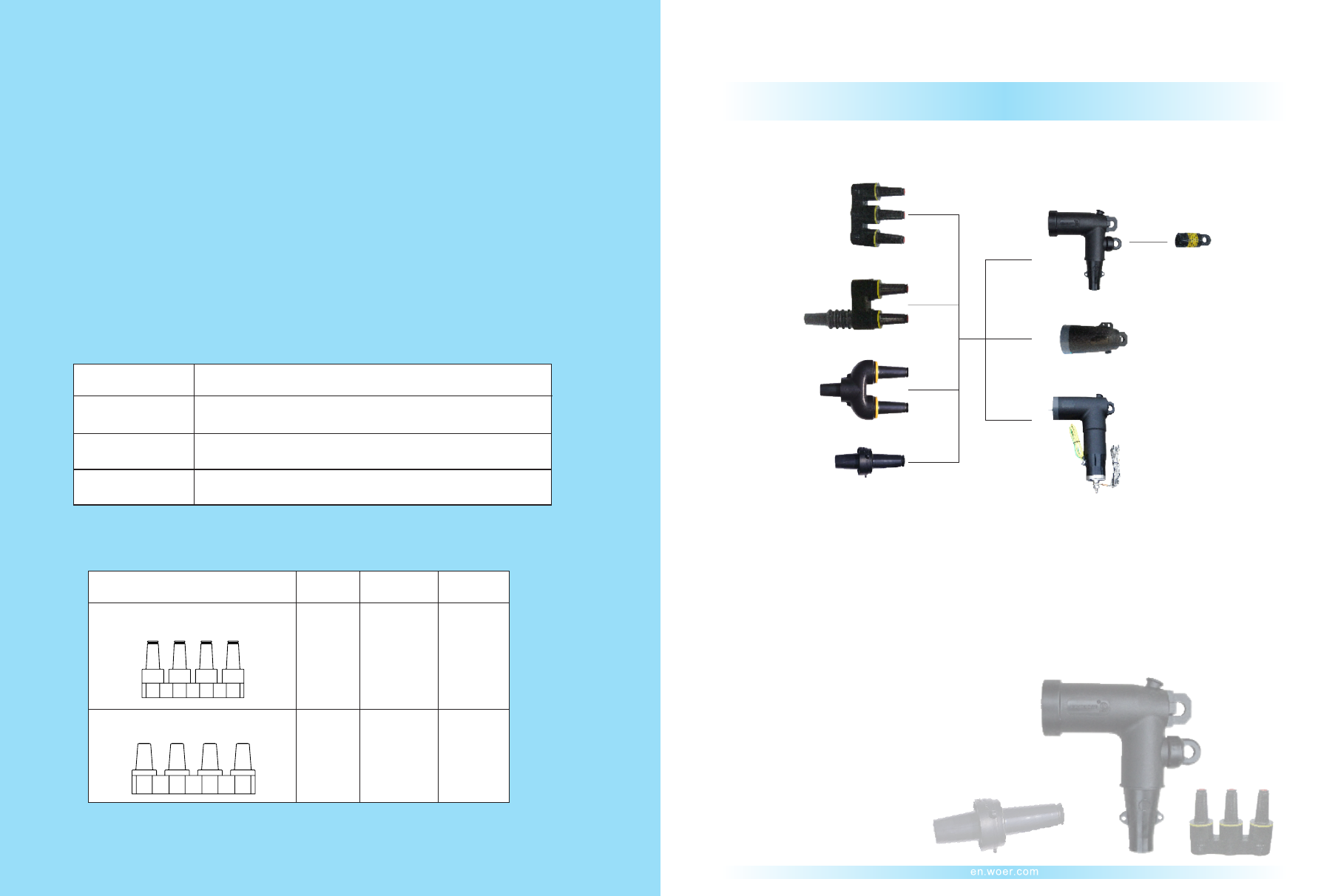
200A Serial Loadbreak
200A Serial Loadbreak
Typical
components
of 200A Loadbreak Separable Insulated Connector System
3-way Junction
2-way Specific
Junction
Feed-thru Bushing Insert
Bushing Insert
Energized Indicator
Elbow Connector
Insulated Cap
Elbow Connector With Surge Arrseter
Operation Interface
Rated
Voltage
Interface
Description Standard
200A Series Loadbreak Bushing
or Junction
600A Series Deadbreak Bushing
or Junction
WOER-Separable-Connectors-and-Kits-html.html
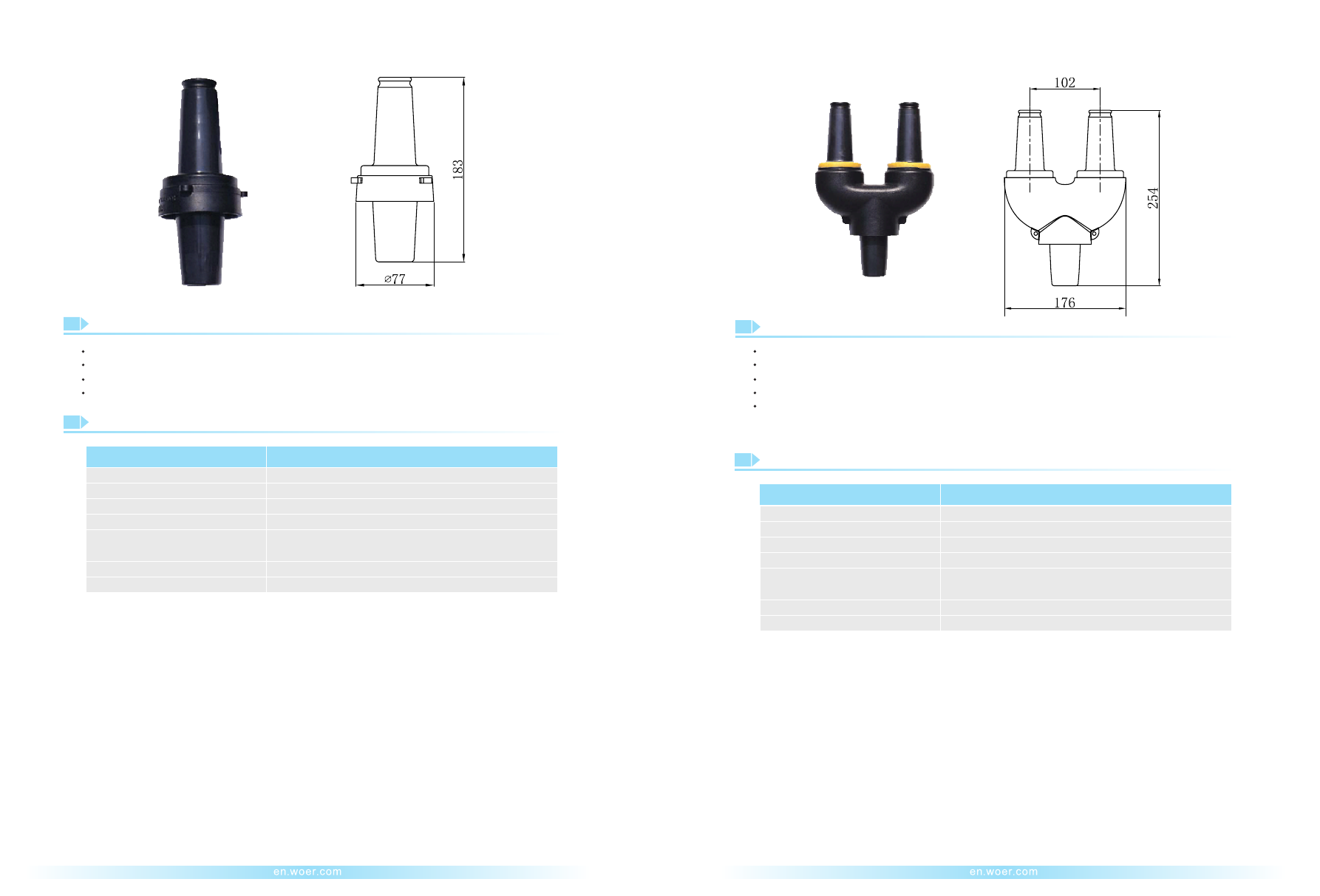
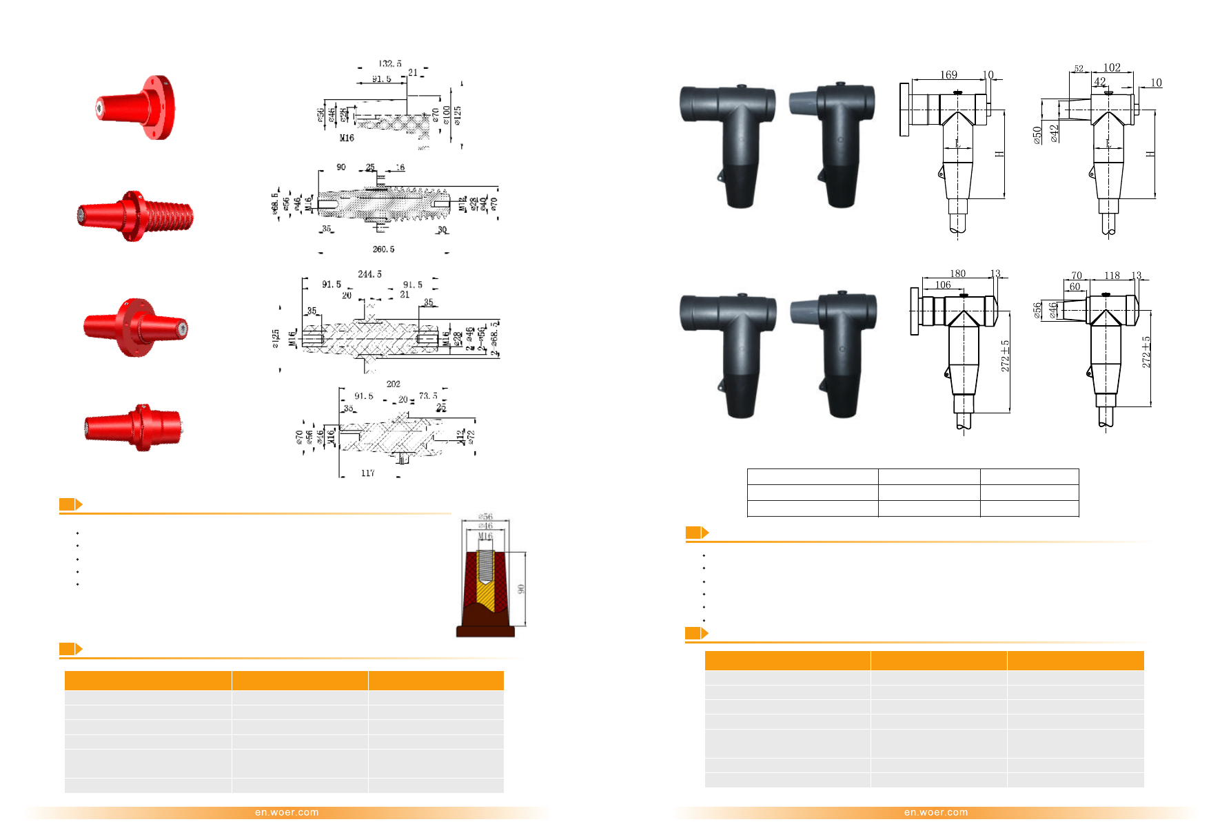
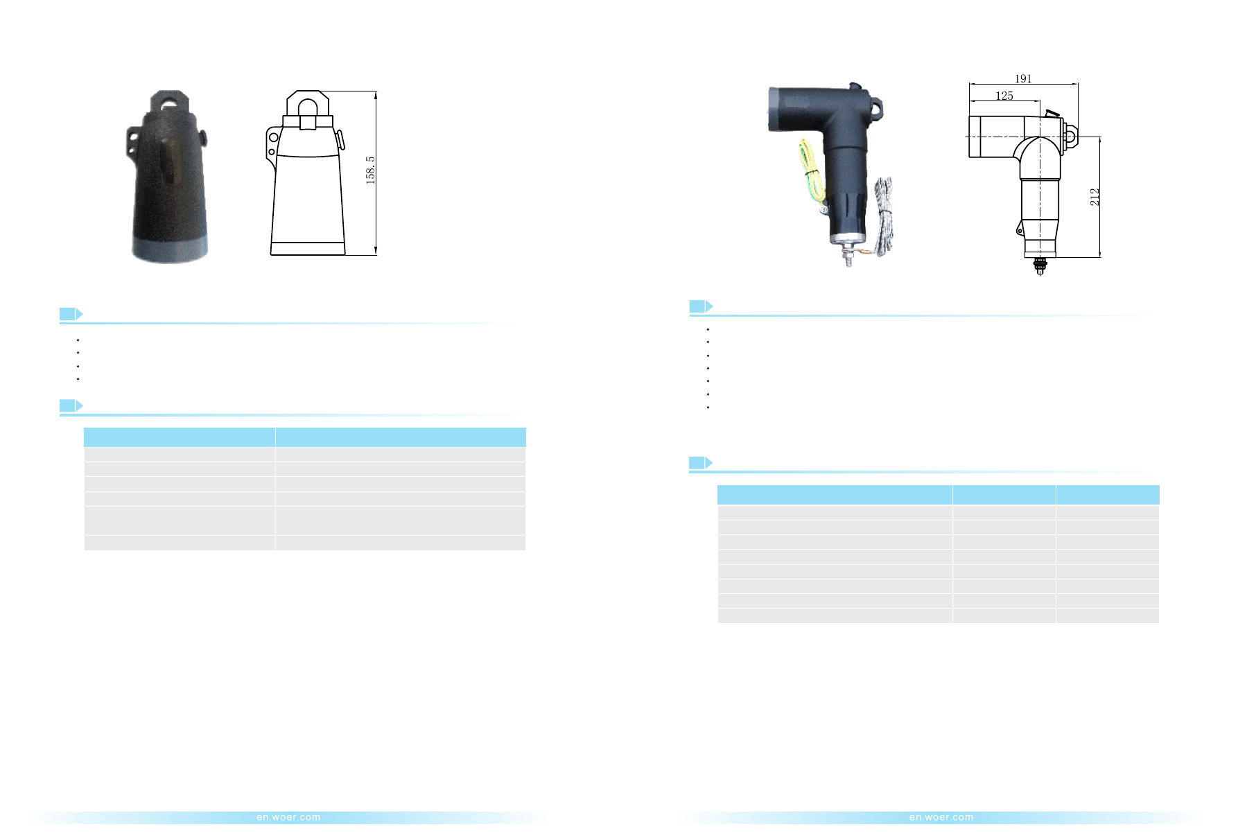
200A Loadbreak Feed-thru Bushing Insert(WAST 15/200)
200A Loadbreak Bushing Insert(WADT 15/200)
Dimension: mm
Dimension: mm
Description
Providing a fully shielded and submersible connection for mated loadbreak operation
Used with loadbreak connectors meeting the requirements of IEEE 386
Compact design
Made of high quality EPDM rubber
Description
Providing two electrically interconnected bushing interface
Providing a fully shielded and submersible connection for mated loadbreak operation
Used with loadbreak connectors meeting the requirements of IEEE 386
Compact design
Made of high quality EPDM rubber
Technical Data
Technical Data
Item
Item
Bushing
Insert
Feed-thru Bushing Insert
Rated Voltage(U /U)
0
Rated Voltage(U /U)
0
Rated Current
Rated Current
AC Withstand Voltage
AC Withstand Voltage
Partial Discharge
Partial Discharge
Impulse Withstand Voltage
(10 times for each polarity)
Impulse Withstand Voltage
(10 times for each polarity)
Switching Current
Switching Current
Screen Resistance
Screen Resistance
8.3/14.4kV
8.3/14.4kV
200A
200A
34kV for 1min
34kV for 1min
11kV,
≤
3pC
11kV,
≤
3pC
95kV
95kV
14.4kV,200A,10times
14.4kV,200A,10times
≤
5000
Ω
≤
5000
Ω
17
18
WOER-Separable-Connectors-and-Kits-html.html
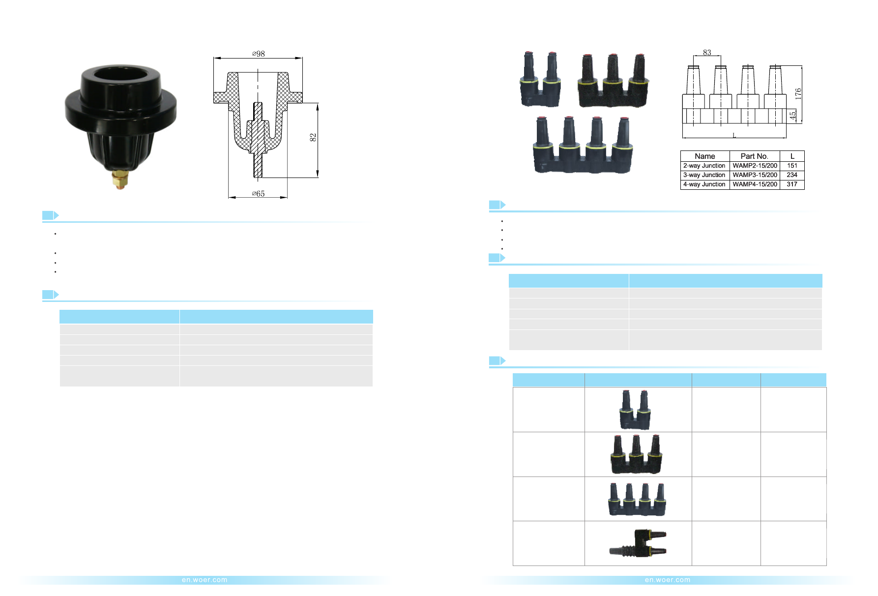
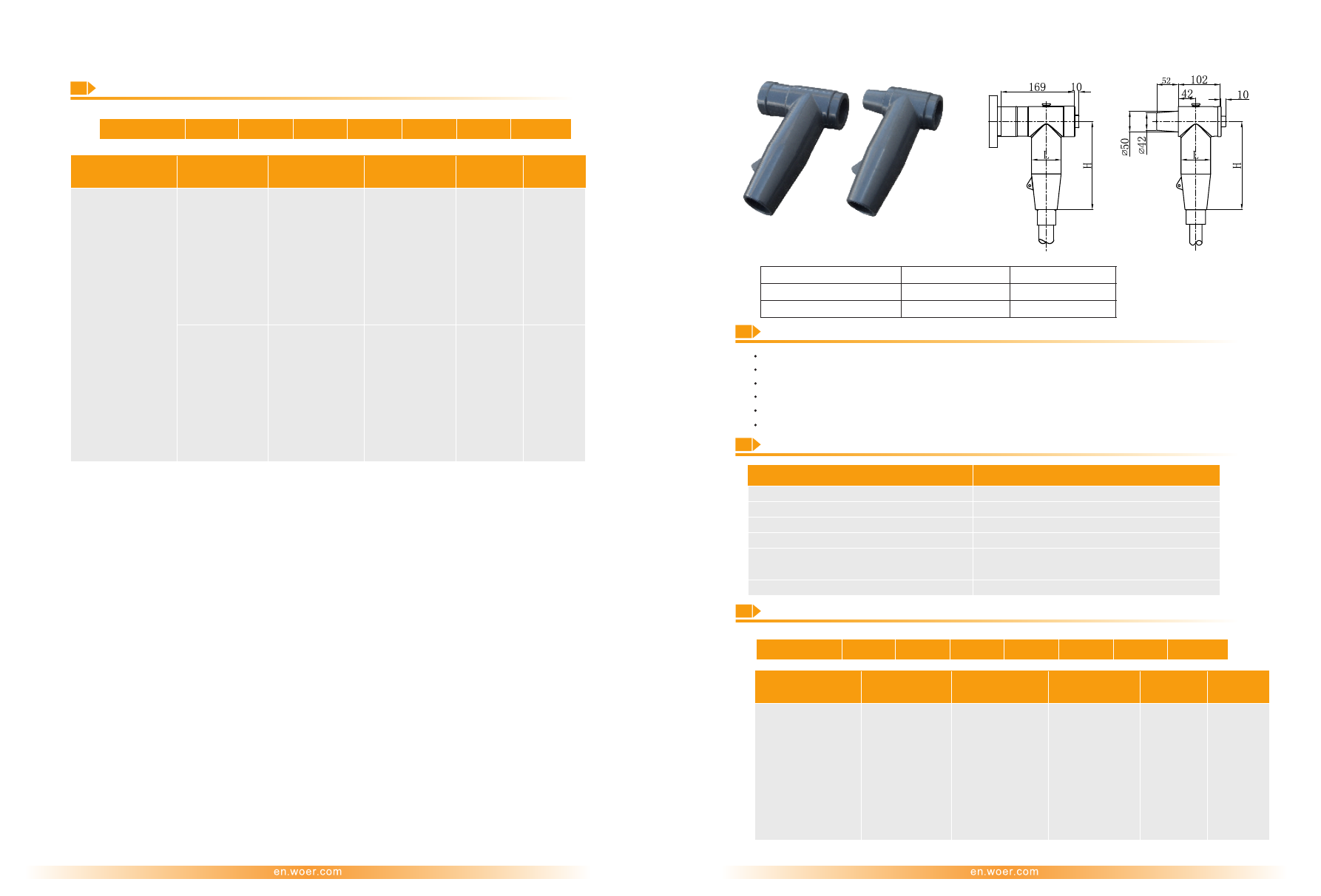
200A Loadbreak Junction
200A Loadbreak Bushing Well(WATGZ 15/200)
Dimension: mm
Description
Technical Data
Providing a fully shielded and submersible connection for loadbreak conne tor component, such
as bushing insert
c
Used with loadbreak connectors meeting the requirements of IEEE 386
Compact design
Made of high quality epoxy resin
Description
Providing a fully shielded and submersible connection for mated loadbreak operation
Using with loadbreak connectors meeting the requirements of IEEE 386
Optional number of interface
Made of high quality EPDM rubber
Technical Data
Item
Item
Bushing
Well
Result
Rated Voltage(U /U)
0
Rated Voltage(U /U)
0
Rated Current
Rated Current
AC Withstand Voltage
AC Withstand Voltage
Partial Discharge
Partial Discharge
Impulse Withstand Voltage
(10 times for each polarity)
Impulse Withstand Voltage
(10 times for each polarity)
8.3/14.4kV
8.3/14.4kV
200A
200A
34kV for 1min
34kV for 1min
11kV,
≤
3pC
11kV,
≤
3pC
95kV
95kV
19
20
Name
Profile
Part No.
Interface
Loadbreak
Sliding
WAMP2-15/200
Loadbreak
Sliding
Loadbreak
Sliding
Loadbreak
Sliding
WAMP3-15/200
WAMP4-15/200
WAYMP2-15/200
2-way Junction
3-way Junction
4-way Junction
2-way Specific
Junction
Selection Table
Dimension: mm
WOER-Separable-Connectors-and-Kits-html.html
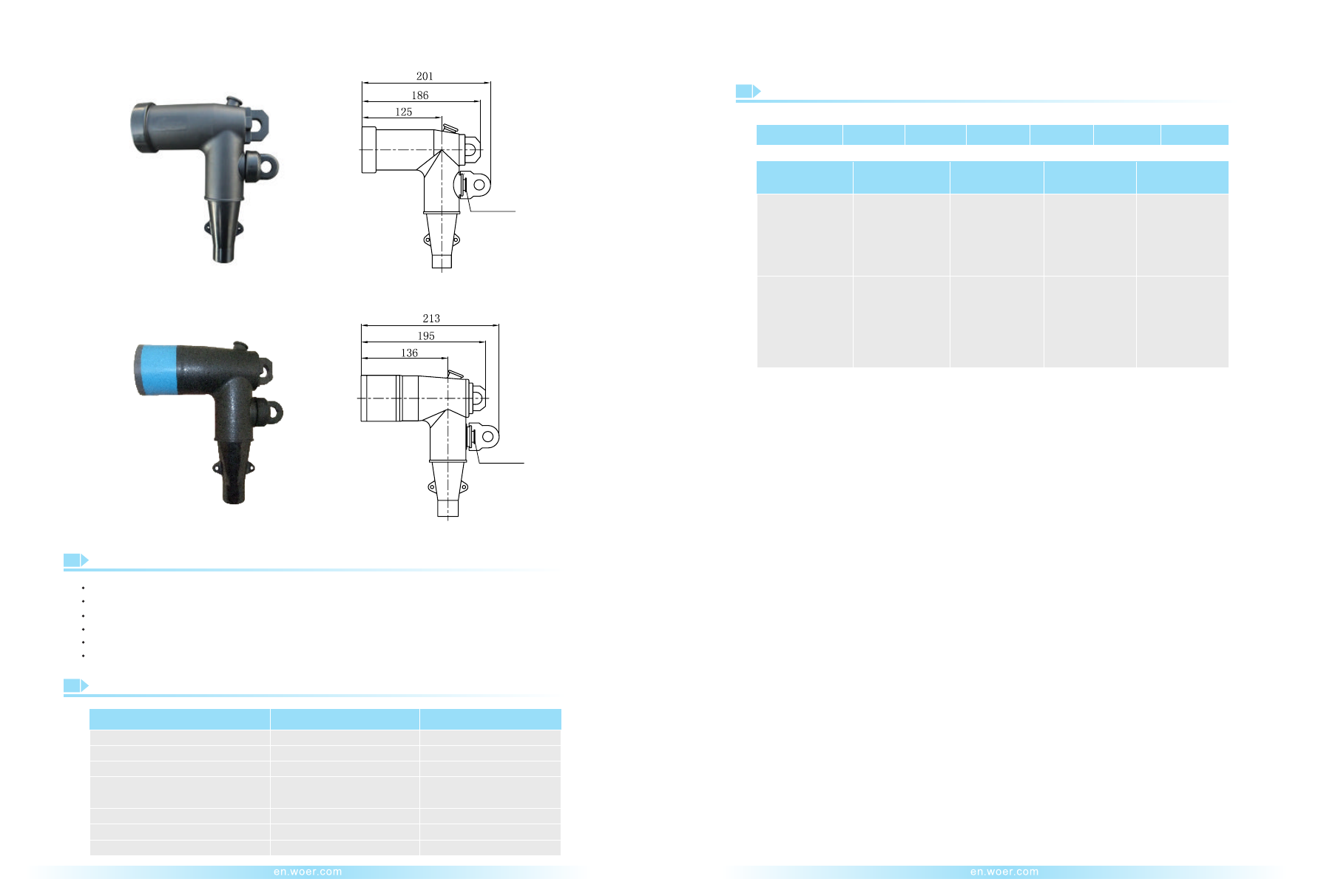
200A Loadbreak Elbow Connector(WAZT 15/200 or WAZT 25/200)
200A Loadbreak Elbow Connector(WAZT 15/200 or WAZT 25/200)
Description
Technical Data
Made of high quality EPDM rubber
Fully screened and submersible
Built-in capacitive test point
100% factory tested
Voltage class: 15kV, 25 kV
In compliance with IEEE 386
Ordering Information and Designation
Rated Voltage (U /U)
0
8.3/14.4kV
Rated Current
AC Withstand Voltage
Partial Discharge
Switching Current
Screen Resistance
Cable Cross-section
Impulse Withstand Voltage
(10 times for each polarity)
15.2/26.3kV
200A
200A
40kV for 1min
19kV,
≤
3pC
125kV
26.3kV, 200A, 10 times
≤
5000Ω
2
25-120mm
34kV for 1min
11kV,
≤
3pC
14.4kV, 200A, 10 times
≤
5000Ω
2
35-120mm
95kV
Dimension: mm
Rated 15kV
Rated 25kV
21
22
WAZT
1
Rated Voltage
:
15: 8.3/14.4kV
25: 15.2/26.3kV
A:Ø17-Ø20
B:Ø20-Ø23
C: Ø23-Ø26
A: Ø16-Ø21
B:Ø18-Ø24
C: Ø22-Ø28
D: Ø25-Ø32
02: 35
03: 50
04:70
05:95
06:120
01: 25
02: 35
03:50
04:70
05:95
06:120
C: Cu
A: Al
C: Cu
A: Al
3: 3pcs/kit
1: 1pc/kit
3: 3pcs/kit
1: 1pc/kit
2: Diameter over
Insulation /mm
3: Cable Cross-
2
section /mm
4: Material of Lug
5: Kit
/
200
1
2
3
4
5
F
or
example
:
WAZT 15/200B04C3
Test Point
Test Point
WOER-Separable-Connectors-and-Kits-html.html
200A Loadbreak Elbow Connector with Surge Arrester
200A Loadbreak Insulated Cap(WAJM 15/200)
Description
Technical Data
Made of high quality EPDM rubber
Used to insulate, shield and seal the loadbreak interface of 200A bushings
In compliance with IEEE 386
100% factory tested
Description
Fully screened and insulated
Protecting electrical components against over-voltage and transients
The surge arrester’s active part is made of metal oxide
The connected braid to manage short circuit currents
In compliance with IEC 60099.4-2006, JB/T 8952
100% factory tested
Made of high quality EPDM rubber
Technical Data
Item
Item
WAJM 15/200
WAZT-BLQ-17/45
WAZT-BLQ-17/50
System Nominal Voltage(kV)
Rated Voltage (U /U)
0
Rated Voltage
Rated Current
Continuous Operation Voltage (kV)
AC Withstand Voltage
Impulse Withstand Voltage
(10 times for each polarity)
Screen Resistance
Partial Discharge
Steep Current Impulse Residual Voltage (kV)
Lightning Impulse Residual Voltage(kV)
Switching Impulse Residual Voltage(kV)
Long Duration Current Impulse Withstand(A)
High Current Impulse Withstand (kA)
15
15
8.3/14.4kV
17
17
200A
13.6
13.6
34kV for 1min
95kV
≤
5000Ω
11kV,
≤
3pC
≤
51.8
≤
45
≤
35
150
65
≤
57
.
5
≤
50
≤
42
.
5
100
65
Dimension: mm
Dimension: mm
23
24
WOER-Separable-Connectors-and-Kits-html.html
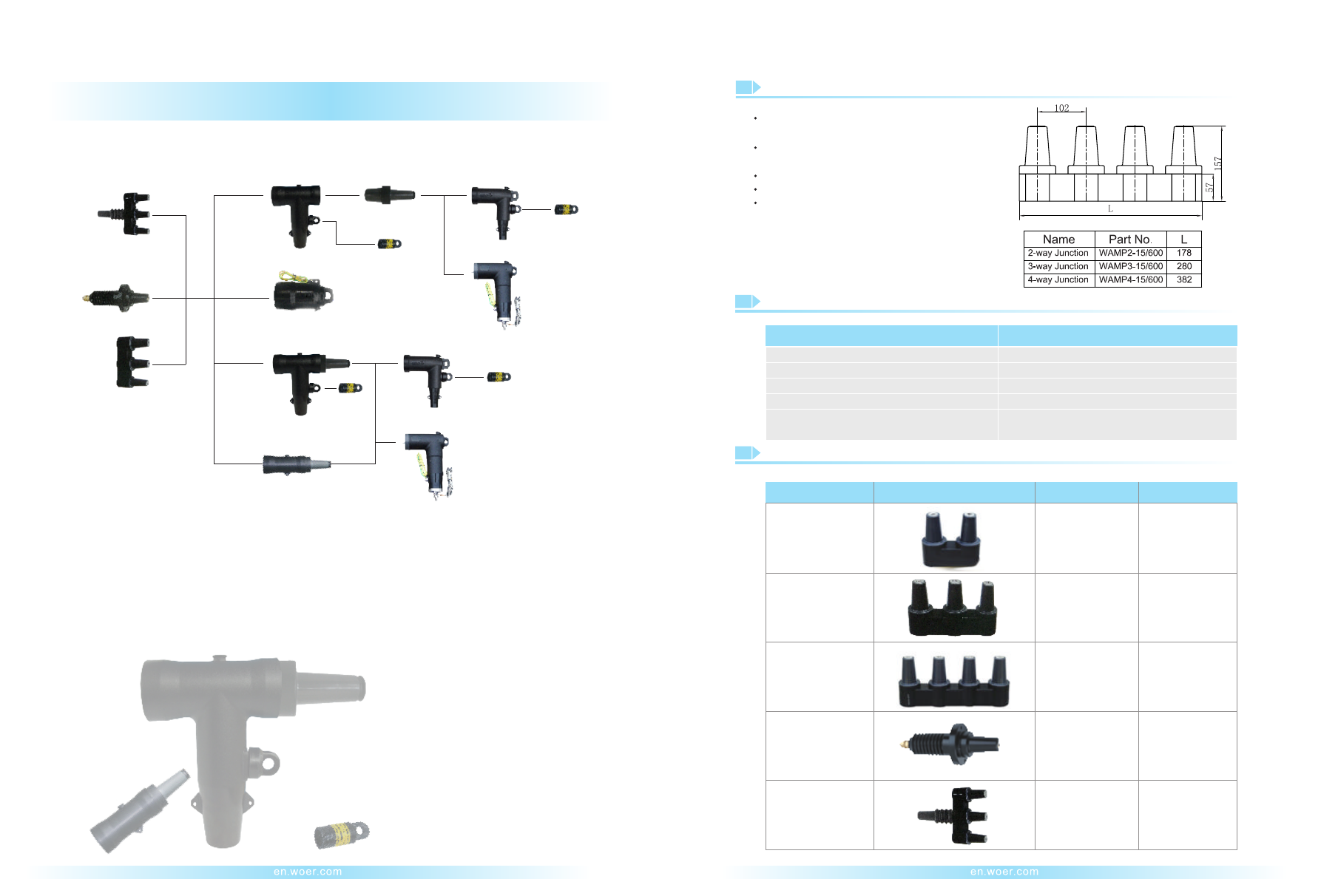
600A Deadbreak Junction and Integral Bushing
Description
Providing a fully shielded, submersible, threaded
connection for mated deadbreak operation
Using with deadbreak connectors meeting the
requirements of IEEE 386
Compact design
In compliance with IEEE 386
Made of high quality EPDM
Technical Data
Selection Table
Item
Name
Result
Profile
Part No.
Interface
8.3/14.4kV
600A
34kV for 1min
11kV,
≤
3pC
Deadbreak
Bolted
Deadbreak
Bolted
Deadbreak
Bolted
Deadbreak
Bolted
WAMP2-15/600
WAMP3-15/600
WAMP4-15/600
WAYMP3-15/600
95kV
Rated Voltage(U /U)
0
Deadbreak
Bolted
WAYTSG-15/600
Integral Bushing
with Skirt
Rated Current
AC Withstand Voltage
Partial Discharge
2-way Junction
3-way Junction
4-way Junction
3-way Specific
Junction
Impulse Withstand Voltage
(10 times for each polarity)
25
26
Dimension: mm
600A Serial Deadbreak
600A Serial Deadbreak
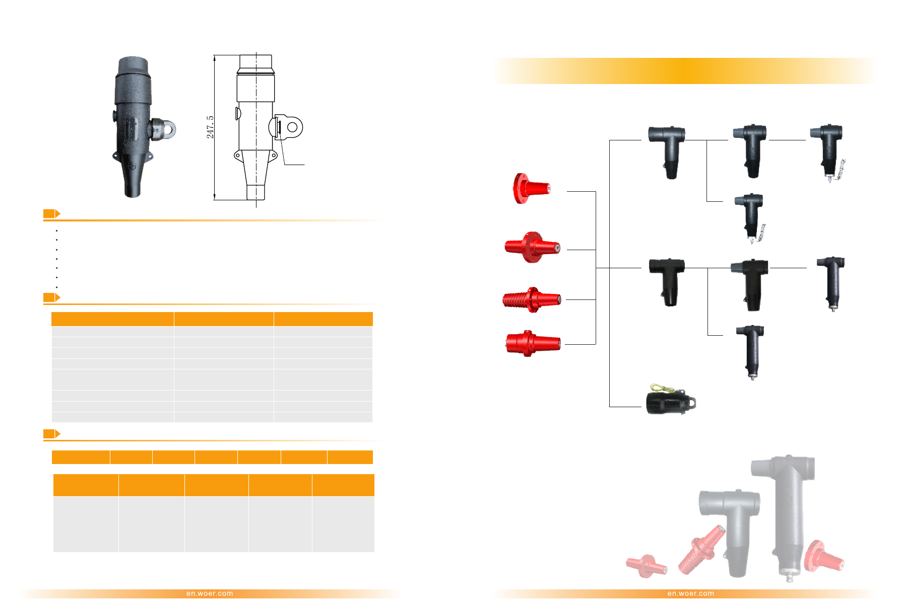
3-way Specific Junction
Tee
Connector
Elbow
Connector
Elbow
Connector
with Surge Arrester
Insulated Cap
Tee-
Ⅱ
Connector
Reducing
Ta
p Plug
with Bushing Extender
Elbow
Connector
with Surge Arrester
Typical Components of 600A Deadbreak Separable Insulated Connector System
Elbow
Connector
Energized
Indicator
Energized
Indicator
Energized
Indicator
Energized
Indicator
Reducing
Tap Plug
3-way Junction
Integral
Bushing with Skirt
WOER-Separable-Connectors-and-Kits-html.html
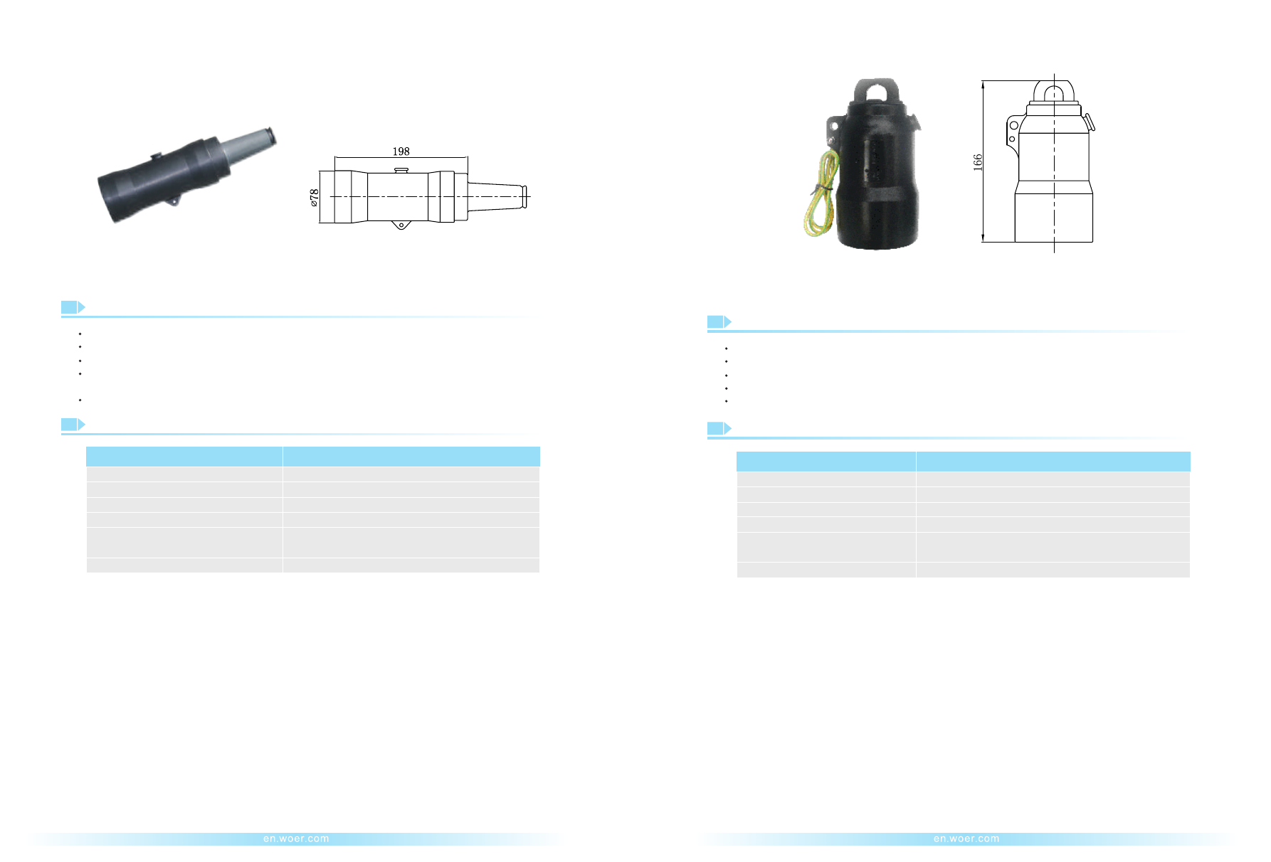
600A Deadbreak Tee Connector(WABT 15/600 or WABT2 15/600)
600A Deadbreak Connecting Plug(WAZH 15/600/600)
600A Deadbreak Reducing Tap Plug(WAZH 15/600/200)
Technical Data
Item
WAZH-15/600/600 or WAZH-15/600/200
8.3/14.4kV
600A
34kV for 1min
11kV,
≤
3pC
≤
5000Ω
95kV
Rated Voltage
Rated Current
AC Withstand Voltage
Partial Discharge
Screen Resistance
Impulse Withstand Voltage
(10 times for each polarity)
Description
Technical Data
Made of high quality EPDM rubber, providing a fully screened and submersible separable connection
In complying with IEEE 386
100% factory tested
Compact design
Voltage class: 15 kV
Description
Description
Providing a fully shielded, submersible, threaded connection for mated deadbreak operation
Providing a fully shielded, submersible, threaded connection for mated deadbreak operation
Using with deadbreak connectors meeting the requirements of IEEE 386
Using with deadbreak connectors meeting the requirements of IEEE 386
Compact design and made of high quality EPDM rubber
Compact design made of high quality EPDM rubber
In compliance with IEEE 386
In compliance with IEEE 386
Providing two in-line bushing interface
Transition of a 600A deadbreak system to a 200A loadbreak system
Item
Result
Rated Voltage (U /U)
0
Rated Current
AC Withstand Voltage
Impulse Withstand Voltage
(10 times for each polarity)
Screen Resistance
Cable Cross-section
Partial Discharge
8.3/14.4kV
600A
34kV for 1min
95kV
≤
5000Ω
2
25-400mm
11kV,
≤
3pC
Tee-
Ⅱ
Connector
Tee Connector
27
28
Dimension: mm
Dimension: mm
Dimension: mm
Ordering Information and Designation
WA
1
Characteristic
:
15: 8.3/14.4kV
A:Ø14-Ø16
B:Ø16-Ø18
C:Ø17-Ø20
D:Ø20-Ø23
E:Ø23-Ø26
F:Ø26-Ø30
G:Ø30-Ø33
H:Ø33-Ø36
C: Cu
A: Al
01:25 02:35
03:50 04:70
05:95 06:120
07:150 08:185
09:240 10:300
11:400
3: 3pcs/kit
1: 1pc/kit
BT: Tee
BT2: Tee-
Ⅱ
2: Rated Voltage
3: Diameter over
Insulation /mm
4: Cable Cross-
2
section /mm
5: Material
of Lug
6: Kit
/
600
1
2
3
4
6
5
F
or example: WABT2 15/600B05C3
Test
Point
Test Point
WOER-Separable-Connectors-and-Kits-html.html
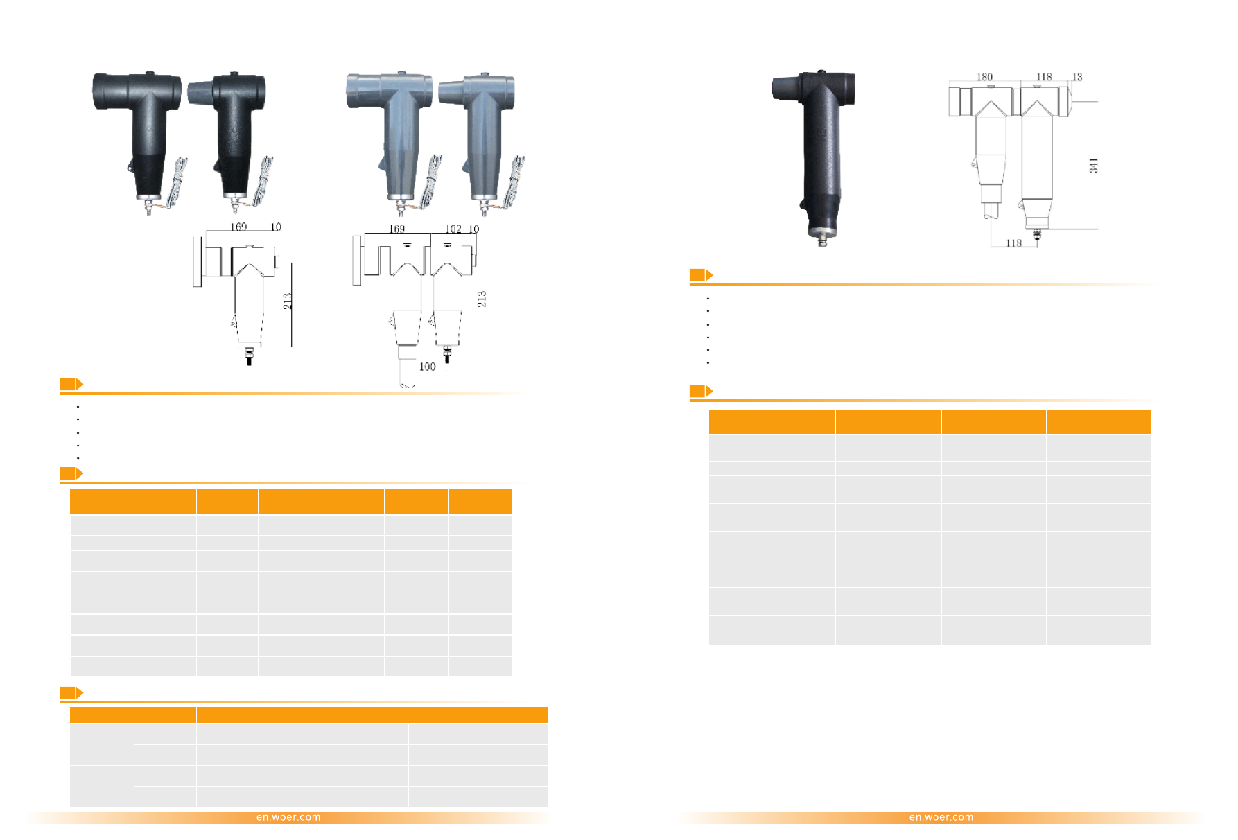
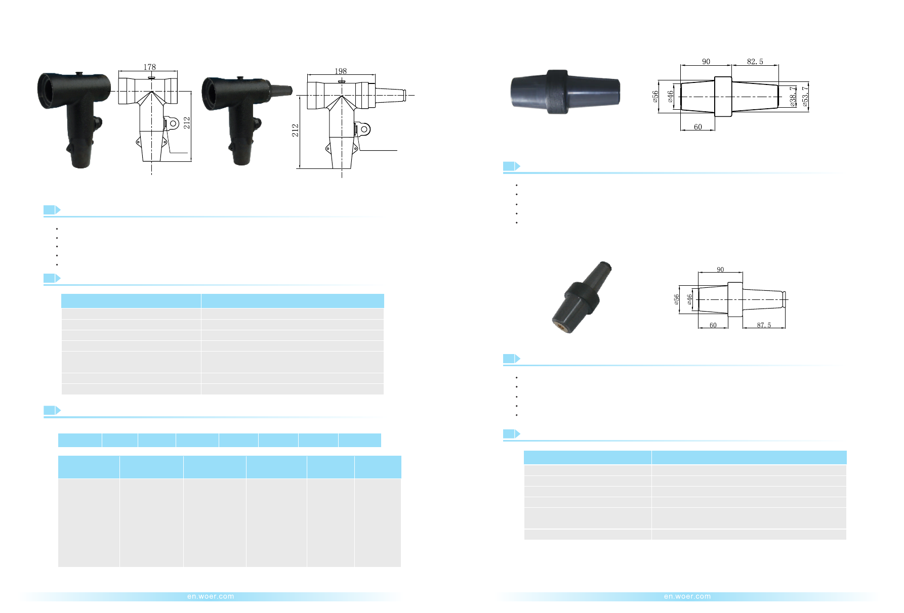
600A Deadbreak Reducing Tap Plug with Bushing Extender
(WAFZH 15/600/200)
600A Deadbreak Insulated Cap(
)
WAJM 15/600
Technical Data
Item
WAJM 15/600
8.3/14.4kV
600A
34kV for 1min
11kV,
≤
3pC
≤
5000Ω
95kV
Rated Voltage
Rated Current
AC Withstand Voltage
Partial Discharge
Screen Resistance
Impulse Withstand Voltage
(10 times for each polarity)
Extender
Technical Data
Providing a fully shielded, submersible, threaded connection for mated deadbreak operation
Using with deadbreak components meeting the requirements of IEEE 386
Compact design
Made of
high
quality
EPDM rubber
Transition of a 600A deadbreak system to a 200A loadbreak system, with the 600A interface
connecting to a bushing or a junction
Description
Made of
EPDM rubber
high quality
Used to insulate, shield and seal the deadbreak interfaces of 600A bushings per IEEE 386
Compact design
100% factory tested
Tested in compliance with IEEE 386
Item
WAFZH 15/600/200
Rated Voltage
Rated Current
AC Withstand Voltage
Impulse Withstand Voltage
(10 times for each polarity)
Screen Resistance
Partial Discharge
8.3/14.4kV
600A/200A
34kV for 1min
95kV
≤
5000Ω
11kV,
≤
3pC
29
30
Dimension: mm
Dimension: mm
WOER-Separable-Connectors-and-Kits-html.html
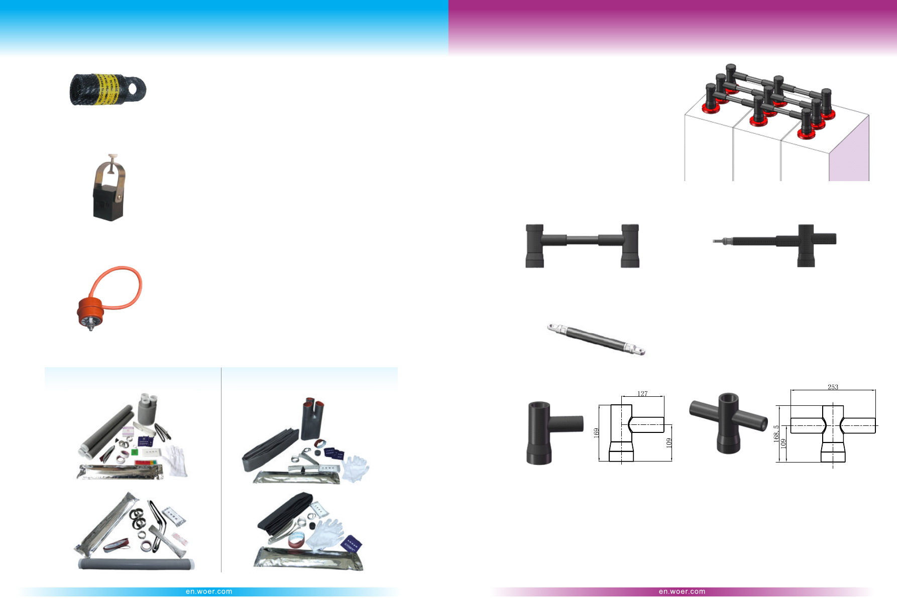
Accessories
Busbar Connecting System
Busbar Connector
Energized Indicator(WDDX)
Fault Indicator(EKL2)
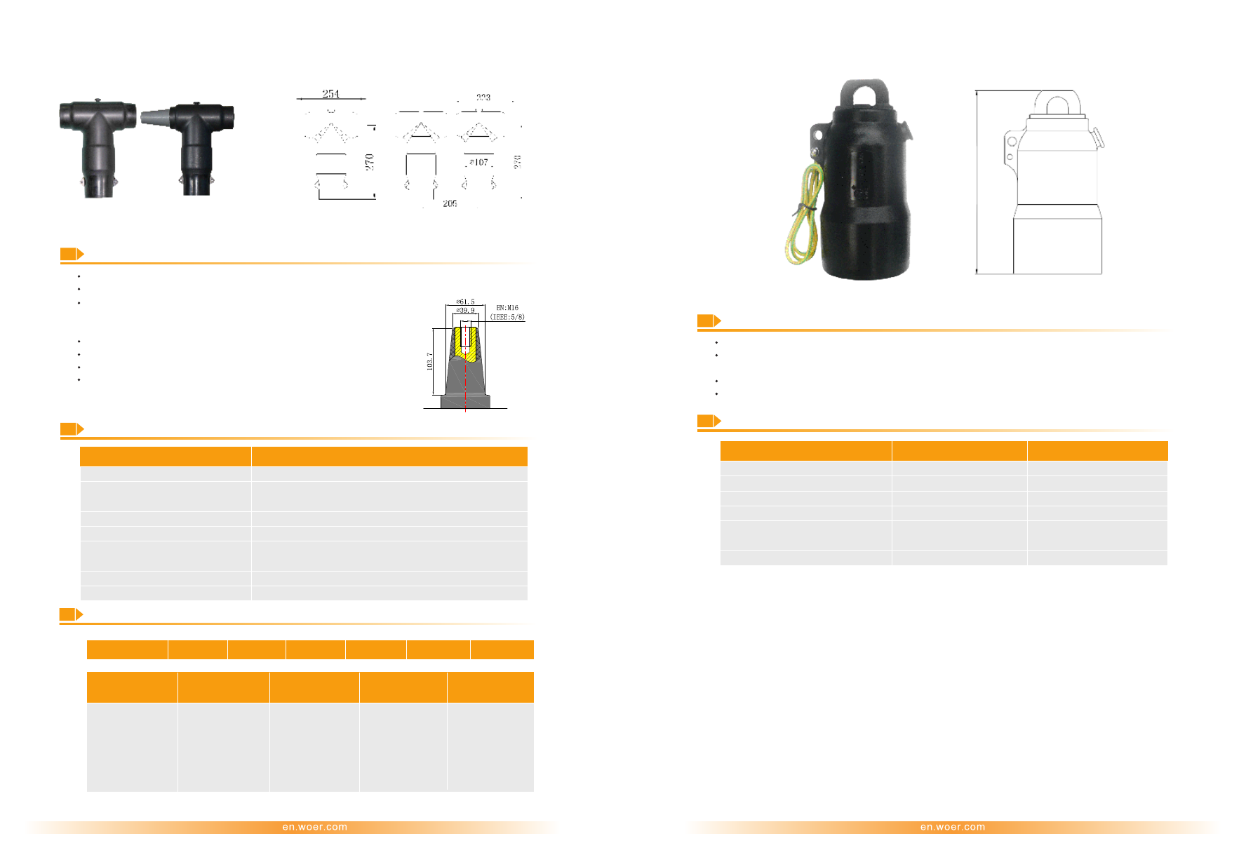
Cable Sheath Voltage Limiter (WBHQ 7/400 or
)
WBHQ 7/600
Install at the test point to indicate the circuit energized
status with flicker warning the energized circuit.
Moreover, it is fully insulated and sealed with unlimited
climate condition.
Busbar connector system is made of silicone rubber,
mainly applied for the connection for SF6 insulated
switchgear with metal housing. Such special designed
connector can be also made screened or unscreened,
which can electrically insulate and mechanically seal
the connecting busbar and switchgear. The connecting
interface conforms to type C according to EN50180, EN
50181 and DIN 47636.
Indicate the circuit status with flicker warning the fault
circuit to shorten the fault inspecting time.
Following are our unscreened products. Screened products are available according to different requirements.
End-adapter with Busba
Part No. ZDMX 10/630-L
r
End-adapter
Cross-adapter with Busbar
Part No. ZJMX 10/630-L
Cross-adapter
L
:
busbar length
Use for single-core power cable route to restrict the
inducted voltage on the cable metal sheath. It protects
the sheath from breakdown by overvoltage.
3-core
1-core
3-core
1-core
Cold Shrink Sealing Kits for Connectors
Heat Shrink Sealing Kits for Connectors
31
32
Dimension: mm
Busbar
WOER-Separable-Connectors-and-Kits-html.html
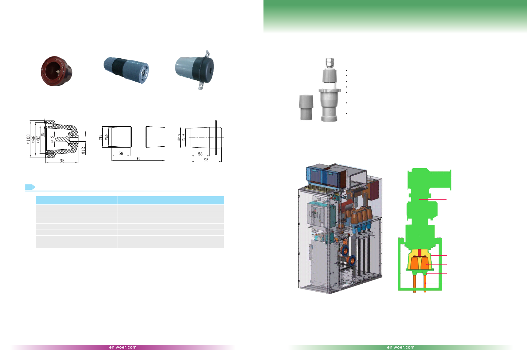
Inner Cone Busbar Kits
Termination
Inner cone busbar kits are suitable for the combined connection of ring main units to supply more branches
for expansion. Meanwhile, it is a prior option to combined ring main units.
Technical Data
Item
Busbar Connector and Kits
Voltage Class
Rated Current
Appliance Bushing
AC Withstand Voltage
Partial Discharge
Impulse Withstand Voltage
(10 times for each polarity)
15kV
630A
EN 50181&50180 type C
42kV for 1min
15kV,
≤
10pC
75kV
Inner Cone Plug-in Serial up to 42kV
Conforming to EN 50181&50180
Switch Cabinet Column
Connecting Apparatus
Inner Cone Bushing
Inner Cone Plug-in Termination
Cable
Dry interface
Premould stress control cone of silicone rubber with 100% factory tested
Metal protective shell on tail to provide great mechanical protection and
fully shield
Adopting one-piece compression structure of tail tube and spring to ensure
enough interface force between the stress control cone and bushing
Suitable for indoor& outdoor condition mated with C-GIS or transformers
Tested according to IEC 60502
33
34
Dimension: mm
Application
Inner Cone Busbar Insulator 1#
Part No. WNML1-TG
Inner Cone Busbar Connector 1#
Part No. WNML1-15
Inner Cone Busbar Plug 1#
Part No. WNMLD1-15
WOER-Separable-Connectors-and-Kits-html.html
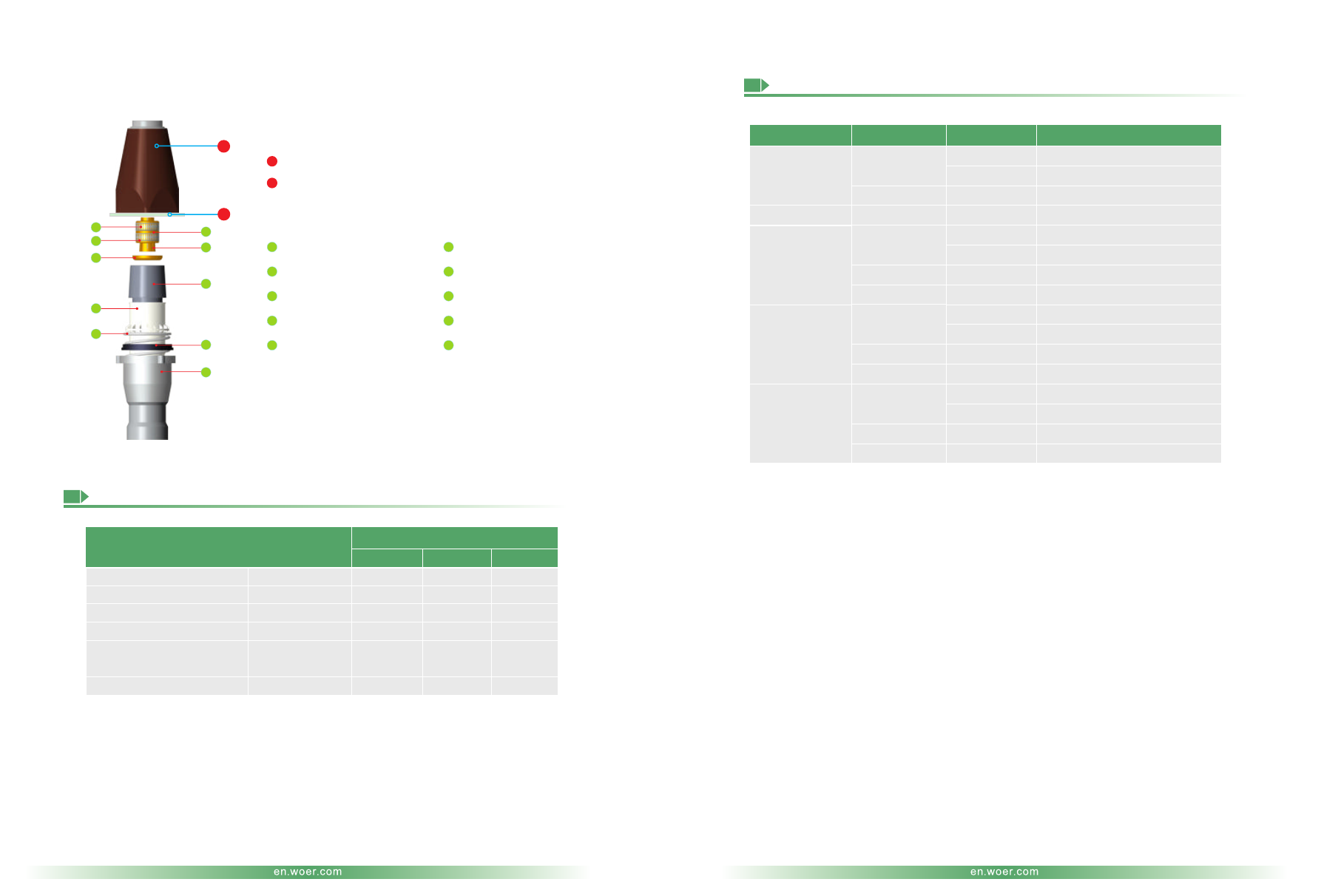
Designed Profile
35
36
1#
Main Body
Item
2#
Rated Current
Maximum System Voltage(U )
m
A
kV
AC Withstand Voltage
630
36
70
800
42
117
Installation
50Hz for 5min (kV)
1.73U
0
1.2/50μs(kV)
1sec(kA)
≤
5pC
170
31.5
≤
5pC
200
40
3#
1250
42
117
≤
5pC
200
50
Impulse Withstand Voltage
(10 times for each polarity)
Partial Discharge
Technical Data
Selection Table
Rated Voltage
Main Body
3#
2#
3#
3#
2#
1
#
3#
2#
1#
3#
2#
1#
Core Number
1 or 3
1
1 or 3
1
1 or 3
1
1 or 3
1 or 3
1 or 3
1
1 or 3
1 or 3
1 or 3
1
1 or 3
1 or 3
Part No.
35kV WCBN-3-1(3)×50~500
35kV WCBN-3-1×630
35kV WCBN-2-1(3)×50~120
27.5kV WCBN-3-1×50~500
30kV WCBN-3-1(3)×35~500
30kV WCBN-3-1×630~800
30kV WCBN-2-1(3)×70~240
30kV WCBN-1-1(3)×35~240
20kV WCBN-3-1(3)×35~500
20kV WCBN-3-1×630~800
20kV WCBN-2-1(3)×150~400
20kV WCBN-1-1(3)×35~400
10kV WCBN-3-1(3)×35~500
10kV WCBN-3-1×630~1000
10kV WCBN-2-1(3)×240~500
10kV WCBN-1-1(3)×25~400
26/35kV
27.5/42kV
18/30kV
12/20kV
6/10, 8.7/10
or 8.7/15kV
Insulated Bushing
Inner Cone Plug-in Termination
Inner Cone Insulated Bushing
Wedge-shaped Cylinder
Bite-wire Tool
Premould Stress Cone
Gasket
Tail Tube
Non-magnetic Spring
Supporting Tube
Stopper Set
Clamp Ring
Conductive Strip
Flange
1
1
2
2
1
1
2
6
7
8
9
10
3
5
7
9
2
4
6
8
10
5
4
3
WOER-Separable-Connectors-and-Kits-html.html
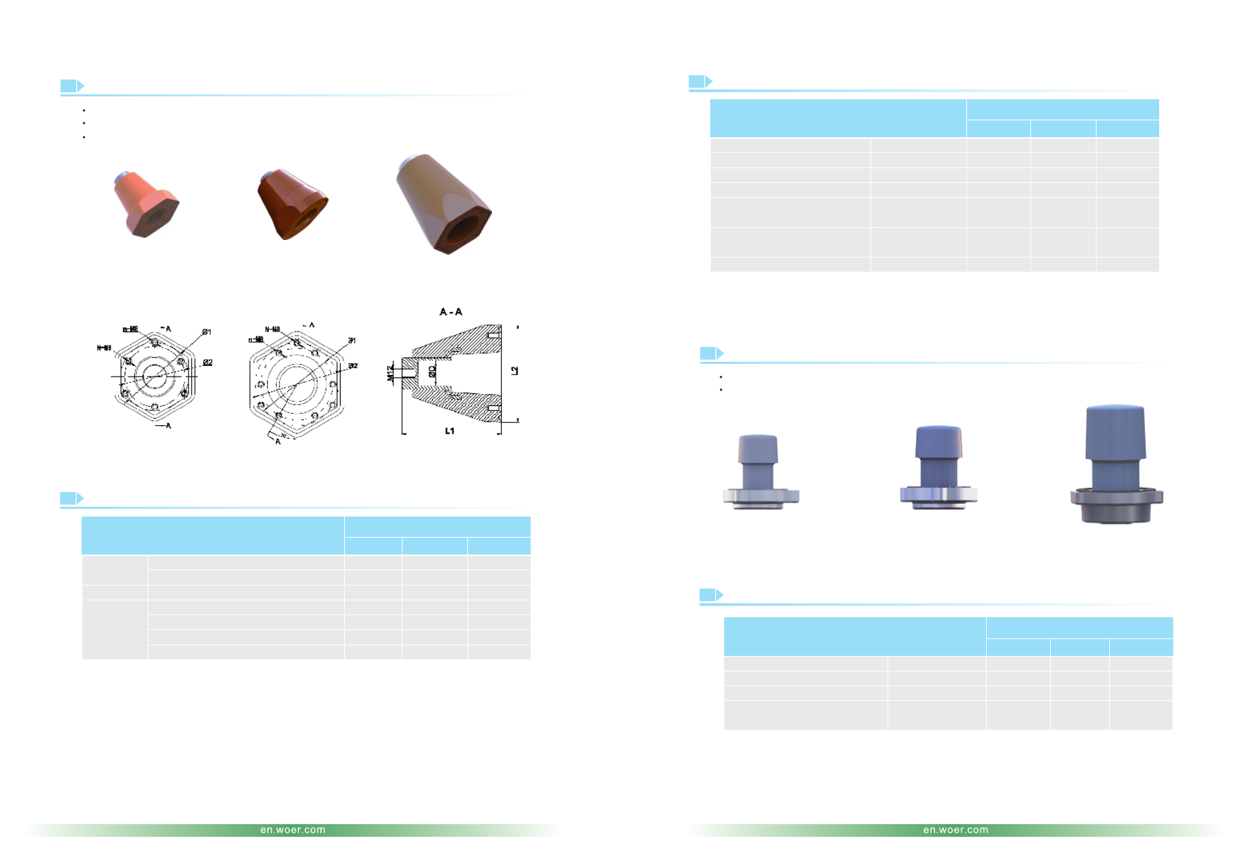
Conforming to EN 50181&50180
Conforming to EN 50181 &50180
Connecting to high voltage conductor of C-GIS cabinets or transformers
To seal and insulate inner cone insulated bushing used for spare outlet port
Compact design, fully insulated and no maintenance
Insulated Bushing
Description
WMT-1
WNJT-1
WNJT-2
WNJT-3
WMT-2
WMT-3
Technical Data
Description
Referred Dimension
Technical Data
Insulated Insert
WNJT-1
WMT-1
WNJT-1
Part No.
Part No.
Part No.
Item
Item
Item
WNJT-2
WMT-2
WNJT-2
Outline
Maximum System Voltage(U )
m
Rated Current
Maximum System Voltag(U )
m
L1(mm)
kV
A
L2(mm)
50Hz for 5min(kV)
kV
Conductor
AC Withstand Voltage
Partial Discharge
AC Withstand Voltage
ΦD(mm)
1.73U
0
50Hz for 5min (kV)
140
36
630
136
70
36
36
≤
5pC
70
140
42
800
136
117
42
39
≤
5pC
117
Installation
Impulse Withstand Voltage
(10 times for each polarity)
Maximum Short-time
Current Withstand
Rated Impulse Current
Installation Position for Bushing
Φ1(mm)
1.2/50μs(kV)
1.73U
0
Number of Installation Hole n(pcs)
1.2/50μs(kV)
Installation Position for Termination
Φ2(mm)
1sec(kA)
Number of Installation Hole N(pcs)
kA
108
170
≤
5pC
3
170
95
31.5
3
125
108
200
≤
5pC
3
200
102
40
3
150
WNJT-3
WMT-3
WNJT-3
217
42
1250
165
117
42
55
≤
5pC
117
113
200
≤
5pC
6
200
130
50
3
150
Partial Discharge
Impulse Withstand Voltage
(10 times for each polarity)
37
38
Dimension: mm
WOER-Separable-Connectors-and-Kits-html.html
39
40
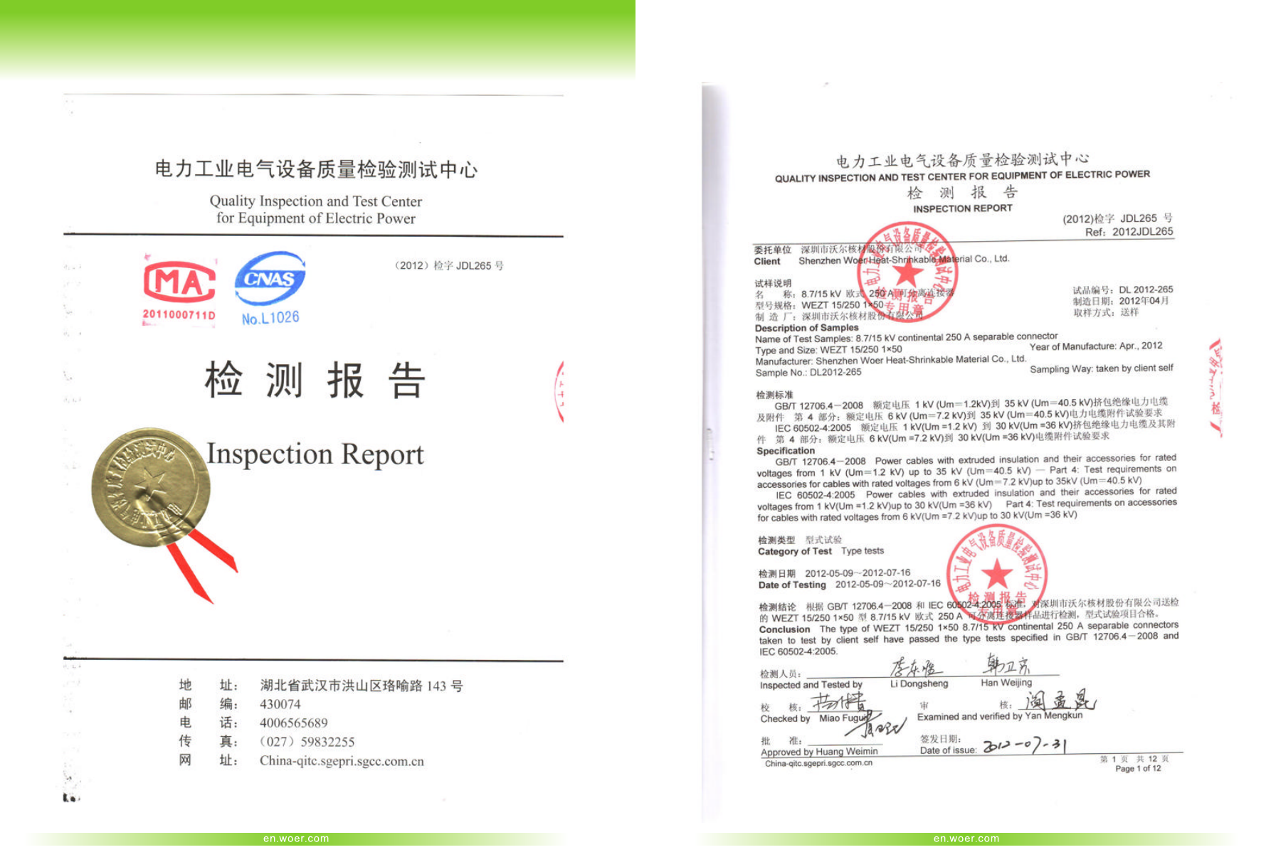
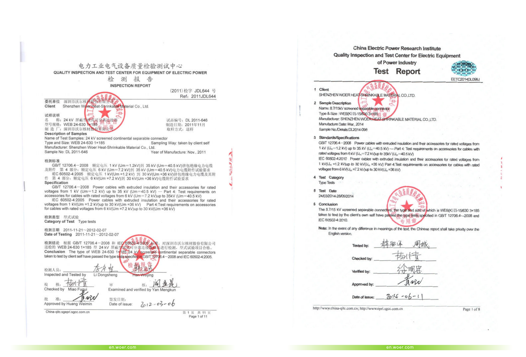
Test Report
WOER-Separable-Connectors-and-Kits-html.html
41
42