background image


  X382O 
  X382G 


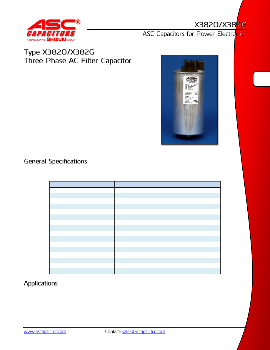
ASC™  X382  (Three  Phase)  capacitors  are  manufactured  with 
very high quality metallized polypropylene film, designed for 
long  life,  low  dielectric  losses,  higher  RMS  current  ratings, 
and low ESR.  
 
The capacitors are filled with ASC™ soft gel or biodegradable 
vegetable  based  oil  designed  to  offer  excellent  thermal 
conductivity  to  help  reduce  internal  heating  and  extend  the 
life of the capacitor.  
 
The  capacitor  is  incorporated  with  internal  UL  recognized 
fusing  mechanisms  that  interrupt  when  pressure  reaches  a 
tested level.  


*Capacitance and KVAR ratings are dependent upon voltage levels, frequency and total current 
** UL recognized product is limited to 620Vrms max 
 

Parameter 

Value 

Capacitance 

3 x 13µF – 3 x 233µF* 

Tolerance 

±5%, ±10% – Special tolerance on request 

KVAR Ratings 

Available on request* 

Rated Voltage 

240 – 690 Vrms* 

Temperature Range (operational)  -40/70C (custom ratings available) 
Temperature Range (storage) 

-40/85C 

RMS Current (phase) 

Up to 40 Arms – Higher values on request 

Standards 

IEC61071, IEC60831, UL810** 

Can/ Cover 

Aluminum 

Terminals 

SIGUIT (6 slots with independent screw down clamps)  

Suggested Mounting Position 

Oil – Upright,  Gel – Any position 

AFC Rating (UL810) 

10,000 A 

Tan δ 

2 x 10

-4 

 Polypropylene 

Terminal to Terminal Test 

2.15 x Urms 10 seconds 

Terminal to Case Test 

U

T-CASE 

= 2 U

+1000V or 3000V whichever is highest value 

Reliability 

100 FIT  


AC input and output filtering 


X382-html.html
background image


Cap 

[µF] 

I

TERM

[A

RMS

I

MAX

† 

(10°ΔT)


[A

RMS

I

PEAK

† 

[kA] 

I

SURGE

† 

[kA] 

R

th

 C-E 

[°C/W] 

ESR 

(1kHz) 

[mΩ] 

Diameter 

“D” [mm] 

Height 

“H” [mm] 

Weight 

[kg] 

Pieces 

/ Box 

240 Vrms 

340 Vac Peak 

516 Vsurge 

3 x 75 

56.0 

16.0 

1.1 

3.3 

6.1 

1.5 

75 

157 

0.9 

10 

3 x 140 

56.0 

22.0 

1.6 

4.8 

4.3 

1.2 

85 

179 

1.2 

3 x 200 

56.0 

32.0 

2.3 

6.8 

3.3 

1.0 

100 

179 

2.1 

3 x 233 

104.0 

35.0 

3.0 

9.0 

2.5 

0.7 

116 

179 

2.5 

450 Vrms 

636 Vac Peak 

968 Vsurge 

3 x 30 

56.0 

10.0 

0.6 

1.9 

5.3 

3.0 

75 

179 

0.9 

10 

3 x 40 

56.0 

13.0 

0.8 

2.5 

4.3 

2.3 

85 

179 

0.9 

3 x 60 

56.0 

18.0 

1.2 

3.8 

3.3 

1.5 

100 

179 

1.8 

3 x 85 

104.0 

40.0 

1.8 

5.4 

2.5 

1.1 

116 

179 

2.5 

3 x 135 

104.0 

40.0 

1.8 

5.6 

2.1 

1.6 

116 

233 

2.9 

3 x 190 

104.0 

40.0 

2.6 

7.8 

1.6 

1.2 

136 

233 

4.1 

525 Vrms 

742 Vac Peak 

1129 Vsurge 

3 x 16 

56.0 

8.0 

0.5 

1.3 

5.7 

1.5 

75 

179 

1.0 

10 

3 x 22 

56.0 

12.0 

0.7 

2.0 

4.4 

1.0 

85 

179 

1.3 

3 x 33 

56.0 

18.0 

1.0 

3.0 

3.4 

0.7 

100 

179 

1.8 

3 x 65 

104.0 

30.0 

1.3 

4.0 

2.3 

0.7 

116 

233 

2.9 

3 x 100 

104.0 

40.0 

1.8 

5.4 

1.8 

0.6 

136 

233 

4.1 

600 Vrms 

849 Vac Peak 

1290 Vsurge 

3 x 19 

56.0 

9.0 

0.6 

1.8 

4.3 

1.1 

85 

179 

1.3 

10 

3 x 27 

56.0 

16.0 

0.8 

2.5 

3.3 

0.8 

100 

179 

1.8 

3 x 38 

56.0 

21.0 

1.2 

3.6 

2.6 

0.6 

116 

179 

2.4 

3 x 55 

104.0 

26.0 

1.1 

3.4 

2.3 

0.9 

116 

233 

2.9 

3 x 85 

104.0 

38.0 

1.4 

5.2 

1.7 

0.6 

136 

233 

4.1 

**690 Vrms 

976 Vac Peak 

1484 Vsurge 


(** Max UL Rating is 620 Vrms) 

3x13 

56.0 

10.0 

0.3 

1.0 

3.9 

2.8 

75 

270 

1.3 

10 

3x18 

56.0 

13.0 

0.4 

1.4 

3.3 

2.0 

85 

270 

1.8 

3x27 

56.0 

18.0 

0.7 

2.1 

2.6 

1.3 

100 

270 

2.4 

3x38 

104.0 

25.0 

0.9 

2.9 

1.9 

1.0 

116 

270 

3.3 

3x55 

104.0 

32.0 

1.4 

4.3 

1.6 

0.7 

136 

270 

4.6 

 
*  I

TERM

  is  the  maximum  rated  pass-though  terminal  current.  This  rating  is  applicable  when  connecting  multiple 

capacitors in parallel. 


 I

MAX

, I

PEAK

, and I

SURGE

 current ratings are designated as maximum phase current ratings. 


    To convert I

MAX

 to line current, use the following formula: 


    Note that I

PEAK

 and I

SURGE

 should not be converted to line currents with this formula because peak and surge events 

are rarely shared equally among the phases. 


X382-html.html
background image


  X382O 
  X382G 


Type  Fill Material  Capacitance  Tolerance  Voltage 

X382 

O = Oil 

3X13 

5 = ±5% 

240 


G = Gel 

↕ 

10 = ±10% 

↕ 


3X233 


690 


Examples: 

Order Code 

Type X382, Oil Filled, 3 x 200uF ±5%, 240 Vrms   X382O 3X200-5-240 
Type X382, Gel Filled, 3 x 55uF ±10%, 600 Vrms  X382G 3X55-10-600