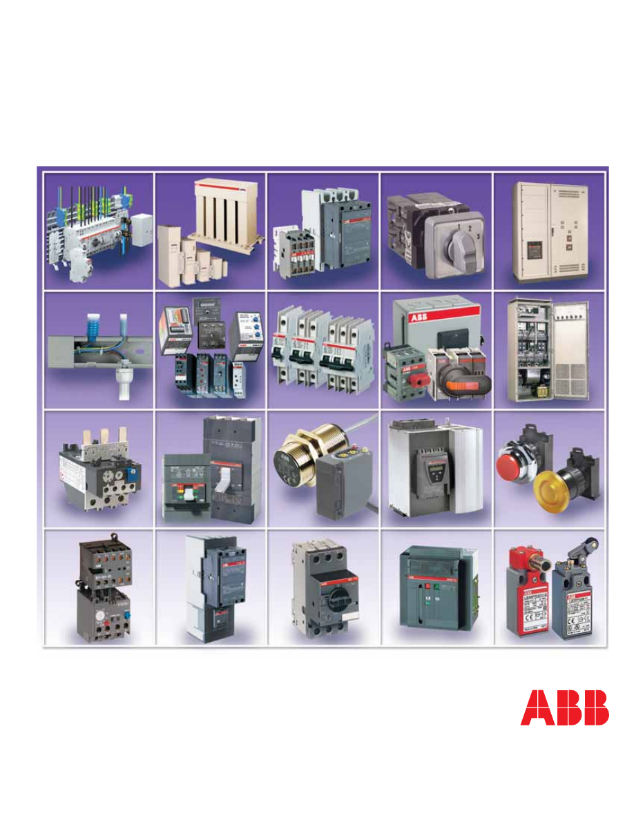
background image

Product Selector

Control Products
Circuit Protective Devices
Power Quality
Systems

Main catalog

abb-low-voltage-catalog-html.html
background image

ABB... 

Your complete low voltage solution!

Products referenced in other publications

Automation products

AC010 Micro Controllers • AC 31 Programmable Controllers, I/O modules, & con-
nection modules • AC500 PLCs • PM Modular PLCs and Remote I/O • PM ASI Bus 
modules • S500 Remote I/O • Field bus plug • Bridgeport radio fi eldbus • CX Touch 
screens & CE Touch computers • Wiring interface modules • Power supplies • Low 
power surge protection • Diode logic modules • Serial data converters • Analog signal 
converters • Plug-in relays • Interface relays • Optocoupler modules • Sensors • Wire-
less proximity detectors

Terminal blocks

The largest assortment of terminal blocks and connection systems available. Functions 
include feed through blocks, fuse blocks, protection blocks, & switch blocks in single 
to triple deck models. Connection choices include screw terminals, spring terminals 
and ADO insulation displacement connectors. The ABB terminal block line includes 
power blocks, distribution blocks, 5.08

mm

 blocks, mini blocks, railway blocks and 

ATEX blocks. Accessories include popular DIN rail styles, a complete marking system 
including tags, software, and plotter. Absolute Rail Design product confi gurator avail-
able for download on www.abb-control.com; also available on CD.

Switchboard MaxSB 

Switchgear MaxSG

UL 891 low voltage switchboard 

ANSI C37.20.1, C37.51 & UL1558

Main breakers up to 5000 amps 

Modular frame arrangements

Plated copper bus 

Emax 1066 UL Listed power circuit

Single & group mounted feeder breakers 

   breakers up to 5000A

Expandable frame based enclosure 

Closed door draw out w/safety shutters

Large cable area, easy access to terminals 

Plated copper bus

NEMA Type 12 and full glass doors available 

Trip unit visible with door closed


Plug-in UL accessories can be 


   fi eld installed

Literature:  AC1800 Switchgear MaxSB brochure, AC1801 Switchgear MaxSG brochure

Literature:  LV006 [1SXU 160 006 C0201] - Terminal Blocks

Literature:  LV018 [1SXU133018C0201] - HVAC Products

Literature:  SS3 Timers & Controls on-line catalog:  www.ssac.com
 

SS3 [1TRC 001 009 C0201] ABB SSAC Timers & Controls catalog 


SS3 [1TRC 001 010 C0203] ABB SSAC Timers & Controls CD-ROM catalog

Literature:  LV020 [1SXU 000 020 C0201] - Automation Products

Timers and Controls – ABB and SSAC products

Programmable timers & controls • Time delay relays • Solid state timing modules
Solid state fl ashers • Three phase voltage monitors • AC & DC current sensors
Motor protection controls • Alternating relays • Liquid level controls
HVAC/R timers & controls • Obstruction lighting controls • Vending timers
DIN rail mount timers, fl ashers, voltage & current monitors, liquid level controls and
motor monitoring relays

HVAC Products

A collection of control products designed for HVAC and Refrigeration applications 
including: Combination starters • Across the line starters • MSSP single phase manual 
starters • Enclosed pilot devices • Enclosed disconnect switches • Softstarters  

abb-low-voltage-catalog-html.html
background image

Low Voltage Products & Systems 

0.1

ABB Inc. • 888-385-1221 • www.abb-control.com 

1SXU 000 023 C0201

0

This catalog is published for information purposes only and is not all inclusive. For additional information on products or technical informa-
tion, consult ABB Inc. The installation and use of ABB Inc. products should be in accordance with the provisions of the U.S. National Elec-
trical Code and/or other local codes or industry standards that are pertinent to the particular end use. Installation or use not in accordance 
with these codes and standards could be hazardous to personnel and/or equipment.

•  Index, table of contents, alphanumeric

1.   Contactors 

1

2. Overload relays 

2

3. Starters 

3

4. Miniature control 

4

5. Manual motor protectors 

5

6.  Softstarters & electronic brakes 

6

7.  Relays, timers, monitoring & safety relays, liquid level ctls 

7

8. Pilot devices 

8

9. Limit switches 

9

10. Sensors 

10

11. Cam  switches 

11

12. Transformers 

12

13. Cable  management  systems 

13

14. Modular DIN rail products 

14

15. Molded case circuit breakers 

15

16. Low voltage power breakers  

16

17. Power  distribution  systems 

17

18. Disconnect  switches 

18

19. Arc Guard Systems 

19

20. LVNQ  capacitors 

20

21. MCCs,  Smissline 

21

Industrial

contr

ols

Cir

cuit Pr

otective

Devices

LVNQ

Systems

abb-low-voltage-catalog-html.html
background image

Ta

ble of

Contents

0.2 

Low Voltage Products & Systems 

1SXU 000 023 C0201 

ABB Inc. • 888-385-1221 • www.abb-control.com

0

Industrial controls
Contactors

Across the line contactors...................................... 1.1 – 1.136

4 pole,  A9 - A/AE75 ................................................................................................................1.13
4 pole, AF45 - AF75 ................................................................................................................1.14
4 pole, AL9 - AL26 ...................................................................................................................1.13
4 pole, EK110 - EK1000 ..........................................................................................................1.13
A/AE9 - A/AE110 Contactors for ring tongue termination.......................................................1.10
A/AF/AL & AE Auxiliary contact blocks ...................................................................................1.16
A9 - A/AE75, 4 pole .................................................................................................................1.13
A9 - A110 Interlocks for two horizontally mounted contactors ...............................................1.17
A9 - A300 General information ..................................................................................................1.2
A9 - A300, Non-reversing, mechanically interlocked, reversing ...............................................1.3
A9 - AF1650, Features...............................................................................................................1.1
A9 - AF1650, NEMA rated,  Non-reversing, mechanically interlocked, reversing ...................1.11
A95 - AF750 Interlocks for two horizontally mounted contactors ...........................................1.17
A95 - AF750 Interlocks for two vertically mounted contactors ...............................................1.17
Accessories .................................................................................................................. 1.16 - 1.35
Accessory combinations for A contactors ..............................................................................1.18
Additional terminal blocks  for A/AE/AL/AF contactors ..........................................................1.29
AE9 - AE110, General information ............................................................................................1.4
AE9 - AE110, Non-reversing, mechanically interlocked, reversing ...........................................1.5
AE9 - AF1650, NEMA rated, Non-reversing, mechanically interlocked, reversing ..................1.12
AF1350 - AF1650 Interlocks for two horizontally mounted contactors ...................................1.17
AF45 - AF75, 4 pole ................................................................................................................1.14
AF50 - AF1650, General information .........................................................................................1.8
AF50 - AF1650, Non-reversing, mechanically interlocked, reversing .......................................1.9
AL9 - AL26, 4 pole ...................................................................................................................1.13
AL9 - AL26, NEMA rated, Non-reversing, mechanically interlocked, reversing ......................1.12
AL9 - AL40 General information ................................................................................................1.6
AL9 - AL40, Non-reversing, mechanically interlocked, reversing .............................................1.7
AL9Z - AL16Z, Non-reversing, mechanically interlocked, reversing .........................................1.7
Arc chutes  for A/AE/AL/AF contactors ...................................................................................1.29
Auxiliary contact block technical data, CA5/CAL5-11/CAL18-11/CC5 ..................................1.19
Auxiliary contact block technical data, CE5 ............................................................................1.20
Auxiliary contact blocks, A/AF/AL & AE ..................................................................................1.16
Auxiliary lead terminals ............................................................................................................1.17
CA5/CAL5-11/CAL18-11/CC5 Auxiliary contact block technical data ...................................1.19
Capacitor switching, 3 phase, UA26 - UA110.........................................................................1.15
CE5 Auxiliary contact block technical data .............................................................................1.20
Coils & coil voltage codes  for A/AE/AL/AF contactors ..........................................................1.26
Coils & coil voltage codes for EK contactors ..........................................................................1.27
Connection kits for phase to phase for A/AE/AL/AF contactors .............................................1.28
Connection kits for reversing  for A/AE/AL/AF contactors ......................................................1.28
Connection kits for wye-delta starters for A/AE/AL/AF contactors.........................................1.28
Contact kits  for A/AE/AL/AF contactors ................................................................................1.25
Dimensions, approximate, across the line contactors ................................................. 1.83 - 1.96
EK110 - EK1000, 4 pole ..........................................................................................................1.13
Electronic timer, TE5S, for wye-delta starters .............................................................. 1.31 - 1.32
Features, A9 - AF1650...............................................................................................................1.1
General information, A9 - A300 .................................................................................................1.2
General information, AE9 - AE110 ............................................................................................1.4
General information, AF50 - AF1650 .........................................................................................1.8
General information, AL9 - AL40 ...............................................................................................1.6
Horizontal connection bars between contactor and MCCB  for A/AE/AF contactors ............1.30
Identifi cation markers  for A/AE/AL/AF contactors .................................................................1.25
Interface relays for A contactors .................................................................................. 1.23 - 1.24
Interlocks for two horizontally mounted contactors, A9 - A110 ..............................................1.17
Interlocks for two horizontally mounted contactors, A95 - AF750 ..........................................1.17
Interlocks for two horizontally mounted contactors, AF1350 - AF1650 ..................................1.17
Interlocks for two vertically mounted contactors, A95 - AF750 ..............................................1.17
Mechanical latches  for A/AE/AL/AF contactors .....................................................................1.25
Mechanically interlocked, A9 - A300 .........................................................................................1.3
Mechanically interlocked, AE9 - AE110 ....................................................................................1.5
Mechanically interlocked, AE9 - AF1650, NEMA rated ...........................................................1.12
Mechanically interlocked, AF50 - AF1650 .................................................................................1.9
Mechanically interlocked, AL9 - AL26, NEMA rated ...............................................................1.12
Mechanically interlocked, AL9 - AL40 .......................................................................................1.7
Mechanically interlocked, AL9Z - AL16Z ..................................................................................1.7
Mechanically interlocked, NEMA rated, A9 - AF1650 .............................................................1.11
NEMA rated, A9 - AF1650, Non-reversing, mechanically interlocked, reversing ....................1.11
NEMA rated, AE9 - AF1650, Non-reversing, mechanicallly interlocked, reversing .................1.12
NEMA rated, AL9 - AL26, Non-reversing, mechanicallly interlocked, reversing .....................1.12
Non-reversing, A9 - A300 ..........................................................................................................1.3
Non-reversing, AE9 - AE110 .....................................................................................................1.5
Non-reversing, AE9 - AF1650, NEMA rated ............................................................................1.12
Non-reversing, AF50 - AF1650 ..................................................................................................1.9

Non-reversing, AL9 - AL26, NEMA rated ................................................................................1.12
Non-reversing, AL9 - AL40 ........................................................................................................1.7
Non-reversing, AL9Z - AL16Z ...................................................................................................1.7
Non-reversing, NEMA rated, A9 - AF1650 ..............................................................................1.11
Pneumatic timers.....................................................................................................................1.17
Possible accessory combinations for A contactors ................................................................1.18
Relays, interface, for A contactors ............................................................................... 1.23 - 1.24
Reversing, A9 - A300.................................................................................................................1.3
Reversing, AE9 - AE110 ............................................................................................................1.5
Reversing, AE9 - AF1650, NEMA rated ...................................................................................1.12
Reversing, AF50 - AF1650 ........................................................................................................1.9
Reversing, AL9 - AL26, NEMA rated .......................................................................................1.12
Reversing, AL9 - AL40...............................................................................................................1.7
Reversing, AL9Z - AL16Z ..........................................................................................................1.7
Reversing, NEMA rated, A9 - AF1650 .....................................................................................1.11
Ring tongue termination, A/AE9 - A/AE110 ............................................................................1.10
Shorting bars  for A/AE/AF contactors ....................................................................................1.30
Surge suppressors for A/AE/AL/EK contactors ........................................................... 1.21 - 1.22
Technical data for TE5S Electronic timer for wye-delta starters .............................................1.32
Technical data, Auxiliary contact blocks, CA5/CAL5-11/CAL18-11/CC5 ...............................1.19
Technical data, Auxiliary contact blocks, CE5 ........................................................................1.20
Technical data, IEC, contactors................................................................................... 1.41 -  1.82
Technical data, Interface relays ...............................................................................................1.24
Technical data, UL & CSA,  contactors ........................................................................ 1.36 - 1.40
Terminal blocks, additional,  for A/AE/AL/AF contactors ........................................................1.29
Terminal enlargements  for A/AE/AL/AF contactors ................................................................1.29
Terminal extensions  for A/AE/AL/AF contactors ....................................................................1.29
Terminal lug kits for A/AE/AL/AF contactors ...........................................................................1.25
Terminal marking and positioning for AE/AL contactors .........................................................1.35
Terminal markings & positioning for A/UA contactors.............................................................1.34
Terminal markings for CA/CC/CAL/CCL auxiliary contacts ....................................................1.33
Terminal shrouds  for A/AE/AL/AF contactors.........................................................................1.29
Terminals, auxiliary lead ..........................................................................................................1.17
Timer, electronic, TE5S, for wye-delta starters ............................................................ 1.31 - 1.32
Timers, pneumatic ...................................................................................................................1.17
UA26 - UA110 for 3 phase capacitor switching ......................................................................1.15
Vertical connection bars between contactor and MCCB  for A/AE/AF contactors .................1.30

Defi nite purpose contactors................................. 1.97 – 1.104

Agency approvals ....................................................................................................................1.97
Applications .............................................................................................................................1.97
Catalog number explanation ...................................................................................................1.97
“Defi nite purpose contactors, 30A, 40A & 60A” ......................................................................1.98
Dimensions ............................................................................................................... 1.100 - 1.103
Features ...................................................................................................................................1.97
Technical data .........................................................................................................................1.99

Drive contactors .................................................. 1.105 – 1.114

Arc shields .............................................................................................................................1.109
Coils.......................................................................................................................................1.109
Contact kits ...........................................................................................................................1.110
Description, features .............................................................................................................1.105
Dimensions ............................................................................................................... 1.113 - 1.114
Lug kits ..................................................................................................................................1.110
Replacement parts ................................................................................................... 1.109 - 1.110
Technical data .......................................................................................................... 1.111 - 1.112
Type DA & EHDB, 60 - 960A, Mechanically interlocked ........................................................1.108
Type DA, 60A, Non-reversing ................................................................................................1.106
Type EHDB, 220 - 960A, Non-reversing ................................................................................1.107

Lighting contactors ..............................................1.115 - 1.120

A9 - A300, Electrically & mechanically held ............................................................. 1.116 - 1.117
Accessories ...........................................................................................................................1.118
Applications ...........................................................................................................................1.115
Auxiliary contact blocks ........................................................................................................1.118
Description ............................................................................................................................1.115
Dimensions ............................................................................................................................1.119
Factory modifi cations ............................................................................................................1.118
Mechanical latch ...................................................................................................................1.118
Pilot devices ..........................................................................................................................1.118
Surge suppressor ..................................................................................................................1.118

 1 - Contactors

abb-low-voltage-catalog-html.html
background image

Ta

ble of

Contents

Low Voltage Products & Systems 

0.3

ABB Inc. • 888-385-1221 • www.abb-control.com 

1SXU 000 023 C0201

0

Welding contactors ............................................. 1.121 – 1.126

140A - 600A, 2 & 3 pole ........................................................................................................1.122
Applications ...........................................................................................................................1.121
Dimensions ............................................................................................................... 1.124 - 1.125
Features .................................................................................................................................1.121

Technical data .......................................................................................................................1.123

AC Switching contactors .................................... 1.127 – 1.130

Description ...................................................................................................... 1.127
Surge suppressors .......................................................................................... 1.129
TAL9 - TAE110, 3 & 4 pole ............................................................................... 1.128
Technical data ................................................................................................. 1.130

Industrial controls
Contactors
Overload relays

DC Switching contactors .................................... 1.131 – 1.134

Description ...................................................................................................... 1.131
Dimensions ...................................................................................................... 1.133
GA75 - GAE75 ................................................................................................. 1.132
General information ......................................................................................... 1.131

Bar contactors ..................................................... 1.135 – 1.136

Description ...................................................................................................... 1.135
Standards ........................................................................................................ 1.135
Applications ..................................................................................................... 1.135
Specifi cation checklist..................................................................................... 1.136

2 - Overload relays

Thermal overload relays ........................................... 2.1 – 2.18

Abstract from IEC 947-4-1 ...................................................................................2.1
Accessories ................................................................................................. 2.7 - 2.8
Description .................................................................................................. 2.1 - 2.3
Dimensions .............................................................................................. 2.15 - 2.17
Flat pin terminal blocks ........................................................................................2.7
Mounting kit for TA450 overload relay ......................................................... 2.7 - 2.8
Remote tripping coils ...........................................................................................2.8
Selection guide, TA25DU - TA450DU .......................................................... 2.4 - 2.5
Separate mounting kits ........................................................................................2.7
TA25 - TA450 ........................................................................................................2.6
Technical data ........................................................................................... 2.9 - 2.14
Terminal block - AWG #8 cable ................................................................... 2.7 - 2.8
Terminal lug kits ....................................................................................................2.7
Terminal shrouds ..................................................................................................2.7
Tripping classes of thermal overload relays .........................................................2.1

Electronic overload relays ...................................... 2.19 – 2.28

Abstract from IEC 947-4-1 .................................................................................2.19
Accessories ........................................................................................................2.22
Catalog number explanation ................................................................................2.2
Description .........................................................................................................2.19
Dimensions .............................................................................................. 2.27 - 2.28
E16DU - E800DU ...............................................................................................2.21
Lug kits ...............................................................................................................2.22
Mounting kits ......................................................................................................2.22
Separate mounting kits ......................................................................................2.22
Technical data ......................................................................................... 2.23 - 2.26
Terminal shrouds ................................................................................................2.22
Tripping classes of thermal overload relays .......................................................2.19

abb-low-voltage-catalog-html.html
background image

Ta

ble of

Contents

0.4 

Low Voltage Products & Systems 

1SXU 000 023 C0201 

ABB Inc. • 888-385-1221 • www.abb-control.com

0

Industrial controls
Starters

General information .................................................. 3.1 – 3.10

Additional auxiliary contact blocks .......................................................................3.3
Catalog number explanation ................................................................................3.4
Control circuit transformer ...................................................................................3.3
Control cover accessories ....................................................................................3.3
Electronic overload relays ....................................................................................3.7
Enclosure rating defi nitions ..................................................................................3.9
Enclosures ............................................................................................................3.8
Factory modifi cations ...........................................................................................3.3
Field modifi cation kits ..........................................................................................3.2
Hazardous location enclosure accessories, NEMA 7 & 9 ....................................3.3
IP Environmental ratings.......................................................................................3.1
Motor data ............................................................................................................3.4
Pilot light kits ........................................................................................................3.2
Price adders for reduced voltage & multispeed starters ......................................3.3
Pushbutton kits ....................................................................................................3.2
Reset button kits ..................................................................................................3.2
Selector switch kits ..............................................................................................3.2
Special modifi cations ...........................................................................................3.3
Thermal overload relays, standard .......................................................................3.6

Across the line starters ........................................... 3.11 – 3.46

Description ........................................................................................................ 3.11
2 Speed, 1 Winding .................................................................................3.20 - 3.21
2 Speed, 2 Winding .................................................................................3.22 - 3.23
Catalog number explanation ............................................................................. 3.11
Circuit diagrams ......................................................................................3.44 - 3.46
Dimensions ..............................................................................................3.25 - 3.43
Multi-speed .............................................................................................3.20 - 3.23
Non-reversing, A9 - A185, single phase ..................................................3.16 - 3.17
Non-reversing, A9 - A750, 3 phase .........................................................3.14 - 3.15
Plastic enclosed, IP65 ....................................................................................... 3.24
Reversing, A9 - A750...............................................................................3.18 - 3.19
Starter selection by motor horsepower & voltage ...................................3.12 - 3.13

Combination starters .............................................. 3.47 – 3.70

Additional auxiliary contact blocks .................................................................... 3.49
Catalog number explanation ............................................................................. 3.48
Circuit breaker type, non-reversing, NEMA rated ...................................3.58 - 3.59
Circuit breaker type, reversing ................................................................3.60 - 3.61
Circuit breaker type, reversing, NEMA rated ...........................................3.62 - 3.63
Control circuit transformer ................................................................................ 3.49
Control cover accessories ................................................................................. 3.49
Description ........................................................................................................ 3.47
Dimensions ..............................................................................................3.64 - 3.70
Disconnect switch type, fusible, non-reversing ......................................3.52 - 3.53
Disconnect switch type, fusible, reversing ..............................................3.54 - 3.55
Disconnect switch type, non-fusible .......................................................3.50 - 3.51
Factory modifi cations ........................................................................................ 3.49
Fusible disconnect switch type, non-reversing .......................................3.52 - 3.53
Fusible disconnect switch type, reversing ..............................................3.54 - 3.55
Hazardous location enclosure accessories ....................................................... 3.49
Non-fusible disconnect switch type ........................................................3.50 - 3.51
Overload relay protection .................................................................................. 3.47
Price adders for reduced voltage & multi-speed starters ................................. 3.49
Special modifi cations ........................................................................................ 3.49

Reduced voltage starters ....................................... 3.71 – 3.92

Additional auxiliary contact blocks .................................................................... 3.73
Auto-transformer, non-combination type ................................................3.74 - 3.75
Catalog numbering information ......................................................................... 3.72
Circuit diagrams ......................................................................................3.82 - 3.83
Control circuit transformers ............................................................................... 3.73
Control cover accessories ................................................................................. 3.73
Description ........................................................................................................ 3.71
Dimensions ..............................................................................................3.84 - 3.91
Factory modifi cations ........................................................................................ 3.73
Hazardous location enclosure accessories, NEMA 7 & 9 ................................. 3.73
Overload relay protection .................................................................................. 3.71
Part winding, non-reversing ....................................................................3.80 - 3.81
Reduced voltage & multi-speed starters ........................................................... 3.73
Special modifi cations ........................................................................................ 3.73
Wye-delta, closed transition ....................................................................3.78 - 3.79
Wye-delta, open transition ......................................................................3.76 - 3.77

3 - Starters

abb-low-voltage-catalog-html.html
background image

Ta

ble of

Contents

Low Voltage Products & Systems 

0.5

ABB Inc. • 888-385-1221 • www.abb-control.com 

1SXU 000 023 C0201

0

Industrial controls
Miniature controls
Manual motor protectors

Miniature controls ..................................................... 4.1 – 4.20

Description .......................................................................................................... 4.1
Accessories for B6 & B7 contactors ...................................................... 4.11 - 4.12
Auxiliary contact blocks ....................................................................................4.11
Contactors for connection to PLCs .....................................................................4.5
Contactors, interface ...........................................................................................4.4
Contactors, mechanically interlocked .................................................................4.3
Contactors, non-reversing ...................................................................................4.2
Control relays ......................................................................................................4.9
Dimensions ............................................................................................. 4.19 - 4.20
General features ..................................................................................................4.1
Identifi cation labels............................................................................................4.11
Interface contactors ............................................................................................4.4
Interface relays ..................................................................................................4.10
Mechanically interlocked contactors ...................................................................4.3
Non-reversing contactors ....................................................................................4.2
Plunger ..............................................................................................................4.11
Protective cover ................................................................................................4.12
Reversing connection link .................................................................................4.12
Soldering connection ........................................................................................4.11
Starters ....................................................................................................... 4.7 - 4.8
Surge suppressors ............................................................................................4.12
Technical data, IEC ................................................................................. 4.13 - 4.18
Thermal overload relays ......................................................................................4.6

Manual motor protectors .......................................... 5.1 – 5.28

Accessories for MS116 ...............................................................................5.4 - 5.5
Accessories for MS325 ...........................................................................5.12 - 5.13
Accessories for MS450 - MS497 ............................................................5.16 - 5.17
Applications, group motor ................................................................................... 5.1
Applications, single motor ................................................................................... 5.1
Auxiliary contact blocks for MS116..................................................................... 5.4
Auxiliary contact blocks for MS325................................................................... 5.12
Auxiliary contacts for MS450 - MS497 ............................................................. 5.16
Auxiliary release for MS450 - MS497 ................................................................ 5.16
Bell alarm contacts for MS116 ............................................................................ 5.4
Bell alarm contacts for MS325 .......................................................................... 5.12
Busbars for MS116 ............................................................................................. 5.5
Busbars for MS325 ........................................................................................... 5.13
Busbars for MS450 - MS497 ............................................................................. 5.16
Close coupling adaptors for MS450 - MS497 ................................................... 5.16
Close coupling adaptors for MS325 ................................................................. 5.13
Description .......................................................................................................... 5.1
Dimensions for MS116 ................................................................................5.8 - 5.9
Dimensions for MS325 ............................................................................5.24 - 5.26
Dimensions for MS450 & MS490 ...................................................................... 5.27
Door mounting hardware for MS116 ................................................................... 5.5
Enclosures, molded plastic, for MS116 .............................................................. 5.4
Enclosures, molded plastic, for MS325 ............................................................ 5.13
FLA adjustment cover for MS450 - MS497 ....................................................... 5.17
General information ............................................................................................. 5.2
Group motor applications.................................................................................... 5.1
IEC coordination tables ..................................................................................... 5.23
Locking device for MS116................................................................................... 5.4
Molded plastic enclosures for MS116 ................................................................. 5.4
Molded plastic enclosures for MS325 ............................................................... 5.13
MS116 ................................................................................................................. 5.3

MS325 .....................................................................................................5.10 - 5.11
MS450 - MS497 ......................................................................................5.14 - 5.15
Padlocking devices for MS325.......................................................................... 5.12
Plastic adaptors for enclosures for MS116 ......................................................... 5.4
Plastic adaptors for enclosures for MS325 ....................................................... 5.13
Power feed terminal blocks for MS116 ............................................................... 5.5
Power feed terminal blocks for MS450 - MS497 .............................................. 5.16
Power feed terminal blocks for MS325 ............................................................. 5.13
Remote control unit for MS325 ......................................................................... 5.12
Selector handles for MS450 - MS497 ............................................................... 5.17
Selector handles for through-the-door operation for MS325............................ 5.13
Shunt trip for MS116 ........................................................................................... 5.4
Shunt trip for MS325 ......................................................................................... 5.12
Signalling contact for MS450 - MS497 ............................................................. 5.17
Single motor applications .................................................................................... 5.1
Supporting terminal for MS325 ......................................................................... 5.12
Technical data for MS116 ............................................................................5.6 - 5.7
Technical data for MS325 ........................................................................5.18 - 5.19
Technical data for MS325, MS45x, MS49x .............................................5.20 - 5.21
Technical data for MS45x, MS49x .................................................................... 5.22
Terminal shrouds for MS450 - MS497 ............................................................... 5.17
Type E Terminal for MS450 - MS497 ................................................................. 5.17
UL 508 Type E Accessories for MS325 ............................................................. 5.13
Undervoltage trip for MS116 ............................................................................... 5.4
Undervoltage trip for MS325 ............................................................................. 5.12

4 - Miniature controls

5 - Manual motor protectors

abb-low-voltage-catalog-html.html
background image

Ta

ble of

Contents

0.6 

Low Voltage Products & Systems 

1SXU 000 023 C0201 

ABB Inc. • 888-385-1221 • www.abb-control.com

0

Industrial controls
Softstarters

Type PSS Softstarters ................................................6.1 - 6.20

Accessories for softstarters................................................................................. 6.8
Additional auxiliary contact blocks ...................................................................... 6.8
Auxiliary relay accessories .................................................................................. 6.8
Catalog number explanation ............................................................................... 6.2
Circuit diagrams ......................................................................................6.11 - 6.15
Control transformers ........................................................................................... 6.8
Current transformers ........................................................................................... 6.8
Dimensions ..............................................................................................6.16 - 6.19
General information ............................................................................................. 6.1
Meters & metering accessories ........................................................................... 6.8
PSS, Enclosed .............................................................................................6.5 - 6.7
PSS, Open ...................................................................................................6.3 - 6.4
Technical data ...........................................................................................6.9 - 6.10
Terminal block to increase connection capacity ................................................. 6.8
Terminal covers ................................................................................................... 6.8
Terminal lug kits ................................................................................................... 6.8
Transformers, control .......................................................................................... 6.8
Transformers, current .......................................................................................... 6.8

Type PST Softstarters ..............................................6.21 - 6.50

Accessories ............................................................................................ 6.31 - 6.35
Additional auxiliary contact blocks ....................................................................6.32
Application and description.................................................................... 6.23 - 6.24
Auxiliary relay accessories ................................................................................6.32
Catalog number explanation .............................................................................6.22
Circuit diagrams ..................................................................................... 6.40 - 6.43
Control transformers .........................................................................................6.31
Description ........................................................................................................6.21
DeviceNet Fieldbus connectors & accessories .................................................6.33
DeviceNet round cable & accessories for bus extension ..................................6.33
DeviceNet round cable for bus junctions ..........................................................6.33
DeviceNet termination resistor ..........................................................................6.33
DeviceNet FieldBusPlug ....................................................................................6.33
Dimensions ............................................................................................. 6.44 - 6.49
Meters & metering accessories .........................................................................6.32
Modbus FieldBusPlug .......................................................................................6.35
Modbus round cable and accessories for bus extension .................................6.35
Modbus round cable for bus extension ............................................................6.35
Modbus round cable for bus junctions .............................................................6.35
Modbus RTU Fieldbus connectors and accessories ........................................6.35
Modbus termination resistor .............................................................................6.35
PST, Enclosed, NEMA 1, 12 ................................................................... 6.26 - 6.27

PST, Enclosed, NEMA 1, Combination................................................... 6.28 - 6.29
PST, Open .........................................................................................................6.25
Options ..............................................................................................................6.30
Profi bus DP accessories for bus extension ......................................................6.34
Profi bus DP Fieldbus connectors & accessories ..............................................6.34
Profi bus DP FieldBusPlug .................................................................................6.34
Profi bus DP round cable for bus extension.......................................................6.34
Profi bus DP round cable for bus junctions........................................................6.34
Profi bus DP termination resistor .......................................................................6.34
Remote key pad ................................................................................................6.31
Softstarter, PST, accessories.............................................................................6.32
Technical data ........................................................................................ 6.36 - 6.39
Terminal enlargement pieces .............................................................................6.31
Terminal extension pieces .................................................................................6.31
Terminal lug kits .................................................................................................6.31
Terminal shrouds ...............................................................................................6.31

Type SSM Softstarters .............................................6.51 - 6.56

Catalog number explanation ............................................................................. 6.53
Custom engineered systems ............................................................................. 6.52
Description ........................................................................................................ 6.51
Digital microprocessor control .......................................................................... 6.52
Dimensions ........................................................................................................ 6.55
General information ........................................................................................... 6.52
Heavy duty SCR power assemblies .................................................................. 6.52
Industrial "real world" packaging ...................................................................... 6.52
Key construction features ................................................................................. 6.52
SSM Softstarters ............................................................................................... 6.53
Technical data ................................................................................................... 6.54

Type PEB Electronic brakes ....................................6.57 - 6.64

Description ........................................................................................................6.57
Catalog number explanation .............................................................................6.58
Circuit diagram ........................................................................................ 6.62- 6.63
Dimensions ........................................................................................................6.62
Power electronic brakes ......................................................................... 6.59 - 6.60
Technical data ...................................................................................................6.61

6 - Softstarters

abb-low-voltage-catalog-html.html
background image

Ta

ble of

Contents

Low Voltage Products & Systems 

0.7

ABB Inc. • 888-385-1221 • www.abb-control.com 

1SXU 000 023 C0201

0

Industrial controls
Relays

Timers & controls .......................................................7.1 - 7.18

General information ............................................................................................. 7.1
Multi-function timers ........................................................................................... 7.2
ProgramaCube .................................................................................................... 7.3
Solid state timers with relay outputs ...........................................................7.4 - 7.5
Solid state timers with solid state outputs .......................................................... 7.6
Solid state timers ................................................................................................. 7.7
Voltage monitors..........................................................................................7.8 - 7.9
Current monitoring ..................................................................................7.10 - 7.11
Liquid level controls.................................................................................7.12 - 7.13
Semi-conductor contactors, R100.xx & R300.xx .............................................. 7.14
Tower and obstruction lighting controls ............................................................ 7.15

Control relays ............................................................7.17 - 7.34

Accessories .............................................................................................7.23 - 7.26
Accessory mounting information....................................................................... 7.25
Accessory possible combinations ..................................................................... 7.26
Auxiliary contact blocks .................................................................................... 7.23
Coils .................................................................................................................. 7.24
Description ..............................................................................................7.17 - 7.20
Dimensions ..............................................................................................7.33 - 7.34
Identifi cation markers ........................................................................................ 7.23
Interlocks ........................................................................................................... 7.23
Mechanical latches ............................................................................................ 7.23
N & NL Control relays ........................................................................................ 7.21
Pneumatic timers .............................................................................................. 7.23
Surge suppressors ............................................................................................ 7.24
Technical data .........................................................................................7.27 - 7.32
TNL Control relays ............................................................................................. 7.22

Electronic safety relays ............................................7.35 - 7.66

Accessories for C560 Series ............................................................................. 7.46
Application examples, C57x ....................................................................7.57 - 7.64
Application examples, C670x ..................................................................7.50 - 7.53
C565-S with positively guided contacts............................................................ 7.47
C570 .................................................................................................................. 7.36
C571 .................................................................................................................. 7.37
C572 .................................................................................................................. 7.38
C573 .................................................................................................................. 7.39
C574 .................................................................................................................. 7.40
C575 .................................................................................................................. 7.41
C576 .................................................................................................................. 7.42
C577 .................................................................................................................. 7.43
C578 .................................................................................................................. 7.44
C579 .................................................................................................................. 7.45
C6700 - C6702 .................................................................................................. 7.48
Description ........................................................................................................ 7.35
Dimensions ........................................................................................................ 7.65
Personnel safety & machine protection ...................................................7.54 - 7.55
Selection guide, C570 - C6702 ......................................................................... 7.56
Technical data ................................................................................................... 7.49

7 - Relays

abb-low-voltage-catalog-html.html
background image

Ta

ble of

Contents

0.8 

Low Voltage Products & Systems 

1SXU 000 023 C0201 

ABB Inc. • 888-385-1221 • www.abb-control.com

0

Industrial controls
Pilot devices

Modular .......................................................................8.1 - 8.30

22mm Hole plug ................................................................................................ 8.27
30mm Adaptors ................................................................................................. 8.26
Accessories .............................................................................................8.22 - 8.27
Adaptors ............................................................................................................ 8.26
Bezel .................................................................................................................. 8.25
Bulbs, fi lament ................................................................................................... 8.24
Buttons for pushbuttons ................................................................................... 8.26
Buzzers .............................................................................................................. 8.20
Contact blocks and lamp blocks ....................................................................... 8.22
Defi nite purpose pushbuttons ........................................................................... 8.18
Diode block ....................................................................................................... 8.23
Double pushbuttons ....................................................................................8.6 - 8.8
Emergency stop pushbuttons ........................................................................... 8.11
Emergency stop shroud .................................................................................... 8.25
Extra key ............................................................................................................ 8.26
Filament bulbs ................................................................................................... 8.24
Flashing LED ..................................................................................................... 8.25
Flush & extended pushbuttons ...................................................................8.4 - 8.5
Gasket, spare .................................................................................................... 8.27
General information .....................................................................................8.1 - 8.2
Holders .............................................................................................................. 8.22
Key, extra ........................................................................................................... 8.26
Key operated selector switches ........................................................................ 8.16
Label sheet ........................................................................................................ 8.26
Lamp changing tool ........................................................................................... 8.25
LED, fl ashing ..................................................................................................... 8.25
LEDs .................................................................................................................. 8.24
Lenses for pilot lights ........................................................................................ 8.26
Membrane of rubber.......................................................................................... 8.25
Mounting ............................................................................................................. 8.2
Mounting tool .................................................................................................... 8.25
Mushroom pushbuttons .................................................................................... 8.10
Padlock attachment for 30mm mushroom head ............................................... 8.27
Pilot light lenses ................................................................................................ 8.26
Pilot lights .......................................................................................................... 8.20
Potentiometers .................................................................................................. 8.21
Press-to-test pushbuttons .................................................................................. 8.9
Protective cover ................................................................................................ 8.25
Protective ring ................................................................................................... 8.25
Reset pushbuttons ............................................................................................ 8.19
Selection guide .................................................................................................... 8.3
Selector switch guard ........................................................................................ 8.27
Selector switch lock .......................................................................................... 8.27
Selector switches, key operated ....................................................................... 8.16
Selector switches, three-position, illuminated .................................................. 8.15
Selector switches, three-position, non-illuminated ........................................... 8.13
Selector switches, two-position, illuminated ..................................................... 8.14
Selector switches, two position, non-illuminated.............................................. 8.12
Spare gasket ..................................................................................................... 8.27
Technical data .........................................................................................8.28 - 8.29
Three-position selector switches, illuminated ................................................... 8.15
Three-position selector switches, non-illuminated............................................ 8.13
Toggle switches ................................................................................................. 8.17
Transformer block .............................................................................................. 8.23
Two-position selector switches, illuminated ...................................................... 8.14
Two-position selector switches, non-illuminated .............................................. 8.12

Compact ....................................................................8.31 - 8.40

30mm Adaptors ................................................................................................. 8.38
Accessories .............................................................................................8.36 - 8.38
Adaptors ............................................................................................................ 8.38
Adaptors, 30mm ................................................................................................ 8.38
Bezel .................................................................................................................. 8.37
Bulbs, fi lament ................................................................................................... 8.36
Button ................................................................................................................ 8.37
Emergency stop pushbuttons ........................................................................... 8.33
Extra key ............................................................................................................ 8.38
Filament bulbs ................................................................................................... 8.36
Flush & extended pushbuttons ......................................................................... 8.32
General information ........................................................................................... 8.31
Key, extra ........................................................................................................... 8.38
Lamp changing tool ........................................................................................... 8.37
LEDs .................................................................................................................. 8.36
Membrane of silicone ........................................................................................ 8.37
Mounting tool .................................................................................................... 8.37
Pilot lights .......................................................................................................... 8.35
Protective cover ................................................................................................ 8.37
Protective ring ................................................................................................... 8.37
Selector switches, two & three position ............................................................ 8.34
Technical data ................................................................................................... 8.39
Two & three position selector switches ............................................................. 8.34

Assembled stations and enclosures .......................8.41 - 8.48

Accessories ....................................................................................................... 8.45
Blanking plug ..................................................................................................... 8.45
Contact blocks .................................................................................................. 8.45
Degree of protection, IP66 ................................................................................ 8.44
Earthing terminal ............................................................................................... 8.45
General information ........................................................................................... 8.41
Lamp blocks ...................................................................................................... 8.45
Plastic enclosures ...................................................................................8.42 - 8.43
Protective sleeves ............................................................................................. 8.45
Selector switches, three position ...................................................................... 8.47
Selector switches, two position ........................................................................ 8.46
Spacer ............................................................................................................... 8.45
Three position selector switches ....................................................................... 8.47
Two position selector switches ......................................................................... 8.46

Legend plates ...........................................................8.49 - 8.66

Custom engraved inserts .................................................................................. 8.56
Custom engraved nameplates .......................................................................... 8.57
Custom legend plate form .......................................................................8.58 - 8.62
General information ........................................................................................... 8.49
Legend plates for pushbuttons ...............................................................8.53 - 8.55
Special legend plates .....................................................................8.50 - 8.52, 8.65
Text caps .................................................................................................8.63 - 8.64

Signal towers and signal beacons ..........................8.67 - 8.72

Accessories for K70 signal towers .................................................................... 8.70
AS-Interface module ......................................................................................... 8.70
Audible module ................................................................................................. 8.70
Bulbs ................................................................................................................. 8.70
Description ........................................................................................................ 8.68
General information ........................................................................................... 8.67
LED bulbs .......................................................................................................... 8.70
Signal beacons, KSB ......................................................................................... 8.71
Signal towers, K70 ............................................................................................ 8.69
Special parts...................................................................................................... 8.70
Technical data ................................................................................................... 8.72
Terminal elements .............................................................................................. 8.70

8 - Pilot devices

abb-low-voltage-catalog-html.html
background image

Ta

ble of

Contents

Low Voltage Products & Systems 

0.9

ABB Inc. • 888-385-1221 • www.abb-control.com 

1SXU 000 023 C0201

0

Industrial controls
Limit switches
Sensors

Plastic casing limit switches .................................... 9.1 - 9.30

Assembled, 30mm ..................................................................................... 9.6 - 9.9
Assembled, 40mm ................................................................................. 9.14 - 9.18
Components, 30mm ............................................................................... 9.10 - 9.13
Components, 40mm ............................................................................... 9.19 - 9.24
General information .............................................................................................9.1
General information .................................................................................... 9.4 - 9.5
Selection guide ........................................................................................... 9.2 - 9.3
Technical data ........................................................................................ 9.25 - 9.30

Metal casing limit switches .................................... 9.31 - 9.60

Assembled, 40mm ................................................................................. 9.36 - 9.41
Assembled, 60mm ................................................................................. 9.48 - 9.53
Components, 40mm ............................................................................... 9.42 - 9.47
Components, 60mm ............................................................................... 9.54 - 9.59
Description ............................................................................................. 9.34 - 9.35
General information ...........................................................................................9.31
Selection guide ....................................................................................... 9.32 - 9.33
Technical data ...................................................................................................9.60

Safety limit switches ............................................. 9.63 - 9.102

General information ...........................................................................................9.63
Latch & manual reset ............................................................................ 9.91 - 9.102
Latch key ................................................................................................ 9.69 - 9.78
Rotative axis ........................................................................................... 9.79 - 9.90
Selection guide ....................................................................................... 9.64 - 9.67

Foot switches ...................................................... 9.103 - 9.110

Components ....................................................................................................9.107
Dimensions ......................................................................................... 9.109 - 9.110
Foot switches ..................................................................................... 9.105 - 9.106
General information ............................................................................ 9.103 - 9.104
Technical data .................................................................................... 9.108 - 9.110

Sensors ................................................................... 10.1 – 10.80

Accesssories ...................................................................................................10.54
Capacitive ..........................................................................................................10.4
Connectors & cables .......................................................................... 10.55 - 10.70
C1 Micro style .................................................................................... 10.56 - 10.63
    3 Wire 90° ....................................................................................................10.57
    3 Wire 90° PNP, NPN ...................................................................................10.58
    3 Wire straight .............................................................................................10.56
    3 Wire straight .............................................................................................10.64
    4 Wire 90° ....................................................................................................10.60
    4 Wire straight .............................................................................................10.59
    5 Wire 90° ....................................................................................................10.62
    5 Wire straight .............................................................................................10.61
    Custom wire straight ...................................................................................10.63
C2 Micro style .................................................................................... 10.64 - 10.65
    3 Wire 90° ....................................................................................................10.65
    3 Wire straight .............................................................................................10.64
C7 Mini style ....................................................................................... 10.66 - 10.67
    3 Wire 90° ....................................................................................................10.67
    3 Wire straight .............................................................................................10.66
C8 Nano style ..................................................................................... 10.68 - 10.70
    3 Wire 90° ....................................................................................................10.69
    3 Wire 90° PNP, NPN ...................................................................................10.70
    3 Wire straight .............................................................................................10.68
Catalog numbering system .............................................................................10.54
Inductive ................................................................................................. 10.2 - 10.4

Photoelectric  ....................................................................................................10.5
Technical data & dimensions .........................................10.6 - 10.44, 10.47 - 10.53
    Inductive sensors ............................................................................. 10.6 - 10.31
    Capacitive sensors ......................................................................................10.32
    Photoelectric sensors ..................................................................... 10.33 - 10.44
    Ultrasonic sensors .......................................................................... 10.47 - 10.53
OPUS Software set .........................................................................................10.46
Tuning on target object, Series B45 ................................................................10.45
Ultrasonic ..........................................................................................................10.5
Wireless proximity switches ............................................................... 10.71 - 10.79
    Catalog numbering system .........................................................................10.72
    General information .....................................................................................10.72
 Ordering 

information 

...................................................................................10.73


Technical data ................................................................................ 10.74 - 10.79

9 - Limit switches

10 - Sensors

abb-low-voltage-catalog-html.html
background image

Ta

ble of

Contents

0.10 

Low Voltage Products & Systems 

1SXU 000 023 C0201 

ABB Inc. • 888-385-1221 • www.abb-control.com

0

Industrial controls
Cam switches, Transformers
Cable management systems

Transformers .......................................................... 12.1 – 12.12

General information .................................................................................12.1 - 12.4
Technical data .....................................................................................12.10 - 12.11
Transformers ............................................................................................12.3 - 12.6
Transformers with CE Mark .....................................................................12.7 - 12.9

General information ................................................. 13.1 - 13.2

Wiring duct & spiral wrap ........................................ 13.1 - 13.2

General information ............................................................................................13.3
Wiring duct .............................................................................................. 13.4 - 13.6
Spiral wrap .........................................................................................................13.6
Tools & accessories ................................................................................. 13.7 - 13.9
Rivets ..................................................................................................................13.7
Wire stops ..........................................................................................................13.7
Rapid clip for DIN rail .........................................................................................13.7
Hand cutting tool ................................................................................................13.7
Rivet gun ............................................................................................................13.7
Adhesive tape .....................................................................................................13.7
Wiring duct covers .............................................................................................13.7
Wiring duct cutter .................................................................................... 13.8 - 13.9
Technical data ..................................................................................... 13.10 - 13.13
Dimensions .......................................................................................................13.14

Cable ties .............................................................. 13.15 - 13.20

Accessories ......................................................................................................13.17 
Cable tie cutter .................................................................................................13.17
Cable ties .........................................................................................................13.16 
Dimensions .......................................................................................... 13.18 - 13.20
General information ..........................................................................................13.15
Outer cable tie cutter ........................................................................................13.17
Push in base .....................................................................................................13.17
Screw mounted base .......................................................................................13.17
Self adhesive tape ............................................................................................13.17
Technical data ..................................................................................... 13.18 - 13.19

11 - Cam switches

Cam switches ........................................................ 11.1 – 11.24

 Accessories ........................................................................................ 11.13 - 11.14
Adaptor ring for 30mm door drilling .................................................................11.13
Additional lettering plate...................................................................................11.13
Ammeter switches ............................................................................................11.12
Base mounting switches ..................................................................................11.14
Change-over switches............................................................................. 11.4 - 11.5
Contact plan .....................................................................................................11.20
Cylinder interlock ..............................................................................................11.14
Dimensions .......................................................................................... 11.17 - 11.19
Front plate, blank without engraving ................................................................11.13
Front ring only ..................................................................................................11.13
General information ................................................................................. 11.1 - 11.2
Handle with blank front plate without engraving ..............................................11.13

Handle with round escutcheon plate................................................................11.13
Motor control switches .....................................................................................11.10
Multi-step switches ................................................................................. 11.6 - 11.9
Nut spanner for mounting the handle to the door ............................................11.13
ON - OFF Switches ................................................................................  11.3 - 11.4
Padlockable handles ........................................................................................11.13
Protective rear cover ........................................................................................11.13
Pushbutton interlock ........................................................................................11.14
Spare key .........................................................................................................11.13
Technical data ..................................................................................... 11.15 - 11.16
Voltmeter switches ...........................................................................................11.11

12 - Transformers

13 - Cable management systems

abb-low-voltage-catalog-html.html
background image

Ta

ble of

Contents

Low Voltage Products & Systems 

0.11

ABB Inc. • 888-385-1221 • www.abb-control.com 

1SXU 000 023 C0201

0

Circuit protective devices
System pro M compact

S200 Miniature circuit breakers ............................14.1 - 14.34

Accessories ....................................................................................................... 14.2
Accessories .........................................................................................14.19 - 14.23
Applications ....................................................................................................... 14.2
Auxiliary contacts ............................................................................................ 14.21
Bell alarm ......................................................................................................... 14.21
Blanking plates ................................................................................................ 14.22
Busbar accessories ......................................................................................... 14.23
Busbars ...............................................................................................14.19 - 14.20
Connection terminals ...................................................................................... 14.23
Construction details .......................................................................................... 14.5
Cross-reference ............................................................................................... 14.33
Description ........................................................................................................ 14.1
Dimensions ..........................................................................................14.30 - 14.32
DIN rail ............................................................................................................. 14.22
Electrical accessories ...................................................................................... 14.23
Enclosure, IP40 ............................................................................................... 14.22
Enclosure, IP55 ............................................................................................... 14.22
Features ............................................................................................................. 14.1
Front mounting bracket ................................................................................... 14.22
Front mounting clip ......................................................................................... 14.22
Front mounting kit ........................................................................................... 14.22
General information .................................................................................14.1 - 14.5
Handle mechanism .......................................................................................... 14.22
Interruption ratings ............................................................................................ 14.3
Labeling accessory.......................................................................................... 14.22
Locking device ................................................................................................ 14.22
Posidrive tools ................................................................................................. 14.23
Ring tongue accessories ................................................................................. 14.23
S200 ........................................................................................................14.6 - 14.9
S200P .............................................................................................................. 14.10
S200P & S280UC ............................................................................................ 14.13
S200U ..................................................................................................14.14 - 14.15
S200UP ...............................................................................................14.16 - 14.17
S280 (W) .......................................................................................................... 14.11
S280UC ........................................................................................................... 14.12
S290 ................................................................................................................ 14.18
Shunt trip ......................................................................................................... 14.21
Technical data .....................................................................................14.24 - 14.29
Trip characteristics overview ............................................................................. 14.3
Tripping characteristics ..................................................................................... 14.2
Tripping curves .................................................................................................. 14.4
Undervoltage release....................................................................................... 14.21

S500 Miniature circuit breakers ..........................14.35 - 14.42

Accessories ..................................................................................................... 14.40 
Auxiliary contacts ............................................................................................ 14.40
Bell alarm with auxiliary contacts .................................................................... 14.40
Busbars ........................................................................................................... 14.40
Description ...................................................................................................... 14.35
Dimensions ...................................................................................................... 14.42
Features ........................................................................................................... 14.35
Front mounting kit ........................................................................................... 14.40
General information ......................................................................................... 14.35
Handle mechanism .......................................................................................... 14.40
Power feed terminal ........................................................................................ 14.40
S500 ....................................................................................................14.36 - 14.37
S500UC ...............................................................................................14.38 - 14.39
Shunt trip ......................................................................................................... 14.40
Technical data ................................................................................................. 14.41
Undervoltage release....................................................................................... 14.40

Galaxie miniature circuit breakers ......................14.43 - 14.46

Catalog number explanation ........................................................................... 14.44
Description ...................................................................................................... 14.43
Dimensions ...................................................................................................... 14.46
Features ........................................................................................................... 14.43
General information ......................................................................................... 14.43
Technical data ................................................................................................. 14.45

Residual current devices .....................................14.47 - 14.52

Accessories ..................................................................................................... 14.49
Auxiliary contacts ............................................................................................ 14.49
Bell alarm ......................................................................................................... 14.49
Circuit diagrams .............................................................................................. 14.51
Description ...................................................................................................... 14.47
Dimensions ...................................................................................................... 14.51
F200 & F670 .................................................................................................... 14.48
General information ......................................................................................... 14.47
Shunt trip ......................................................................................................... 14.49
Technical data ................................................................................................. 14.50
Undervoltage release....................................................................................... 14.49

Modular DIN rail components .............................14.53 - 14.60

Description ...................................................................................................... 14.53
Digital meters .................................................................................................. 14.57
Dimensions ..........................................................................................14.59 - 14.60
E221 & E222 .................................................................................................... 14.54
E225 - E229 ..................................................................................................... 14.56
E241 - E274 ..................................................................................................... 14.55
General information ......................................................................................... 14.53
Technical data ................................................................................................. 14.58

Transient voltage surge suppressors .................14.61 - 14.78

Application sheets ........................................................................................... 14.75
Description ...................................................................................................... 14.61
Different types of surges ................................................................................. 14.64
Dimensions ...................................................................................................... 14.72
General information ......................................................................................... 14.61
General points of lightning and it's risks .............................................14.62 - 14.63
General points on lightning and it's risks ........................................................ 14.76
Installation rules............................................................................................... 14.71
OVR range, main features ............................................................................... 14.65
OVR range, single pole .................................................................................... 14.67
OVR TVSS, multi-pole ..................................................................................... 14.68
Selection, example of a protected industrial installation ................................. 14.77
Technical data ...................................................................................... 14.66, 14.70
Technical details ..................................................................................14.79 - 14.80
Terminology of electrical characteristics ......................................................... 14.78
Very low voltage transmission lines protection ............................................... 14.69

14 - System pro M compact 

abb-low-voltage-catalog-html.html
background image

Ta

ble of

Contents

0.12 

Low Voltage Products & Systems 

1SXU 000 023 C0201 

ABB Inc. • 888-385-1221 • www.abb-control.com

0

Emax power breakers ............................................16.1 - 16.64

Accessories .........................................................................................16.29 - 16.31
Air circuit breakers ...............................................................................16.26 - 16.28
Current transformers ....................................................................................... 16.29
Electronic time delay ....................................................................................... 16.31
Emax breakers, IEC ..............................................................................16.18 -16.25
Emax breakers, UL ................................................................................16.6 - 16.13
General information, IEC .....................................................................16.14 - 16.17
General information, UL ..........................................................................16.1 - 16.5
Mechanical interlocks ...................................................................................... 16.30
Spare parts ...................................................................................................... 16.31
Test kits ........................................................................................................... 16.31
Transparent front cover ................................................................................... 16.31

Tmax MCCBs .................................................... 15.129 - 15.146

Accessories, electrical, T1 - T3 ........................................................................15.25
Accessories, electrical, T4 - T5 ........................................................................15.29
Accessories, external, T1 - T3 ..........................................................................15.28
Accessories, external, T4 & T5 .........................................................................15.32
Accessories, mechanical, T1 - T3 ....................................................... 15.26 - 15.27
Accessories, mechanical, T4 - T5 ....................................................... 15.30 - 15.31
Catalog number information ...............................................................................15.6
Dimensions .......................................................................................................15.53
Enclosures ........................................................................................... 15.33 - 15.34
General information ................................................................................. 15.1 - 15.6
Specifi c let-through energy curves ..................................................... 15.46 - 15.52
T1 Tmax ................................................................................................... 15.7 - 15.8
T2 Tmax ................................................................................................. 15.9 - 15.11
T3 Tmax ............................................................................................... 15.12 - 15.14
T4 Tmax ............................................................................................... 15.15 - 15.19
T5 Tmax ........................................................................15.20 - 15.22, 15.23 - 15.24
Trip curves for distribution ................................................................... 15.35 - 15.43
Trip curves for MCP ............................................................................. 15.44 - 15.45

Circuit protective devices
Molded case circuit breakers, Power breakers
Power distribution systems

Switchboard MaxSB .................................................17.1 - 17.8

Emax air circuit breakers .........................................................................17.7 - 17.8
General information ........................................................................................... 17.1
Isomax MCCBs .......................................................................................17.5 - 17.6
Switchboard MaxSB.......................................................................................... 17.3
Tmax MCCBs .................................................................................................... 17.4

ATLV MaxSG ............................................................17.9 - 17.16

Bus design ....................................................................................................... 17.11
Description ........................................................................................................ 17.9
Dimensional data .................................................................................17.14 - 17.05
Features ........................................................................................................... 17.10
MaxSG air circuit breakers .............................................................................. 17.16
Structural design ............................................................................................. 17.12
Wiring / Instrumentation .................................................................................. 17.13

Isomax MCCBs ................................................... 15.65 - 15.118

Accessories, electrical, S3 - S7 ........................................................... 15.89 - 15.91
Accessories, external .......................................................................... 15.92 - 15.96
Accessories, IEC ..............................................................................................15.97
Catalog numbering system ..............................................................................15.65
Dimensions ...................................................................................... 15.101 - 15.102
Enclosures ......................................................................................... 15.98 - 15.100
Motor horsepower ratings ............................................................... 15.116 - 15.117
Protective releases ...............................................15.103 - 15.104, 15.108 - 15.115
S3 Isomax ............................................................................................ 15.66 - 15.69
S4 Isomax ............................................................................................ 15.70 - 15.73
S5 Isomax ............................................................................................ 15.74 - 15.77
S6 Isomax ............................................................................................ 15.78 - 15.81
S7 Isomax ............................................................................................ 15.82 - 15.85
S8 Isomax ............................................................................................ 15.86 - 15.88
Trip curves for distribution ............................................................... 15.105 - 15.107

16 - Power breakers

15 - Molded case circuit breakers

17 - Power distribution systems

abb-low-voltage-catalog-html.html
background image

Ta

ble of

Contents

Low Voltage Products & Systems 

0.13

ABB Inc. • 888-385-1221 • www.abb-control.com 

1SXU 000 023 C0201

0

18 - Disconnect switches

Non-fusible disconnect switches .........................18.1 - 18.74

1200A - 3150A ....................................................................................18.30 - 18.33
125A ....................................................................................................18.20 - 18.22
16A - 100A ..........................................................................................18.10 - 18.19
200A ....................................................................................................18.23 - 18.25
400A - 800A ........................................................................................18.26 - 18.29
Dimensions ..........................................................................................18.56 - 18.74
Flange operated ..................................................................................18.35 - 18.38
General information .................................................................................18.1 - 18.7
Kits ..........................................................................................................18.8 - 18.9
Maintenance bypass switches for fUPS .............................................18.39 - 18.40
Other confi gurations ............................................................................18.34 - 18.35
Other confi gurations, motor operators ............................................................ 18.41
Selection guide ........................................................................................18.2 - 18.3
Shaft operated ................................................................................................. 18.35
Side operated .................................................................................................. 18.34
Technical data .....................................................................................18.42 - 18.55

Fusible disconnect switches .............................18.75 - 18.128

30A ......................................................................................................18.83 - 18.86
400A - 800A ........................................................................................18.91 - 18.95
60A - 200A ..........................................................................................18.87 - 18.90
BS Fuse pattern ............................................................................................ 18.104
Dimensions ......................................................................................18.117 - 18.128
DIN Fuse pattern ........................................................................................... 18.105
Flange operated ................................................................................18.97 - 18.100
Fuse monitors ................................................................................................ 18.107
General information .............................................................................18.75 - 18.81
Global concept disconnect switches ............................................................ 18.101
High speed fuse pattern ..................................................................18.102 - 18.103
Kits .................................................................................................................. 18.82
Motor operators............................................................................................. 18.108
NFC Fuse pattern .......................................................................................... 18.106
Other confi gurations ...................................................................................... 18.101
Other confi gurations, side operated ................................................................ 18.96
Selection guide ................................................................................................ 18.76
Technical data .................................................................................18.109 - 18.116

Enclosed disconnect switches .......................18.129 - 18.156

2 & 4 Pole, 30-800A ...................................................................................... 18.149
2 Pole, 125A - 3150A .................................................................................... 18.137
3 Pole bypass switches, 16A - 1200A ........................................................... 18.141
3 Pole mechanically interlocked switches, 16A - 1200A............................... 18.142
3 Pole transfer switches, 16A - 1200A .......................................................... 18.140
3 Pole, 16A - 3150A ...................................................................................... 18.135
3 Pole, 30A - 800A ........................................................................................ 18.147
4 Pole, 16A - 3150A ...................................................................................... 18.138
6 Pole, 16A - 1200A ...................................................................................... 18.139
6 Pole, 30 - 800A ........................................................................................... 18.150
Accessories ................................................................................................... 18.143
Accessories ................................................................................................... 18.152
Auxiliary contacts ............................................................................. 18.143, 18.152
Bypass switches, 30A - 800A ....................................................................... 18.151
Catalog number explanation ......................................................................... 18.130
Dimensions ............................................................... 18.145 - 18.146, 154 - 18.155
Environmental ratings, IP............................................................................... 18.133
Environmental ratings, NEMA........................................................................ 18.132
Fusible, enclosed ............................................................................18.147 - 18.156
General information .........................................................................18.129 - 18.133
Ground lugs ...................................................................................... 18.143, 18.152
Handle ratings, 16A - 3150............................................................................ 18.136
Mechanically interlocked, 30 - 800A ............................................................. 18.150
Neutral block ................................................................................................. 18.152
Neutral or isolated ground block ................................................................... 18.143
Non-fusible, enclosed .....................................................................18.129 - 18.146
Non-fusible, fusible, lockable ........................................................................ 18.131
Pilot devices ..................................................................................... 18.143, 18.152
Service entrance ............................................................................... 18.143, 18.152
Switch and handle ratings ............................................................................. 18.149
Switch ratings, 16A - 3150A .......................................................................... 18.136
Technical data .................................................................................. 18.144, 18.153
Transfer switches, 30A - 800A....................................................................... 18.151

Circuit protective devices
Disconnect switches

abb-low-voltage-catalog-html.html
background image

Ta

ble of

Contents

0.14 

Low Voltage Products & Systems 

1SXU 000 023 C0201 

ABB Inc. • 888-385-1221 • www.abb-control.com

0

Circuit protective devices
Arc Guard Systems

Arc Guard Systems .................................................19.1 - 19.12

Arc monitor ........................................................................................................ 19.2
Circuit diagrams ....................................................................................19.5 - 19.10
Current sensing unit .......................................................................................... 19.2
Detectors ........................................................................................................... 19.2
Dimensions ...................................................................................................... 19.11
Flush mounting set ............................................................................................ 19.2
General description .................................................................................19.3 - 19.5
General information ........................................................................................... 19.1
Mounting bracket .............................................................................................. 19.2
Optical fi ber cable ............................................................................................. 19.2
Technical data .........................................................................................19.6 - 19.7

19 - Arc Guard Systems

abb-low-voltage-catalog-html.html
background image

Ta

ble of

Contents

Low Voltage Products & Systems 

0.15

ABB Inc. • 888-385-1221 • www.abb-control.com 

1SXU 000 023 C0201

0

Low Voltage Network Quality

General information .................................................20.1 - 20.6

Capacitor construction ............................................................................20.2 - 20.3
General information .................................................................................20.1 - 20.6
Options for correcting power factor .................................................................. 20.4
Sizing capacitors at the motor load ........................................................20.5 - 20.6

Individual units ........................................................20.7 - 20.22

3 Phase with fuses and blown fuse indicators, 240V ...................................... 20.12
3 Phase with fuses and blown fuse indicators, 480V ...................................... 20.13
3 Phase with fuses and blown fuse indicators, 600V ...................................... 20.14
3 Phase, 240V ................................................................................................... 20.9
3 Phase, 480V ................................................................................................. 20.10
3 Phase, 600V ................................................................................................. 20.11
Catalog numbering explanation ........................................................................ 20.8
CLMD-13, 208 - 600V ..................................................................................... 20.16
CLMD-13SC, Stud connected ............................................................20.17 - 20.18
Description ..............................................................................................20.7 - 20.8
Dimensions ..........................................................................................20.19 - 20.22
Pump jack ....................................................................................................... 20.15

Fixed banks ...........................................................20.23 - 20.28

3 Phase, Internally protected elements, 240 & 480V ...................................... 20.23
3 Phase, Internally protected elements, 600V  ................................................ 20.24
3 Phase, w/three fuses & blown fuse indicators, 240V & 480V ....................... 20.25
3 Phase, w/three fuses & blown fuse indicators, 600V ................................... 20.26
Dimensions ..........................................................................................20.27 - 20.28

AutoBank 300 & 1200 ...........................................20.29 - 20.36

AutoBank 1200 ................................................................................................ 20.32
AutoBank 300 .................................................................................................. 20.31
Catalog number explanation ............................................................................. 20.3
Current transformers ....................................................................................... 20.33
Description ..........................................................................................20.29 - 20.30
Dimensions ............................................................................................20.3 - 20.35
Factory modifi cations ...................................................................................... 20.33

Dynacomp .............................................................20.37 - 20.38

Catalog numbering system ............................................................................. 20.38
Contents .......................................................................................................... 20.38
Description ..........................................................................................20.37 - 20.38
Harmonic effect on capacitors ........................................................................ 20.38
Technical data ................................................................................................. 20.38
Typical applications ......................................................................................... 20.37

Power Active Filter, Type PQF .............................20.39 - 20.42

Advantages of the PQF ..................................................................................... 20.4
Description ...................................................................................................... 20.39
Harmonics and power quality ........................................................................... 20.4
PQF ratings and capabilities ........................................................................... 20.41
PQF sizing information .................................................................................... 20.39
The ABB solution:  PQF power quality fi lters .................................................... 20.4
The PQF manager ........................................................................................... 20.41
Typical application ........................................................................................... 20.39

Application manual ...............................................20.43 - 20.60

Application and installation .................................................................20.47 - 20.49
Capacitor installation locations ....................................................................... 20.46
Extract from NEC, Separate overcurrent protection ....................................... 20.59
General information .............................................................................20.44 - 20.45
Harmonic phenomena .........................................................................20.50 - 20.52
Sizing capacitors at the motor load ....................................................20.53 - 20.56
Typical recommended ratings of cables & protected devices ............20.57 - 20.58

20 - Low Voltage Network Quality

abb-low-voltage-catalog-html.html
background image

Ta

ble of

Contents

0.16 

Low Voltage Products & Systems 

1SXU 000 023 C0201 

ABB Inc. • 888-385-1221 • www.abb-control.com

0

Systems

Panels, MCCs, Distribution systems ......................21.1 - 21.2

General information .................................................................................21.1 - 21.2

smissline modular bus system ..............................21.3 - 21.16

A-Line contactors ............................................................................................ 21.11
Applications with other ABB products ................................................21.09 - 21.13
Bus bars ............................................................................................................ 21.5
Bus cover DIN rail extensions ........................................................................... 21.7
Bus covers ......................................................................................................... 21.7
Bus divider ........................................................................................................ 21.7
Bus stab adaptors ............................................................................................. 21.6
Combi module ................................................................................................... 21.5
Components ............................................................................................21.4 - 21.8
Contactors, A-Line .......................................................................................... 21.11
Description ........................................................................................................ 21.3
Dimensions ..........................................................................................21.14 - 21.15
End stops .......................................................................................................... 21.5
Ground terminals ............................................................................................... 21.8
Labels ................................................................................................................ 21.8
Main power feed bus stab adaptor ................................................................... 21.5
Main power feed terminals ................................................................................ 21.5
Manual motor protectors ................................................................................... 21.9
Miniature contactors.......................................................................................... 21.1
Miniature MCCBs ................................................................................21.12 - 21.13
Neutral and ground bus covers ......................................................................... 21.8
Neutral and ground sockets .............................................................................. 21.8
Neutral terminals ............................................................................................... 21.8
Sockets ............................................................................................................. 21.5
Technical data ................................................................................................. 21.14

21 - Systems

abb-low-voltage-catalog-html.html
background image

Low Voltage Products & Systems 

0.17

ABB Inc. • 888-385-1221 • www.abb-control.com 

1SXU 132 019 C0201

Alphanumeric

Catalog No. 

Page No. 

Catalog No. 

Page No. 

Catalog No. 

Page No. 

Catalog No. 

Page No. 

Catalog No. 

Page No.

0

05019 13.4
05033 13.4
05035 13.4
05037 13.4
05043 13.4

05045 13.4
05047 13.4
05049 13.4
05051 13.4
05053 13.4

05063 13.4
05065 13.4
05067 13.4
05069 13.4
05071 13.4

05073 13.4
05083 13.4
05085 13.4
05087 13.4
05089 13.4

05091 13.4
05093 13.4
05094 13.4
05095 13.4
05096 13.4

05097 13.4
05098 13.4
05099 13.4
05119 13.4
05133 13.4

05135 13.4
05137 13.4
05143 13.4
05145 13.4
05147 13.4

05149 13.4
05151 13.4
05153 13.4
05163 13.4
05165 13.4

05167 13.4
05169 13.4
05171 13.4
05173 13.4
05183 13.4

05185 13.4
05187 13.4
05189 13.4
05191 13.4
05193 13.4

05194 13.4
05195 13.4
05196 13.4
05197 13.4
05198 13.4

05199 13.4
05210 13.7
05214 13.7
05216 13.7
05224 13.7

05226 13.7
05228 13.7
05230 13.7
05240 13.7
05250 13.7

05252 13.7
05254 13.7
05256 13.7
05258 13.7
05260 13.7

05262 13.7
05265 13.7
05266 13.7
05300 13.7
05302 13.7

05304 13.7
05306 13.7
05308 13.7
05310 13.7
05312 13.7

05314 13.7
05330 13.6
05331 13.6
05400 13.6
05402 13.6

05405 13.6
05410 13.6
05415 13.6
05420 13.6
05425 13.6

05930 13.7
05932 13.7
12402 14.22
12404 14.22
12406 14.22

12408 14.22
12644 5.4
12644 5.13
12644 14.22
12646 5.4

12646 5.13
12646 14.22
12650 14.22
12652 14.22
18010 13.16

18011 13.16
18012 13.16
18013 13.16
18014 13.16
18015 13.16

18017 13.16
18018 13.16
18020 13.16
18024 13.16
18026 13.16

18028 13.16
18034 13.16
18036 13.16
18038 13.16
18060 13.16

18061 13.16
18062 13.16
18063 13.16
18064 13.16
18110 13.16

18111 13.16
18112 13.16
18113 13.16
18114 13.16
18115 13.16

18117 13.16
18118 13.16
18120 13.16
18124 13.16
18126 13.16

18128 13.16
18134 13.16
18136 13.16
18138 13.16
18160 13.16

18161 13.16
18162 13.16
18163 13.16
18164 13.16
18210 13.16

18212 13.16
18218 13.16
18220 13.16
18222 13.16
18224 13.16

18250 13.17
18251 13.17
18252 13.17
18253 13.17
18270 13.17

18280 13.17
18282 13.17
18290 13.17
18370 13.6
18372 13.6

18374 13.6
18376 13.6
18380 13.6
18382 13.6
18384 13.6

18386 13.6
1SAF 104 211 R 1000 

10.2

1SAF 104 411 R 1000 

10.2

1SAF 106 211 R 1000 

10.2

1SAF 106 411 R 1000 

10.2

1SAF 108 111 R 1000 

10.2

1SAF 108 111 R 3000 

10.2

1SAF 108 122 R 1000 

10.2

1SAF 108 122 R 3000 

10.2

1SAF 108 123 R 1000 

10.2

1SAF 108 423 R 1000 

10.2

1SAF 108 511 R 1000 

10.2

1SAF 108 511 R 1001 

10.2

1SAF 108 511 R 3001 

10.2

1SAF 108 522 R 1000 

10.2

1SAF 108 522 R 3000 

10.2

1SAF 109 211 R 1000 

10.2

1SAF 109 222 R 1000 

10.2

1SAF 112 111 R 1000 

10.2

1SAF 112 111 R 1200 

10.2

1SAF 112 111 R 3000 

10.2

1SAF 112 111 R 3200 

10.2

1SAF 112 111 R 5000 

10.2

1SAF 112 111 R 6000 

10.2

1SAF 112 111 R 6100 

10.2

1SAF 112 122 R 1000 

10.2

1SAF 112 122 R 1200 

10.2

1SAF 112 122 R 3000 

10.2

1SAF 112 122 R 3200 

10.2

1SAF 112 122 R 5000 

10.2

1SAF 112 122 R 6000 

10.2

1SAF 112 123 R 1000 

10.2

1SAF 112 511 R 1000 

10.2

1SAF 112 511 R 1001 

10.2

1SAF 112 511 R 3000 

10.2

1SAF 112 522 R 1000 

10.2

1SAF 112 522 R 3000 

10.2

1SAF 112 523 R 1000 

10.2

1SAF 113 122 R 1000 

10.2

1SAF 113 211 R 1000 

10.2

1SAF 113 511 R 1000 

10.2

1SAF 113 522 R 1000 

10.2

1SAF 118 111 R 1000 

10.3

1SAF 118 111 R 1200 

10.3

1SAF 118 111 R 3000 

10.3

1SAF 118 111 R 3200 

10.3

1SAF 118 111 R 5000 

10.3

1SAF 118 111 R 6000 

10.3

1SAF 118 111 R 6100 

10.3

1SAF 118 112 R 8000 

10.4

1SAF 118 122 R 1000 

10.3

1SAF 118 122 R 1200 

10.3

1SAF 118 122 R 3000 

10.3

1SAF 118 122 R 5000 

10.3

1SAF 118 122 R 6000 

10.3

1SAF 118 122 R 6100 

10.3

1SAF 118 123 R 1000 

10.3

1SAF 118 511 R 1000 

10.3

1SAF 118 511 R 1001 

10.3

1SAF 118 511 R 3000 

10.3

1SAF 118 511 R 3001 

10.3

1SAF 118 522 R 1000 

10.3

1SAF 118 522 R 1001 

10.3

1SAF 118 522 R 3000 

10.3

1SAF 118 522 R 3200 

10.3

1SAF 118 523 R 1000 

10.3

1SAF 123 111 R 1000 

10.4

1SAF 123 111 R 3000 

10.4

1SAF 125 111 R 1000 

10.4

1SAF 130 111 R 1000 

10.3

1SAF 130 111 R 1200 

10.3

1SAF 130 111 R 3000 

10.3

1SAF 130 111 R 3200 

10.3

1SAF 130 111 R 5000 

10.3

1SAF 130 111 R 6000 

10.3

1SAF 130 111 R 6100 

10.3

1SAF 130 122 R 1000 

10.3

1SAF 130 122 R 1200 

10.3

1SAF 130 122 R 3000 

10.3

1SAF 130 122 R 3200 

10.3

1SAF 130 122 R 6000 

10.3

1SAF 130 122 R 6100 

10.3

1SAF 130 511 R 1000 

10.3

1SAF 130 511 R 1001 

10.3

1SAF 130 511 R 3000 

10.3

1SAF 130 522 R 1000 

10.3

1SAF 130 522 R 1001 

10.3

1SAF 130 522 R 3000 

10.3

1SAF 144 511 R 1000 

10.4

1SAF 144 811 R 1000 

10.4

1SAF 144 811 R 1200 

10.4

1SAF 144 811 R 3000 

10.4

1SAF 144 822 R 1000 

10.4

1SAF 144 822 R 6200 

10.4

1SAF 144 823 R 1000 

10.4

1SAF 144 823 R 1200 

10.4

1SAF 144 823 R 6200 

10.4

1SAF 145 812 R 1000 

10.4

1SAF 145 823 R 1000 

10.4

1SAF 146 812 R 1000 

10.4

1SAF 146 812 R 1200 

10.4

1SAF 146 823 R 1200 

10.4

1SAF 148 811 R 1200 

10.4

1SAF 148 822 R 1000 

10.4

1SAF 148 822 R 1200 

10.4

1SAF 230 111 R 1000 

10.4

1SAF 230 111 R 1200 

10.4

1SAF 230 111 R 6000 

10.4

1SAF 230 511 R 1000 

10.4

1SAF 230 511 R 1200 

10.4

1SAF 318 542 R 1001 

10.5

1SAF 318 542 R 1002 

10.5

1SAF 318 553 R 1000 

10.5

1SAF 320 750 R 1100 

10.5

1SAF 323 242 R 1000 

10.5

1SAF 323 253 R 1000 

10.5

1SAF 325 151 R 0001 

10.5

1SAF 325 152 R 0001 

10.5

1SAF 325 160 R 1000 

10.5

1SAF 325 163 R 0001 

10.5

1SAF 325 163 R 0002 

10.5

1SAF 325 543 R 1210 

10.5

1SAF 325 543 R 3210 

10.5

1SAF 325 545 R 1210 

10.5

1SAF 325 545 R 3210 

10.5

1SAF 325 553 R 1210 

10.5

1SAF 325 553 R 3210 

10.5

1SAF 325 586 R 1210 

10.5

1SAF 325 586 R 3210 

10.5

1SAF 328 842 R 1000 

10.5

1SAF 328 842 R 1100 

10.5

1SAF 328 853 R 1000 

10.5

1SAF 328 853 R 1100 

10.5

1SAF 430 551 R 8002 

10.5

1SAF 430 553 R 8002 

10.5

1SAF 430 554 R 8002 

10.5

1SAF 430 555 R 8002 

10.5

1SAF 430 651 R 1002 

10.5

1SAF 430 651 R 3002 

10.5

1SAF 430 653 R 1002 

10.5

1SAF 430 653 R 3002 

10.5

1SAF 430 654 R 1002 

10.5

1SAF 430 654 R 3002 

10.5

1SAF 430 655 R 1002 

10.5

1SAF 430 655 R 3002 

10.5

1SAF 908 225 R 3100 

10.54

1SAF 912 010 R 4000 

10.54

1SAF 912 020 R 4000 

10.54

1SAF 912 030 R 7000 

10.54

1SAF 912 115 R 4000 

10.54

1SAF 912 125 R 4000 

10.54

1SAF 912 225 R 3100 

10.54

1SAF 950 988 R 9401 

10.54

1SAF 950 988 R 9402 

10.54

1SAF 950 988 R 9403 

10.54

1SAF 950 988 R 9404 

10.54

1SAF 950 988 R 9405 

10.54

1SAF108911R3000 10.75
1SAF108921R3000 10.75
1SAF112911R3000 10.75

1SAF112921R3000 10.75
1SAF118911R3000 10.75
1SAF118921R3000 10.75
1SAF130911R3000 10.75
1SAF130921R3000 10.75

1SAF900100R3000 10.75
1SAF900200R0001 10.75
1SAF900300R0001 10.75
1SAF900600R0001 10.75
1SAF900600R0002 10.75

1SAF900600R1030 10.75
1SAF900600R1050 10.75
1SAF900800R1100 10.75
1SAF900800R1110 10.75
1SAF900800R1120 10.75

1SAF900800R1130 10.75
1SAF900800R1140 10.75
1SAF900800R1150 10.75
1SAF900800R1160 10.75
1SAF900800R1170 10.75

1SAF900800R1180 10.75
1SAF900800R1190 10.75
1SAF900800R1200 10.75
1SAF900800R1210 10.75
1SAF900800R1220 10.75

05019 – 1SAF900800R1220

abb-low-voltage-catalog-html.html
background image

0.18 

Low Voltage Products & Systems 

1SXU 132 019 C0201 

ABB Inc. • 888-385-1221 • www.abb-control.com

Alphanumeric

Catalog No. 

Page No. 

Catalog No. 

Page No. 

Catalog No. 

Page No. 

Catalog No. 

Page No. 

Catalog No. 

Page No.

0

1SAF900800R1230 10.75
1SAF900800R1240 10.75
1SAF900800R1250 10.75
1SAF900800R1260 10.75
1SAF900800R1270 10.75

1SAF900800R1280 10.75
1SAF900900R0001 10.75
1SAJ230000R0003 6.33
1SAJ230000R0005 6.33
1SAJ230000R0010 6.33

1SAJ230000R0050 6.33
1SAJ240000R0003 6.34
1SAJ240000R0005 6.34
1SAJ240000R0010 6.34
1SAJ240000R0050 6.34

1SAJ250000R0003 6.35
1SAJ250000R0005 6.35
1SAJ250000R0010 6.35
1SAJ250000R0050 6.35
1SAJ923001R0010 6.33

1SAJ923001R0010 6.35
1SAJ923001R0030 6.33
1SAJ923001R0030 6.35
1SAJ923001R0050 6.33
1SAJ923001R0050 6.35

1SAJ923002R0005 6.33
1SAJ923002R0005 6.35
1SAJ923003R0005 6.33
1SAJ923003R0005 6.35
1SAJ923004R1000 6.33

1SAJ923004R1000 6.35
1SAJ923005R0001 6.33
1SAJ923005R0001 6.35
1SAJ923006R0001 6.33
1SAJ923006R0001 6.35

1SAJ923007R0001 6.33
1SAJ923007R0001 6.35
1SAJ924001R0010 6.34
1SAJ924001R0030 6.34
1SAJ924001R0050 6.34

1SAJ924002R0005 6.34
1SAJ924003R0005 6.34
1SAJ924004R1000 6.34
1SAJ924005R0001 6.34
1SAJ924006R0001 6.34

1SAJ924007R0001 6.34
1SAR 510 120 R 0003 

7.48

1SAR 511 320 R 0003 

7.48

1SAR 513 320 R 0003 

7.48

1SAR 543 320 R 0003 

7.48

1SAR330030R0000 7.47
1SAR390000R1000 7.46
1SAR390000R1000 7.47
1SAR390000R2000 7.46
1SAR390000R2000 7.47

1SAR390000R4000 7.47
1SAR501020R0001 7.37
1SAR501020R0003 7.37
1SAR501020R0004 7.37
1SAR501020R0005 7.37

1SAR501031R0001 7.39
1SAR501032R0002 7.38
1SAR501032R0003 7.38
1SAR501032R0004 7.38
1SAR501032R0005 7.38

1SAR501042R0002 7.36
1SAR501042R0003 7.36
1SAR501042R0004 7.36
1SAR501042R0005 7.36
1SAR501120R0001 7.42

1SAR501220R0001 7.43
1SAR502040R0001 7.45
1SAR502040R0003 7.45
1SAR502040R0004 7.45
1SAR503041R0002 7.40

1SAR503041R0003 7.40
1SAR503041R0004 7.40
1SAR503041R0005 7.40
1SAR503141R0002 7.40
1SAR503141R0003 7.40

1SAR503141R0004 7.40
1SAR503141R0005 7.40
1SAR504022R0002 7.41
1SAR504022R0003 7.41
1SAR504022R0004 7.41

1SAR504022R0005 7.41
1SAR505031R0002 7.44
1SAR505031R0003 7.44
1SAR505031R0004 7.44
1SAR505031R0005 7.44

1SAR533141R0002 7.40
1SAR533141R0003 7.40
1SAR533141R0004 7.40
1SAR533141R0005 7.40
1SAR533241R0002 7.40

1SAR533241R0003 7.40
1SAR533241R0004 7.40
1SAR533241R0005 7.40
1SDA038092R1 16.31
1SDA038093R1 16.31

1SDA038096R1 16.31
1SDA038328R1 16.31
1SDA038339R1 16.31
1SDA038342R1 16.31
1SDA038362R1 16.31

1SDA045724R1 16.31
1SFA 611 930 R 1070 

8.50

1SFA 611 930 R 1071 

8.50

1SFA 611 930 R 1072 

8.50

1SFA 611 930 R 1073 

8.50

1SFA 611 930 R 1074 

8.50

1SFA 611 930 R 1075 

8.50

1SFA 611 930 R 1076 

8.50

1SFA 611 930 R 1077 

8.50

1SFA 611 930 R 1078 

8.50

1SFA 611 930 R 1079 

8.50

1SFA 611 930 R 1080 

8.51

1SFA 611 930 R 1081 

8.51

1SFA 611 930 R 1082 

8.51

1SFA 611 930 R 1083 

8.51

1SFA 611 930 R 1084 

8.51

1SFA 611 930 R1000 

8.65

1SFA 611 930 R1002 

8.65

1SFA 611 930 R1003 

8.65

1SFA 611 930 R1004 

8.65

1SFA 611 930 R1005 

8.65

1SFA 611 930 R1006 

8.65

1SFA 611 930 R1007 

8.65

1SFA 611 930 R1008 

8.65

1SFA 611 930 R1009 

8.65

1SFA 611 930 R1010 

8.65

1SFA 611 930 R1011 

8.65

1SFA 611 930 R1012 

8.65

1SFA 611 930 R1013 

8.65

1SFA 611 930 R1014 

8.65

1SFA 611 930 R1015 

8.65

1SFA 611 930 R1016 

8.65

1SFA 611 930 R1017 

8.65

1SFA 611 930 R1018 

8.65

1SFA 611 930 R1019 

8.65

1SFA 611 930 R1020 

8.65

1SFA 611 930 R1021 

8.65

1SFA 611 930 R1022 

8.65

1SFA 611 930 R1023 

8.65

1SFA 611 930 R1032 

8.50

1SFA 611 930 R1033 

8.50

1SFA 611 930 R1034 

8.50

1SFA 611 930 R1035 

8.50

1SFA 611 930 R1036 

8.50

1SFA 611 930 R1037 

8.50

1SFA 611 930 R1038 

8.50

1SFA 611 930 R1039 

8.50

1SFA 611 930 R1040 

8.50

1SFA 611 930 R1041 

8.50

1SFA 611 930 R1042 

8.50

1SFA 611 930 R1043 

8.50

1SFA 611 930 R1044 

8.50

1SFA 611 930 R1045 

8.50

1SFA 611 930 R1060 

8.51

1SFA 611 930 R1061 

8.51

1SFA 611 930 R1062 

8.51

1SFA 611 930 R1063 

8.51

1SFA 611 930 R1064 

8.51

1SFA 616 105 R4016 

8.18

1SFA 616 105 R4026 

8.18

1SFA 616 105 R4046 

8.18

1SFA 616 105 R4056 

8.18

1SFA 616 105 R4076 

8.18

1SFA 616 901 R9002 

8.64

1SFA 616 901 R9003 

8.64

1SFA 616 901 R9004 

8.64

1SFA 616 901 R9005 

8.64

1SFA 616 901 R9006 

8.64

1SFA 616 901 R9011 

8.64

1SFA 616 901 R9012 

8.64

1SFA 616 901 R9014 

8.64

1SFA 616 901 R9015 

8.64

1SFA 616 901 R9016 

8.64

1SFA 616 901 R9017 

8.64

1SFA 616 901 R9018 

8.64

1SFA 616 901 R9019 

8.64

1SFA 616 901 R9020 

8.64

1SFA 616 901 R9021 

8.64

1SFA 616 901 R9022 

8.64

1SFA 616 901 R9023 

8.64

1SFA 616 901 R9024 

8.64

1SFA 616 901 R9025 

8.64

1SFA 616 901 R9026 

8.64

1SFA 616 901 R9027 

8.64

1SFA 616 901 R9028 

8.64

1SFA 616 902 R9002 

8.64

1SFA 616 902 R9003 

8.64

1SFA 616 902 R9004 

8.64

1SFA 616 902 R9005 

8.64

1SFA 616 902 R9006 

8.64

1SFA 616 902 R9011 

8.64

1SFA 616 902 R9014 

8.64

1SFA 616 902 R9015 

8.64

1SFA 616 902 R9016 

8.64

1SFA 616 902 R9017 

8.64

1SFA 616 902 R9018 

8.64

1SFA 616 902 R9019 

8.64

1SFA 616 902 R9020 

8.64

1SFA 616 902 R9021 

8.64

1SFA 616 902 R9022 

8.64

1SFA 616 902 R9023 

8.64

1SFA 616 902 R9024 

8.64

1SFA 616 902 R9025 

8.64

1SFA 616 902 R9026 

8.64

1SFA 616 902 R9027 

8.64

1SFA 616 902 R9028 

8.64

1SFA 616 903 R9002 

8.64

1SFA 616 903 R9003 

8.64

1SFA 616 903 R9004 

8.64

1SFA 616 903 R9005 

8.64

1SFA 616 903 R9006 

8.64

1SFA 616 904 R9004 

8.64

1SFA 616 904 R9012 

8.64

1SFA 616 905 R9004 

8.64

1SFA 616 906 R9002 

8.64

1SFA 616 906 R9003 

8.64

1SFA 616 906 R9011 

8.64

1SFA 616 908 R9002 

8.64

1SFA 616 908 R9003 

8.64

1SFA 616 908 R9004 

8.64

1SFA 616 908 R9005 

8.64

1SFA 616 908 R9011 

8.64

1SFA 616 908 R9012 

8.64

1SFA 616 908 R9014 

8.64

1SFA 616 908 R9015 

8.64

1SFA 616 908 R9016 

8.64

1SFA 616 908 R9017 

8.64

1SFA 616 908 R9018 

8.64

1SFA 616 908 R9019 

8.64

1SFA 616 908 R9020 

8.64

1SFA 616 908 R9021 

8.64

1SFA 616 908 R9022 

8.64

1SFA 616 908 R9023 

8.64

1SFA 616 908 R9024 

8.64

1SFA 616 908 R9025 

8.64

1SFA 616 908 R9026 

8.64

1SFA 616 908 R9027 

8.64

1SFA 616 908 R9028 

8.64

1SFA 616 915 R1005 

8.52

1SFA616901R1019 8.63

1SFA616901R1020 8.63
1SFA616901R1025 8.63
1SFA616901R1031 8.63
1SFA616901R1039 8.63
1SFA616901R1045 8.63

1SFA616901R1046 8.63
1SFA616901R1053 8.63
1SFA616901R2030 8.63
1SFA616901R9000 8.63
1SFA616901R9036 8.63

1SFA616902R1019 8.63
1SFA616902R1020 8.63
1SFA616902R1025 8.63
1SFA616902R1031 8.63
1SFA616902R1040 8.63

1SFA616902R2030 8.63
1SFA616902R9000 8.63
1SFA616903R1019 8.63
1SFA616903R1020 8.63
1SFA616903R1025 8.63

1SFA616903R1031 8.63
1SFA616903R1039 8.63
1SFA616903R2030 8.63
1SFA616903R9000 8.63
1SFA616904R1047 8.63

1SFA616905R1040 8.63
1SFA616905R1047 8.63
1SFA616906R1039 8.63
1SFA616906R1042 8.63
1SFA616906R1043 8.63

1SFA616906R1044 8.63
1SFA616906R1045 8.63
1SFA616906R1046 8.63
1SFA616906R1048 8.63
1SFA616906R1049 8.63

1SFA616906R1050 8.63
1SFA616906R1051 8.63
1SFA616906R1052 8.63
1SFA616908R1030 8.63
1SFA616908R1040 8.63

1SFA616908R1041 8.63
1SFA616908R1042 8.63
1SFA616909R1040 8.63
1SL5019A00 13.5
1SL5033A00 13.5

1SL5035A00 13.5
1SL5037A00 13.5
1SL5043A00 13.5
1SL5045A00 13.5
1SL5047A00 13.5

1SL5049A00 13.5
1SL5051A00 13.5
1SL5053A00 13.5
1SL5063A00 13.5
1SL5065A00 13.5

1SL5067A00 13.5
1SL5069A00 13.5
1SL5071A00 13.5
1SL5073A00 13.5
1SL5083A00 13.5

1SL5085A00 13.5
1SL5087A00 13.5
1SL5089A00 13.5
1SL5091A00 13.5
1SL5093A00 13.5

1SL5094A00 13.5
1SL5095A00 13.5
1SL5096A00 13.5
1SL5097A00 13.5
1SL5098A00 13.5

1SL5099A00 13.5
1SL5119A00 13.5
1SL5133A00 13.5
1SL5135A00 13.5
1SL5137A00 13.5

1SL5143A00 13.5
1SL5145A00 13.5
1SL5147A00 13.5
1SL5149A00 13.5
1SL5151A00 13.5

1SL5153A00 13.5
1SL5163A00 13.5
1SL5165A00 13.5
1SL5167A00 13.5
1SL5169A00 13.5

1SL5171A00 13.5
1SL5173A00 13.5
1SL5183A00 13.5
1SL5185A00 13.5
1SL5187A00 13.5

1SL5189A00 13.5
1SL5191A00 13.5
1SL5193A00 13.5
1SL5194A00 13.5
1SL5195A00 13.5

1SL5196A00 13.5
1SL5197A00 13.5
1SL5198A00 13.5
1SL5199A00 13.5
1SL5300A00 13.7

1SL5302A00 13.7
1SL5304A00 13.7
1SL5306A00 13.7
1SL5308A00 13.7
1SL5310A00 13.7

1SAF900800R1230 – 1SL5310A00

abb-low-voltage-catalog-html.html
background image

Low Voltage Products & Systems 

0.19

ABB Inc. • 888-385-1221 • www.abb-control.com 

1SXU 132 019 C0201

Alphanumeric

Catalog No. 

Page No. 

Catalog No. 

Page No. 

Catalog No. 

Page No. 

Catalog No. 

Page No. 

Catalog No. 

Page No.

0

1SL5312A00 13.7
1SL5314A00 13.7
1SVR 430 500 R 2300 

10.70

20.032.86349 20.18
20.032.86350 20.18

20.032.86351 20.18
20.032.86363 20.18
20.032.86364 20.18
20.032.86365 20.18
20.032.86366 20.18

20.032.86367 20.18
20.032.86370 20.18
20.032.86371 20.18
20.032.86372 20.18
20.032.86373 20.18

20.910.86783 20.18
20.910.86784 20.18
2152 0357-1 

8.27

2154 373-1 

8.18

2949 1468-2 

8.63

2949 1469-2 

8.63

2949 1725-1 

8.26

4950 512-1 

8.25

4950 512-2 

8.25

4950 512-3 

8.25

5396 0543-1 

8.45

5911 086-11 

8.24

5911 086-11 

8.36

5911 086-12 

8.24

5911 086-12 

8.36

5911 086-13 

8.24

5911 086-13 

8.36

5911 086-14 

8.24

5911 086-14 

8.36

5911 086-15 

8.24

5911 086-15 

8.36

5911 086-4 

8.24

5911 086-4 

8.36

5911 086-5 

8.24

5911 086-5 

8.36

5911 086-7 

8.24

5911 086-7 

8.36

A1103000RT-84 1.10
A110-30-11-84 1.3
A110M-30-11-84 1.3

A110R-30-11-84 1.3
A110S1-84* 3.14
A110S2-84* 3.15
A110S3-84* 3.14
A110S4-84* 3.15

A110S7-84* 3.15
A110S-84* 3.14
A110SA1-84* 3.74
A110SA2-84* 3.75
A110SA3-84* 3.75

A110SA4-84* 3.75
A110SA-84* 3.74
A110SAX-84* 3.75
A110SF1-84*6D 3.52
A110SF2-84*6D 3.53

A110SF3-84*6D 3.52
A110SF4-84*6D 3.53
A110SFP-84*6D 3.53
A110SFX-84*6D 3.53
A110SG1-84** 3.76

A110SG2-84** 3.77
A110SG3-84** 3.77
A110SG4-84** 3.77
A110SG-84** 3.76
A110SGX-84** 3.77

A110SH1-84** 3.80
A110SH2-84** 3.81
A110SH3-84** 3.81
A110SH4-84** 3.81
A110SH-84** 3.80

A110SHX-84** 3.81
A110SM1-84*** 3.56
A110SM2-84*** 3.57
A110SM3-84*** 3.56
A110SM4-84*** 3.57

A110SM7-84*** 3.57
A110SMP-84*** 3.57
A110SMX-84*** 3.57
A110SN1-84* 3.50
A110SN2-84* 3.51

A110SN3-84* 3.50
A110SN4-84* 3.51
A110SNP-84* 3.51
A110SNX-84* 3.51
A110SP-84* 3.15

A110SR1-84* 3.18
A110SR2-84* 3.19
A110SR3-84* 3.19
A110SR4-84* 3.19
A110SR-84* 3.18

A110SRF1-84*6D 3.54
A110SRF2-84*6D 3.55
A110SRF3-84*6D 3.54
A110SRF4-84*6D 3.55
A110SRFP-84*6D 3.55

A110SRFX-84*6D 3.55
A110SRM1-84*** 3.60
A110SRM2-84*** 3.61
A110SRM3-84*** 3.60
A110SRM4-84*** 3.61

A110SRMP-84*** 3.61
A110SRMX-84*** 3.61
A110SRP-84* 3.19
A110SRX-84* 3.19
A110SS1-84* 3.16

A110SS2-84* 3.17
A110SS3-84* 3.17
A110SS4-84* 3.17
A110SS-84* 3.16
A110SSP-84* 3.17

A110SSX-84* 3.17
A110ST1-84*1* 3.20
A110ST1-84*2* 3.22
A110ST2-84*1* 3.21
A110ST2-84*2* 3.23

A110ST3-84*1* 3.21
A110ST3-84*2* 3.23
A110ST4-84*1* 3.21
A110ST4-84*2* 3.23
A110ST-84*1* 3.20

A110ST-84*2* 3.22
A110STP-84*1* 3.21
A110STP-84*2* 3.23
A110STX-84*1* 3.21
A110STX-84*2* 3.23

A110SX-84* 3.15
A110SY1-84** 3.78
A110SY2-84** 3.79
A110SY3-84** 3.79
A110SY4-84** 3.79

A110SY-84** 3.78
A110SYX-84** 3.79
A110W-30-11-84 1.122
A12-30-01-84 1.3
A123001RT-84 1.10

A12-30-10-84 1.3
A123010RT-84 1.10
A12M-30-01-84 1.3
A12M-30-10-84 1.3
A12R-30-01-84 1.3

A12R-30-10-84 1.3
A12S1-84* 3.14
A12S2-84* 3.15
A12S3-84* 3.14
A12S4-84* 3.15

A12S7-84* 3.15
A12S-84* 3.14
A12SD-84* 3.24
A12SD-84*A 3.24
A12SD-84*R 3.24

A12SF1-84*6A 3.52
A12SF2-84*6A 3.53
A12SF3-84*6A 3.52
A12SF4-84*6A 3.53
A12SFP-84*6A 3.53

A12SFX-84*6A 3.53
A12SM1-84*** 3.56
A12SM2-84*** 3.57
A12SM3-84*** 3.56
A12SM4-84*** 3.57

A12SM7-84*** 3.57
A12SMP-84*** 3.57
A12SMX-84*** 3.57
A12SN1-84* 3.50
A12SN2-84* 3.51

A12SN3-84* 3.50
A12SN4-84* 3.51
A12SNP-84* 3.51
A12SNX-84* 3.51
A12SP-84* 3.15

A12SR1-84* 3.18
A12SR2-84* 3.19
A12SR3-84* 3.19
A12SR4-84* 3.19
A12SR-84* 3.18

A12SRF1-84*6A 3.54
A12SRF2-84*6A 3.55
A12SRF3-84*6A 3.54
A12SRF4-84*6A 3.55
A12SRFP-84*6A 3.55

A12SRFX-84*6A 3.55
A12SRM1-84*** 3.60
A12SRM2-84*** 3.61
A12SRM3-84*** 3.60
A12SRM4-84*** 3.61

A12SRMP-84*** 3.61
A12SRMX-84*** 3.61
A12SRP-84* 3.19
A12SRX-84* 3.19
A12SS1-84* 3.16

A12SS2-84* 3.17
A12SS3-84* 3.17
A12SS4-84* 3.17
A12SS-84* 3.16
A12SSD-84* 3.24

A12SSD-84*A 3.24
A12SSD-84*R 3.24
A12SSP-84* 3.17
A12SSX-84* 3.17
A12ST1-84*1* 3.20

A12ST1-84*2* 3.22
A12ST2-84*1* 3.21
A12ST2-84*2* 3.23
A12ST3-84*1* 3.21
A12ST3-84*2* 3.23

A12ST4-84*1* 3.21
A12ST4-84*2* 3.23
A12ST-84*1* 3.20
A12ST-84*2* 3.22
A12STP-84*1* 3.21

A12STP-84*2* 3.23
A12STX-84*1* 3.21
A12STX-84*2* 3.23
A12SX-84* 3.15
A145-30-00-84 1.116

A145-30-11-84 1.3
A145C3P1-84 1.116
A145M-30-11-84 1.3
A145N4-30-11-84 1.11
A145N4M-11-84 1.11

A145N4R-11-84 1.11
A145N4S-84* 3.14
A145N4SA-84* 3.74
A145N4SG-84** 3.76
A145N4SH-84** 3.80

A145N4SR-84* 3.18
A145N4ST-84*1* 3.20
A145N4ST-84*2* 3.22
A145N4SY-84** 3.78
A145NS1-84* 3.14

A145NS2-84* 3.15
A145NS3-84* 3.14
A145NS4-84* 3.15
A145NS7-84* 3.15
A145NSA1-84* 3.74

A145NSA2-84* 3.75
A145NSA3-84* 3.75
A145NSA4-84* 3.75
A145NSAX-84* 3.75
A145NSF1-84*6E 3.52

A145NSF2-84*6E 3.53
A145NSF3-84*6E 3.52
A145NSF4-84*6E 3.53
A145NSFP-84*6E 3.53
A145NSFX-84*6E 3.53

A145NSG1-84** 3.76
A145NSG2-84** 3.77
A145NSG3-84** 3.77
A145NSG4-84** 3.77
A145NSGX-84** 3.77

A145NSH1-84** 3.80
A145NSH2-84** 3.81
A145NSH3-84** 3.81
A145NSH4-84** 3.81
A145NSHX-84** 3.81

A145NSM1-84*** 3.58
A145NSM2-84*** 3.59
A145NSM3-84*** 3.58
A145NSM4-84*** 3.59
A145NSM7-84*** 3.59

A145NSMP-84*** 3.59
A145NSMX-84*** 3.59
A145NSN1-84* 3.50
A145NSN2-84* 3.51
A145NSN3-84* 3.50

A145NSN4-84* 3.51
A145NSNP-84* 3.51
A145NSNX-84* 3.51
A145NSP-84* 3.15
A145NSR1-84* 3.18

A145NSR2-84* 3.19
A145NSR3-84* 3.19
A145NSR4-84* 3.19
A145NSRF1-84*6E 3.54
A145NSRF2-84*6E 3.55

A145NSRF3-84*6E 3.54
A145NSRF4-84*6E 3.55
A145NSRFP-84*6E 3.55
A145NSRFX-84*6E 3.55
A145NSRM1-84*** 3.62

A145NSRM2-84*** 3.63
A145NSRM3-84*** 3.62
A145NSRM4-84*** 3.63
A145NSRMP-84*** 3.63
A145NSRMX-84*** 3.63

A145NSRP-84* 3.19
A145NSRX-84* 3.19
A145NST1-84*1* 3.20
A145NST1-84*2* 3.22
A145NST2-84*1* 3.21

A145NST2-84*2* 3.23
A145NST3-84*1* 3.21
A145NST3-84*2* 3.23
A145NST4-84*1* 3.21
A145NST4-84*2* 3.23

A145NSTP-84*1* 3.21
A145NSTP-84*2* 3.23
A145NSTX-84*1* 3.21
A145NSTX-84*2* 3.23
A145NSX-84* 3.15

A145NSY1-84** 3.78
A145NSY2-84** 3.79
A145NSY3-84** 3.79
A145NSY4-84** 3.79
A145NSYX-84** 3.79

A145R-30-11-84 1.3
A145S1-84* 3.14
A145S2-84* 3.15
A145S3-84* 3.14
A145S4-84* 3.15

A145S7-84* 3.15
A145S-84* 3.14
A145SA1-84* 3.74
A145SA2-84* 3.75
A145SA3-84* 3.75

A145SA4-84* 3.75
A145SA-84* 3.74
A145SAX-84* 3.75
A145SF1-84*6E 3.52
A145SF2-84*6E 3.53

A145SF3-84*6E 3.52
A145SF4-84*6E 3.53
A145SFP-84*6E 3.53
A145SFX-84*6E 3.53
A145SG1-84** 3.76

A145SG2-84** 3.77
A145SG3-84** 3.77
A145SG4-84** 3.77
A145SG-84** 3.76
A145SGX-84** 3.77

A145SH1-84** 3.80
A145SH2-84** 3.81
A145SH3-84** 3.81
A145SH4-84** 3.81
A145SH-84** 3.80

A145SHX-84** 3.81
A145SM1-84*** 3.56
A145SM2-84*** 3.57
A145SM3-84*** 3.56
A145SM4-84*** 3.57

A145SM7-84*** 3.57
A145SMP-84*** 3.57
A145SMX-84*** 3.57
A145SN1-84* 3.50
A145SN2-84* 3.51

1SL5312A00 – A145SN2-84*

abb-low-voltage-catalog-html.html
background image

0.20 

Low Voltage Products & Systems 

1SXU 132 019 C0201 

ABB Inc. • 888-385-1221 • www.abb-control.com

Alphanumeric

Catalog No. 

Page No. 

Catalog No. 

Page No. 

Catalog No. 

Page No. 

Catalog No. 

Page No. 

Catalog No. 

Page No.

0

A145SN3-84* 3.50
A145SN4-84* 3.51
A145SNP-84* 3.51
A145SNX-84* 3.51
A145SP-84* 3.15

A145SR1-84* 3.18
A145SR2-84* 3.19
A145SR3-84* 3.19
A145SR4-84* 3.19
A145SR-84* 3.18

A145SRF1-84*6E 3.54
A145SRF2-84*6E 3.55
A145SRF3-84*6E 3.54
A145SRF4-84*6E 3.55
A145SRFP-84*6E 3.55

A145SRFX-84*6E 3.55
A145SRM1-84*** 3.60
A145SRM2-84*** 3.61
A145SRM3-84*** 3.60
A145SRM4-84*** 3.61

A145SRMP-84*** 3.61
A145SRMX-84*** 3.61
A145SRP-84* 3.19
A145SRX-84* 3.19
A145SS1-84* 3.16

A145SS2-84* 3.17
A145SS3-84* 3.17
A145SS4-84* 3.17
A145SS-84* 3.16
A145SSP-84* 3.17

A145SSX-84* 3.17
A145ST1-84*1* 3.20
A145ST1-84*2* 3.22
A145ST2-84*1* 3.21
A145ST2-84*2* 3.23

A145ST3-84*1* 3.21
A145ST3-84*2* 3.23
A145ST4-84*1* 3.21
A145ST4-84*2* 3.23
A145ST-84*1* 3.20

A145ST-84*2* 3.22
A145STP-84*1* 3.21
A145STP-84*2* 3.23
A145STX-84*1* 3.21
A145STX-84*2* 3.23

A145SX-84* 3.15
A145SY1-84** 3.78
A145SY2-84** 3.79
A145SY3-84** 3.79
A145SY4-84** 3.79

A145SY-84** 3.78
A145SYX-84** 3.79
A145W-20-11-84 1.122
A145W-30-11-84 1.122
A16-012-00-84 1.116

A16-04-00-84 1.13
A16-04-00-84 1.116
A16-08-00-84 1.116
A16-120-00-84 1.116
A16-120L-00-84 1.116

A16-22-00-84 1.13
A16-22-00-84 1.116
A16-30-01-84 1.3
A163001RT-84 1.10
A16-30-10-84 1.3

A163010RT-84 1.10
A16-40-00-84 1.13
A16-40-00-84 1.116
A16-40L-00-84 1.116
A16-80-00-84 1.116

A16-80L-00-84 1.116
A16C12NCP1-84 1.116
A16C12P1-84 1.116
A16C12PL1-84 1.116
A16C22P1-84 1.116

A16C4NCP1-84 1.116
A16C4P1-84 1.116
A16C4PL1-84 1.116
A16C8NCP1-84 1.116
A16C8P1-84 1.116

A16C8PL1-84 1.116
A16L-012-00-84 1.116
A16L-04-00-84 1.116
A16L-08-00-84 1.116
A16L-120-00-84 1.116

A16L-120L-00-84 1.116
A16L-22-00-84 1.116
A16L-40-00-84 1.116
A16L-40L-00-84 1.116
A16L-80-00-84 1.116

A16L-80L-00-84 1.116
A16LC12NCP1-84 1.116
A16LC12P1-84 1.116
A16LC12PL1-84 1.116
A16LC22P1-84 1.116

A16LC4NCP1-84 1.116
A16LC4P1-84 1.116
A16LC4PL1-84 1.116
A16LC8NCP1-84 1.116
A16LC8P1-84 1.116

A16LC8PL1-84 1.116
A16M-30-01-84 1.3
A16M-30-10-84 1.3
A16N0-30-10-84 1.11
A16N0M-10-84 1.11

A16N0R-10-84 1.11
A16N0S-84* 3.14
A16N0SA-84* 3.74
A16N0SP-84* 3.17
A16N0SR-84* 3.18

A16N0SS1-84* 3.16
A16N0SS2-84* 3.17
A16N0SS3-84* 3.17
A16N0SS4-84* 3.17
A16N0SS-84* 3.16

A16N0ST-84*1* 3.20
A16N0ST-84*2* 3.22
A16N0SX-84* 3.17
A16NS1-84* 3.14
A16NS2-84* 3.15

A16NS3-84* 3.14
A16NS4-84* 3.15
A16NS7-84* 3.15
A16NSA1-84* 3.74
A16NSA2-84* 3.75

A16NSA3-84* 3.75
A16NSA4-84* 3.75
A16NSAX-84* 3.75
A16NSF1-84*6A 3.52
A16NSF2-84*6A 3.53

A16NSF3-84*6A 3.52
A16NSF4-84*6A 3.53
A16NSFP-84*6A 3.53
A16NSFX-84*6A 3.53
A16NSM1-84*** 3.58

A16NSM2-84*** 3.59
A16NSM3-84*** 3.58
A16NSM4-84*** 3.59
A16NSM7-84*** 3.59
A16NSMP-84*** 3.59

A16NSMX-84*** 3.59
A16NSN1-84* 3.50
A16NSN2-84* 3.51
A16NSN3-84* 3.50
A16NSN4-84* 3.51

A16NSNP-84* 3.51
A16NSNX-84* 3.51
A16NSP-84* 3.15
A16NSR1-84* 3.18
A16NSR2-84* 3.19

A16NSR3-84* 3.19
A16NSR4-84* 3.19
A16NSRF1-84*6A 3.54
A16NSRF2-84*6A 3.55
A16NSRF3-84*6A 3.54

A16NSRF4-84*6A 3.55
A16NSRFP-84*6A 3.55
A16NSRFX-84*6A 3.55
A16NSRM1-84*** 3.62
A16NSRM2-84*** 3.63

A16NSRM3-84*** 3.62
A16NSRM4-84*** 3.63
A16NSRMP-84*** 3.63
A16NSRMX-84*** 3.63
A16NSRP-84* 3.19

A16NSRX-84* 3.19
A16NST1-84*1* 3.20
A16NST1-84*2* 3.22
A16NST2-84*1* 3.21
A16NST2-84*2* 3.23

A16NST3-84*1* 3.21
A16NST3-84*2* 3.23
A16NST4-84*1* 3.21
A16NST4-84*2* 3.23
A16NSTP-84*1* 3.21

A16NSTP-84*2* 3.23
A16NSTX-84*1* 3.21
A16NSTX-84*2* 3.23
A16NSX-84* 3.15
A16R-30-01-84 1.3

A16R-30-10-84 1.3
A16S1-84* 3.14
A16S2-84* 3.15
A16S3-84* 3.14
A16S4-84* 3.15

A16S7-84* 3.15
A16S-84* 3.14
A16SA1-84* 3.74
A16SA2-84* 3.75
A16SA3-84* 3.75

A16SA4-84* 3.75
A16SA-84* 3.74
A16SAX-84* 3.75
A16SD-84* 3.24
A16SD-84*A 3.24

A16SD-84*R 3.24
A16SF1-84*6A 3.52
A16SF2-84*6A 3.53
A16SF3-84*6A 3.52
A16SF4-84*6A 3.53

A16SFP-84*6A 3.53
A16SFX-84*6A 3.53
A16SM1-84*** 3.56
A16SM2-84*** 3.57
A16SM3-84*** 3.56

A16SM4-84*** 3.57
A16SM7-84*** 3.57
A16SMP-84*** 3.57
A16SMX-84*** 3.57
A16SN1-84* 3.50

A16SN2-84* 3.51
A16SN3-84* 3.50
A16SN4-84* 3.51
A16SNP-84* 3.51
A16SNX-84* 3.51

A16SP-84* 3.15
A16SR1-84* 3.18
A16SR2-84* 3.19
A16SR3-84* 3.19
A16SR4-84* 3.19

A16SR-84* 3.18
A16SRF1-84*6A 3.54
A16SRF2-84*6A 3.55
A16SRF3-84*6A 3.54
A16SRF4-84*6A 3.55

A16SRFP-84*6A 3.55
A16SRFX-84*6A 3.55
A16SRM1-84*** 3.60
A16SRM2-84*** 3.61
A16SRM3-84*** 3.60

A16SRM4-84*** 3.61
A16SRMP-84*** 3.61
A16SRMX-84*** 3.61
A16SRP-84* 3.19
A16SRX-84* 3.19

A16SS1-84* 3.16
A16SS2-84* 3.17
A16SS3-84* 3.17
A16SS4-84* 3.17
A16SS-84* 3.16

A16SSD-84* 3.24
A16SSD-84*A 3.24
A16SSD-84*R 3.24
A16SSP-84* 3.17
A16SSX-84* 3.17

A16ST1-84*1* 3.20
A16ST1-84*2* 3.22
A16ST2-84*1* 3.21
A16ST2-84*2* 3.23
A16ST3-84*1* 3.21

A16ST3-84*2* 3.23
A16ST4-84*1* 3.21
A16ST4-84*2* 3.23
A16ST-84*1* 3.20
A16ST-84*2* 3.22

A16STP-84*1* 3.21
A16STP-84*2* 3.23
A16STX-84*1* 3.21
A16STX-84*2* 3.23
A16SX-84* 3.15

A185-30-11-84 1.3
A185M-30-11-84 1.3
A185R-30-11-84 1.3
A185S1-84* 3.14
A185S2-84* 3.15

A185S3-84* 3.14
A185S4-84* 3.15
A185S7-84* 3.15
A185S-84* 3.14
A185SA1-84* 3.74

A185SA2-84* 3.75
A185SA3-84* 3.75
A185SA4-84* 3.75
A185SA-84* 3.74
A185SAX-84* 3.75

A185SF1-84*6E 3.52
A185SF2-84*6E 3.53
A185SF3-84*6E 3.52
A185SF4-84*6E 3.53
A185SFP-84*6E 3.53

A185SFX-84*6E 3.53
A185SG1-84** 3.76
A185SG2-84** 3.77
A185SG3-84** 3.77
A185SG4-84** 3.77

A185SG-84** 3.76
A185SGX-84** 3.77
A185SH1-84** 3.80
A185SH2-84** 3.81
A185SH3-84** 3.81

A185SH4-84** 3.81
A185SH-84** 3.80
A185SHX-84** 3.81
A185SM1-84*** 3.56
A185SM2-84*** 3.57

A185SM3-84*** 3.56
A185SM4-84*** 3.57
A185SM7-84*** 3.57
A185SMP-84*** 3.57
A185SMX-84*** 3.57

A185SN1-84* 3.50
A185SN2-84* 3.51
A185SN3-84* 3.50
A185SN4-84* 3.51
A185SNP-84* 3.51

A185SNX-84* 3.51
A185SP-84* 3.15
A185SR1-84* 3.18
A185SR2-84* 3.19
A185SR3-84* 3.19

A185SR4-84* 3.19
A185SR-84* 3.18
A185SRF1-84*6E 3.54
A185SRF2-84*6E 3.55
A185SRF3-84*6E 3.54

A185SRF4-84*6E 3.55
A185SRFP-84*6E 3.55
A185SRFX-84*6E 3.55
A185SRM1-84*** 3.60
A185SRM2-84*** 3.61

A185SRM3-84*** 3.60
A185SRM4-84*** 3.61
A185SRMP-84*** 3.61
A185SRMX-84*** 3.61
A185SRP-84* 3.19

A185SRX-84* 3.19
A185SS1-84* 3.16
A185SS2-84* 3.17
A185SS3-84* 3.17
A185SS4-84* 3.17

A185SS-84* 3.16
A185SSP-84* 3.17
A185SSX-84* 3.17
A185ST1-84*1* 3.20
A185ST1-84*2* 3.22

A185ST2-84*1* 3.21
A185ST2-84*2* 3.23
A185ST3-84*1* 3.21
A185ST3-84*2* 3.23
A185ST4-84*1* 3.21

A185ST4-84*2* 3.23
A185ST-84*1* 3.20
A185ST-84*2* 3.22
A185STP-84*1* 3.21
A185STP-84*2* 3.23

A185STX-84*1* 3.21
A185STX-84*2* 3.23
A185SX-84* 3.15
A185SY1-84** 3.78
A185SY2-84** 3.79

A145SN3-84* – A185SY2-84**

abb-low-voltage-catalog-html.html
background image

Low Voltage Products & Systems 

0.21

ABB Inc. • 888-385-1221 • www.abb-control.com 

1SXU 132 019 C0201

Alphanumeric

Catalog No. 

Page No. 

Catalog No. 

Page No. 

Catalog No. 

Page No. 

Catalog No. 

Page No. 

Catalog No. 

Page No.

0

A185SY3-84** 3.79
A185SY4-84** 3.79
A185SY-84** 3.78
A185SYX-84** 3.79
A185W-20-11-84 1.122

A185W-30-11-84 1.122
A210-30-00-84 1.116
A210-30-11-84 1.3
A210C3P1-84 1.116
A210M-30-11-84 1.3

A210R-30-11-84 1.3
A210S1-84* 3.14
A210S2-84* 3.15
A210S3-84* 3.14
A210S4-84* 3.15

A210S7-84* 3.15
A210S-84* 3.14
A210SA1-84* 3.74
A210SA2-84* 3.75
A210SA3-84* 3.75

A210SA4-84* 3.75
A210SA-84* 3.74
A210SAX-84* 3.75
A210SF1-84*6E 3.52
A210SF2-84*6E 3.53

A210SF3-84*6E 3.52
A210SF4-84*6E 3.53
A210SFP-84*6E 3.53
A210SFX-84*6E 3.53
A210SG1-84** 3.76

A210SG2-84** 3.77
A210SG3-84** 3.77
A210SG4-84** 3.77
A210SG-84** 3.76
A210SGX-84** 3.77

A210SH1-84** 3.80
A210SH2-84** 3.81
A210SH3-84** 3.81
A210SH4-84** 3.81
A210SH-84** 3.80

A210SHX-84** 3.81
A210SM1-84*** 3.56
A210SM2-84*** 3.57
A210SM3-84*** 3.56
A210SM4-84*** 3.57

A210SM7-84*** 3.57
A210SMP-84*** 3.57
A210SMX-84*** 3.57
A210SN1-84* 3.50
A210SN2-84* 3.51

A210SN3-84* 3.50
A210SN4-84* 3.51
A210SNP-84* 3.51
A210SNX-84* 3.51
A210SP-84* 3.15

A210SR1-84* 3.18
A210SR2-84* 3.19
A210SR3-84* 3.19
A210SR4-84* 3.19
A210SR-84* 3.18

A210SRF1-84*6E 3.54
A210SRF2-84*6E 3.55
A210SRF3-84*6E 3.54
A210SRF4-84*6E 3.55
A210SRFP-84*6E 3.55

A210SRFX-84*6E 3.55
A210SRM1-84*** 3.60
A210SRM2-84*** 3.61
A210SRM3-84*** 3.60
A210SRM4-84*** 3.61

A210SRMP-84*** 3.61
A210SRMX-84*** 3.61
A210SRP-84* 3.19
A210SRX-84* 3.19
A210ST1-84*1* 3.20

A210ST1-84*2* 3.22
A210ST2-84*1* 3.21
A210ST2-84*2* 3.23
A210ST3-84*1* 3.21
A210ST3-84*2* 3.23

A210ST4-84*1* 3.21
A210ST4-84*2* 3.23
A210ST-84*1* 3.20
A210ST-84*2* 3.22
A210STP-84*1* 3.21

A210STP-84*2* 3.23
A210STX-84*1* 3.21
A210STX-84*2* 3.23
A210SX-84* 3.15
A210SY1-84** 3.78

A210SY2-84** 3.79
A210SY3-84** 3.79
A210SY4-84** 3.79
A210SY-84** 3.78
A210SYX-84** 3.79

A210W-20-11-84 1.122
A210W-30-11-84 1.122
A25SRFP-84*6B 3.55
A25SY1-84** 3.78
A260-30-11-84 1.3

A260M-30-11-84 1.3
A260N5-30-11-84 1.11
A260N5M-11-84 1.11
A260N5R-11-84 1.11
A260N5S-84* 3.14

A260N5SA-84* 3.74
A260N5SG-84** 3.76
A260N5SH-84** 3.80
A260N5SR-84* 3.18
A260N5ST-84*1* 3.20

A260N5ST-84*2* 3.22
A260N5SY-84** 3.78
A260NS1-84* 3.14
A260NS2-84* 3.15
A260NS3-84* 3.14

A260NS4-84* 3.15
A260NS7-84* 3.15
A260NSA1-84* 3.74
A260NSA2-84* 3.75
A260NSA3-84* 3.75

A260NSA4-84* 3.75
A260NSAX-84* 3.75
A260NSF1-84*6E 3.52
A260NSF2-84*6E 3.53
A260NSF3-84*6E 3.52

A260NSF4-84*6E 3.53
A260NSFP-84*6E 3.53
A260NSFX-84*6E 3.53
A260NSG1-84** 3.76
A260NSG2-84** 3.77

A260NSG3-84** 3.77
A260NSG4-84** 3.77
A260NSGX-84** 3.77
A260NSH1-84** 3.80
A260NSH2-84** 3.81

A260NSH3-84** 3.81
A260NSH4-84** 3.81
A260NSHX-84** 3.81
A260NSM1-84*** 3.58
A260NSM2-84*** 3.59

A260NSM3-84*** 3.58
A260NSM4-84*** 3.59
A260NSMP-84*** 3.59
A260NSMX-84*** 3.59
A260NSN1-84* 3.50

A260NSN2-84* 3.51
A260NSN3-84* 3.50
A260NSN4-84* 3.51
A260NSNP-84* 3.51
A260NSNX-84* 3.51

A260NSP-84* 3.15
A260NSR1-84* 3.18
A260NSR2-84* 3.19
A260NSR3-84* 3.19
A260NSR4-84* 3.19

A260NSRF1-84*6E 3.54
A260NSRF2-84*6E 3.55
A260NSRF3-84*6E 3.54
A260NSRF4-84*6E 3.55
A260NSRFP-84*6E 3.55

A260NSRFX-84*6E 3.55
A260NSRM1-84*** 3.62
A260NSRM2-84*** 3.63
A260NSRM3-84*** 3.62
A260NSRM4-84*** 3.63

A260NSRMP-84*** 3.63
A260NSRMX-84*** 3.63
A260NSRP-84* 3.19
A260NSRX-84* 3.19
A260NST1-84*1* 3.20

A260NST1-84*2* 3.22
A260NST2-84*1* 3.21
A260NST2-84*2* 3.23
A260NST3-84*1* 3.21
A260NST3-84*2* 3.23

A260NST4-84*1* 3.21
A260NST4-84*2* 3.23
A260NSTP-84*1* 3.21
A260NSTP-84*2* 3.23
A260NSTX-84*1* 3.21

A260NSTX-84*2* 3.23
A260NSX-84* 3.15
A260NSY1-84** 3.78
A260NSY2-84** 3.79
A260NSY3-84** 3.79

A260NSY4-84** 3.79
A260NSYX-84** 3.79
A260R-30-11-84 1.3
A260S1-84* 3.14
A260S2-84* 3.15

A260S3-84* 3.14
A260S4-84* 3.15
A260S7-84* 3.15
A260S-84* 3.14
A260SA1-84* 3.74

A260SA2-84* 3.75
A260SA3-84* 3.75
A260SA4-84* 3.75
A260SA-84* 3.74
A260SAX-84* 3.75

A260SF1-84*6E 3.52
A260SF2-84*6E 3.53
A260SF3-84*6E 3.52
A260SF4-84*6E 3.53
A260SFP-84*6E 3.53

A260SFX-84*6E 3.53
A260SG1-84** 3.76
A260SG2-84** 3.77
A260SG3-84** 3.77
A260SG4-84** 3.77

A260SG-84** 3.76
A260SGX-84** 3.77
A260SH1-84** 3.80
A260SH2-84** 3.81
A260SH3-84** 3.81

A260SH4-84** 3.81
A260SH-84** 3.80
A260SHX-84** 3.81
A260SM1-84*** 3.56
A260SM2-84*** 3.57

A260SM3-84*** 3.56
A260SM4-84*** 3.57
A260SMP-84*** 3.57
A260SMX-84*** 3.57
A260SN1-84* 3.50

A260SN3-84* 3.50
A260SN4-84* 3.51
A260SNP-84* 3.51
A260SNX-84* 3.51
A260SP-84* 3.15

A260SR1-84* 3.18
A260SR2-84* 3.19
A260SR3-84* 3.19
A260SR4-84* 3.19
A260SR-84* 3.18

A260SRF1-84*6E 3.54
A260SRF2-84*6E 3.55
A260SRF3-84*6E 3.54
A260SRF4-84*6E 3.55
A260SRFP-84*6E 3.55

A260SRFX-84*6E 3.55
A260SRM1-84*** 3.60
A260SRM2-84*** 3.61
A260SRM3-84*** 3.60
A260SRM4-84*** 3.61

A260SRMP-84*** 3.61
A260SRMX-84*** 3.61
A260SRP-84* 3.19
A260SRX-84* 3.19
A260ST1-84*1* 3.20

A260ST1-84*2* 3.22
A260ST2-84*1* 3.21
A260ST2-84*2* 3.23
A260ST3-84*1* 3.21
A260ST3-84*2* 3.23

A260ST4-84*1* 3.21
A260ST4-84*2* 3.23
A260ST-84*1* 3.20
A260ST-84*2* 3.22
A260STP-84*1* 3.21

A260STP-84*2* 3.23
A260STX-84*1* 3.21
A260STX-84*2* 3.23
A260SX-84* 3.15
A260SY1-84** 3.78

A260SY2-84** 3.79
A260SY3-84** 3.79
A260SY4-84** 3.79
A260SY-84** 3.78
A260SYX-84** 3.79

A260W-20-11-84 1.122
A260W-30-11-84 1.122
A26-120-00-84 1.116
A26-22-00-84 1.13
A26-22-00-84 1.116

A26-30-01-84 1.3
A263001RT-84 1.10
A26-30-10-84 1.3
A263010RT-84 1.10
A26-40-00-84 1.13

A26-40-00-84 1.116
A26-80-00-84 1.116
A26C12P1-84 1.116
A26C22P1-84 1.116
A26C4P1-84 1.116

A26C8P1-84 1.116
A26L-120-00-84 1.116
A26L-22-00-84 1.116
A26L-40-00-84 1.116
A26L-80-00-84 1.116

A26LC12P1-84 1.116
A26LC22P1-84 1.116
A26LC4P1-84 1.116
A26LC8P1-84 1.116
A26M-30-01-84 1.3

A26M-30-10-84 1.3
A26N1-30-10-84 1.11
A26N1M-10-84 1.11
A26N1R-10-84 1.11
A26N1S-84* 3.14

A26N1SA-84* 3.74
A26N1SG-84** 3.76
A26N1SH-84** 3.80
A26N1SP-84* 3.17
A26N1SR-84* 3.18

A26N1SS1-84* 3.16
A26N1SS2-84* 3.17
A26N1SS3-84* 3.17
A26N1SS4-84* 3.17
A26N1SS-84* 3.16

A26N1ST-84*1* 3.20
A26N1ST-84*2* 3.22
A26N1SX-84* 3.17
A26N1SY-84** 3.78
A26NS1-84* 3.14

A26NS2-84* 3.15
A26NS3-84* 3.14
A26NS4-84* 3.15
A26NS7-84* 3.15
A26NSA1-84* 3.74

A26NSA2-84* 3.75
A26NSA3-84* 3.75
A26NSA4-84* 3.75
A26NSAX-84* 3.75
A26NSF1-84*6A 3.52

A26NSF1-84*6B 3.52
A26NSF2-84*6A 3.53
A26NSF2-84*6B 3.53
A26NSF3-84*6A 3.52
A26NSF3-84*6B 3.52

A26NSF4-84*6A 3.53
A26NSF4-84*6B 3.53
A26NSFP-84*6A 3.53
A26NSFP-84*6B 3.53
A26NSFX-84*6A 3.53

A26NSFX-84*6B 3.53
A26NSG1-84** 3.76
A26NSG2-84** 3.77
A26NSG3-84** 3.77
A26NSG4-84** 3.77

A26NSGX-84** 3.77
A26NSH1-84** 3.80
A26NSH2-84** 3.81
A26NSH3-84** 3.81
A26NSH4-84** 3.81

A26NSHX-84** 3.81
A26NSM1-84*** 3.58
A26NSM2-84*** 3.59
A26NSM3-84*** 3.58
A26NSM4-84*** 3.59

A185SY3-84** – A26NSM4-84***

abb-low-voltage-catalog-html.html
background image

0.22 

Low Voltage Products & Systems 

1SXU 132 019 C0201 

ABB Inc. • 888-385-1221 • www.abb-control.com

Alphanumeric

Catalog No. 

Page No. 

Catalog No. 

Page No. 

Catalog No. 

Page No. 

Catalog No. 

Page No. 

Catalog No. 

Page No.

0

A26NSM7-84*** 3.59
A26NSMP-84*** 3.59
A26NSMX-84*** 3.59
A26NSN1-84* 3.50
A26NSN2-84* 3.51

A26NSN3-84* 3.50
A26NSN4-84* 3.51
A26NSNP-84* 3.51
A26NSNX-84* 3.51
A26NSP-84* 3.15

A26NSR1-84* 3.18
A26NSR2-84* 3.19
A26NSR3-84* 3.19
A26NSR4-84* 3.19
A26NSRF1-84*6A 3.54

A26NSRF1-84*6B 3.54
A26NSRF2-84*6A 3.55
A26NSRF2-84*6B 3.55
A26NSRF3-84*6A 3.54
A26NSRF3-84*6B 3.54

A26NSRF4-84*6A 3.55
A26NSRF4-84*6B 3.55
A26NSRFP-84*6A 3.55
A26NSRFP-84*6B 3.55
A26NSRFX-84*6A 3.55

A26NSRFX-84*6B 3.55
A26NSRM1-84*** 3.62
A26NSRM2-84*** 3.63
A26NSRM3-84*** 3.62
A26NSRM4-84*** 3.63

A26NSRMP-84*** 3.63
A26NSRMX-84*** 3.63
A26NSRP-84* 3.19
A26NSRX-84* 3.19
A26NST1-84*1* 3.20

A26NST1-84*2* 3.22
A26NST2-84*1* 3.21
A26NST2-84*2* 3.23
A26NST3-84*1* 3.21
A26NST3-84*2* 3.23

A26NST4-84*1* 3.21
A26NST4-84*2* 3.23
A26NSTP-84*1* 3.21
A26NSTP-84*2* 3.23
A26NSTX-84*1* 3.21

A26NSTX-84*2* 3.23
A26NSX-84* 3.15
A26NSY1-84** 3.78
A26NSY2-84** 3.79
A26NSY3-84** 3.79

A26NSY4-84** 3.79
A26NSYX-84** 3.79
A26R-30-01-84 1.3
A26R-30-10-84 1.3
A26S1-84* 3.14

A26S2-84* 3.15
A26S3-84* 3.14
A26S4-84* 3.15
A26S7-84* 3.15
A26S-84* 3.14

A26SA1-84* 3.74
A26SA2-84* 3.75
A26SA3-84* 3.75
A26SA4-84* 3.75
A26SA-84* 3.74

A26SAX-84* 3.75
A26SF1-84*6B 3.52
A26SF2-84*6B 3.53
A26SF3-84*6B 3.52
A26SF4-84*6B 3.53

A26SFP-84*6B 3.53
A26SFX-84*6B 3.53
A26SG1-84** 3.76
A26SG2-84** 3.77
A26SG3-84** 3.77

A26SG4-84** 3.77
A26SG-84** 3.76
A26SGX-84** 3.77
A26SH1-84** 3.80
A26SH2-84** 3.81

A26SH3-84** 3.81
A26SH4-84** 3.81
A26SH-84** 3.80
A26SHX-84** 3.81
A26SM1-84*** 3.56

A26SM2-84*** 3.57
A26SM3-84*** 3.56
A26SM4-84*** 3.57
A26SM7-84*** 3.57
A26SMP-84*** 3.57

A26SMX-84*** 3.57
A26SN1-84* 3.50
A26SN2-84* 3.51
A26SN3-84* 3.50
A26SN4-84* 3.51

A26SNP-84* 3.51
A26SNX-84* 3.51
A26SP-84* 3.15
A26SR1-84* 3.18
A26SR2-84* 3.19

A26SR3-84* 3.19
A26SR4-84* 3.19
A26SR-84* 3.18
A26SRF1-84*6B 3.54
A26SRF2-84*6B 3.55

A26SRF3-84*6B 3.54
A26SRF4-84*6B 3.55
A26SRFX-84*6B 3.55
A26SRM1-84*** 3.60
A26SRM2-84*** 3.61

A26SRM3-84*** 3.60
A26SRM4-84*** 3.61
A26SRMP-84*** 3.61
A26SRMX-84*** 3.61
A26SRP-84* 3.19

A26SRX-84* 3.19
A26SS1-84* 3.16
A26SS2-84* 3.17
A26SS3-84* 3.17
A26SS4-84* 3.17

A26SS-84* 3.16
A26SSP-84* 3.17
A26SSX-84* 3.17
A26ST1-84*1* 3.20
A26ST1-84*2* 3.22

A26ST2-84*1* 3.21
A26ST2-84*2* 3.23
A26ST3-84*1* 3.21
A26ST3-84*2* 3.23
A26ST4-84*1* 3.21

A26ST4-84*2* 3.23
A26ST-84*1* 3.20
A26ST-84*2* 3.22
A26STP-84*1* 3.21
A26STP-84*2* 3.23

A26STX-84*1* 3.21
A26STX-84*2* 3.23
A26SX-84* 3.15
A26SY2-84** 3.79
A26SY3-84** 3.79

A26SY4-84** 3.79
A26SY-84** 3.78
A26SYX-84** 3.79
A300-30-00-84 1.116
A300-30-11-84 1.3

A300C3P1-84 1.116
A300M-30-11-84 1.3
A300R-30-11-84 1.3
A300S1-84* 3.14
A300S2-84* 3.15

A300S3-84* 3.14
A300S4-84* 3.15
A300S7-84* 3.15
A300S-84* 3.14
A300SA1-84* 3.74

A300SA2-84* 3.75
A300SA3-84* 3.75
A300SA4-84* 3.75
A300SA-84* 3.74
A300SAX-84* 3.75

A300SF1-84*6E 3.52
A300SF2-84*6E 3.53
A300SF3-84*6E 3.52
A300SF4-84*6E 3.53
A300SFP-84*6E 3.53

A300SFX-84*6E 3.53
A300SG1-84** 3.76
A300SG2-84** 3.77
A300SG3-84** 3.77
A300SG4-84** 3.77

A300SG-84** 3.76
A300SGX-84** 3.77
A300SH1-84** 3.80
A300SH2-84** 3.81
A300SH3-84** 3.81

A300SH4-84** 3.81
A300SH-84** 3.80
A300SHX-84** 3.81
A300SM1-84*** 3.56
A300SM2-84*** 3.57

A300SM3-84*** 3.56
A300SM4-84*** 3.57
A300SMP-84*** 3.57
A300SMX-84*** 3.57
A300SN1-84* 3.50

A300SN2-84* 3.51
A300SN3-84* 3.50
A300SN4-84* 3.51
A300SNP-84* 3.51
A300SNX-84* 3.51

A300SP-84* 3.15
A300SR1-84* 3.18
A300SR2-84* 3.19
A300SR3-84* 3.19
A300SR4-84* 3.19

A300SR-84* 3.18
A300SRF1-84*6E 3.54
A300SRF2-84*6E 3.55
A300SRF3-84*6E 3.54
A300SRF4-84*6E 3.55

A300SRFP-84*6E 3.55
A300SRFX-84*6E 3.55
A300SRM1-84*** 3.60
A300SRM2-84*** 3.61
A300SRM3-84*** 3.60

A300SRM4-84*** 3.61
A300SRMP-84*** 3.61
A300SRMX-84*** 3.61
A300SRP-84* 3.19
A300SRX-84* 3.19

A300ST1-84*1* 3.20
A300ST1-84*2* 3.22
A300ST2-84*1* 3.21
A300ST2-84*2* 3.23
A300ST3-84*1* 3.21

A300ST3-84*2* 3.23
A300ST4-84*1* 3.21
A300ST4-84*2* 3.23
A300ST-84*1* 3.20
A300ST-84*2* 3.22

A300STP-84*1* 3.21
A300STP-84*2* 3.23
A300STX-84*1* 3.21
A300STX-84*2* 3.23
A300SX-84* 3.15

A300SY1-84** 3.78
A300SY2-84** 3.79
A300SY3-84** 3.79
A300SY4-84** 3.79
A300SY-84** 3.78

A300SYX-84** 3.79
A300W-20-11-84 1.122
A300W-30-11-84 1.122
A30-30-01-84 1.3
A30-30-10-84 1.3

A30-30-10-84 1.116
A30C3P1-84 1.116
A30L-30-10-84 1.116
A30LC3P1-84 1.116
A30M-30-01-84 1.3

A30M-30-10-84 1.3
A30R-30-01-84 1.3
A30R-30-10-84 1.3
A30S1-84* 3.14
A30S2-84* 3.15

A30S3-84* 3.14
A30S4-84* 3.15
A30S7-84* 3.15
A30S-84* 3.14
A30SF1-84*6B 3.52

A30SF2-84*6B 3.53
A30SF3-84*6B 3.52
A30SF4-84*6B 3.53
A30SFP-84*6B 3.53
A30SFX-84*6B 3.53

A30SG1-84** 3.76
A30SG2-84** 3.77
A30SG3-84** 3.77
A30SG4-84** 3.77
A30SG-84** 3.76

A30SGX-84** 3.77
A30SH1-84** 3.80
A30SH2-84** 3.81
A30SH3-84** 3.81
A30SH4-84** 3.81

A30SH-84** 3.80
A30SHX-84** 3.81
A30SM1-84*** 3.56
A30SM2-84*** 3.57
A30SM3-84*** 3.56

A30SM4-84*** 3.57
A30SM7-84*** 3.57
A30SMP-84*** 3.57
A30SMX-84*** 3.57
A30SN1-84* 3.50

A30SN2-84* 3.51
A30SN3-84* 3.50
A30SN4-84* 3.51
A30SNP-84* 3.51
A30SNX-84* 3.51

A30SP-84* 3.15
A30SR1-84* 3.18
A30SR2-84* 3.19
A30SR3-84* 3.19
A30SR4-84* 3.19

A30SR-84* 3.18
A30SRF1-84*6B 3.54
A30SRF2-84*6B 3.55
A30SRF3-84*6B 3.54
A30SRF4-84*6B 3.55

A30SRFP-84*6B 3.55
A30SRFX-84*6B 3.55
A30SRM1-84*** 3.60
A30SRM2-84*** 3.61
A30SRM3-84*** 3.60

A30SRM4-84*** 3.61
A30SRMP-84*** 3.61
A30SRMX-84*** 3.61
A30SRP-84* 3.19
A30SRX-84* 3.19

A30SS1-84* 3.16
A30SS2-84* 3.17
A30SS3-84* 3.17
A30SS4-84* 3.17
A30SS-84* 3.16

A30SSP-84* 3.17
A30SSX-84* 3.17
A30ST1-84*1* 3.20
A30ST1-84*2* 3.22
A30ST2-84*1* 3.21

A30ST2-84*2* 3.23
A30ST3-84*1* 3.21
A30ST3-84*2* 3.23
A30ST4-84*1* 3.21
A30ST4-84*2* 3.23

A30ST-84*1* 3.20
A30ST-84*2* 3.22
A30STP-84*1* 3.21
A30STP-84*2* 3.23
A30STX-84*1* 3.21

A30STX-84*2* 3.23
A30SX-84* 3.15
A30SY1-84** 3.78
A30SY2-84** 3.79
A30SY3-84** 3.79

A30SY4-84** 3.79
A30SY-84** 3.78
A30SYX-84** 3.79
A400S1-70* 3.14
A400S2-70* 3.15

A400S3-70* 3.14
A400S4-70* 3.15
A400S-70* 3.14
A400SA1-70* 3.74
A400SA2-70* 3.75

A400SA3-70* 3.75
A400SA4-70* 3.75
A400SA-70* 3.74
A400SAX-70* 3.75
A400SF1-70*6F 3.52

A400SF2-70*6F 3.53
A400SF3-70*6F 3.52
A400SF4-70*6F 3.53
A400SFX-70*6F 3.53
A400SG1-70** 3.76

A400SG2-84** 3.77
A400SG3-84** 3.77
A400SG4-84** 3.77
A400SG-70** 3.76
A400SGX-84** 3.77

A26NSM7-84*** – A400SGX-84**

abb-low-voltage-catalog-html.html
background image

Low Voltage Products & Systems 

0.23

ABB Inc. • 888-385-1221 • www.abb-control.com 

1SXU 132 019 C0201

Alphanumeric

Catalog No. 

Page No. 

Catalog No. 

Page No. 

Catalog No. 

Page No. 

Catalog No. 

Page No. 

Catalog No. 

Page No.

0

A400SH1-70** 3.80
A400SH2-70** 3.81
A400SH3-70** 3.81
A400SH4-70** 3.81
A400SH-70** 3.80

A400SHX-70** 3.81
A400SM1-70*** 3.56
A400SM2-70*** 3.57
A400SM3-70*** 3.56
A400SM4-70*** 3.57

A400SMX-70*** 3.57
A400SN1-70* 3.50
A400SN2-70* 3.51
A400SN3-70* 3.50
A400SN4-70* 3.51

A400SNX-70* 3.51
A400SR1-70* 3.18
A400SR2-70* 3.19
A400SR3-70* 3.19
A400SR4-70* 3.19

A400SR-70* 3.18
A400SRF1-70*6F 3.54
A400SRF2-70*6F 3.55
A400SRF3-70*6F 3.54
A400SRF4-70*6F 3.55

A400SRFP-70*6F 3.55
A400SRFX-70*6F 3.55
A400SRM1-70*** 3.60
A400SRM2-70*** 3.61
A400SRM3-70*** 3.60

A400SRM4-70*** 3.61
A400SRMX-70*** 3.61
A400SRX-70* 3.19
A400ST1-70*1* 3.20
A400ST1-70*2* 3.22

A400ST2-70*1* 3.21
A400ST2-70*2* 3.23
A400ST3-70*1* 3.21
A400ST3-70*2* 3.23
A400ST4-70*1* 3.21

A400ST4-70*2* 3.23
A400ST-70*1* 3.20
A400ST-70*2* 3.22
A400STX-70*1* 3.21
A400STX-70*2* 3.23

A400SX-70* 3.15
A400SY1-70** 3.78
A400SY2-70** 3.79
A400SY3-70** 3.79
A400SY4-70** 3.79

A400SY-70** 3.78
A400SYX-70** 3.79
A40-30-01-84 1.3
A40-30-10-84 1.3
A40-30-10-84 1.116

A40C3P1-84 1.116
A40L-30-10-84 1.116
A40LC3P1-84 1.116
A40M-30-01-84 1.3
A40M-30-10-84 1.3

A40R-30-01-84 1.3
A40R-30-10-84 1.3
A40S1-84* 3.14
A40S2-84* 3.15
A40S3-84* 3.14

A40S4-84* 3.15
A40S7-84* 3.15
A40S-84* 3.14
A40SA1-84* 3.74
A40SA2-84* 3.75

A40SA3-84* 3.75
A40SA4-84* 3.75
A40SA-84* 3.74
A40SAX-84* 3.75
A40SF1-84*6B 3.52

A40SF2-84*6B 3.53
A40SF3-84*6B 3.52
A40SF4-84*6B 3.53
A40SFP-84*6B 3.53
A40SFX-84*6B 3.53

A40SG1-84** 3.76
A40SG2-84** 3.77
A40SG3-84** 3.77
A40SG4-84** 3.77
A40SG-84** 3.76

A40SGX-84** 3.77
A40SH1-84** 3.80
A40SH2-84** 3.81
A40SH3-84** 3.81
A40SH4-84** 3.81

A40SH-84** 3.80
A40SHX-84** 3.81
A40SM1-84*** 3.56
A40SM2-84*** 3.57
A40SM3-84*** 3.56

A40SM4-84*** 3.57
A40SM7-84*** 3.57
A40SMP-84*** 3.57
A40SMX-84*** 3.57
A40SN1-84* 3.50

A40SN2-84* 3.51
A40SN3-84* 3.50
A40SN4-84* 3.51
A40SNP-84* 3.51
A40SNX-84* 3.51

A40SP-84* 3.15
A40SR1-84* 3.18
A40SR2-84* 3.19
A40SR3-84* 3.19
A40SR4-84* 3.19

A40SR-84* 3.18
A40SRF1-84*6B 3.54
A40SRF2-84*6B 3.55
A40SRF3-84*6B 3.54
A40SRF4-84*6B 3.55

A40SRFP-84*6B 3.55
A40SRFX-84*6B 3.55
A40SRM1-84*** 3.60
A40SRM2-84*** 3.61
A40SRM3-84*** 3.60

A40SRM4-84*** 3.61
A40SRMP-84*** 3.61
A40SRMX-84*** 3.61
A40SRP-84* 3.19
A40SRX-84* 3.19

A40SS1-84* 3.16
A40SS2-84* 3.17
A40SS3-84* 3.17
A40SS4-84* 3.17
A40SS-84* 3.16

A40SSP-84* 3.17
A40SSX-84* 3.17
A40ST1-84*1* 3.20
A40ST1-84*2* 3.22
A40ST2-84*1* 3.21

A40ST2-84*2* 3.23
A40ST3-84*1* 3.21
A40ST3-84*2* 3.23
A40ST4-84*1* 3.21
A40ST4-84*2* 3.23

A40ST-84*1* 3.20
A40ST-84*2* 3.22
A40STP-84*1* 3.21
A40STP-84*2* 3.23
A40STX-84*1* 3.21

A40STX-84*2* 3.23
A40SX-84* 3.15
A40SY1-84** 3.78
A40SY2-84** 3.79
A40SY3-84** 3.79

A40SY4-84** 3.79
A40SY-84** 3.78
A40SYX-84** 3.79
A45-22-00-84 1.13
A45-22-00-84 1.116

A45-40-00-84 1.13
A45-40-00-84 1.116
A45C22CP1-84 1.116
A45C4P1-84 1.116
A45L-22-00-84 1.116

A45L-40-00-84 1.116
A45LC22CP1-84 1.116
A45LC4P1-84 1.116
A460N6S-70* 3.14
A460N6SA-70* 3.74

A460N6SG-70** 3.76
A460N6SH-70** 3.80
A460N6SR-70* 3.18
A460N6ST-70*1* 3.20
A460N6ST-70*2* 3.22

A460N6SY-70** 3.78
A460NS1-70* 3.14
A460NS2-70* 3.15
A460NS3-70* 3.14
A460NS4-70* 3.15

A460NSA1-70* 3.74
A460NSA2-70* 3.75
A460NSA3-70* 3.75
A460NSA4-70* 3.75
A460NSAX-70* 3.75

A460NSF1-70*6F 3.52
A460NSF1-70*6G 3.52
A460NSF2-70*6F 3.53
A460NSF2-70*6G 3.53
A460NSF3-70*6F 3.52

A460NSF3-70*6G 3.52
A460NSF4-70*6F 3.53
A460NSF4-70*6G 3.53
A460NSFX-70*6F 3.53
A460NSFX-70*6G 3.53

A460NSG1-70** 3.76
A460NSG2-70** 3.77
A460NSG3-70** 3.77
A460NSG4-70** 3.77
A460NSGX-70** 3.77

A460NSH1-70** 3.80
A460NSH2-70** 3.81
A460NSH3-70** 3.81
A460NSH4-70** 3.81
A460NSHX-70** 3.81

A460NSM1-70*** 3.58
A460NSM2-70*** 3.59
A460NSM3-70*** 3.58
A460NSM4-70*** 3.59
A460NSMX-70*** 3.59

A460NSN1-70* 3.50
A460NSN2-70* 3.51
A460NSN3-70* 3.50
A460NSN4-70* 3.51
A460NSNX-70* 3.51

A460NSR1-70* 3.18
A460NSR2-70* 3.19
A460NSR3-70* 3.19
A460NSR4-70* 3.19
A460NSRF1-70*6F 3.54

A460NSRF1-70*6G 3.54
A460NSRF2-70*6F 3.55
A460NSRF2-70*6G 3.55
A460NSRF3-70*6F 3.54
A460NSRF3-70*6G 3.54

A460NSRF4-70*6F 3.55
A460NSRF4-70*6G 3.55
A460NSRFX-70*6F 3.55
A460NSRFX-70*6G 3.55
A460NSRM1-70*** 3.62

A460NSRM2-70*** 3.63
A460NSRM3-70*** 3.62
A460NSRM4-70*** 3.63
A460NSRMX-70*** 3.63
A460NSRX-70* 3.19

A460NST1-70*1* 3.20
A460NST1-70*2* 3.22
A460NST2-70*1* 3.21
A460NST2-70*2* 3.23
A460NST3-70*1* 3.21

A460NST3-70*2* 3.23
A460NST4-70*1* 3.21
A460NST4-70*2* 3.23
A460NSTX-70*1* 3.21
A460NSTX-70*2* 3.23

A460NSX-70* 3.15
A460NSY1-70** 3.78
A460NSY2-70** 3.79
A460NSY3-70** 3.79
A460NSY4-70** 3.79

A460NSYX-70** 3.79
A460S1-70* 3.14
A460S2-70* 3.15
A460S3-70* 3.14
A460S4-70* 3.15

A460S-70* 3.14
A460SA1-70* 3.74
A460SA2-70* 3.75
A460SA3-70* 3.75
A460SA4-70* 3.75

A460SA-70* 3.74
A460SAX-70* 3.75
A460SF1-70*6F 3.52
A460SF1-70*6G 3.52
A460SF2-70*6F 3.53

A460SF2-70*6G 3.53
A460SF3-70*6F 3.52
A460SF3-70*6G 3.52
A460SF4-70*6F 3.53
A460SF4-70*6G 3.53

A460SFX-70*6F 3.53
A460SFX-70*6G 3.53
A460SG1-70** 3.76
A460SG2-70** 3.77
A460SG3-70** 3.77

A460SG4-70** 3.77
A460SG-70** 3.76
A460SGX-70** 3.77
A460SH1-70** 3.80
A460SH2-70** 3.81

A460SH3-70** 3.81
A460SH4-70** 3.81
A460SH-70** 3.80
A460SHX-70** 3.81
A460SM1-70*** 3.56

A460SM2-70*** 3.57
A460SM3-70*** 3.56
A460SM4-70*** 3.57
A460SMX-70*** 3.57
A460SN1-70* 3.50

A460SN2-70* 3.51
A460SN3-70* 3.50
A460SN4-70* 3.51
A460SNX-70* 3.51
A460SR1-70* 3.18

A460SR2-70* 3.19
A460SR3-70* 3.19
A460SR4-70* 3.19
A460SR-70* 3.18
A460SRF1-70*6F 3.54

A460SRF1-70*6G 3.54
A460SRF2-70*6F 3.55
A460SRF2-70*6G 3.55
A460SRF3-70*6F 3.54
A460SRF3-70*6G 3.54

A460SRF4-70*6F 3.55
A460SRF4-70*6G 3.55
A460SRFX-70*6F 3.55
A460SRFX-70*6G 3.55
A460SRM1-70*** 3.60

A460SRM2-70*** 3.61
A460SRM3-70*** 3.60
A460SRM4-70*** 3.61
A460SRMX-70*** 3.61
A460SRX-70* 3.19

A460ST1-70*1* 3.20
A460ST1-70*2* 3.22
A460ST2-70*1* 3.21
A460ST2-70*2* 3.23
A460ST3-70*1* 3.21

A460ST3-70*2* 3.23
A460ST4-70*1* 3.21
A460ST4-70*2* 3.23
A460ST-70*1* 3.20
A460ST-70*2* 3.22

A460STX-70*1* 3.21
A460STX-70*2* 3.23
A460SX-70* 3.15
A460SY1-70** 3.78
A460SY2-70** 3.79

A460SY3-70** 3.79
A460SY4-70** 3.79
A460SY-70** 3.78
A460SYX-70** 3.79
A4D1000B10A 20.32

A4D100B2A 20.32
A4D1100B11A 20.32
A4D1200B12A 20.32
A4D125B3B 20.32
A4D150B3A 20.32

A4D175B4B 20.32
A4D200B4A 20.32
A4D225B5B 20.32
A4D250B5A 20.32
A4D300B6A 20.32

A4D350B7A 20.32
A4D400B8A 20.32
A4D450B9A 20.32
A4D500B10A 20.32
A4D550B11A 20.32

A4D600B12A 20.32
A4D650B7B 20.32
A4D700B7A 20.32
A4D800B8A 20.32
A4D900B9A 20.32

A400SH1-70*** – A4D900B9A

abb-low-voltage-catalog-html.html
background image

0.24 

Low Voltage Products & Systems 

1SXU 132 019 C0201 

ABB Inc. • 888-385-1221 • www.abb-control.com

Alphanumeric

Catalog No. 

Page No. 

Catalog No. 

Page No. 

Catalog No. 

Page No. 

Catalog No. 

Page No. 

Catalog No. 

Page No.

0

A4G1000B10A 20.32
A4G100B2A 20.32
A4G1100B11A 20.32
A4G1200B12A 20.32
A4G125B3B 20.32

A4G150B3A 20.32
A4G175B4B 20.32
A4G200B4A 20.32
A4G225B5B 20.32
A4G250B5A 20.32

A4G300B6A 20.32
A4G350B7A 20.32
A4G400B8A 20.32
A4G450B9A 20.32
A4G500B10A 20.32

A4G550B11A 20.32
A4G600B12A 20.32
A4G650B7B 20.32
A4G700B7A 20.32
A4G800B8A 20.32

A4G900B9A 20.32
A4R1000B10A 20.32
A4R100B2A 20.32
A4R1100B11A 20.32
A4R1200B12A 20.32

A4R125B3B 20.32
A4R145B4B 20.32
A4R150B3A 20.32
A4R200B4A 20.32
A4R225B5B 20.32

A4R250B5A 20.32
A4R300B6A 20.32
A4R350B7A 20.32
A4R400B8A 20.32
A4R450B9A 20.32

A4R500B10A 20.32
A4R550B11A 20.32
A4R600B12A 20.32
A4R650B7B 20.32
A4R700B7A 20.32

A4R800B8A 20.32
A4R900B9A 20.32
A50-30-00-84 1.116
A503000RT-84 1.10
A50-30-11-84 1.3

A50-40-00-84 1.13
A50-40-00-84 1.116
A50C3P1-84 1.116
A50C4P1-84 1.116
A50L-30-00-84 1.116

A50L-40-00-84 1.116
A50LC3P1-84 1.116
A50LC4P1-84 1.116
A50M-30-11-84 1.3
A50N2-30-11-84 1.11

A50N2M-11-84 1.11
A50N2R-11-84 1.11
A50N2S-84* 3.14
A50N2SA-84* 3.74
A50N2SG-84** 3.76

A50N2SH-84** 3.80
A50N2SP-84* 3.17
A50N2SR-84* 3.18
A50N2SS1-84* 3.16
A50N2SS2-84* 3.17

A50N2SS3-84* 3.17
A50N2SS4-84* 3.17
A50N2SS-84* 3.16
A50N2ST-84*1* 3.20
A50N2ST-84*2* 3.22

A50N2SX-84* 3.17
A50N2SY-84** 3.78
A50NS1-84* 3.14
A50NS2-84* 3.15
A50NS3-84* 3.14

A50NS4-84* 3.15
A50NS7-84* 3.15
A50NSA1-84* 3.74
A50NSA2-84* 3.75
A50NSA3-84* 3.75

A50NSA4-84* 3.75
A50NSAX-84* 3.75
A50NSF1-84*6B 3.52
A50NSF2-84*6B 3.53
A50NSF3-84*6B 3.52

A50NSF4-84*6B 3.53
A50NSFP-84*6B 3.53
A50NSFX-84*6B 3.53
A50NSG1-84** 3.76
A50NSG2-84** 3.77

A50NSG3-84** 3.77
A50NSG4-84** 3.77
A50NSGX-84** 3.77
A50NSH1-84** 3.80
A50NSH2-84** 3.81

A50NSH3-84** 3.81
A50NSH4-84** 3.81
A50NSHX-84** 3.81
A50NSM1-84*** 3.58
A50NSM2-84*** 3.59

A50NSM3-84*** 3.58
A50NSM4-84*** 3.59
A50NSM7-84*** 3.59
A50NSMP-84*** 3.59
A50NSMX-84*** 3.59

A50NSN1-84* 3.50
A50NSN2-84* 3.51
A50NSN3-84* 3.50
A50NSN4-84* 3.51
A50NSNP-84* 3.51

A50NSNX-84* 3.51
A50NSP-84* 3.15
A50NSR1-84* 3.18
A50NSR2-84* 3.19
A50NSR3-84* 3.19

A50NSR4-84* 3.19
A50NSRF1-84*6B 3.54
A50NSRF2-84*6B 3.55
A50NSRF4-84*6B 3.55
A50NSRFP-84*6B 3.55

A50NSRFX-84*6B 3.55
A50NSRM1-84*** 3.62
A50NSRM2-84*** 3.63
A50NSRM3-84*** 3.62
A50NSRM4-84*** 3.63

A50NSRMP-84*** 3.63
A50NSRMX-84*** 3.63
A50NSRP-84* 3.19
A50NSRX-84* 3.19
A50NST1-84*1* 3.20

A50NST1-84*2* 3.22
A50NST2-84*1* 3.21
A50NST2-84*2* 3.23
A50NST3-84*1* 3.21
A50NST3-84*2* 3.23

A50NST4-84*1* 3.21
A50NST4-84*2* 3.23
A50NSTP-84*1* 3.21
A50NSTP-84*2* 3.23
A50NSTX-84*1* 3.21

A50NSTX-84*2* 3.23
A50NSX-84* 3.15
A50NSY1-84** 3.78
A50NSY2-84** 3.79
A50NSY3-84** 3.79

A50NSY4-84** 3.79
A50NSYX-84** 3.79
A50R-30-11-84 1.3
A50S1-84* 3.14
A50S2-84* 3.15

A50S3-84* 3.14
A50S4-84* 3.15
A50S7-84* 3.15
A50S-84* 3.14
A50SA1-84* 3.74

A50SA2-84* 3.75
A50SA3-84* 3.75
A50SA4-84* 3.75
A50SA-84* 3.74
A50SAX-84* 3.75

A50SF1-84*6C 3.52
A50SF2-84*6C 3.53
A50SF3-84*6C 3.52
A50SF4-84*6C 3.53
A50SFP-84*6C 3.53

A50SFX-84*6C 3.53
A50SG1-84** 3.76
A50SG2-84** 3.77
A50SG3-84** 3.77
A50SG4-84** 3.77

A50SG-84** 3.76
A50SGX-84** 3.77
A50SH1-84** 3.80
A50SH2-84** 3.81
A50SH3-84** 3.81

A50SH4-84** 3.81
A50SH-84** 3.80
A50SHX-84** 3.81
A50SM1-84*** 3.56
A50SM2-84*** 3.57

A50SM3-84*** 3.56
A50SM4-84*** 3.57
A50SM7-84*** 3.57
A50SMP-84*** 3.57
A50SMX-84*** 3.57

A50SN1-84* 3.50
A50SN2-84* 3.51
A50SN3-84* 3.50
A50SN4-84* 3.51
A50SNP-84* 3.51

A50SNX-84* 3.51
A50SP-84* 3.15
A50SR1-84* 3.18
A50SR2-84* 3.19
A50SR3-84* 3.19

A50SR4-84* 3.19
A50SR-84* 3.18
A50SRF1-84*6C 3.54
A50SRF2-84*6C 3.55
A50SRF3-84*6C 3.54

A50SRF4-84*6C 3.55
A50SRFP-84*6C 3.55
A50SRFX-84*6C 3.55
A50SRM1-84*** 3.60
A50SRM2-84*** 3.61

A50SRM3-84*** 3.60
A50SRM4-84*** 3.61
A50SRMP-84*** 3.61
A50SRMX-84*** 3.61
A50SRP-84* 3.19

A50SRX-84* 3.19
A50SS1-84* 3.16
A50SS2-84* 3.17
A50SS3-84* 3.17
A50SS4-84v 3.17

A50SS-84* 3.16
A50SSP-84* 3.17
A50SSX-84* 3.17
A50ST1-84*1* 3.20
A50ST1-84*2* 3.22

A50ST2-84*1* 3.21
A50ST2-84*2* 3.23
A50ST3-84*1* 3.21
A50ST3-84*2* 3.23
A50ST4-84*1* 3.21

A50ST4-84*2* 3.23
A50ST-84*1* 3.20
A50ST-84*2* 3.22
A50STP-84*1* 3.21
A50STP-84*2* 3.23

A50STX-84*1* 3.21
A50STX-84*2* 3.23
A50SX-84* 3.15
A50SY1-84** 3.78
A50SY2-84** 3.79

A50SY3-84** 3.79
A50SY4-84** 3.79
A50SY-84** 3.78
A50SYX-84** 3.79
A580NSY2-70** 3.79

A580S1-70* 3.14
A580S2-70* 3.15
A580S3-70* 3.14
A580S4-70* 3.15
A580S-70* 3.14

A580SA1-70* 3.74
A580SA2-70* 3.75
A580SA3-70* 3.75
A580SA4-70* 3.75
A580SA-70* 3.74

A580SAX-70* 3.75
A580SF1-70*6H 3.52
A580SF2-70*6H 3.53
A580SF3-70*6H 3.52
A580SF4-70*6H 3.53

A580SFX-70*6H 3.53
A580SG1-70** 3.76
A580SG2-70** 3.77
A580SG3-70** 3.77
A580SG4-70** 3.77

A580SG-70** 3.76
A580SGX-70** 3.77
A580SH1-70** 3.80
A580SH2-70** 3.81
A580SH3-70** 3.81

A580SH4-70** 3.81
A580SH-70** 3.80
A580SHX-70** 3.81
A580SM1-70*** 3.56
A580SM2-70*** 3.57

A580SM3-70*** 3.56
A580SM4-70*** 3.57
A580SMX-70*** 3.57
A580SN1-70* 3.50
A580SN2-70* 3.51

A580SN3-70* 3.50
A580SN4-70* 3.51
A580SNX-70* 3.51
A580SR1-70* 3.18
A580SR2-70* 3.19

A580SR3-70* 3.19
A580SR4-70* 3.19
A580SR-70* 3.18
A580SRF1-70*6H 3.54
A580SRF2-70*6H 3.55

A580SRF3-70*6H 3.54
A580SRF4-70*6H 3.55
A580SRFX-70*6H 3.55
A580SRM1-70*** 3.60
A580SRM2-70*** 3.61

A580SRM3-70*** 3.60
A580SRM4-70*** 3.61
A580SRMX-70*** 3.61
A580SRX-70* 3.19
A580ST1-70*1* 3.20

A580ST1-70*2* 3.22
A580ST2-70*1* 3.21
A580ST2-70*2* 3.23
A580ST3-70*1* 3.21
A580ST3-70*2* 3.23

A580ST4-70*1* 3.21
A580ST4-70*2* 3.23
A580ST-70*1* 3.20
A580ST-70*2* 3.22
A580STX-70*1* 3.21

A580STX-70*2* 3.23
A580SX-70* 3.15
A580SY1-70** 3.78
A580SY2-70** 3.79
A580SY3-70** 3.79

A580SY4-70** 3.79
A580SY-70** 3.78
A580SYX-70** 3.79
A63-30-00-84 1.116
A633000RT-84 1.10

A63-30-11-84 1.3
A63C3P1-84 1.116
A63L-30-00-84 1.116
A63LC3P1-84 1.116
A63M-30-11-84 1.3

A63R-30-11-84 1.3
A63S1-84* 3.14
A63S2-84* 3.15
A63S3-84* 3.14
A63S4-84* 3.15

A63S7-84* 3.15
A63S-84* 3.14
A63SA1-84* 3.74
A63SA2-84* 3.75
A63SA3-84* 3.75

A63SA4-84* 3.75
A63SA-84* 3.74
A63SAX-84* 3.75
A63SF1-84*6C 3.52
A63SF2-84*6C 3.53

A63SF3-84*6C 3.52
A63SF4-84*6C 3.53
A63SFP-84*6C 3.53
A63SFX-84*6C 3.53
A63SG1-84** 3.76

A63SG2-84** 3.77
A63SG3-84** 3.77
A63SG4-84** 3.77
A63SG-84** 3.76
A63SGX-84** 3.77

A63SH1-84** 3.80
A63SH2-84** 3.81
A63SH3-84** 3.81
A63SH4-84** 3.81
A63SH-84** 3.80

A4G1000B10A – A63SH-84**

abb-low-voltage-catalog-html.html
background image

Low Voltage Products & Systems 

0.25

ABB Inc. • 888-385-1221 • www.abb-control.com 

1SXU 132 019 C0201

Alphanumeric

Catalog No. 

Page No. 

Catalog No. 

Page No. 

Catalog No. 

Page No. 

Catalog No. 

Page No. 

Catalog No. 

Page No.

0

A63SHX-84** 3.81
A63SM1-84*** 3.56
A63SM2-84*** 3.57
A63SM3-84*** 3.56
A63SM4-84*** 3.57

A63SM7-84*** 3.57
A63SMP-84*** 3.57
A63SMX-84*** 3.57
A63SN1-84* 3.50
A63SN2-84* 3.51

A63SN3-84* 3.50
A63SN4-84* 3.51
A63SNP-84* 3.51
A63SNX-84* 3.51
A63SP-84* 3.15

A63SR1-84* 3.18
A63SR2-84* 3.19
A63SR3-84* 3.19
A63SR4-84* 3.19
A63SR-84* 3.18

A63SRF1-84*6C 3.54
A63SRF2-84*6C 3.55
A63SRF3-84*6C 3.54
A63SRF4-84*6C 3.55
A63SRFP-84*6C 3.55

A63SRFX-84*6C 3.55
A63SRM1-84*** 3.60
A63SRM2-84*** 3.61
A63SRM3-84*** 3.60
A63SRM4-84*** 3.61

A63SRMP-84*** 3.61
A63SRMX-84*** 3.61
A63SRP-84* 3.19
A63SRX-84* 3.19
A63SS1-84* 3.16

A63SS2-84* 3.17
A63SS3-84* 3.17
A63SS4-84* 3.17
A63SS-84* 3.16
A63SSP-84* 3.17

A63SSX-84* 3.17
A63ST1-84*1* 3.20
A63ST1-84*2* 3.22
A63ST2-84*1* 3.21
A63ST2-84*2* 3.23

A63ST3-84*1* 3.21
A63ST3-84*2* 3.23
A63ST4-84*1* 3.21
A63ST4-84*2* 3.23
A63ST-84*1* 3.20

A63ST-84*2* 3.22
A63STP-84*1* 3.21
A63STP-84*2* 3.23
A63STX-84*1* 3.21
A63STX-84*2* 3.23

A63SX-84* 3.15
A63SY1-84** 3.78
A63SY2-84** 3.79
A63SY3-84** 3.79
A63SY4-84** 3.79

A63SY-84** 3.78
A63SYX-84** 3.79
A6D1000B10A 20.32
A6D100B2A 20.32
A6D1100B11A 20.32

A6D1200B12A 20.32
A6D125B3B 20.32
A6D150B3A 20.32
A6D175B4B 20.32
A6D200B4A 20.32

A6D225B5B 20.32
A6D250B5A 20.32
A6D300B6A 20.32
A6D350B7A 20.32
A6D400B8A 20.32

A6D450B9A 20.32
A6D500B10A 20.32
A6D550B11A 20.32
A6D600B12A 20.32
A6D650B7B 20.32

A6D700B7A 20.32
A6D800B8A 20.32
A6D900B9A 20.32
A6G1000B10A 20.32
A6G100B2A 20.32

A6G1100B11A 20.32
A6G1200B12A 20.32
A6G125B3B 20.32
A6G150B3A 20.32
A6G175B4B 20.32

A6G200B4A 20.32
A6G225B5B 20.32
A6G250B5A 20.32
A6G300B6A 20.32
A6G350B7A 20.32

A6G400B8A 20.32
A6G450B9A 20.32
A6G500B10A 20.32
A6G550B11A 20.32
A6G600B12A 20.32

A6G650B7B 20.32
A6G700B7A 20.32
A6G800B8A 20.32
A6G900B9A 20.32
A6R1000B10A 20.32

A6R100B2A 20.32
A6R1100B11A 20.32
A6R1200B12A 20.32
A6R125B3B 20.32
A6R150B3A 20.32

A6R175B4B 20.32
A6R200B4A 20.32
A6R225B5B 20.32
A6R250B5A 20.32
A6R300B6A 20.32

A6R350B7A 20.32
A6R400B8A 20.32
A6R450B9A 20.32
A6R500B10A 20.32
A6R550B11A 20.32

A6R600B12A 20.32
A6R650B7B 20.32
A6R700B7A 20.32
A6R800B8A 20.32
A6R900B9A 20.32

A750N7S-70* 3.14
A750N7SA-70* 3.74
A750N7SG-70** 3.76
A750N7SH-70** 3.80
A750N7SR-70* 3.18

A750N7ST-70*1* 3.20
A750N7ST-70*2* 3.22
A750N7SY-70** 3.78
A750NS1-70* 3.14
A750NS2-70* 3.15

A750NS3-70* 3.14
A750NS4-70* 3.15
A750NSA1-70* 3.74
A750NSA2-70* 3.75
A750NSA3-70* 3.75

A750NSA4-70* 3.75
A750NSAX-70* 3.75
A750NSF1-70*6H 3.52
A750NSF2-70*6H 3.53
A750NSF3-70*6H 3.52

A750NSF4-70*6H 3.53
A750NSFX-70*6H 3.53
A750NSG1-70** 3.76
A750NSG2-70** 3.77
A750NSG3-70** 3.77

A750NSG4-70** 3.77
A750NSGX-70** 3.77
A750NSH1-70** 3.80
A750NSH2-70** 3.81
A750NSH3-70** 3.81

A750NSH4-70** 3.81
A750NSHX-70** 3.81
A750NSM1-70*** 3.58
A750NSM2-70*** 3.59
A750NSM3-70*** 3.58

A750NSM4-70*** 3.59
A750NSMX-70*** 3.59
A750NSN1-70* 3.50
A750NSN2-70* 3.51
A750NSN3-70* 3.50

A750NSN4-70* 3.51
A750NSNX-70* 3.51
A750NSR1-70* 3.18
A750NSR2-70* 3.19
A750NSR3-70* 3.19

A750NSR4-70* 3.19
A750NSRF1-70*6H 3.54
A750NSRF2-70*6H 3.55
A750NSRF3-70*6H 3.54
A750NSRF4-70*6H 3.55

A750NSRFX-70*6H 3.55
A750NSRM1-70*** 3.62
A750NSRM2-70*** 3.63
A750NSRM3-70*** 3.62
A750NSRM4-70*** 3.63

A750NSRMX-70*** 3.63
A750NSRX-70* 3.19
A750NST1-70*1* 3.20
A750NST1-70*2* 3.22
A750NST2-70*1* 3.21

A750NST2-70*2* 3.23
A750NST3-70*1* 3.21
A750NST3-70*2* 3.23
A750NST4-70*1* 3.21
A750NST4-70*2* 3.23

A750NSTX-70*1* 3.21
A750NSTX-70*2* 3.23
A750NSX-70* 3.15
A750NSY1-70** 3.78
A750NSY3-70** 3.79

A750NSY4-70** 3.79
A750NSYX-70** 3.79
A750S1-70* 3.14
A750S2-70* 3.15
A750S3-70* 3.14

A750S4-70* 3.15
A750S-70* 3.14
A750SA1-70* 3.74
A750SA2-70* 3.75
A750SA3-70* 3.75

A750SA4-70* 3.75
A750SA-70* 3.74
A750SAX-70* 3.75
A750SF1-70*6H 3.52
A750SF2-70*6H 3.53

A750SF3-70*6H 3.52
A750SF4-70*6H 3.53
A750SFX-70*6H 3.53
A750SG1-70** 3.76
A750SG2-70** 3.77

A750SG3-70** 3.77
A750SG4-70** 3.77
A750SG-70** 3.76
A750SGX-70** 3.77
A750SH1-70** 3.80

A750SH2-70** 3.81
A750SH3-70** 3.81
A750SH4-70** 3.81
A750SH-70** 3.80
A750SHX-70** 3.81

A750SM1-70*** 3.56
A750SM2-70*** 3.57
A750SM3-70*** 3.56
A750SM4-70*** 3.57
A750SMX-70*** 3.57

A750SN1-70* 3.50
A750SN2-70* 3.51
A750SN3-70* 3.50
A750SN4-70* 3.51
A750SNX-70* 3.51

A750SR1-70* 3.18
A750SR2-70* 3.19
A750SR3-70* 3.19
A750SR4-70* 3.19
A750SR-70* 3.18

A750SRF1-70*6H 3.54
A750SRF2-70*6H 3.55
A750SRF3-70 *6H 

3.54

A750SRF4-70*6H 3.55
A750SRFX-70*6H 3.55

A750SRM1-70*** 3.60
A750SRM2-70*** 3.61
A750SRM3-70*** 3.60
A750SRM4-70*** 3.61
A750SRMX-70*** 3.61

A750SRX-70* 3.19
A750ST1-70*1* 3.20
A750ST1-70*2* 3.22
A750ST2-70*1* 3.21
A750ST2-70*2* 3.23

A750ST3-70*1* 3.21
A750ST3-70*2* 3.23
A750ST4-70*1* 3.21
A750ST4-70*2* 3.23
A750ST-70*1* 3.20

A750ST-70*2* 3.22
A750STX-70*1* 3.21
A750STX-70*2* 3.23
A750SX-70* 3.15
A750SY1-70** 3.78

A750SY2-70** 3.79
A750SY3-70** 3.79
A750SY4-70** 3.79
A750SY-70** 3.78
A750SYX-70** 3.79

A75-22-00-84 1.13
A75-22-00-84 1.116
A75-30-00-84 1.116
A753000RT-84 1.10
A75-30-11-84 1.3

A75-40-00-84 1.13
A75-40-00-84 1.116
A75C22CP1-84 1.116
A75C3P1-84 1.116
A75C4P1-84 1.116

A75L-22-00-84 1.116
A75L-30-00-84 1.116
A75L-40-00-84 1.116
A75LC22CP1-84 1.116
A75LC3P1-84 1.116

A75LC4P1-84 1.116
A75M-30-11-84 1.3
A75N3-30-11-84 1.11
A75N3M-11-84 1.11
A75N3R-11-84 1.11

A75N3S-84* 3.14
A75N3SA-84* 3.74
A75N3SG-84** 3.76
A75N3SH-84** 3.80
A75N3SR-84* 3.18

A75N3ST-84*1* 3.20
A75N3ST-84*2* 3.22
A75N3SY-84** 3.78
A75NS1-84* 3.14
A75NS2-84* 3.15

A75NS3-84* 3.14
A75NS4-84* 3.15
A75NS7-84* 3.15
A75NSA1-84* 3.74
A75NSA2-84* 3.75

A75NSA3-84* 3.75
A75NSA4-84* 3.75
A75NSAX-84* 3.75
A75NSF1-84*6C 3.52
A75NSF1-84*6D 3.52

A75NSF2-84*6C 3.53
A75NSF2-84*6D 3.53
A75NSF3-84*6C 3.52
A75NSF3-84*6D 3.52
A75NSF4-84*6C 3.53

A75NSF4-84*6D 3.53
A75NSFP-84*6C 3.53
A75NSFP-84*6D 3.53
A75NSFX-84*6C 3.53
A75NSFX-84*6D 3.53

A75NSG1-84** 3.76
A75NSG2-84** 3.77
A75NSG3-84** 3.77
A75NSG4-84** 3.77
A75NSGX-84** 3.77

A75NSH1-84** 3.80
A75NSH2-84** 3.81
A75NSH3-84** 3.81
A75NSH4-84** 3.81
A75NSHX-84** 3.81

A75NSM1-84*** 3.58
A75NSM2-84*** 3.59
A75NSM3-84*** 3.58
A75NSM4-84*** 3.59
A75NSM7-84*** 3.59

A75NSMP-84*** 3.59
A75NSMX-84*** 3.59
A75NSN1-84* 3.50
A75NSN2-84* 3.51
A75NSN3-84* 3.50

A75NSN4-84* 3.51
A75NSNP-84* 3.51
A75NSNX-84* 3.51
A75NSP-84* 3.15
A75NSR1-84* 3.18

A75NSR2-84* 3.19
A75NSR3-84* 3.19
A75NSR4-84* 3.19
A75NSRF1-84*6C 3.54
A75NSRF1-84*6D 3.54

A63SHX-84** – A75NSRF1-84*6D

abb-low-voltage-catalog-html.html
background image

0.26 

Low Voltage Products & Systems 

1SXU 132 019 C0201 

ABB Inc. • 888-385-1221 • www.abb-control.com

Alphanumeric

Catalog No. 

Page No. 

Catalog No. 

Page No. 

Catalog No. 

Page No. 

Catalog No. 

Page No. 

Catalog No. 

Page No.

0

A75NSRF2-84*6C 3.55
A75NSRF2-84*6D 3.55
A75NSRF3-84*6C 3.54
A75NSRF3-84*6D 3.54
A75NSRF4-84*6C 3.55

A75NSRF4-84*6D 3.55
A75NSRFP-84*6C 3.55
A75NSRFP-84*6D 3.55
A75NSRFX-84*6C 3.55
A75NSRFX-84*6D 3.55

A75NSRM1-84*** 3.62
A75NSRM2-84*** 3.63
A75NSRM3-84*** 3.62
A75NSRM4-84*** 3.63
A75NSRMP-84*** 3.63

A75NSRMX-84*** 3.63
A75NSRP-84* 3.19
A75NSRX-84* 3.19
A75NST1-84*1* 3.20
A75NST1-84*2* 3.22

A75NST2-84*1* 3.21
A75NST2-84*2* 3.23
A75NST3-84*1* 3.21
A75NST3-84*2* 3.23
A75NST4-84*1* 3.21

A75NST4-84*2* 3.23
A75NSTP-84*1* 3.21
A75NSTP-84*2* 3.23
A75NSTX-84*1* 3.21
A75NSTX-84*2* 3.23

A75NSX-84* 3.15
A75NSY1-84** 3.78
A75NSY2-84** 3.79
A75NSY3-84** 3.79
A75NSY4-84** 3.79

A75NSYX-84** 3.79
A75R-30-11-84 1.3
A75S1-84* 3.14
A75S2-84* 3.15
A75S3-84* 3.14

A75S4-84* 3.15
A75S7-84* 3.15
A75S-84* 3.14
A75SA1-84* 3.74
A75SA2-84* 3.75

A75SA3-84* 3.75
A75SA4-84* 3.75
A75SA-84* 3.74
A75SAX-84* 3.75
A75SF1-84*6D 3.52

A75SF2-84*6D 3.53
A75SF3-84*6D 3.52
A75SF4-84*6D 3.53
A75SFP-84*6D 3.53
A75SFX-84*6D 3.53

A75SG1-84** 3.76
A75SG2-84** 3.77
A75SG3-84** 3.77
A75SG4-84** 3.77
A75SG-84** 3.76

A75SGX-84** 3.77
A75SH1-84** 3.80
A75SH2-84** 3.81
A75SH3-84** 3.81
A75SH4-84** 3.81

A75SH-84** 3.80
A75SHX-84** 3.81
A75SM1-84*** 3.56
A75SM2-84*** 3.57
A75SM3-84*** 3.56

A75SM4-84*** 3.57
A75SM7-84*** 3.57
A75SMP-84*** 3.57
A75SMX-84*** 3.57
A75SN1-84* 3.50

A75SN2-84* 3.51
A75SN3-84* 3.50
A75SN4-84* 3.51
A75SNP-84* 3.51
A75SNX-84* 3.51

A75SP-84* 3.15
A75SR1-84* 3.18
A75SR2-84* 3.19
A75SR3-84* 3.19
A75SR4-84* 3.19

A75SR-84* 3.18
A75SRF1-84*6D 3.54
A75SRF2-84*6D 3.55
A75SRF3-84*6D 3.54
A75SRF4-84*6D 3.55

A75SRFP-84*6D 3.55
A75SRFX-84*6D 3.55
A75SRM1-84*** 3.60
A75SRM2-84*** 3.61
A75SRM3-84*** 3.60

A75SRM4-84*** 3.61
A75SRMP-84*** 3.61
A75SRMX-84*** 3.61
A75SRP-84* 3.19
A75SRX-84* 3.19

A75SS1-84* 3.16
A75SS2-84* 3.17
A75SS3-84* 3.17
A75SS4-84* 3.17
A75SS-84* 3.16

A75SSP-84* 3.17
A75SSX-84* 3.17
A75ST1-84*1* 3.20
A75ST1-84*2* 3.22
A75ST2-84*1* 3.21

A75ST2-84*2* 3.23
A75ST3-84*1* 3.21
A75ST3-84*2* 3.23
A75ST4-84*1* 3.21
A75ST4-84*2* 3.23

A75ST-84*1* 3.20
A75ST-84*2* 3.22
A75STP-84*1* 3.21
A75STP-84*2* 3.23
A75STX-84*1* 3.21

A75STX-84*2* 3.23
A75SX-84* 3.15
A75SY1-84** 3.78
A75SY2-84** 3.79
A75SY3-84** 3.79

A75SY4-84** 3.79
A75SY-84** 3.78
A75SYX-84** 3.79
A9-120-00-84 1.116
A9-22-00-84 1.13

A9-22-00-84 1.116
A9-30-01-84 1.3
A93001RT-84 1.10
A9-30-10-84 1.3
A93010RT-84 1.10

A9-40-00-84 1.13
A9-40-00-84 1.116
A95-30-00-84 1.116
A953000RT-84 1.10
A95-30-11-84 1.3

A95C3P1-84 1.116
A95M-30-11-84 1.3
A95R-30-11-84 1.3
A95S1-84* 3.14
A95S2-84* 3.15

A95S3-84* 3.14
A95S4-84* 3.15
A95S7-84* 3.15
A95S-84* 3.14
A95SA1-84* 3.74

A95SA2-84* 3.75
A95SA3-84* 3.75
A95SA4-84* 3.75
A95SA-84* 3.74
A95SAX-84* 3.75

A95SF1-84*6D 3.52
A95SF2-84*6D 3.53
A95SF3-84*6D 3.52
A95SF4-84*6D 3.53
A95SFP-84*6D 3.53

A95SFX-84*6D 3.53
A95SG1-84** 3.76
A95SG2-84** 3.77
A95SG3-84** 3.77
A95SG4-84** 3.77

A95SG-84** 3.76
A95SGX-84** 3.77
A95SH1-84** 3.80
A95SH2-84** 3.81
A95SH3-84** 3.81

A95SH4-84** 3.81
A95SH-84** 3.80
A95SHX-84** 3.81
A95SM1-84*** 3.56
A95SM2-84*** 3.57

A95SM3-84*** 3.56
A95SM4-84*** 3.57
A95SM7-84*** 3.57
A95SMP-84*** 3.57
A95SMX-84*** 3.57

A95SN1-84* 3.50
A95SN2-84* 3.51
A95SN3-84* 3.50
A95SN4-84* 3.51
A95SNP-84* 3.51

A95SNX-84* 3.51
A95SP-84* 3.15
A95SR1-84* 3.18
A95SR2-84* 3.19
A95SR3-84* 3.19

A95SR4-84* 3.19
A95SR-84* 3.18
A95SRF1-84*6D 3.54
A95SRF2-84*6D 3.55
A95SRF3-84*6D 3.54

A95SRF4-84*6D 3.55
A95SRFP-84*6D 3.55
A95SRFX-84*6D 3.55
A95SRM1-84*** 3.60
A95SRM2-84*** 3.61

A95SRM3-84*** 3.60
A95SRM4-84*** 3.61
A95SRMP-84*** 3.61
A95SRMX-84*** 3.61
A95SRP-84* 3.19

A95SRX-84* 3.19
A95SS1-84* 3.16
A95SS2-84* 3.17
A95SS3-84* 3.17
A95SS4-84* 3.17

A95SS-84* 3.16
A95SSP-84* 3.17
A95SSX-84* 3.17
A95ST1-84*1* 3.20
A95ST1-84*2* 3.22

A95ST2-84*1* 3.21
A95ST2-84*2* 3.23
A95ST3-84*1* 3.21
A95ST3-84*2* 3.23
A95ST4-84*1* 3.21

A95ST4-84*2* 3.23
A95ST-84*1* 3.20
A95ST-84*2* 3.22
A95STP-84*1* 3.21
A95STP-84*2* 3.23

A95STX-84*1* 3.21
A95STX-84*2* 3.23
A95SX-84* 3.15
A95SY1-84** 3.78
A95SY2-84** 3.79

A95SY3-84** 3.79
A95SY4-84** 3.79
A95SY-84** 3.78
A95SYX-84** 3.79
A9-80-00-84 1.116

A9C12P1-84 1.116
A9C22P1-84 1.116
A9C4P1-84 1.116
A9C8P1-84 1.116
A9L-120-00-84 1.116

A9L-22-00-84 1.116
A9L-40-00-84 1.116
A9L-80-00-84 1.116
A9LC12P1-84 1.116
A9LC22P1-84 1.116

A9LC4P1-84 1.116
A9LC8P1-84 1.116
A9M-30-01-84 1.3
A9M-30-10-84 1.3
A9N00-30-10-84 1.11

A9N00M-10-84 1.11
A9N00R-10-84 1.11
A9N00S-84* 3.14
A9N00SP-84* 3.17
A9N00SR-84* 3.18

A9N00SS1-84* 3.16
A9N00SS2-84* 3.17
A9N00SS3-84* 3.17
A9N00SS4-84* 3.17
A9N00SS-84* 3.16

A9N00ST-84*1* 3.20
A9N00ST-84*2* 3.22
A9N00SX-84* 3.17
A9NS1-84* 3.14
A9NS2-84* 3.15

A9NS3-84* 3.14
A9NS4-84* 3.15
A9NS7-84* 3.15
A9NSF1-84*6A 3.52
A9NSF2-84*6A 3.53

A9NSF3-84*6A 3.52
A9NSF4-84*6A 3.53
A9NSFP-84*6A 3.53
A9NSFX-84*6A 3.53
A9NSM1-84*** 3.58

A9NSM2-84*** 3.59
A9NSM3-84*** 3.58
A9NSM4-84*** 3.59
A9NSM7-84*** 3.59
A9NSMP-84*** 3.59

A9NSMX-84*** 3.59
A9NSN1-84* 3.50
A9NSN2-84* 3.51
A9NSN3-84* 3.50
A9NSN4-84* 3.51

A9NSNP-84* 3.51
A9NSNX-84* 3.51
A9NSP-84* 3.15
A9NSR1-84* 3.18
A9NSR2-84* 3.19

A9NSR3-84* 3.19
A9NSR4-84* 3.19
A9NSRF1-84*6A 3.54
A9NSRF2-84*6A 3.55
A9NSRF3-84*6A 3.54

A9NSRF4-84*6A 3.55
A9NSRFP-84*6A 3.55
A9NSRFX-84*6A 3.55
A9NSRM1-84*** 3.62
A9NSRM2-84*** 3.63

A9NSRM3-84*** 3.62
A9NSRM4-84*** 3.63
A9NSRMP-84*** 3.63
A9NSRMX-84*** 3.63
A9NSRP-84* 3.19

A9NSRX-84* 3.19
A9NST1-84*1* 3.20
A9NST1-84*2* 3.22
A9NST2-84*1* 3.21
A9NST2-84*2* 3.23

A9NST3-84*1* 3.21
A9NST3-84*2* 3.23
A9NST4-84*1* 3.21
A9NST4-84*2* 3.23
A9NSTP-84*1* 3.21

A9NSTP-84*2* 3.23
A9NSTX-84*1* 3.21
A9NSTX-84*2* 3.23
A9NSX-84* 3.15
A9R-30-01-84 1.3

A9R-30-10-84 1.3
A9S1-84* 3.14
A9S2-84* 3.15
A9S3-84* 3.14
A9S4-84* 3.15

A9S7-84* 3.15
A9S-84* 3.14
A9SD-84* 3.24
A9SD-84*A 3.24
A9SD-84*R 3.24

A9SF1-84*6A 3.52
A9SF2-84*6A 3.53
A9SF3-84*6A 3.52
A9SF4-84*6A 3.53
A9SFP-84*6A 3.53

A9SFX-84*6A 3.53
A9SM1-84*** 3.56
A9SM2-84*** 3.57
A9SM3-84*** 3.56
A9SM4-84*** 3.57

A9SM7-84*** 3.57
A9SMP-84*** 3.57
A9SMX-84*** 3.57
A9SN1-84* 3.50
A9SN2-84* 3.51

A9SN3-84* 3.50
A9SN4-84* 3.51
A9SNP-84* 3.51
A9SNX-84* 3.51
A9SP-84* 3.15

A75NSRF2-84*6C – A9SP-84*

abb-low-voltage-catalog-html.html
background image

Low Voltage Products & Systems 

0.27

ABB Inc. • 888-385-1221 • www.abb-control.com 

1SXU 132 019 C0201

Alphanumeric

Catalog No. 

Page No. 

Catalog No. 

Page No. 

Catalog No. 

Page No. 

Catalog No. 

Page No. 

Catalog No. 

Page No.

0

A9SR1-84* 3.18
A9SR2-84* 3.19
A9SR3-84* 3.19
A9SR4-84* 3.19
A9SR-84* 3.18

A9SRF1-84*6A 3.54
A9SRF2-84*6A 3.55
A9SRF3-84*6A 3.54
A9SRF4-84*6A 3.55
A9SRFP-84*6A 3.55

A9SRFX-84*6A 3.55
A9SRM1-84*** 3.60
A9SRM2-84*** 3.61
A9SRM3-84*** 3.60
A9SRM4-84*** 3.61

A9SRMP-84*** 3.61
A9SRMX-84*** 3.61
A9SRP-84* 3.19
A9SRX-84* 3.19
A9SS1-84* 3.16

A9SS2-84* 3.17
A9SS3-84* 3.17
A9SS4-84* 3.17
A9SS-84* 3.16
A9SSD-84* 3.24

A9SSD-84*A 3.24
A9SSD-84*R 3.24
A9SSP-84* 3.17
A9SSX-84* 3.17
A9ST1-84*1* 3.20

A9ST1-84*2* 3.22
A9ST2-84*1* 3.21
A9ST2-84*2* 3.23
A9ST3-84*1* 3.21
A9ST3-84*2* 3.23

A9ST4-84*1* 3.21
A9ST4-84*2* 3.23
A9ST-84*1* 3.20
A9ST-84*2* 3.22
A9STP-84*1* 3.21

A9STP-84*2* 3.23
A9STX-84*1* 3.21
A9STX-84*2* 3.23
A9SX-84* 3.15
AA1-110 5.4

AA1-230 5.4
AA1-24 5.4
AA1-400 5.4
AA2D100B8A 20.31
AA2D125B10A 20.31

AA2D150B12A 20.31
AA2D25B5A 20.31
AA2D50B5A 20.31
AA2D75B6A 20.31
AA2G100B8A 20.31

AA2G125B10A 20.31
AA2G150B12A 20.31
AA2G25B5A 20.31
AA2G50B5A 20.31
AA2G75B6A 20.31

AA2R100B8A 20.31
AA2R125B10A 20.31
AA2R150B12A 20.31
AA2R25B5A 20.31
AA2R50B5A 20.31

AA2R75B6A 20.31
AA4-110 5.16
AA4-24 5.16
AA4-240 5.16
AA4-415 5.16

AA4D100B5A 20.31
AA4D125B5A 20.31
AA4D150B6A 20.31
AA4D175B7A 20.31
AA4D200B8A 20.31

AA4D225B9A 20.31
AA4D250B10A 20.31
AA4D300B12A 20.31
AA4D50B3B 20.31
AA4D75B5A 20.31

AA4G100B5A 20.31
AA4G125B5A 20.31
AA4G150B6A 20.31
AA4G175B7A 20.31
AA4G200B8A 20.31

AA4G225B9A 20.31
AA4G250B10A 20.31
AA4G300B12A 20.31
AA4G50B3B 20.31
AA4G75B5A 20.31

AA4R100B5A 20.31
AA4R125B5A 20.31
AA4R150B6A 20.31
AA4R175B7A 20.31
AA4R200B8A 20.31

AA4R225B9A 20.31
AA4R250B10A 20.31
AA4R300B12A 20.31
AA4R50B3B 20.31
AA4R75B5A 20.31

AA6D100B5A 20.31
AA6D125B5A 20.31
AA6D150B6A 20.31
AA6D175B7A 20.31
AA6D200B8A 20.31

AA6D225B9A 20.31
AA6D250B10A 20.31
AA6D300B12A 20.31
AA6G100B5A 20.31
AA6G125B5A 20.31

AA6G150B6A 20.31
AA6G175B7A 20.31
AA6G200B8A 20.31
AA6G225B9A  

20.31

AA6G250B10A  

20.31

AA6G300B12A  

20.31

AA6R100B5A 20.31
AA6R125B5A  

20.31

AA6R150B6A 20.31
AA6R175B7A  

20.31

AA6R200B8A 20.31
AA6R225B9A 20.31
AA6R250B10A 20.31
AA6R300B12A 20.31
AE1103000RT-81 1.10

AE110-30-11-81 1.5
AE110M-30-11-81 1.5
AE110R-30-11-81 1.5
AE123000RT-81 1.10
AE12-30-11-81 1.5

AE12M-30-11-81 1.5
AE12R-30-11-81 1.5
AE163000RT-81 1.10
AE16-30-11-81 1.5
AE16M-30-11-81 1.5

AE16N0-30-11-81 1.12
AE16N0M-11-81 1.12
AE16N0R-11-81 1.12
AE16R-30-11-81 1.5
AE263000RT-81 1.10

AE26-30-11-81 1.5
AE26M-30-11-81 1.5
AE26N1-30-11-81 1.12
AE26N1M-11-81 1.12
AE26N1R-11-81 1.12

AE26R-30-11-81 1.5
AE30-30-11-81 1.5
AE30M-30-11-81 1.5
AE30R-30-11-81 1.5
AE40-30-11-81 1.5

AE40M-30-11-81 1.5
AE40R-30-11-81 1.5
AE45-22-00-86 1.13
AE45-40-00-86 1.13
AE503000RT-81 1.10

AE50-30-11-81 1.5
AE50-40-00-86 1.13
AE50M-30-11-81 1.5
AE50N2-30-11-81 1.12
AE50N2M-11-81 1.12

AE50N2R-11-81 1.12
AE50R-30-11-81 1.5
AE633000RT-81 1.10
AE63-30-11-81 1.5
AE63M-30-11-81 1.5

AE63R-30-11-81 1.5
AE75-22-00-86 1.13
AE753000RT-81 1.10
AE75-30-11-81 1.5
AE75-40-00-86 1.13

AE75M-30-11-81 1.5
AE75N3-30-11-81 1.12
AE75N3M-11-81 1.12
AE75N3R-11-81 1.12
AE75R-30-11-81 1.5

AE93000RT-81 1.10
AE9-30-11-81 1.5
AE953000RT-81 1.10
AE95-30-11-81 1.5
AE95M-30-11-81 1.5

AE95R-30-11-81 1.5
AE9M-30-11-81 1.5
AE9N00-30-11-81 1.12
AE9N00M-11-81 1.12
AE9N00R-11-81 1.12

AE9R-30-11-81 1.5
AF110-30-11-70 1.9
AF110M-30-11-70 1.9
AF110R-30-11-70 1.9
AF1350-30-11-70 1.9

AF145-30-11-70 1.9
AF145M-30-11-70 1.9
AF145N4-3011-70 1.12
AF145N4M-11-70 1.12
AF145N4R-11-70 1.12

AF145R-30-11-70 1.9
AF1650-30-11-70 1.9
AF1650N83011-70 1.11
AF1650N83011-70 1.12
AF185-30-11-70 1.9

AF185M-30-11-70 1.9
AF185R-30-11-70 1.9
AF210-30-11-70 1.9
AF210M-30-11-70 1.9
AF210R-30-11-70 1.9

AF260-30-11-70 1.9
AF260M-30-11-70 1.9
AF260N5-3011-70 1.12
AF260N5M-11-70 1.12
AF260N5R-11-70 1.12

AF260R-30-11-70 1.9
AF300-30-11-70 1.9
AF300M-30-11-70 1.9
AF300R-30-11-70 1.9
AF400-30-11-70 1.9

AF400M-30-11-70 1.9
AF400R-30-11-70 1.9
AF45-22-00-70 1.14
AF45-40-00-70 1.14
AF460-30-11-70 1.9

AF460M-30-11-70 1.9
AF460N6-3011-70 1.11
AF460N6-3011-70 1.12
AF460N6M-11-70 1.11
AF460N6M-11-70 1.12

AF460N6R-11-70 1.11
AF460N6R-11-70 1.12
AF460R-30-11-70 1.9
AF460W-30-11-70 1.122
AF50-30-11-70 1.9

AF50-40-00-70 1.14
AF50M-30-11-70 1.9
AF50R-30-11-70 1.9
AF580-30-11-70 1.9
AF580M-30-11-70 1.9

AF580R-30-11-70 1.9
AF63-30-11-70 1.9
AF63M-30-11-70 1.9
AF63R-30-11-70 1.9
AF750-30-11-70 1.9

AF750M-30-11-70 1.9
AF750N7-3011-70 1.11
AF750N7-3011-70 1.12
AF750N7M-11-70 1.11
AF750N7M-11-70 1.12

AF750N7R-11-70 1.11
AF750N7R-11-70 1.12
AF750R-30-11-70 1.9
AF75-22-00-70 1.14
AF75-30-11-70 1.9

AF75-40-00-70 1.14
AF75M-30-11-70 1.9
AF75R-30-11-70 1.9
AF95-30-11-70 1.9
AF95M-30-11-70 1.9

AF95R-30-11-70 1.9
AGS-AM240 19.2
AGS-AM48 19.2
AGS-CP.5 19.2
AGS-CP1 19.2

AGS-CP10 19.2
AGS-CP15 19.2
AGS-CP2 19.2
AGS-CP20 19.2
AGS-CP4 19.2

AGS-CP6 19.2
AGS-CP8 19.2
AGS-CS240 19.2
AGS-DP10 19.2
AGS-DP15 19.2

AGS-DP2 19.2
AGS-DP20 19.2
AGS-DP30 19.2
AGS-DP4 19.2
AGS-DP6 19.2

AGS-DP8 19.2
AGS-FMS 19.2
AGS-MB 19.2
AL110 14.40
AL12 14.40

AL12-30-01-81 1.7
AL12-30-10-81 1.7
AL12M-30-01-81 1.7
AL12M-30-10-81 1.7
AL12R-30-01-81 1.7

AL12R-30-10-81 1.7
AL12Z-30-01-15 1.7
AL12Z-30-10-15 1.7
AL12ZM-30-01-15 1.7
AL12ZM-30-10-15 1.7

AL12ZR-30-01-15 1.7
AL12ZR-30-10-15 1.7
AL16-22-00-81 1.13
AL16-30-01-81 1.7
AL16-30-10-81 1.7

AL16-40-00-81 1.13
AL16M-30-01-81 1.7
AL16M-30-10-81 1.7
AL16N0-30-10-81 1.12
AL16N0M-10-81 1.12

AL16N0R-10-81 1.12
AL16R-30-01-81 1.7
AL16R-30-10-81 1.7
AL16Z-30-01-15 1.7
AL16Z-30-10-15 1.7

AL16ZM-30-01-15 1.7
AL16ZM-30-10-15 1.7
AL16ZR-30-01-15 1.7
AL16ZR-30-10-15 1.7
AL230 14.40

AL24 14.40
AL26-22-00-81 1.13
AL26-30-01-81 1.7
AL26-30-10-81 1.7
AL26-40-00-81 1.13

AL26M-30-01-81 1.7
AL26M-30-10-81 1.7
AL26N1-30-10-81 1.12
AL26N1M-10-81 1.12
AL26N1R-10-81 1.12

AL26R-30-01-81 1.7
AL26R-30-10-81 1.7
AL30-30-01-81 1.7
AL30-30-10-81 1.7
AL30M-30-01-81 1.7

AL30M-30-10-81 1.7
AL30R-30-01-81 1.7
AL30R-30-10-81 1.7
AL40-30-01-81 1.7
AL40-30-10-81 1.7

AL40M-30-01-81 1.7
AL40M-30-10-81 1.7
AL40R-30-01-81 1.7
AL40R-30-10-81 1.7
AL48 14.40

AL500 14.40
AL9-22-00-81 1.13
AL9-30-01-81 1.7
AL9-30-10-81 1.7
AL9-40-00-81 1.13

AL9M-30-01-81 1.7
AL9M-30-10-81 1.7
AL9N00-30-10-81 1.12
AL9N00M-10-81 1.12
AL9N00R-10-81 1.12

AL9R-30-01-81 1.7
AL9R-30-10-81 1.7
AL9Z-30-01-15 1.7
AL9Z-30-10-15 1.7
AL9ZM-30-01-15 1.7

A9SR1-84* – AL9ZM-30-01-15

abb-low-voltage-catalog-html.html
background image

0.28 

Low Voltage Products & Systems 

1SXU 132 019 C0201 

ABB Inc. • 888-385-1221 • www.abb-control.com

Alphanumeric

Catalog No. 

Page No. 

Catalog No. 

Page No. 

Catalog No. 

Page No. 

Catalog No. 

Page No. 

Catalog No. 

Page No.

0

AL9ZM-30-10-15 1.7
AL9ZR-30-01-15 1.7
AL9ZR-30-10-15 1.7
AMTD-1 14.57
ATK1350/4 1.25

ATK1350/4HK 2.22
ATK1650/4 1.25
ATK1650/6 1.25
ATK185 1.25
ATK185 2.22

ATK300 1.25
ATK300 2.22
ATK300/2 1.25
ATK300/2 2.22
ATK300/2HK 2.7

ATK300HK 2.7
ATK580/2 1.25
ATK580/2HK 2.22
ATK750/3 1.25
ATK750/3HK 2.22

B6C-* 4.2
B6C-*01 4.2
B6C4P-* 4.2
B6C4PFP-* 4.2
B6C4PSP-* 4.2

B6CFP-* 4.2
B6CFP-*01 4.2
B6CSP-* 4.2
B6CSP-*01 4.2
B6S-** 4.7

B6S-*01* 4.7
B6SC-01-1.7 4.5
B6SC-01-2.8 4.5
B6SC-1.7 4.5
B6SC-2.8 4.5

B6SR-** 4.7
B6SR-*01* 4.7
B6SS-** 4.8
B6SS-*01* 4.8
B7C-* 4.2

B7C-*01 4.2
B7C4P-* 4.2
B7C4PFP-* 4.2
B7C4PSP-* 4.2
B7CFP-* 4.2

B7CFP-*01 4.2
B7CSP-* 4.2
B7CSP-*01 4.2
B7S-** 4.7
B7S-*01* 4.7

B7SC-01-1.7 4.5
B7SC-01-2.8 4.5
B7SC-1.7 4.5
B7SC-2.8 4.5
B7SR-** 4.7

B7SR-*01* 4.7
B7SS-** 4.8
B7SS-*01* 4.8
BA50 4.11
BA5-50 1.25

BA5-50 7.23
BC6-01-1.4 4.4
BC6-01-2.4 4.4
BC6-1.4 4.4
BC6-2.4 4.4

BC6C-* 4.2
BC6C-*01 4.2
BC6CFP-* 4.2
BC6CFP-*01 4.2
BC6CSP-* 4.2

BC6CSP-*01 4.2
BC6FP-01-1.4 4.4
BC6FP-01-2.4 4.4
BC6FP-1.4 4.4
BC6FP-2.4 4.4

BC6S-** 4.7
BC6S-*01* 4.7
BC6SP-01-1.4 4.4
BC6SP-01-2.4 4.4
BC6SP-1.4 4.4

BC6SP-2.4 4.4
BC6SR-** 4.7
BC6SR-*01* 4.7
BC6SS-** 4.8
BC6SS-*01* 4.8

BC7-01-1.4 4.4
BC7-01-2.4 4.4
BC7-1.4 4.4
BC7-2.4 4.4
BC7C-* 4.2

BC7C-*01 4.2
BC7CFP-* 4.2
BC7CFP-*01 4.2
BC7CSP-* 4.2
BC7CSP-*01 4.2

BC7FP-01-1.4 4.4
BC7FP-01-2.4 4.4
BC7FP-1.4 4.4
BC7FP-2.4 4.4
BC7S-** 4.7

BC7S-*01* 4.7
BC7SP-01-1.4 4.4
BC7SP-01-2.4 4.4
BC7SP-1.4 4.4
BC7SP-2.4 4.4

BC7SR-** 4.7
BC7SR-*01* 4.7
BC7SS-** 4.8
BC7SS-*01* 4.8
BEA110/495 5.16

BEA110/T3 1.30
BEA16/116 5.5
BEA16/116AL 5.5
BEA16/325 5.13
BEA16/325AL 5.13

BEA185/S3/S4 1.30
BEA185/T3 1.30
BEA185-20D/S3S4 1.122
BEA185D/S3/S4 1.30
BEA185H/S4 1.30

BEA210/S4 1.30
BEA210-20D/S4 1.122
BEA210D/S4 1.30
BEA210H/S4 1.30
BEA26/116 5.5

BEA26/325 5.13
BEA26/325AL 5.13
BEA300/S5 1.30
BEA300-20D/S5 1.122
BEA300D/S5 1.30

BEA300H/S5 1.30
BEA40/450 5.16
BEA400/S5 1.30
BEA400D/S5 1.30
BEA400H/S5 1.30

BEA460H/S6 1.30
BEA50/450 5.16
BEA7/116 5.5
BEA7/325 5.13
BEA75/495 5.16

BEA75/T1 1.30
BEA750/S6 1.30
BEA750D/S6 1.30
BEA750H/S6 1.30
BED110U 1.28

BED145U 1.28
BED185U 1.28
BED210U 1.28
BED300U 1.28
BED400U 1.28

BED40U 1.28
BED460U 1.28
BED50U 1.28
BED580U 1.28
BED750U 1.28

BED75U 1.28
BED95U 1.28
BEM110-30 1.28
BEM16-30 1.28
BEM185-30 1.28

BEM26-30 1.28
BEM40-30 1.28
BEM460-30 1.28
BEM750-30 1.28
BEM75-30 1.28

BEMA300-30 1.28
BES110-30 1.28
BES185-30 1.28
BES460-30 1.28
BES750-30 1.28

BES75-30 1.28
BESA300-30 1.28
BEXT-75 1.29
BIT-PZ1 14.23
BIT-PZ2 14.23

BN6 4.11
BP-12P 14.22
BP-1P 14.22
BS 14.22
BS1/40 14.22

BSM6-30 4.12
C13W9LNV2 10.57
C13W9LPV2 10.57
C13W9V2 10.56
C13W9V4 10.56

C13WSV2 10.55
C13WSV4 10.55
C14W9V2 10.59
C14W9V4 10.59
C14WSV2 10.58

C14WSV4 10.58
C15W9V2 10.61
C15W9V4 10.61
C15WSV2 10.60
C15WSV4 10.60

C1XW9 10.62
C1XWS 10.62
C201G0.8 20.16
C201G0.8SC 20.17
C201G1.1 20.16

C201G1.1SC 20.17
C201G2 20.16
C201G2.5 20.16
C201G2.5SC 20.17
C201G2SC 20.17

C201G3 20.16
C201G3SC 20.17
C201G4 20.16
C201G4SC 20.17
C201G5 20.16

C201G5SC 20.17
C201G7.5 20.16
C201G7.5SC 20.17
C23W9V2 10.64
C23W9V6 10.64

C23WSV2 10.63
C23WSV6 10.63
C241G1 20.16
C241G1.5 20.16
C241G1.5SC 20.17

C241G10 20.16
C241G10SC 20.17
C241G1SC 20.17
C241G2 20.16
C241G2.5 20.16

C241G2.5SC 20.17
C241G2SC 20.17
C241G3.5 20.16
C241G3.5SC 20.17
C241G5 20.16

C241G5SC 20.17
C241G7.5 20.16
C241G7.5SC 20.17
C244D1 20.9
C244D1.5 20.9

C244D1.5-3FI 20.12
C244D10 20.9
C244D11 20.9
C244D12 20.9
C244D12.5 20.9

C244D1-3FI 20.12
C244D14 20.9
C244D15 20.9
C244D17 20.9
C244D2 20.9

C244D2.5 20.9
C244D2.5-3FI 20.12
C244D20 20.9
C244D2-3FI 20.12
C244D3 20.9

C244D3.5 20.9
C244D3.5-3FI 20.12
C244D3-3FI 20.12
C244D4 20.9
C244D4-3FI 20.12

C244D5 20.9
C244D5-3FI 20.12
C244D6 20.9
C244D6-3FI 20.12
C244D7 20.9

C244D7.5 20.9
C244D7.5-3FI 20.12
C244D7-3FI 20.12
C244D8 20.9
C244D8-3FI 20.12

C244D9 20.9
C244G1 20.9
C244G1.5 20.9
C244G1.5-3FI 20.12
C244G10 20.9

C244G11 20.9
C244G12 20.9
C244G12.5 20.9
C244G1-3FI 20.12
C244G14 20.9

C244G15 20.9
C244G17 20.9
C244G2 20.9
C244G2.5 20.9
C244G2.5-3FI 20.12

C244G20 20.9
C244G2-3FI 20.12
C244G3 20.9
C244G3.5 20.9
C244G3.5-3FI 20.12

C244G3-3FI 20.12
C244G4 20.9
C244G4-3FI 20.12
C244G5 20.9
C244G5-3FI 20.12

C244G6 20.9
C244G6-3FI 20.12
C244G7 20.9
C244G7.5 20.9
C244G7.5-3FI 20.12

C244G7-3FI 20.12
C244G8 20.9
C244G8-3FI 20.12
C244G9 20.9
C244R1 20.9

C244R1.5 20.9
C244R1.5-3FI 20.12
C244R10 20.9
C244R11 20.9
C244R12 20.9

C244R12.5 20.9
C244R1-3FI 20.12
C244R14 20.9
C244R15 20.9
C244R17 20.9

C244R2 20.9
C244R2.5 20.9
C244R2.5-3FI 20.12
C244R20 20.9
C244R2-3FI 20.12

C244R3 20.9
C244R3.5 20.9
C244R3.5-3FI 20.12
C244R3-3FI 20.12
C244R4 20.9

C244R4-3FI 20.12
C244R5 20.9
C244R5-3FI 20.12
C244R6 20.9
C244R6-3FI 20.12

C244R7 20.9
C244R7.5 20.9
C244R7.5-3FI 20.12
C244R7-3FI 20.12
C244R8 20.9

C244R8-3FI 20.12
C244R9 20.9
C245D10-3FI 20.12
C245D11-3FI 20.12
C245D12.5-3FI 20.12

C245D12-3FI 20.12
C245D14-3FI 20.12
C245D22.5 20.9
C245D25 20.9
C245D30 20.9

C245D35 20.9
C245D40 20.9
C245D9-3FI 20.12
C245G10-3FI 20.12
C245G11-3FI 20.12

C245G12.5-3FI 20.12
C245G12-3FI 20.12
C245G14-3FI 20.12
C245G22.5 20.9
C245G25 20.9

AL9ZM-30-10-15 – C245G25

abb-low-voltage-catalog-html.html
background image

Low Voltage Products & Systems 

0.29

ABB Inc. • 888-385-1221 • www.abb-control.com 

1SXU 132 019 C0201

Alphanumeric

Catalog No. 

Page No. 

Catalog No. 

Page No. 

Catalog No. 

Page No. 

Catalog No. 

Page No. 

Catalog No. 

Page No.

0

C245G30 20.9
C245G35 20.9
C245G40 20.9
C245G9-3FI 20.12
C245R10-3FI 20.12

C245R11-3FI 20.12
C245R12.5-3FI 20.12
C245R12-3FI 20.12
C245R14-3FI 20.12
C245R22.5 20.9

C245R25 20.9
C245R30 20.9
C245R35 20.9
C245R40 20.9
C245R9-3FI 20.12

C246D15-3FI 20.12
C246D17-3FI 20.12
C246D20-3FI 20.12
C246D22.5-3FI 20.12
C246D25-3FI 20.12

C246D30-3FI 20.12
C246D35-3FI 20.12
C246D40-3FI 20.12
C246D45 20.9
C246D50 20.9

C246D55 20.9
C246D60 20.9
C246D70 20.9
C246D80 20.9
C246G15-3FI 20.12

C246G17-3FI 20.12
C246G20-3FI 20.12
C246G22.5-3FI 20.12
C246G25-3FI 20.12
C246G30-3FI 20.12

C246G35-3FI 20.12
C246G40-3FI 20.12
C246G45 20.9
C246G50 20.9
C246G55 20.9

C246G60 20.9
C246G70 20.9
C246G80 20.9
C246R15-3FI 20.12
C246R17-3FI 20.12

C246R20-3FI 20.12
C246R22.5-3FI 20.12
C246R25-3FI 20.12
C246R30-3FI 20.12
C246R35-3FI 20.12

C246R40-3FI 20.12
C246R45 20.9
C246R50 20.9
C246R55 20.9
C246R60 20.9

C246R70 20.9
C246R80 20.9
C248D45-3FI 20.12
C248D50-3FI 20.12
C248D55-3FI 20.12

C248D60-3FI 20.12
C248G45-3FI 20.12
C248G50-3FI 20.12
C248G55-3FI 20.12
C248G60-3FI 20.12

C248R45-3FI 20.12
C248R50-3FI 20.12
C248R55-3FI 20.12
C248R60-3FI 20.12
C2SS110 -01 8.34

C2SS110 -02 8.34
C2SS110 -10 8.34
C2SS110 -11 8.34
C2SS110 -20 8.34
C2SS210 -01 8.34

C2SS210 -02 8.34
C2SS210 -10 8.34
C2SS210 -11 8.34
C2SS210 -20 8.34
C2SS310 -01 8.34

C2SS310 -02 8.34
C2SS310 -10 8.34
C2SS310 -11 8.34
C2SS310 -20 8.34
C3SS110 -02 8.34

C3SS110 -11 8.34
C3SS110 -20 8.34
C3SS210 -02 8.34
C3SS210 -11 8.34
C3SS210 -20 8.34

C3SS310 -02 8.34
C3SS310 -11 8.34
C3SS310 -20 8.34
C3SS710 -02 8.34
C3SS710 -11 8.34

C3SS710 -20 8.34
C481G0.9SC 20.17
C481G1.5SC 20.17
C481G10SC 20.17
C481G14SC 20.17

C481G15SC 20.17
C481G17SC 20.17
C481G2.5SC 20.17
C481G2SC 20.17
C481G3.5SC 20.17

C481G4SC 20.17
C481G5SC 20.17
C481G6SC 20.17
C481G7.5SC 20.17
C481G8SC 20.17

C481G9SC 20.17
C484D1.5 20.10
C484D1.5-3FI 20.13
C484D10 20.10
C484D10-3FI 20.13

C484D12 20.10
C484D12.5 20.10
C484D12.5-3FI 20.13
C484D12-3FI 20.13
C484D13 20.10

C484D13.5 20.10
C484D13.5-3FI 20.13
C484D13-3FI 20.13
C484D14 20.10
C484D14-3FI 20.13

C484D15 20.10
C484D15-3FI 20.13
C484D16 20.10
C484D16-3FI 20.13
C484D17 20.10

C484D17.5 20.10
C484D18 20.10
C484D19 20.10
C484D2 20.10
C484D2.5 20.10

C484D2.5-3FI 20.13
C484D20 20.10
C484D21 20.10
C484D22 20.10
C484D22.5 20.10

C484D2-3FI 20.13
C484D24 20.10
C484D25 20.10
C484D27 20.10
C484D3 20.10

C484D30 20.10
C484D3-3FI 20.13
C484D4 20.10
C484D4-3FI 20.13
C484D5 20.10

C484D5-3FI 20.13
C484D6 20.10
C484D6-3FI 20.13
C484D7.5 20.10
C484D7.5-3FI 20.13

C484D8 20.10
C484D8-3FI 20.13
C484D9 20.10
C484D9-3FI 20.13
C484G0.9 20.16

C484G1.5 20.10
C484G1.5 20.16
C484G1.5-3FI 20.13
C484G10 20.10
C484G10 20.16

C484G10-3FI 20.13
C484G12 20.10
C484G12.5 20.10
C484G12.5-3FI 20.13
C484G12-3FI 20.13

C484G13 20.10
C484G13.5 20.10
C484G13.5-3FI 20.13
C484G13-3FI 20.13
C484G14 20.10

C484G14 20.16
C484G14-3FI 20.13
C484G15 20.10
C484G15 20.16
C484G15-3FI 20.13

C484G16 20.10
C484G16-3FI 20.13
C484G17 20.10
C484G17 20.16
C484G17.5 20.10

C484G18 20.10
C484G19 20.10
C484G2 20.10
C484G2 20.16
C484G2.5 20.10

C484G2.5 20.16
C484G2.5-3FI 20.13
C484G20 20.10
C484G21 20.10
C484G22 20.10

C484G22.5 20.10
C484G2-3FI 20.13
C484G24 20.10
C484G25 20.10
C484G27 20.10

C484G3 20.10
C484G3.5 20.16
C484G30 20.10
C484G3-3FI 20.13
C484G4 20.10

C484G4 20.16
C484G4-3FI 20.13
C484G5 20.10
C484G5 20.16
C484G5-3FI 20.13

C484G6 20.10
C484G6 20.16
C484G6-3FI 20.13
C484G7.5 20.10
C484G7.5 20.16

C484G7.5-3FI 20.13
C484G8 20.10
C484G8 20.16
C484G8-3FI 20.13
C484G9 20.10

C484G9 20.16
C484G9-3FI 20.13
C484R1.5 20.10
C484R1.5-3FI 20.13
C484R10 20.10

C484R10-3FI 20.13
C484R12 20.10
C484R12.5 20.10
C484R12.5-3FI 20.13
C484R12-3FI 20.13

C484R13 20.10
C484R13.5 20.10
C484R13.5-3FI 20.13
C484R13-3FI 20.13
C484R14 20.10

C484R14-3FI 20.13
C484R15 20.10
C484R15-3FI 20.13
C484R16 20.10
C484R16-3FI 20.13

C484R17 20.10
C484R17.5 20.10
C484R18 20.10
C484R19 20.10
C484R2 20.10

C484R2.5 20.10
C484R2.5-3FI 20.13
C484R20 20.10
C484R21 20.10
C484R22 20.10

C484R22.5 20.10
C484R2-3FI 20.13
C484R24 20.10
C484R25 20.10
C484R27 20.10

C484R3 20.10
C484R30 20.10
C484R3-3FI 20.13
C484R4 20.10
C484R4-3FI 20.13

C484R5 20.10
C484R5-3FI 20.13
C484R6 20.10
C484R6-3FI 20.13
C484R7.5 20.10

C484R7.5-3FI 20.13
C484R8 20.10
C484R8-3FI 20.13
C484R9 20.10
C484R9-3FI 20.13

C485D17.5-3FI 20.13
C485D17-3FI 20.13
C485D18-3FI 20.13
C485D19-3FI 20.13
C485D20-3FI 20.13

C485D21-3FI 20.13
C485D22.5-3FI 20.13
C485D22-3FI 20.13
C485D24-3FI 20.13
C485D25-3FI 20.13

C485D27-3FI 20.13
C485D32.5 20.10
C485D35 20.10
C485D37.5 20.10
C485D40 20.10

C485D42.5 20.10
C485D45 20.10
C485D47.5 20.10
C485D50 20.10
C485G17.5-3FI 20.13

C485G17-3FI 20.13
C485G18-3FI 20.13
C485G19-3FI 20.13
C485G20-3FI 20.13
C485G21-3FI 20.13

C485G22.5-3FI 20.13
C485G22-3FI 20.13
C485G24-3FI 20.13
C485G25-3FI 20.13
C485G27-3FI 20.13

C485G32.5 20.10
C485G35 20.10
C485G37.5 20.10
C485G40 20.10
C485G42.5 20.10

C485G45 20.10
C485G47.5 20.10
C485G50 20.10
C485R17.5-3FI 20.13
C485R17-3FI 20.13

C485R18-3FI 20.13
C485R19-3FI 20.13
C485R20-3FI 20.13
C485R21-3FI 20.13
C485R22.5-3FI 20.13

C485R22-3FI 20.13
C485R24-3FI 20.13
C485R25-3FI 20.13
C485R27-3FI 20.13
C485R32.5 20.10

C485R35 20.10
C485R37.5 20.10
C485R40 20.10
C485R42.5 20.10
C485R45 20.10

C485R47.5 20.10
C485R50 20.10
C486D30-3FI 20.13
C486D32.5-3FI 20.13
C486D35-3FI 20.13

C486D37.5-3FI 20.13
C486D40-3FI 20.13
C486D42.5-3FI 20.13
C486D45-3FI 20.13
C486D47.5-3FI 20.13

C486D50-3FI 20.13
C486D52.5 20.10
C486D55 20.10
C486D57.5 20.10
C486D60 20.10

C486D62.5 20.10
C486D65 20.10
C486D70 20.10
C486D75 20.10
C486D77.5 20.10

C486G30-3FI 20.13
C486G32.5-3FI 20.13
C486G35-3FI 20.13
C486G37.5-3FI 20.13
C486G40-3FI 20.13

C245G30 – C486G40-3FI

abb-low-voltage-catalog-html.html
background image

0.30 

Low Voltage Products & Systems 

1SXU 132 019 C0201 

ABB Inc. • 888-385-1221 • www.abb-control.com

Alphanumeric

Catalog No. 

Page No. 

Catalog No. 

Page No. 

Catalog No. 

Page No. 

Catalog No. 

Page No. 

Catalog No. 

Page No.

0

C486G42.5-3FI 20.13
C486G45-3FI 20.13
C486G47.5-3FI 20.13
C486G50-3FI 20.13
C486G52.5 20.10

C486G55 20.10
C486G57.5 20.10
C486G60 20.10
C486G62.5 20.10
C486G65 20.10

C486G70 20.10
C486G75 20.10
C486G77.5 20.10
C486G77.5-3FI 20.13
C486R30-3FI 20.13

C486R32.5-3FI 20.13
C486R35-3FI 20.13
C486R37.5-3FI 20.13
C486R40-3FI 20.13
C486R42.5-3FI 20.13

C486R45-3FI 20.13
C486R47.5-3FI 20.13
C486R50-3FI 20.13
C486R52.5 20.10
C486R55 20.10

C486R57.5 20.10
C486R60 20.10
C486R62.5 20.10
C486R65 20.10
C486R70 20.10

C486R75 20.10
C486R77.5 20.10
C488D100 20.10
C488D105 20.10
C488D110 20.10

C488D115 20.10
C488D120 20.10
C488D52.5-3FI 20.13
C488D55-3FI 20.13
C488D57.5-3FI 20.13

C488D60-3FI 20.13
C488D62.5-3FI 20.13
C488D65-3FI 20.13
C488D70-3FI 20.13
C488D75-3FI 20.13

C488D77.5-3FI 20.13
C488D80 20.10
C488D85 20.10
C488D87.5 20.10
C488D90 20.10

C488D95 20.10
C488G100 20.10
C488G105 20.10
C488G110 20.10
C488G115 20.10

C488G120 20.10
C488G52.5-3FI 20.13
C488G55-3FI 20.13
C488G57.5-3FI 20.13
C488G60-3FI 20.13

C488G62.5-3FI 20.13
C488G65-3FI 20.13
C488G70-3FI 20.13
C488G75-3FI 20.13
C488G80 20.10

C488G85 20.10
C488G87.5 20.10
C488G90 20.10
C488G95 20.10
C488R100 20.10

C488R105 20.10
C488R110 20.10
C488R115 20.10
C488R120 20.10
C488R52.5-3FI 20.13

C488R55-3FI 20.13
C488R57.5-3FI 20.13
C488R60-3FI 20.13
C488R62.5-3FI 20.13
C488R65-3FI 20.13

C488R70-3FI 20.13
C488R75-3FI 20.13
C488R77.5-3FI 20.13
C488R80 20.10
C488R85 20.10

C488R87.5 20.10
C488R90 20.10
C488R95 20.10
C489D100-3FI 20.13
C489D105-3FI 20.13

C489D110-3FI 20.13
C489D115-3FI 20.13
C489D120-3FI 20.13
C489D80-3FI 20.13
C489D85-3FI 20.13

C489D87.5-3FI 20.13
C489D90-3FI 20.13
C489D95-3FI 20.13
C489G100-3FI 20.13
C489G105-3FI 20.13

C489G110-3FI 20.13
C489G115-3FI 20.13
C489G120-3FI 20.13
C489G80-3FI 20.13
C489G85-3FI 20.13

C489G87.5-3FI 20.13
C489G90-3FI 20.13
C489G95-3FI 20.13
C489R100-3FI 20.13
C489R105-3FI 20.13

C489R110-3FI 20.13
C489R115-3FI 20.13
C489R120-3FI 20.13
C489R80-3FI 20.13
C489R85-3FI 20.13

C489R87.5-3FI 20.13
C489R90-3FI 20.13
C489R95-3FI 20.13
C601G10 20.16
C601G10SC 20.17

C601G15 20.16
C601G15SC 20.17
C601G2 20.16
C601G2SC 20.17
C601G3 20.16

C601G3SC 20.17
C601G4 20.16
C601G4SC 20.17
C601G5 20.16
C601G5SC 20.17

C601G7.5 20.16
C601G7.5SC 20.17
C604D10 20.11
C604D10-3FI 20.14
C604D14 20.11

C604D14-3FI 20.14
C604D15 20.11
C604D15-3FI 20.14
C604D17.5 20.11
C604D17.5-3FI 20.14

C604D2.2 20.11
C604D2.2-3FI 20.14
C604D20 20.11
C604D20-3FI 20.14
C604D25 20.11

C604D3 20.11
C604D30 20.11
C604D3-3FI 20.14
C604D4 20.11
C604D4-3FI 20.14

C604D5 20.11
C604D5-3FI 20.14
C604D7.5 20.11
C604D7.5-3FI 20.14
C604G10 20.11

C604G10-3FI 20.14
C604G14 20.11
C604G14-3FI 20.14
C604G15 20.11
C604G15-3FI 20.14

C604G17.5 20.11
C604G17.5-3FI 20.14
C604G2.2 20.11
C604G2.2-3FI 20.14
C604G20 20.11

C604G20-3FI 20.14
C604G25 20.11
C604G3 20.11
C604G30 20.11
C604G3-3FI 20.14

C604G4 20.11
C604G4-3FI 20.14
C604G5 20.11
C604G5-3FI 20.14
C604G7.5 20.11

C604G7.5-3FI 20.14
C604R10 20.11
C604R10-3FI 20.14
C604R14 20.11
C604R14-3FI 20.14

C604R15 20.11
C604R15-3FI 20.14
C604R17.5 20.11
C604R17.5-3FI 20.14
C604R2.2 20.11

C604R2.2-3FI 20.14
C604R20 20.11
C604R20-3FI 20.14
C604R25 20.11
C604R3 20.11

C604R30 20.11
C604R3-3FI 20.14
C604R4 20.11
C604R4-3FI 20.14
C604R5 20.11

C604R5-3FI 20.14
C604R7.5 20.11
C604R7.5-3FI 20.14
C605D25-3FI 20.14
C605D30-3FI 20.14

C605D35 20.11
C605D40 20.11
C605D45 20.11
C605D50 20.11
C605G25-3FI 20.14

C605G30-3FI 20.14
C605G35 20.11
C605G40 20.11
C605G45 20.11
C605G50 20.11

C605R25-3FI 20.14
C605R30-3FI 20.14
C605R35 20.11
C605R40 20.11
C605R45 20.11

C605R50 20.11
C606D35-3FI 20.14
C606D40-3FI 20.14
C606D45-3FI 20.14
C606D50-3FI 20.14

C606D60 20.11
C606D70 20.11
C606D75 20.11
C606D80 20.11
C606G35-3FI 20.14

C606G40-3FI 20.14
C606G45-3FI 20.14
C606G50-3FI 20.14
C606G60 20.11
C606G70 20.11

C606G75 20.11
C606G80 20.11
C606R35-3FI 20.14
C606R40-3FI 20.14
C606R45-3FI 20.14

C606R50-3FI 20.14
C606R60 20.11
C606R70 20.11
C606R75 20.11
C606R80 20.11

C608D100 20.11
C608D105 20.11
C608D110 20.11
C608D115 20.11
C608D120 20.11

C608D125 20.11
C608D130 20.11
C608D135 20.11
C608D60-3FI 20.14
C608D70-3FI 20.14

C608D75-3FI 20.14
C608D80-3FI 20.14
C608D90 20.11
C608D95 20.11
C608G100 20.11

C608G105 20.11
C608G110 20.11
C608G115 20.11
C608G120 20.11
C608G125 20.11

C608G130 20.11
C608G135 20.11
C608G60-3FI 20.14
C608G70-3FI 20.14
C608G75-3FI 20.14

C608G80-3FI 20.14
C608G90 20.11
C608G95 20.11
C608R100 20.11
C608R105 20.11

C608R110 20.11
C608R115 20.11
C608R120 20.11
C608R125 20.11
C608R130 20.11

C608R135 20.11
C608R60-3FI 20.14
C608R70-3FI 20.14
C608R75-3FI 20.14
C608R80-3FI 20.14

C608R90 20.11
C608R95 20.11
C609D100-3FI 20.14
C609D105-3FI 20.14
C609D110-3FI 20.14

C609D115-3FI 20.14
C609D120-3FI 20.14
C609D125-3FI 20.14
C609D130-3FI 20.14
C609D135-3FI 20.14

C609D90-3FI 20.14
C609D95-3FI 20.14
C609G100-3FI 20.14
C609G105-3FI 20.14
C609G110-3FI 20.14

C609G115-3FI 20.14
C609G120-3FI 20.14
C609G125-3FI 20.14
C609G130-3FI 20.14
C609G135-3FI 20.14

C609G90-3FI 20.14
C609G95-3FI 20.14
C609R100-3FI 20.14
C609R105-3FI 20.14
C609R110-3FI 20.14

C609R115-3FI 20.14
C609R120-3FI 20.14
C609R125-3FI 20.14
C609R130-3FI 20.14
C609R135-3FI 20.14

C609R90-3FI 20.14
C609R95-3FI 20.14
C73W9V2 10.66
C73W9V6 10.66
C73WSV2 10.65

C73WSV6 10.65
C83W9LNV2 10.69
C83W9LPV2 10.69
C83W9V2 10.68
C83W9V6 10.68

C83WSV2 10.67
C83WSV6 10.67
CA1-8075 8.38
CA1-8076 8.37
CA1-8077 8.37

CA1-8078 8.37
CA5-01 1.16
CA5-01 1.118
CA5-01 7.23
CA5-04E 1.16

CA5-04M 1.16
CA5-04N 7.23
CA5-10 1.16
CA5-10 1.118
CA5-10 7.23

CA5-11/11E 1.16
CA5-11/11M 1.16
CA5-13M 1.16
CA5-22E 1.16
CA5-22ERT 1.10

CA5-22M 1.16
CA5-22M 1.118
CA5-22N 7.23
CA5-31E 1.16
CA5-31ERT 1.10

CA5-31M 1.16
CA5-31M 1.118
CA5-40E 1.16
CA5-40ERT 1.10
CA5-40N 1.16

C486G42.5-3FI – CA5-40N

abb-low-voltage-catalog-html.html
background image

Low Voltage Products & Systems 

0.31

ABB Inc. • 888-385-1221 • www.abb-control.com 

1SXU 132 019 C0201

Alphanumeric

Catalog No. 

Page No. 

Catalog No. 

Page No. 

Catalog No. 

Page No. 

Catalog No. 

Page No. 

Catalog No. 

Page No.

0

CA5-40N 7.23
CA5D-01 1.110
CA5D-11 1.110
CA6-11E 4.11
CA6-11E-F 4.11

CA6-11E-P 4.11
CA6-11K 4.11
CA6-11K-F 4.11
CA6-11K-P 4.11
CA6-11M 4.11

CA6-11M-F 4.11
CA6-11M-P 4.11
CA6-11N 4.11
CA6-11N-F 4.11
CA6-11N-P 4.11

CADP40-10 1.98
CADP40-11 1.98
CADP60-10 1.98
CAF6-02E 4.11
CAF6-02K 4.11

CAF6-02M 4.11
CAF6-02N 4.11
CAF6-11E 4.11
CAF6-11K 4.11
CAF6-11M 4.11

CAF6-11N 4.11
CAF6-20E 4.11
CAF6-20K 4.11
CAF6-20M 4.11
CAF6-20N 4.11

CAL16-11A 1.109
CAL16-11B 1.109
CAL16-11C 1.109
CAL16-11D 1.109
CAL16-11E 1.109

CAL16-11N 1.109
CAL16-11P 1.109
CAL18-11 1.16
CAL18-11 1.16
CAL18-11 1.118

CAL18-11B 1.16
CAL18-11B 1.118
CAL5-11 1.16
CAL5-11 1.118
CAL5-11 7.23

CBK-XSWG 8.27
CBK-XSWL 8.27
CC5-01 1.16
CC5-10 1.16
CCL18-01 1.26

CE3K1-10R-02 8.33
CE3K1-10R-11 8.33
CE3P-10R-02 8.33
CE3P-10R-11 8.33
CE3T-10R-01 8.33

CE3T-10R-02 8.33
CE3T-10R-11 8.33
CE3T-10R-20 8.33
CE4K1-10R-02 8.33
CE4K1-10R-11 8.33

CE4P-10R-02 8.33
CE4P-10R-11 8.33
CE4T-10R-01 8.33
CE4T-10R-02 8.33
CE4T-10R-11 8.33

CE4T-10R-20 8.33
CE5-01D0.1 1.16
CE5-01D2 1.16
CE5-01W0.1 1.16
CE5-01W2 1.16

CE5-10D0.1 1.16
CE5-10D2 1.16
CE5-10W0.1 1.16
CE5-10W2 1.16
CK-11 5.13

CL-100C 8.35
CL-100G 8.35
CL-100L 8.35
CL-100R 8.35
CL-100W 8.35

CL-100Y 8.35
CL-501G 8.35
CL-501L 8.35
CL-501R 8.35
CL-501W 8.35

CL-501Y 8.35
CL-502G 8.35
CL-502L 8.35
CL-502R 8.35
CL-502W 8.35

CL-502Y 8.35
CL-504G 8.35
CL-504L 8.35
CL-504R 8.35
CL-504W 8.35

CL-504Y 8.35
CL-505G 8.35
CL-505L 8.35
CL-505R 8.35
CL-505W 8.35

CL-505Y 8.35
CL-513G 8.35
CL-513L 8.35
CL-513R 8.35
CL-513W 8.35

CL-513Y 8.35
CL-515G 8.35
CL-515L 8.35
CL-515R 8.35
CL-515W 8.35

CL-515Y 8.35
CL-520G 8.35
CL-520L 8.35
CL-520R 8.35
CL-520W 8.35

CL-520Y 8.35
CL-523G 8.35
CL-523L 8.35
CL-523R 8.35
CL-523W 8.35

CL-523Y 8.35
CL-530G 8.35
CL-530L 8.35
CL-530R 8.35
CL-530W 8.35

CL-530Y 8.35
CL-541G 8.35
CL-541L 8.35
CL-541R 8.35
CL-541W 8.35

CL-541Y 8.35
CP110*-01 8.32
CP110*-02 8.32
CP110*-10 8.32
CP110*-11 8.32

CP110*-20 8.32
CP1110W-10 8.32
CP1210W-10 8.32
CP210*-01 8.32
CP210*-02 8.32

CP210*-10 8.32
CP210*-11 8.32
CP210*-20 8.32
CP310*-01 8.32
CP310*-02 8.32

CP310*-10 8.32
CP310*-11 8.32
CP310*-20 8.32
CP3310B-01 8.32
CP410*-01 8.32

CP410*-02 8.32
CP410*-10 8.32
CP410*-11 8.32
CP410*-20 8.32
CXBY67121 18.85

CXBY68005 18.22
CXBY68100 18.22
CXBY68135 18.11
CXBY68140 18.19
CXBY68306 18.11

CXBY68362 18.88
CXBY68419/1 18.11
CXBY68674 18.88
CXBY68794 18.88
DA75-20-11-84 1.106

DA75-21-21-84 1.106
DA75-21A-11-84 1.106
DA75M-20-11-84 1.108
DA75M-21A-11-84 1.108
DB16E 2.22

DB200 2.7
DB25/25A 2.7
DB25/32A 2.7
DB80 2.7
DIN RAIL 

18.13

DP30C1P-F 1.98
DP30C2P-F 1.98
DP30C3P-F 1.98
DP30C4P-F 1.98
DP40C2P-F 1.98

DP40C3P-F 1.98
DP40C4P-F 1.98
DP60C3P-F 1.98
DR25-A-110 2.8
DR25-A-220/380 2.8

DR25-A-24 2.8
DR25-A-48 2.8
DR25-A-500 2.8
DS25-A-110 2.8
DS25-A-220/380 2.8

DS25-A-24 2.8
DS25-A-48 2.8
DS25-A-500 2.8
DSFHN-HS12 18.35
DSFHN-HS12 18.97

DSFHN-HS4 18.35
DSFHN-HS4 18.97
DSFHS-12 18.35
DSFHS-12 18.97
DSFHS-17 18.35

DSFHS-17 18.97
DSFHS-22 18.35
DSFHS-22 18.97
DS-SA1 18.13
DS-SA2 18.13

DS-SA3 18.13
DT450/A185 2.7
DT450/A300 2.7
DT500/AF460L 2.22
DT500/AF460S 2.22

DT800/AF750L 2.22
DT800/AF750S 2.22
DTS7/1 14.57
DX25 2.7
DX495 5.17

E10/110 14.56
E10/220 14.56
E10/24 14.56
E1173 14.56
E1174 14.56

E1175 14.56
E1175-C 14.56
E1250DU1250 2.21
E16DU0.32-10 2.21
E16DU0.32-20 2.21

E16DU0.32-30 2.21
E16DU1.0-10 2.21
E16DU1.0-20 2.21
E16DU1.0-30 2.21
E16DU18.9-10 2.21

E16DU18.9-20 2.21
E16DU18.9-30 2.21
E16DU2.7-10 2.21
E16DU2.7-20 2.21
E16DU2.7-30 2.21

E16DU6.3-10 2.21
E16DU6.3-20 2.21
E16DU6.3-30 2.21
E200DU200 2.21
E221-10 14.54

E221-11 14.54
E221-20 14.54
E221-22 14.54
E221-30 14.54
E221-31 14.54

E221-4 14.54
E221-4/2 14.54
E221-40 14.54
E221-6 14.54
E221-6/2 14.54

E222-10 14.54
E222-11 14.54
E222-20 14.54
E222-30 14.54
E222-4 14.54

E222-40 14.54
E222-6 14.54
E225-11B 14.56
E225-11C 14.56
E225-11D 14.56

E225-11E 14.56
E225-11F 14.56
E225-11G 14.56
E227-10B/110 14.56
E227-10C/110 14.56

E227-10D/110 14.56
E227-10E/110 14.56
E227-10G/110 14.56
E229-B/110 14.56
E229-C/110 14.56

E229-D/110 14.56
E229-E/110 14.56
E229-G/110 14.56
E233-120/60 14.56
E233-24/60 14.56

E233-240/60 14.56
E241/45 14.55
E242/45 14.55
E243/45 14.55
E244/45 14.55

E271/100 14.55
E271/63 14.55
E271/80 14.55
E272/100 14.55
E272/63 14.55

E272/80 14.55
E273/100 14.55
E273/63 14.55
E273/80 14.55
E274/100 14.55

E274/63 14.55
E274/80 14.55
E320DU320 2.21
E500DU500 2.21
E800DU800 2.21

EHDB220C-1L 1.107
EHDB220C2P-1L 1.107
EHDB220M-1L 1.108
EHDB220M2P-1L 1.108
EHDB280C-1L 1.107

EHDB280C2P-1L 1.107
EHDB280M-1L 1.108
EHDB280M2P-1L 1.108
EHDB360C-1L 1.107
EHDB360C2P-1L 1.107

EHDB360M-1L 1.108
EHDB360M2P-1L 1.108
EHDB520C-1L 1.107
EHDB520C2P-1L 1.107
EHDB520M-1L 1.108

EHDB520M2P-1L 1.108
EHDB650C-1L 1.107
EHDB650C2P-1L 1.107
EHDB650M-1L 1.108
EHDB650M2P-1L 1.108

EHDB800C-1L 1.107
EHDB800C2P-1L 1.107
EHDB800M-1L 1.108
EHDB800M2P-1L 1.108
EHDB960C-1L 1.107

EHDB960C2P-1L 1.107
EHDB960M-1L 1.108
EHDB960M2P-1L 1.108
EHDBAS220 1.109
EHDBAS220-2 1.109

EHDBAS280 1.109
EHDBAS280-2 1.109
EHDBAS360 1.109
EHDBAS360-2 1.109
EHDBAS520 1.109

EHDBAS520-2 1.109
EHDBAS650 1.109
EHDBAS650-2 1.109
EHDBAS800 1.109
EHDBAS800-2 1.109

EHDBAS960 1.109
EHDBAS960-2 1.109
EHDBCK220-2 1.110
EHDBCK220-NC 1.110
EHDBCK280-2 1.110

EHDBCK280-NC 1.110
EHDBCK360-2 1.110
EHDBCK360-NC 1.110
EHDBCK520-2 1.110
EHDBCK520-NC 1.110

EHDBCK650-2 1.110
EHDBCK650-NC 1.110
EHDBCK800-2 1.110
EHDBCK800-NC 1.110
EHDBCK960-2 1.110

CA5-40N – EHDBCK960-2

abb-low-voltage-catalog-html.html
background image

0.32 

Low Voltage Products & Systems 

1SXU 132 019 C0201 

ABB Inc. • 888-385-1221 • www.abb-control.com

Alphanumeric

Catalog No. 

Page No. 

Catalog No. 

Page No. 

Catalog No. 

Page No. 

Catalog No. 

Page No. 

Catalog No. 

Page No.

0

EHDBCK960-NC 1.110
EHDBRC280-* 1.109
EHDBRC360-* 1.109
EHDBRC650-* 1.109
EHDBRC960-* 1.109

EHDRC280-* 1.109
EHDRC360-* 1.109
EHTK210 1.110
EHTK210 2.7
EHTK550N 1.110

EHTK700 1.110
EHTK800 1.110
EK1000C4P-1L 1.13
EK1000C4P-PL 1.13
EK110C4P-1L 1.13

EK110C4P-PL 1.13
EK150C4P-1L 1.13
EK150C4P-PL 1.13
EK175C4P-1L 1.13
EK175C4P-PL 1.13

EK210C4P-1L 1.13
EK210C4P-PL 1.13
EK370C4P-1L 1.13
EK370C4P-PL 1.13
EK550C4P-1L 1.13

EK550C4P-PL 1.13
F202AC-16/0.01 14.48
F202AC-25/0.03 14.48
F202AC-25/0.1 14.48
F202AC-25/0.3 14.48

F202AC-40/0.03 14.48
F202AC-40/0.1 14.48
F202AC-40/0.3 14.48
F202AC-63/0.03 14.48
F202AC-63/0.1 14.48

F202AC-63/0.3 14.48
F204AC-25/0.03 14.48
F204AC-25/0.1 14.48
F204AC-25/0.3 14.48
F204AC-25/0.5 14.48

F204AC-40/0.03 14.48
F204AC-40/0.1 14.48
F204AC-40/0.3 14.48
F204AC-40/0.5 14.48
F204AC-63/0.03 14.48

F204AC-63/0.1 14.48
F204AC-63/0.3 14.48
F204AC-63/0.5 14.48
F246D100 20.23
F246D100-3FI 20.25

F246D110 20.23
F246D110-3FI 20.25
F246D120 20.23
F246D120-3FI 20.25
F246D130 20.23

F246D130-3FI 20.25
F246D150 20.23
F246D150-3FI 20.25
F246D160 20.23
F246D160-3FI 20.25

F246D180 20.23
F246D180-3FI 20.25
F246D200 20.23
F246D200-3FI 20.25
F246D250 20.23

F246D250-3FI 20.25
F246D300 20.23
F246D300-3FI 20.25
F246D70 20.23
F246D70-3FI 20.25

F246D80 20.23
F246D80-3FI 20.25
F246D90 20.23
F246D90-3FI 20.25
F246G100 20.23

F246G100-3FI 20.25
F246G110 20.23
F246G110-3FI 20.25
F246G120 20.23
F246G120-3FI 20.25

F246G120-3FI 20.25
F246G130 20.23
F246G150 20.23
F246G150-3FI 20.25
F246G160 20.23

F246G160-3FI 20.25
F246G180 20.23
F246G180-3FI 20.25
F246G200 20.23
F246G200-3FI 20.25

F246G250 20.23
F246G250-3FI 20.25
F246G300 20.23
F246G300-3FI 20.25
F246G70 20.23

F246G70-3FI 20.25
F246G80 20.23
F246G80-3FI 20.25
F246G90 20.23
F246G90-3FI 20.25

F246R100 20.23
F246R100-3FI 20.25
F246R110 20.23
F246R110-3FI 20.25
F246R120 20.23

F246R120-3FI 20.25
F246R130 20.23
F246R130-3FI 20.25
F246R150 20.23
F246R150-3FI 20.25

F246R160 20.23
F246R160-3FI 20.25
F246R180 20.23
F246R180-3FI 20.25
F246R200 20.23

F246R200-3FI 20.25
F246R250 20.23
F246R250-3FI 20.25
F246R300 20.23
F246R300-3FI 20.25

F246R70 20.23
F246R70-3FI 20.25
F246R80 20.23
F246R80-3FI 20.25
F246R90 20.23

F246R90-3FI 20.25
F486D125 20.23
F486D125-3FI 20.25
F486D130 20.23
F486D130-3FI 20.25

F486D140 20.23
F486D140-3FI 20.25
F486D150 20.23
F486D150-3FI 20.25
F486D220 20.23

F486D220-3FI 20.25
F486D225 20.23
F486G125 20.23
F486G125-3FI 20.25
F486G130 20.23

F486G130-3FI 20.25
F486G140 20.23
F486G140-3FI 20.25
F486G150 20.23
F486G150-3FI 20.25

F486G220 20.23
F486G220-3FI 20.25
F486G225 20.23
F486G225-3FI 20.25
F486R125 20.23

F486R125-3FI 20.25
F486R130-3FI 20.25
F486R140 20.23
F486R140-3FI 20.25
F486R150 20.23

F486R150-3FI 20.25
F486R220 20.23
F486R220 20.23
F486R220-3FI 20.25
F486R225-3FI 20.25

F486R8130 20.23
F488D160 20.23
F488D160-3FI 20.25
F488D175 20.23
F488D175-3FI 20.25

F488D180 20.23
F488D180-3FI 20.25
F488D200 20.23
F488D200-3FI 20.25
F488D225-3FI 20.25

F488D240 20.23
F488D240-3FI 20.25
F488D250 20.23
F488D250-3FI 20.25
F488D260 20.23

F488D260-3FI 20.25
F488D280 20.23
F488D280-3FI 20.25
F488D300 20.23
F488D300-3FI 20.25

F488D350 20.23
F488D350-3FI 20.25
F488D360 20.23
F488D360-3FI 20.25
F488D400 20.23

F488D400-3FI 20.25
F488D450 20.23
F488D450-3FI 20.25
F488D475 20.23
F488D475-3FI 20.25

F488D500 20.23
F488D500-3FI 20.25
F488D600 20.23
F488D600-3FI 20.25
F488G160 20.23

F488G160-3FI 20.25
F488G175 20.23
F488G175-3FI 20.25
F488G180 20.23
F488G180-3FI 20.25

F488G200 20.23
F488G200-3FI 20.25
F488G240 20.23
F488G240-3FI 20.25
F488G250 20.23

F488G250-3FI 20.25
F488G260 20.23
F488G260-3FI 20.25
F488G280 20.23
F488G280-3FI 20.25

F488G300 20.23
F488G300-3FI 20.25
F488G350 20.23
F488G350-3FI 20.25
F488G360 20.23

F488G360-3FI 20.25
F488G400 20.23
F488G400-3FI 20.25
F488G450 20.23
F488G450-3FI 20.25

F488G475 20.23
F488G475-3FI 20.25
F488G500 20.23
F488G500-3FI 20.25
F488G600 20.23

F488G600-3FI 20.25
F488R160 20.23
F488R160-3FI 20.25
F488R175 20.23
F488R175-3FI 20.25

F488R180 20.23
F488R180-3FI 20.25
F488R200 20.23
F488R200-3FI 20.25
F488R240 20.23

F488R240-3FI 20.25
F488R250 20.23
F488R250-3FI 20.25
F488R260 20.23
F488R260-3FI 20.25

F488R280 20.23
F488R280-3FI 20.25
F488R300 20.23
F488R300-3FI 20.25
F488R350 20.23

F488R350-3FI 20.25
F488R360 20.23
F488R360-3FI 20.25
F488R400 20.23
F488R400-3FI 20.25

F488R450 20.23
F488R450-3FI 20.25
F488R475 20.23
F488R475-3FI 20.25
F488R500 20.23

F488R500-3FI 20.25
F488R600 20.23
F488R600-3FI 20.25
F606D160 20.24
F606D160-3FI 20.26

F606D240 20.24
F606D240-3FI 20.26
F606D320 20.24
F606D320-3FI 20.26
F606G160 20.24

F606G160-3FI 20.26
F606G240 20.24
F606G240-3FI 20.26
F606G320 20.24
F606G320-3FI 20.26

F606R160 20.24
F606R160-3FI 20.26
F606R240 20.24
F606R240-3FI 20.26
F606R320 20.24

F606R320-3FI 20.26
F608D200 20.24
F608D200-3FI 20.26
F608D270 20.24
F608D270-3FI 20.26

F608D300 20.24
F608D300-3FI 20.26
F608D350 20.24
F608D350-3FI 20.26
F608D360 20.24

F608D360-3FI 20.26
F608D400 20.24
F608D400-3FI 20.26
F608D500 20.24
F608D500-3FI 20.26

F608D600 20.24
F608D600-3FI 20.26
F608G200 20.24
F608G200-3FI 20.26
F608G270 20.24

F608G270-3FI 20.26
F608G300 20.24
F608G300-3FI 20.26
F608G350 20.24
F608G350-3FI 20.26

F608G360 20.24
F608G360-3FI 20.26
F608G400 20.24
F608G400-3FI 20.26
F608G500 20.24

F608G500-3FI 20.26
F608G600 20.24
F608G600-3FI 20.26
F608R200 20.24
F608R200-3FI 20.26

F608R270 20.24
F608R270-3FI 20.26
F608R300 20.24
F608R300-3FI 20.26
F608R350 20.24

F608R350-3FI 20.26
F608R360 20.24
F608R360-3FI 20.26
F608R400 20.24
F608R400-3FI 20.26

F608R500 20.24
F608R500-3FI 20.26
F608R600 20.24
F608R600-3FI 20.26
F672-100/0.03 14.48

F672-100/0.1 14.48
F672-100/0.3 14.48
F672-80/0.03 14.48
F672-80/0.1 14.48
F672-80/0.3 14.48

F674-100/0.03 14.48
F674-100/0.1 14.48
F674-100/0.3 14.48
F674-125/0.03 14.48
F674-125/0.1 14.48

F674-125/0.3 14.48
F674-80/0.03 14.48
F674-80/0.1 14.48
F674-80/0.3 14.48
FBWM 20.24

FBWM 20.26
FC301-3BB8B 18.151
FC301-3MB6B 18.150
FC301-3PB6B 18.147
FC301-3TB6B 18.151

FC301-4PB6B 18.149
FC301-6PB6B 18.150
FC302-3BB6B 18.151
FC302-3MB6B 18.150
FC302-3PB6B 18.147

EHDBCK960-NC – FC302-3PB6B

abb-low-voltage-catalog-html.html
background image

Low Voltage Products & Systems 

0.33

ABB Inc. • 888-385-1221 • www.abb-control.com 

1SXU 132 019 C0201

Alphanumeric

Catalog No. 

Page No. 

Catalog No. 

Page No. 

Catalog No. 

Page No. 

Catalog No. 

Page No. 

Catalog No. 

Page No.

0

FC302-3TB6B 18.151
FC302-4PB6B 18.149
FC302-6PB6B 18.150
FC303-3BB8B 18.151
FC303-3MB6B 18.150

FC303-3PB6B 18.147
FC303-3TB6B 18.151
FC303-4PB6B 18.149
FC303-6PB6B 18.150
FC304-3BB8B 18.151

FC304-3PB6B 18.147
FC304-3TB6B 18.151
FC304-4PB6B 18.149
FC304-6PB6B 18.150
FC30P-3BB6B 18.151

FC30P-3MB6B 18.150
FC30P-3PB6B 18.147
FC30P-3TB6B 18.151
FC30P-4PB6B 18.149
FC30P-6PB6B 18.150

FC30X-3BB8B 18.151
FC30X-3MB6B 18.150
FC30X-3PB6B 18.147
FC30X-3TB6B 18.151
FC30X-4PB6B 18.149

FC30X-6PB6B 18.150
FH-3RL 15.94
FH-DHK 15.94
FJ1001-2PB8B 18.149
FJ1001-3MB8B 18.150

FJ1001-3PB8B 18.147
FJ1001-3TB8B 18.151
FJ1001-4PB8B 18.149
FJ1001-6PB4B 18.150
FJ1002-2PB8B 18.149

FJ1002-3MB8B 18.150
FJ1002-3PB8B 18.147
FJ1002-3TB8B 18.151
FJ1002-4PB8B 18.149
FJ1002-6PB4B 18.150

FJ1003-2PB8B 18.149
FJ1003-3MB8B 18.150
FJ1003-3PB8B 18.147
FJ1003-3TB8B 18.151
FJ1003-4PB8B 18.149

FJ1003-6PB4B 18.150
FJ1004-2PB8B 18.149
FJ1004-3MB8B 18.150
FJ1004-3PB8B 18.147
FJ1004-3TB8B 18.151

FJ1004-4PB8B 18.149
FJ1004-6PB4B 18.150
FJ100P-2PB8B 18.149
FJ100P-3MB8B 18.150
FJ100P-3PB8B 18.147

FJ100P-3TB8B 18.151
FJ100P-4PB8B 18.149
FJ100P-6PB4B 18.150
FJ100X-2PB8B 18.149
FJ100X-3MB8B 18.150

FJ100X-3PB8B 18.147
FJ100X-3TB8B 18.151
FJ100X-4PB8B 18.149
FJ100X-6PB4B 18.150
FJ2001-2PB8C 18.149

FJ2001-3B8C 18.151
FJ2001-3MB8C 18.150
FJ2001-3PB8C 18.147
FJ2001-3TB8C 18.151
FJ2001-4PB8C 18.149

FJ2002-2PB8C 18.149
FJ2002-3B8C 18.151
FJ2002-3MB8C 18.150
FJ2002-3PB8C 18.147
FJ2002-3TB8C 18.151

FJ2002-4PB8C 18.149
FJ2003-2PB8C 18.149
FJ2003-3B8C 18.151
FJ2003-3MB8C 18.150
FJ2003-3PB8C 18.147

FJ2003-3TB8C 18.151
FJ2003-4PB8C 18.149
FJ2004-2PB8C 18.149
FJ2004-3B8C 18.151
FJ2004-3MB8C 18.150

FJ2004-3PB8C 18.147
FJ2004-3TB8C 18.151
FJ2004-4PB8C 18.149
FJ200P-2PB8C 18.149
FJ200P-3B8C 18.151

FJ200P-3MB8C 18.150
FJ200P-3PB8C 18.147
FJ200P-3TB8C 18.151
FJ200P-4PB8C 18.149
FJ200X-2PB8C 18.149

FJ200X-3B8C 18.151
FJ200X-3MB8C 18.150
FJ200X-3PB8C 18.147
FJ200X-3TB8C 18.151
FJ200X-4PB8C 18.149

FJ301-3BB8B 18.151
FJ301-3MB6B 18.150
FJ301-3PB6B 18.147
FJ301-3TB6B 18.151
FJ301-4PB6B 18.149

FJ301-6PB6B 18.150
FJ302-3BB6B 18.151
FJ302-3MB6B 18.150
FJ302-3PB6B 18.147
FJ302-3TB6B 18.151

FJ302-4PB6B 18.149
FJ302-6PB6B 18.150
FJ303-3BB8B 18.151
FJ303-3MB6B 18.150
FJ303-3PB6B 18.147

FJ303-3TB6B 18.151
FJ303-4PB6B 18.149
FJ303-6PB6B 18.150
FJ304-3BB8B 18.151
FJ304-3MB6B 18.150

FJ304-3PB6B 18.147
FJ304-3TB6B 18.151
FJ304-4PB6B 18.149
FJ304-6PB6B 18.150
FJ30P-3BB6B 18.151

FJ30P-3MB6B 18.150
FJ30P-3PB6B 18.147
FJ30P-3TB6B 18.151
FJ30P-4PB6B 18.149
FJ30P-6PB6B 18.150

FJ30X-3BB8B 18.151
FJ30X-3MB6B 18.150
FJ30X-3PB6B 18.147
FJ30X-3TB6B 18.151
FJ30X-4PB6B 18.149

FJ30X-6PB6B 18.150
FJ4001-2PB4B 18.149
FJ4001-3B6B 18.151
FJ4001-3MB4B 18.150
FJ4001-3PB4B 18.147

FJ4001-3TB4B 18.151
FJ4001-4PB4B 18.149
FJ4001-6P8B 18.150
FJ4002-2PB4B 18.149
FJ4002-3B6B 18.151

FJ4002-3MB4B 18.150
FJ4002-3PB4B 18.147
FJ4002-3TB4B 18.151
FJ4002-4PB4B 18.149
FJ4002-6PB8B 18.150

FJ4003-2PB4B 18.149
FJ4003-3B6B 18.151
FJ4003-3MB4B 18.150
FJ4003-3PB4B 18.147
FJ4003-3TB4B 18.151

FJ4003-4PB4B 18.149
FJ4003-6P8B 18.150
FJ4004-2PB4B 18.149
FJ4004-3B6B 18.151
FJ4004-3MB4B 18.150

FJ4004-3PB4B 18.147
FJ4004-3TB4B 18.151
FJ4004-4PB4B 18.149
FJ4004-6P8B 18.150
FJ400P-2PB4B 18.149

FJ400P-3B6B 18.151
FJ400P-3MB4B 18.150
FJ400P-3PB4B 18.147
FJ400P-3TB4B 18.151
FJ400P-4PB4B 18.149

FJ400P-6PB8B 18.150
FJ400X-2PB4B 18.149
FJ400X-3B6B 18.151
FJ400X-3MB4B 18.150
FJ400X-3PB4B 18.147

FJ400X-3TB4B 18.151
FJ400X-4PB4B 18.149
FJ400X-6P8B 18.150
FJ6001-2PB4B 18.149
FJ6001-3B6B 18.151

FJ6001-3MB4B 18.150
FJ6001-3PB4B 18.147
FJ6001-3TB4B 18.151
FJ6001-4PB4B 18.149
FJ6001-6P8B 18.150

FJ6002-2PB4B 18.149
FJ6002-3B6B 18.151
FJ6002-3MB4B 18.150
FJ6002-3PB4B 18.147
FJ6002-3TB4B 18.151

FJ6002-4PB4B 18.149
FJ6002-6P8B 18.150
FJ6003-2PB4B 18.149
FJ6003-3B6B 18.151
FJ6003-3MB4B 18.150

FJ6003-3PB4B 18.147
FJ6003-3TB4B 18.151
FJ6003-4PB4B 18.149
FJ6003-6P8B 18.150
FJ6004-2PB4B 18.149

FJ6004-3B6B 18.151
FJ6004-3MB4B 18.150
FJ6004-3PB4B 18.147
FJ6004-3TB4B 18.151
FJ6004-4PB4B 18.149

FJ6004-6P8B 18.150
FJ600P-2PB4B 18.149
FJ600P-3B6B 18.151
FJ600P-3MB4B 18.150
FJ600P-3PB4B 18.147

FJ600P-3TB4B 18.151
FJ600P-4PB4B 18.149
FJ600P-6P8B 18.150
FJ600X-2PB4B 18.149
FJ600X-3B6B 18.151

FJ600X-3MB4B 18.150
FJ600X-3PB4B 18.147
FJ600X-3TB4B 18.151
FJ600X-4PB4B 18.149
FJ600X-6P8B 18.150

FJ601-3MB6B 18.150
FJ601-3PB6B 18.147
FJ601-3TB8B 18.151
FJ601-4PB6B 18.149
FJ601-6PB4B 18.150

FJ602-3MB6B 18.150
FJ602-3PB6B 18.147
FJ602-3TB8B 18.151
FJ602-4PB6B 18.149
FJ602-6PB4B 18.150

FJ603-3MB6B 18.150
FJ603-3PB6B 18.147
FJ603-3TB8B 18.151
FJ603-4PB6B 18.149
FJ603-6PB4B 18.150

FJ604-3MB8B 18.150
FJ604-3PB8B 18.147
FJ604-3TB8B 18.151
FJ604-4PB8B 18.149
FJ604-6PB4B 18.150

FJ60P-3MB8B 18.150
FJ60P-3PB8B 18.147
FJ60P-3TB8B 18.151
FJ60P-4PB8B 18.149
FJ60P-6PB4B 18.150

FJ60X-3MB8B 18.150
FJ60X-3PB8B 18.147
FJ60X-3TB8B 18.151
FJ60X-4PB8B 18.149
FJ60X-6PB4B 18.150

FL8001-2PB4B 18.149
FL8001-3B6B 18.151
FL8001-3MB4B 18.150
FL8001-3PB4B 18.147
FL8001-3TB4B 18.151

FL8001-4PB4B 18.149
FL8001-6P8B 18.150
FL8002-2PB4B 18.149
FL8002-3B6B 18.151
FL8002-3MB4B 18.150

FL8002-3PB4B 18.147
FL8002-3TB4B 18.151
FL8002-4PB4B 18.149
FL8002-6P8B 18.150
FL8003-2PB4B 18.149

FL8003-3B6B 18.151
FL8003-3PB4B 18.147
FL8003-3TB4B 18.151
FL8003-4PB4B 18.149
FL8003-6P8B 18.150

FL8004-2PB4B 18.149
FL8004-3B6B 18.151
FL8004-3MB4B 18.150
FL8004-3PB4B 18.147
FL8004-3TB4B 18.151

FL8004-4PB4B 18.149
FL8004-6P8B 18.150
FL800P-2PB4B 18.149
FL800P-3B6B 18.151
FL800P-3MB4B 18.150

FL800P-3PB4B 18.147
FL800P-3TB4B 18.151
FL800P-4PB4B 18.149
FL800P-6P8B 18.150
FL800X-2PB4B 18.149

FL800X-3B6B 18.151
FL800X-3MB4B 18.150
FL800X-3PB4B 18.147
FL800X-3TB4B 18.151
FL800X-4PB4B 18.149

FL800X-6P8B 18.150
FLSWM5X8AY 18.11
GA75-10-00-84 1.132
GAE75-10-00-81 1.132
GAE75-10-11-81 1.132

HK1-02 5.4
HK1-11 5.4
HK1-20 5.4
HK4-11 5.16
HKF1-11 5.4

HKS4-02 5.16
HKS4-11 5.16
HKS4-20 5.16
HK-W 5.16
IB116-G 5.4

IB116-Y 5.4
IB325-G 5.13
IB325-Y 5.13
IPM1B 9.103
IPM1G 9.103

IPM1R 9.103
IPM1Y 9.103
IPM2B 9.103
IPM2G 9.103
IPM2R 9.103

IPM2Y 9.103
IPSXCA11 9.105
IPSXCD11 9.105
IPSXG 9.105
IPSXR 9.105

IPSXY 9.105
IPSXZ 9.105
IPSZ1A11 9.104
IPSZ1A22 9.104
IPSZ1D11 9.104

IPSZ1D22 9.104
IPSZ3A11 9.104
IPSZ3A22 9.104
IPSZ3D11 9.104
IPSZ3D22 9.104

IPSH1A11 9.104
IPSH1A22 9.104
IPSH1D11 9.104
IPSH1D22 9.104
IPSH2A11 9.104

IPSH2A22 9.104
IPSH2D11 9.104
IPSH2D22 9.104
IPSH3A11 9.104
IPSH3A22 9.104

IPSH3D11 9.104
IPSH3D22 9.104
K3DMB 15.96
K3FHD-12S12 15.94
K3FHD-12S4 15.94

K3FHD-17S12 15.94
K3FHD-17S4 15.94
K3FHD-22S12 15.94
K3FHD-22S4 15.94
K3MI-H 15.96

FC302-3TB6B – K3MI-H

abb-low-voltage-catalog-html.html
background image

0.34 

Low Voltage Products & Systems 

1SXU 132 019 C0201 

ABB Inc. • 888-385-1221 • www.abb-control.com

Alphanumeric

Catalog No. 

Page No. 

Catalog No. 

Page No. 

Catalog No. 

Page No. 

Catalog No. 

Page No. 

Catalog No. 

Page No.

0

K3MI-V 15.96
K3PF 15.97
K3PFF 15.97
K3PFR 15.97
K3PR 15.97

K3TA 15.69
K3TA 15.92
K3TA-2 15.69
K3TA-2 15.92
K3WF 15.97

K3WFF 15.97
K3WFR 15.97
K3WR 15.97
K4DMB 15.96
K4ET-250 15.69

K4ET-250 15.73
K4ET-250 15.92
K4FCT 15.97
K4FCT 15.97
K4FHD-12S12 15.94

K4FHD-12S4 15.94
K4FHD-17S12 15.94
K4FHD-17S4 15.94
K4FHD-22S12 15.94
K4FHD-22S4 15.94

K4FPM 15.95
K4LC 15.96
K4LCH 6.8
K4LCH 15.96
K4MI-H 15.96

K4MI-V 15.96
K4NCT-100 15.73
K4NCT-250 15.73
K4PF 15.97
K4PFF 15.97

K4PFR 15.97
K4PMK 15.97
K4PMK 15.97
K4PR 15.97
K4RC 15.97

K4TB 15.69
K4TB 15.73
K4TB 15.92
K4TB-2 15.69
K4TB-2 15.73

K4TB-2 15.92
K4TB-2C 15.92
K4TBC 15.92
K4TC 15.69
K4TC 15.73

K4TC 15.92
K4TC-2 15.69
K4TC-2 15.73
K4TC-2 15.92
K4TC-2C 15.92

K4TCC 15.92
K4TD 15.69
K4TD 15.73
K4TD 15.92
K4TD-2 15.69

K4TD-2 15.73
K4TD-2 15.92
K4TD-2C 15.92
K4TDC 15.92
K4TE 15.73

K4TE 15.92
K4TE-2 15.73
K4TE-2 15.92
K4TE-2C 15.92
K4TEC 15.92

K4TER 15.69
K4TER 15.73
K4TER 15.92
K4TES 15.69
K4TES 15.73

K4TES 15.92
K4TN 15.92
K4WF 15.97
K4WFF 15.97
K4WFR 15.97

K4WMK 15.97
K4WR 15.97
K5AS 15.90
K5BA 15.90
K5C036 15.28

K5C036 15.32
K5C036 18.37
K5C036 18.99
K5C048 15.28
K5C048 15.32

K5C048 18.37
K5C048 18.99
K5C060 15.28
K5C060 15.32
K5C060 18.37

K5C060 18.99
K5C072 15.28
K5C072 18.37
K5C072 18.99
K5C084 15.32

K5C096 15.32
K5C108 15.32
K5C120 15.32
K5DMB 15.96
K5ET-400 15.77

K5ET-400 15.92
K5FCH 15.28
K5FCH 15.32
K5FCH 15.95
K5FCH 18.37

K5FCH 18.99
K5FCH4 15.28
K5FCH4 15.32
K5FCH4 15.95
K5FCH4 18.37

K5FCH4 18.99
K5FCT 15.97
K5FHD-12S12 15.94
K5FHD-12S4 15.94
K5FHD-17S12 15.94

K5FHD-17S4 15.94
K5FHD-22S12 15.94
K5FHD-22S4 15.94
K5FPM 15.95
K5KL-EO 15.96

K5KL-EO-2 15.96
K5LC 15.96
K5LCH 6.8
K5LCH 15.96
K5LD 15.96

K5LDW 15.96
K5M2 15.91
K5M4 15.91
K5M7 15.91
K5M8 15.91

K5MI-H 15.96
K5MI-V 15.96
K5NCT-400 15.77
K5PF 15.97
K5PFF 15.97

K5PFR 15.97
K5PMK 15.97
K5PR 15.97
K5RC 15.97
K5RH 15.93

K5S1 15.89
K5S2 15.89
K5S4 15.89
K5S7 15.89
K5S8 15.89

K5S9 15.89
K5SA 15.89
K5SB 15.89
K5TF 15.77
K5TF 15.92

K5TF-2 15.77
K5TF-2 15.92
K5TF-2C 15.92
K5TFC 15.92
K5TG 15.77

K5TG 15.92
K5TG-2 15.77
K5TG-2 15.92
K5TG-2C 15.92
K5TGC 15.92

K5TGD 15.92
K5TGR 15.77
K5TGR 15.92
K5TGS 15.77
K5TGS 15.92

K5U1 15.89
K5U2 15.89
K5U3 15.89
K5U4 15.89
K5U5 15.89

K5U6 15.89
K5U7 15.89
K5U8 15.89
K5VD-H 15.93
K5VD-LSS 15.93

K5VD-M 15.93
K5VD-M 15.93
K5VD-S12 15.93
K5WF 15.97
K5WFF 15.97

K5WFR 15.97
K5WMK 15.97
K5WR 15.97
K622-* 4.9
K622FP-* 4.9

K622SP-* 4.9
K631-* 4.9
K631FP-* 4.9
K631SP-* 4.9
K640-* 4.9

K640FP-* 4.9
K640SP-* 4.9
K6C-AB 15.90
K6C-ABP 15.90
K6C-M 15.91

K6C-M 15.91
K6C-MP 15.91
K6C-SU 15.89
K6C-SU 15.89
K6C-SUP 15.89

K6C-SUP 15.89
K6ET-600 15.81
K6ET-600 15.92
K6ET-800 15.81
K6ET-800 15.92

K6FHD-12S12 15.94
K6FHD-12S4 15.94
K6FHD-17S12 15.94
K6FHD-17S4 15.94
K6FHD-22S12 15.94

K6FHD-22S4 15.94
K6FPM 15.95
K6LC 15.96
K6LCH 15.96
K6LC-S 15.96

K6LD 15.96
K6LDW 15.96
K6M2 15.91
K6M4 15.91
K6M7 15.91

K6M8 15.91
K6MI-H 15.96
K6MI-V 15.96
K6NCT-600 15.81
K6NCT-800 15.81

K6RC 15.97
K6RH 15.93
K6TH 15.81
K6TH 15.92
K6TH-2 15.81

K6TH-2 15.92
K6TH-2C 15.92
K6THC 15.92
K6THR 15.81
K6THR 15.92

K6TJ 15.92
K6TJ  

15.81

K6TJ-2 15.81
K6TJ-2 15.92
K6TJ-2C 15.92

K6TJC 15.92
K6TJR 15.81
K6TJR 15.92
K6VD-M 15.93
K6VD-M 15.93

K6WF 15.97
K6WFF 15.97
K6WFR-H 15.97
K6WFR-V 15.97
K6WMK 15.97

K6WR-H 15.97
K6WR-V 15.97
K7AS 15.90
K7BA 15.90
K7BA-3 15.90

K7C048 18.37
K7C048 18.99
K7C060 18.37
K7C060 18.99
K7C072 18.37

K7C072 18.99
K7C084 18.37
K7C084 18.99
K7C-AB 15.90
K7C-ABP 15.90

K7C-M 15.91
K7C-MP 15.91
K7C-SU 15.89
K7C-SU 15.89
K7C-SUP 15.89

K7C-SUP 15.89
K7DB 15.96
K7ET-1250 15.85
K7ET-1250 15.92
K7FCH 18.37

K7FCH 18.99
K7FCH4 18.37
K7FCH4 18.99
K7FHD-HS12 15.94
K7FHD-HS12 15.94

K7FHD-HS12 15.94
K7FHD-HS12 15.94
K7FHD-HS4 15.94
K7FHD-HS4 15.94
K7FHD-HS4 15.94

K7FHD-HS4 15.94
K7FHD-S12 15.94
K7FHD-S12 15.94
K7FHD-S12 15.94
K7FHD-S12 15.94

K7FHD-S12 15.94
K7FHD-S12 15.94
K7FHD-S12 15.94
K7FHD-S12 15.94
K7FHD-S17 15.94

K7FHD-S17 15.94
K7FHD-S17 15.94
K7FHD-S17 15.94
K7FHD-S17 15.94
K7FHD-S17 15.94

K7FHD-S17 15.94
K7FHD-S17 15.94
K7FHD-S22 15.94
K7FHD-S22 15.94
K7FHD-S22 15.94

K7FHD-S22 15.94
K7FHD-S22 15.94
K7FHD-S22 15.94
K7FHD-S22 15.94
K7FHD-S22 15.94

K7FPM 15.95
K7KL 15.96
K7KL 15.96
K7KL-2 15.96
K7KL-2 15.96

K7KL-EO 15.96
K7KL-EO-2 15.96
K7LC 15.96
K7LD 15.96
K7LDW 15.96

K7M2 15.91
K7M4 15.91
K7M7 15.91
K7M8 15.91
K7MI-H 15.96

K7MI-V 15.96
K7NCT-1000 15.85
K7NCT-1200 15.85
K7RC 15.97
K7RH 15.93

K7S1 15.89
K7S2 15.89
K7S4 15.89
K7S7 15.89
K7S8 15.89

K7S9 15.89
K7SA 15.89
K7SB 15.89
K7TK 15.85
K7TK 15.92

K7TK-2 15.85
K7TK-2 15.92
K7TK-2C 15.92
K7TKC 15.92
K7TUT 15.97

K3MI-V – K7TUT

abb-low-voltage-catalog-html.html
background image

Low Voltage Products & Systems 

0.35

ABB Inc. • 888-385-1221 • www.abb-control.com 

1SXU 132 019 C0201

Alphanumeric

Catalog No. 

Page No. 

Catalog No. 

Page No. 

Catalog No. 

Page No. 

Catalog No. 

Page No. 

Catalog No. 

Page No.

0

K7TUT 16.31
K7U1 15.89
K7U2 15.89
K7U3 15.89
K7U4 15.89

K7U5 15.89
K7U6 15.89
K7U7 15.89
K7U8 15.89
K7VD-H 15.93

K7VD-M 15.93
K7VD-M 15.93
K7VD-S20 15.93
K7WCR 15.97
K7WF 15.97

K7WFF 15.97
K7WFR-H 15.97
K7WFR-V 15.97
K7WMK 15.97
K7WR-H 15.97

K7WR-V 15.97
K8FP 15.88
K8NCT-1600 15.88
K8NCT-2000 15.88
K8NCT-2500 15.88

K8RT2500 15.88
K8TL 15.88
K8TM 15.88
KA1-8002 8.25
KA1-8002 8.37

KA1-8005 8.20
KA1-8010 8.25
KA1-8010 8.37
KA1-8015 8.25
KA1-8015 8.37

KA1-8021 8.25
KA1-8021 8.37
KA1-8022 8.25
KA1-8022 8.37
KA1-8024 8.25

KA1-8027 8.26
KA1-8028 8.26
KA1-8029 8.26
KA1-8029 8.38
KA1-8030 8.26

KA1-8030 8.38
KA1-8031 8.26
KA1-8032 8.26
KA1-8033 8.26
KA1-8034 8.26

KA1-8035 8.26
KA1-8045 8.45
KA1-8046 8.19
KA1-8046MR 8.19
KA1-8047 8.19

KA1-8052 8.25
KA1-8052 8.37
KA1-8053 8.25
KA1-8072 8.25
KA1-8072 8.37

KA1-8073 8.26
KA1-8073 8.38
KA1-8074 8.26
KA1-8077 8.25
KA1-8079 8.25

KA1-8079 8.37
KA1-8080 8.25
KA1-8081 8.26
KA1-8082 8.26
KA1-8083 8.26

KA1-8084 8.26
KA1-8085 8.26
KA1-8086 8.26
KA1-8087 8.26
KA1-8087 8.37

KA1-8088 8.26
KA1-8091 8.26
KA1-8092 8.26
KA1-8093 8.26
KA1-8094 8.26

KA1-8095 8.26
KA1-8096 8.26
KA1-8097 8.26
KA1-8097 8.37
KA1-8098 8.26

KA1-8101 8.26
KA1-8102 8.26
KA1-8103 8.26
KA1-8104 8.26
KA1-8105 8.26

KA1-8108 8.26
KA1-8111 8.26
KA1-8112 8.26
KA1-8113 8.26
KA1-8114 8.26

KA1-8115 8.26
KA1-8118 8.26
KA1-8124 8.25
KA1-8124 8.37
KA2-2011 8.24

KA2-2011 8.36
KA2-2012 8.24
KA2-2012 8.36
KA2-2013 8.24
KA2-2013 8.36

KA2-2014 8.24
KA2-2014 8.36
KA2-2015 8.24
KA2-2015 8.36
KA2-2021 8.24

KA2-2021 8.36
KA2-2022 8.24
KA2-2022 8.36
KA2-2023 8.24
KA2-2023 8.36

KA2-2024 8.24
KA2-2024 8.36
KA2-2025 8.24
KA2-2025 8.36
KA2-2041 8.24

KA2-2041 8.36
KA2-2042 8.24
KA2-2042 8.36
KA2-2043 8.24
KA2-2043 8.36

KA2-2044 8.24
KA2-2044 8.36
KA2-2045 8.24
KA2-2045 8.36
KA2-2051 8.24

KA2-2051 8.36
KA2-2052 8.24
KA2-2052 8.36
KA2-2053 8.24
KA2-2053 8.36

KA2-2054 8.24
KA2-2054 8.36
KA2-2055 8.24
KA2-2055 8.36
KA2-2131 8.24

KA2-2131 8.36
KA2-2132 8.24
KA2-2132 8.36
KA2-2133 8.24
KA2-2133 8.36

KA2-2134 8.24
KA2-2134 8.36
KA2-2135 8.24
KA2-2135 8.36
KA2-2141 8.24

KA2-2141 8.36
KA2-2142 8.24
KA2-2142 8.36
KA2-2143 8.24
KA2-2143 8.36

KA2-2144 8.24
KA2-2144 8.36
KA2-2145 8.24
KA2-2145 8.36
KA2-2221 8.24

KA2-2221 8.36
KA2-2222 8.24
KA2-2222 8.36
KA2-2223 8.24
KA2-2223 8.36

KA2-2224 8.24
KA2-2224 8.36
KA2-2225 8.24
KA2-2225 8.36
KA450 5.17

KA495 5.17
KA495C 5.17
KB1-4010 8.20
KB1-4030 8.20
KB1-4040 8.20

KB1-4110 8.20
KB1-4130 8.20
KB1-4140 8.20
KC622-* 4.9
KC622FP-* 4.9

KC622SP-* 4.9
KC631-* 4.9
KC631-1.4 4.10
KC631-2.4 4.10
KC631FP-* 4.9

KC631FP-1.4 4.10
KC631FP-2.4 4.10
KC631SP-* 4.9
KC631SP-1.4 4.10
KC631SP-2.4 4.10

KC640-* 4.9
KC640-1.4 4.10
KC640-2.4 4.10
KC640FP-* 4.9
KC640FP-1.4 4.10

KC640FP-2.4 4.10
KC640SP-* 4.9
KC640SP-1.4 4.10
KC640SP-2.4 4.10
KDH2R 15.28

KDH2R 15.32
KDH2R 15.95
KDH2R 18.36
KDH2R 18.38
KDH2R 18.98

KDH2R 18.100
KDH3R 15.28
KDH3R 15.32
KDH3R 15.95
KDH3R 18.36

KDH3R 18.38
KDH3R 18.98
KDH3R 18.100
KE1FHRVR 16.31
KE2CT1000 16.29

KE2CT1200 16.29
KE2CT1250 16.29
KE2CT1600 16.29
KE2CT250 16.29
KE2CT400 16.29

KE2CT800 16.29
KE2FHRVR 16.31
KE2ML 16.30
KE2NCT-1000 16.29
KE2NCT-1200 16.29

KE2NCT-1200 16.29
KE2NCT-1600 16.29
KE2NCT-250 16.29
KE2NCT-400 16.29
KE2NCT-800 16.29

KE2PS3 16.27
KE2PS4 16.27
KE3CT1000 16.29
KE3CT1200 16.29
KE3CT1250 16.29

KE3CT1600 16.29
KE3CT2000 16.29
KE3CT250 16.29
KE3CT2500 16.29
KE3CT400 16.29

KE3CT800 16.29
KE3F25HRVR 16.31
KE3FHRVR 16.31
KE3ML 16.30
KE3NCT-1000 16.29

KE3NCT-1200 16.29
KE3NCT-1250 16.29
KE3NCT-1600 16.29
KE3NCT-2000 16.29
KE3NCT-250 16.29

KE3NCT-2500 16.29
KE3NCT-400 16.29
KE3NCT-800 16.29
KE3PS3 16.27
KE3PS4 16.27

KE4CT1600 16.29
KE4CT2000 16.29
KE4CT2500 16.29
KE4CT3200 16.29
KE4CT3600 16.29

KE4CT4000 16.29
KE4FHRVR 16.31
KE4ML-3 16.30
KE4NCT-1600 16.29
KE4NCT-2000 16.29

KE4NCT-2500 16.29
KE4NCT-3200 16.29
KE4NCT-3600 16.29
KE4NCT-4000 16.29
KE6A10 16.27

KE6A10 16.27
KE6A15 16.27
KE6A15-W 16.27
KE6A4 16.27
KE6A4 16.27

KE6C0 16.26
KE6C1 16.26
KE6C2 16.26
KE6C3 16.26
KE6C4 16.26

KE6C5 16.26
KE6C6 16.26
KE6C7 16.26
KE6C8 16.26
KE6C9 16.26

KE6CT3200 16.29
KE6CT4000 16.29
KE6CT5000 16.29
KE6CT6300 16.29
KE6DC 16.31

KE6FHRVR 16.31
KE6KKB-E2F 16.31
KE6KKB-E2W 16.31
KE6KKB-E3F 16.31
KE6KKB-E3W 16.31

KE6KKB-E4F 16.31
KE6KKB-E4F-F 16.31
KE6KKB-E4W 16.31
KE6KKB-E4W-4 16.31
KE6KKB-E6F 16.31

KE6KKB-E6F-4 16.31
KE6KKB-E6W 16.31
KE6KKB-E6W-4 16.31
KE6KL1 16.27
KE6KL2 16.27

KE6KL3 16.27
KE6KL4 16.27
KE6KL5 16.27
KE6M3 16.26
KE6M5 16.26

KE6M7 16.26
KE6M9 16.26
KE6MC 16.27
KE6ML-3 16.30
KE6ML-4 16.30

KE6MLA 16.30
KE6MLC 16.30
KE6MLC-HA 16.30
KE6MLC-HB 16.30
KE6MLC-HC 16.30

KE6MLC-HD 16.30
KE6MLC-VA 16.30
KE6MLC-VB 16.30
KE6MLC-VC 16.30
KE6MLC-VD 16.30

KE6MLP 16.30
KE6NCT-3200 16.29
KE6NCT-4000 16.29
KE6NCT-5000 16.29
KE6NCT-6300  

16.29

KE6PD1 16.27
KE6PG 16.27
KE6PL1 16.27
KE6PL2 16.27
KE6PL3 16.27

KE6PL4 16.27
KE6PL5 16.27
KE6PLA 16.27
KE6PS1 16.27
KE6PS2 16.27

KE6S0 16.26
KE6S0-2 16.26
KE6S1 16.26
KE6S1-2 16.26
KE6S2 16.26

KE6S2-2 16.26
KE6S3 16.26
KE6S3-2 16.26
KE6S4 16.26
KE6S4-2 16.26

K7TUT – KE6S4-2

abb-low-voltage-catalog-html.html
background image

0.36 

Low Voltage Products & Systems 

1SXU 132 019 C0201 

ABB Inc. • 888-385-1221 • www.abb-control.com

Alphanumeric

Catalog No. 

Page No. 

Catalog No. 

Page No. 

Catalog No. 

Page No. 

Catalog No. 

Page No. 

Catalog No. 

Page No.

0

KE6S5 16.26
KE6S5-2 16.26
KE6S6 16.26
KE6S6-2 16.26
KE6S7 16.26

KE6S8 16.26
KE6S8-2 16.26
KE6S9 16.26
KE6S9-2 16.26
KE6SC 16.26

KE6SP 16.27
KE6TBA 16.26
KE6TL3 16.31
KE6TL5 16.31
KE6TL7 16.31

KE6TL8 16.31
KE6TL9 16.31
KE6TSM 16.26
KE6U0 16.27
KE6U1 16.27

KE6U2 16.27
KE6U3 16.27
KE6U4 16.27
KE6U5 16.27
KE6U6 16.27

KE6U7 16.27
KE6U8 16.27
KE6U9 16.27
KE6UE01 16.27
KE6UE10 16.27

KH210-* 1.27
KH210-* 1.27
KH300-* 1.27
KH300-* 1.27
KH800-* 1.27

KH800-* 1.27
KP6-40B 8.18
KP6-40G 8.18
KP6-40R 8.18
KPR1-100B 8.19

KPR1-100G 8.19
KPR1-100L 8.19
KPR1-100R 8.19
KPR1-100W 8.19
KPR1-100Y 8.19

KPR1-101L 8.19
KPR1-101W 8.19
KPR1-102W 8.19
KPR1-103G 8.19
KPR1-103W 8.19

KPR1-104B 8.19
KPR2-100B 8.19
KPR2-100R 8.19
KPR2-100W 8.19
KPR2-105B 8.19

KPR2-105R 8.19
KPR3-100B 8.19
KPR3-100G 8.19
KPR3-100L 8.19
KPR3-100R 8.19

KPR3-100W 8.19
KPR3-100Y 8.19
KPR3-101L 8.19
KPR3-101W 8.19
KPR3-102W 8.19

KPR3-103G 8.19
KPR3-103W 8.19
KPR3-104B 8.19
KPR3-104BMR 8.19
KPR4-100B 8.19

KPR4-100R 8.19
KPR4-100W 8.19
KPR4-105B 8.19
KPR4-105R 8.19
KT-100B 8.21

KT-105B 8.21
KT-110B 8.21
KT1HTC-3 15.27
KT1HTC-4 15.27
KT1LTC-3 15.27

KT1LTC-4 15.27
KT2100-3 15.26
KT2100-4 15.26
KT2AS-E 15.25
KT2DIN 15.27

KT2EF-3 15.26
KT2EF-4 15.26
KT2FPM 15.28
KT2HTC-3 15.27
KT2HTC-4 15.27

KT2LTC-3 15.27
KT2LTC-4 15.27
KT2PFF 15.27
KT2PMK 15.27
KT2R-3 15.26

KT2R-4 15.26
KT-300B 8.21
KT-305B 8.21
KT3060-3 15.26
KT3060-4 15.26

KT3100-3 15.26
KT3100-3C 15.26
KT3100-4 15.24
KT3100-4C 15.26
KT-310B 8.21

KT3150-3 15.26
KT3150-3C 15.26
KT3150-4 15.26
KT3150-4C 15.26
KT3225-3 15.26

KT3225-3C 15.26
KT3225-4 15.26
KT3225-4C 15.26
KT3AS 15.25
KT3AS3 15.25

KT3AS3-AU 15.25
KT3DIN 15.27
KT3EF-3 15.26
KT3EF-4 15.26
KT3FPM 15.28

KT3HTC-3 15.27
KT3HTC-4 15.27
KT3LD 15.24
KT3LDO 15.24
KT3LTC-3 15.27

KT3LTC-4 15.27
KT3M1 15.23
KT3M2 15.23
KT3MIF2 15.27
KT3MIF3 15.27

KT3PC-12 15.27
KT3PC-12CK 15.27
KT3PC-2CK 15.27
KT3PC-3 15.27
KT3PC-6 15.27

KT3PC-6CK 15.27
KT3PFF 15.27
KT3PMK 15.27
KT3R-3 15.26
KT3R-4 15.26

KT3RH 15.26
KT3S1 15.25
KT3S2 15.25
KT3S3 15.25
KT3S4 15.25

KT3S7 15.25
KT3S8 15.25
KT3S9 15.25
KT3TN 15.26
KT3U1 15.25

KT3U2 15.25
KT3U3 15.25
KT3U4 15.25
KT3U5 15.25
KT3U7 15.25

KT3U8 15.25
KT3VD-H 15.26
KT3VD-M 15.26
KT3VD-S 15.26
KT4100-2 15.30

KT4100-2C 15.30
KT4100-3 15.30
KT4100-3C 15.30
KT4100-4 15.30
KT4100-4C 15.30

KT4250-2 15.30
KT4250-2C 15.30
KT4250-3 15.30
KT4250-3C 15.30
KT4250-4 15.30

KT4250-4C 15.30
KT4EF-3 15.31
KT4EF-4 15.31
KT4FPM 15.32
KT4HTC-3 15.31

KT4HTC-4 15.31
KT4LTC-3 15.31
KT4LTC-4 15.31
KT4PFEF 15.30
KT4PFHR 15.30

KT4PFVR 15.30
KT4PMK 15.30
KT4R-3 15.31
KT4R-4 15.31
KT4TN 15.31

KT4WFEF 15.30
KT4WFHR 15.30
KT4WFVR 15.30
KT5300-2 15.30
KT5300-2C 15.30

KT5300-3 15.30
KT5300-3C 15.30
KT5300-4 15.30
KT5300-4C 15.30
KT5400-2 15.30

KT5400-2C 15.30
KT5400-3 15.30
KT5400-3C 15.30
KT5400-4 15.30
KT5400-4C 15.30

KT5600-2 15.30
KT5600-3 15.30
KT5600-4 15.30
KT5ADP-10 15.29
KT5ADP-12 15.29

KT5ADP-6 15.29
KT5AS 15.29
KT5AS3 15.29
KT5AS3-AU 15.29
KT5EF-3 15.31

KT5EF-4 15.31
KT5FLD 15.30
KT5FLDW 15.30
KT5FPM 15.32
KT5HTC-3 15.31

KT5HTC-4 15.31
KT5LTC-3 15.31
KT5LTC-4 15.31
KT5M2 15.29
KT5M4 15.29

KT5M7 15.29
KT5M8 15.29
KT5MA 15.29
KT5MIR-HB 15.31
KT5MIR-PA 15.31

KT5MIR-PB 15.31
KT5MIR-PC 15.31
KT5MIR-PD 15.31
KT5MIR-PE 15.31
KT5MIR-PF 15.31

KT5MIR-VB 15.31
KT5PFEF 15.30
KT5PFHR 15.30
KT5PFVR 15.30
KT5PMK 15.30

KT5R-3 15.31
KT5R-4 15.31
KT5RH 15.30
KT5RHW 15.30
KT5S1 15.29

KT5S2 15.29
KT5S3 15.29
KT5S4 15.29
KT5S7 15.29
KT5S8 15.29

KT5S9 15.29
KT5SP4 15.29
KT5SP8 15.29
KT5TGD 15.31
KT5U1 15.29

KT5U2 15.29
KT5U3 15.29
KT5U4 15.29
KT5U5 15.29
KT5U7 15.29

KT5U8 15.29
KT5VD-H 15.30
KT5VD-M 15.30
KT5VD-S 15.30
KT5WFEF 15.30

KT5WFHR 15.30
KT5WFVR 15.30
KTR1-1001 8.23
KTR1-1002 8.23
KTR1-1003 8.23

KTR1-1003 8.23
KTR1-1005 8.23
KTR1-1011 8.23
KTR1-1012 8.23
KTR1-1013 8.23

KTR1-1014 8.23
KTR1-2001 8.23
KTR1-2002 8.23
KTR1-2003 8.23
KTR1-2004 8.23

KTR1-2005 8.23
KTR1-2011 8.23
KTR1-2012 8.23
KTR1-2013 8.23
KTR1-2014 8.23

LB6 4.11
LB6-CA 4.11
LC26-B1 2.7
LC30-T 2.7
LD-110 1.29

LD-16 1.29
LD-26 1.29
LD-40 1.29
LD-75 1.29
LF75 1.30

LK110 1.17
LK75-A 1.17
LK75-A1 1.17
LP185 1.30
LP300 1.30

LP460 1.30
LP750 1.30
LS35P10B02 9.6
LS35P10B11 9.6
LS35P10C11 9.6

LS35P10D11 9.6
LS35P10L02 9.6
LS35P10L20 9.6
LS35P11B02 9.6
LS35P11B02-R 9.90

LS35P11B11 9.6
LS35P11C11 9.6
LS35P11D11 9.6
LS35P11D11-R 9.90
LS35P11L02 9.6

LS35P11L02-R 9.90
LS35P11L20 9.6
LS35P12B02-R 9.90
LS35P12D11-R 9.90
LS35P12L02-R 9.90

LS35P13B02 9.7
LS35P13B02-R 9.90
LS35P13B11 9.7
LS35P13C11 9.7
LS35P13D11 9.7

LS35P13D11-R 9.90
LS35P13L02 9.7
LS35P13L02-R 9.90
LS35P13L20 9.7
LS35P15B02 9.6

LS35P15B11 9.6
LS35P15C11 9.6
LS35P15D11 9.6
LS35P15L02 9.6
LS35P15L20 9.6

LS35P16B02 9.6
LS35P16B11 9.6
LS35P16C11 9.6
LS35P16D11 9.6
LS35P16L02 9.6

LS35P16L20 9.6
LS35P30B02 9.7
LS35P30B11 9.7
LS35P30C11 9.7
LS35P30D11 9.7

LS35P30L02 9.7
LS35P30L20 9.7
LS35P31B02 9.7
LS35P31B02-R 9.91
LS35P31B11 9.7

LS35P31C11 9.7
LS35P31D11 9.7
LS35P31D11-R 9.91
LS35P31L02 9.7
LS35P31L02-R 9.91

KE6S5 – LS35P31L02-R

abb-low-voltage-catalog-html.html
background image

Low Voltage Products & Systems 

0.37

ABB Inc. • 888-385-1221 • www.abb-control.com 

1SXU 132 019 C0201

Alphanumeric

Catalog No. 

Page No. 

Catalog No. 

Page No. 

Catalog No. 

Page No. 

Catalog No. 

Page No. 

Catalog No. 

Page No.

0

LS35P31L20 9.7
LS35P32B02 9.7
LS35P32B02-R 9.91
LS35P32B11 9.7
LS35P32C11 9.7

LS35P32D11 9.7
LS35P32D11-R 9.91
LS35P32L02 9.7
LS35P32L02-R 9.91
LS35P32L20 9.7

LS35P34B02 9.7
LS35P34B11 9.7
LS35P34C11 9.7
LS35P34D11 9.7
LS35P34L02 9.7

LS35P34L20 9.7
LS35P40B02 9.12
LS35P40B11 9.12
LS35P40C11 9.12
LS35P40D11 9.12

LS35P40L02 9.12
LS35P40L20 9.12
LS35P41B02 9.8
LS35P41B02-R 9.91
LS35P41B11 9.8

LS35P41C11 9.8
LS35P41D11 9.8
LS35P41D11-R 9.91
LS35P41L02 9.8
LS35P41L02-R 9.91

LS35P41L20 9.8
LS35P42B02 9.8
LS35P42B11 9.8
LS35P42C11 9.8
LS35P42D11 9.8

LS35P42L02 9.8
LS35P42L20 9.8
LS35P50B02 9.13
LS35P50B11 9.13
LS35P50C11 9.13

LS35P50D11 9.13
LS35P50L02 9.13
LS35P50L20 9.13
LS35P51B02 9.8
LS35P51B11 9.8

LS35P51C11 9.8
LS35P51D11 9.8
LS35P51L02 9.8
LS35P51L20 9.8
LS35P52B02 9.8

LS35P52B11 9.8
LS35P52C11 9.8
LS35P52D11 9.8
LS35P52L02 9.8
LS35P52L20 9.8

LS35P71B02 9.9
LS35P71B11 9.9
LS35P71C11 9.9
LS35P71D11 9.9
LS35P71L02 9.9

LS35P71L20 9.9
LS35P72B02 9.9
LS35P72B11 9.9
LS35P72C11 9.9
LS35P72D11 9.9

LS35P72L02 9.9
LS35P72L20 9.9
LS35P75C11-S 9.78
LS35P75D11-S 9.78
LS35P75L02-S 9.78

LS35P76C11-S 9.78
LS35P76D11-S 9.78
LS35P76L02-S 9.78
LS35P77C11-S 9.79
LS35P77D11-S 9.79

LS35P77L02-S 9.79
LS35P80C11-S 9.68
LS35P80C11-S 9.68
LS35P80C11-S 9.69
LS35P80C11-S 9.69

LS35P80C11-S 9.69
LS35P80C11-S 9.70
LS35P80C11-S 9.70
LS35P80D11-S 9.68
LS35P80D11-S 9.68

LS35P80D11-S 9.69
LS35P80D11-S 9.69
LS35P80D11-S 9.69
LS35P80D11-S 9.70
LS35P80D11-S 9.70

LS35P80L02-S 9.68
LS35P80L02-S 9.68
LS35P80L02-S 9.69
LS35P80L02-S 9.69
LS35P80L02-S 9.69

LS35P80L02-S 9.70
LS35P80L02-S 9.70
LS35P81C11-S 9.72
LS35P81C11-S 9.72
LS35P81C11-S 9.73

LS35P81C11-S 9.73
LS35P81C11-S 9.73
LS35P81C11-S 9.74
LS35P81C11-S 9.74
LS35P81D11-S 9.72

LS35P81D11-S 9.72
LS35P81D11-S 9.73
LS35P81D11-S 9.73
LS35P81D11-S 9.73
LS35P81D11-S 9.74

LS35P81D11-S 9.74
LS35P81L02-S 9.72
LS35P81L02-S 9.72
LS35P81L02-S 9.73
LS35P81L02-S 9.73

LS35P81L02-S 9.73
LS35P81L02-S 9.74
LS35P81L02-S 9.74
LS35P91B02 9.9
LS35P91B11 9.9

LS35P91C11 9.9
LS35P91D11 9.9
LS35P91L02 9.9
LS35P91L20 9.9
LS35P92B02 9.9

LS35P92B11 9.9
LS35P92C11 9.9
LS35P92D11 9.9
LS35P92L02 9.9
LS35P92L20 9.9

LS45M00B02 9.45
LS45M00B11 9.45
LS45M00C11 9.45
LS45M00D11 9.45
LS45M00L02 9.45

LS45M00L20 9.45
LS45M11B02 9.36
LS45M11B11 9.36
LS45M11C11 9.36
LS45M11D11 9.36

LS45M11L02 9.36
LS45M11L20 9.36
LS45M12B02 9.36
LS45M12B11 9.36
LS45M12C11 9.36

LS45M12D11 9.36
LS45M12L02 9.36
LS45M12L20 9.36
LS45M13B02 9.36
LS45M13B11 9.36

LS45M13C11 9.36
LS45M13D11 9.36
LS45M13L02 9.36
LS45M13L20 9.36
LS45M21B02 9.36

LS45M21B11 9.36
LS45M21C11 9.36
LS45M21D11 9.36
LS45M21L02 9.36
LS45M21L20 9.36

LS45M22B02 9.37
LS45M22B11 9.37
LS45M22C11 9.37
LS45M22D11 9.37
LS45M22L02 9.37

LS45M22L20 9.37
LS45M23B02 9.37
LS45M23B11 9.37
LS45M23C11 9.37
LS45M23D11 9.37

LS45M23L02 9.37
LS45M23L20 9.37
LS45M31B02 9.37
LS45M31B11 9.37
LS45M31C11 9.37

LS45M31D11 9.37
LS45M31L02 9.37
LS45M31L20 9.37
LS45M32B02 9.37
LS45M32B11 9.37

LS45M32C11 9.37
LS45M32D11 9.37
LS45M32L02 9.37
LS45M32L20 9.37
LS45M33B02 9.38

LS45M33B11 9.38
LS45M33C11 9.38
LS45M33D11 9.38
LS45M33L02 9.38
LS45M33L20 9.38

LS45M41B02 9.38
LS45M41B11 9.38
LS45M41C11 9.38
LS45M41D11 9.38
LS45M41L02 9.38

LS45M41L20 9.38
LS45M42B02 9.38
LS45M42B11 9.38
LS45M42C11 9.38
LS45M42D11 9.38

LS45M42L02 9.38
LS45M42L20 9.38
LS45M43B02 9.38
LS45M43B11 9.38
LS45M43C11 9.38

LS45M43D11 9.38
LS45M43L02 9.38
LS45M43L20 9.38
LS45M44B02 9.39
LS45M44B11 9.39

LS45M44C11 9.39
LS45M44D11 9.39
LS45M44L02 9.39
LS45M44L20 9.39
LS45M51B02 9.39

LS45M51B11 9.39
LS45M51C11 9.39
LS45M51D11 9.39
LS45M51L02 9.39
LS45M51L20 9.39

LS45M52B02 9.39
LS45M52B11 9.39
LS45M52C11 9.39
LS45M52D11 9.39
LS45M52L02 9.39

LS45M52L20 9.39
LS45M53B02 9.39
LS45M53B11 9.39
LS45M53C11 9.39
LS45M53D11 9.39

LS45M53L02 9.39
LS45M53L20 9.39
LS45M54B02 9.40
LS45M54B11 9.40
LS45M54C11 9.40

LS45M54D11 9.40
LS45M54L02 9.40
LS45M54L20 9.40
LS45M61B02 9.40
LS45M61B11 9.40

LS45M61C11 9.40
LS45M61D11 9.40
LS45M61L02 9.40
LS45M61L20 9.40
LS45M62B02 9.40

LS45M62B11 9.40
LS45M62C11 9.40
LS45M62D11 9.40
LS45M62L02 9.40
LS45M62L20 9.40

LS45M71B02 9.40
LS45M71B11 9.40
LS45M71C11 9.40
LS45M71D11 9.40
LS45M71L02 9.40

LS45M71L20 9.40
LS45M72B02 9.41
LS45M72B11 9.41
LS45M72C11 9.41
LS45M72D11 9.41

LS45M72L02 9.41
LS45M72L20 9.41
LS45M91B02 9.41
LS45M91B11 9.41
LS45M91C11 9.41

LS45M91D11 9.41
LS45M91L02 9.41
LS45M91L20 9.41
LS45M92B02 9.41
LS45M92B11 9.41

LS45M92C11 9.41
LS45M92D11 9.41
LS45M92L02 9.41
LS45M92L20 9.41
LS45M93B02 9.41

LS45M93B11 9.41
LS45M93C11 9.41
LS45M93D11 9.41
LS45M93L02 9.41
LS45M93L20 9.41

LS45P00B02 9.22
LS45P00B11 9.22
LS45P00C11 9.22
LS45P00D11 9.22
LS45P00L02 9.22

LS45P00L20 9.22
LS45P11B02 9.14
LS45P11B11 9.14
LS45P11C11 9.14
LS45P11D11 9.14

LS45P11L02 9.14
LS45P11L20 9.14
LS45P12B02 9.14
LS45P12B11 9.14
LS45P12C11 9.14

LS45P12D11 9.14
LS45P12L02 9.14
LS45P12L20 9.14
LS45P13B02 9.14
LS45P13B11 9.14

LS45P13C11 9.14
LS45P13D11 9.14
LS45P13L02 9.14
LS45P13L20 9.14
LS45P31B02 9.14

LS45P31B11 9.14
LS45P31C11 9.14
LS45P31D11 9.14
LS45P31L02 9.14
LS45P31L20 9.14

LS45P32B02 9.15
LS45P32B11 9.15
LS45P32C11 9.15
LS45P32D11 9.15
LS45P32L02 9.15

LS45P32L20 9.15
LS45P33B02 9.15
LS45P33B11 9.15
LS45P33C11 9.15
LS45P33D11 9.15

LS45P33L02 9.15
LS45P33L20 9.15
LS45P41B02 9.15
LS45P41B11 9.15
LS45P41C11 9.15

LS45P41D11 9.15
LS45P41L02 9.15
LS45P41L20 9.15
LS45P42B02 9.15
LS45P42B11 9.15

LS45P42C11 9.15
LS45P42D11 9.15
LS45P42L02 9.15
LS45P42L20 9.15
LS45P43B02 9.15

LS45P43B11 9.15
LS45P43C11 9.15
LS45P43D11 9.15
LS45P43L02 9.15
LS45P43L20 9.15

LS45P44B02 9.15
LS45P44B11 9.15
LS45P44C11 9.15
LS45P44D11 9.15
LS45P44L02 9.15

LS45P44L20 9.15
LS45P51B02 9.16
LS45P51B11 9.16
LS45P51C11 9.16
LS45P51D11 9.16

LS35P31L20 – LS45P51D11

abb-low-voltage-catalog-html.html
background image

0.38 

Low Voltage Products & Systems 

1SXU 132 019 C0201 

ABB Inc. • 888-385-1221 • www.abb-control.com

Alphanumeric

Catalog No. 

Page No. 

Catalog No. 

Page No. 

Catalog No. 

Page No. 

Catalog No. 

Page No. 

Catalog No. 

Page No.

0

LS45P51L02 9.16
LS45P51L20 9.16
LS45P52B02 9.16
LS45P52B11 9.16
LS45P52C11 9.16

LS45P52D11 9.16
LS45P52L02 9.16
LS45P52L20 9.16
LS45P53B02 9.16
LS45P53B11 9.16

LS45P53C11 9.16
LS45P53D11 9.16
LS45P53L02 9.16
LS45P53L20 9.16
LS45P54B02 9.16

LS45P54B11 9.16
LS45P54C11 9.16
LS45P54D11 9.16
LS45P54L02 9.16
LS45P54L20 9.16

LS45P61B02 9.17
LS45P61B11 9.17
LS45P61C11 9.17
LS45P61D11 9.17
LS45P61L02 9.17

LS45P61L20 9.17
LS45P62B02 9.17
LS45P62B11 9.17
LS45P62C11 9.17
LS45P62D11 9.17

LS45P62L02 9.17
LS45P62L20 9.17
LS45P71B02 9.17
LS45P71B11 9.17
LS45P71C11 9.17

LS45P71D11 9.17
LS45P71L02 9.17
LS45P71L20 9.17
LS45P72B02 9.17
LS45P72B11 9.17

LS45P72C11 9.17
LS45P72D11 9.17
LS45P72L02 9.17
LS45P72L20 9.17
LS45P91B02 9.18

LS45P91B11 9.18
LS45P91C11 9.18
LS45P91D11 9.18
LS45P91L02 9.18
LS45P91L20 9.18

LS45P92B02 9.18
LS45P92B02 9.18
LS45P92B11 9.18
LS45P92C11 9.18
LS45P92D11 9.18

LS45P92L02 9.18
LS45P92L20 9.18
LS45P93B11 9.18
LS45P93C11 9.18
LS45P93D11 9.18

LS45P93L02 9.18
LS45P93L20 9.18
LS65M00B02 9.57
LS65M00B11 9.57
LS65M00C11 9.57

LS65M00D11 9.57
LS65M00L02 9.57
LS65M00L20 9.57
LS65M11B02 9.48
LS65M11B11 9.48

LS65M11C11 9.48
LS65M11D11 9.48
LS65M11L02 9.48
LS65M11L20 9.48
LS65M12B02 9.48

LS65M12B11 9.48
LS65M12C11 9.48
LS65M12D11 9.48
LS65M12L02 9.48
LS65M12L20 9.48

LS65M13B02 9.49
LS65M13B11 9.49
LS65M13C11 9.49
LS65M13D11 9.49
LS65M13L02 9.49

LS65M13L20 9.49
LS65M21B02 9.48
LS65M21B11 9.48
LS65M21C11 9.48
LS65M21D11 9.48

LS65M21L02 9.48
LS65M21L20 9.48
LS65M22B02 9.49
LS65M22B11 9.49
LS65M22C11 9.49

LS65M22D11 9.49
LS65M22L02 9.49
LS65M22L20 9.49
LS65M23B02 9.49
LS65M23B11 9.49

LS65M23C11 9.49
LS65M23D11 9.49
LS65M23L02 9.49
LS65M23L20 9.49
LS65M31B02 9.49

LS65M31B11 9.49
LS65M31C11 9.49
LS65M31D11 9.49
LS65M31L02 9.49
LS65M31L20 9.49

LS65M32B02 9.49
LS65M32B11 9.49
LS65M32C11 9.49
LS65M32D11 9.49
LS65M32L02 9.49

LS65M32L20 9.49
LS65M33B02 9.50
LS65M33B11 9.50
LS65M33C11 9.50
LS65M33D11 9.50

LS65M33L02 9.50
LS65M33L20 9.50
LS65M41B02 9.50
LS65M41B11 9.50
LS65M41C11 9.50

LS65M41D11 9.50
LS65M41L02 9.50
LS65M41L20 9.50
LS65M42B02 9.50
LS65M42B11 9.50

LS65M42C11 9.50
LS65M42D11 9.50
LS65M42L02 9.50
LS65M42L20 9.50
LS65M43B02 9.51

LS65M43B11 9.51
LS65M43C11 9.51
LS65M43D11 9.51
LS65M43L02 9.51
LS65M43L20 9.51

LS65M44B02 9.51
LS65M44B11 9.51
LS65M44C11 9.51
LS65M44D11 9.51
LS65M44L02 9.51

LS65M44L20 9.51
LS65M51B02 9.51
LS65M51B11 9.51
LS65M51C11 9.51
LS65M51D11 9.51

LS65M51L02 9.51
LS65M51L20 9.51
LS65M52B02 9.51
LS65M52B11 9.51
LS65M52C11 9.51

LS65M52D11 9.51
LS65M52L02 9.51
LS65M52L20 9.51
LS65M53B02 9.51
LS65M53B11 9.51

LS65M53C11 9.51
LS65M53D11 9.51
LS65M53L02 9.51
LS65M53L20 9.51
LS65M54B02 9.52

LS65M54B11 9.52
LS65M54C11 9.52
LS65M54D11 9.52
LS65M54L02 9.52
LS65M54L20 9.52

LS65M61B02 9.52
LS65M61B11 9.52
LS65M61C11 9.52
LS65M61D11 9.52
LS65M61L02 9.52

LS65M61L20 9.52
LS65M62B02 9.52
LS65M62B11 9.52
LS65M62C11 9.52
LS65M62D11 9.52

LS65M62L02 9.52
LS65M62L20 9.52
LS65M71B02 9.53
LS65M71B11 9.53
LS65M71C11 9.53

LS65M71D11 9.53
LS65M71L02 9.53
LS65M71L20 9.53
LS65M72B02 9.53
LS65M72B11 9.53

LS65M72C11 9.53
LS65M72D11 9.53
LS65M72L02 9.53
LS65M72L20 9.53
LS65M91B02 9.53

LS65M91B11 9.53
LS65M91C11 9.53
LS65M91D11 9.53
LS65M91L02 9.53
LS65M91L20 9.53

LS65M92B02 9.53
LS65M92B11 9.53
LS65M92C11 9.53
LS65M92D11 9.53
LS65M92L02 9.53

LS65M92L20 9.53
LS65M93B02 9.53
LS65M93B11 9.53
LS65M93C11 9.53
LS65M93D11 9.53

LS65M93L02 9.53
LS65M93L20 9.53
LSA30P03 9.68
LSA30P03 9.72
LSA30P04 9.68

LSA30P04 9.72
LSA30P05 9.13
LSA30P05 9.69
LSA30P05 9.73
LSA30P06 9.13

LSA30P06 9.69
LSA30P06 9.73
LSA30P07 9.69
LSA30P07 9.73
LSA30P08 9.70

LSA30P08 9.74
LSA30P09 9.70
LSA30P09 9.74
LSA30X41 9.13
LSA30X42 9.13

LSA30X51 9.13
LSA30X52 9.13
LSA30X71 9.13
LSA30X72 9.13
LSA30X73 9.13

LSA30X74 9.13
LSA40X41 9.23
LSA40X41 9.46
LSA40X41 9.58
LSA40X42 9.23

LSA40X42 9.46
LSA40X42 9.58
LSA40X43 9.23
LSA40X43 9.46
LSA40X43 9.58

LSA40X44 9.23
LSA40X44 9.46
LSA40X44 9.58
LSA40X51 9.24
LSA40X51 9.47

LSA40X51 9.58
LSA40X52 9.24
LSA40X52 9.47
LSA40X52 9.58
LSA40X53 9.24

LSA40X53 9.47
LSA40X53 9.58
LSA40X54 9.24
LSA40X54 9.47
LSA40X54 9.58

LSA40X61 9.24
LSA40X61 9.47
LSA40X61 9.58
LSA40X62 9.24
LSA40X62 9.47

LSA40X62 9.58
LSA40X71 9.24
LSA40X71 9.47
LSA40X71 9.58
LSA40X72 9.24

LSA40X72 9.47
LSA40X72 9.58
LSA40X73 9.24
LSA40X73 9.47
LSA40X73 9.58

LSC30XB02 9.13
LSC30XB11 9.13
LSC30XC11 9.13
LSC30XD11 9.13
LSC30XL02 9.13

LSC30XL20 9.13
LSC40XB02 9.24
LSC40XB02 9.47
LSC40XB02 9.59
LSC40XB11 9.24

LSC40XB11 9.47
LSC40XB11 9.59
LSC40XC11 9.24
LSC40XC11 9.47
LSC40XC11 9.59

LSC40XD11 9.24
LSC40XD11 9.47
LSC40XD11 9.59
LSC40XL02 9.24
LSC40XL02 9.47

LSC40XL02 9.59
LSC40XL20 9.24
LSC40XL20 9.47
LSC40XL20 9.59
LSR1305 9.13

LSTE11 9.45
LSTE11 9.57
LSTE12 9.45
LSTE12 9.57
LSTE13 9.45

LSTE13 9.57
LSTE21 9.45
LSTE21 9.57
LSTE22 9.45
LSTE22 9.57

LSTE23 9.45
LSTE23 9.57
LSTE31 9.45
LSTE31 9.57
LSTE32 9.45

LSTE32 9.57
LSTE33 9.45
LSTE33 9.57
LSTE40 9.46
LSTE40 9.58

LSTE41 9.46
LSTE41 9.57
LSTE42 9.46
LSTE42 9.57
LSTE43 9.46

LSTE43 9.57
LSTE44 9.46
LSTE44 9.57
LSTE50 9.47
LSTE50 9.58

LSTE51 9.46
LSTE51 9.57
LSTE52 9.46
LSTE52 9.57
LSTE53 9.46

LSTE53 9.57
LSTE54 9.46
LSTE54 9.57
LSTE61 9.46
LSTE61 9.58

LSTE62 9.46
LSTE62 9.58
LSTE71 9.46
LSTE71 9.58
LSTE72 9.46

LSTE72 9.58
LSTE73 9.46
LSTE73 9.58
LSTE91 9.46
LSTE91 9.58

LS45P51L02 – LSTE91

abb-low-voltage-catalog-html.html
background image

Low Voltage Products & Systems 

0.39

ABB Inc. • 888-385-1221 • www.abb-control.com 

1SXU 132 019 C0201

Alphanumeric

Catalog No. 

Page No. 

Catalog No. 

Page No. 

Catalog No. 

Page No. 

Catalog No. 

Page No. 

Catalog No. 

Page No.

0

LSTE92 9.46
LSTE92 9.58
LSTE93 9.46
LSTE93 9.58
LSTH11 9.22

LSTH12 9.22
LSTH13 9.22
LSTH14 9.22
LSTH19 9.22
LSTH31 9.22

LSTH32 9.22
LSTH33 9.22
LSTH35 9.22
LSTH36 9.22
LSTH37 9.22

LSTH40 9.23
LSTH41 9.23
LSTH42 9.23
LSTH43 9.23
LSTH44 9.23

LSTH50 9.24
LSTH51 9.23
LSTH52 9.23
LSTH53 9.23
LSTH54 9.23

LSTH61 9.23
LSTH62 9.23
LSTH71 9.23
LSTH72 9.23
LSTH73 9.23

LSTH91 9.23
LSTH92 9.23
LSTH93 9.23
LT185-AC 1.29
LT185-AC 6.31

LT185-AL 1.29
LT185-AL 6.31
LT185-AY 1.29
LT185-AY 2.7
LT200A185 2.7

LT200E 2.22
LT300-AC 1.29
LT300-AC 6.31
LT300-AL 1.29
LT300-AL 6.31

LT300-AY 1.29
LT320E 2.22
LT460-AC 1.29
LT460-AC 6.31
LT460-AC 6.31

LT460-AL 1.29
LT460-AL 6.31
LT460-AL 6.31
LT500E 2.22
LT6-B 4.12

LT750-AC 1.29
LT750-AC 6.31
LT750-AL 1.29
LT750-AL 6.31
LT800E 2.22

LW110 1.29
LW110 6.31
LW-110 1.29
LW185 1.29
LW185 6.31

LW300 1.29
LW300 6.31
LW460 1.29
LW460 6.31
LW750 1.29

LW750 6.31
LX185 1.29
LX185 6.31
LX300 1.29
LX300 6.31

LX460 1.29
LX460 6.31
LX750 1.29
LX750 6.31
LY110 1.30

LY185 1.30
LY460 1.30
LY750 1.30
LYA300 1.30
M2SS1-10B 8.12

M2SS1-10R 8.12
M2SS1-10U 8.12
M2SS1-11C 8.14
M2SS1-11G 8.14
M2SS1-11L 8.14

M2SS1-11R 8.14
M2SS1-11Y 8.14
M2SS2-10B 8.12
M2SS2-10R 8.12
M2SS2-10U 8.12

M2SS2-11C 8.14
M2SS2-11G 8.14
M2SS2-11L 8.14
M2SS2-11R 8.14
M2SS2-11Y 8.14

M2SS3-10B 8.12
M2SS3-10R 8.12
M2SS3-10U 8.12
M2SS3-11C 8.14
M2SS3-11G 8.14

M2SS3-11L 8.14
M2SS3-11R 8.14
M2SS3-11Y 8.14
M2SS4-10B 8.12
M2SS4-10R 8.12

M2SS4-10U 8.12
M2SS4-11C 8.14
M2SS4-11G 8.14
M2SS4-11L 8.14
M2SS4-11R 8.14

M2SS4-11Y 8.14
M2SS5-10B 8.12
M2SS5-10R 8.12
M2SS5-10U 8.12
M2SS5-11C 8.14

M2SS5-11G 8.14
M2SS5-11L 8.14
M2SS5-11R 8.14
M2SS5-11Y 8.14
M2SS6-10B 8.12

M2SS6-10R 8.12
M2SS6-10U 8.12
M2SS6-11C 8.14
M2SS6-11G 8.14
M2SS6-11L 8.14

M2SS6-11R 8.14
M2SS6-11Y 8.14
M2SSK1-10 8.16
M2SSK2-10 8.16
M2SSK3-10 8.16

M2SSV1-10B 8.46
M2SSV1-10R 8.46
M2SSV1-11G 8.46
M2SSV1-11R 8.46
M2SSV1-11Y 8.46

M2SSV2-10B 8.46
M2SSV2-10R 8.46
M2SSV2-11G 8.46
M2SSV2-11R 8.46
M2SSV2-11Y 8.46

M2SSV3-10B 8.46
M2SSV3-10R 8.46
M2SSV3-11G 8.46
M2SSV3-11R 8.46
M2SSV3-11Y 8.46

M3SS1-10B 8.13
M3SS1-10R 8.13
M3SS1-10U 8.13
M3SS1-11C 8.15
M3SS1-11G 8.15

M3SS1-11L 8.15
M3SS1-11R 8.15
M3SS1-11Y 8.15
M3SS2-10B 8.13
M3SS2-10R 8.13

M3SS2-10U 8.13
M3SS2-11C 8.15
M3SS2-11G 8.15
M3SS2-11L 8.15
M3SS2-11R 8.15

M3SS2-11Y 8.15
M3SS3-10B 8.13
M3SS3-10R 8.13
M3SS3-10U 8.13
M3SS3-11C 8.15

M3SS3-11G 8.15
M3SS3-11L 8.15
M3SS3-11R 8.15
M3SS3-11Y 8.15
M3SS4-10B 8.13

M3SS4-10R 8.13
M3SS4-10U 8.13
M3SS4-11C 8.15
M3SS4-11G 8.15
M3SS4-11L 8.15

M3SS4-11R 8.15
M3SS4-11Y 8.15
M3SS5-10B 8.13
M3SS5-10R 8.13
M3SS5-10U 8.13

M3SS5-11C 8.15
M3SS5-11G 8.15
M3SS5-11L 8.15
M3SS5-11R 8.15
M3SS5-11Y 8.15

M3SS6-10B 8.13
M3SS6-10R 8.13
M3SS6-10U 8.13
M3SS6-11C 8.15
M3SS6-11G 8.15

M3SS6-11L 8.15
M3SS6-11R 8.15
M3SS6-11Y 8.15
M3SS7-10B 8.13
M3SS7-10R 8.13

M3SS7-10U 8.13
M3SS7-11C 8.15
M3SS7-11G 8.15
M3SS7-11L 8.15
M3SS7-11R 8.15

M3SS7-11Y 8.15
M3SS8-10B 8.13
M3SS8-10R 8.13
M3SS8-10U 8.13
M3SS8-11C 8.15

M3SS8-11G 8.15
M3SS8-11L 8.15
M3SS8-11R 8.15
M3SS8-11Y 8.15
M3SSK1-10 8.16

M3SSK2-10 8.16
M3SSK3-10 8.16
M3SSK4-10 8.16
M3SSK5-10 8.16
M3SSV1-10B 8.47

M3SSV1-10R 8.47
M3SSV1-11G 8.47
M3SSV1-11R 8.47
M3SSV1-11Y 8.47
M3SSV2-10B 8.47

M3SSV2-10R 8.47
M3SSV2-11G 8.47
M3SSV2-11R 8.47
M3SSV2-11Y 8.47
M3SSV3-10B 8.47

M3SSV3-10R 8.47
M3SSV3-11G 8.47
M3SSV3-11R 8.47
M3SSV3-11Y 8.47
MA5-2005 8.45

MB-3PD 14.22
MB-CL 14.22
MCB-01 8.4
MCB-01 8.5
MCB-01 8.6

MCB-01 8.7
MCB-01 8.8
MCB-01 8.10
MCB-01 8.11
MCB-01 8.12

MCB-01 8.13
MCB-01 8.14
MCB-01 8.16
MCB-01 8.17
MCB-01 8.18

MCB-01 8.22
MCB-01B 8.45
MCB-01BG 8.45
MCB-01G 8.22
MCB-02 8.22

MCB-02B 8.45
MCB-10 8.4
MCB-10 8.5
MCB-10 8.6
MCB-10 8.7

MCB-10 8.8
MCB-10 8.10
MCB-10 8.11
MCB-10 8.12
MCB-10 8.13

MCB-10 8.14
MCB-10 8.16
MCB-10 8.17
MCB-10 8.18
MCB-10 8.22

MCB-10B 8.45
MCB-10BG 8.45
MCB-10G 8.22
MCB-11 8.22
MCB-11B 8.45

MCB-20 8.22
MCB-20B 8.45
MCBH-00 8.4
MCBH-00 8.5
MCBH-00 8.6

MCBH-00 8.7
MCBH-00 8.8
MCBH-00 8.10
MCBH-00 8.11
MCBH-00 8.12

MCBH-00 8.13
MCBH-00 8.14
MCBH-00 8.16
MCBH-00 8.17
MCBH-00 8.22

MCBH-001 8.20
MCBH-002 8.20
MCBH-003 8.20
MCBH-01 8.4
MCBH-01 8.10

MCBH-01 8.11
MCBH-01 8.12
MCBH-01 8.13
MCBH-01 8.17
MCBH-01 8.22

MCBH-011 8.5
MCBH-011 8.10
MCBH-011 8.11
MCBH-011 8.14
MCBH-011 8.22

MCBH-02 8.4
MCBH-02 8.6
MCBH-02 8.10
MCBH-02 8.11
MCBH-02 8.12

MCBH-02 8.13
MCBH-02 8.16
MCBH-02 8.17
MCBH-02 8.22
MCBH-021 8.5

MCBH-021 8.7
MCBH-021 8.8
MCBH-021 8.10
MCBH-021 8.11
MCBH-021 8.14

MCBH-021 8.22
MCBH-03 8.22
MCBH-10 8.4
MCBH-10 8.10
MCBH-10 8.11

MCBH-10 8.12
MCBH-10 8.13
MCBH-10 8.17
MCBH-10 8.22
MCBH-101 8.5

MCBH-101 8.10
MCBH-101 8.11
MCBH-101 8.14
MCBH-101 8.22
MCBH-11 8.4

MCBH-11 8.6
MCBH-11 8.10
MCBH-11 8.11
MCBH-11 8.12
MCBH-11 8.13

MCBH-11 8.16
MCBH-11 8.17
MCBH-11 8.22
MCBH-111 8.5
MCBH-111 8.7

MCBH-111 8.8
MCBH-111 8.10
MCBH-111 8.11
MCBH-111 8.14
MCBH-111 8.22

LSTE92 – MCBH-111

abb-low-voltage-catalog-html.html
background image

0.40 

Low Voltage Products & Systems 

1SXU 132 019 C0201 

ABB Inc. • 888-385-1221 • www.abb-control.com

Alphanumeric

Catalog No. 

Page No. 

Catalog No. 

Page No. 

Catalog No. 

Page No. 

Catalog No. 

Page No. 

Catalog No. 

Page No.

0

MCBH-12 8.22
MCBH-20 8.4
MCBH-20 8.6
MCBH-20 8.10
MCBH-20 8.11

MCBH-20 8.12
MCBH-20 8.13
MCBH-20 8.16
MCBH-20 8.17
MCBH-20 8.22

MCBH-201 8.5
MCBH-201 8.7
MCBH-201 8.8
MCBH-201 8.10
MCBH-201 8.11

MCBH-201 8.14
MCBH-201 8.22
MCBH-21 8.22
MCBH-30 8.22
MCBH5-00 8.22

MDB-1001 8.23
MEP1-0 8.44
MEP2-0 8.44
MEP3-0 8.44
MEP4-0 8.44

MEP6-0 8.44
MEPY-0 8.44
ML1-100C 8.20
ML1-100G 8.20
ML1-100L 8.20

ML1-100R 8.20
ML1-100W 8.20
ML1-100Y 8.20
MLB-1 8.5
MLB-1 8.7

MLB-1 8.8
MLB-1 8.10
MLB-1 8.11
MLB-1 8.14
MLB-1 8.22

MLB-1B 8.45
MLB-2 8.22
MLB-2B 8.45
MLB-3 8.22
MLB-3B 8.45

MLB-4 8.22
MLB-5 8.22
MP1-10B 8.4
MP1-10C 8.4
MP1-10G 8.4

MP1-10L 8.4
MP1-10R 8.4
MP1-10W 8.4
MP1-10Y 8.4
MP1-11C 8.5

MP1-11G 8.5
MP1-11L 8.5
MP1-11R 8.5
MP1-11W 8.5
MP1-11Y 8.5

MP1-KLFPT1* 8.9
MP1-KLFPT6* 8.9
MP1-KLFPT7* 8.9
MP1-KLFPT8* 8.9
MP1-KLFPT9* 8.9

MP1-KLFPTL1* 8.9
MP1-KLFPTL2* 8.9
MP1-KLFPTL8* 8.9
MP1-KLPT* 8.9
MP1-KLRPT1* 8.9

MP1-KLRPT2* 8.9
MP1-KLTPN2* 8.9
MP1-KLTPT1* 8.9
MP1-KLTPT2* 8.9
MP1-KLTPT3* 8.9

MP1-KLTPT4* 8.9
MP1-KLTPT5* 8.9
MP1-KLTPT6* 8.9
MP1-KLTPT7* 8.9
MP1-KLTPT8* 8.9

MP1-KLTPTL2* 8.9
MP1-KLTPTL3* 8.9
MP1-KLTPTL4* 8.9
MP1-MLFPT1* 8.9
MP1-MLFPT6* 8.9

MP1-MLFPT7* 8.9
MP1-MLFPT8* 8.9
MP1-MLFPT9* 8.9
MP1-MLFPTL1* 8.9
MP1-MLFPTL2* 8.9

MP1-MLFPTL8* 8.9
MP1-MLPT* 8.9
MP1-MLRPT1* 8.9
MP1-MLRPT2* 8.9
MP1-MLTPN2* 8.9

MP1-MLTPT1* 8.9
MP1-MLTPT2* 8.9
MP1-MLTPT3* 8.9
MP1-MLTPT4* 8.9
MP1-MLTPT5* 8.9

MP1-MLTPT6* 8.9
MP1-MLTPT7* 8.9
MP1-MLTPT8* 8.9
MP1-MLTPTL1* 8.9
MP1-MLTPTL2* 8.9

MP1-MLTPTL3* 8.9
MP1-MLTPTL4* 8.9
MP2-10B 8.4
MP2-10C 8.4
MP2-10G 8.4

MP2-10L 8.4
MP2-10R 8.4
MP2-10W 8.4
MP2-10Y 8.4
MP2-11C 8.5

MP2-11G 8.5
MP2-11L 8.5
MP2-11R 8.5
MP2-11W 8.5
MP2-11Y 8.5

MP3-10B 8.4
MP3-10C 8.4
MP3-10G 8.4
MP3-10L 8.4
MP3-10R 8.4

MP3-10W 8.4
MP3-10Y 8.4
MP3-11C 8.5
MP3-11G 8.5
MP3-11L 8.5

MP3-11R 8.5
MP3-11W 8.5
MP3-11Y 8.5
MP4-10B 8.4
MP4-10C 8.4

MP4-10G 8.4
MP4-10L 8.4
MP4-10R 8.4
MP4-10W 8.4
MP4-10Y 8.4

MP4-11C 8.5
MP4-11G 8.5
MP4-11L 8.5
MP4-11R 8.5
MP4-11W 8.5

MP4-11Y 8.5
MPD1-11B 8.6
MPD1-11C 8.7
MPD1-11G 8.7
MPD1-11R 8.7

MPD1-11Y 8.7
MPD12-11B 8.6
MPD12-11C 8.8
MPD12-11G 8.8
MPD12-11R 8.8

MPD12-11Y 8.8
MPD13-11B 8.6
MPD13-11C 8.8
MPD13-11G 8.8
MPD13-11R 8.8

MPD13-11Y 8.8
MPD14-11B 8.6
MPD14-11C 8.8
MPD14-11G 8.8
MPD14-11R 8.8

MPD14-11Y 8.8
MPD15-11B 8.6
MPD15-11C 8.8
MPD15-11G 8.8
MPD15-11R 8.8

MPD15-11Y 8.8
MPD16-11B 8.6
MPD16-11C 8.8
MPD16-11G 8.8
MPD16-11R 8.8

MPD16-11Y 8.8
MPD17-11B 8.6
MPD17-11C 8.8
MPD17-11G 8.8
MPD17-11R 8.8

MPD17-11Y 8.8
MPD18-11B 8.6
MPD18-11C 8.8
MPD18-11G 8.8
MPD18-11R 8.8

MPD18-11Y 8.8
MPD19-11B 8.6
MPD19-11C 8.8
MPD19-11G 8.8
MPD19-11R 8.8

MPD19-11Y 8.8
MPD2-11B 8.6
MPD2-11C 8.7
MPD2-11G 8.7
MPD2-11R 8.7

MPD2-11Y 8.7
MPD3-11B 8.6
MPD3-11C 8.7
MPD3-11G 8.7
MPD3-11R 8.7

MPD3-11Y 8.7
MPD4-11B 8.6
MPD4-11C 8.7
MPD4-11G 8.7
MPD4-11R 8.7

MPD4-11Y 8.7
MPD5-11B 8.6
MPD5-11C 8.7
MPD5-11G 8.7
MPD5-11R 8.7

MPD5-11Y 8.7
MPD6-11B 8.6
MPD6-11C 8.7
MPD6-11G 8.7
MPD6-11R 8.7

MPD6-11Y 8.7
MPD7-11B 8.6
MPD7-11C 8.7
MPD7-11G 8.7
MPD7-11R 8.7

MPD7-11Y 8.7
MPD8-11B 8.6
MPD8-11C 8.7
MPD8-11G 8.7
MPD8-11R 8.7

MPD8-11Y 8.7
MPM1-10B 8.10
MPM1-10R 8.10
MPM1-10Y 8.10
MPM1-11R 8.10

MPM1-11Y 8.10
MPM2-10B 8.10
MPM2-10R 8.10
MPM2-10Y 8.10
MPM2-11R 8.10

MPM2-11Y 8.10
MPMP3-10R 8.11
MPMP3-11R 8.11
MPMP4-10R 8.11
MPMP4-11R 8.11

MPMT3-10R 8.11
MPMT3-11R 8.11
MPMT4-10R 8.11
MPMT4-11R 8.11
MP-NP19-01 8.56

MP-NP19-02 8.56
MP-NP19-03 8.56
MP-NP19-04 8.56
MP-NP19-05 8.56
MP-NPC 29 

8.55

MP-NPE28-01 8.57
MP-NPE28-02 8.57
MP-NPE28-03 8.57
MP-NPE28-04 8.57
MP-NPE28-05 8.57

MP-NPE28-06 8.57
MP-NPE28-07 8.57
MP-NPE28B-01 8.57
MP-NPE28B-02 8.57
MP-NPE28B-03 8.57

MP-NPE28B-04 8.57
MP-NPE28B-05 8.57
MP-NPE28B-06 8.57
MP-NPE28B-07 8.57
MP-NPE28BA-01 8.57

MP-NPE28BA-02 8.57
MP-NPE28BA-03 8.57
MP-NPE28BA-04 8.57
MP-NPE28BA-05 8.57
MP-NPE28BA-06 8.57

MP-NPE28BA-07 8.57
MP-NPE28W-01 8.57
MP-NPE28W-016 8.57
MP-NPE28W-02 8.57
MP-NPE28W-03 8.57

MP-NPE28W-04 8.57
MP-NPE28W-05 8.57
MP-NPE28W-07 8.57
MP-NPE29-01 8.57
MP-NPE29-02 8.57

MP-NPE29-03 8.57
MP-NPE29-04 8.57
MP-NPE29-05 8.57
MP-NPE29-06 8.57
MP-NPE29-07 8.57

MP-NPE29B-01 8.57
MP-NPE29B-02 8.57
MP-NPE29B-03 8.57
MP-NPE29B-04 8.57
MP-NPE29B-05 8.57

MP-NPE29B-06 8.57
MP-NPE29B-07 8.57
MP-NPE29BA-01 8.57
MP-NPE29BA-02 8.57
MP-NPE29BA-03 8.57

MP-NPE29BA-04 8.57
MP-NPE29BA-05 8.57
MP-NPE29BA-06 8.57
MP-NPE29BA-07 8.57
MP-NPE29W-01 8.57

MP-NPE29W-02 8.57
MP-NPE29W-03 8.57
MP-NPE29W-04 8.57
MP-NPE29W-05 8.57
MP-NPE29W-06 8.57

MP-NPE29W-07 8.57
MS116-0.16 5.3
MS116-0.25 5.3
MS116-0.40 5.3
MS116-0.63 5.3

MS116-1.0 5.3
MS116-1.6 5.3
MS116-10 5.3
MS116-12 5.3
MS116-16 5.3

MS116-2.5 5.3
MS116-4.0 5.3
MS116-6.3 5.3
MS325-0.16 5.10
MS325-0.16E 5.11

MS325-0.25 5.10
MS325-0.25E 5.11
MS325-0.40 5.10
MS325-0.40E 5.11
MS325-0.63 5.10

MS325-0.63E 5.11
MS325-1.0 5.10
MS325-1.0E 5.11
MS325-1.6 5.10
MS325-1.6E 5.11

MS325-12.5 5.10
MS325-12.5E 5.11
MS325-16 5.10
MS325-16E 5.11
MS325-2.5 5.10

MS325-2.5E 5.11
MS325-20 5.10
MS325-20E 5.11
MS325-25 5.10
MS325-25E 5.11

MS325-4.0 5.10
MS325-4.0E 5.11
MS325-6.3 5.10
MS325-6.3E 5.11
MS325-9.0 5.10

MS325-9.0E 5.11
MS325-AS 5.12
MS325-BB1 5.13
MS325-HK02 5.12
MS325-HK11 5.12

MCBH-12 – MS325-HK11

abb-low-voltage-catalog-html.html
background image

Low Voltage Products & Systems 

0.41

ABB Inc. • 888-385-1221 • www.abb-control.com 

1SXU 132 019 C0201

Alphanumeric

Catalog No. 

Page No. 

Catalog No. 

Page No. 

Catalog No. 

Page No. 

Catalog No. 

Page No. 

Catalog No. 

Page No.

0

MS325-HK20 5.12
MS325-HKF11 5.12
MS325-HKF20 5.12
MS325-SA1 5.4
MS325-SA1 5.12

MS325-SA3 5.4
MS325-SA3 5.12
MS325-SK01 5.12
MS325-SK10 5.12
MS325-SM1 5.13

MS325-ST110 5.12
MS325-ST24 5.12
MS325-UA110 5.12
MS325-UA230 5.12
MS325-UA24 5.12

MS325-UA400 5.12
MS325-UA415 5.12
MS325-UA48 5.12
MS325-UA480 5.12
MS325-UA60 5.12

MS325-VB7 5.13
MS450-16 5.14
MS450-16E 5.15
MS450-20 5.14
MS450-20E 5.15

MS450-25 5.14
MS450-25E 5.15
MS450-32 5.14
MS450-32E 5.15
MS450-40 5.14

MS450-40E 5.15
MS450-45 5.14
MS450-45E 5.15
MS450-50 5.14
MS450-50E 5.15

MS451-16 5.14
MS451-16E 5.15
MS451-20 5.14
MS451-20E 5.15
MS451-25 5.14

MS451-25E 5.15
MS451-32 5.14
MS451-32E 5.15
MS451-40 5.14
MS451-40E 5.15

MS451-45 5.14
MS451-45E 5.15
MS451-50 5.14
MS451-50E 5.15
MS495-100 5.14

MS495-100E 5.15
MS495-40 5.14
MS495-40E 5.15
MS495-50 5.14
MS495-50E 5.15

MS495-63 5.14
MS495-63E 5.15
MS495-75 5.14
MS495-75E 5.15
MS495-90 5.14

MS495-90E 5.15
MS496-100 5.14
MS496-100E 5.15
MS496-40 5.14
MS496-40E 5.15

MS496-50 5.14
MS496-50E 5.15
MS496-63 5.14
MS496-63E 5.15
MS496-75 5.14

MS496-75E 5.15
MS496-90 5.14
MS496-90E 5.15
MS497-100 5.14
MS497-100E 5.15

MS497-16 5.14
MS497-16E 5.15
MS497-20 5.14
MS497-20E 5.15
MS497-25 5.14

MS497-25E 5.15
MS497-32 5.14
MS497-32E 5.15
MS497-40 5.14
MS497-40E 5.15

MS497-50 5.14
MS497-50E 5.15
MS497-63 5.14
MS497-63E 5.15
MS497-75 5.14

MS497-75E 5.15
MS497-90 5.14
MS497-90E 5.15
MSMN 5.5
MSMN 5.13

MSMN 5.17
MTS1-10B 8.17
MTS1-30B 8.17
MTS2-10B 8.17
MTS2-30B 8.17

MTS3-10B 8.17
MTS3-30B 8.17
N22E-84 7.22
N3150X-2P8A 18.137
N31E-84 7.22

N40E-84 7.21
N44E-84 7.22
N53E-84 7.22
N62E-84 7.22
N71E-84 7.22

N80E-84 7.22
NE12E-86 7.22
NE21E-86 7.22
NE30E-86 7.22
NE43E-86 7.22

NE52E-86 7.22
NE61E-86 7.22
NE70E-86 7.22
NF1001-3BB8B 18.141
NF1001-3MB6B 18.142

NF1001-3PB6B 18.134
NF1001-3TB8B 18.140
NF1001-4PB6B 18.138
NF1001-6PB6B 18.139
NF1002-3BB8B 18.141

NF1002-3MB6B 18.142
NF1002-3PB6B 18.135
NF1002-3TB8B 18.140
NF1002-4PB6B 18.138
NF1002-6PB6B 18.139

NF1003-3BB8B 18.141
NF1003-3MB6B 18.142
NF1003-3PB6B 18.134
NF1003-3TB8B 18.140
NF1003-4PB6B 18.138

NF1003-6PB6B 18.139
NF1004-3BB8B 18.141
NF1004-3MB6B 18.142
NF1004-3PB6B 18.134
NF1004-3TB8B 18.140

NF1004-4PB6B 18.138
NF1004-6PB6B 18.139
NF1007-3P 18.135
NF1007-4P 18.138
NF100E-3PB6A 18.135

NF100E-4PB4B 18.138
NF100E-6PB6B 18.139
NF100P-3BB8B 18.141
NF100P-3MB6B 18.142
NF100P-3PB6B 18.135

NF100P-3TB8B 18.140
NF100P-4PB6B 18.138
NF100P-6PB6B 18.139
NF100X-3BB8B 18.141
NF100X-3MB6B 18.142

NF100X-3PB6B 18.134
NF100X-3TB8B 18.140
NF100X-4PB6B 18.138
NF100X-6PB6B 18.139
NF12001-2PB4A 18.137

NF12001-3B6A 18.141
NF12001-3MB4A 18.142
NF12001-3PB4A 18.134
NF12001-3TB4A 18.140
NF12001-4PB4A 18.138

NF12001-6P8A 18.139
NF12002-2PB4A 18.137
NF12002-3B6A 18.141
NF12002-3MB4A 18.142
NF12002-3PB4A 18.135

NF12002-3TB4A 18.140
NF12002-4PB4A 18.138
NF12002-6P8A 18.139
NF12003-2PB4A 18.137
NF12003-3B6A 18.141

NF12003-3MB4A 18.142
NF12003-3PB4A 18.134
NF12003-3TB4A 18.140
NF12003-4PB4A 18.138
NF12003-6PB4A 18.139

NF12004-2PB4A 18.137
NF12004-3B6A 18.141
NF12004-3MB4A 18.142
NF12004-3PB4A 18.134
NF12004-3TB4A 18.140

NF12004-4PB4A 18.138
NF12004-6P8A 18.139
NF1200P-2PB4A 18.137
NF1200P-3B6A 18.141
NF1200P-3MB4A 18.142

NF1200P-3PB4A 18.135
NF1200P-3TB4A 18.140
NF1200P-4PB4A 18.138
NF1200P-6P8A 18.139
NF1200X-2PB4A 18.137

NF1200X-3B6A 18.141
NF1200X-3MB4A 18.142
NF1200X-3PB4A 18.134
NF1200X-3TB4A 18.140
NF1200X-4PB4A 18.138

NF1200X-6P8A 18.139
NF1251-2PB6A 18.137
NF1251-3MB6A 18.142
NF1251-3PB6A 18.134
NF1251-3TB8A 18.140

NF1251-4PB6A 18.138
NF1251-6PB2A 18.139
NF1252-2PB6A 18.137
NF1252-3PB6A 18.135
NF1252-3TB8A 18.140

NF1252-4PB6A 18.138
NF1252-6PB4A 18.139
NF1252-6PB6A 18.142
NF1253-2PB6A 18.137
NF1253-3MB6A 18.142

NF1253-3PB6A 18.134
NF1253-3TB8A 18.140
NF1253-4PB6A 18.138
NF1253-6PB2A 18.139
NF1254-2PB8A 18.137

NF1254-3MB8A 18.142
NF1254-3PB8A 18.134
NF1254-3TB8A 18.140
NF1254-4PB6A 18.138
NF1254-6PB4A 18.139

NF125E-3PB6A 18.135
NF125P-2PB8A 18.137
NF125P-3MB8A 18.142
NF125P-3PB8A 18.135
NF125P-3TB8A 18.140

NF125P-4PB8A 18.138
NF125P-6PB4A 18.139
NF125X-2PB8A 18.137
NF125X-3MB8A 18.142
NF125X-3PB8A 18.134

NF125X-3TB8A 18.140
NF125X-4PB8A 18.138
NF125X-6PB4A 18.139
NF16001-2P8A 18.137
NF16001-3P8A 18.134

NF16001-4P8A 18.138
NF16002-2P8A 18.137
NF16002-3P8A 18.135
NF16002-4P8A 18.138
NF16003-2P8A 18.137

NF16003-3P8A 18.134
NF16003-4P8A 18.138
NF16004-2P8A 18.137
NF16004-3P8A 18.134
NF16004-4P8A 18.138

NF1600P-2P8A 18.137
NF1600P-3P8A 18.135
NF1600P-4P8A 18.138
NF1600X-2P8A 18.137
NF1600X-3P8A 18.134

NF1600X-4P8A 18.138
NF161-3BB8A 18.141
NF161-3MB6A 18.142
NF161-3PB6C 18.134
NF161-3PBJC 18.134

NF161-3TB8A 18.140
NF161-4PB6C 18.138
NF161-6PB6C 18.139
NF162-3BB8A 18.141
NF162-3MB6A 18.142

NF162-3PB6C 18.135
NF162-3PBJC 18.135
NF162-3TB8A 18.140
NF162-4PB6C 18.138
NF162-6PB6C 18.139

NF163-3BB8A 18.141
NF163-3MB6A 18.142
NF163-3PB6C 18.134
NF163-3PBJC 18.134
NF163-3TB8A 18.140

NF163-4PB6C 18.138
NF163-6PB6C 18.139
NF164-3BB8A 18.141
NF164-3MB6A 18.142
NF164-3PB6A 18.134

NF164-3TB8A 18.140
NF164-4PB6A 18.138
NF164-6PB6A 18.139
NF167-3P 18.135
NF167-4P 18.138

NF167-6P 18.139
NF16E-3PB4B 18.135
NF16E-3PBJA 18.135
NF16E-3PBJB 18.135
NF16E-4PBJB 18.138

NF16E-6PBJB 18.139
NF16P-3BB8A 18.141
NF16P-3MB6A 18.142
NF16P-3PB6A 18.135
NF16P-3PBJA 18.135

NF16P-3TB8A 18.140
NF16P-4PB6A 18.138
NF16P-6PB6A 18.139
NF16X-3BB8A 18.141
NF16X-3MB6A 18.142

NF16X-3PB6C 18.134
NF16X-3TB8A 18.140
NF16X-4PB6C 18.138
NF16X-6PB6C 18.139
NF20001-2P8A 18.137

NF20001-3P8A 18.134
NF20001-4P8A 18.138
NF20002-2P8A 18.137
NF20002-3P8A 18.135
NF20002-4P8A 18.138

NF20003-2P8A 18.137
NF20003-3P8A 18.134
NF20003-4P8A 18.138
NF20004-2P8A 18.137
NF20004-3P8A 18.134

NF20004-4P8A 18.138
NF2000P-2P8A 18.137
NF2000P-3P8A 18.135
NF2000P-4P8A 18.138
NF2000X-2P8A 18.137

NF2000X-3P8A 18.134
NF2000X-4P8A 18.138
NF2001-2PB8B 18.137
NF2001-3MB8B 18.142
NF2001-3PB8B 18.134

NF2001-3TB4B 18.140
NF2001-4PB8B 18.138
NF2001-6PB4B 18.139
NF2002-2PB8B 18.137
NF2002-3MB8B 18.142

NF2002-3PB8B 18.135
NF2002-3TB4B 18.140
NF2002-4PB8B 18.138
NF2002-6PB4B 18.139
NF2003-2PB8B 18.137

NF2003-3MB8B 18.142
NF2003-3PB8B 18.134
NF2003-3TB4B 18.140
NF2003-4PB8B 18.138
NF2003-6PB4B 18.139

NF2004-2PB8B 18.137
NF2004-3MB8B 18.142
NF2004-3PB8B 18.134
NF2004-3TB4B 18.140
NF2004-4PB8B 18.138

NF2004-6PB4B 18.139
NF200P-2PB8B 18.137
NF200P-3MB8B 18.142
NF200P-3PB8B 18.135
NF200P-3TB4B 18.140

MS325-HK20 – NF200P-3TB4B

abb-low-voltage-catalog-html.html
background image

0.42 

Low Voltage Products & Systems 

1SXU 132 019 C0201 

ABB Inc. • 888-385-1221 • www.abb-control.com

Alphanumeric

Catalog No. 

Page No. 

Catalog No. 

Page No. 

Catalog No. 

Page No. 

Catalog No. 

Page No. 

Catalog No. 

Page No.

0

NF200P-4PB8B 18.138
NF200P-6PB4B 18.139
NF200X-2PB8B 18.137
NF200X-3MB8B 18.142
NF200X-3PB8B 18.134

NF200X-3TB4B 18.140
NF200X-4PB8B 18.138
NF200X-6PB4B 18.139
NF251-3BB8A 18.141
NF251-3MB6A 18.142

NF251-3PB6C 18.134
NF251-3PBJC 18.134
NF251-3TB8A 18.140
NF251-4PB6C 18.138
NF251-6PB6C 18.139

NF252-3BB8A 18.141
NF252-3MB6A 18.142
NF252-3PB6C 18.135
NF252-3PBJC 18.135
NF252-3TB8A 18.140

NF252-4PB6C 18.138
NF252-6PB6C 18.139
NF253-3BB8A 18.141
NF253-3MB6A 18.142
NF253-3PB6C 18.134

NF253-3PBJC 18.134
NF253-3TB8A 18.140
NF253-4PB6C 18.138
NF253-6PB6C 18.139
NF254-3BB8A 18.141

NF254-3MB6A 18.142
NF254-3PB6A 18.134
NF254-3TB8A 18.140
NF254-4PB6A 18.138
NF254-6PB6A 18.139

NF257-3P 18.135
NF257-4P 18.138
NF257-6P 18.139
NF25E-3PB4B 18.135
NF25E-3PBJA 18.135

NF25E-3PBJB 18.135
NF25E-4PBJB 18.138
NF25E-6PBJB 18.139
NF25P-3BB8A 18.141
NF25P-3MB6A 18.142

NF25P-3PB6A 18.135
NF25P-3PBJA 18.135
NF25P-3TB8A 18.140
NF25P-4PB6A 18.138
NF25P-6PB6A 18.139

NF25X-3BB8A 18.141
NF25X-3MB6A 18.142
NF25X-3PB6C 18.134
NF25X-3TB8A 18.140
NF25X-4PB6C 18.138

NF25X-6PB6C 18.139
NF301-3BB8B 18.141
NF301-3MB6B 18.142
NF301-3PB6B 18.134
NF301-3TB8B 18.140

NF301-4PB6B 18.138
NF301-6PB6B 18.139
NF302-3BB8B 18.141
NF302-3MB6B 18.142
NF302-3PB6B 18.135

NF302-3TB8B 18.140
NF302-4PB6B 18.138
NF302-6PB6B 18.139
NF303-3BB8B 18.141
NF303-3MB6B 18.142

NF303-3PB6B 18.134
NF303-3TB8B 18.140
NF303-4PB6B 18.138
NF303-6PB6B 18.139
NF304-3BB8B 18.141

NF304-3MB6B 18.142
NF304-3PB6B 18.134
NF304-3TB8B 18.140
NF304-4PB6B 18.138
NF304-6PB6B 18.139

NF307-3P 18.135
NF307-4P 18.138
NF30E-3PB6A 18.135
NF30E-4PB4B 18.138
NF30E-6PB6B 18.139

NF30P-3BB8B 18.141
NF30P-3MB6B 18.142
NF30P-3PB6B 18.135
NF30P-3TB8B 18.140
NF30P-4PB6B 18.138

NF30P-6PB6B 18.139
NF30X-3BB8B 18.141
NF30X-3MB6B 18.142
NF30X-3PB6B 18.134
NF30X-3TB8B 18.140

NF30X-4PB6B 18.138
NF30X-6PB6B 18.139
NF31501-2P8A 18.137
NF31501-3P8A 18.134
NF31501-4P8A 18.138

NF31502-2P8A 18.137
NF31502-3P8A 18.135
NF31502-4P8A 18.138
NF31503-2P8A 18.137
NF31503-3P8A 18.134

NF31503-4P8A 18.138
NF31504-2P8A 18.137
NF31504-3P8A 18.134
NF31504-4P8A 18.138
NF3150P-2P8A 18.137

NF3150P-3P8A 18.135
NF3150P-4P8A 18.138
NF3150X-3P8A 18.134
NF3150X-4P8A 18.138
NF321-3BB8A 18.141

NF321-3MB6A 18.142
NF321-3PB6C 18.134
NF321-3PBJC 18.134
NF321-3TB8A 18.140
NF321-4PB6C 18.138

NF321-6PB6C 18.139
NF322-3BB8A 18.141
NF322-3MB6A 18.142
NF322-3PB6C 18.135
NF322-3PBJC 18.135

NF322-3TB8A 18.140
NF322-4PB6C 18.138
NF322-6PB6C 18.139
NF323-3BB8A 18.141
NF323-3MB6A 18.142

NF323-3PB6C 18.134
NF323-3PBJC 18.134
NF323-3TB8A 18.140
NF323-4PB6C 18.138
NF323-6PB6C 18.139

NF324-3BB8A 18.141
NF324-3MB6A 18.142
NF324-3PB6A 18.134
NF324-3TB8A 18.140
NF324-4PB6A 18.138

NF324-6PB6A 18.139
NF327-3P 18.135
NF327-4P 18.138
NF327-6P 18.139
NF32E-3PB4B 18.135

NF32E-3PBJA 18.135
NF32E-3PBJB 18.135
NF32E-4PBJB 18.138
NF32E-6PBJB 18.139
NF32P-3BB8A 18.141

NF32P-3MB6A 18.142
NF32P-3PB6A 18.135
NF32P-3PBJA 18.135
NF32P-3TB8A 18.140
NF32P-4PB6A 18.138

NF32P-6PB6A 18.139
NF32X-3BB8A 18.141
NF32X-3MB6A 18.142
NF32X-3PB6C 18.134
NF32X-3TB8A 18.140

NF32X-4PB6C 18.138
NF32X-6PB6C 18.139
NF4001-2PB4B 18.137
NF4001-3B6B 18.141
NF4001-3MB4B 18.142

NF4001-3PB4B 18.134
NF4001-3TB4B 18.140
NF4001-4PB4B 18.138
NF4001-6P8B 18.139
NF4002-2PB4B 18.137

NF4002-3B6B 18.141
NF4002-3MB4B 18.142
NF4002-3PB4B 18.135
NF4002-3TB4B 18.140
NF4002-4PB4B 18.138

NF4002-6P8B 18.139
NF4002-6P8B 18.139
NF4003-2PB4B 18.137
NF4003-3B6B 18.141
NF4003-3MB4B 18.142

NF4003-3PB4B 18.134
NF4003-3TB4B 18.140
NF4003-4PB4B 18.138
NF4003-6P8B 18.139
NF4004-2PB4B 18.137

NF4004-3B6B 18.141
NF4004-3MB4B 18.142
NF4004-3PB4B 18.134
NF4004-3TB4B 18.140
NF4004-4PB4B 18.138

NF4004-6P8B 18.139
NF400P-2PB4B 18.137
NF400P-3B6B 18.141
NF400P-3MB4B 18.142
NF400P-3PB4B 18.135

NF400P-3TB4B 18.140
NF400P-4PB4B 18.138
NF400P-6P8B 18.139
NF400X-2PB4B 18.137
NF400X-3B6B 18.141

NF400X-3MB4B 18.142
NF400X-3PB4B 18.134
NF400X-3TB4B 18.140
NF400X-4PB4B 18.138
NF400X-6P8B 18.139

NF451-3BB8B 18.141
NF451-3MB6B 18.142
NF451-3PB6B 18.134
NF451-3PBJB 18.134
NF451-3TB8B 18.140

NF451-4PB6B 18.138
NF451-6PB6B 18.139
NF452-3BB8B 18.141
NF452-3MB6B 18.142
NF452-3PB6B 18.135

NF452-3PBJB 18.135
NF452-3TB8B 18.140
NF452-4PB6B 18.138
NF452-6PB6B 18.139
NF453-3BB8B 18.141

NF453-3MB6B 18.142
NF453-3PB6B 18.134
NF453-3PBJB 18.134
NF453-3TB8B 18.140
NF453-4PB6B 18.138

NF453-6PB6B 18.139
NF454-3BB8B 18.141
NF454-3MB6B 18.142
NF454-3PB6B 18.134
NF454-3TB8B 18.140

NF454-4PB6B 18.138
NF454-6PB6B 18.139
NF457-3P 18.135
NF457-4P 18.138
NF457-6P 18.139

NF45E-3PB4B 18.135
NF45E-3PBJA 18.135
NF45E-4PBJA 18.138
NF45E-6PBJB 18.139
NF45P-3BB8B 18.141

NF45P-3MB6B 18.142
NF45P-3PB6B 18.135
NF45P-3PBJB 18.135
NF45P-3TB8B 18.140
NF45P-4PB6B 18.138

NF45P-6PB6B 18.139
NF45X-3BB8B 18.141
NF45X-3MB6B 18.142
NF45X-3PB6B 18.134
NF45X-3TB8B 18.140

NF45X-4PB6B 18.138
NF45X-6PB6B 18.139
NF6001-2PB4A 18.137
NF6001-3B6A 18.141
NF6001-3MB4A 18.142

NF6001-3PB4A 18.134
NF6001-3TB4A 18.140
NF6001-4PB4A 18.138
NF6001-6P8A 18.139
NF6002-2PB4A 18.137

NF6002-3B6A 18.141
NF6002-3MB4A 18.142
NF6002-3PB4A 18.135
NF6002-3TB4A 18.140
NF6002-4PB4A 18.138

NF6003-2PB4A 18.137
NF6003-3B6A 18.141
NF6003-3MB4A 18.142
NF6003-3PB4A 18.134
NF6003-3TB4A 18.140

NF6003-4PB4A 18.138
NF6003-6P8A 18.139
NF6004-2PB4A 18.137
NF6004-3B6A 18.141
NF6004-3MB4A 18.142

NF6004-3PB4A 18.134
NF6004-3TB4A 18.140
NF6004-4PB4A 18.138
NF6004-6P8A 18.139
NF600P-2PB4A 18.137

NF600P-3B6A 18.141
NF600P-3MB4A 18.142
NF600P-3PB4A 18.135
NF600P-3TB4A 18.140
NF600P-4PB4A 18.138

NF600P-6P8A 18.139
NF600X-2PB4A 18.137
NF600X-3B6A 18.141
NF600X-3MB4A 18.142
NF600X-3PB4A 18.134

NF600X-3TB4A 18.140
NF600X-4PB4A 18.138
NF600X-6P8A 18.139
NF601-3BB8B 18.141
NF601-3MB6B 18.142

NF601-3PB6B 18.134
NF601-3TB8B 18.140
NF601-4PB6B 18.138
NF601-6PB6B 18.139
NF602-3BB8B 18.141

NF602-3MB6B 18.142
NF602-3PB6B 18.135
NF602-3TB8B 18.140
NF602-4PB6B 18.138
NF602-6PB6B 18.139

NF603-3BB8B 18.141
NF603-3MB6B 18.142
NF603-3PB6B 18.134
NF603-3TB8B 18.140
NF603-4PB6B 18.138

NF603-6PB6B 18.139
NF604-3BB8B 18.141
NF604-3MB6B 18.142
NF604-3PB6B 18.134
NF604-3TB8B 18.140

NF604-4PB6B 18.138
NF604-6PB6B 18.139
NF607-3P 18.135
NF607-4P 18.138
NF60E-3PB6A 18.135

NF60E-4PB4B 18.138
NF60E-6PB6B 18.139
NF60P-3BB8B 18.141
NF60P-3MB6B 18.142
NF60P-3PB6B 18.135

NF60P-3TB8B 18.140
NF60P-4PB6B 18.138
NF60P-6PB6B 18.139
NF60X-3BB8B 18.141
NF60X-3MB6B 18.142

NF60X-3PB6B 18.134
NF60X-3TB8B 18.140
NF60X-4PB6B 18.138
NF60X-6PB6B 18.139
NF631-3BB8A 18.141

NF631-3MB6A 18.142
NF631-3PB6A 18.134
NF631-3PBJA 18.134
NF631-3TB8A 18.140
NF631-4PB6A 18.138

NF631-6PB6A 18.139
NF632-3BB8A 18.141
NF632-3MB6A 18.142
NF632-3PB6A 18.135
NF632-3PBJA 18.135

NF632-3TB8A 18.140
NF632-4PB6A 18.138
NF632-6PB6A 18.139
NF633-3BB8A 18.141
NF633-3MB6A 18.142

NF200P-4PB8B – NF633-3MB6A

abb-low-voltage-catalog-html.html
background image

Low Voltage Products & Systems 

0.43

ABB Inc. • 888-385-1221 • www.abb-control.com 

1SXU 132 019 C0201

Alphanumeric

Catalog No. 

Page No. 

Catalog No. 

Page No. 

Catalog No. 

Page No. 

Catalog No. 

Page No. 

Catalog No. 

Page No.

0

NF633-3PB6A 18.134
NF633-3PBJA 18.134
NF633-3TB8A 18.140
NF633-4PB6A 18.138
NF633-6PB6A 18.139

NF634-3BB8A 18.141
NF634-3MB6A 18.142
NF634-3PB6A 18.134
NF634-3TB8A 18.140
NF634-4PB6A 18.138

NF634-6PB6A 18.139
NF637-3P 18.135
NF637-4P 18.138
NF637-6P 18.139
NF63E-3PB4B 18.135

NF63E-3PBJA 18.135
NF63E-4PBJA 18.138
NF63E-6PBJB 18.139
NF63P-3BB8A 18.141
NF63P-3MB6A 18.142

NF63P-3PB6A 18.135
NF63P-3PBJA 18.135
NF63P-3TB8A 18.140
NF63P-4PB6A 18.138
NF63P-6PB6A 18.139

NF63X-3BB8A 18.141
NF63X-3MB6A 18.142
NF63X-3PB6A 18.134
NF63X-3TB8A 18.140
NF63X-4PB6A 18.138

NF63X-6PB6A 18.139
NF8001-2PB4A 18.137
NF8001-3B6A 18.141
NF8001-3MB4A 18.142
NF8001-3PB4A 18.134

NF8001-3TB4A 18.140
NF8001-4PB4A 18.138
NF8001-6P8A 18.139
NF8002-2PB4A 18.137
NF8002-3B6A 18.141

NF8002-3MB4A 18.142
NF8002-3PB4A 18.135
NF8002-3TB4A 18.140
NF8002-4PB4A 18.138
NF8002-6P8A 18.139

NF8003-2PB4A 18.137
NF8003-3B6A 18.141
NF8003-3MB4A 18.142
NF8003-3PB4A 18.134
NF8003-3TB4A 18.140

NF8003-4PB4A 18.138
NF8003-6PB4A 18.139
NF8004-2PB4A 18.137
NF8004-3B6A 18.141
NF8004-3MB4A 18.142

NF8004-3PB4A 18.134
NF8004-3TB4A 18.140
NF8004-4PB4A 18.138
NF8004-6P8A 18.139
NF800P-2PB4A 18.137

NF800P-3B6A 18.141
NF800P-3MB4A 18.142
NF800P-3PB4A 18.135
NF800P-3TB4A 18.140
NF800P-4PB4A 18.138

NF800P-6P8A 18.139
NF800X-2PB4A 18.137
NF800X-3B6A 18.141
NF800X-3MB4A 18.142
NF800X-3PB4A 18.134

NF800X-3TB4A 18.140
NF800X-4PB4A 18.138
NF800X-6P8A 18.139
NL22E-86 7.22
NL31E-86 7.22

NL40E-86 7.22
NL44E-86 7.22
NL53E-86 7.22
NL62E-86 7.22
NL71E-86 7.22

NL80E-86 7.22
OA1G01 18.12
OA1G01 18.18
OA1G01 18.36
OA1G10 18.12

OA1G10 18.18
OA1G10 18.24
OA1G10 18.27
OA1G10 18.36
OA1G10 18.85

OA1G10 18.88
OA1G10 18.88
OA1G10 18.98
OA1G10 18.152
OA2G11 18.12

OA2G11 18.21
OA2G11 18.36
OA3G01 18.12
OA3G01 18.24
OA3G01 18.27

OA3G01 18.85
OA3G01 18.88
OA3G01 18.88
OA3G01 18.98
OA3G01 18.152

OA4B1C 18.85
OA4B1C 18.152
OA7G10 18.12
OAZX1 18.21
OBEA-01 18.21

OBEA-01AU 18.21
OBEA-10 18.21
OBEA-10AU 18.21
OBEA-ZX01 18.21
OBEA-ZX10 18.21

OEA28 18.24
OEA28 18.27
OEA28 18.88
OEMO002/110VAC 18.41
OEMO002/220VAC 18.41

OEMO002/220VAC 18.108
OEMO002/220VDC 18.41
OEMO002/220VDC 18.108
OEMO002/230VAC 18.41
OEMO002/230VAC 18.108

OEMO002/240VAC 18.41
OEMO002/240VAC 18.108
OEMO002/24VDCAC 18.41
OEMO002/24VDCAC 18.108
OEMO002/48VDCAC 18.41

OEMO002/48VDCAC 18.108
OEMO003/110VAC 18.41
OEMO003/110VDC 18.41
OEMO003/220VAC 18.41
OEMO003/220VAC 18.108

OEMO003/220VDC 18.41
OEMO003/220VDC 18.108
OEMO003/230VAC 18.41
OEMO003/230VAC 18.108
OEMO003/240VAC 18.41

OEMO003/240VAC 18.108
OEMO003/24VDCAC 18.41
OEMO003/24VDCAC 18.108
OEMO003/48VDCAC 18.41
OEMO003/48VDCAC 18.108

OEMO004/110VAC 18.41
OEMO004/220VAC 18.41
OEMO004/220VDC 18.41
OEMO004/230VAC 18.41
OEMO004/240VAC 18.41

OEMO004/24VDCAC 18.41
OEMO004/48VDCAC 18.41
OEMO202/110VAC 18.41
OEMO202/220VAC 18.41
OEMO202/220VAC 18.108

OEMO202/220VDC 18.41
OEMO202/220VDC 18.108
OEMO202/240VAC 18.41
OEMO202/240VAC 18.108
OEMO202/24VDCAC 18.41

OEMO202/24VDCAC 18.108
OEMO202/48VDCAC 18.41
OEMO202/48VDCAC 18.108
OEMO303/110VAC 18.41
OEMO303/220VAC 18.41

OEMO303/220VAC 18.108
OEMO303/240VAC 18.41
OEMO303/240VAC 18.108
OEMO303/24VDCAC 18.41
OEMO303/24VDCAC 18.108

OEMO303/48VDCAC 18.41
OEMO303/48VDCAC 18.108
OEMOZX1 18.41
OEMOZX1 18.108
OEMOZX2 18.41

OEMOZX2 18.108
OES200J3-S 18.96
OES200R03 18.102
OES200R04 18.102
OES400J2 18.91

OES400J3 18.91
OES400J3 18.82
OES400J3-FC 18.99
OES400J3-S 18.96
OES400J4 18.91

OES400R03 18.102
OES400R04 18.102
OES600J2 18.91
OES600J3 18.91
OES600J3 18.82

OES600J3-FC 18.99
OES600J4 18.91
OES600R03 18.102
OES600R04 18.102
OES800J3 18.82

OES800L2 18.91
OES800L3 18.91
OES800L3-FC 18.99
OES800L4 18.91
OES800R03 18.102

OES800R04 18.102
OESA200B1PL1 18.104
OESA200B2PL1 18.104
OESA200B3PL1 18.104
OESA200B4PL1 18.104

OESA250B3PL1 18.104
OESA250B4PL1 18.104
OESA250D1PL 18.105
OESA250D2PL 18.105
OESA250D3PL 18.105

OESA250D4PL 18.105
OESA250DF4PL 18.105
OESA250RD3 18.103
OESA250RD4 18.103
OESA315B1PL1 18.104

OESA315B2PL1 18.104
OESA315B3PL1 18.104
OESA315B4PL1 18.104
OESA400B1PL1 18.104
OESA400B2PL1 18.104

OESA400B3PL1 18.104
OESA400B4PL1 18.104
OESA400D1PL 18.105
OESA400D2PL 18.105
OESA400D3PL 18.105

OESA400D4PL 18.105
OESA400DF4PL 18.105
OESA400RD3 18.103
OESA400RD4 18.103
OESA630B1PL1 18.104

OESA630B2PL1 18.104
OESA630B3PL1 18.104
OESA630B4PL1 18.104
OESA630D1PL 18.105
OESA630D2PL 18.105

OESA630D3PL 18.105
OESA630D4PL 18.105
OESA630DF4PL 18.105
OESA630RD3 18.103
OESA630RD4 18.103

OESA800B1PL1 18.104
OESA800B2PL1 18.104
OESA800B3PL1 18.104
OESA800B4PL1 18.104
OESA800D1PL 18.105

OESA800D2PL 18.105
OESA800D3PL 18.105
OESA800D4PL 18.105
OESA800DF4PL 18.105
OESA800RD3 18.103

OESA800RD4 18.103
OESAZD28 18.85
OESAZD48 18.85
OESA-ZD54 18.89
OESAZD55 18.85

OESA-ZK98 18.89
OESA-ZK98 18.94
OESA-ZL79 18.94
OESA-ZS36 18.89
OESA-ZW1 18.22

OESA-ZW1 18.25
OESA-ZW1 18.90
OESA-ZW1X 18.22
OESA-ZW1X 18.25
OESA-ZW1X 18.90

OESA-ZW2 18.22
OESA-ZW2 18.25
OESA-ZW2 18.90
OESA-ZX123 18.93
OESA-ZX125 18.93

OESA-ZX167 18.21
OESA-ZX167 18.24
OESA-ZX167 18.89
OESA-ZX171 18.85
OESA-ZX196 18.93

OESA-ZX197 18.93
OESA-ZX1-J4T6 18.92
OESA-ZX1-J6T6 18.92
OESA-ZX1-L8T6 18.92
OESAZX1-S10 18.102

OESAZX1-S10/4 18.102
OESAZX1-S11 18.102
OESAZX1-S11/4 18.102
OESAZX1-S2 18.102
OESAZX1-S2/4 18.102

OESAZX1-S3 18.102
OESAZX1-S3/4 18.102
OESAZX1-S4 18.102
OESAZX1-S4/4 18.102
OESAZX1-S5 18.102

OESAZX1-S5/4 18.102
OESAZX1-S6 18.102
OESAZX1-S6/4 18.102
OESAZX1-S7 18.102
OESAZX1-S7/4 18.102

OESAZX1-S8 18.102
OESAZX1-S8/4 18.102
OESAZX1-S9 18.102
OESAZX1-S9/4 18.102
OESA-ZX204 18.93

OESA-ZX216 18.93
OESA-ZX271 18.93
OESA-ZX272 18.93
OESA-ZX273 18.93
OESAZX2-S2 18.102

OESAZX2-S2/4 18.102
OESAZX2-S3 18.102
OESAZX2-S3/4 18.102
OESAZX2-S4 18.102
OESAZX2-S4/4 18.102

OESAZX2-S5 18.102
OESAZX2-S5/4 18.102
OESAZX2-S6 18.102
OESAZX2-S6/4 18.102
OESA-ZX85 18.27

OESA-ZX85 18.93
OESA-ZX88 18.93
OESC250K03 18.39
OESC250K04 18.39
OESC250K04N2 18.39

OESC400K04N2 18.39
OESC500K03 18.39
OESC500K04 18.39
OETL-NF12002SW 18.30
OETL-NF12004SW 18.30

OETL-NF1200-FC 18.37
OETL-NF1200SW 18.30
OETL-NF1200SW 18.9
OETL-NF16002SW 18.30
OETL-NF16004SW 18.30

OETL-NF1600SW 18.30
OETL-NF1600SW 18.9
OETL-NF20002SW 18.30
OETL-NF20004SW 18.30
OETL-NF2000SW 18.30

OETL-NF2000SW 18.9
OETL-NF200A-F 18.35
OETL-NF200A-S 18.34
OETL-NF31502SW 18.30
OETL-NF31504SW 18.30

OETL-NF3150SW 18.30
OETL-NF3150SW 18.9
OETL-NF400-S 18.34
OETL-NF600A2SW 18.26
OETL-NF600A4SW 18.26

OETL-NF600A-FC 18.37
OETL-NF600A-S 18.34
OETL-NF600ASW 18.26
OETL-NF600ASW 18.9
OETL-NF800A2SW 18.26

NF633-3PB6A – OETL-NF800A2SW

abb-low-voltage-catalog-html.html
background image

0.44 

Low Voltage Products & Systems 

1SXU 132 019 C0201 

ABB Inc. • 888-385-1221 • www.abb-control.com

Alphanumeric

Catalog No. 

Page No. 

Catalog No. 

Page No. 

Catalog No. 

Page No. 

Catalog No. 

Page No. 

Catalog No. 

Page No.

0

OETL-NF800A4SW 18.26
OETL-NF800A-FC 18.37
OETL-NF800ASW 18.26
OETL-NF800ASW 18.9
OETL-ZK19 18.24

OETL-ZK19 18.89
OETL-ZT 80A* 

18.28

OETL-ZT 80L* 

18.28

OETL-ZT100 18.28
OETL-ZT80A 18.94

OETL-ZT80A/* 18.32
OETL-ZT80L 18.94
OETL-ZT80L/* 18.32
OETL-ZW12 18.29
OETL-ZW12 18.33

OETL-ZW12 18.95
OETL-ZW13 18.29
OETL-ZW13 18.33
OETL-ZW13 18.95
OETL-ZW14 18.29

OETL-ZW14 18.95
OETL-ZW15 18.29
OETL-ZW15 18.33
OETL-ZW15 18.95
OETL-ZW16 18.13

OETL-ZW16 18.21
OETL-ZW16 18.89
OETL-ZW24 18.14
OETL-ZW3 18.29
OETL-ZW3 18.95

OETL-ZW5 18.28
OETL-ZW5 18.32
OETL-ZW5 18.94
OETL-ZW9 18.29
OETL-ZW9 18.33

OETL-ZW9 18.95
OETL-ZX108 18.28
OETL-ZX108 18.32
OETL-ZX108 18.94
OETL-ZX114 18.31

OETL-ZX115 18.31
OETL-ZX119 18.31
OETL-ZX200A 18.36
OETL-ZX58 18.13
OETL-ZX74 18.34

OETL-ZX74 18.96
OETL-ZX800A 18.27
OETL-ZX94 18.27
OETL-ZX95 18.21
OETL-ZX95 18.24

OETL-ZX95 18.28
OETL-ZX95 18.32
OETL-ZX95 18.89
OETL-ZX95 18.94
OEZNP1 18.21

OFM240 18.107
OFM600 18.107
OFMZX2 18.107
OFMZX4 18.107
OFS240 18.107

OFS600 18.107
OHB125J10 15.93
OHB125J12 18.26
OHB125J12 18.91
OHB125L10 15.93

OHB13 18.20
OHB145J12 18.26
OHB145J12 18.30
OHB145J12 18.34
OHB145J12 18.91

OHB145J12 18.96
OHB145J12 18.9
OHB145J12 18.82
OHB145L12 18.26
OHB145L12 18.30

OHB145L12 18.91
OHB175J10 15.93
OHB175J12 18.26
OHB175J12 18.30
OHB175J12 18.91

OHB175J12E16 18.40
OHB175L10 15.93
OHB175L12 18.26
OHB175L12 18.30
OHB175L12 18.91

OHB1AH1 18.10
OHB1PH 18.17
OHB1RH 18.17
OHB2AJ 5.5
OHB2AJ 5.13

OHB2AJ 5.17
OHB2AJ 18.10
OHB2AJ 18.83
OHB2AJ1 18.10
OHB2AJ1 18.83

OHB2AJ1 18.9
OHB2AJ1 18.82
OHB2AJ1 18.82
OHB2AJE011 18.16
OHB2PJ 18.17

OHB2PJ 18.9
OHB2RJ 18.17
OHB3AH1 18.10
OHB3PH 18.17
OHB3RH 18.17

OHB4 18.87
OHB45J5 18.11
OHB45J5 18.84
OHB5 18.84
OHB65J5 18.11

OHB65J5 18.15
OHB65J5 18.34
OHB65J5 18.84
OHB65J5 18.96
OHB65J5 18.9

OHB65J5 18.9
OHB65J5 18.82
OHB65J5E011 18.16
OHB65J5T 18.84
OHB65J6 18.15

OHB65J6 18.20
OHB65J6 18.87
OHB65L5 18.11
OHB65L5 18.15
OHB65L5 18.84

OHB65L5E011 18.16
OHB80J6 18.15
OHB80J6 18.20
OHB80J6 18.23
OHB80J6 18.34

OHB80J6 18.87
OHB80J6 18.96
OHB80J6 18.82
OHB80J8 18.34
OHB80L6 18.15

OHB80L6 18.20
OHB80L6 18.23
OHB80L6 18.87
OHB95J10 15.30
OHB95J10 15.93

OHB95L10 15.30
OHB95L10 15.93
OHG125J10 15.93
OHG125L10 15.93
OHG175J10 15.93

OHG175L10  

15.93

OHG95J10 15.30
OHG95J10 15.93
OHG95L10 15.30
OHG95L10 15.93

OHY125J12 18.26
OHY125J12 18.91
OHY145J12 18.26
OHY145J12 18.30
OHY145J12 18.34

OHY145J12 18.91
OHY145J12 18.96
OHY145L12 18.26
OHY145L12 18.30
OHY145L12 18.91

OHY175J12 18.26
OHY175J12 18.30
OHY175J12 18.91
OHY175L12 18.26
OHY175L12 18.30

OHY175L12 18.91
OHY1AH1 18.10
OHY1PH 18.17
OHY1RH 18.17
OHY2AJ 5.5

OHY2AJ 5.13
OHY2AJ 5.17
OHY2AJ 18.10
OHY2AJ 18.83
OHY2AJ1 18.10

OHY2AJ1 18.83
OHY2AJE011 18.16
OHY2PJ 18.17
OHY2RJ 18.17
OHY3AH1 18.10

OHY3PH 18.17
OHY3RH 18.17
OHY45J5 18.11
OHY45J5 18.84
OHY65J5 18.11

OHY65J5 18.15
OHY65J5 18.34
OHY65J5 18.84
OHY65J5 18.96
OHY65J5E011 18.16

OHY65J5T 18.84
OHY65J6 15.26
OHY65J6 18.15
OHY65J6 18.20
OHY65J6 18.87

OHY65L5 18.11
OHY65L5 18.15
OHY65L5 18.84
OHY65L5E011 18.16
OHY7 18.11

OHY80J6 18.15
OHY80J6 18.20
OHY80J6 18.23
OHY80J6 18.34
OHY80J6 18.87

OHY80J6 18.96
OHY80J8 18.34
OHY80L6 15.26
OHY80L6 18.15
OHY80L6 18.20

OHY80L6 18.23
OHY80L6 18.87
OHZX1  

18.27

OHZX10 18.88
OHZX3 18.27

OHZX3 18.32
OHZX5  

18.21

OHZX6 18.17
OL40A1PB 11.3
OL40A2PB 11.3

OL40A3PB 11.3
OL40A4PB 11.3
OL40A5PB 11.3
OL40A6PB 11.3
OL40P12PB 11.10

OL40SDEPB 11.22
OL40SDEPB  

11.10

OL40SO101PB 11.9
OL40SO111PB 11.9
OL40SO31PB 11.6

OL40SO61PB 11.7
OL40SO62PB 11.7
OL40SO63PB 11.7
OL40SO71PB 11.8
OL40SO81PB 11.8

OL40SO91PB 11.8
OL40ST101PB 11.9
OL40ST111PB 11.9
OL40ST121PB 11.9
OL40ST301PB 11.10

OL40ST61PB 11.7
OL40ST62PB 11.7
OL40ST63PB 11.7
OL40ST71PB 11.8
OL40ST81PB 11.8

OL40ST91PB 11.8
OL40U1PB 11.4
OL40U2PB 11.4
OL40U3PB 11.4
OL40U4PB 11.4

OL40URR1PB 11.5
OL40URR2PB 11.5
OL40URR3PB 11.5
OL40W3PB 11.10
OL40WS1PB 11.5

OL40WS2PB 11.5
OL40WS3PB 11.5
OL40WS4PB 11.5
OLZ21 11.14
OLZ31 11.14

OMA01KB 11.4
OMA01PB 11.4
OMA02PB 11.4
OMA03KB 11.4
OMA03PB 11.4

OMA04PB 11.4
OMA05PB 11.4
OMA06PB 11.4
OMA1KB 11.3
OMA1PB 11.3

OMA2PB 11.3
OMA3KB 11.3
OMA3PB 11.3
OMA4PB 11.3
OMA5PB 11.3

OMA6PB 11.3
OMAU31PB 11.12
OMF101  

11.13

OMFB72 11.13
OMFG72 11.13

OMK95 11.13
OMNX80 11.13
OMPB1 11.13
OMPG1 11.13
OMSA2PB 11.12

OMSE158PB 11.10
OMSE2PB 11.12
OMSEA10PB 11.12
OMSO21PB 11.6
OMSO22PB 11.6

OMSO23PB 11.6
OMSO24PB 11.6
OMSO31PB 11.6
OMSO32PB 11.6
OMSO33PB 11.6

OMSO34PB 11.6
OMSO41PB 11.6
OMSO42PB 11.6
OMSO43PB 11.6
OMSO51PB 11.7

OMSO52PB 11.7
OMST301PB 11.10
OMST31PB 11.6
OMST32PB 11.6
OMST33PB 11.6

OMST34PB 11.6
OMST41PB 11.6
OMST42PB 11.6
OMST43PB 11.6
OMST51PB 11.7

OMST52PB 11.7
OMU1KB 11.5
OMU1PB 11.4
OMU2PB 11.4
OMU3KB 11.5

OMU3PB 11.4
OMU4PB 11.4
OMURR1PB 11.5
OMURR3PB 11.5
OMV30PB 11.11

OMV32PB 11.11
OMV3PB 11.11
OMVN30PB 11.11
OMVN3PB 11.11
OMWS1PB 11.5

OMWS2PB 11.5
OMWS3PB 11.5
OMWS4PB 11.5
OMX99 11.13
OMXB1 11.13

OMXNB1 11.13
ONA01KB 11.4
ONA01M 11.4
ONA01PB 11.4
ONA02M 11.4

ONA02PB 11.4
ONA03KB 11.4
ONA03M 11.4
ONA03PB 11.4
ONA04PB 11.4

ONA05PB 11.4
ONA06M 11.4
ONA06PB 11.4
ONA1KB 11.3
ONA1M 11.3

ONA1PB 11.3
ONA2EPB 11.22
ONA2EZB 11.22
ONA2M 11.3
ONA2PB 11.3

OETL-NF800A4SW – ONA2PB

abb-low-voltage-catalog-html.html
background image

Low Voltage Products & Systems 

0.45

ABB Inc. • 888-385-1221 • www.abb-control.com 

1SXU 132 019 C0201

Alphanumeric

Catalog No. 

Page No. 

Catalog No. 

Page No. 

Catalog No. 

Page No. 

Catalog No. 

Page No. 

Catalog No. 

Page No.

0

ONA3EKB 11.22
ONA3EPB 11.22
ONA3EZB 11.22
ONA3KB 11.3
ONA3M 11.3

ONA3PB 11.3
ONA4EPB 11.22
ONA4EZB 11.22
ONA4PB 11.3
ONA5EPB 11.22

ONA5EZB 11.22
ONA5PB 11.3
ONA6EPB 11.22
ONA6EZB 11.22
ONA6M 11.3

ONA6PB 11.3
ONA8EPB 11.22
ONA8EZB 11.22
ONA9EPB 11.22
ONA9EPB 11.22

ONAU31M 11.12
ONAU31PB 11.12
ONAU32PB 11.12
ONF 101 

11.13

ONFB72 11.13

ONFG72 11.13
ONFM 101 

11.13

ONFY 101 

11.13

ONK95 11.13
ONP12PB 11.10

ONPB1 11.13
ONPG1 11.13
ONSA2PB 11.12
ONSDEPB 11.10
ONSDEPB 11.22

ONSE158M 11.10
ONSE158PB 11.10
ONSE2PB 11.12
ONSEA10M 11.12
ONSEA10PB 11.12

ONSEA1PB 11.12
ONSO101PB 11.9
ONSO111PB 11.9
ONSO21M 11.6
ONSO21PB 11.6

ONSO22PB 11.6
ONSO23PB 11.6
ONSO24PB 11.6
ONSO31M 11.6
ONSO31PB 11.6

ONSO32PB 11.6
ONSO33PB 11.6
ONSO34PB 11.6
ONSO41PB 11.6
ONSO42PB 11.6

ONSO43PB 11.6
ONSO51PB 11.7
ONSO52PB 11.7
ONSO61PB 11.7
ONSO62PB 11.7

ONSO63PB 11.7
ONSO71PB 11.8
ONSO81PB 11.8
ONSO91PB 11.8
ONST101PB 11.9

ONST111PB 11.9
ONST121PB 11.9
ONST301M 11.10
ONST301PB 11.10
ONST31M 11.6

ONST31PB 11.6
ONST32PB 11.6
ONST33PB 11.6
ONST34PB 11.6
ONST51PB 11.7

ONST52PB 11.7
ONST61PB 11.7
ONST62PB 11.7
ONST63PB 11.7
ONST71PB 11.8

ONST81PB 11.8
ONST91PB 11.8
ONU1EPB 11.22
ONU1KB 11.5
ONU1M 11.4

ONU1PB 11.4
ONU2M 11.4
ONU2PB 11.4
ONU3KB 11.5
ONU3M 11.4

ONU3PB 11.4
ONU4M 11.4
ONU4PB 11.4
ONUR139M 11.12
ONUR139PB 11.12

ONURR1M 11.5
ONURR1PB 11.5
ONURR2PB 11.5
ONURR3PB 11.5
ONV30M 11.11

ONV30PB 11.11
ONV32PB 11.11
ONV3M 11.11
ONV3PB 11.11
ONVN30M 11.11

ONVN30PB 11.11
ONVN3M 11.11
ONVN3PB 11.11
ONW3EPB 11.22
ONW3PB 11.10

ONWS1M 11.5
ONWS1PB 11.5
ONWS2M 11.5
ONWS2PB 11.5
ONWS3M 11.5

ONWS3PB 11.5
ONWS4M 11.5
ONWS4PB 11.5
ONX30 11.13
ONX99 11.13

ONXB1 11.13
ONZ10L2 11.13
ONZ10L4 11.13
ONZ10L6 11.13
ONZ20B 11.13

ONZ20RY 11.13
ONZ74 11.14
OPB1 18.13
OPB1 18.19
OPB1EN1 18.13

OPB1EN1 18.19
OPB2 18.13
OPB2 18.19
OPB2EN1 18.13
OPB2EN1 18.19

OPY1 18.13
OPY1 18.19
OPY1EN1 18.13
OPY1EN1 18.19
OPY2 18.13

OPY2 18.19
OPY2EN1 18.13
OPY2EN1 18.19
OS100B01 18.104
OS100B11 18.104

OS100B12 18.104
OS100B13 18.104
OS100F03 18.106
OS100F04F 18.106
OS100F04N1 18.106

OS100J03 18.87
OS100J03 18.82
OS100J03-FC 18.99
OS100J04F 18.87
OS100-J1T6 18.89

OS100JF30 18.97
OS100JS30 18.96
OS125D01 18.105
OS125D11 18.105
OS125D12 18.105

OS125D22F 18.105
OS125D22N1 18.105
OS125F03 18.106
OS125F04F 18.106
OS125F04N1 18.106

OS125RF0322 18.103
OS125RF0422 18.103
OS160B01 18.104
OS160B11 18.104
OS160B12 18.104

OS160B13 18.104
OS160D01 18.105
OS160D11 18.105
OS160D12 18.105
OS160D22F 18.105

OS160D22N1 18.105
OS160RD03 18.103
OS160RD0380 18.103
OS160RD04 18.103
OS160RD0480 18.103

OS160RF0327 18.103
OS160RF0427 18.103
OS200J02 18.87
OS200J03 18.87
OS200J03 18.82

OS200J03-FC 18.99
OS200J04 18.87
OS200J11 18.87
OS200J12 18.87
OS200J13 18.87

OS200J22 18.87
OS20B12A1 18.104
OS20B22A1F 18.104
OS20B22A1N1 18.104
OS25F1210 18.106

OS25F2210F 18.106
OS25F2210N1 18.106
OS25RF1210 18.103
OS25RF2210 18.103
OS30ACC12 18.83

OS30ACC12 18.82
OS30ACC12 18.82
OS30ACC12-FC 18.99
OS30ACC22F 18.83
OS30ACCF30 18.97

OS30ACCS30 18.96
OS30AJ12 18.83
OS30AJ12 18.82
OS30AJ12 18.82
OS30AJ12-FC 18.99

OS30AJ22F 18.83
OS30AJF30 18.97
OS30AJS30 18.96
OS32B12 18.104
OS32B12A1 18.104

OS32B12A2 18.104
OS32B12F1 18.104
OS32B22A1F 18.104
OS32B22A1N1 18.104
OS32B22A2N1 18.104

OS32B22F1N1 18.104
OS32B22N1 18.104
OS32D12 18.105
OS32D22F 18.105
OS32D22N1 18.105

OS32F1214 18.106
OS32F2214F 18.106
OS32F2214N1 18.106
OS32M12 18.101
OS32M22F 18.101

OS32M22N1 18.101
OS32MS30 18.101
OS32MS40F 18.101
OS32MS40N1 18.101
OS32RD12 18.103

OS32RD22 18.103
OS32RF1214 18.103
OS32RF2214 18.103
OS50F12 18.106
OS50F22F 18.106

OS60J12 18.87
OS60J12 18.82
OS60J12-FC 18.99
OS60J22F 18.87
OS60JF30 18.97

OS60JS30 18.96
OS63B12 18.104
OS63B22N1 18.104
OS63D12 18.105
OS63D22F 18.105

OS63D22N1 18.105
OS63F12 18.106
OS63F22F 18.106
OS63RD12 18.103
OS63RD22 18.103

OS63RF1214 18.103
OS63RF2214 18.103
OS63X12 18.101
OS63X22F 18.101
OS63X22N1 18.101

OS63XS30 18.101
OS63XS40F 18.101
OS63XS40N1 18.101
OSC16D301 18.101
OSC16D401 18.101

OSC25F310 18.101
OSC25F410 18.101
OSC30ACC3 18.101
OSC30ACC4 18.101
OSC30AJ3 18.101

OSC30AJ4 18.101
OSC30B2A1-180 18.82
OSC30B2A1-180 18.82
OSC30B6-150 18.82
OSC30B6-150 18.82

OSC32B3A1 18.101
OSC32B3A2 18.101
OSC32B3E1 18.101
OSC32B3F1 18.101
OSC32B4A1 18.101

OSC32B4A2 18.101
OSC32B4E1 18.101
OSC32B4F1 18.101
OSC32F314 18.101
OSC32F414 18.101

OSC35D302 18.101
OSC35D402 18.101
OSC50F3 18.101
OSC50F4 18.101
OSC60J3 18.88

OSC60J3 18.101
OSC60J4 18.88
OSC60J4 18.101
OSC63B3 18.101
OSC63B4 18.101

OSC63D3 18.101
OSC63D4 18.101
OSC63F3 18.101
OSC63F4 18.101
OSJ100B8-150 18.82

OSJ100B8-150 18.82
OSJ30B2A1-180 18.82
OSJ30B2A1-180 18.82
OSJ30B6-150 18.82
OSJ30B6-150  

18.82

OSJ400B4-280 18.82
OSJ400B4-280 18.82
OSJ600B4-280 18.82
OSJ600B4-280 18.82
OSJ60B6-150 18.82

OSJ60B6-150 18.82
OSKJ200B8-290 18.82
OSKJ200B8-290 18.82
OSL800B4-280 18.82
OSL800B4-280 18.82

OSNF100-S 18.34
OSNF30-S 18.34
OSNF60-S 18.34
OSS160T1 18.88
OSS160T3 18.88

OSS160T3 18.98
OSS200G1L/3 18.88
OSS200G1L/4 18.88
OSS200G1S/3 18.88
OSS200G1S/4 18.88

OSV200BK 18.87
OSVY200BK 18.87
OSZ1 18.89
OSZ2 18.89
OSZ4 18.85

OSZ4 18.98
OT100B2A1-180 18.8
OT100B2A1-180 18.9
OT100B6-170 18.8
OT100B6-170 18.9

OT100E3 18.10
OT100E3 18.9
OT100E3 18.9
OT100E3C 18.16
OT100E3-F 18.35

OT100E6 18.15
OT100ET3 18.17
OT100ET3 18.9
OT100ET3 18.9
OT100ET3P 18.8

OT100ET3P 18.9
OT100ET3S 18.8
OT100ET3S 18.9
OT1200B4-280 18.8
OT1200B4-280 18.9

ONA3EKB – OT1200B4-280

abb-low-voltage-catalog-html.html
background image

0.46 

Low Voltage Products & Systems 

1SXU 132 019 C0201 

ABB Inc. • 888-385-1221 • www.abb-control.com

Alphanumeric

Catalog No. 

Page No. 

Catalog No. 

Page No. 

Catalog No. 

Page No. 

Catalog No. 

Page No. 

Catalog No. 

Page No.

0

OT1600M8-325 18.8
OT1600M8-325 18.9
OT160B6-210 18.8
OT160B6-210 18.9
OT160E2 18.20

OT160E3 18.20
OT160E3 18.9
OT160E3-FC 18.37
OT160ET3 18.20
OT160ET3 18.9

OT160ET3P 18.8
OT160ET3P 18.9
OT16B2A1-180 18.8
OT16B2A1-180 18.9
OT16B6-170 18.8

OT16B6-170 18.9
OT16E3 18.10
OT16E3 18.9
OT16E3 18.9
OT16E3C 18.16

OT16E6 18.15
OT16ET3 18.17
OT16ET3 18.9
OT16ET3S 18.8
OT2000M8-325 18.8

OT2000M8-325 18.9
OT200U02 18.23
OT200U03 18.23
OT200U03 18.9
OT200U03-FC 18.37

OT200U04 18.23
OT200U11 18.23
OT200U12 18.23
OT200U13 18.23
OT200U22 18.23

OT25B2A1-180 18.8
OT25B2A1-180 18.9
OT25B6-170 18.8
OT25B6-170 18.9
OT25E3 18.10

OT25E3 18.9
OT25E3 18.9
OT25E3C 18.16
OT25E6 18.15
OT25ET3 18.17

OT25ET3 18.9
OT25ET3S 18.8
OT25ET3S 18.9
OT30B2A1-180 18.8
OT30B2A1-180 18.9

OT30B6-170 18.8
OT30B6-170 18.9
OT30E3 18.10
OT30E3 18.9
OT30E3 18.9

OT30E3C 18.16
OT30E3-F 18.35
OT30E6 18.15
OT30ET3 18.17
OT30ET3 18.9

OT30ET3 18.9
OT30ET3P 18.8
OT30ET3P 18.9
OT30ET3S 18.8
OT30ET3S 18.9

OT3150M8-325 18.8
OT3150M8-325 18.9
OT32B2A1-180 18.8
OT32B2A1-180 18.9
OT32B6-170 18.8

OT32B6-170 18.9
OT32E3 18.10
OT32E3 18.9
OT32E3 18.9
OT32E3C 18.16

OT32E6 18.15
OT32ET3 18.17
OT32ET3 18.9
OT32ET3S 18.8
OT32ET3S 18.9

OT400U011 18.26
OT400U02 18.26
OT400U03 18.26
OT400U03 18.9
OT400U03-FC 18.37

OT400U12 18.26
OT400U13 18.26
OT400U22 18.26
OT400UO4 18.26
OT45B2A1-180 18.8

OT45B2A1-180 18.9
OT45B6-170 18.8
OT45B6-170 18.9
OT45E3 18.10
OT45E3 18.9

OT45E3 18.9
OT45E3C 18.16
OT45E6 18.15
OT45ET3 18.17
OT45ET3 18.9

OT45ET3S 18.8
OT45ET3S 18.9
OT600B4-280 18.8
OT600B4-280 18.9
OT60B2A1-180 18.8

OT60B2A1-180 18.9
OT60B6-170 18.8
OT60B6-170 18.9
OT60E3 18.10
OT60E3 18.9

OT60E3 18.9
OT60E3C 18.16
OT60E3-F 18.35
OT60E6 18.15
OT60ET3 18.17

OT60ET3 18.9
OT60ET3 18.9
OT60ET3P 18.8
OT60ET3P 18.9
OT60ET3S 18.8

OT60ET3S 18.9
OT63B2A1-180 18.8
OT63B2A1-180 18.9
OT63B6-170 18.8
OT63B6-170 18.9

OT63E3 18.10
OT63E3 18.9
OT63E3 18.9
OT63E3C 18.16
OT63E6 18.15

OT63ET3 18.17
OT63ET3 18.9
OT63ET3S 18.8
OT63ET3S 18.9
OT800B4-280 18.8

OT800B4-280 18.9
OTC25M25 11.22
OTC26M25 11.22
OTC35M25 11.22
OTC36LM25 11.22

OTC36M25 11.22
OTC36NPT3/4 11.22
OTC45M25 11.22
OTC46M25 11.22
OTFS-16 18.35

OTFS-24 18.35
OTK200B8-210 18.8
OTK200B8-210 18.9
OTK400B4-280 18.8
OTK400B4-280 18.9

OTPA116A2P1 5.4
OTPA116L2P1 5.4
OTPA325A2P1 5.13
OTPA325B2P1 5.13
OTPD125ED 18.18

OTPD125EP 18.12
OTPD32ED 18.18
OTPD32EP 18.12
OTPD60EP 18.12
OTPD63ED 18.18

OTPD63EP 18.12
OTPE125ED 18.18
OTPE125EP 18.12
OTPE160EP 18.21
OTPE32ED 18.18

OTPE32EP 18.12
OTPE63ED 18.18
OTPE63EP 18.12
OTPL125ED 18.18
OTPL125EP 18.12

OTPL32ED 18.18
OTPL32EP 18.12
OTPL63ED 18.18
OTPL63EP 18.12
OTPN125ED 18.18

OTPN125EP 18.12
OTPN160EP 18.21
OTPN32ED 18.18
OTPN32EP 18.12
OTPN63ED 18.18

OTPN63EP 18.12
OTPS125ED 18.18
OTPS125EP 18.12
OTPS160EP 18.21
OTPS32ED 18.18

OTPS32EP 18.12
OTPS60EP 18.12
OTPS63ED 18.18
OTPS63EP 18.12
OTS125T1 18.13

OTS125T1 18.19
OTS125T3 18.13
OTS125T3 18.19
OTS125T3 18.36
OTS250G1L/3 18.24

OTS250G1L/4 18.24
OTS250G1S/3 18.24
OTS250G1S/4 18.24
OTS32T1 18.13
OTS32T1 18.19

OTS32T3 18.13
OTS32T3 18.19
OTS400G1L/3 18.27
OTS400G1L/4 18.27
OTS400G1S/3 18.27

OTS400G1S/4 18.27
OTS63T1 18.13
OTS63T1 18.19
OTS63T3 18.13
OTS63T3 18.19

OTV250EK 18.23
OTV400EK 18.27
OTVY250EK 18.23
OTVY400EK 18.27
OTZS1 18.11

OTZS2 18.22
OTZW10 18.22
OTZW10 18.25
OTZW10 18.90
OTZW17 18.14

OTZW17X 18.14
OTZW25 18.90
OTZW25X 18.90
OTZW26 18.90
OTZW6 18.14

OTZW6X 18.14
OTZW8 18.14
OVR 100 275 s P 

14.67

OVR 100 275 s P TS 

14.67

OVR 100 320 s P 

14.67

OVR 100 320 s P TS 

14.67

OVR 100 440 s 

14.67

OVR 100 440 s P 

14.67

OVR 100 440 s P TS 

14.67

OVR 15 150 

14.67

OVR 15 150 s P 

14.67

OVR 15 275 

14.67

OVR 15 275 P TS 

14.67

OVR 15 320 

14.67

OVR 15 440 

14.67

OVR 15 440 P 

14.67

OVR 15 550 

14.67

OVR 15 660 

14.67

OVR 1N 15 150 

14.68

OVR 1N 15 150 s P TS 

14.68

OVR 1N 40 150 s P 

14.68

OVR 1N 40 150 s P TS 

14.68

OVR 1N 65 150 s P 

14.68

OVR 3L 15 275 P 

14.68

OVR 3L 40 275 s P 

14.68

OVR 3L 65 275 s P 

14.68

OVR 3N 100 320 s P 

14.68

OVR 3N 100 320 s P TS 

14.68

OVR 3N 15 150 

14.68

OVR 3N 15 275 

14.68

OVR 3N 15 320 

14.68

OVR 3N 40 150 s P TS 

14.68

OVR 3N 40 275 s P 

14.68

OVR 3N 40 320 P 

14.68

OVR 3N 40 320 s P 

14.68

OVR 3N 40 320 s P TS 

14.68

OVR 3N 40 440 s P 

14.68

OVR 3N 65 150 s P 

14.68

OVR 3N 65 150 s P TS 

14.68

OVR 3N 65 275 s P 

14.68

OVR 3N 65 320 s P 

14.68

OVR 3N 65 320 s P TS 

14.68

OVR 3N 65 440 s P 

14.68

OVR 40 150 s P 

14.67

OVR 40 150 s P TS 

14.67

OVR 40 275 P 

14.67

OVR 40 275 s P 

14.67

OVR 40 275 s P TS 

14.67

OVR 40 320 P 

14.67

OVR 40 320 s P 

14.67

OVR 40 320 s P TS 

14.67

OVR 40 440 

14.67

OVR 40 440 s P 

14.67

OVR 40 440 s P TS 

14.67

OVR 40 550 

14.67

OVR 40 550 s 

14.67

OVR 40 660 s 

14.67

OVR 4L 65 440 s 

14.68

OVR 65 150 s P 

14.67

OVR 65 275 s P 

14.67

OVR 65 275 s P TS 

14.67

OVR 65 320 s P 

14.67

OVR 65 320 s P TS 

14.67

OVR 65 440 s P 

14.67

OVR 65 440 s P TS 

14.67

OVR 65 550 s 

14.67

OVR 65 660 s 

14.67

OWC5DSH1 18.86
OWC5DSH1X 18.86
OWC5DSH2 18.86

OWC5DSH2X 18.86
OWM5DS1 18.86
OWM5DS2 18.86
OWP5DS1 18.86
OWP5DS2 18.86

OXN250 18.24
OXN250 18.89
OXN400 18.27
OXP10X148 15.30
OXP10X225  

15.30

OXP10X500 15.30
OXP12X220 18.92
OXP12X250 18.92
OXP12X250 18.92
OXP12X280 18.26

OXP12X280 18.30
OXP12X280 18.40
OXP12X280 18.92
OXP12X280 18.92
OXP12X280 18.9

OXP12X280 18.82
OXP12X280-45 18.26
OXP12X280-45 18.31
OXP12X280-45 18.92
OXP12X280-45 18.92

OXP12X325 18.26
OXP12X325 18.30
OXP12X325 18.30
OXP12X325 18.34
OXP12X325 18.40

OXP12X325 18.92
OXP12X325 18.92
OXP12X325 18.96
OXP12X325 18.9
OXP12X325-45 18.26

OXP12X325-45 18.31
OXP12X325-45 18.31
OXP12X325-45 18.92
OXP12X395 18.26
OXP12X395 18.30

OXP12X395 18.30
OXP12X395 18.40
OXP12X395 18.92
OXP12X395 18.92
OXP12X465 18.26

OXP12X465 18.30
OXP12X465 18.30
OXP12X465 18.40
OXP12X465 18.92
OXP12X465 18.92

OXP12X465-45 18.26
OXP12X465-45 18.31
OXP12X465-45 18.31
OXP12X465-45 18.92
OXP12X465-45 18.92

OT1600M8-325 – OXP12X465-45

abb-low-voltage-catalog-html.html
background image

Low Voltage Products & Systems 

0.47

ABB Inc. • 888-385-1221 • www.abb-control.com 

1SXU 132 019 C0201

Alphanumeric

Catalog No. 

Page No. 

Catalog No. 

Page No. 

Catalog No. 

Page No. 

Catalog No. 

Page No. 

Catalog No. 

Page No.

0

OXP12X535 18.26
OXP12X535 18.30
OXP12X535 18.30
OXP12X535 18.40
OXP12X535 18.92

OXP12X535 18.92
OXP5X150 18.11
OXP5X150 18.15
OXP5X150 18.16
OXP5X150 18.84

OXP5X150 18.82
OXP5X150-45 18.11
OXP5X170 18.11
OXP5X170 18.15
OXP5X170 18.16

OXP5X170 18.34
OXP5X170 18.84
OXP5X170 18.96
OXP5X170 18.9
OXP5X170-45 18.11

OXP5X265 18.11
OXP5X265 18.15
OXP5X265 18.16
OXP5X265 18.84
OXP5X265-45 18.11

OXP5X400 18.11
OXP5X400 18.15
OXP5X400 18.16
OXP5X400 18.84
OXP5X400-45 18.11

OXP5X500 18.11
OXP5X500 18.15
OXP5X500 18.16
OXP5X500 18.84
OXP5X500-45 18.11

OXP6X130 18.15
OXP6X130 18.20
OXP6X130 18.23
OXP6X130 18.9
OXP6X130-45 18.20

OXP6X130-45 18.23
OXP6X130-45 18.87
OXP6X150 18.15
OXP6X150 18.20
OXP6X150 18.23

OXP6X150 18.87
OXP6X150 18.82
OXP6X210 18.15
OXP6X210 18.20
OXP6X210 18.23

OXP6X210 18.34
OXP6X210 18.87
OXP6X210 18.96
OXP6X210 18.9
OXP6X210-45 18.20

OXP6X210-45 18.23
OXP6X210-45 18.87
OXP6X290 18.15
OXP6X290 18.20
OXP6X290 18.23

OXP6X290 18.87
OXP6X290 18.82
OXP6X290-45 18.20
OXP6X290-45 18.23
OXP6X290-45 18.87

OXP6X360 18.15
OXP6X360 18.20
OXP6X360 18.23
OXP6X360 18.87
OXP6X360-45 18.20

OXP6X360-45 18.23
OXP6X360-45 18.87
OXP6X430 15.26
OXP6X430 18.15
OXP6X430 18.20

OXP6X430 18.23
OXP6X430 18.87
OXP8X240 18.34
OXS5X105 5.5
OXS5X105 5.13

OXS5X105 5.17
OXS5X105 18.10
OXS5X105 18.16
OXS5X105 18.83
OXS5X120 18.10

OXS5X120 18.16
OXS5X120 18.83
OXS5X130 18.10
OXS5X130 18.83
OXS5X150 18.16

OXS5X180 5.5
OXS5X180 5.13
OXS5X180 5.17
OXS5X180 18.10
OXS5X180 18.16

OXS5X180 18.83
OXS5X180 18.9
OXS5X180 18.82
OXS5X250 18.10
OXS5X250 18.16

OXS5X250 18.83
OXS5X330 18.10
OXS5X330 18.16
OXS5X330 18.83
OXS5X85 18.10

OXS5X85 18.16
OXS5X85 18.83
OZXA-175 18.36
OZXA-175/400 18.27
OZXA-175/400 18.38

OZXA-175/400 18.92
OZXA-175/400 18.100
OZXA-200 18.24
OZXA-200 18.38
OZXA-200 18.88

OZXA-200 18.100
OZXA-200 18.9
OZXA-200/3P 18.24
OZXA-200/3P 18.88
OZXA-200/3P 18.100

OZXA-206 18.24
OZXA-206 18.38
OZXA-206 18.88
OZXA-206 18.100
OZXA-24 18.34

OZXA-24 18.88
OZXA-24 18.96
OZXA-24 18.98
OZXA-24 18.100
OZXA-25 18.34

OZXA-25 18.36
OZXA-25 18.96
OZXA-25/3P 18.36
OZXA-26 18.34
OZXA-26 18.92

OZXA-26 18.96
OZXA-26 18.100
OZXA-26/3P 18.92
OZXA-26/3P 18.100
OZXA-27 18.27

OZXA-27 18.34
OZXA-27 18.38
OZXA-27 18.92
OZXA-27 18.100
OZXA-27 18.9

OZXA-27/3P 18.27
OZXA-27/3P 18.38
OZXA-27/3P 18.92
OZXA-27/3P 18.100
OZXA-28 18.31

OZXA-28 18.38
OZXA-28 18.9
OZXA-28/2 18.31
OZXA-28/2 18.9
OZXA-28/3P 18.31

OZXA-28/3P 18.38
OZXA-30 18.27
OZXA-30 18.9
OZXA-30/3P 18.27
OZXA-32 18.27

OZXA-32 18.31
OZXA-32 18.38
OZXA-33 18.92
OZXA-33 18.100
OZXA-400 18.27

OZXA-400 18.38
OZXA-400 18.9
OZXA-400/3P 18.27
OZXA-400/3P 18.38
OZXA-406 18.27

OZXA-406 18.38
OZXK-1 18.27
OZXK-1 18.31
OZXK-1 18.39
OZXK-1 18.93

OZXK-1 18.152
OZXK-12 18.36
OZXK-2 18.27
OZXK-2 18.31
OZXK-2 18.39

OZXK-2 18.93
OZXK-2 18.152
OZXK-3 18.27
OZXK-3 18.31
OZXK-3 18.39

OZXK-3 18.93
OZXK-4 18.27
OZXK-4 18.31
OZXK-4 18.39
OZXK-4 18.93

OZXK-5 18.27
OZXK-5 18.31
OZXK-5 18.39
OZXK-5 18.93
OZXK-6 18.27

OZXK-6 18.31
OZXK-6 18.39
OZXK-6 18.93
P105D1-48 6.5
P105D1-60 6.5

P105D2-48M 6.5
P105D2-60M 6.5
P105DB1-48Y 6.6
P105DB1-60X 6.6
P105DF1-48E 6.6

P105DF1-60E 6.6
P105L1-48 6.5
P105L1-60 6.5
P105L2-48M 6.5
P105L2-60M 6.5

P105LB1-48T 6.6
P105LB1-60T 6.6
P105LF1-48D 6.6
P105LF1-60D 6.6
P1-1ES 8.42

P142D1-48 6.5
P142D1-60 6.5
P142D2-48M 6.5
P142D2-60M 6.5
P142DB1-48Y 6.6

P142DB1-60Y 6.6
P142DF1-48E 6.6
P142DF1-60E 6.6
P142L1-48 6.5
P142L1-60 6.5

P142L2-48M 6.5
P142L2-60M 6.5
P142LB1-48V 6.6
P142LB1-60V 6.6
P142LF1-48D 6.6

P142LF1-60D 6.6
P175D1-48 6.5
P175D1-60 6.5
P175D2-48M 6.5
P175D2-60M 6.5

P175DB1-48A 6.6
P175DB1-60Z 6.6
P175DF1-48E 6.6
P175DF1-60E 6.6
P175L1-48 6.5

P175L1-60 6.5
P175L2-48M 6.5
P175L2-60M 6.5
P175LB1-48X 6.6
P175LB1-60X 6.6

P175LF1-48E 6.6
P175LF1-60E 6.6
P18D1-48 6.5
P18D1-60 6.5
P18D2-48M 6.5

P18D2-60M 6.5
P18DB1-48J 6.6
P18DB1-60J 6.6
P18DF1-48B 6.6
P18DF1-60B 6.6

P18L1-48 6.5
P18L1-60 6.5
P18L2-48M 6.5
P18L2-60M 6.5
P18LB1-48E 6.6

P18LB1-60E 6.6
P18LF1-48A 6.6
P18LF1-60A 6.6
P1-ES 8.42
P1-HOA 8.42

P2-1HOARL 8.42
P2-1OORL 8.42
P22D1-48 6.5
P22D1-60 6.5
P22D2-48M 6.5

P22D2-60M 6.5
P22DB1-48K 6.6
P22DB1-60K 6.6
P22DF1-48B 6.6
P22DF1-60B 6.6

P22L1-48 6.5
P22L1-60 6.5
P22L2-48M 6.5
P22L2-60M 6.5
P22LB1-48G 6.6

P22LB1-60G 6.6
P22LF1-48B 6.6
P22LF1-60B 6.6
P244R10 20.15
P244R12.5 20.15

P244R14 20.15
P244R15 20.15
P244R2.5 20.15
P244R3.5 20.15
P244R5 20.15

P250D1-48 6.5
P250D1-60 6.5
P250D2-48M 6.5
P250D2-60M 6.5
P250DB1-48D 6.6

P250DB1-60D 6.6
P250DF1-48F 6.6
P250DF1-60F 6.6
P250L1-48 6.5
P250L1-60 6.5

P250L2-48M 6.5
P250L2-60M 6.5
P250LB1-48Y 6.6
P250LB1-60Y 6.6
P250LF1-48E 6.6

P250LF1-60E 6.6
P2-SS 8.42
P300D1-48 6.5
P300D1-60 6.5
P300D2-48M 6.5

P300D2-60M 6.5
P300DB1-48E 6.6
P300DB1-60D 6.6
P300DF1-48F 6.6
P300DF1-60F 6.6

P300L1-48 6.5
P300L1-60 6.5
P300L2-48M 6.5
P300L2-60M 6.5
P300LB1-48A 6.6

P300LB1-60Z 6.6
P300LF1-48E 6.6
P300LF1-60E 6.6
P30D1-48 6.5
P30D1-60 6.5

P30D2-48M 6.5
P30D2-60M 6.5
P30DB1-48L 6.6
P30DB1-60N 6.6
P30DF1-48C 6.6

P30DF1-60C 6.6
P30L1-48 6.5
P30L1-60 6.5
P30L2-48M 6.5
P30L2-60M 6.5

P30LB1-48J 6.6
P30LB1-60J 6.6
P30LF1-48B 6.6
P30LF1-60B 6.6
P3-1ESHOARL 8.42

P3-1HOARLGL 8.42
P3-1HOASRL 8.42
P3-1OORLGL 8.42
P3-1SSRL 8.42
P37D1-48 6.5

P37D1-60 6.5
P37D2-48M 6.5
P37D2-60M 6.5
P37DB1-48N 6.6
P37DB1-60N 6.6

OXP12X535 – P37DB1-60N

abb-low-voltage-catalog-html.html
background image

0.48 

Low Voltage Products & Systems 

1SXU 132 019 C0201 

ABB Inc. • 888-385-1221 • www.abb-control.com

Alphanumeric

Catalog No. 

Page No. 

Catalog No. 

Page No. 

Catalog No. 

Page No. 

Catalog No. 

Page No. 

Catalog No. 

Page No.

0

P37DF1-48C 6.6
P37DF1-60C 6.6
P37L1-48 6.5
P37L1-60 6.5
P37L2-48M 6.5

P37L2-60M 6.5
P37LB1-48K 6.6
P37LB1-60K 6.6
P37LF1-48B 6.6
P37LF1-60B 6.6

P4-1ESHOARLGL 8.43
P4-1ESOORLGL 8.43
P4-1ESSSRL 8.43
P4-1HOARLYLGL 8.43
P4-1HOASRLGL 8.43

P4-1OORLYLGL 8.43
P4-1SSRLGL 8.43
P44D1-48 6.5
P44D1-60 6.5
P44D2-48M 6.5

P44D2-60M 6.5
P44DB1-48R 6.6
P44DB1-60R 6.6
P44DF1-48C 6.6
P44DF1-60C 6.6

P44L1-48 6.5
P44L1-60 6.5
P44L2-48M 6.5
P44L2-60M 6.5
P44LB1-48L 6.6

P44LB1-60L 6.6
P44LF1-48C 6.6
P44LF1-60B 6.6
P484R1.5 20.15
P484R10 20.15

P484R15 20.15
P484R2 20.15
P484R20 20.15
P484R21 20.15
P484R22.5 20.15

P484R25 20.15
P484R27 20.15
P484R3 20.15
P484R30 20.15
P484R4 20.15

P484R5 20.15
P484R6 20.15
P484R7.5 20.15
P50D1-48 6.5
P50D1-60 6.5

P50D2-48M 6.5
P50D2-60M 6.5
P50DB1-48S 6.6
P50DB1-60S 6.6
P50DF1-48D 6.6

P50DF1-60D 6.6
P50L1-48 6.5
P50L1-60 6.5
P50L2-48M 6.5
P50L2-60M 6.5

P50LB1-48N 6.6
P50LB1-60N 6.6
P50LF1-48C 6.6
P50LF1-60C 6.6
P60D1-48 6.5

P60D1-60 6.5
P60D2-48M 6.5
P60D2-60M 6.5
P60DB1-48T 6.6
P60DB1-60S 6.6

P60DF1-48D 6.6
P60DF1-60D 6.6
P60L1-48 6.5
P60L1-60 6.5
P60L2-48M 6.5

P60L2-60M 6.5
P60LB1-48N 6.6
P60LB1-60N 6.6
P60LF1-48C 6.6
P60LF1-60C 6.6

P72D1-48 6.5
P72D1-60 6.5
P72D2-48M 6.5
P72D2-60M 6.5
P72DB1-48T 6.6

P72DB1-60T 6.6
P72DF1-48D 6.6
P72DF1-60D 6.6
P72L1-48 6.5
P72L1-60 6.5

P72L2-48M 6.5
P72L2-60M 6.5
P72LB1-48R 6.6
P72LB1-60R 6.6
P72LF1-48C 6.6

P72LF1-60C 6.6
P85D1-48 6.5
P85D1-60 6.5
P85D2-48M 6.5
P85D2-60M 6.5

P85DB1-48V 6.6
P85DB1-60X 6.6
P85DF1-48D 6.6
P85DF1-60E 6.6
P85L1-48 6.5

P85L1-60 6.5
P85L2-48M 6.5
P85L2-60M 6.5
P85LB1-48S 6.6
P85LF1-48D 6.6

P85LF1-60D 6.6
PEB-010-24 6.59
PEB-010-24 6.59
PEB-010-48 6.59
PEB-010-48-1 6.60

PEB-010-60 6.59
PEB-010-60-1 6.60
PEB-024-24 6.59
PEB-024-48 6.59
PEB-024-48-1 6.60

PEB-024-60 6.59
PEB-024-60-1 6.60
PEB-050-24 6.59
PEB-050-24 6.59
PEB-050-48 6.59

PEB-050-48-1 6.60
PEB-050-60 6.59
PEB-050-60-1 6.60
PEB-1000-24 6.59
PEB-1000-24 6.59

PEB-1000-48 6.59
PEB-1000-48-1 6.60
PEB-1000-60 6.59
PEB-1000-60-1 6.60
PEB-100-24 6.59

PEB-100-24 6.59
PEB-100-48 6.59
PEB-100-48-1 6.60
PEB-100-60 6.59
PEB-100-60-1 6.60

PEB-200-24 6.59
PEB-200-24 6.59
PEB-200-48 6.59
PEB-200-48-1 6.60
PEB-200-60 6.59

PEB-200-60-1 6.60
PEB-300-24 6.59
PEB-300-24 6.59
PEB-300-48 6.59
PEB-300-48-1 6.60

PEB-300-60 6.59
PEB-300-60-1 6.60
PEB-400-24 6.59
PEB-400-24 6.59
PEB-400-48 6.59

PEB-400-48-1 6.60
PEB-400-60 6.59
PEB-400-60-1 6.60
PEB-550-24 6.59
PEB-550-24 6.59

PEB-550-48 6.59
PEB-550-48-1 6.60
PEB-550-60 6.59
PEB-550-60-1 6.60
PEB-800-24 6.59

PEB-800-24 6.59
PEB-800-48 6.59
PEB-800-48-1 6.60
PEB-800-60 6.59
PEB-800-60-1 6.60

PG16-1/2 NPT 

5.13

PG16-1/2NPT 5.4
PR010/T 16.31
PR111/P-A-LI 16.26
PR111/P-A-LSI 16.26

PR111/P-A-LSIG 16.26
PR111/P-LI 16.26
PR111/P-LSI 16.26
PR111/P-LSIG 16.26
PR112/P-A-LSI 16.26

PR112/P-A-LSIG 16.26
PR112/PD-A-LSI 16.26
PR112/PD-A-LSIG 16.26
PR112/PD-LSI 16.26
PR112/PD-LSIG 16.26

PR112/P-LSI 16.26
PR112/P-LSIG 16.26
PR113/P-A-LSIG 16.26
PR113/PD-A-LSIG 16.26
PR113/PD-LSIG 16.26

PR113/P-LSIG 16.26
PR120/B 16.31
PS1/12/16BP 14.19
PS1/18/16BP 14.19
PS1/38/16H 14.20

PS1/38H 14.20
PS1/6/16BP 14.19
PS1/60 14.19
PS1/60/16 14.19
PS1-2-0 5.5

PS1-2-1 5.5
PS1-2-2 5.5
PS1-3-0 5.5
PS1-3-1 5.5
PS1-3-2 5.5

PS1-4-0 5.5
PS1-4-1 5.5
PS1-4-2 5.5
PS1-5-0 5.5
PS1-5-1 5.5

PS1-5-2 5.5
PS2/12/16BP 14.19
PS2/18/16BP 14.19
PS2/48/16SP 14.20
PS2/58/16SP 14.19

PS2/58SP 14.19
PS2/6/16BP 14.19
PS3/12/16BP 14.19
PS3/18/16BP 14.19
PS3/39/16SP 14.20

PS3/6/16BP 14.19
PS3/60/16SP 14.19
PS3/60SP 14.19
PS3-2-0 5.13
PS3-2-1 5.13

PS3-2-2 5.13
PS3-3-0 5.13
PS3-3-1 5.13
PS3-4-0 5.13
PS3-4-1 5.13

PS3-4-2 5.13
PS3-5-0 5.13
PS3-5-1 5.13
PS4/58/16NSP 14.20
PS4/60/16SP 14.19

PS4-2-0 5.16
PS4-2-2 5.16
PS4-3-0 5.16
PS4-3-2 5.16
PS4-4-0 5.16

PS4-4-2 5.16
PSCT-100 6.8
PSCT-125 6.8
PSCT-150 6.8
PSCT-200 6.8

PSCT-250 6.8
PSCT-40 6.8
PSCT-400 6.8
PSCT-50 6.8
PSCT-60 6.8

PSCT-60 6.8
PSCT-75 6.8
PS-END1SP 14.23
PS-ENDSP 14.23
PSLK-185 6.8

PSLK-185 6.31
PSLK-300 6.8
PSLK-300 6.31
PSLK-300/2 6.8
PSLK-300/2 6.31

PSLK-580/2 6.31
PSLK-750/3 6.31
PSLW-44 6.8
PSLW-72 6.8
PSS03-220B 6.3

PSS03-400B 6.3
PSS03-480B 6.3
PSS105/181-500F 6.4
PSS105/181-500F 6.4
PSS105/181-690F 6.4

PSS105/181-690F 6.4
PSS12-220B 6.3
PSS12-400B 6.3
PSS12-480B 6.3
PSS12-600B 6.3

PSS142/245-500F 6.4
PSS142/245-500F 6.4
PSS142/245-690F 6.4
PSS142/245-690F 6.4
PSS175/300-500F 6.4

PSS175/300-500F 6.4
PSS175/300-690F 6.4
PSS175/300-690F 6.4
PSS18/30-500F 6.4
PSS18/30-500F 6.4

PSS18/30-690F 6.4
PSS18/30-690F 6.4
PSS250/430-500F 6.4
PSS250/430-500F 6.4
PSS250/430-690F 6.4

PSS250/430-690F 6.4
PSS25-220B 6.3
PSS25-400B 6.3
PSS25-480B 6.3
PSS25-600B 6.3

PSS30/52-500F 6.4
PSS30/52-500F 6.4
PSS30/52-690F 6.4
PSS30/52-690F 6.4
PSS300/515-500F 6.4

PSS300/515-500F 6.4
PSS300/515-690F 6.4
PSS37/64-500F 6.4
PSS37/64-500F 6.4
PSS37/64-690F 6.4

PSS37/64-690F 6.4
PSS44/76-500F 6.4
PSS44/76-500F 6.4
PSS44/76-690F 6.4
PSS44/76-690F 6.4

PSS50/85-500F 6.4
PSS50/85-500F 6.4
PSS50/85-690F 6.4
PSS50/85-690F 6.4
PSS60/105-500F 6.4

PSS60/105-500F 6.4
PSS60/105-690F 6.4
PSS60/105-690F 6.4
PSS72/124-500F 6.4
PSS72/124-500F 6.4

PSS72/124-690F 6.4
PSS72/124-690F 6.4
PSS85/147-500F 6.4
PSS85/147-500F 6.4
PSS85/147-690F 6.4

PSS85/147-690F 6.4
PST105-600-70 6.25
PST105-600-70 6.25
PST142-600-70 6.25
PST142-600-70 6.25

PST175-600-70 6.25
PST175-600-70 6.25
PST210-600-70 6.25
PST210-600-70 6.25
PST250-600-70 6.25

PST250-600-70 6.25
PST300-600-70 6.25
PST300-600-70 6.25
PST30-600-70 6.25
PST30-600-70 6.25

PST37-600-70 6.25
PST37-600-70 6.25
PST44-600-70 6.25
PST44-600-70 6.25
PST50-600-70 6.25

PST50-600-70 6.25
PST72-600-70 6.25
PST72-600-70 6.25
PST85-600-70 6.25
PST85-600-70 6.25

P37DF1-48C – PST85-600-70

abb-low-voltage-catalog-html.html
background image

Low Voltage Products & Systems 

0.49

ABB Inc. • 888-385-1221 • www.abb-control.com 

1SXU 132 019 C0201

Alphanumeric

Catalog No. 

Page No. 

Catalog No. 

Page No. 

Catalog No. 

Page No. 

Catalog No. 

Page No. 

Catalog No. 

Page No.

0

PSTB1050-600-70 6.25
PSTB370-600-70 6.25
PSTB370-600-70 6.25
PSTB470-600-70 6.25

PSTB470-600-70 6.25
PSTB570-600-70 6.25
PSTB570-600-70 6.25
PSTB720-600-70 6.25
PSTB720-600-70 6.25

PSTB840-600-70 6.25
PSTB840-600-70 6.25
PSTEK 6.31
RA5 1.23
RC325-110V 5.12

RC325-230V 5.12
RC325-24V 5.12
RC325-48V 5.12
RC325-60V 5.12
RC5-1/133 1.21

RC5-1/133 7.24
RC5-1/250 1.21
RC5-1/250 7.24
RC5-1/440 1.21
RC5-1/440 7.24

RC5-1/50 1.21
RC5-1/50 7.24
RC5-2/133 1.21
RC5-2/250 1.21
RC5-2/440 1.21

RC5-2/50 1.21
RC-EH250/415 1.21
RC-EH250/48 1.21
RC-EH800/110 1.21
RC-EH800/110 1.21

RC-EH800/600 1.21
RT5/150 1.21
RT5/150 1.129
RT5/264 1.21
RT5/264 1.129

RT5/32 1.21
RT5/32 1.129
RT5/65 1.21
RT5/65 1.129
RT5/90 1.21

RT5/90 1.129
RV5/133 1.21
RV5/133 1.118
RV5/133 7.24
RV5/250 1.21

RV5/250 1.118
RV5/250 7.24
RV5/440 1.21
RV5/440 1.118
RV5/440 7.24

RV5/50 1.21
RV5/50 1.118
RV5/50 7.24
RV-BC6/250 4.12
RV-BC6/380 4.12

RV-BC6/60 4.12
S1E-3R12 15.99
S1-M1 5.5
S1-M2 5.5
S201-B10 14.6

S201-B10NA 14.6
S201-B13 14.6
S201-B13NA 14.6
S201-B16 14.6
S201-B16NA 14.6

S201-B20 14.6
S201-B20NA 14.6
S201-B25 14.6
S201-B25NA 14.6
S201-B32 14.6

S201-B32NA 14.6
S201-B40 14.6
S201-B40NA 14.6
S201-B50 14.6
S201-B50NA 14.6

S201-B6 14.6
S201-B63 14.6
S201-B63NA 14.6
S201-B6NA 14.6
S201-C0.5 14.7

S201-C0.5NA 14.7
S201-C1 14.7
S201-C1.6 14.7
S201-C1.6NA 14.7
S201-C10 14.7

S201-C10NA 14.7
S201-C13 14.7
S201-C13NA 14.7
S201-C16 14.7
S201-C16NA 14.7

S201-C1NA 14.7
S201-C2 14.7
S201-C20 14.7
S201-C20NA 14.7
S201-C25 14.7

S201-C25NA 14.7
S201-C2NA 14.7
S201-C3 14.7
S201-C32 14.7
S201-C32NA 14.7

S201-C3NA 14.7
S201-C4 14.7
S201-C40 14.7
S201-C40NA 14.7
S201-C4NA 14.7

S201-C50 14.7
S201-C50NA 14.7
S201-C6 14.7
S201-C63 14.7
S201-C63NA 14.7

S201-C6NA 14.7
S201-C8 14.7
S201-C8NA 14.7
S201-D0.5 14.8
S201-D1 14.8

S201-D1.6 14.8
S201-D10 14.8
S201-D13 14.8
S201-D16 14.8
S201-D2 14.8

S201-D20 14.8
S201-D25 14.8
S201-D3 14.8
S201-D32 14.8
S201-D4 14.8

S201-D40 14.8
S201-D50 14.8
S201-D6 14.8
S201-D63 14.8
S201-D8 14.8

S201-K0.5 14.9
S201-K0.5NA 14.9
S201-K1 14.9
S201-K1.6 14.9
S201-K1.6NA 14.9

S201-K10 14.9
S201-K10NA 14.9
S201-K13 14.9
S201-K13NA 14.9
S201-K15 14.9

S201-K16 14.9
S201-K16NA 14.9
S201-K1NA 14.9
S201-K2 14.9
S201-K20 14.9

S201-K20NA 14.9
S201-K25 14.9
S201-K25NA 14.9
S201-K2NA 14.9
S201-K3 14.9

S201-K30  

14.9

S201-K32 14.9
S201-K32NA 14.9
S201-K3NA 14.9
S201-K4 14.9

S201-K40 14.9
S201-K40NA 14.9
S201-K4NA 14.9
S201-K5 14.9
S201-K50 14.9

S201-K50NA 14.9
S201-K6 14.9
S201-K60 14.9
S201-K63 14.9
S201-K63NA 14.9

S201-K6NA 14.9
S201-K8 14.9
S201-K8NA 14.9
S201P-K0.2 14.10
S201P-K0.3 14.10

S201P-K0.5 14.10
S201P-K0.75 14.10
S201P-K1 14.10
S201P-K1.6 14.10
S201P-K10 14.10

S201P-K13 14.10
S201P-K16 14.10
S201P-K2 14.10
S201P-K20 14.10
S201P-K25 14.10

S201P-K3 14.10
S201P-K32 14.10
S201P-K4 14.10
S201P-K40 14.10
S201P-K50 14.10

S201P-K6 14.10
S201P-K63 14.10
S201P-K8 14.10
S201P-Z0.5 14.13
S201P-Z1 14.13

S201P-Z1.6 14.13
S201P-Z10 14.13
S201P-Z16 14.13
S201P-Z2 14.13
S201P-Z20 14.13

S201P-Z25 14.13
S201P-Z3 14.13
S201P-Z32 14.13
S201P-Z4 14.13
S201P-Z40 14.13

S201P-Z50 14.13
S201P-Z6 14.13
S201P-Z63 14.13
S201P-Z8 14.13
S201U-K0.2 14.14

S201U-K0.3 14.14
S201U-K0.5 14.14
S201U-K0.75 14.14
S201U-K1 14.14
S201U-K1.6 14.14

S201U-K10 14.14
S201U-K13 14.14
S201U-K15 14.14
S201U-K16 14.14
S201U-K2 14.14

S201U-K20 14.14
S201U-K25 14.14
S201U-K3 14.14
S201U-K30 14.14
S201U-K32 14.14

S201U-K4 14.14
S201U-K40 14.14
S201U-K5 14.14
S201U-K50 14.14
S201U-K6 14.14

S201U-K60 14.14
S201U-K63 14.14
S201U-K8 14.14
S201UP-K0.2 14.16
S201UP-K0.3 14.16

S201UP-K0.5 14.16
S201UP-K0.75 14.16
S201UP-K1 14.16
S201UP-K1.6 14.16
S201UP-K10 14.16

S201UP-K13 14.16
S201UP-K15 14.16
S201UP-K16 14.16
S201UP-K2 14.16
S201UP-K20 14.16

S201UP-K25 14.16
S201UP-K3 14.16
S201UP-K4 14.16
S201UP-K5 14.16
S201UP-K6 14.16

S201UP-K8 14.16
S201UP-Z0.5 14.17
S201UP-Z0.75 14.17
S201UP-Z1 14.17
S201UP-Z1.6 14.17

S201UP-Z10 14.17
S201UP-Z15 14.17
S201UP-Z16 14.17
S201UP-Z2 14.17
S201UP-Z20 14.17

S201UP-Z25 14.17
S201UP-Z3 14.17
S201UP-Z4 14.17
S201UP-Z5 14.17
S201UP-Z6 14.17

S201UP-Z8 14.17
S201U-Z0.5 14.15
S201U-Z0.75 14.15
S201U-Z1 14.15
S201U-Z1.6 14.15

S201U-Z10 14.15
S201U-Z15 14.15
S201U-Z16 14.15
S201U-Z2 14.15
S201U-Z20 14.15

S201U-Z25 14.15
S201U-Z3 14.15
S201U-Z30 14.15
S201U-Z32 14.15
S201U-Z4 14.15

S201U-Z40 14.15
S201U-Z5 14.15
S201U-Z50 14.15
S201U-Z6 14.15
S201U-Z60 14.15

S201U-Z63 14.15
S201U-Z8 14.15
S202-B10 14.6
S202-B13 14.6
S202-B16 14.6

S202-B20 14.6
S202-B25 14.6
S202-B32 14.6
S202-B40 14.6
S202-B50 14.6

S202-B6 14.6
S202-B63 14.6
S202-C0.5 14.7
S202-C1 14.7
S202-C1.6 14.7

S202-C10 14.7
S202-C13 14.7
S202-C16 14.7
S202-C2 14.7
S202-C20 14.7

S202-C25 14.7
S202-C3 14.7
S202-C32 14.7
S202-C4 14.7
S202-C40 14.7

S202-C50 14.7
S202-C6 14.7
S202-C63 14.7
S202-C8 14.7
S202-D0.5 14.8

S202-D1 14.8
S202-D1.6 14.8
S202-D10 14.8
S202-D13 14.8
S202-D16 14.8

S202-D2 14.8
S202-D20 14.8
S202-D25 14.8
S202-D3 14.8
S202-D32 14.8

S202-D4 14.8
S202-D40 14.8
S202-D50 14.8
S202-D6 14.8
S202-D63 14.8

S202-D8 14.8
S202-K0.5 14.9
S202-K1 14.9
S202-K1.6 14.9
S202-K10 14.9

S202-K13 14.9
S202-K15  

14.9

S202-K16 14.9
S202-K2 14.9
S202-K20 14.9

S202-K25 14.9
S202-K3 14.9
S202-K30 14.9
S202-K32 14.9
S202-K4 14.9

S202-K40 14.9
S202-K5  

14.9

S202-K50 14.9
S202-K6 14.9
S202-K60 14.9

PSTB1050-600-70 – S202-K60

abb-low-voltage-catalog-html.html
background image

0.50 

Low Voltage Products & Systems 

1SXU 132 019 C0201 

ABB Inc. • 888-385-1221 • www.abb-control.com

Alphanumeric

Catalog No. 

Page No. 

Catalog No. 

Page No. 

Catalog No. 

Page No. 

Catalog No. 

Page No. 

Catalog No. 

Page No.

0

S202-K63 14.9
S202-K8 14.9
S202P-K0.2 14.10
S202P-K0.3 14.10
S202P-K0.5 14.10

S202P-K0.75 14.10
S202P-K1 14.10
S202P-K1.6 14.10
S202P-K10 14.10
S202P-K13 14.10

S202P-K16 14.10
S202P-K2 14.10
S202P-K20 14.10
S202P-K25 14.10
S202P-K3 14.10

S202P-K3 14.10
S202P-K4 14.10
S202P-K40 14.10
S202P-K50 14.10
S202P-K6 14.10

S202P-K63 14.10
S202P-K8 14.10
S202P-Z0.5 14.13
S202P-Z1 14.13
S202P-Z1.6 14.13

S202P-Z10 14.13
S202P-Z16 14.13
S202P-Z2 14.13
S202P-Z20 14.13
S202P-Z25 14.13

S202P-Z3 14.13
S202P-Z32 14.13
S202P-Z4 14.13
S202P-Z40 14.13
S202P-Z50 14.13

S202P-Z6 14.13
S202P-Z63 14.13
S202P-Z8 14.13
S202U-K0.2 14.14
S202U-K0.3 14.14

S202U-K0.5 14.14
S202U-K0.75 14.14
S202U-K1 14.14
S202U-K1.6 14.14
S202U-K10 14.14

S202U-K13 14.14
S202U-K15 14.14
S202U-K16 14.14
S202U-K2 14.14
S202U-K20 14.14

S202U-K25 14.14
S202U-K3 14.14
S202U-K30 14.14
S202U-K32 14.14
S202U-K4 14.14

S202U-K40 14.14
S202U-K5 14.14
S202U-K50 14.14
S202U-K6 14.14
S202U-K60 14.14

S202U-K63 14.14
S202U-K8 14.14
S202UP-K0.2 14.16
S202UP-K0.3 14.16
S202UP-K0.5 14.16

S202UP-K0.75 14.16
S202UP-K1 14.16
S202UP-K1.6 14.16
S202UP-K10 14.16
S202UP-K13 14.16

S202UP-K15 14.16
S202UP-K16 14.16
S202UP-K2 14.16
S202UP-K20 14.16
S202UP-K25 14.16

S202UP-K3 14.16
S202UP-K4 14.16
S202UP-K5 14.16
S202UP-K6 14.16
S202UP-K8 14.16

S202UP-Z0.5 14.17
S202UP-Z0.75 14.17
S202UP-Z1 14.17
S202UP-Z1.6 14.17
S202UP-Z10 14.17

S202UP-Z15 14.17
S202UP-Z16 14.17
S202UP-Z2 14.17
S202UP-Z20 14.17
S202UP-Z25 14.17

S202UP-Z3 14.17
S202UP-Z4 14.17
S202UP-Z5 14.17
S202UP-Z6 14.17
S202UP-Z8 14.17

S202U-Z0.5 14.15
S202U-Z0.75 14.15
S202U-Z1 14.15
S202U-Z1.6 14.15
S202U-Z10 14.15

S202U-Z15 14.15
S202U-Z16 14.15
S202U-Z2 14.15
S202U-Z20 14.15
S202U-Z25 14.15

S202U-Z3 14.15
S202U-Z30 14.15
S202U-Z32 14.15
S202U-Z4 14.15
S202U-Z40 14.15

S202U-Z5 14.15
S202U-Z50 14.15
S202U-Z6 14.15
S202U-Z60 14.15
S202U-Z63 14.15

S202U-Z8 14.15
S203-B10 14.6
S203-B10NA 14.6
S203-B13 14.6
S203-B13NA 14.6

S203-B16 14.6
S203-B16NA 14.6
S203-B20 14.6
S203-B20NA 14.6
S203-B25 14.6

S203-B25NA 14.6
S203-B32 14.6
S203-B32NA 14.6
S203-B40 14.6
S203-B40NA 14.6

S203-B50 14.6
S203-B50NA 14.6
S203-B6 14.6
S203-B63 14.6
S203-B63NA 14.6

S203-B6NA 14.6
S203-C0.5 14.7
S203-C0.5NA 14.7
S203-C1 14.7
S203-C1.6 14.7

S203-C1.6NA 14.7
S203-C10 14.7
S203-C10NA 14.7
S203-C13 14.7
S203-C13NA 14.7

S203-C16 14.7
S203-C16NA 14.7
S203-C1NA 14.7
S203-C2 14.7
S203-C20 14.7

S203-C20NA 14.7
S203-C25 14.7
S203-C25NA 14.7
S203-C2NA 14.7
S203-C3 14.7

S203-C32 14.7
S203-C32NA 14.7
S203-C3NA 14.7
S203-C4 14.7
S203-C40 14.7

S203-C40NA 14.7
S203-C4NA 14.7
S203-C50 14.7
S203-C50NA 14.7
S203-C6 14.7

S203-C63 14.7
S203-C63NA 14.7
S203-C6NA 14.7
S203-C8 14.7
S203-C8NA 14.7

S203-D0.5 14.8
S203-D1 14.8
S203-D1.6 14.8
S203-D10 14.8
S203-D13 14.8

S203-D16 14.8
S203-D2 14.8
S203-D20 14.8
S203-D25 14.8
S203-D3 14.8

S203-D32 14.8
S203-D4 14.8
S203-D40 14.8
S203-D50 14.8
S203-D6 14.8

S203-D8 14.8
S203-K0.5 14.9
S203-K0.5NA 14.9
S203-K1 14.9
S203-K1.6 14.9

S203-K1.6NA 14.9
S203-K10 14.9
S203-K10NA 14.9
S203-K13 14.9
S203-K13NA 14.9

S203-K15  

14.9

S203-K16 14.9
S203-K16NA 14.9
S203-K1NA 14.9
S203-K2 14.9

S203-K20 14.9
S203-K20NA 14.9
S203-K25 14.9
S203-K25NA 14.9
S203-K2NA 14.9

S203-K3 14.9
S203-K30 14.9
S203-K32 14.9
S203-K32NA 14.9
S203-K3NA 14.9

S203-K4 14.9
S203-K40 14.9
S203-K40NA 14.9
S203-K4NA 14.9
S203-K5 14.9

S203-K50 14.9
S203-K50NA 14.9
S203-K6 14.9
S203-K60  

14.9

S203-K63 14.9

S203-K63NA 14.9
S203-K6NA 14.9
S203-K8 14.9
S203-K8NA 14.9
S203P-K0.2 14.10

S203P-K0.3 14.10
S203P-K0.5 14.10
S203P-K0.75 14.10
S203P-K1 14.10
S203P-K1.6 14.10

S203P-K10 14.10
S203P-K13 14.10
S203P-K16 14.10
S203P-K2 14.10
S203P-K20 14.10

S203P-K25 14.10
S203P-K3 14.10
S203P-K32 14.10
S203P-K4 14.10
S203P-K40 14.10

S203P-K50 14.10
S203P-K6 14.10
S203P-K63 14.10
S203P-K8 14.10
S203P-Z0.5 14.13

S203P-Z1 14.13
S203P-Z1.6 14.13
S203P-Z10 14.13
S203P-Z16 14.13
S203P-Z2 14.13

S203P-Z20 14.13
S203P-Z25 14.13
S203P-Z3 14.13
S203P-Z32 14.13
S203P-Z4 14.13

S203P-Z40 14.13
S203P-Z50 14.13
S203P-Z6 14.13
S203P-Z63 14.13
S203P-Z8 14.13

S203U-K0.2 14.14
S203U-K0.3 14.14
S203U-K0.5 14.14
S203U-K0.75 14.14
S203U-K1 14.14

S203U-K1.6 14.14
S203U-K10 14.14
S203U-K13 14.14
S203U-K15 14.14
S203U-K16 14.14

S203U-K2 14.14
S203U-K20 14.14
S203U-K25 14.14
S203U-K3 14.14
S203U-K30 14.14

S203U-K32 14.14
S203U-K4 14.14
S203U-K40 14.14
S203U-K5 14.14
S203U-K50 14.14

S203U-K6 14.14
S203U-K60 14.14
S203U-K63 14.14
S203U-K8 14.14
S203UP-K0.2 14.16

S203UP-K0.3 14.16
S203UP-K0.5 14.16
S203UP-K0.75 14.16
S203UP-K1 14.16
S203UP-K1.6 14.16

S203UP-K10 14.16
S203UP-K13 14.16
S203UP-K15 14.16
S203UP-K16 14.16
S203UP-K2 14.16

S203UP-K20 14.16
S203UP-K25 14.16
S203UP-K3 14.16
S203UP-K4 14.16
S203UP-K5 14.16

S203UP-K6 14.16
S203UP-K8 14.16
S203UP-Z0.5 14.17
S203UP-Z0.75 14.17
S203UP-Z1 14.17

S203UP-Z1.6 14.17
S203UP-Z10 14.17
S203UP-Z15 14.17
S203UP-Z16 14.17
S203UP-Z2 14.17

S203UP-Z20 14.17
S203UP-Z25 14.17
S203UP-Z3 14.17
S203UP-Z4 14.17
S203UP-Z5 14.17

S203UP-Z6 14.17
S203UP-Z8 14.17
S203U-Z0.5 14.15
S203U-Z0.75 14.15
S203U-Z1 14.15

S203U-Z1.6 14.15
S203U-Z10 14.15
S203U-Z15 14.15
S203U-Z16 14.15
S203U-Z2 14.15

S203U-Z20 14.15
S203U-Z25 14.15
S203U-Z3 14.15
S203U-Z30 14.15
S203U-Z32 14.15

S203U-Z4 14.15
S203U-Z40 14.15
S203U-Z5 14.15
S203U-Z50 14.15
S203U-Z6 14.15

S203U-Z60 14.15
S203U-Z63 14.15
S203U-Z8 14.15
S204-B10 14.6
S204-B13 14.6

S204-B16 14.6
S204-B20 14.6
S204-B25 14.6
S204-B32 14.6
S204-B40 14.6

S204-B50 14.6
S204-B6 14.6
S204-B63 14.6
S204-C0.5 14.7
S204-C1 14.7

S202-K63 – S204-C1

abb-low-voltage-catalog-html.html
background image

Low Voltage Products & Systems 

0.51

ABB Inc. • 888-385-1221 • www.abb-control.com 

1SXU 132 019 C0201

Alphanumeric

Catalog No. 

Page No. 

Catalog No. 

Page No. 

Catalog No. 

Page No. 

Catalog No. 

Page No. 

Catalog No. 

Page No.

0

S204-C1.6 14.7
S204-C10 14.7
S204-C13 14.7
S204-C16 14.7
S204-C2 14.7

S204-C20 14.7
S204-C25 14.7
S204-C3 14.7
S204-C32 14.7
S204-C4 14.7

S204-C40 14.7
S204-C50 14.7
S204-C6 14.7
S204-C63 14.7
S204-C8 14.7

S204-K0.5 14.9
S204-K1 14.9
S204-K1.6 14.9
S204-K10 14.9
S204-K13 14.9

S204-K16 14.9
S204-K2 14.9
S204-K20 14.9
S204-K25 14.9
S204-K3 14.9

S204-K32 14.9
S204-K4 14.9
S204-K40 14.9
S204-K50 14.9
S204-K6 14.9

S204-K63 14.9
S204-K8 14.9
S204U-K0.2 14.14
S204U-K0.3 14.14
S204U-K0.5 14.14

S204U-K0.75 14.14
S204U-K1 14.14
S204U-K1.6 14.14
S204U-K10 14.14
S204U-K13 14.14

S204U-K15 14.14
S204U-K16 14.14
S204U-K2 14.14
S204U-K20 14.14
S204U-K25 14.14

S204U-K3 14.14
S204U-K30 14.14
S204U-K32 14.14
S204U-K4 14.14
S204U-K40 14.14

S204U-K5 14.14
S204U-K50 14.14
S204U-K6 14.14
S204U-K60 14.14
S204U-K63 14.14

S204U-K8 14.14
S204UP-K0.2 14.16
S204UP-K0.3 14.16
S204UP-K0.5 14.16
S204UP-K0.75 14.16

S204UP-K1 14.16
S204UP-K1.6 14.16
S204UP-K10 14.16
S204UP-K13 14.16
S204UP-K15 14.16

S204UP-K16 14.16
S204UP-K2 14.16
S204UP-K20 14.16
S204UP-K25 14.16
S204UP-K3 14.16

S204UP-K4 14.16
S204UP-K5 14.16
S204UP-K6 14.16
S204UP-K8 14.16
S204UP-Z0.5 14.17

S204UP-Z0.75 14.17
S204UP-Z1 14.17
S204UP-Z1.6 14.17
S204UP-Z10 14.17
S204UP-Z15 14.17

S204UP-Z16 14.17
S204UP-Z2 14.17
S204UP-Z20 14.17
S204UP-Z25 14.17
S204UP-Z3 14.17

S204UP-Z4 14.17
S204UP-Z5 14.17
S204UP-Z6 14.17
S204UP-Z8 14.17
S204U-Z0.5 14.15

S204U-Z0.75 14.15
S204U-Z1 14.15
S204U-Z1.6 14.15
S204U-Z10 14.15
S204U-Z15 14.15

S204U-Z16 14.15
S204U-Z2 14.15
S204U-Z20 14.15
S204U-Z25 14.15
S204U-Z3 14.15

S204U-Z30 14.15
S204U-Z32 14.15
S204U-Z4 14.15
S204U-Z40 14.15
S204U-Z5 14.15

S204U-Z50 14.15
S204U-Z6 14.15
S204U-Z60 14.15
S204U-Z63 14.15
S204U-Z8 14.15

S281-K0.2W 14.11
S281-K0.3W 14.11
S281-K0.5W 14.11
S281-K0.75W 14.11
S281-K1.6W 14.11

S281-K10W 14.11
S281-K13W 14.11
S281-K16W 14.11
S281-K1W 14.11
S281-K20W 14.11

S281-K25W 14.11
S281-K2W 14.11
S281-K32W 14.11
S281-K3W 14.11
S281-K40W 14.11

S281-K4W 14.11
S281-K50W 14.11
S281-K63W 14.11
S281-K6W 14.11
S281-K8W 14.11

S281UC-K0.2 14.12
S281UC-K0.3 14.12
S281UC-K0.5 14.12
S281UC-K0.75 14.12
S281UC-K1 14.12

S281UC-K1.6 14.12
S281UC-K10 14.12
S281UC-K16 14.12
S281UC-K2 14.12
S281UC-K20 14.12

S281UC-K25 14.12
S281UC-K3 14.12
S281UC-K32 14.12
S281UC-K4 14.12
S281UC-K40 14.12

S281UC-K50 14.12
S281UC-K6 14.12
S281UC-K63 14.12
S281UC-K8 14.12
S281UC-Z0.5 14.13

S281UC-Z1 14.13
S281UC-Z1.6 14.13
S281UC-Z10 14.13
S281UC-Z16 14.13
S281UC-Z2 14.13

S281UC-Z20 14.13
S281UC-Z25 14.13
S281UC-Z3 14.13
S281UC-Z32 14.13
S281UC-Z4 14.13

S281UC-Z40 14.13
S281UC-Z50 14.13
S281UC-Z6 14.13
S281UC-Z63 14.13
S281UC-Z8 14.13

S282-K0.2W 14.11
S282-K0.3W 14.11
S282-K0.5W 14.11
S282-K0.75W 14.11
S282-K1.6W 14.11

S282-K10W 14.11
S282-K13W 14.11
S282-K16W 14.11
S282-K1W 14.11
S282-K20W 14.11

S282-K25W 14.11
S282-K2W 14.11
S282-K32W 14.11
S282-K3W 14.11
S282-K40W 14.11

S282-K4W 14.11
S282-K50W 14.11
S282-K63W 14.11
S282-K6W 14.11
S282-K8W 14.11

S282UC-K0.2 14.12
S282UC-K0.3 14.12
S282UC-K0.5 14.12
S282UC-K0.75 14.12
S282UC-K1 14.12

S282UC-K1.6 14.12
S282UC-K10 14.12
S282UC-K16 14.12
S282UC-K2 14.12
S282UC-K20 14.12

S282UC-K25 14.12
S282UC-K3 14.12
S282UC-K32 14.12
S282UC-K4 14.12
S282UC-K40 14.12

S282UC-K50 14.12
S282UC-K6 14.12
S282UC-K63 14.12
S282UC-K8 14.12
S282UC-Z0.5 14.13

S282UC-Z1 14.13
S282UC-Z1.6 14.13
S282UC-Z10 14.13
S282UC-Z16 14.13
S282UC-Z2 14.13

S282UC-Z20 14.13
S282UC-Z25 14.13
S282UC-Z3 14.13
S282UC-Z32 14.13
S282UC-Z4 14.13

S282UC-Z40 14.13
S282UC-Z50 14.13
S282UC-Z6 14.13
S282UC-Z63 14.13
S282UC-Z8 14.13

S283-K0.2W 14.11
S283-K0.3W 14.11
S283-K0.5W 14.11
S283-K0.75W 14.11
S283-K1.6W 14.11

S283-K10W 14.11
S283-K13W 14.11
S283-K16W 14.11
S283-K1W 14.11
S283-K20W 14.11

S283-K25W 14.11
S283-K2W 14.11
S283-K32W 14.11
S283-K3W 14.11
S283-K40W 14.11

S283-K4W 14.11
S283-K50W 14.11
S283-K63W 14.11
S283-K6W 14.11
S283-K8W 14.11

S283UC-K0.2 14.12
S283UC-K0.3 14.12
S283UC-K0.5 14.12
S283UC-K0.75 14.12
S283UC-K1 14.12

S283UC-K1.6 14.12
S283UC-K10 14.12
S283UC-K16 14.12
S283UC-K2 14.12
S283UC-K20 14.12

S283UC-K25 14.12
S283UC-K3 14.12
S283UC-K32 14.12
S283UC-K4 14.12
S283UC-K40 14.12

S283UC-K50 14.12
S283UC-K6 14.12
S283UC-K63 14.12
S283UC-K8 14.12
S283UC-Z0.5 14.13

S283UC-Z1 14.13
S283UC-Z1.6 14.13
S283UC-Z10 14.13
S283UC-Z16 14.13
S283UC-Z2 14.13

S283UC-Z20 14.13
S283UC-Z25 14.13
S283UC-Z3 14.13
S283UC-Z32 14.13
S283UC-Z4 14.13

S283UC-Z40 14.13
S283UC-Z50 14.13
S283UC-Z6 14.13
S283UC-Z63 14.13
S283UC-Z8 14.13

S290-A1 14.18
S290-A2 14.18
S290-H11 14.18
S290-S 14.18
S291-C100 14.18

S291-C125 14.18
S291-C80 14.18
S292-C100 14.18
S292-C125 14.18
S292-C80 14.18

S293-C100 14.18
S293-C125 14.18
S293-C80 14.18
S294-C100 14.18
S294-C125 14.18

S294-C80 14.18
S2C-A1 14.21
S2C-A1 14.49
S2C-A1U 14.21
S2C-A2 14.21

S2C-A2 14.49
S2C-A2U 14.21
S2C-DH 14.22
S2C-H6R 14.21
S2C-H6R 14.49

S2C-H6RU 14.21
S2C-P 14.23
S2C-S/H6R 14.21
S2C-S/H6R 14.49
S2C-S6RU 14.21

S2C-UA110 14.21
S2C-UA110 14.49
S2C-UA12 14.21
S2C-UA12 14.49
S2C-UA230 14.21

S2C-UA230 14.49
S2C-UA24 14.21
S2C-UA24 14.49
S2C-UA400 14.21
S2C-UA400 14.49

S2C-UA48 14.21
S2C-UA48 14.49
S2E-3R12 15.99
S3B175TW 15.67
S3B175TW-2 15.67

S3B200TW 15.67
S3B200TW-2 15.67
S3B225DW 15.69
S3B225TW 15.67
S3B225TW-2 15.67

S3D100W 15.69
S3D160W 15.69
S3D250W 15.69
S3E-1 15.99
S3E-3R12 15.99

S3H015TW 15.67
S3H015TW-2 15.67
S3H020TW 15.67
S3H020TW-2 15.67
S3H025TW 15.67

S3H025TW-2 15.67
S3H030TW 15.67
S3H030TW-2 15.67
S3H035TW 15.67
S3H035TW-2 15.67

S3H040TW 15.67
S3H040TW-2 15.67
S3H050TW 15.67
S3H050TW-2 15.67
S3H060TW 15.67

S3H060TW-2 15.67
S3H070TW 15.67
S3H070TW-2 15.67
S3H080TW 15.67
S3H080TW-2 15.67

S204-C1.6 – S3H080TW-2

abb-low-voltage-catalog-html.html
background image

0.52 

Low Voltage Products & Systems 

1SXU 132 019 C0201 

ABB Inc. • 888-385-1221 • www.abb-control.com

Alphanumeric

Catalog No. 

Page No. 

Catalog No. 

Page No. 

Catalog No. 

Page No. 

Catalog No. 

Page No. 

Catalog No. 

Page No.

0

S3H090TW 15.67
S3H090TW-2 15.67
S3H100TW 15.67
S3H100TW-2 15.67
S3H125TW 15.67

S3H125TW-2 15.67
S3H150DW 15.69
S3H150TW 15.67
S3H150TW-2 15.67
S3H175TW 15.67

S3H175TW-2 15.67
S3H200TW 15.67
S3H200TW-2 15.67
S3H225DW 15.69
S3H225TW 15.67

S3H225TW-2 15.67
S3HQ015TW 15.68
S3HQ020TW 15.68
S3HQ025TW 15.68
S3HQ030TW 15.68

S3HQ035TW 15.68
S3HQ040TW 15.68
S3HQ050TW 15.68
S3HQ060TW 15.68
S3HQ070TW 15.68

S3HQ080TW 15.68
S3HQ090TW 15.68
S3HQ100TW 15.68
S3HQ125TW 15.68
S3HQ150TW 15.68

S3HQ175TW 15.68
S3HQ200TW 15.68
S3HQ225TW 15.68
S3L003MW 15.69
S3L005MW 15.69

S3L010MW 15.69
S3L015TW 15.67
S3L015TW-2 15.67
S3L020TW 15.67
S3L020TW-2 15.67

S3L025MW 15.69
S3L025TW 15.67
S3L025TW-2 15.67
S3L030TW 15.67
S3L030TW-2 15.67

S3L035TW 15.67
S3L035TW-2 15.67
S3L040TW 15.67
S3L040TW-2 15.67
S3L050MW 15.69

S3L050TW 15.67
S3L050TW-2 15.67
S3L060TW 15.67
S3L060TW-2 15.67
S3L070TW 15.67

S3L070TW-2 15.67
S3L080TW 15.67
S3L080TW-2 15.67
S3L090TW 15.67
S3L090TW-2 15.67

S3L100MW 15.69
S3L100TW 15.67
S3L100TW-2 15.67
S3L125MW 15.69
S3L125TW 15.67

S3L125TW-2 15.67
S3L150MW 15.69
S3L150TW 15.67
S3L150TW-2 15.67
S3L175TW 15.67

S3L175TW-2 15.67
S3L200MW 15.69
S3L200TW 15.67
S3L200TW-2 15.67
S3L225TW 15.67

S3L225TW-2 15.67
S3LQ015TW 15.68
S3LQ020TW 15.68
S3LQ025TW 15.68
S3LQ030TW 15.68

S3LQ035TW 15.68
S3LQ040TW 15.68
S3LQ050TW 15.68
S3LQ060TW 15.68
S3LQ070TW 15.68

S3LQ080TW 15.68
S3LQ090TW 15.68
S3LQ100TW 15.68
S3LQ125TW 15.68
S3LQ150TW 15.68

S3LQ175TW 15.68
S3LQ200TW 15.68
S3LQ225TW 15.68
S3-M3 5.13
S3N003MW 15.69

S3N005MW 15.69
S3N010MW 15.69
S3N015TW 15.67
S3N015TW-2 15.67
S3N020TW 15.67

S3N020TW-2 15.67
S3N025MW 15.69
S3N025TW 15.67
S3N025TW-2 15.67
S3N030TW 15.67

S3N030TW-2 15.67
S3N035TW 15.67
S3N035TW-2 15.67
S3N040TW 15.67
S3N040TW-2 15.67

S3N050MW 15.69
S3N050TW 15.67
S3N050TW-2 15.67
S3N060TW 15.67
S3N060TW-2 15.67

S3N070TW 15.67
S3N070TW-2 15.67
S3N080TW 15.67
S3N080TW-2 15.67
S3N090TW 15.67

S3N090TW-2 15.67
S3N100MW 15.69
S3N100TW 15.67
S3N100TW-2 15.67
S3N125MW 15.69

S3N125TW 15.67
S3N125TW-2 15.67
S3N150MW 15.69
S3N150TW 15.67
S3N150TW-2 15.67

S3N175TW 15.67
S3N175TW-2 15.67
S3N200TW 15.67
S3N200TW-2 15.67
S3N225TW 15.67

S3N225TW-2 15.67
S3NK225 15.99
S3NQ015TW 15.68
S3NQ020TW 15.68
S3NQ025TW 15.68

S3NQ030TW 15.68
S3NQ035TW 15.68
S3NQ040TW 15.68
S3NQ050TW 15.68
S3NQ060TW 15.68

S3NQ070TW 15.68
S3NQ080TW 15.68
S3NQ090TW 15.68
S3NQ100TW 15.68
S3NQ125TW 15.68

S3NQ150TW 15.68
S3NQ175TW 15.68
S3NQ200TW 15.68
S3NQ225TW 15.68
S4E-1 15.99

S4E-3R12 15.99
S4H100BW 15.71
S4H100BW-2 15.71
S4H100CW 15.71
S4H100CW-2 15.71

S4H100EW 15.71
S4H100MW 15.73
S4H100MW-2 15.73
S4H250BW 15.71
S4H250BW-2 15.71

S4H250CW 15.71
S4H250CW-2 15.71
S4H250DW 15.73
S4H250EW 15.71
S4H250MW 15.73

S4H250MW-2 15.73
S4HQ100BW 15.72
S4HQ100CW 15.72
S4HQ100EW 15.72
S4HQ250BW 15.72

S4HQ250CW 15.72
S4HQ250EW 15.72
S4L100BW 15.71
S4L100BW-2 15.71
S4L100CW 15.71

S4L100CW-2 15.71
S4L100EW 15.71
S4L100MW 15.73
S4L100MW-2 15.73
S4L250BW 15.71

S4L250BW-2 15.71
S4L250CW 15.71
S4L250CW-2 15.71
S4L250EW 15.71
S4L250MW 15.73

S4L250MW-2 15.73
S4LQ100BW 15.72
S4LQ100CW 15.72
S4LQ100EW 15.72
S4LQ250BW 15.72

S4LQ250CW 15.72
S4LQ250EW 15.72
S4-M1 5.16
S4N100BW 15.71
S4N100BW-2 15.71

S4N100CW 15.71
S4N100CW-2 15.71
S4N100EW 15.71
S4N100MW 15.73
S4N100MW-2 15.73

S4N250BW 15.71
S4N250BW-2 15.71
S4N250CW 15.71
S4N250CW-2 15.71
S4N250EW 15.71

S4N250MW 15.73
S4N250MW-2 15.73
S4NK250 15.99
S4NQ100BW 15.72
S4NQ100CW 15.72

S4NQ100EW 15.72
S4NQ250BW 15.72
S4NQ250CW 15.72
S4NQ250EW 15.72
S500-BB313 14.40

S500-BB38 14.40
S500-BB44 14.40
S500-EK 14.40
S500-H02 14.40
S500-H11 14.40

S500-H20 14.40
S500-K1 14.22
S500-K2 14.40
S500-ME1 14.22
S500-ME1 14.40

S500-ME2 14.22
S500-ME2 14.40
S500-ME3 14.22
S500-ME3 14.40
S500-RD3 14.40

S500-S02 14.40
S500-S11 14.40
S500-S20 14.40
S501-B10 14.36
S501-B13 14.36

S501-B16 14.36
S501-B20 14.36
S501-B25 14.36
S501-B32 14.36
S501-B40 14.36

S501-B50 14.36
S501-B6 14.36
S501-B63 14.36
S501-C10 14.36
S501-C13 14.36

S501-C16 14.36
S501-C20 14.36
S501-C25 14.36
S501-C32 14.36
S501-C40 14.36

S501-C50 14.36
S501-C6 14.36
S501-C63 14.36
S501-D13 14.36
S501-D16 14.36

S501-D20 14.36
S501-D25 14.36
S501-D32 14.36
S501-D40 14.36
S501-D50 14.36

S501-D63 14.36
S501-K0.15 14.37
S501-K0.21 14.37
S501-K0.3 14.37
S501-K0.42 14.37

S501-K0.58 14.37
S501-K0.8 14.37
S501-K1.1 14.37
S501-K1.5 14.37
S501-K11 14.37

S501-K15 14.37
S501-K2.1 14.37
S501-K20 14.37
S501-K26 14.37
S501-K3 14.37

S501-K32 14.37
S501-K37 14.37
S501-K4.2 14.37
S501-K41 14.37
S501-K45 14.37

S501-K5.8 14.37
S501-K8 14.37
S501UC-B10 14.38
S501UC-B13 14.38
S501UC-B16 14.38

S501UC-B20 14.38
S501UC-B25 14.38
S501UC-B32 14.38
S501UC-B40 14.38
S501UC-B50 14.38

S501UC-B6 14.38
S501UC-B63 14.38
S501UC-K0.15 14.39
S501UC-K0.21 14.39
S501UC-K0.3 14.39

S501UC-K0.42 14.39
S501UC-K0.58 14.39
S501UC-K0.8 14.39
S501UC-K1.1 14.39
S501UC-K1.5 14.39

S501UC-K11 14.39
S501UC-K15 14.39
S501UC-K2.1 14.39
S501UC-K20 14.39
S501UC-K26 14.39

S501UC-K3 14.39
S501UC-K32 14.39
S501UC-K37 14.39
S501UC-K4.2 14.39
S501UC-K41 14.39

S501UC-K45 14.39
S501UC-K5.8 14.39
S501UC-K8 14.39
S502-B10 14.36
S502-B13 14.36

S502-B16 14.36
S502-B20 14.36
S502-B25 14.36
S502-B32 14.36
S502-B40 14.36

S502-B50 14.36
S502-B6 14.36
S502-B63 14.36
S502-C10 14.36
S502-C13 14.36

S502-C16 14.36
S502-C20 14.36
S502-C25 14.36
S502-C32 14.36
S502-C40 14.36

S502-C50 14.36
S502-C6 14.36
S502-C63 14.36
S502-D13 14.36
S502-D16 14.36

S502-D20 14.36
S502-D25 14.36
S502-D32 14.36
S502-D40 14.36
S502-D50 14.36

S502-D63 14.36
S502-K0.15 14.37
S502-K0.21 14.37
S502-K0.3 14.37
S502-K0.42 14.37

S3H090TW – S502-K0.42

abb-low-voltage-catalog-html.html
background image

Low Voltage Products & Systems 

0.53

ABB Inc. • 888-385-1221 • www.abb-control.com 

1SXU 132 019 C0201

Alphanumeric

Catalog No. 

Page No. 

Catalog No. 

Page No. 

Catalog No. 

Page No. 

Catalog No. 

Page No. 

Catalog No. 

Page No.

0

S502-K0.58 14.37
S502-K0.8 14.37
S502-K1.1 14.37
S502-K1.5 14.37
S502-K11 14.37

S502-K15 14.37
S502-K2.1 14.37
S502-K20 14.37
S502-K26 14.37
S502-K3 14.37

S502-K32 14.37
S502-K37 14.37
S502-K4.2 14.37
S502-K41 14.37
S502-K45 14.37

S502-K5.8 14.37
S502-K8 14.37
S502UC-B10 14.38
S502UC-B13 14.38
S502UC-B16 14.38

S502UC-B20 14.38
S502UC-B25 14.38
S502UC-B32 14.38
S502UC-B40 14.38
S502UC-B50 14.38

S502UC-B6 14.38
S502UC-B63 14.38
S502UC-K0.15 14.39
S502UC-K0.21 14.39
S502UC-K0.3 14.39

S502UC-K0.42 14.39
S502UC-K0.58 14.39
S502UC-K0.8 14.39
S502UC-K1.1 14.39
S502UC-K1.5 14.39

S502UC-K11 14.39
S502UC-K15 14.39
S502UC-K2.1 14.39
S502UC-K20 14.39
S502UC-K26 14.39

S502UC-K3 14.39
S502UC-K32 14.39
S502UC-K37 14.39
S502UC-K4.2 14.39
S502UC-K41 14.39

S502UC-K45 14.39
S502UC-K5.8 14.39
S502UC-K8 14.39
S503-B10 14.36
S503-B13 14.36

S503-B16 14.36
S503-B20 14.36
S503-B25 14.36
S503-B32 14.36
S503-B40 14.36

S503-B50 14.36
S503-B6 14.36
S503-B63 14.36
S503-C10 14.36
S503-C13 14.36

S503-C16 14.36
S503-C20 14.36
S503-C25 14.36
S503-C32 14.36
S503-C40 14.36

S503-C50 14.36
S503-C6 14.36
S503-C63 14.36
S503-D13 14.36
S503-D16 14.36

S503-D20 14.36
S503-D25 14.36
S503-D32 14.36
S503-D40 14.36
S503-D50 14.36

S503-D63 14.36
S503-K0.15 14.37
S503-K0.21 14.37
S503-K0.3 14.37
S503-K0.42 14.37

S503-K0.58 14.37
S503-K0.8 14.37
S503-K1.1 14.37
S503-K1.5 14.37
S503-K11 14.37

S503-K15 14.37
S503-K2.1 14.37
S503-K20 14.37
S503-K26 14.37
S503-K3 14.37

S503-K32 14.37
S503-K37 14.37
S503-K4.2 14.37
S503-K41 14.37
S503-K45 14.37

S503-K5.8 14.37
S503-K8 14.37
S503UC-B10 14.38
S503UC-B13 14.38
S503UC-B16 14.38

S503UC-B20 14.38
S503UC-B25 14.38
S503UC-B32 14.38
S503UC-B40 14.38
S503UC-B50 14.38

S503UC-B6 14.38
S503UC-B63 14.38
S503UC-K0.15 14.39
S503UC-K0.21 14.39
S503UC-K0.3 14.39

S503UC-K0.42 14.39
S503UC-K0.58 14.39
S503UC-K0.8 14.39
S503UC-K1.1 14.39
S503UC-K1.5 14.39

S503UC-K11 14.39
S503UC-K15 14.39
S503UC-K2.1 14.39
S503UC-K20 14.39
S503UC-K26 14.39

S503UC-K3 14.39
S503UC-K32 14.39
S503UC-K37 14.39
S503UC-K4.2 14.39
S503UC-K41 14.39

S503UC-K45 14.39
S503UC-K5.8 14.39
S503UC-K8 14.39
S504UC-B10 14.38
S504UC-B13 14.38

S504UC-B16 14.38
S504UC-B20 14.38
S504UC-B25 14.38
S504UC-B32 14.38
S504UC-B40 14.38

S504UC-B50 14.38
S504UC-B6 14.38
S504UC-B63 14.38
S504UC-K0.15 14.39
S504UC-K0.21 14.39

S504UC-K0.3 14.39
S504UC-K0.42 14.39
S504UC-K0.58 14.39
S504UC-K0.8 14.39
S504UC-K1.1 14.39

S504UC-K1.5 14.39
S504UC-K11 14.39
S504UC-K15 14.39
S504UC-K2.1 14.39
S504UC-K20 14.39

S504UC-K26 14.39
S504UC-K3 14.39
S504UC-K32 14.39
S504UC-K37 14.39
S504UC-K4.2 14.39

S504UC-K41 14.39
S504UC-K45 14.39
S504UC-K5.8 14.39
S504UC-K8 14.39
S5E-1 15.99

S5E-3R12 15.99
S5H300TW 15.75
S5H300TW-2 15.75
S5H400BW 15.75
S5H400BW-2 15.75

S5H400CW 15.75
S5H400CW-2 15.75
S5H400DW 15.77
S5H400EW 15.75
S5H400MW 15.77

S5H400MW-2 15.77
S5H400TW 15.75
S5H400TW-2 15.75
S5HQ400BW 15.76
S5HQ400CW 15.76

S5HQ400EW 15.76
S5L300TW 15.75
S5L300TW-2 15.75
S5L400BW 15.75
S5L400BW-2 15.75

S5L400CW 15.75
S5L400CW-2 15.75
S5L400EW 15.75
S5L400MW 15.77
S5L400MW-2 15.77

S5L400TW 15.75
S5L400TW-2 15.75
S5LQ400BW 15.76
S5LQ400CW 15.76
S5LQ400EW 15.76

S5N300TW 15.75
S5N300TW-2 15.75
S5N400BW 15.75
S5N400BW-2 15.75
S5N400CW 15.75

S5N400CW-2 15.75
S5N400EW 15.75
S5N400MW 15.77
S5N400MW-2 15.77
S5N400TW 15.75

S5N400TW-2 15.75
S5NK400 15.99
S5NQ400BW 15.76
S5NQ400CW 15.76
S5NQ400EW 15.76

S6D400W 15.81
S6D630W 15.81
S6D800W 15.81
S6E-1 15.99
S6E-3R12 15.99

S6H600BW 15.79
S6H600BW-2 15.79
S6H600CW 15.79
S6H600CW-2 15.79
S6H600DW 15.81

S6H600EW 15.79
S6H600MW 15.81
S6H600MW-2 15.81
S6H600TW 15.79
S6H600TW-2 15.79

S6H800BW 15.79
S6H800BW-2 15.79
S6H800CW 15.79
S6H800CW-2 15.79
S6H800DW 15.81

S6H800EW 15.79
S6H800MW 15.81
S6H800MW-2 15.81
S6H800TW 15.79
S6H800TW-2 15.79

S6HQ600BW 15.80
S6HQ600CW 15.80
S6HQ600EW 15.80
S6HQ800BW 15.80
S6HQ800CW 15.80

S6HQ800EW 15.80
S6L600BW 15.79
S6L600BW-2 15.79
S6L600CW 15.79
S6L600CW-2 15.79

S6L600EW 15.79
S6L600MW 15.81
S6L600MW-2 15.81
S6L600TW 15.79
S6L600TW-2 15.79

S6L800BW 15.79
S6L800BW-2 15.79
S6L800CW 15.79
S6L800CW-2 15.79
S6L800EW 15.79

S6L800MW 15.81
S6L800TW 15.79
S6L800TW-2 15.79
S6LQ600BW 15.80
S6LQ600CW 15.80

S6LQ600EW 15.80
S6LQ800BW 15.80
S6LQ800CW 15.80
S6LQ800EW 15.80
S6N600BW 15.79

S6N600BW-2 15.79
S6N600CW 15.79
S6N600CW-2 15.79
S6N600EW 15.79
S6N600MW 15.81

S6N600MW-2 15.81
S6N600TW 15.79
S6N600TW-2 15.79
S6N800BW 15.79
S6N800BW-2 15.79

S6N800CW 15.79
S6N800CW-2 15.79
S6N800EW 15.79
S6N800MW 15.81
S6N800MW-2 15.81

S6N800TW 15.79
S6N800TW-2 15.79
S6NK800 15.99
S6NQ600BW 15.80
S6NQ600CW 15.80

S6NQ600EW 15.80
S6NQ800BW 15.80
S6NQ800CW 15.80
S6NQ800EW 15.80
S7D1000W 15.85

S7D1250W 15.85
S7E-1 15.99
S7E-3R12 15.99
S7H1000BW 15.83
S7H1000BW-2 15.83

S7H1000CW 15.83
S7H1000CW-2 15.83
S7H1000DW 15.85
S7H1000EW 15.83
S7H1000MW 15.85

S7H1000MW-2 15.85
S7H1200BW 15.83
S7H1200BW-2 15.83
S7H1200CW 15.83
S7H1200CW-2 15.83

S7H1200DW 15.85
S7H1200EW 15.83
S7H1200MW 15.85
S7H1200MW-2 15.85
S7HQ1000BW 15.84

S7HQ1000CW 15.84
S7HQ1000EW 15.84
S7HQ1200BW 15.84
S7HQ1200CW 15.84
S7HQ1200EW 15.84

S7NK1200 15.99
S8ES250-1 15.99
S8ES250-3R12 15.99
S8V16CW 15.87
S8V16DW 15.87

S8V16EW 15.87
S8V16MW 15.87
S8V20CW 15.87
S8V20DW 15.87
S8V20EW 15.87

S8V20MW 15.87
S8V25CW 15.87
S8V25DW 15.87
S8V25EW 15.87
S8V25MW 15.87

S8VQ16CW 15.87
S8VQ16EW 15.87
S8VQ20CW 15.87
S8VQ20EW 15.87
SA1 14.22

SA2 14.22
SA450 5.17
SD-PZ1 14.23
SD-PZ2 14.23
SK 516 540-2 

8.55

SK 615 502-B 

8.45

SK 615 502-D 

8.27

SK 615 512-1 

8.25

SK 615 512-1 

8.37

SK 615 516-1 

8.45

SK 615 545-1 

8.52

SK 615 545-2 

8.52

SK 615 545-3 

8.52

SK 615 545-4 

8.52

SK 615 545-5 

8.52

SK 615 546-1 

8.52

SK 615 546-13 

8.52

SK 615 546-2 

8.52

SK 615 546-3 

8.52

SK 615 546-4 

8.52

S502-K0.58 – SK 615 546-4

abb-low-voltage-catalog-html.html
background image

0.54 

Low Voltage Products & Systems 

1SXU 132 019 C0201 

ABB Inc. • 888-385-1221 • www.abb-control.com

Alphanumeric

Catalog No. 

Page No. 

Catalog No. 

Page No. 

Catalog No. 

Page No. 

Catalog No. 

Page No. 

Catalog No. 

Page No.

0

SK 615 546-5 

8.52

SK 615 546-6 

8.52

SK 615 546-8 

8.52

SK 615 550-29 

8.53

SK 615 550-44 

8.53

SK 615 550-61 

8.53

SK 615 550-62 

8.53

SK 615 550-63 

8.53

SK 615 550-71 

8.54

SK 615 550-75 

8.54

SK 615 550-76 

8.54

SK 615 550-80 

8.55

SK 615 550-81 

8.55

SK 615 552-13 

8.53

SK 615 552-14 

8.53

SK 615 552-15 

8.53

SK 615 552-16 

8.53

SK 615 552-17 

8.53

SK 615 552-18 

8.53

SK 615 552-20 

8.53

SK 615 552-21 

8.53

SK 615 552-22 

8.53

SK 615 552-23 

8.53

SK 615 552-24 

8.53

SK 615 552-25 

8.53

SK 615 552-27 

8.53

SK 615 552-28 

8.53

SK 615 552-29 

8.53

SK 615 552-30 

8.53

SK 615 552-31 

8.53

SK 615 552-32 

8.53

SK 615 552-39 

8.53

SK 615 552-40 

8.53

SK 615 552-52 

8.54

SK 615 552-53 

8.54

SK 615 552-55 

8.54

SK 615 552-60 

8.55

SK 615 562-12 

8.53

SK 615 562-18 

8.53

SK 615 562-27 

8.53

SK 615 562-72 

8.54

SK 615 562-82 

8.55

SK 615 562-83 

8.55

SK 615 562-87 

8.21

SK 615 562-88 

8.21

SK 615 998-1 

8.52

SK 615 998-2 

8.52

SK 615 998-3 

8.52

SK 615 998-4 

8.52

SK 615 998-5 

8.52

SK 616 016-2 

8.25

SK 616 016-2 

8.37

SK 616 021-71 

8.26

SK 616 021-71 

8.38

SK 616 021-72 

8.26

SK 616 021-73 

8.26

SK 616 502-B 

8.27

SK 616 541-2 

8.55

SK1-02 5.4
SK1-11 5.4

SK1-20 5.4
SK4-11 5.17
SMR-39 14.22
SSM-138300-E 6.53
SSM-138300-E-S 6.53

SSM-138600-E 6.53
SSM-138600-E-S 6.53
SSM-23200-E 6.53
SSM-23200-E-S 6.53
SSM-23400-E 6.53

SSM-23400-E-S 6.53
SSM-23600-E 6.53
SSM-23600-E-S 6.53
SSM-33200-E 6.53
SSM-33200-E-S 6.53

SSM-33400-E 6.53
SSM-33400-E-S 6.53
SSM-33600-E 6.53
SSM-33600-E-S 6.53
SSM-41200-E 6.53

SSM-41200-E-S 6.53
SSM-41400-E 6.53
SSM-41400-E-S 6.53
SSM-41600-E 6.53
SSM-41600-E-S 6.53

SSM-66200-E 6.53
SSM-66200-E-S 6.53
SSM-66400-E 6.53
SSM-66400-E-S 6.53
SSM-66600-E 6.53

SSM-66600-E-S 6.53
ST-E 18.13
STL-ST 18.13
SZ-AST50I 14.23
SZ-AST50U 14.23

SZ-AST55I 14.23
SZ-AST55U 14.23
SZ-AST55UPRT 14.23
SZ-BSK 14.23
SZ-ESK2 14.23

T010L1-48 6.26
T010L2-48M 6.26
T010LB1-48E 6.28
T010LF1-48A 6.28
T015L1-60 6.26

T015L2-60M 6.26
T015LB1-60E 6.28
T015LF1-60A 6.28
T020D1-48 6.27
T020D2-48M 6.27

T020DB1-48J 6.29
T020DF1-48B 6.29
T020L1-48 6.26
T020L2-48M 6.26
T020LB1-48J 6.28

T020LF1-48B 6.28
T025D1-48 6.27
T025D1-60 6.27
T025D2-48M 6.27
T025D2-60M 6.27

T025DB1-48K 6.29
T025DB1-60J 6.29
T025DF1-48B 6.29
T025DF1-60B 6.29
T025L1-48 6.26

T025L1-60 6.26
T025L2-48M 6.26
T025L2-60M 6.26
T025LB1-48K 6.28
T025LB1-60J 6.28

T025LF1-48B 6.28
T025LF1-60B 6.28
T030D1-48 6.27
T030D1-60 6.27
T030D2-48M 6.27

T030D2-60M 6.27
T030DB1-48L 6.29
T030DB1-60K 6.29
T030DF1-48C 6.29
T030DF1-60B 6.29

T030L1-48 6.26
T030L1-60 6.26
T030L2-48M 6.26
T030L2-60M 6.26
T030LB1-48L 6.28

T030LB1-60K 6.28
T030LF1-48C 6.28
T030LF1-60B 6.28
T040D1-48 6.27
T040D1-60 6.27

T040D2-48M 6.27
T040D2-60M 6.27
T040DB1-48N 6.29
T040DB1-60L 6.29
T040DF1-48C 6.29

T040DF1-60C 6.29
T040L1-48 6.26
T040L1-60 6.26
T040L2-48M 6.26
T040L2-60M 6.26

T040LB1-48N 6.28
T040LB1-60L 6.28
T040LF1-48C 6.28
T040LF1-60C 6.28
T050D1-48 6.27

T050D1-60 6.27
T050D2-48M 6.27
T050D2-60M 6.27
T050DB1-48R 6.29
T050DB1-60N 6.29

T050DF1-48C 6.29
T050DF1-60C 6.29
T050L1-48 6.26
T050L1-60 6.26
T050L2-48M 6.26

T050L2-60M 6.26
T050LB1-48R 6.28
T050LB1-60N 6.28
T050LF1-48C 6.28
T050LF1-60C 6.28

T060D1-48 6.27
T060D1-60 6.27
T060D2-48M 6.27
T060D2-60M 6.27
T060DB1-48S 6.29

T060DB1-60R 6.29
T060DF1-48D 6.29
T060DF1-60C 6.29
T060L1-48 6.26
T060L1-60 6.26

T060L2-48M 6.26
T060L2-60M 6.26
T060LB1-48S 6.28
T060LB1-60R 6.28
T060LF1-48D 6.28

T060LF1-60C 6.28
T075D1-48 6.27
T075D1-60 6.27
T075D2-48M 6.27
T075D2-60M 6.27

T075DB1-48T 6.29
T075DB1-60S 6.29
T075DF1-48D 6.29
T075DF1-60D 6.29
T075L1-48 6.26

T075L1-60 6.26
T075L2-48M 6.26
T075L2-60M 6.26
T075LB1-48T 6.28
T075LB1-60S 6.28

T075LF1-48D 6.28
T075LF1-60D 6.28
T-10 13.6
T1000D1-48M 6.27
T1000D1-60M 6.27

T1000D2-48M 6.27
T1000D2-60M 6.27
T1000DB1-48LM 6.29
T1000DB1-60KM 6.29
T1000DF1-48KM 6.29

T1000DF1-60KM 6.29
T1000L1-60M 6.26
T1000L2-60M 6.26
T1000LB1-60KM 6.28
T1000LF1-60KB 6.28

T100D1-48 6.27
T100D1-60 6.27
T100D2-48M 6.27
T100D2-60M 6.27
T100DB1-48V 6.29

T100DB1-60T 6.29
T100DF1-48D 6.29
T100DF1-60D 6.29
T100L1-48 6.26
T100L1-60 6.26

T100L2-48M 6.26
T100L2-60M 6.26
T100LB1-48V 6.28
T100LB1-60T 6.28
T100LF1-48D 6.28

T100LF1-60D 6.28
T1200D1-48M 6.27
T1200D1-60M 6.27
T1200D2-48M 6.27
T1200D2-60M 6.27

T1200DB1-48MM 6.29
T1200DB1-60LM 6.29
T1200DF1-48LM 6.29
T1200DF1-60KM 6.29
T125D1-48 6.27

T125D1-60 6.27
T125D2-48M 6.27
T125D2-60M 6.27
T125DB1-48X 6.29
T125DB1-60V 6.29

T125DF1-48E 6.29
T125DF1-60D 6.29
T125L1-48 6.26
T125L1-60 6.26
T125L2-48M 6.26

T125L2-60M 6.26
T125LB1-48X 6.28
T125LB1-60V 6.28
T125LF1-48E 6.28
T125LF1-60D 6.28

T1500D1-48M 6.27
T1500D1-60M 6.27
T1500D2-48M 6.27
T1500D2-60M 6.27
T1500DB1-48NM 6.29

T1500DB1-60MM 6.29
T1500DF1-48NM 6.29
T1500DF1-60LM 6.29
T150D1-48 6.27
T150D1-60 6.27

T150D2-48M 6.27
T150D2-60M 6.27
T150DB1-48Y 6.29
T150DB1-60X 6.29
T150DF1-48E 6.29

T150DF1-60E 6.29
T150L1-48 6.26
T150L1-60 6.26
T150L2-48M 6.26
T150L2-60M 6.26

T150LB1-48Y 6.28
T150LB1-60X 6.28
T150LF1-48E 6.28
T150LF1-60E 6.28
T1800D1-60M 6.27

T1800D2-60M 6.27
T1800DB1-60NM 6.29
T1800DF1-60NM 6.29
T1B015TL-1 15.8
T1B020TL-1 15.8

T1B025TL-1 15.8
T1B030TL-1 15.8
T1B040TL-1 15.8
T1B050TL-1 15.8
T1B060TL-1 15.8

T1B070TL-1 15.8
T1B080TL-1 15.8
T1B090TL-1 15.8
T1B100TL-1 15.8
T1E-1 15.33

T1E-3R12 15.33
T1N015TL 15.8
T1N020TL 15.8
T1N025TL 15.8
T1N030TL 15.8

T1N040TL 15.8
T1N050TL 15.8
T1N060TL 15.8
T1N070TL 15.8
T1N080TL 15.8

T1N090TL 15.8
T1N100DL 15.8
T1N100TL 15.8
T1NQ015TL 15.8
T1NQ020TL 15.8

T1NQ025TL 15.8
T1NQ030TL 15.8
T1NQ040TL 15.8
T1NQ050TL 15.8
T1NQ060TL 15.8

T1NQ070TL 15.8
T1NQ080TL 15.8
T1NQ090TL 15.8
T1NQ100TL 15.8
T-20 13.6

T200D1-48 6.27
T200D1-60 6.27
T200D2-48M 6.27
T200D2-60M 6.27
T200DB1-48A 6.29

T200DB1-60Y 6.29
T200DF1-48E 6.29
T200DF1-60E 6.29
T200L1-48 6.26
T200L1-60 6.26

T200L2-48M 6.26
T200L2-60M 6.26
T200LB1-48A 6.28
T200LB1-60Y 6.28
T200LF1-48E 6.28

T200LF1-60E 6.28
T250D1-48 6.27
T250D1-60 6.27
T250D2-48M 6.27
T250D2-60M 6.27

SK 615 546-5 – T250D2-60M

abb-low-voltage-catalog-html.html
background image

Low Voltage Products & Systems 

0.55

ABB Inc. • 888-385-1221 • www.abb-control.com 

1SXU 132 019 C0201

Alphanumeric

Catalog No. 

Page No. 

Catalog No. 

Page No. 

Catalog No. 

Page No. 

Catalog No. 

Page No. 

Catalog No. 

Page No.

0

T250DB1-48B 6.29
T250DB1-60Z 6.29
T250DF1-48F 6.29
T250DF1-60E 6.29
T250L1-48 6.26

T250L1-60 6.26
T250L2-48M 6.26
T250L2-60M 6.26
T250LB1-48B 6.28
T250LB1-60Z 6.28

T250LF1-48F 6.28
T250LF1-60E 6.28
T2E-1 15.33
T2E-3R12 15.33
T2H015TW 15.10

T2H020MW 15.10
T2H020TW 15.10
T2H025BW 15.10
T2H025E5W 15.10
T2H025TW 15.10

T2H030TW 15.10
T2H040TW 15.10
T2H050MW 15.10
T2H050TW 15.10
T2H060BW 15.10

T2H060E5W 15.10
T2H060TW 15.10
T2H070TW 15.10
T2H080TW 15.10
T2H090TW 15.10

T2H100BW 15.10
T2H100E5W 15.10
T2H100MW 15.10
T2H100TW 15.10
T2HQ015TW 15.11

T2HQ020TW 15.11
T2HQ025BW 15.11
T2HQ025TW 15.11
T2HQ030TW 15.11
T2HQ040TW 15.11

T2HQ050TW 15.11
T2HQ060BW 15.11
T2HQ060TW 15.11
T2HQ070TW 15.11
T2HQ080TW 15.11

T2HQ090TW 15.11
T2HQ100BW 15.11
T2HQ100TW 15.11
T2NK125 15.33
T2S015TW 15.10

T2S020MW 15.10
T2S020TW 15.10
T2S025BW 15.10
T2S025E5W 15.10
T2S025TW 15.10

T2S030TW 15.10
T2S040TW 15.10
T2S050MW 15.10
T2S050TW 15.10
T2S060BW 15.10

T2S060E5W 15.10
T2S060TW 15.10
T2S070TW 15.10
T2S080TW 15.10
T2S090TW 15.10

T2S100BW 15.10
T2S100E5W 15.10
T2S100MW 15.10
T2S100TW 15.10
T2SQ015TW 15.11

T2SQ020TW 15.11
T2SQ025BW 15.11
T2SQ025TW 15.11
T2SQ030TW 15.11
T2SQ040TW 15.11

T2SQ050TW 15.11
T2SQ060BW 15.11
T2SQ060TW 15.11
T2SQ070TW 15.11
T2SQ080TW 15.11

T2SQ090TW 15.11
T2SQ100BW 15.11
T2SQ100TW 15.11
T-30 13.6
T300D1-48 6.27

T300D1-60 6.27
T300D2-48M 6.27
T300D2-60M 6.27
T300DB1-48D 6.29
T300DB1-60B 6.29

T300DF1-48F 6.29
T300DF1-60F 6.29
T300L1-48M 6.26
T300L1-60 6.26
T300L2-48M 6.26

T300L2-60M 6.26
T300LB1-48DM 6.28
T300LB1-60B 6.28
T300LF1-48FM 6.28
T300LF1-60F 6.28

T350D1-48 6.27
T350D1-60 6.27
T350D2-48M 6.27
T350D2-60M 6.27
T350DB1-48E 6.29

T350DB1-60C 6.29
T350DF1-48F 6.29
T350DF1-60F 6.29
T350L1-48M 6.26
T350L1-60M 6.26

T350L2-48M 6.26
T350L2-60M 6.26
T350LB1-48EM 6.28
T350LB1-60CM 6.28
T350LF1-48FM 6.28

T350LF1-60FM 6.28
T3E-1 15.33
T3E-3R12 15.33
T3N060TW 15.13
T3N070TW 15.13

T3N080TW 15.13
T3N090TW 15.13
T3N100TW 15.13
T3N125TW 15.13
T3N150TW 15.13

T3N175TW 15.13
T3N200TW 15.13
T3N225TW 15.13
T3NK225 15.33
T3NQ060TW 15.14

T3NQ070TW 15.14
T3NQ080TW 15.14
T3NQ090TW 15.14
T3NQ100TW 15.14
T3NQ125TW 15.14

T3NQ150TW 15.14
T3NQ175TW 15.14
T3NQ200TW 15.14
T3NQ225TW 15.14
T3S060TW 15.13

T3S070TW 15.13
T3S080TW 15.13
T3S090TW 15.13
T3S100MW 15.13
T3S100TW 15.13

T3S125MW 15.13
T3S125TW 15.13
T3S150DW 15.13
T3S150MW 15.13
T3S150TW 15.13

T3S175TW 15.13
T3S200MW 15.13
T3S200TW 15.13
T3S225DW 15.13
T3S225TW 15.13

T3SQ060TW 15.14
T3SQ070TW 15.14
T3SQ080TW 15.14
T3SQ090TW 15.14
T3SQ100TW 15.14

T3SQ125TW 15.14
T3SQ150TW 15.14
T3SQ175TW 15.14
T3SQ200TW 15.14
T3SQ225TW 15.14

T-40  

13.6

T400D1-48 6.27
T400D1-60 6.27
T400D2-48M 6.27
T400D2-60M 6.27

T400DB1-48F 6.29
T400DB1-60D 6.29
T400DF1-48G 6.29
T400DF1-60F 6.29
T400L1-48M 6.26

T400L1-60M 6.26
T400L2-48M 6.26
T400L2-60M 6.26
T400LB1-48FM 6.28
T400LB1-60DM 6.28

T400LF1-48GM 6.28
T400LF1-60FM 6.28
T4045SF1 12.5
T4050PSF1 12.5
T4075PSF1 12.5

T41.5K1 12.5
T4100PSF1 12.5
T4150PSF1 12.5
T41K1 12.5
T4200PSF1 12.5

T4250PSF1 12.5
T42K1 12.5
T4300PSF1 12.5
T4350PSF1 12.5
T43K1 12.5

T4500PSF1 12.5
T45K1 12.5
T4750PS1 12.5
T4E-1 15.33
T4E-3R12 15.33

T4H020TW 15.17
T4H030TW 15.17
T4H040TW 15.17
T4H050TW 15.17
T4H080TW 15.17

T4H100BW 15.16
T4H100CW 15.16
T4H100E5W 15.19
T4H100EW 15.16
T4H100TW 15.17

T4H125TW 15.17
T4H150BW 15.16
T4H150CW 15.16
T4H150E5W 15.19
T4H150EW 15.16

T4H150TW 15.17
T4H200TW 15.17
T4H250BW 15.16
T4H250CW 15.16
T4H250DW 15.17

T4H250E5W 15.19
T4H250EW 15.16
T4H250TW 15.17
T4HQ020TW 15.19
T4HQ030TW 15.19

T4HQ040TW 15.19
T4HQ050TW 15.19
T4HQ080TW 15.19
T4HQ100BW 15.18
T4HQ100CW 15.18

T4HQ100EW 15.18
T4HQ100TW 15.19
T4HQ125TW 15.19
T4HQ150BW 15.18
T4HQ150CW 15.18

T4HQ150EW 15.18
T4HQ150TW 15.19
T4HQ200TW 15.19
T4HQ250BW 15.18
T4HQ250CW 15.18

T4HQ250EW 15.18
T4HQ250TW 15.19
T4L020TW 15.17
T4L030TW 15.17
T4L040TW 15.17

T4L050TW 15.17
T4L080TW 15.17
T4L100BW 15.16
T4L100CW 15.16
T4L100E5W 15.19

T4L100EW 15.16
T4L100TW 15.17
T4L125TW 15.17
T4L150BW 15.16
T4L150CW 15.16

T4L150E5W 15.19
T4L150EW 15.16
T4L150TW 15.17
T4L200TW 15.17
T4L250BW 15.16

T4L250CW 15.16
T4L250DW 15.17
T4L250E5W 15.19
T4L250EW 15.16
T4L250TW 15.17

T4LQ020TW 15.19
T4LQ030TW 15.19
T4LQ040TW 15.19
T4LQ050TW 15.19
T4LQ080TW 15.19

T4LQ100BW 15.18
T4LQ100CW 15.18
T4LQ100EW 15.18
T4LQ100TW 15.19
T4LQ125TW 15.19

T4LQ150BW 15.18
T4LQ150CW 15.18
T4LQ150EW 15.18
T4LQ150TW 15.19
T4LQ200TW 15.19

T4LQ250BW 15.18
T4LQ250CW 15.18
T4LQ250EW 15.18
T4LQ250TW 15.19
T4N020TW 15.17

T4N030TW 15.17
T4N040TW 15.17
T4N050TW 15.17
T4N080TW 15.17
T4N100BW 15.16

T4N100CW 15.16
T4N100E5W 15.19
T4N100EW 15.16
T4N100TW 15.17
T4N125TW 15.17

T4N150BW 15.16
T4N150CW 15.16
T4N150E5W 15.19
T4N150EW 15.16
T4N150TW 15.17

T4N200TW 15.17
T4N250BW 15.16
T4N250CW 15.16
T4N250E5W 15.19
T4N250EW 15.16

T4N250TW 15.17
T4NK250 15.33
T4NQ020TW 15.19
T4NQ030TW 15.19
T4NQ040TW 15.19

T4NQ050TW 15.19
T4NQ080TW 15.19
T4NQ100BW 15.18
T4NQ100CW 15.18
T4NQ100EW 15.18

T4NQ100TW 15.19
T4NQ125TW 15.19
T4NQ150BW 15.18
T4NQ150CW 15.18
T4NQ150EW 15.18

T4NQ150TW 15.19
T4NQ200TW 15.19
T4NQ250BW 15.18
T4NQ250CW 15.18
T4NQ250EW 15.18

T4NQ250TW 15.19
T4S020TW 15.17
T4S030TW 15.17
T4S040TW 15.17
T4S050TW 15.17

T4S080TW 15.17
T4S100BW 15.16
T4S100CW 15.16
T4S100E5W 15.19
T4S100EW 15.16

T4S100TW 15.17
T4S125TW 15.17
T4S150BW 15.16
T4S150CW 15.16
T4S150E5W 15.19

T4S150EW 15.16
T4S150TW 15.17
T4S200TW 15.17
T4S250BW 15.16
T4S250CW 15.16

T4S250E5W 15.19
T4S250EW 15.16
T4S250TW 15.17
T4SQ020TW 15.19
T4SQ030TW 15.19

T250DB1-48B – T4SQ030TW

abb-low-voltage-catalog-html.html
background image

0.56 

Low Voltage Products & Systems 

1SXU 132 019 C0201 

ABB Inc. • 888-385-1221 • www.abb-control.com

Alphanumeric

Catalog No. 

Page No. 

Catalog No. 

Page No. 

Catalog No. 

Page No. 

Catalog No. 

Page No. 

Catalog No. 

Page No.

0

T4SQ040TW 15.19
T4SQ050TW 15.19
T4SQ080TW 15.19
T4SQ100BW 15.18
T4SQ100CW 15.18

T4SQ100EW 15.18
T4SQ100TW 15.19
T4SQ125TW 15.19
T4SQ150BW 15.18
T4SQ150CW 15.18

T4SQ150EW 15.18
T4SQ150TW 15.19
T4SQ200TW 15.19
T4SQ250BW 15.18
T4SQ250CW 15.18

T4SQ250EW 15.18
T4SQ250TW 15.19
T4V020TW 15.17
T4V030TW 15.17
T4V040TW 15.17

T4V050TW 15.17
T4V080TW 15.17
T4V100BW 15.16
T4V100CW 15.16
T4V100EW 15.16

T4V100TW 15.17
T4V125TW 15.17
T4V150BW 15.16
T4V150CW 15.16
T4V150EW 15.16

T4V150TW 15.17
T4V200TW 15.17
T4V250BW 15.16
T4V250CW 15.16
T4V250DW 15.17

T4V250EW 15.16
T4V250TW 15.17
T4VQ020TW 15.19
T4VQ030TW 15.19
T4VQ040TW 15.19

T4VQ050TW 15.19
T4VQ080TW 15.19
T4VQ100BW 15.18
T4VQ100CW 15.18
T4VQ100EW 15.18

T4VQ100TW 15.19
T4VQ125TW 15.19
T4VQ150BW 15.18
T4VQ150CW 15.18
T4VQ150EW 15.18

T4VQ150TW 15.19
T4VQ200TW 15.19
T4VQ250BW 15.18
T4VQ250CW 15.18
T4VQ250EW 15.18

T4VQ250TW 15.19
T500D1-48M 6.27
T500D1-60 6.27
T500D2-48M 6.27
T500D2-60M 6.27

T500DB1-48GM 6.29
T500DB1-60E 6.29
T500DF1-48HM 6.29
T500DF1-60G 6.29
T500L1-48M 6.26

T500L1-60M 6.26
T500L2-48M 6.26
T500L2-60M 6.26
T500LB1-48GM 6.28
T500LB1-60EM 6.28

T500LF1-48HM 6.28
T500LF1-60GM 6.28
T5E-1 15.33
T5E-3R12 15.33
T5H300BW 15.21

T5H300CW 15.21
T5H300E5W 15.24
T5H300EW 15.21
T5H300TW 15.22
T5H400BW 15.21

T5H400CW 15.21
T5H400DW 15.22
T5H400E5W 15.24
T5H400EW 15.21
T5H400TW 15.22

T5H600BW 15.21
T5H600CW 15.21
T5H600DW 15.22
T5H600E5W 15.24
T5H600EW 15.21

T5HQ300BW 15.23
T5HQ300CW 15.23
T5HQ300EW 15.23
T5HQ300TW 15.23
T5HQ400BW 15.23

T5HQ400CW 15.23
T5HQ400EW 15.23
T5HQ400TW 15.23
T5L300BW 15.21
T5L300CW 15.21

T5L300E5W 15.24
T5L300EW 15.21
T5L300TW 15.22
T5L400BW 15.21
T5L400CW 15.21

T5L400E5W 15.24
T5L400EW 15.21
T5L400TW 15.22
T5L600BW 15.21
T5L600CW 15.21

T5L600DW 15.22
T5L600E5W 15.24
T5L600EW 15.21
T5LQ300BW 15.23
T5LQ300CW 15.23

T5LQ300EW 15.23
T5LQ300TW 15.23
T5LQ400BW 15.23
T5LQ400CW 15.23
T5LQ400EW 15.23

T5LQ400TW 15.23
T5N300BW 15.21
T5N300CW 15.21
T5N300E5W 15.24
T5N300EW 15.21

T5N300TW 15.22
T5N400BW 15.21
T5N400CW 15.21
T5N400E5W 15.24
T5N400EW 15.21

T5N400TW 15.22
T5N600BW 15.21
T5N600CW 15.21
T5N600E5W 15.24
T5N600EW 15.21

T5NK400 15.33
T5NQ300BW 15.23
T5NQ300CW 15.23
T5NQ300EW 15.23
T5NQ300TW 15.23

T5NQ400BW 15.23
T5NQ400CW 15.23
T5NQ400EW 15.23
T5NQ400TW 15.23
T5S300BW 15.21

T5S300CW 15.21
T5S300E5W 15.24
T5S300EW 15.21
T5S300TW 15.22
T5S400BW 15.21

T5S400CW 15.21
T5S400E5W 15.24
T5S400EW 15.21
T5S400TW 15.22
T5S600BW 15.21

T5S600CW 15.21
T5S600E5W 15.24
T5S600EW 15.21
T5SQ300BW 15.23
T5SQ300CW 15.23

T5SQ300EW 15.23
T5SQ300TW 15.23
T5SQ400BW 15.23
T5SQ400CW 15.23
T5SQ400EW 15.23

T5SQ400TW 15.23
T5V300BW 15.21
T5V300CW 15.21
T5V300EW 15.21
T5V300TW 15.22

T5V400BW 15.21
T5V400CW 15.21
T5V400EW 15.21
T5V400TW 15.22
T5V600BW 15.21

T5V600CW 15.21
T5V600DW 15.22
T5V600EW 15.21
T5VQ300BW 15.23
T5VQ300CW 15.23

T5VQ300EW 15.23
T5VQ300TW 15.23
T5VQ400BW 15.23
T5VQ400CW 15.23
T5VQ400EW 15.23

T5VQ400TW 15.23
T600D1-48M 6.27
T600D1-60M 6.27
T600D2-48M 6.27
T600D2-60M 6.27

T600DB1-48JM 6.29
T600DB1-60GM 6.29
T600DF1-48HM 6.29
T600DF1-60HM 6.29
T600L1-48M 6.26

T600L1-60M 6.26
T600L2-48M 6.26
T600L2-60M 6.26
T600LB1-48JM 6.28
T600LB1-60GM 6.28

T600LF1-48HM 6.28
T600LF1-60HB 6.28
T6045S1 12.6
T6050PS1 12.6
T6075PS1 12.6

T61.5K1 12.6
T6100PS1 12.6
T6150PS1 12.6
T61K1 12.6
T6200PS1 12.6

T6250PS1 12.6
T62K1 12.6
T6300PS1 12.6
T6350PS1 12.6
T63K1 12.6

T6500PS1 12.6
T65K1 12.6
T6750PS1 12.6
T700D1-48M 6.27
T700D1-60M 6.27

T700D2-48M 6.27
T700D2-60M 6.27
T700DB1-48KM 6.29
T700DB1-60JM 6.29
T700DF1-48JM 6.29

T700DF1-60HM 6.29
T700L1-48M 6.26
T700L1-60M 6.26
T700L2-48M 6.26
T700L2-60M 6.26

T700LB1-48KM 6.28
T700LB1-60JM 6.28
T700LF1-48JM 6.28
T700LF1-60HB 6.28
T7DU0.16 4.6

T7DU0.24 4.6
T7DU0.4 4.6
T7DU0.6 4.6
T7DU1.0 4.6
T7DU1.6 4.6

T7DU12.0 4.6
T7DU2.4 4.6
T7DU4.0 4.6
T7DU6.0 4.6
T7DU9.0 4.6

T800D1-48M 6.27
T800D1-60M 6.27
T800D2-48M 6.27
T800D2-60M 6.27
T800DB1-48KM 6.29

T800DB1-60JM 6.29
T800DF1-48JM 6.29
T800DF1-60JM 6.29
T800L1-48M 6.26
T800L1-60M 6.26

T800L2-48M 6.26
T800L2-60M 6.26
T800LB1-48KM 6.28
T800LB1-60JM 6.28
T800LF1-48JM 6.28

T800LF1-60JB 6.28
T900D1-48M 6.27
T900D1-60M 6.27
T900D2-48M 6.27
T900D2-60M 6.27

T900DB1-48KM 6.29
T900DB1-60KM 6.29
T900DF1-48KM 6.29
T900DF1-60JM 6.29
T900L1-48M 6.26

T900L1-60M 6.26
T900L2-48M 6.26
T900L2-60M 6.26
T900LB1-48KM 6.28
T900LB1-60KM 6.28

T900LF1-48KM 6.28
T900LF1-60JB 6.28
TA110DU110 2.6
TA110DU90 2.6
TA200DU110 2.6

TA200DU135 2.6
TA200DU150 2.6
TA200DU175 2.6
TA200DU200 2.6
TA200DU90 2.6

TA25DU0.16 2.6
TA25DU0.16 2.6
TA25DU0.25 2.6
TA25DU0.4 2.6
TA25DU0.63 2.6

TA25DU1.0 2.6
TA25DU1.4 2.6
TA25DU1.8 2.6
TA25DU11 2.6
TA25DU14 2.6

TA25DU19 2.6
TA25DU2.4 2.6
TA25DU25 2.6
TA25DU3.1 2.6
TA25DU32 2.6

TA25DU4.0 2.6
TA25DU5.0 2.6
TA25DU6.5 2.6
TA25DU8.5 2.6
TA42DU25 2.6

TA42DU32 2.6
TA42DU42 2.6
TA450DU185 2.6
TA450DU235 2.6
TA450DU310 2.6

TA75DU25 2.6
TA75DU32 2.6
TA75DU42 2.6
TA75DU52 2.6
TA75DU63 2.6

TA75DU80 2.6
TA80DU42 2.6
TA80DU52 2.6
TA80DU63 2.6
TA80DU80 2.6

TAE110-30-00-* 1.128
TAE110-30-11-* 1.128
TAE45-40-00-* 1.128
TAE50-30-00-* 1.128
TAE50-30-11-* 1.128

TAE50-40-00-* 1.128
TAE75-30-00-* 1.128
TAE75-30-11-* 1.128
TAE75-40-00-* 1.128
TAE95-30-00-* 1.128

TAE95-30-11-* 1.128
TAL12-30-01-* 1.128
TAL12-30-10-* 1.128
TAL16-22-00-* 1.128
TAL16-30-01-* 1.128

TAL16-30-10-* 1.128
TAL16-40-00-* 1.128
TAL26-22-00-* 1.128
TAL26-30-01-* 1.128
TAL26-30-10-* 1.128

TAL26-40-00-* 1.128
TAL30-30-01-* 1.128
TAL30-30-10-* 1.128
TAL40-30-01-* 1.128
TAL40-30-10-* 1.128

TAL9-22-00-* 1.128
TAL9-30-01-* 1.128
TAL9-30-10-* 1.128
TAL9-40-00-* 1.128
TC2050F 12.7

T4SQ040TW – TC2050F

abb-low-voltage-catalog-html.html
background image

Low Voltage Products & Systems 

0.57

ABB Inc. • 888-385-1221 • www.abb-control.com 

1SXU 132 019 C0201

Alphanumeric

Catalog No. 

Page No. 

Catalog No. 

Page No. 

Catalog No. 

Page No. 

Catalog No. 

Page No. 

Catalog No. 

Page No.

0

TC2075F 12.7
TC2100F 12.7
TC2150F 12.7
TC2200F 12.7
TC2250F 12.7

TC2300F 12.7
TC2350F 12.7
TC2500F 12.7
TC2750F 12.7
TC305021 12.8

TC3050F 12.9
TC307521 12.8
TC3075F 12.9
TC310021 12.8
TC3100F 12.9

TC315021 12.8
TC3150F 12.9
TC320021 12.8
TC3200F 12.9
TC325021 12.8

TC3250F 12.9
TC330021 12.8
TC3300F 12.9
TC335021 12.8
TC3350F 12.9

TC350021 12.8
TC3500F 12.9
TC375021 12.8
TC3750F 12.9
TC40501 12.7

TC4050F1 12.9
TC40751 12.7
TC4075F1 12.9
TC41001 12.7
TC4100F1 12.9

TC41501 12.7
TC4150F1 12.9
TC42001 12.7
TC4200F1 12.9
TC42501 12.7

TC4250F1 12.9
TC43001 12.7
TC4300F1 12.9
TC43501 12.7
TC4350F1 12.9

TC45001 12.7
TC4500F1 12.9
TC47501 12.7
TC60501 12.8
TC60751 12.8

TC61001 12.8
TC61501 12.8
TC62001 12.8
TC62501 12.8
TC63001 12.8

TC63501 12.8
TC65001 12.8
TC67501 12.8
TE5S-115 1.31
TE5S-230 1.31

TE5S-24 1.31
TM15/12 14.57
TNL22E-* 7.22
TNL31E-* 7.22
TNL40E-* 7.22

TNL44E-* 7.22
TNL62E-* 7.22
TP180DA 1.17
TP180DA 7.23
TP180IA 1.17

TP180IA 7.23
TP40DA 1.17
TP40DA 7.23
TP40IA 1.17
TP40IA 7.23

UA110 14.40
UA110-30-00-84 1.15
UA110-30-11-84 1.15
UA1-120 5.4
UA12 14.40

UA1-230 5.4
UA1-24 5.4
UA1-400 5.4
UA1-415 5.4
UA1-48 5.4

UA1-60 5.4
UA1-HK-120 5.4
UA1-HK-230 5.4
UA1-HK-24 5.4
UA1-HK-400 5.4

UA1-HK-415 5.4
UA1-HK-48 5.4
UA1-HK-60 5.4
UA230 14.40
UA24 14.40

UA26-30-10-84 1.15
UA30-30-10-84 1.15
UA4-120 5.16
UA4-208 5.16
UA4-240 5.16

UA4-400 5.16
UA4-480 5.16
UA48 14.40
UA4-HK-230 5.16
UA4-HK-400 5.16

UA4-HK-480 5.16
UA500 14.40
UA50-30-00-84 1.15
UA50-30-11-84 1.15
UA75-30-00-84 1.15

UA75-30-11-84 1.15
UA95-30-00-84 1.15
UA95-30-11-84 1.15
VB6M-* 4.3
VB6M-*01 4.3

VB6MFP-* 4.3
VB6MFP-*01 4.3
VB6MSP-* 4.3
VB6MSP-*01 4.3
VB7M-* 4.3

VB7M-*01 4.3
VB7MFP-* 4.3
VB7MFP-*01 4.3
VB7MSP-* 4.3
VB7MSP-*01 4.3

VBC6M-* 4.3
VBC6M-*01 4.3
VBC6MFP-* 4.3
VBC6MFP-*01 4.3
VBC6MSP-* 4.3

VBC6MSP-*01 4.3
VBC7M-* 4.3
VBC7M-*01 4.3
VBC7MFP-* 4.3
VBC7MFP-*01 4.3

VBC7MSP-* 4.3
VBC7MSP-*01 4.3
VE5-1 1.17
VE5-1 7.23
VE5-2 1.17

VLMD-1-2 14.57
VM1650H 1.17
VM300/460H 1.17
VM300/460V 1.17
VM300H 1.17

VM300V 1.17
VM5-1 1.17
VM5-1 7.23
VM750H 1.17
VM750V 1.17

VMDP-1 1.98
WB75-01 1.118
WB75-03 1.118
WB75-04 1.118
WB75-05 1.118

WB75-07 1.118
WB75-08 1.118
WB75A-* 1.25
WB75A-* 7.23
WM83K 20.9

XUS001628 13.8
XUS001629 13.8
XUS002518 13.9
XUS002519 13.9
YASDA-33 18.26

YASDA-33 18.91
YASDA-34 18.31
YASDA-8 18.26
YASDA-8 18.30
YASDA-8 18.30

YASDA-8 18.91
YASDA-8 18.9
ZA110-* 1.26
ZA16-* 1.26
ZA16-* 7.24

ZA185-* 1.26
ZA300-* 1.26
ZA40-* 1.26
ZA75-* 1.26
ZA75-* 1.109

ZAE110-* 1.26
ZAE16-* 1.26
ZAE16-* 7.24
ZAE40-* 1.26
ZAE75-* 1.26

ZAF110-* 1.26
ZAF1650-* 1.26
ZAF185-* 1.26
ZAF300-* 1.26
ZAF460-* 1.26

ZAF75-* 1.26
ZAF750-* 1.26
ZL110 1.25
ZL1350 1.25
ZL145 1.25

ZL1650 1.25
ZL185 1.25
ZL210 1.25
ZL260 1.25
ZL300 1.25

ZL400 1.25
ZL460 1.25
ZL50 1.25
ZL580 1.25
ZL63 1.25

ZL75 1.25
ZL75 1.110
ZL750 1.25
ZL95 1.25
ZLS101 21.7

ZLS160 21.6
ZLS160 21.6
ZLS161 21.6
ZLS161 21.6
ZLS161L300 21.6

ZLS161L300 21.6
ZLS162 21.6
ZLS162 21.6
ZLS162L300 21.6
ZLS162L300 21.6

ZLS163 21.6
ZLS163 21.6
ZLS163L300 21.6
ZLS163L300 21.6
ZLS164 21.6

ZLS164 21.6
ZLS164 21.6
ZLS166 21.6
ZLS166 21.6
ZLS167 21.6

ZLS167 21.6
ZLS167L300 21.6
ZLS167L300 21.6
ZLS168 21.6
ZLS168 21.6

ZLS168L300 21.6
ZLS168L300 21.6
ZLS169 21.6
ZLS169 21.6
ZLS169L300 21.6

ZLS169L300 21.6
ZLS170 21.6
ZLS170 21.6
ZLS171 21.6
ZLS171 21.6

ZLS171L300 21.6
ZLS171L300 21.6
ZLS172 21.6
ZLS172 21.6
ZLS1728L300 21.6

ZLS172L300 21.6
ZLS173 21.6
ZLS173 21.6
ZLS173L300 21.6
ZLS173L300 21.6

ZLS174 21.6
ZLS176 21.6
ZLS176 21.6
ZLS177 21.6
ZLS177 21.6

ZLS177L300 21.6
ZLS177L300 21.6
ZLS178 21.6
ZLS178 21.6
ZLS178L300 21.6

ZLS178L300 21.6
ZLS179 21.6
ZLS179 21.6
ZLS179L300 21.6
ZLS179L300 21.6

ZLS183TB 21.6
ZLS183TB 21.6
ZLS183TB 21.6
ZLS183TT 21.6
ZLS189BB 21.6

ZLS189TB 21.6
ZLS189TB 21.6
ZLS189TT 21.6
ZLS200 21.5
ZLS224 21.5

ZLS225 21.5
ZLS239 21.7
ZLS240 21.5
ZLS241 21.5
ZLS250 21.5

ZLS251 21.5
ZLS252 21.5
ZLS253 21.5
ZLS254 21.8
ZLS255 21.8

ZLS721 21.7
ZLS722 21.7
ZLS730 21.5
ZLS806 21.5
ZLS808 21.5

ZLS812 21.8
ZLS813 21.8
ZLS815 21.8
ZLS816 21.8
ZLS820 21.8

ZLS821 21.8
ZLS825 21.8
ZLS832 21.8
ZLS833 21.8
ZLS8403LWB-S 21.5

ZLS8403LWT-S 21.5
ZLSS164 21.6
ZLT45 1.25
ZLT50 1.25
ZLT75 1.25

ZLU110 1.25
ZLU50 1.25
ZLU75 1.25
ZLU95 1.25
ZP1650 1.26

ZW1650 1.29
ZW185 1.29
ZW300 1.29
ZW460 1.29
ZW750 1.29

TC2075F – ZW750

abb-low-voltage-catalog-html.html
background image

0.58 

Low Voltage Products & Systems 

1SXU 132 019 C0201 

ABB Inc. • 888-385-1221 • www.abb-control.com

0

Notes

abb-low-voltage-catalog-html.html
background image

Low Voltage Products & Systems 

1.A

ABB Inc. • 888-385-1221 • www.abb-control.com 

1SXU 000 023 C0201

1

1

Contactors

Contactors
Index

Continued next page

Across the line contactors............................................................................. 1.1 – 1.136

4 pole,  A9 - A/AE75 ............................................................................................................................................ 1.13
4 pole, AF45 - AF75 ............................................................................................................................................ 1.14
4 pole, AL9 - AL26 ............................................................................................................................................... 1.13
4 pole, EK110 - EK1000 ...................................................................................................................................... 1.13
A/AE9 - A/AE110 Contactors for ring tongue termination................................................................................... 1.10
A/AF/AL & AE Auxiliary contact blocks ............................................................................................................... 1.16
A9 - A/AE75, 4 pole ............................................................................................................................................. 1.13
A9 - A110 Interlocks for two horizontally mounted contactors ........................................................................... 1.17
A9 - A300 General information .............................................................................................................................. 1.2
A9 - A300, Non-reversing, mechanically interlocked, reversing ........................................................................... 1.3
A9 - AF1650, Features........................................................................................................................................... 1.1
A9 - AF1650, NEMA rated,  Non-reversing, mechanically interlocked, reversing ............................................... 1.11
A95 - AF750 Interlocks for two horizontally mounted contactors ....................................................................... 1.17
A95 - AF750 Interlocks for two vertically mounted contactors ........................................................................... 1.17
Accessories ...............................................................................................................................................1.16 - 1.35
Accessory combinations for A contactors .......................................................................................................... 1.18
Additional terminal blocks  for A/AE/AL/AF contactors ...................................................................................... 1.29
AE9 - AE110, General information ........................................................................................................................ 1.4
AE9 - AE110, Non-reversing, mechanically interlocked, reversing ....................................................................... 1.5
AE9 - AF1650, NEMA rated, Non-reversing, mechanically interlocked, reversing .............................................. 1.12
AF1350 - AF1650 Interlocks for two horizontally mounted contactors ............................................................... 1.17
AF45 - AF75, 4 pole ............................................................................................................................................ 1.14
AF50 - AF1650, General information ..................................................................................................................... 1.8
AF50 - AF1650, Non-reversing, mechanically interlocked, reversing ................................................................... 1.9
AL9 - AL26, 4 pole ............................................................................................................................................... 1.13
AL9 - AL26, NEMA rated, Non-reversing, mechanically interlocked, reversing .................................................. 1.12
AL9 - AL40 General information ............................................................................................................................ 1.6
AL9 - AL40, Non-reversing, mechanically interlocked, reversing ......................................................................... 1.7
AL9Z - AL16Z, Non-reversing, mechanically interlocked, reversing ..................................................................... 1.7
Arc chutes  for A/AE/AL/AF contactors ............................................................................................................... 1.29
Auxiliary contact block technical data, CA5/CAL5-11/CAL18-11/CC5 .............................................................. 1.19
Auxiliary contact block technical data, CE5 ........................................................................................................ 1.20
Auxiliary contact blocks, A/AF/AL & AE .............................................................................................................. 1.16
Auxiliary lead terminals ........................................................................................................................................ 1.17
CA5/CAL5-11/CAL18-11/CC5 Auxiliary contact block technical data ............................................................... 1.19
Capacitor switching, 3 phase, UA26 - UA110..................................................................................................... 1.15
CE5 Auxiliary contact block technical data ......................................................................................................... 1.20
Coils & coil voltage codes  for A/AE/AL/AF contactors ...................................................................................... 1.26
Coils & coil voltage codes for EK contactors ...................................................................................................... 1.27
Connection kits for phase to phase for A/AE/AL/AF contactors ......................................................................... 1.28
Connection kits for reversing  for A/AE/AL/AF contactors .................................................................................. 1.28
Connection kits for wye-delta starters for A/AE/AL/AF contactors..................................................................... 1.28
Contact kits  for A/AE/AL/AF contactors ............................................................................................................ 1.25
Dimensions, approximate, across the line contactors ..............................................................................1.83 - 1.96
EK110 - EK1000, 4 pole ...................................................................................................................................... 1.13
Electronic timer, TE5S, for wye-delta starters ...........................................................................................1.31 - 1.32
Features, A9 - AF1650........................................................................................................................................... 1.1
General information, A9 - A300 ............................................................................................................................. 1.2
General information, AE9 - AE110 ........................................................................................................................ 1.4
General information, AF50 - AF1650 ..................................................................................................................... 1.8
General information, AL9 - AL40 ........................................................................................................................... 1.6
Horizontal connection bars between contactor and MCCB  for A/AE/AF contactors ........................................ 1.30
Identifi cation markers  for A/AE/AL/AF contactors ............................................................................................. 1.25
Interface relays for A contactors ...............................................................................................................1.23 - 1.24
Interlocks for two horizontally mounted contactors, A9 - A110 .......................................................................... 1.17
Interlocks for two horizontally mounted contactors, A95 - AF750 ...................................................................... 1.17
Interlocks for two horizontally mounted contactors, AF1350 - AF1650 .............................................................. 1.17
Interlocks for two vertically mounted contactors, A95 - AF750 .......................................................................... 1.17
Mechanical latches  for A/AE/AL/AF contactors ................................................................................................. 1.25

abb-low-voltage-catalog-html.html
background image

1.B 

Low Voltage Products & Systems 

1SXU 000 023 C0201 

ABB Inc. • 888-385-1221 • www.abb-control.com

1

1

Contactors

Mechanically interlocked, A9 - A300 ..................................................................................................................... 1.3
Mechanically interlocked, AE9 - AE110 ................................................................................................................ 1.5
Mechanically interlocked, AE9 - AF1650, NEMA rated ....................................................................................... 1.12
Mechanically interlocked, AF50 - AF1650 ............................................................................................................. 1.9
Mechanically interlocked, AL9 - AL26, NEMA rated ........................................................................................... 1.12
Mechanically interlocked, AL9 - AL40 ................................................................................................................... 1.7
Mechanically interlocked, AL9Z - AL16Z .............................................................................................................. 1.7
Mechanically interlocked, NEMA rated, A9 - AF1650 ......................................................................................... 1.11
NEMA rated, A9 - AF1650, Non-reversing, mechanically interlocked, reversing ................................................ 1.11
NEMA rated, AE9 - AF1650, Non-reversing, mechanicallly interlocked, reversing ............................................. 1.12
NEMA rated, AL9 - AL26, Non-reversing, mechanicallly interlocked, reversing ................................................. 1.12
Non-reversing, A9 - A300 ...................................................................................................................................... 1.3
Non-reversing, AE9 - AE110 ................................................................................................................................. 1.5
Non-reversing, AE9 - AF1650, NEMA rated ........................................................................................................ 1.12
Non-reversing, AF50 - AF1650 .............................................................................................................................. 1.9
Non-reversing, AL9 - AL26, NEMA rated ............................................................................................................ 1.12
Non-reversing, AL9 - AL40 .................................................................................................................................... 1.7
Non-reversing, AL9Z - AL16Z ............................................................................................................................... 1.7
Non-reversing, NEMA rated, A9 - AF1650 .......................................................................................................... 1.11
Pneumatic timers ................................................................................................................................................ 1.17
Possible accessory combinations for A contactors ............................................................................................ 1.18
Relays, interface, for A contactors ............................................................................................................1.23 - 1.24
Reversing, A9 - A300............................................................................................................................................. 1.3
Reversing, AE9 - AE110 ........................................................................................................................................ 1.5
Reversing, AE9 - AF1650, NEMA rated ............................................................................................................... 1.12
Reversing, AF50 - AF1650 .................................................................................................................................... 1.9
Reversing, AL9 - AL26, NEMA rated ................................................................................................................... 1.12
Reversing, AL9 - AL40........................................................................................................................................... 1.7
Reversing, AL9Z - AL16Z ...................................................................................................................................... 1.7
Reversing, NEMA rated, A9 - AF1650 ................................................................................................................. 1.11
Ring tongue termination, A/AE9 - A/AE110 ........................................................................................................ 1.10
Shorting bars  for A/AE/AF contactors ................................................................................................................ 1.30
Surge suppressors for A/AE/AL/EK contactors ........................................................................................1.21 - 1.22
Technical data for TE5S Electronic timer for wye-delta starters ......................................................................... 1.32
Technical data, Auxiliary contact blocks, CA5/CAL5-11/CAL18-11/CC5 ........................................................... 1.19
Technical data, Auxiliary contact blocks, CE5 .................................................................................................... 1.20
Technical data, IEC, contactors................................................................................................................1.41 -  1.82
Technical data, Interface relays ........................................................................................................................... 1.24
Technical data, UL & CSA,  contactors .....................................................................................................1.36 - 1.40
Terminal blocks, additional,  for A/AE/AL/AF contactors .................................................................................... 1.29
Terminal enlargements  for A/AE/AL/AF contactors ............................................................................................ 1.29
Terminal extensions  for A/AE/AL/AF contactors ................................................................................................ 1.29
Terminal lug kits for A/AE/AL/AF contactors ....................................................................................................... 1.25
Terminal marking and positioning for AE/AL contactors ..................................................................................... 1.35
Terminal markings & positioning for A/UA contactors......................................................................................... 1.34
Terminal markings for CA/CC/CAL/CCL auxiliary contacts ................................................................................ 1.33
Terminal shrouds  for A/AE/AL/AF contactors..................................................................................................... 1.29
Terminals, auxiliary lead ...................................................................................................................................... 1.17
Timer, electronic, TE5S, for wye-delta starters .........................................................................................1.31 - 1.32
Timers, pneumatic ............................................................................................................................................... 1.17
UA26 - UA110 for 3 phase capacitor switching .................................................................................................. 1.15
Vertical connection bars between contactor and MCCB  for A/AE/AF contactors ............................................. 1.30

Defi nite purpose contactors........................................................................ 1.97 – 1.104

Agency approvals ................................................................................................................................................ 1.97
Applications ......................................................................................................................................................... 1.97
Catalog number explanation ............................................................................................................................... 1.97
“Defi nite purpose contactors, 30A, 40A & 60A” .................................................................................................. 1.98
Dimensions ............................................................................................................................................1.100 - 1.103
Features ............................................................................................................................................................... 1.97
Technical data ..................................................................................................................................................... 1.99

Drive contactors ......................................................................................... 1.105 – 1.114

Arc shields ......................................................................................................................................................... 1.109
Coils .................................................................................................................................................................. 1.109
Contact kits ....................................................................................................................................................... 1.110
Description, features ......................................................................................................................................... 1.105
Dimensions ............................................................................................................................................1.113 - 1.114
Lug kits .............................................................................................................................................................. 1.110
Replacement parts ................................................................................................................................1.109 - 1.110
Technical data .......................................................................................................................................1.111 - 1.112
Type DA & EHDB, 60 - 960A, Mechanically interlocked .................................................................................... 1.108
Type DA, 60A, Non-reversing ............................................................................................................................ 1.106
Type EHDB, 220 - 960A, Non-reversing ............................................................................................................ 1.107

Index

abb-low-voltage-catalog-html.html
background image

Low Voltage Products & Systems 

1.C

ABB Inc. • 888-385-1221 • www.abb-control.com 

1SXU 000 023 C0201

1

1

Contactors

Lighting contactors .................................................................................... 1.115 - 1.120

A9 - A300, Electrically & mechanically held ..........................................................................................1.116 - 1.117
Accessories ....................................................................................................................................................... 1.118
Applications ....................................................................................................................................................... 1.115
Auxiliary contact blocks .................................................................................................................................... 1.118
Description ........................................................................................................................................................ 1.115
Dimensions ........................................................................................................................................................ 1.119
Factory modifi cations ........................................................................................................................................ 1.118
Mechanical latch ............................................................................................................................................... 1.118
Pilot devices ...................................................................................................................................................... 1.118
Surge suppressor .............................................................................................................................................. 1.118

Welding contactors .................................................................................... 1.121 – 1.126

140A - 600A, 2 & 3 pole .................................................................................................................................... 1.122
Applications ....................................................................................................................................................... 1.121
Dimensions ............................................................................................................................................1.124 - 1.125
Features ............................................................................................................................................................. 1.121
Technical data ................................................................................................................................................... 1.123

AC Switching contactors ........................................................................... 1.127 – 1.130

Description ........................................................................................................................................................ 1.127
Surge suppressors ............................................................................................................................................ 1.129
TAL9 - TAE110, 3 & 4 pole ................................................................................................................................. 1.128
Technical data ................................................................................................................................................... 1.130

DC Switching contactors ........................................................................... 1.131 – 1.134

Description ........................................................................................................................................................ 1.131
Dimensions ........................................................................................................................................................ 1.133
GA75 - GAE75 ................................................................................................................................................... 1.132
General information ........................................................................................................................................... 1.131

Bar contactors ............................................................................................ 1.135 – 1.136

Description ........................................................................................................................................................ 1.135
Standards .......................................................................................................................................................... 1.135
Applications ....................................................................................................................................................... 1.135
Specifi cation checklist....................................................................................................................................... 1.136

Index

abb-low-voltage-catalog-html.html
background image

1.D 

Low Voltage Products & Systems 

1SXU 000 023 C0201 

ABB Inc. • 888-385-1221 • www.abb-control.com

1

1

Contactors

Notes

abb-low-voltage-catalog-html.html
background image

1

1

Acr

oss the

 line 

contactors

Low Voltage Products & Systems 

1.1

ABB Inc. • 888-385-1221 • www.abb-control.com 

1SXU 000 023 C0201

Across the line contactors
A9 - AF1650

A145 - AF1650

•  Maximum UL/CSA horsepower ratings according 

to UL508 and CSA22.2 No. 14

•  Includes NEMA sizes 4 - 8
• CE mark
•  1 NO & 1 NC auxiliary contacts are standard and 

up to 6 additional auxiliary contacts may be added 
to provide a total of 8 (4 NO & 4 NC)

•  Contactors ensure positive safety between their 

auxiliary contact blocks.

•  D.C. ratings and D.C. control operation available
•  Easy maintenance of main contacts and coil 

inspection

•  Can be mounted in any position
•  Operates over an extended voltage range of 85% 

to 110% of rated control voltage

•  NEMA, UL, IEC, CSA, VDE and most other 

international standards

•  UL File No: E79416 (A/AF145 - AF750)
•  UL File No: E73397 (AF1350 - AF1650)
•  CSA File No: LR19700

A9 - A110

•  Maximum UL/CSA horsepower ratings according 

to UL508 and CSA22.2 No. 14

•  Includes NEMA sizes 00 - 3
• CE mark
•  Compact space saving design
•  Standard auxiliary contact confi gurations:
    A9 - A40 

1 NO or 1 NC 

    A50 - A110 

1 NO & 1 NC

•  Contactor sizes A50 - A110 can be supplied 

without auxiliaries

•  Additional auxiliary contact blocks are available
•  D.C. ratings & D.C. control operation available
•  Fast, snap-on DIN rail mounting
•  Double break contact design
•  Snap-on front mounted accessories include 

mechanical latch, pneumatic timer, and 1 & 4 pole 
auxiliary contact blocks

•  Contactors ensure positive safety between their 

auxiliary contact blocks.

•  Easy coil change 
• Captive terminal screws
•  NEMA, UL, IEC, CSA, VDE  and most other 

international standards

•  Touch safe design: All connection terminals are 

protected against accidental touch

•  Terminals supplied open for ease of wiring 
•  Operates over an extended voltage range of 85% 

to 110% of rated control voltage

•  Screwdriver guide holes
•  UL File No: E39231 (A9 - A75); (AE9 - AE75); (AL9 

- AL40); (AF50 - AF75)

•  UL File No: E79416 (A95 - A110); 

(AE95 - AE110); (AF145 - AF750)

•  CSA File No: LR56745 (A9 - A75); (AE9 - AE75); 

(AF50 - AF75)

•  CSA File No: LR19700 (A95 - A110); 

(AE95 - AE110); (AF145 - AF750)

•  CSA approved for elevator service

abb-low-voltage-catalog-html.html
background image

1

1

Acr

oss the line 

contactors

1.2 

Low Voltage Products & Systems 

1SXU 000 023 C0201 

ABB Inc. • 888-385-1221 • www.abb-control.com

General information
A9 - A300, AC operated
UL rated, 3 phase

Application

A-Line contactors are mainly used for controlling 3-phase motors and for 
controlling power circuits corresponding to their operating characteristics up to 
690 and even 1000 VAC. and 440 VDC.

Description of 3 pole and 4 pole contactors A9 - A300

All A-Line contactors can be assembled side by side. The add-on or built-in 
auxiliary contacts are suitable for low level currents.

Control circuit types

•  A-Line types: AC operated with laminated magnetic circuit.

Contactor types

•  3 pole contactors with NO or NC built in auxiliary contact for A9 - A40 

contactors; factory assembled auxiliary contacts for A50 - A300 contactors

•  4 pole contactors: 4 NO or 2 NO & 2 NC without any auxiliary contacts. 

(A9 - A75)

Catalog number explanation

A9-30-10-84

Frame size

Power pole

30 =  3 NO
40 =  4 NO
22  =  2 NO & 2 NC


Coil voltage 

(see coil voltage selection chart)

Auxiliary contacts

10  =  1 NO & 0 NC
01  =  0 NO & 1 NC
11  =  1 NO & 1 NC
00  =  No auxiliary provided
22  =  2 NO & 2 NC

Hz

  Cntr 


Volts


type 12  24  48  110 120 125 208 220 240 277  380 415 440  480 500  600


60 A    81 83 84 84    34 36 80 42    86 86  51 53  55


50 

A  81 

83 

84      80     85 

86    55

For other voltages, see page 1.26.

Coil voltage selection chart

A9 - A300

Location of surge suppressors.

Quick mounting on DIN rail: EN 50022 and 
EN 50023 standards:

35 x 7.5

mm

 for A9 - A40

35 x 15

mm

 for A9 - A75

75

mm

 for A45 - A110

Terminal screws:

•  Posidrive (+,-) No 2 for all A9 - A75

•  M8 hex threaded socket screw for A95 - A300 

main terminals.

Terminal marking according to IEC 947-4-1, 
EN 50005, EN 50012 and NEMA standards.

Connecting point for control leads in top part of 
main terminals of A50 - A75 contactors. For A95  
& A110 contactors these are additional power 
connections.

Clear marking of coil voltages and frequencies.

Location of function marker.

Stops for attaching front mounted accessories.

Terminals delivered in open position with captive 
screws (screws of unused terminals must be 
tightened).

Screwdriver guidance for all terminals makes it        
possible to use motorized screwdrivers.

All terminals provide protection against accidental 
direct contact with live parts according to 
VDE0106 - Part. 100.

All A9 - A40 contactor terminals as well as 
A45 - A300 contactor auxiliary contact and coil 
terminals ensure  IP20 degree of protection 
according to IEC 947-1.

Holes for screw mounting (screws not supplied). 
Distance between holes according to
EN 50003.

Location of side mounted accessories: on right or 
left hand side. Factory mounted on left hand side for 
CAL5 on A50 - A300

abb-low-voltage-catalog-html.html
background image

1

1

Acr

oss the

 line 

contactors

Low Voltage Products & Systems 

1.3

ABB Inc. • 888-385-1221 • www.abb-control.com 

1SXU 000 023 C0201

Discount schedule AA - A9 - A110
Discount schedule AEA - A145 - A300

A9 - A300, AC operated
Non-reversing, mechanically interlocked, reversing
UL rated, 3 phase

 A26-30-10-84 

A110M-30-11-84 

A110R-30-11-84

  UL general   UL motor 
 purpose  switching
 current 

current

 Maximum 

motor 

Standard


horsepower ratings

R

 Aux. 

contacts  Non-reversing 

Mechanically 

interlocked 

Reversing

Coil voltage selection

All AC operated catalog numbers include a 120VAC coil. To select other coil 
voltages, substitute the code from the Coil Voltage Selection Chart for the two 
digits after the last dash in the catalog number.

Ex.: A 240V coil is required for an A75 contactor:  A75-30-11-80

Auxiliary contact blocks

For additional auxiliary contact blocks, see catalog number explanation on page 
1.2. Add $ 20 to list price for each additional auxiliary, and see page 1.18 for 
available combinations. Only side-mounted blocks are allowed to be factory 
installed. If auxiliary contacts are not required for A50 - A300, subtract $ 40 from 
list price and change catalog number to “00” instead of “11.”

Mechanical interlock

Mechanically interlocked contactors are designed for reversing, 2 speed, reduced 
voltage, etc. type starter applications. The complete assembly consists of two 
mechanically and electrically interlocked contactors mounted as follows with line 
and load terminals:

•  A9 - A16 — mounted on 35mm DIN rail
•  A26 - A300 — mounted on common baseplate

Reversing

Reversing contactors are designed for reversing type starter applications. The 
complete assembly consists of two mechanically and electrically interlocked 
contactors mounted as follows with line and load terminals:

•  A9 - A16 — mounted on 35

mm

 DIN rail

•  A26 - A300 — mounted on common baseplate

The NC electrical interlock is provided with the mechanical interlock for A9 - A110 
contactors.


AC1 


UL 

rated


21 9 2 

2 5 

7.5

 1  0 


A9-30-10-84 

$ 78 

A9M-30-10-84 

$ 255 

A9R-30-10-84 

$ 315


         0 


A9-30-01-84 


A9M-30-01-84  

A9R-30-01-84


25 11 3 3 

7.5 

10

 1 0 


A12-30-10-84 

84 

A12M-30-10-84 

315 

A12R-30-10-84 

375


         0 


A12-30-01-84 


A12M-30-01-84  

A12R-30-01-84


30 17 5 5 10 

15

 1 0 

A16-30-10-84 

102


A16M-30-10-84 

345


A16R-30-10-84 

413


         0 

A16-30-01-84 


A16M-30-01-84  

A16R-30-01-84


40 28 

7.5 

10 

20 

25

 1 0 

A26-30-10-84 

183


A26M-30-10-84 

405 

A26R-30-10-84 

480


         0 

A26-30-01-84 


A26M-30-01-84  

A26R-30-01-84


50  34  10 10  25 30

 1 0 

A30-30-10-84 

252


A30M-30-10-84 

548


A30R-30-10-84 

623


         0 

A30-30-01-84 


A30M-30-01-84 


A30R-30-01-84


60  42  10 15  30 40

 1 0 

A40-30-10-84 

297


A40M-30-10-84 

639


A40R-30-10-84 

750


         0 

A40-30-01-84 


A40M-30-01-84  

A40R-30-01-84


80  54  15 20  40 50  1  1 A50-30-11-84 

330 

A50M-30-11-84 

713 

A50R-30-11-84 

810


90  65  20 25  50 60  1  1 A63-30-11-84 

372 

A63M-30-11-84 

870 

A63R-30-11-84 

1013


105  80  25 30  60 75  1  1 A75-30-11-84 

413 

A75M-30-11-84 

1155 

A75R-30-11-84 

1298


125  95  30 30  60 75  1  1 A95-30-11-84 

450 

A95M-30-11-84 

1230 

A95R-30-11-84 

1425

 140 

110 

30 

40 

75 

100 

A110-30-11-84 

480 

A110M-30-11-84 

1365 

A110R-30-11-84 

1628

 230 

130 

40 

50 

100  125 

A145-30-11-84 

825 

A145M-30-11-84 

2235 

A145R-30-11-84 

2250

 250 

156 

50 

60 

125  150 

A185-30-11-84 

1290 

A185M-30-11-84 

3360 

A185R-30-11-84 

3375

 300 

192 

60 

75 

150  200 

A210-30-11-84 

1635 

A210M-30-11-84 

4035 

A210R-30-11-84 

4050

 350 

248 

75 

100 

200  250 

A260-30-11-84 

1815 

A260M-30-11-84 

4485 

A260R-30-11-84 

4500


400  302  100 100  250 300  1 

1  A300-30-11-84  1875 

A300M-30-11-84 

5460 

A300R-30-11-84 

5475

 550 

414 

125  150 

350  400 


650  480  150 200  400 500  1 


750  602  200 250  500 600  1 


900  810  250 300  600 700  1 

1

 1350 

960 

— 

400 

800 

900 

1

 1650 

1080 

— 

450 

900  1000 

1


208V 240V 480V 575/600V NO 

NC

 Catalog  List  Catalog List  Catalog List


number  price  number  price  number  price

See Type AF contactors, page 1.9

Hz

  Cntr 


Volts


type 12  24  48  110 120 125 208 220 240 277  380 415 440  480 500  600


60 A    81 83 84 84    34 36 80 42    86 86  51 53  55


50 

A  81 

83 

84      80     85 

86    55

For other voltages, see page 1.26.

Coil voltage selection chart

Power wiring is not included. The NC electrical interlock is provided with the 
mechanical interlock for A9 - A110 contactors.

abb-low-voltage-catalog-html.html
background image

1

1

Acr

oss the line 

contactors

1.4 

Low Voltage Products & Systems 

1SXU 000 023 C0201 

ABB Inc. • 888-385-1221 • www.abb-control.com

Uc (DC)

A1

A2

B2 - Holding

B1 - Pull-in

A3

NC contact in
4th contactor
pole

AE9 to AE40

Uc (DC)

A1

A2

B2 - Holding

B1 - Pull-in

CDL5 (AE45 to AE75)
CCL5 (AE95 to AE110)

Va

ri

s

to

r

A3

U

AE45 to AE110

General information
AE9 - AE110, DC operated
UL rated, 3 phase

Application

A-Line contactors are mainly used for controlling 3-phase motors and for 
controlling power circuits corresponding to their operating characteristics up to 
690 and even 1000 VAC. and 440 VDC.

Control circuit types

AE types: with laminated magnetic circuit and double-winding coil fed from DC 
supply via a CDL5 insertion contact mounted on the device. The CDL5 has an NC 
lagging contact for insertion of the second winding. (See schematic.)

Catalog number explanation

AE9-30-00-81

Frame size

Power pole

30 =  3 NO
40 =  4 NO
22  =  2 NO & 2 NC


Coil voltage 

(see coil voltage selection chart)

Auxiliary contacts

00  =  No auxiliary provided
11  =  1 NO & 1 NC

AE9 - AE110

Location of surge suppressors.

Quick mounting on DIN rail: EN 50022 and 
EN 50023 standards:

35 x 7.5

mm

 for AE9 - AE40

35 x 15

mm

 for AE9 - AE75

75

mm

 for AE45 - AE110

Terminal screws:

•  Posidrive (+,-) No° 2 for all AE9 - AE75

•  M8 hex threaded socket screw for AE95 & AE110

Terminal marking according to IEC 947-4-1, 
EN 50005, EN 50012 and NEMA standards.

Connecting point for control leads in top part of 
main terminals of AE50 - AE75 contactors. For 
AE95  & AE110 contactors these are additional 
power connections.

Clear marking of coil voltages and frequencies.

Location of function marker.

Stops for attaching front mounted accessories.

Terminals delivered in open position with captive 
screws (unused terminal screws must be 
tightened).

Screwdriver guidance for all terminals makes it        
possible to use motorized screwdrivers.

All terminals provide protection against accidental 
direct contact with live parts according to 
VDE0106 - Part. 100.

All AE9 - AE40 contactor terminals as well as 
AE45 - AE110 contactor auxiliary contact and 
coil terminals ensure  IP20 degree of protection 
according to IEC 947-1.

Holes for screw mounting (screws not supplied). 
Distance between holes according to EN 50003.

Location of side mounted accessories: on right 
or left hand side. Factory mounted on left hand 
side for CAL5 on A50 - A300

•  right hand side for CDL5/CCL5 on 

AE45 - AE110


Hz


Contr.

 Volts


type 12  24 48 110 

125 220 

240 


DC 

AE  80 81 

83 86 87 88 89

For other voltages, see page 1.26.

Coil voltage selection chart

abb-low-voltage-catalog-html.html
background image

1

1

Acr

oss the

 line 

contactors

Low Voltage Products & Systems 

1.5

ABB Inc. • 888-385-1221 • www.abb-control.com 

1SXU 000 023 C0201


General  

UL motor 

 purpose  switching
 current 

current

 Maximum 

motor 

Standard


horsepower ratings

R

 Aux. 

contacts  Non-reversing 

Mechanically 

interlocked 

Reversing


208V 240V 480V 575/600V NO 

NC

 Catalog  List  Catalog List  Catalog List


number  price  number  price  number  price

AE9 - AE110
Non-reversing, mechanically interlocked, reversing
DC operated, UL rated, 3 phase

Coil voltage selection

All DC operated catalog numbers include a 24VDC coil. To select other coil 
voltages, substitute the code from the Coil Voltage Selection Chart for the two 
digits after the last dash in the catalog number.

Ex.: A 110V coil is required for an AE75 contactor:  AE75-30-11-86

Auxiliary contact blocks

For additional auxiliary contact blocks, see catalog number explanation on page 
1.4. Add $ 20 to list price for each additional auxiliary, and see page 1.18 for 
available combinations.

Mechanical interlock

Mechanically interlocked contactors are designed for reversing, 2 speed, reduced 
voltage, etc. type starter applications. The complete assembly consists of two 
mechanically and electrically interlocked ocntactors mounted as follows with line 
and load terminals:

•  AE9 - AE16 — mounted on 35mm DIN rail
•  AE26 - AE110 — mounted on common baseplate

Power wiring is not included.

The NC electrical interlock is provided with the mechanical interlock.

Reversing

Reversing contactors are designed for reversing type starter applications. The 
complete assembly consists of two mechanically and electrically interlocked 
contactors mounted as follows with line and load terminals:

•  AE9 - AE16 — mounted on 35

mm

 DIN rail

•  AE26 - AE110 — mounted on common baseplate

The NC electrical interlock is provided with the mechanical interlock.

 AE26-30-11-81 

AE110M-30-11-81 

AE110R-30-11-81

Discount schedule AA - AE9 - AE110


Hz


Contr.

 Volts


type 12  24 48 110 

125 220 

240 


DC 

AE  80 81 

83 86 87 88 89

For other voltages, see page 1.26.

Coil voltage selection chart


AC1 


UL 

rated


21 9 2 

2 5 

7.5 

AE9-30-11-81 

$ 118 

AE9M-30-11-81   

$ 335 

AE9R-30-11-81   

$ 395

 25 

11 

7.5 

10 

1  AE12-30-11-81 

124 

AE12M-30-11-81 

395 AE12R-30-11-81 

455

 30 

17 

10 

15 

1  AE16-30-11-81 

142 

AE16M-30-11-81 

425 

AE16R-30-11-81 

493

 40 

28 

7.5 

10 

20 

25


1 1 

AE26-30-11-81 223 

AE26M-30-11-81 

485 

AE26R-30-11-81 

560


50  34  10 10  25 30  1  1 AE30-30-11-81  292 

AE30M-30-11-81 

628 AE30R-30-11-81 

703


60  42  10 15  30 40  1  1 AE40-30-11-81  337 

AE40M-30-11-81 

720 

AE40R-30-11-81 

830


80  54  15 20  40 50  1  1 AE50-30-11-81  375 

AE50M-30-11-81 

803 

AE50R-30-11-81 

930


90  65  20 25  50 60  1  1 AE63-30-11-81  477 

AE63M-30-11-81 

1080 

AE63R-30-11-81 

1208


105  80  25 30  60 75  1  1 AE75-30-11-81  518 

AE75M-30-11-81 

1365 

AE75R-30-11-81 

1493


125  95  30 30  60 75  1  1 AE95-30-11-81  555 

AE95M-30-11-81 

1440 

AE95R-30-11-81 

1635


140 110 30 40 75 

100 1  1 

AE110-30-11-81 690 

AE110M-30-11-81 

1785 

AE110R-30-11-81 

2048

 230 

130 

40 

50 

100  125 

1

 250 

156 

50 

60 

125  150 

1

 300 

192 

60 

75 

150  200 

1

 350 

248 

75 

100 

200  250 

1


400  302  100 100  250 300  1 

1

 550 

414 

125  150 

350  400 

1


650  480  150 200  400 500  1 

1


750  602  200 250  500 600  1 


900  810  250 300  600 700  1 

1

 1350 

960 

— 

400 

800 

900 

1

 1650 

1080 

— 

450 

900  1000 

1

See AF contactors, page 1.9

abb-low-voltage-catalog-html.html
background image

1

1

Acr

oss the line 

contactors

1.6 

Low Voltage Products & Systems 

1SXU 000 023 C0201 

ABB Inc. • 888-385-1221 • www.abb-control.com

General information
AL9 - AL40, DC operated
UL rated, 3 phase

Application

AL and AL...Z contactors are mainly used for controlling 3-phase motors and for 
controlling power circuits corresponding to their operating characteristics up to 
690 and even 1000 VAC. and 440 VDC.

Control circuit types

AL9 - AL40:  DC coil with low power consumption of 3W to 3.5W
AL9Z - AL16Z:  DC coil with low power consumption of 2.4W. Designed to be 
directly controlled by PLC.

Catalog number explanation

AL9 - 30 - 10 - 81

Frame size

Power pole

30 =  3 NO 

Coil voltage 

(see coil voltage selection chart)

Auxiliary contacts

10  =  1 NO & 0 NC
01  =  0 NO & 1 NC

AL9 - AL40

Location of surge suppressors.

Quick mounting on DIN rail: EN 50022 and 
EN 50023 standards:

35 x 7.5

mm

 for AL9 - AL40

35 x 15

mm

 for AL9 - AL40

Terminal screws:

•  Posidrive (+,-) No° 2 for all AL contactors

Terminal marking according to IEC 60947-4-1, 
EN 50005, EN 50012 and NEMA standards.

Clear marking of coil voltages and frequencies.

Location of function marker.

Stops for attaching front mounted accessories.

Terminals delivered in open position with captive 
screws (unused terminal screws must be 
tightened).

Screwdriver guidance for all terminals makes it        
possible to use motorized screwdrivers.

All terminals provide protection against accidental 
direct contact with live parts according to 
VDE0106 - Part. 100.

All AL9 - AL40 contactor terminals as well as 
contactor auxiliary contacts and coil terminals 
ensure  IP20 degree of protection according to 
IEC 60947-1.

Holes for screw mounting (screws not supplied). 
Distance between holes according to EN 50003.

Location of side mounted accessories: on right 
or left hand side.


Hz


Contr.

 Volts


type 12  24 48 110 

125 220 

240 


DC 

AL  80 81 

83 86 87 88 89

 DC 

AL...Z 


15 

28

For other voltages, see page 1.26.

Coil voltage selection

abb-low-voltage-catalog-html.html
background image

1

1

Acr

oss the

 line 

contactors

Low Voltage Products & Systems 

1.7

ABB Inc. • 888-385-1221 • www.abb-control.com 

1SXU 000 023 C0201

AL9 - AL40, AL9Z - AL16Z
Non-reversing, mechanically interlocked, reversing
DC operated, UL rated, 3 phase

Coil voltage selection

All DC operated catalog numbers include a 24VDC coil. To select other coil 
voltages, substitute the code from the Coil Voltage Selection Chart for the two 
digits after the last dash in the catalog number.

Ex.: A 48V coil is required for an AL30 contactor:  AL30-30-10-83

Auxiliary contact blocks

For additional auxiliary contact blocks, see catalog number explanation on page 
1.6. Add $ 20 to list price for each additional auxiliary, and see page 1.18 for 
available combinations.


General  

UL motor 

 purpose  switching
 current 

current

 Maximum 

motor 

Standard


horsepower ratings

R

 Aux. 

contacts  Non-reversing 

Mechanically 

interlocked 

Reversing


AC1 


UL 

rated


21 9 2 

2 5 

7.5 

1 0 

AL9-30-10-81 

$ 110


AL9M-30-10-81 

$ 319 

   AL9R-30-10-81 

$ 379 


         0 

AL9-30-01-81 


AL9M-30-01-81  

AL9R-30-01-81


25 11 3 3 

7.5 

10 

1 0 

AL12-30-10-81 

135


AL12M-30-10-81 

417 

   AL12R-30-10-81 

477 


         0 

AL12-30-01-81 


AL12M-30-01-81  

AL12R-30-01-81


30 17 5 5 10 

15 

1 0 

AL16-30-10-81 

150


AL16M-30-10-81 

441


AL16R-30-10-81 

501


         0 

AL16-30-01-81 


AL16M-30-01-81  

AL16R-30-01-81


40 28 

7.5 

10 

20 

25 

1 0 

AL26-30-10-81 

190


AL26M-30-10-81 

473


AL26R-30-10-81 

533


         0 

AL26-30-01-81 


AL26M-30-01-81  

AL26R-30-01-81


50  34  10 10  20 30 

1 0 

AL30-30-10-81 

260


AL30M-30-10-81 

618


AL30R-30-10-81 

678


         0 

AL30-30-01-81 


AL30M-30-01-81 


AL30R-30-01-81


60  42  10 15  30 40 

1 0 

AL40-30-10-81 

300


AL40M-30-10-81 

715


AL40R-30-10-81 

775


         0 

AL40-30-01-81 


AL40M-30-01-81 


AL40R-30-01-81


208V 240V 480V 575/600V NO 

NC

 Catalog  List  Catalog List  Catalog List


number  price  number  price  number  price

AL Contactors — 3W and 3.5W consumption

 AL9-30-10-81 

AL26-30-10-81 

AL40-30-10-81

Mechanical interlock

Mechanically interlocked contactors are designed for reversing, 2 speed, reduced 
voltage, etc. type starter applications. The complete assembly consists of two 
mechanically and electrically interlocked contactors mounted as follows with line 
and load terminals:

•  AL9 & AL16 — mounted on 35mm DIN rail
•  AL26 & AL40 — mounted on common baseplate

Power wiring is not included.

The NC electrical interlock is provided

Reversing

Reversing contactors are designed for reversing type starter applications. The 
complete assembly consists of two mechanically and electrically interlocked 
contactors mounted with line and load terminals.

Discount schedule AA — AL9 - AL40


General  

UL motor 

 purpose  switching
 current 

current

 Maximum 

motor 

Standard


horsepower ratings

R

 Aux. 

contacts  Non-reversing 

Mechanically 

interlocked 

Reversing


AC1 


UL 

rated


21 9 2 

2 5 

7.5 

1 0 

AL9Z-30-10-15 

$ 110


AL9ZM-30-10-15 

$ 319 

   AL9ZR-30-10-15 

$ 379 


         0 

AL9Z-30-01-15 


AL9ZM-30-01-15  

AL9ZR-30-01-15


25 11 3 3 

7.5 

10 

1 0 

AL12Z-30-10-15 

135


AL12ZM-30-10-15 

417 

   AL12ZR-30-10-15 

477 


         0 

AL12Z-30-01-15   

AL12ZM-30-01-15  

AL12ZR-30-01-15


30 17 5 5 10 

15 

1 0 

AL16Z-30-10-15 

150


AL16ZM-30-10-15 

441


AL16ZR-30-10-15 

501


         0 

AL16Z-30-01-15   

AL16ZM-30-01-15  

AL16ZR-30-01-15


208V 240V 480V 575/600V NO 

NC

 Catalog  List  Catalog List  Catalog List


number  price  number  price  number  price

ALZ Contactors — 2.4W consumption

1

   Only coil voltages available for AL9Z – AL16Z.


Hz


Contr.

 Volts


type 12  24 48 110 

125 220 

240 


DC 

AL  80 81 

83 86 87 88 89

 DC 

AL...Z 


15 

28

For other voltages, see page 1.26.

Coil voltage selection

abb-low-voltage-catalog-html.html
background image

1

1

Acr

oss the line 

contactors

1.8 

Low Voltage Products & Systems 

1SXU 000 023 C0201 

ABB Inc. • 888-385-1221 • www.abb-control.com

1 L

1

3 L

2

A1

A2

5 L

3

UL

General information
AF50 - AF1650, AC & DC operated
UL rated, 3 phase

Application

A-Line contactors are mainly used for controlling 3-phase motors 
and for controlling power circuits corresponding to their operating 
characteristics up to 690 and even 1000 VAC. and 440 VDC.

Description of 3 pole contactors AF50 - AF1650

All AF contactors can be assembled side by side. The add-on auxiliary 
contacts are suitable for low level currents.

Control circuit types

•  AF types: AC/DC operated with laminated magnetic circuit.

Contact or types

•  3 pole contactors with 1 NO or 1 NC factory assembled auxiliary 

contacts for AF50 - AF1650 contactors

Catalog number explanation

AF50 - 30 - 11 - 70

Frame size

Power pole

30 =  3 NO
40 =  4 NO
22  =  2 NO & 2 NC


Coil voltage 

(see coil voltage selection chart)

Auxiliary contacts

11  =  1 NO & 1 NC
00  =  No auxiliary provided
22  =  2 NO & 2 NC

AF50 - AF1650

Surge suppressors built in as standard on the 
printed circuit board.

Quick mounting on DIN rail: EN 50022 and 
EN 50023 standards:

35 x 15

mm

 for AF50 - AF75

75

mm

 for AF50 - AF110

Terminal screws:

•  Posidrive (+,-) No 2 for all AF50 – AF75

•  M8 hex threaded socket screw for AF95 – 

AF1650 main terminals.

Terminal marking according to IEC 947-4-1, 
EN 50005, EN 50012 and NEMA standards.

Connecting point for control leads in top part of 
main terminals of AF50 - AF75 contactors. For 
AF95  & AF110 contactors these are additional 
power connections.

Clear marking of coil voltages and frequencies.

Location of function marker.

Stops for attaching front mounted accessories.

Terminals delivered in open position with captive 
screws (screws of unused terminals must be 
tightened).

Screwdriver guidance for all terminals makes it        
possible to use motorized screwdrivers.

All terminals provide protection against accidental 
direct contact with live parts according to VDE0106 
- Part. 100.

All AF50- AF110 contactor terminals as well as 
AF50 - AF1650 contactor auxiliary contact and 
coil terminals ensure  IP20 degree of protection 
according to IEC 947-1.

Holes for screw mounting (screws not supplied). 
Distance between holes according to
EN 50003.

Location of side mounted accessories: on right or 
left hand side. Factory mounted on left hand side for 
CAL5 on AF50 - AF1650

Coil voltage selection – AF50 to AF1650

AC/DC VOLTS, 40 - 60 Hz

24 - 60 DC

20 - 60 DC  48 - 130 AC/DC

100 - 250 AC/DC

250 - 500 AC//DC

68 

1

72 

2

69

70 

3

71 

4

AF400 – AF750, DC only.

2

 AF50 – AF300, DC only.

3

 Only option for AF1350 / AF1650.

4

  AF400 - AF750 only.

abb-low-voltage-catalog-html.html
background image

1

1

Acr

oss the

 line 

contactors

Low Voltage Products & Systems 

1.9

ABB Inc. • 888-385-1221 • www.abb-control.com 

1SXU 000 023 C0201

AF50 - AF1650
Non-reversing, mechanically interlocked, reversing
AC & DC operated, UL rated, 3 phase

AF400 – AF750, DC only.

2

 AF50 – AF300, DC only.

3

 Only option for AF1350 / AF1650.

4

  AF400 - AF750 only.

3 Pole


80 54 15 20 40 50 

AF50-30-11-70 

$ 450 AF50M-30-11-70 

$ 953  AF50R-30-11-70 

$ 1050


90 65 20 25 50 60 

AF63-30-11-70  495 

AF63M-30-11-70 

1116  AF63R-30-11-70 

1259


105 

80 25 30 60 75 

AF75-30-11-70  535 

AF75M-30-11-70 

1399  AF75R-30-11-70 

1542


125 

95 30 30 60 75 

AF95-30-11-70  570 

AF95M-30-11-70 

1470  AF95R-30-11-70 

1665

 140 

110 

30 

40 

75 

100 

1  1  AF110-30-11-70 

600 

AF110M-30-11-70 

1605  AF110R-30-11-70 

1868


230 

130 40 50 100 

125 

AF145-30-11-70 

1110 

AF145M-30-11-70 

2655  AF145R-30-11-70 

2670


250 

156 50 60 125 

150 

AF185-30-11-70 

1635 

AF185M-30-11-70 

3870  AF185R-30-11-70 

3885


300 

192 60 75 150 

200 

AF210-30-11-70 

1980 

AF210M-30-11-70 

4545  AF210R-30-11-70 

4560

 350 

248 

75 

100 

200 

250 

1  1  AF260-30-11-70 

2235 

AF260M-30-11-70 

5055  AF260R-30-11-70 

5070


400 302 100 100 250 300 1 

AF300-30-11-70 2385 

AF300M-30-11-70 

6030  AF300R-30-11-70 

6045


550 414 125 150 350 400 1 

AF400-30-11-70 3120 

AF400M-30-11-70 

6705  AF400R-30-11-70 

6720


650 480 150 200 400 500 1 

AF460-30-11-70 4425 

AF460M-30-11-70 

13,275  AF460R-30-11-70 

13,290


750 602 200 250 500 600 1 

AF580-30-11-70 6900 

AF580M-30-11-70 

18,375  AF580R-30-11-70 

18,390


900 810 250 300 600 700 1 

AF750-30-11-70 7200 

AF750M-30-11-70 

19,725  AF750R-30-11-70 

19,740

 1350 

960 

— 

400 

800 

900 

1  1  AF1350-30-11-70  8490 — 

— 

— 

 1650  1080 

— 

450 

900 

1000 

1  1  AF1650-30-11-70 10,230 — 

— 

— 

 General  UL 

motor 


Standard 

Non-reversing 

Mechanically 

interlocked 

Reversing

  purpose 

switching 

Maximum UL Listed 

auxiliary 

Catalog List Catalog  List Catalog 

List

  current 

current  

motor horsepower ratings 

contacts 

number price number  price number 

price


AC1 208V 

240V 

480V 

575/600V 

NO 

NC

 AF63-30-11-70 

AF95-30-11-70 

AF400-30-11-70 

AF750-30-11-70 

Coil voltage selection – wide range AC/DC coils

All catalog numbers include a 100-250V AC/DC coil. To select other coil voltages, 
substitute the code from the Coil Voltage Selection Chart for the two digits after 
the last dash in the catalog number.

Ex.: A 24V coil is required for a AF110 contactor:  AF110-30-11-72

  Discount schedule AA - AF50 – AF110
  Discount schedule AEA - AF145 - AF750

Coil voltage selection – AF50 to AF1650

AC/DC VOLTS, 40 - 60 Hz

24 - 60 DC

20 - 60 DC  48 - 130 AC/DC

100 - 250 AC/DC

250 - 500 AC//DC

68 

1

72 

2

69

70 

3

71 

4

abb-low-voltage-catalog-html.html
background image

1

1

Acr

oss the line 

contactors

1.10 

Low Voltage Products & Systems 

1SXU 000 023 C0201 

ABB Inc. • 888-385-1221 • www.abb-control.com

Contactors for ring tongue termination
A/AE9 - A/AE110, AC & DC operated
UL rated, 3 phase


UL 

UL Motor 

UL/CSA horsepower ratings 

Auxiliary contacts 

AC operated 

DC operated

 general 

purpose 

switching 


current current 240V 480V 575/600V 

NO  NC 

Catalog List Catalog List


AC1 


number price number price


21 9  2 5 7.5

 1 

A93010RT-84  

$ 81


AE93000RT-81 

$ 91


0 

1 

A93001RT-84 


— 


25 11  3 

7.5 10

 1 

A123010RT-84  

87


AE123000RT-81 

97


0 

1 

A123001RT-84 


— 


30 17  5 10 15 1 

A163010RT-84  

106


AE163000RT-81 

116


0 

1 

A163001RT-84 


— 


40 28 10 

20 25

 1 

A263010RT-84  

189


AE263000RT-81 

199


0 

1 

A263001RT-84 


— 


80 54 20 

40 50 0 

A503000RT-84 

 311 

AE503000RT-81 

356


90 65 25 

50 60 0 

A633000RT-84 

 354 

AE633000RT-81 

459


105 80  30 60  75  0 0 

A753000RT-84 

 396 

AE753000RT-81 

501


125 95  30 60  75  0 0 

A953000RT-84 

 466 

AE953000RT-81 

571


140 110  40 75  100  0 0 

A1103000RT-84 

543 

AE1103000RT-81 

753

Coil voltage selection – AC coils

All AC operated catalog numbers include a 120VAC coil. To select other coil 
voltages, substitute the code from the AC coils Coil Voltage Selection Chart for 
the two digits after the last dash in the catalog number.

Ex.: A 240V coil is required for an A75 contactor:  A753000RT-80

Coil voltage selection – DC coils

All DC operated catalog numbers include a 24VDC coil. To select other coil 
voltages, substitute the code from the DC coils Coil Voltage Selection Chart for 
the two digits after the last dash in the catalog number.

Ex.: A 110V coil is required for an AE75 contactor:  AE753000RT-86

Auxiliary contact blocks

For additional auxiliary contact blocks, see catalog number explanation on page 
1.2. Add $ 20 to list price for each additional auxiliary, and see page 1.18 for 
available combinations. Only side-mounted blocks are allowed to be factory 
installed.

Coil voltage selection chart – AC coils


Cntr


Volts

 Hz  type 12  24  48  110 120 125 208 220 240 277  380 415 440  480 500  600


60 A    81 83 84 84    34 36 80 42    86 86  51 53  55


50 

A  81 

83 

84      80     85 

86    55

For other voltages, see page 

1.26.

 Hz 

Contr. 

Volts


type 24  48  110 125 220 240 


DC 

AE 81 83  86 87 88 89

For other voltages, see page 

1.26.

Coil voltage selection chart – DC coils

Auxiliary contact block with ring tongue termination


Positioning

 Maximum 

number Contact 

Catalog 

List


of contact blocks 

description 

number 

price

  Front mounting 

1 block


2 NO & 2 NC 

CA5-22ERT 


(C4-pole) A/AE9 

– 

A/AE110


3 NO & 1 NC 

CA5-31ERT 

$ 35


NO CA5-40ERT

  Discount schedule AA – A9 - A110
  Discount schedule ABA – Auxiliary contact blocks

abb-low-voltage-catalog-html.html
background image

1

1

Acr

oss the

 line 

contactors

Low Voltage Products & Systems 

1.11

ABB Inc. • 888-385-1221 • www.abb-control.com 

1SXU 000 023 C0201

A9 – AF1650
Non-reversing, mechanically interlocked, reversing
NEMA rated, AC operated, 3 phase

 A26N1-30-10-84 

A145N4-30-11-84 

AF400N6-30-11-70


 NEMA  Continuous
 size 

current


Maximum motor  

Standard


horsepower ratings

R

 Aux. 

contacts  Non-reversing 

Mechanically 

interlocked 

Reversing

NEMA rated


00 

1.5 

1.5 

2  

0 A9N00-30-10-84  $ 78 

A9N00M-10-84 

$ 255   A9N00R-10-84 

$ 315

 0 

18 

5  

0 A16N0-30-10-84  102 

A16N0M-10-84 

345  A16N0R-10-84 

413

 1 

27 

7.5 

7.5 

10   1 

0  A26N1-30-10-84 

183 

A26N1M-10-84 

405  A26N1R-10-84 

480

 2 

45 

10 

15 

25   1 

1  A50N2-30-11-84 

330 

A50N2M-11-84 

713  A50N2R-11-84 

810

 3 

90 

25 

30 

50   1 

1  A75N3-30-11-84 

413 

A75N3M-11-84 

1155  A75N3R-11-84 

1298

 4 

135 

40 

50 

100  1 

1  A145N4-30-11-84  825 

A145N4M-11-84 

2235  A145N4R-11-84 

2250

 5 

270 

75 

100 

200  1 

1  A260N5-30-11-84 1815 

A260N5M-11-84 

4485  A260N5R-11-84 

4500

 6 

540 

150 

200 

400  1 

1  AF460N6-3011-70 4425 

AF460N6M-11-70 

13,275  AF460N6R-11-70 

13,290

 7 

810 

— 

300 

600  1 

1  AF750N7-3011-70 7200 AF750N7M-11-70  19,725  AF750N7R-11-70 

19,740

 8 

1215 

— 

450 

900  1 

1  AF1650N83011-70 

10,230 — 

—  — 

Coil voltage selection – A contactors

All AC operated catalog numbers include a 120VAC coil. To select other coil 
voltages, substitute the code from the Coil Voltage Selection Chart for the two 
digits after the last dash in the catalog number.

Ex.: A 240V coil is required for an A75 contactor:  A75N3-30-11-80

Coil voltage selection – wide range AC/DC coils

The NEMA size 6,7 and 8 contactors are provided with a wide range coil voltage.  
They are shown with the standard 100-250V AC/DC coil.  To select other ranges 
substitute the code from the coil voltage selection chart for the two digits after the 
last dash in the catalog number.

Ex.: A 24V coil is required for the AF460N6 contactor: AF460N6-3011-68

Auxiliary contact blocks

For additional auxiliary contact blocks, see catalog number explanation on page 
1.2. Add $ 20 to list price for each additional auxiliary, and see page 1.18 for 
available combinations.

Mechanical interlock

Mechanically interlocked contactors are designed for reversing, 2 speed, reduced 
voltage, etc. type starter applications. The complete assembly consists of two 
mechanically and electrically interlocked contactors mounted as follows with line 
and load terminals:

•  A9 - A16 — mounted on 35mm DIN rail
•  A26 - A750 — mounted on common baseplate

Power wiring is not included.

For A9 - A110 contactors the NC electrical interlock is provided with the 
mechanical interlock.

Discount schedule AA - A9 - A110
Discount schedule AEA - A145 - AF750

Reversing

Reversing contactors are designed for reversing type starter applications. The 
complete assembly consists of two mechanically and electrically interlocked 
contactors mounted as follows with line and load terminals:

•  A9 - A16 — mounted on 35mm DIN rail
•  A26 - A750 — mounted on common baseplate

For A9 - A750 contactors the NC electrical interlock is provided with the 
mechanical interlock.


Hz  Cntr


Volts


type

 12  24  48  110 120 125 208 220 240 277  380 415 440  480 500  600


60 A    81 83 84 84    34 36 80 42    86 86  51 53  55


50 

A  81 

83 

84      80     85 

86    55

For other voltages, see page 1.26.

Coil voltage selection – A contactors

AF400 – AF750, DC only.

2

  AF400 - AF750 only.

3

  Only option for AF1650.


200V 230V 

460/575V 


NO 

NC

 Catalog  List  Catalog List  Catalog List


number  price  number  price  number  price


AC/DC VOLTS, 40 - 60 HZ


24 - 60 DC 

48 - 130 AC/DC 

100 - 250 AC/DC 

250-500 AC/DC

 68 

1

 69  70 

3

 71 

2

Coil voltage selection – AF460N6 to AF1650N8

abb-low-voltage-catalog-html.html
background image

1

1

Acr

oss the line 

contactors

1.12 

Low Voltage Products & Systems 

1SXU 000 023 C0201 

ABB Inc. • 888-385-1221 • www.abb-control.com

AE9 – AF1650, AL9 – AL26
Non-reversing, mechanically interlocked, reversing
NEMA rated, DC operated, 3 phase

 AE26N1-30-11-81 

AF145N4-30-11-68 

AF460N6R-11-68

Coil voltage selection – AE contactors

All DC operated catalog numbers include a 24VDC coil. To select other coil 
voltages, substitute the code from the Coil Voltage Selection Chart for the two 
digits after the last dash in the catalog number.

Ex.: A 125V coil is required for an AE75 contactor:  AE75N3-30-11-87

Coil voltage selection – AF wide range AC/DC coils

All catalog numbers include a 100-250V AC/DC coil. To select other coil voltages, 
substitute the code from the Coil Voltage Selection Chart for the two digits after 
the last dash in the catalog number.

Ex.: A 24V coil is required for a AF145 contactor:  AF145N4-30-11-72

Auxiliary contact blocks

For additional auxiliary contact blocks, see catalog number explanation on page 
1.2. Add $ 20 to list price for each additional auxiliary, and see page 1.18 for 
available combinations.

Mechanical interlock

Mechanically interlocked contactors are designed for reversing, 2 speed, reduced 
voltage, etc. type starter applications. The complete assembly consists of two 
mechanically and electrically interlocked contactors mounted as follows with line 
and load terminals:

•  AE9 - AE16 — mounted on 35mm DIN rail
•  AE26 - AE75 — mounted on common baseplate

Power wiring is not included.

For AE9 - AE75 contactors the NC electrical interlock is provided with the 
mechanical interlock.

Discount schedule AA - A9 - A110
Discount schedule AEA - A145 - AF750

AF400 – AF750, DC only. 

3

  AF400 - AF750 only.

2

 AF50 – AF300, DC only. 

4

  Only option for AF1650.


 NEMA  Continuous
 size 

current

 Maximum 

motor 

Standard


horsepower ratings

R

 Aux. 

contacts  Non-reversing 

Mechanically 

interlocked 

Reversing


NEMA 

rated


00 

1.5 

1.5 

2  

0 AE9N00-30-11-81 

$ 118 

AE9N00M-11-81 

$ 335    AE9N00R-11-81 

$ 395 

 0 

18 

5  

0 AE16N0-30-11-81 142 

AE16N0M-11-81 

425  AE16N0R-11-81 

493

 1 

27 

7.5 

7.5 

10   1 

0  AE26N1-30-11-81  223 

AE26N1M-11-81 

485  AE26N1R-11-81 

560

 2 

45 

10 

15 

25   1 

1  AE50N2-30-11-81  375 

AE50N2M-11-81 

803  AE50N2R-11-81 

930

 3 

90 

25 

30 

50   1 

1  AE75N3-30-11-81  518 

AE75N3M-11-81 

1365  AE75N3R-11-81 

1493

 4 

135 

40 

50 

100  1 

1  AF145N4-3011-70 1110 

AF145N4M-11-70 

2655  AF145N4R-11-70 

2670

 5 

270 

75 

100 

200  1 

1  AF260N5-3011-70 2235 

AF260N5M-11-70 

5055  AF260N5R-11-70 

5070

 6 

540 

150 

200 

400  1 

1  AF460N6-3011-70 4425 

AF460N6M-11-70 

13,275  AF460N6R-11-70 

13,290

 7 

810 

— 

300 

600  1 

1  AF750N7-3011-70 7200 AF750N7M-11-70  19,725  AF750N7R-11-70 

19,740


8 1215 —  450  900 


1 1 

AF1650N83011-70 

10,230 

 — 


200V 230V 

460/575V   NO 

NC

 Catalog  List  Catalog List  Catalog List


number  price  number  price  number  price

AE & AF Contactors


 NEMA  Continuous
 size 

current

 Maximum 

motor 

Standard


horsepower ratings

R

 Aux. 

contacts  Non-reversing 

Mechanically 

interlocked 

Reversing


NEMA 

rated

 00 

1.5 

1.5 

2   1 

0  AL9N00-30-10-81 

$ 110 

AL9N00M-10-81 

$ 319   AL9N00R-10-81 

$ 379 

 0 

18 

5   1 

0  AL16N0-30-10-81 150 

AL16N0M-10-81 

441 

AL16N0R-10-81 

501

 1 

27 

7.5 

7.5 

10  1 

0  AL26N1-30-10-81 190 AL26N1M-10-81 

473 

AL26N1R-10-81 

533


208V 240V 

460/575V   NO 

NC

 Catalog  List  Catalog List  Catalog List


number  price  number  price  number  price

AL Contactors

Reversing

Reversing contactors are designed for reversing type starter applications. The 
complete assembly consists of two mechanically and electrically interlocked 
contactors mounted as follows with line and load terminals:

•  AE9 - AE16 — mounted on 35mm DIN rail
•  AE26 - AE75 — mounted on common baseplate

For AE9 - AE75 contactors the NC electrical interlock is provided with the 
mechanical interlock.


Hz Contactor

 Volts


type 

12 

24 

48 

110 

125 

220 

240 


DC 

AE, 

AL –  81 83 86 87  88  89

Coil voltage selection – AE & AL contactors

Coil voltage selection – AF50 to AF1650

AC/DC VOLTS, 40 - 60 Hz

24 - 60 DC

20 - 60 DC  48 - 130 AC/DC 100 - 250 AC/DC 250 - 500 AC/DC

68 

1

72 

2

69

70 

4

71 

3

abb-low-voltage-catalog-html.html
background image

1

1

Acr

oss the

 line 

contactors

Low Voltage Products & Systems 

1.13

ABB Inc. • 888-385-1221 • www.abb-control.com 

1SXU 000 023 C0201

 A9-40-00 

A75-40-00 

EK175C4P-PL

4 Pole – 4 NO power poles


UL general purpose current 

AC  operated 

DC operated 


AC operated 

DC operated 

Catalog number 

List price 

Catalog number 

List price

 21 

21  A9-40-00-84 

$ 120 

AL9-40-00-81 

$ 133

 30 

30  A16-40-00-84 

165 AL16-40-00-81 

172

 40 

40  A26-40-00-84 

228 

AL26-40-00-81 

224

 65 

65  A45-40-00-84 

360 

AE45-40-00-86 

420

 80 

80  A50-40-00-84 

413 AE50-40-00-86 

473


105 105 

A75-40-00-84 

525 

AE75-40-00-86 

570


150 

150 

EK110C4P-1L 743 

EK110C4P-PL 

953

 200 

200  EK150C4P-1L 

1013 EK150C4P-PL 

1238

 250 

250  EK175C4P-1L 


1763 EK175C4P-PL 

1988

 300 


300 EK210C4P-1L 

2025 EK210C4P-PL 

2280

 400 

400  EK370C4P-1L 

4650 EK370C4P-PL 

5010

 600 

600  EK550C4P-1L 

6510 EK550C4P-PL 

7005 


1000 

1


  1000 

1

 EK1000C4P-1L 

9000 

EK1000C4P-PL 

9700

Coil voltage selection

All AC operated catalog numbers include a 120VAC coil. All DC operated catalog 
numbers include a 110VDC coil. To select other coil voltages, substitute the code 
from the Coil Voltage Selection Chart for the two digits after the last dash in the 
catalog number.

Ex.: A 240V coil is required for an A75 contactor:  A75-30-00-80

Auxiliary contact blocks

For additional auxiliary contact blocks, see catalog number explanation on page 
1.2. Add $ 20 to list price for each additional auxiliary, and see page 1.18 for 
available combinations.

Accessories for EK

Please consult factory.

4 Pole – 2 NO & 2 NC power poles

 21 

21 

A9-22-00-84 

$ 120 

AL9-22-00-81 

$ 133

 30 

21 

A16-22-00-84 

165 AL16-22-00-81 

172

 40 

30 

A26-22-00-84 

228 

AL26-22-00-81 

224

 65 

65 

A45-22-00-84 

360 

AE45-22-00-86 

420


105 105 

A75-22-00-84 

525 

AE75-22-00-86 

570


UL general purpose current 

AC  operated 

DC operated 


AC operated 

DC operated 

Catalog number 

List price 

Catalog number 

List price


Hz 

Contr.       

Volts


type 

24  48  110 120 125 208 220 240 277  380 415 440  480 500  600


60 EK  F G  1  B  2 C Z  3 4   6


50 EK N  1    J   3 

M    5

 DC 

EK 


•  For other voltages, consult factory.
•  24 & 48VAC coils are not available for sizes EK550. For these applications, use an 
    interposing control relay.

Coil voltage selection – EK contactors


Hz 

Cntr 


Volts

    type 12  24  48  110 120 125 208 220 240 277  380 415 440  480 500  600


60 A    81 83 84 84    34 36 80 42    86 86  51 53  55


50 

A  81 

83 

84      80     85 

86    55

For other voltages, see page 1.26.

Coil voltage selection – A contactors

4 Pole – 4 NC power poles


UL general purpose current 

AC operated 

 AC 

Catalog 

List

 operated 


number 

price

 30 

A16-04-00-84 

 $ 165

1

  Not UL Listed. IEC value AC1 for 40°C.

Discount schedule AA - A9 - A75
Discount schedule AEA - EK110 - EK550

A9 – A/AE75 , EK110 – EK1000, AL9 – AL26
AC & DC operated
UL rated, 4 pole

 Hz 

Contr. 

Volts


type 

12 

24 

48 

110 

125 

220 

240 


DC 

AE, 

AL –  81 83 86 87  88  89

For other voltages, see page 1.26.

Coil voltage selection – AE & AL contactors

abb-low-voltage-catalog-html.html
background image

1

1

Acr

oss the line 

contactors

1.14 

Low Voltage Products & Systems 

1SXU 000 023 C0201 

ABB Inc. • 888-385-1221 • www.abb-control.com

Auxiliary contact blocks

For additional auxiliary contact blocks, see catalog number explanation on page 1.8. Add $ 20 to the list price for each 
additional auxiliary and see page 1.18 for available combinations. If auxiliary contacts are required for AF50 – AF750 
contactors, add $ 40 to the list price and change the 8th & 9th digits in the catalog number from "00" to "11".

4 Pole — 2 NO - 2 NC power poles

 65  0 

AF45-22-00-70 

$ 385

 105  0 

AF75-22-00-70 

645

 General Auxiliary 

Catalog 

List

 purpose contacts 

number 

price

 AC1 

NO 

NC

4 Pole — 4 NO power poles

 65  0 

AF45-40-00-70 

$ 385

 80  0 

AF50-40-00-70 

435

 105  0 

AF75-40-00-70 

645

 General  Auxiliary 

Catalog 

List

 purpose  contacts 

number 

price

 AC1 NO 

NC

These contactors (2 NO & 2 NC power poles) can be used for controlling either 2 separate circuits, i.e. 2 loads with 2 
separate supplies, or 1 circuit comprising 2 separate loads with 1 single supply (see diagrams below).

When the contactor operates, there is no mechanical overlapping between the NO main poles and NC main poles: Break 
before Make.

These contactors (2 NO & 2 NC power poles)  are not suitable for a reversing starter or a wye-delta starter or for controlling a 
single load from 2 separate supplies.

AF45 - AF75
AC & DC operated
UL rated, 4 pole

Coil voltage selection – wide range AC/DC coils

All catalog numbers include a 100-250V AC/DC coil. To select other coil voltages, 
substitute the code from the Coil Voltage Selection Chart for the two digits after 
the last dash in the catalog number.

Ex.: A 24V coil is required for a AF45 contactor:  AF45-22-00-72

AF400 – AF750, DC only.

2

 AF50 – AF300, DC only.

Discount schedule AA - AF45 - AF75


AC/DC VOLTS, 40 - 60 HZ


24 - 60 DC 

20 - 60 DC  

48 - 130 AC/DC 

100 - 250 AC/DC

 68 

1

 72 

2

 69  70

Coil voltage selection – AF50 to AF75

A1

A2

1

2

R5

R6

R3

R4

7

8

Supply

Load

Load

1 single supply and 2 separate loads

A1

A2

1

2

R5

R6

R3

R4

7

8

"Back-up"

supply

"Main" supply

Load

Load

2 separate supplies and 2 separate loads

abb-low-voltage-catalog-html.html
background image

1

1

Acr

oss the

 line 

contactors

Low Voltage Products & Systems 

1.15

ABB Inc. • 888-385-1221 • www.abb-control.com 

1SXU 000 023 C0201

Coil voltage selection

All AC operated catalog numbers include a 120VAC coil. To select other coil 
voltages, substitute the code from the Coil Voltage Selection Chart for the two 
digits after the last dash in the catalog number.

Auxiliary contact blocks

For additional auxiliary contact blocks, see catalog number explanation on page 
1.2. Add $20 to list price for each additional auxiliary, and see page 1.18 for 
available combinations.

 12.5 

25 

30 

UA26-30-10-84 

$ 225

 16 

32 

40 

UA30-30-10-84 

338


20 40 50 0 0 

UA50-30-00-84 

345


1  UA50-30-11-84 

375


27.5 55  70 0 0 

UA75-30-00-84 

450


1  UA75-30-11-84 

480


35 70 75 0 0 

UA95-30-00-84 

465


1  UA95-30-11-84 

495


40 80 85 0 0 

UA110-30-00-84 

525


1  UA110-30-11-84 

570

For 3 phase capacitors carrying out single bank or stepped bank compensation.
Max. peak current Î: 100 times the capacitor nominal r.m.s. current at U

e


500V or 90 times for U

e

>500V

Electrical durability: 100,000 operating cycles. 


Max kvar switching capacity 


Standard auxiliary contacts    

Catalog List

 240V 

480V 

575/600V 

NO 

NC 

number 

price

UA26 – UA110
for 3 phase capacitor switching, 3 phase
AC operated

 UA75-30-00-84 

UA95-30-00-84

Discount schedule AA - UA26 - UA110


Contactor 208V 240V 480V 600V 

Max 

amps

 UA26 

3.5 

4.0 

8.0 

10.0 

10

 UA30 

7.0 

8.0 

16.5 

20.5 

20


UA50  10.5 12.5 25.0 31.0  30


UA75  21.5 25.0 50.0 62.0  60


UA95  25.0 29.0 58.0 72.0  70


UA110  28.5 33.0 66.0 83.0  80

 A145 

43 

50 

100 

125 

120

 A185 

57 

66 

133 

166 

160

 A210 

66 

77 

153 

192 

185

 A260 

75 

87 

174 

218 

210


A300  88  101 203 254 245


AF400  119 137 274 343 330


AF460  142 164 329 410 396


AF580  178 205 411 514 495


AF750  214 247 495 618 595

Power in kvar

Coil voltage selection chart


Cntr 


Volts

 Hz  type 12  24  48  110 120 125 208 220 240 277  380 415 440  480 500  600


60 A    81 83 84 84    34 36 80 42    86 86  51 53  55


50 

A  81 

83 

84      80     85 

86    55

For other voltages, see page 

1.26.

abb-low-voltage-catalog-html.html
background image

1

1

Acr

oss the line 

contactors

1.16 

Low Voltage Products & Systems 

1SXU 000 023 C0201 

ABB Inc. • 888-385-1221 • www.abb-control.com

Auxiliary contact blocks – Standard

CAL5-11                  

CA5-10                  


Positioning 

 Maximum 

number  Contact Catalog 


List


of contact blocks 

Description 

number 

price


4 blocks: A9 – A26 

1 N.O. 

CA5-10


AE9 – AE26 

1 N.C. 

CA5-01 

 Front mounting   

AL9 – AL26

  (single pole) 

5 blocks: A30, A40, AE30, AE40, AL30, AL40  1 N.O. Early make 

CC5-10 

$ 15


6 blocks: A45 – A110 

1 N.C. Late break 

CC5-01


AE45 - AE110


AF45 - AF110


A9 – A26-40-00

 4 

N.O. 

CA5-40E


A30 – A110


3 N.O. & 1 N.C. 

CA5-31E

 Front mounting  1 block: 

AE9 – AE110


2 N.O. & 2 N.C. 

CA5-22E


(4 pole) 


4 N.C. 

CA5-04E


2 N.O./2 N.C.

1

 CA5-11/11E 


3 N.O. & 1 N.C. 

CA5-31M 


1 block:  A9 – A40-30-10 

2 N.O. & 2 N.C. 

CA5-22M 


AL9 – AL40-30-10 

1 N.O. & 3 N.C. 

CA5-13M 

30


N.C. 

CA5-04M


N.O. 

CA5-40N


2 N.O./2 N.C.

1

 CA5-11/11M 


2 blocks: A9 – A75, AE9-AE45 

1 N.O. & 1 N.C. 

CAL5-11


1 block:  AE50 – AE75, AL9 – AL40

 Side mounting  1 block:  A/AE/AF95 - A/AE/AF110 

1 N.O. & 1 N.C. 

CAL18-11

(2 pole) 

2 blocks: A145 – A300, AF145-AF1650 

1 N.O. & 1 N.C. (inside L or R) 

CAL18-11


2 blocks: A145 – A300, AF145-AF1650 

1 N.O. & 1 N.C. (outside, L or R)  CAL18-11B

Accessories 
for A/AF/AL & AE contactors

1

  Includes 1 N.O. & 1 N.C. overlapping

Auxiliary contact blocks – Front mounting, switching low voltage and low current


Positioning 


Maximum number 

Contact 

Degree of 

Catalog  

List


of contact blocks 

Description 

protection 

number 

price


N.O. 

IP40 

CE5-10D0.1


4 blocks:  A9 – A26 

1 N.C. 

IP40 

CE5-01D0.1 

$ 38

 Front mounting   

AE9 – AE26 

1 N.O. 

IP40 

CE5-10D2

  (single pole) 


AL9 – AL26 

1 N.C.


 IP40  CE5-01D2


5 blocks:  A30, A40, AE30, AE40, AL30, AL40


1 N.O. 


IP67 CE5-10W0.1


6 blocks:  A45 – A110 

1 N.C. 


IP67 CE5-01W0.1 

42


AE45 - AE110 

1 N.O. 


IP67 CE5-10W2


AF45 - AF110 

1 N.C.


 IP67  CE5-01W2 

Discount schedule ABA

abb-low-voltage-catalog-html.html
background image

1

1

Acr

oss the

 line 

contactors

Low Voltage Products & Systems 

1.17

ABB Inc. • 888-385-1221 • www.abb-control.com 

1SXU 000 023 C0201

TP40DA

VE5-1

 LK75-A 

LK75-A1 

LK110

VM300H


Connections

 Mounting 

Catalog 


List


on 

number 

price

Auxiliary lead terminals (Set of 2)


Connects from side 

A50  –  A75 

LK75-A 

$ 15


Connects from top 

A50  –  A75 

LK75-A1 

15


Connects from side 

A95  –  A110 

LK110 

23

Pneumatic timers


A9 – A75 

On delay 0.1 – 40 s 

TP40DA 


AE9 – AE75 

On delay 10 – 180 s  

TP180DA 

$ 108


AL9 – AL40 

Off delay 0.1 – 40 s 

TP40IA 


Off delay 10 – 180 s 

TP180IA

 Mounting 

Timing 

Contacts 

Catalog 


List


on 

range 

N.O.   N.C. 

number 

price

Interlocks for two horizontally mounted contactors – A9 - A110

 Mechanical/electrical 

A/AE/AL9 

– 

A/AE/AL40 

— 

VE5-1 

$ 45


Mechanical/electrical A45 

– 

A110 

— 

2 VE5-2 

1


45


Mechanical A/AE/AL9 

– 

A/AE/AL40 

— 

— 

VM5-1 

21

 Feature 

Mounting 

Contacts 

Catalog 


List


on 

N.O.   N.C. 

number 

price

Interlocks for two horizontally mounted contactors – A95 - AF750 contactors

 Mechanical 

A95 

– 

A300 

A145 

– 

A300 

VM300H 

$ 110


Mechanical A210 

– 

A300 

AF400 

– 

AF460 

VM300/460H 

130


Mechanical AF400 

– 

AF750 

AF400 

– 

AF750 

VM750H 

150


Feature

 Left  Right 

Catalog 


List


contactors 

contactors 

number 

price

Interlocks for two vertically mounted contactors – A95 - AF750 contactors

 Mechanical 

A95 

– 

A300 

A145 

– 

A300 

VM300V 

$ 205


Mechanical A210 

– 

A300 

AF400 

– 

AF460 

VM300/460V 

250


Mechanical AF400 

– 

AF750 

AF400 

– 

AF750 

VM750V 

270


Feature

 Top  Bottom 

Catalog 


List


contactor 

Contactor 

number 

price

Accessories 
for A/AF/AL & AE contactors

Discount schedule ABA

1

 Use type VE 5-2 for mechanical and electrical interlocking between A30/A40 and A50 - A75 contactors.

Interlocks for two horizontally mounted contactors – AF1350 - AF1650 contactors

 Mechanical 

AF1350 

– 

AF1650 

AF1350 

– 

AF1650 

VM1650H 

$ 665


Feature

 Left 

Right 

Catalog 


List


contactor 

Contactor 

number 

price

abb-low-voltage-catalog-html.html
background image

1

1

Acr

oss the line 

contactors

1.18 

Low Voltage Products & Systems 

1SXU 000 023 C0201 

ABB Inc. • 888-385-1221 • www.abb-control.com

Contactor mounting confi gurations (standard from factory)

Auxiliary contacts are mounted on the contactor in the following order:

 Left – 

1st

 Right 

– 

2nd


Top 

–  3rd (L to R)

Accessories
Possible accessory combinations for A contactors

Positioning 

Accessories — Front face mounting 

Accessories — Side mounting


Auxiliary contacts 


Pneumatic 

Auxiliary 

Electrical or


1 – pole 

4 – pole 

timers 

contacts 

mechanical interlock

1


CA5-10 

CA5-40 

TP – D 

CAL 5-11 

VE5-1 

VE 5-2 


or CA5-01 

or CA5-22 

or TP – I 

CAL18-11 

or VM 5-1 

VM300H


or 

CA5-31 


CAL18-11B 


VM300/460H


VM750H

1

  In mounting position 5 (see page 1.36), there should be no more than 2 "N.C." front-mounted auxiliary contacts  – The CAL 5-11 side-mounted blocks offer additional "N.C." contacts.

2

  Whatever the mounting position (see page 1.36), there should be no more than 2 "N.C." front-mounted auxiliary contacts – The CAL 5-11 side-mounted blocks offer additional "N.C." contacts.

Top

Front

face

Left

side

Confi gurations of accessories are different depending on whether front or side mounted.

N Contactor relays


Accessories

 — Front mounting 


Accessories 

— Side mounting

A and AE Contactors


Auxiliary contact blocks 

TP - A Pneumatic 

Auxiliary contact Blocks 

Interlock units


1-pole CA5- 

 4-pole 

CA5- 


 timer block 

 2-pole 

CAL5-11,


            CAL18-11 


Type 

Main Built-in 


poles  auxiliary 


contacts 


A9 – A26 

–  3  0  –  1  0

A9 – A26 

–  3  0  –  0  1 

1 to 4 CA5- 

OR

  CA5-   

OR

 1 TP - A block  

+

  1 to 2   

OR

 1 VM/E 5-1 block 

A9 – A26 

–  4  0  –  0  0   

1-pole blocks  


4-pole block 


 CAL5-11 

blocks 


+ 1 CAL5-11 block 

A9 – A26 

–  2  2  –  0  0 

1

AE9 – AE26 

–  3  0  –  0  0

AL9 – AL26 

–  3  0  –  1  0   

1 to 4 CA5- 

OR 

CA5- 

OR 

— 

 OR 

CAL5-11 block


OR 

VM/E 5-1 block

AL9 – AL26 

–  3  0  –  0  1   

1-pole blocks 


4-pole block 


CAL5-11 block

AL9 - AL16 

–  4  0  –  0  0

AL9 - AL16 

–  2  2  –  0  0   

1 to 4 CA5- 

OR

  CA5- 

OR 

— 


OR

 1 CAL5-11 block 

OR


VM/E 5-1 block

AL26 – 

– 


1-pole 

blocks 

 4-pole 

block 


 + 

CAL5-11 block

AL26 – 

– 

0

A9 – A16 

–  3  0  –  2  2   

— 


—  

— 


+

  1 to  2  

OR

  1  VM/E 5-1 block 

A9 – A26 

–  3  0  –  3  2   


CAL5-11 blocks 


+ 1 CAL5-11 block 

A30, A40 

–  3  0  –  1  0   

1 to 5 CA5-   

OR


 1 CA5- 4-pole block 

OR

 1 TP - A block  

+

  1 to 2  

OR

 1 VM/E 5-1 block 

A30, A40 

–  3  0  –  0  1   

1-pole blocks 


+ 1 CA5- 1-pole block   

+ 1 CA5- 1-pole block  

CAL5-11 blocks  

CAL5-11 block

AE30, AE40 

–  3  0  –  1  0

AE30, AE40 

–  3  0  –  0  1   


AE30, AE40 

–  3  0  –  1  0   

1 to 5 CA5- 

OR

  CA5- 4-pole block 

OR

 —   

OR

 1 


OR

 1 VM/E 5-1 block

AE30, AE40 

–  3  0  –  0  1   

1-pole blocks 


+ 1 CA5- 1-pole block   


CAL5-11 block  

CAL5-11 block

A30, A40 

–  3  0  –  3  2


CA5-   


—  

— 


+

  1 to 2  

OR

  VM/E 5-1 block 


1-pole 

block 


 CAL5-11 

blocks 


+ 1 CAL5-11 block

A50 – A75 

–  3  0  –  0  0   

1 to 6 CA5-  

CA5- 4-pole block  


TP - A block 

A45 – A75 

–  4  0  –  0  0   

1-pole blocks   

OR

  + 2 CA5- 1-pole blocks 

OR


+ 2  CA5-  

+

  1 to 2  

OR

 1 VE5-2 block

A45, A75 

–  2  2  –  0  0 

2


1-pole blocks 


CAL5-11 blocks 


+ 1 CAL5-11 block 

A95, A110 

–  3  0  –  0  0   


   — 

 2 

CAL18-11 blocks 


VE5-2 + CAL5-11

A50 – A75 

–  3  0  –  2  2   

CA5-   


—  

— 


+

  1 to 2  

OR

 1 VE5-2 block 

A95, A110 

–  3  0  –  2  2   

1-pole blocks 


 CAL5-11 

blocks 


+ 1 CAL5-11 block 

AE50 – AE75 

–  3  0  –  0  0    


TP - A block  


CAL5-11 block

AE45 – AE75 

–  4  0  –  0  0   

1 to 6 CA5-   

OR

   1 CA5- 4-pole block 

OR


+ 2 CA5-    

+

 1 

CAL5-11 block 

OR

 1 VE5-2 block

AE45, AE75 

–  2  2  –  0  0 

2

 1-pole 

blocks 


+ 2 CA5- 1-pole blocks    

1-pole 

blocks 

  1 

CAL5-11 block 


AE95, AE110 

–  3  0  –  0  0 


   — 

 1 

CAL18-11 block

A50 – A75 

–  3  0  –  1  1   


CA5- 4-pole block 


TP - A block 

 1 

CAL5-11 block 


VE5-2 block 

AE50, AE75 

–  3  0  –  1  1   

1 to 6 CA5-   

OR

 + 2 CA5- 1-pole blocks  

OR


+ 2 CA5- 

 —  

 —

A95, A110 

–  3  0  –  1  1   1-pole 

blocks 


1-pole blocks 

+

  CAL18-11 block  

OR

  VE5-2 block 

AE95, AE110 

–  3  0  –  1  1   


   — 

 —  

 —


 1 to 2 


CAL18-11 block

A145 – AF1650  –  3  0  –  0  0   — 


— 


  CAL18-11 

blocks 

OR

  + 1 CAL18-11B block


 + 

to 

 + VM300H or VM300/460H 


CAL18-11B blocks 


or VM750H interlock

abb-low-voltage-catalog-html.html
background image

1

1

Acr

oss the

 line 

contactors

Low Voltage Products & Systems 

1.19

ABB Inc. • 888-385-1221 • www.abb-control.com 

1SXU 000 023 C0201

Electrical durability 

AC-15 according to IEC 947-5-1
making current: 10 x 

I

e

 where cos 

ϕ

 = 0.7 and U

e

breaking current:  

I

e

 where cos 

ϕ

 = 0.4 and U

e

The curves opposite show the electrical durability of the auxiliary contact blocks 
according to breaking current I

c

.

These curves have been plotted for resistive and inductive loads up to 690 
V, 40 to 60 Hz.

Accessories
Auxiliary contact block technical data
CA5/CAL5-11/CAL18-11/CC5

Breaking current (A)

0.02

0.05

0.1

0.3

0.5

1

2

4 5

10

0.1

0.2

0.3

0.5

1

2

3

5

10

20

30

Million

op

s

3

6

0.2

CA 5, CAL 5

Breaking current (A)

0.02

0.05

0.1

0.3

0.5

1

2

4 5

10

0.1

0.2

0.3

0.5

1

2

3

5

10

20

30

A/AF210...AF750

AF1350/AF1650

Million

ops.

3

6

0.2

A/AF95...A/AF185

CAL18 CA5, 

CAL5

Types 


1-pole CA5, 4-pole CA5 

CAL18-11 


2-pole CAL5-11 and 1-pole CC5   

CAL18-11B 

Standards  


IEC 947-5-1 

and EN 60947-5-1

Rated insulation voltage U

i

according to IEC 947-5-1 


V 690 

690

according to UL/CSA 


V 600 

690

Rated operational voltage U

e


 ~ 

V 

 24 to 690

Conventional thermal current I

th


A 16

Rated operational current I

e


in AC-15 acc. to IEC 947-5-1 24 

to 

127 V 

A 

6


220 to 240 V 

A 

4


380 to 440 V 

A 

3


500 to 690 V 

A 

2

in DC-13 acc. to IEC 947-5-1 

24 V 

A 

6

 48 

A 2.8

 72 

A 

1

 125 

A 0.55

 250 

A 0.3

Connecting terminals 


M 3.5 (+,-) pozidriv 2 screw 

(delivered in open position. Screws of unused terminals should be tightened).


with cable clamp

Connecting capacity 


 Rigid solid  

1 or 2 x mm

2


 1 

to 

4

 Flexible with cable end 

1 x mm

2


0.75 to 2.5


2 x mm

2


0.75 to 2.5

Mechanical durability 


cycles 

10 million, A9 - A75;  

5 million, A/AF95 - A/AF185;


3 million, A/AF210 - AF750;


0.5 million, AF1350 & AF1650

Max. switching frequency  

cycles/h 

3600

Electrical durability 


See curve below

Max. switching frequency  

cycles/h 

1200

Rated making capacity  


10 

I

e

 AC-15

Rated breaking capacity  


10 

I

e

 AC-15

Rated short-time withstand current I

cw


1 s 

A 100

q = 40°C 

0.1 s 

A 140

Min. switching capacity 


17 V / 1 mA  

24V / 50 mA


Short-circuit protection - gG (gl) fuses  


A  

10

Power loss per pole at 6 A 


W 0.15

Degree of protection according to IEC 529, 


IEC 144, DIN 40 050 and NFC 20-010 


IP 20

abb-low-voltage-catalog-html.html
background image

1

1

Acr

oss the line 

contactors

1.20 

Low Voltage Products & Systems 

1SXU 000 023 C0201 

ABB Inc. • 888-385-1221 • www.abb-control.com

Accessories
Auxiliary contact block technical data
CE5

Auxiliary contact blocks for switching low level voltage and current

Types 


CE5-10D0.1 CE5-10DZ


CE5-01D0.1 

CE5-01DZ


CE5-10W0.1 

CE5-10WZ


CE5-01W0.1 

CE5-01WZ


Version 100 mA 

Version 2 A


Standards  


IEC 947-5-1 

and EN 60947-5-1

Approvals  


UL / CSA

Rated insulation voltage U

i

according to IEC 947-5-1 


V 250 

250

according to UL/CSA 


V 125 

250

Rated operational voltage U

e


V  

125 

250

Rated operational current I

e


in AC-15 or AC-14 acc. to IEC 947-5-1 


A 0.1 

2

in DC-12 acc. to IEC 947-5-1 

24 V 

A 0.1 

2

 60 

A 0.1 

0.5

 110 

A 0.1 

0.2

 220 

A 0.1 

0.1

Minimal switching 


3 V / 1 mA 

17 V / 1 mA

Reliability for the minimal switching 


10 

-8

Connecting terminals 


M3.5 (+,-) posidriv 2 screw with cable clamp

Connecting capacity

  • Rigid solid 


1 ou 2 (1...4) mm

2

  • Flexible with cable end 


1 ou 2 (0.75... 2.5) mm

2

Short circuit protection 


100 mA 

10 A

Degree of protection

according to IEC529, IEC 144, DIN 40 050, NFC 20-010 


IP 20

Mounting  


Front mounting on contactors:  A, AE, TAE9...110, AL, AF, GA, N, NE 

Dimensions  


Identical to those of CA5 single pole

abb-low-voltage-catalog-html.html
background image

1

1

Acr

oss the

 line 

contactors

Low Voltage Products & Systems 

1.21

ABB Inc. • 888-385-1221 • www.abb-control.com 

1SXU 000 023 C0201


RV 5/50


Accessories 
Surge suppressors for A/AE/AL/EK contactors

Surge suppression device

Discount schedule ABA

RC 5-1/150

Technical data

Type 


Control 

Opening time 

Residual overvoltage 

Remarks


circuit 

growth factor 

or clipping voltage 


RT 5 /... transil diode 


Advantages 

•  Good energy absorption


32 

DC 


  50 V 


•  Unpolarized system


65 

DC 


100 V 


•  Simple, reliable system


90 

DC 

2.5 to 3 

150 V 

Drawback 

•  A certain delay on drop out which does not


150 DC 


210 


 however reduce contactor breaking capacity.


264 DC 


390 


Varistor  

RV 5/...


Advantages 

•  High energy absorption; good damping


50 

AC/DC 


132 V 


•  Unpolarized system


133  AC/DC 

1.1 to 1.5 

270 V 


250  AC/DC 


480 V 

Drawback 

•  Clipping as from U

vdr

, thus voltage front up to


440  AC/DC 


825 V 


  this point

RC 5-1/... or RC 5-2/... 

see table  AC 


Advantages  

•  Very fast clipping

RC-EH 300/... 

above 


1.2 to 3 

2 to 3 x Uc 


•  Attenuation of steep fronts and thus of


  high frequencies


•  No operating delays

Varistor + RC 

RC-EH ... 


Advantages 

•  High energy absorption: good damping

 800/110 

AC/DC 

1.1 to 1.5 

  205 V 


•  Unpolarized system 


800/600  AC 


1100 V 


•  The RC system damps the voltage


  front under the  Uvdr* threshold.


*Uvdr = Varistor operating voltage (voltage dependent resistor), tolerance ± 10%

   12 

– 

32 

VDC 

RT5/32 

   25 

– 

65 

VDC 

RT5/65 


AE9 to AE110 

50  –  90 VDC 

RT5/90


AL9 to AL40 

77  –  150 VDC 

RT5/150 

  150 

– 

264 

VDC 

RT5/264

   24 

– 

50 

VAC/VDC 

RV5/50


A9 to A110; AE9 to AE110 

50  –  133 VAC/VDC 

RV5/133


AL9 to AL40 

110  –  250 VAC/VDC 

RV5/250

  250 

– 

440 

VAC/VDC 

RV5/440 

$ 30

   24 

– 

50 

VAC 

RC5-1/50


A9 to A40 

50  –  133 VAC 

RC5-1/133

  110 

– 

250 

VAC 

RC5-1/250

  250 

– 

440 

VAC 

RC5-1/440


24  –  50 VAC 

RC5-2/50


A45 to A300 

50  –  133 VAC 

RC5-2/133

  110 

– 

250 

VAC 

RC5-2/250

  250 

– 

440 

VAC 

RC5-2/440


EK110 to EK210 

24  –  48 VAC 

RC-EH250/48

  110 

– 

415 

VAC 

RC-EH250/415


EK370 to EK550 

48  –  110VAC 

RC-EH800/110 

26


EK110 to EK550 

24  –  125VDC 

RC-EH800/110


EK370 to EK550 

220  –  600VAC 

RC-EH800/600

 Mounting 

Voltage 

Catalog 


List

 on 

range 

number 

price

abb-low-voltage-catalog-html.html
background image

1

1

Acr

oss the line 

contactors

1.22 

Low Voltage Products & Systems 

1SXU 000 023 C0201 

ABB Inc. • 888-385-1221 • www.abb-control.com

A1

A2

Varistor (only)

General

The operation of inductive circuits causes overvoltages, in particular on opening of the contactor coil.

The electromagnetic energy stored by the coil during contactor closing is restored on opening in the form of surges, the 
slope and amplitude of which may rise to several kilovolts. A number of drawbacks are observed ranging from interference 
on the electronic devices to breakdown of insulators and even destruction of certain sensitive components.

The graph opposite reproduces the oscillogram showing voltage discharges at the terminals of a 42V/50Hz coil without 
peak clipping. The coil was switched by 8 series-connected poles of a contactor relay.

Following a burst of discharges with a very steep slope a damped oscillation emerges with a peak value of 3500V.

Overvoltage factor

The overvoltage factor k is defi ned as the ratio of the maximum overvoltage peak value Û

  to the peak value Û

of the coil 

rated control voltage U

c

:


Û

s

 max. 


Û

s

 max. 


Û

s

 max.

k = _______ 

in DC: 

k = _______ 

or in AC: 

k = _______


Û


U


U

c

2


    3500

For example the following is obtained for the above graph:   k  = _____ 

 60


     42 

2

Surge suppressors

To guard against the harmful effects of these overvoltages, ABB has developed a range of surge suppressors designed to 
reduce the k factor defi ned above and to limit or even completely eliminate the high pre-damping voltage frequencies.

Each case is different, but the technical data tolerances and the generous sizing of parts have enabled us to reduce the 
number of variants.

We have chosen the following solutions: transil diodes, varistors and RC blocks. 

Note: A varistor is a resistor  whose value increases to a very large extent when a certain voltage is applied at its 
terminals.

Wiring diagrams

General technical data

The housings and impregnation resins of the surge suppressors are made of fl ame-resistant materials in accordance with 
the UL 94 standard.

These systems are not polarized, i.e. d.c. operated devices do not have to be connected in a specifi c direction.

•  Operating temperature: -20 to +70 °C

•  Connection to the coil terminals (parallel mounting)

 – 

For 

RT 5RV 5RC 5-1 and RC 5-2: clip-on for both fi xing and connection. 

• Mounting:

 – 

RT 5RV 5 and RC 5: clipped onto the top part of the contactor base. This mounting method prevents any  


  projections and change in contactor dimensions.

 – 

RC-EH: glued to the top part of the contactor base.

Accessories 
Surge suppressors for A/AE/AL/EK contactors
General information

0

1000

100

U

(V)

T

(

μ

s)

0

1000

100

A1

A2

Transil diode

A1

A2

RC type

A1

A2

U

Varistor + RC

abb-low-voltage-catalog-html.html
background image

1

1

Acr

oss the

 line 

contactors

Low Voltage Products & Systems 

1.23

ABB Inc. • 888-385-1221 • www.abb-control.com 

1SXU 000 023 C0201

Accessories 
Interface relays for A contactors

Description

RA5 interface relays are designed to receive 24 VDC signals delivered by PLCs or other sources with a low output power and 
to restore them with suffi cient power to operate the coils of the relevant contactors

Types

• RA5 for combination with A9 – A110 contactors and N contactor relays.

Description

RA5 interface relays are made up of a miniature electromechanical relay equipped with a N.O. contact and with a low 
consumption 24 VDC coil.

The interface relay coil is controlled by the PLC while the N.O. contact ensures switching of the power contactor.

Coil switching gives rise to overvoltages which have adverse effects on the electronic devices, insulators and, more 
generally, on component lifetime. The RA 5 is equipped with surge suppressors:


• on the 24 VDC relay coil via a diode


• on the power contactor coil via a varistor.

Furthermore, the RA5 are protected against relay pole reversal by a diode inserted between the E1 and E2 input terminals.

Connection

The  “E1+” and “E2 –” input terminals must be connected, according to their polarity, to the PLC output.

• The RA 5 is equipped with two terminal pads for connection to the A1 and A2 terminals of the contactor coil. This coil is 

supplied between the A0 and A2 terminals of the RA 5.


RA 5 interface relay for the A 9 – A 110 


contactors and N control relays

Mounting

• RA5: terminal pads clamped inside the contactor coil terminals.

A30-30-10 + RA 5

RA 5


N, A9 – A110 

24 – 250V, 50, 60 Hz 

RA5 

$ 75

 Mounting 

on 

Coil 

Catalog 

List

 contactor 

types 

voltages 

number 

price

Interface relays

Discount schedule ABA

U

c

250 VAC

24 VDC

+

RA 5

A0

E2 –

E1 +

KM1

A1

A2

PLC

Output

A2

abb-low-voltage-catalog-html.html
background image

1

1

Acr

oss the line 

contactors

1.24 

Low Voltage Products & Systems 

1SXU 000 023 C0201 

ABB Inc. • 888-385-1221 • www.abb-control.com

Accessories 
Interface relay technical data

General technical data

Standards  

IEC 255-5

Rated insulation voltage U

i

acc. to IEC 947-4-1 and VDE 0110 

VAC 

250

Permissible ambient temperature
 

• For free air operation:


  – at U

e

 = 24VDC (between E1 & E2) 

°C 

-25 to + 70


  – from 0.85 to 1.1 U

e


°C 

-25 to +55


• For storage 

°C 

-40 to +70

Climatic withstand 


Complies with that of associated contactors

Mounting position 


No limitation

Operating height 

meters 3000

Mounting  

Using the contactor A1 and A2


terminal connecting points

Connecting terminals (open on delivery) 


Cable clamps and M 3.5 (+, –) pozidriv screws (2)

Cable cross-sectional area:
 

• Rigid solid 

2 x mm

1 to 4


• Flexible 

2 x mm

0.75 to 2.5

Degree of protection 


Protection against direct contact acc. to VDE 0106, Part 100

Construction data

Surge suppression:
 

• For contactor coil 


Varistor


• For interface relay coil 


Diode

Protection against polarity reversal between terminals E1 and E2 

 Diode

Use on contactors with coils:
 

• 24 to 250V/50, 60 Hz 

types 

N, A9 – A110

Interface relay operating time 

ms 

Total operating time, interface relay + contactor
 

• Between energization and:


  – NO contact opening 

ms 

19 to 36


  – NC contact opening 

ms 

16 to 32


• Between de-energization and:


  – NO contact opening 

ms 

15 to 25


  – NC contact opening 

ms 

18 to 28

Electrical input data

Control voltage (E1 and E2 terminals) U

c


• Rated value  

VDC 

24


• Maximum range 

VDC 

17 to 30

Max. consumption for U

c

 = 24 VDC, Ø=20°C 

0.3

“0” status (relay open)
 

• For U

c

 VDC 

 2.4


• For I

c

 mA 

1

“1” status (relay closed) for U

c

 VDC 

 17

Max. short supply interruption immunity time 

ms 4

Electrical output data

Switching voltage (A0 and A2 terminals) 

VAC 

 250


VDC 

Electrical lifetime 

millions of operations 

4 (600 ops.h) on A9 – A40


2 (600 ops./h) on A45 – A110

abb-low-voltage-catalog-html.html
background image

1

1

Acr

oss the

 line 

contactors

Low Voltage Products & Systems 

1.25

ABB Inc. • 888-385-1221 • www.abb-control.com 

1SXU 000 023 C0201

Discount schedule ABA

Accessories 
for A/AE/AL/AF contactors

WB75A-04

BA5-50

Identifi cation markers

 Mounting 

Coil 

Catalog 


List

 on 

voltage 

number 

price


A/AE/AL/AF9 – A/AE/AL/AF110 

Pack of 50 

BA5-50 

$  15

Terminal lug kits (Set of 3)

 Wire 

For 

Catalog 


List

 range 

contactor 

number 

price


6 – 250 MCM 

A145  –  A185 

ATK185 

$ 45


4 – 400 MCM 

A210  –  A300 

ATK300 

68


(2) 4-500 MCM 

A210  –  A300 

ATK300/2 

110


(2) 2/0 – 500 MCM 

AF400  –  AF580 

ATK580/2 

150


(3) 2/0 – 500 MCM 

AF580  –  AF750 

ATK750/3 

225


(4) 4/0 – 500 MCM 

 AF1350 ATK1350/4 

235


(4) 1/0 – 750 MCM 

AF1350  –  AF1650 

ATK1650/4 

335


(6) 1/0 – 750 MCM 

AF1350  –  AF1650 

ATK1650/6 

560

ZL75


For contactors

 Catalog 


List


number 

price

Contact kits

3 Pole

 A/AE/AF50 

ZL50 

$ 113

 A/AE/AF63 

ZL63 

135

 A/AE/AF75 

ZL75 

158

 A/AE/AF95 

ZL95 

225

 A/AE/AF110 

ZL110 

255

 A/AF145 ZL145 

  300

 A/AF185 ZL185 

420

 A/AF210 ZL210 

525


A/AF260 

ZL260 

855 

 A/AF300 ZL300 

1020

 AF400  ZL400 

1716

 AF460  ZL460 

2434

 AF580  ZL580 

3795

 AF750  ZL750 

3960


AF1350 ZL1350 

4255

 AF1650 ZL1650 

4890

4 Pole

 A/AE45 ZLT45 

150

 A/AE50 ZLT50 

150

 A/AE75 ZLT75 

210

3 Pole


UA50 ZLU50 

150


UA75 ZLU75 

215

 UA95 

ZLU95 

306

 UA110  ZLU110 

347

ATK185


For contactors

 Catalog 


List


number 

price

Mechanical latches


A9 - A75, AE45 - AE75, & AL9 - AL40 

WB75A-


$  84

 - Coil voltage suffi x. Refer to Coil Voltage Selection chart and substitute the desired coil voltage suffi x for the 

.

Coil voltage selection chart — mechanical latches for A, AE & AL contactors

Range:

 WB75A for contactors A9 – A75, AL9 – AL40, AE45 – AE75 and control relays N and NL.

Description:

 WB75A block: contains a mechanical latching device with electromagnetic impulse unlatching (AC or DC) 

or manual unlatching. Captive screw type connecting terminals, built-in cable clamps, M 3.5 (=, -) posidrive 1 screw with 
screwdriver guidance, delivered untightened and protected against accidental direct contact.

Operation:

 After closing, the contactor continues to be held in the closed position by the latching mechanisim should the 

supply voltage fail at the contact coil terminals.

Contactor opening can be controlled:

•  Electrically by an impulse* (AC or DC) on the WB75A block coil. The coil is not designed to permanently energized.
•  Manually by pressing the pushbutton on the front face of the WB75A block.

Mounting:

 WB75A is clipped onto the front face of the contactor.


50 Hz (AC/DC) 

60 Hz (AC)

 Voltage


code


24 


24 

– 

28 

01


42 


42 

– 

48 

02


48 


48 

– 

55 

03


 110 110 

– 

127  04

ZL145

ATK750/3


50 Hz (DC) 

60 Hz (AC)

 Voltage


code

 220 

– 

230 

220 

– 

255 

06

 230 

– 

240 

230 

– 

277 

05

 380 

– 

415 

380 

– 

440 

07

 415 

– 

440 

440 

– 

480 

08

abb-low-voltage-catalog-html.html
background image

1

1

Acr

oss the line 

contactors

1.26 

Low Voltage Products & Systems 

1SXU 000 023 C0201 

ABB Inc. • 888-385-1221 • www.abb-control.com

Coils — AC operated

ZA16-81

Accessories
for A/AE/AL/AF contactors
Coils & coil voltage codes

Discount schedule ABA

1

  Only for A9 – A16.

2

  Not for A145 – A300

3

  A145 – A300 at 60 Hz, 115V only

4

  AF400 – AF750, DC only

5

  AF45 – AF300

6

  AF400 - AF750 only

7

  Only option for AF1350 - AF1650

Coil voltage selection — AC/DC operated for AF50 – AF1650


24 – 60 VDC 

68 

4


20 – 60 VDC 

72 

5


48 – 130 VAC/VDC 

69


100 – 250 VAC/VDC 

70 

7


250 – 500 VAC/DC 71 

6


VAC & VDC 

Suffi x

 40-60 

Hz 

Code

 12 

80

 24 

81

 42 

82

 48 

83

 50 

21

 60 

84

 75 

85

 110 

86

 125 

87

 220 

88

 240 

89


250 

38

Coil voltage selection — DC operated for AE contactors


Voltage 

code

 VDC 

AE


contactors

Coil voltage selection — AC operated 
for A9 – A300; UA26 – UA110

 24 

24 

81

 26 

28 

16

 28 

32 

17

 42 

42 

82

 48 

48 

83

 60 

60 

73


100 

100 – 110 

74 

2


110 

110 – 120 

84


110 – 115 

115 – 127 

89 

3

 120 

140 

29


125 – 127 

150 

30


175 208 

34


190 220 

36


200 200 

– 

220 

75 

2


220 – 230 

230 – 240 

80


230 – 240 

240 – 260 

88


230 – 240 

277 

42

 230/400 

— 

62 

1


— 230/400 

63 

1


380 – 400 

400 – 415 

85


400 – 415 

415 – 440 

86

 — 

480 

51

 440 

500 

53

 500 

600 

55

 550 

— 

56


660 – 690 

— 

58


Voltage


VAC (50Hz) 

VAC (60Hz) 

Code

ZAF1650

ZP1650


For contactors

 Catalog 


List


number 

price

 A9 

– 

A16  ZA16-


$  24

 A26 

– 

A40 

ZA40-


  30

 A45 

– 

A75 

ZA75-


57

 A95 

– 

A110  ZA110-


60


A145 – A185 

ZA185-


150


A210 – A300 

ZA300-


180

Coils — DC operated

 AE9 


– 

AE16  ZAE16-


 24


AE26 – AE40 

ZAE40-


30


AE45 – AE75 

ZAE75-


57


AE95 – AE110 

ZAE110-


90

Auxiliary including an insertion contact and a varistor for DC operated contactors


AE95 – AE110 

CCL18-01 

45

Coils — AC/DC operated (coil and printed circuit board except ZAF1650)


AF45 – AF75 

ZAF75-


 120  

 AF95, 

AF110 

ZAF110-


165


AF145 – AF185 

ZAF185-


200


AF210 – AF300 

ZAF300-


240

 AF400, 

AF460 

ZAF460-


450

 AF580, 

AF750 

ZAF750-


525


AF1350, AF1650 (Set of 2 coils only) 

ZAF1650-


920

Printed circuit board — AC/DC operated


AF1350 – AF1650 

ZP1650 

 1620  

 – Coil voltage suffi x. Refer to Coil Voltage Selection charts below and substitute the desired coil voltage code for the 

.


abb-low-voltage-catalog-html.html
background image

1

1

Acr

oss the

 line 

contactors

Low Voltage Products & Systems 

1.27

ABB Inc. • 888-385-1221 • www.abb-control.com 

1SXU 000 023 C0201

Accessories
for EK contactors
Coils & coil voltage codes

Coils — AC & DC operated


VAC (50Hz) 

VAC (60Hz)

 Voltage


Code

Coil voltage selection — AC operated 
for EK110 – EK550

 – 

24 

F

 24 

– 

N


– 48 

G


110 120 

1


– 208 

B


– 240 

2


220 – 230 

– 

J


– 380 

Z


380 – 400 

440 

3


400 – 415 

– 

M


– 480 

4


500 – 

5


– 600 

6

Consult factory if other voltages are required.


VDC

 Voltage


Code

Coil voltage selection — DC operated 
for EK110 – EK550

 24 

Y

 48 

W


110 

P


125 

Q


220 

R


440 

T

Consult factory if other voltages are required.
 

Discount schedule AB


AC Coils 

DC Coils


Contactor 

Catalog  List Catalog List


size 

number  price number price

 EK110, 

EK150 

KH210-


$ 200 

KH210-


$ 260


EK175, EK210 

KH300-


240 

KH300-


320


EK370, EK550 

KH800-


580 

KH800-


700

 – Coil voltage suffi x. Refer to the Coil Voltage Selection chart and substitute the desired coil voltage suffi x for the 

. AC and DC operated contactors DO NOT have 

the same magnet structure. Therefore, DC coils will not fi t on an AC magnet structure and vice versa.

abb-low-voltage-catalog-html.html
background image

1

1

Acr

oss the line 

contactors

1.28 

Low Voltage Products & Systems 

1SXU 000 023 C0201 

ABB Inc. • 888-385-1221 • www.abb-control.com

BEM circuit diagram

BES110 connection diagram

Accessories
for A/AE/AL/AF contactors

Discount schedule ABA

Connection kits for reversing

Application

Connections between the main poles of two 3 pole contactors mounted side by side so that they operate as reversing 
contactors.

Description

The connection kits for reversing contactors are made up of three reversing connections and three phase to phase 
connections.
BEM16-30 

— Insulated, solid, rigid copper wires

BEM26 and 40-30 

— Insulated, stranded, rigid copper wires

BEM75 and 110-30 

— Insulated, solid copper bars


Mounting on 3 pole contactors

 Catalog 


List


number 

price


A/AE/AF50,  A/AE/AF75 

BES75-30 

$ 75


A/AE/AF95,  A/AE/AF110 

BES110-30 

90


A/AF145 – A/AF185 

BES185-30 

130


A/AF210 – A/AF300 

BESA300-30 

200


AF400 – AF460 

BES460-30 

425


AF580 – AF750 

BES750-30 

650

The connection kit for phase to phase contactors is made up of three phase to phase bus bars.

Connection kits for phase to phase

Application

Connections between the main poles of a wye-delta starter.

Connection kits for wye-delta starters


Mounting on contactors 


Catalog  

List


Line and delta contactor 


Wye contactor 

number 

price


A30 

A26 

BED40U 

$ 53

 A40 

A26   

 A50 

A30 

BED50U 

165

 A63 

A40   

 A75 

A50  BED75U 

180

 A95 

A75  BED95U 

195

 A110 

A95  BED110U 

225


A145 A110 

BED145U 

250


A185 A145 

BED185U 

290


A210 A185 

BED210U 

375


A260/A300 A210 

BED300U 

500

 AF400/AF460 

A260/A300 

BED400U 

850

 AF460 

AF400 

BED460U 

900

 AF580 

AF400/AF460 

BED580U 

1250

 AF750 

AF580 

BED750U 

1450

Description

The connection kits for wye-delta starters are made up of:
• Three line contactor/wye contactor connections — line side.
• Three wye contactor/delta contactor connections — load 

side.

• The shorting connection for the “S” contactor.

BED40U – Insulated, stranded, rigid copper wires.

BED50U thru BED750U — Insulated, solid copper bars.

The above connection sets allow a mechanical interlock unit to 
be mounted between the wye and delta contactors if required.

BEM...

BES...

BED...

A1

A2

A1

A2

3

1

5

3

1

5

4

2

6

4

2

6

A1

A2

A1

A2

3

1

5

5

3

4

2

6

6

4

1

2


A/AE/AL9 – A/AE/AL16 

BEM16-30 

$ 23

 A/AE/AL26 

BEM26-30 

30


A/AE/AL30, A/AE/AL40  

BEM40-30 

45


A/AE/AF50 – A/AE/AF75 

BEM75-30 

165


A/AE/AF95, A/AE/AF110 

BEM110-30 180


A/AF145 – A/AF185 

BEM185-30 

260


A/AF210 – A/AF300 

BEMA300-30 

470


AF400 – AF460 

BEM460-30 

850


AF580 – AF750 

BEM750-30 

1200


Mounting on 3 pole contactors

 Catalog 


List


number 

price

abb-low-voltage-catalog-html.html
background image

1

1

Acr

oss the

 line 

contactors

Low Voltage Products & Systems 

1.29

ABB Inc. • 888-385-1221 • www.abb-control.com 

1SXU 000 023 C0201

Accessories 
for A/AE/AL/AF contactors

LD110

Terminal extensions


A/AE/AF50 – A/AE/AF75 

BEXT-75 

$ 15

 A/AE/AF95, 

A/AE/AF110 

LW-110 

15


A/AF145 – A/AF185 

LX185 

90


A/AF210 – A/AF300 

LX300 

140


AF400 – AF460 

LX460 

195


AF580 – AF750 

LX750 

225

Application

They are designed to increase the width of the contactor terminal pads to allow larger connectors to be mounted.

Description

Terminal extension sets contain 3 bars.


Mounting  

Catalog  

List

 on 

contactors number 

price

Terminal enlargements


A/AF95 – A/AF110 

LW110 

$ 95


A/AF145 – A/AF185 

LW185 

 120 


A/AF210 – A/AF300 

LW300 

130


AF400 – AF460 

LW460 

295


AF580 – AF750 

LW750 

355


For contactor

 Catalog 

List


number 

price

Terminal shrouds — two pieces


A/AF145  –  A/AF185 for fl ush mount 

LT185-AC 


A/AF145  –  A/AF185 for extended mount 

LT185-AL


A/AF145  –  A/AF185 for shorting bar LY...between A(F)145 / A(F)185 & TA200DU 

LT185-AY 

$ 10 


A/AF210  –  A/AF300 for fl ush mount 

LT300-AC 


A/AF210  –  A/AF300 for extended mount 

LT300-AL


A/AF210  –  A/AF300 for shorting bar LY300 

LT300-AY 


AF400  –  AF460 for fl ush mount 

LT460-AC 


AF400  –  AF460 for extended mount 

LT460-AL 

20


AF580  –  AF750 for fl ush mount 

LT750-AC 


AF580  –  AF750 for extended mount 

LT750-AL 


For contactor

 Catalog 

List


number 

price

BEXT-75

Discount schedule ABA

LT185-AC

LT185-AL

LX...

LW...


Mounting on 3 pole contactors

 Wire 


Catalog 


List


range 

number 

price


A/AE/AL9  – A/AE/AL16 (set of 2) 

16 – 6 

LD-16 

$ 20

 A/AE/AL26 

 (set of 2) 

14 – 6 

LD-26 

22

 A/AE/AL30 

– 

A/AE/AL40 

12 

– 

LD-40 

26

 A/AE/AF50 

– 

A/AE/AF75 

10 

– 

LD-75 

28


A/AE/AF95 – A/AE/AF110 

8 – 1 

LD-110 

30

Utilization – The LD series terminal block is designed to increase the connection capacity of the contactor on which it is 
mounted. The LD 75 and LD110 terminal blocks are mounted in the three independ apertures located above the built-in 
connectors.

Additional terminal blocks

Arc chutes


A/AF145 – A/AF185 

ZW185 

$ 130


A/AF210 – A/AF300 

ZW300 

 180 


A/AF400 – A/AF460 

ZW460 

190


A/AF580 – A/AF750 

ZW750 

230


AF1350 – AF1650 

ZW1650 315


For contactor

 Catalog 

List


number 

price

abb-low-voltage-catalog-html.html
background image

1

1

Acr

oss the line 

contactors

1.30 

Low Voltage Products & Systems 

1SXU 000 023 C0201 

ABB Inc. • 888-385-1221 • www.abb-control.com

Accessories 
for A/AE/AF contactors

Discount schedule ABA

Vertical connection bars between contactor and MCCB — three bars

Horizontal connection busbars between contactor and MCCB — three bars

Shorting bars,  2 pole

Shorting bars,  3 pole

Vertical connection bars between contactor and MCCB — three bars

BEA185/S3/S4

BEAD185D/S3/S4

LP185

BEA185H/S4

LY...

1

 Not for use with fl ange handles.


MCCB 

                   For contactor

 Catalog 

List


number 

price

 T1 

A/AE/AF50 

– 

A/AE/AF75 

BEA75/T1 

$ 85

 T3 

A/AE/AF95 

– 

A/AE/AF110 

BEA110/T3 

95

 T3 

A/AF145 

– 

A/AF185 

BEA185/T3 

60


S3, S4 

A/AF145 –  A/AF185 

BEA185/S3/S4 

60 

 S4 

A/AF210 

– 

A/AF300 

BEA210/S4 

70 

 S5 

A/AF210 

– 

A/AF300 

BEA300/S5 

75


S5

1

 AF400 

– 

AF460 

BEA400/S5 

95


S6 AF400 

– 

AF750 

BEA750/S6 

115


MCCB 

                   For contactor

 Catalog 

List


number 

price

 S3, 

S4 

A/AF145 

– 

A/AF185 

BEA185D/S3/S4 

$ 70 

 S4 

A/AF210 

– 

A/AF300 

BEA210D/S4 

80 

 S5 

A/AF210 

– 

A/AF300 

BEA300D/S5 

85


S5 AF400 

– 

AF460 

BEA400D/S5 

105


S6 AF400 

– 

AF750 

BEA750D/S6 

125

To be used when power take off is needed (IP00) or with other bus bars. (EX:  Reversing, IP20)


MCCB 

                  For contactor

 Catalog 

List


number 

price

 S3, 

S4 

A/AF145 

– 

A/AF185 

BEA185H/S4 

$ 150  

 S4 

A/AF210 

– 

A/AF300 

BEA210H/S4 

220


S5 A/AF210 

– 

A/AF300 

BEA300H/S5 

220


S5 AF400 

– 

AF460 

BEA400H/S5 

435


S6 AF400 

– 

AF460 

BEA460H/S6 

660


S6 AF580 

– 

AF750 

BEA750H/S6 

670


For contactor

 Catalog 

List


number 

price


A/AF145 – A/AF185 

LP185 

$ 35  


A/AF210 – A/AF300 

LP300 

50


AF400 – AF460 

LP460 

50


AF580 – AF750 

LP750 

50


For contactor

 Catalog 

List


number 

price


A/AE45 – A/AE/AF75 

LF75 

$ 40  


A/AE/AF95 – A/AE/AF110 

LY110 

40


A/AE/AF145 – A/AE/AF185 

LY185 

40  


A/AE/AF210 – A/AE/AF300 

LYA300 

60


AF400 – AF460 

LY460 

60


AF580 – AF750 

LY750 

60

abb-low-voltage-catalog-html.html
background image

1

1

Acr

oss the

 line 

contactors

Low Voltage Products & Systems 

1.31

ABB Inc. • 888-385-1221 • www.abb-control.com 

1SXU 000 023 C0201

Accessories
for A contactors
TE5S electronic timer for wye-delta starters

TE5S-*

Chart

Equivalent diagram

Front face

Application

Utilization

When used in wye-delta starters, the TE5S lags the wye connection and provides a lapse of 50 ms before the switchover to 
the delta connection.

Description

According to the type of device chosen, the electronic circuit has a 24 VAC/VDC, 110 – 120 VAC or 220 – 230 VAC supply. 
An output relay with reversing contact ensures high current switching.  A two-position switch allows selection of one of the 
two time delay ranges: 0.8 to 8 s or 6 to 60 s. The 0.1 to 1.0 adjustable knob allows an initial setting without steps within the 
previously selected range which can then be adjusted using a stopwatch.

Note: We recommend that you allow for temperature drift for the fi nal adjustment of the time delay setting.  Drift: – 0.2% per 
°C. For example, a setting made at 20 °C will yield a time delay shorter by 7% at 55 °C in an enclosure. ( – 0.2% per °C i.e. 
– 0.2 x 35 = – 7%).

The TE5S, which is not affected by these settings, establishes a fi xed “lapse” of 50 ms between the opening of contact 15 – 
16 and the closing of contact 15 – 18.  It is this time delay that prevents from arc short-circuit during wye to delta switching.

Operation

On energization, the green U indicator light (voltage applied) comes on. Contact 15 – 16 then immediately moves to the 
closed position. 

Count-down of the programmed time immediately commences.

When the time delay has elapsed, contact 15 – 16 opens and at the same time the 50 ms lapse, t2, begins after which 
contact 15 – 18 moves to the closed position. The yellow R indicator light comes on.

On de-energization, the U and R indicator lights go out and, after the 250 ms resetting time, the device is ready for a new 
cycle. 

Mounting

Mounts on 35mm DIN rail.

Discount schedule ABA

Electronic timer

15-18

U

15-16

t1

t2 = 50ms

R

TE 5S

t1

t1+t2

A1

A

2

16

15

18

TE5S

R

Star-Delta Timer

U

0.1

0.5

1.0

0.8 ... 8s

t1

A1

15

16

A2

18

6 ... 60s


For

 Rated 

control 

Packing

 Unit 

Catalog List


contactors

 voltage 

U

c


piece

 weight 

number price


V  

kg


24 

AC/DC 1 

0.080 

TE5S-24 


A9 – AF750 

110 – 120 AC 

0.080 

TE5S-120 

$ 120


220 – 240 AC 

0.080 

TE5S-240


380 – 440 AC 

0.080 

TE5S-440

abb-low-voltage-catalog-html.html
background image

1

1

Acr

oss the line 

contactors

1.32 

Low Voltage Products & Systems 

1SXU 000 023 C0201 

ABB Inc. • 888-385-1221 • www.abb-control.com

Accessories
for A contactors
TE5S electronic timer for wye-delta starters, technical data

Technical Data

Types


TE5S-24  

TE5S-120  

TE5S-240 

TE5S-440

Compliance with standards 


IEC 60947-5-1, EN 60947-5-1

Rated insulation voltage U


according to IEC 60947-5-1 


440

Rated operational voltage U

e


V d.c. 

24 


according to IEC 60947-5-1 


V a.c. 

24 ... 240 


440

Conventional free air thermal current I

th 

 A 

10

Rated operational current I

 acc. to IEC 60947-5-1


  AC-15 

24-120 V a.c. 


220-240 V a.c. 


380-440 V a.c. 

– 


3

  DC-13 

24 V d.c. 


Short-circuit protection - gG type fuses 


10

Rated supply voltage U

c


V d.c. 

24  

– 

– 

– 


V a.c.  

24  

110 ... 120 

220 ... 240 

380 ... 440

  – Rated frequency limits 


Hz 

48 ... 63

  – Supply voltage range 


0.85 ... 1.1 U

c

  – Overvoltage protection 


Built-in varistor

  – Load factor 


100

  – Average consumption 

– in d.c. 

0.7 

– 

– 


– in a.c. 

VA 

1.5 

3.5 

6.5 

12.5

Time delay range (t

1

) selected by switch


0.8 ... 8 and 6 ... 60 

  – Temperature drift 

 % per °C 

-0.2

  – Mechanical setting accuracy 


±15 % of the setting range

  –  On-load reiteration accuracy 
    under constant conditions 


±2 % after 1 million operating cycles

Minimum time lapse (t

2

)  


ms 

50

Min. time lapse after 1 million operating cycles 

ms 

40

Resetting time (maximum) 


ms 

250

Front panel display:  – green indicator light 


Energization


– yellow indicator light                                         


Output relay activated

Permissible air temperature
– for operation 


°C 

-25 ... +60

– for storage 


°C 

-40 ... +85

Vibration withstand acc. to 
IEC 60068-2-6, EN 60068-2-6 


3 g from 10 to 300 Hz in the 3 directions

Shock withstand acc. to 


20 g / 11 ms in directions A and C

IEC 60068-2-27, EN 60068-2-27 


15 g / 11 ms in direction B

Electrical durability  

in millions of op. cycles 

1

Mechanical durability  

in millions of op. cycles 

5

On-load maximum switching frequency 

 cycles/h 

720 


600

Fixing on mounting rail acc. to IEC/EN 60715 


 35 x 7.5 or 35 x 15

Connecting terminals 


(+,-) pozidriv 1 screw  

Connecting capacity
– rigid solid 

1 or 2 x mm

2


1 ... 2.5

– fl exible with cable end 

1 or 2 x mm

0.75 ... 2.5

Tightening torque 


Nm 

0.6 ... 0.8 max.

Degree of protection  

Terminals 

IP 20

according to IEC 60947-1 / EN 60947-1 
and IEC 60529 / EN 60529

abb-low-voltage-catalog-html.html
background image

1

1

Acr

oss the

 line 

contactors

Low Voltage Products & Systems 

1.33

ABB Inc. • 888-385-1221 • www.abb-control.com 

1SXU 000 023 C0201

Accessories
Terminal markings
CA/CC/CAL/CCL auxiliary contacts

One pole auxiliary contacts

Two pole auxiliary contacts

Four pole auxiliary contacts

-1

-2

CA5-01

NC

-5

-6

CC5-01

NC

-3

-4

CA5-10

NO

-7

-8

CC5-10

NO

-1

-2

CE5-01

NC

-3

-4

CE5-10

NO

21

22

11

12

41

42

31

32

CA5-04 E

NC

NC

NC

NC

CA5-04 M

31

32

21

22

51

52

41

42

NC

NC

NC

NC

CA5-04 N

61

62

51

52

81

82

71

72

NC

NC

NC

NC

21

22

13

14

43

44

31

32

CA5-22 E

NO

NC

NC

NO

21

22

31

32

43

44

53

54

CA5-22 M

NO

NO

NC

NC

CA5-22 N

61

62

53

54

83

84

71

72

NO

NC

NC

NO

CA5-31 E

21

22

13

14

43

44

33

34

NO

NC

NO

NO

CA5-31 M

21

22

33

34

43

44

53

54

NO

NO

NO

NC

51

52

63

64

73

74

83

84

CA5-31 N

NO

NO

NO

NC

13

14

23

24

33

34

43

44

CA5-40 E

NO

NO

NO

NO

CA5-40 N

53

54

63

64

73

74

83

84

NO

NO

NO

NO

CA5-11/11 E

21

22

13

14

47

48

35

36

NO

NC

NC

NO

CA5-11/11 M

33

34

21

22

57

58

45

46

NC

NO

NO

NC

21X /

22X /

13X /

14X /

NO

NC

43X

44X

31X

32X

CAL5-11

(L. h. s. mounted)

NC

NO

43X /

44X /

31X /

32X /

21X

22X

13X

14X

CAL5-11

(R. h. s. mounted)

61X /

62X /

53X /

54X /

NO

NC

83X

84X

71X

72X

CAL5-11B

(L. h. s. mounted)

CAL5-11B

(R. h. s. mounted)

NC

NO

83X /

84X /

71X /

72X /

61X

62X

53X

54X

25X /

26X /

17X /

18X /

NO

NC

47X

48X

35X

36X

CCL5-11

(L. h. s. mounted)

CCL5-11

(R. h. s. mounted)

NC

NO

47X /

48X /

35X /

36X /

25X

26X

17X

18X

21

22

13

14

CAL16-11 A

NO

NC

CAL16-11 B

43

44

31

32

NO

NC

61

62

53

54

CAL16-11 C

NO

NC

CAL16-11 D

83

84

71

72

NO

NC

CCL16-11 E

47

48

35

36

NO

NC

abb-low-voltage-catalog-html.html
background image

1

1

Acr

oss the line 

contactors

1.34 

Low Voltage Products & Systems 

1SXU 000 023 C0201 

ABB Inc. • 888-385-1221 • www.abb-control.com

Accessories
Terminal markings & positioning 
for A/UA contactors

Standard devices without addition of auxiliary contacts

Other possible contact combinations with auxiliary contacts added by the user

Standard 3 pole devices with factory mounted auxiliary contacts

1

R3

R5

2

R4

R6

A9 – A26-22-00
A45 – A75-22-00

A1

A2

A2

7

8

1

L1

3

L2

5

L3

2

T1

4

T2

6

T3

A9 ... A26-40-00
A45 ... A75-40-00

A1

A2

A2

7

L4

8

T4

A1

A2

A50 – A110-30-00
UA50 – UA110-30-00

1L1

2T1

5L3

6T3

3L2

4T2

A1

A2

1

2

R5

R6

R3

R4

7

8

A9 – A26-22-00
A45 – A75-22-00

A1

1

L1

3

L2

5

L3

2

T1

4

T2

6

T3

A2

A2

A50 – A110-30-00
UA50 – UA110-30-00

A1

A2

1L1

2T1

3L2

4T2

5L3

6T3

13

NO

NO

14

A9 – A40-30-10

A1

A2

1L1

2T1

3L2

4T2

5L3

6T3

21

NC

NC

22

A9 – A40-30-01

A1

A2

A9 – A26-40-00
A45 – A75-40-00

1L1

2T1

3L2

4T2

5L3

6T3

7L4

8T4

A9 – A40-30-01

1

L1

3

L2

5

L3

2

T1

4

T2

6

T3

A1

A2

A2

21

NC

NC

22

A9 – A40-30-10

1

L1

3

L2

5

L3

2

T1

4

T2

6

T3

A1

A2

A2

13

NO

NO

14

A1

1

L1

2

T1

A2

13X

21X

14X

22X

A2

3

L2

5

L3

4

T2

6

T3

43X

31X

44X

32X

Combination

22

A1

A2

5L3

6T3

3L2

4T2

1L1

2T1

43

NO

NO

44

31

NC

NC

32

21

NC

NC

22

13

NO

NO

14

A9 – A16-30-22
A50 – A110-30-22

5L3

3L2

A1

A2

6T3

4T2

1L1

2T1

53

NO

NO

54

43

NO

NO

44

31

NC

NC

32

21

NC

NC

22

13

NO

NO

14

A9 – A40-30-32

A1

A2

1L1

2T1

3L2

4T2

21X

NC

NC

22X

5L3

6T3

13X

NO

NO

14X

A50 – A110-30-11
UA50 – UA110-30-11

A9 – A40-30-32

1

L1

3

L2

5

L3

2

T1

4

T2

6

T3

A1

A2

A2

13

NO

NO

14

NO

NC

NC

NO

21

31

43

53

22

32

44

54

A1

1

L1

2

T1

A2

13X

21X

14X

22X

A2

3

L2

5

L3

4

T2

6

T3

NC

NO

NO

NC

2

A50 ... A110-30-11
UA50 ... UA110-30-11

A9 – A16-30-22

1

L1

3

L2

5

L3

2

T1

4

T2

6

T3

A1

A2

A2

NC

NC

NO

NO

13

21

31

43

14

22

32

44

A9 – A40-30-10

CA5-01

CA5-10

1

L1

3

L2

5

L3

2

T1

4

T2

6

T3

A1

A2

A2

13

NO

NO

14

Combination

21

=

=

1

L1

3

L2

5

L3

2

T1

4

T2

6

T3

A1

A2

A2

13

NO

NO

14

+

+

+

+

21

22

2-

2-

NC

33

34

3-

3-

NO

-1

-2

NC

-3

-4

NO

A1

A2

5L3

6T3

3L2

4T2

1L1

2T1

21

NC

NC

22

13

NO

NO

14

13

NO

NO

14

13

NO

NO

14

33

NO

NO

34

Combination 21

A9 – A40-30-10

CA5-01

1

L1

3

L2

5

L3

2

T1

4

T2

6

T3

A1

A2

A2

13

NO

NO

14

Combination

11

=

=

1

L1

3

L2

5

L3

2

T1

4

T2

6

T3

A1

A2

A2

13

NO

NO

14

+

+

21

22

2-

2-

NC

-1

-2

NC

43X

31X

44X

32X

A1

1

L1

2

T1

A2

13X

21X

14X

22X

A2

3

L2

5

L3

4

T2

6

T3

NC

NO

NO

NC

NC

NO

NO

NC

A50 – A75-30-11

CAL5-11

=

=

+

+

13

21

31

43

1

L1

3

L2

5

L3

2

T1

4

T2

6

T3

14

22

32

44

6-

6-

5-

5-

A1

A2

A2

NC

NC

NO

NO

A50 – A110-30-22

A1

A2

Combination 10

1L1

2T1

3L2

4T2

5L3

6T3

7L4

8T4

13

NO

NO

14

1

L1

3

L2

5

L3

2

T1

4

T2

6

T3

Combination

10

A1

A2

A2

7

L4

8

T4

13

14

6-

6-

2-

2-

3-

3-

4- 5-

4- 5-

NO

-3

-4

NO

1

L1

3

L2

5

L3

2

T1

4

T2

6

T3

A1

A2

A2

7

L4

8

T4

1-

1-

6-

6-

2-

2-

3-

3-

4- 5-

4- 5-

A45 – A75-40-00

CA5-10

=

=

+

+

5L3

3L2

A1

A2

6T3

4T2

1L1

2T1

43X

NO

31X

NC

21X

NC

13X

NO

NO

14X

NC

22X

NC

32X

NO

44X

Combination 22

A1

A2

5L3

6T3

3L2

4T2

1L1

2T1

21

NC

NC

22

13

NO

NO

14

Combination 11

abb-low-voltage-catalog-html.html
background image

1

1

Acr

oss the

 line 

contactors

Low Voltage Products & Systems 

1.35

ABB Inc. • 888-385-1221 • www.abb-control.com 

1SXU 000 023 C0201

Accessories
Terminal marking and positioning
for AE/AL contactors

AE Contactors — D.C. operated

AL Contactors — D.C. operated
Standard devices without addition of auxiliary contacts

Other possible contact combinations with auxiliary contacts added by the user

A1

1

L1

3

L2

5

L3

2

T1

4

T2

6

T3

A2

A3

C
D

L
5

AE50 – AE75-30-00

A1

A2

AE50 – AE110-30-00

1L1

2T1

5L3

6T3

3L2

4T2

A1

A2

1

2

R5

R6

R3

R4

7

8

AE45 – AE75-22-00

A1

1

L1

2

T1

A2

13X

21X

14X

22X

A3

3

L2

5

L3

4

T2

6

T3

NC

NO

C
C

L
5

NO

NC

AE95 – AE110-30-11

A1

A2

AE45 – AE75-40-00

1L1

2T1

3L2

4T2

5L3

6T3

7L4

8T4

1

R3

R5

2

R4

R6

A1

A2

A3

7

8

C
D

L
5

AE45 – AE75-22-00

A1

1

L1

3

L2

5

L3

2

T1

4

T2

6

T3

A2

A3

C
C

L
5

AE95 – AE110-30-00

A1

A2

1L1

2T1

3L2

4T2

21X

NC

NC

22X

5L3

6T3

13X

NO

NO

14X

AE50 – AE110-30-11

A1

1

L1

2

T1

A2

13X

21X

14X

22X

A3

3

L2

5

L3

4

T2

6

T3

NC

NO

C
D

L
5

NO

NC

AE50 – AE75-30-11

A3

A2

3 L2

1 L1

5 L3

4 T2

2 T1

6 T3

A1

U

35 X

36 X

{

VDC

Coil wiring

1

L1

3

L2

5

L3

2

T1

4

T2

6

T3

A1

A2

A3

7

L4

8

T4

C
D

L
5

AE45 – AE75-40-00

A3

A2

1 L1

2 T1

A1

U

15 X

16 X

{

VDC

7 L4

8 T4

Coil wiring

AL9 – AL40-30-01

1

L1

3

L2

5

L3

2

T1

4

T2

6

T3

A1

A2

21

NC

NC

22

A1

A2

1L1

2T1

3L2

4T2

5L3

6T3

21

NC

NC

22

AL9 – AL40-30-01

A1

A2

1L1

2T1

3L2

4T2

5L3

6T3

13

NO

NO

14

AL9 – AL40-30-10

A1

A2

1

L1

3

L2

5

L3

7

L4

2

T1

4

T2

6

T3

8

T4

AL9 – AL26-40-00

A1

A2

1

R3

R5

7

2

R4

R6

8

AL9 – AL26-22-00

A1

A2

AL9 – AL26-40-00

1L1

2T1

3L2

4T2

5L3

6T3

7L4

8T4

A1

A2

1

2

R5

R6

R3

R4

7

8

AL9 – AL26-22-00

AL9 – AL40-30-10

CA5-01

CA5-10

Combination

21

=

=

+

+

+

+

1

L1

3

L2

5

L3

2

T1

4

T2

6

T3

A1

A2

13

NO

NO

14

2-

2-

3-

3-

4-

4-

5-

5-

1

L1

3

L2

5

L3

2

T1

4

T2

6

T3

A1

A2

13

NO

NO

14

21

22

NC

33

34

NO

-1

-2

NC

-3

-4

NO

A1

A2

5L3

6T3

3L2

4T2

1L1

2T1

21

NC

NC

22

13

NO

NO

14

13

NO

NO

14

13

NO

NO

14

33

NO

NO

34

Combination 21

AL9 – AL40-30-10

1

L1

3

L2

5

L3

2

T1

4

T2

6

T3

A1

A2

13

NO

NO

14

abb-low-voltage-catalog-html.html
background image

1

1

Acr

oss the line 

contactors

1.36 

Low Voltage Products & Systems 

1SXU 000 023 C0201 

ABB Inc. • 888-385-1221 • www.abb-control.com

UL & CSA Technical data 
A/AE9 – A/AE/AF110, AL9 – AL40
AC & DC operated

ABB 

contactor 

frame 

size 

  A/AE/AL A/AE/AL A/AE/AL A/AE/AL A/AE/AL A/AE/AL A/AE/AF A/AE/AF A/AE/AF A/AE/AF A/AE/AF A/AE/AF 


9 12 16 26 30 40 45 50 63 75 95 110

NEMA 

size 


00 

— 0  1 1P 

— — 2 — 3 — —

Number of poles 


3 OR 4 

3 OR 4 

3 OR 4 

3 OR 4 

3 OR 4 

3

AC rating information 


NEMA cont. amp rating 

thermal current 

— 

18 

27 

36 

— 

— 

45 

— 

90 

— 

NEMA maximum H.P. ratings  

1 phase 


115 

VAC 

1/3 

—  1  2  3 — —  3 — — — —


230 

VAC 

1 —  2  3  5 — — 7.5 — — — —

NEMA maximum H.P. ratings  

3 phase 


200 

VAC 

1.5 —  3 7.5 — — — 10 — 25 — —


230 

VAC 

1.5 —  3 7.5 — — — 15 — 30 — —


460/575 

VAC 

2 —  5  10 — — — 25 — 50 — —

U.L. 

general 

purpose 

current 


40°C 

21 25 30 40 50 60 65 80 90 105 

125 

140

Max. 3 Ph Switching motor loads  

11 

17 

28 

34 

42 

— 

54 

65 

80 

95 

110

U.L. maximum H.P. ratings  

1 phase 


  115 

VAC 

1/2 

3/4 

1.5 

— 

7.5 

7.5 

10


230 

VAC 

2  2  3  5  7.5 

7.5 — 7.5 10 15 20 25

U.L. maximum H.P. ratings  

3 phase 


200-208 

VAC 

2  3  5  7.5 10 10 — 15 20 25 30 30


220-240 

VAC 

2  3  5  10 10 15 — 20 25 30 30 40


440-480 

VAC 

5 7.5 10 20 25 30 — 40 50 60 60 75


550-600 

VAC 

7.5 10 15 25 30 40 — 50 60 75 75 100

U.L. maximum H.P. ratings 
  120 

VDC 

1.5 

— 

7.5 

10 

10 

— 

  240 

VDC 

7.5 

10 

— 

15 

20 

25 

— 

Lighting — ballast and incandescent 

600VAC 

15 

15 

    20 

1


35 50 60 65 65 85 105 

120 —

Resistive 

heating 

applications 

600VAC 

15 15 20 35 50 60 65 65 85 105 —  —

CSA Elevator ratings


  220 – 240VAC 

3 phase 

— 

— 

— 

— 

10 

— 

15 

— 

20 

20 

  440 – 480VAC 

3 phase 

— 

— 

10 

— 

— 

20 

— 

30 

— 

30 

40 

  550 – 600VAC 

3 phase 

— 

— 

10 

— 

— 

20 

— 

30 

— 

40 

50 

          230VAC 

1 phase 

— 

— 

— 

— 

— 

7.5 

— 

10 

10 

Auxiliary contacts


  NEMA rating 

AC 

A600 

A600 

A600 

A600 

A600 

A600 

— 

A600 

A600 

A600 

A600 

A600


AC 

rated 

voltage 

VAC 

600 600 600 600 600 600  —  600 600 600 600 600

  AC thermal rated current 

10 

10 

10 

10 

10 

10 

— 

10 

10 

10 

10 

10

  AC maximum volt-ampere making 

VA 

7200 

7200 

7200 

7200 

7200 

7200 

— 

7200 

7200 

7200 

7200 

7200

  AC maximum volt-ampere breaking 

VA 

720 

720 

720 

720 

720 

720 

— 

720 

720 

720 

720 

720

  NEMA rating 

DC 

P600 

P600 

P600 

P600 

P600 

P600 

— 

P600 

P600 

P600 

P600 

P600


DC 

rated 

voltage 

VDC 

600 600 600 600 600 600  —  600 600 600 600 600

  DC thermal rated current 

— 

5

  DC Maximum make-break 

0.2 

0.2 

0.2 

0.2 

0.2 

0.2 

— 

0.2 

0.2 

0.2 

0.2 

0.2

Approximate weight


  Contactor 

lbs. 

0.7 

0.7 

0.7 

1.01 

1.2 

2.25 

2.25 

2.25 

2.25 

2.25 

3.5 

5


Starter 

lbs. 

1.04 1.04 1.04 1.35 1.54  3 

— 

7

Terminal wire range


AWG 

18-10 

18-10 

18-10 

12-8 8-4 8-4 8-1 8-1 8-1 8-1 6-2/0 

6-2/0


Number 

of 

wires 

per 

phase 


2 2 2 2 2 2 1 1 1 1 1 1

Maximum short circuit ratings


  MCCB,MCP, Amps/kA 

480VAC 

50/35 

50/35 

50/35 

100/35 

150/65 

150/65 

— 

150/85 

250/85 

250/85 

250/85 

250/85

  MCCB,MCP, Amps/kA 

600VAC 

10/35 

10/35 

10/35 

100/35 

150/25 

150/25 

— 

— 

— 

— 

250/35 

250/35

  Fuse,Amps — type/kA 

600VAC 

30J/200 

30J/200 

30J/200 

60J/200 

60J/200 

100J/200 

— 

100J/200  200J/200 

200J/200 

200J/200 

200J/200

Mounting positions

ABB

ABB

ABB

ABB

ABB

Pos. 2

Pos. 6
(AL unauthorized)

30

°

30

°

Pos. 1

±

30

°

Pos. 3

Pos. 4

Pos. 1

Pos. 5

1

 30A Ballast

abb-low-voltage-catalog-html.html
background image

1

1

Acr

oss the

 line 

contactors

Low Voltage Products & Systems 

1.37

ABB Inc. • 888-385-1221 • www.abb-control.com 

1SXU 000 023 C0201

UL & CSA Technical data 
A/AF145 – AF750
AC & DC operated

ABB contactor frame size 


A/AF 

A/AF 

A/AF 

A/AF 

A/AF 

AF 

AF 

AF 

AF


145 185  210 260  300 400  460 580 

750

NEMA 

size 


4 — — 

5 — 

— 6 

— 

7

Number of poles 


3

AC rating information


NEMA maximum H.P. ratings  

3 phase 


200 VAC 

40 

— 

— 

75 

— 

— 

150 

— 

230 

VAC 

50 —  — 

100 — — 200 

— 

300

460/575 

100  —  — 200  —  —  400 — 

600

U.L. general purpose current 

  40°C 

230 250  300 350  400 550  650 750 

900

Max. 3 Ph switching motor loads  

Amps 

130 

156 

192 

248 

302 

414 

480 

590 

720

U.L. maximum H.P. ratings  

1 phase 


  115 

VAC 

10 

15 

— 

— 

— 

— 

— 

— 

  230 

VAC 

25 

30 

40 

50 

— 

— 

— 

— 

U.L. maximum H.P. ratings  

3 phase 


  200—208 

VAC 

40 

50 

60 

75 

100 

125 

150 

200 

250

  220—240 

VAC 

50 

60 

75 

100 

100 

150 

200 

250 

300

  440—480 

VAC 

100 

125 

150 

200 

250 

350 

400 

500 

600

  550—600 

VAC 

125 

150 

200 

250 

300 

400 

500 

600 

700

Lighting – ballast and incandescent 

600VAC 

200 

— 

300 

— 

400 

— 

— 

— 

CSA Elevator ratings

220 – 240VAC 

3 phase 


40 

50 

60 

— 

— 

— 

240 – 480VAC 

3 phase 

Consult 

Consult 

75 

100 

125 

— 

— 

— 

550 - 600VAC 

3 phase 

factory 

factory 

100 

125 

150 

— 

— 

— 

230VAC 

phase 

    — 

— — — — 

— 

Auxiliary contacts


  NEMA rating 

AC 

A600 

A600 

A600 

A600 

A600 

A600 

A600 

A600 

A600

  AC rated voltage 

VAC 

600 

600 

600 

600 

600 

600 

600 

600 

600

  AC thermal rated current 

10 

10 

10 

10 

10 

10 

10 

10 

10

  AC maximum volt—ampere making 

VA 

7200 

7200 

7200 

7200 

7200 

7200 

7200 

7200 

7200

  AC maximum volt—ampere breaking 

VA 

720 

720 

720 

720 

720 

720 

720 

720 

720

  NEMA rating 

DC 

P600 

P600 

P600 

P600 

P600 

P600 

P600 

P600 

P600

  DC rated voltage 

VDC 

600 

600 

600 

600 

600 

600 

600 

600 

600

  DC thermal rated current 

5

  DC Maximum make—break 

0.2 

0.2 

0.2 

0.2 

0.2 

0.2 

0.2 

0.2 

0.2

Approximate weight


  Contactor 

lbs. 

7.1 

7.1 

13 

13 

13 

26 

26 

33 

33

  Starter 

lbs. 

9.11 

9.11 

17.67 

17.67 

17.67 

35 

35 

45 

45

Terminal wire range


AWG 6-250MCM  6-250MCM  4-400MCM  4-400MCM  4-500MCM 250-500MCM 250-500MCM 

2/0-500MCM 2/0-500MCM

  Number of wires per phase 


3

Maximum short circuit ratings


  MCCB,MCP,amps/kA 

480VAC 

400/85 

400/85 

800/85 

800/85 

800/85 

800/80 

800/80 

1200/42 

1200/42

  MCCB,MCP,amps/kA 

600VAC 

400/35 

400/35 

800/35 

800/35 

800/35 

800/42 

800/42 

— 

 Fuse, amps—Type/kA 

600VAC 

400J/200 

400J/200 

600J/200 

600J/200 

600J/200 

1000L/80 

1000L/80 

1200L/80 

1200L/80

abb-low-voltage-catalog-html.html
background image

1

1

Acr

oss the line 

contactors

1.38 

Low Voltage Products & Systems 

1SXU 000 023 C0201 

ABB Inc. • 888-385-1221 • www.abb-control.com

UL & CSA Technical data 
AF1350 – AF1650
AC & DC operated

ABB contactor frame size 


AF 

AF


1350 

1650

NEMA size 


— 

8

Number of poles 


3

AC rating information


NEMA maximum H.P. ratings  

3 phase 


200 VAC 

— 

230 VAC 

— 

450

460/575 V 

— 

900

U.L. general purpose current 

 40°C 

1350 

1650

Max. 3 Ph switching motor loads  

Amps 

960 

1080

U.L. maximum H.P. ratings  

1 phase 


  115 

VAC 

— 

  230 

VAC 

— 

U.L. maximum H.P. ratings  

3 phase 


  200—208 

VAC 

— 

  220—240 

VAC 

400 

450

  440—480 

VAC 

800 

900

  550—600 

VAC 

900 

1000

Auxiliary contacts


  NEMA rating 

AC 

A600 

A600

  AC rated voltage 

VAC 

600 

600

  AC thermal rated current 

10 

10

  AC maximum volt—ampere making 

VA 

7200 

7200

  AC maximum volt—ampere breaking 

VA 

720 

720

  NEMA rating 

DC 

P600 

P600

  DC rated voltage 

VDC 

600 

600

  DC thermal rated current 

5

  DC Maximum make—break 

0.2 

0.2

Approximate weight


  Contactor 

lbs. 

75 

75

  Starter 

lbs. 

— 

Terminal wire range


AWG 

1/0-750 MCM  1/0-750 MCM

  Number of wires per phase 


6

Maximum short circuit ratings


  MCCB,MCP,amps/kA 

480VAC 

2000/42 

2000/42

  MCCB,MCP,amps/kA 

600VAC 

— 

 Fuse, amps—Type/kA 

600VAC 

1600L/82 

2000L/82

abb-low-voltage-catalog-html.html
background image

1

1

Acr

oss the

 line 

contactors

Low Voltage Products & Systems 

1.39

ABB Inc. • 888-385-1221 • www.abb-control.com 

1SXU 000 023 C0201

B1

B2

C2

C1

A

A

UL/CSA & IEC Technical data
A/AE9 – A/AE/AF/TAE110

1

 3 g for AF 45-22, AE 45-22, AF 75-22 and AE 75-22.

2

 10 g for AF 45-22, AE 45-22, AF 75-22 and AE 75-22.

Contactor 

types: 

A..., 

AE... 


12 16 26 30 40 45 50  63 75  95 110


AF..., 

TAE... 


–  – – – – – 45 

50 63 

75 95 

110

Rated insulation voltage U

i


according to IEC 60947-4-1  

1000

according to UL/CSA  

600

Rated impulse withstand voltage U

imp.


kV 

8

Standards 


Devices complying with international standards IEC 60947-1 / 60947-4-1


and European standards EN 60947-1 / 60947-4-1

Air temperature close to contactor  


see "Conditions for use" page 1.50, for control voltage limits and authorized mounting positions

– fi tted with thermal O/L relay  

°C 


        -25 to +55 


– without thermal O/L relay  

°C 


-40 to +70 (55 max. for TAE... contactors) 


– for storage  

°C 


        -60 to +80 


-40 to +70

Climatic withstand 


acc. to IEC 60068-2-30 and 60068-2-11 - UTE C 63-100 specifi cation II 


acc. to IEC 68-2-

30

Operating altitude   

< 3000

Shock withstand 


acc. IEC 60068-2-27 and EN 60068-2-27 


Mounting position 1 (see page 1.50) 


1/2 sinusoidal shock for 11 ms: no change in contact position


Shock direction 

Making position 

Breaking position 


20 

20 


B1 

10 g 

5 g 

1


B2 

15 

2

 15 

2


C1 

20 g 

20 g


C2 

20 g 

20 g


Not valid for DIN-rail 


       mounting

abb-low-voltage-catalog-html.html
background image

1

1

Acr

oss the line 

contactors

1.40 

Low Voltage Products & Systems 

1SXU 000 023 C0201 

ABB Inc. • 888-385-1221 • www.abb-control.com

UL/CSA & IEC Technical data
A/AF145 – AF1650

A/AF145 – AF750

Contactor 

types: 

A... 


145 185 210 260 300 – 

– 

– 


AF... 


145 185 210 260 300 400 460 580 750

Rated insulation voltage U

i


according to IEC 60947-4-1 

1000

according to UL/CSA  


V600

Rated impulse withstand voltage U

imp. 

 kV 

8

Standards 


Devices complying with international standards IEC 60947-1 / 60947-4-1


and European standards EN 60947-1 / 60947-4-1

Air temperature close to contactor  


see "Conditions for use" page 1.51 , for control voltage limits and authorized mounting positions

– fi tted with thermal O/L relay  

°C 

-25 to +55 

– without thermal O/L relay  

°C 

-40 to +70

– for storage  


°C 

-40 to +70

Climatic withstand 


acc. to IEC 60068-2-30    


Operating altitude     

< 3000

Shock withstand 


acc. IEC 60068-2-27 and EN 60068-2-27 


Mounting position 1 (see page 1.51) 


1/2 sinusoidal shock for 30 ms: no change in contact position


5 g in all directions (A, B1, B2, C1, C2)

B2

A

A

B1

C2

C1

ABB

AF1350 – AF1650

Contactor types: 

AF... 


1350 

1650

Rated insulation voltage U

i


according to IEC 60947-4-1 


1000

according to UL/CSA  

600

Rated impulse withstand voltage U

imp.  

kV 8

Standards 


Devices complying with international standards IEC 60947-1 / 60947-4-1


and European standards EN 60947-1 / 60947-4-1

Air temperature close to contactor  


see "Conditions for use" page 1.51 , for control voltage limits and authorized mounting positions

– fi tted with thermal O/L relay  


°C-25 to +55 

– without thermal O/L relay  


°C-40 to +70

– for storage  


°C-40 to +70

Climatic withstand 


acc. to IEC 60068-2-30  


Operating altitude     

< 3000

Shock withstand 


acc. IEC 60068-2-27 and EN 60068-2-27 


Mounting position 1 (See page 1.51) 


1/2 sinusoidal shock for 30 ms: no change in contact position


5 g in all directions (A, B1, B2, C1, C2)

B2

A

A

B1

C2

C1

ABB

abb-low-voltage-catalog-html.html
background image

1

1

Acr

oss the

 line 

contactors

Low Voltage Products & Systems 

1.41

ABB Inc. • 888-385-1221 • www.abb-control.com 

1SXU 000 023 C0201

General

The arc switching on d.c. is more diffi cult than on a.c.
•  For selecting a contactor it is essential to determine the current, the voltage and the L/R time constant of the controlled load.
•  For information, typical time constant values are quoted hereafter: non inductive loads such as resistance furnaces (L/R ~ 1 ms), inductive loads such as shunt 

motors (L/R ~ 2 ms) or series motors (L/R ~ 7.5 ms). 

•  The addition of a resistor in parallel with an inductive winding helps in the elimination of the arcs.
•  All the poles required for breaking must be connected in series between the load and the source polarity not linked to earth (or chassis).

a.c. 

operated 

contactors 


A9  A12 A16 A26 A30 A40 A45 A50 A63 A75 GA75

a.c. / d.c. operated (electronic coil interface) 


– 

– 

– 

– 

– 

– 

AF45 

AF50 

AF63 

AF75 

d.c. 

operated 

contactors 


 AE9  AE12 AE16 AE26 AE30 AE40 AE45 AE50 AE63 AE75 GAE75

Utilization category DC-1, L/R < 1 ms


 72 V 

25 

27 

30 

45 

55 

60 

70 

100 

110 

120 

120


110 

10 

15 

20 – – – – – –  – 

120


220 

– –  – – – – – – –  – 

120


440 

– –  – – – – – – –  – 

100


600 

– –  – – – – – – –  – 75


 72 V 

25 

27 

30 

45 

55 

60 

70 

100 

110 

120 


110 

25 27  30 45  55 60  70 100 

110 120 –


220 

10 

15 

20 – – – – – –  – –


 72 V 

25 

27 

30 

45 

55 

60 

70 

100 

110 

120 


110 

25 27  30 45  55 60  70 100 

110 120 –


220 

25 27  30 45  55 60  70 100 

110 120 –


 72 V 

25 

27 

30 

45 

– 

– 

70 

100 

– 

120 


110 

25 

27 30 45 –  – 70 

100 – 120 –


220 

25 

27 30 45 –  – 70 

100 – 120 –


440 

10 

15 

20 – – – – – –  – –

 Utilization category DC-3, L/R < 2 ms


 72 V 

25 

27 

30 

45 

55 

60 

70 

100 

110 

120 

120


110 

6 7 8 – – – – – –  – 

120


220 

– –  – – – – – – –  – 

100


440 

– –  – – – – – – –  – 85


 72 V 

25 

27 

30 

45 

55 

60 

70 

100 

110 

120 


110 

25 27  30 45  55 60  70 100 

110 120 –


220 

6 7 8 – – – – – –  – –


 72 V 

25 

27 

30 

45 

55 

60 

70 

100 

110 

120 


110 

25 27  30 45  55 60  70 100 

110 120 –


220 

25 27  30 45  55 60  70 100 

110 120 –


 72 V 

25 

27 

30 

45 

– 

– 

70 

100 

– 

120 


110 

25 

27 30 45 –  – 70 

100 – 120 –


220 

25 

27 30 45 –  – 70 

100 – 120 –


440 

6 7 8 – – – – – –  – –

Utilization category DC-5, L/R < 7.5 ms


72 

9  12  16 25  30 40  50  50 63  75 85


110 

4 4 4 – – – – – –  – 85


220 

– –  – – – – – – –  – 85


440 

– –  – – – – – – –  – 35


 72 V 

25 

27 

30 

45 

55 

60 

70 

100 

110 

120 


110 

10 15  20 30 45 50 70 80 90 100 –


220 

4 4 4 – – – – – –  – –


 72 V 

25 

27 

30 

45 

55 

60 

70 

100 

110 

120 


110 

25 27  30 45  55 60  70 100 

110 120 –


220 

9  12  16 25 30 40 50 50 63  75  –


 72 V 

25 

27 

30 

45 

– 

– 

70 

100 

– 

120 


110 

25 

27 30 45 –  – 70 

100 – 120 –


220 

10 

15 20 30 –  – 70 70 – 100 –


440 

4 4 4 – – – – – –  – –

IEC Technical data
DC circuit switching
A/AE9 – GAE75

abb-low-voltage-catalog-html.html
background image

1

1

Acr

oss the line 

contactors

1.42 

Low Voltage Products & Systems 

1SXU 000 023 C0201 

ABB Inc. • 888-385-1221 • www.abb-control.com

IEC Technical data
DC circuit switching
A/AF/AE95 – AF750

Technical Data

•  The tables indicate for the standard contactors the I

e

 max. operating currents depending on: the utilization category (i.e. L/R) DC-1, DC-3, DC-5 as defi ned in the 

IEC 60947-4-1 publication, the operating voltage U

and the pole coupling details. See page 1.81. 

  Ampere values quoted in the tables below are valid for a -25 … +70 °C temperature close to the contactors, as long as the AC-1 Ampere values (see pages 1.45 

- 146) for the corresponding ambient temperature are not exceeded.

•  Max. switching frequency: 300 ops/h.

•  For switching higher d.c. ratings, we recommend the use of bar mounted contactors, R series (63 … 2000 A).

The selection table for AE 50 ... AE 110 contactors can be used for the TAE 50 ... TAE 110 types.

a.c. operated contactors 


A95 

A110 

A145 

A185 

A210 

A260 

A300 

– 

– 

– 

a.c. / d.c. operated (electronic coil interface) 


AF95 

AF110 

AF145 

AF185 

AF210 

AF260 

AF300 

AF400 

AF460 

AF580 

AF750

d.c. operated contactors 


AE95 

AE110 

– 

– 

– 

– 

– 

– 

– 

– 

Utilization category DC-1, L/R < 1 ms


<110 

–  – – – – – – 

600 

700 

800 

1050


<110 

145  160 250 275 350 400 450 600 700 800 

1050


220 

–  – – – – – – 

600 

700 

800 

1050


<110 

145  160 250 275 350 400 450 600 700 800 

1050


220 

145  160 250 275 350 400 450 600 700 800 

1050


440 

–  – – – – – – 

600 

700 

800 

1050


600 

–  – – – – – – 

600 

700 

800 

1050

 Utilization category DC-3, L/R 

 2.5 ms


<110 

–  – – – – – – 

600 

700 

800 

1050


<110 

145  160 250 275 350 400 450 600 700 800 

1050


220 

–  – – – – – – 

600 

700 

800 

1050


<110 

145  160 250 275 350 400 450 600 700 800 

1050


220 

145  160 250 275 350 400 450 600 700 800 

1050


440 

–  – – – – – – 

600 

700 

800 

1050


600 

–  – – – – – – 

600 

700 

800 

1050

 Utilization category DC-5, L/R 

 15 ms


<110 

–  – – – – – – 

600 

700 

800 

1050


<110 

145  160 250 275 350 400 450 600 700 800 

1050


220 

–  – – – – – – 

600 

700 

800 

1050


<110 

145  160 250 275 350 400 450 600 700 800 

1050


220 

145  160 250 275 350 400 450 600 700 800 

1050


440 

–  – – – – – – 

600 

700 

800 

1050


600 

–  – – – – – – 

600 

700 

800 

1050

abb-low-voltage-catalog-html.html
background image

1

1

Acr

oss the

 line 

contactors

Low Voltage Products & Systems 

1.43

ABB Inc. • 888-385-1221 • www.abb-control.com 

1SXU 000 023 C0201

General

The arc switching on d.c. is more diffi cult than on a.c.
•  For selecting a contactor it is essential to determine the current, the voltage and the L/R time constant of the controlled load.
•  For information, typical time constant values are quoted hereafter: non inductive loads such as resistance furnaces (L/R ~ 1 ms), inductive loads such as shunt 

motors (L/R ~ 2 ms) or series motors (L/R ~ 7.5 ms). 

•  The addition of a resistor in parallel with an inductive winding helps in the elimination of the arcs.
•  All the poles required for breaking must be connected in series between the load and the source polarity not linked to earth (or chassis).

A.C. operated contactors 


AL9 

AL12 

AL16 

AL26 

AL30 

AL40

Utilization category DC-1, L/R < 1 ms


 72 V 

25 

27 

30 

45 

55 

60

 110 

10 

15 

20 

– 

– 

 220 

– 

– 

– 

– 

– 

 440 

– 

– 

– 

– 

– 

 600 

– 

– 

– 

– 

– 


 72 V 

25 

27 

30 

45 

55 

60


110 

25 27  30 45  55 60

 220 

10 

15 

20 

– 

– 


 72 V 

25 

27 

30 

45 

55 

60


110 

25 27  30 45  55 60


220 

25 27  30 45  55 60


 72 V 

25 

27 

30 

45 

– 

 110 

25 

27 

30 

45 

– 

 220 

25 

27 

30 

45 

– 

 440 

10 

15 

20 

– 

– 

 Utilization category DC-3, L/R < 2 ms


 72 V 

25 

27 

30 

45 

55 

60

 110 

– 

– 

 220 

– 

– 

– 

– 

– 

 440 

– 

– 

– 

– 

– 


 72 V 

25 

27 

30 

45 

55 

60


110 

25 27  30 45  55 60

 220 

– 

– 


 72 V 

25 

27 

30 

45 

55 

60


110 

25 27  30 45  55 60


220 

25 27  30 45  55 60


 72 V 

25 

27 

30 

45 

– 

 110 

25 

27 

30 

45 

– 

 220 

25 

27 

30 

45 

– 

 440 

– 

– 

Utilization category DC-5, L/R < 7.5 ms


 72 V 

12 

16 

25 

30 

40

 110 

– 

– 

 220 

– 

– 

– 

– 

– 

 440 

– 

– 

– 

– 

– 


 72 V 

25 

27 

30 

45 

55 

60


110 

10 15  20 30  45 50

 220 

– 

– 


 72 V 

25 

27 

30 

45 

55 

60


110 

25 27  30 45  55 60


220 

9 12 16 25 30 40


 72 V 

25 

27 

30 

45 

– 

 110 

25 

27 

30 

45 

– 

 220 

10 

15 

20 

30 

– 

 440 

– 

– 

IEC Technical data
DC circuit switching
AL9 — AL40

abb-low-voltage-catalog-html.html
background image

1

1

Acr

oss the line 

contactors

1.44 

Low Voltage Products & Systems 

1SXU 000 023 C0201 

ABB Inc. • 888-385-1221 • www.abb-control.com

General

The arc switching on d.c. is more diffi cult than on a.c.
•  For selecting a contactor it is essential to determine the current, the voltage and the L/R time constant of the controlled load.
•  For information, typical time constant values are quoted hereafter: non inductive loads such as resistance furnaces (L/R ~ 1 ms), inductive loads such as shunt 

motors (L/R ~ 2 ms) or series motors (L/R ~ 7.5 ms). 

•  The addition of a resistor in parallel with an inductive winding helps in the elimination of the arcs.
•  All the poles required for breaking must be connected in series between the load and the source polarity not linked to earth (or chassis).

Technical Data

•  The tables indicate for the standard contactors the I

e

 max. operating currents depending on: the utilization category (i.e. L/R) DC-1, DC-3, DC-5 as defi ned in the 

IEC 60947-4-1 publication (see page 1.75 for more details), the operating voltage U

e

 and the pole coupling details.

  Ampere values quoted in the tables below are valid for a -25 … +70 °C temperature close to the contactors, as long as the AC-1 Ampere values (see page 1.61) 

for the corresponding ambient temperature are not exceeded.

•  Max. switching frequency: 300 ops/h.

•  For switching higher d.c. ratings, we recommend the use of bar mounted contactors, R series (63 … 2000 A).

Selection Table 

a.c. / d.c. operated contactors 


EK110 

EK150 

EK175 

EK210 

EK370 

EK550 

EK1000

Utilization category DC-1, L/R < 1 ms


 72 V 

120 

145 

210 

210 

370 

550 

 110 

120 

145 

210 

210 

370 

550 


 72 V 

200 

200 

300 

300 

550 

800 

 110 

200 

200 

300 

300 

550 

800 

 220 

200 

200 

300 

300 

550 

800 


 72 V 

200 

200 

300 

300 

550 

800 

 110 

200 

200 

300 

300 

550 

800 

 220 

200 

200 

300 

300 

550 

800 

 440 

– 

– 

210 

210 

450 

650 


600 

– – – – 450 

650 


 72 V 

200 

200 

300 

300 

550 

800 

 110 

200 

200 

300 

300 

550 

800 

 220 

200 

200 

300 

300 

550 

800 

 440 

200 

200 

260 

300 

450 

650 

 600 

– 

– 

260 

300 

450 

650 

Utilization category DC-3, L/R < 2 ms


 72 V 

120 

145 

210 

210 

370 

550 


 72 V 

135 

145 

210 

210 

450 

650 

 110 

135 

135 

210 

210 

450 

650 

 220 

135 

135 

210 

210 

450 

650 


 72 V 

135 

145 

210 

210 

450 

650 

 110 

135 

135 

210 

210 

450 

650 

 220 

135 

135 

210 

210 

450 

650 

 440 

– 

– 

210 

210 

450 

650 


600 

– – – – 450 

650 


 72 V 

135 

145 

210 

210 

450 

650 

 110 

135 

135 

210 

210 

450 

650 

 220 

135 

135 

210 

210 

450 

650 

 440 

135 

135 

210 

210 

450 

650 

 600 

– 

– 

170 

210 

450 

650 

Utilization category DC-5, L/R < 7.5 ms


 72 V 

135 

145 

210 

210 

450 

650 

 110 

135 

135 

210 

210 

450 

650 

 220 

135 

135 

210 

210 

450 

650 


 72 V 

135 

145 

210 

210 

450 

650 

 110 

135 

135 

210 

210 

450 

650 

 220 

135 

135 

210 

210 

450 

650 

 440 

– 

– 

210 

210 

450 

650 


600 

– – – – 450 

650 


 72 V 

135 

145 

210 

210 

450 

650 

 110 

135 

135 

210 

210 

450 

650 

 220 

135 

135 

210 

210 

450 

650 

 440 

135 

135 

210 

210 

450 

650 

 600 

– 

– 

170 

210 

450 

650 

IEC Technical data
DC circuit switching
EK110 — EK1000

abb-low-voltage-catalog-html.html
background image

1

1

Acr

oss the

 line 

contactors

Low Voltage Products & Systems 

1.45

ABB Inc. • 888-385-1221 • www.abb-control.com 

1SXU 000 023 C0201

M

3

M

3

M

3

IEC Technical data
A/AE9 — A/AE/AF/TAE110

Main Pole - Utilization Characteristics

Contactor types: 

A..., AE...   


12 

16 

26 

30 

40 

45 

50 

63 

75 

95 

110


AF..., 

TAE... 


–  – – – – – 45 

50 63 

75 95 

110

Rated operational voltage U

e

 max.      

690 


1000 (690 for AF... contactors)

Rated frequency limits 


Hz 


25-400

Conventional free-air thermal current I

th


acc. to IEC 60947-4-1, 
open contactors   ø 

 40 °C    


26  28 30 45 65 65 100 

100 125 

125 145 

160 

with conductor cross-sectional area mm

4  6  16 16 35 35 50  50 50  70

Rated operational current I

e

 / AC-1

for air temperature close to contactor
  

ø 


40 

°C 


25  27 30 45 55 60 70 100 115 

125 145 

160

U

e

 max. 690 V 

ø 


55 

°C 


22  25 27 40 55 60 60 85  95 105 135 

145

 ø 

 70 °C 

3


18  20 23 32 39 42 50 70  80 85  115 

130

with conductor cross-sectional area  mm

2


2.5  4  4  6  10 16 25 35  50 50  50 70

Utilization categorie AC-3
for air temperature close to contactor < 55 °C

Rated operational current I

e

 AC-3 

1


220-230-240 


12 17 26 33 40 40 53  65 75  96 110

3-phase motors


380-400 


12 17 26 32 37 37 50  65 75  96 110


415 


12 17 26 32 37 37 50  65 72  96 110


440 


12 16 26 32 37 37 45  65 70  93 100


500 

V   


12 14 22 28 33 33 45  55 65  80 100


690 


9  10 17 21 25 25 35  43 46  65 82


1000 


–  – – – – – – 23 

2

 25 

2

 28 

2

 30 

2

 30 

2

Rated operational power AC-3 

1

1500 r.p.m. 50 Hz


220-230-240 V  

kW 

2.2 

6.5 

11 

11 

15 

18.5 

22 

25 

30

1800 r.p.m. 60 Hz


380-400 V  


kW 

5.5 

7.5 

11 

15 

18.5 

18.5 

22 

30 

37 

45 

55

3-phase motors


415 V  


kW 

5.5 

11 

15 

18.5 

18.5 

25 

37 

40 

55 

59


440 V  


kW 

5.5 

15 

18.5 

22 

22 

25 

37 

40 

55 

59


500 V  


kW 

5.5 

7.5 

15 

18.5 

22 

22 

30 

37 

45 

55 

59


690 V  


kW 

5.5 

7.5 

15 

18.5 

22 

22 

30 

37 

40 

55 

75


1000 


kW 

–  – – – – – – 30 

2

 33 

2

 37 

2

 40 

2

 40 

2

Rated making capacity AC-3 
according to IEC 60947-4-1 


10 x I

e

 AC-3

Rated breaking capacity AC-3 
according to IEC 60947-4-1 


8 x I

e

 AC-3

Short-circuit protection for contactors
without thermal O/L relay - Motor protection excluded
U

e

 < 500 V a.c. - gG type fuse  

25 

32 

32 

50 

63 


80 

100 

125 

160 

160 

200

Rated short-time withstand current I

cw 

at 40 °C ambient temp., in free air,
from a cold state  

1 s  

250 

280 

300 

400 

600 


1000 


1320 

1320


10 s  

100 

120 

140 

210 

400 


650 


800 

800


30 s  

60 

70 

80 

110 

225 


370 


500 

500


1 min  

50 

55 

60 

90 

150 


250 


350 

350


15 min  

26 

28 

30 

45 

65 


110 

110 

135 

135 

160 

175

Maximum breaking capacity 
cos ø = 0.45 (cos ø = 0.35 for I

> 100 A)


at 440 V  

250 


420 

820 


900 

1300 


1160


at 690 V  

90 


170 

340 


490 

630 


800

Heat dissipation per pole   

I

e

 / AC-1    W 

0.8 

1.2 

1.8 

2.5 

2.5 

6.5 

6.5 

7.5


I

e

 / AC-3    W 

0.1 

0.2 

0.35 

0.6 

0.9 

1.3 

0.65 

1.3 

1.5 

2.7 

3.6

Max. electrical switching frequency 
– for AC-1  


cycles/h 

600 


600 (300 for AF..., AE... TAE...) 

300

– for AC-3  


cycles/h 

1200 (600 for AE...)   


600 (300 for AF..., AE... TAE...) 

300

– for AC-2, AC-4  


cycles/h 

300 


150 


150

Electrical durability 


see pages 1.70 - 1.73

Mechanical durability 
– millions of operating cycles 


10 (5 for AE... and TAE... contactors)

– max. mechanical switching
   frequency  


cycles/h 

3600 (300 for AF... contactors)

{

1

 For the corresponding hp/A values of 1500 r.p.m., 50Hz, 3-phase motors, see page 1.76.       

2

 AF... contactors excluded

3

 Unauthorized for TAE... contactors.

abb-low-voltage-catalog-html.html
background image

1

1

Acr

oss the line 

contactors

1.46 

Low Voltage Products & Systems 

1SXU 000 023 C0201 

ABB Inc. • 888-385-1221 • www.abb-control.com

IEC Technical data
A/AF145 – AF750

1

  Conductors with preparation.

2

  Dimensions of the bars (in mm).

3

  For currents above 450A, use terminal extension / enlargement pieces LX 300 / LW 300 see page 1.31).

M

3

M

3

{

Main Pole - Utilization Characteristics

Contactor 

types: 

A... 


145 185 210 260 300 – 

– 

– 


AF... 


145 185 210 260 300 400 460 580 750

Rated operational voltage U

e

 max.  

690 


Rated frequency limits 

Hz 

25 ... 400

Conventional free-air thermal current I

th


acc. to IEC 60947-4-1, 
open contactors   ø 


40 

°C 


250 275 350 400 500 600 700 800 1050

with conductor cross-sectional area 

1

  mm

120 150 185 240 300 

3


2 x 185 

2 x 240 

2 x 240 

2 x 80 x 5 

2

Rated operational current I

e

 / AC-1

for air temperature close to contactor
 ø 


40 

°C 

250 275 350 400 500 600 700 800 1050

U

e

 max. 690 V 

ø 


55 

°C 


230 250 300 350 400 500 600 700 800

 ø 


70 

°C 


180 180 240 290 325 400 480 580 720

with conductor cross-sectional area    mm

2


120 150 185 240 300 

3


2 x 185 

2 x 240 

2 x 240 

2 x 80 x 5 

2

Utilization categorie AC-3
for air temperature close to contactor < 55 °C

Rated operational current I

e

 AC-3 


220-230-240 


145 185 210 260 305 400 460 580 750

3-phase motors

 380-400 


145 185 210 260 305 400 460 580 750


415 


145 185 210 260 300 400 460 580 750


440 


145 185 210 240 280 400 460 580 750


500 

145 170 210 240 280 400 460 580 750


690 


120 170 210 220 280 350 400 500 650


1000 


– – – – – – – – –

Rated operational power AC-3 

1500 r.p.m. 50 Hz


220-230-240 


kW 

45 55 59 80 90 110 

132 

160 

220

1800 r.p.m. 60 Hz

  380-400 


kW 

75  90  110 140 160 200 250 315 400

3-phase motors


415 


kW 

75  90  110 140 160 220 250 355 425


440 


kW 

75  90  110 140 160 220 250 355 450


500 


kW 

90  110 132 180 200 250 315 400 520


690 


kW 

110 132 160 200 250 315 355 500 600


1000 


kW 

– – – – – – – – –

Rated making capacity AC-3 
according to IEC 60947-4-1 


10 x I

e

 AC-3

Rated breaking capacity AC-3 
according to IEC 60947-4-1 


8 x I

e

 AC-3

Short-circuit protection for contactors
without thermal O/L relay - Motor protection excluded 
U

e

 < 500 V a.c. - gG type fuse  


315 

355 

400 

500 


630 

800 

1000

Rated short-time withstand current I

cw 

at 40 °C ambient temp., in free air,
from a cold state  

1 s  

1800 

2000 

2500 

3500 


4600 


7000


10 


1200 1500 1700 2400  

4400  

6400


30 


800  1000 1200 1500  

3100  

4500


1 min  

600 

800 

1000 

1100 


2500 


3500


15 

min 


280 320 400 500  

840  

1300

Maximum breaking capacity 
cos ø = 0.45 (cos ø = 0.35 for I

> 100 A)


at 

440 


1500 2000 2300 2600 3000 4000 5000 6000 7500


at 

690 


1200 1600 2000 2400 2500 3500 4500 5000 7000

Heat dissipation per pole   

I

e


AC-1 


13 16 18 25 32 30 42 32 50 


I

e

 / AC-3    W 

14 

18 

16 

21 

17 

28 

Max. electrical switching frequency 
– for AC-1  

cycles/h 

300 


300 


300 


300

– for AC-3  

cycles/h 

300 


300 


300 


300

– for AC-2, AC-4  

cycles/h 

150 


150 


60 


60

Electrical durability 


see pages 1.65 ... 1.69 


– 

– 

– 

Mechanical durability 
– millions of operating cycles 


– max. mechanical switching
   frequency  

cycles/h 

3600 (300 for AF... contactors) 


300

abb-low-voltage-catalog-html.html
background image

1

1

Acr

oss the

 line 

contactors

Low Voltage Products & Systems 

1.47

ABB Inc. • 888-385-1221 • www.abb-control.com 

1SXU 000 023 C0201

M

3

M

3

{

IEC Technical data
AF1350 – AF1650

1

  Dimensions of the bars (in mm).

Main Pole - Utilization Characteristics

Contactor types: 

AF... 


1350 

1650

Rated operational voltage U

e

 max.  

1000 

1000 


Rated frequency limits 

Hz 

25-400 

25-400

Conventional free-air thermal current I

th


acc. to IEC 60947-4-1, 
open contactors   ø 

 40 °C  

1350 

1650

with conductor cross-sectional area

1

  mm

2/100x5 3/100x5

Rated operational current I

e

 / AC-1

for air temperature close to contactor
 ø 

 40 °C 

1350 

1650

U

e

 max. 690 V 

ø 

 55 °C  

1150 

1450

 ø 

 70 °C  

1000 

1270

with conductor cross-sectional area    mm

2


2 x 80 x 5

1

  2 x 80 x 5

1


Utilization categorie AC-3
for air temperature close to contactor < 55 °C

Rated operational current I

e

 AC-3 


220-230-240 V  

860 

1050

3-phase motors


380-400 V  

860 

1050


415 V  

860 

1050


440 V  

860 

1050

 500 

— 


690 V  

— 


1000 V  

— 

Rated operational power AC-3 

1500 r.p.m. 50 Hz


220-230-240 V  

kW 

257 

315

1800 r.p.m. 60 Hz


380-400 V  

kW 

475 

560

3-phase motors


415 V  

kW 

500 

600


440 V  

kW 

560 

670


500 V  

kW 

— 


690 V  

kW 

— 


1000 V  

kW 

— 

Rated making capacity AC-3  


10 x I

e

, AC-3

according to IEC 60947-4-1 


Rated breaking capacity AC-3  


8 x I

e

, AC-3

according to IEC 60947-4-1 


Short-circuit protection for contactors 


Product coordination

without thermal O/L relay - Motor protection excluded  

with ABB circuit breaker

U

e

 < 500 V a.c. - gG type fuse  


Consult factory 

Rated short-time withstand current I

cw 

at 40 °C ambient temp., in free air,
from a cold state  

1 s  

10,000 

12,000


10 s  

8000 

10,000


30 s  

6000 

7500


1 min  

4500 

5500


15 min  

1600 

2200

Maximum breaking capacity 
cos ø = 0.45 (cos ø = 0.35 for I

> 100 A)


at 440 V  

10,000 

12,000


at 690 V  

— 

Max. electrical switching frequency 
– for AC-1  

cycles/h 

60 

60

– for AC-3  

cycles/h 

– for AC-2, AC-4  

cycles/h 

Electrical durability 


50,000 

50,000

Mechanical durability 
– millions of operating cycles 


500,000 

500,000 

– max. mechanical switching
   frequency  

cycles/h 

60 

60

abb-low-voltage-catalog-html.html
background image

1

1

Acr

oss the line 

contactors

1.48 

Low Voltage Products & Systems 

1SXU 000 023 C0201 

ABB Inc. • 888-385-1221 • www.abb-control.com

IEC Technical data
A/AF9 — AF110

1

 50/60 Hz coils: voltage codes 8 0 to 8 8. see page 1.28.

Magnet System Characteristics for A... Contactors

Contactor 

types: 

A... 


12 16 26 30 40 45 50  63 75  95 110

Rated control circuit voltage U

c

– at 50 Hz   

20 ... 690 

– at 60 Hz   

24 ... 600

Coil operating limits  


ø < 55 °C   


ø < 70 °C

according to IEC 60947-4-1 


0.85 ... 1.1 x U

c


          0.85 

... 

1.1 

U

c

Drop-out voltage in % of U

c


roughly 40 ... 65 % 

Coil consumption 
Average pull-in value  

50 Hz  

VA 

70 


120 


180 


350


60 

Hz 


VA 

80 

  140 

  210 

     450


50/60 Hz  

1

  VA/VA 

74/70 


125/120  


190/180   


410/365

Average holding value 

50 Hz  

VA/W 

8/2 


12/3 


18/5.5 


22/6.5


60 Hz  

VA/W 

8/2 


12/3 


18/5.5 


26/8 


50/60 Hz  

1


VA/W 

8/2 

  12/3 

  18/5.5 

     27/7.5

Operating time
between coil energization and:
– N.O. contact closing   

ms 

10 ... 26   


8 ... 21   


8 ... 27 


10 ... 25

– N.C. contact opening   

ms 

7 ... 21 


6 ... 18   


7 ... 22 


7 ... 22

between coil de-energization and:
– N.O. contact opening   

ms 

4 ... 11 


4 ... 11   


4 ... 11 


7 ... 15

– N.C. contact closing   

ms 

9 ... 16 


7 ... 14   


7 ... 14 


10 ... 18

Magnet System Characteristics for AF... Contactors

Contactor 

types: 

AF... 


–  – – – – – 45 

50 63 

75 95 

110

Rated control circuit voltage U

c


– at 50 Hz   


48 ... 250  


48 ... 250

– at 60 Hz   


48 ... 250  


48 ... 250

– d.c.  


20 ... 250  


20 ... 250

Coil operating limits 


ø < 70 °C

according to IEC 60947-4-1 


0.85 ... 1.1 x U

c


Drop-out voltage in % of U

c


       55 

Coil consumption
Average pull-in value  

50 Hz  

VA 


210 


350


60 

Hz 


VA 

       210 

     350


d.c. 

       190 

     400

Average holding value 

50 Hz  

VA/W 


7/2.8 


7/3.5


60 

Hz 


VA/W 

       7/2.8 

     7/3.5 


d.c. 


       2.8 

     2

Operating time
between coil energization and:
– N.O. contact closing   

ms 


30 ... 100  


30 ... 80

– N.C. contact opening   

ms 


27 ... 95   


27 ... 77

between coil de-energization and:
– N.O. contact opening   

ms 


30 ... 110  


55 ... 125

– N.C. contact closing   

ms 


35 ... 115  


60 ... 130

abb-low-voltage-catalog-html.html
background image

1

1

Acr

oss the

 line 

contactors

Low Voltage Products & Systems 

1.49

ABB Inc. • 888-385-1221 • www.abb-control.com 

1SXU 000 023 C0201

IEC Technical data
A145 — AF750

1

 50/60 Hz coils: voltage codes 8 0 to 8 8. see page 1.28.

Magnet System Characteristics for A... Contactors

Contactor 

types: 

A... 


145 185 210 260 300 – 

– 

– 

Rated control circuit voltage U

c


– at 50 Hz   

24 ... 690 

– at 60 Hz   

24 ... 690

Coil operating limits 


ø < 70 °C

according to IEC 60947-4-1 


0.85 ... 1.1 x U

c


Drop-out voltage in % of U

c


roughly 25 ... 65 % 

Coil consumption 
Average pull-in value  

50 Hz   

VA 

550 


1350 


60 Hz  

VA 

600 


1550 


 50/60 

Hz 

1

 VA/VA 

700/650   

1700/1550

Average holding value 

50 Hz   

VA/W 

35/11 


60/16


60 Hz   

VA/W 

40/12 


65/19


                                 50/60 Hz 

VA/W 44/13 


80/21

Operating time 
between coil energization and:
– N.O. contact closing 


ms 

13 ... 27 


17 ... 35

– N.C. contact opening   


ms 

8 ... 22 


12 ... 30

between coil de-energization and
– N.O. contact opening   


ms 

5 ... 10 


7 ... 13

– N.C. contact closing   


ms 

9 ... 13 


10 ... 16

Magnet System Characteristics for AF... Contactors

Contactor 

types: 

AF... 


145 185 210 260 300 400 460 580 750

Rated control circuit voltage U

c

– at 50 Hz   


48 ... 250

– at 60 Hz   


48 ... 250

– d.c.  


24 ... 250

Coil operating limits   


ø < 70 °C

according to IEC 60947-4-1 


0.85 ... 1.1 x U

c


Drop-out voltage in % of U

c


55 

%

Coil consumption
Average pull-in value  

50 Hz  

VA 

430 


470 


890 


850


60 

Hz 

 VA 

430  

470  


890  

850


d.c.  W 

500  

520  


990  

950

Average holding value 

50 Hz  

VA/W 

12/3.5 


10/2.5 


12/4 


12/4.5


60 Hz  

VA/W 

12/3.5 


10/2.5 


12/4 


12/4.5


d.c. 


2   2     4   4.5

Operating time
between coil energization and:
– N.O. contact closing   

ms 

30 ... 115 


50 ... 120 


– N.C. contact opening   

ms 

30 ... 115 


50 ... 120 


between coil de-energization and
– N.O. contact opening   

ms 

25 ... 80 


40 ... 70

– N.C. contact closing   

ms 

25 ... 80 


40 ... 70

abb-low-voltage-catalog-html.html
background image

1

1

Acr

oss the line 

contactors

1.50 

Low Voltage Products & Systems 

1SXU 000 023 C0201 

ABB Inc. • 888-385-1221 • www.abb-control.com

IEC Technical data
AF1350 — AF1650

1

 50/60 Hz coils: voltage codes 8 0 to 8 8. see page 1.28.

Magnet System Characteristics for AF... Contactors

Contactor types: 

AF... 


1350 

1650

Rated control circuit voltage U

c

– at 50 Hz   


100 - 250

– at 60 Hz   


100 - 250

– d.c.  


100 - 250

Coil operating limits 


ø < 70 °C

according to IEC 60947-4-1 


0.85 ... 1.1 x U

c


Drop-out voltage in % of U

c


55 

%

Coil consumption
Average pull-in value  

50 Hz  

VA 

1900


60 Hz  

VA 

1900


d.c. 

1700

Average holding value  50 Hz  

VA/W 

48/17


60 Hz  

VA/W 

48/17


d.c. 


16

Operating time
between coil energization and:
– N.O. contact closing     

ms 

50 - 80 


– N.C. contact opening   


ms 

50 - 80 


between coil de-energization and
– N.O. contact opening   


ms 

35 - 55

– N.C. contact closing     

ms 

35 - 55

With PLC
between coil energization and
– N.O. contact opening   


ms 

40 - 65

– N.C. contact closing     

ms 

40 - 65

between coil de-energization and
– N.O. contact opening   


ms 

10 - 30

– N.C. contact closing     

ms 

10 - 30

abb-low-voltage-catalog-html.html
background image

1

1

Acr

oss the

 line 

contactors

Low Voltage Products & Systems 

1.51

ABB Inc. • 888-385-1221 • www.abb-control.com 

1SXU 000 023 C0201

IEC Technical data
AE9 — AE110
TAE45 — TAE110

1

  The use of surge suppressors increases the opening time on a scale of 1.1 to 1.5 for a varistor suppressor and on a scale of 4 to 8 for a diode suppressor.


AE 9 ... AE 40 contactors and U

c

 > 110 V: table values for contactors with RV 5 surge suppressor (factory mounted).

2

  The use of surge suppressors increases the opening time on a scale of 1.1 to 1.5 for a varistor suppressor and on a scale of 4 to 8 for a diode suppressor. 


Magnet System Characteristics for AE... Contactors

Contactor 

types: 

AE... 


12 16 26 30 40 45 50  63 75  95 110

Rated control circuit voltage U

c


V d.c. 

12 ... 250

Coil operating limits 


ø < 55 °C   


ø < 70 °C

according to IEC 60947-4-1 


0.85 ... 1.1 x U

c


Drop-out voltage in % of U


roughly 10 ... 30 %   


roughly 15 ... 40 %

Coil consumption - Average values
– 

pull-in 

value 

90 

  110 

  200 

     400

– 

holding 

value 

2   2.5 

  4 

     2.4

Coil time constant
– 

open 

L/R 

ms 

2   3 

  3 

     6

– 

closed 

L/R 

ms 

9   16 

  15 

     30 

... 

40

Operating time
between coil energization and:
– N.O. contact closing   

ms 

10 ... 16   


13 ... 21  


13 ... 30   


15 ... 25

– N.C. contact opening   

ms 

8 ... 12 


11 ... 16  


10 ... 27   


12 ... 22

between coil de-energization and
– N.O. contact opening   

ms 

5 ... 14 

1


6 ... 12 

1


5 ... 15 

1


15 ... 20 

1

– N.C. contact closing   

ms 

11 ... 17 

1


8 ... 16 

1


8 ... 18 

1


18 ... 23 

1

Magnet System Characteristics for TAE... Contactors

Contactor 

types: 

TAE... 


–  – – – – – 45 

50 – 75 95 

110

Rated control circuit voltage U

c


d.c. 

       17 

... 

264

Coil operating limits  


ø < 55 °C 

according to IEC 60947-4-1 


U

c

 min. ... U

c

 max. 

Drop-out voltage in % of U

c

 max. 


roughly 20 ... 35 % 

Coil consumption
values for U

c

 min. ... U

c

 max.

– pull-in value 


120 ...  250 


300 ... 1000

– holding value 


1.7 ... 6.5  


2 ... 7

Coil time constant
– 

open 


L/R 

ms 

       3 

     6

– 

closed 


L/R 

ms 

       15 

     40

Operating time  
between coil energization and:
– N.O. contact closing   

ms 


13 ... 30   


15 ... 25

– N.C. contact opening   

ms 


10 ... 27   


12 ... 22

between coil de-energization and
– N.O. contact opening   

ms 


5 ... 15 

2


15 ... 20 

2

– N.C. contact closing   

ms  


8 ... 18 

2


18 ... 23 

2

abb-low-voltage-catalog-html.html
background image

1

1

Acr

oss the line 

contactors

1.52 

Low Voltage Products & Systems 

1SXU 000 023 C0201 

ABB Inc. • 888-385-1221 • www.abb-control.com

Built-in Auxiliary Contacts - Utilization Characteristics

Contactor 

types: 

A... 


12 16 26 30 40 45 50  63 75  95 110

Rated operational voltage U

e

 max.  V 

690 

     – 

– – 

– – 

Conventional free air thermal 
current I

th

 - ø 

 40 °C  

16 


– 

– 

– 

– 

– 

Rated frequency limits  

Hz 

25 ... 400   


– 

– 

– 

– 

– 

Rated operational current I

e

 / AC-15

according to IEC 60947-5-1
 

24-127 V 50/60 Hz  


– 

– 

– 

– 

– 


220-240 V 50/60 Hz  


– 

– 

– 

– 

– 


380-440 V 50/60 Hz  


– 

– 

– 

– 

– 


500 V 50/60 Hz  


– 

– 

– 

– 

– 


690 V 50/60 Hz  


– 

– 

– 

– 

– 

Rated operational current I

e

 / DC-13 

according to IEC 60947-5-1
 

24 V d.c.  

A / W 

6 / 144 


– 

– 

– 

– 

– 


48 V d.c.  

A / W 

2.8 / 134   


– 

– 

– 

– 

– 


72 V d.c.  

A / W 

2 / 144 


– 

– 

– 

– 

– 


125 V d.c. 

A / W 

1.1 / 138   


– 

– 

– 

– 

– 


250 V d.c.  

A / W 

0.55 / 138  


– 

– 

– 

– 

– 

Rated making capacity
acc. to IEC 60947-5-1 


10 x I

e


AC-15 

    – 

– – 

– – 

Rated breaking capacity
acc. to IEC 60947-5-1 


10 x I

e


AC-15 

    – 

– – 

– – 

Short-circuit protection
gG type fuse  

10 


– 

– 

– 

– 

– 

Rated short-time withstand current I

cw


for 1.0 s  

100  


– 

– 

– 

– 

– 


for 0.1 s  

140 


– 

– 

– 

– 

– 

Minimum switching capacity  

V / mA 

17 / 5 


– 

– 

– 

– 

– 

Non-overlapping time between
N.O. and N.C. contacts  

ms 

> 2 


– 

– 

– 

– 

– 

Insulating resistance at 500 V d.c.
after durability test  

MOhm 


– 

– 

– 

– 

– 

Heat dissipation per pole at 6 A  

0.10 


– 

– 

– 

– 

– 

IEC Technical data
A9 — A110

abb-low-voltage-catalog-html.html
background image

1

1

Acr

oss the

 line 

contactors

Low Voltage Products & Systems 

1.53

ABB Inc. • 888-385-1221 • www.abb-control.com 

1SXU 000 023 C0201

IEC Technical data
A/AE9 — AF/TAE110

Position 1

Position 3

Position 4

Position 2

Position 5

Position 1

±

30

°

-30

°

+30

°

Position 6

ABB

ABB

ABB

ABB

Mounting characteristics

Contactor 

types: 

A..., 

AE... 


12 16 26 30 40 45 50  63 75  95 110


AF..., 

TAE... 


–  – – – – – 45 

50 63 

75 95 

110

Mounting positions   


see "Conditions for use"

Mounting distances   


The contactors can be assembled side by side

Mounting

on DIN rail 


35 x 7.5 mm 


35 x 15 mm 


according to IEC 715 and EN 50022 / EN 50023


35 x 15 mm 


75 x 25 mm 


75 x 25 mm

by screws (not supplied) 


2 x M4 


2 x M6 

Conditions for Use

Sustainable utilization conditions for contactors involving at the same time the Mounting position, Ambient temperature and Control voltage operating limits are 
summarized in the table below.
Contactors 


Mounting position 

Ambient temperature 

Control voltage


1, 1 + 30°, 2, 3, 4, 5


< 55 °C 

0.85 ... 1.1 x U

c

A 9 ... A 110, AE 9 ... AE 110


55 ... 70 °C 

U

c


6


< 55 °C 

0.95 ... 1.1 x U

c


> 55 °C unauthorized 

AF 45 ... AF 110


1, 1 + 30°, 2, 3, 4, 5 

< 70 °C 

0.85 U

c

 min. ... 1.1 x U

c

 max.


unauthorized  – 


1, 1 + 30°, 2, 3, 4, 5


< 55 °C 

U

c

 min. ... U

c

 max.

TAE 45 ... TAE 110 


> 55 °C unauthorized 


unauthorized  – 

Notes for 4-pole contactors

Whatever the coil voltage: Pos. 5 unauthorized for A 45-22-00, AE 45-22-00, A 75-22-00, AE 75-22-00 contactors.

For 60 Hz coil voltage: (only for devices fi tted with CA 5-.. and CAL 5-11 auxiliary contacts or TP timer)

–  A 45-40-00, A 50-40-00 and A 75-40-00 contactors
  Mounting positions 1 to 5 and ambient temperature < 55 °C: tolerance reduced to 0.9 ... 1.1 U

c

 (instead of 0.85 ... 1.1 U

c

) for coil voltage codes 7   and 8  .

–  A 45-22-00 and A 75-22-00 contactors
  Mounting positions 1 to 4 (pos. 5 unauthorized) and ambient temperature < 55 °C: tolerance reduced to 0.9 ... 1.1 U

c

 (instead of 0.85 ... 1.1 U

c

) for coil voltage 

codes 7   and 8  .

For mounting position 6 or ambient temperature of 55 to 70 °C the information given on this page remains applicable.

Mounting Positions (see the above table for authorized positions)

abb-low-voltage-catalog-html.html
background image

1

1

Acr

oss the line 

contactors

1.54 

Low Voltage Products & Systems 

1SXU 000 023 C0201 

ABB Inc. • 888-385-1221 • www.abb-control.com

IEC Technical data
A/AF145 — AF1650

ABB

ABB

ABB

ABB

-30

°

+30

°

Position 1

Position 3

Position 4

Position 2

Position 5

Position 1

±

30

°

Position 6

Mounting Characteristics — A/AF145 — AF750

Contactor 

types: 

A... 


145 185 210 260 300 – 

– 

– 


AF... 


145 185 210 260 300 400 460 580 750

Mounting positions   


see "Condition for use"

Mounting distances   


The contactors can be assembled side by side

Fixing

on 

DIN 

rail 


– – – – – – – – –

according to IEC 715 and EN 50022 / EN 50023


by screws (not supplied) 


4 x M5 


4 x M6

Mounting Characteristics — AF1350 — AF1650

Contactor types: 

AF 


1350 

1650

Mounting positions   


see "Condition for use"

Mounting distances   


The contactors can be assembled side by side

Fixing

on DIN rail 


– 

according to IEC 715 and EN 50022 / EN 50023


by screws (not supplied) 


4 x M8 

Conditions for Use

Sustainable utilization conditions for contactors involving at the same time the Mounting position, Ambient temperature and Control voltage operating limits are 
summarized in the table below.
Contactors 


Mounting position 

Ambient temperature 

Control voltage

A 145 ... A 300


1, 1 + 30°, 2, 3, 4, 5 

< 70 °C 

0.85 ... 1.1 x U

c


unauthorized  – 

AF 145 ... AF 750


1, 1 + 30°, 2, 3, 4, 5 

< 70 °C 

0.85 x U

c

 min. ... 1.1 x U

c

 max.


unauthorized  – 

Mounting Positions (see the above table for authorized positions)

abb-low-voltage-catalog-html.html
background image

1

1

Acr

oss the

 line 

contactors

Low Voltage Products & Systems 

1.55

ABB Inc. • 888-385-1221 • www.abb-control.com 

1SXU 000 023 C0201

}

L

l

L

l

IEC Technical data
A/AE9 — AF/TAE110

1

 L < 8 and l > 3.7 for coil terminal - L < 10 and l > 4.2 for built-in auxiliary terminals.

2

  With LW 110 enlargement piece. See page 1.31.

Connecting Characteristics

Contactor 

types: 

A..., 

AE... 


12 16 26 30 40 45 50  63 75  95 110


AF..., 

TAE... 


–  – – – – – 45 

50 63 

75 95 

110

Main terminals 


with cable clamp 


with double 

with single connector 


with single


connector 

(13 x 10 mm)

     connector


2 x (5.6 x 6.5 mm)


(14 x 14 mm)

Connecting capacity (min. ... max.)
Main conductors (poles) 


Rigid: solid (

 4 mm

2

1 x mm

2


1 ... 4 


1.5 ... 6  2.5 ... 16  

6 ... 50 


10 ... 95

 stranded 

(

 6 mm

2

2 x mm

1 ... 4 


1.5 ... 6  2.5 ... 16  

6 ... 16 


6 ... 35

Rigid with connector
single for Cu cable 

mm

–  – – – – – – –  – –  – –

single for Al/Cu cable 

mm

–  – – – – – – –  – –  – –

double for Al/Cu cable 

mm

2


–  – – – – – – –  – –  – –

Flexible with cable end 

1 x mm

2


0.75 ... 2.5 


0.75 ... 4


2.5 ... 10   

6 ... 35 


10 ... 70


2 x mm

2


0.75 ... 2.5 


0.75 ... 4


2.5 ... 10   

6 ... 25 


6 ... 35

Bars or lugs 

L mm 


8      10 

– – – –  – –  30 

2


mm 

3.7 

    4.2 

– – – –  – –  6

Auxiliary conductors
(built-in auxiliary terminals + coil terminals)   


Rigid solid 

1 x mm

2


... 

           0.75 

... 

2.5

 2 

mm

2


... 

           0.75 

... 

2.5

Flexible with cable end 

1 x mm

0.75 ... 2.5 


1 ... 2.5   


0.75 ... 2.5

 2 

mm

2


0.75 ... 2.5 


Lugs L 

mm 

 8 


1


8


l mm > 

3.7 


1

 3.7

Degree of protection acc. to IEC 60947-1 /   

Protection against direct contact acc. to VDE 0106 - Part. 100

EN 60947-1 and IEC 60529 / EN 60529
– Main terminals 


IP 20 


IP 10

– Coil terminals 


IP 20

– Built-in auxiliary terminals 


IP 20 


– 

– 

– 

– 

– 

Screw terminals  


(delivered in open position, screws of unused terminals must be tightened)    


Main terminals 


(+,-) pozidriv 2 screws 


hexagon socket


M3.5 


M4 

M5   


M6 


M8 (s = 4 mm)

Coil terminals 


M3.5 (+,-) pozidriv 2 screws with cable clamp

Built-in auxiliary terminals 


(+,-) pozidriv 2 screws with cable clamp 


– 

– 

– 

– 

– 


M3.5 

  M4 

M5 

 – 

– – 

– – 

Tightening torque

Main pole terminals
– recommended 

Nm / lb.in 

1.00 / 9 


1.7 / 15  2.30 / 20  

4.00 / 35  


6.00 / 53

– 

max. 

Nm 

1.20 

  2.20 

2.60 

 4.50 

     6.50

Coil terminals
– recommended 

Nm / lb.in 

1.00 / 9 


– max. 

Nm 

1.20

Built-in auxiliary terminals
– recommended 

Nm / lb.in 

1.00 / 9 


1.7 / 15  1.00 / 9   

– 

– 

– 

– 

– 

– 

max. 

Nm 

1.20 

  2.20 

1.20 

 – 

– – 

– – 

Terminal marking and positioning 


see pages 1.34

abb-low-voltage-catalog-html.html
background image

1

1

Acr

oss the line 

contactors

1.56 

Low Voltage Products & Systems 

1SXU 000 023 C0201 

ABB Inc. • 888-385-1221 • www.abb-control.com

IEC Technical data
A/AF145 — AF750

17.5

ø 8.5

5

20

ø 10.2

5

25

ø 6.5

22.5

ø 10.5

6

40

ø 6.5

22.5

ø 12.5

6

L

l

L

ø

Connecting Characteristics

Contactor 

types: 

A... 


145 185 210 260 300 – 

– 

– 


AF... 


145 185 210 260 300 400 460 580 750

Main terminals
Flat type 


Connecting capacity (min. ... max.)
Main conductors (poles) 


  Rigid:   

1 x mm

2


– – – – – – – – – 


2 x mm

– – – – – – – – –

Rigid with connector
single for Cu cable 

mm

6 ... 185 


16 ... 240 


240 


300

single for Al/Cu cable 

mm

25 ... 150 


120 ... 240   


240 


300

double for Al/Cu cable 

mm

2


– 


2 x 95 ... 120 


2 x 240 


3 x 185

Flexible 

1 x mm

2


– – – – – – – – –


2 x mm

2


– – – – – – – – –

Bars or lugs 

L mm 


24 


32 


47 / 45 


52 / 50


Ø mm > 


10 


10 


12

Auxiliary conductors 
(coil terminals) 


Rigid solid 

1 x mm

2


1 ... 4


2 x mm

2


1 ... 4

Flexible with cable end 1 

mm

0.75 ... 2.5


2 x mm

2


0.75 ... 2.5

Lugs L 

mm 


8


l mm > 

3.7

Degree of protection acc. to IEC 60947-1 /   

Protection against direct contact acc. to VDE 0106 - part 100

EN 60947-1 and IEC 60529 / EN 60529
– Main terminals 


IP 00 


– Coil terminals 


IP 20

– Built-in auxiliary terminals 


Screw terminals  


Main terminals 


Screws and bolts 


 M8 

 M10 

  M10 


 M12

Coil terminals (delivered in open position)   

M3.5 (+,-) pozidriv 2 screws with cable clamp

Built-in 

auxiliary 

terminals 


– – – – – – – – –


– – – – – – – – –

Tightening torque

Main pole terminals
– recommended 

Nm / lb.in 

18 / 160  


28 / 240 


40 / 354 


45 / 443

– max. 

Nm 

20  

30  


44  

49

Coil terminals
– recommended 

Nm / lb.in 

1.00 / 9 

– max. 

Nm 

1.20

Built-in auxiliary terminals
– recommended 

Nm 

lb.in 

– – – – – – – – – 


– max. 

Nm 

– – – – – – – – – 

Terminal marking and positioning 


see pages 1.36 & 1.37

abb-low-voltage-catalog-html.html
background image

1

1

Acr

oss the

 line 

contactors

Low Voltage Products & Systems 

1.57

ABB Inc. • 888-385-1221 • www.abb-control.com 

1SXU 000 023 C0201

L

l

L

ø

IEC Technical data
AF1350 — AF1650

Connecting Characteristics

Contactor types: 

AF... 


1350 

1650

Main terminals
Flat type 


Connecting capacity (min. ... max.)
Main conductors (poles) 


  Rigid:   

1 x mm

2


2 x mm

2 — 

Rigid with connector
single for Cu cable 

mm

2 — 

single for Al/Cu cable 

mm

2 — 

double for Al/Cu cable 

mm

2


— —

Flexible 

1 x mm

2


— —


2 x mm

2


— —

Bars or lugs 

L mm 

 100 

100


Ø mm > 

12 

12

Auxiliary conductors 
(coil terminals) 


Rigid solid 

1 x mm

2

 1...4 

1...4


2 x mm

2

 1...4 

1...4

Flexible with cable end 1 

mm

0.75...2.5 0.75...2.5


2 x mm

2

 0.75...2.5 

0.75...2.5

Lugs L 

mm 

 8 

8


l mm > 

3.7 

3.7

Degree of protection acc. to IEC 60947-1 /   
EN 60947-1 and IEC 60529 / EN 60529
– Main terminals 


IP 00 

IP 00 


– Coil terminals 


IP 20 

IP 20

– Built-in auxiliary terminals 


Screw terminals  


    Screw and bolts

Main terminals 


             M12 


Coil terminals (delivered in open position)   

M3.5 (+,-) pozidriv 2 screws with cable clamp

Built-in auxiliary terminals 


— 


Tightening torque

Main pole terminals
– recommended 

Nm / lb.in 45/443  45/443

– max. 

Nm 49 

49

Coil terminals
– recommended 

Nm / lb.in 

1.00 / 9 

1.00 / 9

– max. 

Nm 1.20 

1.20

Built-in auxiliary terminals
– recommended 

Nm / lb.in 

— 

— 


– max. 

Nm — 

abb-low-voltage-catalog-html.html
background image

1

1

Acr

oss the line 

contactors

1.58 

Low Voltage Products & Systems 

1SXU 000 023 C0201 

ABB Inc. • 888-385-1221 • www.abb-control.com

B1

B2

C2

C1

A

A

UL/CSA & IEC Technical data
AL9 — AL40

Contactor types: 

AL  

AL9 

AL12 

AL16 

AL26 

AL30 

AL40

Rated insulation voltage U

i


according to IEC 60947-4-1  

1000

according to UL/CSA  

600

Rated impulse withstand voltage U

imp.


kV 

8

Standards 


Devices complying with international standards IEC 60947-1 / 60947-4-1


and European standards EN 60947-1 / 60947-4-1

Air temperature close to contactor  


see "Conditions for use" page 1.50, for control voltage limits and authorized mounting positions

– fi tted with thermal O/L relay  

°C 


        -25 to +55 


– without thermal O/L relay  

°C 


-40 to +70 (55 max. for TAE... contactors) 


– for storage  

°C 


        -60 to +80 


Climatic withstand 


acc. to IEC 60068-2-30 and 60068-2-11 - UTE C 63-100 specifi cation II 


Operating altitude   

< 3000

Shock withstand 


acc. IEC 60068-2-27 and EN 60068-2-27 


Mounting position 1 (see page 1.50) 


1/2 sinusoidal shock for 11 ms: no change in contact position


Shock direction 

Making position 

Breaking position 


20 g 

20 g 


B1 

10 g 

5 g  


B2 

15 g 

15 g


C1 

20 

20 

g


C2 

20 

20 

g

abb-low-voltage-catalog-html.html
background image

1

1

Acr

oss the

 line 

contactors

Low Voltage Products & Systems 

1.59

ABB Inc. • 888-385-1221 • www.abb-control.com 

1SXU 000 023 C0201

M

3

M

3

M

3

IEC Technical data
AL9 — AL40

Main Pole - Utilization Characteristics

Contactor 

types:  

AL  AL9 

AL12 AL16 AL26 AL30 AL40

Rated operational voltage U

e


max. 


   690 


Rated frequency limits 


Hz 


25-400

Conventional free-air thermal current I

th


acc. to IEC 60947-4-1, 
open contactors   ø 

 40 °C    


26  28 30 45 65 65 

with conductor cross-sectional area mm

4 4 

16  16 

35

Rated operational current I

e

 / AC-1

for air temperature close to contactor
  

ø 

 40 °C  


25 

27 

30 

45 

55 

60

U

e

 max. 690 V 

ø 

 55 °C  


22 

25 

27 

40 

55 

60

 ø 

 70 °C 

3


18  20 23 32 39 42

with conductor cross-sectional area  mm

2

   2.5 

10 

16

Utilization categorie AC-3
for air temperature close to contactor < 55 °C

Rated operational current I

e

 AC-3 

1


220-230-240     V  

12 

17 

26 

33 

40

3-phase motors


380-400 V  


12 

17 

26 

32 

37


415 V  


12 

17 

26 

32 

37


440 V  


12 

16 

26 

32 

37


500 

V   


12 14 22 28 33


690 V  


10 

17 

21 

25


1000 V  


– 

– 

– 

– 

– 

Rated operational power AC-3 

1

1500 r.p.m. 50 Hz


220-230-240 V  

kW 

2.2 

6.5 

11

1800 r.p.m. 60 Hz


380-400 V  


kW 

5.5 

7.5 

11 

15 

18.5

3-phase motors


415 V  


kW 

5.5 

11 

15 

18.5


440 V  


kW 

5.5 

15 

18.5 

22


500 V  


kW 

5.5 

7.5 

15 

18.5 

22


690 V  


kW 

5.5 

7.5 

15 

18.5 

22


1000 V  


kW 

– 

– 

– 

– 

– 

Rated making capacity AC-3 
according to IEC 60947-4-1 


10 x I

e

 AC-3

Rated breaking capacity AC-3 
according to IEC 60947-4-1 


8 x I

e

 AC-3

Short-circuit protection for contactors
without thermal O/L relay - Motor protection excluded
U

e

 < 500 V a.c. - gG type fuse  

25 

32 

32 

50 

63

Rated short-time withstand current I

cw 

at 40 °C ambient temp., in free air,
from a cold state  

1 s  

250 

280 

300 

400 

600


10 s  

100 

120 

140 

210 

400


30 s  

60 

70 

80 

110 

225


1 min  

50 

55 

60 

90 

150


15 min  

26 

28 

30 

45 

65

Maximum breaking capacity 
cos ø = 0.45 (cos ø = 0.35 for I

> 100 A)


at 440 V  

250 

— 

— 

420 

820


at 690 V  

90 

— 

— 

170 

340

Heat dissipation per pole   

I

e

 / AC-1    W 

0.8 

1.2 

1.8 

2.5


I

e

 / AC-3    W 

0.1 

0.2 

0.35 

0.6 

0.9

Max. electrical switching frequency 
– for AC-1  


cycles/h 


600

– for AC-3  


cycles/h 


1200  

– for AC-2, AC-4  


cycles/h 


300

Mechanical durability 
– millions of operating cycles 


10

– max. mechanical switching
   frequency  


cycles/h 


3600

{

abb-low-voltage-catalog-html.html
background image

1

1

Acr

oss the line 

contactors

1.60 

Low Voltage Products & Systems 

1SXU 000 023 C0201 

ABB Inc. • 888-385-1221 • www.abb-control.com

IEC Technical data
AL9 — AL40, TAL9 – TAL40

1

 The use of surge suppressors increases the opening time on a scale of 1.1 to 1.5 for a varistor suppressor and on a scale of 4 to 8 for a diode suppressor.

Magnet system characteristics for AL contactors

Contactor types: 

AL 


AL9 

AL12 

16 

26 

30 

40 

Rated control circuit voltage U

c


V d.c. 

12 ... 240  (24V & 48V for AL...Z)

Coil operating limits    


ø < 55 °C

according to IEC 60947-4-1 


0.85 ... 1.1 x U

c


Drop-out voltage in % of U

c


roughly 15 ... 30 % 


Coil consumption - Average values
– pull-in value  


3 (2.4 for AL9Z - AL16Z) 


3.5 


– holding value  


3 (2.4 for AL9Z - AL16Z) 


3.5 


Coil time constant
– open  

L/R 

ms 

40

– closed  

L/R 

ms 

90

Operating time  
between coil energization and:
– N.O. contact closing   

ms 

50 ... 75

– N.C. contact opening   

ms 

45 ... 70

between coil de-energization and
– N.O. contact opening   

ms 

15 ... 30

– N.C. contact closing   

ms  

17 ... 32

Magnet System Characteristics for TAL... Contactors

Contactor types: 

TAL 


TAL9 

TAL12 

TAL16 

TAL26 

TAL30 

TAL40

Rated control circuit voltage U

c


V d.c. 

9 ... 264

Coil operating limits    


ø < 55 °C

according to IEC 60947-4-1 


0.85 ... 1.1 x U

c


Drop-out voltage in % of U

c

 max. 


roughly 20... 35 % 


Coil consumption 
values for U

c

 max. and 20 °C

– Uc max. DC  


8.5 


– Uc min. DC  


2.5 


2.7

– Uc DC 


5.4 


Operating time  
between coil energization and:
– N.O. contact closing   

ms 

50 ... 100 


55 ... 110

– N.C. contact opening   

ms 

20 ... 70 


25 ... 75

between coil de-energization and
– N.O. contact opening   

ms 

10 ... 17 

1  


12 ... 18 

1

– N.C. contact closing   

ms  

16 ... 27 

1  


18 ... 28 

1

abb-low-voltage-catalog-html.html
background image

1

1

Acr

oss the

 line 

contactors

Low Voltage Products & Systems 

1.61

ABB Inc. • 888-385-1221 • www.abb-control.com 

1SXU 000 023 C0201

Built-in Auxiliary Contacts - Utilization Characteristics

Contactor types: AL 


AL9 

AL12 

AL16 

AL26 

AL30 

AL40

Rated operational voltage U

e

 max.  V 


690

Conventional free air thermal 
current I

th

 - ø 

 40 °C  


16

Rated frequency limits  

Hz 


25 ... 400

Rated operational current I

e

 / AC-15

according to IEC 60947-5-1
 

24-127 V 50/60 Hz  

6


220-240 V 50/60 Hz  

4


380-440 V 50/60 Hz  

3


500 V 50/60 Hz  

2


690 V 50/60 Hz  

2

Rated operational current I

e

 / DC-13 

according to IEC 60947-5-1
 

24 V d.c.   A / W 

6 / 144


48 V d.c.   A / W 

2.8 / 134


72 V d.c.   A / W 

2 / 144


125 V d.c. 

A / W 

1.1 / 138


250 V d.c.   A / W 

0.55 / 138

Rated making capacity
acc. to IEC 60947-5-1 


10 x I

e

 / AC-15

Rated breaking capacity
acc. to IEC 60947-5-1 


10 x I

e

 / AC-15

Short-circuit protection
gG type fuse  


10

Rated short-time withstand current I

cw


for 1.0 s  

100


for 0.1 s  

140

Minimum switching capacity  

V / mA 


17 / 5

Non-overlapping time between
N.O. and N.C. contacts  

ms 


> 2

Insulating resistance at 500 V d.c.
after durability test  

MOhm 


5

Heat dissipation per pole at 6 A  


0.10

IEC Technical data
AL9 — AL40

abb-low-voltage-catalog-html.html
background image

1

1

Acr

oss the line 

contactors

1.62 

Low Voltage Products & Systems 

1SXU 000 023 C0201 

ABB Inc. • 888-385-1221 • www.abb-control.com

IEC Technical data
AL9 — AL40

Mounting characteristics

Contactor types: 

AL  


AL9 

AL12 

AL16 

AL26 

AL30 

AL40

Mounting positions   


see "Conditions for use"

Mounting distances   


The contactors can be assembled side by side

Mounting

on DIN rail 


35 x 7.5 mm

according to IEC 715 and EN 50022 / EN 50023


35 x 15 mm

by screws (not supplied) 


2 x M4 

Conditions for Use

Sustainable utilization conditions for contactors involving at the same time the Mounting position, Ambient temperature and Control voltage operating limits are 
summarized in the table below.
Contactors 


Mounting position 

Ambient temperature 

Control voltage


1, 1 + 30°, 2, 3, 4, 5


< 55 °C 

0.85 ... 1.1 x U

c

AL9 – AL40


55 ... 70 °C 

U

c


6 (Unauthorized)


Mounting Positions (see the above table for authorized positions)

Position 1

Position 3

Position 4

Position 2

Position 5

Position 1

±

30

°

-30

°

+30

°

Position 6

ABB

ABB

ABB

ABB

abb-low-voltage-catalog-html.html
background image

1

1

Acr

oss the

 line 

contactors

Low Voltage Products & Systems 

1.63

ABB Inc. • 888-385-1221 • www.abb-control.com 

1SXU 000 023 C0201

}

L

l

L

l

IEC Technical data
AL9 — AL40

1

 L < 8 and l > 3.7 for coil terminal - L < 10 and l > 4.2 for built-in auxiliary terminals.

2

  With LW 110 enlargement piece. See page 1.31.

Connecting Characteristics

Contactor 

types: AL 

  AL9 

AL12 AL16 AL26 AL30 AL40

Main terminals 


with cable clamp 


with double


connector


2 x (5.6 x 6.5 mm)

Connecting capacity (min. ... max.)
Main conductors (poles) 


Rigid: solid (

 4 mm

2

1 x mm

2


1 ... 4 


1.5 ... 6  2.5 ... 16

 stranded 

(

 6 mm

2

2 x mm

1 ... 4 


1.5 ... 6  2.5 ... 16

Rigid with connector
single for Cu cable 

mm

–  – – – – –

single for Al/Cu cable 

mm

–  – – – – –

double for Al/Cu cable 

mm

2


–  – – – – –

Flexible with cable end 

1 x mm

2


0.75 ... 2.5 


0.75 ... 4


2.5 ... 10


2 x mm

2


0.75 ... 2.5 


0.75 ... 4


2.5 ... 10

Bars or lugs 

L mm 

 8 


10  – 


l mm > 

3.7 


4.2 

– 

Auxiliary conductors
(built-in auxiliary terminals + coil terminals)   


Rigid solid 

1 x mm

2


1 ... 4


2 x mm

2


1 ... 4

Flexible with cable end 

1 x mm

0.75 ... 2.5


2 x mm

2


0.75 ... 2.5

Lugs L 

mm 

 8 


1


8


l mm > 

3.7 


1

 3.7

Degree of protection acc. to IEC 60947-1 /   

Protection against direct contact acc. to VDE 0106 - Part. 100

EN 60947-1 and IEC 60529 / EN 60529
– Main terminals 


IP 20

– Coil terminals 


IP 20

– Built-in auxiliary terminals 


IP 20

Screw terminals  


(delivered in open position, screws of unused terminals must be tightened)    


Main terminals 


(+,-) pozidriv 2 screws


M3.5 


M4 

M5

Coil terminals 


M3.5 (+,-) pozidriv 2 screws with cable clamp

Built-in auxiliary terminals 


(+,-) pozidriv 2 screws with cable clamp


M3.5 


M4 

M5

Tightening torque

Main pole terminals
– recommended 

Nm / lb.in 

1.00 / 9 


1.7 / 15  2.30 / 20

– max. 

Nm 

1.20 


2.20 

2.60

Coil terminals
– recommended 

Nm / lb.in 

1.00 / 9 


– max. 

Nm 

1.20

Built-in auxiliary terminals
– recommended 

Nm / lb.in 

1.00 / 9 


1.7 / 15  1.00 / 9

– max. 

Nm 

1.20 


2.20 

1.20

Terminal marking and positioning 


see pages 1.35

abb-low-voltage-catalog-html.html
background image

1

1

Acr

oss the line 

contactors

1.64 

Low Voltage Products & Systems 

1SXU 000 023 C0201 

ABB Inc. • 888-385-1221 • www.abb-control.com

IEC Technical data
EK110 — EK1000

B2

A

A B1

C2

C1

ABB

General Technical Data

Contactor 

types: 

EK... 


110 150 175 210 370 550 1000

Rated insulation voltage U

i


according to IEC 60947-4-1 V 

1000

according to UL/CSA  

600

Rated impulse withstand voltage U

imp.


kV 

8

Standards 


Devices complying with international standards IEC 60947-1 / 60947-4-1


and European standards EN 60947-1 / 60947-4-1

Air temperature close to contactor  


see "Conditions for use" page 1.63, for control voltage limits and authorized mounting positions

– fi tted with thermal O/L relay  

°C 

-25 to +55 


– without thermal O/L relay  

°C 

-40 to +70 


– for storage  

°C 

-50 to +70 


Climatic withstand 


acc. to IEC 60068-2-30 


Operating altitude   

< 3000

Shock withstand 


acc. IEC 60068-2-27 and EN 60068-2-27 


Mounting position 1 (see page 1.63) 


1/2 sinusoidal shock for 15 ms: no change in contact position


Contactor in making or breaking position 


Shock direction: 

A, C1, C2:  

10 g 


B1: 


10 

g


  B2: 


10 


abb-low-voltage-catalog-html.html
background image

1

1

Acr

oss the

 line 

contactors

Low Voltage Products & Systems 

1.65

ABB Inc. • 888-385-1221 • www.abb-control.com 

1SXU 000 023 C0201

IEC Technical data
EK110 — EK1000

{

M

3

M

3

Main Pole - Utilization Characteristics

Contactor 

types: 

EK... 


110 150 175 210 370 550 1000

Rated operational voltage U

e


max. 


1000 

     690

Rated frequency limits 

Hz 

25 ... 400

Conventional free-air thermal current I

th


acc. to IEC 60947-4-1, 
open contactors   ø 

 40 °C  

200 

250 

300 

350 

550 

800 

1000 

with conductor cross-sectional area 

mm

95 

150 

185 

240 

2 x 185 

2 x 240 

2 x 300

Rated operational current I

e

 / AC-1

for air temperature close to contactor
 ø 


40 

°C 

200 250 300 350 550 800 1000

U

e

 max. 690 V 

ø 

 55 °C  

180 

230 

270 

310 

470 

650 

800

 ø 

 70 °C  

155 

200 

215 

250 

400 

575 

720

with conductor cross-sectional area  

mm

2


95 

150 

185 

240 

2 x 185 

2 x 240 

2 x 300

Utilization categorie AC-3
for air temperature close to contactor < 55 °C

Rated operational current I

e

 AC-3


220-230-240 V  

120 

145 

210 


400 

550 

 –

3-phase motors


380-400 V  

120 

145 

210


 400 

550 


415 V  

120 

145 

210 


400 

550 

 –


440 V  

120 

145 

210 


370 

550 

 –


500 

120 145 210  

370 550  


690 V  

120 

120 

210 


370 

550 

 –


1000 V  

64 

80 

113 


155 

175 

 –

Rated operational power AC-3

1500 r.p.m. 50 Hz


220-230-240 V  

kW 

30 

45 

59 


110 

160 

 –

1800 r.p.m. 60 Hz


380-400 V  

kW 

55 

75 

110


 200 

280 


3-phase motors


415 V  

kW 

55 

75 

110 


220 

315 

 –


440 V  

kW 

59 

75 

110 


220 

315 

 –


500 V  

kW 

75 

90 

132 


250 

400 

 –


690 V  

kW 

110 

110 

160 


355 

500 

 –


1000 V  

kW 

90 

110 

160 


220 

250 

 –

Rated making capacity AC-3 
according to IEC 60947-4-1 


10 x I

e


AC-3 


Rated breaking capacity AC-3 
according to IEC 60947-4-1 


8 x I

e


AC-3 


Short-circuit protection for contactors

without thermal O/L relay - Motor protection excluded

U

e

 < 500 V a.c. - gG type fuse  

250 


355 


630 

800 

1000 

Rated short-time withstand current I

cw 

at 40 °C ambient temp., in free air,
from a cold state  

1 s  

1700 

1800 

2300 


5500 


6800


10 s  

900 

1200 

1680 


5300 


6400


30 s  

600 

700 

1000 


3700 


4400


1 min  

450 

550 

800 


3000 


3400


15 min  

210 

250 

320 


1000 


1200

Maximum breaking capacity 
cos ø = 0.45 (cos ø = 0.35 for I

> 100 A)


at 440 V  

1400 

1500 

2000 


5000 

5400 

– 


at 690 V  

1100 

1200 

1700 


5000 

5400 

– 

Heat dissipation per pole   

I

e

 / AC-1    W 

10 

13 

18 


40 

60 

80


I

e

 / AC-3    W 


15 

25 

– 

Max. electrical switching frequency 
– for AC-1  


cycles/h 

300 


300

– for AC-3  


cycles/h 

300 


– for AC-2, AC-4  


cycles/h 

150 


120 


Electrical durability 


see pages 1.75   


Mechanical durability 
– millions of operating cycles 


10 


– max. mechanical switching
   frequency  


cycles/h 

3600 


3600 


abb-low-voltage-catalog-html.html
background image

1

1

Acr

oss the line 

contactors

1.66 

Low Voltage Products & Systems 

1SXU 000 023 C0201 

ABB Inc. • 888-385-1221 • www.abb-control.com

IEC Technical data
EK110 — EK1000

1

 "A" coil voltage codes see page 1.29.

2

 50/60 Hz "E" coil voltage codes see page 1.29.

Magnet System Characteristics for EK... Contactors - a.c. Operated

Contactor 

types: 

EK... 


110 150 175 210 370 550 1000

Rated control circuit voltage U

c

– at 50 Hz   


24 ... 500 


48 ... 500 


– at 60 Hz   


24 ... 600 


110 ... 600 


Coil operating limits    


ø < 70 °C

according to IEC 60947-4-1 


0.85 ... 1.1 x U

c

Drop-out voltage in % of U

c


roughly 45 ... 65 % 

Coil consumption 
Average pull-in value  

50 Hz

1


VA 

800 

 1100 

 3500 


 60 

Hz

1


VA 

900 

 1200 

 4000 


 50/60 

Hz

2


  VA/VA 

500/500 


630/630 


3800/3400 


Average holding value 

50 Hz

1


VA/W 

44/15 

 52/18 

 125/50 


 60 

Hz

1


VA/W 

52/18 

 65/22 

 140/60 


 50/60 

Hz

2


VA/W 

2.5/2.5  

2.5/2.5  

140/60  

Operating time
between coil energization and:
– N.O. contact closing   

ms 

20 ... 40

1

 / 30 ... 50

2


30 ... 60 


– N.C. contact opening   

ms 

15 ... 35

1

 / 25 ... 45

2


25 ... 55 


between coil de-energization and:
– N.O. contact opening   

ms 

7.5 ... 15

1

 / 95 ... 120

2


10 ... 20 


– N.C. contact closing   

ms 

10 ... 18

1

 / 100 ... 125

2


13 ... 23 


Magnet System Characteristics for EK... Contactors - d.c. Operated

Contactor 

types: 

EK... 


110 150 175 210 370 550 1000

Rated control circuit voltage U

c


V d.c. 

12 ... 220 


24 ... 220

Coil operating limits   


ø < 70 °C

according to IEC 60947-4-1 


0.85 ... 1.1 x U

c


Drop-out voltage in % of U


roughly 15 ... 50 %

Coil consumption - Average values
– pull-in value 


500 


630 


1100 


– holding value 


2.5 


2.5 


20 

Coil time constant
– 

open 

L/R ms 

   12

– 

closed 

L/R ms 

50 

   60

Operating time
between coil energization and:
– N.O. contact closing   

ms 

30 ... 50 


60 ... 80 


– N.C. contact opening   

ms 

27 ... 47 


55 ... 75 


between coil de-energization and:
– N.O. contact opening   

ms 

10 ... 35 

– N.C. contact closing   

ms 

13 ... 38

abb-low-voltage-catalog-html.html
background image

1

1

Acr

oss the

 line 

contactors

Low Voltage Products & Systems 

1.67

ABB Inc. • 888-385-1221 • www.abb-control.com 

1SXU 000 023 C0201

IEC Technical data
EK110 — EK1000

1

 Damping elements are supplied

ABB

ABB

ABB

ABB

Position 1

Position 3

Position 4

Position 2

Position 5

Position 1

±

30

°

-30

°

+30

°

Position 6

Mounting Characteristics

Contactor 

types: 

EK... 


110 150 175 210 370 550 1000

Mounting positions   


see "Conditions for use"

Fixing  


by screws (supplied)   

4 x M6 


4 x M6 (1)

Conditions for Use

Sustainable utilization conditions for contactors involving at the same time the Mounting position, Ambient temperature and Control voltage operating limits are 
summarized in the table below.
Contactors 


Mounting position 

Ambient temperature 

Control voltage

E110 ... EK210 


1, 1 + 30°, 3, 4, 5 

< 70 °C 

0.85 ... 1.1 x U

c


2, 6 unauthorized

E370 ... EK1000 


1, 1 + 30°, 2, 3, 4, 5 

< 70 °C 

0.85 ... 1.1 x U

c


unauthorized

Mounting Positions (see the above table for authorized positions)

abb-low-voltage-catalog-html.html
background image

1

1

Acr

oss the line 

contactors

1.68 

Low Voltage Products & Systems 

1SXU 000 023 C0201 

ABB Inc. • 888-385-1221 • www.abb-control.com

IEC Technical data
EK110 — EK1000

L

l

L

ø

15

ø 6.6

4.5

20

ø 11

5

25

ø 11

6

40

ø 11

8

20

ø 11

4

Connecting Characteristics

Contactor types: 

EK...  


110 

150 

175 

210 

370 

550 

1000

Main terminals  
Flat type


Connecting capacity (min. ... max.)
Main conductors (poles) 


Rigid: 


1 x mm

2


– 

– 

– – 

– –  –


2 x mm

– –


Rigid with connector
single for Cu cable mm

25 ... 120 

25 ... 185 


70 ... 300 


– 

single for Al/Cu cable 

mm

10 ... 70 

35 ... 120 


70 ... 300   

95 ... 300

double for Al/Cu cable 

mm

2


– 

– 


2 x 35 ... 185 

2 x 95 ... 300

Flexible 


1 x mm

2


– 

– 

– – 

– –  – 


2 x mm

2


– 

– 

– – 

– –  –

Bars or lugs 


L mm 

 30 

30 

33 


55


Ø mm > 

10 

10 


10

Auxiliary conductors 
(coil terminals) 


Rigid solid 


1 x mm

2


0.5 ... 2.5


2 x mm

2


0.5 ... 2.5

Flexible with cable end 1 

mm

0.5 ... 2.5


2 x mm

2


0.5 ... 2.5

Lugs   L 

mm 


8


l mm > 

3.7

Degree of protection acc. to IEC 60947-1 /   

Protection against direct contact acc. to VDE 0106 - Part. 100

EN 60947-1 and IEC 60529 / EN 60529
– Main terminals 


IP 00 


– Coil terminals 


IP 20

Screw terminals  


Main terminals 


Screws and bolts 


  M6 

M10

Coil terminals (delivered in open position)   

M3.5 (+,-) pozidriv 2 screws with cable clamp

Tightening torque

Main pole terminals
– recommended 


Nm / lb.in 

5 / 44 

18 / 160 

– max. 

 Nm 

6 22 

Coil terminals
– recommended 


Nm / lb.in 

1.00 / 9 

– max. 

 Nm 

1.20 

abb-low-voltage-catalog-html.html
background image

1

1

Acr

oss the

 line 

contactors

Low Voltage Products & Systems 

1.69

ABB Inc. • 888-385-1221 • www.abb-control.com 

1SXU 000 023 C0201

IEC Technical data
Contactor electrical durability
and Utilization categories

General

Utilization categories determine the current making and breaking conditions relating to the characteristics of the loads to be controlled by the contactors. Interna-
tional standard IEC 60947-4-1 and European standard EN 60947-4-1 are the standards to be referred to.

If I

c

 is the current to be broken by the contactor and I

e

 the rated operational current normally drawn by the load, then:

•  Categories AC-1 and AC-3: I

c

 = I

e

• Category AC-2: I

c

 = 2.5 x I

e

• Category AC-4: I

c

 = 6 x I

e

Generally speaking I

c

 = m x I

e

 where m is a multiple of the load operational current.

On pages 1.66 - 1.71, the curves corresponding to categories AC-1, AC-2, AC-3 and AC-4 represent the electrical durability variation of standard contactors in 
relation to the breaking current I

.

Electrical durability is expressed in millions of operating cycles.
These curves have been plotted for 400 V - 50 Hz 3-phase currents but remain valid up to 690 V - 40 ... 60 Hz provided that a check is carried out to make sure 
that at the operational voltage U

e

 , the current I

e

 normally drawn by the load does not exceed the value of the contactor rated operational current: I

e

 / AC-1 for 

category AC-1 and I

e

 / AC-3 for categories AC-3 and AC-4. The values are given for each type of contactor in pages 1.44, 1.45, 1.54, and 1.61 (Technical Data).

Curve Utilization Mode

Electrical durability forecast and contactor selection for categories AC-1, AC-2, AC-3 or AC-4

•  Note the characteristics of the load to be controlled:

– Operational voltage ............................................................................................U

e

–  Current normally drawn ......................................................................................I

e

 (U

e

 / I

e

 / kW relation for motors, + page 0/0).

– Utilization category ............................................................................................AC-1, AC-2, AC-3 or AC-4

– Breaking current .................................................................................................I

c

 = I

e

 for AC-1 and for AC-3 ; I

c

 = 2.5 x I

e

 for AC-2 ; I

c

 = 6 x I

e

 for AC-4

• Defi ne the number of operating cycles N required.

•  On the diagram corresponding to the operational category, select the contactor with the curve immediately above the intersection point (I

c

 ; N).

Electrical durability forecast and contactor selection for mixed duty motor control: AC-3 (I

c

 = I

e

) type switching off while "motor running" 

and, occasionally, AC-4 (I

c

 = 6 x I

e

) type switching off while "motor accelerating". 

•  Note the characteristics of the motor to be controlled:

– Operational voltage ............................................................................................U

e

–  Current normally drawn while "motor running" ..................................................I

e

   (U

e

 / I

e

 / kW relation for motors, + 0/0).

–  Breaking current for AC-3 ..................................................................................I

c

 = I

e

–  Breaking current for AC-4 while "motor accelerating" .......................................I

c

 = 6 x I

e

–  Percentage of AC-4 operations .........................................................................K (on the basis of the total number of operating cycles)

• Defi ne the total number of operating cycles N required.

•  Note the smallest contactor rating compatible for AC-3 (U

e

 / I

e

) on pages 2/62, 2/63, 2/73, and 2/79.

•  For the selected contactor make a note of the following in relation to the voltage using diagram AC-3 page 2/85 and AC-4 page 2/86 or 2/87:

–  The number of operating cycles 

A  for  I

c

 = I

 (AC-3)

–  The number of operating cycles B 

for 

I

c

 = 6 x I

e

 (AC-4)

•  Calculate the estimated number of cycles N' (N' is always below A)


A

N' = 


1 + 0.01 K (A/B - 1)

• If N' is too low in relation to the target N, calculate the estimated number of cycles for a higher contactor rating.

Case of uninterrupted duty. 
Among the different utilization categories, the uninterrupted duty implies the following remark. The combinated effect of environmental conditions and the proper 
temperature of the product may require some disposals. As a matter of fact, for this duty, the use duration prevails over the number of operating cycles.
For long term service, some verifi cations of preventing maintenance are needed to check the functionality of the concerned product (consult us). 
Over a duration of fi ve years, in these conditions the contactor might present high internal resistance. We recommend to change the contactor or change the 
contacts.

abb-low-voltage-catalog-html.html
background image

1

1

Acr

oss the line 

contactors

1.70 

Low Voltage Products & Systems 

1SXU 000 023 C0201 

ABB Inc. • 888-385-1221 • www.abb-control.com

1

3

5

7

9

1

3 5 7 9

1

3

5

7

9

1

3

5

7

9

1

3

5

7

9

1

3 5 7 9

1

3

5

7

9

10

1

0.1

0.2

0.3

0.5

3

5

10

100

1000

2

3

5

20

30

50

200

300

500

A

14

5

A

9

A

12

A

16

A

26

A

30

A

40

A

45

A

50

A

63

A

75

A

95

A

11

0

A

18

5

A

21

0

A

30

0

A

260

AF

40

0

AF

46

0

AF

58

0

A

F

75

0

2

24

IEC Technical data
A9 — AF750
Electrical durability

Electrical Durability for AC-1 Utilization Category. Ambient Temperature < 55 °C

Switching non-inductive or slightly inductive loads. The breaking current I

c

 for AC-1 is equal to the rated operational current of the load.

Millions of 
operations

Breaking current I

c

 (A)

Example:
I

c

 / AC-1 = 24 A – Electrical durability required = 2 million operations.

Using the AC-1 curves above select the A 30 contactor at intersection " " (24 A / 2 million operations).

abb-low-voltage-catalog-html.html
background image

1

1

Acr

oss the

 line 

contactors

Low Voltage Products & Systems 

1.71

ABB Inc. • 888-385-1221 • www.abb-control.com 

1SXU 000 023 C0201

10

1

10

100

1000

2

3

5

20

30

50

200

300

500

0.2

0.3

0.5

2

3

5

1

3 5 7 9

1

3

5

7

9

1

3

5

7

9

1

3 5 7 9

1

3 5 7 9

1

3

5

7

9

1

3

5

7

9

A

9

A

12

A

16

A

26

A

30

A

40

A

50

A

63

A

75

A

95

A

11

0

A

145

A

185

A

21

0

A

26

0

A3

00

AF

400

AF

46

0

AF

58

0

AF

75

0

1.5

79

1

3 5 7 9

1

3

5

7

9

1

3

5

7

9

1

3

5

7

9

1

3

5

7

9

1

3 5 7 9

1

3 5 7 9

10

1

10

100

1000

2

3

5

20

30

50

200

300

500

0.2

0.3

0.5

2

3

5

A

9

A

12

A

16

A

26

A

30

A

40

A

50

A

63

A

75

A

95

A

110

A

145

AF

400

AF

46

0

AF

580

AF

750

A

185

A

210

A

300

A

260

IEC Technical data
A9 — AF750
Electrical durability

Switching cage motors: starting and switching off running motors. The breaking current I

c

 for AC-3 is equal to the rated operational current I

e

(I

e

 = motor full load current).

Electrical Durability for AC-3 Utilization Category - U

e

 < 440 V. Ambient Temperature < 55 °C

Millions of 
operations

Breaking current I

c

 (A)

Electrical Durability for AC-3 Utilization Category - 440 V < U

e

 < 690 V. Ambient Temperature < 55 °C

Millions of 
operations

Breaking current I

c

 (A)

Example:
Motor power 40 kW for AC-3 - U

e

 = 400 V utilization – Electrical durability required = 1.5 million operations.

40 kW, 400 V corresponds to I

e

 = 79 A. For AC-3: I

=


I

e

. Select the A 110 contactor at intersection " " (79 A / 1.5 million operations) on the curves

(AC-3 - U

e

 < 440 V).

abb-low-voltage-catalog-html.html
background image

1

1

Acr

oss the line 

contactors

1.72 

Low Voltage Products & Systems 

1SXU 000 023 C0201 

ABB Inc. • 888-385-1221 • www.abb-control.com

3000

1000

100

10

2

3

5

20

30

50

200

300

500

2000

5000

10

1

0.1

0.005

0.01

0.02

0.03

0.05

0.3

0.5

2

3

5

1 3 5 7 9

1

3

5

7

9

1 3 5 7 9

1

3

5

7

9

1 3 5 7 9

1

3

5

7

9

1

3

5

7

9

1

3

5

7

9

1

3

5

7

9

1

3

5

7

9

1

3

5

7

9

1

3

5

7

9

A

9

A

12

A

16

A

26

A

30

A

40

A

50

A

63

A

75

A

95

A

11

0

A

26

0

A

30

0

A

14

5

A

185

A

210

0.2

510

A

9

A

12

A

16

A

26

A

30

A

40

A

50

A

63

A

75

A

95

A

11

0

A

26

0

A

30

0

A

14

5

AF

40

0

AF

46

0

A

F

58

0

AF

75

0

A

185

A

210

0.2

510

IEC Technical data
A9 — AF750
Electrical durability

Electrical Durability for AC-2 or AC-4 Utilization Category - U

e

 < 440 V. Ambient Temperature < 55 °C

Maximum number of AC-2 or AC-4 operations: 

300 per hour for A 9 ... A 40 contactors,


150 per hour for A 50 ... A 300 contactors.

Switching cage motors: starting, reverse operation and step-by-step operation. The breaking current I

c

 is equal to 2.5 x I

e

 for AC-2 and 6 x I

e

 for 

AC-4, keeping in mind that I

e

 is the motor rated operational current (I

e

 = motor full-load current).

Millions of 
operations

Breaking current I

c

 (A)

Example:
Motor power 45 kW for AC-4 - U

e

 = 400 V utilization – Electrical durability required = 0.2 million operations.

45 kW, 400 V corresponds to I

e

 = 85 A.

For AC-4: I

c

 = 6 x I

e

 = 510 A - Select the A 260 contactor at intersection " " (510 A / 0.2 million operations) on the curves (AC-4 - U

e

 < 440 V).

abb-low-voltage-catalog-html.html
background image

1

1

Acr

oss the

 line 

contactors

Low Voltage Products & Systems 

1.73

ABB Inc. • 888-385-1221 • www.abb-control.com 

1SXU 000 023 C0201

1 3 5 7 9

1

3

5

7

9

1 3 5 7 9

1

3

5

7

9

1 3 5 7 9

1

3

5

7

9

10

1

0.1

0.005

0.01

0.02

0.03

0.05

0.2

0.3

0.5

2

3

5

5000

1000

100

10

2

3

5

20

30

50

200

300

500

2000

3000

1

3

5

7

9

1

3

5

7

9

1

3

5

7

9

1

3

5

7

9

1

3

5

7

9

1

3

5

7

9

427

A

9

A

12

A

16

A

26

A

30

A

40

A

50

A

63

A

75

A

95

A

11

0

A

14

5

A

18

5

A

21

0

A

260

A

30

0

A

F

40

0

A

F

46

0

AF

58

0

A

F

75

0

0.04

IEC Technical data
A9 — AF750
Electrical durability

Electrical Durability for AC-2 or AC-4 Utilization Category - 440 V < U

e

 < 690 V. Ambient Temperature < 55 °C

Maximum number of AC-2 or AC-4 operations: 

300 per hour for A 9 ... A 40 contactors,


150 per hour for A 50 ... A 300 contactors.

Switching cage motors: starting, reverse operation and step-by-step operation. The breaking current I

c

 is equal to 2.5 x I

e

 for AC-2 and 6 x I

e

 for 

AC-4, keeping in mind that I

e

 is the motor rated operational current (I

e

 = motor full-load current).

Millions of 
operations

Breaking current I

c

 (A)

Example:
Motor power 59 kW for AC-4 - U

e

 = 600 V utilization – Electrical durability required = 0.04 million operations.

As stated on page 0/0: 59 kW, 600 V corresponds to I

e

 = 71.1 A.

For AC-4: I

c

 = 6 x I

e

 = 426.6 A - Select the A 145 contactor at intersection " " (427 A / 0.04 million operations) on the curves 

(AC-4 - 440 V < U

e

 < 690 V).

abb-low-voltage-catalog-html.html
background image

1

1

Acr

oss the line 

contactors

1.74 

Low Voltage Products & Systems 

1SXU 000 023 C0201 

ABB Inc. • 888-385-1221 • www.abb-control.com

IEC Technical data
AL9 — AL40
Electrical durability

Consult

factory

abb-low-voltage-catalog-html.html
background image

1

1

Acr

oss the

 line 

contactors

Low Voltage Products & Systems 

1.75

ABB Inc. • 888-385-1221 • www.abb-control.com 

1SXU 000 023 C0201

1

3

5

7

9

1

3 5 7 9

1

3

5

7

9

1

3

5

7

9

1

3

5

7

9

1

3

5

7

9

1

3 5 7 9

10

1

0.1

0.2

0.3

0.5

3

5

10

100

1000

2

3

5

20

30

50

200

300

500

EK 1000

EK 1

10

EK 150 EK 175

EK 2

10

EK 370EK 550

2

240

IEC Technical data
EK110 — EK1000
Electrical durability

Electrical Durability for AC-1 Utilization Category. Ambient Temperature < 55 °C

Switching non-inductive or slightly inductive loads. The breaking current I

c

 for AC-1 is equal to the rated operational current of the load.

Millions of 
operations

Breaking current I

c

 (A)

Example:
I

c

 / AC-1 = 240 A – Electrical durability required = 2 million operations.

Using the AC-1 curves above select the EK 370 contactor at intersection " " (240 A / 2 million operations).

abb-low-voltage-catalog-html.html
background image

1

1

Acr

oss the line 

contactors

1.76 

Low Voltage Products & Systems 

1SXU 000 023 C0201 

ABB Inc. • 888-385-1221 • www.abb-control.com

1

10

100

1000

10000

1

2000

20

2

3

5

30

50

200

300

500

3000

5000

2.5

10

100

1000

10000

2.5

25000
20000

2000

20

3

5

30

50

200

300

500

3000

5000

4

10

100

1000

10000

20000

40000

4

2000

20

5

30

50

200

300

500

3000

5000

30000

1

10

100

1000

10000

1.5

10

100

1000

10000

1.5

15000

20

2

3

5

30

50

200

300

500

3000

5000

2

3

5

20

30

50

200

300

500

2000

5000

Cross-sectional area (Cu) in mm

2

Coil pull-in consumption: in VA for a.c. fed contactors

in W for d.c. fed contactors

single

line

length

in

m.

1 3 5 7 9

1 3 5 7 9

1 3 5 7 9

1 3 5 7 9

2000

660

V

- 69

0 V

500

V

380

V

- 40

0 V

220

V

- 230

V

110

V

60

V

48

V

24

V

70

IEC Technical data
Infl uence of the length of conductors
used in contactor control circuits

A 50-30-00

AF 460-30-11

Permissible single length for the control circuit conductors on contactor closing:
Depending on the coil pull-in power consumption on the supply voltage and on the control circuit conductor cross-sectional area.

Example: 
A 9 contactor
Coil voltage: 230 V 50 Hz, contactor coil pull-in power consumption: 70 VA, 
control circuit conductor cross-sectional area: Cu 1.5 mm

2

Max. permissible length: 2000 m.

Under certain conditions the excessive length of the control circuit conductors may prevent the contactor from carrying 
out closing and opening orders.

–  no closing: 

due to excessive voltage drop (in a.c. or d.c.).

–  no opening: 

due to excessive capacitance (in a.c.).

Contactor Closing (contactor with a.c. or d.c. fed control circuit)

The voltage drop is due to the pull-in current (pull-in power) and to the resistance of the control circuit 
conductors.

The table and graph below can be used to determine the single length of line feeders (distance between the control device 
and the contactor coil) in relation to:

l  the coil pull-in consumption.

l  the supply voltage.

l  the connecting wire cross-sectional area.

The graph has been drawn for a max. line voltage drop of 5 %.

Coil pull-in consumption (average value)

Contactors 

a.c. control circuit 

Contactors 

d.c. control circuit

 50 

Hz

A 9, 12, 16 

70 VA 

AE 9, 12, 16 

90 W

A 26, 30, 40 

120 VA 

AE 26, 30, 40 

110 W

A 45, 50, 63, 75 

180 VA 

AE 45, 50, 63, 75 

200 W

A 95, 110 

450 VA 

AE 95, 110 

400 W

A 145, 185 

700 VA 

BC 9, 16, 18, 25, 30 

7 W

A 210, 260, 300 

1700 VA

AF 45, 50, 63, 75 

210 VA 

AF 45, 50, 63, 75 

190 W

AF 95, 110 

350 VA 

AF 95, 110 

400 W

AF 145,185 

430 VA 

AF 145,185 

500 W

AF 210, 260, 300 

470 VA 

AF 210, 260, 300 

520 W

AF 400, 460 

890 VA 

AF 400, 460 

990 W

AF 580, 750 

850 VA 

AF 580, 750 

950 W

abb-low-voltage-catalog-html.html
background image

1

1

Acr

oss the

 line 

contactors

Low Voltage Products & Systems 

1.77

ABB Inc. • 888-385-1221 • www.abb-control.com 

1SXU 000 023 C0201

0.60

Coil holding consumption in VA

Single

line

length

in

metres

10

100

1000

2

1.7

3

5

20

30

50

200

300

500

1700

1

10

100

1000

2

3

5

20

30

50

200

300

500

0.10

10

100

1000

10000

20

30

50

200

300

500

2000

3000

5000

0.20

10

100

1000

20

30

50

200

300

500

2000

3000

5000

5

0.30

10

100

1000

3.3

5

20

30

50

200

300

500

2000

3300

0.40

10

100

1000

2.5

5

20

30

50

200

300

500

2000

2500

0.50

10

100

1000

2

3

5

20

30

50

200

300

500

2000

Line capacitance in mF/km

380

38

0

V

- 4

00

V

660

V

- 69

0

V

220

V

- 230

V

110

V

60

V

48

V

24

V

500

V

18

8

60

1

3 5 7 9

1

3 5 7 9

1

3 5 7 9

IEC Technical data
Infl uence of the length of conductors
used in contactor control circuits

Permissible single length for the control circuit conductors on contactor opening:
Depending on the coil holding power consumption, on the supply voltage and on the control circuit conductor capacity.

Single control line length

Wiring diagram A
Via maintained pushbutton and 2-core 
cable (with a capacity of 0.2 µF/km, for 
example).

Single control line length

Wiring diagram B
Via momentary pushbutton plus hold-in 
contact and 3-core cable (with a capacity 
of 2 x 0.2 = 0.4 µF/km, for example).

Examples:
A 16 contactor
Coil voltage U

c

 = 500 V, 50 Hz, 8 VA contactor coil holding consum-

ption, control type: diagram A, via maintained pushbutton, and 2-core 
cable with a capacity of  0.2 µF/km.
Max. permissible length: 60 m.

A 50 contactor
Coil voltage U

c

 = 230 V, 50 Hz, 18 VA contactor coil holding consum-

ption, control type: diagram B via momentary pushbutton, hold-in con-
tact and 3-core cable with a capacity of 2 x 0.2 µF/km = 0.4 µF/km.
Max. permissible length: 380  m.

Contactor Opening (contactor with a.c. fed control circuit)

Under certain conditions, an a.c. operated contactor does not open when the control circuit is de-energized.

This is due to a critical capacity of the excessively long control circuit line and the type of contactor coil control layout 
(see diagrams A and B opposite).

This may be caused by the following factors:

• high control voltage.

•  low coil holding consumption.

•  low contactor drop-out voltage (according to IEC 60947-4-1: 0.2 to 0.75 x U

c

).

If lines longer than those indicated are required, the following measures must be taken:

•  select a contactor with a higher rating.

•  select a lower control voltage.   

• connect "R

P

" impedances in parallel with the contactor coil:


10

sizing of parallel resistor: R

P  

  (with C in µF)


C

The table and graph below can be used to determine the single length of line feeders (distance between the control 
device and the contactor coil) in relation to:

•  the coil holding consumption VA.

• the supply voltage.

•  the capacity in µF/km (depending on the control layout).

Wiring diagrams A and B opposite show two supply and coil control wiring examples.

Coil holding consumption (average value)

Contactors 

a.c. control circuit 

Contactors 

a.c. control circuit


50 Hz 


50 Hz

A 9, 12, 16 

8 VA 

AF 45, 50, 63, 75 

7 VA

A 26, 30, 40 

12 VA 

AF 95, 110, 

7 VA

A 45, 50, 63, 75 

18 VA 

AF 145, 185,   

12 VA

A 95, 110 

22 VA 

AF 210, 260, 300 

10 VA

A 145, 185 

35 VA 

AF 400, 460 

12 VA

A 210, 260, 300 

60 VA 

AF 580, 750 

12 VA 

abb-low-voltage-catalog-html.html
background image

1

1

Acr

oss the line 

contactors

1.78 

Low Voltage Products & Systems 

1SXU 000 023 C0201 

ABB Inc. • 888-385-1221 • www.abb-control.com

L2

L1

L3

N

L2

L1

L3

N

L2

L1

L3

N

IEC Technical data
Parallel connection of main poles

Parallel Connection of Main Poles

Purpose: Increasing the a.c. resistive load.
Remarks: 

– Parallel connection of main poles to increase the d.c. resistive load is not acceptable.

– Parallel connection of main poles does'nt increase the breaking capacity.

Means: The poles can be connected in parallel via shorting bars. See page 1.30.

– LP and LH for parallel connection of 2 poles,

– LY and LF for parallel connection of 3 poles,

The table below shows the uprating factor for  I

e

 / AC-1 max. in relation to the number of poles in parallel and for a max. switching frequency.


2 poles in // 

3 poles in // 

4 poles in //

Contactors 


Factor to be applied to the rated operational current I

e

 / AC-1 to obtain the permissible  

a.c. Operated 

d.c. Operated 

Cycles / h 

current I

e

 / AC-1 with "n" poles in parallel.

3-pole contactors

A 9 ... A 75 

AF 50 ... AF 75

AF 50 ... AF 75 

AE..., TAE... 

600 

1.6 

2.2 


AL... 

A 95 ... A 300 

AF 145 ... AF 750 

300 

1.6 

2.2 

 –

AF 145 ... AF 750 

4-pole contactors

A 9 ... A 75 

AF 45 ... AF 75

AF 45 ... AF 75 

AE..., TAE... 

600 

1.6 

2.2 

2.6

 AL... 

EK... 

EK... 

300 

1.6 

2.2 

2.8

abb-low-voltage-catalog-html.html
background image

1

1

Acr

oss the

 line 

contactors

Low Voltage Products & Systems 

1.79

ABB Inc. • 888-385-1221 • www.abb-control.com 

1SXU 000 023 C0201

IEC Technical data
Temporary or intermittent duty

Utilization of Contactors for Temporary / Intermittent Duty

The table below shows the factor to be applied to the rated operational current I

/ AC-1 to obtain the permissible operational current I

/ AC-1 in 

relation to the switching frequency and the current fl ow time per cycle.

Operating cycles per hour 

120 

60 

20 

1

Current fl ow time  


Factor to be applied to the rated operational current I

/ AC-1 max.

per cycle in seconds. 


to obtain the permissible current I

/ AC-1 for temporary / intermittent duty. 

 5 2.8 

3.4 

4.7 

5.2


10 

2.2 2.6 3  3.4 3.7 3.8

 20 

1.6 

2.4 

2.6 

2.7 

2.8


30 

–  1.7 2.1 2.2 2.3 2.4


40 

–  1.5 1.9 2.0 2.1 2.2


60 

–  –  1.7 1.8 1.8 1.9

Example:

A 9 contactor (intermittent duty, resistive load)

Rated operational current I

/ AC-1 at 55 °C (see page 1.42) 

22 A

Switching frequency 

2 operations/h 

Current fl ow time per cycle 

20 s

Factor to be applied to the current I

/ AC-1 

2.7

Permissible current: 2.7 x 22 = 

59 A

abb-low-voltage-catalog-html.html
background image

1

1

Acr

oss the line 

contactors

1.80 

Low Voltage Products & Systems 

1SXU 000 023 C0201 

ABB Inc. • 888-385-1221 • www.abb-control.com

Altitude

Refers to the height of the site where the equipment is located, expressed in 
meters above the sea level.

Ambient temperature

Temperature of the air surrounding the unit.

Circuits

• Auxiliary circuit

All the conducting parts of a contactor, intended to be included in a circuit 
different from the main circuit and the control circuit of the contactor e.g. 
signalization, interlocking circuits etc …

• Control circuit

All the conducting parts of a contactor (other than the main circuit) included in 
a circuit used for the closing operation, or opening operation, or both, of the 
contactor.

• Main circuit 

All the conducting parts of a contactor included in the circuit which it is designed 
to close or open.

Coil operating range

Expressed as a multiple of the rated control circuit voltage Uc for the lower and 
upper limits.

Cycle duration 

Total time of the on-load + off-load period.

Endurance / durability

• Electrical endurance

Number of on-load operating cycles (i.e. with current on the main contacts) a 
contactor can achieve, varies depending on the utilization category.

• Mechanical endurance

Number of off-load operating cycles (i.e. without current on the main contacts) a 
contactor can achieve.

Inching

Energizing a motor once or repeatedly for short periods to obtain small 
movements of the driven mechanism.

Insulation class according to the VDE 0110 and NFC 20-040

Characterizes contactors suitability in accordance with environment and 
utilization conditions. A contactor can be classifi ed depending on its own 
clearance and creepage distances in the insulation classes A, B, C, D which 
correspond to different insulation voltage values. 

The insulation class C is applicable to most of the industrial applications. 
Equipment described in this catalogue correspond to insulation class C.

Intermittent duty

Duty in which the main contacts of a contactor remain closed for periods of time 
insuffi cient to allow the contactor to reach thermal equilibrium, the current-
carrying periods being separated by off-load periods of suffi cient duration to 
restore equality of temperature with the cooling medium.

Mounting positions

Stated by the manufacturer. Please note restrictions when applicable.

On-load factor

Ratio of the current fl ow time to the total time of the cycle x 100.

Plugging

Stopping or reversing a motor quickly by interchanging two supply leads whilst 
the motor is running.

Rated breaking capacity; Rated making capacity

Value of r.m.s current a contactor can break or make at a fi xed voltage value, 
within the conditions specifi ed by the standards, depending on the utilization 
category.

Technical data
Technical terms and defi nitions

Rated control circuit voltage Uc

Control voltage value for which the control circuit of the unit is sized.

Rated insulation voltage U

i

Voltage value which designates the unit and to which dielectric tests, clearance 
and creepage distances are referred.

Rated impulse withstand voltage U

imp

The highest peak value of an impulse voltage of prescribed form 1.2/50, which 
does not cause breakdown under specifi ed conditions of test.

Rated operating current I

e

Current value stated by the manufacturer and taking into account the rated 
operating voltage U

e

, the rated frequency, the rated duty, the utilization category, 

the electrical contact life and the type of the protective enclosure.

Rated operating voltage U

e

Voltage value to which utilization characteristics of the contactor are referred, i.e. 
phase to phase voltage in 3 phase circuits.

Conventional  thermal current I

th

Value of current the contactor can withstand with poles in closed position, in 
free air for an eight hour duty, without the temperature rise of its various parts 
exceeding the limits specifi ed by the standards.

Resistance to shocks

Requirements applicable for instance to vehicles, crane operation or switchgear 
slide-in module systems.

At the quoted permissible «g» values, contactors must not undergo a change in 
switching state and O/L relays must not trip.

Resistance to vibrations

Requirements applicable to all the vehicles, vessels and other similar transport 
systems. At the quoted amplitude and vibration frequency values, the unit must 
be capable to achieve the required duty.

Short-circuit protection co-ordination

Achieved by using back-up protection devices such as circuit-breakers, H.R.C. 
fuses or standard fuses.

Co-ordination types a, b, c are defi ned in IEC 292-1 publication, VDE 0660, NFC 
63-650 standards. Co-ordination types "1" and "2" are defi ned in IEC 947-4-1.

• Type 1 co-ordination

There has been no discharge of parts beyond the enclosure. Damage to the 
contactor and the overload relay is acceptable.

• Type 2 co-ordination

No damage to the overload relay or other parts has occured, except that welding 
of contactor or starter contacts is permitted, if they are easily separated.

Switching frequency

Number of operating cycles per hour.

Time

• Closing time 

Time between energization of the coil until the moment the contacts of the fi rst 
current path to be closed actually close.

• Opening time

Time from the beginning of state causing breaking until the moment when the 
contacts of the last current path to be opened are open.

• Minimal operation time

Shortest control duration to ensure complete closing or opening of a contactor.

• Short time current permissible

Value of current which the contactor can withstand in closed position for a short 
time period and within specifi ed conditions.

• Time constant

Ratio of inductance to the resistance : L/R = mH/Ohm = ms.

abb-low-voltage-catalog-html.html
background image

1

1

Acr

oss the

 line 

contactors

Low Voltage Products & Systems 

1.81

ABB Inc. • 888-385-1221 • www.abb-control.com 

1SXU 000 023 C0201

IEC Technical data
Standards, utilization categories

Standards

• IEC standards 158-1: “Contactors” and series IEC 292 :

“Motor-starters” have been revised and replaced by the new IEC 947-4-1 (1990-05): “Contactors and Motor-starters” referring to IEC 947-1 (1988): “General rules”

The new standards will constitute the basis of the future European and National standards, not yet revised.

Therefore the ratings indicated in this catalog are established according to the former and the future standards.

• Main changes and additions in the new standards are:

• Revision and extension of the utilization categories (see hereafter)

• Replacement of the coordination classes types a, b, c by new types: “1” (approximately equivalent to former class “a”) and “2” (approximately equivalent to former 
class “c”) with additional requirements.

• Classifi cation of the thermal overload relays in tripping classes: 10 A; 10; 20 and 30 depending on their tripping times, at 1.5 and 7.2 times their setting current, in order 
to cover motor applications depending on their starting times. Class 10 A is adapted for motors according to IEC 34-1.

• Introduction of tests to verify the connecting capability and the mechanical strength of terminals.

Utilization categories

A contactor duty is characterized by the utilization category plus indication of the rated operating voltage and the rated operating current (see at Rated …), or the motor 
characteristics.

Utilization categories for contactors according to IEC 947-4-1

Alternating current: 

AC-1 

Non-inductive or slightly inductive loads, resistance furnaces. Power factor 0.7 - 0.8 (slightly inductive).


AC-2 

Slip-ring motors: starting, switching-off.


AC-3 

Squirrel-cage motors: starting, switching-off motors during running. Power factor 0.4 - 0.5 (AC-3).


AC-4 

Squirrel-cage motors: starting, plugging, inching.


AC-5a 

Switching of electric discharge lamp controls.


AC-5b 

Switching of incandescent lamps.

 AC-6a 

Switching 

of 

transformers.


AC-6b 

Switching of capacitor banks


AC-8a 

Hermetic refrigerant compressor motor control with manual resetting of overload releases


AC-8b 

Hermetic refrigerant compressor motor control with automatic resetting of overload releases.

Direct current: 

DC-1 

Non-inductive or slightly inductive loads, resistance furnaces.


DC-3 

Shunt motors: starting, plugging, inching. Dynamic breaking of d.c. motors.


DC-5 

Series motors: starting, plugging, inching. Dynamic breaking of d.c. motors.


DC-6 

Switching of incandescent lamps

Alternating current:               AC-12 

Control of resistive loads and solid state loads with isolation by opto couplers.


AC-13 

Control of solid state loads with transformer isolation.


AC-14 

Control of small electromagnetic loads (

 72 VA).


AC-15 

Control of electromagnetic loads (> 72 VA).

Direct current: 

DC-12 

Control of resistive loads and solid state loads with isolation by opto couplers.


DC-13 

Control of electromagnets.


DC-14 

Control of electromagnetic loads having economy resistors in circuit.

Utilization categories for contactor relays according to IEC 947-5-1

Utilization categories AC-1, AC-2, AC-3, AC-4 and DC-1, DC-3, DC-5 are maintained with slightly more severe tests.

Other categories have been added in order to standardize specifi c applications. In fact some contactor applications and the specifi c criteria characterizing the types of 
load controlled can modify the recommended utilization characteristics. These major applications are, for example :

Switching of capacitor banks

This application is characterized by high current peaks when switching-on the contactor and presence of harmonic currents on uninterrupted duty. For this application, 
IEC 947-4-1 has defi ned an utilization category AC-6b. Practical ratings have to be defi ned according to tests or, in absence of tests, by a calculation indicated in IEC 
947-4-1.

Switching of transformers

This application is characterized by high current peaks on contactor closing due to magnetization phenomena. The corresponding utilization category according to IEC 
947-4-1 is AC-6a. Ratings are derived from test-values for AC-3 or AC-4 according to formula given in IEC 947-4-1.

Switching of lighting circuits

The current peaks on contactor closing and power factor vary depending on the type of lamps, the switching method used and if compensation systems are fi tted or 
not.

IEC 947-4-1 contains two standard utilization categories


AC-5a for switching of the electric discharge lamps.


AC-5b for switching of incandescent lamp.

abb-low-voltage-catalog-html.html
background image

1

1

Acr

oss the line 

contactors

1.82 

Low Voltage Products & Systems 

1SXU 000 023 C0201 

ABB Inc. • 888-385-1221 • www.abb-control.com

1

  To obtain full load currents for 265V and 277V motors, decrease corresponding 220 – 240V ratings by 13 percent and 17 percent.

UL/CSA Technical data
Motor data


1/10 3.0  —  — 1.65 —  — 1.5 —  —  1.0  —  —  — —  —  —  —


1/8 3.8  —  —  2.1 —  — 1.9 —  —  1.2  —  —  — —  —  —  —


1/6 4.4  —  —  2.4 —  — 2.2 —  —  1.4  —  —  — —  —  —  —


1/4 5.8  —  —  3.2 —  — 2.9 —  —  1.8  —  —  — —  —  —  —


1/3 7.2  —  —  4.0 —  — 3.6 —  —  2.3  —  —  — —  —  —  —


1/2 9.8 4.0 4.4 5.4 2.2  2.4 4.9 2.0 2.2 3.2 1.3 2.5  1.0 1.1 2.0 0.8 0.9


3/4 13.8 4.8  6.4  7.6 2.6  3.5 6.9 2.4  3.2  4.5  1.8 3.5  1.2 1.6  2.8  1.0 1.3


1  16.0 6.4 8.4 8.8 3.6  4.6 8.0 3.2 4.2 5.1 2.3 4.0  1.6 2.1 3.2 1.3 1.7


1/2 20.0  9.0  12.0 11.0 5.0  6.6 10.0 4.5  6.0  6.4  3.3  5.0  2.3 3.0  4.0  1.8  2.4


2  24.0 11.8 13.6 13.2 6.5  7.5 12.0 5.9  6.8  7.7  4.3  6.0 

3.0  3.4  4.8  2.4  2.7


3  34.0 16.6 19.2 18.7 9.2  10.6 17.0 8.3  9.6  10.9  6.1  8.5 

4.2  4.8  6.8  3.3  3.9


5  56.0 26.4 30.4 30.8 14.5  16.8 28.0 13.2 15.2 17.9  9.7 14.0  6.6  7.6  11.2  5.3  6.1


1/2 80.0  38.0  44.0  44.0 21.0  24.2 40.0 19.0  22.0  27.0  14.0 21.0  9.0 11.0  16.0  8.0  9.0


10  100.0 48.0 56.0 55.0 26.4  30.8 50.0 24.0 28.0 33.0 18.0 26.0  12.0 

14.0. 20.0 10.0 11.0


15  135.0 72.0 84.0 75.0 39.6  46.2 68.0 36.0 42.0 44.0 27.0 34.0  18.0 21.0 27.0 14.0 17.0


20 

—  94.0 108.0 96.8 52.0  60.0 88.0 47.0  54.0  56.0  34.0 44.0  23.0 27.0  35.0  19.0 22.0


25 

—  118.0 136.0 121.0 65.0  75.0 110.0 59.0  68.0  70.0  44.0  55.0  29.0 34.0  44.0  24.0  27.0


30 

—  138.0 160.0 150.0 76.0  88.0 136.0 69.0  80.0  87.0  51.0  68.0  35.0 40.0  54.0  28.0  32.0

 40 

— 

180.0  208.0  194.0  100.0 

115.0  176.0 

90.0 

104.0  112.0 

66.0 

88.0 

45.0 

52.0 

70.0 

36.0 

41.0


50 

— 

226.0  260.0  238.0 125.0  143.0 216.0 113.0  130.0  139.0  83.0  108.0  56.0  65.0  86.0  45.0  52.0


60  — 

— 

— 

— 147.0 160.0 — 133.0 

154.0  —  103.0 —  67.0 77.0  —  53.0 62.0


75  — 

— 

— 

— 183.0 212.0 — 166.0 

192.0  —  128.0 —  83.0 96.0  —  66.0 77.0


100  — 

— 

— 

— 240.0 273.0 — 218.0 

248.0  —  165.0 —  109.0 

124.0  —  87.0 99.0


125  —  —  —  —  —  344.0 —  — 312.0 — 208.0 —  135.0 

156.0 — 108.0 

125.0


150  —  —  —  —  —  396.0 —  — 360.0 — 240.0 —  156.0 

180.0 — 125.0 

144.0


200  —  —  —  —  —  528.0 —  — 480.0 — 320.0 —  208.0 

240.0 — 167.0 

192.0


250 — — — — — 

663.0 

— — 

602.0 

— 

403.0 

—  — 

302.0 

— — 

242.0


300 — — — — —  — — — — — 

482.0 

—  — 

361.0 

— — 

289.0


350 — — — — —  — — — — — 

560.0 

—  — 

414.0 

— — 

336.0


400 — — — — —  — — — — — 

636.0 

—  — 

477.0 

— — 

382.0


500 — — — — —  — — — — — 

786.0 

—  — 

590.0 

— — 

472.0


110 – 120V 

200 – 208V 

220 – 240V 

380 – 415V

1


440 – 480V 

550 – 600V


Horse Single  Two  Three Single  Two  Three Single  Two Three  Single Three Single  Two  Three Single  Two 

  Three


power phase phase phase phase phase  phase phase phase 

phase  phase phase phase phase  phase phase phase phase

Ampere ratings of 3 phase, AC induction motors  

abb-low-voltage-catalog-html.html
background image

00.00

00.00

Inches

[Millimeters]

1

1

Acr

oss the

 line 

contactors

Low Voltage Products & Systems 

1.83

ABB Inc. • 888-385-1221 • www.abb-control.com 

1SXU 000 023 C0201

3.54

90

2.13

54

3.15

80

1.77

45

0.17

4.2

70

2.76

3.69

93.6

3.44

87.3

0.35

9

3.54

90

4.84

123.0

5.25

133.4

5.25

133.4

3.69

93.6

3.44

87.3

0.35

9

4.03

102

70

2.76 3.15

80

4.64

117.9

0.17

4.2

1.77

45

2.72

69

2.32

59

4.64

117.9

0.22

5.5

2.91

74

1.73

44

1.97

2.36

60

50

1.38

35

0.18

4.5

2.91

74

2.68

68

0.22

5.5

5.50

139.7

2.91

74

4.06

103

1.38

35

2.36

60

1.97

50

2.32

59

0.18

4.5

2.91

74

2.68

68

0.22

5.5

A/AE26 — Contactor, 3 pole

A/AE26 + VM5 or VE5 — Mechanically interlocked contactor, 3 pole

Approximate dimensions 
3 pole contactors, A/AE9 – A/AE26

A/AE9 – A/AE16 — Contactor, 3 pole

A/AE9 – A/AE16 + VM5 or VE5 — Mechanically interlocked contactor, 3 pole

abb-low-voltage-catalog-html.html
background image

00.00

00.00

Inches

[Millimeters]

1

1

Acr

oss the line 

contactors

1.84 

Low Voltage Products & Systems 

1SXU 000 023 C0201 

ABB Inc. • 888-385-1221 • www.abb-control.com

4.26

108.3

4.02

102

0.35

9

3.15

80

1.77

0.17

4.2

70

2.13

54

3.54

90

45

2.76

2.32

59

90

4.84

123.0

5.25

133.4

5.25

133.4

3.54

70

3.15

80

4.64

117.9

0.17

4.2

1.77

45

2.72

69

4.64

117.9

0.22

5.5

4.02

102

0.35

9

4.26

108.3

4.60

117

2.76

2.76

70

4.25

108

4.00

101.5

0.39

10

0.24

6.2

2.36

60

3.54

90

3.94

100

3.22

82

4.33

110

6.10

155

6.62

168.2

6.50

165

110

4.33

4.25

108

4.00

101.5

0.39

10

4.54

115.3

5.87

149

6.00

152.5

0.22

5.5

3.00

76.3

0.24

6.2

90

3.94

100

3.54

2 36

A/AE30 & A/AE40 — Contactor, 3 pole

A/AE30 & A/AE40 + VM5 or VE5 — Mechanically interlocked contactor, 3 pole

Approximate dimensions 
3 pole , A/AE30 – A/AE/AF75

A/AE/AF50 – A/AE/AF75 — Contactor, 3 pole

A/AE/AF50 – A/AE/AF75 + VM5 or VE5 — Mechanically interlocked contactor, 3 pole

abb-low-voltage-catalog-html.html
background image

00.00

00.00

Inches

[Millimeters]

1

1

Acr

oss the

 line 

contactors

Low Voltage Products & Systems 

1.85

ABB Inc. • 888-385-1221 • www.abb-control.com 

1SXU 000 023 C0201


7.68

195

8.10

205.7

148

4.33

8.70

221

4.86

123.5

0.39

10

5.17

131

7.28

185

7.91

200.1

3.90

99

0.31

8

126

5.35

136

3.07

78

4.13

105

0.24

6.2

4.96

Approximate dimensions 
3 pole, A/AE/AF95 & A/AE/AF110

A/AE/AF95 & A/AE/AF110 — Contactor, 3 pole

A/AE/AF95 & A/AE/AF110 + VE5 — Mechanically interlocked contactor, 3 pole

abb-low-voltage-catalog-html.html
background image

00.00

00.00

Inches

[Millimeters]

1

1

Acr

oss the line 

contactors

1.86 

Low Voltage Products & Systems 

1SXU 000 023 C0201 

ABB Inc. • 888-385-1221 • www.abb-control.com

2.91

74

1.73

44

1.97

2.36

60

50

1.38

35

0.18

4.5

2.91

74

2.68

68

0.22

5.5

3.54

90

2.13

54

3.15

80

1.77

45

0.17

4.2

70

2.76

3.69

93.6

3.44

87.3

0.35

9

0.24

6.2

3.62

92

4.33

110

3.23

82

3.54

90

3.94

100

4.71

119.5

4.45

113

0.39

10

Approximate dimensions 
4 pole contactors, A/AE9 – A/AE/AF75

A/AE9 – A/AE16 — Contactor, 4 pole

A/AE26 — Contactor, 4 pole

A/AE/AF45 – A/AE/AF75 — Contactor, 4 pole

abb-low-voltage-catalog-html.html
background image

00.00

00.00

Inches

[Millimeters]

1

1

Acr

oss the

 line 

contactors

Low Voltage Products & Systems 

1.87

ABB Inc. • 888-385-1221 • www.abb-control.com 

1SXU 000 023 C0201

Approximate dimensions 
3 & 4 pole contactors, AL9 – AL40

AL9, AL12,, AL16 — Contactor, 3 & 4 pole

AL26 — Contactor, 3 & 4 pole

AL30, AL40 — Contactor, 3 pole

abb-low-voltage-catalog-html.html
background image

00.00

00.00

Inches

[Millimeters]

1

1

Acr

oss the line 

contactors

1.88 

Low Voltage Products & Systems 

1SXU 000 023 C0201 

ABB Inc. • 888-385-1221 • www.abb-control.com

MECH INTERLOCK D.C.

OPERATED

SIDE MOUNTED

AUXILIARY

A

SINGLE POLE

TOP MOUNTED

AUXILIARY

B

C

FOUR POLE

TOP MOUNTED

AUXILIARY

ON-POSITION

LATCH

E

D

PNEUMATIC

TIMER

F

TYPE

A/AE9-16

IN

MM

A

2.20

56

B

3.96

100.5

C

4.21

107

D

5.71

145

E

5.00

127

F


A/AE26

IN

MM

2.20

56

4.72

119.8

4.97

126.3

6.47

164.3

5.76

146.3


A/AE30-40

IN

MM

2.20

56

5.30

134.5

5.55

141

7.05

179

6.34

161


A/AE/AF50-75

IN

MM

3.23

82

5.27

133.9

5.52

140.3

7.03

178.5

6.32

160.4


A/AE/AF45

IN

MM

4.09

104

5.73

145.5

5.98

152

7.48

190

6.77

172


A/AE/AF95-110

IN

MM

4.02

102

5.91

150

6.16

156.5


Approximate dimensions 
Accessories for A/AE9 – A/AE/AF110

A/AE9 – A/AE40
A/AE/AF50 – A/AE/AF110

abb-low-voltage-catalog-html.html
background image

00.00

00.00

Inches

[Millimeters]

1

1

Acr

oss the

 line 

contactors

Low Voltage Products & Systems 

1.89

ABB Inc. • 888-385-1221 • www.abb-control.com 

1SXU 000 023 C0201

Approximate dimensions 
A/AF145 – A/AF185

A/AF145 & A/AF185

A/AF145, A/AF185 with mechanical interlock

A/AF145, A/AF185 reversing

abb-low-voltage-catalog-html.html
background image

00.00

00.00

Inches

[Millimeters]

1

1

Acr

oss the line 

contactors

1.90 

Low Voltage Products & Systems 

1SXU 000 023 C0201 

ABB Inc. • 888-385-1221 • www.abb-control.com

Approximate dimensions 
A/AF145 – A/AF300

A/AF145 – A/AE/AF95-110 mechanically interlocked

A/AF210, A/AF260, A/AF300

abb-low-voltage-catalog-html.html
background image

00.00

00.00

Inches

[Millimeters]

1

1

Acr

oss the

 line 

contactors

Low Voltage Products & Systems 

1.91

ABB Inc. • 888-385-1221 • www.abb-control.com 

1SXU 000 023 C0201

Approximate dimensions 
A/AF210 – A/AF300

A/AF210, A/AF260, A/AF300 with mechanical interlock

A/AF210, A/AF145 with mechanical interlock

A/AF210, A/AF260, A/AF300 reversing +TA450

abb-low-voltage-catalog-html.html
background image

00.00

00.00

Inches

[Millimeters]

1

1

Acr

oss the line 

contactors

1.92 

Low Voltage Products & Systems 

1SXU 000 023 C0201 

ABB Inc. • 888-385-1221 • www.abb-control.com

Approximate dimensions 
AF400 – AF460

AF400, AF460

AF400, AF460 with mechanical interlock

abb-low-voltage-catalog-html.html
background image

00.00

00.00

Inches

[Millimeters]

1

1

Acr

oss the

 line 

contactors

Low Voltage Products & Systems 

1.93

ABB Inc. • 888-385-1221 • www.abb-control.com 

1SXU 000 023 C0201

Approximate dimensions 
AF400 – AF750

AF580 – AF750

AF400, AF460 reversing

abb-low-voltage-catalog-html.html
background image

00.00

00.00

Inches

[Millimeters]

1

1

Acr

oss the line 

contactors

1.94 

Low Voltage Products & Systems 

1SXU 000 023 C0201 

ABB Inc. • 888-385-1221 • www.abb-control.com

AF580 – AF750 with mechanical interlock

Approximate dimensions 
AF580 – AF750

AF580 – AF750 reversing

abb-low-voltage-catalog-html.html
background image

00.00

00.00

Inches

[Millimeters]

1

1

Acr

oss the

 line 

contactors

Low Voltage Products & Systems 

1.95

ABB Inc. • 888-385-1221 • www.abb-control.com 

1SXU 000 023 C0201

;=

Approximate dimensions 
AF1350 – AF1650

AF1350 – AF1650

abb-low-voltage-catalog-html.html
background image

00.00

00.00

Inches

[Millimeters]

1

1

Acr

oss the line 

contactors

1.96 

Low Voltage Products & Systems 

1SXU 000 023 C0201 

ABB Inc. • 888-385-1221 • www.abb-control.com

C

C2

C1

F1

E

T

T1

P

P1

PE

H

D

G

H1

K1

F

B1

B

M6

M4

B

6.50

165

6.50

165

EK 110

EK 150

in

mm

in

mm

B1

5.35

136

5.35

136

C1

5.51

140

5.51

140

E

1,57

40

1.57

40

C

4.72

120

4.72

120

D

0.26

6.6

0.43

11

K1

H1

6.14

156

6.77

172

F1

1.69

43

1.65

42

H

6.14

156

6.14

156

F

1.61

41

1.65

42

G

0.59

15

0.79

20

P

P1

T

0.39

10

0.39

10

T1

0.16

4

0.16

4

0.30

7.5

0.39

10

6.08

154.5

6.08

154.5

4.03

102.3

4.03

102.3

7.91

201

7.91

201

EK 175

EK 210

in

mm

in

mm

6.93

176

6.93

176

5.51

140

5.51

140

0.59

15

0.59

15

6.30

160

6.30

160

0.43

11

0.43

11

7.80

198

7.80

198

2.64

67

2.64

67

6.14

156

6.14

156

1.77

45

1.77

45

0.79

20

0.79

20

0.39

10

0.39

10

0.20

5

0.20

5

0.39

10

0.39

10

6.77

172

6.77

172

4.20

106.7

4.20

106.7

10.63

270

10.63

270

EK 370

EK 550

in

mm

in

mm

9.61

244

9.61

244

7.87

200

7.87

200

1.57

40

1.57

40

8.66

220

8.66

220

0.43

11

0.43

11

10.71

272

10.71

272

2.76

70

2.76

70

8.78

223

8.78

223

2.64

67

2.64

67

0.98

25

0.98

25

0.91

23

0.91

23

0.24

6

0.24

6

0.49

12.5

0.49

12.5

8.88

225.5

8.88

225.5

5.49

139.5

5.49

139.5

EK 1000

Approximate dimensions 
EK110 – EK550, 4 pole, non-reversing

abb-low-voltage-catalog-html.html
background image

1

1

Defi

 nite purpose

contactors

Low Voltage Products & Systems 

1.97

ABB Inc. • 888-385-1221 • www.abb-control.com 

1SXU 000 023 C0201

Defi nite purpose contactors

Applications

Type DP contactors provide high performance with
fl exibility and reliability, designed to match 
numerous applications including:
 • Motors
 • Power 

supplies 

  •  Food service equipment
 • Compressors
 • Business 

machines

 • Resistive 

heating

 • Air 

conditioning

 • Refrigeration 

equipment

 • Welding

Agency approvals

• UL 508 Guide No. NLDX2, File # E224401
• CE/Semko Certifi ed
• EN60947-4-1:1991
• IEC 947-4-1

Features


•  Available as:


  – 30A, 1, 2, 3 or 4 pole


  – 40A, 2, 3 or 4 pole


  – 60A, 3 pole


• Industry standard mounting plate provides 

easily accessible mounting holes


• Coil terminals are provided with #6-32 screws 

and (1) .250 quick connect or dual .250 quick 
connect terminals


• Exclusive hex, slotted, phillips #10-32 terminal 

screws for main terminals


• Coil is Class B (130° C) Insulation system with 

wide range of voltages and 50/60 Hz ratings


• Double E Magnet Assembly provides optimal 

performance with reduced power consumption


• Snap-in auxiliary switch with 1 SPDT or 2 SPDT 

contacts available as an option


• 1 NO & 1 NC auxiliary contact block with 

600 VAC rating available as an option


• Base assembly is made from high arc-resistant 

plastic

Catalog number explanation


DP 30 C 3P - 1 /B

Defi nite purpose

Frame size

 30 = 30A
 40 = 40A
 60 = 60A

Coil voltage


(See coil voltage selection chart)

Power poles

 1P 

NO

 2P 

NO

 3P 

NO

 4P 

NO

Contactor type

 C = 

Non-reversing

Bulk pack quantities

abb-low-voltage-catalog-html.html
background image

1

1

Defi

 nite purpose

contactors

1.98 

Low Voltage Products & Systems 

1SXU 000 023 C0201 

ABB Inc. • 888-385-1221 • www.abb-control.com

30A, 40A & 60A

Discount schedule DP

30A, 40A & 60A


30  1 150 75 50 40  1  2  —  —  —  — 

50 

DP30C1P-F 

$ 30 

$ 27


30  2  150 125 100  40  2 

3  —  —  —  — 50 

DP30C2P-F  38 34


30 3 180 

150 

120 

40 2  5 10 10 15 20 

25 

DP30C3P-F 55 50


30 4 180 

150 

120 

40 2  5 10 10 10 — 

20 

DP30C4P-F 75 68


40  2  240 200 160  50  2 

3  —  —  —  — 50 

DP40C2P-F  46 42


40  3 240 

200 

160 50  3  7.5 10 10 20 25 

25 

DP40C3P-F  60 54


40  4 240 

200 

160 50  3  7.5 10 10 10 — 

20 

DP40C4P-F 100 90


60  3 360 

300 

240 75  2  10 25 25 30 30 

10 

DP60C3P-F 147 140


Locked rotor amps 


Maximum HP 

Maximum HP


Full 

Number 


1 phase 

3 phase 

Bulk 

Catalog 

Individual 

Bulk

 load 

of 

240/


 Resistive  


200/ 240/ 


 pack   

number 

pack 

pack

 amps 

poles 

277V 480V 600V

 amps 

120V 240V 208V 277V 480V 600V


qty. 

list price  list price


1

Coil voltage selection chart

 Voltage 

24VAC 

120VAC 208/240VAC 277VAC 

480VAC 

575VAC

Suffi 

# F 1 2 C 4 5


DP30C3P-F DP40C4P-F 

DP60C3P-F

Auxiliary contact blocks (3 pole only)


NO or NC SPDT 

CADP40-10 

CADP60-10 

$ 10


1 NO & 1 NC 

CADP40-11 


Catalog 

Catalog 

List

 Description 

number 

number price


30A - 40A 

60A

Contact rating of SPDT


Voltage  

Current rating

125VAC 

10A, 1/3 HP

120VAC 

4A on lamp load

250VAC 

10A, 1/3 HP

125VDC .5A
250VDC .25A

Coil voltage selection

All catalog numbers include a 24VAC coil. To select other coil voltages, 
substitute the code from the Coil Voltage Selection Chart for the fi rst digit after 
the dash in the catalog number.

Contact rating of 1 NO & 1 NC


120V 

240V 

480V 

600V

Break A 

3.0  1.5 

.75 

.6 

Make A 

30 

15 

7.5 

6

Continous A 

10 

10 

10 

10 

Quick connect terminals on all auxiliary switches are .250 wide.

Ordering bulk quantities

To order bulk package quantities add “/B” to the end of the catalog number.  

Example: For quantities of 25 of a 30A 3 pole contactor with 24VAC coil, the 
catalog number would be: DP30C3P-F/B

Must be ordered in standard pack quantities as shown. Add suffi x “/B” to the catalog number.

Mechanical interlock

 DP30 


VMDP-1 

$ 7

 DP40

 Frame 

Catalog 

List

 size 

number 

price

abb-low-voltage-catalog-html.html
background image

1

1

Defi

 nite purpose

contactors

Low Voltage Products & Systems 

1.99

ABB Inc. • 888-385-1221 • www.abb-control.com 

1SXU 000 023 C0201

Technical data
30A – 60A
1, 2, 3, & 4 Pole

30A – 40A — 1 & 2 pole

30A- 60A — 3 pole


Coil technical data 

DP30C1P 

DP30, DP40C2P

Nominal coil voltage 


24 

120 

208/240 

277 

24 

120 

208/240 

277

Maximum pickup volts 


18 

88 

177 

221 

18 

88 

177 

221 

Drop-out volts range 


6 – 15 

20 – 70 

40 – 170 

50 – 165 

6 – 15 

20 – 70 

40 – 140 

50 – 165 

Nominal inrush VA   

50 Hz 

31 

31 

35 

31 

22 

22 

22 

22 

Nominal inrush VA   

60 Hz 

28 

28 

32 

28 

20 

20 

20 

20 

Nominal sealed VA   

50 Hz 

5.5 

5.5 

5.5 

5.5 

Nominal sealed VA   

60 Hz 

4.5 

4.5 

4.5 

4.5 

Nominal DC resistance 

Ohms 

17.5 

450 

1800 

2252 

13 

275 

1056 

1772


Line and load terminals 

# 10 – 32 screw 

1

 Box 

lug 

1


Wire size AWG min – max 

16 – 8

2


14 – 4 Cu/Al 


Tightening torque (recommended) 

25 in. lbs. 

40 in. lbs 


Coil termination 

Dual .250 QC (2) 

Dual .250 QC (2) 


Quick connects .250 std. 1 – 1.5 pole 

Quad 

Quad 


Quick connects .250 std.  2 pole 

Dual or quad 

Dual or quad 


Covers Optional 

Standard 


Insulation system 

130° C Class B 

130° C Class B

 Other 

specifi cations 

DP30C1P DP30, 

DP40C2P

1

 See page 1.82 to 1.85 for description and approximate dimensions.

2

 Stranding must be split for #8 wire.


Coil technical data 

DP30, DP40C3P 

DP60C3P

Nominal coil voltage 


24 

120 

208/240 

277 

480 

24 

120 

208/240 

277 

480 

Maximum pickup volts 


18 

88 

177 

220 

384 

18 

93 

177 

235 

374 

Drop-out volts range 


6 –15 

20 – 70 

40 – 140 

65 – 185 

150 – 270 

6 – 15 

 20 – 70 

40 – 135 

50 – 180 

150 – 286 

Nominal inrush VA   

50 Hz 

65 

65 

65 

65 

65 

140 

140 

140 

140 

140 

Nominal inrush VA  

60 Hz 

60 

60 

60 

60 

60 

132 

132 

132 

132 

132 

Nominal sealed VA  

50 Hz 

7.5 

7.5 

7.5 

7.5 

7.5 

20 

20 

20 

20 

20 

Nominal sealed VA  

60 Hz 

14 

14 

14 

14 

14 

Nominal DC resistance 

Ohms 

6.6 

165 

660 

880 

1320 

2.4 

45 

180 

280 

852

 Other 

specifi cations 

DP30C3P 

DP40C3P 

DP60C3P

Line and load terminals 

# 10 – 32 Screw 

1

 Box 

lug 

1

 Box 

lug 

1


Wire size AWG min – max 

16 – 8 

2


14 – 7 Cu/Al 

14 – 2 Cu/Al 

Tightening torque (recommended) 

25 in. lbs 

40 in.lbs 

50 in. lbs 


Quick connects: power terminals 

Dual.250 QC 

Dual.250 QC 

Dual.250 QC 


Coil terminals 

Dual .250 QC (2) 

Dual .250 QC (2) 

#6 – 35 screw & .250 QC (2)

Covers Optional 

Standard 

Standard 


Insulation system 

130° C Class B 

130° C Class B 

130° C Class B 

30A – 40A — 4 Pole

Nominal coil voltage 


24 

120 

208/240 

277 

480

Maximum pickup volts 


19.2 

88 

177 

220 

384

Drop-out volts range 


6 – 15 

20 –  70 

40 – 140 

65 – 185 

150 – 270

Nominal inrush VA  

50 Hz 

68 

68 

58 

58 

48

Nominal inrush VA 

60 Hz 

60 

60 

55 

52 

52

Nominal sealed VA 

50 Hz 

14 

14 

11 

11 

11

Nominal sealed VA 

60 Hz 

9.5 

9.5 

9

Nominal DC resistance 

Ohms 

148 

550 

750 

2100


Coil technical data 

DP30, DP40C4P

 Other 

specifi cations 

DP30C4P DP40C4P

Line and load terminals 

# 10 – 32 screw 

1

 Box 

Lug

Wire size AWG Min – Max 

16 – 8 

2


14 – 4 Cu/AL

Tightening torque (recommended) 

22 in. lbs 

40 in. lbs

Quick connects: power terminals 

Dual .250 QC 

Dual .250 QC

Coil terminals 

Dual .250 QC (2) 

Dual .250 QC (2)

Covers Optional 

Standard

Insulation system 

130° C Class B 

130° C Class B

abb-low-voltage-catalog-html.html
background image

1

1

Defi

 nite purpose

contactors

1.100 

Low Voltage Products & Systems 

1SXU 000 023 C0201 

ABB Inc. • 888-385-1221 • www.abb-control.com

2.00

51

2.00

51

1.62

41

2.31

59

1.62

41

.87

21

Ø.21

TYP. 4

5

3.30

84

2.44

62

2.44

62

3.30

84

2.00

51

2.31

59

1.62

41

.87

21

Ø.21

TYP. 4

5

1.62

41

2.98

76

3.39

86

2.00

51

.203

5

.203

6

2.41

61

.203

5

3.12

79

3.75

95

3.25

83

A

u

xiliar

y

c

ontact

3.09

78

2.41

61

Approximate dimensions
30A
1, 2 & 3 Pole

DP30C1P

DP30C2P

DP30C3P

00.00

00.00

Inches

[Millimeters]

abb-low-voltage-catalog-html.html
background image

1

1

Defi

 nite purpose

contactors

Low Voltage Products & Systems 

1.101

ABB Inc. • 888-385-1221 • www.abb-control.com 

1SXU 000 023 C0201

Approximate dimensions
30A 4 Pole
40A 2 & 3 Pole

DP30C4P

DP40C2P

DP40C3P

00.00

00.00

Inches

[Millimeters]

abb-low-voltage-catalog-html.html
background image

1

1

Defi

 nite purpose

contactors

1.102 

Low Voltage Products & Systems 

1SXU 000 023 C0201 

ABB Inc. • 888-385-1221 • www.abb-control.com

Approximate dimensions
40A 4 Pole
60A 3 Pole

DP40C4P

DP60C3P

abb-low-voltage-catalog-html.html
background image

1

1

Defi

 nite purpose

contactors

Low Voltage Products & Systems 

1.103

ABB Inc. • 888-385-1221 • www.abb-control.com 

1SXU 000 023 C0201

# 10-32 Combination

Phillips, slotted &

5/16 Hex Head

# 10-32 Combination

Phillips, slotted &

5/16 Hex Head

Standard on

DP30

14 - 4 AWG, Cu / Al

0.25

6

Standard on

DP40

14 - 2 AWG, Cu / Al

0.32

8

Standard on

DP60

Approximate dimensions
Terminations

Screw

Lugs

abb-low-voltage-catalog-html.html
background image

1

1

Defi

 nite purpose

contactors

1.104 

Low Voltage Products & Systems 

1SXU 000 023 C0201 

ABB Inc. • 888-385-1221 • www.abb-control.com

Notes

abb-low-voltage-catalog-html.html
background image

1

Drive

 contactors

1

Low Voltage Products & Systems 

1.105

ABB Inc. • 888-385-1221 • www.abb-control.com 

1SXU 000 023 C0201

Drive contactors
Type DA & EHDB

Description
Type DA

  • 60 amps size
  • 500 volt DC ratings
  • 160 and 300 volt DC normal closed 

ratings for dynamic braking

  • Low energy auxiliary contacts available 

(17V, 5mA)

  • Mechanically interlocked version available 

for reversing applications

  • Small compact design
  • 2 pole (2 N.O.) and 

3 pole (2 N.O. & 1 N.C.) available

  • Additional auxiliary contact blocks 

available

  • Auxiliary contacts available to meet 

elevator standards

  • Fast, snap-on DIN rail mounting
  • Double break contact design
  • Captive terminal screws
  • Touch-safe design: all connection 

terminals are protected against accidental 
touch

  • Terminals supplied open for ease of wiring
  • Operates over an extended voltage range 

of 85% to 110% of rated control voltage

  • N.C. dynamic braking pole is easily added 

to two pole contactors

  • Screwdriver guide holes
  • Snap-on front mounted accessories
  • UL and CSA approved

Type EHDB

  • 220 amps to 960 amps
  • 2 pole (2 N.O.) and 3 pole (2 N.O. & 1 N.C.) 

power poles available

  • 600 VDC making capacity: 

300 VDC breaking capacity

  • 1 N.O. & 1 N.C. auxiliary contacts are 

standard and up to six additional auxiliary 
contacts may be added to provide a total of 
8 (4 N.O. & 4 N.C.)

  • Early make & late break auxiliary contacts 

available

  • Auxiliary contacts available to meet 

elevator standards

  • EHDB 220, 280 & 360 contactors have 

withdrawable coils

  • Mechanically interlocked contactors 

available for reversing applications

  • Double break contact design with magnetic 

arc chamber extinguishes arc in shortest 
possible time

  • High temperature encapsulated coil
  • Easy removal of arc chute for quick 

inspection and change of contacts

  • Operates over an extended voltage range of 

85% to 110% of rated control voltage

  • DC control operation available
  • UL & CSA approved
    UL File # E79416
    CSA File # LR19700

abb-low-voltage-catalog-html.html
background image

1

Drive

 contactors

1

1.106 

Low Voltage Products & Systems 

1SXU 000 023 C0201 

ABB Inc. • 888-385-1221 • www.abb-control.com

Type DA
60 Amps

2 & 3 pole — 500 volt N.O. ratings with 160 volt N.C. dynamic braking rating


60 90 

55 

2 1 

— 

— 

DA75-21-21-84 

385


   1 

DA75-20-11-84 

310 — 


Thermal 

Maximum amp rating 

Auxiliary contacts 

2 pole (2 N.O.) 

3 pole (2 N.O. & 1 N.C.)


amp

 N.C. 

contact 

included

 rating 

Make Break 

N.O. N.C.


Catalog List 

Catalog List


300 VDC 

160 VDC 


number 

price 

number 

price

3 pole — 500 volt N.O. ratings with 300 volt N.C. dynamic braking rating

 60 

90 

55 

DA75-21A-11-84 

430


Thermal 

Maximum amp rating 

Auxiliary contacts 

3 pole (2 N.O. & 1 N.C.)


amp 

N.C. contact 

included

 rating 

Make 

Break 

N.O. N.C. 

Catalog List


500 VDC 

300 VDC 


number 

price

NOTE: DA75 2 & 3 pole contactors are equipped with poloarity-dependent N.O. contacts.

Description

DA drive contactors are specifi cally designed for use with solid state D.C. 
adjustable speed drive systems. In drive applications, the contactor is not 
required to make or break the load during normal operation. The N.C. contact is 
used for dynamic braking applications.

Coil voltage selection

All DC operated catalog numbers include a 24VDC coil. To select other coil 
voltages, substitute the code from the Coil Voltage Selection Chart for the two 
digits after the last dash in the catalog number.

Ex.: A 24V coil is required for an DA75 contactor:  DA75-20-11-81

Additional auxiliary contacts


Contactor 

Number of auxiliary contacts that may be


number 

added to DA contactors


DA75-21-21-84 

(1 – 2) CA5 & (1) CAL5 Aux   


DA75-20-11-84


(1) DB Adder deck &


(2) CA5 & (1) CAL5 Aux

Auxiliary contact block adders


Top mounted for 

Catalog 

List


DA9 – DA75 

number 

price

 N.O. 

CA5-10 

$ 15

 N.C. 

CA5-01 


1 N.O. & 1 N.C. 

CAL5-11 

30

All above auxiliary contact blocks fulfi ll the mirror contacts standards in 
IEC609 47-1 Annex F, Positive driven action IEC 609 47-1, Chapter 4. They also 
fulfi ll elevator standard ASME A17-1-2000.


DA75-21A-11-84 

  Discount schedule DA — Type DA
  Discount schedule ABA — Auxiliary contact blocks


Hz 

Cntr


Volts


type

 12  24  48  110 120 125 208 220 240 277  380 415 440  480 500  600


60 A    81 83 84 84    34 36 80 42    86 86  51 53  55


50 

A  81 

83 

84      80     85 

86    55

NOTE: DC coils are available for DA75 contactors only.

For other voltages, see page 1.26.

Coil voltage selection chart

abb-low-voltage-catalog-html.html
background image

1

Drive

 contactors

1

Low Voltage Products & Systems 

1.107

ABB Inc. • 888-385-1221 • www.abb-control.com 

1SXU 000 023 C0201

Type EHDB
220 to 960 Amps

2 & 3 pole — 600 volt N.O. ratings with 300 volt N.C. dynamic braking rating

Description

EHDB drive contactors are specifi cally designed for use with solid 
state D.C. adjustable speed drive systems. In drive applications, the 
contactor is not required to make or break the load during normal 
operation. The N.C. contact is used for dynamic braking applications. 
EHDB contactors are provided less terminal lugs.

Coil voltage selection

All catalog numbers include a 120V coil. To select other coil voltages, 
substitute the code from the coil voltage selection chart for the fi rst 
digit after the dash in the catalog number.

DC operated contactors

EHDB220 – EHDB960

DC and AC operated contactors have the same magnet structure except 
the DC coil includes a resistor and a normally closed late break auxiliary 
interlock. To order, substitute the code from the coil voltage selection 
chart and refer to the DC magnet coils chart for the price adder.

DC operated contactors are supplied with 2 N.O. & 1 N.C. auxiliary 
contacts. One additional 1 N.O. & 1 N.C. auxiliary contact block can be 
mounted on the left side of the contactor.

 Contactor 

List

 size 

price


EHDB220 – EHDB280 

255

 EHDB360 

285

 EHDB520 

360


EHDB650 – EHDB960 

495

DC magnet coils (per contactor)

 EHDB280C-1L 

EHDB520C2P-1L

Discount schedule DE — Type EHDB

Volts


24  48  110 120 125 208 220 240 277 380 415 440 480 500 600


60 F G  1  B 2 2 C    3 4  6


50 N  1    J      3 4    6 


DC Y W P  O  R

Coil voltage selection chart – EHDB contactors

NOTE: For other voltages, consult factory. • 24VAC coils are not available for sizes EHDB520 
– EHDB960. • 48VAC coils are not available for sizes EHDB520 – EHDB960. For these 24V and 
48V applications, use an interposing control relay. • 12VDC coils are not available for EHDB520 
– EHDB960.

 220 

450 

285 1 1 

EHDB220C2P-1L 

698 EHDB220C-1L 

998

 280 

565 

363 1 1 

EHDB280C2P-1L 

945 EHDB280C-1L 

1290

 380 

728 

472 1 1 

EHDB360C2P-1L 

1950 EHDB360C-1L 

2820

 520 

1040 

680 1 1 

EHDB520C2P-1L 

2250 EHDB520C-1L 

3375

 650 

1300 

850 1 1 

EHDB650C2P-1L 

3953 EHDB650C-1L 

4650

 800 

1600 

1050 1 1 

EHDB800C2P-1L 

4845 EHDB800C-1L 

5700

 960 

1920 

1250 1 1 

EHDB960C2P-1L 

6120 EHDB960C-1L 

7200


Thermal


Maximum amp rating 

Auxiliary contacts 

2 pole (2 N.O.) 

3 pole (2 N.O. & 1 N.C.)


amp rating

 N.C. 

contact  included

 600 

volts 

Make  Break 

N.O. N.C. 

Catalog List 

Catalog List


300 VDC 

160 VDC 


number 

price 

number 

price

abb-low-voltage-catalog-html.html
background image

1

Drive

 contactors

1

1.108 

Low Voltage Products & Systems 

1SXU 000 023 C0201 

ABB Inc. • 888-385-1221 • www.abb-control.com

Type DA & EHDB, mechanically interlocked
60 to 960 Amps

2 & 3 pole — 600 volt N.O. ratings with 300 volt N.C. dynamic braking rating

Description

EHDB mechanically interlocked drive contactors are designed for reversing 
applications. The complete assembly consists of two mechanically and 
electrically interlocked contactors supplied without control and power wiring.
The coil voltage selection

Coil voltage selection

Type DA

All DC operated catalog numbers include a 24VDC coil. To select other coil 
voltages, substitute the code from the Coil Voltage Selection Chart for the two 
digits after the last dash in the catalog number.

Ex.: A 24V coil is required for an DA75M contactor:  DA75M-20-11-81

Type EHDB

All catalog numbers include a 120V coil. To select other coil voltages, substitute 
the code from the coil voltage selection chart for the fi rst digit after the dash in 
the catalog number.

Ex.: A 220V coil is required for an EHDB960M contactor:  EHDB960M2P-2L

EHDB280M-1L

Volts


24  48  110 120 125 208 220 240 277 380 415 440 480 500 600


60 F G  1  B 2 2 C    3 4  6


50 N  1      J    3 4    6 


DC Y W P  O  R

NOTE: For other voltages, consult factory. • 24VAC coils are not available for sizes EHDB520 
– EHDB960. • 48VAC coils are not available for sizes EHDB520 – EHDB960. For these 24V and 
48V applications, use an interposing control relay. • 12VDC coils are not available for EHDB520 
– EHDB960.

Coil voltage selection chart – EHDB contactors

DC magnet coils (per contactor)

  Discount schedule DA — DA contactors

  Discount schedule DE — EHDB contactors


Hz  Cntr


Volts


type

 12  24  48  110 120 125 208 220 240 277  380 415 440  480 500  600


60 A    81 83 84 84    34 36 80 42    86 86  51 53  55


50 

A  81 

83 

84      80     85 

86    55

NOTE: DC coils are available for DA75 contactors only.

For other voltages, see page 1.26.

Coil voltage selection chart – DA contactors


Thermal


Maximum amp rating 

Auxiliary contacts included 

2 pole (2 N.O.) 

3 pole (2 N.O. & 1 N.C.)


amp rating


N.C. contact 

each contactor

 500V 

(DA) 

Make Break


3 Pole 

2 Pole 

Catalog 

List 

Catalog 

List


600V 

(EHDB) 


  N.O. 

N.C. 

number price 

number price


60 

90 

55 

1 NO & 1 NC  1 NO & 1 NC  DA75M-20-11-84 

$ 780 DA75M-21A-11-84  $ 935


220 

450 

285 

1 NO & 1 NC  1 NO & 1 NC  EHDB220M2P-1L 

1653 EHDB220M-1L 

2253


280 

565 

363 

1 NO & 1 NC  1 NO & 1 NC  EHDB280M2P-1L 

2148 EHDB280M-1L 

2838


380 

728 

472 

1 NO & 1 NC  1 NO & 1 NC  EHDB360M2P-1L 

4296 EHDB360M-1L 

6036


520 

1040 

680 

1 NO & 1 NC  1 NO & 1 NC  EHDB520M2P-1L 

4986 EHDB520M-1L 

7236


650 

1300 

850 

1 NO & 1 NC  1 NO & 1 NC  EHDB650M2P-1L 

8391 EHDB650M-1L 

9786


800 

1600 

1050 

1 NO & 1 NC  1 NO & 1 NC  EHDB800M2P-1L 

10,266 EHDB800M-1L 

11,976


950 

1920 

1250 

1 NO & 1 NC  1 NO & 1 NC  EHDB960M2P-1L 

12,816 EHDB960M-1L 

14,976

DA75 contactors are equipped with polarity dependent N.O. contacts. EHDB contactors are equipped with polarity dependent N.C. contacts.

 Contactor 

List

 size 

price


EHDB220M – EHDB280M 

510

 EHDB360M 

570

 EHDB520M 

720


EHDB650M – EHDB960M 

990

abb-low-voltage-catalog-html.html
background image

1

Drive

 contactors

1

Low Voltage Products & Systems 

1.109

ABB Inc. • 888-385-1221 • www.abb-control.com 

1SXU 000 023 C0201

Replacement parts

Coils

Arc shields

EHDBRC280-1

EHDBAS280

  Discount schedule D — Parts
  Discount schedule AB — Auxiliary contact blocks
  Discount schedule ABA  — ZA75

Auxiliary contact blocks — EHDB220 to EHDB960

EHDB130 to EHDB960 contactors are provided with a 1 N.O. & 1 N.C. auxiliary contact block mounted on each contactor. 
One additional 1 N.O. & 1 N.C. auxiliary contact block can be mounted on the left side of the contactor and two additional 1 
N.O. & 1 N.C. contact blocks can be mounted on the right side.

Positive driven action auxiliary contact blocks — EHDB220 to EHDB360

Only one of these auxiliary contact blocks can be mounted on each side of the contactor. They fulfi ll the mirror contacts 
IEC609 47-1 Annex F, positive driven action IEC609 47-1, Chapter 4. They also fulfi ll elevator standard ASME A17-1-2000. 


Hz  Cntr


Volts


type

 12  24  48  110 120 125 208 220 240 277  380 415 440  480 500  600


60 A    81 83 84 84    34 36 80 42    86 86  51 53  55


50 

A  81 

83 

84      80     85 

86    55

NOTE: DC coils are available for DA75 contactors only.

Coil voltage selection chart – DA contactors 

1

Volts


24  48  110 120 125 208 220 240 277 380 415 440 480 500 600


60 F G  1  B 2 2 C    3 4  6


50 N  1    J      3 4    6 


DC Y W P  O  R

Coil voltage selection chart – EHDB contactors

NOTE: For other voltages, consult factory. • 24VAC coils are not available for sizes EHDB520 
– EHDB960. • 48VAC coils are not available for sizes EHDB520 – EHDB960. For these 24V and 
48V applications, use an interposing control relay. • 12VDC coils are not available for EHDB520 
– EHDB960.

1

 For other voltages, see page 1.26.


DA75 

ZA75-

★ 

1

 $ 

57 $ 

57


EHD220, 

EHD280 

EHDRC280-


150 195


EHD350 

EHDRC360-


180 240

Withdrawable type

 EHDB220, 

EHDB280 

EHDBRC280-


150 195


EHDB360 

EHDBRC360-


180 240


EHDB520, 

EHDB650 

EHDBRC650-


360 450


EHDB800, 

EHDB960 

EHDBRC960-


435 525

 Subtitute the 

 for a coil voltage suffi x found in the Coil Voltage Selection Chart.

EHDB coils can be used as replacement parts in EHD contactors.


Contactor 

Catalog 

AC coils 

DC coils


size 

number 

list price 

list price

 Contactor 

Catalog 

List

 size 

number 

price

3 Pole


EHDB220 

EHDBAS220 

200


EHDB280 

EHDBAS280 

233


EHDB360 

EHDBAS360 

254


EHDB520 

EHDBAS520 

305


EHDB650 

EHDBAS650 

350


EHDB800 

EHDBAS800 

371


EHDB960 

EHDBAS960 

396

2 Pole


EHDB220 

EHDBAS220-2 

192


EHDB280 

EHDBAS280-2 

221


EHDB360 

EHDBAS360-2 

242


EHDB520 

EHDBAS520-2 

293


EHDB650 

EHDBAS650-2 

338


EHDB800 

EHDBAS800-2 

357


EHDB960 

EHDBAS960-2 

383

 Contactor 

Description 

Terminal 

markings 

Catalog 

List

 sizes 

N.O. 

N.C. 

number 

price


Standard 1 N.O. & 1 N.C. 

13, 14 

21, 22 

CAL16-11A 

$ 88

  EHDB130 

Standard 1 N.O. & 1 N.C. 

43, 44 

31, 32 

CAL16-11B 

88


to 

Standard 1 N.O. & 1 N.C. 

53, 54 

61, 62 

CAL16-11C 

88

  EHDB960 

Standard 1 N.O. & 1 N.C. 

83, 84 

71, 72 

CAL16-11D 

88


Late break 1 N.O. & 1 N.C. 

47, 48 

35, 36 

CAL16-11E 

L,R 

100

 Contactor 

Description 

Terminal 

markings 

Catalog 

List

 sizes 

N.O. 

N.C. 

number 

price

 EHDB220 

Standard 1 N.O. & 1 N.C. (left side) 

13, 14 

21, 22 

CAL16-11N 

$ 160

 to 

Standard 1 N.O. & 1 N.C. (right side) 

43, 44 

31, 32 

CAL16-11P 

 EHDB360 

abb-low-voltage-catalog-html.html
background image

1

Drive

 contactors

1

1.110 

Low Voltage Products & Systems 

1SXU 000 023 C0201 

ABB Inc. • 888-385-1221 • www.abb-control.com

Replacement parts

Contact kits

EHDBCK280-NC

EHDBCK280-2

N.C. DB Kit only

  Discount schedule D — Parts
  Discount schedule ABA — ZL75; EHTK210

Lug kits

 Contactor 

Catalog 

List

 size 

number 

price

2 Pole, N.O.


DA75 

ZL75 

$ 158


EHDB220 

EHDBCK220-2 

300


EHDB280 

EHDBCK280-2 

360


EHDB360 

EHDBCK360-2 

698


EHDB520 

EHDBCK520-2 

1026


EHDB650 

EHDBCK650-2 

1368


EHDB800 

EHDBCK800-2 

1688


EHDB960 

EHDBCK960-2 

2115

 Contactor 

Contact 

Auxiliary 

Catalog 

List

 size 

rating 

interlocks 

number price


DA75 

55A/160V; 28A/300V 

1 NO  

CA5D-11 

$ 60

 DA75 

300V 

— 

CA5D-01 

75

 EHDB220 

300V 

— 

EHDBCK220-NC 

165

 EHDB280 

300V 


— EHDBCK280-NC 

165

 EHDB360 

300V 

— 

EHDBCK360-NC 

315

 EHDB520 

300V 

— 

EHDBCK520-NC 

513

 EHDB650 

300V 

— 

EHDBCK650-NC 

513

 EHDB800 

300V 

— 

EHDBCK800-NC 

690

 EHDB960 

300V 

— 

EHDBCK960-NC 

690

 Contactor 

Wire 

Catalog 

List

 size 

size 

number 

price

2 & 3 Pole


EHDB220 – EHDB280 

6-250 

EHTK210 $ 

90


EHDB360 – EHDB650 

4-500 

EHTK550N 

150


EHDB800 (2) 

4-500 

EHTK700 

200


EHDB960 (3) 

2-600 

EHTK800 

450

abb-low-voltage-catalog-html.html
background image

1

Drive

 contactors

1

Low Voltage Products & Systems 

1.111

ABB Inc. • 888-385-1221 • www.abb-control.com 

1SXU 000 023 C0201

Technical data
Type DA

Contactor  


DA75-21 

DA75-21A

Main poles

  N.O. Poles, Amps @ 500VDC 

60 

60

 240 VDC 


HP 

15 

15

 500 VDC 


HP 

30 

30

Center pole 

  N.C. Pole, 160V Make   

Max. Amps 

90 

  N.C. Pole, 160V Break   

Max. Amps 

55 

  N.C. Pole, 300V Make   

Max. Amps 

— 

90

  N.C. Pole, 300V Break   

Max. Amps 

— 

55

DC rating

  Maximum thermal current 

60 

60

  Peak interrupting current 

90 

90

Connectable wire size

  Main poles with lugs 


8 – 1 

8 – 1

  Auxiliary contacts, min/max 


18 – 10 

18 – 10

Main contacts (contactor life)

  Mechanical endurance @ no load 

mil. 

5

  Electrical endurance, main poles 

mil. 

1.5 

1.5

  Frequency of operations 

per hour 

600 

600

Auxiliary contacts

 NEMA rating 


A600 

A600

  AC rated voltage 


600 

600

  AC thermal rated current 

10 

10

  AC maximum making   

VA 

7200 

7200

  AC maximum breaking   

VA 

720 

720

 NEMA rating 


P600 

P600

  DC rated voltage 


600 

600

  DC thermal rated current 

5

  DC maximum make-break 

0.2 

0.2

  Min. breakdown AC RMS voltage 
    between live parts and ground 

2200 

2200

  Minimum permissable load, 17V 

0.005 

0.005

  Max. wire size on terminals @ 2/term 


10 AWG 

10 AWG

  Max. operations per hour 


600 

600

  Min. expected mechanical life 

mil. 

10 

10

  Min. expected electrical life 

mil. 

2

Coil operating data

AC power consumption
  Inrush 60 Hz 


VA 

200 

200

  Holding 60 Hz 


VA 

20 

20

  Holding 60 Hz 


5.5 

5.5

AC operating time (in milliseconds) 


  Closing time 


ms 

20 – 25 

20 – 15

  Opening time 


ms 

10 – 15 

10 – 15

General data

Approximate weight 


lbs 

2.4 

2.4

Temperature limits

  Maximum operating temperature 

°C 

50 

50

  Minimum operating temperature 

°C 

-25 

-25

  Minimum storage temperature 

°C 

-40 

-40

  Maximum storage temperature 

°C 

70 

70

  Min. breakdown AC RMS voltage 

2200 

2200

Operating altitude

  Maximum operating altitude 

feet 

10,000 

10,000

abb-low-voltage-catalog-html.html
background image

1

Drive

 contactors

1

1.112 

Low Voltage Products & Systems 

1SXU 000 023 C0201 

ABB Inc. • 888-385-1221 • www.abb-control.com

Technical data
Type EHDB

Contactor 

model 

number 


EHDB220 EHDB280 EHDB360 EHDB520 EHDB650  EHDB800  EHDB960

N.O. 

poles, 

Amps  600 

VDC 

220 280 360 520 650  800  960

N.C. pole, 600V Make 

Max. amps 

456 

565 

728 

1040 

1300 

1600 

1920

N.C. pole, 300V Break 

Max. amps 

285 

363 

472 

680 

850 

1050 

1250

Connectable wire size

  Main poles with lugs 


8 – 30 

5 – 250 kcmils 

4 – 500 kcmils 

(2) 4 – 500 kcmils  (2) 4 – 500 kcmils  (3) 2 – 600 kcmils  (3) 2 – 600 kcmils


Auxiliary 

contacts  min./max. 

16/10 16/10 16/10 16/10 16/10  16/10  16/10

DC rating information 

No. Poles 


Peak 

interrupting 

current  A 

330 420 540 780 975  1200 1440


Maximum 

thermal 

current A 

220 280 360 520 650  800  960

Main contacts (contactor life)

  Mechanical endurance @ no load  mil. 

5


Electrical 

endurance 

mil. 

1.5 1.5 1.5 1.5 1.5  1.5  1.5

  Frequency of  operations 

per hour 

300 

300 

300 

300 

300 

300 

300

Auxiliary contacts

NEMA 

rating 


A600 A600 A600 A600 A600  A600  A600


AC 

rated 

voltage 

600 600 600 600 600  600  600


AC 

thermal 

rated 

current A 

10 10 10 10 10  10  10


AC 

maximum 

making 

VA 

7200 7200 7200 7200 7200  7200  7200


AC 

maximum 

breaking  VA 

720 720 720 720 720  720  720

NEMA rating
 

DC 

rated 

voltage 

600 600 600 600 600  600  600


DC 

thermal 

rated 

current 

5 5 5 5 5  5  5


DC 

maximum 

make-break 

0.2 0.2 0.2 0.2 0.2  0.2  0.2

Min. breakdown AC RMS voltage 
    between live parts and ground 


2200 

2200 

2200 

2200 

2200 

2200 

2200


Min. 

permissable 

load, 

17V A 

0.005 0.005 0.005 0.005 0.005  0.005  0.005


Expected 

mechanical 

life 

mil. 

5 5 5 5 5  5  5


Max. 

operations 

per 

hour   

300 300 300 300 300  300  300

Coil operating data

AC power consumption
  Inrush 60 Hz 

VA 

900 

900 

1200 

2900 

2900 

400 

4000

  Holding 60 Hz 

VA 

52 

52 

65 

105 

105 

140 

140


Holding 

60 

Hz 

18 18 22 44 44  60  60

DC power consumption
 

Inrush 

500 500 630 800 800  1100 1100

 Holding 

3.6 

3.6 

20 

20 

20 

20

AC operating time
  Closing time 

ms 

20 – 30 

20 – 30 

20 – 30 

30 – 50 

30 – 50 

30 – 50 

30 – 50

  Opening time 

ms 

7 – 15 

7 – 15 

7 – 15 

10 – 20 

10 – 20 

10 – 20 

10 – 20

DC operating time
  Closing time 

ms 

30 – 40 

30 – 40 

30 – 40 

60 – 80 

60 – 80 

60 – 80 

60 – 80

  Opening time 

ms 

27 – 37 

27 – 37 

27 – 37 

10 – 20 

55 – 75 

55 – 75 

55 – 75

General data

Approximate weight 

lbs 

9.2 

9.2 

13 

27.3 

27.3 

37 

38

Temperature limits
 

Maximum 

operating 

temperature 

°C 

70 70 70 70 70  70  70


Minimum 

operating 

temperature 

°C 

-40 -40 -40 -40 -40  -40  -40


Minimum 

storage 

temperature 

°C 

-50 -50 -50 -50 -50  -50  -50


Maximum 

storage 

temperature 

°C 

70 70 70 70 70  70  70

  Min. Breakdown AC  

RMS Voltage 

2200 

2200 

2200 

2200 

2200 

2200 

2200

Operating altitude


Maximum 

operating 

altitude 

feet 

10,000 10,000 10,000 10,000 10,000  10,000  10,000

abb-low-voltage-catalog-html.html
background image

1

Drive

 contactors

1

Low Voltage Products & Systems 

1.113

ABB Inc. • 888-385-1221 • www.abb-control.com 

1SXU 000 023 C0201

Approximate dimensions
Type DA, 2 & 3 pole

DA75

DA75M

abb-low-voltage-catalog-html.html
background image

1

Drive

 contactors

1

1.114 

Low Voltage Products & Systems 

1SXU 000 023 C0201 

ABB Inc. • 888-385-1221 • www.abb-control.com

F1

G

K1

D

0.19

4.8

F

B
C

C1 H1

E

P

P1

T

T1

H

C1

C

C2

0.22

5.69

EHDB960 Main Terminal

C3

G

K1

Approximate dimensions
Type EHDB 2 & 3 pole;  Mounting positions

EHDB220 – EHDB960

Type DA & EHDB mounting positions

DIM. 


B2 

C1 

C2      E D 

F G 

H1 

K1 

P1 

T1 

C3


1, 


1 2 3 

4


                                                                          Aux. contact block

EHDB220 in 

5.35 

5.83 

6.30 

6.46 4.72 5.51 5.39 5.39 5.87 

6.34 0.59 0.24 

1.77 0.79 

6.14 

7.79 

0.39 

6.65 

4.06 

0.41 

0.20 

––


mm 

136 

148 

160 

164 120 140 137 137 149 

161  15  6  45  20 156 

198 10 169 

103 

10.5 

5 ––

EHDB280 in 

5.35 

5.83 

6.30 

6.46 4.72 5.51 5.39 5.39 5.87 

6.34 0.59 0.24 

1.77 0.79 

6.14 

7.79 

0.39 

6.65 

4.06 

0.41 

0.20 

––


mm 

136 

148 

160 

164 120 140 137 137 149 

161  15  6  45  20 156 

198 10 169 

103 

10.5 

5 ––

EHDB360 in 

6.92 

7.44 

7.72 

8.11 6.30 5.51 7.20 7.32 7.48 

7.76 1.18 0.24 

2.44 0.98 

6.14 

8.14 

0.49 

6.88 

4.21 

0.7 

 0.20  ––


mm 

176 

189 

196 

206 160 140 183 186 190 

197  30  6  62  25 156 

207 

12.5 

175 

107 

19 


––

EHDB520 in 

7.80 

8.23 

8.62 

8.90 6.69 7.87 7.91 7.91 8.19 

8.54 1.57 0.24 

2.64 0.98 

8.78 

10.71 

0.49 

8.90 

5.51 

0.9 

 0.24  ––


mm 

198 

209 

219 

226 170 200 201 201 208 

217  40  6  67  25 223 

272 

12.5 

226 

140 

23 

 6  ––

EHDB650 in 

7.80 

8.23 

8.62 

8.90 6.69 7.87 7.91 7.91 8.19 

8.54 1.57 0.24 

2.64 0.98 

8.78 

10.71 

0.49 

8.90 

5.51 

0.9 

 0.24  ––


mm 

198 

209 

219 

226 170 200 201 201 208 

217  40  6  67  25 223 

272 

12.5 

226 

140 

23 

 6  ––

EHDB800 in 

9.61 

9.96 

10.31 

10.63 8.66 7.87 9.69 9.690 

10.00 

10.35 1.57 0.24 

3.23 1.57 

8.78 

11.57 

0.79 

8.90 

5.51 

0.9 

 0.24  ––


mm 

244 

253 

262 

270 220 200 246 246 254 

263  40  6  82  40 223 

294 20 226 

140 

23 

 6  ––

EHDB960 in 

9.61 

9.96 

10.31 

10.63 8.66 7.87 9.69 9.690 

10.00 

10.35 1.57 0.24 

3.23 1.57 

8.78 

11.57 

0.79 

8.90 

5.51 

0.9 

 0.24  1.36


mm 

244 

253 

262 

270 220 200 246 246 254 

263  40  6  82  40 223 

294 20 226 

140 

23 

 6  34.5

1


Minimum dimension

2


Makes distance F1 = F

3


Includes space for three auxiliary contact blocks between the contactors.

4


Includes space for four auxiliary contact blocks between the contactors.

5


Damping elements are included.

NOTE:  Screw, nut and washer are included for terminal hardware.

abb-low-voltage-catalog-html.html
background image

1

Lighting

Contactors

Low Voltage Products & Systems 

1.115

ABB Inc. • 888-385-1221 • www.abb-control.com 

1SXU 000 023 C0201

1

Lighting contactors
A9 – A300

Applications

Lighting contactors can be used to control a variety of lighting loads including:
• Tungsten fi lament lighting loads (incandescent)
• Electric discharge lighting loads (ballast)

Description

The A-Line lighting contactors are available with or without an enclosure.
• Maximum operating voltage of 600VAC 60Hz
• Includes 3, 4, 8 or 12 pole versions, other versions on request
• Electrically or mechanically held contactors
• IP 20 protection for connection terminals
• Can be mounted onto a mounting plate or a 35 X 7.5

mm

 DIN rail

• UL/CSA Approved

abb-low-voltage-catalog-html.html
background image

1

Lighting

Contactors

1.116 

Low Voltage Products & Systems 

1SXU 000 023 C0201 

ABB Inc. • 888-385-1221 • www.abb-control.com

1

Normally Open Power Poles

Electrically Held

Mechanically Held

Open Type

UL Type 1 Enclosed

Open Type

UL Type 1 Enclosed

Ballast

Amp

Rating

Incandes-

cent

(Tungsten)

Amp Rating

Number

of Power

Poles

Catalog
number

 List 

 price 

 Enclosure 

 Size 

Catalog
number

 List 

 price 

Catalog
number

 List 

 price 

 Enclosure 

 Size 

Catalog
number

 List 

 price 

15

15

4

A9-40-00-84

$ 120 

 A 

A9C4P1-84

$ 175 

A9L-40-00-84

$ 214 

 A 

A9LC4P1-84

$ 269 

15

15

8

A9-80-00-84

272 

 A 

A9C8P1-84

327 

A9L-80-00-84

460 

 A 

A9LC8P1-84

515 

15

15

12

A9-120-00-84

392 

 A 

A9C12P1-84

447 

A9L-120-00-84

674 

 A 

A9LC12P1-84

729 

30

20

4

A16-40-00-84

165 

 A 

A16C4P1-84

220 

A16L-40-00-84

259 

 A 

A16LC4P1-84

314 

30

20

8

A16-80-00-84

362 

 A 

A16C8P1-84

417 

A16L-80-00-84

550 

 A 

A16LC8P1-84

605 

30

20

12

A16-120-00-84

527 

 A 

A16C12P1-84

582 

A16L-120-00-84

809 

 A 

A16LC12P1-84

864 

30

30

4

A16-40L-00-84

175 

 A 

A16C4PL1-84

230 

A16L-40L-00-84

269 

 A 

A16LC4PL1-84

324 

30

30

8

A16-80L-00-84

372

 A 

A16C8PL1-84

427 

A16L-80L-00-84

560 

 A 

A16LC8PL1-84

615 

30

30

12

A16-120L-00-84

537 

 A 

A16C12PL1-84

592 

A16L-120L-00-84

819 

 A 

A16LC12PL1-84

874 

35

35

4

A26-40-00-84

228 

 A 

A26C4P1-84

283 

A26L-40-00-84

322 

 B 

A26LC4P1-84

409 

35

35

8

A26-80-00-84

488 

 A 

A26C8P1-84

543 

A26L-80-00-84

676 

 B 

A26LC8P1-84

764 

35

35

12

A26-120-00-84

716 

 B 

A26C12P1-84

803 

A26L-120-00-84

998 

 B 

A26LC12P1-84

1,085 

50

50

3

A30-30-10-84

252 

 A 

A30C3P1-84

328 

A30L-30-10-84

346 

 C 

A30LC3P1-84

522 

60

60

3

A40-30-10-84

297

 A 

A40C3P1-84

373 

A40L-30-10-84

391 

 C 

A40LC3P1-84

567 

60

60

4

A45-40-00-84

360 

 B 

A45C4P1-84

536 

A45L-40-00-84

454 

 C 

A45LC4P1-84

730 

65

65

3

A50-30-00-84

300 

 B 

A50C3P1-84

424 

A50L-30-00-84

394 

 C 

A50LC3P1-84

618 

65

65

4

A50-40-00-84

413 

 B 

A50C4P1-84

568 

A50L-40-00-84

507 

 C 

A50LC4P1-84

772 

85

85

3

A63-30-00-84

342 

 B 

A63C3P1-84

502 

A63L-30-00-84

436 

 C 

A63LC3P1-84

696 

105

105

3

A75-30-00-84

383 

 B 

A75C3P1-84

576 

A75L-30-00-84

477 

 C 

A75LC3P1-84

 770 

105

105

4

A75-40-00-84

525 

 B 

A75C4P1-84

672 

A75L-40-00-84

619 

 C 

A75LC4P1-84

866 

120

120

3

A95-30-00-84

420 

 B 

A95C3P1-84

720 

---

---

---

---

---

200

200

3

A145-30-00-84

785 

 E 

A145C3P1-84

1,336 

---

---

---

---

---

300

300

3

A210-30-00-84

1,595 

 F 

A210C3P1-84

3,624 

---

---

---

---

400

400

3

A300-30-00-84

1,835 

 F 

A300C3P1-84

3,864 

---

---

---

---

---

Normally Closed Power Poles

Electrically Held

Mechanically Held

Open Type

UL Type 1 Enclosed

Open Type

UL Type 1 Enclosed

Ballast

Amp

Rating

Incandes-

cent

(Tungsten)

Amp Rating

Number

of Power

Poles

Catalog
number

 List 

 price 

 Enclosure 

 Size 

Catalog
number

 List 

 price 

Catalog
number

 List 

 price 

 Enclosure 

 Size 

Catalog
number

 List 

 price 

30

20

4

A16-04-00-84

$ 165 

 A 

A16C4NCP1-84

$ 220 

A16L-04-00-84

$ 259 

A

A16LC4NCP1-84

$ 314 

30

20

8

A16-08-00-84

362 

 A 

A16C8NCP1-84

417 

A16L-08-00-84

550 

A

A16LC8NCP1-84

605 

30

20

12

A16-012-00-84

527 

 A 

A16C12NCP1-84

582 

A16L-012-00-84

809 

A

A16LC12NCP1-84

 864 

2 Normally Open & 2 Normally

Closed Power Poles

Electrically Held

Mechanically Held

Open Type

UL Type 1 Enclosed

Open Type

UL Type 1 Enclosed

Ballast

Amp

Rating

Incandes-

cent

(Tungsten)

Amp Rating

Number

of Power

Poles

Catalog
number

 List 

 price 

 Enclosure 

 Size 

Catalog
number

 List 

 price 

Catalog
number

 List 

 price 

 Enclosure 

 Size 

Catalog
number

 List 

 price 

15

15

2NO/2NC

A9-22-00-84

$ 120 

 A 

A9C22P1-84

$ 175 

A9L-22-00-84

$ 214 

A

A9LC22P1-84

$ 269 

30

20

2NO/2NC

A16-22-00-84

165 

 A 

A16C22P1-84

220 

A16L-22-00-84

259 

A

A16LC22P1-84

314 

35

35

2NO/2NC

A26-22-00-84

228 

 A 

A26C22P1-84

283 

A26L-22-00-84

322 

B

A26LC22P1-84

409 

60

60

2NO/2NC

A45-22-00-84

360 

 B 

A45C22CP1-84

536 

A45L-22-00-84

454 

C

A45LC22CP1-84

730 

105

105

2NO/2NC

A75-22-00-84

525 

 B 

A75C22CP1-84

672 

A75L-22-00-84

619 

C

A75LC22CP1-84

866 

A9 - A300
Electrically & mechanically held

Discount schedule AA – Open
Discount schedule ALE – Enclosed

A9-40-00 A45-40-00 

A145-30-11 

abb-low-voltage-catalog-html.html
background image

1

Lighting

Contactors

Low Voltage Products & Systems 

1.117

ABB Inc. • 888-385-1221 • www.abb-control.com 

1SXU 000 023 C0201

1

Coil voltage selection

All catalog numbers include a 120VAC coil. To select other coil voltages, 
substitute the code from the Coil Voltage Selection Chart for the two digits after 
the last dash in the catalog number.

Ex.: A 240V coil is required for an A75 contactor:  A75-30-00-80

Coil voltage selection

 Cntr

Volts 

Hz Type

12

24

48

110 120 125 208 220 240 277 380 415 440 480 500 600

60

A

81

83

84

84

34 36

80

42

86

86

51

53

55

50

A

81

83

84

80

85

86

55

For other voltages, consult factory

Control transformer voltage selection chart

 Volts 

Hz

Type

208/120

230 – 240/120

460 – 480/120

575 – 600/120

50/60

A

0

7

8

9

For other voltages, consult factory

Control transformer option

Contactor 

size

VA 

rating

List price 

adder


A9   –   A40

45 

$ 300


A9   –   A40

50

360

 A50 

– 


A75

75

435


A95

100

560


 A145

150

720


A210   –   A300

250

795

A9 - A300
Electrically & mechanically held

Discount schedule AA – Open
Discount schedule ALE – Enclosed

abb-low-voltage-catalog-html.html
background image

1

Lighting

Contactors

1.118 

Low Voltage Products & Systems 

1SXU 000 023 C0201 

ABB Inc. • 888-385-1221 • www.abb-control.com

1

Accessories
Factory modifi cations

Discount schedule ABA – Accessories 

Accessories

Auxiliary contact blocks

Mounting on contactors

Positioning

Contacts


Catalog number

List 

price

A 9 … A 95

Front face

1          -

CA5-10

$ 15

-         1

CA5-01

A 9 … A 40

Front face

3         1

CA5-31M

30

2         2

CA5-22M

A 9 … A 75

Side

1         1

CAL5-11

A 95 … A 300

Side

1         1

CAL18-11

A145... A 300

Side

1         1

CAL18-11B

Mechanical latch

For contactors

Voltage

Catalog number

List

price

A 9 … A 75

24 … 28 V a.c./d.c.

WB75-01

$ 84

48 … 55 V a.c./d.c.

WB75-03

110 … 127V  a.c./d.c.

WB75-04

230 … 277 V  a.c./d.c.

WB75-05

380 … 440 V  a.c./d.c.

WB75-07

440 … 480 V  a.c./d.c.

WB75-08

Surge suppressor, varistor

For contactors

Voltage range

Catalog number

List

price

A 9 … A 110

24 … 50 V a.c./d.c.

RV5/50

$ 30

50 … 133 V a.c./d.c.

RV5/133

110 … 250 V a.c./d.c.

RV5/250

250 … 440 V a.c./d.c.

RV5/440

Factory modifi cations for enclosed contactors

Pilot devices

Description

Suffi x code

List 

price


Selector - 2 position maintained OFF - ON

C

$ 72


Selector - 3 position maintained HAND OFF - AUTO

D

72


Pilot light - ON (green)

R

135

CAL5-11 

   CA5-10 

WB75-01 

 RV5/50 

abb-low-voltage-catalog-html.html
background image

1

Lighting

Contactors

Low Voltage Products & Systems 

1.119

ABB Inc. • 888-385-1221 • www.abb-control.com 

1SXU 000 023 C0201

1

(

7

$

ABB Inc.

Approximate dimensions

Enclosure dimensions (in)

Type

H

W

D

A

11

6

5

B

13

9

7

C

14

12

8

D

24

12

8

E

30

24

9

abb-low-voltage-catalog-html.html
background image

1

Lighting

Contactors

1.120 

Low Voltage Products & Systems 

1SXU 000 023 C0201 

ABB Inc. • 888-385-1221 • www.abb-control.com

1

Notes

abb-low-voltage-catalog-html.html
background image

1

1

We

lding

 contactors

Low Voltage Products & Systems 

1.121

ABB Inc. • 888-385-1221 • www.abb-control.com 

1SXU 000 023 C0201

Welding isolation contactors

Applications

A

BB welding isolation contactors are suited 

to the rugged demands set forth by the 
automotive industry and are specifi cally 
designed for use in high current welding 
applications. ABB is the leading contactor 
supplier for automotive welding applications.

Features

• Includes sizes:
  – W3 thru W6 in 3 pole confi gurations
  – W4 thru W5 in 2 pole confi gurations
• Unique contact design assures reliable and safe 

operation during high current welding cycles

• 1 N.O. & 1 N.C. auxiliary contacts are standard 

and up to 6 additional auxiliary 

  contacts may be added to provide a total of 
  8 (4 N.O. & 4 N.C.)
• Easy front removal of arc chute for quick 

inspection and change of contacts

• Operates over an extended voltage range of 85% 

to 110% of rated control voltage

• UL Listed, File # E79416
• CSA Certifi ed, File # LR19700
AW welding isolation contactors can save 
substantial space compared to other conventional 
contactors.

abb-low-voltage-catalog-html.html
background image

1

1

W

el

ding

 contactors

1.122 

Low Voltage Products & Systems 

1SXU 000 023 C0201 

ABB Inc. • 888-385-1221 • www.abb-control.com

 Size 

Amp 

Catalog 

List 


rating 

number 

price

 W3 

140 

A110W-30-11-84 

$  480

 — 

200 

A145W-30-11-84 

825

 W4 

250 

A185W-30-11-84 

  1290


— 300 

A210W-30-11-84 

1635

 W5 

350 

A260W-30-11-84 

1815

 — 

400 

A300W-30-11-84 

1875

 W6 

600 

AF460W-30-11-70 

4425

140A – 600A
2 & 3 Pole

3-Pole,  A.C.

2-Pole,  A.C.

 A110W 

A300W 

AF460W

 Size 

Amp 

Catalog 

List 


rating 

number 

price

 W3 

140 

— 

 — 

200 

A145W-20-11-84 

$ 750

 W4 

250 

A185W-20-11-84 

  1180


— 300 

A210W-20-11-84 

1500

 W5 

350 

A260W-20-11-84 

1675

 — 

400 

A300W-20-11-84 

1750

 W6 

600 

— 

Coil voltage selection – wide range AC/DC coils for 


            AF contactors

All AC operated catalog numbers include a 100-250 V AC/DC coil. To select other 
coil voltages, substitute the code from the Coil Voltage Selection Chart for the 
two digits after the last dash in the catalog number.

Ex.: A 24V coil is required for a AF460W contactor:  AF460W-30-11-68

Coil voltage selection – A contactors

All AC operated catalog numbers include a 120VAC coil. To select other coil 
voltages, substitute the code from the Coil Voltage Selection Chart for the two 
digits after the last dash in the catalog number.

Ex.: A 240V coil is required for an A75 contactor:  A75-30-11-80

Auxiliary contact blocks

For additional auxiliary contact blocks, see catalog number explanation on page 
1.2. Add $ 20 to list price for each additional auxiliary, and see page 1.18 for 
available combinations.


AC/DC VOLTS, 40 - 60 HZ


24 - 60 DC 

20 - 60 DC  

48 - 130 AC/DC 

100 - 250 AC/DC

 68 

1

 72 

2

 69 

70

Coil voltage selection – AF50 to AF750


Hz

  Cntr 


Volts


type

 12  24  48  110 120 125 208 220 240 277  380 415 440  480 500  600


60 A    81 83 84 84    34 36 80 42    86 86  51 53  55


50 

A  81 

83 

84      80     85 

86    55

For other voltages, see page 1.26.

Coil voltage selection chart – A contactors

AF400 – AF750, DC only.

2

 AF50 – AF300, DC only.

Vertical connection bars between 2 pole 
contactor and MCCB 
 – two bars 


MCCB

 For 

Catalog 

List


contactor 

number 

price


S3, S4 

A145W-20 – A185W-20 

BEA185-20D/S3S4 

$ 50

 S3,S4  A210W-20 

– 

A300W-20 BEA210-20D/S4 

55


S5 

A210W-20 – A300W-20 

BEA300-20D/S5 

60

For other accessories, see page 1.16 to 1.35.

  Discount schedule AEA — 2-Pole & 3-pole devices
  Discount schedule ABA — Vertical connection bars

abb-low-voltage-catalog-html.html
background image

1

1

We

lding

 contactors

Low Voltage Products & Systems 

1.123

ABB Inc. • 888-385-1221 • www.abb-control.com 

1SXU 000 023 C0201

Frame size


A110W A145W A185W  A210W A260W  A300W AF460W

Amp rating, 50°C


140  200 250 300 350 400  600


Making capacity, 600 VAC  


1320 

1740 

2220 

2520 

3120 

3360 

4550


Breaking capacity, 480 VAC  


880 

1160 

1480 

1680 

2080 

2240 

4180

Withstand current


RMS 


2500  2700 2900 3200 3600 4100  5800


Peak 


3500  3900 4100 4600 5200 5900  8816

Short time current


second 


1320  1800 2000 2500 3100 3500  4600


10 

seconds 


800  1200 1500 1700 2100 2400  4400


30 

seconds 


500  800 1000 1200 1300 1500  3100

 1 

minute 


350 

600 

800 

1000 

1000 

1100 

2500


15 

minute 


175  280 320 400 450 500  840

Coil operating data


A.C. power consumption


Inrush 60 Hz, VA 


450 

600 

600 

1350 

1350 

1350 

800


Holding 60 Hz, VA 


27 

40 

40 

65 

65 

65 

40


Holding 60 Hz, W 


12 

12 

19 

19 

19 

4.5

Maximum short circuit ratings


MCCB 

kA 

480VAC 

85  85 85 85 85 85  84


kA @ 600VAC 

35 

35 

35 

35 

35 

35 

42


Class J fuses 

kA @ 600VAC 

200 

200 

200 

200 

200 

200 

Technical data

abb-low-voltage-catalog-html.html
background image

1

1

W

el

ding

 contactors

1.124 

Low Voltage Products & Systems 

1SXU 000 023 C0201 

ABB Inc. • 888-385-1221 • www.abb-control.com


Approximate dimensions
A110W – A300W

00.00

00.00

Inches

[Millimeters]

A145W, A185W

A110W

A210W, A260W, A300W

abb-low-voltage-catalog-html.html
background image

1

1

We

lding

 contactors

Low Voltage Products & Systems 

1.125

ABB Inc. • 888-385-1221 • www.abb-control.com 

1SXU 000 023 C0201

Approximate dimensions
AF460W

AF460W

00.00

00.00

Inches

[Millimeters]

abb-low-voltage-catalog-html.html
background image

1

1

W

el

ding

 contactors

1.126 

Low Voltage Products & Systems 

1SXU 000 023 C0201 

ABB Inc. • 888-385-1221 • www.abb-control.com

Notes

abb-low-voltage-catalog-html.html
background image

1

1

AC Cir

cuit

switching

 contactors

Low Voltage Products & Systems 

1.127

ABB Inc. • 888-385-1221 • www.abb-control.com 

1SXU 000 023 C0201

AC Circuit switching contactors
Type TAL & TAE

Description

TAL and TAE contactors with a wide coil voltage range are designed 
to operate in control circuits with large voltage variations. Example: 
battery supply.

abb-low-voltage-catalog-html.html
background image

1

1

AC Cir

cuit

switching

contactors

1.128 

Low Voltage Products & Systems 

1SXU 000 023 C0201 

ABB Inc. • 888-385-1221 • www.abb-control.com

TAL9 - TAE110
D.C. Operated
3 & 4 pole  

TAL9-30-01

These contactors can be used for controlling either 2 separate circuits, i.e. 2 loads with 2 separate supplies, or 1 circuit com-
prising 2 separate loads with 1 single supply. When the contactor operates, there is no mechanical overlapping between the 
N.O. main poles and N.C. main poles: BREAK before MAKE.

NOTE:  These contactors are not suitable for a reversing starter or a star-delta starter or for controlling a single load from 2 
separate supplies.


General purpose 

Maximum motor  

Standard 

Catalog 

List

 current 

horsepower 

ratings 

R

 auxiliary 

contacts 

number 

price

 AC1 

AC3 

208V 

240V 

480V 

575/600V 

N.O. 

N.C. 


22 9 2  2 5  7.5

 1  0 TAL9-30-10-


$ 141


0 1 

TAL9-30-01-


25 11  3  3  7.5  10

 1 0 

TAL12-30-10-


173


0 1 

TAL12-30-01-


28 16 5  5 10  15

 1 0 

TAL16-30-10-


218


0 1 

TAL16-30-01-


45 25 7.5 10 20 

25

 1 0 

TAL26-30-10-

★ 

263


0 1 

TAL26-30-01-


55 30 10  10 25 

30

 1 0 

TAL30-30-10-

★ 

338


0 1 

TAL30-30-01-


60 42 10  15 30 

40

 1 0 

TAL40-30-10-


354


0 1 

TAL40-30-01-


100 50 15  20 40 

50

 0 0 

TAE50-30-00-

★ 

388


1 1 

TAE50-30-11-

 428


125 75 25  30 60 

75

 0 0 

TAE75-30-00-


560


1 1 

TAE75-30-11-

 600


146 96 30  30 60 

75

 0 0 

TAE95-30-00-

★ 

600


1 1 

TAE95-30-11-

 640


160 110  30  40  75 

100

 0  0 TAE110-30-00-

★ 

755


1 1 

TAE110-30-11-

 795

★ 

  To select a coil voltage, substitute the code from the Coil Voltage Selection Chart for the 

3 Pole


Rated operational 

Maximum motor  

Standard 

Catalog List

 current 

horsepower 

ratings 

R

 auxiliary 

contacts 

number price

 AC1 

AC1 

208V 

240V 

480V 

575/600V 

N.O. 

N.C.

  0

40°C 0

55°C 

 22 

20 

7.5 

TAL9-40-00-


$ 190


28 25 5  5 10  15  0  0  TAL16-40-00-

★ 

268


45 40 7.5 10 20 

25  0 

0  TAL26-40-00-


303


70 60 10  10 25 

30  0 

0  TAE45-40-00-

★ 

405


100 85 15  20 40 

50  0 

0  TAE50-40-00-

★ 

505

 125 

105 

25 

30 

60 

75 

TAE75-40-00-

★ 

615

★ 

  To select a coil voltage, substitute the code from the Coil Voltage Selection Chart for the 

4 Pole


Rated operational 

Maximum motor  

Standard 

Catalog List

 current 

horsepower 

ratings 

R

 auxiliary 

contacts 

number price

 AC1 

AC1 

208V 240V 480V 575/600V N.O.  N.C.

  0

40°C 0

55°C 

 22 

20 

7.5 

TAL9-22-00-

★ 

$ 190


28 25 5  5 10  15  0  0  TAL16-22-00-

★ 

268


45 40 7.5 10 20 

25  0 

0  TAL26-22-00-

★ 

303

★ 

  To select a coil voltage, substitute the code from the Coil Voltage Selection Chart for the 


4 Pole mounted with 2 N.O. & 2 N.C. main poles

Coil voltage selection


Min.   U

C

 Max 

Voltage

 17 

– 

32  51

 24 

– 

45  52

 36 

– 

65  54

 42 

– 

78  58

 50 

– 

90  55

 77 

– 

143  62

 90 

– 

150  66

 152 

– 

264  68

No extra voltages applicable on the U

c

 min. - max. values of the Coil Volt-

age selection table.

Coil consumption at U

c

 max. and q  = 20 °C: 


• 9 W pull-in/holding for TBC type


• 450 W pull-in/ 7 W holding for TAE 50 and TAE 75 types


• 950 W pull-in/ 7 W holding for TAE 95 and TAE 110 types

Coil characteristics

Discount schedule AA

abb-low-voltage-catalog-html.html
background image

1

1

AC Cir

cuit

switching

 contactors

Low Voltage Products & Systems 

1.129

ABB Inc. • 888-385-1221 • www.abb-control.com 

1SXU 000 023 C0201

Surge supressors
for contactor coils

Technical data


Type


Control 

Opening time  Residual overvoltage 

Remarks


circuit 

growth factor 

or clipping voltage

RT5 /...transil diode 


Advantages 

• Good energy absorption


32 

DC 

2.5 to 3 

50V 


• Unpolarized system


65 

DC 

2.5 to 3 

100V 


• Simple, reliable system


90 

DC 

2.5 to 3 

150V 

Disadvantages 

• A certain delay on drop out which 


150 

DC 

2.5 to 3 

210V 


  does not reduce contactor  


264 

DC 

2.5 to 3 

390V 


  breaking capacity

NOTE:   For all other accessories, see the Accessories section for across the line contactors, pages 1.16 – 1.32.
 

TAL contactors use the same accessories as AL contactors.


TAE contactors use the same accessories as AE contactors. 


For mounting 

Control  

Packing Weight

 Catalog 

List


on contactor type 

voltage 


number  

price


12 to 32 VDC 

0.015 

RT5/32


25 to 65 VDC 

0.015 

RT5/65


TAE/AE45 – TAE/AE75


50 to 90 VDC 

0.015 

RT5/90 

30


TAL9 – TAL30

 77 

to 

150 

0.015 

RT5/150


150 to 264 

0.015 

RT5/264

Discount schedule ABA

abb-low-voltage-catalog-html.html
background image

1

1

AC Cir

cuit

switching

contactors

1.130 

Low Voltage Products & Systems 

1SXU 000 023 C0201 

ABB Inc. • 888-385-1221 • www.abb-control.com

Add-on accessories


Contactors  

Max. number of auxiliary contact blocks 

Timer Interlock 


Label


CA5-10   CA5-01   CA5-40   CA5-31   CA5-22   CA5-04  

TP - A 

unit  

marker

pos. 1, 3 or 4
TAL - –30 - 00
TAL - –30 - 10 


– 

– 


VE5-1 

BA5-50

TAL - –40 - 00

pos. 1, 3 or 4
TAL - –30 - 01 


– 

– 

– 


VE5-1 

BA5-50

pos. 1, 3 or 4

TAL - –22 - 00 


– 

– 

– 

– 

– 


VE5-1 

BA5-50

pos. 1 ±30°

TAL - all types 


– – – – – – 

– 

  VE5-1  BA5-50

all positions

TAE 


6 6 1 1 1 1 


 VE5-2


1


BA5-50

Note: Railway (traction) projects on request. Type RT surge suppressors are suitable for TAL and TAE contactors.

Technical data

Mounting Distance

 – for coil operating limits U

c


min.

 - U

c


max.

 A 

B


Ambient temp. 

Max. switching frequency

  mm  

mm  

°C  

Operating cycles/h

  2  

20  

 20  

1200

  5  

20  

 55  

1200

1

 Only valid for TAE 50-30-00 and TAE 75-30-00.

Mounting positions:

ABB

ABB

Pos. 1

Pos. 3 / Pos. 4

A

ABB

ABB

B

Pos. 1

Pos. 3

Pos. 1

±

30

°

ABB

ABB

ABB

30

°

30

°

Pos. 4

abb-low-voltage-catalog-html.html
background image

1

1

DC Cir

cuit

switching

 contactors

Low Voltage Products & Systems 

1.131

ABB Inc. • 888-385-1221 • www.abb-control.com 

1SXU 000 023 C0201

DC Circuit switching contactors

Type GA75 & GAE75

General

Arc suppression is more diffi cult in DC than 
in AC. To choose a contactor, it is necessary 
to know the current and voltage to be broken 
as well as the L/R time constant of the power 
circuit to be controlled.

Here are some typical time constant values:
•  Non inductive loads such as resistance 

furnaces: 

L / R ~ 1ms.

•  Shunt motors: 

L / R ~ 2 ms.

•  Series motors: 

L / R ~ 7.5 ms.

Remark: the addition of a resistor in parallel 
with an inductive winding makes arc suppres-
sion easier.

Types

GA75-10 - 

. .


AC operated contactor

GAE 75-10 - 

. .


DC operated contactor

Description

GA and GAE contactors are mounted with 
arc chutes with permanent magnets specially 
designed for DC breaking.

The three contactor paths are arranged in series 
via two supplied and mounted insulated con-
nections (25

mm

2

).

The GA75 and GAE75 are “single-pole” devices 
for which the connection polarities, indicated 
next to the connection terminals, must be 
respected. See wiring diagram information on 
next page.

abb-low-voltage-catalog-html.html
background image

1

1

DC Cir

cuit

switching

contactors

1.132 

Low Voltage Products & Systems 

1SXU 000 023 C0201 

ABB Inc. • 888-385-1221 • www.abb-control.com

A1

1

L1 +

2

T1 –

A2

13X

21X

14X

22X

13X 21X

A1

1L1 +

14X 22X

A2

2T1 –

13X

A1

1L1 +

14X

21X

22X

A2

2T1 –

A3

35X

36X

A1

A2

13X

21X

14X

22X

C
D
L

5

1

L1 +

2

T1 –

A3

36X

35X

GA75 - GAE75

GAE75-10-00-84

Wiring diagrams

In D.C. circuits, the source to earth (or frame) connection mode is an important element.

Three modes are mainly used:
 

A – insulated source, i.e. unearthed (or not connected to the frame).


B – source earthed via its central point.


C – source earthed via one of its outer poles.

Modes A and B do not impose any constraints with regard to the distribution of the contactor poles between the two source/
load connecting branches. Mode C requirements are therefore suitable for modes A and B.
For mode Call the poles necessary for breaking must be installed in series between the load and the ungrounded source 
polarity.We recommend this solution for all connection modes.

The above provisions relate to power circuit switching, the SCPD (Short-Circuit Protection Device) must comply with protec-
tion rules.

Accessories

Standard A and AE 40 - 75 contactor accessories are suitable for GA75 and GAE75 contactors.
Coils are the standard coils for A and AE50 - 75 contactors.
Contacts cannot be changed.

Coil voltage selection chart

 Hz  Cntr 


Volts


type

 12  24  48  110 120 125 208 220 240 277  380 415 440  480 500  600


60 GA    81 83 84 84    34 75 80 42  48 86 86  51 53  55


50 

GA  81 

83 

84      80     85 

86    55

DC 

GAE


80 

81 

83 

86  87  88 

89

For other voltages, see page 1.26.

Coil voltage selection

All AC operated catalog numbers include a 120VAC coil. All DC operated catalog numbers include a 24VDC coil. To select 
other coil voltages, substitute the code from the Coil Voltage Selection Chart for the two digits after the last dash in the 
catalog number.

Ex.:  A 240VAC coil is required for a GA75 contactor:  GA75-10-00-80
 

A 110VDC coil is required for a GAE75 contactor:  GAE75-10-00-86

GA75-10-00-84

Discount schedule AA

GA 75 / GAE 75

SCPD

+

– 2

T1

+ 1

L1

Load

{

GA 75 / GAE 75

SCPD

+

Load

{

– 2

T1

+ 1

L1


Maximum rated operational current 

Mounted auxiliary 

Catalog List

 DC-1 

DC-3 

DC-5 

contacts 

number price


U

e

440V U

e

600V U

e

440V U

e

220V U

e

440V 


A A A A  N.O. 

N.C.


100 75  85  85 

35

 – 

– 

GA75-10-00-84 

$ 570


100 75  85  85 

35

 – 

– 

GAE75-10-00-81 

675


1  GAE75-10-11-81  705

Rated insulation voltage U

i

 = 1000 V d.c. according to IEC 947-4-1.

Maximum switching frequencies: 300  operating cycles/h

abb-low-voltage-catalog-html.html
background image

1

1

DC Cir

cuit

switching

 contactors

Low Voltage Products & Systems 

1.133

ABB Inc. • 888-385-1221 • www.abb-control.com 

1SXU 000 023 C0201

Approximate dimensions (

mm

)

GA75

GAE75

70

110

11

11

6.5

6

10

4

10

75

mm

EN

50023

35

m

m

x

15

E

N5

0

022

108

72

72

60

90

5

5

5

5

(M6)

82

11

110

11

6.5

6

10

4

10

75

mm

EN

50023

35

m

m

x

1

5E

N5

0

022

108

72

72

60

90

5

5

5

5

(M6)

abb-low-voltage-catalog-html.html
background image

1

1

DC Cir

cuit

switching

contactors

1.134 

Low Voltage Products & Systems 

1SXU 000 023 C0201 

ABB Inc. • 888-385-1221 • www.abb-control.com

Notes

abb-low-voltage-catalog-html.html
background image

1

1

Bar

contactors

Low Voltage Products & Systems 

1.135

ABB Inc. • 888-385-1221 • www.abb-control.com 

1SXU 000 023 C0201

Bar contactors

Description

•  Variable number and type of main poles, 

(N.O., N.C.)

•  Large number and type of auxiliary con-

tacts

•  Extremely versatile and easily accessible 

for maintenance

•  Main poles maximum operating voltage:
  –  AC switching up to 500 V, Type IOR
  –   AC switching up to 1200V, 
   

Type IOR – MT

  –   DC switching up to 440V, Type IOR
  –  DC switching up to 750V,
   

Type IOR – CC

•  Specifi c construction available as 
 standard:
  –   Contactors with N.O./N.C. main poles,
       with or without overlapping
  –   Contactors with magnetic latch or 
   mechanical 

latch

Applications

Bar mounted contactors are largely used in 
the iron and steel industry for traction (rolling 
stock), electrolysis and hoisting equipment for 
applications from 63A to 5000A.

Standards

Bar contactors comply with major international standards:

  •  IEC 947-4-1 

International Electrotechnical Commission

  •  UTE NF C 63-110 

France

 • VDE 

0660 

Germany

  •  BS 5424 

Great Britain

 • NBN 

222-2 

Belgium

Please fi ll out the form on the next page with the required information and fax to us at 
940-397-7085, ATTN: Standard control. We will get right back to you!

abb-low-voltage-catalog-html.html
background image

1

1

Bar

contactors

1.136 

Low Voltage Products & Systems 

1SXU 000 023 C0201 

ABB Inc. • 888-385-1221 • www.abb-control.com

Specifi cation check list

Control circuit

 Supply 

Operating


❏  

AC current 

AC current 

R 

   Voltage 

……V … Hz Rectifi ed current  RR 


  DC current 

DC current 

RE 


(economy 

resistor)

       Voltage … VDC


DC 

current 

RC 


(solid 

core


magnetic 

circuit)

Available auxiliary contacts


NO 

contacts:____________


NC 

contacts:____________

Magnetic latch  


Mechanical latch 


 Latching 

voltage 

BF:____________ 

 Delatching 

voltage 

BOI:____________

Switching frequency

  Number of operations:____________

 On-load 

factor:____________

Dimensions

Fixing dimension F=

:____________mm

Expected delivery date:    /     /


Alternative current 

Direct current


AC1, AC2, AC3, AC4 

DC1, DC2, DC3, DC4, DC5


L/R = ____ ms 

  Rated operational current Ie:___________A

  Rated operational voltage Ue:__________V

  Rated insulation voltage Ui:____________kV

Number of poles

  NO main poles:__________

  NC main poles:__________

  3-phase + Neutral:

 ❏

Ratings


❏ 

R63/85 

❏ 

R800 

❏ 

R3150 


❏ 

R125/170 

❏ 

R1000 

❏ 

R4000


❏ 

R200/260 

❏ 

R1250 

❏ 

other


❏ 

R315/420 

❏ 

R1500


❏ 

R500/550 

❏ 

R2000

Contactors with NC main poles:


 With mechanical overlapping 


 Without mechanical overlapping

 Adapted blow-out coil: (DC switching)

I = _____________A

 No blow-out coil

Climactic conditions


 Corrosive atmosphere


 Salty mist atmosphere

Additional information you can provide:

Specifi cation sheet, electrical diagrams, mounting sketches and any other useful information.

Operating altitude


  above 2,000 meters


  below 2,000 meters

NAME:  

_______________________________________

COMPANY:  

____________________________________

PHONE: ______________________________________

FAX:  

_________________________________________

Copy

, complete, 

and fax to 

us at 940-397-7085. W

e’ll 

get  right back to you!

abb-low-voltage-catalog-html.html
background image

2

Low Voltage Products & Systems 

2.A

ABB Inc. • 888-385-1221 • www.abb-control.com 

1SXU 000 023 C0201

2

Overload

 relays

Overload relays
Index

Thermal overload relays ................................................................................ 2.1 – 2.18

Abstract from IEC 947-4-1 ..................................................................................................................................2.1
Accessories ................................................................................................................................................ 2.7 - 2.8
Description ................................................................................................................................................. 2.1 - 2.3
Dimensions ............................................................................................................................................. 2.15 - 2.17
Flat pin terminal blocks .......................................................................................................................................2.7
Mounting kit for TA450 overload relay ........................................................................................................ 2.7 - 2.8
Remote tripping coils ..........................................................................................................................................2.8
Selection guide, TA25DU - TA450DU ......................................................................................................... 2.4 - 2.5
Separate mounting kits .......................................................................................................................................2.7
TA25 - TA450 .......................................................................................................................................................2.6
Technical data .......................................................................................................................................... 2.9 - 2.14
Terminal block - AWG #8 cable .................................................................................................................. 2.7 - 2.8
Terminal lug kits ...................................................................................................................................................2.7
Terminal shrouds .................................................................................................................................................2.7
Tripping classes of thermal overload relays ........................................................................................................2.1

Electronic overload relays ........................................................................... 2.19 – 2.28

Abstract from IEC 947-4-1 ................................................................................................................................2.19
Accessories .......................................................................................................................................................2.22
Catalog number explanation ...............................................................................................................................2.2
Description ........................................................................................................................................................2.19
Dimensions ............................................................................................................................................. 2.27 - 2.28
E16DU - E800DU ..............................................................................................................................................2.21
Lug kits ..............................................................................................................................................................2.22
Mounting kits .....................................................................................................................................................2.22
Separate mounting kits .....................................................................................................................................2.22
Technical data ........................................................................................................................................ 2.23 - 2.26
Terminal shrouds ...............................................................................................................................................2.22
Tripping classes of thermal overload relays ......................................................................................................2.19

abb-low-voltage-catalog-html.html
background image

2

2.B 

Low Voltage Products & Systems 

1SXU 000 023 C0201 

ABB Inc. • 888-385-1221 • www.abb-control.com

2

Overload

 relays

Notes

abb-low-voltage-catalog-html.html
background image

2

2

Therm

al

Overload

re

lays

Low Voltage Products & Systems 

2.1

ABB Inc. • 888-385-1221 • www.abb-control.com 

1SXU 000 023 C0201

Thermal overload relays
Type TA
Class 10

Description

•  Available for starter construction with 

A Line contactors and separate panel 
mounting

•  Designed for close couple mounting

•  Separate base mounting available for all 

overload relays

•  Class 10 adjustable overload relays are 

standard with all ABB Line starters

•  Reset can also be adjusted to function as a 

stop button

•  Screwdriver guide holes

•  All terminal screws are available from the 

front

•  UL File No: E48139

•  CSA File No: LR98336

• Trip indication

•  Remote trip and reset option available

•  Single phase and phase unbalance protection

•  Isolated alarm circuit (N.O.) contact

• Ambient compensation:
  -25°C to +55°C (-13

o

F to +131

o

F)

• Manual test

•  Manual or automatic reset

•  Factory calibrated and tested

•  Wide adjustment range

Tripping classes of the thermal overload relays

Standard classes in IEC 947-4-1 are classes: 10 A, 10, 20, 30. The tripping class indicates 
according to IEC 947-4-1 the maximum tripping time in seconds under specifi ed conditions of 
test at 7.2 times the setting current and specifi es tripping and non tripping times for 1.5 and 7.2 
times the setting current. Mostly used class is 10 A.

Abstract from IEC 947-4-1

Tripping class 


10 A 

10 

20 

30

Max. tripping time
at 1.5 x setting current  

(s) 

120 

240 

480 

720

(warm state) 

Tripping time at
7.2 x setting current  

(s) 

2 – 10 

4 – 10 

6 – 20 

9 – 30

(cold state)

At 1.05 x setting current 

no tripping

abb-low-voltage-catalog-html.html
background image

2

2

Thermal 

Overload

re

lays

2.2 

Low Voltage Products & Systems 

1SXU 000 023 C0201 

ABB Inc. • 888-385-1221 • www.abb-control.com

Description

TA thermal overload relays are used with A Line contactors for the protection of 
motors having a nominal voltage of up to 600VAC max per UL/CSA (690VAC and 
800VDC per IEC).

Product range

• Standard relays:

Types:  TA25DU, TA42DU, TA75DU, TA80DU, TA110DU, TA200DU and TA450DU

  –  TA25 to TA110 and TA200 are directly connected in the motor circuit.
  –  TA450DU relays are fed through a linear type transformer

• Special construction
Thermal overload relays with different certifi cations and approvals.
Relays for protection EEx e motors.

Construction and function

• General

Thermal O/L relays and their accessories meet UL, CSA and most other important 
international standards (IEC), European standards (EN) and the most important 
national standards  (DIN-VDE, NFC-UTE, BS, etc.). They meet the certifi cation 
and approval directives required throughout the world.

Thermal overload relays are 3 pole. The motor current fl ows through their bimetals 
(1 per phase) which are indirectly heated. Under the effect of the heating, the 
bimetals bend, cause the relay to trip and the position of the auxiliary contacts to 
change.

The relay setting range is graduated in amps. In compliance with international and 
national standards, the setting current is the motor nominal current and not the 
tripping current (no tripping at 1.05 x setting current, tripping at 1.2 times setting 
current).

The tripping curves (cold or warm starting, 3 phases and 2 phases) are shown on 
page 2.14.

The relays are built to be self protecting in the event of an overload until the short 
circuit protection device is activated.

Frame size

TA....DU

Amp setting range

Signaling contact, (97, 98)

Terminals T1, T2, T3

Manual test

Manual or automatic reset

Trip indication light

Tripping contact (95, 96)

Terminals L1, L3, L5

abb-low-voltage-catalog-html.html
background image

2

2

Therm

al

Overload

re

lays

Low Voltage Products & Systems 

2.3

ABB Inc. • 888-385-1221 • www.abb-control.com 

1SXU 000 023 C0201

{

Description

Application
Technical data

• All the relays have:

  –  Free tripping: the resetting button, even if held in, does not prevent tripping of the thermal overload relay in the 
   

event of a fault.

 – Temperature 

compensation

  –  Phase failure protection according to IEC 947-4-1: Within the limits of the setting range, a reduced tripping time, and 
   

thus improved motor protection, is obrtained in case of a phase failure.

  –  Tripping class: 10A, for TA relays
  –  Test functions and resetting: see table below.

• Auxiliary contacts
The relays have two built in auxiliary contacts: NC marked 95-96; NO marked 97-98. Both contacts are physically separate 
and can thus be used for 2 different circuits (control circuit and indication circuit).

Function of TA25DU – TA450DU thermal O/L relays

 Resetting 

Relay tripped 

95-96 Open 

Relay not tripped 

95-96 Closed


97-98 

Closed 

 97-98 

Open


Contacts 


Manual 


Automatic 


Both manual and automatic

Effect of blue 

Resetting 


Yes 


No 


No

button indexed 

95-96 


Closed when the 

on R 


button is pressed 

No effect   

No effect

(RESET ONLY)
 

97-98 


Open when the


button is pressed

Effect of blue 

Resetting 


Yes 

No 


No

button indexed 

95-96


Closed when the 


Open when the button is pressed

on R/O 


button is released 


Closed when the button is released

(RESET/OFF) 

97-98


Open when the 


No effect


button is pressed

No effect

{

TA25DU

abb-low-voltage-catalog-html.html
background image

2

2

Thermal 

Overload

re

lays

2.4 

Low Voltage Products & Systems 

1SXU 000 023 C0201 

ABB Inc. • 888-385-1221 • www.abb-control.com

Selection guide
TA25DU – TA80DU

Types


TA25DU TA42DU  TA75DU  TA80DU

Main characteristics

Construction


3 pole with ambient temperature variation compensation.


Protection against single phase operation. Built in auxiliary contacts: 1N.O. + 1N.C.

Resetting


Convertible:      Manual   to Automatic 

Setting ranges

 Number 

18 

3    6 

4


from 

  0.1 – 0.16A 

18 – 25A 


18 – 25A 

29 – 42A


to 

24 – 32A 

29 – 42A 


60 – 80A 

60 – 80A

Mounted with contactors

Mounting kit


No kit is required for mounting thermal O/L relays below contactors

Types of contactors 


A/AE/AL9 

for combined mounting 


A/AE/AL12


A/AE/AL16 


A/AE/AL26 


A/AE/AL30 


A/AE30 


A/AE/AL40 


A/AE40


A/AE/AF50


A/AE/AF63


A/AE/AF75


A/AE/AF95


A/AE/AF110

Mounted separately

 (i.e. separate from contactor)

Separate mounting kit 


DB25 


DB80

Accessories

Tripping coil 


DS25-A

Resetting coil 


DR25-A

Terminal shroud 


Terminals protected against direct contact (without the addition of terminal shrouds)

Function markers 


BA5-50

abb-low-voltage-catalog-html.html
background image

2

2

Therm

al

Overload

re

lays

Low Voltage Products & Systems 

2.5

ABB Inc. • 888-385-1221 • www.abb-control.com 

1SXU 000 023 C0201

Selection guide
TA110DU – TA450DU

Types


TA110DU TA200DU  TA450DU

Main characteristics

Terminals protected against direct contact (without the addition of terminal shrouds)

1

3

5

R

2

4

6

95

97

96

98

Construction


3 pole with ambient temperature variation compensation.


Protection against single phase operation. Built in auxiliary contacts: 1N.O. + 1N.C.

Resetting


Convertible: manual to automatic 

Setting ranges

 Number 

3


from 

65 – 90 

65 – 90 

130 – 185


to 

80 – 110 

150 – 200 

220 – 310

Mounted with contactors

Mounting kit


No kit is required for mounting thermal O/L relays 

See page 2.7.

Types of contactors 


for combined mounting


A/AE/AF95


A/AE/AF110


A/AF145


A/AF185 

A/AF210 

DT450/A300


A/AF260 + DT450/A300


A/AF300 + DT450/A300


Mounted separately


(i.e. separate from contactor)

Separate mounting kit 

DB200 

No kit required for separate mounting of thermal O/L relays

Accessories

Tripping coil 


Resetting coil 


Terminal shroud 

LT200 – 

LT450 – 

Function markers 


BA5-50

abb-low-voltage-catalog-html.html
background image

2

2

Thermal 

Overload

re

lays

2.6 

Low Voltage Products & Systems 

1SXU 000 023 C0201 

ABB Inc. • 888-385-1221 • www.abb-control.com


TA42DU

TA75DU

TA80DU

TA110DU

TA25 - TA450
Class 10
for Contactors A9 – A/AF300


For  

Setting range 

Suffi x 

Catalog 

List

 contactor 

A Code 

number 

price

 Discount schedule TAA — TA25
 Discount schedule TBA — TA42, TA75
 Discount schedule TCA — TA80, TA110, TA200, TA450 


0.1 – 0.16 

TA25DU0.16 


0.16 – 0.25 

TA25DU0.25 


0.25 – 0.4 

TA25DU0.4 


0.4 – 0.63 

TA25DU0.63 


0.63 – 1.0 

TA25DU1.0 


1.0 – 1.4 

TA25DU1.4 


1.3 – 1.8 

TA25DU1.8 


1.7 – 2.4 

TA25DU2.4 


A/AE/AL9 – A/AE/AL40 

2.2 – 3.1 

TA25DU3.1 


2.8 – 4.0 

TA25DU4.0 

$ 63


3.5 – 5.0 

TA25DU5.0 


4.5 – 6.5 

TA25DU6.5 


6.0 – 8.5 

TA25DU8.5 


7.5 – 11 

TA25DU11 


10 – 14 

TA25DU14 


13 – 19 

TA25DU19 


18 – 25 

TA25DU25 


24 – 32 

TA25DU32 


18 – 25 

TA42DU25 


A/AE30 – A/AE40 

22 – 32 

TA42DU32 

78


29 – 42 

TA42DU42 


18 – 25 

TA75DU25 


22 – 32 

TA75DU32 


A/AE/AF50 – A/AE/AF75 

29 – 42 

TA75DU42 

102


36 – 52 

TA75DU52 


45 – 63 

TA75DU63 


60 – 80 

TA75DU80 


29 – 42 

TA80DU42 


36 – 52 

TA80DU52 

135


45 – 63 

TA80DU63 


A/AE/AF95 – A/AE/AF110 

60 – 80 

TA80DU80 


65 – 90 

TA110DU90 

165


80 – 110 

TA110DU110


65 – 90 

TA200DU90 

165


80 – 110 

TA200DU110 


A/AF145 – A/AF185 

100 – 135 

TA200DU135 


110 – 150 

TA200DU150 

225


130 – 175 

TA200DU175 


150 – 200 

TA200DU200 


130 – 185 

TA450DU185 

1


A/AF210  – A/AF300 

165 – 235 

TA450DU235 

488


220 – 310 

TA450DU310 


AF400 – AF750


    See electronic overloads, pages 2.21


TA25DU

1

 TA450 overloads require mounting kits for installation.

abb-low-voltage-catalog-html.html
background image

2

2

Therm

al

Overload

re

lays

Low Voltage Products & Systems 

2.7

ABB Inc. • 888-385-1221 • www.abb-control.com 

1SXU 000 023 C0201

Accessories

DB25/25A

DB80

DB200

LC26-B1

Separate mounting kits

Flat pin terminal blocks

Terminal block — AWG #8 cable

Mounting kit – for TA450 overload relay


A145 – A185 

DT450/A185 

$ 225


A210 – A300 

DT450/A300 


Catalog 

List

 For 

contactor 

number 

price

LC terminal blocks can be used to convert standard connections into Faston connections: 2 x 6.3

mm

 or 4 x 2.8

mm

 per pole. 

The connections are protected against accidental contact.

The LC30-T has a terminal block for the 3 power terminals and a second for the 4 auxiliary terminals of a TA25DU thermal 
O/L relay.

The LC26-B1 has two identical terminal blocks each for 3 power terminals. This block allows the power terminals to be 
mounted with two DB25 kits or a TA25DU thermal O/L relay and DB25 kit assembly.

NOTE: According to DIN 46429 part 1 and NFC 20-120 the max. capacity of a Faston connection is 25 A.

Terminal shrouds – for contactors and overload relays


Overload 

Catalog 

List


Contactor

 relay 

number 

price

 A9 

– 

A16 

TA25DU


Included —

 A26 

– 

A40

 A30 

– 

A40 

TA42DU 

Included 

 A50 

– 

A75 

TA75DU 

Included 


A95 – A110

 TA80DU 

Included —


TA110DU

 A145 

– 

A185 

TA200DU 

LT185-AY 

$ 10


A145  –  A185 

Load side of TA200DU 

LT200A185 

50

Terminal lug kits

 Wire 

For 

Catalog 

List

 range 

overloads 

number 

price

 6 

– 

250MCM  TA110DU, 

TA200DU  EHTK210 

$ 90


4 –  400MCM 

TA450DU185 

ATK300HK 

78


(2) 4  –  500MCM 

TA450DU310 

ATK300/2HK 

120

 Discount schedule ABA — A-contactor accessories
 Discount schedule TAA — TA25
 Discount schedule TBA — TA42, TA75
 Discount schedule TCA — TA80, TA110, TA200, TA450

 For 

O/L 

Amps

 Catalog 

List

 relays 


number 

price

 TA25DU 

0.1 

– 

25  DB25/25A 

$ 30

 TA25DU 

24 

– 

32  DB25/32A 

38


TA42DU, TA75DU, TA80DU 

18  –  80 

DB80 

45


TA110DU, TA200DU 

 100  –  200 

DB200 

60


Catalog 

List

 Mounting 

on: 

number 

price

 TA25DU 

relay  LC30-T 

$ 6


DB25/25A or DB25/32A 

LC26-B1 


Catalog 

List

 Mounting 

on: 

number 

price


TA25DU (25A or less) or DB25/25A 

DX25 

$ 15

abb-low-voltage-catalog-html.html
background image

2

2

Thermal 

Overload

re

lays

2.8 

Low Voltage Products & Systems 

1SXU 000 023 C0201 

ABB Inc. • 888-385-1221 • www.abb-control.com

Cannot be used with TA42, TA75, or TA200 overload relays.

DS25A

DR25A

Application

• The DS25-A coil is used for remote electrical tripping of the TA25 DU thermal O/L relay and is connected to the relay's 
normally closed 95-96 auxiliary contact.

• The DR 25-A coil is used for remote electrical resetting of the TA25DU thermal O/L relay which is
adjusted for “Manual resetting;” it is connected to the relay’s normally open 97-98 auxiliary contact.

The coils are not designed for continuous duty. Impulse duration: 0.2 to 0.35 s.

Set the button to “Man” (Manual resetting).

Mounting: clipped on to TA25DU thermal O/L relay.

Installation diagrams

For connection of DS25-A to TA25DU relay 

For connection of DR25-A to TA25DU relay

Remote tripping coils

Discount schedule TAA — TA25

Accessories

23

24

13

14

HAND

OFF

AUTO

M

13

14

A1

A2

M

95

96

O L

21

22

STOP

START

13

14

E1

E2

OL

TRIPPING

COIL

OVERLOAD

TRIP

L1

L2/N

A1

A2

M

96

O L

E1

E2

OL

TRIPPING

COIL

OVERLOAD

TRIP

L1

L2/N

95

23

24

13

14

HAND

OFF

AUTO

M

13

14

A1

A2

M

95

96

O L

21

22

STOP

START

13

14

E1

E2

OL

RESETTING

COIL

OVERLOAD

RESET

L1

L2/N

A1

A2

M

96

O L

E1

E2

OL

RESETTING

COIL

OVERLOAD

RESET

L1

L2/N

95

97

98

O L

97

98

O L


U voltage at 50/60 Hz 

Catalog 

List


number 

1

 price

DS25-A remote tripping coil

 24V 

DS25-A-24 

 48V 

DS25-A-48 

 110V 

DS25-A-110 

 220/380V 

DS25-A-220/380 

 500V 

DS25-A-500 

$ 60

DS25-A remote resetting coil

 24V 

DR25-A-24 

 48V 

DR25-A-48 

 110V 

DR25-A-110 

 220/380V 

DR25-A-220/380 

 500V 

DR25-A-500 

abb-low-voltage-catalog-html.html
background image

2

2

Therm

al

Overload

re

lays

Low Voltage Products & Systems 

2.9

ABB Inc. • 888-385-1221 • www.abb-control.com 

1SXU 000 023 C0201

Ambient temperature compensation

Thermal O/L relays are compensated against ambient temperature 
variations by a compensation bimetal which is sensitive to the 
ambient temperature.

Thermal O/L relays are designed to operate between  –5 °C  and 
+40 °C in compliance with standard IEC 947-4-1. For a wider range 
of –25° C  to +55 °C consult the graph opposite.

Example: tripping at – 25 °C. Tripping takes place before 1.5 times 
the setting current.

Resetting: TA25DU – TA450 DU thermal O/L relays have convertible 
manual/automatic resetting.

Delivery: in manual resetting mode.

Switching frequency

in relation to load factor.

t

a

: motor starting time.

TA thermal O/L relay cold-state 

tripping characteristics 

Technical data 
TA25DU – TA450DU

Switching frequency:

To avoid untimely tripping, TA and T thermal O/L relays have been designed to withstand roughly 15 switching operations 
per hour with an approximately equal distribution between working and rest cycles.

In these conditions, the motor starting time must not exceed 1 second and the starting current must be lower than or equal 
to 6 times the motor I

n

.

For intermittent operations, the diagram opposite specifi es relay operating limits. 

Example:   Motor starting time: 

1 sec.


Load factor: 


40 %


Switching frequency: 

60 ops./h according to diagram

For a higher number of operations and for load variations (e.g. frequent starting and braking), it is advisable to use 
CUSTORAPID

®

 protection.

For motors subject to particularly severe operating conditions (e.g. locked rotor) it is advisable to use protection combined 
with a thermal O/L relay and the CUSTORAPID

®

 system.  

Protection of motors with long starting time

See electronic overload relay section, pages 2.21 - 2.32.

Mounting position

On a support at an angle of ± 30° in relation to the vertical plane (standard position).

Other mounting positions possible, except mounting on a horizontal plane (in this case the tripping 

mechanism would be located above the bimetals).

Special version for EEx e motors

Consult factory.

Tripping limits at ambient temperatures varying by + 20°C

0

20

40

60

80 100(%)

Closing time

0

20

40

60

80

100

120

140

Switching

frequency

(ops/h)

ta

=

0

.5

s

ta

=

1s

ta

=

1.5s

ta =

3s

ta = 3.5s

Intermittent duty

Ambient temperature
compensation limits
according to IEC 947-4-1

No tripping

Multiple

of

th

e

setting

current

Tripping

Ambient temperature

-20

-10

0

10

20

30

40

50

0.9

1.0

1.1

1.2

1.3

1.4

1.5

40

20

11

10

6
4
3

2

1

3

4

5

6

7

7.4

8

[s]

Multiple of the setting current

T

ripping

time

abb-low-voltage-catalog-html.html
background image

2

2

Thermal 

Overload

re

lays

2.10 

Low Voltage Products & Systems 

1SXU 000 023 C0201 

ABB Inc. • 888-385-1221 • www.abb-control.com

Technical data
TA25DU – TA80DU

A1

A2

Types 

TA25DU TA42DU TA75DU TA80DU

Standards: 

IEC 947-4-1, EN 60947-4-1

(international, European)

Rated insulation voltage U

i

 V 

690

according to IEC 947-4-1

Rated impulse withstand voltage U

imp

 kV 

6

according to IEC 947-4-1

Permissible ambient temperature
 

– for storage 

°C 

–40 to +70


– for operation 

°C 

–25 to +55 with temperature compensation (maximum values: see page 2.9)

Climatic withstand DIN 50017 


Humidity in alternate climate KFW, 30 cycles

Mounting positions 

On a support at an angle of ±30° in relation to the vertical plane (standard position). Other positions 


possible except mounting on a horizontal plane (in this case the tripping mechanism


would be located above the bimetals).

Shock withstand 

shock duration   ms 

15

at nominal I


Critical direction
of shocks A1, A2 

multiples of g 

12

Resistance to vibrations
(±1 mm, 50 Hz) 

multiples of g 

8

Mounting 

– on contactor 

  Latching below the contactor, screw fi xing on main terminals


– separate with DB - kit 

  Using screws: 2 x M4 or 35 mm EN 50022

Terminals and cross-sectional areas  

TA25DU setting ranges:

for main conductors (motor side) 

           from 0.1-0.16A      24-32 A


• screw terminal 

       to 18-25A


– with cable clamp 

M4 

   –


– via tunnel connector 

– 

   M5 

M6 

M6 

M6


– 

fl at type for lug or bar 

– 

   – 

– 

– 


• conductor cross-sectional area


– rigid solid or rigid stranded 

mm2       2 x 1.5 - 6 

1 x 10  

1 x 2.5 - 35  or  2 x 2.5 x 16


– 

fl exible with cable end 

mm2      2 x 1.5 - 4        2 x 0.75- 6  

1 x 2.5 - 25  or  2 x 2.5 x 10


– recommended bars 

mm 

– 

    – 

– 

– 

Terminals and cross-sectional area
for auxiliary conductors


• screw terminal (screw size)


– with cable clamp 


M 3.5


• conductor cross-sectional area


– rigid solid or rigid stranded 

2 x mm2 

0.75 - 4


– 

fl exible with cable end 

2 x mm2 

0.75 - 2.5

Degree of protection 

All the terminals are protected against direct contact according to 

All the terminals are


VDE 0106/Part. 100. (without additional terminal shrouds) 

protected against direct


direct contact according to


VDE0106/part 100 (with


additional terminal shrouds


for the main terminals

Pole Technical Characteristics

Types 

TA25 TA42  TA75 TA80  TA10 TA200 TA450


DU DU  DU DU  DU  DU  DU

Number of poles 

3

Setting ranges 

see page 2.6

Tripping class according to IEC 947-4-1, EN 60947-1 

10 A

Rated operational frequencies 

Hz 

0 - 400 

50/60

Max. switching frequency 

Up to 15 starts/h or 60 starts/h with 40 % on-load factor when neither

without untimely tripping 

the starting current of 6 x I

n

 nor the starting time 1 s are exceeded.

Resistance per phase in m

Ω

and heat dissipation in W 

see page 2.13

abb-low-voltage-catalog-html.html
background image

2

2

Therm

al

Overload

re

lays

Low Voltage Products & Systems 

2.11

ABB Inc. • 888-385-1221 • www.abb-control.com 

1SXU 000 023 C0201

Technical data
TA110DU – TA450DU

A1

A2

Types TA110DU 

TA200DU 

TA450DU

Standards: 

IEC 947-4-1, EN 60947-4-1

(international, European)

Rated insulation voltage U

i

 V 

690 

1000

according to IEC 947-4-1

Rated impulse withstand voltage U

imp

 kV 

8

according to IEC 947-4-1

Permissible ambient temperature
 

– for storage 

°C 

–40 to +70


– for operation 

°C 

–25 to +55 with temperature compensation (maximum values: see page 2.9)

Climatic withstand DIN 50017 


Humidity in alternate climate KFW, 30 cycles

Mounting positions 

        On a support at an angle of ±30° in relation to the vertical plane (standard position). Other positions  


possible except mounting on a horizontal plane (in this case the tripping mechanism would 


      be located above the bimetals).

Shock withstand 

shock duration   ms 

15

at nominal I


Critical direction
of shocks A1, A2 

multiples of g 

12

Resistance to vibrations
(±1 mm, 50 Hz) 

multiples of g 

8

Mounting – 

on 

contactor 

4 x M5 screws 


– separate with DB - kit 


Terminals and cross-sectional areas  
for main conductors (motor side) 


• screw terminal 


– with cable clamp 


– 

   – 

– 


– via tunnel connector 


HC, M8 

   – 

– 


– 

fl at type for lug or bar 


– 

   M10 

M10 


• conductor cross-sectional area


– rigid solid or rigid stranded 

mm

    16 – 35 

25 – 120 

2 x 240 


– 

fl exible with cable end 

mm

    16 – 35 

25 – 95 

2 x 240


– recommended bars 

mm


   12 x 3 

    20 x 4 

20 x 4...5

Terminals and cross-sectional area
for auxiliary conductors


• screw terminal (screw size)


– with cable clamp 


M 3.5


• conductor cross-sectional area


– rigid solid or rigid stranded 

2 x 

mm

0.75 - 4


– 

fl exible with cable end 

2 x 

mm

0.75 - 2.5

Degree of protection 

All the terminals are protected against direct contact according to


VDE 0106/Part. 100. (with additional terminal shrouds)

Technical characteristics of auxiliary contacts for thermal O/L relays: TA25DU to TA450DU

Auxiliary contacts 


normally closed N.C. 

normally open N.O.

Terminal marking 


95-96 

97-98

Rated operational voltage U

e

 VAC 

500 

500

Conventional thermal current (in free air) I

th

 A 

10 

6

Rated operational current I

e

, AC-15


up to 240 V 

3.0 

1.5


up to 440 V 

1.9 

0.95


up to 500 V 

1.0 

0.75

Rated operational current I

e

 DC-13


up to 250 V 

0.12 

0.04

Protection against short circuits
gG (gl) fuses (according to IEC 269) 

10 

6

S 271/S 281circuit-breaker 

k3 

k1

Maximum potential difference  

VAC 

500 

500

between N.C. and N.O. auxiliary contacts 

VDC 

440 

440

abb-low-voltage-catalog-html.html
background image

2

2

Thermal 

Overload

re

lays

2.12 

Low Voltage Products & Systems 

1SXU 000 023 C0201 

ABB Inc. • 888-385-1221 • www.abb-control.com

Technical data
Motor protection; Choice of protective device

Note: Fuses

Fuses do not protect motors against overloads. They are only used to protect installations and lines against short circuits.

To ensure effi cient protection of a motor against short circuits, it is advisable to use aM type fuses in association with thermal 
OLR relays.

For the selection of fuses or circuit-breakers, refer to the indications given in this catalogue concerning contactors on the one 
hand and thermal O/L relays on the other.

In general, fuse protection for direct-on-line starting must be sized as follows:
– aM fuses: choose the fuse rating immediately above the full load value of the motor current.
– gG (gI) fuses: determine the fuse rating immediately above the motor current value and choose the next highest fuse rating.


Protection effi ciency:

  unsuitable

  very average effi ciency


  perfectly effi cient

M

3~

M

3~

M

3~

M

3~

SPEM

Motor Protection — general

It is very important to choose an adequate protective device for the safety of the motor during operation and for its durability.
The effi ciency of protection methods varies according to the application. The overview below will help you to choose.
There is no general rule and we are available to advise you for special applications and especially in the case of diffi cult starting. 

Protective devices and effi ciency


Protection in relation to current: 

Protection in relation to temperature:


Fuses 

Protective relay with 

Motor protection 

Motor protection


phase fault protection 

via CUSTORAPID

®


via SPEM electronic 


  thermistor


relay

Causes of dangerous overloads for the motor windings

1  Overload with current  

❑ 


● 


● 


1.2 times the nominal current

2 S1-S8 nominal duties 


● ●


according to IEC 34-I

3 Operation with starting, 


● ●


braking, reversal in operating direction

4 Operation with starting 


● ●


rate at > 15 cycles/hour

5 Locked rotor 


 for motors with 


special 

rotor

6  Overloads due to phase failure 


● ●

7  Network undervoltage or overvoltage 


● ●


8  Fluctuation of network frequency 


● ❑

9 Ambient temperature too high 


● ❑

10  Overheating due to external 


● ❑

     cause (i.e. overheating of bearings)

11  Motor cooling disturbed  


● ❑

12 


Undercurrent 

protection 


on drop in load

13 


Protection 

of 

asymmetry:


wrong 

phase 

direction


rotation or asymmetrical load

14 


Earth 

fault 

protection

15 


Automatic 

disconnection 

for


auxiliary 

load 

fault

abb-low-voltage-catalog-html.html
background image

2

2

Therm

al

Overload

re

lays

Low Voltage Products & Systems 

2.13

ABB Inc. • 888-385-1221 • www.abb-control.com 

1SXU 000 023 C0201

Technical data
Resistance and Joule losses per phase
Short circuit protection

Resistance and Joule losses per phase, short circuit protection


Joule  losses


Setting range 

Resistance 

per phase at

 current 

per 

phase 

max. 

setting


from  –   to 


 A 


m

Ω


W

TA25DU


  0.1 –    0.16 

85850 

2.2


  0.16 –    0.25 

85150 

2.2


  0.25 –    0.4 

13750 

2.2


  0.4 –    0.63 

5370 

2.2


  0.63 –    1.0 

2190 

2.2


  1.0 –    1.4 

1120 

2.2


  1.3 –    1.8 

670 

2.2


  1.7 –    2.4 

383 

2.2


  2.2 –    3.1 

229 

2.2


  2.8 –    4.0 

137 

2.2


  3.5 –    5.0 

87.5 

2.2


  4.5 –    6.5 

61 

2.2


  6.0 –     8.5 30.4 

2.2


  7.5 –  11 

18.2 

2.2

 10 

– 

14 

11.2 

2.2

 13 

– 

19 

6.3 

2.3

 18 

– 

25 

4.7 

2.9

 24 

– 

32 

3.2 

3.3

TA42DU

 18 

– 

25 

5.5 

3.43

 22 

– 

32 

2.89 

2.91

 29 

– 

42 

1.84 

3.24

TA75DU

 18 

– 

25 

5.5 

3.43

 22 

– 

32 

2.89 

2.91

 29 

– 

42 

1.84 

3.24

 36 

– 

52 

1.3 

3.51

 45 

– 

63 

0.936 

3.72

 60 

– 

80 

0.615 

3.94

TA80DU

 29 

– 

42 

1.84 

3.24

 36 

– 

52 

1.3 

3.51

 45 

– 

63 

0.936 

3.72

 60 

– 

80 

0.615 

3.94


Joule  losses


Setting range 

Resistance 

per phase at

 current 

per 

phase 

max. 

setting


from  –   to 


 A 


m

Ω


W

TA110DU


  80 –    110 

0.378 

3.78

TA200DU

 100 

– 

135 

0.318 

5.79

 110 

– 

150 

0.255 

5.74

 130 

– 

175 

0.214 

6.55

 150 

– 

200 

0.182 

7.28

TA450DU

 130 

– 

185 

— 

2.5

 165 

– 

235 

— 

2.5

 220 

– 

310 

— 

2.5

abb-low-voltage-catalog-html.html
background image

2

2

Thermal 

Overload

re

lays

2.14 

Low Voltage Products & Systems 

1SXU 000 023 C0201 

ABB Inc. • 888-385-1221 • www.abb-control.com

T

ripping

time

Minutes

Tripping current
in multiples of the setting current

Seconds

120

100

80
60

40

40

20

20

10

10

8

8

6

8
6

4

4

2

2

1

1

0.8

1

2

3

4

5

6

7

8 9 10

1.2

1.5

from warm state

from cold state

3 Phases

3 Phases

2 Phases

2 Phases

T

ripping

time

Minutes

Tripping current
in multiples of the setting current

Seconds

120

100

80
60

40

40

20

20

10

10

8

8

6

8
6

4

4

2

2

1

1

0.8

1

2

3

4

5

6

7

8 9 10

1.2

1.5

from warm state

from cold state

3 Phases

3 Phases

2 Phases

2 Phases

T

ripping

time

Minutes

Tripping current
in multiples of the setting current

Seconds

120

100

80
60

40

40

20

20

10

10

8

8

6

8
6

4

4

2

2

1

1

0.8

1

2

3

4

5

6

7

8 9 10

1.2

1.5

from warm state

from cold state

3 Phases

3 Phases

2 Phases

2 Phases

6

8

0.8

1 1.2

1.5

2

3

4

5

6

7 8 9 10

1

2

4

8

10

20

40

1

2

4

6

10

20

40

60

80

100

120

from warm state

from cold state

3 Phases

3 Phases

2 Phases

2 Phases

T

ripping

time

Min

utes

Tripping current
in multiples of the setting current

Seconds

6

8

0.8

1 1.2

1.5

2

3

4

5

6

7 8 9 10

Tripping current
as multiple of setting current

1

2

4

8

10

20

40

1

2

4

6

10

20

40

60

80

100

120

T

riping

time

min

utes

seconds

from warm state

from cold state

2 Phase

3 Phase

2 Phase

3 Phase

TA200DU  

TA450DU

(tripping class 10A) 

(tripping class 10A)

Technical data 
Tripping curves

 TA25DU 

TA75DU 

TA110DU/SU 

TA450DU

Thermal O/L relay tripping curves

TA25DU  

TA42DU, TA75DU and TA80DU  

TA110DU 

(tripping class 10A)  

(tripping class 10A)  

(tripping class 10A)

TA-DU thermal O/L relays are 3-pole with manual or automatic resetting mode selection.
The resetting button can also be used for stopping. 
Built-in auxiliary contacts are physically separate and, consequently, can be used in different circuits (control circuit/indication circuit). 
Each relay is temperature compensated and ensures phase failure protection. 
Protective relays up to size TA75DU are protected against direct contact via the front face. Terminal shrouds are available for TA200DU to TA450DU size relays. 
The connecting terminals are delivered in open position with (+,-) pozidriv screws and screwdriver guidance. It is advisable to tighten unused terminal screws.

abb-low-voltage-catalog-html.html
background image

2

2

Therm

al

Overload

re

lays

Low Voltage Products & Systems 

2.15

ABB Inc. • 888-385-1221 • www.abb-control.com 

1SXU 000 023 C0201

Approximate dimensions
T25DU – TA42DU

TA25DU

TA42DU

TA25DU & DB25

TA25DU & DB25/32 

TA42DU / TA75DU & DB80

00.00

00.00

Inches

[Millimeters]

0.24

3.70

94

0.51

13

3.15

80

1.73

44

3.70

94

6

TA25DU32

only

3.54

90

0.24

6

4.35

110.5

2.13

54

0.51

13

3.31

84

1.73

44

0.35

6

4.25

108

0.24

6

0.51

13

1.38

35

1.88

48

4.2

0.17

1.38

35

1.88

48

4.2

0.17

0.35

6

4.25

108

0.24

6

0.51

13

1.73

44

4.41

112

0.51

13

3.86

98

2.36

60

5.03

127.7

0.24

6

1.97

50

2.95

75

abb-low-voltage-catalog-html.html
background image

2

2

Thermal 

Overload

re

lays

2.16 

Low Voltage Products & Systems 

1SXU 000 023 C0201 

ABB Inc. • 888-385-1221 • www.abb-control.com

3.99

93

2.13

54

0.24

6

4.35

110.5

0.51

13

6 - 0.21 HOLES

2.52

64.0

0.24

6.0

.61

15.5

1.98

50.2

1.48

37.5

3.14

80.0

5.44

138.1

TOUCH SAFE COVER

4.73

120.1

0.24

6.0

0.07

1.7

1.18

2 - M4 Mtg. Slots

30.0

0.47

12.0

0.47

12.0

3.77

2.85

54.0

95.7

72.3

4.37

0.50

12.5

111.0

TOUCH SAFE COVER

2.12

TA200DU 

00.00

00.00

Inches

[Millimeters]

Approximate dimensions 
TA75DU – TA200DU

TA75DU

TA80DU

TA110DU

abb-low-voltage-catalog-html.html
background image

2

2

Therm

al

Overload

re

lays

Low Voltage Products & Systems 

2.17

ABB Inc. • 888-385-1221 • www.abb-control.com 

1SXU 000 023 C0201

Approximate dimensions 
TA450DU

TA450DU

168.0

4.5

58.0

58.0

21.0

28.3

0.18

6.62

2.28

2.28

1.11

0.82

6.0

76.0

24.5

55.0

193.0

2.17

0.96

7.60

0.24

2.99

5.0 DIA.

0.2 DIA.

6

4

2

00.00

00.00

Inches

[Millimeters]

abb-low-voltage-catalog-html.html
background image

2

2

Thermal 

Overload

re

lays

2.18 

Low Voltage Products & Systems 

1SXU 000 023 C0201 

ABB Inc. • 888-385-1221 • www.abb-control.com

Notes

abb-low-voltage-catalog-html.html
background image

2

2

Electr

onic

Overload

re

lays

Low Voltage Products & Systems 

2.19

ABB Inc. • 888-385-1221 • www.abb-control.com 

1SXU 000 023 C0201

Electronic overload relays
E16DU – E1250DU

Description

•  Available for starter construction with 

A Line contactors and separate panel 
mounting

•  Designed for close couple mounting

•  Separate base mounting available for 

all overload relays

•  E16DU Class 10, 20, & 30, factory 

selectable

•  E200DU – E800DU Class 10, 20 & 30, 

fi eld selectable

• Stop button

•  Screwdriver guide holes

•  All terminal screws are available from the 

front

•  Single phase and phase unbalance 

protection

•  Isolated alarm circuit (N.O.) contact

• Ambient compensation:
  -25°C to +70°C (-13

o

F to +158

o

F)

• Manual test

•  Manual or automatic reset

•  Factory calibrated and tested

•  Wide adjustment range

•  UL File No: E48139

•  CSA File No: LR98336

Tripping classes of the thermal overload relays

Standard classes in IEC 947-4-1 are classes: 10 A, 10, 20, 30. The 
tripping class indicates according to IEC 947-4-1 the maximum tripping 
time in seconds under specifi ed conditions of test at 7.2 times the 
setting current and specifi es tripping and non tripping times for 1.5 and 
7.2 times the setting current. Mostly used class is 10 A.

Abstract from IEC 947-4-1

Tripping class 


10 A 

10 

20 

30

Max. tripping time
at 1.5 x setting current  

(s) 

120 

240 

480 

720

(warm state) 

Tripping time at
7.2 x setting current  

(s) 

2 – 10 

4 – 10 

6 – 20 

9 – 30

(cold state)

At 1.05 x setting current 

no tripping

abb-low-voltage-catalog-html.html
background image

2

2

Electr

onic

Overload

re

lays

2.20 

Low Voltage Products & Systems 

1SXU 000 023 C0201 

ABB Inc. • 888-385-1221 • www.abb-control.com

Catalog number explanation

Frame size

E16DU
E200DU
E320DU
E500DU
E800DU

Amp rating

1.0
200
320
500
800

Catalog number explanation

E16DU 1.0 10

Class size

10
20
30

Nominal current setting

Stop button

Reset, manual or automatic

Trip indicator test function

abb-low-voltage-catalog-html.html
background image

2

2

Electr

onic

Overload

re

lays

Low Voltage Products & Systems 

2.21

ABB Inc. • 888-385-1221 • www.abb-control.com 

1SXU 000 023 C0201

E16DU – E800DU
for contactors and mini contactors

E16DU

E16DU – Tripping Class 10


0.1 – 0.32 

A1 

E16DU0.32-10


B/BC6 – B/BC7

 0.3 

– 

1.0 

B1 

E16DU1.0-10


A/AE/AL9 – A/AE/AL16

 0.9 

– 

2.7 

C1 

E16DU2.7-10 

$ 96


2.0 – 6.3 

D1 

E16DU6.3-10


5.7 – 18.9 

E1 

E16DU18.9-10

 For 

Setting  Suffi x 

Catalog 

List


contactor 

range 

code 

    number 

1

 price

E16DU – Tripping class 20


0.1 

– 

0.32 

A2 

E16DU0.32-20


B/BC6 – B/BC7 

0.3 – 1.0 

B2 

E16DU1.0-20


A/AE/AL9 – A/AE/AL16 

0.9 – 2.7 

C2 

E16DU2.7-20 

$ 96


2.0 

– 

6.3 

D2 

E16DU6.3-20


5.7 

– 

18.9 

E2 

E16DU18.9-20

Discount Schedule TS

1

 Not suitable for single-phase motors and direct current (DC) motors.

E16DU – Tripping class 30


0.1 

– 

0.32 

A3 

E16DU0.32-30


B/BC6 – B/BC7 

0.3 – 1.0 

B3 

E16DU1.0-30


A/AE/AL9 – A/AE/AL16 

0.9 – 2.7 

C3 

E16DU2.7-30 

$ 96


2.0 

– 

6.3 

D3 

E16DU6.3-30


5.7 

– 

18.9 

E3 

E16DU18.9-30

E200DU – E1250DU – Tripping class 10, 20 & 30


A/AF145 – A/AF185 

65 – 200 

E2 

E200DU200 

$ 325


A/AF210a – A/AF300 

105 – 320 

E3 

E320DU320 

775


AF400 – AF460 

170 – 500 

E5 

E500DU500 

865


AF580 – AF750 

270 – 800 

E8 

E800DU800 

950

                             AF1350 

375  –  1250 

E9 

E1250DU1250 

2970

E200DU

E320DU

E500DU

E800DU

 For 

Setting  Suffi x 

Catalog 

List


contactor 

range 

code 

    number 

1

 price

 For 

Setting  Suffi x 

Catalog 

List


contactor 

range 

code 

    number 

1

 price

 For 

Setting  Suffi x 

Catalog 

List


contactor 

range 

code 

    number 

1

 price

E1250DU

abb-low-voltage-catalog-html.html
background image

2

2

Electr

onic

Overload

re

lays

2.22 

Low Voltage Products & Systems 

1SXU 000 023 C0201 

ABB Inc. • 888-385-1221 • www.abb-control.com

Accessories

Mounting kits
for direct mounting on contactors AF400 – AF750


E500DU 

AF400 – AF460 

DT500/AF460S 

$ 395


AF400 – AF460 w/reversing kits 

DT500/AF460L


E800DU


AF580 – AF750 

DT800/AF750S 

415


AF580 – AF750 w/reversing kits 

DT800/AF750L

 For 

On 

Catalog 

List

 overload 

relays 

contactor 

number 

price

Separate mounting kits

 E16DU DB16E 

$ 15

 For 

Catalog 

List

 overload 

relays 

number 

price

Lug kits

 6 

– 

250 

MCM 

E200DU200  ATK185 

$ 45


4 – 400 MCM 

E320DU320 

ATK300 

68


(2) 4 –  500 MCM 

E320DU320 

ATK300/2 

110


(2) 2/0 –  500 MCM 

E500DU500 

ATK580/2HK 

160


(3) 2/0 –  500 MCM 

E800DU800 

ATK750/3HK 

235


(4) 1/0 –  750 MCM 

E12150DU1250 

ATK1350/4HK 

275

 Wire 


Electronic 

Catalog 

List

 range 

overload 

number 

price

DB16E

  Discount schedule ABA – All products except DB16E
  Discount schedule TS – DB16E

Terminal shrouds

 E200DU LT200E 

$ 41

 E320DU LT320E

 E500DU LT500E 

52

 E800DU LT800E 

56

 For 

Catalog 

List

 overload 

relays 

number 

price

A300 contactor with E320 overload &

LT320E terminal shrouds

abb-low-voltage-catalog-html.html
background image

2

2

Electr

onic

Overload

re

lays

Low Voltage Products & Systems 

2.23

ABB Inc. • 888-385-1221 • www.abb-control.com 

1SXU 000 023 C0201

Technical data
E16DU

General technical data 


Type 


E 16 DU

Standards: 


UL508, IEC 60 947-4-1 / IEC 60 947-5-1


EN 60 947-4-1 / EN 60 947-5-1

Rated insulation voltage U

i  

 UL / IEC  V 

600 / 690

Rated operational voltage U

 UL / IEC  V 

600 / 690

Impulse withstand voltage U

imp 

kV 6

Permissible ambient temperature
 

- for storage 

°C 

- 25 to 70 


- with compensated operation 

°C 

- 25 to 70

Climatic resistance acc. to 


IEC 68-2-1, IEC 68-2-2, IEC 68-2-14, IEC 68-2-30

Resistance to shock 

Shock duration ms 

11


multiple 

of 

15

Resistance to vibrations 


(±1 mm, 10 ... 100 Hz) 

multiple of g 

5

Mounting 

- on contactor 


Direct to contactor’s 


- with AB... kit 


main terminal

Terminal types and connecting capacity
of main conductors (on load side) /and auxiliary contacts.
 

- Screw terminals (screw size)


- with self-disengaging clamping piece 


M3.5 


- with terminal block 


– 


- with busbar or cable lugs 


– 


- Torque  

lbin / Nm 

7 / 1.0


- connection cross sections 


- copper stranded 

AWG / mm

10 - 20 / 2X0.75...4

  - 

fl exible with connector sleeve 

AWG / mm

10 - 20 / 2X0.75...4

Protection degree to IEC 947-1/EN 60 947-1 


All terminals are safe from fi nger-touch and touch by the


back of the hand in acc. with VDE 0106, Part 100

Weight   


lbs / kg 

.33 / .15 

Technical data of the current paths


Type 


E 16 DU

Number of paths   


Setting ranges 


see page 2.21 

Tripping class acc. to IEC 947-4-1/EN 60 947-4-1 


see page 2.21 

Operating frequency 

Hz 

50 and 60 


Switching frequency  


up to 80 ops./h with 40 % continuous duty if starting current not higher

without early tripping 


than 6 x I

n

 and starting time not longer than 1s

Resistance per phase q
and heat dissipation per phase in W 


see page 2.24 

acc. to max. setting current

Required fuses 


for short circuit protection 


see page 2.24

abb-low-voltage-catalog-html.html
background image

2

2

Electr

onic

Overload

re

lays

2.24 

Low Voltage Products & Systems 

1SXU 000 023 C0201 

ABB Inc. • 888-385-1221 • www.abb-control.com

Tripping characteristics

Technical data

Resistance and power dissipation

Technical characteristics of auxiliary contacts

Tripping current

As multiples of setting current

0.8

1 1.2

1.5

2

3

4

5

6 7 8 9 10

1

2

4

6

8

10

20

40

Class 30

120
100

80
60

Seconds

Min

utes

T

ripping

time

2

4

6

8

10

20

40

1

Class 20

Class 10

3 phase

from cold state


Short circuit protection 

Resistance 

Joule losses

 Setting 

gL/gG UL/CSA  UL/CSA 

per 

per 

phase


range 


600V 5kA 

480V/50kA 

phase 

at upper


current 

setting


A – A 

RK5 

Class J 

m

Ω

 q 

W

 0.1 

– 

0.32 

970 

0.97 

0.1

 0.3 

– 

1.0 

113 

0.113 

0.11

 0.9 

– 

2.7 

10 

14 

0.014 

0.1

 2.0 

– 

6.3 

20 

15 

15 

2.4 

0.0024  0.1

 5.7 

– 

18.9  50 

30 

30 

0.8 

0.0008  0.29

 Type  N.C. 

N.O.

   95-96 

97-98

Rated operational voltage U

 V 

500

Conventional free air thermal current I

th 

A 6

Rated operational current I

th


on AC-15, 230V 

3


on AC-15, 400V 

1.1


on AC-15, 500V 

0.9


on AC-15, 690V 

0.7


on DC-13, 24V 

1.5


on DC-13, 60V 

0.5


on DC-13, 110V 

0.4


on DC-13, 220V 

0.2

Short circuit protection gG (gf) fuses 

6

abb-low-voltage-catalog-html.html
background image

2

2

Electr

onic

Overload

re

lays

Low Voltage Products & Systems 

2.25

ABB Inc. • 888-385-1221 • www.abb-control.com 

1SXU 000 023 C0201

Technical data
E200DU – E1250DU

Type 


E 200 DU 

E 320 DU 

E 500 DU 

E 800 DU 

E 1250 DU

Standards: 


 IEC 60947-4-1 / IEC 60947-5-1

(major European and international standards) 


 EN 60947-4-1 / EN 60947-5-1

Rated insulation voltage U

V  


690

Rated operating voltage U

V


690

Impulse withstand voltage U

imp 

kV  


6

Permissible ambient temperature  

- Storage 

°C 


- 25 to +70 


- Operation 

°C 


- 25 to +70

Climatic resistance according to 


IEC 60068-2-1, IEC 60068-2-2,  

IEC 60068-2-1, IEC 60068-2-2,  


IEC 60068-2-14, IEC 60068-2-30 

IEC 60068-2-30 

Mounting position 


any

Resistance to shock 

Shock duration ms 

30 


multiple 

of 

Resistance to vibrations to IEC/EN 61373 


category 1, class B 

Mounting - 

onto 

contactor 


Clipped beneath the contactor, fi xed by screws on its main terminals 


- with DT.. mounting kit for single set-ups 


  By screws: 2 x M4 or DIN rail   


- onto panel plate 


By screws: 4 x M5 

By screws: 4 x M6  

Connection terminals and attachment type
Auxiliary contacts.
 

• Screw terminal (screw size)


- with self-disengaging clamping piece 


M3.5 


• Tightening torque  

Nm 


1


• Connection cross-sections 


  - 

single-core 

or 

stranded 

mm


2 x 0.75...4

  - 

fl exible with wire end ferrule  

mm


2 x 0.75...4

Connection terminals and attachment type
Main conductors.
 

•  Screw terminal (screw size) 


M8 

M10 

(M10) 

(M12) 

(M12)


(rail order separately)

Protection degree to IEC 60947-1/EN 60947-1 


All terminals are protected against access to hazardous parts  IP 00 

(Main terminals)


with back hand and fi nger in acc. with EN 50274 

(auxiliary circuits


are protected)

Technical data of the conducting paths

Type 


E 200 DU 

E 320 DU 

E 500 DU 

E 800 DU 

E 1250 DU

Number of conducting paths 


Setting ranges   

60 ... 200 

100 ... 320 

150 ... 500 

250 ... 800 

375 ... 1250

Tripping classes to IEC 60947-4-1/EN 60947-4-1 


10, 20, 30 eligible 


Frequency range 

Hz 

50 and 60 

(only for a.c. operating 3 phase)

Load rating of auxiliary contacts

Type 

E 200 DU, E320 DU, E 500 DU, E 800 DU, E 1250 DU

Contact 


NC (95-96) 


NO (97-98)

Rated operating voltage U

e


600  600

Rated thermal continuous current 


6

Rated operating current I

e


at AC-15  230 V 


3


at AC-15  400 V 

1.1 


1.1


at AC-15  500 V 

0.7 


0.7


at DC-13  24 V 

1.5 


1.5


at DC-13  60 V 

0.5 


0.5


at DC-13  110 V 

0.4 


0.4


at DC-13  220 V 

0.2 


0.2

Short-circuit protection fuse 

gG  


6

or


STOTZ safety circuit-breaker: 

S271 


(1)  (1)

 S281

(1) on request

abb-low-voltage-catalog-html.html
background image

2

2

Electr

onic

Overload

re

lays

2.26 

Low Voltage Products & Systems 

1SXU 000 023 C0201 

ABB Inc. • 888-385-1221 • www.abb-control.com

Technical data
Terms and technical defi nitions

Altitude

Characterizes the place of use. It is expressed in meters above sea 
level.

Circuits


• Auxiliary circuit – all the conductive parts of a contactor designed 

to be inserted in a different circuit from the main circuit and the 
contactor control circuits.


• Control circuit – all the conductive parts of a contactor (other 

than the main circuit and the auxiliary circuit) used to control the 
contactor’s closing operation or opening operation or both.


• Main circuit – all the conductive parts of a contactor designed to 

be inserted in the circuit that it controls.

Insulation Class according to NFC 20 040 and VDE 0110

Characterizes adaptation of the devices to ambient temperature and 
operating conditions. For given clearances and creepage distances, 
a device will have different insulating voltages depending on 
insulation classes A, B, C & D. Class C corresponds to most industrial 
applications. The devices in this catalog belong to Class C.

Coordination of equipment protections during a short circuit

This is the addition upstream of the contactor and thermal overload 
relay of a short circuit (SCPD) protection device such as a circuit 
breaker, a fuse with a high breaking capacity or other fuses.

IEC publication 947-4-1 defi nes coordination Types 1 & 2:

  • Type 1 – Coordination requires that, in the event of a short circuit, 

the contactor or starter does not endanger persons or installations 
and will not be able to operate without being repaired or parts being 
replaced.

  • Type 2 – Coordination requires that, in short circuit conditions, the 

contactor or starter does not endanger persons or installations and 
will be able to operate afterwards. The risk of contacts being welded 
is acceptable. In this case, the manufacturer must stipulate the 
measures to be taken with respect to maintenance of the equipment.

Rated operational current I

e

Current rated by the manufacturer. It is mainly based on the rated 

operational voltage U

e

, the rated frequency, the utilization category, 

the rated duty and the type of protective enclosure, if necessary.

Conventional free air thermal current I

th

Current that the contactor can withstand in free air for a duty time of 8 

hours without the temperature rise of its various parts exceeding the 
maximum values given by the standard.

Cycle time

Cycle time is the sum of the current fl ow time and the no-current time 

for given cycle.

Electrical durability

Number of on-load operations that the contactor is able to carry out; it 

depends on the utilization category.

Mechanical durability

Number of no-current operations that a contactor is able to carry out.

Load factor

Ratio of the on-load operating time to the total cycle time x 100.

Switching frequency

Number of switching cycles per hour.

abb-low-voltage-catalog-html.html
background image

2

2

Electr

onic

Overload

re

lays

Low Voltage Products & Systems 

2.27

ABB Inc. • 888-385-1221 • www.abb-control.com 

1SXU 000 023 C0201

44

75

17

75

54.5

63.5

57.5

128

15

18

7

44

1.73

2.15

2.5

2.26

5.04

.59

.71

.28

1.73

2.95

0.67

2.95

9.3

2.4

1.2

9.3

44.4

74.6

14

8.2

5.65

10.3

36.3

37.5

53

57

4.4

14.8

44.6

68.5

35.7

41.7

5.5

14 14

69.5

65.2

64.5

50

82.7

91.1

E16DU with A/AE9, A/AE12, A/AE16 

E16DU with B/BC6, B/BC7

Approximate dimensions
E16DU – E200DU

E200DU

E16DU

E16DU with DB16E

abb-low-voltage-catalog-html.html
background image

2

2

Electr

onic

Overload

re

lays

2.28 

Low Voltage Products & Systems 

1SXU 000 023 C0201 

ABB Inc. • 888-385-1221 • www.abb-control.com

E800DU

Approximate dimensions
E320DU – E800DU

E320DU

E500DU

abb-low-voltage-catalog-html.html
background image

3

Low Voltage Products & Systems 

3.A

ABB Inc. • 888-385-1221 • www.abb-control.com 

1SXU 000 023 C0201

3

Starters

Starters
Index

General information .........................................................................................3.1 – 3.10

Additional auxiliary contact blocks ....................................................................................................................... 3.3
Catalog number explanation ................................................................................................................................ 3.4
Control circuit transformer ................................................................................................................................... 3.3
Control cover accessories .................................................................................................................................... 3.3
Electronic overload relays .................................................................................................................................... 3.7
Enclosure rating defi nitions .................................................................................................................................. 3.9
Enclosures ............................................................................................................................................................ 3.8
Factory modifi cations ........................................................................................................................................... 3.3
Field modifi cation kits .......................................................................................................................................... 3.2
Hazardous location enclosure accessories, NEMA 7 & 9 .................................................................................... 3.3
IP Environmental ratings....................................................................................................................................... 3.1
Motor data ............................................................................................................................................................ 3.4
Pilot light kits ........................................................................................................................................................ 3.2
Price adders for reduced voltage & multispeed starters ...................................................................................... 3.3
Pushbutton kits .................................................................................................................................................... 3.2
Reset button kits .................................................................................................................................................. 3.2
Selector switch kits .............................................................................................................................................. 3.2
Special modifi cations ........................................................................................................................................... 3.3
Thermal overload relays, standard ....................................................................................................................... 3.6

Across the line starters ..................................................................................3.11 – 3.46

Description ......................................................................................................................................................... 3.11
2 Speed, 1 Winding .................................................................................................................................. 3.20 - 3.21
2 Speed, 2 Winding .................................................................................................................................. 3.22 - 3.23
Catalog number explanation .............................................................................................................................. 3.11
Circuit diagrams ....................................................................................................................................... 3.44 - 3.46
Dimensions ............................................................................................................................................... 3.25 - 3.43
Multi-speed .............................................................................................................................................. 3.20 - 3.23
Non-reversing, A9 - A185, single phase ................................................................................................... 3.16 - 3.17
Non-reversing, A9 - A750, 3 phase .......................................................................................................... 3.14 - 3.15
Plastic enclosed, IP65 ........................................................................................................................................ 3.24
Reversing, A9 - A750................................................................................................................................ 3.18 - 3.19
Starter selection by motor horsepower & voltage .................................................................................... 3.12 - 3.13

Combination starters .....................................................................................3.47 – 3.70

Additional auxiliary contact blocks ..................................................................................................................... 3.49
Catalog number explanation .............................................................................................................................. 3.48
Circuit breaker type, non-reversing, NEMA rated .................................................................................... 3.58 - 3.59
Circuit breaker type, reversing ................................................................................................................. 3.60 - 3.61
Circuit breaker type, reversing, NEMA rated ............................................................................................ 3.62 - 3.63
Control circuit transformer ................................................................................................................................. 3.49
Control cover accessories .................................................................................................................................. 3.49
Description ......................................................................................................................................................... 3.47
Dimensions ............................................................................................................................................... 3.64 - 3.70
Disconnect switch type, fusible, non-reversing ....................................................................................... 3.52 - 3.53
Disconnect switch type, fusible, reversing ............................................................................................... 3.54 - 3.55
Disconnect switch type, non-fusible ........................................................................................................ 3.50 - 3.51
Factory modifi cations ......................................................................................................................................... 3.49
Fusible disconnect switch type, non-reversing ........................................................................................ 3.52 - 3.53
Fusible disconnect switch type, reversing ............................................................................................... 3.54 - 3.55
Hazardous location enclosure accessories ........................................................................................................ 3.49
Non-fusible disconnect switch type ......................................................................................................... 3.50 - 3.51
Overload relay protection ................................................................................................................................... 3.47
Price adders for reduced voltage & multi-speed starters .................................................................................. 3.49
Special modifi cations ......................................................................................................................................... 3.49

Continued next page

abb-low-voltage-catalog-html.html
background image

3

3.B 

Low Voltage Products & Systems 

1SXU 000 023 C0201 

ABB Inc. • 888-385-1221 • www.abb-control.com

3

Starters

Reduced voltage starters ..............................................................................3.71 – 3.92

Additional auxiliary contact blocks ..................................................................................................................... 3.73
Auto-transformer, non-combination type ................................................................................................. 3.74 - 3.75
Catalog numbering information .......................................................................................................................... 3.72
Circuit diagrams ....................................................................................................................................... 3.82 - 3.83
Control circuit transformers ................................................................................................................................ 3.73
Control cover accessories .................................................................................................................................. 3.73
Description ......................................................................................................................................................... 3.71
Dimensions ............................................................................................................................................... 3.84 - 3.91
Factory modifi cations ......................................................................................................................................... 3.73
Hazardous location enclosure accessories, NEMA 7 & 9 .................................................................................. 3.73
Overload relay protection ................................................................................................................................... 3.71
Part winding, non-reversing ..................................................................................................................... 3.80 - 3.81
Reduced voltage & multi-speed starters ............................................................................................................ 3.73
Special modifi cations ......................................................................................................................................... 3.73
Wye-delta, closed transition ..................................................................................................................... 3.78 - 3.79
Wye-delta, open transition ....................................................................................................................... 3.76 - 3.77

Starters
Index

abb-low-voltage-catalog-html.html
background image

3

3

Starters

Low Voltage Products & Systems 

3.1

ABB Inc. • 888-385-1221 • www.abb-control.com 

1SXU 000 023 C0201

Starters
Across the line
Combination
Reduced voltage

abb-low-voltage-catalog-html.html
background image

3

3

Starters

3.2 

Low Voltage Products & Systems 

1SXU 000 023 C0201 

ABB Inc. • 888-385-1221 • www.abb-control.com

General information
Field modifi cation kits
A Starters

Start-Stop pushbutton kit – dual element


A9 – A750 

MPSSK 

$ 38

For fi eld installation on NEMA 1 enclosures. Kit includes one dual element
pushbutton
 and hardware.

 Starter 

Catalog 

List

 size 

number 

price

1

  For use with UL Type 3R, 4, 4X, 12 & 13.

Fwd-Rev-Stop pushbutton kit


A9 – A750 

MPFRK-4 

$ 120

For fi eld installation on all enclosures. Kit includes three momentary pushbuttons 
and hardware. 

1

 Starter 

Catalog 

List

 size 

number 

price

2 Position selector switch kit


A9 – A750 

MPSL2K-4 

$ 90

For fi eld installation on all enclosures. Labels for ON-OFF are included. Kits 
include mounting hardware. 

1

 Starter 

Catalog 

List

 size 

number 

price

3 Position selector switch kit


A9 – A750 

MPSL3K-4 

$ 90

For fi eld installation on all enclosures. Labels for HAND-OFF-AUTO are included. 
Kits include mounting hardware. 

1

 Starter 

Catalog 

List

 size 

number 

price

Pilot light kits


120 

MPPLK-41 


A9 – A750 

240 MPPLK-42 $ 90


480V 

MPPLK-44

For fi eld installation on all enclosures. 

1

 Starter 

Voltage

 Catalog  List

 size 


number 

price

Reset button kits


A9 – A750 

KPR3-104B 

$ 14

For fi eld installation on all enclosures. 

1

 Starter 

Catalog 

List

 size 

number 

price

Discount schedule FM

Start-Stop pushbutton kit


A9 – A750 

MP4SSK4 

$ 48

For fi eld installation on all enclosures. Kit includes two momentary pushbuttons 
and hardware. 

1

 Starter 

Catalog 

List

 size 

number 

price

abb-low-voltage-catalog-html.html
background image

3

3

Starters

Low Voltage Products & Systems 

3.3

ABB Inc. • 888-385-1221 • www.abb-control.com 

1SXU 000 023 C0201

General information
Factory modifi cations

Control cover accessories – A9-A750

Start-stop pushbutton 

$ 72

Fwd-rev-stop pushbutton 

360

2 position selector switch (Std. ON-OFF) 

72

3 position selector switch (Std. HAND-OFF-AUTO) 

72

Pilot light, Red, RUN (Std.) 

135

Pilot light, Green, RUN 

135

Pilot light suffi x + V= Neon bulb 

Pilot light suffi x + X= LED bulb 

– 

Start-stop pushbutton & pilot light 

207

Fwd-rev-stop pushbutton & pilot light 

496

2 position selector switch & pilot light 

207

3 position selector switch & pilot light 

207

Fast-slow-stop pushbuttons 

360

Fast-slow-stop pushbuttons & pilot light 

495

Fast-slow-off-auto selector switch 

150

Emergency stop 

100

F suffi x + 1NO & 1NC auxiliary contact 

237

J suffi x + 1NO & 1NC auxiliary contact 

237

Pushbutton (standard START) 

Y 36

1 N.O. 

10 

$ 20  

1 N.C. 

01 

20 –

2 N.O. 

20 

30 –

1 N.O. & 1 N.C. 

11 

30 $ 

30

2 N.C. 

02 

30 –

4 N.O. 

40 

60 –

3 N.O. & 1 N.C. 

31 

60 –

2 N.O. & 2 N.C. 

22 

60 60

1 N.O. & 3 N.C. 

13 

60 –

4 N.C. 

04 

60 –

3 N.O. & 3 N.C. 

33 

90 90

Reduced voltage & multi-speed starters — price adders

A9 

$ 990 

$ 1008 

$ 1287

A12 

990 1008 1287

A16 

990 1008 1287

A26 

990 1008 1287

A30 

990 1224 1350

A40 

990 1224 1350

A50 

1152 1224 1350

A63 

1230 1350 1785

A75 

1494 1602 1809

A95 – A110 

2310 2565 2982

A145 

3042 3366 4158

A185 

3300 3735 4533

A210 

3450 3825 6000

A260 

3744 4068 6849

A300 

4200 6000 8750

A400 

6600 9450 9030

A460 

8200 11,100  9475

A580 

8400 11,800 10,200

A750 

9000 12,450 12,900


Non-fusible 

Fusible 

MCCB 

or

 Starter 

switch 

switch 

MCP

 size 


price 

price 

price


adder 

adder 

adder

Special modifi cations

 Contact 


Suffi x 

List price

 confi guration 

code 

1

 adder

Contactor
Coil surge suppressor 

$ 75

Auxiliary relays
Type N control relay (4 pole) 

CR 

   225

Electronic timer 


  1.5 –  30, On Delay 

TN30 

300


5 –  100, On Delay 

TN100 

300

  1.5 –  30, Off Delay 

TF30 

300

 5 

– 

100, 

Off 

Delay 

TF100 

300

Phase failure phase reversal with over and
    undervoltage relays 

PFPR 

525

Ground fault protection 

GFP 

2250

For multi-speed controllers
Compelling relay 

CPR 

600

Accelerating relay 

ACR 

600

Decelerating relay 

DCR 

600

Meters & metering
Current transformer 

CT 

375

Ammeter (including C.T.) 

AM 

705

Ammeter & ammeter switch 

AMS 

1800

Voltmeter VM 

1200

Voltmeter & voltmeter switch 

VMS 

1800

Elapsed time meter 

ETM 

375

Operation counter 

OC 

560

Wattmeter WM 

3650

Miscellaneous
Lightning arrestor 

LA 

320

Space heater, 100W with thermostat 

SH 

600

1

  Add this suffi x to the last digit of the catalog number.

2

  Consult factory if additional VA is required.

3

  Does not include primary fusing.

4

  A400 - A750 utilizes the AF wide range coil with a lower coil consumption than A210 - A300.

Additional auxiliary contact blocks — A9 – A750


Suffi x 

A9 – A110  A145 – A750


Contact  

code 

list price 

list price


confi guration 

1

 adder 

adder


Control 

List price


suffi x

 adder

 Description 

1


NEMA 1 3R


4, 4X & 12

Hazardous location enclosure
accessories, NEMA 7 & 9

3R Breather/drain 

$ 80

Start PB green 

180

Stop PB red 

180

St/St dual PB 

360

Em. Stop mush momentary 

220

Em. Stop mush maintained 

460

Black PB N.O. auxiliary 

180

Black PB N.C. auxiliary 

180

Pilot light 

180

Illuminated PB 

460

Push-to-test pilot light 

450

Potentiometer M 

460

2-Pos Selector Maintained 

260

2-Pos Selector spring L to R 

280

2-Pos Selector spring R to L 

280

3-Pos Selector sw. main. 

260

3-Pos Selector spring L to R 

280

3-Pos Selector spring R to L 

280

3-Pos Selector spring to C 

280

2-Pos Selector key operated 

450

3-Pos Selector key operated 

450

  Catalog 

1


Item

 Suffi x 

List


No. 

price

Control circuit transformer (standard VA) – A9 - A750 

2


A9 

– 

A40 

45 

3


$ 300


A9 

– 

A40 

50 

  360

 200/208V 

110V 

50/60 

A50 

– 

A75 

75 

  435

 220/240V 

110/120V 

50/60 

A95 

– 

A110 

100 

560


440/480V 110/120V  50/60 

8 

A145 – A185 

150 

720


550/600V 110/120V  50/60 

9 

A210 – A300 

250 

795


A400 – A460 

150 

720 

4


A580 – A750 

250 

795 

4

Control circuit transformers do include two primary fuses and one secondary fuse.


Standard size with fused secondary

 Coil 

Starter 

CCT 

List

 Primary 

Secondary 

Hz 

suffi x 

size 

VA 

price

Discount schedule – Always applied to the    
 

applicable starter discounts

abb-low-voltage-catalog-html.html
background image

3

3

Starters

3.4 

Low Voltage Products & Systems 

1SXU 000 023 C0201 

ABB Inc. • 888-385-1221 • www.abb-control.com

  A110    SR  F  1 - 84 C 6 D  4  L  A

Starter size

Starter type

S - Non-reversing
SR - Reversing
SS - Single phase, non-reversing
ST - Multi-speed, 2 speed 1 winding, 2 speed 2 winding
SA - Autotransformer
SG - Wye-delta open transition
SY - Wye-delta closed transition
SH - Part winding
N - NEMA

Combination type

N - Non-fusible disconnect
F - Fusible disconnect
B - Thermal magnetic or electronic trip type circuit breaker
M - Motor Circuit Protection (MCP)

Enclosure

1 - UL Type 1 

7 -  UL Type 7 & 9  

2 - UL Type 12 

  Class I, Group C, D, Div 1 & 2

3 - UL Type 3R 

  Class II, Groups E, F & G, Div 1 & 2

4 - UL Type 4 

  Class III

X - UL Type 4X stainless steel 

74 -  Hazardous Type 4

P - Plastic

Coil voltage/CCT

General information
Catalog number explanation

Overload range

See Overload Relay Selection chart, see page 3.6.

Coil voltage selection – A9 - A300 

1


Cntr


Volts

 Hz  type 12  24  48  110 120 125 208 220 240 277  380 415 440  480 500  600


60 A    81 83 84 84    34 36 80 42    86 86  51 53  55


50 

A  81 

83 

84      80     85 

86    55

For other voltages, see page 1.26.

Coil voltage selection – A400 - A750


Cntr 


Volts

 Hz  type  24 - 60 

48 - 130  100 - 250  250 - 500 


60 

AF 

68 69 70 

71 

2


50 

AF 

68 69 70 

71 

2


DC 

AF 

68 69 70 

71 

2

Control transformer voltage selection chart


Volts


Hz 

Type 

208/120 

230 – 240/120 

460 – 480/120 

575 – 600/120

 50/60  A/AF 

9

For other voltages, consult factory.

1

  For AF50 - AF300 starters, consult factory.

2

  For AF400 - AF750 only.

Accessories

See Factory modifi cations, page 3.3.

Horsepower

A - 10       N - 200
B - 15       P - 250
C - 20       R - 300
D - 25       S - 350
E - 30       T -  400
F - 40       U - 500
G - 50       V - 600
H - 60       W -  700
J - 75        X - 800
K - 100 

Y - 900

L - 125 

Z - 1000

M - 150

Line voltage

1 - 200 – 208V
2 - 230 – 240V
3 - 380 – 415V
4 - 460 – 480V
6 - 575 – 600V

Fuse clip

6A -  30A, 600V, Class J
6B -  60A, 600V, Class J
6C - 100A, 600V, Class J
6D -  200A, 600V, Class J
6E -  400A, 600V, Class J
6F -  600A, 600V, Class J 
6G - 800A, 600V, Class L                      
6H - 1200A, 600V, Class L

Circuit breaker amp rating (600V)

6D -15 

6M -70 

6W - 225 

6E - 700

6E -20 

6N - 80 

6X - 250 

6F - 800

6F -25 

6P - 90 

6Y - 300 

6G - 900

6G -30 

6R - 100  6Z - 350 

6H - 1000

6H -35 

6S - 125  6A - 400 

6J - 1200

6J  -40 

6T - 150  6B - 450 

6K -50 

6U - 175  6C - 500 

6L -60 

6V - 200  6D - 600

Circuit breaker amp rating (200V – 480V)

4D -15 

4M -70 

4W - 225 

4E - 700

4E -20 

4N - 80 

4X - 250 

4F - 800

4F -25 

4P - 90 

4Y - 300 

4G - 900

4G -30 

4R - 100  4Z - 350 

4H - 1000

4H-35 

4S - 125  4A - 400 

4J - 1200

4J  -40 

4T - 150  4B - 450 

4K -50 

4U - 175  4C - 500 

 4L-60 

4V - 200  4D - 600 


MCP amp rating (600V)

6A - 3 

6E - 50 

6J - 400  6N -1200 

6B - 5 

6F - 100 

6K - 600 


6C - 10 

6G - 150 

6L - 800 


6D - 25 

6H - 250 

6M - 1000

MCP amp rating (200V – 480V)

4A - 3 

4E - 50 

4J - 400  4N - 1200

4B - 5 

4F - 100 

4K - 600

4C - 10 

4G - 150 

4L - 800

4D - 25 

4H - 250 

4M - 1000

abb-low-voltage-catalog-html.html
background image

3

3

Starters

Low Voltage Products & Systems 

3.5

ABB Inc. • 888-385-1221 • www.abb-control.com 

1SXU 000 023 C0201

General information
Motor data 

1


1/10 3.0  —  — 1.65 —  — 1.5 —  —  1.0  —  —  — —  —  —  —


1/8 3.8  —  —  2.1 —  — 1.9 —  —  1.2  —  —  — —  —  —  —


1/6 4.4  —  —  2.4 —  — 2.2 —  —  1.4  —  —  — —  —  —  —


1/4 5.8  —  —  3.2 —  — 2.9 —  —  1.8  —  —  — —  —  —  —


1/3 7.2  —  —  4.0 —  — 3.6 —  —  2.3  —  —  — —  —  —  —


1/2 9.8 4.0 4.4 5.4 2.2  2.4 4.9 2.0 2.2 3.2 1.3 2.5  1.0 1.1 2.0 0.8 0.9


3/4 13.8 4.8  6.4  7.6 2.6  3.5 6.9 2.4  3.2  4.5  1.8 3.5  1.2 1.6  2.8  1.0 1.3


1  16.0 6.4 8.4 8.8 3.6  4.6 8.0 3.2 4.2 5.1 2.3 4.0  1.6 2.1 3.2 1.3 1.7


1/2 20.0 9.0 12.0 11.0 5.0  6.6 10.0 4.5  6.0  6.4  3.3 5.0  2.3 3.0  4.0  1.8 2.4


2  24.0 11.8 13.6 13.2 6.5  7.5 12.0 5.9  6.8  7.7  4.3  6.0 

3.0  3.4  4.8  2.4  2.7


3  34.0 16.6 19.2 18.7 9.2  10.6 17.0 8.3  9.6  10.9  6.1  8.5 

4.2  4.8  6.8  3.3  3.9


5  56.0 26.4 30.4 30.8 14.5  16.8 28.0 13.2 15.2 17.9  9.7 14.0  6.6  7.6  11.2  5.3  6.1


1/2 80.0 38.0 44.0 44.0 21.0  24.2 40.0 19.0 22.0 27.0 14.0 21.0  9.0 11.0 16.0  8.0  9.0


10  100.0 48.0 56.0 55.0 26.4  30.8 50.0 24.0 28.0 33.0 18.0 26.0  12.0 

14.0. 20.0 10.0 11.0


15  135.0 72.0 84.0 75.0 39.6  46.2 68.0 36.0 42.0 44.0 27.0 34.0  18.0 21.0 27.0 14.0 17.0


20 

—  94.0 108.0 96.8 52.0  60.0 88.0 47.0  54.0  56.0  34.0 44.0  23.0 27.0  35.0  19.0 22.0


25 

—  118.0 136.0 121.0 65.0  75.0 110.0 59.0  68.0  70.0  44.0  55.0  29.0 34.0  44.0  24.0  27.0


30 

—  138.0 160.0 150.0 76.0  88.0 136.0 69.0  80.0  87.0  51.0  68.0  35.0 40.0  54.0  28.0  32.0

 40 

— 

180.0  208.0  194.0  100.0 

115.0  176.0 

90.0 

104.0  112.0 

66.0 

88.0 

45.0 

52.0 

70.0 

36.0 

41.0


50 

— 

226.0  260.0  238.0 125.0  143.0 216.0 113.0  130.0  139.0  83.0  108.0  56.0  65.0  86.0  45.0  52.0


60  — 

— 

— 

— 147.0 160.0 — 133.0 

154.0  —  103.0 —  67.0 77.0  —  53.0 62.0


75  — 

— 

— 

— 183.0 212.0 — 166.0 

192.0  —  128.0 —  83.0 96.0  —  66.0 77.0


100  — 

— 

— 

— 240.0 273.0 — 218.0 

248.0  —  165.0 —  109.0 

124.0  —  87.0 99.0


125  —  —  —  —  —  344.0 —  — 312.0 — 208.0 —  135.0 

156.0 — 108.0 

125.0


150  —  —  —  —  —  396.0 —  — 360.0 — 240.0 —  156.0 

180.0 — 125.0 

144.0


200  —  —  —  —  —  528.0 —  — 480.0 — 320.0 —  208.0 

240.0 — 167.0 

192.0


250 — — — — — 

663.0 

— — 

602.0 

— 

403.0 

—  — 

302.0 

— — 

242.0


300 — — — — —  — — — — — 

482.0 

—  — 

361.0 

— — 

289.0


350 — — — — —  — — — — — 

560.0 

—  — 

414.0 

— — 

336.0


400 — — — — —  — — — — — 

636.0 

—  — 

477.0 

— — 

382.0


500 — — — — —  — — — — — 

786.0 

—  — 

590.0 

— — 

472.0


110 – 120V 

200 – 208V 

220 – 240V 

380 – 415V 

440 – 480V 

550 – 600V

 Horse 

Single 

Two 

Three 

Single 

Two 

Three 

Single 

Two 

Three 

Single 

Three 

Single 

Two 

Three 

Single 

Two  

Three


power phase phase phase phase phase  phase phase phase 

phase  phase phase phase phase  phase phase phase phase

Ampere ratings of 3 phase, AC induction motors


1

  The above values of full-load currents are typical for motors running at speeds normal for belted motors and motors with normal torque characteristics. Whenever possible, use the actual motor 

nameplate full-load current when selecting motor control products.

abb-low-voltage-catalog-html.html
background image

3

3

Starters

3.6 

Low Voltage Products & Systems 

1SXU 000 023 C0201 

ABB Inc. • 888-385-1221 • www.abb-control.com

General information
Standard thermal overload relays


Standard – Thermal, Type TA, Class 10 & Electronic, Type E, Class 10, 20 & 30

A50

A9

1

  TA450 overloads require mounting kits for installation.

2  

Not suitable for single-phase motors or direct current (DC) motors.


0.1 – 0.16 

TA25DU0.16


0.16 – 0.25 

TA25DU0.25


0.25 – 0.4 

TA25DU0.4


0.4 – 0.63 

TA25DU0.63


0.63 – 1.0 

TA25DU1.0


1.0 – 1.4 

TA25DU1.4


1.3 – 1.8 

TA25DU1.8


1.7 – 2.4 

TA25DU2.4

 A/AE9 

– 

A/AE40 

2.2 

– 

3.1 

TA25DU3.1


BC9 – BC30 

2.8 – 4.0 

TA25DU4.0


3.5 – 5.0 

TA25DU5.0


4.5 – 6.5 

TA25DU6.5


6.0 – 8.5 

TA25DU8.5


7.5 – 11 

TA25DU11 


10 – 14 

TA25DU14 


13 – 19 

TA25DU19 


18 – 25 

TA25DU25 


24 – 32 

TA25DU32 


18 – 25 

TA42DU25 


A/AE30 – A/AE40 

22 – 32 

TA42DU32


29 – 42 

TA42DU42 


18 – 25 

TA75DU25 


22 – 32 

TA75DU32 


A/AE/AF50 – A/AE/AF75

 29 

– 

42 

TA75DU42


36 – 52 

TA75DU52 


45 – 63 

TA75DU63 


60 – 80 

TA75DU80 


29 – 42 

TA80DU42 


36 – 52 

TA80DU52


45 – 63 

TA80DU63 


A/AE/AF95 – A/AE/AF110 

60 – 80 

TA80DU80 


65 – 90 

TA110DU90


80 – 110 

TA110DU110


65 – 90 

TA200DU90


80 – 110 

TA200DU110


A/AF145 – A/AF185 

100 – 135 

TA200DU135


110 – 150 

TA200DU150


130 – 175 

TA200DU175


150 – 200 

TA200DU200


130 – 185 

TA450DU185 

1

 A/AF210 


– 

A/AF300 

165 

– 

235 B 

TA450DU235


220 – 310 

TA450DU310


A/AF400 – A/AF460 

170 – 500 

E5 

E500DU500 

2

 A/AF580 


– 

A/AF750 

270 

– 

800 E8 

E800DU800 

2


For 


Setting range

 Suffi x code 

Catalog


contactor


A


for all other 

number


starters 

abb-low-voltage-catalog-html.html
background image

3

3

Starters

Low Voltage Products & Systems 

3.7

ABB Inc. • 888-385-1221 • www.abb-control.com 

1SXU 000 023 C0201

General information
Electronic overload relays

Optional – Electronic, Type E, Class 10, 20 & 30

E16DU – Tripping Class 10

 0.1 

– 

0.32 

A1 

E16DU0.32-10


 0.3 

– 

1.0 

B1 

E16DU1.0-10

 A/AE9 

– 

A/AE16 

0.9 

– 

2.7 

C1 

E16DU2.7-10 

$ 33


2.0 

– 

6.3 

D1 

E16DU6.3-10


5.7 

– 

18.9 

E1 

E16DU18.9-10

E16DU – Tripping Class 20

 0.1 

– 

0.32 

A2 

E16DU0.32-20


 0.3 

– 

1.0 

B2 

E16DU1.0-20

 A/AE9 

– 

A/AE16 

0.9 

– 

2.7 

C2 

E16DU2.7-20 

33


2.0 

– 

6.3 

D2 

E16DU6.3-20


5.7 

– 

18.9 

E2 

E16DU18.9-20

E16DU – Tripping Class 30

 0.1 

– 

0.32 

A3 

E16DU0.32-30


 0.3 

– 

1.0 

B3 

E16DU1.0-30

 A/AE9 

– 

A/AE16 

0.9 

– 

2.7 

C3 

E16DU2.7-30 

33


2.0 

– 

6.3 

D3 

E16DU6.3-30


5.7 

– 

18.9 

E3 

E16DU18.9-30

E200DU – Tripping Class 10, 20 & 30


 A/AF145 

– 

A/AF185 

65 

– 

200 

E2 

E200DU200 

325

 A/AF210 

– 

A/AF300 

105 

– 

320 

E3 

E320DU320 

775

 AF400 

– 

AF460 

170 

– 

500 

E5 

E500DU500 

865

 AF580 

– 

AF750 

270 

– 

800 

E8 

E800DU800 

950

 For 

Setting 

Suffi x 

Catalog 

List


contactor 

range 

code 

    number 

1

 price 

adder

A145

1

  Not suitable for single-phase motors and direct current (DC) motors.

abb-low-voltage-catalog-html.html
background image

3

3

Starters

3.8 

Low Voltage Products & Systems 

1SXU 000 023 C0201 

ABB Inc. • 888-385-1221 • www.abb-control.com

General information
Enclosures

 Type 

For use with


Dimensions H x W x D 

Catalog 

List

 enclosure 


(inches) 

number 

price


A9 – A16 Contactors & starters, blank cover 


EKA16S-0 

  $  75


IP65 

A9 – A16 Contactors & starters, start & stop/reset 

7 x 3.5 x 5.2 

EKA16S-A 

90


A9 – A16 Contactors & starters, reset only 


EKA16S-R 

90


NEMA 1 

A9 – A26 Contactors, non-reversing & reversing starters 

11.5 x 7 x 6 

EK-N1A9A26 

113


Lift off cover 

A30 – A75 Contactors, non-reversing & reversing starters 

13 x 9 x 7 

EK-N1A30A75 

188


A9 – A40 Non-reversing starters + CCT 


A9 – A40 Reversing contactors 

10 x 8 x 6 

EK-11H  

160


NEMA 1 

A9 – A40 Reversing starters 


Indoor metal 

A50 – A75 Contactors 


hinged cover 

A50 – A75 Non-reversing starters + CCT 

14 x 12 x 8 

EK-12 

205


A50 – A75 Reversing starters


A95 –  A110 Contactors


24 x 12 x 8 

EK-13 

405


A95 – A110 Non-reversing starters + CCT


A9 – A40 Contactors


NEMA 1, 3R 

A9 – A40 Non-reversing starters + CCT 

10 x 8 x 7 

EK-W 

160


4, 4X & 12 

A9 – A40 Reversing starters


Plastic 

A50 – A75 Contactors


A50 – A75 Non-reversing starters + CCT


12 x 10 x 7 

EK-W2 

220


A50 – A75 Reversing starters


A9 – A40 Contactors


A9 – A40 Non-reversing starters


10 x 8 x 6 

EK-24 

180


A9 – A40 Reversing contactors


NEMA 12 

A9 – A40 Reversing starters


Indoor metal 

A50 – A75 Contactors + CCT


dusttight 

A50 – A75 Non-reversing starters + CCT 

14 x 12 x 8 

EK-22 

270


A50 – A75 Reversing starters


A9 – A40 Contactors + CCT


A9 – A40 Non-reversing starters + CCT 

10 x 8 x 6 

EK-31 

225


A9 – A40 Reversing contactors


NEMA 3R 

A9 – A40 Reversing starters


Outdoor 

A50 – A75 Contactors + CCT


metal 

A50 – A75 Non-reversing starters + CCT


A50 – A75 Reversing contactors 

14 x 12 x 8 

EK-32 

435


A50 – A75 Reversing starters


A95 – A110 Contactors + CCT


A110 Non-reversing starters + CCTA95 – A110 Contactors + CCT


A110 Non-reversing starters + CCT

NOTE : 

(1) All enclosures come standard with reset button and predrilled back panel.

Discount schedule EE

abb-low-voltage-catalog-html.html
background image

3

3

Starters

Low Voltage Products & Systems 

3.9

ABB Inc. • 888-385-1221 • www.abb-control.com 

1SXU 000 023 C0201

General information
Enclosure rating defi nitions


 Type 

1

Enclosures are intended for indoor use 
primarily to provide a degree of protection 
against limited amounts of falling dirt. 
(NEMA Standard 7-15-1991.)

 Type 

3R

Enclosures are intended for outdoor use 
primarily to provide a degree of protection 
against rain, sleet and damage from external 
ice formation. (NEMA Standard 7-15-1991.)

 Type 

4

Enclosures are intended for indoor or 
outdoor use primarily to provide a degree 
of protection against windblown dust and 
rain, splashing water, hose-directed water 
and damage from external ice formation. 
(NEMA Standard 1-10-1979.)

 Type 

4X

Enclosures are intended for indoor or outdoor 
use primarily to provide a degree of protection 
against corrosion, windblown dust and 
rain, splashing water, hose-directed water 
and damage from external ice formation. 
(NEMA Standard 1-10-1979)

 Type 

12

Enclosures are intended for indoor 
use primarily to provide a degree of 
protection against circulating dust, falling 
dirt, and dripping noncorrosive liquids. 
(NEMA Standard 7-15-1991.)

 Type 

13

Enclosures are intended for indoor 
use primarily to provide a degree of 
protection against dust, spraying of 
water, oil and noncorrosive coolant. 
(NEMA Standard 1-10-1979.)

 Type 

7

Enclosures are intended for indoor use in 
locations classifi ed as Class I, Groups, A, B, 
C, or D, as defi ned in the National Electrical 
Code. (NEMA Standard 7-15-1991.)

 Type 

9

Enclosures are intended for indoor use in 
locations classifi ed as Class II, Groups E, F, or 
G, as defi ned in the National Electrical Code. 
(NEMA Standard 7-15-1991.)

Defi nitions pertaining to nonhazardous locations

Introduction

An enclosure is a surrounding case constructed to provide a degree of 
protection to personnel against accidental contact with the enclosed 
equipment and to provide a degree of protection to the enclosed 
equipment against specifi ed environmental conditions.

A brief description of the more common types of enclosures used by 
the electrical industry relating to their environmental capabilities follows. 

Refer to NEMA Standards Publication for more information regarding 
applications, features and design tests.

Individual NEMA product Standards Publications or third party 
certifi cation standards may contain additional requirements for 
product testing and performance.

X

– Indoors

– Outdoors

– Water

– Dirt/dust

– Corrosion

Legend

abb-low-voltage-catalog-html.html
background image

3

3

Starters

3.10 

Low Voltage Products & Systems 

1SXU 000 023 C0201 

ABB Inc. • 888-385-1221 • www.abb-control.com


no 

protection


protected against vertically  


falling rain or condensation


protected against direct    


sprays of water up to 15°   


from 

vertical


protected against sprays to  


60° from vertical


protected against water    


sprayed from all directions


protected against low  


pressure jets of water from  


all 

directions


protected from strong jets of  


water (e.g. for use on ship


decks)


protected against the effects  


of immersion between 15cm  


and 

1m


fi rst number 

second number 

third number


protection against solid objects 

protection against liquids 

protection against mechanical impacts


no 

protection


protected against solid    


objects over 50

mm

 (e.g.    


accidental touch by hands.)


protected against solid    


objects over 12

mm

 (e.g.    


fi ngers)


protected against solid    


objects over 2.5

mm

 (tools &  


wires)


protected against solid    


objects over 1

mm

 (small    


tools & small wires)


protected against dust (no  


harmful 

deposit)


totally protected against dust


no 

protection


impact 0.225 joule


150g falling from 15cm


impact 0.375 joule


250g falling from15cm


impact 0.50 joule


250g falling from 20cm


impact 2.00 joule


500g falling from 40cm


impact 6.00 joule


1.5kg falling from 40cm


impact 20.00 joule


5 kg falling from 40cm

General information
IP Environmental ratings

IP ratings


indicate the degree of protection against dust, liquids and impacts. The IP degrees of protection are defi ned by


the French standard NFC 20-010. To rate a device’s degrees of protection, the letters IP are followed by up to


three numbers.  These numbers are defi ned as follows:


IP

0

1

2

3

4

5

6

IP

0

1

2

3

5

7

9

IP

0

1

2

3

4

5

6

7

abb-low-voltage-catalog-html.html
background image

3

3

Starters

Low Voltage Products & Systems 

3.11

ABB Inc. • 888-385-1221 • www.abb-control.com 

1SXU 000 023 C0201

Across the line starters
Open & enclosed
A9 – A750

Enclosure types 

•  NEMA 1 (Indoor metal)
•  NEMA 3R (Outdoor metal)
•  NEMA 12 (Metal dusttight)
•  NEMA 4X (Stainless steel)
•  NEMA 4 (Water tight)
•  NEMA 1, 3R, 4, 4X, & 12 (Plastic)
•  IP 65 plastic A9 – A16 starters
•  NEMA 7 & 9
    Class I, Group C, D, Div 1 & 2
    Class II, Groups E, F, & G, D   iv 1 & 2
  Class 

III, 

4X

Overload relay protection

Starters, sizes A9 – A185, have Class 10 
adjustable thermal bimetallic overload relay 
protection as standard.

Sizes A210 – A750, have selectable Class 10, 20, 
30 adjustable electronic overload relay protection 
as standard.

Electronic overload relay protection is available 
for other starter sizes.

Starter size

Starter type

S - Non-reversing
SR - Reversing
SS - Single phase, non-reversing
ST - Multi-speed, 2 speed 1 winding, 2 speed 2 winding
N - NEMA

Enclosure

1 - UL Type 1 

7 -  UL Type 7 & 9  

2 - UL Type 12 

  Class I, Group C, D, Div 1 & 2

3 - UL Type 3R 

  Class II, Groups E, F & G, Div 1 & 2

4 - UL Type 4 

  Class III

X - UL Type 4X stainless steel 

74 -  Hazardous Type 4

P - Plastic

Coil voltage/CCT

See Coil Voltage Selection charts on page 3.12

Overload range

See Overload Relay Selection chart, see page 3.6.

  A110    SR   1 - 84 C A

Accessories

See Factory modifi -
cations, page 3.3

Description

A9 – A750

•  Maximum UL/CSA horsepower ratings
•  UL508A Panel Program, #E105450
•  NEMA sizes 00 – 7 available
•  Compact space-saving design
•  Standard auxiliary contact confi gurations:
    A9 – A40 

1 NO or 1 NC

    A50 – A750 

1 NO & 1 NC

•  Additional auxiliary contact blocks are 

available

•  DC ratings & DC control operation available
•  Fast, snap-on DIN rail mounting (A9 - A110)

•  Double break contact design
•  Snap-on front and side mounted 

accessories include mechanical latch, 
pneumatic timer and 1 & 4 pole auxiliary 
contact blocks (A9 – A110)

•  Easy coil change
• Captive terminal screws
•  NEMA, UL, CSA, and most other 

international standards

• cUL marked
•  Operates over an extended voltage range  

of 85% to 110% of rated control voltage

•  Screwdriver guide holes

abb-low-voltage-catalog-html.html
background image

3

3

Starters

3.12 

Low Voltage Products & Systems 

1SXU 000 023 C0201 

ABB Inc. • 888-385-1221 • www.abb-control.com

Starter selection by motor horsepower & voltage
Maximum UL/CSA ratings, three phase

1

  For motors with RPM greater or less than 1800 RPM, check full load amp rating on motor nameplate to ensure proper overload protection.

2

  For AF50 – AF 300 starters, consult factory.

CAUTION: The above ratings are based on average motor FLA. Actual FLA 
on the motor nameplate should be used for overload relay setting. 


— 

— 

— 

1/4 

A9S-84C 


A9-30-10-84 


TA25DU0.4 (0.25 – .4) 


— 

— 

1/4,1/3 

1/3 

A9S-84D 


A9-30-10-84 


TA25DU0.63 (0.4 – .63) 


— 

— 

— 

1/2 

A9S-84E 


A9-30-10-84 


TA25DU1.0 (0.63 – 1.0) 


— 

— 

1/2 

3/4 

A9S-84F 


A9-30-10-84 


TA25DU1.4 (1.0 – 1.4) 


— 

— 

3/4 

— 

A9S-84G 


A9-30-10-84 


TA25DU1.8 (1.3 – 1.8) 

 — 

1/2 

1.5  A9S-84H 

$ 165

 A9-30-10-84 

$ 78


TA25DU2.4 (1.7 – 2.4) 

$ 63


1/2 

— 

1.5 

A9S-84J 


A9-30-10-84 


TA25DU3.1 (2.2 – 3.1)  


3/4 

3/4 

— 

A9S-84K 


A9-30-10-84 


TA25DU4.0 (2.8 – 4.0) 


— 

— 

A9S-84L 


A9-30-10-84 


TA25DU5.0 (3.5 – 5.0) 


1.5 

A9S-84M 


A9-30-10-84 


TA25DU6.5 (4.5 – 6.5) 


— 

A9S-84N 


A9-30-10-84 


TA25DU8.5 (6.0 – 8.5) 


— 

— 

— 

7.5 

A9S-84P 


A9-30-10-84 


TA25DU11 (7.5 – 11) 

 3 

7.5 

10  A12S-84Q 

171 A12-30-10-84 

84 

TA25DU14 (10 – 14) 

 5 

10 

15  A16S-84R 

200 A16-30-10-84 

102 

TA25DU19 (13 – 19) 

 — 

7.5 

15 

20  A26S-84S 

294

 A26-30-10-84 

183


TA25DU25 (18 – 25) 


7.5 

10 

20 

25 

A26S-84T 


A26-30-10-84 


TA25DU32 (24 – 32) 

 10 

10 

— 

—  A30S-84B 

365 

A30-30-10-84 

252


TA42DU32 (22 – 32)  


— 

— 

25 

30 

A30S-84C 


TA42DU42 (29 – 42) 

78

 10 

15 

30 

40  A40S-84C 

423 A40-30-10-84 

297 

TA42DU42 (29 – 42) 

 15 

— 

40 

50  A50S-84D 

458

 A50-30-11-84 

330


TA75DU52 (36 – 52) 


— 

20 

— 

— 

A50S-84E 


A50-30-11-84 


TA75DU63 (45 – 63) 

 20 

— 

— 

—  A63S-84F 

522

 A63-30-11-84 

372


— 

— 

50 

60 

A63S-84F 


A63-30-11-84 


TA75DU80 (60 – 80) 

102

 25 

30 

60 

75  A75S-84F 

563 A75-30-11-84 

413 


 30 

— 

— 

—  A95S-84A 

735 A95-30-11-84 

450 

TA110DU90 (65 – 90) 

165

 — 

40 

75 

100  A110S-84B 

765 A110-30-11-84 

480 

TA110DU110 (80 – 110)

 40 

— 

— 

—  A145S-84C 

1315 

A145-30-11-84 

825

 TA200DU135 

(100 – 135) 

 — 

50 

100 

125  A145S-84D 


 TA200DU150 

(110 – 150) 

225

 50 

60 

125 

150  A185S-84E 

1730 A185-30-11-84 

1290 TA200DU175 

(130 – 175) 

 60 

75 

150 

200  A210S-84E3 

2135 A210-30-11-84 

1635 

 75 

100 

200 

250  A260S-84E3 

2740 A260-30-11-84 

1815 E320D4320 

(105-320) 

775

 100 

— 

250 

300  A300S-84E3 

2890 A300-30-11-84 

1875 


 125  125, 

150  350 

400  A400S-70E5 

4125

 AF400-30-11-70 

3120 

E500DU500 (170 – 500) 

865

 150 

200 

400 

500  A460S-70E5 

5700 AF460-30-11-70 

4425 


 200 

250 

500 

600  A580S-70E8 

8346 AF580-30-11-70 

6900 

E800DU800 (270 – 800) 

950

 250 

300 

600 

700  A750S-70E8 

8646 AF750-30-11-70 

7200 


Motor horsepower 

Complete starter 

Starter components


3-phase, 1800 RPM 

1


Contactors 

Overload 

relays


 Catalog List  Catalog List  Catalog List

 200V 

230V 

460V 

575V


number price  number price  number price

Coil voltage selection

All AC operated catalog numbers include a 120VAC coil. To select other coil 
voltages, substitute the code from the Coil Voltage Selection Chart for the two 
digits after the last dash in the catalog number.

Ex.: A 240V coil is required for an A75 starter: A75S-80F

D.C. operated starters

If DC operation is required, consult factory.

Factory modifi cations

See page 3.3

Control transformer voltage selection chart


Volts


Hz 

Type 

208/120 

230 – 240/120 

460 – 480/120 

575 – 600/120

 50/60  A/AF 

9

For other voltages, consult factory.

Coil voltage selection – A9 - A300 

2


Cntr


Volts

 Hz  type 12  24  48  110 120 125 208 220 240 277  380 415 440  480 500  600


60 A    81 83 84 84    34 36 80 42    86 86  51 53  55


50 

A  81 

83 

84      80     85 

86    55

For other voltages, see page 

1.26.

Coil voltage selection – A400 - A750 

2

Cntr

Volts

 Hz  type  24 - 60 

48 - 130  100 - 250  250 - 500 


60 

AF 

68 69 70 71 


50 

AF 

68 69 70 71


DC 

AF 

68 69 70 71


Open Enclosed

  Discount schedule   AA 

AAE   – A9 - A110


AEA 

AEAE 

– A145 - AF1650

abb-low-voltage-catalog-html.html
background image

3

3

Starters

Low Voltage Products & Systems 

3.13

ABB Inc. • 888-385-1221 • www.abb-control.com 

1SXU 000 023 C0201

Starter selection by motor horsepower & voltage
NEMA sizes & ratings, three phase


— 

— 

— 

1/4 

A9N00S-84C 


A9N00-30-10-84 


TA25DU0.4 (0.25 – .4) 


— 

— 

— 

1/3 

A9N00S-84D 


A9N00-30-10-84 


TA25DU0.63 (0.4 – .63) 


— 

— 

1/4 

1/2 

A9N00S-84E 


A9N00-30-10-84 


TA25DU1.0 (0.63 – 1.0) 


— 

1/4 

1/3,1/2 

— 

A9N00S-84F 


A9N00-30-10-84 


TA25DU1.4 (1.0 – 1.4) 


— 

1/3 

3/4 

3/4 

A9N00S-84G 


A9N00-30-10-84 


TA25DU1.6 (1.3 – 1.6) 

 00  1/3,1/4 

1/2 

A9N00S-84H 

$ 165 A9N00-30-10-84 

$ 78 

TA25DU2.4 (1.7 – 2.4) 


1/2 

— 

— 

1.5, 2 

A9N00S-84J 


A9N00-30-10-84 


TA25DU3.1 (2.2 – 3.1)  


3/4 

3/4 

1.5, 2 

— 

A9N00S-84K 


A9N00-30-10-84 


TA25DU4.0 (2.8 – 4.0) 


— 

— 

— 

A9N00S-84L 


A9N00-30-10-84 


TA25DU5.0 (3.5 – 5.0) 


1.5 

— 

— 

A9N00S-84M 


A9N00-30-10-84 


TA25DU6.5 (4.5 – 6.5) 


1.5 

— 

— 

— 

A9N00S-84N 


A9N00-30-10-84 


TA25DU8.5 (6.0 – 8.5) 

$ 63


— 

— 

— 

A16N0S-84L 


A16N0-30-10-84 


TA25DU5.0 (3.5 – 5.0) 

 0 

— 

— 

A16N0S-84M 

200

 A16N0-30-10-84 

102


TA25DU6.5 (4.5 – 6.5) 


— 

A16N0S-84N 


A16N0-30-10-84 


TA25DU8.5 (6.0 – 8.5) 


— 

— 

A16N0S-84P 


A16N0-30-10-84 


TA25DU11 (7.5 – 11) 


— 

— 

— 

7.5 

A26N1S-84P 


A26N1-30-10-84 


TA25DU11 (7.5 – 11) 

 1 

— 

— 

7.5 

10 

A26N1S-84Q 

294

 A26N1-30-10-84 

183


TA25DU14 (10 – 14) 


10 

— 

A26N1S-84R 


A26N1-30-10-84 


TA25DU19 (13 – 19) 


7.5 

7.5 

— 

— 

A26N1S-84S 


A26N1-30-10-84 


TA25DU25 (18 – 25) 


— 

— 

— 

15 

A50N2S-84R 

393 A50N2-30-11-84 

330 

TA25DU19 (13 – 19) 

3


— 

— 

15 

20 

A50N2S-84A 


A50N2-30-11-84 


TA75DU25 (18 – 25) 


— 

10 

20 

25 

A50N2S-84B 

458 A50N2-30-11-84 

330 

TA75DU32 (22 – 32) 


10 

15 

25 

— 

A50N2S-84C 


A50N2-30-11-84 


TA75DU42 (29 – 42) 

102


— 

— 

— 

30 

A75N3S-84C 


A75N3-30-11-84 


TA75DU42 (29 – 42) 

 3 

15 

— 

30 

40 

A75N3S-84D 

563

 A75N3-30-11-84 

413


TA75DU52 (36 – 52) 


20 

20 

40 

50 

A75N3S-84E 


A75N3-30-11-84 


TA75DU63 (45 – 63) 


25 

25,30 

50 

— 

A75N3S-84F 


A75N3-30-11-84 


TA75DU80 (60 – 80)


— 

— 

60 

60, 

75  A145N4S-84A 

1315

 A145N4-30-11-84 

825 

TA200DU90 (65 – 90)


165


30 

40 

75 

100 

A145N4S-84B 


A145N4-30-11-84 


TA200DU110 (80 – 110)


40 

50 

100 

— 

A145N4S-84C 


A145N4-30-11-84 


TA200DU135 (100 – 135) 


5

 50,60,75 

60,75,100 

125,150,200  200 

A260N5S-8E3 

2740


A260N5-30-11-84


1815


E320DU320 (105-320)


775


— 

100 

200 

— 

A260N5S-8E3 


 6  100, 

125 125,150  250, 

300  250, 

300 

A460N6S-70E5 

5700 AF460N6-3011-70 

4425 

E500DU500 (170 - 500) 

865


150 

200 

400 

400 


— 

250, 300 

500, 600 

500, 600 

A750N7S-70E8 

8646 AF750N7-3011-70 

7200 

E800DU800 (270 - 800) 

950

1

  For motors with RPM greater or less than 1800 RPM, check full load amp rating on motor nameplate to ensure proper overload protection.

2

  For AF50 – AF 300 starters, consult factory.

3

  Overload to be base mounted.

AF400 - AF750 only.

CAUTION: The above ratings are based on average motor FLA. Actual FLA 
on the motor nameplate should be used for overload relay setting. 

Coil voltage selection

All AC operated catalog numbers include a 120VAC coil. To select other coil 
voltages, substitute the code from the Coil Voltage Selection Chart for the two 
digits after the last dash in the catalog number.

Ex.: A 240V coil is required for an A75 starter: A75NS-80F

D.C. operated starters

If DC operation is required, consult factory.

Factory modifi cations

See page 3.3

Control transformer voltage selection chart


Volts


Hz 

Type 

208/120 

230 – 240/120 

460 – 480/120 

575 – 600/120

 50/60  A/AF 

9

For other voltages, consult factory.

Coil voltage selection – A9 - A300 

2


Cntr


Volts

 Hz  type 12  24  48  110 120 125 208 220 240 277  380 415 440  480 500  600


60 A    81 83 84 84    34 36 80 42    86 86  51 53  55


50 

A  81 

83 

84      80     85 

86    55

For other voltages, see page 

1.26.

Coil voltage selection – A400 - A750 

2

Cntr

Volts

 Hz  type  24 - 60 

48 - 130  100 - 250  250 - 500 


60 

AF 

68 69 70 

71 

4


50 

AF 

68 69 70 

71 

4


DC 

AF 

68 69 70 

71 

4


Open Enclosed

  Discount schedule   AA 

AAE   – A9 - A110


AEA 

AEAE 

– A145 - AF1650


Motor horsepower 

Complete starter 

Starter components


3-phase, 1800 RPM 

1

    Contactors 

Overload 

relays


NEMA 


Catalog  List 

Catalog 

List 

Catalog 

List


size

 200V  230V 

460V 

575V


number 

price 

number price  number price

abb-low-voltage-catalog-html.html
background image

3

3

Starters

3.14 

Low Voltage Products & Systems 

1SXU 000 023 C0201 

ABB Inc. • 888-385-1221 • www.abb-control.com

Control transformer option

 Contactor 

VA 

List 

price

 size 

rating 

adder

 A9 

– 

A40 

45 

1


$ 300

 A9 

– 

A40 

50 


360


A9  –  A40 (N7 & 9) 

50  630 

3

 A50 

– 

A75 

75 

 435

 A95 

– 

A110 


100 

560


A145 – A185 

150 

720

 A210 

– 

A300 

250 

795

 A400 

– 

A460 


150 

720 

4

 A580 

– 

A750 


250 

795 

4

Maximum ratings – UL Listed


Catalog  List Catalog List Catalog List


number  price number price number price

 200/208V 

230/240V  460/480V  575/600V


Open & enclosed

Non-reversing
A9 - A750
Three phase


Open type


UL Type1 

UL Type 3R


(Indoor 

metal)


5

 (Outdoor 

metal)

Maximum motor horsepower ratings 


UL

motor

switching

current

  Overload relay suffi x code. Select from the overload relay selection chart on page 

3.6.

1


No primary fusing provided.

2

  For AF50 – AF 300 starters, consult factory.

3

  List price refl ects larger enclosure for starters with control transformer.

4

  A400 - A750 utilizes the AF wide range coil with a lower coil consumption than A210 - A300.

5

  A9 – A75 starters are mounted in a UL Type 1 lift-off cover enclosure.

AF400 - AF750 only.

Coil voltage selection

All AC operated catalog numbers include a 120VAC coil. To select other coil 
voltages, substitute the code from the Coil Voltage Selection Chart for the two 
digits after the last dash in the catalog number.

Ex.: A 240V coil is required for an A75 starter:  A75S-80F

D.C. operated starters

If DC operation is required, consult factory.

Factory modifi cations

See page 3.3

  UL rated

 9 

2 2 5 

7.5 

A9S-84


$ 165 

A9S1-84

 $ 

255 

A9S3-84


$ 330

 11 

3  3 7.5 

10 

A12S-84

★ 

171 A12S1-84

★ 

285 

A12S3-84


360

 17 

5  5 10 15 

A16S-84

★ 

200 A16S1-84

★ 

300 

A16S3-84


383

  28 

7.5 10 20 25 

A26S-84

★ 

294 A26S1-84

★ 

405 A26S3-84

★ 

 465

  34 

10 10 25 30 

A30S-84

★ 

365 A30S1-84

★ 

473 A30S3-84

★ 

533

  42 

10 15 30 40 

A40S-84

★ 

423 A40S1-84

★ 

525 A40S3-84

★ 

578

  54 

15 20 40 50 

A50S-84

★ 

458 A50S1-84

★ 

600 A50S3-84

★ 

719

  65 

20 25 50 50 

A63S-84

★ 

522 A63S1-84

★ 

713 A63S3-84

★ 

795

  80 

25 30 60 75 

A75S-84

★ 

563 A75S1-84

★ 

975 A75S3-84

★ 

1058

  95 

30 30 60 75 

A95S-84

★ 

735 A95S1-84

★ 

1140 A95S3-84

★ 

1485

 110 

30 40 75 100 

A110S-84

★ 

765 A110S1-84

★ 

1170

 A110S3-84

★ 

1515

 130 

40 50 100 

125 

A145S-84

★ 

1315 A145S1-84

★ 

1765 A145S3-84

★ 

2130

 156 

50 60 125 

150 

A185S-84

★ 

1730 A185S1-84

★ 

2400 A185S3-84

★ 

2805

 192 

60 75 150 

200 

A210S-84

★ 

2135 A210S1-84

★ 

2650 A210S3-84

★ 

3375

  248 

75  100 200 250 

A260S-84

★ 

2740 A260S1-84

★ 

3825 A260S3-84

★ 

4650

  302 

100 100 250 300 

A300S-84

★ 

2890 A300S1-84

★ 

4125 A300S3-84

★ 

4875

  414 

125 150 350 400 

A400S-70

★ 

4125 A400S1-70

★ 

7857 A400S3-70

★ 

8625

  480 

150 200 400 500 

A460S-70

★ 

5700 A460S1-70

★ 

9375 A460S3-70

★ 

9435

  590 

200 250 500 600 

A580S-70

★ 

8346 A580S1-70

★ 

12,400 A580S3-70

★ 

13,465

  810 

250 300 600 700 

A750S-70

★ 

8646 A750S1-70


13,350 A750S3-70

★ 

14,325

NEMA rated

   NEMA 

Continuous  

200V 230V 

460/575V

 size 

current

 00 

1.5 

1.5 

A9N00S-84


  $ 165 

A9NS1-84


  $ 255 A9NS3-84

★ 

$ 330

 0 

18 

A16N0S-84


200 

A16NS1-84

★ 

300 A16NS3-84

★ 

383

 1 

27 

7.5 

7.5 

10 

A26N1S-84


294 

A26NS1-84

★ 

405 A26NS3-84

★ 

465

 2 

45 

10 

15 

25 

A50N2S-84


458 

A50NS1-84

★ 

600 A50NS3-84

★ 

719

 3 

90 

25 

30 

50 

A75N3S-84


563 

A75NS1-84

★ 

975 A75NS3-84

★ 

1058

 4 

135 

40 

50 

100 

A145N4S-84


1315 

A145NS1-84

★ 

1765 A145NS3-84

★ 

2130

 5 

270 

75 

100 

200 

A260N5S-84


2740 

A260NS1-84

★ 

3825 A260NS3-84

★ 

4650

 6 

540 

150 

200 

400 

A460N6S-70


5700 

A460NS1-70

★ 

9375 A460NS3-70

★ 

9435

 7 

810 

— 

300 

600 

A750N7S-70


8646 

A750NS1-70

★ 

13,350 A750NS3-70

★ 

14,325

Control transformer voltage selection chart


Volts


Hz 

Type 

208/120 

230 – 240/120 

460 – 480/120 

575 – 600/120

 50/60  A/AF 

9

For other voltages, consult factory.

Coil voltage selection – A9 - A300 

2


Cntr


Volts

 Hz  type 12  24  48  110 120 125 208 220 240 277  380 415 440  480 500  600


60 A    81 83 84 84    34 36 80 42    86 86  51 53  55


50 

A  81 

83 

84      80     85 

86    55

For other voltages, see page 

1.26.

Coil voltage selection – A400 - A750 

2

Cntr

Volts

 Hz  type  24 - 60 

48 - 130  100 - 250  250 - 500 


60 

AF 

68 69 70 

71 

6


50 

AF 

68 69 70 

71 

6


DC 

AF 

68 69 70 

71 

6

R


Open Enclosed

  Discount schedule   AA 

AAE   – A9 - A110


AEA 

AEAE 

– A145 - AF1650

abb-low-voltage-catalog-html.html
background image

3

3

Starters

Low Voltage Products & Systems 

3.15

ABB Inc. • 888-385-1221 • www.abb-control.com 

1SXU 000 023 C0201


UL Type 12 

UL Type 4 

UL Type 4X 

UL Type 1, 3R, 4, 4X & 12 

 UL Type 7 & 9 non-reversing 


(Metal dustight) 

(Watertight) 

(Stainless steel) 

(Plastic) 

(Explosion proof)

Non-reversing
A9 - A750
Three phase


Catalog 

List 

Catalog List 

Catalog List Catalog 

List Catalog 

List


number 

price 

number price 

number price number 

price number 

price

  Overload relay suffi x code. Select from the overload relay selection chart on page 

3.6.

  UL rated

A9S2-84

 $ 

330 

A9S4-84

 $ 

495 

A9SX-84

 $ 

645 A9SP-84

★ 

$ 315 A9S7-84

★ 

$ 1500

A12S2-84

★ 

360 

A12S4-84

★ 

540 A12SX-84

 713 A12SP-84

★ 

345 A12S7-84

★ 

1560

A16S2-84

★ 

383 A16S4-84

★ 

570 A16SX-84

 743 A16SP-84

★ 

360 A16S7-84

★ 

1590

A26S2-84

★ 

465 A26S4-84

★ 

630 A26SX-84

 831 A26SP-84

★ 

443 A26S7-84

★ 

1680

A30S2-84

★ 

533 A30S4-84

★ 

690 A30SX-84

 885 A30SP-84

★ 

510 A30S7-84

★ 

2040

A40S2-84

★ 

578 A40S4-84

★ 

1050 A40SX-84

 1275 A40SP-84

★ 

555 A40S7-84

★ 

2410

A50S2-84

★ 

719 A50S4-84

★ 

1103 A50SX-84

 1328 A50SP-84

★ 

698 A50S7-84

★ 

2600

A63S2-84

★ 

795 A63S4-84

★ 

1170 A63SX-84

 1410 A63SP-84

★ 

773 A63S7-84

★ 

3350

A75S2-84

★ 

1058 A75S4-84

★ 

1425 A75SX-84

 2010 A75SP-84

★ 

1035 A75S7-84

★ 

3900

A95S2-84

★ 

1485 A95S4-84

★ 

2070 A95SX-84

★ 

2783 A95SP-84

★ 

1410


A95S7-84

★ 

5510

A110S2-84

★ 

1515 A110S4-84

★ 

2100 

A110SX-84

★ 

2813 

A110SP-84

★ 

1440 A110S7-84

★ 

5550

A145S2-84

★ 

2130 A145S4-84

★ 

2700 A145SX-84

★ 

3375 A145SP-84

★ 

1950


A145S7-84

★ 

6040

A185S2-84

★ 

2805 A185S4-84

★ 

3340 A185SX-84

★ 

3900 A185SP-84

★ 

2440


A185S7-84

★ 

8100

A210S2-84

★ 

3375

 A210S4-84

★ 

3900 A210SX-84

★ 

4785 A210SP-84

★ 

3000


A210S7-84

★ 

9600

A260S2-84

★ 

4650 A260S4-84

★ 

5175 A260SX-84

★ 

5815 A260SP-84

★ 

4200


A260S7-84

★ 

11,740

A300S2-84

★ 

4875 A300S4-84

★ 

5400 A300SX-84

★ 

6040 A300SP-84

★ 

4425


A300S7-84

★ 

11,965

A400S2-70

★ 

8625 A400S4-70

★ 

9000 A400SX-70

★ 

9855 — 


A460S2-70

★ 

10,380 A460S4-70

★ 

10,800 A460SX-70

★ 

11,700 — 


A580S2-70

★ 

13,465 A580S4-70

★ 

14,250 A580SX-70

★ 

14,590 — 


A750S2-70

★ 

14,325 A750S4-70

★ 

14,850 

A750SX-70

★ 

15,745 

— — 


NEMA rated

A9NS2-84


  $ 330 

A9NS4-84


  $ 495 

A9NSX-84

 $ 

645 A9NSP-84

★ 

$ 315 

A9NS7-84

★ 

$ 1500

A16NS2-84

★ 

383 A16NS4-84

★ 

570 A16NSX-84

 743 A16NSP-84

★ 

360 

A16NS7-84

★ 

1590

A26NS2-84

★ 

465 A26NS4-84

★ 

630 A26NSX-84

 831 A26NSP-84

★ 

443 

A26NS7-84

 1680

A50NS2-84

★ 

719 A50NS4-84

★ 

1103 A50NSX-84

 1328 A50NSP-84

★ 

698 

A50NS7-84

 2600

A75NS2-84

★ 

1058 A75NS4-84

★ 

1425 A75NSX-84

 2010 A75NSP-84

★ 

1035 

A75NS7-84

 3900

A145NS2-84

★ 

2130 A145NS4-84

★ 

2700 A145NSX-84

 3375 A145NSP-84

★ 

1950 

A145NS7-84

 6040

A260NS2-84

★ 

4650 A260NS4-84

★ 

5175 A260NSX-84

 5815 A260NSP-84

★ 

4200 

A260NS7-84

 11,740

A460NS2-70

★ 

10,380 A460NS4-70

★ 

10,800 A460NSX-70

 11,700 — 


A750NS2-70

★ 

14,325 A750NS4-70

★ 

14,850 A750NSX-70

 15,745 — 


Open Explosion-proof


  Discount schedule   AAE 

AXE  – A9 - A110


AEAE 


– A145 - AF1650

abb-low-voltage-catalog-html.html
background image

3

3

Starters

3.16 

Low Voltage Products & Systems 

1SXU 000 023 C0201 

ABB Inc. • 888-385-1221 • www.abb-control.com

Non-reversing
A9 - A185
Single phase

Maximum ratings – UL Listed

 Catalog 

List 

Catalog 

List

 number 

price 

number 

price

 115V 

230V 

UL

motor

switching

current

Open & enclosed


Open type 

UL Type 1


(Indoor 

metal)

Maximum motor horsepower ratings 

  Overload relay suffi x code. Select from the overload relay selection chart on page 

3.6.

Coil voltage selection

All AC operated catalog numbers include a 120VAC coil. To select other coil 
voltages, substitute the code from the Coil Voltage Selection Chart for the two 
digits after the last dash in the catalog number.

Ex.: A 240V coil is required for an A75 starter: A75SS-80F

D.C. operated starters

If DC operation is required, consult factory.

Factory modifi cations

See page 3.3


Frame


Max


Maximum DC HP ratings (UL)

 size 

current 

125VDC 

250VDC

 A9 

9.5 

 A12 

13.2 

1.5 

 A16 

17 

3

 A26 

25 

5

 A30 

25 

7.5

 A40 

40 

10

 A50 

58 

7.5 

15

 A63 

76 

10 

20

 A75 

76 

10 

25

DC ratings

  No primary fusing provided.

2

  For AF50 – AF 300 starters, consult factory.

Control transformer option

 Contactor 

VA 

List 

price

 size 

rating 

adder

 A9 

– 

A30 

45 

1


$ 300

 A9 

– 

A30 

50 


360

 A40 

– 

A75 

75 


435

 A95 

– 

A110 


100 

560


A145 – A185 

150 

720

Control transformer voltage selection chart


Volts


Hz 

Type 

208/120 

230 – 240/120 

460 – 480/120 

575 – 600/120

 50/60  A/AF 

9

For other voltages, consult factory.

Coil voltage selection – A9 - A300 

2


Cntr


Volts

 Hz  type 12  24  48  110 120 125 208 220 240 277  380 415 440  480 500  600


60 A    81 83 84 84    34 36 80 42    86 86  51 53  55


50 

A  81 

83 

84      80     85 

86    55

For other voltages, see page 

1.26.


UL rated

 9 

1/2 

A9SS-84


$ 165 

A9SS1-84

 $ 

255

 11 

3/4 

A12SS-84

★ 

171 A12SS1-84

★ 

285

 17 

A16SS-84

★ 

200 A16SS1-84

★ 

300

 28 

1.5 

A26SS-84

★ 

294 A26SS1-84

★ 

405

 34 

7.5 

A30SS-84

★ 

372 A30SS1-84

★ 

473

 42 

7.5 

A40SS-84

★ 

423 A40SS1-84

★ 

525

 54 

7.5 

A50SS-84

★ 

458 A50SS1-84

★ 

600

 65 

10 

A63SS-84

★ 

522 A63SS1-84

★ 

713

 80 

7.5 

15 

A75SS-84

★ 

563 A75SS1-84

★ 

975

 95 

7.5 

20 

A95SS-84

★ 

735 A95SS1-84


1140

 110 

10 

25 

A110SS-84

★ 

765 A110SS1-84

★ 

1170

 130 

10 

25 

A145SS-84

★ 

1315 A145SS1-84

★ 

1765

 156 

15 

30 

A185SS-84

★ 

1728 A185SS1-84

★ 

2400

NEMA rated

 NEMA  Continuous 


115V 230V 

 size 

current

 00 

1/3 

A9N00SS-84

★ 

$ 165 

A9N00SS1-84


$ 255


0 18 

A16N0SS-84

★ 

200 

A16N0SS1-84


300


1 27 

A26N1SS-84

★ 

294 

A26N1SS1-84


405


2 45 

7.5 

A50N2SS-84

★ 

458 

A50N2SS1-84


600


R


Open Enclosed

  Discount schedule   AA 

AAE   – A9 - A110


AEA 

AEAE 

– A145 - AF1650

abb-low-voltage-catalog-html.html
background image

3

3

Starters

Low Voltage Products & Systems 

3.17

ABB Inc. • 888-385-1221 • www.abb-control.com 

1SXU 000 023 C0201

Non-reversing
A9 - A185
Single phase


UL Type  3R 

UL Type 12 

UL Type 4 

UL Type 4X 

UL Type 1, 3R, 4, 4X & 12

 (Outdoor 


metal) 

(Metal 

dustight) 

(Watertight) 

(Stainless 

steel) 

(Plastic)


Catalog 

List 

Catalog List 

Catalog List Catalog 

List Catalog 

List


number 

price 

number price 

number price number 

price number 

price

  Overload relay suffi x code. Select from the overload relay selection chart on page 

3.6.


UL rated

A9SS3-84


$ 330 

A9SS2-84

 $ 

330 

A9SS4-84

 $ 

495 

A9SSX-84

 $ 

645 A9SSP-84


$ 315

A12SS3-84


360 

A12SS2-84


360 

A12SS4-84


540 A12SSX-84


713 A12SSP-84


345

A16SS3-84


383 

A16SS2-84


383 A16SS4-84


570 A16SSX-84


743 A16SSP-84


360

A26SS3-84


465 

A26SS2-84


465 A26SS4-84


630 A26SSX-84


831 A26SSP-84


443

A30SS3-84


533 

A30SS2-84


533 A30SS4-84


690 A30SSX-84


885 A30SSP-84


510

A40SS3-84


578 

A40SS2-84


578 A40SS4-84


1050 A40SSX-84


1275 A40SSP-84


555

A50SS3-84


719 

A50SS2-84


719 A50SS4-84


1103 A50SSX-84


1328 A50SSP-84


698

A63SS3-84


795 

A63SS2-84


795 A63SS4-84


1170 A63SSX-84


1410 A63SSP-84


773

A75SS3-84


1058 

A75SS2-84


1058 A75SS4-84


1425 A75SSX-84


2010 A75SSP-84


1035

A95SS3-84

★ 

1485 A95SS2-84

★ 

1485 A95SS4-84

★ 

2070 A95SSX-84

★ 

2783 A95SSP-84

★ 

1075

A110SS3-84


1515 

A110SS2-84


1515

 A110SS4-84


2100 

A110SSX-84


2813 

A110SSP-84

 1440

A145SS3-84


2130 

A145SS2-84


2130 A145SS4-84


2700 

A145SSX-84


3375 

A145SSP-84

 1950

A185SS3-84


2805 

A185SS2-84


2805 A185SS4-84


3340 

A185SSX-84


3900 

A185SSP-84

 2440

NEMA Rated

A9N00SS3-84


$ 330 

A9N00SS2-84


$ 330 

A9N00SS4-84


$ 495 A9N00SX-84


$ 645 

A9N00SP-84


$ 315

A

16N0SS3-84


383 

A

16N0SS2-84


383 

A

16N0SS4-84


570 

A

16N0SX-84


743 

A

16N0SP-84


360

A

26N1SS3-84


465 

A

26N1SS2-84


465 

A

26N1SS4-84


630 

A

26N1SX-84


831 

A

26N1SP-84


443

A

50N2SS3-84


719 

A

50N2SS2-84


719 

A

50N2SS4-84


1103 

A

50N2SX-84


1328 

A

50N2SP-84


698


Enclosed

  Discount schedule   AAE    – A9 - A110
 

  AEAE   – A145 - AF1650

abb-low-voltage-catalog-html.html
background image

3

3

Starters

3.18 

Low Voltage Products & Systems 

1SXU 000 023 C0201 

ABB Inc. • 888-385-1221 • www.abb-control.com

Reversing
A9 - A750
Three phase


200/208V 230/240V 460/480V 575/600V

Open & enclosed

Maximum ratings – UL Listed

Maximum motor horsepower ratings 


Open type 

UL Type 1


(Indoor 

metal)

 Catalog 

List 

Catalog 

List

 number 

price 

number 

price

UL

motor

switching

current

  Overload relay suffi x code. Select from the overload relay selection chart on page 

3.6.

  UL rated

 9 

7.5 

A9SR-84


$ 342 

A9SR1-84

 $ 

510

 11 

7.5 

10 

A12SR-84


387 

A12SR1-84

★ 

585

 17 

10 

15 

A16SR-84


443 

A16SR1-84

★ 

630

 28 

7.5 

10 

20 

25 

A26SR-84


503 

A26SR1-84

★ 

810


34 

10 10 25 30 

A30SR-84


675 

A30SR1-84

★ 

953


42 

10 15 30 40 

A40SR-84


765 

A40SR1-84

★ 

1080


54 

15 20 40 50 

A50SR-84


1152 

A50SR1-84

★ 

1395


65 

20 25 50 50 

A63SR-84


1515 

A63SR1-84

★ 

1780


80 

25 30 60 75 

A75SR-84


1620 

A75SR1-84

★ 

1905


95 

30 30 60 75 

A95SR-84 

★ 

1697 A95SR1-84

★ 

2767

 110 

30 

40 

75 

100 

A110SR-84


1800 

A110SR1-84

★ 

2970

 130 

40 

50 

100 

125 

A145SR-84


2997 

A145SR1-84

★ 

3570

 156 

50 

60 

125 

150 

A185SR-84


3996 

A185SR1-84

★ 

4755

 192 

60 

75 

150 

200 

A210SR-84


4650 

A210SR1-84

★ 

5580

 248 

75 

100 

200 

250 

A260SR-84


5436 

A260SR1-84

★ 

7615


302 

100 100 250 300 

A300SR-84


6190 

A300SR1-84

★ 

8070


414 

125 150 350 400 

A400SR-70


7980 

A400SR1-70

★ 

15,450


480 

150 200 400 500 

A460SR-70


14,550 

A460SR1-70

★ 

22,482


590 

200 250 500 600 

A580SR-70


19,755 

A580SR1-70

★ 

25,800


810 

250 300 600 700 

A750SR-70


21,105 

A750SR1-70

★ 

29,250

NEMA rated

 NEMA  Continuous 


200V 230V 

460/575V

 size 

current

 00 

1.5 

1.5 

A9N00SR-84


  $ 342 

A9NSR1-84


  $ 510

 0 

18 

A16N0SR-84


443 

A16NSR1-84

★ 

630

 1 

27 

7.5 

7.5 

10 

A26N1SR-84


503 

A26NSR1-84

★ 

810

 2 

45 

10 

15 

25 

A50N2SR-84


1152 

A50NSR1-84

★ 

1395

 3 

90 

25 

30 

50 

A75N3SR-84


1620 

A75NSR1-84

★ 

1905

 4 

135 

40 

50 

100 

A145N4SR-84


2997 

A145NSR1-84

★ 

3570

 5 

270 

75 

100 

200 

A260N5SR-84


5436 

A260NSR1-84

★ 

7615

 6 

540 

150 

200 

400 

A460N6SR-70


14,550 

A460NSR1-70

★ 

22,482

 7 

810 

— 

300 

600 

A750N7SR-70


21,105 

A750NSR1-70

★ 

29,250

Coil voltage selection

All AC operated catalog numbers include a 120VAC coil. To select other coil 
voltages, substitute the code from the Coil Voltage Selection Chart for the two 
digits after the last dash in the catalog number.

Ex.: A 240V coil is required for an A75 starter:  A75SS-80F

D.C. operated starters

If DC operation is required, consult factory.

Factory modifi cations

See page 3.3

Control transformer voltage selection chart


Volts


Hz 

Type 

208/120 

230 – 240/120 

460 – 480/120 

575 – 600/120

 50/60  A/AF 

9

For other voltages, consult factory.

Coil voltage selection – A9 - A300 

2


Cntr


Volts

 Hz  type 12  24  48  110 120 125 208 220 240 277  380 415 440  480 500  600


60 A    81 83 84 84    34 36 80 42    86 86  51 53  55


50 

A  81 

83 

84      80     85 

86    55

For other voltages, see page 

1.26.

Coil voltage selection – A400 - A750 

2


Cntr


               Volts

 Hz  type  24 - 60 

48 - 130  100 - 250  250 - 500 


60 

AF 

68 69 70 71 


50 

AF 

68 69 70 71


DC 

AF 

68 69 70 71

1


No primary fusing provided.

2

  For AF50 – AF 300 starters, consult factory.

3

  A400 - A750 utilizes the AF wide range coil with a lower coil consumption than A210 - A300.

R

Control transformer option

 Contactor 

VA 

List 

price

 size 

rating 

adder

 A9 

– 

A40 

45 

1


$ 300

 A9 

– 

A40 

50 


360


A9  –  A40 (N7 & 9) 

50  630

 A50 

– 

A75 

75 

 435

 A95 

– 

A110 


100 

560


A145 – A185 

150 

720

 A210 

– 

A300 

250 

795

 A400 

– 

A460 


150 

720 

3

 A580 

– 

A750 


250 

795 

3


Open Enclosed

  Discount schedule   AA 

AAE   – A9 - A110


AEA 

AEAE 

– A145 - AF1650

abb-low-voltage-catalog-html.html
background image

3

3

Starters

Low Voltage Products & Systems 

3.19

ABB Inc. • 888-385-1221 • www.abb-control.com 

1SXU 000 023 C0201

Reversing
A9 - A750
Three phase


UL Type 3R 

UL Type 12 

UL Type 4 

UL Type 4X 

UL Type 1, 3R, 4, 4X & 12

 (Outdoor 


metal) 

(Metal 

dustight) 

(Watertight) 

(Stainless 

steel) 

(Plastic)


Catalog 

List 

Catalog List 

Catalog List Catalog 

List Catalog 

List


number 

price 

number price 

number price number 

price number 

price

  Overload relay suffi x code. Select from the overload relay selection chart on page 

3.6.


Enclosed

  Discount schedule  

AAE   – A9 - A110


AEAE 

– A145 - AF1650

  UL rated

A9SR3-84


$ 630 

A9SR2-84

 $ 

630 

A9SR4-84

 $ 

810 

A9SRX-84


$ 1125 A9SRP-84

★ 

$ 608

A12SR3-84


705 

A12SR2-84

★ 

705 

A12SR4-84

★ 

915 A12SRX-84


1230 A12SRP-84

★ 

683

A16SR3-84


750 

A16SR2-84

★ 

750 A16SR4-84

★ 

990 A16SRX-84


1313 A16SRP-84

★ 

765

A26SR3-84


900 

A26SR2-84

★ 

900 A26SR4-84

★ 

1125 A26SRX-84


1725 A26SRP-84

★ 

960

A30SR3-84


1043 

A30SR2-84

★ 

1043 A30SR4-84

★ 

1313 A30SRX-84


1868 A30SRP-84

★ 

1103

A40SR3-84


1305 

A40SR2-84

★ 

1305 A40SR4-84

★ 

1500 A40SRX-84


2010 A40SRP-84

★ 

1230

A50SR3-84


1763 

A50SR2-84

★ 

1763 A50SR4-84

★ 

1875 A50SRX-84


2213 A50SRP-84

★ 

1530

A63SR3-84


2310 

A63SR2-84

★ 

2310 A63SR4-84

★ 

2588 A63SRX-84


3143 A63SRP-84

★ 

1695

A75SR3-84


2813 

A75SR2-84

★ 

2813 A75SR4-84

★ 

3113 A75SRX-84


3600 A75SRP-84

★ 

2250

A95SR3-84

★ 

3427 A95SR2-84

★ 

3427 A95SR4-84

★ 

3697 A95SRX-84

★ 

4276 A95SRP-84

★ 

3025

A110SR3-84


3630 

A110SR2-84

★ 

3630 A110SR4-84

★ 

3900 

A110SRX-84


4479 

A110SRP-84


3230

A145SR3-84


4275 

A145SR2-84

★ 

4275 A145SR4-84

★ 

4650 

A145SRX-84


5665 

A145SRP-84


3804

A185SR3-84


5215 

A185SR2-84

★ 

5215 A185SR4-84

★ 

5550 

A185SRX-84


6555 

A185SRP-84


4640

A210SR3-84


6255 

A210SR2-84

★ 

6255 A210SR4-84

★ 

6640 

A210SRX-84


7680 

A210SRP-84


5566

A260SR3-84


8355 

A260SR2-84

★ 

8355 A260SR4-84

★ 

9340 

A260SRX-84


11,995 

A260SRP-84


7434

A300SR3-84


8835 

A300SR2-84

★ 

8835 A300SR4-84

★ 

10,015 

A300SRX-84


12,055 

A300SRP-84


7861

A400SR3-70


16,125 

A400SR2-70

★ 

16,125 A400SR4-70

★ 

17,100 

A400SRX-70


20,690 

— —

A460SR3-70


23,230 

A460SR2-70

★ 

23,230 A460SR4-70

★ 

23,625 

A460SRX-70


24,250 

— —

A580SR3-70


26,250 

A580SR2-70

★ 

26,250 A580SR4-70

★ 

27,000 

A580SRX-70


28,500 

— —

A750SR3-70


30,225 

A750SR2-70

★ 

30,225 A750SR4-70

★ 

31,275 

A750SRX-70


32,625 

— —

NEMA rated


A9NSR3-84


  $ 630 

A9NSR2-84


  $ 630 A9NSR4-84


  $ 810 

A9NSRX-84


$ 1125 A9NSRP-84

★ 

  $ 608 

A16NSR3-84


750 

A16NSR2-84

★ 

750 A16NSR4-84

★ 

990 A16NSRX-84


1313 A16NSRP-84

★ 

765

A26NSR3-84


900 

A26NSR2-84

★ 

900 A26NSR4-84

★ 

1125 A26NSRX-84


1725 A26NSRP-84

★ 

960

A50NSR3-84


1763 

A50NSR2-84

★ 

1763 A50NSR4-84

★ 

1875 A50NSRX-84


2213 A50NSRP-84

★ 

1530

A75NSR3-84


2813 

A75NSR2-84

★ 

2813 A75NSR4-84

★ 

3113 A75NSRX-84


3600 A75NSRP-84

★ 

2250

A145NSR3-84


4275 

A145NSR2-84

★ 

4275 A145NSR4-84

★ 

4650 A145NSRX-84


5665

 A145NSRP-84

★ 

3804

A260NSR3-84


8355 

A260NSR2-84

★ 

8355 A260NSR4-84

★ 

9340 A260NSRX-84


11,995 A260NSRP-84

★ 

7434

A460NSR3-70


23,230 

A460NSR2-70

★ 

23,230 A460NSR4-70

★ 

23,625 A460NSRX-70


24,250 


A750NSR3-70


30,225 

A750NSR2-70

★ 

30,225 A750NSR4-70

★ 

31,275 A750NSRX-70


32,625 


abb-low-voltage-catalog-html.html
background image

3

3

Starters

3.20 

Low Voltage Products & Systems 

1SXU 000 023 C0201 

ABB Inc. • 888-385-1221 • www.abb-control.com

2 Speed, 1 winding
A9 - A750
Three phase

Maximum ratings – UL Listed


Open type 

UL Type 1


(Indoor 

metal)

UL

motor

switching

current

  Overload relay suffi x code. Select from the overload relay selection chart on page 

3.6.

 1st 

 low speed, 2nd 

 high speed

Coil voltage selection

All catalog numbers include a 120V coil. To select other coil voltages, substitute 
the code from the coil voltage selection chart for the fi rst digit after the dash in 
the catalog number.

Ex.: A 240V coil is required for an A95-starter:  A95ST-80

1B

D.C. operated starters

If DC operation is required, consult factory.

Factory modifi cations

See page 3.3

Open & enclosed

  UL rated

 9 

5  7.5 

A9ST-84

1


$ 504 

A9ST1-84

1

 $ 

690

 11 

7.5  10 

A12ST-84

1


525 

A12ST1-84

1

★ 

771

 17 

10  15 

A16ST-84

1


581 

A16ST1-84

1

★ 

837

 28 

7.5  10 

20  25 

A26ST-84

1


752 

A26ST1-84

1

★ 

1097

 34 

10  10 

25  30 

A30ST-84

1


1038 

A30ST1-84

1

★ 

1316

 42 

10  15 

30  40 

A40ST-84

1


1259 

A40ST1-84

1

★ 

1577

 54 

15  20 

40  50 

A50ST-84

1


1697 

A50ST1-84

1

★ 

1940

 65 

20  25 

50  50 

A63ST-84

1


2150 

A63ST1-84

1

★ 

2195

 80 

25  30 

60  75 

A75ST-84

1


2307 

A75ST1-84

1

★ 

2592

 95 

30  30 

60  75 

A95ST-84

1

★ 

2495 A95ST1-84

1

★ 

2950

 110 

30 

40 

75  100 

A110ST-84

1


2681 

A110ST1-84

1

★ 

3851

 130 

40 

50 

100  125 

A145ST-84

1


4506 

A145ST1-84

1

★ 

5079

 156 

50 

60 

125  150 

A185ST-84

1


5845 

A185ST1-84

1

★ 

6605

 192 

60 

75 

150  200 

A210ST-84

1


6895 

A210ST1-84

1

★ 

7825

 248 

75  100 

200  250 

A260ST-84

1


8535 

A260ST1-84

1

★ 

10,710

 302 

100  100 

250  300 

A300ST-84

1


9171 

A300ST1-84

1

★ 

11,391

 414 

125  150 

350  400 

A400ST-70

1


10,100 

A400ST1-70

1

★ 

19,460

 480 

150  200 

400  500 

A460ST-70

1


17,995 

A460ST1-70

1

★ 

28,910

 590 

200  250 

500  600 

A580ST-70

1


23,735 

A580ST1-70

1

★ 

35,400

 810 

250  300 

600  700 

A750ST-70

1


26,645 

A750ST1-70

1

★ 

39,195

NEMA rated

 NEMA 

Continuous 


200V 230V 460/575V

 size 

current

 00 

1.5 

1.5 

A9N00ST-84

1


  $ 504  

A9NST1-84

1


  $ 690

 0 

18 

A16N0ST-84

1


581 

A16NST1-84

1

★ 

837

 1 

27 

7.5 

7.5 

10 

A26N1ST-84

1


752 

A26NST1-84

1

★ 

1097

 2 

45 

10 

15 

25 

A50N2ST-84

1


1697 

A50NST1-84

1

★ 

1940

 3 

90 

25 

30 

50 

A75N3ST-84

1


2307 

A75NST1-84

1

★ 

2589

 4 

135 

40 

50 

100 

A145N4ST-84

1


4506 

A145NST1-84

1

★ 

5079

 5 

270 

75 

100 

200 

A260N5ST-84

1


8535 

A260NST1-84

1

★ 

10,710

 6 

540 

150 

200 

400 

A460N6ST-70

1


17,995 

A460NST1-70

1

★ 

28,910

 7 

810 

— 

300 

600 

A750N7ST-70

1


26,645 

A750NST1-70

1

★ 

39,195

 200/208V 

230/240V 

460/480V 

575/600V

 Catalog 

List 

Catalog 

List

 number 

price 

number 

price

Description

Motors that have separate windings for each speed provide more combinations of 
speed variations. Multi-speed starters from ABB Control are available for constant 
horsepower, constant torque and variable torque motors.

Constant horsepower
Motors that maintain the same horsepower regardless of speed are called 
constant horsepower motors. These motors are used in applications like 
metal working.
Constant torque
Motors that maintain constant torque at all speeds are called constant torque 
motors. In applications like conveyors, horsepower varies directly with speed.
Variable torque motors
Motors that produce a torque characteristic which varies as the square of 
the speed are called variable torque motors and are used in applications like 
blowers and fans.

Control transformer voltage selection


Volts


Hz 

Type 

208/120 

230 – 240/120 

460 – 480/120 

575 – 600/120

 50/60  A/AF 

9

For other voltages, consult factory.

Coil voltage selection – A9 - A300 

2


Cntr 


Volts

 Hz  type 12  24  48  110 120 125 208 220 240 277  380 415 440  480 500  600


60 A    81 83 84 84    34 36 80 42    86 86  51 53  55


50 

A  81 

83 

84      80     85 

86    55

For other voltages, see page 

1.26.

Coil voltage selection – A400 - A750 

2


Cntr


              Volts

 Hz  type  24 - 60 

48 - 130  100 - 250  250 - 500 


60 

AF 

68 69 70 

71 

4


50 

AF 

68 69 70 

71 

4


DC 

AF 

68 69 70 

71 

4

1


No primary fusing provided.

2

  For AF50 – AF 300 starters, consult factory.

3

  A400 - A750 utilizes the AF wide range coil with a lower coil consumption than A210 - A300.

AF400 - AF750 only.

Maximum motor horsepower ratings 

R

Control transformer option

 Contactor 

VA 

List 

price

 size 

rating 

adder

 A9 

– 

A40 

45 

1


$ 300

 A9 

– 

A40 

50 


360


A9  –  A40 (N7 & 9) 

50  630

 A50 

– 

A75 

75 

 435

 A95 

– 

A110 


100 

560


A145 – A185 

150 

720

 A210 

– 

A300 

250 

795

 A400 

– 

A460 


150 

720 

3

 A580 

– 

A750 


250 

795 

3


Open Enclosed

  Discount schedule   AA 

AAE   – A9 - A110


AEA 

AEAE 

– A145 - AF1650

abb-low-voltage-catalog-html.html
background image

3

3

Starters

Low Voltage Products & Systems 

3.21

ABB Inc. • 888-385-1221 • www.abb-control.com 

1SXU 000 023 C0201

2 Speed, 1 winding
A9 - A750
Three phase


UL Type  3R 

UL Type 12 

UL Type 4 

UL TYpe 4X 

UL Type 1, 3R, 4, 4X & 12


(Outdoor   metal) 

(Metal dustight) 

(Watertight) 

(Stainless steel) 

(Plastic)


Catalog 

List 

Catalog List 

Catalog List Catalog 

List Catalog 

List


number 

price 

number price 

number price number 

price number 

price

  Overload relay suffi x code. Select from the overload relay selection chart on page 

3.6.

 1st 

 low speed, 2nd 

 high speed

  UL rated

A9ST3-84

1


$ 810 

A9ST2-84

1

 $ 

810 

A9ST4-84

1

 $ 

1020 

A9STX-84

1


$ 1305 A9STP-84

1

★ 

$ 788

A12ST3-84

1


891 

A12ST2-84

1

★ 

891 

A12ST4-84

1

★ 

1095 A12STX-84

1


1416 A12STP-84

1

★ 

869

A16ST3-84

1


957 

A16ST2-84

1

★ 

957 A16ST4-84

1

★ 

1215 A16STX-84

1


1520 A16STP-84

1

★ 

972

A26ST3-84

1


1187 

A26ST2-84

1

★ 

1187 A26ST4-84

1

★ 

1515 A26STX-84

1


2012 A26STP-84

1

★ 

1247

A30ST3-84

1


1406 

A30ST2-84

1

★ 

1406 A30ST4-84

1

★ 

1688 A30STX-84

1


2231 A30STP-84

1

★ 

1466

A40ST3-84

1


1802 

A40ST2-84

1

★ 

1802 A40ST4-84

1

★ 

2100 

A40STX-84

1


2507 A40STP-84

1

★ 

1727

A50ST3-84

1


2307 

A50ST2-84

1

★ 

2307 A50ST4-84

1

★ 

2528 A50STX-84

1


2757 A50STP-84

1

★ 

2075

A63ST3-84

1


2945 

A63ST2-84

1

★ 

2945 A63ST4-84

1

★ 

3285 

A63STX-84

1


3777 A63STP-84

1

★ 

2330

A75ST3-84

1


3500 

A75ST2-84

1

★ 

3500 A75ST4-84

1

★ 

3788 

A75STX-84

1


4287 A75STP-84

1

★ 

2835

A95ST3-84

1

★ 

3900 A95ST2-84

1

★ 

3900 A95ST4-84

1

★ 

4250 A95STX-84

1

★ 

4850 A95STP-84

1

★ 

3200

A110ST3-84

1


4511 

A110ST2-84

1

★ 

4511 A110ST4-84

1

★ 

4800 

A110STX-84

1


5358  A110STP-84

1

★ 

4300

A145ST3-84

1


5784 

A145ST2-84

1

★ 

5784 A145ST4-84

1

★ 

6265 

A145STX-84

1


7175  A145STP-84

1

★ 

5513

A185ST3-84

1


7059 

A185ST2-84

1

★ 

7059 A185ST4-84

1

★ 

7440 

A185STX-84

1


8400  A185STP-84

1

★ 

6729

A210ST3-84

1


8500 

A210ST2-84

1

★ 

8500 A210ST4-84

1

★ 

8890 

A210STX-84

1


9925  A210STP-84

1

★ 

8103

A260ST3-84

1


11,455 

A260ST2-84

1

★ 

11,455 A260ST4-84

1

★ 

12,940 

A260STX-84

1


15,090  A260STP-84

1

★ 

10,919

A300ST3-84

1


12,155 

A300ST2-84

1

★ 

12,155 A300ST4-84

1

★ 

13,425 

A300STX-84

1


16,275  A300STP-84

1

★ 

11,586

A400ST3-70

1


20,135 

A400ST2-70

1

★ 

20,135 A400ST4-70

1

★ 

21,600 

A400STX-70

1


24,700  


A460ST3-70

1


29,652 

A460ST2-70

1

★ 

29,652 A460ST4-70

1

★ 

30,000 

A460STX-70

1


30,675  


A580ST3-70

1


35,850 

A580ST2-70

1

★ 

35,850 A580ST4-70

1

★ 

36,225 

A580STX-70

1


38,097  


A750ST3-70

1


40,170 

A750ST2-70

1

★ 

40,170 A750ST4-70

1

★ 

40,875 

A750STX-70

1


42,570  


NEMA rated

A9NST3-84

1


  $ 810 

A9NST2-84

1


  $ 810 

A9NST4-84

1


  $ 1020 

A9NSTX-84

1


$ 1305 A9NSTP-84

1

★ 

  $ 788 

A16NST3-84

1


957 

A16NST2-84

1

★ 

957 A16NST4-84

1

★ 

1215 A16NSTX-84

1


1520 A16NSTP-84

1

★ 

972

A26NST3-84

1


1187 

A26NST2-84

1

★ 

1187 A26NST4-84

1

★ 

1515 A26NSTX-84

1


2012 A26NSTP-84

1

★ 

1247

A50NST3-84

1


2307 

A50NST2-84

1

★ 

2307 A50NST4-84

1

★ 

2528 A50NSTX-84

1


2757 A50NSTP-84

1

★ 

2075

A75NST3-84

1


3500 

A75NST2-84

1

★ 

3500 A75NST4-84

1

★ 

3788 A75NSTX-84

1


4287 A75NSTP-84

1

★ 

2835

A145NST3-84

1


5784 

A145NST2-84

1

★ 

5784 A145NST4-84

1

★ 

6265 A145NSTX-84

1


7175 A145NSTP-84

1

★ 

5513

A260NST3-84

1


11,455 

A260NST2-84

1

★ 

11,455 A260NST4-84

1

★ 

12,940 A260NSTX-84

1


15,090 A260NSTP-84

1

★ 

10,919

A460NST3-70

1


29,652 

A460NST2-70

1

★ 

29,652 A460NST4-70

1

★ 

30,000 A460NSTX-70

1


30,675  —


A750NST3-70

1


40,170 

A750NST2-70

1

★ 

40,170 A750NST4-70

1

★ 

40,875 A750NSTX-70

1


42,570  —


Enclosed

  Discount schedule  

AAE   – A9 - A110


AEAE 

– A145 - AF1650

abb-low-voltage-catalog-html.html
background image

3

3

Starters

3.22 

Low Voltage Products & Systems 

1SXU 000 023 C0201 

ABB Inc. • 888-385-1221 • www.abb-control.com

2 Speed, 2 winding
A9 - A750
Three phase

Open & enclosed

Maximum motor horsepower ratings 

Maximum ratings – UL Listed


Open type 

UL Type 1


(Indoor 

metal)

 Catalog 

List 

Catalog 

List

 number 

price 

number 

price


200/208V 230/240V 460/480V 575/600V

UL

motor

switching

current

  Overload relay suffi x code. Select from the overload relay selection chart on page 

3.6.

 1st 

 low speed, 2nd 

 high speed

AC3

  UL rated


2 2 5 

7.5 

A9ST-84

2

★ 

$ 396 A9ST1-84

2

 $ 

582

 11 

7.5 

10 

A12ST-84

2


426 

A12ST1-84

2

 657

 17 

10 

15 

A16ST-84

2


476 

A16ST1-84

2

★ 

702

 28 

7.5 

10 

20 

25 

A26ST-84

2


552 

A26ST1-84

2

★ 

882


34 

10 10 25 30 

A30ST-84

2


747 

A30ST1-84

2

★ 

1025


42 

10 15 30 40 

A40ST-84

2


834 

A40ST1-84

2

★ 

1152


54 

15 20 40 50 

A50ST-84

2


1224 

A50ST1-84

2

★ 

1467


65 

20 25 50 50 

A63ST-84

2


1587 

A63ST1-84

2

★ 

1632


80 

25 30 60 75 

A75ST-84

2


1692 

A75ST1-84

2

★ 

1977


95 

30 30 60 75 

A95ST-84

2

★ 

1795 A95ST1-84

2

★ 

2450


110 

30 40 75 100 

A110ST-84

2


1872 

A110ST1-84

2

★ 

3042

 130 

40 

50 

100  125 

A145ST-84

2


3069 

A145ST1-84

2

★ 

3642

 156 

50 

60 

125  150 

A185ST-84

2


4068 

A185ST1-84

2

★ 

4827

 192 

60 

75 

150  200 

A210ST-84

2


4722 

A210ST1-84

2

★ 

5652

 248 

75 

100 

200  250 

A260ST-84

2


5500 

A260ST1-84

2

★ 

7685

 302 

100 

100 

250  300 

A300ST-84

2


6340 

A300ST1-84

2

★ 

8142

 414 

125 

150 

350  400 

A400ST-70

2


6855 

A400ST1-70

2

★ 

15,522

 480 

150 

200 

400  500 

A460ST-70

2


13,560 

A460ST1-70

2

★ 

22,554

 590 

200 

250 

500  600 

A580ST-70

2


18,660 

A580ST1-70

2

★ 

25,872

 810 

250 

300 

600  700 

A750ST-70

2


20,025 

A750ST1-70

2

★ 

29,322

NEMA rated

 NEMA 

Continuous 


200V 230V 

460/575V


size current

 00 

1.5 

1.5 

A9N00ST-84

2


  $ 396 

A9NST1-84

2


  $ 582

 0 

18 

A16N0ST-84

2


476 

A16NST1-84

2

★ 

702

 1 

27 

7.5 

7.5 

10 

A26N1ST-84

2


552 

A26NST1-84

2

★ 

882

 2 

45 

10 

15 

25 

A50N2ST-84

2


1224 

A50NST1-84

2

★ 

1467

 3 

90 

25 

30 

50 

A75N3ST-84

2


1692 

A75NST1-84

2

★ 

1977

 4 

135 

40 

50 

100 

A145N4ST-84

2


3069 

A145NST1-84

2

★ 

3642

 5 

270 

75 

100 

200 

A260N5ST-84

2


5508 

A260NST1-84

2

★ 

7685

 6 

540 

150 

200 

400 

A460N6ST-70

2


13,560 

A460NST1-70

2

★ 

22,554

 7 

810 

— 

300 

600 

A750N7ST-70

2


20,025 

A750NST1-70

2

★ 

29,322

Coil voltage selection

All catalog numbers include a 120V coil. To select other coil voltages, substitute 
the code from the coil voltage selection chart for the fi rst digit after the dash in 
the catalog number.

Ex.: A 240V coil is required for an A95-starter:  A95ST-80

2

D.C. operated starters

If DC operation is required, consult factory.

Factory modifi cations

See page 3.3

Description

Motors that have separate windings for each speed provide more combinations of 
speed variations. Multi-speed starters from ABB Control are available for constant 
horsepower, constant torque and variable torque motors.

Constant horsepower
Motors that maintain the same horsepower regardless of speed are called 
constant horsepower motors. These motors are used in applications like 
metal working.
Constant torque
Motors that maintain constant torque at all speeds are called constant torque 
motors. In applications like conveyors, horsepower varies directly with speed.
Variable torque motors
Motors that produce a torque characteristic which varies as the square of 
the speed are called variable torque motors and are used in applications like 
blowers and fans.

Control transformer voltage selection


Volts


Hz 

Type 

208/120 

230 – 240/120 

460 – 480/120 

575 – 600/120

 50/60  A/AF 

9

For other voltages, consult factory.

Coil voltage selection – A9 - A300 

2


Cntr


Volts

 Hz  type 12  24  48  110 120 125 208 220 240 277  380 415 440  480 500  600


60 A    81 83 84 84    34 36 80 42    86 86  51 53  55


50 

A  81 

83 

84      80     85 

86    55

For other voltages, see page 

1.26.

Coil voltage selection – A400 - A750 

2

Cntr

Volts

 Hz  type  24 - 60 

48 - 130  100 - 250  250 - 500 


60 

AF 

68 69 70 

71 

4


50 

AF 

68 69 70 

71 

4


DC 

AF 

68 69 70 

71 

4

1


No primary fusing provided.

2

  For AF50 – AF 300 starters, consult factory.

3

  A400 - A750 utilizes the AF wide range coil with a lower coil consumption than A210 - A300.

AF400 - AF 750 only.

R

Control transformer option

 Contactor 

VA 

List 

price

 size 

rating 

adder

 A9 

– 

A40 

45 

1


$ 300

 A9 

– 

A40 

50 


360


A9  –  A40 (N7 & 9) 

50  630

 A50 

– 

A75 

75 

 435

 A95 

– 

A110 


100 

560


A145 – A185 

150 

720

 A210 

– 

A300 

250 

795

 A400 

– 

A460 


150 

720 

3

 A580 

– 

A750 


250 

795 

3


Open Enclosed

  Discount schedule   AA 

AAE   – A9 - A110


AEA 

AEAE 

– A145 - AF1650

abb-low-voltage-catalog-html.html
background image

3

3

Starters

Low Voltage Products & Systems 

3.23

ABB Inc. • 888-385-1221 • www.abb-control.com 

1SXU 000 023 C0201

2 Speed, 2 winding
A9 - A750
Three phase


UL Type  3R 

UL Type 12 

UL Type 4 

UL Type 4X 

UL Type 1, 3R, 4, 4X & 12


(Outdoor metal) 

(Metal dustight) 

(Watertight) 

(Stainless steel) 

(Plastic)


Catalog 

List 

Catalog List 

Catalog List Catalog 

List Catalog 

List


Number 

Price 

Number Price 

Number Price Number 

Price Number 

Price

  Overload relay suffi x code. Select from the overload relay selection chart on page 

3.6.

   1st 

 low speed, 2nd 

 high speed

  UL rated

A9ST3-84

2


$ 702 

A9ST2-84

2

 $ 

702 

A9ST4-84

2

 $ 

915 

A9STX-84

2

 $ 

1197 

A9STP-84

2

★ 

$ 680

A12ST3-84

2


777 

A12ST2-84

2

★ 

777 

A12ST4-84

2

★ 

990  A12STX-84

2


1302 A12STP-84

2

★ 

755

A16ST3-84

2


822 

A16ST2-84

2

★ 

822 A16ST4-84

2

★ 

1065  A16STX-84

2


1385 A16STP-84

2

★ 

837

A26ST3-84

2


972 

A26ST2-84

2

★ 

972 A26ST4-84

2

★ 

1200  A26STX-84

2


1797 A26STP-84

2

★ 

1032

A30ST3-84

2


1115 

A30ST2-84

2

★ 

1115 A30ST4-84

2

★ 

1388  A30STX-84

2


1940 A30STP-84

2

★ 

1175

A40ST3-84

2


1377 

A40ST2-84

2

★ 

1377 A40ST4-84

2

★ 

1545  A40STX-84

2


2082 A40STP-84

2

★ 

1302

A50ST3-84

2


1835 

A50ST2-84

2

★ 

1835 A50ST4-84

2

★ 

1988  A50STX-84

2


2285 A50STP-84

2

★ 

1602

A63ST3-84

2


2382 

A63ST2-84

2

★ 

2382 A63ST4-84

2

★ 

2513  A63STX-84

2


3215 A63STP-84

2

★ 

1767

A75ST3-84

2


2885 

A75ST2-84

2

★ 

2885 A75ST4-84

2

★ 

3090  A75STX-84

2


3672 A75STP-84

2

★ 

2200

A95ST3-84

2

★ 

3500 A95ST2-84

2

★ 

3500 A95ST4-84

2

★ 

3700 A95STX-84

2

★ 

3950 A95STP-84

2

★ 

2650

A110ST3-84

2


3702 

A110ST2-84

2

★ 

3702 A110ST4-84

2

★ 

3863  A110STX-84

2


4550 

A110STP-84

2

★ 

3300

A145ST3-84

2


4347 

A145ST2-84

2

★ 

4347 A145ST4-84

2

★ 

4650  A145STX-84

2


5735 

A145STP-84

2

★ 

3919

A185ST3-84

2


5285 

A185ST2-84

2

★ 

5285 A185ST4-84

2

★ 

5740  A185STX-84

2


6627 

A185STP-84

2

★ 

4857

A210ST3-84

2


6327 

A210ST2-84

2

★ 

6327 A210ST4-84

2

★ 

6510  A210STX-84

2


7752 

A210STP-84

2

★ 

5899

A260ST3-84

2


8427 

A260ST2-84

2

★ 

8427 A260ST4-84

2

★ 

9150  A260STX-84

2


12,065 

A260STP-84

2

★ 

7512

A300ST3-84

2


8905 

A300ST2-84

2

★ 

8905 A300ST4-84

2

★ 

9750  A300STX-84

2


13,025 

A300STP-84

2

★ 

7990

A400ST3-70

2


16,197 

A400ST2-70

2

★ 

16,197 A400ST4-70

2

★ 

17,100  A400STX-70

2


20,760 


A460ST3-70

2


23,300 

A460ST2-70

2

★ 

23,300 A460ST4-70

2

★ 

23,700  A460STX-70

2


24,320 


A580ST3-70

2


26,322 

A580ST2-70

2

★ 

26,322 A580ST4-70

2

★ 

27,000  A580STX-70

2


28,570 


A750ST3-70

2


30,297 

A750ST2-70

2

★ 

30,297 A750ST4-70

2

★ 

30,900  A750STX-70

2


32,697 


NEMA rated

A9NST3-84

2


  $ 702 

A9NST2-84

2


  $ 702 

A9NST4-84

2


  $ 915  A9NSTX-84

2

 $ 

1197 

A9NSTP-84

2

★ 

  $ 680

A16NST3-84

2


822 

A16NST2-84

2

★ 

822 A16NST4-84

2

★ 

1065  A16NSTX-84

2


1385 A16NSTP-84

2

★ 

837

A26NST3-84

2


972 

A26NST2-84

2

★ 

972 A26NST4-84

2

★ 

1200  A26NSTX-84

2


1797 A26NSTP-84

2

★ 

1032

A50NST3-84

2


1835 

A50NST2-84

2

★ 

1835 A50NST4-84

2

★ 

1988 A50NSTX-84

2


2285 A50NSTP-84

2

★ 

1602

A75NST3-84

2


2885 

A75NST2-84

2

★ 

2885 A75NST4-84

2

★ 

3090  A75NSTX-84

2


3672 A75NSTP-84

2

★ 

2200

A145NST3-84

2


4347 

A145NST2-84

2

★ 

4347 A145NST4-84

2

★ 

4650  A145NSTX-84

2


5735 A145NSTP-84

2

★ 

3919

A260NST3-84

2


8427 

A260NST2-84

2

★ 

8427 A260NST4-84

2

★ 

9150  A260NSTX-84

2


12,065 A260NSTP-84

2

★ 

7512

A460NST3-70

2


23,300 

A460NST2-70

2

★ 

23,300 A460NST4-70

2

★ 

23,700  A460NSTX-70

2


24,320 


A750NST3-70

2


30,297 

A750NST2-70

2

★ 

30,297 A750NST4-70

2

★ 

30,900  A750NSTX-70

2


32,697 


Enclosed

  Discount schedule   AAE   – A9 - A110
  

AEAE 

– A145 - AF1650

abb-low-voltage-catalog-html.html
background image

3

3

Starters

3.24 

Low Voltage Products & Systems 

1SXU 000 023 C0201 

ABB Inc. • 888-385-1221 • www.abb-control.com

Plastic enclosed, IP65
A9 - A16
Three phase & single phase

Open & enclosed – Three phase

Maximum motor horsepower ratings

 2 

7.5  A9SD-84


$ 233 

A9SD-84

R


$ 240 

A9SD-84

A $ 

278

 3 

7.5 

10  A12SD-84


248 

A12SD-84

255 

A12SD-84

A 293

 5 

10 

15  A16SD-84


278 

A16SD-84

293 

A16SD-84

A 330

 208V 

240V 

480V  575V/600V 


 Catalog 

List

 Catalog  List Catalog List 

 number 

price

 number  price number price 


with blank cover 


with reset only 


with start & stop/reset

  Overload Relay suffi x code. Select from the overload relay selection chart  on page 3.6.


0.1 – 0.16 

TA25DU0.16 

A

  0.16 – 0.25 

TA25DU0.25 

B

  0.25 – 0.4 

TA25DU0.4 

C


0.4 – 0.63 

TA25DU0.63 

D

  0.63 – 1.0 

TA25DU1.0 

E


1.0 – 1.4 

TA25DU1.4 

F


1.4 – 1.8 

TA25DU1.8 

G


1.7 – 2.4 

TA25DU2.4 

H


2.2 – 3.1 

TA25DU3.1 

J


2.8 – 4.0 

TA25DU4.0 

K


3.5 – 5.0 

TA25DU5.0 

L


4.5 – 6.5 

TA25DU6.5 

M


6.0 – 8.5 

TA25DU8.5 

N


7.5 – 11 

TA25DU11 

P


10 – 14 

TA25DU14 

Q


13 – 19 

TA25DU19 

R

Overload relay selection chart

 For 

Current 

Catalog

 Starter

 contactor 

range 

number

 suffi x

 sizes 

(motor 

fl a) 


code

A16

A9

A12

 Enclosed
Discount schedule  

AAE

Coil voltage selection

All catalog numbers include a 120V coil. To select other coil voltages, substitute 
the code from the coil voltage selection chart for the fi rst digit after the dash in the 
catalog number.

Ex.: A 240V coil is required for an A9 starter:  A9SD-80E

D.C. operated starters

If DC operation is required, consult factory.

Coil voltage selection – A9 - A16 starters


Cntr


Volts

 Hz  type 12  24  48  110 120 125 208 220 240 277  380 415 440  480 500  600


60 A    81 83 84 84    34 36 80 42    86 86  51 53  55


50 

A  81 

83 

84      80     85 

86    55

For other voltages, see page 

1.26.

Open & enclosed – Single phase

Maximum motor horsepower ratings

 0.50 

1.00  A9SSD-84


$ 233 

A9SSD-84

R


$ 240 

A9SSD-84

A $ 

278

 0.75 

2.00  A12SSD-84


248 

A12SSD-84

255 

A12SSD-84

A 293

 1.00 

3.00  A16SSD-84


278 

A16SSD-84

293 

A16SSD-84

A 330

 115V 

230V 

 Catalog 

List

 Catalog  List Catalog List 

 number 

price

 number  price number price 


with blank cover 


with reset only 


with start & stop/reset

abb-low-voltage-catalog-html.html
background image

00.00

00.00

Inches

[Millimeters]

3

Acr

oss the

Line Starters

3

Low Voltage Products & Systems 

3.25

ABB Inc. • 888-385-1221 • www.abb-control.com 

1SXU 000 023 C0201

Approximate dimensions 
AC/DC operated, 3 pole
A/AE9 – A/AE16

A/AE9 – A/AE16 + TA25 — Starter

A/AE9 – A/AE16 + VM5 or VE5 + TA25 — Reversing starter

A/AE9 – A/AE16  — 2 Speed, 1 winding starter

RESET

1.73

44

1.97

2.36

60

50

1.38

35

0.18

4.5

2.91

74

2.68

68

0.22

5.5

2.91

74

5.26

133.5

0.24

6

3.74

95

0.14

3.5

3.46

88

RESET

5.50

139.7

2.91

74

4.06

103

2.91

74

2.68

68

0.22

5.5

2.36

60

1.97

50

2.32

59

0.18

4.5

1.38

35

0.24

6

3.74

95

0.14

3.5

5.26

133.5

3.46

88

7.00

177.8

5.00

127.0

2.91

74

2.68

68

0.22

5.5

0.24

6

3.74

95

2.36

60

0.18

4.5

0.14

3.5

RESET

RESET

1.97

50

3.46

88

abb-low-voltage-catalog-html.html
background image

00.00

00.00

Inches

[Millimeters]

3

Acr

oss the

Line Starters

3

3

3.26 

Low Voltage Products & Systems 

1SXU 000 023 C0201 

ABB Inc. • 888-385-1221 • www.abb-control.com

RESET

90

4.84

123.0

5.25

133.4

3.69

93.6

3.44

87.3

0.35

9

4.03

102

70

2.76

4.64

117.9

0.17

4.2

2.32

59

4.64

117.9

0.22

5.5

3.54

0.24

6

4.31

109.5

2.72

69

0.52

13.5

1.77

45

3.15

80

4.10

104.2

6.87

174.5

5.25

133.4

147

5.79

RESET

2.13

54

45

0.24

6

4.31

109.5

5.79

147

3.54

90

3.69

93.6

3.44

87.3

0.35

9

0.53

13.5

4.10

104.2

3.15

80

1.77

0.17

4.2

70

2.76

0.18

4.5

0.14

3.5

RESET

RESET

1.97

50

3.46

88

2.68

68

0.22

5.5

0.24

6

3.74

95

5.50

139.7

6.67

169.4

4.85

123.2

2.91

74

4.23

107.4

2.36

60

4.63

117.6

Approximate dimensions 
AC/DC operated, 3 pole
A/AE9 – A/AE26

A/AE26 + VM5 or VE5 + TA25 — Reversing starter

A/AE26 + TA25 — Starter

A/AE9 – A/AE16 — 2 Speed, 2 winding starter

abb-low-voltage-catalog-html.html
background image

00.00

00.00

Inches

[Millimeters]

3

Acr

oss the

Line Starters

3

Low Voltage Products & Systems 

3.27

ABB Inc. • 888-385-1221 • www.abb-control.com 

1SXU 000 023 C0201

RESET

70

2.76

4.64

117.9

0.17

4.2

2.32

59

4.64

117.9

0.22

5.5

2.72

69

1.77

45

3.15

80

4.10

104.2

RESET

0.52

13.5

90

3.54

147

5.79

176.5

6.95

133.0

5.25

3.69

93.6

3.44

87.3

0.35

9

4.03

102

0.24

6

4.31

109.5

RESET

9

0.24

6

4.08

104

4.26

108.3

4.02

102

0.35

4.20

106.7

3.15

80

1.77

0.17

4.2

70

2.76

0.35

8.8

45

2.13

54

5.87

3.54

90

6.44

163.5

TA25DU32

ONLY

149

90

3.54

147

5.79

174.5

6.87

200.0

7.87

70

2.76

0.17

4.2

3.94

100.0

7.25

184.1

0.22

5.5

2.72

69

0.52

13.5

1.77

45

3.15

80

4.10

104.2

4.64

117.9

RESET

RESET

3.69

93.6

3.44

87.3

0.35

9

4.03

102

0.24

6

4.31

109.5

Approximate dimensions 
AC/DC operated, 3 pole
A/AE26 to A/AE40

A/AE30 & A/AE40 + TA25 — Starter

A/AE26 — 2 speed, 1 winding starter

A/AE26 — 2 Speed, 2 winding starter

abb-low-voltage-catalog-html.html
background image

00.00

00.00

Inches

[Millimeters]

3

Acr

oss the

Line Starters

3

3

3.28 

Low Voltage Products & Systems 

1SXU 000 023 C0201 

ABB Inc. • 888-385-1221 • www.abb-control.com

RESET

4.43

112.5

4.26

108.3

4.02

102

0.35

4.09

104

3.15

80

1.77

0.17

4.2

70

2.76

0.33

8.3

45

2.13

54

6.08

3.54

90

154.5

0.24

6

9

RESET

123.0

4.02

102

0.35

9

4.26

108.3

4.60

117

0.24

6

4.08

104

90

4.84

5.25

133.4

3.54

5.87

6.44

163.5

TA25DU32

ONLY

149

5.25

133.4

7.25

191

70

4.64

117.9

0.17

4.2

4.64

117.9

0.22

5.5

2.32

59

3.15

80

4.20

106.7

1.77

45

2.72

69

0.35

8.8

2.76

RESET

4.02

102

0.35

9

4.26

108.3

4.60

117

90

4.84

5.25

133.4

3.54

6.08

154.5

5.25

133.4

123

70

4.64

117.9

0.17

4.2

4.64

117.9

0.22

5.5

2.32

59

3.15

80

4.09

104

1.77

45

2.72

69

0.33

8.3

2.76

A/AE30 & A/AE40 + VM5 or VE5 + TA25 — Reversing starter

Approximate dimensions 
AC/DC operated, 3 pole
A/AE30 – A/AE40

A/AE30 & A/AE40 + VM5 or VE5 + TA42 — Reversing starter

A/AE30 & A/AE40 + TA42 — Starter

abb-low-voltage-catalog-html.html
background image

00.00

00.00

Inches

[Millimeters]

3

Acr

oss the

Line Starters

3

Low Voltage Products & Systems 

3.29

ABB Inc. • 888-385-1221 • www.abb-control.com 

1SXU 000 023 C0201

2.76

70

4.33

110

4.25

108

4.00

101.5

0.39

10

0.24

6.2

2.36

60

6.93

176

0.24

4.45

113

6

RESET

4.88

124

0.62

15.8

90

3.54

3.94

100

7.87

200.0

90

3.54

5.87

6.44

163.5

TA25DU32

ONLY

149

5.25

133.4

7.25

191

70

2.76

0.17

4.2

3.94

100.0

7.25

184.1

0.22

5.5

2.72

69

0.52

13.5

1.77

45

3.15

80

4.10

104.2

4.64

117.9

RESET

RESET

4.02

102

0.35

9

4.26

108.3

4.60

117

0.24

6

4.08

104

4.02

102

0.35

9

4.26

108.3

0.24

6

4.08

104

RESET

70

4.64

117.9

0.17

4.2

4.64

117.9

0.22

5.5

2.32

59

3.15

80

4.20

106.7

1.77

45

2.72

69

2.76

RESET

90

3.54

5.87

6.44

163.5

TA25DU32

ONLY

149

5.25

133.4

7.25

191

5.25

133.3

4.60

117

4.90

150

0.35

8.8

Approximate dimensions 
AC/DC operated, 3 pole
A/AE30 – A/AE75

A/AE50 – A/AE75 + TA75 — Starter

A/AE30 & A/AE40 — 2 Speed, 1 winding starter

A/AE30 & A/AE40 — 2 Speed, 2 winding starter

abb-low-voltage-catalog-html.html
background image

00.00

00.00

Inches

[Millimeters]

3

Acr

oss the

Line Starters

3

3

3.30 

Low Voltage Products & Systems 

1SXU 000 023 C0201 

ABB Inc. • 888-385-1221 • www.abb-control.com

4.25

108

4.00

101.5

0.39

10

4.54

115.3

0.24

4.45

113

6

RESET

5.87

149

6.00

152.5

3.00

76.3

90

3.94

100

3.54

0.22

5.5

2.36

60

3.35

85

0.62

15.8

4.88

124

RESET

6.82

173

6.62

168

6.50

165

6.93

176

8.25

209

110

4.33

RESET

4.25

108

4.00

101.5

0.39

10

4.54

115.3

5.87

149

6.00

152.5

3.00

76.3

90

3.94

100

3.54

0.22

5.5

2.36

60

3.35

85

0.24

6.2

0.62

15.8

4.88

124

6.10

155

6.62

168.2

110

4.33

6.50

165

6.93

176

8.25

209.5

0.24

4.45

113

6

10.12

257.0

9.62

244.3

6.50

165

6.93

176

8.25

209.5

110

4.33

4.25

108

4.00

101.5

0.39

10

4.54

115.3

0.24

4.45

113

6

4.81

122.0

90

3.94

100

3.54

0.22

5.5

2.36

60

3.35

85

0.24

6.2

0.62

15.8

4.88

124

5.87

149

9.00

228.6

RESET

RESET

5.58

142.0

Approximate dimensions 
AC/DC operated, 3 pole
A/AE50 – A/AE75

A/AE50 – A/AE75 + VM5 or VE5 + TA75 — Reversing starter

A/AE50 – A/AE75 — 2 Speed, 1 winding

A/AE50 – A/AE75 — 2 Speed, 2 winding

abb-low-voltage-catalog-html.html
background image

00.00

00.00

Inches

[Millimeters]

3

Acr

oss the

Line Starters

3

Low Voltage Products & Systems 

3.31

ABB Inc. • 888-385-1221 • www.abb-control.com 

1SXU 000 023 C0201

RESET

0.39

10

123.5

4.86

90

3.54

258

10.16

3.07

78

136

5.35

126

4.96

176

6.93

0.24

6.2

0.98

25

4.61

117

0.24

6

5.16

131

90

3.54

214

8.43

0.39

10

123.5

4.86

4.61

117

4.49

114

0.24

6

3.07

78

136

5.35

126

4.96

0.24

6.2

162

6.38

1.00

25.4

RESET

RESET

7.91

200.1

3.90

99

0.31

8

126

5.35

136

4.96

162

6.38

0.24

6.2

7.28

185

3.07

78

4.10

104

0.98

25

4.86

123.5

0.39

10

5.17

131

4.49

114

0.24

6

7.68

195

148

4.33

8.70

221

248

9.97

8.10

205.7

214

8.43

Approximate dimensions 
AC/DC operated, 3 pole
A/AE/AF95 & A/AE/AF110

A/AE/AF95 & A/AE/AF110 + TA110 — Starter

A/AE/AF95 & A/AE/AF110 + VE5 + TA80 — Reversing starter

A/AE/AF95 & A/AE/AF110 + TA80 — Starter

abb-low-voltage-catalog-html.html
background image

00.00

00.00

Inches

[Millimeters]

3

Acr

oss the

Line Starters

3

3

3.32 

Low Voltage Products & Systems 

1SXU 000 023 C0201 

ABB Inc. • 888-385-1221 • www.abb-control.com

RESET

7.68

195

148

4.33

8.70

221

4.86

123.5

0.39

10

5.17

131

7.28

185

7.91

200.1

3.90

99

0.31

8

126

5.35

136

0.24

6.2

4.96

176

6.93

0.98

25

3.07

78

4.13

105

0.24

6

290

11.45

8.10

205.7

258

10.16

5.16

131

0.83

21.0

2.38

60.4

RESET

BUTTON

4.40

111.7

RESET

BUTTON

5.17

131.3

4.86

123.5

4.73

120.1

0.24

6.0

0.07

1.7

105.0

4.13

205.7

8.10

290.8

11.45

12.85

326.3

12.06

306.3

7.28

185.0

0.31

7.8

0.33

8.3

2.38

60.4

RESET

BUTTON

4.40

111.7

RESET

BUTTON

205.7

8.10

248.6

9.79

12.85

326.3

12.06

306.3

7.28

185.0

3.70

94.0

105.0

4.13

131.3

5.17

4.86

123.5

0.31

7.8

6.0

0.24

Approximate dimensions 
AC/DC operated, 3 pole
A/AE/AF95 & A/AE/AF110

A/AE/AF95 & A/AE/AF110 + VE5 + TA110 — Reversing starter

A/AE/AF95 & A/AE/AF110 + TA80 — 2 Speed, 1 winding starter

A/AE/AF95 & A/AE/AF110 + TA110 — 2 Speed, 1 winding starter

abb-low-voltage-catalog-html.html
background image

00.00

00.00

Inches

[Millimeters]

3

Acr

oss the

Line Starters

3

Low Voltage Products & Systems 

3.33

ABB Inc. • 888-385-1221 • www.abb-control.com 

1SXU 000 023 C0201

254.0

10.0

205.7

8.10

248.6

9.79

3.70

94.0

105.0

4.13

7.91

200.1

RESET

BUTTON

0.33

8.3

6.0

0.24

2.38

60.4

131.3

5.17

4.86

123.5

8.70

221.0

111.7

185.0

7.28

RESET

BUTTON

4.40

0.31

7.8

254.0

10.0

205.7

8.10

290.8

11.45

105.0

4.13

7.91

200.1

8.70

221.0

5.17

131.3

4.86

123.5

RESET

BUTTON

0.83

21.0

2.38

60.4

4.73

120.1

0.24

6.0

0.07

1.7

185.0

7.28

0.31

7.8

RESET

BUTTON

4.40

111.7

Approximate dimensions 
AC/DC operated, 3 pole
A/AE/AF95 & A/AE/AF110

A/AE/AF95 & A/AE/AF110 + TA80 — 2 Speed, 2 winding starter

A/AE/AF95 & A/AE/AF110 + TA110 — 2 Speed, 2 winding starter

abb-low-voltage-catalog-html.html
background image

00.00

00.00

Inches

[Millimeters]

3

Acr

oss the

Line Starters

3

3

3.34 

Low Voltage Products & Systems 

1SXU 000 023 C0201 

ABB Inc. • 888-385-1221 • www.abb-control.com

Approximate dimensions 
AC/DC operated, 3 pole
A/AF145 & A/AF185

A/AF145 – A/AF185 + E200 — Starter

A/AF145 – A/AF185 + TA200 — Starter

abb-low-voltage-catalog-html.html
background image

00.00

00.00

Inches

[Millimeters]

3

Acr

oss the

Line Starters

3

Low Voltage Products & Systems 

3.35

ABB Inc. • 888-385-1221 • www.abb-control.com 

1SXU 000 023 C0201

Approximate dimensions 
AC/DC operated, 3 pole
A/AF145 & A/AF210

A/AF145 – A/AF185 + TA200 – Reversing starter

A210 – A300 + TA450

abb-low-voltage-catalog-html.html
background image

00.00

00.00

Inches

[Millimeters]

3

Acr

oss the

Line Starters

3

3

3.36 

Low Voltage Products & Systems 

1SXU 000 023 C0201 

ABB Inc. • 888-385-1221 • www.abb-control.com

Approximate dimensions 
AC/DC operated, 3 pole
A/AF210

A210 – A300 + E320

A210 – A300 + TA450 – Reversing starter

abb-low-voltage-catalog-html.html
background image

00.00

00.00

Inches

[Millimeters]

3

Acr

oss the

Line Starters

3

Low Voltage Products & Systems 

3.37

ABB Inc. • 888-385-1221 • www.abb-control.com 

1SXU 000 023 C0201

Approximate dimensions 
AC/DC operated, 3 pole
A/AF400 & A/AF460

AF400 – AF460 + E500 — Starter

AF400 – AF460 + E500 – Reversing starter

abb-low-voltage-catalog-html.html
background image

00.00

00.00

Inches

[Millimeters]

3

Acr

oss the

Line Starters

3

3

3.38 

Low Voltage Products & Systems 

1SXU 000 023 C0201 

ABB Inc. • 888-385-1221 • www.abb-control.com

Approximate dimensions 
AC/DC operated, 3 pole
A/AF580 & A/AF750

AF580 – AF750 + E800 — Starter

AF580 – AF750 + E800 – Reversing starter

abb-low-voltage-catalog-html.html
background image

00.00

00.00

Inches

[Millimeters]

3

Acr

oss the

Line Starters

3

Low Voltage Products & Systems 

3.39

ABB Inc. • 888-385-1221 • www.abb-control.com 

1SXU 000 023 C0201

C

B

A

D

K

K

J

H

N

L

M

E

F

G

 Item 

N

A26


7.87 5.25  6.87  2.6  4.03 

5.78  4.64 4.64 7.23  0.22  1.54 2.35 

0.36


200 133  175  66  102 

147  118 118 184  6 

39  60 9

A30 - A40


7.87 5.25  7.25 2.43  4.6 

5.85  4.42 4.64 7.23 0.22 1.56 2.33 

0.36


200 133  191  62  117 

149  112 118 184  6 

40  59 9

A50 - A75

 9.62 

6.5 

8.25 

3.13 

5.58 

6.9 

4.45 

5.87 

0.22 

1.88 

0.2


244 165  210  80  142 

175  113 149 229  6 

48  76 5

A95-A110+TA80


12.85 8.1  9.79 4.08 5.17 

8.34  4.93 7.28 12.06 0.31 2.38  4.4 

0.33


326 206  249 104 131 

212  125 185 306  8 

60  112 

8

A95-A110+TA110


12.85 8.1 11.45  4  5.17 

9.4  5.4 7.28 

12.06 0.31 2.38 4.4 

0.83


326 206  291 102 131 

239  137 185 306  8 

60  112 

21

A145-A185+TA200

 16.81 

10.75 

14.6 

5.33 

7.1 

14.73 

5.77 

9.6 

15.36 

0.31 

2.57 

5.33  0.42


427 273  371 135 180 

374  147 244 390  8 

65  135 

11

A145-A185+E200

 16.81  10.75 

15.33 

5.33 

7.1 

15.34 

5.58 

9.6 

15.36 

0.31 

– 

– 


427 273  371 135 180 

389  142 244 390  8 


A210-A300+E320

 20.92  11.75 

16.98 

6.71 

7.92 

17.02 

5.6 

10.6 

19.62 

0.31 

– 

– 


531 298  431 170 201 

432  142 269 498  8 


A400-A460+E500

 26.33  14.25 

19.61 

4.96 

9.27 

19.53 

6.62 

13.1 

25.33 

0.31 

– 

– 

 669 

362 

498 

126 

235 

496 

168 

333 

643 


A580-A750+E800

 29.75  14.25 

20.2 

6.54 

10.3 

20.25 

8.33 

13.1 

28.75 

0.31 

– 

– 


756 362  513 166 269 

514  212 333 730  8 


Approximate dimensions 
2 speed, 1 winding
A/AE26 – AF750, AC & DC operated, 3 pole

A26 – AF750 – 2 Speed, 1 Winding

abb-low-voltage-catalog-html.html
background image

00.00

00.00

Inches

[Millimeters]

3

Acr

oss the

Line Starters

3

3

3.40 

Low Voltage Products & Systems 

1SXU 000 023 C0201 

ABB Inc. • 888-385-1221 • www.abb-control.com

 Item 

N

A26


5.25 5.79 6.95 2.6 4.02 5.78 

4.64 4.64 4.64 0.22 1.77 2.72 0.36


133 147 177 66 102 147 

118 118 118  6  45  69  9

A30 - A40


5.25 5.25 7.25 2.43 4.9  5.85 

4.42 4.64 4.64 0.22 1.77 2.72 0.36


133 133 191 62 150 149 

112 118 118  6  45  69  9

A50 - A75

 6.62 

6.5 

8.25 

3.42 

4.54 

6.9 

4.82 

5.87 

0.22 

2.36 

335 

0.2


168 165 210 87 115 175 

122 149 152  6  60  85  5

A95-A110


8.7  8.1 11.45 

4.14 5.17 9.39 

5.42 7.28 7.91 0.31 2.36  4.4 0.83


221 206 291 105 131 239 

138 185 200  8  60  111 21

A145-A185+TA200


11.5 10.75 14.6 3.31 7.03 12.69 5.7  9.6 10.09 0.31 3.13  5.33 0.51


292 273 371 84 179 322 

145 244 256  8  80  135 13

A145-A185+E200


11.5 10.75 15.27 2.76  7.11  13.48 5.58  9.6  10.09  0.31  – 

– 


292 273 388 70 181 342 

142 244 256  8 –  – –

A210-A300+TA450


11.5 10.75 14.35 2.76  7.11  14.18 6.81  9.6  10.09  0.31  – 

– 


292 273 364.5 70 180 360 

173 244 256  8   


A210-A300+E320


14.25 

11.75 16.98 3.45 7.92 15.29 5.6  10.6 12.84 0.31  – 

– 


362 298 431 88 201 388 

142 269 326  8   


A400-A460+E500


18  14.25 19.61 2.48  9.3  16.68 

6.62 11.32 

16.83 0.31  – 

– 


457 362 498 63 236 423 

168 288 427  8   


A580-A750+E800

 19.75  14.25 

20.2 

3.27 

10.05 

17.41  8.33 

13.1 

18.75 

0.31 

– 

– 


502 362 513 83 255 442 

212 333 476  8   


Approximate dimensions 
2 speed, 2 winding
A/AE26 – AF750, AC & DC operated, 3 pole

A26 – AF750 – 2 Speed, 2 Winding

abb-low-voltage-catalog-html.html
background image

00.00

00.00

Inches

[Millimeters]

3

Acr

oss the

Line Starters

3

Low Voltage Products & Systems 

3.41

ABB Inc. • 888-385-1221 • www.abb-control.com 

1SXU 000 023 C0201

Approximate dimensions
Across the line w/CCT
Across the line, reversing w/CCT

Across the line w/CCT 

Starter size 

Enclosure type 

C


A9 – A26 

11 

5


A9 – A40 

3R 

10 

6


10 

6


4X 

Stainless 

10 

6


4X 

Plastic 

10 

7


12 

10 

6


7 (w/o CCT) 

1

 11 

5


A30 – A75 

13 

7


A50 – A75 

3R 

14 

12 

8


14 

12 

6


4X 

Stainless 

14 

12 

6


4X 

Plastic 

14 

12 

7


12 

14 

12 

8


A9 – A75 

1

 12 

6


A95 – A110 

20 

16 

8


3R 

20 

16 

8


20 

16 

8


4X 

Stainless 

20 

16 

8


4X 

Plastic 

20 

16 

8


12 

20 

16 

8


1

 18 

12 

6


A145 – A185 

30 

24 

12


3R 

30 

20 

8


30 

20 

8


4X 

Stainless 

30 

24 

8


4X 

Plastic 

30 

20 

12


12 

30 

20 

8


1

 30 

12 

6


A210 – A300 

30 

24 

12


3R 

30 

20 

10


30 

20 

10


4X 

Stainless 

30 

24 

12


4X 

Plastic 

30 

20 

12


12 

30 

20 

10


1

 30 

12 

 A400 

36 

30 

12


3R 

36 

24 

12


36 

24 

12


4X 

Stainless 

36 

24 

12


4X 

Plastic 

– 

– 


12 

36 

24 

12

 A460 

42 

30 

13


3R 

42 

36 

12


42 

36 

12


4X 

Stainless 

42 

36 

12


4X 

Plastic 

– 

– 


12 

42 

36 

12

 A580 

36 

30 

12


3R 

36 

24 

12


36 

24 

12


4X 

Stainless 

36 

24 

12


4X 

Plastic 

– 

– 


12 

36 

24 

12

 A750 

42 

30 

13


3R 

42 

36 

12


42 

36 

12


4X 

Stainless 

42 

36 

12


4X 

Plastic 

– 

– 


12 

42 

36 

12

Across the line, reversing w/CCT

Starter size 

Enclosure type 

C


A9 – A40 

12 

10 

6


3R 

14 

12 

8


14 

12 

6


4X 

Stainless 

14 

12 

6


4X 

Plastic 

14 

12 

7


12 

14 

12 

8


A50 – A75 

14 

12 

8


3R 

14 

12 

8


14 

12 

6


4X 

Stainless 

14 

12 

6


4X 

Plastic 

14 

12 

7


12 

14 

12 

8


A95 – A110 

20 

16 

8


3R 

20 

16 

8


20 

16 

8


4X 

Stainless 

20 

16 

8


4X 

Plastic 

20 

16 

8


12 

20 

16 

8


A145 – A185 

30 

24 

12


3R 

30 

20 

8


30 

20 

8


4X 

Stainless 

30 

24 

8


4X 

Plastic 

30 

20 

12


12 

30 

20 

8


A210 – A300 

30 

24 

12


3R 

30 

20 

10


30 

20 

10


4X 

Stainless 

30 

24 

12


4X 

Plastic 

30 

20 

12


12 

30 

20 

10

 A400 

36 

30 

12


3R 

36 

24 

12


36 

24 

12


4X 

Stainless 

36 

24 

12


4X 

Plastic 

– 

– 


12 

36 

24 

12

 A460 

42 

30 

13


3R 

42 

36 

12


42 

36 

12


4X 

Stainless 

42 

36 

12


4X 

Plastic 

– 

– 


12 

42 

36 

12

 A580 

36 

30 

12


3R 

36 

24 

12


36 

24 

12


4X 

Stainless 

36 

24 

12


4X 

Plastic 

– 

– 


12 

36 

24 

12

 A750 

42 

30 

13


3R 

42 

36 

12


42 

36 

12


4X 

Stainless 

42 

36 

12


4X 

Plastic 

– 

– 


12 

42 

36 

12

1

  Type 7, explosion-proof inside dimensions.

A

B

C

abb-low-voltage-catalog-html.html
background image

00.00

00.00

Inches

[Millimeters]

3

Acr

oss the

Line Starters

3

3

3.42 

Low Voltage Products & Systems 

1SXU 000 023 C0201 

ABB Inc. • 888-385-1221 • www.abb-control.com

Approximate dimensions
2-Speed, 1 Winding w/CCT
2-Speed, 2-Winding w/CCT

A

B

C

2 Speed, 1 winding w/CCT

2 Speed, 2 winding w/CCT

Starter size 

Enclosure type 

C


A9 – A40 

12 

10 

6


3R 

14 

12 

8


14 

12 

6


4X 

Stainless 

14 

12 

6


4X 

Plastic 

14 

12 

7


12 

14 

12 

8


A50 – A75 

14 

12 

8


3R 

14 

12 

8


14 

12 

6


4X 

Stainless 

14 

12 

6


4X 

Plastic 

14 

12 

7


12 

14 

12 

8


A95 – A110 

20 

16 

8


3R 

20 

16 

8


20 

16 

8


4X 

Stainless 

20 

16 

8


4X 

Plastic 

20 

16 

8


12 

20 

16 

8


A145 – A185 

30 

24 

12


3R 

30 

20 

8


30 

20 

8


4X 

Stainless 

30 

24 

8


4X 

Plastic 

30 

20 

12


12 

30 

20 

8


A210 – A300 

30 

24 

12


3R 

30 

20 

10


30 

20 

10


4X 

Stainless 

30 

24 

12


4X 

Plastic 

30 

20 

12


12 

30 

20 

10

 A400 

36 

30 

12


3R 

36 

24 

12


36 

24 

12


4X 

Stainless 

36 

24 

12


4X 

Plastic 

– 

– 


12 

36 

24 

12

 A460 

42 

30 

13


3R 

42 

36 

12


42 

36 

12


4X 

Stainless 

42 

36 

12


4X 

Plastic 

– 

– 


12 

42 

36 

12

 A580 

36 

30 

12


3R 

36 

24 

12


36 

24 

12


4X 

Stainless 

36 

24 

12


4X 

Plastic 

– 

– 


12 

36 

24 

12

 A750 

42 

30 

13


3R 

42 

36 

12


42 

36 

12


4X 

Stainless 

42 

36 

12


4X 

Plastic 

– 

– 


12 

42 

36 

12

Starter size 

Enclosure type 

C


A9 – A40 

14 

12 

8


3R 

14 

12 

8


14 

12 

6


4X 

Stainless 

14 

12 

6


4X 

Plastic 

14 

12 

7


12 

14 

12 

8


A50 – A75 

20 

16 

8


3R 

20 

16 

8


20 

16 

8


4X 

Stainless 

20 

16 

8


4X 

Plastic 

20 

16 

8


12 

20 

16 

8


A95 – A110 

20 

16 

8


3R 

20 

16 

8


20 

16 

8


4X 

Stainless 

20 

16 

8


4X 

Plastic 

20 

16 

8


12 

20 

16 

8


A145 – A185 

30 

24 

12


3R 

30 

20 

8


30 

20 

8


4X 

Stainless 

30 

24 

8


4X 

Plastic 

30 

20 

12


12 

30 

20 

8


A210 – A300 

30 

24 

12


3R 

30 

24 

12


30 

24 

12


4X 

Stainless 

30 

24 

12


4X 

Plastic 

30 

20 

12


12 

30 

24 

12

 A400 

36 

30 

12


3R 

36 

30 

12


36 

30 

12


4X 

Stainless 

36 

30 

12


4X 

Plastic 

– 

– 


12 

36 

30 

12

 A460 

42 

30 

13


3R 

42 

36 

12


42 

36 

12


4X 

Stainless 

42 

36 

12


4X 

Plastic 

– 

– 


12 

42 

36 

12


A580 – A750 

42 

36 

13


3R 

42 

36 

12


42 

36 

12


4X 

Stainless 

42 

36 

12


4X 

Plastic 

– 

– 


12 

42 

36 

12

1

  Type 7, explosion-proof inside dimensions.

abb-low-voltage-catalog-html.html
background image

00.00

00.00

Inches

[Millimeters]

3

Acr

oss the

Line Starters

3

Low Voltage Products & Systems 

3.43

ABB Inc. • 888-385-1221 • www.abb-control.com 

1SXU 000 023 C0201

Approximate dimensions
Plastic enclosed, IP65

Plastic enclosed, IP65

2X 0.25

2X M5

7.00

178.0

3.54

90.0

6.30

160.0

5.12

130.0

4.84

123.0

0.28

0.7

abb-low-voltage-catalog-html.html
background image

00.00

00.00

Inches

[Millimeters]

3

Acr

oss the

Line Starters

3

3

3.44 

Low Voltage Products & Systems 

1SXU 000 023 C0201 

ABB Inc. • 888-385-1221 • www.abb-control.com

L1

L2

INCOMING

LINES

O L

L1

L2

L3

T1

T2

T3

M

CIRCUIT

PROTECTIVE

DEVICE

MOTOR

21

22

STOP

START

13

14

M

M1

OL

CXFU

XF

H2

H4

H1

H3

CHFU

CCT

CHFU

13 14

A1

A2

95

96

RUN

X1

X2

R

M

O L

A1

A2

95

96

13

14

OFF

23

24

AUTO

HAND

X

X

CXFU

XF

H2

H4

H1

H3

CHFU

CCT

CHFU

L1

L2

INCOMING

LINES

O L

L1

L2

L3

T1

T2

T3

M

CIRCUIT

PROTECTIVE

DEVICE

MOTOR

Non-reversing, single phase – A9 - A185 shown with control circuit transformer, START-STOP

Circuit diagrams
Non-reversing, single phase
A9 – A185

Non-reversing, single phase – A9 - A185 shown with control circuit transformer, HOA

abb-low-voltage-catalog-html.html
background image

00.00

00.00

Inches

[Millimeters]

3

Acr

oss the

Line Starters

3

Low Voltage Products & Systems 

3.45

ABB Inc. • 888-385-1221 • www.abb-control.com 

1SXU 000 023 C0201

A

C

INCOMING

LINES

O L

L1

L2

L3

T1

T2

T3

M

MOTOR

CIRCUIT

PROTECTIVE

DEVICE

RUN

X1

X2

R

M

O L

A1

A2

95

96

13

14

OFF

23

24

AUTO

HAND

X

X

B

CXFU

XF

H2

H4

H1

H3

CHFU

CCT

CHFU

A

B

C

INCOMING

LINES

O L

L1

L2

L3

T1

T2

T3

F

MOTOR

CIRCUIT

PROTECTIVE

DEVICE

T1

T2

T3

L1

L2

L3

R

T1

T2

T3

R

A1

A2

F

95

96

O L

F

A1

A2

R

F

13

14

R

13

14

CXFU

XF

H2

H4

H1

H3

CHFU

CCT

CHFU

02

01

02

01

21

22

STOP

REV

13

14

FWD

13

14

23

24

13

14

HAND

OFF

AUTO

Circuit diagrams
Non-reversing, reversing
A9 – A750

Non-reversing 

A9 – A750 shown with control circuit transformer, HOA

Reversing 

A9 – A750 shown with control circuit transformer, HOA, STOP, FWD, REV

abb-low-voltage-catalog-html.html
background image

00.00

00.00

Inches

[Millimeters]

3

Acr

oss the

Line Starters

3

3

3.46 

Low Voltage Products & Systems 

1SXU 000 023 C0201 

ABB Inc. • 888-385-1221 • www.abb-control.com

T13

T12

T11

A

INCOMING

LINES

L1

L2

L3

S

MOTOR

CIRCUIT

PROTECTIVE DEVICE

T1

T2

T3

L1

L2

L3

F

T1

T2

T3

SO L

T1

T2

T3

FO L

T1

T2

T3

T1

T2

T3

B

C

95

96

SO L

CXFU

XF

H2

H4

H1

H3

1

CHFU

CCT

CHFU

FAST

SLOW

OFF

1

2

3

5

6

4

JUMPERS

95

96

FO L

S

F

AUTO

FAST

SLOW

21

22

21

22

A1

A2

F

A1

A2

S

A1

A2

TR

15

TR

NCTC

16

A

INCOMING LINES

CIRCUIT

PROTECTIVE

DEVICE

B

C

T1

T2

T3

2F

FOL

L2

L3

L1

T1

T2

T3

S

SOL

L2

L3

L1

T1

T2

T3

1F

L2

L3

L1

T6

T4

T5

T1

T2

T3

2-SPEED,

1-WINDING

MOTOR

15

NCTC

16

A1

A2

2F

01

02

13 14

1F

S

A1

A2

1F

A1

A2

S

MECH
INTLK

01

02

A1

A2

TR

FAST

X1

X2

R

13

14

13 14

2F

13

14

13 14

S

21

22

21

22

STOP

23

24

13

14

HAND

OFF

AUTO

SLOW

FAST

TR

1F

SLOW

X1

X2

R

SLOW

FAST

95

96

SO L

CXFU

XF

H2

H4

H1

H3

CHFU

CCT

CHFU

95

96

FO L

Circuit diagrams
2 Speed, 1 Winding; 2 Speed, 2 Winding
A9 – A750

2 Speed, 2 winding

A9 – A750 shown with control circuit transformer, FAST-SLOW-OFF-AUTO

2 Speed, 1 winding — constant or variable torque, selective control

A9 – A750 shown with control circuit transformer, HOA, STOP-FAST-SLOW

abb-low-voltage-catalog-html.html
background image

3

3

Combinatio

n

starters

Low Voltage Products & Systems 

3.47

ABB Inc. • 888-385-1221 • www.abb-control.com 

1SXU 000 023 C0201

Combination starters
Enclosed
A9 – A750

Description
A9 – A750

•  Maximum UL/CSA horsepower ratings
•  Available with ABB non-fusible or fusible 

disconnect switches and MCP, thermal 
magnetic or electronic trip type circuit 
breakers

•  Compact space saving design
•  Standard auxiliary contact confi gurations:
    A9 – A40 

1 N.O. or 1 N.C.

    A50 – A750 

1 N.O. & 1 N.C.

•  Double break contact design
•  Lowest possible contact bounce
•  Early make & late break auxiliary contacts 

available

•  Operates over an extended voltage range 

of 85% to 110% of rated control voltage

• UL listed

Overload relay protection

Starters, sizes A9 – A185, have Class 10 
adjustable thermal bimetallic overload relay 
protection as standard.

Sizes A210 – A750, have selectable Class 10, 
20, 30 adjustable electronic overload relay 
protection as standard.

Electronic overload relay protection is available 
for other starter sizes.

abb-low-voltage-catalog-html.html
background image

3

3

Combination

 Starters

3.48 

Low Voltage Products & Systems 

1SXU 000 023 C0201 

ABB Inc. • 888-385-1221 • www.abb-control.com

  A110    SR  F  1 - 84 C 6 D  A

Starter size

Starter type

S - Non-reversing
SR - Reversing
SS - Single phase, non-reversing
N - NEMA

Combination type

N - Non-fusible disconnect
F - Fusible disconnect
B - Thermal magnetic or electronic trip type circuit breaker
M - Motor Circuit Protection (MCP)

Enclosure

1 - UL Type 1 

7 -  UL Type 7 & 9  

2 - UL Type 12 

  Class I, Group D, Div 1 & 2

3 - UL Type 3R 

  Class II, Groups E, F & G, Div 1 & 2

4 - UL Type 4 

  Class III

X - UL Type 4X stainless steel 

74 -  Hazardous Type 4

P - Plastic

Coil voltage/CCT

Overload range

See Overload Relay Selection chart, see page 3.6.

Accessories

See Factory modifi cations, page 3.3.

Fuse clip

6A -  30A, 600V, Class J
6B -  60A, 600V, Class J
6C - 100A, 600V, Class J
6D -  200A, 600V, Class J
6E -  400A, 600V, Class J
6F -  600A, 600V, Class J 


6G - 800A, 600V, Class L                      
6H - 1200A, 600V, Class L

Circuit breaker amp rating (600V)

6D -15 

6M -70 

6W - 225 

6E - 700 

6E -20 

6N - 80 

6X - 250 

6F - 800 

6F -25 

6P - 90 

6Y - 300 

6G - 900 

6G -30 

6R - 100  6Z - 350 

6H - 1000

6H-35 

6S - 125  6A - 400 

6J - 1200

6J  -40 

6T - 150  6B - 450 

6K -50 

6U - 175  6C - 500 

6L -60 

6V - 200  6D - 600

Circuit breaker amp rating (200V – 480V)

4D -15 

4M -70 

4W - 225 

4E - 700

4E -20 

4N - 80 

4X - 250 

4F - 800

4F -25 

4P - 90 

4Y - 300 

4G - 900

4G -30 

4R - 100  4Z - 350 

4H - 1000

4H-35 

4S - 125  4A - 400 

4J - 1200

4J  -40 

4T - 150  4B - 450 

4K -50 

4U - 175  4C - 500 

4L -60 

4V - 200  4D - 600 


MCP amp rating (600V)

6A - 3  6D - 25 

6G - 

150 6K - 

600 

6N - 1200
6B - 5  6E - 50 

6H - 

250 6L - 

800

6C - 10  6F - 100  6J - 

400 6M - 

1000

MCP amp rating (200V – 480V)

4A - 3  4D - 25 

4G - 150 4K 

600 

4N - 1200
4B - 5  4E - 50 

4H - 

250 4L - 

800

4C - 10  4F - 100  4J - 

400 4M - 

1200

General information
Catalog number explanation

abb-low-voltage-catalog-html.html
background image

3

3

Combinatio

n

starters

Low Voltage Products & Systems 

3.49

ABB Inc. • 888-385-1221 • www.abb-control.com 

1SXU 000 023 C0201

General information
Factory modifi cations

Control cover accessories – A9-A750

Start-stop pushbutton 

$ 72

Fwd-rev-stop pushbutton 

360

2 position selector switch (Std. ON-OFF) 

72

3 position selector switch (Std. HAND-OFF-AUTO) 

72

Pilot light, Red, RUN (Std.) 

135

Pilot light, Green, RUN 

135

Pilot light suffi x + V= Neon bulb 

Pilot light suffi x + X= LED bulb 

– 

Start-stop pushbutton & pilot light 

207

Fwd-rev-stop pushbutton & pilot light 

496

2 position selector switch & pilot light 

207

3 position selector switch & pilot light 

207

Fast-slow-stop pushbuttons 

360

Fast-slow-stop pushbuttons & pilot light 

495

Fast-slow-off-auto selector switch 

150

Emergency stop 

100

F suffi x + 1NO & 1NC auxiliary contact 

237

J suffi x + 1NO & 1NC auxiliary contact 

237

Pushbutton (standard START) 

Y 36

1 N.O. 

10 

$ 20  

1 N.C. 

01 

20 –

2 N.O. 

20 

30 –

1 N.O. & 1 N.C. 

11 

30 $ 

30

2 N.C. 

02 

30 –

4 N.O. 

40 

60 –

3 N.O. & 1 N.C. 

31 

60 –

2 N.O. & 2 N.C. 

22 

60 60

1 N.O. & 3 N.C. 

13 

60 –

4 N.C. 

04 

60 –

3 N.O. & 3 N.C. 

33 

90 90

Reduced voltage & multi-speed starters — price adders

A9 

$ 990 

$ 1008 

$ 1287

A12 

990 1008 1287

A16 

990 1008 1287

A26 

990 1008 1287

A30 

990 1224 1350

A40 

990 1224 1350

A50 

1152 1224 1350

A63 

1230 1350 1785

A75 

1494 1602 1809

A95 – A110 

2310 2565 2982

A145 

3042 3366 4158

A185 

3300 3735 4533

A210 

3450 3825 6000

A260 

3744 4068 6849

A300 

4200 6000 8750

A400 

6600 9450 9030

A460 

8200 11,100  9475

A580 

8400 11,800 10,200

A750 

9000 12,450 12,900


Non-fusible 

Fusible 

MCCB 

or

 Starter 

switch 

switch 

MCP

 size 


price 

price 

price


adder 

adder 

adder

1

  Add this suffi x to the last digit of the catalog number.

2

  Consult factory if additional VA is required.

3

  Does not include primary fusing.

4

  A400 - A750 utilizes the AF wide range coil with a lower coil consumption than A210 - A300.

Additional auxiliary contact blocks — A9 – A750


Suffi x 

A9 – A110  A145 – A750

 Contact


code list 

price 

list 

price

 confi guration


1

 adder 

adder


Control 

List price


suffi x


adder

 Description 

1


NEMA 1 3R


4, 4X & 12

Hazardous location enclosure
accessories, NEMA 7 & 9

3R Breather/drain 

$ 80

Start PB green 

180

Stop PB red 

180

St/St dual PB 

360

Em. Stop mush momentary 

220

Em. Stop mush maintained 

460

Black PB N.O. auxiliary 

180

Black PB N.C. auxiliary 

180

Pilot light 

180

Illuminated PB 

460

Push-to-test pilot light 

450

Potentiometer M 

460

2-Pos Selector Maintained 

260

2-Pos Selector spring L to R 

280

2-Pos Selector spring R to L 

280

3-Pos Selector sw. main. 

260

3-Pos Selector spring L to R 

280

3-Pos Selector spring R to L 

280

3-Pos Selector spring to C 

280

2-Pos Selector key operated 

450

3-Pos Selector key operated 

450

  Catalog 

1


Item

 Suffi x 

List


No. 

price

Control circuit transformer (standard VA) – A9 - A750 

2


A9 

– 

A40 

45 

3


$ 300


A9 

– 

A40 

50 

  360

 200/208V 

110V 

50/60 

A50 

– 

A75 

75 

  435

 220/240V 

110/120V 

50/60 

A95 

– 

A110 

100 

560


440/480V 110/120V  50/60 

8 

A145 – A185 

150 

720


550/600V 110/120V  50/60 

9 

A210 – A300 

250 

795


A400 – A460 

150 

720 

4


A580 – A750 

250 

795 

4

Control circuit transformers do include two primary fuses and one secondary fuse.


Standard size with fused secondary

 Coil 

Starter 

CCT 

List

 Primary 

Secondary 

Hz 

suffi x 

size 

VA 

price

  Discount schedule – Always applied to the  


applicable starter discounts

Special modifi cations

 Contact 


Suffi x 

List price

 confi guration 

code 

1

 adder

Contactor
Coil surge suppressor 

$ 75

Auxiliary relays
Type N control relay (4 pole) 

CR 

   225

Electronic timer 


  1.5 –  30, On Delay 

TN30 

300


5 –  100, On Delay 

TN100 

300

  1.5 –  30, Off Delay 

TF30 

300


5 –  100, Off Delay 

TF100 

300

Phase failure phase reversal with over and
    undervoltage relays 

PFPR 

525

Ground fault protection 

GFP 

2250

For multi-speed controllers
Compelling relay 

CPR 

600

Accelerating relay 

ACR 

600

Decelerating relay 

DCR 

600

Meters & metering
Current transformer 

CT 

375

Ammeter (including C.T.) 

AM 

705

Ammeter & ammeter switch 

AMS 

1800

Voltmeter VM 

1200

Voltmeter & voltmeter switch 

VMS 

1800

Elapsed time meter 

ETM 

375

Operation counter 

OC 

560

Wattmeter WM 

3650

Miscellaneous
Lightning arrestor 

LA 

320

Space heater, 100W with thermostat 

SH 

600

abb-low-voltage-catalog-html.html
background image

3

3

Combination

 Starters

3.50 

Low Voltage Products & Systems 

1SXU 000 023 C0201 

ABB Inc. • 888-385-1221 • www.abb-control.com

Non-fusible disconnect switch type
A9 - A750
Non-reversing, three phase


UL Type 1 

UL Type 3R


(Indoor metal) 

(Outdoor metal)


Maximum motor horsepower ratings    

Maximum ratings – UL Listed


200/208V 230/240V 460/480V 575/600V

 Enclosed
  Discount schedule 

ACE

  Overload relay suffi x code. Select from the overload relay selection chart on page 3.6. Overload relays are required for all combination starters. If overload relay  is provided by customer, substi-

tute an “X” in place of the 

 and then substract list price of overload relay from combination starter’s list price. 

Example: A9SN1-84X 

$ 825 

List


   -  63 

- OLR


$ 762 

Net price

Coil voltage selection

All AC operated catalog numbers include a 120VAC coil. To select other coil 
voltages, substitute the code from the Coil Voltage Selection Chart for the two 
digits after the last dash in the catalog number.

Ex.: A 240V coil is required for an A75 starter: A75SN1-80F

To select starter with control transformer, substitute the code from the Control 
transformer voltage selector chart for the two digits fter the last dash in the 
catalog number.

Ex.: A 480V primary voltage with a 120V secondary voltage is required for an A75 
starter:  A75SN1-8F

Factory modifi cations

See page 3.3

Control transformer voltage selection chart


Volts


Hz 

Type 

208/120 

230 – 240/120 

460 – 480/120 

575 – 600/120

 50/60  A/AF 

9

For other voltages, consult factory.

Coil voltage selection – A9 - A300 

2


Cntr


Volts

 Hz  type 12  24  48  110 120 125 208 220 240 277  380 415 440  480 500  600


60 A    81 83 84 84    34 36 80 42    86 86  51 53  55


50 

A  81 

83 

84      80     85 

86    55

For other voltages, see page 

1.26.

Coil voltage selection – A400 - A750 

2

Cntr

Volts

 Hz  type  24 - 60 

48 - 130  100 - 250  250 - 500 


60 

AF 

68 69 70 

71 

4


50 

AF 

68 69 70 

71 

4


DC 

AF 

68 69 70 

71 

4

1


No primary fusing provided.

2

  For AF50 – AF 300 starters, consult factory.

3

  A400 - A750 utilizes the AF wide range coil with a lower coil consumption than A210 - A300.

4

  AF400 - AF750 only.

Control transformer option

 Contactor 

VA 

List 

price

 size 

rating 

adder

 A9 

– 

A40 

45 

1


$ 300

 A9 

– 

A40 

50 


360

 A50 

– 

A75 

75 

 435

 A95 

– 

A110 


100 

 560


A145 – A185 

150  720

 A210 

– 

A300 

250 

 795

 A400 

– 

A460 


150 


720 

3


A580 – A750 

250  

795 

3

R

UL

motor

switching

current

 Catalog 

List 

Catalog 

List


number price number price

  UL rated

 9 

7.5 

A9SN1-84

★ 

$ 825 A9SN3-84

 $ 

1005

 11 

3 3 

7.5 

10 

A12SN1-84

★ 

855 A12SN3-84

 1035

 17 

5 5 

10 

15 

A16SN1-84

★ 

885 A16SN3-84

★ 

1065

 28 

7.5 

10 

20 

25 

A26SN1-84

★ 

968 A26SN3-84

★ 

1148

 34 

10 

10 

25 

30 

A30SN1-84

★ 

1050 A30SN3-84

★ 

1230

 42 

10 

15 

30 

40 

A40SN1-84


1155 

A40SN3-84

★ 

1335

 54 

15 

20 

40 

50 

A50SN1-84


1650 

A50SN3-84

★ 

1830

 65 

20 

25 

50 

50 

A63SN1-84


1875 

A63SN3-84

★ 

2055

 80 

25 

30 

60 

75 

A75SN1-84


2295 

A75SN3-84

★ 

2775

 95 

30 

30 

60 

75 

A95SN1-84

★ 

2650 A95SN3-84

★ 

3200

 110 

30 

40 

75 

100 

A110SN1-84


2865 

A110SN3-84

★ 

3765

 130 

40 

50 

100 

125 

A145SN1-84


3675 

A145SN3-84

★ 

4890

 156 

50 

60 

125 

150 

A185SN1-84


4050 

A185SN3-84

★ 

5250

 192 

60 

75 

150 

200 

A210SN1-84


5685 

A210SN3-84

★ 

7650

 248 

75 

100 

200 

250 

A260SN1-84


6090 

A260SN3-84

★ 

8085

 302 

100 

100 

250 

300 

A300SN1-84


7080 

A300SN3-84

★ 

8850

 414 

125 

150 

350 

400 

A400SN1-70


11,250 

A400SN3-70

★ 

12,285

 480 

150 

200 

400 

500 

A460SN1-70


17,100 

A460SN3-70

★ 

18,900

 590 

200 

250 

500 

600 

A580SN1-70


20,490 

A580SN3-70

★ 

22,290

 810 

250 

300 

600 

700 

A750SN1-70


21,990 

A750SN3-70

★ 

25,050

NEMA rated

 NEMA 

Continuous 


200V 230V 

460/575V


size current

 00 

1.5 

1.5 

A9NSN1-84


  $ 825 

A9NSN3-84


1005

 0 

18 

A16NSN1-84


885 

A16NSN3-84

★ 

1065

 1 

27 

7.5 

7.5 

10 

A26NSN1-84


968 

A26NSN3-84

★ 

1148

 2 

45 

10 

15 

25 

A50NSN1-84


1650 

A50NSN3-84

★ 

1830

 3 

90 

25 

30 

50 

A75NSN1-84


2295 

A75NSN3-84

★ 

2775

 4 

135 

40 

50 

100 

A145NSN1-84


3675 

A145NSN3-84

★ 

4890

 5 

270 

75 

100 

200 

A260NSN1-84


6090 

A260NSN3-84

★ 

8085

 6 

540 

150 

200 

400 

A460NSN1-70


17,100 

A460NSN3-70

★ 

18,900

 7 

810 

— 

300 

600 

A750NSN1-70


21,990 

A750NSN3-70

★ 

25,050

abb-low-voltage-catalog-html.html
background image

3

3

Combinatio

n

starters

Low Voltage Products & Systems 

3.51

ABB Inc. • 888-385-1221 • www.abb-control.com 

1SXU 000 023 C0201


UL Type 12 

UL Type 4 

UL Type 4X 

UL Type 1, 3R, 4, 4X & 12


(Metal dusttight) 

(Watertight) 

(Stainless steel) 

(Plastic)

  Overload relay suffi x code. Select from the overload relay selection chart on page 3.6. Overload relays are required for all combination starters. If overload relay  is provided by customer, substi-

tute an “X” in place of the 

 and then substract list price of overload relay from combination starter’s list price. 

Non-fusible disconnect switch type
A9 - A750
Non-reversing, three phase

 Enclosed
  Discount schedule 

ACE


Catalog List Catalog 

List Catalog 

List 

Catalog List


number price number 

price number 

price 

number price

  UL rated

A9SN2-84

 $ 

1005 

A9SN4-84


$ 1290 A9SNX-84

 $ 

1600 

A9SNP-84

★ 

$ 945

A12SN2-84

★ 

1035 

A12SN4-84


1320 A12SNX-84

★ 

1630 A12SNP-84

★ 

975

A16SN2-84

★ 

1065 A16SN4-84


1365 A16SNX-84

★ 

1675 A16SNP-84

★ 

1005

A26SN2-84

★ 

1148 A26SN4-84


1448 A26SNX-84

★ 

1790 A26SNP-84

★ 

1088

A30SN2-84

★ 

1230 A30SN4-84


1613 A30SNX-84

★ 

2110 A30SNP-84

★ 

1170

A40SN2-84

★ 

1335 A40SN4-84


1800 A40SNX-84

★ 

2500 A40SNP-84

★ 

1275

A50SN2-84

★ 

1830 A50SN4-84


2190 A50SNX-84

★ 

3100 A50SNP-84

★ 

1770

A63SN2-84

★ 

2055 A63SN4-84


2535 A63SNX-84

★ 

3550 A63SNP-84

★ 

1995

A75SN2-84

★ 

2775 A75SN4-84


3015 A75SNX-84

★ 

4000 A75SNP-84

★ 

2415 

A95SN2-84

★ 

3200 A95SN4-84

★ 

3650 A95SNX-84

★ 

4800 A95SNP-84

★ 

2950

A110SN2-84

★ 

3765 A110SN4-84


4163 A110SNX-84

★ 

5530 

A110SNP-84

★ 

3225

A145SN2-84

★ 

4890 A145SN4-84


5175 A145SNX-84

★ 

6450 

A145SNP-84

★ 

4360

A185SN2-84

★ 

5250 A185SN4-84


5775 A185SNX-84

★ 

7650 

A185SNP-84

★ 

5100

A210SN2-84

★ 

7650 A210SN4-84


9150 A210SNX-84

★ 

12,000 

A210SNP-84

★ 

8300

A260SN2-84

★ 

8085 A260SN4-84


9600 A260SNX-84

★ 

16,500 

A260SNP-84

★ 

8750

A300SN2-84

★ 

8850 A300SN4-84


10,350

 A300SNX-84

★ 

21,000 

A300SNP-84

★ 

9750

A400SN2-70

★ 

12,285 A400SN4-70


13,800 A400SNX-70

★ 

25,800 


A460SN2-70

★ 

18,900 A460SN4-70


20,700 A460SNX-70

★ 

27,900 


A580SN2-70

★ 

22,290 A580SN4-70


24,750 A580SNX-70

★ 

32,550 


A750SN2-70

★ 

25,050 A750SN4-70


26,850 A750SNX-70

★ 

34,800 


NEMA rated

A9NSN2-84


  $ 1005 

A9NSN4-84


$ 1290 A9NSNX-84


  $ 1600 

A9NSNP-84

★ 

  $ 945

A16NSN2-84

★ 

1065 A16NSN4-84


1365 A16NSNX-84

★ 

1675 A16NSNP-84

★ 

1005

A26NSN2-84

★ 

1148 A26NSN4-84


1448 A26NSNX-84

★ 

1780 A26NSNP-84

★ 

1088

A50NSN2-84

★ 

1830

 A50NSN4-84


2190 A50NSNX-84

★ 

3100 A50NSNP-84

★ 

1770

A75NSN2-84

★ 

2775 A75NSN4-84


3015 A75NSNX-84

★ 

4000 A75NSNP-84

★ 

2415

A145NSN2-84

★ 

4890 A145NSN4-84


5175 A145NSNX-84

★ 

6450 A145NSNP-84

★ 

4360

A260NSN2-84

★ 

8085 A260NSN4-84


9600 A260NSNX-84

★ 

16,500 A260NSNP-84

★ 

8750

A460NSN2-70

★ 

18,900 A460NSN4-70


20,700 A460NSNX-70

★ 

27,900 


A750NSN2-70

★ 

25,050 A750NSN4-70


26,850 A750NSNX-70

★ 

34,800 


abb-low-voltage-catalog-html.html
background image

3

3

Combination

 Starters

3.52 

Low Voltage Products & Systems 

1SXU 000 023 C0201 

ABB Inc. • 888-385-1221 • www.abb-control.com

Maximum ratings – UL Listed


Fuse 

clip

 200V/208V 

230/240V 

460/480V 

575/600V 

rating


amp/volts


UL Type 1 

UL Type 3R


(Indoor metal) 

(Outdoor metal)

UL

motor

switching

current

  Overload relay suffi x code. Select from the overload relay selection chart on page 3.6. Overload relays are required for all combination starters. If overload relay  is provided by customer, substi-

tute an “X” in place of the 

 and then substract list price of overload relay from combination starter’s list price. 

Coil voltage selection

All AC operated catalog numbers include a 120VAC coil. To select other coil 
voltages, substitute the code from the Coil Voltage Selection Chart for the two 
digits after the last dash in the catalog number.

Ex.: A 240V coil is required for an A75 fused starter:  A75SF1-80F6D

To select starter with control transformer, substitute the code from the Control 
transformer voltage selector chart for the two digits fter the last dash in the 
catalog number.

Ex.: A 480V primary voltage with a 120V secondary voltage is required for an A75 
starter:  A75SF1-8F

Fusible disconnect switch type 

1

A9 - A750
Non-reversing, three phase

Factory modifi cations

See page 3.3

Control transformer voltage selection chart


Volts


Hz 

Type 

208/120 

230 – 240/120 

460 – 480/120 

575 – 600/120

 50/60  A/AF 

9

For other voltages, consult factory.

Coil voltage selection – A9 - A300 

3

Example: A9SF1-84X6A 

$ 885 

List


   -  63 

- OLR


$ 823 

Net price

1

  Power fuses are not included as standard.

2


No primary fusing provided.

3

  For AF50 – AF 300 starters, consult factory.

4

  A400 - A750 utilizes the AF wide range coil with a lower coil consumption than A210 - A300.

5

  AF400 - AF750 only.

 Enclosed
  Discount schedule 

ACE


Maximum motor horsepower ratings    

R

Control transformer option

 Contactor 

VA 

List 

price

 size 

rating 

adder

 A9 

– 

A40 

45 

1


$ 300

 A9 

– 

A40 

50 


360

 A50 

– 

A75 

75 

 435

 A95 

– 

A110 


100 

 560


A145 – A185 

150  720

 A210 

– 

A300 

250 

 795

 A400 

– 

A460 


150 


720 

4


A580 – A750 

250  

795 

4

 Catalog 

List 

Catalog 

List


number price number price

  UL rated

 9 

2  2 

5  7.5 30/600 

A9SF1-84

6A $ 

885 

A9SF3-84

6A $ 

1065

 11 

3  3 

7.5  10 30/600 

A12SF1-84

6A 915 

A12SF3-84

6A 1095

 17 

5  5 

10  15 30/600 

A16SF1-84

6A


945 

A16SF3-84

6A


1125

 28 

7.5  10 

20  25 60/600 

A26SF1-84

6B


1020 

A26SF3-84

6B


1230

 34 

10  10 

25  30 60/600 

A30SF1-84

6B


1095 

A30SF3-84

6B


1313

 42 

10  15 

30  40 60/600 

A40SF1-84

6B


1185 

A40SF3-84

6B


1418

 54 

15  20 

40  50 100/600 

A50SF1-84

6C


1725 

A50SF3-84

6C


1913

 65 

20  25 

50  50 100/600 

A63SF1-84

6C


1980 

A63SF3-84

6C


2138

 80 

25  30 

60  75 200/600 

A75SF1-84

6D


2445 

A75SF3-84

6D


2858

 95 

30  30 

60  75 200/600 

A95SF1-84

6D 

2590 A95SF3-84

6D 

3290

 110 

30  40 

75  100 200/600 

A110SF1-84

6D


2925 

A110SF3-84

6D


3818

 130 

40  50 

100  125 200/600 

A145SF1-84

6E


3735 

A145SF3-84

6E


5183

 156 

50  60 

125  150 400/600 

A185SF1-84

6E


4650 

A185SF3-84

6E


5400

 192 

60  75 

150  200 400/600 

A210SF1-84

6E


6870 

A210SF3-84

6E


8850

 248 

75  100 

200  250 400/600 

A260SF1-84

6E


7680 

A260SF3-84

6E


9930

 302 

100 100 

250  300 400/600 

A300SF1-84

6E


8100 

A300SF3-84

6E


10,350

 414 

125 150 

350  400 600/600 

A400SF1-70

6F


11,895 

A400SF3-70

6F


12,600

 480 

150  – 

– 

–  600/600 

A460SF1-70

6F


16,890 

A460SF3-70

6F


19,560


480 – 

200 

400 

500 

800/600 

A460SF1-70

6G


18,750 

A460SF3-70

6G


21,600

 590 

200 250 

500  600 

1200/600 

A580SF1-70

6H


22,050 

A580SF3-70

6H


25,050

 810 

250 300 

600  700 

1200/600 

A750SF1-70

6H


23,550 

A750SF3-70

6H


28,050

NEMA rated

 NEMA 

Continuous 


200V 230V 

460/575V

 size 

current

 00 

1.5 

1.5 

30/600 

A9NSF1-84

6A 

  $ 885 

A9NSF3-84

6A 

  $ 1065

 0 

18 

30/600 

A16NSF1-84

6A 

945 

A16NSF3-84

6A


1125

 1 

27 

– 

7.5 

10 

30/600 

A26NSF1-84

6A 

1020 

A26NSF3-84

6A


1230


1 27 

7.5 

– 

– 

60/600 

A26NSF1-84

6B 

1020 

A26NSF3-84

6B


1230

 2 

45 

10 

15 

25 

60/600 

A50NSF1-84

6B 

1725 

A50NSF3-84

6B


1913

 3 

90 

– 

– 

50 

100/600  A75NSF1-84

6C 

2021 

A75NSF3-84

6C


2434


3 90 

25 

30 

– 

200/600 

A75NSF1-84

6D 

2445 

A75NSF3-84

6D


2858

 4 

135 

40 

50 

100 

200/600  A145NSF1-84

6E 

3735 

A145NSF3-84

6E


5183

 5 

270 

75 

100 

200 

400/600  A260NSF1-84

6E 

7680 

A260NSF3-84

6E


9930

 6 

540 

150 

– 

– 

600/600  A460NSF1-70

6F 

16,890 

A460NSF3-70

6F


19,560

 6 

540 

– 

200 

400 

800/600  A460NSF1-70

6G 

18,750 

A460NSF3-70

6G


21,600

 7 

810 

— 

300 

600 

1200/600  A750NSF1-70

6H 

23,550 

A750NSF3-70

6H


28,050


Cntr 


Volts

 Hz  type 12  24  48  110 120 125 208 220 240 277  380 415 440  480 500  600


60 A    81 83 84 84    34 36 80 42    86 86  51 53  55


50 

A  81 

83 

84      80     85 

86    55

For other voltages, see page 

1.26.

Coil voltage selection – A400 - A750 

3


Cntr


       Volts

 Hz  type  24 - 60 

48 - 130  100 - 250  250 - 500 


60 

AF 

68 69 70 

71 

5


50 

AF 

68 69 70 

71 

5


DC 

AF 

68 69 70 

71 

5

abb-low-voltage-catalog-html.html
background image

3

3

Combinatio

n

starters

Low Voltage Products & Systems 

3.53

ABB Inc. • 888-385-1221 • www.abb-control.com 

1SXU 000 023 C0201


UL Type 12 

UL Type 4 

UL Type 4X 

UL Type 1, 3R, 4, 4X & 12


(Metal Dusttight) 

(Watertight) 

(Stainless steel) 

(Plastic)

  Overload relay suffi x code. Select from the overload relay selection chart on page 3.6. Overload relays are required for all combination starters. If overload relay  is provided by customer, substi-

tute an “X” in place of the 

 and then substract list price of overload relay from combination starter’s list price. 

 Contactor 

Switch/fuse 

at 

KA 

at

 size 

600VAC 

600VAC

 A9 

CF30/30J 

 A12 

CF30/30J 

 A16 

CF30/30J 

 A26 

F60/60J 

 A30 

F60/60J 

 A40 

F100/100J 

 A50 

F100/100J 

 A63 

OES200/200J 

 A75 

OES200/200J 

 A95 

OES200/200J 

200


A110 

OES200/200J 

 A145 

OES400/400J 

 A185 

OES400/400J 

 A210 

OES400/400J

 A260 OES400/400J 

or 

OES600/600J

 A300 OES400/400J 

or 

OES600/600J

 A400 

OES600/600J

 A460 

OES800/800L

 A580  OETL1200W/1200L 

fuses

 A750  OETL1200W/1200L 

fuses

Maximum short circuit ratings 
for UL listed combination starters

Fusible disconnect switch type
A9 - A750
Non-reversing, three phase

 Enclosed
  Discount schedule 

ACE


Catalog List Catalog  List  Catalog 

List 

Catalog List


number price number  price  number 

price 

number price

  UL rated

A9SF2-84

6A $ 

1065 

A9SF4-84

6A 

$ 1350 A9SFX-84

6A $ 

1800 

A9SFP-84

6A


$ 1005

A12SF2-84

6A


1095 

A12SF4-84

6A 

1380 A12SFX-84

6A


1830 A12SFP-84

6A


1035

A16SF2-84

6A


1125 A16SF4-84

6A 

1425 A16SFX-84

6A


1860 A16SFP-84

6A


1065

A26SF2-84

6B


1230 A26SF4-84

6B 

1530 A26SFX-84

6B


1965 A26SFP-84

6B


1148

A30SF2-84

6B


1313 A30SF4-84

6B 

1688 A30SFX-84

6B


2295 A30SFP-84

6B


1230

A40SF2-84

6B


1418 A40SF4-84

6B 

1898 A40SFX-84

6B


2685 A40SFP-84

6B


1335

A50SF2-84

6C


1913 A50SF4-84

6C 

2400 A50SFX-84

6C


3340 A50SFP-84

6C


1830

A63SF2-84

6C


2138 A63SF4-84

6C 

2640 A63SFX-84

6C


3600 A63SFP-84

6C


2055

A75SF2-84

6D


2858 A75SF4-84

6D 

3300 A75SFX-84

6D


4020 A75SFP-84

6D


2475

A95SF2-84

6D 

3290 A95SF4-84

6D 

3950 A95SFX-84

6D 

4990 A95SFP-84

6D 

3125

A110SF2-84

6D


3818 A110SF4-84

6D 

4275 A110SFX-84

6D


5850 

A110SFP-84

6D 

3550

A145SF2-84

6E


5183 A145SF4-84

6E 

5685 A145SFX-84

6E


7455 

A145SFP-84

6E 

4880

A185SF2-84

6E


5400 A185SF4-84

6E 

6200 A185SFX-84

6E


8865 

A185SFP-84

6E 

5400

A210SF2-84

6E


8850 A210SF4-84

6E 

9600 A210SFX-84

6E


12,375 

A210SFP-84

6E 

8800

A260SF2-84

6E


9930 A260SF4-84

6E 

10,950 A260SFX-84

6E


16,800 

A260SFP-84

6E 

10,100

A300SF2-84

6E


10,350 A300SF4-84

6E 

12,000 A300SFX-84

6E


22,350 

A300SFP-84

6E 

11,200

A400SF2-70

6F


12,600 A400SF4-70

6F 

14,663

 A400SFX-70

6F


26,400 

– 

A460SF2-70

6F


19,560 A460SF4-70

6F 

21,360 A460SFX-70

6F


26,955 

– 

A460SF2-70

6G


21,600 A460SF4-70

6G 

23,400 A460SFX-70

6G


28,995 

– 

A580SF2-70

6H


25,050 A580SF4-70

6H 

27,000 A580SFX-70

6H


37,350 

– 

A750SF2-70

6H


28,050 A750SF4-70

6H 

30,000 A750SFX-70

6H


39,000 

– 

NEMA rated

A9NSF2-84

6A 

  $ 1065 

A9NSF4-84

6A 

$ 1350 A9NSFX-84

6A 

  $ 1800 

A9NSFP-84

6A


  $ 1005

A16NSF2-84

6A


1125 A16NSF4-84

6A 

1425 A16NSFX-84

6A


1860 A16NSFP-84

6A


1065

A26NSF2-84

6A


1230 A26NSF4-84

6A 

1530 A26NSFX-84

6A


1965 A26NSFP-84

6A


1148

A26NSF2-84

6B


1230 A26NSF4-84

6B 

1530 A26NSFX-84

6B


1965 A26NSFP-84

6B


1148

A50NSF2-84

6B


1913 A50NSF4-84

6B 

2400 A50NSFX-84

6B


3240 A50NSFP-84

6B


1830

A75NSF2-84

6C


2434 A75NSF4-84

6C 

2876 A75NSFX-84

6C


3596 A75NSFP-84

6C


2051

A75NSF2-84

6D


2858 A75NSF4-84

6D 

3300 A75NSFX-84

6D


4020 A75NSFP-84

6D


2475

A145NSF2-84

6E


5183 A145NSF4-84

6E 

5685 A145NSFX-84

6E


7455 A145NSFP-84

6E


4880

A260NSF2-84

6E


9930 A260NSF4-84

6E 

10,950 A260NSFX-84

6E


16,800 A260NSFP-84

6E


10,100

A460NSF2-70

6F


19,560 A460NSF4-70

6F 

21,360 A460NSFX-70

6F


26,955 


A460NSF2-70

6G


21,600 A460NSF4-70

6G 

23,400 A460NSFX-70

6G


28,995 


A750NSF2-70

6H


28,050 A750NSF4-70

6H 

30,000 A750NSFX-70

6H


39,000 


abb-low-voltage-catalog-html.html
background image

3

3

Combination

 Starters

3.54 

Low Voltage Products & Systems 

1SXU 000 023 C0201 

ABB Inc. • 888-385-1221 • www.abb-control.com

Maximum ratings – UL Listed


                 Maximum motor horsepower ratings    


Fuse 

clip

 200/208V 

230/240V 

460/480V 

575/600V 

rating


amp/volts


UL Type 1 

UL Type 3R


(Indoor metal) 

(Outdoor metal)

UL

motor 

switching

current

Coil voltage selection

All AC operated catalog numbers include a 120VAC coil. To select other coil 
voltages, substitute the code from the Coil Voltage Selection Chart for the two 
digits after the last dash in the catalog number.

Ex.: A 240V coil is required for an A75 starter:  A75SRF1-80FC

To select starter with control transformer, substitute the code from the Control 
transformer voltage selector chart for the two digits fter the last dash in the 
catalog number.

Ex.: A 480V primary voltage with a 120V secondary voltage is required for an A75 
starter:  A75SRF1-8F

  Overload relay suffi x code. Select from the overload relay selection chart on page 3.6. Overload relays are required for all combination starters. If overload relay  is provided by customer, substi-

tute an “X” in place of the 

 and then substract list price of overload relay from combination starter’s list price. 

Fusible disconnect switch type 

1

A9 - A750
Reversing, three phase

Factory modifi cations

See page 3.3

Control transformer voltage selection chart


Volts


Hz 

Type 

208/120 

230 – 240/120 

460 – 480/120 

575 – 600/120

 50/60  A/AF 

9

For other voltages, consult factory.

Coil voltage selection – A9 - A300 

3

Example: A9SRF1-84X6A 

$ 1140 

List


   -  63 

- OLR


$ 1077 

Net price

Power fuses are not included as standard.

2


No primary fusing provided.

3

  For AF50 – AF 300 starters, consult factory.

4

  A400 - A750 utilizes the AF wide range coil with a lower coil consumption than A210 - A300.

5

  AF400 - AF750 only.

 Enclosed
  Discount schedule 

ACE

R

Control transformer option

 Contactor 

VA 

List 

price

 size 

rating 

adder

 A9 

– 

A40 

45 

1


$ 300

 A9 

– 

A40 

50 


360

 A50 

– 

A75 

75 

 435

 A95 

– 

A110 


100 

 560


A145 – A185 

150  720

 A210 

– 

A300 

250 

 795

 A400 

– 

A460 


150 


720 

4


A580 – A750 

250  

795 

4


Catalog List Catalog List


number price number price


Cntr 


Volts

 Hz  type 12  24  48  110 120 125 208 220 240 277  380 415 440  480 500  600


60 A    81 83 84 84    34 36 80 42    86 86  51 53  55


50 

A  81 

83 

84      80     85 

86    55

For other voltages, see page 

1.26.

Coil voltage selection – A400 - A750 

3


Cntr 


Volts

 Hz  type  24 - 60 

48 - 130  100 - 250  250 - 500 


60 

AF 

68 69 70 

71 

5


50 

AF 

68 69 70 

71 

5


DC 

AF 

68 69 70 

71 

5

  UL rated

 9 

7.5 30/600 

A9SRF1-84

6A $ 

1140 

A9SRF3-84

6A $ 

1320

 11 

7.5 

10  30/600 

A12SRF1-84

6A 1230 

A12SRF3-84

6A 1410

 17 

10 

15  30/600 

A16SRF1-84

6A


1290 

A16SRF3-84

6A


1470


28 

7.5 10 20 25 

60/600 

A26SRF1-84

6B


1425 

A26SRF3-84

6B


1635


34 

10 10 25 30 

60/600 

A30SRF1-84

6B


1643 

A30SRF3-84

6B


1860


42 

10 15 30 40 

60/600 

A40SRF1-84

6B


1860 

A40SRF3-84

6B


2093


54 

15 20 40 50 

100/600 

A50SRF1-84

6C


2438 

A50SRF3-84

6C


2625


65 

20 25 50 50 

100/600 

A63SRF1-84

6C


2850 

A63SRF3-84

6C


3008


80 

25 30 60 75 

200/600 

A75SRF1-84

6D


3600 

A75SRF3-84

6D


4013


95 

30 30 60 75 

200/600 

A95SRF1-84

6D 

3890 A95SRF3-84

6D 

4700

 110 

30 

40 

75 

100  200/600 

A110SRF1-84

6D


4290 

A110SRF3-84

6D


5183

 130 

40 

50 

100 

125  200/600 

A145SRF1-84

6E


5970 

A145SRF3-84

6E


7418

 156 

50 

60 

125 

150  400/600 

A185SRF1-84

6E


8010 

A185SRF3-84

6E


8760

 192 

60 

75 

150 

200  400/600 

A210SRF1-84

6E


10,905 

A210SRF3-84

6E


12,885


248 

75 100 200 250 

400/600 

A260SRF1-84

6E


12,165 

A260SRF3-84

6E


14,415


302 

100 100 250 300 

400/600 

A300SRF1-84

6E


13,560 

A300SRF3-84

6E


15,810


414 

125 150 350 400 

600/600 

A400SRF1-70

6F


17,880 

A400SRF3-70

6F


18,585


480 

150 

— — — 

600/600 

A460SRF1-70

6F


29,175 

A460SRF3-70

6F


32,025


480 

—  200 400 500 

800/600 

A460SRF1-70

6G


31,035 

A460SRF3-70

6G


33,885


590 

200 250 500 600 

1200/600 

A580SRF1-70

6H


39,435 

A580SRF3-70

6H


42,435


810 

250 300 600 700 

1200/600 

A750SRF1-70

6H


42,285 

A750SRF3-70 

6H


46,785

NEMA rated              

 NEMA 

Continuous 


200V 230V 

460/575V

 size 

current

 00 

1.5 

1.5 

30/600  A9NSRF1-84

6A 

  $ 1140 

A9NSRF3-84

6A 

  $ 1320

 0 

18 

30/600  A16NSRF1-84

6A 

1290 

A16NSRF3-84

6A


1470

 1 

27 

— 

7.5 

10 

30/600  A26NSRF1-84

6A 

1425 

A26NSRF3-84

6A


1635


1 27 

7.5 

— 

— 

60/600 

A26NSRF1-84

6B 

1425 

A26NSRF3-84

6B


1635

 2 

45 

10 

15 

25 

60/600  A50NSRF1-84

6B 

2438 

A50NSRF3-84

6B


2625

 3 

90 

— 

— 

50 

100/600  A75NSRF1-84

6C 

3176 

A75NSRF3-84

6C


3589

 3 

90 

25 

30 

— 

200/600  A75NSRF1-84

6D 

3600 

A75NSRF3-84

6D


4013

 4 

135 

40 

50 

100 

200/600  A145NSRF1-84

6E 

5970 

A145NSRF3-84

6E


7418

 5 

270 

75 

100 

200 

400/600  A260NSRF1-84

6E 

12,165 

A260NSRF3-84

6E


14,415

 6 

540 

150 

— 

— 

600/600  A460NSRF1-70

6F 

29,175 

A460NSRF3-70

6F


32,025

 6 

540 

— 

200 

400 

800/600  A460NSRF1-70

6G 

31,035 

A460NSRF3-70

6G


33,885

 7 

810 

— 

300 

600 

1200/600 A750NSRF1-70

6H 

42,285 

A750NSRF3-70

6H


46,785

abb-low-voltage-catalog-html.html
background image

3

3

Combinatio

n

starters

Low Voltage Products & Systems 

3.55

ABB Inc. • 888-385-1221 • www.abb-control.com 

1SXU 000 023 C0201


UL Type 12 

UL Type 4 

UL Type 4X 

UL Type 1, 3R, 4, 4X & 12


(Metal dusttight) 

(Watertight) 

(Stainless steel) 

(Plastic)

  Overload relay suffi x code. Select from the overload relay selection chart on page 3.6. Overload relays are required for all combination starters. If overload relay  is provided by customer, substi-

tute an “X” in place of the 

 and then substract list price of overload relay from combination starter’s list price. 

Maximum short circuit ratings 
for UL listed combination starters

 Contactor 

Switch/fuse 

at 

KA 

at

 size 

600VAC 

600VAC

 A9 

CF30/30J 

 A12 

CF30/30J 

 A16 

CF30/30J 

 A26 

F60/60J 

 A30 

F60/60J 

 A40 

F100/100J 

 A50 

F100/100J 

 A63 

OES200/200J 

 A75 

OES200/200J 

 A95 

OES200/200J 

200


A110 

OES200/200J 

 A145 

OES400/400J 

 A185 

OES400/400J 

 A210 

OES400/400J

 A260 OES400/400J 

or 

OES600/600J

 A300 OES400/400J 

or 

OES600/600J

 A400 

OES600/600J

 A460 

OES800/800L

 A580  OETL1200W/1200L 

fuses

 A750  OETL1200W/1200L 

fuses

Fusible disconnect switch type
A9 - A750
Reversing, three phase

 Enclosed
  Discount schedule 

ACE


Catalog List Catalog  List  Catalog 

List 

Catalog List


number price number  price  number 

price 

number price

  UL rated

A9SRF2-84

6A $ 

1320 

A9SRF4-84

6A $ 

1425 

A9SRFX-84

6A $ 

1955 

A9SRFP-84

6A


$ 1275 

A12SRF2-84

6A


1410 

A12SRF4-84

6A 1515 

A12SRFX-84

6A


2045 A12SRFP-84

6A


1365

A16SRF2-84

6A


1470 

A16SRF4-84

6A 1575 A16SRFX-84

6A


2105 A16SRFP-84

6A


1425

A26SRF2-84

6B


1635 

A26SRF4-84

6B 1763 A26SRFX-84

6B


2270 A25SRFP-84

6B


1560

A30SRF2-84

6B


1860 

A30SRF4-84

6B 1988 A30SRFX-84

6B


2745 A30SRFP-84

6B


1778

A40SRF2-84

6B


2093 

A40SRF4-84

6B 2213 A40SRFX-84

6B


3260 A40SRFP-84

6B


1995

A50SRF2-84

6C


2625 

A50SRF4-84

6C 2850 A50SRFX-84

6C


3855 A50SRFP-84

6C


2573

A63SRF2-84

6C


3008 

A63SRF4-84

6C 3225 A63SRFX-84

6C


4370 A63SRFP-84

6C


2985

A75SRF2-84

6D


4013 

A75SRF4-84

6D 4200 A75SRFX-84

6D


5075 A75SRFP-84

6D


3735

A95SRF2-84

6D 

4700 A95SRF4-84

6D 

5100 A95SRFX-84

6D 

6250 A95SRFP-84

6D 

4125

A110SRF2-84

6D


5183 

A110SRF4-84

6D


5550 A110SRFX-84

6D


7115 

A110SRFP-84

6D 4600

A145SRF2-84

6E


7418 

A145SRF4-84

6E


7800 A145SRFX-84

6E


9690 

A145SRFP-84

6E 7600

A185SRF2-84

6E


8760 

A185SRF4-84

6E


9225 A185SRFX-84

6E


12,225 

A185SRFP-84

6E 9000

A210SRF2-84

6E


12,885 

A210SRF4-84

6E


13,238 A210SRFX-84

6E


16,410 

A210SRFP-84

6E 13,000

A260SRF2-84

6E


14,415 

A260SRF4-84

6E


15,150 A260SRFX-84

6E


21,285 

A260SRFP-84

6E 14,885

A300SRF2-84

6E


15,810 

A300SRF4-84

6E


16,530 A300SRFX-84

6E


27,810 

A300SRFP-84

6E 16,200

A400SRF2-70

6F


18,585 

A400SRF4-70

6F


20,625 A400SRFX-70

6F


32,385 

A400SRFP-70

6F 20,000

A460SRF2-70

6F


32,025 

A460SRF4-70

6F


33,540 A460SRFX-70

6F


39,420 


A460SRF2-70

6G


33,885 

A460SRF4-70

6G


35,400 A460SRFX-70

6G


41,280 


A580SRF2-70

6H


42,435 

A580SRF4-70

6H


45,150 A580SRFX-70

6H


54,735 


A750SRF2-70

6H


46,785 

A750SRF4-70

6H


48,450 A750SRFX-70

6H


57,735 


NEMA rated

A9NSRF2-84

6A 

  $ 1320 

A9NSRF4-84

6A 

  $ 1425 

A9NSRFX-84

6A 

  $ 1955 

A9NSRFP-84

6A


  $ 1275 

A16NSRF2-84

6A


1470 

A16NSRF4-84

6A 1575 A16NSRFX-84

6A


2105 A16NSRFP-84

6A


1425

A26NSRF2-84

6A


1635 

A26NSRF4-84

6A 1763 A26NSRFX-84

6A


2270 A26NSRFP-84

6A


1560

A26NSRF2-84

6B


1635 

A26NSRF4-84

6B 1763 A26NSRFX-84

6B


2270 A26NSRFP-84

6B


1560

A50NSRF2-84

6B


2625 

A50NSRF4-84

6B 2850 A50NSRFX-84

6B


3855 A50NSRFP-84

6B


2573

A75NSRF2-84

6C


3589 

A75NSRF4-84

6C 3776 A75NSRFX-84

6C


4651 A75NSRFP-84

6C


3311

A75NSRF2-84

6D


4013 

A75NSRF4-84

6D 4200 A75NSRFX-84

6D


5075 A75NSRFP-84

6D


3735

A145NSRF2-84

6E


7418 

A145NSRF4-84

6E 7800 A145NSRFX-84

6E


9690 A145NSRFP-84

6E


7600

A260NSRF2-84

6E


14,415 

A260NSRF4-84

6E 15,150 A260NSRFX-84

6E


21,285 A260NSRFP-84

6E


14,885

A460NSRF2-70

6F


32,025 

A460NSRF4-70

6F 33,540 A460NSRFX-70

6F


39,420 


A460NSRF2-70

6G


33,885 

A460NSRF4-70

6G 35,400 A460NSRFX-70

6G


41,280 


A750NSRF2-70

6H


46,785 

A750NSRF4-70

6H 48,450 A750NSRFX-70

6H


57,735 


abb-low-voltage-catalog-html.html
background image

3

3

Combination

 Starters

3.56 

Low Voltage Products & Systems 

1SXU 000 023 C0201 

ABB Inc. • 888-385-1221 • www.abb-control.com

Maximum ratings – UL Listed

 200/208V 

230/240V 

460/480V 

575/600V


UL Listed 1 

UL Listed 3R


(Indoor metal) 

(Outdoor metal)

UL

motor

switching

current

    Overload relay suffi x code. Select from the overload relay selection chart on page 3.6. Overload relays are required for all combination starters. If overload relay  is provided by customer, 


substitute an “X” in place of the 

 and then substract list price of overload relay from combination starter’s list price. 

◆◆

  MCP or breaker rating. See codes on page 3.48.

Coil voltage selection

All AC operated catalog numbers include a 120VAC coil. To select other coil 
voltages, substitute the code from the Coil Voltage Selection Chart for the two 
digits after the last dash in the catalog number.

Ex.: A 240V coil is required for an A75 combination starter:  A75SM1-80

★◆◆

To select starter with control transformer, substitute the code from the Control 
transformer voltage selector chart for the two digits fter the last dash in the 
catalog number.

Ex.: A 480V primary voltage with a 120V secondary voltage is required for an A75 
starter:  A75SM1-8F

Example: A9SM1-84X

★◆◆

 $ 

930  List


   -  63 

- OLR


$ 867 

Net price

1

  MCPs are supplied as standard. Thermal magnetic/electronic trip type breakers can be supplied by substituting the letter "B" in place of the "M". List price is the same. 

Example:  A9SB3-84

★◆◆

, $ 1110.00.

2

  No primary fusing provided.

3

  For AF50 - AF300 starters, consult factory.

4

  A400 - A750 utilizes the AF wide range coil with a lower coil consumption than A210 - A300.

5

  AF400 - AF750 only.

Circuit breaker type 

1

A9 - A750
Non-reversing, three phase

Factory modifi cations

See page 3.3

Maximum short circuit rating for UL listed combination starters


Maximum 


 Contactor 

MCP 

KA 

at 

MCP 

KA 

at


480VAC 480VAC 600VAC 600VAC

 A9  S3L050MW 

35 

S3L010MW 

35


A12 

S3L050MW  35 S3L010MW 35

 A16  S3L050MW 

35 

— 


A26 

S3L100MW  35 S3L100MW 35

 A30  S3L150MW 

65 

— 

 A40  S3L150MW 

65 

— 


A50 

S3L150MW  85 S3L150MW 35

 A63  S4L250MW 

85 

— 

 A75  S4L250MW 

85 

— 


A95 

S4L250MW  85 S4L250MW 35


A110 

S4L250MW  85 S4L250MW 35


A145 

S5L400MW  65 S4L250MW 10


A185 

S5L400MW  85 S4L250MW 10


A210 

S6L800MW  85 S4L250MW 18


A260 

S6L800MW  85 S5L400MW 18


A300 

S6L800MW  85 S5L400MW 18

 A400  S7H1200MW 

85

 A460  S7H1200MW 

85 

                        Consult factory

 A580  S7H1200MW 

85

 A750  S7H1200MW 

85

For thermal magnetic molded case breakers, consult factory.

Control transformer voltage selection chart


Volts


Hz 

Type 

208/120 

230 – 240/120 

460 – 480/120 

575 – 600/120

 50/60  A/AF 

9

For other voltages, consult factory.

Coil voltage selection – A9 - A300 

3


Cntr 


Volts

 Hz  type 12  24  48  110 120 125 208 220 240 277  380 415 440  480 500  600


60 A    81 83 84 84    34 36 80 42    86 86  51 53  55


50 

A  81 

83 

84      80     85 

86    55

For other voltages, see page 

1.26.

Coil voltage selection – A400 - A750 

3

Cntr

Volts

 Hz  type  24 - 60 

48 - 130  100 - 250  250 - 500 


60 

AF 

68 69 70 

71 

5


50 

AF 

68 69 70 

71 

5


DC 

AF 

68 69 70 

71 

5

 Enclosed
  Discount schedule 

ACE

Maximum motor horsepower ratings 

R

Control transformer option

 Contactor 

VA 

List 

price

 size 

rating 

adder

 A9 

– 

A40 

45 

1


$ 300

 A9 

– 

A40 

50 


360

 A50 

– 

A75 

75 

 435

 A95 

– 

A110 


100 

 560


A145 – A185 

150  720

 A210 

– 

A300 

250 

 795

 A400 

– 

A460 


150 


720 

4


A580 – A750 

250  

795 

4

 Catalog 

List 

Catalog 

List

 number 

price 

number 

price

  UL rated

 9 

7.5  A9SM1-84

★◆◆

 $ 

930 

A9SM3-84

★◆◆

 $ 

1110

 11 

7.5 

10 

A12SM1-84

★◆◆

 960 

A12SM3-84

★◆◆

 1140

 17 

10 

15 

A16SM1-84

★◆◆ 

990 

A16SM3-84

★◆◆ 

1170

 28 

7.5 

10 

20 

25 

A26SM1-84

★◆◆ 

1073 

A26SM3-84

★◆◆ 

1253

 34 

10 

10 

25 

30 

A30SM1-84

★◆◆ 

1155 

A30SM3-84

★◆◆ 

1335

 42 

10 

15 

30 

40 

A40SM1-84

★◆◆ 

1260 

A40SM3-84

★◆◆ 

1440

 54 

15 

20 

40 

50 

A50SM1-84

★◆◆ 

1755 

A50SM3-84

★◆◆ 

1935

 65 

20 

25 

50 

50 

A63SM1-84

★◆◆ 

2070 

A63SM3-84

★◆◆ 

2160

 80 

25 

30 

60 

75 

A75SM1-84

★◆◆ 

2550 

A75SM3-84

★◆◆ 

2880

 95 

30 

30 

60 

75 

A95SM1-84

★◆◆ 

2750 A95SM3-84

★◆◆ 

3125

 110 

30 

40 

75 

100 

A110SM1-84

★◆◆ 

2970 

A110SM3-84

★◆◆ 

3870

 130 

40 

50 

100 

125 

A145SM1-84

★◆◆ 

4020 

A145SM3-84

★◆◆ 

5235

 156 

50 

60 

125 

150 

A185SM1-84

★◆◆ 

4950 

A185SM3-84

★◆◆ 

5610

 192 

60 

75 

150 

200 

A210SM1-84

★◆◆ 

7080 

A210SM3-84

★◆◆ 

9045

 248 

75 

100 

200 

250 

A260SM1-84

★◆◆ 

8160 

A260SM3-84

★◆◆ 

10,155

 302 

100 

100 

250 

300 

A300SM1-84

★◆◆ 

8850 

A300SM3-84

★◆◆ 

10,650

 414 

125 

150 

350 

400 

A400SM1-70

★◆◆ 

12,450 

A400SM3-70

★◆◆ 

12,990

 480 

150 

200 

400 

500 

A460SM1-70

★◆◆ 

19,350 

A460SM3-70

★◆◆ 

21,150

 590 

200 

250 

500 

600 

A580SM1-70

★◆◆ 

22,650 

A580SM3-70

★◆◆ 

24,450

 810 

250 

300 

600 

700 

A750SM1-70

★◆◆ 

24,150 

A750SM3-70

★◆◆ 

27,330

abb-low-voltage-catalog-html.html
background image

3

3

Combinatio

n

starters

Low Voltage Products & Systems 

3.57

ABB Inc. • 888-385-1221 • www.abb-control.com 

1SXU 000 023 C0201


UL Listed 12 

UL Listed 4 

UL Listed 4X 

UL Listed 1, 3R, 4, 4X & 12 

 UL Listed 7 & 9 non-reversing 


(Metal dustight) 

(Watertight) 

(Stainless steel) 

(Plastic) 

(Explosion proof)

    Overload relay suffi x code. Select from the overload relay selection chart on page 3.6. Overload relays are required for all combination starters. If overload relay  is provided by customer, 


substitute an “X” in place of the 

 and then substract list price of overload relay from combination starter’s list price. 

◆◆

  MCP or breaker rating. See codes on page 3.48.

Circuit breaker type 

1

A9 - A750
Non-reversing, three phase

 Enclosed 

Explosion-proof

  Discount schedule 

ACE 

AXE

Motor circuit protector data

 Motor 


MCP 

Suffi x 

Catalog


Starter


full load 

continous   code 

number


size 

1.5X 

2X 4X 5X 6X 7X 

8X 9X 

10X 

11X 

12X

 amperes 

rating 


.92 – 2.76 

S3L003MW 

 —  

 —  

12 

15 

18 

21 

24 

27 

30 

33 

36

  1.53 – 4.61 

S3L005MW 

 —  

 —  

20 

25 

30 

35 

40 

45 

50 

55 

60

  3.07 – 9.23 

10 

S3L010MW 

 —  

 —  

40 

50 

60 

70 

80 

90 

100 

110 

120

  7.69 – 23.08 

25 

S3L025MW 

 —  

 —  

100 

125 

150 

175 

200 

225 

250 

275 

300

  15.38 – 46.15 

50 

S3L050MW 

 —  

 —  

200 

250 

300 

350 

400 

450 

500 

550 

600

  30.77 – 92.31 

100 

S3L100MW 

 —  

 —  

400 

500 

600 

700 

800 

900 

1000 

1100 

1200

  46.15 – 138.46 

150 

S3L150MW 

 —  

 —  

600 

750 

900 

1050 

1200 

1350 

1500 

1650 

1800

  28.85 – 230.77 

250 

S4L250MW 

375 

500 

1000 

 —  

1500 

 —  

2000 

—  

2500 

 —  

3000


46.15 

– 

369.23 400 

S5L400MW  5 600 800 1600  — 2400 — 3200 — 4000  — 4800


69.23 

– 

553.85 600 

S6L600MW  6 900 1200 

2400  — 3600 — 4800 — 6000  — 7200


92.31 

– 

738.46 800 

S6L800MW  7 1200 

1600 

3200  — 4800 — 6400 — 8000  — 9600


115.38 

– 

923.07 

1000 

S7H1000MW 

7 1500 

2000 

4000  — 6000 — 8000 — 10,000 — 

12,000


138.46 

– 

1107.69 

1200 

S7H1200MW 

7 1800 

2400 

4800  — 7200 — 9600 — 12,000 — 

14,400


Catalog 

List 

Catalog List 

Catalog List Catalog 

List Catalog 

List


number 

price 

number price 

number price number 

price number 

price

  UL rated

A9SM2-84

★◆◆

 $ 

1110 

A9SM4-84

★◆◆

 $ 

1260 

A9SMX-84

★◆◆

 $ 

1835 

A9SMP-84

★◆◆ 

$ 1050 

A9SM7-84

★◆◆ 

$ 2660

A12SM2-84

★◆◆ 

1140 

A12SM4-84

★◆◆

 1290 

A12SMX-84

★◆◆ 

1865 A12SMP-84

★◆◆ 

1080 A12SM7-84

★◆◆ 

2850

A16SM2-84

★◆◆ 

1170 

A16SM4-84

★◆◆

 1320 A16SMX-84

★◆◆ 

1895 A16SMP-84

★◆◆ 

1110 A16SM7-84

★◆◆ 

3030

A26SM2-84

★◆◆ 

1253 

A26SM4-84

★◆◆

 1410 A26SMX-84

★◆◆ 

2000 A26SMP-84

★◆◆ 

1193 A26SM7-84

★◆◆ 

3105

A30SM2-84

★◆◆ 

1335 

A30SM4-84

★◆◆

 1500 A30SMX-84

★◆◆ 

2330 A30SMP-84

★◆◆ 

1275 A30SM7-84

★◆◆ 

3480

A40SM2-84

★◆◆ 

1440 

A40SM4-84

★◆◆

 1635 A40SMX-84

★◆◆ 

2720 A40SMP-84

★◆◆ 

1380 A40SM7-84

★◆◆ 

3860

A50SM2-84

★◆◆ 

1935 

A50SM4-84

★◆◆

 2115 A50SMX-84

★◆◆ 

3275 A50SMP-84

★◆◆ 

1875 A50SM7-84

★◆◆ 

4150

A63SM2-84

★◆◆ 

2160 

A63SM4-84

★◆◆

 2438 A63SMX-84

★◆◆ 

3635 A63SMP-84

★◆◆ 

2100 A63SM7-84

★◆◆ 

5540

A75SM2-84

★◆◆ 

2880 

A75SM4-84

★◆◆

 3225 A75SMX-84

★◆◆ 

4055 A75SMP-84

★◆◆ 

2520 A75SM7-84

★◆◆ 

6850

A95SM2-84

★◆◆ 

3125 A95SM4-84

★◆◆ 

3800 A95SMX-84

★◆◆ 

5200 A95SMP-84

★◆◆ 

3250 A95SM7-84

★◆◆ 

7940

A110SM2-84

★◆◆ 

3870 A110SM4-84

★◆◆ 

4200 A110SMX-84

★◆◆ 

6050 

A110SMP-84

★◆◆

 3700 A110SM7-84

★◆◆ 

11,370

A145SM2-84

★◆◆ 

5235 A145SM4-84

★◆◆ 

5588 A145SMX-84

★◆◆ 

7650 

A145SMP-84

★◆◆

 5400 A145SM7-84

★◆◆ 

13,595

A185SM2-84

★◆◆ 

5610 A185SM4-84

★◆◆ 

6300 A185SMX-84

★◆◆ 

9150 

A185SMP-84

★◆◆

 6150 A185SM7-84

★◆◆ 

14,475

A210SM2-84

★◆◆ 

9045 A210SM4-84

★◆◆ 

9713

 A210SMX-84

★◆◆ 

12,510 

A210SMP-84

★◆◆

 9500 A210SM7-84

★◆◆ 

17,775

A260SM2-84

★◆◆ 

10,155 A260SM4-84

★◆◆ 

10,950 A260SMX-84

★◆◆ 

17,250 

A260SMP-84

★◆◆

 10,650 


A300SM2-84

★◆◆ 

10,650 A300SM4-84

★◆◆ 

12,000 A300SMX-84

★◆◆ 

22,800 

A300SMP-84

★◆◆

 11,500 


A400SM2-70

★◆◆ 

12,990 A400SM4-70

★◆◆ 

13,800 A400SMX-70

★◆◆ 

26,850 


A460SM2-70

★◆◆ 

21,150 A460SM4-70

★◆◆ 

22,500 A460SMX-70

★◆◆ 

28,995 


A580SM2-70

★◆◆ 

24,450 A580SM4-70

★◆◆ 

26,850 A580SMX-70

★◆◆ 

36,000 


A750SM2-70

★◆◆ 

27,330 A750SM4-70

★◆◆ 

30,000 A750SMX-70

★◆◆ 

37,650 


abb-low-voltage-catalog-html.html
background image

3

3

Combination

 Starters

3.58 

Low Voltage Products & Systems 

1SXU 000 023 C0201 

ABB Inc. • 888-385-1221 • www.abb-control.com

Maximum ratings – UL Listed

 200V 

230V 

460/575V


UL Type 1 

UL Type 3R


(Indoor metal) 

(Outdoor metal)

Maximum motor horsepower ratings 

Coil voltage selection

All AC operated catalog numbers include a 120VAC coil. To select other coil 
voltages, substitute the code from the Coil Voltage Selection Chart for the two 
digits after the last dash in the catalog number.

Ex.: A 240V coil is required for an A75 starter:  A75NSM1-80

★◆◆

To select starter with control transformer, substitute the code from the Control 
transformer voltage selector chart for the two digits fter the last dash in the 
catalog number.

Ex.: A 480V primary voltage with a 120V secondary voltage is required for an A75 
starter:  A75SRF1-8F

1

  MCPs are supplied as standard. Thermal magnetic breakers can be supplied by substituting the letter "B" in place of the "M". List price is the same. Example:  A9SB3-84

★◆◆

, $ 1110.00.

2

  No primary fusing provided.

3

  For AF50 - AF300 starters, consult factory.

4

  A400 - A750 utilizes the AF wide range coil with a lower coil consumption than A210 - A300.

5

  AF400 - AF750 only.

    Overload relay suffi x code. Select from the overload relay selection chart on page 3.6. Overload relays are required for all combination starters. If overload relay  is provided by customer, 


substitute an “X” in place of the 

 and then substract list price of overload relay from combination starter’s list price. 

◆◆

  MCP or breaker rating. See codes on page 3.48.

Example: A9NSM1-84X 

$ 930 

List


   -  63 

- OLR


$ 867 

Net price

Circuit breaker type 

1

A9 - A750, NEMA rated
Non-reversing, three phase

Factory modifi cations

See page 3.3

Discount schedule ACE

Control transformer voltage selection chart


Volts


Hz 

Type 

208/120 

230 – 240/120 

460 – 480/120 

575 – 600/120

 50/60  A/AF 

9

For other voltages, consult factory.

Coil voltage selection – A9 - A300 

3


Cntr 


Volts

 Hz  type 12  24  48  110 120 125 208 220 240 277  380 415 440  480 500  600


60 A    81 83 84 84    34 36 80 42    86 86  51 53  55


50 

A  81 

83 

84      80     85 

86    55

For other voltages, see page 

1.26.

Coil voltage selection – A400 - A750 

3


Cntr 


Volts

 Hz  type  24 - 60 

48 - 130  100 - 250  250 - 500 


60 

AF 

68 69 70 

71 

5


50 

AF 

68 69 70 

71 

5


DC 

AF 

68 69 70 

71 

5

R

Maximum short circuit rating for UL listed combination starters


Maximum 


 Contactor 

MCP 

KA 

at 

MCP 

KA 

at


480VAC 480VAC 600VAC 600VAC

 A9  S3L050MW 

35 

S3L010MW 

35


A12 

S3L050MW  35 S3L010MW 35

 A16  S3L050MW 

35 

— 


A26 

S3L100MW  35 S3L100MW 35

 A30  S3L150MW 

65 

— 

 A40  S3L150MW 

65 

— 


A50 

S3L150MW  85 S3L150MW 35

 A63  S4L250MW 

85 

— 

 A75  S4L250MW 

85 

— 


A95 

S4L250MW  85 S4L250MW 35


A110 

S4L250MW  85 S4L250MW 35


A145 

S5L400MW  65 S4L250MW 10


A185 

S5L400MW  85 S4L250MW 10


A210 

S6L800MW  85 S4L250MW 18


A260 

S6L800MW  85 S5L400MW 18


A300 

S6L800MW  85 S5L400MW 18

 A400  S7H1200MW 

85

 A460  S7H1200MW 

85 

                        Consult factory

 A580  S7H1200MW 

85

 A750  S7H1200MW 

85

For thermal magnetic molded case breakers, consult factory.

Control transformer option

 Contactor 

VA 

List 

price

 size 

rating 

adder

 A9 

– 

A40 

45 

1


$ 300

 A9 

– 

A40 

50 


360

 A50 

– 

A75 

75 

 435

 A95 

– 

A110 


100 

 560


A145 – A185 

150  720

 A210 

– 

A300 

250 

 795

 A400 

– 

A460 


150 


720 

4


A580 – A750 

250  

795 

4

 Catalog 

List 

Catalog 

List

 number 

price 

number 

price 

NEMA rated

 NEMA  Continuous 
 size 

current

 00 

1.5 

1.5 2 

A9NSM1-84

★◆◆


  $ 930 

A9NSM3-84

★◆◆


  $ 1110

 0 

18 

A16NSM1-84

★◆◆


990 

A16NSM3-84

★◆◆ 

1170

 1 

27 

7.5 

7.5 

10 

A26NSM1-84

★◆◆


1073 

A26NSM3-84

★◆◆ 

1253

 2 

45 

10 

15 

25 

A50NSM1-84

★◆◆


1755 

A50NSM3-84

★◆◆ 

1935

 3 

90 

25 

30 

50 

A75NSM1-84

★◆◆


2550 

A75NSM3-84

★◆◆ 

2880

 4 

135 

40 

50 

100 

A145NSM1-84

★◆◆


4020 

A145NSM3-84

★◆◆ 

5235

 5 

270 

75 

100 

200 

A260NSM1-84

★◆◆


8160 

A260NSM3-84

★◆◆ 

10,155

 6 

540 

150 

200 

400 

A460NSM1-70

★◆◆


19,350 

A460NSM3-70

★◆◆ 

21,150

 7 

810 

— 

300 600 

A750NSM1-70

★◆◆


24,150 

A750NSM3-70

★◆◆ 

27,330

abb-low-voltage-catalog-html.html
background image

3

3

Combinatio

n

starters

Low Voltage Products & Systems 

3.59

ABB Inc. • 888-385-1221 • www.abb-control.com 

1SXU 000 023 C0201


UL Type 12 

UL Type 4 

UL Type 4X 

UL Type 1, 3R, 4, 4X & 12 

UL Type 7 & 9 non-reversing 


(Metal dustight) 

(Watertight) 

(Stainless steel) 

(Plastic) 

(Explosion proof)

  Overload relay suffi x code. Select from the overload relay selection chart on page 3.6. Overload relays are required for all combination starters. If overload relay  is provided by customer, substi-

tute an “X” in place of the 

 and then substract list price of overload relay from combination starter’s list price. 

  MCP or breaker rating. See MCP codes on page 3.50.

Circuit breaker type 

1

A9 - A750, NEMA rated
Non-reversing, three phase

 Enclosed 

Explosion-proof

  Discount schedule 

ACE 

AXE

Motor circuit protector data

 Motor 


MCP 

Suffi x 

Catalog


Starter


full load 

continous   code 

number


size 

1.5X 

2X 4X 5X 6X 7X 

8X 9X 

10X 

11X 

12X

 amperes 

rating 


.92 – 2.76 

S3L003MW 

 —  

 —  

12 

15 

18 

21 

24 

27 

30 

33 

36

  1.53 – 4.61 

S3L005MW 

 —  

 —  

20 

25 

30 

35 

40 

45 

50 

55 

60

  3.07 – 9.23 

10 

S3L010MW 

 —  

 —  

40 

50 

60 

70 

80 

90 

100 

110 

120

  7.69 – 23.08 

25 

S3L025MW 

 —  

 —  

100 

125 

150 

175 

200 

225 

250 

275 

300

  15.38 – 46.15 

50 

S3L050MW 

 —  

 —  

200 

250 

300 

350 

400 

450 

500 

550 

600

  30.77 – 92.31 

100 

S3L100MW 

 —  

 —  

400 

500 

600 

700 

800 

900 

1000 

1100 

1200

  46.15 – 138.46 

150 

S3L150MW 

 —  

 —  

600 

750 

900 

1050 

1200 

1350 

1500 

1650 

1800

  28.85 – 230.77 

250 

S4L250MW 

375 

500 

1000 

 —  

1500 

 —  

2000 

—  

2500 

 —  

3000


46.15 

– 

369.23 400 

S5L400MW  5 600 800 1600  — 2400 — 3200 — 4000  — 4800


69.23 

– 

553.85 600 

S6L600MW  6 900 1200 

2400  — 3600 — 4800 — 6000  — 7200


92.31 

– 

738.46 800 

S6L800MW  7 1200 

1600 

3200  — 4800 — 6400 — 8000  — 9600


115.38 

– 

923.07 

1000 

S7H1000MW 

7 1500 

2000 

4000  — 6000 — 8000 — 10,000 — 

12,000

 138.46 – 1107.69 

1200 

S7H1200MW 

1800 

2400 

4800 

— 

7200 

— 

9600 

— 

12,000 

— 

14,400


Catalog 

List 

Catalog List 

Catalog List Catalog 

List Catalog 

List


number 

price 

number price 

number price number 

price number 

price

NEMA rated

A9NSM2-84

★◆◆


  $ 1110 A9NSM4-84

★◆◆ 

$ 1260 

A9NSMX-84

★◆◆


  $ 1835 

A9NSMP-84

★◆◆ 

  $ 1050   A9NSM7-84

★◆◆


$ 2660

A16NSM2-84

★◆◆ 

1170 A16NSM4-84

★◆◆ 

1320 A16NSMX-84

★◆◆ 

1895 A16NSMP-84

★◆◆ 

1110 

A16NSM7-84

★◆◆


3030

A26NSM2-84

★◆◆ 

1253 A26NSM4-84

★◆◆ 

1410 A26NSMX-84

★◆◆ 

2000 A26NSMP-84

★◆◆ 

1193 

A26NSM7-84

★◆◆


3105

A50NSM2-84

★◆◆ 

1935 A50NSM4-84

★◆◆ 

2115 A50NSMX-84

★◆◆ 

3275 A50NSMP-84

★◆◆ 

1875 

A50NSM7-84

★◆◆


4150

A75NSM2-84

★◆◆ 

2880 A75NSM4-84

★◆◆ 

3225 A75NSMX-84

★◆◆ 

4055 A75NSMP-84

★◆◆ 

2520 

A75NSM7-84

★◆◆


6850

A145NSM2-84

★◆◆ 

5235 A145NSM4-84

★◆◆ 

5588 A145NSMX-84

★◆◆ 

7650 A145NSMP-84

★◆◆ 

5400 

A145NSM7-84

★◆◆


13,595

A260NSM2-84

★◆◆ 

10,155 A260NSM4-84

★◆◆ 

10,950 A260NSMX-84

★◆◆ 

17,250 A260NSMP-84

★◆◆ 

18,650 

— —

A460NSM2-70

★◆◆ 

21,150 A460NSM4-70

★◆◆ 

22,500 A460NSMX-70

★◆◆ 

28,995 

 – 

— —

A750NSM2-70

★◆◆ 

27,330 A750NSM4-70

★◆◆ 

30,000 A750NSMX-70

★◆◆ 

37,650 

 – 

— —

abb-low-voltage-catalog-html.html
background image

3

3

Combination

 Starters

3.60 

Low Voltage Products & Systems 

1SXU 000 023 C0201 

ABB Inc. • 888-385-1221 • www.abb-control.com

Coil voltage selection

All AC operated catalog numbers include a 120VAC coil. To select other coil 
voltages, substitute the code from the Coil Voltage Selection Chart for the two 
digits after the last dash in the catalog number.

Ex.: A 240V coil is required for an A75 starter:  A75SRM1-80

★◆

To select starter with control transformer, substitute the code from the Control 
transformer voltage selector chart for the two digits fter the last dash in the 
catalog number.

Ex.: A 480V primary voltage with a 120V secondary voltage is required for an A75 
starter:  A75SRF1-8F

Factory modifi cations

See page 3.3

Maximum ratings – UL Listed

 200/208V 

230/240V 

460/480V 

575/600V


UL Type 1 

UL Type 3R


(Indoor metal) 

(Outdoor metal)

Maximum motor horsepower ratings 

UL

motor

switching

current

    Overload relay suffi x code. Select from the overload relay selection chart on page 3.6. Overload relays are required for all combination starters. If overload relay  is provided by customer, 


substitute an “X” in place of the 

 and then substract list price of overload relay from combination starter’s list price. 

◆◆

  MCP or breaker rating. See codes on page 3.48.

1

  MCPs are supplied as standard. Thermal magnetic/electronic trip type breakers can be supplied by substituting the letter "B" in place of the "M". List price is the same. 

Example:  A9SRB1-84

★◆◆

, $ 740.00.

2

  No primary fusing provided.

3

  For AF50 - AF300 starters, consult factory.

4

  A400 - A750 utilizes the AF wide range coil with a lower coil consumption than A210 - A300.

5

  AF400 - AF750 only.

Circuit breaker type 

1

A9 - A750
Reversing, three phase

Control transformer voltage selection chart


Volts


Hz 

Type 

208/120 

230 – 240/120 

460 – 480/120 

575 – 600/120

 50/60  A/AF 

9

For other voltages, consult factory.

Coil voltage selection – A9 - A300 

3


Cntr


Volts

 Hz  type 12  24  48  110 120 125 208 220 240 277  380 415 440  480 500  600


60 A    81 83 84 84    34 36 80 42    86 86  51 53  55


50 

A  81 

83 

84      80     85 

86    55

For other voltages, see page 

1.26.

Coil voltage selection – A400 - A750 

3


Cntr


Volts

 Hz  type  24 - 60 

48 - 130  100 - 250  250 - 500 


60 

AF 

68 69 70 

71 

5


50 

AF 

68 69 70 

71 

5


DC 

AF 

68 69 70 

71 

5

Example: A9SRM1-84X 

$ 1185 

List


   -  63 

- OLR


$ 1122 

Net price

 Enclosed
  Discount schedule 

ACE

R

Maximum short circuit rating for UL listed combination starters


Maximum 


 Contactor 

MCP 

KA 

at 

MCP 

KA 

at


480VAC 480VAC 600VAC 600VAC

 A9  S3L050MW 

35 

S3L010MW 

35


A12 

S3L050MW  35 S3L010MW 35

 A16  S3L050MW 

35 

— 


A26 

S3L100MW  35 S3L100MW 35

 A30  S3L150MW 

65 

— 

 A40  S3L150MW 

65 

— 


A50 

S3L150MW  85 S3L150MW 35

 A63  S4L250MW 

85 

— 

 A75  S4L250MW 

85 

— 


A95 

S4L250MW  85 S4L250MW 35


A110 

S4L250MW  85 S4L250MW 35


A145 

S5L400MW  65 S4L250MW 10


A185 

S5L400MW  85 S4L250MW 10


A210 

S6L800MW  85 S4L250MW 18


A260 

S6L800MW  85 S5L400MW 18


A300 

S6L800MW  85 S5L400MW 18

 A400  S7H1200MW 

85

 A460  S7H1200MW 

85 

                        Consult factory

 A580  S7H1200MW 

85

 A750  S7H1200MW 

85

For thermal magnetic molded case breakers, consult factory.

Control transformer option

 Contactor 

VA 

List 

price

 size 

rating 

adder

 A9 

– 

A40 

45 

1


$ 300

 A9 

– 

A40 

50 


360

 A50 

– 

A75 

75 

 435

 A95 

– 

A110 


100 

 560


A145 – A185 

150  720

 A210 

– 

A300 

250 

 795

 A400 

– 

A460 


150 


720 

4


A580 – A750 

250  

795 

4

 Catalog 

List 

Catalog 

List

 number 

price 

number 

price


  UL rated

 9 

7.5 A9SRM1-84

★◆◆

 $ 

1185 

A9SRM3-84

★◆◆

 $ 

1365

 11 

7.5 

10  A12SRM1-84

★◆◆

 1275 

A12SRM3-84

★◆◆

 1455

 17 

10 

15  A16SRM1-84

★◆◆ 

1335 

A16SRM3-84

★◆◆ 

1515

 28 

7.5 

10 

20 

25  A26SRM1-84

★◆◆ 

1478 

A26SRM3-84

★◆◆ 

1658

 34 

10 

10 

25 

30  A30SRM1-84

★◆◆ 

1703 

A30SRM3-84

★◆◆ 

1883

 42 

10 

15 

30 

40  A40SRM1-84

★◆◆ 

1935 

A40SRM3-84

★◆◆ 

2115

 54 

15 

20 

40 

50  A50SRM1-84

★◆◆ 

2468 

A50SRM3-84

★◆◆ 

2648

 65 

20 

25 

50 

50  A63SRM1-84

★◆◆ 

2899 

A63SRM3-84

★◆◆ 

3030

 80 

25 

30 

60 

75  A75SRM1-84

★◆◆ 

2940 

A75SRM3-84

★◆◆ 

4035

 95 

30 

30 

60 

75  A95SRM1-84

★◆◆ 

3705 A95SRM3-84

★◆◆ 

5100

 110 

30 

40 

75 

100  A110SRM1-84

★◆◆ 

4200 

A110SRM3-84

★◆◆ 

5235

 130 

40 

50 

100 

125  A145SRM1-84

★◆◆ 

4335 

A145SRM3-84

★◆◆ 

7470

 156 

50 

60 

125 

150  A185SRM1-84

★◆◆ 

6285 

A185SRM3-84

★◆◆ 

8970

 192 

60 

75 

150 

200  A210SRM1-84

★◆◆ 

8310 

A210SRM3-84

★◆◆ 

13,080

 248 

75 

100 

200 

250  A260SRM1-84

★◆◆ 

8160 

A260SRM3-84

★◆◆ 

14,640

 302 

100 

100 

250 

300  A300SRM1-84

★◆◆ 

11,115 

A300SRM3-84

★◆◆ 

16,110

 414 

125 

150 

250 

400  A400SRM1-70

★◆◆ 

18,435 

A400SRM3-70

★◆◆ 

18,975

 480 

150 

200 

400 

500  A460SRM1-70

★◆◆ 

31,635 

A460SRM3-70

★◆◆ 

33,435

 590 

200 

250 

500 

600  A580SRM1-70

★◆◆ 

40,035 

A580SRM3-70

★◆◆ 

41,835

 810 

250 

300 

600 

700  A750SRM1-70

★◆◆ 

42,885 

A750SRM3-70

★◆◆ 

46,065

abb-low-voltage-catalog-html.html
background image

3

3

Combinatio

n

starters

Low Voltage Products & Systems 

3.61

ABB Inc. • 888-385-1221 • www.abb-control.com 

1SXU 000 023 C0201

Circuit breaker type 

1

A9 - A750
Reversing, three phase


UL Type 12 

UL Type 4 

UL Type 4X 

UL Type 1, 3R, 4, 4X & 12


(Metal dustight) 

(Watertight) 

(Stainless steel) 

(Plastic)

    Overload relay suffi x code. Select from the overload relay selection chart on page 3.6. Overload relays are required for all combination starters. If over-

load relay  is provided by customer, substitute an “X” in place of the 

 and then substract list price of overload relay from combination starter’s list price. 

◆◆

  MCP or breaker rating. See codes on page 3.48.

 Enclosed
  Discount schedule 

ACE

Motor circuit protector data

 Motor 


MCP 

Suffi x 

Catalog


Starter


full load 

continous   code 

number


size 

1.5X 

2X 4X 5X 6X 7X 

8X 9X 

10X 

11X 

12X

 amperes 

rating 


.92 – 2.76 

S3L003MW 

 —  

 —  

12 

15 

18 

21 

24 

27 

30 

33 

36

  1.53 – 4.61 

S3L005MW 

 —  

 —  

20 

25 

30 

35 

40 

45 

50 

55 

60

  3.07 – 9.23 

10 

S3L010MW 

 —  

 —  

40 

50 

60 

70 

80 

90 

100 

110 

120

  7.69 – 23.08 

25 

S3L025MW 

 —  

 —  

100 

125 

150 

175 

200 

225 

250 

275 

300

  15.38 – 46.15 

50 

S3L050MW 

 —  

 —  

200 

250 

300 

350 

400 

450 

500 

550 

600

  30.77 – 92.31 

100 

S3L100MW 

 —  

 —  

400 

500 

600 

700 

800 

900 

1000 

1100 

1200

  46.15 – 138.46 

150 

S3L150MW 

 —  

 —  

600 

750 

900 

1050 

1200 

1350 

1500 

1650 

1800

  28.85 – 230.77 

250 

S4L250MW 

375 

500 

1000 

 —  

1500 

 —  

2000 

—  

2500 

 —  

3000


46.15 

– 

369.23 400 

S5L400MW  5 600 800 1600  — 2400 — 3200 — 4000  — 4800


69.23 

– 

553.85 600 

S6L600MW  6 900 1200 

2400  — 3600 — 4800 — 6000  — 7200


92.31 

– 

738.46 800 

S6L800MW  7 1200 

1600 

3200  — 4800 — 6400 — 8000  — 9600


115.38 

– 

923.07 

1000 

S7H1000MW 

7 1500 

2000 

4000  — 6000 — 8000 — 10,000 — 

12,000


138.46 

– 

1107.69 

1200 

S7H1200MW 

7 1800 

2400 

4800  — 7200 — 9600 — 12,000 — 

14,400


Catalog 

List 

Catalog List 

Catalog List Catalog 

List


number 

price 

number price 

number price number 

price

  UL rated

A9SRM2-84

★◆◆

 $ 

1365 

A9SRM4-84

★◆◆

 $ 

1515 

A9SRMX-84

★◆◆

 $ 

2090 

A9SRMP-84

★◆◆ 

$ 1320

A12SRM2-84

★◆◆ 

1455 

A12SRM4-84

★◆◆

 1605 

A12SRMX-84

★◆◆ 

2180 A12SRMP-84

★◆◆ 

1410

A16SRM2-84

★◆◆ 

1515 

A16SRM4-84

★◆◆

 1688 A16SRMX-84

★◆◆ 

2240 A16SRMP-84

★◆◆ 

1470

A26SRM2-84

★◆◆ 

1658 

A26SRM4-84

★◆◆

 1800 A26SRMX-84

★◆◆ 

2405 A26SRMP-84

★◆◆ 

1703

A30SRM2-84

★◆◆ 

1883 

A30SRM4-84

★◆◆

 2100 A30SRMX-84

★◆◆ 

2878 A30SRMP-84

★◆◆ 

1853

A40SRM2-84

★◆◆ 

2115 

A40SRM4-84

★◆◆

 2438 A40SRMX-84

★◆◆ 

3395 A40SRMP-84

★◆◆ 

2085

A50SRM2-84

★◆◆ 

2648 

A50SRM4-84

★◆◆

 2963 A50SRMX-84

★◆◆ 

3988 A50SRMP-84

★◆◆ 

2618

A63SRM2-84

★◆◆ 

3030 

A63SRM4-84

★◆◆

 3338 A63SRMX-84

★◆◆ 

4505 A63SRMP-84

★◆◆ 

3090

A75SRM2-84

★◆◆ 

4035 

A75SRM4-84

★◆◆

 4200 A75SRMX-84

★◆◆ 

5210 A75SRMP-84

★◆◆ 

3855

A95SRM2-84

★◆◆ 

5100 A95SRM4-84

★◆◆ 

5500 A95SRMX-84

★◆◆ 

7200 A95SRMP-84

★◆◆ 

4450

A110SRM2-84

★◆◆ 

5235 A110SRM4-84

★◆◆ 

5663 A110SRMX-84

★◆◆ 

7415 

A110SRMP-84

★◆◆

 4700

A145SRM2-84

★◆◆ 

7470 A145SRM4-84

★◆◆ 

7950 A145SRMX-84

★◆◆ 

9885 

A145SRMP-84

★◆◆

 7620

A185SRM2-84

★◆◆ 

8970 A185SRM4-84

★◆◆ 

9638 A185SRMX-84

★◆◆ 

12,510 

A185SRMP-84

★◆◆

 9250

A210SRM2-84

★◆◆ 

13,080 A210SRM4-84

★◆◆ 

13,650 A210SRMX-84

★◆◆ 

16,545 

A210SRMP-84

★◆◆

 13,300

A260SRM2-84

★◆◆ 

14,640 A260SRM4-84

★◆◆ 

15,450 A260SRMX-84

★◆◆ 

21,735 

A260SRMP-84

★◆◆

 15,000

A300SRM2-84

★◆◆ 

16,110 A300SRM4-84

★◆◆ 

18,150 A300SRMX-84

★◆◆ 

28,260 

A300SRMP-84

★◆◆

 17,600

A400SRM2-70

★◆◆ 

18,975 A400SRM4-70

★◆◆ 

21,000 A400SRMX-70

★◆◆ 

32,835 


A460SRM2-70

★◆◆ 

33,435 A460SRM4-70

★◆◆ 

35,850 A460SRMX-70

★◆◆ 

41,280 


A580SRM2-70

★◆◆ 

41,835 A580SRM4-70

★◆◆ 

45,000 A580SRMX-70

★◆◆ 

53,385 


A750SRM2-70

★◆◆ 

46,065 A750SRM4-70

★◆◆ 

48,338 A750SRMX-70

★◆◆ 

56,385 


abb-low-voltage-catalog-html.html
background image

3

3

Combination

 Starters

3.62 

Low Voltage Products & Systems 

1SXU 000 023 C0201 

ABB Inc. • 888-385-1221 • www.abb-control.com

Coil voltage selection

All AC operated catalog numbers include a 120VAC coil. To select other coil 
voltages, substitute the code from the Coil Voltage Selection Chart for the two 
digits after the last dash in the catalog number.

Ex.: A 240V coil is required for an A75 starter:  A75NSRM1-80

★◆◆

To select starter with control transformer, substitute the code from the Control 
transformer voltage selector chart for the two digits fter the last dash in the 
catalog number.

Ex.: A 480V primary voltage with a 120V secondary voltage is required for an A75 
starter:  A75SRF1-8F

Maximum ratings – UL Listed

 200V 

230V 

460/575V


UL Type 1 

UL Type 3R


(Indoor metal) 

(Outdoor metal)

Maximum motor horsepower ratings 

UL

motor

switching

current

    Overload relay suffi x code. Select from the overload relay selection chart on page 3.6. Overload relays are required for all combination starters. If overload relay  is provided by customer, 


substitute an “X” in place of the 

 and then substract list price of overload relay from combination starter’s list price. 

◆◆

  MCP or breaker rating. See codes on page 3.48.

Example: A9NSRM1-84X  $ 1185 

List


   -  63 

- OLR


$ 1122 

Net price

Circuit breaker type 

1

A9 - A750, NEMA rated
Reversing, three phase

Factory modifi cations

See page 3.3

Control transformer voltage selection chart


Volts


Hz 

Type 

208/120 

230 – 240/120 

460 – 480/120 

575 – 600/120

 50/60  A/AF 

9

For other voltages, consult factory.

Coil voltage selection – A9 - A300 

3

1

  MCPs are supplied as standard. Thermal magnetic/electronic trip type breakers can be supplied by substituting the letter "B" in place of the "M". List price is the same. 

Example:  A9SRB1-84

★◆◆

, $ 740.00.

2

  No primary fusing provided.

3

  For AF50 - AF300 starters, consult factory.

4

  A400 - A750 utilizes the AF wide range coil with a lower coil consumption than A210 - A300.

5

  AF400 - AF750 only.

 Enclosed
  Discount schedule 

ACE

R

Maximum short circuit rating for UL listed combination starters


Maximum 


 Contactor 

MCP 

KA 

at 

MCP 

KA 

at


480VAC 480VAC 600VAC 600VAC

 A9  S3L050MW 

35 

S3L010MW 

35


A12 

S3L050MW  35 S3L010MW 35

 A16  S3L050MW 

35 

— 


A26 

S3L100MW  35 S3L100MW 35

 A30  S3L150MW 

65 

— 

 A40  S3L150MW 

65 

— 


A50 

S3L150MW  85 S3L150MW 35

 A63  S4L250MW 

85 

— 

 A75  S4L250MW 

85 

— 


A95 

S4L250MW  85 S4L250MW 35


A110 

S4L250MW  85 S4L250MW 35


A145 

S5L400MW  65 S4L250MW 10


A185 

S5L400MW  85 S4L250MW 10


A210 

S6L800MW  85 S4L250MW 18


A260 

S6L800MW  85 S5L400MW 18


A300 

S6L800MW  85 S5L400MW 18

 A400  S7H1200MW 

85

 A460  S7H1200MW 

85 

                        Consult factory

 A580  S7H1200MW 

85

 A750  S7H1200MW 

85

For thermal magnetic molded case breakers, consult factory.

Control transformer option

 Contactor 

VA 

List 

price

 size 

rating 

adder

 A9 

– 

A40 

45 

1


$ 300

 A9 

– 

A40 

50 


360

 A50 

– 

A75 

75 

 435

 A95 

– 

A110 


100 

 560


A145 – A185 

150  720

 A210 

– 

A300 

250 

 795

 A400 

– 

A460 


150 


720 

4


A580 – A750 

250  

795 

4

 Catalog 

List 

Catalog 

List

 number 

price 

number 

price 

NEMA rated

 NEMA  Continuous 
 size 

current

 00 

1.5 

1.5 

A9NSRM1-84

★◆◆


  $ 1185 

A9NSRM3-84

★◆◆


  $ 1365

 0 

18 

5 A16NSRM1-84

★◆◆


1335 

A16NSRM3-84

★◆◆ 

1515

 1 

27 

7.5 

7.5 

10 

A26NSRM1-84

★◆◆


1478 

A26NSRM3-84

★◆◆ 

1658

 2 

45 

10 

15 

25 

A50NSRM1-84

★◆◆


2468 

A50NSRM3-84

★◆◆ 

2648

 3 

90 

25 

30 

50 

A75NSRM1-84

★◆◆


3705 

A75NSRM3-84

★◆◆ 

4035

 4 

135 

40 

50 

100 

A145NSRM1-84

★◆◆


6285 

A145NSRM3-84

★◆◆ 

7470

 5 

270 

75 

100 

200 

A260NSRM1-84

★◆◆

  12,645 

A260NSRM3-84

★◆◆ 

14,640

 6 

540 

150 

200 

400 

A460NSRM1-70

★◆◆

  31,635 

A460NSRM3-70

★◆◆ 

33,435

 7 

810 

— 

300 

600 

A750NSRM1-70

★◆◆


42,885 

A750NSRM3-70

★◆◆ 

46,065


Cntr 


Volts

 Hz  type 12  24  48  110 120 125 208 220 240 277  380 415 440  480 500  600


60 A    81 83 84 84    34 36 80 42    86 86  51 53  55


50 

A  81 

83 

84      80     85 

86    55

For other voltages, see page 

1.26.

Coil voltage selection – A400 - A750 

3


Cntr 


Volts

 Hz  type  24 - 60 

48 - 130  100 - 250  250 - 500 


60 

AF 

68 69 70 

71 

5


50 

AF 

68 69 70 

71 

5


DC 

AF 

68 69 70 

71 

5

abb-low-voltage-catalog-html.html
background image

3

3

Combinatio

n

starters

Low Voltage Products & Systems 

3.63

ABB Inc. • 888-385-1221 • www.abb-control.com 

1SXU 000 023 C0201


UL Listed 12 

UL Listed 4 

UL Listed 4X 

UL Listed 1, 3R, 4, 4X & 12


(Metal dustight) 

(Watertight) 

(Stainless steel) 

(Plastic)

    Overload relay suffi x code. Select from the overload relay selection chart on page 3.6. Overload relays are required for all combination starters. If over-

load relay  is provided by customer, substitute an “X” in place of the 

 and then substract list price of overload relay from combination starter’s list price. 

◆◆

  MCP or breaker rating. See codes on page 3.48.

Circuit breaker type 

1

A9 - A750, NEMA rated
Reversing, three phase

 Enclosed
  Discount schedule 

ACE

Motor circuit protector data

 Motor 


MCP 

Suffi x 

Catalog


Starter


full load 

continous   code 

number


size 

1.5X 

2X 4X 5X 6X 7X 

8X 9X 

10X 

11X 

12X

 amperes 

rating 


.92 – 2.76 

S3L003MW 

 —  

 —  

12 

15 

18 

21 

24 

27 

30 

33 

36

  1.53 – 4.61 

S3L005MW 

 —  

 —  

20 

25 

30 

35 

40 

45 

50 

55 

60

  3.07 – 9.23 

10 

S3L010MW 

 —  

 —  

40 

50 

60 

70 

80 

90 

100 

110 

120

  7.69 – 23.08 

25 

S3L025MW 

 —  

 —  

100 

125 

150 

175 

200 

225 

250 

275 

300

  15.38 – 46.15 

50 

S3L050MW 

 —  

 —  

200 

250 

300 

350 

400 

450 

500 

550 

600

  30.77 – 92.31 

100 

S3L100MW 

 —  

 —  

400 

500 

600 

700 

800 

900 

1000 

1100 

1200

  46.15 – 138.46 

150 

S3L150MW 

 —  

 —  

600 

750 

900 

1050 

1200 

1350 

1500 

1650 

1800

  28.85 – 230.77 

250 

S4L250MW 

375 

500 

1000 

 —  

1500 

 —  

2000 

—  

2500 

 —  

3000


46.15 

– 

369.23 400 

S5L400MW  5 600 800 1600  — 2400 — 3200 — 4000  — 4800


69.23 

– 

553.85 600 

S6L600MW  6 900 1200 

2400  — 3600 — 4800 — 6000  — 7200


92.31 

– 

738.46 800 

S6L800MW  7 1200 

1600 

3200  — 4800 — 6400 — 8000  — 9600


115.38 

– 

923.07 

1000 

S7H1000MW 

7 1500 

2000 

4000  — 6000 — 8000 — 10,000 — 

12,000


138.46 

– 

1107.69 

1200 

S7H1200MW 

7 1800 

2400 

4800  — 7200 — 9600 — 12,000 — 

14,400


Catalog 

List 

Catalog List 

Catalog List Catalog 

List


number 

price 

number price 

number price number 

price

NEMA rated

A9NSRM2-84

★◆◆


  $ 1365 A9NSRM4-84

★◆◆ 

$ 1515  A9NSRMX-84

★◆◆


  $ 2090 

A9NSRMP-84

★◆◆ 

  $ 1320 

A16NSRM2-84

★◆◆ 

1515 A16NSRM4-84

★◆◆ 

1688 A16NSRMX-84

★◆◆ 

2240 A16NSRMP-84

★◆◆ 

1470

A26NSRM2-84

★◆◆ 

1658 A26NSRM4-84

★◆◆ 

1800 A26NSRMX-84

★◆◆ 

2405 A26NSRMP-84

★◆◆ 

1703

A50NSRM2-84

★◆◆ 

2648 A50NSRM4-84

★◆◆ 

2963 A50NSRMX-84

★◆◆ 

3988 A50NSRMP-84

★◆◆ 

2618

A75NSRM2-84

★◆◆ 

4035 A75NSRM4-84

★◆◆ 

4200 A75NSRMX-84

★◆◆ 

5210 A75NSRMP-84

★◆◆ 

3855

A145NSRM2-84

★◆◆ 

7470 A145NSRM4-84

★◆◆ 

7950

 A145NSRMX-84

★◆◆ 

9885 

A145NSRMP-84

★◆◆ 

7620

A260NSRM2-84

★◆◆ 

14,640 A260NSRM4-84

★◆◆ 

15,450  A260NSRMX-84

★◆◆ 

21,735 

A260NSRMP-84

★◆◆ 

15,000

A460NSRM2-70

★◆◆ 

33,435 A460NSRM4-70

★◆◆ 

35,850  A460NSRMX-70

★◆◆ 

41,280 


A750NSRM2-70

★◆◆ 

46,065 A750NSRM4-70

★◆◆ 

48,338  A750NSRMX-70

★◆◆ 

56,385 


abb-low-voltage-catalog-html.html
background image

3

3

Combination

 Starters

3.64 

Low Voltage Products & Systems 

1SXU 000 023 C0201 

ABB Inc. • 888-385-1221 • www.abb-control.com

Approximate dimensions
Non-fused, across the line
Fused, across the line

Non-fused, across the line w/CCT

Fused, across the line w/CCT

Starter size 

Enclosure type 

C


A9 – A40 

10 

6


3R 

10 

6


10 

6


4X 

Stainless 

10 

6


4X 

Plastic 

10 

7


12 

10 

6


A50 – A75 

14 

12 

8


3R 

14 

12 

8


14 

12 

6


4X 

Stainless 

14 

12 

6


4X 

Plastic 

14 

12 

7


12 

14 

12 

8


A95 – A110 

20 

16 

8


3R 

20 

16 

8


20 

16 

8


4X 

Stainless 

20 

16 

8


4X 

Plastic 

20 

16 

8


12 

20 

16 

8


A145 – A185 

30 

24 

12


3R 

30 

20 

8


30 

20 

8


4X 

Stainless 

30 

24 

8


4X 

Plastic 

30 

20 

12


12 

30 

20 

8


A210 – A300 

30 

24 

12


3R 

30 

20 

10


30 

20 

10


4X 

Stainless 

30 

24 

12


4X 

Plastic 

30 

20 

12


12 

30 

20 

10

 A400 

36 

30 

12


3R 

36 

30 

10


36 

30 

10


4X 

Stainless 

36 

30 

12


4X 

Plastic 

– 

– 


12 

36 

30 

10

 A460 

42 

30 

12


3R 

42 

36 

12


42 

36 

12


4X 

Stainless 

42 

36 

12


4X 

Plastic 

– 

– 


12 

42 

36 

12

 A580 

36 

30 

12


3R 

36 

30 

10


36 

30 

10


4X 

Stainless 

36 

30 

12


4X 

Plastic 

– 

– 


12 

36 

30 

10

 A750 

– 

– 


3R 

60 

36 

16


60 

36 

16


4X 

Stainless 

60 

36 

16


4X 

Plastic 

– 

– 


12 

60 

36 

16

Starter size 

Enclosure type 

C


A9 – A40 

14 

12 

8


3R 

14 

12 

8


14 

12 

6


4X 

Stainless 

14 

12 

6


4X 

Plastic 

14 

12 

7


12 

14 

12 

8


A50 – A75 

20 

16 

8


3R 

20 

16 

8


20 

16 

8


4X 

Stainless 

20 

16 

8


4X 

Plastic 

20 

16 

8


12 

20 

16 

8


A95 – A110 

24 

20 

10


3R 

24 

20 

10


24 

20 

10


4X 

Stainless 

24 

20 

10


4X 

Plastic 

24 

20 

12


12 

24 

20 

10


A145 – A185 

30 

24 

12


3R 

30 

20 

10


30 

20 

10


4X 

Stainless 

30 

24 

12


4X 

Plastic 

30 

20 

12


12 

30 

20 

10


A210 – A400 

36 

30 

12


3R 

30 

30 

10


30 

30 

10


4X 

Stainless 

36 

30 

12


4X 

Plastic 

40 

30 

14


12 

30 

30 

10

 A460 

42 

30 

12


3R 

42 

36 

12


42 

36 

12


4X 

Stainless 

42 

36 

12


4X 

Plastic 

– 

– 


12 

42 

36 

12


A580 – A750 

87 

36 

24


3R 

87 

36 

24


87 

36 

24


4X 

Stainless 

– 

– 


4X 

Plastic 

– 

– 


12 

87 

36 

24

A

B

C

abb-low-voltage-catalog-html.html
background image

3

3

Combinatio

n

starters

Low Voltage Products & Systems 

3.65

ABB Inc. • 888-385-1221 • www.abb-control.com 

1SXU 000 023 C0201

Approximate dimensions
Circuit breaker, across the line
Reversing, non-fused w/CCT

Circuit breaker, across the line

Starter size 

Enclosure type 

C


A9 – A40 

14 

12 

8

 (S3) 

3R 

14 

12 

8


16 

12 

8


4X 

Stainless 

16 

12 

8


4X 

Plastic 

14 

12 

7


12 

14 

12 

8


3

 14 

10 

6


A50 – A75 

14 

12 

8

 (S3) 

3R 

14 

12 

8


16 

12 

8


4X 

Stainless 

16 

12 

8


4X 

Plastic 

14 

12 

7


12 

14 

12 

8


3

 18 

12 

6


A95 – A110 

20 

16 

8

 (S3) 

3R 

20 

16 

8


20 

16 

8


4X 

Stainless 

20 

16 

8


4X 

Plastic 

20 

16 

8


12 

20 

16 

8


3


24 16  6


A145 – A185 

24 

20 

8

 (S3, 

S4) 

1

 3R 

24 

16 

8


24 

16 

8


4X 

Stainless 

24 

16 

8


4X 

Plastic 

30 

20 

12


12 

24 

16 

8


3


24 16  6


A210 – A300 

30 

24 

12

 (S4, 

S5) 

1

 3R 

30 

20 

10


30 

20 

10


4X 

Stainless 

30 

24 

12


4X 

Plastic 

30 

20 

12


12 

30 

20 

10


3


30 18  8

 A300 

36 

30 

12

 (S6) 

2

 3R 

36 

30 

12


36 

30 

12


4X 

Stainless 

36 

30 

12


4X 

Plastic 

33 

25 

12


12 

36 

30 

12


3


30 24  8

 A400 

30 

24 

12

 (S6) 

1

 3R 

30 

24 

10


30 

24 

10


4X 

Stainless 

30 

24 

12


4X 

Plastic 

33 

25 

12


12 

30 

24 

10


A460 – A580 

36 

30 

12

 (S6) 

1

 3R 

36 

24 

12


36 

24 

12


4X 

Stainless 

36 

24 

12


4X 

Plastic 

– 

– 


12 

36 

24 

12

 A580 

42 

30 

13

 (S7) 

2

 3R 

42 

36 

12


42 

36 

12


4X 

Stainless 

42 

36 

12


4X 

Plastic 

– 

– 


12 

42 

36 

12

 A750 

48 

36 

13

 (S7) 

2

 3R 

48 

36 

13


48 

36 

13


4X 

Stainless 

48 

36 

13


4X 

Plastic 

– 

– 


12 

48 

36 

13

1

  Busbars breaker-starter, bottom entry

2

 Cable, breaker-starter.

3

  Type 7, explosion-proof inside dimensions.

Reversing, non-fused w/CCT

Starter size 

Enclosure type 

C


A9 – A40 

14 

12 

8


3R 

14 

12 

8


14 

12 

6


4X 

Stainless 

14 

12 

6


4X 

Plastic 

14 

12 

7


12 

14 

12 

8


A50 – A75 

20 

16 

8


3R 

20 

16 

8


20 

16 

8


4X 

Stainless 

20 

16 

8


4X 

Plastic 

20 

16 

8


12 

20 

16 

8


A95 – A110 

30 

24 

8


3R 

30 

24 

8


30 

24 

8


4X 

Stainless 

30 

24 

8


4X 

Plastic 

30 

30 

12


12 

30 

24 

8


A145 – A185 

30 

24 

12


3R 

30 

24 

8


30 

24 

8


4X 

Stainless 

30 

24 

8


4X 

Plastic 

33 

25 

12


12 

30 

24 

8

 A210 

30 

24 

12


3R 

30 

24 

10


30 

24 

10


4X 

Stainless 

30 

24 

10


4X 

Plastic 

33 

25 

12


12 

30 

24 

10


A260 – A300 

36 

30 

12


3R 

30 

30 

10


30 

30 

10


4X 

Stainless 

36 

30 

12


4X 

Plastic 

40 

30 

12


12 

30 

30 

10


A400 – A460 

48 

36 

13


3R 

48 

36 

12


48 

36 

12


4X 

Stainless 

48 

36 

12


4X 

Plastic 

– 

– 


12 

48 

36 

12


A580 – A750 

87 

36 

24 


3R 

87 

36 

24


87 

36 

24


4X 

Stainless 

– 

– 


4X 

Plastic 

– 

– 


12 

87 

36 

24

A

B

C

abb-low-voltage-catalog-html.html
background image

3

3

Combination

 Starters

3.66 

Low Voltage Products & Systems 

1SXU 000 023 C0201 

ABB Inc. • 888-385-1221 • www.abb-control.com

Approximate dimensions
Reversing fused combination
Reversing breaker combination w/CCT

A

B

C

Reversing breaker combination w/CCT

Starter size 

Enclosure type 

C


A9 – A40 

14 

12 

8

 (S3) 

3R 

14 

12 

8


16 

12 

8


4X 

Stainless 

16 

12 

8


4X 

Plastic 

14 

12 

7


12 

14 

12 

8


A50 – A75 

24 

20 

8

 (S3) 

3R 

24 

20 

8


24 

20 

8


4X 

Stainless 

24 

20 

8


4X 

Plastic 

24 

16 

8


12 

24 

20 

8


A95 – A110 

30 

24 

8

 (S3) 

3R 

30 

24 

8


30 

24 

8


4X 

Stainless 

30 

24 

8


4X 

Plastic 

30 

30 

12


12 

30 

24 

8

 A145 

24 

20 

8

 (S3) 

3R 

24 

20 

8


24 

20 

8


4X 

Stainless 

24 

20 

8


4X 

Plastic 

30 

20 

12


12 

24 

20 

8

 A185 

30 

24 

12

 (S3, 

S4) 

3R 

30 

20 

8


30 

20 

8


4X 

Stainless 

30 

24 

8


4X 

Plastic 

30 

20 

12


12 

30 

20 

8


A210 – A300 

30 

24 

12

 (S4, 

S5) 

3R 

30 

24 

10


30 

24 

10


4X 

Stainless 

30 

24 

12


4X 

Plastic 

33 

25 

12


12 

30 

24 

10

 A300 

36 

30 

12

 (S6) 

3R 

30 

30 

10


30 

30 

10


4X 

Stainless 

36 

30 

12


4X 

Plastic 

40 

30 

14


12 

30 

30 

10


A400 – A580 

42 

30 

13

 (S6, 

S7) 

3R 

42 

36 

12


42 

30 

12


4X 

Stainless 

42 

30 

12


4X 

Plastic 

– 

– 


12 

42 

36 

12

 A750 

48 

36 

17

 (S7) 

3R 

48 

36 

16


48 

36 

16


4X 

Stainless 

48 

36 

16


4X 

Plastic 

– 

– 


12 

48 

36 

16

Reversing, fused combination w/CCT

Starter size 

Enclosure type 

C


A9 – A40 

20 

16 

8


3R 

20 

16 

8


20 

16 

8


4X 

Stainless 

20 

16 

8


4X 

Plastic 

20 

16 

8


12 

20 

16 

8


A50 – A75 

24 

20 

8


3R 

24 

20 

8


24 

20 

8


4X 

Stainless 

24 

20 

8


4X 

Plastic 

24 

16 

8


12 

24 

20 

8


A95 – A110 

30 

24 

10


3R 

30 

24 

10


30 

24 

10


4X 

Stainless 

30 

24 

10


4X 

Plastic 

30 

30 

12


12 

30 

24 

10


A145 – A210 

36 

30 

12


3R 

30 

30 

12


30 

30 

12


4X 

Stainless 

30 

30 

12


4X 

Plastic 

40 

30 

12


12 

30 

30 

12


A260 – A300 

42 

36 

13


3R 

36 

36 

10


36 

36 

10


4X 

Stainless 

36 

36 

12


4X 

Plastic 

40 

30 

12


12 

36 

36 

10


A400 – A460 

48 

36 

13


3R 

48 

36 

12


48 

36 

12


4X 

Stainless 

48 

36 

12


4X 

Plastic 

– 

– 


12 

48 

36 

12


A580 – A750 

87 

36 

24


3R 

87 

36 

24


87 

36 

24


4X 

Stainless 

87 

36 

24


4X 

Plastic 

– 

– 


12 

87 

36 

24

abb-low-voltage-catalog-html.html
background image

3

3

Combinatio

n

starters

Low Voltage Products & Systems 

3.67

ABB Inc. • 888-385-1221 • www.abb-control.com 

1SXU 000 023 C0201

Approximate dimensions for combination starters
2 Speed, 1 winding, non-fused w/CCT
2 Speed, 1 winding, fused combination w/CCT

A

B

C

2 Speed - 1 Winding, fused combination w/CCT

Starter size 

Enclosure type 

C


A9 – A40 

20 

16 

8


3R 

20 

16 

8


20 

16 

8


4X 

Stainless 

20 

16 

8


4X 

Plastic 

20 

16 

8


12 

20 

16 

8


A50 – A75 

30 

24 

12


3R 

30 

24 

8


30 

24 

8


4X 

Stainless 

30 

24 

8


4X 

Plastic 

30 

20 

12


12 

30 

24 

8


A95 – A110 

42 

30 

12


3R 

42 

30 

12


42 

30 

12


4X 

Stainless 

42 

30 

12


4X 

Plastic 

– 

– 


12 

42 

30 

12


A145 – A185 

42 

36 

13

 (F400) 

3R 

36 

36 

12


36 

36 

12


4X 

Stainless 

36 

36 

12


4X 

Plastic 

– 

– 


12 

36 

36 

12

 A210 

42 

36 

13

 (F400) 

3R 

36 

36 

12


36 

36 

12


4X 

Stainless 

36 

36 

12


4X 

Plastic 

– 

– 


12 

36 

36 

12


A260 – A300 

42 

36 

13

 (F600) 

3R 

42 

36 

12


42 

36 

12


4X 

Stainless 

42 

36 

12


4X 

Plastic 

– 

– 


12 

42 

36 

12

 A400 

– 

– 

 (F800) 

3R 

60 

36 

12


60 

36 

12


4X 

Stainless 

60 

36 

12


4X 

Plastic 

– 

– 


12 

60 

36 

12

 A460 

(F800) 

87 

36 

24

 A580 

(NF1200 

3R 

87 

36 

24


+ fuse block) 

– 

– 


A750 (NF 1600 

4X Stainless 

– 

– 


+ fuse block) 

4X Plastic 

– 

– 


12 

87 

36 

24

2 Speed - 1 Winding, non-fused w/CCT

Starter size 

Enclosure type 

C


A9 – A40 

14 

12 

8


14 

12 

8


4X 

Stainless 

14 

12 

6


4X 

Plastic 

14 

12 

7


12 

14 

12 

8


A50 – A75 

20 

16 

8


3R 

20 

16 

8


20 

16 

8


4X 

Stainless 

20 

16 

8


4X 

Plastic 

20 

16 

8


12 

20 

16 

8


A95 – A110 

30 

30 

8


3R 

30 

30 

10


30 

30 

10


4X 

Stainless 

30 

30 

10


4X 

Plastic 

30 

30 

12


12 

20 

30 

10


A145 – A185 

36 

30 

8

 (NF200) 

3R 

36 

30 

8


36 

30 

8


4X 

Stainless 

36 

30 

8


4X 

Plastic 

– 

– 


12 

36 

30 

8

 A210 

42 

36 

13

 (NF200) 

3R 

36 

36 

12


36 

36 

12


4X 

Stainless 

36 

36 

12


4X 

Plastic 

– 

– 


12 

36 

36 

12


A260 – A300 

42 

36 

13

 (NF400) 

3R 

42 

36 

13


42 

36 

13


4X 

Stainless 

42 

36 

13


4X 

Plastic 

– 

– 


12 

42 

36 

13

 A400 

– 

– 

 (NF600) 

3R 

60 

36 

12


60 

36 

12


4X 

Stainless 

60 

36 

12


4X 

Plastic 

– 

– 


12 

60 

36 

12

 A460 

(NF600) 

87 

36 

24

 A580 

(NF800) 

3R 

87 

36 

24

 A750 

(NF1200) 

– 

– 


4X 

Stainless 

– 

– 


4X 

Plastic 

– 

– 


12 

87 

36 

24

abb-low-voltage-catalog-html.html
background image

3

3

Combination

 Starters

3.68 

Low Voltage Products & Systems 

1SXU 000 023 C0201 

ABB Inc. • 888-385-1221 • www.abb-control.com

Approximate dimensions
2 Speed, 1 winding, breaker combination w/CCT

A

B

C

2 Speed - 1 Winding, breaker combination w/CCT

Starter size 

Enclosure type 

C


A9 – A40 

14 

12 

8


3R 

14 

12 

8


14 

12 

8


4X 

Stainless 

16 

12 

8


4X 

Plastic 

14 

12 

7


12 

14 

12 

8


A50 – A75 

24 

20 

8


3R 

24 

20 

8


24 

20 

8


4X 

Stainless 

24 

20 

8


4X 

Plastic 

30 

20 

12


12 

24 

20 

8


A95 – A110 

36 

30 

12


3R 

36 

30 

12


36 

30 

12


4X 

Stainless 

36 

30 

12


4X 

Plastic 

40 

30 

14


12 

36 

30 

12

 A145 

(S3) 

36 

24 

8


A185 (S3, S4) 

3R 

36 

24 

8


36 

24 

8


4X 

Stainless 

36 

24 

8


4X 

Plastic 

40 

30 

14


12 

36 

24 

8


A210 – A300 

36 

30 

12

 (S4, 

S5) 

3R 

36 

30 

12


36 

30 

12


4X 

Stainless 

36 

30 

12


4X 

Plastic 

40 

30 

14


12 

36 

30 

12

 A300 

42 

30 

13

 (S6) 

3R 

42 

36 

12


42 

36 

12


4X 

Stainless 

42 

36 

12


4X 

Plastic 

– 

– 


12 

42 

36 

12

 A400 

48 

36 

13

 (S6) 

3R 

48 

36 

12


48 

36 

12


4X 

Stainless 

48 

36 

12


4X 

Plastic 

– 

– 


12 

48 

36 

12

 A460 


48 

36 

13

 (S6) 

3R 

48 

36 

12


48 

36 

12


4X 

Stainless 

48 

36 

12


4X 

Plastic 

– 

– 


12 

48 

36 

12

 A580 


– 

– 

 (S6) 

3R 

60 

36 

12


60 

36 

12


4X 

Stainless 

60 

36 

12


4X 

Plastic 

– 

– 


12 

60 

36 

12


A580 – A750  

87 

36 

24

 (S7) 

3R 

87 

36 

24


– 

– 


4X 

Stainless 

– 

– 


4X 

Plastic 

– 

– 


12 

87 

36 

24

abb-low-voltage-catalog-html.html
background image

3

3

Combinatio

n

starters

Low Voltage Products & Systems 

3.69

ABB Inc. • 888-385-1221 • www.abb-control.com 

1SXU 000 023 C0201

Approximate dimensions
2 Speed - 2 Winding, Non-fused w/CCT
2 Speed - 2 Winding, Fused combination w/CCT

A

B

C

2 Speed - 2 Winding, non-fused w/CCT

2 Speed - 2 Winding, fused combination w/CCT

Starter size 

Enclosure type 

C


A9 – A40 

14 

12 

8


3R 

14 

12 

8


14 

12 

6


4X 

Stainless 

14 

12 

6


4X 

Plastic 

14 

12 

7


12 

14 

12 

8


A50 – A75 

20 

16 

8


3R 

20 

16 

8


20 

16 

8


4X 

Stainless 

20 

16 

8


4X 

Plastic 

20 

16 

8


12 

20 

16 

8


A95 – A110 

30 

24 

12


3R 

30 

24 

8


30 

24 

8


4X 

Stainless 

30 

24 

8


4X 

Plastic 

30 

30 

12


12 

30 

24 

8


A145 – A185 

30 

24 

8


3R 

30 

24 

8


30 

24 

8


4X 

Stainless 

30 

24 

8


4X 

Plastic 

33 

25 

12


12 

30 

24 

8

 A210 

30 

24 

12


3R 

30 

24 

10


30 

24 

10


4X 

Stainless 

30 

24 

10


4X 

Plastic 

33 

25 

12


12 

30 

24 

10


A260 – A300 

36 

30 

12


3R 

30 

30 

10


30 

30 

10


4X 

Stainless 

36 

30 

12


4X 

Plastic 

40 

30 

12


12 

30 

30 

10


A400 – A460 

48 

36 

13


3R 

48 

36 

12


48 

36 

12


4X 

Stainless 

48 

36 

12


4X 

Plastic 

– 

– 


12 

48 

36 

12


A580 – A750 

87 

36 

24


3R 

87 

36 

24


87 

36 

24


4X 

Stainless 

– 

– 


4X 

Plastic 

– 

– 


12 

87 

36 

24

Starter size 

Enclosure type 

C


A9 – A40 

20 

16 

8


3R 

20 

16 

8


20 

16 

8


4X 

Stainless 

20 

16 

8


4X 

Plastic 

20 

16 

8


12 

20 

16 

8


A50 – A75 

24 

20 

8


3R 

24 

20 

8


24 

20 

8


4X 

Stainless 

24 

20 

8


4X 

Plastic 

24 

16 

8


12 

24 

20 

8


A95 – A110 

30 

24 

10


3R 

30 

24 

10


30 

24 

10


4X 

Stainless 

30 

24 

10


4X 

Plastic 

30 

30 

12


12 

30 

24 

10


7


A145 – A210 

36 

30 

12


3R 

30 

30 

12


30 

30 

12


4X 

Stainless 

30 

30 

12


4X 

Plastic 

40 

30 

12


12 

30 

30 

12


A260 – A300 

42 

36 

13


3R 

36 

36 

10


36 

36 

10


4X 

Stainless 

36 

36 

12


4X 

Plastic 

40 

30 

12


12 

36 

36 

10


A400 – A460 

48 

36 

13


3R 

48 

36 

12


48 

36 

12


4X 

Stainless 

48 

36 

12


4X 

Plastic 

– 

– 


12 

48 

36 

12


A580 – A750 

87 

36 

24


3R 

87 

36 

24


87 

36 

24


4X 

Stainless 

87 

36 

24


4X 

Plastic 

– 

– 


12 

87 

36 

24

abb-low-voltage-catalog-html.html
background image

3

3

Combination

 Starters

3.70 

Low Voltage Products & Systems 

1SXU 000 023 C0201 

ABB Inc. • 888-385-1221 • www.abb-control.com

Approximate dimensions
2 Speed - 2 Winding, breaker combination w/CCT

1

  Busbars breaker-starter, bottom entry

2

 Cable, breaker-starter.

2 Speed - 2 Winding, breaker combination w/CCT

Starter size 

Enclosure type 

C


A9 – A40 

14 

12 

8

 (S3) 

3R 

14 

12 

8


16 

12 

8


4X 

Stainless 

16 

12 

8


4X 

Plastic 

14 

12 

7


12 

14 

12 

8


A50 – A75 

24 

20 

8

 (S3) 

3R 

24 

20 

8


24 

20 

8


4X 

Stainless 

24 

20 

8


4X 

Plastic 

24 

16 

8


12 

24 

20 

8


A95 – A110 

30 

24 

12

 (S3) 

3R 

30 

24 

8


30 

24 

8


4X 

Stainless 

30 

24 

8


4X 

Plastic 

30 

30 

12


12 

30 

24 

8

 A145 

24 

20 

8

 (S3) 

1

 3R 

24 

20 

8


24 

20 

8


4X 

Stainless 

24 

20 

8


4X 

Plastic 

30 

20 

12


12 

24 

20 

8

 A185 

30 

24 

12

 (S3, 

S4) 

1

 3R 30 

20 

8


30 

20 

8


4X 

Stainless 

30 

24 

8


4X 

Plastic 

30 

20 

12


12 

30 

20 

8


A210 – A300 

30 

24 

12

 (S4, 

S5) 

1

 3R 30 

24 

10


30 

24 

10


4X 

Stainless 

30 

24 

12


4X 

Plastic 

33 

25 

12


12 

30 

24 

10

 A300 

36 

30 

12

 (S6) 

2

 3R 

30 

30 

10


30 

30 

10


4X 

Stainless 

36 

30 

12


4X 

Plastic 

40 

30 

14


12 

30 

30 

10


A400 – A580 

42 

30 

13

 (S6) 

1

 3R 

42 

36 

12

 (S7) 

2

 4 

42 

30 

12


4X 

Stainless 

42 

30 

12


4X 

Plastic 

– 

– 


12 

42 

36 

12

 A750 

48 

36 

17

 (S7) 

2

 3R 

48 

36 

16


48 

36 

16


4X 

Stainless 

48 

36 

16


4X 

Plastic 

– 

– 


12 

48 

36 

16

A

B

C

abb-low-voltage-catalog-html.html
background image

3

3

Reduced voltage

starters

Low Voltage Products & Systems 

3.71

ABB Inc. • 888-385-1221 • www.abb-control.com 

1SXU 000 023 C0201

Reduced voltage starters
Open & enclosed

Description

•  Compact, space saving design
•  8 starter frame sizes, A16 to A750
•  Maximum U.L. horsepower ratings
•  Mechanically interlocking as standard for 

wye-delta and autotransformer starters

•  Incomplete sequence timer as standard for 

wye-delta and autotransformer starters

•  Remote customer connection point at 

separate terminal blocks

•  Double break contact design with magnetic 

arc chamber extinguishes arc in the 
shortest possible time

•  NEMA sizes 0, 1, 2, 3, 4, 5, 6, 7

Overload relay protection

Starters, sizes A16 – A185, have Class 10 
adjustable thermal bimetallic overload relay 
protection as standard.

Sizes A210 – A750, have selectable Class 10, 
20, 30 adjustable electronic overload relay 
protection as standard.

Electronic overload relay protection is 
available for other starter sizes.

abb-low-voltage-catalog-html.html
background image

3

3

Reduced voltage

 Starters

3.72 

Low Voltage Products & Systems 

1SXU 000 023 C0201 

ABB Inc. • 888-385-1221 • www.abb-control.com

Starter size

Starter type

SA - Autotransformer
SG - Wye-delta open transition
SY - Wye-delta closed transition
SH - Part winding
N - NEMA

Combination type

No digit - Non-combination
N - Non-Fusible disconnect
F - Fusible disconnect
B - Thermal magnetic or electronic trip type circuit breaker
M - Motor circuit protection (MCP)

Enclosure

No digit - Open
1 - UL Type 1
2 - UL Type 12
3 - UL Type 3R
4 - UL Type 4
X - UL Type 4X – stainless steel

Coil voltage

See voltage selection chart

Overload range

See overload relay selection chart, page 3.6.

 A110  SA F 1 - 84 C 6D 4 L A

Accessories

A - Start-stop pushbutton
C - 2 pos. sel. switch (off-on)
D - 3 pos. sel. switch (HOA)
E - Pilot light
F - Start-stop pushbutton &
       pilot light
H - 2 pos. sel. switch & pilot
       light
J - 3 pos. sel. switch & pilot
       light

Horsepower

A - 10       N - 200
B - 15       P - 250
C - 20       R - 300
D - 25       S - 350
E - 30       T -  400
F - 40       U - 500
G - 50       V - 600
H - 60       W -  700
J - 75        X - 800
K - 100 

Y - 900

L - 125 

Z - 1000

M - 150

Line voltage

1 - 200 – 208V
2 - 230 – 240V
3 - 380 – 415V
4 - 460 – 480V
6 - 575 – 600V

General information
Catalog numbering information

Fuse clip

6A -  30A, 600V, Class J
6B -  60A, 600V, Class J
6C - 100A, 600V, Class J
6D -  200A, 600V, Class J
6E -  400A, 600V, Class J
6F -  600A, 600V, Class J 


6G - 800A, 600V, Class L                      
6H - 1200A, 600V, Class L

Circuit breaker amp rating (600V)

6D -15 

6M -70 

6W - 225 

6E - 700 

6E -20 

6N - 80 

6X - 250 

6F - 800 

6F -25 

6P - 90 

6Y - 300 

6G - 900 

6G -30 

6R - 100  6Z - 350 

6H - 1000

6H -35 

6S - 125  6A - 400 

6J - 1200

6J  -40 

6T - 150  6B - 450 

6K -50 

6U - 175  6C - 500 

6L -60 

6V - 200  6D - 600

Circuit breaker amp rating (200V – 480V)

4D -15 

4M -70 

4W - 225 

4E - 700

4E -20 

4N - 80 

4X - 250 

4F - 800

4F -25 

4P - 90 

4Y - 300 

4G - 900

4G -30 

4R - 100  4Z - 350 

4H - 1000

4H -35 

-40 - 125  4A - 400 

4J - 1200

4J  -40 

4T - 150  4B - 450 

4K -50 

4U - 175  4C - 500 

4L -60 

4V - 200  4D - 600 


MCP amp rating (600V)

6A - 3  6D - 25 

6G - 

150 6K - 

600 

6N - 1200
6B - 5  6E - 50 

6H - 

250 6L - 

800

6C - 10  6F - 100  6J - 

400 6M - 

1000

MCP amp rating (200V – 480V)

4A - 3  4D - 25 

4G - 150 4K 

600 

4N - 1200
4B - 5  4E - 50 

4H - 

250 4L - 

800

4C - 10  4F - 100  4J - 

400 4M - 

1200

abb-low-voltage-catalog-html.html
background image

3

3

Reduced voltage

starters

Low Voltage Products & Systems 

3.73

ABB Inc. • 888-385-1221 • www.abb-control.com 

1SXU 000 023 C0201

General information
Factory modifi cations

Control cover accessories – A9-A750

Start-stop pushbutton 

$ 72

Fwd-rev-stop pushbutton 

360

2 position selector switch (Std. ON-OFF) 

72

3 position selector switch (Std. HAND-OFF-AUTO) 

72

Pilot light, Red, RUN (Std.) 

135

Pilot light, Green, RUN 

135

Pilot light suffi x + V= Neon bulb 

Pilot light suffi x + X= LED bulb 

– 

Start-stop pushbutton & pilot light 

207

Fwd-rev-stop pushbutton & pilot light 

496

2 position selector switch & pilot light 

207

3 position selector switch & pilot light 

207

Fast-slow-stop pushbuttons 

360

Fast-slow-stop pushbuttons & pilot light 

495

Fast-slow-off-auto selector switch 

150

Emergency stop 

100

F suffi x + 1NO & 1NC auxiliary contact 

237

J suffi x + 1NO & 1NC auxiliary contact 

237

Pushbutton (standard START) 

Y 36

1 N.O. 

10 

$ 20  

1 N.C. 

01 

20 –

2 N.O. 

20 

30 –

1 N.O. & 1 N.C. 

11 

30 $ 

30

2 N.C. 

02 

30 –

4 N.O. 

40 

60 –

3 N.O. & 1 N.C. 

31 

60 –

2 N.O. & 2 N.C. 

22 

60 60

1 N.O. & 3 N.C. 

13 

60 –

4 N.C. 

04 

60 –

3 N.O. & 3 N.C. 

33 

90 90

Reduced voltage & multi-speed starters — price adders

A9 

$ 990 

$ 1008 

$ 1287

A12 

990 1008 1287

A16 

990 1008 1287

A26 

990 1008 1287

A30 

990 1224 1350

A40 

990 1224 1350

A50 

1152 1224 1350

A63 

1230 1350 1785

A75 

1494 1602 1809

A95 – A110 

2310 2565 2982

A145 

3042 3366 4158

A185 

3300 3735 4533

A210 

3450 3825 6000

A260 

3744 4068 6849

A300 

4200 6000 8750

A400 

6600 9450 9030

A460 

8200 11,100  9475

A580 

8400 11,800 10,200

A750 

9000 12,450 12,900


Non-fusible 

Fusible 

MCCB 

or

 Starter 

switch 

switch 

MCP

 size 


price 

price 

price


adder 

adder 

adder

1

  Add this suffi x to the last digit of the catalog number.

2

  Consult factory if additional VA is required.

3

  Does not include primary fusing.

4

  A400 - A750 utilizes the AF wide range coil with a lower coil consumption than A210 - A300.

Additional auxiliary contact blocks — A9 – A750


Suffi x 

A9 – A110  A145 – A750


Contact  

code list 

price 

list 

price


confi guration 

1

 adder 

adder


Control 

List price


suffi x


adder

 Description 

1


NEMA 1 3R


4, 4X & 12

Hazardous location enclosure
accessories, NEMA 7 & 9

3R Breather/drain 

$ 80

Start PB green 

180

Stop PB red 

180

St/St dual PB 

360

Em. Stop mush momentary 

220

Em. Stop mush maintained 

460

Black PB N.O. auxiliary 

180

Black PB N.C. auxiliary 

180

Pilot light 

180

Illuminated PB 

460

Push-to-test pilot light 

450

Potentiometer M 

460

2-Pos Selector Maintained 

260

2-Pos Selector spring L to R 

280

2-Pos Selector spring R to L 

280

3-Pos Selector sw. main. 

260

3-Pos Selector spring L to R 

280

3-Pos Selector spring R to L 

280

3-Pos Selector spring to C 

280

2-Pos Selector key operated 

450

3-Pos Selector key operated 

450

  Catalog 

1


Item

 Suffi x 

List


No. 

price

Control circuit transformer (standard VA) – A9 - A750 

2


A9 

– 

A40 

45 

3


$ 300


A9 

– 

A40 

50 

  360

 200/208V 

110V 

50/60 

A50 

– 

A75 

75 

  435

 220/240V 

110/120V 

50/60 

A95 

– 

A110 

100 

560


440/480V 110/120V  50/60 

8 

A145 – A185 

150 

720


550/600V 110/120V  50/60 

9 

A210 – A300 

250 

795


A400 – A460 

150 

720 

4


A580 – A750 

250 

795 

4

Control circuit transformers do include two primary fuses and one secondary fuse.


Standard size with fused secondary Coil 

Starter 

CCT 

List

 Primary 

Secondary 

Hz 

suffi x 

size 

VA 

price

Discount schedule – Always applied to the    
 

applicable starter discounts

Special modifi cations

 Contact 


Suffi x 

List price

 confi guration 

code 

1

 adder

Contactor
Coil surge suppressor 

$ 75

Auxiliary relays
Type N control relay (4 pole) 

CR 

   225

Electronic timer 


  1.5 –  30, On Delay 

TN30 

300


5 –  100, On Delay 

TN100 

300

  1.5 –  30, Off Delay 

TF30 

300


5 –  100, Off Delay 

TF100 

300

Phase failure phase reversal with over and
    undervoltage relays 

PFPR 

525

Ground fault protection 

GFP 

2250

For multi-speed controllers
Compelling relay 

CPR 

600

Accelerating relay 

ACR 

600

Decelerating relay 

DCR 

600

Meters & metering
Current transformer 

CT 

375

Ammeter (including C.T.) 

AM 

705

Ammeter & ammeter switch 

AMS 

1800

Voltmeter VM 

1200

Voltmeter & voltmeter switch 

VMS 

1800

Elapsed time meter 

ETM 

375

Operation counter 

OC 

560

Wattmeter WM 

3650

Miscellaneous
Lightning arrestor 

LA 

320

Space heater, 100W with thermostat 

SH 

600

abb-low-voltage-catalog-html.html
background image

3

3

Reduced voltage

 Starters

3.74 

Low Voltage Products & Systems 

1SXU 000 023 C0201 

ABB Inc. • 888-385-1221 • www.abb-control.com

Auto-transformer, non-combination type
A16 - A750
Three phase


Open type


UL Type 1


(Indoor 

metal)

 200/208V 

230/240V 

460/480V 

575/600V

Maximum ratings – UL Listed

UL

motor

switching

current

 Open 

Enclosed

  Discount schedule 

RVA 

RVAE

Coil voltage selection

All AC operated catalog numbers include a 120VAC coil. To select other coil 
voltages, substitute the code from the Coil Voltage Selection Chart for the two 
digits after the last dash in the catalog number.

Ex.: A 240V coil is required for an A75 starter:  A75SA-84

  Overload relay suffi x code. Select from the overload relay selection chart on page 3.6.

Description

An autotransformer starter reduces inrush current by using a transformer in 
the line just ahead of the motor to step down the voltage applied to the motor 
terminals. By reducing the voltage, the current drawn from the line is reduced 
during start-up.

When the setting time on the timer has expired, the autotransformer is bypassed. 
The 1S contactor drops out, the run contactor closes, and the 2S contactor 
opens, proving full voltage to the motor.

The ABB autotransformer starter is a closed transition type, meaning that the 
motor remains connected to the line during the entire acceleration period.

The transformer has three taps which provide 50%, 65% and 80% of full line 
voltage. At delivery, the transformer is connected to the 65% tap; the inrush 
current will be reduced to 42% of normal; and the starting torque will be reduced 
to 42%.

The autotransformer starter can be used for any squirrel-cage motor.

Factory modifi cations

See page 3.3

Control transformer voltage selection chart


Volts


Hz 

Type 

208/120 

230 – 240/120 

460 – 480/120 

575 – 600/120

 50/60  A/AF 

9

For other voltages, consult factory.

Coil voltage selection – A9 - A300 

1


Cntr 


Volts

 Hz  type 12  24  48  110 120 125 208 220 240 277  380 415 440  480 500  600


60 A    81 83 84 84    34 36 80 42    86 86  51 53  55


50 

A  81 

83 

84      80     85 

86    55

For other voltages, see page 

1.26.

Coil voltage selection – A400 - A750 

1

Cntr

Volts

 Hz  type  24 - 60 

48 - 130  100 - 250  250 - 500 


60 

AF 

68 69 70 

71 

4


50 

AF 

68 69 70 

71 

4


DC 

AF 

68 69 70 

71 

4

1

  For AF50 – AF 300 starters, consult factory.

2

  AF400 - AF750 only.

R

Maximum motor horsepower ratings 


Catalog List Catalog List


number price number price

  UL rated

 17 

10 

15 

A16SA-84


$ 3987 

A16SA1-84

★ 

$ 5103

 28 

7.5 

10 

20 

25 

A26SA-84


4341 

A26SA1-84

★ 

5457

 42 

10 

15 

30 

40 

A40SA-84


4698 

A40SA1-84

★ 

5814

 54 

15 

20 

40 

50 

A50SA-84


4887 

A50SA1-84

★ 

6003

 65 

20 

25 

50 

50 

A63SA-84


5130 

A63SA1-84

★ 

6246

 80 

25 

30 

60 

75 

A75SA-84


5787 

A75SA1-84

★ 

6471

 95 

30 

30 

60 

75 

A95SA-84

★ 

9300 A95SA1-84

★ 

9800

 110 

30 

40 

75 

100 

A110SA-84


9972 

A110SA1-84

★ 

10,694

 130 

40 

50 

100 

125 

A145SA-84


10,863 

A145SA1-84

★ 

11,853

 156 

50 

60 

125 

150 

A185SA-84


14,334 

A185SA1-84

★ 

16,880

 192 

60 

75 

150 

200 

A210SA-84


17,196 

A210SA1-84

★ 

19,781

 248 

75 

100 

200 

250 

A260SA-84


19,670 

A260SA1-84

★ 

21,668

 302 

100 

— 

250 

300 

A300SA-84


24,042 

A300SA1-84

★ 

26,034

 414 

125 

150 

350 

400 

A400SA-70


30,996 

A400SA1-70

★ 

32,981

 480 

150 

200 

400 

500 

A460SA-70


35,978 

A460SA1-70

★ 

39,182

 590 

200 

250 

500 

600 

A580SA-70


52,562 

A580SA1-70

★ 

55,898

 810 

250 

300 

600 

700 

A750SA-70


59,250 

A750SA1-70

★ 

62,618

NEMA rated

 NEMA 

Continuous 

200V 230V 

460/575V 

 size 

current


18 

3 3 5 

A16N0SA-84


  $ 3987 

A16NSA1-84

★ 

  $ 5103

 1 

27 

7.5 

7.5 

10 

A26N1SA-84


4341 

A26NSA1-84

★ 

5457

 2 

45 

10 

15 

25 

A50N2SA-84


4887 

A50NSA1-84

★ 

6003

 3 

90 

25 

30 

50 

A75N3SA-84


5787 

A75NSA1-84

★ 

6471

 4 

135 

40 

50 

100 

A145N4SA-84


10,863 

A145NSA1-84

★ 

11,853

 5 

270 

75 

100 

200 

A260N5SA-84


19,670 

A260NSA1-84

★ 

21,668

 6 

540 

150 

200 

400 

A460N6SA-70


35,978 

A460NSA1-70

★ 

39,182

 7 

810 

— 

300 

600 

A750N7SA-70


59,250 

A750NSA1-70

★ 

62,618

abb-low-voltage-catalog-html.html
background image

3

3

Reduced voltage

starters

Low Voltage Products & Systems 

3.75

ABB Inc. • 888-385-1221 • www.abb-control.com 

1SXU 000 023 C0201

 Enclosed
  Discount schedule 

RVAE

  Overload relay suffi x code. Select from the overload relay selection chart on page 3.6.

 No primary fusing provided.

2

  A400 - A750 utilizes the AF wide range coil with a lower coil consumption than A210 - A300.

Control transformer option

Auto-transformer – non-combination type
A16 - A750
Three phase


UL Type 3R 

UL Type 12 

UL Type 4 

UL Type 4X


(Outdoor metal) 

(Metal dustight) 

(Watertight) 

(Stainless steel)


Catalog List Catalog  List  Catalog 

List 

Catalog List


number price number  price  number 

price 

number price

  UL rated

A16SA3-84

★ 

$ 5823 

A16SA2-84

★ 

$ 5823 A16SA4-84

★ 

$ 6993 A16SAX-84

★ 

$ 8550

A26SA3-84

★ 

6177 

A26SA2-84

★ 

6177 A26SA4-84

★ 

7347 A26SAX-84

★ 

8888

A40SA3-84

★ 

6549 

A40SA2-84

★ 

6549 A40SA4-84

★ 

7719 A40SAX-84

★ 

9375

A50SA3-84

★ 

6723 

A50SA2-84

★ 

6723 A50SA4-84

★ 

7893 A50SAX-84

★ 

9600

A63SA3-84

★ 

7694 

A63SA2-84

★ 

7694 A63SA4-84

★ 

9014 A63SAX-84

★ 

10,725

A75SA3-84

★ 

8181 

A75SA2-84

★ 

8181 A75SA4-84

★ 

9261 A75SAX-84

★ 

10,988

A95SA3-84

★ 

11,200 A95SA2-84

★ 

11,200 A95SA4-84

★ 

12,400 A95SAX-84

★ 

13,600

A110SA3-84

★ 

12,323 

A110SA2-84

★ 

12,323 A110SA4-84

★ 

13,388 A110SAX-84

★ 

14,700

A145SA3-84

★ 

14,013 

A145SA2-84

★ 

14,013 A145SA4-84

★ 

16,983 A145SAX-84

★ 

18,300

A185SA3-84

★ 

18,972 

A185SA2-84

★ 

18,972 A185SA4-84

★ 

21,951 A185SAX-84

★ 

24,450

A210SA3-84

★ 

21,842 

A210SA2-84

★ 

21,842 A210SA4-84

★ 

24,812 A210SAX-84

★ 

27,600

A260SA3-84

★ 

24,098 

A260SA2-84

★ 

24,098 A260SA4-84

★ 

26,798 A260SAX-84

★ 

29,400

A300SA3-84

★ 

28,391 

A300SA2-84

★ 

28,391 A300SA4-84

★ 

31,184 A300SAX-84

★ 

33,000

A400SA3-70

★ 

35,247 

A400SA2-70

★ 

35,247 A400SA4-70

★ 

38,807 A400SAX-70

★ 

41,175

A460SA3-70

★ 

42,557 

A460SA2-70

★ 

42,557 A460SA4-70

★ 

45,932 A460SAX-70

★ 

50,700

A580SA3-70

★ 

59,997 

A580SA2-70

★ 

59,997 A580SA4-70

★ 

62,324 A580SAX-70

★ 

68,700

A750SA3-70

★ 

65,993 

A750SA2-70

★ 

65,993 A750SA4-70

★ 

69,368 A750SAX-70

★ 

75,300

NEMA rated

A16NSA3-84

★ 

  $ 5823 A16NSA2-84

★ 

  $ 5823 A16NSA4-84

★ 

  $ 6993 A16NSAX-84

★ 

  $ 8550

A26NSA3-84

★ 

6117 A26NSA2-84

★ 

6177 A26NSA4-84

★ 

7347 A26NSAX-84

★ 

8888

A50NSA3-84

★ 

6723 A50NSA2-84

★ 

6723 A50NSA4-84

★ 

7893 A50NSAX-84

★ 

9600

A75NSA3-84

★ 

8181 A75NSA2-84

★ 

8181 A75NSA4-84

★ 

9261 A75NSAX-84

★ 

10,988

A145NSA3-84

★ 

14,013 A145NSA2-84

★ 

14,013 A145NSA4-84

★ 

16,983 A145NSAX-84

★ 

18,300

A260NSA3-84

★ 

24,098 A260NSA2-84

★ 

24,098 A260NSA4-84

★ 

26,798 A260NSAX-84

★ 

29,400

A460NSA3-70

★ 

42,557 A460NSA2-70

★ 

42,557 A460NSA4-70

★ 

45,932 A460NSAX-70

★ 

50,700

A750NSA3-70

★ 

65,993 A750NSA2-70

★ 

65,993 A750NSA4-70

★ 

69,368 A750NSAX-70

★ 

75,300

 A9 

– 

A40 

45 

1


$ 300

 A9 

– 

A40 

50 


360

 A50 

– 

A75 

75 

 435

 A95 

– 

A110 


100 

 560


A145 – A185 

150  720

 A210 

– 

A300 

250 

 795

 A400 

– 

A460 


150 


720 

2

 A580 

– 

A750 


250 


795 

2

 Contactor 

VA 

List 

price

 size 

rating 

adder

abb-low-voltage-catalog-html.html
background image

3

3

Reduced voltage

 Starters

3.76 

Low Voltage Products & Systems 

1SXU 000 023 C0201 

ABB Inc. • 888-385-1221 • www.abb-control.com

Wye-delta, open transition
A26 - A750
Three phase


Open type


UL Type 1


(Indoor 

metal)


Catalog List Catalog List


number price number price

 200/208V 

230/240V 

460/480V 

575/600V

Maximum motor horsepower ratings 

Maximum ratings – UL Listed

UL

motor

switching

current

Coil voltage selection

All AC operated catalog numbers include a 120VAC coil. To select other coil 
voltages, substitute the code from the Coil Voltage Selection Chart for the two 
digits after the last dash in the catalog number.

Ex.: A 240V coil is required for an A75 starter:  A75SG1-80

  Overload Relay suffi x code. Select from the overload relay selection chart on page 3.6.

  Horsepower and line voltage suffi x code. Select from page 3.74.

 Open 

Enclosed

  Discount schedule  WDA 

WDAE

  UL rated

 28 

15 

15 

40 

40 

A26SG-84

★◆


$ 3038 

A26SG1-84

★◆ 

$ 3092

 34 

15 

20 

40 

50 

A30SG-84

★◆


3347 

A30SG1-84

★◆ 

3392

 42 

20 

25 

50 

60 

A40SG-84

★◆


3450 

A40SG1-84

★◆ 

3494

 54 

25 

30 

60 

75 

A50SG-84

★◆


3515 

A50SG1-84

★◆ 

3659

 65 

30 

40 

75 

100 

A63SG-84

★◆


3615 

A63SG1-84

★◆ 

4704

 80 

40 

50 

100  125 

A75SG-84

★◆


4766 

A75SG1-84

★◆ 

5324

 95 

50 

60 

125  150 

A95SG-84

★◆ 

6600 A95SG1-84

★◆ 

6900

 110 

60 

60 

150 

150 

A110SG-84

★◆


8834 

A110SG1-84

★◆ 

9222

 130 

75 

75 

150 

200 

A145SG-84

★◆


10,103 

A145SG1-84

★◆ 

11,333

 156 

75 

100 

200 

250 

A185SG-84

★◆


13,133 

A185SG1-84

★◆ 

14,120

 192 

100 

125 

250 

300 

A210SG-84

★◆


15,498 

A210SG1-84

★◆ 

16,500


248 

125, 150 

150 

300, 350 

350, 400 

A260SG-84

★◆


17,960 

A260SG1-84

★◆ 

19,958

 302 

150 

200 

400 

500 

A300SG-84

★◆


25,950 

A300SG1-84

★◆ 

27,900

 414 

200, 

250  250 

500 

700 

A400SG-70

★◆


36,000 

A400SG1-70

★◆ 

38,916

 480 

300 

300 

650 

850 

A460SG-70

★◆


38,506 

A460SG1-70

★◆ 

42,710

 590 

350 

400 

800  1000 

A580SG-70

★◆


49,409 

A580SG1-70

★◆ 

51,018

 810 

450 

500 

1000  1250 

A750SG-70

★◆


54,401 

A750SG1-70

★◆ 

57,605

NEMA rated

 NEMA 

Continuous 


200V 

230V 

460/575V

 size 

current

 1 

27 

10 

10 

15 

A26N1SG-84

★◆


  $ 3038 

A26NSG1-84

★◆ 

  $ 3092

 2 

45 

20 

25 

40 

A50N2SG-84

★◆


3515 

A50NSG1-84

★◆ 

3659

 3 

90 

40 

50 

75 

A75N3SG-84

★◆


4766 

A75NSG1-84

★◆ 

5324

 4 

135 

60 

75 

150 

A145N4SG-84

★◆


10,103 

A145NSG1-84

★◆ 

11,333

 5 

270 

150 

150 

300 

A260N5SG-84

★◆


17,960 

A260NSG1-84

★◆ 

19,958

 6 

540 

300 

350 

700 

A460N6SG-70

★◆


39,506 

A460NSG1-70

★◆ 

42,710

 7 

810 

500 

500 

1000 

A750N7SG-70

★◆


54,401 

A750NSG1-70

★◆ 

57,605

1

  For AF50 - AF300 starters, consult factory.

2

  For AF400 - AF750 only.

Description

The wye-delta open transition starter starts the motor by closing the S and 1M 
contactors which energize the windings in wye. The inrush current in wye is 
reduced to 33% of what it would be if the motor was started with an across the 
line starter.

The starting time in wye is adjustable with a timer. After the elapsed time, the S 
contactor opens which closes the 2M contactor; there is a short period (about 
50ms) when the motor is not energized; and then the motor runs full voltage in 
delta.

A wye-delta starter requires a wye-delta wound motor with all six leads 
terminated outside the motor housing.

Factory modifi cations

See page 3.3

Contactors and 

overload r

elays

are size

d at 58% of 

full 

load amps!

Control transformer voltage selection chart


Volts


Hz 

Type 

208/120 

230 – 240/120 

460 – 480/120 

575 – 600/120

 50/60  A/AF 

9

For other voltages, consult factory.

Coil voltage selection – A9 - A300 

1


Cntr


Volts

 Hz  type 12  24  48  110 120 125 208 220 240 277  380 415 440  480 500  600


60 A    81 83 84 84    34 36 80 42    86 86  51 53  55


50 

A  81 

83 

84      80     85 

86    55

For other voltages, see page 

1.26.

Coil voltage selection – A400 - A750 

1

Cntr

Volts

 Hz  type  24 - 60 

48 - 130  100 - 250  250 - 500 


60 

AF 

68 69 70 

71

 2


50 

AF 

68 69 70 

71

 2


DC 

AF 

68 69 70 

71

 2

R

abb-low-voltage-catalog-html.html
background image

3

3

Reduced voltage

starters

Low Voltage Products & Systems 

3.77

ABB Inc. • 888-385-1221 • www.abb-control.com 

1SXU 000 023 C0201

 Enclosed
  Discount schedule 

WDAE

  Overload Relay suffi x code. Select from the overload relay selection chart on page 3.6.

  Horsepower and line voltage suffi x code. Select from page 3.74.

1

  No primary fusing provided.

2

  A400 - A750 utilizes the AF wide range coil with a lower coil consumption than A210 - A300.

Wye-delta, open transition
A26 - A750
Three phase

Control transformer option

 Contactor 

VA 

List 

price

 size 

rating 

adder

 A9 

– 

A40 

45 

1


$ 300

 A9 

– 

A40 

50 


360

 A50 

– 

A75 

75 

 435

 A95 

– 

A110 


100 

 560


A145 – A185 

150  720

 A210 

– 

A300 

250 

 795

 A400 

– 

A460 


150 


720 

2

 A580 

– 

A750 


250 


795 

2


UL Type 3R 

UL Type 12 

UL Type 4 

UL Type 4X


(Outdoor Metal) 

(Metal Dustight) 

(Watertight) 

(Stainless Steel)

  UL rated

A26SG3-84

★◆ 

$ 3992 

A26SG2-84

★◆ 

$ 3992 A26SG4-84

★◆ 

$ 4172 A26SGX-84

★◆ 

$ 4800

A30SG3-84

★◆ 

4335 

A30SG2-84

★◆ 

4335 A30SG4-84

★◆ 

4485 A30SGX-84

★◆ 

5138

A40SG3-84

★◆ 

4425 

A40SG2-84

★◆ 

4425 A40SG4-84

★◆ 

4575 A40SGX-84

★◆ 

5400

A50SG3-84

★◆ 

4784 

A50SG2-84

★◆ 

4784 A50SG4-84

★◆ 

4874 A50SGX-84

★◆ 

5738

A63SG3-84

★◆ 

5847 

A63SG2-84

★◆ 

5847 A63SG4-84

★◆ 

5850 A63SGX-84

★◆ 

6750

A75SG3-84

★◆ 

6674 

A75SG2-84

★◆ 

6674 A75SG4-84

★◆ 

7079 A75SGX-84

★◆ 

8438

A95SG3-84

★◆ 

7875 A95SG2-84

★◆ 

7875 A95SG4-84

★◆ 

8205 A95SGX-84

★◆ 

9625

A110SG3-84

★◆ 

10,508 

A110SG2-84

★◆ 

10,508 A110SG4-84

★◆ 

10,950 A110SGX-84

★◆ 

13,125

A145SG3-84

★◆ 

12,902 

A145SG2-84

★◆ 

12,902 A145SG4-84

★◆ 

13,865 A145SGX-84

★◆ 

16,238

A185SG3-84

★◆ 

14,385 

A185SG2-84

★◆ 

14,385 A185SG4-84

★◆ 

15,150 A185SGX-84

★◆ 

18,150

A210SG3-84

★◆ 

18,215 

A210SG2-84

★◆ 

18,215 A210SG4-84

★◆ 

19,035 A210SGX-84

★◆ 

21,450

A260SG3-84

★◆ 

22,388 

A260SG2-84

★◆ 

22,388 A260SG4-84

★◆ 

25,088 A260SGX-84

★◆ 

27,338

A300SG3-84

★◆ 

30,383 

A300SG2-84

★◆ 

30,383 A300SG4-84

★◆ 

31,538 A300SGX-84

★◆ 

35,475

A400SG3-84

★◆ 

41,150 

A400SG2-84

★◆ 

41,150 A400SG4-84

★◆ 

42,816 A400SGX-84

★◆ 

46,575

A460SG3-70

★◆ 

46,085 

A460SG2-70

★◆ 

46,085 A460SG4-70

★◆ 

49,460 A460SGX-70

★◆ 

51,900

A580SG3-70

★◆ 

54,576 

A580SG2-70

★◆ 

54,576 A580SG4-70

★◆ 

57,783 A580SGX-70

★◆ 

61,425

A750SG3-70

★◆ 

60,980 

A750SG2-70

★◆ 

60,980 A750SG4-70

★◆ 

64,355 A750SGX-70

★◆ 

70,125

NEMA rated

 A26NSG3-84

★◆ 

  $ 3992 A26NSG2-84

★◆ 

  $ 3992 

A26NSG4-84

★◆ 

  $ 4172 

A26NSGX-84

★◆ 

  $ 4800

 A50NSG3-84

★◆ 

4784 A50NSG2-84

★◆ 

4784 

A50NSG4-84

★◆ 

4874 

A50NSGX-84

★◆ 

5738

 A75NSG3-84

★◆ 

6674 A75NSG2-84

★◆ 

6674 

A75NSG4-84

★◆ 

7079 

A75NSGX-84

★◆ 

8438

 A145NSG3-84

★◆ 

12,902 A145NSG2-84

★◆ 

12,902 

A145NSG4-84

★◆ 

13,865 

A145NSGX-84

★◆ 

16,238

 A260NSG3-84

★◆ 

22,388 A260NSG2-84

★◆ 

22,388 

A260NSG4-84

★◆ 

25,088 

A260NSGX-84

★◆ 

27,338

 A460NSG3-70

★◆ 

46,085 A460NSG2-70

★◆ 

46,085 

A460NSG4-70

★◆ 

49,460 

A460NSGX-70

★◆ 

51,900

 A750NSG3-70

★◆ 

60,980 A750NSG2-70

★◆ 

60,980 

A750NSG4-70

★◆ 

64,355 

A750NSGX-70

★◆ 

70,125


Catalog List Catalog  List  Catalog 

List 

Catalog List


number price number  price  number 

price 

number price

abb-low-voltage-catalog-html.html
background image

3

3

Reduced voltage

 Starters

3.78 

Low Voltage Products & Systems 

1SXU 000 023 C0201 

ABB Inc. • 888-385-1221 • www.abb-control.com

Wye-delta, closed transition
A26 - A750
Three phase


Open type


UL Type 1


(Indoor 

metal)

 200/208V 

230/240V 

460/480V 

575/600V

Maximum ratings – UL Listed

UL

motor

switching

current

 Open 

Enclosed

 Discount schedule 

WDA 

WDAE

Coil voltage selection

All AC operated catalog numbers include a 120VAC coil. To select other coil 
voltages, substitute the code from the Coil Voltage Selection Chart for the two 
digits after the last dash in the catalog number.

Ex.: A 240V coil is required for an A75 starter:  A75SY1-80

Factory modifi cations

See page 3.3

  Overload Relay suffi x code. Select from the overload relay selection chart on page 3.6.

  Horsepower and line voltage suffi x code. Select from page 3.74.

Description

The wye-delta closed transition starter works the same way as the open transition 
wye-delta starter except the closed transition version utilizes a set of resistors 
during the transition from start to run (wye to delta connection). These resistors 
eliminate the open circuit and prevent transient currents.

Contactors and 

overload r

elays

are size

d at 58% of 

full 

load amps!

1

  For AF50 - AF300 starters, consult factory.

2

  AF400 - AF750 only.

Control transformer voltage selection chart


Volts


Hz 

Type 

208/120 

230 – 240/120 

460 – 480/120 

575 – 600/120

 50/60  A/AF 

9

For other voltages, consult factory.

Coil voltage selection – A9 - A300 

1


Cntr


Volts

 Hz  type 12  24  48  110 120 125 208 220 240 277  380 415 440  480 500  600


60 A    81 83 84 84    34 36 80 42    86 86  51 53  55


50 

A  81 

83 

84      80     85 

86    55

For other voltages, see page 

1.26.

Coil voltage selection – A400 - A750 

1

Cntr

Volts

 Hz  type  24 - 60 

48 - 130  100 - 250  250 - 500 


60 

AF 

68 69 70 

71 

2


50 

AF 

68 69 70 

71 

2


DC 

AF 

68 69 70 

71 

2

Maximum motor horsepower ratings 

R


Catalog List Catalog List


number price number price

  UL rated


28 

15 15 30  40 

A26SY-84

★◆


$ 4667 

A25SY1-84

★◆ 

$ 4721


34 

15 20 40  50 

A30SY-84

★◆


4967 

A30SY1-84

★◆ 

5021


42 

20 25 50  60 

A40SY-84

★◆


5198 

A40SY1-84

★◆ 

5342


54 

25 30 60  75 

A50SY-84

★◆


5396 

A50SY1-84

★◆ 

5540


65 

30 40 75  100 

A63SY-84

★◆


7034 

A63SY1-84

★◆ 

7592

 80 

40 

50 

100 

125 

A75SY-84

★◆


7781 

A75SY1-84

★◆ 

8339

 95 

50 

60 

125 

— 

A95SY-84

★◆ 

12,000 A95SY1-84

★◆ 

13,000

 110 

60 

60 

150 

150 

A110SY-84

★◆


13,108 

A110SY1-84

★◆ 

14,107

 130 

75 

75 

150 

200 

A145SY-84

★◆


14,324 

A145SY1-84

★◆ 

15,323

 156 

75 

100 

200 

250 

A185SY-84

★◆


20,174 

A185SY1-84

★◆ 

21,173


192 

100 125 250  300 

A210SY-84

★◆


23,054 

A210SY1-84

★◆ 

25,052


248 

125, 150 

150 

300, 350 

350, 400 

A260SY-84

★◆


24,413 

A260SY1-84

★◆ 

26,411


302 

150 200 400  500 

A300SY-84

★◆


32,063 

A300SY1-84

★◆ 

37,061

 414 

200, 

250  250 

500 

700 

A400SY-70

★◆


39,863 

A400SY1-70

★◆ 

43,350


480 

300 300 650  850 

A460SY-70

★◆


50,522 

A460SY1-70

★◆ 

53,726


590 

350 400 800  1000 

A580SY-70

★◆


65,910 

A580SY1-70

★◆ 

68,132

 810 

450 

500 

1000 

1250 

A750SY-70

★◆


71,492 

A750SY1-70

★◆ 

74,696

NEMA rated

 NEMA 

Continuous 


200V 230V 

460/575V

 size 

current

 1 

27 

10 

10 

15 

A26N1SY-84

★◆


  $ 4667 

A26NSY1-84

★◆ 

  $ 4721

 2 

45 

20 

25 

40 

A50N2SY-84

★◆


5396 

A50NSY1-84

★◆ 

5540

 3 

90 

40 

50 

75 

A75N3SY-84

★◆


7781 

A75NSY1-84

★◆ 

8339

 4 

135 

60 

75 

150 

A145N4SY-84

★◆


14,324 

A145NSY1-84

★◆ 

15,323

 5 

270 

150 

150 

300 

A260N5SY-84

★◆


24,413 

A260NSY1-84

★◆ 

26,411

 6 

540 

300 

350 

700 

A460N6SY-70

★◆


50,522 

A460NSY1-70

★◆ 

53,726

 7 

810 

500 

500 

1000 

A750N7SY-70

★◆


71,492 

A750NSY1-70

★◆ 

74,696

abb-low-voltage-catalog-html.html
background image

3

3

Reduced voltage

starters

Low Voltage Products & Systems 

3.79

ABB Inc. • 888-385-1221 • www.abb-control.com 

1SXU 000 023 C0201

 Enclosed
  Discount schedule 

WDAE

  Overload Relay suffi x code. Select from the overload relay selection chart on page 3.6.

  Horsepower and line voltage suffi x code. Select from page 3.74.

1

  No primary fusing provided.

2

  A400 - A750 utilizes the AF wide range coil with a lower coil consumption than A210 - A300.

Wye-delta, closed transition
A26 - A750
Three phase

Control transformer option

 Contactor 

VA 

List 

price

 size 

rating 

adder

 A9 

– 

A40 

45 

1


$ 300

 A9 

– 

A40 

50 


360

 A50 

– 

A75 

75 

 435

 A95 

– 

A110 


100 

 560


A145 – A185 

150  720

 A210 

– 

A300 

250 

 795

 A400 

– 

A460 


150 


720 

2

 A580 

– 

A750 


250 


795 

2


UL Type 3R 

Type 12 

UL Type 4 

UL Type 4X


(Outdoor metal) 

(Metal dustight) 

(Watertight) 

(Stainless steel)


Catalog List Catalog 

List Catalog 

List 

Catalog List


number price number 

price number 

price 

number price

  UL rated

A26SY3-84

★◆ 

$ 5621 

A26SY2-84

★◆ 

$ 5621 A26SY4-84

★◆ 

$ 5801 A26SYX-84

★◆ 

$ 6450

A30SY3-84

★◆ 

5921 

A30SY2-84

★◆ 

5921 A30SY4-84

★◆ 

6101 A30SYX-84

★◆ 

6788

A40SY3-84

★◆ 

6467 

A40SY2-84

★◆ 

6467 A40SY4-84

★◆ 

6557 

A40SYX-84

★◆ 

7275

A50SY3-84

★◆ 

6665 

A50SY2-84

★◆ 

6665 A50SY4-84

★◆ 

6755 

A50SYX-84

★◆ 

7650

A63SY3-84

★◆ 

8942 

A63SY2-84

★◆ 

8942 A63SY4-84

★◆ 

9347 A63SYX-84

★◆ 

10,163

A75SY3-84

★◆ 

9689 

A75SY2-84

★◆ 

9689 A75SY4-84

★◆ 

10,094 A75SYX-84

★◆ 

11,138

A95SY3-84

★◆ 

14,900 A95SY2-84

★◆ 

14,900 A95SY4-84

★◆ 

15,900 A95SYX-84

★◆ 

17,000

A110SY3-84

★◆ 

15,907 

A110SY2-84

★◆ 

15,907 A110SY4-84

★◆ 

16,870 A110SYX-84

★◆ 

18,350

A145SY3-84

★◆ 

17,123 

A145SY2-84

★◆ 

17,023 A145SY4-84

★◆ 

18,086 A145SYX-84

★◆ 

19,950

A185SY3-84

★◆ 

22,973 

A185SY2-84

★◆ 

22,973 A185SY4-84

★◆ 

28,436 A185SYX-84

★◆ 

30,225

A210SY3-84

★◆ 

27,482 

A210SY2-84

★◆ 

27,482 A210SY4-84

★◆ 

30,182 A210SYX-84

★◆ 

32,400

A260SY3-84

★◆ 

28,841 

A260SY2-84

★◆ 

28,841 A260SY4-84

★◆ 

31,541 A260SYX-84

★◆ 

33,450

A300SY3-84

★◆ 

34,991 

A300SY2-84

★◆ 

34,991 A300SY4-84

★◆ 

37,691 A300SYX-84

★◆ 

40,688

A400SY3-70

★◆ 

41,250 

A400SY2-70

★◆ 

41,250 A400SY4-70

★◆ 

45,330 A400SYX-70

★◆ 

48,675

A460SY3-70

★◆ 

57,101 

A460SY2-70

★◆ 

57,101 A460SY4-70

★◆ 

60,476 A460SYX-70

★◆ 

66,900

A580SY3-70

★◆ 

72,749 

A580SY2-70

★◆ 

72,749 A580SY4-70

★◆ 

75,633 A580SYX-70

★◆ 

83,625

A750SY3-70

★◆ 

78,071 

A750SY2-70

★◆ 

78,071 A750SY4-70

★◆ 

81,446

 A750SYX-70

★◆ 

88,725

NEMA rated

A26NSY3-84

★◆ 

  $ 5621 A26NSY2-84

★◆ 

  $ 5621 A26NSY4-84

★◆ 

  $ 5801 A26NSYX-84

★◆ 

  $ 6450

A50NSY3-84

★◆ 

6665 A50NSY2-84

★◆ 

6665 A50NSY4-84

★◆ 

6755 A50NSYX-84

★◆ 

7650

A75NSY3-84

★◆ 

9689 A75NSY2-84

★◆ 

9689 A75NSY4-84

★◆ 

10,094 A75NSYX-84

★◆ 

11,138

A145NSY3-84

★◆ 

17,123 A145NSY2-84

★◆ 

17,023 A145NSY4-84

★◆ 

18,086 A145NSYX-84

★◆ 

19,950

A260NSY3-84

★◆ 

28,841 A260NSY2-84

★◆ 

28,841 A260NSY4-84

★◆ 

31,541 A260NSYX-84

★◆ 

33,450

A460NSY3-70

★◆ 

57,101 A460NSY2-70

★◆ 

57,101 A460NSY4-70

★◆ 

60,476 A460NSYX-70

★◆ 

66,900

A750NSY3-70

★◆ 

78,071 A580NSY2-70

★◆ 

78,071 A750NSY4-70

★◆ 

81,446 A750NSYX-70

★◆ 

88,725

abb-low-voltage-catalog-html.html
background image

3

3

Reduced voltage

 Starters

3.80 

Low Voltage Products & Systems 

1SXU 000 023 C0201 

ABB Inc. • 888-385-1221 • www.abb-control.com

Part winding, non-reversing
A26 - A750
Three phase


Open type


UL Type 1


(Indoor 

metal)

 200/208V 

230/240V 

460/480V 

575/600V

Maximum motor horsepower ratings 

Maximum ratings – UL Listed

UL

motor

switching 

current

 Open 

Enclosed

  Discount schedule 

PWA 

PWAE

Coil voltage selection

All AC operated catalog numbers include a 120VAC coil. To select other coil 
voltages, substitute the code from the Coil Voltage Selection Chart for the two 
digits after the last dash in the catalog number.

Ex.: A 240V coil is required for an A75 starter:  A75SH1-80

Factory modifi cations

See page 3.3

1

  No primary fusing provided.

2

  AF400 - AF750 only.

Coil voltage selection chart


Cntr 


Volts

 Hz  type 12  24  48  110 120 125 208 220 240 277  380 415 440  480 500  600


60 A    81 83 84 84    34 36 80 42    86 86  51 53  55


50 

A  81 

83 

84      80     85 

86    55

For other voltages, see page 

1.26.


Cntr  

                Volts

 Hz  type  24 - 60 

48 - 130  100 - 250  250 - 500 


60 

AF 

68 69 70 

71 

2


50 

AF 

68 69 70 

71 

2


DC 

AF 

68 69 70 

71 

2

Control transformer voltage selection chart


Volts


Hz 

Type 

208/120 

230 – 240/120 

460 – 480/120 

575 – 600/120

 50/60  A/AF 

9

For other voltages, consult factory

  Overload Relay suffi x code. Select from the overload relay selection chart on page 3.6.

  Horsepower and line voltage suffi x code. Select from page 3.74.

Part winding

The part winding starter reduces inrush current by using two different sets of 
windings in the motor. Therefore, part winding starters can be used only with 
motors having stator windings divided into two equal parts with the terminals of 
each part available for external connection.

The part winding starter consists of two across the line starters and a timer. The 
fi rst starter is used to connect one winding of the motor across the line. The 
starting current from one winding will be about 50% of the starting current if both 
windings were connected. The starting torque is correspondingly 50%.

Because the starting torque is so low and will not increase until the second 
winding is connected, the motor may not begin to accelerate. Therefore, the time 
delay for the second winding to be energized should not be more than 4 seconds.

When the second winding is energized, the inrush current will increase depending 
upon the speed of the motor when the second winding is energized.

Contactors and 

overload r

elays

are sized at 50% of 

full 

load amps!

R

 Catalog 

List 

Catalog 

List

 number 

price 

number 

price

  UL rated

 28 

15 

15 

40 

40 

A26SH-84

★◆


$ 1917 

A26SH1-84

★◆ 

$ 1971

 34 

15 

20 

40 

50 

A30SH-84

★◆


2097 

A30SH1-84

★◆ 

2151

 42 

20 

25 

50 

60 

A40SH-84

★◆


2586 

A40SH1-84

★◆ 

2643

 54 

25 

30 

60 

75 

A50SH-84

★◆


2664 

A50SH1-84

★◆ 

2808

 65 

30 

40 

75 

100 

A63SH-84

★◆


3305 

A63SH1-84

★◆ 

3458

 80 

40 

50 

100 

125 

A75SH-84

★◆


3708 

A75SH1-84

★◆ 

3960

 95 

50 

60 

125 

150 

A95SH-84

★◆ 

6700 A95SH1-84

★◆ 

6950

 110 

60 

60 

150 

150 

A110SH-84

★◆


7142 

A110SH1-84

★◆ 

7395

 130 

75 

75 

150 

200 

A145SH-84

★◆


8001 

A145SH1-84

★◆ 

8469

 156 

75 

100 

200 

250 

A185SH-84

★◆


10,098 

A185SH1-84

★◆ 

10,569

 192 

100 

125 

250 

300 

A210SH-84

★◆


14,310 

A210SH1-84

★◆ 

14,769


248 

125, 150 

150 

300, 350 

350, 400 

A260SH-84

★◆


16,749 

A260SH1-84

★◆ 

17,739

 302 

200, 

250  200 

400 

500 

A300SH-84

★◆


30,591 

A300SH1-84

★◆ 

31,590

 414 

300 

300 

600 

800 

A400SH-70

★◆


36,000 

A400SH1-70

★◆ 

37,089

 480 

300 

350 

700 

900 

A460SH-70

★◆


39,885 

A460SH1-70

★◆ 

42,938

 590 

350 

400 

800 

1000 

A580SH-70

★◆


42,158 

A580SH1-70

★◆ 

51,471

 810 

500 

500 

1100 

1400 

A750SH-70

★◆


50,994 

A750SH1-70

★◆ 

56,664

NEMA rated

 NEMA 

Continuous 


200V 230V 

460/575V

 size 

current

 1 

27 

10 

10 

15 

A26N1SH-84

★◆


  $ 1917 

A26NSH1-84

★◆ 

  $ 1971

 2 

45 

20 

25 

40 

A50N2SH-84

★◆


2664 

A50NSH1-84

★◆ 

2808

 3 

90 

40 

50 

75 

A75N3SH-84

★◆


3708 

A75NSH1-84

★◆ 

3960

 4 

135 

75 

125 

150 

A145N4SH-84

★◆


8001 

A145NSH1-84

★◆ 

8469

 5 

270 

150 

150 

350 

A260N5SH-84

★◆


16,749 

A260NSH1-84

★◆ 

17,739

 6 

540 

250 

300 

600 

A460N6SH-70

★◆


39,885 

A460NSH1-70

★◆ 

42,938

 7 

810 

400 

450 

900 

A750N7SH-70

★◆


50,994 

A750NSH1-70

★◆ 

56,664

abb-low-voltage-catalog-html.html
background image

3

3

Reduced voltage

starters

Low Voltage Products & Systems 

3.81

ABB Inc. • 888-385-1221 • www.abb-control.com 

1SXU 000 023 C0201


UL Type 3R 

UL Type 12 

UL Type 4 

UL Type 4X


(Outdoor metal) 

(Metal dustight) 

(Watertight) 

(Stainless steel)

 Enclosed
  Discount schedule 

PWAE

  Overload Relay suffi x code. Select from the overload relay selection chart on page 3.6.

  Horsepower and line voltage suffi x code. Select from page 3.74.

1

  No primary fusing provided.

2

  A400 - A750 utilizes the AF wide range coil with a lower coil consumption than A210 - A300.

Part winding, non-reversing
A26 - A750
Three phase

Control transformer option

 Contactor 

VA 

List 

price

 size 

rating 

adder

 A9 

– 

A40 

45 

1


$ 300

 A9 

– 

A40 

50 


360

 A50 

– 

A75 

75 

 435

 A95 

– 

A110 


100 

 560


A145 – A185 

150  720

 A210 

– 

A300 

250 

 795

 A400 

– 

A460 


150 


720 

2

 A580 

– 

A750 


250 


795 

2

  UL rated

A26SH3-84

★◆ 

$ 2871 

A26SH2-84

★◆ 

$ 2871 A26SH4-84

★◆ 

$ 3051 

A26SHX-84

★◆ 

$ 3638   

A30SH3-84

★◆ 

3075 

A30SH2-84

★◆ 

3075 A30SH4-84

★◆ 

3233 

A30SHX-84

★◆ 

3825

A40SH3-84

★◆ 

3543 

A40SH2-84

★◆ 

3543 A40SH4-84

★◆ 

3723 

A40SHX-84

★◆ 

4313

A50SH3-84

★◆ 

3933 

A50SH2-84

★◆ 

3933 A50SH4-84

★◆ 

4023 

A50SHX-84

★◆ 

4500

A63SH3-84

★◆ 

4583 

A63SH2-84

★◆ 

4583 A63SH4-84

★◆ 

4673 

A63SHX-84

★◆ 

5363

A75SH3-84

★◆ 

5310 

A75SH2-84

★◆ 

5310 A75SH4-84

★◆ 

5715 

A75SHX-84

★◆ 

6540

A95SH3-84

★◆


8500 A95SH2-84

★◆


8500 A95SH4-84

★◆


8700 A95SHX-84

★◆


9300

A110SH3-84

★◆


8745 

A110SH2-84

★◆


8745 A110SH4-84

★◆


9150 

A110SHX-84

★◆


9900

A145SH3-84

★◆


10,269 

A145SH2-84

★◆


10,269 A145SH4-84

★◆


11,232 

A145SHX-84

★◆


12,225

A185SH3-84

★◆


12,369 

A185SH2-84

★◆


12,369 A185SH4-84

★◆


13,332 

A185SHX-84

★◆


14,813

A210SH3-84

★◆


16,569 

A210SH2-84

★◆


16,569 A210SH4-84

★◆


17,532 

A210SHX-84

★◆


19,050

A260SH3-84

★◆


20,169 

A260SH2-84

★◆


20,169 A260SH4-84

★◆


22,869 

A260SHX-84

★◆


26,100

A300SH3-84

★◆


34,020 

A300SH2-84

★◆


34,020 A300SH4-84

★◆


36,720 

A300SHX-84

★◆


38,225

A400SH3-70

★◆


41,589 

A400SH2-70

★◆


41,589 A400SH4-70

★◆


42,552 

A400SHX-70

★◆


45,263

A460SH3-70

★◆


47,438 

A460SH2-70

★◆


47,438 A460SH4-70

★◆


48,401 

A460SHX-70

★◆


49,913

A580SH3-70

★◆


55,971 

A580SH2-70

★◆


55,971 A580SH4-70

★◆


56,934 

A580SHX-70

★◆


59,400

A750SH3-70

★◆ 

62,064 

A750SH2-70

★◆ 

62,064 A750SH4-70

★◆ 

62,541 

A750SHX-70

★◆ 

66,150

NEMA rated

A26NSH3-84

★◆ 

  $ 2871 

A26NSH2-84

★◆ 

  $ 2871 A26NSH4-84

★◆ 

  $ 3051 A26NSHX-84

★◆ 

  $ 3638

A50NSH3-84

★◆ 

3933 

A50NSH2-84

★◆ 

3933 A50NSH4-84

★◆ 

4023 A50NSHX-84

★◆ 

4500

A75NSH3-84

★◆ 

5310 

A75NSH2-84

★◆ 

5310 A75NSH4-84

★◆ 

5715 A75NSHX-84

★◆ 

6540

A145NSH3-84

★◆ 

10,269 

A145NSH2-84

★◆ 

10,269 A145NSH4-84

★◆ 

11,232 A145NSHX-84

★◆ 

12,225

A260NSH3-84

★◆ 

20,169 

A260NSH2-84

★◆ 

20,169 A260NSH4-84

★◆ 

22,869 A260NSHX-84

★◆ 

26,100

A460NSH3-70

★◆ 

47,438 

A460NSH2-70

★◆ 

47,438 A460NSH4-70

★◆ 

48,401 A460NSHX-70

★◆ 

49,913

A750NSH3-70

★◆ 

62,064 

A750NSH2-70

★◆ 

62,064 A750NSH4-70

★◆ 

62,541 A750NSHX-70

★◆ 

66,150


Catalog List Catalog 

List Catalog 

List 

Catalog List


number price number 

price number 

price 

number price

abb-low-voltage-catalog-html.html
background image

3

3

Reduced voltage

 Starters

3.82 

Low Voltage Products & Systems 

1SXU 000 023 C0201 

ABB Inc. • 888-385-1221 • www.abb-control.com

Circuit diagrams
Autotransformer & part winding

Autotransformer – HOA

An autotransformer starter reduces inrush 
current by using a transformer in the line just 
ahead of the motor to step down the voltage 
applied to the motor terminals. By reducing 
the voltage, the current drawn from the line is 
reduced during start-up.

When the setting time on the timer has 
expired, the autotransformer is bypassed. 
The 1S contactor drops out, the run contactor 
closes, and the 2S contactor opens, proving 
full voltage to the motor.

The ABB autotransformer starter is a closed 
transition type, meaning that the motor 
remains connected to the line during the entire 
acceleration period.

The transformer has three taps which provide 
50%, 65% and 80% of full line voltage. At 
delivery, the transformer is connected to the 
65% tap; the inrush current will be reduced to 
42% of normal; and the starting torque will be 
reduced to 42%.

The autotransformer starter can be used for 
any squirrel-cage motor.

Part winding – STOP-START

The part winding starter reduces inrush 
current by using two different sets of windings 
in the motor. Therefore, part winding starters 
can be used only with motors having stator 
windings divided into two equal parts with the 
terminals of each part available for external 
connection.

The part winding starter consists of two 
across the line starters and a timer. The 
fi rst starter is used to connect one winding 
of the motor across the line. The starting 
current from one winding will be about 
50% of the starting current if both windings 
were connected. The starting torque is 
correspondingly 50%.

Because the starting torque is so low and 
will not increase until the second winding 
is connected, the motor may not begin to 
accelerate. Therefore, the time delay for the 
second winding to be energized should not be 
more than 4 seconds.

When the second winding is energized, the 
inrush current will increase depending upon 
the speed of the motor when the second 
winding is energized.

A

B

C

INCOMING

LINES

1M

O L

L1 L2 L3

T1 T2 T3

1M

MOTOR

CIRCUIT

PROTECTIVE

DEVICE

T1 T2 T3

L1 L2 L3

2M

T1 T2 T3

2M

O L

T1 T2 T3

CXFU

XF

H2

H4

H1

H3

CHFU

CCT

CHFU

95 96

1MOL

95 96

2MO L

A1

A2

1M

A1

A2

2M

1M

13 14

TR

15

18

NOTC

A1

A2

TR

1M

53 54

START

21 22

STOP

13 14

T1

CXFU

XF

H2

H4

H1

H3

CHFU

CCT

CHFU

96

95

O L

CIRCUIT

PROTECTIVE

DEVICE

A

B

C

INCOMING

LINES

RUN

L1

O L

T1

T2

T3

A1

A2

1S

1S

RUN

X1

X2

R

23 24

13 14

HAND

OFF

AUTO

02

01

RUN

02

01

T1

T1

2S

RUN

L2

L2

T2

T2

2S

RUN

L3

L3

T3

T3

2S

100%

80%

50%

65%

100%

80%

50%

65%

L1

L3

T3

L1 L2 L3

MOTOR

SAT

SAT

0%

0%

OTT

21

22

ISR

TR

NCTO

16

15

A1

A2

TR

13 14

1S

A1

A2

2S

13 14

2S

A1

A2

ISR

L1

L2

JUMPER

A1

A2

RUN

21

22

RUN

IST

TR

NOTC

28

25

13 14

RUN

L1

abb-low-voltage-catalog-html.html
background image

3

3

Reduced voltage

starters

Low Voltage Products & Systems 

3.83

ABB Inc. • 888-385-1221 • www.abb-control.com 

1SXU 000 023 C0201

1M

2M

S

MECH

INTLK

L2 L3

L1

L1 L2 L3

L1

L2 L3

T1 T2 T3

T1

TO WYE-DELTA MOTOR

T2 T3

T6 T4 T5

T1 T2 T3

O L

T1 T2 T3

A1

A2

TR

TR

A1

A2

S

A1

A2

2M

A1

A2

1M

15 16

18

2M

02

01

15

S

13 14

1M

23 24

CXFU

XF

H2

H4

H1

H3

CHFU

CCT

CHFU

96

95

O L

1M

START

21 22

STOP

13 14

14

13

CIRCUIT

PROTECTIVE DEVICE

(WHEN SPECIFIED)

A

B

C

INCOMING LINES

S

02 01

A1

A2

A1

A2

1M

2M

S

2M

1M

1M

S

2M

T

MECH

INTLK

MECH

INTLK

L2 L3

L1

L1 L2 L3

L1 L2 L3

T1 T2 T3

44 43

13 14

A1

A2

S

A1

A2

ISR

A1

A2

T

A1

A2

21

22

15

18

TR

L1

L2

JUMPER

IST

21 22

ISR

T

L3 L2 L1

T3 T2 T1

T1

TO WYE-DELTA MOTOR

T2 T3

T6 T4 T5

T1 T2 T3

O L

T1

T3

R3 R2 R1

96 95

OL

CXFU

XF

H2

H4

H1

H3

CHFU

CCT

CHFU

TR

02

01

START

21 22

STOP

13 14

T2

CIRCUIT

PROTECTIVE DEVICE

(WHEN SPECIFIED)

A

B

C

INCOMING LINES

S

02 01

Circuit diagrams
Wye-delta

Wye-delta, open transition – STOP-START

The wye-delta open transition starter starts the motor by closing the S and 1M contactors which energize the windings in wye. The inrush current in 
wye is reduced to 33% of what it would be if the motor was started with an across the line starter.

The starting time in wye is adjustable with a timer. After the elapsed time, the S contactor opens which closes the 2M contactor; there is a short 
period (about 50ms) when the motor is not energized; and then the motor runs full voltage in delta.

A wye-delta starter requires a wye-delta wound motor with all six leads terminated outside the motor housing.

Wye-delta, closed transition – STOP-START

The wye-delta closed transition starter works the same way as the open transition wye-delta starter except the closed transition version utilizes 
a set of resistors during the transition from start to run (wye to delta connection). These resistors eliminate the open circuit and prevent transient 
currents.

abb-low-voltage-catalog-html.html
background image

3

3

Reduced voltage

 Starters

3.84 

Low Voltage Products & Systems 

1SXU 000 023 C0201 

ABB Inc. • 888-385-1221 • www.abb-control.com

Approximate dimensions
Autotransformer w/CCT
Autotransformer, non-fused combination w/CCT

Autotransformer w/CCT

Starter size 

Enclosure type 

C


A9 – A40 

20 

16 

8


3R 

20 

16 

8


20 

16 

8


4X 

Stainless 

20 

16 

8


4X 

Plastic 

20 

16 

8


12 

20 

16 

8


A50 – A75 

24 

20 

10


3R 

24 

20 

10


24 

20 

10


4X 

Stainless 

24 

20 

10


4X 

Plastic 

30 

20 

12


12 

24 

20 

10


A95 – A110 

30 

24 

12


3R 

30 

30 

12


30 

30 

12


4X 

Stainless 

30 

30 

12


4X 

Plastic 

30 

30 

12


12 

30 

30 

12


A145 – A260 

36 

30 

12


3R 

36 

30 

12


36 

30 

12


4X 

Stainless 

36 

30 

12


4X 

Plastic 

– 

– 


12 

36 

30 

12

 A300 

48 

36 

17


3R 

48 

36 

16


– 

– 


4X 

Stainless 

– 

– 


4X 

Plastic 

– 

– 


12 

48 

36 

16


A400 – A750 

87 

36 

24


3R 

87 

36 

24


– 

– 


4X 

Stainless 

– 

– 


4X 

Plastic 

– 

– 


12 

87 

36 

24

Autotransformer, non-fused combination w/CCT

Starter size 

Enclosure type 

C


A9 – A40 

20 

16 

8


3R 

20 

16 

8


20 

16 

8


4X 

Stainless 

20 

16 

8


4X 

Plastic 

20 

16 

8


12 

20 

16 

8


A50 – A75 

30 

24 

12


3R 

30 

24 

8


30 

24 

8


4X 

Stainless 

30 

24 

8


4X 

Plastic 

30 

20 

12


12 

30 

24 

8


A95 – A110 

36 

30 

12


3R 

36 

30 

12


36 

30 

12


4X 

Stainless 

36 

30 

12


4X 

Plastic 

– 

– 


12 

36 

30 

12


A145 – A260 

36 

30 

12


3R 

36 

30 

12


36 

30 

12


4X 

Stainless 

36 

30 

12


4X 

Plastic 

– 

– 


12 

36 

30 

12

 A300 

48 

36 

17


3R 

48 

36 

16


48 

36 

16


4X 

Stainless 

– 

– 


4X 

Plastic 

– 

– 


12 

48 

36 

16


A400 – A750 

87 

36 

24


3R 

87 

36 

24


– 

– 


4X 

Stainless 

– 

– 


4X 

Plastic 

– 

– 


12 

87 

36 

24

A

B

C

abb-low-voltage-catalog-html.html
background image

3

3

Reduced voltage

starters

Low Voltage Products & Systems 

3.85

ABB Inc. • 888-385-1221 • www.abb-control.com 

1SXU 000 023 C0201

Approximate dimensions
Autotransformer fused combination w/CCT
Autotransformer, breaker combination w/CCT

Autotransformer, fused combination w/CCT

Starter size 

Enclosure type 

C


A9 – A40 

20 

16 

8


3R 

20 

16 

8


20 

16 

8


4X 

Stainless 

20 

16 

8


4X 

Plastic 

20 

16 

8


12 

20 

16 

8


A50 – A75 

30 

24 

12


3R 

30 

24 

10


30 

24 

10


4X 

Stainless 

30 

24 

10


4X 

Plastic 

30 

20 

12


12 

30 

24 

10


A95 – A110 

36 

30 

12


3R 

36 

30 

12


36 

30 

12


4X 

Stainless 

36 

30 

12


4X 

Plastic 

– 

– 


12 

36 

30 

12


A145 – A260 

36 

30 

12


3R 

36 

30 

12


36 

30 

12


4X 

Stainless 

36 

30 

12


4X 

Plastic 

– 

– 


12 

36 

30 

12

 A300 

48 

36 

17


3R 

48 

36 

16


48 

36 

16


4X 

Stainless 

– 

– 


4X 

Plastic 

– 

– 


12 

48 

36 

16


A400 – A750 

87 

36 

24


3R 

87 

36 

24


– 

– 


4X 

Stainless 

– 

– 


4X 

Plastic 

– 

– 


12 

87 

36 

24

Autotransformer, breaker combination w/CCT

Starter size 

Enclosure type 

C


A9 – A40 

20 

16 

8


3R 

20 

16 

8


20 

16 

8


4X 

Stainless 

20 

16 

8


4X 

Plastic 

20 

16 

8


12 

20 

16 

8


A50 – A75 

30 

24 

12


3R 

30 

24 

10


30 

24 

10


4X 

Stainless 

30 

24 

10


4X 

Plastic 

30 

20 

12


12 

30 

24 

10


A95 – A110 

36 

30 

12


3R 

36 

30 

12


36 

30 

12


4X 

Stainless 

36 

30 

12


4X 

Plastic 

– 

– 


12 

36 

30 

12


A145 – A260 

36 

30 

12


3R 

36 

30 

12


36 

30 

12


4X 

Stainless 

36 

30 

12


4X 

Plastic 

– 

– 


12 

36 

30 

12

 A300 

48 

36 

17


3R 

48 

36 

16


48 

36 

16


4X 

Stainless 

– 

– 


4X 

Plastic 

– 

– 


12 

48 

36 

16


A400 – A750 

87 

36 

24


3R 

87 

36 

24


– 

– 


4X 

Stainless 

– 

– 


4X 

Plastic 

– 

– 


12 

87 

36 

24

A

B

C

abb-low-voltage-catalog-html.html
background image

3

3

Reduced voltage

 Starters

3.86 

Low Voltage Products & Systems 

1SXU 000 023 C0201 

ABB Inc. • 888-385-1221 • www.abb-control.com

Approximate dimensions
Wye-Delta, open transitionw/CCT
Wye-Delta, open transition, combination, non-fused

Wye-Delta, open transition w/CCT

Starter size 

Enclosure type 

C


A9 – A40 

14 

12 

8


3R 

14 

12 

8


14 

12 

8


4X 

Stainless 

14 

12 

6


4X 

Plastic 

14 

12 

7


12 

14 

12 

8


A50 – A75 

20 

16 

8


3R 

20 

16 

8


20 

16 

8


4X 

Stainless 

20 

16 

8


4X 

Plastic 

20 

16 

8


12 

20 

16 

8


A95 – A110 

20 

16 

8


3R 

20 

16 

8


20 

16 

8


4X 

Stainless 

20 

16 

8


4X 

Plastic 

20 

16 

8


12 

20 

16 

8


A145 – A185 

30 

24 

12


3R 

30 

20 

8


30 

20 

8


4X 

Stainless 

30 

24 

8


4X 

Plastic 

30 

20 

12


12 

30 

20 

8


A210 – A300 

30 

24 

12


3R 

30 

24 

12


30 

24 

12


4X 

Stainless 

30 

24 

12


4X 

Plastic 

30 

20 

12


12 

30 

24 

12

 A400 

36 

30 

12


3R 

36 

30 

12


36 

30 

12


4X 

Stainless 

36 

30 

12


4X 

Plastic 

– 

– 


12 

36 

30 

12

 A460 

42 

30 

13


3R 

42 

36 

12


42 

36 

12


4X 

Stainless 

42 

36 

12


4X 

Plastic 

– 

– 


12 

42 

36 

12


A580 – A750 

42 

36 

13


3R 

42 

36 

12


42 

36 

12


4X 

Stainless 

42 

36 

12


4X 

Plastic 

– 

– 


12 

42 

36 

12

Wye-Delta, open transition, combination, non-fused

Starter size 

Enclosure type 

C


A9 – A40 

14 

12 

8


3R 

14 

12 

8


14 

12 

8


4X 

Stainless 

14 

12 

6


4X 

Plastic 

14 

12 

7


12 

14 

12 

8


A50 – A75 

20 

16 

8


3R 

20 

16 

8


20 

16 

8


4X 

Stainless 

20 

16 

8


4X 

Plastic 

20 

16 

8


12 

20 

16 

8


A95 – A110 

36 

30 

8


3R 

36 

30 

8


36 

30 

8


4X 

Stainless 

36 

30 

8


4X 

Plastic 

40 

30 

12


12 

36 

30 

8


A145 – A185 

42 

36 

9

 (NF400) 

3R 

36 

36 

8


36 

36 

8


4X 

Stainless 

36 

36 

12


4X 

Plastic 

– 

– 


12 

36 

30 

8

 A210 

42 

36 

9

 (NF400) 

3R 

36 

36 

12


36 

36 

12


4X 

Stainless 

36 

36 

12


4X 

Plastic 

– 

– 


12 

36 

36 

12


A260 – A300 

– 

– 

 (NF600) 

3R 

60 

36 

10


60 

36 

10


4X 

Stainless 

60 

36 

10


4X 

Plastic 

– 

– 


12 

60 

36 

10

 A400 

(NF800) 

87 

36 

24

 A460 

(NF1200) 

3R 

87 

36 

24

 A580 

(NF1200) 

87 

36 

24


A750 (NF1600) 

4X Stainless 

– 

– 


4X 

Plastic 

– 

– 


12 

87 

36 

24

A

B

C

abb-low-voltage-catalog-html.html
background image

3

3

Reduced voltage

starters

Low Voltage Products & Systems 

3.87

ABB Inc. • 888-385-1221 • www.abb-control.com 

1SXU 000 023 C0201

Approximate dimensions
Wye-Delta, open transition, combination, fused
Wye-Delta, open transition, combination, breaker

A

B

C

Wye-Delta, open transition, combination, fused

Starter size 

Enclosure type 

C


  A9 – A40 

14 

12 

8


3R 

14 

12 

8


14 

12 

8


4X 

Stainless 

14 

12 

6


4X 

Plastic 

14 

12 

7


12 

14 

12 

8

  A50 – A75 

24 

16 

8


3R 

24 

16 

8


24 

16 

8


4X 

Stainless 

24 

16 

8


4X 

Plastic 

24 

16 

8


12 

24 

16 

8

  A95 – A110 

36 

30 

8


3R 

36 

30 

8


36 

30 

8


4X 

Stainless 

36 

30 

8


4X 

Plastic 

40 

30 

12


12 

36 

30 

8

 A145 

(F400) 

42 

36 

9

 A185 

(F600) 

3R 

36 

36 

8


36 

36 

8


4X 

Stainless 

36 

36 

12


4X 

Plastic 

– 

– 


12 

36 

36 

8

 A210 

(F600) 

– 

– 

 A260 

(F800) 

3R 

60 

36 

10


60 

36 

10


4X 

Stainless 

60 

36 

10


4X 

Plastic 

– 

– 


12 

60 

36 

10


A300 (NF1200+FB)

 1 

87 

36 

24


A400 (NF1600+FB)

 3R 

87 

36 

24


A460(NF1600+FB)

 4 

– 

– 


A580(NF2000+FB)

 4X 

Stainless 

–  –  –


A750(NF3150+FB)

 4X 

Plastic 

– –  –


12 

87 

36 

24

Wye-Delta, open transition, combination, breaker

Starter size 

Enclosure type 

C


  A9 – A40 

14 

12 

8


3R 

14 

12 

8


14 

12 

8


4X 

Stainless 

16 

12 

6


4X 

Plastic 

14 

12 

7


12 

14 

12 

8

  A50 – A75 

24 

20 

8


3R 

24 

20 

8


24 

20 

8


4X 

Stainless 

24 

20 

8


4X 

Plastic 

30 

20 

12


12 

24 

20 

8

  A95 – A110 

36 

30 

8


3R 

36 

30 

8


36 

30 

8


4X 

Stainless 

36 

30 

8


4X 

Plastic 

40 

30 

12


12 

36 

30 

8

 A145 

(S6) 

42 

36 

9

 A185 

(S6) 

3R 

36 

36 

8


36 

36 

8


4X 

Stainless 

36 

36 

12


4X 

Plastic 

– 

– 


12 

36 

36 

8

 A210 

(S7) 

42 

36 

13

 A300 

(S7) 

3R 

36 

36 

12


36 

36 

12


4X 

Stainless 

36 

36 

12


4X 

Plastic 

– 

– 


12 

36 

36 

12

 A400 

(S8) 

87 

36 

24

 A750 

(S8) 

3R 

87 

36 

24


– 

– 


4X 

Stainless 

– 

– 


4X 

Plastic 

– 

– 


12 

87 

36 

24

abb-low-voltage-catalog-html.html
background image

3

3

Reduced voltage

 Starters

3.88 

Low Voltage Products & Systems 

1SXU 000 023 C0201 

ABB Inc. • 888-385-1221 • www.abb-control.com

Approximate dimensions
Wye-Delta, closed transition w/CCT
Wye-Delta, closed transition, combination, non-fused

Wye-Delta, closed transition w/CCT

Starter size 

Enclosure type 

C


A9 – A40 

20 

16 

8


3R 

20 

16 

8


20 

16 

8


4X 

Stainless 

20 

16 

8


4X 

Plastic 

20 

16 

8


12 

20 

16 

8


A50 – A75 

24 

20 

10


3R 

24 

20 

10


24 

20 

10


4X 

Stainless 

24 

20 

10


4X 

Plastic 

30 

20 

12


12 

24 

20 

10


A95 – A110 

30 

24 

10


3R 

30 

30 

12


30 

30 

12


4X 

Stainless 

30 

30 

12


4X 

Plastic 

30 

30 

12


12 

30 

30 

10


A145 – A260 

36 

30 

12


3R 

36 

30 

12


36 

30 

12


4X 

Stainless 

36 

30 

12


4X 

Plastic 

– 

– 


12 

36 

30 

12

 A300 

48 

36 

17


3R 

48 

36 

16


– 

– 


4X 

Stainless 

– 

– 


4X 

Plastic 

– 

– 


12 

48 

36 

16


A400 – A750 

87 

36 

24


3R 

87 

36 

24


– 

– 


4X 

Stainless 

– 

– 


4X 

Plastic 

– 

– 


12 

87 

36 

24

Wye-Delta, closed transition, combination, non-fused

Starter size 

Enclosure type 

C


A9 – A40 

14 

12 

8


3R 

14 

12 

8


14 

12 

8


4X 

Stainless 

14 

12 

6


4X 

Plastic 

14 

12 

7


12 

14 

12 

8


A50 – A75 

20 

16 

8


3R 

20 

16 

8


20 

16 

8


4X 

Stainless 

20 

16 

8


4X 

Plastic 

20 

16 

8


12 

20 

16 

8


A95 – A110 

36 

30 

8


3R 

36 

30 

8


36 

30 

8


4X 

Stainless 

36 

30 

8


4X 

Plastic 

40 

30 

12


12 

36 

30 

8


A145 – A185 

42 

36 

9

 (NF400) 

3R 

36 

36 

8


36 

36 

8


4X 

Stainless 

36 

36 

12


4X 

Plastic 

– 

– 


12 

36 

36 

8

 A210 

42 

36 

9

 (NF400) 

3R 

36 

36 

12


36 

36 

12


4X 

Stainless 

36 

36 

12


4X 

Plastic 

– 

– 


12 

36 

36 

12


A260 – A300 

– 

– 

 (NF600) 

3R 

60 

36 

10


60 

36 

10


4X 

Stainless 

60 

36 

10


4X 

Plastic 

– 

– 


12 

60 

36 

10

 A400 

(NF800) 

87 

36 

24

 A460 

(NF1200) 

3R 

87 

36 

24

 A580 

(NF1200) 

87 

36 

24


A750 (NF1600) 

4X Stainless 

– 

– 


4X 

Plastic 

– 

– 


12 

87 

36 

24

A

B

C

abb-low-voltage-catalog-html.html
background image

3

3

Reduced voltage

starters

Low Voltage Products & Systems 

3.89

ABB Inc. • 888-385-1221 • www.abb-control.com 

1SXU 000 023 C0201

Approximate dimensions
Wye-Delta, closed transition, combination, fused
Wye-Delta, closed transition, combination, breaker

Wye-Delta, closed transition, combination, fused

Starter size 

Enclosure type 

C


  A9 – A40 

14 

12 

8


3R 

14 

12 

8


14 

12 

8


4X 

Stainless 

14 

12 

6


4X 

Plastic 

14 

12 

7


12 

14 

12 

8

  A50 – A75 

24 

16 

8


3R 

24 

16 

8


24 

16 

8


4X 

Stainless 

24 

16 

8


4X 

Plastic 

24 

16 

8


12 

24 

16 

8

  A95 – A110 

36 

30 

8


3R 

36 

30 

8


36 

30 

8


4X 

Stainless 

36 

30 

8


4X 

Plastic 

40 

30 

12


12 

36 

30 

8

 A145 

(F400) 

42 

36 

9

 A185 

(F600) 

3R 

36 

36 

8


36 

36 

8


4X 

Stainless 

36 

36 

12


4X 

Plastic 

– 

– 


12 

36 

36 

8

 A210 

(F600) 

– 

– 

 A260 

(F800) 

3R 

60 

36 

10


60 

36 

10


4X 

Stainless 

60 

36 

10


4X 

Plastic 

– 

– 


12 

60 

36 

10


A300 (NF1200+FB)

 1  87 

36 

24


A400 (NF1600+FB)

 3R 

87 

36 

24


A460(NF1600+FB)

 4 

– 

– 


A580(NF2000+FB)

 4X 

Stainless 

–  –  –


A750(NF3150+FB)

 4X 

Plastic 

– – –


12 

87 

36 

24

Wye-Delta, closed transition, combination, breaker

Starter size 

Enclosure type 

C


  A9 – A40 

20 

16 

8


3R 

20 

16 

8


20 

16 

8


4X 

Stainless 

20 

16 

8


4X 

Plastic 

20 

16 

8


12 

20 

16 

8

  A50 – A75 

30 

24 

12


3R 

30 

24 

8


30 

24 

8


4X 

Stainless 

30 

24 

8


4X 

Plastic 

30 

20 

12


12 

30 

24 

8

  A95 – A110 

36 

30 

8


3R 

36 

30 

8


36 

30 

8


4X 

Stainless 

36 

30 

8


4X 

Plastic 

– 

– 


12 

36 

30 

8

 A145 

(S6) 

42 

36 

9

 A185 

(S6) 

3R 

36 

36 

8


36 

36 

8


4X 

Stainless 

36 

36 

12


4X 

Plastic 

– 

– 


12 

36 

36 

8

 A210 

(S7) 

42 

36 

13

 A300 

(S7) 

3R 

36 

36 

12


36 

36 

12


4X 

Stainless 

36 

36 

12


4X 

Plastic 

– 

– 


12 

36 

36 

12

 A400 

(S8) 

87 

36 

24

 A460 

(S8) 

3R 

87 

36 

24

 A580 

(S8) 

– 

– 

  A750 (S8) 

4X Stainless 

– 

– 


4X 

Plastic 

– 

– 


12 

87 

36 

24

A

B

C

abb-low-voltage-catalog-html.html
background image

3

3

Reduced voltage

 Starters

3.90 

Low Voltage Products & Systems 

1SXU 000 023 C0201 

ABB Inc. • 888-385-1221 • www.abb-control.com

Approximate dimensions
Part winding w/CCT
Part winding, non-fused combination w/CCT

Part winding w/CTT

Starter size 

Enclosure type 

C


A9 – A40 

12 

10 

6


3R 

14 

12 

8


14 

12 

6


4X 

Stainless 

14 

12 

6


4X 

Plastic 

14 

12 

7


12 

14 

12 

8


A50 – A75 

14 

12 

8


3R 

14 

12 

8


14 

12 

6


4X 

Stainless 

14 

12 

6


4X 

Plastic 

14 

12 

7


12 

14 

12 

8


A95 – A110 

20 

16 

8


3R 

20 

16 

8


20 

16 

8


4X 

Stainless 

20 

16 

8


4X 

Plastic 

20 

16 

8


12 

20 

16 

8


A145 – A185 

30 

24 

12


3R 

30 

20 

8


30 

20 

8


4X 

Stainless 

30 

24 

8


4X 

Plastic 

30 

20 

12


12 

30 

20 

8


A210 – A300 

30 

24 

12


3R 

30 

20 

10


30 

20 

10


4X 

Stainless 

30 

24 

12


4X 

Plastic 

30 

20 

12


12 

30 

20 

10

 A400 

36 

30 

12


3R 

36 

24 

12


36 

24 

12


4X 

Stainless 

36 

24 

12


4X 

Plastic 

– 

– 


12 

36 

24 

12

 A460 

42 

30 

13


3R 

42 

36 

12


42 

36 

12


4X 

Stainless 

42 

36 

12


4X 

Plastic 

– 

– 


12 

42 

36 

12

 A580 

36 

30 

12


3R 

36 

24 

12


36 

24 

12


4X 

Stainless 

36 

24 

12


4X 

Plastic 

– 

– 


12 

36 

24 

12

 A750 

42 

30 

13


3R 

42 

36 

12


42 

36 

12


4X 

Stainless 

42 

36 

12


4X 

Plastic 

– 

– 


12 

42 

36 

12

Part winding, non-fused combination w/CCT

Starter size 

Enclosure type 

C


A9 – A40 

14 

12 

8


3R 

14 

12 

8


14 

12 

6


4X 

Stainless 

14 

12 

6


4X 

Plastic 

14 

12 

7


12 

14 

12 

8


A50 – A75 

20 

16 

8


3R 

20 

16 

8


20 

16 

8


4X 

Stainless 

20 

16 

8


4X 

Plastic 

20 

16 

8


12 

20 

16 

8


A95 – A110 

30 

24 

12


3R 

30 

24 

8


30 

24 

8


4X 

Stainless 

30 

24 

8


4X 

Plastic 

30 

30 

12


12 

30 

24 

8


A145 – A185 

30 

24 

8


3R 

30 

24 

8


30 

24 

8


4X 

Stainless 

30 

24 

8


4X 

Plastic 

33 

25 

12


12 

30 

24 

8

 A210 

30 

24 

12


3R 

30 

24 

10


30 

24 

10


4X 

Stainless 

30 

24 

10


4X 

Plastic 

33 

25 

12


12 

30 

24 

10


A260 – A300 

36 

30 

12


3R 

30 

30 

10


30 

30 

10


4X 

Stainless 

36 

30 

12


4X 

Plastic 

40 

30 

12


12 

30 

30 

10


A400 – A460 

48 

36 

13


3R 

48 

36 

12


48 

36 

12


4X 

Stainless 

48 

36 

12


4X 

Plastic 

– 

– 


12 

48 

36 

12


A580 – A750 

87 

36 

24


3R 

87 

36 

24


87 

36 

24


4X 

Stainless 

– 

– 


4X 

Plastic 

– 

– 


12 

87 

36 

24

A

B

C

abb-low-voltage-catalog-html.html
background image

3

3

Reduced voltage

starters

Low Voltage Products & Systems 

3.91

ABB Inc. • 888-385-1221 • www.abb-control.com 

1SXU 000 023 C0201

Approximate dimensions
Part winding, fused combination w/CCT
Part winding, breaker combination w/CCT

Part winding, fused combination w/CCT

Starter size 

Enclosure type 

C


A9 – A40 

20 

16 

8


3R 

20 

16 

8


20 

16 

8


4X 

Stainless 

20 

16 

8


4X 

Plastic 

20 

16 

8


12 

20 

16 

8


A50 – A75 

24 

20 

8


3R 

24 

20 

8


24 

20 

8


4X 

Stainless 

24 

20 

8


4X 

Plastic 

24 

16 

8


12 

24 

20 

8


A95 – A110 

30 

24 

10


3R 

30 

24 

10


30 

24 

10


4X 

Stainless 

30 

24 

10


4X 

Plastic 

30 

30 

12


12 

30 

24 

10


A145 – A210 

36 

30 

8


3R 

30 

30 

8


30 

30 

8


4X 

Stainless 

30 

30 

8


4X 

Plastic 

40 

30 

12


12 

30 

30 

8


A260 – A300 

42 

36 

13


3R 

36 

36 

10


36 

36 

10


4X 

Stainless 

36 

36 

12


4X 

Plastic 

40 

30 

12


12 

36 

36 

10


A400 – A460 

48 

36 

13


3R 

48 

36 

12


48 

36 

12


4X 

Stainless 

48 

36 

12


4X 

Plastic 

– 

– 


12 

48 

36 

12


A580 – A750 

87 

36 

24


3R 

87 

36 

24


87 

36 

24


4X 

Stainless 

87 

36 

24


4X 

Plastic 

– 

– 


12 

87 

36 

24

Part winding, breaker combination w/CCT

Starter size 

Enclosure type 

C


A9 – A40 

14 

12 

8

 (S3) 

3R 

14 

12 

8


16 

12 

8


4X 

Stainless 

16 

12 

8


4X 

Plastic 

14 

12 

7


12 

14 

12 

8


A50 – A75 

24 

20 

8

 (S3) 

3R 

24 

20 

8


24 

20 

8


4X 

Stainless 

24 

20 

8


4X 

Plastic 

24 

16 

8


12 

24 

20 

8


A95 – A110 

30 

24 

12

 (S3) 

3R 

30 

24 

8


30 

24 

8


4X 

Stainless 

30 

24 

8


4X 

Plastic 

30 

30 

12


12 

30 

24 

8

 A145 

24 

20 

8

 (S3) 

3R 

24 

20 

8


24 

20 

8


4X 

Stainless 

24 

20 

8


4X 

Plastic 

30 

20 

12


12 

24 

20 

8

 A185 

30 

24 

12

 (S3, 

S4) 

3R 

30 

20 

8


30 

20 

8


4X 

Stainless 

30 

24 

8


4X 

Plastic 

30 

20 

12


12 

30 

20 

8


A210 – A300 

30 

24 

12

 (S4, 

S5) 

3R 

30 

24 

10


30 

24 

10


4X 

Stainless 

30 

24 

12


4X 

Plastic 

33 

25 

12


12 

30 

24 

10

 A300 

36 

30 

12

 (S6) 

3R 

30 

30 

10


30 

30 

10


4X 

Stainless 

36 

30 

12


4X 

Plastic 

40 

30 

14


12 

30 

30 

10


A400 – A580 

42 

30 

13

 (S6, 

S7) 

3R 

42 

36 

12


42 

30 

12


4X 

Stainless 

42 

30 

12


4X 

Plastic 

– 

– 


12 

42 

36 

12

 A750 

48 

36 

17

 (S7) 

3R 

48 

36 

16


48 

36 

16


4X 

Stainless 

48 

36 

16


4X 

Plastic 

– 

– 


12 

48 

36 

16

A

B

C

abb-low-voltage-catalog-html.html
background image

3

3

Reduced voltage

 Starters

3.92 

Low Voltage Products & Systems 

1SXU 000 023 C0201 

ABB Inc. • 888-385-1221 • www.abb-control.com

Notes

abb-low-voltage-catalog-html.html
background image

4

Low Voltage Products & Systems 

4.A

ABB Inc. • 888-385-1221 • www.abb-control.com 

1SXU 000 023 C0201

4

Miniatur

e

coantr

ols

Miniature controls
Index

Description ........................................................................................................................................................... 4.1
Accessories for B6 & B7 contactors ........................................................................................................ 4.11 - 4.12
Auxiliary contact blocks ..................................................................................................................................... 4.11
Contactors for connection to PLCs ...................................................................................................................... 4.5
Contactors, interface ............................................................................................................................................ 4.4
Contactors, mechanically interlocked .................................................................................................................. 4.3
Contactors, non-reversing .................................................................................................................................... 4.2
Control relays ....................................................................................................................................................... 4.9
Dimensions ............................................................................................................................................... 4.19 - 4.20
General features ................................................................................................................................................... 4.1
Identifi cation labels............................................................................................................................................. 4.11
Interface contactors ............................................................................................................................................. 4.4
Interface relays ................................................................................................................................................... 4.10
Mechanically interlocked contactors .................................................................................................................... 4.3
Non-reversing contactors ..................................................................................................................................... 4.2
Plunger ............................................................................................................................................................... 4.11
Protective cover ................................................................................................................................................. 4.12
Reversing connection link .................................................................................................................................. 4.12
Soldering connection ......................................................................................................................................... 4.11
Starters ......................................................................................................................................................... 4.7 - 4.8
Surge suppressors ............................................................................................................................................. 4.12
Technical data, IEC ................................................................................................................................... 4.13 - 4.18
Thermal overload relays ....................................................................................................................................... 4.6

abb-low-voltage-catalog-html.html
background image

4

4.B 

Low Voltage Products & Systems 

1SXU 000 023 C0201 

ABB Inc. • 888-385-1221 • www.abb-control.com

4

Miniatur

e

coantr

ols

Notes

abb-low-voltage-catalog-html.html
background image

4

4

Miniatur

e

contr

ols

Low Voltage Products & Systems 

4.1

ABB Inc. • 888-385-1221 • www.abb-control.com 

1SXU 000 023 C0201

Description

General features

•  Wiring terminations available include plug-

on connectors, wire pins for PC board 
mounting and solder connections

•  Low power consumption coils
•  Touch safe design: All screw connection 

terminals are protected against accidental 
touch

•  Slotted Pozidriv terminal screws
•  Screwdriver guide holes
•  Self-lifting cable clamps
•  Panel or DIN rail mounting
•  Terminals supplied in the open position
•  Electrically noiseless operation
• Snap-on accessories 
•  UL Listed, fi le # E39231
•  CSA approved, fi le #LR15332
•  IEC, VDE & most international standards

Contactors

•  B6 and BC6 miniature contactors can be 

used for small motors up to 1 HP, 460V

•  B7 and BC7 miniature contactors can be 

used for small motors up to 5 HP, 460V

•  Applications include use in machines, 

electrical appliances, building automation 
systems, heating systems, overhead door 
applications, etc.

•  B6 and B7 miniature contactors are 

designed to be directly connected to a PLC 
transistor output

Interface contactors

•  “Interface” mini-contactors are normally 

used to establish an isolation between the 
electronic part and the process in large 
automation systems

Mechanically interlocked 
contactors

•  Compact, mechanically interlocked 

contactors are available

•  Can be used for reversing applications

Control relays

•  AC & DC operated

Overload relays

•  14 setting ranges from 0.11 to 10.5 amps
•  Manual or automatic reset
• Phase failure compensation
• Ambient temperature compensation
•  Stop and test button functions
•  UL Listed, fi le #E149922
•  CSA approved, fi le # LR98336

Miniature controls
• Contactors
• Overload relays
• Starters
• Control relays

abb-low-voltage-catalog-html.html
background image

4

4

Miniatur

e

 Contr

ols

4.2 

Low Voltage Products & Systems 

1SXU 000 023 C0201 

ABB Inc. • 888-385-1221 • www.abb-control.com

Contactors
B6 & B7, non-reversing
3 Phase

B6C-1

Non-reversing with screw connections

B6CFP-1

B7CSP-1

B7C-1

Discount schedule MB

Non-reversing with fl at pin connections

Non-reversing with soldering pin connections

Coil voltage selection

 Coil voltage suffi x. Refer to Coil Voltage Selection Chart and substitute the desired coil voltage suffi x for the 

.

Coil voltage selection chart


     Volts

   12 

24 

42 

48 

110/125 

110/120 

220 

220/240 

380/415


AC 40-450 Hz 


M

 DC  U 


AC operated


N.O. B6C-

 12 

6.8 

1  1/2 1 

N.C.  B6C-

01 

$ 51


  4 

–– B6C4P-


N.O. B7C-

 16 

9.6 

5  1  2 

N.C.  B7C-

01 

72


  4 

–– B7C4P-

DC operated


12 6.8  1 2 3 1


1/2 1

 3  1 

N.O. 

BC6C-


57


N.C. BC6C-

01


16 9.6  2 3 5 5


1 2

 3  1 

N.O. 

BC7C-


78


N.C. BC7C-

01

AC operated


N.O. B6CFP-

 12 

6.8 

1  1/2 1 

N.C.  B6CFP-

01 

$ 51


    4 

–– B6C4PFP-


N.O. B7CFP-

 16 

9.6 

5  1  2 

N.C.  B7CFP-

01 

72


    4 

–– B7C4PFP-

DC operated


12 6.8  1 2 3 1


1/2 1

 3  1 

N.O. 

BC6CFP-


57


N.C. BC6CFP-

01


16 9.6  2 3 5 5


1 2

 3  1 

N.O. 

BC7CFP-


78


N.C. BC7CFP-

01

AC operated


N.O. B6CSP-

 12 

6.8 

1  1/2 1 

N.C.  B6CSP-

01 

$ 51


––  B6C4PSP-


N.O. B7CSP-

 16 

9.6 

5  1  2 

N.C.  B7CSP-

01 

72


––  B7C4PSP-

DC operated


12 6.8  1 2 3 1

 1/2 

1  3 

N.O. BC6CSP-


57


N.C. BC6CSP-

01


16 9.6  2 3 5 5


1 2

 3  1 

N.O. 

BC7CSP-


78


N.C. BC7CSP-

01


General 

Maximum 

3 Phase motor horsepower 

Single phase 

Number of 

Auxiliary Catalog List

 purpose 

motor 

FLA 


power 

contacts number price

 AC1 

AC3 

208V  230V  460V  600V 120V 

230V poles 


General 

Maximum 

3 Phase motor horsepower 

Single phase 

Number of 

Auxiliary Catalog List

 purpose 

motor 

FLA 


power 

contacts number price

 AC1 

AC3 

208V  230V  460V  600V 120V 

230V poles 


General 

Maximum 

3 Phase motor horsepower 

Single phase 

Number of 

Auxiliary Catalog List

 purpose 

motor 

FLA 


power 

contacts number price

 AC1 

AC3 

208V  230V  460V  600V 120V 

230V poles 


abb-low-voltage-catalog-html.html
background image

4

4

Miniatur

e

contr

ols

Low Voltage Products & Systems 

4.3

ABB Inc. • 888-385-1221 • www.abb-control.com 

1SXU 000 023 C0201

Contactors
B6 & B7, mechanically interlocked
3 Phase

VB6M-1

VB7M-1

Discount schedule MB

Mechanically interlocked with screw connections

Mechanically interlocked with fl at pin connections

Mechanically interlocked with soldering pin connections

Coil voltage selection

 Coil voltage suffi x. Refer to Coil Voltage Selection Chart and substitute the desired coil voltage suffi x for the 

.

Coil voltage selection chart


Volts


12 24 42 48 

110/125 

110/120 

220 

220/240 

380/415


AC 40-450 Hz 


M

 DC  U 


General 

Maximum 

3 Phase motor horsepower 

Single phase  Number of 

Auxiliary Catalog List

 purpose 

motor 

FLA 


power 

contacts number price

 AC1 

AC3 

208V  230V  460V  600V 120V 

230V poles 


AC operated


12 6.8  1 2 3 1


1/2 1 

3

 1 

N.O. 

VB6M-


$ 104


N.C. 

VB6M-

01 


16 9.6  2 3 5 5 

3

 1 

N.O. 

VB7M-


143


N.C. 

VB7M-

01 

DC operated


12 6.8  1 2 3 1


1/2 1 

3

 1 

N.O. 

VBC6M-


105


N.C. 

VBC6M-

01


16 9.6  2 3 5 5


1 2 

3

 1 

N.O. 

VBC7M-


156


N.C. 

VBC7M-

01


General 

Maximum 

3 Phase motor horsepower 

Single phase 

Number of 

Auxiliary Catalog List

 purpose  motor 

FLA 


power 

contacts number price


AC1 

AC3  208V 230V 460V 600V 

120V 

230V poles 


AC operated


12 6.8  1 2 3 1


1/2 1 

3

 1 

N.O. 

VB6MFP-


$ 104


N.C. 

VB6MFP-

01 


16 9.6  2 3 5 5 

3

 1 

N.O. 

VB7MFP-


143


N.C. 

VB7MFP-

01 

DC operated


12 6.8  1 2 3 1


1/2 1 

3

 1 

N.O. 

VBC6MFP-


105


N.C. 

VBC6MFP-

01


16 9.6  2 3 5 5


1 2 

3

 1 

N.O. 

VBC7MFP-


156


N.C. 

VBC7MFP-

01


General 

Maximum 

3 Phase motor horsepower 

Single phase  Number of 

Auxiliary Catalog List

 purpose  motor 

FLA 


power 

contacts number price


AC1 

AC3 

208V 230V 460V 600V 

120V 

230V poles 


AC operated


12 6.8  1 2 3 1


1/2 1 

3

 1 

N.O. 

VB6MSP-


$ 104


N.C. 

VB6MSP-

01 


16 9.6  2 3 5 5 

3

 1 

N.O. 

VB7MSP-


143


N.C. 

VB7MSP-

01 

DC operated


12 6.8  1 2 3 1


1/2 1 

3

 1 

N.O. 

VBC6MSP-


105


N.C. 

VBC6MSP-

01


16 9.6  2 3 5 5


1 2 

3

 1 

N.O. 

VBC7MSP-


156


N.C. 

VBC7MSP-

01

abb-low-voltage-catalog-html.html
background image

4

4

Miniatur

e

 Contr

ols

4.4 

Low Voltage Products & Systems 

1SXU 000 023 C0201 

ABB Inc. • 888-385-1221 • www.abb-control.com

Contactors 

1

B6 & B7, Interface
3 Phase

BC7-2.4

BC6-2.4

1

  Interface contactors cannot utilize auxiliary contacts.

Discount schedule MB

Non-reversing with screw connections

Non-reversing with soldering pin connections

Non-reversing with fl at pin connections


General 

Maximum 

3 Phase motor horsepower 

Single phase 

Number of 

Auxiliary Catalog List

 purpose 

motor 

FLA 


power 

contacts number price

 AC1 

AC3 

208V  230V  460V  600V 120V 

230V poles 


DC operated — 24VDC (1.4W low power consumption)


12 6.8  1 2 3 1


1/2 1 

3

 1 

N.O. 

BC6-1.4 

$ 57


N.C. 

BC6-01-1.4 


16 9.6  2 3 5 5 

3

 1 

N.O. 

BC7-1.4 

80


N.C. 

BC7-01-1.4 

DC operated — 17 – 32VDC (2.4W low power consumption)


12 6.8  1 2 3 1


1/2 1 

3

 1 

N.O. 

BC6-2.4 

63


N.C. 

BC6-01-2.4


16 9.6  2 3 5 5


1 2 

3

 1 

N.O. 

BC7-2.4 

80


N.C. 

BC7-01-2.4


General 

Maximum 

3 Phase motor horsepower 

Single phase 

Number of 

Auxiliary Catalog List

 purpose 

motor 

FLA 


power 

contacts number price

 AC1 

AC3 

208V  230V  460V  600V 120V 

230V poles 


DC operated — 24VDC (1.4W low power consumption)


12 6.8  1 2 3 1


1/2 1 

3

 1 

N.O. 

BC6FP-1.4 

$ 57


N.C. 

BC6FP-01-1.4 


16 9.6  2 3 5 5 

3

 1 

N.O. 

BC7FP-1.4 

80


N.C. 

BC7FP-01-1.4 

DC operated — 17 – 32VDC (2.4W low power consumption)


12 6.8  1 2 3 1


1/2 1 

3

 1 

N.O. 

BC6FP-2.4 

63


N.C. 

BC6FP-01-2.4


16 9.6  2 3 5 5


1 2 

3

 1 

N.O. 

BC7FP-2.4 

80


N.C. 

BC7FP-01-2.4


General 

Maximum 

3 Phase motor horsepower 

Single phase 

Number of 

Auxiliary Catalog List

 purpose 

motor 

FLA 


power 

contacts number price

 AC1 

AC3 

208V  230V  460V  600V 120V 

230V poles 


DC operated — 24VDC (1.4W low power consumption)


12 6.8  1 2 3 1


1/2 1 

3

 1 

N.O. 

BC6SP-1.4 

$ 57


N.C. 

BC6SP-01-1.4 


16 9.6  2 3 5 5 

3

 1 

N.O. 

BC7SP-1.4 

80


N.C. 

BC7SP-01-1.4 

DC operated — 17 – 32VDC (2.4W low power consumption)


12 6.8  1 2 3 1


1/2 1 

3

 1 

N.O. 

BC6SP-2.4 

63


N.C. 

BC6SP-01-2.4


16 9.6  2 3 5 5


1 2 

3

 1 

N.O. 

BC7SP-2.4 

80


N.C. 

BC7SP-01-2.4

abb-low-voltage-catalog-html.html
background image

4

4

Miniatur

e

contr

ols

Low Voltage Products & Systems 

4.5

ABB Inc. • 888-385-1221 • www.abb-control.com 

1SXU 000 023 C0201

Contactors
for connection to PLCs 

1

3 Phase

B7SC-2.8

B6SC-2.8

1

  Contactors for connection to PLCs cannot utilize auxiliary contacts.

Discount schedule MB

Non-reversing with screw connections


General 

Maximum 

3 Phase motor horsepower 

Single phase  Number of 

Auxiliary Catalog List

 purpose 

motor 

FLA 


power 

contacts number price

 AC1 

AC3 

208V  230V  460V  600V 120V 

230V poles 


DC operated — 24VDC (1.4W low power consumption)


12 6.8  1 2 3 1


1/2 1 

3

 1 

N.O. 

B6SC-1.7 

$ 65


N.C. 

B6SC-01-1.7 


16 9.6  2 3 5 5 

3

 1 

N.O. 

B7SC-1.7 

69


N.C. 

B7SC-01-1.7 

DC operated — 17 – 32VDC (2.4W low power consumption)


12 6.8  1 2 3 1


1/2 1 

3

 1 

N.O. 

B6SC-2.8 

65


N.C. 

B6SC-01-2.8


16 9.6  2 3 5 5


1 2 

3

 1 

N.O. 

B7SC-2.8 

69


N.C. 

B7SC-01-2.8

Oscillograms

typical operation

Switching off of interface contactors 
BC6, BC7, coil voltage 24 VDC.

Switching off of B6S, B7S coil voltage 
24VDC which provides electrically 
noiseless operation

0

switch off

with internal surge suppression

24V 0

without internal surge suppression

24 V

-1000 V

0

280

μ

s

0

abb-low-voltage-catalog-html.html
background image

4

4

Miniatur

e

 Contr

ols

4.6 

Low Voltage Products & Systems 

1SXU 000 023 C0201 

ABB Inc. • 888-385-1221 • www.abb-control.com

Thermal overload relays
T7DU

Discount schedule MB

Thermal overload relay — for contactors  B6,B7, BC6, BC7, B6S, B7S, VB6(7), VBC6(7), 
VB6A(7A), VBC6A(/7A)

Thermal overload relay T7DU

 0.1 

– 

0.16 

0.5 

20 

15A 

62.3 

1.6

 0.16 

– 

0.24 

20 

15A 

27 

1.6


0.24  –  0.4 

20 

15A 

11.7 

1.9

 0.4 

– 

0.6 

20 

15A 

4.61 

1.7

 0.6 

– 

1.0 

20 

15A 

1.66 

1.7

 1.0 

– 

1.6 

20 

15A 

0.63 

1.6

 1.6 

– 

2.4 

20 

15A 

0.27 

1.6

 2.4 

– 

4.0 

10 

20 

15 

15A 

0.107 

1.7

 4.0 

– 

6.0 

10 

20 

20 

15A 

0.049 

1.8

 6.0 

– 

9.0 

10 

20 

35 

15A 

0.021 

1.7

 9.0 

– 

12.0 

20 

20 

45 

15A 

0.010 

1.4

Loading capacity of auxiliary switches 


 Setting 

range 


Short circuit protection  (fuses, circuit breakers) 


Joule losses


per 

phase


Coordination Type 2 (IEC)  

 Coordination Type 1(IEC) 

600V, 5kA  

Resistance 

at upper


 per 

phase 

current


gL/gG 

gL/gG 

Fuse


MCCB   setting


A – A 

A


W

Electronic overload relays

See pages 2.19 to 2.30.

T7DU


Setting range 

Catalog 

List

 Amps 

number 

price

 0.1 

– 

0.16  T7DU0.16 

 0.16 

– 

0.24 

T7DU0.24 

 0.24 

– 

0.4 

T7DU0.4 

 0.4 

– 

0.6 

T7DU0.6

 0.6 

– 

1.0 

T7DU1.0 

 1.0 

– 

1.6 

T7DU1.6 

$ 48

 1.6 

– 

2.4 

T7DU2.4 

 2.4 

– 

4.0 

T7DU4.0 

 4.0 

– 

6.0 

T7DU6.0

 6.0 

– 

9.0 

T7DU9.0 

 9.0 

– 

12.0  T7DU12.0 

 Type 

T7DU


N.C. 

N.O.


95 – 96 

97 – 98

Rated operating voltage U

e

/V  IEC / UL508


500 / 300 

500 / 300

Thermal current 


6

Rated operating current I


at AC-15  220/240 V 

1.5 

1.5


at AC-15  380/415 V 

0.7 

0.5


at AC-15  500 V 

0.5 

0.3


at DC-15  220 V 

0.2 

0.2


Pilot duty rating 


AC 

A300 

A300


DC 

P300 

P300

 General 

use 


240V 

1.5A 

1.5A


600V 

0.6A 

0.6A

abb-low-voltage-catalog-html.html
background image

4

4

Miniatur

e

contr

ols

Low Voltage Products & Systems 

4.7

ABB Inc. • 888-385-1221 • www.abb-control.com 

1SXU 000 023 C0201

Starters 

1

B6 & B7, non-reversing
3 Phase

Coil voltage selection

 Volts
  

12 

24 

42 

48 

110/125 

110/120 

220 

220/240 

380/415

 AC 40-450 Hz 


M

 DC 

U Y V 

W  P 


R

T7DU – Thermal overload

Reversing, 3 phase – Screw connections only

Non-Reversing, 3 phase – Screw connections only

Overload relay selection

1

 For enclosed miniature starters, please consult factory for catalog number and pricing.

Discount schedule MB 

B6S-

★★

E16DU – Electronic overload


General 

Maximum 

3 Phase motor horsepower 

Single phase  Number of 

Auxiliary Catalog List

 purpose 

motor 

FLA 


power 

contacts number price

 AC1 

AC3 

208V  230V  460V  600V 120V 

230V poles 


AC operated


12 6.8  1 2 3 1


1/2 1 

3

 1 

N.O. 

B6S-

★◆


$ 108


N.C. 

B6S-

01


16 9.6  2 3 5 5 

3

 1 

N.O. 

B7S-

★◆


132


N.C. 

B7S-

01


DC operated


12 6.8  1 2 3 1


1/2 1 

3

 1 

N.O. 

BC6S-

★◆


114


N.C. 

BC6S-

01


16 9.6  2 3 5 5


1 2 

3

 1 

N.O. 

BC7S-

★◆


138


N.C. 

BC7S-

01

 Coil voltage suffi x. Refer to Coil Voltage Selection chart and substitute the desired coil voltage suffi x for the 

.

 Overload relay suffi x. Refer to the Overload Relay Selection chart and substitute the desired starter suffi x code for the 

.


General 

Maximum 

3 Phase motor horsepower 

Single phase  Number of 

Auxiliary Catalog List

 purpose 

motor 

FLA 


power 

contacts number price

 AC1 

AC3 

208V  230V  460V  600V 120V 

230V poles 


AC operated 


12 6.8  1 2 3 1


1/2 1 

3

 1 

N.O. 

B6SR-

★◆


$ 179


N.C. 

B6SR-

01


16 9.6  2 3 5 5 

3

 1 

N.O. 

B7SR-

★◆


218


N.C. 

B7SR-

01


DC operated


12 6.8  1 2 3 1


1/2 1 

3

 1 

N.O. 

BC6SR-

★◆


180


N.C. 

BC6SR-

01


16 9.6  2 3 5 5


1 2 

3

 1 

N.O. 

BC7SR-

★◆


231


N.C. 

BC7SR-

01

 Coil voltage suffi x. Refer to Coil Voltage Selection chart and substitute the desired coil voltage suffi x for the 

.

 Overload relay suffi x. Refer to the Overload Relay Selection chart and substitute the desired starter suffi x code for the 

.


Catalog

 Current  Starter


number

 setting  range


range 

code

 T7DU0.16 

0.1 

– 

0.16 

A

 T7DU0.24 

0.16 

– 

0.24 

B

 T7DU0.4 

0.24 

– 

0.4 

C

 T7DU0.6 

0.4 

– 

0.6 

D

 T7DU1.0 

0.6 

– 

1.0 

E

 T7DU1.6 

1.0 

– 

1.6 

F

 T7DU2.4 

1.6 

– 

2.4 

G

 T7DU4.0 

2.4 

– 

4.0 

H

 T7DU6.0 

4.0 

– 

6.0 

J

 T7DU9.0 

6.0 

– 

9.0 

K

 T7DU12.0 

9.0 

– 

12.0 

L


Catalog

 Current 

Current 

Starter


number

 setting 

tripping 

range


range 

class 

code

 E16DU0.32-10 

0.1 

– 

0.32 

10 

A1

 E16DU1.0-10 

0.3 

– 

1.0 

10 

B1

 E16DU2.7-10 

0.9 

– 

2.7 

10 

C1

 E16DU6.3-10 

2.0 

– 

6.3 

10 

D1

 E16DU18.9-10 

5.7 

– 

18.9 

10 

E1

 E16DU0.32-20 

0.1 

– 

0.32 

20 

A2

 E16DU1.0-20 

0.3 

– 

1.0 

20 

B2

 E16DU2.7-20 

0.9 

– 

2.7 

20 

C2

 E16DU6.3-20 

2.0 

– 

6.3 

20 

D2

 E16DU18.9-20 

5.7 

– 

18.9 

20 

E2

 E16DU0.32-30 

0.1 

– 

0.32 

30 

A3

 E16DU1.0-30 

0.3 

– 

1.0 

30 

B3

 E16DU2.7-30 

0.9 

– 

2.7 

30 

C3

 E16DU6.3-30 

2.0 

– 

6.3 

30 

D3

 E16DU18.9-30 

5.7 

– 

18.9 

30 

E3


abb-low-voltage-catalog-html.html
background image

4

4

Miniatur

e

 Contr

ols

4.8 

Low Voltage Products & Systems 

1SXU 000 023 C0201 

ABB Inc. • 888-385-1221 • www.abb-control.com

Non-Reversing, Single phase – Screw connections only

Starters 

1

B6 & B7, Non-reversing
Single phase

Overload relay selection

1

 For enclosed miniature starters, please consult factory for catalog number and pricing.

Discount schedule MB

Coil voltage selection

 Volts
  

12 

24 

42 

48 

110/125 

110/120 

220 

220/240 

380/415

 AC 40-450 Hz 


M

 DC 

U Y V 

W  P 


R


General 

Maximum 

Single phase 

Number of 

Auxiliary Catalog 

List

 purpose 

motor 

FLA 


power 

contacts number 

price

 AC1 

AC3 

120V 

230V 

poles 


AC operated 


12 6.8 

1/2 

3

 1 

N.O. 

B6SS-

★◆


$ 108


N.C. 

B6SS-

01


16 9.6 

3

 1 

N.O. 

B7SS-

★◆


132


N.C. 

B7SS-

01


DC operated


12 6.8 

1/2 

3

 1 

N.O. 

BC6SS-

★◆


114


N.C. 

BC6SS-

01


16 9.6 

3

 1 

N.O. 

BC7SS-

★◆


138


N.C. 

BC7SS-

01

★ 

Coil voltage suffi x. Refer to Coil Voltage Selection chart and substitute the desired coil voltage suffi x for the 

.

 Overload relay suffi x. Refer to the Overload Relay Selection chart and substitute the desired starter suffi x code for the 

.


Catalog

 Current  Starter


number

 setting  range


range 

code

 T7DU0.16 

0.1 

– 

0.16 

A

 T7DU0.24 

0.16 

– 

0.24 

B

 T7DU0.4 

0.24 

– 

0.4 

C

 T7DU0.6 

0.4 

– 

0.6 

D

 T7DU1.0 

0.6 

– 

1.0 

E

 T7DU1.6 

1.0 

– 

1.6 

F

 T7DU2.4 

1.6 

– 

2.4 

G

 T7DU4.0 

2.4 

– 

4.0 

H

 T7DU6.0 

4.0 

– 

6.0 

J

 T7DU9.0 

6.0 

– 

9.0 

K

 T7DU12.0 

9.0 

– 

12.0 

L

T7DU – Thermal overload


Catalog Current 

Current 

Starter

 number 

setting 

tripping  range


range 

class code

 E16DU0.32-10 

0.1 

– 

0.32 

10 

A1

 E16DU1.0-10 

0.3 

– 

1.0 

10 

B1

 E16DU2.7-10 

0.9 

– 

2.7 

10 

C1

 E16DU6.3-10 

2.0 

– 

6.3 

10 

D1

 E16DU18.9-10 

5.7 

– 

18.9 

10 

E1

 E16DU0.32-20 

0.1 

– 

0.32 

20 

A2

 E16DU1.0-20 

0.3 

– 

1.0 

20 

B2

 E16DU2.7-20 

0.9 

– 

2.7 

20 

C2

 E16DU6.3-20 

2.0 

– 

6.3 

20 

D2

 E16DU18.9-20 

5.7 

– 

18.9 

20 

E2

 E16DU0.32-30 

0.1 

– 

0.32 

30 

A3

 E16DU1.0-30 

0.3 

– 

1.0 

30 

B3

 E16DU2.7-30 

0.9 

– 

2.7 

30 

C3

 E16DU6.3-30 

2.0 

– 

6.3 

30 

D3

 E16DU18.9-30 

5.7 

– 

18.9 

30 

E3


E16DU – Electronic overload

abb-low-voltage-catalog-html.html
background image

4

4

Miniatur

e

contr

ols

Low Voltage Products & Systems 

4.9

ABB Inc. • 888-385-1221 • www.abb-control.com 

1SXU 000 023 C0201

Control relays
K622 - K640
AC & DC operated

Control relays with screw connections

Discount schedule MB

Control relays with fl at pin connections

Control relays with soldering pin connections

K640-1

KC631-1

Coil voltage selection

 Coil voltage suffi x. Refer to Coil Voltage Selection Chart and substitute the desired coil voltage suffi x for the 

.

Coil voltage selection chart


Volts


12 24 42 48 

110/125 

110/120 

220 

220/240 

380/415


AC 40-450 Hz 


M

 DC  U 


 Contact confi guration 

Catalog 

List

 N.O. 


N.C. 

number 

price

AC Operated

 4 

K640-

 3 

K631-


$ 48

 2 

K622-

DC Operated

 4 

KC640-

 3 

KC631-


54

 2 

KC622-


 Contact confi guration 

Catalog 

List

 N.O. 


N.C. 

number 

price

AC Operated

 4 

K640FP-

 3 

K631FP-


$ 48

 2 

K622FP-

DC Operated

 4 

KC640FP-

 3 

KC631FP-


54

 2 

KC622FP-


 Contact confi guration 

Catalog 

List

 N.O. 


N.C. 

number 

price

AC Operated

 4 

K640SP-

 3 

K631SP-


$ 48

 2 

K622SP-

DC Operated

 4 

KC640SP-

 3 

KC631SP-


54

 2 

KC622SP-

abb-low-voltage-catalog-html.html
background image

4

4

Miniatur

e

 Contr

ols

4.10 

Low Voltage Products & Systems 

1SXU 000 023 C0201 

ABB Inc. • 888-385-1221 • www.abb-control.com

Interface relays 

1

KC631 - KC640
DC operated

1

  Interface relays cannot utilize auxiliary contacts.

Discount schedule MB 

KC640-1.4

BC7-2.4

Interface relays with screw connections

Interface relays with fl at pin connections

Interface relays with soldering pin connections


 Contact confi guration 

Catalog 

List

 N.O. 


N.C. 

number 

price

DC Operated — 24VDC (1.4W low power consumption)

 4 

KC640-1.4 

$ 59

 3 

KC631-1.4 

DC Operated — 17 – 32VDC (2.4W low power consumption)

 4 

KC640-2.4 

59

 3 

KC631-2.4 


 Contact confi guration 

Catalog 

List

 N.O. 


N.C. 

number 

price

DC Operated — 24VDC (1.4W low power consumption)

 4 

KC640FP-1.4 

$ 59

 3 

KC631FP-1.4 

DC Operated — 17 – 32VDC (2.4W low power consumption)

 4 

KC640FP-2.4 

59

 3 

KC631FP-2.4 


 Contact confi guration 

Catalog 

List

 N.O. 


N.C. 

number 

price

DC Operated — 24VDC (1.4W low power consumption)

 4 

KC640SP-1.4 

$ 59

 3 

KC631SP-1.4 

DC Operated — 17 – 32VDC (2.4W low power consumption)

 4 

KC640SP-2.4 

59

 3 

KC631SP-2.4 


abb-low-voltage-catalog-html.html
background image

4

4

Miniatur

e

contr

ols

Low Voltage Products & Systems 

4.11

ABB Inc. • 888-385-1221 • www.abb-control.com 

1SXU 000 023 C0201

Accessories
for B6 & B7 contactors

Auxiliary contact blocks

1


 Miniature contactors and control relays can use either front or side mounted auxiliary blocks but not both.

Soldering connection

Plunger

Identifi cation labels

Discount schedule MB

CA6-11K

CA6-11E-F

CA6-11K-P

CAF6- 11M

BA 50

 Item 

Contact 

Catalog 

List

 description 

confi guration 

number 

1

 price

Side mounted auxiliary contact blocks, 1 N.O. & 1 N.C.

Screw connection type
 

• KC6 & K6 relay 

1 N.O. & 1 N.C. 

CA6-11K


• B6 or BC6;  B7 or BC7 4 pole contactor 

1 N.O. & 1 N.C. 

CA6-11E


• B6 or BC6;  B7 or BC7 3 pole contactor, 1 N.O. 

1 N.O. & 1 N.C. 

CA6-11M


• B6 or BC6;  B7 or BC7 3 pole contactor, 1 N.C. 

1 N.O. & 1 N.C. 

CA6-11N

Flat pin connection type
 

• KC6 & K6 relay 

1 N.O. & 1 N.C. 

CA6-11K-F


• B6 or BC6;  B7 or BC7 4 pole contactor 

1 N.O. & 1 N.C. 

CA6-11E-F


• B6 or BC6;  B7 or BC7 3 pole contactor, 1 N.O. 

1 N.O. & 1 N.C. 

CA6-11M-F


• B6 or BC6;  B7 or BC7 3 pole contactor, 1 N.C. 

1 N.O. & 1 N.C. 

CA6-11N-F

Soldering pin connection type 
 

• KC6 & K6 relay 

1 N.O. & 1 N.C. 

CA6-11K-P


• B6 or BC6;  B7 or BC7 4 pole contactor 

1 N.O. & 1 N.C. 

CA6-11E-P


• B6 or BC6;  B7 or BC7 3 pole contactor, 1 N.O. 

1 N.O. & 1 N.C. 

CA6-11M-P


• B6 or BC6;  B7 or BC7 3 pole contactor, 1 N.C. 

1 N.O. & 1 N.C. 

CA6-11N-P 

$ 15

Front mounted auxiliary contact blocks, 1 N.O. & 1 N.C. 


Screw connection type
 

• KC6 & K6 relay 

1 N.O. & 1 N.C. 

CAF6-11K


• KC6 & K6 relay 

2 N.O. & 0 N.C. 

CAF6-20K


• KC6 & K6 relay 

0 N.O. & 2 N.C. 

CAF6-02K


• B6 or BC6;  B7 or BC7 4 pole contactor, VB(C)... 

1 N.O. & 1 N.C. 

CAF6-11E


• B6 or BC6;  B7 or BC7 4 pole contactor, VB(C)... 

2 N.O. & 0 N.C. 

CAF6-20E


• B6 or BC6;  B7 or BC7 4 pole contactor, VB(C)... 

0 N.O. & 2 N.C. 

CAF6-02E


• B6 or BC6;  B7 or BC7 3 pole contactor, 1 N.O., VB(C)... 

1 N.O. & 1 N.C. 

CAF6-11M


• B6 or BC6;  B7 or BC7 3 pole contactor, 1 N.O., VB(C)... 

2 N.O. & 0 N.C. 

CAF6-20M


• B6 or BC6;  B7 or BC7 3 pole contactor, 1 N.O., VB(C)... 

0 N.O. & 2 N.C. 

CAF6-02M


• B6 or BC6;  B7 or BC7 3 pole contactor, 1 N.C., VB(C)... 

1 N.O. & 1 N.C. 

CAF6-11N


• B6 or BC6;  B7 or BC7 3 pole contactor, 1 N.C., VB(C)... 

2 N.O. & 0 N.C. 

CAF6-20N


• B6 or BC6;  B7 or BC7 3 pole contactor, 1 N.C., VB(C)... 

0 N.O. & 2 N.C. 

CAF6-02N

 Item 

Catalog 

List

 description 

number 

price


For mini contactors, B, BC, K, & KC 

LB6 

$ 15


For 2 pole auxiliary contacts 

LB6-CA 

8

 Item 

Catalog 

List

 description 

number 

price


For manual operation 

BN6 

$ 15

 Item 

Catalog 

List

 description 

number 

price


50 clip-on label holders, 60 non-adhesive labels 

BA50 

$ 30


50 transparent covers, 75 self adhesive labels 

abb-low-voltage-catalog-html.html
background image

4

4

Miniatur

e

 Contr

ols

4.12 

Low Voltage Products & Systems 

1SXU 000 023 C0201 

ABB Inc. • 888-385-1221 • www.abb-control.com

Protective cover

Accessories
for B6 & B7 contactors

LT6-B

BSM6-30

RV-BC6/...

Line side (L)

Load side (T)

Discount schedule MB 

Surge supressors

Reversing connection link

 Item 

Voltage

 Catalog List

 description 


number 

price


24 

– 

60V 

RV-BC6/60


Varistor type surge suppressor for DC operated coils 

110  –  250V 

RV-BC6/250 

$ 24


200 

– 

420V 

RV-BC6/380

 Item 

Catalog 

List

 description 

number 

price


For contactors B, BC, K, & KC6 with screw connection 

LT6-B 

$ 15

 Item 

Catalog 

List

 description 

number 

price


For compact interlocking contactors with screw connection 

BSM6-30 

$ 12

abb-low-voltage-catalog-html.html
background image

4

4

Miniatur

e

contr

ols

Low Voltage Products & Systems 

4.13

ABB Inc. • 888-385-1221 • www.abb-control.com 

1SXU 000 023 C0201

IEC Technical data

Breaking power (W)

Millions

of

operating

cycles

+

+

+

D.C. Power Circuit Switching

Utilization category 


DC-1 

DC-3 

DC-5


L/R 

 1 ms 

L/R 

 2 ms 

L/R 

 7.5 ms

 24 

16.0 16.0  16.0 

 48 

A 16.0 

8.0 

2.0 

 60 

A 16.0 

4.0 

1.25 


110 V  

A 7.0 

1.5 

0.4 

 220 

A 0.8 

0.25 

0.2 

 24 

16.0 16.0  16.0 

 48 

A 16.0 

16.0 

16.0 

 60 

A 16.0 

15.0 

12.0 


110 V  

A 16.0 

7.0 

2.0 

 220 

A 5.0 

1.5 

0.5 

 24 

16.0 16.0  16.0 

 48 

A 16.0 

16.0 

16.0 

 60 

A 16.0 

16.0 

16.0 


110 V  

A 16.0 

15.0 

8.0 

 220 

A 14.0 

4.0 

2.0 

Electrical Durability Curves for DC-1, DC-3 and DC-5

The curves below take into account the time constant L/R for each utilization category and show the electrical durability of the contactors during DC-1, DC-3 and 
DC-5 use for 3 poles connected in series.

If one single pole is used, the corresponding breaking capacity (W) is reduced to 1/3 and for 2 poles connected in series it is reduced to 2/3.

A = DC-1 

3 poles in series

B = DC-3 

3 poles in series

C = DC-5 

3 poles in series

abb-low-voltage-catalog-html.html
background image

4

4

Miniatur

e

 Contr

ols

4.14 

Low Voltage Products & Systems 

1SXU 000 023 C0201 

ABB Inc. • 888-385-1221 • www.abb-control.com

IEC Technical data
B6 Contactors & K6 control relays
Auxiliary contacts & magnetic coils

Endurance curves – B 6, BC 6, B 6S

Endurance curves – K6, KC6, CA6, CAF6

Millions

of

operations

Switch off current (A)

0.01 0.02 0.05 0.1 0.2

0.5

1

2 3

5

10

10

5

2

1

0.5

0.2

0.1

AC 15

10

1

3

0

20

1.

2

3

4

5 6

8

Rated operating current [A]

15

Millions

of

operations

0.01

0.1

1

2

0.02

0.03

0.04

0.05

0.06

0.08

0.2

0.3

0.4

0.5

0.6

0.8

3

4

5

6

8

10

AC3

AC1

10

1

3

0

20

1.5 2

3

4

5 6

8

Switch off current [A]

15

Millions

of

operations

0.01

0.1

1

2

0.02

0.03

0.04

0.05

0.06

0.08

0.2

0.3

0.4

0.5

0.6

0.8

3

4

5

6

8

10

AC4

B6 contactors & K6 control relays

Rated insulating voltage  

V

i

 500

Permissible ambient temperature
    Contactor without relay 

°C 

– 25 ... + 55

    Contactor with relay   

°C 

– 25 ... + 50

    Storage temperature  

°C 

– 40 ... + 80

Climatic resistance 

acc. to DIN 50 017 


alternating climate proof 


acc. to UTE C 63-100 


30 cycles, version 1

Mounting position  


optional

Mechanical endurance   

10 million operations

Max. switching frequency    AC 1 

cyc./h 

300


          AC 2/AC 3  cyc./h 

600

Rated operating voltage  V

e


V AC 

12  to 500

Rated operating current I

e

/AC 1, AC 3 

  AC 1/I

e

 A   

 AC 2, AC 3

Rated operating power 


55 °C 


40 °C 

I

A  

kW


220/240 

16  20 

9   2.2


380/440 

16  20 

9/8  4.0


500 

12  12 

5.5  3.0

Switching times 


B6 


BC6 

K6 


KC6


Closing delay 

NO 


ms 

  20 to 26   

  20 to 26 


Opening delay 

NO 


ms  16 to 20   

4 to 6 

16 to 20   

4 to 6


Closing delay 

NC 


ms  16 to 20   

4 to 6 

16 to 20   

4 to 6


Opening delay 

NC 


ms 

  14 to 18   

  14 to 18

Auxiliary Contacts and Magnetic Coils

Rated operating voltage V

e


VDC 

12 to 240


VAC 

12 to 500

Conventional 
rated thermal current I

th


6

Rated operating current
I

e

/ AC 15 at V

e


 220/240 

4

 380/440 

3

 500 

2

Rated operating current
I

e

/DC 13 at V

e


  24 V 

2.5


  60 V 

1.2

 110 

0.7

 220/240 

0.4

Rated power of magnetic coils

Basic contactors 


closing /holding

B6 / K6, VB6 

AC 

VA 

3.5

BC6 / KC 6, VBC6 

DC 

3.5

Interface contactors
BC6 / KC6-1.4 

DC 

• 24 • V W 

1.4

BC6 / KC6-2.4 

DC 

17 ... 32 V W 

2.4

Mini contactor  for connection to PLC's 


cold 


warm


I mA 


P W 


I mA 


P W

B6 S-1.7 

DC 

+ 24 + V W 

77 


1.75 


60 


1.35

B6 S-2.8 

DC             + 17 ... 32 +V W 

125 


2.80 


94 


2.10

Coil voltage range 


 0.8 ...1.1x V

c

abb-low-voltage-catalog-html.html
background image

4

4

Miniatur

e

contr

ols

Low Voltage Products & Systems 

4.15

ABB Inc. • 888-385-1221 • www.abb-control.com 

1SXU 000 023 C0201

A1

14

NO

6

T3

4

T2

2

T1

1

L1

3

L2

5

L3

13

NO

0

A2

B2

A

C1

B1

A

C2

IEC Technical data
B7 contactors
Magnetic coils

Endurance curves – B 7, BC 7, B 7S

Rated operating current

Millions

of

operations

0.01

0.1

1

2

0.02

0.03

0.04

0.05

0.06

0.08

0.2

0.3

0.4

0.5

0.6

0.8

3

4

5

6

8

10

AC1

AC3

1

1.5

2

3

4 5 6

8 10

15 20

30

10

1

0

20

1.5 2

3

4

5 6

8

Switch off current [A]

15

Millions

of

operations

0.01

0.1

1

2

0.02

0.03

0.04

0.05

0.06

0.08

0.2

0.3

0.4

0.5

0.6

0.8

3

4

5

6

8

10

AC4

B7 contactors

Rated insulating voltage  

V

i

 500

Permissible ambient temperature
    Contactor without relay 

°C 

– 25 ... + 55

    Contactor with relay   

°C 

– 25 ... + 50

    Storage temperature  

°C 

– 40 ... + 80

Climatic resistance 

acc. to DIN 50 017 


alternating climate proof 


acc. to UTE C 63-100 


30 cycles, version 1

Mounting position 


optional

Mechanical endurance   

10 million operations

Max. switching frequency   AC 1 

cyc./h 

300


        AC 2/AC 3 

cyc./h 

600

Rated operating voltage V

e


VAC 

12 to 500

Rated operating current I

e

/AC 1, AC 3 

  AC 1/I

e

 A   

 AC 2, AC 3

Rated operating power 


55 °C 


40 °C 

I

A  

kW


220/240 

16  20 

12/11 

  3


380/440 

16  20 

12/11 

 5.5


500 

12  12 

7    4

Switching times 


B7 


BC7 


Closing delay  


ms 

  20 to 26   


NO


Opening delay 


ms  16 to 20   

4 to 6 


Closing delay 


ms  16 to 20   

4 to 6 


NC


Opening delay 


ms 

  14 to 18

Shock resistance B6, B7                                       

 1/2 sinusoidal shock, 10 ms:

standard mounting position                                        

 no change in contact position 


                                               shock directions   

B1 

B2 

C1 

C2


contactor switched on 

20 g 

20 g 

20 g 

20 g 

20 g


contactor switched off 

10 g 

20 g 

20 g 

20 g 

20 g 


Magnetic Coils

Coil voltage range  


0.8...1.1x U

c

Rated power of magnetic coils
Basic contactors 


closing /holding

B7 / VB7 

AC 

VA 

3.5

BC7 / VBC7 

DC 

3.5

Interface contactors
BC7-1.4 

DC          + 24  V  

1.4

BC7-2.4 

DC   +17 ... 32 V 

 W 

2.4

Mini contactor for connection to PLC's 


cold 


warm


I (mA) 


P (W) 


I (mA) 


P (W)

B7 S-1.7 

DC 

+ 24  V  

77 


1.75 


60 


1.35

B7 S-2.8 

DC                    +17 ... 32 V  

125 


2.80 


94 


2.10

abb-low-voltage-catalog-html.html
background image

4

4

Miniatur

e

 Contr

ols

4.16 

Low Voltage Products & Systems 

1SXU 000 023 C0201 

ABB Inc. • 888-385-1221 • www.abb-control.com

IEC Technical data

Switching of light fi ttings

The following tables show the number of lamps which can be connec-
ted per phase at 230 V/ 60 Hz. Note the following:

a)  Increased current consumption for 1.1 times the rated voltage is 
considered.

b)  Failure of about 5% of the lamps is considered since not ignited 
lamps additionally charge the contactor with their preheating current.

c)  This data only apply to connection of the lamps at main pole termi-
nals 1 ...8  


Endurance curves for DC1, DC3, DC5

The following shows endurance curves for DC1, DC3 and DC5 for 3 
poles in series. If only one current path is used, the corresponding
breaking capacity is multiplied by 0.33, for two current paths by 0.66.

Varying time constants L/R (ms) have been considered.

A = 3 poles in series DC 1
B = 3 poles in series DC 3
C = 3 poles in series DC 5

10

5
4

3

2
1.5

1

0.5
0.4
0.3

0.2
0.15

0.1

0.05

0.04
0.03

15

20

30

40

50

100

150

200

300

400 500

1000

Switch off power (W)

Millions

of

operations

A

B

C

Lamp type  

Lamp data 


Permissible 

number 


of lamps per 

phase 


  (230 V, 60 

Hz) 


 for contactor 

type  


Watt 

cm 

B6, 

B7, 

BC6, BC7 

Incandescent 

    60 


0.27 

20 


lamps 

100 


0.45 

12 


200 


0.91 

  6 


300 


1.36 

  4 


500 


2.27 

  2 


1000 


4.5 

  1 


Fluorescent 

    15 

  44 

0.35 

25 


lamps 

    20 

  59 

0.37 

23 

uncompensated 

40 

120 

0.43 

20 


42 

105 

0.54 

16 


65 

150 

0.67 

12 


115 

120 

1.5 

  5 


140 

150 

1.5 

  5 


Fluorescent 

2 x  20 

  59 

2 x 0.13 

2 x 26  lamp 

lamps in 

2 x   40 

120 

2 x 0.22 

2 x 20  pairs 

two-lamp circuit  2 x   42 

105 

2 x 0.24 

2 x 16     


2 x  65 

150 

2 x 0.34 

2 x 12     


2 x 115 

120 

2 x 0.65 

2 x   5     


2 x 140 

150 

2 x 0.75 

2 x   5

Metal halogen 

  35 

0.53 

10

lamps 

  70 

1.0 

  5

uncompensated 

150 

1.8 

  3


250 

3.0 

  2


400 

3.5 

  1

Low pressure 

  35 

1.5 

  4

sodium vapor 

  55 

1.5 

  4

lamps 

  90 

2.4 

  2

uncompensated 

135 

3.5 

  2


150 

3.3 

  2


180 

3.3 

  2


200 

2.3 

  2

High pressure  

150 

1.8 

  3

mercury vapor 

250 

3.0 

  2

lamps 

330 

3.7 

  2

uncompensated 

400 

4.7 

  1

High pressure 

  50 

0.61 

10

mercury vapor 

  80 

0.8 

  7

lamps 

125 

1.15 

  5

uncompensated 

250 

2.15 

  3


400 

3.25 

  2


700 

5.40 

  1

abb-low-voltage-catalog-html.html
background image

4

4

Miniatur

e

contr

ols

Low Voltage Products & Systems 

4.17

ABB Inc. • 888-385-1221 • www.abb-control.com 

1SXU 000 023 C0201

1

3

5 13 A1

2

4

6 14 A2

A1 13

1

3

5

A2 14

2

4

6

1

3

5 13 A1

2

4

6 14 A2

1

3

5

21 A1

2

4

6

22 A2

B6(7)-40-00 ...
BC6(7)-40-00 ...

B6(7)-30-10 ...
BC6(7)-30-10 ...

B6(7)-30-01 ...
BC6(7)-30-01 ...

VB6(7)-30-10 ...
VBC6(7)-30-10 ...

VB6(7)-30-01 ...
VBC6(7)-30-01 ...

K6-40 E ...
KC6-40 E ...

K6-31 Z ...
KC6-31 Z ...

K6-22 Z ...
KC6-22 Z ...

Miniature control relays

Miniature mechanically interlocked contactors

Miniature contactors

A1 21 1

3

5

A2 22 2

4

6

1

3

5

7

A1

2

4

6

8

A2

1

3

5

21 A1

2

4

6

22 A2

13 23 33 43 A1

14 24 34 44 A2

13 33 43 21 A1

14 34 44 22 A2

13 43 21 31 A1

14 44 22 32

A2

1

2

3

1

3

5

7

2

4

6

8

CA6-11E
CA6-11E-F
CA6-11E-P

Side mounted auxiliary contact blocks

13

21

22

14

B6(7)-40-00
B6(7)-40-00-F
B6(7)-40-00-P
BC6(7)-40-00

1

3

5

13

2

4

6

14

CA6-11M
CA6-11M-F
CA6-11M-P

33

21

22

34

B6(7)-30-10
B6(7)-30-10-F
B6(7)-30-10-P
BC6(7)-30-10

1

3

5

21

2

4

6

22

CA6-11N
CA6-11N-F
CA6-11N-P

13

31

32

14

B6(7)-30-01
B6(7)-30-01-F
B6(7)-30-01-P
BC6(7)-30-01

40 E

31Z

22Z

CA6-11K
CA6-11K-F
CA6-11K-P

53

61

62

54

K6 ...
K6 ... F
K6 ...P
KC6 ...

Front mounted auxiliary contact blocks

1

3

5

7

2

4

6

8

1

3

5

13

2

4

6

14

1

3

5

21

2

4

6

22

40 E

31Z

22Z

CAF6 ...

CAF6 ...

CAF6 ...

33 21

34 22

23 33

24 34

21 31

22 32

13 31

14 32

13 33

14 34

11 31

12 32

53 61

54 62

13 33

14 34

51 61

52 62

1 = CAF6-11E
2 = CAF6-20E
3 = CAF6-02E

1 = CAF6-11M
2 = CAF6-20M
3 = CAF6-02M

1 = CAF6-11N
2 = CAF6-20N
3 = CAF6-02N

1 = CAF6-11K
2 = CAF6-20K
3 = CAF6-02K

B6(7)-40-00
B6(7)-40-00-F
B6(7)-40-00-P
BC6(7)-40-00

B6(7)-30-10
B6(7)-30-10-F
B6(7)-30-10-P
BC6(7)-30-10

B6(7)-30-01
B6(7)-30-01-F
B6(7)-30-01-P
BC6(7)-30-01

K6 ...
K6 ... F
K6 ...P
KC6 ...

13 21

14 22

13 23

14 24

11 21

12 22

IEC Technical data
Pole confi gurations

NOTE:  Only side mounted type or front mounted type auxiliary contact blocks can be used at one time. Auxililiary contact blocks must not be mounted on Interface contactors, Interface control 
             relays or contactors for connection to PLCs. Two CAF 6 front mounted auxiliary contact blocks can installed on the mechanically interlocked contactors VB(C)6(7).

abb-low-voltage-catalog-html.html
background image

4

4

Miniatur

e

 Contr

ols

4.18 

Low Voltage Products & Systems 

1SXU 000 023 C0201 

ABB Inc. • 888-385-1221 • www.abb-control.com

IEC technical data
Overload relays

 UL 

CSA 

EZU 

PTB 

GL 

LRS 


USA 

Canada 

Czech. Republic 

Germany 

Germany 

Great Britain


■ ■ ❏ ❏ ❏ ❏

Approvals 

Legend:


Standard design approved: identifi cation plates bear the approval marks if it is mandatory


Submitted for approval

Type  


T7DU 


Standards: (major international and European standards) 


IEC 947-4-1, UL 508 


EN 

60 

947-4-1 

Approvals, certifi cates 


UL, CSA 

Rated insulation voltage Ui
acc. to IEC 158-1, IEC 947-4-1 


690V 


acc. to IEC / UL 508Ui/V660V / 600V

Impulse withstand voltage UimpkV6
acc. to IEC 947-4-1 


Permissible ambient temperature 


• for storage 

°C 

-40 to 70 


• with compensated operation 

°C 


– open 

°C 

-25° to + 50°C


– enclosed 

°C 

-25° to + 40°C 

Climatic resistance according to 


IEC 68-2-3, IEC 68-2-30 

Mounting position  


±30°  from vertical position 


not horizontally, not upside down 


Side by side mounting distance, 5

mm


Resistance to shock 


Shock duration ms 

10 

*Critical shock 


direction A1, A2   


multiple of g 

10 

Resistance to vibrations 


— 

(±1 mm, 50 Hz) 


multiple of g 


Mounting 


• on contactor 


Hooking underneath the contactor, screwing on its main terminal

Terminal types and connecting capacity 


of main conductors (on motor side)   


• Screw terminals  (screw size) 


• with self-disengaging clamping piece 


M3.5 


• with terminal block 


— 


• with busbar or cable lugs 


— 


• connection cross sections 


• single-core or stranded 

Awg/

mm2


2 x 18 – 14  /  2 x 0.75 – 2.5 

  • 

fl exible with connector sleeve 

mm2


2 x 0.5 – 1.5 

Terminals and auxiliary conductors   


• Screw terminals  (screw size) 


• with self-disengaging clamping piece 


M3.5 


• connection cross sections 


• single-core or stranded 

Awg/

mm2


2 x 18 – 14  /  2 x 0.75 – 2.5 

  • 

fl exible with connector sleeve 

mm2


2 x 0.5 – 1.5 

Protection degree  to IEC 947-1/EN 60 947-1 


All terminals are safe from fi nger-touch and touch by the 


back of the hand in accordance with  VDE 0106, Part 100

Power pole technical data

Number of poles   


Setting ranges 


see order codes 

Tripping class acc. to IEC 947-4-1/EN 60 947-4-1 


10A 

Frequency limit 


Hz 

0  – 400 

Switching frequency up to 15 ops./h or 60 ops./h with 40% on load factor 
without early tripping if starting current not higher than 6 x In
and starting time not longer than 1s. 

abb-low-voltage-catalog-html.html
background image

4

4

Miniatur

e

contr

ols

Low Voltage Products & Systems 

4.19

ABB Inc. • 888-385-1221 • www.abb-control.com 

1SXU 000 023 C0201

1.83

46.5

1.71

43.5

1.32

33.5

0.18

4.5

1.00

25.4

1.65

42.0

1.77

45.0

2.26

57.5

1.87

47.5

2.07

52.5

1.97

50.0

0.18

4.5

1.77

45.0

1.57

40.0

1.38

35.0

4.13

105.0

1.83

46.5

0.18

4.5

1.87

47.5

0.36

9.1

1.00

25.4

1.97

50.0

1.38 .. 1.77

35.0 .. 45.0

2.07

52.5

1.77

45.0

1.65

42.0

1.26

32.0

1.85

47.0

0.16

4.0

0.25

6.5

2.20

56.0

Mini contactors
AC & DC Operated – B6, BC6, B7, BC7

Mini contactor with overload relay
B6, B7 & T7DU

E16DU with B/BC6, B/BC7

Approximate dimensions
Mini contactors & overload relays

00.00

00.00

Inches

[Millimeters]

abb-low-voltage-catalog-html.html
background image

4

4

Miniatur

e

 Contr

ols

4.20 

Low Voltage Products & Systems 

1SXU 000 023 C0201 

ABB Inc. • 888-385-1221 • www.abb-control.com

2.26

1.77

1.65

1.00

57.5

45.0

42.0

25.4

1.32

33.5

1.71

43.5

1.83

46.5

0.18

4.5

CAF6

A1

A2

1.10

28

2.36

1.71

1.02

60

43.5

26

2.79

71

1.83

46.5

1.71

43.5

1.32

33.5

0.18

4.5

1.00

25.4

1.65

42.0

1.77

45.0

2.26

57.5

1.87

47.5

2.07

52.5

1.97

50.0

0.18

4.5

1.77

45.0

1.57

40.0

1.38

35.0

0.18

4.5

1.83

46.5

1.71

43.5

1.32

33.5

2.26

1.77

1.65

1.00

57.5

45.0

42.0

25.4

3.80

96.5

1.97

50.0

3.54

90.0

0.18

4.5

Mini control relays
AC & DC Operated – K6, KC6

Mini contactor with side mounted auxiliary contact block
B6, B7 & CA6

Mini contactor with front  mounted auxiliary contact block
B6, B7 & CA6

Mechanically interlocked – AC & DC Operated
VB6M, VBC6M, VB7M, VBC7M

Approximate dimensions
Mechanically interlocked contactors, control relays
Auxiliary contact blocks

00.00

00.00

Inches

[Millimeters]

abb-low-voltage-catalog-html.html
background image

5

Low Voltage Products & Systems 

5.A

ABB Inc. • 888-385-1221 • www.abb-control.com 

1SXU 000 023 C0201

5

Manual m

otor

pr

otector

s

Manual motor protectors
Product index

Accessories for MS116 ................................................................................................................................ 5.4 - 5.5
Accessories for MS325 ............................................................................................................................ 5.12 - 5.13
Accessories for MS450 - MS497 ............................................................................................................. 5.16 - 5.17
Applications, group motor .................................................................................................................................... 5.1
Applications, single motor .................................................................................................................................... 5.1
Auxiliary contact blocks for MS116...................................................................................................................... 5.4
Auxiliary contact blocks for MS325.................................................................................................................... 5.12
Auxiliary contacts for MS450 - MS497 .............................................................................................................. 5.16
Auxiliary release for MS450 - MS497 ................................................................................................................. 5.16
Bell alarm contacts for MS116 ............................................................................................................................. 5.4
Bell alarm contacts for MS325 ........................................................................................................................... 5.12
Busbars for MS116 .............................................................................................................................................. 5.5
Busbars for MS325 ............................................................................................................................................ 5.13
Busbars for MS450 - MS497 .............................................................................................................................. 5.16
Close coupling adaptors for MS450 - MS497 .................................................................................................... 5.16
Close coupling adaptors for MS325 .................................................................................................................. 5.13
Description ........................................................................................................................................................... 5.1
Dimensions for MS116 ................................................................................................................................. 5.8 - 5.9
Dimensions for MS325 ............................................................................................................................. 5.24 - 5.26
Dimensions for MS450 & MS490 ....................................................................................................................... 5.27
Door mounting hardware for MS116 .................................................................................................................... 5.5
Enclosures, molded plastic, for MS116 ............................................................................................................... 5.4
Enclosures, molded plastic, for MS325 ............................................................................................................. 5.13
FLA adjustment cover for MS450 - MS497 ........................................................................................................ 5.17
General information .............................................................................................................................................. 5.2
Group motor applications..................................................................................................................................... 5.1
IEC coordination tables ...................................................................................................................................... 5.23
Locking device for MS116.................................................................................................................................... 5.4
Molded plastic enclosures for MS116 .................................................................................................................. 5.4
Molded plastic enclosures for MS325 ................................................................................................................ 5.13
MS116 .................................................................................................................................................................. 5.3
MS325 ...................................................................................................................................................... 5.10 - 5.11
MS450 - MS497 ....................................................................................................................................... 5.14 - 5.15
Padlocking devices for MS325........................................................................................................................... 5.12
Plastic adaptors for enclosures for MS116 .......................................................................................................... 5.4
Plastic adaptors for enclosures for MS325 ........................................................................................................ 5.13
Power feed terminal blocks for MS116 ................................................................................................................ 5.5
Power feed terminal blocks for MS450 - MS497 ............................................................................................... 5.16
Power feed terminal blocks for MS325 .............................................................................................................. 5.13
Remote control unit for MS325 .......................................................................................................................... 5.12
Selector handles for MS450 - MS497 ................................................................................................................ 5.17
Selector handles for through-the-door operation for MS325............................................................................. 5.13
Shunt trip for MS116 ............................................................................................................................................ 5.4
Shunt trip for MS325 .......................................................................................................................................... 5.12
Signalling contact for MS450 - MS497 .............................................................................................................. 5.17
Single motor applications ..................................................................................................................................... 5.1
Supporting terminal for MS325 .......................................................................................................................... 5.12
Technical data for MS116 ............................................................................................................................. 5.6 - 5.7
Technical data for MS325 ......................................................................................................................... 5.18 - 5.19
Technical data for MS325, MS45x, MS49x .............................................................................................. 5.20 - 5.21
Technical data for MS45x, MS49x ..................................................................................................................... 5.22
Terminal shrouds for MS450 - MS497 ................................................................................................................ 5.17
Type E Terminal for MS450 - MS497 .................................................................................................................. 5.17
UL 508 Type E Accessories for MS325 .............................................................................................................. 5.13
Undervoltage trip for MS116 ................................................................................................................................ 5.4
Undervoltage trip for MS325 .............................................................................................................................. 5.12

abb-low-voltage-catalog-html.html
background image

5

5.B 

Low Voltage Products & Systems 

1SXU 000 023 C0201 

ABB Inc. • 888-385-1221 • www.abb-control.com

5

Manual m

otor

pr

otector

s

Notes

abb-low-voltage-catalog-html.html
background image

5

5

Manual

motor pr

otectors

Low Voltage Products & Systems 

5.1

ABB Inc. • 888-385-1221 • www.abb-control.com 

1SXU 000 023 C0201

Manual motor protectors
Type MS116
Type MS325
Type MS45X
Type MS49X

Single motor applications

Single motor applications employing a manual 
motor protector (MMP) result in a simple, 
compact and economical alternative to 
conventional magnetic motor controllers for 
manual operation of a single motor. Upstream 
short circuit and overcurrent protection in the 
form of fuses or a circuit breaker is required 
but the MMP can replace the overload relay, 
contactor and associated electrical components 
and wiring for controlling the contactor.

Group motor applications

Group motor installations offer several 
advantages when controlling two or more 
motors or other loads over conventional single 
motor starters. Several MMPs can be grouped 
together and fed from a single set of fuses or a 
circuit breaker. These devices can be installed 
together on a single DIN rail and fed power 
through three phase insulated busbars and 
a power feed terminal. Protecting this group 
of MMPs is a single circuit breaker or fusible 
switch, sized specifi cally for the load. Excellent 
coordination and short circuit protection can 
be achieved, as high as 50kAIC, when using 
the MS325 product in this manner. Close 
coupling adapters are offered to connect 
contactors to the load side of each MMP for 
automatic operation of each motor. If a single 
motor experiences an overload, the associated 
MMP trips and allows the other motors to 
continue running. Numerous accessories are 
available for signaling in the event of a trip, 
to indicate status, to provide shunt trip and 
for undervoltage release. The main benefi ts 
of group installation are quick, fool proof 
assembly, minimal wiring and a reduction of the 
necessary enclosure size.  The only constraint 
is that the upstream circuit protective device 
must be sized specifi cally for the load – a 
highly desirable feature in order to provide the 
closest coordination and the greatest level 
of circuit protection. Article 430.53(C) of the 

NEC

®


 specifi es the requirements for group 

motor installations; all ABB MMPs meet these 
requirements.

Description

Type MS116

•  Suitable for use with 3-phase motors up to 

10 HP @ 480V

•  UL Listed and CSA certifi ed for Group 

Motor Installations

•  12 Setting ranges from 0.1 to 16 amps.
•  Up to 30kA or 50kA with no back up fuse 

required

• 35

mm

 DIN rail snap-on mounting

•  Wide range of accessories

Type MS325

•  Suitable for use with 3-phase motors up to 

15 HP @ 480V

•  UL Listed and CSA certifi ed for Group 

Motor Installations

•  12 Setting ranges from 0.1 to 25 amps.
•  Up to 50kA or 100kA with no back up fuse 

required

• 35

mm

 DIN rail snap-on mounting

•  Wide range of accessories

Type MS45x

•  Suitable for use with 3-phase motors up to 

40 HP @ 480V

•  UL Listed and CSA certifi ed for Group 

Motor Installations

•  14 Setting ranges from 11 to 50 amps
•  Up to 100kA with no back up fuse required
• 35

mm

 DIN rail snap-on mounting

•  Wide range of accessories

Type MS49x

•  Suitable for use with 3-phase motors up to 

75 HP @ 480V

•  UL Listed and CSA certifi ed for Group 

Motor Installations

•  22 Setting ranges from 11 to 100 amps
•  Up to 100kA with no back up fuse required
•  35mm DIN rail snap-on mounting
•  Wide range of accessories

 MS116 

MS325 

MS45X 

MS49X

abb-low-voltage-catalog-html.html
background image

5

5

Manual m

otor

pr

otector

s

5.2 

Low Voltage Products & Systems 

1SXU 000 023 C0201 

ABB Inc. • 888-385-1221 • www.abb-control.com

1M

2

4

6

1

3

5

I>

I>

I>

L1

L2

L3

1C

T1

T2

T3

INCOMING LINES

ISOMAX MCCB

or

Fusible Switch

(If specified)

A B C

2M

L1

L2

L3

2C

T1

T2

T3

3M

2

4

6

1

3

5

I>

I>

I>

L1

L2

L3

3C

T1

T2

T3

4M

2

4

6

1

3

5

I>

I>

I>

L1

L2

L3

4C

T1

T2

T3

5M

2

4

6

1

3

5

I>

I>

I>

L1

L2

L3

5C

T1

T2

T3

MOTOR

MOTOR

MOTOR

MOTOR

MOTOR

2

4

6

1

3

5

I>

I>

I>

Selection

Group installation is an approach to building multi-motor control systems in 
accordance with Section 430-53 of the National Electrical Code. The selection 
of components used in group installations is a simple process which consists of 
several steps.  
•  First is the selection of the appropriate fuse as Branch Circuit Protective 

Device (BCPD).  

•  Second is the selection of the appropriate motor starter and protector.  
•  Third, the selected MMP must be checked for UL listing with the selected 

BCPD and the available short circuit current at the application location.

1. Fused disconnect

Calculate maximum fuse size according to NEC 430-53 (c). I

max

 (fuse size) = 

175% x FLC (full load current for largest motor) + the sum of FLC (full load 
current for largest motor) + the sum of FLC values for other motors on that 
branch using NEC Table 430-150 on the right.  Select fuse from NEC Table 240-6 
below. Where I

max

 falls between two fuse ampere ratings NEC 430-53 (c) permits 

going to the next high ampere rating.

2.  Motor  protector selection

Select the proper MMP catalog number for each motor load from the following 
pages based on the actual motor full load current (FLA) using the “Thermal 
setting range” column for reference.

3. MMP Interruption ratings

Using the interruption ratings table on the next page, identify the system 
application voltage and interrupting capacity for the type of fuse  selected in step 
1 above.  

NEC 240-6 Standard fuse amperes
15, 20, 25, 30, 40, 45, 50, 60, 70, 80, 90, 110, 125, 150, 175, 200, 225, 250, 300, 
350, 400, 450, 500, 600, 700, 800, 1000, 1200, 1600

Examples: Select components for protecting the following 3-phase, 460VAC, 
squirrel cage induction motors.  The nameplate data are: 
1/2 HP, 1.0 FLA;  3 HP, 4.8 FLA;  5 HP, 7.6 FLA;  7.5 HP, 11 FLA;  
10 HP, 14 FLA.

Example: using fused disconnect
• I

max

 = 175% x 14 + (11 + 7.6 + 4.8 + 1) = 48.9A

• Fuse rating using Table NEC 240-6 = 50A
• Minimum disconnect size = 115% x Total FLA 
• NEC 430-150 table = 115% x (14+ 11 + 7.6 + 4.8 + 1) = 44.16

Disconnect for 50A fuses is ok.

General information

1


These values of full-load current are for motors running at speeds usual for belted motors and motors with normal torque characteristics. Motors built for especially low speeds or high torques 

may require more running current, and multispeed motors will have full-load current varying with speed, in which case the nameplate current rating shall be used.

     The voltage listed are rated motor voltages. The currents listed shall be permitted for system voltage ranges of 110 to 120, 220 to 240, 440 to 480, and 550 to 600 volts.

Induction type

squirrel cage & wound rotor 

1

Horsepower

 230V 

460V 

575V

 amps 

amps 

amps

 1/2 

.8


3/4 2.8 1.4 1.1


1  3.6 1.8 1.4


1.5 5.2 2.6 2.1


2  6.8 3.4 2.7


3  9.6 4.8 3.9

 5 

15.2 

7.6 

6.1

 7.5 

22 

11 

9


10 28 14 11


15 42 21 17


20 54 27 22


25 68 34 27

NEC Table 430-150 full load current, 3ph AC motor

Note: Refer to NEC 310-1 and NEC 430-53(d) for cable sizing.

For full load currents of 208 and 200 volt motors, increase the 
corresponding 230 volt motor full-load current by 10% and 15%, 
respectively.

MS325 data


1/2 1.0 

MS325-1.0 

A9C

 3 

4.8  MS325-6.3 A9C

 5 

7.6  MS325-9.0 A9C

 7.5 

11 

MS325-12.5 A12C

 10 

14 

MS325-16  A16C


Motor rating at 460V 

MS325 Contactor

 Horsepower 

FLA, 

AC3

abb-low-voltage-catalog-html.html
background image

5

5

Manual

motor pr

otectors

Low Voltage Products & Systems 

5.3

ABB Inc. • 888-385-1221 • www.abb-control.com 

1SXU 000 023 C0201

Type MS116


MS116

Manual motor protectors

MS116


0.10 – 0.16 

— 

— 

— 

— 

— 

MS116-0.16


0.16 – 0.25 

— 

— 

— 

— 

— 

MS116-0.25 

$ 129 


0.25 – 0.40 

— 

— 

— 

— 

— 

MS116-0.40


0.40 – 0.63 

— 

— 

— 

— 

— 

MS116-0.63 


0.63 – 1.0 

— 

— 

— 

1/2 

1/2 

MS116-1.0 


1.0 – 1.6 

— 

1/10 

— 

3/4 

3/4 

MS116-1.6 


1.6 – 2.5 

— 

1/6 

1/2 

1.5 

MS116-2.5 

148.50


2.5 – 4.0 

1/8 

1/3 

MS116-4.0 


4.0 – 6.3 

1/4 

1/2 

1.5 

MS116-6.3 

 6.3 


– 

10 

1/2 

1.5 

7.5 

MS116-10


8.0 – 12 

1/2 

7.5 

10 

MS116-12 

172.50


10.0 – 16 

10 

10 

MS116-16

UL File # E137861


Thermal setting 

Single-phase 

3-phase 

Catalog 

List


range (Amps) 

horsepower ratings 

1

 horsepower 

ratings 

number 

price


120V 

240V 

240V 

480V 

600V

1

  Single phase motor ratings are based upon wiring all three poles in series.

Discount schedule MA

abb-low-voltage-catalog-html.html
background image

5

5

Manual m

otor

pr

otector

s

5.4 

Low Voltage Products & Systems 

1SXU 000 023 C0201 

ABB Inc. • 888-385-1221 • www.abb-control.com

Type MS116
Accessories

Auxiliary contact blocks for Type MS116 (side mount)

 Contact 

Catalog 

List

 confi guration 

number 

price


1 NO & 1 NC 

HK1-11 

   2 

NO 

HK1-20 

$ 33  

 2 

NC 

HK1-02 

Auxiliary contact blocks for Type MS116 (front mount)

 Contact 

Catalog 

List

 confi guration 

number 

price


1 NO & 1 NC 

HKF1-11 

$ 33

Bell alarm contact blocks for Type MS116

 Contact 

Catalog 

List

 confi guration 

number 

price


1 NO & 1 NC 

SK1-11 

   2 

NO 

SK1-20 

$ 33 

 2 

NC 

SK1-02 

Undervoltage trip for Type MS116


Voltage (VAC)

 Catalog 

List


number 

price


24 UA1-24 

   48 

UA1-48 


 60 

UA1-60

 120 

UA1-120 

$ 82.50

 230 

UA1-230

 400 

UA1-400

 415 

UA1-415 

Undervoltage trip with 1NO & 1NC auxiliary contact for Type MS116


Voltage (VAC)

 Catalog 

List


number 

price


24 UA1-HK-24 

   48 

UA1-HK-48 


 60 

UA1-HK-60

 120 

UA1-HK-120 

$ 97.50

 230 

UA1-HK-230

 400 

UA1-HK-400

 415 

UA1-HK-415 

Locking device for Type MS116


Description

 Catalog 

List


number 

price


Adaptor for padlock Type SA1 

MS325-SA1 

$ 15.00


Complete padlock locking kit (adaptor, padlock & 3 keys) 

MS325-SA3 

37.50

Plastic adaptors for enclosures for Type MS116


Description

 Catalog 

List


number 

price


PG16 to 1/2NPT 

PG16-1/2NPT 

 $ 10

Molded plastic enclosures for Type MS116

 Item 

Protection 

Catalog 

List

 description 

level 

number 

price


Gray enclosure with black handle 

IP64 

OTPA116L2P1 $ 

75


Yellow enclosure with red handle 

IP64 

OTPA116A2P1 

75


Gray enclosure with clear cover, 4 module 

IP55 

12644 

84


Gray enclosure with clear cover, 6 module 

IP55 

12646 

98


Gray enclosure with black handle 

IP65 

IB116-G 

75


Yellow enclosure with red handle 

IP65 

IB116-Y 

75

OTPA116

  Discount schedule MA – Manual motor protectors
  Discount schedule H6 – Handles, shafts & accessories

Shunt trip for Type MS116

 Voltage 

Catalog 

List

 (VAC) 

number 

price


24V AA1-24 


110V AA1-110 


$ 75


200 – 240V 

AA1-230 


350 – 415V 

AA1-400

HK1-11

HKF1-11

 SK1-11 

UA1-120

12644

abb-low-voltage-catalog-html.html
background image

5

5

Manual

motor pr

otectors

Low Voltage Products & Systems 

5.5

ABB Inc. • 888-385-1221 • www.abb-control.com 

1SXU 000 023 C0201

Busbars for Type MS116


Description

 Catalog 

List


number 

price


for 2 devices without auxiliary contacts 

PS1-2-0 

$ 24


for 3 devices without auxiliary contacts 

PS1-3-0 

30


for 4 devices without auxiliary contacts 

PS1-4-0 

36


for 5 devices without auxiliary contacts 

PS1-5-0 

42


for 2 devices with 1 auxiliary contact 

PS1-2-1 

24


for 3 devices with 1 auxiliary contact 

PS1-3-1 

30


for 4 devices with 1 auxiliary contact 

PS1-4-1 

36


for 5 devices with 1 auxiliary contact 

PS1-5-1 

42


for 2 devices with 2 auxiliary contacts 

PS1-2-2 

24


for 3 devices with 2 auxiliary contacts 

PS1-3-2 

30


for 4 devices with 2 auxiliary contacts 

PS1-4-2 

36


for 5 devices with 2 auxiliary contacts 

PS1-5-2 

42

Type MS116
Accessories

Power feed terminal blocks for Type MS116


Description

 Catalog 

List


number 

price


for 4 AWG wire 

S1-M1 

$ 24

 for 

busbar 

S1-M2 

Door mounting hardware for for Type MS116 

1


Description

 Catalog 

List


number 

price


Shaft coupler 

MSMN 

$ 15


NEMA 1, 3R, 12 Black selector handle 

OHB2AJ 

30


NEMA 1, 3R, 12 Red, yellow selector handle 

OHY2AJ 

30


 4.1” length shaft 

OXS5X105 

4


7.1” length shaft 

OXS5X180 

6

OHB2AJ

1

  Must have shaft coupler, handle and shaft for through-the-door operation.

 S1-M1 

S1-M2

 PS1-2-1

  Discount schedule MA – Manual motor protectors
  Discount schedule H6 – Handles, shafts & accessories

Busbar for direct mounting of contactors


Description

 Catalog 

List


number 

price


B6/B7 BEA7/116 

$ 12.00

 A9/A12/A16 

BEA16/116 

13.50


A26 BEA26/116 

15.00


AL9 - AL16 

BEA16/116AL 

14.50

PS1-...

S1- M2

S1- M2

PS1-...

UA1-...

SA1

HKF1-11

SK1-...

HK1-...

HK1-...

HK1-...

abb-low-voltage-catalog-html.html
background image

5

5

Manual m

otor

pr

otector

s

5.6 

Low Voltage Products & Systems 

1SXU 000 023 C0201 

ABB Inc. • 888-385-1221 • www.abb-control.com

Type MS116
Technical data

Softstarter type 


MS116

Standards, approvals 


UL, CSA, CE

Rated operating current 

16

Current range 

0.16 – 16

Number of poles 


3

Frequency Hz 

50 

60

Tripping class 

10

Max. kAIC & 600V 

kAIC 

30

Mechanical life 

Operations 

100,000

Wire range 

AWG 

12 – 18

Terminal torque 

in. lbs. 

14

Terminal tool options 


Flat screwdriver PZ2

Permissible attitude without derating 

3000

Degree of protection 


IP20

UL Listed for group installation 


Yes

Self-protected Type E manual
    combination starter 


No

Accessories

 Terminal 

shroud 


No

 Auxiliary 

contacts 


Yes

 Shunt 

trip 


No

  Trip signal contacts 


Yes

 UV 

release 


Yes

 Busbar 


Yes

  Through the door handle 


Yes

Minimum enclosure size 


H x W x D

Loads for accessories

  Auxiliary contact for front mounting, HKF 

AC15 

24 V, 3.0 A


230 V, 1.5 A

  Auxiliary contact for front mounting, HKF 

DC13 

24 V, 1.0 A


48 / 60V, 0.7 A


110 V, 0.27 A

  Auxiliary and signal contact, HK + SK 

AC15 

24 V, 6 A


230 V, 4 A


400 V, 3 A

  Auxiliary and signal contact, HK + SK 

DC13 

24 V, 2 A


110 V, 0.5 A


220 V, 0.25 A


440 V, 0.1 A

Electromagnet trips

Response value set ex-works 


9.6 – 14.4 x In

Undervoltage release

Pick-up value 

% of U C 

85

Drop-out value 

% of U C 

35 – 75

Power consumption

Pick-up VA 


Consult factory

Hold VA 


Consult factory

Short-circuit protection MS 116 

Setting ranges, short-circuit strength and max. back-up fuses

Maximum rated current of the short-circuit fuses if I

cc

> I

cs

at

at

at

at

at

from

to

230 V AC

400 V AC

440 V AC

500 V AC

690 VAC

I

cu

I

cs

gL, gG

I

cu

I

cs

gL, gG

I

cu

I

cs

gL, gG

I

cu

I

cs

gL, gG

I

cu

I

cs

gL, gG

A

A

kA

kA

A

kA

kA

A

kA

kA

A

kA

kA

A

kA

kA

A

Setting ranges

0.1

... 0.16

to

1.0

...

1.6

1.6

...

2.5

10

10

25

10

10

25

5

5

25

2.5

...

4.0

6

6

25

6

6

25

2

2

25

4.0

...

6.3

6

6

63

6

6

63

2

2

40

6.3

... 10.0

6

6

63

6

6

63

2

2

50

8.0

... 12.0

25

25

80

25

25

80

6

6

63

6

6

63

2

2

50

10.0

... 16.0

16

16

80

16

16

80

4

4

63

4

4

63

2

2

63

Short-circuit proof

up to I

cc

= 50 kA

Short-circuit proof

up to I

cc

= 30 kA

abb-low-voltage-catalog-html.html
background image

5

5

Manual

motor pr

otectors

Low Voltage Products & Systems 

5.7

ABB Inc. • 888-385-1221 • www.abb-control.com 

1SXU 000 023 C0201

Type MS116
Technical data

Short circuit ratings

18,000 RMS symmetrical 480 VAC
5,000 RMS symmetrical 600 VAC

General purpose


MS116 range 

Maximum current (600 VAC Max.)

 0.1 

– 

0.16 

0.16

 0.16 

– 

0.25 

0.25

 0.25 

– 

0.40 

0.40

 0.04 


– 

0.63 

0.63

 0.63 

– 

1.0 

1.0

 1.0 

– 

1.6 

1.6

 1.6 

– 

2.5 

2.5

 2.5 

– 

4.0 

4.0

 4 

– 

6.3 

6.3

 6.3 

– 

10 

10

 8 

– 

12 

12

 10 

– 

16 

16

Maximum ratings


Horsepower, HP, Breaking-All-Lines

 MS116 

Single 

phase 

Three 

phase


Range 

50/60 Hz 

50/60 Hz


120 VAC 

240 VAC 

240 VAC 

480 VAC 

600 VAC

 0.1 – 

0.16 

— 

— 

— 

— 

 0.16  – 0.25 

— 

— 

— 

— 

 0.25  – 0.40 

— 

— 

— 

— 

 0.40  – 0.63 

— 

— 

— 

— 

 0.63  – 1.0 

— 

— 

— 

1/2 

1/2

 1.0 – 

1.6 

— 

1/10 

— 

3/4 

3/4

 1.6 – 

2.5 

— 

1/6 

1/2 

1/2

 2.5 – 

4.0 

1/8 

1/3 

3

 4.0 – 

6.3 

1/4 

1/2 

1/2 

5

  6.3  –  10 

1/2 

1 1/2 

7 1/2

 8 

– 

12 

1/2 

1/2 

10

 10 

– 

16 

10 

10

abb-low-voltage-catalog-html.html
background image

5

5

Manual m

otor

pr

otector

s

5.8 

Low Voltage Products & Systems 

1SXU 000 023 C0201 

ABB Inc. • 888-385-1221 • www.abb-control.com

177

85,6

45

75

HK F1-11

A9 ... A16

B E A16/116

177

85.6

45

75

HKF1-11

A9 ... A16

BEA16/116

159

85.6

45

47.5

47

52

BEA7/116

B6 / B7

HKF1-11

9

9

18

90

81

85.6

SK1-...

HK1-...

UA1-...

HKF1-11

Type MS116
Approximate dimensions

MS116

MS116 — mounted with A9 - A16 contactor

MS116 — mounted with UA1..., SK1..., HK1..., HKF1-11

MS116 — mounted with B6/B7 minicontactor

abb-low-voltage-catalog-html.html
background image

5

5

Manual

motor pr

otectors

Low Voltage Products & Systems 

5.9

ABB Inc. • 888-385-1221 • www.abb-control.com 

1SXU 000 023 C0201

4.13

105

4.92

125

4.92

125

7.09

180

4.13

105

4.92

125

6.30

160

7.09

180

Type MS116
Approximate dimensions

12644

12646

Molded plastic enclosures for MS116
OTPA116L2P1 and OTPA116A2P1

abb-low-voltage-catalog-html.html
background image

5

5

Manual m

otor

pr

otector

s

5.10 

Low Voltage Products & Systems 

1SXU 000 023 C0201 

ABB Inc. • 888-385-1221 • www.abb-control.com

MS325-1.0

Type MS325

Discount schedule MA

Manual motor protectors — Type MS325

  0.10 – 0.16 

— 

— 

— 

— 

— 

MS325-0.16

  0.16 – 0.25 

— 

— 

— 

— 

— 

MS325-0.25 

$ 144

  0.25 – 0.40 

— 

— 

— 

— 

— 

MS325-0.40

  0.40 – 0.63 

— 

— 

— 

— 

— 

MS325-0.63 

  0.63 – 1.0 

— 

— 

— 

1/2 

1/2 

MS325-1.0 


1.0 – 1.6 

— 

1/10 

— 

3/4 

3/4 

MS325-1.6 


1.6 – 2.5 

— 

1/6 

1/2 

1.5 

MS325-2.5 

165


2.5 – 4.0 

1/8 

1/3 

MS325-4.0 


4.0 – 6.3 

1/4 

1/2 

1.5 

MS325-6.3 

 6.3 


– 

9.0 

1/3 

2.5 

7.5 

MS325-9.0 


9.0 – 12.5 

1/2 

7.5 

10 

MS325-12.5 

192

  12.5 – 16 

2.5 

10 

10 

MS325-16 


16 – 20 

1.5 

10 

15 

MS325-20 

211.50


20 – 25 

7.5 

15 

20 

MS325-25 

223.50

MS325 UL File #E137861
Accessories UL File #E90353

 Thermal setting 

Single-phase 

3-phase 

Catalog List


range  

horsepower ratings 

1

 horsepower 

ratings 

number price


(Amps) 120V 240V 240V  480V 600V

➀  

Single phase motor ratings are based upon wiring all three poles in series.

abb-low-voltage-catalog-html.html
background image

5

5

Manual

motor pr

otectors

Low Voltage Products & Systems 

5.11

ABB Inc. • 888-385-1221 • www.abb-control.com 

1SXU 000 023 C0201

MS325-1.0

Type MS325
UL 508E

Discount schedule MA

Manual motor protectors — Type MS325

  0.10 – 0.16 

— 

— 

— 

— 

— 

MS325-0.16E

  0.16 – 0.25 

— 

— 

— 

— 

— 

MS325-0.25E 

$ 223

  0.25 – 0.40 

— 

— 

— 

— 

— 

MS325-0.40E

  0.40 – 0.63 

— 

— 

— 

— 

— 

MS325-0.63E 

  0.63 – 1.0 

— 

— 

— 

1/2 

1/2 

MS325-1.0E 


1.0 – 1.6 

— 

1/10 

— 

3/4 

3/4 

MS325-1.6E 


1.6 – 2.5 

— 

1/6 

1/2 

1.5 

MS325-2.5E 

244


2.5 – 4.0 

1/8 

1/3 

MS325-4.0E 


4.0 – 6.3 

1/4 

1/2 

1.5 

MS325-6.3E 

 6.3 


– 

9.0 

1/3 

2.5 

7.5 

MS325-9.0E 


9.0 – 12.5 

1/2 

7.5 

10 

MS325-12.5E 

271

  12.5 – 16 

2.5 

10 

10 

MS325-16E 


16 – 20 

1.5 

10 

15 

MS325-20E 

290


20 – 25 

7.5 

15 

20 

MS325-25E 

302

MS325 UL File #E137861
Accessories UL File #E90353
Class 10 overload
Short circuit rating of 18kA

 Thermal setting 

Single-phase 

3-phase 

Catalog List


range  

horsepower ratings 

1

 horsepower 

ratings 

number  

2

 price


(Amps) 120V 240V 240V  480V 600V

3-
,INESIDEINFEEDBLOCK
REQUIREDFOR5,4YPE% 

-3
-ANUAL-OTOR0ROTECTOR

"%!
#ONNECTOR

!
#ONTACTOR

#+
3HORTCIRCUITTRIPSIGNAL
REQUIREDFOR5,4YPE% 

1


Single phase motor ratings are based upon wiring all three poles in series.

2

 Part includes MMP, barrier and trip signal.

abb-low-voltage-catalog-html.html
background image

5

5

Manual m

otor

pr

otector

s

5.12 

Low Voltage Products & Systems 

1SXU 000 023 C0201 

ABB Inc. • 888-385-1221 • www.abb-control.com

Type MS325
Accessories

 MS325-SA1 

MS325-SA3

Discount schedule MA 

Padlocking devices for Type MS325 

 Item 

Catalog 

List

 description 

number 

price


Adapter for padlock type SA1 

MS325-SA1 $ 

15.00


Complete padlock kit (includes adaptor, padlock & 3 keys) 

MS325-SA3 

37.50

Auxiliary contact blocks for Type MS325 (side mount)

 Item 

Catalog 

List

 description 

number 

price


1 NO & 1 NC 

MS325-HK11 

   2 

NO 

MS325-HK20 

$ 33

 2 

NC 

MS325-HK02 

Undervoltage trip for Type MS325

 Item  Catalog 

List

 description  number 

price


24V 

MS325-UA24

 48V 

MS325-UA48

 60V 

MS325-UA60

 110V 

MS325-UA110 

$ 82.50

 230V 

MS325-UA230

 400V 

MS325-UA400

 415V 

MS325-UA415

 480V 

MS325-UA480

Shunt trips for Type MS325

 Item  Catalog 

List

 description  number 

price


110 – 240 VAC/VDC, 60 Hz 

MS325-ST110 

$ 82.50


24 – 60 VAC/DC, 60 Hz 

MS325-ST24 

Bell alarm contact blocks for Type MS325

 Item  Catalog 

List

 description  number 

price

 1 

NO 

MS325-SK10 

$ 33

 1 

NC 

MS325-SK01

Auxiliary contact blocks for Type MS325 (front mount)

 Item 

Catalog 

List

 description 

number 

price


1 NO & 1 NC 

MS325-HKF11 

$ 33

   2 

NO 

MS325-HKF20 

Supporting terminal for Type MS325

 Item  Catalog 

List

 description  number 

price


for UA or as N/LS clamp 

MS325-AS 

$ 15

MS325-HKF11

MS325-AS

MS325-HK11

                    MS325-UA24

Remote control unit

 Item 

Catalog 

List

 description 

number 

price


Electrically operated remote control unit for MS325.

 24V 

AC/DC 

RC325-24V 


For use up to MS325-16 and below. Not for use with

 48V 

AC/DC 

RC325-48V 


MS325-20 & MS325-25. Provided with 1 NO & 1 NC

 60V 

AC/DC 

RC325-60V 

$ 165


auxiliary contacts and 1NO trip signal contacts

 110V 

AC/DC 

RC325-110V


230V 

AC/DC 

RC325-230V

NOTE: May not be used with HFK, SK, ST or UV accessories 

abb-low-voltage-catalog-html.html
background image

5

5

Manual

motor pr

otectors

Low Voltage Products & Systems 

5.13

ABB Inc. • 888-385-1221 • www.abb-control.com 

1SXU 000 023 C0201

Type MS325
Accessories

Selector handles for through-the-door operation for Type MS325 

1

 Item 

Catalog 

List

 description 

number 

price


Shaft coupler 

MSMN 

$ 15


NEMA 1, 3R, 12 black selector handle 

OHB2AJ 

30


NEMA 1, 3R, 12 red/yellow selector handle 

OHY2AJ 

30  


4.1” length shaft 

OXS5X105 

4


7.1” length shaft 

OXS5X180 

6

NOTE: Use Discount schedule MA for shaft coupler;  use Discount schedule H6 for handles and shafts.

Power feed terminal blocks for Type MS325

 Item 

Catalog 

List

 description 

number 

price


Standard, accepts 4 AWG wire 

MS325-SM1 

$ 24

 Low 

profi le, accepts 4 AWG wire 

MS325-BB1 

25.50

MS325-BB1

MS325-SM1

  Discount schedule MA – Manual motor protectors & accessories
  Discount schedule H6 – Handles, shafts & accessories
  Discount schedule CB8 – IP55 plastic enclosures

Molded plastic enclosures for Type MS325

 Item 

Protection 

Catalog 

List

 description 

level 

number 

price


Light gray enclosure with black handle 

IP64 

OTPA325B2P1 

$


75


Light gray enclosure with red/yellow handle 

IP64 

OTPA325A2P1 

75


Gray enclosure w/clear lid, 4 module 

IP55 

12644 

84


Gray enclosure w/clear lid, 6 module 

IP55 

12646 

98


Gray enclosure with black handle 

IP65 

IB325-G 

75


Yellow enclosure with red handle 

IP65 

IB325-Y 

75

NOTE: Use Discount schedule MA for IP64 & IP65 enclosures; use Discount schedule CB8 for IP55 enclosures. 

Plastic adaptors for enclosures for Type MS325

 Item 

Catalog 

List

 description 

number 

price


PG16 TO 1/2 NPT 

PG16-1/2 NPT 

  $ 10

Busbars for Type MS325 

2


 Item 

Catalog 

List

 description 

number 

price


for 2 devices; without auxiliary switch 

PS3-2-0 

$ 24


for 3 devices; without auxiliary switch 

PS3-3-0 

30


for 4 devices; without auxiliary switch 

PS3-4-0 

33


for 5 devices; without auxiliary switch 

PS3-5-0 

39


for 2 devices; with 1 auxiliary switch 

PS3-2-1 

30


for 3 devices; with 1 auxiliary switch 

PS3-3-1 

34.50


for 4 devices; with 1 auxiliary switch 

PS3-4-1 

37.50


for 5 devices; with 1 auxiliary switch 

PS3-5-1 

42


for 2 devices; with 2 auxiliary switches 

PS3-2-2 

30


for 4 devices, with 2 auxiliary switches 

PS3-4-2 

37.50

Busbars can be daisy chained to connect additional MS325s.

Must have shaft coupler, handle and shaft for through-the-door operation.

2

 UL fi le # E167205;  CSA fi le# LR98427M7-11 

Close coupling adapters


Device

 Catalog 

List


number 

price


MS325 + B6/B7 contactor 

BEA7/325 

$ 12.00


MS325 + VB6/VB7 reversing contactor 

MS325-VB7


MS325 + A9, A12, A16 contactor 

BEA16/325 

13.50


MS325 + A26 contactor 

BEA26/325 

15.00


AL9 - AL16 

BEA16/325AL 

14.50


AL26 BEA26/325AL 

16.00

Switch cublicle mounting kit

MS325 coupled to mini-contactor

PS3-2-0

PS3-4-0

UL 508 Type E Accessories – Required


Device

 Catalog 

List


number 

price


Line side infeed block 

S3-M3 

$ 30


Short circuit trip signal 

CK-11 

49

abb-low-voltage-catalog-html.html
background image

5

5

Manual m

otor

pr

otector

s

5.14 

Low Voltage Products & Systems 

1SXU 000 023 C0201 

ABB Inc. • 888-385-1221 • www.abb-control.com

Type MS450 – MS497

 MS450 

MS497

Manual motor starters

FLA

adjustment

range

1


Single phase motor ratings are based upon wiring all three poles in series.

2


Maximum motor current 95A.

Discount schedule MA

 Weight 

Availability 

Catalog 

List

 (lbs) 

code 

number 

price

Horsepower ratings

 Single-phase

1

 Three-phase 


115V 230V 

200V 

– 

208V 

230V 460V 575V

Availability code
A – Standard item, stock to two weeks lead time
B – Stock to four weeks lead time
C – 4 to 6 weeks lead time

UL File # E167205

MS450


11 

– 

16 

1 3 5 5 10 

15  2.12 

A MS450-16 

$ 450

  14 – 20 

1.5 

7.5 

15 

20 

2.12 

MS450-20 

450

  18 – 25 

7.5 

10 

20 

25 

2.12 

MS450-25 

450

  22 – 32 

10 

10 

25 

30 

2.12 

MS450-32 

450

  28 – 40 

7.5 

15 

15 

30 

40 

2.12 

MS450-40 

510

  36 – 45 

7.5 

15 

15 

30 

40 

2.12 

MS450-45 

510


40 

– 

50 

5  10 15 20 40 50 

2.12 

A  MS450-50 510

MS495

  28 – 40 

7.5 

15 

15 

30 

40 

4.63 

MS495-40 

562.50


36 

– 

50 

5  10 15 20 40 50 

4.63 

A  MS495-50 562.50


45 

– 

63 

5  15 20 25 50 60 

4.63 

A  MS495-63 562.50


57 

– 

75 

7.5 15 25 25 60 75 

4.63 

A  MS495-75 600

  70 – 90 

10 

20 

30 

30 

75 

100 

4.63 

MS495-90 

615

  80 – 100 

10 

25 

40 

40 

75 

100 

4.63 

MS495-100 

690

MS497


11 

– 

16 

1 3 5 5 10 

15  2.12 

B MS497-16 

450

  14 – 20 

1.5 

7.5 

15 

20 

2.12 

MS497-20 

450

  18 – 25 

7.5 

10 

20 

25 

2.12 

MS497-25 

450

  22 – 32 

10 

10 

25 

30 

2.12 

MS497-32 

450

  28 – 40 

7.5 

15 

15 

30 

40 

4.63 

MS497-40 

562.50


36 

– 

50 

5  10 15 20 40 50 

4.63 

B  MS497-50 562.50

  45 – 63 

— 

20 

25 

50 

60 

4.63 

MS497-63 

562.50

  57 – 75 

7.5 

— 

25 

25 

60 

75 

4.63 

MS497-75 

600

  70 – 90 

10 

— 

30 

30 

75 

100 

4.63 

MS497-90 

615

  80 – 100 

10 

— 

30 

40 

75 

100 

4.63 

MS497-100 

690

MS451


11 

– 

16 

1 3 5 5 10 

15  2.12 

B MS451-16 

450

  14 – 20 

1.5 

7.5 

15 

20 

2.12 

MS451-20 

450

  18 – 25 

7.5 

10 

20 

25 

2.12 

MS451-25 

450

  22 – 32 

10 

10 

25 

30 

2.12 

MS451-32 

450

  28 – 40 

7.5 

15 

15 

30 

40 

2.12 

MS451-40 

510

  36 – 45 

7.5 

15 

15 

30 

40 

2.12 

MS451-45 

510


40 

– 

50 

5  10 15 20 40 50 

2.12 

B  MS451-50 510

MS496

  28 – 40 

7.5 

15 

15 

30 

40 

4.63 

MS496-40 

562.50


36 

– 

50 

5  10 15 20 40 50 

4.63 

B  MS496-50 562.50


45 

– 

63 

5  15 20 25 50 60 

4.63 

B  MS496-63 562.50


57 

– 

75 

7.5 15 25 25 60 75 

4.63 

B  MS496-75 600

  70 – 90 

10 

20 

30 

30 

75 

100 

4.63 

MS496-90 

615

  80 – 100

2


10 25 40 40 75 100 

4.63 

B  MS496-100 

690

Overload tripping class 10

Overload tripping class 20

abb-low-voltage-catalog-html.html
background image

5

5

Manual

motor pr

otectors

Low Voltage Products & Systems 

5.15

ABB Inc. • 888-385-1221 • www.abb-control.com 

1SXU 000 023 C0201

Type MS450 – MS497
for UL 508 Type E Applications

 MS450-16E 

MS497-16E

Manual motor starters

FLA

adjustment

range

1


Single phase motor ratings are based upon wiring all three poles in series.

2


Maximum motor current 95A.

3

  Catalog number includes all parts required for UL508/E applications.

Discount schedule MA

 Weight 

Availability 

Catalog 

3

 List

 (lbs) 

code 

number 

price

Horsepower ratings

 Single-phase

1

 Three-phase 


115V 230V 

200V 

– 

208V 

230V 460V 575V

Availability code
A – Standard item, stock to two weeks lead time
B – Stock to four weeks lead time
C – 4 to 6 weeks lead time

MS450


11 

– 

16 

1 3 5 5 10 

15  2.12 

A MS450-16E 

$ 525

  14 – 20 

1.5 

7.5 

15 

20 

2.12 

MS450-20E 

525

 18 – 25 

7.5 

10 

20 

25 

2.12 

MS450-25E 

525

  22 – 32 

10 

10 

25 

30 

2.12 

MS450-32E 

525


28 

– 

40 

3  7.5 15 15 30 40 

2.12 

A  MS450-40E 585


36 

– 

45 

5  7.5 15 15 30 40 

2.12 

A  MS450-45E 585


40 

– 

50 

5  10 15 20 40 50 

2.12 

A  MS450-50E 585

MS495


28 

– 

40 

3  7.5 15 15 30 40 

4.63 

A  MS495-40E 622.50


36 

– 

50 

5  10 15 20 40 50 

4.63 

A  MS495-50E 622.50


45 

– 

63 

5  15 20 25 50 60 

4.63 

A  MS495-63E 622.50


57 

– 

75 

7.5 15 25 25 60 75 

4.63 

A  MS495-75E 720


70 

– 

90 

10 20 30 30 75 100 

4.63 

A  MS495-90E 735


80 

– 

100 

10 25 40 40 75 100 

4.63 

A  MS495-100E 

810

MS497


11 

– 

16 

1 3 5 5 10 

15  2.12 

B MS497-16E 

570


14 

– 

20 

1.5 3  5 7.5 15 20 

2.12 

B  MS497-20E 570

 18 – 25 

7.5 

10 

20 

25 

2.12 

MS497-25E 

570

  22 – 32 

10 

10 

25 

30 

2.12 

MS497-32E 

570


28 

– 

40 

3  7.5 15 15 30 40 

4.63 

B  MS497-40E 622.50


36 

– 

50 

5  10 15 20 40 50 

4.63 

B  MS497-50E 622.50


45 

– 

63 

5  — 20 25 50 60 

4.63 

B  MS497-63E 622.50


57 

– 

75 

7.5 — 25 25 60 75 

4.63 

B  MS497-75E 720


70 

– 

90 

10 — 30 30 75 100  4.63 

B  MS497-90E 735


80 

– 

100 

10 — 30 40 75 100  4.63 

B  MS497-100E 

810

MS451


11 

– 

16 

1 3 5 5 10 

15  2.12 

B MS451-16E 

525


14 

– 

20 

1.5 3  5 7.5 15 20 

2.12 

B  MS451-20E 525

 18 – 25 

7.5 

10 

20 

25 

2.12 

MS451-25E 

525

  22 – 32 

10 

10 

25 

30 

2.12 

MS451-32E 

525


28 

– 

40 

3  7.5 15 15 30 40 

2.12 

B  MS451-40E 585


36 

– 

45 

5  7.5 15 15 30 40 

2.12 

B  MS451-45E 585


40 

– 

50 

5  10 15 20 40 50 

2.12 

B  MS451-50E 585

MS496


28 

– 

40 

3  7.5 15 15 30 40 

4.63 

B  MS496-40E 622.50


36 

– 

50 

5  10 15 20 40 50 

4.63 

B  MS496-50E 622.50


45 

– 

63 

5  15 20 25 50 60 

4.63 

B  MS496-63E 622.50


57 

– 

75 

7.5 15 25 25 60 75 

4.63 

B  MS496-75E 720


70 

– 

90 

10 20 30 30 75 100 

4.63 

B  MS496-90E 735

 80 – 100

2


10 25 40 40 75 100 

4.63 

B  MS496-100E 

810

Overload tripping class 10

Overload tripping class 20

abb-low-voltage-catalog-html.html
background image

5

5

Manual m

otor

pr

otector

s

5.16 

Low Voltage Products & Systems 

1SXU 000 023 C0201 

ABB Inc. • 888-385-1221 • www.abb-control.com

Type MS450 – MS497
Accessories

Discount schedule MA

Auxiliary contacts — top mount

 Item 

Weight 

Packaged 

Availability 

Catalog 

List


description 

(lbs) 

in quantity of 

code 

number 

price


1 N.O.  + 1 N.C. 

.044 

10 

HK4-11 

$ 36


 1 

changeover 

.044 

10 

HK-W 

Auxiliary contacts — mounts on left side, max. 1

 Item 

Weight 

Packaged 

Availability 

Catalog 

List


description 

(lbs) 

in quantity of 

code 

number 

price


1 N.O.  + 1 N.C. 

.066 

HKS4-11 

 2 

N.O. 

.066 

HKS4-20 

$ 36

 2 

N.C. 

.066 

HKS4-02 

1

  Mounting sequence: motor protection switch, pilot switch, auxiliary switch.

AA4-24

Auxiliary release
  •  Only one auxiliary release per manual motor protector
  •  Mounts on right side of manual motor protector

 Item 

Rating

 Weight 

Pkg. 

Avail. 

Catalog 

List

 description 


(lbs) 

qty. 

code 

number 

price


110–120V, 

50–60Hz 

.264 

UA4-120 


208V, 

60Hz .264 

UA4-208 


Undervoltage release 

230–240V, 50–60Hz 

.264 

UA4-240 

$ 93


400V, 

50Hz .264 

UA4-400 


480V, 

60Hz .264 

UA4-480 


Undervoltage release 

230V, 50Hz 

.286 

UA4-HK-230 


with early make contacts 

400V, 50Hz 

.286 

UA4-HK-400 

117


2 N.O. 

480V, 60Hz 

.286 

UA4-HK-480 


Voltage 

Voltage


continuous 

sec. 

max.


50 – 60Hz 

50 – 60Hz, DC 


Shunt trip

 20 

– 

24 

20 

– 

70V 

.242 

AA4-24    


30 – 110 

70 – 190V 

.242 

AA4-110 

93


210 – 240  190 – 330V 

.242 

AA4-240 


350 – 415  330 – 500V 

.242 

AA4-415 

HK4-11

HKS4-02

UA4-HK-220

Power feed terminal blocks — for MS45X

 Item 

Catalog 

List

 description 

number 

price


For feeding power to multiple MS45Xs when using busbar 

S4-M1 

$ 81


Accepts 10 - 1/0 AWG, 108A 

Busbars – for MS45X

 Item 

Catalog 

List

 description 

number 

price


PS4-2-0 

$ 51


Without side mounted auxiliary devices 

PS4-3-0 

60


PS4-4-0 

76.50


PS4-2-2 

58.50


With one side mounted auxiliary device 

PS4-3-2 

60


PS4-4-2 

84

Close coupling adapters

 Item 

Catalog 

List

 description 

number 

price


MS45X + A30, A40 

BEA40/450 

$ 54


MS45X + A50 

BEA50/450 

63


MS49X + A50, A63, A75 

BEA75/495 

120


MS495 + A95, A110 

BEA110/495 

180

abb-low-voltage-catalog-html.html
background image

5

5

Manual

motor pr

otectors

Low Voltage Products & Systems 

5.17

ABB Inc. • 888-385-1221 • www.abb-control.com 

1SXU 000 023 C0201

Signalling contact — indication of short-circuit trip (required for UL508 Type E applications)

 Item 

Weight 

Packaged 

Availability 

Catalog 

List


description 

(lbs) 

in quantity of 

code 

number 

price


Short circuit trip


1 N.O. + 1 N.C. 

.154 

SK4-11 

$ 60

Terminal shrouds

 Item 

Weight 

Packaged 

Availability 

Catalog 

List


description 

(lbs) 

in quantity of 

code 

number 

price

 for 

MS45x 

.022 

KA450 

1


$ 15

 for 

MX49x 

.022 

KA495 

1


18

 for 

MS49x 

.066 

KA495C 

21

FLA adjustment cover

 Item 

Weight 

Packaged 

Availability 

Catalog 

List


description 

(lbs) 

in quantity of 

code 

number 

price

 for 

MS45x 

.015 

10 

SA450 

3


$ 30  

Type MS450 – MS497
Accessories

  Discount schedule MA – Manual motor protectors
  Discount schedule H6 – Handles, shafts & accessories

1

  Plug onto box terminals in each case.

2

  Plug onto housing after removing box terminals, if using cable lugs or buses.

3

  Supplied only as a set of 10 scale covers.

4

  Must have shaft coupler, handle and shaft for through-the-door operation.

Type E Terminal — Required for UL 508 Type E Applications

 Item 

Weight 

Packaged 

Availability 

Catalog 

List


description 

(lbs) 

in quantity of 

code 

number 

price

 for 

MS49x 

.550 

DX495 

$ 45  

Selector handles — for thru the door operation for Types MS450 & MS451

4

 Item 

Catalog 

List

 description 

number 

price

 Shaft 

coupler 

MSMN 

$ 15


NEMA 1, 3R, 12 black selector handle 

OHB2AJ 

30


NEMA 1, 3R, 12 red/yellow selector handle 

OHY2AJ 

30


4.1” length shaft 

OXS5X105 

4


7.1” length shaft 

OXS5X180 

6

KA450

SA450

DX495

SK4-11

abb-low-voltage-catalog-html.html
background image

5

5

Manual m

otor

pr

otector

s

5.18 

Low Voltage Products & Systems 

1SXU 000 023 C0201 

ABB Inc. • 888-385-1221 • www.abb-control.com

Technical data
Type MS325
Short circuit ratings

Group installation short circuit ratings


MS325 

5 kA 

30 kA 

50 kA 

85kA


Current 

Fuse 

MCCB Fuse MCCB  Fuse MCCB Fuse


range 

 A   A  A

480V 

1


0.1 

0.16 

1600 S7H1200 1600 S7H1200  1600 S7H1200 1600


0.25 

0.40 

1600 S7H1200 1600 S7H1200  1600 S7H1200 1600


0.40 

0.63 

1600 S7H1200 1600 S7H1200  1600 S7H1200 1600


0.63 

1.0 

1600 S7H1200 1600 S7H1200  1600 S7H1200 1600


1.0 

1.6 

1600 S7H1200 1600 S7H1200  1600 S7H1200 1600


1.6 

2.5 

1600 S7H1200 1600 S7H1200  1600 S7H1200 1600


2.5 

4.0 

1600 S7H1200 1600 S7H1200  1600 S7H1200 1600

 4.0 

6.3 

1600 

S7H1200 

1600 

S7H1200 

600 

S7H1200 

 6.3 

9.0 

1600 

S7H1200 

1600 

S7H1200 

600 

S7H1200 

 9.0 

12.5 

1600 

S7H1200 

1600 

S7H1200 

400 

S4H250 

 12.5 

16 

1600 

S7H1200 

1600 

S7H1200 

400 

S4H250 

 16 

20 

1600 

S7H1200 

1600 

S7H1200 

400 

S4H250 

 20 

25 

1600 

S7H1200 

1600 

S7H1200 

400 

S4H250 

600V 

2

 0.1 

0.16 

1200 

S7H1200 

1200 

S7H1200 

1200 

S7H1200 

 0.25 

0.40 

1200 

S7H1200 

1200 

S7H1200 

1200 

S7H1200 

 0.40 

0.63 

1200 

S7H1200 

1200 

S7H1200 

1200 

S7H1200 

 0.63 

1.0 

1200 

S7H1200 

1200 

S7H1200 

1200 

S7H1200 

 1.0 

1.6 

1200 

S7H1200 

1200 

S7H1200 

1200 

S7H1200 

 1.6 

2.5 

1200 

S7H1200 

1200 

S7H1200 

1200 

S7H1200 

 2.5 

4.0 

1200 

S7H1200 

1200 

S7H1200 

1200 

S7H1200 

 4.0 

6.3 

1200 

S7H1200 

1200 

S7H1200 

1200 

S7H1200 

 6.3 

9.0 

1200 

S7H1200 

1200 

S7H1200 

250 

S4H250 

 9.0 

12.5 

1200 

S7H1200 

1200 

S7H1200 

— 

— 

 12.5 

16 

1200 

S7H1200 

1200 

S7H1200 

— 

— 

 16 

20 

1200 

S7H1200 

250 

S4H250 

— 

— 

 20 

25 

1200 

S7H1200 

250 

S4H250 

— 

— 

1

  Fuse:  Rated 1600A, Listed Class L. All others, listed RK5. Both time delay fuses.

2

  Fuse:  Rated 1600A, Listed Class L. All others, listed K5. Both time delay fuses.

Short circuit ratings – MS325


Short 

Circuit  Maximum 

Fuse

 Range 

rating 

size


kA, 

600VAC 

A

 0.1 

0.16 

15

 0.16 

0.25 

15

 0.25 

0.40 

15

 0.40 

0.63 

15

 0.63 

1.0 

15

 1.0 

1.6 

15

 1.6 

2.5 

15

 2.5 

4.0 

15

 4.0 

6.3 

25

 6.3 

9.0 

35

 9.0 

12.5 

50

 12.5 

16 

60

 16 

20 

80

 20 

25 

100


abb-low-voltage-catalog-html.html
background image

5

5

Manual

motor pr

otectors

Low Voltage Products & Systems 

5.19

ABB Inc. • 888-385-1221 • www.abb-control.com 

1SXU 000 023 C0201

Technical data
Short circuit protection
Type MS325

Short-circuit protection MS325 — Setting ranges, short-circuit strength and max. back-up fuses

Maximum rated current of the short-circuit fuses if I

cc

 > I

cs

at

at

at

at

at

from

to

230 V AC

400 V AC

440 V AC

500 V AC

690 VAC

I

cs

gL, aM

I

cs

gL, aM

I

cs

gL, aM

I

cs

gL, aM

I

cs

gL, aM

kA

A

kA

A

kA

A

kA

A

kA

A

A

A

Fuse types: Diazed, l.v.h.b.c., utilisation categories: gL, aM (VDE), gL/gG (IEC)

Setting ranges

0.1

... 0.16
to

1.0

...

1.6

1.6

...

2.5

40

25

2.5

...

4.0

60

35 / 40

10

40

4.0

...

6.3

70

50

40

50

7

40

6.3

...

9.0

50

80

30

80

5

50

9.0

... 12.5

75

80

45

80

27

80

4.5

50

12.5

... 16.0

60

100

40

100

25

100

4

50

16.0

... 20.0

55

100

35

100

22

100

3.5

50

20.0

... 25.0

50

125

30

125

20

125

3

50

Short-circuit proof

No back-up fuse required up to  I

cc

 = 100 kA

Maximum rated current of the short-circuit fuses if I

cc

 > I

cs

at

at

at

at

at

from

to

230 V AC

400 V AC

440 V AC

500 V AC

690 VAC

I

cs

gL, aM

I

cs

gL, aM

I

cs

gL, aM

I

cs

gL, aM

I

cs

gL, aM

kA

A

kA

A

kA

A

kA

A

kA

A

A

A

Fuse types: Diazed, l.v.h.b.c., utilisation categories: gL, aM (VDE), gL/gG (IEC)

Setting ranges

0.1

... 0.16

to

1.0

...

1.6

1.6

...

2.5

40

25

2.5

...

4.0

60

35 / 40

10

40

4.0

...

6.3

40

50

7

40

6.3

...

9.0

30

80

5

50

9.0

... 12.5

45

80

27

80

4.5

50

12.5

... 16.0

40

100

25

100

4

50

16.0

... 20.0

35

100

22

100

3.5

50

20.0

... 25.0

30

125

20

125

3

50

Short-circuit proof

No back-up fuse required up to

I

cc

 = 50 kA

I

cs

= Rated service short-circuit breaking capacity, I

cu

 = Rated ultimate short-circuit capacity, I

cc

 = Prospective short-circuit current at installation location.

I

cs

= I

cu

  in the case of MS 325 and MS 116!

Short-circuit protection MS325 — Setting ranges, short-circuit strength and max. back-up fuses

abb-low-voltage-catalog-html.html
background image

5

5

Manual m

otor

pr

otector

s

5.20 

Low Voltage Products & Systems 

1SXU 000 023 C0201 

ABB Inc. • 888-385-1221 • www.abb-control.com

Technical data
Type MS325, MS45x, MS49x

Device type 


MS325 

MS450 

MS451 

MS495 

MS496 

MS497

Standards, approvals 


UL, CSA, CE 

UL, CSA, CE 

UL, CSA, CE 

UL, CSA, CE 

UL, CSA, CE 

UL, CSA, CE

Rated operating current 

25 

50 

50 

100 

100 

100

Current range 

0.10 - 25 

11 - 50 

11- 50 

40 - 100 

28 - 100 

11 - 100

Number of poles 


3

Frequency 

Hz 

50/60 50/60  50/60  50/60 50/60 50/60

Tripping 

class A 

10 10  20  10 20 10

Max. kAIC & 600V 

kAIC 

50 

50 

50 

50 

100 

100

Mechanical 

life 

Operations 

100,000 50,000  50,000  50,000 50,000 50,000

Wire range 

AWG 

14-8 

2x18-3x18-2 

2x18-3x18.2 

2x10⁻¹/0; 1x10⁻²/0 

2x10⁻¹/0;1x10-2/0 

2x10⁻¹/0; 1x10⁻²/0

Terminal torque 

in. lbs 

14 

27 – 40 

27 – 40 

35 – 53 

35 – 53 

35 – 53

Terminal tool options 


fl at screwdriver 

fl at screwdriver 

fl at screwdriver 

hex allen 

hex allen 

hex allen


PZ2 

PZ2 

PZ2 

4

mm 

4

mm 

4

mm

Permissible altitude without
   derating 

3000 

2000 

2000 

2000 

2000 

2000

Degree of protection 


IP20 

IP20 

IP20 

IP20 

IP20 

IP20

UL Listed for group installation 


Yes 

Yes 

Yes 

Yes 

Yes 

Yes

Self-protected Type E manual
   combination starter 


No 

Yes 

Yes 

Yes 

Yes 

Yes

Accessories
  Terminal shroud 


No 

Yes 

Yes 

Yes 

Yes 

Yes

  Auxiliary contacts 


Yes 

Yes 

Yes 

Yes 

Yes 

Yes

  Shunt trip 


Yes 

Yes 

Yes 

Yes 

Yes 

Yes

  Trip signal contacts 


Yes 

Yes 

Yes 

Yes 

Yes 

Yes

  UV release 


Yes 

Yes 

Yes 

Yes 

Yes 

Yes

  Busbar 


Yes 

Yes 

Yes 

No 

No 

No

  Through door handle 


Yes 

Yes 

Yes 

No 

No 

No

abb-low-voltage-catalog-html.html
background image

5

5

Manual

motor pr

otectors

Low Voltage Products & Systems 

5.21

ABB Inc. • 888-385-1221 • www.abb-control.com 

1SXU 000 023 C0201

Technical data
Type MS325, MS45x, MS49x

Manual motor starter type 

MS325 

MS450/451 

MS495/496/497

Auxiliary circuits

Load rating of the auxiliary circuits
Minimum load at: 

24 VDC mA 

5 mA at 17 VDC


12 VDC mA 

10 

Rated operating at AC 15 to  24 VAC A 

2.5 

current I

e


230 VAC A 

3 / 0.5 / 6


400 VAC A 

1.5 / — / 3


12

Rated operating at DC 13 to  24 VDC A 

2.5 

— / — / —

current I

e


60 VDC A 

2.5 

— / 0.15 / —


110 VDC A 

0.6 

0.22 / — / 0.5


220 VDC A 

0.25 

0.1 / — / 0.25


440 VDC A 

— 

— / — 0.1

Short circuit protection
    back up fuse 

gL A 

10 

gL / gG 10 A

 aM 

Release

Device for phase failure protection 


With 

With

Electromagnetic trips
    Response value set ex-works 


7.5 – 12 I

n


1

 10.4 

I

n

 – 15.6 I

n


9 – 14 I

n


2


10 – 15 I

n


3


12.5 – 17.5 I

n


4

Undervoltage release
    Pick-up value 

% of U

c


 85 

 85

    Drop-out value 

% of U

c


35 – 75 

35 – 70

    Power consumption - Pick-up 

VA 

0.9 

20.2

    Power consumption - Hold 

VA 

0.9 

7.2

Open circuit shunt release
    Pick-up value 

% of U

c


 85 

 70

    Relative duty consumption 

% ED 

— 

100 at voltages 50 / 60 Hz to Power


Pick-up       VA 

110 - 240V: 13 - 61 

3

 Consult 

factory


Hold             VA  

— 

Consult factory 

1

  Correction factors for other frequencies on request.

2

  On front side 1 chageover contact / on front side 1 NO + 1 NC / at side, 1 NO + 1 NC, 2 NO, 2 NC

3

  24 - 60V: 14.4 - 90vA

abb-low-voltage-catalog-html.html
background image

5

5

Manual m

otor

pr

otector

s

5.22 

Low Voltage Products & Systems 

1SXU 000 023 C0201 

ABB Inc. • 888-385-1221 • www.abb-control.com

Technical data
Short circuit protection
Type MS450/451, MS495,6,7

Short-circuit protection  MS450 / MS451 — Setting ranges, short-circuit strength and max. back-up fuses

  Maximum rated current of the short-circuit fuses if I

cu

 > I

cu

Setting ranges

230 V AC

400 V AC

440 V AC

500 V AC

690 V AC

I

cs

   I

cu

gL,gG

   I

cs

   I

cu

gL,gG

   I

cs

   I

cu

gL,gG

   I

cs

   I

cu

gL,gG

   I

cs

   I

cu

gL,gG

in A

 in kA

 in kA

in A

 in kA

 in kA

in A

 in kA

 in kA

in A

 in kA

 in kA

in A

 in kA

 in kA

  in A

11

...

16

25

50

100

25

50

100

6

12

63

3

5

63

14

...

20

25

50

125

25

50

100

6

12

80

3

5

63

18

...

25

25

50

125

15

30

100

6

12

80

3

5

63

22

...

32

25

50

125

15

30

125

5

10

100

2

4

63

28

...

40

25

50

160

15

30

125

5

10

100

2

4

63

36

...

45

25

50

160

15

30

125

5

10

100

2

4

63

36

...

50

25

50

160

15

30

125

5

10

100

2

4

80

Short-circuit-proof

No back-up fuse required

up to I

cc

= 100kA

  Maximum rated current of the short-circuit fuses if I

cu

 > I

cu

Setting ranges

230 V AC

400 V AC

440 V AC

500 V AC

690 V AC

I

cs

   I

cu

gL,gG

   I

cs

   I

cu

gL,gG

   I

cs

   I

cu

gL,gG

   I

cs

   I

cu

gL,gG

   I

cs

   I

cu

gL,gG

in A

 in kA

 in kA

in A

 in kA

 in kA

in A

 in kA

 in kA

in A

 in kA

 in kA

in A

 in kA

 in kA

  in A

28

...

40

25

50

125

20

40

125

6

12

100

6

3

63

36

...

50

25

50

125

20

40

125

6

12

100

6

3

80

45

...

63

25

50

160

20

40

160

6

12

100

6

3

80

57

...

75

25

50

160

20

40

160

4

8

125

5

3

100

70

...

90

25

50

160

20

40

160

4

8

125

5

3

125

80

...

100

25

50

160

20

40

160

4

8

125

5

3

125

Short-circuit-proof

No back-up fuse required

up to I

cc

= 100kA

  Maximum rated current of the short-circuit fuses if I

cu

 > I

cu

Setting ranges

230 V AC

400 V AC

440 V AC

500 V AC

690 V AC

I

cs

   I

cu

gL,gG

   I

cs

   I

cu

gL,gG

   I

cs

   I

cu

gL,gG

   I

cs

   I

cu

gL,gG

   I

cs

   I

cu

gL,gG

in A

 in kA

 in kA

in A

 in kA

 in kA

in A

 in kA

 in kA

in A

 in kA

 in kA

in A

 in kA

 in kA

  in A

28

...

40

25

50

160

9

18

160

6

12

80

36

...

50

25

50

160

7.5

15

160

5

10

100

45

...

63

25

50

200

7.5

15

160

4

7.5

100

57

...

75

25

50

200

5

10

160

3

6

125

70

...

 90

25

50

200

5

10

160

3

6

160

 80

...

100

25

50

200

5

10

160

3

6

160

Short-circuit-proof

No back-up fuse required up to

I

cc

= 100kA

  Maximum rated current of the short-circuit fuses if I

cu

 > I

cu

Setting ranges

230 V AC

400 V AC

440 V AC

500 V AC

690 V AC

I

cs

   I

cu

gL,gG

   I

cs

   I

cu

gL,gG

   I

cs

   I

cu

gL,gG

   I

cs

   I

cu

gL,gG

   I

cs

   I

cu

gL,gG

in A

 in kA

 in kA

in A

 in kA

 in kA

in A

 in kA

 in kA

in A

 in kA

 in kA

in A

 in kA

 in kA

  in A

11

..

16

25

50

100

15

30

80

7

15

63

14

...

 20

25

50

100

15

30

80

7

15

63

18

...

25

25

50

100

15

30

80

7

15

63

22

...

32

25

50

125

11

22

100

7

15

63

28

...

40

25

50

160

9

18

160

6

12

80

36

...

50

25

50

160

7.5

15

160

5

10

100

45

...

63

25

50

200

7.5

15

160

4

7.5

100

 57

...

75

25

50

200

5

10

160

3

6

125

 70

...

90

25

50

200

5

10

160

3

6

160

80

..

100

25

50

200

5

10

160

3

6

160

Short-circuit-proof

No back-up fuse required up to

 I

cc

= 100kA

I

cs

 = Rated service short-circuit breaking capacity, I

cu

 = Rated ultimate short-circuit breaking capacity I

cc

 = pProspective short-circuit current at installation location.

Short-circuit protection  MS495 — Setting ranges, short-circuit strength and max. back-up fuses

Short-circuit protection  MS496 — Setting ranges, short-circuit strength and max. back-up fuses

Short-circuit protection  MS497 — Setting ranges, short-circuit strength and max. back-up fuses

abb-low-voltage-catalog-html.html
background image

5

5

Manual

motor pr

otectors

Low Voltage Products & Systems 

5.23

ABB Inc. • 888-385-1221 • www.abb-control.com 

1SXU 000 023 C0201

Technical data 
IEC coordination tables

Coordination tables

The tables below show the MS 325 manual motor starter and DLA starter combinations according to the type of coordination 
and motor current.


Motor power AC-3 

 MS 325 manual motor starter 

DLA starter 

WLA starter 

Copper 

Max.


and rated current 


type  

type 

cable 

authorized


  three-phase cage motor, 

Type 


Setting 

(120V coil shown)  (120V coil shown) 


current for


1500 

rpm  


range 


 Minimum

 combination

 380 


cross- 

 400 


section 

 kW 


– 


mm

2 A

Coordination type I, 400 V – 50 Hz, 50 kA, normal starting


0.37 

1.2 

MS 325 – 1.6 

1.0  –  1.6 

DLA9-30-84 

WLA9-30-84 

1.5 

1.6


0.55 

1.5 

MS 325 – 1.6 

1.0  –  1.6 

DLA9-30-84 

WLA9-30-84 

1.5 

1.6


0.75 

MS 325 – 2.5 

1.6  –  2.5 

DLA9-30-84 

WLA9-30-84 

1.5 

2.5


1.1 

2.6 

MS 325 – 4 

2.5  –  4.0 

DLA9-30-84 

WLA9-30-84 

1.5 

4


1.5 

3.5 

MS 325 – 4 

2.5  –  4.0 

DLA9-30-84 

WLA9-30-84 

1.5 

4


2.2 

MS 325 – 6.3 

4.0  –  6.3 

DLA9-30-84 

WLA9-30-84 

1.5 

6.3


6.6 

MS 325 – 9 

6.3  –  9.0 

DLA9-30-84 

WLA9-30-84 

1.5 

9


8.5 

MS 325 – 9 

6.3  –  9.0 

DLA9-30-84 

WLA9-30-84 

1.5 

9


5.5 

11.5 

MS 325 – 12.5 

9.0  –  12.5 

DLA12-30-84 

WLA12-30-84 

1.5 

12


7.5 

15.2 

MS 325 – 16 

12.5  –  16.0 

DLA16-30-84 

WLA16-30-84 

2.5 

16


11 

22 

MS 325 – 25 

16.0  –  25.0 

DLA26-30-84 

WLA26-30-84 

2.5 

25

* Ambient temperature 

 30 °C

Coordination type II, 400 V – 50 Hz, 25 kA, normal starting


0.37 

1.2 

MS 325 – 1.6 

1.0  –  1.6 

DLA9-30-84 

WLA9-30-84 

1.5 

1.6


0.55 

1.5 

MS 325 – 1.6 

1.0  –  1.6 

DLA9-30-84 

WLA9-30-84 

1.5 

1.6


0.75 

MS 325 – 2.5 

1.6  –  2.5 

DLA9-30-84 

WLA9-30-84 

1.5 

2.5


1.1 

2.6 

MS 325 – 4 

2.5  –  4.0 

DLA12-30-84 

WLA12-30-84 

1.5 

4


1.5 

3.5 

MS 325 – 4 

2.5  –  4.0 

DLA26-30-84 

WLA26-30-84 

1.5 

4


2.2 

MS 325 – 6.3 

4.0  –  6.3 

DLA26-30-84 

WLA26-30-84 

1.5 

6.3


6.6 

MS 325 – 9 

6.3  –  9.0 

DLA26-30-84 

WLA26-30-84 

1.5 

9


8.5 

MS 325 – 9 

6.3  –  9.0 

DLA26-30-84 

WLA26-30-84 

1.5 

9


5.5 

11.5 

MS 325 – 12.5 

9.0  –  12.5 

DLA26-30-84 

WLA26-30-84 

1.5 

12.5


7.5 

15.2 

MS 325 – 16 

12.5  –  16.0 

DLA26-30-84 

WLA26-30-84 

2.5 

16


11 

22 

MS 325 – 25 

16.0  –  25.0 

DLA26-30-84 

WLA26-30-84 

2.5 

25

* Ambient temperature 

 30 °C

abb-low-voltage-catalog-html.html
background image

5

5

Manual m

otor

pr

otector

s

5.24 

Low Voltage Products & Systems 

1SXU 000 023 C0201 

ABB Inc. • 888-385-1221 • www.abb-control.com

Approximate dimensions
MS325

MS325

Power feed terminal blocks for MS325

00.00

00.00

Inches

[Millimeters]

1.95

49.5

2.66

67.5

2.95

75

3.54

90

1.77

45

1.06

27

0.35

9

RC325

MS325

HK, SK, AS

1.77

45

2.13

54

1.06

27

Connection terminal block for busbar

Connection terminal block for 4 AWG / 25 mm wires

0.71

0.16

0.24

0.047

0.89

0.91

2.05

52.0

6.0

4.0

18.0

1.2

23.0

22.5

0.71

0.16

4.0

18.0

0.24

1.73

0.86

1.71

1.42

0.047

0.39

44.0

6.0

43.5

22.5

36.0

10.0

1.2

1.26

32.0

abb-low-voltage-catalog-html.html
background image

5

5

Manual

motor pr

otectors

Low Voltage Products & Systems 

5.25

ABB Inc. • 888-385-1221 • www.abb-control.com 

1SXU 000 023 C0201

Busbar Connector
(2 x MS 325 with 1 aux.contact)

Busbar Connector
(4 x MS 325 with aux.contact)

0.41

0.77

1.16

0.047

1.2

29.5

19.5

10.5

4.29

0.71

1.10

0.16

109.0

18.0

28.0

4.0

0.71

1.10

0.16

18.0

28.0

4.0

9.25

235.0

Approximate dimensions
Accessories for MS325

Busbar connectors for MS325

Molded plastic enclosures for MS325
OTPA325B2P1 and OTPA325A2P1

12644

12646

00.00

00.00

Inches

[Millimeters]

4.13

105

4.92

125

4.92

125

7.09

180

4.13

105

4.92

125

6.30

160

7.09

180

abb-low-voltage-catalog-html.html
background image

5

5

Manual m

otor

pr

otector

s

5.26 

Low Voltage Products & Systems 

1SXU 000 023 C0201 

ABB Inc. • 888-385-1221 • www.abb-control.com

DLA9 – DLA16

DLA26

Approximate dimensions
Accessories for MS325
DLA9 – DLA26

00.00

00.00

Inches

[Millimeters]

Ø 0.17

4.2

for M4

8.39

213

4.27

108.5

0.20

5

3.08

78.2

1.77

45

6.50

165

2.13

54

DLA

Ø 0.17

4.2

for M4

4.27

108.5

0.20

5

3.08

78.2

1.77

45

6.50

165

2.13

54

8.39

213

DLA

abb-low-voltage-catalog-html.html
background image

5

5

Manual

motor pr

otectors

Low Voltage Products & Systems 

5.27

ABB Inc. • 888-385-1221 • www.abb-control.com 

1SXU 000 023 C0201

Approximate dimensions
MS450 & MS490

MS450

MS490

00.00

00.00

Inches

[Millimeters]

5.51

140

0.71

18

5.85

148.5

2.16

55

C.L.

0.71

18

1.38

35

4.49

114

7.09

180

C.L.

2.76

70

0.71

18

0.71

18

6.50

165

abb-low-voltage-catalog-html.html
background image

5

5

Manual m

otor

pr

otector

s

5.28 

Low Voltage Products & Systems 

1SXU 000 023 C0201 

ABB Inc. • 888-385-1221 • www.abb-control.com

Notes

abb-low-voltage-catalog-html.html
background image

6

Softtarter

s

6

Low Voltage Products & Systems 

6.A

ABB Inc. • 888-385-1221 • www.abb-control.com 

1SXU 000 023 C0201

Softstarters
Index

Type PSS Softstarters ...................................................................................... 6.1 - 6.20

Accessories for softstarters................................................................................................................................... 6.8
Additional auxiliary contact blocks ........................................................................................................................ 6.8
Auxiliary relay accessories .................................................................................................................................... 6.8
Catalog number explanation ................................................................................................................................. 6.2
Circuit diagrams ........................................................................................................................................6.11 - 6.15
Control transformers ............................................................................................................................................. 6.8
Current transformers ............................................................................................................................................. 6.8
Dimensions ................................................................................................................................................6.16 - 6.19
General information ............................................................................................................................................... 6.1
Meters & metering accessories ............................................................................................................................. 6.8
PSS, Enclosed ...............................................................................................................................................6.5 - 6.7
PSS, Open .....................................................................................................................................................6.3 - 6.4
Technical data .............................................................................................................................................6.9 - 6.10
Terminal block to increase connection capacity ................................................................................................... 6.8
Terminal covers ..................................................................................................................................................... 6.8
Terminal lug kits ..................................................................................................................................................... 6.8
Transformers, control ............................................................................................................................................ 6.8
Transformers, current ............................................................................................................................................ 6.8

Type PST Softstarters .................................................................................... 6.21 - 6.50

Accessories ...............................................................................................................................................6.31 - 6.35
Additional auxiliary contact blocks ...................................................................................................................... 6.32
Application and description.......................................................................................................................6.23 - 6.24
Auxiliary relay accessories .................................................................................................................................. 6.32
Catalog number explanation ............................................................................................................................... 6.22
Circuit diagrams ........................................................................................................................................6.40 - 6.43
Control transformers ........................................................................................................................................... 6.31
Description .......................................................................................................................................................... 6.21
DeviceNet Fieldbus connectors & accessories ................................................................................................... 6.33
DeviceNet round cable & accessories for bus extension .................................................................................... 6.33
DeviceNet round cable for bus junctions ............................................................................................................ 6.33
DeviceNet termination resistor ............................................................................................................................ 6.33
DeviceNet FieldBusPlug ...................................................................................................................................... 6.33
Dimensions ................................................................................................................................................6.44 - 6.49
Meters & metering accessories ........................................................................................................................... 6.32
Modbus FieldBusPlug ......................................................................................................................................... 6.35
Modbus round cable and accessories for bus extension ................................................................................... 6.35
Modbus round cable for bus extension .............................................................................................................. 6.35
Modbus round cable for bus junctions ............................................................................................................... 6.35
Modbus RTU Fieldbus connectors and accessories .......................................................................................... 6.35
Modbus termination resistor ............................................................................................................................... 6.35
PST, Enclosed, NEMA 1, 12 ......................................................................................................................6.26 - 6.27
PST, Enclosed, NEMA 1, Combination......................................................................................................6.28 - 6.29
PST, Open ........................................................................................................................................................... 6.25
Options ................................................................................................................................................................ 6.30
Profi bus DP accessories for bus extension ........................................................................................................ 6.34
Profi bus DP Fieldbus connectors & accessories ................................................................................................ 6.34
Profi bus DP FieldBusPlug ................................................................................................................................... 6.34
Profi bus DP round cable for bus extension......................................................................................................... 6.34
Profi bus DP round cable for bus junctions.......................................................................................................... 6.34
Profi bus DP termination resistor ......................................................................................................................... 6.34
Remote key pad .................................................................................................................................................. 6.31
Softstarter, PST, accessories............................................................................................................................... 6.32
Technical data ...........................................................................................................................................6.36 - 6.39
Terminal enlargement pieces ............................................................................................................................... 6.31
Terminal extension pieces ................................................................................................................................... 6.31
Terminal lug kits ................................................................................................................................................... 6.31
Terminal shrouds ................................................................................................................................................. 6.31

Continued next page

abb-low-voltage-catalog-html.html
background image

6

Softstarters

6

6.B 

Low Voltage Products & Systems 

1SXU 000 023 C0201 

ABB Inc. • 888-385-1221 • www.abb-control.com

Type SSM Softstarters ................................................................................... 6.51 - 6.56

Catalog number explanation ............................................................................................................................... 6.53
Custom engineered systems ............................................................................................................................... 6.52
Description .......................................................................................................................................................... 6.51
Digital microprocessor control ............................................................................................................................ 6.52
Dimensions .......................................................................................................................................................... 6.55
General information ............................................................................................................................................. 6.52
Heavy duty SCR power assemblies .................................................................................................................... 6.52
Industrial "real world" packaging ........................................................................................................................ 6.52
Key construction features ................................................................................................................................... 6.52
SSM Softstarters ................................................................................................................................................. 6.53
Technical data ..................................................................................................................................................... 6.54

Type PEB Electronic brakes .......................................................................... 6.57 - 6.64

Description .......................................................................................................................................................... 6.57
Catalog number explanation ............................................................................................................................... 6.58
Circuit diagram ...........................................................................................................................................6.62- 6.63
Dimensions .......................................................................................................................................................... 6.62
Power electronic brakes ............................................................................................................................6.59 - 6.60
Technical data ..................................................................................................................................................... 6.61

Index

abb-low-voltage-catalog-html.html
background image

6

Softtarter

s

6

Low Voltage Products & Systems 

6.C

ABB Inc. • 888-385-1221 • www.abb-control.com 

1SXU 000 023 C0201

033

033

034"


!DVANCED

0342ANGE

&LEXIBLE

0332ANGE

#OMPACT

0332ANGE

&ULLLOADCURRENT! 

n!

&ROM!TO!

n  n


●  


&IELDBUSCOMMUNICATIONENABLED

n  n 

●  


2EALTIMECLOCK

n  n 

 0ROGRAMMABLEFAULTSUPERVISIONFUNCTIONS

n  n 

 0ROGRAMMABLEWARNINGFUNCTIONS

n  n 

 04#INPUTFORMOTORPROTECTION

n  n 

 (IGHCURRENTPROTECTION

n  n 

 0HASEIMBALANCEPHASEREVERSALPROTECTION

n  n 

 ,OCKEDROTORPROTECTION

n  n 

 4HYRISTOROVERTEMPERATUREPROTECTION

n  n 

 -OTOROVERLOADPROTECTION

n  n 

&OURBUTTONKEYPAD

EXTERNALKEYPADAVAILABLEFROM 

n  / 

#URRENTLIMITCONTROL

)N,INEAND)NSIDE$ELTACONNECTION

,%$INDICATIONS

 n 

"UILTINBYPASSCONTACTOR

2AMP3TART3TOP

/N034"

&UNCTIONALITY


3TANDARD

/

/PTIONAL

n.OTAVAILABLE

n!

)NSIDE$ELTA 

n!

)N,INE 


n!

)NSIDE$ELTA 

n!

)N,INE 

3HUNTTRIPPROTECTION

4ESTMODE

Application and description
Softstarters... the complete range

ABB offers three types of softstarters to cover every customer need from 3 A to 
1800 A. The overview table at the bottom of this page shows the main character-
istics of the different types. For more specifi c technical details and ordering data, 
see the following pages.

PSS03 – 25

The compact range covers motor currents from 3 to 25 A and has the following 
advantages:

•  Compact: As a result of the built in bypass contacts, the softstarter be-

comes small. There is room for more products on a given mounting surface.

•  Easy to install: DIN rail mounting. With clear marking for conncections and 

set up on the front.

PSS18 – 300

The fl exible range for motor currents from 18 to 515 A offers a solution possible to 
adapt to almost any application:

•  Flexible: It is possible to wire both in line with the motor or inside the motor 

delta. Can also be equipped with current limit.

•  Easy to set up: With three rotary switches clearly labelled.

•  Solid state electrical circuit: This ensures the highest reliability and re-

duces maintenance to a minimum, even in applications with frequent starts 
and stops.

PST(B)30 – 1800

The new PST Softstarter range covers motor currents from 30 to 1800 A and of-
fers a long list of integrated functionalities:

•  Advanced integrated protections: For the motor; integrated electronic 

overload relay, phase monitoring relays, high current and PTC protection. 
For the Softstarter; advanced thyristor protection.

•  Flexible bus communication system: By using the ABB
 

FieldBusPlug (FBP), you can decide at any time which bus system to 
select. The softstarter has a fi eld-bus neutral interface and the ABB Field-
BusPlug is the central communication element.

•  Digital text display: With 10 languages, a menu system similar to your 

mobile phone, pre-programmed application settings and automatic status 
and event logging, it couldn’t be easier to set up and operate!

•  Programmable signal relays: gives you several possibilities for signalling 

warnings, faults and other events. 

abb-low-voltage-catalog-html.html
background image

6

Softstarters

6

6.D 

Low Voltage Products & Systems 

1SXU 000 023 C0201 

ABB Inc. • 888-385-1221 • www.abb-control.com

Notes

abb-low-voltage-catalog-html.html
background image

6

6

Softstarters

Ty

pe PSS

Low Voltage Products & Systems 

6.1

ABB Inc. • 888-385-1221 • www.abb-control.com 

1SXU 000 023 C0201

Softstarters
Type PSS

General information

ABB low voltage softstarters now cover the 
whole range from 3A to 1250A. The new PSS 
line brings a wide array of benefi ts for smaller 
motors in a fl exible, compact form. 

Compact line

PSS03 to PSS25 softstarters are a very 
compact solution for starting small motors 
with rated current from 3 to 25A. They are 
suitable for 230, 400, 500 and 600V and 
designed for DIN rail mounting. 

The built-in bypass contacts allow you to build 
space-saving, compact designs.

Adjustable parameters include acceleration 
time and initial voltage for starting and 
deceleration time for stopping. In addition, 
these units cover a control voltage range of 24 
– 110 VAC/DC and 100V – 277 VAC.

UL File # E161428

Flexible line

PSS18/30 to PSS300/515 softstarters provide 
a fl exible solution for motor starting. Rated 
motor currents are covered from 18A to 300A 
when connected in line like a traditional full 
voltage starter. These units can also be wired 
inside the motor-delta, like a wye-delta starter, 
covering motors up to 515A. This fl exibility 
makes it easier than ever before to replace 
wye-delta starters. 

The total solid state solution — with no 
moving contacts in the power circuit — is an 
attractive solution for applications with many 
starts per hour. Adjustable parameters include 
acceleration time, initial voltage and optional 
current limit for starting and deceleration time 
for stopping. 

Class 10 overload protection is standard for 
Type PSS enclosed softstarters.

UL File # E161428

abb-low-voltage-catalog-html.html
background image

6

6

Softstarters

Ty

pe PSS

6.2 

Low Voltage Products & Systems 

1SXU 000 023 C0201 

ABB Inc. • 888-385-1221 • www.abb-control.com

PSS Open type

PSS - 18/30 - 500 - F 

3

Maximum motor current

when connected in-line

Control voltage

F  - 100V – 120V, 50/60Hz
L  - 220V – 240V, 50/60Hz

Maximum motor current

when connected inside delta

Line voltage

500:  208V – 500V
690:  575V – 690V

General information
Catalog number explanation

1

 For more options, see page 6.8

2

 Bypass contactor required.

3

 See page 6.3  for the PSS03, PSS12 & PSS25 softstarters.

P 18 D F 1 - 48 A A

Soft starter

PSS enclosed

Softstarter amps

 18 60 

175

 30 72 

250

 37 85 

300

 44 

105

 50 

142

Line voltage 

 20: 208V 120V control voltage
23: 230V 120V control voltage
38: 380V 220V control voltage
41: 415V 220V control voltage
48: 480V 120V control voltage
60: 600V 120V control voltage

Combination type

No digit – non-combination
F – fusible 

disconnect

B  –  thermal magnetic circuit breaker
M  –  magnetic only breaker
N   –  non-fusible disconnect

Enclosure

1 – NEMA 

1

2 – NEMA 

12 

2

3 – NEMA 

3R 

2

4 – NEMA 

2

X  –  NEMA 4x stainless steel 

2

Fuse clip

A  –  30A, 600V, Class J
B  –  60A, 600V, Class J
C  –  100A, 600V, Class J
D  –  200A, 600V, Class J
E  –   400A, 600V, Class J
F  –  600A, 600V, Class J
G  –  800A, 600V, Class L

Circuit breaker amp ratings

D  – 15  M – 70 

W – 225 

E – 700

E  – 20  N – 80 

X – 250

F  – 25 

P – 90 

Y –  300

G – 30  R – 100  Z – 350
H  – 35 

S – 125  A – 400

J  – 40 

T – 150  B –  450

K  – 50  U – 175  C – 500
L  – 60 

V – 200  D – 600

MCP/MAG only rating

A – 3  E – 50  J – 400
B – 5 

F – 100  K – 600

C – 10  G – 150  L – 800
D – 25  H – 225


PSS Enclosed type

Connection type

 L: 

Inline


D: Inside delta

Options 

1

A –  Start-stop pushbutton
B  –  Across the line rated (AC3) contactor with  
  emergency 

bypass 

control

C  –  2 position selector switch
D  –  3 position selector switch
E –  Pilot light
F  –  Start-stop pushbutton and pilot light
H  –  2 position selector switch and pilot light
J  –  3 position selector switch and pilot light
M –  Shunt rated (AC1) bypass contactor
W –  Isolation contactor

abb-low-voltage-catalog-html.html
background image

6

6

Softstarters

Ty

pe PSS

Low Voltage Products & Systems 

6.3

ABB Inc. • 888-385-1221 • www.abb-control.com 

1SXU 000 023 C0201

Open
3A – 25A

Discount schedule PSS

Type PSS03-480B

Type PSS25-480B

PSS Open type 

12


Operating voltage 

Maximum HP rating 

Maximum current 

Catalog 

List


50Hz – 60Hz 

three phase 

amperes 

number 

price


0.5 

3 PSS03-220B 

$ 270


220 – 240V 

12 

PSS12-220B 

345


7.5 

25 PSS25-220B 

405


3 PSS03-400B 

270


380 – 415V 

12 

PSS12-400B 

345


10 

25 PSS25-400B 

405


1.5 

3 PSS03-480B 

270


440 – 480V 

7.5 

12 

PSS12-480B 

345


15 

25 PSS25-480B 

405


550 – 600V

 10 

12 

PSS12-600B 

375


20 

25 PSS25-600B 

445

1

  Overload protection not included; external overload relay must be in power circuit. Use ABB TA series overload.

2

  See page 6.12 for single phase wiring schematic.

abb-low-voltage-catalog-html.html
background image

6

6

Softstarters

Ty

pe PSS

6.4 

Low Voltage Products & Systems 

1SXU 000 023 C0201 

ABB Inc. • 888-385-1221 • www.abb-control.com

Discount schedule PSS

Open

 PSS18/30 

PSS50/85 

PSS85/147 

PSS300/515

Connected inline 

123

Catalog numbers are shown with 120V control. For 240V control, replace “F” with “L” in catalog number.

2

  Overload protection not included; external overload relay must be in power circuit. Use ABB TA series overload.

3

  Current  transformer not included. See page 6.8 for current transformers.


Maximum motor current 

Maximum horsepower 


Catalog List 

 UL 

IEC 

208V 

240V 

380V 

480V 

600V  Weight 

(lbs.)


number price


18 18

 5  5  10 10  — 

5

 PSS18/30-500F 

$  620


— 

— 

— 

— 

15 

 PSS18/30-690F 


744


28 30

 7.5  10  15  20  — 

5

 PSS30/52-500F 


680


— 

— 

— 

— 

25 

 PSS30/52-690F 


820


34 37

 10  10  20  25  — 

5

 PSS37/64-500F 


750


— 

— 

— 

— 

30 

 PSS37/64-690F 


900


40 44

 10  10  25  30  — 

5

 PSS44/76-500F 


900


— 

— 

— 

— 

30 

 PSS44/76-690F 


1080


47 50

 15  15  25  30  — 

8

 PSS50/85-500F 


1120


— 

— 

— 

— 

40 

 PSS50/85-690F 


1345


56 60

 15  20  30  40  — 

8.4

 PSS60/105-500F 


1325


— 

— 

— 

— 

50 

 PSS60/105-690F 


1590


67 72

 20  20  40  50  — 

8.4

 PSS72/124-500F 


1460


— 

— 

— 

— 

60 

 PSS72/124-690F 


1750


85 85

 25  30  50  60  — 

19

 PSS85/147-500F 


1650


— 

— 

— 

— 

75 

 PSS85/147-690F 


1980


105 105

 30  40  60  75  — 

23

 PSS105/181-500F 


1700


— 

— 

— 

— 

100 

 PSS105/181-690F 

  2040


125 142

 40  40  75  100  — 

23

 PSS142/245-500F 


2250


— 


— 

— 

— 

125 

 PSS142/245-690F  2700

 156 

175

 50  60  100 125  — 

45

 PSS175/300-500F 

2900


— 

— 

— 

— 

150 

 PSS175/300-690F  3395

 225 

250

 75  75  150 150  — 

48.4

 PSS250/430-500F 

3400


— 

— 

— 

— 

200 

 PSS250/430-690F  3965

 248 

300

 75  100 150 200  — 

48.4

 PSS300/515-500F 

3950


— 

— 

— 

— 

250 

 PSS300/515-690F  4530

Connected inside delta 

123


30 30

 7.5  10  15  20  — 

5

 PSS18/30-500F 

$  620


— 

— 

— 

— 

25 

 PSS18/30-690F 


744


48 52

 15  15  30  30  — 

5

 PSS30/52-500F 


680


— 

— 

— 

— 

40 

 PSS30/52-690F 


820


58 64

 20  20  30  40  — 

5

 PSS37/64-500F 


750


— 

— 

— 

— 

50 

 PSS37/64-690F 


900


69 76

 20  25  40  50  — 

5

 PSS44/76-500F 


900


— 

— 

— 

— 

60 

 PSS44/76-690F 


1080


81 85

 25  30  50  60  — 

8

 PSS50/85-500F 


1120


— 

— 

— 

— 

75 

 PSS50/85-690F 


1345


96 105

 30  30  60  75  — 

8.4

 PSS60/105-500F 


1325


— 

— 

— 

— 

75 

 PSS60/105-690F 


1590


116 124

 40  40  60  75  — 

8.4

 PSS72/124-500F 


1460


— 

— 

— 

— 

100 

 PSS72/124-690F 


1750


147 147

 50  50  75  100  — 

19

 PSS85/147-500F 


1650


— 

— 

— 

— 

150 

 PSS85/147-690F 


1980


181 181

 60  60  100 150  — 

23

 PSS105/181-500F 


1700


— 

— 

— 

— 

150 

 PSS105/181-690F 

  2040


215 245

 75  75  150 150  — 

23

 PSS142/245-500F 


2250


— 

— 

— 

— 

200 

 PSS142/245-690F 

  2700

 270 

300

 75  100 150 200  — 

45

 PSS175/300-500F 

2900


— 

— 

— 

— 

250 

 PSS175/300-690F  3395

 389 

430

 125  150  250  300  — 

48.4

 PSS250/430-500F 

3400


— 

— 

— 

— 

400 

 PSS250/430-690F  3965

 429 

515

 150  150  300  350  — 

48.4

 PSS300/515-500F 

3950


— 

— 

— 

— 

400 

 PSS300/515-690F  4530

NOTE: Open softstarters are converted from connected inline to connected inside delta by means of a DIP switch. See circuit diagram on pages 6.13 - 6.15 for information.

abb-low-voltage-catalog-html.html
background image

6

6

Softstarters

Ty

pe PSS

Low Voltage Products & Systems 

6.5

ABB Inc. • 888-385-1221 • www.abb-control.com 

1SXU 000 023 C0201

Enclosed 

1

NEMA 1, 12

1

 All enclosed softstarters include a control power transformer and Class 10 overload.

2

 Includes shunt rated (AC1) bypass contactor.

Discount schedule PSSE

Connected inline


18 18

 5 5 10 

10 

— 

P18L1-48 

$ 1095 — 

—  P18L2-48M 

$ 1395 — 


— — — — 15 

— 

— 

P18L1-60 

$ 1219 — 

  P18L2-60M 

$ 1519


25 —

 — 

7.5 

— 

15 

— 

P22L1-48 

1155 — 

—  P22L2-48M 

1480 — 


— — — — 20 

— 

— 

P22L1-60 

1295 — 

— P22L2-60M 

1620


28 30

 7.5 10 15 20 — 

P30L1-48 

1155 — 

—  P30L2-48M 

1480 — 


— — — — 25 

— 

— 

P30L1-60 

1295 — 

— P30L2-60M 

1620


34 37

  10 10 20 25 — P37L1-48 

1325 — 

—  P37L2-48M 

1725 — 


— — — — 30 

— 

— 

P37L1-60 

1475 — 

  P37L2-60M 

1875


40 44

  10 10 25 30 — P44L1-48 

1475 — 

—  P44L2-48M 

1925 — 


— — — — 30 

— 

— 

P44L1-60 

1755 — 

  P44L2-60M 

2205


47 50

  15 15 25 30 — P50L1-48 

1595 — 

—  P50L2-48M 

2045 — 


— — — — 40 

— 

— 

P50L1-60 

1820 — 

  P50L2-60M 

2270


56 60

  15 20 30 40 — P60L1-48 

1860 — 

—  P60L2-48M 

2360 — 


— — — — 50 

— 

— 

P60L1-60 

2135 — 

  P60L2-60M 

2635


67 72

  20 20 40 50 — P72L1-48 

1935 — 

—  P72L2-48M 

2485 — 


— — — — 60 

— 

— 

P72L1-60 

2225 — 

  P72L2-60M 

2775


85 85

  25 30 50 60 — P85L1-48 

2475 — 

—  P85L2-48M 

3250 — 


— — — — 75 

— 

— 

P85L1-60 

2805 — 

  P85L2-60M 

3580


105 105

  30 40 60 75 — P105L1-48 

2600 — 

—  P105L2-48M 

3375 — 


— — — — 100 

— 

— 

P105L1-60 

2940 — 

  P105L2-60M 

3715


125 142

 40 40 75 100 — 

P142L1-48 

3350 — 

—  P142L2-48M 

4225 — 


— — — — 125 

— 

— 

P142L1-60 

3800 — 

  P142L2-60M 

4675

 156 

175

 50 60 100 

125 — 

P175L1-48 

3780 — 

—  P175L2-48M 

5180 — 


— — — — 150 

— 

— 

P175L1-60 

4150 

— — 

P175L2-60M 5550

 225 

250

 75 75 150 

150 — 

P250L1-48 

4300 — 

—  P250L2-48M 

5700 — 


— — — — 200 

— 

— 

P250L1-60 

4750 — 

— P250L2-60M 

6140

 248 

300

 75 100 

150 

200 — 

P300L1-48 

4760 — 

—  P300L2-48M 

6460 — 


— — — — 250 

— 

— 

P300L1-60 

5215 — 

— P300L2-60M 

6915

Connected inside delta


30


30

 7.5 10 15 20 — 

P18D1-48 

$ 1095  — 

—  P18D2-48M 

$ 1395 — 


— — — — 25 

— 

— 

P18D1-60 

$ 1219 — 

— P18D2-60M 

$ 1519


37 —

  10 — — 25 — P22D1-48 

1155 — 

—  P22D2-48M 

1480 — 


— — — — 30 

— 

— 

P22D1-60 

1295 — 

  P22D2-60M 

1620


48 52

  15 15 30 30 — P30D1-48 

1155 — 

—  P30D2-48M 

1480 — 


— — — — 40 

— 

— 

P30D1-60 

1295 — 

  P30D2-60M 

1620


58 64

  20 20 30 40 — P37D1-48 

1325 — 

—  P37D2-48M 

1725 — 


— — — — 50 

— 

— 

P37D1-60 

1475 — 

  P37D2-60M 

1875


69 76

  20 25 40 50 — P44D1-48 

1475 — 

—  P44D2-48M 

1925 — 


— — — — 60 

— 

— 

P44D1-60 

1755 — 

  P44D2-60M 

2205


81 85

  25 30 50 60 — P50D1-48 

1595 — 

—  P50D2-48M 

2045 — 


— — — — 75 

— 

— 

P50D1-60 

1820 — 

  P50D2-60M 

2270


96 105

  30 30 60 75 — P60D1-48 

1860 — 

—  P60D2-48M 

2360 — 


— — — — 75 

— 

— 

P60D1-60 

2135 — 

  P60D2-60M 

2635


116 124

  40 40 60 75 — P72D1-48 

1935 — 

—  P72D2-48M 

2485 — 


— — — — 100 

— 

— 

P72D1-60 

2225 — 

  P72D2-60M 

2775


147 147

 50 50 75 100 — 

P85D1-48 

2475 — 

—  P85D2-48M 

3250 — 


— — — — 150 

— 

— 

P85D1-60 

2805 — 

  P85D2-60M 

3580


181 181

 60 60 100 

150 — 

P105D1-48 

2600 — 

—  P105D2-48M 

3375 — 


— — — — 150 

— 

— 

P105D1-60 

2940 — 

  P105D2-60M 

3715


215 245

 75 75 150 

150 — 

P142D1-48 

3350 — 

—  P142D2-48M 

4225 — 


— — — — 200 

— 

— 

P142D1-60 

3800 — 

  P142D2-60M 

4675

 270 

300

 75 100 

150 

200 — 

P175D1-48 

3780 — 

—  P175D2-48M 

5180 — 


— — — — 250 

— 

— 

P175D1-60 

4150 

— — 

P175D2-60M 5550

 389 

430

  125 150 250 300  —  P250D1-48 

4300 — 

—  P250D2-48M 

5700 — 


— — — — 400 

— 

— 

P250D1-60 

4750 — 

— P250D2-60M 

6140

 429 

515

  150 150 300 350  —  P300D1-48 

4760 — 

—  P300D2-48M 

6460 — 


— — — — 400 

— 

— 

P300D1-60 

5215 — 

— P300D2-60M 

6915


Maximum 

Maximum 

 NEMA 1, 480V 

NEMA 1, 600V 

NEMA 12, 480V 

2


NEMA 12, 600V 

2

 motor 

current 

horsepower 


 UL 

IEC 

208V 

240V 

380V 

480V 

600V 

Catalog number 

 List price   Catalog number 

List price 

Catalog number 

List price 

Catalog number List 

price

abb-low-voltage-catalog-html.html
background image

6

6

Softstarters

Ty

pe PSS

6.6 

Low Voltage Products & Systems 

1SXU 000 023 C0201 

ABB Inc. • 888-385-1221 • www.abb-control.com


Maximum 

Maximum 

 480V with fusible disconnect 

600V with fusible disconnect 

480V with circuit breaker 

600V with circuit breaker


motor current 

horsepower 

switch NEMA 1 

switch NEMA 1 

NEMA 1 

NEMA 1


 UL 

IEC 

208V 

240V 

380V 

480V 

600V 

Catalog number 

 List price  

Catalog number 

List price 

Catalog number 

List price 

Catalog number List 

price

Enclosed 

1

NEMA 1 Combination

Discount schedule PSSE

Connected inline

1

  All enclosed softstarters include  control power transformer and Class 10 overload.


18 18

 5 5 10 

10 

— 

P18LF1-48A $ 1370 — 

—  P18LB1-48E 

$ 1370 — 


— — — — 15 

— 

— 

P18LF1-60A  $ 1709 — 

— P18LB1-60E 

$ 1709


25 —

 — 

7.5 

— 

15 

— 

P22LF1-48B 

1580 — 

—  P22LB1-48G 

1580 — 


— — — — 20 

— 

— 

P22LF1-60B 

1835 — 

— P22LB1-60G 

1835


28 30

 7.5 10 15 20 — 

P30LF1-48B 

1580 — 

—  P30LB1-48J 

1580 — 


— — — — 25 

— 

— 

P30LF1-60B 

1835 — 

— P30LB1-60J 

1835


34 37

  10 10 20 25 — P37LF1-48B 

1750 — 

—  P37LB1-48K 

1750 — 


— — — — 30 

— 

— 

P37LF1-60B 

2040 — 

— P37LB1-60K 

2040


40 44

  10 10 25 30 — P44LF1-48C 

2075 — 

—  P44LB1-48L 

2075 — 


— — — — 30 

— 

— 

P44LF1-60B 

2400 — 

— P44LB1-60L 

2400


47 50

  15 15 25 30 — P50LF1-48C 

2195 — 

—  P50LB1-48N 

2195 — 


— — — — 40 

— 

— 

P50LF1-60C 

2565 — 

— P50LB1-60N 

2565


56 60

  15 20 30 40 — P60LF1-48C 

2460 — 

—  P60LB1-48N 

2460  — —


— — — — 50 

— 

— 

P60LF1-60C 

2905 — 

— P60LB1-60N 

2905


67 72

  20 20 40 50 — P72LF1-48C 

2535 — 

—  P72LB1-48R 

2535 — 


— — — — 60 

— 

— 

P72LF1-60C 

3010 — 

— P72LB1-60R 

3010


85 85

  25 30 50 60 — P85LF1-48D 

3475 — 

—  P85LB1-48S 

3475 — 


— — — — 75 

— 

— 

P85LF1-60D 

4060 — 

— P85LB1-60S 

4060


105 105

  30 40 60 75 — P105LF1-48D 

3600 — 

—  P105LB1-48T 

3600 — 


— — — — 100 

— 

— 

P105LF1-60D  4195 — 

— P105LB1-60T 

4195

  125 142 40 40 75 100 — P142LF1-48D  4550 — 

—  P142LB1-48V 

4550 — 


— — — — 125 

— 

— 

P142LF1-60D  5365 — 

— P142LB1-60V 

5365

 156 

175

 50 60 100 

125 — 

P175LF1-48E 

5580 — 

—  P175LB1-48X 

5580 — 


— — — — 150 

— 

— 

P175LF1-60E 

5950 — 

— P175LB1-60X 

5950

 225 

250

 75 75 150 

150 — 

P250LF1-48E 

6100 — 

—  P250LB1-48Y 

6100 — 


— — — — 200 

— 

— 

P250LF1-60E 

7900 — 

— P250LB1-60Y 

7900

 248 

300

 75 100 

150 

200 — 

P300LF1-48E 

6560 — 

—  P300LB1-48A 

6560 — 


— — — — 250 

— 

— 

P300LF1-60E 

8360 — 

— P300LB1-60Z 

8360

Connected inside delta


30 30

 7.5 10 15 20 — 

P18DF1-48B  $ 1370 — 

—  P18DB1-48J 

$ 1370   


— — — — 25 

— 

— 

P18DF1-60B  $ 1709 — 

— P18DB1-60J 

$ 1709


37 —

  10 — — 25 — P22DF1-48B 

1580 — 

—  P22DB1-48K 

1580   


— — — — 30 

— 

— 

P22DF1-60B 

1835 — 

— P22DB1-60K 

1835


48 52

  15 15 30 30 — P30DF1-48C 

1580 — 

—  P30DB1-48L 

1580   


— — — — 40 

— 

— 

P30DF1-60C 

1835 — 

— P30DB1-60N 

1835


58 64

  20 20 30 40 — P37DF1-48C 

1750 — 

—  P37DB1-48N 

1750 — 


— — — — 50 

— 

— 

P37DF1-60C 

2040 — 

— P37DB1-60N 

2440


69 76

  20 25 40 50 — P44DF1-48C 

2075 — 

—  P44DB1-48R 

2075 — 


— — — — 60 

— 

— 

P44DF1-60C 

2400 — 

— P44DB1-60R 

2400


81 85

  25 30 50 60 — P50DF1-48D 

2195 — 

—  P50DB1-48S 

2195 — 


— — — — 75 

— 

— 

P50DF1-60D 

2565 — 

— P50DB1-60S 

2565


96 105

  30 30 60 75 — P60DF1-48D 

2460 — 

—  P60DB1-48T 

2460 — 


— — — — 75 

— 

— 

P60DF1-60D 

2905 — 

— P60DB1-60S 

2905


116 124

  40 40 60 75 — P72DF1-48D 

2535 — 

—  P72DB1-48T 

2535 — 


— — — — 100 

— 

— 

P72DF1-60D 

3010 — 

— P72DB1-60T 

3010


147 147

 50 50 75 100 — 

P85DF1-48D 

3475 — 

—  P85DB1-48V 

3475 — 


— — — — 150 

— 

— 

P85DF1-60E 

4060 — 

— P85DB1-60X 

4060


181 181

 60 60 100 

150 — 

P105DF1-48E  3600 — 

—  P105DB1-48Y 

3600 — 


— — — — 150 

— 

— 

P105DF1-60E  4195 — 

— P105DB1-60X 

4195


215 245

 75 75 150 

150 — 

P142DF1-48E  4550 — 

—  P142DB1-48Y 

4550 — 


— — — — 200 

— 

— 

P142DF1-60E  5365 — 

— P142DB1-60Y 

5365

 270 

300

 75 100 

150 

200 — 

P175DF1-48E  5580 — 

—  P175DB1-48A 

5580 — 


— — — — 250 

— 

— 

P175DF1-60E  5950 — 

— P175DB1-60Z 

5950

 389 

430

  125 150 250 300  —  P250DF1-48F 

6100 — 

—  P250DB1-48D 

6100 — 


— — — — 400 

— 

— 

P250DF1-60F  7900 — 

— P250DB1-60D 

7900

 429 

515

  150 150 300 350  —  P300DF1-48F 

6560 — 

—  P300DB1-48E 

6560 — 


— — — — 400 

— 

— 

P300DF1-60F  8360 — 

— P300DB1-60D 

8360

abb-low-voltage-catalog-html.html
background image

6

6

Softstarters

Ty

pe PSS

Low Voltage Products & Systems 

6.7

ABB Inc. • 888-385-1221 • www.abb-control.com 

1SXU 000 023 C0201

Enclosed
Options

Discount schedule PSSE

Connected inside delta

Connected inline

1

 Bypass contactor required.

2

 Includes emergency bypass control.

3

 Subtract AC1 List price when AC1 rating ("M"suffi x) is included 


in the catalog numbers shown on page 6.5.


Shunt rated  

Across the 


(AC1) bypass or 

line rated 

Electronic  Electronic 

Start/Stop 

HOA 

Run 

NEMA 

NEMA 

NEMA 

NEMA

 Maximum 

Maximum 

isolation  (AC3) 

bypass 

brake brake 

pushbuttons 

selector 

pilot  12  3R 

4  4X


motor current 

horsepower 

contactor 

contactor 

std. duty 

hvy .duty 


switch 

light 

adder 

1

 adder 

1

 adder 

1

 adder 

1


UL 

IEC 

208V 

240V 

380V 

480V 

600V 

List price 

List price 

List price 

List price 

List price 

List price  List price  List price  List price List 

price List 

price


30 30

 7.5 10  15  20  —  $ 150 

$ 775 

$ 1445 

$ 1445  

$ 72  

$ 72  

$ 135 

$ 150  

$ 150  

$ 225   $  675 


— 

— 

— 

— 

25 


37 —

 10 —  — 25 — 

175  

850 

1445 

2175 

72  

72  

135  

150  

150  

225  

675 


— 

— 

— 

— 

30 


48 52

 15 15 30 30 — 

175  

850 

1445 

2175 

72  

72  

135  

150  

150  

225  

675 


— 

— 

— 

— 

40 


58 64

 20 20 30 40 — 

250  

900 

2175 

2175 

72  

72  

135  

150  

150  

225  

675 


— 

— 

— 

— 

50 


69 76

 20 25 40 50 — 

300 

950 

2175 

2975  

72  

72  

135  

150  

150  

225  

675 


— 

— 

— 

— 

60 


81 85

 25 30 50 60 — 

300  

950 

2175 

2975 

72  

72  

135  

150  

150  

225  

675 


— 

— 

— 

— 

75 


96 105

 30  30  60  75  — 

350  

1000 

2175 

2975 

72  

72  

135  

150  

150  

225  

675 


— 

— 

— 

— 

75 


116 124

 40  40  60  75  — 

400  

1100 

2975 

2975 

72  

72  

135  

150  

150  

225  

675 


— 

— 

— 

— 

100   


147 147

 50  50  75 100 — 

500 

1150 

2975 

5800  

72  

72  

135  

275  

275  

350  

1150 


— 

— 

— 

— 

155   


181 181

 60  60 100 150 — 

500 

1150 

2975 

5800  

72  

72  

135  

275  

275  

350  

1150


— 

— 

— 

— 

150   


215 245

 75  75 150 150 — 

600 

1550 

5800 

5800  

72  

72  

135  

275  

275  

350  

1150 


  —  —  —  — 200

 270  300

 75 100 150 200 —


950 

1850  5800 6500  72 

72 135 450 450 525 

1575


  —  —  —  — 250 

 389  430

 125 150 250 300  — 

950 

2100  5800 6500  72 

72 135 450 450 525 

1575


  —  —  —  — 400 

 429  515

 150 150 300 350  — 

1250 

2700  6500 7000  72 

72 135 450 450 525 

1575


  —  —  —  — 400 


Shunt rated  

Across the 


(AC1) bypass or 

line rated 

Electronic  Electronic 

Start/Stop 

HOA 

Run 

NEMA 

NEMA 

NEMA 

NEMA

 Maximum 

Maximum 

isolation  (AC3) 

bypass 

brake brake 

pushbuttons 

selector 

pilot  12  3R 

4  4X

 motor 

current 

horsepower 

contactor  contactor 

23

  std. duty 

hvy .duty 


switch 

light 

adder 

1

 adder 

1

 adder 

1

 adder 

1


UL 

IEC 

208V 

240V 

380V 

480V 

600V 

List price 

List price 

List price 

List price 

List price 

List price  List price  List price  List price List 

price List 

price


18 30

 5  5 10 10 —  $ 150 

$ 775 

$ 1445 

$ 1445  

$ 72  

$ 72  

$ 135 

$ 150  

$ 150  

$ 225   $  675 


— 

— 

— 

— 

15 


25 —

 — 7.5 — 15 — 

175  

850 

1445 

2175 

72  

72  

135  

150  

150  

225  

675 


— 

— 

— 

— 

20 


28 30

 7.5 10  15  20  — 

175  

850 

1445 

2175 

72  

72  

135  

150  

150  

225  

675 


— 

— 

— 

— 

25 


34 37

 10 10 20 25 — 

250  

900 

2175 

2175 

72  

72  

135  

150  

150  

225  

675 


— 

— 

— 

— 

30 


40 44

 10 10 25 30 — 

300 

950 

2175 

2975  

72  

72  

135  

150  

150  

225  

675 


— 

— 

— 

— 

30 


47 50

 15 15 25 30 — 

300  

950 

2175 

2975 

72  

72  

135  

150  

150  

225  

675 


— 

— 

— 

— 

40 


56 60

 15 20 30 40 — 

350  

1000 

2175 

2975 

72  

72  

135  

150  

150  

225  

675 


— 

— 

— 

— 

50 


67 72

 20 20 40 50 — 

400  

1100 

2975 

2975 

72  

72  

135  

150  

150  

225  

675 


— 

— 

— 

— 

60 


85 85

 25 30 50 60 — 

500 

1150 

2975 

5800  

72  

72  

135  

275  

275  

350  

1150 


— 

— 

— 

— 

75 


105 105

 30  40  60  75  — 

500 

1150 

2975 

5800  

72  

72  

135  

275  

275  

350  

1150


— 

— 

— 

— 

100   


125 142

 40  40  75 100 — 

600 

1550 

5800 

5800  

72  

72  

135  

275  

275  

350  

1150 


  —  —  —  — 125

 156  175

 50  60 100 125 —


950 

1850  5800 6500  72 

72 135 450 450 525 

1575


  —  —  —  — 150 

 225  250

 75  75 150 150 — 

950 

2100  5800 6500  72 

72 135 450 450 525 

1575


  —  —  —  — 200 

 248  300

 75 100 150 200 — 

1250 

2700  6500 7000  72 

72 135 450 450 525 

1575


  —  —  —  — 250 

abb-low-voltage-catalog-html.html
background image

6

6

Softstarters

Ty

pe PSS

6.8 

Low Voltage Products & Systems 

1SXU 000 023 C0201 

ABB Inc. • 888-385-1221 • www.abb-control.com

Accessories

Current transformers for current limit function 

2

 Technical 

For 

Catalog 

List

 data 

softstarter 

number 

price


60/1 – 2 

turns 

PSS18/30 

PSCT-60 


40/1 – 1 

turn 

PSS30/52 

PSCT-40 

$ 70


50/1 – 1 

turn 

PSS37/64 

PSCT-50 


60/1 – 1 

turn 

PSS44/76 

PSCT-60 


75/1 – 1 

turn 

PSS50/85 

PSCT-75 


75/1 – 1 

turn 

PSS60/105 

PSCT-75 


100/1 – 1 

turn 

PSS72/124 

PSCT-100 


125/1 – 1 

turn 

PSS85/147 

PSCT-125 


150/1 – 1 

turn 

PSS105/181 

PSCT-150 

130


200/1 – 1 

turn 

PSS142/245 

PSCT-200


250/1 – 1 

turn 

PSS175/300 

PSCT-250 


400/1 – 1 

turn 

PSS250/430 

PSCT-400 


400/1 – 1 

turn 

PSS300/515 

PSCT-400

Accessories

Additional auxiliary contact blocks for
bypass or isolation contactors

Control transformers


Size Standard 

VA 


Price adder for extra VA 


100VA 

250VA 

  PSS18/30 – PSS 142/245 

75 

$ 175 

  PSS175/300 – PSS300/515 

150 

225 $ 

300 

  Discount schedule PSS – Terminal blocks, lug kits, & current transformers
  Discount schedule PSSE – Accessories, aux contact blocks
  Discount schedule SA — Terminal covers

Terminal block to increase connection capacity 

3

Terminal lug kits 

4

1

  Add the suffi x code after the last digit of the catalog number.

2

  1 VA minimum.

3

 Stranded conductors.

4

  Includes line/load lugs and hardware.

5

  Softstarters listed are provided with terminating bus tabs as standard.

6

  Discount schedule SA.

Terminal covers (Includes line & load covers)

7

  Control includes panel mounted Norm/E-Bypass switch, START/STOP pushbutton & 


Class 10 external overload unless otherwise specifi ed.


Suffi x

 List

 Item 

code 

1

 price


adder

Softstarters


  Door mounted reset 

$ 72

  E-Stop      

72

 Start-stop 

pushbutton 

72

  2 position selector switch 

72

  3 position selector switch 

72

  Pilot light run 

135

  Start-stop pushbutton & pilot light 

207

  2 position selector switch & pilot light 

207

  3 position selector switch & pilot light 

207

  Shunt rated (AC1) bypass contactor 

see pg 6.7

    Across the line rated (AC3) contactor with 
    emergency bypass control 

7


see pg 6.7

  Isolation contactor 

see pg 6.7

  Electronic brake (standard duty) 

see pg 6.7

  Electronic brake (heavy duty) 

see pg 6.7

  Service entrance, 3-wire 

SE3 

100

  Service entrance, 4-wire 

SE4 

300

  Lightning arrestor 

LA 

320

  Space heater, 100W with thermostat 

SH 

600 

Auxiliary relays


  Type N control relay (4 pole) 

CR 

150

  Electronic timer
   1.5 

– 

 30s On Delay 

TN30 

125


5 – 100s On Delay 

TN100 

125


1.5 –  30s Off Delay 

TF30 125


5 – 100s Off Delay 

TF100 

125

  Phase failure phase reversal 

PFPR 

375

  Undervoltage relay 

UV 

150

  Overvoltage relay 

OV 

180

  Ground fault protection 

GFP 

1500

Meters & metering

  Current transformer 

CT 

250

  Ammeter (including C.T.) 

AM 

470

  Ammeter & ammeter switch 

AMS 

1800

  Voltmeter  

VM 

1200

  Voltmeter & voltmeter switch 

VMS 

1800

  Elapsed time meter 

ETM 

350

  Operation counter 

OC 

375

  Wattmeter  

WM 

2450 

 Contact 

Suffi x 

List Price 

 confi guration 

code 

adder


1 N.O. & 1 N.C. 

11 

$  54


2 N.O. & 2 N.C. 

22 98


3 N.O. & 3 N.C. 

33 

142

 Wire 

For  Catalog 

List

 range 

softstarter 

number 

price


#8 - #1 (1 per phase) 

PSS18 – PSS44 

PSLW-44 

$ 65


#6 - 2/0 (1 per phase) or 

PSS50 – PSS72 

PSLW-72 

70


#4 - 1/0 (2 per phase)

 Wire 

For  Catalog 

List

 range 

softstarter 

5

 number 

price

  #6 - 250 MCM (1 per phase) 

PSS85 – PSS142 

PSLK-185 

$ 150

  #4 - 400 MCM (1 per phase) 

PSS175 – PSS300 

PSLK-300 

195

  #4 - 500 MCM (2 per phase) 

PSS175 – PSS300 

PSLK-300/2 

280

 For 

Catalog 

6

 List 


 softstarter 

number 

price


PSS85 – PSS142 

K4LCH $ 

16


PSS175 – PSS300 

K5LCH 

24

abb-low-voltage-catalog-html.html
background image

6

6

Softstarters

Ty

pe PSS

Low Voltage Products & Systems 

6.9

ABB Inc. • 888-385-1221 • www.abb-control.com 

1SXU 000 023 C0201

Technical data

PSS03 – PSS25 and PSS18/30 – PSS300/515

1

  When more than six starts per hour are required, contact your sales offi ce.

2

  Above 40°C, up to max 60°C, reduce the rated current with 0.8% per °C.

3

  Only if current transformer is connected (accessory).

4

  The unit has built-in bypass contacts (AC-53b).

5

  Total power loss: P

Ltot

 = [3 x l

e

 x 1.0] + 50 (W), reduced to 50W only when using by-pass.

6

  50% on and 50% off, 3.5 times rated current and 7 second starting time.

Size related data

PSS03 TA25DU 

2.2 

– 

3.1 

— 

16A 

170M1359 

2

PSS12 TA25DU 

10 

– 

14 

— 

40A 

170M1363 

2

PSS25 TA25DU 

18 

– 

25 

— 

50A 

170M1364 

5

PSS18/30 TA25DU 

– 

18 

5

 50A 

170M1364 

9

PSS30/52 TA25DU 

10 

– 

30 

5

 80A 

170M1366 

9

PSS37/64 TA42DU 

22 

– 

37 

5

 125A 

170M1368 

9

PSS44/76 TA75DU 

29 

– 

44 

5

 160A 

170M1369 

9

PSS50/85 TA75DU 

29 

– 

50 

5

 160A 

170M1369 

10

PSS60/105 TA75DU 

29 

– 

60 

5

 200A 

170M1370 

10

PSS72/124 TA75DU 

45 

– 

72 

5

 250A 

170M1371 

10

PSS85/147 TA110DU 

65 

– 

85 

5

 315A 

170M1372 

36

PSS105/181 TA110DU 

65 

– 

105 

5

 400A 

170M3019 

36

PSS142/245 TA200DU 

100 

– 

142 

5

 450A 

170M3020 

36

PSS175/300 TA200DU 

100 

– 

175 

5

 500A 

170M3021 

65

PSS250/430 TA450DU 

130 

– 

250 

5

 700A 

170M4017 

65

PSS300/515 TA450DU 

130 

– 

300 

5

 900A 

170M5015 

65

Size Type 


Max. power loss 

Max. SCR fuse 

Bussman  

Power requirements


at max  l

e

 W 

 rating (optional) 

fuses 

of supply circuit VA

Rated insulation voltage Uz V 

630 

630 

690 

Rated operational Voltage Ue 

220 – 600 

220 – 600 

200 – 690

SCR PIV ratings
 

up to 500V 

1200 

1200 

1600


up to 600V 

1600 

1600 

1800

Starting capacity at max. rated current Ie 

5 x Ie for 5 sec 

5 x Ie for 5 sec 

500% for 30 sec

Number of starts per hour 

1


30 

6

Overload class 

10 

10 

10

Service factor 

100 

100 

115


                       110 (PSS300/515)

Ambient temperature


During operation 

°C 

-20 to +50 

-20 to +50 

-20 to +60 

2


During storage 

°C 

-40 to +70 

-40 to +70 

-40 to +70

Degree of protection

Main circuit 


IP20 

IP20 

IP20 (PSS18/30-500 – PSS44/76-500)


IP10 (PSS50/85-500 – PSS72/124/-500)


IP10 (PSS18/30-690 – PSS72/124-690)


IP00     (PSS85/147 – PSS300/515)

Supply and control circuit 


IP20 

IP20 

IP20

Settings

Ramp time during start 

0.5 – 6.5 

0.5 – 10 

1 – 30

Ramp time during stop 

0.5 – 8 

0.5 – 20  

0 – 30

Initial voltage during start 

0 – 85 

5 – 50 

30 – 70

Current limit function 

xle 

No 

No 

1.5 – 4 

3

Switch for 

Inside delta connection ON/OFF 


No 

No 

Yes

Signal relay

Bypass signal 


No 

4

 No 

4

 Yes

Fault signal 


No 

No 

Yes

Rated operational voltage Ue V 

— 

— 

250

Rated thermal current Ith A 

— 

— 

5

Rated operational current Ie 
 

at AC 15 (Ue=250V) A 

— 

— 

1.5

Signal indication LED

Ready to start/stand by 

ON 

Green 

Green 

Green

Ramping up/down 


Yellow 

Yellow (fl ashing) 

No

Completed start ramp 

T.O.R. 

Yellow 

Yellow 

Green

General fault (internal) 

F1 

— 

Red 

Red

External fault (phase loss) 

F2 

— 

— 

Red


PSS03 – PSS12 

PSS25 

PSS18/30 – PSS300/515

abb-low-voltage-catalog-html.html
background image

6

6

Softstarters

Ty

pe PSS

6.10 

Low Voltage Products & Systems 

1SXU 000 023 C0201 

ABB Inc. • 888-385-1221 • www.abb-control.com

Technical data

Cross section of connection cables PSS03 – PSS25 and PSS18/30 – PSS300/515

1

 See accessories on page 6.8.


PSS50/85-500 – 

PSS85/147-500 –  

PSS175/300-500 –

Type PSS 


PSS03 – 

 PSS25 

PSS18/30-500 –  

PSS72/124-500 & 

PSS142/245-500 & 

PSS300/515-500 &


PSS12 


PSS44/76-500 

PSS18/30-690 – 

PSS85/147-690 – 

PSS175/300-690 –


PSS72/124-690 

PSS142/245-690 

PSS300/515-690


Main circuit

Connection clamp
 

Rigid solid/rigid stranded 

1x 

AWG 12 

AWG 6 

AWG 4 - 8 

AWG 1 - 8 

— 


Rigid solid/rigid stranded 

2x 

AWG 12 

AWG 8 

AWG 4 - 8 

AWG 4 - 8 

— 

Tightening torque 

(for guidance only)

 max. lb./in 

4.3 

17.5 

23 

40 

— 

Terminal lugs 

1


Rigid solid / rigid stranded 

1x 

— 

— 

— 

— 

#6 - 250 MCM 

#4 - 400 MCM


Rigid solid / rigid stranded 

2x 

— 

— 

— 

— 

— 

#4 - 500 MCM

Tightening torque 

(for guidance only)

 max. lb./in 

— 

— 

— 

— 

300 

375

Connection bar
 

Width and thickness 

mm 

— 

— 

— 

— 

17.5 x 5 

20 x 5

 Hole 

diameter 

mm  — 

— 

— 

— 

8.5 

10.2

Tightening torque 

(for guidance only)

 max. lb./in 

— 

— 

— 

— 

79 

155

Supply and control circuit

Connection clamp
 

Rigid solid/rigid stranded 

1x 

AWG 12 

AWG 12 

AWG 12 

AWG 12 

AWG 12 

AWG 12


Rigid solid/rigid stranded 

2x 

AWG 12 

— 

— 

— 

— 

Tightening torque 

(for guidance only)

 max. lb./in 

4.3 

4.3 

4.3 

4.3 

4.3 

4.3

abb-low-voltage-catalog-html.html
background image

6

6

Softstarters

Ty

pe PSS

Low Voltage Products & Systems 

6.11

ABB Inc. • 888-385-1221 • www.abb-control.com 

1SXU 000 023 C0201

Circuit diagrams
PSS03 – PSS25

CXFU

H2

H4

H1

H3

CHFU

CCT

CHFU

A

B

C

INCOMING LINES

CIRCUIT

PROTECTIVE DEVICE

(WHEN SPECIFIED)

NOTES

PSS

SOFT

STARTER

L3

T3

MOTOR

LEGEND

CONTROL CIRCUIT TRANSFORMER

CCT SECONDARY FUSE

CCT PRIMARY FUSE

CCT

CHFU
CXFU

CONN POINT ON DEVICE WITH NUMBER
REMOTE DEVICE

13

OVERLOAD RELAY

OL

CONN POINT AT TERMINAL BLOCK

BYPASS CONTACTOR

B

PSS03-25

A1

NEUT

1. ALL CONTROL WIRING TO BE 18GA.

COLOR OF CONTROL WIRE SHALL BE
PER VOLTAGE OF CONTACTOR COILS:

RED - ALL AC VOLTAGES

WHITE MAY BE USED ON THE
GROUNDED SIDE OF THE AC
CIRCUIT IF SPECIFIED.

BLUE - ALL DC VOLTAGES

2. ALL DEVICES ARE SHOWN DE-ENERGIZED.

3. DO NOT USE SELECTOR SWITCHES WITH

AUTO-RESET OVERLOAD RELAYS.

WHEN SPECIFIED

L2

T2

L1

T1

OL

L1

L2

L3

T1

T2

T3

A2

24-110V

AC/DC

A3

110-277VAC

95

96

O L

23

24

13

14

HAND

OFF

AUTO

abb-low-voltage-catalog-html.html
background image

6

6

Softstarters

Ty

pe PSS

6.12 

Low Voltage Products & Systems 

1SXU 000 023 C0201 

ABB Inc. • 888-385-1221 • www.abb-control.com

Circuit diagrams
Single-Phase 

12

PSS03 – PSS12

1

  Softstarter voltage rating must be the same as the network voltage.

2

  PSS25 cannot be used for single phase applications.

L1

INCOMING LINES

CIRCUIT

PROTECTIVE DEVICE

(WHEN SPECIFIED)

PSS

SOFT

STARTER

L3

T3

MOTOR

PSS03-12

A1

NEUT

L2

T2

L1

T1

OL

L1

L2

L3

T1

T2

T3

A2

24-110V

AC/DC

A3

110-277VAC

CXFU

XF

H2

H4

H1

H3

CHFU

CCT

CHFU

NOTES

LEGEND

CONTROL CIRCUIT TRANSFORMER

CCT SECONDARY FUSE

CCT PRIMARY FUSE

CCT

CHFU
CXFU

CONN POINT ON DEVICE WITH NUMBER
REMOTE DEVICE

13

OVERLOAD RELAY

OL

CONN POINT AT TERMINAL BLOCK

1. ALL CONTROL WIRING TO BE 18GA.

COLOR OF CONTROL WIRE SHALL BE
PER VOLTAGE OF CONTACTOR COILS:

RED - ALL AC VOLTAGES

WHITE MAY BE USED ON THE

GROUNDED SIDE OF THE AC
CIRCUIT IF SPECIFIED.

BLUE - ALL DC VOLTAGES

2. ALL DEVICES ARE SHOWN DE-ENERGIZED.

3. DO NOT USE SELECTOR SWITCHES WITH

AUTO-RESET OVERLOAD RELAYS.

O L

95

96

L1

L2

13

14

OFF

23

24

AUTO

HAND

X

X

WHEN SPECIFIED

abb-low-voltage-catalog-html.html
background image

6

6

Softstarters

Ty

pe PSS

Low Voltage Products & Systems 

6.13

ABB Inc. • 888-385-1221 • www.abb-control.com 

1SXU 000 023 C0201

Circuit diagrams
PSS18/30 – PSS300/515, In-line motor confi guration

CXFU

H2

H4

H1

H3

CHFU

CCT

CHFU

A

B

C

INCOMING LINES

CIRCUIT

PROTECTIVE DEVICE

(IF SPECIFIED)

NOTES

SOFT

STARTER

B

L1

L2

L3

T1

T2

T3

L1

L2

L3

T1

T2

T3

OL

L1

L2

L3

T1

T2

T3

MOTOR

LEGEND

CONTROL CIRCUIT TRANSFORMER

CCT SECONDARY FUSE

CCT PRIMARY FUSE

CCT

CHFU
CXFU

CONN POINT ON DEVICE WITH NUMBER
REMOTE DEVICE

13

OVERLOAD RELAY

OL

CONN POINT AT TERMINAL BLOCK

BYPASS CONTACTOR

B

SET DIP SWITCH S1

AS SHOWN

M

ES

ES

M

A1

A2

B

GND

L

N

BYPASS

CURRENT

LIMIT

PSS

18/30 - 300/515

FAULT

1

ST

AR

T

ST

OP

COMMON

95

96

O L

21

22

STOP

START

13

14

GND

L

N

BYPASS

CURRENT

LIMIT

PSS

18/30 - 300/515

FAULT

ST

AR

T

ST

OP

COMMON

95

96

O L

23

24

13

14

HAND

OFF

AUTO

1. ALL CONTROL WIRING TO BE 18GA.

COLOR OF CONTROL WIRE SHALL BE
PER VOLTAGE OF CONTACTOR COILS:

RED - ALL AC VOLTAGES

WHITE MAY BE USED ON THE

GROUNDED SIDE OF THE AC
CIRCUIT IF SPECIFIED.

BLUE - ALL DC VOLTAGES

2. ALL DEVICES ARE SHOWN DE-ENERGIZED.

3. DO NOT USE SELECTOR SWITCHES WITH

AUTO-RESET OVERLOAD RELAYS.

HOA CONNECTION DETAILS

WHEN BYPASS

IS SPECIFIED

WHEN SPECIFIED

WHEN BYPASS

IS SPECIFIED

abb-low-voltage-catalog-html.html
background image

6

6

Softstarters

Ty

pe PSS

6.14 

Low Voltage Products & Systems 

1SXU 000 023 C0201 

ABB Inc. • 888-385-1221 • www.abb-control.com

Circuit diagrams
PSS18/30 – PSS300/515, Delta motor confi guration

CXFU

H2

H4

H1

H3

CHFU

CCT

CHFU

PSS

SOFT

STARTER

B

L1

L2

L3

T1

T2

T3

L1

L2

L3

T1

T2

T3

OL

L1

L2

L3

T1

T2

T3

MOTOR

A1

A2

B

GND

L

N

BYPASS

CURRENT

LIMIT

PSS

18/30 - 300/515

FAULT

1

ST

AR

T

ST

OP

COMMON

95

96

O L

21

22

STOP

START

13

14

GND

L

N

BYPASS

CURRENT

LIMIT

PSS

18/30 - 300/515

FAULT

ST

AR

T

ST

OP

COMMON

95

96

O L

23

24

13

14

HAND

OFF

AUTO

1. ALL CONTROL WIRING TO BE 18GA.

COLOR OF CONTROL WIRE SHALL BE
PER VOLTAGE OF CONTACTOR COILS:

RED - ALL AC VOLTAGES

WHITE MAY BE USED ON THE
GROUNDED SIDE OF THE AC
CIRCUIT IF SPECIFIED.

BLUE - ALL DC VOLTAGES

2. ALL DEVICES ARE SHOWN DE-ENERGIZED.

3. DO NOT USE SELECTOR SWITCHES WITH

AUTO-RESET OVERLOAD RELAYS.

HOA CONNECTION DETAILS

WHEN

SPECIFIED

WHEN SPECIFIED

WHEN BYPASS

IS SPECIFIED

T1

T2

T3

T6

T4

T5

NOTES

LEGEND

CONTROL CIRCUIT TRANSFORMER

CCT SECONDARY FUSE

CCT PRIMARY FUSE

CCT

CHFU
CXFU

CONN POINT ON DEVICE WITH NUMBER
REMOTE DEVICE

13

OVERLOAD RELAY

OL

CONN POINT AT TERMINAL BLOCK

BYPASS CONTACTOR

B

SET DIP SWITCH S1

AS SHOWN

M

ES

ES

M

A

B

C

INCOMING LINES

CIRCUIT

PROTECTIVE DEVICE

(IF SPECIFIED)

(High voltage)

abb-low-voltage-catalog-html.html
background image

6

6

Softstarters

Ty

pe PSS

Low Voltage Products & Systems 

6.15

ABB Inc. • 888-385-1221 • www.abb-control.com 

1SXU 000 023 C0201

Circuit diagrams
PSS18/30 – PSS300/515, Delta motor confi guration
Fault contactor

PSS

SOFT

STARTER

B

L1

L2

L3

T1

T2

T3

L1 L2 L3

T1 T2 T3

OL

L1

L2

L3

T1

T2

T3

MOTOR

95

96

O L

23

24

13

14

HAND

OFF

AUTO

1. ALL CONTROL WIRING TO BE 18GA.

COLOR OF CONTROL WIRE SHALL BE
PER VOLTAGE OF CONTACTOR COILS:

RED - ALL AC VOLTAGES

WHITE MAY BE USED ON THE
GROUNDED SIDE OF THE AC
CIRCUIT IF SPECIFIED.

BLUE - ALL DC VOLTAGES

2. ALL DEVICES ARE SHOWN DE-ENERGIZED.

3. DO NOT USE SELECTOR SWITCHES WITH

AUTO-RESET OVERLOAD RELAYS.

HOA CONNECTION DETAILS

WHEN

SPECIFIED

T1

T2

T3

T6

T4

T5

NOTES

LEGEND

CONTROL CIRCUIT TRANSFORMER

CCT SECONDARY FUSE

CCT PRIMARY FUSE

CCT

CHFU
CXFU

CONN POINT ON DEVICE WITH NUMBER
REMOTE DEVICE

13

OVERLOAD RELAY

OL

CONN POINT AT TERMINAL BLOCK

BYPASS CONTACTOR

B

SET DIP SWITCH S1

AS SHOWN

M

ES

ES

M

CXFU

H2

H4

H1

H3

CHFU

CCT

CHFU

A1

A2

B

95

96

O L

21

22

STOP

START

13

14

WHEN SPECIFIED

WHEN BYPASS

IS SPECIFIED

FC

L1 L2 L3

T1 T2 T3

WHEN

SPECIFIED

A1

A2

FC

WHEN FAULT CONTR

IS SPECIFIED

GND

L

N

BYPASS

CURRENT

LIMIT

PSS

18/30 - 300/515

(WITH N.C. FAULT CONTACT)

FAULT

ST

AR

T

ST

OP

COMMON

GND

L

N

BYPASS

CURRENT

LIMIT

PSS

18/30 - 300/515

(WITH N.C. FAULT CONTACT)

FAULT

ST

AR

T

ST

OP

COMMON

A B C

INCOMING LINES

CIRCUIT

PROTECTIVE DEVICE

(IF SPECIFIED)

(High voltage)

abb-low-voltage-catalog-html.html
background image

6

6

Softstarters

Ty

pe PSS

6.16 

Low Voltage Products & Systems 

1SXU 000 023 C0201 

ABB Inc. • 888-385-1221 • www.abb-control.com

4.09

104

3.22

82

1.77

45

3.98

101

3.98

101

4.09

104

3.54

90

3.43

87

0.26

Ø 6.5 ( 4x )

0.39

10

6.39

162.3

0.30

7.5

7.88

200

7.24

184

0.08

2

4.72

120

4.13

105

0.26

Ø 6.5 ( 4x )

0.30

7.5

9.84

250

9.21

234

0.08

2

5.51

140

4.92

125

0.39

10

6.39

162.3

0.35

9

Approximate dimensions
Open, PSS03 – PSS18-72

PSS03, PSS12

PSS18 to PSS44 (208V – 480V)

PSS18 to PSS72 (690V)
PSS50 to PSS72 (208 – 480V)

PSS25

00.00

00.00

Inches

[Millimeters]

abb-low-voltage-catalog-html.html
background image

6

6

Softstarters

Ty

pe PSS

Low Voltage Products & Systems 

6.17

ABB Inc. • 888-385-1221 • www.abb-control.com 

1SXU 000 023 C0201

Approximate dimensions
Open, PSS85 – PSS300

PSS85 to PSS142 (208V – 690V)

00.00

00.00

Inches

[Millimeters]

PSS175 to PSS300 (208V – 690V)

0.12

3.1

0.28

Ø7 ( 4x )

0.39

10

7.13

181

6.22

158

13.39

340

12.60

320

0.06

1.5

10.41

264.3

0.06

1.5

10.41

264.3

0.28

Ø7 ( 4x )

0.12

3.1

14.02

356

13.11

333

13.39

340

12.60

320

0.40

10

abb-low-voltage-catalog-html.html
background image

6

6

Softstarters

Ty

pe PSS

6.18 

Low Voltage Products & Systems 

1SXU 000 023 C0201 

ABB Inc. • 888-385-1221 • www.abb-control.com

Approximate dimensions
Enclosed

208V – 500V

1

  Dimensions remain the same if bypass contactor is added.

!

"

#

$

$IA

%

 Softstarter 

Softstarter 

Dimensions 


Dimensions


type 

combination 

In-line (in.) 

Inside delta (in.)


E

 PSS18/30-500  Softstarter 

only 

20  20  12 

18.50  18.50  20 

20  12  18.50  18.50

 thru  Softstarter 

with 

bypass 

20 

20 

12 

18.50 

18.50 

20 

20 

12 

18.50 

18.50

  PSS44/76-500 

Softstarter with fused disconnect 

1

 20 20 12  18.50 18.50 20  20 12 18.50 18.50


Softstarter with circuit breaker 

1

 20 

20 

12 

18.50 

18.50 

20 

20 

12 

18.50 

18.50


PSS50/85-500

 Softstarter 

only 

20 20  12  18.50  18.50  20  20  12  18.50  18.50


thru


Softstarter with bypass 

20 

20 

12 

18.50 

18.50 

20 

20 

12 

18.50 

18.50


PSS72/124-500

  Softstarter with fused disconnect 

1

 20 20 12  18.50 18.50 24  20 12 22.50 18.50


Softstarter with circuit breaker 

1

 20 

20 

12 

18.50 

18.50 

20 

20 

12 

18.50 

18.50


PSS85/147-500

 Softstarter 

only 

24  24  12  22.50  22.50  24 

24  12  22.50  22.50


thru


Softstarter with bypass 

24 

24 

12 

22.50 

22.50 

24 

24 

12 

22.50 

22.50


PSS142/245-500

  Softstarter with fused disconnect 

1

 36 30 12  34.50 28.50 36  30 12 34.50 28.50


Softstarter with circuit breaker 

1

 30 

24 

12 

28.50 

22.50 

30 

24 

12 

28.50 

22.50


PSS175/300-500

 Softstarter only 

36  30  12 

34.50  28.50  42 

36  12  40.50  34.50


thru


Softstarter with bypass 

36 

30 

12 

34.50 

28.50 

42 

36 

12 

40.50 

34.50


PSS300/515-500

  Softstarter with fused disconnect 

1

 48 36 16  46.50 34.50 48  36 16 46.50 34.50


Softstarter with circuit breaker 

1

 42 

36 

12 

40.50 

34.50 

48 

36 

16 

46.50 

34.50

575V – 690V


PSS18/30-690

 Softstarter 

only 

20 20  12  18.50  18.50  20  20  12  18.50  18.50


thru


Softstarter with bypass 

20 

20 

12 

18.50 

18.50 

20 

20 

12 

18.50 

18.50


PSS72/124-690

  Softstarter with fused disconnect 

1

 20 20 12  18.50 18.50 20  20 12 18.50 18.50


Softstarter with circuit breaker 

1

 20 

20 

12 

18.50 

18.50 

20 

20 

12 

18.50 

18.50


PSS85/147-690

 Softstarter 

only 

24  24  12  22.50  22.50  24 

24  12  22.50  22.50


thru


Softstarter with bypass 

24 

24 

12 

22.50 

22.50 

24 

24 

12 

22.50 

22.50


PSS142/245-690

  Softstarter with fused disconnect 

1

 36 30 12  34.50 28.50 36  30 12 34.50 28.50


Softstarter with circuit breaker 

1

 30 

24 

12 

28.50 

22.50 

30 

24 

12 

28.50 

22.50


PSS175/300-690

 Softstarter only 

36  30  12 

34.50  28.50  42 

36  12  40.50  34.50


thru


Softstarter with bypass 

36 

30 

12 

34.50 

28.50 

42 

36 

12 

40.50 

34.50


PSS300/575-690

  Softstarter with fused disconnect 

1

 48 36 16  46.50 34.50 48  36 16 46.50 34.50


Softstarter with circuit breaker 

1

 42 

36 

12 

40.50 

34.50 

48 

36 

16 

46.50 

34.50

abb-low-voltage-catalog-html.html
background image

6

6

Softstarters

Ty

pe PSS

Low Voltage Products & Systems 

6.19

ABB Inc. • 888-385-1221 • www.abb-control.com 

1SXU 000 023 C0201

Approximate dimensions
Mounting information

Minimum distance to wall / front

 Catalog 


Dimensions

 number 

F


PSS18/30-500 – 44/76-500 

4.7/120 

7.9/200 

6.4/163


PSS50/85-500 – 72/124-500 

5.5/140 9.8/250  6.4/163


PSS18/30-690 – 72/124-690 


PSS85/147-500 – 142/245-500 

7.1/181 13.4/340  10.4/265


PSS85/147-690 – 142/245-690 

  PSS175/300-500 – 300/515-500 

14/356 13.4/340 10.4/265

  PSS175/300-690 – 300/515-690 

Approximate dimensions (in./mm)

Minimum distance to wall / front (in./mm)

A = .79/20

B = .39/10

C = 3.9/100 – both top and bottom

F

A

D

E

C

B

B

abb-low-voltage-catalog-html.html
background image

6

6

Softstarters

Ty

pe PSS

6.20 

Low Voltage Products & Systems 

1SXU 000 023 C0201 

ABB Inc. • 888-385-1221 • www.abb-control.com

Notes

abb-low-voltage-catalog-html.html
background image

6

6

Softstarters

Ty

pe PST

Low Voltage Products & Systems 

6.21

ABB Inc. • 888-385-1221 • www.abb-control.com 

1SXU 000 023 C0201

Description

•  Wide main voltage range, 200 - 690 VAC
•  Wide control voltage range, 100 - 250 V, 

50/60 Hz

•  Current ratings 30 to 1050 A (In Line) and 

52 - 1800 A (Inside Delta)

•  Same unit can be used for both In Line and 

Inside Delta connection

•  Premium adjustable Softstarter functions 

like start/stop ramp, kick start, jog, step 
down voltage and sequential starts

•  Current limit adjustable between 200% to 

500% of motor FLA

Softstarters
Type PST

•  Thermistor (PTC) supervision of motor 

winding

•  Real time clock
•  Logging of last 20 events with time stamp
•  Prepared for Field-bus communication
•  Programmable electronic overloads: Classes 

10A, 10, 20 & 30

• Locked rotor protection
• Motor underload protection
• Phase imbalance protection
• Phase reversal protection

abb-low-voltage-catalog-html.html
background image

6

6

Softstarters

Ty

pe PST

6.22 

Low Voltage Products & Systems 

1SXU 000 023 C0201 

ABB Inc. • 888-385-1221 • www.abb-control.com

PST  B  370  600  -  70

Softstarter

Type PST

Line voltage

  600 – 208/230/480/600 V
  690 – 690 V 

3

Control voltage

  70  –  100 - 250 V, 50/60 Hz

General information
Catalog number explanation
Open & enclosed

Soft starter settings

T – Type PST Enclosed

Horsepower

 010 

– 10

 015 

– 15

 020 

– 20

 025 

– 25

 030 

– 30

 040 

– 40

 050 

– 50

 060 

– 60

 075 

– 75

 100 

– 100

Options 

1

A –  Start-stop pushbutton
B  –  Across the line rated (AC3) contactor with  
  emergency 

bypass 

control

C  –  2 position selector switch
D  –  3 position selector switch
E –  Pilot light
F  –  Start-stop pushbutton and pilot light
H  –  2 position selector switch and pilot light
J  –  3 position selector switch and pilot light
M –  Shunt rated (AC1) bypass contactor
W –  Isolation contactor

Combination type

No digit – non-combination
F – fusible 

disconnect

B  –  thermal magnetic circuit breaker
M  –  magnetic only breaker
N – non-fusible 

disconnect

Enclosure

1 – NEMA 

1

2 – NEMA 

12 

2

3 – NEMA 

3R 

2

4 – NEMA 

2

X  –  NEMA 4x stainless steel 

2

Fuse clip

A  –  30A, 600V, Class J
B  –  60A, 600V, Class J
C  –  100A, 600V, Class J
D  –  200A, 600V, Class J
E  –  400A, 600V, Class J
F  –  600A, 600V, Class J
G  –  800A, 600V, Class L

Circuit Breaker Amp Ratings

D  – 15  M – 70 

W – 225 

E – 700  N – 3000

E  – 20  N – 80 

X – 250 

F – 800

F  – 25 

P – 90 

Y – 300  G – 900

G – 30  R – 100  Z – 350  H – 1000
H  – 35 

S – 125  A – 400 

J – 1200

J  – 40 

T – 150  B – 450 

K – 1600

K  – 50  U – 175  C – 500 

L – 2000

L  – 60 

V – 200  D – 600  M – 2500

H  –  1200A, 600V, Class L
J  –  1600A, 600V, Class L
K  –  2000A, 600V, Class L
L   –  2500A, 600V, Class L
M –  3000A, 600V, Class L
N  –  4000A, 600V, Class L

MCP/MAG Only Rating

A  – 3 

E – 50 

J – 400

B  – 5 

F – 100  K – 600

C  – 10  G – 150  L – 800
D  – 25  H – 225  M – 1200 

Enclosed

Open

1

  For more options, see page 6.27

2

  Bypass contactor required when integrated bypass is not included.

3

  Consult factory for pricing.

Line voltage 

 20: 208V 120V control voltage
23: 230V 120V control voltage
38: 380V 220V control voltage
41: 415V 220V control voltage
48: 480V 120V control voltage
60: 600V 120V control voltage

T  100  D  F  1  –  48  D  A

Bypass

No digit – No integrated bypass
B – Integrated bypass

 125 

– 125

 150 

– 150

 200 

– 200

 250 

– 250

 300 

– 300

 350 

– 350

 400 

– 400

 450 

– 450

 500 

– 500

 600 

– 600

 800 

– 800

 900 

– 900

 1000 –  1000
 1200 –  1200
 1400 –  1400
 1500 –  1500
 1600 –  1600
 1700 –  1700
 1800 –  1800

Current rating


UL / IEC


30 – 28/30


37 – 34/37


44 – 42/44


50 – 54/50


72 – 68/72


85 – 80/85

  105 – 104/105
  142 – 130/142
  175 – 156/175


UL / IEC

  210 – 192/210
  250 – 248/250
  300 – 302/300
  370 – 361/370
  470 – 480/470
  570 – 590/570
  720 – 720/720
  840 – 840/840
  1050 – 1062/1050

Connection type

L – Inline
D – Inside 

Delta

abb-low-voltage-catalog-html.html
background image

6

6

Softstarters

Ty

pe PST

Low Voltage Products & Systems 

6.23

ABB Inc. • 888-385-1221 • www.abb-control.com 

1SXU 000 023 C0201

General information
Application and description

)N,INE

!

!

!

!

)NSIDE$ELTA

In-Line and Inside Delta connection of PST30 - 1050

Digital display

Your business is going global. Shouldn't your motor control go global, too? The 
PST display gives you information presented in plain words — in your language. 
You can choose between almost a dozen languages including English, German, 
Italian, Chinese, Finnish, Swedish, French, Spanish, Dutch, Russian, Turkish 
and Portuguese. On the PST display, you get all the information you need to set 
up, adjust and trouble-shoot. This makes the PST extremely easy to handle and 
reduces the risk of misinterpretations.

At any time, you can read output current, output voltage, number of starts, total 
run time and motor temperature on the display. If a fault should occur, this is also 
indicated on the display. The fault messages are presented in clear text in the 
selected language.

Application

The PST range is a microprocessor based softstarter designed with the latest 
technology for soft start and soft stop of motors. The PST Softstarter has several 
advanced motor protection features as standard. The four button key pad and the 
logic structure of the menu makes the installation, commissioning and operation 
easy. It is possible to choose between 12 different languages.

The PST Softstarter can be used with or without a by-pass contactor. The larger 
sizes, PSTB370 – PSTB1050, include a built-in by-pass contactor.

The PST Softstarter can be selected according to the rated motor power in 
normal duty applications like pumps, compressors, elevators, escalators, short 
conveyor belts and bow thrusters.

Three separate terminals
prepared for external by-pass

Display with
plain words in
your language

Clear
information

FieldBus communication

Programmable
inputs

Programmable
signal relays

Digital key-pad

abb-low-voltage-catalog-html.html
background image

6

6

Softstarters

Ty

pe PST

6.24 

Low Voltage Products & Systems 

1SXU 000 023 C0201 

ABB Inc. • 888-385-1221 • www.abb-control.com

PSTB1050 with integrated by-pass contactor.

Four button keypad

The PST employs the same basic user concept as today’s advanced mobile 
telephones. Using the four buttons on the keypad, you can easily adjust your own 
start and stop profi le and motor protection functions for any type of application. 
There are standard settings for many common applications including pumps, 
conveyors, fans, mixers and compressors for quick and easy set up. 

You can also set the advanced warning parameters to allow potential problems to 
be identifi ed before real problems occur. A password protection function is avail-
able to prevent unauthorized changes to the programming.

Remote four button keypad

This optional remote keypad is an extended HMI (human-machine interface) for 
all PST(B) softstarters. The remote keypad allows you to access all functions from 
the PST(B) on the outside of the enclosure door.

The interface/display is exactly the same as the one on the softstarter (working 
in parallel with the one on the product). Used as a handheld device, it is easy to 
set up parallel softstarter units as you can copy data from one softstarter unit and 
download to another.

The keypad kit includes all necessary details for assembling:  3 screws, 10 ft. 
communication cable, installation instructions and a drilling plan. 

The keypad has the following approvals:  UL Type 1, 12, Indoor 4/4X.

Starting several motors

You can store as many as three different starting parameter sets for optimal 
sequence start of three different motors. You can use this function for two or three 
speed motors as well.

Integrated advanced motor protection

Inside the PST Softstarter, you will fi nd useful features for advanced motor and 
softstarter protection, including:  programmable overload protection, high current, 
underload, phase imbalance, phase reversal, thyristor overload protection, and 
bypass monitoring to ensure proper by-pass operation.

Programmable signal relays

All PST units have three programmable signal relays where each relay can signal 
Run, Top of Ramp or Event. The Event setting can be used to signal fault protec-
tions or warnings. The supervisory functions monitor not only software and critical 
softstarter functionality but also phase loss and out of frequency range.

Integrated by-pass contactor

On the larger sizes (PSTB370 – PSTB1050), there is an integrated ABB AF 
contactor. This gives you advantages in terms of cost-saving, (less investment in 
fans, cables, time), space saving (more compact soft starter; no fan that takes up 
space), and last but not least, energy saving. With a by-pass contactor you can 
reduce the power losses during normal run by 90% or more.

For the smaller PST below 370A, which are not equipped with built-in contactors, 
the units have double connections for the main terminals on the line side. The ex-
tra terminals are used to connect an external by-pass contactor in order to enable 
the integrated protection functions.

General information
Application and description

Fieldbus communication

The PST Softstarter has a built-in interface on the front for connection of the ABB 
FieldBusPlug used for fi eldbus communication. Through this interface, it is pos-
sible to control the softstarter, achieve status information, upload and download 
parameters. The interface between the softstarter and the FieldBusPlug is always 
the same. Independently of PST Softstarter size or delivery date, it is possible 
to connect to any fi eldbus protocol later on since this is defi ned in the Field-
BusPlug itself. The following protocols are currently available:  AS-I, DeviceNet 
and Profi bus DP. To connect the PST Softstarter to a fi eldbus system, you need 
the accessories described on pages 6.33 to 6.34 as well as specifi c software for 
PLC set-up, which is available on the ABB web site; see the Resources section 
at the bottom of the Softstarter product page at www.abb-control.com/products/
softstarters.htm.

abb-low-voltage-catalog-html.html
background image

6

6

Softstarters

Ty

pe PST

Low Voltage Products & Systems 

6.25

ABB Inc. • 888-385-1221 • www.abb-control.com 

1SXU 000 023 C0201

Open
In-Line, Inside Delta
7.5 – 1800 HP

Connected In-Line

  Maximum motor current 

Maximum horsepower 

Weight Catalog 


List


UL 

IEC  208V 240V 380V 480V 600V (lbs.) 

number 

price


28  30 7.5 10  15  20  25  9 

PST30-600-70  $ 1330 


34  37 10 10  20 25  30  9 

PST37-600-70 

1360


42  44 10 15  25 30  40  11 

PST44-600-70 

1390


54  50 15 20  30 40  50  11 

PST50-600-70 

1730


68  72 20 25  40 50  60  22 

PST72-600-70 

1755


80  85 25 30  50 60  75  22 

PST85-600-70 

2380


104 105 30 40  60 75 100 27 

PST105-600-70  2410


130 142 40  50  75 100 125  33 

PST142-600-70  3375

 156 

175 

50 

60 

100 

125 

150 

44  PST175-600-70 

3420

 192 

210 

60 

75 

125 

150 

200 

49  PST210-600-70 

3870


248 250 75 100 150 200 250  49 

PST250-600-70  4350


302  300 100 100  150 250  300  53 

PST300-600-70 

4480


361  370 125 150  200 300  350  84 

PSTB370-600-70  5660


480  470 150 200  300 400  500  93 

PSTB470-600-70  7000


590  570 200 250  350 500  600  97 

PSTB570-600-70  8550


720  720 250 300  450 600  700  119 

PSTB720-600-70  9630


840  840 300 350  500 700  800  124 

PSTB840-600-70 

10,900


1062 1050 400 450  600 900 1000 137 

PSTB1050-600-70 

18,000

Connected Inside Delta

  Maximum motor current 

Maximum horsepower 

Weight Catalog 


List


UL 

IEC  208V 240V 380V 480V 600V (lbs.) 

number 

price


42  51 10 15  30 30  40  9 

PST30-600-70  $ 1330


54  64 15 20  40 40  50  9 

PST37-600-70 

1360


72  76 20 25  50 50  60  11 

PST44-600-70 

1390


80  86 25 30  50 60  75  11 

PST50-600-70 

1730


104 124 30 40  75 75 100 22 

PST72-600-70 

1755


130 148 40  50  75 100 125  22 

PST85-600-70 

2380

 156 

181 

50 

60 

100 

125 

150 

27  PST105-600-70 

2410

 192 

245 

60 

75 

150 

150 

200 

33  PST142-600-70 

3375


248 303 75 100 200 200 250  44 

PST175-600-70  3420


302  363 100 100  200 250  300  49 

PST210-600-70 

3870


361  433 125 150  250 300  350  49 

PST250-600-70 

4350


480  519 150 200  300 400  500  53 

PST300-600-70 

4480


590  640 200 250  400 500  600  84 

PSTB370-600-70  5660


720  814 250 300  500 600  700  93 

PSTB470-600-70  7000


840  987 300 350  600 700  800  97 

PSTB570-600-70  8550

 1247 

1247 

400 

500 

800 

1000 

1200 

119  PSTB720-600-70 

9630

 1454 

1454 

500 

600 

900 

1200 

1500 

124  PSTB840-600-70 

10,900

 1839 

1818 

600 

700 

1000 

1500 

1800 

137  PSTB1050-600-70  18,000

PST72-600-70

PST142-600-70

PST175-600-70

PSTB370-600-70

PSTB570-600-70

  Discount schedule PST

abb-low-voltage-catalog-html.html
background image

6

6

Softstarters

Ty

pe PST

6.26 

Low Voltage Products & Systems 

1SXU 000 023 C0201 

ABB Inc. • 888-385-1221 • www.abb-control.com

Enclosed
NEMA 1, 12
In-Line, 5 – 1000 HP

Connected In-Line

  Discount schedule PSTE

1

  Includes integrated shunt rated (AC1) bypass contactor as standard. For across the line rated (AC3) bypass contactors, see page 6.30.


NEMA1, 480V 

NEMA1, 600V 

NEMA12, 480V 

NEMA12, 600V 


Max. motor current 

Maximum horsepower 

Catalog Catalog  List  Catalog  Catalog  List

 UL 

IEC 

208V 

240V 

380V 

480V 

600V 

Number 

Number 

Price 

Number 

Number 

Price


18 18

 5  5 10 10 — 

T010L1-48 

— 

$ 1655

 T010L2-48M — 

$ 1905


— 

— 

— 

— 

15 

— T015L1-60  

— T015L2-60M


28 30

 7.5 10 15  20 — 

T020L1-48 

— 

1655

 T020L2-48M — 

1930


— 

— 

— 

— 

25 

— T025L1-60  

— T025L2-60M


34 37

 10 10 20  25 — 

T025L1-48 

— 

1685

 T025L2-48M — 

2085


— 

— 

— 

— 

30 

— T030L1-60  

— T030L2-60M


42 44

 10 15 25  30 — 

T030L1-48 

— 

1715

 T030L2-48M — 

2165


— 

— 

— 

— 

40 

— T040L1-60  

— T040L2-60M


54 50

 15 20 30  40 — 

T040L1-48 

— 

2055

 T040L2-48M — 

2555


— 

— 

— 

— 

50 

— T050L1-60  

— T050L2-60M


68 72

 20 25 40  50 — 

T050L1-48 

— 

2080

 T050L2-48M — 

2630


— 

— 

— 

— 

60 

— T060L1-60  

— T060L2-60M


80 85

 25 30 50  60 — 

T060L1-48 

— 

2705

 T060L2-48M — 

3355


— 

— 

— 

— 

75 

— T075L1-60  

— T075L2-60M


104 105

 30  40 60  75  — 

T075L1-48 

— 

2735

 T075L2-48M — 

3460


— 

— 

— 

— 

100 

— T100L1-60  

— T100L2-60M


130 142

 40  50 75  100 — 

T100L1-48 

— 

3875

 T100L2-48M — 

4775


— 

— 

— 

— 

125 

— T125L1-60  

— T125L2-60M


156 175

 50  60 100 125 — 

T125L1-48 

— 

3920

 T125L2-48M — 

5170


— 

— 

— 

— 

150 

— T150L1-60  

— T150L2-60M


192 210

 60  75 125 150 — 

T150L1-48 

— 

4370

 T150L2-48M — 

5770


— 

— 

— 

— 

200 

— T200L1-60  

— T200L2-60M


248 250

 75 100 

150 200 — 

T200L1-48 

— 

4850

 T200L2-48M — 

6550


— 

— 

— 

— 

250 

— T250L1-60  

— T250L2-60M


302 300

 100 100 150  250  — 

T250L1-48 

— 

5080

 T250L2-48M — 

7830


— 

— 

— 

— 

300 

— T300L1-60  

— T300L2-60M


361 370

 125 150 200  300  — 

T300L1-48M

1

 — 

6260

 T300L2-48M

1

 — 

6910


— 

— 

— 

— 

350 

— 

T350L1-60M

1


— 

T350L2-60M

1


414 400

 —  — 250 350 — 

T350L1-48M

1

 — 

7700

 T350L2-48M

1

 — 

8450


— 

— 

— 

— 

400 

— 

T400L1-60M

1


— 

T400L2-60M

1


480 470

 150 200 300  400  — 

T400L1-48M

1

 — 

7700

 T400L2-48M

1

 — 

8550


— 

— 

— 

— 

500 

— 

T500L1-60M

1


— 

T500L2-60M

1


590 570

 200 250 350  500  — 

T500L1-48M

1

 — 

9350

 T500L2-48M

1

 — 

10,350


— 

— 

— 

— 

600 

— 

T600L1-60M

1


— 

T600L2-60M

1


720 720

 250 300 450  600  — 

T600L1-48M

1

 — 

10,830

 T600L2-48M

1

 — 

11,830


— 

— 

— 

— 

700 

— 

T700L1-60M

1


— 

T700L2-60M

1


840 840

 300 350 500  700  — 

T700L1-48M

1

 — 

12,900

 T700L2-48M

1

 — 

14,000


— 

— 

— 

— 

800 

— 

T800L1-60M

1


— 

T800L2-60M

1


960 —

 350 

400 —  800 — 

T800L1-48M

1

 — 

21,000

 T800L2-48M

1

 — 

22,300


— 

— 

— 

— 

900 

— 

T900L1-60M

1


— 

T900L2-60M

1


1062 1050

 400  450 600  900  — 

T900L1-48M

1

 — 

21,000

 T900L2-48M

1

 — 

22,300


— 

— 

— 

—  1000 

— 

T1000L1-60M

1


— 

T1000L2-60M

1

abb-low-voltage-catalog-html.html
background image

6

6

Softstarters

Ty

pe PST

Low Voltage Products & Systems 

6.27

ABB Inc. • 888-385-1221 • www.abb-control.com 

1SXU 000 023 C0201

Enclosed
NEMA 1, 12
Inside Delta, 7.5 – 1800 HP

Connected Inside Delta


NEMA1, 480V 

NEMA1, 600V 

NEMA12, 480V 

NEMA12, 600V 


Max. motor current 

Maximum horsepower 

Catalog Catalog  List  Catalog  Catalog  List


UL  IEC  208V 240V 380V 480V 600V  Number  Number  Price Number 

Number  Price


28 30

 7.5 10 15  20 — 

T020D1-48 

— 

$ 1655

 T020D2-48M — 

$ 1905


— 

— 

— 

— 

25 

— T025D1-60  

— T025D2-60M


34 37

 10 10 20  25 — 

T025D1-48 

— 

1655

 T025D2-48M — 

1905


— 

— 

— 

— 

30 

— T030D1-60  

— T030D2-60M


42 44

 10 15 25  30 — 

T030D1-48 

— 

1655

 T030D2-48M — 

1930


— 

— 

— 

— 

40 

— T040D1-60  

— T040D2-60M


54 50

 15 20 30  40 — 

T040D1-48 

— 

1685

 T040D2-48M — 

2085


— 

— 

— 

— 

50 

— T050D1-60  

— T050D2-60M


68 72

 20 25 40  50 — 

T050D1-48 

— 

1715

 T050D2-48M — 

2165


— 

— 

— 

— 

60 

— T060D1-60  

— T060D2-60M


80 85

 25 30 50  60 — 

T060D1-48 

— 

2055

 T060D2-48M — 

2555


— 

— 

— 

— 

75 

— T075D1-60  

— T075D2-60M


104 105

 30  40 60  75  — 

T075D1-48 

— 

2080

 T075D2-48M — 

2630


— 

— 

— 

— 

100 

— T100D1-60  

— T100D2-60M


130 142

 40  50 75  100 — 

T100D1-48 

— 

2705

 T100D2-48M — 

3355


— 

— 

— 

— 

125 

— T125D1-60  

— T125D2-60M


156 175

 50  60 100 125 — 

T125D1-48 

— 

2735

 T125D2-48M — 

3460


— 

— 

— 

— 

150 

— T150D1-60  

— T150D2-60M


192 210

 60  75 125 150 — 

T150D1-48 

— 

3875

 T150D2-48M — 

4775


— 

— 

— 

— 

200 

— T200D1-60  

— T200D2-60M


248 250

 75 100 

150 200 — 

T200D1-48 

— 

3920

 T200D2-48M — 

5120


— 

— 

— 

— 

250 

— T250D1-60  

— T250D2-60M


302 300

 100 100 150  250  — 

T250D1-48 

— 

4370

 T250D2-48M — 

5770


— 

— 

— 

— 

300 

— T300D1-60  

— T300D2-60M


361 370

 125 150 200  300  — 

T300D1-48 

— 

4850

 T300D2-48M — 

6550


— 

— 

— 

— 

350 

— T350D1-60  

— T350D2-60M


414 400

 —  — 250 350 — 

T350D1-48 

— 

5080

 T350D2-48M — 

7830


— 

— 

— 

— 

400 

— T400D1-60  

— T400D2-60M


480 470

 150 200 300  400  — 

T400D1-48 

— 

5080

 T400D2-48M — 

7830


— 

— 

— 

— 

500 

— T500D1-60  

— T500D2-60M


590 570

 200 250 350  500  — 

T500D1-48M

1

 — 

6260

 T500D2-48M

1

 — 

6910


— 

— 

— 

— 

600 

— 

T600D1-60M

1


— 

T600D2-60M

1


720 720

 250 300 450  600  — 

T600D1-48M

1

 — 

7700

 T600D2-48M

1

 — 

8550


— 

— 

— 

— 

700 

— 

T700D1-60M

1


— 

T700D2-60M

1


840 840

 300 350 500  700  — 

T700D1-48M

1

 — 

9350

 T700D2-48M

1

 — 

10,350


— 

— 

— 

— 

800 

— 

T800D1-60M

1


— 

T800D2-60M

1


960 —

 350 

400 —  800 — 

T800D1-48M

1

 — 

10,830

 T800D2-48M

1

 — 

12,130


— 

— 

— 

— 

900 

— 

T900D1-60M

1


— 

T900D2-60M

1


1062 1050

 400  450 600  900  — 

T900D1-48M

1

 — 

10,830 T900D2-48M

1

 — 

12,130


— 

— 

— 

—  1000 

— 

T1000D1-60M

1


— 

T1000D2-60M

1


1247 1215

 400  500 800  1000  — 

T1000D1-48M

1

 — 

10,830

 T1000D2-48M

1

 — 

12,130


— 

— 

— 

—  1200 

— 

T1200D1-60M

1


— 

T1200D2-60M

1


1454 1370

 500  600 900  1200  — 

T1200D1-48M

1

 — 

12,900

 T1200D2-48M

1

 — 

14,650


— 

— 

— 

—  1500 

— 

T1500D1-60M

1


— 

T1500D2-60M

1


1839 1823

 600  700 1200 1500  — 

T1500D1-48M

1

 — 

21,000

 T1500D2-48M

1

 — 

22,750


— 

— 

— 

—  1800 

— 

T1800D1-60M

1


— 

T1800D2-60M

1

  Discount schedule PSTE

1

  Includes integrated shunt rated (AC1) bypass contactor as standard. For across the line rated (AC3) bypass contactors, see page 6.30.

abb-low-voltage-catalog-html.html
background image

6

6

Softstarters

Ty

pe PST

6.28 

Low Voltage Products & Systems 

1SXU 000 023 C0201 

ABB Inc. • 888-385-1221 • www.abb-control.com

Enclosed
NEMA 1, Combination
In-Line, 5 – 1000 HP

Connected In-Line


NEMA1, 480V 

NEMA1, 600V 

NEMA1, 480V 

NEMA 1, 600V


Circuit breaker 

Circuit breaker 

Fused disconnect 

Fused disconnect 

 Max. motor current 

Maximum horsepower 

Catalog Catalog 

List 

Catalog  Catalog 

List

 UL 

IEC  208V  240V 380V 480V  600V 

Number 

Number 

Price 

Number 

Number 

Price


18 18

 5  5 10 10 — 

T010LB1-48E 

— 

$ 2055

 T010LF1-48A 

— 

$ 2055


  —  — — — 15 

— 

T015LB1-60E 


— 

T015LF1-60A


28 30

 7.5  10 15 20  — 

T020LB1-48J — 

2065

 T020LF1-48B 

— 

2065


  —  — — — 25 

— 

T025LB1-60J 


— 

T025LF1-60B


34 37

  10  10 20 25  — 

T025LB1-48K 

— 

2110

 T025LF1-48B 

— 

2110


  —  — — — 30 

— 

T030LB1-60K 


— 

T030LF1-60B


42 44

  10  15 25 30  — 

T030LB1-48L — 

2315

 T030LF1-48C 

— 

2315


  —  — — — 40 

— 

T040LB1-60L 


— 

T040LF1-60C


54 50

  15  20 30 40  — 

T040LB1-48N 

— 

2655

 T040LF1-48C 

— 

2655


  —  — — — 50 

— 

T050LB1-60N 


— 

T050LF1-60C


68 72

  20  25 40 50  — 

T050LB1-48R 

— 

2680

 T050LF1-48C 

— 

2680


  —  — — — 60 

— 

T060LB1-60R 


— 

T060LF1-60C


80 85

  25  30 50 60  — 

T060LB1-48S 

— 

3705

 T060LF1-48D 

— 

3705


  —  — — — 75 

— 

T075LB1-60S 


— 

T075LF1-60D


104 105

 30  40 60 75  — 

T075LB1-48T — 

3735

 T075LF1-48D 

— 

3735


  —  — — — 100 

— 

T100LB1-60T 


— 

T100LF1-60D


130 142

 40  50  75 100 — 

T100LB1-48V — 

5075

 T100LF1-48D 

— 

5075


  —  — — — 125 

— 

T125LB1-60V 


— 

T125LF1-60D


156 175

 50  60 100 125 — 

T125LB1-48X — 

5720

 T125LF1-48E 

— 

5720


  —  — — — 150 

— 

T150LB1-60X 


— 

T150LF1-60E


192 210

 60  75 125 150 — 

T150LB1-48Y — 

6170

 T150LF1-48E 

— 

6170


  —  — — — 200 

— 

T200LB1-60Y 


— 

T200LF1-60E


248 250

  75  100 150 200  — T200LB1-48A — 

6650

 T200LF1-48E 

— 

6650


  —  — — — 250 

— 

T250LB1-60Z 


— 

T250LF1-60E


302 300

 100  100 150 250  — 

T250LB1-48B — 

7580

 T250LF1-48F 

— 

7580


  —  — — — 300 

— 

T300LB1-60B 


— 

T300LF1-60F


361 370

 125  150 200 300  — 

T300LB1-48DM

1

 — 

8860

 T300LF1-48FM

1

 — 

8860


  —  — — — 350 

— 

T350LB1-60CM

1


— 

T350LF1-60FM

1


414 400

 —  — 250 

350 — 

T350LB1-48EM

1

 — 

11,300

 T350LF1-48FM

1

 — 

11,300


  —  — — — 400 

— 

T400LB1-60DM

1


— 

T400LF1-60FM

1


480 470

 150  200 300 400  — 

T400LB1-48FM

1

 — 

11,800

 T400LF1-48GM

1

 — 

11,800


  —  — — — 500 

— 

T500LB1-60EM

1


— 

T500LF1-60GM

1


590 570

 200  250 350 500  — 

T500LB1-48GM

1

 — 

14,550

 T500LF1-48HM

1

 — 

14,550


  —  — — — 600 

— 

T600LB1-60GM

1


— 

T600LF1-60HB

1


720 720

 250  300 450 600  — 

T600LB1-48JM

1

 — 

16,030

 T600LF1-48HM

1

 — 

16,030


  —  — — — 700 

— 

T700LB1-60JM

1


— 

T700LF1-60HB

1


840 840

 300  350 500 700  — 

T700LB1-48KM

1

 — 

19,400

 T700LF1-48JM

1

 — 

19,400


  —  — — — 800 

— 

T800LB1-60JM

1


— 

T800LF1-60JB

1


960 —

 350 400 — 800 — 

T800LB1-48KM

1

 — 

27,500

 T800LF1-48JM

1

 — 

27,500


  —  — — — 900 

— 

T900LB1-60KM

1


— 

T900LF1-60JB

1


1062 1050

 400  450  600  900  — T900LB1-48KM

1

 — 

28,200

 T900LF1-48KM

1

 — 

28,200


  —  — — — 

1000 

— 

T1000LB1-60KM

1


— 

T1000LF1-60KB

1

  Discount schedule PSTE

1

  Includes integrated shunt rated (AC1) bypass contactor as standard. For across the line rated (AC3) bypass contactors, see page 6.30.

abb-low-voltage-catalog-html.html
background image

6

6

Softstarters

Ty

pe PST

Low Voltage Products & Systems 

6.29

ABB Inc. • 888-385-1221 • www.abb-control.com 

1SXU 000 023 C0201

Enclosed
NEMA 1, Combination
Inside Delta, 7.5 – 1900 HP

Connected Inside Delta

  Discount schedule PSTE

1

  Includes integrated shunt rated (AC1) bypass contactor as standard. For across the line rated (AC3) bypass contactors, see page 6.30.


NEMA1, 480V 

NEMA1, 600V 

NEMA1, 480V 

NEMA 1, 600V


Circuit breaker 

Circuit breaker 

Fused disconnect 

Fused disconnect 


Max. motor current 

Maximum horsepower 

Catalog Catalog 

List 

Catalog Catalog 

List

 UL  IEC  208V  240V 380V 480V 600V 

Number 

Number 

Price 

Number 

Number 

Price


28 30

 7.5 10 15  20 — 

T020DB1-48J 

— 

$ 2065

 T020DF1-48B  — 

$ 2065


— 

— 

— 

— 

25 

— T025DB1-60J 


— T025DF1-60B


34 37

 10 10 20 25 — 

T025DB1-48K 

— 

2080

 T025DF1-48B  — 

2080


— 

— 

— 

— 

30 

— T030DB1-60K 


— T030DF1-60B


42 44

 10 15 25 30 — 

T030DB1-48L 

— 

2255

 T030DF1-48C  — 

2255


— 

— 

— 

— 

40 

— T040DB1-60L 


— T040DF1-60C


54 50

 15 20 30 40 — 

T040DB1-48N 

— 

2285

 T040DF1-48C  — 

2285


— 

— 

— 

— 

50 

— T050DB1-60N 


— T050DF1-60C


68 72

 20 25 40 50 — 

T050DB1-48R 

— 

2315

 T050DF1-48C  — 

2315


— 

— 

— 

— 

60 

— T060DB1-60R 


— T060DF1-60C


80 85

 25 30 50 60 — 

T060DB1-48S 

— 

3055

 T060DF1-48D  — 

3055


— 

— 

— 

— 

75 

— T075DB1-60S 


— T075DF1-60D


104 105

 30 40  60  75  — 

T075DB1-48T 

— 

3080

 T075DF1-48D  — 

3080


— 

— 

— 

— 

100 

— T100DB1-60T 


— T100DF1-60D


130 142

 40 50  75 100 — 

T100DB1-48V 

— 

3905

 T100DF1-48D  — 

3905


— 

— 

— 

— 

125 

— T125DB1-60V 


— T125DF1-60D


156 175

 50 60 100 125 — 

T125DB1-48X 

— 

4535

 T125DF1-48E 

— 

4535


— 

— 

— 

— 

150 

— T150DB1-60X 


— T150DF1-60E


192 210

 60 75 125 150 — 

T150DB1-48Y 

— 

5675

 T150DF1-48E 

— 

5675


— 

— 

— 

— 

200 

— T200DB1-60Y 


— T200DF1-60E


248 250

 75 100 150 200 — 

T200DB1-48A 

— 

5720

 T200DF1-48E 

— 

5720


— 

— 

— 

— 

250 

— T250DB1-60Z 


— T250DF1-60E


302 300

 100 100 150 250  — 

T250DB1-48B 

— 

6870

 T250DF1-48F 

— 

6870


— 

— 

— 

— 

300 

— T300DB1-60B 


— T300DF1-60F


361 370

 125 150 200 300  — 

T300DB1-48D 

— 

7450

 T300DF1-48F 

— 

7450


— 

— 

— 

— 

350 

— T350DB1-60C 


— T350DF1-60F


414 400

  —  — 250 350 — 

T350DB1-48E 

— 

8680

 T350DF1-48F 

— 

8680


— 

— 

— 

— 

400 

— T400DB1-60D 


— T400DF1-60F


480 470

 150 200 300 400  — 

T400DB1-48F — 

9180

 T400DF1-48G  — 

9180


— 

— 

— 

— 

500 

— T500DB1-60E 


— T500DF1-60G


590 570

 200 250 350 500  — 

T500DB1-48GM

1

 — 

11,460

 T500DF1-48HM

1

 — 

11,460


—  —  — 

—  600 

— 

T600DB1-60GM

1


— 

T600DF1-60HM

1


720 720

 250 300 450 600  — 

T600DB1-48JM

1

 — 

12,900

 T600DF1-48HM

1

 — 

12,900


—  —  — 

—  700 

— 

T700DB1-60JM

1


— 

T700DF1-60HM

1


840 840

 300 350 500 700  — 

T700DB1-48KM

1

 — 

15,850

 T700DF1-48JM

1

 — 

15,850


—  —  — 

—  800 

— 

T800DB1-60JM

1


— 

T800DF1-60JM

1


960 —

 350 

400 — 800 — 

T800DB1-48KM

1

 — 

17,330

 T800DF1-48JM

1

 — 

17,330


—  —  — 

—  900 

— 

T900DB1-60KM

1


— 

T900DF1-60JM

1


1062 1050

 400 450  600  900  — 

T900DB1-48KM

1

 — 

18,030

 T900DF1-48KM

1

 — 

18,030


—  —  — 

—  1000 

— 

T1000DB1-60KM

1


— 

T1000DF1-60KM

1


1247 1215

 400 500  800 1000  — 

T1000DB1-48LM

1

 — 

20,830

 T1000DF1-48KM

1

 — 

20,830


—  —  — 

—  1200 

— 

T1200DB1-60LM

1


— 

T1200DF1-60KM

1


1454 1370

 500 600  900 1200  — 

T1200DB1-48MM

1

 — 

22,900

 T1200DF1-48LM

1

 — 

22,900


—  —  — 

—  1500 

— 

T1500DB1-60MM

1


— 

T1500DF1-60LM

1


1839 1823

 600 700 1200 1500  — 

T1500DB1-48NM

1

 — 

33,500

 T1500DF1-48NM

1

 — 

33,500


—  —  — 

—  1800 

— 

T1800DB1-60NM

1


— 

T1800DF1-60NM

1

abb-low-voltage-catalog-html.html
background image

6

6

Softstarters

Ty

pe PST

6.30 

Low Voltage Products & Systems 

1SXU 000 023 C0201 

ABB Inc. • 888-385-1221 • www.abb-control.com

Options

1

  Must add bypass contactor.

2

  PSTB includes an integrated shunt rated (AC1) bypass contactor.

3

  Includes emergency bypass control.

4

  Subtract AC1 List price when AC1 rating ("M" code) is included in catalog numbers shown on page 6.26.

  Discount schedule PSTE


Shunt rated (AC1)


bypass or 

Across the line 


HOA 


 isolation 

rated 

(AC3) 

4


Start/Stop 

Selector 

Run pilot 

NEMA 12 

NEMA 3R 

NEMA 4 

NEMA 4X

 Max 

FLA 

contactor  bypass 

contactor pushbuttons 

Switch 

Light 

adder 

adder 

adder 

adder

 UL 

IEC 

List 

price 

List 

price 

3


List price 

List price 

List price 

List price 

List price 

List price 

List price

  18 18 

$ 150 

$ 775 

$ 72 

$ 72 

$ 135 

$ 100 

1

 $ 

100 

1

 $ 

150 

1

 $ 

450 

1

  28 30 175 

850 

72 

72 

135 

100 

1

 100 

1

 150 

1

 450 

1

  34 37 250 

900 

72 

72 

135 

150 

1

 150 

1

 200 

1

 600 

1

  42 44 300 

950 

72 

72 

135 

150 

1

 150 

1

 200 

1

 600 

1


54 50 350  1000 

72 

72 

135 

150 

1

 150 

1

 200 

1

 600 

1

  68 72 400  1100 

72 

72 

135 

150 

1

 150 

1

 200 

1

 600 

1

  80 85 500  1150 

72 

72 

135 

150 

1

 150 

1

 225 

1

 775 

1

  104 105 550 

1200 

72 

72 

135 

175 

1

 175 

1

 225 

1

 775 

1

 130 

142 600 

1550 

72 

72 

135 

300 

1

 300 

1

 350 

1

 1050 

1

 156 

150 950 

1850 

72 

72 

135 

300 

1

 300 

1

 350 

1

 1050 

1

 192 

210 950 

2100 

72 

72 

135 

450 

1

 450 

1

 525 

1

 1575 

1


248 250 1250 

2700 

72 

72 

135 

450 

1

 450 

1

 525 

1

 1575 

1

 302 

300 2100 

3500 

72 

72 

135 

650 

1

 650 

1

 775 

1

 2325 

1


361 370 

2

 4800  72  72  135  650  650  775 2325

 414 

400 

2

 4800  72  72  135  750  750  950 2850

 480 

470 

2

 4800  72  72  135  850  850 1025 3075

 590 

570 

2

 6800  72  72  135 1000 1000 1300 3900


720 720 

2

 7100  72  72  135 1000 1000 1300 3900

 840 

840 

2


10,100  72 

72  135  1100 1100 1425 4275


960 — 

2


10,100  72 

72  135  1300 1300 1700 5100


1062 1050 

2


14,600  72 

72  135  1300 1300 1700 5100


1247 1215 

2


14,600  72 

72  135  1300 1300 1700 5100


1454 1370 

2


14,600  72 

72  135  1750 1750 2200 7000


1839 1823 

2


14,600  72 

72  135  1750 1750 2200 7000

abb-low-voltage-catalog-html.html
background image

6

6

Softstarters

Ty

pe PST

Low Voltage Products & Systems 

6.31

ABB Inc. • 888-385-1221 • www.abb-control.com 

1SXU 000 023 C0201

Accessories

LX400

LW185

LT185-AC

LT460-AC

Control transformers


PST Amp 

Standard VA


Price adder for extra VA 

 ratings 


100VA 

250VA 

500VA 

750VA


9 – 68 

50 

$ 175 

— 

— 


69 – 130 

75 

225 

 $ 300 

— 


131 – 480 

250 

360 

 400 

$ 500 

$ 625


481 – 1050 

750 

— 725 

—  975

Terminal lug kits 

1

 Wire 

For 

Catalog 

List

 range 

softstarter 

2

 number 

price

  #6 - 250 MCM (1 per phase) 

PST85  –  PST142 

PSLK-185 

46


$ 150

  #4 - 400 MCM (1 per phase) 

PST175  –  PST300 

PSLK-300 

46


195

  #4 - 500 MCM (2 per phase) 

PST175  –  PST300 

PSLK-300/2 

46


280

  2/0 - 500 MCM (2 per phase) 

PSTB370  –  PSTB470 

PSLK-580/2 

350

  2/0 - 500 MCM (3 per phase) 

PSTB570  –  PSTB1050 

PSLK-750/3 

525

  Discount schedule ABA — All products this page except terminal lug kits
  Discount schedule PSS — Terminal lug kits

1

  Includes line/load lugs and hardware.

2

  Softstarters listed are provided with terminating bus tabs as standard.

3

  Use Discount Schedule ABA.

4

  Must order two sets if using bypass contactor.

5

  Requires two sets.

6

  Discount schedule PSS

Remote key pad (HMI) – 10 ft. cable included

 Softstarter 

Dimensions 

Weight 

Catalog 

List


type 

H x W x D (inches) 

(lbs.) 

number 

price


All PST(B) 

5.43 x 5.3 x 0.9 

PSTEK 

$ 385

PSTEK

Terminal extension pieces (set of 3) 

3

 Softstarter 


Dimensions 

Weight 

Catalog 

List

 Type  Hole

 (mm)

 Bar

 (mm)

 lbs. 

number 


price

  PST85 – 142 

8.5 

17.5 x 5 

0.55 

LX185 

$ 90

  PST175 – 300 

10.5 

20 x 5 

0.77 

LX300 

140 

  PST370 – 470 

10.5 

25 x 5 

1.1 

LX460 

195

  PST570 – 1050 

13 

40 x 6 

1.9 

LX750 

225

Delivered with straps to prevent them from rotating.

Terminal enlargement pieces (set of 3) 

3

 Softstarter 


Dimensions 

Weight 

Catalog 

List

 Type  Hole

 (mm)

 Bar

 (mm)

 lbs. 

number 


price

  PST30 – 72 

6.5 

15 x 3 

0.22 

LW110 

$ 15

  PST85 – 142 

10.5 

17.5 x 5 

0.55 

LW185 

120

  PST175 – 300 

10.5 

20 x 5 

0.99 

LW300 

130

  PST370 – 470 

10.5 

25 x 5 

1.6 

LW460 

295

  PST570 – 1050 

13 

40 x 6 

2.7 

LW750 

355

Delivered with straps to prevent them from rotating.

Terminal shrouds 

3

 Softstarter 


Required 

Weight 

Catalog 

List

 Type 

quantity 

lbs. 

number 

 price


PST85 – 142 

(1) - LT185-AC & (1) LT460-AC 

0.11 LT185-AC 

$ 10


0.22 

LT460-AC 

20


PST85 – 142


(1) - LT185-AL & (1) LT460-AL 

0.48 LT185-AL 

10


1.8 

LT460-AL 

20


PST175 – 300

 LT300-AC 

5


0.15 LT300-AC 

10


LT300-AL 

5

 0.62 

LT300-AL 

10


PSTB370 – 470

 LT460-AC


0.22 LT460-AC 

20


LT460-AL 

1.8 

LT460-AL 

20


PSTB570 – 1050

 LT750-AC


0.26 LT750-AC 

20


LT750-AL 

1.8 

LT750-AL 

20

abb-low-voltage-catalog-html.html
background image

6

6

Softstarters

Ty

pe PST

6.32 

Low Voltage Products & Systems 

1SXU 000 023 C0201 

ABB Inc. • 888-385-1221 • www.abb-control.com

Softstarters


  Door mounted reset 

$ 72

  E-Stop    

72

 Start-stop 

pushbutton 

72

  2 position selector switch 

72

  3 position selector switch 

72

  Pilot light run 

135

  Start-stop pushbutton & pilot light 

207

  2 position selector switch & pilot light 

207

  3 position selector switch & pilot light 

207

  Shunt rated (AC1) bypass contactor 

see pg 6.30

  Isolation contactor 

see pg 6.30

   Across the line rated (AC3) contactor 
        with emergency bypass control 

3


see pg 6.30

 Remote 

keypad 

485

  Service entrance, 3-wire 

SE3 

100

  Service entrance, 4-wire 

SE4 

300

  Lightning arrestor 

LA 

320

  Space heater, 100W with thermostat 

SH 

600

  Emergency bypass control for PSTB 

3

 X 600

Auxiliary relays


  Type N control relay (4 pole) 

CR 

150

  Electronic timer
   

1.5 – 30s On Delay 

TN30 

125


5 – 100s On Delay 

TN100 

125


1.5 – 30s Off Delay 

TF30 125


5 – 100s Off Delay 

TF100 

125

  Phase failure phase reversal 

2

 PFPR 

375

  Undervoltage relay 

UV 

150

  Overvoltage relay 

OV 

180

  Ground fault protection 

GFP 

1000

Meters & metering

   Current transformer 

CT 

250

  Ammeter (including C.T.) 

AM 

470

  Ammeter & ammeter switch 

AMS 

1800

  Voltmeter  

VM 

1200

  Voltmeter & voltmeter switch 

VMS 

1800

  Elapsed time meter 

ETM 

350

  Operation counter 

OC 

375

  Wattmeter  

WM 

2450

Accessories

Additional auxiliary contact blocks for
bypass or isolation contactors


1 N.O. & 1 N.C. 

11 

$  54


2 N.O. & 2 N.C. 

22 98


3 N.O. & 3 N.C. 

33 

142

 Contact 

Suffi x 

List price

 confi guration 

code 

adder

1

  Add the suffi x code after the last digit of the catalog number.

2

  Included as standard in the PST.

3

  Control includes panel mounted Norm/E-Bypass switch, START/STOP pushbutton & Class 10 external overload, unless otherwise specifi ed.


Suffi x

 List

 Item 

code 

1


 price


adder

Accessories

  Discount schedule PSTE

abb-low-voltage-catalog-html.html
background image

6

6

Softstarters

Ty

pe PST

Low Voltage Products & Systems 

6.33

ABB Inc. • 888-385-1221 • www.abb-control.com 

1SXU 000 023 C0201

Accessories
Communications
DeviceNet Fieldbus connectors & accessories

DNF11-FBP.0

DNM11-FBP.0

DNM-11FBP.050

DNF-11FBP.050

DNP21-11FBP

DNX11-FBP

DeviceNet FieldBusPlug

 Designation 

Cable 

Weight 

Type

 Catalog 

List

 FieldBusPlug 

length 

lbs 


number 

price

 DeviceNet 

0.25 

.20 

DNP21-FBP.025 

1SAJ230000R0003 

$ 286.47

 DeviceNet 

0.50 

.22 

DNP21-FBP.050 

1SAJ230000R0005 286.47

 DeviceNet 

1.00 

.29 

DNP21-FBP.100 

1SAJ230000R0010 286.47

 DeviceNet 

5.00 

.79 

DNP21-FBP.500 

1SAJ230000R0050 304.83

Ready-made DeviceNet fi eldbus interface with various cable lengths
•  Applicable on all FBP motor starters and other devices
•  Degree of protection IP65, diagnostic LED   

DeviceNet round cable for bus junctions


Designation

 Cable 

Weight 

Type

 Catalog 

List


length 

lbs 


number 

price

  DeviceNet round cable with 

0.50 m 

.09 

DNF11-FBP.050  1SAJ923002R0005 

$ 48.21 

 female 

connector 

  DeviceNet round cable with 

0.50 m 

.09 

DNM11-FBP.050  1SAJ923003R0005 

49.96 

 male 

connector

Ready made bus cable with an M12 connector and an open cable end.
•  Applicable on all bus junctions such as DeviceNet couplers or devices with an integrated DeviceNet interface.

DeviceNet round cable for bus extension


Designation

 Cable 

Weight 

Type

 Catalog 

List


length 

lbs 


number 

price


1 m 

0.18 

DNX11-FBP.100 

2

 1SAJ923001R0010  $ 70.93


DeviceNet extension cable


3 m 

0.44 

DNX11-FBP.300 

2

  1SAJ923001R0030 114.96


0.68 

DNX11-FBP.500 

3

 1SAJ923001R0050  148.74


100 

12.30 

DNC11-FBP.999 

3

 1SAJ923004R1000  1517.12

DeviceNet round cable and accessories for bus extension – Bus cable & coupling accessories


Designation

 Weight 

Type 

Catalog 

List


lbs 


number 

price

  DeviceNet round cable  

.33 DNM11-FBP.0 

1

 1SAJ923005R0001 

$ 108.56

 male 

connector

  DeviceNet round cable 

.33 DNF11-FBP.0 

1

 1SAJ923006R0001 

 female 

connector

DeviceNet termination resistor


Designation

 Weight 

Type

 Catalog 

List


lbs 


number 

price

DeviceNet termination  

.05 DNR11-FBP.120 

1SAJ923007R0001 

$ 37.22 

  resistor, 120 Ohm 

To connect the PST Softstarter to a fi eldbus system
You need specifi c software for PLC setup which is available free from the ABB Inc. web site; see the Resources section at the 
bottom of the Softstarter product page at www.abb-control.com/products/softstarters.htm. If you need help or advice, please 
contact your local ABB offi ce.

  Discount schedule I/O

1

 Includes fi ve connectors.

Ready made bus cable with M12 male and female connectors.

Cable only. Connectors not provided.

abb-low-voltage-catalog-html.html
background image

6

6

Softstarters

Ty

pe PST

6.34 

Low Voltage Products & Systems 

1SXU 000 023 C0201 

ABB Inc. • 888-385-1221 • www.abb-control.com

Accessories
Communications
Profi bus DP Fieldbus connectors & accessories

PDF11-FBP.0

PDM11-FBP.0

PDM11-FBP.050

PDX11-FBP

Profi bus DP FieldBusPlug

 Designation 

Cable 

Weight 

Type

 Catalog 

List

 FieldBusPlug 

length 

lbs 


number 

price

 Profi bus DP-FBP 

0.25 m 

.20 

PDP21-FBP.025 

1SAJ240000R0003  $ 390.39 

 Profi bus DP-FBP 

0.50 m 

.22 

PDP21-FBP.050 

1SAJ240000R0005 

390.39

 Profi bus DP-FBP 

1.00 m 

.29 

PDP21-FBP.100 

1SAJ240000R0010 

390.39

 Profi bus DP-FBP 

5.00 m 

.79 

PDP21-FBP.500 

1SAJ240000R0050 

409.43

Ready-made Profi bus DP fi eldbus interface with various cable lengths.
•  Applicable on all FBP motor starters and other devices.
•  Degree of protection IP65, diagnostic LED.  

Profi bus DP round cable for bus junctions


Designation

 Cable 

Weight 

Type 

Catalog 

List


length 

lbs 

 number 

price

 Profi bus DP round cable with 

0.50 m 

.09 

PDF11-FBP.050 

1SAJ924002R0005  

$ 45.70

 female 

connector

 Profi bus DP round cable with 

0.50 m 

.09 

PDM11-FBP.050 

1SAJ924003R0005

 male 

connector 

Ready made bus cable with an M12 connector an an open cable end.
•  Applicable on all bus junctions such as Profi bus DB couplers or devices with an integrated Profi bus DB interface.

Profi bus DP round cable for bus extension


Designation

 Cable 

Weight 

Type

 Catalog 

List


length 

lbs 

 number 

price


1 m 

0.18 

PDX11-FBP.100

 1

 1SAJ924001R0010 $ 64.75


Profi bus DP extension cable


3 m 

0.44 

PDX11-FBP.300

 1

 1SAJ924001R0030  99.03


0.68 

PDX11-FBP.500

 1

 1SAJ924001R0050  133.30


100 

12.30 

PDC11-FBP.999

 2

 1SAJ924004R1000 1416.82

Profi bus DP accessories for bus extension


Designation

 Weight 

Type

 Catalog 

List


lbs 

 number 

price

 Profi bus DP  

.07 PDM11-FBP.0 

1SAJ924005R0001 

$ 38.09


 male 

connector 

 Profi bus DP 

.07 PDF11-FBP.0 

1SAJ924006R0001

 female 

connector

Profi bus DP termination resistor


Designation

 Weight 

Type

 Catalog 

List


lbs 

 number 

price

 Profi bus DP termination  

.02 PDR11-FBP.150 

1SAJ924007R0001 

$ 251.16 

  resistor, 150 Ohm 


PDP21-FBP

PDF11-FBP.050

  Discount schedule I/O

To connect the PST Softstarter to a fi eldbus system
You need specifi c software for PLC setup which is available free from the ABB Inc. web site; see the Resources section at the 
bottom of the Softstarter product page at www.abb-control.com/products/softstarters.htm. If you need help or advice, please 
contact your local ABB offi ce.

Ready made bus cable with M12 male and female connectors.

Cable only. Connectors not provided.

abb-low-voltage-catalog-html.html
background image

6

6

Softstarters

Ty

pe PST

Low Voltage Products & Systems 

6.35

ABB Inc. • 888-385-1221 • www.abb-control.com 

1SXU 000 023 C0201

Accessories
Communications
Modbus RTU Fieldbus connectors & accessories

DNF11-FBP.0

DNM11-FBP.0

DNM-11FBP.050

DNF-11FBP.050

DNP21-11FBP

DNX11-FBP

Modbus FieldBusPlug

 Designation 

Cable 

Weight 

Type

 Catalog 

List

 FieldBusPlug 

length 

lbs 


number 

price

  Modbus RTU-FBP 

0.25 m 

.20 

MPR21-FBP.025 

1SAJ250000R0003  $ 333.44

  Modbus RTU-FBP 

0.50 m 

.22 

MPR21-FBP.050 

1SAJ250000R0005 

338.25

  Modbus RTU-FBP 

1.00 m 

.29 

MPR21-FBP.100 

1SAJ250000R0010 

343.32

  Modbus RTU-FBP 

5.00 m 

.79 

MPR21-FBP.500 

1SAJ250000R0050 

355.11

Ready-made Modbus fi eldbus interface with various cable lengths
•  Applicable on all FBP motor starters and other devices
•  Degree of protection IP65, diagnostic LED   

Modbus round cable for bus junctions 

2


Designation

 Cable 

Weight 

Type

 Catalog 

List


length 

lbs 


number 

price

  Modbus round cable with 

0.50 m 

.09 

DNF11-FBP.050  1SAJ923002R0005 

$ 48.21 

 female 

connector 

  Modbus round cable with 

0.50 m 

.09 

DNM11-FBP.050  1SAJ923003R0005 

49.96 

 male 

connector

Ready made bus cable with an M12 connector and an open cable end.
•  Applicable on all bus junctions such as Modbus couplers or devices with an integrated Modbus interface.

Modbus round cable for bus extension 

2


Designation

 Cable 

Weight 

Type

 Catalog 

List


length 

lbs 


number 

price


1 m 

0.18 

DNX11-FBP.100

 3

 1SAJ923001R0010  $ 70.93


Modbus extension cable


3 m 

0.44 

DNX11-FBP.300

 3

  1SAJ923001R0030 114.96


0.68 

DNX11-FBP.500

 3

 1SAJ923001R0050  148.74


100 

12.30 

DNC11-FBP.999

 4

 1SAJ923004R1000  1517.12

Modbus round cable and accessories for bus extension 

2

 – Bus cable & coupling accessories


Designation

 Weight 

Type 

Catalog 

List


lbs 


number 

price

  Modbus round cable  

.33 DNM11-FBP.0 

1

 1SAJ923005R0001 

$ 108.56

 male 

connector

  Modbus round cable 

.33 DNF11-FBP.0 

1

 1SAJ923006R0001 

 female 

connector

To connect the PST Softstarter to a fi eldbus system
You need specifi c software for PLC setup which is available free from the ABB Inc. web site; see the Resources section at the 
bottom of the Softstarter product page at www.abb-control.com/products/softstarters.htm. If you need help or advice, please 
contact your local ABB offi ce.

  Discount schedule I/O

1

 Includes fi ve connectors.

2

 Modbus accessories are the same as DeviceNet accessories.

3

 Ready made bus cable with M12 male and female connectors.

Cable only. Connectors not provided.

Modbus termination resistor 

2


Designation

 Weight 

Type

 Catalog 

List


lbs 


number 

price

Modbus termination  

.05 DNR11-FBP.120 

1SAJ923007R0001 

$ 37.22 

resistor, 120 Ohm 

abb-low-voltage-catalog-html.html
background image

6

6

Softstarters

Ty

pe PST

6.36 

Low Voltage Products & Systems 

1SXU 000 023 C0201 

ABB Inc. • 888-385-1221 • www.abb-control.com

Technical data
PST30 – 300
PSTB370 – 1050

1

  Valid for 50 % on time and 50 % off time, with 3.5 x  I

e

  for 7 seconds. If other data is required, please contact your sales offi ce

2

  Above 40 ºC up to max. 50 ºC reduce the rated current by 0.8 % per ºC.

3


When used at high altitudes above 1000 meters, consult factory.

PSTB Integrated bypass ratings


PSTB370  PSTB470 PSTB570 PSTB720 PSTB840 PSTB1050

Contactor 

type  

AF260  AF300 AF400 AF580 AF750 AF750

AC3 Rating @ 480V  

HP 

200 

250 

350 

500 

600 

600

AC3 Rating  

248 

302 

414 

590 

720 

720


PST30 – 300 

PSTB370 – 1050

Rated insulation voltage U

i


690 V 

690 V

Rated operational voltage U

e


208 – 690 V 

208 – 690 V

Starting capacity


  at max rated current I

500% for 30 sec 

500% for 30 sec

Number of starts per hour

 30 

1

 10 

1


Overload capability

  Overload Class 

10 – 30 

10 – 30

Service factor


115 % 

115 % 


(PSTB370 – PSTB840)


100 % (PSTB1050)

Ambient temperature


   During operation     

±0… +50 °C 

2


±0… +50 °C 

2


  During storage 

-25… +70 °C 

-25… +70 °C

 Altitudes
  Maximum altitude 

4000 m 

3

 4000 

3

Degree of protection


  Main circuit 

IP10  (PST30 ... 72) 

IP00 (all)


IP00 ( PST85 ... 300)

  Supply and Control circuit 

IP20 

IP20

Main circuit

  Built in By-pass contactor 

No 

Yes

  Cooling system - Fan cooled 
 (thermostat controlled) 

Yes 

Yes

Supply circuit


  Control voltage – one range 

100 ... 250 V, 

100 ... 250 V


50/60 Hz  

50/60 Hz 


+10 %/-15 %  

+10 %/-15 %

HMI for settings

(Human Machine Interface) 
  20 segment display 

Yes 

Yes

  Keypad with two selection 
  keys and two navigating keys 

Yes 

Yes

  Plain text in 12 languages 
  (English, German, Italian,
  Chinese, Finnish, Swedish,
  French, Spanish, Dutch, 
  Russian, Turkish & Portuguese) 

Yes 

Yes 


Remote HMI for settings (PSTEK)

(Human Machine Interface) 
  20 segment display 

Yes 

Yes

  Keypad with two selection 
  keys and two navigating keys 

Yes 

Yes

  Plain text in 12 languages 
  (English, German, Italian,
  Chinese, Finnish, Swedish,
  French, Spanish, Dutch, 
  Russian, Turkish & Portuguese) 

Yes 

Yes

 Approvals: UL, Type 1, 12, 4/4X

 Upload Parameters 

Yes 

Yes

 Download Parameters 

Yes 

Yes


PST30 – 300 

PSTB370 – 1050

Signal relays

  Number of programmable
  signal relays (Each relay can 
  be programmed to be Run, 
  By-pass or Event signal) 

  K4 – Default as Run signal 

Yes 

Yes

  K5 – Default as By-pass signal 

Yes 

Yes 

  K6 – Default as Event signal 

Yes 

Yes

  Rated operational voltage U

e


250 V 

250 V

  Rated thermal current I

th


5 A 

5 A

  Rated operational current I

e


  at AC-15 (U

e

 = 250 V) 

1.5 A 

1.5 A

Control circuit /Hardware inputs


Internal 24 V DC (10 mA closed) 

Yes 

Yes


Start / Stop inputs 

Yes 

Yes


Two extra programmable 


inputs (Each input can be 


programmed to be None, Reset, 


Enable, Jog, DOL or 


Start motor 2 (or 3)).  

Yes 

Yes

Signal indication LED’s


Run power on – Green 

Yes 

Yes


Fault - Red 

Yes 

Yes


Protection - Yellow 

Yes 

Yes

Protections

 Electronic 

overload 

Yes 

Yes


Adjustable tripping classes -


Class 10 A, 10, 20 and 30 

Yes 

Yes


Dual ramp (separate overload


function for start and run) 

Yes 

Yes

 PTC 

connection 

Yes 

Yes


Locked rotor protection  

Yes 

Yes

 Underload 

protection 

Yes 

Yes

 Phase 

imbalance 

Yes 

Yes


High current (8 x  I

e

) Yes  Yes


Phase reversal protection 

Yes 

Yes

Warnings (pre-warning)

 High 

current 

Yes 

Yes


Low current (underload) 

Yes 

Yes

 Overload 

trip 

Yes 

Yes


Overtemp. thyristors (SCR) 

Yes 

Yes

Start of several motors


Possible to set up and start


three different motors  

Yes 

Yes 

Field bus connection

 Connection 

for

 ABB 

FielBusPlug 

Yes 

Yes


AS-I (option cable) 

Yes 

Yes


DeviceNet (option cable) 

Yes 

Yes

 Profi bus DP  (option cable) 

Yes 

Yes

abb-low-voltage-catalog-html.html
background image

6

6

Softstarters

Ty

pe PST

Low Voltage Products & Systems 

6.37

ABB Inc. • 888-385-1221 • www.abb-control.com 

1SXU 000 023 C0201

Technical data
Display settings

Major possible settings and the displayed text and the set default values

Description 

Text on display (Eng) 

Values on display 

Default value

Motor FLA 

Setting I

e


9.0 ...1380 A divided into 19 overlapping ranges. 

See table, page 6.38

Time for start ramp 

Start Ramp 

1 ... 30 s,  1 ... 120 s (Range depends on Start Range) 

10 s

Time for stop ramp 

Stop Ramp 

0 ... 30 s,  0 ... 120 s (Range depends on Stop Range) 

0 s

Initial voltage for start ramp 

Init Volt 

30 ... 70 % 

30 %

End voltage for stop ramp 

End Volt 

30 ... 70 % 

30 %

Step down voltage 

Step Down 

30 ...100 % 

100 %

Level of the current limit. 

Current Lim 

2.0 ... 5.0 x I

e


4.0 x I

e

Selection of Kick start 

Kick Start 

Yes, No 

No

Level of Kick start if selected 

Kick Level 

50 ... 100 % 

50 %

Time for Kick start if selected 

Kick Time 

0.1 ... 1.5 s 

0.2

Selectable range for start ramp 

Start Range 

1 ... 30 s, 1...120 s  

1 ... 30 s

Selectable range for stop ramp 

Stop Range 

0 ... 30 s, 0 ... 120 s 

0 ... 30 s

Overload protection 

Overload 

No, Normal, Dual 

Normal

Overload Class 

OL Class 

10A, 10, 20, 30 

10

Overload Class, Dual type, Start Class 

OL Class S 

10A, 10, 20, 30 

10

Overload Class, Dual type, Run Class 

OL Class R 

10A, 10, 20, 30 

10

Type of operation for overload protection 

OL Op 

Stop-M, Stop-A, Ind 

Stop-M

Locked rotor protection 

Locked Rotor 

Yes, No 

No

Trip level for locked rotor protection 

Lock R Lev 

3.0 ... 8.0 x I

e


4.0 x I

e

Trip time for locked rotor protection 

Lock R Time 

0.2 ... 10 s 

1.0 s

Type of operation for locked rotor protection 

Lock R Op 

Stop-M, Stop-A, Ind 

Stop-M

Underload protection 

Underload 

Yes, No 

No

Trip level for Underload protection 

Underl Lev 

0.4 ... 0.8 x I

e


0.8 x I

e

Trip time for Underload protection 

Underl Time 

1...30 s 

10 s

Type of operation for Underload protection 

Underl Op 

Stop-M, Stop-A, Ind 

Stop-M

Phase imbalance protection 

Phase Imb 

Yes, No 

No

Trip level for phase imbalance protection 

Ph Imb Lev 

10...80 % 

80 %

Type of operation for phase imbalance protection 

Ph Imb Op 

Stop-M, Stop-A, Ind 

Stop-M

High current protection 

High I 

Yes, No 

No

Type of operation for high current protection 

High I Op 

Stop-M, Stop-A, Ind 

Stop-M

Phase reversal protection 

Phase Rev 

Yes, No 

No

Type of operation for phase reversal protection 

Ph Rev Op 

Stop-M, Stop-A, Ind 

Stop-M

PTC protection 

PTC 

Yes, No 

No

Type of operation for PTC protection 

PTC Op 

Stop-M, Stop-A 

Stop-M

An external Bypass contactor is used 

Ext ByPass 

Yes, No 

No

High current warning 

Warn I=High 

Yes, No 

No

Trip level for high current warning 

Wa I=H Lev 

0.5 ... 5.0 x I

e


1.2 x I

e

Low current warning 

Warn I=Low 

Yes, No 

No

Trip level for low current warning 

Wa I=L Lev 

0.4 ...1.0 x I

e


0.5 x I

e

Overload warning 

Warn OL 

Yes, No 

No

Trip level for overload warning 

Wa OL Lev 

40...99 % 

90 %

Thyristor overload warning 

Warn SCR OL 

Yes, No 

Yes

Type of operation for phase loss fault 

Ph Loss Op 

Stop-M, Stop-A 

Stop-M

Type of operation for by-pass fault 

BP Fault Op 

Stop-M, Stop-A, Ind 

Stop-M

Type of operation for fi eldbus fault 

FB Fault Op 

Stop-M, Stop-A 

Stop-M

Type of operation for frequency fault 

Freq F Op 

Stop-M, Stop-A 

Stop-M

Type of operation for heat sink over temperature fault 

HS Temp Op 

Stop-M, Stop-A 

Stop-M

Type of operation for thyristor short circuit fault 

SCR SC Op 

Stop-M, Stop-A 

Stop-M

Function of programmable input In_0 

In0 

None, Reset, Enable, Jog, DOL, Start 2 

Reset

Function of programmable input In_1 

In1 

None, Reset, Enable, Jog, DOL, Start 3 

Reset

Function of programmable relay output K4 

Relay K4 

Run, TOR, Event 

Run

Function of programmable relay output K5 

Relay K5 

Run, TOR, Event 

TOR

Function of programmable relay output K6 

Relay K6 

Run, TOR, Event 

Event

Control of the softstarter with fi eldbus 

Fieldb Ctrl 

Yes, No 

No

Number of sequences for sequence start. 

No of Seq 

No, 2, 3 

No

1

st 

 sequence, time for start ramp 

Start Ramp1 

1...30 s,  1...120 s (Range depends on Start Range) 

10 s

1

st

  sequence, initial voltage for start ramp 

Init Volt1 

30...70 % 

30 %

1

st

  sequence, current limit 

Curr Lim1 

2.0 ... 5.0 x I

e


4.0 x I

e

1

st

  sequence, setting current 

1st Set Ie 

9.0 ... 1380 A divided into 19 overlapping ranges 

See table, page 6.38

2

nd

  sequence, time for start ramp 

Start Ramp2 

1...30 s,  1...120 s (Range depends on Start Range) 

10 s

2

nd

  sequence, initial voltage for start ramp 

Init Volt2 

30...70 % 

30 %

2

nd

  sequence, current limit 

Curr Lim2 

2.0 ... 5.0 x I

e


4.0 x I

e

2

nd

  sequence, setting current 

2nd Set Ie 

9.0 ... 1380 A divided into 19 overlapping ranges 

See table, page 6.38

abb-low-voltage-catalog-html.html
background image

6

6

Softstarters

Ty

pe PST

6.38 

Low Voltage Products & Systems 

1SXU 000 023 C0201 

ABB Inc. • 888-385-1221 • www.abb-control.com

Technical data
Display settings
Tripping curves

Tripping curves for the integrated electronic overload

All units have an integrated electronic overload possible to set on four different 
tripping classes. Below, you will fi nd a curve for each tripping class in cold state.

ABB FieldBusPlug
Controlling possibilities when using different fi eld buses

 Item 

ASI 

DeviceNet 

Profi bus DP

Simple control (start/stop etc) 

X

Complete control 

— 

X

Simple status information 

X

Detailed status information 

— 

X

Possibilities to write parameters 

— 

X

Possibilities to read parameters 

— 

For more detailed information, please refer to the LV021 (1SXU 132 021 M0201) 
Installation and Maintenance manual, available at ABB Inc. web site. See the Re-
sources section at the bottom of the Softstarters product page at www.abb-con-
trol.com/products/softstarters.htm. Click on the Literature Library File Downloads 
link which will take you to the Softstarters section of the Literature Library. Right 
click on AC1006.9 to download the manual. If you need help or advice, please 
contact your local ABB offi ce.

Class 30
Class 20

Class 10

Class 10A

6
Current (x

I

e

)

5

4

3

2

1

0

1

10

100

1000

10,000

Time(s)

Major possible settings and the displayed text and the set default values

Description 

Text on display (Eng) 

Values on display 

Default value

Time for start ramp 

Start Ramp 

1...30 s,  1...120 s (Range depends on Start Range) 

10 s

Initial voltage for start ramp 

Init Volt 

30 ... 70 % 

30 %

Current limit 

Curr Lim 

2.0 ... 5.0 x I

e


4.0 x I

e

Motor FLA 

Set Ie 

9.0 ... 1380 A divided into 19 overlapping ranges 

See table, page 6.38 

Language to use on display 

Language 

US/UK, FI, SE, PT, NL, IT, FR, ES, DE, CN 

US/UK

Time for display automatic turn off 

LCD Auto Off 

1 ... 255 min 

15 min

Password for display 

Password 

No, 1 ... 255 

1

Type of date presentation 

Date Type 

ISO, CE, US 

ISO

Year  

Date Year 

2001...2060 

Individual

Month 

Date Month 

1 ...12 

Individual

Day 

Date Day 

1 ... 31 

Individual

Hour 

Time Hour 

0 ... 23 

Individual

Minutes 

Time Min 

0 ... 59 

Individual

abb-low-voltage-catalog-html.html
background image

6

6

Softstarters

Ty

pe PST

Low Voltage Products & Systems 

6.39

ABB Inc. • 888-385-1221 • www.abb-control.com 

1SXU 000 023 C0201

Technical data
PST30 – 300
PSTB370 – 1050

20

ø 10.2

5

40

ø 6.5

22.5

ø 12.5

6

17.5

ø 8.5

5

25

ø 6.5

22.5

ø 10.5

6

Cross section of connectable cables


Type of softstarter


PST30 ... 72 

PST85 ... 142 

PST175 ... 300 

PSTB370 ... 470 

PSTB570 ... 1050

Main circuit

Available terminals: 

L1, L2, L3 

Yes 

Yes 

Yes 

Yes 

Yes


T1, T2, T3 

Yes 

Yes 

Yes 

Yes 

Yes

(For external by-pass): 

B1, B2, B3 

Yes 

Yes 

Yes 

No 

No

Connection clamp 


Solid/Stranded 

1 x mm

10 ... 95 

See page 6.31 

See page 6.31 

See page 6.31 

See page 6.31


Solid/Stranded 

1 x mm

6 ... 35 

See page 6.31 

See page 6.31 

See page 6.31 

See page 6.31

Tightening torque (recommended),  Nm 

6.0 

See page 6.31 

See page 6.31 

See page 6.31 

See page 6.31

Connection bar  

No


Width and thickness 

 mm 

 Hole 

diameter 

mm – 


Tightening torque (recommended),  Nm – 

18 

40 

49

Supply and control circuit

Connection 

clamp 


Yes Yes Yes  Yes Yes


Solid/Stranded 

1 x mm

2.5 2.5 2.5  2.5 2.5


Solid/Stranded 

1 x mm

1.5 1.5 1.5  1.5 1.5

Tightening torque (recommended),  Nm 

0.5 0.5 0.5  0.5 0.5

Fuse ratings and power losses


Recommended  

Max 


Power


ABB Overload protection 

power 


requirements


Current 

loss at 

Maximum fuse ratings - main circuit 


supply

For  

range 

rated 

I

e


Bussmann fuses 


Ferraz fuses 


circuit

softstarter 

Type 

Type 

Holder 

Type 

VA/VA pull in

PST

PST30 Integrated  9... 

35


100 

80 

170M1366 

170H1007 

100 

6.6 URB 000 D08V 0100 

5

PST37 

Integrated 

12…46 

120 

125 

170M1368 

170H1007 

160 

6.6 URB 000 D08V 0160 

5

PST44 

Integrated 

15…58 

140 

160 

170M1369 

170H1007 

200 

6.6 URD 30   D08A 0200 

5

PST50 

Integrated 

15…58 

160 

160 

170M1369 

170H1007 

200 

6.6 URD 30   D08A 0200 

5

PST72 

Integrated 

23…86 

230 

250 

170M1371 

170H1007 

315 

6.6 URD 30   D08A 0315 

5

PST85 

Integrated 

30…115 

270 

315 

170M1372 

170H1007 

400 

6.6 URD 30   D08A 0400 

10

PST105 

Integrated 

38…144 

325 

400 

170M3019 

170H3004 

400 

6.6 URD 30   D08A 0400 

10

PST142 

Integrated 

45…173 

435 

450 

170M3020 

170H3004 

500 

6.6 URD 30   D08A 0500 

10

PST175 

Integrated 

60…230 

540 

500 

170M3021 

170H3004 

550 

6.6 URD 30   D08A 0550 

15

PST210 

Integrated 

75…288 

645 

630 

170M5012 

170H3004 

630 

6.6 URD 31   D08A 0630 

15

PST250 

Integrated 

75…288 

765 

700 

170M5013 

170H3004 

630 

6.6 URD 31   D08A 0630 

15

PST300 

Integrated 

90…345 

920 

900 

170M5015 

170H3004 

900 

6.6 URD 31   D11A 0900 

15

PSTB – 600V


PSTB370 

Integrated 

120…460 

90 

700 

170M5013 

170H3004 

630 

6.6 URD 31   D08A 0630 

20/480

PSTB470 

Integrated 

150…575 

110 

900 

170M5015 

170H3004 

900 

6.6 URD 31   D11A 0900 

20/480

PSTB570 

Integrated 

180…690 

105 

900 

170M5015 

170H3004 

900 

6.6 URD 31   D11A 0900 

25/900

PSTB720 

Integrated 

225…863 

110 

1250 

170M5018 

170H3004 

1250 

6.6 URD 33   D11A 1250 

25/860

PSTB840 

Integrated 

300…1160 

170 

1500 

170M5018 

170H3004 

1600 

6.6 URD 33   D11A 1250 

25/860

PSTB1050 

Integrated 

360…1380 

170 

1800 

170M6020 

170H3004 

2000 

6.6 URD 233 PLAF 2000 

25/860

PSTB – 690V 

PSTB370 

Integrated 

120…460 

90 

700 

170M5013 

170H3004 

630 

6.6 URD 31   D08A 0630 

20/480

PSTB470 

Integrated 

150…575 

110 

900 

170M5015 

170H3004 

900 

6.6 URD 31   D11A 0900 

20/480

PSTB570 

Integrated 

180…690 

105 

900 

170M5015 

170H3004 

900 

6.6 URD 31   D11A 0900 

25/900

PSTB720 

Integrated 

225…863 

110 

1250 

170M6018 

170H3004 

1250 

6.6 URD 33   D11A 1250 

25/860

PSTB840 

Integrated 

300…1150 

170 

1500 

170M6018 

170H3004 

1600 

6.6 URD 33   TTFA 1600 

25/860

PSTB1050 

Integrated 

360…1380 

170 

1600 

170M6019 

170H3004 

1600 

6.6 URD 33   TTFA 1600 

25/860

abb-low-voltage-catalog-html.html
background image

6

6

Softstarters

Ty

pe PST

6.40 

Low Voltage Products & Systems 

1SXU 000 023 C0201 

ABB Inc. • 888-385-1221 • www.abb-control.com

Circuit diagrams
PST30 – PST300
In-Line

PST30 – PST300

abb-low-voltage-catalog-html.html
background image

6

6

Softstarters

Ty

pe PST

Low Voltage Products & Systems 

6.41

ABB Inc. • 888-385-1221 • www.abb-control.com 

1SXU 000 023 C0201

Circuit diagrams
PST30 – PST300
Inside Delta

PST30 – PST300

(IGHVOLTAGE 

abb-low-voltage-catalog-html.html
background image

6

6

Softstarters

Ty

pe PST

6.42 

Low Voltage Products & Systems 

1SXU 000 023 C0201 

ABB Inc. • 888-385-1221 • www.abb-control.com

Circuit diagrams
PSTB370 – PSTB1050
In-Line

1

  See page 6.35 for across the line rated (AC3) contactor ratings.

1

abb-low-voltage-catalog-html.html
background image

6

6

Softstarters

Ty

pe PST

Low Voltage Products & Systems 

6.43

ABB Inc. • 888-385-1221 • www.abb-control.com 

1SXU 000 023 C0201

Circuit diagrams
PSTB370 – PSTB1050
Inside Delta

1

  See page 6.35 for across the line rated (AC3) contactor ratings.

(IGHVOLTAGE 

abb-low-voltage-catalog-html.html
background image

6

6

Softstarters

Ty

pe PST

6.44 

Low Voltage Products & Systems 

1SXU 000 023 C0201 

ABB Inc. • 888-385-1221 • www.abb-control.com

Approximate dimensions
Open
PST30 – PST142

PST30 – PST72

PST85 – PST142

00.00

00.00

Inches

[Millimeters]

abb-low-voltage-catalog-html.html
background image

6

6

Softstarters

Ty

pe PST

Low Voltage Products & Systems 

6.45

ABB Inc. • 888-385-1221 • www.abb-control.com 

1SXU 000 023 C0201

Approximate dimensions
Open
PST175 – PSTB470

PST175 – PST300

PSTB370 – PSTB470

00.00

00.00

Inches

[Millimeters]

abb-low-voltage-catalog-html.html
background image

6

6

Softstarters

Ty

pe PST

6.46 

Low Voltage Products & Systems 

1SXU 000 023 C0201 

ABB Inc. • 888-385-1221 • www.abb-control.com

Approximate dimensions
Open
PSTB570 – PSTB1050

PSTB570 – PSTB1050

00.00

00.00

Inches

[Millimeters]

abb-low-voltage-catalog-html.html
background image

6

6

Softstarters

Ty

pe PST

Low Voltage Products & Systems 

6.47

ABB Inc. • 888-385-1221 • www.abb-control.com 

1SXU 000 023 C0201

Approximate dimensions
Open
Wall mounting


Softstarter type

 A  B  C


In. / mm 

In. / mm 

In. / mm

  PST30 – 72 

3.94 / 100 

0.39 / 10 

0.79 / 20

  PST85 – 300 

3.94 / 100 

0.39 / 10 

0.79 / 20

  PST175 – 300 

3.94 / 100 

0.39 / 10 

0.79 / 20

  PSTB370 – 470 

5.91 / 150 

0.59 / 15 

0.79 / 20

  PSTB570 – 1050 

5.91 / 150 

0.59 / 15 

0.79 / 20

abb-low-voltage-catalog-html.html
background image

6

6

Softstarters

Ty

pe PST

6.48 

Low Voltage Products & Systems 

1SXU 000 023 C0201 

ABB Inc. • 888-385-1221 • www.abb-control.com

Approximate dimensions
Enclosed
Horsepower to PST Softstarter type cross-reference

Maximum horsepower in-line


208V 240V 380V 480V  600V 

PST 

Type

 5 

10 

10 

— 

PST30


— — — — 15


7.5 10 15 20  — 

PST30


— — — — 25


10 10 20 25  — 

PST37


— — — — 30


10 15 25 30  — 

PST44


— — — — 40


15 20 30 40  — 

PST50


— — — — 50


20 25 40 50  — 

PST72


— — — — 60


25 30 50 60  — 

PST85


— — — — 75


30 40 60 75  — 

PST105


— — — — 100


40 50 75 100 — 

PST142


— — — — 125

 50 

60 

100 

125 

— 

PST175


— — — — 150

 60 

75 

125 

150 

— 

PST210


— — — — 200


75  100 150 200  — 

PST250


— — — — 250


100 100 150 250  — 

PST300


— — — — 300


125 150 200 300  — 

PSTB370


— — — — 350

 — 

— 

250 

350 

— 

PSTB470


— — — — 400


150 200 300 400  — 

PSTB470


— — — — 500


200 250 350 500  — 

PSTB570


— — — — 600


250 300 450 600  — 

PSTB720


— — — — 700


300 350 500 700  — 

PSTB840


— — — — 800


350 400 — 800  — 

PSTB1050


— — — — 900


400 450 600 900  — 

PSTB1050


— — — — 

1000

Maximum horsepower inside delta


208V 240V 380V 480V  600V 

PST 

Type


7.5 10 15 20  — 

PST30


— — — — 25


10 10 20 25  — 

PST30


— — — — 30


10 15 25 30  — 

PST30


— — — — 40


15 20 30 40  — 

PST37


— — — — 50


20 25 40 50  — 

PST44


— — — — 60


25 30 50 60  — 

PST50


— — — — 75


30 40 60 75  — 

PST72


— — — — 100


40 50 75 100 — 

PST85


— — — — 125

 50 

60 

100 

125 

— 

PST105


— — — — 150

 60 

75 

125 

150 

— 

PST142


— — — — 200


75  100 150 200  — 

PST175


— — — — 250


100 100 150 250  — 

PST210


— — — — 300


125 150 200 300  — 

PST250


— — — — 350

 — 

— 

250 

350 

— 

PST300


— — — — 400


150 200 300 400  — 

PST300


— — — — 500


200 250 350 500  — 

PSTB370


— — — — 600


250 300 450 600  — 

PSTB470


— — — — 700


300 350 500 700  — 

PSTB570


— — — — 800


350 400 — 800  — 

PSTB720


— — — — 900


400 450 600 900  — 

PSTB720


— — — — 

1000


400 500 800 1000  — 

PSTB720


— — — — 

1200


500 600 900 1200  — 

PSTB840


— — — — 

1500

 600 

700 

1200 

1500 

— 

PSTB1050


— — — — 

1800

abb-low-voltage-catalog-html.html
background image

6

6

Softstarters

Ty

pe PST

Low Voltage Products & Systems 

6.49

ABB Inc. • 888-385-1221 • www.abb-control.com 

1SXU 000 023 C0201

Approximate dimensions
Enclosed
208V – 600V

A

B

C

Enclosed, 208V – 600V


Combination

 In-Line 

Inside 

Delta


A B C 

A B C

PST30 – PST72

Softstarter only 

20 x 20 x 12 

20 x 20 x 12

Softstarter with bypass 

20 x 20 x 12 

20 x 20 x 12

Softstarter with fused disconnect 

20 x 20 x 12 

24 x 20 x 12

Softstarter with circuit breaker 

20 x 20 x 12 

24 x 20 x 12

PST85 – PST142

Softstarter only 

24 x 20 x 12 

36 x 24 x 12

Softstarter with bypass 

24 x 20 x 12 

36 x 24 x 12

Softstarter with fused disconnect 

30 x 30 x 12 

42 x 36 x 12

Softstarter with circuit breaker 

24 x 24 x 12 

42 x 36 x 12

PST175 – PST300

Softstarter only 

30 x 30 x 12 

42 x 30 x 12

Softstarter with bypass 

30 x 30 x 12 

42 x 30 x 12

Softstarter with fused disconnect 

36 x 36 x 12 

36 x 36 x 12

Softstarter with circuit breaker 

36 x 36 x 12 

36 x 36 x 12


Combination

 In-Line 

Inside 

Delta

 A 

C

PSTB370 – PSTB470

Softstarter with bypass, internal 

48 x 36 x 16 

48 x 36 x 16

Softstarter with fused disconnect 

48 x 36 x 16 

87 x 36 x 24

Softstarter with circuit breaker 

48 x 36 x 16 

48 x 36 x 16

PSTB570 – PSTB720

Softstarter with bypass, internal 

48 x 36 x 16 

48 x 36 x 16

Softstarter with fused disconnect 

87 x 36 x 24 

87 x 36 x 24

Softstarter with circuit breaker 

48 x 36 x 16 

48 x 36 x 16 

PSTB840 – PSTB1050

Softstarter with bypass, internal 

87 x 36 x 24 

87 x 36 x 24

Softstarter with fused disconnect 

87 x 48 x 24 

87 x 48 x 24

Softstarter with circuit breaker 

87 x 48 x 24 

87 x 48 x 24

abb-low-voltage-catalog-html.html
background image

6

6

Softstarters

Ty

pe PST

6.50 

Low Voltage Products & Systems 

1SXU 000 023 C0201 

ABB Inc. • 888-385-1221 • www.abb-control.com

Notes

abb-low-voltage-catalog-html.html
background image

6

6

Softstarters

Ty

pe SSM

Low Voltage Products & Systems 

6.51

ABB Inc. • 888-385-1221 • www.abb-control.com 

1SXU 000 023 C0201

Softstarters
Type SSM
Medium voltage
2300 – 13,800V 

1

Description

  • Fused disconnect switch with blown fuse 

indicators and door safety interlocks rated 
for load break/fault make with automatic 
grounding arm

  • Inline isolation vacuum contactor sized for 

across-the-line motor starting (optional on 
"soft start only" models)

  • Bi-metallic thermal overload provides 

backup motor protection when operating 
in emergency bypass mode (optional on 
"soft start only" models)

  • 120V fused control power transformer 

standard in line start section (optional on 
"soft start only" models)

  • Digital controller provides solid state 

overload and numerous protective 
features for both the motor and the soft 
starter

  • Fiber optic fi ring circuit for superior 

electrical noise isolation

  • Programmable keypad with LCD and 

status LEDs for easy setup and operation

  • Bypass vacuum contactor sized for 

across-the-line (emergency) motor starting 
is standard on all models to guarantee 
cool operation in all environments and 
extend unit life

  • Heavy duty SCR stack assemblies with 

ring transformer isolated circuit for 
reliable, hard-fi ring gate pulse

  • Isolated low voltage compartment 

provides maximum protection for 
operating personnel

  • Mechanically interlocked medium voltage 

compartment

  • UL File # E175732 

2

1

 Consult factory for higher voltages.

2

 For softstarters rated 4160V, 400A and below.

abb-low-voltage-catalog-html.html
background image

6

6

Softstarters

Ty

pe SSM

6.52 

Low Voltage Products & Systems 

1SXU 000 023 C0201 

ABB Inc. • 888-385-1221 • www.abb-control.com

Heavy duty SCR power assemblies

  • Rated for 500 percent overload for 60 seconds

  • Field-proven design in use since 1975

  • Fiber optics gate-fi ring circuit using “ring transformer” isolation 

design for superior noise immunity

Industrial “real world” packaging


• Load break/fault make disconnect switch with door safety 

interlocking mechanism

  • Isolated, noise-immune low voltage control compartment

  • NEMA 12 enclosure with bypass vacuum contactor included as 

standard

12

  • Extra wiring space for MV cables for easy installation

Custom engineered systems

  • Available in special enclosures and lineups

  • Numerous control component options including:
   Reversing 

contactors

      Motor protection relays
   Customer 

specifi ed devices

  • Horizontal and custom bus interconnects

  • Various motor confi gurations including synchronous, wound rotor 

and two speed

Digital microprocessor control

  • Full featured for fl exibility, including dual ramp and programmable 

custom start curves

  • LCD status/alarm display and 

built-in programing keypad

  • Serial communications port 

standard:  RS485 with Modbus 
RTU protocol or RS232 with 
Windows interface

  • In-depth motor and system 

protection monitors

  • Monitors 18 separate parameters 

and maintains a nonvolatile fault 
memory

Key construction features

  • Fused disconnect switch with blown fuse indicators and door 

safety interlocks rated for load break/fault make with automatic 
grounding arm

  • Inline isolation vacuum contactor

2

 sized for across-the-line motor 

starting (optional on "soft start only" models)

  • Bi-metallic thermal overload provides backup motor protection 

when operating in emergency bypass mode (optional on "soft start 
only" models)

  • 120V fused control power transformer standard in line start 

section (optional on "soft start only" models)

  • Digital controller provides solid state overload and numerous 

protective features for both the motor and the soft starter

  • Programmable keypad with LCD and status LEDs for easy setup 

and operation

  • Bypass vacuum contactor

2

 standard on all models to guarantee 

cool operation in all environments and extend unit life

  • Heavy duty SCR stack assemblies with ring transformer isolated 

circuit for reliable, hard-fi ring gate pulse

  • Isolated low voltage compartment provides maximum protection 

for operating personnel

  • Mechanically interlocked medium voltage compartment

General  information

1

 13.8 kV softstarters are rated NEMA 1.

2

 13.8 kV, 600A softstarters use circuit breakers for isolation and bypass functions.

abb-low-voltage-catalog-html.html
background image

6

6

Softstarters

Ty

pe SSM

Low Voltage Products & Systems 

6.53

ABB Inc. • 888-385-1221 • www.abb-control.com 

1SXU 000 023 C0201

Type SSM

Discount schedule SSME

1

  Contact factory for higher horsepower and voltage requirements.

2

  Must be used with customer supplied line start panel.

Consult factory.

4

  Consult factory for other enclosure types.

5

  13.8 kV softstarters are rated NEMA 1.

Custom line-up

SSM-41200-E-S

Catalog number explanation

SSM - 23 200 - E - S

Softstarter


SSM — medium voltage

Voltage


23 = 2300V


33 = 3300V


41 = 4160V


66 = 6600/6900V

 138 

=13,800V

Amperage


200 = 200A


400 = 400A


600 = 600A

S = Switchgear line start panel

E = NEMA 12 enclosure  

45


200 

800 

SSM-23200-E-S 


  SSM-23200-E 


 2300 

400 

1500 

SSM-23400-E-S 


3

 SSM-23400-E 


3


600  2500 

SSM-23600-E-S 


  SSM-23600-E 


200 

1000 

SSM-33200-E-S 


SSM-33200-E 


 3300 

400 

1800 

SSM-33400-E-S 


3

 SSM-33400-E 


3


600  3000 

SSM-33600-E-S 


  SSM-33600-E 


200 

1250 

SSM-41200-E-S 


SSM-41200-E 


 4160 

400 

2500 

SSM-41400-E-S 

3

 SSM-41400-E 

3


600  5000 

SSM-41600-E-S 


SSM-41600-E 


6600/

 200  2500 

SSM-66200-E-S 


  SSM-66200-E 


6900

 400  5000  SSM-66400-E-S 

3


SSM-66400-E 

3


600  7500 

SSM-66600-E-S 


SSM-66600-E

13,800

 300  7500 

SSM-138300-E-S 

3

 SSM-138300-E 

3


600  15,000  SSM-138600-E-S 


SSM-138600-E 

 Ratings 

1


Soft start with line start section 

Optional soft start only 

2

 Volts

 Max. Nominal 

Catalog 

List 

Catalog 

List


amps  max. 

HP 

number 

price 

number 

price

abb-low-voltage-catalog-html.html
background image

6

6

Softstarters

Ty

pe SSM

6.54 

Low Voltage Products & Systems 

1SXU 000 023 C0201 

ABB Inc. • 888-385-1221 • www.abb-control.com

Technical data

Auxiliary contacts

FORM C, 8 Amps @ 250V

Adjustments

Motor FLA
Dual adjustments — Two independent settings for:
 

Initial voltage 

0 – 100% of nominal voltage


Current limit 

0 – 600% of motor FLA


Acceleration time 

1 – 120 seconds


Deceleration time 

1 – 60 seconds

Kick start 

0.1 – 2.0 seconds, 10 - 100% of line voltage

Under voltage trip 

70 – 95% (adjustable trip delay)

Over voltage trip 

105 – 130% (adjustable trip delay)

Under current trip 

20 – 90% of motor FLA (adjustable trip delay)

Over current trip 

100 - 300% of motor FLA (adjustable trip delay)

Allowable re-starts 

0 – 10 (adjustable time inhibit)

Motor and starter protection

Electronic overload 

Inverse time, 75 – 150% of motor FLA

Electronic shear pin 

Trips within 1 cycle of setpoint

Phase loss 

One or more phases missing

Phase sequence 

Phase sequency incorrect

Over voltage 

Trips at high line setpoint

Under voltage 

Trips at low line setpoint

Stall protection 

Starting process is not complete

Shorted SCR 

Internal fault detected

Error connection 

Internal fault/motor connection

Starter over-temp 

Heatsink over temperature

Metering

Current 

Phase A, B, C & average current

Thermal data 

Thermal capacity of motor

Power 

KVA, KW, KVAR, power factor, KWH

Line start section

Load break/fault make disconnect switch with automatic grounding arm and 
viewing window
Fuses with blown fuse indicator
In-line vacuum contactor

3

Control power transformer with fused primary/secondary
Packaged in common enclosure with soft start
Optional "Soft Start" (requires customer supplied line start panel)

Statistical data

Total amount of run time since soft start was reset
Amount of time it took motor to start during last period
Maximum current during last start period
Total number of starts since soft start was reset
Event history for last 60 events

Elevation

1000 m / 3300 ft. without derating (contact factory for higher elevations)

Enclosure 

2

NEMA 12, top and bottom entrance plates
11 gauge steel
ASA #61 gray paint with lifting eyes

1

 Consult factory for higher horsepower and voltage requirements.

2

 13.8 kV softstarters are rated NEMA 1.

3

 13.8 kV, 600A softstarters use circuit breakers for isolation and bypass functions.

Type of load

Three phase medium voltage AC induction motors

AC supply voltage

2300, 3300, 4160, 6600/6900, 13,800 VAC
+10% to -10%
50/60 Hz line voltages

HP ratings 

1

Up to 15,000 HP @ 13,800V (600 Amps max)

Overload rating

500% – 60 Seconds

Power circuit

Series strings of SCR power modules (2,4 or 6 matched pairs of SCRs per 
phase depending on voltage rating)

SCR peak inverse voltage

 Amps 

Line 

voltage 

PIV 

rating


2300 

6500


200 to 

3300 V 

13,000


400 4160 

V 13,000


6600/6900 

19,500


11-14 

kV 

39,000


2300 

7000


3300 

14,000

 600 

4160 

14,000


6600/6900 

21,000


11-14 

kV 

39,000

Transient voltage protection

dv/dt circuits (1 per SCR power module)

Vacuum bypass contactor 

3

Standard on all models, line start rated

Ambient operating temperature

0 to 50°C (32°F to 122°F)
(Optional -20° to 50°C with heaters)

Control

Digital microprocessor controller with read-out in English text
Alphanumeric LCD display
Non-volatile memory for programming and faults 
Opto-isolated inputs

Communications

RS485 with modbus RTU protocol
RS232 with Windows interface

abb-low-voltage-catalog-html.html
background image

6

6

Softstarters

Ty

pe SSM

Low Voltage Products & Systems 

6.55

ABB Inc. • 888-385-1221 • www.abb-control.com 

1SXU 000 023 C0201

Approximate dimensions


Soft start with line start section (inches) 

Optional softstart only (inches)

 Model 

number 

A B C 

Model 

number 

A B C

 SSM-23200-E-S 

92 

36 

30 

SSM-23200-E 

92 

36 

30

 SSM-23400-E-S 

92 

36 

30 

SSM-23400-E 

92 

36 

30

 SSM-23600-E-S 

92 

72 

30 

SSM-23600-E 

92 

36 

30

 SSM-33200-E-S 

92 

36 

30 

SSM-33200-E 

92 

36 

30

 SSM-33400-E-S 

92 

36 

30 

SSM-33400-E 

92 

36 

30

 SSM-33600-E-S 

92 

72 

30 

SSM-33600-E 

92 

36 

30

 SSM-41200-E-S 

92 

36 

30 

SSM-41200-E 

92 

36 

30

 SSM-41400-E-S 

92 

36 

30 

SSM-41400-E 

92 

36 

30

 SSM-41600-E-S 

92 

72 

30 

SSM-41600-E 

92 

36 

30

 SSM-66200-E-S 

92 

72 

30 

SSM-66200-E 

92 

36 

30

 SSM-66400-E-S 

92 

72 

30 

SSM-66400-E 

92 

36 

30

 SSM-66600-E-S 

92 

72 

30 

SSM-66600-E 

92 

72 

30

 SSM-138300-E-S 

92 

120 

44 

SSM-138300-E 


Consult factory

 SSM-138600-E-S 

92 

84 

96 

SSM-138600-E 


A

B

C

abb-low-voltage-catalog-html.html
background image

6

6

Softstarters

Ty

pe SSM

6.56 

Low Voltage Products & Systems 

1SXU 000 023 C0201 

ABB Inc. • 888-385-1221 • www.abb-control.com

Notes

abb-low-voltage-catalog-html.html
background image

6

6

Softstarters

Ty

pe PEB

Low Voltage Products & Systems 

6.57

ABB Inc. • 888-385-1221 • www.abb-control.com 

1SXU 000 023 C0201

Softstarters
Power electronic brakes
Type PEB

Description

Electronic braking stops the load by injecting 
a controlled amount of DC current into a three 
phase AC motor. The Power Electronic Brake 
(PEB) Series features full-wave DC braking 
which can be adjusted to stop your load quickly, 
repeatedly and reliably...even if load conditions 
change.

Unlike other brakes that only provide voltage 
control, the PEB Series is a current regulated 
brake. It automatically adjusts for resistance 
changes in the motor windings due to any input 
voltage fl uctuations. What does this mean? 
Repeatable, reliable operation every time you 
stop your motor.

An exceptionally accurate method of micro-
processor controlled sensing determines when 

the motor shaft has come to a stop. Braking current 
is removed when the motor stops, eliminating excess 
braking current which means longer motor life.

Built-in jogging circuitry allows you to select the 
time you need for machine setup and positioning 
without applying DC current to the motor windings. 
DC current is only applied when system setup is 
complete... no excess current, no excess heating, no 
premature motor failure.

The PEB Series has a built-in feature to control
a mechanical holding brake. Any fault indication 
automatically enables the mechanical brake for fail-
safe operation.

The PEB Series has been designed and tested to 
meet the most stringent industry standards: UL & 
cUL. 

UL File # E169883

abb-low-voltage-catalog-html.html
background image

6

6

Softstarters

Ty

pe PEB

6.58 

Low Voltage Products & Systems 

1SXU 000 023 C0201 

ABB Inc. • 888-385-1221 • www.abb-control.com

PEB - 010 - 48 - 1

Enclosure

 No digit – Open chassis
 1 

– 

NEMA 

1

 2 

– 

NEMA 

12

 3 

– 

NEMA 

3R

 4 

– 

NEMA 

4


X  –  NEMA 4X

Voltage


24 – 208/240


48 – 480


60 – 600

Maximum brake amps

 010 – 10
 024 – 24
 050 – 50
 100 – 100
 200 – 200
 300 – 300
 400 – 400
 550 – 550
 800 – 800
 1000 –  1000

General information
Catalog number explanation

abb-low-voltage-catalog-html.html
background image

6

6

Softstarters

Ty

pe PEB

Low Voltage Products & Systems 

6.59

ABB Inc. • 888-385-1221 • www.abb-control.com 

1SXU 000 023 C0201

Power electronic brakes
Open


PEB-100-48 PEB-10-48

1

 Never exceed the motor FLA without checking the motor manufacturers data with regards to application duty cycle.

Discount Schedule SSP

 Max 

208V 

240V 

480V 

600V 

 amps 

Horsepower 

Catalog 

Horsepower 

Catalog 

Horsepower 

Catalog 

Horsepower 

Catalog 

List 


1


 Std. duty 

 Hvy. duty 

number 

Std. duty 

Hvy. duty 

number 

Std. duty 

Hvy. duty 

number 

Std. duty  Hvy. duty 

number price

 10 

1  PEB-010-24 

PEB-010-24 

7.5 

PEB-010-48  10 

5  PEB-010-60 $ 755 

 24 

7.5 

3  PEB-024-24 

10 

PEB-024-24 

20 

10 

PEB-024-48  25  15  PEB-024-60  1070 

 50 

15 

7.5  PEB-050-24 

20 

10  PEB-050-24 

40 

25 

PEB-050-48  50  30  PEB-050-60  1450

 100 

30 

20  PEB-100-24 

40 

15 

PEB-100-24 

75 

50 

PEB-100-48  100  60  PEB-100-60  2250

 200 

75 

40  PEB-200-24 

75 

50 

PEB-200-24 

150 

100 

PEB-200-48  200  125  PEB-200-60  3900 

 300 

100 

60  PEB-300-24 

125 

75 

PEB-300-24 

250 

150 

PEB-300-48  300  200  PEB-300-60  4300 

 400 

150 

75  PEB-400-24 

150 

100  PEB-400-24 

350 

200 

PEB-400-48  400  250  PEB-400-60  6500 

 550 

250 

125  PEB-550-24 

200 

150  PEB-550-24 

500 

300 

PEB-550-48  600  350  PEB-550-60  8700 


800 350 200 

PEB-800-24 350  200 

PEB-800-24 700  450 PEB-800-48 

900 

500 

PEB-800-60 

10,250  

 1000 

400 

250  PEB-1000-24 

400 

300 

PEB-1000-24 

900 

500 

PEB-1000-48 1000  600  PEB-1000-60 

13,000

NOTE:  If duty cycle is not known, it is recommended to use the heavy duty brake since braking current can be adjusted down to meet actual load requirements. 

abb-low-voltage-catalog-html.html
background image

6

6

Softstarters

Ty

pe PEB

6.60 

Low Voltage Products & Systems 

1SXU 000 023 C0201 

ABB Inc. • 888-385-1221 • www.abb-control.com

Power electronic brakes
Enclosed, NEMA 1

     Model


NEMA 12 

NEMA 3R 

NEMA 4 

NEMA 4X

 number

PEB-010 

$ 100  

$ 100  

$ 150  

$ 450 

PEB-024 

 100  

100  

  150  

450 

PEB-050  

100  

100  

  150  

450 

PEB-100 

 100  

100  

  150  

450 

PEB-200  

150  

150  

  200  

600 

PEB-300 

 300  

300  

  350  

1050 

PEB-400 

 300  

300  

  350  

1050 

PEB-550 

 300  

300  

  350  

1050 

PEB-800 

 300  

300  

  350  

1050 

PEB-1000 

 300  

300  

  350  

1050 

Options 

1

1

 Add to list price of NEMA 1 enclosed products and change part number appropriately.


Maximum motor HP ratings

 Maximum 

208V 

240V 

480V 

600V 

NEMA 1, 480V 

NEMA 1, 600V 

List

 Amps 

Standard 

Heavy 

Standard 

Heavy 

Standard 

Heavy 

Standard 

Heavy 

Catalog number 

Catalog number 

price


FLA  Duty Duty  Duty  Duty Duty  Duty Duty Duty 


10  3  1  3  1 7.5  3 10 5 PEB-010-48-1 

PEB-010-60-1 

$ 805

 24 

7.5 

10 

20 

10 

25 

15 

PEB-024-48-1  PEB-024-60-1 

1120


50  15 7.5 20  10 40  25 50 30 PEB-050-48-1 

PEB-050-60-1 1650


100 30  20 40  15 75  50 100 60 PEB-100-48-1 

PEB-100-60-1 2450


200  75  40  75  50  150  100 200 125 PEB-200-48-1 PEB-200-60-1  4320


300 100  60 125  75 250 150 300 200 PEB-300-48-1 

PEB-300-60-1 4800


400  150  75  150  100 350  200 400 250 PEB-400-48-1 PEB-400-60-1  7000


550 250 125 200 150 500  300 600 350 PEB-550-48-1 

PEB-550-60-1 9200


800  350  200 350  200 700  450 900 500 PEB-800-48-1 PEB-800-60-1 

10,750


1000 400  250 400  300 900  500 1000 600 PEB-1000-48-1 

PEB-1000-60-1 

13,500

NOTE:  See below for additional enclosure styles and price adders.

Discount Schedule SSPE

abb-low-voltage-catalog-html.html
background image

6

6

Softstarters

Ty

pe PEB

Low Voltage Products & Systems 

6.61

ABB Inc. • 888-385-1221 • www.abb-control.com 

1SXU 000 023 C0201

Item  

Specifi cation

Voltage rating 


Models rated from 208 - 600V ±10%


Selectable for 50/60Hz ± 2 Hz

Current ratings 


10 - 1000A in 10 sizes:  10, 24, 50, 100, 200, 300, 400, 550, 800, 1000A

Output capacity 


25% duty cycle at 100% unit rating

Power circuit 


Full wave bridge, 4 SCRs, designed for use without isolation contactors

Transient protection  


RC snubber dv/dt circuit on each SCR device

Fusing 


Approved for use with existing motor starter fusing when unit is sized for motor FLA. Consult NEC for any other fusing   


requirements.

Control circuit 


Self-powered directly from line terminals. No separate control voltage required

Control method 


Microprocessor unit controls sequencing, I/O monitoring and status annunciation. Braking current is adjustable via true RMS


regulated control using phase angle fi ring of SCRs.

Operator adjustments 


Brake Time and Jog Time = 7 position binary dipswitch


Brake Current = potentiometer

Adjustment ranges 


Brake Jog Times = 0 - 127 seconds in 1 sec. increments


Brake Current = Up to 100% unit rating

Inputs 


Starter Monitor = Dry input for auxiliary contact from motor starter. 


Jumper selectable for N.O. or N.C. contact.


Brake Disable = Dry input for N.O. contact to disable braking before or during operation. Can be wired to the starter thermal 


overload N.O.  auxiliary contact to prevent braking of overloaded motor.


Motor Power Sensor (T3) = voltage input used for sensing motor power presence in sequencing/status circuit and for zero 


speed sensing during braking 

Outputs 


Starter Coil Interlock = Two sets of FORM “C” relay contacts for use in interlocking the starter coil and/or other devices to 


prevent energizing as the braking power is applied. 


Mechanical Brake Release = N.O. relay contact for use in controlling electro-mechanical brake as a holding brake. When the 


PEB Series is “disabled,” this circuit controls the mechanical brake normally as if it is the only brake in the system.

Auxilliary contact ratings  


5 amps, 250VAC max

LED Status indicators 


Large LEDs: Braking = green; Fault = red


Small LEDs: Power On, Jog/Armed, Brake Off, Disabled, Over Temp, and Wiring Error 

Operating design temperature 


0 - 50 °C (32-122 °F) open


0 - 40 °C (32 - 104 °F ) enclosed

Ambient conditions 


0 - 95% relative humidity


0 - 3300ft (1000M) elevation

Approvals 


UL, cUL Listed

Technical data

abb-low-voltage-catalog-html.html
background image

6

6

Softstarters

Ty

pe PEB

6.62 

Low Voltage Products & Systems 

1SXU 000 023 C0201 

ABB Inc. • 888-385-1221 • www.abb-control.com

Approximate dimensions (inches)

Approximate dimensions & Circuit diagram
Open

Circuit diagram

 Model No. 

F

 PEB-10 

8.5 

7.3 

6.2 

6.9 

0.21

 PEB-24 

8.5 

7.3 

6.2 

6.9 

0.21

 PEB-50 

10.5 

7.9 

7.2 

10 

6.8 

0.22

 PEB-100 

10.5 

7.9 

7.2 

10 

6.8 

0.22

 PEB-200 

16.5 

10 

10 

15.9 

0.28

 PEB-300 

16 

16 

10 

15 

15 

0.5

 PEB-400 

16 

16 

10 

15 

15 

0.5

 PEB-550 

16 

16 

10 

15 

15 

0.5

 PEB-800 

16 

16 

10 

15 

15 

0.5

 PEB-1000 

16 

16 

10 

15 

15 

0.5

OL

L1

L2

L3

T1

T2

T3

MOTOR

M

PEB

POWER

ELECTRONIC

BRAKE

L1

L2

T1

T2

T3

L1

L2

L3

T1

T2

T3

A1

A2

M

22

21

96

95

98

97

OL

BRAKE

COMMAND

OPTIONAL

DISABLE

MECHANICAL

BRAKE

STARTER

INTERLOCK

START/STOP

CONTROL

L1

LINE

POWER

MECHANICAL

BRAKE

COIL

MECH

BRAKE

RELAY

N

A

B

C

D

E

F

abb-low-voltage-catalog-html.html
background image

6

6

Softstarters

Ty

pe PEB

Low Voltage Products & Systems 

6.63

ABB Inc. • 888-385-1221 • www.abb-control.com 

1SXU 000 023 C0201

Approximate dimensions (inches) 

1

Approximate dimensions & Circuit diagram
Enclosed

 Model No. 

F

 PEB-10 

16 

12 

14.5 

10.5 

0.5

 PEB-24 

16 

12 

14.5 

10.5 

0.5

 PEB-50 

20 

16 

18.5 

14.5 

0.5

 PEB-100 

20 

16 

18.5 

14.5 

0.5

 PEB-200 

24 

20 

13 

22.5 

18.5 

0.5

 PEB-300 

36 

24 

13 

34.5 

22.5 

0.5

 PEB-400 

36 

24 

13 

34.5 

22.5 

0.5

 PEB-550 

36 

24 

13 

34.5 

22.5 

0.5

 PEB-800 

36 

24 

13 

34.5 

22.5 

0.5

 PEB-1000 

36 

24 

13 

34.5 

22.5 

0.5

Circuit diagram

1

 Dimensions apply to NEMA 1, NEMA 12, NEMA 3R and NEMA 4 enclosures. Consult factory for NEMA 4X dimensions.

A

B

C

D

E

F

OL

L1

L2

L3

T1

T2

T3

MOTOR

M

PEB

POWER

ELECTRONIC

BRAKE

L1

L2

T1

T2

T3

L1

L2

L3

T1

T2

T3

A1

A2

M

22

21

96

95

98

97

OL

BRAKE

COMMAND

OPTIONAL

DISABLE

MECHANICAL

BRAKE

STARTER

INTERLOCK

START/STOP

CONTROL

L1

LINE

POWER

MECHANICAL

BRAKE

COIL

MECH

BRAKE

RELAY

N

abb-low-voltage-catalog-html.html
background image

6

6

Softstarters

Ty

pe PEB

6.64 

Low Voltage Products & Systems 

1SXU 000 023 C0201 

ABB Inc. • 888-385-1221 • www.abb-control.com

Notes

abb-low-voltage-catalog-html.html
background image

7

Relays

7

Low Voltage Products & Systems 

7.A

ABB Inc. • 888-385-1221 • www.abb-control.com 

1SXU 000 023 C0201

Relays
Index

Timers & controls .............................................................................................7.1 - 7.16

General information .............................................................................................................................................. 7.1
Multi-function timers ............................................................................................................................................ 7.2
ProgramaCube ..................................................................................................................................................... 7.3
Solid state timers with relay outputs ........................................................................................................... 7.4 - 7.5
Solid state timers with solid state outputs ........................................................................................................... 7.6
Solid state timers .................................................................................................................................................. 7.7
Voltage monitors.......................................................................................................................................... 7.8 - 7.9
Current monitoring .................................................................................................................................. 7.10 - 7.11
Liquid level controls................................................................................................................................. 7.12 - 7.13
Semi-conductor contactors, R100.xx & R300.xx ............................................................................................... 7.14
Tower and obstruction lighting controls ............................................................................................................. 7.15

Control relays ..................................................................................................7.17 - 7.34

Accessories ............................................................................................................................................. 7.23 - 7.26
Accessory mounting information........................................................................................................................ 7.25
Accessory possible combinations ...................................................................................................................... 7.26
Auxiliary contact blocks ..................................................................................................................................... 7.23
Coils ................................................................................................................................................................... 7.24
Description .............................................................................................................................................. 7.17 - 7.20
Dimensions .............................................................................................................................................. 7.33 - 7.34
Identifi cation markers ......................................................................................................................................... 7.23
Interlocks ............................................................................................................................................................ 7.23
Mechanical latches ............................................................................................................................................. 7.23
N & NL Control relays ......................................................................................................................................... 7.21
Pneumatic timers ............................................................................................................................................... 7.23
Surge suppressors ............................................................................................................................................. 7.24
Technical data ......................................................................................................................................... 7.27 - 7.32
TNL Control relays .............................................................................................................................................. 7.22

Electronic safety relays ..................................................................................7.35 - 7.66

Accessories for C560 Series .............................................................................................................................. 7.46
Application examples, C57x .................................................................................................................... 7.57 - 7.64
Application examples, C670x .................................................................................................................. 7.50 - 7.53
C565-S with positively guided contacts............................................................................................................. 7.47
C570 ................................................................................................................................................................... 7.36
C571 ................................................................................................................................................................... 7.37
C572 ................................................................................................................................................................... 7.38
C573 ................................................................................................................................................................... 7.39
C574 ................................................................................................................................................................... 7.40
C575 ................................................................................................................................................................... 7.41
C576 ................................................................................................................................................................... 7.42
C577 ................................................................................................................................................................... 7.43
C578 ................................................................................................................................................................... 7.44
C579 ................................................................................................................................................................... 7.45
C6700 - C6702 ................................................................................................................................................... 7.48
Description ......................................................................................................................................................... 7.35
Dimensions ......................................................................................................................................................... 7.65
Personnel safety & machine protection ................................................................................................... 7.54 - 7.55
Selection guide, C570 - C6702 .......................................................................................................................... 7.56
Technical data .................................................................................................................................................... 7.49

abb-low-voltage-catalog-html.html
background image

7

Relays

7

7.B 

Low Voltage Products & Systems 

1SXU 000 023 C0201 

ABB Inc. • 888-385-1221 • www.abb-control.com

Notes

abb-low-voltage-catalog-html.html
background image

10

Timers &

contr

ols

Low Voltage Products & Systems 

7.1

ABB Inc. • 888-385-1221 • www.abb-control.com 

1SXU 000 023 C0201

7

Timers & controls

This section features product selection guides from the Timers and Controls Catalog 
(SS3 Cat. # 1TRC001009C0201). Use the SS3 catalog to view the individual product pages for the series 
shown in these selection guides.  The SS3 is available in print and on CD-ROM.

SS3 Catalog:

This 552 page catalog and application manual provides concise data and application tips unavailable elsewhere. 
A double indexing system speeds the selection of: 

Timers Alternating 

Relays

Time Delay Relays  

Vending Timers and Controls

Encapsulated Timing Modules  

HVAC/ Timers and Controls

Universal Timers 

Solid State Flashers

Multifunction Timers 

Tower & Obstruction Lighting Controls

ProgramaCube

®  

Timers and Counters  

Solid State Relays

Voltage Monitors 

Motion Detectors

Current Sensors & Monitors  

Lamp Dimmers & Motor Speed Controls

Phase Monitors 

Power Factor Monitors

Liquid Level Controls  

Insulation Monitors

Accessories  

This new edition includes the complete ABB brand of DIN3 mount timers, monitoring relays, and solid state 
relays. 

All products are manufactured within an ISO9000 quality monitoring system. All products are shipped with 
UL and CSA approvals, and CE certifi cation. Quality designs and rugged encapsulated construction allow the 
SSAC brand products to be backed by an exclusive 10 Year Product Warranty.

Each data sheet includes complete specifi cations, illustrations, photos and operational information needed 
to select one of the over 225 product series. The SS3 is easy-to-use and can be understood by designers, 
technicians, service contractors and non-technical users.

The SS3 includes informative application notes along with a colorful plant tour, and information about custom 
product design programs.

Timers & controls

abb-low-voltage-catalog-html.html
background image

10

Tim

ers &

contr

ols

7.2 

Low Voltage Products & Systems 

1SXU 000 023 C0201 

ABB Inc. • 888-385-1221 • www.abb-control.com

7

Selection Guide

Multi-function Timers

S Series

Onboard 

Adjust

Knob or    

Switch Adjust 

Plug-in

E Series

Onboard 

Adjust

Knob or

 Switch 

Adjust

 Series 

TRDU 

TRU   CT-MFS  CT-MVS  CT-MBS  CT-MBS  CT-MFE  

CT-MKE 

 CT-MFD 

ASQU/ASTU


DSQU/DSTU 


Output Form 

DPDT  DPDT  DPDT 

DPDT  SPDT 

DPDT 

SPDT  Solid State 

SPDT 

Solid State

Delay on Make (ON-delay) 

• 

• • • • • •  •   


• 


Delay on Break (OFF-delay) 

• 

• • • • • •     


• 

Delay on Break (Inverted) 

• 


Single Shot (Pulse Former) 

• 

• 

    •    


Single Shot Trailing Edge 

•      

Single Shot Retriggerable 

• •

(Motion Detector)

Single Shot (Inverted) 

• 

Interval (Impulse ON) 

• 

• • • • • •  •   


• 

• 

Interval, Trailing Edge (Impulse OFF) 


• • • •      


Interval/Recycling (Equal) 


Recycling (Pulse Generator) 


(Both Time Adjustable)

Recycling (Equal Times ON First) 

• 

• • • • • •  •   


• 

Recycling (Equal Times OFF First) 


• •  • •  •  •  • 


Dual Functions

Star Delta Motor Starting 


•   •

Delay on Make & Delay on Break


Delay on Make & Single Shot 


Delay on Make & Interval 


Delay on Make (Accumulative) & Interval 

Delay on Make & Recycling (Equal) 

Delay on Break & Recycle (Equal) 

Single Shot & Recycle (Equal Times) 

• 

Interval & Delay on Make

 • 

General Features

Instantaneous Contacts 


• •  •

Accumulative Timing 

•   •      •

Solid 

State 

Output 


•  

Relay Output


• • •  • •  •  •   


Knob or Onboard Adjustment 


• •  • • •  •   


• 

Switch Adjustment 


External Adjustment 


• • • •

Dimensions 

Function and Features  


1.78 x 2.39 x 3.40

45.2 x 60.7 x 87.4

   in

mm

0.89 x 3.07 x 3.98

 22.5 x 78 x 101

0.89 x 3.07 x 3.09


22.5 x 78 x 78.5

0.69 x 2.76 x 2.48

17.5 x 70 x 63 

 0.69 x 3.0 x 2.41

 17.5 x 76.2 x 61.2

To view individual catalog pages, 

see Catalog SS3 (1TRC001009C0201)

or www.ssac.com

abb-low-voltage-catalog-html.html
background image

10

Timers &

contr

ols

Low Voltage Products & Systems 

7.3

ABB Inc. • 888-385-1221 • www.abb-control.com 

1SXU 000 023 C0201

7

Selection Guide

ProgramaCube

® 

Relay Output Resistive Rating
Solid State Output Rating
Knob or External Adjustment or Fixed
Accurate Switch Adjustment
Repeat Accuracy 0.5%
Repeat Accuracy 0.1%

Single Timer Functions

Accumulative Delay on Make (AM)
Alternating Relay (Trailing Edge Flip-Flop) (FT)
Delay on Break  (B)
Delay on Make (M)
Interval (I)
Inverted Delay on Break (UB)
Inverted Single Shot (US)
Leading Edge Flip-Flop (F)
Recycling (RE, RD)
Retriggerable Single Shot (Motion Detector) (PSD)
Retriggerable Single Shot (Motion Detector) (PSE)
Single Shot (S, SD)
Trailing Edge Single Shot (TS)

Dual Timer Functions

Accumulative Delay on Make/Interval (AMI)
Delay on Break/Recycle (BRE)
Delay on Make / Delay on Break (MB)
Delay on Make/Interval (MI)
Delay on Make/Recycle  (MRE)
Delay on Make/Single Shot  (MS)
Interval/Delay on Make  (IM)
Interval/Recycle (IRE)
Recycling (RXE, RXD)
Single Shot/Recycle (SRE)

Single Shot/Lockout  (SL)

Counter Functions

Counter Pulse Output (C)
Counter Interval Output (CI)

Functions and Features


10A 

10A 

30A 

30A 

30A

1A 

1A 


1A 

6...20A 

6...20A 

6...20A 

     1A


• • 


  • 

 • 


  •  • • • 


•  


•      • •


• • 


  • 

 • 


  •  • • •  


•  


•      • •


 • 


•  


• 


•   •  • • 


 • 


•  


• 


•   •  • • 


    •   • • 


 • 


•  


• 


•   •  • • 


 • 


•  


• 


•   •  • • 


 • 


•  


• 


•   •  • • 


 • 


•  


• 


•   •  • •


 • 


•  


• 


•   •  • •


 • 


•  


• 


•   •  • •


 • 


•  


• 


•   •  • • 


 • 


•  


• 


•   •  • •


 • 


•  


• 


•   •  • •


 • 


•  


• 


•   •  • •


 • 


•  


• 


•   •  • • 


•  


  • 


  •    •     •


•  


  • 


  •    •     •


•  


  • 


  •    •     •


•  


  • 


  •    •     •


•  


  • 


  •    •     •


•  


  • 


  •    •     •


•  


  • 


  •    •     •


•  


  • 


  •    •     •


•  


  • 


  •    •     •


•  


  • 


  •    •     •


•  


  • 


  •    •     •


•  


  • 


  •    •     •


•  


•      • 


•  


•      •


•  


•      • 


New ProgramaCube

® 

Products

KRPD

HRPD/HRID

HSPZ

ERPQ

HRPU/HRIU

Series

To view individual catalog pages, 

see Catalog SS3 (1TRC001009C0201)

or www.ssac.com

KSPD KSPS  KSPU  NHPD  NHPS  NHPU  KRPD  KRPS HRPD HRPS HRPU  HSPZ

abb-low-voltage-catalog-html.html
background image

10

Tim

ers &

contr

ols

7.4 

Low Voltage Products & Systems 

1SXU 000 023 C0201 

ABB Inc. • 888-385-1221 • www.abb-control.com

7

Selection Guide

Solid State Timers with Relay Outputs

DIN Rail Mounting (35 mm) 
Surface Mounting                                         
Output Relay                                                
Resistive Rating at Contacts                       
                   
Screw Terminals 
Dimensions

0.89 x 3.07 x 3.09

   22.5 x 78 x 78.5  


1.78 x 2.39 x 3.20

 45.2 x 60.7 x 81.3  

1.78 x 2.39 x 3.62
45.2 x 60.7 x 91.6  

0.89 x 3.07 x 3.98 

       22.5 x 78 x 101        

Time Delay Range                                       
 
Repeat Accuracy                                       


Knob Adjust 
Onboard Adjust 
Switch Adjust 
External Adjust 
Factory Fixed

Time Delay & Adjustment


Delay on Make (ON-Delay) 


Interval (Impulse ON) 


Interval, Trailing Edge (Impulse OFF)
Interval, True Trailing Edge (Impulse OFF) 
Recycling Equal Times 


Recycling, Unequal Times (Pulse Generator) 


Single Shot (Pulse Former) 


Delay on Break (OFF - delay) 


True Delay on Break (OFF - delay) 


Delay on Make / Delay on Break  


Star Delta 
   
Delayed Interval (Single Pulse Generator)

Dedicated Function


(a) = includes time accumulation; (e) = equal time delays; (i) = includes an instantaneous contact;  (tb) = true delay on break;  (te) = trailing edge triggered; 
A = amps resistive rating; (!) = most series consult catalog pages


S Series

Onboard

 Adjust

Plug-in 

Switch 

Adjust

Plug-in

Knob 

Adjust

E Range

Onboard 

Adjust

D Range
Onboard 

Adjust

   in 
mm  

CT-ERS (a)  


CT-ERS (i) 


CT-VWS  

CT-AWS (te) 


CT-EBS (e) 


CT-TGS  

CT-AHS  
CT-APS  


CT-ARS (tb) 


CT-EAS (i),(e) 


CT-EVS (a) 


CT-YDAV  
CT-YDEW  
CT-PGS  


0.05 s to 300 h (!)

 0.2%

Some Series

Adaptor Required

SPDT or DPDT (i)

4 A

 •

TDM  
 
TDI  

TRU  
TDR  
TDS  

TDB  

TDMB  

TRDU  

TRM 
PRLM 
TRS    
PRLS 

TRS  
PRLS 
TRB  
PRLB 

0.05 s to 10 m (!)

TRU 16 h

 2%

TR Series

Socket Required
Socket Required

SPDT or DPDT

10 A 

Socket Required

CT-ERD 


CT-VWD 


CT-EBD 


CT-TGD 


CT-AHD 


  .05 s to 100 h

 0.5%

Adaptor Required

SPDT

6 A

CT-ERE   


CT-VWE  


CT-AWE  
CT-AWE         
CT-EBE 

CT-AHE  


CT-ARE (tb) 

CT-SDE 
CT-YDE 

0.1 s to 300 s (!)

 1%

 Adaptor Required

 SPDT 

4 A 

0.1 s to 2.8 h (!)

TRDU to 1705 h

 0.1% 

Socket Required
Socket Required

SPDT or DPDT

10 A

  Socket Required 

General Features

.69 x 2.76 x 2.48

17.5 x 70 x 63

Series 


 Series 


Series 


Series 


Series

To view individual catalog pages, 

see Catalog SS3 (1TRC001009C0201)

or www.ssac.com

abb-low-voltage-catalog-html.html
background image

10

Timers &

contr

ols

Low Voltage Products & Systems 

7.5

ABB Inc. • 888-385-1221 • www.abb-control.com 

1SXU 000 023 C0201

7

Selection Guide

Solid State Timers with Relay Outputs 

Time Delay Range                                            
Repeat Accuracy       
Knob Adjust 
Onboard Adjust
Switch Adjust 
External Adjust 
Factory Fixed

Time Delay & Adjustment

Delay on Make (ON Delay) 
 
Interval (Impulse ON) 
 
Recycling Equal Times 
 
Recycling (Pulse Generator) 
 
Single Shot (Pulse Former) 
 

Delay on Break (On Release) 

Delay on Make / Delay on Break  
Delayed Interval (Single Pulse Generator)
Other Functions Available

Dedicated Function


KRDM 
KRPS 
KRDI 
KRPS 
KRD3 (e) 
KRPS 
KRDR 
KRPD 
KRDS 
KRD9 (r) 

KRDB 
KRPS 
KRPD 
KRPD 

0.1 s  to 1000 m

 0.5%


• 

Adaptor Required

10 A

• 
• 

HR Series

Onboard & 

External Adjust

or Fixed

ERD Series

Knob & 

External Adjust

or Fixed

OR Series

Knob & 

External Adjust

or Fixed

KR Series

Onboard & 

External Adjust

or Fixed

2.50 x 3.50 x 1.70 
63.5 x 88.9 x 43.2


2.02 x 3.02 x 1.50 
51.3 x 76.7 x 38.1  

2.12 x 3.69 x 1.88 
53.9 x 93.7 x 47.8  

2.0 x 2.0 x 1.21 

    50.8 x 50.8 x 30.7 

(e) = equal time delays; (r) = retriggerable; (!) = Most series consult catalog pages  

DIN Rail Mounting
Surface Mounting                                             
DPDT  Relay/Resistive  Rating                                                       
SPDT Relay/Resistive Rating 
Popular  AC  &  DC  Voltages                                        
Encapsulated
Quick Connects
Dimensions 

      in


      mm

General Features 

HRDM 
HRPS 
HRDI 
HRPS 
HRD3 (e) 
HRPS 
HRDR 
HRPD 
HRDS 
HRD9 (r) 
HRPS 
HRDB 
HRPS 
HRPD 
HRPD 

 •

 0.1 s to 1000 m

  0.5%


Adaptor Required

SPDT  30 A

 •
 •
 •

ERDM 

ERDI 

ERD3 (e) 

ERDI 

0.1 s to 500 m (!)

 0.5% to 2%


10 A
10 A

 •


ORM 

ORS 

ORS 

ORB 

0.05 to 300 s (!)

  2%


 •

10 A
10 A

ORB, ORS AC Only


Series 


Series 


  Series 


Series 


To view individual catalog pages, 

see Catalog SS3 (1TRC001009C0201)

or www.ssac.com

abb-low-voltage-catalog-html.html
background image

10

Tim

ers &

contr

ols

7.6 

Low Voltage Products & Systems 

1SXU 000 023 C0201 

ABB Inc. • 888-385-1221 • www.abb-control.com

7

Selection Guide

Solid State Timers with Solid State Output

Time Delay & Adjustment

Dedicated Function

Delay on Make (ON Delay) 
 
Delay on Make Normally Closed 
 
Delay on Break (OFF-delay) 
 
Delay on Break (2 Terminal) 
Single Shot (Pulse Former)  


Single Shot (Motion Detector)  
Interval (Impulse ON) 
 
Interval (DC Volts Only) 
Interval (2 Terminal)
Recycling (Delays Separately Adjustable) 

Recycling (Equal Delays)

Percentage 
Delay on Make/ Delay on Break 
Delay on Make/Interval 

E Range

Knob Adjust

MicroTime

Onboard or 

Switch Adjust

Digi-Timer

Onboard, 

Switch, Fixed or 

External Adjust

Typical Time Delay Range 
Repeat Accuracy 
Onboard Adjustment                                           
Switch Adjustment 
External Adjustment 
Factory Fixed

DIN Rail Mounting 
Surface Mounting
Output Rating  
Popular AC Voltages 
Popular DC Voltages 
Screw Terminals 


Quick Connects 
Dimensions                                    

in

 mm

General Features 


Digi-Timer

Onboard,

Switch, Fixed, or 

External Adjust

2.0 x 2.0 x 1.21 

50.8 x 50.8 x 30.7 

TSD1  


KSD1  


TSD4  


KSD4 

TSDB  


KSDB  


TSD7 

TSDS  


KSDS 

KSPS (r) 


TSD2 

KSD2 
TSD6 (d) 
TSD7  


ESDR 

TSDR 
KSDR 
TSD3 (e) 


KSD3 (e) 

PT 
KSPD  


ESD5 

KSPD 

0.1 s to 1000 m

 0.1 to 1%

Except PT and KSDR 

Series

Adaptor Required

1 A


 0.69 x 3.0 x 2.41 

        17.5 x 76.2 x 61.2 


0.1 s to 100 m 

 ≤

 0.1 to 1%

AS_U Series
DS_U Series   


0.7 A 


2.0 x 2.0 x 1.21

50.8 x 50.8 x 30.7

0.1 s to 170 m (!)

 ≤

 0.5%

TDU_ Series

KSDU Series

         Adaptor Required 

1 A 


TDU 
KSDU 

TDUB 

TDUS 

TDUI 

  0.89 x 4.09 x 3.27 

          22.5 x 104 x 83 


0.1 to 300 s

 1% 

Adaptor Required

0.7 to 0.8 A

CT-AKE AC Only     


CT-EKE 

CT-AKE 

ASQU/ASTU 
DSQU/DSTU 

ASQU/ASTU 
DSQU/DSTU 

ASQU/ASTU 
DSQU/DSTU 

ASQU/ASTU 
DSQU/DSTU 

(d) = DC Volts Only; (e) = equal time delays;  (s) =  3 or 4 channel sequencer;  (!) = most series consult catalog pages;  (r) = retriggerable 

Series 


Series 


Series 


Series 


To view individual catalog pages, 

see Catalog SS3 (1TRC001009C0201)

or www.ssac.com

abb-low-voltage-catalog-html.html
background image

10

Timers &

contr

ols

Low Voltage Products & Systems 

7.7

ABB Inc. • 888-385-1221 • www.abb-control.com 

1SXU 000 023 C0201

7


General Features 

DIN Rail Mounting
Surface Mounting 
Output Rating  
Popular AC Voltages
Popular DC Voltages 
Screw Terminals

Male Quick Connects
Dimensions                                         in


mm 

Dedicated Function

Delay on Make (ON Delay) 

Delay on Make Normally Closed 
Delay on Break (OFF - delay) 
Single Shot (Pulse Former)  
 
Interval (Single Pulse on Operate) 
 
Interval (DC Volts Only) 
Interval (2 Terminal)
Recycling (Delays Separately Adjust) 
Recycling (Equal Delays) 
Percentage 
Delay on Make/ Delay on Break 
Delay on Make/Interval
Other Functions Available

Time Delay Adjustment

Typical Time Delay Range 
Repeat Accuracy
Onboard  Adjustment                                                        
Switch Adjustment 
External Adjustment 
Factory Fixed


  0.05 to 600 s     

0.1 s to 1000 m 

 0.1 s to 255.75 h   

0.05 to 180 s 

0.2 s to 1000 m 


 0.5 to 2%  

  0.5% 

 ≤

  0.1%      

  5% 

  0.5%


 Some (!)   

  Most (!) 


     • 

                   • 


  • 


                                     •

                   • 


  • 


      •                             •


TMV/TSU 


MSM  


TS1  


TS4  


TSB 


 EISB (ii) 


TSS 


TS2 


TS6 (d) 


 RS 


 SQ (s) (e)      


               • 

Digi-Power

Onboard, Fixed 

or 

External Adjust

Digi-Set

Switch Adjust

PC Mount / 

Wires Fixed

2.0 x 2.0 x 1.51

50.8 x 50.8 x 38.4

76.7 x 51.3  x 38.1

0.94 x 1.5 

          23.8 x 38.1 

Onboard, Fixed,

or

 External Adjust

2.0 x 2.0 x 1.21 

50.8 x 50.8 x 30.7

Selection Guide

Solid State Timers 

(d) = DC Volts only;  (e) = equal time delays; (ii) = isolated input;  (s) = 3 or 4 channel sequencer;  (!) Some Series consult catalog pages

3 x 2 x 1.5  

Surface Mount

2.5 x 3.5


 Adaptor Required 


           •                                  • 

             • 

           • 

 •


1A  

           6, 10, or 20 A  


1 A  


 0.5 A  

1 A


• 

           •                                 • 

• 

 •


• 

Delay On Make Only 

        • 


•                  


       6

 Wire Leads or   


                             PC Board Mount


• 

           • 

                 • 


2.5 x 3.5 x 1.22

   63.5 x 88.9 x 31 

Series 


 Series 


Series 


   Series 


Series 


THDM
THD1
TH1
THD4
THDB
THDS
THS
THD2
TH2

THD7
PTHA
THD3
PTHF
NHPD
NHPD

To view individual catalog pages, 

see Catalog SS3 (1TRC001009C0201)

or www.ssac.com

abb-low-voltage-catalog-html.html
background image

10

Tim

ers &

contr

ols

7.8 

Low Voltage Products & Systems 

1SXU 000 023 C0201 

ABB Inc. • 888-385-1221 • www.abb-control.com

7

Three Phase

Functions and Features


General Features 


DIN Rail Mounting 
Surface Mounting 
8-Pin Plug-In 
Screw Terminals 
Quick Connects 
 

Output

DPDT Relay(s) 
SPDT Relay 
SPST-NO

Line V Connection

Wired Phase-to-Phase 
Universal Voltage 
Phase-to-Neutral
Single Phase
Trip Point(s) Adjustable 
Trip Point(s) Fixed 
Supply Voltage Required


Protection


Phase Sequence 

Phase Loss


(!)


Motor (On Start Up Only) 
Motor (While Operating) 
Undervoltage 
Overvoltage 
Unbalance (Asymmetry) 
Rapid Recycling 

Time Delays & Reset

Trip Delay 
Restart Delay 
Automatic Restart 
Manual Reset 

Indicator LED(s)

Output ON/OFF 
Supply ON/OFF 
Fault(s) 
Timing 

Dimensions

WVM    


 DLM    DLA   PLM  PLMU  PLR   PLS


RLM 

        HLM


TVM 

 TVW       CM-MPS

w/a

 w/s 

w/s

w/s
w/s

w/s
w/s

  w/a


4.4 x 6.9 x 2.4

  111.8 x 175.3 x 61

1.97 x 2.95 x 4.33

50 x 75 x 110

 1.78 x 2.39 x 


3.2

45.2 x 60.7 x 

 81.3

   in
mm      

3.12 x 4.5 x 1.35

      79.3 x 114.3 x 34.3


2.0 x 2.0 x 

 1.86 

    50.8 x 50.8 x 

 47.2


w/a

w/a = with adaptor;  w/s = with socket;  v = Line voltage adjustable on some models
! Phase loss protection for resistive and non-rotating loads.  Motor protection can be affected by regenerated voltages.  

To view individual 

catalog pages, 

see Catalog SS3 

(1TRC001009C0201)

or www.ssac.com

w/a

V

w/s
w/s


•     

Selection Guide

Voltage Monitors

Available 4th 

Quarter,

2005

abb-low-voltage-catalog-html.html
background image

10

Timers &

contr

ols

Low Voltage Products & Systems 

7.9

ABB Inc. • 888-385-1221 • www.abb-control.com 

1SXU 000 023 C0201

7

Selection Guide

Voltage Monitors

General Features 


DIN Rail Mounting 
Surface Mounting 
8-Pin Plug-In 
Screw Terminals 
Quick Connects 
 

Output

DPDT Relay(s) 
SPDT Relay 
SPST-NO

Line V Connection

Wired Phase-to-Phase 
Universal Voltage 
Phase-to-Neutral
Single Phase
Trip Point(s) Adjustable 
Trip Point(s) Fixed 
Supply Voltage Required

Protection


Phase Sequence 

Phase Loss


(!)


Motor (On Start Up Only) 
Motor (While Operating) 
Undervoltage 
Overvoltage 
Unbalance (Asymmetry) 
Rapid Recycling 

Time Delays & Reset

Trip Delay 
Restart Delay 
Automatic Restart 
Manual Reset 

Indicator LED(s)

Output ON/OFF 
Supply ON/OFF 
Fault(s) 
Timing

Dimensions

Functions and Features


CM-     CM-   CM-      CM- 

CM- 

CM- 

CM-   CM- 

KVM                  CM-EFN 

  CM-      CM-ESS

ASN     PVN   PFN 

ASS 

PFS 

PBE 

PFE 

 PVE 


  ESN 


    • 

• 

• 

  • 

• 

 • 

• 

• 

w/a

 • 


• 


w/a 

w/a w/a 

w/a w/a w/a 

w/a 

w/a 


w/a 

  w/a   

w/a


• • • 

•  • 


• • • 


• 


 • 


• 

• 

• 

 • 


• 


• 


•  


 •  


• 


• 

 • 


• • • 

•  • 


• • • 


  • 


 •  


 • 


•   

•   


 • 


•   

•  


•    

•    


• •     


•   • 

 •   


•   

• 


  • 


• 


• 


• • • 


•   • 


• 


 • 


 • 

• 

•  • 

•    

• 


• • • 

•  • 


• • • 


 • • 

  • 


• • • 


• 


•  


 • • 


•   • 

 •  


•    

•    


• 

• 


•   


•   

• 


• 


•  


• 


• • • 


•   • 


• 


 •


• 

• 

•  


• 


• 


• • • 

•  • 


• • • 


• 


 • 


• • • 

•   


• • • 

 • 


 • 


  • 


 •


• 

• 

• 

 • 


• 


• 


• 

• 

• 


• 


Three Phase

Single Phase

   in
mm

1.77 x 3.07 x 

 3.98 

       45 x 78x 

 101 

 0.886 x 3.07 x 

 3.98

   22.5 x 78 x 

 101

 0.886 x 3.07 x 3.09

22.5 x 78 x 78.5

1.77 x 3.07 x 

 3.98

    45 x 78 x 

 101 

0.886 x 3.07 x 

 3.98

22.5 x 78 x 

 101

w/a = with adaptor;  w/s = with socket
! Phase loss protection for resistive and non-rotating loads.  Motor protection can be affected by regenerated voltages.  

 2 x 2 x 1.21

50.8 x 50.8 x 30.7   

To view individual 

catalog pages, 

see Catalog SS3 

(1TRC001009C0201)

or www.ssac.com

abb-low-voltage-catalog-html.html
background image

10

Tim

ers &

contr

ols

7.10 

Low Voltage Products & Systems 

1SXU 000 023 C0201 

ABB Inc. • 888-385-1221 • www.abb-control.com

7

Selection Guide

Current Monitoring

Sensing/Control Relays

General Features

DIN Rail Mounting 
Surface Mounting 
Screw Terminals 
Quick Connects 

Output

Linear 4 to 20 mA 
SPDT Relay 
1 A Solid State 

Monitored Current 


AC 
DC 


Input or Output Voltage


24 VAC 
24 … 240 V AC 
110 … 130 V AC 
220 … 240 V AC 
12 & 24 V DC 
3 … 50 V DC

Trip Range(s)


Fixed
Adjustable 
3 mA … 1 A 
 2 … 45 A fi xed / 2… 20 adjustable
0 … 50 A 
 0.5 … 50 A 

Delay(s)


Trip Delay 
Start up Delay 
  

Indicator LED(s) 


Output ON/OFF 
Supply ON/OFF 
Fault(s) 
Timing 
  

Dimensions


Adjustable, AC over 
& undercurrent trip 
points w/selectable 
response modes.

Selectable AC over or
undercurrent; 
adjustable trip point 
& delay.

Low cost AC current 
switch; direct connection 
to digital PLC input; 
sinking or sourcing.


Series


Functions and Features


ECSW ECS 

TCS  TCSA 

DCSA


w/adaptor 

w/adaptor 

 • 

• 

  • 


• 

w/adaptor


•  


• 

  • 

 • 


 • 

 • 

 • 

• 


• 

 • 

• 

  • 

 • 

  •


 • 

• 


Self-Powered  


 • 

• 


 • 

• 


 • 

• 


Loop Powered


Loop Powered


Self-Powered


  • 


 • 

• 

  • 

 • 

  •


  • 


 • 

  •   

 • 

• 


 • 

• 


 • 

• 


 • 


 • 

• 


   in
mm

 2.50 x 3.50 x 1.75
 63.5 x 88.9 x 44.5

 2.0 x 2.0 x 1.75
50.8 x 50.8 x 44.5

Current transducer; linear 
output proportional to the 
RMS AC current.

Analog Output

Current transducer; linear 
output proportional to the
RMS AC current.

 0.71 x 2.44 x 2.56

18 x 62 x 65

To view individual catalog pages, 

see Catalog SS3

 (1TRC001009C0201)

or www.ssac.com

abb-low-voltage-catalog-html.html
background image

10

Timers &

contr

ols

Low Voltage Products & Systems 

7.11

ABB Inc. • 888-385-1221 • www.abb-control.com 

1SXU 000 023 C0201

7

General Features

DIN Rail Mounting 
Surface Mounting 
Screw Terminals 
Quick Connects 
Wire Leads

Output

DPDT Relay 
SPDT Relay 
SPST Solid State 
Analog

Monitored Current 


AC 
DC 


Supply Voltage 


24 VAC 
24 … 240 V AC/DC 
42 … 48 V AC 
110 … 130 V AC 
220 … 240 V AC 
380 … 415 V AC 
480 ... 500 V AC 

Trip Range(s) 


Fixed
Adjustable 
3 mA … 1 A 
3 mA … 15 A 
0.5 ... 20 A 
0.5 … 50 A 
Hystersis Adjustable 
 

Delay(s)


Trip 
Inrush 
  

Indicator LED(s) 


Output ON/OFF 
Supply ON/OFF 
Fault(s) 
Timing 
  

Dimensions


Series

Functions and Features

Selection Guide

Current Monitoring

Monitor AC current fl ow 
with visual indication up to
500 feet from source.

LCS/LPM CM-LWN 


CM-SRN 

CM-SRS

   in
mm


0.98 x 1.51 x 0.46

24.89 x 38.35 x 11.68

AC/DC version w/selecta-
ble over or undercurrent; 
relay output.

AC/DC undercurrent trip points as 
low as 3mA; adjustable hysteresis; 
relay output.

 0.886 x 3.07 x 

 3.98

  22.5 x 78 x 

 101

1.77 x 3.07 x 

 3.98

45 x 78 x 

 101

1.77 x 3.07 x 

 3.98

45 x 78 x 

 101

Current

Indicator

Motor Load 

Monitor

AC/DC 

Current Sensors

AC/DC 

Current Sensors

2 Relay outputs; monitors 
under & over loading.


• 

  • 


w/adaptor


w/adaptor w/adaptor


  •


•  


2 SPDT


  • 


•  

• 

  • 

 •


  • 

 •


• 

  • 


• 

  • 

 • 


• 

  • 

 •


• 

  •


• 

  • 

 •


  • 

 •


  • 


  • 

 •


• 

  • 


• 

  • 

 •


• 

  • 

 •


• 

To view individual catalog pages, 

see Catalog SS3

 (1TRC001009C0201)

or www.ssac.com

abb-low-voltage-catalog-html.html
background image

10

Tim

ers &

contr

ols

7.12 

Low Voltage Products & Systems 

1SXU 000 023 C0201 

ABB Inc. • 888-385-1221 • www.abb-control.com

7

To view individual catalog pages, 

see Catalog SS3

 (1TRC001009C0201)

or www.ssac.com

Selection Guide
Liquid Level Controls                                        

Monitor and control  
conductive liquid 
levels to prevent dry 
running and overfl ow.

Monitor and control conductive liquid levels 
when fi lling or emptying tanks.  Low cost 
open board design.

CM-ENE

LLC1

LLC2

LLC8

General Features


Single Probe & Common 

•   • 

• 


• 


• 


Dual Probe & Common 

 •  


• 


DIN Rail Mounting 


 w/socket 

w/socket 

w/socket  


Surface Mounting 

• • • 

w/socket w/socket  w/socket 

w/adaptor

Plug-In Socket Required 


8 pin 

8 pin 

11 pin 


Screw Terminals 

 •  

w/socket w/socket  w/socket 


Quick Connects 

• • •

Output Form

Isolated Output (2) = Two Outputs 

SPDT 

SPDT 

SPDT 

SPDT 

SPDT   


SP-NO

Non-Isolated Output 

SPST 


SPDT 

Sensing Range

6K ... 20K 

Ω  


1K or 5K ... 100K 

Ω  

• 


• 


• 

1K or 5K ... 250K 

Ω • 


• 

  •  


250 

Ω

 ... 500K 

Ω 


Set Point: A = Adjustable; F = Fixed 

A or F 

A or F 

A or F 

A or F   

F

Trip Delay Fixed 

1...60 s 


1...60 s 

1...60 s 


1...60 s 

≅ 

200 ms 

Probe Voltage

12 V AC 

• • • 

• 

• 


• 

20 V AC or 30 V AC 


Logic Type

Drain/Emptying 

• •  

• 

• 


• 

Fill 

• •  

• 

• 


Low Level Cut Off 


•  


• 


Input Voltage

24 V AC 

• • • 

• 

• 


• 


• 

24 ... 240 V AC/DC 


110 ... 130 V AC 

• • • 

• 

• 


• 


220 ... 240 V AC 

• • • 

• 

• 


• 


380 ... 415 V AC 


Indicator LED (s)

Output(s) ON/OFF 

  • 


• 


• 


Supply 

ON/OFF 


•  

Dimensions


                           in


2.75 x 3.5 x 

≤ 

2.0          3.0 x 4.0 x 2.0         2.19 x 2.5 x 1.88 

1.78 x 2.39 x 2.91 (LLC5 D = 3.30) 

0.886 x 3.07 x 3.09


mm


69.9 x 88.9 x 

≤ 

50.8


    76.2 x 101.6 x 50.8


   55.6 x 63.5 x 47.8 

45.2 x 60.7 x 73.9 (LLC5 D = 83.8) 

22.5 x 78 x 78.5

Monitor and control conductive 
liquid levels when fi lling or empty-
ing tanks.  Convenient plug-in 
packaging.

LLC4

LLC5

LLC6

Functions and Features

Open PC Board

Plug-in Package

DIN Mount

22.5 mm Fixed

Series

abb-low-voltage-catalog-html.html
background image

10

Timers &

contr

ols

Low Voltage Products & Systems 

7.13

ABB Inc. • 888-385-1221 • www.abb-control.com 

1SXU 000 023 C0201

7

To view individual catalog pages, 

see Catalog SS3

 (1TRC001009C0201)

or www.ssac.com

Monitor and control conduc-
tive liquid levels when fi lling 
or emptying tanks.  Thin 
profile Snap-ON mounting 
package.

CM-ENS

 CM-ENS
UP/DOWN

Single Probe & Common 


Dual Probe & Common 

• • •  • 


DIN Rail Mounting 

• • •  • 

w/socket


 w/socket    w/socket 

 • 

Surface 

Mounting 

w/adaptor w/adaptor w/adaptor w/adaptor w/socket 


w/socket 


w/socket

Plug-In Socket Required 


8 pin 

11 pin 

    8 pin 


Screw Terminals 

• • • 


• 

w/socket     w/socket    w/socket

Quick Connects 


Output Form

Isolated Output (2) = Two Outputs 

SPDT 

SPDT 

(2)SPDT 

(2)SPDT 

SPDT 

DPDT 


SPDT or DPDT 

Non-Isolated Output 


  DPDT-X 


Sensing Range

6K ... 20K 

Ω  


1K or 5K ... 100K 

Ω 


• •   •


1K to 500K 

Ω 


  •


250 

Ω

 ... 500K 

Ω 


•   


Set Point: A=Adjustable; F=Fixed 

A

Trip Delay Fixed 

250 ms 

250 ms 

0.1...10s Adj  01...10s Adj 

Probe Voltage

20 V AC or 30 V AC 

• • •  •


Logic Type

Drain/Emptying 

• 

Selectable 

• 

Selectable 

Fill 

• 

Selectable 

• 

Selectable 

Alarm Levels 


Low & High 


Alternating/Duplexing  


• •  • 

• 


Set Point Control

24 V AC 

• 

• • 

• • •  •

24 ... 240 V AC/DC 


• • 


  •


110 ... 130 V AC 

• 

• • 

• • •  •


220 ... 240 V AC 

• 

• • 

• • •  •


380 ... 415 V AC 


• 

   •


Indicator LED (s)

Output(s) ON/OFF 

• • •  •

 Loads 

A/B 

Loads A/B  Loads A/B 


Supply ON/OFF 

• • •  •


Dimensions 

in 

0.886 x 3.07 x 

≤ 

3.98 

1.77 x 3.07 x 

≤ 

3.98 

1.78 x 2.39 x 3.20 

1.77 x 3.07 x 3.98 

 mm 


22.5 x 78 x 

≤ 

101


45 x 78 x 

≤ 

101


45.2 x 60.7 x 81.3


48 x 78 x 

≤ 

101


Monitor and control conduc-
tive liquid levels when fi lling or 
emptying tanks w/time-depen-
dent features.

CM-ENN

 CM-ENN
UP/DOWN

Provides equal run time for two 
loads.  Automatically changes 
lead load upon the opening 
of the control switch input.  
Industry standard wir

ing. 

  ARP_1 

 ARP_2

 ARP_3

CM-IWN .... C558.03

Alternating Relays & 

Duplexors

Insulation
 Monitors

Monitors the insulation 
resistance between 
ungrounded AC/DC 
systems and ground.

 Series

Functions and Features

General Features

DIN Mount

22.5 mm Adjustable

DIN Mount

45 mm Adjustable

Selection Guide
Liquid Level Controls                                        

abb-low-voltage-catalog-html.html
background image

10

Tim

ers &

contr

ols

7.14 

Low Voltage Products & Systems 

1SXU 000 023 C0201 

ABB Inc. • 888-385-1221 • www.abb-control.com

7

To view individual catalog pages, 

see Catalog SS3

 (1TRC001009C0201)

or www.ssac.com

Semiconductor Contactor R100.xx and R300.xx 
Solid-State Relays R111, R12x and R31x
Benefi ts and Advantages

     To View Individual Catalog Pages See Catalog SS3 

(1TRC001009C0201) or www.ssac.com

R311/25

R111/45

R122/50

R100.20

R100.45

R 300.20

• Standard design

•  Zero voltage tripping, radio interference 

suppressed

• LED display 

•  Screw mounting or snap-on mounting with 

adapter for 35 mm DIN rail according to 
DIN EN 50022

Properties

• 

R11x and R12x range - load side:
Thyristors for AC-51 and AC-53 up to 690 V AC and 100 A

• 

R31x - load side:
Alternistor for AC-51 and AC-53 up to 530 V AC and 50 A with 
internal RC circuit and overvoltage protection 

• 

Electrical isolation by means of optocoupler between control 
circuit and load circuit

• 

Protection against electric shock: 
R111 and R115 range with additional terminal cover

• 

Control side protected against reversed polarity

Special properties of R31x range

•  Screw mounting

Application

•  Contactless and wear-free switching of 1-phase and 3-phase AC 

loads up to a power factor of cos 

ϕ

 = 0.5.

Approvals

• 

         , 

• Compact design

•  Zero voltage or instantaneous tripping

• LED display

•  Protected against electric shock

• Integrated heat sink

• Ready for use

•  Mounting on 35 mm DIN rail or screw mounting 

on plate

Properties

•  Load current range 20 A, 30 A and 45 A
•  DC control
•  Single-pole, thre-pole
•  Switching by thyristors
•  Peak inverse voltage 1200 V
•  Insulation voltage > 4000 V
•  Connecting terminals for 2 x 2.5 mm

2

 or 1 x 4 mm

2

Special properties

•  The semiconductor relay R100.45-SG is internally protected 

against overload with overload signaling via signaling output.

•  Cables with a conductor cross section up to 1 x 25 mm

2

 can be 

connected to the output terminals of the semiconductor relays 
R100.45 and R100.45-SG.

Application

•  Contactless and wear-free switching of ohmic and inductive

1-phase and 3-phase AC loads with high switching frequency.

Approvals

• 

Depending on the device: 


 ,          ,   c

 US

R100.xx range

R300.xx range

R31x range

R12x range

R111 range

abb-low-voltage-catalog-html.html
background image

10

Timers &

contr

ols

Low Voltage Products & Systems 

7.15

ABB Inc. • 888-385-1221 • www.abb-control.com 

1SXU 000 023 C0201

7

1

 To view individual catalog pages, see Catalog SS3 (1TRC001009C0201) or www.ssac.com

Selection Guide

Tower and Obstruction Lighting Controls 

1

Beacon Flasher for High RF Installations,
2500 W (200 A Inrush Maximum)
Meets FAA-AC NO:  150/5345-43E


 P/N

Voltage


Description

Precision Photo Control Calibrated to FAA and FCC
Specifi cations for Tower and Obstruction Lighting.
Two SPST N.O. 20 A Contacts. Without Cast Aluminum 
Housing. Meets FAA-AC NO:  150/5345-43E

Lamp Alarm Relays · Senses Lamp Failure

Universal Light Alarm Relay.  Senses the Failure of
One Lamp Out of 1, 2, 3, or 4 Lamps; 116 or 620 W,
120 V AC Lamps
SPDT - 10 A Isolated Alarm Contacts. 
Meets FAA-AC NO:  150/5345-43E

Side Light Alarm Relay.  Senses the Failure of One
Lamp Out of 2, 3, 4, 5, 6, 7, 8, or 9; Steadily Burning
116 W, 120 V AC Lamps
SPDT - 10 A Isolated Alarm Contacts (not shown)

Beacon Alarm Relay · Senses Lamp Failure and Flasher Failure

Flasher and Beacon Lamp Alarm Relay
Senses Failure of Beacon Lamps
Senses Failure of Beacon Flasher
Two Line Voltage Alarm Outputs
SPDT - 10 A Isolated Alarm Contacts
Meets FAA-AC No:  150/5345-43E

As Above With Cast Aluminum Housing (as shown)

Beacon Flasher for FM, TV, Chimneys, Bridges,
Smoke Stacks, and Low RF Applications,
2500 W (200 A Inrush Maximum)
Meets FAA-AC NO:  150/5345-43E

Auxiliary Unit for Synchronous Flashing of Additional 
Beacons, 2500 W (200 A Inrush Maximum) 

Auxiliary Unit Provides Alternate Operation for
Constant Line Loading, 2500 W (200 A Inrush Maximum) 
(not shown)

FS155-30RF

FS165-30RF

FS155-30T

FS165-30T

 FA155-2


FA165-2


FA155

 FA165

120 V AC

230 V AC

120 V AC

230 V AC

120 V AC

230 V AC

120 V AC

230 V AC


PCR10

 PCR12

 PCR11

 PCR13

120 V AC

230 V AC

120 V AC

230 V AC

120 V AC

230 V AC

120 V AC

120 V AC

230 V AC


SCR430T

 SCR630T

 SCR490D


FB120A

 FB230A

Flasher  ·  Solid State Beacon Flasher

Photo Control · Accurate Dusk to Dawn Control

abb-low-voltage-catalog-html.html
background image

10

Tim

ers &

contr

ols

7.16 

Low Voltage Products & Systems 

1SXU 000 023 C0201 

ABB Inc. • 888-385-1221 • www.abb-control.com

7

Notes

abb-low-voltage-catalog-html.html
background image

7

7

Contr

ol r

elays

Low Voltage Products & Systems 

7.17

ABB Inc. • 888-385-1221 • www.abb-control.com 

1SXU 000 023 C0201

Control relays
Type N, NE, NL & TNL
Positive safety
AC/DC operated

Positive safety relays

There are many applications where safety is 
very critical and it is important to use electrical 
equipment which ensures that dangerous 
machine movement cannot occur when a fault 
is detected with the moving contacts during 
the cycle which the fault is indicated.

Regulations and standards have been written 
to ensure that safety is maintained:

  • United States 

ANSI B11.19-1990


ANSI 

B11.20-1991

 • 

Germany 

SÜVA


ZH1/457

 • 

France 

INRS

  • United Kingdom 

BIA

 • 

Switzerland 

SA


The ABB Type N & NL 4 and 8 pole relays are 
designed with “Positive Guided” contacts 
and fulfi ll the regulations or standards shown. 
The relays can provide positive safety for the 
N.O. and N.C. contacts which assure that 
the N.O. contacts will not close before any 
N.C. contact opens. Therefore, if one of the 
contacts weld due to abnormal conditions 
in the control circuit, the other contacts will 
also remain in the same position as when the 
welding occurred. This means that the open 
contacts must maintain an air distance 0.5mm 
when the coil is energized at 110% Vc or 
when it is de-energized.

UL File No: E39231 (N & NL)

abb-low-voltage-catalog-html.html
background image

7

7

Contr

ol r

elays

7.18 

Low Voltage Products & Systems 

1SXU 000 023 C0201 

ABB Inc. • 888-385-1221 • www.abb-control.com

N40E

14NO

24NO

34NO

44NO

13NO 23NO

33NO 43NO

5-

6-

7-

8-

5-

6-

7-

8-

A 1

A 2

2 2 0 - 2 3 0

V 5 0 H z

2 3 0 - 2 4 0

V 6 0 H z

R 8 0

General information
Type N, AC operated

Description

•  AC operated with laminated magnetic circuit.

•  2 versions: 4 pole or 8 pole. The width of 8 pole devices is identical 

to that of 4 pole devices; only the depth is increased.

•  Side by side mounting possible.

•  Self cleaning auxiliary contacts.

•  Alone or by itself or with a 4 pole CA5 auxiliary contact block, these 

devices offer “positive safety” between their auxiliary contacts.

Application

Type N control relays are used for switching auxiliary circuits and 
control circuits.

N 40E–84

Catalog number explanation

Frame type

Coil voltage 

(see coil voltage chart below)

Contact confi guration

Hz 

Relay


Volts


type

  12  24  48  110 120 125 208 220 240 277 380 415 440 480 500 600


60  N 

  81 83 84 84    34 36 80 42    86 86 51 53 55


50 N   81 

83 

84      80    85 

86    55

 DC  NE, NL 

80 

81 

83 86  87  88 89

Coil voltage selection chart

Clear marking of coil voltages 
and frequencies.

Holes for screw mounting (screws not 
supplied). Distances between holes 
according to EN50 002.

Location of side mounted accessories: 
mounting on right or left hand side.

Terminal marking according 
to IEC947-5-1 and 
EN50 011.

Location of function marker.

Stops for attaching front 
mounted accessories.

All terminal screws: 
Posidrive  (+, -) N° 2 

Location of surge suppressors 

Quick mounting on 35 x 7.5

mm

 DIN 

mounting rail according to IEC715 and 
EN50 022.

Terminals delivered in open position 
with captive screws (screws of unused 
terminals should be tightened).

Screwdriver guidance for all screws 
makes it possible to use motorized 
screwdrivers.

All terminals provide protection against 
accidental direct contact with live parts 
according to VDE0106 – Part. 100 
and offer IP 20 degree of protection 
according to IEC947-1.

abb-low-voltage-catalog-html.html
background image

7

7

Contr

ol r

elays

Low Voltage Products & Systems 

7.19

ABB Inc. • 888-385-1221 • www.abb-control.com 

1SXU 000 023 C0201

NE12E

14NO

22NC

32NC

86NC

13NO 21NC

31NC 85NC

4-

5-

6-

7-

4-

5-

6-

7-

A 1

A 2

2 2 0 - 2 3 0

V 5 0 H z

2 3 0 - 2 4 0

V 6 0 H z

R 8 0

General information
Type NE, DC operated

Description

•  Contactor relays with laminated magnet circuit and double-winding coil fed from a DC supply via a built-in N.C. lagging auxiliary contact.

•  1-stack version with three built-in auxiliary contacts.

•  Self-cleaning auxiliary contacts

•  Alone or fi tted with a 4-pole CA5 auxiliry contact block, these devices offer mechanically linked contacts.

•  Side by side mounting possible.

Application

NE... contactor relays are used for switching auxiliary circuits and control circuits.

Catalog number explanation

NE 12E–84

Frame type

Coil voltage 

(see coil voltage chart below)

Contact confi guration

Electrical connection between 
the coil and the N.C. lagging 
auxiliary contact.

Clear marking of the coil voltage

Location of side mounted accessories: 
mounting on right or left hand side.

Terminal marking according 
to IEC947-5-1 and 
EN50 011.

N.C. lagging auxiliary 
contact path.

Stops for attaching front- 
mounted accessories.

All terminal screws:

Posidrive  (+, -) N° 2 

Location of surge suppressor. 

Hole for screw mounting (screws not 
supplied). Distances between holes 
according to EN50 002.

Terminals delivered in open position 
with captive screws (screws of unused 
terminals should be tightened).

Screwdriver guidance for all screws 
makes it possible to use motorized 
screwdrivers.

All terminals provide protection against 
accidental direct contact with live parts 
according to VDE0106 – Part. 100 
and offer IP 20 degree of protection 
according to IEC947-1.

Quick mounting on 35 x 7.5

mm


mounting rail according to 
IEC 715 and EN 50 022.

Location of function marker.

Hz 

Relay


Volts


type

  12  24  48  110 120 125 208 220 240 277 380 415 440 480 500 600


60  N 

  81 83 84 84    34 36 80 42    86 86 51 53 55


50 N   81 

83 

84      80    85 

86    55

 DC  NE, NL 

80 

81 

83 86  87  88 89

Coil voltage selection chart

abb-low-voltage-catalog-html.html
background image

7

7

Contr

ol r

elays

7.20 

Low Voltage Products & Systems 

1SXU 000 023 C0201 

ABB Inc. • 888-385-1221 • www.abb-control.com

13

A1

23

33

43

5-

V DC

24

6-

7-

8-

14

24

34

44

5-

6-

7-

8-

KC 40 E

General information
Type NL & TNL, DC operated

Type NL

Description

•  Magnetic circuit variants: NL types: d.c. operated with solid magnetic circuits.

•  2 versions: 4 pole or 8 pole


The width of 8 pole devices is identical to that of 4 pole devices; only the 
depth is increased.

•  Bifurcated auxiliary contacts.

•  Alone or mounted with a 4 pole CA5 auxiliary contact block, these devices 

offer “positive safety” between their auxiliary contacts.

Application

Type NL control relays are used for switching auxiliary circuits and control 
circuits.

Type TNL

Description

• Magnetic circuit variants
  – NL types: D.C. operated with solid magnetic

   circuits.

  – TNL types: D.C. operated with solid magnetic

   circuit and large coil voltage range.

• 2 versions 
  –  4-pole/1-stack or 8-pole/2-stack
  – The width of 8-pole devices is identical to that of

   4 pole devices; only the depth is increased.

• Double sharp auxiliary contacts.

•  Alone or mounted with a 4-pole CA 5 auxiliary contact block, these devices offer 

"positive safety" between their auxiliary contacts.

Application

Type NL and TNL control relays are used for switching auxiliary circuits and control 
circuits.

Catalog number explanation

(T)NL 44E–84

Frame type

Coil voltage 

(see coil voltage chart below.)

Contact confi guration

Location of surge suppressors.

Quick mounting on 35 x 7.5

mm

 or 

35 x 15

mm

 DIN mounting rail according to 

IE715 and EN50022.

Holes for screw mounting (screws not 
supplied). Distances between holes 
according to EN50002.

Clear marking of coil voltages.

Terminals delivered in open position 
with captive screws (screws of unused 
terminal should be tightened).

Screwdriver guidance for all screws 
makes it possible to use motorized 
screwdrivers.

All terminals provide protection against 
accidental direct contact with live parts 
according to VDE0106 – Part. 100. 

Terminal marking according to 
IEC947-5-1 and EN50 011.

All terminal screws: 
M 3.5, posidrive (+,-) N° 2 

Location of function marker and 
surge suppressor.

Stops for attaching front 
mounted accessories.

Hz 

Relay


Volts


type

  12  24  48  110 120 125 208 220 240 277 380 415 440 480 500 600


60  N 

  81 83 84 84    34 36 80 42    86 86 51 53 55


50 N   81 

83 

84      80    85 

86    55

 DC  NE, NL 80 81 83  86    87    88  89

Coil voltage selection chart

abb-low-voltage-catalog-html.html
background image

7

7

Contr

ol r

elays

Low Voltage Products & Systems 

7.21

ABB Inc. • 888-385-1221 • www.abb-control.com 

1SXU 000 023 C0201

 N40E-1 

NE12E-1

A.C. operated

Type N & NL
AC & DC operated


                 Contact confi guration 

Catalog 

List

 N.O. 

N.C. 

number 

price

 4 

N40E-84 

 3 

N31E-84 

$ 60

 2 

N22E-84

 4 

N44E-84

 5 

N53E-84

 6 

N62E-84 

120

 7 

N71E-84

 8 

N80E-84

D.C. operated


                 Contact confi guration 

Catalog 

List

 N.O. 

N.C. 

number 

price

 4 

NL40E-86 

 3 

NL31E-86 

$ 72

 2 

NL22E-86

 4 

NL44E-86 

1


 5 

NL53E-86

 6 

NL62E-86 

144

 7 

NL71E-86

 8 

NL80E-86

 1 

NE12E-86 

 2 

NE21E-86 

72

 3 

NE30E-86

 4 

NE43E-86 

1

 5 

NE52E-86

 6 

NE61E-86 

144

 7 

NE70E-86

Discount schedule KCN

Coil voltage selection

All AC operated catalog numbers include a 120VAC coil. All DC operated 
catalog numbers include a 110VDC coil. To select other coil voltages, 
substitute the code from the Coil Voltage Selection Chart for the fi rst digit after 
the last dash in the catalog number.

Ex.: A 240V coil is required for an N80 control relay: N80E-80

Block diagrams for NE... contactor relay coil supply

1

 NE43 – NE70 and NL44 – NL62 control relays cannot accept any front mounted auxiliary contact blocks.

Hz 

Relay


Volts


type

  12  24  48  110 120 125 208 220 240 277 380 415 440 480 500 600


60  N 

  81 83 84 84    34 36 80 42    86 86 51 53 55


50 N   81 

83 

84      80    85 

86    55

 DC  NE, NL 

80 

81 

83 86  87  88 89

Coil voltage selection chart

Uc (DC)

A1

A2

B2 - Holding

B1 - Pull-in

A3

Coil supply Uc <110 VDC

Coil supply via built-in varistor UC

110 VDC

B1 - Pull-in

B2 - Holding

Uc (DC)

A1

A2

Varistor

A3

U

abb-low-voltage-catalog-html.html
background image

7

7

Contr

ol r

elays

7.22 

Low Voltage Products & Systems 

1SXU 000 023 C0201 

ABB Inc. • 888-385-1221 • www.abb-control.com

Type TNL
4 Pole & 8 Pole

4 Pole, 1 stack

 4 

– 


– 

0.600 

TNL44E-


$ 180

 4 

– 

0.600 

TNL62E-

 - Substitute the 

 for the coil voltage code. See the Type TNL Coil voltage Selection chart beneath the photos. 


Number of contacts 

 Catalog 

List


1st stack 

2nd stack 

Weight 

number price

 N.O. 

N.C. 

N.O. 

N.C.

8 Pole, 2 stack

 2 


– 

– 

0.540 

TNL22E-


 3 

– 

– 

0.540 

TNL31E-


$ 121

 4 

– 

– 

– 

0.540 

TNL40E-


Number of contacts 


Catalog List


1st stack 

2nd stack 

Weight 

number price

 N.O. 

N.C. 

N.O. 

N.C.

Coil characteristics

No extra tolerances applicable to the U

c

 min. ... max. 

values quoted in the Coil voltage selection table

• Coil consumption at U

c

 max. q  = 20 °C: 9 W pull-in/holding

• Replacement coils: consult us (standard coils used on NL control

 relays are not suitable for TNL control relays).

Pos.1

A

B

Pos. 3, 4

ABB

ABB

ABB

ABB

 A 


B


Ambient temp. 

Max. switching frequency

  mm  

mm  

°C  

Operating cycles/h


2  

20  

< 20  

1200


5  

20  

< 55  

1200

Mounting distance  for coil operating limits U

c

 min. … U

c

 max.

ABB

ABB

ABB

Mounting positions

Pos. 1, 3 or 4

TNL 40-E 


– 

– 

VBC 30 

BA 5-50

Pos. 1, 3 or 4

TNL 31-E 


– 

– 

– 

VBC 30 

BA 5-50

Pos. 1, 3 or 4

TNL 22-E 


– 

– 

– 

– 

– 

VBC 30 

BA 5-50

Pos. 1 ±30°

TNL -  all types 


– 

– 

– 

– 

– 

– 

– 

VBC 30 

BA 5-50


Control 

Max. number of auxiliary contact blocks 

Timer 

Mechanical  

Label


relays 

  CA5-10  

CA5-01  

CA5-40  

CA5-31  

CA5-22  

CA5-04  

TP  

interlock  

marker

Add-on accessories

Discount schedule KCN 

TNL22E

Coil voltage selection


Min.   U

C

 Max 

Voltage

 17 

– 

32  51

 24 

– 

45  52

 36 

– 

65  54

 42 

– 

78  58

 50 

– 

90  55

 77 

– 

143  62

 90 

– 

150  66

 152 

– 

264  68

abb-low-voltage-catalog-html.html
background image

7

7

Contr

ol r

elays

Low Voltage Products & Systems 

7.23

ABB Inc. • 888-385-1221 • www.abb-control.com 

1SXU 000 023 C0201

TP40DA

VE5-1

Accessories
Type N, NL & TNL


Feature

 Contacts 

Catalog 


List


N.O.     N.C. 

number 

price

 Timing 

Contacts 

Catalog 


List

 range 

N.O. 

N.C. 

number 

price

Pneumatic timers

Interlocks


On delay 0.1 – 40s 

TP40DA 

  N, NL 

On delay 10 – 180s  

TP180DA 

$ 108

  NE, TNL 

Off delay 0.1 – 40s  

TP40IA 


Off delay 10 – 180s 

TP180IA 


N, NE, NL, TNL 

Mechanical/electrical 

— 

VE5-1 

$ 45


N, NE, NL, TNL 

Mechanical 

— 

— 

VM5-1 

21

 CAL5-11 

CA5-10

BA5-50

Discount schedule ABA 

Auxiliary contact blocks


Positioning

 Contacts 

Catalog 


List


N.O.     N.C. 

number 

price


N, NE, NL, TNL  (front mount)

 1 

— 

CA5-10 

$ 15


— 1 

CA5-01 


4 — 

CA5-40N


N, NL, NE, TNL (4 pole) 

CA5-22N 

30


— 4 

CA5-04N 


N, NE, NL, TNL (side mount) 

CAL5-11 


Feature

 Catalog 

List

   number 

price

Mechanical latches


N, NL (4 pole only) 

WB75A-


$ 84

Coil voltage selection chart — mechanical latches


 50 Hz 

 60 Hz

 Voltage


code


24 


24 

– 

28 

01


42 


42 

– 

48 

02


48 


48 

– 

55 

03


 110 110 

– 

127  04

 220 

– 

230 

220 

– 

255 

06

 230 

– 

240 

230 

– 

277 

05

 380 

– 

415 

380 

– 

440 

07

 415 

– 

440 

440 

– 

480 

08


Feature

 Catalog 

List


number 

price

Identifi cation markers


Pack of 50 

BA5-50 

$ 15

abb-low-voltage-catalog-html.html
background image

7

7

Contr

ol r

elays

7.24 

Low Voltage Products & Systems 

1SXU 000 023 C0201 

ABB Inc. • 888-385-1221 • www.abb-control.com

Accessories
Type N, NL, NE & TNL

ZA16-84


Feature


Type 

Voltage 

Catalog 

List


range number 

price

Surge suppressors — for Type N control relays


 24 –  50 VAC/DC 

RV5/50 


Varistor 

N, NE   

50 – 133 VAC/DC 

RV5/133 


NL, TNL 

110 – 250 VAC/DC 

RV5/250 


250 – 440 VAC/DC 

RV5/440 

$ 30


  24 –  50 VAC 

RC5-1/50 


RC 

  50 – 133 VAC 

RC5-1/133 


110 – 250 VAC 

RC5-1/250 


250 – 440 VAC 

RC5-1/440

Technical data


Type


Control 

Opening time  Residual overvoltage 

Remarks


circuit 

growth factor 

or clipping voltage

RV5/... 


Advantages 

• Good energy absorption & damp-

ing
 

50 

AC/DC 

1.1 to 1.5 

132V 


• Unpolarized system


133 

AC/DC 

1.1 to 1.5 

270V 

Disadvantages  • Clipping from U

vdr

 thus voltage 


250 

AC/DC 

1.1 to 1.5 

480V 


  front up to this point

 440 

AC/DC 

1.1 

to 

1.5 

825V

RC5-1/... or RC5-2/... 


AC 

1.2 to 3 

2 to 3 x U

Advantages 

• Very fast clipping

RC-EH300/... 


• Attenuation of steep fronts and


  therefore, high frequencies


• No operating delays

Discount schedule ABA 

Coils


 Relay 

Catalog 

List

 type 

number 

price


ZA16-


$ 24


NE 

ZAE16-

★ 

24

★ 

Select the coil voltage from the Control Relay Coil Voltage Selection chart and substitute the letter code for the 

 as the 

last digit in the catalog number.

Hz 

Relay


Volts


type

  12  24  48  110 120 125 208 220  240  277  380 415  440 480  500 600


60  N 

  81 83 84 84    34 36 80 42    86 86 51 53 55


50 N   81 

83 

84      80    85 

86    55

 DC  NE, NL 

80 

81 

83 86  87  88 89

Coil voltage selection chart

 RV5/50 

RC5-1/50

abb-low-voltage-catalog-html.html
background image

7

7

Contr

ol r

elays

Low Voltage Products & Systems 

7.25

ABB Inc. • 888-385-1221 • www.abb-control.com 

1SXU 000 023 C0201

02

NC

NC

01

NC

02

01

NC

VM5-1

RV5
RC5-1
Surge
suppressor

VM5-1
VE5-1
Interlock unit

CAL5-11
Side-mounted 2-pole
auxiliary contact block

N44E
N53E
N62E
N71E
N80E
Control Relay

N44E
N53E
N62E
N71E
N80E
Control Relay

CAL5-11
Side-mounted 2-pole
auxiliary contact block

02

NC

NC

01

NC

02

01

NC

RV5
RC5-1
Surge
suppressor

VM5-1
VE5-1
Interlock unit

CAL5-11
Side-mounted 2-pole
auxiliary contact block

CAL5-11
Side-mounted 2-pole auxiliary contact block

N22E
N31E
N40E
Control Relay

N22E
N31E
N40E
Control
Relay

CA5-10 and CA5-01
Front-mounted 1-pole
auxiliary contact blocks

CA5...
Front-mounted 4-pole
auxiliary contact block

TP40DA
TP180DA
TP40IA
TP180IA
Pneumatic timer

Accessory mounting information 
Type N, NE, NL & TNL

4 Pole, N control relays

8 Pole, N contactor relays

abb-low-voltage-catalog-html.html
background image

7

7

Contr

ol r

elays

7.26 

Low Voltage Products & Systems 

1SXU 000 023 C0201 

ABB Inc. • 888-385-1221 • www.abb-control.com

Possible accessory combinations
Type N, NE, NL, TNL

Confi gurations of accessories are different depending on whether front or side mounted.


Accessories

 — Front mounting 


Accessories 

— Side mounting


Auxiliary contact blocks 

TP - A Pneumatic 

Auxiliary contact Blocks 

Interlock units


1-pole CA5- 

 4-pole 

CA5- 


 timer block 

 2-pole 

CAL5-11 


Type 

Main Built-in 


poles  auxiliary 


contacts 


............................... 

1

   2  2  E 

1 to 4  CA5-   


CA5- 


 1 

to 

 1 V

M

/

E

5-1 block 

............................... 

1

   3  1  E 

1-pole blocks 

or

  4-pole block 

or

  TP - A block  

+

 CAL5-11 blocks 

or


...................................    4  0  E 


+ 1 CAL5-11 block 

...................................    4  4  E
...................................    5  3  E 


1 to 2  


V

M

/

E

5-1 block 

...................................    6  2  E 

—  

— 


— 


+

 CAL5-11 blocks 

or

  + 1 CAL5-11 block

................................... 


...................................    8  0  E

NE ............................... 

1

 2  2  E 

1 to 4  CA5-   


CA5- 


1 to 2


V

M

/

E

5-1 block 

NE ............................... 

1

 3  1  E 

1-pole blocks 

or

  4-pole block 

or

  TP - A block  

+


CAL5-11 blocks


or


+ 1 CAL5-11 block


NE ...................................  4  0  E 


NE ...................................  4  4  E
NE 
...................................  5  3  E 


1 to 2  


V

M

/

E

5-1 block

NE ...................................  6  2  E 

—  

— 


— 


+

 CAL5-11 blocks 

or

  + 1 CAL5-11 block

NE ................................... 


NE ...................................  8  0  E

NL ............................... 

1

 2  2 E 

1 to 4  CA5-   


CA5- 


1  


V

M

/

E

5-1 block

NL ............................... 

1

 3  1 E 

1-pole blocks 

or

  4-pole block 

or

  —  

or


CAL5-11 block


or

  + 1 CAL5-11 block 

NL ...................................  4  0  E 


NL ...................................  4  4  E
NL 
...................................  5  3  E 


1  


V

M

/

E

5-1 block

NL ...................................  6  2  E 

—  

— 


— 


or 

CAL5-11 block


or 

+ 1 CAL5-11 block

NL ................................... 


NL ...................................  8  0  E

TNL ..............................

1

 2  2  E 

1 to 4  CA5-   


CA5- 


1  


V

M

/

E

5-1 block

TNL ..............................

1

 3  1  E 

1-pole blocks 

or

  4-pole block 

or

  —  


or


CAL5-11 block


or

  + 1 CAL5-11 block 

TNL .................................. 4 0 E 


TNL .................................. 4 4 E
TNL 
.................................. 5 3 E 


1  


V

M

/

E

5-1 block

TNL .................................. 6 2 E 

—  

— 


— 


or 

CAL5-11 block


or 

+ 1 CAL5-11 block

TNL .................................. 7 1 E 


TNL .................................. 8 0 E

abb-low-voltage-catalog-html.html
background image

7

7

Contr

ol r

elays

Low Voltage Products & Systems 

7.27

ABB Inc. • 888-385-1221 • www.abb-control.com 

1SXU 000 023 C0201

Technical data 
UL & CSA 

AC inductive ratings — NEMA A600

AC mechanical endurance

30 million operations

 80VA 

8VA

 In 

rush 

Sealed

AC coil consumption


10 – 20ms 

10 – 20ms

 Pickup 

Dropout

AC operating time

DC inductive ratings — NEMA P300

DC mechanical endurance

30 million operations

 7.0W 

7.0W

 In 

rush 

Sealed

DC coil consumption


30 – 90ms 

10 – 20ms

 Pickup 

Dropout

DC operating time


Voltage


Continuous  

Maximum  

Maximum 


current 

make 

break

 120V
 240V 

10 7200VA 

720VA

 480V 
 600V 


Voltage


Continuous  

Maximum  

Maximum 


current 

make 

break

 120V
 250V 

138VA 

138VA

 300-600V 

abb-low-voltage-catalog-html.html
background image

7

7

Contr

ol r

elays

7.28 

Low Voltage Products & Systems 

1SXU 000 023 C0201 

ABB Inc. • 888-385-1221 • www.abb-control.com

Technical data 
Terminal marking and positioning
Type N

N control relays

Pole confi guration schematics

Other possible contact combinations with auxiliary contacts added by the user

4 Pole control relay with 4 pole adder deck

4 Pole control relay

N22E

13

21

31

43

NO NC NC NO

NO NC NC NO

14

22

32

44

A1

A2

A2

N31E

13

21

33

43

NO NC NO NO

NO NC NO NO

14

22

34

44

A1

A2

A2

N44E

13

23

33

43

NO NO NO NO

NO NO NO NO

14

24

34

44

A1

A2

A2

NC

NC

NC

NC

51

61

71

81

52

62

72

82

N53E

13

23

33

43

NO NO NO NO

NO NO NO NO

14

24

34

44

A1

A2

A2

NC

NC

NO

NC

53

61

71

81

54

62

72

82

N62E

13

23

33

43

NO NO NO NO

NO NO NO NO

14

24

34

44

A1

A2

A2

NC

NC

NO

NO

53

61

71

83

54

62

72

84

N80E

13

23

33

43

NO NO NO NO

NO NO NO NO

14

24

34

44

A1

A2

A2

NO

NO

NO

NO

53

63

73

83

54

64

74

84

N40E

13

23

33

43

NO NO NO NO

NO NO NO NO

14

24

34

44

A1

A2

A2

N71E

13

23

33

43

NO NO NO NO

NO NO NO NO

14

24

34

44

A1

A2

A2

NO

NC

NO

NO

53

61

73

83

54

62

74

84

43

NO

NO

44

31

NC

NC

32

21

NC

NC

22

13

NO

NO

14

A1

A2

N22E

33

NO

NO

34

21

NC

NC

22

13

NO

NO

14

A1

A2

43

NO

NO

44

N31E

A1

A2

43

NO

NO

44

33

NO

NO

34

23

NO

NO

24

13

NO

NO

14

N40E

A1

A2

43

NO

NO

44

33

NO

NO

34

23

NO

NO

24

13

NO

NO

14

83

NO

NO

84

73

NO

NO

74

61

NC

NC

62

53

NO

NO

54

N71E

A1

A2

43

NO

NO

44

33

NO

NO

34

23

NO

NO

24

13

NO

NO

14

83

NO

NO

84

71

NC

NC

72

61

NC

NC

62

53

NO

NO

54

N62E

A1

A2

43

NO

NO

44

33

NO

NO

34

23

NO

NO

24

13

NO

NO

14

81

NC

NC

82

71

NC

NC

72

61

NC

NC

62

53

NO

NO

54

N53E

A1

A2

43

NO

NO

44

33

NO

NO

34

23

NO

NO

24

13

NO

NO

14

81

NC

NC

82

71

NC

NC

72

61

NC

NC

62

51

NC

NC

52

N44E

A1

A2

43

NO

NO

44

33

NO

NO

34

23

NO

NO

24

13

NO

NO

14

83

NO

NO

84

73

NO

NO

74

63

NO

NO

64

53

NO

NO

54

N80E

N33/11

13

23

33

41

NO NO NO NC

NO NO NO NC

14

24

34

42

A1

A2

A2

NC

NC

NC

NO

51

61

75

87

52

62

76

88

N51/11

13

23

33

43

NO NO NO NO

NO NO NO NO

14

24

34

44

A1

A2

A2

NC

NC

NO

NO

53

61

75

87

54

62

76

88

A1

A2

33

NO

NO

34

23

NO

NO

24

13

NO

NO

14

87

NO

NO

88

75

NC

NC

76

61

NC

NC

62

N31/11

41

NC

NC

42

51

NC

NC

52

A1

A2

43

NO

NO

44

33

NO

NO

34

23

NO

NO

24

13

NO

NO

14

87

NO

NO

88

75

NC

NC

76

61

NC

NC

62

53

NO

NO

54

N51/11

33

NO

NO

34

21

NC

NC

22

13

NO

NO

14

A1

A2

43

NO

NO

44

53

NO

NO

54

Combination 41 E

Combination

41 E

N 31 E

=

=

+

+

CA5-10

A1

A2

13

21

33

43

NO NC NO NO

13

21

33

43

NO NC NO NO

53

54

NO

53

NO

NO NC NO NO

14

22

34

44

NO NC NO NO

14

22

34

44

A2

13

21

33

43

NO NC NO NO

NO NC NO NO

14

22

34

44

13

21

33

43

NO NC NO NO

NO

5-

5-

NC NO NO

14

22

34

44

A1

A2

A2

-3

-4

NO

NO

A1

A2

43

NO

NO

44

53

NO

NO

54

33

NO

NO

34

23

NO

NO

24

13

NO

NO

14

Combination 50 E

A1

A2

43

NO

NO

44

53

NO

NO

54

63

NO

NO

64

33

NO

NO

34

23

NO

NO

24

13

NO

NO

14

Combination 60 E

A1

A2

43

NO

NO

44

33

NO

NO

34

23

NO

NO

24

13

NO

NO

14

61

NC

NC

62

51

NC

NC

52

Combination 42 E

Combination

42 E

N 40 E

=

=

+

+

+

+

CA5-01

CA5-01

-1

-2

NC

A1

A2

13

23

33

43

NO NO NO NO

NO

NO NO

51

52

NC

61

62

NC

NO NO NO NO

14

24

34

44

A2

13

23

33

43

NO NO NO NO

NO NO NO NO

14

24

34

44

5-

5-

6-

6 -

A1

A2

A2

-1

-2

NC

Combination

60 E

N 40 E

=

=

+

+

+

+

CA5-10

CA5-10

A1

A2

13

23

33

43

NO NO NO NO

NO

NO NO

53

54

NO

63

64

NO

NO NO NO NO

14

24

34

44

A2

13

23

33

43

NO NO NO NO

NO NO NO NO

14

24

34

44

5-

5-

6-

6 -

A1

A2

A2

-3

-4

NO

-3

-4

NO

Combination

50 E

N 40 E

CA5-10

=

=

+

+

-3

-4

NO

A1

A2

13

23

33

43

NO NO NO NO

NO

NO NO

53

54

NO

NO NO NO NO

14

24

34

44

A2

13

23

33

43

NO NO NO NO

NO NO NO NO

14

24

34

44

5-

5-

A1

A2

A2

abb-low-voltage-catalog-html.html
background image

7

7

Contr

ol r

elays

Low Voltage Products & Systems 

7.29

ABB Inc. • 888-385-1221 • www.abb-control.com 

1SXU 000 023 C0201

Technical data 
Terminal marking and positioning
Type NE

NE control relays

Pole confi guration schematics

NE12E

13

21

31

85

NO NC NC NC

NO NC NC NC

14

22

32

86

A1

A2

A3

NE21E

13

21

33

85

NO NC NO NC

NO NC NO NC

14

22

34

86

A1

A2

A3

NE30E

13

23

33

85

NO NO NO NC

NO NO NO NC

14

24

34

86

A1

A2

A3

31

NC

NC

32

21

NC

NC

22

13

NO

NO

14

A1

A2

NE12E

A3

86

85

33

NO

NO

34

21

NC

NC

22

13

NO

NO

14

A1

A2

NE21E

A3

86

85

33

NO

NO

34

23

NO

NO

24

13

NO

NO

14

A1

A2

NE30E

A3

86

85

abb-low-voltage-catalog-html.html
background image

7

7

Contr

ol r

elays

7.30 

Low Voltage Products & Systems 

1SXU 000 023 C0201 

ABB Inc. • 888-385-1221 • www.abb-control.com

Technical data 
Terminal marking and positioning
Type NL & TNL

Standard devices without addition of auxiliary contacts

Other possible contact combinations with auxiliary contacts added by the user

NL22E
TNL22E

13

21

31

43

NO NC NC NO

NO NC NC NO

14

22

32

44

A1

A2

NL40E
TNL40E

13

23

33

43

NO NO NO NO

NO NO NO NO

14

24

34

44

A1

A2

A1

A2

43

NO

NO

44

33

NO

NO

34

23

NO

NO

24

13

NO

NO

14

NL40E
TNL40E

43

NO

NO

44

31

NC

NC

32

21

NC

NC

22

13

NO

NO

14

A1

A2

NL22E
TNL22E

33

NO

NO

34

21

NC

NC

22

13

NO

NO

14

A1

A2

43

NO

NO

44

NL31E
TNL31E

NL44E
TNL44E

13

23

33

43

NO NO NO NO

NO NO NO NO

14

24

34

44

A1

A2

NC

NC

NC

NC

51

61

71

81

52

62

72

82

NL62E
TNL62E

13

23

33

43

NO NO NO NO

NO NO NO NO

14

24

34

44

A1

A2

NC

NC

NO

NO

53

61

71

83

54

62

72

84

A1

A2

43

NO

NO

44

33

NO

NO

34

23

NO

NO

24

13

NO

NO

14

81

NC

NC

82

71

NC

NC

72

61

NC

NC

62

51

NC

NC

52

NL44E
TNL44E

A1

A2

43

NO

NO

44

33

NO

NO

34

23

NO

NO

24

13

NO

NO

14

83

NO

NO

84

71

NC

NC

72

61

NC

NC

62

53

NO

NO

54

NL62E
TNL62E

NL31E
TNL31E

13

21

33

43

NO NC NO NO

NO NC NO NO

14

22

34

44

A1

A2

33

NO

NO

34

21

NC

NC

22

13

NO

NO

14

A1

A2

43

NO

NO

44

43

NO

NO

44

43

NO

NO

44

43

NO

NO

44

53

NO

NC

54

Combination 41 E

A1

A2

43

NO

NO

44

33

NO

NO

34

23

NO

NO

24

13

NO

NO

14

61

NC

NC

62

51

NC

NC

52

Combination 42 E

Combination

41E

13

21

33

43

NO NC NO NO

NO NC NO NO

14

22

34

44

A1

A2

=

=

+
+

+

53

54

NO

NL31E
TNL31E

CA5-10
CA5-10

13

21

33

43

NO NC NO NO

NO NC NO NO

14

22

34

44

A1

A2

5-

5-

-3

-4

NO

Combination

50E

13

23

33

43

NO NO NO NO

NO NO NO NO

14

24

34

44

A1

A2

=

=

+
+

+

53

54

NO

NL40E
TNL40E

CA5-10
CA5-10

13

23

33

43

NO NO NO NO

NO NO NO NO

14

24

34

44

A1

A2

5-

5-

-3

-4

NO

A1

A2

43

NO

NO

44

53

NO

NO

54

33

NO

NO

34

23

NO

NO

24

13

NO

NO

14

Combination 50 E

A1

A2

43

NO

NO

44

53

NO

NO

54

63

NO

NO

64

33

NO

NO

34

23

NO

NO

24

13

NO

NO

14

Combination 60 E

Combination

80E

13

23

33

43

NO NO NO NO

NO NO NO NO

14

24

34

44

A1

A2

NO

NO

NO

NO

53

63

73

83

54

64

74

84

NO

NO

NO

NO

53

63

73

83

54

64

74

84

NL40E
TNL40E

CA5-40E
CA5-40E

13

23

33

43

NO NO NO NO

NO NO NO NO

14

24

34

44

A1

A2

5-

6-

7-

8-

5-

6-

7-

8-

=

=

+
+

+

A1

A2

43

NO

NO

44

33

NO

NO

34

23

NO

NO

24

13

NO

NO

14

83

NO

NO

84

73

NO

NO

74

63

NO

NO

64

53

NO

NO

54

Combination 80 E

A1

A2

Combination

42 E

NL40E
TNL40E

=

=

+
+

+

+

+
+

CA5-01
CA5-01

CA5-01
CA5-01

13

23

33

43

NO NO NO NO

NO NO NO NO

14

24

34

44

13

23

33

43

NO NO NO NO

NO

NO NO

51

52

NC

61

62

NC

-1

-2

5-

5-

6-

6 -

NC

NO NO NO NO

14

24

34

44

A1

A2

-1

-2

NC

A1

A2

Combination

60 E

NL40E
TNL40E

=

=

+
+

+
+

+

+

CA5-10
CA5-10

CA5-10
CA5-10

13

23

33

43

NO NO NO NO

NO NO NO NO

14

24

34

44

13

23

33

43

NO NO NO NO

NO

NO NO

53

54

NO

63

64

NO

-3

-4

5-

5-

6-

6 -

NO

NO NO NO NO

14

24

34

44

A1

A2

-3

-4

NO

abb-low-voltage-catalog-html.html
background image

7

7

Contr

ol r

elays

Low Voltage Products & Systems 

7.31

ABB Inc. • 888-385-1221 • www.abb-control.com 

1SXU 000 023 C0201

ABB

Pos. 4

Pos. 2

Pos. 6

Pos. 1

Pos. 5

Pos. 5

Pos. 1

±

30

°

30

°

30

°

A

A

B1

B2

C2

C1

ABB

Technical data
IEC  

Mounting positions


Electrical durability of contacts


utilization category AC – 15 according to IEC947-5-1


making current: 

10 x 

I

 with cos 

ϕ

  = 0.7 and U

e

 breaking 

current: 


I

 with cos 

ϕ

  = 0.4 and U

e

The curves opposite show 
the electrical durability of 
the control relays as well 
as the add-on auxiliary 
contact blocks in relation 
to the breaking current I

c

.

These curves have been 
drawn  for resistive and 
inductive  loads up to 
690V, 40 – 60 Hz.

Type 


NE12, NE 21, NE 30 

N22, N31, N40 

N44, N53, N62, N71, N80 

NL22, NL31, NL40 

NL44, NL62

Number of poles 


3 4 8 4 8

Insulation characteristics

Rated insulation voltage U

i


acc. to IEC947-5-1 and VDE0110 (Gr. C) 

V 690


acc. to UL/CSA 

V 600

Rated impulse withstand voltage U

imp


acc. to IEC947-5-1 

kV 

8

General technical data

Standards 

  Devices complying with international standards IEC947-5-1/947-4-1


  and European standards EN60 947-5-1/60 947-4-1


  Electromagnetic compatibility (EMC) according to amendment A11 to IEC947-1;


  EN60 947-1 and amendment 2 to IEC947-4-1

Air temperature near contactor 
 

— for operation in free air:


°C 

-40 to +55 (0.85 – 1.1 U

c

) / +55 to +70 (U

c


— for storage: 

°C 

-60 to +80 

Climatic withstand  


according to IEC68-2-30 and 68-2-11  –  UTE C63-100, Specifi cation II 

Mounting positions 


Positions 1 to 5  - 

θ

 < 55°C : 0.85 – 1.1 


θ

 = 55 - 70°C :        


Position 

θ

 < 55°C : 0.95 – 1.1 


(see diagrams below) 


θ

 > 55°C : not acceptable 

unauthorized

Operating altitude 

< 3000   

Shock withstand according to 


1/2 sinusoidal shock, 11ms: no  change in contact position


IEC 68-2-27 and 


EN 60068-2-27 


Shock direction: A, C1, C2 : 20 g


Mounting pos. 1 


B1 

:   5 g


(see below) 


B2 

: 15 g

Mounting 


— on mounting rail 


35mm according to IEC715 and EN50022 


— with screws (not supplied) 


2 x M4

Connection terminals (delivered in open position,    

M 3.5 (+,-) posidrive  2 screw with cable clamp


screws of unused terminals must be tightened)  


Connection capacity

 Rigid 

solid 

1 x AWG


16 – 12 


2 x AWG


16 – 12 

Degree of protection
 

according to IEC529, IEC947-1 and EN60529


— Pole terminals 

IP20 

IP20


— Coil terminals 

IP20 

IP20

Breaking current (A)

Million

ops

CA5, CAL 5

0.02

0.05

0.1

0.2

0.3

0.5

1

2

3

5

10

0.1

0.2

0.3

0.5

1

2

3

5

10

20

30

4

6

4 and

8-pole

NL

types

4 and

8-pole

N &

NE

types

abb-low-voltage-catalog-html.html
background image

7

7

Contr

ol r

elays

7.32 

Low Voltage Products & Systems 

1SXU 000 023 C0201 

ABB Inc. • 888-385-1221 • www.abb-control.com

Technical data
IEC  

1

 50/60 Hz coils: voltage codes 80 to 88, see page


7.5.

Type 


NE12, NE21, NE30 

N22, N31, N40 

N44, N53, N62, N71, N80 

NL22, NL31, NL40 

NL44, NL62

Number of poles 


3  4 8 4 8

Pole utilization characteristics

Rated operational voltage U

e

V  

690

Conventional thermal current in free air I

th


according to IEC947-5-1 

θ


 40°C 

16 

16

Rated operating current I

e


in AC-15 according to IEC947-5-1 


24 – 127 V 50/60 Hz 

6


230 – 240 V 50/60 Hz 

A 4 

4


400 – 415 V 50/60 Hz 

A 3 

3


500 V 50/60 Hz 

A 2 

2


690 V 50/60 Hz 

A 2 

2


in DC-13 according to IEC947-5-1 


24VDC 

A/W 

6/144 

6/144


48VDC 

A/W 2.8/134 

2.8/134


72VDC 

A/W 1/72 

1/72


125VDC 

A/W 0.55/69 

0.55/69


250VDC 

A/W 0.3/75 

0.3/75

Field of rated frequencies 

Hz 

25 – 400

Mechanical durability in operating cycles 


10 million 

> 20 million 


30 million


Max. switching frequency 

cycles/h 

3000 

6000 


6000

Electrical durability in operating cycles 


Max. switching frequency 

cycles/h 

1200

Rated making capacity according to IEC947-5-1 


10 x I

/AC-15

Rated breaking capacity according to IEC947-5-1 


10 x I

/AC-15

gG (gl) protection fuse A 

10

Rated short time withstand current 


at ambient temp. of 40 °C,  

1.0 s 

100A 

50A


in free air, from cold state 

0.1 s


140A 100A

Insulation resistance at 500 VDC 


after durability test: 5 M

Ω

Min. switching capacity 


with failure rate below 10

-6


17V / 5mA 

24V / 5mA

Non overlapping time between N.O. and N.C. 
contacts


ms 

 2

Power loss per pole at 6A 

W 0.10 

0.15

Magnet system characteristics

Coil operating limits 

θ


 40°C 


according to IEC 947-5-1 : 0.85 - 1.1 U

c

Drop out voltage in % of U

c  

10 – 30% 

roughly 40 – 65% 


roughly 10 – 30%

Coil consumption (average value)
 

— a.c. operation:  50 Hz pull in 

VA 

— 

70 


—   


60 Hz pull in 


VA — 

80 


— 


 50/60 

Hz

1

 pull in  

VA/VA — 

74/70 


 50/60Hz 

holding 


VA/W — 

8/2 


— 


— d.c. operation: cold pull in 

W 

90 — 


3


   warm holding 


W 2 


3

Rated control voltage U

c


— AC operation:  50/60 Hz 

V 

— 

20 – 690 


— DC operation:   

VDC 12 

– 

250 


12 – 240

Max. permissible short supply interruption
 

without opening of contacts  

 ms 

2 

2 


2

Operating time
 

between coil energization and: 


— closing of N.O. contact  

ms 

10 – 16 

10 – 26 


100


— opening of N.C. contact 

ms 

8 — 12 

7 – 21 


20 – 70


between coil de energization and:


— opening of N.O. contact 

ms 

5 — 14 

4 – 11 


10 – 17


— closing of N.C. contact 

ms 

11 — 17 

9 – 16 


16 – 27

abb-low-voltage-catalog-html.html
background image

7

7

Contr

ol r

elays

Low Voltage Products & Systems 

7.33

ABB Inc. • 888-385-1221 • www.abb-control.com 

1SXU 000 023 C0201

Type N, 4 Pole, AC operated

Approximate dimensions 
Type N, NE, NL, & TNL
AC & DC operated

00.00

00.00

Inches

[Millimeters]

Type NE, 4 Pole, DC operated

Type NL, TNL

2.91

74

1.73

44

1.97

2.36

60

50

1.38

35

0.18

4.5

2.91

74

2.68

68

0.22

5.5

2.91

74

1.73

44

1.97

2.36

60

50

1.38

35

0.18

4.5

2.91

74

2.68

68

0.22

5.5

abb-low-voltage-catalog-html.html
background image

7

7

Contr

ol r

elays

7.34 

Low Voltage Products & Systems 

1SXU 000 023 C0201 

ABB Inc. • 888-385-1221 • www.abb-control.com

Approximate dimensions 
Accessories for Type N & NE

N & NE

 Type 


F


N

 IN 

2.20 

3.96 

4.21 

5.71 

5.00 


MM 56 

100.5 

107 

145 

127 —


NE

 IN 

2.20 

3.96 

4.21 

5.71 

5.00 


MM 56 

100.5 

107 

145 

127 —

MECH INTERLOCK D.C.

OPERATED

SIDE MOUNTED

AUXILIARY

A

SINGLE POLE

TOP MOUNTED

AUXILIARY

B

C

FOUR POLE

TOP MOUNTED

AUXILIARY

ON-POSITION

LATCH

E

D

PNEUMATIC

TIMER

F

abb-low-voltage-catalog-html.html
background image

7

Electr

onic

Safety r

elays

7

Low Voltage Products & Systems 

7.35

ABB Inc. • 888-385-1221 • www.abb-control.com 

1SXU 000 023 C0201

Electronic relays

Safety

Description

The C57x series covers 10 safety relays which 
perform safety functions on machines. Their 
fi elds of application extend from emergency-
stop circuits through guard door monitoring 
functions and tread mats to presses and 
punches. All C57x products are UL Listed, 
CSA approved and bear the CE Mark.
All safety relays can be used on the basis 
of their classifi cation into the risk categories 
to EN 954-1, they are approved by the 
employers’ liability insurance associations 
and/or the German Technical Inspection 
Authority (TÜV) and comply with the 
requirements of EN 60204, Part 1.
Redundancy is achieved by series-connection 
of two N.O. contacts. These N.O. contacts 
are located in two mutually independent, 
positive-action, all-or-nothing relays which 
monitor each other by means of a special-
purpose circuit.
Diversity is provided thanks to the 
combination of N.C. contact and N.O. 
contact. Cyclic monitoring of the safety circuit 
in each On/Off cycle ensures maximum 
reliability.
Thanks to the two-channel control and/or 
control which is immune to shorts across 

contacts, it is also possible to monitor signalling 
devices such as emergency-stop buttons or 
limit switches of the guard doors. This ensures 
the required level of safety even on systems 
subject to a high level of pollution.
In the event of a fault or error, the safe state of 
the system is achieved directly after opening 
the safety contacts. These enable circuits are 
N.O. contacts which open reliably in the event 
of fault or error and thus reliably switch off the 
potentially hazardous drives or machines.
Additional signalling contacts, N.C. contacts 
which close in the event of a fault or error 
or semiconductor outputs, are available, 
depending on the type of equipment.
Easy, reliable and fast wiring is achieved by 
a clear and manageable terminal designation 
system. This allows wiring errors to be 
minimized.
In addition to all these safe features, the C57x 
safety relays correspond to the product design 
of ABB’s range of switchgear and control 
systems. They fi t in perfectly with the overall 
design of the switch cabinet.

abb-low-voltage-catalog-html.html
background image

7

Electr

onic

Safety r

elays

7

7.36 

Low Voltage Products & Systems 

1SXU 000 023 C0201 

ABB Inc. • 888-385-1221 • www.abb-control.com

Type C570

Description

  •  Single channel connection
  •  Feedback circuit for monitoring external contactors
  •  LED indicators for power and operation
  •  Output: 4 N.O. and 1 N.O. & 1 N.C. positively driven
  •  Overall width: 75

mm

Application

The safety relay can be used to monitor Emergency Stop circuits and for monitoring of other protective devices (i.e., safety 
gates).


Voltage range 

Output contacts 


Enable contacts Auxiliary 

Safety 

Weight 

Piece 

Catalog 

List

  50/60Hz 

VDC Instan- 

Time 


category (oz.)  per 

unit 

number 

price


  taneous 

delay 


— 

24VDC 


1SAR501042R0003 


24VAC 

— 

4 N.O. 

— 

1 N.C. 

33.86 

1

 1SAR501042R0002


 110VAC 

— 


1 N.O.


  1SAR501042R0004 

$ 870


230VAC 

—  


1SAR501042R0005

C570

Discount schedule AR

abb-low-voltage-catalog-html.html
background image

7

Electr

onic

Safety r

elays

7

Low Voltage Products & Systems 

7.37

ABB Inc. • 888-385-1221 • www.abb-control.com 

1SXU 000 023 C0201

Type C571

Description

Emergency Stop monitor and safety gate monitor C571
 

• Auto-start / monitored start


• Operating voltage Vc at Emergency Stop button or limit switch


• Feedback loop for monitoring of external contactors


• LED indicators for power, channel 1 and 2


• Safety outputs: 2 N.O. contacts, positively guided


• Width of enclosure: 22.5

mm

Application

Use the safety control gears C571/C573 in Emergency Stop devices as per EN418 and in safety circuits as per VDE 
0113 Part 1 (11.98) and/or EN 60 204-1 (11.98), e.g., with moveable covers and guard doors. Depending on the external 
connections, categories 3 and 4 (with additional external measures) as per DIN EN 954-1 are achievable.

1

  Possible with additional external measures. The digit in parenthesis applies only if the cables and sensors are laid safely and protected 

mechanically.

C571

Discount schedule AR


Voltage range 

Output contacts 


Enable contacts   Auxiliary  Safety 

Weight 

Piece 

Catalog 

List


50/60Hz 

VDC Instan- 

Time 


category (oz.)  per 

unit 

number 

price


  taneous 

delay 


24VAC 

24VDC 

N.O. 

—  — 3, 

(4)

1


  1SAR501020R0001 


24VDC 

2 N.O. 


3, (4)

8.47 1

 1SAR501020R0003 

$ 280


  115 VAC 

— 

2 N.O. 


3, (4)


1SAR501020R0004 


  230 VAC 

— 

2 N.O. 


3, (4)


1SAR501020R0005

abb-low-voltage-catalog-html.html
background image

7

Electr

onic

Safety r

elays

7

7.38 

Low Voltage Products & Systems 

1SXU 000 023 C0201 

ABB Inc. • 888-385-1221 • www.abb-control.com

Type C572

Description

Emergency Stop monitor and safety gate monitor C572
  • Auto-start / monitored start
  • 24 VDC at Emergency Stop button or limit switch
  • Cross-short circuit detection at Emergency Stop button or limit switch
  • Feedback loop for monitoring of external contactors
  • LED indicators for power, channel 1 and 2
  • Safety outputs: 3 NO contacts positively guided
  • Signalling contacts: 2 NC contacts positively guided
  • Width of enclosure: 45

mm

Application

Use safety control gear C572 in Emergency Stop devices as per EN 418, in safety circuits as per VDE 0113 Part 1 (06.93) 
and/or EN 60 204-1 (12.97), e.g. with moveable covers and guard doors. Depending on the external connection, safety 
category 4 as per DIN EN 945-1 is achievable with this device.


Voltage range 

Output contacts 


  Enable 

contacts 

Auxiliary 

Safety 

Weight Piece 

Catalog 

List


50/60Hz 

VDC Instan- 

Time 

  category 

(oz.) per 

unit 

number 

price


  taneous 

delay 


 —  24VDC 

— 

— 

— 


0.360 


1SAR501032R0003


24VAC 

— 

3 N.O. 

— 

2 N.C. 

4

 0.450 

1

 1SAR501032R0002 

$ 520


110VAC 

— 

3 N.O. 

— 

2 N.C. 


0.450 


1SAR501032R0004 


230VAC 

— 

3 N.O. 

— 

2 N.C. 


0.360 


1SAR501032R0005

C572

Discount schedule AR

abb-low-voltage-catalog-html.html
background image

7

Electr

onic

Safety r

elays

7

Low Voltage Products & Systems 

7.39

ABB Inc. • 888-385-1221 • www.abb-control.com 

1SXU 000 023 C0201

Type C573


Voltage range 

Output contacts 


  Enable 

contacts 

Auxiliary 

Safety 

Weight Piece 

Catalog 

List


50/60Hz 

VDC Instan- 

Time 

  category 

(oz.) per 

unit 

number 

price


  taneous 

delay 


24VAC 

24VDC 

3 N.O. 

— 

1 N.C. 

3, (4)

1

 8.47 

1SAR501031R0001 

$ 340

Description

• Operating voltage U

e

 at Emergency-Stop button or limit switch

• Single or two-channel connection
• Feedback circuit for monitoring external contactors
• LED indicators for Power, Channels 1 and 2
• Output:  3NO and 1 NC positively driven
• Overall width:  45mm

Application

The safety relays C571/C573 can be used in Emergency Stop circuits as per EN 418 and in safety circuits as per VDE 
0113 Part 1 (11.98) and/or EN 60 204-1 (11.98), i.e., with movable covers and guard doors. Depending on the external 
connections, categories 3 and 4 (with additional external measures) as per DIN EN 954-1 are achievable.

C573

1

  Possible with additional external measures. The digit in parenthesis applies only if the cables and sensors are laid safely and protected 

mechanically.

Discount schedule AR

abb-low-voltage-catalog-html.html
background image

7

Electr

onic

Safety r

elays

7

7.40 

Low Voltage Products & Systems 

1SXU 000 023 C0201 

ABB Inc. • 888-385-1221 • www.abb-control.com

Type C574

C574

1

  Possible with additional external measures. The digit in parenthesis apply only if the cables and sensors are laid safely and protected 

mechanically.

Discount schedule AR


Voltage range 

Output contacts 


  Enable 

contacts 

Auxiliary 

Safety 

Weight Piece 

Catalog 

List


50/60Hz 

VDC Instan- 

Time 

  category 

(oz.) per 

unit 

number 

price


  taneous 

delay 


— 

24VDC 


1SAR503041R0003 


24VAC 

—  


1SAR503041R0002 

$ 675


110VAC 

— 

2 N.O.  2 N.O.  1 N.C.  3, (4) 

1

 15.87 

1

 1SAR503041R0004 


230VAC 

—  


1SAR503041R0005

Description

Emergency Stop switching device and safety door monitor with time delay C574
  • Single or two-channel connection 
  • Feedback circuit for monitoring external contactors
  • LED indicators for Power, Channels 1 and 2, delayed channel 1/2
  • Release time adjustable steplessly up to 30 s
  • Output: 2 NO, 1 NC, 2 NO time-delayed 
  • Overall width: 45 mm

Application

The safety relay C574 can be used in Emergency Stop devices as per EN 418, in safety circuits as per VDE 0113 Part 1 
(06.93) and/or EN 60 204-1 (12.97), such as for monitoring safety gates, or in circuits with controlled stand-still requirement 
(Stop Category 1). Depending on the external circuitry, this device can be used to realize Safety Category 4 instantaneous 
release circuits and Safety Category 3 delayed release circuits according to DIN EN 954-1.

• Delay time, 0.5 to 30 s stepless adjustment
• Auto-start


— 

24VDC 

2 N.O.  2 N.O.  1 N.C.  3, (4)

1

 15.17 

1SAR503141R0003 


  24VAC 

— 

2 N.O.  2 N.O.  1 N.C.  3, (4)

1

 21.16 

1SAR503141R0002


  110VAC 

— 

2 N.O.  2 N.O.  1 N.C.  3, (4)

1

 21.16 

1SAR503141R0004 

$ 675


  230VAC 

— 

2 N.O.  2 N.O.  1 N.C.  3, (4)

1

 15.17 

1SAR503141R0005

• Delay time, 0.05 to 3 s stepless adjustment
• Monitoring-start


— 

24VDC 

2 N.O.  2 N.O.  1 N.C.  3, (4)

1

 15.17 

1SAR533241R0003 


  24VAC 

— 

2 N.O.  2 N.O.  1 N.C.  3, (4)

1

 21.16 

1SAR533241R0002


  110VAC 

— 

2 N.O.  2 N.O.  1 N.C.  3, (4)

1

 21.16 

1SAR533241R0004 

$ 675


  230VAC 

— 

2 N.O.  2 N.O.  1 N.C.  3, (4)

1

 15.17 

1SAR533241R0005

• Auto-start


— 

24VDC 

2 N.O.  2 N.O.  1 N.C.  3, (4)

1

 15.17 

1SAR533141R0003 


  24VAC 

— 

2 N.O.  2 N.O.  1 N.C.  3, (4)

1

 21.16 

1SAR533141R0002


  110VAC 

— 

2 N.O.  2 N.O.  1 N.C.  3, (4)

1

 21.16 

1SAR533141R0004 

$ 675


  230VAC 

— 

2 N.O.  2 N.O.  1 N.C.  3, (4)

1

 15.17 

1SAR533141R0005

abb-low-voltage-catalog-html.html
background image

7

Electr

onic

Safety r

elays

7

Low Voltage Products & Systems 

7.41

ABB Inc. • 888-385-1221 • www.abb-control.com 

1SXU 000 023 C0201

Type C575

Description

Two-hand control C 575
  • For activating presses (e.g. in conjunction with overtravel monitor C 578)
  • 24 V DC at the two-hand control switches
  • Feedback circuit for monitoring external contactors
  • 5 LED circuit state indicators for Power, S1 ON, S1 OFF, S2 ON, S2 OFF
  • Simultaneity monitoring: 0.5 s
  • Output: 2 NO, 2 NC positively driven
  • Overall width: 45 mm

Application

C575 is suitable for installation in controls for presses.
  • Hydraulic presses DIN EN 693
  • Eccentric and related presses EN 692
  • Screw presses EN 692


Voltage range 

Output contacts 


  Enable 

contacts 

Auxiliary 

Safety 

Weight Piece 

Catalog 

List


50/60Hz 

VDC Instan- 

Time 

  category 

(oz.) per 

unit 

number 

price


  taneous 

delay 


— 

24VDC 


1SAR504022R0003 


24VAC 

—  


1SAR504022R0002 

$ 780


110VAC 

— 

2 N.O. 

— 

2 N.C. 

12.35 

1

 1SAR504022R0004 


230VAC 

—  


1SAR504022R0005

C575

Discount schedule AR

abb-low-voltage-catalog-html.html
background image

7

Electr

onic

Safety r

elays

7

7.42 

Low Voltage Products & Systems 

1SXU 000 023 C0201 

ABB Inc. • 888-385-1221 • www.abb-control.com

Type C576

Description

Emergency Stop switching device and safety door monitor C 576
  • Cross-short detection at the EMERGENCY-STOP button or limit switch
  • 24 V DC at the EMERGENCY-STOP button
  • Single or two-channel connection
  • Feedback circuit for monitoring external contactors
  • LED indicators for Power, Channel 1, Channel 2 and Power
  • Output: 2 NO
 • 

Auto-start

  • Overall width: 22.5 mm

Application

The safety relay C576 can be used in safety circuits as per VDE 0113 Part 1 (11.98) or EN 60 204-1 (11.98), i.e., with movable 
covers and safety gates; the safety relay C577 in Emergency Stop circuits as per EN 418. Depending on external connec-
tions, category 4 as per DIN EN 954-1 is achievable.


Voltage range 

Output contacts 


  Enable 

contacts 

Auxiliary 

Safety 

Weight Piece 

Catalog 

List


50/60Hz 

VDC Instan- 

Time 

  category 

(oz.) per 

unit 

number 

price


  taneous 

delay 


24VAC 

24VDC 

N.O. 

—  — 

4  8.47  1 

1SAR501120R0001 

$ 350

C575

Discount schedule AR

abb-low-voltage-catalog-html.html
background image

7

Electr

onic

Safety r

elays

7

Low Voltage Products & Systems 

7.43

ABB Inc. • 888-385-1221 • www.abb-control.com 

1SXU 000 023 C0201

Type C577

Description

Emergency stop switching device and safety door monitor C577
  • Cross-short detection at the Emergency Stop button or limit switch
  • 24 V DC at the Emergency Stop button
  • Single or two-channel connection
  • Feedback circuit for monitoring external contactors
  • LED indicators for Power, Channel 1, Channel 2 and Power
  • Output: 2 NO
  • Controlled start
  • Overall width: 22.5 mm

Application

The safety relay C576 can be used in safety circuits as per VDE 0113 Part 1 (11.98), or EN 60 204-1 (11.98) i.e., with mov-
able covers and safety gates; the safety relay C577 in Emergency Stop circuits as per EN 418. Depending on external con-
nections, category 4 as per DIN EN 954-1 is achievable.


Voltage range 

Output contacts 


  Enable 

contacts 

Auxiliary 

Safety 

Weight Piece 

Catalog 

List


50/60Hz 

VDC Instan- 

Time 

  category 

(oz.) per 

unit 

number 

price


  taneous 

delay 


24VAC 

24VDC 

N.O. 

—  — 

4  8.47  1 

1SAR501220R0001 

$ 350

C575

Discount schedule AR

abb-low-voltage-catalog-html.html
background image

7

Electr

onic

Safety r

elays

7

7.44 

Low Voltage Products & Systems 

1SXU 000 023 C0201 

ABB Inc. • 888-385-1221 • www.abb-control.com

Type C578


Voltage range 

Output contacts 


  Enable 

contacts 

Auxiliary 

Safety 

Weight Piece 

Catalog 

List


50/60Hz 

VDC Instan- 

Time 

  category 

(oz.) per 

unit 

number 

price


  taneous 

delay 


Description

Overtravel monitor C 578

  • Cross-short detection at the EMERGENCY-STOP button or limit switch
  • 24 V DC at the EMERGENCY-STOP button
  • Feedback circuit for monitoring external contactors
  • LED indicators for Power and Enable
  • Output: 3 NO and 1 NC positively driven
  • Controlled start
  • Overall width: 45 mm

Application

The overtravel distance tester C578 is intended for checking the overtravel of linearly operating hydraulic, pneumatic and 
spindle presses in accordance with VBG 7n5.2 §11.


— 

24VDC 


     1SAR505031R0003 


24VAC 

—  

     1SAR505031R0002 

$ 910


110VAC 

— 

3 N.O. 

— 

1 N.C. 

15.87 

1

 1SAR505031R0004 


230VAC 

—  

     1SAR505031R0005

C575

Discount schedule AR

abb-low-voltage-catalog-html.html
background image

7

Electr

onic

Safety r

elays

7

Low Voltage Products & Systems 

7.45

ABB Inc. • 888-385-1221 • www.abb-control.com 

1SXU 000 023 C0201

Type C579

Description

Expansion unit for contact expansion of the safety switching devices C 579.
One enable contact of the basic device is required for connection to the expansion unit.

  • 4 NO positively driven
  • Overall width: 22.5 mm

Application

You can use the C579 expansion unit in combination with all the C57x basic units. It extends the number of release circuits. 
Depending on the external connection, category 4 as per DIN EN 954-1 is achievable with this device.


Voltage range 

Output contacts 


  Enable 

contacts 

Auxiliary 

Safety 

Weight Piece 

Catalog 

List

  50/60Hz 

VDC Instan- 

Time 

  category 

(oz.) per 

unit 

number 

price


  taneous 

delay 


24VAC 


     1SAR502040R0001 


110VAC 

—  4 

N.O. 

—  — 

—  8.47  1 

1SAR502040R0004 

$ 390


230VAC 


     1SAR502040R0003 

C575

Discount schedule AR

abb-low-voltage-catalog-html.html
background image

7

Electr

onic

Safety r

elays

7

7.46 

Low Voltage Products & Systems 

1SXU 000 023 C0201 

ABB Inc. • 888-385-1221 • www.abb-control.com

Accessories
for Type C560

 Type 

Description 

Weight Pcs 

per 

Catalog 

List


(oz.) 

unit 

pk 

number 

price


C560.10


Cover cap sealable, for protection against 

8.47 5 

sets 

1SAR390000R1000 

$ 30


unauthorized 

adjustment


 5 

sets

  C560.20 

Panel mounting bracket 

8.47 

of two 

1SAR390000R2000 

22


 pcs 

ea. 

Discount schedule AR

abb-low-voltage-catalog-html.html
background image

7

Electr

onic

Safety r

elays

7

Low Voltage Products & Systems 

7.47

ABB Inc. • 888-385-1221 • www.abb-control.com 

1SXU 000 023 C0201

A1

15

B1

A2

16 18

25

28

26

AC/DC
24...240 VAC/DC

C565-S
with positively guided contacts

Terminal positioning C 565-S

1

  Switch position y no timing. To be used for testing purposes (ON/OFF function) within the installation. When voltage is applied the relay remains   


energized or remains de-energizes permanently.

2

  Operating range 0,7 to 1,25 x U

s

.

3

  Operating range 0,85 to 1,1 x U

s

.

4

  The c/o contacts are operated simultaneously, so that 8 functions can be selected (no Ym, no instantaneous contact)

5

  Positively guided: N/C and N/O contacts are never closed both, contact distance of 22.5mm is guaranteed, minimum switching load 12V, 3mA.

Circuit diagram C 565-S

1SAR390000R2000

1SAR330030R0000

1SAR390000R4000


0.05s - 100h

1


24 - 240V

2

  24 - 240V

3

 5.28 

1SAR330030R0000 

$ 129.00

Functions can be set by a rotary switch.
Separate markers allow a clearly legible and distinctive setting of the timing functions.
The markers are available as an accessory.

  Time range with rotary 

Supply voltage 

Weight 

Piece 

Catalog 

List


switch can be set to 

AC 50/60Hz 

DC 

(oz.) 

per unit 

number 

price

Multifunction time relay – 8 functions

4

, 15 time ranges, 2 c/o positively guided & gold plated 

C560.10, cover sealable

For protecting against unauthorized 

— 

1SAR390000R1000 

$ 30.00

readjustment

C560.20, plug-in tab for screw mounting

Mounting  


— 

5 with 2 

1SAR390000R2000 

22.00

on panel 


pieces each

C560.40, Set of labels for multifunction relay 
C565, full set with 16 functions

ON-delay  


OFF-delay, with auxiliary voltage 

B

ON and OFF-delay, with auxiliary voltage 

C

Flascher, starting with OFF 

5 sets 

1SAR390000R4000 

42.00

Impulse-ON  

E

Impulse-OFF, with auxiliary voltage 


Pulseformer with auxiliary voltage 

G

 Item 

Ident 

Piece 


Catalog 

List

 description 

letter 

per 

unit 

number  price

Accessories 

Technical data 

1

  Unless otherwise specifi ed

2

  Without any welding as per IEC 60947-5-1.

3

  For C565-S; open I

e

=1A

4

  Wide range voltage power pack; voltage dependent 10 to 250 ms.

Discount schedule AR

Time relay 


C 565-S 

Mechanical service life 


operations 30 

10

6

Rated insulated voltage (Pollution degree 3) 

AC V 

300

Overvoltage categorie III acc. to DIN VDE 0110

Permissible ambient temperature 

during operation 

°C 

– 25 to + 60


storage 

°C 

– 40 to + 80 

Operating range of excitation 

1


0.85 to 1.1 x U

s

 with AC; 0.8 to 1.25 x U

s

 with DC 


0.95 to 1.05 times rated frequency

Rated power 


W 2

at AC 230V, 50 Hz 


VA 

6

Rated operating currents I


AC-15 at AC 230V, 50 Hz  

3

Output relay


AC-140; DC-13 

— 


DC-13 at DC 24V 

1


DC-13 at DC 48V 

0.45


DC-13 at DC 60V 

0.35


DC-13 at DC 110V 

0.2


DC-13 at DC 230V 

0.1

Fusing DIAZED 

2


[Utilization category gL/gG]


A 4

Switching frequency
when loaded with I

e

, AC 230V 


1/h 2500

when loaded with contactors B6, B7, AC 230 V 

1/h 

5000

Recovery time 


ms 150 

4


Minimum ON period 


ms 35

Setting tolerance referred to full scale value  

typically ± 5% 

Repeat accuracy 


 ± 1% 

Enclosure  


IP 20 terminals

acc. to DIN EN 60 529 


IP 40 covers 

Wire size 

single-core 

mm/in. 

1 x (0.5 – 4)


2 x (0.5 – 2.5)


stranded with wire end ferrule 

mm¨ 

1 x (0.5 – 2.5)


2 x (0.5 – 1.5)


single-core or stranded 

AWG 

2 x (20 – 14)

Terminal screws 

for normal screw-driver size 3 and Pozidrive 2 

M 3.5

Permissible normal position 


any

Resistance to shock semi-sinusoidal acc. to IEC 60068-2-27 

g/ms 15/11

Vibrostability acc. to IEC 60068-2-6 


Hz/mm 10-55 

0,35

EMV-tests by basic specifi cation 


EN 50081-1


 EN 

50082-2

abb-low-voltage-catalog-html.html
background image

7

Electr

onic

Safety r

elays

7

7.48 

Low Voltage Products & Systems 

1SXU 000 023 C0201 

ABB Inc. • 888-385-1221 • www.abb-control.com

Internal standard circuit diagram of 
safety relay C 6701with solid-state 
output.

Internal standard circuit diagram 
of a safe circuit in accordance to 
C 6700 

  •  Solid-state control of actuators, 

therfore no wear

  •  No contact failure at currents of 

17V, 1mA

  •  Short circuit proof

  •  High switching frequencies

  •  24VDC sensor supply

 • Economical

C6700 - C6702
with soid state output

Discount schedule AR

ON

EMERGENCY-
STOP

24V DC

L1 L2 L3

M

POWER

RUN

Fail

A1

Y11

Y33

Y34

Y12

Y21

Y22

A2

1 2

11

Y20

consumer

C 6700

Emergency

stop

On

Electronic safety relays with solid-state output C 67xx

• Solid-state outputs – no contacts – no wear
• Low weight & small size – Space and weight advantage
• Positively guided standard contactors operate as switching elements

C 67xx safety relays are solely used to monitor the sensors connected (e.g. limit switches resp. EMERGENCY-STOP-but-
tons) and actuators (positively guided standard contactors).

The basic unit C 6700 itself does not feature safe outputs. Only when the unit is used together with positively guided actua-
tors (e.g. contactors B6, B7) the complete circuit fulfi lls up to category 3 to EN 954-1. 
Us = 24VDC; Ue = 24VDC; Ie = 0.5ADC 13.

The safety relay C 6701 with solid-state outputs can be used directly to switch off connected devices up to category 3 or 4 
to EN 954-1. Us = 24VDC; Ue = 24VDC; Ie = 1.5ADC 13.

The safety relay C 6702 with solid-state outputs can also be used to directly switch off connected devices up to category 3 
to EN 954-1 and stop categories 0 and 1 at a width of 22.5 mm only. 
Time delay settable from 0.05-3 or 0.5-30s. Us = 24VDC; Ue = 24VDC; Ie = 1.5ADC 13.

 Type 

Supply 

voltage Package  Weight 

Catalog 

List


V

c


unit 

1 piece 

number  

Price 


piece  kg/lb 


  C 6700 


1SAR 510 120 R 0003 


 C 

6701 

24VDC 1 


0.150/0.33


1SAR 511 320 R 0003 

Consult

  C 6702 


1SAR 543 320 R 0003 

factory

  C 6702 


1SAR 513 320 R 0003 

Technical data


C 6700 

C 6701 

C 6702 

Permissible ambient temperature T

U


Operation / storage 


-25...+60 °C / -40...+80 °C 

Degree of protection acc. to EN 60 529 


IP40, IP20 at terminals

Rated insulation voltage V

i


50V

Rated impulse withstand voltage V

imp 

500V 2kV  2kV

Rated control supply voltage V

S


24VDC 

24VDC 

24VDC

Rated power consumption 

1.5W 

1.3W 

1.3W

Operational voltage range 

0.9...1.15 x V

S


0.9...1.15 x V

0.9...1.15 x V

S

Shock resistance (half-sine) acc. to IEC 60068 

8g/10ms 

8g/10ms 

8g/10ms

Weight 150g/0.33lb 

150g/0.33lb 

150g/0.33lb

Recovery time after EMERGENCY STOP 

min. 20ms 

min. 30ms 

min. 30ms 

Recovery time after power failure 

— 

7 s 

Release time after EMERGENCY STOP 

< 30ms 

min. 30ms 

30ms / 0.05...3s


or 

0.5...30s 


adjustable 


Recovery time after power failure 

max. 25ms 

— 

Response time 

— 

max. 40ms 

max. 40ms 

Response time monitored start 

< 125ms 

— 

Response time Auto-start 

< 250ms 

— 

— 

Short circuit protection 

no fusing necessary 

no fusing necessary 

no fusing necessary

 
Utilization category acc. to IEC 60947-5-1:


Rated 

operational 


Rated 

operational 


voltage 

V

e


current 

I

e

C 6700 

DC-13 

24V 


0.5A (per output, 60 °C)

C 6701 

DC-13 

24V 


2.0A

C 6702 

DC-13 

24V 


2.0A

abb-low-voltage-catalog-html.html
background image

7

Electr

onic

Safety r

elays

7

Low Voltage Products & Systems 

7.49

ABB Inc. • 888-385-1221 • www.abb-control.com 

1SXU 000 023 C0201

Technical data
C570 - C579

Type 

C570 

C571 C572  C573 C574  C575  C576  C577  C578  C579

Single-channel 

connection 

x x  x x  x  x  x  -  x

2-channel 

connection 

x x  x x  x  x  x  -  x 

Cross-short protection 

(x)

1

 (x)

1

 x 

(x)

1

 x 

-

Test certifi cate 

BIA, SUVA 

BG, SUVA

UL, CSA

Safety category to EN 954-1 

2, (3)


1

 , (4)


1

 3, 

(4)


1

 4 

3, 

(4)

1

 4, 

(3)

2


4  4 4 4 4

Mechanical service life  

3 million operations 

10 million operations

Rated insulation voltage U

250 V control circuit 

300 V

Pollution severity 3 

400 V output contacts

Overvoltage category III to DIN VDE 0110

Rated impulse strength U

imp 

1.5 kV control circuit 

4 kV

Pollution severity 3 

4 kV output contacts

Permissible ambient temperature
for operation 

-25 to + 55 °C 

-25 to +60 °C (suitable for butt-mounting design)

for storage 

-25 to + 80 °C 

-40 to +80 °C 

Enclosure to EN 60 529 

IP20 

IP20

3

 IP20 

IP20

3

 IP20 

IP20 

IP20

3

 IP20

3

 IP20 

IP20

3

Shock-hazard protection to VDE 0106 

Safe from fi nger-touch  

Safe from fi nger-touch

Rated power 
DC/AC operation at 1.0 x U

6 W 

1.5 W 

3 W 

1.5 W 

4 W 

3 W 

1.5 W 

1.5 W 

4 W 

1.5 W

Operating range 
AC operation 

0.8 to 1.1 x U

0.85 to 1.1 x U

S

DC operation 

0.8 to 1.1 x U

0.85 to 1.1 x U

S

Switching frequency 

500/h  

1000/h when loaded with I

e


at AC-15 resp. DC-13

Resistance to shock
 

Rectangular shock: 10/5 and 6/10 g/ms 

8 g/10 ms


Sinusoidal shock: 30/5 and 8/10 g/ms 

semi-sinusoidal to IEC 60 068 

Short-circuit protection 
(non-welding fusing at I

k

 = 1kA) 

Fuse-links for Enable/signalling  

Fuse-links l.v.h.b.c. Type 3NA, DIAZED Type 5SB, NEOZED Type 5SE6A


contacts: l.v.h.b.c., neozed and diazed   

Utilisation category gL/gG quick-acting


utilization cats. gL/gG quick-acting


Fuse supply C570:


Cartridge fuse quick-acting/slow-blow, 


power circuit bkr. A, B, C-characteristic

Wire ranges
Flexible with wire end ferrule 

2 x (0.5-1.5) 

mm

2

 or 1 x (0.5-2.5) 

mm

2

Single-core 2 

(0.5-2.5) 

mm

2

 or 1 x (0.5-4) 

mm

2

Tightening torque, terminal screw M3.5 

0.8 to 1.2 Nm

Electrical service life at I

e


100.000 operations

Rated operating currents
to IEC 60 947-5-1
Thermal continuous current I

th 

6A 

5A

I

e

/AC-15 


115 V, 5 A


up to 230 V, 4 A 

230 V, 5 A

I

e

/DC-13  

24 V, 2 A


115 V, 0.2 A


230 V, 0.1 A 

Continuous current 


Enable circuits 

2FK 

3 FK 

4FK


UT 70 °C 

4 A 

3.5 A 

3 A


UT 60 °C 

4.5 A 

4 A 

3.5 A


UT 50 °C 

5 A 

4.5 A 

4 A

Mounting positions 

any

Width / mm 

75 

22.5 

45 

22.5 

45 

45 

22.5 

22.5 

45 

22.5

1

  Possible with additional external measures. The fi gures in bracket apply only if the cables and sensors are laid safely and protected mechanically. 

2

  Applies only to undelayed FK; category 3 applies to time-delayed FK

3

  IP 20 terminals, IP 40 housing

abb-low-voltage-catalog-html.html
background image

7

Electr

onic

Safety r

elays

7

7.50 

Low Voltage Products & Systems 

1SXU 000 023 C0201 

ABB Inc. • 888-385-1221 • www.abb-control.com

Application examples
C6700

Applications

The C 6700 safety combination can be used in EMERGENCY STOP circuits ac-
cording to EN 418 and in safety circuits according to 
EN 60 204-1 (11.98), e.g. for moving covers and safety gates. 
Safety catetory 3 according to DIN EN 954-1 or SIL2 according to 
IEC 61508 can be  achieved, depending on the external circuits.

Functions and connections

The C 6700 safety relay has two solid-state outputs. Three LEDs indicate the 
operating state and the function. During operation, all internal circuit elements 
are cyclically monitored for faults. 
The EMERGENCY STOP button or the position switch are connected  to ter-
minals Y11, 12 or Y21, 22. The ON button is connected in series to the NC con-
tacts of the external actuators (feedback loop) to terminals Y33, 34 .
The C 6700 safety relay and the activated contactors K1 and K2 must have the 
same frame potential. Safety category 3 to EN 954-1 is achieved only in combi-
nation with 2 external actuators with positively driven feedback contacts.

 Use a power pack to IEC 60536 safety class III (SELV or    


PELV) for power supply!

Terminal marking

Supply voltage 

A1 

L/+

 A2 

M

Inputs 

Y11, 12 

Channel 1 EMERGENCY STOP 


or 

position 

switch


Y21, 22 

Channel 2 EMERGENCY STOP 


or 

position 

switch

 Y20 

Single 

channel 

switch


Y33, 34 

ON button, feedback loop

Outputs 14, 

24 

Solid-state 

outputs

Internal circuit

EMERGENCY STOP, single channel, with monitored start 
Category 3/SIL2

Two channel autostart for safety gate monitoring
Category 3/SIL2

EMERGENCY STOP, single channel, with monitored start 
Category 2/SIL1

Single channel autostart for safety gate monitoring 
Category 2/SIL1

A2

Y12

(-)

Y22 Y34

24

14

A1

Y11

(+)

Y21

Y20

Y33

2.5 A

2

1

3

4

1

Power pack

2

Control logic

3

Output 1

4

Output 2

open

closed

M

14 24

K2

A2

K1

M

A1

L/+

Y33 Y34

K1

K2

Y21

Y20

Y11

Y22

Y12

K1

K2

C6700

M

14

24

K2

A2

K1

M

A1

L+

EIN

EMERGENCY-STOP

Y34

K1

K2

Y21

Y20

Y11

Y22

Y12

K1

K2

C6700

EIN

M

M

K2

K1

Y11

14

24

K2

A2

Y21

Y20

Y22

K1

M

A1

Y12

L+

Y34

K1

K2

EMERGENCY-STOP

open

closed

M

M

14 24

K2

A2

K1

M

A1

L+

Y33 Y34

K1

K2

Y21

Y20

Y11

Y22

Y12

K1

K2

C6700

Operation

  LEDs Operation

 POWER 

RUN 

FAIL 

PS  E-STOP 

ON 

Outputs


 ON 

non 

activated on


activated


activated 

non  off


 activated


non 

non off


activated 

activated


Faults


  • Defect in electronic 

off


  • Crossover in 


EMERGENCY STOP circ. 


No supply voltage


Fault clearance
1. Switch supply voltage off.
2. Clear fault or replace device.
3. Switch supply voltage back on.

Cable length
for  

2 x 1.5mm

2


max. 2000m total cable length for

 150nF/km 

 sensors

abb-low-voltage-catalog-html.html
background image

7

Electr

onic

Safety r

elays

7

Low Voltage Products & Systems 

7.51

ABB Inc. • 888-385-1221 • www.abb-control.com 

1SXU 000 023 C0201

Application

The C 6701 safety combination can be used in EMERGENCY STOP circuits ac-
cording to EN 418 and in safety circuits according to 
EN 60 204-1 (11.98), e.g. in movable guards and safety gates.
Depending on the external circuit elements, safety category 4 according to DIN 
EN 954-1 or SIL 3 according to IEC 61508 can be achieved.

Functions and connections

The C 6701 safety combination has two reliable solid-state outputs. Three 
LEDs indicate the operating state and the function.
When the device is put into operation it runs through a self-test to test the cor-
rect functioning of the internal electronics. All internal circuit components are 
monitored for faults cyclically during operation.
The EMERGENCY STOP button and/or the position switches or light arrays are 
connected to terminals Y11, Y12 and Y21, Y22. The ON button is connected in 
series with the NC contacts of the external actuators to the supply voltage L+ 
(24 V DC) and to terminal Y34. The cascading input 1 is connected either via a 
safe output or directly to the supply voltage L+ (24 V DC).
External actuators or loads can be switched via safe outputs 14, 24. 
It must be ensured that the actuators or loads and the C 6701 electronic safety 
combination have the same frame potential. Paralleling outputs 14 and 24 to 
increase the load current is not permissible. 
If electronic sensors (e.g. light-array monitoring) are used, in 
single-channel operation, Y35 must be connected to L+ (24VDC). 
For autostart operation, Y32 must be connected directly to L+ (24VDC) and Y34 
must be connected to it via  NC contacts of the external actuators.

 Use a power pack to IEC 60536 safety class III (SELV or    


PELV) for power supply!

Terminal marking

Supply voltage 

A1 

L/+

 A2 

M

Inputs 

Y11, 12 

Channel 1 EMERGENCY STOP or  


position 

switch


Y21, 22 

Channel 2 EMERGENCY STOP or  


position 

switch


Y35 

With / without cross circuit detection

 Y32 

Autostart 

switch


Y34 

ON button, feedback loop

Input 1 

Cascading 

input

Outputs 

14, 24 

Safe solid state outputs

Operation

 LEDs 

Operation

 POWER 

RUN 

FAIL 

PS  E-STOP 

ON 

Outputs


 ON 

non 

activated 

on


activated


activated 

non  off


1

 activated


non 

non off


activated 

activated


 on start up self test approx. 7 sec.


fl 

ashes


Fault


   Defect in the electronic 

off


   Change in terminal 


fl 

ashes 


assignment 

during 


operation


   Short circuit to 24V 

2


No supply voltage 

Fault clearance
1. Switch supply voltage off.
2. Clear fault or replace device.
3. Switch supply voltage back on.
Cable length
for  

2 x 1.5mm

2


max. 2000m total cable length for

 150nF/km 

sensors

EMERGENCY STOP, single channel, monitored start
Category 2/SIL 1

Safety gate monitoring,  two channel, autostart 
Category 4/SIL 3

Internal circuit

Application examples
C6701

1

 Sensor circuits open; Cross circuit between the sensors; Short circuit of sensors to frame

2

 Only when using circuit variant with "cross circuit detection".

EMERGENCY STOP, two channel, monitored start with additional 
ON button category
 — Category 4/SIL3

Light array monitoring, two channel, autostart category,
Category 4/SIL3

M

14

24

K2

A2

K1

K2

K1

M

A1

L+

Y32 1

Y34

K1

K2

Y21

Y35

Y11

Y22

Y12

C6701

M

M

14

24

K2

A2

K1

K2

EIN

K1

M

A1

L+

Y32 1

Y34

K1

K2

Y21

Y35

Y11

Y22

Y12

C6701

14

24

K2

A2

K1

K2

K1

M

A1

L+

Y32

1

Y34

K1

K2

Y21

Y35

Y11

Y22

Y12

C6701

M

14

24

K2

A2

K1

K2

EIN

K1

M

A1

L+

Y32

1

Y34

K1

K2

Y21

Y35

Y11

Y22

Y12

C6701

M

μ

C1

μ

C2

A2

Y12

(-)

Y22 Y34

24

14

1

A1

Y11

(+)

Y35

Y21

Y32

6,3 A

1

1

2

3

4

Power pack

2

Sensors

3

Output 1

4

Output 2

abb-low-voltage-catalog-html.html
background image

7

Electr

onic

Safety r

elays

7

7.52 

Low Voltage Products & Systems 

1SXU 000 023 C0201 

ABB Inc. • 888-385-1221 • www.abb-control.com

Application examples
C6702

Application

The C 6702 safety combination can be used in EMERGENCY STOP circuits ac-
cording to EN 418 and in safety circuits according to 
EN 60 204-1 (11.98), e.g. in movable guards and safety gates. Depending on the 
external circuit elements, safety category 4 according to DIN EN 954-1 or SIL 3 
according to IEC 61508 can 
be achieved.

Functions and connections

The C 6702 solid-state safety combination has one safe solid-state output and 
one time-delayed safe solid-state output. Three LEDs indicate the operating state 
and the function. 
When the device is put into operation it runs through a self-test to test the correct 
functioning of the internal electronics. All internal circuit components are monito-
red for faults cyclically during operation. 
The EMERGENCY STOP button and/or the position switches or light arrays are 
connected to terminals Y11, Y12 and Y21, Y22. The ON button is connected in 
series with the NC contacts of the external. 
The  cascading input 1 is connected either via a safe output or directly to the 
supply voltage L+ (24 V DC). External actuators or loads can be switched via safe 
outputs 14, 28. It must be ensured that the actuators or loads and the C 6702 
electronic safety combination have the same frame potential. Paralleling outputs 
14 and 28 to increase the load current is not permissible.
If electronic sensors (e.g. light-array monitoring) are used in 
single-channel operation, Y35 must be connected to L+ (24VDC). 
For autostart operation, Y32 must be connected directly to L+ (24VDC) and Y34 
must be connected to it via NC contacts of the external actuators.

 Use a power pack to IEC 60536 safety class III (SELV or  


PELV) for power supply!

Terminal marking

Supply voltage 

A1 

L/+

 A2 

M

Inputs 

Y11, 12 

Channel 1 EMERGENCY STOP or  


 position 

switch


Y21, 22 

Channel 1 EMERGENCY STOP or  


 position 

switch


Y35 

With / without cross circuit detection

 Y32 

Autostart 

changeover 

switch


Y34 

ON button, feedback circuit

Input 1 

Cascading 

input

Outputs 

14 

Safe solid state output


28 

Safe solid state output, time delayed

Safety mat, two channel, autostart category 3/SIL 2

Emergency Stop,  two channel, monitored start with additional 
ON button and safety gate monitoring  category 4/SIL 3

Internal circuit

1

 Sensor circuits open; Cross circuit between the sensors; Short circuit of sensors to frame

2

 Only when using device with "cross circuit detection".

14

24

K2

A2

K1

K2

K1

M

A1

L+

Y32

1

Y34

K1

K2

Y21

Y35

Y11

Y22

Y12

C6701

M

14

24

K2

A2

K1

K2

EIN

K1

M

A1

L+

Y32

1

Y34

K1

K2

Y21

Y35

Y11

Y22

Y12

C6701

14

24

A2

A1

Y32 1

Y34

Y21

Y35

Y11

Y22

Y12

C6701

M

μ

C1

μ

C2

A2

Y12

(-)

Y22 Y34

28

14

1

A1

Y11

(+)

Y35

Y21

Y32

6,3 A

1

1

2

3

4

1

Power pack

2

Sensors

3

Output 1

4

Output 2

Operation

 LEDs 

Operation

  POWER RUN  FAIL PS 

E-STOP ON  Outputs


 ON 

non 

activated  on


activated


activated 

non 

off


1

 activated


non non 

off


activated 

activated


activated 

non  off/on


fl ashes 


activated


on start up self test approx. 7 sec.


fl ashes


  Fault


Defect in electronic 

off


Change in terminal


fl ashes 

assignment during 


operation


Short circuit to 24V 

2


No supply voltage 


Fault clearance

1. Switch supply voltage off.
2. Clear fault or replace device.
3. Switch supply voltage back on.

Cable length

for  

2 x 1.5mm

2


max. 2000m total cable length for

 150nF/km sensors

abb-low-voltage-catalog-html.html
background image

7

Electr

onic

Safety r

elays

7

Low Voltage Products & Systems 

7.53

ABB Inc. • 888-385-1221 • www.abb-control.com 

1SXU 000 023 C0201

Application examples
C670x

Safety gate monitoring, two-channel, autostart category 4 / SIL 3
with voltage-operated e.l.c.b. and delayed disconnection, stop category 1

EMERGENCY STOP, two-channel, monitored start with additional ON 
button category 4 / SIL 3 with voltage-operated e.l.c.b. and delayed 
disconnection, stop category 1

Safety mat, two-channel, autostart; category 3 SIL2

Light-array monitoring, two-channel, autostart category 4 SIL 3

EMERGENCY STOP, two-channel, monitored start with additional ON 
button and safety gate monitoring, two-channel, autostart; 
category 4 / SIL 3

EMERGENCY STOP, single-channel, monitored start with additional ON 
button category 2 / SIL 1 with voltage-operated e.l.c.b. and delayed 
disconnection, stop category 1

EMERGENCY STOP and safety gate monitoring, two channel with 
tumbler, monitored start category 4 / SIL 3

M

FU

14

28

K2

A2

K1

K2

K1

M

A1

L+

Y32 1

Y34

K1

K2

Y21

Y35

Y11

Y22

Y12

C6702

M

FU

14

28

K2

A2

K1

K2

EIN

K1

M

A1

L+

Y32 1

Y34

K1

K2

Y21

Y35

Y11

Y22

Y12

C6702

K2

K1

K2

K1

M

FU

14

24

A2

EIN

M

A1

L+

Y32 1

Y34

K1

K2

Y21

Y35

Y11

Y22

Y12

C6702

14

28

A2

A1

Y32 1

Y34

Y21

Y35

Y11

Y22

Y12

C6702

14

28

K2

A2

K1

K2

K1

M

A1

L+

Y32 1

Y34

K1

K2

Y21

Y35

Y11

Y22

Y12

C6702

M

FU

FU

14

28

K2

A2

K1

K2

EIN

K1

M

A1

L+

Y32 1

Y34

K1

K2

Y21

Y35

Y11

Y22

Y12

C6702

M

M

14

28

K2

A2

K1

M

A1

L+

Y32

1

Y34

K1

K2

Y21

Y35

Y11

Y22

Y12

C6702

K2

EIN

K1

14

28

K2

A2

K1

K2

K1

M

A1

L+

Y32 1

Y34

K1

K2

Y21

Y35

Y11

Y22

Y12

C6702

M

FU

abb-low-voltage-catalog-html.html
background image

7

Electr

onic

Safety r

elays

7

7.54 

Low Voltage Products & Systems 

1SXU 000 023 C0201 

ABB Inc. • 888-385-1221 • www.abb-control.com

Personnel safety and machine protection
Risk category according to EN 954-1

F- 

Frequency and/or duration of the risk exposure


F1 

Rare to frequent and/or short duration of exposure


F1 

Frequent to sustained and/or longduration of exposure

P- 

Options for risk avoidance


(Generally referred to the speed and frequency at which the  


dangerous components moves and to the clearance from 


the dangerous component).


P1 

Possible under certain conditions


P2 Hardly 

possible

B1-4 Categories for safety-related components of controls


 Preferred 

category


Possible category requiring additional measures


Disproportionately extensive measures by comparison 


with the risk 

Classifi cation of a machine into categories to EN 954-1

Pursuant to the Machinery Directive 89/393/EEC, every machine must 

comply with the relevant directives and standards. Measures must be taken to 
keep the risk to persons below a tolerable extent.

In the fi rst step, the project planner performs a risk evaluation to 
EN 1050 "Risk Assessment". This must take into consideration the machine's 
ambient conditions for instance. Any overall risk must then be assessed. This risk 
assessment must be conducted in such a form as to allow documentation of the 
procedure and the results achieved. The risks, dangers and possible technical 
measures to reduce risks and dangers must be stipulated in this risk assessment. 
After stipulating the extent of the risk, the category on the basis of which the 
safety circuits are to be designed is determined with the aid of EN 954-1 “Safety-
Related Components of Controls”. 

This determined category defi nes the technical requirements applicable to the 
design of the safety equipment. 

There are fi ve categories (B, 1, 2, 3 and 4), whereby B (standing for basic catego-
ry) defi nes the lowest risk and, thus, also the minimum requirements applicable to 
the controller.

Possible selection of categories pursuant to EN 954-1
Starting point for the risk assessment of the safety-related component of the 
controller.

S- Serious 

injuries


S1 

Slight (normally reversible) injuries, 


S2 

Serious (normally irreversible) injuries, 

   including 

death

Safety 

Summary of requirements 

System behaviour 

2

 Principles 

for

category 

1


 achieving 

safety

The safety-related components of controls and/or their protection 

The occurrence of a fault may lead 


devices and their components must be designed, constructed, 

 to loss of the safety function. 


selected, assembled and combined in compliance with the 


applicable standards, such that they can withstand the anticipated 


Predominantly characterised

 infl uences. 


by selection of componentsl 


The requirements of B must be complied with. 

The occurrence of a fault may lead 


Time-proven components and time-proven safety principles 

to loss of the safety function but the 


must be applied. 

probability of occurrence is less than


in category B.

The requirements of B and the use of the time-proven safety principles 

• 

The occurrence of a fault may lead


must be complied with. 


to loss of the safety function between


The safety function must be checked at appropriate intervals 


the inspection intervals.


by the machine control. 


• 

The loss of the safety function is


detected by the check/inspection.

The requirements of B and the use of the time-proven safety principles 

• 

If the single fault occurs, the safety


must be complied with. 


function is always retained.


Safety related components must be designed such that: 


•  a single fault in any of these components does not lead to loss 

• 

Certain faults but not all faults are


  of the safety function and 


detected.


•  the individual fault is detected, wherever feasible in an  

• 

An accumulation of undetected faults


  appropriate manner. 


may lead to loss of the safety function. 


Predominantly   


characterised 


The requirements of B and the use of the time-proven safety principles 

• 

If the faults occur, the safety function 

by the structure


must be complied with. 


is always retained.


Safety related components must be designed such that: 

• 

The faults are detected in good time to


•  a single fault in any of these components does not lead to loss  


prevent loss of the safety function


  of the safety function and 


•  the individual fault is detected at or before the next requirement


  applicable to the safety function or, if this is not possible


  an accumulation offaults may then not lead to loss of the


safety 

function.

This mandatory classifi cation runs likes a red thread from selection of the smallest limit switch through to the overall concept of the entire
machine, whereby it is necessary to grapple with the permanent confl ict between what is technically feasible and what is permitted on the basis
of “pure theory”.

Thus: Depending on application, not every technically feasible safety category is also permitted. For instance, in the case of contactless
protection devices (light barriers etc.) only categories 2 or 4 are permitted. By contrast, in the case of tread mats, categories B to 4 can be used,
depending on risk assessment, provided these categories can be reached at all owing to the design.
The 2-hand control C575 would technically also comply with the lower categories but it cannot be connected in categories 1-3.

1

 The categories are not intended to be applied in any specifi c order or hierarchical arrangements with respect to the technical-safety requirements.

2

 The risk assessment will indicate whether full or partial loss of the safety function(s) as the result of fault is acceptable.

B

1

2

3

4

Categories

S1

S2

F1

F2

P1

P2

P1

P2

abb-low-voltage-catalog-html.html
background image

7

Electr

onic

Safety r

elays

7

Low Voltage Products & Systems 

7.55

ABB Inc. • 888-385-1221 • www.abb-control.com 

1SXU 000 023 C0201

Personnel and machine protection

Classifi cation of a machine into
categories to EN 954-1

Pursuant to the Machinery Directive 89/393/EEC, ev-
ery machine must comply with the relevant Directives 
and Standards. Measures must be taken to keep the 
risk to persons below a tolerable extent.
In the fi rst step, the project planner performs a risk 
evaluation to EN 1050 “Risk Assessment”. This must 
take into consideration the machine’s ambient con-
ditions for instance. Any overall risk must then be 
assessed. This risk  assessment must be conducted 
in such a form as to allow documentation of the pro-
cedure and the results achieved. The risks, dangers 
and possible technical measures to reduce risks and 
dangers must be stipulated in this risk assessment.
After stipulating the extent of the risk, the category 
on the basis of which the safety circuits are to be 
designed is determined with the aid of EN 954-1 
“Safety-Related Components of Controls”.
This determined category defi nes the technical 
requirements applicable to the design of the safety 
equipment. There are fi ve categories (B, 1, 2, 3 and 4) 
whereby B (standing for basic category) defi nes the 
lowest risk and, thus, also the minimum requirements 
applicable to the controller. 

Possible selection of categories pursuant to 
EN 954-1
Starting point for risk assessment of the safety-re-
lated components of the control.

Description

Scope of application
Potential risks and hazards posed by a machine must 
be eliminated as quickly as possible in the event of 
danger.
For dangerous movements, the safe state is gener-
ally standstill. All safety switching devices of Series 
C 570 switch to de-energised state, i.e. standstill for 
drives, in the event of danger or fault. Standard EN 
60204 demands that every machine must feature the 
Stop function of category 0. 
Stop functions of categories 1 and/or 2 must be pro-
vided if necessary for technical-safety and/or techni-
cal-function requirements of the machine. Category-0 
and category-1 stops must be operable indepen-
dently of the operating mode, and a category-0 stop 
must have priority.
There are three categories of stop function:

Category 0:
Shut-down by immediate switch-off of the energy 
supply to the machine drives.

Category 1:
Controlled shut-down, whereby the energy supply 
to the machine drive is retained in order to achieve 
shut-down and the energy supply is only interrupted 
when shut-down has been reached.

Category 2:
A controlled shut-down in which the energy supply to 
the machine drive is retained.
EMERGENCY-STOP
EMERGENCY-STOP devices must have priority 
over all other functions. The energy supplied to the 
machine drives which may cause dangerous states 
must be switched off as quickly as possible without 
further risks or dangers. Resetting of the drives may 
not trigger a restart. The EMERGENCY-STOP must 
act either as a stop of category 0 or as a stop of 
category 1.

The basic device of the 570 Series of safety switch-
ing devices can be used for EMERGENCY-STOP 
applications up to maximum category 4 to EN 954-1. 
Depending on external wiring and cable routing of 
the sensors, category 3 resp. 4
to EN 954-1 must be reached.

Safety door monitoring
Pursuant to EN 1088, a distinction is made between 
interlocked, separating protective devices and inter-
locked, separating protective devices with follower.
Here as well, the safety switching devices are used 
for EMERGENCY-STOP applications. Controls up to 
category 4 to EN 954-1 are possible.

Presses and punches
The two-hand control C 575 is a device on which the 
operator must use both hands simultaneously, thus 
protecting him against risks and dangers. 
The overtravel monitor C 578 is used on linear-driven 
presses (e.g. hydraulic, pneumatic and
spindle presses) in accordance with VBG7n52. 
It checks for the following only once during the 
test stroke:
-  Correct connection of the operating controls
-  External cable discontinuity
-  Possible failure of the components to be  


    monitored cyclically
The overtravel monitor can be used only in conjunc-
tion with a two-hand control. The press controllers 
and overtravel monitors are suitable for installation in 
controls for eccentric, hydraulic and spindle presses.
They can be used up to category 4 to EN 954-1. Type 
III C to DIN 574 is possible specifi cally for presses. 

Device construction
The safety switching device C 570 operates internally 
with several contactor relays. The contacts of the 
relays comply with the requirement in respect of pos-
itively driven operation to ZH 1/457, Edition 2, 1978. 
This means that NO contact and NC contact may not 
be closed simultaneously.
Safety relays with positively driven contacts are used 
in the newly developed safety switching devices C 
571-C 574, C 576, C 577 , the contact expansion C 
579 and on the press controllers 
C 575 and C 578. This series of devices is character-
ised by an extremely narrow design 
(22.5mm and 45 mm). Approvals and
test certifi cates, conventional on the market, have
been issued by BG, SUVA, UL and CSA. 
The function of the internal contactor relays/relays 
is monitored in a redundant circuit. In the event of 
failure of a relay, the safety switching device always 
switches to de-energised state. The fault is detected 
and the safety switching device can no longer be 
switched on. Using normally closed contacts and 
normally open contacts for the same function com-
plies with the requirement in respect 
of diversity.

Enable contacts (FK)
The safety-related function must be controlled via
safe output contacts, the so-called Enable contacts. 
Enable contacts are always normally open contacts 
and switch off without delay.
Signalling contacts (MK)
Normally open contacts and normally closed con-
tacts which may not perform safety-related functions 
are used as the signalling contact. 
An Enable contact may also be used as a 
signalling contact.

Delayed Enable contacts
Drives which have a long overtravel must be
decelerated in the event of danger. For this purpose, 
the energy supply must be maintained for electrical 
braking (stop category 1 to EN 60 204-1). The safety 
switching device C 574 also feature OFF-delayed 
Enable contacts, besides undelayed Enable contacts. 
Delay times of 0.5 to 30 s are available. 
The sealable cover cap C 560.10 (see Selection data 
and Ordering details, Accessories) can be fi tted onto 
C 574, C 6702 to protect against unauthorised ad-
justment of the set delay time.

Contact expansion
If the Enable contacts of the basic device do not
suffi ce, positively driven contactors (e.g. B6, B7) 
may be used for contact expansion. One solution for 
increasing the number of Enable contacts, which is 
both simple to use and space-saving, 
is the expansion unit C 579 (only 22.5mm wide). 
The expansion unit C 579 provides 4 additional En-
able contacts. 

Expansion unit C 579
Expansion unit C 579 may not be operated sepa-
rately in safety-related circuits but must be combined 
with a safety switching device C 57x. One Enable 
contact of the basic device is required for connection 
of an expansion unit. The category of a control with 
expansion units corresponds to the category of the 
basic device.

Mounting
Snap-on mounting on 35mm top-hat rail to 
EN 50 022. Screw mounting of the safety switching 
devices C 57x can be implemented with two addi-
tional plug-in tabs C 560.20 (see Selection data and 
Ordering details, Accessories).

User Manual
A User Manual with a device description, connec-
tion diagrams and application information in several 
languages is enclosed with every safety switching 
devices of Series C 570 and C 67xx.

“Safety Engineering” Application Manual
You can fi nd further information in the “Safety 
Engineering” Application Manual. It provides you with 
the required information on the relevant safety stan-
dards and project planning information. 
The entire range of components used for safety ap-
plications is explained in this Manual, from the sensor 
(Emergency-Stop command devices and position 
switches), through evaluation units (safety switching 
devices C 57x and fail-safe control
 AC 31 S) to the actuator (e.g. contactor for switching 
motors). All these components must be selected cor-
rectly in order to meet the requirements applicable to 
modern safety facilities.
Please order the “Safety Engineering” Application 
Manual
1SAC 103 201 H 0101 German
1SAC 103 201 H 0201 English

abb-low-voltage-catalog-html.html
background image

7

Electr

onic

Safety r

elays

7

7.56 

Low Voltage Products & Systems 

1SXU 000 023 C0201 

ABB Inc. • 888-385-1221 • www.abb-control.com

Selection guide
C570 – C6702

1

   Possible with additional external measures.

2

   Applies only to undelayed contact. Category 3 applies to delayed contact.

3

   Contact extension 

4  

Solid-state outputs requirements of safety in acc. to 954-1 only in combination with positively guided contactors. 

5

   Solid-state outputs could also be used as safe messaging outputs.

Selection table for ABB safety relays in accordance to risk category (EN 954-1):


Category 

C 570 

C 571 

C 572 

C 573 

C 574 

C 575 

C 576 

C 577 

C 578 

C 6700 

C 6701 

C 6702


B 


1 

x  x x  x  x    x x   x  x  x


2 

x  x x  x  x    x x   x  x  x


3 

x

1


x x  x  x    x x   x  x  x


4 


x

1


x x

1


x

2


x x x  x   x  x

Selection table for ABB safety relays in accordance to device characteristics

Characteristics
suitable for device 

C 570 

C 571 

C 572 

C 573 

C 574 

C 575 

C 576 

C 577 

C 578 

C 579 

C 6700 

C 6701 

C 6702

EMERGENCY 

STOP 

yes yes yes yes yes  —  yes yes — 

3

 yes yes yes

Safety gate monitoring 

yes 

yes 

yes 

yes 

yes 

— 

yes 

yes 

— 

3

 yes yes yes

Tread 

mats 

— — — — — —  — — — — — —  -

Two-hand 

control 

— — — — — yes  — — — — — —  -

e.g. presses 

Feedback 

loop 

for 

moni- 

yes yes yes yes yes yes  yes yes —  —  yes yes yes

toring of external contactors

Single 

channel 

yes 

yes yes yes yes —  —  — — — yes yes yes

Two 

channel 

— yes yes yes  —  yes  yes yes —  —  yes yes yes

Cross-short circuit monitoring 

— 

— yes — yes —  yes yes — —  — yes yes

24VDC at the EMERGENCY  

— 

— 

yes 

— 

— 

yes 

yes 

yes 

yes 

— 

yes 

yes 

yes

STOP limit switch

Operating voltage at the 

yes 

yes 

— 

yes 

yes 

— 

— 

— 

— 

— 

— 

— 

-

EMERG. STOP limit switch

No. of safety outputs 

— 

4

 2  1

No. 

of 

time 

delayed 

— — — —  1  —  — — — — — —  1

safety output contacts

No. of signalling contacts 

— 

— 

— 

— 

— 

—  

— 

5

 — 

5

Enclosure width in mm 

75 

22.5 

45 

22.5 

45 

45 

22.5 

22.5 

45 

22.5 

22.5 

22.5 

22.5

Monitoring 

overtravel 

— — — — — —  — — 

yes   — — —

e.g. presses

Auto-start 

yes yes yes yes yes  —  yes  —  —  —  yes yes yes

Controlled/monitored 

start 

— — yes —  —  —  — yes — — yes yes yes

abb-low-voltage-catalog-html.html
background image

7

Electr

onic

Safety r

elays

7

Low Voltage Products & Systems 

7.57

ABB Inc. • 888-385-1221 • www.abb-control.com 

1SXU 000 023 C0201

Application examples
C570, C571, C573

C570

Application

The safety relay can be used to monitor EMERGENCY STOP circuits and for 
monitoring of other protective devices (e.g. safety gates)


L+

L-

F1

C570

L+

X

1

X

3

X

5

13

NO

33

NO

57

NO

23

NO

43

NO

65

NC

L-

X

2

X

4

X

6

14

NO

34

NO

58

NO

24

NO

44

NO

66

NC

Operation

Operating states indication:
“READY“ indicates that the supply voltage is applied to the unit, provided that the 
contacts of the EMERGENCY STOP pushbutton or door safety switch are closed. 
“ON“ lights up, when the ON button is pressed and the enabling circuits are swit-
ched through.


L+

L-

C570

L+

X

1

X

3

X

5

A

B

F1

13

NO

33

NO

57

NO

23

NO

43

NO

65

NC

L-

X

2

X

4

X

6

14

NO

34

NO

58

NO

24

NO

44

NO

66

NC

C571, C573

Application

The safety relays C 571/C 573 can be used in EMERGENCY STOP circuits as per 
EN 418 and in safety circuits as per VDE 0113 Part 1 (11.98) and/or EN 60 204-1 
(11.98), e.g. with movable covers and guard doors. Depending on the external 
connections, categories 3 and 4 (with additional external measures) as per DIN 
EN 954-1 are achievable.

Functions and connection

The safety relay C 573 has three release circuits (safety outputs) which are confi -
gured as NO contacts and a signal circuit confi gured as a NC contact. The safety 
relay C 571 has two release (safe) circuits which are confi gured as NO contacts. 
The number of release circuits can be increased by adding one or more C 579 
extension units. Three LEDs indicate the operating state and function. 
When the EMERGENCY STOP button or the limit switch is unlocked and when 
the ON button is pressed, the internal circuits of the safety relays and the external 
contactors are checked for proper functioning. 
Connect the EMERGENCY STOP pushbutton or the limit switch in the supply 
cable from A1 to +24 or L24 V. To evaluate over two channels, connect Channel 2 
from A2 to 0 V or N. Connect the ON button in series with the NC contacts of the 
external contactor (feedback loop) between terminals Y1 and Y2.

Information

The safety relays are tested by BIA. The shown external wiring diagrams / application examples are examples of use only. A risk appraisal has to be done by the user. 
Further application examples on request.

EMERGENCY-
STOP circuit

Safety gate moni-
toring 
(A= door open, 
B= door closed)

IInternal circuit

Emergency Stop, category 2 acc. to EN 954-1

EMERGENCY STOP, category 3 and 4 acc. to EN 954-1

Operating states

Terminal markings

Supply  

A1 


L/+

voltage A2 


N/-

Sensors 

Y1, Y2 


ON button, feedback loop

Outputs 

13, 14 


Safety output 1 (n/o)


23, 24 


Safety output 2 (n/o)


33, 34 


Safety output 3 (n/o)*


41, 42 


Signal circuit 1 (n/c)*


* with C 573 only

Fault clearance
1. Switch supply voltage off.
2. Clear fault or replace device.
3. Switch supply voltage back on.

Cable length
for 2 

1.5mm


max. 1000m (total cable length for 


150 nF/km sensors and power supply lines)

A1

A2

Y1

Y2

13

23

33

41

14

24

34

42

2

1

3

4

5

1

PTC fuse

2

Power pack

3

Control logic

4

Channel 1

5

Channel 2

NOT-AUS

EIN

M

M

M

13 23

24

K2

A2

K1

N/ñ

N/ñ

A1

24 V AC/DC

L/+

(34) (42)

(33) (41)

K3

K3 H1

K2

K1

K1

K2

K3

Y1

Y2

14

C571/C573

ON

EMERGENCY-STOP

M

13

23

14

24

K2

K1

K2

A2

K1

N/ñ

N/ñ

A1

24 V AC/DC

L/+

(34)

(42)

(33)

(41)

Y1

K1

K2

C571/C573

Y2

H1

 LEDs 

Operation

 POWER Channel 

1  Channel 

2  PS  EMERG.  ON 

Safety 


 STOP   

output


 ON 

non 

activated 

closed


activated


activated 

non open


 activated


non 

non open


activated 

activated


  Faults


   Relay fusion-welded 

open


    Motor contactor


fusion-welded


    Defects in electronic


Cross or ground faults in 


EMERG. STOP circuit 


(min. fault currentI

Kmin

= 0.5A; 


PTC-fuse trips or supply 


  voltage 

missing

abb-low-voltage-catalog-html.html
background image

7

Electr

onic

Safety r

elays

7

7.58 

Low Voltage Products & Systems 

1SXU 000 023 C0201 

ABB Inc. • 888-385-1221 • www.abb-control.com

Application examples
C571-AC

Application

The safety relay C 571-AC can be used in EMERGENCY STOP circuits as per 
EN 418 and in safety circuits as per VDE 0113 Part 1 (11.98) and/or EN 60 204-1 
(12.97), e.g. with movable covers and safety gates. Depending on the external 
connections, safety categories 3 and 4 as per DIN EN 954-1 are achievable.
When the safety combination is used in «automatic start» mode, automatic re-
starting (as per EN 60 204-1, sections 9.2.5.4.2 and 10.8.3) must be prevented by 
the higher-level control system in the event of EMERGENCY STOP.

Functions and connections

The safety relay C 571-AC has two release circuits (safety outputs) which are 
confi gured as NO contacts. The number of safety outputs can be increased by 
adding one or more C 579 extension modules. Three LEDs indicate the operating 
state and function.
When the EMERGENCY STOP button or the limit switch is unlocked and when 
the ON button is pressed, the internal circuits of the safety relay and the external 
contactors are checked for proper functioning.

Connect the EMERGENCY STOP button or the limit switch to terminals Y11, 12 
and Y21, 22. The ON button is connected in series with the NC contacts of the 
external contactor (feedback loop) between terminals Y33, 34.

Terminal marking

Supply voltage 

A1 

L

 A2 

N

Sensors 

Y11, 12 

Channel 1 EMERGENCY STOP 


or limit switch


Y21, 22 

Channel 2 EMERGENCY STOP 


or limit switch


Y33, 34 

ON button, feedback loop

Outputs 

13, 14 

Safety output 1 (n/o)


23, 24 

Safety output 2 (n/o)

Safety gate monitoring, category 2 acc. to EN 954-1

Safety gate monitoring, category 3 and 4 acc. to EN 954-1

Two-channel EMERGENCY STOP with additional ON button
Safety category 3 and 4 acc. to EN 954-1

Internal circuit

Two channel autostart for contactor 
monitoring; Safety category 3 and 4 
acc. to EN 954-1

Single-channel EMERGENCY STOP with additional ON button
Safety category 2 acc. to EN 954-1

open

M

M

M

13

23

14

24

K2

A2

K1

N/ñ

N/ñ

A1

24 V AC/DC

L/+

(34) (42)

(33) (41)

K3

K2

K1

(K3)

K1

K2

K3

Y1

Y2

H1

closed

open

closed

C571/C573

M

13

23

14

24

K2

A2

K1

N/ñ

N/ñ

A1

24 V AC/DC

L/+

(34) (42)

(33) (41)

K1

K2

K1

K2

Y1 Y2

H1

open

closed

open

closed

C571/C573

A1

A2

Y11 Y21 Y33

13

Y12 Y22 Y34

14

23

24

2

1

3

4

1

Power pole

2

Control logic

3

Channel 1

4

Channel 2

open

closed

L 50/60 Hz

M

13 23

14 24

K2

A2

K1

N/ñ

N

A1

L/+

Y33 Y34

K1

K2

Y21

Y11

Y2

Y12

K1

K2

C571-AC

EMERGENCY-STOP

EIN

K1

M

K2

M

K2

K1

Y11

Y34

13 23

14 24

K2

A2

Y21 Y22

K1

N/ñ

N

A1

Y12

L/+

Y33

L 50/60Hz

C571-AC

EMERGENCY-STOP

EIN

M

K2

K1

Y11

Y34

13 23

14 24

K2

A2

Y21 Y22

K1

N/ ñ

N

A1

Y12

L/+

Y33

K1

K2

L 50/60 Hz

C571-AC

Operating states

 LEDs 

Operation

 POWER Channel 

1  Channel 

2  PS  E-STOP 

ON 

Safety 

output


 ON non 

activated closed


activated


activated 

non open


 activated


non 

non open


activated 

activated


  Faults


  Relay fusion-welded 

open


   Motor cont.fusion-welded


   Defects in electronic


Cross or ground faults in 


EMERG. STOP circuit 

Fault clearance
1. Switch supply voltage off.
2. Clear fault or replace device.
3. Switch supply voltage back on.

Cable length
for 2 

1.5mm


max. 1000m (total cable length for 


150 nF/km sensors and power supply lines)

abb-low-voltage-catalog-html.html
background image

7

Electr

onic

Safety r

elays

7

Low Voltage Products & Systems 

7.59

ABB Inc. • 888-385-1221 • www.abb-control.com 

1SXU 000 023 C0201

Application

The safety relay C 572 can be used in EMERGENCY STOP circuits as per 
EN 418, in safety circuits as per VDE 0113 Part 1 (06.93) and/or EN 60 204-1 
(12.97), e.g. with movable covers and safety gates. 
Depending on the external connection, safety category 4 as per DIN EN 945-1 
is achievable with this device.

Functions and connections

The safety relay C 572 has three release circuits (safety outputs) which are con-
fi gured as NO contacts and two signal circuits confi gured as an NC contact. 
Three LEDs indicate operating state and function.
When the EMERGENCY STOP pushbutton or limit pushbutton is unlocked and 
the ON pushbutton is pressed, the redundant safety relays, electronic circuitry 
and external contactors are tested for proper functioning.
On the C 572, the ON circuit Y33, 34 is checked for short circuit. This means 
that a fault ist detected when Y33,34 is closed before the EMERGENCY STOP 
button is closed. 

Terminal marking

Supply  

A1 


L/+

voltage A2 


N/-

Outputs 

13, 14 


Safety output 1 (n/o)


23, 24 


Safety output 2 (n/o)


33, 34 


Safety output 3 (n/o)


41, 42 


Signal output 1 (n/c)


51, 52 


Signal output 2 (n/c)

Function  Monitored 

Monitored start / 

Autostart


start 

Autostart

1-channel 

ON push button  Jumper from  Y11 to Y12 

Feedback loop


at Y33, 34 

Jumper from Y21 to Y22 

or jumper to


EMERGENCY-STOP  

Y33, 34 and


circuits at Y10, 11 

jumper from

  2-channel 


Jumper from Y10 to Y11 

Y43 auf Y44


EMERGENCY-STOP  

Important:


circuits at Y11, 12 and  

Y21, 22 must be   


Y21, 22 

closed before or    


at the same time    


as Y11, 12

Internal circuit

Autostart for guard door monitoring; Safety category 2 acc. to EN 954-1

Monitored start for EMERGENCY STOP
Safety category 2 acc. to EN 954-1

Autostart and safety gate monitoring 
Safety category 4 acc. to EN 954-1

Monitored start for EMERGENCY STOP
Safety category 3 and 4 ac. to EN 954-1

Application examples
C572

A1

A2

Y10 Y11

13

23

33

41

14

24

34

42

51

52

Y12 Y21 Y22

PE

Y33

Y34

Y43

Y44

2

1

3

4

5

1

Power pack

2

PTC-fuse

3

Control logic

4

Channel 1

5

Channel 2

open

closed

M

M

M

A 2

N /ñ

L /+

L /+

N /ñ

PE

PE

K2

K1

K3

13 23

A1

33 41

Y22

51

Y21

Y12

Y10 Y11

14 24

Y33

34 42

Y44

52

Y34 Y43

K2

K1

K3

H2

H1

K1

K2

K3

C572

open

closed

M

N /ñ

L/+

K 2

K1

A2

L/+

N /ñ

PE

PE

13 23

A1

33 41

Y22

51

Y21

Y12

Y10 Y11

14 24

Y33

34 42

Y44

52

Y34 Y43

K2

K1

H2

H1

C572

open

closed

K1

K2

EMERGENCY-

STOP

ON

M

K3

M

K1

M

K2

13 23

14 24

K2

Y33

K1

N /ñ

A1

L /+

34 42

33 41

Y22

Y44

L /+

N /ñ

52

51

PE

K3

PE

K1

K2

Y21

Y34

Y12

Y43

Y10 Y11

K3

A2

H2

H1

C572

M

K1

K 2

N /ñ

L /+

L /+

N /ñ

PE

PE A2

C572

13 23

A1

33 41

Y22

51

Y21

Y12

Y10 Y11

14 24

Y33

34 42

Y44

52

Y34 Y43

K2

K1

K3

H2

H1

K1

K2

EMERGENCY-

STOP

ON

Operation states

 LEDs 

Operation

 POWER Channel 

1  Channel 

2  PS  E-STOP 

ON 

Safety 

outputs


 ON 

non 

activated 

closed


activated


activated 

non open


 activated


non 

non open


activated 

activated


  Faults


  Relay fusion-welded 

open


   Motor cont.fusion-welded


   Defects in electronic


  Short circuit in ON circuit


Cross or ground faults in 


EMERG. STOP circuit 


(min. fault current


I

Kmin

= 0.5A; 


PTC-fuse trips or supply 


  voltage 

missing

Fault clearance

1. Switch supply voltage off.
2. Clear fault or replace device.
3. Switch supply voltage back on.

Cable length
for 2 

1.5mm


max. 1000m (total cable length for 


150 nF/km sensors and power supply lines)

abb-low-voltage-catalog-html.html
background image

7

Electr

onic

Safety r

elays

7

7.60 

Low Voltage Products & Systems 

1SXU 000 023 C0201 

ABB Inc. • 888-385-1221 • www.abb-control.com

Application examples
C574

Application

The safety relay C 574 can be used in EMERGENCY STOP devices as per 
EN 418, in safety circuits as per VDE 0113 Part 1 (06.93) and/or EN 60 204-
1 (12.97), such as for monitoring safety gates, or in circuits with controlled 
stand-still requirement (STOP Category 1). 
Depending on the external circuitry, this device can be used to realize Safety 
Category 4 instantaneous release circuits and Safety 
Category 3 delayed release circuits according to DIN EN 954-1.

Functions and connections

The C 574 safety relay possesses two delayed and two instantaneous re-
lease circuits (safety outputs) as NO contacts and one instantaneous signal 
output as NC contact. Five LEDs indicate the operating status and the func-
tions.
The redundant safety relays, the electronics and the operated motor 
contactors are tested for proper functioning when the EMERGENCY STOP 
button or the limit switch button is unlatched, and when ON circuit Y33, Y34 
is closed.
On the C 574 (monitored start), the ON circuit Y33, 34 is checked 
for short circuit. This means that a fault ist detected when Y33, 34 
is closed before the EMERGENCY STOP button is closed.

Terminal marking

Supply voltage 

A1 


L/+

 A2 


N/-

Output 

13, 14 


Safety output 1, instantaneous


23, 24 


Safety output 2, instantaneous


31, 32 


Signal output, instantaneous


47, 48 


Safety output 1, delayed (t)


57, 58 


Safety output 2, delayed (t)

Function Monitored 

Start 

1-channel 

ON pushbutton  Jumper from Y11 toY12 


at Y33, 34 

Jumper from Y21 to Y22 


EMERGENCY STOP circuits at Y10, 11 

  2-channel   

Jumper from Y10 to Y11 


EMERGENCY STOP circuits at 


Y11, 12 and Y21, 22 


Internal circuit

Safety gate monitoring
Safety category  2 acc.to EN 954-1

Monitored start for EMERGENCY STOP  
Safety category 2 acc. to EN 954-1

Safety gate monitoring
Safety category 3 and 4 acc.to EN 954-1

Monitored start for EMERGENCY STOP 
Safety category 3 and 4 acc. to EN 954-1

A1

A2

Y10 Y11

13

23

47

31

14

24

48

32

Y12 Y21 Y22

PE

Y33

Y34

57

58

2

1

3

4

5

6

7

Power pack

PTC-fuse

Control logic

Channel 1

Channel 2

Channel 1 (+)

Channel 2 (+)

L /+

N /ñ

P E

PE A 2

N /ñ

L /+

K2

K1

M

13 23

A1

31

47

Y22

57

Y21

Y12

Y10 Y11

14 24

Y33

32

48 58

Y34

K2

K1

H1

EMERGENCY-

STOP

ON

K1

K2

C574

L /+

N /ñ

PE

PE A2

N /ñ

L /+

K2

K1

M

M

13 23

A1

33

41

Y22

51

Y21

Y12

Y10 Y11

14 24

Y33

34 48 58

Y34

K2

K1

H1

EMERGENCY-

STOP

ON

C574

K1

K2

M

N/ ñ

L /+

K2

K1

A 2

L /+

PE

N /ñ

PE

C574

K1

K2

13 23

A1

31

47

Y22

57

Y21

Y12

Y10 Y11

14 24

Y33

32

48 58

Y34

K2

K1

H1

ON

open

closed

M

M

A2

L /+

PE

N /ñ

PE

N/ñ

L /+

K1

K2

13 23

A1

31

47

Y22

57

Y21

Y12

Y10 Y11

14 24

Y33

32

48 58

Y34

K2

K1

H1

ON

C574

K1

K2

open

closed

open

closed

Operation

 LEDs 

Operation

  POWER  Ch 1  Ch 2  Ch 1  Ch 2 

PS 

E-STOP 

ON 

Safety outputs


 ON  non  activated  closed


activated


activated 

non 

open


        delay 

activated


         time


elapsed


   non  non 

open


activated 

activated 


activated 

non 

FK 1 & 2 open,


delay 

activated  FK1(t) & FK2(t)


         time 


closed


elapsed


Faults


  Relay fusion-welded 

open


     Motor cont. fusion-welded 


   Defect in electronic


  Short circuit in ON circuit


Cross or ground faults in


emergency 

trip 

circuit 


(min. 

fault 

current 


I

Kmin

= 0.5A; PTC fuse trips)

Fault clearance
1. Switch supply voltage off.
2. Clear fault or replace device.
3. Switch supply voltage back on.

Cable length

for  

2 x 1.5 mm

2


max. 1000m total cable length for


150nF/km 

sensors and power supply lines)

abb-low-voltage-catalog-html.html
background image

7

Electr

onic

Safety r

elays

7

Low Voltage Products & Systems 

7.61

ABB Inc. • 888-385-1221 • www.abb-control.com 

1SXU 000 023 C0201

Application examples
C575

Application

C 575 is suitable for installation in controls for presses.
• Hydraulic presses DIN EN 693,
• Eccentric and related presses EN 692,
• Screw presses EN 692.

Functions  and connections

The two-hand control unit C 575 possesses two release circuits (safety outputs) 
confi gure as NO contacts and two signal outputs confi gured as NC contacts. Five 
LEDs indicate the operating status and the functions.

The safety outputs are closed by simultaneous operation (< 0.5s) 
of the push-buttons S1, S2. If one pushbutton is no longer pressed, the outputs 
open. They do not close again until both pushbuttons 
are no longer pressed and then simultaneously pressed again.

1.  Operating voltage to be applied to the terminals A1 and A2. 
 

The operating voltage must be de-energized with the operating 


energy of the press.

2.  Feedback loop to be closed:
 

Y11, Y12 to be jumperd or connected to the NC contacts of  


external contactors.
3.  Input circuits to be connected:
 

Pushbutton S1 to terminals Y21, Y22, Y23 and  


pushbutton S2 to terminals Y31, Y32, Y33.

Terminal marking

Supply voltage 

A1 


L/+

 A2 


N/-

Outputs 

13, 14 


Safety output 1 (n/o contact)


23, 24 


Safety output 2 (n/o contact)


31, 32 


n/c signal output


41, 42 


n/c signal output

Inputs Y11,12 


Feedback 

loop


Y21, 22, 23   

Pushbutton S1


Y31, 32, 33   

Pushbutton S2

External circuit  S1, S2 pushbuttons on two-hand control console, 
H1 indicator light, K1and K2 must  be positively guided contactors, 
Safety category 4 acc.to EN 954-1

Internal circuit

A1

A2

Y11 Y12

13

23

41

31

14

24

42

32

Y21 Y22 Y23

Y31 Y32 Y33

J

2

1

3

4

5

6

L /+

K1

K2

S1

A2

S2

N/-

N /-

K2

K1

M

L /+

13 23

A1

31 41

Y22 Y23

Y12 Y21

Y11

14 24

Y33

32

42

C575

Y32

Y31

K2

K1

H1

Operation

  LEDs Operation

  POWER  S1 ON  S2 ON   Channel 1  Channel 2  Pushbutton


 non 

activated


only S1 activated


only S2 activated


S1 and S2 activated

The unit cannot be started with the following faults:

• Short circuit, e.g. between the pushbuttons
• Defective relay coils
• Conductor failure
• Welded contacts

The output relays does not enegize if:

• The pushbuttons are not pressed simultaneously (< 0.5s)
• Only one pushbutton is pressed
• The feedback loop Y11, Y12 is open.

Cable length

max. 1000m for 2 x 1.5mm

2


(Total cable length for sensors


and power supply lines)

abb-low-voltage-catalog-html.html
background image

7

Electr

onic

Safety r

elays

7

7.62 

Low Voltage Products & Systems 

1SXU 000 023 C0201 

ABB Inc. • 888-385-1221 • www.abb-control.com

Application examples
C576, C577

Application

The safety relay C 576 can be used in safety circuits as per 
VDE 0113 Part 1 (11.98) or EN 60 204-1 (11.98), e.g. with movable covers and 
safety gates; the safety relay C 577 in EMERGENCY STOP circuits as per EN 418. 
Depending on external connections, category 4 as per DIN EN 954-1 is achiev-

able.

Functions and connections

The safety relays C 576/C 577 have two release circuits (safety outputs) confi gured 
as NO contacts. The number of release circuits can be increased by adding one 
or more C 579 extension units. 
Three LEDs indicate operating state and function.
When the EMERGENCY STOP button or the limit switch is unlocked 
and when the ON button is pressed, the internal circuit of the safety relay and the 
external contactors are checked for proper functioning.
On the C 577, the ON circuit Y33, 34 is checked for short circuit. 
This means that a fault is detected when Y33, 34 is closed before 
the EMERGENCY STOP button is closed.
The EMERGENCY STOP button or the limit switch are connected to terminals Y11, 
12, 21, 22. The ON button is connected in series to the NC contacts of the external 
contactors (feedback loop) to terminals Y33, 34.

Terminal marking

Supply voltage 

A1 


L/+

 A2 


N/-

Sensors 

Y11, 12 


Channel 1 EMERGENCY STOP 


or limit switch


Y21, 22 


Channel 2 EMERGENCY STOP 


or limit switch


Y33, 34 


ON button, feedback loop

Outputs 

13, 14 


Safety output 1 (n/o contact)


23, 24 


Safety output 2 (n/o contact)

Fault clearance
1. Switch supply voltage off.
2. Clear fault or replace device.
3. Switch supply voltage back on.

Cable length

for  

2 x 1.5mm

2


max. 1000m total cable length for


150nF/km 

sensors and power supply lines)

Operation

 LEDs 

Operation

  POWER  Channel 1 

Channel 2 

PS 

E-Stop 

ON 

Safety outputs


 ON 

non 

activated closed


activated


activated 

non open


 activated


non 

non open


activated 

activated


  Faults


  Relay fusion-welded 

open 


   Motor cont. fusion-welded


   Defect in electronic


  Short circuit in ON circuit


Cross or ground faults in


  EMERGENCY 

STOP circuit 


(min. fault current 


I

Kmin

= 0.5A; PTC fuse trips)

Internal circuit

C 577 with monitored start for EMERGENCY STOP
Category 4 acc. to EN 954-1

C 577 with monitored start for EMERGENCY STOP
Category 4 acc. to EN 954-1

ϑ

A1

A2

Y11

13

23

14

24

Y12

2

1

3

4

5

Y22 Y34

Y21 Y33

24 V AC/DC

M

N/ñ

L /+

13 23

A1

Y22

Y21

Y12

Y11

14 24

Y33 Y34

C576

open

closed

K1

K2

N/ñ

A2

24 V AC/DC

M

N/ñ

L/+

13 23

A1

Y12

Y11

Y21 Y22 A2

C577

EMERGENCY-STOP

K1

K2

Y34

Y33

ON

K1

K2

K1 K2

14 24

N/ñ

abb-low-voltage-catalog-html.html
background image

7

Electr

onic

Safety r

elays

7

Low Voltage Products & Systems 

7.63

ABB Inc. • 888-385-1221 • www.abb-control.com 

1SXU 000 023 C0201

Application examples
C578

Application

The overtravel distance tester C 578 is intended for checking the overtravel of 
linearly operating hydraulic, pneumatic and spindle presses in accordance with 
VBG 7n5.2 §11.

Functions and connections

The overtravel distance tester C 578 has four safety outputs, three NO contacts 
and one NC contact. Two LEDs indicate the functions. 
The C 578 tests the overtravel distance in connection with a position switch every 
time the control voltage is switched on. The permissible overtravel distance corre-
sponds to dimension ’s’ of the cam that is used 
to operate the position switch. Obtain dimension ’s’ from the press manufac-
turer in accordance with ZH 1/456 (published by the German central offi ce for 
accident prevention and labour safety, Cologne).

Terminal marking

Supply 

 A1 

 L/+

voltage 

 A2 

 N/-

Outputs 


13, 14 


Safety output 1  (tool down)


23, 24 


n/o contact (tool up)

  33, 

34 

 n/o contact (overtravel distance OK)


41, 42 


n/c contact (hydraulic pump ON)

Inputs 


Y11,12, 13, 14 

Feedback loop (K4)

  Y21, 

22 

 Position 

switch 

(S4)


Y31, 32, 33, 34 

Top dead centre switch (S3)

C 575 two hand control unit,
S0 Main switch,
S1, S2 keys at two hand 
control console, 
S3 Position switch for top 
dead centre, 
S4 Position switch for test 
cam
S5 Hydraulic pump "ON", 
S6 Tool "up" (manual mode), 
K1 Contactor for hydr. pump, 
K2 Tool "up", 
K3, K4  Tool "down", 
H1 Indicator light

External circuit

Internal circuit

L /+

L /+

S 0

S1

A2

S2

N /-

N /-

K4

S 6

S3

S 4

K4

S5

K1

C575

C578

13 23

A1

31 41

Y22

Y21

Y12

Y11

14

24

Y33

32 42

Y32

Y31

K2

K3

H1

K4

K3

Y23

K1

13 23 33 41

14 24 34 42

Y22

A1

Y14

Y13

Y12

Y11

Y21

A1

A2

Y11 Y12

13

23

41

33

14

24

42

34

Y13 Y14 Y21

Y31

Y32

Y33

Y34

Y22

J

2

1

3

4

Operation

Sequence of operations after the press has been switched on:

1.  Switch on the hydraulic pump with S5, move plunger to top dead   
centre, if necessary by means of S6.
2.  Operate S1, S2 on the two-hand control console until the position  
 

switch for test-cam (S4) opens.

3.  Stop operating S1, S2.
4.  Operate S1, S2 again: Indicator light H1 lights up if the overtravel   
distance is OK.
5. Stop operating S1, S2: The plunger returns to top dead centre.
6.  If overtravel distance is OK, all outputs remain active until the  


control voltage is switched OFF.

 LEDs 

Operation

 POWER 

Release


Overtravel distance OK.


Overtravel distance incorrect or test not yet  


performed

Fault

If the cam overtravels position switch S4, indicator light H1 does not light up. 
The hazardous part of the machine can be moved up to top dead centre only 
by means of S6.
The press can no longer be used for production. When this happens, notify the 
maintenance staff that the press needs attention.

abb-low-voltage-catalog-html.html
background image

7

Electr

onic

Safety r

elays

7

7.64 

Low Voltage Products & Systems 

1SXU 000 023 C0201 

ABB Inc. • 888-385-1221 • www.abb-control.com

Application examples
C579

Applications

You can use the C 579 expansion unit in combination with all 
the C 57x basic units. It extends the number of release circuits. Depending on 
the external connection, category 4 as per 
DIN EN 954-1 is achievable with this device.

Functions and connections

The C 579 expansion unit has four release circuits (safety circuits) confi gured 
as NO circuits. 
Two LEDs indicate operating state and function. The device is controlled via 
any release circuit of the safety relays C 57x.
When the EMERGENCY STOP pushbutton or the limit switch is unlocked and 
the ON button is pressed, the internal circuit of the safety relay and the external 
contactors are checked for correct functioning.

Terminal marking

Supply voltage 

A1 


L/+

 A2 


N/-

Outputs 

13, 14 


Safety output 1 (n/o contact)


23, 24 


Safety output 2 (n/o contact)


33, 34 


Safety output 3 (n/o contact)


43, 44 


Safety output 4 (n/o contact)

Feedback loop 

51, 52 


Monitoring of the extension unit

Internal circuit

Safety gate monitoring
Safety category 4 acc. to EN 954-1

EMERGENCY STOP
Safety category 4 acc. to EN 954-1

EMERGENCY STOP with time delay

Fault clearance
1. Switch supply voltage off.
2. Clear fault or replace device.
3. Switch supply voltage back on.

Cable length

For 2 x 1.5mm

2

 max. 1000m total cable length for 150nF/km sensors and po-

wer supply lines.

ϑ

A1

A2

13

23

33

43

51

14

24

34

44

52

2

1

3

4

5

A2

N/-

N/-

13 23

A1

A1

Y34

EIN

13 23 33 43 51

Y33

Y12

Y11

14 24

Y21

A2 14 24 34 44 52

Y22

C577

C579

EMERGENCY-

STOP

24 V AC/DC

K3 K4 K5 K6

K1

K1

L/+

K5

L/+

A2

N/-

N/-

PE

PE

13 23

A1

A1

33 41

Y22

51

13 23 33 43 51

Y21

Y12

Y10 Y11

14 24

Y33

34 42

Y44

52

A2 14 24 34 44 52

Y34 Y43

K2

K1

H2

H1

C572

C579

open

closed

24 V AC/DC

N/-

N/-

K3 K4 K5 K6

K1

K6

A2

N/-

PE

PE

A1

A1

Y22

13 23 33 43 51

Y21

Y12

Y10 Y11

14 24

Y33

32

48

57

47

58

A2 14 24 34 44 52

Y34

K2

K1

H1

C574

C579

24 V AC/DC

N/-

N/-

N/-

K3

K4 K5 K6 K7

K1

K7

ON

EMERGENCY-STOP

31

23

13

L/+

Operation

  LEDs Operation

  Channel 1 

Channel 2 

PS 

Safety output of C 57x 


safety 

relays


 ON 

closed


  open


Faults


   Relay fusion-welded


   Defect in electronics


   Motor contactor fusion welded

abb-low-voltage-catalog-html.html
background image

7

Electr

onic

Safety r

elays

7

Low Voltage Products & Systems 

7.65

ABB Inc. • 888-385-1221 • www.abb-control.com 

1SXU 000 023 C0201

Approximate dimensions

C571, C573, C576, C577, C579

C570

C572, C574, C575,C578

C6700 / C6701 / C6702

C565-S

Y11 Y12 Y34

POWER

RUN

FAIL

A1

Y33

Y20 Y21 A2

Y22 14

24

22.5

82

62

15

110

86

73.5

63.5

35

26.5

5

80 100

1

Y11 Y12 Y34

POWER

RUN

FAIL

A1

Y33

Y35 Y21 A2

Y22 14

28

22.5

82

62

15

110

86

73.5

63.5

35

26.5

5

80

100

abb-low-voltage-catalog-html.html
background image

7

Electr

onic

Safety r

elays

7

7.66 

Low Voltage Products & Systems 

1SXU 000 023 C0201 

ABB Inc. • 888-385-1221 • www.abb-control.com

Notes

abb-low-voltage-catalog-html.html
background image

8

Low Voltage Products & Systems 

8.A

ABB Inc. • 888-385-1221 • www.abb-control.com 

1SXU 000 023 C0201

8

Pilot 

devices

Pilot devices
Index

Continued next page

Modular ............................................................................................................ 8.1 - 8.30

22mm Hole plug ................................................................................................................................................ 8.27
30mm Adaptors ................................................................................................................................................. 8.26
Accessories ............................................................................................................................................. 8.22 - 8.27
Adaptors ............................................................................................................................................................ 8.26
Bezel .................................................................................................................................................................. 8.25
Bulbs, fi lament ................................................................................................................................................... 8.24
Buttons for pushbuttons ................................................................................................................................... 8.26
Buzzers .............................................................................................................................................................. 8.20
Contact blocks and lamp blocks ....................................................................................................................... 8.22
Defi nite purpose pushbuttons ........................................................................................................................... 8.18
Diode block ....................................................................................................................................................... 8.23
Double pushbuttons .................................................................................................................................... 8.6 - 8.8
Emergency stop pushbuttons ........................................................................................................................... 8.11
Emergency stop shroud .................................................................................................................................... 8.25
Extra key ............................................................................................................................................................ 8.26
Filament bulbs ................................................................................................................................................... 8.24
Flashing LED ..................................................................................................................................................... 8.25
Flush & extended pushbuttons ................................................................................................................... 8.4 - 8.5
Gasket, spare .................................................................................................................................................... 8.27
General information ..................................................................................................................................... 8.1 - 8.2
Holders .............................................................................................................................................................. 8.22
Key, extra ........................................................................................................................................................... 8.26
Key operated selector switches ........................................................................................................................ 8.16
Label sheet ........................................................................................................................................................ 8.26
Lamp changing tool ........................................................................................................................................... 8.25
LED, fl ashing ..................................................................................................................................................... 8.25
LEDs .................................................................................................................................................................. 8.24
Lenses for pilot lights ........................................................................................................................................ 8.26
Membrane of rubber.......................................................................................................................................... 8.25
Mounting ............................................................................................................................................................. 8.2
Mounting tool .................................................................................................................................................... 8.25
Mushroom pushbuttons .................................................................................................................................... 8.10
Padlock attachment for 30mm mushroom head ............................................................................................... 8.27
Pilot light lenses ................................................................................................................................................ 8.26
Pilot lights .......................................................................................................................................................... 8.20
Potentiometers .................................................................................................................................................. 8.21
Press-to-test pushbuttons .................................................................................................................................. 8.9
Protective cover ................................................................................................................................................ 8.25
Protective ring ................................................................................................................................................... 8.25
Reset pushbuttons ............................................................................................................................................ 8.19
Selection guide .................................................................................................................................................... 8.3
Selector switch guard ........................................................................................................................................ 8.27
Selector switch lock .......................................................................................................................................... 8.27
Selector switches, key operated ....................................................................................................................... 8.16
Selector switches, three-position, illuminated .................................................................................................. 8.15
Selector switches, three-position, non-illuminated ........................................................................................... 8.13
Selector switches, two-position, illuminated ..................................................................................................... 8.14
Selector switches, two position, non-illuminated.............................................................................................. 8.12
Spare gasket ..................................................................................................................................................... 8.27
Technical data ......................................................................................................................................... 8.28 - 8.29
Three-position selector switches, illuminated ................................................................................................... 8.15
Three-position selector switches, non-illuminated............................................................................................ 8.13
Toggle switches ................................................................................................................................................. 8.17
Transformer block .............................................................................................................................................. 8.23
Two-position selector switches, illuminated ...................................................................................................... 8.14
Two-position selector switches, non-illuminated .............................................................................................. 8.12

abb-low-voltage-catalog-html.html
background image

8

8.B 

Low Voltage Products & Systems 

1SXU 000 023 C0201 

ABB Inc. • 888-385-1221 • www.abb-control.com

8

Pilot 

devices

Compact ......................................................................................................... 8.31 - 8.40

30mm Adaptors ................................................................................................................................................. 8.38
Accessories ............................................................................................................................................. 8.36 - 8.38
Adaptors ............................................................................................................................................................ 8.38
Adaptors, 30mm ................................................................................................................................................ 8.38
Bezel .................................................................................................................................................................. 8.37
Bulbs, fi lament ................................................................................................................................................... 8.36
Button ................................................................................................................................................................ 8.37
Emergency stop pushbuttons ........................................................................................................................... 8.33
Extra key ............................................................................................................................................................ 8.38
Filament bulbs ................................................................................................................................................... 8.36
Flush & extended pushbuttons ......................................................................................................................... 8.32
General information ........................................................................................................................................... 8.31
Key, extra ........................................................................................................................................................... 8.38
Lamp changing tool ........................................................................................................................................... 8.37
LEDs .................................................................................................................................................................. 8.36
Membrane of silicone ........................................................................................................................................ 8.37
Mounting tool .................................................................................................................................................... 8.37
Pilot lights .......................................................................................................................................................... 8.35
Protective cover ................................................................................................................................................ 8.37
Protective ring ................................................................................................................................................... 8.37
Selector switches, two & three position ............................................................................................................ 8.34
Technical data ................................................................................................................................................... 8.39
Two & three position selector switches ............................................................................................................. 8.34

Assembled stations and enclosures ............................................................ 8.41 - 8.48

Accessories ....................................................................................................................................................... 8.45
Blanking plug ..................................................................................................................................................... 8.45
Contact blocks .................................................................................................................................................. 8.45
Degree of protection, IP66 ................................................................................................................................ 8.44
Earthing terminal ............................................................................................................................................... 8.45
General information ........................................................................................................................................... 8.41
Lamp blocks ...................................................................................................................................................... 8.45
Plastic enclosures ................................................................................................................................... 8.42 - 8.43
Protective sleeves ............................................................................................................................................. 8.45
Selector switches, three position ...................................................................................................................... 8.47
Selector switches, two position ........................................................................................................................ 8.46
Spacer ............................................................................................................................................................... 8.45
Three position selector switches ....................................................................................................................... 8.47
Two position selector switches ......................................................................................................................... 8.46

Legend plates ................................................................................................ 8.49 - 8.66

Custom engraved inserts .................................................................................................................................. 8.56
Custom engraved nameplates .......................................................................................................................... 8.57
Custom legend plate form ....................................................................................................................... 8.58 - 8.62
General information ........................................................................................................................................... 8.49
Legend plates for pushbuttons ............................................................................................................... 8.53 - 8.55
Special legend plates ..................................................................................................................... 8.50 - 8.52, 8.65
Text caps ................................................................................................................................................. 8.63 - 8.64

Signal towers and signal beacons ............................................................... 8.67 - 8.72

Accessories for K70 signal towers .................................................................................................................... 8.70
AS-Interface module ......................................................................................................................................... 8.70
Audible module ................................................................................................................................................. 8.70
Bulbs ................................................................................................................................................................. 8.70
Description ........................................................................................................................................................ 8.68
General information ........................................................................................................................................... 8.67
LED bulbs .......................................................................................................................................................... 8.70
Signal beacons, KSB ......................................................................................................................................... 8.71
Signal towers, K70 ............................................................................................................................................ 8.69
Special parts...................................................................................................................................................... 8.70
Technical data ................................................................................................................................................... 8.72
Terminal elements .............................................................................................................................................. 8.70

Index

abb-low-voltage-catalog-html.html
background image

8

Pilot Devices

Modular Range

Low Voltage Products & Systems 

8.1

ABB Inc. • 888-385-1221 • www.abb-control.com 

1SXU 000 023 C0201

8

Discount schedule CA

Modular range

General construction

•   Snap-on feature reduces installation time

•   Bezels: Black plastic, chrome metal.   
 

Grey plastic available as an option

•  Contact block holder features rear
 

mounting with quick-release locking


mechanism for high security

•  Buttons available in several colors

•  Engraved text caps available

• Custom-specifi c markings on request

•  UL File# E57057

•  CSA File# LR19700

Operators

•  Pushbuttons, illuminated and non-
 illuminated

•  Double pushbuttons, illuminated and
  

non-illuminated 

•  Mushroom pushbuttons, illuminated
 

and non-illuminated , Ø 40 mm and


Ø 60 mm


Emergency stop pushbuttons, illumi-


nated and non-illuminated, twist or pull

 release

•  Selector switches, illuminated and non-
 

illuminated , 2 or 3 position, short or long

 handle

•  Key operated selector switches, 2 or 3
 position

•  Toggle switches, 2 or 3 position

Pilot lights


  Full voltage, resistor and transformer


  LED & fi lament bulbs available for illumi-


nated pushbuttons and pilot lights

Contact blocks


  Quick-mount, quick-release contact block


holder for fast and easy assembly


  NO & NC contact blocks are color coded


for easy identifi cation: Green = NO,


Red = NC


  Silver tipped contacts


  Wiping action for high reliability


  Low energy gold plated contact blocks

•  Base mounted contact blocks which
 

snap onto a 35 mm DIN rail or into a

 plastic 

enclosure


  Contact block holder for three or fi ve


blocks in a single row

Additional products


  Buzzer, continuous and pulsating


5 k

Ω 

and 10 k

Ω

 potentiometers


Defi nite purpose pushbuttons


Reset pushbuttons


Broad range of accessories

abb-low-voltage-catalog-html.html
background image

8

Pilot Devices

Modular Range

8.2 

Low Voltage Products & Systems 

1SXU 000 023 C0201 

ABB Inc. • 888-385-1221 • www.abb-control.com

8

Discount schedule CA

General information
Mounting

Contact block

Single pole with making or 
breaking contact

Legend plates

Of aluminum with slots 
that guide the legend 
plate and the operator 
into the correct position.
Please, see the chapter 
’legend plates’ for more 
information.

Nut

Operator

Buttons, lenses and 
handles in several 
colors. Illuminated or 
non-illuminated.

Bezels

Pushbuttons, selector 
switches and toggle 
switches with bezel in 
black plastic, chrome 
metal are available.

Holder

Available either for three 
or fi ve blocks in one single 
row. Additional blocks can 
be stacked on holders for 
three blocks.

Lamp block

Illuminated pushbuttons, il-
luminated selector switches 
and pilot lights have a lamp 
block in the center position 
of the holder.

Exploded view

Easy to mount

The operator is to be inserted
from the front..... 

...and the holder snaps on to the 
operator. 

Legend plate holder

Of black plastic. Insert of 
brushed aluminum.
Please, see the chapter 
’legend plates’ for more 
information.

...and secured at the back with 
a nut.

The contact blocks/lamp block
are then snapped on to the 
holder...

...and to remove

Press down the spring on 
the holder and pull the
holder from the actuator.

abb-low-voltage-catalog-html.html
background image

8

Pilot Devices

Modular Range

Low Voltage Products & Systems 

8.3

ABB Inc. • 888-385-1221 • www.abb-control.com 

1SXU 000 023 C0201

8

Discount schedule CA

Selection Guide

Defi nite purpose push-
buttons

Pilot lights

Buzzers

Potentiometers

Reset pushbuttons

Lamp block

combination

Selector switches 

Contact block/lamp block combinations

Contact block/lamp block combinations

Not for the key-
operated selector 
switches

Pushbuttons and Mushroom pushbuttons 

Double pushbuttons 

Contact block/lamp block combinations

Emergency stop pushbuttons 

Contact block/lamp block combinations

Toggle switches 

Contact block combinations

abb-low-voltage-catalog-html.html
background image

8

Pilot Devices

Modular Range

8.4 

Low Voltage Products & Systems 

1SXU 000 023 C0201 

ABB Inc. • 888-385-1221 • www.abb-control.com

8

Discount schedule CA

Flush and extended pushbuttons
Non-illuminated
Momentary and maintained

Ordering example 

Requested: A modular pushbutton, momentary,
with red fl ush button and one NO contact.

Ref.: 

1 piece of  MP1-10R + 1 piece of MCBH-10

Operator ... 

Description Catalog 

No. 

Ref. 

Code 

List 

Price

with fl ush button

Momentary


Red 

MP1-10R 

1SFA 611 100 R1001 

Green 

MP1-10G 

1SFA 611 100 R1002 

Yellow 

MP1-10Y 

1SFA 611 100 R1003 

Blue 

MP1-10L 

1SFA 611 100 R1004 

$ 6.10

White 

MP1-10W 

1SFA 611 100 R1005 

Black 

MP1-10B 

1SFA 611 100 R1006 

Clear 

MP1-10C 

1SFA 611 100 R1008 

Maintained 

1


Red 

MP2-10R 

1SFA 611 101 R1001 

Green 

MP2-10G 

1SFA 611 101 R1002 

Yellow 

MP2-10Y 

1SFA 611 101 R1003 

Blue 

MP2-10L 

1SFA 611 101 R1004 

17.30

White 

MP2-10W 

1SFA 611 101 R1005 

Black 

MP2-10B 

1SFA 611 101 R1006 

Clear 

MP2-10C 

1SFA 611 101 R1008 

with extended button

Momentary


Red 

MP3-10R 

1SFA 611 102 R1001 

Green 

MP3-10G 

1SFA 611 102 R1002 

Yellow 

MP3-10Y 

1SFA 611 102 R1003 

Blue 

MP3-10L 

1SFA 611 102 R1004 

 6.10

White 

MP3-10W 

1SFA 611 102 R1005 

Black 

MP3-10B 

1SFA 611 102 R1006 

Clear 

MP3-10C 

1SFA 611 102 R1008 

Maintained 

1


Red 

MP4-10R 

1SFA 611 103 R1001 

Green 

MP4-10G 

1SFA 611 103 R1002 

Yellow 

MP4-10Y 

1SFA 611 103 R1003 

Blue 

MP4-10L 

1SFA 611 103 R1004 

17.30

White 

MP4-10W 

1SFA 611 103 R1005 

Black 

MP4-10B 

1SFA 611 103 R1006 

Clear 

MP4-10C 

1SFA 611 103 R1008 

Contact blocks, and holder

Blocks Catalog 

No. 

Ref. 

Code 

List 

Price

1 NO with holder 

MCBH-10 

1SFA 611 605 R1101 

$ 10.00

1 NC with holder 

MCBH-01 

1SFA 611 605 R1110 

 10.00

2 NO with holder 

MCBH-20 

1SFA 611 605 R1102 

18.00

2 NC with holder 

MCBH-02 

1SFA 611 605 R1120 

18.00

1 NO + 1 NC with holder 

MCBH-11 

1SFA 611 605 R1111 

18.00

1 NO without holder 

MCB-10 

1SFA 611 610 R1001 

8.00

1 NC without holder 

MCB-01 

1SFA 611 610 R1010 

8.00

Holder for 3 blocks 

MCBH-00 

1SFA 611 605 R1100 

2.00

Bezel in black plastic as standard

Bezel in metal:

Replace ‘1’ in the: 

Cat No. MPX-1 0X 

Ref Code 1SFA 611XXX R 1XXX

3  for metal bezel

4  for grey plastic

1


No contact block in the center position

abb-low-voltage-catalog-html.html
background image

8

Pilot Devices

Modular Range

Low Voltage Products & Systems 

8.5

ABB Inc. • 888-385-1221 • www.abb-control.com 

1SXU 000 023 C0201

8

Discount schedule CA

Flush and extended pushbuttons
Illuminated
Momentary and maintained

Operator ... 

Description Catalog 

No. 

Ref. 

Code 

List 

Price

with fl ush button

Momentary 

1


Red 

MP1-11R 

1SFA 611 100 R1101 

Green 

MP1-11G 

1SFA 611 100 R1102 

Yellow 

MP1-11Y 

1SFA 611 100 R1103 

$ 6.10


Blue 

MP1-11L 

1SFA 611 100 R1104 

White 

MP1-11W 

1SFA 611 100 R1105 

Clear 

MP1-11C 

1SFA 611 100 R1108 

Maintained 

13


Red 

MP2-11R 

1SFA 611 101 R1101 

Green 

MP2-11G 

1SFA 611 101 R1102 

Yellow 

MP2-11Y 

1SFA 611 101 R1103 

17.30

Blue 

MP2-11L 

1SFA 611 101 R1104 

White 

MP2-11W 

1SFA 611 101 R1105 

Clear 

MP2-11C 

1SFA 611 101 R1108 

with extended button

Momentary 

1


Red 

MP3-11R 

1SFA 611 102 R1101 

Green 

MP3-11G 

1SFA 611 102 R1102 

Yellow 

MP3-11Y 

1SFA 611 102 R1103 

6.10

Blue 

MP3-11L 

1SFA 611 102 R1104 

White 

MP3-11W 

1SFA 611 102 R1105 

Clear 

MP3-11C 

1SFA 611 102 R1108 

Maintained 

13


Red 

MP4-11R 

1SFA 611 103 R1101 

Green 

MP4-11G 

1SFA 611 103 R1102 

Yellow 

MP4-11Y 

1SFA 611 103 R1003 

17.30

Blue 

MP4-11L 

1SFA 611 103 R1004 

White 

MP4-11W 

1SFA 611 103 R1005 

Clear 

MP4-11C 

1SFA 611 103 R1108 

Ordering example 

Requested: A modular pushbutton, maintained and illuminated
with green fl ush button and one NO + one NC contact.

Ref.: 

1 piece of  MP2-11G + 1 piece of MCBH-111


Bulb - see accessories

Contact blocks, lamp block and holder


2

Blocks Catalog 

No. 

Ref. 

Code 

List 

Price

1 NO + 1 LB with holder 


MCBH-101 

1SFA 611 605 R1201 

$ 27.50

1 NC + 1 LB with holder 

MCBH-011 

1SFA 611 605 R1210 

 27.50

2 NO + 1 LB with holder  

MCBH-201 

1SFA 611 605 R1202 

35.50

2 NC + 1 LB with holder 

MCBH-021 

1SFA 611 605 R1220 

35.50

1 NO + 1 NC +1 LB with holder  

MCBH-111 

1SFA 611 605 R1211 

35.50

1 NO without holder 

MCB-10 

1SFA 611 610 R1001 

8.00

1 NC without holder 

MCB-01 

1SFA 611 610 R1010 

8.00

Lamp block for 2 W, max 230 V AC/DC
bulb or LED  

MLB-1 

1SFA 611 620 R1001 

17.50

Holder for 3 blocks  

MCBH-00 

1SFA 611 605 R1100 

2.00

Bulb max 1.2 W

Bezel in black plastic as standard

Bezel in metal:

Replace ‘1’ in the: 

Catalog No. MPX-1 0X 

Ref. Code 1SFA611XXX R 1XXX

3  for metal bezel

4  for grey plastic bezel

No contact block in the center position

Lamp block MLB-1. Bulb not included. For other lamp blocks see Accessories.

Bulb max 1.2 W, not included.

abb-low-voltage-catalog-html.html
background image

8

Pilot Devices

Modular Range

8.6 

Low Voltage Products & Systems 

1SXU 000 023 C0201 

ABB Inc. • 888-385-1221 • www.abb-control.com

8

Discount schedule CA

Double pushbuttons
Non-illuminated

Ordering example – Double pushbutton

Requested: A non-illuminated double pushbutton,Green/Red,
No text, with 2 NO blocks

Ref.: 

1 piece of  MPD1-11B + 1 piece of MCBH-20

Contact blocks, and holder

Blocks Catalog 

No. 

Ref. 

Code 

List 

Price

2 NO with holder 

MCBH-20 

1SFA 611 605 R1102 

2 NC with holder 

MCBH-02 

1SFA 611 605 R1120 

 $ 18.00

1 NO + 1 NC with holder 

MCBH-11 

1SFA 611 605 R1111 

1 NO without holder 

MCB-10 

1SFA 611 610 R1001 

8.00

1 NC without holder 

MCB-01 

1SFA 611 610 R1010 

8.00

Holder for 3 blocks


MCBH-00 

1SFA 611 605 R1100 

2.00

Operator ... 

Upper button 

Lower button 

Catalog No. 

Ref. Code 

List Price

Color Text 

Color Text

with fl ush buttons


1


Green  No text Red No text 

MPD1-11B 

1SFA 611 130 R1106 

$ 18.00

 I 

 O 

MPD2-11B 

1SFA 611 131 R1106 

21.00

 ON   OFF MPD3-11B 

1SFA 611 132 R1106 

21.00

 START 

 STOP 

MPD4-11B 

1SFA 611 133 R1106 

21.00

White  No text 

Black  No text MPD5-11B 

1SFA 611 134 R1106 

18.00

 I 

 O 

MPD6-11B 

1SFA 611 135 R1106 

21.00

 ON   OFF MPD7-11B 

1SFA 611 136 R1106 

21.00

 START 

 STOP 

MPD8-11B 

1SFA 611 137 R1106 

21.00

with extended lower button


1

Green  No text Red No text 

MPD12-11B 

1SFA 611 141 R1106 

18.00

 I 

 O 

MPD13-11B 

1SFA 611 142 R1106 

21.00

 ON   OFF MPD14-11B 

1SFA 611 143 R1106 

21.00

 START 

 STOP 

MPD15-11B 

1SFA 611 144 R1106 

21.00

White  No text 

Black  No text MPD16-11B 

1SFA 611 145 R1106 

18.00

 I 

 O 

MPD17-11B 

1SFA 611 146 R1106 

21.00

 ON   OFF MPD18-11B 

1SFA 611 147 R1106 

21.00

 START 

 STOP 

MPD19-11B 

1SFA 611 148 R1106 

21.00

Lens color
= black

Lens color
= black

No contact block in the center position.

abb-low-voltage-catalog-html.html
background image

8

Pilot Devices

Modular Range

Low Voltage Products & Systems 

8.7

ABB Inc. • 888-385-1221 • www.abb-control.com 

1SXU 000 023 C0201

8

Discount schedule CA

Double pushbuttons
Illuminated

Contact blocks, lamp block and holder


2

Blocks Catalog 

No. 

Ref. 

Code 

List 

Price

2 NO + 1 LB with holder 


MCBH-201 

1SFA 611 605 R1202 

2 NC + 1 LB with holder 

MCBH-021 

1SFA 611 605 R1220 

$ 35.50

1 NO + 1 NC + 1 LB with holder 

MCBH-111 

1SFA 611 605 R1211 

1 NO without holder 

MCB-10 

1SFA 611 610 R1001 

8.00

1 NC without holder 

MCB-01 

1SFA 611 610 R1010 

8.00

Lamp block for 2 W, max 230 V AC/DC
bulb or LED 

MLB-1 

1SFA 611 620 R1001 

17.50

Holder for 3 blocks 

MCBH-00 

1SFA 611 605 R1100 

2.00

Lens colors:
Red
Green
Yellow
Clear

Operator ... 

Upper button 

Lower button 

Catalog No. 

Ref. Code 

List Price

Color Text 

Color Text

with fl ush buttons


1

Red lens


Green  No text Red No text 

MPD1-11R 

1SFA 611 130 R1101 

$ 26.00

 I 

 O 

MPD2-11R 

1SFA 611 131 R1101 

29.00

 ON   OFF MPD3-11R 

1SFA 611 132 R1101 

29.00

 START 

 STOP 

MPD4-11R 

1SFA 611 133 R1101 

29.00

White  No text 

Black  No text MPD5-11R 

1SFA 611 134 R1101 

26.00

 I 

 O 

MPD6-11R 

1SFA 611 135 R1101 

29.00

 ON   OFF MPD7-11R 

1SFA 611 136 R1101 

29.00

 START 

 STOP 

MPD8-11R 

1SFA 611 137 R1101 

29.00

Green lens

Green  No text Red No text 

MPD1-11G 

1SFA 611 130 R1102 

26.00

 I 

 O 

MPD2-11G 

1SFA 611 131 R1102 

29.00

 ON   OFF MPD3-11G 

1SFA 611 132 R1102 

29.00

 START 

 STOP 

MPD4-11G 

1SFA 611 133 R1102 

29.00

White  No text 

Black  No text MPD5-11G 

1SFA 611 134 R1102 

26.00

 I 

 O 

MPD6-11G 

1SFA 611 135 R1102 

29.00

 ON   OFF MPD7-11G 

1SFA 611 136 R1102 

29.00

 START 

 STOP 

MPD8-11G 

1SFA 611 137 R1102 

29.00

Yellow lens

Green  No text Red No text 

MPD1-11Y 

1SFA 611 130 R1103 

26.00

 I 

 O 

MPD2-11Y 

1SFA 611 131 R1103 

29.00

 ON   OFF MPD3-11Y 

1SFA 611 132 R1103 

29.00

 START 

 STOP 

MPD4-11Y 

1SFA 611 133 R1103 

29.00

White  No text 

Black  No text MPD5-11Y 

1SFA 611 134 R1103 

26.00

 I 

 O 

MPD6-11Y 

1SFA 611 135 R1103 

29.00

 ON   OFF MPD7-11Y 

1SFA 611 136 R1103 

29.00

 START 

 STOP 

MPD8-11Y 

1SFA 611 137 R1103 

29.00

Clear lens

Green  No text Red No text 

MPD1-11C 

1SFA 611 130 R1108 

26.00

 I 

 O 

MPD2-11C 

1SFA 611 131 R1108 

29.00

 ON   OFF MPD3-11C 

1SFA 611 132 R1108 

29.00

 START 

 STOP 

MPD4-11C 

1SFA 611 133 R1108 

29.00

White  No text 

Black  No text MPD5-11C 

1SFA 611 134 R1108 

26.00

 I 

 O 

MPD6-11C 

1SFA 611 135 R1108 

29.00

 ON   OFF MPD7-11C 

1SFA 611 136 R1108 

29.00

 START 

 STOP 

MPD8-11C 

1SFA 611 137 R1108 

29.00

No contact block in the center position. 

Lamp block MLB-1. Bulb not included. For other lamp blocks see Accessories, bulb max 1.2 W.

abb-low-voltage-catalog-html.html
background image

8

Pilot Devices

Modular Range

8.8 

Low Voltage Products & Systems 

1SXU 000 023 C0201 

ABB Inc. • 888-385-1221 • www.abb-control.com

8

Discount schedule CA

Contact blocks, lamp block and holder


2


Blocks Catalog 

No. 

Ref. 

Code 

List 

Price

2 NO + 1 LB with holder 


MCBH-201 

1SFA 611 605 R1202 

$ 35.50

2 NC + 1 LB with holder  

MCBH-021 

1SFA 611 605 R1220 

 35.50

1 NO + 1 NC + 1 LB with holder  

MCBH-111 

1SFA 611 605 R1211 

 35.50

1 NO without holder 

MCB-10 

1SFA 611 610 R1001 

8.00

1 NC without holder 

MCB-01 

1SFA 611 610 R1010 

8.00

Lamp block for 2 W, max 230 V AC/DC
bulb or LED 

MLB-1 

1SFA 611 620 R1001 

17.50

Holder for 3 blocks 

MCBH-00 

1SFA 611 605 R1100 

2.00

Lens colors:
Red
Green
Yellow
Clear

Double pushbuttons
Illuminated

Operator ... 

Upper button 

Lower button 

Catalog No. 

Ref. Code 

List Price

Color Text 

Color Text

with extended lower button


1

Red lens


Green  No text Red No text 

MPD12-11R 

1SFA 611 141 R1101 

$ 26.00

 I 

 O 

MPD13-11R 

1SFA 611 142 R1101 

29.00

 ON   OFF MPD14-11R 

1SFA 611 143 R1101 

29.00

 START 

 STOP 

MPD15-11R 

1SFA 611 144 R1101 

29.00

White  No text 

Black  No text MPD16-11R 

1SFA 611 145 R1101 

26.00

 I 

 O 

MPD17-11R 

1SFA 611 146 R1101 

29.00

 ON   OFF MPD18-11R 

1SFA 611 147 R1101 

29.00

 START 

 STOP 

MPD19-11R 

1SFA 611 148 R1101 

29.00

Green lens

Green  No text Red No text 

MPD12-11G 

1SFA 611 141 R1102 

26.00

 I 

 O 

MPD13-11G 

1SFA 611 142 R1102 

29.00

 ON   OFF MPD14-11G 

1SFA 611 143 R1102 

29.00

 START 

 STOP 

MPD15-11G 

1SFA 611 144 R1102 

29.00

White  No text 

Black  No text MPD16-11G 

1SFA 611 145 R1102 

26.00

 I 

 O 

MPD17-11G 

1SFA 611 146 R1102 

29.00

 ON   OFF MPD18-11G 

1SFA 611 147 R1102 

29.00

 START 

 STOP 

MPD19-11G 

1SFA 611 148 R1102 

29.00

Yellow lens

Green  No text Red No text 

MPD12-11Y 

1SFA 611 141 R1103 

26.00

 I 

 O 

MPD13-11Y 

1SFA 611 142 R1103 

29.00

 ON   OFF MPD14-11Y 

1SFA 611 143 R1103 

29.00

 START 

 STOP 

MPD15-11Y 

1SFA 611 144 R1103 

29.00

White  No text 

Black  No text MPD16-11Y 

1SFA 611 145 R1103 

26.00

 I 

 O 

MPD17-11Y 

1SFA 611 146 R1103 

29.00

 ON   OFF MPD18-11Y 

1SFA 611 147 R1103 

29.00

 START 

 STOP 

MPD19-11Y 

1SFA 611 148 R1103 

29.00

Clear lens

Green  No text Red No text 

MPD12-11C 

1SFA 611 141 R1108 

26.00

 I 

 O 

MPD13-11C 

1SFA 611 142 R1108 

29.00

 ON   OFF MPD14-11C 

1SFA 611 143 R1108 

29.00

 START 

 STOP 

MPD15-11C 

1SFA 611 144 R1108 

29.00

White  No text 

Black  No text MPD16-11C 

1SFA 611 145 R1108 

26.00

 I 

 O 

MPD17-11C 

1SFA 611 146 R1108 

29.00

 ON   OFF MPD18-11C 

1SFA 611 147 R1108 

29.00

 START 

 STOP 

MPD19-11C 

1SFA 611 148 R1108 

29.00

No contact block in the center position

Lamp block MLB-1. Bulb not included. Other lamp block see Accessories, bulb max 1.2 W.

abb-low-voltage-catalog-html.html
background image

8

Pilot Devices

Modular Range

Low Voltage Products & Systems 

8.9

ABB Inc. • 888-385-1221 • www.abb-control.com 

1SXU 000 023 C0201

8

Discount schedule CA

Press-to-test pushbuttons
Illuminated

★ 

Select the lens color from the “Illuminated buttons & lenses” selection chart and substitute the suffi x code for the 

. The 

lens and bulb are included in the price.

Press-to-test (LED bulb) 

2

Press-to-test 

★ 

Select the lens color from the “Illuminated buttons & lenses” selection chart and substitute the suffi x code for the 

. The 

lens and bulb are included in the price.

1

  1 N.O. & 1 N.C. contact supplied; lamp module and bulb must be ordered separately.

2

  For blue or white LEDs, add $ 3 to the list price.

3

  Use with red, yellow and clear lenses only. For 120VAC, consult factory.

Operator only 

1

 MP1-KLPT

 MP1-MLPT


$ 22.50

Full voltage type

 6V 

MP1-KLFPT6

★ 

MP1-MLFPT6

 12V 

MP1-KLFPT7

 MP1-MLFPT7

 24V 

MP1-KLFPT8

 MP1-MLFPT8


46.00

 48V 

MP1-KLFPT9

 MP1-MLFPT9

 120V 

MP1-KLFPT1

 MP1-MLFPT1

Resistor type

 120V 

MP1-KLRPT1

 MP1-MLRPT1


54.00

 240V 

MP1-KLRPT2

 MP1-MLRPT2

Transformer type

 120V/6V 

MP1-KLTPT1

★ 

MP1-MLTPT1

 240V/6V 

MP1-KLTPT2

 MP1-MLTPT2


 80.00

 380V/6V 

MP1-KLTPT3

 MP1-MLTPT3

 480V/6V 

MP1-KLTPT4

 MP1-MLTPT4

 120V/24V 

MP1-KLTPT5

 MP1-MLTPT5

 240V/24V 

MP1-KLTPT6

★ 

MP1-MLTPT6


  80.00

 380V/24V 

MP1-KLTPT7

★ 

MP1-MLTPT7

 480V/24V 

MP1-KLTPT8

★ 

MP1-MLTPT8


Type


Black plastic ring 

Chrome metal ring


Catalog number 

Catalog number 

List price


Type


Black plastic ring 

Chrome metal ring


Catalog number 

Catalog number 

List price

Press-to-test (neon bulb) 

3

Full voltage type


220VAC 


MP1-KLTPN2


MP1-MLTPN2


$ 46.00


Illuminated buttons

 Button 

Suffi x

 color 

code

 Red 

R

 Green 

G

 Yellow 

Y

 Blue 

L

 Clear 

C

 White 

W

NOTE:  White LEDs use clear lenses.

Schematic

MP1-MLFPT1C

21

22

X1

X2

13

14

L1

L2

CONTROL

VOLTAGE SOURCE

WIRING

INCLUDED

LIGHT COLOR

PER ORDER

CUSTOMER'S

CONTROL
CONTACT

Press- to-test schematic

Full voltage type

 24V 


MP1-KLFPTL8

 MP1-MLFPTL8


$ 55.00


120V  

MP1-KLFPTL1


MP1-MLFPTL1


55.00


230V  


MP1-MLFPTL2


61.00

Transformer type

 120V/24V 


MP1-KLFPTL2

 MP1-MLTPTL1


 240V/24V 


MP1-KLTPTL2

 MP1-MLTPTL2

★ 

80.00

 380V/24V 


MP1-KLTPTL3

 MP1-MLTPTL3


 480V/24V 


MP1-KLTPTL4

 MP1-MLTPTL4


Type


Black plastic ring 

Chrome metal ring


Catalog number 

Catalog number 

List price

abb-low-voltage-catalog-html.html
background image

8

Pilot Devices

Modular Range

8.10 

Low Voltage Products & Systems 

1SXU 000 023 C0201 

ABB Inc. • 888-385-1221 • www.abb-control.com

8

Discount schedule CA

Mushroom pushbuttons 
Non-illuminated and illuminated
Momentary

Operator ...

Operator material 

Button color 

Catalog No. 

Ref. Code 

List Price

non-illuminated

Ø 40 mm


Plastic Red 

MPM1-10R 

1SFA 611 124 R1001 

$ 16.00

 Yellow 

MPM1-10Y 

1SFA 611 124 R1003 

 16.00

 Black 

MPM1-10B 

1SFA 611 124 R1006 

 16.00

Ø 60 mm


Plastic Red 

MPM2-10R 

1SFA 611 125 R1001 

20.00

 Yellow 

MPM2-10Y 

1SFA 611 125 R1003 

20.00

 Black 

MPM2-10B 

1SFA 611 125 R1006 

20.00

illuminated


1

Ø 40 mm


Plastic Red 

MPM1-11R 

1SFA 611 124 R1101 

16.00

 Yellow 

MPM1-11Y 

1SFA 611 124 R1103 

16.00

Ø 60 mm


Plastic Red 

MPM2-11R 

1SFA 611 125 R1101 

20.00

 Yellow 

MPM2-11Y 

1SFA 611 125 R1103 

20.00

Contact blocks, lamp block and holder


2

Blocks Catalog 

No. 

Ref. 

Code 

List 

Price

1 NO with holder 

MCBH-10 

1SFA 611 605 R1101 

$ 10.00

1 NC with holder 

MCBH-01 

1SFA 611 605 R1110 

 10.00

2 NO with holder 

MCBH-20 

1SFA 611 605 R1102 

18.00

2 NC with holder 

MCBH-02 

1SFA 611 605 R1120 

18.00

1 NO + 1 NC with holder 

MCBH-11 

1SFA 611 605 R1111 

18.00

1 NO + 1 LB with holder  

MCBH-101 

1SFA 611 605 R1201 

27.50

1 NC + 1 LBwith holder 


MCBH-011 

1SFA 611 605 R1210 

27.50

2 NO + 1 LB with holder 


MCBH-201 

1SFA 611 605 R1202 

35.50

2 NC + 1 LB with holder


MCBH-021 

1SFA 611 605 R1220 

35.50

1 NO + 1 NC + 1 LB with holder  

MCBH-111 

1SFA 611 605  R1211 

35.50

1 NO without holder 

MCB-10 

1SFA 611 610 R1001 

8.00

1 NC without holder 

MCB-01 

1SFA 611 610 R1010 

8.00

Lamp block for 2 W, max 230 V AC/DC
bulb or LED  

MLB-1 

1SFA 611 620 R1001 

17.50

Holder for 3 blocks 

MCBH-00 

1SFA 611 605 R1100 

2.00

Ordering example – Mushroom Pushbutton

Requested: A modular mushroom pushbutton, Ø 40 mm,
illuminated, red, with  one NO + one NC contact and a 
standard lamp block

Ref.: 

1 piece of  MPM1-11R + 1 piece of MCBH-111


Bulb - see accessories

Bezel in black plastic as standard

Bezel in metal:

Replace ‘1’ in the: 

Catalog No. MPMX-1 0X 

Ref. Code 1SFA611XXX R 1XXX

3  for metal bezel

 4  for grey plastic bezel

No contact block in the center position

Lamp block MLB-1. Bulb not included. Other lamp block see Accessories, bulb max 1.2 W.

abb-low-voltage-catalog-html.html
background image

8

Pilot Devices

Modular Range

Low Voltage Products & Systems 

8.11

ABB Inc. • 888-385-1221 • www.abb-control.com 

1SXU 000 023 C0201

8

Discount schedule CA

Emergency stop pushbuttons
Non-illuminated and illuminated

Contact blocks, lamp block and holder


2

Blocks Catalog 

No. 

Ref. 

Code 

List 

Price

1 NO with holder 

MCBH-10 

1SFA 611 605 R1101 

$ 10.00

1 NC with holder 

MCBH-01 

1SFA 611 605 R1110 

 10.00

2 NO with holder 

MCBH-20 

1SFA 611 605 R1102 

18.00

2 NC with holder 

MCBH-02 

1SFA 611 605 R1120 

18.00

1 NO + 1 NC with holder 

MCBH-11 

1SFA 611 605 R1111 

18.00

1 NO + 1 LB with holder 

MCBH-101 

1SFA 611 605 R1201 

27.50

1 NC + 1 LB with holder 

MCBH-011 

1SFA 611 605 R1210 

27.50

2 NO + 1 LB with holder 

MCBH-201 

1SFA 611 605 R1202 

35.50

2 NC + 1 LB with holder 

MCBH-021 

1SFA 611 605 R1220 

35.50

1 NO + 1 NC + 1 LB with holder 


MCBH-111 

1SFA 611 605 R1211 

35.50

1 NO without holder 

MCB-10 

1SFA 611 610 R1001 

8.00

1 NC without holder 

MCB-01 

1SFA 611 610 R1010 

8.00

Lamp block for 2 W, max 230 V AC/DC
bulb or LED 

MLB-1 

1SFA 611 620 R1001 

17.50

Holder for 3 blocks 

MCBH-00 

1SFA 611 605 R1100 

2.00

Durability test


6,050 cycles.  This is not a


test of mechanical life. The


product has a mechanical life


of 100,000 operations.

Robustness


The force 113 N applied in

 three 

axes

Conditioning


Heat and cold, moist atmos-


phere, and in 5 % NaC

Latching test


Impulse voltage test at 2,500 V

Resetting test


Pulling force < 50 N


Turning torque < 1 Nm

Shock


15 g shock

Vibration


2 h at 50m/s

2

Contacts with
positive opening
operation


15 g shock

To comply with the standard, IEC 60947-5-5, a number of tests
have to be conducted:

Fulfi lls IEC 60947-5-5

Operator ...

Operator function 

Button color


and material 

Catalog No. 

Ref. Code  

List Price

non-illuminated

Ø 40 mm


Twist release 

Red, plastic 

MPMT3-10R 

1SFA 611 510 R1001 

Pull release 

Red, plastic 

MPMP3-10R 

1SFA 611 511 R1001 

$ 34.00

Ø 60 mm


Twist release 

Red, plastic 

MPMT4-10R 

1SFA 611 513 R1001 

Pull release 

Red, plastic 

MPMP4-10R 

1SFA 611 514 R1001 

46.00

illuminated


1

Ø 40 mm


Twist release 

Red, plastic 

MPMT3-11R 

1SFA 611 510 R1101 

Pull release 

Red, plastic 

MPMP3-11R 

1SFA 611 511 R1101 

34.00

Ø 60 mm


Twist release 

Red, plastic 

MPMT4-11R 

1SFA 611 513 R1101 

Pull release 

Red, plastic 

MPMP4-11R 

1SFA 611 514 R1101 

46.00

For compact E-Stops, see page 8.31.

No contact in the center position

Lamp block MLB-1. Bulb not included. Other lamp block see Accessories, bulb max 2 W.

abb-low-voltage-catalog-html.html
background image

8

Pilot Devices

Modular Range

8.12 

Low Voltage Products & Systems 

1SXU 000 023 C0201 

ABB Inc. • 888-385-1221 • www.abb-control.com

8

Discount schedule CA

Operator ...

Symbol Handle 

color 

Catalog 

No. 

Ref. 

Code 

List 

Price

with short handle


1


Maintained


 Red 

M2SS1-10R 

1SFA 611 200 R1001 

 Black 

M2SS1-10B 

1SFA 611 200 R1006 

 Grey 

M2SS1-10U 

1SFA 611 200 R1007 

Maintained


 Red 

M2SS2-10R 

1SFA 611 201 R1001 

$ 11.00

 Black 

M2SS2-10B 

1SFA 611 201 R1006 

 Grey 

M2SS2-10U 

1SFA 611 201 R1007 

Momentary, spring return
from C to  B


 Red 

M2SS3-10R 

1SFA 611 202 R1001 

 Black 

M2SS3-10B 

1SFA 611 202 R1006 

14.00

 Grey 

M2SS3-10U 

1SFA 611 202 R1007 

with long handle


1

Maintained


 Red 

M2SS4-10R 

1SFA 611 203 R1001 

 Black 

M2SS4-10B 

1SFA 611 203 R1006 

 Grey 

M2SS4-10U 

1SFA 611 203 R1007 

Maintained


 Red 

M2SS5-10R 

1SFA 611 204 R1001 

11.00

 Black 

M2SS5-10B 

1SFA 611 204 R1006 

 Grey 

M2SS5-10U 

1SFA 611 200 R1007 

Momentary, spring return
from C to  B


 Red 

M2SS6-10R 

1SFA 611 205 R1001 

 Black 

M2SS6-10B 

1SFA 611 205 R1006 

14.00

 Grey 

M2SS6-10U 

1SFA 611 205 R1007 

Two-position selector switches
Non-illuminated

Contact blocks and holder

Blocks Catalog 

No. 

Ref. 

Code 

List 

Price

1 NO with holder 


MCBH-10 

1SFA 611 605 R1101 

$ 10.00

1 NC with holder 


MCBH-01 

1SFA 611 605 R1110 

 10.00

2 NO with holder  

MCBH-20 

1SFA 611 605 R1102 

18.00

2 NC with holder  

MCBH-02 

1SFA 611 605 R1120 

18.00

1 NO + 1 NC with holder 


MCBH-11 

1SFA 611 605 R1111 

18.00

1 NO without holder 


MCB-10 

1SFA 611 610 R1001 

8.00

1 NC without holder 

MCB-01 

1SFA 611 610 R1010 

8.00

Holder for 3 blocks  

MCBH-00 

1SFA 611 605 R1100 

2.00

Ordering example 

Requested: A non-illuminated modular selector switch. Black. 
Maintained.
Handle positions: A and C
With 2 NC contacts 

Ref.: 

1 piece of  M2SS2-10B + 1 pice of MCBH-02

Contact functions

Block positions as seen from
operator front.

Handle Left Right
position block 

block

A (B) 

O

C x 

x

O = not actuated (normal state)
x = actuated (state changed)

Bezel in black plastic as standard

Bezel in metal:

Replace ‘1’ in the: 

Catalog No. M2SSX-1 0X 

Ref. Code 1SFA61 XXX R 1XXX

3  for metal bezel

4  for grey plastic bezel

No contact block in the center position

abb-low-voltage-catalog-html.html
background image

8

Pilot Devices

Modular Range

Low Voltage Products & Systems 

8.13

ABB Inc. • 888-385-1221 • www.abb-control.com 

1SXU 000 023 C0201

8

Discount schedule CA

Three-position selector switches
Non-illuminated

Operator ...

Symbol 

Handle color 

Catalog No. 

Ref. Code  

List Price

with short handle


1


Maintained


 Red 

M3SS1-10R 

1SFA 611 210 R1001 

 Black 

M3SS1-10B 

1SFA 611 210 R1006 

$ 11.00

 Grey 

M3SS1-10U 

1SFA 611 210 R1007 

Momentary, spring return
from A to B and from C to B


 Red 

M3SS2-10R 

1SFA 611 211 R1001 

 Black 

M3SS2-10B 

1SFA 611 211 R1006 

14.00

 Grey 

M3SS2-10U 

1SFA 611 211 R1007 

Momentary, spring return
from C to  B


 Red 

M3SS3-10R 

1SFA 611 212 R1001 

 Black 

M3SS3-10B 

1SFA 611 212 R1006 

14.00

 Grey 

M3SS3-10U 

1SFA 611 212 R1007 

Momentary, spring return
from A to  B


 Red 

M3SS7-10R 

1SFA 611 216 R1001 

 Black 

M3SS7-10B 

1SFA 611 216 R1006 

14.00

 Grey 

M3SS7-10U 

1SFA 611 216 R1007 

with long handle


1


Maintained


 Red 

M3SS4-10R 

1SFA 611 213 R1001 

 Black 

M3SS4-10B 

1SFA 611 213 R1006 

11.00

 Grey 

M3SS4-10U 

1SFA 611 213 R1007 

Momentary, spring return
from A to  B and from C to B


 Red 

M3SS5-10R 

1SFA 611 214 R1001 

 Black 

M3SS5-10B 

1SFA 611 214 R1006 

14.00

 Grey 

M3SS5-10U 

1SFA 611 214 R1007 

Momentary, spring return
from C to  B


 Red 

M3SS6-10R 

1SFA 611 215 R1001 

 Black 

M3SS6-10B 

1SFA 611 215 R1006 

14.00

 Grey 

M3SS6-10U 

1SFA 611 215 R1007 

Momentary, spring return
from A to  B


 Red 

M3SS8-10R 

1SFA 611 217 R1001 

 Black 

M3SS8-10B 

1SFA 611 217 R1006 

14.00

 Grey 

M3SS8-10U 

1SFA 611 217 R1007 

Contact blocks and holder

Blocks Catalog 

No. 

Ref. 

Code 

List 

Price

1 NO with holder 

MCBH-10 

1SFA 611 605 R1101 

$ 10.00

1 NC with holder 

MCBH-01 

1SFA 611 605 R1110 

 10.00

2 NO with holder 

MCBH-20 

1SFA 611 605 R1102 

18.00

2 NC with holder 

MCBH-02 

1SFA 611 605 R1120 

18.00

1 NO + 1 NC with holder  

MCBH-11 

1SFA 611 605 R1111 

18.00

1 NO without holder 

MCB-10 

1SFA 611 610 R1001 

8.00

1 NC without holder 

MCB-01 

1SFA 611 610 R1010 

8.00

Holder for 3 blocks  

MCBH-00 

1SFA 611 605 R1100 

2.00

Contact functions

Block positions as seen from 
operator front.

Handle Left Right
position block 

block

A x 

O

B O 

O

C O 

x

Bezel in black plastic as standard

Bezel in metal:

Replace ‘1’ in the: 

Catalog No. M3SSX-1 0X 

Ref. Code 1SFA611XXX R 1XXX

3  for metal bezel

4  for grey plastic bezel

No contact block in center position

43

13

44

14

23

53

24

54

41

11

42

12

21

51

22

52

A

B

C

43 44

23 24

53 54

X

X

X

X

A

Contacts may be N.O. or N.C.

13 14

A

A

A

B

C

41

42

11

12

21

22

51

52

X

X

X

X

Contacts may be N.O. or N.C.

A

A

A

Center position connection detail

abb-low-voltage-catalog-html.html
background image

8

Pilot Devices

Modular Range

8.14 

Low Voltage Products & Systems 

1SXU 000 023 C0201 

ABB Inc. • 888-385-1221 • www.abb-control.com

8

Discount schedule CA

Two-position selector switches
Illuminated

Operator ...

Symbol Handle 

color 

Catalog 

No. 

Ref. 

Code 

List 

Price

with short handle


1


Maintained


 Red 

M2SS1-11R 

1SFA 611 200 R1101 

 Green 

M2SS1-11G 

1SFA 611 200 R1102 

 Yellow 

M2SS1-11Y 

1SFA 611 200 R1103 

$ 17.00

 Blue 

M2SS1-11L 

1SFA 611 200 R1104 

 Clear 

M2SS1-11C 

1SFA 611 200 R1108 

Maintained


 Red 

M2SS2-11R 

1SFA 611 201 R1101 

 Green 

M2SS2-11G 

1SFA 611 201 R1102 

 Yellow 

M2SS2-11Y 

1SFA 611 201 R1103 

17.00

 Blue 

M2SS2-11L 

1SFA 611 201 R1104 

 Clear 

M2SS2-11C 

1SFA 611 201 R1108 

Momentary, spring return
from C to  B


 Red 

M2SS3-11R 

1SFA 611 202 R1101 

 Green 

M2SS3-11G 

1SFA 611 202 R1102 

 Yellow 

M2SS3-11Y 

1SFA 611 202 R1103 

26.00

 Blue 

M2SS3-11L 

1SFA 611 202 R1104 

 Clear 

M2SS3-11C 

1SFA 611 202 R1108 

with long handle


1


Maintained


 Red 

M2SS4-11R 

1SFA 611 203 R1101 

 Green 

M2SS4-11G 

1SFA 611 203 R1102 

 Yellow 

M2SS4-11Y 

1SFA 611 203 R1103 

17.00

 Blue 

M2SS4-11L 

1SFA 611 203 R1104 

 Clear 

M2SS4-11C 

1SFA 611 203 R1108 

Maintained


 Red 

M2SS5-11R 

1SFA 611 204 R1101 

 Green 

M2SS5-11G 

1SFA 611 204 R1102 

 Yellow 

M2SS5-11Y 

1SFA 611 204 R1103 

17.00

 Blue 

M2SS5-11L 

1SFA 611 204 R1104 

 Clear 

M2SS5-11C 

1SFA 611 204 R1108 

Momentary, spring return
from C to  B


 Red 

M2SS6-11R 

1SFA 611 205 R1101 

 Green 

M2SS6-11G 

1SFA 611 205 R1102 

 Yellow 

M2SS6-11Y 

1SFA 611 205 R1103 

26.00

 Blue 

M2SS6-11L 

1SFA 611 205 R1104 

 Clear 

M2SS6-11C 

1SFA 611 205 R1108 

Contact functions

 See Page 8.11

Ordering example

 See Page 8.12

Contact blocks, lamp block and holder


2

Blocks Catalog 

No. 

Ref. 

Code 

List 

Price

1 NO + 1 LB with holder 

MCBH-101 

1SFA 611 605 R1201 

$ 27.50

1 NC + 1 LB with holder


MCBH-011 

1SFA 611 605 R1210 

 27.50

2 NO + 1 LB with holder 

MCBH-201 

1SFA 611 605 R1202 

35.50

2 NC + 1 LB with holder 

MCBH-021 

1SFA 611 605 R1220 

35.50

1 NO + 1 NC with holder 

MCBH-111 

1SFA 611 605 R1211 

35.50

1 NO without holder 

MCB-10 

1SFA 611 610 R1001 

8.00

1 NC without holder 

MCB-01 

1SFA 611 610 R1010 

8.00

Lamp block for 2 W, max 230 V AC/DC
bulb or LED 

MLB-1 

1SFA 611 620 R1001 

17.50

Holder for 3 blocks 

MCBH-00 

1SFA 611 605 R1100 

2.00

Bezel in black plastic as standard

Bezel in metal:

Replace ‘1’ in the: 

Catalog No. M2SSX-1 0X 

Ref. Code 1SFA61 XXX R 1XXX

3  for metal bezel

4  for grey plastic bezel

No contact block in the center position

Lamp block MLB-1. Bulb not included. Other lamp block see Accessories, bulb max 1.2 W.

abb-low-voltage-catalog-html.html
background image

8

Pilot Devices

Modular Range

Low Voltage Products & Systems 

8.15

ABB Inc. • 888-385-1221 • www.abb-control.com 

1SXU 000 023 C0201

8

Discount schedule CA

Operator ...

Symbol 

Handle color 

Catalog No. 

Ref. Code 

List Price

with short handle


1


Maintained


 Red 

M3SS1-11R 

1SFA 611 210 R1101 

 Green 

M3SS1-11G 

1SFA 611 210 R1102 

 Yellow 

M3SS1-11Y 

1SFA 611 210 R1103 

$ 17.00

 Blue 

M3SS1-11L 

1SFA 611 210 R1104 

 Clear 

M3SS1-11C 

1SFA 611 210 R1108 

Momentary, spring return
from A to  B and from C to B


 Red 

M3SS2-11R 

1SFA 611 211 R1101 

 Green 

M3SS2-11G 

1SFA 611 211 R1102 

 Yellow 

M3SS2-11Y 

1SFA 611 211 R1103 

26.00

 Blue 

M3SS2-11L 

1SFA 611 211 R1104 

 Clear 

M3SS2-11C 

1SFA 611 211 R1108 

Momentary, spring return
from C to  B


 Red 

M3SS3-11R 

1SFA 611 212 R1101 

 Green 

M3SS3-11G 

1SFA 611 212 R1102 

 Yellow 

M3SS3-11Y 

1SFA 611 212 R1103 

26.00

 Blue 

M3SS3-11L 

1SFA 611 212 R1104 

 Clear 

M3SS3-11C 

1SFA 611 212 R1108 

Momentary, spring return
from A to  B 


 Red 

M3SS7-11R 

1SFA 611 216 R1101 

 Green 

M3SS7-11G 

1SFA 611 216 R1102 

 Yellow 

M3SS7-11Y 

1SFA 611 216 R1103 

26.00

 Blue 

M3SS7-11L 

1SFA 611 216 R1104 

 Clear 

M3SS7-11C 

1SFA 611 216 R1108 

with long handle


1


Maintained


 Red 

M3SS4-11R 

1SFA 611 213 R1101 

 Green 

M3SS4-11G 

1SFA 611 213 R1102 

 Yellow 

M3SS4-11Y 

1SFA 611 213 R1103 

17.00

 Blue 

M3SS4-11L 

1SFA 611 213 R1104 

 Clear 

M3SS4-11C 

1SFA 611 213 R1108 

Momentary, spring return
from A to  B and from C to B


 Red 

M3SS5-11R 

1SFA 611 214 R1101 

 Green 

M3SS5-11G 

1SFA 611 214 R1102 

 Yellow 

M3SS5-11Y 

1SFA 611 214 R1103 

26.00

 Blue 

M3SS5-11L 

1SFA 611 214 R1104 

 Clear 

M3SS5-11C 

1SFA 611 214 R1108 

Momentary, spring return
from C to  B


 Red 

M3SS6-11R 

1SFA 611 215 R1101 

 Green 

M3SS6-11G 

1SFA 611 215 R1102 

 Yellow 

M3SS6-11Y 

1SFA 611 215 R1103 

26.00

 Blue 

M3SS6-11L 

1SFA 611 215 R1104 

 Clear 

M3SS6-11C 

1SFA 611 215 R1108 

Momentary, spring return
from A to  B


 Red 

M3SS8-11R 

1SFA 611 217 R1101 

 Green 

M3SS8-11G 

1SFA 611 217 R1102 

 Yellow 

M3SS8-11Y 

1SFA 611 217 R1103 

26.00

 Blue 

M3SS8-11L 

1SFA 611 217 R1104 

 Clear 

M3SS8-11C 

1SFA 611 217 R1108 


Three-position selector switches
Illuminated

Contact blocks, lamp block and holder

 See Page 8.13

Contact functions

 See Page 8.12

Ordering example

 See Page 8.12

Bezel in black plastic as standard

Bezel in metal:

Replace ‘1’ in the: 

Catalog No. M3SSX-1 0X 

Ref. Code 1SFA611XXX R 1XXX

3  for metal bezel

4  for grey plastic bezel

No contact block in the center position

43

13

44

14

23

53

24

54

41

11

42

12

21

51

22

52

A

B

C

43 44

23 24

53 54

X

X

X

X

A

Contacts may be N.O. or N.C.

13 14

A

A

A

B

C

41

42

11

12

21

22

51

52

X

X

X

X

Contacts may be N.O. or N.C.

A

A

A

Center position connection detail

abb-low-voltage-catalog-html.html
background image

8

Pilot Devices

Modular Range

8.16 

Low Voltage Products & Systems 

1SXU 000 023 C0201 

ABB Inc. • 888-385-1221 • www.abb-control.com

8

Discount schedule CA

Key-operated selector switches
Two and three positions

Operator ...


The key can be

Symbol 

removed in 

Catalog No. 

Ref. Code 

List Price

two positions


1

Maintained


in both positions 

M2SSK1-10


2


1SFA 611 280 R100


2


Maintained


in position B only  M2SSK2-10


2


1SFA 611 281 R100


2


$ 41.00

Momentary, spring return
from C to  B


in position B only  M2SSK3-10


2


1SFA 611 282 R100


2


three positions


1

Maintained


in all positions 

M3SSK1-10


2


1SFA 611 283 R100


2


Maintained


in position B only  M3SSK2-10


2


1SFA 611 284 R100


2


Momentary, spring return
from A to  B and from C to B


in position B only  M3SSK3-10


2


1SFA 611 285 R100


2

 53.00

Momentary, spring return
from C to  B


in position A only  M3SSK4-10


3

   1SFA 611 286 R100


3


Momentary, spring return
from C to  B 


in all positions 

M3SSK5-10


2


1SFA 611 287 R100


2

Contact blocks and holder

Blocks Catalog 

No. 

Ref. 

Code 

List 

Price

2 NO with holder  

MCBH-20 

1SFA 611 605 R1102 

2 NC with holder  

MCBH-02 

1SFA 611 605 R1120 

$ 18.00

1 NO + 1 NC with holder 

MCBH-11 

1SFA 611 605 R1111 

1 NO without holder  

MCB-10 

1SFA 611 610 R1001 

8.00

1 NC without holder  

MCB-01 

1SFA 611 610 R1010 

8.00

Holder for 3 blocks 


MCBH-00 

1SFA 611 605 R1100 

2.00

Contact functions

Two positions: See Page 8.12
Three positions: See Page 8.13

Ordering example

Requested: A key-operated selector switch. Three positions. 
Maintained. The key removeable in position B. Key code 72.
With 2 NC contacts

Ref.: 

1 piece of  M3SSK2-102 + 1 piece of MCBH-02


Key codes

 71 

(standard) 

■ 

=1

 72 

■ 

=2

 73 

■ 

=3

 Other 

(on 

request)


3

 Key codes

 71 

(standard) 

■ 

=1

 72 

■ 

=2

Bezel in black plastic as stan-
dard

Bezel in  metal:

Replace ‘1’ in the: 

Catalog No. MXSSKX-1 0


Ref. Code 1SFA6112XX R 1XX

3  for metal bezel

No contact block in the center position

abb-low-voltage-catalog-html.html
background image

8

Pilot Devices

Modular Range

Low Voltage Products & Systems 

8.17

ABB Inc. • 888-385-1221 • www.abb-control.com 

1SXU 000 023 C0201

8

Discount schedule CA

Toggle switches
Two and three positions

Operator

Symbol 

Bezel 

Catalog No. 

Ref. Code 

List Price

Toggle switch with two positions

Maintained


 Black 

plastic 

MTS1-10B 

1SFA 611 300 R1006 

 Metal 

MTS1-30B 

1SFA 611 300 R 3006


$ 18.00

Toggle switch with three positions

Momentary, spring return from
A to B and from C to B


 Black 

plastic 

MTS2-10B  

1SFA 611 301 R1006 

 Metal 

MTS2-30B


1SFA 611 301 R 3006 

18.00


Maintained


 Black 

plastic 

MTS3-10B


1SFA 611 302 R1006


 Metal 

MTS3-30B 

1SFA 611 302 R 3006


18.00

Contact blocks and holder

Blocks Catalog 

No. 

Ref. 

Code 

List 

Price

1 NO with holder 

MCBH-10 

1SFA 611 605 R1101 

$ 10.00

1 NC with holder 

MCBH-01 

1SFA 611 605 R1110 

 10.00

2 NO with holder 

MCBH-20 

1SFA 611 605 R1102 

18.00

2 NC with holder 

MCBH-02 

1SFA 611 605 R1120 

18.00

1 NO + 1 NC with holder 

MCBH-11 

1SFA 611 605 R1111 

18.00

1 NO without holder 

MCB-10 

1SFA 611 610 R1001 

8.00

1 NC without holder 

MCB-01 

1SFA 611 610 R1010 

8.00

Holder for 3 blocks 

MCBH-00 

1SFA 611 605 R1100 

2.00

Contact block functions

Block positions as seen from

operator front.

Two-position maintained switch

Handle Left  Right
position block block

A  

O

C x 

x

O = not actuated (normal state)
x = actuated (state changed)

Three-position switch

Handle Left  Middle Right
position block  block  block

A O 

x x

B O 

O O

C x 

x O

O = not actuated (normal state)
x = actuated (state changed)

43

13

44

14

23

53

24

54

41

11

42

12

21

51

22

52

A

B

C

43 44

23 24

53 54

X

X

X

X

A

Contacts may be N.O. or N.C.

13 14

A

A

A

B

C

41

42

11

12

21

22

51

52

X

X

X

X

Contacts may be N.O. or N.C.

A

A

A

Center position connection detail

abb-low-voltage-catalog-html.html
background image

8

Pilot Devices

Modular Range

8.18 

Low Voltage Products & Systems 

1SXU 000 023 C0201 

ABB Inc. • 888-385-1221 • www.abb-control.com

8

Discount schedule CA

Defi nite purpose pushbuttons
30 mm
IP 66 Rated only

Included Membrane
contact blocks 

color 

Catalog No. 

Ref. Code 

List Price

1 NO + 1 NC 

Black 

1SFA 616 105 R4076 

1SFA 616 105 R4076


$ 45.00

1 NO  

Black 

1SFA 616 105 R4016 

1SFA 616 105 R4016


37.00

1 NC 

Black 

1SFA 616 105 R4046 

1SFA 616 105 R4046


37.00

2 NO  

Black 

1SFA 616 105 R4026 

1SFA 616 105 R4026


45.00

2 NC 

Black 

1SFA 616 105 R4056 

1SFA 616 105 R4056 

45.00

– Red 

KP6-40R 

1SFA 616 105 R4001 

29.00

– Green 

KP6-40G 

1SFA 616 105 R4002 

29.00

– Black 

KP6-40B 

1SFA 616 105 R4006 

29.00

Contact block


Description 


Catalog No. 

Ref. Code 

List Price

1 NO 


MCB-10 

1SFA 611 610 R1001 

1 NC 


MCB-01 

1SFA 611 610 R1010 

$ 8.00

Accessories


Description  

Catalog 

No. 

1


Ref. Code 

List Price

Guide washer for positioning and 
anti rotation 


2154 373-1 2154 

373-1 

$ 3.00 

Defi nite purpose pushbuttons

The defi nite purpose pushbutton, 30 mm, is a robust and compact pushbutton for use in cold, hot, damp, 
oily and other tough environments.
Suitable especially for hydraulic lifts, compact pendant controllers and pushbutton stations.

Mounting

Technical data

Degree of protection 


IP66

Ambient temperature 


-30° ...+70°

Dimensions

1

 IP66 Rating only.

abb-low-voltage-catalog-html.html
background image

8

Pilot Devices

Modular Range

Low Voltage Products & Systems 

8.19

ABB Inc. • 888-385-1221 • www.abb-control.com 

1SXU 000 023 C0201

8

Discount schedule CA

Reset pushbuttons

Reset pushbutton without shaft

Lens Color 

Text 

Catalog No. 

Ref. Code 

List Price

With fl ush button


Red No 

text 

KPR1-100R 

1SFA 616 160 R1001 

$ 8.50

Green No 

text 

KPR1-100G 

1SFA 616 160 R1002 

 8.50

 II 

KPR1-103G 

1SFA 616 160 R1032 

 8.50

Yellow No 

text KPR1-100Y 

1SFA 616 160 R1003 

 8.50

Blue No 

text 

KPR1-100L 

1SFA 616 160 R1004 

 8.50

 R 

KPR1-101L 

1SFA 616 160 R1014 

 8.50

White  

No text 

KPR1-100W 

1SFA 616 160 R1005 

 8.50

 R 

KPR1-101W 

1SFA 616 160 R1015 

 8.50

 I KPR1-102W 

1SFA 616 160 R1025 

 8.50

 II 

KPR1-103W 

1SFA 616 160 R1035 

 8.50

Black No 

text 

KPR1-100B 

1SFA 616 160 R1006 

 8.50

 RESET 

KPR1-104B 

1SFA 616 160 R1046 

12.00

With extended button


Red No 

text 

KPR2-100R 

1SFA 616 161 R1001 

 O 

KPR2-105R 

1SFA 616 161 R1051 

White No 

text 

KPR2-100W 

1SFA 616 161 R1005 

 9.10

Black No 

text 

KPR2-100B 

1SFA 616 161 R1006 

 O 

KPR2-105B 

1SFA 616 161 R1056 

Reset pushbutton with shaft

   The shaft can be cut to desired length

Lens Color 

Text 

Catalog No. 

Ref. Code 

List Price

With fl ush button


Red No 

text 

KPR3-100R 

1SFA 616 162 R1001 

$ 11.00

Green No 

text 

KPR3-100G 

1SFA 616 162 R1002 

 11.00

 II 

KPR3-103G 

1SFA 616 162 R1032 

 11.00

Yellow No 

text KPR3-100Y 

1SFA 616 162 R1003 

 11.00

Blue No 

text 

KPR3-100L 

1SFA 616 162 R1004 

 11.00

 R 

KPR3-101L 

1SFA 616 162 R1014 

 11.00

White  

No text 

KPR3-100W 

1SFA 616 162 R1005 

 11.00

 R 

KPR3-101W 

1SFA 616 162 R1015 

 11.00

 I KPR3-102W 

1SFA 616 162 R1025 

 11.00

 II 

KPR3-103W 

1SFA 616 162 R1035 

 11.00

Black No 

text 

KPR3-100B 

1SFA 616 162 R1006 

 11.00

 RESET 

KPR3-104B 

1SFA 616 162 R1046 

14.00

 RESET 

KPR3-104BMR 

(Reset w/metal shaft) 

29.00

With extended button


Red No 

text 

KPR4-100R 

1SFA 616 163 R1001 

 O 

KPR4-105R 

1SFA 616 163 R1051 

White No 

text 

KPR4-100W 

1SFA 616 163 R1005 

12.00

Black No 

text 

KPR4-100B 

1SFA 616 163 R1006 

 O 

KPR4-105B 

1SFA 616 163 R1056 

Accessories

In applications with a long shaft, a fl exible joint can be used to avoid damage to the shaft.

Description 


Catalog No. 

Ref. Code 


List Price

Shaft

Including fi xing nut


 KA1-8046 

1SFA 616 920 R8046 


$ 2.25

Flexible joint 


KA1-8047 

1SFA 616 920 R8047 


5.00

Metal shaft


Including fi xing nut & foot


KA1-8046MR — 


12.00

abb-low-voltage-catalog-html.html
background image

8

Pilot Devices

Modular Range

8.20 

Low Voltage Products & Systems 

1SXU 000 023 C0201 

ABB Inc. • 888-385-1221 • www.abb-control.com

8

Discount schedule CA

Pilot lights and Buzzers

Pilot light head


12

Lens color 

Catalog No. 

Ref. Code  

List Price

Red 

ML1-100R 

1SFA 611 400 R1001 

Green 

ML1-100G 

1SFA 611 400 R1002 

Yellow 

ML1-100Y 

1SFA 611 400 R1003 

Blue 

ML1-100L 

1SFA 611 400 R1004 

$ 4.50

White 

ML1-100W 

1SFA 611 400 R1005 

Clear 

ML1-100C 

1SFA 611 400 R1008 

Lamp blocks with holder


1

Supply voltage 

Catalog No. 

Ref. Code  

List Price

For max. 2 W, 230 V AC and DC
fi lament bulb or LED 

MCBH-001 

1SFA 611 605 R1200 

$ 19.50

115 V AC supply voltage.
For 60 V fi lament bulb
max. 1.2 W 

MCBH-002 

1SFA 611 605 R1300 

23.50

230 V AC supply voltage.
For 130 V fi lament bulb
max. 2 W
 

MCBH-003 

1SFA 611 605 R1400 

23.50

Light diffusing lens 

To improve illumination. Note: Cannot be used with text cap.

Description 

Catalog No. 

Ref. Code  

List Price

The lens is used instead of text cap 

KA1-8005 

1SFA 616 920 R8005 

$ 3.00

Buzzers

Black. Frequency: Approx. 2400 Hz. Loudness: Min 80 dB (A)/10 cm
Rated current: 

 8 mA. Service life:>5000 h

Supply voltage 

Tone Catalog No. 

Catalog No. 

Ref. Code  

List Price

24 V AC/DC 

Continuous KB1-4010 

1SFA 616 401 R4010 

$ 75.00

115 V AC/DC 

Continuous 

KB1-4030 

1SFA 616 401 R4030 

 75.00

230 VAC 

Continuous 

KB1-4040 

1SFA 616 401 R4040 

75.00

24 V AC/DC 

Pulsating 

KB1-4110 

1SFA 616 401 R4110 

85.00

115 V AC/DC 

Pulsating 

KB1-4130 

1SFA 616 401 R4130 

85.00

230 V AC 

Pulsating 

KB1-4140 

1SFA 616 401 R4140 

85.00


Bulb not included. See page 8.23


For compact style, see page 8.33.

abb-low-voltage-catalog-html.html
background image

8

Pilot Devices

Modular Range

Low Voltage Products & Systems 

8.21

ABB Inc. • 888-385-1221 • www.abb-control.com 

1SXU 000 023 C0201

8

Discount schedule CA

Potentiometers

Complete potentiometers

Black knob with integrated position
indication and marking in white.

Description 


Catalog No. 

Ref. Code 

List Price

- with resistor 5 kohm

Black plastic 


KT-105B 

1SFA 616 410 R1056 

$ 90.00

Metal  


KT-305B 

1SFA 616 410 R3056 

95.00

- with resistor 10 kohm


Black plastic 


KT-110B 

1SFA 616 410 R1106 

90.00

Metal  


KT-310B 

1SFA 616 410 R3106 

95.00

Operating knob – without resistor

Black knob with integrated position 
indication and marking in white.

For shaft diameter 6 - 6.35 mm.
Min. shaft length 20 mm

Description 


Catalog No. 

Ref. Code 

List Price

Black plastic 


KT-100B 

1SFA 616 410 R1006 

$ 15.00

Metal  


KT-300B 

1SFA 616 410 R3006 

20.00

Legend plates

Aluminum

Description 


Catalog No. 

Ref. Code 

List Price

Symbol - see fi gure  

SK 615 562-87 

SK 615 562-87 

Scale: 0 - 10 


SK 615 562-88 

SK 615 562-88 

$ 10.00

Resistor data

Element Catalog No.  Cermet

Power rating 

2 W

Mechanical angle  280°

Terminals Solder 

lugs

Insulation voltage  900 V

Operating
temperature 

-1  – +70 °C


29.6 x 44.5 mm

48.5 x 44.5 mm

abb-low-voltage-catalog-html.html
background image

8

Pilot Devices

Modular Range

8.22 

Low Voltage Products & Systems 

1SXU 000 023 C0201 

ABB Inc. • 888-385-1221 • www.abb-control.com

8

Discount schedule CA

Accessories

Contact blocks and lamp blocks with holder for front mounting

Max. number
of blocks 

Included

in holder 

blocks 

Catalog No. 

Ref. Code 

List Price

For non-illuminated operators


3 1 

NC MCBH-01 

1SFA 611 605 R1110 

$ 10.00

3 1 

NO 

MCBH-10 

1SFA 611 605 R1101 

 10.00

3 2 

NC 

MCBH-02 

1SFA 611 605 R1120 

18.00

3 2 

NO MCBH-20 

1SFA 611 605 R1102 

18.00

3 3 

NC MCBH-03 

1SFA 611 605 R1130 

26.00

3 3 

NO MCBH-30 

1SFA 611 605 R1103 

26.00

1 NO + 1 NC MCBH-11 

1SFA 611 605 R1111 

18.00

1 NO + 2 NC MCBH-12 

1SFA 611 605 R1121 

26.00

2 NO + 1 NC MCBH-21 

1SFA 611 605 R1112 

26.00

For illuminated operators


1 NC + 1 LB MCBH-011 

1SFA 611 605 R1210 

27.50

1 NO + 1 LB 

MCBH-101 

1SFA 611 605 R1201 

27.50

1 NO + 1 NC + 1 LB MCBH-111 

1SFA 611 605 R1211 

35.50

2 NC + 1 LB MCBH-021 

1SFA 611 605 R1220 

35.50

2 NO + 1 LB MCBH-201 

1SFA 611 605 R1202 

35.50

Single contact blocks for front mounting

Included
blocks 


Catalog No. 

Ref. Code 

List Price

1 NO  

MCB-10 

1SFA 611 610 R1001 

$ 8.00

1 NC 

 MCB-01 

1SFA 611 610 R1010 

 8.00

1 NO with gold plated contacts MCB-10G 

1SFA 611 610 R1101 

16.00

1 NC with gold plated contacts 

MCB-01G 

1SFA 611 610 R1110 

16.00

Double contact block for front mounting

To be used together with MCBH5-00 when contact blocks in position 4- and 5- are needed.
Also when using MCBH-00 together with selector switch and contact block in positioon 3- is needed

Included blocks   

Catalog No. 

Ref. Code 

List Price

2 NO  

MCB-20 

1SFA 611 610 R1002 

2 NC 

 MCB-02 

1SFA 611 610 R1020 

$ 16.00

1 NO + 1 NC 

 MCB-11 

1SFA 611 610 R1011 

Single lamp blocks for front mounting, Ba 9s base

Description 


Catalog No. 

Ref. Code  

List Price

For max. 2 W, 230 V AC and DC
fi lament bulb or LED 

MLB-1 

1SFA 611 620 R1001 

$ 17.50

115 V AC supply voltage.
For 60 V fi lament bulb
max. 1.2 W 


MLB-2 

1SFA 611 620 R1002 

21.50

230 V AC supply voltage.
For 130 V fi lament bulb
max. 2 W 


MLB-3 

1SFA 611 620 R1003 

21.50

115 V AC and DC supply voltage
For 24 V LED   

MLB-4 

1SFA 611 620 R1004 

21.50

24 V AC and DC supply voltage.
With resistor. Intended for electronic
circuits. The resistor limits the making
current and protects against disturban-
ces in the electronic circuit
For 24 V fi lament bulb 

MLB-5 

1SFA 611 620 R1005 

21.50

Holders

Description 


Catalog No. 

Ref. Code 

List Price

Holders for front mounting
For three blocks 

MCBH-00 

1SFA 611 605 R1100 

$ 2.00

For fi ve blocks   MCBH5-00 

1SFA 611 601 R1100 

4.00

Contact blocks and  lamp blocks for rear mounting

 See Page 8.43

abb-low-voltage-catalog-html.html
background image

8

Pilot Devices

Modular Range

Low Voltage Products & Systems 

8.23

ABB Inc. • 888-385-1221 • www.abb-control.com 

1SXU 000 023 C0201

8

Discount schedule CA

Accessories

Transformer block 

For 6 or 24 V fi lament bulb and 24 V LED. Rated power 1.5 W.

Primary Secondary
voltage 

voltage 

Catalog No. 

Ref. Code 

List Price

With lamp holder for front mounting, Ba 9s base

Intended to supply a 1.2 W fi lament bulb.


110 - 127V AC 

6 V AC


KTR1-1001


1SFA 616 950 R1001


220 - 250 V AC 

6 V AC


KTR1-1002


1SFA 616 950 R1002


380 - 420 V AC 

6 V AC 

KTR1-1003 

1SFA 616 950 R1003


440 - 480 V AC 

6 V AC 

KTR1-1004 

1SFA 616 950 R1004


500 - 600 V AC 

6 V AC 

KTR1-1005


1SFA 616 950 R1005


110 - 127 V AC 

24 V AC 

1


KTR1-1011 

1SFA 616 950 R1011


$ 35.00

220 - 250 V AC 

24 V AC 

1


KTR1-1012 

1SFA 616 950 R1012


380 - 420 V AC 

24 V AC 

1


KTR1-1013 

1SFA 616 950 R1013 

440 - 480 V AC


24 V AC


1


KTR1-1014 

1SFA 616 950 R1014


For illuminated operators


2


Intended to supply a 1.2 W fi lament bulb mounted in
lamp block MLB-1 (1SFA 611 620 R1001) only.

110 - 127V AC 

6 V AC


KTR1-2001


1SFA 616 950 R2001


220 - 250 V AC 

6 V AC


KTR1-2002


1SFA 616 950 R2002


380 - 420 V AC 

6 V AC 

KTR1-2003 

1SFA 616 950 R2003


440 - 480 V AC 

6 V AC 

KTR1-2004 

1SFA 616 950 R2004


500 - 600 V AC 

6 V AC 

KTR1-2005


1SFA 616 950 R2005


110 - 127 V AC 

24 V AC 

1


KTR1-2011 

1SFA 616 950 R2011


35.00

220 - 250 V AC 

24 V AC 

1


KTR1-2012 

1SFA 616 950 R2012


380 - 420 V AC 

24 V AC 

1


KTR1-2013 

1SFA 616 950 R2013 

440 - 480 V AC


24 V AC


1


KTR1-2014 

1SFA 616 950 R2014


Diode block

To be used if several lamps are to be connected to a common lamp-test pushbutton.
A diode must be connected in  series with each lamp. The diode block snaps onto
the lamp block or is placed at the side. 

Description 


Catalog No. 

Ref. Code 

List Price

Diode block 


MDB-1001 

1SFA 611 630 R1001 

$ 14.00

Diagram for lamp test with three diode block


Can be used with LED bulb


To be used with with directly supplied lamp blocks only.

abb-low-voltage-catalog-html.html
background image

8

Pilot Devices

Modular Range

8.24 

Low Voltage Products & Systems 

1SXU 000 023 C0201 

ABB Inc. • 888-385-1221 • www.abb-control.com

8

Discount schedule CA

Accessories

Filament bulbs


Ba 9s base  Catalog No. of current: AC/DC. 

A lamp changing tool is required for changing bulb.

Description 


Catalog No. 

Ref. Code 

List Price

Rated Rated  Rated Service 

Lumi-

voltage current  output  life 

nance

V mA 

W h mcd


6 200  1.2 10 

000


350


5911 086-11 

5911 086-11 


12 100  1.2 10 

000 

230


5911 086-12 5911 

086-12 


24 50 1.2 

10 

000 

280


5911 086-13 5911 

086-13 


30 40 1.2 

10 

000 

250


5911 086-4 5911 

086-4 


48 42 2  6 

000 

500 

5911 086-5


5911 086-5


6.00

 60 

20 

1.2 

000  190


5911 086-14 5911 

086-14 


110 18 2  7 

500 

250


5911 086-7 5911 

086-7 


130 15 2  7 

500 

120


5911 086-15 5911 

086-15 

LEDs

With one diode chip mounted on a Ba 9s base. Choose the same color for the LED and the lamp cap or else use a
clear lamp cap.

For white light use white LED with clear lamp cap. At DC the lamp base have to be connected to  cathode (-) and the 
bottom contact to anode (+).

Description 


Catalog No. 

Ref. Code 

List Price

Color Rated 

Wave-  

 current 

length 

Luminance

 mA 

nm 

mcd 


Rated voltage 12 V, DC


Service life >50 000 h

Red 15  630  250 

KA2-2011 

1SFA 616 921 R2011 

Green 15 

525 

1000 

KA2-2012 

1SFA 616 921 R2012 


Yellow 15 

592 

250 

KA2-2013 

1SFA 616 921 R2013 

 $ 21.00

Blue 15  470  450 

KA2-2014 

1SFA 616 921 R2014 

White 15 

x=0.31 

600 

KA2-2015 

1SFA 616 921 R2015 

  y=0.32

Rated voltage 24 V,


(AC)/DC


1


Service life >50 000 h

Red 15  630  250 

KA2-2021 

1SFA 616 921 R2021 

Green 15 

525 

800 

KA2-2022 

1SFA 616 921 R2022 

Yellow 15 

592 

250 

KA2-2023 

1SFA 616 921 R2023 

15.00

Blue 15  470  400 

KA2-2024 

1SFA 616 921 R2024 

White 15 

x=0.31 

500 

KA2-2025 

1SFA 616 921 R2025 

  y=0.32

Rated voltage 48 V, (AC)/DC


1


Service life >50 000 h

Red 12  630  200 

KA2-2041 

1SFA 616 921 R2041 

Green 12 

525 

1700 

KA2-2042 

1SFA 616 921 R2042 

Yellow 12 

592 

240 

KA2-2043 

1SFA 616 921 R2043 

21.00

Blue 12  470  720 

KA2-2044 

1SFA 616 921 R2044 

White 12 

x=0.31 

1200 

KA2-2045 

1SFA 616 921 R2045 

  y=0.32

Rated voltage 60 V,


(AC)/DC


1


Service life >50 000 h

Red 10  630  160 

KA2-2051 

1SFA 616 921 R2051 

Green 10 

525 

1400 

KA2-2052 

1SFA 616 921 R2052 

Yellow 10 

592 

200 

KA2-2053 

1SFA 616 921 R2053 

21.00

Blue 10  470  600 

KA2-2054 

1SFA 616 921 R2054 

White 10 

x=0.31 

1000 

KA2-2055 

1SFA 616 921 R2055 

  y=0.32

Rated voltage 110-130 V, AC 

1


Service life 25 000 h

Red 4-6 630  60-100 

KA2-2131 

1SFA 616 921 R2131 

Green 4-6  525 

500-850 

KA2-2132 

1SFA 616 921 R2132 

Yellow 4-6 

592 

70-120 

KA2-2133 

1SFA 616 921 R2133 

15.00

Blue 4-6  470  220-350 

KA2-2134 

1SFA 616 921 R2134 

White 4-6  x=0.31 

350-600 

KA2-2135 

1SFA 616 921 R2135 

  y=0.32

Rated voltage 110-130 V,


AC/DC


1

 Service life 25 000 h

Red 4-6 630  60-100 

KA2-2141 

1SFA 616 921 R2141 

Green 4-6  525 

500-850 

KA2-2142 

1SFA 616 921 R2142 

Yellow 4-6 

592 

70-120 

KA2-2143 

1SFA 616 921 R2143 

21.00

Blue 4-6  470  220-350 

KA2-2144 

1SFA 616 921 R2144 

White 4-6  x=0.31 

350-600 

KA2-2145 

1SFA 616 921 R2145 

  y=0.32

Rated voltage 230 V,


AC


1


 Service life 25 000 h

Red 4  630  60 KA2-2221 

1SFA 616 921 R2221 

Green 4 

525 

500 KA2-2222 

1SFA 616 921 R2222 

Yellow 4 

592 

70 KA2-2223 

1SFA 616 921 R2223 

21.00

Blue 4 

470  220 

KA2-2224 

1SFA 616 921 R2224 

White 4 

x=0.31 

350 

KA2-2225 

1SFA 616 921 R2225 

  y=0.32


At AC the luminance is decreased with 30 % and there is also a slight fl ickering.

abb-low-voltage-catalog-html.html
background image

8

Pilot Devices

Modular Range

Low Voltage Products & Systems 

8.25

ABB Inc. • 888-385-1221 • www.abb-control.com 

1SXU 000 023 C0201

8

Discount schedule CA

Accessories

Flashing LED

A lamp changing tool is required for changing bulb.
Choose the same color for the LED and the lamp cap or use a clear lamp cap.
The lamp base has to be connected to cathode (-) and the bottom contact to anode (+).

Description 


Catalog No. 

Ref. Code 

List Price

Rated voltage 24 V,
rated current 25 mA, DC

 Wave 

Service

 length 

life

Color nm  hours 

Red 630 50 

000  

4950 

512-1 

4950 512-1 

$ 20.00

Green 565  50 

000  4950 

512-2 

4950 512-2 

44.25

Yellow 585  50 

000  

4950 

512-3 

4950 512-3 

20.00

Lamp changing tool

Description 


Catalog No. 

Ref. Code 

List Price

For LEDs and for bulbs 

KA1-8072 

1SFA 616 920 R8072 $ 

10.00

Mounting tool

Description 


Catalog No. 

Ref. Code 

List Price

Used for tightening the sleeve 

KA1-8015 

1SFA 611 920 R8015 $ 

10.00

Membrane of rubber

Of transparent, heat and cold resistant rubber. Does not harden at low temperature.
Gives IP 67 degree of protection. When membrane is used, remove the gasket.

For operator with   

Catalog No. 

Ref. Code 

List Price

Flush button 


KA1-8052 

1SFA 616 920 R8052 

Extended button   

KA1-8002 

1SFA 616 920 R8002 

$ 8.00

Emergency stop shroud

For 40 mm Emergency Stop Pushbuttons. Not for use with plastic enclosure. 

Color 


Catalog No. 

Ref. Code 

List Price

To prevent inadvertant operation. 
Yellow  

KA1-8053 

1SFA 616 920 R8053 $ 

16.00

Protective ring

For fl ush and extended buttons

Description 


Catalog No. 

Ref. Code 

List Price

To prevent inadvertant operation. 
Not together with legend plate holder.  SK 615 512-1 

SK 615 512-1 $ 

4.00

Protective cover

Description 


Catalog No. 

Ref. Code 

List Price

For fl ush button. 
To prevent inadvertant operation.
Not together with legend plate holder.  KA1-8010 

1SFA 616 920 R8010 $ 

15.00

Bezel 

(Packing unit 10 pieces)

Description 


Catalog No. 

Ref. Code 

List Price

For pushbutton

Grey, plastic 


KA1-8079 

1SFA 616 920 R8079 $ 

1.00

Black, plastic 


KA1-8022 

1SFA 616 920 R8022 1.00

Metal  

KA1-8021 

1SFA 616 920 R8021 2.50

For selector switch

Grey, plastic 


KA1-8077 

1SFA 616 920 R8077 1.00

Black, plastic 


KA1-8080 

1SFA 616 920 R8080 1.00

Metal  

KA1-8024 

1SFA 616 920 R8024 2.50

Square bezel

Black, plastic 

(Packing unit 10 pieces)


SK 616 016-2 

SK 616 016-2 

Grey, plastic 

(Packing unit 10 pieces)


KA1-8124 

1SFA 611 920 R8124 

2.00

abb-low-voltage-catalog-html.html
background image

8

Pilot Devices

Modular Range

8.26 

Low Voltage Products & Systems 

1SXU 000 023 C0201 

ABB Inc. • 888-385-1221 • www.abb-control.com

8

Discount schedule CA

Accessories

30 mm adaptors

For use when fi tting the 22 mm pilot devices in 30 mm mounting holes. (1.5 – 4 mm panels)

Description Catalog 

No. 

Ref. 

Code 

List 

Price

For use with emergency stop pushbuttons

Black plastic. 

KA1-8027 

1SFA 616 920 R8027 

$ 8.00

Metal. 

KA1-8028 

1SFA 616 920 R8028 

10.00

For use with pushbuttons, selector
switches, pilot lights, potentiometers and buzzers

Black plastic. 

KA1-8029 

1SFA 616 920 R8029 

8.00

Metal. 

KA1-8030 

1SFA 616 920 R8030 

10.00

Adaptors

Description Catalog 

No. 

Ref. 

Code 

List 

Price

For fl ush mounted pushbuttons


KA1-8073 

1SFA 616 920 R8073 

For fl ush mounted selector switches

 KA1-8074 

1SFA 616 920 R8074 

$ 15.00

Extra key

Description Catalog 

No. 

Ref. 

Code 

List 

Price

Ronis 455 (key code 71) 

SK 616 021-71 

SK 616 021-71 

Ronis 421 (key code 72) 

SK 616 021-72 

SK 616 021-72 $ 

10.00

Ronis 3433-E (key code 73) 

SK 616 021-73 

SK 616 021-73 

Label sheet

Description Catalog 

No. 

Ref. 

Code 

List 

Price

For marking of contact blocks at two
levels 

2949 1725-1 2949 

1725-1 $ 

10.00

Lenses for pilot lights 

(Packing unit 10 pieces)

Description/Color 


Catalog No. 

Ref. Code 

List Price

Red 

 KA1-8031 

1SFA 616 920 R8031 

Green 

 KA1-8032 

1SFA 616 920 R8032 

Yellow 

 KA1-8033 

1SFA 616 920 R8033 

2.50

Blue 

 KA1-8034 

1SFA 616 920 R8034 

White 

 KA1-8035 

1SFA 616 920 R8035 

Buttons for pushbuttons 

(Packing unit 10 pieces)

Description 

Color 

Catalog No. 

Ref. Code 

List Price

Flush, opaque

 Red 

KA1-8081 

1SFA 616 920 R8081 

 Green 

KA1-8082 

1SFA 616 920 R8082 

 Yellow 

KA1-8083 

1SFA 616 920 R8083 

 Blue 

KA1-8084 

1SFA 616 920 R8084 

 White 

KA1-8085 

1SFA 616 920 R8085 

 Black 

KA1-8086 

1SFA 616 920 R8086 

 Grey 

KA1-8087 

1SFA 616 920 R8087 

 Clear 

KA1-8088 

1SFA 616 920 R8088 

Extended, opaque

 Red 

KA1-8091 

1SFA 616 920 R8091 

 Green 

KA1-8092 

1SFA 616 920 R8092 

 Yellow 

KA1-8093 

1SFA 616 920 R8093 

 Blue 

KA1-8094 

1SFA 616 920 R8094 

 White 

KA1-8095 

1SFA 616 920 R8095 

 Black 

KA1-8096 

1SFA 616 920 R8096 

1.50


 Grey 

KA1-8097 

1SFA 616 920 R8097 

 Clear 

KA1-8098 

1SFA 616 920 R8098 

Flush, transparent

 Red 

KA1-8101 

1SFA 616 920 R8101 

 Green 

KA1-8102 

1SFA 616 920 R8102 

 Yellow 

KA1-8103 

1SFA 616 920 R8103 

 Blue 

KA1-8104 

1SFA 616 920 R8104 

 White 

KA1-8105 

1SFA 616 920 R8105 

 Clear 

KA1-8108 

1SFA 616 920 R8108 

Extended, transparent

 Red 

KA1-8111 

1SFA 616 920 R8111 

 Green 

KA1-8112 

1SFA 616 920 R8112 

 Yellow 

KA1-8113 

1SFA 616 920 R8113 

 Blue 

KA1-8114 

1SFA 616 920 R8114 

 White 

KA1-8115 

1SFA 616 920 R8115 

 Clear 

KA1-8118 

1SFA 616 920 R8118 

abb-low-voltage-catalog-html.html
background image

8

Pilot Devices

Modular Range

Low Voltage Products & Systems 

8.27

ABB Inc. • 888-385-1221 • www.abb-control.com 

1SXU 000 023 C0201

8

Discount schedule CA

Accessories

22mm hole plug (UL Type 1, 3R, 4, 4X, 12)

Hole plugs are used to cover pushbutton holes in panels

Description Catalog 

No. 


List 

Price

22mm hole plug 

SK 616 502-B 


$ 2.00

Padlock attachment for 30mm mushroom head (twist release only)

Prevents unauthorized use of equipment. Provides space for up to 4 padlocks with the button in the 
depressed position. Holes fi t standard 1/4” padlock.

Description Catalog 

No. 


List 

Price

Padlock attachment 

SK 615 502-D 


$ 20.00

Spare gasket

Description Catalog 

No. 


List 

Price

Gasket 

2152 0357-1 


$ 1.00

Selector switch lock

Description Catalog 

No. 


List 

Price

Selector switch lock 

CBK-XSWL 


$ 35.00

Selector switch guard

Description Catalog 

No. 


List 

Price

Selector switch guard 

CBK-XSWG 


$ 8.00

abb-low-voltage-catalog-html.html
background image

8

Pilot Devices

Modular Range

8.28 

Low Voltage Products & Systems 

1SXU 000 023 C0201 

ABB Inc. • 888-385-1221 • www.abb-control.com

8

Discount schedule CA

Approvals

The pushbuttons, selector switches and pilot lights are approved by:
- National approval agencies: UL, CSA  and China Compulsory Product
 Certifi cation

For detail information please contact ABB

Standards

IEC 60947-1 

Low-voltage switchgear and controlgear - Part 1:

 General 

rules

IEC 60947-5-1 

Low-voltage switchgear and controlgear - Part 5-1:


Control circuit devices and switching elements -


Electromechanical control circuit devices

IEC 60947-5-5  

Low-voltage switchgear and controlgear - Part 5-5:


Control circuit devices and switching elements -


Electrical emergency stop device with mechanical

 latching 

function

IEC 60073 

Basic and safety principles for man-machine


interface, marking and identifi cation - Coding


principles for indicators and actuators

IEC 60529 

Degrees of protection provided by enclosures (IP Code)

EN 60947-1 

Low-voltage switchgear and controlgear - Part 1:

 General 

rules

EN 60947-5-1 

Low-voltage switchgear and controlgear - Part 5-1:


Control circuit devices and switching elements -


Electromechanical control circuit devices

EN 60947-5-5 

Low-voltage switchgear and controlgear - Part 5-5:


Control circuit devices and switching elements -


Electrical emergency stop device with mechanical

 latching 

function

EN 60073 

Basic and safety principles for man-machine


interface, marking and identifi cation - Coding


principles for indication devices and actuators

EN 60529 

Degrees of protection provided by enclosures (IP Code)

EN 50013 

Low-voltage switchgear and controlgear for


industrial use - Terminal marking and distinctive


number for particular control switches

UL 508 

Industrial Control Equipment

CSA C22.2 No 14  Industrial Control Equipment

Degrees of protection

Operators IP 

UL/CSA

Pushbutton with fl ush or
extended button, MP 

IP 66 

Type 1, 3R, 4, 4X, 12, 13

Double pushbutton, MPD 

IP 66 

Type1, 3R, 4, 4X, 12, 13

Mushroom pushbutton,
momentary, MPM 

IP 66 

Type 1, 3R, 4, 4X, 12, 13

Emergency stop pushbutton,
MPMT/P 

IP 66 

Type 1, 3R, 4, 4X, 12, 13

Selector switch, M2SS/M3SS 

IP 66 

Type 1, 3R, 4, 4X, 12, 13

Key operated selector switch, 
M2SSK/M3SSK 

IP 66 

Type 1, 3R, 4, 4X, 12

Toggle switch, MTS2/MTS3 

IP 66 

Type 1, 3R, 4, 4X, 12, 13

Defi nite purpose pushbutton,
30 mm, KP6 IP 

66 

Reset button, KPR 

IP 66 

Type 1, 3R, 4, 4X, 12, 13

Pilot lights, ML 

IP 66 

Type 1, 3R, 4, 4X, 12, 13

Buzzer, KB 

IP 65 

Type 4X

Potentiometer, KT 

IP 66 

Type 1, 3R, 4, 4X, 12, 13

Contact block & transformer
block
 IP 

20

Enclosures
Plastic enclosures  

IP 66

Metallic enclosures 

IP 67

Material

No ozone depleting substances in the products.

All front parts are made of polycarbonate


Material 

 PC  Polycarbonate 

High impact strength, good outdoor resis- 


tance. Can withstand light acid solutions,  


aliphatic hydrocarbons, paraffi n, alcohols, 


animal and vegetable greases.

  PSU  Polysulphone 

Can withstand high temperatures, acids,


basic solutions, alkaline compounds,


oils, 

alcohols.

  PA 

Polyamide 

Can withstand high temperatures, ali-


phatic, aromatic and chlorinated hydro -


carbons, esters, ketone-aldehydes,  


alcohols and basic solutions.

  PBT 


Can withstand high temperature, aliphatic and


aromatic hydrocarbons, acids, basic


solutions, alcohols, grease and oils

  Zinc 


Good corrosion resistance in inland-,


sea and industrial atmosphere.

  Light-alloy 

Good corrosion resistance in inland-, 


sea and industrial atmosphere.

 Rubber 

Chloroprene 


Nitrile

Technical data

E 57057

abb-low-voltage-catalog-html.html
background image

8

Pilot Devices

Modular Range

Low Voltage Products & Systems 

8.29

ABB Inc. • 888-385-1221 • www.abb-control.com 

1SXU 000 023 C0201

8

Discount schedule CA

Mechanical life

Operators
Pushbuttons with fl ush or extended
button, momentary mushroom push-
button 2 

million 

operations

Selector switch, maintained mushroom
pushbutton, key operated selector
switch and double pushbutton 

0.5 million operations

Emergency stop pushbutton 

0.1 million operations 

Toggle switch 

1 million operations

Lockable pushbuttons 

0.3 million operations

Temperature

Ambient temperature during operation 

-25 to +70 °C


Exception: All pilot devices with 2 W


continuously lit fi lament bulb 

-25 to +40 °C

Storage temperature 

-30 to +85 °C

Terminals

Plus-minus Pozidriv No.2 screw with DIN-washer.

Connectable area 

min. 1 x 0.5 mm

2

/AWG 20


max. 2 x 2.5 mm

2

/2 x AWG14

Recommended torque 

0.9 Nm

Tightening torque

Locking nut, M22 


Min. 2 Nm


Max. 2.3 Nm

Contact blocks

Mechanical endurance 

10 million operations

Self cleaning contacts of silver, NC contact with positive opening.
At voltages and currents below 24 V and 5.6 mA two contact blocks in parallel 
are recommended. As an alternative, gold plated contacts can be used.

Ratings as per UL, CSA, NEMA 

A600 

Q600


 AC 


DC

Rated insulation voltage 


600 V 

  600 V

Rated thermal current 


10 A 

  2.5 A

Rated operational current  

at 120 V 

6 A 

at 125 V  0.55 A


240 V 

3 A 

250 V  0.27 A


480 V 

1.5 A 

480 V  0.10 A


600 V 

1.2 A 

600 V  0.10 A

Ratings as per IEC 60 947-5-1
Rated insulation voltage, U

i


690 

V  

Rated thermal current, I

th


10 


Rated operational current, I

e

utilisation category AC 15,  

at 120 V 

8 A 


230 V 

6 A 


400 V 

4 A 


690 V 

2 A 

Rated operational current, I

e

utilisation category DC 13,  

at 24 V 

5 A 


125 V 

1.1 A


250 V 

0.55 A

Contact resistance 


< 25 m

Ω

Compulsory function test 

 at 

5V, 16 mA

Max. number of contact blocks per operator 

1

Pushbutton, toggle switch and 


mushroom pushbutton 


6

Maintained pushbutton 


Double pushbutton, selector switch,
key operated selector switch and
emergency stop pushbutton 


Short circuit protection
Max. fuse at 1 kA 


16 A ordinary


10 A delayed

The contact blocks can be stacked in max. two levels on the 3- block holder. 


Only one level is accepted on the 5-block holder.

Lamp block

Ratings as per IEC 60 947-5-1
Rated insulation voltage 

230 V

Base Ba 

9s

Permissible power, up to 

2 W

Service life of fi lament bulb
Relative service life, luminous fl ux and power consumption 
at different service voltages.
It is generally true to say that bulbs for lower voltages give more light and have bet-
ter vibration-withstand capability than bulbs for higher voltages.

Lamp comparison

Bulb Approx. 

Shock 

and 

High 

Low 

power 

Brightness 

Catalog No. 

service 

vibration 

operating 

consumption

 life 

(hours) 

immunity 

temperature

Filament 5000 

-

 10 

000 

+  +  +  +++

LED 25 

000 

-

 50 

000 

+++ 

++ ++ ++

Very good   +++
Good ++
Less good  +

U

d

/U

m

Service life

a = service life (H)
b = luminous fl ux (lm)
c = power (W)
U

= service voltage, V

U

m

= bulb voltage (V)

Transformer block

Suitable for fi lament bulb 6 or 24 V AC and 1.2 W and LED 24 V.

Rated power 

1.5 W

Rated voltage 

Ratio, see 


Accessories page 8.25

Rated insulation voltage acc. to IEC
70 °C (DT) 


Class E

Technical data

abb-low-voltage-catalog-html.html
background image

8

Pilot Devices

Modular Range

8.30 

Low Voltage Products & Systems 

1SXU 000 023 C0201 

ABB Inc. • 888-385-1221 • www.abb-control.com

8

Discount schedule CA

Notes

abb-low-voltage-catalog-html.html
background image

8

Pilot Devices

Compact range

Low Voltage Products & Systems 

8.31

ABB Inc. • 888-385-1221 • www.abb-control.com 

1SXU 000 023 C0201

8

Compact range

The compact range is a new competitive choice for customers with 
high requirements of cost effi cient, easy to use and reliable products.

General construction

 ”All-in-one function”

  One Ref. code =one complete function

•  

Easy mounting

 Less inventory

  Broad range of accessories

  Same front design as for the modular

 range.

  Durable actuators in clear colors with

  large text and push area
•  UL File# E57057
•  CSA File# LR19700

Technical advantages

  High degree of protection: 

  UL Type 1, 3R, 4, 4X, 12 & 13

  One or two built-in electrically separated

  contacts (1NO, 1NC, 2NO, 2NC or 1NC &  
 1NO)

  Contacts with wiping action

  Low built-in depth

Operators

  Pushbuttons, non-illuminated

  Emergency stop pushbuttons, non-

  illuminated, twist, pull or key release

  Selector switches, non-illuminated,

  2 or 3 position

Pilot lights

  Ba 9s base for bulbs (6-130 V) or

  LED (12-130 V DC, 24-230 V AC) 

  Pilot light with integrated LED (12-220 V

  DC, 24-230 V AC)

42 mm

abb-low-voltage-catalog-html.html
background image

8

Pilot Devices

Compact range

8.32 

Low Voltage Products & Systems 

1SXU 000 023 C0201 

ABB Inc. • 888-385-1221 • www.abb-control.com

8

Flush and extended pushbuttons
Non-illuminated

Pushbutton with ...

Description Catalog 

No. 

Ref. 

Code 

List 

Price

Flush button

Momentary


Contacts included:

1 NO  

CP110

-10 

1SFA 619 100 R101


$ 15.20

2 NO 

CP110

-20 

1SFA 619 100 R102


 19.90

1 NC 

CP110

-01 

1SFA 619 100 R104


15.20

2 NC 

CP110

-02 

1SFA 619 100 R105


19.90

1 NO +1 NC 

CP110

-11 

1SFA 619 100 R107


19.90

Maintained

Contacts included:

1 NO  

CP210

-10 

1SFA 619 101 R101


19.90

2 NO 

CP210

-20 

1SFA 619 101 R102


22.50

1 NC 

CP210

-01 

1SFA 619 101 R104


19.90

2 NC 

CP210

-02 

1SFA 619 101 R105


22.50

1 NO +1 NC 

CP210

-11 

1SFA 619 101 R107


22.50

Extended button

Momentary


Contacts included:

1 NO  

CP310

-10 

1SFA 619 102 R101


15.20

2 NO 

CP310

-20 

1SFA 619 102 R102


19.90

1 NC 

CP310

-01 

1SFA 619 102 R104


15.20

2 NC 

CP310

-02 

1SFA 619 102 R105


19.90

1 NO +1 NC 

CP310

-11 

1SFA 619 102 R107


19.90

Maintained


Contacts included:

1 NO  

CP410

-10 

1SFA 619 103 R101


19.90

2 NO 

CP410

-20 

1SFA 619 103 R102


22.50

1 NC 

CP410

-01 

1SFA 619 103 R104


19.90

2 NC 

CP410

-02 

1SFA 619 103 R105


22.50

1 NO +1 NC 

CP410

-11 

1SFA 619 103 R107


22.50


Flush button

Momentary 


White button with black I
Contacts included: 

1 NO  

CP1110W-10 

1SFA 619 110 R1015 

16.70

Momentary 


White button with black II
Contacts included:

1 NO  

CP1210W-10 

1SFA 619 120 R1015 

16.70


Extended button

Momentary


Black button with white O
Contacts included: 
1NC 

CP3310B-01 

1SFA 619 132 R1046 16.70

Ordering example – Compact pushbutton

Requested: A compact pushbutton, momentary,
with red extended button and one NO contact.

Ref.: 

10 pieces of  CP3-10R-10

Minimum Ref. quantity: 10 pieces
Packing: 10 pieces/plastic bag. 10 bags/box

Bezel in black plastic as standard

Bezel in metal:

Replace ‘1’ in the: 

Catalog No. CPX-1 0X 

Ref. Code 1SFA619XXX R 1XXX

3  for metal bezel

Codes for button colors
 

Catalog No.  Ref. Code


■ 

Red 

R 1

Green  G 2

Yellow  Y 3

Blue 

L 4

White  W 5

Black  B 6

Grey   U 7

Discount schedule CE

abb-low-voltage-catalog-html.html
background image

8

Pilot Devices

Compact range

Low Voltage Products & Systems 

8.33

ABB Inc. • 888-385-1221 • www.abb-control.com 

1SXU 000 023 C0201

8

Emergency stop pushbuttons
Non-illuminated

Plastic operator

Description 

Color 

Catalog No. 

Ref. Code 

List Price

 Ø 30 mm


Twist release 

Red

Contacts included:

1 NC  

 CE3T-10R-01 

1SFA 619 500 R1041 

$ 28.00

2 NO 

 CE3T-10R-20 

1SFA 619 500 R1021 

28.00

2 NC 

 CE3T-10R-02 

1SFA 619 500 R1051 

33.60

1 NO +1 NC 

 CE3T-10R-11 

1SFA 619 500 R1071 

33.60

Pull release 

Red 

Contacts included:
2 NC 

 CE3P-10R-02 

1SFA 619 501 R1051 

33.60

1 NO +1 NC 

 CE3P-10R-11 

1SFA 619 501 R1071 

33.60

Key release 

Red

(Key code 71, Ronis 455)

Contacts included:
2 NC 

 CE3K1-10R-02 

1SFA 619 502 R1051 

53.40

1 NO +1 NC 

 CE3K1-10R-11 

1SFA 619 502 R1071 

53.40

Ø 40 mm


Twist release 

Red

Contacts included:

1 NC  

 CE4T-10R-01 

1SFA 619 550 R1041 

30.80

2 NO 

 CE4T-10R-20 

1SFA 619 550 R1021 

36.40

2 NC 

 CE4T-10R-02 

1SFA 619 550 R1051 

36.40

1 NO +1 NC 

 CE4T-10R-11 

1SFA 619 550 R1071 

36.40

Pull release 

Red

Contacts included:
2 NC 

 CE4P-10R-02 

1SFA 619 551 R1051 

36.40

1 NO +1 NC 

 CE4P-10R-11 

1SFA 619 551 R1071 

36.40

Key release 

Red

(Key code 71, Ronis 455)

Contacts included: 
2 NC 

 CE4K1-10R-02 

1SFA 619 552 R1051 

57.50

1 NO +1 NC 

 CE4K1-10R-11 

1SFA 619 552 R1071 

57.50

Ordering example – Compact Emergency stop pushbutton

Requested: A compact emergency stop pushbutton, 30 mm,
with key release and two NC contacts.

Ref.: 

10 pieces of  CE3K1-10R-02.

Minimum Ref. quantity: 10 pieces
Packing: 1 piece/plastic bag. 

The emergency stops with key
release are delivered with two
keys.

Fulfi lls IEC 60947-5-5

Discount schedule CE

abb-low-voltage-catalog-html.html
background image

8

Pilot Devices

Compact range

8.34 

Low Voltage Products & Systems 

1SXU 000 023 C0201 

ABB Inc. • 888-385-1221 • www.abb-control.com

8

Ordering example – Compact selector switch

Requested: A red compact selector switch with three
positions, Momentary, spring return from A to B and
maintained position in C. With 2 NC contacts.

Ref.: 

10 pieces of  C3SS7-10R-02

Minimum Ref. quantity: 10 pieces
Packing: 10 pieces/plastic bag. 10 bags/box

Two and three position selector switches
Non-illuminated

Contacts actuated

Bezel in black plastic as standard

Bezel in metal:

Replace ‘1’ in the: 

Catalog No. CPX-1 0X 

Ref. Code 1SFA619XXX R 1XXX

3  for metal bezel

Contacts actuated

Three position selector switch

Contacts included,

 actuated in position:


A C


NC NO 

NC NO


21 23 

11 13


22 24 

12 14

2NO – 

– 

1

2NC 1 

– 

1NO + 1NC  1 

– 

– 

1

Two position selector switch

Contacts included,

actuated in position C


NC NO  NC NO


11 13 

21  23


12 14 

22  24

1NO 

– 1  – –

2NO 

– 1  – 1

1NC 1 

– 

– 

2NC 

1 –  1 –

1NO + 1NC  – 

Codes for handle colors
 

Catalog No.  Ref. Code


■ 

Red 

R 1

Black  B 6

Grey   U 7

Discount schedule CE

Selector switch with ...

Description Catalog 

No. 

Ref. 

Code 

List 

Price

Short handle.  Two positions 

Maintained


Contacts included:

1 NO  

C2SS110

-10 

1SFA 619 200 R101


$ 19.60

2 NO 

C2SS110

-20 

1SFA 619 200 R102


27.20

1 NC 

C2SS110

-01 

1SFA 619 200 R104


22.70

2 NC 

C2SS110

-02 

1SFA 619 200 R105


27.20

1 NO +1 NC 

C2SS110

-11 

1SFA 619 200 R107


27.20

Maintained

Contacts included:

1 NO  

C2SS210

-10 

1SFA 619 201 R101


16.70

2 NO 

C2SS210

-20 

1SFA 619 201 R102


27.20

1 NC 

C2SS210

-01 

1SFA 619 201 R104


22.70

2 NC 

C2SS210

-02 

1SFA 619 201 R105


27.20

1 NO +1 NC 

C2SS210

-11 

1SFA 619 201 R107


27.20

Momentary


Contacts included:

1 NO  

C2SS310

-10 

1SFA 619 202 R101


22.70

2 NO 

C2SS310

-20 

1SFA 619 202 R102


27.20

1 NC 

C2SS310

-01 

1SFA 619 202 R104


22.70

2 NC 

C2SS310

-02 

1SFA 619 202 R105


27.20

1 NO +1 NC 

C2SS310

-11 

1SFA 619 202 R107


27.20

Short handle.  Three positions

Maintained


Contacts included:

2 NO  

C3SS110

-20 

1SFA 619 210 R102


2 NC 

C3SS110

-02 

1SFA 619 210 R105


27.20

1 NO + 1 NC 

C3SS110

-11 

1SFA 619 210 R107


Momentary 


Contacts included: 

2 NO  

C3SS210

-20 

1SFA 619 211 R102


2 NC 

C3SS210

-02 

1SFA 619 211 R105


27.20

1 NO + 1 NC 

C3SS210

-11 

1SFA 619 211 R107


Momentary 


Contacts included:

2 NO  

C3SS310

-20 

1SFA 619 212 R102


2 NC 

C3SS310

-02 

1SFA 619 212 R105


27.20

1 NO + 1 NC 

C3SS310

-11 

1SFA 619 212 R107


Momentary


Contacts included:

2 NO  

C3SS710

-20 

1SFA 619 216 R102


2 NC 

C3SS710

-02 

1SFA 619 216 R105

 27.20

1 NO + 1 NC 

C3SS710

-11 

1SFA 619 216 R107


abb-low-voltage-catalog-html.html
background image

8

Pilot Devices

Compact range

Low Voltage Products & Systems 

8.35

ABB Inc. • 888-385-1221 • www.abb-control.com 

1SXU 000 023 C0201

8

Pilot lights

Pilot light


Ba 9s base, bulb not included

Description Catalog 

No. 

Ref. 

Code 

List 

Price

Color:
Red 

CL-100R 

1SFA 619 402 R1001 

Green 

CL-100G 

1SFA 619 402 R1002 

Yellow 

CL-100Y 

1SFA 619 402 R1003 

Blue 

CL-100L 

1SFA 619 402 R1004 

$ 14.00

White 

CL-100W 

1SFA 619 402 R1005 

Clear 

CL-100C 

1SFA 619 402 R1008 

Pilot light with integrated LED

 Service life >50 000 hours


Color Rated 


Lumi- 

Wave- 

 current 


nance 

length 


mA 


mcd 

nm 

Catalog No. 

Ref. Code 

List Price

Rated voltage 12 V, DC 

1

Red


30  

60  625 CL-501R 

1SFA 619 402 R5011 

Green


15  

126 520 CL-501G 

1SFA 619 402 R5012 

Yellow


30  

60  590 CL-501Y 

1SFA 619 402 R5013 

$ 25.00

Blue


30  

22  470 CL-501L 

1SFA 619 402 R5014 

White


30  

88   

2


CL-501W 

1SFA 619 402 R5015 

Rated voltage 24 V, AC/DC

Red 15  

60  625 CL-502R 

1SFA 619 402 R5021 

Green 15   

126  520  CL-502G 

1SFA 619 402 R5022 

Yellow 15 


60 

590  CL-502Y 

1SFA 619 402 R5023 

25.00

Blue 15  

22  470 CL-502L 

1SFA 619 402 R5024 

White 15   

88 


2


CL-502W 

1SFA 619 402 R5025 

Rated voltage 48 V, AC/DC

Red 15  

60  625 CL-504R 

1SFA 619 402 R5041 

Green 15   

126  520  CL-504G 

1SFA 619 402 R5042 

Yellow 15 


60 

590  CL-504Y 

1SFA 619 402 R5043 

25.00

Blue 15  

22  470 CL-504L 

1SFA 619 402 R5044 

White 15   

88 


2


CL-504W 

1SFA 619 402 R5045 

Rated voltage 60 V, AC/DC

Red 15  

60  625 CL-505R 

1SFA 619 402 R5051 

Green 15   

126  520  CL-505G 

1SFA 619 402 R5052 

Yellow 15 


60 

590  CL-505Y 

1SFA 619 402 R5053 

25.00

Blue 15  

22  470 CL-505L 

1SFA 619 402 R5054 

White 15   

88 


2


CL-505W 

1SFA 619 402 R5055 

Rated voltage 110-130 V, AC 

Red 15  

60  625 CL-513R 

1SFA 619 402 R5131 

Green 15   

126  520  CL-513G 

1SFA 619 402 R5132 

Yellow 15 


60 

590  CL-513Y 

1SFA 619 402 R5133 

25.00

Blue 15  

22  470 CL-513L 

1SFA 619 402 R5134 

White 15   

88 


2


CL-513W 

1SFA 619 402 R5135 

Rated voltage 110-130 V, DC 

1

Red 15  

60  625 CL-515R 

1SFA 619 402 R5151 

Green 15   

126  520  CL-515G 

1SFA 619 402 R5152 

Yellow 15 


60 

590  CL-515Y 

1SFA 619 402 R5153 

25.00

Blue 15  

22  470 CL-515L 

1SFA 619 402 R5154 

White 15   

88 


2


CL-515W 

1SFA 619 402 R5155 

Rated voltage 220 V, DC 

1

Red 15  

60  625 CL-520R 

1SFA 619 402 R5201 

Green 15   

126  520  CL-520G 

1SFA 619 402 R5202 

Yellow 15 


60 

590  CL-520Y 

1SFA 619 402 R5203 

25.00

Blue 15  

22  470 CL-520L 

1SFA 619 402 R5204 

White 15   

88 


2


CL-520W 

1SFA 619 402 R5205 

Rated voltage 230 V, AC 

Red 15  

60  625 CL-523R 

1SFA 619 402 R5231 

Green 15   

126  520  CL-523G 

1SFA 619 402 R5232 

Yellow 15 


60 

590  CL-523Y 

1SFA 619 402 R5233 

25.00

Blue 15  

22  470 CL-523L 

1SFA 619 402 R5234 

White 15   

88 


2


CL-523W 

1SFA 619 402 R5235 

Rated voltage 380 V, AC 

Red 15  

60  625 CL-530R 

1SFA 619 402 R5301 

Green 15   

126  520  CL-530G 

1SFA 619 402 R5302 

Yellow 15 


60 

590  CL-530Y 

1SFA 619 402 R5303 

25.00

Blue 15  

22  470 CL-530L 

1SFA 619 402 R5304 

White 15   

88 


2


CL-530W 

1SFA 619 402 R5305 

Rated voltage 415 V, AC 

Red 15  

60  625 CL-541R 

1SFA 619 402 R5411 

Green 15   

126  520  CL-541G 

1SFA 619 402 R5412 

Yellow 15 


60 

590  CL-541Y 

1SFA 619 402 R5413 

25.00

Blue 15  

22  470 CL-541L 

1SFA 619 402 R5414 

White 15   

88 


2


CL-541W 

1SFA 619 402 R5415 

Minimum Ref. quantity: 10 pieces
Packing: 10 pieces/plastic bag. 10 bags/box


1


Care should be taken for DC supply where + and - must be

    correctly connected. (this is marked on the product, X1 (+)
    and X2 (-)).


2


X=0.31,  Y=0.32

Discount schedule CE

abb-low-voltage-catalog-html.html
background image

8

Pilot Devices

Compact range

8.36 

Low Voltage Products & Systems 

1SXU 000 023 C0201 

ABB Inc. • 888-385-1221 • www.abb-control.com

8

Accessories

Filament bulbs


Ba 9s base  Catalog No. of current: AC/DC. 

A lamp changing tool is required for changing 

bulb.

Description 


Catalog No. 

Ref. Code 

List Price

Rated Rated  Rated Service 

Lumi-

voltage current  output  life 

nance

V mA 

W h mcd

6 200 

1.2 

10 

000


350


5911 086-11 

5911 086-11 

12 100 1.2 10 

000 

230


5911 086-12 5911 

086-12 

24 50  1.2 10 

000 

280


5911 086-13 5911 

086-13 

30 40  1.2 10 

000 

250


5911 086-4 5911 

086-4 

48 42  2  6 

000 

500 

5911 086-5


5911 086-5


$ 6.00

60 20  1.2 5 

000 

190


5911 086-14 5911 

086-14 

110 18 

500 250


5911 086-7 5911 

086-7 

130 15 

500 120


5911 086-15 5911 

086-15 

LEDs

With one diode chip mounted on a Ba 9s base. Choose the same color for the LED and the lamp cap or else use a
clear lamp cap.
For white light use white LED with clear lamp cap. At DC the lamp base have to be connected to  cathode (-) and the 
bottom contact to anode (+).

Color Rated 

Wave- Lumi- 


 current 

length 

nance 


mA 

nM 

mcd 

Catalog No. 

Ref. Code 

List Price

Rated voltage 12 V, DC


Service life >50 000 h

Red 15  630  250 

KA2-2011 

1SFA 616 921 R2011 

Green 15 

525 

1000 

KA2-2012 

1SFA 616 921 R2012 

Yellow 15 

592 

250 

KA2-2013 

1SFA 616 921 R2013 

$ 21.00

Blue 15  470  450 

KA2-2014 

1SFA 616 921 R2014 

White 15 

x=0.31 

600 

KA2-2015 

1SFA 616 921 R2015 

  y=0.32

Rated voltage 24 V,


(AC)/DC 

1


Service life >50 000 h

Red 15  630  250 

KA2-2021 

1SFA 616 921 R2021 

Green 15 

525 

800 

KA2-2022 

1SFA 616 921 R2022 

Yellow 15 

592 

250 

KA2-2023 

1SFA 616 921 R2023 

15.00

Blue 15  470  400 

KA2-2024 

1SFA 616 921 R2024 

White 15 

x=0.31 

500 

KA2-2025 

1SFA 616 921 R2025 

  y=0.32

Rated voltage 48 V, (AC)/DC 

1


Service life >50 000 h

Red 12  630  200 

KA2-2041 

1SFA 616 921 R2041 

Green 12 

525 

1700 

KA2-2042 

1SFA 616 921 R2042 

Yellow 12 

592 

240 

KA2-2043 

1SFA 616 921 R2043 

21.00

Blue 12  470  720 

KA2-2044 

1SFA 616 921 R2044 

White 12 

x=0.31 

1200 

KA2-2045 

1SFA 616 921 R2045 

  y=0.32

Rated voltage 60 V,


(AC)/DC 

1


Service life >50 000 h

Red 10  630  160 

KA2-2051 

1SFA 616 921 R2051 

Green 10 

525 

1400 

KA2-2052 

1SFA 616 921 R2052 

Yellow 10 

592 

200 

KA2-2053 

1SFA 616 921 R2053 

21.00

Blue 10  470  600 

KA2-2054 

1SFA 616 921 R2054 

White 10 

x=0.31 

1000 

KA2-2055 

1SFA 616 921 R2055 

  y=0.32

Rated voltage 110-130 V,


AC 

1


Service life 25 000 h

Red 4-6 630  60-100 

KA2-2131 

1SFA 616 921 R2131 

Green 4-6  525 

500-850 

KA2-2132 

1SFA 616 921 R2132 

Yellow 4-6 

592 

70-120 

KA2-2133 

1SFA 616 921 R2133 

15.00

Blue 4-6  470  220-350 

KA2-2134 

1SFA 616 921 R2134 

White 4-6  x=0.31 

350-600 

KA2-2135 

1SFA 616 921 R2135 

  y=0.32

Rated voltage 110-130 V,


AC/DC 

1

 Service life 25 000 h

Red 4-6 630  60-100 

KA2-2141 

1SFA 616 921 R2141 

Green 4-6  525 

500-850 

KA2-2142 

1SFA 616 921 R2142 

Yellow 4-6 

592 

70-120 

KA2-2143 

1SFA 616 921 R2143 

21.00

Blue 4-6  470  220-350 

KA2-2144 

1SFA 616 921 R2144 

White 4-6  x=0.31 

350-600 

KA2-2145 

1SFA 616 921 R2145 

  y=0.32

Rated voltage 230 V,


AC 

1


 Service life 25 000 h

Red 4  630  60 KA2-2221 

1SFA 616 921 R2221 

Green 4 

525 

500 KA2-2222 

1SFA 616 921 R2222 

Yellow 4 

592 

70 KA2-2223 

1SFA 616 921 R2223 

21.00

Blue 4 

470  220 

KA2-2224 

1SFA 616 921 R2224 

White 4 

x=0.31 

350 

KA2-2225 

1SFA 616 921 R2225 

  y=0.32


1


At AC the luminance is decreased with 30 % and there is also a slight fl ickering.

Discount schedule CA

abb-low-voltage-catalog-html.html
background image

8

Pilot Devices

Compact range

Low Voltage Products & Systems 

8.37

ABB Inc. • 888-385-1221 • www.abb-control.com 

1SXU 000 023 C0201

8

Accessories

Lamp changing tool

Description 


Catalog No. 

Ref. Code 

List Price

For LEDs and for bulbs 

KA1-8072 

1SFA 616 920 R8072 

$ 10.00

Mounting tool

Description 


Catalog No. 

Ref. Code 

List Price

Used for tightening the locking nut 

KA1-8015 

1SFA 611 920 R8015 

$ 10.00

Membrane of silicone

Of transparent, heat and cold resistant silicon rubber. Does not harden at low temperature.
Gives IP 67 degree of protection. When membrane is used, remove the gasket.

For operator with   

Catalog No. 

Ref. Code 

List Price

Flush button 


KA1-8052 

1SFA 616 920 R8052 

$ 8.00

Extended button   

KA1-8002 

1SFA 616 920 R8002 

8.00

Protective ring

Description 


Catalog No. 

Ref. Code 

List Price

For fl ush and extended pushbutton
To prevent inadvertant operation. 
Not together with legend plate holder. 

SK 615 512-1 

SK 615 512-1 

$ 4.00

Protective cover

Description 


Catalog No. 

Ref. Code 

List Price

For fl ush button. To prevent inadvertant
operation. Not together with legend
plate holder. 

 KA1-8010 

1SFA 616 920 R8010 

$ 15.00

Button 

Description 


Catalog No. 

Ref. Code 

List Price

Grey, fl ush 

(Packing unit 10 pieces)


KA1-8087 

1SFA 616 920 R8087 

$ 1.50

Grey, extended 

(Packing unit 10 pieces)


KA1-8097 

1SFA 616 920 R8097 

1.50

Bezel

Description 


Catalog No. 

Ref. Code 

List Price

For pushbutton

Grey 

(Packing unit 10 pieces)


KA1-8079 

1SFA 616 920 R8079 

$ 1.00

Black 

(Packing unit 10 pieces)


KA1-8022 

1SFA 616 920 R8022 

1.00

Metal 

(Packing unit 10 pieces)


KA1-8021 

1SFA 616 920 R8021 

2.50

For selector switch

Grey 

(Packing unit 10 pieces)


CA1-8076 

1SFA 619 920 R8076 

1.00

Black 

(Packing unit 10 pieces)


CA1-8077 

1SFA 619 920 R8077 

1.00

Metal 

(Packing unit 10 pieces)


CA1-8078 

1SFA 619 920 R8078 

2.50

Square bezel

Black, plastic 

(Packing unit 10 pieces)


SK 616 016-2 

SK 616 016-2 

2.00

Grey, plastic 

(Packing unit 10 pieces)


KA1-8124 

1SFA 611 920 R8124 

2.00

Discount schedule CA

abb-low-voltage-catalog-html.html
background image

8

Pilot Devices

Compact range

8.38 

Low Voltage Products & Systems 

1SXU 000 023 C0201 

ABB Inc. • 888-385-1221 • www.abb-control.com

8

Accessories

30 mm adaptors

For use when fi tting the 22 mm pilot devices in 30 mm mounting holes. (1.5 – 4 mm panels)

Description 


Catalog No. 

Ref. Code 

List Price

For use with pushbuttons, selector
switches, emergency stop push-
button and pilot lights
Black plastic. 

 KA1-8029 

1SFA 616 920 R8029 

$ 8.00

Metal. 

 KA1-8030 

1SFA 616 920 R8030 

10.00

Adaptors

For fl ush mounted pushbutton 

KA1-8073 

1SFA 616 920 R8073 

For fl ush mounted  selector 


15.00

switches  

CA1-8075 

1SFA 619 920 R8075 

Extra key

Description 


Catalog No. 

Ref. Code 

List Price

Ronis 455 (key code 71) 

SK 616 021-71 

SK 616 021-71 $ 

10.00

Discount schedule CA

abb-low-voltage-catalog-html.html
background image

8

Pilot Devices

Compact range

Low Voltage Products & Systems 

8.39

ABB Inc. • 888-385-1221 • www.abb-control.com 

1SXU 000 023 C0201

8

Technical data

Approvals

The pushbuttons, selector switches and pilot lights are approved by:
- National approval agencies: UL and China Compulsory Product
 Certifi cation

For detail information please contact ABB

Standards

IEC 60947-1 

Low-voltage switchgear and controlgear - Part 1:

 General 

rules

IEC 60947-5-1 

Low-voltage switchgear and controlgear - Part 5-1:


Control circuit devices and switching elements -


Electromechanical control circuit devices

IEC 60947-5-5  

Low-voltage switchgear and controlgear - Part 5-5:


Control circuit devices and switching elements -


Electrical emergency stop device with mechanical

 latching 

function

IEC 60073 

Basic and safety principles for man-machine


interface, marking and identifi cation - Coding


principles for indicators and actuators

IEC 60529 

Degrees of protection provided by enclosures

 (IP 

Code)

EN 60947-1 

Low-voltage switchgear and controlgear - Part 1:

 General 

rules

EN 60947-5-1 

Low-voltage switchgear and controlgear - Part 5-1:


Control circuit devices and switching elements -


 Electromechanical control circuit devices

EN 60947-5-5 

Low-voltage switchgear and controlgear - Part 5-5:


Control circuit devices and switching elements -


Electrical emergency stop device with mechanical

 latching 

function

EN 60073 

Basic and safety principles for man-machine


interface, marking and identifi cation - Coding


principles for indication devices and actuators

EN 60529 

Degrees of protection provided by enclosures

 (IP 

Code)

EN 50013 

Low-voltage switchgear and controlgear for


industrial use - Terminal marking and distinctive


number for particular control switches

UL 508 

Industrial Control Equipment

CSA C22.2 No 14  Industrial Control Equipment

Degrees of protection

Pilot device 

IP 

UL/CSA

 Compact 

pushbutton,

  CP1, CP2, CP3, CP4 

IP66 

Type 1, 3R, 4, 4X, 12, 13

  Compact selector switch,
   C2SS, C3SS 

IP66 

Type  1, 3R, 4, 4X, 12, 13

  Compact pilot light, CL 

IP66 

Type  1, 3R, 4, 4X, 12, 13

  Compact emergency stop
 pushbutton,

  CE3T,CE3P, CE4T,
  CE4P, CE3K1, CE4K1 

IP66 

Type 

 1, 3R, 4, 4X, 12,13

Terminals IP20 

Temperature

Ambient temperature during operation 

-25 to +70 °C

  Exception: All pilot devices with 2 W
  continuously lit fi lament bulb 

-25 to +40 °C

Storage temperature 

-30 to +85 °C

Tightening torque

Locking nut, M22 

Min. 2 Nm


Max. 2.3 Nm

Contacts 

Ratings as per 

UL, CSA, NEMA 


C300 

R300

Rated insulation voltage 


250 V 

250 V

Rated thermal current 


2.5 A 

1 A

Rated operational current 
   

at 120 V 

1.5 A


125 V 


0.22 A 


240 V 

0.75 A


250 V 


0.11 A

Ratings as per IEC 60947-5-1
Rated insulation voltage, U

i


300 

V

Rated thermal current, I

th


A

Rated operational current, I

e

utilisation category AC-15
   

at 120 V 

1.5 A


240 V 

1 A

Rated operational current, I

e

,

utilisation category DC-13,
   

at 24 V 

0.3 A


125 V 

0.2 A

Short circuit protection
Max. fuse at 1 kA 


16 A ordinary 


10 A delayed

Tightening torque


compact pushbutton & selector switch


0.8 Nm (M3)

compact pilot light


0.9 Nm (M3.5)

c

ompact emergency stop pushbutton 


0.8 Nm (M3)

Terminals
Plus-minus Pozidriv No. 2
Compact pushbutton
Compact selector switch
Compact emergency stop
Connectable area 


min. 1 x 0.5 mm

2

/1 x AWG22


max. 2 x 1.5 mm

2

/2 x AWG14

Compact pilot light
Connectable area 


min. 1 x 0.5 mm

2

/1 x AWG20


max. 2 x 2.5 mm

2

/2 x AWG14

Material

No ozone depleting substances in the products.
All front parts are made of polycarbonate


Material Characteristics

  PC 

Polycarbonate 

High impact strength, good outdoor resis- 


tance. Can withstand light acid solutions,  


aliphatic hydrocarbons, paraffi n, alcohols, 


animal and vegetable greases.

  PA 

Polyamide 

Can withstand high temperatures, ali-


phatic, aromatic and chlorinated hydro -


carbons, esters, ketone-aldehydes,  


alcohols and basic solutions.

  PBT 


Can withstand temperature, aliphatic and


aromatic hydrocarbons, acids, basic


solutions, alcohols, grease and oils

  Zinc 


Good corrosion resistance in inland-,


sea and industrial atmosphere.

  Light-alloy 

Good corrosion resistance in inland-, 


sea and industrial atmosphere.

 Rubber 

Chloroprene 


Nitrile

E 57057

abb-low-voltage-catalog-html.html
background image

8

Pilot Devices

Compact range

8.40 

Low Voltage Products & Systems 

1SXU 000 023 C0201 

ABB Inc. • 888-385-1221 • www.abb-control.com

8

Notes

abb-low-voltage-catalog-html.html
background image

8

Pilot Devices

Enclosed

Low Voltage Products & Systems 

8.41

ABB Inc. • 888-385-1221 • www.abb-control.com 

1SXU 000 023 C0201

8

Assembled stations and enclosures

Features

•  Available for 1, 2, 3, 4 & 6 operators.
•  Base mounted contacts allow for easy 

removal of operator cover. Wiring remains 
with base.

•  Up to 5 contact blocks can be used per 

operator for some combinations.

•  Environmental ratings:  UL/CSA Type 1, 

3R, 4, 4X, 12 & 13, IP66

•  Available in high impact strength polycar-

bonate (plastic) material.

•  Rated for outdoor use.
•  Enclosures can withstand light acid solu-

tions and other chemicals.

• Metallic enclosures available.

abb-low-voltage-catalog-html.html
background image

8

Pilot Devices

Enclosed

8.42 

Low Voltage Products & Systems 

1SXU 000 023 C0201 

ABB Inc. • 888-385-1221 • www.abb-control.com

8

Plastic enclosures
1, 2 & 3 seat

0OSITION

0OSITION

0OSITION

Discount schedule CAE

1-seat Plastic enclosures. Yellow top/light grey bottom

Description 


Catalog No.  List Price


Pos - 1 

Pos - 2 

Pos - 3 

Pos - 4


Twist Release 40mm E 

— 

— 

Type Stop 

— 

—  —

Color Red 

— 

—  —

Contacts 2 

NC 

— 

— 

Name plate 

EMERGENCY STOP 

— 

— 

— 

P1-ES 

$ 84.00


Ill. Twist Release 40mm E 

— 

— 

Type 40mm 

E-Stop 

— 

— 

Color Red, 

120V 

— 

— 

Contacts 

2 NC, 1 LB 

— 

— 

Name plate 

EMERGENCY STOP 

— 

— 

— 

P1-1ES 

107.50

1-seat Plastic enclosure, dark grey top/light grey bottom

Description 


Catalog No.  List Price


Pos - 1 

Pos - 2 

Pos - 3 

Pos - 4

Type 3-pos 

sel. 

Main 

— 

— 

Color Black 

— 

— 

Contacts 2 

NO 

— 

— 

Name plate 

HAND/OFF/AUTO 

— 

— 

— 

P1-HOA 

$ 55.00

2-seat Plastic enclosure, dark grey top/light grey bottom

Description 


Catalog No.  List Price


Pos - 1 

Pos - 2 

Pos - 3 

Pos - 4

Type 

Button mom, Ext. 

Button mom, Flush 

— 

Color Red 

Green 

—  —

Contacts 1 

NC 

NO 

— 

Name plate 

STOP 

START 

— 

— 

P2-SS 

$ 63.20

Type 

3-pos sel. Main 

Pilot Light 

— 

Color Black 

Red 

— 

Contacts 2 

NO 

LB 

— 

Name plate 

HAND/OFF/AUTO 

RUN 

— 

— 

P2-1HOARL 

90.00

Type 

2-pos sel. Main 

Pilot Light 

— 

Color Black 

Red 

— 

Contacts 1 

NO 

LB 

— 

Name plate 

ON/OFF 

RUN 

— 

— 

P2-1OORL 

82.00

3-seat Plastic enclosure, dark grey top/light grey bottom

Description 


Catalog No.  List Price


Pos - 1 

Pos - 2 

Pos - 3 

Pos - 4

Type 

Button mom, Ext. 

Button mom, Flush 

Pilot Light 

Color Red 

Green  Red  —

Contacts 

1 NC 

1 NO 

1 LB 

Name plate 

STOP 

START 

RUN 

— 

P3-1SSRL 

$ 96.70

Type 

3-pos sel. Main 

Pilot Light 

Pilot Light 

Color Black 

Red 

Green  —

Contacts 2 

NO 

LB 

LB 

Name plate 

HAND/OFF/AUTO 

RUN 

OFF 

— 

P3-1HOARLGL 

123.50

Type 

2-pos sel. Main 

Pilot Light 

Pilot Light 

Color Black 

Red 

Green  —

Contacts 1 

NO 

LB 

LB 

Name plate 

ON/OFF 

RUN 

OFF 

— 

P3-1OORLGL 

115.50

Type 

3-pos sel. Main 

Button mom, Flush 

Pilot Light 

Color Black 

Green 

Red  —

Contacts 

2 NO 

1 NO 

1 LB 

Name plate 

HAND/OFF/AUTO 

START 

RUN 

— 

P3-1HOASRL 

109.60

Type 

Twist Release 40mm E Stop 

3-pos sel. Main 

Pilot Light 

Color Red 

Black 

Red  —

Contacts 

2 NC 

2 NO 

1 LB 

Name plate 

EMERGENCY STOP 

HAND/OFF/AUTO 

RUN 

— 

P3-1ESHOARL 

145.50

0OSITION

0OSITION

0OSITION

abb-low-voltage-catalog-html.html
background image

8

Pilot Devices

Enclosed

Low Voltage Products & Systems 

8.43

ABB Inc. • 888-385-1221 • www.abb-control.com 

1SXU 000 023 C0201

8

Plastic enclosures
4 seat

4-seat Plastic enclosure, dark grey top/light grey bottom

Description 


Catalog No. 

List Price


Pos - 1 

Pos - 2 

Pos - 3 

Pos - 4

Type 

Button mom., Ext. 

Button mom., Flush 

Pilot Light 

Pilot Light

Color Red 

Green  Green Red

Contacts 

1 NC 

1 NO 

1 LB 

1 LB

Name plate 

STOP 

START 

OFF 

RUN 

P4-1SSRLGL 

$ 134.20

Type 

3-pos sel. Main 

Button mom, Flush 

Pilot Light 

Pilot Light

Color Black 

Green  Green RED

Contacts 

2 NO 

1 NO 

1 LB 

1 LB

Name plate 

HAND/OFF/AUTO 

START 

OFF 

RUN 

P4-1HOASRLGL 

147.10

Type 

3-pos sel. Main 

Pilot Light 

Pilot Light 

Pilot Light

Color Black 

Green  Yellow Red

Contacts 

2 NO 

1 LB 

1 LB 

1 LB

Name plate 

HAND/OFF/AUTO 

OFF 

FAULT 

RUN 

P4-1HOARLYLGL 

161.00

Type 

2-pos. sel. Main 

Pilot Light 

Pilot Light 

Pilot Light

Color Black 

Green  Yellow Red

Contacts 

1 NO 

1 LB 

1 LB 

1 LB

Name plate 

ON/OFF 

OFF 

FAULT 

RUN 

P4-1OORLYLGL 

153.00

Type 

Twist Release 40mm E Stop 

Button mom., Ext. 

Button mom., Flush 

Pilot Light

Color Red 

Red  Green Red

Contacts 

2 NC 

1 NC 

1 NO 

1 LB

Name plate 

EMERGENCY STOP 

STOP 

START 

RUN 

P4-1ESSSRL 

156.20

Type 

Twist Release 40mm E Stop 

3-pos. sel. Main 

Pilot Light 

Pilot Light

Color Red 

Black  Green Red

Contacts 

2 NC 

2 NO 

1 LB 

1 LB

Name plate 

EMERGENCY STOP 

HAND/OFF/AUTO 

OFF 

RUN 

P4-1ESHOARLGL 

183.00

Type 

Twist Release 40mm E Stop 

2-pos sel. Main 

Pilot Light 

Pilot Light

Color Red 

Black  Green Red

Contacts 

2 NC 

1 NO 

1 LB 

1 LB

Name plate 

EMERGENCY STOP 

ON/OFF 

OFF 

RUN 

P4-1ESOORLGL 

175.00

0OSITION

0OSITION

0OSITION

0OSITION

Discount schedule CAE

abb-low-voltage-catalog-html.html
background image

8

Pilot Devices

Enclosed

8.44 

Low Voltage Products & Systems 

1SXU 000 023 C0201 

ABB Inc. • 888-385-1221 • www.abb-control.com

8

Degree of protection IP 66

Empty plastic enclosures 

Now with stainless steel screws

 Color 
Size 

top/bottom 

Catalog No. 

Ref. Code 

List Price

1-seat Dark 

grey/Light 

grey 

MEP1-0 

1SFA 611 811 R1000 

$ 28.00


1-seat Yellow/Light 

grey 

MEPY-0 

1SFA 611 821 R1000 

28.00

2-seat Dark 

grey/Light 

grey 

MEP2-0 

1SFA 611 812 R1000 

32.00

3-seat Dark 

grey/Light 

grey 

MEP3-0 

1SFA 611 813 R1000 

36.00

4-seat Dark 

grey/Light 

grey 

MEP4-0 

1SFA 611 814 R1000 

44.00

6-seat Dark 

grey/Light 

grey 

MEP6-0 

1SFA 611 816 R1000 

52.00

When Ordering

•  Select operators from page 8.4 and 8.38.

  N.B. Selector switches with short handle for
  vertically mounted selector switches must be
  Ref.ed from page 8.45 - 8.46
•  Select contact blocks and lamp blocks for
  rear mounting,see page 8.44.
•  Accessories, see page 8.43 
 N.B. 

One spacer per operator has to be

  Ref.ed if legend plate is not used.
  (for rear mounted pilot devices)

Discount schedule CAE

abb-low-voltage-catalog-html.html
background image

8

Pilot Devices

Enclosed

Low Voltage Products & Systems 

8.45

ABB Inc. • 888-385-1221 • www.abb-control.com 

1SXU 000 023 C0201

8

Accessories

Contact blocks for rear mounting

Description Catalog 

No. 

Ref. 

Code 

List 

Price

Contact block


1NO 

MCB-10B 

 1SFA 611 610 R2001 

1NC 

MCB-01B 

 1SFA 611 610 R2010 

$ 8.00

Double contact block


2NO 

MCB-20B 

 1SFA 611 610 R2002 

2NC 

MCB-02B 

 1SFA 611 610 R2020 

16.00

1NO+1NC 

MCB-11B 

 1SFA 611 610 R2011 

Contact block with
gold plated contacts


1NO 

MCB-10BG 

 1SFA 611 610 R2101 

1NC 

MCB-01BG 

 1SFA 611 610 R2110 

16.00

Lamp blocks 


For max. 2 W, 230 V AC and DC
fi lament bulb or LED
 

MLB-1B 

 1SFA 611 620 R2001 

17.50

115 V AC supply voltage.
For 60 V fi lament bulb
max. 1.2 W 

MLB-2B 

 1SFA 611 620 R2002 

21.50

230 V AC supply voltage.
For 130 V fi lament bulb
max. 2 W 

MLB-3B 

 1SFA 611 620 R2003 

21.50

Protective sleeve

Description Catalog 

No. 

Ref. 

Code 

List 

Price

To make a rear mounted lamp block
screen protected. IP20 

5396 0543-1 5396 

0543-1 

$ 2.00

Earthing terminal

Description Catalog 

No. 

Ref. 

Code 

List 

Price

For plastic enclosure. 

MA5-2005 

1SFA 611 925 R3005 

$ 2.00

Spacer

Description Catalog 

No. 

Ref. 

Code 

List 

Price

1 mm thick. Needed when legend plates
are not used in plastic enclosures. 


Spacer (Packing unit 10 pieces) 

SK 615 516-1 

SK 615 516-1 $ 

1.00

Spacer for Modular emergency stop
pushbutton, page ??
(Packing unit 10 pieces) 

KA1-8045 

1SFA 616 920 R 8045 

1.00

Blanking plug (22

mm

)

Description Catalog 

No. 

Ref. 

Code 

List 

Price

Black plastic 

SK 615 502-B 

SK 615 502-B 

$ 2.00

Discount schedule CA

abb-low-voltage-catalog-html.html
background image

8

Pilot Devices

Enclosed

8.46 

Low Voltage Products & Systems 

1SXU 000 023 C0201 

ABB Inc. • 888-385-1221 • www.abb-control.com

8

Two position selector switches 
for mounting in vertically mounted enclosures

Non-illuminated operator ... 

1

Symbol 

Handle color 

Catalog No. 

Ref. Code  

List Price

with short handle

Maintained


 Red 

M2SSV1-10R 

1SFA 611 220 R1001 

 Black 

M2SSV1-10B 

1SFA 611 220 R1006 

$ 11.00

Maintained


 Red 

M2SSV2-10R 

1SFA 611 221 R1001 

 Black 

M2SSV2-10B 

1SFA 611 221 R1006 

11.00

Momentary, spring return
from C to  B


 Red 

M2SSV3-10R 

1SFA 611 222 R1001 

 Black 

M2SSV3-10B 

1SFA 611 222 R1006 

14.00

Illuminated operator ... 

1


2


Symbol Handle 

color 

Catalog 

No. 

Ref. 

Code 


 List 

Price

with short handle 

Maintained


 Red 

M2SSV1-11R 

1SFA 611 220 R1101 

 Green 

M2SSV1-11G 

1SFA 611 220 R1102 

$ 17.00

 Yellow 

M2SSV1-11Y 

1SFA 611 220 R1103 


Maintained


 Red 

M2SSV2-11R 

1SFA 611 221 R1101 

 Green 

M2SSV2-11G 

1SFA 611 221 R1102 

17.00

 Yellow 

M2SSV2-11Y 

1SFA 611 221 R1103 


Momentary, spring return
from C to  B


 Red 

M2SSV3-11R 

1SFA 611 222 R1101 

 Green 

M2SSV3-11G 

1SFA 611 222 R1102 

26.00

 Yellow 

M2SSV3-11Y 

1SFA 611 22 2 R1103 


Contact functions

Block positions as seen from
operator front.

Handle Left Right
position block 

block

A (B) 

O

O x 

x

O = not actuated (normal state)
x = actuated (state changed)

Bezel in black plastic as standard

Bezel in metal:

Replace ‘1’ in the: 

Catalog No. M2SSX-1 0X 

Ref. Code 1SFA611XXX R 1XXX

3  for metal bezel

4  for grey plastic bezel

Discount schedule CA


No contact in center position


Lamp block for max 230 V AC/DC. Bulb not included. Other lamp block see Accessories

abb-low-voltage-catalog-html.html
background image

8

Pilot Devices

Enclosed

Low Voltage Products & Systems 

8.47

ABB Inc. • 888-385-1221 • www.abb-control.com 

1SXU 000 023 C0201

8

Three position selector switches 
for mounting in vertically mounted enclosures

Contact functions

Block positions as seen from 
operator front.

Handle Left Right
position block 

block

A x 

O

B O 

O

C O 

x

Non-illuminated operator  ... 

1

Symbol 

Handle color 

Catalog No. 

Ref. Code 

List Price

with short handle 

Maintained


 Red 

M3SSV1-10R 

1SFA 611 230 R1001 

 Black 

M3SSV1-10B 

1SFA 611 230 R1006 

$ 11.00

Momentary, spring return
from A to B and from C to B


 Red 

M3SSV2-10R 

1SFA 611 231 R1001 

 Black 

M3SSV2-10B 

1SFA 611 231 R1006 

14.00


Momentary, spring return
from C to  B


 Red 

M3SSV3-10R 

1SFA 611 232 R1001 

 Black 

M3SSV3-10B 

1SFA 611 232 R1006 

14.00


Illuminated operator ... 

1


2


Symbol 

Handle color 

Catalog No. 

Ref. Code 

List Price

with short handle


Maintained


 Red 

M3SSV1-11R 

1SFA 611 230 R1101 

 Green 

M3SSV1-11G 

1SFA 611 230 R1102 

$ 17.00

 Yellow 

M3SSV1-11Y 

1SFA 611 230 R1103 

Momentary, spring return
from A to  B and from C to B


 Red 

M3SSV2-11R 

1SFA 611 231 R1101 

 Green 

M3SSV2-11G 

1SFA 611 231 R1102 

26.00

 Yellow 

M3SSV2-11Y 

1SFA 611 231 R1103 

Momentary, spring return
from C to  B


 Red 

M3SSV3-11R 

1SFA 611 232 R1001 

 Green 

M3SSV3-11G 

1SFA 611 232 R1002 

26.00

 Yellow 

M3SSV3-11Y 

1SFA 611 232 R1003 


Contact blocks, lamp block and holder 

See Page 8.45

Bezel in black plastic as standard

Bezel in metal:

Replace ‘1’ in the: 

Catalog No. M3SSX-1 0X 

Ref. Code 1SFA611XXX R 1XXX

3  for metal bezel

4  for grey plastic bezel

Discount schedule CA

No contact in center position

Lamp block for max 230 V AC/DC. Bulb not included. Other lamp block see Accessories

abb-low-voltage-catalog-html.html
background image

8

Pilot Devices

Enclosed

8.48 

Low Voltage Products & Systems 

1SXU 000 023 C0201 

ABB Inc. • 888-385-1221 • www.abb-control.com

8

Notes

abb-low-voltage-catalog-html.html
background image

8

Pilot Devices

Legend plate

s

Low Voltage Products & Systems 

8.49

ABB Inc. • 888-385-1221 • www.abb-control.com 

1SXU 000 023 C0201

8

Discount schedule CA

Legend plates

Fixed legend plates

•  Of silvergrey aluminum for:
 -pushbuttons
 

-two-position selector switches


-three-position selector switches

 -toggle 

switches


-customer selected text

•  Of black/white plastic. Text on one side 
 

or both sides:


 -with customer selected text

Special legend plates

•   For emergency stop pushbuttons

•   Legend plate with or without customer
 selected 

text

•   Legend plate holders with inserts of
 

brushed aluminum on black plastic.  


With or without text or symbol for:

 -pushbuttons
 

-two-position selector switch


-three position selector switch


-customer selected text

   For plastic enclosures:
•  Legend plate holders with inserts of
 

brushed aluminum on black plastic.  


With or without text or symbol for push-

 buttons

•   Legend plates of silvergrey aluminum
 

For 1- 2-, 3- 4- or 6-seat plastic enclo-

 sures
 

With or without text or symbol for:

 -pushbuttons

Text caps

•   For illuminated pushbuttons (fl ush or
 

extended) and pilot lights with


or without text or symbol or with


customer selected text.

abb-low-voltage-catalog-html.html
background image

8

Pilot Devices

Legend plates

8.50 

Low Voltage Products & Systems 

1SXU 000 023 C0201 

ABB Inc. • 888-385-1221 • www.abb-control.com

8

Discount schedule CA

Special legend plates

Legend plate holders with inserts 

- Holder of black plastic. 
- Holder of grey plastic for plastic enclosures.
- Insert of brushed aluminum on black plastic.
The insert is securely retained in a pocket and
can be removed. 
3 mm high text in typeface Helvetica.

Legend plate holder (black)

Description 


Catalog No. 

List Price

Black  


1SFA 616 920 R8120 

$ .70

Inserts  

Description 


Catalog No. 

List Price

Of brushed aluminum on black plastic
Without  text or symbol  


1SFA 616 920 R8121 

$ .70

Inserts with text/symbol

Description 


Catalog No. 

List Price

Of brushed aluminum on black plastic

With text or symbol


1SFA 611 930 R1032 


1SFA 611 930 R1033 


1SFA 611 930 R1034 

➞➞


1SFA 611 930 R1035 


Close  


1SFA 611 930 R1036 

Open 


1SFA 611 930 R1037 

On  


1SFA 611 930 R1038 

Off 


1SFA 611 930 R1039 

$ .70

Fast  


1SFA 611 930 R1040 

Slow 


1SFA 611 930 R1041 

Down  


1SFA 611 930 R1042 

Up 


1SFA 611 930 R1043 

Start  


1SFA 611 930 R1044 

Stop 


1SFA 611 930 R1045 

Inserts for two-position selector switches 

Of brushed aluminum on black plastic. Text on both sides.

Description 


Catalog No. 

List Price

With text or symbol

Pos. 21 

Pos. 22 

O I 

1SFA 611 930 R 1070 

I II 

1SFA 611 930 R 1071 


➞➞


1SFA 611 930 R 1072 

Off On 

1SFA 611 930 R 1073 

Stop Start 

1SFA 611 930 R 1074 

Low High 

1SFA 611 930 R 1075 

$ .70

Slow Fast 

1SFA 611 930 R 1076 

Close Open 

1SFA 611 930 R 1077 

Jog Run 

1SFA 611 930 R 1078 

Hand Auto 

1SFA 611 930 R 1079 

30

47

For two-position. selector switch

abb-low-voltage-catalog-html.html
background image

8

Pilot Devices

Legend plate

s

Low Voltage Products & Systems 

8.51

ABB Inc. • 888-385-1221 • www.abb-control.com 

1SXU 000 023 C0201

8

Discount schedule CA

Special legend plates

For three-position selector switch

Legend plate holder (grey) for plastic enclosures 

Description 


Catalog No. 

List Price

Grey  


1SFA 611 930 R1060 

$ .70

Inserts  

Description 


Catalog No. 

List Price

Of brushed aluminum on black plastic
Without  text or symbol  


1SFA 611 930 R1061 

$ .70

Inserts with text/symbol

Description 


Catalog No. 

List Price

Of brushed aluminum on black plastic

With text or symbol


1SFA 611 930 R1062 


1SFA 611 930 R1063 

$ .70

II 


1SFA 611 930 R1064 

Inserts for three-position selector switches 

Of brushed aluminum on black plastic. Text on both sides.

Description 


Catalog No. 

List Price

With text or symbol 

Pos. 31 

Pos. 32 

Pos. 33 

 O 


1SFA 611 930 R 1080 


O 

➞➞ 

1SFA 611 930 R 1081 

I O 

II 

1SFA 611 930 R 1082 

$ .70

Hand O 

Auto 

1SFA 611 930 R 1083 

Slow Off  Fast 

1SFA 611 930 R 1084 

44

30

abb-low-voltage-catalog-html.html
background image

8

Pilot Devices

Legend plates

8.52 

Low Voltage Products & Systems 

1SXU 000 023 C0201 

ABB Inc. • 888-385-1221 • www.abb-control.com

8

Discount schedule CA

Special legend plates

Emergency stop legend plates 

1

Description/Text  


Catalog No. 

List Price

Black text on a yellow aluminum plate.
Nöd Stopp 


SK 615 546-1 

Emergency Stop 


SK 615 546-2 

Not Aus 


SK 615 546-3 

ARRET D’URGENCE 


SK 615 546-4 

HÄTÄSEIS 


SK 615 546-5 

$ 6.00

PARADA DE EMERGENCIA 


SK 615 546-6 

EMERGENCY STOP
NOT AUS
ARRET D’URGENCE 


SK 615 546-13 

Without text 


SK 615 546-8 

Black text on a yellow plastic plate.
Quantity per package: 10
Can be used as yellow background.

Emergency Stop 


1SFA 616 915 R1005 

5.00

More emergency stop legend plates on page 8.60.

Legend plates without or with customer-selected text

Of aluminum

Number Max. 

number  


of 

of characters  

Dimensions   

Without text 

 With 

text 

3

operations  per line 

Catalog No. 

Catalog No. 

List Price

1 7  - 

29.6 

23.6 

SK 615 545-1 

SK 615 998-1 

2 20 

30.5 

60 

54 

SK 615 545-2 

SK 615 998-2 

2 24 

40 

70 

64 

SK 615 545-3 

SK 615 998-3 

$ 6.00

3 33 

30.5 

90 

84 

SK 615 545-4 

SK 615 998-4 

3 42 

40 

110 

104 

SK 615 545-5 

SK 615 998-5 

1

 Does not work with pushbutton enclosure.

Quantity per package: 10.

When ordering, please state text and position (Line 21 and  Line 22). Only the initial character is upper case unless

  other is stated. Quantity per packkage: 1.

abb-low-voltage-catalog-html.html
background image

8

Pilot Devices

Legend plate

s

Low Voltage Products & Systems 

8.53

ABB Inc. • 888-385-1221 • www.abb-control.com 

1SXU 000 023 C0201

8

Discount schedule CA

Legend plates

for pushbuttons

Engraved fi xed legend plates, with symbols


1


Of silvergrey aluminum

Symbol 


Catalog No. 

List Price


SK 615 550-61 


SK 615 550-62 

l l 


SK 615 550-63 


SK 615 562-12 

$ 1.50


SK 615 562-18 

➞➞


SK 615 562-27 

Engraved fi xed legend plates, with text


1


Of silvergrey aluminum

Text 


Catalog No.  

List Price

English

Close 


SK 615 552-13 

Down  


SK 615 552-14 

Emergency stop 


SK 615 552-15 

Fast 


SK 615 552-16 

Forward 


SK 615 552-17 

In 


SK 615 550-29 

Inching 


SK 615 552-18 

Left 


SK 615 552-39 

Lower 


SK 615 552-20 

Off 


SK 615 552-21 

On 


SK 615 552-22 

Open 


SK 615 552-23 

$ 1.50

Out 


SK 615 552-24 

Raise 


SK 615 552-25 

Reset 


SK 615 552-27 

Reverse 


SK 615 552-28 

Right 


SK 615 552-40 

Run 


SK 615 552-29 

Slow 


SK 615 552-30 

Start 


SK 615 550-44 

Stop 


SK 615 552-31 

Up 


SK 615 552-32 


Text height 3 mm. 

abb-low-voltage-catalog-html.html
background image

8

Pilot Devices

Legend plates

8.54 

Low Voltage Products & Systems 

1SXU 000 023 C0201 

ABB Inc. • 888-385-1221 • www.abb-control.com

8

Discount schedule CA

Legend plates 

for two-position selector switches

Engraved fi xed legend plates, with symbols


1

Of silvergrey aluminum

Symbol/Text
Pos 21  Pos. 22 


Catalog No.  

List Price

O I 


SK 615 550-75 

l II 


SK 615 550-76 

$ 1.50


➞➞


SK 615 562-72 

Engraved fi xed legend plates, with text


1

Of silvergrey aluminum

Symbol/Text
Pos 21  Pos. 22 


Catalog No. 


List Price

English

Hand Auto 


SK 615 550-71 

Jog  

Run 


SK 615 552-52 

Off On 


SK 615 552-53 

$ 1.50

Stop Start 


SK 615 552-55 

H = 39 mm

Text height 3 mm. Only the initial character is upper case unless other is stated.

abb-low-voltage-catalog-html.html
background image

8

Pilot Devices

Legend plate

s

Low Voltage Products & Systems 

8.55

ABB Inc. • 888-385-1221 • www.abb-control.com 

1SXU 000 023 C0201

8

Discount schedule CA

Legend plates 
for three-position selector switches

Engraved fi xed legend plates, with symbols


1

Of silvergrey aluminum

Symbol/Text
Pos 31  Pos. 32  Pos. 33 


Catalog No. 

List Price

I O 

II 


SK 615 550-81 

 O 


SK 615 562-82 

$ 1.50


O

 ➞➞


SK 615 562-83 

Engraved fi xed legend plates, with text


1

Of silvergrey aluminum

Symbol/Text
Pos 31  Pos. 32  Pos. 33 


Catalog No. 


List Price

English

Hand O 

Auto 


SK 615 550-80 

Slow Off  Fast 


SK 615 552-60 

$ 1.50

Plastic name plate blank (silvergray aluminum)

Blank insert 


MP-NPC 29 

$ .70 

Blank 39mm  


SK 616 541-2 

1.50

 44.5mm 


SK 516 540-2 

1.50 


H = 39 mm

H = 39 mm

H = 44.5 mm

Text height 3 mm. Only the initial character is upper case unless other is stated.

abb-low-voltage-catalog-html.html
background image

8

Pilot Devices

Legend plates

8.56 

Low Voltage Products & Systems 

1SXU 000 023 C0201 

ABB Inc. • 888-385-1221 • www.abb-control.com

8

Discount schedule CA

Custom engraved inserts
for legend plate holders

1

  For drilling plans, see page 8.74.

2

  “PW” and “PB” are the same material with either the white or black side showing.

Nameplate inserts  — Brushed aluminum on black plastic 

1

General specifi cations

  1.  All characters are 1/8" high, upper & lower case. Please specify if all capital 

letters are desired.

  2.  The legend plate inserts and the fi xed legend plates are silver-grey anodized 

aluminum.

  3.  All special engravings involve engraving the desired lettering into the metal 

surface and then treating the engraved surfaces with black ink.

EXAMPLE:

MP-NP19-05
 1: 

FWD

 2: 

REV

“MP-NP19” is the blank legend plate catalog number. “-05” refers to the layout of 
text (see dimension illustrations).
 

CBK-NPE19-01

,).%

,).%!

,).%"

,).%

,).%

,).%

,).%

,).%

,).%

,).%

LINE 1

LINE 2

FWD

REV


Maximum

 Type 

letters 

Catalog List


per 

line 

number price


11 

MP-NP19-01


1 line


11 

MP-NP19-02


2 lines 


MP-NP19-03 

$ 5.90


2 position selector switch


MP-NP19-04


3 position selector switch


MP-NP19-05


2 position selector switch

abb-low-voltage-catalog-html.html
background image

8

Pilot Devices

Legend plate

s

Low Voltage Products & Systems 

8.57

ABB Inc. • 888-385-1221 • www.abb-control.com 

1SXU 000 023 C0201

8

Discount schedule CA

Fixed nameplates — aluminum or plastic 

1

CBK-NPE28-02

Custom engraved nameplates

1

  For drilling plans, see page 8.74.

2

  Finish: A = brushed aluminum; B = black plastic face with white letters; BA = plastic with brushed aluminum fi nish; W = white plastic face with black letters.

   Maximum
 Type 

letters 

Finish 

Catalog 

List

   per 

line 

2

 number  price

Fixed nameplates — aluminum or plastic 

1


MP-NPE28-06


11 

MP-NPE28B-06


BA 

MP-NPE28BA-06


39

mm 

MP-NPE28W-016


MP-NPE29-06


11 

MP-NPE29B-06


BA 

MP-NPE29BA-06 


 44.5

mm 

MP-NPE29W-06 

 $ 6.50


Pushbuttons or pilot lights


MP-NPE28-07

  5 

MP-NPE28B-07


BA 

MP-NPE28BA-07


39

mm 

MP-NPE28W-07


11 (line 1)

 A 

MP-NPE29-07


5 (line 2)

 B  MP-NPE29B-07


5 (line 3)

 BA  MP-NPE29BA-07


 44.5

mm 

MP-NPE29W-07


2 Position selector switches

   Maximum
 Type 

letters 

Finish 

Catalog 

List

   per 

line 

2

 number  price

General specifi cations

  1.  All characters are 1/8" high, upper & lower case. Please specify if all capital 

letters are desired.

  2.  The legend plate inserts and the fi xed legend plates are silver-grey anodized 

aluminum.

  3.  All special engravings involve engraving the desired lettering into the metal 

surface and then treating the engraved surfaces with black ink.

Ordering custom engraved nameplates

  1.  Select the desired legend plate.

  2.  Indicate the catalog number.

  3.  Write the desired words to be engraved on each line.

EXAMPLE:

MP-NPE28P-03
 1: 

OFF

 2: 

HAND

 3: 

AUTO

“MP-NPE28P” is the blank legend plate 
catalog number. “B” indicates that the 
black side of the plate is to be engraved. 
“-03” refers to the layout of text (see 
dimension illustrations above).


MP-NPE28-01


11 

MP-NPE28B-01


BA 

MP-NPE28BA-01


39

mm 

W MP-NPE28W-01


MP-NPE29-01


11 

MP-NPE29B-01


BA 

MP-NPE29BA-01 


Pushbuttons or pilot lights 

44.5

mm 

W MP-NPE29W-01


MP-NPE28-02

  5 

MP-NPE28B-02


BA 

MP-NPE28BA-02


39

mm 

W MP-NPE28W-02


11 (line 1)

 A 

MP-NPE29-02


5 (line 2)

 B  MP-NPE29B-02


5 (line 3)

 BA  MP-NPE29BA-02


2 Position selector switches 

44.5

mm 

W MP-NPE29W-02


MP-NPE28-03


5

 B MP-NPE28B-03


BA 

MP-NPE28BA-03 


39

mm 

W MP-NPE28W-03


$ 6.50


11 (line 1)


5 (line 2)

 A 

MP-NPE29-03


5 (line 3A)

 B 

MP-NPE29B-03


5 (line 3B)

 BA  MP-NPE29BA-03


3 Position selector switches 

44.5

mm 

W MP-NPE29W-03


MP-NPE28-04

  4 

MP-NPE28B-04


BA 

MP-NPE28BA-04


MP-NPE28W-04


39

mm


MP-NPE29-04

  5 

MP-NPE29B-04


BA 

MP-NPE29BA-04


MP-NPE29W-04


2 Position toggle switches 

44.5

mm


MP-NPE28-05


MP-NPE28B-05


BA 

MP-NPE28BA-05


MP-NPE28W-05


39

mm


MP-NPE29-05


MP-NPE29B-05 


BA 

MP-NPE29BA-05


MP-NPE29W-05


3 Position toggle switches 

44.5

mm

1

1
2

1.75

44.50

1.18

30.00

1.18

30.00

1.54

39.00

2

3

2

1

2

1

3

1.54

39.00

1.18

30.00

1.18

30.00

1.75

44.50

1

2

2

1

1.54

1.18

1.75

30.00

1.18

30.00

44.50

39.00

1

2B

1

3B

2

3A

2A

1.75

44.50

1.18

1.18

1.54

39.00

30.00

30.00

2

2

1

3

3

1

1.54

1.18

1.18

39.00

30.00

30.00

1.75

44.50

1

2

1.54

1.18

1.75

30.00

1.18

30.00

44.50

39.00

1

2

1.75

44.50

1.18

30.00

1.18

30.00

1.54

39.00

1

2

2

3

1

3

1

2

Auto

Off

Hand

abb-low-voltage-catalog-html.html
background image

8

Pilot Devices

Legend plates

8.58 

Low Voltage Products & Systems 

1SXU 000 023 C0201 

ABB Inc. • 888-385-1221 • www.abb-control.com

8

Discount schedule CA

Engraved legend plate form
Custom engraved nameplates

abb-low-voltage-catalog-html.html
background image

8

Pilot Devices

Legend plate

s

Low Voltage Products & Systems 

8.59

ABB Inc. • 888-385-1221 • www.abb-control.com 

1SXU 000 023 C0201

8

Discount schedule CA

Engraved legend plate form
Custom engraved nameplates

abb-low-voltage-catalog-html.html
background image

8

Pilot Devices

Legend plates

8.60 

Low Voltage Products & Systems 

1SXU 000 023 C0201 

ABB Inc. • 888-385-1221 • www.abb-control.com

8

Discount schedule CA

Engraved legend plate form
Custom engraved nameplates

abb-low-voltage-catalog-html.html
background image

8

Pilot Devices

Legend plate

s

Low Voltage Products & Systems 

8.61

ABB Inc. • 888-385-1221 • www.abb-control.com 

1SXU 000 023 C0201

8

Discount schedule CA

Engraved legend plate form
Custom engraved nameplates

abb-low-voltage-catalog-html.html
background image

8

Pilot Devices

Legend plates

8.62 

Low Voltage Products & Systems 

1SXU 000 023 C0201 

ABB Inc. • 888-385-1221 • www.abb-control.com

8

Discount schedule CA

Engraved legend plate form
Custom engraved nameplates

abb-low-voltage-catalog-html.html
background image

8

Pilot Devices

Legend plate

s

Low Voltage Products & Systems 

8.63

ABB Inc. • 888-385-1221 • www.abb-control.com 

1SXU 000 023 C0201

8

Discount schedule CA

Text caps

1

  Illuminated pushbuttons and pilot lights must use white insert.

2

  For extended pushbuttons, insert “E” at the end of the catalog number. For pilot lights, insert “P” at end of the catalog number.

Flush 

pushbutton

Extended 

pushbutton

Pilot light

Examples of inserts

 1 

3

Insert assembly


Flush button 

Extended button 

Pilot light

 Legend 

Cap 

color 

Suffi x 

catalog 

catalog 

catalog 

List


1


  code 

2

 number  number number 

price


White 

C82 

1SFA616901R9036 

— 

— 

 Start 

White 

C67 1SFA616901R2030 

1SFA616902R2030 

1SFA616903R2030


START

 Green 

C5 

1SFA616906R1042 

— 

— 


Black 

C81 

1SFA616908R1042 

— 

 On 

White 

C68 

1SFA616901R1020 

1SFA616902R1020 

1SFA616903R1020


White 

C69 

1SFA616901R1039 

— 

1SFA616903R1039

 ON 

Green 

C70 

1SFA616906R1039 

— 


Black 

C1 

1SFA616908R1030 

— 

 Off 

White 

C71 

1SFA616901R1019 

1SFA616902R1019 

1SFA616903R1019


White 

C72 

— 

1SFA616902R1040 

 OFF 

Red 

C73 — 

1SFA616905R1040 


Black 

C2 

1SFA616908R1040 

1SFA616909R1040 

 Stop 

White 

C74 1SFA616901R1031 

1SFA616902R1031 

1SFA616903R1031

 STOP 

Red C4  1SFA616904R1047 

1SFA616905R1047 

 Reset 

White 

C75 1SFA616901R1025 

1SFA616902R1025 

1SFA616903R1025 

$ .90


Blank

 White  C15 

1SFA616901R9000 

1SFA616902R9000 

1SFA616903R9000


Green 

CG 

2949 

1468-2 

2949 

1469-2 

 UP 

Green 

C11 

1SFA616906R1043 

— 

 DOWN 

Green 

C12  1SFA616906R1044 

— 


OPEN

 White  C16 

1SFA616901R1045 

— 


Green 

C19 

1SFA616906R1045 

— 


CLOSE

 White 

C17 

1SFA616901R1046 

— 


Green 

C20 

1SFA616906R1046 

— 

 REV 

Green 

C6 1SFA616906R1048 

— 

 FWD 

Green 

C7  1SFA616906R1049 

— 

 SLOW 

Green C8  1SFA616906R1050 

— 

 FAST 

Green 

C9  1SFA616906R1051 

— 

 JOG 

Green 

C10 1SFA616906R1052 

— 

 RESET 

Black C3  1SFA616908R1041 

— 

 LATCH 

White 

C18  1SFA616901R1053 

— 

abb-low-voltage-catalog-html.html
background image

8

Pilot Devices

Legend plates

8.64 

Low Voltage Products & Systems 

1SXU 000 023 C0201 

ABB Inc. • 888-385-1221 • www.abb-control.com

8

Discount schedule CA

 White 

C14 

1SFA 616 901 R9006 

1SFA 616 902 R9006 

1SFA 616 903 R9006

O White 

C21


1SFA 616 901 R9004 

1SFA 616 902 R9004 

1SFA 616 903 R9004

 Red 

C22 

1SFA 616 904 R9004 

1SFA 616 905 R9004 

 Black 

C23 

1SFA 616 908 R9004 

– –

I White 

C24 

1SFA 616 901 R9002 

1SFA 616 902 R9002 

1SFA 616 903 R9002

 Green 

C25 

1SFA 616 906 R9002 

– –

 Black 

C26 

1SFA 616 908 R9002 

– –

II White 

C27 

1SFA 616 901 R9003 

1SFA 616 902 R9003 

1SFA 616 903 R9003

 Green 

C28 

1SFA 616 906 R9003 

– –

 Black 

C29 

1SFA 616 908 R9003 

– –

III White 

C30 

1SFA 616 901 R9028 

1SFA 616 902 R9028 

 Black 

C31 

1SFA 616 908 R9028 

– –

+ White 

C32 

1SFA 616 901 R9011 

1SFA 616 902 R9011 

 Green 

C33 

1SFA 616 906 R9011 

– –

 Black 

C34 

1SFA 616 908 R9011 

– –

 White 

C35 

1SFA 616 901 R9012 


 Red 

C36 

1SFA 616 904 R9012 

– –

 Black 

C37 

1SFA 616 908 R9012 

– –

 White 

C38 

1SFA 616 901 R9005 

1SFA 616 902 R9005 

1SFA 616 903 R9005

 Black 

C39 

1SFA 616 908 R9005 

– –

 White 

C40 

1SFA 616 901 R9014 

1SFA 616 902 R9014 

 Black 

C41 

1SFA 616 908 R9014 

– –

 White 

C42 

1SFA 616 901 R9015 

1SFA 616 902 R9015 

 Black 

C43 

1SFA 616 908 R9015 

– –

 White 

C44 

1SFA 616 901 R9016 

1SFA 616 902 R9016 

 Black 

C45 

1SFA 616 908 R9016 

– –

 White 

C46 

1SFA 616 901 R9017 

1SFA 616 902 R9017 

 Black 

C47 

1SFA 616 908 R9017 

– –

 White 

C47 

1SFA 616 901 R9018 

1SFA 616 902 R9018 

 Black 

C48 

1SFA 616 908 R9018 

– –

 White 

C49 

1SFA 616 901 R9019 

1SFA 616 902 R9019 

 Black 

C50 

1SFA 616 908 R9019 

– –

 White 

C51 

1SFA 616 901 R9020 

1SFA 616 902 R9020 

 Black 

C52 

1SFA 616 908 R9020 

– –

 White 

C53 

1SFA 616 901 R9021 

1SFA 616 902 R9021 

 Black 

C54 

1SFA 616 908 R9021 

– –

 White 

C55 

1SFA 616 901 R9022 

1SFA 616 902 R9022 

 Black 

C56 

1SFA 616 908 R9022 

– –

 White 

C57 

1SFA 616 901 R9023 

1SFA 616 902 R9023 

 Black 

C58 

1SFA 616 908 R9023 

– –

 White 

C59 

1SFA 616 901 R9024 

1SFA 616 902 R9024 

 Black 

C60 

1SFA 616 908 R9024 

– –

 White 

C61 

1SFA 616 901 R9025 

1SFA 616 902 R9025 

v Black 

C62 

1SFA 616 908 R9025 

– –

 White 

C63 

1SFA 616 901 R9026 

1SFA 616 902 R9026 

 Black 

C64 

1SFA 616 908 R9026 

– –

 White 

C65 

1SFA 616 901 R9027 

1SFA 616 902 R9027 

 Black 

C66 

1SFA 616 908 R9027 

– –

Flush  

Extended

button button

Can be turned 90° or 180° 

Pilot light

Text caps for illuminated pushbuttons and pilot lights

Text/Symbol 

1

 Cap color 

2

 Suffi x 

Flush button 

Extended button 

Pilot light 

List


Catalog No. 

Catalog No. 

Catalog No. 

 Price

Text caps


Use only white caps for illuminated pushbutton and pilot lights.


Add “E” for extended button or “P” for pilot light.

$ .90

abb-low-voltage-catalog-html.html
background image

8

Pilot Devices

Legend plate

s

Low Voltage Products & Systems 

8.65

ABB Inc. • 888-385-1221 • www.abb-control.com 

1SXU 000 023 C0201

8

Discount schedule CA

Special legend plates 

for plastic enclosures

Legend plates for plastic enclosures

For 1, 2, 3, 4 or 6-seat

Description 


Catalog No. 

List Price

Of silvergrey aluminum.

1-seat   


1SFA 611 930 R1000 

$ 12

2-seat    


1SFA 611 930 R1002 

15

3-seat   


1SFA 611 930 R1003 

18

4-seat   


1SFA 611 930 R1004 

21

6-seat   


1SFA 611 930 R1005 

27

Of silvergrey aluminum.(Pos. 1 Yellow)

2-seat    


1SFA 611 930 R1006 

20

3-seat   


1SFA 611 930 R1007 

23

4-seat   


1SFA 611 930 R1008 

26

6-seat   


1SFA 611 930 R1009 

32

Symbol/Text
Pos


Catalog No. 

List Price

Of silvergrey aluminum.

1-seat  


OFF 


1SFA 611 930 R1012 

$ 17

1-seat  


ON  


1SFA 611 930 R1013 

17

2-seat    


OFF/ON 


1SFA 611 930 R1014 

20

3-seat 
OFF/ON/RUN


1SFA 611 930 R1015 

23

3-seat 
HAND/OFF/AUTO


1SFA 611 930 R1016 

23

Emergency stop legend plate

Desciption/Text   


Catalog No. 

List Price

Black text on an yellow aluminum plate.

Legend plate without text 


1SFA 611 930 R1010

Legend plate (1SFA 611 930 R1010) with text:
Nöd stopp 


1SFA 611 930 R1017 

Not Aus 


1SFA 611 930 R1018 

Emergency Stop 


1SFA 611 930 R1019 

$ 15

ARRET D’URGENCE 


1SFA 611 930 R1020 

Hätäseis 


1SFA 611 930 R1021 

PARADA DE EMERGENCIA 


1SFA 611 930 R1022 

Black text on an yellow plastic plate.

Legend plate without text 


1SFA 611 930 R1011 

5

Legend plate (1SFA 611 930 R1011) with text:
Emergency Stop 


1SFA 611 930 R1023 

10

O

I

 O 

I

 O  I 

I

 I O  II

abb-low-voltage-catalog-html.html
background image

8

Pilot Devices

Legend plates

8.66 

Low Voltage Products & Systems 

1SXU 000 023 C0201 

ABB Inc. • 888-385-1221 • www.abb-control.com

8

Discount schedule CA

Notes

abb-low-voltage-catalog-html.html
background image

8

Pilot Devices

Stacklights &

signal beacons

Low Voltage Products & Systems 

8.67

ABB Inc. • 888-385-1221 • www.abb-control.com 

1SXU 000 023 C0201

8

Discount schedule CD

Signal towers K70

• 


Fast mounting of signal elements using

 bayonet 

fi xing.

• 


Easy changing of bulbs for each module

 without 

tools.

• 


Flexibility of signal element combination.

• 


Up to 5 elements possible/up to 10

  elements with bracket for 2-sided
 mounting.

•  Flashing light elements can be mounted
  in each module.

• 


Up to 5 fl ashing light elements possible.

• 


High protection rating optical and

  audible signal elements with IP 54.

• 


LED elements for long life

•  Large variety of different versions

  -  Permanent light, 12-240V, AC/DC

  -  Blinking light, 24-230V

  -  Flashing light, 24-230V

  -  Audible 85db continuous or pulsating

  -  LED, 24-230V

Signal beacons KSB

•  Large variety of different versions:
  -  Permanent light, max. 250V
  -  Blinking light, 24V, AC/DC
  -  Flashing light, 24-230VAC
  -  LED light, 24V, AC/DC
•  IP65 for outdoor use
•  Available in 5 colors
• High impact polycarbonate

Signal towers K70 and Signal beacons KSB offer a wide range of signal 
elements in all voltages and a solution for every signalling fi eld.

Signal towers K70
Signal beacons KSB

abb-low-voltage-catalog-html.html
background image

8

Pilot Devices

Stacklights &

signal beacons

8.68 

Low Voltage Products & Systems 

1SXU 000 023 C0201 

ABB Inc. • 888-385-1221 • www.abb-control.com

8

Discount schedule CD

Signal towers K70
Description

Simple fi tting with quick fi x system

Each K 70 module is equipped with a bayonet fi xing with integral
contact system. The modules are fastened together by aligning the
corresponding white marks then with a gentle twist they are locked
into place (see the fi gures).

Connection plans

With AS Interface module

MAXELEMENTS

+4 #AP
+"+3!UDIBLEMODULES"UZZER3IREN 

+!3)!3)NTERFACEMODULE
+,,IGHTELEMENT

+4
4ERMINALELEMENT

+4
4ERMINALELEMENT

+!
"RACKET
3URFACEMOUNTING 

+!
#ONTACTBOX

+!
"RACKET
SIDEDMOUNTING 

+!
#ONTACTBOX

+!
#ONTACTBOX

+!
"RACKET
SIDEDMOUNTING 

+!
"RACKET
&ORTUBEMOUNTING 

+!
#ONTACTBOX

+!
"ASEFORTUBE0LASTIC 

+!
"ASEFORTUBE-ETAL 

+!

"ASEWITHTUBE

+!

4UBE

+!

4UBE

Combination possibilities

!3) 

5

EXTERN 

5

EXTERN 

!3) 

abb-low-voltage-catalog-html.html
background image

8

Pilot Devices

Stacklights &

signal beacons

Low Voltage Products & Systems 

8.69

ABB Inc. • 888-385-1221 • www.abb-control.com 

1SXU 000 023 C0201

8

Discount schedule CD

Signal towers K70

Optical modules

Description Catalog 

No. 

Ref. 

Code 

List 

Price

Light element

Permanent light

,


1

2-240 V AC/DC. For bulb BA15d. Bulb not included.

Red 

KL70-401R 

1SFA 616 070 R4011 

Green 

KL70-401G 

1SFA 616 070 R4012 

Yellow 

KL70-401Y 

1SFA 616 070 R4013 

$ 36.00

Blue 

KL70-401L 

1SFA 616 070 R4014 

Clear 

KL70-401C 

1SFA 616 070 R4018 

Blinking light

, 2

4 V AC/DC. For bulb BA15d. Bulb not included.

Red 

KL70-302R 

1SFA 616 070 R3021 

Green 

KL70-302G 

1SFA 616 070 R3022 

Yellow 

KL70-302Y 

1SFA 616 070 R3023 

100.00

Blue 

KL70-302L 

1SFA 616 070 R3024 

Clear 

KL70-302C 

1SFA 616 070 R3028 

Flashing light

24 V DC. Xenon tube included. Not changeable.

Red 

KL70-203R 

1SFA 616 070 R2031 

Green 

KL70-203G 

1SFA 616 070 R2032 

Yellow 

KL70-203Y 

1SFA 616 070 R2033 

165.00

Blue 

KL70-203L 

1SFA 616 070 R2034 

Clear 

KL70-203C 

1SFA 616 070 R2038 

Blinking light

, 1

15 V AC/DC. For bulb BA15d. Bulb not included.

Red 

KL70-312R 

1SFA 616 070 R3121 

Green 

KL70-312G 

1SFA 616 070 R3122 

Yellow 

KL70-312Y 

1SFA 616 070 R3123 

100.00

Blue 

KL70-312L 

1SFA 616 070 R3124 

Clear 

KL70-312C 

1SFA 616 070 R3128 

Flashing light

,

 115 V AC. Xenon tube included. Not changeable.

Red 

KL70-113R 

1SFA 616 070 R1131 

Green 

KL70-113G 

1SFA 616 070 R1132 

Yellow 

KL70-113Y 

1SFA 616 070 R1133 

155.00

Blue 

KL70-113L 

1SFA 616 070 R1134 

Clear 

KL70-113C 

1SFA 616 070 R1138 

Blinking light

, 230 V AC/DC. For bulb BA15d. Bulb not included.

Red 

KL70-322R 

1SFA 616 070 R3221 

Green 

KL70-322G 

1SFA 616 070 R3222 

Yellow 

KL70-322Y 

1SFA 616 070 R3223 

100.00

Blue 

KL70-322L 

1SFA 616 070 R3224 

Clear 

KL70-322C 

1SFA 616 070 R3228 

Flashing light

,

 2

30 V AC. Xenon tube included. Not changeable.

Red 

KL70-123R 

1SFA 616 070 R1231 

Green 

KL70-123G 

1SFA 616 070 R1232 

Yellow 

KL70-123Y 

1SFA 616 070 R1233 

155.00

Blue 

KL70-123L 

1SFA 616 070 R1234 

Clear 

KL70-123C 

1SFA 616 070 R1238 

LED Permanent light

24 V AC/DC. LED included. Not changeable.

Red 

KL70-305R 

1SFA 616 070 R3051 

Green 

KL70-305G 

1SFA 616 070 R3052 

Yellow 

KL70-305Y 

1SFA 616 070 R3053 

135.00

Blue 

KL70-305L 

1SFA 616 070 R3054 

White 

KL70-305C 

1SFA 616 070 R3058 

LED Blinking light

24 V AC/DC. LED included. Not changeable.

Red 

KL70-306R 

1SFA 616 070 R3061 

Green 

KL70-306G 

1SFA 616 070 R3062 

Yellow 

KL70-306Y 

1SFA 616 070 R3063 

140.00

Blue 

KL70-305L 

1SFA 616 070 R3064 

White 

KL70-305C 

1SFA 616 070 R3068 

LED Rotating light

,

 24 V AC/DC. LED included. Not changeable.

Red 

KL70-307R 

1SFA 616 070 R3071 

Green 

KL70-307G 

1SFA 616 070 R3072 

Yellow 

KL70-307Y 

1SFA 616 070 R3073 

140.00

Blue 

KL70-305L 

1SFA 616 070 R3074 

White 

KL70-305C 

1SFA 616 070 R3078 

abb-low-voltage-catalog-html.html
background image

8

Pilot Devices

Stacklights &

signal beacons

8.70 

Low Voltage Products & Systems 

1SXU 000 023 C0201 

ABB Inc. • 888-385-1221 • www.abb-control.com

8

Discount schedule CD

Signal towers K70
Accessories

Description Catalog 

No. 

Ref. 

Code 

List 

Price

Bulbs for Signal Tower K70


Bulb Ba 15d, 42 mm, Max 7 W For permanent or blinking light.

24 V, 5 W, AC/DC


1SFA 616 923 R1028


1SFA 616 923 R1028


115 V, 5 W, AC/DC


1SFA 616 923 R1118


1SFA 616 923 R1118


$ 8.00

230 V, 5 W, AC/DC


1SFA 616 923 R1148


1SFA 616 923 R1148


LED bulbs for Signal Tower K70 

Ba 15d. For 24 V AC/DC, 40 mA 


Color:

Red 

KA4-1021 

1SFA 616 924 R1021 

Green 

KA4-1022 

1SFA 616 924 R1022 

Yellow 

KA4-1023 

1SFA 616 924 R1023 

175.00

Blue 

KA4-1024 

1SFA 616 924 R1024 

White 

KA4-1025 

1SFA 616 924 R1025 

Audible modules

Buzzer element

85 dB, continuous or pulsating tone, adjustable
24 V AC/DC 

KB70-3001 

1SFA 616 071 R3001 

95.00

115 V AC/DC 

KB70-3101 

1SFA 616 071 R3101 

115.00

230 V AC 

KB70-1201 

1SFA 616 071 R1201 

115.00

Siren element

Multi function,  8 diff. tones adjustable,
volume adjustable 100 dB, 115 V AC  

KS70-1104 

1SFA 616 073 R1104 

155.00

Multi function,  8 diff. tones adjustable,
volume adjustable 100 dB, 230 V AC 

KS70-1204 

1SFA 616 073 R1204 

155.00

Multi function, 7 diff. tones adjustable,
volume adjustable, remote control
100 dB, 24 V DC 

KS70-2004 

1SFA 616 073 R2004 

145.00

Multi function, 8 diff. tones adjustable,
volume adjustable,100 dB, 24 V AC/DC  KS70-3004 

1SFA 616 073 R3004 

145.00

Continuous tone alternating
108 dB, 24 V DC 

KS70-2002 

1SFA 616 073 R2002 

100.00

AS-Interface Module

18,5-31,6 V AC/DC 

KASI-4101 

1SFA 616 079 R4101 

300.00

for external voltage
18,5-31,6 V AC/DC  

KASI-4102 

1SFA 616 079 R4102 

300.00

Terminal elements

For tube mounting, including cap 

KT70-1001 

1SFA 616 075 R1001 

40.00

For bracket or base, including cap 

KT70-1002 

1SFA 616 075 R1002 

40.00

Special parts

Contact box

Cable exit at side 

KA70-1001 

1SFA 616 077 R1001 

23.00

Magnetic base 

KA70-1002 

1SFA 616 077 R1002 

65.00

Base with tube

D=25 mm L=110 mm 

KA70-1011 

1SFA 616 077 R1011 

33.00

Base for tube

D=25 mm, Plastic 

KA70-1012 

1SFA 616 077 R1012 

15.00

D=25 mm, Metal 

KA70-1013 

1SFA 616 077 R1013 

32.00

Tube, anodized aluminum

D=25 mm L=250 mm 

KA70-1021 

1SFA 616 077 R1021 

20.00

D=25 mm L=400 mm 

KA70-1022 

1SFA 616 077 R1022 

27.00

Bracket

1-sided mounting 

KA70-1031 

1SFA 616 077 R1031 

20.00

2-sided mounting 

KA70-1032 

1SFA 616 077 R1032 

20.00

For tube mounting 

KA70-1033 

1SFA 616 077 R1033 

20.00

For surface mounting 

KA70-1034 

1SFA 616 077 R1034 

20.00

KA70-1032

KA70-1033

KA70-1013

KA70-1012

KA70-1011

KA70-1002

KA70-1001

KA70-1021

abb-low-voltage-catalog-html.html
background image

8

Pilot Devices

Stacklights &

signal beacons

Low Voltage Products & Systems 

8.71

ABB Inc. • 888-385-1221 • www.abb-control.com 

1SXU 000 023 C0201

8

Discount schedule CD

Signal Beacons KSB

Description Catalog 

No. 

Ref. 

Code 

List 

Price

Permanent light

, 12-240 V AC/DC. For bulb BA15d. Bulb not included.

Red 

KSB-401R 

1SFA 616 080 R4011 

Green 

KSB-401G 

1SFA 616 080 R4012 

Yellow 

KSB-401Y 

1SFA 616 080 R4013 

$ 55.00

Blue 

KSB-401L 

1SFA 616 080 R4014 

Clear 

KSB-401C 

1SFA 616 080 R4018 

Flashing light

, 24 V DC. Xenon tube included. Not changeable.

Red 

KSB-203R 

1SFA 616 080 R2031 

Green 

KSB-203G 

1SFA 616 080 R2032 

Yellow 

KSB-203Y 

1SFA 616 080 R2033 

180.00

Blue 

KSB-203L 

1SFA 616 080 R2034 

Clear 

KSB-203C 

1SFA 616 080 R2038 

Flashing light

, 115 V ACXenon tube included. Not changeable.

Red 

KSB-113R 

1SFA 616 080 R1131 

Green 

KSB-113G 

1SFA 616 080 R1132 

Yellow 

KSB-113Y 

1SFA 616 080 R1133 

155.00

Blue 

KSB-113L 

1SFA 616 080 R1134 

Clear 

KSB-113C 

1SFA 616 080 R1138 

Flashing light

, 230 V AC. Xenon tube included. Not changeable.

Red 

KSB-123R 

1SFA 616 080 R1231 

Green 

KSB-123G 

1SFA 616 080 R1232 

Yellow 

KSB-123Y 

1SFA 616 080 R1233 

155.00

Blue 

KSB-123L 

1SFA 616 080 R1234 

Clear 

KSB-123C 

1SFA 616 080 R1238 

LED Permanent light

,  24 V AC/DC. LED included. Not changeable.

Red 

KSB-305R 

1SFA 616 080 R3051 

Green 

KSB-305G 

1SFA 616 080 R3052 

190.00

Yellow 

KSB-305Y 

1SFA 616 080 R3053 

LED Blinking light

, 24 V AC/DC. LED included. Not changeable.

Red 

K SB-306R 

1SFA 616 080 R3061 

Green 

K SB-306G 

1SFA 616 080 R3062 

195.00

Yellow 

K SB-306Y 

1SFA 616 080 R3063 

LED Rotating light

, 24 V AC/DC. LED included. Not changeable.

Red 

KSB-307R 

1SFA 616 080 R3071 

Green 

KSB-307G 

1SFA 616 080 R3072 

195.00

Yellow 

KSB-307Y 

1SFA 616 080 R3073 

Special parts 

Anti-twist device 

KASB-100 

1SFA 616 087 R1000


8.00

Bulbs for Signal Beacons

 Max 10 W. For permanent light.

Bulb Ba15d, 52 mm: 


12 V, 7 W, AC/DC 

1SFA 616 922 R1018 

1SFA 616 922 R1018 

24 V, 7 W, AC/DC 

1SFA 616 922 R1028 

1SFA 616 922 R1028 

115 V, 7 W, AC/DC 

1SFA 616 922 R1118 

1SFA 616 922 R1118 

8.00

220-260 V, 7-10 W, AC/DC 

1SFA 616 922 R1148 

1SFA 616 922 R1148 

Signal Beacons KSB

abb-low-voltage-catalog-html.html
background image

8

Pilot Devices

Stacklights &

signal beacons

8.72 

Low Voltage Products & Systems 

1SXU 000 023 C0201 

ABB Inc. • 888-385-1221 • www.abb-control.com

8

Discount schedule CD

Technical data

Signal Towers K70
Signal Beacons KSB

Approvals

Technical specifi cations

Housing and accessories 

Polyamide, high impact, black

Dome Polycarbonate, 

transparent

Fixing Base 

mounting


Tube mounting, for tube ø 25 mm

 Bracket 

mounting

Socket 

B 15 d, for bulb max. 7W

Connection 

Screwable connection up to 2.5 mm

2

Number of modules possible max. 

5

2-sided  bracket  

max.10 elements

Degrees of protection


Light elements 

IP 54 UL Type 5

Audible elements 

IP 54 UL Type 5

Electrical data

Permanent light element 

12 - 240 V AC/DC

Bulb socket B 15 d, max 7 W 

Bulb not included

Blinking light element 

24 V 

115 V  

230 V 


 AC/DC 

AC/DC AC/DC


Bulb not included

Starting current 

< 0.5 A  

Flashing light element  

24 V 

115 V   230 V


DC  AC  AC

Flash frequency 

1 Hz 

1 Hz 

1 Hz

Flash energy 

2 Ws 

2 Ws 

2 Ws

Life duration 

4 x 10 

6

 fl ashes

Current consumption 

125 mA 20 mA  35 mA

reduced for AS-Interface 

80 mA

Starting current 

< 0.5 A at 24 V

LED Permanent light element


24 V 

115 V  

230 V


AC/DC   

AC 

AC

Current consumption 

45 mA 

25 mA 

25 mA

Starting current 

< 0.5 A at 24 V

LED Blinking light element  

24 V 

115 V  

230 V


AC/DC   

AC 

AC

Current consumption 

25 mA 

25 mA 

25 mA

Starting current 

< 0.5 A at 24 V

Blink frequency 

c. 1 Hz 

c. 1Hz 

c. 1 Hz

LED Rotating light element  

24 V, AC/DC   

Current consumption 

70 mA

Starting current 

< 0.5 A at 24 V

Rotation frequency 

c. 120  r.p m.

Temperature 


Ambient temperature during
operations 

–20  to  +50 °C 

Signal Towers K70

Approvals

Technical specifi cations

Housing and accessories 

PC/ABS-Blend, high impact,

 black

Dome Polycarbonate, 

transparent

Fixing 

Installation mounting for ø 37 mm

 (PG 

29)

Bulb socket 

B 15 d, max. 10 W

Bulb change 

via rear access with bayonet

 mechanism
 

(Bulb not included)

Connection 

Screwable connection max. 2.5 mm

2

Degrees of protection


IP 65 UL Type 5

Electrical data

Permanent light element

Operating voltage 

max. 250 V

Bulb socket B 15 d, max 10 W 

Bulb not included

LED version:

Permanent light 

24 V, AC/DC

Current consumption 

45 mA

Blinking light element 

24 V, AC/DC

Current consumption 

25 mA

Rotating light element 

24 V, AC/DC

Current consumption 

70 mA

Starting current 

< 0.5 A  

Flashing light element  

Operating voltage 

24 V 

115 V  

230 V


AC/DC  AC 

AC

Flash frequency 

1 Hz 

1 Hz 

1 Hz

Flash energy 

2 Ws 

2 Ws 

2 Ws

Life duration 

4 x 10 

6

 fl ashes

Current consumption 

125 mA 

20 mA 

35 mA

Starting current 

< 0.5 A 

< 0.5 A 

< 0.25 A

Temperature 


Ambient temperature during
operations 

–20  to  +50 °C 

Signal Beacons KSB

E 175 441

E 175 441

abb-low-voltage-catalog-html.html
background image

8

Pilot Devices

Dimensions

Low Voltage Products & Systems 

8.73

ABB Inc. • 888-385-1221 • www.abb-control.com 

1SXU 000 023 C0201

8

All dimensions in MM

Approximate dimensions
Modular range

Pushbutton

Flush

Extended

Double pushbutton

Mushroom pushbutton

Emergency stop pushbutton

Selector switch

Key-operated selector switch

Toggle switch

Pilot light

Pilot light with transformer

abb-low-voltage-catalog-html.html
background image

8

Pilot Devices

Dimensions

8.74 

Low Voltage Products & Systems 

1SXU 000 023 C0201 

ABB Inc. • 888-385-1221 • www.abb-control.com

8

All dimensions in MM

Approximate dimensions and drilling plans
Miscellaneous

Potentiometer

Drilling plans for pushbuttons, 
switches and pilot lights

1)

  55 mm when legend plate H= 44.5 mm is used.


61 mm for mushroom pushbutton with D=60 mm

2)

  37 mm when legend plate with insert is used,

Drilling plan for
double pushbutton

1)

’

’

2)

Drilling plan for 30 mm adaptor

Transformer block

Emergency stop shroud

Reset pushbutton

1)

   Length of stroke.

2)

  Can be cut to desired length.

Defi nite purpose pushbutton

Buzzer

abb-low-voltage-catalog-html.html
background image

8

Pilot Devices

Dimensions

Low Voltage Products & Systems 

8.75

ABB Inc. • 888-385-1221 • www.abb-control.com 

1SXU 000 023 C0201

8

All dimensions in MM

Approximate dimensions
Compact range

Pushbutton

’

’

’

&LUSH
BUTTON

%XTENDED
BUTTON

Selector switch

Pilot light

Emergency stop pushbuttons

CE3T/CE4T (Twist release)

CE3P/CE4P (Pull release)

CE3K1/CE4K1

abb-low-voltage-catalog-html.html
background image

8

Pilot Devices

Dimensions

8.76 

Low Voltage Products & Systems 

1SXU 000 023 C0201 

ABB Inc. • 888-385-1221 • www.abb-control.com

8

All dimensions in MM

Approximate dimensions and drilling plans
Signal Towers/Signal Beacons

Signal Towers K 70

’

’

0'

2UBBER

SEAL

’

o

’

’

0'

’

’

’

’

’

Drilling plan for Signal Towers K 70

Contact box for cable exit at side

Base with integrated tube

Contact box with magnetic base

Bracket 1-sided mounting

Bracket 2-sided mounting

Base for tube, plastic

Base for tube, metal

Audible module

’

0G’ 

’

0ULLRELIEF

3CREWTERMINAL

-

Signal Beacons K SB

Drilling plan for Signal Beacons KSB

abb-low-voltage-catalog-html.html
background image

8

Pilot Devices

Dimensions

Low Voltage Products & Systems 

8.77

ABB Inc. • 888-385-1221 • www.abb-control.com 

1SXU 000 023 C0201

8

All dimensions in MM

Approximate dimensions
Enclosures

20

8

60,5

50,5

40

40

140

152

98

4,5

6,5

181

ˉ

4,8 (2x) 

74,4

6

4,8  

ˉ

20,5 / M20 / Pg 13,5

ˉ

25,2 (2x)

59 54

20

8

60,5

50,5

40

40

180

192

128

40

4,5

6,5

221

ˉ

4,8 (2x) 

74,4

6

4,8  

ˉ

25,2 / M25

ˉ

25,2 (2x)

ˉ

22,3

59 54

20

8

60,5 

50,5

40

100

112

68

4,5

6,5

141

ˉ

4,8 (2x) 

74,4

6

4,8  

ˉ

20,5 / M20 / Pg 13,5

ˉ

25,2 (2x)

59 54

20

8

60,5 

50,5

60

72

4,5

6,5

101

ˉ

4,8 (2x) 

ˉ

22,6 / Pg 16 / (M20)

74,4

6

4,8  

ˉ

20,5 / M20 / Pg 13,5

ˉ

22,6 / Pg16, (M20)

ˉ

25,2 (2x)

59 54

ˉ

22,6 / Pg 16 / (M20)

ˉ

22,6 / Pg 16 / (M20)

ˉ

22,3

ˉ

22,3

20

8

60,5

50,5

40

40

260

272

158

40

40

40

4,5

6,5

301

ˉ

4,8 (2x) 

74,4

6

4,8  

ˉ

25,2 / M25

ˉ

25,2 (2x)

59

ˉ

22,6 / Pg 16 / (M20)

ˉ

22,6 / Pg 16 / (M20)

54

ˉ

22,3

ˉ

22,3

ˉ

25,2 / M25

ˉ

20,5 / M20, Pg13,5

Hole diameter / Cable gland

abb-low-voltage-catalog-html.html
background image

8

Pilot Devices

Appendix

8.78 

Low Voltage Products & Systems 

1SXU 000 023 C0201 

ABB Inc. • 888-385-1221 • www.abb-control.com

8

Color selection according to IEC 60204-1

IEC 60204-1 specifi es coding principles for indicators and actuators and gives recommendation regarding the use of colors. An excerpt from 
the standard is given below. For detailed information, see the standard.

Meaning of colors – General principles


Meaning

Color 

Safety of persons or 

Condition of process 

State of equipment

 environment 


RED Danger 

Emergency 

Faulty

YELLOW Warning/caution 

Abnormal 

Abnormal

GREEN Safe 

Normal 

Normal

BLUE 

Mandatory signifi cance

WHITE, GREY, BLACK 

No specifi c meaning assigned

Non-illuminated actuators

Emergency actuators
EMERGENCY-STOP / OFF actuators shall be identifi ed by the color RED

STOP / OFF actuators
WHITE
GREY and BLACK are the preferred colors for STOP / OFF actuators, with the main preference being for BLACK. RED is also 
permitted. GREEN shall not be used.

START / ON actuators
WHITE
GREY and BLACK are the preferred colors for START / ON actuators, which cause the closing of switching devices and the 
equipment to start, with the main preference being for WHITE. GREEN is also permitted. RED shall not be used.

Use of WHITE and BLACK for specifi c meanings
Where the colors WHITE and BLACK are used to distinguish between START / ON and STOP / OFF actuators, then the color WHITE shall be 
used for START / ON actuators and the color BLACK shall be used for STOP / OFF actuators.

The same actuators serving for START and STOP or ON and OFF
WHITE
GREY and BLACK are the preferred colors for actuators which, when actuated several times, act alternately as a START / ON and 
STOP / OFF actuator.
The colors YELLOW and GREEN shall not be used. The color RED shall be used only in cases where the same actuator, other than a push-
button, is used for both EMERGENCYSTOP / OFF and normal operation.

WHITEGREY and BLACK are preferred colors for actuators which cause a movement while they are actuated and stop the movement when 
they are released (such as inching or jogging actuators). GREEN is also permitted. RED shall not be used.

RESET actuators
RESET actuators (used, for example, with protective relays) shall be BLUEWHITEGREY and BLACK, except RESET actuators which also 
act as STOP / OFF actuators. The color of such STOP / OFF actuators shall be in accordance with
STOP / OFF actuators above.

Color selection

abb-low-voltage-catalog-html.html
background image

8

Pilot Devices

Appendix

Low Voltage Products & Systems 

8.79

ABB Inc. • 888-385-1221 • www.abb-control.com 

1SXU 000 023 C0201

8

Explanation of type codes

M= “Generation” M, Modular range

C=  Compact Range

E Emergency stop
L Pilot 

Light

P Pushbutton
2SS 2-pos. Selector Switch
3SS 3-pos. Selector Switch

Button color/
Lens color for compact pilot light and 
pushbuttons
R
 = Red 

WWhite

G = Green  B = Black
Y = Yellow  Clear 

(pilot light only)

Y = Blue 

U = Grey

Button color for compact 
selector switch
R
 = Red
B = Black
U = Grey

Compact Pilot Devices

Example 5:


Type CL-100R

Example 6:


Type C2SS1-10R


-10

Lens color:
R
 = Red 

W = White

G = Green  C = Clear
Y = Yellow 
Blue 

Button color:
R
 = Red 

WWhite

G = Green  B = Black 

(non-illuminated only)

Y = Yellow  Clear
L = Blue 

U = Grey 

(non-illuminated only)

Lens color for
double pushbuttons:
R
 = Red 
G = Green 
Y = Yellow
Clear
B = Black 

(non-illuminated only

L1  

Pilot Light Head

2SSK  2-pos. Selector Switch, Key-lockable
3SSK  3-pos. Selector Switch, Key-lockable
PK 

Pushbutton, Key-lockable

Key code :
71 
2 = 72 
73


Buzzer

CB  

Contact Block

CBH 

Contact Block with Holder

LB  

Lamp Block

Contact blocks:
10
 1 

NO 

01 1 

NC

11  1 NO +1 NC
02 2 

NO

20 2 

NC


Pushbutton

PD 

Pushbutton, Double

PK 

Pushbutton, Key-lockable

PM 

Pushbutton, Mushroom

PMT 

Pushbutton, Mushroom, Twist release

PMP 

Pushbutton, Mushroom, Pull release

2SS 

2-pos. Selector Switch

3SS 

3-pos. Selector Switch

KB 

Buzzer

KT Potentiometer
TS 

Toggle Switch

Modular Pilot Devices


Pilot light

Example 1:


Type ML1-100R


Operators

Example 2:  Type MP1-10Y


Example 3:  Type M2SSK1-101


Buzzer, contact blocks, lamp block

Example 4:


Type MCBH-10

abb-low-voltage-catalog-html.html
background image

8

Pilot Devices

Dimensions

8.80 

Low Voltage Products & Systems 

1SXU 000 023 C0201 

ABB Inc. • 888-385-1221 • www.abb-control.com

8

All dimensions in MM

Notes

abb-low-voltage-catalog-html.html
background image

9

Low Voltage Products & Systems 

9.A

ABB Inc. • 888-385-1221 • www.abb-control.com 

1SXU 000 023 C0201

9

Limit

switches

Limit switches
Index

Plastic casing limit switches .......................................................................... 9.1 - 9.30

Assembled, 30mm ...................................................................................................................................... 9.6 - 9.9
Assembled, 40mm .................................................................................................................................. 9.14 - 9.18
Components, 30mm ................................................................................................................................ 9.10 - 9.13
Components, 40mm ................................................................................................................................ 9.19 - 9.24
General information ............................................................................................................................................. 9.1
General information ..................................................................................................................................... 9.4 - 9.5
Selection guide ............................................................................................................................................ 9.2 - 9.3
Technical data ......................................................................................................................................... 9.25 - 9.30

Metal casing limit switches .......................................................................... 9.31 - 9.60

Assembled, 40mm .................................................................................................................................. 9.36 - 9.41
Assembled, 60mm .................................................................................................................................. 9.48 - 9.53
Components, 40mm ................................................................................................................................ 9.42 - 9.47
Components, 60mm ................................................................................................................................ 9.54 - 9.59
Description .............................................................................................................................................. 9.34 - 9.35
General information ........................................................................................................................................... 9.31
Selection guide ........................................................................................................................................ 9.32 - 9.33
Technical data ................................................................................................................................................... 9.60

Safety limit switches ................................................................................... 9.61 - 9.100

General information ........................................................................................................................................... 9.61
Latch & manual reset ............................................................................................................................. 9.89 - 9.100
Latch key ................................................................................................................................................. 9.67 - 9.76
Rotative axis ............................................................................................................................................ 9.77 - 9.88
Selection guide ........................................................................................................................................ 9.62 - 9.65

Foot switches ............................................................................................ 9.101 - 9.108

Components .................................................................................................................................................... 9.105
Dimensions .......................................................................................................................................... 9.107 - 9.108
Foot switches ...................................................................................................................................... 9.103 - 9.104
General information ............................................................................................................................. 9.101 - 9.102
Technical data ..................................................................................................................................... 9.106 - 9.108

abb-low-voltage-catalog-html.html
background image

9

9.B 

Low Voltage Products & Systems 

1SXU 000 023 C0201 

ABB Inc. • 888-385-1221 • www.abb-control.com

9

Limit

switches

Notes

abb-low-voltage-catalog-html.html
background image

9

9

Plastic

Limit switches

Low Voltage Products & Systems 

9.1

ABB Inc. • 888-385-1221 • www.abb-control.com 

1SXU 000 023 C0201

Limit Switches 
Plastic casing, 30

mm


& 40

mm

Assembled
Components

Description

Limit switches are made of reinforced UL-V0 
thermoplastic fi berglass, offer double insula-
tion 

 and a degree of protection of IP 65 

and UL Type 4.

Casings come in 2 dimensions: 
• 30

mm 

width


 – 

LS35P

• 40

mm 

width


 – 

LS45P

Applications

Easy to use, electromechanical limit 
switches offer specifi c qualities:
• Visible operation
• Electrically separated contacts
• Precise operating points (consistency)
• Immune to electromagnetic disturbances

Limit switches used for these mechanical 
applications:
• Presence/absence
• Positioning and travel limit
• Objects passing/counting

UL Listed fi le #E191693

abb-low-voltage-catalog-html.html
background image

9

9

Plastic

Limit switches

9.2 

Low Voltage Products & Systems 

1SXU 000 023 C0201 

ABB Inc. • 888-385-1221 • www.abb-control.com

30

mm

 width — LS35P

40

mm

 width — LS45P

Selection guide
30

mm

 & 40

mm

IP65, UL Type 4

Positive contact opening  


CENELEC conformity 

— 

EN 50 047 

EN 50 047 

EN 50 047

Actuating device and actuation type 

Key translation  

Plain plunger 

Roller plunger 

Roller lever


movement

 LS35P16 

LS35P11 

LS35P13 

LS35P31

Positive contact opening  


CENELEC conformity 

EN 50 041 

EN 50 041 

— 

EN 50 041

Actuating device and actuation type 

Plain plunger 

Roller plunger 

Roller lever 

Roller lever

 LS45P11 

LS45P13 

LS45P31 

LS45P41

abb-low-voltage-catalog-html.html
background image

9

9

Plastic

Limit switches

Low Voltage Products & Systems 

9.3

ABB Inc. • 888-385-1221 • www.abb-control.com 

1SXU 000 023 C0201

Selection guide
30

mm

 & 40

mm

IP65, UL Type 4

 LS35P32 

LS35P41 

LS35P51 

LS35P71 

LS35P91


LS45P44 LS45P51 LS45P54 LS45P61 LS45P72 LS45P91


 — 

—  —


— 

EN 50 047 

— 

— 


Roller lever 

Roller lever 

Adjustable roller lever 

Adjustable rod lever 

Flexible rod


— — — — — —

 — 

— 

— 

— 

EN 

50 

041 


 —


Roller lever 


Adjustable roller levers           

Adjustable fl exible and rigid rod levers 

Flexible rod

abb-low-voltage-catalog-html.html
background image

9

9

Plastic

Limit switches

9.4 

Low Voltage Products & Systems 

1SXU 000 023 C0201 

ABB Inc. • 888-385-1221 • www.abb-control.com

General information
30

mm

 & 40

mm

IP65, UL Type 4

Applications

Easy to use, electromechanical limit switches offer specifi c qualities:
 

• Visible operation


• Able to switch strong currents (10 A conventional thermal current)


• Electrically separated contacts


• Precise operating points (consistency)


• Immune to electromagnetic disturbances

Limit switches used for these mechanical applications:
 • 

Presence/absence


• Positioning and travel limit


• Objects passing/counting

Description

Limit switches, which are made of reinforced UL-V0 thermoplastic fi berglass, offer double insulation 

 and a degree of protection of IP 65 and 

UL type 4.

Casings come in 2 dimensions: 
 • 

30

mm 

width


  – 

LS35P

 • 

40

mm 

width


  – 

LS45P

Mounting the casing:
•  2 x M4 screws on top part for 30mm width
•  2 or 4 x M5 screws for 40mm width

Block of 2 contacts:
• Contact 

confi guration: N.O. + N.C., 2 N.O., 2 N.C.

• Positive 

opening 

operation

•  Snap action or slow  action
•  Zb shape: the 2 contacts are electrically separated

Connecting terminals:
•  M3.5 (+,–) pozidriv 2 screw
•  Screw head with captive cable clamp 
•  Markings conform with IEC 947—1, IEC 947—5—1,
 

EN 50005 and 50013 standards

Electrical connection 

•  1 x Pg 11 cable gland for LS31P
•  1 x Pg 13.5 cable gland for LS30P
•  1 x Pg 13.5 cable gland for LS40P
•  1 x 1/2" NPT cable gland for LS35P
•  1 x 1/2" NPT cable gland for LS45P

Cover

•  Closed using ø 3 screws for 30

mm

 width 

•  Self clipping closure for 40

mm

 width

One piece sealing gasket to ensure tightness  

A variety of operating heads

• Plain 

plunger

• Roller 

plunger

•  Roller lever, adjustable or not, etc.
Assembled using 4 x ø 3 screws for 30

mm

 width

Assembled using 4 x ø 4 screws for 40

mm

 width

30 or 40mm width casings with standardized dimensions 
corresponding to: 
•  EN 50047 for 30mm width
•   EN 50041 for 40mm width

Catalog number explanation

Limit switch

Casing width

30 = 30

mm

 width+1 cable inlet for Pg 13.5 cable gland

31 = 30

mm

 width+1 cable inlet for Pg 11 cable gland

35 = 30

mm

 width+1 cable inlet for 1/2" NPT cable gland 

40 = 40

mm

 width+1 cable inlet for Pg 13.5 cable gland 

45 = 40

mm

 width+1 cable inlet for 1/2" NPT cable gland

Operating heads:

 codes 10 – 93

Plastic casing

B: Zb Snap action
L: Zb Slow action (contact dependent)
D: Zb Slow action non-overlapping late make
C: Zb Slow action overlapping early make

Contact block

11: 1 N.O. contact + 1 N.C. contact 
20: 2 N.O. contacts 
02: 2 N.C. contacts

LS  35  P    41   B   11

abb-low-voltage-catalog-html.html
background image

9

9

Plastic

Limit switches

Low Voltage Products & Systems 

9.5

ABB Inc. • 888-385-1221 • www.abb-control.com 

1SXU 000 023 C0201

General information
Implementation
30

mm

 & 40

mm

IP65, UL Type 4

Lever round turning:

LS35P & LS45P

Head orientation:

LS35P & LS45P

Free position adjustment

10 in 10° of lever:

LS35P 

Operating mode selection only, LS45P

Free position adjustment

9 in 9° of lever:

LS45P

abb-low-voltage-catalog-html.html
background image

9

9

Plastic

Limit switches

9.6 

Low Voltage Products & Systems 

1SXU 000 023 C0201 

ABB Inc. • 888-385-1221 • www.abb-control.com

Assembled
30

mm

, IP 65, UL Type 4

Movement to be detected


Right angle 

Straight  

Plain thermoplastic 

Plain steel 


key key 

plunger 

plunger


Key translation, on end or lateral          

On end

Operating head type

Approximate dimensions (

mm

)

Discount schedule RM

4

53

O

4

30.3

20

22

12.5

1/2" NPT

24.5

15

30.5

24

24

13

9.4

30

37

1.6

4.4

85

6.5

90

24

22

8

30

24

24

13

9.4

30

37

4.4

85

6.5

90

24

2

8

49

1.6

O

8

20

12.5

73

O

8

20

12.5

73

Snap action contacts 

Catalog number 


LS35P15B11 

LS35P16B11 

LS35P10B11 

LS35P11B11


List price 


$ 31 

$ 33 

 $ 22 

$ 22

21

22

13

14

Zb

 Operation 


2.8

6.7

0

21-22

13-14
21-22

13-14

9.6 mm

1.2


2.8

6.7

0

21-22

13-14
21-22

13-14

9.6 mm

1.2


1.9

4.5

0

21-22

13-14
21-22

13-14

6.5 mm

0.8


1.9

4.5

0

21-22

13-14
21-22

13-14

6.5 mm

0.8

 diagram 


Non-overlapping  

Catalog number 


LS35P15D11 

LS35P16D11 

LS35P10D11 

LS35P11D11

Slow action contacts 

List price 


33 35 23 23

21

22

13

14

Zb

 Operation  

2.1 4.1

0

21-22

13-14

9.2 mm

3.8


2.1 4.1

0

21-22

13-14

9.2 mm

3.8


1.5 2.9

0

21-22

13-14

6.5 mm

2.7


1.5 2.9

0

21-22

13-14

6.5 mm

2.7

 diagram 


Overlapping  

Catalog number 


LS35P15C11 

LS35P16C11 

LS35P10C11 

LS35P11C11

Slow action contacts 

List price 


34 36 24 24

21

22

13

14

Zb

 Operation  

3.7 5.7

0

21-22

13-14

9.2 mm

2.1


3.7 5.7

0

21-22

13-14

9.2 mm

2.1


2.6 4.0

0

21-22

13-14

6.5 mm

1.5


2.6 4.0

0

21-22

13-14

6.5 mm

1.5

 diagram 


Slow action contacts 

Catalog number 


LS35P15L02 

LS35P16L02 

LS35P10L02 

LS35P11L02

 List 

price 


34 36 24 24

21

22

11

12

Zb

 Operation 


1.8

3.8

0

11-12

21-22

9.2 mm


1.8

3.8

0

11-12

21-22

9.2 mm


1.3

2.7

0

11-12

21-22

6.5 mm


1.3

2.7

0

11-12

21-22

6.5 mm

 diagram 


Slow action contacts 

Catalog number 


LS35P15L20 

LS35P16L20 

LS35P10L20 

LS35P11L20

 List 

price 


34 36 24 24

23

24

13

14

Zb

 Operation  

1.8

0

13-14

23-24

9.2 mm


1.8

0

13-14

23-24

9.2 mm


1.3

0

13-14

23-24

6.5 mm


1.3

0

13-14

23-24

6.5 mm

 diagram 


Snap action contacts 

Catalog number 


LS35P15B02 

LS35P16B02 

LS35P10B02 

LS35P11B02

 List 

price 


34 36 24 24

21

22

11

12

Zb

 Operation 


2.8

6.7

0

11-12

21-22
11-12

21-22

9.6 mm

1.2


2.8

6.7

0

11-12

21-22
11-12

21-22

9.6 mm

1.2


1.9

4.5

0

11-12

21-22
11-12

21-22

6.5 mm

0.8


1.9

4.5

0

11-12

21-22
11-12

21-22

6.5 mm

0.8

 diagram 


Weight (packing per unit) 


 kg 

0.085 

0.085 

0.065 

0.070

Conformity /  

(N.C. contact with positive opening operation)


  EN 50 047   

  EN 50 047    

Maximum actuation speed m/s 

 0.5  

 0.5  

 0.5  

 0.5

Min. force: 

- actuation 

N  

18 


18 


- positive opening operation 

N 

 60  

 60  

 44  

 44

abb-low-voltage-catalog-html.html
background image

9

9

Plastic

Limit switches

Low Voltage Products & Systems 

9.7

ABB Inc. • 888-385-1221 • www.abb-control.com 

1SXU 000 023 C0201

O

11

31

20

30

12.5

3.5

84

O

12.5

39

19.5

31

20

30

92

5.2

12.5

O

12.5

39

19.5

31

20

30

92

5.2

12.5

O

12.5

39

19.5

29

20

21

30

92

5.2

12.5

O

12.5

39

19.5

29

20

21

30

92

5.2

12.5

Assembled
30

mm

, IP 65, UL Type 4

 30° Cam Translat. 

30° Unidirectional Cam Translation Movement


Plastic roller 

Plastic roller lever 

Plastic roller lever 

Plastic roller lever 

Plastic roller lever 


plunger 

on plastic plunger 

on steel plunger 

on steel plunger 

on plastic plunger 

Discount schedule RM

EN 50 047   

  EN 50 047   

  EN 50 047   


0.3 


12 


41 


24 


24 


24 


24 


LS35P13B11 LS35P30B11 LS35P31B11 LS35P32B11 LS35P34B11 


$ 25 

$ 24 

$ 25 

$ 24 

$ 25

3.3

7.8

0

21-22

13-14
21-22

13-14

11.2 mm

1.4


7.1

16.9

0

21-22

13-14
21-22

13-14

24.4 mm

3.0


7.1

16.9

0

21-22

13-14
21-22

13-14

24.4 mm

3.0


6.2

14.7

0

21-22

13-14
21-22

13-14

21.3 mm

2.6


6.2

14.7

0

21-22

13-14
21-22

13-14

21.3 mm

2.6


LS35P13D11 LS35P30D11 LS35P31D11 LS35P32D11 LS35P34D11


26 25 26 25 26

2.6 5.1

0

21-22

13-14

11.4 mm

4.7


5.6 10.9

0

21-22

13-14

24.4 mm

10.1


5.6 10.9

0

21-22

13-14

24.4 mm

10.1


4.9 9.4

0

21-22

13-14

21.1 mm

8.8


4.9 9.4

0

21-22

13-14

21.1 mm

8.8


LS35P13C11 LS35P30C11 LS35P31C11 LS35P32C11 LS35P34C11


27 26 27 26 27

4.6 7.0

0

21-22

13-14

11.4 mm

2.6


9.8 15.0

0

21-22

13-14

24.4 mm

5.6


9.8 15.0

0

21-22

13-14

24.4 mm

5.6


8.5 13.0

0

21-22

13-14

21.1 mm

4.9


8.5 13.0

0

21-22

13-14

21.1 mm

4.9


LS35P13L02 LS35P30L02 LS35P31L02 LS35P32L02 LS35P34L02


27 26 27 26 27

2.3

4.7

0

11-12

21-22

11.4 mm


4.9 10.1

0

11-12

21-22

24.4 mm


4.9 10.1

0

11-12

21-22

24.4 mm


4.2

8.8

0

11-12

21-22

21.1 mm


4.2

8.8

0

11-12

21-22

21.1 mm


LS35P13L20 LS35P30L20 LS35P31L20 LS35P32L20 LS35P34L20


27 26 27 26 27

2.3

0

13-14

23-24

11.4 mm


4.9

0

13-14

23-24

24.4 mm


4.9

0

13-14

23-24

24.4 mm


4.2

0

13-14

23-24

21.1 mm


4.2

0

13-14

23-24

21.1 mm


LS35P13B02 LS35P30B02 LS35P31B02 LS35P32B02 LS35P34B02


27 26 27 26 27

3.3

7.8

0

11-12

21-22
11-12

21-22

11.2 mm

1.4


7.1

16.9

0

11-12

21-22
11-12

21-22

24.4 mm

3.0


7.1

16.9

0

11-12

21-22
11-12

21-22

24.4 mm

3.0


6.2

14.7

0

11-12

21-22
11-12

21-22

21.3 mm

2.6


6.2

14.7

0

11-12

21-22
11-12

21-22

21.3 mm

2.6


0.070 0.065 0.070 0.075 0.070

abb-low-voltage-catalog-html.html
background image

9

9

Plastic

Limit switches

9.8 

Low Voltage Products & Systems 

1SXU 000 023 C0201 

ABB Inc. • 888-385-1221 • www.abb-control.com

4

53

O

4

30.3

20

22

12.5

1/2" NPT

24.5

15

30.5

O

18

17.5

53

15

40

45

36

106

5.5

O

45

17.5

66.5

43.5

51

36

1

19.5

9

O

18

17.5

45.5...1

17.5

34

41

45.5

42

98.5...170.5

5.5

17.5

70...128.5

O

45

32.5

44.5

52

42

123...181.5

9

Movement to be detected

Assembled
30

mm

, IP 65, UL Type 4

Operating head type


Ø 18 Polyamide 

Ø 45 Rubber 

Adjustable Ø 18  

Adjustable Ø 45 


roller lever 

roller lever 

polyamide roller lever 

rubber roller lever 

Additional technical data

Dimensions (

mm

)

Discount schedule RM

30° Cam translation movement


Snap action contacts 

Catalog number 


LS35P41B11 

LS35P42B11 

LS35P51B11 

LS35P52B11

 List 

price 


$ 26 

$ 27 

$ 27 

$ 28

21

22

13

14

Zb

 Operation 


23

°

55

°

0

21-22

13-14
21-22

13-14

77

°

9

°


23

°

0

21-22

13-14
21-22

13-14

77

°

9

°


23

°

0

21-22

13-14
21-22

13-14

77

°

9

°


23

0

21-22

13-14
21-22

13-14

77

9

 diagram 


Non-overlapping Catalog 

number 


LS35P41D11  LS35P42D11  LS35P51D11  LS35P52D11

slow action contacts 

List price 


27 29 28 30

21

22

13

14

Zb

 Operation  

18

°

34

°

0

21-22

13-14

77

°

32

°


18

°

0

21-22

13-14

77

°

32

°


18

°

0

21-22

13-14

77

°

32

°


18

0

21-22

13-14

77

32

 diagram 


Overlapping Catalog 

number 


LS35P41C11 

LS35P42C11 

LS35P51C11 

LS35P52C11

slow action contacts 

List price 


28 30 29 30

21

22

13

14

Zb

 Operation 


30

°

49

°

0

21-22

13-14

77

°

18

°


30

°

0

21-22

13-14

77

°

18

°


30

°

0

21-22

13-14

77

°

18

°


30

0

21-22

13-14

77

18

 diagram 


Slow action contacts 

Catalog number 


LS35P41L02 

LS35P42L02 

LS35P51L02 

LS35P52L02

 List 

price 


28 30 29 30

21

22

11

12

Zb

 Operation 


15

°

31

°

0

11-12

21-22

77

°


15

°

0

11-12

21-22

77

°


15

°

0

11-12

21-22

77

°


15

0

11-12

21-22

77

 diagram 


Slow action contacts 

Catalog number 


LS35P41L20 

LS35P42L20 

LS35P51L20 

LS35P52L20

 List 

price 


28 30 29 30


23

24

13

14

Zb

 Operation 


15

°

0

13-14

23-24

77

°


15

°

0

13-14

23-24

77

°


15

°

0

13-14

23-24

77

°


1.3

0

13-14

23-24

6.5 mm


 diagram

Snap action contacts 

Catalog number 


LS35P41B02 

LS35P42B02 

LS35P51B02 

LS35P52B02

 List 

price 


28 30 29 30

21

22

11

12

Zb

 Operation 


23

°

55

°

0

11-12

21-22
11-12

21-22

77

°

9

°


23

°

0

11-12

21-22
11-12

21-22

77

°

9

°


23

°

0

11-12

21-22
11-12

21-22

77

°

9

°


23

°

0

11-12

21-22
11-12

21-22

77

°

9

°

 diagram 


Weight (packing per unit) 


 kg 

0.090 

0.120 

0.100 

0.130

Conformity / 

(N.C. contact with positive opening operation)

    EN 50 047   


Maximum 

actuation 

speed 

m/s  

1.5 


1.5 


1.5 


1.5

Min. torque:  - actuation 

N.m   

0.10 


0.10 


0.10 


0.10 


- positive opening operation 

N.m   

0.32 


— 


— 


abb-low-voltage-catalog-html.html
background image

9

9

Plastic

Limit switches

Low Voltage Products & Systems 

9.9

ABB Inc. • 888-385-1221 • www.abb-control.com 

1SXU 000 023 C0201

Dimensions (

mm

)

Discount schedule RM

4

53

O

4

30.3

20

22

12.5

1/2" NPT

24.5

15

30.5

O

3

17.5

Maxi

137.5

41

Maxi

190.5

130

36

O

3

17.5

Maxi

137.5

41

Maxi

190.5

130

36

135

O

1.2

O

6.3

188

11

5

O

6.2

168


Fully directional translation  

Multidirectional

Assembled
30

mm

, IP 65, UL Type 4

Movement to be detected

Operating head type


Adjustable ø 3


stainless  

Adjustable ø 3  

Spring rod 

Flexible rod 


steel rod lever  

fi ber-glass rod lever  


with insulated end  

Snap action contacts 

Catalog number 


LS35P71B11 

LS35P72B11 

LS35P91B11 

LS35P92B11

 List 

price 


$ 27 

$ 27 

$ 25 

$ 25

21

22

13

14

Zb

 Operation  

23

°

0

21-22

13-14
21-22

13-14

77

°

9

°


23

°

0

21-22

13-14
21-22

13-14

77

°

9

°


16

°

0

21-22

13-14
21-22

13-14

52

°

6

°


16

°

0

21-22

13-14
21-22

13-14

52

°

6

°

 diagram 


Non-overlapping Catalog 

number 


LS35P71D11  LS35P72D11  LS35P91D11  LS35P92D11

Slow action contacts 

List price 


28 28 27 27

21

22

13

14

Zb

 Operation 


18

°

0

21-22

13-14

77

°

32

°


18

°

0

21-22

13-14

77

°

32

°


12

°

0

21-22

13-14

50

°

21

°


12

°

0

21-22

13-14

50

°

21

°

 diagram 


Overlapping Catalog 

number 


LS35P71C11 

LS35P72C11 

LS35P91C11 

LS35P92C11

Slow action contacts 

List price 


29 29 27 27

21

22

13

14

Zb

 Operation  

30

°

0

21-22

13-14

77

°

18

°


30

°

0

21-22

13-14

77

°

18

°


19

0

21-22

13-14

50

12


19

°

0

21-22

13-14

50

°

12

°

 diagram 


Slow action contacts 

Catalog number 


LS35P71L02 

LS35P72L02 

LS35P91L02 

LS35P92L02

 List 

price 


29 29 27 27

21

22

11

12

Zb

 Operation 


15

°

0

11-12

21-22

77

°


15

°

0

11-12

21-22

77

°


10

°

0

11-12

21-22

50

°


10

°

0

11-12

21-22

50

°

 diagram 


Slow action contacts 

Catalog number 


LS35P71L20 

LS35P72L20 

LS35P91L20 

LS35P92L20

 List 

price 


29 29 27 27

23

24

13

14

Zb

 Operation 


15

°

0

13-14

23-24

77

°


15

°

0

13-14

23-24

77

°


10

°

0

13-14

23-24

50

°


10

°

0

13-14

23-24

50

°

 diagram 


Snap action contacts 

Catalog number 


LS35P71B02 

LS35P72B02 

LS35P91B02 

LS35P92B02

 List 

price 


29 29 27 27

21

22

11

12

Zb

 Operation 


23

°

0

11-12

21-22
11-12

21-22

77

°

9

°


23

°

0

11-12

21-22
11-12

21-22

77

°

9

°


16

°

0

11-12

21-22
11-12

21-22

52

°

6

°


16

°

0

11-12

21-22
11-12

21-22

52

°

6

°

 diagram 


Weight (packing per unit) 


kg 

0.100 

0.100 

0.080 

0.080

Conformity / 

 (N.C. contact with positive opening operation)


Maximum 

actuation 

speed 

m/s  

1.5 


1.5 


1

Min. torque:  - actuation 

N.m   

0.10 


0.10 


0.12 


0.12 


- positive opening operation 

N.m   

— 


— 


— 


abb-low-voltage-catalog-html.html
background image

9

9

Plastic

Limit switches

9.10 

Low Voltage Products & Systems 

1SXU 000 023 C0201 

ABB Inc. • 888-385-1221 • www.abb-control.com

LS35P40B11

LSA30X41

LSC30XD11

Limit Switch

 ..................................................... LS

Cable inlet

1 cable inlet for Pg 13.5 cable gland ......................................... 0
1 cable inlet for Pg 11 cable gland  ........................................... 1
1 cable inlet M16 x 1.5 for ISO 16 cable gland ......................... 2
1 cable inlet M20 x 1.5 for ISO 20 cable gland ......................... 3
1 cable inlet by 1/2" NPT plastic adaptor .................................. 5

Plastic casing

 .........................................................................................P

Operating heads (without actuator)

With angular movement for non-adjustable roller levers ......................................... 40 
With angular movement for adjustable roller or rod levers ...................................... 50

Contacts

11  ............. 1 N.O. + 1 N.C. contacts
02  ............. 2 N.C. contacts 
20  ............. 2 N.O. contacts 

Snap action

B  ...........Zb Snap

Dependent (slow) action

L  ............Zb  Slow / Simultaneous
D  ...........Zb  Non-overlapping late make
C  ...........Zb  Overlapping early make

Casings with contact block and angular motion head (without actuator)


L S  3 5  P  4 0  B 1 1

Limit Switch

 ..................................................... LS

Actuator (lever, key)

  .........................................................A

Casing width:

 30 mm .........................................................................30

Separate actuators (lever, key)


S A 3 

0 X 4 

1

Reference of actuators

05, 06  .....................key
41, 42  .....................non-adjustable roller lever
51, 52  .....................adjustable roller lever
71, 72, 73, 74  .........adjustable rod lever

For casing

M  ........................... Metal
P  ........................... Plastic
X  ........................... Plastic or metal

Limit Switch

 ..................................................... LS

Contact blocks

  ................................................................. C

For casing:

Metal .................................................................................................................... M
P
lastic ...................................................................................................................P
Plastic or metal .....................................................................................................X

Contacts

11  ............. 1 N.O. + 1 N.C. contacts
02  ............. 2 N.C. contacts 
20  ............. 2 N.O. contacts

Snap action

B  ...........Zb Snap

Dependent (slow) action

L  ............Zb  Slow / Simultaneous
D  ...........Zb  Non-overlapping late make
C  ...........Zb  Overlapping early make

Separate contact blocks


L S  C  3 0  X  D  1 1

Casing width:

 30 mm ........................................................................30

Casing width

 30 mm ..........................................................3

Components
30

mm

, IP 65, UL Type 4

abb-low-voltage-catalog-html.html
background image

9

9

Plastic

Limit switches

Low Voltage Products & Systems 

9.11

ABB Inc. • 888-385-1221 • www.abb-control.com 

1SXU 000 023 C0201

LSA30X52 

  Casings equiped with angular motion head (without actuator)

 Separate actuators

  Separate contact blocks

LS35P40 casings equiped with angular mo-
tion head 
for roller levers (non-adjustable)

Roller levers (non-adjustable)

Adjustable roller levers

Adjustable rod levers

LS35P40B11, LS35P40D11, LS35P40C11, 
LS35P40L02, LS35P40B02

LS35P40L20


Suitable for positive opening operation (IEC 60947-5-1 
and EN 50041).

Warning! The positive opening operation of limit switch is 
only guaranteed if the elements noted with 

 are fi tted.

LSC30XB11, LSC30XD11, LSC30XC11, 
LSC30XL02, LSC30XB02

LSC30XL20

Contact blocks

LS30P50 ... LS35P50 casings equiped with 
angular motion head 
for adjustable roller or 
rod levers

LSA30X42 


LSA30X41 


(A Shape)

LSA30X51 

LSA30X71

LSA30X72

LSA30X73

LSA30X74

Components
30

mm

, IP 65, UL Type 4

LS35P50B11, LS35P50D11, LS35P50C11, 
LS35P50L02, LS35P50L20, LS35P50B02

abb-low-voltage-catalog-html.html
background image

9

9

Plastic

Limit switches

9.12 

Low Voltage Products & Systems 

1SXU 000 023 C0201 

ABB Inc. • 888-385-1221 • www.abb-control.com

Zb

Zb

Zb

Zb

Za

Zb

Casings with angular motion head for non-adjustable roller levers, delivered without actuator

Contact 

blocks 


Positive Actuation  Unit 

Catalog 

List 


opening speed weight  number price


operation max. 

m/s 

kg 

(1 

pc)


 B11 

D11 

C11 

L02 

L20 

B02 


1        

 1.5 

0.092 

LS35P40B11 

$ 23


 1        

 1.5 

0.092 

LS35P40D11 

24


   1      

 1.5 

0.092 

LS35P40C11 

25


   1     

 1.5 

0.092 

LS35P40L02 

25


 1.5 

0.092 

LS35P40L20 

25


 1.5 

0.092 

LS35P40B02 

25

LS35P40B11

  "N.C." contact with positive 

opening operation or element (subas-
sembly, head, lever) suitable for positive 
opening operation.

Warning! The positive opening 
operation of limit switch is only 
guaranteed if the elements noted 
with 

 are fi tted.

Components
30

mm

, IP 65, UL Type 4

Discount schedule RM

abb-low-voltage-catalog-html.html
background image

9

9

Plastic

Limit switches

Low Voltage Products & Systems 

9.13

ABB Inc. • 888-385-1221 • www.abb-control.com 

1SXU 000 023 C0201

LS35P50B11

LSC30XD11 LSR1305

LSA30P05

LSA30P06

LSA30X51

LSA30X71

LSA30X41

LSA30X42

"N.C." contact with positive opening 

operation or element (subassembly, 
head, lever) suitable for positive 
opening operation.

Warning! The positive opening 
operation of limit switch is only 
guaranteed if the elements noted 
with 

are fi tted.

Casings with angular motion head for adjustable rod or roller levers, delivered without actuator

Contact blocks   


Positive Actuation  Unit 

Catalog 

List 


opening speed weight  number price


operation max. 

m/s 

kg 

(1 

pc)


B11 D11 C11 L02  L20  B02 


1        

 1.5 

0.092 

LS35P50B11 

$ 23


 1        

 1.5 

0.092 

LS35P50D11 

24


   1      

 1.5 

0.092 

LS35P50C11 

25


   1     

 1.5 

0.092 

LS35P50L02 

25


 1.5 

0.092 

LS35P50L20 

25


 1.5 

0.092 

LS35P50B02 

25

Actuators for LS35P40 (delivered with M3.5 screw)

To be actuated by 30° cam
ø 18mm polyamide roller lever  

 — 

0.012 

LSA30X41 

 3

ø 45mm rubber roller lever 

 — 

0.026 

LSA30X42 

5

Actuators for LS35P50 (delivered with M3.5 screw and adaptation parts)

To be actuated by 30° cam
ø 18mm adjustable polyamide roller lever  

 — 

0.022 

LSA30X51 

 5

ø 45mm adjustable rubber roller lever 

 — 

0.035 

LSA30X52 

6

To be actuated by fully directional translation movement
ø 3mm adjustable inox rod lever, 170mm 

 — 

0.021 

LSA30X71 


5

ø 3mm adjustable fi berglass rod lever, 170mm 

 — 

0.015 

LSA30X72 


5

ø 6mm adjustable polyamide rod lever, 195mm 

 — 

0.018 

LSA30X73 


5

ø 6mm adjustable fi berglass rod lever, 195mm 

 — 

0.022 

LSA30X74 


6

Right angle key for LS35P15

Right angle key (mounting 13mm) 

 — 

0.013 

LSA30P05 


5

Straight key for LS35P16

Straight key (mounting 13mm)


 — 

0.013 

LSA30P06 


5

Separate contact blocks

1 NC & 1 NO 2-pole snap action


 — 

0.025 

LSC30XB11 


14

1 NC & 1 NO 2-pole non-overlapping slow action


 — 

0.025 

LSC30XD11 


14

1 NO & 1 NC 2-pole non-overlapping slow action


 — 

0.025 

LSC30XC11 


16

2 NC 2-pole simultaneous slow action


 — 

0.025 

LSC30XL02 


16

2 NO 2-pole simultaneous slow action


 — 

0.025 

LSC30XL20 


16

2 NC 2-pole snap action


 — 

0.025 

LSC30XB02 


16

1/2" NPT plastic adaptors

1 piece 

— 

— 

0.007 

LSR1305 

5

1

 Free position adjustment of lever 10° by 10° over 360°.

Components
30

mm

, IP 65, UL Type 4

Discount schedule RM

Zb

Zb

Zb

Zb

Za

Zb

abb-low-voltage-catalog-html.html
background image

9

9

Plastic

Limit switches

9.14 

Low Voltage Products & Systems 

1SXU 000 023 C0201 

ABB Inc. • 888-385-1221 • www.abb-control.com

Dimensions (mm)

Assembled
40

mm

, IP 65, UL Type 4

Movement to be detected

Operating head type


Steel plain  

Steel ball 

Steel roller 

Polyamide


plunger plunger plunger 

roller 

lever

Conformity / 

 (N.C. contact with positive opening operation)

    EN 50 041   

  EN 50 041    

  EN 50 041   


Maximum 

actuation 

speed 

m/s  

0.5 


0.5 


0.5 


1

Min. force/torque: 

- actuation 


22 N 


22 N 


16 N 


12 N 


- positive opening operation 


66 N 


66 N 


48 N 


40 N

Discount schedule RM

5.4

7.4

74

O

5.4

7

60

30

41

15.5

Pg13.5

6.4

30.5

17

40.5

O

10

37

104

15.5

O

10

38.5

105.5

15.5

O

12

20

44

30

50

11

7

5

15.5

O

10

54

31.5

27

48.5

20

O

22

30

121

15.5

6

Snap action contacts 

Catalog number  


LS45P11B11 

LS45P12B11 

LS45P13B11 

LS45P31B11

 List 

price 


$ 30 

$ 32 

$ 37 

$ 34

21

22

13

14

Zb

 Operation 


1.9

4.5

0

21-22

13-14
21-22

13-14

6.5 mm

0.8


1.9

4.5

0

21-22

13-14
21-22

13-14

6.5 mm

0.8


3.5

8.4

0

21-22

13-14
21-22

13-14

12.1 mm

1.5


4.6

10.9

0

21-22

13-14
21-22

13-14

15.8 mm

1.9

 diagram 


Non-overlapping  

Catalog number  


LS45P11D11 

LS45P12D11 

LS45P13D11 

LS45P31D11

Slow action contacts 

List price 


32 34 39 36

21

22

13

14

Zb

 Operation 


1.5 2.9

0

21-22

13-14

6.5 mm

2.7


1.5 2.9

0

21-22

13-14

6.5 mm

2.7


3.5 6.8

0

21-22

13-14

15.2 mm

6.3


3.0 5.8

0

21-22

13-14

13.0 mm

5.4

 diagram 


Overlapping Catalog 

number 


LS45P11C11 

LS45P12C11 

LS45P13C11 

LS45P31C11

Slow action contaacts 

List price 


33 35 40 37

21

22

13

14

Zb

 Operation 


2.6 4.0

0

21-22

13-14

6.5 mm

1.5


2.6 4.0

0

21-22

13-14

6.5 mm

1.5


6.1

9.3

0

21-22

13-14

15.2 mm

3.5


5.2

8.0

0

21-22

13-14

13.0 mm

3.0

 diagram 


Slow action contacts 

Catalog number  


LS45P11L02 

LS45P12L02 

LS45P13L02 

LS45P31L02

 List 

price 


33 35 40 37

21

22

11

12

Zb

 Operation 


1.3

2.7

0

11-12

21-22

6.5 mm


1.3

2.7

0

11-12

21-22

6.5 mm


3.0

6.3

0

11-12

21-22

15.2 mm


2.6

5.4

0

11-12

21-22

13.0 mm

 diagram 


Slow action contacts 

Catalog number  


LS45P11L20 

LS45P12L20 

LS45P13L20 

LS45P31L20

 List 

price 


33 35 40 37

23

24

13

14

Zb

 Operation 


1.3

0

13-14

23-24

6.5 mm


1.3

0

13-14

23-24

6.5 mm


3.0

0

13-14

23-24

15.2 mm


2.6

0

13-14

23-24

13.0 mm

 diagram 


Snap action contacts 

Catalog number  


LS45P11B02 

LS45P12B02 

LS45P13B02 

LS45P31B02

 List 

price 


33 35 40 37

21

22

11

12

Zb

 Operation 


1.9

4.5

0

11-12

21-22
11-12

21-22

6.5 mm

0.8


1.9

4.5

0

11-12

21-22
11-12

21-22

6.5 mm

0.8


3.5

8.4

0

11-12

21-22
11-12

21-22

12.1 mm

1.5


4.6

10.9

0

11-12

21-22
11-12

21-22

15.8 mm

1.9

 diagram 


Weight (packing per unit) 


 kg 

0.140 

0.140 

0.145 

0.175

 On 

end 

30° Cam translation  

Unidirectional

abb-low-voltage-catalog-html.html
background image

9

9

Plastic

Limit switches

Low Voltage Products & Systems 

9.15

ABB Inc. • 888-385-1221 • www.abb-control.com 

1SXU 000 023 C0201

Dimensions (in mm)


Stainless steel 

Ball-bearing  

Ø 22 Polyamide   

Ø 22 Stainless steel 

Ø 22 Ball-bearing  

Ø 45 Rubber


roller lever 

roller lever 

roller lever 

roller lever 

roller lever  

roller lever

 30° Cam translat. 

30° Cam translation movement


Assembled
40

mm

, IP 65, UL Type 4

Discount schedule RM

54

31.5

27

48.5

20

O

22

30

121

15.5

6

54

31.5

48.5

20

O

22

30

27

121

15.5

7

63

22

O

22

130

6

38.2

53.7

59

52

63

O

22

22

130

6

38.2

53.7

59

52

63

O

22

22

130

7

38.2

53.7

59

52

74.5

O

45

22

141.5

9

57

64.5

52


LS45P32B11 LS45P33B11 LS45P41B11 LS45P42B11 LS45P43B11 LS45P44B11


$ 39 

$ 36 

$ 39 

$ 47 

$ 42 

$ 41


4.6

10.9

0

21-22

13-14
21-22

13-14

15.8 mm

1.9


4.6

10.9

0

21-22

13-14
21-22

13-14

15.8 mm

1.9


21

°

50

°

0

21-22

13-14
21-22

13-14

87

°

9

°


21

°

50

°

0

21-22

13-14
21-22

13-14

87

°

9

°


21

°

50

°

0

21-22

13-14
21-22

13-14

87

°

9

°


21

°

0

21-22

13-14
21-22

13-14

87

°

9

°


LS45P32D11 LS45P33D11 LS45P41D11 LS45P42D11 LS45P43D11 LS45P44D11


42 38 42 50 45 44

3.0 5.8

0

21-22

13-14

13.0 mm

5.4


3.0 5.8

0

21-22

13-14

13.0 mm

5.4


16

°

31

°

0

21-22

13-14

87

°

30

°


16

°

31

°

0

21-22

13-14

87

°

30

°


16

°

31

°

0

21-22

13-14

87

°

30

°


16

°

0

21-22

13-14

87

°

30

°


LS45P32C11 LS45P33C11 LS45P41C11 LS45P42C11 LS45P43C11 LS45P44C11


43 39 43 52 47 45

5.2

8.0

0

21-22

13-14

13.0 mm

3.0


5.2

8.0

0

21-22

13-14

13.0 mm

3.0


28

°

45

°

0

21-22

13-14

87

°

16

°


28

°

45

°

0

21-22

13-14

87

°

16

°


28

°

45

°

0

21-22

13-14

87

°

16

°


28

°

0

21-22

13-14

87

°

16

°


LS45P32L02 LS45P33L02 LS45P41L02 LS45P42L02 LS45P43L02 LS45P44L02


43 39 43 52 47 45

2.6

5.4

0

11-12

21-22

13.0 mm


2.6

5.4

0

11-12

21-22

13.0 mm


14

°

29

°

0

11-12

21-22

87

°


14

°

29

°

0

11-12

21-22

87

°


14

°

29

°

0

11-12

21-22

87

°


14

°

0

11-12

21-22

87

°


LS45P32L20 LS45P33L20 LS45P41L20 LS45P42L20 LS45P43L20 LS45P44L20


43 39 43 52 47 45

2.6

0

13-14

23-24

13.0 mm


2.6

0

13-14

23-24

13.0 mm


14

°

0

13-14

23-24

87

°


14

°

0

13-14

23-24

87

°


14

°

0

13-14

23-24

87

°


14

°

0

13-14

23-24

87

°


LS45P32B02 LS45P33B02 LS45P41B02 LS45P42B02 LS45P43B02 LS45P44B02


43 39 43 52 47 45

4.6

10.9

0

11-12

21-22
11-12

21-22

15.8 mm

1.9


4.6

10.9

0

11-12

21-22
11-12

21-22

15.8 mm

1.9


21

°

50

°

0

11-12

21-22
11-12

21-22

87

°

9

°


21

°

50

°

0

11-12

21-22
11-12

21-22

87

°

9

°


21

°

50

°

0

11-12

21-22
11-12

21-22

87

°

9

°


21

°

0

11-12

21-22
11-12

21-22

87

°

9

°


0.185 0.185 0.185 0.195 0.195 0.205 


  EN 50 041   

  EN 50 041   

  EN 50 041    


1.5 


1.5 


1.5 


1.5 


12 N 


12 N 


0.15 N.m 


0.15 N.m 


0.15 N.m 


0.15 N.m 


40 N 


40 N 


0.44 N.m 


0.44 N.m 


0.44 N.m 


– 

abb-low-voltage-catalog-html.html
background image

9

9

Plastic

Limit switches

9.16 

Low Voltage Products & Systems 

1SXU 000 023 C0201 

ABB Inc. • 888-385-1221 • www.abb-control.com


Adjustable Ø 22 


Adjustable Ø 22 


Adjustable Ø 22  

stainless steel  

stainless steel  

Adjustable Ø 45 


polyamide roller lever 

roller lever 

ball-bearing roller lever 

rubber roller lever  

Operating head Catalog number

Conformity / 

 (N.C. contact with positive opening operation)


Maximum 

actuation 

speed 

m/s  

1.5 


1.5 


1.5 


1.5

Min. torque:  - actuation 

N.m   

0.15 


0.15 


0.15 


0.15 


- positive opening operation 

N.m   

 — 


— 


— 


Assembled
40

mm

, IP 65, UL Type 4

Discount schedule RM

Dimensions (in mm)

5.4

7.4

74

O

5.4

7

60

30

41

15.5

1/2" NPT

6.4

30.5

17

40.5

68...124

O

22

22

135...191

6

46

55

61.5

60

68...124

O

22

22

135...191

6

46

55

61.5

60

68...124

O

22

22

135...191

7

46

55

61.5

60

79.5...135.5

O

45

22

146.5...202.5

9

43.5

57.5

61.5

65

Movement to be detected

Snap action contacts 

Catalog number  


LS45P51B11 

LS45P52B11 

LS45P53B11 

LS45P54B11

 List 

price 


$ 39 

$ 47 

$ 43 

$ 41

21

22

13

14

Zb

 Operation 


21

°

0

21-22

13-14
21-22

13-14

87

°

9

°


21

°

0

21-22

13-14
21-22

13-14

87

°

9

°


21

0

21-22

13-14
21-22

13-14

87

9


21

°

0

21-22

13-14
21-22

13-14

87

°

9

°

 diagram 


Non-overlapping Catalog 

number 


LS45P51D11  LS45P52D11  LS45P53D11  LS45P54D11

Slow action contacts 

List price 


42 50 46 44

21

22

13

14

Zb

 Operation 


16

°

0

21-22

13-14

87

°

30

°


16

°

0

21-22

13-14

87

°

30

°


16

0

21-22

13-14

87

30


16

°

0

21-22

13-14

87

°

30

°

 diagram 


Overlapping Catalog 

number 


LS45P51C11 

LS45P52C11 

LS45P53C11 

LS45P54C11

Slow action contacts 

List price 


43 52 47 45

21

22

13

14

Zb

 Operation 


28

°

0

21-22

13-14

87

°

16

°


28

°

0

21-22

13-14

87

°

16

°


28

0

21-22

13-14

87

16


28

°

0

21-22

13-14

87

°

16

°

 diagram 


Slow action contacts 

Catalog number  


LS45P51L02 

LS45P52L02 

LS45P53L02 

LS45P54L02

 List 

price 


43 52 47 45

21

22

11

12

Zb

 Operation 


14

°

0

11-12

21-22

87

°


14

°

0

11-12

21-22

87

°


14

0

11-12

21-22

87


14

°

0

11-12

21-22

87

°

 diagram 


Slow action contacts 

Catalog number 


LS45P51L20 

LS45P52L20 

LS45P53L20 

LS45P54L20

 List 

price 


43 52 47 45

23

24

13

14

Zb

 Operation 


14

°

0

13-14

23-24

87

°


14

°

0

13-14

23-24

87

°


14

0

13-14

23-24

87


14

°

0

13-14

23-24

87

°

 diagram 


Snap action contacts 

Catalog number  


LS45P51B02 

LS45P52B02 

LS45P53B02 

LS45P54B02

 List 

price 


43 52 47 45

21

22

11

12

Zb

 Operation 


21

°

0

11-12

21-22
11-12

21-22

87

°

9

°


21

°

0

11-12

21-22
11-12

21-22

87

°

9

°


21

0

11-12

21-22
11-12

21-22

87

9


21

°

0

11-12

21-22
11-12

21-22

87

°

9

°

 diagram 


Weight (packing per unit) 


 kg 

0.190 

0.200 

0.200 

0.200

30° Cam translation movement

abb-low-voltage-catalog-html.html
background image

9

9

Plastic

Limit switches

Low Voltage Products & Systems 

9.17

ABB Inc. • 888-385-1221 • www.abb-control.com 

1SXU 000 023 C0201

5.4

7.4

74

O

5.4

7

60

30

41

15.5

1/2" NPT

6.4

30.5

17

40.5

132

7

22

199

61.5

50.5

O

7

132

7

22

199

61.5

50.5

O

7

142

Maxi

7

22

209

Maxi

130

61.5

50.5

O

3

210

Maxi

7

22

277

Maxi

200

61.5

50.5

O

6

Movement to be detected


Adjustable Ø 3 


Flexible lever 

Coil spring lever 

stainless steel 

Adjustable ø 6 


with insulated end 


rod lever 

polyamide rod lever

Operating head type

Conformity / 

 (N.C. contact with positive opening operation)


   EN 50 041   

   EN 50 041   

Maximum 

actuation 

speed 

m/s  

1.5 


1.5 


1.5 


1.5

Min. torque:  - actuation 

N.m   

0.15 


0.15 


0.15 


0.15 


- positive opening operation 

N.m   

– 


– 


– 


Dimensions (in mm)

Assembled
40

mm

, IP 65, UL Type 4

Discount schedule RM

Snap action contacts 

Catalog number  


LS45P61B11 

LS45P62B11 

LS45P71B11 

LS45P72B11

 List 

price 


 $ 41 

$ 41 

$ 38 

$ 38

21

22

13

14

Zb

 Operation 


21

°

0

21-22

13-14
21-22

13-14

87

°

9

°


21

°

0

21-22

13-14
21-22

13-14

87

°

9

°


21

°

0

21-22

13-14
21-22

13-14

87

°

9

°


21

°

0

21-22

13-14
21-22

13-14

87

°

9

°

 diagram 


Non-overlapping  

Catalog number  


LS45P61D11 

LS45P62D11 

LS45P71D11 

LS45P72D11

Slow action contacts 

List price 


44 44 41 41

21

22

13

14

Zb

 Operation 


16

°

0

21-22

13-14

87

°

30

°


16

°

0

21-22

13-14

87

°

30

°


16

°

0

21-22

13-14

87

°

30

°


16

°

0

21-22

13-14

87

°

30

°

 diagram 


Overlapping Catalog 

number 


LS45P61C11 

LS45P62C11 

LS45P71C11 

LS45P72C11

Slow action contacts 

List price 


46 45 43 42

21

22

13

14

Zb

 Operation 


28

°

0

21-22

13-14

87

°

16

°


28

°

0

21-22

13-14

87

°

16

°


28

°

0

21-22

13-14

87

°

16

°


28

°

0

21-22

13-14

87

°

16

°

 diagram 


Slow action contacts 

Catalog number  


LS45P61L02 

LS45P62L02 

LS45P71L02 

LS45P72L02

 List 

price 


46 45 43 42

21

22

11

12

Zb

 Operation 


14

°

0

11-12

21-22

87

°


14

°

0

11-12

21-22

87

°


14

°

0

11-12

21-22

87

°


14

°

0

11-12

21-22

87

°

 diagram 


Slow action contacts 

Catalog number  


LS45P61L20 

LS45P62L20 

LS45P71L20 

LS45P72L20

 List 

price 


46 45 43 42

23

24

13

14

Zb

 Operation 


14

°

0

13-14

23-24

87

°


14

°

0

13-14

23-24

87

°


14

°

0

13-14

23-24

87

°


14

°

0

13-14

23-24

87

°

 diagram 


Snap action contacts 

Catalog number  


LS45P61B02 

LS45P62B02 

LS45P71B02 

LS45P72B02

 List 

price 


46 45 43 42

21

22

11

12

Zb

 Operation 


21

°

0

11-12

21-22
11-12

21-22

87

°

9

°


21

°

0

11-12

21-22
11-12

21-22

87

°

9

°


21

°

0

11-12

21-22
11-12

21-22

87

°

9

°


21

°

0

11-12

21-22
11-12

21-22

87

°

9

°

 diagram 


Weight (packing per unit) 


 kg 

0.190 

0.190 

0.185 

0.185

Fully directional translation movement

abb-low-voltage-catalog-html.html
background image

9

9

Plastic

Limit switches

9.18 

Low Voltage Products & Systems 

1SXU 000 023 C0201 

ABB Inc. • 888-385-1221 • www.abb-control.com

5.4

7.4

74

O

5.4

7

60

30

41

15.5

1/2" NPT

6.4

30.5

17

40.5

128

O

1.3

195

15.5

128

195

15.5

O 7

128

O

7

195

15.5

Movement to be detected


Spring rod 

Flexible rod 

Coil spring rod 


with insulated end 


Conformity / 


(N.C. contact with positive opening operation)


Maximum 

actuation 

speed 

m/s  


Min. torque:  - actuation  

N.m   

0.18 


0.18 


0.18 


- positive opening operation 

N.m   

– 


– 


– 


Operating head type

Dimensions (in mm)

Assembled
40

mm

, IP 65, UL Type 4

Discount schedule RM

Multidirectional  


Snap action contacts 

Catalog number 


LS45P91B11 

LS45P92B11 

LS45P93B11 


List price 


$ 32 

$ 35 

$ 33 

21

22

13

14

Zb

 Operation 


14

°

0

21-22

13-14
21-22

13-14

59

°

6

°


14

°

0

21-22

13-14
21-22

13-14

59

°

6

°


14

°

0

21-22

13-14
21-22

13-14

59

°

6

°


 diagram 


Non-overlapping  

Catalog number 


LS45P91D11 

LS45P92D11 

LS45P93D11 

Slow action contacts 

List price 


34 37 35 

21

22

13

14

Zb

 Operation  

12

°

0

21-22

13-14

65

°

23

°


12

°

0

21-22

13-14

65

°

23

°


12

°

0

21-22

13-14

65

°

23

°


 diagram 


Overlapping Catalog 

number 


LS45P91C11 

LS45P92C11 

LS45P93C11 

Slow action contacts 

List price  35 

38 

37 

21

22

13

14

Zb

 Operation 


21

°

0

21-22

13-14

65

°

12

°


21

°

0

21-22

13-14

65

°

12

°


21

°

0

21-22

13-14

65

°

12

°


 diagram 


Slow action contacts 

Catalog number  


LS45P91L02 

LS45P92L02 

LS45P93L02 


List price 


35 38 37

21

22

11

12

Zb

 Operation  

11

°

0

11-12

21-22

65

°


11

°

0

11-12

21-22

65

°


11

°

0

11-12

21-22

65

°


 diagram 


Slow action contacts 

Catalog number  


LS45P91L20 

LS45P92L20 

LS45P93L20 


List price 


35 38 37

23

24

13

14

Zb

 Operation 


11

°

0

13-14

23-24

65

°


11

°

0

13-14

23-24

65

°


11

°

0

13-14

23-24

65

°


 diagram 


Snap action contacts 

Catalog number  


LS45P91B02 

LS45P92B02 


List price 


35 38 37 

21

22

11

12

Zb

 Operation 


14

°

0

11-12

21-22
11-12

21-22

59

°

6

°


14

°

0

11-12

21-22
11-12

21-22

59

°

6

°


14

°

0

11-12

21-22
11-12

21-22

59

°

6

°


 diagram 


Weight (packing per unit) 


 kg 

0.135 

0.140 

0.145 

abb-low-voltage-catalog-html.html
background image

9

9

Plastic

Limit switches

Low Voltage Products & Systems 

9.19

ABB Inc. • 888-385-1221 • www.abb-control.com 

1SXU 000 023 C0201

LSC40XC11

LSA40X51

LSTH41

Limit Switch

 ..................................................... LS

Cable inlet

1 cable inlet for Pg 13.5 cable gland ......................................... 0
1 cable inlet M20 x 1.5 for ISO 20 cable gland ......................... 3
1 cable inlet for 1/2" NPT .......................................................... 5

Plastic casing

 .........................................................................................P

Without operating head

  ........................................................................................ 00

Contacts

11  ............. 1 N.O. + 1 N.C. contacts
02  ............. 2 N.C. contacts 
20  ............. 2 N.O. contacts

Snap action

B  ...........Zb Snap

Dependent (slow) action

L  ............Zb  Slow / Simultaneous
D  ...........Zb  Non-overlapping late make
C  ...........Zb  Overlapping early make

Bodies with contact block for rectilinear or angular motion heads


L S  4 5  P  0 0  B 1 1

Limit Switch

 ..................................................... LS

Operating head

  ................................................................ T

Operating heads


L S  T  H  4 1

References of heads

11 ... 14, 19  .... with rectilinear movement (plain plunger, steel
 

ball plunger or roller plunger

31 ... 37  ......... with rectilinear movement (roller lever on steel
 plunger)
40  .................. with angular movement (without actuator)
 

actuator to be ordered separately

41 ... 44  ......... with angular movement (roller lever)
50  .................. with angular movement (without actuator)
 

actuator to be ordered separately

51 ... 54  ......... with angular movement (adjustable roller lever)
61, 62  ............ fl exible lever (spring)
71, 72, 73  ...... adjustable lever (rod)
91 ... 93  ......... multidirectional angular movement (spring rod)

For plastic casing 40 mm width

  ................................................. 40

Casing width

 40 mm  ....................................................... 3

Limit Switch

 ..................................................... LS

Actuator (roller)

  .................................................................A

Casing width:

 40 mm  ........................................................................40

Separate actuators (roller lever, adjustable roller or rod levers, etc.)


S A 4 

0 X 5 

1

Reference of actuators

41 ... 44  ..................non-adjustable roller lever
51 ... 54  ..................adjustable roller lever
61, 62  .....................fl exible lever (spring)
71, 72, 73  ...............adjustable lever (rod)

For casing

M  ........................... Metal
P  ........................... Plastic
X  ........................... Plastic or metal

Limit Switch

 ..................................................... LS

Contact blocks

  ................................................................. C

For casing

Metal .................................................................................................................... M
Plastic ...................................................................................................................P
Plastic or metal .....................................................................................................X

Contacts

11  ............. 1 N.O. + 1 N.C. contacts
02  ............. 2 N.C. contacts 
20  ............. 2 N.O. contacts

Snap action:
B  ...........Zb Snap

Dependent (slow) action:
L  ............Zb  Slow / Simultaneous
D  ...........Zb  Non-overlapping late make
C  ...........Zb  Overlapping early make

Separate contact blocks


L S  C  4 0  X  C  1 1

Casing width:

 40 mm  .......................................................................40

Components
40

mm

, IP 65, UL Type 4

LS45P00B11

abb-low-voltage-catalog-html.html
background image

9

9

Plastic

Limit switches

9.20 

Low Voltage Products & Systems 

1SXU 000 023 C0201 

ABB Inc. • 888-385-1221 • www.abb-control.com

Bodies with contact block

  LS45P00B11, LS45P00D11, LS45P00C11,  


 LS45P00L02, 

LS45P00B02


LS45P00L20


Suitable for positive opening operation (IEC 60947-5-1 and 
EN 50041).

Warning! The positive opening operation of limit switch is only guaranteed 
if the elements noted with 

 are fi tted.

LSTH37 

LSTH33 

LSTH36 

LSTH32 

LSTH35 

LSTH31 

LSTH93 

LSTH92 

LSTH91 

LSTH51 

LSTH44 

LSTH61 

LSTH62 

 Bodies with contact block

 Operating heads with actuator

LSTH...  rectilinear motion heads


To be actuated from end.
With plunger (plain or with ball): LSTH11, LSTH12 and 
LSTH14.


To be actuated by 30° cam translation.

  With roller plunger: LSTH13, LSTH19.


To be actuated unidirectionally by 30° cam translation.

  With roller lever on steel plunger: LSTH31 ... LSTH37.

LSTH...  angular motion heads


To be actuated by 30° cam translation.
With roller lever: LSTH41 ... LSTH54.


To be actuated by fully directional translation move-
ment.
 

With rod or spring lever: LSTH61 ... LSTH72.


To be actuated multidirectionally.
 

With spring rod: LSTH91 ... LSTH93.

Rectilinear motion

Angular motion

LSTH12 

(B Shape)

LSTH14 

(B Shape)

LSTH11 

(B Shape)

LSTH19 

(C Shape)

LSTH13 

(C Shape)

LSTH41 

(A Shape)

LSTH42 

(A Shape)

LSTH43 

(A Shape)

LSTH72  

(D Shape)

LSTH71 

(D Shape)

Components
40

mm

, IP 65, UL Type 4

LSTH52 

LSTH53 

LSTH54 

abb-low-voltage-catalog-html.html
background image

9

9

Plastic

Limit switches

Low Voltage Products & Systems 

9.21

ABB Inc. • 888-385-1221 • www.abb-control.com 

1SXU 000 023 C0201

Components
40

mm

, IP 65, UL Type 4

LSA40X44 

LSA40X43 

(A Shape)

LSA40X42 

(A Shape)

LSTH40 

LSA40X41 

(A Shape)

LSTH50 

LSA40X51 

LSA40X52


LSA40X53


LSA40X54


LSA40X61 

LSA40X62


LSA40X71


(D Shape)

LSA40X72


(D Shape)

LS45P00B11, LS45P00D11, LS45P00C11, 
LS45P00L02, LS45P00B02

 LS45P00L20

LSC40XB11, 
LSC40XD11,
LSC40XC11,
LSC40XL02,
LSC40XB02

LSC40XL20

• Bodies with contact block
• Angular motion heads (without actuator)
• Separate actuators
• Separate contact blocks

LSTH50 angular motion head

For fl exible or adjustable levers LSA40X51 ... LSA40X54,
LSA40X61, LSA40X62, LSA40X71 and LSA40X72

Bodies with contact block

Contact blocks

LSTH40 angular motion head

For roller levers (non-adustable)
LSA40X41 ... LSA40X44

 : Suitable for positive opening operation (IEC 60947-5-1 and EN 50041)

Warning! The positive opening operation of limit switch is only guaranteed if the elements noted with 

 are fi tted.

Roller levers

 Adjustable or fl exible levers

abb-low-voltage-catalog-html.html
background image

9

9

Plastic

Limit switches

9.22 

Low Voltage Products & Systems 

1SXU 000 023 C0201 

ABB Inc. • 888-385-1221 • www.abb-control.com

LSTH31

LSTH37

LSTH19

LSTH11

LS45P00B11

 "N.C." contact with positive opening 

operation or element (subassembly, 
head, lever) suitable for positive 
opening operation.

Warning! The positive opening 
operation of limit switch is only 
guaranteed if the elements noted 
with 

 are fi tted.

Zb

Zb

Zb

Zb

Za

Zb

Bodies with contact block for rectilinear or angular motion heads

Contact blocks   


Positive Actuation  Unit 

Catalog 

List


opening speed weight  number price


operation max. 

m/s 

kg 

(1 

pc)


B11 D11 C11 L02  L20  B02 


1        

 — 

0.108 

LS45P00B11 

$ 23


 1        

 — 

0.108 

LS45P00D11 

24


   1      

 — 

0.108 

LS45P00C11 

25


   1     

 — 

0.108 

LS45P00L02 

25


 — 

0.108 

LS45P00L20 

25


 — 

0.108 

LS45P00B02 

25

Rectilinear motion heads with actuator

To be actuated by end
Steel plain plunger (zinc-plated)


 0.5 

0.042 

LSTH11   9

Steel plain plunger (zinc-plated) 


 0.5 

0.043 

LSTH14  12

and dust protection cup

Steel ball plunger 

 0.5 

0.042 

LSTH12  11

To be actuated by 30° cam 

 0.5 

0.048 

LSTH13  16

Steel roller plunger (zinc-plated)


Steel roller plunger (zinc-plated) 

 0.5 

0.048 

LSTH19  19

and dust protection cup


To be actuated unidirectionally by 30° cam
ø 22mm polyamide roller lever 

 1.5 

0.046 

LSTH31  15

on steel plunger (zinc-plated)

ø 22mm polyamide roller lever on steel plunger 

 1.5 

0.049 

LSTH35  18

(zinc-plated) & dust protection cup

ø 22mm stainless steel roller lever 

 1.5 

0.055 

LSTH32  20

on steel plunger (zinc-plated)

ø 22mm stainless steel roller lever on steel 

 1.5 

0.058 

LSTH36  23

plunger (zinc-plated) & dust protection cup

ø 22mm steel ball-bearing roller 

 1.5 

0.057 

LSTH33  17

lever on steel plunger (zinc-plated)

ø 22mm steel ball-bearing roller lever on steel 

 1.5 

0.060 

LSTH37  20

plunger (zinc-plated) & dust protection cup

Components
40

mm

, IP 65, UL Type 4

Discount schedule RM

abb-low-voltage-catalog-html.html
background image

9

9

Plastic

Limit switches

Low Voltage Products & Systems 

9.23

ABB Inc. • 888-385-1221 • www.abb-control.com 

1SXU 000 023 C0201

LSTH51

LSTH41

LSTH92

LSA40X41

LSA40X43

LSTH40

 "N.C." contact with positive opening 

operation or element (subassembly, 
head, lever) suitable for positive 
opening operation.

Warning! The positive opening 
operation of limit switch is only 
guaranteed if the elements noted 

with 

 are fi tted.

Bodies with contact block for rectilinear or angular motion heads

Contact 

blocks 


Positive Actuation 

Unit 

Catalog 

List


opening speed  weight  number  price


operation max. 

m/s  kg 

(1 

pc)


Angular motion heads with actuator

To be actuated by 30° cam
ø 22

mm

 polyamide roller lever 

 1.5 0.082 

LSTH41 

$ 20

ø 22

mm

 stainless steel roller lever 

 1.5 0.091 

LSTH42  28

ø 22

mm

 steel ball-bearing roller lever 

 1.5 0.093 

LSTH43  23

ø 45

mm

 rubber roller lever 

 1.5 0.098 

LSTH44  22

ø 22

mm

 adjustable polyamide roller lever 

 1.5 0.088 

LSTH51  20

ø 22

mm

 adjustable stainless steel roller lever 

 1.5 0.098 

LSTH52  28

ø 22

mm

 adjustable steel ball-bearing roller lever 

 1.5 0.100 

LSTH53  24

ø 45

mm

 adjustable rubber roller lever 

 1.5 0.105 

LSTH54  22

To be actuated by fully directional translation movement

Stainless steel fl exible lever with insulated end 

 1 0.083 

LSTH61 22

Stainless steel coil spring lever 

 1 0.089 

LSTH62 22


ø 3

mm

 adjustable stainless steel rod lever, 195

mm

1


 1 0.087 

LSTH71 19

ø 6

mm

 adjustable polyamide rod lever, 195

mm 

1


 1 0.083 

LSTH72 19

ø 6

mm

 adjustable fi berglass rod lever, 195

mm 

1


 1 0.087 

LSTH73 20

Multidirectional angular motion heads 

(to be actuated by fully directional translation movement)

Stainless steel spring rod


 1 0.046 

LSTH91 13

Stainless steel fl exible rod with insulated end


 1 0.049 

LSTH92 16


Stainless steel coil spring rod 

 1 0.055 

LSTH93 14

Angular motion head without actuator for non-adjustable roller levers 

(delivered with M5 screw and washer)


 1.5 0.050 

LSTH40  14

Actuators for angular motion head LSTH40

ø 22

mm

 polyamide roller lever 

1


 — 0.032 

LSA40X41 

6

ø 22

mm

 stainless steel roller lever 

1


 — 0.042 

LSA40X42 

14

ø 22

mm

 steel ball-bearing roller lever 

1


 — 0.044 

LSA40X43 

9

ø 45

mm

 rubber roller lever 

1


 — 0.050 

LSA40X44 

8

Discount schedule RM

1

 Free position adjustment of lever 9° by 9° over 360°.

Components
40

mm

, IP 65, UL Type 4

abb-low-voltage-catalog-html.html
background image

9

9

Plastic

Limit switches

9.24 

Low Voltage Products & Systems 

1SXU 000 023 C0201 

ABB Inc. • 888-385-1221 • www.abb-control.com

Components
40

mm

, IP 65, UL Type 4


Positive Actuation 

Unit 

Catalog 

List


opening speed  weight  number  price


operation max. 

m/s  kg 

(1 

pc)


Angular motion head without actuator, for fl exible or adjustable levers 

(delivered with M5 screw, washer & adaptation parts)


 — 0.058 

LSTH50 

$ 15

Actuators for angular motion head LSTH50

ø 22

mm

 adjustable polyamide roller lever 

 — 0.023 

LSA40X51 

5

ø 22

mm

 adjustable stainless steel roller lever 

 — 0.032 

LSA40X52 

13

ø 22

mm

 adjustable steel ball-bearing roller lever 

 — 0.034 

LSA40X53 

9

ø 45

mm

 adjustable rubber roller lever 

 — 0.039 

LSA40X54 

7

Stainless steel fl exible lever with insulated end 

 — 0.017 

LSA40X61 

7

Stainless steel coil spring lever 

 — 0.023 

LSA40X62 

7

ø 3

mm

 adjustable stainless steel rod lever, 195

mm


 — 0.014 

LSA40X71 

4

ø 6

mm

 adjustable polyamide rod lever, 195

mm


 — 0.010 

LSA40X72 

4

ø 6

mm

 adjustable fi berglass rod lever, 195

mm


 — 0.014 

LSA40X73 

5

Contact blocks (with adaptor)

1 NC & 1 NO 2-pole snap action


 — 0.032 

LSC40XB11 

15

1 NC & 1 NO 2-pole non-overlapping slow action


 — 0.032 

LSC40XD11 

15


1 NO & 1 NC 2-pole overlapping slow action 

 — 0.032 

LSC40XC11 

17

2 NC 2-pole simultaneous slow action 

 — 0.032 

LSC40XL02 

17

2 NO 2-pole simultaneous slow action 

 — 0.032 

LSC40XL20 

17

2 NC 2-pole snap action 

 — 0.032 

LSC40XB02 

17

Discount schedule RM

1

 Free position adjustment of lever 9° by 9° over 360°.

LSC40XB11

LSA40X72

LSA40X51

LSTH50

 "N.C." contact with positive opening 

operation or element (subassembly, 
head, lever) suitable for positive 
opening operation.

Warning! The positive opening 
operation of limit switch is only 
guaranteed if the elements noted 

with 

 are fi tted.

abb-low-voltage-catalog-html.html
background image

9

9

Plastic

Limit switches

Low Voltage Products & Systems 

9.25

ABB Inc. • 888-385-1221 • www.abb-control.com 

1SXU 000 023 C0201

1

2

3

5

10

Current (A)

0.1

0.2

0.3

0.5

1

2

3

5

Millions

of

operating

cycles

1

2

-

2

4

4

8

1

3

0

2

30

Millions

of

operating

cycles

0.1

0.2

0.3

0.5

Current (A)

1

2

3

5

1

2

3

5

10

0.2 0.3

0.5

12

- 24

48

130

230

- 2

40

40

0

{

}

AC-15 — Snap action

DC-13 


  Snap action 

  Slow action


Power breaking for a durability of


 5 million operating cycles 

Voltage 

24 V 

9.5 W 

12 W

Voltage 

48 V 

6.8 W 

9 W

Voltage 

110 V 

3.6 W 

6 W

General technical data 


Standards 

Devices conform with international IEC 947-5-1 and European EN 60 947-5-1 standards

Certifi cations - Approvals 


UL & CSA

Air temperature near the device (IEC) 
– during operation 

°C 

– 25 ... + 70

– for storage 

°C 

– 30 ... + 80

Climatic withstand 

                 According to IEC 68-2-3 and salty mist according to IEC 68-2-11

Mounting positions 


All positions are authorized

Shock withstand (according to IEC 68-2-27 and EN 60 068-2-27)  

50g 

1

 (1/2 sinusoidal shock for 11 ms) no change in contact position

Resistance to vibrations (acc. to IEC 68-2-6 and EN 60 068-2-6)   

25g (10 – 500 Hz) no change in position of contacts greater than 100 µs

Protection against electrical shocks (acc. to IEC 536) 


Class II

Degree of protection 


UL Type 4 & IP 65

Consistency (measured over 1 million operations) 


0.1 mm (upon closing point)

Minimum actuation speed 

m/s 

Slow action contacts  0.060 / Snap action contacts 0.001

Electrical Data 

Rated insulation voltage U

i

- according to IEC 947-1 and EN 60-947-1 


500 V (degree of pollution 3)

- according to UL 508 and CSA C22-2 n° 14 


A 600, Q 600

Rated impulse withstand voltage U

imp

 kV 

6

(according to IEC 947-1 and EN 60 947-1)

Conventional free air thermal current I

th

 A 

10

(according to IEC 947-5-1) q < 40 °C

Short-circuit protection  

10

U

e

 < 500 V a.c. - gG (gl) type fuses

Rated operational current
I

e

 / AC-15 (according to IEC 947-5-1) 

24 V - 50/60 Hz 

10


130 V - 50/60 Hz 

5.5


230 V - 50/60 Hz 

3.1


240 V - 50/60 Hz 

3


400 V - 50/60 Hz 

1.8

I

e

 / DC-13 (according to IEC 947-5-1) 

24 V - d.c. 

2.8


110 V - d.c. 

0.6


250 V - d.c. 

0.27

Switching frequency 

Cycles/h 

3600

Load factor 


0.5

Resistance between contacts 

mW 

25

Connecting terminals 


M3.5 (+, –) pozidriv 2 screw with cable clamp

Terminal for protective conductor 


– 

  M3.5 (+, –) pozidriv 2 screw with cable clamp

Connecting capacity 

1 or 2 x mm

2


0.5 ... 2.5

Terminal marking 


According to EN 50 013

Mechanical durability 

Millions 

15 


10 – 12; 30 – 34


of


10 

  30   

13; 41 – 44; 51– 54; 61 – 72


LS 

31 

91– 

93

 operations 


40 


15; 

16

Electrical durability (according to IEC 947-5-1) 


Utilization categories AC-15 and DC-13 (Load factor of 0.5 according to curves below)

AC-15 — Slow action

1

 except for LS30/31/35 (P42): 25g

Technical data
IP 65, UL Type 4

abb-low-voltage-catalog-html.html
background image

9

9

Plastic

Limit switches

9.26 

Low Voltage Products & Systems 

1SXU 000 023 C0201 

ABB Inc. • 888-385-1221 • www.abb-control.com

11

12

13

14

Za

21

22

13

14

Zb

Technical data
Terminology

Double insulation 

Class II materials, according to IEC 536, are designed with double insulation. This measure consists in doubling the functional insulation with an 
additional layer of insulation so as to eliminate the risk of electric shock and thus not having to protect elsewhere. No conductive part of “double 
insulated” material should be connected to a protective conductor.

Positive opening operation 

A control switch, with one or more break-contact elements, has a positive opening operation when the switch actuator ensures full contact opening 
of the break-contact. For the part of travel that separates the contacts, there must be a positive drive, with no resilient member (e.g. springs), 
between the moving contacts and the point of the actuator to which the actuating force is applied.
The positive opening operation does not deal with N.O. contacts.
Control switches with positive opening operation may be provided with either snap action or slow action contact elements. To use several contacts 
on the same control switch with positive opening operation, they must be electrically separated from each other, if not, only one may be used.
Every control switch with positive opening operation must be indelibly marked on the outside with the symbol: 

.

Snap action 

Snap action contacts are characterized by a release position that is distinct from the operating position (differential travel). Snap breaking of moving 
contacts is independent of the switch actuator's speed and contributes to regular electric performance even for slow switch actuator speeds. 

Utilization category

AC-15: switching of electromagnetic loads of electromagnets using an alternating current (>72 VA).
DC-13: switching of electromagnets using a direct current.

Terminals

Limit switches with metal casings must have a terminal, for a protective conductor, that is placed inside the casing very close to the cable inlet and 
must be indelibly marked.

Minimum actuation force/torque

The minimum amount of force/torque that is to be applied to the switch actuator to produce a change in contact position.

Minimum force/torque to achieve positive opening operation

The minimum amount of force/torque that is to be applied to the switch actuator to ensure positive opening operation of the N.C. contact.

Contact shape according to IEC 947-5-1.

Change-over contact elements with 4 terminals must be indelibly marked with the corresponding Za or Zb symbol as in the diagrams below.

Slow action 

Slow action contacts are characterized by a release position that is the same as the operating position. The switch actuator's speed directly conditions the travel 
speed of contacts.


State of rest 

Contact change 

Positive opening


State of rest 

Completely closed


Contacts with the same polarity 


The 2 moving contacts are electrically separated

abb-low-voltage-catalog-html.html
background image

9

9

Plastic

Limit switches

Low Voltage Products & Systems 

9.27

ABB Inc. • 888-385-1221 • www.abb-control.com 

1SXU 000 023 C0201

3.5

8.4

0

21-22

13-14
21-22

13-14

12.1 mm

1.5

21

°

50

°

0

21-22

13-14
21-22

13-14

87

°

9

°

1.5 2.9

0

21-22

13-14

6.5 mm

2.7

C

C1

C2

C3

C4

F1

CP

P

O

P

A

P

P

L

P

R

CL

21-22

13-14
21-22

13-14

P

P

C

P

C

L

C

1

Release

Actuation

C

4

C

3

21-22

13-14

P

P

C

P

C

L

C

1-1

Actuation
and release

C

1-2

C

C

C

Technical data
Travel and operation diagrams

P

O

 Free 

position

Position of the switch actuator when no external 
force is exerted on it.

P

A

 Operating 

position

Position of the switch actuator, under the effect 
of force F1, when the contacts leave their initial 
free position.

P

P

  Positive opening position

Position of the switch actuator from which      
positive opening is ensured.

Max. travel position

Maximum acceptable travel position of the 
switch actuator under the effect of a force  
F1.

P

R

 Release 

position

Position of the switch actuator when the          
contacts return to their initial free position.

C

1

 Pre-travel

Distance between the free position P

O

 and                  

the operating position P

A

.

C

P

  Positive opening travel

Minimum travel of the switch actuator, from 
the free position, to ensure positive opening 
operation of the normally closed contact.

C

2

 Over-travel

Distance between the operating position P

A

 and       

the max. travel position L.

C

L

 Max. 

travel

Distance between the free position P

O

 and the 

max. travel position L.

C

3

  Differential travel (C1-C4)

Travel difference of the switch actuator between 
the operating position P

A

 and the release 

position P

R

.

C

4

 Release 

travel

Distance between the release position P

R

 and           

the free position P

O

.

Diagram for snap action contacts:

Diagram for non-overlapping slow action 
contacts:

Note:

 for slow action contacts, C

3

  = 0,  C

1-1

 = pre-travel of contact 21-22,  C

1-2

 = pre-travel of contact 13-14.

Examples:

LS45M13B11 

Diagram in millimeters/cam travel

(snap action contacts)

LS45M41B11 

Diagram in degrees/lever rotation

(snap action contacts)

LS45M11D11 

Diagram in millimeters/plunger travel

(non-overlapping slow action contacts)

Diagram in millimeters 

Diagram in degrees

abb-low-voltage-catalog-html.html
background image

9

9

Plastic

Limit switches

9.28 

Low Voltage Products & Systems 

1SXU 000 023 C0201 

ABB Inc. • 888-385-1221 • www.abb-control.com

30

°

30

°

30

o

30

o

30

°

Technical data
Utilization precautions

Plain plunger

Roller plunger or roller lever

For a relatively slow movement of the switch actuator, a limit switch with a 

snap action contact block is preferred.

Correct

Incorrect

Correct 

Incorrect 

Correct 

Incorrect

abb-low-voltage-catalog-html.html
background image

9

9

Plastic

Limit switches

Low Voltage Products & Systems 

9.29

ABB Inc. • 888-385-1221 • www.abb-control.com 

1SXU 000 023 C0201

+1

-0

40

12.5 min.

5 min.

10 min.

Cable inlet

Reference axis

15

30 max.

50 max.

31 max.

20

+ 10

-

+ 3

-

+

0.1

-

+ 0.1

-

22

+ 0.1

-

15

+ 2

-

40

Differential travel

Operating position

4.3

20

min.

55

max.

55

30

˚

+ 0
- 2.5

18

+

0.5

-

Differential travel

Operating

21

min.

15

min.

12.5

position

+1

-0

+0
- 2.5

25

2.5 min.

10 min.

12.5

+ 1.5

-

+

1

-

10

Differential travel

Differential travel

Operating position

20

min.

35

30˚

Operating

25

min.

28

31

min.

position

+0
- 2.5

+1

-0

31

5 min.

10 min.

12.5

+ 2

-

10

Differential travel

Operating position

20

min.

40

30

max.

30˚

Technical data
EN 50047 standard 

B Shape

Rounded plunger operating heads

A Shape 


Roller lever operating heads 

C Shape

Roller plunger operating heads

E Shape

Roller lever operating heads

The European Committee for Electrotechnical Standardization 
(CENELEC), which groups together 18 European countries, publishes 
EN standards.
The present standard defi nes dimensions and mechanical data for 
limit switches (30 x 55

mm

).

abb-low-voltage-catalog-html.html
background image

9

9

Plastic

Limit switches

9.30 

Low Voltage Products & Systems 

1SXU 000 023 C0201 

ABB Inc. • 888-385-1221 • www.abb-control.com

15 min.

5 min.

10 min.

Cable inlet

Optional oblong holes

Reference axis

30

46 max.

70 max.

42.5 max.

80

max.

+10
- 5

30

+1

-0

52

5.3

5.3

+ 3

-

+ 0.1

-

+

0.1

-

5.3

+

0.1

-

+

0.1

-

20

+ 2

-

56

Differential travel

Operating position

7.3

20

min.

60

67

30

˚

70

max.

35

+

1.5

-

Differential travel

Operating

40

min.

31

min.

16

+ 2

-

position

3 min.

10 min.

+ 2

-

16

44

+1

0

+ 2.5

-

15

Differential travel

Differential travel

Operating position

20

min.

58

30˚

48

+

1.5

-

53

min.

4

4

min.

39 min.

Differential
travel

+ 1.5

-

34

+ 2

-

16

+ 1.5

-

51

47 min.

56 min.

20

30 min.

Operating

Differential
travel

position

Operating
position

+ 10

-

56

20 max.

20 max.

Bottom edge of actuation

Operating range

200

100

40˚

40˚

20 min.

41

+1

0

20 min.

58

+1

0

+

2.5

-

15

+

2.5

-

15

+ 2

-

16

55

30˚

72

30˚

Differential
travel

Differential
travel

Operating position

3 min.

20

3 min.

20

Differential
travel

Operating

+ 2

-

16

+ 1.5

-

62

59 min.

67 min.

Differential
travel

Operating

+ 1.5

-

45

50 min.

41 min.

position

position

Technical data
EN 50041 standard 

The European Committee for Electrotechnical Standardization 
(CENELEC), which groups together 18 European countries, publishes 
EN standards.

The present standard defi nes dimensions and mechanical data for limit 
switches (42.5 x 80 mm).

A Shape

Roller lever operating heads

B Shape

Rounded plunger operating heads

C Shape

Roller plunger operating heads

F Shape

Rounded lateral plunger operating heads 

D Shape

Rod operating heads

G Shape

Lateral roller plunger operating heads - Lateral actuation

Lateral roller plunger operating heads - Front actuation 

abb-low-voltage-catalog-html.html
background image

9

9

Metal

Limit switches

Low Voltage Products & Systems 

9.31

ABB Inc. • 888-385-1221 • www.abb-control.com 

1SXU 000 023 C0201

Limit Switches 
Metal casing, 40

mm 

& 60

mm

Assembled
Components

Description

Limit switches are made of aluminum alloy 
and have a degree of protection of IP 66 and 
UL type 4X.

The casings come in 2 dimensions: 


– LS45M, 40

mm

 width.


– LS65M, 60

mm

 width.

UL Listed #E191693

Applications

Easy to use, electromechanical limit switches 
offer specifi c qualities:
• Visible operation.
• Able to switch strong currents (10 A conven-
  tional thermal current).
• Electrically separated contacts.
• Precise operating points (consistency).
• Immune to electromagnetic disturbances.

Limit switches used for these mechanical 
applications:

• Presence/absence.

• Positioning and travel limit.

• Objects passing/counting.

abb-low-voltage-catalog-html.html
background image

9

9

Metal

Limit switches

9.32 

Low Voltage Products & Systems 

1SXU 000 023 C0201 

ABB Inc. • 888-385-1221 • www.abb-control.com

Selection guide
IP 66, UL Type 4X
40

mm

 & 60

mm

60

mm

 width — LS65M

40

mm

 width — LS45M

Positive contact opening 


CENELEC conformity 

EN 50 041 

EN 50 041 

EN 50 041 

EN 50 041 

Actuating device and actuation type 

Plain plunger 

Roller plunger 

Plain plunger 

Roller plunger 

Roller lever

 LS45M11 

LS45M13 

LS45M21 

LS45M22 

LS45M31

Positive contact opening 


Actuating device and actuation type 

Plain plunger 

Roller plunger 

Plain plunger 

Roller plunger 

Roller lever

 LS65M11 

LS65M13 

LS65M21 

LS65M22 

LS65M31

abb-low-voltage-catalog-html.html
background image

9

9

Metal

Limit switches

Low Voltage Products & Systems 

9.33

ABB Inc. • 888-385-1221 • www.abb-control.com 

1SXU 000 023 C0201

Selection guide
IP 66, UL Type 4X
40

mm

 & 60

mm


LS65M41 LS65M51 LS65M54 LS65M61 LS65M72 LS65M91


LS45M41 LS45M51 LS45M54 LS45M61 LS45M72 LS45M91


 — — — — —


EN 50 041 

— 

— 

— 

EN 50 041 


Roller lever 


Adjustable roller levers 

Adjustable fl exible and rigid rod levers 

Flexible rod


 — — — — —


Roller lever 


Adjustable roller levers 

Adjustable fl exible and rigid rod levers 

Flexible rod

abb-low-voltage-catalog-html.html
background image

9

9

Metal

Limit switches

9.34 

Low Voltage Products & Systems 

1SXU 000 023 C0201 

ABB Inc. • 888-385-1221 • www.abb-control.com

General information
IP66, UL Type 4X
40

mm

 & 60

mm

Applications

Easy to use, electromechanical limit switches offer specifi c qualities:
 

• Visible operation.


• Able to switch strong currents (10 A conventional thermal current).


• Electrically separated contacts.


• Precise operating points (consistency).


• Immune to electromagnetic disturbances.

Limit switches used for these mechanical applications:
 • 

Presence/absence.


• Positioning and travel limit.


• Objects passing/counting.

Description

Limit switches, which are made of aluminum alloy, have a degree of protection of IP 66 and UL Type 4X.

The casings come in 2 dimensions: 

 • 

40

mm 

width


  – 

LS40M

  – 

LS45M

 • 

60

mm 

width


  – 

LS65M

Cover

•  Closed using 2 x M4 screws for 40mm width
•  Closed using 4 x M4 screws for 60mm width
One piece sealing gasket to ensure tightness

Casing width

40 = 40

mm

 width+1 cable inlet for Pg13.5 cable gland

45 = 40

mm

 width+1/2" NPT  cable gland

60 = 60

mm

 width+3 cable inlets for Pg13.5 cable glands

65 = 60

mm

 width+3 1/2" NPT  cable glands

Catalog number explanation

Connecting terminals

•  M3.5 (+,–) pozidriv 2 screw
•  Screw heads with captive cable clamp
•  Markings conform with IEC 947-1, IEC 947-5-1, 

EN 50005 and 50013 standards

Block of 2 contacts

• Contact 

confi guration: N.O. + N.C., 2 N.O., 2 N.C.

• Positive 

opening 

operation

•  Snap action or slow action
•  Zb shape: the 2 contacts are electrically separated

Mounting the casing

•  2 or 4 x M5 screws for 40

mm

 width

•  2 x M5 screws for 60

mm

 width

Casing

• 40

mm

 width with standardized dimensions according 

to EN 50041

• 60

mm

 width

Terminal for protective conductor placed near the cable 
inlet and marked 

•  M3.5  (+,–) pozidriv 2 screw
•  Screw head with captive cable clamp

Electrical connection

•  1 x pg 13.5 cable gland for 40mm width – LS40M
•  1 x 1/2" NPT cable gland –  LS45M
•  3 x pg 13.5 cable glands for 60mm width – LS60M
•  3 x 1/2" NPT cable glands for 60mm width –  LS65M

A variety of operating heads

• Plain 

plunger

• Roller 

plunger

•  Roller lever, adjustable or not, etc.
Assembled using 4 x M4 screws for 40 & 60mm widths

Contact block

11: 1 N.O. contact + 1 N.C. contact
20: 2 N.O. contacts
02: 2 N.C. contacts

B: Zb Snap action
L: Zb Slow action (contact dependent)
D: Zb Slow action non—overlapping late make
C: Zb Slow action overlapping early make

Metal casing

Operating heads: codes 11 – 93

Limit switch

LS 45  M  41  B 11

abb-low-voltage-catalog-html.html
background image

9

9

Metal

Limit switches

Low Voltage Products & Systems 

9.35

ABB Inc. • 888-385-1221 • www.abb-control.com 

1SXU 000 023 C0201

General information
Implementation
IP66, UL Type 4X, 40

mm

 & 60

mm

Lever round turning

LS40M, LS45M , LS60M & LS65M

Head orientation

Free position adjustment 9 in 9° of lever

Operating mode selection

abb-low-voltage-catalog-html.html
background image

9

9

Metal

Limit switches

9.36 

Low Voltage Products & Systems 

1SXU 000 023 C0201 

ABB Inc. • 888-385-1221 • www.abb-control.com

Assembled
IP66, UL Type 4X
40

mm


Stainless steel 

Stainless steel  

Stainless steel  

Stainless steel 


plain plunger 

ball plunger 

lateral plain plunger 

roller plunger

Movement to be detected

Dimensions (

mm

)

Conformity / 


(N.C. contact with positive opening operation)

    EN 50 041   

  EN 50 041    

  EN 50 041   

  EN 50 041   

Maximum 

actuation 

speed 

m/s  

0.5 


0.5 


0.5 


0.5

Min. force: 

- actuation 

N   

22  


22  


30 


16  


- positive opening operation 

N   

66 


66 


70 


48

Operating head type

Discount schedule RM


On end 

30° Cam 

5.3

76.5

O

5.3

30

40

6.5

60

10

O

7.3

16

1/2" NPT

5

15

31

43

38.5

O

10

O

8

108.5

16

O

12

20

44

30

50

120

16

10
5

37

107

30.5

20

O

10

100.5

36

Snap action contacts 

Catalog number 


LS45M11B11 

LS45M12B11 

LS45M21B11 

LS45M13B11

 List 

price 


$ 38 

$ 41 

$ 41 

$ 44

21

22

13

14

Zb

 Operation 


1.9

4.5

0

21-22

13-14
21-22

13-14

6.5 mm

0.8


1.9

4.5

0

21-22

13-14
21-22

13-14

6.5 mm

0.8


2.1

4.9

0

21-22

13-14
21-22

13-14

7.1 mm

0.9


3.5

8.4

0

21-22

13-14
21-22

13-14

12.1 mm

1.5

 diagram 


Non-overlapping Catalog 

number 


LS45M11D11  LS45M12D11  LS45M21D11  LS45M13D11

Slow action contacts 

List price 


41 44 44 48

21

22

13

14

Zb

 Operation 


1.5 2.9

0

21-22

13-14

6.5 mm

2.7


1.5 2.9

0

21-22

13-14

6.5 mm

2.7


1.8 3.5

0

21-22

13-14

7.9 mm

3.2


3.5 6.8

0

21-22

13-14

15.2 mm

6.3

 diagram 


Overlapping Catalog 

number 


LS45M11C11 

LS45M12C11 

LS45M21C11 

LS45M13C11

Slow action contacts 

List price 


42 45 45 49

21

22

13

14

Zb

 Operation 


2.6 4.0

0

21-22

13-14

6.5 mm

1.5


2.6 4.0

0

21-22

13-14

6.5 mm

1.5


3.2 4.9

0

21-22

13-14

7.9 mm

1.8


6.1

9.3

0

21-22

13-14

15.2 mm

3.5

 diagram 


Slow action contacts 

Catalog number  


LS45M11L02 

LS45M12L02 

LS45M21L02 

LS45M13L02

 List 

price 


42 45 45 49

21

22

11

12

Zb

 Operation 


1.3

2.7

0

11-12

21-22

6.5 mm


1.3

2.7

0

11-12

21-22

6.5 mm


1.6

3.3

0

11-12

21-22

7.9 mm


3.0

6.3

0

11-12

21-22

15.2 mm

 diagram 


Slow action contacts 

Catalog number  


LS45M11L20 

LS45M12L20 

LS45M21L20 

LS45M13L20

 List 

price 


42 45 45 49

23

24

13

14

Zb

 Operation 


1.3

0

13-14

23-24

6.5 mm


1.3

0

13-14

23-24

6.5 mm


1.6

0

13-14

23-24

7.9 mm


3.0

0

13-14

23-24

15.2 mm

 diagram 


Snap action contacts 

Catalog number  


LS45M11B02 

LS45M12B02 

LS45M21B02 

LS45M13B02

 List 

price 


42 45 45 49

21

22

11

12

Zb

 Operation 


1.9

4.5

0

11-12

21-22
11-12

21-22

6.5 mm

0.8


1.9

4.5

0

11-12

21-22
11-12

21-22

6.5 mm

0.8


2.1

4.9

0

11-12

21-22
11-12

21-22

7.1 mm

0.9


3.5

8.4

0

11-12

21-22
11-12

21-22

12.1 mm

1.5

 diagram 


Weight (packing per unit) 


 kg 

0.240 

0.240 

0.260 

0.240

abb-low-voltage-catalog-html.html
background image

9

9

Metal

Limit switches

Low Voltage Products & Systems 

9.37

ABB Inc. • 888-385-1221 • www.abb-control.com 

1SXU 000 023 C0201

Assembled
IP66, UL Type 4X
40

mm

Movement to be detected

30° Cam translation movement 

Operating head type


Lateral plunger 

Lateral plunger 

ø 22 Polyamide 

ø 22 Stainless steel


with vertical roller 

with horizontal roller 

roller lever 

roller lever 

Conformity / 


(N.C. contact with positive opening operation)

   EN 50 041   

  EN 50 041    


Maximum 

actuation 

speed 

m/s  

0.5 


0.5 


1.5 


1.5

Min. 

force:  - 

actuation 

N  

30 


30 


12 


12 


- positive opening operation 

N   

70 


70 


40 


40

Dimensions (

mm

)

Discount schedule RM

5.3

76.5

O

5.3

30

40

6.5

60

10

O

7.3

16

1/2" NPT

5

15

31

43

5

30.5

20

100.5

63.3

47.3

O

12

58

20

30

30.5

20

5

O

12

100.5

63.3

47.3

O

22

57.5

20

30

64

32

34

134

16

6

O

22

57.5

20

30

64

32

34

134

16

6

Snap action contacts 

Catalog number  


LS45M22B11 

LS45M23B11 

LS45M31B11 

LS45M32B11

 List 

price 


$ 45 

$ 45 

$ 43 

$ 50

21

22

13

14

Zb

 Operation 


3.8

9.0

0

21-22

13-14
21-22

13-14

13.0 mm

1.6


3.8

9.0

0

21-22

13-14
21-22

13-14

13.0 mm

1.6


4.6

10.9

0

21-22

13-14
21-22

13-14

15.8 mm

1.9


4.6

10.9

0

21-22

13-14
21-22

13-14

15.8 mm

1.9

 diagram 


Non-overlapping  

Catalog number  


LS45M22D11 

LS45M23D11 

LS45M31D11 

LS45M32D11

Slow action contacts 

List price 


48 48 46 53

21

22

13

14

Zb

 Operation 


4.2 8.1

0

21-22

13-14

18.1 mm

7.5


4.2 8.1

0

21-22

13-14

18.1 mm

7.5


3.0 5.8

0

21-22

13-14

13.0 mm

5.4


3.0 5.8

0

21-22

13-14

13.0 mm

5.4

 diagram 


Overlapping  

Catalog number  


LS45M22C11 

LS45M23C11 

LS45M31C11 

LS45M32C11

Slow action contacts 

List price 


50 50 47 55

21

22

13

14

Zb

 Operation  

7.2 11.1

0

21-22

13-14

18.1 mm

4.2


7.2 11.1

0

21-22

13-14

18.1 mm

4.2


5.2

8.0

0

21-22

13-14

13.0 mm

3.0


5.2

8.0

0

21-22

13-14

13.0 mm

3.0

 diagram 


Slow action contacts 

Catalog number 


LS45M22L02 

LS45M23L02 

LS45M31L02 

LS45M32L02

 List 

price 


50 50 47 55

21

22

11

12

Zb

 Operation 


3.6

7.5

0

11-12

21-22

18.1 mm


3.6

7.5

0

11-12

21-22

18.1 mm


2.6

5.4

0

11-12

21-22

13.0 mm


2.6

5.4

0

11-12

21-22

13.0 mm

 diagram 


Slow action contacts 

Catalog number  


LS45M22L20 

LS45M23L20 

LS45M31L20 

LS45M32L20

 List 

price 


50 50 47 55

23

24

13

14

Zb

 Operation 


3.6

0

13-14

23-24

18.1 mm


3.6

0

13-14

23-24

18.1 mm


2.6

0

13-14

23-24

13.0 mm


2.6

0

13-14

23-24

13.0 mm

 diagram 


Snap action contacts 

Catalog number  


LS45M22B02 

LS45M23B02 

LS45M31B02 

LS45M32B02

 List 

price 


50 50 47 55

21

22

11

12

Zb

 Operation 


3.8

9.0

0

11-12

21-22
11-12

21-22

13.0 mm

1.6


3.8

9.0

0

11-12

21-22
11-12

21-22

13.0 mm

1.6


4.6

10.9

0

11-12

21-22
11-12

21-22

15.8 mm

1.9


4.6

10.9

0

11-12

21-22
11-12

21-22

15.8 mm

1.9

 diagram 


Weight (packing per unit) 


 kg 

0.265 

0.265 

0.275 

0.280

abb-low-voltage-catalog-html.html
background image

9

9

Metal

Limit switches

9.38 

Low Voltage Products & Systems 

1SXU 000 023 C0201 

ABB Inc. • 888-385-1221 • www.abb-control.com

Movement to be detected

  Unidirectional 

30° Cam translation movement 


Operating head type 


ø 22 Ball-bearing  

ø 22 Polyamide 

ø 22 Stainless steel 

ø 22 Ball-bearing 


roller lever 

roller lever 

roller lever 

roller lever 

Conformity / 


(N.C. contact with positive opening operation)


  EN 50 041    

  EN 50 041   

  EN 50 041   

Maximum 

actuation 

speed 

m/s  

1.5 


1.5 


1.5 


1.5

Min. force/torque: 

- actuation 


12 N 


0.15 N.m 


0.15 N.m 


0.15 N.m 


- positive opening operation 


40 N 


0.44 N.m 


0.44 N.m 


0.44 N.m

Dimensions (

mm

)

Assembled
IP66, UL Type 4X
40

mm

Discount schedule RM

5.3

76.5

O

5.3

30

40

6.5

60

10

O

7.3

16

1/2" NPT

5

15

31

43

O

22

57.5

20

30

64

32

34

134

16

7

O

22

22

63

133

56

6

41

61.5

60

O

22

22

63

133

56

6

41

61.5

60

O

22

22

63

133

56

7

41

61.5

60

Snap action contacts 

Catalog number  


LS45M33B11 

LS45M41B11 

LS45M42B11 

LS45M43B11

 List 

price 


$ 45 

$ 50 

$ 57 

$ 53 

21

22

13

14

Zb

 Operation 


4.6

10.9

0

21-22

13-14
21-22

13-14

15.8 mm

1.9


21

°

50

°

0

21-22

13-14
21-22

13-14

87

°

9

°


21

°

50

°

0

21-22

13-14
21-22

13-14

87

°

9

°


21

°

50

°

0

21-22

13-14
21-22

13-14

87

°

9

°

 diagram 


Non-overlapping  

Catalog number  


LS45M33D11 

LS45M41D11 

LS45M42D11 

LS45M43D11

slow action contacts 

List price 


49 53 61 57

21

22

13

14

Zb

 Operation 


3.0 5.8

0

21-22

13-14

13.0 mm

5.4


16

°

31

°

0

21-22

13-14

87

°

30

°


16

°

31

°

0

21-22

13-14

87

°

30

°


16

°

31

°

0

21-22

13-14

87

°

30

°

 diagram 


Overlapping  

Catalog number  


LS45M33C11 

LS45M41C11 

LS45M42C11 

LS45M43C11

slow action contacts 

List price 


50 55 63 58

21

22

13

14

Zb

 Operation 


5.2

8.0

0

21-22

13-14

13.0 mm

3.0


28

°

45

°

0

21-22

13-14

87

°

16

°


28

°

45

°

0

21-22

13-14

87

°

16

°


28

°

45

°

0

21-22

13-14

87

°

16

°

 diagram 


Slow action contacts 

Catalog number  


LS45M33L02 

LS45M41L02 

LS45M42L02 

LS45M43L02

 List 

price 


50 55 63 58

21

22

11

12

Zb

 Operation 


2.6

5.4

0

11-12

21-22

13.0 mm


14

°

29

°

0

11-12

21-22

87

°


14

°

29

°

0

11-12

21-22

87

°


14

°

29

°

0

11-12

21-22

87

°

 diagram 


Slow action contacts 

Catalog number 


LS45M33L20 

LS45M41L20 

LS45M42L20 

LS45M43L20

 List 

price 


50 55 63 58

23

24

13

14

Zb

 Operation 


2.6

0

13-14

23-24

13.0 mm


14

°

0

13-14

23-24

87

°


14

°

0

13-14

23-24

87

°


14

°

0

13-14

23-24

87

°

 diagram 


Snap action contacts 

Catalog number  


LS45M33B02 

LS45M41B02 

LS45M42B02 

LS45M43B02

 List 

price 


50 55 63 58

21

22

11

12

Zb

 Operation 


4.6

10.9

0

11-12

21-22
11-12

21-22

15.8 mm

1.9


21

°

50

°

0

11-12

21-22
11-12

21-22

87

°

9

°


2.1

4.9

0

11-12

21-22
11-12

21-22

7.1 mm

0.9


21

°

50

°

0

11-12

21-22
11-12

21-22

87

°

9

°

 diagram 


Weight (packing per unit) 


 kg 

0.280 

0.280 

0.280 

0.280

abb-low-voltage-catalog-html.html
background image

9

9

Metal

Limit switches

Low Voltage Products & Systems 

9.39

ABB Inc. • 888-385-1221 • www.abb-control.com 

1SXU 000 023 C0201

Movement to be detected

Operating head type


Adjustable ø 22 


Adjustable ø 22 


ø 45 Rubber  

Adjustable ø 22  

 stainless steel 

stainless steel 


roller lever 

polyamide roller lever 

roller lever 

ball-bearing roller lever 

Conformity / 


(N.C. contact with positive opening operation)


Maximum actuation speed  

m/s   

1.5 


1.5 


1.5 


1.5

Min. 

torque: - 

actuation 

N.m  

0.15 


0.15 


0.15 


0.15 


- positive opening operation 

N.m   

– 


– 


– 


Dimensions (

mm

)

Assembled
IP66, UL Type 4X
40

mm

Discount schedule RM

30° Cam translation movement

5.3

76.5

O

5.3

30

40

6.5

60

10

O

7.3

16

1/2" NPT

5

15

31

43

O

45

22

74.5

144.5

58.5

9

66

60

O

22

22

68...124

138...194

53

6

58

60

45

O

22

22

68...124

138...194

53

6

58

60

45

O

22

22

68...124

138...194

53

6

58

45

60

Snap action contacts 

Catalog number  


LS45M44B11 

LS45M51B11 

LS45M52B11 

LS45M53B11

 List 

price 


$ 51 

$ 51 

$ 59 

$ 55

21

22

13

14

Zb

 Operation 


21

°

0

21-22

13-14
21-22

13-14

87

°

9

°


21

°

0

21-22

13-14
21-22

13-14

87

°

9

°


21

°

0

21-22

13-14
21-22

13-14

87

°

9

°


21

°

0

21-22

13-14
21-22

13-14

87

°

9

°

 diagram 


Non-overlapping  

Catalog number  


LS45M44D11 

LS45M51D11 

LS45M52D11 

LS45M53D11

slow action contacts 

List price 


55 55 63 59

21

22

13

14

Zb

 Operation 


16

°

0

21-22

13-14

87

°

30

°


16

°

0

21-22

13-14

87

°

30

°


16

°

0

21-22

13-14

87

°

30

°


16

°

0

21-22

13-14

87

°

30

°

 diagram 


Overlapping  

Catalog number  


LS45M44C11 

LS45M51C11 

LS45M52C11 

LS45M53C11

slow action contacts 

List price 


57 57 65 61

21

22

13

14

Zb

 Operation 


28

°

0

21-22

13-14

87

°

16

°


28

°

0

21-22

13-14

87

°

16

°


28

°

0

21-22

13-14

87

°

16

°


28

°

0

21-22

13-14

87

°

16

°

 diagram 


Slow action contacts 

Catalog number  


LS45M44L02 

LS45M51L02 

LS45M52L02 

LS45M53L02

 List 

price 


57 57 65 61

21

22

11

12

Zb

 Operation 


14

°

0

11-12

21-22

87

°


14

°

0

11-12

21-22

87

°


14

°

0

11-12

21-22

87

°


14

°

0

11-12

21-22

87

°

 diagram 


Slow action contacts 

Catalog number  


LS45M44L20 

LS45M51L20 

LS45M52L20 

LS45M53L20

 List 

price 


57 57 65 61

23

24

13

14

Zb

 Operation 


14

°

0

13-14

23-24

87

°


14

°

0

13-14

23-24

87

°


14

°

0

13-14

23-24

87

°


14

°

0

13-14

23-24

87

°

 diagram 


Snap action contacts 

Catalog number  


LS45M44B02 

LS45M51B02 

LS45M52B02 

LS45M53B02

 List 

price 


57 57 65 61

21

22

11

12

Zb

 Operation 


21

°

0

11-12

21-22
11-12

21-22

87

°

9

°


21

°

0

11-12

21-22
11-12

21-22

87

°

9

°


21

°

0

11-12

21-22
11-12

21-22

87

°

9

°


21

°

0

11-12

21-22
11-12

21-22

87

°

9

°

 diagram 


Weight (packing per unit) 


 kg 

0.310 

0.290 

0.300 

0.300

abb-low-voltage-catalog-html.html
background image

9

9

Metal

Limit switches

9.40 

Low Voltage Products & Systems 

1SXU 000 023 C0201 

ABB Inc. • 888-385-1221 • www.abb-control.com

Assembled
IP66, UL Type 4X
40

mm

Movement to be detected

Operating head type


Adjustable ø 3


Adjustable ø 45  

Flexible lever 

Coil spring lever 

 stainless steel 


rubber roller lever 

with insulated end 


rod lever 

Conformity / 


(N.C. contact with positive opening operation)


EN 

50 

041 


Maximum 

actuation 

speed 

m/s  

1.5 


1.5 


1.5 


0.5

Min. torque:  - actuation 

N.m   

0.15 


0.15 


0.15 


0.15 


- positive opening operation 

N.m   

– 


– 


– 


Dimensions (

mm

)

Discount schedule RM

5.3

76.5

O

5.3

30

40

6.5

60

10

O

7.3

16

1/2" NPT

5

15

31

43

22

79...135.5

O

45

149...205.5

55

9

62.5

60

43

7

22

132

202

48.5

60

O

7

7

22

132

202

48.5

60

O

7

7

22

142

Maxi

212

Maxi

48.5

60

130

O

3

Snap action contacts 

Catalog number  


LS45M54B11 

LS45M61B11 

LS45M62B11 

LS45M71B11

 List 

price 


$ 53 

$ 50 

$ 50 

$ 47

21

22

13

14

Zb

 Operation 


21

°

0

21-22

13-14
21-22

13-14

87

°

9

°


21

°

0

21-22

13-14
21-22

13-14

87

°

9

°


21

°

0

21-22

13-14
21-22

13-14

87

°

9

°


21

°

0

21-22

13-14
21-22

13-14

87

°

9

°

 diagram 


Non-overlapping  

Catalog number  


LS45M54D11 

LS45M61D11 

LS45M62D11 

LS45M71D11

Slow action contacts 

List price 


57 53 53 51

21

22

13

14

Zb

 Operation  

16

°

0

21-22

13-14

87

°

30

°


16

°

0

21-22

13-14

87

°

30

°


16

°

0

21-22

13-14

87

°

30

°


16

°

0

21-22

13-14

87

°

30

°

 diagram 


Overlapping  

Catalog number  


LS45M54C11 

LS45M61C11 

LS45M62C11 

LS45M71C11

Slow action contacts  

List price 


58 55 55 53

21

22

13

14

Zb

 Operation 


28

°

0

21-22

13-14

87

°

16

°


28

°

0

21-22

13-14

87

°

16

°


28

°

0

21-22

13-14

87

°

16

°


28

°

0

21-22

13-14

87

°

16

°

 diagram 


Slow action contacts 

Catalog number  


LS45M54L02 

LS45M61L02 

LS45M62L02 

LS45M71L02

 List 

price 


58 55 55 53

21

22

11

12

Zb

 Operation 


14

°

0

11-12

21-22

87

°


14

°

0

11-12

21-22

87

°


14

°

0

11-12

21-22

87

°


14

°

0

11-12

21-22

87

°

 diagram 


Slow action contacts 

Catalog number  


LS45M54L20 

LS45M61L20 

LS45M62L20 

LS45M71L20

 List 

price 


58 55 55 53

23

24

13

14

Zb

 Operation 


14

°

0

13-14

23-24

87

°


14

°

0

13-14

23-24

87

°


14

°

0

13-14

23-24

87

°


14

°

0

13-14

23-24

87

°

 diagram 


Snap action contacts 

Catalog number  


LS45M54B02 

LS45M61B02 

LS45M62B02 

LS45M71B02

 List 

price 


58 55 55 53

21

22

11

12

Zb

 Operation 


21

°

0

11-12

21-22
11-12

21-22

87

°

9

°


21

°

0

11-12

21-22
11-12

21-22

87

°

9

°


21

°

0

11-12

21-22
11-12

21-22

87

°

9

°


21

°

0

11-12

21-22
11-12

21-22

87

°

9

°

 diagram 


Weight (packing per unit) 


 kg 

0.315 

0.290 

0.295 

0.285

 30° Cam 

Fully directional translation movement  


abb-low-voltage-catalog-html.html
background image

9

9

Metal

Limit switches

Low Voltage Products & Systems 

9.41

ABB Inc. • 888-385-1221 • www.abb-control.com 

1SXU 000 023 C0201

Movement to be detected

Operating head type


Adjustable Ø 6  

Spring rod 

Flexible rod with 

Coil spring rod


 polyamide rod lever  


insulated end 


Conformity / 


(N.C. contact with positive opening operation)

    EN 50 041   


Maximum actuation speed  

m/s   

1.5 


1

Min. torque:  - actuation  

N.m   

0.15 


0.18 


0.18 


0.18 


- positive opening operation  

N.m   

– 


– 


– 


Dimensions (

mm

)

Assembled
IP66, UL Type 4X
40

mm

Discount schedule RM

 Translation  (cont.) Multidirectional

5.3

76.5

O

5.3

30

40

6.5

60

10

O

7.3

16

1/2" NPT

5

15

31

43

7

22

210

Maxi

280

Maxi

48.5

60

200

O

6

O

7

130

O

1.3

200

16

130

O

7

200

16

130

O

7

200

16

Snap action contacts 

Catalog number 


LS45M72B11 

LS45M91B11 

LS45M92B11 

LS45M93B11

 List 

price 


$ 47 

$ 41 

$ 43 

$ 42

21

22

13

14

Zb

 Operation 


21

°

0

21-22

13-14
21-22

13-14

87

°

9

°


14

°

0

21-22

13-14
21-22

13-14

59

°

6

°


14

°

0

21-22

13-14
21-22

13-14

59

°

6

°


14

°

0

21-22

13-14
21-22

13-14

59

°

6

°

 diagram 


Non-overlapping  

Catalog number  


LS45M72D11 

LS45M91D11 

LS45M92D11 

LS45M93D11

Slow action contacts 

List price 


50 43 46 45

21

22

13

14

Zb

 Operation 


16

°

0

21-22

13-14

87

°

30

°


12

°

0

21-22

13-14

65

°

23

°


12

°

0

21-22

13-14

65

°

23

°


12

°

0

21-22

13-14

65

°

23

°

 diagram 


Overlapping Catalog 

number 


LS45M72C11 

LS45M91C11 

LS45M92C11 

LS45M93C11

Slow action contacts 

List price 


52 45 47 47

21

22

13

14

Zb

 Operation 


28

°

0

21-22

13-14

87

°

16

°


21

°

0

21-22

13-14

65

°

12

°


21

°

0

21-22

13-14

65

°

12

°


21

°

0

21-22

13-14

65

°

12

°

 diagram 


Slow action contacts 

Catalog number  


LS45M72L02 

LS45M91L02 

LS45M92L02 

LS45M93L02

 List 

price 


52 45 47 47

21

22

11

12

Zb

 Operation 


14

°

0

11-12

21-22

87

°


11

°

0

11-12

21-22

65

°


11

°

0

11-12

21-22

65

°


11

°

0

11-12

21-22

65

°

 diagram 


Slow action contacts 

Catalog number 


LS45M72L20 

LS45M91L20 

LS45M92L20 

LS45M93L20

 List 

price 


52 45 47 47

23

24

13

14

Zb

 Operation 


14

°

0

13-14

23-24

87

°


11

°

0

13-14

23-24

65

°


11

°

0

13-14

23-24

65

°


11

°

0

13-14

23-24

65

°

 diagram 


Snap action contacts 

Catalog number  


LS45M72B02 

LS45M91B02 

LS45M92B02 

LS45M93B02

 List 

price 


52 45 47 47

21

22

11

12

Zb

 Operation 


21

°

0

11-12

21-22
11-12

21-22

87

°

9

°


14

°

0

11-12

21-22
11-12

21-22

59

°

6

°


14

°

0

11-12

21-22
11-12

21-22

59

°

6

°


14

°

0

11-12

21-22
11-12

21-22

59

°

6

°

 diagram 


Weight (packing per unit) 


 kg 

0.285 

0.235 

0.235 

0.235

abb-low-voltage-catalog-html.html
background image

9

9

Metal

Limit switches

9.42 

Low Voltage Products & Systems 

1SXU 000 023 C0201 

ABB Inc. • 888-385-1221 • www.abb-control.com

LSC40XB11

LSA40X54

LSTE41

Components
IP66, UL Type 4X
40

mm

Limit Switch

 ..................................................... LS

Cable inlet:

1 cable inlet for Pg 13.5 cable gland ........................................ 0
1 cable inlet M20 x 1.5 for ISO 20 cable gland ........................ 3
1 cable inlet for 1/2" NPT ......................................................... 5

Metal casing

 ..........................................................................................M

Without operating head

  ........................................................................................ 00

Contacts

11  ............. 1 N.O. + 1 N.C. contacts
02  ............. 2 N.C. contacts 
20  ............. 2 N.O. contacts

Snap action

B  ...........Zb Snap

Dependent (slow) action

L  ............Zb  Slow / Simultaneous
D  ...........Zb  Non-overlapping late make
C  ...........Zb  Overlapping early make

Bodies with contact block for rectilinear or angular motion heads


L S  4 5  M  0 0  B 1 1

Casing width:

 40 mm  ...................................................... 4

Limit Switch

 ..................................................... LS

Operating head

  ................................................................ T

Operating heads


L S  T  E  4 1

References of heads:

11 ... 13  ......with rectilinear movement (plain plunger, steel
 

ball plunger or roller plunger

21 ... 23  ......with rectilinear movement (with lateral plain or

 ....................

roller plunger)

31 ... 33  ......with rectilinear movement (with roller lever on steel
 plunger) 
40  ...............with angular movement (without actuator) actuator
 

to be ordered separately

41 ... 44  ......with angular movement (roller lever)
50  ...............with angular movement (without actuator)
51 ... 54  ......with angular movement (adjustable roller lever)
61, 62  .........fl exible lever (spring)
71, 72, 73  ...adjustable lever (rod)
91 ... 93  ......multidirectional angular movement (spring rod)

For Metal casing 40 mm or 60 mm width

   ................................... E 

Limit Switch

 ..................................................... LS

Actuator (roller)

  ................................................................. A

Casing width:

 40 mm  ........................................................................40

Separate actuators (Roller lever, adjustable roller or rod levers, etc.)


S A 4 

0 X 5 

4

Reference of actuators:

41 ... 44  ..................non-adjustable roller lever
51 ... 54  ..................adjustable roller lever
61, 62  .....................fl exible lever (spring)
71, 72, 73  ...............adjustable lever (rod)

For casing:

M  ........................... Metal
P  ........................... Plastic
X  ........................... Plastic or metal

Limit Switch

 ................................................ LS

Contact blocks

  ................................................................. C

For casing:

Metal .................................................................................................................... M
P
lastic ...................................................................................................................P
Plastic or metal .....................................................................................................X

Contacts

11  ............. 1 N.O. + 1 N.C. contacts
02  ............. 2 N.C. contacts 
20  ............. 2 N.O. contacts

Snap action:

B  ...........Zb Snap

Dependent (slow) action:

L  ............Zb  Slow / Simultaneous
D  ...........Zb  Non-overlapping late make
C  ...........Zb  Overlapping early make

Separate contact blocks


L S  C  4 0  X  B  1 1

Casing width:

 40 mm ........................................................................40

LS45M00B11

abb-low-voltage-catalog-html.html
background image

9

9

Metal

Limit switches

Low Voltage Products & Systems 

9.43

ABB Inc. • 888-385-1221 • www.abb-control.com 

1SXU 000 023 C0201

Components
IP66, UL Type 4X
40

mm

LSTE44 

LSTE32 

LSTE33 

LSTE31 

LSTE93 

LSTE92 

LSTE91 

LSTE61 

LSTE62 

LSTE54 

LSTE53 

LSTE52 

LS45M00B11, LS45M00D11, LS45M00C11, 
LS45M00L02, LS45M00B02

LS45M00L20

LSTE51 

Rectilinear motion

Angular motion

 Bodies with contact block

 Operating heads with actuator

LSTE... rectilinear motion heads

  To be actuated from end. With plunger (plain, lateral plain or 

ball): LSTE11, LSTE12 and LSTE21.

  To be actuated by 30° cam translation.

With roller plunger: LSTE13, LSTE22 and LSTE23.

  To be actuated unidirectionally by 30° cam translation.

With roller lever on stainless steel plunger: 
LSTE31 ... LSTE33.

LSTE... angular motion heads

  To be actuated by 30° cam translation.

With roller lever: LSTE41 ... LSTE54.

  To be actuated by fully directional translation movement.

With rod or spring lever: LSTE61 ... LSTE72.

  To be actuated multidirectionally.

With spring rod: LSTE91 ... LSTE93.


: Suitable for positive opening operation (IEC 60947-5-1 and EN 50041).

Warning! The positive opening operation of limit switch is only guaranteed if the elements 
noted with 

 are fi tted.

Bodies with contact block

LSTE41 

(A Shape)

LSTE42 

(A Shape)

LSTE43 

(A Shape)

LSTE11 

(B Shape)

LSTE12 

(B Shape)

LSTE21 

(F Shape)


LSTE13 

(C Shape)

LSTE22 

(G Shape)

LSTE23 

(G Shape)


LSTE72 

(D Shape)

LSTE71 

(D Shape)

abb-low-voltage-catalog-html.html
background image

9

9

Metal

Limit switches

9.44 

Low Voltage Products & Systems 

1SXU 000 023 C0201 

ABB Inc. • 888-385-1221 • www.abb-control.com

Components
IP66, UL Type 4X
40

mm

LSA40X44 

LSA40X43 

LSA40X42 

LSA40X41 

LSA40X51 

LSA40X52


LSA40X53


LSA40X54


LSA40X61 

LSA40X62


LSA40X71


LSA40X72


LSTE50 

LSTE40 

LSC40XB11, 
LSC40XD11,
LSC40XC11,
LSC40XL02,
LSC40XB02

LSC40XL20

  Bodies with contact blocks

  Angular motion heads (without actuator)

 Separate actuators

  Separate contact blocks

LSTE50 angular motion head

For fl exible or adjustable levers LSA40X51 ... LSA40X54, 
LSA40X61, LSA40X62, LSA40X71 and LSA40X72.

LSTE40 angular motion head

For roller levers (non-adustable)
LSA40X41 ... LSA40X44

Roller levers

 Adjustable or fl exible levers

Contact blocks

 : Suitable for positive opening operation (IEC 60947-5-1)

Warning! The positive opening operation of limit switch is only guaranteed if the elements noted with 

 are fi tted.

LS45M00B11, LS45M00D11, LS45M00C11, 
LS45M00L02, LS45M00B02

LS45M00L20

Bodies with contact block

abb-low-voltage-catalog-html.html
background image

9

9

Metal

Limit switches

Low Voltage Products & Systems 

9.45

ABB Inc. • 888-385-1221 • www.abb-control.com 

1SXU 000 023 C0201

Components
IP66, UL Type 4X
40

mm

Zb

Zb

Zb

Zb

Zb

Zb

Contact blocks   


Positive Actuation 

Unit 

Catalog 

List


opening speed  weight  number  price


operation max. 

m/s  kg 

(1 

pc)


B11 D11 C11 L02  L20  B02 


Bodies with contact block for rectilinear or angular motion heads


 — 0.168 

LS45M00B11 

$ 28


 — 0.168 

LS45M00D11 

29


1    

 — 0.168 

LS45M00C11 

30


   1    

 — 0.168 

LS45M00L02 

30


1  

 — 0.168 

LS45M00L20 

30


 — 0.168 

LS45M00B02 

30

Rectilinear motion heads with actuator

To be actuated from end
Stainless steel plain plunger


 0.5 0.077 

LSTE11  14

Stainless steel ball plunger


 0.5 0.076 

LSTE12  17

Stainless steel lateral plain plunger


 0.5 0.093 

LSTE21  17

To be actuated by 30° cam
Stainless steel roller plunger 


 0.5 0.084 

LSTE13  20

Stainless steel lateral plunger with vertical roller 


 0.5 0.098 

LSTE22  21

Stainless steel lateral plunger with horizontal roller 


 0.5 0.098 

LSTE23  21

To be actuated unidirectionally by 30° cam
ø 22

mm

 polyamide roller lever on stainless 

 1.5 0.111 

LSTE31  19

steel plunger


ø 22

mm

 stainless steel roller lever on stainless 

 1.5 0.121 

LSTE32  26

steel plunger

ø 22

mm

 steel ball-bearing roller lever on stainless 

 1.5 0.122 

LSTE33  21

steel plunger

Discount schedule RM

LSTE11

LSTE21

LSTE13

LSTE22

LSTE32

LS40M00B11

 "N.C." contact with positive opening 

operation or element (subassembly, 
head, lever) suitable for positive 
opening operation.

Warning! The positive opening 
operation of limit switch is only 
guaranteed if the elements noted 

with 

 are fi tted.

abb-low-voltage-catalog-html.html
background image

9

9

Metal

Limit switches

9.46 

Low Voltage Products & Systems 

1SXU 000 023 C0201 

ABB Inc. • 888-385-1221 • www.abb-control.com

Components
IP66, UL Type 4X
40

mm


Positive Actuation 

Unit 

Catalog 

List


opening speed  weight  number  price


operation max. 

m/s  kg 

(1 

pc)


Angular motion heads with actuator

To be actuated by 30° cam
ø 22

mm

 polyamide roller lever 

 1.5 0.134 

LSTE41 

$ 26

ø 22

mm

 stainless steel roller lever 

 1.5 0.142 

LSTE42  34

ø 22

mm

 steel ball-bearing roller lever 

 1.5 0.145 

LSTE43  29

ø 45

mm

 rubber roller lever 

 1.5 0.162 

LSTE44  28

ø 22

mm

 adjustable polyamide roller lever 

 1.5 0.152 

LSTE51  27

ø 22

mm

 adjustable stainless steel roller lever 

 1.5 0.161 

LSTE52  35

ø 22

mm

 adjustable steel ball-bearing roller lever 

 1.5 0.163 

LSTE53  31

ø 45

mm

 adjustable rubber roller lever 

 1.5 0.168 

LSTE54  29

To be actuated by fully directional translation movement
Stainless steel fl exible lever with insulated end 

1


 1 0.145 

LSTE61 29

Stainless steel coil spring lever 

1


 1 0.152 

LSTE62 29

ø 3

mm

 stainless steel rod lever, 195

mm


 1 0.150 

LSTE71 26

ø 6

mm

 polyamide rod lever, 195

mm


 1 0.145 

LSTE72 26

ø 6

mm

 fi berglass rod lever, 195

mm


 1 0.149 

LSTE73 27

Multidirectional angular motion heads 

(to be actuated by fully directional translation movement)

Stainless steel spring rod 

 1 0.066 

LSTE91 17

Stainless steel fl exible rod with insulated end 

 1 0.068 

LSTE92 19

Stainless steel coil spring rod 

 1 0.075 

LSTE93 18

Angular motion head without actuator, for non-adjustable roller levers 

(delivered with M5 nylstop nut)


 1.5 0.102 

LSTE40  20

Actuators for angular motion head LSTE40

ø 22

mm

 polyamide roller lever 

 — 0.032 

LSA40X41 

6

ø 22

mm

 stainless steel roller lever 

 — 0.042 

LSA40X42 

14

ø 22

mm

 steel ball-bearing roller lever 

 — 0.044 

LSA40X43 

9

ø 45

mm

 rubber roller lever 

 — 0.050 

LSA40X44 

8

Discount schedule RM

LSTE41

LSTE52

LSA40X41

LSTE40

LSTE72 LSTE91

  "N.C." contact with positive 

opening operation or element (subas-
sembly, head, lever) suitable for positive 
opening operation.

Warning! The positive opening 
operation of limit switch is only 
guaranteed if the elements noted 

with 

 are fi tted.

1

  Free position adjustment of lever 9° by 9° over 360°

abb-low-voltage-catalog-html.html
background image

9

9

Metal

Limit switches

Low Voltage Products & Systems 

9.47

ABB Inc. • 888-385-1221 • www.abb-control.com 

1SXU 000 023 C0201

Components
IP66, UL Type 4X
40

mm


Positive Actuation 

Unit 

Catalog 

List


opening speed  weight  number  price


operation max. 

m/s  kg 

(1 

pc)


Angular motion heads with actuator

To be actuated by 30° cam
ø 22

mm

 polyamide roller lever 

 1.5 0.134 

LSTE41 

$ 26

ø 22

mm

 stainless steel roller lever 

 1.5 0.142 

LSTE42  34

ø 22

mm

 steel ball-bearing roller lever 

 1.5 0.145 

LSTE43  29

ø 45

mm

 rubber roller lever 

 1.5 0.162 

LSTE44  28

ø 22

mm

 adjustable polyamide roller lever 

 1.5 0.152 

LSTE51  27

ø 22

mm

 adjustable stainless steel roller lever 

 1.5 0.161 

LSTE52  35

ø 22

mm

 adjustable steel ball-bearing roller lever 

 1.5 0.163 

LSTE53  31

ø 45

mm

 adjustable rubber roller lever 

 1.5 0.168 

LSTE54  29

To be actuated by fully directional translation movement
Stainless steel fl exible lever with insulated end 

1


 1 0.145 

LSTE61 29

Stainless steel coil spring lever 

1


 1 0.152 

LSTE62 29

ø 3

mm

 stainless steel rod lever, 195

mm


 1 0.150 

LSTE71 26

ø 6

mm

 polyamide rod lever, 195

mm


 1 0.145 

LSTE72 26

ø 6

mm

 fi berglass rod lever, 195

mm


 1 0.149 

LSTE73 27

Multidirectional angular motion heads 

(to be actuated by fully directional translation movement)

Stainless steel spring rod 

 1 0.066 

LSTE91 17

Stainless steel fl exible rod with insulated end 

 1 0.068 

LSTE92 19

Stainless steel coil spring rod 

 1 0.075 

LSTE93 18

Angular motion head without actuator, for non-adjustable roller levers 

(delivered with M5 nylstop nut)


 1.5 0.102 

LSTE40  20

Actuators for angular motion head LSTE40

ø 22

mm

 polyamide roller lever 

 — 0.032 

LSA40X41 

6

ø 22

mm

 stainless steel roller lever 

 — 0.042 

LSA40X42 

14

ø 22

mm

 steel ball-bearing roller lever 

 — 0.044 

LSA40X43 

9

ø 45

mm

 rubber roller lever 

 — 0.050 

LSA40X44 

8

Discount schedule RM

LSTE41

LSTE52

LSA40X41

LSTE40

LSTE72 LSTE91

  "N.C." contact with positive 

opening operation or element (subas-
sembly, head, lever) suitable for positive 
opening operation.

Warning! The positive opening 
operation of limit switch is only 
guaranteed if the elements noted 

with 

 are fi tted.

1

  Free position adjustment of lever 9° by 9° over 360°

abb-low-voltage-catalog-html.html
background image

9

9

Metal

Limit switches

9.48 

Low Voltage Products & Systems 

1SXU 000 023 C0201 

ABB Inc. • 888-385-1221 • www.abb-control.com

Components
IP66, UL Type 4X
40

mm


Positive Actuation 

Unit 

Catalog 

List


opening speed  weight  number  price


operation max. 

m/s  kg 

(1 

pc)


Angular motion head without actuator, for fl exible or adjustable levers 

(delivered with M5 nylstop nut & adaptation parts)


 1 

1.5 

2

 0.121 LSTE50 

$ 22

Actuators for angular motion head LSTE50

ø 22

mm

 adjustable polyamide roller lever 

1


 — 0.023 

LSA40X51 

5

ø 22

mm

 adjustable stainless steel roller lever 

1


 — 0.032 

LSA40X52 

13

ø 22

mm

 adjustable steel ball-bearing roller lever 

1


 — 0.034 

LSA40X53 

9

ø 45

mm

 adjustable rubber roller lever 

1


 — 0.039 

LSA40X54 

7

Stainless steel fl exible lever with insulated end 

1


 — 0.017 

LSA40X61 

7

Stainless steel coil spring lever 

1


 — 0.023 

LSA40X62 

7

ø 3

mm

 adjustable stainless steel rod lever, 195

mm


1


 — 0.014 

LSA40X71 

4

ø 6

mm

 adjustable polyamide rod lever, 195

mm


1


 — 0.010 

LSA40X72 

4

ø 6

mm

 adjustable fi berglass rod lever, 195

mm


1


 — 0.014 

LSA40X73 

5

Contact blocks (with adaptor)

1 NC & 1 NO 2-pole snap action 


 — 0.032 

LSC40XB11 

15

1 NC & 1 NO 2-pole non-overlapping slow action 


 — 0.032 

LSC40XD11 

15

1 NO & 1 NC 2-pole overlapping slow action 


 — 0.032 

LSC40XC11 

17

2 NC 2-pole simultaneous slow action 


 — 0.032 

LSC40XL02 

17

2 NO 2-pole simultaneous slow action 


 — 0.032 

LSC40XL20 

17

Bipolar 2 NC 2-pole snap action 


 — 0.032 

LSC40XB02 

17

Discount schedule RM

1

  Free position adjustment of lever 9° by 9° over 360°

2

  According to lever.

LSA40X52

LSA40X71 LSA40X61

LSC40XB11

LSTE50

 "N.C." contact with positive opening 

operation or element (subassembly, 
head, lever) suitable for positive 
opening operation.

Warning! The positive opening 
operation of limit switch is only 
guaranteed if the elements noted 

with 

 are fi tted.

abb-low-voltage-catalog-html.html
background image

9

9

Metal

Limit switches

Low Voltage Products & Systems 

9.49

ABB Inc. • 888-385-1221 • www.abb-control.com 

1SXU 000 023 C0201

On end

Snap action contacts 

Catalog number  


LS65M11B11 

LS65M12B11 

LS65M21B11

 List 

price 


$ 40 

$ 42 

$ 42

21

22

13

14

Zb

 Operation 


1.9

4.5

0

21-22

13-14
21-22

13-14

6.5 mm

0.8


1.9

4.5

0

21-22

13-14
21-22

13-14

6.5 mm

0.8


2.1

4.9

0

21-22

13-14
21-22

13-14

7.1 mm

0.9

 diagram 


Non-overlapping  

Catalog number  


LS65M11D11 

LS65M12D11 

LS65M21D11

Slow action contacts  

List price 


43 45 45

21

22

13

14

Zb

 Operation 


1.5 2.9

0

21-22

13-14

6.5 mm

2.7


1.5 2.9

0

21-22

13-14

6.5 mm

2.7


1.8 3.5

0

21-22

13-14

7.9 mm

3.2

 diagram 


Overlapping  

Catalog number  


LS65M11C11 

LS65M12C11 

LS65M21C11

Slow action contacts  

List price 


44 47 47

21

22

13

14

Zb


Operation   


2.6 4.0

0

21-22

13-14

6.5 mm

1.5


2.6 4.0

0

21-22

13-14

6.5 mm

1.5


3.2 4.9

0

21-22

13-14

7.9 mm

1.8

 diagram 


Slow action contacts 

Catalog number  


LS65M11L02 

LS65M12L02 

LS65M21L02

 List 

price 


44 47 47

21

22

11

12

Zb

 Operation 


1.3

2.7

0

11-12

21-22

6.5 mm


1.3

2.7

0

11-12

21-22

6.5 mm


1.6 3.3

0

11-12

21-22

7.9 mm

 diagram 


Slow action contacts 

Catalog number  


LS65M11L20 

LS65M12L20 

LS65M21L20

 List 

price 


44 47 47

23

24

13

14

Zb

 Operation 


1.3

0

13-14

23-24

6.5 mm


1.3

0

13-14

23-24

6.5 mm


1.6

0

13-14

23-24

7.9 mm

 diagram 


Snap action contacts 

Catalog number  


LS65M11B02 

LS65M12B02 

LS65M21B02

 List 

price 


44 47 47

21

22

11

12

Zb

 Operation 


1.9

4.5

0

11-12

21-22
11-12

21-22

6.5 mm

0.8


1.9

4.5

0

11-12

21-22
11-12

21-22

6.5 mm

0.8


2.1

4.9

0

11-12

21-22
11-12

21-22

7.1 mm

0.9

 diagram 


Weight (packing per unit) 


 kg 

0.265 

0.265 

0.280

Conformity / 

 (N.C. contact with positive opening operation)     


Maximum 

actuation 

speed 

m/s 

 0.5  

 0.5  

 0.5

Min. 

force: 

actuation 

 22  

 22  

 30 


- positive opening operation 

N   

66 


66 


70

Movement to be detected

Dimensions (

mm

)

Operating head type


Stainless 

steel 


Stainless 

steel 


Stainless 

steel


plain plunger 


ball plunger 


lateral plain plunger 

Assembled
IP66, UL Type 4X
60

mm

Discount schedule RM

3xPg13.5

6.5

65.5

40

66

5.3

O

7.3

15

43

16

6

O

10

37

16

102.5

38.5

O

10

O

8

16

104

30.5

20

O

10

96

52

36

abb-low-voltage-catalog-html.html
background image

9

9

Metal

Limit switches

9.50 

Low Voltage Products & Systems 

1SXU 000 023 C0201 

ABB Inc. • 888-385-1221 • www.abb-control.com

O

12

20

44

50

30

°

16

10
5

115.5

30.5

20

5

96

47.3

63.3

O

12

20

30

°

58

5

O

12

30.5

20

96

63.3

47.3

O

22

57.5

32

20

30

34

64

o

129.5

16

6

O

22

57.5

32

20

30

°

34

64

129.5

16

7


LS65M13B11 LS65M22B11 LS65M23B11 LS65M31B11 LS65M32B11


$ 46 

$ 47 

$ 47 

$ 44 

$ 51


3.5

8.4

0

21-22

13-14
21-22

13-14

12.1 mm

1.5


3.8

9.0

0

21-22

13-14
21-22

13-14

13.0 mm

1.6


3.8

9.0

0

21-22

13-14
21-22

13-14

13.0 mm

1.6


4.6

10.9

0

21-22

13-14
21-22

13-14

15.8 mm

1.9


4.6

10.9

0

21-22

13-14
21-22

13-14

15.8 mm

1.9


LS65M13D11 LS65M22D11 LS65M23D11 LS65M31D11 LS65M32D11


49 50 50 47 55


3.5 6.8

0

21-22

13-14

15.2 mm

6.3


4.2 8.1

0

21-22

13-14

18.1 mm

7.5


4.2 8.1

0

21-22

13-14

18.1 mm

7.5


3.0 5.8

0

21-22

13-14

13.0 mm

5.4


3.0 5.8

0

21-22

13-14

13.0 mm

5.4


LS65M13C11 LS65M22C11 LS65M23C11 LS65M31C11 LS65M32C11


51 52 52 49 57


6.1

9.3

0

21-22

13-14

15.2 mm

3.5


7.2 11.1

0

21-22

13-14

18.1 mm

4.2


7.2 11.1

0

21-22

13-14

18.1 mm

4.2


5.2

8.0

0

21-22

13-14

13.0 mm

3.0


5.2

8.0

0

21-22

13-14

13.0 mm

3.0


LS65M13L02 LS65M22L02 LS65M23L02 LS65M31L02 LS65M32L02


51 52 52 49 57


3.0

6.3

0

11-12

21-22

15.2 mm


3.6

7.5

0

11-12

21-22

18.1 mm


3.6

7.5

0

11-12

21-22

18.1 mm


2.6

5.4

0

11-12

21-22

13.0 mm


2.6

5.4

0

11-12

21-22

13.0 mm


LS65M13L20 LS65M22L20 LS65M23L20 LS65M31L20 LS65M32L20


51 52 52 49 57


3.0

0

13-14

23-24

15.2 mm


3.6

0

13-14

23-24

18.1 mm


3.6

0

13-14

23-24

18.1 mm


2.6

0

13-14

23-24

13.0 mm


2.6

0

13-14

23-24

13.0 mm


LS65M13B02 LS65M22B02 LS65M23B02 LS65M31B02 LS65M32B02


51 52 52 49 57


3.5

8.4

0

11-12

21-22
11-12

21-22

12.1 mm

1.5


3.8

9.0

0

11-12

21-22
11-12

21-22

13.0 mm

1.6


3.8

9.0

0

11-12

21-22
11-12

21-22

13.0 mm

1.6


4.6

10.9

0

11-12

21-22
11-12

21-22

15.8 mm

1.9


4.6

10.9

0

11-12

21-22
11-12

21-22

15.8 mm

1.9


0.270 0.280 0.280 0.290 0.300 

30° Cam translation movement 


Stainless steel 


Lateral plunger  


Lateral plunger  


ø 22 Polyamide   


ø 22 Stainless steel 


roller plunger 


with vertical roller 


with horizontal roller 


roller lever  


roller lever 


 0.5  

 0.5  

 0.5  

 1.5  

 1.5

 16  

 30  

 30  

 12  

 12

 48  

 70  

 70  

 40  

 40 

Dimensions (

mm

)

Assembled
IP66, UL Type 4X
60

mm

Discount schedule RM

abb-low-voltage-catalog-html.html
background image

9

9

Metal

Limit switches

Low Voltage Products & Systems 

9.51

ABB Inc. • 888-385-1221 • www.abb-control.com 

1SXU 000 023 C0201

Movement to be detected

Dimensions (

mm

)

Operating head type


Ball-bearing   


ø 22 Polyamide  


ø 22 Stainless steel


roller lever  


roller lever 


roller lever

Conformity / 

 (N.C. contact with positive opening operation)     


Maximum 

actuation 

speed 

m/s 

 1.5  

 1.5  

 1.5

Min. force/torque: 

- actuation 


12 N 


0.15 N.m 


0.15 N.m 


- positive opening operation 


40 N 


0.44 N.m 


0.44 N.m

Assembled
IP66, UL Type 4X
60

mm

Discount schedule RM


Unidirectional 

30° Cam translation movement

3xPg13.5

6.5

65.5

40

66

5.3

O

7.3

15

43

16

6

O

22

57.5

32

20

30

°

34

64

129.5

16

7

O

22

22

63

128.5

56

6

41

61.5

60

O

22

22

63

128.5

56

6

41

61.5

60

Snap action contacts 

Catalog number  


LS65M33B11 

LS65M41B11 

LS65M42B11

 List 

price 


$ 47 

$ 51 

$ 58

21

22

13

14

Zb

 Operation 


4.6

10.9

0

21-22

13-14
21-22

13-14

15.8 mm

1.9


21

°

50

°

0

21-22

13-14
21-22

13-14

87

°

9

°


21

°

50

°

0

21-22

13-14
21-22

13-14

87

°

9

°

 diagram 


Non-overlapping  

Catalog number  


LS65M33D11 

LS65M41D11 

LS65M42D11

Slow action contacts 

List price 


51 55 63

21

22

13

14

Zb

 Operation 


3.0 5.8

0

21-22

13-14

13.0 mm

5.4


16

°

31

°

0

21-22

13-14

87

°

30

°


16

°

31

°

0

21-22

13-14

87

°

30

°

 diagram 


Overlapping  

Catalog number  


LS65M33C11 

LS65M41C11 

LS65M42C11

Slow action contacts  

List price 


52 57 65

21

22

13

14

Zb

 Operation 


5.2

8.0

0

21-22

13-14

13.0 mm

3.0


28

°

45

°

0

21-22

13-14

87

°

16

°


28

°

45

°

0

21-22

13-14

87

°

16

°

 diagram 


Slow action contacts 

Catalog number  


LS65M33L02 

LS65M41L02 

LS65M42L02

 List 

price 


52 57 65

21

22

11

12

Zb

 Operation 


2.6

5.4

0

11-12

21-22

13.0 mm


14

°

29

°

0

11-12

21-22

87

°


14

°

29

°

0

11-12

21-22

87

°

 diagram 


Slow action contacts 

Catalog number  


LS65M33L20 

LS65M41L20 

LS65M42L20

 List 

price 


52 57 65

23

24

13

14

Zb

 Operation 


2.6

0

13-14

23-24

13.0 mm


14

°

0

13-14

23-24

87

°


14

°

0

13-14

23-24

87

°

 diagram 


Snap action contacts 

Catalog number  


LS65M33B02 

LS65M41B02 

LS65M42B02

 List 

price 


52 57 65

21

22

11

12

Zb

 Operation 


4.6

10.9

0

11-12

21-22
11-12

21-22

15.8 mm

1.9


21

°

50

°

0

11-12

21-22
11-12

21-22

87

°

9

°


21

°

50

°

0

11-12

21-22
11-12

21-22

87

°

9

°

 diagram 


Weight (packing per unit) 


 kg 

0.300 

0.300 

0.305

abb-low-voltage-catalog-html.html
background image

9

9

Metal

Limit switches

9.52 

Low Voltage Products & Systems 

1SXU 000 023 C0201 

ABB Inc. • 888-385-1221 • www.abb-control.com


Adjustable ø 22 


Adjustable ø 22 


ø 22 Ball-bearing 


ø 45 Rubber  


Adjustable ø 22  


stainless steel 


stainless steel 


roller lever 


roller lever 


polyamide roller lever 


roller lever 


ball-bearing roller lever 

 1.5  

 1.5  

 1.5  

 1.5  

 1.5


0.15 N.m 


0.15 N.m 


0.15 N.m 


0.15 N.m 


0.15 N.m


0.44 

N.m 


 –  

 –  

 –  

 – 

Assembled
IP66, UL Type 4X
60

mm

Discount schedule RM

30° Cam translation movement 

O

22

22

63

128.5

56

7

41

61.5

60

O

45

22

74.5

140

58.5

9

66

60

22

O

22

68...124

133.5...189.5

53

6

58

60

45

22

O

22

68...124

133.5...189.5

53

6

58

60

45

22

O

22

68...124

133.5...189.5

53

7

58

60

45


LS65M43B11 LS65M44B11 LS65M51B11 LS65M52B11 LS65M53B11


$ 54 

$ 53 

$ 53 

$ 60 

$ 56 


21

°

50

°

0

21-22

13-14
21-22

13-14

87

°

9

°


21

°

0

21-22

13-14
21-22

13-14

87

°

9

°


21

°

0

21-22

13-14
21-22

13-14

87

°

9

°


21

°

0

21-22

13-14
21-22

13-14

87

°

9

°


21

°

0

21-22

13-14
21-22

13-14

87

°

9

°


LS65M43D11 LS65M44D11 LS65M51D11 LS65M52D11 LS65M53D11


58 56 57 65 60


16

°

31

°

0

21-22

13-14

87

°

30

°


16

°

0

21-22

13-14

87

°

30

°


16

°

0

21-22

13-14

87

°

30

°


16

°

0

21-22

13-14

87

°

30

°


16

°

0

21-22

13-14

87

°

30

°


LS65M43C11 LS65M44C11 LS65M51C11 LS65M52C11 LS65M53C11


60 58 59 67 62


28

°

45

°

0

21-22

13-14

87

°

16

°


28

°

0

21-22

13-14

87

°

16

°


28

°

0

21-22

13-14

87

°

16

°


28

°

0

21-22

13-14

87

°

16

°


28

°

0

21-22

13-14

87

°

16

°


LS65M43L02 LS65M44L02 LS65M51L02 LS65M52L02 LS65M53L02


60 58 59 67 62


14

°

29

°

0

11-12

21-22

87

°


14

°

0

11-12

21-22

87

°


14

°

0

11-12

21-22

87

°


14

°

0

11-12

21-22

87

°


14

°

0

11-12

21-22

87

°


LS65M43L20 LS65M44L20 LS65M51L20 LS65M52L20 LS65M53L20


60 58 59 67 62


14

°

0

13-14

23-24

87

°


14

°

0

13-14

23-24

87

°


14

°

0

13-14

23-24

87

°


14

°

0

13-14

23-24

87

°


14

°

0

13-14

23-24

87

°


LS65M43B02 LS65M44B02 LS65M51B02 LS65M52B02 LS65M53B02


60 58 59 67 62


21

°

50

°

0

11-12

21-22
11-12

21-22

87

°

9

°


21

°

0

11-12

21-22
11-12

21-22

87

°

9

°


21

°

0

11-12

21-22
11-12

21-22

87

°

9

°


21

°

0

11-12

21-22
11-12

21-22

87

°

9

°


21

°

0

11-12

21-22
11-12

21-22

87

°

9

°


0.305 0.330 0.315 0.325 0.325 

abb-low-voltage-catalog-html.html
background image

9

9

Metal

Limit switches

Low Voltage Products & Systems 

9.53

ABB Inc. • 888-385-1221 • www.abb-control.com 

1SXU 000 023 C0201

3xPg13.5

6.5

65.5

40

66

5.3

O

7.3

15

43

16

6

22

79...135.5

O

45

144.5...201

55

9

62.5

60

43

22

7

132

197.5

48.5

60

O

7

22

132

7

197.5

48.5

60

O

7

Movement to be detected

Operating head type


Adjustable ø 45  


Flexible lever 


Coil spring lever


rubber roller lever 


with insulated end 


Conformity / 

 (N.C. contact with positive opening operation)     


Maximum actuation speed  

m/s   

1.5 


1.5 


1.5

Min. torque:  - actuation  

N.m   

0.15 


0.15 


0.15 


- positive opening operation  

N.m   

– 


– 


Dimensions (

mm

)

Assembled
IP66, UL Type 4X
60

mm

Discount schedule RM


30° Cam (cont.) 

Fully directional translation movement

Snap action contacts 

Catalog number  


LS65M54B11 

LS65M61B11 

LS65M62B11

 List 

price 


$ 54 

$ 52 

$ 51

21

22

13

14

Zb

 Operation 


21

°

0

21-22

13-14
21-22

13-14

87

°

9

°


21

°

0

21-22

13-14
21-22

13-14

87

°

9

°


21

°

0

21-22

13-14
21-22

13-14

87

°

9

°

 diagram 


Non-overlapping  

Catalog number  


LS65M54D11 

LS65M61D11 

LS65M62D11

Slow action contacts  

List price 


58 55 55

21

22

13

14

Zb

 Operation 


16

°

0

21-22

13-14

87

°

30

°


16

°

0

21-22

13-14

87

°

30

°


16

°

0

21-22

13-14

87

°

30

°

 diagram 


Overlapping  

Catalog number 


LS65M54C11 

LS65M61C11 

LS65M62C11

Slow action contacts 

List price 


60 57 57

21

22

13

14

Zb

 Operation 


28

°

0

21-22

13-14

87

°

16

°


28

°

0

21-22

13-14

87

°

16

°


28

°

0

21-22

13-14

87

°

16

°

 diagram 


Slow action contacts 

Catalog number  


LS65M54L02 

LS65M61L02 

LS65M62L02

 List 

price 


60 57 57

21

22

11

12

Zb

 Operation 


14

°

0

11-12

21-22

87

°


14

°

0

11-12

21-22

87

°


14

°

0

11-12

21-22

87

°

 diagram 


Slow action contacts 

Catalog number  


LS65M54L20 

LS65M61L20 

LS65M62L20

 List 

price 


60 57 57

23

24

13

14

Zb

 Operation 


14

°

0

13-14

23-24

87

°


14

°

0

13-14

23-24

87

°


14

°

0

13-14

23-24

87

°

 diagram 


Snap action contacts 

Catalog number 


LS65M54B02 

LS65M61B02 

LS65M62B02

 List 

price 


60 57 57

21

22

11

12

Zb

 Operation 


21

°

0

11-12

21-22
11-12

21-22

87

°

9

°


21

°

0

11-12

21-22
11-12

21-22

87

°

9

°


21

°

0

11-12

21-22
11-12

21-22

87

°

9

°

 diagram 


Weight (packing per unit) 


 kg 

0.335 

0.320 

0.325

abb-low-voltage-catalog-html.html
background image

9

9

Metal

Limit switches

9.54 

Low Voltage Products & Systems 

1SXU 000 023 C0201 

ABB Inc. • 888-385-1221 • www.abb-control.com

22

7

142

Maxi

207.5

M

axi

48.5

60

130

O

3

22

7

210

M

axi

L0155D

275.5

M

axi

48.5

60

200

O

6

O

7

130

O

1.3

195.5

16

130

O

7

195.5

16

130

O

7

195.5

16


Adjustable ø 3  


Adjustable ø 6  


Spring rod 


Flexible rod with 


Coil spring rod


stainless steel rod lever  


 polyamide rod lever  


insulated end 


 1.5 


 1  

 1  

 1  

 1

 0.15 


 0.15  

 0.18  

 0.18  

 0.18

 –  

 –  

 –  

 –  

 – 

Assembled
IP66, UL Type 4X
60

mm

Discount schedule RM


Fully directional translation movement 

Multidirectional  


LS65M71B11 LS65M72B11 LS65M91B11 LS65M92B11 LS65M93B11


$ 49 

$ 49 

$ 42 

$ 44 

$ 44


21

°

0

21-22

13-14
21-22

13-14

87

°

9

°


21

°

0

21-22

13-14
21-22

13-14

87

°

9

°


14

°

0

21-22

13-14
21-22

13-14

59

°

6

°


14

°

0

21-22

13-14
21-22

13-14

59

°

6

°


14

°

0

21-22

13-14
21-22

13-14

59

°

6

°


LS65M71D11 LS65M72D11 LS65M91D11 LS65M92D11 LS65M93D11


53 52 45 47 47


16

°

0

21-22

13-14

87

°

30

°


16

°

0

21-22

13-14

87

°

30

°


12

°

0

21-22

13-14

65

°

23

°


12

°

0

21-22

13-14

65

°

23

°


12

°

0

21-22

13-14

65

°

23

°


LS65M71C11 LS65M72C11 LS65M91C11 LS65M92C11 LS65M93C11


54 54 47 49 48


28

°

0

21-22

13-14

87

°

16

°


28

°

0

21-22

13-14

87

°

16

°


21

°

0

21-22

13-14

65

°

12

°


21

°

0

21-22

13-14

65

°

12

°


21

°

0

21-22

13-14

65

°

12

°


LS65M71L02 LS65M72L02 LS65M91L02 LS65M92L02 LS65M93L02


54 54 47 49 48


14

°

0

11-12

21-22

87

°


14

°

0

11-12

21-22

87

°


11

°

0

11-12

21-22

65

°


11

°

0

11-12

21-22

65

°


11

°

0

11-12

21-22

65

°


LS65M71L20 LS65M72L20 LS65M91L20 LS65M92L20 LS65M93L20


54 54 47 49 48


14

°

0

13-14

23-24

87

°


14

°

0

13-14

23-24

87

°


11

°

0

13-14

23-24

65

°


11

°

0

13-14

23-24

65

°


11

°

0

13-14

23-24

65

°


LS65M71B02 LS65M72B02 LS65M91B02 LS65M92B02 LS65M93B02


54 54 47 49 48


21

°

0

11-12

21-22
11-12

21-22

87

°

9

°


21

°

0

11-12

21-22
11-12

21-22

87

°

9

°


14

°

0

11-12

21-22
11-12

21-22

59

°

6

°


14

°

0

11-12

21-22
11-12

21-22

59

°

6

°


14

°

0

11-12

21-22
11-12

21-22

59

°

6

°


0.315 0.315 0.255 0.260 0.255 

abb-low-voltage-catalog-html.html
background image

9

9

Metal

Limit switches

Low Voltage Products & Systems 

9.55

ABB Inc. • 888-385-1221 • www.abb-control.com 

1SXU 000 023 C0201

LSC40XD11

LS65M00B11

LSA40X51

LSTE41

Components
IP66, UL Type 4X
60

mm

Limit Switch

 ..................................................... LS

Cable inlet:

3 cable inlets for Pg 13.5 cable gland ....................................... 0
3 cable inlets M20 x 1.5 for ISO 20 cable gland ........................ 3
3 cable inlets for 1/2" NPT ......................................................... 5

Metal casing

 .......................................................................................... M

Without operating head

  ........................................................................................ 00

Contacts

11  ............. 1 N.O. + 1 N.C. contacts
02  ............. 2 N.C. contacts 
20  ............. 2 N.O. contacts

Snap action:

B  ...........Zb  Snap

Dependent (slow) action:

L  ............Zb  Slow / Simultaneous
D  ...........Zb  Non-overlapping late make
C  ...........Zb  Overlapping early make

Bodies with contact block for rectilinear or angular motion heads


L S  6 5  M  0 0  B 1 1

Casing width:

 60 mm  ........................................................6

Limit Switch

 ..................................................... LS

Operating head

  ................................................................ T

Operating heads


L S  T  E  4 1

References of heads:

11 ... 13  ......with rectilinear movement (plain plunger, steel
 ....................ball plunger and roller plunger
21 ... 23  ......with rectilinear movement (with lateral plain or 
 ....................roller  plunger)
31 ... 33  ......with rectilinear movement (with roller lever on steel
 ....................plunger) 
40  ...............with angular movement (without actuator) actuator 
 ....................to be ordered separately
41 ... 44  ......with angular movement (roller lever)
50  ...............with angular movement (without actuator)
51  ... 54  .....with angular movement (adjustable roller lever)
61, 62  .........fl exible lever (spring)
71, 72, 73  ...adjustable lever (rod)
91 ... 93  ......multidirectional angular movement (spring rod)

For Metal casing:

 40 mm or 60 mm width   .................................... E 

Limit Switch

 ..................................................... LS

Actuator (roller)

  ................................................................. A

Casing width:

 40 mm  ........................................................................40

The reference 40 is common to all casings (LS40P, LS40M and LS60M) 

Separate actuators (Roller lever, adjustable roller or rod levers, etc.)


S A 4 

0 X 5 

1

Reference of actuators:

41 ... 44  ..................non-adjustable roller lever
51 ... 54  ..................adjustable roller lever
61, 62  .....................fl exible lever (spring)
71, 72, 73  ...............adjustable lever (rod)

For casing:

M  ........................... Metal
P  ........................... Plastic
X  ........................... Plastic or metal

Limit Switch

 ..................................................... LS

Contact blocks

  ................................................................. C

For casing:

Metal .................................................................................................................... M
Plastic ...................................................................................................................P
Plastic or metal .....................................................................................................X

Contacts

11  ............. 1 N.O. + 1 N.C. contacts
02  ............. 2 N.C. contacts 
20  ............. 2 N.O. contacts

Snap action:

B  ...........Zb Snap

Dependent (slow) action:

L  ............Zb  Slow / Simultaneous
D  ...........Zb  Non-overlapping late make
C  ...........Zb  Overlapping early make

Separate contact blocks


L S  C  4 0  X  D  1 1

Casing width:

 40 mm  .......................................................................40

The reference 40 is common to all casings (LS40P, LS40M and LS60M) 

abb-low-voltage-catalog-html.html
background image

9

9

Metal

Limit switches

9.56 

Low Voltage Products & Systems 

1SXU 000 023 C0201 

ABB Inc. • 888-385-1221 • www.abb-control.com

Components
IP66, UL Type 4X
60

mm

LSTE... rectilinear motion heads

  To be actuated from end. With plunger (plain, lateral plain or 

ball): LSTE11, LSTE12 and LSTE21.

  To be actuated by 30° cam translation.

With roller plunger: LSTE13, LSTE22 and LSTE23.

  To be actuated unidirectionally by 30° cam translation.

With roller lever on stainless steel plunger: 
LSTE31 ... LSTE33.

LSTE... angular motion heads

  To be actuated by 30° cam translation.

With roller lever: LSTE41 ... LSTE54.

  To be actuated by fully directional translation movement.

With rod or spring lever: LSTE61 ... LSTE72.

  To be actuated multidirectionally.

With spring rod: LSTE91 ... LSTE93.

LS65M00B11, LS65M00D11, LS65M00C11, LS65M00L02, 
LS65M00B02

LS65M00L20


: Suitable for positive opening operation (IEC 60947-5-1).

Warning! The positive opening operation of limit switch is only guaranteed if 
the elements noted with 

  are fi tted.

Bodies with contact block

 Bodies with contact block

 Operating heads with actuator

LSTE41 

LSTE42 

LSTE43 

LSTE44 

LSTE11 

LSTE12 

LSTE21 

LSTE13 

LSTE22 

LSTE23 

LSTE32 

LSTE33 

LSTE31 

LSTE93 

LSTE92 

LSTE91 

LSTE72 

LSTE71 

LSTE61 

LSTE62 

LSTE54 

LSTE53 

LSTE52 

LSTE51 

Rectilinear motion

Angular motion

abb-low-voltage-catalog-html.html
background image

9

9

Metal

Limit switches

Low Voltage Products & Systems 

9.57

ABB Inc. • 888-385-1221 • www.abb-control.com 

1SXU 000 023 C0201

LS65M00B11, LS65M00D11, LS65M00C11, 
LS65M00L02, LS65M00B02

LS65M00L20

LSA40X44 

LSA40X43 

LSA40X42 

LSA40X41 

LSA40X51 

LSA40X52


LSA40X53


LSA40X54


LSA40X61 

LSA40X62


LSA40X71


LSA40X72


LSTE50 

LSTE40 

LSC40XB11, 
LSC40XD11,
LSC40XC11,
LSC40XL02,
LSC40XB02

LSC40XL20

  Bodies with contact blocks

  Angular motion heads (without actuator)

 Separate actuators

  Separate contact blocks

LSTE50 angular motion head

For fl exible or adjustable levers LSA40X51 ... LSA40X54, 
LSA40X61, LSA40X62, LSA40X71 and LSA40X72.

LSTE40 angular motion head

For roller levers (non-adustable)
LSA40X41 ... LSA40X44

Roller levers

 Adjustable or fl exible levers

Contact blocks

 : Suitable for positive opening operation (IEC 60947-5-1)

Warning! The positive opening operation of limit switch is only guaranteed if the elements noted with 

 are fi tted.

Bodies with contact block

Components
IP66, UL Type 4X
60

mm

abb-low-voltage-catalog-html.html
background image

9

9

Metal

Limit switches

9.58 

Low Voltage Products & Systems 

1SXU 000 023 C0201 

ABB Inc. • 888-385-1221 • www.abb-control.com

Components
IP66, UL Type 4X
60

mm

Discount schedule RM

1

  Free position adjustment of lever 9° by 9° over 360°.

LS60M00B11

LSTE31 LSTE42

LSTE54 LSTE52 

LSTE11 LSTE13

LSTE12 LSTE23

 "N.C." contact with positive opening 

operation or element (subassembly, 
head, lever) suitable for positive 
opening operation.

Warning! The positive opening 
operation of limit switch is only 
guaranteed if the elements noted 
with 

 are fi tted.

Zb

Zb

Zb

Zb

Zb

Zb

Contact 

blocks 


Positive Actuation 

Unit 

Catalog 

List


opening speed  weight  number  price


operation max. 

m/s  kg 

(1 

pc)


B11 D11 C11 L02  L20  B02 


Bodies with contact block for rectilinear or angular motion heads


 — 0.198 

LS65M00B11 

$ 30


 — 0.198 

LS65M00D11 

31


1    

 — 0.198 

LS65M00C11 

32


   1    

 — 0.198 

LS65M00L02 

32


1  

 — 0.198 

LS65M00L20 

32


 — 0.198 

LS65M00B02 

32

Rectilinear motion heads

To be actuated from end
Stainless steel plain plunger


 0.5 0.077 

LSTE11  14

Stainless steel ball plunger


 0.5 0.076 

LSTE12  17

Stainless steel lateral plain plunger


 0.5 0.093 

LSTE21  17

To be actuated by 30° cam
Stainless steel roller plunger 


 0.5 0.084 

LSTE13  20

Stainless steel lateral plunger with vertical roller 


 0.5 0.098 

LSTE22  21

Stainless steel lateral plunger with horizontal roller 


 0.5 0.098 

LSTE23  21

To be actuated unidirectionally by 30° cam
ø 22

mm

 polyamide roller lever on stainless 

 1.5 0.111 

LSTE31  19

steel plunger


ø 22

mm

 stainless steel roller lever on stainless 

 1.5 0.121 

LSTE32  26

steel plunger

ø 22

mm

 steel ball-bearing roller lever on stainless 

 1.5 0.122 

LSTE33  21

steel plunger

Angular motion heads with actuator

To be actuated by 30° cam
ø 22

mm

 polyamide roller lever 

 1.5 0.134 

LSTE41  26

ø 22

mm

 stainless steel roller lever 

 1.5 0.142 

LSTE42  34

ø 22

mm

 steel ball-bearing roller lever 

 1.5 0.145 

LSTE43  29

ø 45

mm

 rubber roller lever 

 1.5 0.162 

LSTE44  28

ø 22

mm

 adjustable polyamide roller lever 

 1.5 0.152 

LSTE51  27

ø 22

mm

 adjustable stainless steel roller lever 

 1.5 0.161 

LSTE52  35

ø 22

mm

 steel ball-bearing roller lever 

 1.5 0.163 

LSTE53  31

ø 45

mm

 adjustable rubber roller lever 

 1.5 0.168 

LSTE54  29

abb-low-voltage-catalog-html.html
background image

9

9

Metal

Limit switches

Low Voltage Products & Systems 

9.59

ABB Inc. • 888-385-1221 • www.abb-control.com 

1SXU 000 023 C0201

Components
IP66, UL Type 4X
60

mm

Discount schedule RM

1

  Free position adjustment of lever 9° by 9° over 360°.

2

  According to lever.

Zb

Zb

Zb

Zb

Zb

Zb

Contact 

blocks 


Positive Actuation 

Unit 

Catalog 

List


opening speed  weight  number  price


operation max. 

m/s  kg 

(1 

pc)


B11 D11 C11 L02  L20  B02 


To be actuated by fully directional translation movement
Stainless steel fl exible lever with insulated end 

 1 0.145 

LSTE61 

$ 29

Stainless steel coil spring lever 

 1 0.152 

LSTE62 29

ø 3

mm

 adjustable stainless steel rod lever, 195

mm 

 1 0.150 

LSTE71 26

ø 3

mm

 adjustable polyamide rod lever, 195

mm 

 1 0.145 

LSTE72 26

ø 6

mm

 adjustable fi berglass rod lever, 195

mm 

 1 0.149 

LSTE73 27

Multidirectional angular motion head 

(to be actuated by fully directional translation movement)

Stainless steel spring rod 


 1 0.066 

LSTE91 17

Stainless steel fl exible rod with insulated end 


 1 0.068 

LSTE92 19

Stainless steel coil spring rod 


 1 0.075 

LSTE93 18

Angular motion head without actuator, for non-adjustable roller levers 

(delivered with M5 nylstop nut)


 1.5 0.102 

LSTE40  20

Actuator for angular motion head LSTE40

ø 22

mm

 polyamide roller lever


 — 0.032 

LSA40X41 

6

ø 22

mm

 stainless steel roller lever


 — 0.042 

LSA40X42 

14

ø 22

mm

 steel ball-bearing roller lever


 — 0.044 

LSA40X43 

9

ø 45

mm

 rubber roller lever


 — 0.050 

LSA40X44 

8

Angular motion head without actuator for fl exible or adjustable levers 

(delivered with M5 nylstop nut & adaptation parts)


 1 

1.5 

2

 0.121 LSTE50 

22

Actuators for angular motion head LSTE50
ø 22

mm

 adjustable polyamide roller lever


 — 0.023 

LSA40X51 

5

ø 22

mm

 adjustable stainless steel roller lever


 — 0.032 

LSA40X52 

13

ø 45

mm

 adjustable steel ball-bearing roller lever


 — 0.034 

LSA40X53 

9

ø 45

mm

 adjustable rubber roller lever


 — 0.039 

LSA40X54 

7

Stainless steel fl exible lever with insulated end 


 — 0.017 

LSA40X61 

7

Stainless steel coil spring lever 


 — 0.023 

LSA40X62 

7

ø 3

mm

 adjustable stainless steel rod lever, 195

mm 

 — 0.014 

LSA40X71 

4

ø 6

mm

 adjustable polyamide rod lever, 195

mm 

 — 0.010 

LSA40X72 

4

ø 6

mm

 adjustable fi berglass rod lever, 195

mm 

 — 0.014 

LSA40X73 

5

LSTE71

LSTE93

LSTE40

LSA40X42

LSTE50

LSA40X53

LSA40X62

 "N.C." contact with positive opening 

operation or element (subassembly, 
head, lever) suitable for positive 
opening operation.

Warning! The positive opening 
operation of limit switch is only 
guaranteed if the elements noted 

with 

 are fi tted.

LSTE61

abb-low-voltage-catalog-html.html
background image

9

9

Metal

Limit switches

9.60 

Low Voltage Products & Systems 

1SXU 000 023 C0201 

ABB Inc. • 888-385-1221 • www.abb-control.com

Components
IP66, UL Type 4X
60

mm

Discount schedule RM

1

  Free position adjustment of lever 9° by 9° over 360°.

Zb

Zb

Zb

Zb

Zb

Zb

Contact 

blocks 


Positive Actuation 

Unit 

Catalog 

List


opening speed  weight  number  price


operation max. 

m/s  kg 

(1 

pc)


B11 D11 C11 L02  L20  B02 


Contact blocks

 (with adaptor)

1 NC & 1 NO 2-pole snap action 


 — 0.032 

LSC40XB11 

$ 15

1 NC & 1 NO 2-pole non-overlapping slow action 


 — 0.032 

LSC40XD11 

15

1 NO & 1 NC 2-pole overlapping slow action 


 — 0.032 

LSC40XC11 

17

2 NC 2-pole simultaneous slow action 


 — 0.032 

LSC40XL02 

17

2 NO 2-pole simultaneous slow action 


 — 0.032 

LSC40XL20 

17

2 NC 2-pole snap action 


 — 0.032 

LSC40XB02 

17

LSC40XB11

  "N.C." contact with positive 

opening operation or element (subas-
sembly, head, lever) suitable for positive 
opening operation.

Warning! The positive opening 
operation of limit switch is only 
guaranteed if the elements noted 
with 

 are fi tted.

abb-low-voltage-catalog-html.html
background image

9

9

Metal

Limit switches

Low Voltage Products & Systems 

9.61

ABB Inc. • 888-385-1221 • www.abb-control.com 

1SXU 000 023 C0201

{

}

AC-15 — Snap action

DC-13 


  Snap action 

  Slow action


Power breaking for a durability of


 5 million operating cycles 

Voltage 

24 V 

9.5 W 

12 W

Voltage 

48 V 

6.8 W 

9 W

Voltage 

110 V 

3.6 W 

6 W

General technical data 


Standards 

Devices conform with international IEC 947-5-1 and European EN 60 947-5-1 standards

Certifi cations - Approvals 


UL & CSA

Air temperature near the device (IEC) 
– during operation 

°C 

– 25 ... + 70

– for storage 

°C 

– 30 ... + 80

Climatic withstand 


                According to IEC 68-2-3 and salty mist according to IEC 68-2-11

Mounting positions 


All positions are authorized

Shock withstand (according to IEC 68-2-27 and EN 60 068-2-27)  

50g 

1

 (1/2 sinusoidal shock for 11 ms) no change in contact position

Resistance to vibrations (acc. to IEC 68-2-6 and EN 60 068-2-6)   

25g (10 – 500 Hz) no change in position of contacts greater than 100 µs

Protection against electrical shocks (acc. to IEC 536) 


Class I

Degree of protection 


UL Type 4X & IP 66

Consistency (measured over 1 million operations) 


0.05 mm (upon closing point)

Minimum actuation speed 

m/s 

Slow action contacts  0.060 / Snap action contacts 0.001

Electrical Data 

Rated insulation voltage U

i

- according to IEC 947-1 and EN 60-947-1 


500 V (degree of pollution 3)

- according to UL 508 and CSA C22-2 n° 14 


A 600, Q 600

Rated impulse withstand voltage U

imp

 kV 

6

(according to IEC 947-1 and EN 60 947-1)

Conventional free air thermal current I

th

 A 

10

(according to IEC 947-5-1) q < 40 °C

Short-circuit protection  

10

U

e

 < 500 V a.c. - gG (gl) type fuses

Rated operational current
I

e

 / AC-15 (according to IEC 947-5-1) 

24 V - 50/60 Hz 

10


130 V - 50/60 Hz 

5.5


230 V - 50/60 Hz 

3.1


240 V - 50/60 Hz 

3


400 V - 50/60 Hz 

1.8

I

e

 / DC-13 (according to IEC 947-5-1) 

24 V - d.c. 

2.8


110 V - d.c. 

0.6


250 V - d.c. 

0.27

Switching frequency 

Cycles/h 

3600

Load factor 


0.5

Resistance between contacts 

mW 

25

Connecting terminals 


M3.5 (+, –) pozidriv 2 screw with cable clamp

Terminal for protective conductor 


M3.5 (+, –) pozidriv 2 screw with cable clamp

Connecting capacity 

1 or 2 x mm

2


0.5 ... 2.5

Terminal marking 


According to EN 50 013

Mechanical durability 

Millions 

30 


40   

11– 13; 21 – 23; 31 – 33


of


25  LS 

  M  41 – 44; 51 – 54; 61 – 72


10 


60   

91 – 93

 operations 

Electrical durability (according to IEC 947-5-1) 


Utilization categories AC-15 and DC-13 (Load factor of 0.5 according to curves below)

AC-15 — Slow action

1

 except for LS30/31/35 (P42): 25g

Technical data
IP 65, UL Type 4

Millions

o

f

operating

cycles

0.1

0.2

0.3

0.5

Current (A)

1

2

3

5

1

2

3

5

10

0.2 0.3

0.5

12

- 2

4

48

13

0

230

- 2

40

40

0

1

2

3

5

10

Current (A)

0.1

0.2

0.3

0.5

1

2

3

5

Millions

of

operating

c

ycles

12

-

2

4

48

1

3

0

230

abb-low-voltage-catalog-html.html
background image

9

9

Metal

Limit switches

9.62 

Low Voltage Products & Systems 

1SXU 000 023 C0201 

ABB Inc. • 888-385-1221 • www.abb-control.com

Notes

abb-low-voltage-catalog-html.html
background image

9

9

Safety 

limit switches

Low Voltage Products & Systems 

9.63

ABB Inc. • 888-385-1221 • www.abb-control.com 

1SXU 000 023 C0201

Safety limit switches
Latch key
Rotative axis
Latch & manual reset

Description of Red Safety Range


30mm limit switches for safety applications, 
conforming to the IEC/EN 60947-5-1, EN1088 
and EN954-1 standards, are available with a 
red casing in three types:

• 

Latch key

 – The key being straight or 

with a right angle, with or without shock 
absorber.

• 

Stainless steel rotative axis

 – Some 

limit switches come with a fl ush mount-
ing lever. They offer double insulation 
with plastic casing (UL Type 4 (IP65)) 
and mechanical positive drive.

• 

Latch & manual reset range

 – These 

models offer double insulation with a 
grey plastic casing (UL type 4 (IP65)). 
Available actuators include plunger, 
roller plunger, roller lever on plunger and 
rotary lever. 

abb-low-voltage-catalog-html.html
background image

9

9

Safety 

limit switches

9.64 

Low Voltage Products & Systems 

1SXU 000 023 C0201 

ABB Inc. • 888-385-1221 • www.abb-control.com

Selection guide
IP65, UL Type 4
30

mm

 Plastic casing

30

mm

 width — LS35P

CENELEC conformity 

LS35P80...-S 

LS35P81...-S

Actuating device and actuation type 

Translation with small latch 

Translation with small latch


(key) and adjustable head 

(key) and pivoting head 

30

mm

 width — LS35P

Positive contact opening  


CENELEC conformity 

LS35P80...-S 

LS35P81...-S

Actuating device and actuation type 

Galvanized steel rotative axis 

Stainless steel rotative axis

Positive contact opening  


abb-low-voltage-catalog-html.html
background image

9

9

Safety 

limit switches

Low Voltage Products & Systems 

9.65

ABB Inc. • 888-385-1221 • www.abb-control.com 

1SXU 000 023 C0201

Selection guide
IP65, UL Type 4
30

mm

 Plastic casing

30

mm

 width — LS35P

CENELEC conformity 

LS35P77...-S

Actuating device and actuation type 

Galvanized steel fl ush mounting


right angle lever

Positive contact opening  

30

mm

 width — LS35P

CENELEC 

conformity 


LSA30P03 LSA30P04 LSA30P05  LSA30P06 LSA30P07 LSA30P08 LSA30P09


Right angle 

Straight  

Right angle 

Straight 

Right angle key 

Straight key 

Adjustable


key 

key 

key 

key 

shock absorber 

shock absorber 

angle key


22mm 22mm 13mm  13mm 15mm 15mm 40mm

abb-low-voltage-catalog-html.html
background image

9

9

Safety 

limit switches

9.66 

Low Voltage Products & Systems 

1SXU 000 023 C0201 

ABB Inc. • 888-385-1221 • www.abb-control.com

30

mm

 width — LS35P

CENELEC conformity 

LS35P11...-R 

LS35P12...-R

Actuating device and actuation type 

Galvanized steel  

Galvanized steel


plain plunger 

roller plunger

Positive contact opening  


30

mm

 width — LS35P

CENELEC conformity 

LS35P13...-R

Actuating device and actuation type 

Galvanized steel


plain plunger

Positive contact opening  

Selection guide
IP65, UL Type 4, latch & manual reset
30

mm

 Plastic casing

abb-low-voltage-catalog-html.html
background image

9

9

Safety 

limit switches

Low Voltage Products & Systems 

9.67

ABB Inc. • 888-385-1221 • www.abb-control.com 

1SXU 000 023 C0201

30

mm

 width — LS35P

CENELEC conformity 

LS35P31...-R 

LS35P12...-R

Actuating device and actuation type 

Plastic roller on  

Plastic roller lever on


galvanized steel plunger 

galvanized steel plunger

Positive contact opening  


30

mm

 width — LS35P

CENELEC conformity 

LS35P13...-R

Actuating device and actuation type 

Galvanized steel


plain plunger

Positive contact opening  

Selection guide
IP65, UL Type 4, latch & manual reset
30

mm

 Plastic casing

abb-low-voltage-catalog-html.html
background image

9

9

Safety 

limit switches

9.68 

Low Voltage Products & Systems 

1SXU 000 023 C0201 

ABB Inc. • 888-385-1221 • www.abb-control.com

Notes

abb-low-voltage-catalog-html.html
background image

9

9

Safety 

limit switches

Low Voltage Products & Systems 

9.69

ABB Inc. • 888-385-1221 • www.abb-control.com 

1SXU 000 023 C0201

Catalog explanation

 Example 

L S  3 5  P    80 

D 11   –  S

Limit Switch .................................................................................LS

Cable inlet:
1 cable inlet for Pg 13.5 cable gland ....................................................................0
1 cable inlet for Pg 11 cable gland .......................................................................1
1 x 1/2" NPT (adaptor) cable inlet ........................................................................5

Plastic casing ..................................................................................................................... P

Operating heads:
Adjustable every 90° .......................................................................................................................... 80
Continuously pivoting from 0° to 360° ............................................................................................... 81

Contact types:
11  ........... 1 N.O. + 1 N.C. contacts
02  ........... 2 N.C. contacts 

Casing width: 30 mm ..................................................................................... 3

............Safety device

Snap action:
 ...........Zb Snap

Dependent (slow) action:
 ............Zb Slow / Simultaneous
 ...........Zb Non-overlapping late make
 ...........Zb Overlapping early make

7 small latch (key) options to be ordered separately:

  Right angle key (13 or 22 mm fi xing)

  Straight key (13 or 22 mm fi xing)

  Straight key or right angle key with shock absorber

  Adjustable right angle key

Casing

  30 mm wide with standardised dimensions corresponding 

to EN 50047

Casing fi xing

  2 x M4 screws in the top part

Cover

  Closure by 1 x ø 3 screw with (+,-) pozidriv 1 head

  Gasket made in one part to prevent tightness breaks

Blocks of 2 contacts

 Contact confi guration: 1 N.O. + 1 N.C. or 2 N.C.

  Positive opening operation 


  Contact dependent action

  Zb shape: the 2 contacts are electrically separated

Connecting terminals

  M3.5 screw with (+,-) posidriv 2 head

  Screw heads with captive cable clamps

  Marking conform to IEC 60947-1, IEC 60947-5-1, 

EN 50005 and EN 50013 standards

2 operating head options:

  Adjustable every 90° (4 x ø 3 screws with (+,-) pozidriv 1 

head)

  Pivoting from 0° to 360° (1 x M3 screw with Phillips 

head No. 1)

Electrical connection in various options:

  1 x Pg 13.5 cable gland for LS30P

  1 x Pg 11 cable gland for LS31P

  1 x 1/2" NPT adaptor delivered not mounted for LS35P

Description

Safety limit switches with small latch (key), made 
of fi bre-glass reinforced UL-V0 thermoplastic 
material, offer double insulation and a degree of 
protection IP65. They are equipped with 1 N.C. + 
1 N.O. or 2 N.C. contact blocks with dependent 
action and positive opening operation of the "N.C." 
contact(s).

Applications

Easy to use, the limit switches with small latch 
(key) offer specifi c qualities:

• Visible operation.

•  Capability for strong current switching (conven-

tional thermal current 10 A).

•  Opening guaranteed of the "N.C." contact(s) 

when the small latch is withdrawn from the limit 
switch.

•  Contact blocks with dependent action and posi-

tive opening operation of the "N.C." normally 

closed contact(s) (symbol 

).

•  Electrically separated contacts (Zb shape).

•  Precision on operation positions (consistency).

•  Immunity to electromagnetic disturbances.

These specifi c features make the limit switches 
ideal for monitoring and protection of industrial 
machines without inertia in which downtime is 
less than access time to the dangerous area. Use 
on sliding or pivoting protectors (covers, cases, 
doors, grids, etc.).

•  They contribute to protection of operators 

working on dangerous machines, by opening 
the control circuit. Withdrawal of the small latch 
(key) by opening the mobile protector causes 
immediate stopping of the machine drive.

•  Associated with other standard limit switches 

and safety switching devices, they produce 
automatic control circuits meeting standard EN 
954-1.

•  They comply with the requirements of European 

Directives (Low Voltage, Machines and Elec-
tromagnetic Compatibility) and are conform to 
European and international standards.

Latch key safety limit switches

abb-low-voltage-catalog-html.html
background image

9

9

Safety 

limit switches

9.70 

Low Voltage Products & Systems 

1SXU 000 023 C0201 

ABB Inc. • 888-385-1221 • www.abb-control.com

Latch key safety limit switches
30

mm

21

22

13

14

Zb

21

22

11

12

Zb

21

22

13

14

Zb

4

ø4.4

12

8x24

9.4

22

30

11

2

30

1.6

23

R 400 mini.

19.2

30

R 400 mini.

23

12

4

1.6

9.4

ø4.4

22

30

2

8x24

38.5

R 400 mini.

19.2

30

R 400 mini.

ø 23

30.3

20

24.1

22

53

18

37

90

ø 4

4

1

30

30

1/2" NPT
plastic
adaptor

12.45

6.5

7

delivered not
mounted

Discount schedule RM

Movement to be detected


Small Latch (Key), Front or Vertical Translation

Casing

 Plastic

 30 mm width

 Degree of protection IP65

Actuator


Right angle key (22 mm mounting) 

Straight key (22 mm mounting)

NC contact with positive opening operation 


Actuation speed: maximal / minimal 

m/s 

0.5 / 0.01 

0.5 / 0.01 

Min. force:   –  for insertion of the key 

15 

15


–  for extraction of the key 

10 

10


  –  positive opening operation 

30 

30 


Non-overlapping Catalog 

number 

LS35P80D11-S 

LS35P80D11-S

slow action contacts 

List price 

$ 43 

$ 43 


 Operation 

3.8 5.3

0

21-22

13-14

21.5 mm

4.8


3.5

2.0

0

21-22

13-14

21.5 mm

3.0


3.8 5.3

0

21-22

13-14

21.5 mm

4.8


3.5

2.0

0

21-22

13-14

21.5 mm

3.0


 diagram

Overlapping Catalog 

number 

LS35P80C11-S 

LS35P80C11-S

slow action contacts 

List price 

43 

43

 Operation 

5.0 6.5

0

21-22

13-14

21.5 mm

3.4


5.0 6.5

0

21-22

13-14

21.5 mm

3.4


5.0 6.5

0

21-22

13-14

21.5 mm

3.4


4.8

3.3

0

21-22

13-14

21.5 mm

1.7


 diagram 


Simultaneous Catalog 

number LS35P80L02-S 

LS35P80L02-S

slow action contacts 

List price 

43 

43

 Operation 

5.0

0

11-12

21-22

21.5 mm

3.5


3.3

0

11-12

21-22

21.5 mm

1.8


5.0

0

11-12

21-22

21.5 mm

3.5


3.3

0

11-12

21-22

21.5 mm

1.8

 diagram

Weight with 1/2" NPT adaptor (packing per unit)  kg 

0.087 

0.087

Small Latch (Key)

To order 

Catalog number 

LSA30P03 

LSA30P04

separately List 

price 

5 5

Weight (packing per unit)   

kg 

0.009 

0.009 


Accessories, special contact arrangement or particular function: please consult us.

Dimensions (in mm)

abb-low-voltage-catalog-html.html
background image

9

9

Safety 

limit switches

Low Voltage Products & Systems 

9.71

ABB Inc. • 888-385-1221 • www.abb-control.com 

1SXU 000 023 C0201

Latch key safety limit switches
30

mm

9.4

12

8x24

13

24

8

5

4.

4

4.4

1.6

22

23

30

2

R 400 mini.

19.2

30

R 400 mini.

85

9.4

13

24

23 12

4.

4

4.

4

1.6

2

8x24

49

R 400 mini.

19.2

30

R 400 mini.

1

5

8

6.5

16

ø4.5

12

3

0

1.6x24

ø1

1

8.6

35.3

2

23

R 250 mini.

19.2

30

R 350 mini.

Small latch (key), front or vertical translation

Discount schedule RM


Right angle key (13mm mounting) 

Straight key (13mm mounting) 

Right angle key with shock absorber


0.5 / 0.01 

0.5 / 0.01 

0.5 / 0.01

 15 

15 

15

 10 

10 

10

 30 

30 

30

 LS35P80D11-S 

LS35P80D11-S 

LS35P80D11-S


$ 43 

$ 43 

$ 43


3.8 5.3

0

21-22

13-14

21.5 mm

4.8


3.5

2.0

0

21-22

13-14

21.5 mm

3.0


3.8 5.3

0

21-22

13-14

21.5 mm

4.8


3.5

2.0

0

21-22

13-14

21.5 mm

3.0


3.8 5.3

0

21-22

13-14

21.5 mm

4.8


3.5

2.0

0

21-22

13-14

21.5 mm

3.0

 LS35P80C11-S 

LS35P80C11-S 

LS35P80C11-S


43 43 43


5.0 6.5

0

21-22

13-14

21.5 mm

3.4


4.8

3.3

0

21-22

13-14

21.5 mm

1.7


5.0 6.5

0

21-22

13-14

21.5 mm

3.4


4.8

3.3

0

21-22

13-14

21.5 mm

1.7


5.0 6.5

0

21-22

13-14

21.5 mm

3.4


4.8

3.3

0

21-22

13-14

21.5 mm

1.7

 LS35P80L02-S 

LS35P80L02-S 

LS35P80L02-S


43 43 43


5.0

0

11-12

21-22

21.5 mm

3.5


3.3

0

11-12

21-22

21.5 mm

1.8


5.0

0

11-12

21-22

21.5 mm

3.5


3.3

0

11-12

21-22

21.5 mm

1.8


5.0

0

11-12

21-22

21.5 mm

3.5


3.3

0

11-12

21-22

21.5 mm

1.8


0.087 0.011 0.014


LSA30P05 LSA30P06 LSA30P07


5 5 9


0.011 0.011 0.014

Accessories, special contact arrangement or particular function: please consult us.

Dimensions (in mm)

abb-low-voltage-catalog-html.html
background image

9

9

Safety 

limit switches

9.72 

Low Voltage Products & Systems 

1SXU 000 023 C0201 

ABB Inc. • 888-385-1221 • www.abb-control.com

Latch key safety limit switches
30

mm

16

15

1.

6

6.5

23

ø 4.5

12

2

ø1

1

8.6

8x24

62.3

R 350 mini.

19.2

30

R 350 mini.

12

ø4.5

8x24

40

52

30

10

26

23

38.5

1.6

16.5

7.5

2

10

R 180 mini.

19.2

30

R 200 mini.

21

22

13

14

Zb

21

22

11

12

Zb

21

22

13

14

Zb

Discount schedule RM

ø 23

30.3

20

24.1

22

53

18

37

90

ø 4

4

1

30

30

1/2" NPT
plastic
adaptor

12.45

6.5

7

delivered not
mounted

Movement to be detected


Small Latch (Key), Front or Vertical Translation

Casing

 Plastic

 30 mm width

 Degree of protection IP65

Actuator


Right angle key (22 mm mounting) 

Straight key (22 mm mounting)

NC contact with positive opening operation 


Actuation speed: maximal / minimal 

m/s 

0.5 / 0.01 

0.5 / 0.01 

Min. force:   –  for insertion of the key 

15 

15


–  for extraction of the key 

10 

10


  –  positive opening operation 

30 

30 


Non-overlapping Catalog 

number 

LS35P80D11-S 

LS35P80D11-S

slow action contacts 

List price 

$ 43 

$ 43 


 Operation 

3.8 5.3

0

21-22

13-14

21.5 mm

4.8


3.5

2.0

0

21-22

13-14

21.5 mm

3.0


3.8 5.3

0

21-22

13-14

21.5 mm

4.8


3.5

2.0

0

21-22

13-14

21.5 mm

3.0


 diagram 


Overlapping Catalog 

number 

LS35P80C11-S 

LS35P80C11-S

slow action contacts 

List price 

43 

43

 Operation 

5.0 6.5

0

21-22

13-14

21.5 mm

3.4


4.8

3.3

0

21-22

13-14

21.5 mm

1.7


5.0 6.5

0

21-22

13-14

21.5 mm

3.4


4.8

3.3

0

21-22

13-14

21.5 mm

1.7


 diagram 


Simultaneous Catalog 

number LS35P80L02-S 

LS35P80L02-S

slow action contacts 

List price 

43 

43

 Operation 

5.0

0

11-12

21-22

21.5 mm

3.5


3.3

0

11-12

21-22

21.5 mm

1.8


5.0

0

11-12

21-22

21.5 mm

3.5


3.3

0

11-12

21-22

21.5 mm

1.8

 diagram 


Weight with 1/2" NPT adaptor (packing per unit)  kg 

0.087 

0.087

Small Latch (Key)

To order 

Catalog number 

LSA30P08 

LSA30P09

separately List 

price 

9 11

Weight (packing per unit)   

kg 

0.014 

0.022 


Accessories, special contact arrangement or particular function: please consult us.

Dimensions (in mm)

abb-low-voltage-catalog-html.html
background image

9

9

Safety 

limit switches

Low Voltage Products & Systems 

9.73

ABB Inc. • 888-385-1221 • www.abb-control.com 

1SXU 000 023 C0201

Notes

abb-low-voltage-catalog-html.html
background image

9

9

Safety 

limit switches

9.74 

Low Voltage Products & Systems 

1SXU 000 023 C0201 

ABB Inc. • 888-385-1221 • www.abb-control.com

Latch key safety limit switches
30

mm

4

ø4.4

12

8x24

9.4

22

30

11

2

30

1.6

23

R 400 mini.

25.2

39.75

19.2

R 400 mini.

23

12

4

1.6

9.4

ø4.4

22

30

2

8x24

38.5

R 400 mini.

39.75

25.2

19.2

R 400 mini.

ø 23

18

1

30.3

20

24.1

22

53

39.75

100

ø 4

4

26

1.5

12.45

6.8

7.25

10.

9

72.5

30

6

1/2" NPT
plastic adaptor

delivered not
mounted

Discount schedule RM

21

22

13

14

Zb

21

22

11

12

Zb

21

22

13

14

Zb

Movement to be detected


Small Latch (Key), Front or Vertical Translation

Casing

• Plastic

• 30 mm width

• Degree of protection IP65

Actuator


Right angle key (22 mm mounting)


Straight key (22 mm mounting)

"N.C." contact with positive opening operation 


Actuation speed: maximal / minimal 

m/s 

0.5 / 0.01 

0.5 / 0.01 

Min. force:   – for insertion of the key 

15 

15


 – for extraction of the key 

10 

10


  – positive opening operation 

30 

30 


Non-overlapping


Catalog number

 LS35P81D11-S 

LS35P81D11-S

slow action contacts 

List price


$ 52 

$ 52

 Operation 

4.1 5.6

0

21-22

13-14

21.5 mm

5.1


1.9 3.4

0

21-22

13-14

21.5 mm

2.9


4.1 5.6

0

21-22

13-14

21.5 mm

5.1


1.9 3.4

0

21-22

13-14

21.5 mm

2.9

 diagram 

Overlapping


Catalog number

 LS35P81C11-S 

LS35P81C11-S

slow action contacts


List price


52 

52

 Operation 

5.3 6.8

0

21-22

13-14

21.5 mm

3.7


3.2 4.7

0

21-22

13-14

21.5 mm

1.6


5.3 6.8

0

21-22

13-14

21.5 mm

3.7


3.2 4.7

0

21-22

13-14

21.5 mm

1.6

 diagram

Simultaneous


Catalog number 

LS35P81L02-S LS35P81L02-S

slow action contacts


List price


52 

52

 Operation 


5.3

0

11-12

21-22

21.5 mm

3.8


3.2

0

11-12

21-22

21.5 mm

1.7


5.3

0

11-12

21-22

21.5 mm

3.8


3.2

0

11-12

21-22

21.5 mm

1.7

 diagram

Weight with 1/2" NPT adaptor 

(packing per unit) 

kg 0.097 

0.097

Small Latch (Key)

To order 

Catalog number 


LSA30P03 LSA30P04

separately List 

price


5 

5

Weight 

(packing per unit)


kg 

0.009 

0.009 


Accessories, special contact arrangement or particular function: please consult us.

Dimensions (in mm)

abb-low-voltage-catalog-html.html
background image

9

9

Safety 

limit switches

Low Voltage Products & Systems 

9.75

ABB Inc. • 888-385-1221 • www.abb-control.com 

1SXU 000 023 C0201

Latch key safety limit switches
30

mm

9.4

12

8x24

13

24

8

5

4.

4

4.4

R 400 mini.

25.2

39.75

19.2

1.6

22

23

30

2

R 400 mini.

85

9.4

13

24

23 12

4.4

4.4

1.6

2

8x24

49

R 400 mini.

39.75

25.2

19.2

R 400 mini.

15

8

6.5

16

ø4.5

12

30

1.6x24

ø 1

1

8.6

35.3

2

23

R 250 mini.

25.2

39.75

19.2

R 350 mini.

Discount schedule RM

Small Latch (Key), Front or Vertical Translation


Right angle key (13 mm fi xing) 

Straight key (13 mm fi xing) 

Right angle key with shock absorber


0.5 / 0.01 

0.5 / 0.01 

0.5 / 0.01

 15 

15 

15

 10 

10 

10

 30 

30 

30 


 LS35P81D11-S 

LS35P81D11-S 

LS35P81D11-S


$ 52 

$ 52 

$ 52


4.1 5.6

0

21-22

13-14

21.5 mm

5.1


1.9 3.4

0

21-22

13-14

21.5 mm

2.9


4.1 5.6

0

21-22

13-14

21.5 mm

5.1


1.9 3.4

0

21-22

13-14

21.5 mm

2.9


4.1 5.6

0

21-22

13-14

21.5 mm

5.1


1.9 3.4

0

21-22

13-14

21.5 mm

2.9

 LS35P81C11-S 

LS35P81C11-S 

LS35P81C11-S

 52 

52 

52


5.3 6.8

0

21-22

13-14

21.5 mm

3.7


3.2 4.7

0

21-22

13-14

21.5 mm

1.6


5.3 6.8

0

21-22

13-14

21.5 mm

3.7


3.2 4.7

0

21-22

13-14

21.5 mm

1.6


5.3 6.8

0

21-22

13-14

21.5 mm

3.7


3.2 4.7

0

21-22

13-14

21.5 mm

1.6


LS35P81L02-S LS35P81L02-S LS35P81L02-S

 52 

52 

52


5.3

0

11-12

21-22

21.5 mm

3.8


3.2

0

11-12

21-22

21.5 mm

1.7


5.3

0

11-12

21-22

21.5 mm

3.8


3.2

0

11-12

21-22

21.5 mm

1.7


5.3

0

11-12

21-22

21.5 mm

3.8


3.2

0

11-12

21-22

21.5 mm

1.7

 0.097 

0.097 

0.097

 LSA30P05 

LSA30P06 

LSA30P07


5 

5 

9

 0.011 

0.011 

0.014

Accessories, special contact arrangement or particular function: please consult us.

Dimensions (in mm)

abb-low-voltage-catalog-html.html
background image

9

9

Safety 

limit switches

9.76 

Low Voltage Products & Systems 

1SXU 000 023 C0201 

ABB Inc. • 888-385-1221 • www.abb-control.com

Latch key safety limit switches
30

mm

16

15

1.

6

6.5

23

ø 4.5

12

2

ø1

1

8.6

8x24

62.3

R 350 mini.

25.2

39.75

19.2

R 350 mini.

R 180 mini.

25.2

39.75

19.2

23

38.5

1.6

16.5

7.5

2

10

R 200 mini.

21

22

13

14

Zb

21

22

11

12

Zb

21

22

13

14

Zb

Discount schedule RM

ø 23

18

1

30.3

20

24.1

22

53

39.75

100

ø 4

4

26

1.5

12.45

6.8

7.25

10.

9

72.5

30

6

1/2" NPT
plastic adaptor

delivered not
mounted

Movement to be detected


Small Latch (Key), Front or Vertical Translation

Casing

 Plastic

 30 mm width

 Degree of protection IP65

Actuator


Straight key with shock absorber 

Adjustable angle key

"N.C." 

contact with positive opening operation


Actuation speed: maximal / minimal 

m/s 

0.5 / 0.01 

0.5 / 0.01 

Min. force:  –  for insertion of the key 

15 

15


 –  for extraction of the key 

10 

10


 –  positive opening operation 

30 

30 


Non-overlapping


Catalog number

 LS35P81D11-S 

LS35P81D11-S

slow action contacts 

List price


$ 52 

$ 52

 Operation 

4.1 5.6

0

21-22

13-14

21.5 mm

5.1


1.9 3.4

0

21-22

13-14

21.5 mm

2.9


4.1 5.6

0

21-22

13-14

21.5 mm

5.1


1.9 3.4

0

21-22

13-14

21.5 mm

2.9

 diagram 


Overlapping


Catalog number

 LS35P81C11-S 

LS35P81C11-S

slow action contacts


List price


52 

52

 Operation 

5.3 6.8

0

21-22

13-14

21.5 mm

3.7


3.2 4.7

0

21-22

13-14

21.5 mm

1.6


5.3 6.8

0

21-22

13-14

21.5 mm

3.7


3.2 4.7

0

21-22

13-14

21.5 mm

1.6

 diagram

Simultaneous


Catalog number 

LS35P81L02-S LS35P81L02-S

slow action contacts


List price


52 

52

 Operation 

5.3

0

11-12

21-22

21.5 mm

3.8


3.2

0

11-12

21-22

21.5 mm

1.7


5.3

0

11-12

21-22

21.5 mm

3.8


3.2

0

11-12

21-22

21.5 mm

1.7

 diagram 

Weight with 1/2" NPT adaptor 

(packing per unit) 

kg 0.097 

0.097

Small Latch (Key)

To order 

Catalog number 

LSA30P08 LSA30P09

separately List 

price


9 

11

Weight 

(packing per unit)


kg 

0.014 

0.022 


Accessories, special contact arrangement or particular function: please consult us.

Dimensions (in mm)

abb-low-voltage-catalog-html.html
background image

9

9

Safety 

limit switches

Low Voltage Products & Systems 

9.77

ABB Inc. • 888-385-1221 • www.abb-control.com 

1SXU 000 023 C0201

Latch key safety limit switches
Technical data

Implementation

Limit switches with small latch (key) LS30P80...-S, LS31P80...-S and LS35P80...-S

•  Head adjustment every 90°.

Limit switches with small latch (key) LS30P81...-S, LS31P81...-S and LS35P81...-S

•  Pivoting head continuous between 0° to 360°.

Adjusting the small latches (keys) 

Blanking off the window not used (IP4x protection)

90˚

180˚

270˚

0˚...360˚

=

=

Front translation

movement

Vertical translation

movement

Clearance

=

2

to

3

mm

Gasket

1.6

mm

thick

included

Vertical translation

movement

Clearance = 2 to 4 mm

Gasket 1.6 mm thick included

Front transition movement

Clearances to be respected on installation

abb-low-voltage-catalog-html.html
background image

9

9

Safety 

limit switches

9.78 

Low Voltage Products & Systems 

1SXU 000 023 C0201 

ABB Inc. • 888-385-1221 • www.abb-control.com

Notes

abb-low-voltage-catalog-html.html
background image

9

9

Safety 

limit switches

Low Voltage Products & Systems 

9.79

ABB Inc. • 888-385-1221 • www.abb-control.com 

1SXU 000 023 C0201

Description

Safety limit switches made of fi bre-glass reinforced 
UL-V0 thermoplastic material, with rotative axis 
or fl ush mounting right angle lever, offer double 
insulation and a degree of protection IP65. They are 
equipped with 1 N.C. + 1 N.O. or 2 N.C. contact 
blocks with dependent action and positive opening 
operation of the "N.C." contact(s).

Applications

Easy to use, the limit switches with rotative axis 
or lever offer specifi c qualities:

• Visible operation.

•  Capability for strong current switching (conven-

tional thermal current 10 A).

•  Opening of the "N.C." contact(s) for a very small 

rotation angle: 7°.

•  Contact blocks with dependent action and positive 

opening operation of the "N.C." normally closed 

contact(s) (symbol 

 ).

•  Electrically separated contacts (Zb shape).

Catalog number explanation

 Example 

L S  3 5  P  7 5  D 1 1  S

Limit Switch .................................................................................LS

Cable inlet:
1 cable inlet for Pg 13.5 cable gland ....................................................................0
1 cable inlet for Pg 11 cable gland .......................................................................1
1 x 1/2" NPT (adaptor) cable inlet ........................................................................5

Plastic casing ..................................................................................................................... P

Operating heads:
Galvanised steel rotative axis ............................................................................................................ 75
Stainless steel rotative axis ............................................................................................................... 76
Galvanised steel fl ush mounting right angle lever ............................................................................. 77

Contact types:
11  ........... 1 N.O. + 1 N.C. contacts
02  ........... 2 N.C. contacts 

Casing width: 30 mm ..................................................................................... 3

............Safety device

Snap action:
 ...........Zb Snap

Dependent (slow) action:
 ............Zb Slow / Simultaneous
 ...........Zb Non-overlapping late make
 ...........Zb Overlapping early make

Cover

  Closure by 1 x ø 3 screw with (+,-) pozidriv 1 head

Gasket made in one part to prevent tightness breaks

3 operating head options:

  Galvanised steel rotative axis

  Stainless steel rotative axis

  Galvanised steel fl ush mounting right angle lever

Assembly by 4 x ø 3 screws with (+,-) pozidriv 1 head

Electrical connection in various options:

  1 x Pg 13.5 cable gland for LS30P

  1 x Pg 11 cable gland for LS31P

  1 x 1/2" NPT adaptor delivered not mounted for LS35P

Casing

  30 mm wide with standardised dimensions corresponding 

to EN 50047

Casing fi xing

  2 x M4 screws in the top part

Connecting terminals

  M3.5 screw with (+,-) posidriv 2 head

  Screw heads with captive cable clamps

  Marking conform to IEC 60947-1, IEC 60947-5-1, 

EN 50005 and EN 50013 standards

Blocks of 2 contacts

 Contact confi guration: 1 N.O. + 1 N.C. or 2 N.C.

  Positive opening operation 

  Contact dependent action

  Zb shape: the 2 contacts are electrically separated

•  Precision on operating positions (consistency).

•  Immunity to electromagnetic disturbances.

These specifi c features make the limit switches 
ideal for monitoring and protection of light 
industrial machines without inertia equipped with 
angular movement protectors (doors, hinged 
grids, rotative covers or cases, etc.). Detection by 
the rotative axis or by means of a lever.

•  Opening of the mobile protector guarantees 

operator protection by immediately stopping the 
machine drive.

•  These switches are suitable for conformity of the 

existing installed machine base, as they can be 
mounted on protection devices already installed.

•  Associated with other standard limit switches and 

safety switching devices, they produce automatic 
control circuits meeting standard EN 954-1.

•  They comply with the requirements of European 

Directives (Low Voltage, Machines and Elec-
tromagnetic Compatibility) and are conform to 
European and international standards.

Rotative axis limit switches

abb-low-voltage-catalog-html.html
background image

9

9

Safety 

limit switches

9.80 

Low Voltage Products & Systems 

1SXU 000 023 C0201 

ABB Inc. • 888-385-1221 • www.abb-control.com

Rotative axis safety limit switches 
30

mm

24.1

18

27

80

98

13.2

ø 3.2

7

ø8

.4

ø 3.2

ø1

2

20

27

51.4

ø 23

18

1

30.3

20

22

53

ø 4

4

15

30

12.5

24.5

1/2" NPT
plastic
adaptor

delivered not
mounted

90

°

90

°

0

°

90

°

90

°

0

°

21

22

13

14

Zb

21

22

11

12

Zb

21

22

13

14

Zb

Discount schedule RM

Movement to be detected


Angular Around Rotative Axis

Casing

 Plastic

 30 mm width

 Degree of protection IP65

Actuator


Galvanized steel rotative axis 

Stainless steel rotative axis

"N.C." 

contact with positive opening operation


Actuation speed: maximal / minimal 

m/s 

0.5 / 0.01 

0.5 / 0.01

Min. torque:  – actuation 

N.m 

0.12 

0.12


  –  positive opening operation N.m 0.60 

0.60

Non-overlapping


Catalog number

 LS35P75D11-S 

LS35P76D11-S

slow action contacts 

List price


$ 51 

$ 57

 Operation 

31

°

31

°

6

°

6

°

0

21-22

13-14

90

°

90

°

15

°

15

°

21-22

13-14


31

°

31

°

6

°

6

°

0

21-22

13-14

90

°

90

°

15

°

15

°

21-22

13-14


 diagram

Overlapping


Catalog number

 LS35P75C11-S 

LS35P76C11-S

slow action contacts


List price


51 

$ 57

 Operation 

42

°

17

°

42

°

17

°

0

21-22

13-14

90

°

90

°

5

°

5

°

21-22

13-14


42

°

17

°

42

°

17

°

0

21-22

13-14

90

°

90

°

5

°

5

°

21-22

13-14


 diagram

Simultaneous


Catalog number 

LS35P75L02-S LS35P76L02-S

slow action contacts


List price


51 

$ 57

 Operation 

30

°

5

°

5

°

0

11-12

21-22

90

°

90

°

5

°

30

°

30

°

30

°

5

°

11-12

21-22


30

°

5

°

5

°

0

11-12

21-22

90

°

90

°

5

°

30

°

30

°

30

°

5

°

11-12

21-22


 diagram

Weight with 1/2" NPT adaptor 

(packing per unit) 

kg 0.097 

0.097

Accessories, special contact arrangement or particular function: please consult us.

Dimensions (in mm)

abb-low-voltage-catalog-html.html
background image

9

9

Safety 

limit switches

Low Voltage Products & Systems 

9.81

ABB Inc. • 888-385-1221 • www.abb-control.com 

1SXU 000 023 C0201

Rotative axis safety limit switches 
30

mm

16

18

7.65

74.55

...

78.85

*

48.7

ø 5.3

Adjusted to maximum by factory

39

80

90.7

...

9.5

*

153.2

...

157.5

*

42

2

Discount schedule RM

ø 23

18

1

30.3

20

22

53

ø 4

4

15

30

12.5

24.5

1/2" NPT
plastic
adaptor

delivered not
mounted

Movement to be detected


Angular with Lever

Casing

 Plastic

 30 mm width

 Degree of protection IP65


Lever adjusted to the left 

Lever in central position 

Lever adjusted to the right


(by user) 

(factory assembled) 

(by user)

Actuator


Galvanized steel fl ush mounting right angle lever

"N.C." 

contact with positive opening operation 


Actuation speed: maximal / minimal 

m/s 

0.5 / 0.01

Min. torque:  – actuation 

N.m 

0.12


  – positive opening operation N.m 0.60

Non-overlapping


Catalog number

 LS35P77D11-S

slow action contacts 

List price


$ 52

 Operation 

6

°

31

°

0

21-22

13-14

180

°

15

°


31

°

31

°

6

°

6

°

0

21-22

13-14

90

°

90

°

15

°

15

°

21-22

13-14


6

°

31

°

0

21-22

13-14

180

°

15

°


 diagram

Overlapping


Catalog number

 LS35P77C11-S

slow action contacts


List price


52

 Operation 

17

°

42

°

0

21-22

13-14

180

°

5

°


42

°

17

°

42

°

17

°

0

21-22

13-14

90

°

90

°

5

°

5

°

21-22

13-14


17

°

42

°

180

°

21-22

13-14

0

5

°


 diagram

Simultaneous


Catalog number 

LS35P77L02-S

slow action contacts


List price


52

 Operation 

5

°

30

°

0

11-12

21-22

180

°

5

°

30

°


30

°

5

°

5

°

0

11-12

21-22

90

°

90

°

5

°

30

°

30

°

30

°

5

°

11-12

21-22


180

°

5

°

30

°

0

11-12

21-22

5

°

30

°


 diagram

Weight with 1/2" NPT adaptor 

(packing per unit) 

kg 0.117

Accessories, special contact arrangement or particular function: please consult us.

Dimensions (in mm)

abb-low-voltage-catalog-html.html
background image

9

9

Safety 

limit switches

9.82 

Low Voltage Products & Systems 

1SXU 000 023 C0201 

ABB Inc. • 888-385-1221 • www.abb-control.com

Rotative axis safety limit switches
Technical data

General Data

Standards 


IEC 60947-1, IEC 60947-5-1, EN 60947-1, EN 60947-5-1, UL 508, 


and CSA C22-2 No. 14

Certifi cations - Approvals 


UL and CSA

Air temperature near the device
– during operation 

°C 


-25 ... +70

– for storage 

°C 


-30 ... +80

Climatic withstand 


According to IEC 68-2-3 and salty mist according to IEC 68-2-11

Mounting positions 


All positions are authorised

Shock withstand (according to IEC 68-2-27 and EN 60068-2-27)  g 

Limit switch with small latch (key): 10 g

(1/2 sinusoidal shock for 11 ms) no change in  


Limit switch with rotative axis or lever: 40 g

contact position 


Resistance to vibrations  

5 g (10 ... 500 Hz) no change in position of contacts > 100 µs

Protection against electrical shocks (acc. to IEC 536) 


Class II

Degree of protection (according to IEC 529 and EN 60529) 


UL Type 4 & IP65

Minimum actuation speed 

m/s 

Slow action contacts 0.060 / Snap action contacts 0.001

Electrical Data

Rated insulation voltage U

i  


– according to IEC 60947-1 and EN 60947-1 


690 (degree of pollution 3)

– according to UL 508, CSA C22-2 No. 14 


A600, Q600

Rated impulse withstand voltage U

imp

 kV 


6

(according to IEC 60947-1 and EN 60947-1)

Conventional free air thermal current I

th

 A 


10

(according to IEC 60947-5-1 and EN 60947-5-1) (0 < 40 °C)

Short-circuit protection - gG type fuses 


10

Rated operational current 


I

/ AC-15 

– acc. to IEC 60947-5-1 

24 V - 50/60 Hz 


10


130 V - 50/60 Hz 


5.5


230 V - 50/60 Hz 


3.1


240 V - 50/60 Hz 


3


400 V - 50/60 Hz 


1.8


– according to UL 508, CSA C22 No.14 


A600

I

/ DC-13 

– acc. to IEC 60947-5-1 

24 V - d.c. 


2.8


110 

d.c. 


0.6


250 

d.c. 


0.27


– according to UL 508, CSA C22 No.14      Q600

Positivity 


Contacts with positive opening operation as per IEC 60947-5-1 chapter 3


and EN 60947-5-1

Resistance between contacts 

m

Ω

 25

Mechanical durability 

Millions of operations 

> 1 million of operating cycles

Max. switching frequency  

Cycles/h 

600

Electrical durability (according to IEC 60947-5-1 appendice C) 


Utilization categories AC-15 and DC-13 (see curves and values below)

– Max. switching frequency 

Cycles/h 

3600

– Load factor 


0.5

Electrical durability for AC-15 utilization category 

Electrical durability for DC-13 utilization category 


Slow action 


Slow action


Power breaking for a durability of 


5 million operating cycles


Voltage 

24 

12 

W


Voltage 

48 

W


Voltage 

110 

W

1

2

3

5

10

Current (A)

0.1

0.2

0.3

0.5

1

2

3

5

Millions

of

operating

cycles

1

2

-

2

4

48

13

0

23

0

abb-low-voltage-catalog-html.html
background image

9

9

Safety 

limit switches

Low Voltage Products & Systems 

9.83

ABB Inc. • 888-385-1221 • www.abb-control.com 

1SXU 000 023 C0201

Rotative axis safety limit switches
Technical data
Specifi cations, directives, standards & EC conformity

Defi nitions

The ABB limit switches listed in this catalogue are developed and manufactured 
according to the rules set out in IEC international publications and EN European 
standards. In most countries, the devices are not subject to further obligation for 
approval. In some countries, however, the law stipulates obligation for approval.

Specifi cations

• International Specifi cations
  The International Electrotechnical Commission, IEC, which is part of the Inter-

national Standards Organization, ISO, publishes IEC publications which act as 
a basis for the world market.

• European Specifi cations
  The European Committee for Electrotechnical Standardization (CENELEC), 

grouping 18 European countries, publishes EN standards for low voltage indus-
trial apparatus. These European standards vary very little from IEC international 
standards and use a similar numbering system. The same is true of national 
standards. Contradicting national standards are withdrawn.

• Harmonized European Specifi cations
  The European Committees for Standardization (CEN and CENELEC), grouping 

18 European countries, publish EN standards relating to safety of machinery.

• Specifi cations in Canada and the USA
  These are equivalent, but differ markedly from IEC, UTE, VDE and BS specifi ca-

tions.

  UL 

Underwriters Laboratories (USA)

  CSA 

Canadian Standards Association (Canada)

Remark concerning the label issued by the UL (USA). Two levels of acceptance 

between devices must be distinguished:

"Recognized" 

Authorized to be included in equipment, if the equipment in 
question has been entirely mounted and wired by qualifi ed 
personnel. They are not valid for use as "General purpose 
products" as their possibilities are limited. 


They bear the mark: 

.

"Listed" 

Authorized to be included in equipment and for separate 
sale as "General purpose products" components in the 
USA.


They bear the mark: 

R

.

European Directives


The guarantee of free movement of goods within the European Community assumes 
elimination of any regulatory differences between the member states. European 
Directives set up common rules that are included in the legislation of each state 
while contradictory regulations are cancelled.
There are three main directives:
• Low Voltage Directive 73/23/EEC, amended by Directive 93/68/EEC 

concerning electrical equipment from 50 to 1000 V a.c. and from 75 to 
1500 VDC. This specifi es that compliance with the requirements that it sets out is 
acquired once the equipment conforms to the standards harmonized at European 
level: EN 60947-1 and EN 60947-5-1 for limit switches.

•  Machines Directives - 89/392/EEC, 91/368/EEC, 93/44/EEC, 93/68/EEC - de-

fi ning main safety and health requirements concerning design and manufacture 
of the machines and other equipment including safety components in European 
Union countries.

•  Electromagnetic Compatibility Directive 89/336/EEC, amended by Directive 

92/31/EEC and Directive 93/68/EEC concerning all electrical devices likely to 

create electromagnetic disturbances.

Signifi cation of CE marking:
CE marking must not be confused with a quality label.
CE marking placed on a product is proof of conformity with the European Directives 
concerning the product.
CE marking is part of an administrative procedure and guarantees free movement 
of the product within the European Community.

Standards

• International standards

IEC 60947-1 

Low-voltage switchgear and controlgear – Part 1: General 
Rules (NFC 63-001).

IEC 60947-5-1 

Low-voltage switchgear and controlgear – Part 5: Control 
circuit devices and switching elements – Section 1: Electro-
mechanical control circuit devices (NFC 63-146) – Chapter 
3: Special requirements for control switches with positive 
opening operation.

IEC 60204-1 

Electrical equipment of industrial machines – Part 1: General 
requirements (

 NFC 79-130).

IEC 60204-2  

Electrical equipment of industrial machines – Part 2: Item 
designation and examples of drawings, diagrams, tables 
and instructions (Appendices D and E of Publications

IEC 60204-1).

• European Standards

EN 50005 

Low-voltage switchgear and controlgear for industrial use 
– Terminal marking and distinctive number: General rules (NFC 
63-030).

EN 50013 

Low-voltage switchgear and controlgear for industrial use 
– Terminal marking and distinctive number for particular 
control switches (NFC 63-033).

EN 50041 

Low-voltage switchgear and controlgear for industrial use 
– Control switches – Position switches 42.5 x 80 – Dimensions 
and characteristics.

EN 50047 

Low-voltage switchgear and controlgear for industrial use 
– Control switches – Position switches 30 x 55 – Dimensions 
and characteristics.

EN 60947-1 

Low-voltage switchgear and controlgear for industrial use 
– Part 1: General rules (NFC 63-001).

EN 60947-5-1 

Low-voltage switchgear and controlgear for industrial use – Part 
5: Control circuit devices and switching elements – Section 
1: Electromechanical control circuit devices (NFC 63-146) 
– Chapter 3: Special requirements for control switches with 
positive opening operation.

• Harmonized European Standards
  These standards are common to all European Union and EFTA (European Free 

Trade Association) countries. They were prepared (prEN project) and written (EN 
fi nal text) by the European standardization committees CEN or CENELEC.

  Harmonized European standards were drawn up to allow defi nition of the rules and 

technical means to be used to satisfy the main safety requirements on machines 
and thus guarantee conformity with the Machines Directive.

  Compliance with a harmonized European standard is presumption of conformity 

with the relevant Directive.

  European standards relating to machine safety are divided into groups (A, B and 

C types).
Type  A  standards:  basic standards: setting out design principles and the general 

aspects valid for all machine types. 

EN 292-1 

Safety of machinery – Basic concepts, general principles for 
design – Part 1: Basic terminology, methodology.

EN 292-2 and 

Safety of machinery – Basic concepts, general principles for 
design – Part 2: Technical principles and specifi cations.

EN 292-2/A1 
EN 1050 

Safety of machinery – Principles for risk assessment.

Type B standards:  group standards:
B1: dealing with specifi c safety aspects.
EN  60204-1 

Safety of machinery – Electrical equipment of machines – Part 
1: General requirements.

EN  954-1 

Safety of machinery – Safety-related parts of control systems 
– Part 1: General principles for design. 

B2: dealing with components and devices determining safety.
EN 1088 

Safety of machinery – Interlocking devices associated with 
guards – Principles for design and selection.

Type C standards:  specifi c standards or standards per machine family giving 

detailed safety specifi cations applicable to a machine or to 
a group of machines.

EN  81-1 

Safety rules for the construction and installations of lifts – Part 
1: Electric lifts.

Content of the "EC" Declaration of Conformity for Safety 
Components

The "EC" Declaration of Conformity is intended to certify that the safety 
component complies with the main safety and health requirements of 
Machines Directive 89/392/EEC.
It must contain the following information:
–  the name and address of the manufacturer or his representative established in 

the European Community,

–  the description of the safety component (brand, type, serial number, etc.),
–  the safety function performed by the safety component if this is not obvious from 

the description,

–  when needed, the name and address of the notifi ed organisation and the number 

of the type "CE" certifi cate,

–  when needed, the name and address of the notifi ed organisation to which the 

fi le has been sent as per article 8, paragraph 2, point c), fi rst hyphen,

–  when needed, the name and address of the notifi ed organisation who performed 

the check referred to in article 8, paragraph 2, point c), second hyphen,

–  when needed, the reference to the harmonized standards,
–  when needed, the national technical standards and specifi cations used,
– identifi cation of the signatory authorized to hire the manufacturer or his repre-

sentative established in the European Community.

abb-low-voltage-catalog-html.html
background image

9

9

Safety 

limit switches

9.84 

Low Voltage Products & Systems 

1SXU 000 023 C0201 

ABB Inc. • 888-385-1221 • www.abb-control.com

Classifi cation of a machine into categories to EN 954-1

Pursuant to the Machinery Directive 89/392/EEC, every machine must comply with 
the relevant Directives and standards. Measures must be taken to keep the risk to 
persons below a tolerable extent.

In the fi rst step, the project planner performs a risk evaluation to EN 1050 "Risk 
Assessment". This must take into consideration the machine's ambient conditions 
for instance. Any overall risk must then be assessed. This risk assessment must be 
conducted in such a form as to allow documentation of the procedure and the result 

Rotative axis safety limit switches
Technical data
Risk assessment & determination of control system categories

achieved. The risk, dangers and possible technical measures to reduce risks and 
dangers must be stipulated in this risk assessment. After stipulating the extent on 
the risk, the category on the basis of which the safety circuits are to be designed is 
determined with the aid of EN 954-1 "Safety-Related Components of Controls".
This determined category defi nes the technical requirements applicable to the 
design of the safety equipment. There are fi ve categories (B, 1, 2, 3 and 4) whereby 
B (standing for basic category) defi nes the lowest risk and, thus, also the minimum 
requirements applicable to the controller.

abb-low-voltage-catalog-html.html
background image

9

9

Safety 

limit switches

Low Voltage Products & Systems 

9.85

ABB Inc. • 888-385-1221 • www.abb-control.com 

1SXU 000 023 C0201

Rotative axis safety limit switches
Technical data
Control system categories as per EN 954-1

The main aim of all machine designers is to guarantee that the faults on safety-related control system parts or external disturbances cannot result 
in a dangerous situation or a dangerous event on the machine.

The summarising table below determines the category of the safety-related control system parts.

Summary of control 

system requirements

The parts of the safety-related control system 
and / or its devices must be designed, manu-
factured, selected, mounted and combined 
according to proper procedures so as to 
withstand expected infl uences.

The requirements formulated in category B are 
combined with use of tried and tested safety 
components and principles.

The requirements formulated in category B 
and use of tried and tested safety principles 
apply.

The safety function(s) must be tested regularly 
by the machine control system. Test frequency 
must be adapted to the machine and to its 
application.

The requirements formulated in category B 
and use of tried and tested safety principles 
apply.

The control system must be designed so 
that:

a)  a single fault in the control does not lead to 

loss of the safety function and… 

(see paragraph 

b)

.

b)  if this is reasonably feasible, the single fault 

must be detected by appropriate technical 
means.

The requirements formulated in category B 
and use of tried and tested safety principles 
must be applied.

The control system must be designed so 
that:

a)  a single fault in the control does not lead to 

loss of the safety function and… 

(see paragraph 

b)

.

b)  if possible the single fault must be detected 

as soon as or before the next tripping of 
the safety function or... (

see paragraph c)

.

c)  if this was not possible, an accumulation 

of faults must not lead to loss of the safety 
function.

Main principle for  ensu-

ring safety

By selection of com-
ponents conforming to 
relevant standards.

By choice and use of 
safety components and 
principles.

By improvement of 
safety circuit structure.

By improvement of 
safety circuit structure.

By improvement of 
safety circuit structure.

Categories

B

1

2

3

4

Important: The safety categories apply to the entire control system and not to the individually considered safety components.

Control system behavior

If a fault occurs, it may lead to possible 

loss of the safety function.

 –  Occurrence of a fault may lead to pos-

sible loss of the safety function, but this 
is less probable than in category B.

 –  Occurrence of a fault may lead to possible 

loss of the safety function between the 
periodic test intervals.

 –  Loss of the safety function is detected 

at each test.

 –  When a single fault occurs, the safety 

function is always guaranteed.

 –  Some faults will be detected, but not 

all.

 –  Accumulation of undetected faults may 

lead to loss of the safety function.

–  When faults occur, the safety function is 

always guaranteed.

 –  The faults will be detected in time to 

prevent loss of the safety function.

abb-low-voltage-catalog-html.html
background image

9

9

Safety 

limit switches

9.86 

Low Voltage Products & Systems 

1SXU 000 023 C0201 

ABB Inc. • 888-385-1221 • www.abb-control.com

Rotative axis safety limit switches
Technical data

90˚

180˚

270˚

90˚

180˚

270˚

90˚

180˚

270˚

Heads P75 and P76

Head P81

Head P77

Head P80

A

F

B

C

C

D

E

C

Tightening torques


A B C D E F


Contact block 

Closing  

Assembling  

Assembling  

Adjusting  

Cable 


connecting  

the cover 

the operating 

the fl ush mounting 

the pivoting 

inlet by


terminals 


head 

right angle lever 

head 

1/2" NPT adaptor

Screws 

M3.5 + pozidriv 2 

ø3 + pozidriv 1 

ø3 + pozidriv 1 

M3.5 pozidriv 2 

M3 Philips No. 1 

Tightening  

Recommended Max. Recommended 

Max. Recommended 

Max. Recommended 

Max. Recommended 

Max. Recommended 

Max. 

torque 

N.m / lb.in 

N.m 

N.m / lb.in 

N.m 

N.m / lb.in 

N.m 

N.m / lb.in 

N.m 

N.m / lb.in 

N.m 

N.m / lb.in 

N.m

Limit

switches  


LS35P80...-S 

0.8 / 7 

0.9 

0.5 / 4.3 

0.8 

0.5 / 4.3 

0.8 

– 

– 

– 

– 

17 / 150 

18

LS35P81...-S 

0.8 / 7 

0.9 

0.5 / 4.3 

0.8 

– 

– 

– 

– 

0.3 / 2.63 

0.5 

17 / 150 

18

LS35P75...-S 

0.8 / 7 

0.9 

0.5 / 4.3 

0.8 

0.5 / 4.3 

0.8 

– 

– 

– 

– 

17 / 150 

18

LS35P76...-S 

0.8 / 7 

0.9 

0.5 / 4.3 

0.8 

0.5 / 4.3 

0.8 

– 

– 

– 

– 

17 / 150 

18

LS35P77...-S 

0.8 / 7 

0.9 

0.5 / 4.3 

0.8 

0.5 / 4.3 

0.8 

0.5 / 4.3 

0.8 

– 

– 

17 / 150 

18

Connecting data of contact blocks

Connecting terminals 


M3.5 (+,–) pozidriv 2 screw with cable clamp

Connecting capacity 

1 or 2 x mm

2

 / AWG 

0.5 mm

2

 / AWG 20 to 2.5 mm

2

 / AWG 14

Terminal marking 


According to EN 50013

abb-low-voltage-catalog-html.html
background image

9

9

Safety 

limit switches

Low Voltage Products & Systems 

9.87

ABB Inc. • 888-385-1221 • www.abb-control.com 

1SXU 000 023 C0201

Examples:

Rotative axis safety limit switches
Technical data

P

O

 Free 

position:

position of the switch actuator when no 
external force is exerted on it.

P

A

 Operating 

position:

position of the switch actuator, under the 
effect of force F1, when the contacts leave 
their initial free position.

P

P

  Positive opening position:

position of the switch actuator from which 
positive opening is ensured.

Max. travel position:

maximum acceptable travel position of the 
switch actuator under the effect of a force 
F1.

C

1

  Pre-travel (average travel):

distance between the free position P

O

 and 

the operating position P

A

.

C

P

  Positive opening travel:

minimum travel of the switch actuator, from 
the free position, to ensure positive opening 
operation of the normally closed contact 
(N.C.).

C

2

  Over-travel (average travel):

distance between the operating position P

A


and the max. travel position L.

C

L

  Max. travel (maximum travel):

distance between the free position P

O

 and 

the max. travel position L.

Note:

  C

1-1

 = pre-travel of contact 21-22, 


C

1-2

 = pre-travel of contact 13-14.

C

1

C

2

F1

C

P

P

O

P

A

P

P

L

C

L

C

C

C

0

C

C

C: Travel in millimeters

C: Travel in degrees

C: Travel in degrees

C

Key

extraction

Diagram for non-overlapping slow

action contacts:

C

1-1

C

1-2

C

P

C

L

P

P

Key extraction

21-22

13-14

Key insertion

C: Travel

C

C

0

5.0

0

11-12

21-22

21.5 mm

3.5

31

°

31

°

6

°

6

°

0

21-22

13-14

90

°

90

°

15

°

15

°

21-22

13-14

LS30P80L02-S

Simultaneous slow action contacts

LS30P76D11-S

Non-overlapping slow action contacts

Diagram

in millimeters / key travel

Diagram

in degrees / lever rptatopm

C

0

C

C

Diagram for non-overlapping slow

action contacts

C

1-2

C

P

C

L

P

P

21-22

13-14

21-22

13-14

0

Actuation

and

Release

C

1-1

21-22

21-22

Contact closed

Contact open

Contacts position

abb-low-voltage-catalog-html.html
background image

9

9

Safety 

limit switches

9.88 

Low Voltage Products & Systems 

1SXU 000 023 C0201 

ABB Inc. • 888-385-1221 • www.abb-control.com

Rotative axis safety limit switches
Technical data
Terminology

Double Insulation

Class II materials, according to IEC 536, are designed with double insulation. This measure consists in doubling the functional insulation with an additional layer of insula-
tion so as to eliminate the risk of electric shock and thus not having to protect elsewhere. No conductive part of "double insulated" material should be connected to a 
protective conductor.

Positive Opening Operation

A control switch, with one or more break-contact elements, has a positive opening operation when the switch actuator ensures full contact opening of the break-contact.  
For the part of travel that separates the contacts, there must be a positive drive, with no resilient member (e.g. springs), between the moving contacts and the point of the 
actuator to which the actuating force is applied.

Control switches with positive opening operation may be provided with either snap action or slow action contact elements. To use several contacts on the same control 
switch with positive opening operation, they must be electrically separated from each other, if not, only one may be used.

Every control switch with positive opening operation must be indelibly marked on the outside with the symbol:

Snap Action

Snap action contacts are characterised by a release position 
that is distinct from the operating position (differential travel).  
Snap breaking of  moving contacts is independent of the 
switch actuator's speed and contributes to regular electric 
performance even for slow switch actuator speeds.

Slow Action

Slow action contacts are characterised by a release posi-
tion that is the same as the operating position. The switch 
actuator's speed directly conditions the travel speed of 
contacts.

Contact shape according to IEC 60947-5-1.
Change-over contact elements with 4 terminals must be 
indelibly marked Za or Zb. 
See fi gure opposite for contact representation. 

Utilization category

AC-15: switching of electromagnetic loads of electromagnets using an alternating current (>72 VA).
DC-13: switching of electromagnets using a direct courant.

Minimum actuation force / torque

The minimum amount of force/torque that is to be applied to the switch actuator to produce a change in contact position.

Minimum force / torque to achieve positive opening operation

The minimum amount of force/torque that is to be applied to the switch actuator to ensure positive opening operation of the N.C. contact.

C

h

State of rest

Completely closed

11

12

13

14

Za

21

22

13

14

Zb

Contacts with the same polarity

The two contacts are electrically separated.

abb-low-voltage-catalog-html.html
background image

9

9

Safety 

limit switches

Low Voltage Products & Systems 

9.89

ABB Inc. • 888-385-1221 • www.abb-control.com 

1SXU 000 023 C0201

Rotative axis safety limit switches
Technical data
Utilization cautions

Stop

Gap

Stop

Gap

To foresee a mechanical stop unit
and a function gap
Gap: Setting of small latches (key),
page 9.75

R...

The small latch (key) shall be presented in the axis of the control head.

The limit switch shall be installed
close to the cover axis.

To foresee a stop gear

Correct

Wrong

Curve of connecting cable

Cable gland orientation

Wrong

abb-low-voltage-catalog-html.html
background image

9

9

Safety 

limit switches

9.90 

Low Voltage Products & Systems 

1SXU 000 023 C0201 

ABB Inc. • 888-385-1221 • www.abb-control.com

Implementation

Limit switches with rotative axis 

Limit switches with fl ush mounting right angle lever

LS35P75...-S, LS35P76...-S 

LS35P77...-S

•  Head adjustment every 90° 

•  Head adjustment every 90°

Rotative axis safety limit switches
Technical data

Each lever adjustment has a specifi c operation diagram.

(In these exxamples, the diagrams correspond to an L02 contact block.)

Factory delivered 
position

Lever adjustment by the user

90˚

180˚

270˚

90˚

180˚

270˚

5

°

30

°

0

11-12

21-22

180

°

5

°

30

°

Lever adjusted to the right

180

°

5

°

30

°

0

11-12

21-22

5

°

30

°

30

°

5

°

5

°

0

11-12

21-22

90

°

90

°

5

°

30

°

30

°

30

°

5

°

11-12

21-22

abb-low-voltage-catalog-html.html
background image

9

9

Safety 

limit switches

Low Voltage Products & Systems 

9.91

ABB Inc. • 888-385-1221 • www.abb-control.com 

1SXU 000 023 C0201

Blocks of 2 contacts

 Contact confi guration: 1 N.O. + 1 N.C. or 2 N.C.

  Positive opening operation 

  Snap or dependent action

  Zb shape: the 2 contacts are electrically separated

Connecting terminals

  M3.5 screw with (+,-) posidriv 2 head

  Screw heads with captive cable clamps

  Marking conform to IEC 60947-1, IEC 60947-5-1, 

EN 50005 and EN 50013  standards

Latch & manual reset
Safety limit switches

Description

Limit switches with latch and manual reset are 
equipped with operating heads with plunger, roller 
plunger or roller lever, used to detect rectilinear or 
angular movements.
Made of fi bre-glass reinforced UL-V0 thermoplastic 
material, they offer double insulation 
and a degree of protection IP65.
Limit switches with latch and manual reset are 
equipped with 1 N.C. + 1 N.O. or 2 N.C. contact 
blocks with positive opening operation of the "N.C." 
contact(s). After actuating the control device and 
overshooting the latching point, the N.C. safety 
contact(s) remain in the open position. Return to the 
initial operating state takes place by voluntary action 
on the reset button.

Applications

Easy to use, the limit switches for safety applications 
with latch and manual reset offer specifi c qualities:

•  Visible operation (fault memorisation).

•  Capability for strong current switching (conven-

tional thermal current 10 A).

Casing

  30 mm wide with standardized dimensions corresponding 

to EN 50047

Casing fi xing

  2 M4 screws in the top part

4 operating head options:

 Plain plunger

 Roller plunger

  Roller lever on plunger

  Rotative roller lever

Assembly by 4 x ø 3 screws with (+,-) pozidriv 1 head

Blue manual reset button

Cover

  Closure by 1x ø 3 screw with (+,-) pozidriv 1 head

Gasket made in one part to prevent tightness breaks

Electrical connection in various options:

  1 x Pg 13.5 cable gland for LS30P

  1 x Pg 11 cable gland for LS31P

  1 x 1/2" NPT adaptor delivered not mounted for LS35P

Catalog number explanation


Example:  

L S  3 5  P  1 3  D 1 1  R

Limit Switch

 ................................................................................LS

Cable inlet:

1 cable inlet for Pg 13.5 cable gland ....................................................................0
1 cable inlet for Pg 11 cable gland  ......................................................................1
1 x 1/2" NPT (adaptor) cable inlet ........................................................................5

Plastic casing

 ................................................................................................................... P

Operating heads:

Galvanised steel plain plunger ..... 11 

Plastic roller lever on plunger (hori. act.) ...................31

Galvanised steel roller plunger .... 12 

Plastic roller lever on plunger (ver. act.) .....................32

Plastic roller plunger .................... 13 

Rotative lever with plastic roller .................................41

Casing width: 30 mm

 ................................................................................... 3

Contact types:

11  ........... 1 N.O. + 1 N.C. contacts
02  ........... 2 N.C. contacts 

R  ...........

Reset Device

Snap action:

B  ...........Zb Snap

Dependent (slow) action:

L  ............Zb Slow / Simultaneous
D  ...........Zb Non-overlapping late make
C  ...........Zb Overlapping early make

•  Contact blocks with positive opening operation of 

the "N.C." normally closed contact(s) (symbol 

).

•  Electrically separated contacts (Zb shape).

•  Precision on operating positions (consistency).

•  Immunity to electromagnetic disturbances.

These specifi c features make the limit switches ideal 
for detection and monitoring of faults in hoisting 
machines, electric lifts, freight elevators, escalators, 
conveyor belts, etc.
Limit switches with latch and manual reset comply 
with the requirements of standard EN 81-1: safety 
rules for the construction and installations of electric 
lifts. In this application they detect or monitor: cabin 
overtravel, cabin speed by means of a speed limit-
ing device, energisation of the parachute block on 
detection of excessive speed with respect to the 
set-point value, etc.

They comply with the requirements of European 
Directives (Low Voltage, Machines and Electromag-
netic Compatibility) and are conform to European 
and international standards.

abb-low-voltage-catalog-html.html
background image

9

9

Safety 

limit switches

9.92 

Low Voltage Products & Systems 

1SXU 000 023 C0201 

ABB Inc. • 888-385-1221 • www.abb-control.com

Latch & manual reset
30

mm

Discount schedule RM

21

22

13

14

Zb

21

22

11

12

Zb

21

22

11

12

Zb

ø 23

18

1

30.3

20

22

53

ø 4

4

15

30

12.5

24.5

1/2" NPT
plastic
adaptor

delivered not
mounted

ø 8

24.1

17

35

88

12.5

ø1

5

36.5

ø 11

24.1

17

46

99

ø1

5

12.5

3.5

36.5

ø 11

24.1

17

46

99

ø1

5

12.5

3.5

36.5

Movement to be detected 

On End 

On End or 30° Cam Translation

Casing

 Plastic

 30 mm width

 Degree of protection IP65

Actuator


Galvanized steel 

Galvanized steel 

Plastic 


plain plunger 

roller plunger 

roller plunger

"N.C." 

contact with positive opening operation 


Maximum actuation speed 

m/s 0.5 

0.3 

0.3

Min. force:   – actuation 

12 

12


 – 

positive 

opening 

operation 

44 41 41 

Non-overlapping


Catalog number

  LS35P11D11-R LS35P12D11-R LS35P13D11-R

slow action contacts 

List price


$ 39 

$ 43 

$ 41

 Operation 

1.6

3.2

0

21-22

13-14

5.9 mm

2.5

4.4


2.7

5.4

0

21-22

13-14

9.6 mm

4.3

7.5


2.7

5.4

0

21-22

13-14

9.6 mm

4.3

7.5


 diagram

Simultaneous


Catalog number

  LS35P11L02-R LS35P12L02-R LS35P13L02-R

slow action contacts


List price


39 

43 

41

 Operation 

1.4

3.0

3.0

0

11-12

21-22

5.9 mm

1.4

4.4


2.4

2.4

5.1

0

11-12

21-22

9.6 mm

5.1

7.5


2.4

2.4

5.1

0

11-12

21-22

9.6 mm

5.1

7.5


 diagram

Snap action 


Catalog number 

LS35P11B02-R LS35P12B02-R LS35P13B02-R

contacts


List price


39 

43 

41

 Operation 

2.4

4.0

0

11-12

21-22
11-12

21-22

5.9 mm

4.4

1.4


4.2

6.9

0

11-12

21-22
11-12

21-22

9.6 mm

7.5

2.4


4.2

6.9

0

11-12

21-22
11-12

21-22

9.6 mm

7.5

2.4


 diagram

Weight


(packing per unit)


kg 

0.097 0.102 0.097

Accessories, special contact arrangement or particular function: please consult us.

Dimensions


(in mm)

abb-low-voltage-catalog-html.html
background image

9

9

Safety 

limit switches

Low Voltage Products & Systems 

9.93

ABB Inc. • 888-385-1221 • www.abb-control.com 

1SXU 000 023 C0201

Latch & manual reset
30

mm

5.3 10.7

0

21-22

13-14

19.6 mm

8.6

15.6

4.6

10.0

0

11-12

21-22

19.6 mm

4.6

15.6

10.0

8.4 13.8

0

11-12

21-22
11-12

21-22

19.6 mm

15.6

4.6

5.3 10.7

0

21-22

13-14

19.6 mm

8.6

15.6

4.6

10.0

0

11-12

21-22

19.6 mm

4.6

15.6

10.0

8.4 13.8

0

11-12

21-22
11-12

21-22

19.6 mm

15.6

4.6

17

°

43

°

0

21-22

13-14

73

°

31

°

54

°

16

°

42

°

0

11-12

21-22

73

°

42

°

16

°

54

°

29

°

53

°

0

11-12

21-22
11-12

21-22

73

°

54

°

14

°

Discount schedule RM

21

22

13

14

Zb

21

22

11

12

Zb

21

22

11

12

Zb

ø 23

18

1

30.3

20

22

53

ø 4

4

15

30

12.5

24.5

1/2" NPT
plastic
adaptor

delivered not
mounted

ø 12.5

17

34.5

107

12.5

ø1

5

5.2

36.5

ø 12.5

29

17

34.5

107

12.5

ø1

5

5.2

36.5

ø 18

ø 15

14

17.

52

6

.5

12.5

40

36

5.5

15

45

Movement to be detected


30° Unidirectional Cam Translation Movement 

30° Cam Translation 

Casing

 Plastic

 30 mm width

 Degree of protection IP65

Actuator


Plastic roller lever  

Plastic roller lever 

Rotary lever


on galvanized steel plunger 

on galvanized steel plunger 

with plastic roller

"N.C." contact with positive opening operation   


Maximum actuation speed 

m/s 1 

1.5

Min. force / torque: 

 –  actuation 


7 N 

3 N 

0.10 N.m


  –  positive opening operation   

24 N 

24 N 

0.32 N.m 

Non-overlapping Catalog 

number 

LS35P31D11-R 

LS35P32D11-R 

LS35P41D11-R

slow action contacts 

List price 

$ 43 

$ 43 

$ 43

 Operation 


 diagram

Simultaneous Catalog 

number 

LS35P31L02-R 

LS35P32L02-R 

LS35P41L02-R

slow action contacts 

List price 

43 

43 

43

 Operation 


 diagram

Snap action  

Catalog number 

LS35P31B02-R 

LS35P32B02-R 

LS35P41B02-R

contacts List 

price 

43 

43 

43

 Operation 


 diagram

Weight with 1/2" NPT adaptor (packing per unit)  kg 

0.102 

0.102 

0.102

Accessories, special contact arrangement or particular function: please consult us.

Dimensions

 (in mm)

abb-low-voltage-catalog-html.html
background image

9

9

Safety 

limit switches

9.94 

Low Voltage Products & Systems 

1SXU 000 023 C0201 

ABB Inc. • 888-385-1221 • www.abb-control.com

Latch & manual reset
Technical data

General Data

Standards


IEC 60947-1, IEC 60947-5-1, EN 60947-1, EN 60947-5-1, UL 508, CSA C22-2 No.14

Certifi cations - Approvals


UL and CSA

Air temperature near the device

– during operation 

°C 


-25 ... +70

– for storage 

°C 


-30 ... +80

Climatic withstand


According to IEC 68-2-3 and salty mist according to IEC 68-2-11

Mounting positions


All positions are authorised

Shock withstand

 (according to IEC 68-2-27 and EN 60068-2-27)  g 

50 g (1/2 sinusoidal shock for 11 ms) no change in contact position

Resistance to vibrations

 (acc. to IEC 68-2-6 and EN 60068-2-6)  g 

25 g (10 ... 500 Hz) no change in position of contacts > 100 µs

Protection against electrical shocks

 (acc. to IEC 536) 


Class II

Degree of protection

 (according to IEC 529 et EN 60529) 


IP65

Consistency


0.1 mm upon closing points

Minimum actuation speed


m/s 

Slow action contacts 0.060 / Snap action contacts 0.001

Electrical Data

Rated insulation voltage U

i


– according to IEC 60947-1 and EN 60947-1 


690 (degree of pollution 3)

– according to UL 508, CSA C22-2 No.14 


A600, Q600

Rated impulse withstand voltage U

imp

 kV 

 6

(according to IEC 60947-1 and EN 60947-1)

Conventional free air thermal current I

th

 A 

  10

(according to IEC 60947-5-1 and EN 60947-5-1) (Ø < 40 °C)

Short-circuit protection

 A 


10

gG type fuses

Rated operational current


I

/ AC-15 

– acc. to IEC 60947-5-1 

24 V - 50/60 Hz 


10


130 V - 50/60 Hz 


5.5


230 V - 50/60 Hz 


3.1


240 V - 50/60 Hz 


3


400 V - 50/60 Hz 


1.8


– according to UL 508, CSA C22 No.14 


A600

I

/ DC-13 

– according to IEC 60947-5-1 

24 V -  d.c. 


2.8


110 

d.c. 


0.6


250 

d.c. 


0.27


– according to UL 508, CSA C22 No.14      Q600

Positivity


Contacts with positive opening operation as per IEC 60947-5-1 chapter 3


and EN 60947-5-1

Resistance between contacts


m

Ω

 25

Mechanical durability


Millions of operations 

> 1 million of operating cycles

Max. switching frequency

 Cycles/h 

600

Electrical durability

 (according to IEC 60947-5-1 appendice C) 


Utilization categories AC-15 and DC-13 (see curves and values below)

– Max. switching frequency 

Cycles/h 

3600

– Load factor 


0.5

Electrical durability for AC-15 utilization category  

Electrical durability for DC-13 utilization category


Snap action 

Slow action 


Snap action 


Slow action


Power breaking for a durability of 


5 million operating cycles


Voltage 

24 V 

9.5 W 


12 W


Voltage 

48 V 

6.8 W 


9 W


Voltage 

110 V 

3.6 W 


6 W

Millions

of

operating

cycles

0.1

0.2

0.3

0.5

Current (A)

1

2

3

5

1

2

3

5

10

0.2 0.3

0.5

12

- 24

48

130

230

- 2

40

400

1

2

3

5

10

Current (A)

0.1

0.2

0.3

0.5

1

2

3

5

Millions

of

operating

cycles

1

2

-

2

4

48

130

2

30

abb-low-voltage-catalog-html.html
background image

9

9

Safety 

limit switches

Low Voltage Products & Systems 

9.95

ABB Inc. • 888-385-1221 • www.abb-control.com 

1SXU 000 023 C0201

Latch & manual reset
Technical data

90˚

180˚

270˚

90˚

180˚

270˚

Heads P11, P12, P13,

P31 and P32

A

E

B

C

C

D

Head P41

Roller lever

Tightening Torques


A B 

E


Contact block  

Closing  

Assembling 

Assembling or adjusting 

Cable


connecting  

the cover 

the operating 

the lever with 

inlet by 


terminals 


head 

plastic roller 

1/2" NPT adaptor

Screws 

M3.5 + pozidriv 2 

ø3 + pozidriv 1 

ø3 + pozidriv 1 

ø4 + Philips No. 2 

Tightening  

Recommended Max. Recommended 

Max. Recommended 

Max. Recommended 

Max. Recommended 

Max. 

torque 

N.m / lb.in 

N.m 

N.m / lb.in 

N.m 

N.m / lb.in 

N.m 

N.m / lb.in 

N.m 

N.m / lb.in 

N.m

Limit

switches  


LS35P11...-R 

0.8 / 7 

0.9 

0.5 / 4.3 

0.8 

0.5 / 4.3 

0.8 

– 

– 

17 / 150 

18

LS35P12...-R 

0.8 / 7 

0.9 

0.5 / 4.3 

0.8 

0.5 / 4.3 

0.8 

– 

– 

17 / 150 

18

LS35P13...-R 

0.8 / 7 

0.9 

0.5 / 4.3 

0.8 

0.5 / 4.3 

0.8 

– 

– 

17 / 150 

18

LS35P31...-R 

0.8 / 7 

0.9 

0.5 / 4.3 

0.8 

0.5 / 4.3 

0.8 

– 

– 

17 / 150 

18

LS35P32...-R 

0.8 / 7 

0.9 

0.5 / 4.3 

0.8 

0.5 / 4.3 

0.8 

– 

– 

17 / 150 

18

LS35P41...-R  

0.8 / 7 

0.9 

0.5 / 4.3 

0.8 

0.5 / 4.3 

0.8 

0.5 / 4.3 

0.8 

17 / 150 

18

Connecting data of contact blocks

Connecting terminals 


M3.5 (+,–) pozidriv 2 screw with cable clamp

Connecting capacity 

1 or 2 x mm

2

 / AWG 

0.5 mm

2

 / AWG 20 to 2.5 mm

2

 / AWG 14

Terminal marking 


According to EN 50013

abb-low-voltage-catalog-html.html
background image

9

9

Safety 

limit switches

9.96 

Low Voltage Products & Systems 

1SXU 000 023 C0201 

ABB Inc. • 888-385-1221 • www.abb-control.com

Latch & manual reset
Technical data

2.7

5.4

0

21-22

13-14

9.6 mm

4.3

7.5

16

°

42

°

0

11-12

21-22

73

°

42

°

16

°

54

°

2.4

4.0

0

11-12

21-22
11-12

21-22

5.9 mm

4.4

1.4

P

O

 Free 

position:

position of the switch actuator when no external 
force is exerted on it.

P

A

 Operating 

position:

position of the switch actuator, under the effect 
of force F1, when the contacts leave their initial 
free position.

P

P

  Positive opening position:

position of the switch actuator from which positive 
opening is ensured.

S

A

 Latching 

point:

point of no return of the switch actuator beyond 
which the opened status of the (N.C.) contact(s) 
is maintained. Unlocking will only occur after 
deliberate action on the reset button.

Max. travel position:

maximum acceptable travel position of the switch 
actuator under the effect of a force F1.

P

R

 Release 

position:

position of the switch actuator when the contacts 
return to their initial free position.

C

1

  Pre-travel (average travel):

distance between the free position P

O

 and the 

operating position P

A

.

C

P

  Positive opening travel:

minimum travel of the switch actuator, from the free 
position, to ensure positive opening operation of 
the normally closed contact (N.C.).

C

A

  Latching travel (average travel):

distance between the free position P

and the 

latching point S

A

.

C

2

  Over-travel (average travel):

distance between the operating position P

A

 and 

the max. travel position L.

C

L

  Max. travel (maximum travel):

distance between the free position P

O

 and the max. 

travel position L.

C

3

  Differential travel (C

1

-C

4

) (average travel):

travel difference of the switch actuator between the 
operating position P

A

 and the release position P

R

.

C

4

  Release travel (average travel):

distance between the release position P

R

 and the 

free position P

O

.

Diagram for snap 

action contacts:

Diagram for non-overlapping 

slow action contacts:

Contacts position

Note:

 for slow action contacts, C

3

 = 0,  C

1-1

 = pre-travel of contact 21-22,  C

1-2

 = pre-travel of contact 13-14.

Examples:

LS30P13D11-R 

Diagram in millimetres / cam travel

non-overlapping slow action contacts

LS30P41L02-R 

Diagram in degrees / lever rotation

simultaneous slow action contacts

LS30P11B02-R 

Diagram in millimetres / plunger travel

snap action contacts

Travel and operation diagrams

C

1

C

4

C

3

C

A

C

P

C

L

S

A

P

P

Actuation

11-12

21-22
11-12

21-22

Release

C

1-1

C

1-2

C

A

C

P

C

L

S

A

P

P

21-22

13-14

Actuation

and

Release

21-22

21-22

Contact closed

Contact open

Contacts identification (example)

C

1

C

A

C

2

C

3

C

4

F1

C

P

P

O

P

A

P

P

S

A

L

P

R

C

L

C:  Travel in millimeters

C

C:  Travel in degrees

abb-low-voltage-catalog-html.html
background image

9

9

Safety 

limit switches

Low Voltage Products & Systems 

9.97

ABB Inc. • 888-385-1221 • www.abb-control.com 

1SXU 000 023 C0201

State of rest

Contact change

Positive opening

Latch & manual reset
Technical data
Terminology

State of rest

Completely closed

11

12

13

14

Za

21

22

13

14

Zb

Contacts with the same polarity

The two contacts are electrically separated.

Double Insulation

Class II materials, according to IEC 536, are designed with double insulation. This measure consists in doubling the functional insulation with an additional layer of insula-
tion so as to eliminate the risk of electric shock and thus not having to protect elsewhere. No conductive part of "double insulated" material should be connected to a 
protective conductor.

Positive Opening Operation

A control switch, with one or more break-contact elements, has a positive opening operation when the switch actuator ensures full contact opening of the break-contact.  
For the part of travel that separates the contacts, there must be a positive drive, with no resilient member (e.g. springs), between the moving contacts and the point of the 
actuator to which the actuating force is applied.

Control switches with positive opening operation may be provided with either snap action or slow action contact elements. To use several contacts on the same control 
switch with positive opening operation, they must be electrically separated from each other, if not, only one may be used.

Every control switch with positive opening operation must be indelibly marked on the outside with the symbol:

Snap Action

Snap action contacts are characterised by a release position 
that is distinct from the operating position (differential travel).  
Snap breaking of  moving contacts is independent of the 
switch actuator's speed and contributes to regular electric 
performance even for slow switch actuator speeds.

Slow Action

Slow action contacts are characterised by a release posi-
tion that is the same as the operating position. The switch 
actuator's speed directly conditions the travel speed of 
contacts.

Contact shape according to IEC 60947-5-1.
Change-over contact elements with 4 terminals must be 
indelibly marked Za or Zb. 
See fi gure opposite for contact representation. 

Utilization category

AC-15: switching of electromagnetic loads of electromagnets using an alternating current (>72 VA).
DC-13: switching of electromagnets using a direct courant.

Minimum actuation force / torque

The minimum amount of force/torque that is to be applied to the switch actuator to produce a change in contact position.

Minimum force / torque to achieve positive opening operation

The minimum amount of force/torque that is to be applied to the switch actuator to ensure positive opening operation of the N.C. contact.

abb-low-voltage-catalog-html.html
background image

9

9

Safety 

limit switches

9.98 

Low Voltage Products & Systems 

1SXU 000 023 C0201 

ABB Inc. • 888-385-1221 • www.abb-control.com

90˚

180˚

270˚

Latch & manual reset
Technical data
Implementation

90˚

180˚

270˚

Implementation

Limit switches with latch and manual reset
LS35P...-R. 


Adjustment of the heads reference P11, P12, P13, P31 and P32. 


Adjustment of the head reference P41.


Angular adjustment 10° in 10° of the lever on head P41. 


Lever round turning on head P41.

abb-low-voltage-catalog-html.html
background image

9

9

Safety 

limit switches

Low Voltage Products & Systems 

9.99

ABB Inc. • 888-385-1221 • www.abb-control.com 

1SXU 000 023 C0201

Latch & manual reset
Technical data
Utilization precautions

Plain plunger

Roller plunger or roller lever

Correct

Incorrect

30

°

Incorrect

Incorrect

30

°

30

°

Correct

Correct

30

o

30

o

abb-low-voltage-catalog-html.html
background image

9

9

Safety 

limit switches

9.100 

Low Voltage Products & Systems 

1SXU 000 023 C0201 

ABB Inc. • 888-385-1221 • www.abb-control.com

Curve of connecting cable / cable gland orientation

Latch & manual reset
Technical data
Utilization precautions

Correct

Incorrect

abb-low-voltage-catalog-html.html
background image

9

9

Safety 

limit switches

Low Voltage Products & Systems 

9.101

ABB Inc. • 888-385-1221 • www.abb-control.com 

1SXU 000 023 C0201

Latch & manual reset
Technical data
EN 50047 standard

The European Committee for Electrotechnical Standardization (CENELEC), which 
groups together 18 European countries, publishes EN standards. The present 
standard defi nes dimensions and mechanical data for limit switches (30

mm

 x 

55

mm

).

A Shape

Roller lever operating heads

B Shape

Rounded plunger operating heads

C Shape

Roller plunger operating heads

E Shape

Roller lever operating heads

+1

-0

40

12.5 min.

5 min.

10 min.

Cable inlet

Reference axis

15

30 max.

50 max.

31 max.

20

+ 10

-

+ 3

-

+

0.1

-

+ 0.1

-

22

+ 0.1

-

15

+ 2

-

40

Differential travel

Operating position

4.3

20

min.

55

max.

55

30

˚

+1

-0

+0
- 2.5

25

2.5 min.

10 min.

12.5

+ 1.5

-

+

1

-

10

Differential travel

Differential travel

Operating position

20

min.

35

30˚

Operating

25

min.

28

31

min.

position

+ 0
- 2.5

18

+

0.5

-

Differential travel

Operating

21

min.

15

min.

12.5

position

+0
- 2.5

+1

-0

31

5 min.

10 min.

12.5

+ 2

-

10

Differential travel

Operating position

20

min.

40

30

max.

30

˚

abb-low-voltage-catalog-html.html
background image

9

9

Safety 

limit switches

9.102 

Low Voltage Products & Systems 

1SXU 000 023 C0201 

ABB Inc. • 888-385-1221 • www.abb-control.com

Latch & manual reset
Technical data
EN 50041 standard

The European Committee for Electrotechnical Standardization (CENELEC), which 
groups together 18 countries, publishes EN standards. The present standard 
defi nes dimensions and mechanical data for limit switches (42.5 x 80 mm).

A Shape

Roller lever operating heads

B Shape

Rounded plunger operating heads

C Shape

Roller plunger operating heads

D Shape

Rod operating heads

F Shape

Rounded lateral plunger operating heads

G Shape

Lateral roller plunger operating heads – Lateral actuation

Lateral roller plunger operating heads – Front actuation

3 min.

20

Differential
travel

Operating

+ 2

-

16

+ 1.5

-

62

59 min.

67 min.

Differential
travel

Operating

+ 1.5

-

45

50 min.

41 min.

position

position

15 min.

5 min.

10 min.

Cable inlet

Optional oblong holes

Reference axis

30

46 max.

70 max.

42.5 max.

80

max.

+10
- 5

30

+1

-0

52

5.3

5.3

+ 3

-

+ 0.1

-

+

0.1

-

5.3

+

0.1

-

+

0.1

-

20

+ 2

-

56

Differential travel

Operating position

7.3

20

min.

60

67

30

˚

70

max.

35

+

1.5

-

Differential travel

Operating

40

min.

31

min.

16

+ 2

-

position

3 min.

10 min.

+ 2

-

16

44

+1

0

+ 2.5

-

15

Differential travel

Differential travel

Operating position

20

min.

58

30

˚

48

+

1.5

-

53

min.

44

min.

+ 10

-

56

20 max.

20 max.

Bottom edge of actuation

Operating range

200

100

40˚

40˚

39 min.

Differential
travel

+ 1.5

-

34

+ 2

-

16

+ 1.5

-

51

47 min.

56 min.

20

30 min.

Operating

Differential
travel

position

Operating
position

20 min.

41

+1

0

20 min.

58

+1

0

+

2.5

-

15

+

2.5

-

15

+ 2

-

16

55

30˚

72

30˚

Differential
travel

Differential
travel

Operating position

3 min.

20

abb-low-voltage-catalog-html.html
background image

9

9

Foot swit

ches

Low Voltage Products & Systems 

9.103

ABB Inc. • 888-385-1221 • www.abb-control.com 

1SXU 000 023 C0201

Foot switches

Description of Mini foot switches 

• Reduced dimensions: 100 x 75 x 34 mm.
• Materials: cover and base made of self-

extinguishing ABS.

• Color choice: black or grey base; black, 

grey, yellow or red cover.

Description of foot switches with 
covers

  • Dimensions: 285 x 140 x 145.
  • Materials: base, cover and pedal made 

of shock resistant  Bayblend

®

 FR 90 

material (alloyed polycarbonate and 
ABS).

  • Color choice: grey base; grey, yellow or 

red cover.

  • Variations: grey base, half-red cover. 

Especially used for emergency stop 
function.

Note: this emergency stop function must 
never contain the «locked in neutral position» 
device.

UL Listed fi le #E191693

Application

Foot switch-operated machines such as: 
shearing machines, folding machines, spinning 
lathes, machine tools, wrapping machines, 
riveting presses, etc.

Foot switches with covers come in three 
operation formats:
  • Free movement: contact position follows 

pedal movement: actuated when the pedal 
is pushed down, released when pedal is in 
a state of rest.

  • Foot switch locked in neutral position: 

same operation as above, after unlocking 
the pedal with the end of the foot.

  • Foot switch latched in low position: same 

operation as free movement, except that a 
state of rest is obtained only after having 
unlatched the pedal with the end of the 
foot.

abb-low-voltage-catalog-html.html
background image

9

9

Foot switches

9.104 

Low Voltage Products & Systems 

1SXU 000 023 C0201 

ABB Inc. • 888-385-1221 • www.abb-control.com

General information
IPM Mini foot switches, IPS Foot switches with covers
Description

Comment: Foot switches with covers can be assembled on a plate and equipped with a transportation handle. Upon request, instead of the 
handle an emergency stop button can be installed above a tube that allows for connection cable passage.

Cable guide 

Cable clamp

HC, M4 screw

4 skidproof pads

Connections
M3 x 0.5 screw with Philips 
head no. 1 and washer     

Base 

NO/NC contact block

Cover

Pedal return spring 

Contact block 
actuating lever

Block(s) of two contacts:
•  one block: 1 N.O. + 1 N.C.
•  two blocks: 2 N.O. + 2 N.C.
• Positive opening operation.
•  Za snap action contacts orZb 

slow action contacts: the contacts 
are electrically separated.

1 pre-pressed Pg16 
knockout on each side.

Base

Cable inlet with 
1/2" NPT cable gland.

Cable clamp

Connecting terminals
• M 3.5 (+, –) Philips no. 1 screw
• Screw head with captive cable clamp.
• Markings conform with IEC 947-1,
  IEC 947-5-1, EN 50 005 and 50 013 standards.

Pedal 

Cover

4 skidproof pads

4 stainless steel 18/8. Philips no. 2 
screws 

Application

Foot switch-operated machines such as: shearing machines, folding 
machines, spinning lathes, machine tools, wrapping machines, riveting 
presses, etc.

Foot switches with covers come in three operation formats:
  • Free movement: contact position follows pedal movement: 

actuated when the pedal is pushed down, released when pedal is in 
a state of rest.

  • Foot switch locked in neutral position: same operation as above, 

after unlocking the pedal with the end of the foot.

  • Foot switch latched in low position: same operation as free 

movement, except that a state of rest is obtained only after having 
unlatched the pedal with the end of the foot.

Description of Mini foot switches 

• Reduced dimensions: 100 x 75 x 34 mm.
• Materials: cover and base made of self-extinguishing ABS.
• Color choice: black or grey base; black, grey, yellow or red cover.

Description of foot switches with covers

  • Dimensions: 285 x 140 x 145.
  • Materials: base, cover and pedal made of shock resistant  

Bayblend

®

 FR 90 material (alloyed polycarbonate and ABS).

  • Color choice: grey base; grey, yellow or red cover.
  • Variations: grey base, half-red cover. Especially used for emergency 

stop function.

Note: this emergency stop function must never contain the «locked in 
neutral position» device.

abb-low-voltage-catalog-html.html
background image

9

9

Foot swit

ches

Low Voltage Products & Systems 

9.105

ABB Inc. • 888-385-1221 • www.abb-control.com 

1SXU 000 023 C0201

Foot switches 
Mini foot switches

IPM Mini foot switches

IPM1R

Black base 

 1 

Yellow 

0.130  IPM1Y 

 1 

Grey 

0.130  IPM1G 

$ 28

 1 

Black 

0.130  IPM1B 

 1 

Red 

0.130  IPM1R 

Grey base

 1 

Yellow 


0.130  IPM2Y 

 1 

Grey 

0.130  IPM2G 


28

 1 

Black 

0.130  IPM2B 

 1 

Red 

0.130  IPM2R 


Unit weight


N.O. + N.C. 

Cover 

in kg

 Catalog 

List

 contact 

block 

color 

Packing 1 piece 

number price

Mini foot switch

Cover color
Y - yellow
G - grey
B - black
R - red

Base color
1 - black
2 - grey

Catalog number explanation

IPM 1 Y

IPM1Y

IPM1G

IPM1B

IPM1R

Discount schedule RM

NC

NO

C

abb-low-voltage-catalog-html.html
background image

9

9

Foot switches

9.106 

Low Voltage Products & Systems 

1SXU 000 023 C0201 

ABB Inc. • 888-385-1221 • www.abb-control.com

IPSZ1A11

Foot switches
Foot switches with covers

IPSR1A11

IPS foot switches

Free movement


1  — — — 

1.100 

IPS

1A11 

$ 76


  — — 1 — 

1.100 

IPS

1D11 

76


— 

1 + 1 

— 

— 

1.100 

IPS

1A22 

88


— 

— 

— 

1 + 1 

1.100 

IPS

1D22 

88

Locked in neutral position


1  — — — 

1.100 

IPS

2A11 

83


— — 1 — 

1.100 

IPS

2D11 

83


— 

1 + 1 

— 

— 

1.100 

IPS

2A22 

91


— 

— 

— 

1 + 1 

1.100 

IPS

2D22 

91

Latched in low position


1  — — — 

1.100 

IPS

3A11 

81


— — 1 — 

1.100 

IPS

3D11 

81


— 

1 + 1 

— 

— 

1.100 

IPS

3A22 

93


— 

— 

— 

1 + 1 

1.100 

IPS

3D22 

93

Free movement foot switch with half-red cover 


1  — — — 

0.800 

IPSZ1A11 85


— — 1 — 

0.800 

IPSZ1D11 85


— 

1 + 1 

— 

— 

0.800 

IPSZ1A22 

97


— 

— 

— 

1 + 1 

0.800 

IPSZ1D22 

97

Foot switch latched in low position with half-red cover


1  — — — 

0.800 

IPSZ3A11 90


— — 1 — 

0.800 

IPSZ3D11 90


— 

1 + 1 

— 

— 

0.800 

IPSZ3A22 

102


— 

— 

— 

1 + 1 

0.800 

IPSZ3D22 

102

To select a foot switch color, substitute 
the appropriate color code for the 

 in the 

catalog number

Color code


Yellow Y 

 Grey 

G

 Red 

R

Contact blocks
11 - 1 N.O. contact + 1 N.C. contact
22 - 2 N.O. contacts  + 2 N.C. contacts 

Cover color
Y - yellow
G - grey
R - red
Z - half-red cover 

1

1 - Free movement
2 - Foot switch locked in neutral position
3 - Foot switch latched in low position

A - Za Snap action
D - Zb Slow action non-overlapping late make

Plain foot switch with cover

Catalog number explanation

IPS      Y    1   A   11

1

  Incompatible with locked in neutral position function.

IPSY1A11

IPSG1A11

Discount schedule RM

Zb

Za

Za

Za

Zb

Zb

 Contact 

blocks 


Unit 


Snap action 


 Non-overlapping slow action  

weight 


in 

kg 

Catalog  List


        number price


Packing


piece

abb-low-voltage-catalog-html.html
background image

9

9

Foot swit

ches

Low Voltage Products & Systems 

9.107

ABB Inc. • 888-385-1221 • www.abb-control.com 

1SXU 000 023 C0201

IPSXG

IPSXZ

 IPSXCA11 

IPSXCD11

Zb

Za

  "N.C." contact with positive ope-

ning operation.

Components
Double Insulation - Protection Cover in ABS - IP65

Contact blocks 

Positive Catalog  List 


opening number  price


operation


B11 D11  C11 


Protection cover for foot switch

Grey cover 

— IPSXG 

Yellow cover 

— IPSXY 

$ 28

Red cover 

— IPSXR 

Half red cover 

— 

IPSXZ 

Contact block for IPS... foot switches

1NC & 1NO (Za) snap action
 1 

— 

— 

 IPSXCA11  17

1NC & 1NO (Zb) slow action non-overlapping late make
 — 

— 

 IPSXCD11  17

Discount schedule RM

abb-low-voltage-catalog-html.html
background image

9

9

Foot switches

9.108 

Low Voltage Products & Systems 

1SXU 000 023 C0201 

ABB Inc. • 888-385-1221 • www.abb-control.com

Technical data

AC-15 — Snap action 

AC-15 — Slow action

General technical data

Electrical data

1

2

3

5

10

Current (A)

0.1

0.2

0.3

0.5

1

2

3

5

Millions

of

operating

cycles

12

-

24

4

8

1

3

0

2

3

0

Millions

of

operating

cycles

0.1

0.2

0.3

0.5

Current (A)

1

2

3

5

1

2

3

5

10

0.2 0.3

0.5

12

- 2

4

48

130

230

- 2

40

40

0


Mini foot switch 

Foot switch with cover

Standards 


IEC 1058-1  

IEC 947-5-1

Certifi cations & Approvals 


— 

UL -  CSA  - BG

Air temperature near the device 
– during operation 

°C 

– 10 ... + 70 

– 10 ... + 70

– for storage 

°C 

– 25 ... + 80 

– 30 ... + 80

Climatic withstand 


— 

according to IEC 68-2-3 


and salty mist according to IEC 68-2-11

Shock withstand

 (according to IEC 68-2-27 and EN 60 068-2-27)


— 

50g (1/2 sinusoidal shock for 11 ms)


no change in contact position

Degree of protection (according to IEC 529 and EN 60 529) 


IP 40 

IP 65

Actuation torque 

N.m 

1.2 

0.25

Operating angle 

Degree 

2 to 4 

15

Cable inlet 


Cable guide 

Pg 16


ø min. 6

mm

; ø max. 8.5 mm 

Rated insulation voltage U

V 250 

500


(according to IEC 947-1 and EN 60-947-1)    


Degree of pollution 3

Rated impulse withstand voltage U

imp

 kV  1 

6

(according to IEC 947-1 and EN 60 947-1)

Conventional free air thermal current I

th


15 

10 (according to IEC 947-1)

(q < 40 °C)

Short-circuit protection 

10 

10

U

e

 < 500 V a.c. - gG (gl) type fuses

Rated operational current 

(250 V a.c.)

 A 

600 

(according to UL 508 and CSA C22-2 n° 14)

 A 

0.06 

(230 V d.c.)

 Q 

600 

(according to UL 508 and CSA C22-2 n° 14)

AC-15 acc. to IEC 947-5-1 

24 V 

— 

10

 130 

— 

5.5

 230 

— 

3.1

 240 

— 

3

 400 

— 

1.8

DC-13 acc. to IEC 947-5-1 

24 V 

— 

2.8

 110 

— 

0.6

 250 

— 

0.27

Resistance between contacts 

m

Ω

 30 

25

Connecting terminals 


M3 x 0.5 screw 

M3.5 (+, –) screw 


with Philips head no. 1 and washer 

with Philips head no. 1 with cable clamp

Positive opening operation 


— 

(according to IEC 947-5-1)

Connecting capacity 

1 or 2 x mm

2


— 

0.5 – 2.5

Terminal marking 


— 

According to EN 50 013

Mechanical durability 

Millions of operations 

10 

30

Electrical durability 

Operations 

100,000 

According to IEC 947-5-1, 


utilization categories AC-15 and DC-13


(Load factor of 0.5 according to curves below)

DC-13 


Snap action 

 Slow action


Power breaking for a durability of


5 million operating cycles

Voltage  

24 V 

9.5 W 

12 W

Voltage  

48 V 

6.8 W 

9 W

Voltage 110 

V  3.6 

W

abb-low-voltage-catalog-html.html
background image

9

9

Foot swit

ches

Low Voltage Products & Systems 

9.109

ABB Inc. • 888-385-1221 • www.abb-control.com 

1SXU 000 023 C0201

Technical data & approximate dimensions
Mini-footswitches

Dimensions (

mm

)

N.O. + N.C. Contact block

IPM Mini foot switches

NC

NO

C

1

2

3

2

°

... 4

°

101

127

75

15.5

19.5

35

Black base 

Catalog number 

IPM1Y 

IPM1G 

IPM1B 

IPM1R 

Grey base 

Catalog number 

IPM2Y 

IPM2G 

IPM2B 

IPM2R 

Weight (packing per unit) 

 kg 

0.130 

0.130 

0.130 

0.130


Base color

 Yellow 

Grey 

Black 

Red


cover 

cover 

cover 

cover

abb-low-voltage-catalog-html.html
background image

9

9

Foot switches

9.110 

Low Voltage Products & Systems 

1SXU 000 023 C0201 

ABB Inc. • 888-385-1221 • www.abb-control.com

Technical data & approximate dimensions
Foot switches with covers

IPS Foot switches


Free 


Locked 

in 


Latched 

in


movement 


neutral 

position 


low 

position 

Snap action contacts 

Catalog number 


IPS1A11 

IPS2A11 

IPS3A11


11

12

13

14

Za


(Positive opening operation


of the N.C. contact)


Snap action contacts 

Catalog number 


IPS1A22 

IPS2A22 

IPS3A22


11

12

13

14

Za


11

12

13

14

Za


 (Positive opening operation


 of the N.C. contact)


Non-overlapping Catalog 

number 


IPS1D11 

IPS2D11 

IPS3D11

Slow action contacts 

21

22

13

14

Zb


 (Positive opening operation


of the N.C. contact)


Non-overlapping Catalog 

number 


IPS1D22 

IPS2D22 

IPS3D22

Slow action contacts 

21

22

13

14

Zb


21

22

13

14

Zb


(Positive opening operation


of the N.C. contact)


Weight (packing per unit) 


kg 

1.10 

1.10 

1.10

Dimensions (

mm

)

12

°

a

280

17.5

°

b

85

138

Plain foot switch

a = pre-travel
b = total travel

140

51.5

35

abb-low-voltage-catalog-html.html
background image

10

Low Voltage Products & Systems 

10.A

ABB Inc. • 888-385-1221 • www.abb-control.com 

1SXU 000 023 C0201

10

Sensors

Sensors
Index

Accesssories ................................................................................................................................................... 10.54
Capacitive .......................................................................................................................................................... 10.4
Connectors & cables ........................................................................................................................... 10.55 - 10.70
C1 Micro style ..................................................................................................................................... 10.56 - 10.63
    3 Wire 90° .................................................................................................................................................... 10.57
    3 Wire 90° PNP, NPN ................................................................................................................................... 10.58
    3 Wire straight ............................................................................................................................................. 10.56
    3 Wire straight ............................................................................................................................................. 10.64
    4 Wire 90° .................................................................................................................................................... 10.60
    4 Wire straight ............................................................................................................................................. 10.59
    5 Wire 90° .................................................................................................................................................... 10.62
    5 Wire straight ............................................................................................................................................. 10.61
    Custom wire straight ................................................................................................................................... 10.63
C2 Micro style ..................................................................................................................................... 10.64 - 10.65
    3 Wire 90° .................................................................................................................................................... 10.65
    3 Wire straight ............................................................................................................................................. 10.64
C7 Mini style ........................................................................................................................................ 10.66 - 10.67
    3 Wire 90° .................................................................................................................................................... 10.67
    3 Wire straight ............................................................................................................................................. 10.66
C8 Nano style ...................................................................................................................................... 10.68 - 10.70
    3 Wire 90° .................................................................................................................................................... 10.69
    3 Wire 90° PNP, NPN ................................................................................................................................... 10.70
    3 Wire straight ............................................................................................................................................. 10.68
Catalog numbering system ............................................................................................................................. 10.54
Inductive .................................................................................................................................................. 10.2 - 10.4
Photoelectric  .................................................................................................................................................... 10.5
Technical data & dimensions ..........................................................................................10.6 - 10.44, 10.47 - 10.53
    Inductive sensors .............................................................................................................................. 10.6 - 10.31
    Capacitive sensors ...................................................................................................................................... 10.32
    Photoelectric sensors ...................................................................................................................... 10.33 - 10.44
    Ultrasonic sensors ........................................................................................................................... 10.47 - 10.53
OPUS Software set ......................................................................................................................................... 10.46
Tuning on target object, Series B45 ................................................................................................................ 10.45
Ultrasonic .......................................................................................................................................................... 10.5
Wireless proximity switches ................................................................................................................ 10.71 - 10.79
    Catalog numbering system ......................................................................................................................... 10.72
    General information ..................................................................................................................................... 10.72
 Ordering 

information 

................................................................................................................................... 10.73

 Technical 

data 

................................................................................................................................. 10.74 - 10.79

abb-low-voltage-catalog-html.html
background image

10

10.B 

Low Voltage Products & Systems 

1SXU 000 023 C0201 

ABB Inc. • 888-385-1221 • www.abb-control.com

10

Sensors

Notes

abb-low-voltage-catalog-html.html
background image

10

10

Sensors

Low Voltage Products & Systems 

10.1

ABB Inc. • 888-385-1221 • www.abb-control.com 

1SXU 000 020 C0201

Sensors

abb-low-voltage-catalog-html.html
background image

10

10.2 

Low Voltage Products & Systems 

1SXU 000 020 C0201 

ABB Inc. • 888-385-1221 • www.abb-control.com

Sensors

10

SIF0,8-Z4N-V2-PO 

1SAF 104 211 R 1000 

0.020

SIF0,8-Z4N-C8-PO 

1SAF 104 411 R 1000 

0.010

SIF1,5-Z6N-U2-PO 

1SAF 106 211 R 1000 

0.030

SIF1,5-Z6N-C8-PO 

1SAF 106 411 R 1000 

0.010

SIF1,5-M8N-V2-PO 

1SAF 108 111 R 1000 

0.050

SIF1,5-M8N-V2-NO 

1SAF 108 111 R 3000 

0.044

SIF1,5-M8S-U2-PO 

1SAF 109 211 R 1000 

0.040

SIF1,5-M8S-C1-PO 

1SAF 108 511 R 1000 

0.030

SIF1,5-M8E-C1-PO 

1SAF 108 511 R 1001 

0.035

SIF1,5-M8E-C1-NO 

1SAF 108 511 R 3001 

0.035

SIN2-M8N-V2-PO 

1SAF 108 122 R 1000 

0.040

SIN2-M8N-V2-NO 

1SAF 108 122 R 3000 

0.040

SIN2-M8S-U2-PO 

1SAF 109 222 R 1000 

0.040

SIN2-M8N-C1-PO 

1SAF 108 522 R 1000 

0.030

SIN2-M8N-C1-NO 

1SAF 108 522 R 3000 

0.030

SIN3-M8N-V2-PO 

1SAF 108 123 R 1000 

0.050

SIN3-M8N-C8-PO 

1SAF 108 423 R 1000 

0.030

SIF2-M12N-V2-PO 

1SAF 112 111 R 1000 

0.030

SIF2-M12N-V2-PK 

1SAF 112 111 R 1200 

0.074

SIF2-M12N-V2-NO 

1SAF 112 111 R 3000 

0.030

SIF2-M12N-V2-NK 

1SAF 112 111 R 3200 

0.074

SIF2-M12N-V2-DO 

1SAF 112 111 R 5000 

0.040

SIF2-M12N-V2-AO 

1SAF 112 111 R 6000 

0.085

SIF2-M12S-V2-PO 

1SAF 113 211 R 1000 

0.030

SIF2-M12N-C1-PO 

1SAF 112 511 R 1000 

0.020

SIF2-M12N-C1-NO 

1SAF 112 511 R 3000 

0.020

SIF2-M12S-C1-PO 

1SAF 113 511 R 1000 

0.020

SIF2-M12E-C1-PO 

1SAF 112 511 R 1001 

0.065

SIF2-M12E-V2-AC 

1SAF 112 111 R 6100 

0.125

SIN4-M12N-V2-PO 

1SAF 112 122 R 1000 

0.030

SIN4-M12N-V2-PK 

1SAF 112 122 R 1200 

0.074

SIN4-M12N-V2-NO 

1SAF 112 122 R 3000 

0.030

SIN4-M12N-V2-NK 

1SAF 112 122 R 3200 

0.074

SIN4-M12N-V2-DO 

1SAF 112 122 R 5000 

0.040

SIN4-M12S-V2-PO 

1SAF 113 122 R 1000 

0.030

SIN4-M12N-V2-AO 

1SAF 112 122 R 6000 

0.085

SIN4-M12N-C1-PO 

1SAF 112 522 R 1000 

0.020

SIN4-M12S-C1-PO 

1SAF 113 522 R 1000 

0.020

SIN4-M12N-C1-NO 

1SAF 112 522 R 3000 

0.020

SIN6-M12N-V2-PO 

1SAF 112 123 R 1000 

0.090

SIN6-M12N-C1-PO 

1SAF 112 523 R 1000 

0.020


Pack. Weight 

Type Catalog 

number size/ 

piece


pieces 

kg

Inductive sensors

SIN4-M12N-C1-PO

SIF1,5-M8N-V2-PO

Inductive Sensors

Output signal

Connection

Type of housing

Operating distance

abb-low-voltage-catalog-html.html
background image

10

10

Sensors

Low Voltage Products & Systems 

10.3

ABB Inc. • 888-385-1221 • www.abb-control.com 

1SXU 000 020 C0201


Pack. 

Weight 


Type Catalog 

number 

size/ 

piece


pieces 

kg

Inductive sensors

SIF5-M18N-V2-PO

SIF5-M18N-C1-PO

Inductive Sensors

Output signal

Connection

Type of housing

Operating distance

SIF5-M18N-V2-PO 

1SAF 118 111 R 1000 

0.100

SIF5-M18N-V2-NO 

1SAF 118 111 R 3000 

0.100

SIF5-M18N-V2-NK 

1SAF 118 111 R 3200 

0.120

SIF5-M18N-V2-PK 

1SAF 118 111 R 1200 

0.120

SIF5-M18N-V2-DO 

1SAF 118 111 R 5000 

0.120

SIF5-M18N-V2-AO 

1SAF 118 111 R 6000 

0.130

SIF5-M18N-V2-AC 

1SAF 118 111 R 6100 

0.130

SIF5-M18N-C1-PO 

1SAF 118 511 R 1000 

0.060

SIF5-M18N-C1-NO 

1SAF 118 511 R 3000 

0.060

SIF5-M18E-C1-PO 

1SAF 118 511 R 1001 

0.125

SIF5-M18E-C1-NO 

1SAF 118 511 R 3001 

0.125

SIN8-M18N-V2-PO 

1SAF 118 122 R 1000 

0.100

SIN8-M18N-V2-PK 

1SAF 118 122 R 1200 

0.120

SIN8-M18N-V2-NO 

1SAF 118 122 R 3000 

0.100

SIN8-M18N-V2-NK 

1SAF 118 522 R 3200 

0.120

SIN8-M18N-V2-DO 

1SAF 118 122 R 5000 

0.120

SIN8-M18N-V2-AO 

1SAF 118 122 R 6000 

0.130

SIN8-M18N-V2-AC 

1SAF 118 122 R 6100 

0.130

SIN8-M18N-C1-PO 

1SAF 118 522 R 1000 

0.060

SIN8-M18N-C1-NO 

1SAF 118 522 R 3000 

0.060

SIN8-M18E-C1-PO 

1SAF 118 522 R 1001 

0.235

SIN12-M18N-V2-PO 

1SAF 118 123 R 1000 

0.120

SIN12-M18N-C1-PO 

1SAF 118 523 R 1000 

0.060

SIF10-M30N-V2-PO 

1SAF 130 111 R 1000 

0.120

SIF10-M30N-V2-PK 

1SAF 130 111 R 1200 

0.130

SIF10-M30N-V2-NO 

1SAF 130 111 R 3000 

0.120

SIF10-M30N-V2-NK 

1SAF 130 111 R 3200 

0.130

SIF10-M30N-V2-DO 

1SAF 130 111 R 5000 

0.200

SIF10-M30N-V2-AO 

1SAF 130 111 R 6000 

0.280

SIF10-M30N-V2-AC 

1SAF 130 111 R 6100 

0.280

SIF10-M30N-C1-PO 

1SAF 130 511 R 1000 

0.130

SIF10-M30N-C1-NO 

1SAF 130 511 R 3000 

0.130

SIF10-M30E-C1-PO 

1SAF 130 511 R 1001 

0.129

SIN15-M30N-V2-PO 

1SAF 130 122 R 1000 

0.120

SIN15-M30N-V2-PK 

1SAF 130 122 R 1200 

0.130

SIN15-M30N-V2-NO 

1SAF 130 122 R 3000 

0.120

SIN15-M30N-V2-NK 

1SAF 130 122 R 3200 

0.130

SIN15-M30N-V2-AO 

1SAF 130 122 R 6000 

0.280

SIN15-M30N-V2-AC 

1SAF 130 122 R 6100 

0.280

SIN15-M30N-C1-PO 

1SAF 130 522 R 1000 

0.120

SIN15-M30N-C1-NO 

1SAF 130 522 R 3000 

0.120

SIN15-M30E-C1-PO 

1SAF 130 522 R 1001 

0.131

abb-low-voltage-catalog-html.html
background image

10

10.4 

Low Voltage Products & Systems 

1SXU 000 020 C0201 

ABB Inc. • 888-385-1221 • www.abb-control.com

Sensors

10

SIF2-B28N-V0,1-PO 

1SAF 123 111 R 1000 

0.010

SIF2-B28N-V0,1-N0 

1SAF 123 111 R 3000 

0.010

SIF6-B45N-U2-PO 

1SAF 125 111 R 1000 

0.100

SIF15-Q40N-T-PO 

1SAF 144 811 R 1000 

0.280

SIF15-Q40N-T-PK 

1SAF 144 811 R 1200 

0.280

SIF15-Q40N-T-NO 

1SAF 144 811 R 3000 

0.280

SIF15-Q40N-C1-PO 

1SAF 144 511 R 1000 

0.280

SIF20-Q40N-T-PO 

1SAF 144 822 R 1000 

0.280

SIN20-Q40N-T-AK 

1SAF 144 822 R 6200 

0.280

SIN30-Q40N-T-PO 

1SAF 144 823 R 1000 

0.280

SIN30-Q40N-T-PK 

1SAF 144 823 R 1200 

0.280

SIN30-Q40N-T-AK 

1SAF 144 823 R 6200 

0.280

SIF20-Q40S-C1-PO 

1SAF 145 812 R 1000 

0.140

SIF20-Q40T-C1-PO 

1SAF 146 812 R 1000 

0.140

SIF20-Q40T-C1-PK 

1SAF 146 812 R 1200 

0.140

SIN30-Q40S-C1-PO 

1SAF 145 823 R 1000 

0.140

SIN30-Q40T-C1-PK 

1SAF 146 823 R 1200 

0.140

SIF40-Q80N-T-PK 

1SAF 148 811 R 1200 

0.460

SIN50-Q80N-T-PO 

1SAF 148 822 R 1000 

0.415

SIN50-Q80N-T-PK 

1SAF 148 822 R 1200 

0.415

SIF5-M18N-V2-M 

1SAF 118 112 R 8000 

0.170


Pack. 

Weight 

Type Catalog 

number size/ 

piece


pieces 

kg

Inductive Sensors

Capacitive Sensors


Pack. 

Weight 

Type Catalog 

number size/ 

piece


pieces 

kg

SCF10-M30N-V2-PO 

1SAF 230 111 R 1000 

1   

0.280

SCF10-M30N-C1-PO 

1SAF 230 511 R 1000 

0.148

SCF10-M30N-V2-AO 

1SAF 230 111 R 6000 

0.270

SCF10-M30N-V2-PK 

1SAF 230 111 R 1200 

0.240

SCF10-M30N-C1-PK 

1SAF 230 511 R 1200 

0.140

Output signal

Connection

Type of housing

Operating distance

 Output signal

 Connection

           Type of housing
Operating distance

Inductive & capacitive sensors

SIF15-Q40N-T-PO

SCF10-M30N-V2-AO

abb-low-voltage-catalog-html.html
background image

10

10

Sensors

Low Voltage Products & Systems 

10.5

ABB Inc. • 888-385-1221 • www.abb-control.com 

1SXU 000 020 C0201


Pack. 

Weight 

Type Catalog 

number 

size/ 

piece


pieces 

kg

Photoelectric Sensors

Photoelectric & ultrasonic sensors

SUD500-M30N-C1-M

SOD500-B45N-C1-PKS

SOT  20M - 

B75N-T-KK 

1SAF 320 750 R 1100 

0.190

SOR 1500 - 

M18N-C1-PO 

1SAF 318 542 R 1001 

0.100

SOR 4000 - 

M18N-C1-PO 

1SAF 318 542 R 1002 

0.110

SOD  200 - 

M18N-C1-PO 

1SAF 318 553 R 1000 

0.070

SOR 2000 - 

B26N-U2-PO 

1SAF 323 242 R 1000 

0.070

SOD   400 - 

B26N-U2-PO 

1SAF 323 253 R 1000 

0.100

SOR 5000 - 

B75N-T-POS 

1SAF 328 842 R 1000 

0.200

SOR 5000 - 

B75N-T-KK 

1SAF 328 842 R 1100 

0.110

SOD  500 - 

B45N-C1-PKS 

1SAF 325 553 R 1210 

0.060

SOD  500 - 

B45N-C1-NKS 

1SAF 325 553 R 3210 

0.060

SOR 6000 - 

B45N-C1-PKS 

1SAF 325 545 R 1210 

0.060

SOR 6000 - 

B45N-C1-NKS 

1SAF 325 545 R 3210 

0.060

SOT 15M -  

B45N- C1-PKS 

1SAF 325 586 R 1210 

0.120

SOT 15M -  

B45N- C1-NKS 

1SAF 325 586 R 3210 

0.120

SORG 2000 -   B45N- C1-PKS 

1SAF 325 543 R 1210 

0.060

SORG 2000 -   B45N- C1-NKS 

1SAF 325 543 R 3210 

0.060

SOD 800 - 

B75N-T-POS 

1SAF 328 853 R 1000 

0.200

SOD 2000 - 

B75N-T-KK 

1SAF 328 853 R 1100 

0.110

Ultrasonic Sensors

     Output signal

       Connection

    Type of housing

Operating distance


Pack. 

Weight 

Type Catalog 

number 

size/ 

piece


pieces 

kg


Pack. 

Weight 

Type Catalog 

number 

size/ 

piece


pieces 

kg

SOLX-  

B50N-C8-PKS 

1SAF 325 160 R 1000 

0.120

SOLD 50- 

B50N-PVM6 

1SAF 325 152 R 0001 

0.020

SOLD15- 

B50N-PVM3 

1SAF 325 151 R 0001 

0.020

SOLT150- 

B50N-PVM4 

1SAF 325 163 R 0001 

0.011

SOLT150- 

B50N-PVM3 

1SAF 325 163 R 0002 

0.011

Photoelectric Sensors with Waveguides

     Output signal

          Connection

            Type of housing

Operating distance

SUD  500-M30N-C1-POS 

1SAF 430 651 R 1002 

0.200

SUD2000-M30N-C1-POS 

1SAF 430 653 R 1002 

0.200

SUD4000-M30N-C1-POS 

1SAF 430 654 R 1002 

0.210

SUD6000-M30N-C1-POS 

1SAF 430 655 R 1002 

0.400

SUD  500-M30N-C1-NOS 

1SAF 430 651 R 3002 

0.200

SUD2000-M30N-C1-NOS 

1SAF 430 653 R 3002 

0.200

SUD4000-M30N-C1-NOS 

1SAF 430 654 R 3002 

0.210

SUD6000-M30N-C1-NOS 

1SAF 430 655 R 3002 

0.400

SUD  500-M30N-C1-M 

1SAF 430 551 R 8002 

0.220

SUD2000-M30N-C1-M 

1SAF 430 553 R 8002 

0.220

SUD4000-M30N-C1-M 

1SAF 430 554 R 8002 

0.300

SUD6000-M30N-C1-M 

1SAF 430 555 R 8002 

0.400

abb-low-voltage-catalog-html.html
background image

10

10.6 

Low Voltage Products & Systems 

1SXU 000 020 C0201 

ABB Inc. • 888-385-1221 • www.abb-control.com

Sensors

10

Operating distance S

n

, mounting   


0.8 mm fl ush 

 0.8 mm fl ush  

1.5 mm fl ush  

1.5 mm fl ush

PNP 

NO  

SIF0,8-Z4N-V2-PO 

SIF0,8-Z4N-C8-PO 

SIF1,5-Z6N-U2-PO 

SIF1,5-Z6N-C8-PO

 NC 


 Antivalent

NPN 

NO

 Antivalent

DC 2-wire 

NO

AC 

NO

 NC

 Antivalent

Switching distance 

[mm] 

0 ... 0.648 

0 ... 0.648 

0 ... 1.215 

0 ... 1.215

Reduction factor  r

V2A 

0.85


0.85 0.7 0.7

  r

AL 

0,45 0.45 0.25 0.25

  r

Cu 

0.4 0.4 0.2 0.2

Operating voltage   

 [V]  

10 ... 30  

10 ... 30  

10 ... 60 

 10 ... 60

Operating current   

  [mA]  

200  200  

100  100

Switching frequency 

 [Hz]  3000 


3000  

500  

500

Idle current / residual current 

 [mA]  

10  

10  

 15  

15

Line voltage drop   

 [V]  

2 22 3 3

Short circuit protection    

clocking 

 clocking 

 clocking 

 clocking

Inverse polarity protection 


  yes  yes 

 yes 

 yes

Indication 


output signal 

LED yellow 

LED yellow 

LED yellow 

 -


voltage 

 - 

 - 

 -

Operating temperature range 

[°C] 

-25 ... 70 

-25 ... 70 

-25 ... 70 

-25 ... 70

In compliance with  


EN60947-5-2 

EN60947-5-2 

EN60947-5-2 

EN60947-5-2

Protection class acc. to IEC 60529 


IP67 

IP67 

IP67 

IP67

Connection type   


2 m, PVC-cable 

Connector M8 

2 m, PUR-cable 

Connector M8

Conductor diameter 


0.14 mm

 - 

0.14 mm

 -

Housing material   


stainless steel 

stainless steel 

stainless steel 

stainless steel

Front face 


PBT (Crastin) 

PBT (Crastin) 

PBT (Crastin) 

PBT (Crastin)

Drawing No. 


LS008002 

LS000001 

FZ015003 

FZ015004

Inductive Sensors, small, cylindrical

Technical data & Approximate dimensions
Inductive sensors, small & cylindrical

3 / BU

4 / BK

1 / BN

L+

L-

Output PO

Output signals

Dimensions in mm

ÿ 4

18

25

LED

ÿ 6,5

LED

M8x1

ÿ 4

18

19

38

Ø 6,5

LED

26

40

¯ 6,5

50

M8x1

abb-low-voltage-catalog-html.html
background image

10

10

Sensors

Low Voltage Products & Systems 

10.7

ABB Inc. • 888-385-1221 • www.abb-control.com 

1SXU 000 020 C0201

3 / BU

4 / BK

1 / BN

L+

L-

Output PO

M8x1

4

50

LED

13

M8x1

4

26

40

13

LED

1 / BN

L

+

L-

4 / BK

3 / BU

Output NO

Inductive Sensors, with thread M 8 x 1

Operating distance S

n

, mounting 


  1.5 mm  fl ush 

 1.5 mm fl ush  

1.5 mm fl ush

PNP 

NO  

SIF1,5-M8N-V2-PO 

SIF1,5-M8S-U2-PO 

SIF1,5-M8S-C1-PO

 NC 


 Antivalent

NPN 

NO  

SIF1,5-M8N-V2-NO 

 Antivalent 


DC 2-wire  

NO  


AC 

NO

 NC

 Antivalent

Switching distance 

[mm] 

0 ... 1.215 

0 ... 1.215 

0 ... 1.215

Reduction factor     

r

V2A  

0.75  

0.7  

0.75


  r

AL  

0.45  

0.25  

0.45


  r

Cu  

0.35  0.2   

0.35

Operating voltage   

 [V]  

10 ... 30  

10 ... 60  

10 ... 30

Operating current   

 [mA]  

100  

100  100

Switching frequency 

 [Hz]  1500 


500  1500

Idle current / residual current 

 [mA]  

15 15 

 15

Line voltage drop   

 [V]  

3  

3  

3

Short circuit protection    

clocking 

 clocking 

 clocking

Inverse polarity protection    

yes 

 yes 

 yes 

Indication 


output signal 

LED yellow 

LED yellow 

LED yellow


voltage 

 - 

 - 

 - 


Operating temperature range 

[°C] 

-25 ... 70 

-25 ... 70 

-25 ... 70

In compliance with  


EN60947-5-2 

EN60947-5-2 

EN60947-5-2

Protection class acc. to IEC 60529 


IP67 

IP67 

IP67

Connection type   


2 m, PVC-cable 

2 m, PUR-cable 

Connector M12

Conductor diameter 


0,14 mm

0,14 mm

-

Housing material   


nickel-plated brass 

stainless steel 

nickel-plated brass

Front face 


PBT (Crastin) 

PBT (Crastin) 

PBT (Crastin)

Drawing No. 


FZ015013 

FZ015015 

FZ015009

M8x1

4

13

40

65

LED

M12x1

6

55

Dimensions in mm

Output signals

Technical data & Approximate dimensions
Inductive sensors, M 8 x 1 thread

abb-low-voltage-catalog-html.html
background image

10

10.8 

Low Voltage Products & Systems 

1SXU 000 020 C0201 

ABB Inc. • 888-385-1221 • www.abb-control.com

Sensors

10

3 / BU

4 / BK

1 / BN

L+

L-

Output PO

1 / BN

L

+

L-

4 / BK

3 / BU

Output NO

Inductive Sensors, with thread M 8 x 1

Operating distance S

n

, mounting   


1.5 mm  fl ush  

1.5 mm  fl ush 

PNP 

NO  

SIF1,5-M8E-C1-PO 


 NC 


 Antivalent

NPN 

NO  


SIF1,5-M8E-C1-NO 


 Antivalent 


DC 2-wire  

NO  


AC 

NO

 NC

 Antivalent

Switching distance 

[mm] 

0 ... 1.215 

0 ... 1.215 

Reduction factor   

  r

V2A  

0.7  

0.67 


r

AL  

0.25  0.24 


  r

Cu  

0.2  

0.21 

Operating voltage   [V]  


10 ... 60  

10 ... 60 

Operating current   [mA]   

100 


100 

Switching frequency 

 [Hz]  

500  

5000 

Idle current / residual current 

 [mA]  15 

 10 

Line voltage drop   

[V]   

3  2.6 

Short circuit protection    

clocking 

 clocking 

Inverse polarity protection    

yes 

 yes 

Indication 


output signal 

LED yellow 

LED yellow 

  voltage 


Operating temperature range 

[°C] 

-25 ... 70 

-25 ... 70 

In compliance with  


EN60947-5-2 

EN60947-5-2 

Protection class acc. to IEC 60529 


IP67 

IP67 


Connection type   


Connector M12 

Connector M12 

Conductor diameter 


Housing material   


stainless steel 

stainless steel 

Front face 


PBT (Crastin) 

PBT (Crastin) 


Drawing No. 


EZ015009 

EZ015020

Dimensions in mm

M8x1

4

25

40

60

6

M12x1

13

LED

M8x1

4

32,5

37,5

M12x1

60

6

13

LED

Output signals

Technical data & Approximate dimensions
Inductive sensors, M 8 x 1 thread

abb-low-voltage-catalog-html.html
background image

10

10

Sensors

Low Voltage Products & Systems 

10.9

ABB Inc. • 888-385-1221 • www.abb-control.com 

1SXU 000 020 C0201

Inductive sensors, with thread  M 8 x 1

M8x1

4

4

50

LED

13

M8x1

4

4

26

40

13

LED

M8x1

4

4

40

55

6

M12x1

65

13

LED

LED

M8x1

4

33

45

13

Operating distance S

n

, mounting 


  2 mm non-fl ush  

2 mm non-fl ush 

 2 mm non-fl ush  

3 mm quasi fl ush

PNP 

NO  

SIN2-M8N-V2-PO 

SIN2-M8S-U2-PO 

SIN2-M8N-C1-PO 

SIN3-M8N-V2-PO

 NC

 Antivalent

NPN 

NO  

SIN2-M8N-V2-NO 


SIN2-M8N-C1-NO

 Antivalent

DC 2-wires 

NO

AC 

NO

 NC

 Antivalent

Switching distance 

[mm] 

0 ... 1.62 

0 ... 1.62 

0 ... 1.62 

0 ... 2.43

Reduction factor   

  r

V2A  

0.75  0.7 

 0.75 


0.77


  r

AL  

0.45  0.4   

0.45  0.36


  r

Cu  

0.35  

0.35  0.35  

0.27

Operating voltage   

[V] 

 10 

...30 

 10...60 


10 ... 30 

 10 ... 30

Operating current   

 [mA]  100 

 100 

 100 

 200 

Switching frequency  [Hz] 


1500  

400  1500 

 1000 

Idle current / residual current  [mA] 

 15 

15 

15 


10 


Line voltage drop   

[V] 

 3 

 3 

 3 

 2 

Short circuit protection    

clocking 

 clocking 

 clocking 

 no

Inverse polarity protection    

yes 

 yes  

yes  yes

Indication 


output signal 

LED yellow 

LED yellow 

Multi-hole-LED yellow 

LED yellow


voltage 

 - 

 - 

 -

Operating temperature range 

[°C] 

-25 ... 70 

-25 ... 70 

-25 ... 70 

-25 ... 70

In compliance with  


EN60947-5-2 

EN60947-5-2 

EN60947-5-2 

EN60947-5-2

Protection class acc. to IEC 60529 


IP67 

IP67 

IP67 

IP67

Connection type   


2 m, PVC-cable 

2 m, PUR-cable 

Connector M12 

2 m, PVC-cable

Conductor diameter 


0.14 mm

0.14 mm

- 0.14 

mm

2

Housing material   


nickel-plated brass 

stainless steel 

nickel-plated brass 

chrome-plated brass

Front face 


PBT (Crastin) 

PBT (Crastin) 

PBT (Crastin) 

PBT (Crastin)

Drawing No. 


FZ020038 

FZ020002 

FZ015032 

FZ030001

1 / BN

L

+

L-

4 / BK

3 / BU

Output NO

3 / BU

4 / BK

1 / BN

L+

L-

Output PO

Dimensions in mm

Output signals

Technical data & Approximate dimensions
Inductive sensors, M 8 x 1 thread

abb-low-voltage-catalog-html.html
background image

10

10.10 

Low Voltage Products & Systems 

1SXU 000 020 C0201 

ABB Inc. • 888-385-1221 • www.abb-control.com

Sensors

10

Inductive sensors, with thread M 8 x 1

LED

M8x1

4

33

57

60

13

Operating distance S

n

, mounting 


  3 mm quasi fl ush

PNP 

NO  

SIN3-M8N-C8-PO

 NC

 Antivalent

NPN 

NO

 Antivalent

DC 2-wire 

NO

AC 

NO

 NC

 Antivalent

Switching distance 

[mm] 

0 ... 2.43

Reduction factor   

  r

V2A  

0.77


  r

AL  

0.36


  r

Cu  

0.27

Operating voltage   

 [V]  

10 ... 30

Operating current   

  [mA]  200

Switching frequency 

 [Hz]  

1000

Idle current / residual current  [mA] 


10 / -

Line voltage drop   [V] 


2

Short circuit protection   no

Inverse polarity protection   yes

Indication 


output signal 

LED yellow

  voltage 


-

Operating temperature range 

[°C] 

-25 ... 70

In compliance with  


EN60947-5-2

Protection class acc. to IEC 60529 


IP67

Connection type   


Connector M8

Conductor diameter 


-

Housing material   


chrome-plated brass

Front face 


PBT (Crastin)

Drawing No. 


FZ030002

3 / BU

4 / BK

1 / BN

L+

L-

Output PO

Dimensions in mm

Output signals

Technical data & Approximate dimensions
Inductive sensors, M 8 x 1 thread

abb-low-voltage-catalog-html.html
background image

10

10

Sensors

Low Voltage Products & Systems 

10.11

ABB Inc. • 888-385-1221 • www.abb-control.com 

1SXU 000 020 C0201

M12x1

4

60

LED

17

Inductive sensors, with thread M 12 x 1

50

M12x1

4

LED

17

Operating distance S

n

, mounting 


  2 mm  fl ush 

 2 mm  fl ush  

2 mm fl ush 

PNP 

NO  

SIF2-M12N-V2-PO

 NC

 Antivalent 


SIF2-M12N-V2-PK

NPN 

NO  

SIF2-M12N-V2-NO

 Antivalent 


SIF2-M12N-V2-NK

DC 2-wire  

NO  


SIF2-M12N-V2-DO 

AC 

NO  


 NC

 Antivalent

Switching distance 

[mm] 

0 ... 1.62 

0 ... 1.62 

0 ... 1.62 

Reduction factor     

r

V2A  

0.7  

0.66  

0.67 


  r

AL  

0.3  

0.25  

0.18 


  r

Cu  

0.2  

0.15  

0.12 

Operating voltage    [V] 


10 ... 30  

10 ... 30 

 6 ... 60 

Operating current   

  [mA]  

200  

200  

4 ... 100 

Switching frequency   [Hz] 


1500  

1000  

2000 

Idle current / residual current 

 [mA]  

17  

20  

0.7 

Line voltage drop    [V] 


3  

3  

Short circuit protection    

clocking 


clocking  

no 

Inverse polarity protection 

   yes 


yes  yes 

Indication 


output signal 

LED yellow 

LED yellow 

LED yellow


voltage 

 - 

 - 

 - 

Operating temperature range 

[°C] 

-25 ... 70 

-25 ... 70 

-25 ... 70 

In compliance with  


EN60947-5-2 

EN60947-5-2 

EN60947-5-2 

Protection class acc. to IEC 60529 


IP67 

IP67 

IP67 

Connection type   


2 m, PVC-Kabel 

2 m, PVC-Kabel 

2 m, PVC-Kabel 

Conductor diameter 


0.14 mm

0.14 mm

0.,14 mm

Housing material   


nickel-plated brass 

nickel-plated brass 

nickel-plated brass 

Front face 


PBT (Crastin) 

PBT (Crastin) 

PBT (Crastin) 

Drawing No. 


FZ020010 

FZ020044 

FZ020020

M12x1

4

40

LED

17

Dimensions in mm

3 / BU

4 / BK

1 / BN

L+

L-

Output PO

L+

1 / BN

L-

4 / BK
2 / WH
3 / BU

Output PK

1 / BN

L+

L-

4 / BK
2 / WH

3 / BU

Output NK

1 / BN

L

+

L-

4 / BK

3 / BU

Output NO

Output DO

L-

L+

3/BN

4/BK

Output signals

Technical data & Approximate dimensions
Inductive sensors, M 12 x 1 thread

abb-low-voltage-catalog-html.html
background image

10

10.12 

Low Voltage Products & Systems 

1SXU 000 020 C0201 

ABB Inc. • 888-385-1221 • www.abb-control.com

Sensors

10

2/BN

3/BU

N

L1

PE

1/GY

2/BN

3/BU

N

L1

1/GY

PE

Output AO

Output AC

Inductive sensors, with thread  M 12 x 1

1 / BN

L

+

L-

4 / BK

3 / BU

Output NO

3 / BU

4 / BK

1 / BN

L+

L-

Output PO

Operating distance S

n

, mounting   


2 mm  fl ush  

2 mm fl ush 

PNP 

NO  

SIF2-M12E-C1-PO 


 NC

 Antivalent 


NPN 

NO  


 Antivalent 


DC 2-wire 

NO  


AC 

NO  


 NC 


SIF2-M12E-V2-AC

 Antivalent

Switching distance 

[mm] 

0 ... 1.62 

0 ... 1.62 

Reduction factor     

r

V2A  

0.7  

0.65 


r

AL  

0.23  

0.15 


r

Cu  

0.21  

0.1 

Operating voltage   

 [V]  

10 ... 60 

 20 ... 253 

Operating current    

[mA]   

200 

Switching frequency  [Hz] 


3000 25 

Idle current / residual current 

[mA] 

11 

0,8 

Line voltage drop   

[V] 

Short circuit protection 


clocking 

no 

Inverse polarity protection 


yes 

no 

Indication 


output signal 

LED yellow 

LED red 

  voltage 


Operating temperature range 

[°C] 

-25 ... 70 

-25 ... 70 

In compliance with  


EN60947-5-2 

EN60947-5-2 

Protection class acc. to IEC 60529 


IP67 

IP67 

Connection type   


Connector M12 

2 m, PVC-cable 

Conductor diameter 


-


0.34 mm

Housing material   


stainless steel 

stainless steel 

Front face 


PBT (Crastin) 

PBT (Crastin) 


Drawing No. 


EZ020014 

FZ020014

Dimensions in mm

M12x1

4

28

50

17

LED

M12x1

4

28

50

17

LED

M12x1

4

28

50

17

LED

5

Output signals

Technical data & Approximate dimensions
Inductive sensors, M 12 x 1 thread

abb-low-voltage-catalog-html.html
background image

10

10

Sensors

Low Voltage Products & Systems 

10.13

ABB Inc. • 888-385-1221 • www.abb-control.com 

1SXU 000 020 C0201

Operating distance S

n

, mounting 


  2 mm fl ush 

 2 mm  fl ush 

 2 mm fl ush  

2 mm fl ush

PNP 

NO  


SIF2-M12S-V2-PO 

SIF2-M12N-C1-PO 

SIF2-M12S-C1-PO 

 NC

 Antivalent

NPN 

NO  


SIF2-M12N-C1-NO

 Antivalent

DC 2-wire 

NO

AC 

NO  


 NC 


SIF2-M12N-V2-AO

 Antivalent

Switching distance 

[mm] 

0 ... 1.62 

0 ... 1.62 

0 ... 1.62 

0 ... 1.62 

Reduction factor     

r

V2A  

0.65  

0.7  0.7  

0.7 


  r

AL  

0.15  

0.3  

0.3  

0.3 


  r

Cu  

0.1  

0.2  

0.2  

0.2 

Operating voltage   

[V]   

20 ...253 

 10...30 1 0 

...30 

1 0...30 

Operating current   

[mA]   

5...200  

100  

200  

100 

Switching frequency  [Hz] 


25 1000 1 500 


1000 

Idle current / residual current  [mA] 

 0,8 

15 / - 17 / - 15 / - 

Line voltage drop   

 [V]  

5  

3  

3  

Short circuit protection    

no 


clocking  

clocking  

clocking 

Inverse polarity protection    

no 

 yes  

yes  

yes 

Indication 


output signal 

LED red 

LED yellow 

Multi-hole LED yellow 

LED yellow 


voltage 

 - 

 - 

 - 

Operating temperature range 

[°C] 

-25 ... 70 

-25 ... 70 

-25 ... 70 

-25 ... 70 

In compliance with  


EN60947-5-2 

EN60947-5-2 

EN60947-5-2 

EN60947-5-2 

Protection class acc. to IEC 60529 


IP67 

IP67 

IP67 

IP67 

Connection type   


2 m, PVC-cable 

2 m, PVC-cable 

Connector M12 

Connector M12 

Conductor diameter 


0.34 mm

0.14 mm

- - 

Housing material   


stainless steel 

nickel-plated brass 

nickel-plated brass 

nickel-plated brass 

Front face 


PBT (Crastin) 

PBT (Crastin) 

PBT (Crastin) 

Drawing No. 


FZ0200017 

WZ000003 

FZ020046 

WZ060002

4

38

50

M12x1

17

LED

Inductive Sensors, with thread M 12 x 1

M12x1

4

50

M12x1

65

6

17

LED

M12x1

LED

17

4

37

40

50

29

M12x1

4

17

L E D

Dimensions in mm

2/BN

3/BU

N

L1

PE

1/GY

2/BN

3/BU

N

L1

1/GY

PE

Output AO

Output AC

Output signals

1 / BN

L

+

L-

4 / BK

3 / BU

Output NO

3 / BU

4 / BK

1 / BN

L+

L-

Output PO

Technical data & Approximate dimensions
Inductive sensors, M 12 x 1 thread

abb-low-voltage-catalog-html.html
background image

10

10.14 

Low Voltage Products & Systems 

1SXU 000 020 C0201 

ABB Inc. • 888-385-1221 • www.abb-control.com

Sensors

10

Operating distance S

n

, mounting 


4 mm  non-fl ush 

 4 mm non-fl ush 

 4 mm  non-fl ush  

4 mm non-fl ush

PNP 

NO  

SIN4-M12N-V2-PO 


SIN4-M12S-V2-PO

 NC

 Antivalent 


SIN4-M12N-V2-PK

NPN 

NO  

SIN4-M12N-V2-NO

 Antivalent 


SIN4-M12N-V2-NK

DC 2-wire  

NO  


SIN4-M12N-V2-DO

AC 

NO

 NC

 Antivalent

Switching distance 

[mm] 

0 ... 3.24 

0 ... 3.24 

0 ... 3.24 

0 ... 3.24

Reduction factor     

r

V2A  

0.8  

0.75  

0.74  

0.75


  r

AL  

0.5  

0.45  

0.37  

0.45


  r

Cu  

0.4  

0.4  

0.36  0.4

Operating voltage   

 [V]  

10 ... 30 

 10 ... 30 

 6 ... 60 

 10 ... 30

Operating current   

 [mA]  

200  

200  

4 ... 100  200

Switching frequency 

 [Hz]  

1200  

1000  

2000  

1500

Idle current / residual current 

 [mA]  

17  

20 - 

-  

0.7 15

Line voltage drop   

[V]   

3  

3  

6  

3

Short circuit protection    

clocking 


clocking  

no  

clocking

Inverse polarity protection 


  yes  

yes  

yes  

yes

Indication 


output signal 

LED yellow 

LED yellow 

LED yellow 

LED yellow


voltage 

 - 

 - 

 - 

 -

Operating temperature range 

[°C] 

-25 ... 70 

-25 ... 70 

-25 ... 70 

-25 ... 70

In compliance with  


EN60947-5-2 

EN60947-5-2 

EN60947-5-2 

EN60947-5-2

Protection class acc. to IEC 60529 


IP67 

IP67 

IP67 

IP67

Connection type   


2 m, PVC-cable 

2 m, PVC-cable 

2 m, PVC-cable 

2 m, PVC-cable

Conductor diameter 


0.14 mm

0.14 mm

0.14 mm

0.14 mm

2

Housing material   


nickel-plated brass 

nickel-plated brass 

nickel-plated brass 

nickel-plated brass

Front face 


PBT (Crastin) 

PBT (Crastin) 

PBT (Crastin) 

PBT (Crastin)

Drawing No. 


FZ040005 

FZ040021 

FZ040013 

WZ000002

Inductive Sensors, with thread M 12 x 1

3 / BU

4 / BK

1 / BN

L+

L-

Output PO

1 / BN

L

+

L-

4 / BK

3 / BU

Output NO

L+

1 / BN

L-

4 / BK
2 / WH
3 / BU

Output PK

1 / BN

L+

L-

4 / BK
2 / WH

3 / BU

Output NK

M12x1

5

47

50

4

LED

17

60

M12x1

8

4

LED

17

40

M12x1

4

LED

17

5

M12x1

5

37

40

4

LED

17

Dimensions in mm

Output signals

Ausgang DO

L-

L+

3/BN

4/BK

Technical data & Approximate dimensions
Inductive sensors, M 12 x 1 thread

abb-low-voltage-catalog-html.html
background image

10

10

Sensors

Low Voltage Products & Systems 

10.15

ABB Inc. • 888-385-1221 • www.abb-control.com 

1SXU 000 020 C0201

Inductive Sensors, with thread M 12 x 1

LED

M12x1

5

38

50

4

17

M12x1

4

5

50

65

M12x1

LED

6

17

M12 x 1

5

4

17

LED

28

50

Operating distance S

n

, mounting 


4 mm non-fl ush 

4 mm non-fl ush 

4 mm  non-fl ush

PNP 

NO  


SIN4-M12N-C1-PO 

SIN4-M12S-C1-PO

 NC

 Antivalent

NPN 

NO  


SIN4-M12N-C1-NO

 Antivalent

DC 2-wire  

NO

AC 

NO  

SIN4-M12N-V2-AO 


 NC

 Antivalent

Switching distance 

[mm] 

0 ... 3.24 

0 ... 3.24 

0 ... 3.24 

Reduction factor   

r

V2A 

0.8 0.8 0.75


r

AL 

0.45 0.5  0.45


r

Cu 

0.4 0.4 0.4

Operating voltage   

[V] 

20 ... 253 

10 ... 301 

0 ... 30

Operating current   

[mA] 

5 ... 200 

200 

100

Switching frequency 

[Hz] 

251 

200 

800

Idle current / residual current 

[mA] 

- / 0.8 

17 / - 

15 / -

Line voltage drop   

[V] 

3

Short circuit protection 


no 

taktend 

taktend

Inverse polarity protection 


no 

yes 

yes

Indication 


output signal 

LED red 

Multi-hole LED yellow 

LED yellow 


voltage 

 - 

 - 

 - 

Operating temperature range 

[°C] 

-25 ... 70 

-25 ... 70 

-25 ... 70 

In compliance with  


EN60947-5-2 

EN60947-5-2 

EN60947-5-2 

Protection class acc. to IEC 60529 


IP67 

IP67 

IP67 

Connection type   


2 m, PVC-cable 

Connector M12 

Connector M12 

Conductor diameter 


0.34 mm

- - 

Housing material   


stainless steel 

nickel-plated brass 

nickel-plated brass 

Front face 


PBT (Crastin) 

PBT (Crastin) 

PBT (Crastin) 

Drawing No. 


FZ040009 

FZ040028 

FZ040008

Dimensions in mm

2/BN

3/BU

N

L1

PE

1/GY

Output AO

Output signals

1 / BN

L

+

L-

4 / BK

3 / BU

Output NO

3 / BU

4 / BK

1 / BN

L+

L-

Output PO

Technical data, Approximate dimensions
Inductive sensors, M 12 x 1 thread

abb-low-voltage-catalog-html.html
background image

10

10.16 

Low Voltage Products & Systems 

1SXU 000 020 C0201 

ABB Inc. • 888-385-1221 • www.abb-control.com

Sensors

10

Operating distance S

n

, mounting 


6 mm quasi fl ush 

6 mm quasi fl ush

PNP 

NO  

SIN6-M12N-V2-PO 

SIN6-M12N-C1-PO

 NC

 Antivalent

NPN 

NO

 Antivalent

DC 2-wire 

NO

AC 

NO

 NC

 Antivalent

Switching distance 

[mm] 

0 ... 4.86 

0 ... 4.86

Reduction factor   

r

V2A 

0.67 0.67


r

AL 

0.28 0.28


r

Cu 

0.2 0.2

Operating voltage   

[V] 

10 ... 30 

10 ... 30

Operating current   

[mA] 

200 

200

Switching frequency 

[Hz] 

800 

800

Idle current / residual current 

[mA] 

10 

10

Line voltage drop   

[V] 

22

Short circuit protection 


no 

no

Inverse polarity protection 


yes 

yes

Indication 


output signal 

LED yellow 

LED yellow

  voltage 


-

Operating temperature range 

[°C] 

-25 ... 70 

-25 ... 70

In compliance with  


EN 60947-5-2 

EN 60947-5-2

Protection class acc. to IEC 60529 


IP 67 

IP 67

Connection type   


2 m, PVC-cable 

Connector M12

Conductor diameter 


0.34 mm

-

Housing material   


chrome-plated brass 

chrome-plated brass

Front face 


PBT (Crastin) 

PBT (Crastin)

Drawing No. 


FZ060001 

FZ060002

Inductive sensors, with thread M 12 x 1

3 / BU

4 / BK

1 / BN

L+

L-

Output PO

37

60

M12x1

LED

17

4

LED

M 12 x 1

4

17

37

50

Dimensions in mm

Output signals

Technical data, Approximate dimensions
Inductive sensors, M 12 x 1 thread

abb-low-voltage-catalog-html.html
background image

10

10

Sensors

Low Voltage Products & Systems 

10.17

ABB Inc. • 888-385-1221 • www.abb-control.com 

1SXU 000 020 C0201

Operating distance S

n

, mounting 


5 mm  fl ush 

5 mm  fl ush 

5 mm  fl ush 

5 mm fl ush

PNP 

NO  

SIF5-M18N-V2-PO

 NC

 Antivalent 


SIF5-M18N-V2-PK

NPN 

NO  

SIF5-M18N-V2-NO

 Antivalent 


SIF5-M18N-V2-NK

DC 2-wire  

NO  


SIF5-M18N-V2-DO

AC 

NO  


SIF5-M18N-V2-AO

 NC 


SIF5-M18N-V2-AC

 Antivalent

Switching distance 

[mm] 

0 ... 4.05 

0 ... 4.05 

0 ... 4.05 

0 ... 4.05

Reduction factor   

r

V2A 

0.7 0.66 

0.72  0.62


r

AL 

0.3 0.25 

0.34  0.2


r

Cu 

0.3 0.15 

0.31  0.15

Operating voltage   

[V] 

10 ... 30 

10 ... 30 

6 ... 60 

20 ... 253

Operating current   

[mA] 

200 

200 

4...100 

200

Switching frequency 

[Hz] 

800 

800 

1500 

20

Idle current / residual current 

[mA] 

20 / - 

20 / - 

- / 0,7 

- / 1,7

Line voltage drop   

[V] 

8

Short circuit protection 


clocking 

clocking 

no 

no

Inverse polarity protection 


yes 

yes 

yes 

no

Indication 


output signal 

LED yellow 

LED yellow 

LED yellow 

LED yellow


voltage 

 - 

 - 

 - 

 -

Operating temperature range 

[°C] 

-25 ... 70 

-25 ... 70 

-25 ... 70 

-25 ... 70

In compliance with  


EN 60947-5-2 

EN 60947-5-2 

EN 60947-5-2 

EN 60947-5-2

Protection class acc. to IEC 60529 


IP 67 

IP 67 

IP 67 

IP 67

Connection type   


2 m, PVC-cable 

2 m, PVC-cable 

2 m, PVC-cable 

2 m, PVC-cable

Conductor diameter 


0.14 mm

0.34 mm

0.34 mm

0.34 mm

2

Housing material   


nickel-plated brass 

nickel-plated brass 

nickel-plated brass 

nickel-plated brass

Front face 


PBT (Crastin) 

PBT (Crastin) 

PBT (Crastin) 

PBT (Crastin)

Drawing No. 


FZ050008 

FZ050020 

FZ050008 

FZ050020

Inductive sensors, with thread M 18 x 1

M18x1

4

LED

50

24

60

M18x1

4

LED

24

M18x1

4

LED

50

24

60

M18x1

4

LED

24

Dimensions in mm

Output signals

3 / BU

4 / BK

1 / BN

L+

L-

Output PO

1 / BN

L

+

L-

4 / BK

3 / BU

Output NO

L+

1 / BN

L-

4 / BK
2 / WH
3 / BU

Output PK

1 / BN

L+

L-

4 / BK
2 / WH

3 / BU

Output NK

Output DO

2/BN

3/BU

N

L1

L-

L+

3/BN

4/BK

PE

1/GY

2/BN

3/BU

N

L1

1/GY

PE

Output AO

Output AC

Technical data, Approximate dimensions
Inductive sensors, M 18 x 1 thread

abb-low-voltage-catalog-html.html
background image

10

10.18 

Low Voltage Products & Systems 

1SXU 000 020 C0201 

ABB Inc. • 888-385-1221 • www.abb-control.com

Sensors

10

Operating distance S

n

, mounting 


5 mm fl ush 

8 mm  non-fl ush 

8 mm  non-fl ush

PNP 

NO  

SIF5-M18N-C1-PO 

SIN8-M18N-V2-PO

 NC

 Antivalent 


SIN8-M18N-V2-PK

NPN 

NO  

SIF5-M18N-C1-NO 

SIN8-M18N-V2-NO

 Antivalent 


SIN8-M18N-V2-NK

DC 2-wire 

NO

AC 

NO  


 NC 


 Antivalent

Switching distance 

[mm] 

0 ... 4.05 

0 ... 6.48 

0 ... 6.48

Reduction factor   

r

V2A 

0.7 0.7 

0.75


r

AL 

0.3 0.5 

0.45


r

Cu 

0.3 0.4 

0.4

Operating voltage   

[V] 

10 ... 30 

10 ... 30 

10 ... 30

Operating current   

[mA] 

200 

200 

200

Switching frequency 

[Hz] 

800 

500 

700

Idle current / residual current 

[mA] 

20 

18 

20

Line voltage drop   

[V] 

3

Short circuit protection 


clocking 

clocking 

Inverse polarity protection 


yes 

yes 

yes

Indication 


output signal 

Mulit-hole LED yellow 

LED yellow 

LED yellow

  voltage 


-

Operating temperature range 

[°C] 

-25 ... 70 

-25 ... 70 

-25 ... 70

In compliance with  


EN 60947-5-2 

EN 60947-5-2 

EN 60947-5-2

Protection class acc. to ICE 60529 


IP 67 

IP 67 

IP 67

Connection type   


Connector M12 

2m, PVC-cable 

2m, PVC-cable

Conductor diameter 


0.34 mm

0.34 mm

2

Housing material   


nickel-plated brass 

nickel-plated brass 

nickel-plated brass

Front face 


PBT (Crastin) 

PBT (Crastin) 

PBT (Crastin)

Drawing No. 


FZ050032 

FZ080003 

FZ080013

60

M18x1

10

4

LED

24

Inductive sensors, with thread M 18 x 1

3 / BU

4 / BK

1 / BN

L+

L-

Output PO

1 / BN

L

+

L-

4 / BK

3 / BU

Output NO

L+

1 / BN

L-

4 / BK
2 / WH
3 / BU

Output PK

1 / BN

L+

L-

4 / BK
2 / WH

3 / BU

Output NK

Dimensions in mm

M18x1

4

M12x1

LED

6

50

65

24

M18x1

10

4

50

LED

24

Output signals

Technical data, Approximate dimensions
Inductive sensors, M 18 x 1 thread

abb-low-voltage-catalog-html.html
background image

10

10

Sensors

Low Voltage Products & Systems 

10.19

ABB Inc. • 888-385-1221 • www.abb-control.com 

1SXU 000 020 C0201

Operating distance S

n

, mounting 


8 mm  non-fl ush 

8 mm  non-fl ush 

8 mm  non-fl ush 

12 mm quasi fl ush

PNP 

NO  


SIN8-M18N-C1-PO 

SIN12-M18N-V2-PO

 NC

 Antivalent

NPN 

NO  


SIN8-M18N-C1-NO

 Antivalent

DC 2-wire  

NO  

SIN8-M18N-V2-DO

AC 

NO  


SIN8-M18N-V2-AO 


 NC 


SIN8-M18N-V2-AC

 Antivalent

Switching distance 

[mm] 

0 ... 6.5 

0 ... 6.5 

0 ... 6.48 

0 ... 9.72

Reduction factor   

r

V2A 

0.73 0.72 0.7 

0.63


r

AL 

0.43 0.42 0.5 

0.26


r

Cu 

0.42 0.4  0.4 

0.2

Operating voltage   

[V] 

6 ... 60 

20 ... 253 

10 ... 30 

10 ... 30

Operating current   


[mA] 

4 ... 100 

200 

200  

200

Switching frequency 


[Hz] 

1000 

20 

500  

500

Idle current / residual current                       [mA]  - / 0.7 

- / 1.7 

18 / - 

10 / -

Line voltage drop   

[V] 

2

Short circuit protection 


no 

no 

clocking 

no

Inverse polarity protection 


yes 

no 

yes 

yes

Indication 


output signal 

LED yellow 

LED yellow 

Multi-hole LED yellow 

LED yellow


voltage 

 - 

 - 

 - 

 -

Operating temperature range 

[°C] 

-25 ... 70 

-25 ... 70 

-25 ... 70 

-25 ... 70

In compliance with  


EN 60947-5-2 

EN 60947-5-2 

EN 60947-5-2 

EN 60947-5-2

Protection class acc. to ICE 60529 


IP 67 

IP 67 

IP 67 

IP 67

Connection type   


2 m, PVC-cable 

2 m, PVC-cable 

Connector M12 

2 m, PVC-cable

Conductor diameter 


0.34 mm

0.34 mm

- 0.5 

mm

2

Housing material   


nickel-plated brass 

nickel-plated brass 

nickel-plated brass 

chrome-plated brass

Front face 


PBT (Crastin) 

PBT (Crastin) 

PBT (Crastin) 

PBT (Crastin)

Drawing No. 


FZ080003 

FZ080010 

FZ080020 

FZ120001

Inductive sensors, with thread M 18 x 1

M18x1

10

4

50

LED

24

60

M18x1

10

4

LEDs

24

LED

LED

4

M18x1

10

50

65

M12x1

6

24

50

M18x1

4

34

24

LED

Dimensions in mm

Output signals

3 / BU

4 / BK

1 / BN

L+

L-

Output PO

1 / BN

L

+

L-

4 / BK

3 / BU

Output NO

Output DO

2/BN

3/BU

N

L1

L-

L+

3/BN

4/BK

PE

1/GY

2/BN

3/BU

N

L1

1/GY

PE

Output AO

Output AC

Technical data, Approximate dimensions
Inductive sensors, M 18 x 1 thread

abb-low-voltage-catalog-html.html
background image

10

10.20 

Low Voltage Products & Systems 

1SXU 000 020 C0201 

ABB Inc. • 888-385-1221 • www.abb-control.com

Sensors

10

Inductive sensors, with thread M 18 x 1

3 / BU

4 / BK

1 / BN

L+

L-

Output PO

24

4

LED

M18x1

36

50

59

M12x1

6

Operating distance S

n

, mounting 


12 mm quasi fl ush

PNP 

NO  

SIN12-M18N-C1-PO

 NC

 Antivalent

NPN 

NO

 Antivalent

DC 2-wire 

NO

AC 

NO

 NC

 Antivalent

Switching distance 

[mm] 

0 ... 9.72

Reduction factor   

r

V2A 

0.63


r

AL 

0.26


r

Cu 

0.2

Operating voltage   

[V] 

10 ... 30

Operating current   

[mA] 

200

Switching frequency 

[Hz] 

500

Idle current / residual current 

[mA] 

10 / -

Line voltage drop   

[V] 

2

Short circuit protection 

no

Inverse polarity protection 

yes

Indication 


output signal 

LED yellow

   voltage 


-

Operating temperature range 

[°C] 

-25 ... 70

In compliance with  


EN 60947-5-2

Protection class acc. to ICE 60529 


IP 67

Connection type   


Connector M12

Conductor diameter 


-

Housing material   


chrome-plated brass

Front face 


PBT (Crastin)

Drawing No. 


FZ120002

Dimensions in mm

Output signals

Technical data, Approximate dimensions
Inductive sensors, M 18 x 1 thread

abb-low-voltage-catalog-html.html
background image

10

10

Sensors

Low Voltage Products & Systems 

10.21

ABB Inc. • 888-385-1221 • www.abb-control.com 

1SXU 000 020 C0201

Operating distance S

n

, mounting 


5 mm fl ush 

8 mm non-fl ush

PNP 

NO  

SIF5-M18E-C1-PO 

SIN8-M18E-C1-PO

 NC

 Antivalent

NPN 

NO  

SIF5-M18E-C1-NO 


 Antivalent

DC 2-wire 

NO  


AC 

NO  


 NC 


 Antivalent

Switching distance 

[mm] 

0 ... 4.05 

0 ... 6.48 

Reduction factor   

r

V2A 

0.62 0.72


r

AL 

0.2 0.42


r

Cu 

0.15 0.4

Operating voltage   

[V] 

10 ... 60 

10 ... 60

Operating current   

[mA] 

200 

200

Switching frequency 

[Hz] 

1500 

1000

Idle current / residual current 

[mA] 

8.5 

8.5

Line voltage drop   

[V] 

33

Short circuit protection 


clocking 

clocking

Inverse polarity protection 


yes 

yes

Indication 


output signal 

LED yellow 

LED yellow 

   voltage 


Operating temperature range 

[°C] 

-25 ... 70 

-25 ... 70 

In compliance with  


EN 60947-5-2 

EN 60947-5-2 

Protection class acc. to ICE 60529 


IP 67 

IP 67 

Connection type   


Connector M12 

Connector M12 

Conductor diameter 


-


Housing material   


stainless steel 

stainless steel 

Front face 


PBT (Crastin) 

PBT (Crastin) 


Drawing No. 


EZ050013 

SIN8-M18E-C1-PO

Inductive sensors, with thread M 18 x 1

Dimensions in mm

4

36

50

60

M12x1

LED

M18x1

24

Output signals

3 / BU

4 / BK

1 / BN

L+

L-

Output PO

1 / BN

L

+

L-

4 / BK

3 / BU

Output NO

Technical data, Approximate dimensions
Inductive sensors, M 18 x 1 thread

abb-low-voltage-catalog-html.html
background image

10

10.22 

Low Voltage Products & Systems 

1SXU 000 020 C0201 

ABB Inc. • 888-385-1221 • www.abb-control.com

Sensors

10

Operating distance S

n

, mounting 


10 mm  fl ush 

10 mm  fl ush 

10 mm  fl ush 

10 mm  fl ush

PNP 

NO  

SIF10-M30N-V2-PO

 NC

 Antivalent 


SIF10-M30N-V2-PK

NPN 

NO  

SIF10-M30N-V2-NO

 Antivalent 


SIF10-M30N-V2-NK

DC 2-wire  

NO  


SIF10-M30N-V2-DO

AC 

NO  


SIF10-M30N-V2-AO

 NC 


SIF10-M30N-V2-AC

 Antivalent

Switching distance 

[mm] 

0 ... 8.1 

0 ... 8.1 

0 ... 8.1 

0 ... 8.1

Reduction factor   

r

V2A 

0.8 0.66 0.7 

0.71


r

AL 

0.3 0.25 0.3 

0.29


r

Cu 

0.3 0.15 0.25 

0.26

Operating voltage   

[V] 

10 ... 30 

10 ... 30 

6 ... 60 

20 ... 253

Operating current   

[mA] 

200 

2004 ...  

1005 ...  

200

Switching frequency 

[Hz] 

200 

200 

700 

200

Idle current / residual current 

[mA] 

20 / - 

20 / - 

- / 0.7 

- /1.7

Line voltage drop   

[V] 

8

Short circuit protection 


clocking 

clocking 

no 

no

Inverse polarity protection 


yes 

yes 

yes 

no

Indication 


output signal 

LED yellow 

LED yellow 

LED yellow 

LED yellow


voltage 

 - 

 - 

 - 

 -

Operating temperature range 

[°C] 

-25 ... 70 

-25 ... 70 

-25 ... 70 

-25 ... 70

In compliance with  


EN 60947-5-2 

EN 60947-5-2 

EN 60947-5-2 

EN 60947-5-2

Protection class acc. to ICE 60529 


IP 67 

IP 67 

IP 67 

IP 67

Connection type   


2 m, PVC-Kabel 

2 m, PVC-Kabel 

2 m, PVC-Kabel 

2 m, PVC-Kabel

Conductor diameter 


0.34 mm

0.34 mm

0.34 mm

0.34 mm

2

Housing material   


nickel-plated brass 

nickel-plated brass 

nickel-plated brass 

nickel-plated brass

Front face 


PBT (Crastin) 

PBT (Crastin) 

PBT (Crastin) 

PBT (Crastin)

Drawing No. 


FZ100007 

FZ100021 

FZ100007 

FZ100021

Inductive sensors, with thread M 30 x 1,5

M30x1,5

5

50

LED

36

M30x1,5

5

60

36

LED

M30x1,5

5

50

LED

36

M30x1,5

5

60

36

LED

Dimensions in mm

Output signals

Output DO

2/BN

3/BU

N

L1

L-

L+

3/BN

4/BK

PE

1/GY

2/BN

3/BU

N

L1

1/GY

PE

Output AO

Output AC

3 / BU

4 / BK

1 / BN

L

+

L-

Output PO

Output NO

3 / BU

4 / BK

1 / BN

+

L-

L

L+

1 / BN

L-

4 / BK

2 / WH

3 / BU

Output PK

1 / BN

L+

L-

4 / BK

2 / WH

3 / BU

Output NK

Technical data, Approximate dimensions
Inductive sensors, M 30 x 1.5 thread

abb-low-voltage-catalog-html.html
background image

10

10

Sensors

Low Voltage Products & Systems 

10.23

ABB Inc. • 888-385-1221 • www.abb-control.com 

1SXU 000 020 C0201

Operating distance S

n

, mounting 


10 mm fl ush 

15 mm non-fl ush 

15 mm non-fl ush

PNP 

NO  

SIF10-M30N-C1-PO 

SIN15-M30N-V2-PO

 NC

 Antivalent 


SIN15-M30N-V2-PK

NPN 

NO  

SIF10-M30N-C1-NO 

SIN15-M30N-V2-NO

 Antivalent 


SIN15-M30N-V2-NK

DC 2-wire  

NO

AC 

NO  


 NC 


 Antivalent
Switching distance 

[mm] 

0 ... 8.1 

0 ... 12.15 

0 ... 12.15

Reduction factor   

r

V2A 

0.8 0.8 0.75


r

AL 

0.3 0.5 0.45


r

Cu 

0.3 0.4 0.4

Operating voltage   

[V] 

10 ... 30 

10 ... 30 

10 ... 30

Operating current   

[mA] 

200 

200 

200

Switching frequency 

[Hz] 

200 

200 

200

Idle current / residual current 

[mA] 

20 / - 

15 / - 

20 / -

Line voltage drop   

[V] 

3

Short circuit protection clockingclockingclocking

Inverse polarity protectionyesyesyes

Indication 


output signal 

Multi hole LED yellow 

LED yellow 

LED yellow

   voltage 

-

Operating temperature range 

[°C] 

-25 ... 70 

-25 ... 70 

-25 ... 70

In compliance with  


EN 60947-5-2 

EN 60947-5-2 

EN 60947-5-2 

Protection class acc. to  ICE 60529 


IP 67 

IP 67 

IP 67

Connection type   


Connector M12 

2m, PVC-cable 

2m, PVC-cable

Conductor diameter 


0.34 mm

0.34 mm

2

Housing material   


nickel-plated brass 

nickel-plated brass 

nickel-plated brass

Front face 


PBT (Crastin) 

PBT (Crastin) 

PBT (Crastin)

Drawing No. 


FZ100035 

FZ150003 

FZ150014

Inductive sensors, with thread M 30 x 1,5

36

LED

M30x1,5

5

50

65

M12x1

6

M30x1,5

5

18

50

LED

36

M30x1,5

18

60

5

LED(s)

36

Dimensions in mm

Output signals

3 / BU

4 / BK

1 /  BN

L

+

L-

Output PO

Output NO

3 / BU

4 / BK

1 /  BN

+

L-

L

L+

1 / BN

L-

4 / BK

2 / WH

3 / BU

Output PK

1 / BN

L+

L-

4 / BK

2 / WH

3 / BU

Output NK

Technical data, Approximate dimensions
Inductive sensors, M 30 x 1.5 thread

abb-low-voltage-catalog-html.html
background image

10

10.24 

Low Voltage Products & Systems 

1SXU 000 020 C0201 

ABB Inc. • 888-385-1221 • www.abb-control.com

Sensors

10

Operating distance S

n

, mounting 


15 mm non-fl ush 

15 mm non-fl ush

PNP 

NO  


SIN15-M30N-C1-PO

 NC

 Antivalent

NPN 

NO  


SIN15-M30N-C1-NO

 Antivalent

DC 2-wire  

NO  

AC 

NO  

SIN15-M30N-V2-AO 


 NC 


SIN15-M30N-V2-AC 


 Antivalent

Switching distance 

[mm] 

0 ... 12.2 

0 ... 12.15 

Reduction factor   

r

V2A 

0.82 0.8


r

AL 

0.43 0.5


r

Cu 

0.41 0.4

Operating voltage   

[V] 

20 ... 253 

10 ... 30

Operating current   

[mA] 

5 ... 200 

200

Switching frequency 

[Hz] 

20 

200

Idle current / residual current 

[mA] 

- / 1.7 

20 / -

Line voltage drop   

[V] 

3

Short circuit protection 


no 

clocking

Inverse polarity protection 

no 

yes

Indication 


output signal 

LED yellow 

Multi-hole LED yellow 

  voltage 


Operating temperature range 

[°C] 

25 ... 70 

-25 ... 70 

In compliance with  


EN 60947-5-2 

EN 60947-5-2 

Protection class acc. to ICE 60529 


IP 67 

IP 67 

Connection type   


2 m, PVC-cable 

Connector M12 

Conductor diameter 


0.34 mm

Housing material   


nickel-plated brass 

nickel-plated brass 

Front face 


PBT (Crastin) 

PBT (Crastin) 

Drawing No. 


FZ 150014 

FZ 150027 

Inductive sensors, with thread M 30 x 1,5

M30x1,5

18

60

5

LED(s)

36

M30x1,5

M12x1

6

5

18

50

65

LED

36

Dimensions in mm

Output signals

2/BN

3/BU

N

L1

PE

1/GY

2/BN

3/BU

N

L1

1/GY

PE

Output AO

Output AC

3 / BU

4 / BK

1 /  BN

L+

L-

Output PO

Output NO

3 / BU

4 / BK

1 /  BN

+

L-

L

Technical data, Approximate dimensions
Inductive sensors, M 30 x 1.5 thread

abb-low-voltage-catalog-html.html
background image

10

10

Sensors

Low Voltage Products & Systems 

10.25

ABB Inc. • 888-385-1221 • www.abb-control.com 

1SXU 000 020 C0201

Operating distance S

n

, mounting 


15 mm fl ush 

15 mm non-fl ush

PNP 

NO  

SIF10-M30E-C1-PO 

SIN15-M30E-C1-PO

 NC

 Antivalent

NPN 

NO  


 Antivalent

DC 2-wire  

NO  


AC 

NO  


 NC 


 Antivalent

Switching distance 

[mm] 

0 ... 8.1 

0 ... 12.15 

Reduction factor   

r

V2A 

0.72 0.71


r

AL 

0.34 0.4


r

Cu 

0.32 0.38

Operating voltage   

[V] 

10 ... 60 

10 ... 60

Operating current   

[mA] 

200 

200

Switching frequency 

[Hz] 

650 

500

Idle current / residual current 

[mA] 

12

Line voltage drop   

[V] 

2.8 

2.8

Short circuit protection 


clocking 

clocking

Inverse polarity protection 


yes 

yes

Indication 


output signal 

LED yellow 

LED yellow 

  voltage 


Operating temperature range 

[°C] 

-25 ... 70 

-25 ... 70 

In compliance with  


EN 60947-5-2 

EN 60947-5-2 

Protection class acc. to ICE 60529 


IP 67 

IP 67 

Connection type   


Connector M12 

Connector M12 

Conductor diameter 


-


Housing material   


stainless steel 

stainless steel 

Front face 


PBT (Crastin) 

PBT (Crastin) 


Drawing No. 


SIF10-M30E-C1-PO 

SIN15-M30E-C1-PO

Inductive sensors, with thread M 30 x 1,5

Dimensions in mm

Output signals

3 / BU

4 / BK

1 / BN

L+

L-

Output PO

Technical data, Approximate dimensions
Inductive sensors, M 30 x 1.5 thread

abb-low-voltage-catalog-html.html
background image

10

10.26 

Low Voltage Products & Systems 

1SXU 000 020 C0201 

ABB Inc. • 888-385-1221 • www.abb-control.com

Sensors

10

Inductive sensors, Block and square housings

Operating distance S

n

, mounting 


2 mm  fl ush 

6 mm  fl ush

PNP 

NO  

SIF2-B28N-V0,1-PO 

SIF6-B45N-U2-PO

 NC

 Antivalent

NPN 

NO  

SIF2-B28N-V0,1-NO

 Antivalent

DC 2-wire  

NO

AC 

NO  


 NC 


 Antivalent

Switching distance 

[mm] 

0 ... 1.62 

0 ... 4.8 

Reduction factor   

r

V2A 

0.7 0.7


r

AL 

0.35 0.22


r

Cu 

0.2 0.2

Operating voltage   

[V] 

10 ... 30 

10 ... 60

Operating current   

[mA] 

100 

200

Switching frequency 

[Hz] 

1000 

500

Idle current / residual current 

[mA] 

15 / - 

20 / _

Line voltage drop   

[V] 

3

Short circuit protection 


clocking 

clocking

Inverse polarity protection 


yes 

yes

Indication 


output signal 

LED yellow 

LED yellow 

  voltage 


Operating temperature range 

[°C] 

-25 ... 70 

-25 ... 70 

In compliance with  


EN 60947-5-2 

EN 60947-5-2 

Protection class acc. to ICE 60529 


IP 67 

IP 67 

Connection type   


0.1 m, PVC-cable 

2 m, PUR-cable 

Conductor diameter 

0.14 mm

0.34 mm

Housing material   

PBT (Crastin) 

PBT (Crastin) 

Front face 


PBT (Crastin) 

PBT (Crastin) 

Drawing No. 


FQ030001 

FF00001 

Dimensions in mm

30

18

5

LED

45

24,5

9,5

3,5

12

8

9,2

19,6

22,2

27,8

3

10,3

16

LED

Output signals

3 / BU

4 / BK

1 / BN

L+

L-

Output PO

Technical data, Approximate dimensions
Inductive sensors , block & square housings

abb-low-voltage-catalog-html.html
background image

10

10

Sensors

Low Voltage Products & Systems 

10.27

ABB Inc. • 888-385-1221 • www.abb-control.com 

1SXU 000 020 C0201

Operating distance S

n

, mounting 


15 mm fl ush 

15 mm  fl ush 

20 mm  fl ush 

20 mm non-fl ush

PNP 

NO  

SIF15-Q40N-T-PO 

SIF15-Q40N-C1-PO 

SIF20-Q40N-T-PO

 NC

 Antivalent 


SIF15-Q40N-T-PK 


NPN 

NO  

SIF15-Q40N-T-NO 


 Antivalent 


DC 2-wire  

NO

AC 

NO  

 NC


Antivalent 


   SIN20-Q40N-T-AK

Switching distance 

[mm] 

0 ... 12.15 

0 ... 12,15 

0 ... 16,2 

0 ... 16.2

Reduction factor   

r

V2A 

0.75 0.75 0.8  0.8


r

AL 

0.3 0.3 0.3 0.35


r

Cu 

0.25 0.25 0.3  0.35

Operating voltage   

[V] 

10 ... 60 

20 ... 253 

10 ... 60 

20 ...253

Operating current   

[mA] 

200 

8 ... 500 

200 

8 ... 500

Switching frequency 

[Hz] 

150 

20 

150 

20

Idle current / residual current 

[mA] 

10 / -- / 1.9510 / -- / 1.95

Line voltage drop   

[V] 

2.8 

12 

2.8 

12

Short circuit protection 


clocking 

no 

clocking 

no

Inverse polarity protection 


yes 

no 

yes 

no

Indication 


output signal 

LED yellow 

LED yellow 

LED yellow 

LED yellow


voltage 

 - 

 - 

 - 

-

Operating temperature range 

[°C] 

-25 ... 70 

-25 ... 70 

-25 ... 70 

-25 ... 70

In compliance with  


EN 60947-5-2 

EN 60947-5-2 

EN 60947-5-2 

EN 60947-5-2

Protection class acc. to ICE 60529 


IP 68 

IP 68 

IP 68 

IP 68

Connection type   


terminal connection 

Connector M12 

terminal connection 

terminal connection

Conductor diameter 


up to 2,5 mm

up to 2,5 mm

up to 2,5 mm

up to 2,5 mm

2

Housing material   


PBT (Crastin) 

PBT (Crastin) 

PBT (Crastin) 

PBT (Crastin)

Front face 


PBT (Crastin) 

PBT (Crastin) 

PBT (Crastin) 

PBT (Crastin)

Drawing No. 


CV150002 

CV150002 

CV150002 

CV150002

Inductive sensors, Block- and square housings

11

118

58

40,5

Pg13,5

60

40

LED(s)

5,5

30

46,5

(*)

(*)   Cable inlet acc. to new standard 
 

henceforth in M20

Dimensions in mm

Output signals

3 / BU

4 / BK

1 / BN

L+

L-

Output PO

Output NO

3 / BU

4 / BK

1 / BN

+

L-

L

1

4

3

2

L1

N

L1

N

Output AK

3 / BU

4 / BK

1 / BN

L+

L-

Output PO

L+

1 / BN

L-

4 / BK

2 / WH

3 / BU

Output PK

Technical data, Approximate dimensions
Inductive sensors , block & square housings

abb-low-voltage-catalog-html.html
background image

10

10.28 

Low Voltage Products & Systems 

1SXU 000 020 C0201 

ABB Inc. • 888-385-1221 • www.abb-control.com

Sensors

10

Operating distance S

n

, mounting 


30 mm non-fl ush 

30 mm non-fl ush

PNP 

NO  

SIN30-Q40N-T-PO

 NC

 Antivalent 


SIN30-Q40N-T-PK

NPN 

NO  

 Antivalent 


DC 2-wire  

NO

AC 

NO  

 NC

 Antivalent 


SIN30-Q40N-T-AK

Switching distance 

[mm] 

0 ... 24.3 

0 ... 24.3

Reduction factor   

r

V2A 

0.8 0.8


r

AL 

0.45 0.45


r

Cu 

0.4 0.4

Operating voltage   

[V] 

10 ... 60 

20 ... 253

Operating current   

[mA] 

200 

8 ... 500

Switching frequency 

[Hz] 

100 

20

Idle current / residual current 

[mA] 

10 / - 

- / 1.95

Line voltage drop   

[V] 

2,8 

12

Short circuit protection 


clocking 

no

Inverse polarity protection 


yes 

no

Indication 


output signal 

LED yellow 

LED yellow

  voltage 


-

Operating temperature range 

[°C] 

-25 ... 70 

-25 ... 70

In compliance with  


EN 60947-5-2 

EN 60947-5-2

Protection class acc. to ICE 60529 


IP 68 

IP 68

Connection type   


terminal connection 

terminal connection

Conductor diameter 


up to 2.5 mm

up to 2.5 mm

2

Housing material   


PBT (Crastin) 

PBT (Crastin)

Front face 


PBT (Crastin) 

PBT (Crastin)

Drawing No. 


CV150002 

CV150002

Inductive sensors, Block- and square housings

11

118

58

40,5

Pg13,5

60

40

LED(s)

5,5

30

46,5

(*)

(*)   Cable inlet acc. to new standard 
 

henceforth in M20

Dimensions in mm

Output signals

3 / BU

4 / BK

1 / BN

L+

L-

Output PO

L+

1 / BN

L-

4 / BK

2 / WH

3 / BU

Output PK

3 / BU

4 / BK

1 / BN

L+

L-

Output PO

Output NO

3 / BU

4 / BK

1 / BN

+

L-

L

1

4

3

2

L1

N

L1

N

Output AK

Technical data, Approximate dimensions
Inductive sensors , block & square housings

abb-low-voltage-catalog-html.html
background image

10

10

Sensors

Low Voltage Products & Systems 

10.29

ABB Inc. • 888-385-1221 • www.abb-control.com 

1SXU 000 020 C0201

Inductive sensors, Block and square housings

72

40,5

40

30

Ø 5,4

LED

M12x1

46,5

55,5

1

55,5

1

67

40,5

40

30

Ø 5,4

LED

M12x1

46,5

Operating distance S

n

, mounting 


20 mm, fl ush 

30 mm, non-fl ush 

20 mm, fl ush 

30 mm non-fl ush

PNP 

NO  

SIF20-Q40S-C1-PO 

SIN30-Q40S-C1-PO 

SIF20-Q40T-C1-PO

 NC


Antivalent 


  SIF20-Q40T-C1-PK 

SIN30-Q40T-C1-PK

NPN 

NO

 Antivalent

DC 2-wire  

NO

AC 

NO  

 NC

 Antivalent

Switching distance 

[mm] 

0 ... 16,2 

0 ... 24,3 

0 ... 16,2 

0 ... 24,3

Reduction factor   

r

V2A 

0.85 0.85 0.85  0.85


r

AL 

0.4 0.5 0.4  0.5


r

Cu 

0.35 0.45 0.35  0.45

Operating voltage   

[V] 

10 ... 30 

10 ... 30 

10 ... 30 

10 ... 30

Operating 

current 


[mA] 

200 200 200  200

Switching 

frequency 

[Hz] 

150 150 150  150

Idle current / residual current 

[mA] 

20 / - 

20 / - 

20 / - 

20 / -

Line voltage drop   

[V] 

3

Short circuit protection 


clocking 

clocking 

clocking 

clocking

Inverse polarity protection 


yes 

yes 

yes 

yes

Indication 


output signal 

Multi-hole LED yellow 

Multi-hole LED yellow 

LED yellow 

LED yellow


voltage 

 - 

 - 

 -

Operating temperature range 

[°C] 

-25 ... 70 

-25 ... 70 

-25 ... 70 

-25 ... 70

In compliance with  


EN 60947-5-2 

EN 60947-5-2 

EN 60947-5-2 

EN 60947-5-2

Protection class acc. to ICE 60529 


IP 67 

IP 67 

IP 67 

IP 67

Connection type   


Connector M12 

Connector M12 

Connector M12 

Connector M12

Conductor diameter 


-

Housing material   


PBT (Crastin) 

PBT (Crastin) 

PBT (Crastin) 

PBT (Crastin)

Front face 


PBT (Crastin) 

PBT (Crastin) 

PBT (Crastin) 

PBT (Crastin)

Drawing 

No. 


CV150006 CV150006 CV150007  CV150007

Dimensions in mm

Output signals

3 / BU

4 / BK

1 / BN

L+

L-

Output PO

L+

1 / BN

L-

4 / BK

2 / WH

3 / BU

Output PK

Technical data, Approximate dimensions
Inductive sensors, block & square housings

abb-low-voltage-catalog-html.html
background image

10

10.30 

Low Voltage Products & Systems 

1SXU 000 020 C0201 

ABB Inc. • 888-385-1221 • www.abb-control.com

Sensors

10

Operating distance S

n

, mounting 


40 mm  fl ush 

50 mm non-fl ush

PNP 

NO  


SIN50-Q80N-T-PO

 NC

 Antivalent 


SIF40-Q80N-T-PK 

SIN50-Q80N-T-PK

NPN 

NO

 Antivalent

DC 2-wire 

NO

AC 

NO  

 NC

 Antivalent

Switching distance 

[mm] 

0 ... 32.4 

0 ... 40.5

Reduction factor    

r

V2A 

0.83 0.85


r

AL 

0.38 0.4


r

Cu 

0.38 0.3

Operating voltage   

[V] 

10 ... 60 

10 ... 60

Operating current   

[mA] 

200 

200

Switching frequency 

[Hz] 

100 

100

Idle current / residual current 

[mA] 

20 / -20 / -

Line voltage drop   

[V] 

3

Short circuit protection 


clocking 

clocking

Inverse polarity protection 


yes 

yes

Indication 


output signal 

LED yellow 

LED yellow

  voltage 

LED 

green LED 

green

Operating temperature range 

[°C] 

-25 ... 7 

-25 ... 70

In compliance with  


EN 60947-5-2 

EN 60947-5-2

Protection class acc. to ICE 60529 


IP 67 

IP 67

Connection type   


terminal connection 

terminal connection

Conductor diameter 


up to 2.5 mm

up to 2.5 mm

2

Housing material   


PBT (Crastin) 

PBT (Crastin)

Front face 


PBT (Crastin) 

PBT (Crastin)

Drawing No. 


CFP40001 

CFP40002

Inductive sensors, Block- and square housings

Dimensions in mm

Output signals

3 / BU

4 / BK

1 / BN

L+

L-

Output PO

L+

1 / BN

L-

4 / BK

2 / WH

3 / BU

Output PK

LED

14

40

7

80

w

 84

11

65

65

PG 13,5

ÿ 5,3

(*)

(*)   Cable input according to new norm
 

henceforth in M20

40

80

11

65

65

PG 13,5

7

ÿ 5,3

(*)   Cable input according to new norm
 

henceforth in M20

(*)

Technical data, Approximate dimensions
Inductive sensors, block & square housings

abb-low-voltage-catalog-html.html
background image

10

10

Sensors

Low Voltage Products & Systems 

10.31

ABB Inc. • 888-385-1221 • www.abb-control.com 

1SXU 000 020 C0201

Inductive sensors:  Analog sensor

Metering range

2 mm... 5mm

Type

SIF5-M18N-V2-M

Operating voltage 

V

15...30

Compensation tolerance zero-point 

%

±2

Frequency limit (3 dB) 

Hz

ca. 110

Reproducability µm

6

Output signal 

mA

0...20

Load resistance 

Ω

0... 500

Output ripple

ca. ± 0.15% of fi nal value

Inverse polarity protection

yes

Temperature drift

ca. ± 0.1%K of fi nal value

Idle current 

mA

8

Operating temperature range 

°C

-10... 70

In compliance with

EN 60947-5-2

Protection class acc. to IEC 60529

IP 67

Connection type

2 m PVC - cable

Conductor diameter

0.5mm

2

Housing material

nickel-plated brass

Front face

PBT (Crastin)

Drawing No.

WZ000004

Output signals 

Approximate dimensions

L+

1/BN

3/BU

L-

4/BK   0...10 V

£nÊÝÊ£

{

Ó{

Èä

Technical data, Approximate dimensions
Inductive sensors, Analog sensor

abb-low-voltage-catalog-html.html
background image

10

10.32 

Low Voltage Products & Systems 

1SXU 000 020 C0201 

ABB Inc. • 888-385-1221 • www.abb-control.com

Sensors

10

Capacitive sensors, with thread M 30 x 1,5

Operating distance S

n

, mounting

10 mm fl ush

10 mm fl ush

10 mm fl ush

PNP 

NO

SCF10-M30N-V2-PO

SCF10-M30N-C1-PO

 NC
 Antivalent 

SCF10-M30N-V2-PK

SCF10-M30N-C1-PK

NPN 

NO

 Antivalent
DC 2-Draht  

NO

AC 

NO

SCF10-M30N-V2-AO

 NC
 Antivalent

Switching distance

[mm] 1 ... 10

1 ... 10

1 ... 10

Reduction factor

r

V2A

-

-

-

r

AL

-

-

-

r

Cu

-

-

-

Operating voltage

[V] 10 ... 60

10 ... 60

20 ... 253

Operating current

[mA] 200

200

200

Switching frequency

[Hz] 10

10

10

Idle current / residual current

[mA] 20 / 0.5

20 / 0.5

- / 1.5

Line voltage drop

[V] 2,8

2,8

8

Short circuit protection 

clocking

clocking

no

Inverse polarity protection

yes

yes

yes

Indication

output signal LED yellow

LED yellow 

LED yellow

voltage -

-

-

Operating temperature range

[°C] -25 ... 70

-25 ... 70

-25 ... 70

In compliance with 

EN 60947-5-2

EN 60947-5-2

EN 60947-5-2

Protection class acc. to ICE 60529

IP 67

IP 67

IP 67

Connection type

2 m, PVC-cable

Connector

2 m, PVC-cable

Conductor diameter

0.75 mm

2

-

0.75 mm

2

Housing material

stainless steel

stainless steel

stainless steel

Front face

PBT (Crastin)

PBT (Crastin)

PBT (Crastin)

Drawing No.

LS100018

LS100019

LS100018

Output signals

Approximate dimensions

3 / BU

4 / BK

1 / BN

L+

L-

Output PO

3 / BN

L1

N

4 / BU

Output AO

L+

1 / BN

L-

4 / BK
2 / WH
3 / BU

Output PK

LED

M 30x1,5

18

80

Poti

5

36

78

LED

M 30x1,5

18

80

Poti

5

36

78

M 30x1,5

18

80

93

LED

M 12x1

Poti

5

36

78

Technical data, Approximate dimensions
Capacitive sensors, M 30 x 1.5 thread

abb-low-voltage-catalog-html.html
background image

10

10

Sensors

Low Voltage Products & Systems 

10.33

ABB Inc. • 888-385-1221 • www.abb-control.com 

1SXU 000 020 C0201

Photoelectric sensors:  Through beam sensors

Device identifi cation

STO20M-B75N-T-KK

Sensing range

20,000 mm

Output

DC, PNP

Operating data
Polarized

No

Reference value

through beam photoelectric sensor

Range setting

with potentiometer

Switching frequency (1:1) / response time

25 Hz / 

 ms

Readiness delay

 50

Range hyteresis

Detectable object

opaque

Operating mode

Light ON/dark ON, selectable

LED yellow

only receiver: Output status

LED red

rec.: stability control output, send.: net on

Type of light

IR-light 940 mm

External light limit (daylight / halogen light)

 10,000 Lux / 

 7,500 Lux

Operating temperature range

-25°C... +55°C

Storage temperature range

-40°C... +55°C

Electrical data
Operating voltage

12... 240 VDC ± 10%
24... 240 VAC ± 10%: 50...60 Hz

Idle current

Output

NC / NO

     Rated operational current

relay: 

 240 VAC, 

 30 VDC, 

 3A

     Line voltage drop

Stability control output

     Rated operational current

Short-circuit and overload protection

no

Inverse polarity protection

no

Mechanical data
Protection class acc. to EN 60529

IP 65

Optical system

PMMA lenses, pole fi lter

Permissible shock 

shock b 

 30 g, T 

 11ms;  

and vibration resistance

vibrations f 

 55 Hz, a 

 1 

mm

Connection type

Terminal compartment, cable ø 10 

mm


Weight

emitter: 90 g; receiver: 100g

In compliance with

EN 60 947-5-2

Drawing No.

CO000008

Output signals                                               Approximate dimensions


LED yellow

  LED r

ed

Sender +
Receiver

LED yellow only
on receiver

Cable-

connect

 ion Pg 9

1
2
3
4

AC/DC

Relais

Receiver
Output KK

Technical data, Approximate dimensions
Photoelectric sensors, Through beam

abb-low-voltage-catalog-html.html
background image

10

10.34 

Low Voltage Products & Systems 

1SXU 000 020 C0201 

ABB Inc. • 888-385-1221 • www.abb-control.com

Sensors

10

Photoelectric sensors:  Through beam sensors

Device identifi cation

SOT15M-B45N-C1-PKS

SOT15M-B45N-C1-NKS

Sensing range

2,000 mm ... 15,000 mm 

2,000 mm ... 15,000 mm 

Output

DC, PNP

DC, NPN

Operating data
Polarized

no

no

Reference value

receiver 

receiver 

Range setting

with +/- keys

with +/- keys

Switching frequency (1:1) / response time

max. 1 kHz / 

 3 ms

max. 1 kHz / 

 3 ms

Readiness delay

< 400 ms, with switch-on standardisation

< 400 ms, with switch-on standardisation

Range hyteresis

Detectable object:

opaque, refl ective

opaque, refl ective

LED red

stability control output fl ashing 2 Hz,

stability control output fl ashing 2 Hz,

fault indication in teach-in mode 1,5 s

fault indication in teach-in mode 1,5 s

LED yellow

switching condition

switching condition

LED green

operating status, in teach-in mode fl ashing

operating status, in teach-in mode fl ashing

Type of light

visible red light 660 mm

visible red light 660 mm

External light limit (daylight / halogen light)

 10,000 Lux  / 

 7,500  Lux

 10,000 Lux / 

 7,500 Lux

Operating temperature range

-25 °C ... +55 °C 

-25 °C ... +55 °C

Storage temperature range

-40 °C ... +55 °C

-40 °C ... +55 °C

Electrical data
Operating voltage

10 VDC ... 30 VDC ±10%

10 VDC ... 30 VDC ±10%

Idle current

ca.  25 mA per device

ca.  25 mA per device

Rated operational current

200 mA per device

200 mA per device

Line voltage drop

 2,5 V

 2,5 V

Input voltage

for control / test: < 2 V off / > 7 V on

for control / test: < 2 V off / > 7 V on

Short-ciucuit and overload protection

yes

yes

Inverse polarity protection

yes

yes

Mechanical data
Protection class acc. to EN 60529

> IP 67, materials approved for use in food production > IP 67, materials approved for use in food production

Optical system

PMMA lenses

PMMA lenses

Permissible shock-

shock b 

 30 g, T 

 11 ms

shock b 

 30 

, T 

 11 ms

and vibration resistance

vibrations f 

 55 Hz, a 

 1mm

vibrations f 

 55 Hz, a 

 1mm

Connection type

Connector M12 x 1, 5 - pole, 

Connector M12 x 1, 5 - pole,

90 ° pivoting

90 ° pivoting

Weight

60 g per device

60 g per device

In compliance with

EN 60 947-5-2

EN 60 947-5-2

Housing material

PBT (Crastin), plug and dovetail AlSi

PBT (Crastin), plug and dovetail AlSi


Output signals                                                 Approximate dimensions


,iViˆÛiÀ

-i˜`iÀ

*-

 -

³

£É  

‡

ÓÉ7-
ÎÉ 1

xÉ,

³

£É  

ÓÉ7-

ÎÉ 1

xÉ,

‡

³

£É  

‡

ÎÉ 1

xÉ,

/

/

/

i˜ÌiÀʜ«ÌˆV>Ê>݈Ã
ÀiViˆÛiÀÊÉÊÃi˜`iÀ

x‡«œ°ÊVœ˜˜iV̜À
­£ÓÝ£®

iÞ«>`ʜ˜ÞÊ>ÌÊÀiViˆÛiÀ
­Ãi˜ÃˆÌˆÛˆÌÞÊ>`ÕÃ̓i˜Ì]Ê/Ê ®

Î]Ó

ÓÈ]x

Î]Ó

™äÂ

{

£n

£n

{

{

{x

{

£ÓÝ£

Technical data, Approximate dimensions
Photoelectric sensors, Through beam

abb-low-voltage-catalog-html.html
background image

10

10

Sensors

Low Voltage Products & Systems 

10.35

ABB Inc. • 888-385-1221 • www.abb-control.com 

1SXU 000 020 C0201

Photoelectric sensors: Retrorefl ective sensors

Device identifi cation

SOR1500-M18N-C1-PO

SOR4000-M18N-C1-PO

Sensing range

1,500 mm 

4,000 mm 

Output

DC, PNP

DC, PNP

Operating data
Polarized

yes

yes

Reference value

Retrorefl ector 50mm x 50mm

Retrorefl ector 50mm x 50mm 

Range setting

with potentiometer

with potentiometer

Switching frequency (1:1) / response time

300 Hz / 

 1,5 ms

 500 Hz

Readiness delay

 50 ms

 25 ms

Range hyteresis

Detectable object:

opaque, refl ective

opaque, refl ective

Mode of operation

Light ON/dark ON, selectable by wiring

Light ON/dark ON, selectable electronicallysss

LED yellow

switching condition

switching condition

LED red

Type of light

red light 660 nm

red light 660 nm

External light limit (daylight / halogen light)

 10,000 Lux /  

 3,000 Lux

 10,000 Lux /  

 3,000 Lux

Operating temperature range

-25°C ... +55°C 

-25°C ... +55°C

Storage temperature range

-40°C ... +70°C

-40°C ... +70°C 

Electrical data
Operating voltage

10 VDC ... 30 VDC, ripple 10%

ss

10 VDC ... 30 VDC

Idle current

 20 mA

 25 mA

Output

NC/NO

NC/NO


Rated operational current

100 mA

100 mA


Line voltage drop

 2,5 V

 2,5 V

Stability control output 


Rated operational current

Short-ciucuit and overload protection

yes

yes

Inverse polarity protection

yes

yes 

Mechanical data
Protection class acc. to EN 60529 

IP 67

IP 67

Optical system

PMMA lenses, pole fi lter

PMMA lenses, pole fi lter

Permissible shock-

shock b  

 30 g, T 

 11 ms

shock b  

 30 g, T 

 11 ms

and vibration resistance

vibrations f  

 55 Hz, a 

 1mm

vibrations f  

 55 Hz, a 

 1mm

Connection type

Connector M12

Connector M12

Housing material

nickel-plated brass

nickel-plated brass

Weight

45 g

45 g

In compliance with

EN 60 947-5-2

EN 60 947-5-2

Drawing No.

CO000001A

CO000001B


Output signals                                               Approximate dimensions 

1 / BN

4 / BK

3 / BU

L+

L-

Output PO


Incidence of light 

 –> Output high

1 / BN

4 / BK

3 / BU

L+

L-

Output PO


Incidence of light 

 –> Output high

LED

50

 Thickness

Potentiom

eter

4

M18x1

35,5

M12x1

70

79

24

LED

51

                        Th

ickness

Potentiom

eter

4

M18x1

35,5

M12x1

60

70

44

24

Technical data, Approximate dimensions
Photoelectric sensors, Retrofl ective

abb-low-voltage-catalog-html.html
background image

10

10.36 

Low Voltage Products & Systems 

1SXU 000 020 C0201 

ABB Inc. • 888-385-1221 • www.abb-control.com

Sensors

10

Photoelectric sensors: Retrorefl ective sensors

Device identifi cation

SOR2000-B26N-U2-PO

Sensing range

2,000 mm

Output

DC, PNP

Operating data
Polarized

no

Reference value

Retrorefl ector 50mm x 50mm

Range setting

with potentiometer

Switching frequency (1:1) / response time

500 Hz /  

 1 ms

Readiness delay

 30 ms

Range hyteresis

Detectable object:

opaque

Operating mode

Light ON/dark ON, selectable

LED yellow

switching condition

LED red

stability control output 

Type of light

IR-light 950 nm

External light limit (daylight / halogen light)

 20,000 Lux  /  

 5,000  Lux

Operating temperature range

-25°C ... +70°C

Storage temperature range

-25°C ... +70°C

Electrical data
Operating voltage

10 VDC ... 30 VDC, ripple 10%

ss


Idle current

 30 mA

Output

NC/NO


Rated operational current

200 mA


Line voltage drop 

 2,5 V

Stability control output


Rated operational current

Short-ciucuit and overload protection

yes

Inverse polarity protection

yes

Mechanical data
Protection class acc. to EN 60529 

IP67

Optical system

PC lenses

Permissible shock 

shock b  

 30 g, T 

 11 ms  

and vibration resistance

vibrations f  

 55 Hz, a 

 1mm

Connection type

2 m cable, 3 x 0.14mm2 , PUR black 

Housing material

PBT (Crastin)

Weight

20 g

In compliance with

EN 60 947-5-2

Drawing No.

CO000003 

Output signals                                                Approximate dimensions


1 / BN

L+

L-

4 / BK

3 / BU

Ouput PO

Output low / high:
Selection with Potentiometer

24

26,4

21

12

LED

red

Potentiom

eter

LED

 yellow

Technical data, Approximate dimensions
Photoelectric sensors, Retrofl ective

abb-low-voltage-catalog-html.html
background image

10

10

Sensors

Low Voltage Products & Systems 

10.37

ABB Inc. • 888-385-1221 • www.abb-control.com 

1SXU 000 020 C0201

Photoelectric sensors: Retrorefl ective sensors

Device identifi cation

SOR5000-B75N-T-POS

SOR5000-B75N-T-KK

Sensing range

5,000 mm 

5,000 mm

Output

DC, PNP

DC, PNP

Operating data
Polarized

yes

yes

Reference value

Retrorefl ector 50mm x 50mm

Retrorefl ector 50mm x 50mm 

Range setting

with potentiometer

with potentiometer

Switching frequency (1:1) / response time

300 Hz / 

 15 ms

25 Hz / 

 20 ms

Readiness delay

 50 ms

 50 ms

Range hyteresis

Detectable object:

opaque, refl ective

opaque, refl ective

Mode of operation

Light ON/dark ON, switchable

Light ON/dark ON, switchable

LED yellow

switching condition

switching condition

LED red

stability control output

stability control output

Type of light

red light 660 nm

red light 660 nm

External light limit (daylight / halogen light)

 10,000 Lux / 

 7,500 Lux

 10,000 Lux / 

 7,500  Lux

Operating temperature range

-25°C ... +55°C 

-25°C ... +55°C 

Storage temperature range

-40°C ... +55°C

-40°C ... +55°C 

Electrical data
Operating voltage

10 VDC ... 30 VDC, ripple 10%

ss

12 ... 240 VDC ±10%
24 ... 240 VAC ±10%, 50 ... 60 Hz

Idle current

 35 mA

Output

NC/NO

NC/NO


Rated operational current

200 mA

relay: 

 240 VAC, 30 VDC, 

 3A 


Line voltage drop

 3 V

Stability control output 

NO


Rated operational current

200 mA short-ciucuit/overload proof

Short-ciucuit and overload protection

yes

no

Inverse polarity protection

yes

no 

Mechanical data
Protection class acc. to EN 60529

IP 66

IP 66

Optical system

PMMA lenses, polarisation fi lter

PMMA lenses, polarisation fi lter

Permissible shock-

shock b 

 30 g, T 

 11 ms

shock b 

 30 g, T 

 11 ms

and vibration resistance

vibrations f 

 55 Hz, a 

 1mm

vibrations f 

 55 Hz, a 

 1 mm

Connection type

Terminal compartment, cable ø 10 mm

Terminal compartment, cable ø 10 mm

Housing material

PBT (Crastin)

PBT (Crastin) 

Weight

100 g

110 g

In compliance with

EN 60 947-5-2

EN 60 947-5-2

Drawing No.

CO000006

CO000006


Output signals                                                 Approximate dimensions


1

L+

L-

3

2

Output POS

4: Switchin output low / high

reversable

3: Prefail output

4

1
2
3
4

A C / D C

R e l a y

Output KK

Cable

-

connection Pg9

75

19

64

21

25

45

LED

 re

d

6

LED

 yellow

Technical data, Approximate dimensions
Photoelectric sensors, Retrofl ective

abb-low-voltage-catalog-html.html
background image

10

10.38 

Low Voltage Products & Systems 

1SXU 000 020 C0201 

ABB Inc. • 888-385-1221 • www.abb-control.com

Sensors

10

Photoelectric sensors: Retrorefl ective sensors

Device identifi cation

SOR6000-B45N-C1-PKS

SOR6000-B45N-C1-NKS

Sensing range

0 mm ... 4,000 mm with 50 x 50 mm

2

 Refl ector

0 mm ... 4,000 mm with 50 x 50 mm

2

 Refl ector 

0 mm ... 6,000 mm with 100 x 100 mm

2

 Refl ector

0 mm ... 6,000 mm with 100 x 100 mm

2

 Refl ector

Output

DC, PNP

DC, NPN

Operating data
Polarized

no

no

Reference value

included refl ector 50 x 50 mm

2

 alternativly

included refl ektor 50 x 50 mm

2

 alternativly 

100 x 100 mm

2

  refl ector

100 x 100 mm

2

  refl ector 

Range setting

with +/- keys

with +/- keys

Switching frequency (1:1) / response time

max. 1 kHz / 

 3 ms

max. 1 kHz / 

 3 ms

Readiness delay

< 80 ms, with Einschaltnorm

< 80 ms, with Einschaltnorm

Range hyteresis

adjustable

adjustable

Detectable object:

opaque, refl ective 

opaque, refl ective

LED red

Stability control output fl ashing 2 Hz,

Stability control output fl ashing 2 Hz,

Fault indication in teach-in mode 1,5 s

Fault indication in teach-in mode 1,5 s

LED yellow

switching condition

switching condition

LED green

operating status, in teach-in mode fl ashing

operating status, in teach-in mode fl ashing

Type of light

visible red light 660 mm

visible red light 660 mm

External light limit (daylight / halogen light)

 10,000 Lux / 

 7,500 Lux

 10,000 Lux / 

 7,500 Lux

Operating temperature range

-25 °C ... +55 °C 

-25 °C ... +55 °C 

Storage temperature range

-40 °C ... +55 °C 

-40 °C ... +55 °C

Electrical data
Operating voltage

10 VDC ... 30 VDC ±10%

10 VDC ... 30 VDC ±10%

Idle current

ca.  25 mA

ca.  25 mA

Rated operational current

200 mA

200 mA 

Line voltage drop

 2,5 V

 2,5 V

Input voltage 

for control / test: < 2 V off / > 7 V on

for control / test: < 2 V off / > 7 V on

Short-ciucuit and overload protection

yes

yes

Inverse polarity protection

yes

yes  

Mechanical data
Protection class acc. to EN 60529 

> IP 67, materials approved for use in food production > IP 67, materials approved for use in food production

Optical system

PMMA lenses

PMMA lenses

Permissible shock-

shock b 

 30 g, T 

 11 ms

shock b 

 30 g, T 

 11 ms

and vibration resistance

vibrations f 

 55 Hz, a 

 1 mm

vibrations f 

 55 Hz, a 

 1 mm

Connection type

Connector M12 x 1, 5 - pole, 90 ° pivoting

Connector M12 x 1,5-pole, 90 ° pivoting

Housing material

PBT (Grastin), plug and dovetail AlSi

PBT (Grastin), plug and dovetail AlSi

Weight

60 g

110 g

In compliance with

EN 60 947-5-2

EN 60 947-5-2


Output signals                                               Approximate dimensions


­Õ˜V̈œ˜‡
ˆ˜«ÕÌ®

­Õ˜V̈œ˜‡
ˆ˜«ÕÌ®

*-

 -

³

£É  

‡

ÓÉ7
ÎÉ 1

xÉ,

³

£É  


ÓÉ7

ÎÉ 1

xÉ,

‡

,

,

,%$

#ENTEROPTICALAXIS
SENDER

POLCONNECTOR
-X 

+EYPADONLYATRECEIVER
SENSITIVITYADJUSTMENT
4%!#(). 

#ENTEROPTICALAXIS
RECEIVER

-X

ƒ

Technical data, Approximate dimensions
Photoelectric sensors, Retrofl ective

abb-low-voltage-catalog-html.html
background image

10

10

Sensors

Low Voltage Products & Systems 

10.39

ABB Inc. • 888-385-1221 • www.abb-control.com 

1SXU 000 020 C0201

Photoelectric sensors: Retrorefl ective sensors for the detection of transparent objects

Device identifi cation

SORG2000-B45N-C1-PKS

SORG2000-B45N-C1-NKS

Sensing range

0 mm ... 2,000 mm with 50 x 50 mm

2

 refl ector

0 mm ... 2,000 mm with 50 x 50 mm

2

 refl ector 

Output

DC, PNP

DC, NPN

Operating data
Polarized

yes

yes

Reference value

Refl ector 50 x 50 mm

2

Refl ektor 50 x 50 mm

2


Range setting

with +/- keys

with +/- keys

Switching frequency (1:1) / response time

max. 1 kHz / 

 3 ms

max. 1 kHz / 

 3 ms

Readiness delay

< 80 ms, with Einschaltnorm

< 80 ms, with Einschaltnorm

Range hyteresis

adjustable

adjustable

Detectable object:

opaque, transparent 

opaque, transparent 

(z.B. Klarglas, PET, Folien)

(z.B. Klarglas, PET, Folien)

LED red

Stability control output fl ashing 2 Hz,

Stability control output fl ashing 2 Hz,

Fault indication in teach-in mode 1,5 s

Fault indication in teach-in mode 1,5 s

LED yellow

switching condition

switching condition

LED green

operating status, in teach-in mode fl ashing

operating status, in teach-in mode fl ashing

Type of light

visible red light 660 mm

visible red light 660 mm

External light limit (daylight / halogen light)

 10,000 Lux  / 

 7,500  Lux

 10,000 Lux / 

 7,500 Lux

Operating temperature range

-25 °C ... +55 °C 

-25 °C ... +55 °C

Storage temperature range

-40 °C ... +55 °C  

-40 °C ... +55 °C

Electrical data
Operating voltage

10 VDC ... 30 VDC ±10%

10 VDC ... 30 VDC ±10%

Idle current

ca.  25 mA

ca.  25 mA

Rated operational current

200 mA

200 mA

Line voltage drop

 2,5 V

 2,5 V

Input voltage 

for control / test: < 2 V off / > 7 V on

for control / test: < 2 V off / > 7 V on

Short-ciucuit and overload protection

yes

yes

Inverse polarity protection

yes

yes  

Mechanical data
Protection class acc. to EN 60529

> IP 67, materials approved for use in food production > IP 67, materials approved for use in food production

Optical system

PMMA lenses

PMMA lenses

Permissible shock-

shock b 

 30 g, T 

 11 ms

shock b 

 30 

, T 

 11 ms

and vibration resistance

vibrations f 

 55 Hz, a 

 1mm

vibrations f 

 55 Hz, a 

 1mm

Connection type

Connector M12 x 1, 5 - pole, 

Connector M12 x 1, 5 - pole,


90 ° schwenkbar

90 ° pivoting

Housing material

PBT (Grastin), plug and dovetail AlSi

PBT (Grastin), plug and dovetail AlSi

Weight

60 g

60 g

In compliance with

EN 60 947-5-2

EN 60 947-5-2


Output signals                                               Approximate dimensions


Technical data, Approximate dimensions
Photoelectric sensors, Retrofl ective

&UNCTION
INPUT 

&UNCTION
INPUT 

0.0

.0.

".

"+

7(
"5

'2

".
"+
7(

"5

'2

$

$

,%$

#ENTEROPTICALAXIS
SENDER

POLCONNECTOR
-X 

+EYPADONLYATRECEIVER
SENSITIVITYADJUSTMENT
4%!#(). 

#ENTEROPTICALAXIS
RECEIVER

-X

ƒ

abb-low-voltage-catalog-html.html
background image

10

10.40 

Low Voltage Products & Systems 

1SXU 000 020 C0201 

ABB Inc. • 888-385-1221 • www.abb-control.com

Sensors

10

Photoelectric sensors: Diffuse Refl ective sensors

Device identifi cation

SOD200-M18N-C1-PO

SOD400-B26N-U2-PO

Sensing range

200 mm

400 mm

Output

DC, PNP

DC, PNP

Operating data
Polarized

no

no

Reference value

white 200mm x 200mm

white 100mm x 100mm

Range setting

with potentiometer

with potentiometer

Switching frequency (1:1) / response time

300 Hz / 

 1,5 ms

500 Hz / 

 1 ms

Readiness delay

 50 ms

 30 ms

Range hyteresis

 15 %

 15 %

Detectable object:

opaque

opaque, transparent

Operating mode

Light ON/dark ON, selectable by wiring

Light ON/dark ON, switchable

LED yellow

switching condition

switching condition

LED red

stability control output

Type of light

IR-light 940 nm

IR-light 950 nm

External light limit (daylight / halogen light)

 10,000 Lux / 

 3,000 Lux

 20,000 Lux  / 

 5,000 Lux

Operating temperature range

-25°C ... +55°C  

-25°C ... +70°C

Storage temperature range

-40°C ... +70°C 

-25°C ... +70°C 

Electrical data
Operating voltage

10 VDC ... 30 VDC, ripple 10%

ss

10 VDC ... 30 VDC, ripple 10%

ss

Idle current

 20 mA

 30 mA

Output

NC / NO

NC/NO


Rated operational current

100 mA

200 mA


Line voltage drop

 2,5 V

 2,5 V

Stability control output 


Rated operational current

Short-ciucuit and overload protection

yes

yes

Inverse polarity protection

yes

yes  

Mechanical data
Protection class acc. to EN 60529 

IP 67

IP 67

Optical system

PC lenses

PC lenses

Permissible shock-

shock b 

 30 g, T 

 11 ms

shock b 

 30 g, T 

 11 ms

and vibration resistance

vibrations f 

 55 Hz, a 

 1 mm

vibrations f 

 55 Hz, a 

 1 mm

Connection type

Connector M12

2m cable PUR black, 3 x 0.14 mm

2

Housing material

nickel-plated brass

PBT (Crastin)

Weight

45 g

20 g

In compliance with

EN 60 947-5-2

EN 60 947-5-2

Drawing No.

CO000001

CO000003


Output signals                                               Approximate dimensions


Technical data, Approximate dimensions
Photoelectric sensors, Diffuse Retrofl ective

1 / BN

4 / BK

3 / BU

L+

L-

Output PO


Incidence of light 

 –> Output high

1 / BN

L+

L-

4 / BK

3 / BU

Output PO

Incidence of light –> Output low

1 / BN

L+

L-

4 / BK

3 / BU

Ouput PO

Output low / high:
Selection with Potentiometer

LED

51

                        Th

ickness

Potentiom

eter

4

M18x1

35,5

M12x1

60

70

44

24

24

26,4

21

12

LED

red

Potentiom

eter

LED

 yellow

abb-low-voltage-catalog-html.html
background image

10

10

Sensors

Low Voltage Products & Systems 

10.41

ABB Inc. • 888-385-1221 • www.abb-control.com 

1SXU 000 020 C0201

Technical data, Approximate dimensions
Photoelectric sensors, Diffuse Retrofl ective

Photoelectric sensors: Diffuse Refl ective sensors

Device identifi cation

SOD800-B75N-T-POS

Sensing range

800 mm

Output

DC, PNP

Operating data
Polarized

no

Reference value

white 100mm x 100mm

Range setting

with potentiometer

Switching frequency (1:1) / response time

300 Hz / 

 15 ms

Readiness delay

 50 ms

Range hyteresis

 15 %

Detectable object:

opaque, transparent 

Operating mode

Light ON/dark ON, switchable

LED yellow

switching condition

LED red

stability control output 

Type of light

IR-light 940 nm

External light limit (daylight / halogen light)

 10,000 Lux / 

 7,500 Lux

Operating temperature range

-25°C ... +70°C 

Storage temperature range

-40°C ... +80°C 

Electrical data
Operating voltage

10 VDC ... 30 VDC, ripple 10%

ss


Idle current

 25 mA

Output

NC/NO


Rated operational current

200 mA short cicuit/overload proof


Line voltage drop 

 3 V

Stability control output

NO


Rated operational current

10 mA

Short-ciucuit and overload protection

yes

Inverse polarity protection

yes

Mechanical data
Protection class acc. to EN 60529

IP 66

Optical system

PMMA lenses

Permissible shock-

shock b 

 30 g, T 

 11 ms

and vibration resistance

vibrations f 

 55 Hz, a 

 1mm

Connection type

Terminal compartment, cable ø 10 mm 

Housing material

PBT (Crastin)

Weight

100 g

In compliance with

EN 60 947-5-2

Drawing No.

CO000006

Output signals                                               Approximate dimensions


1

L+

L-

3

2

Output POS

4: Switchin output low / high

reversable

3: Prefail output

4

Cable

-

connection Pg9

75

19

64

21

25

45

LED

 re

d

6

LED

 yellow

abb-low-voltage-catalog-html.html
background image

10

10.42 

Low Voltage Products & Systems 

1SXU 000 020 C0201 

ABB Inc. • 888-385-1221 • www.abb-control.com

Sensors

10

Technical data, Approximate dimensions
Photoelectric sensors, Diffuse Retrofl ective

Photoelectric sensors: Diffuse Refl ective sensors

Device identifi cation

SOD2000-B75N-T-KK

Sensing range

2,000 mm

Output

DC, PNP

Operating data
Polarized

no

Reference value

white 200mm x 200mm

Range setting

with potentiometer

Switching frequency (1:1) / response time

300 Hz / 

 1,5 ms

Readiness delay

 50 ms

Range hyteresis

 15 %

Detectable object

opaque, transparent 

Operating mode

Light ON/dark ON, switchable

LED yellow

switching condition

LED red

stability control output 

Type of light

IR-light 940 mm

External light limit (daylight / halogen light)

 10,000 Lux / 

 7,500 Lux

Operating temperature range

-25°C ... +55°C  

Storage temperature range

-40°C ... +55°C  

Electrical data
Operating voltage

12 ...240  VDC. ±10%   
24 ... 240 VAC, ±10%; 50 ... 60 Hz

Idle current 

Output

NC/NO


Rated operational current

relay: 

 240 VAC, 

 30 VDC, 

 3 A 


Line voltage drop 

Stability control output


Rated operational current

Short-ciucuit and overload protection

no

Inverse polarity protection

no

Mechanical data
Protection class acc. to EN 60529

IP 66

Optical system

PMMA lenses

Permissible shock-

shock b 

 30 g, T 

 11 ms

and vibration resistance

vibrations f 

 55 Hz, a 

 1mm

Connection type

Terminal compartment, cable ø 10 mm 

Weight

110 g

In compliance with

EN 60 947-5-2

Drawing No.

CO000007

Output signals                                               Approximate dimensions


LED yellow

  LED r

ed

Cable

connection P

1
2
3
4

AC/DC

Relay

Output KK

abb-low-voltage-catalog-html.html
background image

10

10

Sensors

Low Voltage Products & Systems 

10.43

ABB Inc. • 888-385-1221 • www.abb-control.com 

1SXU 000 020 C0201

Photoelectric sensors: Diffuse Refl ective sensors

Device identifi cation

SOD500-B45N-C1-PKS

SOD500-B45N-C1-NKS

Sensing range
Output

DC, PNP

DC, NPN

Operating data
Polarized

no

no

Reference value

standard white 100 x 100 mm

2

standard white  100 x 100 mm

2

Range setting

with +/- keys

with +/- keys

Switching frequency (1:1) / response time

max. 1 kHz / 

 3 ms

max. 1 kHz / 

 3 ms

Readiness delay

< 80 ms, with activation standard

< 80 ms, with activation standard

Range hyteresis

adjustable

adjustable

Detectable object:

opaque

opaque

LED red

stability control output fl ashing2 Hz,

stability control output fl ashing 2 Hz,

Fault indication in learning mode 1,5 s

Fault indication in learning mode 1,5 s

LED yellow

switching condition

switching condition

LED green

Operation indication, fl ashing in teach-in mode

Operation indication, fl ashing in teach-in mode

Type of light

visible red light 660 mm

visible red light 660 mm

External light limit (daylight / halogen light)

 10,000 Lux / 

 7,500 Lux

 10,000 Lux / 

 7,500 Lux

Operating temperature range

-25 °C ... +55 °C  

-25 °C ... +55 °C 

Storage temperature range

-40 °C ... +55 °C  

-40 °C ... +55 °C

Electrical data
Operating voltage

10 VDC ... 30 VDC ±10%

10 VDC ... 30 VDC ±10%

Idle current

ca.  25 mA

ca.  25 mA

Rated operational current

200 mA

200 mA

Line voltage drop

 2,5 V

 2,5 V

Input voltage 

for control/ test: < 2 V off / > 7 V on

for control/ test: < 2 V off / > 7 V on

Short-ciucuit and overload protection

yes

yes

Inverse polarity protection

yes

yes  

Mechanical data
Protection class acc. to EN 60529

> IP 67, materials approved for use in food production > IP 67, materials approved for use in food production

Optical system

PMMA lenses

PMMA lenses

Permissible shock-

shock b 

 30 g, T 

 11 ms

shock b 

 30 g, T 

 11 ms

and vibration resistance

vibrationsf 

 55 Hz, a 

 1 mm

vibrationsf f 

 55 Hz, a 

 1 mm

Connection

Connector M12 x 1. 5 - pole, 90 ° pivoting

Connector M12 x 1.5-pole, 90 ° pivoting

Housing material

PBT (Grastin), plug and dovetail AlSi 

PBT (Grastin), plug and dovetail AlSi 

Weight

60 g

60 g

In compliance with

EN 60 947-5-2

EN 60 947-5-2


Output signals                                               Approximate dimensions


Technical data, Approximate dimensions
Photoelectric sensors, Diffuse Retrofl ective

­Õ˜V̈œ˜‡
ˆ˜«ÕÌ®

­Õ˜V̈œ˜‡
ˆ˜«ÕÌ®

*-

 -

³

£É  

‡

ÓÉ7
ÎÉ 1

xÉ,

³

£É  


ÓÉ7

ÎÉ 1

xÉ,

‡

,

,

,%$

#ENTEROPTICALAXIS
SENDER

POLCONNECTOR
-X 

+EYPADONLYATRECEIVER
SENSITIVITYADJUSTMENT
4%!#(). 

#ENTEROPTICALAXIS
RECEIVER

-X

ƒ

abb-low-voltage-catalog-html.html
background image

10

10.44 

Low Voltage Products & Systems 

1SXU 000 020 C0201 

ABB Inc. • 888-385-1221 • www.abb-control.com

Sensors

10

Fibre-optic photoelectric sensors: diffuse-refl ective and thru-beam

Device identifi cation 

SOLX-B50N-C8-PKS

Output DC, 

PNP

Sensing ranges with optical waveguides

Diffuse-refl ective

SOLD50-B50N-PVM6:  50 mm 

50 mm

SOLD15-B50N-PVM3:  15 mm 

15 mm

Thru-beam

SOLT150-B50N-PVM4:  150 mm 

150 mm

SOLT150-B50N-PVM3:  150 mm 

150 mm

Reference target 

white object 50mm x 50mm

Centered/ right angle
Range setting 

with potentiometer

Switching rate (mark:space1:1) 

200 Hz / 1.5 kHz switchable

no stability control at 1,5 kHz

Response time at 200 Hz / 1.5 kHz 

2.5 ms / 0.3 ms

Readiness delay 

20 ms

Repeatability 

 0,5 % of sensing range

Detectable object 

depending on fi bre-optic waveguide type

Operating mode 

Light ON/dark ON selectable

Pulse prolongation (als Lichttaster) 

20 ms ± 20 %, switchable

Protection against mutual interaction 

2 pulse frequencies, selectable

     LED yellow 

ouput status

     DUAL-LED green 

Power on

     LED red, blinking at 2 Hz 

Stability control indication (dynamic)

Type of light 

red light 660 nm 

External light limits: daylight/ halogen light 

 40 000 Lux / 

 30 000 Lux

Operating temperature range 

-25°C.... +70°C

Storage temperature range 

-40°C...  +80°C

Elektrical data
Operational voltage10 VDC... 30 VDC, ripple10%

ss

Idle current

 30 mA

Switch outputNO/NC, switchable
Rated operational current200 mA
Line voltage drop

 2.5 V

Stability control outputNO (dynamical)
Rated operational current10 mA, short-circuit/overload proof
Short-circuit and overload predectionyes
Reverse polarity predection 

yes

Mechanical data
Predection class acc. to EN 60529 

IP 63

Permissible shock- 

shock b 

 30 g, T 

 11 ms


and vibration loading 

vibrations f 

 55 Hz, a 

 1 mm

Mounting DIN 

rail

Connection C8-connection, 

pin

Housing material 

PBT (Crastin)

Weight 80 

g

In compliance with 

EN 60 947-5-2

Programming via encoding switch

Switch output: 

NO/ NC

Pulse frequency: 

frequency 1 / frequency 2

Pulse prolongation: 

0 ms / 20 ms ±20%


only for diffuse-refl ective op.

Switching rate: 

200 Hz / 1,5 kHz

Encoding Switch 

Pulse  Pulse  Switching

switch output  freq. 

prolong.1) rate


0 NO 1 

ms 

200 

Hz


1 NO 1 

ms 

1.5 

kHz


2 NO 1 

20 

ms 

200 

Hz


3 NO 1 

20 

ms 

1.5 

kHz


4 NO 2 

ms 

200 

Hz


5 NO 2 

ms 

1.5 

kHz


6 NO 2 

20 

ms 

200 

Hz


7 NO 2 

20 

ms 

1.5 

kHz


8 NC 1 

ms 

200 

Hz


9 NC 1 

ms 

1.5 

kHz


NC 

20 ms 

200 Hz


NC 

20 ms 

1.5 kHz


NC 

0 ms 

200 Hz


NC 

0 ms 

1.5 kHz


NC 

20 ms 

200 Hz


NC 

20 ms 

1.5 kHz

 1) only for diffuse-refl ective operation

Plastic fi bre-optic waveguides for Type B50N:
The length of the fi bre-optic waveguides is 2 m. A cutting 
tool is also supplied. The minimum bending radius is 15 mm. 
The fi bre-optice waveguide may not be bent in the area of 
15 mm at the sensor and waveguide head. The fi bre-optic 
waveguides must be pressed into the sensor's opening, 
whereby slight resistance will be felt. Fix the fi bre-optic 
waveguide in positions with the screw.

Fibre-optic waveguides for diffuse mode
Reference target 

50mm x 50mm white

SOLD50-B50N-PVM6
Nominal range: 

50 mm

SOLD15-B50N-PVM3
Nominal range 

15 mm

Fibre-optic waveguides for thru-beam mode
SOLT150-B50N-PVM4 
(1 set = 2 pieces)
Nominal range 

150 mm

SOLT150-B50N-PVM3 (1 set = 2 pieces)
Nominal range 

150 mm

Technical data, Approximate dimensions
Fiber-optic photoelectric sensors, Diffuse refl ective & thru beam

SOLD50-B50N-PVM6

SOLT150-B50N-PVM4

SOLD15-B50N-PVM3

SOLT150-B50N-PVM3

Programming via encoding switch

Switch output: 

NO/ NC

Pulse frequency: 

frequency 1 / frequency 2

Pulse prolongation: 

0 ms / 20 ms ±20%


only for diffuse-refl ective op.

Switching rate: 

200 Hz / 1,5 kHz

Encoding Switch 

Pulse  Pulse  Switching

switch output  freq. 

prolong.1) rate


0 NO 1 

ms 

200 

Hz


1 NO 1 

ms 

1.5 

kHz


2 NO 1 

20 

ms 

200 

Hz


3 NO 1 

20 

ms 

1.5 

kHz


4 NO 2 

ms 

200 

Hz


5 NO 2 

ms 

1.5 

kHz


6 NO 2 

20 

ms 

200 

Hz


7 NO 2 

20 

ms 

1.5 

kHz


8 NC 1 

ms 

200 

Hz


9 NC 1 

ms 

1.5 

kHz


NC 

20 ms 

200 Hz


NC 

20 ms 

1.5 kHz


NC 

0 ms 

200 Hz


NC 

0 ms 

1.5 kHz


NC 

20 ms 

200 Hz


NC 

20 ms 

1.5 kHz

 1) only for diffuse-refl ective operation

Plastic fi bre-optic waveguides for Type B50N:
The length of the fi bre-optic waveguides is 2 m. A cutting 
tool is also supplied. The minimum bending radius is 15 mm. 
The fi bre-optice waveguide may not be bent in the area of 
15 mm at the sensor and waveguide head. The fi bre-optic 
waveguides must be pressed into the sensor's opening, 
whereby slight resistance will be felt. Fix the fi bre-optic 
waveguide in positions with the screw.

Fibre-optic waveguides for diffuse mode
Reference target 

50mm x 50mm white

SOLD50-B50N-PVM6
Nominal range: 

50 mm

SOLD15-B50N-PVM3
Nominal range 

15 mm

Fibre-optic waveguides for thru-beam mode
SOLT150-B50N-PVM4 
(1 set = 2 pieces)
Nominal range 

150 mm

SOLT150-B50N-PVM3 (1 set = 2 pieces)
Nominal range 

150 mm

ÿ 2,2

Output POS

4/BK = Switching output
2/WH = Prefail output

ÿ 2,2

ÿ 2,2

SOLX-B50N-C8-PKS

Dimensions in mm

Output signals

59

35,5

3,5

51,75

3,3

6,15

3,5

3,3

2,2

12,9

12

20,9

4,25

3,15

LED yellow

LED red/green

Sensitivity/TEACH-IN

37

4

M8 x 1

++

--

M8
connector

abb-low-voltage-catalog-html.html
background image

10

10

Sensors

Low Voltage Products & Systems 

10.45

ABB Inc. • 888-385-1221 • www.abb-control.com 

1SXU 000 020 C0201

Tuning on target object, Series B45
Photoelectric sensors

If necessary, press the "+"- und "-"- keys at the same time for 5 s (until 
the green LED fl ashes once). The sensor is now "unlocked".

Press the "+"- und "-"- keys at the same time (about 1 s) until the 
red LED is turned off. The sensor now is in the "teach in" mode and 
anounces that through a fl ashing (2 Hz) green LED.

Move the objects to be detected (one object should be enough) through 
the sensing range in the desired distance. The green LED will fl ash with a 
higher frequency (4 Hz) for a short period of time. The teach-in has been 
sucessful when an object is within the sensing range and the LED fl ashes  
with its original frequency again.

Note
It might happen that the change in frequency is not always noticable.

To conclude the TEACH-IN you now have to press either the "+"- or 
the "-"- key. This way the sensor returns to "normal mode".

Dynamic TEACH-IN for moving objects

LED "red"
LED "yellow"
LED "green"

LED "red"
LED "yellow"
LED "green"

LED "red"
LED "yellow"
LED "green"

LED "red"
LED "yellow"
LED "green"

If necessary, press the "+"- und "-"- keys at the same time for 5 s (until 
the green LED fl ashes once). The sensor is now "unlocked".

Move the objects to be detected into the sensing range in the desired 
distance. 
Press the "+"- und "-"- keys at the same time (about 1 s) until the red LED 
is turned off. The sensor now is in the "teach in" mode and anounces that 
through a fl ashing (2 Hz) green LED.

Note
The sensor is not yet unlocked if the red LED does not start fl ashing when 
pressing the keys.

To conclude the TEACH-IN you now have to press either the "+"- or the 
"-"- key. This way the sensor returns to "normal mode".

Static TEACH-IN of objects with a set distance

LED "red"
LED "yellow"
LED "green"

LED "red"
LED "yellow"
LED "green"

LED "red"
LED "yellow"
LED "green"

LED "red"
LED "yellow"
LED "green"

The green LED will fl ash with a higher frequency (4 Hz) for a short period 
of time. The teach-in has been sucessful when the LED fl ashes  with its 
original frequency again.

abb-low-voltage-catalog-html.html
background image

10

10.46 

Low Voltage Products & Systems 

1SXU 000 020 C0201 

ABB Inc. • 888-385-1221 • www.abb-control.com

Sensors

10

OPUS software set

This program is a multi-lingual user interface for the read-in and editing the param-
eters of photoelectric sensors of series B45. It is a menu-driven program that con-
tains numerous help- and support functions.
The sensors communicate with the PC using an photoelectric-serial interface.
The program shows, which sensor is connected. The program data used as well as 
the parameters obtained from the sensor can be saved on hard drive or disc, printed 
out and exported to a database for external use.
The software opens up a variety of setting options for sensors:

• Choosing the output function: 

NO/NC

• Type of stability control: 

dynamic/static

• Switching frequency: 

1.5 kHz ... 20 Hz

• Hystereses: 

small/standard/large

• Readiness delay: 

none/ 0.1 s ... 25.5 s

• Falling delay/ impulse extension/wiper function

• 3 different pulse frequencies

• Key-lock: 

off/automatic/always

• Choice of kind of function input:  test-/logical-input/div.

• Set-up lock: 

on/off

• Default 

read-in/reset

Requirements:

The OPUS parameterization software runs on every PC or Laptop using Windows 

3.x, 95 or later that has a free interface for the connection to the sensors.

Included:

• 2 disks 3,5”, 1.44 MB for the installation of the OPUS software

• One B45 combi clip

• Manual

abb-low-voltage-catalog-html.html
background image

10

10

Sensors

Low Voltage Products & Systems 

10.47

ABB Inc. • 888-385-1221 • www.abb-control.com 

1SXU 000 020 C0201

Device identifi cation: 

SUD500-M30N-C1-POS (...-NOS) 

SUD2000-M30N-C1-POS (...-NOS)

Sensing range: 

60...500 mm (NOS), 30...500 mm (POS)  

200...2000 mm  (NOS), 80...2000 mm (POS) 

Output signal: 

PNP, NO (NPN, NO) 

PNP, NO (NPN, NO)

Characteristics:

Standard test target (min. fl at surface) 

100 mm x 100 mm 

100 mm x 100 mm

Beam divergence angle 

approx. 5 ° at -3 dB 

v. 5 ° at -3 dB

Transducer frequency 

approx. 375 kHz 

approx. 175 kHz

Response time 

approx. 38 ms 

approx. 145 ms

Hysteresis 

 1 % of set operating distance 

 1 % of set operating distance

Repeatability 

 1 % 

 1 %

Temperature drift 

0,2 % / K 

0,2 % / K

Electrical data:

Operating voltageU

B  

/ ripple 

20 ... 30 VDC / +/- 10 % 

ss 

20 ... 30 VDC / +/- 10 % 

ss

Reverse polarity protection 

yes 

yes

Rated operational current 

 60 mA 

 60 mA

Switch output (PNP-output ) 

200 mA,  U

B

 -3V short-circuit/overload proof 

200 mA,  U

B

 -3V short-circuit/overload proof

Teach-in input (2/WH): 


near switch point-U

B

 near switch point-U

B

 near switch point    

far switch point+U

B

 far switch point+U

B

 far switch point

Synchronisation input (5/GR) 

 1s  low level or open input 

 1s  low level or open input

for continuous measurement

Synchronisation (used for 2 or more sensors) 

Start with falling edge 

Start with falling edge

Measuring time/ switching rateapprox.  

6,5 ms/ 

 13Hz 

approx

.

 25 ms / 

 3,4 Hz

Change of output signals after: 

5 impulses /  

 60 ms 

5 impulses / 

 150 ms

Synchronisation pulse / pause length 

 100 

μ

s / 

 100  µs


100 

μ

s / 

 100  µs

Synchronisation input levels (5/GR) / impedance: 

Low P.  0...1 V, High P. 5V ...+U

B

 ca. 27 k

Ω


Low P. 0...1 V, High P. 5V ...+U

B

  ca. 27 k

Ω

Indicators:  

LED  green 

Power on, Teach-in function, object detected 

Power on, Teach-in function, object detected


LED  red 

Fault, object uncertain 

Fault, object uncertain


LED  yellow 

Output status indicator,  

Output status indicator,  


Teach-in function, no object detected 

Teach-in function, no object detected

Mechanical data:

Operating temperature range 

-25°C ... +70°C  

-25°C ... +70°C 

Storage temperature range 

-40°C ... +85°C  

-40°C ... +85°C 

Protection class acc. to DIN 40 050 

IP 65 

IP 65

Housing material 

nickel-plated brass 

nickel-plated brass

Transducer material 

Epoxy resin/hollow glass bead composite 

Epoxy resin/hollow glass bead composite


expanded PUR (Polyurethan) 

expanded PUR (Polyurethan)

Cover and head 

PBT (Crastin) 

PBT (Crastin)

Permissible shock- 

b  

 30 g, T 

 11  ms 

 30 g, T 

 11  ms

and vibration resistance 

f  

 55 Hz, a 

 1 mm 

 55 Hz, a 

 1mm

Connection Connector 

M12 

Connector 

M12

In compliance with 

EN 60974-5-2 

EN 60974-5-2

Drawing No. 

CU000001 

CU000001

Ultrasonic sensors (switch output)

Technical data, Approximate dimensions
Ultrasonic sensors (switch output)

M30x1,5

LED

94

22

 Thickness 5

36

LS000013

Connector side of sensor 
LEDs: green / red / yellow

TEACH-IN input

Synchronisation input

Switching output

Output POS

Dimensions in mm

Output signals

TEACH-IN input

Synchronisation input

Switching output

Output NOS

LS000013A

abb-low-voltage-catalog-html.html
background image

10

10.48 

Low Voltage Products & Systems 

1SXU 000 020 C0201 

ABB Inc. • 888-385-1221 • www.abb-control.com

Sensors

10

Device identifi cation: 

SUD4000-M30N-C1-POS (...-NOS) 

SUD6000-M30N-C1-POS (...-NOS)

Sensing range: 

500...4000 mm (NOS), 200...4000 mm (POS)  

800...6000 mm (NOS), 350...6000 mm (POS)

Output signal: 

PNP, NO (NPN, NO) 

PNP, NO (NPN, NO)

Characteristics:

Standard test target (min. fl at surface) 

100 mm x 100 mm 

100 mm x 100 mm

Beam divergence angle 

approx. 5 ° at -3 dB 

approx. 5° at -3 dB

Transducer frequency 

approx. 85 kHz 

approx. 65 kHz

Response time 

approx. 280 ms 

approx. 480 ms

Hysteresis 

 1 % of set operating distance 

 1 % of set operating distance

Repeatability 

 1 % 

 1 %

Temperature drift 

0.2 % / K 

0.2 % / K

Electrical data:

Operating voltageU

B  

/ ripple 

20 ... 30 VDC / +/- 10 % 

ss 

20 ... 30 VDC / +/- 10 % 

ss

Reverse polarity protection 

yes 

yes

Rated operational current 

 60 mA 

 60 mA

Switch output (PNP-output ) 

200 mA,  U

B

 -3V short-circuit/overload proof 

200 mA,  U

B

 -3V short-circuit/overload proof

Synchronisation input (5/GR) 

 1s   low  level or open input 

 1s   low  level or open input

for continuous measurement

Synchronisation (used for s2 or more sensors) 

Start with falling edge 

Start with falling edge

Measuring time/ switching rateca.   

48 ms  / 

 1,7 Hzca.  

66 ms / 

 1,2 Hz

Change of output signals after: 

5 impulses / 

 265 ms 

5 impulses / 

 355 ms

Synchronisation pulse / pause length 

 100 µs / 

 100 µs 

 100 

μ

s / 

 100 µs

Synchronisation input levels (5/GR) / impedance 

Low P.  0...1 V, High P. 5V ...+U

B

  approx. 27 k

Ω


Low P.  0...1 V, High P. 5V ...+U

B

  approx. 27 k

Ω

Indicators:  

LED  green 

Power on, Teach-in function, object detected 

Power on, Teach-in function, object detected


LED  red 

Fault, object uncertain 

Fault, object uncertain


LED  yellow 

Output status indicator,  

Output status indicator, 


Teach-in function, no object detectednt 

Teach-in function, no object detected

Mechanical data:

Operating temperature range 

-25°C ... +70°C  

-25 °C ... +70 °C 

Storage temperature range 

-40°C ... +85°C  

-40 °C ... +85 °C 

Protection class acc. to DIN 40 050 

IP 65 

IP 65

Housing material 

nickel-plated brass 

nickel-plated brass

Transducer material 

Epoxy resin/hollow glass bead composite 

Epoxy resin/hollow glass bead composite


expanded PUR (Polyurethan) 

expanded PUR (Polyurethan)

Cover and head 

PBT (Crastin) 

PBT (Crastin)

Permissible shock- 

 30g, T 

 11 ms 

 30 g, T 

 11 ms

and vibration resistance 

f  

 55 Hz, a 

 1 mm 

 55 Hz, a 

 1 mm

Connection Connector 

M12 

Round 

Connector 

M12

In compliance with 

EN 60974-5-2 

EN 60974-5-2

Drawing No. 

CU000002 

CU000003

Ultrasonic sensors (switch output)

Technical data, Approximate dimensions
Ultrasonic sensors (switch output)

LS000013

36

TEACH-IN input

Synchronisation input

Switching output

Output POS

Dimensions in mm

Output signals

Connector side of sensor 
LEDs: green / red / yellow

TEACH-IN input

Synchronisation input

Switching output

Output NOS

LS000013A

abb-low-voltage-catalog-html.html
background image

10

10

Sensors

Low Voltage Products & Systems 

10.49

ABB Inc. • 888-385-1221 • www.abb-control.com 

1SXU 000 020 C0201

Ultrasonic sensors (switch output)

Technical Data
Ultrasonic sensors (switch output)

Setting the switching points:
The ultrasonic sensor is provided with a swith output 
with 2 teachable switch points. These are set by applying 
the supply voltage -U

B

 or +U

B

 at the tech-in input. The 

supply voltage should be applied to the teach-in input 
for at least 1 s. During the teach-in process, the LEDs 
indicate whether the sensor has detected the target. 
Teh switch points A1 and A2 are taught by voltage -U

B


and +U

B

 respectively.

Five different modes can be set:

1.  Window mode, NO function
2.  Window mode, NC function
3.  One switch point, NO function
4. One switch point, NC function
5.  Detection of presence of an object

1. Teach-in Window mode, NO function
-   Set object at near switch point
-   Teach in switch point A1 with-U

B


-   Set object at far switch point
-   Teach in switch point A2 with +U

B


2. Teach-in Window mode, NC function
-   Set object at near switch point
-   Teach in switch point A2 with+U

B


-   Set object at far switch point
-   Teach in switch point A1 with -U

B


3.  Teach-in one switch point, NO function
-   Set object at near switch point
-   Teach in switch point A2 with+U

B


-   Cover sensor with the palm of your 
 

hand or remove all objects from the  


detection range of sensor

-   Teach in switch point A1 with -U

B


4. Teach-in one switch point, NC function
-   Set object at near switch point
-   Teach in switch point A1 with -U

B


-   Cover sensor with the palm of your 
 

hand or remove all objects from the  


detection range of sensor

-   Teach in switch point A2 with+U

B


5.  Teach-in detection of presence of object
-  Cover sensor with the palm of your 
 

hand or remove all objects from the  


detection range of sensor

-   Teach in switch point A1 with -U

B


-   Teach in switch point A2 with+U

B


Presetting the switch points:
A1: near range
A2: nominal range

Synchronisation:
The sensor features a synchronisation input in 
order to supress mutual interference. If the input 
is not connected, the sensor operates with an 
internally generated pulse rate. The sensor can be 
synchronised by applying a square-wave voltage. 
A synchronisation pulse at the synchonisation input 
enables one measuring cycle to be completed. 
The pulse width mus be greater than 100 

μ

s. The 

measuring cycle commences with the falling edge. 
The state of the switch output changes after the 
switching threshold has been exceeded fi ve times, 
as determined internally by fi ve measurements.  A 
low  level 1 s or an open synchronisation input result 
in normal operation of the sensor. Synchronisation 
cannot be carried out during teach-in and vice versa.

Two operating modes are possible:
1. Multiple sensors are controlled with the  


    same synchronising signal but the sensors   
    operate on the same pulse
2. The synchronising pulses are fed cyclically   
     to only one sensor at one time. The sensors  
 

operate in multiplex mode. A high level at    

     the synchonisation input deactivates the    
     sensor.

Accessory: Programming device SZP2>PROG
The programming device ZP2>PROG is available as 
accessory for the easy programming of ultrasonic 
sensors with switch output. The device is equipped 
with a  2 m cable, whose connector/socket can 
be placed between the connector of the ultrasonic 
sensor and its connection cable. The sensing range 
of the sensor can be memorized with two keys 
A1 and A2. Otherwise follow the teach-in process 
according to the description above.

Technical  data:
Dimensions: 
H x W x D [mm]: 22 x 39 x 69
Electric connection: 
2 m cable with device connector and socket M12

Indication as a function of operating condition 

LED green 

LED red 

LED yellow

Teach-in switch point
Object detected 

fl ashing 

off 

off

No object detected 

fl ashing 

off 

off

Object uncertain (teach-in invalid) 

off 

fl ashing 

off

Normal operation 

off 

off 

output


status

Fault (e.g. compressed air) 

off 

fl ashing 

last


status

Mode of operation of the switch output depending on setting

Window mode, NO function

A1 < A2: 
 A1 

A2

Window mode, NC function

A2 < A1:

 A1 

A2

one switch point, NO function

A1 -> 

:

 A2

one switch point, NC function

A2->

:

 A1

A,->

, A2->

: Detection for presence of object

Object detected: switch output closed / no object detected: switch output open

abb-low-voltage-catalog-html.html
background image

10

10.50 

Low Voltage Products & Systems 

1SXU 000 020 C0201 

ABB Inc. • 888-385-1221 • www.abb-control.com

Sensors

10

 Thickness 5

36

Temperatur

e-/

Pr

ogramming Pin

Ultrasonic sensors (Analog outputs)

Technical data, Approximate dimensions
Ultrasonic sensors (analog output)

Output M

Dimensions in mm

Output signals

Device identifi cation: 

SUD500-M30N-C1-M 


SUD2000-M30N-C1-M

General data
Sensing range 

30 ... 500 mm 


80 ... 2000 mm 


Operating range 

50 ... 500 mm 


120 ... 2000 mm

Blind zone  

0 ... 30 mm 


0 ... 80 mm

Standard test target 


100 mm  x 100 mm  

Transducer frequency 

approx. 380 kHz 


approx. 180 kHz

Response time 

21 ms minimum  


65 ms minimum


63 ms default 


195 ms default

Indicator/Operating elements
LED green 


permanent: Power on 


fl ashing: standbyor teach-in function: object detected 

LED yellow 1 


permanent: object in operating range 


fl ashing: teach-in function

LED yellow 2 


permanent: object in sensing range


fl ashing: teach-in function

LED  red 


permanent: temperature-/program plug not plugged in 


fl ashing: fault or teach-in function object not detected

Temperature-/program plugs 


temperature compensation, teach-in of operating range , 


switching of output functions

Electrical data
Operating voltage 


10 ... 30 V DC , ripple 10 %ss

Power consumption Po 


 900 mw

In-/Output
synchronisation  

bidirectional


0-level: 

-U

B

...+1 V


1 -level: +4 V...+U

B


input impedancy: > 12 K

Ω


synchronisation 

impulse: 

 100 µs synchronisation impulse pause: 

2 ms

Synchronisation frequency        

     Common mode 

 95 Hz 


 30 Hz 

      Multiplex mode 

 95/n Hz, n = number of sensors 


 30/n Hz, n = number of sensors

Output
Output type 


1 current output: 4 ... 20 mA 


1 voltage output: 0 ... 10 V 


Resolution 


Evaluation limit [mm]/4000, 


but 

 0.05 mm 


but 

 0.35 mm

Characteristic deviation 


 0,2 % of fi nal value

Reproducability 


 0,1 % of fi nal value

Load impedancy 


current output: 

≤ 

500 Ohm


voltage 

output: 

1000 Ohm

Temperature infl uence 


 2 % of fi nal value (with temperature compensation)


 0.2 %/K (without temperature compensation)

Norms
In compliance with 


EN 60947-5-2

Ambient conditions
Ambient temperature 


-25 ... 70 °C (248 ... 343 K)

Storage temperature 


-40 ... 85 -°C (233 ... 358 K)

Mechanical Data
Protection Class 


IP65

Connection 


ConnectorVl 5 (M12 x 1), 5-pole

Material
      Housing 


stainless steel 1.4303


plastic parts PBT 

      Transducer 


Epoxy resin/hollow glass bead composite; expanded PUR (polyurethane)

abb-low-voltage-catalog-html.html
background image

10

10

Sensors

Low Voltage Products & Systems 

10.51

ABB Inc. • 888-385-1221 • www.abb-control.com 

1SXU 000 020 C0201

 Thickness 5

36

Temperatur

e-/

Pr

ogramming Pin

Ultrasonic sensors (Analog outputs)

Technical data, Approximate dimensions
Ultrasonic sensors (analog output)

LED

20

M30x1,5

128

25

Ø40

 Thickness 5

36

Te

mperatur

e-/

Pr

ogr

am

ming Pin

Output M

Dimensions in mm

Output signals

Device identifi cation: 

SUD4000-M30N-C1-M 


SUD6000-M30N-C1-M

General data
Sensing range 

200 ... 4000 mm 


350 ... 6000 mm 


Operating range 

240 ... 4000 mm 


400 ... 2000 mm

Blind zone  

0 ... 200 mm 


0 ... 350 mm

Standard test target 


100 mm  x 100 mm  

Transducer frequency 

ca. 85 kHz 


ca. 65 kHz

Response time 

145 ms minimum 


285 ms minimum


440 ms default 


850 ms default

Indicator/Operating elements
LED green 


permanent: Power on 


fl ashing: standbyor teach-in function: object detected  

LED yellow 1 


permanent: object in operating range 


fl ashing: teach-in function

LED yellow 2 


permanent: object in sensing range


fl ashing: teach-in function

LED  red 


permanent: temperature-/program plug not plugged in 


fl ashing: fault or teach-in function object not detected

Temperature-/program plug 


temperature compensation, teach-in of operating range  , 


switching of output functions

Electrical data
Operating voltage 


10 ... 30 V DC , ripple 10 %ss

Power consumption Po 


 900 mw

In-/Output
synchronisation  

bidirectional


0-level: 

-U

B

...+1 V


1 -level: +4 V...+U

B


Eingangsimpedanz: > 12 K

Ω


synchronisation 

impulse: 

100 µs synchronisation impulse pause: 

 2 ms

Synchronisation frequence        

     Common mode operation 

 13 Hz 


 7 Hz 

      Multiplex operation 

 13/n Hz, n = number of sensors 


 7/n Hz, n = number of sensors

Output
Output type 


1 current output: 4 ... 20 mA 


1 voltage output: 0 ... 10 V 


Resolution 


evaluation limit [mm]/4000, but 

 0,35 mm 


Characteristic deviation 


 0,2 %of fi nal value

Reproducability 


 0,1 % of fi nal value

Load impedancy 


current output: 

≤ 

500 Ohm


voltage 

output: 

1000 Ohm

Temperature infl uence 


 2 % of fi nal value (with temperature compensation)


 0,2 %/K (without temperatur compensation)

Norms
In compliance with 


EN 60947-5-2

Ambient conditions
Ambient temperature 


-25 ... 70 °C (248 ... 343 K)

Storage temperature 


-40 ... 85 -°C (233 ... 358 K)

Mechanical Data
Protection Class 


IP65

Connection 


Connector Vl 5 (M12 x 1), 5-pole

Material
      Housing 


stainless steel 1.4303


plastic parts PBT 

      Transducer 


Epoxy resin/hollow glass bead composite; expanded PUR (polyurethane)

abb-low-voltage-catalog-html.html
background image

10

10.52 

Low Voltage Products & Systems 

1SXU 000 020 C0201 

ABB Inc. • 888-385-1221 • www.abb-control.com

Sensors

10

Ultrasonic sensors (analog output)

Technical data
Ultrasonic sensors (analog output)

Description of the sensor funktions

This ultrasonic senosr is equipped with a four-pin 
temerature/teach-in plug, which can bei inserted 
in four different positions. These positions have the 
signifi cances shown in the table

Plug Signifi cance
position  

  A1 

Teach-in evaluation limit A1

  A2  

Teach-in evaluation limit A2

 E2/E3 

Rising/falling 

ramp   


Output characteristics of the 


voltage output go through  


the zero point

 T 

Temperature 

compensation

Description of the teach-in procedure

Teach-in of program evaluation limit 1 resp. 2
 

Disconnect the supply voltage


Disconnect the plug


Connect the supply voltage (reset)


Set target on desired switch position


Insert and then remove program plug into    
Position A1 resp. A2


This triggers the teach-in of the evaluation limits 
A1 resp. A2

Note

The values of the object position will be memori-
zed with the removal of the temperature/teach-in 
plug.

You can supervise the teach-in process with the 
LEDs. The green LED fl ashes if the object has 
been detected, the red LED fl ashes, when no ob-
ject has been detected.

Insert plug into position T to end the teach-in proz-
ess and to save the taught-in distance. The sensor 
goes back to normal operation.

Teach-in of analog functions

   Disconnect the supply voltage
 

Disconnect the plug


Connect the supply voltage (reset)


Insert teach-in plug in position E2/E3


Repeated plug-ins allow for the   


programming of 3 different operation modes  
in cyclical sequence:


    1)  rising ramp, LED A2 fl ashes


    2)  falling ramp, LED A1 fl ashes


    3)  zero point straight line


LED A1 and A2 fl ash


Insert plug into position T to end the teach-   
in process and to save the taught-in  


distance.


The sensor goes back to normal operation.

Note
 

If the temperature/teach-in plug is not inserted 
into the T-position the sensor will go back to 
normal operation (with the values saved last) 
without temperature compensation.

Synchronisation

The sensor is equipped with a synchron-isation input 
for the suppression of inter-ferences. If this input is 
not on-line the sensor uses with an internally produ-
ced clock-speed. The sensor can be synchron-ised 
by impressing a square wave voltage. 
A falling range will lead to the emission of a single 
ultrasonic impulse. A low level 

1s or an open syn-

chonisation input will lead to the normal operation 
mode.
A high-level  

1 s will lead to the stand-by operation 

mode of the sensor (green LED “ON”). The outputs 
remain in the status they where in before.

While teaching-in the sensors can not be synchro-
nised and vice versa.

Different modes of operation are possible:
1.  2 (or up to 5) sensors can be synchronized by con-

necting their respective synchronisation inputs. 
This way the sensors emit ultrasonic impulses in 
turn.

2.  Several sensors are controlled by the same   

synchronisation signal. The sensors operate in 
common mode

3.  The synchronisations impulses are cyclically  

fed to one sensor at a time. The sensors operate in 
multiplex mode.

4.  A high-level at the synchronisation input deacti-

vates the sensor

The response time of a sensor increases in synchro-
nised mode since the synchronisation also increases 
the measuring cycle time.

Note
 

If you don’t want to use the synchron-isation 
make sure that either the syn-chronisation input is 
grounded or that 
the sensor is operated with a 4-pole connection 
cable.

Default

A1: Close-up 

range

A2: Nominal 

range

Direction of action: 

rising ramp

LED-indicator/Analog output

Indications depending on 

Dual LED 

Dual LED 

LED yellow 

LED yellow 

Analog

operating mode 

green 

red 

 A1   

A2    

output

Teach-in evaluation limit 1  


un-

Object detected 

fl ashing 

off 

fl ashing 

off 

changed

Object not detected 

off 

fl ashing 

fl ashing 

off

Teach-in evaluation limit 2  


un-

Object detected 

fl ashing 

off 

off 

fl ashing 

changed

Object not detected 

off 

fl ashing 

off 

fl ashing

Teach-in operation mode (E2/E3) 


un-

rising ramp 

on 

off 

off 

fl ashing 

changed

falling ramp 

on 

off 

fl ashing 

off

zero-point straight-line 

on 

off 

fl ashing 

fl ashing


(common  mode)  (common  mode)

Normal operation 


on, if 

on, if 

Analog

temperature compensated 

on 

off 

object in eval-


object in eval- 

value

Plug disconn./shorted 

off 

on 

uation range 

uation range

Standby fl ashing 

off 

last status


last status


unchanged

Fault (e.g. compressed air) 

off 

fl ashing 

last status 

last status 

unchanged 


or fault value

Progamming of the analog output

LED-Window

LED 
yellow

Dual-LED 
green/red

LED 
yellow

E2

"Power on" / Fault

Evaluation limit 1

E3

Evaluation limit 2

A2

A1

Analog functions

near limit of
evaluation range

far limit of
evaluation range

abb-low-voltage-catalog-html.html
background image

10

10

Sensors

Low Voltage Products & Systems 

10.53

ABB Inc. • 888-385-1221 • www.abb-control.com 

1SXU 000 020 C0201

SZC1>4POL-0 

Socket M12 

Terminals

 angled 

of 

plug

 4 

pin 

on 

Sensor

SZC1/4POL-0 

Socket M12 


straight 

(cannot be used on

 4 

pin 

ultrasonic 

sensors)

SZC1>U5-3POL-LED0 

Cable socket M12 

Terminals of

 angled 

plug 

on 

sensor


Cable 5 m, PUR, 

1 - BN 


3 polig, 

3 - BU


LED 1 – 3 

4 - BK


LED 4 – 3 

(not available: 2–WH and 5 – GR) 

SZC8>U5-3POL-LED0 

Cable socket M8 

Terminals of

 angled 

plug 

on 

sensor


Cable 5 m, PUR,  

1 - BN


3 pin, 

3 - BU


LED 1 – 3 

4 - BK


LED 4 – 3

SZC1>V5-4POL-0 

Cable socketM12 

Terminals 

 angled 

BN


Cable 5 m, PVC  

2 - WH

SZC1/V5-4POL-0 

Cable socketM12  

3 - BU

 straight 

BK


Cable 5 m, PVC 

27

ÿ15

33

Accessories


Dimension in mm

Approximate dimensions
Ultrasonic sensors (analog output)

2

1

3

4

4

3

1

35

ÿ20

40,5

17,5

8

27

ÿ15

38

L

ÿ20

56

27

ÿ15

35,5

abb-low-voltage-catalog-html.html
background image

10

10.54 

Low Voltage Products & Systems 

1SXU 000 020 C0201 

ABB Inc. • 888-385-1221 • www.abb-control.com

Sensors

10

Accessories
Catalog numbering system


Pack. 

Weight

Type Catalog 

number 


size/ 

piece


pieces 

kg

Accessories

SZP2>PROG 

1SAF 912 030 R 7000 

0.020

SZC1>4POL-0 

1SAF 912 020 R 4000 

0.050

SZC1/4POL-0 

1SAF 912 010 R 4000 

0.050

SZC1>U5-3POL-LED0 

1SAF 912 225 R 3100 

0.200

SZC8>U5-3POL-LED0 

1SAF 908 225 R 3100 

0.200

SZC1>V5-4POL-0 

1SAF 912 125 R 4000 

0.200

SZC1/V5-4POL-0 

1SAF 912 115 R 4000 

0.200

MB5-Kit 

1SAF 950 988 R 9403 

0.100

ST-1 

1SAF 950 988 R 9401 

0.141

RFL-1 

1SAF 950 988 R 9402 

0.120

OPUS-Software 

1SAF 950 988 R 9404 

0.020

MH04-Mounting tool 

1SAF 950 988 R 9405 

0.282

MB-5 Kit

SZP2>PROG

RFL-1

ST-1

OPUS-Software

Catalog numbering system
Inductive / Capacitive / Photoelectric and Ultrasonic Sensors

Type of Sensor

SI 

= Inductive

SC   = Capacitive
SO  = Photoelectric
SU  = Ultrasonic
SOL = Light guide

Installation method 

Sensing range

F  

= fl ush mounting (inductive and capacitive) 

in mm

= non-fl ush mounting (inductive and capacitiv)

= Retrorefl ective

= Diffuse refl ective (photoelectric and ultrasonic)

= Through beam (photoelectric)

Housing

Z  = cylindrical 

4, 6  

= diameter (mm) 

N  = normal type lenght

M  = Thread 

8, 12, 18, 30 

= diameter (mm) 

S  = short type lenght

Q  = block with square front  30, 40, 80 

= diagonal (mm) 

T  = short type lenght

B  = block 

26, 40, 45, 75  = corner distance (mm)  E  = stainless steel

Connections

V2  

= PVC, 2m cable

U2 

= PUR, 2m Kable

C1 

= M12 connector with 3-5 pins

C3 

= M12 connector, AC

C8 

= M8 connector with 3 pins

T  

= Terminal connection

Output signals

PO  = 24 VDC,   3-wire PNP, NO
PC  = 24 VDC,   3-wire PNP, NC
PK  = 24 VDC,   4-wire PNP, NO/NC combination
NO  = 24 VDC,   3-wire NPN, NO

NK  = 24 VDC,   4-wire NPN, NO/NC combination

DO  = 24 VDC,   2-wire , NO

AO  = 230 VAC, 2-wire , NO

AC  = 230 VAC, 2-wire , NC

AK  = 230 VAC, 4-wire , NO/NC combination.

KK  = 12 ... 240 VDC / 24 ... 240 VAC, 4-wire PNP, Relais output

M 

= analog signal

SI F2 

M12N  V2 

PO

abb-low-voltage-catalog-html.html
background image

10

10

Sensors

Low Voltage Products & Systems 

10.55

ABB Inc. • 888-385-1221 • www.abb-control.com 

1SXU 000 020 C0201

Connectors and cables

3

4

1

2

Female End View

1 = Brown
2 = N/C
3 = Blue
4 = Black

0.55

14.0

M12x1

0.43

11.0

0.11

3.0

1.69

43.0

1.00

25.5

0.20

5.2

1.96

50.0

X Meters

Label

abb-low-voltage-catalog-html.html
background image

10

10.56 

Low Voltage Products & Systems 

1SXU 000 020 C0201 

ABB Inc. • 888-385-1221 • www.abb-control.com

Sensors

10

Connectors & cables
C1 Micro style
3 Wire straight

Wire type

3 Wire straight

3 Wire straight

Catalog number
List price

C1-3WS-V2

$ 14.40

C1-3WS-V4

$ 17.40

Cable length 

meters

Number of conductors

Conductor colors

Wire size

Coupling nut

Connector

Contacts

Cable

Conductors

Temperature °F

Protection IEC

LED output indication

2

3

1 - Brown

2 - NC

3 - Blue

4 - Black

20 AWG

Nickel-plated brass

Thermoplastic PUR

Gold-plated brass

Oil resistant gray PVC jacket

250V, 105C

UL recognized

CSA certifi ed

High fl ex stranding, PVC insulation

-40 ... +221

IP68

4

3

1 - Brown

2 - NC

3 - Blue

4 - Black

20 AWG

Nickel-plated brass

Thermoplastic PUR

Gold-plated brass

Oil resistant gray PVC jacket

250V, 105C

UL recognized

CSA certifi ed

High fl ex stranding, PVC insulation

-40 ... +221

IP68

Approximate dimensions

C1-3WS-V2
C1-3WS-V4

3

4

1

2

Female End View

1 = Brown
2 = N/C
3 = Blue
4 = Black

0.55

14.0

M12x1

0.43

11.0

0.11

3.0

1.69

43.0

1.00

25.5

0.20

5.2

1.96

50.0

X Meters

Label

abb-low-voltage-catalog-html.html
background image

10

10

Sensors

Low Voltage Products & Systems 

10.57

ABB Inc. • 888-385-1221 • www.abb-control.com 

1SXU 000 020 C0201

Connectors & cables
C1 Micro style
3 Wire 90°

Wire type

3 Wire 90°

3 Wire 90°

Catalog number
List price

C1-3W9-V2

$ 14.40

C1-3W9-V4

$ 17.40

Cable length 

meters

Number of conductors

Conductor colors

Wire size

Coupling nut

Connector

Contacts

Cable

Conductors

Temperature °F

Protection IEC

LED output indication

2

3

1 - Brown

2 - NC

3 - Blue

4 - Black

20 AWG

Nickel-plated brass

Thermoplastic PUR

Gold-plated brass

Oil resistant gray PVC jacket

250V, 105C

UL recognized

CSA certifi ed

High fl ex stranding, PVC insulation

-40 ... +221

IP68

4

3

1 - Brown

2 - NC

3 - Blue

4 - Black

20 AWG

Nickel-plated brass

Thermoplastic PUR

Gold-plated brass

Oil resistant gray PVC jacket

250V, 105C

UL recognized

CSA certifi ed

High fl ex stranding, PVC insulation

-40 ... +221

IP68

Approximate dimensions

C1-3W9-V2
C1-3W9-V4

3

4

1

2

Female End View

1 = Brown
2 = N/C
3 = Blue
4 = Black

0.20

5.2

0.11

3.0

0.55

14.0

M12x1

Label

1.96

50.0

X Meters

0.74

19.0

0.98

25.0

1.00

25.4

1.27

32.5

abb-low-voltage-catalog-html.html
background image

10

10.58 

Low Voltage Products & Systems 

1SXU 000 020 C0201 

ABB Inc. • 888-385-1221 • www.abb-control.com

Sensors

10

Connectors & cables
C1 Micro style
3 Wire 90° PNP, NPN

Wire type

3 Wire 90° PNP

3 Wire 90° NPN

Catalog number
List price

C1-3W9LP-V2

$ 25.90

C1-3W9LN-V2

$ 25.90

Cable length 

meters

Number of conductors

Conductor colors

Wire size

Coupling nut

Connector

Contacts

Cable

Conductors

Temperature °F

Protection IEC

LED output indication

2

3

1 - Brown

2 - NC

3 - Blue

4 - Black

22 AWG

Nickel-plated brass

Thermoplastic PUR

Gold-plated brass

Oil resistant gray PVC jacket

300V, 90C

High fl ex stranding, PVC insulation

-40 ... +221

IP68

PNP

2

3

1 - Brown

2 - NC

3 - Blue

4 - Black

22 AWG

Nickel-plated brass

Thermoplastic PUR

Gold-plated brass

Oil resistant gray PVC jacket

300V, 90C

High fl ex stranding, PVC insulation

-40 ... +221

IP68

NPN

Approximate dimensions

C1-3W9LP-V2

3

4

1

2

Female End View

1 = Brown
2 = N/C
3 = Blue
4 = Black

0.20

5.2

0.55

14.0

M12x1

X Meters

Power (Green)

Output (Yellow)

Label

1.96

50.0

0.82

21.0

1.14

29.0

1.71

43.5

1.41

36.0

PNP

C1-3W9LN-V2

0.20

5.2

0.55

14.0

M12x1

X Meters

Power (Green)

Output (Yellow)

Label

1.96

50.0

0.82

21.0

1.14

29.0

1.71

43.5

1.41

36.0

NPN

abb-low-voltage-catalog-html.html
background image

10

10

Sensors

Low Voltage Products & Systems 

10.59

ABB Inc. • 888-385-1221 • www.abb-control.com 

1SXU 000 020 C0201

Connectors & cables
C1 Micro style
4 Wire straight

Wire type

4 Wire straight

4 Wire straight

Catalog number
List price

C1-4WS-V2

$ 16.60

C1-4WS-V4

$ 20.30

Cable length 

meters

Number of conductors

Conductor colors

Wire size

Coupling nut

Connector

Contacts

Cable

Conductors

Temperature °F

Protection IEC

LED output indication

2

4

1 - Brown

2 - White

3 - Blue

4 - Black

22 AWG

Nickel-plated brass

Thermoplastic PUR

Gold-plated brass

Oil resistant gray PVC jacket

300V, 105C

UL recognized

CSA certifi ed

High fl ex stranding, PVC insulation

-40 ... +221

IP68

4

4

1 - Brown

2 - White

3 - Blue

4 - Black

22 AWG

Nickel-plated brass

Thermoplastic PUR

Gold-plated brass

Oil resistant gray PVC jacket

300V, 90C

UL recognized

CSA certifi ed

High fl ex stranding, PVC insulation

-40 ... +221

IP68

Approximate dimensions

C1-4WS-V2
C1-4WS-V4

1 = Brown
2 = White
3 = Blue
4 = Black

3

4

1

Female End View

2

M12x1

0.20

5.2

X Meters

0.15

4.0

0.43

11.0

Label

1.96

50.0

1.06

27.0

1.73

44.0

0.55

14.0

abb-low-voltage-catalog-html.html
background image

10

10.60 

Low Voltage Products & Systems 

1SXU 000 020 C0201 

ABB Inc. • 888-385-1221 • www.abb-control.com

Sensors

10

Connectors & cables
C1 Micro style
4 Wire 90°

Wire type

4 Wire 90°

4 Wire 90°

Catalog number
List price

C1-4W9-V2

$ 16.60

C1-4W9-V4

$ 20.30

Cable length 

meters

Number of conductors

Conductor colors

Wire size

Coupling nut

Connector

Contacts

Cable

Conductors

Temperature °F

Protection IEC

LED output indication

2

4

1 - Brown

2 - White

3 - Blue

4 - Black

22 AWG

Nickel-plated brass

Thermoplastic PUR

Gold-plated brass

Oil resistant gray PVC jacket

300V, 105C

UL recognized

CSA certifi ed

High fl ex stranding, PVC insulation

-40 ... +221

IP68

4

4

1 - Brown

2 - White

3 - Blue

4 - Black

22 AWG

Nickel-plated brass

Thermoplastic PUR

Gold-plated brass

Oil resistant gray PVC jacket

300V, 105C

UL recognized

CSA certifi ed

High fl ex stranding, PVC insulation

-40 ... +221

IP68

Approximate dimensions

C1-4W9-V2
C1-4W9-V4

1 = Brown
2 = White
3 = Blue
4 = Black

3

4

1

Female End View

2

0.20

5.2

1.27

32.5

0.55

14.0

M12x1

0.11

3.0

Label

1.96

50.0

X Meters

1.00

25.5

0.74

19.0

0.98

25.0

abb-low-voltage-catalog-html.html
background image

10

10

Sensors

Low Voltage Products & Systems 

10.61

ABB Inc. • 888-385-1221 • www.abb-control.com 

1SXU 000 020 C0201

Connectors & cables
C1 Micro style
5 Wire straight

Wire type

5 Wire straight

5 Wire straight

Catalog number
List price

C1-5WS-V2

$ 17.70

C1-5WS-V4

$ 22.50

Cable length 

meters

Number of conductors

Conductor colors

Wire size

Coupling nut

Connector

Contacts

Cable

Conductors

Temperature °F

Protection IEC

LED output indication

2

5

1 - Brown

2 - White

3 - Blue

4 - Black

5 - Grey

22 AWG

Nickel-plated brass

Thermoplastic PUR

Gold-plated brass

Oil resistant gray PVC jacket

300V, 105C

UL recognized

CSA certifi ed

High fl ex stranding, PVC insulation

-40 ... +221

IP68

4

5

1 - Brown

2 - White

3 - Blue

4 - Black

5 - Grey

22 AWG

Nickel-plated brass

Thermoplastic PUR

Gold-plated brass

Oil resistant gray PVC jacket

300V, 105C

UL recognized

CSA certifi ed

High fl ex stranding, PVC insulation

-40 ... +221

IP68

Approximate dimensions

C1-5WS-V2
C1-5WS-V4

3

4

1

2

5

1 = Brown
2 = White
3 = Blue
4 = Black

Female End View

5 = Grey

X   Meters

0.22

5.7

M12x1

1.06

27.0

1.73

44.0

0.15

4.0

0.43

11.0

Label

1.96

50.0

0.55

14.0

abb-low-voltage-catalog-html.html
background image

10

10.62 

Low Voltage Products & Systems 

1SXU 000 020 C0201 

ABB Inc. • 888-385-1221 • www.abb-control.com

Sensors

10

Connectors & cables
C1 Micro style
5 Wire 90°

1.96

50.0

0.22

5.7

X Meters

0.98

25.0

0.74

19.0

1.27

32.5

0.55

14.0

M12x1

1.00

25.4

0.11

3.0

Label

Wire type

5 Wire 90°

5 Wire 90°

Catalog number
List price

C1-5W9-V2

$ 17.70

C1-5W9-V4

$ 22.50

Cable length 

meters

Number of conductors

Conductor colors

Wire size

Coupling nut

Connector

Contacts

Cable

Conductors

Temperature °F

Protection IEC

LED output indication

2

5

1 - Brown

2 - White

3 - Blue

4 - Black

5 - Grey

22 AWG

Nickel-plated brass

Thermoplastic PUR

Gold-plated brass

Oil resistant gray PVC jacket

300V, 90C

UL recognized

CSA certifi ed

High fl ex stranding, PVC insulation

-40 ... +221

IP68

4

5

1 - Brown

2 - White

3 - Blue

4 - Black

5 - Grey

22 AWG

Nickel-plated brass

Thermoplastic PUR

Gold-plated brass

Oil resistant gray PVC jacket

300V, 90C

UL recognized

CSA certifi ed

High fl ex stranding, PVC insulation

-40 ... +221

IP68

Approximate dimensions

C1-5W9-V2
C1-5W9-V4

3

4

1

2

5

1 = Brown
2 = White
3 = Blue
4 = Black

Female End View

5 = Grey

abb-low-voltage-catalog-html.html
background image

10

10

Sensors

Low Voltage Products & Systems 

10.63

ABB Inc. • 888-385-1221 • www.abb-control.com 

1SXU 000 020 C0201

Connectors & cables
C1 Micro style
Custom wire straight

0.76

19.5

M12x1

2.12

54.0

PG 9

0.72

18.4

Wire type

Custom wire straight

Custom wire straight

Catalog number
List price

C1-XWS

$ 23.70

C1-XW9

$ 23.70

Cable length 

meters

Number of conductors

Conductor colors

Coupling nut

Contacts

Maximum wire size

Cable grip range 

mm

Temperature °F

Protection IEC

LED output indication

Customer supplies cable

Custom build from 1-5 wire cable


PBT

Nickel-plated brass

18 AWG

4 - 8

-40 ... +185

IP67

Customer supplies cable

Custom build from 1-5 wire cable


PBT

Nickel-plated brass

18 AWG

4 - 8

-40 ... +185

IP67

Approximate dimensions

C1-XWS

3

4

1

2

5

Female end view

C1-XW9

1.53

39.0

0.76

19.5

PG 9

0.72

18.4

M12x1

1.54

39.3

abb-low-voltage-catalog-html.html
background image

10

10.64 

Low Voltage Products & Systems 

1SXU 000 020 C0201 

ABB Inc. • 888-385-1221 • www.abb-control.com

Sensors

10

Connectors & cables
C2 Micro style
3 Wire straight

1 = Green
2 = Red/Black
3 = Red/White

2

1

3

Female End View

Wire type

3 Wire straight

3 Wire straight

Catalog number
List price

C2-3WS-V2

$ 19.80

C2-3WS-V6

$ 29.10

Cable length 

meters

Number of conductors

Conductor colors

Wire size

Coupling nut

Connector

Contacts

Cable

Conductors

Temperature °F

Protection IEC

LED output indication

2

3

1 - Green

2 - Red/Black
3 - Red/White

22 AWG

Nickel-plated brass

Thermoplastic PUR

Gold-plated brass

Oil resistant gray PVC jacket

300V, 105C

UL recognized

CSA certifi ed

High fl ex stranding, PVC insulation

-13 ... +221

IP67

6

3

1 - Green

2 - Red/Black
3 - Red/White

22 AWG

Nickel-plated brass

Thermoplastic PUR

Gold-plated brass

Oil resistant gray PVC jacket

300V, 105C

UL recognized

CSA certifi ed

High fl ex stranding, PVC insulation

-13 ... +221

IP67

Approximate dimensions

C2-3WS-V2
C2-3WS-V6

1.96

50.0

0.55

14.0

1/2"-20 UNF-2B

0.11

3.0

1.61

41.0

0.98

25.0

0.43

11.0

0.22

5.7

Label

X Meters

abb-low-voltage-catalog-html.html
background image

10

10

Sensors

Low Voltage Products & Systems 

10.65

ABB Inc. • 888-385-1221 • www.abb-control.com 

1SXU 000 020 C0201

Connectors & cables
C2 Micro 1/2“ – 20 style
3 Wire 90°

1 = Green
2 = Red/Black
3 = Red/White

2

1

3

Female End View

Wire type

3 Wire 90°

3 Wire 90°

Catalog number
List price

C2-3W9-V2

$ 19.80

C2-3W9-V6

$ 29.10

Cable length 

meters

Number of conductors

Conductor colors

Wire size

Coupling nut

Connector

Contacts

Cable

Conductors

Temperature °F

Protection IEC

LED output indication

2

3

1 - Green

2 - Red/Black
3 - Red/White

22 AWG

Nickel-plated brass

Thermoplastic PUR

Gold-plated brass

Oil resistant gray PVC jacket

300V, 105C

UL recognized

CSA certifi ed

High fl ex stranding, PVC insulation

-13 ... +221

IP67

6

3

1 - Green

2 - Red/Black
3 - Red/White

22 AWG

Nickel-plated brass

Thermoplastic PUR

Gold-plated brass

Oil resistant gray PVC jacket

300V, 105C

UL recognized

CSA certifi ed

High fl ex stranding, PVC insulation

-13 ... +221

IP67

Approximate dimensions

C2-3W9-V2
C2-3W9-V6

1.96

50.0

0.55

14.0

1/2"-20 UNF-2B

0.11

3.0

1.61

41.0

0.98

25.0

0.43

11.0

0.22

5.7

Label

X Meters

abb-low-voltage-catalog-html.html
background image

10

10.66 

Low Voltage Products & Systems 

1SXU 000 020 C0201 

ABB Inc. • 888-385-1221 • www.abb-control.com

Sensors

10

Connectors & cables
C7 Mini style
3 Wire straight

1 = Green
2 = Black
3 = White

3

2

1

Female End View

Wire type

3 Wire straight

3 Wire straight

Catalog number
List price

C7-3WS-V2

$ 17.60

C7-3WS-V6

$ 29.00

Cable length 

meters

Number of conductors

Conductor colors

Wire size

Coupling nut

Connector

Contacts

Cable

Conductors

Temperature °F

Protection IEC

LED output indication

2

3

1 - Green

2 - Black
3 - White

16 AWG

Nickel-plated brass

Thermoplastic PUR

Gold-plated brass

Oil resistant gray PVC jacket

600V, 105C

UL recognized

CSA certifi ed

High fl ex stranding, PVC insulation

-40 ... +221

IP67

6

3

1 - Green

2 - Black
3 - White

16 AWG

Nickel-plated brass

Thermoplastic PUR

Gold-plated brass

Oil resistant gray PVC jacket

600V, 105C

UL recognized

CSA certifi ed

High fl ex stranding, PVC insulation

-40 ... +221

IP67

Approximate dimensions

C7-3WS-V2
C7-3WS-V6

1.14

29.0

0.80

20.5

0.68

17.5

7/8"-16 UNC-2B

1.96

50.0

0.42

10.9

Label

X Meters

2.55

65.0

1.06

27.0

abb-low-voltage-catalog-html.html
background image

10

10

Sensors

Low Voltage Products & Systems 

10.67

ABB Inc. • 888-385-1221 • www.abb-control.com 

1SXU 000 020 C0201

Connectors & cables
C7 Mini style
3 Wire 90°

1 = Green
2 = Black
3 = White

3

2

1

Female End View

Wire type

3 Wire 90°

3 Wire 90°

Catalog number
List price

C7-3W9-V2

$ 17.60

C7-3W9-V6

$ 29.00

Cable length 

meters

Number of conductors

Conductor colors

Wire size

Coupling nut

Connector

Contacts

Cable

Conductors

Temperature °F

Protection IEC

LED output indication

2

3

1 - Green

2 - Black
3 - White

16 AWG

Nickel-plated brass

Thermoplastic PUR

Gold-plated brass

Oil resistant gray PVC jacket

600V, 105C

UL recognized

CSA certifi ed

High fl ex stranding, PVC insulation

-40 ... +221

IP67

6

3

1 - Green

2 - Black
3 - White

16 AWG

Nickel-plated brass

Thermoplastic PUR

Gold-plated brass

Oil resistant gray PVC jacket

600V, 105C

UL recognized

CSA certifi ed

High fl ex stranding, PVC insulation

-40 ... +221

IP67

Approximate dimensions

C7-3W9-V2
C7-3W9-V6

1.96

50.0

0.42

10.9

Label

X Meters

1.02

26.0

1.61

41.0

2.01

51.2

7/8"-16 UNC-2B

0.68

17.5

1.20

30.6

1.57

40.0

abb-low-voltage-catalog-html.html
background image

10

10.68 

Low Voltage Products & Systems 

1SXU 000 020 C0201 

ABB Inc. • 888-385-1221 • www.abb-control.com

Sensors

10

Connectors & cables
C8 Nano style
3 Wire straight

1 = Brown
2 = Black
3 = Blue

1

2

3

Female End View

Wire type

3 Wire straight

3 Wire straight

Catalog number
List price

C8-3WS-V2

$ 13.50

C8-3WS-V6

$ 22.70

Cable length 

meters

Number of conductors

Conductor colors

Wire size

Coupling nut

Connector

Contacts

Cable

Conductors

Temperature °F

Protection IEC

LED output indication

2

3

1 - Brown

2 - Black

3 - Blue

24 AWG

Nickel-plated brass

Thermoplastic PUR

Gold-plated brass

Oil resistant gray PVC jacket

300V, 105C

High fl ex stranding, PVC insulation

-40 ... +194

IP67

6

3

1 - Brown

2 - Black

3 - Blue

24 AWG

Nickel-plated brass

Thermoplastic PUR

Gold-plated brass

Oil resistant gray PVC jacket

300V, 105C

High fl ex stranding, PVC insulation

-40 ... +194

IP67

Approximate dimensions

C8-3WS-V2
C8-3WS-V6

M8x1

0.27

7.0

0.17

4.5

Label

1.96

50.0

X Meters

1.25

32.0

0.37

9.6

abb-low-voltage-catalog-html.html
background image

10

10

Sensors

Low Voltage Products & Systems 

10.69

ABB Inc. • 888-385-1221 • www.abb-control.com 

1SXU 000 020 C0201

Connectors & cables
C8 Nano style
3 Wire 90°

1 = Brown
2 = Black
3 = Blue

1

2

3

Female End View

Wire type

3 Wire 90°

3 Wire 90°

Catalog number
List price

C8-3W9-V2

$ 13.50

C8-3W9-V6

$ 22.70

Cable length 

meters

Number of conductors

Conductor colors

Wire size

Coupling nut

Connector

Contacts

Cable

Conductors

Temperature °F

Protection IEC

LED output indication

2

3

1 - Brown

2 - Black

3 - Blue

24 AWG

Nickel-plated brass

Thermoplastic PUR

Gold-plated brass

Oil resistant gray PVC jacket

300V, 105C

High fl ex stranding, PVC insulation

-40 ... +194

IP67

6

3

1 - Brown

2 - Black

3 - Blue

24 AWG

Nickel-plated brass

Thermoplastic PUR

Gold-plated brass

Oil resistant gray PVC jacket

300V, 105C

High fl ex stranding, PVC insulation

-40 ... +194

IP67

Approximate dimensions

C8-3W9-V2
C8-3W9-V6

1.96

50.0

0.17

4.5

Label

0.37

9.6

M8x1

X Meters

1.10

28.0

0.27

7.0

0.65

16.5

abb-low-voltage-catalog-html.html
background image

10

10.70 

Low Voltage Products & Systems 

1SXU 000 020 C0201 

ABB Inc. • 888-385-1221 • www.abb-control.com

Sensors

10

Connectors & cables
C8 Nano style
3 Wire 90° PNP, NPN

1 = Brown
2 = Black
3 = Blue

1

2

3

Female End View

Wire type

3 Wire 90° PNP

3 Wire 90° NPN

Catalog number
List price

C8-3W9LP-V2

$ 28.20

C8-3W9LN-V2

$ 28.20

Cable length 

meters

Number of conductors

Conductor colors

Wire size

Coupling nut

Connector

Contacts

Cable

Conductors

Temperature °F

Protection IEC

LED output indication

2

3

1 - Brown

2 - Black

3 - Blue

24 AWG

Nickel-plated brass

Thermoplastic PUR

Gold-plated brass

Oil resistant gray PVC jacket

300V, 105C

High fl ex stranding, PVC insulation

-40 ... +194

IP68

PNP

2

3

1 - Brown

2 - Black

3 - Blue

24 AWG

Nickel-plated brass

Thermoplastic PUR

Gold-plated brass

Oil resistant gray PVC jacket

300V, 105C

High fl ex stranding, PVC insulation

-40 ... +194

IP68

NPN

Approximate dimensions

C8-3W9LP-V2

0.37

9.6

M8x1

0.27

7.0

1.10

28.0

Output LED (Yellow)

Power LED (Green)

0.17

4.5

Label

1.96

50.0

X Meters

0.65

16.5

0.37

9.6

M8x1

0.27

7.0

1.10

28.0

Output LED (Yellow)

Power LED (Green)

0.17

4.5

Label

1.96

50.0

X Meters

0.65

16.5

C8-3W9LN-V2

abb-low-voltage-catalog-html.html
background image

10

10

Sensors

Low Voltage Products & Systems 

10.71

ABB Inc. • 888-385-1221 • www.abb-control.com 

1SXU 000 020 C0201

Wireless proximity switches

abb-low-voltage-catalog-html.html
background image

10

10.72 

Low Voltage Products & Systems 

1SXU 000 020 C0201 

ABB Inc. • 888-385-1221 • www.abb-control.com

Sensors

10

General information
Catalog numbering system

Description

Wireless proximity switches work according to the  induction principle. In contrast to conventional proximity switches these do 
not require any cable connection between sensor and machine control system. An electromagnetic fi eld that is produced by two 
power supplies with a pair of primary loops respectively supplies all proximity switches within a production line with the energy 
needed for their sensory functions as well as the radio communication. The proximity switches transmit their signals per radio 
communication to an input module which to this end is connected to a pair of antennas.

Design

Wireless proximity switches consist of the sensor head and the communication module, which receives its power from the elec-
tromagnetic fi eld. Communication with the input module takes place according to the standard ETS300328 in the 2.4 GHz band. 
Up to 120 sensors can be allocated to one input module delivering their proximity changes within typically 20ms (REALTIME 
SUITED). The input module transmits the sensor signals to the machine control system via an ABB FieldBusPlug. A continuous 
function messaging of each wireless proximity switch ensures an immediate detection of failures.

Energy transfer

The electromagnetic fi eld used for the power transfer is produced by two pairs of primary loops. The two pairs of primary loops 
supply a volume of  1m x 1m x 1m up to 3m x 3m x 3m which can be enlarged modularly. Up to 360 wireless proximity switches 
can be used within this space.

Advantages of the wireless proximity switches:


• high fl exibilty in use


• reduced engineering


• short commissioning times


• high reliability and availability of  the production system

Catalog numbering system

Type of sensor

WSI  

= Wireless sensor inductive

Mounting type 

F   = fl ush-mounted  
N  = non fl ush-mounted 

Nominal switching distance S

n

0.15 

=  1.,5 mm  nominal switching distance

0.20 

=  2.0 mm  nominal switching distance

0.40 

=  4.0 mm  nominal switching distance

0.50 

=  5.0 mm  nominal switching distance

0.80 

=  8.0 mm  nominal switching distance

0.100  = 10.0 mm  nominal switching distance
0.150  = 15.0 mm  nominal switching distance

Housing

M  = Metric 

8, 12, 18, 30  = 

diameter in mm 

N  = Normal 

overall 

lenght


WSI F 

015  M8N 

abb-low-voltage-catalog-html.html
background image

10

10

Sensors

Low Voltage Products & Systems 

10.73

ABB Inc. • 888-385-1221 • www.abb-control.com 

1SXU 000 020 C0201

Wireless proximity switches


Packing 

Weight

Type Catalog 

number 

unit 

piece


piece/meter 

kg

Sensor heads

WSIF015-M8N  

1SAF108911R3000 

0.025

WSIN020-M8N  

1SAF108921R3000 

0.025

WSIF020-M12N  

1SAF112911R3000 

0.030

WSIN040-M12N 1SAF112921R3000 

0.025

WSIF050-M18N  

1SAF118911R3000 

0.060

WSIN080-M18N 1SAF118921R3000 

0.055

WSIF100-M30N  

1SAF130911R3000 

0.140

WSIF150-M30N  

1SAF130921R3000 

0.120

Communication module one per sensor head

WSIX100-B50N  

1SAF900100R3000 

0.125

Power supply

WPU100-24  

1SAF900200R0001 

15.000

Input module

WDI100-120FBP 1SAF900300R0001 

0.410

Antennas for input module

WAT100-R  

1SAF900600R0001 

0.100

WAT100-L  

1SAF900600R0002 

0.100

Antenna cable for input module

WAC100-N03  

1SAF900600R1030 

0.370

WAC100-N05  

1SAF900600R1050 

0.600

Antenna fi tting

WAM100-N  

1SAF900900R0001 

0.095

Primary loop

WPC100-N10  

1SAF900800R1100 

10 

1.280

WPC100-N11  

1SAF900800R1110 

11 

1.410

WPC100-N12  

1SAF900800R1120 

12 

1.535

WPC100-N13  

1SAF900800R1130 

13 

1.665

WPC100-N14  

1SAF900800R1140 

14 

1.790

WPC100-N15  

1SAF900800R1150 

15 

1.920

WPC100-N16  

1SAF900800R1160 

16 

2.050

WPC100-N17  

1SAF900800R1170 

17 

2.175

WPC100-N18  

1SAF900800R1180 

18 

2.305

WPC100-N19  

1SAF900800R1190 

19 

2.430

WPC100-N20  

1SAF900800R1200 

20 

2.550

WPC100-N21  

1SAF900800R1210 

21 

2.690

WPC100-N22  

1SAF900800R1220 

22 

2.815

WPC100-N23  

1SAF900800R1230 

23 

2.945

WPC100-N24  

1SAF900800R1240 

24 

3.070

WPC100-N12  

1SAF900800R1250 

25 

3.200

WPC100-N26  

1SAF900800R1260 

26 

3.330

WPC100-N27  

1SAF900800R1270 

27 

3.455

WPC100-N28  

1SAF900800R1280 

28 

3.585

WSIN150-M30N

WSIX100-B50N

WDI100-120FBP

WPC100-N

WAT100

abb-low-voltage-catalog-html.html
background image

10

10.74 

Low Voltage Products & Systems 

1SXU 000 020 C0201 

ABB Inc. • 888-385-1221 • www.abb-control.com

Sensors

10

Technical data
Sensor heads WSIF..., WSIN...

Sensor heads

M8x1

4

4

M12x1

30

50

6

13

60

M12x1

4

17

60

4

M12x1

5

17


120025 

  120026 

  117740 

 118943

M8x1

4

30

50

6

M12x1

13

Switching distance S

n

, mounting    

  1,5 mm fl ush-mounted    2 mm non  

 2 mm fl ush-mounted  

4 mm non   


      fl ush-mounted    


fl ush-mounted

Type  


M8x1 

fl ush-mounted 

M8x1 non fl ush-mounted  M12x1  fl ush-mounted 

M12x1 non fl ush-mounted

Identifi cation 


  WSIF015-M8N 

WSIN020-M8N 

WSIF020-M12N 

WSIN040-M12N

Switching distance 

[mm]  0 ... 1.21 

0 ... 1.62 

0 ... 1.62 

0 ... 3.24

Reduction factor  r

V2A 

0.75


0.75 0.75 0.8

  r

AL 

0.4 0.4 0.3 0.45

  r

Cu 

0.4 0.4 0.25 0.4

Nominal signal transfer rate 

1/s 

5 (signal changes per second, typically 20ms)

Hystereses H 


[%] 

≤ 

10 

≤ 

10 

≤ 

10 

≤ 

10

Reproducibility  

[%] 

≤ 

10 

≤ 

10 

≤ 

10 

≤ 

10

Temperature drift 

[%] 

± 

10 

± 

10 

± 

10 

± 

10

Short circuit protection 


no, because usage only in connection with the communication module.

Reverse polarity protection 


no, because usage only in connection with the communication module.

Indication 


see communication module

Operating temperature range 

[°C] 

-25 ... +70

Storage temperature range 

[°C] 

-40 ... +70

Permissible shock 
and vibration loading 


shock b 

 30g, T 

≤ 

11ms

Protection class acc. to IEC 60529 


IP67

In compliance with 


EN 60 947-5-2

Connection 


M12 connector for one communication module

Housing material 


Nickel plated brass

Sensing face 


PBT (Crastin)

Starting torque
recommended/maximum [Nm] 

3/5 

3/5 

10/15 

10/15

Drawing number 

  120025 

120026 

117740 

118943

abb-low-voltage-catalog-html.html
background image

10

10

Sensors

Low Voltage Products & Systems 

10.75

ABB Inc. • 888-385-1221 • www.abb-control.com 

1SXU 000 020 C0201

M18x1

4

50

60

M12x1

36

60

50

4

10

M12x1

M18x1

24

Technical data
Sensor heads WSIF..., WSIN...


120027 120029 

120030  120031

M30x1,5

5

50

60

M12x1

36

60

M18x1

4

M12x1

50

24

Sensor heads

Switching distance S

n

, mounting   

  5 mm fl ush-mounted  

8 mm non   

10 mm fl ush-mounted   15 mm non        


fl ush-mounted   


fl ush-mounted

Type  


M18x1 fl ush-mounted 

M18x1 non fl ush-mounted  M30x1.5 fl ush-mounted 

M30x1.5 non fl ush-mounted

Identifi cation 


  WSIF050-M18N 

WSIN080-M18N 

WSIF100-M30N 

WSIN150-M30N

Switching distance 

[mm]  0 ... 4.05 

0 ... 6.5 

0 ... 8.1 

0 ... 12.15

Reduction factor

  r

V2A  

0 .75


0 .75 

0 .75 

0 .7

  r

AL  


0 .35 

0 .45 

0 .45 

0 .45

  r

Cu  


0 .3 

0 .4 

0 .25 

0 .35

Nominal signal transfer rate 1/s 5 (signal changes per second, typically 20ms)

Hystereses H 


  [%]  

≤ 

10  

≤ 

10  

≤ 

10  

≤ 

10

Reproducibility  


 [%]  

≤ 

10  

≤ 

10  

≤ 

10  

≤ 

10

Temperature drift 

 [%]  

± 

10  

± 

10  

± 

10  

± 

10

Short circuit protection   


no, because usage only in connection with the communication module.

Reverse polarity protection   


no, because usage only in connection with the communication module.

Indication   see communication module

Operating temperature range 

 [°C]  

-25 ... +70

Storage temperature range 

 [°C]  

-40 ... +70

Permissible shock 
and vibration loading  shock  

b  

 30g, T 

≤ 

11ms

Protection class acc.  


IEC 60529  IP67

In compliance with   


EN 60 947-5-2

Connection    


M12 connector for one communication module

Housing material   


Nickel plated brass 

Sensing face    


PBT (Crastin) 

Starting torque
recommended/maximum  

[Nm]  30/50 

 30/50 

 30/100 


30/100

Drawing number 


    120027 

 120029 

 120030 

 120031

abb-low-voltage-catalog-html.html
background image

10

10.76 

Low Voltage Products & Systems 

1SXU 000 020 C0201 

ABB Inc. • 888-385-1221 • www.abb-control.com

Sensors

10

Technical data
Communication module

Short description

The communication module is attached to one of the eight heads of an inductive sensor as if it were a conventional sensor plug. The communication module  for all 
sensor head variations is identical.

The communication module receives its energy for the sensor functions and radio communication with the input module from an electromagnetic fi eld.

  Type WSIX100-B50N 

  Nominal signal transfer rate 1/s 

5 (signal changes per second) 

  Latency (99,9%) 

20 ms (max. 34 ms) until the signal is available on the fi eldbus 

  Switch status 

LED, yellow 

  Operating status 

LED, green 

 Operation 

1 foil push-button 

  Operating temperatur range 

-25 ... +55 °C 

  Storage temperatur range 

-40 ... +70 °C 

 Permissable shock
  and vibration loading 

shock b < 30g, T < 11 ms 

  Protection class in acc. with  IEC 60529 

IP67 

  In compliance with 

EN 60 947-5-2 

  Connection 

Connector M12 with connecting nut for sensor heads


for wireless proximity switches 

  Housing material 

Bergamit A700 (PA6.6 not fortifi ed) 

  Power consumption 

< 6 mW 

  Frequency of the power transfer 

120 kHz 

  Frequency band 

2,4 GHz ISM band in accordance with ETSI standard ETS 300 328 

  Maximum number of communication
  modules in one  machine cell
 (3x3x3 m

3

) 360 

  Maximum transfer rate 

10 m/s 

 Error rate 

10 

-9


  Range for communication 

5 m 

  Frequency change 

Frequency hopping method 

  Address storage 

Adresses cannot be lost

abb-low-voltage-catalog-html.html
background image

10

10

Sensors

Low Voltage Products & Systems 

10.77

ABB Inc. • 888-385-1221 • www.abb-control.com 

1SXU 000 020 C0201

Technical data
Input module

Short description

One input module transmits the information of up to 120 wireless position sensors to the machine control. The sensor signals reach the input module via two 
antennas and are then transfered to the machine control system via a FieldBusPlug.

Communication takes place in the 2.4 GHz band according to the standard ETS 300 328. A frequency hopping process with varying frequency sequences is used 
for reliable data transfer.

Every 500 ms the input module expects a status report of all its assigned sensors . This way the input module monitors the correct functioning of the sensors.

Additionally, the input module is equipped with functions for the confi guration and diagnosis of wireless position sensors.

  Type WDI100-120FBP 


  Number of inputs 

120 digital inputs for wireless position sensors


120 valid-status signals for wireless position sensors

  Frequency band (communication) 

2.4 GHz ISM band in acc. with ETSI standard ETS 300 328 

  Frequency-/antenna change 

Frequency hopping method with varying frequency sequences 


Alternation between emitting- and receiving antenna 

  Error rate (per input) 

10 

-9


  Latency (99,9 %) 

20 ms  (max. 34 ms) until the signal is available on the fi eldbus 

  Range (of antenna) 

5 m 

  Maximum number of input
  modules per machine cell 

  Operating display 

-   LCD-Display, double-spaced with 16 characters each


-   4 foil push-buttons 

  Electrical connection 

-   2 coaxial connectors: 

antenna cable


-   1 connector:  

interface to ABB-FieldBusPlug


-  1 set of screw terminals:    

24 VDC supply 

  Protection class in acc. with IEC 60529 

IP20 

  Supply voltage 

24 V DC (+20%,-15%) 

  Operating temperature range 

0 ... +50°C 

  Storage temperature range 

-25 ... +70°C 

  Permissible humidity for operation 

+50 ... +95 %, without bedewing

  Dimensions (h x w x d) 

140 mm x 120 mm x 85 mm 

  Mounting 

- DIN-rail in acc. with DIN EN 50022


- Mounting holes for screws up to 4 mm diameter


abb-low-voltage-catalog-html.html
background image

10

10.78 

Low Voltage Products & Systems 

1SXU 000 020 C0201 

ABB Inc. • 888-385-1221 • www.abb-control.com

Sensors

10

Technical data
Power supply

Short description

The power supply WPU100 provides the energy for the generation of an electromagnetic  fi eld of 120 kHz with the help of the connected primary loops. This again 
supplies the wireless position sensors. The installation in pairs generates a two-dimensional, rotating, electromagnetic fi eld.

  Type WPU100-24

 Output frequency 

120 kHz 

  Output voltage 

up to 700 V at the connected primary  loops 

  Output current 

4 ... 24 A adjustable in 16 stages 

  Permissable inductivity at output 

0,011 ... 0,058 mH (primary loops including feed line) 

  Control elements 

1 green LED, System ready


2 red LEDs for signalling of errors


16-stage rotary switch for the selection of output current


1 DIL-switch for phase selection (0°/90°)


1 DIL-switch for the selection of operating mode (Master/Slave) 

  Electrical connection 

2 terminals for the electrical connection of primary loops


1 terminal: synchronisation input


1 terminal: synchronisation output


1 terminal: supply voltage 

  Synchronisation 

Automatic synchronisation with a  second power supply for the


generation of a two-dimensional, rotating  electromagnetic fi eld 

  Supply voltage 

120 ... 230 V AC (+10%, -15%), (50 ... 60 Hz (±5%)) 

  Power consumption 

100 ... 700 W

  Operating temperature range 

0 ... +45°C 

  Storage temperature range 

-25 ... +70°C 

  Protection class in acc. with  IEC 60529 

IP67 

  Mounting 

4 mounting holes for srew  mounting 

  Dimensions (h x w x d) 

400 mm x 310 mm x 150 mm 

 Weight 

15 kg 

  Suitable synchronized wires 

screened twisted-pair-cable, screen applied one-sided 

  Suitable primary loops 

Solely the prepacked primary loops that are offered within this product range

abb-low-voltage-catalog-html.html
background image

10

10

Sensors

Low Voltage Products & Systems 

10.79

ABB Inc. • 888-385-1221 • www.abb-control.com 

1SXU 000 020 C0201

Technical data
Antenna
Primary loops

Short description

The antennas WAT100 transmit and receive the signals between an input module and the wireless proximity switches.
Two antennas with varying polarisation are connected to each input module.

  Type WAT100-R, 

WAT100-L 

  Frequency range 

2.4 ... 2.5 GHz 

  Polarisation 

Right- resp. leftcircular polarized (-R, -L) 

 Impedancy 

50 

Ω


  Dimensions (h x w x d) 

101 mm x 95 mm x 32 mm 

  Antenna cable 

Prepacked coaxial cable (length: 3 m and 5 m) 

 Accessories 

Antenna mounting kit 

Short description

The primary loops WPC100 emit an electromagnetic fi eld of 120kHz with the help of the connected power supply for  wireless position sensors. The installation in pairs 
generates a  two-dimensional, rotating  electromagnetic fi eld.

  Type WPC100-N 

  Rated voltages 

1000 V AC, suitable for installation in acc. with VDE100-520 

  Total diameter 

9.4 ± 0.5 mm 

  Total cross section 

6.6 mm

2


  Properties 

Halogene-free, bio-diesel resistant, UV-resistant 

  Conductor insulation 

Silicone (Si/Y); wall thickness 1.3 mm; colour: red 

  Exterior insulation 

TPE/U (thermoplastic polyurethan); wall thickness 1.3 mm;


colour: light grey 

  Availabe types 

prepacked  cable (cable shoes on both ends) for the connection to the power supply for  


wireless position sensors


Lengths between 10 m and 28 m, graduation 1 m 

abb-low-voltage-catalog-html.html
background image

10

10.80 

Low Voltage Products & Systems 

1SXU 000 020 C0201 

ABB Inc. • 888-385-1221 • www.abb-control.com

Sensors

10

Notes

abb-low-voltage-catalog-html.html
background image

11

Low Voltage Products & Systems 

11.A

ABB Inc. • 888-385-1221 • www.abb-control.com 

1SXU 000 023 C0201

11

Cam

switches

Cam switches
Index

Accessories ......................................................................................................................................... 11.13 - 11.14
Adaptor ring for 30mm door drilling ................................................................................................................. 11.13
Additional lettering plate................................................................................................................................... 11.13
Ammeter switches ............................................................................................................................................ 11.12
Base mounting switches .................................................................................................................................. 11.14
Change-over switches............................................................................................................................. 11.4 - 11.5
Contact plan ..................................................................................................................................................... 11.20
Cylinder interlock .............................................................................................................................................. 11.14
Dimensions .......................................................................................................................................... 11.17 - 11.19
Front plate, blank without engraving ................................................................................................................ 11.13
Front ring only .................................................................................................................................................. 11.13
General information ................................................................................................................................. 11.1 - 11.2
Handle with blank front plate without engraving .............................................................................................. 11.13
Handle with round escutcheon plate................................................................................................................ 11.13
Motor control switches ..................................................................................................................................... 11.10
Multi-step switches ................................................................................................................................. 11.6 - 11.9
Nut spanner for mounting the handle to the door ............................................................................................ 11.13
ON - OFF Switches ................................................................................................................................  11.3 - 11.4
Padlockable handles ........................................................................................................................................ 11.13
Protective rear cover ........................................................................................................................................ 11.13
Pushbutton interlock ........................................................................................................................................ 11.14
Spare key ......................................................................................................................................................... 11.13
Technical data ..................................................................................................................................... 11.15 - 11.16
Voltmeter switches ........................................................................................................................................... 11.11

abb-low-voltage-catalog-html.html
background image

11

11.B 

Low Voltage Products & Systems 

1SXU 000 023 C0201 

ABB Inc. • 888-385-1221 • www.abb-control.com

11

Cam

switches

Notes

abb-low-voltage-catalog-html.html
background image

11

11

Cam switches

Low Voltage Products & Systems 

11.1

ABB Inc. • 888-385-1221 • www.abb-control.com 

1SXU 000 023 C0201

Handle, color black or grey. Padlockable handle, color black or red-yellow.

Keylock and cylinder lock solutions

Enlosed cam switches. Water and dustproof IP 65. NEMA4 X for outdoor use.

Cam switches

Cam switches OM, ON & OL (10A, 25A, 40A, 80A, 125A, 160A & 200A)

Complete range of standard and special cam switches for door and base mounting

Complete delivery includes handle 
and frontplate. Snap-on mounting 
of contact block with interlocking

Protected terminals and interconnections. 
Selfl ifting plus-minus screws for fast 
assembly.

abb-low-voltage-catalog-html.html
background image

11

11

Cam switches

11.2 

Low Voltage Products & Systems 

1SXU 000 023 C0201 

ABB Inc. • 888-385-1221 • www.abb-control.com

Features:

•  Complete delivery for easy purchasing and 
    assembly

•  Standard delivery with black handle, alt. 
    grey or red yellow handle

•  Small panel size: front space in side to side 
    mounting 30 mm or 50 mm up to 25 A

•  Finger protected terminals and 
    interconnections (IP20, VBG4)

•  Self lifting screws, terminal screws for fast 
    cabling

•  Double break silver contacts with 0,35  µm 
    gold grid ensure a high breaking capacity 
    and reliable connection. 

  Also available with solid golden contacts 
  for extremely diffi cult circumstances. Have
  to be ordered separately, please add G to
   the type, e.g; OMA 1 PBG. 

•  Fast special engraving service available

•  Metallic shaft as special version

•  Fast-on terminals available as special 

version

User guiding CamWeb 
Confi gurator for special cam 
switches

The user guiding CamWeb Confi gurator 
generates automatically the new cam switch 
type and sends order code for non-standard 
cam switches and front plates.

The global order code enables fast and failure 
free  EDI-orders as standard switch  from the 
fi rst time.

The path to the confi gurator through ABB 
home pages: 
www.abb.com or inside.abb_
Product&Services
Low Voltage Products
Switches&Fusegear
Switches
Cam Switches – CamLine
Special Cam Switches

You may also use the direct internet URL: 
http://194.241.162.3/FICON/FICON075.nsf 

Door mounting cam switches

• IP 65
• NEMA 4X outdoor  (ON, OL40)
• Key operated switch, IP54
• OM, Miniature
• ON, Normal
• OL, Large

Door drilling
OM: Ø 16.5mm / Ø 22.5mm 
ON: Ø  22.5mm / Ø 30.5mm
OL40: Ø  22.5mm / Ø 30.5mm

Maximum panel thickness 5.5 mm.
The black handle with square escutcheon 
plate marked for switch type is supplied 
with the switch body. Optional adaptor ring 
available for 30.5 mm hole.

Escutcheon plates
 OM 

30x30

 ON 

48x48

 OL40 

48x68

DIN-rail mounting

-   P 44
-   ON, Modular

Number of contacts

OM:  

16 contacts

ON:  

20 contacts

ON_M:  

6 contacts

OL40:  

20 contacts

OL80, 125, 160, 200:   24 contacts

Special switches up to 60 contacts
Please consult with us.

General Information

abb-low-voltage-catalog-html.html
background image

11

11

Cam switches

Low Voltage Products & Systems 

11.3

ABB Inc. • 888-385-1221 • www.abb-control.com 

1SXU 000 023 C0201

ON-OFF Switches 

1

O_A2_

O_A3_

O_A1_

O_A4_

O_A5_

O_A6_

Black handle and frontplate with standard text are included. The type and the ordering number are for one piece. Special engraved front-plates to 
be ordered as separate items. 

Function

Number
of poles

Rated 

thermal 

current [A]

Weight

[kg]

Catalog
number

List

price

Rotating angle 90°, O-position: 9 o´clock 

Miniature, door mounted

0 - 1 

1

10

0.04

OMA1PB

$ 51

2

10

0.04

OMA2PB

59

3

10

0.05

OMA3PB

90

0 - 1

4

10

0.05

OMA4PB

124

5

10

0.06

OMA5PB

135

6

10

0.06

OMA6PB

210

Normal, door mounted 

0 - 1 

1

25

0.08

ONA1PB

53

2

25

0.09

ONA2PB

66

3

25

0.10

ONA3PB

102

0 - 1

4

25

0.11

ONA4PB

135

5

25

0.12

ONA5PB

142

6

25

0.12

ONA6PB

237

Large, door mounted

0 - 1

1

40

0.13

OL40A1PB

100

2

40

0.17

OL40A2PB

119

3

40

0.21

OL40A3PB

136

0 - 1

4

40

0.25

OL40A4PB

150

5

40

0.29

OL40A5PB

172

6

40

0.33

OL40A6PB

191

Modular, DIN-rail mounted

0 - 1 

1

25

0.09

ONA1M

50

2

25

0.10

ONA2M

66

3

25

0.11

ONA3M

102

6

25

0.12

ONA6M

237

Key operated, withdrawable in both positions, rotating angle 90

o

, O-position: 9 o´clock 

2


Miniature, door mounted

0 - 1 

1

10

0.06

OMA1KB

66

3

10

0.07

OMA3KB

123

Normal, door mounted 90°  

0 - 1 

1

25

0.11

ONA1KB

78

3

25

0.13

ONA3KB

130

Packing sizes: 

OM    

130 x 100 x 120 [mm]


ON, OL 

250 x 100 x 110 [mm] 

1

 80, 125, 160 & 200A sizes will be available 1st Qtr, 2006. Consult factory for availability.

2

 Different withdrawability of key is also possible to be ordered as special switch.

Standard delivery with black handle. Available also as an optional extra with grey handle, please change in type designation 
B to G, eg. OMA1PB would be OMA1PG with grey handle.

Discount schedule CX

L

abb-low-voltage-catalog-html.html
background image

11

11

Cam switches

11.4 

Low Voltage Products & Systems 

1SXU 000 023 C0201 

ABB Inc. • 888-385-1221 • www.abb-control.com

ON - OFF switches 

1

Change-over switches 

1


1

 80, 125, 160 & 200A sizes will be available 1st Qtr, 2006. Consult factory for availability.

Standard delivery with black handle. Available also as an optional extra with grey handle, please change in type designation B to G, eg.  
  OMA1PB would be OMA1PG with grey handle.

ON - OFF switches

Black handle and frontplate with standard text are included. The type and the ordering number are for one piece, package quantity is 10 pcs. 
Special engraved frontplates to be ordered as separate items. 

Function

Number
of poles

Rated

thermal 

current [A]

Weight

[kg]

Catalog
number

List

price

Rotating angle 90°, O-position: 12 o´clock  

Miniature, door mounted

0 - 1 

1

10

0.04

OMA01PB

$ 51

2

10

0.04

OMA02PB

59

3

10

0.05

OMA03PB

90

0 - 1

4

10

0.05

OMA04PB

124

5

10

0.06

OMA05PB

135

6

10

0.06

OMA06PB

215

Normal, door mounted 

0 - 1 

1

25

0.08

ONA01PB

53

2

25

0.09

ONA02PB

66

3

25

0.10

ONA03PB

102

0 - 1

4

25

0.11

ONA04PB

135

5

25

0.12

ONA05PB

142

6

25

0.12

ONA06PB

237

Modular, DIN-rail mounted

0 - 1 

1

25

0.09

ONA01M

50

2

25

0.10

ONA02M

66

3

25

0.11

ONA03M

102

6

25

0.12

ONA06M

237

Key operated, withdrawable in both positions, rotating angle 90°, O-position: 12 o´clock

Miniature, door mounted

0 - 1 

1

10

0.06

OMA01KB

116

3

10

0.07

OMA03KB

123

Normal, door mounted  

0 - 1 
 

1

25

0.11

ONA01KB

140

3

25

0.13

ONA03KB

130

Change-over switches

Black handle and frontplate with standard text are included. The type and the ordering number are for one piece, package quantity is 10 pcs. 

Special engraved frontplates to be ordered as separate items. 

Rotating angle 60° - 0 - 60°

Miniature, door mounted

1 - 0 - 2

1

10

0.05

OMU1PB

56

2

10

0.06

OMU2PB

85

3

10

0.06

OMU3PB

124

4

10

0.07

OMU4PB

143

Normal, door mounted  

1 - 0 - 2

1

25

0.09

ONU1PB

65

2

25

0.11

ONU2PB

88

3

25

0.13

ONU3PB

135

4

25

0.14

ONU4PB

150

Large, door mounted

1 - 0 - 2

1

40

0.17

OL40U1PB

114

2

40

0.25

OL40U2PB

139

3

40

0.33

OL40U3PB

189

4

40

0.41

OL40U4PB

244

Modular, DIN-rail mounted

1 - 0 - 2

1

25

0.09

ONU1M

65

2

25

0.11

ONU2M

88

3

25

0.13

ONU3M

135

4

25

0.14

ONU4M

150

Packing sizes: 

OM    

130 x 100 x 120 [mm]


ON, OL   

250 x 100 x 110 [mm] 

O_U3_

O_A01_

O_A02_

O_A03_

O_A04_

O_A05_

O_A06_

O_U1_

O_U2_

O_U4_

Discount schedule CX

L


abb-low-voltage-catalog-html.html
background image

11

11

Cam switches

Low Voltage Products & Systems 

11.5

ABB Inc. • 888-385-1221 • www.abb-control.com 

1SXU 000 023 C0201

Change-over switches 

1

Black handle and frontplate with standard text are included. The type and the ordering number are for one piece. Special 
engraved frontplates to be ordered as separate items. 

Function

Number

of 

poles

Rated 

thermal 

current [A]

Weight

[kg]

Catalog
number

List

price

Key operated, with 0-position, withdrawable in all positions

Miniature, door mounted

1 - 0 - 2

1

10

0.07

OMU1KB

$ 107

3

10

0.08

OMU3KB

159

Normal, door mounted

1 - 0 - 2

1

25

0.12

ONU1KB

131

3

25

0.13

ONU3KB

179

1

R

- 0 - 2

R

 , with two sided spring return

Miniature, door mounted

1

- 0 - 2

R

1

10

0.05

OMURR1PB

63

3

10

0.06

OMURR3PB

130

Normal, door mounted

1

- 0 - 2

R

1

25

0.09

ONURR1PB

79

2

25

0.11

ONURR2PB

153

3

25

0.12

ONURR3PB

142

Large, door mounted

1

- 0 - 2

R

1

45

0.17

OL40URR1PB

133

2

45

0.25

OL40URR2PB

144

3

45

0.33

OL40URR3PB

189

Modular, DIN-rail mounted

1

- 0 - 2

R

1

25

0.09

ONURR1M

89

Without 0-position

Miniature, door mounted

1 - 2

1

10

0.09

OMWS1PB

58

2

10

0.11

OMWS2PB

79

3

10

0.13

OMWS3PB

103

4

10

0.14

OMWS4PB

119

Normal, door mounted

1 - 2

1

25

0.09

ONWS1PB

66

2

25

0.11

ONWS2PB

90

3

25

0.13

ONWS3PB

124

4

25

0.14

ONWS4PB

144

Large, door mounted

1 - 2

1

40

0.17

OL40WS1PB

122

2

40

0.25

OL40WS2PB

150

3

40

0.33

OL40WS3PB

200

4

40

0.41

OL40WS4PB

244

Modular, DIN-rail mounted

1 - 2

1

25

0.09

ONWS1M

66

2

25

0.11

ONWS2M

90

3

25

0.13

ONWS3M

124

4

25

0.14

ONWS4M

166

Packing sizes: 

OM         130 x 100 x 120 [mm]


ON, OL   250 x 100 x 110 [mm] 

1

 80, 125, 160 & 200A sizes will be available 1st Qtr, 2006. Consult factory for availability.

Standard delivery with black handle. Available also as an optional extra with grey handle, please change in type designation B to G, eg.
OMA1PB would be OMA1PG with grey handle.

O_URR3_

O_WS1_

O_WS2_

O_WS3_

O_U3_

O_U1_

O_URR1_

O_URR2_

O_WS4_

Discount schedule CX

abb-low-voltage-catalog-html.html
background image

11

11

Cam switches

11.6 

Low Voltage Products & Systems 

1SXU 000 023 C0201 

ABB Inc. • 888-385-1221 • www.abb-control.com


Multi-step switches 

1


Black handle and frontplate with standard text are included. The type and the ordering number are for one piece. Special engraved frontplates to be 
ordered as separate items.

Function

Number
of poles

Rated

thermal 

current [A]

Weight

[kg]

Catalog
number

List

price

2- step, with O-position 

Miniature, door mounted

0 - 1 - 2 

1

10

0.04

OMSO21PB

$  58

2

10

0.05

OMSO22PB

79

3

10

0.06

OMSO23PB

98

4

10

0.07

OMSO24PB

113

Normal, door mounted

0 - 1 - 2 

1

25

0.10

ONSO21PB

68

2

25

0.12

ONSO22PB

82

3

25

0.13

ONSO23PB

111

4

25

0.14

ONSO24PB

135

Modular, DIN-Rail mounted

0 - 1 - 2 

1

25

0.10

ONSO21M

68

3- step, with O-position 
Miniature, door mounted

0 - 1 - 2 - 3

1

10

0.05

OMSO31PB

68

2

10

0.06

OMSO32PB

96

3

10

0.07

OMSO33PB

107

4

10

0.08

OMSO34PB

160

Normal, door mounted

0 - 1 - 2 - 3

1

25

0.10

ONSO31PB

83

2

25

0.12

ONSO32PB

101

3

25

0.13

ONSO33PB

113

4

25

0.14

ONSO34PB

159

Large, door mounted

0 - 1 - 2 - 3

1

45

0.41

OL40SO31PB

133

Modular, DIN-rail mounted

0 - 1 - 2 - 3

1

25

0.11

ONSO31M

83

3- step, without O-position

Miniature, door mounted

1 - 2 - 3

1

10

0.05

OMST31PB

74

2

10

0.06

OMST32PB

98

3

10

0.07

OMST33PB

133

4

10

0.08

OMST34PB

170

Normal, door mounted

1 -2 -3

1

25

0.10

ONST31PB

78

2

25

0.12

ONST32PB

111

3

25

0.13

ONST33PB

154

4

25

0.14

ONST34PB

192

Modular, DIN-rail mounted

1 -2 -3

1

25

0.10

ONST31M

78

4- step, with O-position

Miniature, door mounted

0 - 1 - 2 - 3 - 4

1

10

0.05

OMSO41PB

79

2

10

0.06

OMSO42PB

98

3

10

0.07

OMSO43PB

126

Normal, door mounted

0 - 1 - 2 - 3 - 4

1

25

0.11

ONSO41PB

85

2

25

0.12

ONSO42PB

119

3

25

0.13

ONSO43PB

132

4- step, without O-position

Miniature, door mounted

1 - 2 - 3 - 4

1

10

0.05

OMST41PB

85

2

10

0.06

OMST42PB

124

3

10

0.07

OMST43PB

198

Normal, door mounted

1 - 2 - 3 - 4

1

25

0.11

ONST41PB

90

2

25

0.12

ONST42PB

136

3

25

0.13

ONST43PB

215

Packing sizes: 

OM         130 x100 x 120 [mm]


ON, OL  250 x 100 x 110 [mm] 

1

 80, 125, 160 & 200A sizes will be available 1st Qtr, 2006. Consult factory for availability.

Standard delivery with black handle. Available also as an optional extra with grey handle, please change in type designation  B to G, eg.
OMA1PB would be OMA1PG with grey handle.

O_SO21_

O_SO22_

O_SO23_

O_SO24_

O_SO32_

O_SO34_

O_SO31_

O_SO33_

O_SO43_

O_SO41_

O_SO42_

Discount schedule CX

abb-low-voltage-catalog-html.html
background image

11

11

Cam switches

Low Voltage Products & Systems 

11.7

ABB Inc. • 888-385-1221 • www.abb-control.com 

1SXU 000 023 C0201


Multi-step switches 

1


1

 80, 125, 160 & 200A sizes will be available 1st Qtr, 2006. Consult factory for availability.

Standard delivery with black handle. Available also as an optional extra with grey handle, please change in type designation  B to G, eg. 
OMA1PB would be OMA1PG with grey handle.

Black handle and frontplate with standard text are included. The type and the ordering number are for one piece, package quantity is 10 pcs. 
Special engraved frontplates to be ordered as separate items.

Function

Number
of poles

Rated

thermal 

current [A]

Weight

[kg]

Catalog
number

List

price

5- step, with O-position

Miniature, door mounted

0 - 1 - 2 - 3 - 4 - 5

1

10

0.06

OMSO51PB

$ 102

2

10

0.08

OMSO52PB

147

Normal, door mounted

0 - 1 - 2 - 3 - 4 - 5

1

25

0.12

ONSO51PB

119

2

25

0.14

ONSO52PB

166

5- step, without O-position

Miniature, door mounted

1 - 2 - 3 - 4  - 5

1

10

0.06

OMST51PB

117

2

10

0.08

OMST52PB

155

Normal, door mounted

1 - 2 - 3 - 4  - 5

1

25

0.12

ONST51PB

135

2

25

0.14

ONST52PB

165

6-step with 0-position

Normal, door mounted

1-2-3-4-5-6

1

25

0.115

ONSO61PB

145

2

25

0.19

ONSO62PB

234

3

25

0.265

ONSO63PB

323

Large, door mounted

1-2-3-4-5-6

1

40

0.185

OL40SO61PB

267

2

40

0.305

OL40SO62PB

424

3

40

0.425

OL40SO63PB

658

6-step without 0-position

Normal, door mounted

1-2-3-4-5-6

1

25

0.115

ONST61PB

167

2

25

0.19

ONST62PB

267

3

25

0.265

ONST63PB

357

Large, door mounted

1-2-3-4-5-6

1

40

0.185

OL40ST61PB

267

2

40

0.305

OL40ST62PB

412

3

40

0.425

OL40ST63PB

613

Packing sizes: 

OM         130 x 100 x 120 [mm]


ON, OL  250 x 100 x 110 [mm] 

Discount schedule CX

O_ST31_

O_ST32_

O_ST33_

O_ST34_

O_ST41_

O_ST42_

O_ST43_

O_ST51_

O_ST52_

O_ST61_

O_SO51_

O_SO52_

O_ST62_

O_ST63_

abb-low-voltage-catalog-html.html
background image

11

11

Cam switches

11.8 

Low Voltage Products & Systems 

1SXU 000 023 C0201 

ABB Inc. • 888-385-1221 • www.abb-control.com


Multi-step switches 

1

1

 80, 125, 160 & 200A sizes will be available 1st Qtr, 2006. Consult factory for availability.

Standard delivery with black handle. Available also as an optional extra with grey handle, please change in type designation B to G, eg. 
OMA1PB would be OMA1PG with grey handle.

Black handle and frontplate with standard text are included. The type and the ordering number are for one piece, package quantity is 10 pcs. 
Special engraved frontplates to be ordered as separate items.

Function

Number
of poles

Rated

thermal 

current [A]

Weight

[kg]

Catalog
number

List

price

7-step with 0-position

Normal, door mounted

1-2-3-4-5-6-7

1

25

0.14

ONSO71PB

$ 199

Large, door mounted

1-2-3-4-5-6-7

1

40

0.3  

OL40SO71PB

289

7-step without 0-position

Normal, door mounted

1-2-3-4-5-6-7

1

25

0.14

ONST71PB

167

Large, door mounted

1-2-3-4-5-6-7

1

40

0.3  

OL40ST71PB

290

8-step with 0-position

Normal, door mounted

1-2-3-4-5-6-7-8

1

25

0.145

ONSO81PB

233

Large, door mounted

1-2-3-4-5-6-7-8

1

40

0.148 OL40SO81PB

311

8-step without 0-position

Normal, door mounted

1-2-3-4-5-6-7-8

1

25

0.145 ONST81PB

233

Large, door mounted

1-2-3-4-5-6-7-8

1

40

0.148

OL40ST81PB

311

9-step with 0-position

Normal, door mounted

1-2-3-4-5-6-7-8-9

1

25

0.165

ONSO91PB 

278

Large, door mounted

1-2-3-4-5-6-7-8-9

1

40

0.265 OL40SO91PB

334

9-step without 0-position

Normal, door mounted

1-2-3-4-5-6-7-8-9

1

25

0.165

ONST91PB

200

Large, door mounted

1-2-3-4-5-6-7-8-9

1

40

0.265

OL40ST91PB

345

O_ST81_

O_ST91_

O_ST71_

Discount schedule CX

abb-low-voltage-catalog-html.html
background image

11

11

Cam switches

Low Voltage Products & Systems 

11.9

ABB Inc. • 888-385-1221 • www.abb-control.com 

1SXU 000 023 C0201


O_ST121_

O_ST101_

O_ST111_

Multi-step switches 

1

Black handle and frontplate with standard text are included. The type and the ordering number are for one piece, package quantity is 10 pcs. 
Special engraved frontplates to be ordered as separate items.

Function

Number
of poles

Rated

thermal 

current [A]

Weight

[kg]

Catalog
number

List

price

10-step with 0-position

Normal, door mounted

1-2-3-4-5-6-7-8-9-10

1

25

0.17 ONSO101PB

$ 212

Large, door mounted

1-2-3-4-5-6-7-8-9-10

1

40

0.27

OL40SO101PB

357

10-step without 0-position

Normal, door mounted

1-2-3-4-5-6-7-8-9-10

1

25

0.17

ONST101PB

223

Large, door mounted

1-2-3-4-5-6-7-8-9-10

1

40

0.27 OL40ST101PB

357

11-stop with 0-position

Normal, door mounted

1-2-3-4-5-6-7-8-9-10-11

1

25

0.19

ONSO111PB

245

Large, door mounted

1-2-3-4-5-6-7-8-9-10-11

1

40

0.305

OL40SO111PB

390

11-step without 0-position

Normal, door mounted

1-2-3-4-5-6-7-8-9-10-11

1

25

0.19 ONST111PB

245

Large, door mounted

1-2-3-4-5-6-7-8-9-10-11

1

40

0.305

OL40ST111PB

401

12-step without 0-position

Normal, door mounted

1-2-3-4-5-6-7-8-9-10-11-12

1

25

0.195

ONST121PB

267

Large, door mounted

1-2-3-4-5-6-7-8-9-10-11-12

1

40

0.31

OL40ST121PB

379

Packing sizes: 

OM         130 x 100 x 120 [mm]


ON, OL   250 x 100 x 110 [mm] 

1

 80, 125, 160 & 200A sizes will be available 1st Qtr, 2006. Consult factory for availability.

Standard delivery with black handle. Available also as an optional extra with grey handle, please change in type designation B to G, eg. 
OMA1PB would be OMA1PG with grey handle.

Discount schedule CX

abb-low-voltage-catalog-html.html
background image

11

11

Cam switches

11.10 

Low Voltage Products & Systems 

1SXU 000 023 C0201 

ABB Inc. • 888-385-1221 • www.abb-control.com

9

$

9

$

Motor control switches

Standard delivery with black handle. Available also as an optional extra with grey handle, please change in type designation B to G, eg. 
OMA1PB would be OMA1PG with grey handle.

Pumpstart switches

Miniature, door mounted

Function

Number
of poles

Rated

thermal current  

[A]

Weight

[kg]

Catalog
number

List

price

0 - 1

1

10

0.04

OMSE158PB

$ 78

Normal, door mounted

0 - 1

1

25

0.09

ONSE158PB

79

Modular, DIN-rail mounted

0 - 1

1

25

0.09

ONSE158M

100

Ventilation switches

Black handle and frontplate with standard text are included. The type and the ordering number are for one piece, package quantity is 10 pcs. Spe-
cial engraved frontplates to be ordered as separate items.

Function

Number
of poles

Rated

thermal current  

[A]

Motor

rating

[kW/400V]

Weight

[kg]

Catalog
number

List

price

Miniature, door mounted

A - 0 - 1/2 - 1/1

2

10

7.5

0.06

OMST301PB

$ 74

Normal, door mounted

A - 0 - 1/2 - 1/1

2

25

7.5

0.11

ONST301PB

78

Modular, DIN-rail mounted

A - 0 - 1/2 - 1/1

2

25

7.5

0.11

ONST301M

78

Large, door mounted

A - 0 - 1/2 - 1/1

2

40

15

0.21

OL40ST301PB

139

Reversing switches

Black handle and frontplate with standard text are included. The type and the ordering number are for one piece, package quantity is 10 pcs.. 
Special engraved frontplates to be ordered as separate items. 

Normal, door mounted

1 - 0 -  2

3

25

7.5

0.10

ONW3PB

130

Large, door mounted

1 - 0 -  2

3

40

15

0.21

OL40W3PB

233

Star-delta switches

Normal, door mounted

0 - Y - 

ΔΔ

3

25

7.5

0.12

ONSDEPB

222

Large, door mounted

0 - Y - 

Δ

3

40

15

0.21

OL40SDEPB 

368

Pole-change switches (Dahlander)

Winding for 2 speeds, one direction, 0 - A - AYY

Normal, door mounted

0 - 1 - 2

3

25

7.5

0.12

ONP12PB

234

Large, door mounted

0 - 1 - 2

3

40

15

0.25

OL40P12PB

312

Packing sizes: 

OM        130 x 100 x 120 [mm]


ON, OL  250 x 100 x 110 [mm] 

O_ST301_

O_W3_

O_P12_

O_SD_

O_SE158_

Discount schedule CX

abb-low-voltage-catalog-html.html
background image

11

11

Cam switches

Low Voltage Products & Systems 

11.11

ABB Inc. • 888-385-1221 • www.abb-control.com 

1SXU 000 023 C0201

6

,
,
,


2
3
4

,
,
,


2
3
4

Voltmeter switches

O_V3_

O_V30_

O_VN3_

O_V32

O_VN30_

Standard delivery with black handle. Available also as an optional extra with grey handle, please change in type designation B to G, 
eg. OMA1PB would be OMA1PG with grey handle.

Black handle and frontplate with standard text are included. The type and the ordering number are for one piece, package quantity is 10 pcs. 
Special engraved frontplates to be ordered as separate items.

Function

Number of 

stages

Rated

thermal 

current [A]

Weight

kg

Catalog
number

List

price

4 Positions, 3 phase -3 wire, with 0-position

Miniature, door mounted

0, L1-L2,L2-L3,L3-L1

2

10

0.06

OMV3PB

$ 79

Normal, door mounted

0, L1-L2,L2-L3,L3-L1

2

25

0.11

ONV3PB

86

Modular, DIN-rail mounted

0, L1-L2,L2-L3,L3-L1

2

25

0.11

ONV3M

86

3 Positions, 3 phase -3 wire, without 0-position

Miniature, door mounted

L1-L2,L2-L3,L3-L1

2

10

0.06

OMVN3PB

79

Normal, door mounted

L1-L2,L2-L3,L3-L1

2

25

0.11

ONVN3PB

113

Modular, DIN-rail mounted

L1-L2,L2-L3,L3-L1

2

25

0.11

ONVN3M

113

7 Positions, 3 phase to phase 3 phase to neutral, without 0-position

Miniature, door mounted

L1-L3,L2-L3,L1-L2

L1-N,L2-N,L3-N

3

10

0.08

OMVN30PB

128

Normal, door mounted

L1-L3,L2-L3,L1-L2

L1-N,L2-N,L3-N

3

25

0.12

ONVN30PB

113

Modular, DIN-rail mounted

L1-L3,L2-L3,L1-L2

L1-N,L2-N,L3-N

M

25

0.12

ONVN30M

113

7 Positions, 3 phase to phase 3 phase to neutral, with 0-position

Miniature, door mounted

L1-L3,L2-L3,L1-L2,0

L1-N,L2-N,L3-N

3

10

0.12

OMV30PB

102

Normal, door mounted

L1-L3,L2-L3,L1-L2,0

L1-N,L2-N,L3-N

3

25

0.12

ONV30PB

113

Modular, DIN-rail mounted

L1-L3,L2-L3,L1-L2,0

L1-N,L2-N,L3-N

3

25

0.12

ONV30M

113

7 Positions, 3 phase to phase voltages for 2 circuits, with 0 postition

Miniature, door mounted

L1-L3,L2-L3,L1-L2,0

L1-L3,L2-L3,L1-L2

4

10

0.14

OMV32PB

159

Normal, door mounted

L1-L3,L2-L3,L1-L2,0

L1-L3,L2-L3,L1-L2

4

25

0.14

ONV32PB

192

Packing sizes: 

OM   130 x 100 x 120 [mm]


ON  250 x 100 x 110 [mm] 

Discount schedule CX

abb-low-voltage-catalog-html.html
background image

11

11

Cam switches

11.12 

Low Voltage Products & Systems 

1SXU 000 023 C0201 

ABB Inc. • 888-385-1221 • www.abb-control.com

34!24

34/0

34/0

Ammeter switches

O_AU31

O_AU32

O_SA2_

O_SE2_

O_SEA10_

O_UR139_

ONSEA1PB

Standard delivery with black handle. Available also as an optional extra with grey handle, please change in type designation B to G, eg. OMA1PB 
would be OMA1PG with grey handle.

Black handle and frontplate with standard text are included. The type and the ordering number are for one piece, package quantity is 10 pcs. 
Special engraved frontplates to be ordered as separate items. 

Function

Number of 

stages

Rated

thermal 

current [A]

Weight

kg

Catalog
number

List

price

For 3 current transformer circuits, with 0-position

Miniature, door mounted

Single pole 

3

10

0.12

OMAU31PB

$ 102

Normal, door mounted

Single pole

3

25

0.12

ONAU31PB

113

2 pole or direct measurement 

5

25

0.15

ONAU32PB

in 3 phases

Modular, DIN-rail mounted

Single pole

4

25

0.12

ONAU31M

244

Stop switches 

Black handle and frontplate with standard text are included. The type and the ordering number are for one piece, package quantity is 10 pcs. 
Special engraved frontplates to be ordered as separate items.

Miniature, door mounted, with spring return, contacts N.C.

0

R

-Stop

2

10

0.04

OMSA2PB

56

Normal, door mounted, with spring return, contacts N.C.

0

R

-Stop

2

25

0.09

ONSA2PB

66

Start switches 

Black handle and frontplate with standard text are included. The type and the ordering number are for one piece, package quantity is 10 pcs. 
Special engraved frontplates to be ordered as separate items. With spring return.

Miniature, door mounted, with spring return.

0

R

-Start

1

10

0.04

OMSE2PB

56

0-1

R

-Start

1

10

0.05

OMSEA10PB

Normal, door mounted, with spring return.

Stop-Start

1

25

0.04

ONSEA1PB

83

0

R

-Start

1

25

0.04

ONSE2PB

83

0-1

R

-Start

1

25

0.09

ONSEA10PB

66

Start-1

R

-0-2

R

-Start

1

25

0.09

ONUR139PB

159

Modular, DIN-rail mounted, with spring return

0-1

R

-Start

1

25

0.09

ONSEA10M

89

Start-1

R

-0-2

R

-Start

1

25

0.09

ONUR139M

159

Packing sizes: 

OM   130 x 100 x 120 [mm]


ON  250 x 100 x 110 [mm] 

Discount schedule CX

abb-low-voltage-catalog-html.html
background image

11

11

Cam switches

Low Voltage Products & Systems 

11.13

ABB Inc. • 888-385-1221 • www.abb-control.com 

1SXU 000 023 C0201

Accessories

1


  Special front plate for standard switches: order as separate position. Attach specifi cation in electronic format or paper.  Eg. ONF 101/TEXT 

2

  Additional lettering plate with engraving: order as separate position. Attach specifi cation in electronic format or paper.  The text can also be 


typed as comment. Eg. ONFB 72/TEXT  Pumping station

The type and the ordering number are for one piece.

Color

For cam switches 

type

Packing

quantities

Weight

kg

Catalog
number

List

price

Handle with blank front plate without engraving 

Black

OM_, Mini

5

0.05

OMPB1

$ 51

Grey

OM_, Mini

0.05

OMPG1

Black

ON_Normal, OL40

5

0.08

ONPB1

60

Grey

ON_Normal, OL40 

0.08

ONPG1

Handle with round escutcheon plate 

Black

OM_, Mini

5

0.02

OMXB1

66

Black, nose-type

OM_, Mini

0.02 

OMXNB1

66

Black

ON_Normal, OL40

0.02

ONXB1

72

Padlockable handle

For max 2 padlocks with 6 mm bail diameter or for max 3 padlocks with 4 mm bail diameter, 90 degrees.

Black

ON_Normal, OL40

5

0.06

ONZ20B

41

Red yellow

ON_Normal, OL40

0.06

ONZ20RY

28

Front ring only

Black OM_, 

Mini

10

0.01

OMX99

13

Black

ON_, Normal

0.01

ONX99

Front plate, blank without engraving 

1

Silver

OM_, Mini

10

0.003

OMF101 

7

Silver

ON_, Normal

0.003

ONF 101

8

Yellow

ON_  Normal, OL40

0.003

ONFY 101

17

Grey

ON_, Modular

0.003

ONFM 101

17

Additional lettering plate, without engraving, black engraving from front side


2

Black frame

OM_, Mini

5

0.01

OMFB72

12

Black frame 

ON_, Normal, OL40

0.01

ONFB72

12

Grey frame

OM_, Mini

0.01

OMFG72

12

Grey frame 

ON_, Normal

0.01

ONFG72

13

Spare key

2 pcs 

OM_, Mini

2

0.01

OMK95

56

3 pcs 

ON_, Normal, OL40

0.01

ONK95

68

Protective rear cover

Transparent, IP 42 protection

Number of
chambers

Contats

For cam switches 

type

Packing     

quantities

Weight

   kg

Catalog
number

List

price

1-2

2-4

ON_, Normal

1

0.02

ONZ10L2 

$ 39

3-4

6-8

ON_, Normal

0.04

ONZ10L4

52

5-6

10-12

ON_, Normal

0.06

ONZ10L6

69

Nut spanner for mounting the handle to the door

Black

OM_, Mini

1

0.02

OMNX80

30

ON_, Normal

Adaptor ring for 30 mm door drilling

Black

ON_, Normal

10

0.01

ONX30

10

Discount schedule CX

OMPB1

ONPB1 

          ONPG1

  OMPG1

ONXB1

OMXB1

ONK95                

OMFB72 

ONFB72 

OMK95

OMF101 ONF101

ONFM101

OMX99

ONX99

ONZ20B

OMNX80

ONZ10L_

ONX30

abb-low-voltage-catalog-html.html
background image

11

11

Cam switches

11.14 

Low Voltage Products & Systems 

1SXU 000 023 C0201 

ABB Inc. • 888-385-1221 • www.abb-control.com

The type and the ordering number are for one piece.
Special cam switches to be specifi ed by CAMWEB confi curator.

Base mounting switches

Base mounting kit includes base for DIN-rail mounting, shaft adaptor and 200 mm shaft for cutting up to 250 mm panel 
depth. Can be supplied also as optional extra.

Depth[mm]

For cam switches

Catalog number

List Price

250

ON_Normal

ONZ74

$ 38

Cylinder interlock

To lock all pre-determined positions with a safety key (2 pcs)
Available for special cam switches only. Special confi guration with CAMWEB.

OL_Large

OLZ31

368

Pushbutton interlock

To release  all pre-determined positions while pushed. Special confi guration with CAMWEB.

OL_Large

OLZ21

167

Accessories
Available for special cam switches

ONZ74_

O_Z31_

O_Z21_

Discount schedule CX

abb-low-voltage-catalog-html.html
background image

11

11

Cam switches

Low Voltage Products & Systems 

11.15

ABB Inc. • 888-385-1221 • www.abb-control.com 

1SXU 000 023 C0201

Technical data 

1

According to IEC / 60947-3-4-5

IEC ratings

OM_

ON_

OL40

Resistive and inductive load

AC ratings

Impulse withstand voltage

Uimp

kV

-

-

6

Rated operating voltage U

e

IEC

V

 500

690

690

Isolation conditions acc. to VDE

V

250

400

690

Rated thermal current I

th

IEC

A

10

25

45

Rated short circuit current (prospective)

kA

1

10

10

Max back up fuse link

A

10

25

40

Short time current carrying capacity

3s

A

-

100

360

10s

A

-

60

200

30s

A

-

32

120

60s

A

-

30

80

Rated operational current I

e

A

10

25

45

Non- or slightly inductive load 

AC1

380 V

A

10

25

45

Switching of resistive loads

AC21

400 V

A

10

25

45

Switching of magnetic drives relays, valves, traction magnets

AC11

220-240 V

A

2.5

5.5

14

380-440

A

-

3.5

6

500 V

A

-

4.5

7

Mixed resistive and inductive load, pf. 0,7

AC22

220-500 V

A

10

20

40

660-690 V

A

-

20

40

DC ratings 
Switching capacity DC rated voltage with resistive circuits (T 

1ms)

DC1

24 V

A

10

10

45  

40 V

A

6

10

20

60 V

A

2.5

3

5

110 V

A

0.7

0.8

1

220 V

A

0.3

0.32

0.3

440 V

A

-

0.22

0.25

Switching capacity DC rated voltage with inductive circuits (T < 50 ms)

-

DC1

24 V

A

6

10

45

30 V

A

3

4.5

11

40 V

A

1

1.7

4

60 V

A

0.7

0.7

1.5

110 V

A

0.3

0.3

0.4

Motor  ratings
AC ratings
Rated operational power

AC2

220-240 V

kW

2.5

3.5

11

3-phase

380-440 V

kW

-

6

18.5

Starting of slip-ring, switching off

500 V

kW

-

6

18.5

660-690 V

kW

-

6

18.5

Rated operational power

AC3

220-240 V

kW

1.8

2.2

7.5

3-phase, 3-pole

380-440 V

kW

2.2

5.5

11

Direct starting of squirrel cage motors, switching off running motors

500 V

kW

-

4

11

660-690 V

kW

-

4

11

1-phase

110 V

kW

0.3

0.4

2.5

220-240 V

kW

0.55

0.75

4

400 V

kW

0.75

1.3

5.5

Rated operational power

AC23

220-240 V

kW

1.8

2.6

7.5

3-phase, 3-pole

380-440 V

kW

3.0

7.5

15

Occasional switching of motors or other highly-inductive devices load

500 V

kW

-

4.8

15

660-690 V

kW

-

4.8

17

1-phase

110 V

kW

0.37

0.5

2.5

220-240 V

kW

0.75

0.9

4

380-440 V

kW

1.1

1.5

7.5

1

 80, 125, 160 & 200A sizes will be available 1st Qtr, 2006. Consult factory for availability.

abb-low-voltage-catalog-html.html
background image

11

11

Cam switches

11.16 

Low Voltage Products & Systems 

1SXU 000 023 C0201 

ABB Inc. • 888-385-1221 • www.abb-control.com

Technical data
UL/CSA

Approvals:


UL-Approval, fi le number EG 63822

CSA-Approval

Lloyds Register of Shipping

Det Norske Veritas


(DNV)

Germanischer Lloyd (GL)

Ghost R

Standards:

IEC 60947-3

EN 60947-3

UL 508

CSA C22.2 No14

ON_M, Modular 

OM_, Key operated

OM_, Miniature 

ON_, Normal 

OL_, Large 

UL and CSA ratings

OM_

ON_

OL_40

OL80

OL125

OL160

OL200

UL 508 Manual Motor Controller fi le number E 63822

Maximum operating voltage 

VAC

300

600

600

600

600

600

600

Ampere rating       Pilot duty 

CSA/UL category

 A300

A600

A600

A600

A600

A600

A600


General use   

CSA/UL

A

10

25

40

80

125

160

200

Rated power (HP) 

120V

HP

1

1

5

10

15

15

32

3-phase

240V

HP

1

1

10

30

40

40

64

480V

HP

-

2

20

40

50

50

120

600V

HP

-

5

23

40

50

50

120

1-phase

120V

HP

0.33

.05

2

7.5

10

10

240V

HP

0.75

1

3

15

20

20

480V

HP

-

2

10

600V

HP

-

3

10

Short circuit ratings

Maximum prospective fault current

kA

1

10

10

10

10

10

10

Maximum fuse size

A

16

35(RK5)

50(RK3)

100(RK5)

150(RK5)

200(RK5)

Switching frequency

cycles/h

150

150

150

150

150

150

Connecting screws

M

2.5

3.5

5

5

5

5

10

Max. cable cross section

mm

2

1.5

4

6

70

70

70

150

AGW

14

14-12

14-

8(Cu75)

12-2/0

12-2/0

12-2/0

300 kcmil

abb-low-voltage-catalog-html.html
background image

11

11

Cam switches

Low Voltage Products & Systems 

11.17

ABB Inc. • 888-385-1221 • www.abb-control.com 

1SXU 000 023 C0201

Approximate dimensions
OM, ON and OL switches

OM, Miniature

Dimensions in mm.
Remark: Terminal screws on top and bottom side.

ON, Normal

X

,

,

X

$OORTHICKNESS

MAXMM

$OORTHICKNESS

MAXMM

3TANDARD

3TANDARD

,

X

X

(

$OORTHICKNESS

MAXMM

$OORTHICKNESS

MAXMM

3TANDARD

/.8

/PTIONAL

L number of contact chambers

1

2

3

4

5

6

7

8

9

10

L

54

66

78

90

102

114

126

138

150

162

H

62

76

86

98

110

122

134

146

159

171

L number of contact chambers

1

2

3

4

5

6

7

8

45

57

69

81

90

105

11

138

1

  22mm adaptor ring can be removed and  become 16mm.

abb-low-voltage-catalog-html.html
background image

11

11

Cam switches

11.18 

Low Voltage Products & Systems 

1SXU 000 023 C0201 

ABB Inc. • 888-385-1221 • www.abb-control.com

Approximate dimensions
ON and OL cam switches

ON, Modular

X

OL, Large

Door thickness 
max5.5mm.

ONX30 (Optional)

54

54

Dimensions in mm.

L number of contact chambers

1

2

3

4

5

6

7

8

9

10

59

72

85

98

111

124

137

150

163

176

Standard

abb-low-voltage-catalog-html.html
background image

11

11

Cam switches

Low Voltage Products & Systems 

11.19

ABB Inc. • 888-385-1221 • www.abb-control.com 

1SXU 000 023 C0201

Approximate dimensions
OL Cam switches

OL 80, OL125, & OL150

OL 200

abb-low-voltage-catalog-html.html
background image

11

11

Cam switches

11.20 

Low Voltage Products & Systems 

1SXU 000 023 C0201 

ABB Inc. • 888-385-1221 • www.abb-control.com

Circuit diagrams
3 position

Company_________________________________

Phone/Fax nr.____________________________________

Name_________________________________

Special cam switches, contact plan


1  3  5  7  9 11  13 

15  17 19  21 23  25 27 29 31 33 35 37 39


2  4  6  8  10 12  14 

16  18 20  22 24  26 28 30 32 34 36 38 40

ABB Oy

OM, 10A 


ON, 25A
OL, 40A
OL, 80A
OL, 125A
OL, 160A
OL, 200A

ON_M, Modular 

Type

________________________

Project number__________________

Customer´s number______________

Quantity:__________pcs

Handled by:_____________________

Date:____________________________

Max 3 chambers = 6 contacts
[Max 6 (7) Letters]

Front 
plate

0

o

90

o

180

o

270

o

DIN-rail mounting

Contact closed

Contact closed 
between positions

X

Interconnection 
between contacts

Automatic
spring return

 (step max 60

o

)

Early make/Late break 

X

X

(at least 60

o

 between steps)

X

X

Max 6 (7) Letters

Max 6 (7) Letters

ON_M

OM

ON, OL

Normal

Padlockable 
_X20

Key            
operated _K

Enclosed 
_E_6 IP65

Cylider 
locking

Pusbutton 
locking

Black _B

Grey_G

Red-yellow  
-RY

Door mounting

O

O

O

O

!DDITIONAL
LETTERING
PLATE

&RONT
PLATE

Contact plan

abb-low-voltage-catalog-html.html
background image

11

11

Cam switches

Low Voltage Products & Systems 

11.21

ABB Inc. • 888-385-1221 • www.abb-control.com 

1SXU 000 023 C0201

Enclosed rotary cam switches

abb-low-voltage-catalog-html.html
background image

11

11

Cam switches

11.22 

Low Voltage Products & Systems 

1SXU 000 023 C0201 

ABB Inc. • 888-385-1221 • www.abb-control.com

OTC2_M25

OTC4_M25

ONA_EPB

ONA3EKP

OTU16B3M6

OTC3_M25

ONA_EZB

OTC36LM25

Enclosed cam switches

The type and the ordering number are for one piece, the package quantity is four pieces.

Neutral and earth terminal, 6mm

2

  included

Number
of poles

Function

Size of 

1


enclosure  

Weight

[kg]

Catalog 
number

List

price

ON-OFF switches, IP65

2

0 - 1

96x96x70

0.3

ONA2EPB

$ 227

3

0 - 1

96x96x70

0.3

ONA3EPB

247

4

0 - 1

96x96x70

0.3

ONA4EPB

245

5

0 - 1

96x96x85

0.3

ONA5EPB

279

6

0 - 1

96X96X85

0.3

ONA6EPB

301

8

0 - 1

96X96X108

0.3

ONA8EPB

379

9

0 - 1

96X96X138

0.3

ONA9EPB

400

ON - OFF switches, padlockable handle, IP65

2

0 - 1

96x96x70

0.3

ONA2EZB

279

3

0 - 1

96x96x70

0.3

ONA3EZB

312

4

0 - 1

96x96x70

0.3

ONA4EZB

334

5

0 - 1

96x96x85

0.3

ONA5EZB

357

6

0 - 1

96X96X85

0.3

ONA6EZB

379

8

0 - 1

96X96X108

0.3

ONA8EZB

401

9

0 - 1

96X96X138

0.3

ONA9EPB

446

ON - OFF switches, key type, IP54

3

0 - 1

96x96x100

0.3

ONA3EKB

379

Change-over switches 

1

1 - 0 - 2

96x96x100

0.3

ONU1EPB

222

Reversing switches

3

1 - 0 - 2

96x96x100

0.3

ONW3EPB

311

Star delta switches

25

0 - Y -

ΔΔ

305x215x185

0.3

ONSDEPB

222

40

0 - Y -

ΔΔ

305x215x185

0.4

OL40SDEPB

Enclosures 

Anonymous enclosures

The enclosures can accomodate cam switches for door mounting and OT-switches for door and base mounting, see following pages. Includes 
fastening rings. 
Neutral and earth terminal, 6mm

2

, included

Number 

of 

contacts

Protection- Class  

Size of

enclosure 

Weight [kg]

Catalog
number

List

price

ON-OM: 4 contacts, 2 stages, OL: 2 contacts, 1 stage

IP 54

96x96x70

0.2

OTC25M25

$ 45

IP 65

96x96x70

0.2

OTC26M25

49

ON-OM: 6 contacts, 3 stages, OL: 4 contacts, 2 stages

IP54

96x96x84.5

0.2

OTC35M25

53

IP65

96x96x84.5

0.2

OTC36M25

56

ON-OM: 10 contacts, 5 stages, OL: 6 contacts, 3 stages

IP 54

96x96x108

0.2

OTC45M25

65

IP 65

96x96x108

0.2

OTC46M25

69

ON-OM: 6 contacts, 3 stages, wide, OL: 4 contacts, 2 stages

IP 65

161x100x80

0.2

OTC36LM25

67

NEMA 4x

161x100x80

0.2

OTC36NPT3/4

67

1

 The height without handle.

     Special enclosed cam switches confi curated by CAMWEB tool.

Discount schedule CX

abb-low-voltage-catalog-html.html
background image

11

11

Cam switches

Low Voltage Products & Systems 

11.23

ABB Inc. • 888-385-1221 • www.abb-control.com 

1SXU 000 023 C0201

Approximate dimensions
Enclosed cam switches

OTC_

OTC36LM25

Catalog
number

A/mm

outside

A/mm
inside

OTC2_M25

70

61

OTC3_M25

84.5

75.5

OTC4_M25

108

99

!

abb-low-voltage-catalog-html.html
background image

11

11

Cam switches

11.24 

Low Voltage Products & Systems 

1SXU 000 023 C0201 

ABB Inc. • 888-385-1221 • www.abb-control.com

Notes

abb-low-voltage-catalog-html.html
background image

12

Low Voltage Products & Systems 

12.A

ABB Inc. • 888-385-1221 • www.abb-control.com 

1SXU 000 023 C0201

12

Tr

ansformers

Transformers
Index

General information ................................................................................................................................ 12.1 - 12.4
Technical data .................................................................................................................................... 12.10 - 12.11
Transformers ........................................................................................................................................... 12.3 - 12.6
Transformers with CE Mark .................................................................................................................... 12.7 - 12.9

abb-low-voltage-catalog-html.html
background image

12

12.B 

Low Voltage Products & Systems 

1SXU 000 023 C0201 

ABB Inc. • 888-385-1221 • www.abb-control.com

12

Tr

ansformers

Notes

abb-low-voltage-catalog-html.html
background image

12

12

Tr

ansformers

Low Voltage Products & Systems 

12.1

ABB Inc. • 888-385-1221 • www.abb-control.com 

1SXU 000 023 C0201

Transformers

Description

•  Epoxy encapsulated coils up through 750VA
•  Epoxy resin impregnated coils 1 kVA to 

5 kVA

•  Provides stepped down voltages for 

machine tool control devices and industrial 
control panels

•  Laminations of high quality silicon steel
• Minimum core loss

• Optimized performance
•  Copper magnet wire providing the highest 

quality and effi cient operation

• Molded-in terminals
•  55° C rise, Class 10 insulation system
• 50/60 Hz
•  UL File # E175311
•  CSA File #LR27533
•  IP 20 Touch safe covers available as an 

option

•  Transformers with CE Mark available

abb-low-voltage-catalog-html.html
background image

12

12

Tr

ansformers

12.2 

Low Voltage Products & Systems 

1SXU 000 023 C0201 

ABB Inc. • 888-385-1221 • www.abb-control.com

General information
Catalog number explanation

1

 Consult factory for applications with different voltages.

2

 Whenever both secondary voltages are to be used at the same time, remove the secondary fuse clip and use a separate mounted 2 pole fuse block.

Industrial control transformer

Primary voltage rating 

1

4 - 460V, 230V & 208V
6 - 575V & 600V

VA rating

045 = 45VA  350 = 350VA
050 = 50VA  500 = 500VA
075 = 75VA  750 = 750VA
100 = 100VA  1K = 1000VA
150 = 150VA  1.5K = 1500VA
200 = 200VA  2K = 2000VA
250 = 250VA  3K = 3000VA
300 = 300VA  5K = 5000VA

T  4  100  PS  F1 /C

Option

Add $15 to list price

IP 20 Terminal covers

Meets fi nger safe or touch safe 
requirements for IEC specifi cation 
529. Available 50VA thru 750VA

Secondary voltage(s)

 2

F = 24V
1 = 115V
F1 = 115/24V dual secondary 

2

Fuse blocks

P = primary fuse block (2 pole
      Class CC, less fuses)
S = secondary fuse clip (13/32" x 
      1 1/2", less fuse)

Example:  T4100PSF1
• ABB Industrial control transformer
• Primary voltage:  460V, 230V and 208V
• 100 VA rating
• Primary & secondary fuse blocks provided
•  Secondary voltage  115/24V
• Optional IP 20 terminal covers

Industrial control transformer
in compliance with CE

Primary voltage rating 

1

2 - 240V & 120V
3 - 415V, 400V & 380V
4 - 460V, 230V & 208V
6 - 575V & 600V

VA rating

050 = 50VA 
075 = 75VA 
100 = 100VA 
150 = 150VA 
200 = 200VA 
250 = 250VA 
300 = 300VA
350 = 350VA
500 = 500VA
750 = 750VA 

TC  4  100  F1

Secondary voltage(s)

 2

F = 24V
1 = 115V
2 = 220V
F1 or 21 = dual secondary

Example:  TC4100F1
• ABB Industrial control CE compliant transformer
• Primary voltage:  460V, 230V and 208V
• 100 VA rating
•  Secondary voltage  115/24V

abb-low-voltage-catalog-html.html
background image

12

12

Tr

ansformers

Low Voltage Products & Systems 

12.3

ABB Inc. • 888-385-1221 • www.abb-control.com 

1SXU 000 023 C0201

Regulation

Selecting a transformer for industrial control circuit applications requires 
knowledge of the following terms:

INRUSH VA  is the product of load voltage (V) multiplied by the current (A) 
that is required during circuit start-up. It is calculated by adding the inrush VA 
requirements of all devices (contactors, timers, relays, pilot lights, solenoids, 
etc.), which will be energized together. Inrush VA requirements are best obtained 
from the component  manufacturer.

SEALED VA is the product of load voltage (V) multiplied by the current (A) that 
is required to operate the circuit after initial start-up or under normal operating 
conditions. It is calculated by adding the sealed VA requirements of all electrical 
components of the circuit that will be energized at any given time. Sealed VA 
requirements are best obtained from the component manufacturer. Sealed VA is 
also referred to as steady state VA.

PRIMARY VOLTAGE  is the voltage available from the electrical distribution 
system and its operational frequency, which is connected to the transformer 
supply voltage terminals.

SECONDARY VOLTAGE is the voltage required for load operation which is 
connected to the transformer load voltage terminals.

Once the circuit variables have been determined, transformer selection is a 
simple 5-step process as follows:

1.  Determine the application inrush VA by using the following industry accepted 
formula:

Application inrush VA =     (INRUSH VA)

2

 + (SEALED VA)

2

2.  Refer to the Regulation Data chart. If the primary voltage is basically stable 
and does not vary by more than 5% from nominal, the 90% secondary voltage 
column should be used. If the primary voltage varies between 5 and 10% of 
nominal, the 95% secondary voltage column should be used.

3.  After determining the proper secondary voltage column, read down until 
a value equal to or greater than the application inrush VA is found. In no case 
should a fi gure less than the Application Inrush VA be used.

4. Read left to the Transformer VA rating column to determine the proper 
transformer for this application. As a fi nal check, make sure that the Transformer 
VA rating is equal to or greater than the total sealed requirements. If not, select a 
transformer with a VA rating equal to or greater than the total sealed VA.

5.  Refer to transformer selection pages to determine the proper catalog number 
based on the transformer VA, and primary and secondary voltage requirements.

Inrush

Industrial control circuits and motor control loads typically  require more current 
when they are initially energized than under normal operating conditions. This 
period of high current demand, referred to as inrush, may be as great as ten 
times the current required under steady state (normal) operation conditions and 
can last up to 40 milliseconds. 

A transformer in a circuit subject to inrush will typically attempt to provide the 
load with the required current during the inrush period. However, it will be at 
the expense of the secondary voltage stability by allowing the voltage to the 
load to decrease as the current increases. This period of secondary voltage 
instability, resulting from increased current, can be of such a magnitude that the 
transformer is unable to supply suffi cient voltage to energize the load. 

This transformer must therefore be designed and constructed to accommodate 
the high inrush current, while maintaining secondary voltage stability. According 
to NEMA standards, the secondary voltage should typically be at 85% of the 
rated voltage.

Industrial Control Circuit Transformers by ABB Control Inc. are specifi cally 
designed and built to provide adequate voltage to the load while 
accommodating the high current levels present at inrush. These transformers 
deliver excellent secondary voltage regulation and meet or exceed the standards 
established  by NEMA, ANSI, UL and CSA. Their hearty construction and 
excellent electrical characteristics assure reliable operation of electromagnetic 
devices and trouble-free performance.

To comply with NEMA standards, which require all magnetic devices to operate 

successfully at 85% of rated voltage, the 90% secondary voltage column is most 

often used in selecting a transformer.

Regulation Data Chart

General information

1

 For units with class 105°C insulation systems.

2

 For units with class 180°C insulation systems.

NOTE

For UL overcurrent protection, see page 12.11


25 100 

130 

150

 50 

170 

200 

240

 75 

310 

410 

540 

 100 

370 

540 

730

 150 

780 

930 

1150

 200 

810 

1150 

1450

 250 

1400 

1900 

2300

 300 

1900 

2700 

3850

 350 

3100 

3650 

4800

 500 

4000 

5300 

7000 

 750 

8300 

11000 

14000


    1000 

1

 15000 21000 

27000


    1000 

2

 9000 13000 

18500

 1500 

10500 

15000 

205000

 2000 

17000 

25500 

34000

 3000 

24000 

36000 

47500

 5000 

55000 

92500 

115000


Inrush VA at 20% power factor

 Transformer 

95% 

90% 

85%


VA rating 

secondary voltage 

secondary voltage 

secondary voltage

abb-low-voltage-catalog-html.html
background image

12

12

Tr

ansformers

12.4 

Low Voltage Products & Systems 

1SXU 000 023 C0201 

ABB Inc. • 888-385-1221 • www.abb-control.com

General information

IEC-742

The requirements for industrial control circuit transformers to be used in the 
European Common Market are identifi ed by the International Electrotechnical 
Commission (IEC) and specifi ed under IEC-742, Non-Short Circuit Proof Isolating 
Transformers, under the Low Voltage Directive 73/23/EEC. Manufacturers of 
control transformers indicate compliance with these requirements by placing a CE 
mark on the product.

In addition to being able to handle the inrush requirements of industrial control 
circuits and motor loads, transformers built to the requirements of IEC-742 
will exhibit several major construction differences from those manufactured in 
accordance with UL506. These construction differences will typically increase not 
only the physical size of the transformer when compared to those built only to UL 
requirements, but the inrush capability as well.

•  The winding insulation thickness requirements, depending upon electrical 
currents, are comparable  layer to layer for IEC-742 versus UL506. Winding 
to winding insulation requirements, however, may be twice that for IEC-742 
compared to UL506.

•  The electrical clearances between current carrying parts are one-third greater 
to comply with IEC-742 requirements for units up to 250VA with voltages up to 
440 volts ac.

•  The dielectric strength (hipot) test voltages are twice as long in duration to 
comply with IEC-742 compared to UL506 for all units and up to one-and-a-half 
times greater in magnitude on smaller VA sizes.

•  Transformers manufactured to IEC-742 requirements will have a minimum 
of 10% higher overload capacity than those manufactured only to UL506 
requirements.

l  IEC-742 requires that transformers in a failure mode under excessive current 
(10 times the unit rating) must not exhibit fl ame or molten material. There is no 
comparable requirement under UL506.

While no requirement exists in IEC-742 for the electrical connections to be either 
fi nger safe or touch proof, the specifi cation does state that IF a transformer is 
supplied with a cover to prevent incidental contact with current carrying parts, 
that cover must utilize two separate methods or places of securing it to the 
component, with neither being dependent upon the other. Additionally, one of 
these methods MUST require a tool to remove it.

IEC-529

The requirements for fi nger-safe or touch-proof electrical connections are 
identifi ed by the International Electrotechnical Commission (IEC) under 
specifi cation 529, Classifi cation of Degrees of Protection Provided by Enclosures. 
These various degrees of protection are identifi ed and differentiated by IP ratings.

A variety of IP ratings are defi ned in IEC-529 ranging from IP00, which provides 
no protection from contact, to IP68, which identifi es dust-proof and water-proof 
protection. Optionally, IP ratings may contain additional and supplementary 
designators. The IP specifi cation which most closely approximates protection to a 
human fi nger is IP20. This IP rating would be the most common degree of touch-
proof connection for electrical components such as transformers.

IEC-529 protection requirements would most commonly apply to products which 
fall under the requirements of the Machinery Directive 89/392/EEC, as opposed 
to the Low Voltage Directive 73/23/EEC, which covers components such as 
control transformers. Over time, however, users subject to the requirements of 
the Machinery Directive and/or IEC-529 have expanded their interpretation of 
fi nger-safe or touch-proof electrical connections to include the components of the 
equipment, such as transformers.  

CB Scheme

A CE mark indicates compliance to the applicable requirements of a particular 
product as outlined by the International Electrotechnical Commission (IEC) and 
by mutual agreement is recognized throughout the European Union. By itself, 
however, the CE mark may not necessarily be accepted as evidence of product 
compliance in countries outside of the European Union. Additionally, even 
countries within the European Union may require their own country’s approval 
mark in addition to the CE mark. To that end, a system of mutual recognition 
and reciprocal acceptance has been developed which would allow product 
acceptance outside of the European Union and the ability to obtain the approval 
mark of countries within it.

The offi cial title for this mutual acceptance agreement is The Scheme of the 
IECEE for Recognition of Results of Testing to Standards for Safety of Electrical 
Equipment (CB Scheme for short). The basis of the CB Scheme is a CB Test 
Certifi cate providing evidence that representative samples of a particular product 
have been tested to a particular IEC standard and successfully passed the 
required tests.

Each country participating in the CB Scheme, currently over 50, including 
East and West Europe, the Middle and Far East, and the Pacifi c Rim, has a 
representative agency, referred to as a National Certifi cation Body, in the IECEE. 
Each participant has agreed that they will accept the test results of other 
members if such results are based on a reasonably harmonized IEC standard. 
Thus, by utilizing the CB Scheme, a manufacturer of product carrying a CE mark 
may be able to have that product accepted throughout the world, or obtain 
additional listing marks, with no further product testing being required.

To utilize the CB Scheme, a manufacturer must present the appropriate test 
reports, along with a CB Test Certifi cate prepared by the National Certifi cation 
Body responsible for the original product listing, to the National Certifi cation Body 
of the country to which the product is being supplied. At such time as the reports 
are accepted, the product manufacturer may place the certifi cation mark of the 
country on the product without the need for additional testing.

abb-low-voltage-catalog-html.html
background image

12

12

Tr

ansformers

Low Voltage Products & Systems 

12.5

ABB Inc. • 888-385-1221 • www.abb-control.com 

1SXU 000 023 C0201

Transformers

Primary voltage — 460/230/208V, 480/240V, 440/220/200V
Secondary voltage — 115/24V 

2

120/25V, 110/23V

Primary voltage — 460/230/208V, 480/240V, 440/220/200V
Secondary voltage — 115V, 120V, 110V

1

 Primary & secondary fuse block provided as standard (750VA unit, only).

2

 Whenever both secondary voltages are to be used at the same time, remove the secondary fuse clip and use a separate mounted 2 pole fuse block.

T4050PSF1

T4750PS1

T41K1

Discount schedule AT 

 VA 

Catalog 

List 

Output 


Dimensions (inches • mm)  


Approx.  wt.

 rating 

number 

price 

amps 

mounting slots 

Lbs • kg

 750

1

 T4750PS1   $ 145.00 

6.52 7

3/8 

 187  5

1/4 

 133  6

1/8 

 156  5

3/4 

 146  4

3/8 

 111 

5/16 x 11/16 • 

8 x 17


30.0 • 13.6 

 1000 T41K1 

160.00 

8.70 7

1/8 

 181  6

3/8 

 162  5

3/8 

 137  4

1/2 

 114  5

5/16 

 135 

5/16 x 11/16 • 

8 x 17


29.2 • 13.3

 1500 T41.5K1 

230.00 

13.04 7

1/2 

 191  6

3/4 

 171 5

11/16 

 144  4

7/16 

 113  6

1/16 

 154 

9/32 x 9/16 • 

7 x 14


33.5 • 15.2

 2000 T42K1 

280.00 

17.39 8

1/4 

 210  6

3/4 

 171 5

11/16 

 144  5

1/4 

 133  6

1/16 

 154 

9/32 x 9/16 • 

7 x 14


42.5 • 19.3

 3000 T43K1 

395.00 

26.09 8

9/16 

 217  9


 229  7

1/2 

 191  5

3/4 

 147  7

1/2 

 191 

7/16 x 3/4 • 

11 x 19


77.0 • 35.0

 5000 T45K1 

660.00 

43.48 10

1/2 

 267  9


 229  10

3/16 

 259  6

1/2 

 165  6

1/2 

 165 

7/16 x 3/4 • 

11 x 19


102 • 46.4

 VA 

Catalog 

List 

Output 

amps 


Dimensions (inches • mm)  


Approx.  wt.

 rating 

number 

price 

24/115 

mounting slots 

Lbs • kg

 45  T4045SF1 

$ 39.00  1.90 / 0.39  3

1/4 

 83 

3


 76 

2

9/16 

 65 

2

1/4 

 57 

2

1/2 

 64 

13/64 x 3/8 • 

5 x 10


3.4 • 1.6

  50 T4050PSF1  45.00  2.08 / 0.44  3

1/4 

 83 

3


 76  3

15/16 

 100  2

1/4 

 57 

2

1/2 

 64 

13/64 x 3/8 • 

5 x 10


3.4 • 1.6

 75  T4075PSF1 

50.00  3.13 / 0.65  3

1/2 

 89  3

3/8 

 86  3

15/16 

 100  2

1/2 

 64  2

13/16 

 71 

13/64 x 3/8 • 

5 x 10


4.8 • 2.2

  100 T4100PSF1  55.00  4.17 / 0.87  3

5/8 

 92  3

3/4 

 95  4

1/4 

 108 

2

1/2 

 64 

3

1/8 

 79 

13/64 x 3/8 • 

5 x 10


5.9 • 2.7

  150 T4150PSF1  59.00  6.25 / 1.30  4

3/8 

 111  3

3/4 

 95  4

9/16 

 116  3

1/4 

 83 

3

1/8 

 79 

13/64 x 3/8 • 

5 x 10


7.9 • 3.6

  200 T4200PSF1  70.00  8.33 / 1.74  4

1/2 

 114  4

1/2 

 114  5

3/16 

 132 

3


 76 

3

3/4 

 95 

13/64 x 3/8 • 

5 x 10


10.6 • 4.8

  250 T4250PSF1  78.00  10.42 / 2.17 5

1/4 

 133  4

1/2 

 114  5

3/16 

 132  3

3/4 

 95 

3

3/4 

 95 

13/64 x 3/8 • 

5 x 10


13.9 • 6.3

  300 T4300PSF1  85.00  12.50 / 2.61 5

1/8 

 130  5

1/4 

 133  6

1/8 

 156 

3

7/8 

 98  4

3/8 

 111 

5/16 x 11/16 • 

8 x 17


15.5. • 7.1

  350 T4350PSF1  92.00  14.58 / 3.04 5

3/8 

 137  5

1/4 

 133  6

1/8 

 156  4

1/8 

 105  4

3/8 

 111 

5/16 x 11/16 • 

8 x 17


16.8 • 7.6

  500 T4500PSF1  123.00  20.84 / 4.35 6

7/8 

 175  5

1/4 

 133  6

1/8 

 156  5

1/4 

 133  4

3/8 

 111 

5/16 x 11/16 • 

8 x 17


23.4 • 10.6

NOTE: Primary & secondary fuse block provided as standard (except for the 45VA unit where only the secondary fuse clip is provided.

Top View

Side View

C

B

D

A

E

Side View

C

Top View

Side View

C

B

D

A

E

X1

X3

115V

H1

H3

H2

H4

460V

208V

230V

0V

X2

X3

24V

H1

H3

H2

H4

460V

208V

230V

0V

X1

X3

115V

H1

H3

H2

H4

24V

X2

460V

208V

230V

0V

X1

X2

115V

208V

H1

H3

H2

H4

230V

0V

460V

abb-low-voltage-catalog-html.html
background image

12

12

Tr

ansformers

12.6 

Low Voltage Products & Systems 

1SXU 000 023 C0201 

ABB Inc. • 888-385-1221 • www.abb-control.com

Transformers

Primary voltage — 600/575/550V
Secondary voltage — 120/115/110V

 VA 

Catalog 

List 

Output 


Dimensions (inches • mm)  


Approx.  wt.

 rating 

number 

price 

amps 

mounting slots 

Lbs • kg

 45


 T6045S1 

$ 41.00 

0.43 3


 76 

3


 76 

2

9/16 

 65 

2


 51 

2

1/2 

 64 

13/64 x 3/8 • 

5 x 10


2.7 • 1.2

  50 T6050PS1 

47.00 

0.43 3


 76 

3


 76  3

15/16 

 100 

2


 51 

2

1/2 

 64 

13/64 x 3/8 • 

5 x 10


2.7 • 1.2

  75 T6075PS1 

52.00 

0.65 3

1/2 

 89 

3


 76  3

15/16 

 100  2

1/2 

 64 

2

1/2 

 64 

13/64 x 3/8 • 

5 x 10


3.6 • 1.6

  100 T6100PS1 

58.00 

0.87 3

3/8 

 86  3

3/8 

 86  4

1/4 

 108 

2

3/8 

 60  2

13/16 

 71 

13/64 x 3/8 • 

5 x 10


4.2 • 1.9

  150 T6150PS1 

73.00 

1.30 4


 102 

3

3/4 

 95  4

9/16 

 116  2

7/8 

 73 

3

1/8 

 79 

13/64 x 3/8 • 

5 x 10


6.8 • 3.1

  200 T6200PS1 

87.00 

1.74 4


 102  4

1/2 

 114  5

3/16 

 132  2

1/2 

 64 

3

3/4 

 95 

13/64 x 3/8 • 

5 x 10


8.4 • 3.8

  250 T6250PS1 

92.00 

2.17 4

3/8 

 111  4

1/2 

 114  5

3/16 

 132  2

7/8 

 73 

3

3/4 

 95 

13/64 x 3/8 • 

5 x 10


10.0 • 4.6

  300 T6300PS1  102.00 

2.61 4

3/4 

 121  4

1/2 

 114  5

3/16 

 132  3

1/4 

 83 

3

3/4 

 95 

13/64 x 3/8 • 

5 x 10


11.3 • 5.1

  350 T6350PS1  106.00 

3.04 5

1/4 

 133  4

1/2 

 114  5

3/16 

 132  3

3/4 

 95 

3

3/4 

 95 

13/64 x 3/8 • 

5 x 10


13.6 • 6.2

  500 T6500PS1  132.00 

4.35 5

3/8 

 137  5

1/4 

 133  6

1/8 

 156  4

1/8 

 105  4

3/8 

 111 

5/16 x 11/16 • 

8 x 17


16.8 • 7.6

  750 T6750PS1  175.00 

6.52 7


 178  5

1/4 

 133  6

1/8 

 156  5

3/4 

 146  4

3/8 

 111 

5/16 x 11/16 • 

8 x 17


25.7 • 11.7

Primary voltage — 575/460/230V
Secondary voltage — 115 - 95V

 VA 

Catalog 

List 

Output 


Dimensions (inches • mm)  


Approx.  wt.

 rating 

number 

price 

amps 

mounting slots 

Lbs • kg

 1000 T61K1 

$ 220.00 

8.70 7

1/8 

 184  6

3/8 

 162  5

3/8 

 137  4

1/2 

 114  5

5/16 

 135 

5/16 x 11/16 • 

8 x 17


29.2 • 13.3

 1500 T61.5K1 

258.00 

13.04 8

1/4 

 210  6

3/4 

 171 5

11/16 

 144  5

1/4 

 133  6

1/16 

 154 

9/32 x 9/16 • 

7 x 14


33.5 • 15.2

 2000 T62K1 

319.00 

17.39 7

9/16 

 192  9


 229  7

9/16 

 192  4

3/16 

 106  6

1/2 

 165 

7/16 x 3/4 • 

11 x 19


42.5 • 19.3

 3000 T63K1 

622.00 

26.09 8

5/8 

 219  9


 229  7

9/16 

 192  5

1/4 

 133  6

1/2 

 165 

7/16 x 3/4 • 

11 x 19


63.7 • 29.0

 5000 T65K1 

1222.00 

43.48 13

1/2 

 343  9


 229  10

3/16 

 259  8

1/4 

 210  6

1/2 

 165 

7/16 x 3/4 • 

11 x 19


102 • 46.4

NOTE: No integral fusing capability.

T6045S1

T61K1

NOTE: Primary & secondary fuse block provided as standard (except for the 45VA unit where only the secondary fuse clip is provided.

Discount schedule AT 

Top View

Side View

C

B

D

A

E

Top View

Side View

C

B

D

A

E

X1

X2

115V

H1

H2

600V

0V

X1

X3

115V

H1

H3

H2

H4

95V

X2

575V

230V

460V

0V

abb-low-voltage-catalog-html.html
background image

12

12

Tr

ansformers

Low Voltage Products & Systems 

12.7

ABB Inc. • 888-385-1221 • www.abb-control.com 

1SXU 000 023 C0201

Transformers with CE Mark

Primary voltage - 240/480V, 230/460V, 220/440V
Secondary voltage - 120V, 115V, 110V

 VA 

Catalog 

List 

Output 


Dimensions (inches • mm)  

 Approx. 

wt.

 rating 

number 

price 

amps 

Mounting slots 

Lbs • kg

  50 TC2050F 

$  57 

2.08 3

1/4

 • 83 

3


 76 

3


 76 

2

1/4

 • 57 

2

1/2

 • 64 

.203

x

.460 

 5.1x11.7 3.4 

 1.6

  75 TC2075F  64 

3.13 3

1/4

 • 83 

3

3/8

 • 86 

3

1/4

 • 83 

2

1/4

 • 57  2

13/16

 • 71 

.203

x

.460 

 5.1x11.7 4.2 

 1.9

  100 TC2100F  76 

4.17 3

5/8

 • 92 

3

3/4

 • 95 

3

1/2

 • 89 

2

1/2

 • 64 

3

1/8

 • 79 

.203

x

.460 

 5.1x11.7 5.9 

 2.7

  150 TC2150F  101 

6.25 4 

 102  4

1/2

 • 114  4 • 102 

2

1/2

 • 64 

3

3/4

 • 95 

.203

x

.460 

 5.1x11.7 8.5 

 3.9

  200 TC2200F  114 

8.33 4

3/8

 • 111  4

1/2

 • 114  4 • 102 

2

13/16

 • 71  3

3/4

 • 95 

.203

x

.460 

 5.1x11.7 10.0 

 4.6

  250 TC2250F  125 

10.42 4

3/4

 • 121  4

1/2

 • 114  4 • 102 

3

3/16

 • 81  3

3/4

 • 95 

.203

x

.460 

 5.1x11.7 11.3 

 5.1

 300 

TC2300F 

139 

12.50 5

1/8

 • 130  4

1/2

 • 114  4 • 102 

3

3/4

 • 95 

3

3/4

 • 95 

.203

x

.460 

 5.1x11.7 13.2 

 6.0

 350 

TC2350F 

161 

14.58 5 

 127  5

1/4

 • 133  4

1/2

 • 114 

3

3/4

 • 95  4

3/8

 • 111 

.312

x

.687 

 8x17.5 14.9 

 6.8

 500 

TC2500F 

179 

20.83 5

1/2

 • 140  5

1/4

 • 133  4

1/2

 • 114  4

1/4

 • 108  4

3/8

 • 111 

.312

x

.687 

 8x17.5 19.2 

 8.7

 750 

TC2750F 

267 

31.25 7

3/8

 • 187  5

1/4

 • 133  4

1/2

 • 114  5

3/4

 • 146  4

3/8

 • 111 

.312

x

.687 

 8x17.5 29.8 

 13.6

  50 TC40501 $  55 

0.43 3

3/8

 • 86 

3


 76 

3


 76 

2

1/2

 • 64 

2

1/2

 • 64 

.203

x

.460 

 5.1x11.7 3.5 

 1.6

  75 TC40751  62 

0.65 3

1/2

 • 89  3

3/8

 • 86 

3

1/4

 • 83 

2

1/2

 • 64  2

13/16

 • 71 

.203

x

.460 

 5.1x11.7 4.8 

 2.2

  100 TC41001 

72 

0.87 3

5/8

 • 92  3

3/4

 • 95 

3

1/2

 • 89 

2

1/2

 • 64 

3

1/8

 • 79 

.203

x

.460 

 5.1x11.7 5.9 

 2.7

  150 TC41501 

88 

1.30 4 

 102  4

1/2

 • 114 

4 • 102 

2

1/2

 • 64 

3

3/4

 • 95 

.203

x

.460 

 5.1x11.7 8.5 

 3.9

  200 TC42001  101 

1.74 4

1/2

 • 114  4

1/2

 • 114 

4 • 102 

3

3/16

 • 81 

3

3/4

 • 95 

.203

x

.460 

 5.1x11.7 10.6 

 4.8

  250 TC42501  120 

2.17 4

3/4

 • 121  4

1/2

 • 114 

4 • 102 

3

3/16

 • 81 

3

3/4

 • 95 

.203

x

.460 

 5.1x11.7 11.3 

 5.1

 300 

TC43001 

130 

2.61 5

1/4

 • 133  4

1/2

 • 114 

4 • 102 

3

3/4

 • 95 

3

3/4

 • 95 

.203

x

.460 

 5.1x11.7 13.2 

 6.0

 350 

TC43501 

154 

3.04 5 

 127  5

1/4

 • 133  4

1/2

 • 114 

3

3/4

 • 95 

4

3/8

 • 111 

.312

x

.687 

 8x17.5 14.9 

 6.8

 500 

TC45001 

168 

4.35 6 

 152  5

1/4

 • 133  4

1/2

 • 114 

4 • 102 

4

3/8

 • 111 

.312

x

.687 

 8x17.5 21.0 

 9 .5

 750 

TC47501 

242 

6.52 7

3/8

 • 187  5

1/4

 • 133  4

1/2

 • 114  5

3/4

 • 146  4

3/8

 • 111 

.312

x

.687 

 8x17.5 29.8 

 13.6

 VA 

Catalog 

List 

Output 


Dimensions (inches • mm)  

 Approx. 

wt.

 rating 

number 

price 

amps 

Mounting slots 

Lbs • kg

Primary voltage - 120/240V
Secondary voltage - 24V

Note: No integral fusing capability. Supplied with touch-safe terminal covers installed.

Note: No integral fusing capability. Supplied with touch-safe terminal covers installed.

TC40501

TC2050F

Discount schedule AT 

Top View

Side View

C

B

D

A

E

Top View

Side View

C

B

D

A

E

240V
230V
220V

480V
460V
440V

H1 H3 H2 H4

H1 H3 H2 H4

H1

H3

H2

H4

110V
115V
120V

X2

X1

120V

240V

H1 H3 H2 H4

H1 H3 H2 H4

H1

H3

H2

H4

24V

X2

X1

abb-low-voltage-catalog-html.html
background image

12

12

Tr

ansformers

12.8 

Low Voltage Products & Systems 

1SXU 000 023 C0201 

ABB Inc. • 888-385-1221 • www.abb-control.com

Transformers with CE Mark

Primary voltage - 550/575/ 600V
Secondary voltage - 110/115/120V

 VA 

Catalog 

List 

Output 


Dimensions (inches • mm)  

 Approx. 

wt.

 rating 

number 

price 

amps 

Mounting slots 

Lbs • kg

Primary voltage - 380/400/415V
Secondary voltage - 110/220V

  50 TC305021 

    $ 81 

.46/.23 3

1/2

 • 89 

3


 76 

3


 76 

2

1/2

 • 64 

2

1/2

 • 64 

.203

x

.460 

 5.1x11.7 3.5 

 1.6

  75 TC307521  83 

.68/.34 3

1/2

 • 89  3

3/8

 • 86 

3

1/4

 • 83 

2

1/2

 • 64  2

13/16

 • 71 

.203

x

.460 

 5.1x11.7 4.8 

 2.2

  100 TC310021  94 

.91/.46 3

5/8

 • 92  3

3/4

 • 95 

3

1/2

 • 89 

2

1/2

 • 64 

3

1/8

 • 79 

.203

x

.460 

 5.1x11.7 5.9 

 2.7

  150 TC315021 120 

1.37/.69 4 

 102  4

1/2

 • 114 

4 • 102 

2

1/2

 • 64 

3

3/4

 • 95 

.203

x

.460 

 5.1x11.7 8.5 

 3.9

  200 TC320021 133 

1.82/.91 4

1/2

 • 114 4

1/2

 • 114 

4 • 102 

3

3/16

 • 81  3

3/4

 • 95 

.203

x

.460 

 5.1x11.7 10.6 

 4.8

  250 TC325021 154 

2.28/1.14 4

3/4

 • 121 4

1/2

 • 114 

4 • 102 

3

3/16

 • 81  3

3/4

 • 95 

.203

x

.460 

 5.1x11.7 11.3 

 5.1

 300 

TC330021 

178 

2.72/1.36 5

1/4

 • 133 4

1/2

 • 114 

4 • 102 

3

3/4

 • 95 

3

3/4

 • 95 

.203

x

.460 

 5.1x11.7 13.2 

 6.0

 350 

TC335021 

193 

3.18/1.59 5

1/2

 • 140 4

1/2

 • 114 

4 • 102 

4

1/16

 • 103  3

3/4

 • 95 

.203

x

.460 

 5.1x11.7 15.2 

 6.9

 500 

TC350021 

210 

4.55/2.27 6 

 152  5

1/4

 • 133  4

1/2

 • 114  4

3/4

 • 121  4

3/8

 • 111 

.312

x

.687 

 8x17.5 21.0 

 9.5

 750 

TC375021 

260 

6.82/3.41 7

3/8

 • 187 5

1/4

 • 133  4

1/2

 • 114  5

3/4

 • 146  4

3/8

 • 111 

.312

x

.687 

 8x17.5 29.8 

13.6

 VA 

Catalog 

List 

Output 


Dimensions (inches • mm)  

 Approx. 

wt.

 rating 

number 

price 

amps 

Mounting slots 

Lbs • kg

  50 TC60501 $  56 

0.43 3

3/8

 • 86 

3


 76 

3


 76 

2

1/2

 • 64 

2

1/2

 • 64 

.203

x

.460 

 5.1x11.7 3.5 

 1.6

  75 TC60751 

63 

0.65 3

1/2

 • 89 

3

3/8

 • 86 

3

1/4

 • 83 

2

1/2

 • 64  2

13/16

 • 71 

.203

x

.460 

 5.1x11.7 4.8 

 2.2

  100 TC61001 

76 

0.87 3

5/8

 • 92 

3

3/4

 • 95 

3

1/2

 • 89 

2

1/2

 • 64 

3

1/8

 • 79 

.203

x

.460 

 5.1x11.7 5.9 

 2.7

  150 TC61501  100 

1.30 4 

 102  4

1/2

 • 114  4 • 102 

2

1/2

 • 64 

3

3/4

 • 95 

.203

x

.460 

 5.1x11.7 8.5 

 3.9

  200 TC62001  113 

1.74 4

1/2

 • 114  4

1/2

 • 114  4 • 102 

3

3/16

 • 81  3

3/4

 • 95 

.203

x

.460 

 5.1x11.7 10.6 

 4.8

  250 TC62501  124 

2.17 4

3/4

 • 121  4

1/2

 • 114  4 • 102 

3

3/16

 • 81  3

3/4

 • 95 

.203

x

.460 

 5.1x11.7 11.3 

 5.1

 300 

TC63001 

137 

2.61 5

1/4

 • 133  4

1/2

 • 114  4 • 102 

3

3/4

 • 95 

3

3/4

 • 95 

.203

x

.460 

 5.1x11.7 13.2 

 6.0

 350 

TC63501 

160 

3.04 5 

 127  5

1/4

 • 133  4

1/2

 • 114 

3

3/4

 • 95  4

3/8

 • 111 

.312

x

.687 

 8x17.5 14.9 

 6.8

 500 

TC65001 

178 

4.35 6 

 152  5

1/4

 • 133  4

1/2

 • 114  4

3/4

 • 121  4

3/8

 • 111 

.312

x

.687 

 8x17.5 21.0 

 9 .5

 750 

TC67501 

264 

6.52 7

3/8

 • 187  5

1/4

 • 133  4

1/2

 • 114  5

3/4

 • 146  4

3/8

 • 111 

.312

x

.687 

 8x17.5 29.8 

13.6

Note: No integral fusing capability. Supplied with touch-safe terminal covers installed.

Note: No integral fusing capability. Supplied with touch-safe terminal covers installed.

TC60501

TC305021

Discount schedule AT 

Top View

Side View

C

B

D

A

E

H1

H2

X2

X1

110V
115V
120V

600V
575V
550V

X4

X2

X3

X1

X4 X2 X3 X1 X4 X2 X3 X1

110V

220V

H1

H2

H3

H4

415V

400V

360V

0V

Top View

Side View

C

B

D

A

E

abb-low-voltage-catalog-html.html
background image

12

12

Tr

ansformers

Low Voltage Products & Systems 

12.9

ABB Inc. • 888-385-1221 • www.abb-control.com 

1SXU 000 023 C0201

Transformers with CE Mark

Primary voltage - 200/220/440V, 208/230/460V, 240/480V
Secondary voltage - 23/110V, 24/115V, 25/120V

 VA 

Catalog 

List 

Output 


Dimensions (inches • mm)  

 Approx. 

wt.

 rating 

number 

price 

amps 

Mounting slots 

Lbs • kg

Primary voltage - 380V
Secondary voltage - 24V

  50 TC3050F  $ 57 

2.08 3

1/4

 • 83 

3


 76 

3


 76 

2

1/4

 • 57 

2

1/2

 • 64 

.203

x

.460 

 5.1x11.7 3.5 

 1.6

  75 TC3075F 

64 

3.13 3

1/4

 • 83 

3

3/8

 • 86 

3

1/4

 • 83 

2

1/4

 • 57  2

13/16

 • 71 

.203

x

.460 

 5.1x11.7 4.2 

 1.9

  100 TC3100F 

76 

4.17 3

5/8

 • 92 

3

3/4

 • 95 

3

1/2

 • 89 

2

1/2

 • 64 

3

1/8

 • 79 

.203

x

.460 

 5.1x11.7 5.9 

 2.7

  150 TC3150F  101 

6.25 4

1/8

 • 105  3

3/4

 • 95 

3

1/2

 • 89 

3 • 76 

3

1/8

 • 79 

.203

x

.460 

 5.1x11.7 7.3 

 3.3

  200 TC3200F  114 

8.33 4

1/4

 • 108  4

1/2

 • 114  4 • 102 

2

13/16

 • 71  3

3/4

 • 95 

.203

x

.460 

 5.1x11.7 9.6 

 4.4

  250 TC3250F  125 

10.42 4

3/4

 • 121  4

1/2

 • 114  4 • 102 

3

3/16

 • 81  3

3/4

 • 95 

.203

x

.460 

 5.1x11.7 11.3 

 5.1

 300 

TC3300F 

139 

12.50 5

1/4

 • 130  4

1/2

 • 114  4 • 102 

3

3/4

 • 95 

3

3/4

 • 95 

.203

x

.460 

 5.1x11.7 13.2 

 6.0

 350 

TC3350F 

161 

14.58 5 

 127  5

1/4

 • 133  4

1/2

 • 114 

3

3/4

 • 95  4

3/8

 • 111 

.312

x

.687 

 8x17.5 14.9 

 6.8

 500 

TC3500F 

179 

20.83 5

1/2

 • 140  5

1/4

 • 133  4

1/2

 • 114  4

1/4

 • 108  4

3/8

 • 111 

.312

x

.687 

 8x17.5 19.2 

 8.7

 750 

TC3750F 

267 

31.25 7

3/8

 • 187  5

1/4

 • 133  4

1/2

 • 114  5

3/4

 • 146  4

3/8

 • 111 

.312

x

.687 

 8x17.5 29.8 

 13.6

  50 TC4050F1 $ 62 

2.08/.44 3

1/4

 • 83  3

3/8

 • 86 

3

1/4

 • 83 

2

1/4

 • 57  2

13/16

 • 71 

.203

x

.460 

 5.1x11.7 4.2 

 1.6

  75 TC4075F1  70 

3.13/.65 3

5/8

 • 92  3

3/4

 • 95 

3

1/2

 • 89 

2

1/2

 • 64 

3

1/8

 • 79 

.203

x

.460 

 5.1x11.7 5.9 

 2.7

  100 TC4100F1  91 

4.17/.87 4

3/8

 • 111  3

3/4

 • 95 

3

1/2

 • 89 

3

3/16

 • 81  3

1/8

 • 79 

.203

x

.460 

 5.1x11.7 7.9 

 3.6

  150 TC4150F1  109 

6.25/1.3 4

3/8

 • 111 4

1/2

 • 114 

4 • 102 

2

13/16

 • 71  3

3/4

 • 95 

.203

x

.460 

 5.1x11.7 10.0 

 4.6

  200 TC4200F1  127 

8.33/1.74 5 

 127  4

1/2

 • 114 

4 • 102 

3

7/16

 • 87  3

3/4

 • 95 

.203

x

.460 

 5.1x11.7 12.8 

 5.8

  250 TC4250F1  146 

10.42/2.17 5

1/2

 • 140 4

1/2

 • 114 

4 • 102 

4

1/16

 • 103  3

3/4

 • 95 

.203

x

.460 

 5.1x11.7 15.2 

 6.9

 300 

TC4300F1 

172 

12.5/2.61 5

3/8

 • 137 5

1/4

 • 133  4

1/2

 • 114  4

1/8

 • 105  4

3/8

 • 111 

.312

x

.687 

 8x17.5 16.8 

 7.6

 350 

TC4350F1 

178 

14.58/3.04 5

1/2

 • 140 5

1/4

 • 133  4

1/2

 • 114  4

1/4

 • 108  4

3/8

 • 111 

.312

x

.687 

 8x17.5 19.2 

 8.7

 500 

TC4500F1 

204 

20.84/4.35 7

1/4

 • 184 5

1/4

 • 133  4

1/2

 • 114 

6 • 153  4

3/8

 • 111 

.312

x

.687 

 8x17.5 27.0 

 12.3

 VA 

Catalog 

List 

Output 


Dimensions (inches • mm)  

 Approx. 

wt.

 rating 

number 

price 

amps 

Mounting slots 

Lbs • kg

Note: No integral fusing capability. Supplied with touch-safe terminal covers installed.

Note: No integral fusing capability. Supplied with touch-safe terminal covers installed.

TC4050F1

TC3050F

Discount schedule AT 

H1

H2

H3

H4

440/460/480V

220/230/240V

200/208V

0V

0V

23/24/25V

110/115/120V

X3

X2

X1

Top View

Side View

C

B

D

A

E

X2

X1

24V

H1

H2

380V

Top View

Side View

C

B

D

A

E

abb-low-voltage-catalog-html.html
background image

12

12

Tr

ansformers

12.10 

Low Voltage Products & Systems 

1SXU 000 023 C0201 

ABB Inc. • 888-385-1221 • www.abb-control.com

Technical data
Transformer terminology and FAQs

What is a transformer?

A transformer is a passive electrical device which is designed to change one 
voltage to another by magnetic induction.

What is an isolation transformer?

An isolation transformer, also referred to as an insulating transformer, is one 
where the primary and secondary windings are separate, as opposed to an 
autotransformer where the primary and secondary share a common winding. 

What is a control transformer?

A control transformer is an isolation transformer designed to provide a high 
degree of secondary voltage stability (regulation) during a short period overload 
condition typically referred to as inrush. Control transformers are also referred to 
as Industrial Control Transformers, Machine Tool Transformers or Control Power 
Transformers (CPTs).

Can a control transformer be reversed connected?

A control transformer can be reverse connected. However, the output voltage 
will be less than nameplate due to the compensation factor of the windings.

Can a single phase transformer be used with a three 
phase source?

A single phase transformer can be used with a three phase source by 
connecting the primary leads to any two wires of the three phase system. The 
transformer output will be single phase.

Can a transformer be used at higher frequencies?

A transformer designed for 50/60HZ operation can be utilized at frequencies up 
to 400 HZ. However, at 400 HZ, the inrush capability will be reduced.

What is regulation?

Regulation is the change in output voltage when the load is reduced from rated 
value (full load) to zero (no load) with input voltage remaining constant.

Can transformers be used at ambients other than 40°C?

Transformers may be used  at ambients less than 40°C at full nameplate 
capacity. For ambients above 40°C, they must be derated as follows:


Max. ambient temperature 

Max. percent of load


180°C Units 

105°C Units

 40°C 

100%  100%

 50°C 

90% 

78%

 60°C 

79% 

50%

What is the effect of altitude on a transformer?

A transformer may be used at full nameplate capacity up to 3300 feet (1000 
meters). Above that altitude, the capacity of the transformer should be derated 
by 0.3% for each 300 feet of elevation above 3300 feet.

What is the effect of load on a control transformer?

A control transformer is designed to provide rated output voltage at full VA. As 
the load decreases, the output voltage will go up. Conversely, increases in load 
will result in lower output voltages. Typically, the smaller the VA size of the unit, 
the greater difference there is between no-load and full-load voltage.

What is temperature class?

Temperature class is the rating of the transformer insulation system. It is 
determined by adding the ambient temperature, temperature rise and hottest 
spot temperature. The standard insulation system classifi cation per UL506, are 
as follows:


Ambient  

Average winding 

Hot spot 

Temperature

 temperature temperature 

rise*  temperature 

class 

 40°c 

55°C 

10°C 

105°C

 40°c 

80°C 

10°C 

130°C

 40°c 

100°C 

15°C 

155°C

 40°c 

120°C 

20°C 

180°C

*Measured by change-in-resistance method

What is temperature rise?

Temperature rise is the difference between the average temperature of the 
transformer windings and the ambient temperature.

What is hot spot?

The hot spot is an allowance selected to approximate the difference between the 
highest temperature inside the transformer coil and the average temperature of the 
transformer coil.

Is one insulation system better than another?

One insulation system is not necessarily better than another. Each will typically 
provide a comparable life expectancy. The choice of an insulation system depends 
upon application, performance and cost considerations.

Why is a control transformer needed?

A control transformer is required to supply voltage to a load which requires 
signifi cantly more current when initially energized than under normal steady state 
operating conditions. A control transformer is designed to provide secondary 
voltage stability under a short period of specifi c overload referred to as inrush.

Are control transformers current limiting?

A control transformer is not current limiting and will allow as much current to pass 
through as is demanded by the load. As such, a secondary overcurrent device 
should be utilized.

Will a control transformer regulate output voltage?

Control transformers are not voltage regulating. Because voltage changes are 
a function of the transformer’s turns ratio, variations in input voltage will be 
proportionally refl ected to the output.

What is duty cycle?

Duty cycle is the period and duration when a transformer will be loaded. The 
transformer is designed to run continuously at full load without exceeding the 
temperature limits. Transformers may also be operated for short time duty. 
Depending upon the time and cycle of the maximum load, the transformer VA size 
may be smaller than for continuous duty.

What is the value of encapsulation in control transformers?

Encapsulating the coils of a control transformer will help to protect the unit from 
moisture, dust, dirt and industrial contaminants. Encapsulation helps provide 
maximum protection in hostile environments while allowing the unit to run cooler 
than a non-encapsulated unit.

What effect does a control transformer have on electrical 
disturbances found on the line?

Because a control transformer has isolated primary and secondary windings, it will 
provide some degree of “clean-up” with regard to electrical noise, spikes, surges 
and transients. It will not, however, provide the same degree of power conditioning 
found in products designed for that purpose.

abb-low-voltage-catalog-html.html
background image

12

12

Tr

ansformers

Low Voltage Products & Systems 

12.11

ABB Inc. • 888-385-1221 • www.abb-control.com 

1SXU 000 023 C0201

Technical data
UL Overcurrent protection
Primary & secondary

Overcurrent protection on both the primary and secondary sides of transformers are specifi ed in UL508 and the National Electrical Code. The maximum acceptable 
ratings are shown below. Due to the high inrush currents present when a transformer is initially energized, it is recommended that the primary fuse be time delay, to 
prevent nuisance trips during startup.

Maximum acceptable rating of primary overcurrent protection


115


6/10  1-1/4 

1-8/10  2-1/2 3-1/2 

5  6-1/4 7-1/2  10 

15 


(1) 

(2)  (3-2/10) 

(4) 

(6-1/4) 

(8) 


120

 6/10 

1-1/4 

1-8/10 

2-1/4 

3-1/2 5  5 6-1/4 7  10  15 


(1) 

(2) 

(3) 

(4) 

(6-1/4) 

(8) 


200

 3/10 3/4 

1-1/8 

1-1/2 

2-1/4 3 3-1/2 

4-1/2 5 6-1/4  9 


(6/10)  (1-1/4) 

(1-8/10)  (2-1/2)  (3-1/2) 

(5) 

(6-1/4) (7-1/2) 

(8)


208

 3/10 

6/10 1 1-4/10 2 2-8/10 

3-1/2 4  5  6 


(6/10)  (1-1/8) 

(1-8/10)  (2-1/4)  (3-1/2)  (4-1/2) 

(6) 

(7) 

(8)


220

 3/10 

6/10 1  1-1/4 2 2-1/2 

3-2/10 

4 4-1/2 

5-6/10 8 


(1/2)  (1-1/8) 

(1-6/10)  (2-1/4) (3-2/10) (4-1/2) (5-6/10) (6-1/4)  (7-1/2)


230

 3/10 

6/10 

8/10 1-1/4 

1-8/10 

2-1/2 

3-2/10 

3-1/2 

4-1/2 5 


(1/2) 

(1)  (1-6/10) 

(2)  (3-2/10)  (4) 

(5)  (6-1/4)  (7-1/2) 


240

 3/10 

6/10 

8/10 1-1/4 

1-8/10 

2-1/4 3 3-1/2 4  5  7-1/2 


(1/2) 

(1)  (1-1/2) 

(2) 

(3) 

(4) 

(5)  (6-1/4) 

(7)


277

  1/4  1/2 8/10  1 1-6/10 2  2-1/2 

3-2/10 

3-1/2 5  6-1/4 


(4/10)  (8/10) (1-1/4)  (1-8/10) (2-1/2)  (3-1/2)  (4-1/2)  (5) 

(6-1/4)  (9)


380

 3/16 

3/10 

1/2  3/4 

1-1/8 

1-1/2 

1-8/10 

2-1/4 

2-1/2 

3-1/2 

5-6/10 


(3/10)  (6/10)  (8/10)  (1-1/4) (1-8/10) (2-1/2) (3-2/10) (3-1/2)  (4-1/2) (6-1/4) 

(9)


400

 3/16 

3/10 

1/2  3/4 

1-1/8 

1-1/2 

1-8/10 

2-1/4 

2-1/2 

3-1/2 

5-6/10 


(3/10)  (6/10)  (8/10)  (1-1/4) (1-8/10) (2-1/2) 

(3)  (3-1/2) 

(4)  (6-1/4) 

(9)


415

 15/100 

3/10 1/2  6/10  1  1-4/10 

1-8/10 2  2-1/2 

3-1/2  5 


(3/10)  (6/10)  (8/10)  (1-1/8) (1-8/10) (2-1/4) 

(3)  (3-1/2) 

(4) 

(6) 

(9)


440

 15/100 

3/10 1/2  6/10  1  1-1/4 

1-6/10 2  2-1/4 

3-2/10  5 


(1/4) 

(1/2)  (8/10)  (1-1/8) (1-6/10) (2-1/4) (2-8/10) 

(3-2/10) (3-1/2) (5-6/10) 

(8)


460

 15/100 

3/10 4/10  6/10 8/10 1-1/4 

1-6/10 

1-8/10 

2-1/4 

3-2/10 

4-1/2 


(1/4) 

(1/2)  (8/10) 

(1)  (1-6/10)  (2) 

(2-1/2) (3-2/10) (3-1/2)  (5) 

(8)


480

 15/100 

3/10 4/10  6/10 8/10 1-1/4 1-1/2 

1-8/10  2 

3  4-1/2 


(1/4) (1/2) (3/4)  (1) (1-1/2) (2) (2-1/2) (3) (3-1/2) (5)  (7-1/2)


550

 1/8 1/4 

4/10 1/2 

8/10 1 1-1/4 

1-6/10 

1-8/10 

2-1/2 4 


(2/10)  (4/10)  (6/10) 

(8/10)  (1-1/4) (1-8/10) (2-1/4) (2-1/2) 

(3)  (4-1/2)  (6-1/4)


575

 1/8 1/4 

3/10 1/2 3/4  1 1-1/4 

1-1/2 

1-8/10 

2-1/2 

3-1/2 


(2/10)  (4/10)  (6/10) 

(8/10)  (1-1/4) (1-6/10)  (2)  (2-1/2) 

(3) 

(4) 

(6-1/4)


600

  1/8 2/10 

3/10  1/2  3/4 8/10 

1-1/4 

1-1/2 

1-6/10 

2-1/4 

3-1/2 


(2/10)  (4/10)  (6/10) 

(8/10)  (1-1/4) (1-6/10)  (2)  (2-1/2) (2-8/10)  (4) 

(6-1/4)

 Primary 

VA Rating


voltage 25  50  75 100  150 200 250 300 350 500 750

If the rated primary current is less than 2 amps, the maximum rating of the overcurrent device is 300% for power circuits, shown above, or 500% for control circuits, 
shown above in (brackets). If the rated primary current is 2 amps or more, the maximum rating of the overcurrent device is 250%.
All fi gures assume secondary overcurrent protection per UL/NEC.
Reference: NEC 430 - 72(c) exception #2, 450-3(b) 1 & 2, UL508 32.7, UL845 11.16 & 11.17.

If the rated secondary current is less than 9 amps, the maximum rating of the overcurrent device is 167%; 9 amps or more, the maximum rating of the overcurrent 
device is 125%.  If 125% does not correspond to a standard fuse rating, the next highest standard rating may be used.
Reference: NEC 430 - 72(c) exception #2, 450-3(b) 1 & 2, UL508 32.7, UL845 11.16 & 11.17.

Maximum acceptable rating of secondary overcurrent protection


23 

1-8/10 

3-1/2 5  7  10 12 15 20 20 30 45


24 

1-6/10 

3-2/10 

6-1/4 10 12 15 20 20 30 40


25 

1-6/10 

3-2/10 

6-1/4 10 12 15 15 20 25 40


90 

4/10  8/10  1-1/4 

1-8/10 2-1/2 3-1/2 4-1/2  5  6-1/4 

12


95 4/10 

8/10 

1-1/4 

1-6/10 

2-1/2 

3-1/2 4  5  6  8  12


100 4/10 

8/10 

1-1/4 

1-6/10 

2-1/2 

3-2/10 4 

5 5-6/10 8  12


110 3/10 

3/4 1-1/8 

1-1/2 

2-1/4 3 3-1/2 

4-1/2 5 7-1/2 10


115 3/10 

6/10  1 

1-4/10 2 2-8/10 

3-1/2  4  5 

7  10


120 3/10 

6/10  1 1-1/4  2  2-1/2 

3-2/10 4 4-1/2 

6-1/4 10


220  15/100 3/10  1/2  3/4  1-1/8 1-1/2 1-8/10 2-1/4 2-1/2 3-1/2 5-6/10


230 15/100 

3/10  1/2 6/10 

1  1-4/10 

1-8/10  2  2-1/2 3-1/2  5


240 15/100 

3/10  1/2 6/10 

1  1-1/4 

1-6/10  2  2-1/4 

3-2/10  5

 Secondary 

VA Rating


voltage 25  50  75 100  150 200 250 300 350 500 750

abb-low-voltage-catalog-html.html
background image

12

12

Tr

ansformers

12.12 

Low Voltage Products & Systems 

1SXU 000 023 C0201 

ABB Inc. • 888-385-1221 • www.abb-control.com

Notes

abb-low-voltage-catalog-html.html
background image

13

Low Voltage Products & Systems 

13.A

ABB Inc. • 888-385-1221 • www.abb-control.com 

1SXU 000 023 C0201

13

Cable managem

ent

system

s

Cable management systems
Index

General information ...................................................................................... 13.1 - 13.2

Wiring duct & spiral wrap ............................................................................. 13.1 - 13.2

General information ........................................................................................................................................... 13.3
Wiring duct .............................................................................................................................................. 13.4 - 13.6
Spiral wrap ........................................................................................................................................................ 13.6
Tools & accessories ................................................................................................................................. 13.7 - 13.9
Rivets ................................................................................................................................................................. 13.7
Wire stops ......................................................................................................................................................... 13.7
Rapid clip for DIN rail ........................................................................................................................................ 13.7
Hand cutting tool ............................................................................................................................................... 13.7
Rivet gun ........................................................................................................................................................... 13.7
Adhesive tape .................................................................................................................................................... 13.7
Wiring duct covers ............................................................................................................................................ 13.7
Wiring duct cutter .................................................................................................................................... 13.8 - 13.9
Technical data ..................................................................................................................................... 13.10 - 13.13
Dimensions ...................................................................................................................................................... 13.14

Cable ties ................................................................................................... 13.15 - 13.20

Accessories ..................................................................................................................................................... 13.17 
Cable tie cutter ................................................................................................................................................ 13.17
Cable ties ........................................................................................................................................................ 13.16 
Dimensions .......................................................................................................................................... 13.18 - 13.20
General information ......................................................................................................................................... 13.15
Outer cable tie cutter ....................................................................................................................................... 13.17
Push in base .................................................................................................................................................... 13.17
Screw mounted base ...................................................................................................................................... 13.17
Self adhesive tape ........................................................................................................................................... 13.17
Technical data ..................................................................................................................................... 13.18 - 13.19

abb-low-voltage-catalog-html.html
background image

13

13.B 

Low Voltage Products & Systems 

1SXU 000 023 C0201 

ABB Inc. • 888-385-1221 • www.abb-control.com

13

Cable management

systems

Notes

abb-low-voltage-catalog-html.html
background image

13

13

Cable managem

ent

system

s

Low Voltage Products & Systems 

13.1

ABB Inc. • 888-385-1221 • www.abb-control.com 

1SXU 000 023 C0201

Cable management systems
Wire duct
Cable ties
Spiral wrap

General information

Those requiring 
considerable space 
for cables will fi nd 
their needs met 
by ABB cable 
management 
systems, now also 
available in the 
100 

mm

 height and 

in a choice of six 
different base sizes 
(25, 40, 60, 80, 100 
and 150 

mm

). New 

wiring ducts join the 
established designs (with heights between 
17 and 80 

mm

), bringing to 28 the total size 

combinations offered, all available with 
8 – 12 

mm

 and 4 – 6 

mm

 slots. 

The best solution 
for hinged panels 
and doors are 
our new fl exible 
thermoplastic  
cable management 
systems (available 
in seven sizes), 
which are ideal 
for every situation 
in which wiring is 

subject to fl exion or 
torsion.

Less complicated work brings 
installers and panel builders 
faster solutions thanks to the 
new top profi le of the ribs.

The new fl exible thermoplastic 
wiring ducts solve every electrical 
switchboard and distribution 
switchboard wiring problem.

A new design of 
cable management 
systems with 
circular knockouts 
in the sides to 
facilitate branch 
connections using 
rigid and corrugated 
conduits has also 
been introduced 
for environments in 
which cables require 
greater protection 
against external 
agents (elevator 
rooms are a typical example).

The updated range is completed by 
installation accessories and tools: plastic 
rivets, wire stops, label tags, new wiring ducts 
bases, a new rivet gun and shears.

The top profi le of the ribs of 
these wiring ducts has been 
redesigned to make it 
easier to open and 
close the cover and 
to ensure even more 
secure engagement. 

All in one movement: 
thanks to the controlled splaying of the 
sides, gentle pressure is all it takes to fi x the 
cover on the duct, forming a perfect seal in all 
conditions, even in environments that reach 
high temperatures. 

To release it, simply press the ribs inwards 
with one hand. 

New wiring ducts with circular 
knockouts in the sides are 
available for any specifi c kind of 
branch connections.

continued next page

abb-low-voltage-catalog-html.html
background image

13

13

Cable managem

ent

systems

13.2 

Low Voltage Products & Systems 

1SXU 000 023 C0201 

ABB Inc. • 888-385-1221 • www.abb-control.com

General information
Wire duct, cable ties, spiral wrap

All the space cables need with 
the new wiring ducts available 
in the 100 

mm

 height and six 

different base sizes.

The cover can’t slide in vertical sections, nor 
is the bottom rib affected by the weight of 
the cables in horizontal sections.

The exceptional care with which ABB wiring 
ducts are manufactured also ensures a 
clean internal fi nish. Because there aren’t 
any plastic burrs you can work hour after 
hour without your hands suffering the 
consequences.

The dimensions and resilience of the 
ribs on ABB cable management systems 
ensure they can be moved apart many times 
during the wiring phase. But when you need 
to remove the rib to create openings for 
letting cables in or out, the special knockouts allow you to make an 
instant clean break. The base of the wall also features knockouts that 
make it possible to cut the edge when you want to make level branch 
connections. 

The 80 and 100 

mm

 high versions feature cable holder moldings in the 

middle of the straight sections of the ribs.

The new ABB cable management systems are in a class of their own 
when it comes to ease of installation. In fact they have been made 
for snap-on installation to a new 
accessory that’s been specially 
designed for fast fi tting both 
to DIN rails and base 
plates. The new bottom 
profi le of the wiring ducts 
has been changed and 
no longer needs drilling 
or rivets. Thanks to this 
new accessory, mounting 
and removal both take no 
more than a click.

How do you connect the switchgears installed on switchboard doors? 
Our new fl exible cable management systems can be bent or twisted 
without breaking and allow you to solve all manner of connection 
problems where hinged moving 
parts are concerned. They are 
quick and easy to use: the 
offset position of the ribs and 
the way they are angled slightly 
downwards makes it easier to 
insert and extract the cables. 
These new ducts save time and 
energy compared to traditional 
coiled designs. When you need 
to add new cables, change 
and inspect them or carry out 
maintenance, the operations 
required are simple and take next to no time at all. Simply pull out the 
cables or feed in new ones without having to unwind or rewind the 
coils. The fl exible wiring ducts are supplied as standard with ready-
fi tted double-sided adhesive tape offering high adhesion on steel. And 
you can, of course, naturally fi t them using screws and rivets as well. 
They engage in special slots on the bottom that are orientated in two 
axes to enable the position of the ducts to be adjusted.

In those cases in which it’s advantageous to protect cables from dust 
(IP 40) while retaining maximum installation fl exibility, we designed 
these new cable management systems with circular knockouts 
in the sides for branch connections with rigid or corrugated 
conduits (with or without tube clamps) or directly with 
cables. The neck of the hole also forms part of 
the knockout, making it easier to install 
the cables and branch connections 
in any work phase and 
conditions.

abb-low-voltage-catalog-html.html
background image

13

13

Cable managem

ent

system

s

Low Voltage Products & Systems 

13.3

ABB Inc. • 888-385-1221 • www.abb-control.com 

1SXU 000 023 C0201

Wiring duct

Description

ABB wiring ducts are now also available in the 
100 

mm

 height and in a choice of six different 

base sizes (25, 40, 60, 80, 100 and 150 

mm

). 

These new wiring ducts join the established 
designs (with heights between 17 and 80 

mm

), 

bringing to 28 the total size combinations 
offered, all available with 8 – 12 

mm

 and 

4 – 6 

mm

 slots. 

Flexible thermoplastic  wiring ducts (available 
in seven sizes)are ideal for every situation in 
which wiring is subject to fl exion or torsion.

A new design of wiring ducts with circular 
knockouts in the sides to facilitate branch 

connections using rigid and corrugated 
conduits has also been introduced for 
environments in which cables require greater 
protection against external agents (elevator 
rooms are a typical example).

The updated range is completed by 
installation accessories and tools: plastic 
rivets, wire stops, label tags, new wiring ducts 
bases, a new rivet gun and shears.

The 80 and 100 

mm 

high versions feature cable 

holder moldings in the middle of the straight 
sections of the ribs.

abb-low-voltage-catalog-html.html
background image

13

13

Cable managem

ent

systems

13.4 

Low Voltage Products & Systems 

1SXU 000 023 C0201 

ABB Inc. • 888-385-1221 • www.abb-control.com

Wiring duct, gray
Standard; 8 – 12 

mm

 slot 

High density; 4 – 6 

mm

 slot

1

  Sold in package quantity only. Order quantity must equal quantity shown in "pieces per package" column.

2

  Wire duct cover included.

  15 x 17 

1/2 x 5/8 46  151 

23  05019 

$ 345.00 

$ 15.00 

$ 2.29

  25 x 30 

1 x 1 

1/4

 58 190.5  29 05033 

565.50 19.50  2.97

  40 x 30 

1/2

 x 1 

3/4

 40  131.5 

20  05035  500.00 25.00  3.81

  60 x 30 

1/4

 x 1 

1/4

 52 

171 

26  05037  734.50 28.25  4.31

  25 x 40 

1 x 1 

1/2

 48 157.5  24 05043 

570.00 23.75  3.62

  40 x 40 

1/2

 x 1 

1/2

 30 

98.5 

15  05045  397.50 26.50  4.04

  60 x 40 

1/4

 x 1 

1/2

 40 

131 

20  05047  590.00 29.50  4.50

  80 x 40 

3 x 1 

1/2

 32  105  16 05049 

604.00 37.75  5.75

  100 x 40 

4 x 1 

1/2

 24  79 

12 05051 

474.00 39.50  6.02

  120 x 40 

3/4

 x 1 

1/2

 20 

66 

10  05053  432.50 43.25  6.59

  25 x 60 

1 x 2 

1/4

 34 111.5  17 05063 

442.00 26.00  3.96

  40 x 60 

1/2

 x 2 

1/4

 22 

72 

11  05065  319.00 29.00  4.42

  60 x 60 

1/4

 x 2 

1/4

 32 

105 

16  05067  488.00 30.50  4.65

  80 x 60 

3 x 2 

1/4

 24  79 

12 05069 

468.00 39.00  5.94

  100 x 60 

4 x 2 

1/4

 20  66 

10 05071 

430.00 43.00  6.55

  120 x 60 

3/4

 x 2 

1/4

 14 

46 

05073  343.00 49.00  7.47

  25 x 80 

1 x 3 

28 

92 

14 

05083 

451.50 32.25  4.91

  40 x 80 

1/2

 x 3 

36 

118 

18 

05085 

634.50 35.25  5.37

  60 x 80 

1/4

 x 3 

24 

79 

12 

05087 

456.00 38.00  5.79

  80 x 80 

3 x 3 

16 

52 

05089 

364.00 45.50  6.93

  100 x 80 

4 x 3 

16 

52 

05091 

394.00 49.25  7.51

  120 x 80 

3/4

 x 3 

12 

39 

05093 

336.00 56.00  8.53

  25 x 100 

1 x 4 

20 

65.5 

10 

05094 

377.50 37.75  5.75

  40 x 100 

1/2

 x 4 

28 

92 

14 

05095 

567.00 40.50  6.17

  60 x 100 

1/4

 x 4 

20 

66 

10 

05096 

432.50 43.25  6.59

  80 x 100 

3 x 4 

14 

46 

05097 

371.00 53.00  8.08

  100x 100 

4 x 4 

26 

05098 

236.00 59.00  8.99

 150 x 100 

6 x 4 

26 

05099 

372.00 93.00 14.17

NOTE:  Sold in package quantity only. Order quantity must equal quantity shown in "pieces per package" column.
Example: For 05019, 23 pieces must be ordered to get package quantity.

 Dimensions


Dimensions Meters 

per  Feet 

per  Pieces 

per

1

 Catalog

12


List price 

List price 

List price 

  W x H (mm)


W x H (in) 

package 

package 

package 

number 

per package 

per 2M piece 

per foot

Standard; 8 – 12 mm slot, gray 

05019

Discount schedule G

05119

 Dimensions


Dimensions Meters 

per  Feet 

per Pieces 

per

1

       Catalog

12


List price 

List price 

List price 

  W x H (mm)


W x H (in) 

package 

package 

package 

number 

per package 

per 2M piece 

per foot


15 x 17 

1/2 x 5/8 

46 151 23 

05119 

$ 345.00 

$ 15.00 

$ 2.29


25 x 30 

1 x 1 

1/4

 58 190.5 29 05133 

565.50 19.50 

2.97


40 x 30 

1/2

 x 1 

3/4


40 131.5 20 05135 

500.00 25.00 


3.81


60 x 30 

1/4

 x 1 

1/4


52 171 26 

05137 

734.50 28.25 

4.31


25 x 40 

1 x 1 

1/2

 48 157.5 24 05143 

570.00 23.75 

3.62


40 x 40 

1/2

 x 1 

1/2


30 98.5 15 05145 

397.50 26.50 

4.04


60 x 40 

1/4

 x 1 

1/2


40 131 20 

05147 

590.00 29.50 

4.50


80 x 40 

3 x 1 

1/2

 32 105 16 

05149 

604.00 37.75 

5.75

  100 x 40 

4 x 1 

1/2


24 79 12 

05151 

474.00 39.50 

6.02

  120 x 40 

3/4

 x 1 

1/2


20 66 10 

05153 

432.50 43.25 

6.59


25 x 60 

1 x 2 

1/4

 34 111.5 17 05163 

442.00 26.00 

3.96


40 x 60 

1/2

 x 2 

1/4

 22 

72 

11  05165 319.00 29.00 

4.42


60 x 60 

1/4

 x 2 

1/4


32 105 16 

05167 

488.00 30.50 

4.65


80 x 60 

3 x 2 

1/4


24 79 12 

05169 

468.00 39.00 

5.94

  100 x 60 

4 x 2 

1/4


20 66 10 

05171 

430.00 43.00 

6.55

  120 x 60 

3/4

 x 2 

1/4

 14 

46 

7  05173 343.00 49.00 

7.47


25 x 80 

1 x 3 

28 

92 

14 

05183 

451.50 32.25 

4.91


40 x 80 

1/2

 x 3 

36 

118 

18 

05185 

634.50 35.25 

5.37


60 x 80 

1/4

 x 3 

24 

79 

12 

05187 

456.00 38.00 

5.79


80 x 80 

3 x 3 

16 

52 

05189 

364.00 45.50 

6.93

  100 x 80 

4 x 3 

16 

52 

05191 

394.00 49.25 

7.51

  120 x 80 

3/4

 x 3 

12 

39 

05193 

336.00 56.00 

8.53

  25 x 100 

1 x 4 

20 

65.5 

10 

05194 

377.50 37.75 

5.75

  40 x 100 

1/2

 x 4 

28 

92 

14 

05195 

567.00 40.50 

6.17

  60 x 100 

1/4

 x 4 

20 

66 

10 

05196 

432.50 43.25 

6.59

  80 x 100 

3 x 4 

14 

46 

05197 

371.00 53.00 

8.08

  100x 100 

4 x 4 

26 

05198 

236.00 59.00 

8.99

  150 x 100 

6 x 4 

26 

05199 

372.00 93.00 

14.17

NOTE:  Sold in package quantity only. Order quantity must equal quantity shown in "pieces per package" column.
Example: For 05119, 23 pieces must be ordered to get package quantity.

High density; 4 – 6 mm slot, gray

abb-low-voltage-catalog-html.html
background image

13

13

Cable managem

ent

system

s

Low Voltage Products & Systems 

13.5

ABB Inc. • 888-385-1221 • www.abb-control.com 

1SXU 000 023 C0201

Wiring duct, white
Standard; 8 – 12

mm

 slot

High density; 4 – 6

mm

 slot

1

  Sold in package quantity only.  Order quantity must equal quantity shown in "pieces per package" column.

2

  Wire duct cover included.

  15 x 17 

1/2 x 5/8 46  151  23 

1SL5019A00 

$ 345.00 

$ 15.00 

$ 2.29

  25 x 30 

1 x 1 

1/4

 58  190.5 29 

1SL5033A00 

565.50 19.50  2.97

  40 x 30 

1/2

 x 1 

3/4

 40 

131.5  20 

1SL5035A00 

500.00 25.00  3.81

  60 x 30 

1/4

 x 1 

1/4

 52 

171 

26 

1SL5037A00 

734.50 28.25  4.31

  25 x 40 

1 x 1 

1/2

 48  157.5 24 

1SL5043A00 

570.00 23.75  3.62 

  40 x 40 

1/2

 x 1 

1/2

 30 

98.5 

15 

1SL5045A00 

397.50 26.50  4.04 

  60 x 40 

1/4

 x 1 

1/2

 40 

131 

20 

1SL5047A00 

590.00 29.50  4.50

  80 x 40 

3 x 1 

1/2

 32  105  16 

1SL5049A00 

604.00 37.75  5.75

  100 x 40 

4 x 1 

1/2

 24 

79  12 

1SL5051A00 

474.00 39.50  6.02

  120 x 40 

3/4

 x 1 

1/2

 20 

66 

10 

1SL5053A00 

432.50 43.25  6.59

  25 x 60 

1 x 2 

1/4

 34  111.5 17 

1SL5063A00 

442.00 26.00  3.96

  40 x 60 

1/2

 x 2 

1/4

 22 

72 

11 

1SL5065A00 

319.00 29.00  4.42

  60 x 60 

1/4

 x 2 

1/4

 32 

105 

16 

1SL5067A00 

488.00 30.50  4.65

  80 x 60 

3 x 2 

1/4

 24 

79  12 

1SL5069A00 

468.00 39.00  5.94

  100 x 60 

4 x 2 

1/4

 20 

66  10 

1SL5071A00 

430.00 43.00  6.55

  120 x 60 

3/4

 x 2 

1/4

 14 

46 

7 1SL5073A00 

343.00 49.00  7.47

  25 x 80 

1 x 3 

28 

92 

14 

1SL5083A00 

451.50 32.25  4.91

  40 x 80 

1/2

 x 3 

36 

118 

18 

1SL5085A00 

634.50 35.25  5.37

  60 x 80 

1/4

 x 3 

24 

79 

12 

1SL5087A00 

456.00 38.00  5.79

  80 x 80 

3 x 3 

16 

52 

1SL5089A00 

364.00 45.50  6.93

  100 x 80 

4 x 3 

16 

52 

1SL5091A00 

394.00 49.25  7.51

  120 x 80 

3/4

 x 3 

12 

39 

1SL5093A00 

336.00 56.00  8.53

  25 x 100 

1 x 4 

20 

65.5 

10 

1SL5094A00 

377.50 37.75  5.75

  40 x 100 

1/2

 x 4 

28 

92 

14 

1SL5095A00 

567.00 40.50  6.17

  60 x 100 

1/4

 x 4 

20 

66 

10 

1SL5096A00 

432.50 43.25  6.59

  80 x 100 

3 x 4 

14 

46 

1SL5097A00 

371.00 53.00  8.08

  100 x 100 

4 x 4 

26 

1SL5098A00 

236.00 59.00  8.99

  150 x 100 

6 x 4 

26 

1SL5099A00 

372.00 93.00  14.17

NOTE:  Sold in package quantity only. Order quantity must equal quantity shown in "pieces per package" column.
Example: For 1SL5019A00, 23 pieces must be ordered to get package quantity.

 Dimensions


Dimensions Meters 

per  Feet 

per Pieces 

per

1

        Catalog

12


List price 

List price 

List price 

  W x H (mm)


W x H (in) 

package 

package 

package 

number 

per package 

per 2M piece 

per foot

Standard; 8 – 12 mm slot

1SL5019A00

1SL5119A00

Discount schedule G

 Dimensions


Dimensions Meters 

per  Feet 

per Pieces 

per

1


      Catalog

12


List price 

List price 

List price 

  W x H (mm)


W x H (in) 

package 

package 

package 

number 

per package 

per 2M piece 

per foot


15 x 17 

1/2 x 5/8 46  151  23 

1SL5119A00 

$ 345.00 

$ 15.00 

$ 2.29


25 x 30 

1 x 1 

1/4

 58  190.5 29 

1SL5133A00 

565.50 19.50  2.97


40 x 30 

1/2

 x 1 

3/4

 40 

131.5  20 1SL5135A00 

500.00 25.00  

3.81


60 x 30 

1/4

 x 1 

1/4

 52 

171 

26 1SL5137A00 

734.50 28.25  4.31


25 x 40 

1 x 1 

1/2

 48  157.5 24 

1SL5143A00 

570.00 23.75  3.62


40 x 40 

1/2

 x 1 

1/2

 30 

98.5 

15 1SL5145A00 

397.50 26.50  4.04


60 x 40 

1/4

 x 1 

1/2

 40 

131 

20 1SL5147A00 

590.00 29.50  4.50


80 x 40 

3 x 1 

1/2

 32  105  16 

1SL5149A00 

604.00 37.75  5.75

  100 x 40 

4 x 1 

1/2

 24  79  12 

1SL5151A00 

474.00 39.50  6.02

  120 x 40 

3/4

 x 1 

1/2

 20 

66 

10 1SL5153A00 

432.50 43.25  6.59


25 x 60 

1 x 2 

1/4

 34  111.5 17 

1SL5163A00 

442.00 26.00  3.96


40 x 60 

1/2

 x 2 

1/4

 22 

72 

11 1SL5165A00 

319.00 29.00  4.42


60 x 60 

1/4

 x 2 

1/4

 32 

105 

16 1SL5167A00 

488.00 30.50  4.65


80 x 60 

3 x 2 

1/4

 24  79  12 

1SL5169A00 

468.00 39.00  5.94

  100 x 60 

4 x 2 

1/4

 20  66  10 

1SL5171A00 

430.00 43.00  6.55

  120 x 60 

3/4

 x 2 

1/4

 14 

46 

7 1SL5173A00 

343.00 49.00  7.47


25 x 80 

1 x 3 

28 

82 

14 

1SL5183A00 

451.50 32.25  4.91


40 x 80 

1/2

 x 3 

36 

118 

18 

1SL5185A00 

634.50 35.25  5.37


60 x 80 

1/4

 x 3 

24 

79 

12 

1SL5187A00 

456.00 38.00  5.79


80 x 80 

3 x 3 

16 

52 

1SL5189A00 

364.00 45.50  6.93

  100 x 80 

4 x 3 

16 

52 

1SL5191A00 

394.00 49.25  7.51

  120 x 80 

3/4

 x 3 

12 

39 

1SL5193A00 

336.00 56.00  8.53

  25 x 100 

1 x 4 

20 

65.5 

10 

1SL5194A00 

377.50 37.75  5.75

  40 x 100 

1/2

 x 4 

28 

92 

14 

1SL5195A00 

567.00 40.50  6.17

  60 x 100 

1/4

 x 4 

20 

66 

10 

1SL5196A00 

432.50 43.25  6.59

  80 x 100 

3 x 4 

14 

46 

1SL5197A00 

371.00 53.00  8.08

  100x 100 

4 x 4 

26 

1SL5198A00 

236.00 59.00  8.99

  150 x 100 

6 x 4 

26 

1SL5199A00 

372.00 93.00 14.17

NOTE:  Sold in package quantity only. Order quantity must equal quantity shown in "pieces per package" column.
Example: For 1SL5119A00, 23 pieces must be ordered to get package quantity.

High density; 4 – 6 mm slot

abb-low-voltage-catalog-html.html
background image

13

13

Cable managem

ent

systems

13.6 

Low Voltage Products & Systems 

1SXU 000 023 C0201 

ABB Inc. • 888-385-1221 • www.abb-control.com

Wiring duct
Specialty products

1

  Sold in package quantity only. Order quantity must equal quantity shown in "pieces per package" column.

2

  Wire duct cover included.

3

  T10 has a square body; T20 - T40 has a round body.

 Discount schedule G

05330

05400

Flexible wiring duct – (500

mm

), White

  12.5 x 12.5 

1/2 x 1/2 

56 184 112 

05400 

$ 1344.00 

$ 12.00 

$ 7.32


16 x 16 

5/8 x 5/8 

42 

138 

84 

05402 

1134.00 13.50  8.23


20 x 20 

3/4 x 3/4 

56 

184 

112 

05405 

1820.00 16.25  9.91


25 x 25 

1 x 1 

35 

115 

70 

05410 

1260.00 18.00 10.97


30 x 30 

1 3/4 x 1 3/4 

25 

82 

50 

05415 

1075.00 21.50 13.11


40 x 40 

1 1/2 x 1 1/2 

25 

82 

50 

05420 

1375.00 27.50 16.76


50 x 50 

2 x 2 

16 

52 

32 

05425 

1064.00 33.25 20.27

NOTE:  Sold in package quantity only. Order quantity must equal quantity shown in "pieces per package" column.
Example: For 05400, 112 pieces must be ordered to get package quantity.

 Dimensions


Dimensions Meters 

per  Feet 

per  Pieces 

per 

1


Catalog 

List price 

List price 

List price 


W x H (mm) 

W x H (in) 

package 

package 

package 

number 

1


per package 

per piece 

per foot

Flexible wiring duct – UL Recognized (19.5"), Gray


10 

.39  350 1148 700 T-10 

3


$ 7700.00 

$ 11.00 

$ 6.77


20 

.79  175 574 350 T-20 

3


4112.50 11.75 

7.23


30  1.18 100 328 200 T-30 

3


2550.00 12.75 

7.85

 40 

1.58 

50 

164 

100 

T-40 

3


1450.00 14.50 

8.92

 Dimensions


Dimensions 

Meters per 

Feet per 

Pieces per 

Catalog 

List price 

List price 

List price 

  Inside dia. (mm)  Inside dia. (in.) 

package 

package 

package 

number 

per package 

per piece 

per foot

Spiral wrap

 Height 

Width


Diameter (mm)


Length per 

Length per 

Catalog 

List

  Dim A 

Dim B 

Min. 

Max. 

roll (meters)  roll (feet) 

number 

 price

  in [mm] 

in [mm] 

in [mm] 

in [mm]

Translucent polyethelene

  .12 [3] 

.2 [5]  

.08 [2] 

.47 [12] 

50 

164 

18370 

$ 60.00

  .24 [6] 

.31 [8] 

.2 [5] 

2.20 [56] 

25 

82 

18372 

40.75

  .39 [10]  .43 [11] 

.47 [12] 

3.94 [100] 

25 

82 

18374 

56.50

  .47 [12]  .51 [13] 

.55 [14] 

5.12 [130] 

25 

82 

18376 

92.00

Self-extinguishing polyethelene

  .12 [3] 

.2 [5]  

.08 [2] 

.47 [12] 

50 

164 

18380 

70.00

  .24 [6] 

.31 [8] 

.2 [5] 

2.20 [56] 

25 

82 

18382 

52.50

  .39 [10]  .43 [11] 

.47 [12] 

3.94 [100] 

25 

82 

18384 

84.00

  .47 [12]  .51 [13] 

.55 [14] 

5.12 [130]


25 82 18386 

117.25

Wiring duct with 18

mm

 1/2" and 23

mm

 3/4"knockouts, gray


50 x 50 

2 x 2 

36 

118 

18 

05330 

$ 738.00 

$ 41.00 

$ 6.25


100 x 60 

4 x 1 1/2 18 

59 

9  05331 

450.00 45.00  7.50

NOTE:  Sold in package quantity only. Order quantity must equal quantity shown in "pieces per package" column.
Example: For 05330, 18 pieces must be ordered to get package quantity.

 Dimensions


Dimensions 

Meters per 

Feet per 

Pieces per 

Catalog 

List price 

List price 

List price 


W x H (mm)


W x H (in) 

package 

package 

package 

1

        number 

12

 per 

package 

1

  per 2M piece 

per foot

Wiring duct with knockouts

Flexible wiring duct

Spiral wrap

18372

abb-low-voltage-catalog-html.html
background image

13

13

Cable managem

ent

system

s

Low Voltage Products & Systems 

13.7

ABB Inc. • 888-385-1221 • www.abb-control.com 

1SXU 000 023 C0201

05210


Plastic rivet, 4 

mm 

(to be used with plastic ducting base) 

100 

05214 

$ 30


Plastic rivet, 6 

mm, 

(to be used with plastic ducting base) 

100 

05216 36


Plastic ducting base 

100 

05210 

150


Plastic wire stops for 8 – 12 

mm

 slot 40 

mm

 bases 

100 

05224 100


Plastic wire stops for 8 – 12 

mm 

slot 60 

mm

 bases 

100 

05226 125


Plastic wire stops for 8 – 12 

mm 

slot 80 

mm

 bases 

100 

05228 150


Plastic wire stops for 8 – 12 

mm 

slot 100 

mm

 bases 

100 

05230 200


Plastic label for 8 – 12 

mm

 slot 

100 

05240 240


Rapid clip for DIN rail for 25 

mm

 base 

20 

05250 100


Rapid clip for DIN rail for 40 

mm

 base 

20 

05252 80


Rapid clip for DIN rail for 60 

mm

 base 

20 

05254 90


Rapid clip for DIN rail for 80 

mm

 base 

20 

05256 100


Rapid clip for DIN rail for 100 

mm

 base 

20 

05258 105


Rapid clip for DIN rail for 120 

mm

 base 

20 

05260 110


Rapid clip for DIN rail for 150 

mm

 base 

20 

05262 115


Wire duct hand cutting tool 

05265 150

 Rivet 

gun 

05266 200


Adhesive tape, 6 

mm

 wide x 50 m long 

05930 65


Adhesive tape, 9 

mm

 wide x 50 m long 

05932 95


Item

 Pieces 

per 

Catalog 

List 

price


package 

number 

per 

package

05214

Wiring duct covers

 15 

Gray 

200 656  100 

05300 

400.00 $ 

4.00 $ 

0.61


25 Gray 60 197 30 

05302  144.00 4.80 0.73

 40 

Gray 

40 

131 

20  05304 

170.00 8.50 1.30

 60 

Gray 

24 

79 

12  05306 

159.00 13.25  2.02

 80 

Gray 

16 

52 

8  05308 

164.00 20.50  3.12

 100 

Gray 

48 

157 

24  05310 

576.00 24.00  3.66

 120 

Gray 

36 

118 

18  05312 

621.00 34.50  5.26

 150 

Gray 

28 92  14 

05314 637.00 

45.50 

6.93


15 White 

200 656  100 

1SL5300A00 

  400.00 

 4.00  

0.61

 25 

White 

60 

197 

30  1SL5302A00 144.00 4.80 0.73

 40 

White 

40 

131 

20  1SL5304A00 170.00 8.50 1.30

 60 

White 

24 

79 

12  1SL5306A00 159.00 13.25  2.02

 80 

White 

16 

52 

8  1SL5308A00 164.00 20.50  3.12

 100 

White 

48 


157 

24  1SL5310A00 576.00 24.00  3.66

 120 

White 

36 

118 

18  1SL5312A00 621.00 34.50  5.26

 150 

White 

28 

92 

14  1SL5314A00 637.00 45.50  6.93

NOTE:  Sold in package quantity only. Order quantity must equal quantity shown in "pieces per package" column.
Example: For 05300, 100 pieces must be ordered to get package quantity.

 Dimensions

 Color


Meters per 

Feet per 

Pieces per 

Catalog  

List price 

List price 

List price 

 Width 

mm


package 

package 

package 

number 

per package 

per 2M piece 

per foot

Wiring duct
Tools and Accessories

05240

05224

05250

05265

05266

Discount schedule G

abb-low-voltage-catalog-html.html
background image

13

13

Cable managem

ent

systems

13.8 

Low Voltage Products & Systems 

1SXU 000 023 C0201 

ABB Inc. • 888-385-1221 • www.abb-control.com

Wiring duct
Tools
Wiring duct cutter – Industrial grade

Discount schedule TL

Technical Features

• Length:  1450 

mm

• Height:  950 

mm

• Depth:  260 

mm

• Blade length: 130 

mm

 (maximum wire duct cutting width is 120 

mm

 (5.0 in))

• Blade life: 250,000 cuts
• Blade life is based on usage of traditional PVC wiring duct. Use of halogen-

free wiring or any other wiring duct containing abrasive material dramatically 
reduces the blade life

• Bench mounting material not included.

Description

 Description 

Catalog 

List


number 

price

Wire duct cutting machine - Industrial grade 

XUS001628 

$ 800

Replacement blade   

XUS001629 

300

abb-low-voltage-catalog-html.html
background image

13

13

Cable managem

ent

system

s

Low Voltage Products & Systems 

13.9

ABB Inc. • 888-385-1221 • www.abb-control.com 

1SXU 000 023 C0201

Wiring duct
Tools
Wiring duct cutter – Production grade

Discount schedule TL

Description

 Description 

Catalog 

List


number 

price

Wire duct cutting machine - Production grade 

XUS002518 

$ 1200

Replacement blade   

XUS002519 

495

Technical Features

• Length:  1290 

mm

• Height:  785 

mm

• Depth:  285 

mm

• Blade length: 136 

mm

 (maximum wire duct cutting width is 120 

mm

 (5.0 in))

• Blade life: 400,000 cuts
• Blade life is based on usage of traditional PVC wiring duct. Use of halogen-

free wiring or any other wiring duct containing abrasive material dramatically 
reduces the blade life

• Calibrated scale
• Bench mounting material not included.

abb-low-voltage-catalog-html.html
background image

13

13

Cable managem

ent

systems

13.10 

Low Voltage Products & Systems 

1SXU 000 023 C0201 

ABB Inc. • 888-385-1221 • www.abb-control.com

Wiring duct
Technical data
Wire capacity, 18 - 750 AWG

18 - 1 AWG

1/0 - 750 AWG


ABB wiring duct code 

Nominal 

Nominal 

Usable 

Maximum number of wires according to AGW and cable section (mm2)


Gray 

Gray  

White  

White 

duct size 

duct size 

areas 

18 

16 

14 

12 

10 

1

  4/6 slot  8/12 slot 

4/6 slot 

 8/12 slot 

(mm) 

(inches) 

(mm2) 

0.82 1.3  2.1  3.3  5.3  8.4 13.3 21.2 26.7 33.6 42.4


05119 

05019 

1SL5119A00 

1SL5019A00 

15x17 1/2x5/8  110 67 42 

26 

16 

10 6 4 2 2 1 1


05133 

05033 

1SL5133A00 

1SL5033A00 25x30  1x1 

1/4  490 298 188 

116 74 46 29 18 11  9  7  5


05135 

05035 

1SL5135A00 

1SL5035A00 40X30 

1/2X1 

1/4 890 542 342 

211 

134 83 52 33 20 16 13 10


05137 

05037 

1SL5137A00 

1SL5037A00 60x30 

1/4x1 

1/4 1430 871 550 

340 

216 

134 85 53 33 26 21 16


05143 

05043 

1SL5143A00 

1SL5043A00 25X40  1X1 

1/2  710 432 273 

169 

107 66 42 26 16 13 10  8


05145 

05045 

1SL5145A00 

1SL5045A00 40x40 

1/2x1 

1/2 1260 768 484 

300 

190 

118 75 47 29 23 18 14


05147 

05047 

1SL5147A00 

1SL5047A00 60x40 

1/4x1 

1/2 2000 

1219 

769 

476 

303 

188 

119 75 47 37 29 23


05149 

05049 

1SL5149A00 1SL5049A00  80X40  3X1 

1/2 

2710 1652 1042 

645 410 255 161 101 63  50  40  31 


05151 

05051 

1SL5151A00 1SL5051A00  100X40  4X1 

1/2 

3460 2109 1330 

823 524 326 205 130 81  64  51  40


05153 

05053 

1SL5153A00 

1SL5053A00 

120X40 

3/4X1 

1/2 4200 

2560 

1615 

1000 

636 

396 

250 

157 

99 78 62 49

  05163  05063  1SL5163A00 

1SL5063A00 

25X60 

1 X 2 1/4 

1120 

682 

430 

266 

169 

105 

66 

42 

26 

20 

16 

13


05165 

05065 

1SL5165A00 

1SL5065A00 40X60 

1/2X2 

1/4 1970 

1201 

757 

469 

298 

185 

117 74 46 36 29 23


05167 

05067 

1SL5167A00 

1SL5067A00 60X60 

1/4X2 

1/4 3060 

1865 

1176 

728 

463 

288 

182 

115 

72 57 45 36


05169 

05069 

1SL5169A00 1SL5069A00  80X60  3X2 

1/4 

4190 2554 1611 

997 634 395 249 157 98  78  62  49


05171 

05071 

1SL5171A00 1SL5071A00  100X60  4X2 

1/4 

5320 3243 2046 

1266 806 501 316 200 125  99  79  62


05173 

05073 

1SL5173A00 1SL5073A00  120X60 4 

3/4X2 

1/4  6330 3859 2434 

1507 959 597 376 237 149 118 94  74


05183 

05083 

1SL5183A00 

1SL5083A00 25X80 

1X3 

1540 939 592 

366 

233 

145 91 57 36 28 22 18


05185 

05085 

1SL5185A00 1SL5085A00  40X80  1 

1/2X3 

2670 1628 1026 

635 404 251 158 100 62  50  39  31


05187 

05087 

1SL5187A00 1SL5087A00  60X80  2 

1/4X3 

4140 2524 1592 

985 627 390 246 155 97  77  61  48


05189 

05089 

1SL5189A00 1SL5089A00  80X80 

3X3 

5650 3445 2173 

1345 856 533 336 212 133 105 84  66


05191 

05091 

1SL5191A00 1SL5091A00  100X80 

4X3 

7170 4371 2757 

1707 

1086 676 426 269 169 134 106  84


05193 

05093 

1SL5193A00 1SL5093A00  120X80  4 

3/4X3 

8570 5225 3296 

2040 

1298 808 510 322 202 160 127 101


05194 

05094 

1SL5194A00 

1SL5094A00 

25X100  1X4 

1970 

1201 

757 

469 

298 

185 

117 74 46 36 29 23


05195 

05095 

1SL5195A00 1SL5095A00  40X100  1 

1/2X4 

3410 2079 1311 

811 516 321 202 128 80  63  50  40


05196 

05096 

1SL5196A00 1SL5096A00  60X100  2 

1/4X4 

5300 3231 2038 

1261 803 500 315 199 125  99  78  62


05197 

05097 

1SL5197A00 1SL5097A00  80X100 

3X4 

7190 4384 2765 

1711 

1089 678 427 270 169 134 106  84


05198 

05098 

1SL5198A00 1SL5098A00 100X100 

4X4 

9110 5554 3503 

2169 

1380 859 542 342 214 170 135 107


05199 

05099 

1SL5199A00 1SL5099A00 150X100 

6X4 

13,740 

8378 5284 

3271 

2081 

1296 817 516 324 257 204 162


ABB wiring duct code 

Nominal 

Nominal 

Usable 

Maximum number of wires according to AGW and cable section (mm

2

)


Gray 

Gray  

White  

White 

duct size 

duct size 

areas 

1/0 

2/0 

3/0 

4/0 

250 

300 

350 

400 

500 

600 

750

  4/6 slot  8/12 slot 

4/6 slot 

 8/12 slot 

(mm) 

(inches) 

(mm

2

53.5 67.4  85 107.2 127  152 177  203 253  304 380


05119 

05019 

1SL5119A00 

1SL5019A00 

15x17 1/2x5/8 110  1  0 0 0 0 0 0 0 0 0 0


05133 

05033 

1SL5133A00 

1SL5033A00 

25x30 1x1 

1/4 490  4  3 2 2 1 1 1 1 0 0 0


05135 

05035 

1SL5135A00 

1SL5035A00 

40X30 

1/2X1 

1/4 

890  8  6 5 4 3 2 2 2 1 1 1


05137 

05037 

1SL5137A00 

1SL5037A00 

60x30 

1/4x1 

1/4 

710 13 10 

8 6 5 4 4 3 2 2 1


05143 

05043 

1SL5143A00 

1SL5043A00 

25X40 1X1 

1/2 710  6  5 4 3 2 2 2 1 1 1 0


05145 

05045 

1SL5145A00 

1SL5045A00 

40x40 

1/2x1 

1/2 

1260 11 9 7 5 4 4 3 3 2 2 1


05147 

05047 

1SL5147A00 

1SL5047A00 

60x40 

1/4x1 

1/2 

2000 18 14 

11 9 7 6 5 4 3 3 2


05149 

05049 

1SL5149A00 

1SL5049A00 

80X40 3X1 

1/2 

2710 25 20 

15 

12 

10 8 7 6 5 4 3 


05151 

05051 

1SL5151A00 

1SL5051A00 

100X40 

4X1 

1/2 

3460 32 25 

20 

16 

13 

11 9 8 6 5 4

 05153  05053  1SL5153A00  1SL5053A00 

120X40  4 3/4X1 1/2 

4200 

39 

31 

24 

19 

16 

13 

11 

10 

5

  05163  05063  1SL5163A00 

1SL5063A00 

25X60 

1 X 2 1/4 

1120 

10 

1


05165 

05065 

1SL5165A00 

1SL5065A00 

40X60 

1/2X2 

1/4 

1970 18 14 

11 9 7 6 5 4 3 3 2


05167 

05067 

1SL5167A00 

1SL5067A00 

60X60 

1/4X2 

1/4 

3060 28 22 

18 

14 

12 

10 8 7 6 5 4


05169 

05069 

1SL5169A00 

1SL5069A00 80X60 3X2 

1/4 4190 39 31 24 19 16 13 11 10 8  6  5


05171 

05071 

1SL5171A00 

1SL5071A00 

100X60 4X2 

1/4  5320  49  39 31 24 20 17 15 13 10 8  7


05173 

05073 

1SL5173A00 

1SL5073A00 

120X60 

3/4X2 

1/4 

6330  59  46 37 29 24 20 17 15 12 10  8


05183 

05083 

1SL5183A00 

1SL5083A00 

25X80  1X3  1540 14 11 

9 7 6 5 4 3 3 2 2


05185 

05085 

1SL5185A00 

1SL5085A00 

40X80 1 

1/2X3 

2670 24 19 

15 

12 

10 8 7 6 5 4 3


05187 

05087 

1SL5187A00 

1SL5087A00 60X80 2 

1/4X3 4140 38 30 24 19 16 13 11 10 8  6  5


05189 

05089 

1SL5189A00 

1SL5089A00 80X80 

3X3 

5650  52  41 33 26 22 18 15 13 11 9  7


05191 

05091 

1SL5191A00 

1SL5091A00 

100X80  4X3 

7170  67  53 42 33 28 23 20 17 14 11  9


05193 

05093 

1SL5193A00 

1SL5093A00 

120X80 4 

3/4X3  8570  80  63 50 39 33 28 24 21 16 14 11


05194 

05094 

1SL5194A00 

1SL5094A00 

25X100  1X4  1970 18 14 

11 9 7 6 5 4 3 3 2


05195 

05095 

1SL5195A00 

1SL5095A00 

40X100 

1/2X4 

3410 31 25 

20 

15 

13 

11 9 8 6 5 4


05196 

05096 

1SL5196A00 

1SL5096A00 

60X100 2 

1/4X4  5300  49  39 31 24 20 17 14 13 10 8  6


05197 

05097 

1SL5197A00 

1SL5097A00 

80X100  3X4 

7190  67  53 42 33 28 23 20 17 14 11  9


05198 

05098 

1SL5198A00 

1SL5098A00 

100X100  4X4 

9110  85  67 53 42 35 29 25 22 18 14 11


05199 

05099 

1SL5199A00 

1SL5099A00 

150X100  6X4  13,740 128 101 

80 64 54 45 38 33 27 22 18

abb-low-voltage-catalog-html.html
background image

13

13

Cable managem

ent

system

s

Low Voltage Products & Systems 

13.11

ABB Inc. • 888-385-1221 • www.abb-control.com 

1SXU 000 023 C0201

Wiring duct
Technical data
Wire capacity, 800 - 1000 AWG

800 - 1000 AWG

 05119  05019  1SL5119A00  1SL5019A00 

15x17 

1/2x5/8 

110 

0

 05133  05033  1SL5133A00  1SL5033A00 

25x30 

1x1 1/4 

490 

0

 05135  05035  1SL5135A00  1SL5035A00 

40X30 

1 1/2X1 1/4 

890 

0

 05137  05037  1SL5137A00  1SL5037A00 

60x30 

2 1/4x1 1/4 

1430 

1

 05143  05043  1SL5143A00  1SL5043A00 

25X40 

1X1 1/2 

710 

0

 05145  05045  1SL5145A00  1SL5045A00 

40x40 

1 1/2x1 1/2 

1260 

1

 05147  05047  1SL5147A00  1SL5047A00 

60x40 

2 1/4x1 1/2 

2000 

1

 05149  05049  1SL5149A00  1SL5049A00 

80X40 

3X1 1/2 

2710 

2

 05151  05051  1SL5151A00  1SL5051A00 

100X40 

4X1 1/2 

3460 

3

 05153  05053  1SL5153A00  1SL5053A00 

120X40  4 3/4X1 1/2 

4200 

4

  05163  05063  1SL5163A00 

1SL5063A00 

25X60 

1 X 2 1/4 

1120 

1

 05165  05065  1SL5165A00  1SL5065A00 

40X60 

1 1/2X2 1/4 

1970 

1

 05167  05067  1SL5167A00  1SL5067A00 

60X60 

2 1/4X2 1/4 

3060 

3

 05169  05069  1SL5169A00  1SL5069A00 

80X60 

3X2 1/4 

4190 

4

 05171  05071  1SL5171A00  1SL5071A00 

100X60 

4X2 1/4 

5320 

5

 05173  05073  1SL5173A00  1SL5073A00 

120X60  4 3/4X2 1/4 

6330 

6

 05183  05083  1SL5183A00  1SL5083A00 

25X80 

1X3 

1540 

1

 05185  05085  1SL5185A00  1SL5085A00 

40X80 

1 1/2X3 

2670 

2

 05187  05087  1SL5187A00  1SL5087A00 

60X80 

2 1/4X3 

4140 

4

 05189  05089  1SL5189A00  1SL5089A00 

80X80 

3X3 

5650 

5

 05191  05091  1SL5191A00  1SL5091A00 

100X80 

4X3 

7170 

7

 05193  05093  1SL5193A00  1SL5093A00 

120X80 

4 3/4X3 

8570 

10 

8

 05194  05094  1SL5194A00  1SL5094A00 

25X100 

1X4 

1970 

1

 05195  05095  1SL5195A00  1SL5095A00 

40X100 

1 1/2X4 

3410 

3

 05196  05096  1SL5196A00  1SL5096A00 

60X100 

2 1/4X4 

5300 

5

 05197  05097  1SL5197A00  1SL5097A00 

80X100 

3X4 

7190 

7

 05198  05098  1SL5198A00  1SL5098A00 

100X100 

4X4 

9110 

11 

8

 05199  05099  1SL5199A00  1SL5099A00 

150X100 

6X4 

13,740 

16 

13


ABB wiring duct code 

Nominal 

Nominal 

Usable 

Maximum number of wires according to AGW and cable section (mm

2

)

 Gray 

Gray 


White 


White 

duct 

size 

duct 

size 

areas 

800 

1000

  4/6 slot  8/12 slot 

4/6 slot 

 8/12 slot 

(mm) 

(inches) 

(mm

2

405 508

abb-low-voltage-catalog-html.html
background image

13

13

Cable managem

ent

systems

13.12 

Low Voltage Products & Systems 

1SXU 000 023 C0201 

ABB Inc. • 888-385-1221 • www.abb-control.com

Wiring duct
Technical data

•  Gray color — RAL 7030

•  White color — RAL 9016

•  Plastic insulating, shock-proof, self-extinguishing material in 

compliance with 
UL 94 VO Standard and resistant to abnormal heat and fi re up to 960° 
(glow wire test) in compliance with IEC 695-2-1 Standard. UL File # 
E125800

•  Minimum storage/transport temperature -5°C

•  Minimum installation and usage temperature -15°C

•  Maximum usage temperature +60°C.

•  Resistance to acids, oils and greases

•  No burr, rounded-off inner edges

•  New rib profi le makes it easy to open and close the cover and 

guarantees that it clips on more safely

•  Designed to snap onto the Fix-O-rapid special accessory, suitable to 

be fastened both to DIN rail and base plate

•  The ribs are cut using a special pressing process (rounding of the 

edges) producing wiring ducts completely free of burr and rough 
edges

•  The dimensions and resilence of the ribs ensure repeated splaying 

during cabling

•  Controlled splaying of sides to ensure a perfect seal of the cover in 

the vertical sections and at high temperatures

•  Double trimming line, one at the base of the ribs so that they can 

be removed by bending them outwards, and one at the base of the 
lateral sides so that the edge can be cut when two wiring ducts are 
branched

•  Cable holder moldings half-way up the straight section of the ribs in 

80 and 100 mm high wiring ducts

•  Cover can be opened without having to use a special tool

•  Can be mounted on horizontal or vertical surfaces even when the 

cover is on the bottom

•  Standard 2 meter length

• Industrial application

abb-low-voltage-catalog-html.html
background image

13

13

Cable managem

ent

system

s

Low Voltage Products & Systems 

13.13

ABB Inc. • 888-385-1221 • www.abb-control.com 

1SXU 000 023 C0201

Wiring duct
Technical data
Resistance to chemical agents

 Chemical  Concentration 

Temp. 

°C 

Resistance

  Acetic acid, hydrous 

10% 

50 

1


 Acetic 

acid` 

60% 

50 

1

 Acetone 

Traces 

20 

2

 Acetone 

100% 

20 

2


Acqua regia 


20 

1

 Ammonia 

concentrate 

88% 

50 

1

  Ammonia, dry gas 

100% 

50 

1

 Ammonia, 

liquid 

100% 

20 

3

 Aniline, 

pure 

100% 

20 

2

  Arsenic acid, hydrous 

concentrated 

20 

1

  Barium hydroxide, hydr. 

— 

50 

1

 Beer 

commercial 

20 

1

 Benzene 

— 

20 

2

 Benzoic 

acid 

— 

20 

3

 Borax, 

hydrous 

thinned 

50 

1

  Boric acid, hydrous 

thinned 

50 

1

 Brandy 

commercial 

20 

1

 Bromide 

liquid 

— 

20 

2

 Butane 

gaseous 

— 

20 

1

 Butadiene 

50% 

50 

1

 Butarol 

— 

20 

1

  Butryic acid, hydrous 

20% 

20 

1

 Calcium 

chloride 

— 

50 

1

 Camphor 

oil 

— 

20 

1

 Carbon 

tetrachloride 

— 

20 

3

  Chlorine gaseous, dry 

100% 

20 

1

  Chlorine gaseous, moist 

20% 

20 

3

 Chlorine 

water 

saturated 

20 

3

  Chromic acid, hydrous 

— 

50 

1

  Citric acid, hydrous 

— 

50 

1

  Copper sulphate, hydrous 

thinned 

50 

1

 Diesel 

oil 

— 

20 

1

 Ethyl-alcohol 

100% 

(in 

water) 

20 

1

 Formaldehyde, 

hydrous 

40% 

50 

1

 Chemical 

Concentration 

Temp. 

°C 

Resistance

 Formic 

acid 

100% 

20 

1

 Freon 

12 

— 

20 

1

 Gasoline 

— 

50 

1

 Glycerine, 

hydrous 

— 

50 

1

 Hydrochloric 

acid 

saturated 

50 

1

 Hydrogen 

— 

50 

1

 Linseed 

oil 

— 

50 

1

 Lubricating 

oils 

— 

50 

1

 Mineral 

oil 

— 

50 

1

 Molasses 

— 

20 

4

  Oils and fats 

commercial 

50 

1

  Oil of turpentine 

commercial 

20 

1

 Ozone 

— 

20 

1

 Paraffi n wax 

— 

50 

1

 Photographic 

developer 

commercial 

50 

1

 Photographic 

emulsions 

— 

50 

1

 Potassium 

permanganate 

6% 

20 

1

 Propane, 

liquid 

— 

20 

1

 Salicylic 

acid 

— 

50 

1

 Sea 

water 

— 

50 

1

 Soda, 

hydrous 

satured 

50 

1

 Sodium 

chloride 

thinned 

50 

1

  Spirits, all types 

— 

20 

1

 Sulphur 

— 

50 

1

  Sulphuric acid, hydrous 

40% 

50 

1

 Tannic 

acid 

— 

50 

1

 Tetrahydrofuran 

— 

20 

2

 Toluene 

— 

20 

2

 Urea, 

hydrous 

— 

50 

1

 Urine 

— 

50 

1

 Vinegar 

commercial 

50 

1

 Water 

— 

50 

1

  Wines, red & white 

commercial 

20 

1

  Zinc sulphate, hydrous 

thinned 

50 

1

1

 Resistant

2

 Not suffi ciently resistant

3

  Resistant in certain conditions

4

  Resistance to this product has been determined from the resistance to chemical products of similar composition

abb-low-voltage-catalog-html.html
background image

13

13

Cable managem

ent

systems

13.14 

Low Voltage Products & Systems 

1SXU 000 023 C0201 

ABB Inc. • 888-385-1221 • www.abb-control.com

0.2
[.5]

.55
[14]

±

0.02
[.5]

.31
[8]

±

1.57
[40]

1.97
[50]

2.95
[75]

.98
[25]

.98
[25]

0.04
[1]

.98
[25]

±

0.8
[2]

1.97
[50]

±

0.04
[1]

.98
[25]

±

0.02
[.5]

.26
[6.5]

±

0.18
[4.5]

Wiring duct 
Approximate dimensions

.31 – .47" [8

-

12 

mm

]


slot

.87" [17 

mm

]


height

.16 – .24" [4 – 6 

mm] 

slot

1.47" [40 

mm

]


height

1.18" [30 

mm] 

height

1.57" [40 

mm

]


height

2.36" [60 

mm

]


height

3.15", 3.94" [80 

mm

,100 

mm

]


height

2.36" [60 

mm

]


height

3.15"

3.94" [80 

mm

,

100 

mm] 

height

.16 – .24" [4 – 6 

mm]

 & .31 – .47" [8 – 12 

mm] 

 spacing

.59" [15 

mm 

width]

.98", 1.57", 2.36" [25, 40, 60 

mm

]


width

1.57", 1.97", 2.95" [80, 100, 150 

mm

]


width

00.00

00.00

Inches

[Millimeters]

abb-low-voltage-catalog-html.html
background image

13

13

Cable managem

ent

system

s

Low Voltage Products & Systems 

13.15

ABB Inc. • 888-385-1221 • www.abb-control.com 

1SXU 000 023 C0201

Cable ties

Features

•  Easy to install and remove.
•  Provides protection to the wire bundle.
•  Available in white and black

Applications

•  Fast and economical grouping of wire bundles.
•  Joining groups of wires and/or tubing.
•  Flexible connections between door and panel

abb-low-voltage-catalog-html.html
background image

13

13

Cable managem

ent

systems

13.16 

Low Voltage Products & Systems 

1SXU 000 023 C0201 

ABB Inc. • 888-385-1221 • www.abb-control.com

Cable ties

Cable ties

White (6/6 polyamide)

 3.94" 

(100 

mm

) x .10" (2.5 

mm

) 24 


18010 

$ 6.50

 5.31" 

(135 

mm

) x .10" (2.5 

mm

) 24 


18011 

7.00

 6.30" 

(160 

mm

) x .10" (2.5 

mm

) 24 


18013 

8.00

 5.51 

(140 

mm

) x .14" (3.5 

mm

) 44 


18012 

8.00

 7.87" 

(200 

mm

) x .14" (3.5 

mm

) 44 


18014 

9.00

 11.02" 

(280 

mm

) x .14" (3.5 

mm

) 44 

 18017 

12.00

 7.09" 

(180 

mm

) x .17" (4.5 

mm

) 61 


18015 

10.25

 11.02" 

(280 

mm

) x .17" (4.5 

mm

) 61 

100 

18018 

19.00

 14.17" 

(360 

mm

) x .17" (4.5 

mm

) 61 

 18020 

23.00

 7.87" 

(200 

mm

) x .30" (7.5 

mm

) 143 


18024 

22.00

 11.02" 

(280 

mm

) x .30" (7.5 

mm

) 143 

 18026 

28.00

 14.17" 

(360 

mm

) x .30" (7.5 

mm

) 143 

 18028 

34.00

 16.92" 

(430 

mm

) x .35" (9 

mm

) 176 


18034 

46.00

 21.65" 

(550 

mm

) x .35" (9 

mm

) 176 


18036 

55.00

 30.71" 

(780 

mm

) x .35" (9 

mm

) 176 


18038 

75.00

White (6/6 bulk)

 3.94" 

(100 

mm

) x .10" (2.5 

mm

) 24 


18060 

55.00

 5.31" 

(135 

mm

) x .10" (2.5 

mm

) 24 


18061 

60.00 

 6.30" 

(160 

mm

) x .10" (2.5 

mm

) 24  1000 

18063 

70.00

 5.51 

(140 

mm

) x .14" (3.5 

mm

) 44 


18062 

70.00

 7.87" 

(200 

mm

) x .14" (3.5 

mm

) 44 


18064 

80.00

Black (6/6 polyamide)

 3.94" 

(100 

mm

) x .10" (2.5 

mm

) 24 


18110 

6.75

 5.31" 

(135 

mm

) x .10" (2.5 

mm

) 24 


18111 

7.25

 6.30" 

(160 

mm

) x .10" (2.5 

mm

) 24 


18113 

8.50

 5.51 

(140 

mm

) x .14" (3.5 

mm

) 44 


18112 

8.25

 7.87" 

(200 

mm

) x .14" (3.5 

mm

) 44 


18114 

9.50

 11.02" 

(280 

mm

) x .14" (3.5 

mm

) 44 

 18117 

13.00

 7.09" 

(180 

mm

) x .17" (4.5 

mm

) 61  100 

18115 

10.75

 11.02" 

(280 

mm

) x .17" (4.5 

mm

) 61 

 18118 

20.50

 14.17" 

(360 

mm

) x .17" (4.5 

mm

) 61 

 18120 

25.00

 7.87" 

(200 

mm

) x .30" (7.5 

mm

) 143 


18124 

24.00

 11.02" 

(280 

mm

) x .30" (7.5 

mm

) 143 

 18126 

31.00

 14.17" 

(360 

mm

) x .30" (7.5 

mm

) 143 

 18128 

37.00

 16.92" 

(430 

mm

) x .35" (9 

mm

) 176 


18134 

48.00

 21.65" 

(550 

mm

) x .35" (9 

mm

) 176 


18136 

57.00

 30.71" 

(780 

mm

) x .35" (9 

mm

) 176 


18138 

77.00

Black (6/6 bulk)

 3.94" 

(100 

mm

) x .10" (2.5 

mm

) 24 


18160 

57.00

 5.31" 

(135 

mm

) x .10" (2.5 

mm

) 24 


18161 

63.00

 6.30" 

(160 

mm

) x .10" (2.5 

mm

) 24  1000 

18163 

77.00

 5.51 

(140 

mm

) x .14" (3.5 

mm

) 44 


18162 

77.00

 7.87" 

(200 

mm

) x .14" (3.5 

mm

) 44 


18164 

85.00

Black (12 polyamide)

 4.53" 

(115 

mm

) x .24" (6 

mm

) 55   

18210 

21.00

 6.89" 

(175 

mm

) x .24" (6 

mm

) 55   

18212 

24.00

 4.53" 

(115 

mm

) x .35" (9 

mm

) 88 

100

 18218 

32.00

 7.09" 

(180 

mm

) x .35" (9 

mm

) 110   

18220 

36.00

 10.43" 

(265 

mm)

 x .35" (9 

mm

) 110 


18222 

42.00

 14.17" 

(360 

mm)

 x .35" (9 

mm

) 110 


18224 

55.00

1

 Sold in package quantity only.

25.4

mm 

= 1 inch

 Item  Minimum 

tensile 

Pieces 

per

1

 Catalog 

List 

price

 L 

2

 strength 

(lbs.) 

package 

number 

1

 per 

package

Sample cable tie installations

White 6/6 polyamide cable ties

Black 6/6 polyamide cable ties

Black 12 polyamide cable ties

Discount schedule G2

abb-low-voltage-catalog-html.html
background image

13

13

Cable managem

ent

system

s

Low Voltage Products & Systems 

13.17

ABB Inc. • 888-385-1221 • www.abb-control.com 

1SXU 000 023 C0201

Cable ties
Accessories


Self-adhesive base for cable ties (clear) 

50 

18250 

$ 18.00


Self-adhesive base for cable ties (black) 

50 

18251 

18.00


Screw mounted base for cable ties (clear) 

100 

18252 

14.00


Screw mounted base for cable ties (black) 

100 

18253 

14.00


Cable tie cutter 

18270 

150.00


Screw mounted base for cable ties 

25 

18280 

13.00


Push-in base for cable ties 

25 

18282 

20.00


Outer cable tie cutter 

18290 

80.00

 Item 

Pieces 

per 

1

 Catalog 

List 

price


package 

number 

1

 per 

package

Discount schedule G2

18250

18252

18270

18280

18282

18290

1

 Sold in package quantity only.

Cable tie accessories

abb-low-voltage-catalog-html.html
background image

13

13

Cable managem

ent

systems

13.18 

Low Voltage Products & Systems 

1SXU 000 023 C0201 

ABB Inc. • 888-385-1221 • www.abb-control.com

Cable ties
Technical data & approximate dimensions

General features

• Manufactured in 6/6 nylon; Colorless for general uses
• Better stored at mild temperatures, away from heat and excessively dry 

conditions

• Black cable ties are UV resistant; excellent for outdoor applications

Thermal properties

• Suitable for use at temperatures from -40° to +110°C
• Softening point VICAT VST/B/50-DIN 53460 over 200°C

Electrical characteristics

• Dielectric endurance 50,000 V/mm

Chemical characteristics

• Good resistance to bases, oil, grease, hydrocarbons, acetone, chlorales
• Limited concentrated acid resistance
• Dissolved by phenol and formic acid

Mechanical characteristics

• Bending point 

DIN 53452 

110 M Pa

• Load point 

DIN 53457 

2800 M Pa

•  Resilience 

DIN 53453 

6-8 KJ/m

2

• Yield point 

DIN 53456 

80 M Pa

• Stretch point 

DIN 53455 

35%

• Hardness 

DIN 53456 

125 N/mm

2


White polyamide 

Black polyamide 

Size 

Tightening diameter  

Minimum 

Pcs

 Catalog 

Catalog 

L  D 

Minimum 

Maximum 

tightness  Unit/pack


number 

number 

in [mm] 

in [mm] 

 in [mm] 

 in [mm] 

(N) 

(lbs.) 


18013 

18113 

6.29 [160] 

.1 [2.5] 

.08 [2] 

1.65 [42] 

11 

24 

100/5000


18012 

18112 

5.51 [140]  .14 [3.5] 

.1 [2.5] 

1.42 [36] 

20 

44 

100/5000


18011 

18111 

5.31 [135] 

.1 [2.5] 

.08 [2] 

1.38 [35] 

11 

24 

100/6000


18014 

18114 

7.87 [200]  1.4 [3.5] 

.1 [2.5] 

1.38 [35] 

20 

44 

100/4000


18015 

18115 

7.09 [180]  .18 [4.5] 

.12 [3] 

1.77 [45] 

28 

61 

100/3000


18017 

18117 

11.02 [280]  1.4 [3.5] 

.1 [2.5] 

3.15 [80] 

20 

44 

100/3000


18018 

18118 

11.02 [280]  .18 [4.5] 

.2 [5] 

3.0 [76] 

28 

61 

100/2500


18020 

18120 

14.37 [360]  .18 [4.5] 

.2 [5] 

3.98 [101] 

28 

61 

100/1500


18024 

18124 

7.87 [200] 

.3 [7.5] 

.2 [5] 

2 [51] 

65 

143 

100/2000


18026 

18126 

11.02 [280]  .3 [7.5] 

.2 [5] 

3.0 [76] 

65 

143 

100/1000


18034 

18134 

16.93 [430]  .35 [9.0] 

.2 [5.0] 

4.33 [110] 

80 

176 

100/2000


18036 

18136 

21.65 [550]  .35 [9.0] 

.2 [5.0] 

5.51 [140] 

80 

176 

100/2000


18038 

18138 

30.71 [780]  .35 [9.0] 

.2 [5.0] 

7.48 [190] 

80 

176 

100/800


18028 

18128 

14.17 [360]  .3 [7.5] 

.2 [5.0] 

4.02 [102] 

65 

143 

100/2000


18010 

18110 

3.94 [100] 

.1 [2.5] 

.08 [2] 

.94 [24] 

11 

24 

100/8000

abb-low-voltage-catalog-html.html
background image

13

13

Cable managem

ent

system

s

Low Voltage Products & Systems 

13.19

ABB Inc. • 888-385-1221 • www.abb-control.com 

1SXU 000 023 C0201

Cable ties
Technical data & approximate dimensions

General features

• Manufactured in 12 nylon
• Moisture absorption less than 1%
• Black cable ties are UV resistant; excellent for outdoor applications

Thermal properties

• Suitable for use at temperatures from -30° to +80°C
• Softening point VICAT VST/B/50-DIN 53460 over 160°C

Electrical characteristics

• Dielectric endurance 28,000 V/mm

Chemical characteristics

• Good resistance to bases, oil, grease, hydrocarbons, acetone, chlorales
• Limited resistance to nitric and chromic acid

Mechanical characteristics

• Bending point 

DIN 53452 

20 M Pa

• Load point 

DIN 53457 

420 M Pa

• Breaking load point 

DIN 53455 

61 M Pa

•  Resilience 20°C 

DIN 53453 

KJ/m not broken

• Yield point 

DIN 53456 

24 M Pa

• Stretch point 

DIN 53455 

37%

• Hardness 

G2 Shore D 

  Black polyamide 

Size 

Tightening diameter  

Minimum 

Pcs

 Catalog 

Minimum Maximum  tightness 

Unit/pack


number 

In [mm] 

in [mm] 

in [mm] 

in [mm] 

(N) 

(lbs.)


18210 

4.53 [115] 

.24 [6] 

.2 [5] 

.79 [20] 

25 

55 

100/3000


18212 

6.89 [175] 

.24 [6]  .39 [10] 

1.57 [40] 

25 

55 

100/2000


18218 

4.53 [115] 

.35 [9] 

.2 [5] 

.79 [20] 

40 

88 

100/2000


18220 

7.09 [180] 

.35 [9]  .39 [10] 

1.77 [45] 

50 

110 

100/2000


18222 

10.43 [265]  .35 [9]  .59 [15] 

2.75 [70] 

50 

110 

100/1000


18224 

14.17 [360]  .35 [9]  .98 [25] 

3.94 [100]  50 

110 

100/800

abb-low-voltage-catalog-html.html
background image

13

13

Cable managem

ent

systems

13.20 

Low Voltage Products & Systems 

1SXU 000 023 C0201 

ABB Inc. • 888-385-1221 • www.abb-control.com

Cable ties
Approximate dimensions

18250 & 18251
Self-adhesive base for cable ties

18252 & 18253
Screw-mounted base for cable ties

18280
Screw-mounted base for cable ties

18282
Push-in base for cable ties

18270
Cable tie cutter

18270
Cable tie cutter

00.00

00.00

Inches

[Millimeters]

abb-low-voltage-catalog-html.html
background image

14

Low Voltage Products & Systems 

14.A

ABB Inc. • 888-385-1221 • www.abb-control.com 

1SXU 000 023 C0201

14

System Pr

o M

System pro M compact
Modular DIN rail products
Index

Continued next page

S200 Miniature circuit breakers ..................................................................14.1 - 14.34

Accessories ........................................................................................................................................................ 14.2
Accessories ......................................................................................................................................... 14.19 - 14.23
Applications ........................................................................................................................................................ 14.2
Auxiliary contacts ............................................................................................................................................. 14.21
Bell alarm .......................................................................................................................................................... 14.21
Blanking plates ................................................................................................................................................. 14.22
Busbar accessories .......................................................................................................................................... 14.23
Busbars ............................................................................................................................................... 14.19 - 14.20
Connection terminals ....................................................................................................................................... 14.23
Construction details ........................................................................................................................................... 14.5
Cross-reference ................................................................................................................................................ 14.33
Description ......................................................................................................................................................... 14.1
Dimensions .......................................................................................................................................... 14.30 - 14.32
DIN rail .............................................................................................................................................................. 14.22
Electrical accessories ....................................................................................................................................... 14.23
Enclosure, IP40 ................................................................................................................................................ 14.22
Enclosure, IP55 ................................................................................................................................................ 14.22
Features .............................................................................................................................................................. 14.1
Front mounting bracket .................................................................................................................................... 14.22
Front mounting clip .......................................................................................................................................... 14.22
Front mounting kit ............................................................................................................................................ 14.22
General information ................................................................................................................................. 14.1 - 14.5
Handle mechanism ........................................................................................................................................... 14.22
Interruption ratings ............................................................................................................................................. 14.3
Labeling accessory........................................................................................................................................... 14.22
Locking device ................................................................................................................................................. 14.22
Posidrive tools .................................................................................................................................................. 14.23
Ring tongue accessories .................................................................................................................................. 14.23
S200 ........................................................................................................................................................ 14.6 - 14.9
S200P ............................................................................................................................................................... 14.10
S200P & S280UC ............................................................................................................................................. 14.13
S200U .................................................................................................................................................. 14.14 - 14.15
S200UP ............................................................................................................................................... 14.16 - 14.17
S280 (W) ........................................................................................................................................................... 14.11
S280UC ............................................................................................................................................................ 14.12
S290 ................................................................................................................................................................. 14.18
Shunt trip .......................................................................................................................................................... 14.21
Technical data ..................................................................................................................................... 14.24 - 14.29
Trip characteristics overview .............................................................................................................................. 14.3
Tripping characteristics ...................................................................................................................................... 14.2
Tripping curves ................................................................................................................................................... 14.4
Undervoltage release........................................................................................................................................ 14.21

S500 Miniature circuit breakers ................................................................14.35 - 14.42

Accessories ...................................................................................................................................................... 14.40 
Auxiliary contacts ............................................................................................................................................. 14.40
Bell alarm with auxiliary contacts ..................................................................................................................... 14.40
Busbars ............................................................................................................................................................ 14.40
Description ....................................................................................................................................................... 14.35
Dimensions ....................................................................................................................................................... 14.42
Features ............................................................................................................................................................ 14.35
Front mounting kit ............................................................................................................................................ 14.40
General information .......................................................................................................................................... 14.35
Handle mechanism ........................................................................................................................................... 14.40
Power feed terminal ......................................................................................................................................... 14.40
S500 .................................................................................................................................................... 14.36 - 14.37
S500UC ............................................................................................................................................... 14.38 - 14.39
Shunt trip .......................................................................................................................................................... 14.40
Technical data .................................................................................................................................................. 14.41
Undervoltage release........................................................................................................................................ 14.40

abb-low-voltage-catalog-html.html
background image

14

14.B 

Low Voltage Products & Systems 

1SXU 000 023 C0201 

ABB Inc. • 888-385-1221 • www.abb-control.com

14

System Pr

o M

Index

Galaxie miniature circuit breakers ............................................................14.43 - 14.46

Catalog number explanation ............................................................................................................................ 14.44
Description ....................................................................................................................................................... 14.43
Dimensions ....................................................................................................................................................... 14.46
Features ............................................................................................................................................................ 14.43
General information .......................................................................................................................................... 14.43
Technical data .................................................................................................................................................. 14.45

Residual current devices ...........................................................................14.47 - 14.52

Accessories ...................................................................................................................................................... 14.49
Auxiliary contacts ............................................................................................................................................. 14.49
Bell alarm .......................................................................................................................................................... 14.49
Circuit diagrams ............................................................................................................................................... 14.51
Description ....................................................................................................................................................... 14.47
Dimensions ....................................................................................................................................................... 14.51
F200 & F670 ..................................................................................................................................................... 14.48
General information .......................................................................................................................................... 14.47
Shunt trip .......................................................................................................................................................... 14.49
Technical data .................................................................................................................................................. 14.50
Undervoltage release........................................................................................................................................ 14.49

Modular DIN rail components ...................................................................14.53 - 14.60

Description ....................................................................................................................................................... 14.53
Digital meters ................................................................................................................................................... 14.57
Dimensions .......................................................................................................................................... 14.59 - 14.60
E221 & E222 ..................................................................................................................................................... 14.54
E225 - E229 ...................................................................................................................................................... 14.56
E241 - E274 ...................................................................................................................................................... 14.55
General information .......................................................................................................................................... 14.53
Technical data .................................................................................................................................................. 14.58

Transient voltage surge suppressors .......................................................14.61 - 14.78

Application sheets ............................................................................................................................................ 14.75
Description ....................................................................................................................................................... 14.61
Different types of surges .................................................................................................................................. 14.64
Dimensions ....................................................................................................................................................... 14.72
General information .......................................................................................................................................... 14.61
General points of lightning and it's risks ............................................................................................. 14.62 - 14.63
General points on lightning and it's risks ......................................................................................................... 14.76
Installation rules................................................................................................................................................ 14.71
OVR range, main features ................................................................................................................................ 14.65
OVR range, single pole ..................................................................................................................................... 14.67
OVR TVSS, multi-pole ...................................................................................................................................... 14.68
Selection, example of a protected industrial installation .................................................................................. 14.77
Technical data ....................................................................................................................................... 14.66, 14.70
Technical details .................................................................................................................................. 14.79 - 14.80
Terminology of electrical characteristics .......................................................................................................... 14.78
Very low voltage transmission lines protection ................................................................................................ 14.69

abb-low-voltage-catalog-html.html
background image

14

14

System pr

o M

S200 Series

Low Voltage Products & Systems 

14.1

ABB Inc. • 888-385-1221 • www.abb-control.com 

1SXU 000 023 C0201

Description

The S2 Series of miniature circuit breakers 
offer a compact solution to protection 
requirements. The S2 devices are current 
limiting, DIN rail mounted and can offer a 
good equivalent to fused systems.

The S2 is available with application-specifi c 
trip characteristics to provide maximum 
circuit protection. The breakers offer 
thermal-magnetic trip protection according 
to B, C, D, K and Z characteristics.

For the worldwide market, the breakers 
carry UL, CSA, IEC, CE and many other 
agency approvals and certifi cations.

System pro M compact
Miniature circuit breakers
S200, S200P, S200U, S200UP

Features

• Current limiting

•  Fast breaking time (2.5 – 3.5 msec)

•  Unique bus connection system

•  Wide range of accessories

•  Available with variable depth handle 

 mechanism

•  Optional Z curve for SCR protection

•  CE certifi ed and marked

•  DIN rail or front panel mounting

•  Finger safe terminals

• Multi-function terminals

•  Suitable for reverse feed

•  480Y/277VAC and 500VDC versions

•  UL489 Listed - branch circuit protective 

device. UL fi le # E212323

•  UL1077 Recognized - supplemental 

protective device. UL fi le # E76126

UL Appr

oved Miniatu

re Molded 

Case Cir

cuit Br

eaker

s and 

Supplemental Pr

otectors

abb-low-voltage-catalog-html.html
background image

14

14

System pr

o M

S200 Series

14.2 

Low Voltage Products & Systems 

1SXU 000 023 C0201 

ABB Inc. • 888-385-1221 • www.abb-control.com

General information

Miniature circuit breakers (MCBs) are used throughout the world in all 
types of electrical installations. ABB MCBs are approved for use by 
Underwriters Laboratories in systems rated up to 600VAC/VDC. Devices 
are also certifi ed per CSA.

MCBs are approved per IEC-898 and VDE 0641, and certifi ed under 
IEC-947 and VDE 0660 standards for use in systems rated up to 
690VAC.

MCBs can be applied to 16 

2

/

3

Hz – 400Hz and DC power systems.

Special direct current version MCBs include a permanent magnet for DC 
fault current interruption. These "UC" versions are rated 250/500VDC 
under UL1077/CSA 22.2 No. 235.

Continuous current ratings are as low as 0.2 amperes and up to 125 
amperes maximum.

MCBs are of compact size and can be quickly mounted on standard 
35mm DIN rail or can be front mounted by use of a front mounting kit.  

MCBs include line and load side terminals for conductors from 18 
through 4AWG (0.75 – 25

mm

2

) for 63 amperes.

MCBs can also be connected via busbar conductors which can be 
either upper or lower mounted for top feed or bottom feed. Dual 
function terminals allow busbars to be connected with main incoming 
line conductors without separate lugs.

Accessories

Auxiliary devices can be added to the, S200 series MCBs:
 

•  Shunt trips


•  Auxiliary contacts


•  Bell alarm contacts


•  Aux/bell alarm contacts


•  Undervoltage release

Accessory device modules can be fi eld mounted to all above listed ABB 
MCBs. Auxiliary contacts are also available for the S500 series MCB.

Applications

MCBs can be used for equipment protection, in commercial appliances, 
protection of control circuits against overcurrent faults, computer 
equipment and other computer peripheral devices.

UL 489

S200U and S200UP MCBs are listed as molded case circuit breakers 
for use as branch circuit protective devices. Miniature MCCBs and 
accessories are listed under UL fi le E212323.

UL 1077

S200 and S200P MCBs are recognized as supplementary protectors 
and are intended for use as overcurrent protection within an appliance 
or other electrical equipment where branch circuit overcurrent 
protection is already provided or not required. MCBs and accessories 
are recognized under UL File E76126.

CSA C22.2

MCBs and accessories are certifi ed under CSA C22.2 No. 235 per File 
LR98793.

Tripping characteristics

Time-current curves

ABB miniature circuit breakers are available with different trip 
characteristics, allowing for maximum system protection.   

B Characteristic

Available with the S200 and S500 series has rated currents of 6 through 
63 amperes in 10 steps. The "B" time-current curve is designed 
primarily for use in cable protection applications. Instantaneous tripping 
occurs between approximately 3 to 5 times rated current in 50/60Hz 
systems. This quick trip curve maximizes protection of control circuits 
under low short circuit fault levels that could damage control wiring.

C Characteristic

Available in the S200 and S500 series with rated currents up through 63 
amperes and the S290  series with rated currents of 80, 100 and 125 
amperes. The "C" time-current curve is designed for medium magnetic 
start-up currents. Instantaneous tripping occurs between 5 and 10 
times rated current in 50/60 Hz systems.

D Characteristic

The new magnetic trip action has an instantaneous trip between 10 and 
20 times the breaker rating. Thus, the S200 and S500-D can be a good 
protective solution for applications involving high in-rush transformers, 
motors and other high inductive systems. It is also suitable for any 
application where a high instantaneous trip point is desired.

K Characteristic

The "K" time-current characteristic considers high magnetic start-up 
currents from motors, transformers and other equipment. Instantaneous 
tripping occurs between 8 and 12 times rated current in 50/60Hz 
systems. The "K" characteristic is available up through 63 amperes.

The "K" curve offers the best protection for the broadest range of 
electrical systems. The higher magnetic trip settings maximizes 
protection while allowing for higher in-rush currents during system start-
up. Available in S200P, S200U, S200UP and S500.

Z Characteristic

Also available up through 63 amperes, the "Z" characteristic offers 
instantaneous tripping between 2 and 3 times rated current in 50/60Hz 
systems. This trip characteristic is available in the S200P, S200U and 
S200UP series with both the 480Y/277VAC and 250/500VDC ratings.

Many applications require a very low short circuit trip setting in order 
to protect semiconductor or other sensitive devices and the "Z" trip 
characteristic may provide maximum protection and service in these 
applications.

General information

abb-low-voltage-catalog-html.html
background image

14

14

System pr

o M

S200 Series

Low Voltage Products & Systems 

14.3

ABB Inc. • 888-385-1221 • www.abb-control.com 

1SXU 000 023 C0201

General information
Interruption ratings 
Trip characteristics overview

Trip characteristics overview


Curve

 Magnetic  Thermal 

Series


characteristic 

1

 characteristic

1

 All values are relative to MCB's ampere rating.

Interruption ratings

120 VAC

 10kA 

0.5 

63A 

S200-B,C,D 


0.5 - 63A 

S200-K 


0.2 - 63A 

S200P-K, Z


0.2 - 63A 

S200U-K, Z


0.2 - 25A 

S200UP-K, Z

 18kA 

32 

63A 

S500-B,C,D


26 

45A 

S500-K

 30kA 

25A 

S500-B,C,D


0.15 - 25A 

S500-K

240 VAC 

6kA 0.5 

63A 

S200-B,C,D 

Single 

pole


0.5 - 63A 

S200-K 

Single pole

 10kA 

0.5 

63A 

S200-B,C,D 

Multi 

pole


0.5 - 63A 

S200-K 

Multi pole


0.2 - 63A 

S200P-K,Z 

Single pole


0.2 - 63A 

S200P-K,Z 

Multi pole


0.2 - 63A 

S200U-K,Z 

Single pole


0.2 - 63A 

S200U-K,Z 

Multi pole


0.2 - 25A 

S200UP-K,Z 

Single pole


0.2 - 25A 

S200UP-K,Z 

Multi pole

 18kA 

32 

63A 

S500-B,C,D


26 

45A 

S500-K

 30kA 

25A 

S500-B,C,D


0.15 - 25A 

S500-K

277 VAC

 6kA 

0.5 

63A 

S200-B,C,D 


0.5 - 63A 

S200-K

 10KA 

0.2 

63A 

S200P-K,Z 


0.2 - 25A 

S200UP-K,Z 

480Y/277 VAC 

6kA 0.5 

63A 

S200-B,C,D 


0.5 - 63A 

S200-K

 10KA 

0.2 

63A 

S200P-K,Z 


0.2 - 25A 

S200UP-K,Z 

60 VDC

 10kA 

0.5 

63A 

S200-B,C,D 

Single 

pole


0.5 - 63A 

S200-K 

Single pole

125 VDC

 10kA 

0.5 

63A 

S200-B,C,D 

Multi 

pole


0.5 - 63A 

S200-K 

Multi pole


0.2 - 63A 

S280UC-K,Z 

Single pole

250 VDC

 4.5kA 

0.2 

63A 

S280UC-K,Z 

Single 

pole

500 VDC

 4.5kA 

0.2 

63A 

S280UC-K,Z 

Multi 

pole 


3 - 5X 

1.13   1.45X 

S200, S500


5 - 10X 

1.13   1.45X 

S200, S290, S500


10 - 20X 

1.13   1.45X 

S200, S500


8 - 12X 

1.05   1.20X 

S200, S500


2 - 3X 

1.05   1.20X 

S200


Voltage

 Rated 

interrupting 

Rated  MCB

 Comment


capacity 

current 

type

abb-low-voltage-catalog-html.html
background image

14

14

System pr

o M

S200 Series

14.4 

Low Voltage Products & Systems 

1SXU 000 023 C0201 

ABB Inc. • 888-385-1221 • www.abb-control.com

General information
Tripping curves

0.01

0.1

10

100

1000

10,000

1

1

2

3

5

10

20 30

B

0.05

0.5

50

500

5000

5

DC

AC

7

second

s

multiple of rated current

1

2

3

5

10

20 30

C

0.01

0.1

10

100

1000

10,000

1

0.05

0.5

50

500

5000

5

DC

AC

18

second

s

multiple of rated current

1

2

3

5

10

20

30

D

0.01

0.1

10

100

1000

10,000

1

0.05

0.5

50

500

5000

5

DC

AC

second

s

multiple of rated current

1

2

3

5

10

20 30

0.01

0.1

10

100

1000

10,000

1

0.05

0.5

50

500

5000

5

AC

DC

K

second

s

multiple of rated current

12

8

Z

1

2

3

5

10

20 30

0.01

0.1

10

100

1000

10,000

1

0.05

0.5

50

500

5000

5

AC

DC

second

s

multiple of rated current

UC-Z

1

2

3

5

10

20 30

0.01

0.1

10

100

1000

10,000

1

0.05

0.5

50

500

5000

5

DC

second

s

multiple of rated current

1

2

3

5

10

20 30

UC-K

0.01

0.1

10

100

1000

10,000

1

0.05

0.5

50

500

5000

5

DC

second

s

multiple of rated current

abb-low-voltage-catalog-html.html
background image

14

14

System pr

o M

S200 Series

Low Voltage Products & Systems 

14.5

ABB Inc. • 888-385-1221 • www.abb-control.com 

1SXU 000 023 C0201

General information
Construction details

Space for 
identifi cation marker

Tripping lever

Operator

Operating 
mechanism

Electro-magnetic protection

Thermal protection-bimetal

Upper terminal

Fixed contact

Moving contact

Lower terminal

DIN rail holder

Arc chamber

abb-low-voltage-catalog-html.html
background image

14

14

System pr

o M

S200 Series

14.6 

Low Voltage Products & Systems 

1SXU 000 023 C0201 

ABB Inc. • 888-385-1221 • www.abb-control.com

UL 1077 

CSA C22.2 No. 235

VDE 0641 

IEC-898

Cable protection

B

S201-B, 1 pole

S202-B, 2 pole

S201-BNA, 1 P+N

S203-B, 3 pole

S204-B, 4 pole

S203-BNA, 3P+N

S200
480Y/277 VAC
Supplemental protectors

Discount schedule CB5

Delivery Class

A - Standard item, stock to 2 weeks lead time
B - Stock to 4 weeks lead time
C - 6 to 8 week lead time

1 pole

 6  S201-B6 

$ 36 

 10  S201-B10 

36 

 13  S201-B13 

36 

 16  S201-B16 

36 

 20  S201-B20 

38 

A 10  4.5

 25  S201-B25 

38 

 32  S201-B32 

40 

 40  S201-B40 

42 

 50  S201-B50 

48 


 63  S201-B63 

56

1 pole + neutral

 6  S201-B6NA 

62 

 10  S201-B10NA 

62 

 13  S201-B13NA 

62 

 16  S201-B16NA 

62 

 20  S201-B20NA 

68 

B 5  9.0

 25  S201-B25NA 

72 

 32  S201-B32NA 

74 

 40  S201-B40NA 

76 

 50  S201-B50NA 

90 


 63  S201-B63NA 

102 


2 pole

 6  S202-B6 

 78 

 10  S202-B10 

 78 

 13  S202-B13 

78 

 16  S202-B16 

78 

 20  S202-B20 

86 

A 5  9.0

 25  S202-B25 

88 

 32  S202-B32 

94 

 40  S202-B40 

98 

 50  S202-B50 

112 


 63  S202-B63 

128 


3 pole

 6  S203-B6 

$ 118 

 10  S203-B10 

118 

 13  S203-B13 

118

 16  S203-B16 

118 

 20  S203-B20 

130 

A 1  13.5

 25  S203-B25 

132 

 32  S203-B32 

142 

 40  S203-B40 

148 

 50  S203-B50 

170 


 63  S203-B63 

194

3 pole + neutral

 6  S203-B6NA 


142 

 10  S203-B10NA 

142 

 13  S203-B13NA 

142 

 16  S203-B16NA 

142 

 20  S203-B20NA 

162 

B 1  18.0 

 25  S203-B25NA 

168 

 32  S203-B32NA 

176 

 40  S203-B40NA 

184 

 50  S203-B50NA 

212 


 63  S203-B63NA 

240 


4 pole

 6  S204-B6 

156 

 10  S204-B10 

156 


 13  S204-B13 

156 


 16  S204-B16 

156 


 20  S204-B20 

172 

B 1  18.0

 25  S204-B25 

176 

 32  S204-B32 

188 

 40  S204-B40 

196 

 50  S204-B50 

224 


 63  S204-B63 

256 

 Rated 

Catalog 

List 

Delivery

 Sugg. 

Wgt. oz.

 current 

number 

price 

class

 order 

(1 pc.)


qty

 Rated 

Catalog 

List 

Delivery

 Sugg. 

Wgt. oz.

 current 

number 

price 

class

 order 

(1 pc.)


qty

0.01

0.1

10

100

1000

10,000

1

1

2

3

5

10

20 30

B

0.05

0.5

50

500

5000

5

DC

AC

7

second

s

multiple of rated current

abb-low-voltage-catalog-html.html
background image

14

14

System pr

o M

S200 Series

Low Voltage Products & Systems 

14.7

ABB Inc. • 888-385-1221 • www.abb-control.com 

1SXU 000 023 C0201

 Rated 

Catalog 

List 

Delivery

 Sugg. 

Wgt. oz.

 current 

number 

price 

class

 order 

(1 pc.)


qty

C

UL 1077 

CSA C22.2 - NO. 235

VDE 0641 

IEC-898

Cable & equipment protection

S200
480Y/277 VAC
Supplemental protectors

Discount schedule CB5

 Rated 

Catalog 

List 

Delivery

 Sugg. 

Wgt. oz.

 current 

number 

price 

class

 order 

(1 pc.)


qty

S201-C, 1 pole

S202-C, 2 pole

S201-CNA, 1P+N

S203-C, 3 pole

S204-C, 4 pole

S203-CNA, 3P+N

1 pole

 0.5  S201-C0.5 

$ 42 

 1  S201-C1 

42 

 1.6  S201-C1.6 

42 

 2  S201-C2 

42 

 3  S201-C3 

42 

 4  S201-C4 

42 

 6  S201-C6 

42 

 8  S201-C8 

42 

 10  S201-C10 

42 

A 10  4.5

 13  S201-C13 

42 

 16  S201-C16 

42 

 20  S201-C20 

42 

 25  S201-C25 

46 

 32  S201-C32 

48 

 40  S201-C40 

52 

 50  S201-C50 

60 


 63  S201-C63 

68 

1 pole + neutral

 0.5  S201-C0.5NA 

84 

 1  S201-C1NA 

84 

 1.6  S201-C1.6NA 

84 

 2  S201-C2NA 

84 

 3  S201-C3NA 

84 

 4  S201-C4NA 

84 

 6  S201-C6NA 

84 

 8  S201-C8NA 

84 

B 5  9.0

 10  S201-C10NA 

84 

 13  S201-C13NA 

84 

 16  S201-C16NA 

84 

 20  S201-C20NA 

84 

 25  S201-C25NA 

88 

 32  S201-C32NA 

90 

 40  S201-C40NA 

96 

 50  S201-C50NA 

112 


 63  S201-C63NA 

130 

2 pole

 0.5  S202-C0.5 

 96 

 1  S202-C1 

96 

 1.6  S202-C1.6 

96 

 2  S202-C2 

96 

 3  S202-C3 

96 

 4  S202-C4 

96 

 6  S202-C6 

96 

 8  S202-C8 

96 

A 5  9.0

 10  S202-C10 

96 

 13  S202-C13 

96 

 16  S202-C16 

96 

 20  S202-C20 

96 

 25  S202-C25 

106 

 32  S202-C32 

106 

 40  S202-C40 

116 

 50  S202-C50 

136 


 63  S202-C63 

152 

3 pole

 0.5  S203-C0.5 

$ 138 

 1  S203-C1 

138 

 1.6  S203-C1.6 

138 

 2  S203-C2 

138 

 3  S203-C3 

138 

 4  S203-C4 

138 

 6  S203-C6 

138 

 8  S203-C8 

138 

 10  S203-C10 

138 

A 1 13.5

 13  S203-C13 

138 

 16  S203-C16 

138 

 20  S203-C20 

138 

 25  S203-C25 

156 

 32  S203-C32 

158 

 40  S203-C40 

174 

 50  S203-C50 

200 


 63  S203-C63 

228 

3 pole + neutral

 0.5  S203-C0.5NA 

200 

 1  S203-C1NA 

200 

 1.6  S203-C1.6NA 

200 

 2  S203-C2NA 

200 

 3  S203-C3NA 

200 

 4  S203-C4NA 

200 

 6  S203-C6NA 

200 

 8  S203-C8NA 

200 

B 1 18.0

 10  S203-C10NA 

200 

 13  S203-C13NA 

200 

 16  S203-C16NA 

200 

 20  S203-C20NA 

200 

 25  S203-C25NA 

206 

 32  S203-C32NA 

212 

 40  S203-C40NA 

224 

 50  S203-C50NA 

204 


 63  S203-C63NA 

304 

4 pole

 0.5  S204-C0.5 

218 

 1  S204-C1 

218 

 1.6  S204-C1.6 

218 

 2  S204-C2 

218 

 3  S204-C3 

218 

 4  S204-C4 

218 

 6  S204-C6 

218 

 8  S204-C8 

218 

B 1 18.0

 10  S204-C10 

218 

 13  S204-C13 

218 

 16  S204-C16 

218 

 20  S204-C20 

218 

 25  S204-C25 

234 

 32  S204-C32 

238 

 40  S204-C40 

260 

 50  S204-C50 

300 


 63  S204-C63 

338 

Delivery Class

A - Standard item, stock to 2 weeks lead time
B - Stock to 4 weeks lead time
C - 6 to 8 week lead time

1

2

3

5

10

20 30

C

0.01

0.1

10

100

1000

10,000

1

0.05

0.5

50

500

5000

5

DC

AC

18

second

s

multiple of rated current

abb-low-voltage-catalog-html.html
background image

14

14

System pr

o M

S200 Series

14.8 

Low Voltage Products & Systems 

1SXU 000 023 C0201 

ABB Inc. • 888-385-1221 • www.abb-control.com

S200
480Y/277 VAC
Supplemental protectors

D

UL 1077 

CSA C22.2

VDE 0641 

IEC-898

Cable & equipment protection

 Rated 

Catalog 

List 

Delivery

 Sugg. 

Wgt. oz.

 current 

number 

price 

class

 order 

(1 pc.)


qty

S201-D, 1 pole

S202-D, 2 pole

S203-D, 3 pole

 Rated 

Catalog 

List 

Delivery

 Sugg. 

Wgt. oz.

 current 

number 

price 

class

 order 

(1 pc.)


qty

Discount schedule CB5

1 pole

 0.5  S201-D0.5 

$ 42 

 1  S201-D1 


42 


 1.6  S201-D1.6 

42 

 2  S201-D2 

42 

 3  S201-D3 

42 

 4  S201-D4 

42 

 6  S201-D6 

42 

 8  S201-D8 

42 

 10  S201-D10 

42 A  10 

4.5

 13  S201-D13 

42 

 16  S201-D16 

42 

 20  S201-D20 

42 


 25  S201-D25 

46 

 32  S201-D32 

48 

 40  S201-D40 

52 

 50  S201-D50 

60 

 63  S201-D63 

68 

2 pole

 0.5  S202-D0.5 

96 

 1  S202-D1 


96 


 1.6  S202-D1.6 

96 

 2  S202-D2 

96 

 3  S202-D3 

96 

 4  S202-D4 

96 

 6  S202-D6 

96 

 8  S202-D8 

96 

A 5  9.0

 10  S202-D10 

96 

 13  S202-D13 

96 

 16  S202-D16 

96 

 20  S202-D20 

96 


 25  S202-D25 

106 

 32  S202-D32 

106 

 40  S202-D40 

116 

 50  S202-D50 

136 

 63  S202-D63 

152 

3 pole

 0.5  S203-D0.5 

$ 138 

 1  S203-D1 


138 


 1.6  S203-D1.6 

138 

 2  S203-D2 

138 

 3  S203-D3 

138 

 4  S203-D4 

138 

 6  S203-D6 

138 

 8  S203-D8 

138 A  1  13.5

 10  S203-D10 

138 

 13  S203-D13 

138 

 16  S203-D16 

138 

 20  S203-D20 

138 


 25  S203-D25 

156 

 32  S203-D32 

158 

 40  S203-D40 

174 

 50  S203-D50 

200 

 63  S203-D63 

228 

1

2

3

5

10

20

30

D

0.01

0.1

10

100

1000

10,000

1

0.05

0.5

50

500

5000

5

DC

AC

second

s

multiple of rated current

abb-low-voltage-catalog-html.html
background image

14

14

System pr

o M

S200 Series

Low Voltage Products & Systems 

14.9

ABB Inc. • 888-385-1221 • www.abb-control.com 

1SXU 000 023 C0201

 Rated 

Catalog 

List 

Delivery

 Sugg. 

Wgt. oz.

 current 

number 

price 

class

 order 

(1 pc.)


qty

K

UL 1077 

CSA C22.2 - NO. 235

VDE 0641 

IEC-898

Cable & equipment protection

S200
480Y/277 VAC
Supplemental protectors

S202-K, 2 pole

S201-KNA, 1P+N

S201-K, 1 pole

 Rated 

Catalog 

List 

Delivery

 Sugg. 

Wgt. oz.

 current 

number 

price 

class

 order 

(1 pc.)


qty

S203-K, 3 pole

S204-K, 4 pole

S203-KNA, 3P+N

Discount schedule CB5

1 pole

 0.5  S201-K0.5 

$ 42 

 1  S201-K1 

42 

 1.6  S201-K1.6 

42 

 2  S201-K2 

42 

 3  S201-K3 

42 

 4  S201-K4 

42 

 5  S201-K5 


42

 6  S201-K6 

42 

 8  S201-K8 

42 

 10  S201-K10 

42

 13  S201-K13 

42 A  10  4.5

 15  S201-K15 


42

 16  S201-K16 

42 

 20  S201-K20 

42 

 25  S201-K25 

46 

 30  S201-K30 


48

 32  S201-K32 

48 

 40  S201-K40 

52 

 50  S201-K50 

60 


 60  S201-K60 


68

 63  S201-K63 

68 

1 pole + neutral

 0.5  S201-K0.5NA 

84 

 1  S201-K1NA 

84 

 1.6  S201-K1.6NA 

84 

 2  S201-K2NA 

84 

 3  S201-K3NA 

84 

 4  S201-K4NA 

84 

 6  S201-K6NA 

84 

 8  S201-K8NA 

84 

 10  S201-K10NA 

84 B  5  9.0

 13  S201-K13NA 

84 

 16  S201-K16NA 

84 

 20  S201-K20NA 

84 

 25  S201-K25NA 

88 

 32  S201-K32NA 

90 

 40  S201-K40NA 

96 

 50  S201-K50NA 

112 


 63  S201-K63NA 

130 

2 pole

 0.5  S202-K0.5 

 96 

 1  S202-K1 

96 

 1.6  S202-K1.6 

96 

 2  S202-K2 

96 

 3  S202-K3 

96 

 4  S202-K4 

96 

 5  S202-K5 


96

 6  S202-K6 

96 

 8  S202-K8 

96 

 10  S202-K10 

96 A  5  9.0

 13  S202-K13 

96 

 15  S202-K15 


96

 16  S202-K16 

96 

 20  S202-K20 

96 

 25  S202-K25 

106 

 30  S202-K30 


106

 32  S202-K32 

106 

 40  S202-K40 

116 

 50  S202-K50 

136 


 60  S202-K60 


152

 63  S202-K63 

152 

3 pole

 0.5  S203-K0.5 

$ 138 

 1  S203-K1 

138 

 1.6  S203-K1.6 

138 

 2  S203-K2 

138 

 3  S203-K3 

138 

 4  S203-K4 

138 

 5  S203-K5 


138

 6  S203-K6 

138 

 8  S203-K8 

138 

 10  S203-K10 

138 

 13  S203-K13 

138 A  1  13.5

 15  S203-K15 


138

 16  S203-K16 

138 

 20  S203-K20 

138 

 25  S203-K25 

156 

 30  S203-K30 


158

 32  S203-K32 

158 

 40  S203-K40 

174 

 50  S203-K50 

200 


 60  S203-K60 


228

 63  S203-K63 

228 

3 pole + neutral

 0.5  S203-K0.5NA 

200 

 1  S203-K1NA 

200 

 1.6  S203-K1.6NA 

200 

 2  S203-K2NA 

200 

 3  S203-K3NA 

200 

 4  S203-K4NA 

200 

 6  S203-K6NA 

200 

 8  S203-K8NA 

200 

 10  S203-K10NA 

200 B  1  18.0

 13  S203-K13NA 

200 

 16  S203-K16NA 

200 

 20  S203-K20NA 

200 

 25  S203-K25NA 

206 

 32  S203-K32NA 

212 

 40  S203-K40NA 

224 

 50  S203-K50NA 

264 


 63  S203-K63NA 

304 

4 pole

 0.5  S204-K0.5 

218 

 1  S204-K1 

218 

 1.6  S204-K1.6 

218 

 2  S204-K2 

218 

 3  S204-K3 

218 

 4  S204-K4 

218 

 6  S204-K6 

218 

 8  S204-K8 

218 B  1  18.0

 10  S204-K10 

218 

 13  S204-K13 

218 

 16  S204-K16 

218 

 20  S204-K20 

218 

 25  S204-K25 

234 

 32  S204-K32 

238 

 40  S204-K40 

260 

 50  S204-K50 

300 


 63  S204-K63 

338 

Delivery Class

A - Standard item, stock to 2 weeks lead time
B - Stock to 4 weeks lead time
C - 6 to 8 week lead time

1

2

3

5

10

20 30

0.01

0.1

10

100

1000

10,000

1

0.05

0.5

50

500

5000

5

AC

DC

K

second

s

multiple of rated current

12

8

abb-low-voltage-catalog-html.html
background image

14

14

System pr

o M

S200 Series

14.10 

Low Voltage Products & Systems 

1SXU 000 023 C0201 

ABB Inc. • 888-385-1221 • www.abb-control.com

S200P
480Y/277 VAC
Supplemental protectors

K

UL 1077 

CSA C22.2 - NO. 235

VDE 0660 
Cable & equipment protection

S201P-K, 1 pole

S202P-K, 2 pole

S203P-K, 3 pole

Discount schedule CB7

Delivery Class

A - Standard item, stock to 2 weeks lead time
B - Stock to 4 weeks lead time
C - 6 to 8 week lead time

1 pole

 0.2  S201P-K0.2 

$ 54 

 0.3  S201P-K0.3 

54 

 0.5  S201P-K0.5 

54 

 0.75  S201P-K0.75 

54 


 1  S201P-K1 

54 

 1.6  S201P-K1.6 

54 

 2  S201P-K2 

54 

 3  S201P-K3 

54 

 4  S201P-K4 

54 

 6  S201P-K6 

54 

 8  S201P-K8 

54 A  10 

4.6

 10  S201P-K10 

54 

 13  S201P-K13 

54 

 16  S201P-K16 

54 

 20  S201P-K20 

54 

 25  S201P-K25 

56 

 32  S201P-K32 

58 

 40  S201P-K40 

64 

 50  S201P-K50 

70 


 63  S201P-K63 

80 

2 pole

 0.2  S202P-K0.2 

 128 

 0.3  S202P-K0.3 

128 

 0.5  S202P-K0.5 

128 

 0.75  S202P-K0.75 

128 


 1  S202P-K1 

128 

 1.6  S202P-K1.6 

128 

 2  S202P-K2 

128 

 3  S202P-K3 

128 

 4  S202P-K4 

128 

 6  S202P-K6 

128 A  5 

9.2

 8  S202P-K8 

128 

 10  S202P-K10 

128 

 13  S202P-K13 

128 

 16  S202P-K16 

128 

 20  S202P-K20 

128 

 25  S202P-K25 

130 

 32  S202P-K32 

134 

 40  S202P-K40 

134 

 50  S202P-K50 

162 


 63  S202P-K63 

182 

3 pole 

 0.2  S203P-K0.2 

$ 194 

 0.3  S203P-K0.3 

194 

 0.5  S203P-K0.5 

194 


 0.75  S203P-K0.75 

194 


 1  S203P-K1 

194 

 1.6  S203P-K1.6 

194 

 2  S203P-K2 

194 

 3  S203P-K3 

194 

 4  S203P-K4 

194 

 6  S203P-K6 

194 A  1 

13.9

 8  S203P-K8 

194 

 10  S203P-K10 

194 

 13  S203P-K13 

194 

 16  S203P-K16 

194 

 20  S203P-K20 

194 

 25  S203P-K25 

196 

 32  S203P-K32 

200 

 40  S203P-K40 

214 

 50  S203P-K50 

246 


 63  S203P-K63 

280 

 Rated 

Catalog 

List 

Delivery

 Sugg. 

Wgt. oz.

 current 

number 

price 

class

 order 

(1 pc.)


qty

 Rated 

Catalog 

List 

Delivery

 Sugg. 

Wgt. oz.

 current 

number 

price 

class

 order 

(1 pc.)


qty

1

2

3

5

10

20 30

0.01

0.1

10

100

1000

10,000

1

0.05

0.5

50

500

5000

5

AC

DC

K

second

s

multiple of rated current

12

8

14

abb-low-voltage-catalog-html.html
background image

14

14

System pr

o M

S200 Series

Low Voltage Products & Systems 

14.11

ABB Inc. • 888-385-1221 • www.abb-control.com 

1SXU 000 023 C0201

 Rated 

Catalog 

List 

Delivery

 Sugg. 

Wgt. oz.

 current 

number 

price 

class

 order 

(1 pc.)


qty

3 pole

 0.2  S283-K0.2W 

$ 194 

 0.3  S283-K0.3W 

194 

 0.5  S283-K0.5W 

194 


 0.75  S283-K0.75W 

194 


 1  S283-K1W 

194 

 1.6  S283-K1.6W 

194 

 2  S283-K2W 

194 

 3  S283-K3W 

194 

 4  S283-K4W 

194 

 6  S283-K6W 

194 B  3 

13.9

 8  S283-K8W 

194 

 10  S283-K10W 

194 

 13  S283-K13W 

194 

 16  S283-K16W 

194 

 20  S283-K20W 

194 

 25  S283-K25W 

196 

 32  S283-K32W 

200 

 40  S283-K40W 

214 

 50  S283-K50W 

246 


 63  S283-K63W 

280 

S280 (W)
480Y/277 VAC
Supplemental protectors

 Rated 

Catalog 

List 

Delivery

 Sugg. 

Wgt. oz.

 current 

number 

price 

class

 order 

(1 pc.)


qty

K

UL 1077 

CSA C22.2 - NO. 235

VDE 0660 
Cable & equipment protection

S281-KW, 1 pole

S282-KW, 2 pole

S283-KW, 3 pole

Discount schedule CB7

Delivery Class

A - Standard item, stock to 2 weeks lead time
B - Stock to 4 weeks lead time
C - 6 to 8 week lead time

1 pole


 0.2  S281-K0.2W 

$ 54 

 0.3  S281-K0.3W 

54 

 0.5  S281-K0.5W 

54 

 0.75  S281-K0.75W 

54 


 1  S281-K1W 

54 

 1.6  S281-K1.6W 

54 

 2  S281-K2W 

54 

 3  S281-K3W 

54 

 4  S281-K4W 

54 

 6  S281-K6W 

54 

 8  S281-K8W 

54 B  10 

4.6

 10  S281-K10W 

54 

 13  S281-K13W 

54 

 16  S281-K16W 

54 

 20  S281-K20W 

54 

 25  S281-K25W 

56 

 32  S281-K32W 

58 

 40  S281-K40W 

64 

 50  S281-K50W 

70 


 63  S281-K63W 

80 

2 pole

 0.2  S282-K0.2W 

 128 

 0.3  S282-K0.3W 

128 

 0.5  S282-K0.5W 

128 

 0.75  S282-K0.75W 

128 


 1  S282-K1W 

128 

 1.6  S282-K1.6W 

128 

 2  S282-K2W 

128 

 3  S282-K3W 

128 

 4  S282-K4W 

128 

 6  S282-K6W 

128 B  5 

9.2

 8  S282-K8W 

128 

 10  S282-K10W 

128 

 13  S282-K13W 

128 

 16  S282-K16W 

128 

 20  S282-K20W 

128 

 25  S282-K25W 

130 

 32  S282-K32W 

134 

 40  S282-K40W 

134 

 50  S282-K50W 

162 


 63  S282-K63W 

182 

1

2

3

5

10

20 30

0.01

0.1

10

100

1000

10,000

1

0.05

0.5

50

500

5000

5

AC

DC

K

second

s

multiple of rated current

12

8

For use with ring ton

gue 

terminal con

nectors

abb-low-voltage-catalog-html.html
background image

14

14

System pr

o M

S200 Series

14.12 

Low Voltage Products & Systems 

1SXU 000 023 C0201 

ABB Inc. • 888-385-1221 • www.abb-control.com

K

UL 1077 

VDE 0660

CSA 22.2 

No. 235

Cable and Equipment Protection

S281UC-K, 1 pole

S282UC-K, 2 pole

Direct current applications

The S280UC differs from standard miniature circuit breakers in that the UC versions include a permanent 
magnet which aids in the extinguishing of the arc during medium and high level faults. It is necessary to 
observe the correct polarity and current direction when connecting the UC breakers. Two examples of correct 
connection are shown below.

Termination points are marked on all UC type MCBs, points one (1) and four (4) are negative and points two 
(2) and three (3) are positive.  Four pole breakers are also available for voltage reversal applications.

S283UC-K, 3 pole

S280UC
500 VDC
Supplemental protectors

Discount schedule CB7

Delivery Class

A - Standard item, stock to 2 weeks lead time
B - Stock to 4 weeks lead time
C - 6 to 8 week lead time

1 pole

 0.2  S281UC-K0.2 

$ 104 

 0.3  S281UC-K0.3 

104 

 0.5  S281UC-K0.5 

104 

 0.75  S281UC-K0.75 

104 


 1  S281UC-K1 

104 

 1.6  S281UC-K1.6 

104 

 2  S281UC-K2 

104 

 3  S281UC-K3 

104 

 4  S281UC-K4 

104 

 6  S281UC-K6 

104 B  10 

4.6

 8  S281UC-K8 

104 

 10  S281UC-K10 

104 

 16  S281UC-K16 

104 

 20  S281UC-K20 

104 

 25  S281UC-K25 

108 

 32  S281UC-K32 

110 

 40  S281UC-K40 

116 

 50  S281UC-K50 

136 


 63  S281UC-K63 

152 

2 pole

 0.2  S282UC-K0.2 

242 

 0.3  S282UC-K0.3 

242 

 0.5  S282UC-K0.5 

242 

 0.75  S282UC-K0.75 

242 


 1  S282UC-K1 

242 

 1.6  S282UC-K1.6 

242 

 2  S282UC-K2 

242 

 3  S282UC-K3 

242 

 4  S282UC-K4 

242 B 

9.2

 6  S282UC-K6 

242 

 8  S282UC-K8 

242 

 10  S282UC-K10 

242 

 16  S282UC-K16 

242 

 20  S282UC-K20 

242 

 25  S282UC-K25 

248 

 32  S282UC-K32 

256 

 40  S282UC-K40 

266 

 50  S282UC-K50 

312 


 63  S282UC-K63 

348 

3 pole

 0.2  S283UC-K0.2 

$ 370 

 0.3  S283UC-K0.3 

370 

 0.5  S283UC-K0.5 

370 


 0.75  S283UC-K0.75 

370 


 1  S283UC-K1 

370 

 1.6  S283UC-K1.6 

370 

 2  S283UC-K2 

370 

 3  S283UC-K3 

370 

 4  S283UC-K4 

370 

B 3  13.9

 6  S283UC-K6 

370 

 8  S283UC-K8 

370 

 10  S283UC-K10 

370 

 16  S283UC-K16 

370 

 20  S283UC-K20 

370 

 25  S283UC-K25 

382 

 32  S283UC-K32 

408 

 40  S283UC-K40 

448 

 50  S283UC-K50 

472 


 63  S283UC-K63 

534 

 Rated 

Catalog 

List 

Delivery

 Sugg. 

Wgt. oz.

 current 

number 

price 

class

 order 

(1 pc.)


qty

 Rated 

Catalog 

List 

Delivery

 Sugg. 

Wgt. oz.

 current 

number 

price 

class

 order 

(1 pc.)


qty

L-               L+

-1

+2

-        +

LOAD

3+

4-

1

2

3

5

10

20 30

UC-K

0.01

0.1

10

100

1000

10,000

1

0.05

0.5

50

500

5000

5

DC

second

s

multiple of rated current

L-

L+

-1

+2

-

+

LOAD

L-

L+

-1

+2

-

+

LOAD

3+

4-

Single Pole

S281UC

Two Pole

S282UC

Maximum voltage between leads

 250VDC 

500VDC

abb-low-voltage-catalog-html.html
background image

14

14

System pr

o M

S200 Series

Low Voltage Products & Systems 

14.13

ABB Inc. • 888-385-1221 • www.abb-control.com 

1SXU 000 023 C0201

Z

UL 1077 

VDE 0660

CSA 22.2 

No. 235

Fast trip characteristic

S201P-Z, 1 pole

S202P-Z, 2 pole

S203P-Z, 3 pole

S200P & S280UC
480Y/277 VAC & 500 VDC
Supplemental protectors

Discount schedule CB7

480Y/277 VAC

500 VDC

Delivery Class

A - Standard item, stock to 2 weeks lead time
B - Stock to 4 weeks lead time
C - 6 to 8 week lead time

1 pole

 0.5  S281UC-Z0.5 

$ 168 

 1  S281UC-Z1 

168 

 1.6  S281UC-Z1.6 

168 

 2  S281UC-Z2 

168 

 3  S281UC-Z3 

168 

 4  S281UC-Z4 

168 

 6  S281UC-Z6 

168 

 8  S281UC-Z8 

168 

 10  S281UC-Z10 

168 B  10 

4.6

 16  S281UC-Z16 

168 

 20  S281UC-Z20 

168 

 25  S281UC-Z25 

170 

 32  S281UC-Z32 

176 

 40  S281UC-Z40 

188 

 50  S281UC-Z50 

216 


 63  S281UC-Z63 

242 

2 pole

 0.5  S282UC-Z0.5 

390 

 1  S282UC-Z1 

390 

 1.6  S282UC-Z1.6 

390 

 2  S282UC-Z2 

390 

 3  S282UC-Z3 

390 

 4  S282UC-Z4 

390 

 6  S282UC-Z6 

390 

 8  S282UC-Z8 

390 

B 5  9.2

 10  S282UC-Z10 

390 

 16  S282UC-Z16 

390 

 20  S282UC-Z20 

390 

 25  S282UC-Z25 

398 

 32  S282UC-Z32 

410 

 40  S282UC-Z40 

426 

 50  S282UC-Z50 

498 


 63  S282UC-Z63 

558 

3 pole

 0.5  S283UC-Z0.5 

594 

 1  S283UC-Z1 

594 

 1.6  S283UC-Z1.6 

594 

 2  S283UC-Z2 

594 

 3  S283UC-Z3 

594 

 4  S283UC-Z4 

594 

 6  S283UC-Z6 

594 

 8  S283UC-Z8 

594 B 

13.9

 10  S283UC-Z10 

594 

 16  S283UC-Z16 

594 

 20  S283UC-Z20 

594 

 25  S283UC-Z25 

603 

 32  S283UC-Z32 

612 

 40  S283UC-Z40 

657 

 50  S283UC-Z50 

756 


 63  S283UC-Z63 

855 

 Rated 

Catalog 

List 

Delivery

 Sugg. 

Wgt. oz.

 current 

number 

price 

class

 order 

(1 pc.)


qty

 Rated 

Catalog 

List 

Delivery

 Sugg. 

Wgt. oz.

 current 

number 

price 

class

 order 

(1 pc.)


qty

1 pole

 0.5  S201P-Z0.5 

$ 70 

 1  S201P-Z1 

70 

 1.6  S201P-Z1.6 

70 

 2  S201P-Z2 

70 

 3  S201P-Z3 

70 

 4  S201P-Z4 

70 

 6  S201P-Z6 

70 

 8  S201P-Z8 

70 B  10  4.5

 10  S201P-Z10 

70 

 16  S201P-Z16 

70 

 20  S201P-Z20 

70 

 25  S201P-Z25 

70 

 32  S201P-Z32 

74 

 40  S201P-Z40 

78 

 50  S201P-Z50 

88 


 63  S201P-Z63 

100 

2 pole

 0.5  S202P-Z0.5 

162 

 1  S202P-Z1 

162 

 1.6  S202P-Z1.6 

162 

 2  S202P-Z2 

162 

 3  S202P-Z3 

162 

 4  S202P-Z4 

162 

 6  S202P-Z6 

162 

 8  S202P-Z8 

162 B  5 

9.2

 10  S202P-Z10 

162 

 16  S202P-Z16 

162 

 20  S202P-Z20 

162 

 25  S202P-Z25 

170 

 32  S202P-Z32 

170 

 40  S202P-Z40 

176 

 50  S202P-Z50 

206 


 63  S202P-Z63 

232 

3 pole

 0.5  S203P-Z0.5 244 
 1  S203P-Z1 

244 

 1.6  S203P-Z1.6 

244 

 2  S203P-Z2 

244 

 3  S203P-Z3 

244 

 4  S203P-Z4 

244 

 6  S203P-Z6 

244 

 8  S203P-Z8 

244 B  1  13.9

 10  S203P-Z10 

244 

 16  S203P-Z16 

244 

 20  S203P-Z20 

244 

 25  S203P-Z25 

248 

 32  S203P-Z32 

254 

 40  S203P-Z40 

266 

 50  S203P-Z50 

306 


 63  S203P-Z63 

344 

UC-Z

1

2

3

5

10

20 30

0.01

0.1

10

100

1000

10,000

1

0.05

0.5

50

500

5000

5

DC

second

s

multiple of rated current

Z

1

2

3

5

10

20 30

0.01

0.1

10

100

1000

10,000

1

0.05

0.5

50

500

5000

5

AC

DC

second

s

multiple of rated current

abb-low-voltage-catalog-html.html
background image

14

14

System pr

o M

S200 Series

14.14 

Low Voltage Products & Systems 

1SXU 000 023 C0201 

ABB Inc. • 888-385-1221 • www.abb-control.com

S200U
240 VAC
Miniature MCCBs

Discount schedule CB12

K

UL 489 

CSA C22.2 - NO. 5

VDE 0660 
Cable & equipment protection

S201U-K, 1 pole

S202U-K, 2 pole

S203U-K, 3 pole

Delivery Class

A - Standard item, stock to 2 weeks lead time
B - Stock to 4 weeks lead time
C - 6 to 8 week lead time

1 pole

 0.2  S201U-K0.2 

$ 54 

 0.3  S201U-K0.3 

54 

 0.5  S201U-K0.5 

54 

 0.75  S201U-K0.75 

54 


 1  S201U-K1 

54 

 1.6  S201U-K1.6 

54 

 2  S201U-K2 

54 

 3  S201U-K3 

54 

 4  S201U-K4 

54 

 5  S201U-K5 

54 

 6  S201U-K6 

54 

 8  S201U-K8 

54 

 10  S201U-K10 

54 A  10 

4.6

 13  S201U-K13 

54 

 15  S201U-K15 

54 

 16  S201U-K16 

54 

 20  S201U-K20 

54 

 25  S201U-K25 

56 

 30  S201U-K30 

58 

 32  S201U-K32 

58 

 40  S201U-K40 

64 

 50  S201U-K50 

70 


 60  S201U-K60 

80 


 63  S201U-K63 

80 

2 pole 

 0.2  S202U-K0.2 

 128 

 0.3  S202U-K0.3 

128 

 0.5  S202U-K0.5 

128 

 0.75  S202U-K0.75 

128 


 1  S202U-K1 

128 

 1.6  S202U-K1.6 

128 

 2  S202U-K2 

128 

 3  S202U-K3 

128 

 4  S202U-K4 

128 

 5  S202U-K5 

128 

 6  S202U-K6 

128 

 8  S202U-K8 

128 A  5 

9.2

 10  S202U-K10 

128 

 13  S202U-K13 

128 

 15  S202U-K15 

128 

 16  S202U-K16 

128 

 20  S202U-K20 

128 

 25  S202U-K25 

130 

 30  S202U-K30 

134 

 32  S202U-K32 

134 

 40  S202U-K40 

134 

 50  S202U-K50 

162 


 60  S202U-K60 

182 


 63  S202U-K63 

182 

 Rated 

Catalog 

List 

Delivery

 Sugg. 

Wgt. oz.

 current 

number 

price 

class

 order 

(1 pc.)


qty

 Rated 

Catalog 

List 

Delivery

 Sugg. 

Wgt. oz.

 current 

number 

price 

class

 order 

(1 pc.)


qty

S204U-K, 4 pole

UL489 listed as branch 

cir

cuit pr

otective device

3 pole


 0.2  S203U-K0.2 

$ 194 

 0.3  S203U-K0.3 

194 

 0.5  S203U-K0.5 

194 


 0.75  S203U-K0.75 

194 


 1  S203U-K1 

194 

 1.6  S203U-K1.6 

194 

 2  S203U-K2 

194 

 3  S203U-K3 

194 

 4  S203U-K4 

194 

 5  S203U-K5 

194 

 6  S203U-K6 

194 

 8  S203U-K8 

194 

 10  S203U-K10 

194 A  1 

13.9

 13  S203U-K13 

194 

 15  S203U-K15 

194

 16  S203U-K16 

194 

 20  S203U-K20 

194 

 25  S203U-K25 

196 

 30  S203U-K30 

200 

 32  S203U-K32 

200 

 40  S203U-K40 

214 

 50  S203U-K50 

246 


 60  S203U-K60 

280 


 63  S203U-K63 

280 

4 pole 

 0.2  S204U-K0.2 

265 

 0.3  S204U-K0.3 

265 

 0.5  S204U-K0.5 

265 


 0.75  S204U-K0.75 

265 


 1  S204U-K1 

265 

 1.6  S204U-K1.6 

265 

 2  S204U-K2 

265 

 3  S204U-K3 

265 

 4  S204U-K4 

265 

 5  S204U-K5 

265 

 6  S204U-K6 

265 

 8  S204U-K8 

265 

 10  S204U-K10 

265 B  1 

18.0

 13  S204U-K13 

265 

 15  S204U-K15 

265 

 16  S204U-K16 

265 

 20  S204U-K20 

265 

 25  S204U-K25 

275 

 30  S204U-K30 

285

 32  S204U-K32 

285 

 40  S204U-K40 

314 

 50  S204U-K50 

343 

 60  S204U-K60 

392 


 63  S204U-K63 

392 

1

2

3

5

10

20 30

0.01

0.1

10

100

1000

10,000

1

0.05

0.5

50

500

5000

5

AC

DC

K

second

s

multiple of rated current

12

8

abb-low-voltage-catalog-html.html
background image

14

14

System pr

o M

S200 Series

Low Voltage Products & Systems 

14.15

ABB Inc. • 888-385-1221 • www.abb-control.com 

1SXU 000 023 C0201

Discount schedule CB12

Z

UL 489 

CSA C22.2 - NO. 5

VDE 0660 
Cable & equipment protection

S201U-Z, 1 pole

S202U-Z, 2 pole

S203U-Z, 3 pole

S200U
240 VAC
Miniature MCCBs

1 pole

 0.5  S201U-Z0.5 

70 

 0.75  S201U-Z0.75 

70 


 1  S201U-Z1 

70 

 1.6  S201U-Z1.6 

70 

 2  S201U-Z2 

70 

 3  S201U-Z3 

70 

 4  S201U-Z4 

70 

 5  S201U-Z5 

70 

 6  S201U-Z6 

70 

 8  S201U-Z8 

70 

 10  S201U-Z10 

70 A  10 

4.6

 15  S201U-Z15 

70 

 16  S201U-Z16 

70 

 20  S201U-Z20 

70 

 25  S201U-Z25 

70 

 30  S201U-Z30 

74 

 32  S201U-Z32 

74 

 40  S201U-Z40 

78 

 50  S201U-Z50 

88 

 60  S201U-Z60 

100 


 63  S201U-Z63 

100 

2 pole

 0.5  S202U-Z0.5 

162 

 0.75  S202U-Z0.75 

162 


 1  S202U-Z1 

162 

 1.6  S202U-Z1.6 

162 

 2  S202U-Z2 

162 

 3  S202U-Z3 

162 

 4  S202U-Z4 

162 

 5  S202U-Z5 

162 

 6  S202U-Z6 

162 

 8  S202U-Z8 

162 

 10  S202U-Z10 

162 A  5 

9.2

 15  S202U-Z15 

162 

 16  S202U-Z16 

162 

 20  S202U-Z20 

162 

 25  S202U-Z25 

170 

 30  S202U-Z30 

170 

 32  S202U-Z32 

170 

 40  S202U-Z40 

176 

 50  S202U-Z50 

206 


 60  S202U-Z60 

232 


 63  S202U-Z63 

232 

 Rated 

Catalog 

List 

Delivery

 Sugg. 

Wgt. oz.

 current 

number 

price 

class

 order 

(1 pc.)


qty

 Rated 

Catalog 

List 

Delivery

 Sugg. 

Wgt. oz.

 current 

number 

price 

class

 order 

(1 pc.)


qty

Delivery Class

A - Standard item, stock to 2 weeks lead time
B - Stock to 4 weeks lead time
C - 6 to 8 week lead time

UL489 listed as branch 

cir

cuit pr

otective device

3 pole 

 0.5  S203U-Z0.5 

244 


 0.75  S203U-Z0.75 

244 


 1  S203U-Z1 

244 

 1.6  S203U-Z1.6 

244 

 2  S203U-Z2 

244 

 3  S203U-Z3 

244 

 4  S203U-Z4 

244 

 5  S203U-Z5 

244 

 6  S203U-Z6 

244 

 8  S203U-Z8 

244 

 10  S203U-Z10 

244 A  1 

13.9

 15  S203U-Z15 

244 

 16  S203U-Z16 

244 

 20  S203U-Z20 

244 

 25  S203U-Z25 

248 

 30  S203U-Z30 

254 

 32  S203U-Z32 

254 

 40  S203U-Z40 

266 

 50  S203U-Z50 

306 

 60  S203U-Z60 

344 


 63  S203U-Z63 

344 

4 pole

 0.5  S204U-Z0.5 

343 

 0.75  S204U-Z0.75 

343 


 1  S204U-Z1 

343 

 1.6  S204U-Z1.6 

343 

 2  S204U-Z2 

343 

 3  S204U-Z3 

343 

 4  S204U-Z4 

343 

 5  S204U-Z5 

343 

 6  S204U-Z6 

343 

 8  S204U-Z8 

343 

 10  S204U-Z10 

343 B  1  18.0

 15  S204U-Z15 

343 

 16  S204U-Z16 

343 

 20  S204U-Z20 

343 

 25  S204U-Z25 

343 

 30  S204U-Z30 

363 

 32  S204U-Z32 

363 

 40  S204U-Z40 

382 

 50  S204U-Z50 

431 


 60  S204U-Z60 

490 


 63  S204U-Z63 

490 

S204U-Z, 4 pole

Z

1

2

3

5

10

20 30

0.01

0.1

10

100

1000

10,000

1

0.05

0.5

50

500

5000

5

AC

DC

second

s

multiple of rated current

abb-low-voltage-catalog-html.html
background image

14

14

System pr

o M

S200 Series

14.16 

Low Voltage Products & Systems 

1SXU 000 023 C0201 

ABB Inc. • 888-385-1221 • www.abb-control.com

S200UP
480Y/277 VAC
Miniature MCCBs

Discount schedule CB17

K

UL 489 

CSA C22.2 - NO. 5

VDE 0660 
Cable & equipment protection

S201UP-K, 1 pole

S202UP-K, 2 pole

S203UP-K, 3 pole

1 pole

 0.2  S201UP-K0.2 

$ 90 

 0.3  S201UP-K0.3 

90 

 0.5  S201UP-K0.5 

90 

 0.75  S201UP-K0.75 

90 


 1  S201UP-K1 

90 

 1.6  S201UP-K1.6 

90 

 2  S201UP-K2 

90 

 3  S201UP-K3 

90 

 4  S201UP-K4 

90 


 5  S201UP-K5 

90 

 6  S201UP-K6 

90 

 8  S201UP-K8 

90 A  10 

4.6

 10  S201UP-K10 

90 

 13  S201UP-K13 

90 

 15  S201UP-K15 

90 

 16  S201UP-K16 

90 

 20  S201UP-K20 

90 

 25  S201UP-K25 

90 

2 pole

 0.2  S202UP-K0.2 

 210 

 0.3  S202UP-K0.3 

210

 0.5  S202UP-K0.5 

210

 0.75  S202UP-K0.75 

210 


 1  S202UP-K1 

210 

 1.6  S202UP-K1.6 

210 

 2  S202UP-K2 

210 

 3  S202UP-K3 

210 

 4  S202UP-K4 

210 

 5  S202UP-K5 

210

 6  S202UP-K6 

210 A  5 

9.2

 8  S202UP-K8 

210 

 10  S202UP-K10 

210 

 13  S202UP-K13 

210 

 15  S202UP-K15 

210 

 16  S202UP-K16 

210 

 20  S202UP-K20 

210 

 25  S202UP-K25 

210 


Delivery Class

A - Standard item, stock to 2 weeks lead time
B - Stock to 4 weeks lead time
C - 6 to 8 week lead time

 Rated 

Catalog 

List 

Delivery

 Sugg. 

Wgt. oz.

 current 

number 

price 

class

 order 

(1 pc.)


qty

 Rated 

Catalog 

List 

Delivery

 Sugg. 

Wgt. oz.

 current 

number 

price 

class

 order 

(1 pc.)


qty

S204UP-K, 4 pole

UL489 listed as branch 

cir

cuit pr

otective device

3 pole 

 0.2  S203UP-K0.2 

$ 320 

 0.3  S203UP-K0.3 

320 

 0.5  S203UP-K0.5 

320 


 0.75  S203UP-K0.75 

320 


 1  S203UP-K1 

320 

 1.6  S203UP-K1.6 

320 

 2  S203UP-K2 

320 

 3  S203UP-K3 

320 

 4  S203UP-K4 

320 

 5  S203UP-K5 

320 

 6  S203UP-K6 

320 A  1 

13.9

 8  S203UP-K8 

320 

 10  S203UP-K10 

320 

 13  S203UP-K13 

320 

 15  S203UP-K15 

320 

 16  S203UP-K16 

320 

 20  S203UP-K20 

320 

 25  S203UP-K25 

320 

4 pole

 0.2  S204UP-K0.2 

 440 

 0.3  S204UP-K0.3 

440

 0.5  S204UP-K0.5 

440

 0.75  S204UP-K0.75 

440 


 1  S204UP-K1 

440 

 1.6  S204UP-K1.6 

440 

 2  S204UP-K2 

440 

 3  S204UP-K3 

440 

 4  S204UP-K4 

440 

 5  S204UP-K5 

440

 6  S204UP-K6 

440 B  1  18.0

 8  S204UP-K8 

440 

 10  S204UP-K10 

440 

 13  S204UP-K13 

440 

 15  S204UP-K15 

440 

 16  S204UP-K16 

440 

 20  S204UP-K20 

440 

 25  S204UP-K25 

440 


1

2

3

5

10

20 30

0.01

0.1

10

100

1000

10,000

1

0.05

0.5

50

500

5000

5

AC

DC

K

second

s

multiple of rated current

12

8

abb-low-voltage-catalog-html.html
background image

14

14

System pr

o M

S200 Series

Low Voltage Products & Systems 

14.17

ABB Inc. • 888-385-1221 • www.abb-control.com 

1SXU 000 023 C0201

S200UP
480Y/277 VAC
Miniature MCCBs

Discount schedule CB17

Z

UL 489 

CSA C22.2 - NO. 5

VDE 0660 
Cable & equipment protection

S201UP-Z, 1 pole

S202UP-Z, 2 pole

S203UP-Z, 3 pole

1 pole

 0.5  S201UP-Z0.5 

115 

 0.75  S201UP-Z0.75 

115 


 1  S201UP-Z1 

115 

 1.6  S201UP-Z1.6 

115 

 2  S201UP-Z2 

115 

 3  S201UP-Z3 

115 

 4  S201UP-Z4 

115 

 5  S201UP-Z5 

115 

 6  S201UP-Z6 

115 

 8  S201UP-Z8 

115 A  10 

4.6

 10  S201UP-Z10 

115 

 15  S201UP-Z15 

115 

 16  S201UP-Z16 

115 

 20  S201UP-Z20 

115 


 25  S201UP-Z25 

115 

2 pole

 0.5  S202UP-Z0.5 

270 

 0.75  S202UP-Z0.75 

270 


 1  S202UP-Z1 

270 

 1.6  S202UP-Z1.6 

270 

 2  S202UP-Z2 

270 

 3  S202UP-Z3 

270 

 4  S202UP-Z4 

270 

 5  S202UP-Z5 

270 

 6  S202UP-Z6 

270 A  5 

9.2

 8  S202UP-Z8 

270 

 10  S202UP-Z10 

270 

 15  S202UP-Z15 

270 

 16  S202UP-Z16 

270 

 20  S202UP-Z20 

270 

 25  S202UP-Z25 

270 

 Rated 

Catalog 

List 

Delivery

 Sugg. 

Wgt. oz.

 current 

number 

price 

class

 order 

(1 pc.)


qty

 Rated 

Catalog 

List 

Delivery

 Sugg. 

Wgt. oz.

 current 

number 

price 

class

 order 

(1 pc.)


qty

S204UP-Z, 4 pole

UL489 listed as branch 

cir

cuit pr

otective device

Delivery Class

A - Standard item, stock to 2 weeks lead time
B - Stock to 4 weeks lead time
C - 6 to 8 week lead time

3 pole


 0.5  S203UP-Z0.5 

400 


 0.75  S203UP-Z0.75 

400 


 1  S203UP-Z1 

400 

 1.6  S203UP-Z1.6 

400 

 2  S203UP-Z2 

400 

 3  S203UP-Z3 

400 

 4  S203UP-Z4 

400 

 5  S203UP-Z5 

400

 6  S203UP-Z6 

400 A  1 

13.9

 8  S203UP-Z8 

400 

 10  S203UP-Z10 

400 

 15  S203UP-Z15 

400 

 16  S203UP-Z16 

400 

 20  S203UP-Z20 

400 

 25  S203UP-Z25 

400 

4 pole

 0.5  S204UP-Z0.5 

564 

 0.75  S204UP-Z0.75 

564 


 1  S204UP-Z1 

564 

 1.6  S204UP-Z1.6 

564 

 2  S204UP-Z2 

564 

 3  S204UP-Z3 

564 

 4  S204UP-Z4 

564 

 5  S204UP-Z5 

564 

 6  S204UP-Z6 

564 B  1  18.0 

 8  S204UP-Z8 

564 

 10  S204UP-Z10 

564 

 15  S204UP-Z15 

564 

 16  S204UP-Z16 

564 

 20  S204UP-Z20 

564 

 25  S204UP-Z25 

564

Z

1

2

3

5

10

20 30

0.01

0.1

10

100

1000

10,000

1

0.05

0.5

50

500

5000

5

AC

DC

second

s

multiple of rated current

abb-low-voltage-catalog-html.html
background image

14

14

System pr

o M

S200 Series

14.18 

Low Voltage Products & Systems 

1SXU 000 023 C0201 

ABB Inc. • 888-385-1221 • www.abb-control.com

Discount schedule CB12

S291-C80

S290-H11

C

VDE 0660
Cable and equipment protection

S290
480Y/277 VAC

480 VAC

Delivery Class

A - Standard item, stock to 2 weeks lead time
B - Stock to 4 weeks lead time
C - 6 to 8 week lead time

1

2

3

5

10

20 30

C

0.01

0.1

10

100

1000

10,000

1

0.05

0.5

50

500

5000

5

DC

AC

18

second

s

multiple of rated current

 Rated 

Catalog 

List 

Delivery

 Sugg. 

Wgt. oz.

 current 

number 

price 

class

 order 

(1 pc.)


qty

1 pole

 80  S291-C80 

$ 138 

 100  S291-C100 

144 

B 6  9.2

 125  S291-C125 

192 

2 pole

 80  S292-C80 

 340 

 100  S292-C100 

364 B 

18.4

 125  S292-C125 

568 

3 pole

 80  S293-C80 

536 

 100  S293-C100 

548 B 

27.6

 125  S293-C125 

732 

4 pole

 80  S294-C80 

740 

 100  S294-C100 

756 B 

36.8

 125  S294-C125 

948 

Auxiliary contact

   S290-H11 

72 

B 1  1.75

Bell alarm

   S290-S 

 112 B 

1.75

Shunt trip

   S290-A1 

 144 B 

6.2

For fi eld mounting, left side, 110V – 415VAC

   S290-A2 

 144 B 

6.2

For fi eld mounting, left side, 24 – 48VDC

abb-low-voltage-catalog-html.html
background image

14

14

System pr

o M

S200 Series

Low Voltage Products & Systems 

14.19

ABB Inc. • 888-385-1221 • www.abb-control.com 

1SXU 000 023 C0201

Accessories
Busbars

Discount schedule CB8

Delivery Class

A - Standard item, stock to 2 weeks lead time
B - Stock to 4 weeks lead time
C - 6 to 8 week lead time

NOTE

ALL BUS BARS MAY BE CENTER FED IN 
ORDER TO DOUBLE THE AMPACITY RATING

NOTE

BUS BARS MAY BE USED ON LINE OR LOAD
SIDE OF MCBS

,

, , , ,

, , , , , , , ,

, , , , , ,

,

,

,

,

,

,

,

,

,

,

0HASE

0HASE

0HASE

0HASE


Amp

 Number  Busbar End 

cap 

Catalog List 

Delivery

 Suggested 

Weight


For 


rating

 of 

length 

catalog 

number price 

class

 order 

qty. 

(ozs)


use on:


poles 

(mm) 

number    


quantity 

 S200 

63  60  988 

– PS1/60  $ 36 

A


9

 S200P 

1

 80  60 

988 

– PS1/60/16  46 


1

 14

 
 S200U 

&   

108 

– PS1/6/16BP 

30   

  1.4

       S200UP 

80 

12 

216 

– 

PS1/12/16BP 

60 B 

1 2.9


23


18 

324 

– 

PS1/18/16BP 

90  

 4.3


Amp

 Number  Busbar 

End 

cap 

Catalog List 

Delivery

 Suggested 

Weight


For 


rating

 of  length  catalog 

number price 

class

 order 

qty. 

(ozs) 


use on:


poles 

(mm) 

number 


quantity

  S200 

63 

58 

1035  PS-ENDSP  PS2/58SP 

$ 122  

 11

  S200P 

1

 80 58 1035 

PS-ENDSP 

PS2/58/16SP  152 A  1 18

  S200U 


108 

– 

PS2/6/16BP 

40   

 1.8

     S200UP 

80 

12 

216 

– 

PS2/12/16BP 

80 B  1 3.7


23


18 

324 

– 

PS2/18/16BP 

120  

 5.5


Amp

 Number Busbar 

End 

cap 

Catalog List 

Delivery

 Suggested 

Weight


For


rating

 of  length  catalog 

number price 

class

 order 

qty. 

(ozs)


use on:


poles 

(mm) 

number 


quantity 

 S200 

63 

60  1065 PS-ENDSP 

PS3/60SP 

$ 130 

A


1

 12

 S200P 

1

 80  60  1065 PS-ENDSP 

PS3/60/16SP  176  

  20

 
 S200U 


108 

– 

PS3/6/16BP 

44 


2

    S200UP 

80 

12 

216 

– 

PS3/12/16BP 

88 B  1  4


23


18 

324 

– 

PS3/18/16BP 

132 


6


Amp

 Number Busbar 

End 

cap 

Catalog  


List 

Delivery

 Suggested 

Weight


For


rating

 of  length  catalog 

number  


price class

 order 

qty. 

(ozs)


use on:


poles 

(mm) 

number 


quantity 

 S200 


B 1

 S200P 

80 60 1056 

PS-END1SP 

PS4/60/16SP $ 236


22

1

  UL Approved for use on UL1077 miniature circuit breakers. UL File #E76126

2

  UL approved for use on UL 489 miniature circuit breakers. UL File # E250145

3

  UL 489 bus bars may not be cut.

abb-low-voltage-catalog-html.html
background image

14

14

System pr

o M

S200 Series

14.20 

Low Voltage Products & Systems 

1SXU 000 023 C0201 

ABB Inc. • 888-385-1221 • www.abb-control.com

L1

L1

L1

L2

L1

L2

L3

L1

L1

L2

L1 L2

L1 L2....

L2 L3

L1 L2 L3....

L1

L1....

1 Phase with 1 auxiliary 

2 Phase with 1 auxillary 

3 Phase with 1 auxillary 

NOTE

ALL BUS BARS MAY BE CENTER FED IN 
ORDER TO DOUBLE THE AMPACITY RATING

Accessories
Busbars

Discount schedule CB8

Delivery Class

A - Standard item, stock to 2 weeks lead time
B - Stock to 4 weeks lead time
C - 6 to 8 week lead time

Insulated busbar assembly contains 4 separate circuits for use with 1+N or 2 pole MCBs.

NOTE

BUS BARS MAY BE USED ON LINE OR LOAD
SIDE OF MCBS

.

,

,

,

0HASE.FORUSEWITHPOLE-#"gS
ONPHASE7SYSTEM

, .

, .

, .

, .

,

14


Amp

 Number 

Busbar 

End 

cap 

Catalog List 

Delivery

 Suggested 

Weight


For


rating

 of length  catalog 

number price class

 order 

qty. 

(ozs)


use on:

   poles 

(mm)  number 


  quantity 

 S200 & 

63 

38 

1044 

— 

PS1/38H 

$ 50  

 7.4

 S200P 

80 

38 

1044 

— 

PS1/38/16H 

56 

B


1

 10.1


Amp

 Number  Busbar  End 

cap 

Catalog List 

Delivery

 Suggested 

Weight


For


rating

 of  length  catalog 

number price class

 order 

qty. 

(ozs)


use on:

   poles (mm)  number 


  quantity 

 S200 & 

80 48 

1065 

PS-ENDSP 

PS2/48/16SP 

$ 174 B 

1  23.3 

S200P 


Amp

 Number Busbar 

End 

cap 

Catalog List 

Delivery

 Suggested 

Weight


For


rating

 of  length  catalog 

number price class

 order 

qty. 

(ozs)


use on:

   poles (mm)  number 


quantity 

 S200 & 
 S200P 

80 39 980 

PS-ENDSP 

PS3/39/16SP 

$ 158 B 

1  22.6


Amp

 Number Busbar  End 

cap 

Catalog List 

Delivery

 Suggested 

Weight


For


rating

 of  length catalog 

number price class

 order 

qty. 

(ozs)


use on:

   poles (mm)  number 


quantity 

 S200 & 
 S200P 

80 58  1048 

PS-END1SP PS4/58/16NSP  $ 238 B 

1  30.8

abb-low-voltage-catalog-html.html
background image

14

14

System pr

o M

S200 Series

Low Voltage Products & Systems 

14.21

ABB Inc. • 888-385-1221 • www.abb-control.com 

1SXU 000 023 C0201

Accessories

S2C-H6R

S2C-A_

Discount schedule CB8

Delivery Class

A - Standard item, stock to 2 weeks lead time
B - Stock to 4 weeks lead time
C - 6 to 8 week lead time

S2C-S/H6R

S2C-UA_


Electrical 

For 


Catalog  

List  

Delivery  

Suggested 

Wgt. oz.


accessories 

use on:  

number 

price 

class 

 order quantities 

(1 pc.)

Auxiliary contacts

For fi eld mounting: right side 


S200 & 

S2C-H6R


Form C 1 NO / 1 NC 


S200P 


$ 36 A 

1  1.4


S200U   


S200UP  S2C-H6RU 


The auxiliary contacts will signal whether the breaker is in the ON or OFF position. The contacts are rated 2A/277 VAC and 1.5A/125 VDC. 
Minimum operating voltage is 24 VAC/VDC. 
Wire size: 18 AWG to 16 AWG.

Bell alarm


S200 & 

S2C-S/H6R


S200P  


A 1 

1.4

For fi eld mounting, right side 


48


S200U


S2C-S6RU


S200UP  


The bell alarm includes a set of contacts that will only signal when the breaker has tripped. Typically the contacts would be connected to an alarm 
or bell to signal the operator that an overcurrent trip has occured. The bell alarm also includes a test button for testing the alarm contacts without 
opening the breaker. The contact is rated 2A/277 VAC and 1.5A/125 VDC. Minimum operating voltage is 24 VAC/VDC.

* Combination bell alarm/auxiliary contact

Shunt trip


S200 & 

 S2C-A1

For fi eld mounting, right side 


S200P 

S2C-A2


A1: 12-60 VAC (12-60VDC) 


138 

A 

1 

5.2


A2: 110-415 VAC (110-250 VDC)  

S200U &  S2C-A1U


 S200UP     S2C-A2U

For remote tripping of breaker, a shunt trip device can be added to the MCB. The solenoid device opens the breaker after control voltage is 
applied. Shunt trips are available for on control system voltage (12-415 VAC/VDC).

Undervoltage release

For fi eld mounting, right side
 12 

VDC 


S2C-UA12 


 24 

VAC/VDC 


S2C-UA24 


48 VAC/VDC 


S200 & 

S2C-UA48 

216 A 

1  5.2

 110 

VAC/VDC 


S200P  S2C-UA110 


 220 

VAC/VDC 


S2C-UA230 


 415 

VAC 


S2C-UA400 


When control voltage drops below approximately 50% of rated voltage, the UVR opens the breaker. The breaker can not be operated unless 
proper control voltage is fi rst applied to the UVR coil. Similar in size and mounting to the shunt trip accessory. 

Factory mounting

All accessories may be easily mounted in the fi eld. For factory mounting of any accessory devices, add $30 
list to total price per breaker. To create complete catalog number, take suffi x of accessory device following 
“S2C-” and add suffi x to end of breaker part number. Multiple suffi xes must be added in alphabetical order.

Example:   S202-K20A1 

$ 264 

(2 pole, 20A breaker with type A1 shunt trip)  S202-K20 @ $96 + S2C-A1  


@ $138 +  factory mounting @ $30 = $264


S202-K20A2H6R 

$ 300 

(2 pole, 20A breaker with type A2 shunt trip and H6R aux. contacts) S202- 


K20 @ $96 + S2C-A1 @ $138 + S2C-H6R @ $36 + factory mounting @ $30 = $300

Auxiliary contacts and shunt trips may be mounted in combination. 

abb-low-voltage-catalog-html.html
background image

14

14

System pr

o M

S200 Series

14.22 

Low Voltage Products & Systems 

1SXU 000 023 C0201 

ABB Inc. • 888-385-1221 • www.abb-control.com

Accessories
S200

SA1          

SA2

MB-3PD

MB-CL

S500-ME2

 Discount schedule CB8
 Discount schedule H6
 – Handles & shafts

Delivery Class

A - Standard item, stock to 2 weeks lead time
B - Stock to 4 weeks lead time
C - 6 to 8 week lead time

12404

SMR-39

S2C-DH


Electrical 


Catalog  

List  

Delivery  

Suggested 

Wgt. oz.


accessories 


number 

price 

class 

 order quantities 

(1 pc.)

Front mounting kit


For 2 poles 


S500-ME1 

$ 60  

  2.1


For 2 – 5 poles 


S500-ME2 

70 

A 1

 2.9


For 2 – 10 poles 


S500-ME3 

80  

  3.6


Optional rear terminals 


S500-K1 

16  

  1.5

Includes fl ange, mounting rail and hardware.

Front mounting clip


For 1 – 4 poles 


MB-CL 

35 A 

1  2

Simple mounting clip for up to four module mounting.

Front mounting bracket


For 1 – 3 poles 


MB-3PD 

35 A 

1  2.5

For fl ush mounting of three pole  MCBs: includes hardware.

Locking device

 Adaptor 

only 


SA1 

9 

A 10

 0.7


Padlock only w/ 2 keys 


SA2 

19  


0.1

Allows breaker to be locked in ON or OFF position.

Labeling accessory

1 sheet = 40 blank labels 


BS 

74

1 sheet = 40 numbered labels 


BS1/40 

74 

A 1 

Adhesive labels mount on front face of components.

Enclosure, IP40


For 2 modules 


12402 

32  


2.0


For 4 modules 


12404 

45 

B 1

 2.8


For 6 modules 


12406 

56  


3.4


For 8 modules 


12408 

66  


4.1

For additional protection against accidental contact. Includes integrated mounting rail.

Enclosure, IP55


For 4 modules 


12644 

84  


8.1


For 6 modules 


12646 

98 

A 1

 10.8


For 10 modules 


12650 

126  


20.4


For 20 modules 


12652 

210  


41.0

Molded plastic complete with  mounting rail and knock-outs for cable entries.

Blanking plates


Single pole (set of 10) 


BP-1P 

6 A 


Twelve pole (snap-off, set of 1) 


BP-12P  

7 — 

— 

Handle mechanism 


S2C-DH 

 76 

A 1 

9.2

For use with 2, 3 and 4 pole S2 MCBs and disconnect switch handles with 5

mm

 shaft.

DIN rail

 Universal 

mounting 


SMR-39 

21 A 

8

35mm DIN rails are available in 39-inch strips (1 meter).

abb-low-voltage-catalog-html.html
background image

14

14

System pr

o M

S200 Series

Low Voltage Products & Systems 

14.23

ABB Inc. • 888-385-1221 • www.abb-control.com 

1SXU 000 023 C0201

Accessories
S200

Discount schedule CB8

Delivery Class

A - Standard item, stock to 2 weeks lead time
B - Stock to 4 weeks lead time
C - 6 to 8 week lead time

SZ-BSK

SZ-ESK2

SZ-AST55_

SZ-AST50_


Catalog 

List 

Delivery 

Suggested 

Weight

 Description 

number 

price 

class 

order 

qty. 

ounce


qty. (2 pc.)


Busbar end caps     2 & 3 phase 

PS-ENDSP 

$ 2 

10 


                       4 phase   

         PS-END1SP 


Busbar tooth covers 

SZ-BSK 

A 10 —


(shrouds unused portion of busbar)


Busbar mounted terminal block, 


1 pole, for use on all busbars. 

SZ-ESK2 

10 

A 1 1.0


Wire size:  14 AWG to 2 AWG


Item


Catalog  

List  

Delivery  

Suggested 

Wgt. oz.


number 

price 

class 

 order quantities 

(1 pc.)

Busbar accessories

Electrical accessories


Catalog 

List 

Delivery 

Suggested 

Weight


Description 

For use on 

number 

price 

class 

order qty. 

ounce


qty. (2 pc.)

Ring tongue terminal 

S200 & S200P 

SZ-AST55UPRT 

$ 5 A 

10 

0.5


S200U & S200UP

Plug  

S2C-P 

N/C A 

10 

Factory mounting

Ring tongue connection terminals may be easily mounted in the fi eld. For factory mounting, add $5 list per connector. To 
create a complete catalog number, add the suffi x as defi ned below:

Top & bottom: S201 - K20W   $ 62 

(Single pole, 20A breaker with 2 ring tongue terminals)  S201-K20 @ $42 +


SZ-AST55UPRT times 2 @ $5 + factory mounting times 2 @ $5 = $62

Bottom only: S201 - K20BW   $ 52 

(Single pole, 20A breaker with 1 ring tongue terminal)  S201-K20 @ $42 +


SZ-AST55UPRT @ $5 + factory mounting @ $5 = $52

Top only, S201 - K20TW          $ 52 

(Single pole, 20A breaker with 1 ring tongue terminal)  S201-K20 @ $42 +


SZ-AST55UPRT @ $5 + factory mounting @ $5 = $52

Ring tongue accessories

Posidrive tools

 Screwdriver, 

#1 

SD-PZ1 

 $ 40 

A 1 4

 Screwdriver, 

#2 

SD-PZ2 

40 

A 1 4

 Bit, 

#1 

BIT-PZ1 

A 1 4

 Bit, 

#2 

BIT-PZ2 

A 1 4

Connection terminals


Cross section 

For 

Catalog 

List  

Delivery  

Suggested 

Wgt. oz.


AWG/

mm

2


use on: 

number 

price 

class 

 order quantities 

(1 pc.)

 1/0 

(50

mm

2

)  Straight   

   S200 & S200P

 SZ-AST55I 

$ 15  

10  0.5

 1/0 

(50

mm

2

)  90° 


SZ-AST50I 

15 

B

 10 0.5

 
 1/0 

(50

mm

2

)  Straight   

 S200U & S200UP

 SZ-AST55U 

15  

10  0.5

 1/0 

(50

mm

2

)  90° 


SZ-AST50U 

15 

B

 10 0.5

abb-low-voltage-catalog-html.html
background image

14

14

System pr

o M

S200 Series

14.24 

Low Voltage Products & Systems 

1SXU 000 023 C0201 

ABB Inc. • 888-385-1221 • www.abb-control.com

Mounting

Universal mounting position using snap-on 
mounting to standard 35x7.5

mm

 DIN rail.

Miniature circuit breakers (MCBs) can also be 
mount ed to front of door using a panel cut-out with 
breaker handle pro trud ing through panel opening 
for external operation. Special front mount ing kit 
page 23.

Connection

Terminals are suitable for solid or fl exible 
conductors from 18 to 4 AWG (0.75 to 25

mm

2

) with 

no busbar connected. When max i mum busbar size 
of 36 mm

2

 is used, maximum cable is 6 AWG (16 

mm

2

).

Maximum tightening torque of 17.5 in-lb (2 Nm) 
for line/load terminals and 4.5 in-lb (0.5Nm) for 
ac ces so ry device terminals.

Operation

MCBs are switched on by moving the handle to the 
upper po si tion. Stamped onto the handle switch, a 
“I” is visible confi rming that the breaker is closed.

The MCBs are “trip-free,”  if the handle is being 
forced to the “ON” position, the breaker will still trip 
under fault conditions.

The “O” marking indicates that the breaker is in the 
“OFF” position. The MCB is now open and the load 
is disconnected from line power.

When a breaker has tripped, the MCB handle should 
fi rst be set to the full “OFF” position to make certain 
the trip mechanism has been reset. Once the fault 
has been determined and cleared the MCB can 
again be switched “ON”.

Maintenance

ABB miniature circuit breakers require no special 
maintenance; only normal electrical system 
maintenance pro ce dures are required.

Removing MCB

Mounting MCB

Technical data
Mounting and operating instructions

Possible mounting arrangements of MCB accessories

+ST+S/H+S/H (H)+S/H (H)

S 200

+H+H+H

+S/H+S/H (H)+S/H (H)

+ST+H+H+H

+UR+H+H+H

+UR+S/H+S/H (H)+S/H (H)

Legend

Auxiliary contact

H

Bell alarm/Auxiliary contact

S/H

Bell alarm/Auxiliary contact
used as auxiliary contact

S/H (H)

Shunt trip

ST

Undervoltage release

UR

abb-low-voltage-catalog-html.html
background image

14

14

System pr

o M

S200 Series

Low Voltage Products & Systems 

14.25

ABB Inc. • 888-385-1221 • www.abb-control.com 

1SXU 000 023 C0201

Top and bottom terminals may be bussed 
together with single phase or multi-phase 
busbars as shown. Both line and load side 
terminals can be bus bar connected. 

Top and bottom dual function terminals 
provided in open position for connection to 
busbars or cable.

Terminals allow for connection of cable 
18-4 AWG [top row] and 18-8 AWG [bottom 
row].

Two slots per terminal offer the ability to 
connect, independently, two conductors. 
This may be cables or bus bar.

Easy removal of devices from an assembly 
when using bus bar in the bottom, load side 
terminals.

Conductors may only be inserted into open 
terminals, preventing mis-wiring and potential 
problems.

Technical data
Busbars & connectors
Connection methods

14

abb-low-voltage-catalog-html.html
background image

14

14

System pr

o M

S200 Series

14.26 

Low Voltage Products & Systems 

1SXU 000 023 C0201 

ABB Inc. • 888-385-1221 • www.abb-control.com

Approvals:
 

UL 

1077 1077 1077 1077

  CSA 

C22.2 — No.235 

C22.2 — No. 235 

C22.2 — No. 235 

— 

 VDE 

0641, 

0660 

0660 

0660 

0660

  IEC 

898, 947 

898, 947 

898, 947 

898, 947

No. of poles: 

1,2,3,4 1+N,3+N 

1,2,3, 1+N,3+N 

1,2,3,4, 1+N,3+N 

1,2,3,4,1+N,3+N 

Tripping characteristic: 

C,D 

Rated currents: 

6 to 63A 

0.5 to 63A 

0.5 to 63A  

0.2 to 63A 

Minimum operating voltage: 

12V 

12V 

12V 

12V

UL/CSA rated voltage & 

Single pole 

Multi pole 

Single pole 

Multi pole 

Single pole 

Multi pole 

Single pole 

Multi pole

interrupting capacity
 

120VAC 10kA 

— 

10kA 

— 

10kA 

 10kA 


 240VAC 

6kA 

10kA 

6kA 

10kA 

6kA 

10kA

 10kA 


10kA


 277VAC 

6kA 

— 

6kA 

— 

6kA 

 10kA 

 277/480 

VAC 

— 

6kA 

— 

6kA 

— 

6kA 

— 

10kA


 60VDC 

10kA 

10kA 

10kA 

10kA 

10kA 

10kA 

— 

 125VDC 

— 

10kA 

— 

10kA 

— 

10kA 

— 

— 


Frequency: 

50/60Hz (See below) 

50/60Hz (see below) 

50/60Hz (see below) 

50/60Hz (see below)

Rated voltage
  IEC single pole 

240/415VAC 

240/415VAC 

240/415VAC 

240/415VAC 


60VDC 60VDC 60VDC 60VDC 


IEC 

multi-pole 

415VAC 415VAC 415VAC 415VAC 


110VDC 110VDC 110VDC 110VDC 


Protection category: 

IP20 

IP20 

IP20 

IP20

Depth of unit per DIN 43880: 

68

mm

 68

mm

 68

mm

 68

mm

Mounting 

position: 

optional optional optional optional

Standard mounting: 

35

mm

 DIN rail 

35

mm 

 DIN rail 

35

mm

 DIN rail 

35

mm

  DIN rail

Main and shunt trip terminals: 


  Wire size 

                      18-4 AWG [top]   

                                18-4 AWG [top]  

                               18-4 AWG [top]  

                               18-4 AWG [top]


18-8 [bottom] 

18-8 [bottom] 

18-8 [bottom] 

18-8 [bottom]

  Torque 

17.5 in-lbs. 

17.5 in-lbs. 

17.5 in-lbs. 

17.5 in-lbs.

  Tool 

#2 Posidrive 

#2 Posidrive 

#2 Posidrive 

#2 Posidrive

Accessory terminals
  Wire size 

18-16 AWG 

18-16 AWG 

18-16 AWG 

18-16 AWG

  Torque 

4.5 in-lbs. 

4.5 in-lbs. 

4.5 in-lbs. 

4.5 in-lbs.

  Tool 

#1 Posidrive 

#1 Posidrive 

#1 Posidrive 

#1 Posidrive

Service life at rated load: 

I

n

 < 32 A, 20,000 operations 

I

n

 < 32 A, 20,000 operations 

I

n

 < 32 A, 20,000 operations 

I

n

 < 32 A, 20,000 operations


I

n

 > 32 A, 10,000 operations 

I

n

 > 32 A, 10,000 operations 

I

n

 > 32 A, 10,000 operations 

I

n

 > 32 A, 10,000 operations

Ambient temperatures: 

-25°C to +70°C 

-25°C to +70°C 

-25°C to +70°C 

-25°C to +70°C

Storage temperatures 

-40°C to + 70°C 

-40°C to + 70°C 

-40°C to + 70°C 

-40°C to + 70°C

Shock resistance: 

30g minimum of 2 impacts, 

30g minimum of 2 impacts, 

30g minimum of 2 impacts, 

30g minimum of 2 impacts,


shock duration of 13ms 

shock duration of 13ms 

shock duration of 13ms 

shock duration of 13ms

Vibration resistance: 

5g, 20 cycles, 5 Hz, 150 Hz 

5g, 20 cycles, 5 Hz, 150 Hz 

5g, 20 cycles, 5 Hz, 150 Hz 

5g, 20 cycles, 5 Hz, 150 Hz


@ 0.8 ~ I

n


@ 0.8 ~ I

@ 0.8 ~ I

@ 0.8 ~ I

n

Disconnecting neutral rating: 

6kA switching 

6kA switching 

6kA  switching 

— 

Technical data


Item

 S200-B 

S200-C, 

-D 

S200-K 

S200P-K 

Infl uence of frequency on electro-magnetic trips

Magnetic trip values shown on trip curves are valid for 50/60Hz ap pli ca tions.  
For frequencies other than 50/60Hz, the mag net ic (in stan ta neous) trip values are 
increased by the factor given below:


   16 

2/3 

- 60Hz  100Hz 

200Hz 

400Hz 

DC

Approx. factor 

1.1 

1.2 

1.5 

1.5

Thermal tripping is independent of frequency.

abb-low-voltage-catalog-html.html
background image

14

14

System pr

o M

S200 Series

Low Voltage Products & Systems 

14.27

ABB Inc. • 888-385-1221 • www.abb-control.com 

1SXU 000 023 C0201

Infl uence of frequency on electro-magnetic trips

Magnetic trip values shown on trip curves are valid for 50/60Hz ap pli ca tions.  
For frequencies other than 50/60Hz, the mag net ic (in stan ta neous) trip values are 
increased by the factor given below:


   16 

2/3 

- 60Hz  100Hz 

200Hz 

400Hz 

DC

Approx. factor 

1.1 

1.2 

1.5 

1.5

Thermal tripping is independent of frequency.

Technical data

Approvals:
 UL 

1077 

1077 

1077 

— 

 CSA 

— 

— 

— 

— 

 VDE 

0660 

0660 

0660 

0660 

  IEC 

898,947 

898, 947 

898, 947 

898 

No. of poles: 

1,2,3 

1,2,3,4 

1,2,3 

1,2,3,4 

Tripping characteristic: 

Rated currents: 

0.2 to 63A 

0.5 to 63A 

0.5 to 63A  

80 to 125A 

Minimum operating voltage: 

12V 

12V 

12V 

12V 

UL/CSA rated voltage & 

Single pole 

Multi pole 

Single pole 

Multi pole 

Single pole 

Multi pole 

interrupting capacity

 120VAC 

10kA 

 10kA 

 10kA 


240VAC 

10kA 10kA 10kA 10kA 10kA 10kA 


 277VAC 

10kA 

 10kA 

 10kA 

— —


 277/480 

VAC 


4.5kA for 0.2-40A 

 10kA 


4.5kA for 0.2-40A 


5kA for 50-63A 


5kA for 50-63A 


60VDC 

10kA 

10kA —  — 10kA 

10kA 

— 


125VDC 

10kA 

10kA —  — 10kA 

10kA 


250VDC 

4.5kA 

4.5kA —  — 4.5kA 

4.5kA 

 500VDC 

— 

4.5kA 

— 

— 

— 

4.5kA 

— 


Frequency: 

50/60Hz (see below) 

50/60 Hz (see below) 

50/60Hz (see below) 

50/60Hz (see below) 

Rated voltage
  IEC single pole 

240/415VAC 

240/415VAC 

240/415VAC 

230/440VAC 


220VDC 60VDC 220VDC 60VDC 


IEC 

multi-pole 

415VAC 415VAC 415VAC 440VAC 


440VDC 110VDC 440VDC 110VDC

 
Protection category: 

IP20 

IP20 

IP20 

IP20 

Depth of unit per DIN 43880: 

68

mm

 68

mm

 68

mm

 70

mm


Mounting 

position: 

optional optional optional optional 

Standard mounting: 

35

mm

 DIN rail 

35

mm

 DIN rail 

35

mm

 DIN-rail 

35

mm

 DIN-rail 

Main and shunt trip terminals: 


 Wire 

size 

0.2-40A 

18-4 

AWG 

                                 18-4 AWG [top] 

0.5-40A 

18-4 AWG 

80-125A 

14-1/0 AWG


50A & above 

18-2 AWG                             18-8 AWG [bottom] 

18-2 AWG

  Torque 

17.5 in-lbs. 

17.5 in-lbs. 

17.5 in-lbs. 

17.5 in-lbs.

  Tool 

#2 Posidrive 

#2 Posidrive 

#2 Posidrive 

#2 Posidrive

Accessory terminals
  Wire size 

18-16 AWG 

18-16 AWG 

18-16 AWG 

18-16 AWG

  Torque 

4.5 in-lbs. 

4.5 in-lbs. 

4.5 in-lbs. 

4.5 in-lbs.

  Tool 

#1 Posidrive 

#1 Posidrive 

#1 Posidrive 

#1 Posidrive

Service life at rated load: 

I

n

 < 32 A, 20,000 operations 

I

n

 < 32 A, 20,000 operations 

I

n

 < 32 A, 20,000 operations 

10,000 operations


I

n

 > 32 A, 10,000 operations 

I

n

 > 32 A, 10,000 operations 

I

n

 > 32 A, 10,000 operations 

––

Ambient temperatures: 

-25°C to +55°C 

-25°C to +70°C 

-25°C to +55°C 

-5°C to +45°C

Storage temperatures 

-40°C to + 70°C 

-40°C to + 70°C 

-40°C to + 70°C 

-40°C to + 70°C


Shock resistance: 

30g minimum of 2 impacts, 

30g minimum of 2 impacts, 

30g minimum of 2 impacts, 

30g minimum of 2 impacts, 


shock duration of 13ms 

shock duration of 13ms 

shock duration of 13ms 

shock duration of 13ms 

Vibration resistance: 

5g, 20 cycles, 5 Hz, 150 Hz 

5g, 20 cycles, 5 Hz, 150 Hz 

5g, 20 cycles, 5 Hz, 150 Hz 

60m/s

2

, at 10 – 150 Hz


@ 0.8 ~ I

@ 0.8 ~ I

@ 0.8 ~ I

n


Item

 S280UC-K 

S200P-Z 

S280UC-Z 

S290-C 

abb-low-voltage-catalog-html.html
background image

14

14

System pr

o M

S200 Series

14.28 

Low Voltage Products & Systems 

1SXU 000 023 C0201 

ABB Inc. • 888-385-1221 • www.abb-control.com

Technical data

Infl uence of frequency on electro-magnetic trips

Magnetic trip values shown on trip curves are valid for 50/60Hz ap pli ca tions.  
For frequencies other than 50/60Hz, the mag net ic (in stan ta neous) trip values are 
increased by the factor given below:


   16 

2/3 

- 60Hz  100Hz 

200Hz 

400Hz 

DC

Approx. factor 

1.1 

1.2 

1.5 

1.5

Thermal tripping is independent of frequency.

Approvals:
 UL 

489 

489 

489 

489 

  CSA 

C22.2 No.5 

C22.2 No.5 

C22.2 No.5 

C22.2 No.5 

 VDE 

0660 

0660 

0660 

0660 

  IEC 

898,947 

898, 947 

898, 947 

898 

No. of poles: 

1,2,3,4 

1,2,3,4 

1,2,3,4 

1,2,3,4 

Tripping characteristic: 

Rated currents: 

0.2 to 63A 

0.2 to 63A 

0.2 to 25A  

0.2 to 25A 

Minimum operating voltage: 

12V 

12V 

12V 

12V 

UL/CSA rated voltage & 


interrupting capacity

 120VAC 

10kA 

10kA


10kA 10kA


 240VAC 

10kA 

10kA 

10kA 

10kA 


 277VAC 

10kA 

10kA


 480/277 

VAC 

— 

— 

10kA 

10kA


Frequency: 

50/60Hz (see below) 

50/60 Hz (see below) 

50/60Hz (see below) 

50/60Hz (see below)

Rated voltage
  IEC single pole 

240/415VAC 

240/415VAC 

240/415VAC 

240/415VAC 


220VDC 

60VDC 

220VDC 

220VDC 

 IEC 

multi-pole 

415VAC 

415VAC 

415VAC 

415VAC 


440VDC 

110VDC 

440VDC 

440VDC

 
Protection category: 

IP20 

IP20 

IP20 

IP20 

Depth of unit per DIN 43880: 

68

mm

 68

mm

 68

mm

 68

mm


Mounting position: 

optional 

optional 

optional 

optional 

Standard mounting: 

35

mm

 DIN rail 

35

mm

 DIN rail 

35

mm

 DIN-rail 

35

mm

 DIN-rail 

Main and shunt trip terminals: 


  Wire size 

18-4 AWG [top] 

18-4 AWG [top] 

18-4 AWG [top] 

18-4 AWG [top]


18-8 AWG [bottom] 

18-8 AWG [bottom] 

18-8 AWG [bottom] 

18-8 AWG [bottom] 

  Torque 

17.5 in-lbs. 

17.5 in-lbs. 

17.5 in-lbs. 

17.5 in-lbs.

  Tool 

#2 Posidrive 

#2 Posidrive 

#2 Posidrive 

#2 Posidrive

Accessory terminals
  Wire size 

18-16 AWG 

18-16 AWG 

18-16 AWG 

18-16 AWG

  Torque 

4.5 in-lbs. 

4.5 in-lbs. 

4.5 in-lbs. 

4.5 in-lbs.

  Tool 

#1 Posidrive 

#1 Posidrive 

#1 Posidrive 

#1 Posidrive

Service life at rated load: 

I

n

 < 32 A, 20,000 operations 

I

n

 < 32 A, 20,000 operations 

I

n

 < 32 A, 20,000 operations 

I

n

 < 32 A, 20,000 operations


I

n

 > 32 A, 10,000 operations 

I

n

 > 32 A, 10,000 operations 

I

n

 > 32 A, 10,000 operations 

I

n

 > 32 A, 10,000 operations

Ambient temperatures: 

-25°C to +70°C 

-25°C to +70°C 

-25°C to +70°C 

-25°C to +70°C

Storage temperatures 

-40°C to + 70°C 

-40°C to + 70°C 

-40°C to + 70°C 

-40°C to + 70°C


Shock resistance: 

30g minimum of 2 impacts, 

30g minimum of 2 impacts, 

30g minimum of 2 impacts, 

30g minimum of 2 impacts, 


shock duration of 13ms 

shock duration of 13ms 

shock duration of 13ms 

shock duration of 13ms 

Vibration resistance: 

5g, 20 cycles, 5 Hz, 150 Hz 

5g, 20 cycles, 5 Hz, 150 Hz 

5g, 20 cycles, 5 Hz, 150 Hz 

5g, 20 cycles, 5 Hz, 150 Hz


@ 0.8 ~ I

@ 0.8 ~ I

@ 0.8 ~ I

@ 0.8 ~ I

n


Item

 S200U-K 

S200U-Z 

S200UP-K 

S200UP-Z 

abb-low-voltage-catalog-html.html
background image

14

14

System pr

o M

S200 Series

Low Voltage Products & Systems 

14.29

ABB Inc. • 888-385-1221 • www.abb-control.com 

1SXU 000 023 C0201

Technical data
Wire size comparison

 1.0 

— 

— 

8

 — 

16 

(1.3) 

10 

 1.5 

— 

— 

12

 — 

14 

(2.1) 

15 

 2.5 

— 

— 

20

 — 

12 

(3.3) 

20 

 4 

— 

— 

25

 — 

10 

(5.3) 

30 

 6 

— 

— 

32

 — 

(8.4) 

50 

 10 

— 

— 

50

 — 

(13.3) 

65 

 16 

— 

— 

65

 — 

(21.2) 

85 

 25 

— 

— 

85

 — 

(26.7) 

100 

 — 

(33.6) 

115 

 35 

— 

— 

115

Ampacities for AWG wire are based on copper cable rated 75° C, except for 16AWG which is based on 60° C wire.  Taken from UL508 Table 52.2.

Consult applicable standards for futher detail and information.


mm  

AWG (mm ) 

Amps / UL 

Amps / IEC

Comparison of IEC and AWG wire sizes

abb-low-voltage-catalog-html.html
background image

14

14

System pr

o M

S200 Series

14.30 

Low Voltage Products & Systems 

1SXU 000 023 C0201 

ABB Inc. • 888-385-1221 • www.abb-control.com

Approximate dimensions
S200, S200P, S200U, S200UP

S200 & S200P

S290

S200U

S200UP

00.00

00.00

Inches

[Millimeters]

-A1, -A2

Shunt

trip

1.06

27

2.13

54

3.19

81

0.69

17.5

0.35

9

0.35

9

1.97

50

1.03

26

1.77

45

Accessories mount to right side
of MCB only

-H

Auxiliary

switch

-S

Bell

alarm

abb-low-voltage-catalog-html.html
background image

14

14

System pr

o M

S200 Series

Low Voltage Products & Systems 

14.31

ABB Inc. • 888-385-1221 • www.abb-control.com 

1SXU 000 023 C0201

C.L.

1.77

45

2.26

57.5

C.L.

0.69

17.5

1.38

35

2.07

52.5

1.77

45

D

BKT. MT. HOLES

0.25 DIA. TYP 2

C

L

C

L

3.25

2.12 ( 3P )

1.87

0.74 ( 1P )

1.43 ( 2P )

BREAKER CUT OUT

3.54

90

1.38 35

2.07 52.5

1.77

45

CL

0.83

21

3.26
82.5

4.36

110.4

0.27 6.9

0.63

16

CL

69

45

44

6.8

S 2C-A...
S 2C-UA...

85

17.5

69

45

44

6.8

S 2C-H...
S 2C-S...
S 2C-S/H... 

85

8.8

MB-CL
Front mounting clip

Approximate dimensions
Accessories

00.00

00.00

Inches

[Millimeters]

MB-3PD
Front mounting bracket

S2C-DH
Handle mechanism

Accessories

mm

mm

in

abb-low-voltage-catalog-html.html
background image

14

14

System pr

o M

S200 Series

14.32 

Low Voltage Products & Systems 

1SXU 000 023 C0201 

ABB Inc. • 888-385-1221 • www.abb-control.com

12644

Approximate dimensions
Accessories

12646

12650

12652

12402-12408

00.00

00.00

Inches

[Millimeters]

4.13

105

4.92

125

4.92

125

7.09

180

4.13

105

4.92

125

6.30

160

7.09

180

4.13

105

4.92

125

230

9.06

7.09

180

9.84

250

12.60

320

6.09

155

5.32

135

abb-low-voltage-catalog-html.html
background image

14

14

System pr

o M

S200 Series

Low Voltage Products & Systems 

14.33

ABB Inc. • 888-385-1221 • www.abb-control.com 

1SXU 000 023 C0201

Cross-reference

 S260-B 

S200-B


Same pole spacing 

Same trip char ac ter is tic 

 S260-C 

S200-C


Same pole spacing 

Same trip char ac ter is tic 


 S260-D 

S200-D


Same pole spacing 

Same trip char ac ter is tic

 S270-K 

S200-K


Same pole spacing 

Same trip char ac ter is tic 


 S280-K 

S200P-K


Same pole spacing 

Same trip char ac ter is tic 

 S280-Z 

S200P-Z


Same pole spacing 

Same trip char ac ter is tic 

 S280U-K 

S200U-K


Same pole spacing 

Same trip char ac ter is tic 


S280UX-K 

S200U-K


Smaller pole spacing 

Same trip char ac ter is tic 

 Older 

Suggested 

Physical 

Electrical

 version 

replacement 

comparison 

comparison


series

Many older styles of ABB miniature circuit breakers have been replaced by new and improved versions. Many of these newer styles can be directly interchanged, both 
electrically and physically, with the older version. There are also many international styles of ABB circuit breakers which are not normal stock items and may be inter-
changed with stocked ABB versions.

abb-low-voltage-catalog-html.html
background image

14

14

System pr

o M

S200 Series

14.34 

Low Voltage Products & Systems 

1SXU 000 023 C0201 

ABB Inc. • 888-385-1221 • www.abb-control.com

Notes

abb-low-voltage-catalog-html.html
background image

14

14

System pr

o M

S500 Series

Low Voltage Products & Systems 

14.35

ABB Inc. • 888-385-1221 • www.abb-control.com 

1SXU 000 023 C0201

System pro M compact 
Miniature Circuit Breakers
S500 Series

Description

Increasing energy requirements result in 
larger short-circuit currents which place 
heavy demands on protective switchgear 
regarding safety, reliability and switching 
capacities.

The S500 heavy-duty circuit breaker fulfi lls 
these requirements by virtue of its technical 
features. It is equipped with a thermal and/or 
electromagnetic release to protect circuits, 
motors, switchgear and systems from the 
effects of overload and short-circuit currents.

For the worldwide market, the S500 breakers 
carry UL, CSA, IEC, CE and many other 
agency approvals.

Features

•  High breaking capacity

• Energy-limiting

• Current-limiting

•  Extremely fast breaking time

• Optimal 

selectivity

•  Various versions for special applications

•  Compact dimensions, DIN cap size

•  Easy and quick to install

•  Easy to connect; fi nger safe terminals

•  Wide range of accessories

•  UL 1077 recognized 600VAC and
 500VDC 

versions

UL File # E167556

abb-low-voltage-catalog-html.html
background image

14

14

System pr

o M

S500 Series

14.36 

Low Voltage Products & Systems 

1SXU 000 023 C0201 

ABB Inc. • 888-385-1221 • www.abb-control.com

UL 1077 

CSA C22.2

VDE 0641 

IEC 947-2

B

UL 1077 

CSA C22.2

VDE 0641 

IEC 947-2

C

S500
600Y/277 VAC

S501-C16

S502-C6

S503-C10

Discount schedule CB10

Delivery Class

A - Standard item, stock to 2 weeks lead time
B - Stock to 4 weeks lead time
C - 6 to 8 week lead time

 Rated 


Catalog 

List  Delivery 

Weight


current 

number 

price 

class 

(oz.) 1 pc

1 pole

 6  S501-B6  $  168 
 10  S501-B10 

168 

 13  S501-B13 

168 

 16  S501-B16 

168 

 20  S501-B20 

168 

B 8.90

 25  S501-B25 

168 

 32  S501-B32 

168 

 40  S501-B40 

168 

 50  S501-B50 

186 

 63  S501-B63 

202 

2 pole

 6  S502-B6 

328 

 10  S502-B10 

328 

 13  S502-B13 

328 

 16  S502-B16 

328 

 20  S502-B20 

328 

B 17.85

 25  S502-B25 

328 

 32  S502-B32 

328 

 40  S502-B40 

328

 50  S502-B50 

362 

 63  S502-B63 

392 

3 pole

 6  S503-B6 

478 

 10  S503-B10 

478 

 13  S503-B13 

478 

 16  S503-B16 

478 

 20  S503-B20 

478 

B 25.36

 25  S503-B25 

478 

 32  S503-B32 

478 

 40  S503-B40 

478 

 50  S503-B50 

526 

 63  S503-B63 

574 

 Rated 


Catalog 

List  Delivery 

Weight

 current 

number 

price 

class 

(oz.) 

pc

1 pole

 6  S501-C6 $  168 
 10  S501-C10  168 
 13  S501-C13  168 
 16  S501-C16  168 
 20  S501-C20  168 

B 8.90

 25  S501-C25  168 
 32  S501-C32  168 
 40  S501-C40  168 
 50  S501-C50  184 
 63  S501-C63  202 

2  pole


6 S502-C6  328 

 10  S502-C10  328 
 13  S502-C13  328 
 16  S502-C16  328 
 20  S502-C20  328 

B 17.85

 25  S502-C25  328 
 32  S502-C32  328 
 40  S502-C40  328 
 50  S502-C50  362 
 63  S502-C63  392 

3 pole

 6  S503-C6 

478 

 10  S503-C10  478 
 13  S503-C13  478 
 16  S503-C16  478 
 20  S503-C20  478 

B 25.36

 25  S503-C25  478 
 32  S503-C32  478 
 40  S503-C40  478 
 50  S503-C50  526 
 63  S503-C63  574 

 Rated 


Catalog 

List  Delivery 

Wgt. 

oz.

 current 

number 

price  class  (1 

Pc.)

1 pole


13 S501-D13  $  190 

 16  S501-D16 

190 

 20  S501-D20 

190 

 25  S501-D25 

190 

B 8.90

 32  S501-D32 

190 

 40  S501-D40 

190 

 50  S501-D50 

210 

 63  S501-D63 

226 

2 pole

 13  S502-D13 

372 

 16  S502-D16 

372 

 20  S502-D20 

372 

 25  S502-D25 

372 

B 17.85

 32  S502-D32 

372 

 40  S502-D40 

372 

 50  S502-D50 

408 

 63  S502-D63 

442 

3 pole 

 13  S503-D13 

544 

 16  S503-D16 

544 

 20  S503-D20 

544 

 25  S503-D25 

544 

B 25.36

 32  S503-D32 

544 

 40  S503-D40 

544 

 50  S503-D50 

600 

 63  S503-D63 

646 

UL 1077 

CSA C22.2

VDE 0641 

IEC 947-1

D

0.01

0.1

10

100

1000

10,000

1

1

2

3

5

10

20 30

B

0.05

0.5

50

500

5000

5

DC

AC

7

second

s

multiple of rated current

1

2

3

5

10

20 30

C

0.01

0.1

10

100

1000

10,000

1

0.05

0.5

50

500

5000

5

DC

AC

18

second

s

multiple of rated current

1

2

3

5

10

20

30

D

0.01

0.1

10

100

1000

10,000

1

0.05

0.5

50

500

5000

5

DC

AC

second

s

multiple of rated current

abb-low-voltage-catalog-html.html
background image

14

14

System pr

o M

S500 Series

Low Voltage Products & Systems 

14.37

ABB Inc. • 888-385-1221 • www.abb-control.com 

1SXU 000 023 C0201

UL 1077 

CSA C22.2

VDE 0641 

IEC-898

K

 Rated 


Catalog 

List  Delivery 

Wgt. 

oz.

 current 

number 

price  class  (1 

Pc.)

1 pole


  0.1 – 0.15 

S501-K0.15 

$  182 

 0.14 – 0.21 

S501-K0.21 

182 

  0.2 – 0.3 

S501-K0.3 

182 

 0.28 – 0.42 

S501-K0.42 

182 

 0.38 – 0.58 

S501-K0.58 

182 

 0.53 – 0.8 

S501-K0.8 

182 

 0.73 – 1.1 

S501-K1.1 

182 


1 – 1.5 

S501-K1.5 

182 

  1.4 – 2.1 

S501-K2.1 

182 


2 – 3 

S501-K3 

182 

  2.8 – 4.2 

S501-K4.2 

182 B  8.90

  3.8 – 5.8 

S501-K5.8 

182 

  5.3 – 8 

S501-K8 

182 

  7.3 – 11 

S501-K11 

182 

  10 – 15 

S501-K15 

182 

  14 – 20 

S501-K20 

182 

  18 – 26 

S501-K26 

182 

  23 – 32 

S501-K32 

202 

  29 – 37 

S501-K37 

202 

  34 – 41 

S501-K41 

226 

  38 – 45 

S501-K45 

226 


2 pole 

  0.1 – 0.15 

S502-K0.15 

 356 

 0.14 – 0.21 

S502-K0.21 

356 

  0.2 – 0.3 

S502-K0.3 

356 

 0.28 – 0.42 

S502-K0.42 

356 

 0.38 – 0.58 

S502-K0.58 

356 

 0.53 – 0.8 

S502-K0.8 

356 

 0.73 – 1.1 

S502-K1.1 

356 


1 – 1.5 

S502-K1.5 

356 

  1.4 – 2.1 

S502-K2.1 

356 


2 – 3 

S502-K3 

356 

B 17.85

  2.8 – 4.2 

S502-K4.2 

356 


  3.8 – 5.8 

S502-K5.8 

356 

  5.3 – 8 

S502-K8 

356 

  7.3 – 11 

S502-K11 

356 

  10 – 15 

S502-K15 

356 

  14 – 20 

S502-K20 

356 

  18 – 26 

S502-K26 

356 

  23 – 32 

S502-K32 

392 

  29 – 37 

S502-K37 

392 

  34 – 41 

S502-K41 

442 

  38 – 45 

S502-K45 

442 

3 pole 

  0.1 – 0.15 

S503-K0.15 

 518 

 0.14 – 0.21 

S503-K0.21 

518 

  0.2 – 0.3 

S503-K0.3 

518 

 0.28 – 0.42 

S503-K0.42 

518 

 0.38 – 0.58 

S503-K0.58 

518 

 0.53 – 0.8 

S503-K0.8 

518 

 0.73 – 1.1 

S503-K1.1 

518 


1 – 1.5 

S503-K1.5 

518 

  1.4 – 2.1 

S503-K2.1 

518 


2 – 3 

S503-K3 

518 

B 25.36

  2.8 – 4.2 

S503-K4.2 

518 


  3.8 – 5.8 

S503-K5.8 

518 

  5.3 – 8 

S503-K8 

518 

  7.3 – 11 

S503-K11 

518 

  10 – 15 

S503-K15 

518 

  14 – 20 

S503-K20 

518 

  18 – 26 

S503-K26 

518 

  23 – 32 

S503-K32 

574 

  29 – 37 

S503-K37 

574 

  34 – 41 

S503-K41 

644

  38 – 45 

S503-K45 828

S500
600Y/277 VAC

S501-D20

S502-D13

S503-K6

Discount schedule CB10

Delivery Class

A - Standard item, stock to 2 weeks lead time
B - Stock to 4 weeks lead time
C - 6 to 8 week lead time

1

2

3

5

10

20 30

0.01

0.1

10

100

1000

10,000

1

0.05

0.5

50

500

5000

5

AC

DC

K

second

s

multiple of rated current

12

8

abb-low-voltage-catalog-html.html
background image

14

14

System pr

o M

S500 Series

14.38 

Low Voltage Products & Systems 

1SXU 000 023 C0201 

ABB Inc. • 888-385-1221 • www.abb-control.com

 Rated 


Catalog 

List  Delivery 

Weight

 current 

number 

price  class (oz.) 

pc

S500UC
600Y/277 VAC
600 VDC

 Rated 


Catalog 

List  Delivery 

Weight


current 

number 

price 

class 

(oz.) 1 pc

1 pole 

 6  S501UC-B6 

$  226 

 10  S501UC-B10  226 
 13  S501UC-B13  226 
 16  S501UC-B16  226 
 20  S501UC-B20  226 

C 8.90

 25  S501UC-B25  226 
 32  S501UC-B32  226 
 40  S501UC-B40  226 
 50  S501UC-B50  258 
 63  S501UC-B63  292 

2 pole

 6  S502UC-B6  442 
 10  S502UC-B10  442 
 13  S502UC-B13  442 
 16  S502UC-B16  442 
 20  S502UC-B20  442 

C 17.85

 25  S502UC-B25  442 
 32  S502UC-B32  442 
 40  S502UC-B40  442 
 50  S502UC-B50  502 
 63  S502UC-B63  568 

UL 1077 

CSA C22.2

VDE 0660

B

S502UC-B16

Discount schedule CB10

S501UC-B40

S503UC-B50

3 pole 

 6  S503UC-B6 

$  646 

 10  S503UC-B10  646 
 13  S503UC-B13  646 
 16  S503UC-B16  646 
 20  S503UC-B20  646 

C 25.36

 25  S503UC-B25  646 
 32  S503UC-B32  646 
 40  S503UC-B40  646 
 50  S503UC-B50  734 
 63  S503UC-B63  832 

4 pole 

 6  S504UC-B6  908 
 10  S504UC-B10  908 
 13  S504UC-B13  908 
 16  S504UC-B16  908 
 20  S504UC-B20  908 

C 35.75

 25  S504UC-B25  908 
 32  S504UC-B32  908 
 40  S504UC-B40  908 
 50  S504UC-B50 1030 
 63  S504UC-B63 1164 

Delivery Class

A - Standard item, stock to 2 weeks lead time
B - Stock to 4 weeks lead time
C - 6 to 8 week lead time

0.01

0.1

10

100

1000

10,000

1

1

2

3

5

10

20 30

B

0.05

0.5

50

500

5000

5

DC

AC

7

second

s

multiple of rated current

abb-low-voltage-catalog-html.html
background image

14

14

System pr

o M

S500 Series

Low Voltage Products & Systems 

14.39

ABB Inc. • 888-385-1221 • www.abb-control.com 

1SXU 000 023 C0201

S500 UC
600Y/277 VAC 
600 VDC

S501UC-K0.15

S502UC-K0.15

Discount schedule CB10

UL 1077 

CSA C22.2

VDE 0660

K

S503UC-K0.15

S504UC-K0.15

 Rated 


Catalog 

List 

Delivery 

Weight

 current 

number 

price class 

(oz.) 

pc

3 pole


 0.1 

– 

0.15 S503UC-K0.15  $  712 

  0.14 – 0.21  S503UC-K0.21 

712 

 0.2 

– 

0.3  S503UC-K0.3 

712 

  0.28 – 0.42  S503UC-K0.42 

712 

  0.38 – 0.58  S503UC-K0.58 

712 

  0.53 – 0.8 

S503UC-K0.8 

712 

  0.73 – 1.1 

S503UC-K1.1 

712 


1 – 1.5 

S503UC-K1.5 

712 

 1.4 

– 

2.1  S503UC-K2.1 

712 


2 – 3 

S503UC-K3 

712 

 2.8 

– 

4.2  S503UC-K4.2 

712 C 25.36

 3.8 

– 

5.8  S503UC-K5.8 

712 

 5.3 

– 

S503UC-K8 

712 

 7.3 

– 

11  S503UC-K11 

712 

 10 

– 

15  S503UC-K15 

712 

 14 

– 

20  S503UC-K20 

712 

 18 

– 

26  S503UC-K26 

712 

 23 

– 

32  S503UC-K32 

814 

 29 

– 

37  S503UC-K37 

814 

 34 

– 

41  S503UC-K41 

910 

 38 

– 

45  S503UC-K45 

910 


4 pole


 0.1 

– 

0.15 S504UC-K0.15 

996 

  0.14 – 0.21  S504UC-K0.21 

996 

 0.2 

– 

0.3  S504UC-K0.3 

996 

  0.28 – 0.42  S504UC-K0.42 

996 

  0.38 – 0.58  S504UC-K0.58 

996 

  0.53 – 0.8 

S504UC-K0.8 

996 

  0.73 – 1.1 

S504UC-K1.1 

996 


1 – 1.5 

S504UC-K1.5 

996 

 1.4 

– 

2.1  S504UC-K2.1 

996 


2 – 3 

S504UC-K3 

996 

C 35.75

 2.8 

– 

4.2  S504UC-K4.2 

996 


 3.8 

– 

5.8  S504UC-K5.8 

996 

 5.3 

– 

S504UC-K8 

996 

 7.3 

– 

11  S504UC-K11 

996 

 10 

– 

15  S504UC-K15 

996 

 14 

– 

20  S504UC-K20 

996 

 18 

– 

26  S504UC-K26 

996 

 23 

– 

32  S504UC-K32 

1142 

 29 

– 

37  S504UC-K37 

1142 

 34 

– 

41  S504UC-K41 

1276 

 38 

– 

45  S504UC-K45 

1276 

 Rated 


Catalog 

List Delivery 

Weight


current 

number 

price 

class 

(oz.) 1 pc

1 pole


 0.1 – 0.15 S501UC-K0.15  $  250 
 0.14  –  0.21  S501UC-K0.21 

250 

 0.2 – 0.3  S501UC-K0.3 

250 

 0.28  –  0.42  S501UC-K0.42 

250 

 0.38  –  0.58  S501UC-K0.58 

250 

 0.53  –  0.8 

S501UC-K0.8 

250 

 0.73  –  1.1 

S501UC-K1.1 

250 

 1 

– 

1.5 S501UC-K1.5 

250 

 1.4 – 2.1  S501UC-K2.1 

250 

 2 

– 

3  S501UC-K3 

250 

 2.8 – 4.2  S501UC-K4.2 

250 C  8.90

 3.8 – 5.8  S501UC-K5.8 

250 

 5.3 – 8 

S501UC-K8 

250 

 7.3 – 11  S501UC-K11 

250 

 10 

– 

15  S501UC-K15 

250 

 14 

– 

20  S501UC-K20 

250 

 18 

– 

26  S501UC-K26 

250 

 23 

– 

32  S501UC-K32 

286 

 29 

– 

37  S501UC-K37 

286 

 34 

– 

41  S501UC-K41 

320 

 38 

– 

45  S501UC-K45 

320 


2 pole


 0.1 – 0.15 S502UC-K0.15 

488 

 0.14  –  0.21  S502UC-K0.21 

488 

 0.2 – 0.3  S502UC-K0.3 

488 

 0.28  –  0.42  S502UC-K0.42 

488 

 0.38  –  0.58  S502UC-K0.58 

488 

 0.53  –  0.8 

S502UC-K0.8 

488 

 0.73  –  1.1 

S502UC-K1.1 

488 

 1 

– 

1.5 S502UC-K1.5 

488 

 1.4 – 2.1  S502UC-K2.1 

488 

C 17.85

 2 

– 

3  S502UC-K3 

488 

 2.8 – 4.2  S502UC-K4.2 

488 


 3.8 – 5.8  S502UC-K5.8 

488 

 5.3 – 8 

S502UC-K8 

488 

 7.3 – 11  S502UC-K11 

488 

 10 

– 

15  S502UC-K15 

488 

 14 

– 

20  S502UC-K20 

488 

 18 

– 

26  S502UC-K26 

488 

 23 

– 

32  S502UC-K32 

558 

 29 

– 

37  S502UC-K37 

558 

 34 

– 

41  S502UC-K41 

622 

 38 

– 

45  S502UC-K45 

622 

Delivery Class

A - Standard item, stock to 2 weeks lead time
B - Stock to 4 weeks lead time
C - 6 to 8 week lead time

1

2

3

5

10

20 30

UC-K

0.01

0.1

10

100

1000

10,000

1

0.05

0.5

50

500

5000

5

DC

second

s

multiple of rated current

abb-low-voltage-catalog-html.html
background image

14

14

System pr

o M

S500 Series

14.40 

Low Voltage Products & Systems 

1SXU 000 023 C0201 

ABB Inc. • 888-385-1221 • www.abb-control.com

Accessories

 Electrical 

Catalog List 

Delivery 

Wgt. 

oz.

 accessories 

number  price class (1pc.)

Discount schedule CB8

S500-H11

Auxiliary contacts


Amp

 Number Busbar  End 

cap 

Catalog List Delivery

 Suggested 

Weight


rating

 of  length  catalog 

number price  class

 order 

qty. 

(ozs)


poles  (mm)  number 


quantity 


3 x 8 

650 

— 

S500-BB38 

$ 182 

  150 

4 x 4 

435 

— 

S500-BB44 

142 A 

1


3 x 13 

1055 

— 

S500-BB313 

274

Busbars – 3 phase L1, L2, L3

Auxiliary contacts

  1 N.O./1 N.C. 

S500-H11 


 2 

N.O. 

S500-H20 

$  84 B  2.14

 2 

N.C. 

S500-H02 

For fi eld mounting left side

Bell alarm with auxiliary contacts

  1 N.O./1 N.C. 

S500-S11 


 2 

N.O. 

S500-S20  92 B  2.14

 2 

N.C. 

S500-S02 

For fi eld mounting left side

Handle mechanism


S500-RD3 

100 B  6.5

For use with 1-4 pole S500 MCBs and disconnect switch selector
handles with 5mm shafts

Front mounting kit


For 1 pole 

S500-ME1 

60   2.1


1 to 3 poles 

S500-ME2 

70 

A 

2.9


1 to 7 poles 

S500-ME3 

80   3.6

Power feed terminal – Accepts into 2/0 AWG


S500-K2 

 25 

A 2

Suggested order quantity is 5.

Delivery Class

A - Standard item, stock to 2 weeks lead time
B - Stock to 4 weeks lead time
C - 6 to 8 week lead time

S500-RD3

S500-K2

S500-BB38

 Electrical 

Catalog 

List 

Delivery 

Wgt. 

oz.

 accessories  number 

suffi x 

price 

class 

(1pc.)

Undervoltage release

 12 

UA12 


 24 

UA24 

 48 

UA48 

$  266 B  5.71

 110 

UA110 

 230 

UA230 

 500 

UA500 

Factory mount only.

 Shunt trip

 12 

AL12 


 24 

AL24 

 48 

AL48 

224 B  5.71

 110 

AL110 

 230 

AL230 

 500 

AL500 

Factory mount only

.


Busbar end caps

 Electrical 

Catalog  List Delivery 

Wgt. 

oz.

 accessories 

number 

price  class  (1pc.)


S500-EK $ 

25 A  10

abb-low-voltage-catalog-html.html
background image

14

14

System pr

o M

S500 Series

Low Voltage Products & Systems 

14.41

ABB Inc. • 888-385-1221 • www.abb-control.com 

1SXU 000 023 C0201

Approvals:
 UL 


 CSA 


 VDE


No. of poles:
   
Tripping characteristic: 


Rated currents: 


Rated voltage:
  UL single pole 


  UL multi pole 


  IEC multi pole 


Rated interrupting capacity: 


Frequency:  


Mounting position: 


Standard mounting: 


Terminals:


Service life at rated load: 


Technical data

Approvals:
 UL 


1077 

1077

  CSA 


C22.2 - No.235 

C22.2 - No. 235

 VDE 


0641/6.78 

 0641/6.78 

 IEC 


947-2 

No. of poles: 


1,2,3, +N, +NA 

1,2,3, +N, +NA

Tripping characteristic: 


B.C.D. 

K

Rated currents: 


6 to 63A 

0.1 to 45A  

Rated voltage:
  UL/CSA single pole 


277VAC 

277VAC

  UL/CSA multi pole 


600YVAC 

600YVAC

  IEC single pole 


690VAC 

690VAC

Rated interrupting capacity: 


  Single pole 


6-25A – 30KA/240VAC 

0.15-25A – 30KA/240VAC


14KA/277VAC 

14KA/277VAC


32-63A – 18KA/240VAC 

26-45A – 18KA/240VAC


14KA/277VAC 

14KA/277VAC

  Multi-pole 


6-63A – 14KA/480VAC 

0.15-45A – 14KA/480VAC


6KA/600VAC 

6KA/600VAC

Frequency:  

50/60 

Hz 

50/60Hz

Mounting position: 


optional 

optional 

Standard mounting: 


35

mm

 DIN rail 

35

mm

 DIN rail

Terminals: 


Conductors from 16-4AWG  

Conductors from 16-4AWG 


(1-25sq 

mm

) (1-25sq

 mm

)

Service life at rated load: 


20,000 operations 

20,000 operations

Calibration temperature: 


40°C 

40°C


Item


S500-B, C, D 

S500-K


Item

 S500UC-B, 

1077

C22.2

0660

1,2,3, 4

B, K

B: 6 to 63A

K: 0.15 to 45A

   277VAC/250VDC
   600VAC/600VDC


690VAC/750VDC

B single pole: 
 

6 – 25A 

18KA/240VAC 

14KA/277VAC 

30KA/250VDC


32 – 63A 

30KA/240VAC 

14KA/277VAC 

30KA/250VDC

 
B two-pole:
 

6 – 63A 

14KA/480VAC 

6KA/600VAC 

30KA/500VDC

B three-pole:
 

6 – 63A 

14KA/480VAC 

6KA/600VAC 

30KA/600VDC

K single pole: 
 

0.15 – 25A 

30KA/240VAC 

14KA/277VAC 

30KA/250VDC


32 – 45A 

18KA/240VAC 

14KA/277VAC 

30KA/250VDC

 
K two-pole:
 

0.15 – 45A 

14KA/480VAC 

6KA/600VAC 

30KA/500VDC

K three-pole:
 

0.5 – 45A 

14KA/480VAC 

6KA/600VAC 

30KA/600VDC

50/60Hz 

optional

35

mm

 DIN-rail

Conductors from 16 to 4AWG 

(1-25sq 

mm

)

20,000 operations

abb-low-voltage-catalog-html.html
background image

14

14

System pr

o M

S500 Series

14.42 

Low Voltage Products & Systems 

1SXU 000 023 C0201 

ABB Inc. • 888-385-1221 • www.abb-control.com

Approximate dimensions

S500-RD3 Handle mechanism

S500 Front mounting kit

S500

00.00

00.00

Inches

[Millimeters]

0.24

6

1.14

29

3.62

92

2.22

56.5

3.15

80

1.73

44

3.64

92.5

2.95

75

1.97

50

0.98

25

C

L

2.95

75

1.77

45

2.91

74

1.81

46

L

L + 1.02

26

0.31

8

3.31

84

4.41

112

" L "

2.00

51

C

L

C

L

CUT-OUT

0.24 D

6 D

L + 0.51

13

3.15

80

1.60

40.7

abb-low-voltage-catalog-html.html
background image

14

14

Galaxie

cir

cuit br

eaker

s

Low Voltage Products & Systems 

14.43

ABB Inc. • 888-385-1221 • www.abb-control.com 

1SXU 000 023 C0201

Galaxie circuit breakers
GD, GH, GN & GV

Description

Galaxie circuit breakers are door mounted 
for AC and DC applications. The breakers 
offer thermal-magnetic and magnetic-only 
trip protection.

For the worldwide market, the Galaxie 
breakers carry UL, CSA, IEC, CE and many 
other agency approvals and certifi cations.

Features

•  Convenient actuators:  Switch type, 

rocker switch & pushbutton

•   Various termination mountings

• Tropicalization 

protection

• 480Y/277 

VAC

•  UL 1077 Recognized – supplemental 

protective device. UL File # E75741.

abb-low-voltage-catalog-html.html
background image

14

14

14.44 

Low Voltage Products & Systems 

1SXU 000 023 C0201 

ABB Inc. • 888-385-1221 • www.abb-control.com

Catalog number explanation

 GD 

10 

07 

03 

P2 

-

GD, GH, GN & GV Series circuit breakers
Fitted, unpluggable or projecting type

SERIES

GD  Standard Galaxie AC 240/415 V 50/60 Hz
 

can be used at 48 V DC max.

GH  High rupturing capacity Galaxie
 

AC 240/415 V 50/60 Hz

GN  Special Galaxie 100 V DC max.

GV  Special Galaxie 150 V DC max.

GA  Severe environment Galaxie
 

(i.e. military use) consult us

VERSIONS

U One-pole  (1 

protected 

pole)

B Two-pole  (2 

protected 

poles)

T Three-pole (3 

protected 

poles)

Q 

Four-pole 

(4 protected poles)

1+N  Two-pole 

(1 protected pole + neutral)

3+N  Four-pole 

(3 protected poles + neutral)

RATING (In : Amps)

0.1 - 0.2 - 0.3 - 0.5 - 1 - 1.5 - 2 - 2.5 - 3 - 4 - 5
6 - 8 - 10 - 12 - 13 - 16 - 20 - 25 - 30 - 32
Heavy duty types : ratings according to 
NF EN60 898 Other ratings, consult us.

MODELS

L 

Thermal-magnetic - Curve B


according to NF EN60 898

U 

Thermal-magnetic - Curve C


according to NF EN60 898

D 

Thermal-magnetic - Curve D


according to NF EN60 898


Ratings 6 to 32 A

S 

Thermal-magnetic (series GN and GV only)


according to NF F 62001

T 

Thermal (except series GH)

FASTENINGS AND OPERATIONS 

1

00 - 01 - 02 - 03 - 04 - 05 - 06 - 07 - 08 - 09


TERMINATIONS 

1

00 - 01 - 02 - 03 - 07 - 08 - 09 - 33 - 43 

RATING ENGRAVED

J On 

resetting 

button

METAL THREADED BUSHING

For fastening and operations 6-7-8.


Tightening torque : 3 Nm max.


(compulsory with option K)

CIRCUIT BREAKER SERIES GD MODEL D 

2

R With 

adjustable 

thermal 

protection


(Not possible with option K)

MECHANICAL IMPACT

V 50 

g

E 100 

G

TROPICALIZATION

(Compulsory with option E 100)


THERMAL PROTECTION

Temperature compensated from + 20°C to + 60°C

Temperature compensated from - 40°C to + 85°C


series GD, GH and GA (Compulsory with Option W)

AUXILIARY CONTACT FOR POSITION SIGNALLING O/F

P1 on 

pole

P2 on 

poles

P3 on 

poles

P4 on 

poles

1

  See next page

 Series GD, Model D only 

EXAMPLE :


1 Circuit breaker Series : Galaxie standard AC - Version : 2 protected poles - Rating : 10 A - Model : magnetic-thermal, curve C - Fastenings and operations : 


Threaded bushing fl ush type 2 buttons - Terminations : Screws and back connectors - With Options Auxiliary for position signalling O/F : on 2 poles - Tropicalization

 has 

reference GDB10U0703 P2T

OPTIONS

Circuit Breakers

Galaxie

cir

cuit br

eaker

s

abb-low-voltage-catalog-html.html
background image

14

14

Galaxie

cir

cuit br

eaker

s

Low Voltage Products & Systems 

14.45

ABB Inc. • 888-385-1221 • www.abb-control.com 

1SXU 000 023 C0201

Technical data

Other characteristics

Interrupting capacity

Characteristics 

SERIES GD 

SERIES GH 

SERIES GN 

SERIES GV

Life, number of cycles (On+Off)
Dielectric withstanding voltage

Tripping curves (1) (2)


S

Mechanical shock

Ambient temperature

Rated voltage
 

1 + neutral version


One pole version


 Multipole version


One pole and two pole version

According to standard IEC 898 


According to standard NF F62 001


4 000 

4 000 

4 000 

4 000


2 000 V rms 

2 000 V rms 

2 000 V rms 

2 000 V rms

  Curve B : 3 In < 

S

 < 5 In - Curve C : 5 In < 

S

 < 10 In - Curve D : 10 In < 

S

 < 20 In      Nominal current 0.1 to 2 A : 5 In < S < 10 In - 3 to 32 A : 7 In < S 

< 14 In


30 g. 

30 g. 

30 g. 

30 g.


-5° C to 40° C 

-5° C to 40° C 

-25° C  to + 70° C 

-25° C to + 70° C


240 V AC (50/60 Hz) 


240/415 V AC (50/60 Hz) 

240/415 V AC (50/60 Hz)


415 V AC (50/60 Hz) 

415 V AC (50/60 Hz)


48 V DC max. 


100 V DC max. 

150 V DC max.

UL, CSA : For list of certifi ed products : consult us 


Circuit breakers NF F62 001 : consult us


3 000 A 

4 500 A 

(models U and D: rating 

 5 A)


4 500 A 

(model L: rating 

 10 A)


1 000 A (48 V DC max.) 


500 A 

1 000 A (48 V DC max.)

  10 In cal. < 5 A ; 20 In cal > 5 A 


10 In cal. < 5 A ; 20 In cal > 5 A  10 In cal. < 5 A ; 20 In cal > 5 A

abb-low-voltage-catalog-html.html
background image

14

14

Galaxie

cir

cuit br

eaker

s

14.46 

Low Voltage Products & Systems 

1SXU 000 023 C0201 

ABB Inc. • 888-385-1221 • www.abb-control.com


00 

01 

02 

03 

33 

43 

07 

08 

09


00 01 02 03 04 05 06 07 08 09

Approximate dimensions

-ILLIMETERS

Terminations


P R O J E C T I O N  M O U N T I N G


S C R E W  F L U S H  M O U N T I N G

       Maximum thickness of mounting panel :


3 mm. 

3 mm. 

3 mm. 

6 mm. 

6 mm. 

6 mm. 

6 mm.

Fastenings and operations (3 poles max. except  02  : 2 poles and  05  : 4 poles)

Fastenings and operations N

o


00 - 01 - 02 - 03 - 04 - 06 - 07 - 08


Pole  Pole 

Pole Pole Pole 

Pole Pole Pole Pole


N° 2  N° 1 

N° 3  N° 2  N° 1 

N° 4  N° 3  N° 2  N° 1


1 Width 

2 Widths 

3 Widths = 1 handle 

4 Widths = 2 handles

 Four-pole circuit breaker :

Fastening and operation N

o


05 

only


          Tightening torque :


1,8 Nm max. 

1,8 Nm max. 

1,8 Nm max. 

3 Nm max.


16 A max. 


             240 A max. 


16 A max. 

    16 A max. 

16 A max.

        Except Fastening  08 

2 poles max. 

2 poles max. 


2 poles max.

NOTE :

Neutral on pole N° 1

any

Fastenings and operations

 Fastenings / Operations 

00  01  02  03  04 

05 

06  07  08  09


Size 

8 8 8 8 8 17,5 15 15 21 28


Size 

32 32 32 32 32  37  32  32  32  32

 Terminations 

00 

01 

02 

03 

33 

43 


07 

08 

09


Size 

15 4  4 12 4  4 


4  4  11 

Fastenings and operations N

o


05 - 09


Pole 

Pole Pole 

Pole 

Pole


N° 1  N° 2 

N° 1  N° 2  N° 3


1 Width 

2 Widths 

3 Widths

abb-low-voltage-catalog-html.html
background image

14

14

System pr

o M

Residual curr

ent

devices

Low Voltage Products & Systems 

14.47

ABB Inc. • 888-385-1221 • www.abb-control.com 

1SXU 000 023 C0201

System pro M compact 
Residual current devices
F200, F670 series

Description

RCDs provide ground fault equipment 
protection by monitoring the leakage of 
current to ground. The F200 and F670 series 
will trip when ground faults are detected in 
excess of the GF trip rating of the device. 
These devices provide GF protection only and 
are used in series with standard MCBs which 
provide overload and short circuit protection. 
The F200 and F670 series can be used as 
a main device providing GF protection for 
several MCB branch devices.


2 Pole                                         4 Pole

The F200 and F670 series are UL1053 
recognized for use in 480Y/277VAC 
applications. 

The F202 and F672 is for use in single 
phase/two wire or two wire systems. The F204 
and F674 is for use in three phase/four wire 
systems.

The F200 and F670 series RCDs replace the 
F360, F370 and F660 series with no change in 
fi t, form or function.

The F200 and F670 have a profi le similar to 
the S2 MCBs and can be used with the MCB 
busbars.

abb-low-voltage-catalog-html.html
background image

14

14

System pr

o M

Residual curr

ent

devices

14.48 

Low Voltage Products & Systems 

1SXU 000 023 C0201 

ABB Inc. • 888-385-1221 • www.abb-control.com

F200 & F670

Above devices are UL 1053 recognized and IEC 1008 approved.

 F202 

Two 

pole 

10mA 

16  F202AC-16/0.01 

$  500 

 F672 

480Y/277VAC 

30mA 

25  F202AC-25/0.03   300


 40 

F202AC-40/0.03 

 400


 63 

F202AC-63/0.03 

 550


80 F672-80/0.03  1600


100 F672-100/0.03  2200


100mA 

25 F202AC-25/0.1   300


40 F202AC-40/0.1  400 

B 1 13.8


63 F202AC-63/0.1   550


80 F672-80/0.1 

1600


100 F672-100/0.1 

2200


300mA 25 F202AC-25/0.3  300


40 F202AC-40/0.3   400


63 F202AC-63/0.3   550


80 F672-80/0.3 

1300


100 F672-100/0.3 

1800

 F204 

Four 

pole 

30mA 

25  F204AC-25/0.03   350 

 F674 

480Y/277VAC 


40  F204AC-40/0.03   450


 63 

F204AC-63/0.03 

 600


80 F674-80/0.03  1300


100 F674-100/0.03  1800


125 F674-125/0.03  1800


100mA 

25 F204AC-25/0.1   350


40 F204AC-40/0.1  450


63 F204AC-63/0.1   600


80 F674-80/0.1 

1300


100 F674-100/0.1 1800 

B 1 19.0


125  F674-125/0.1 

1800


300mA 25 F204AC-25/0.3  350


40 F204AC-40/0.3   450


63 F204AC-63/0.3   600


80 F674-80/0.3 

1200


100 F674-100/0.3 

1600


125 

F674-125/0.3 

1600


500mA 25 F204AC-25/0.5  450


40 F204AC-40/0.5   600


63 F204AC-63/0.5   650

 Breaker 

GF 

trip 


Rated 

Catalog 

List 

Delivery 

Suggested 

Wgt. 

oz


level 

current 

number 

price 

class 

order qty 

(1 Pc.)

Residual current devices

F202, F672

F204, F674

Discount schedule CB14

Delivery Class

A - Standard item, stock to 2 weeks lead time
B - Stock to 4 weeks lead time
C - 6 to 8 week lead time

abb-low-voltage-catalog-html.html
background image

14

14

System pr

o M

Residual curr

ent

devices

Low Voltage Products & Systems 

14.49

ABB Inc. • 888-385-1221 • www.abb-control.com 

1SXU 000 023 C0201

Accessories
F200 

1

S2C-H6R

S2C-A_

Discount schedule CB8

Delivery Class

A - Standard item, stock to 2 weeks lead time
B - Stock to 4 weeks lead time
C - 6 to 8 week lead time

S2C-S/H6R

S2C-UA_


Electrical 

For 


Catalog  

List  

Delivery  

Suggested 

Wgt. oz.


accessories 

use on:  

number 

price 

class 

 order quantities 

(1 pc.)

Auxiliary contacts

For fi eld mounting: right side 


F200 

S2C-H6R 

$ 36 

A 1 

1.4


Form C 1 NO/ 1 NC 


The auxiliary contacts will signal whether the breaker is in the ON or OFF position. The contacts are rated 2A/277 VAC and 1.5A/125 VDC. 
Minimum operating voltage is 24 VAC/VDC. 
Wire size: 18 AWG to 16 AWG.

Bell alarm


For fi eld mounting, right side


F200 S2C-S/H6R 

48 

A 1 

1.4 


The bell alarm includes a set of contacts that will only signal when the breaker has tripped. Typically the contacts would be connected to an alarm 
or bell to signal the operator that an overcurrent trip has occured. The bell alarm also includes a test button for testing the alarm contacts without 
opening the breaker. The contact is rated 2A/277 VAC and 1.5A/125 VDC. Minimum operating voltage is 24 VAC/VDC.

* Combination bell alarm/auxiliary contact

Shunt trip


For fi eld mounting, right side


F200 

 S2C-A1    

138 

A 

1 

5.2


A1: 12-60 VAC (12-60VDC) 


S2C-A2


A2: 110-415 VAC (110-250 VDC)

For remote tripping of breaker, a shunt trip device can be added to the MCB. The solenoid device opens the breaker after control voltage is 
applied. Shunt trips are available for on control system voltage (12-415 VAC/VDC).

Undervoltage release

For fi eld mounting, right side
 12 

VDC 


S2C-UA12 


 24 

VAC/VDC 


S2C-UA24 


 48 

VAC/VDC 


F200 

S2C-UA48 

216 A 

1  5.2

 110 

VAC/VDC 


S2C-UA110 


 220 

VAC/VDC 


S2C-UA230 


 380 

VAC 


S2C-UA400 


When control voltage drops below approximately 50% of rated voltage, the UVR opens the breaker. The breaker can not be operated unless 
proper control voltage is fi rst applied to the UVR coil. Similar in size and mounting to the shunt trip accessory. 

Factory mounting

All accessories can be easily mounted in the fi eld. For factory mounting of any accessory devices, add $30 list to total price 
per breaker. To create complete catalog number, take suffi x of accessory device following “S2C-” and add suffi x to end of 
breaker part number. Multiple suffi xes must be added in alphabetical order.

1

 Please consult factory for F670 accessories.

abb-low-voltage-catalog-html.html
background image

14

14

System pr

o M

Residual curr

ent

devices

14.50 

Low Voltage Products & Systems 

1SXU 000 023 C0201 

ABB Inc. • 888-385-1221 • www.abb-control.com

Technical data
F200, F670

F200AC

F670

Electrical features

Standards

UL 1053 & IEC 61008

UL1053 & IEC 61008

Poles

2P, 4P

2P, 4P

Rated current In       

16,25,40,63 AMPS

2P- 80,100  4P- 80,100,125

Rated Voltage Ui    

480Y/277 VAC

480Y/277 VAC

Max operating voltage of curcuit test  

254 (440 for F200 left neutral)

254 (440 for left neutral)

Min operating voltage of circuit test   

110 ( 195 for F200 left neutral)

110 ( 195 for left neutral)

Rated Frequency         

50…60 Hz

50…60 Hz

Rated conditional        

50…60 Hz

50…60 Hz

Short-circuit current       

10 KA

10 KA

Rated residual breaking capacity   

1 KA

2 KA

Rated impulse withstand voltage (1.2/50) Uimp   

6 KV

6 KV

Power- frequency voltage dielectric strength  

2.5 KV

2.5 KV

Surge current resistance acc. To VDE 0432 Part 2 
(wave 8/20)   

250 AMPS

250 AMPS

Mechanical features

Toggle

Blue sealable in ON-OFF position

Blue sealable in ON-OFF position

Contact position indicator

yes

yes

Electrical Life

10000

10000

Mechanical life

20000

20000

Ambient temperature 

-25°C…  +55°C

-25°C…  +55°C

Storage temp.

-40°C… +70°C

-40°C… +70°C

Installation

Terminal Type

failsafe bidirectional cylinder-lift terminal at top and 
bottom (shock protected)

Terminal size top/bottom  per cable

6 AWG Max.

6 AWG Max.

Tightening torque

17.5 in-lb max. 

17.5 in-lb max. 

mounting

35mm din rail by means of fast clip

35mm din rail by means of fast clip

Connection

From top & bottom

From top & bottom

Withdraw from busbar

Possible without the use of tools

Possible without the use of tools

Approximate dimensions

2 Pole   mm

85x69x35 MM

85x69x35 MM

4 Pole   mm

85x69x70 MM

85x69x70 MM

Weight

2 Pole    g

200g

200g

4 Pole    g

350g

350g

Combination with auxiliary elements

Auxiliary contact

yes

yes

signal contact/ auxiliary switch

yes

yes

shunt trip

yes

yes

undervoltage release

yes

yes

abb-low-voltage-catalog-html.html
background image

14

14

System pr

o M

Residual curr

ent

devices

Low Voltage Products & Systems 

14.51

ABB Inc. • 888-385-1221 • www.abb-control.com 

1SXU 000 023 C0201

Approximate dimensions

Circuit diagrams

00.00

00.00

Inches

[Millimeters]

Approximate dimensions
Circuit diagrams
F200, F670

1

  To use on 3p/3w systems, add jumper between 4 and 8N for operation of test button.

.

.

42)0

5.)4

4%34

#4

POLE

42)0

5.)4

4%34

#4

POLE

abb-low-voltage-catalog-html.html
background image

14

14

System pr

o M

Residual curr

ent

devices

14.52 

Low Voltage Products & Systems 

1SXU 000 023 C0201 

ABB Inc. • 888-385-1221 • www.abb-control.com

Notes

abb-low-voltage-catalog-html.html
background image

14

14

System pr

o M

Modular DIN rail

components

Low Voltage Products & Systems 

14.53

ABB Inc. • 888-385-1221 • www.abb-control.com 

1SXU 000 023 C0201

System pro M compact 
Modular DIN rail components
E220 - E270 Series

Description

•  Safe connection by box terminals

•  Captive screws with Pozidrive slotted head, 

Pozidrive system, Gr. 1

• Snap-on labels available

•  Quick mounting with snap-on clip, easily 

accessible and detachable at the bottom

•  Protection against unintentional direct touch

•  System approach for control and circuit 

protection

•  Compact size that dimensionally matches 

the S2 MCB series

•  Control and pilot functions can be along  

side protective devices

•  DIN rail mounted with 45

mm

 front opening

•  For use in auxiliary and logic devices

•  Provide additional user functions for system 

control and operation

•  Include pushbuttons, indicating lights and 

selector switches

•  ABB System Pro M compatibility

•  Most devices are both UL 508 recognized 

and are IEC compliant

•  Labeled with the CE Mark

abb-low-voltage-catalog-html.html
background image

14

14

System pr

o M

Modular DIN rail

components

14.54 

Low Voltage Products & Systems 

1SXU 000 023 C0201 

ABB Inc. • 888-385-1221 • www.abb-control.com

E221 & E222 Switches, 240VAC
16 & 25A

E221-10

Discount schedule CB20

 Type  Rated 

Catalog 

List 

Delivery 

Suggested 

Weight 

(Oz.)


current 

number 

price 

schedule 

order qtys 

1 piece

Switches

Note:  Above devices are UL 508 recognized and IEC certifi ed.
 

A300 pilot duty UL fi le # E171252


1 Pole 

16 

E221-4 

99 

B 10

 2.12

 2 

Pole 

16 

E221-4/2 

147     2.47

 1 

Pole 

25 

E222-4 

150 B  10  2.12

Form “C” switches (I-O-II, Hand-OFF-Automatic)


1 Change-over contact 

16 

E221-6 

69 

B 10

 2.12


2 Change-over contacts 

16 

E221-6/2 

125     2.47


1 Change-over contact 

25 

E222-6 

128 B  10  2.12

Form “C” switches


1 N.O. + 1 N.C. 

16 

E221-11 

$  90 


2 N.O. + 2 N.C. 

16 

E221-22 

177 B  10  2.46


3 N.O. + 1 N.C. 

16 

E221-31 

177

 1 

N.O. 

16 

E221-10 

59     1.94

 2 

N.O. 

16 

E221-20 

110 

B 10

 2.12

 3 

N.O. 

16 

E221-30 

120     2.29

 4 

N.O. 

16 

E221-40 

159     2.47


1 N.O. + 1 N.C. 

25 

E222-11 

140     2.47

 1 

N.O. 

25 

E222-10 

107     1.94

 2 

N.O. 

25 

E222-20 

141 B  10  2.12

 3 

N.O. 

25 

E222-30 

159     2.29

 4 

N.O. 

25 

E222-40 

239     2.47

Delivery Class

A - Standard item, stock to 2 weeks lead time
B - Stock to 4 weeks lead time
C - 6 to 8 week lead time

abb-low-voltage-catalog-html.html
background image

14

14

System pr

o M

Modular DIN rail

components

Low Voltage Products & Systems 

14.55

ABB Inc. • 888-385-1221 • www.abb-control.com 

1SXU 000 023 C0201

E241 - E274 Disconnect switches
45, 63, 80 & 100A

Single pole, 240V

 45 

E241/45 

$  54 

 63 

E271/63 

60 

B 10  2.82

 80 

E271/80 

72 


 100 

E271/100 

96 


Two pole, 415V

 45 

E242/45 

114 

 63 

E272/63 

126 

B 5  6.17

 80 

E272/80 

150 


 100 

E272/100 

204 


Three pole, 415V

 45 

E243/45 

174 

 63 

E273/63 

192 

B 3  9.52

 80 

E273/80 

228 


 100 

E273/100 

306 


Four pole, 415V

 45 

E244/45 

234 

 63 

E274/63 

258 

B 2 12.87

 80 

E274/80 

306 


 100 

E274/100 

410 


Isolator switches

The E240/270 series operate as disconnect 
switches and are typically used as a main 
disconnect for several branch MCB devices. The 
isolator switches offer no overcurrent protection. 
The E240/270 series is the same physical size 
and shape as the S260, S270 & S280 series. The 
switches include dual function terminals and can 
be connected via standard ABB busbar through the 
upper or lower terminals.

 Type  Rated 

Catalog 

List 

Delivery 

Suggested 

Weight 

(Oz.)


current 

number 

price 

schedule 

order qtys 

1 piece

Single pole

Two pole

Three pole

Four pole

Discount schedule CB20

Above devices are IEC certifi ed.

Delivery Class

A - Standard item, stock to 2 weeks lead time
B - Stock to 4 weeks lead time
C - 6 to 8 week lead time

abb-low-voltage-catalog-html.html
background image

14

14

System pr

o M

Modular DIN rail

components

14.56 

Low Voltage Products & Systems 

1SXU 000 023 C0201 

ABB Inc. • 888-385-1221 • www.abb-control.com

E225 - E229, E10 Pilot devices

Pushbutton, 1 N.O. + 1 N.C. contact

E225-11F

E227-10E

 Type 

Catalog List 

Delivery 

Pack 

Weight 

(Oz.)


number 

price 

schedule 

units 

pcs. 

piece

Discount schedule CB20

Lamps

Clear E229-B/110 
Red E229-C/110 


Green E229-D/110 

93 A 

10 

1.59

Yellow E229-E/110 


Blue E229-G/110

Pilot light with lamp, 120 VAC

Clear E227-10B/110 


Red E227-10C/110 


Green E227-10D/110 

100 

A 10  1.94

Yellow E227-10E/110 


Blue E227-10G/110 


Illuminated pushbutton, 1 N.O. contact with lamp, 120 VAC

Grey E225-11B 
Red E225-11C 


Green E225-11D 

$  75


A 10  1.94 

Yellow E225-11E 


Black E225-11F 


Blue E225-11G

 Type 

Catalog List 

Delivery 

Pack 

Weight 

(KG)


number 

price 

schedule 

units 

pcs. 

piece

Elapsed time meter

Special features

•  Safe connection via box terminals
•  Captive screws with Phillips/Slotted head, Posidriv system, Gr. 1
• Snap-on 

labels 

available

•  Protection against unintentional touch acc. to DIN VDE 0106 Part 100
•  Lenses and pushbuttons in six colors

24 VAC/DC 

E10/24 

120 VAC/DC 

E10/110 

 24 A 

0.14

220 VAC/DC 

E10/220

Note:  Above devices are UL 508 recognized and IEC certifi ed. UL fi le # E171252

Delivery Class

A - Standard item, stock to 2 weeks lead time
B - Stock to 4 weeks lead time
C - 6 to 8 week lead time

E233-120/60

E1175

  24 VAC, 60 Hz 

E233-24/60 


  120 VAC, 60 Hz 

E233-120/60 

$ 130 A 

0.045

  240 VAC, 60 Hz 

E233-240/60 


• Non-resettable
• 100,000 

hours 

(99999.99)

UL fi le #171252

Sockets

 Type 

Catalog List 

Delivery 

Pack 

Weight 

(KG)


number 

price 

schedule 

units 

pcs. 

piece

Socket, 250 VAC, 50/60 Hz 

E1173 

$ 57 B 

0.2

Italian standard

Socket, 250 VAC, 50/60 Hz 

E1174 

$ 57 B 

0.2

French standard

Socket, 250 VAC, 50/60 Hz 

E1175 

$ 57 B 

0.2

Schuko standard

Socket w/cover, 250 VAC, 50/60 Hz E1175-C 

$ 57 B 

0.2

Schuko standard

E1175-C

abb-low-voltage-catalog-html.html
background image

14

14

System pr

o M

Modular DIN rail

components

Low Voltage Products & Systems 

14.57

ABB Inc. • 888-385-1221 • www.abb-control.com 

1SXU 000 023 C0201

Digital meters

Measuring instruments

 Type 

Catalog List 

Delivery 

Pack 

Weight 

(KG)


number 

price 

schedule 

units 

pcs. 

piece

Digital timer, 230 VAC, 50/60 Hz 

DTS7/1 

$ 422 B 

0.3

Voltmeter 600 VAC, 50-400 Hz 

VLMD-1-2 

510 B 

0.3

Ammeter 15-20-25-40-60A, 

AMTD-1 

510 B 

0.3

250-400-600A, 50-400 Hz 

Transformer, 230 VAC, 50/60 Hz 

TM15/12 

135 B 

0.3

4-8-12 VAC sec

DTS7/1

VLMD-1-2

TM15/12

abb-low-voltage-catalog-html.html
background image

14

14

System pr

o M

Modular DIN rail

components

14.58 

Low Voltage Products & Systems 

1SXU 000 023 C0201 

ABB Inc. • 888-385-1221 • www.abb-control.com

Components for quick mounting onto DIN rails (35mm)

Mounting depth: 

68

mm

Mounting width: 

1, 2, 3 and 4 pole switches = 17.5

mm

 (= 1 module)

E220 Switches, 16 & 25A

Switching capacity: 

1.25 I

n

, 1.1U

n

, cos j = 0.6

Short-circuit withstanding capacity: 

3 kA, 380V, cos j = 0.9

Toggle sealable: 

In ON and OFF positions

Connection cross-sections: 

Up to 1 x 6

mm

2

 or 2 x 2.5

mm

2

Rated AC voltage: 

240 VAC UL/CSA (E171252)


250/440 VAC IEC

E240/270 Disconnect switches, 45, 63, 80, & 100A

Switching capacity: 

1.25 I

n

, 1.1U

n

, cos j = 0.3

Short-circuit withstanding capacity: 

E240 = 10kA, E270 = 25kA RMS

Connection cross-sections: 

E240 up to 25

mm

2


E270 up to 50

mm

2

Rated AC voltage: 

240/400/415 VAC

E Series components for quick mounting onto DIN rails (35

mm

)

Mounting depth 

68

mm

Mounting width: 

17.5

mm

 (=1 module)

Color: RAL 

7035, 

grey

Connection cross sections: 

Up to 1 X 6

mm

2

 or 2 X 2.5

mm

2

Rated current: 

16A

Rated voltage: 

250 VAC IEC

Rated voltage: 

240 VAC UL/CSA (E171252)

Technical data

Terminal markings

Terminal assignments for pushbuttons and indicator lights

Illuminated pushbutton

Disconnect switches

1 NO

1

2

2 NO

1

2

3

4

3 NO

1

2

3

4

5

6

1

2

3

4

5

6

7

8

4 NO

Switches

2 NO & 2 NC

3 NO & 1 NC

1

2

3

4

5

6

7

8

2 NO

1

2

3

4

1

2

3

4

5

6

7

8

3 NO

7

8

1

2

3

5

6

2 NO

1

2

3

7

8

1 NO

1

2

3

Form "C" switches
(Hand - OFF- Auto)

2 Pole

1

2

3

I

II

0

7

8

5

1 Pole

1

2

3

I

II

0

Form "C" switches

1

2

3

7

8

5

2 Pole

1 Pole

1

2

3

5

7

1

3

2

6

4
8

Pilot light

1 NO

1

2

MAX

2W

Pushbutton

1 NO

Illuminated

5

6

1

2

MAX

2W

1 NO & 1 NC

1

2

7

8

1

2

5

7

1

3

2
6

4
8

abb-low-voltage-catalog-html.html
background image

14

14

System pr

o M

Modular DIN rail

components

Low Voltage Products & Systems 

14.59

ABB Inc. • 888-385-1221 • www.abb-control.com 

1SXU 000 023 C0201

2.52

64.0

3.35

85.0

0.69

17.5

1.99

50.5

1.77

45.0

Pilot light

Pushbutton

2.52

64.0

3.35

85.0

0.69

17.5

1.99

50.5

1.77

45.0

3.35

85.0

0.69

17.5

2.52

64.0

1.99

50.5

1.77

45.0

3.52

89.5

0.69

17.5

1.38

35.0

1.38

52.5

2.76

70.0

1.77

45.0

2.52

64.0

1
2
3
4
5

9
9

3.35

85.0

0.69

17.5

1.97

50.0

Approximate dimensions

E220, 16 & 25A

E220

E240/270

E233

00.00

00.00

Inches

[Millimeters]

abb-low-voltage-catalog-html.html
background image

14

14

System pr

o M

Modular DIN rail

components

14.60 

Low Voltage Products & Systems 

1SXU 000 023 C0201 

ABB Inc. • 888-385-1221 • www.abb-control.com

Approximate dimensions

E1173 - E1175

VLMD, AMTD

DTS

TMS

abb-low-voltage-catalog-html.html
background image

14

14

Transient voltage

surge suppr

essors

Low Voltage Products & Systems 

14.61

ABB Inc. • 888-385-1221 • www.abb-control.com 

1SXU 000 023 C0201

Transient voltage surge supressors
TVSS, OVR range

Description

• Compact
•  DIN rail mounting
• Broad range
•  1, 2, 3, & 4 pole versions
•  Replaceable plug cartridges
• Finger safe
•  15, 40, 65 & 100 kA versions
•  Three position visual status indication
•  Auxiliary contact for remote signalling
•  UL 1449, File # E238957 & E22406

abb-low-voltage-catalog-html.html
background image

14

14

Transient voltage

surge suppr

essors

14.62 

Low Voltage Products & Systems 

1SXU 000 023 C0201 

ABB Inc. • 888-385-1221 • www.abb-control.com

General points on lightning and its risks
Causes of transient overvoltages

1950

1970

2000

PROPAGATION OF DISTURBANCES

A transient overvoltage is a voltage peak with a 
maximum duration of less than one millisecond. There 
are two possible causes of overvoltages on electrical 
networks:
• natural causes (lightning), 
• other causes due to equipment or switching devices.

Natural overvoltages on low voltage networks are 
caused by direct lightning strikes. The high level 
of energy contained in a direct lightning strike on a 
lightning conductor or an overhead low voltage line 
leads to considerable damage of the installation. The 
overvoltage can be over 20 times the nominal voltage.

Operating or switching overvoltages linked to a 
network’s equipment create overvoltages of a lower 
level (3 to 5 times the nominal voltage) but occur much 
more frequently, thus causing premature ageing of the 
equipment.

Three categories of overvoltage propagate 
on low voltage networks:

• direct lightning strikes,
• indirect effects of lightning strikes,
• operating or switching overvoltages.

Propagation of overvoltages by electrical networks
(power and low current)

The most serious consequences of lightning are the death of people and farm animals, and the destruction of equipment: telephone lines, transformers connected 
to the electrical distribution network, electrical meters, household appliances, etc.
At the same time, the growing amount of equipment incorporating very sensitive electronic devices increases the number of incidences linked to lightning.

Within companies, if offi ce automation equipment or machines (in factories) are put out of action, it nearly always leads to operating losses, the cost of 
which is much more than that of the damaged equipment.

For example, if a bank’s computers are no longer operational, it suffers large operating losses. For the general public, the damage is mainly material: computer, 
household appliances, home cinema, etc.

1950

1970

2000

ROBUSTNESS OF EQUIPMENT

Causes of transient overvoltages

abb-low-voltage-catalog-html.html
background image

14

14

Transient voltage

surge suppr

essors

Low Voltage Products & Systems 

14.63

ABB Inc. • 888-385-1221 • www.abb-control.com 

1SXU 000 023 C0201

General points on lightning and its risks
Causes of transient overvoltages

Overvoltages due to direct lightning strikes

These can take two forms:

• When lightning strikes a lightning conductor or the roof of a building which is earthed, the lightning current is dissipated into the ground. The impedance of the 
ground and the current fl owing through it create large difference of potential: this is the overvoltage. This overvoltage then propagates throughout the building via 
the cables, damaging equipment along the way.

• When lightning strikes an overhead low voltage line, the latter conducts high currents which penetrate into the building creating large overvoltages. The damage 
caused by this type of overvoltage is usually spectacular (e.g. fi re in the electrical switchboard causing the destruction of buildings and industrial equipment) and 
results in explosions.

Direct lightning strike on an overhead line

Direct lightning strike on a lightning conductor or the roof of a  
building

Overvoltages due to the indirect effects of lightning strikes

The overvoltages previously mentioned are also found when lightning strikes in the vicinity of a building, due to the increase in potential of the ground at the point of 
impact. The electromagnetic fi elds created by the lightning current generate inductive and capacitive coupling, leading to other overvoltages.

Within a radius up to several kilometres, the electromagnetic fi eld caused by lightning in clouds can also create sudden increases in voltage.

Although less spectacular than in the previous case, irreparable damage is also caused to so called sensitive equipment such as fax machines, computer power 
supplies and safety and communication systems.

Magnetic fi eld

Increase in ground potential

Electrostatic fi eld

abb-low-voltage-catalog-html.html
background image

14

14

Transient voltage

surge suppr

essors

14.64 

Low Voltage Products & Systems 

1SXU 000 023 C0201 

ABB Inc. • 888-385-1221 • www.abb-control.com

Different types of surges

Equipment containing electronic switching components is also likely to generate electrical disturbances comparable to overvoltages. 
The consequences of which on sensitive equipment, albeit not visible, are no less detrimental: premature ageing and unpredictable or fl eeting breakdowns.

Operating overvoltages are produced when reactive or capacitive equipment is switched on and off. 
Furthermore, interrupting factory production, lighting or transformers can generate overvoltages which will themselves cause greater damage to nearby electrical 
equipment.

Representation of the various disturbances on electrical networks

Temporary phenomenon Duration > 200ms

Too long for TVSS

Harmonics

Micro breaks

Operating 

overvoltages

Indirect lightning strikes

Transient phenomenon Duration < 1ms

TVSS needed

Direct lightning strikes

Different type of power supply disturbances

•   Atmospheric discharges
• Industrial 

interferences

•  Switching operations on the power distribution system

Main effects

•   Destruction of the equipment
• Premature 

aging

• Incorrect 

operations

abb-low-voltage-catalog-html.html
background image

14

14

Transient voltage

surge suppr

essors

Low Voltage Products & Systems 

14.65

ABB Inc. • 888-385-1221 • www.abb-control.com 

1SXU 000 023 C0201

OVR Range
Main features

TVSSs protect installations by limiting 
transient overvoltages and run-off 
lightning currents for electric and 
electronic equipment.
They are divided into three families:

• Type 2 TVSSs provide protection 
for equipment against transient over-
voltage and they are installed in the 
Main Switch Board (MSB), or in the 
Sub-Distribution Board (SDB).

In addition to the standard TVSSs, 
two options are available: the Safety 
reserve system and the remote 
indication (TS), in order to ensure 
a preventive maintenance of the 
installation.

ABB TVSS (OVR range) offer the 
same “plus” advantages of the other 
System pro M compact devices, 
in order to get a perfect compati-
bility with all the modular range of 
products.

All these TVSS products comply 
with the international standard IEC 
61643-1 and the European standard 
EN 61643-11.

They also comply with UL 1449 and 
CSA C22.2.


ABB safety reserve system 

Contact for alarm connection

Pluggable unit / replacement modules

DIN rail unit, easy installation and wiring

abb-low-voltage-catalog-html.html
background image

14

14

Transient voltage

surge suppr

essors

14.66 

Low Voltage Products & Systems 

1SXU 000 023 C0201 

ABB Inc. • 888-385-1221 • www.abb-control.com

Technical data
OVR range

Technical Features

Type 2

Electrical features

Standards

IEC 61643-1 / EN 61643-11 / UL1499 / CSA

Type / test class

T2 / II

Poles

1P / 1P+N / 3P / 3P+N / 4P

Types of networks

TNS - TT - TNC - IT / Wye / Delta

Type of current

A.C.

Nominal voltage Un

V

All US network voltages

Max. cont. operating voltage Uc 

(L-N / L-PE / N-PE)

V

150 / 275 / 320 / 440 / 550 / 660

Voltage protection level Up at In 

(L-N / L-PE / N-PE)

kV

0.6 / 1.2 / 1.4 / 1.8 / 2.5 / 2.9 

Nominal discharge current In (8/20)

kA

5 / 15 / 20 / 30

Maximal discharge current Imax (8/20)

kA

15 / 40 / 65 / 100

Impulse current Iimp (10/350)

kA

/

Follow current If

i

kA

None

Operating current Ic

mA

< 1

Short circuit withstand Icc

kA

50

Disconnector


gG - gL fuse

A

16 - 25


curve C circuit breaker

A

10 - 40


curve K circuit breaker

Mechanical features

Stocking temperature

°C

-40 to +80

Operating temperature

°C

-40 to +80

Degree of protection

IP 20

Fire resistance according to UL 94

V2

Material of Housing

PC grey RAL 7035

Maximal altitude

m

2000

Integrated thermal disconnector

Yes

State indicator

Yes

Compatibility with OVR Sign

Yes

Safety reserve

Option

TS remote indicator

Option

Installation

Wire range L/N


solid 

wire

mm

2

2.5 ... 25


stranded 

wire

mm

2

2.5 ... 16

Stripping length L/N

mm

12.5

Tightening torque L/N

Nm

2

Wire range PE


solid 

wire

mm

2

2.5 ... 25


stranded 

wire

mm

2

2.5 ... 16

Stripping length PE

mm

12.5

Tightening torque PE

Nm

2

Dimensions and weight

Pole dimensions (H x D x W)

mm

85 x 58 x 17.5

Pole weight

g

120

Technical Features of the integrated auxiliary contact

Electrical features

Contact complement

1NO (1 make contact),

1NC (1 normally closed contact)

Min. load

12V D.C. - 10 mA

Max. load

250V A.C. - 1A

Installation

Connection cross-section

mm

2

1.5

abb-low-voltage-catalog-html.html
background image

14

14

Transient voltage

surge suppr

essors

Low Voltage Products & Systems 

14.67

ABB Inc. • 888-385-1221 • www.abb-control.com 

1SXU 000 023 C0201

OVR Range
Single pole

  OVR    1N  65  275  s  P  TS

Network

1N  Single phase (left), neutral (right)
3N  Three phase (left), neutral (right)
N1  Neutral (left), single phase (right)
N3  Neutral (left), three phases (right)
3L Three 

poles

4L Four 

poles

Nothing Single 

pole

Max. discharge current 8/20

I

max

 (kA) 

15


40


65


100

TS   

Integrated remote indication

P

             Pluggable unit

Nothing:  Single block

s   

with safety reserve

Max. continuous operating 
voltage

U

c

 (V) 

660

 550
 440
 385
 320
 275
 150
 75

Type 2 - Surge Protection Devices – Single pole

Max Discharge 

Current (KA)

Nominal Voltage (V)

MOV Voltage (V)

Voltage Protection 

Level Up (KV)

Catalog
number

List

price

15

120

150

.06

OVR 15 150

$  230

OVR 15 150 s P

350

230

275

1.2

OVR 15 275

220

OVR 15 275 P TS

340

277

320

1.4

OVR 15 320

220

400

440

1.8

OVR 15 440

220

OVR 15 440 P

350

480

550

2.5

OVR 15 550

275

600

660

2.9

OVR 15 660

290

40

120

150

0.6

OVR 40 150 s P

440

OVR 40 150 s P TS

510

230

275

1.2

OVR 40 275 P

320

OVR 40 275 s P

345

OVR 40 275 s P TS

400

277

320

1.4

OVR 40 320 P

320

OVR 40 320 s P

350

OVR 40 320 s P TS

405

400

440

1.8

OVR 40 440

285

OVR 40 440 s P

350

OVR 40 440 s P TS

400

480

550

2.5

OVR 40 550

435

OVR 40 550 s

475

600

660

2.9

OVR 40 660 s

490

65

120

150

0.6

OVR 65 150 s P

395

230

275

1.2

OVR 65 275 s P

490

OVR 65 275 s P TS

565

277

320

1.4

OVR 65 320 s P

495

OVR 65 320 s P TS

520

400

440

1.8

OVR 65 440 s P

465

OVR 65 440 s P TS

530

480

550

2.5

OVR 65 550 s

600

600

660

2.9

OVR 65 660 s

675

100

230

275

1.2

OVR 100 275 s P

830

OVR 100 275 s P TS

955

277

320

1.4

OVR 100 320 s P

890

OVR 100 320 s P TS

1025

400

440

1.8

OVR 100 440 s

800

OVR 100 440 s P

870

OVR 100 440 s P TS

1005

Transient voltage surge suppressor

Function: TVSS provides protection for equipment against transient overvoltage (indirect lightning strike) that occur on the electrical 
network (mains); the maximum discharge current (Imax) ranges from 15 to 100 kA per pole, based on MOV technology. 


Application: 

residential, 

commercial, 

industrial 


Standard: CEI 61643-1 / EN 61643-11 / UL 1449 / CSA
8/20 current wave

Discount schedule CB15

abb-low-voltage-catalog-html.html
background image

14

14

Transient voltage

surge suppr

essors

14.68 

Low Voltage Products & Systems 

1SXU 000 023 C0201 

ABB Inc. • 888-385-1221 • www.abb-control.com

  OVR    1N  65  275  s  P  TS

Network

1N  Single phase (left), neutral (right)
3N  Three phase (left), neutral (right)
N1  Neutral (left), single phase (right)
N3  Neutral (left), three phases (right)
3L Three 

poles

4L Four 

poles

Nothing Single 

pole

Max. discharge current 8/20

I

max

 (kA) 

15


40


65


100

TS   

Integrated remote indication

P

             Pluggable unit

Nothing:  Single block

s   

with safety reserve

Max. continuous operating 
voltage

U

c

 (V) 

660

 550
 440
 385
 320
 275
 150
 75

Max Discharge 

Current (KA)

Nominal Voltage (V)

MOV Voltage (V)

Voltage Protection 

Level Up (KV)

Catalog
number

List

price

15

120

150

0.6

OVR 1N 15 150

$ 365

OVR 1N 15 150 s P TS

665

OVR 3N 15 150

625

230

275

1.2

OVR 3L 15 275 P

625

OVR 3N 15 275

690

277

320

1.4

OVR 3N 15 320

980

40

120

150

0.6

OVR 1N 40 150 s P

665

OVR 1N 40 150 s P TS

935

OVR 3N 40 150 s P TS

1160

230

275

1.2

OVR 3N 40 275 s P

1120

OVR 3L 40 275 s P

950

277

320

1.4

OVR 3N 40 320 P

1175

OVR 3N 40 320 s P

1250

OVR 3N 40 320 s P TS

1450

400

440

1.8

OVR 3N 40 440 s P

1290

65

120

150

0.6

OVR 1N 65 150 s P

1000

OVR 3N 65 150 s P

1535

OVR 3N 65 150 s P TS

1640

230

275

1.2

OVR 3L 65 275 s P

1045

OVR 3N 65 275 s P

1280

277

320

1.4

OVR 3N 65 320 s P

1650

OVR 3N 65 320 s P TS

1900

400

440

1.8

OVR 3N 65 440 s P

1245

OVR 4L 65 440 s

1320

100

277

320

1.4

OVR 3N 100 320 s P

3200

OVR 3N 100 320 s P TS

3600

Transient voltage surge suppressor

Function: TVSS provides protection for equipment against transient overvoltage (indirect lightning strike) that occur on the electrical 
network (mains); the maximum discharge current (Imax) ranges from 15 to 100 kA per pole, based on MOV technology. 


Application: 

residential, 

commercial, 

industrial 


Standard: CEI 61643-1 / EN 61643-11 / UL 1449 / CSA
8/20 current wave

OVR TVSS
Multi-pole

Discount schedule CB15

abb-low-voltage-catalog-html.html
background image

14

14

Transient voltage

surge suppr

essors

Low Voltage Products & Systems 

14.69

ABB Inc. • 888-385-1221 • www.abb-control.com 

1SXU 000 023 C0201

Transmission line surge arresters (OVR TC) provide protection against transient overvoltages for equipment connected to 
telephone lines (digital or analog) & current loops.

Standards Info: 
Modular low current surge arresters comply with IEC 61643-21 / UL 1449.

Schematic diagrams

Connection

OVR TC 200 V in parallel   

OVR TC / xx V / 200 FR in series

Pratical info:
Telecom and dataline protection surge arresters are installed in electrical 
switchboards or enclosures using DIN rail.

L1

L1

OVR TC 200 V

L2

L1

Simply clips onto DIN rail.

Fixing

OVR TC 200 V in parallel   

OVR TC / xx V / 200 FR in series

OVR TC 200 FR
OVR TC 48 V
OVR TC 24 V
OVR TC 12 V
OVR TC 06 V

L2

l1

l2

L2

L1

L2

l1

l2

OVR TC 06 V

OVR TC 200 FR

Dimensions

Dimensions (mm)

W

H

D

OVR TC (all models)

17.5

85

63

OVR Range
Very low voltage transmission lines protection

abb-low-voltage-catalog-html.html
background image

14

14

Transient voltage

surge suppr

essors

14.70 

Low Voltage Products & Systems 

1SXU 000 023 C0201 

ABB Inc. • 888-385-1221 • www.abb-control.com

Electrical characteristics

6 V

12 V

24 V

48 V

200 V

200 V

OVR TC 06 V

OVR TC 12 V

OVR TC 24 V

OVR TC 48 V

OVR TC 200 V

OVR TC 200 FR

Types of network

Communication

Communication

Communication

Communication

Communication

Communication

Number of pairs

1

1

1

1

1

1

Type of protection

Series

Series

Series

Series

Parallel

Series

Type of current

Low currents

Low currents

Low currents

Low currents

Low currents

Low currents

Nominal voltage: U

n

6 V

12 V

24 V

48 V

200 V

200 V

Max cont operating voltage: U

c

7 V

14 V

27 V

53 V

220 V

220 V

Voltage protection level: U

p

 at I

n

15 V

20 V

35 V

70 V

700 V

300 V

Nominal discharge current: I

n


(8/20)

5 kA

5 kA

5 kA

5 kA

5 kA

5 kA

Maximum discharge current: I

max


(8/20)

10 kA

10 kA

10 kA

10 kA

10 kA

10 kA

Bandwidth

10 MHz

2 MHz

4 MHz

6 MHz

100 MHz

3 MHz

Operating current: I

c

20 mA

20 mA

20 mA

20 mA

-

20 mA

Degree of protection

IP 203

IP 203

IP 203

IP 203

IP 203

IP 203

50 Hz withstand (15 mn)

10 A

10 A

10 A

10 A

-

10 A

Mechanical characteristics

L/N connection terminals:

– solid wire

0.5 ... 2.5 mm

2

– stranded wire

0.5 ... 2.5 mm

2

PE connection terminal:

– solid wire

0.5 ... 2.5 mm

2

– stranded wire

0.5 ... 2.5 mm

2

Integrated thermal disconnector

Yes

No

Yes

End of life indicator

Yes

No

Yes

Compatibility with OVR Sign

Yes

No

Yes

Miscellaneous characteristics

Storage temperature

-40 °C to +80 °C

Operating temperature

-40 °C to +80 °C

Maximum altitude

2000 m

Case material

PC grey RAL 7032

Insulating material

UL94 V0 classifi cation

Reference standard

IEC 61643-21 / UL 1449

Weight

150 g

Technical data

abb-low-voltage-catalog-html.html
background image

14

14

Transient voltage

surge suppr

essors

Low Voltage Products & Systems 

14.71

ABB Inc. • 888-385-1221 • www.abb-control.com 

1SXU 000 023 C0201

The fi rst surge arrester does not provide effective protection for the whole installation by itself.
Certain electrical phenomena can double the protection’s residual voltage if cable lengths exceed 10m.

Surge arresters must be coordinated when they are installed refer to the tables below.

Coordination required if:

The fi rst surge arrester does not reach the protection voltage (U

p

) by itself.

The fi rst surge arrester is more than 10m away from the equipment to be protected.

The fi rst surge arrester diverts most of the current to the ground and the remaining surge current is diverted to 
the ground by the second surge arrester.

The value of this remaining surge current gets lower as the distance between both surge arresters gets longer. 
The lower is the current going through the last surge arrester, the lower is the voltage protection level applied 
to the downstream equipment.

L > 1 m

(1 m minimum between the two devices)

Coordination between Type 2 TVSS units

TVSS

15 kA

8/20

TVSS

65 kA

8/20

Installation rules
Principles of coordination for TVSS

abb-low-voltage-catalog-html.html
background image

14

14

Transient voltage

surge suppr

essors

14.72 

Low Voltage Products & Systems 

1SXU 000 023 C0201 

ABB Inc. • 888-385-1221 • www.abb-control.com

40

95.6

63

45

87.3

40

97

63

45

87.3

17,6

52,8

Transient voltage surge suppressor


1 pole 

3 poles


OVR 15 275 P 

OVR 3L 15 275 P


OVR 15 440 P 

OVR 3L 40 275 P


OVR 40 275 P 

OVR 3L 40 275 s P TS


OVR 40 275 s P TS 

OVR 3L 65 275 s P TS


OVR 40 440 P


OVR 40 440 s P TS


OVR 65 275 s P TS


OVR 65 440 s P TS 


TVSS without TS 

TVSS with TS

70,4


4 poles 

3 poles + Neutral


OVR 4L 15 275 P 

OVR 3N 15 275 P


OVR 4L 40 275 P 

OVR 3N 40 275 P


OVR 4L 40 275 s P TS 

OVR 3N 40 275 s P TS


OVR 4L 65 275 s P TS 

OVR 3N 65 275 s P TS

Approximate dimensions
OVR range

abb-low-voltage-catalog-html.html
background image

14

14

Transient voltage

surge suppr

essors

Low Voltage Products & Systems 

14.73

ABB Inc. • 888-385-1221 • www.abb-control.com 

1SXU 000 023 C0201

Technical details
Installation rules for TVSS choice of associated
breaking devices (fuse/circuit breaker)

Choice of disconnector

Surge arresters must be associated with upstream short-circuit protection and residual current protection against indirect contact (usually already present in the installation)

Function

Application

Protection against

fault currents

The breaking device associated with the surge arrester can
be either a circuit breaker or a fuse.

Its rating should take into consideration the surge arrester’s
characteristics and the short-circuit current of the installation.

Thermal protection

Thermal protection is integrated into the surge arrester.

Maximum circuit-breaker or fuse protection rating depending 
on I

max

 and I

imp

 of the surge arrester.

TVSS surge arresters

Circuit-breaker (curve K)

Fuse (gG)

100 kA (8/20)

• I

cc

 = 300 A to 1 kA

40 A

25 A

• I

cc

 = 1 kA to 7 kA

40 A

25 A

• I

cc

 = 7 kA and above

40 A

25 A

TVSS surge arresters

Circuit-breaker (curve C)

Fuse (gG)

65 kA (8/20)

• I

cc

 = 300 A to 1 kA

30 A

20 A

• I

cc

 = 1 kA to 7 kA

32 A to 40 A

40 A

• I

cc

 = 7 kA and above

32 A to 63 A

63 A

40 kA (8/20)

• I

cc

 = 300 A to 1 kA

25 A

16 A

• I

cc

 = 1 kA to 7 kA

25 A

25 A

• I

cc

 = 7 kA and above

25 A to 50 A

50 A

15 kA (8/20)

• I

cc

 = 300 A to 1 kA

10 A to 25 A

16 A

• I

cc

 = 1 kA to 7 kA

10 A to 32 A

16 A

• I

cc

 = 7 kA and above

10 A to 40 A

25 A to 40 A

abb-low-voltage-catalog-html.html
background image

14

14

Transient voltage

surge suppr

essors

14.74 

Low Voltage Products & Systems 

1SXU 000 023 C0201 

ABB Inc. • 888-385-1221 • www.abb-control.com

50 cm rule

Remember that a 10 kA lightning current passing through a 1 m length of cable generates 1000 Volts. Equipment 
protected by a surge arrester is subjected to a voltage equal to the sum of the U

p

 voltage of the surge arrester, 

U

d

 of its disconnector and the sum of the inductive voltages of connecting cables (U1+U2+U3).

It is therefore essential that the total length (L = L1+L2+L3) of the connecting cables is as short as possible 
(0.50 m).

If this length (L = L1 + L2+L3) exceeds 0.50m, it is necessary to carry out one of the following:

• Reduce this length by moving the connection terminals.

• Choose a surge arrester with a lower U

p

 value.

• Install a second, coordinated surge arrester near the device to be protected so as to adapt the combined 
U

p

 value to the impulse withstand of the equipment to be protected.

Wiring ring surfaces

The wires must be arranged in such a way that they are as close to each other as possible (see adjacent diagram) 
to avoid overvoltages induced by a ring surface between phases, the neutral and the PE conductor.

Routing of clean cables and polluted cables

During installation, lay clean cables (protected) and polluted cables as shown in the adjacent diagrams.

To avoid magnetic coupling between the different cable types (clean and polluted), it is strongly advised that 
they are kept apart (> 30 cm) and if a crossing cannot be avoided, it should be at right angles (90°).


Polluted cables 

D > 30 cm 

Clean cables

U1

U

D

U2

U

P

U3

L1

L2

L3

L

Polluted
cable

Crossing

at 90°

Clean
cable

Clean
cable

Polluted

cable

D > 30 cm

D < 30 cm

Main
circuit-
breaker

Ring

surface

Surge
arrester
circuit-
breaker

Terminal / MCB

MCB / TVSS

TVSS / Earth terminal

Feeder 1

Feeder 2

Equipotential grounding:

It is critical to check the earth equipotentiality of the various items of equipment.

Technical details
Cabling and installation of Surge Protection Devices
in an electrical panel

Note:

The cross-section of the connecting cables is calculated according to 
the local short-circuit current level (where the surge arrester is installed). 
It must be equal to the cross-section of the installation’s upstream 
cables.

The minimum cross-section for the earth conductor is 4 mm

2

 if there is 

not a lightning conductor and 10 mm

2

 if there is a lightning conductor.

abb-low-voltage-catalog-html.html
background image

14

14

Transient voltage

surge suppr

essors

Low Voltage Products & Systems 

14.75

ABB Inc. • 888-385-1221 • www.abb-control.com 

1SXU 000 023 C0201

Example of installation

As shown in the diagrams, one of the possible 
applications is to protect the equipment (TV, 
computer, ...) against overvoltage thanks to a 
Surge Protection Device (TVSS) which ensures 
the protection in common mode (Ph-PE / N-PE) and 
differential mode (Ph-N).

Application sheets
OVR Surge Protection Devices

Operating principle

The Surge Protection Devices (TVSS), suitable for 
residential, commercial and industrial applications, 
are designed to limit transient overvoltage and 
run-off lightning currents.

Application environments

The Surge Protection Devices (TVSS) are 
necessary in any environment where the lightning 
risk exists (direct lightning strike / overvoltage).

,

,

,

.

%QUIPMENT

PROTECTED

Type 2 TVSS

abb-low-voltage-catalog-html.html
background image

14

14

Transient voltage

surge suppr

essors

14.76 

Low Voltage Products & Systems 

1SXU 000 023 C0201 

ABB Inc. • 888-385-1221 • www.abb-control.com

The 100KA or 65KA  surge arrester (depending on the lightning risk) fi tted in the installation’s main incoming electrical switchboard, is capable of deviating the energy 
of a direct lightning strike. This is the fi rst stage of the electrical network’s protection.

The behaviour of the cables, subjected to a transient signal, limits the effectiveness of a surge arrester to 10 m of cable. It is therefore necessary to use one or more 
surge arresters in the installation in order to obtain the required level of protection for the equipment.

Here, a 40KA or 15KA surge arrester (depending on the lightning risk) should be used in coordination with the incoming surge arrester. This is the second stage of 
the protection.

Finally, if there is a risk of overvoltage on the electrical network, this risk also exists for the auxiliary wiring network. The appropriate protection is a surge arrester 
designed to protect telephone or data transmission lines (OVR TC). This is fi tted in series on the network.

Telephone Line

Surge Arrester

OVR TC 200 FR

Protects the telephone

network

PABX

Incoming 
telephone line

Incoming power 

cable 

Main 

electrical 

switchboard

General points on lightning and its risks
Diagram of an installation protected against lightning and its 
indirect effects

Sub-distribution 

switchboard

Protects the building

Protects the machines

Protects computer feeders

OVR 3N 65 275s PTS

OVR 3N 15 275 s P TS

abb-low-voltage-catalog-html.html
background image

14

14

Transient voltage

surge suppr

essors

Low Voltage Products & Systems 

14.77

ABB Inc. • 888-385-1221 • www.abb-control.com 

1SXU 000 023 C0201

Selection
Example of a protected industrial installation

The above diagram is an example of an industrial application located in an area where the lightning strike density (Ng) is 1.2 lightning strikes per km

2

 and per year:

• the building is protected by a lightning conductor.

• the lightning conductor's earthing strip is connected to the installation's earth network.

• the earthing system is IT (with distributed neutral) and then TNS for the sub-distribution boards.

• main switch boards (MSB) 10, 11 and 12 are fi tted with Type 2 surge arresters OVR 3N 65 440 s PTS. 

• sub-distribution boards (SDB) 20, 21 and 22 are fi tted with Type 2 surge arresters OVR 3N 40 440 s P TS.

• sub-distribution boards (SDB) 23, 24 and 25 are fi tted with Type 2 surge arresters OVR 3N 15 440 s P TS.

GE 

(Generator set)

Transformer

T1

Transformer

T2

OVR 3N 65 440s PTS

OVR 3N 65 440s PTS

OVR 3N 65 440s PTS

Type 2 Surge Arrester

OVR 3N 40 440 s P TS

Surge Arrester Type 2

OVR 3N 40 440 s P TS

Type 2 Surge Arrester
OVR 3N 40 440 s P TS

Type 2 Surge Arrester

OVR 3N 15 440 s P TS

Surge Arrester Type 2

OVR 3N 15  440 s P TS

Type 2 Surge Arrester

OVR 3N 15 440 s P TS

MSB 10

MSB 12

MSB 11

SDB 20 (Sub-distribution board)

SDB 22 (Sub-distribution board)

SDB 21 (Sub-distribution board)

SDB 23 (Sub-distribution board)

SDB 25 (Sub-distribution board)

SDB 24 (Sub-distribution board)

(1)

(1)

(1)

(1)

(1)

(1)

abb-low-voltage-catalog-html.html
background image

14

14

Transient voltage

surge suppr

essors

14.78 

Low Voltage Products & Systems 

1SXU 000 023 C0201 

ABB Inc. • 888-385-1221 • www.abb-control.com

Surge arrester:

Device designed to limit transient overvoltages and run-off lightning 
currents. It consists of at least one non-linear component. It must comply 
with European standard EN 61643-11.

1.2/50 wave:

Standardized overvoltage waveform created on networks and which 
adds to the network’s voltage.

8/20 wave:

Current waveform which passes through equipment when subjected 
to an overvoltage.

Type 2 surge arrester:

Surge arrester designed to run-off energy caused by an overvoltage 
comparable to that of an indirect lightning strike or an operating 
overvoltage. It has successfully passed testing to the standard with the 
8/20 wave (class II test).

U

p

:

Voltage protection level / Let through voltage
Parameter characterising surge arrester operation by the level of voltage 
limitation between its terminals and which is selected from the list of 
preferred values in the standard. This value is greater than the highest 
value obtained during voltage limitation measurements (at In).

I

n

:

Nominal discharge current.
Peak current value of an 8/20 waveform (15 times) fl owing in the surge 
arrester. It is used to determine the U

p

 value of the surge arrester.

I

max

:

Maximum discharge current for class II testing.
Peak current value of an 8/20 waveform fl owing in the surge arrester 
with an amplitude complying with the class II operating test sequence. 
I

max

 is greater than I

n

.

U

n

:

Nominal AC voltage of the network : nominal voltage between phase 
and neutral (AC rms value).

Terminology of electrical characteristics

Type 2 Surge Arresters
I

max

: current wave

µs

 8/20

abb-low-voltage-catalog-html.html
background image

15

Low Voltage Products & Systems 

15.A

ABB Inc. • 888-385-1221 • www.abb-control.com 

1SXU 000 023 C0201

15

Molded case

cir

cuit br

eaker

s

Molded case circuit breakers
Index

Tmax MCCBs ..........................................................................................15.129 - 15.146

Accessories, electrical, T1 - T3 ........................................................................................................................ 15.25
Accessories, electrical, T4 - T5 ........................................................................................................................ 15.29
Accessories, external, T1 - T3 .......................................................................................................................... 15.28
Accessories, external, T4 & T5 ......................................................................................................................... 15.32
Accessories, mechanical, T1 - T3 ....................................................................................................... 15.26 - 15.27
Accessories, mechanical, T4 - T5 ....................................................................................................... 15.30 - 15.31
Catalog number information ............................................................................................................................... 15.6
Dimensions ....................................................................................................................................................... 15.53
Enclosures ........................................................................................................................................... 15.33 - 15.34
General information ................................................................................................................................. 15.1 - 15.6
Specifi c let-through energy curves ..................................................................................................... 15.46 - 15.52
T1 Tmax ................................................................................................................................................... 15.7 - 15.8
T2 Tmax ................................................................................................................................................. 15.9 - 15.11
T3 Tmax ............................................................................................................................................... 15.12 - 15.14
T4 Tmax ............................................................................................................................................... 15.15 - 15.19
T5 Tmax ........................................................................................................................ 15.20 - 15.22, 15.23 - 15.24
Trip curves for distribution ................................................................................................................... 15.35 - 15.43
Trip curves for MCP ............................................................................................................................. 15.44 - 15.45

Isomax MCCBs .........................................................................................15.65 - 15.118

Accessories, electrical, S3 - S7 ........................................................................................................... 15.89 - 15.91
Accessories, external .......................................................................................................................... 15.92 - 15.96
Accessories, IEC .............................................................................................................................................. 15.97
Catalog numbering system .............................................................................................................................. 15.65
Dimensions ...................................................................................................................................... 15.101 - 15.102
Enclosures ......................................................................................................................................... 15.98 - 15.100
Motor horsepower ratings ............................................................................................................... 15.116 - 15.117
Protective releases ............................................................................................... 15.103 - 15.104, 15.108 - 15.115
S3 Isomax ............................................................................................................................................ 15.66 - 15.69
S4 Isomax ............................................................................................................................................ 15.70 - 15.73
S5 Isomax ............................................................................................................................................ 15.74 - 15.77
S6 Isomax ............................................................................................................................................ 15.78 - 15.81
S7 Isomax ............................................................................................................................................ 15.82 - 15.85
S8 Isomax ............................................................................................................................................ 15.86 - 15.88
Trip curves for distribution ............................................................................................................... 15.105 - 15.107

abb-low-voltage-catalog-html.html
background image

15

15.B 

Low Voltage Products & Systems 

1SXU 000 023 C0201 

ABB Inc. • 888-385-1221 • www.abb-control.com

15

Molded case

cir

cuit br

eaker

s

Notes

abb-low-voltage-catalog-html.html
background image

15

Tmax

MCCBs

Low Voltage Products & Systems 

15.1

ABB Inc. • 888-385-1221 • www.abb-control.com 

1SXU 000 023 C0201

15

Introduction

ABB is once again demonstrating its 
commitment to new product development 
and its superiority in product performance. 
Never before has the industry seen such high 
performance, versatility and standardization 
in a range of molded case circuit breakers.

The ABB Tmax has been developed to 
complement the performance-proven Isomax 
line of circuit breakers. This new breaker, 
with a range up to 600A, has several very big 
features that go along with its very small size:

•  Double insulation – this construction 

characteristic allows for the UL Listed 
fi eld installation of internal accessories 
without exposure to the power poles.

•  Positive operation – all molded case 

breakers from ABB ensure that the toggle 
indicates the precise position of the 
moving contacts. This guarantees safe 
and reliable signaling by the device.

•  Installation – Tmax Series can be installed 

in panels and switchboards in either the 
horizontal or vertical planes while being 
fed from either end without any derating 
of their performance characteristics.

•  Two ranges of accessories – in the pursuit 

of standardization, all Tmax internal and 
external accessories can be utilized 
across the entire range from 15A to 600A.

•  Interrupt ratings at 480VAC up to 

150kAIC.

• Compact size

•  UL Listed and IEC rated for global 

application and acceptance.

The ABB Tmax has the performance and 
accessories to satisfy all industry requirements 
in the 600VAC to 600VDC ranges. A single pole 
molded case version is available for the fi rst 
time. 

Frame sizes — fi ve basic sizes

The ABB Tmax series includes fi ve basic frame 
sizes as well as the T1 single pole with the 
range rated from 15A to 600A at 480VAC. The 
various versions carry the following interrupting 
capacities:

 • 

B Basic breaking capacity

 • 

N Normal breaking capacity

 • 

S Standard breaking capacity

 • 

H High breaking capacity

 • 

L Limiting capacity

 • 

V Very high breaking capacity

Derived versions

  •  T2, T4 & T5 circuit breakers with LS/I 

electronic trip units

  •  Switch disconnectors in T1, T3, T4 and T5 

frames

  •  Circuit breakers for motor circuit protection 

(MCPs)

  •  Circuit breakers for direct current

ABB Tmax versions

  •  Fixed: all models
  •  Plug-in: T2, T3, T4 and T5 UL
  •  UL File #E93565 (breakers and MCPs)
   #E116596 

(Accessories)


#E116595 (Molded case switches)

Tmax
Molded case circuit breakers

abb-low-voltage-catalog-html.html
background image

15

Tmax

MCCBs

15.2 

Low Voltage Products & Systems 

1SXU 000 023 C0201 

ABB Inc. • 888-385-1221 • www.abb-control.com

15

General information
Circuit breakers for power distribution
T1 – T3

1

  In15A = 10kA @ 277 VAC

2

  In15A = 35kA @ 240 VAC, 14 kA @ 480 VAC

TMF = Thermomagnetic trip unit with fi xed thermal and magnetic threshold
TMD = Thermomagnetic trip unit with adjustable thermal threshold and fi xed magnetic threshold.


T1 T2  T3


Tmax T1 1P  

Tmax T1  

Tmax T2  

Tmax T3

UL 489 CSA C22.2

Frame size 


100 

100 

100 

225

Number of poles 


Nr 

3, 4 

3, 4 

3, 4

Rated voltage 

AC (50-60 Hz)   

277 

600Y / 347V 

480 

600Y/347V

 DC 


500 


500

Interrupting ratings 


B N 

S


AC 240 V 


kA 


50 

65 100 

50 65


      277 V 


kA 

18 

1


      480 V 


kA 


22 

2

 35 

65  25 

35


      600Y/347   

kA 


10 


10 

10


      600 V 


kA


DC 250 V - 2 poles in series 

kA 


25 


25 

35


      500 V - 3 poles in series 

kA 


25 


25 

35


      500 V - 2 poles in series 

kA


      600 V - 3 poles in series 

kA

Trip units 


TMF 


■ ■  ■ 


TMD/TMA


 ELT 


 MA 


■ ■

Versions  MCCB 


■ ■  ■ 


MCS 


■   ■


MCP 


■ ■

IEC 60947-2

Rated uninterrupted current, lu 


160 

160 

160 

250

Number of poles 


Nr 

3,4 

3,4 

3,4

Rated service voltage, Ue 

AC (50-60 Hz) 

240 

690 

690 

690


DC 

125 

500 

500 

500

Rated ultimate short circuit breaking capacity, Icu 


B  C  N 

N S H  L 

N S 


AC (50-60 Hz) 

220/230 V 

kA 

25 

25 

40 

50 

65  85  100  120 

50  85


380/415 

kA 


16  25  36 

36 50 70  85 

36 50


440 

kA 


10  15  22 

30 45 55  75 

25 40


500 

kA 


8  10  15 

25 30 36  50 

20 30


690 

kA 


3  4  6 

6 7 8  10 

5 8


DC   

250 V - 2 poles in series  kA 


16 

25 

36 

36  50  70 

85 

36  50


250 V - 3 poles in series  kA 


20 

30 

40 

40  55  85 

100 

40  55


500 V - 2 poles in series  kA


500 V - 3 poles in series  kA 


16 

25 

36 

36  50  70 

85 

36  50


750 V - 3 poles in series  kA

Trip units 


TMF 


TMD/TMA 


■ ■  ■ 


 ELT 


 MF 


 MA 


■ ■

UL 489 CSA C22.2 and IEC 60947-2

Dimensions  

in/mm 

5.12/130 5.12/130  5.12/130 

5.9/150


W 1p or 3p 

in/mm 

1/25.4 

3/76 

3.54/90 

4.13/105


4p 

in/mm 


4/102 

4.72/120 

5.51/140


in/mm 

2.76/70 

2.76/70 

2.76/70 

2.76/70

Mechanical life 


No. operations 

25,000 

25,000 

25,000 

25,000


No. Hourly operations 

240 

240 

240 

240


No. 

operations 

8000 

8000 

8000 

8000


No. hourly operations 

120 

120 

120 

120

Weights (Fixed 3P) 


Lbs. 

1.06 

2.34 

2.86 

5.45

abb-low-voltage-catalog-html.html
background image

15

Tmax

MCCBs

Low Voltage Products & Systems 

15.3

ABB Inc. • 888-385-1221 • www.abb-control.com 

1SXU 000 023 C0201

15

General information
Circuit breakers for power distribution
T4 – T5

TMA = thermomagnetic trip unit with adjustable thermal and magnetic threshold
MF = Magnetic fi xed trip unit
MA = Magnetic adjustable trip unit
ELT = Electronic trip unit


T4 T5


Tmax T4  

Tmax T5

UL 489 CSA C22.2

Frame size 


250 

600

Number of poles 


Nr 

3, 4 

3, 4

Rated voltage 

AC (50-60 Hz)   

600 

600

 DC 


600 

600

Interrupting ratings 


N S  H  L  V  N S  H  L  V


AC 240 V 


kA  65  100 150 200  200  65  100  150  200  200


      277 V 


kA 


      480 V 


kA  25  35  65  100  150  25  35  65  100  150


      600 V 


kA  18  25  35  65  100  18  25  35  65  100


DC 250 V - 2 poles in series 

kA 


      500 V - 3 poles in series 

kA


      500 V - 2 poles in series 

kA  25  35  50  65  100  25  35  50  65  100


      600 V - 3 poles in series 

kA  16  25  35  50  65  16  25  35  50  65

Trip units 


TMF 


■ 


TMD/TMA 

 ■ 


ELT 


■ ■


MA

Versions  MCCB 


■ ■


MCS 


■ ■


MCP 


■ ■


IEC 60947-2

Rated uninterrupted current, lu 


250 - 320 

400 - 630

Number of poles 


Nr 

3, 4 

3, 4

Rated service voltage, Ue 

AC (50-60 Hz) 

690 

690


DC 

750 

750

Rated ultimate short circuit breaking capacity, Icu 


N S  H  L  V  N S  H  L  V


AC (50-60 Hz) 

220/230 V 

kA  70  85  100 200  300  70  85  100  200  300


380/415 

kA 

36 

50 

70 

120 

200 

36 

50 

70 

120 

200


440 

V  kA 

30 

40 

65 

100 

180 

30 

40 

65 

100 

180


500 

kA  25 

 30  50 85  150 25 30  50  85 150


690 

kA  20 25 40 70  80 20 25 40  70 80


DC   

250 V - 2 poles in series  kA  36  50  70  120  200  36  50  70  120  200


250 V - 3 poles in series  kA 


500 V - 2 poles in series  kA  25  36  50  70  100  25  36  50  70  100


500 V - 3 poles in series  kA 


750 V - 3 poles in series  kA  16  25  36  50  70  16  25  36  50  70

Trip units 


TMF 


TMD/TMA 


■ 


ELT 


MF 


MA 


UL 489 CSA C22.2 and IEC 60947-2

Dimensions  

in/mm 

8.07/205  8.07/205


W 1p or 3p 

in/mm 

4.13/105 

5.51/140


4p 

in/mm 

5.51/140 

7.24/184


in/mm 

4.07/103.5 

4.07/103.5

Mechanical life 


No. operations 

20,000 

20,000


No. Hourly operations 

240 

120


No. 

operations  8000 (250A)–6000 (320A)  7000 (400A)–5000 (630A)


No. hourly operations 

120 

60

Weights (Fixed 3P) 


Lbs. 

6.18 

8.55

abb-low-voltage-catalog-html.html
background image

15

Tmax

MCCBs

15.4 

Low Voltage Products & Systems 

1SXU 000 023 C0201 

ABB Inc. • 888-385-1221 • www.abb-control.com

15

General information
Circuit breakers for specifi c applications in accordance
with IEC 60947-2

1

  For In 16A and In 20A: Icu @ 220/230 VAC = 16 kA


T1 T2  T3


Tmax T1 1P  

Tmax T1  

Tmax T2  

Tmax T3

Circuit breakers for distribution AC-DC

Rated uninterupted circuit 


160 

160 

160 

225

Number of poles 


Nr 

3, 4 

3, 4 

3, 4

Rated voltage 


AC 50-60 Hz 

240 

690 

690 

690


kA 

rms 

B C N 

N S H L 

N  S


380/415 VAC 

kA rms 

25 

1


16 25 36 

36 50 70 85 

36  50


440 

VAC 

kA 

rms 


10 15 22 

30 45 55 75 

25  40


690 

VAC 

kA 

rms 


3 4 6 

6 7 8 10 

5  8

Ics/Icu @ 380/415 VAC % 


100 100  50 

100  100  100  75 

75  50

Dimensions fi xed version (3p) 

in-mm 

5.12 - 130 

5.12 - 130 

5.12 - 130 

5.0 - 150


in-mm 

1 - 25.4 

3 - 76 

3.54 - 90 

4.13 - 105


in-mm 

2.76 - 70 

2.76 - 70 

2.76 - 70 

2.76 - 70

Circuit breakers for motor protection

Iu A 

160 

250

Poles  

3

In 

1 - 100 

100 - 200

Ue V 

690 

690

Trip unit 

Adjustable magnetic only 

(6 - 12xin) 


■ ■

 Electronic 

PR221DS-I 


PR222/MP (IEC 60947-4-1)


PR212/P-I


PR212/MP (IEC 60947-4-1)

Switch-disconnectors

Poles 

Nr 

3, 4 

3,   4

Ith A 

160 

250

Ue V 

690 

690

Uimp kV 

8

Ui V 

800 

800

Icm kA 

2.8 

5.3

Icw (1s) 

kA 

3.6

abb-low-voltage-catalog-html.html
background image

15

Tmax

MCCBs

Low Voltage Products & Systems 

15.5

ABB Inc. • 888-385-1221 • www.abb-control.com 

1SXU 000 023 C0201

15

General information
Circuit breakers for specifi c applications in accordance
with IEC 60947-2

1

  For In 16A and In 20A: Icu @ 220/230 VAC = 16 kA


T4 T5


Tmax T4  

Tmax T5

Circuit breakers for distribution AC-DC

Rated uninterrupted current 


250 

400 - 630

Number of poles 


Nr 

3, 4 

3, 4

Rated voltage 

AC (50-60 Hz)   

690 

690

Icu  

  kA 

rms 

N S  H  L  V  N S  H  L  V


380/415 VAC   

kA rms  36  50  70  120  200  36  50  70  120  200


      440 VAC 


kA  30  40  65  100  180  30  40  65  100  180


      480 V 


kA  20  25  40  70  80  20  25  40  70  80


      690 VAC 


kA  20  25  40  70  80  20  25  40  70  80

Ics/Icu @ 380/415 VAC   


  100 100 100 100  100  100 100  100  100  100

Dimensions fi xed version (3p)


in-mm 

8.07/205 

8.07 - 205

 W 


in-mm 

4.13/105 

5.51/140

 D 


in-mm 

4.07/103.5 

4.07/103.5

Circuit breakers for motor protection

Iu  


250 

400

Poles  


3

In 


80 - 250 

320 - 400

Ue  


690 

690

Trip unit 

Adjustable magnetic only (6 - 12xin) 


 Electronic 

PR221DS-I 


■ ■


PR222/MP (IEC 60947-4-1)   

■ ■


PR212P-I


PR212/MP (IEC 60947-4-1)

Switch-disconnectors

Poles  


Nr 

3/4  3/4

Ith 


250 - 320 

400 - 630

Ue  


690 

690

Uimp  


kV 

Ui  


800 

800

Icm  


kA 

5.3 5.3

Icw (1s) 


kA 

3.6 

abb-low-voltage-catalog-html.html
background image

15

Tmax

MCCBs

15.6 

Low Voltage Products & Systems 

1SXU 000 023 C0201 

ABB Inc. • 888-385-1221 • www.abb-control.com

15

T3   S   080  T W  - 4   xxx

Interrupting rating class  

B  = Basic 
N  =  Normal
S  =  Standard
H  =  High
L = Limiting
V = Very high

Current rating

015 =   15A
080 =   80A
100 =   100A
225 =   225A
250 =   250A
400 =  400A

Trip unit function

B   = LS/I (AC only)
D   =  Molded Case Switch (MCS)
T   =  Thermal-magnetic – 10X Mag
M = Magnetic only (MCP)
E5  =  Electronic MCP (AC only)
C  =  LSI (AC only)
E  =  LSIG (AC only)

Type connectors

W = None
L = Lugs included

Number of poles

-1  

=  1 pole (T1 only)

-4  

=  4 pole

None = 3 pole

Accessories (added in alpha-numeric order) 

1

A   =  Auxiliary Switch
S_ =   Shunt trip with voltage code
U_ =  Undervoltage release with voltage code

Frame size  

T1 = 100A
T2 =  100A
T3 =  225A
T4 =  250A
T5 =  600A

1

 Consult ABB for factory installed accessories.

General information
Catalog number explanation

abb-low-voltage-catalog-html.html
background image

15

Tmax

MCCBs

Low Voltage Products & Systems 

15.7

ABB Inc. • 888-385-1221 • www.abb-control.com 

1SXU 000 023 C0201

15

T1 
100A, 600Y/347
Standard thermal-magnetic

UL489 / CSA C22.2 Interrupting capacity (kA RMS)

 Voltage 

Continuous 

rating 

(1 

pole) 

N


240VAC 

15 – 100A 

— 

50 

1


277VAC

 15A 

10 


20 – 100A 

18 


480VAC

 15A 

— 

14


20 – 100A 

— 

22


600Y/347VAC 

15 – 100A 

— 

10 


250VDC 2 pole series 

15 – 100A 

— 

25


500VDC 3 pole series 

15 – 100A 

— 

25

IEC-947 Interrupting capacity (kA RMS)

 Voltage 

Continuous 

rating 

(1 

pole) 

N

 230V 

15 

– 

100A 

25 

50

 415V 

15 

– 

100A 

— 

36

 440V 

15 

– 

100A 

— 

22

 500V 

15 

– 

100A 

— 

15

 690V 

15 

– 

100A 

— 

6


250VDC 2 pole series 

15 – 100A 

— 

36


500VDC 3 pole series 

15 – 100A 

— 

36

H x W x D

5.12" x 3.00" x 2.76"

T1

General

The T1 breaker family ranges from 15 through 100 amperes. The T1 trip units 
are non-interchangeable and use the very latest technology in electromagnetic 
relays for overcurrent trip protection. Thermal overload protection is provided by 
heat sensitive bimetals. Short circuit protection for the breaker is accomplished 
using a precise magnetic coil. State of the art construction in contacts and arcing 
chambers aid in limiting damaging fault currents through the protected circuits.

Versions

The T1 frame is available in two versions:

T = Thermal-magnetic, fi xed
D = Molded case switch

Performance levels

The T1 breaker has two performance levels available:

B = 277V Single pole
N = 600Y / 347V Three pole

Number of poles

The UL/CSA version of the T1 is available in single, three and four pole versions. 
IEC versions of the T1 are also available with the same dimensions up to 160 
amperes.

Accessory mounting

The T1 frame is double insulated allowing for UL/CSA factory or fi eld installation 
of internal accessories. No extra control cables are required for fi eld installation. 
Shunt trips or UVR’s mount in the left cavity and auxiliary contacts with bell alarm 
mount in the right cavity.

Reverse feeding

All versions of the T1 family are suitable for reverse feed applications.

Molded case switches

UL489 switches include no overcurrent protection except for a high instantaneous 
trip mechanism for self protection.

1

 In 15A 35kA @ 240VAC.

abb-low-voltage-catalog-html.html
background image

15

Tmax

MCCBs

15.8 

Low Voltage Products & Systems 

1SXU 000 023 C0201 

ABB Inc. • 888-385-1221 • www.abb-control.com

15

Discount schedule S1T

T1 
100A, 600Y/347
Standard thermal-magnetic

T1N TMF

T1B TMF — Single pole

T1N-D — Molded case switch

1

  Rated 277/480Y for 15A.

2

  With fuse or MCCB protected circuit.

T1N TMF — 100% Rated standard thermal-magnetic

Breaker

IC  at

480VAC 

Rating

Magnetic

trip

3 pole 600Y/347 500VDC

catalog number

List

price

14kA

    15 

1

1000A

T1NQ015TL

$ 442

T1N

22kA

20

1000A

T1NQ020TL

25

1000A

T1NQ025TL

30

1000A

T1NQ030TL

40

1000A

T1NQ040TL

50

1500A

T1NQ050TL

60

1500A

T1NQ060TL

70

1500A

T1NQ070TL

527

80

1500A

T1NQ080TL

90

1500A

T1NQ090TL

100

1500A

T1NQ100TL


Breaker 

IC  at

 Rating 

Magnetic 3 

pole, 

600Y/347VAC/500VDC  List


480VAC 


trip 

catalog 

number 

price

 14kA 

15A 

1000A 

T1N015TL

1


$ 402


20A 1000A T1N020TL 

402


25A 

1000A 

T1N025TL 

402


30A 

1000A 

T1N030TL 

402


40A 

1000A 

T1N040TL 

402

T1N 22kA 

50A 

1500A 

T1N050TL 

402


60A 

1500A 

T1N060TL 

402


70A 

1500A 

T1N070TL 

479


80A 

1500A 

T1N080TL 

479


90A 

1500A 

T1N090TL 

479


100A 

1500A 

T1N100TL 

479


Breaker 

IC  at

 Rating 

Magnetic 

1 pole, 277VAC  

List


277VAC 


trip 

catalog 

number 

price

 10kA 

15A 

1000A 

T1B015TL-1 

$ 230


20A 1000A T1B020TL-1  230


25A 

1000A 

T1B025TL-1 

230


30A 

1000A 

T1B030TL-1 

230


40A 

1000A 

T1B040TL-1 

230

T1B 18kA 

50A 

1500A 

T1B050TL-1 

230


60A 

1500A 

T1B060TL-1 

230


70A 

1500A 

T1B070TL-1 

262


80A 

1500A 

T1B080TL-1 

262


90A 

1500A 

T1B090TL-1 

262


100A 

1500A 

T1B100TL-1 

262


Breaker 

Interrupting

 Rating 

Magnetic 480VAC/500VDC 

  List


capacity 

2


trip  catalog 

number 

price

T1-D 240V, 

50kA 

100A 

1000A 

T1N100DL  $ 431

abb-low-voltage-catalog-html.html
background image

15

Tmax

MCCBs

Low Voltage Products & Systems 

15.9

ABB Inc. • 888-385-1221 • www.abb-control.com 

1SXU 000 023 C0201

15

T2 
100A, 480V
Thermal-magnetic/electronic

H x W x D

5.12" x 3.54" x 2.76"

T2

General

The T2 breaker family ranges from 10 through 100 amperes. The T2 trip units are 
non-interchangeable and use the very latest technology in electromagnetic relays 
for overcurrent trip protection as well as a version with microprocessor-based 
electronic trip unit. Thermal overload protection is provided by heat sensitive 
bimetals. State of the art construction in contacts and arcing chambers aid in 
limiting damaging fault currents through the protected circuits.

Versions

The T2 frame is available in four versions:

T = Thermal-magnetic, fi xed
B = Adjustable LS/I electronic
M = Magnetic only (MCP)
E5 = Electronic instantaneous only (MCP)

Trip functions

These tripping functions are available:

L = Long time
S = Short time
I - Instantaneous

Performance levels

The T2 breaker has two performance levels available:

S = Standard
H = High

Number of poles

The UL/CSA version of the T2 is available in three and four pole versions. 
IEC versions of the T2 are also available with the same dimensions up to 160 
amperes.

Accessory mounting

The T2 frame is double insulated allowing for UL/CSA factory or fi eld installation 
of internal accessories. No extra control cables are required for fi eld installation. 
Shunt trips or UVR’s mount in the left cavity and auxiliary contacts with bell alarm 
mount in the right cavity.

Reverse feeding

All versions of the T2 family are suitable for reverse feed applications.

UL489 / CSA C22.2 Interrupting capacity (kA RMS)

 Voltage 

Continuous 

rating 

H


240VAC 

15 – 100A 

65 

100


480VAC 

15 – 100A 

35 

65

IEC-947 Interrupting capacity (kA RMS)

 Voltage 

Continuous 

rating 

H


230V 

15 – 100A 

85 

100


415V 

15 – 100A 

50 

70


440V 

15 – 100A 

45 

55


500V 

15 – 100A 

30 

36


690V 

15 – 100A 

8


250VDC 2 pole series 

15 – 100A 

50 

70


500VDC 3 pole series 

15 – 100A 

50 

70

abb-low-voltage-catalog-html.html
background image

15

Tmax

MCCBs

15.10 

Low Voltage Products & Systems 

1SXU 000 023 C0201 

ABB Inc. • 888-385-1221 • www.abb-control.com

15


Breaker 

IC  at

 Rating 

Magnetic 3 

pole, 

480VAC 

List


480VAC 


trip 

catalog 

number 

price

Discount schedule S2T

T2 
100A, 480V
Thermal-magnetic/electronic


15A 

500A 


T2S015TW 

$ 690


20A 500A 


T2S020TW 

690


25A 

500A 


T2S025TW 

690


30A 

500A 


T2S030TW 

690


40A 

500A 


T2S040TW 

690

 T2S 

35kA 

50A 

500A 

  T2S050TW 

690


60A 

600A 


T2S060TW 

690


70A 

700A 


T2S070TW 

793


80A 

800A 


T2S080TW 

793


90A 

900A 


T2S090TW 

793


100A 

1000A 


T2S100TW 

793

T2  — 100A TMF


15A 

500A 

 T2H015TW 

$ 942


20A 500A 


T2H020TW 

942


25A 

500A 

 T2H025TW 

942


30A 

500A 

 T2H030TW 

942


40A 

500A 

 T2H040TW 

942

 T2H 

65kA 

50A 

500A 


T2H050TW 

942


60A 

600A 

 T2H060TW 

942


70A 

700A 

 T2H070TW 

1153


80A 

800A 

 T2H080TW 

1153


90A 

900A 

 T2H090TW 

1153


100A 

1000A 

 T2H100TW 

1153


Breaker 

IC  at

 Rating 

Magnetic 


3 pole, 480VAC 

List


480VAC 


trip 

 catalog 

number 

price


25A 

T2S025BW 

$ 1240

 T2S 

35kA 

PR221DS-LS/I 60A 

T2S060BW 

1240


100A 

T2S100BW 

1343


 25A 

T2H025BW 

1492

 T2H 

65kA  PR221DS-LS/I 

60A 

T2H060BW 

1492


100A 

T2H100BW 

1703


Breaker 

IC  at


Trip unit


CT 3 

pole, 

480VAC 

List


480VAC 

type 

rating 

catalog 

number 

price

T2 — 100A frame electronic trip unit (AC only)


20A 

120 - 240 


T2S020MW 

 $ 598

 T2S 

35kA 

Mag 

only


50A 

300 - 600 


T2S050MW 670


100A 

600 

– 

1200 


T2S100MW 

804


20A 

120 - 240 


T2H020MW 

673


T2H 

65kA 

Mag only 

50A 

300 - 600 


T2H050MW 754


100A 

600 

– 

1200 


T2H100MW 

904


Breaker 

IC  at


Trip unit

 Rating


Adjustment  

3 pole, 480VAC 

List


480VAC 

type 


range 

catalog 

number 

price

T2 — 100A frame magnetic only (MCP)


Breaker 

IC  at


Trip unit

 Rating


Adjustment  

3 pole, 480VAC 

List


480VAC 

type 


range 

catalog 

number 

price


T2S 

35kA


Instantaneous 

25A 

25 - 250 


T2S025E5W 

 $ 656


only 

60A 

60 - 600 


T2S060E5W 

 656


100A 

100 

1000 


T2S100E5W 

753


T2H 

65kA


Instantaneous 

25A 

25 - 250 


T2H025E5W 

895


only 

60A 

60 - 600 


T2H060E5W 

895


100A 

100 

1000 


T2H100E5W 

1095

T2 — 100A frame instantaneous only, electronic (MCP - AC only)

abb-low-voltage-catalog-html.html
background image

15

Tmax

MCCBs

Low Voltage Products & Systems 

15.11

ABB Inc. • 888-385-1221 • www.abb-control.com 

1SXU 000 023 C0201

15

T2 
100A, 480V, 100% rated
Thermal-magnetic/electronic


15A 

500A 

T2SQ015TW 


20A 500A 

T2SQ020TW 


25A 

500A 

T2SQ025TW


30A 

500A 

T2SQ030TW 


$ 760


40A 

500A 

T2SQ040TW 

 T2S 

35kA 

50A 

500A 

T2SQ050TW 


60A 

600A 

T2SQ060TW 


70A 

700A 

T2SQ070TW 


80A 

800A 

T2SQ080TW 


90A 

900A 

T2SQ090TW 

872


100A 

1000A 

T2SQ100TW 


Breaker 

IC  at

 Rating 

Magnetic 3 

pole, 

480VAC 

List


480VAC 


trip 

catalog 

number 

price

T2  – 100A TMF, 100% rated


15A 

500A 

T2HQ015TW 


20A 500A 

T2HQ020TW 


25A 

500A 

T2HQ025TW 


30A 

500A 

T2HQ030TW 

$ 1025


40A 

500A 

T2HQ040TW 

 T2H 

65kA 

50A 

500A 

T2HQ050TW 


60A 

600A 

T2HQ060TW 


70A 

700A 

T2HQ070TW 


80A 

800A 

T2HQ080TW 

1268


90A 

900A 

T2HQ090TW 


100A 

1000A 

T2HQ100TW 


Breaker 

IC  at

 Rating 

Magnetic 3 

pole, 

480VAC 

List


480VAC 


trip 

catalog 

number 

price


25A 

T2SQ025BW 

$ 1363

 T2S 

35kA 

PR221DS-LS/I 60A   

T2SQ060BW


100A 

T2SQ100BW 

1477


 25A 

T2HQ025BW 

1640

 T2H 

65kA 

PR221DS-LS/I 

60A 


T2HQ060BW


100A 

T2HQ100BW 

1873


Breaker 

IC  at


Trip unit


CT 3 

pole, 

480VAC List


480VAC 

type 

rating 

catalog 

number 

price

T2 – 100A frame electronic trip unit (AC only)

Discount schedule S2T

abb-low-voltage-catalog-html.html
background image

15

Tmax

MCCBs

15.12 

Low Voltage Products & Systems 

1SXU 000 023 C0201 

ABB Inc. • 888-385-1221 • www.abb-control.com

15

T3 
600Y/347V
Thermal-magnetic

H x W x D

5.9" x 4.13" x 2.76"

T3

General

The T3 breaker family ranges from 60 through 225 amperes. The T3 trip units are 
non-interchangeable and use the very latest technology in electromagnetic relays 
for overcurrent trip protection. Thermal overload protection is provided by heat 
sensitive bimetals. Short circuit protection begins at 10 times the thermal rating of 
the breaker using a precise magnetic coil. State of the art construction in contacts 
and arcing chambers aid in limiting damaging fault currents through the protected 
circuits.

Versions

The T3 frame is available in three versions:

T = Thermal-magnetic, fi xed
M = Magnetic only (MCP)
D = Molded case switch

Performance levels

The T3 breaker has two performance levels available:

N = Normal
S = Standard

Number of poles

The UL/CSA version of the T3 is available in three and four pole versions. 
IEC versions of the T3 are also available with the same dimensions up to 250 
amperes.

Accessory mounting

The T3 frame is double insulated allowing for UL/CSA factory or fi eld installation 
of internal accessories. No extra control cables are required for fi eld installation. 
Shunt trips or UVR’s mount in the left cavity and auxiliary contacts with bell alarm 
mount in the right cavity.

Reverse feeding

All versions of the T3 family are suitable for reverse feed applications.

Molded case switches

UL489 switches include no overcurrent protection except for a high instantaneous 
trip mechanism for self protection.

UL489 / CSA C22.2 Interrupting capacity (kA RMS)

 Voltage 

Continuous 

rating 

S


240VAC 

60 – 225A 

50 

65


480VAC 

60 – 225A 

25 

35


600Y/347VAC 

60 – 225A 

10 

10


250VDC 2 pole series 

60 – 225A 

25 

35


500VDC 3 pole series 

60 – 225A 

25 

35

IEC-947 Interrupting capacity (kA RMS)

 Voltage 

Continuous 

rating 

S


230V 

60 – 225A 

50 

85


415V 

60 – 225A 

36 

50


440V 

60 – 225A 

25 

40


500V 

60 – 225A 

20 

30


690V 

60 – 225A 

8


250VDC 2 pole series 

60 – 225A 

36 

50


500VDC 3 pole series 

60 – 225A 

36 

50

abb-low-voltage-catalog-html.html
background image

15

Tmax

MCCBs

Low Voltage Products & Systems 

15.13

ABB Inc. • 888-385-1221 • www.abb-control.com 

1SXU 000 023 C0201

15

Discount schedule S3T

T3 
225A, 600Y/347V
Thermal-magnetic trip units


60A 

600A 

T3N060TW 

$ 615


70A 700A T3N070TW 

740


80A 

800A 

T3N080TW 

740


90A 

900A 

T3N090TW 

740


100A 

1000A 

T3N100TW 

740

 T3N 

25kA 

125A 

1250A 

T3N125TW 

1560


150A 

1500A 

T3N150TW 

1560


175A 

1750A 

T3N175TW 

1560


200A 

2000A 

T3N200TW 

1560


225A 

2250A 

T3N225TW 

1560


Breaker 

IC  at

 Rating 

Magnetic 3 

pole, 

480VAC/500VDC  List


480VAC 


trip 

catalog 

number 

price

T3  — 225A Frame TMF


60A 

600A 

T3S060TW 

$ 790


70A 700A T3S070TW 

970


80A 

800A 

T3S080TW 

970


90A 

900A 

T3S090TW 

970


100A 

1000A 

T3S100TW 

970

 T3S 

35kA 

125A 

1250A 

T3S125TW 

2160


150A 

1500A 

T3S150TW 

2160


175A 

1750A 

T3S175TW 

2160


200A 

2000A 

T3S200TW 

2160


225A 

2250A 

T3S225TW 

2160


Breaker 

IC  at

 Rating 

Magnetic 3 

pole, 

480VAC/500VDC  List


480VAC 


trip 

catalog 

number 

price


100A 

600 

– 

1200 


T3S100MW 

$ 1074


T3S 

35kA


Mag only


125A 

750 - 1500 


T3S125MW 

1108


150A 

900 - 1800 


T3S150MW 

1299


200A 

1200 - 2400 


T3S200MW 

1382


Breaker 

IC  at


Trip unit

 Rating


Adjustment  

3 pole, 480VAC 

List


480VAC 

type 


range 

catalog 

number 

price

T3 — 225A frame magnetic only, (MCP)


T3S-D

 240V, 

65kA 

 150A 

1500A 

T3S150DW 

$ 1078


480V, 

35kA  225A 

2250A 

T3S225DW 

1515


Breaker 

Interrupting 

1

 Rating 

Magnetic 3 

pole, 

480VAC/500VDC  List


capacity 


trip 

catalog 

number 

price

T3S-D  — Molded case switch

1

 With fuse or MCCB protected circuit.

abb-low-voltage-catalog-html.html
background image

15

Tmax

MCCBs

15.14 

Low Voltage Products & Systems 

1SXU 000 023 C0201 

ABB Inc. • 888-385-1221 • www.abb-control.com

15

Discount schedule S3T

T3 
225A, 600Y/347V, 100% rated
Thermal-magnetic trip units


60A 

600A 

T3NQ060TW 

$ 656


70A 700A T3NQ070TW 


80A 

800A 

T3NQ080TW 


90A 

900A 

T3NQ090TW 

812


100A 

1000A 

T3NQ100TW 

 T3N 

25kA 

125A 

1250A 

T3NQ125TW 


150A 

1500A 

T3NQ150TW 


175A 

1750A 

T3NQ175TW 

1717


200A 

2000A 

T3NQ200TW 


225A 

2250A 

T3NQ225TW 


Breaker 

IC  at

 Rating 

Magnetic 

3 pole, 600/347V VAC/500VDC 

List


480VAC 


trip 

catalog 

number 

price

T3  – 225A Frame TMF, 100% rated


60A 

600A 

T3SQ060TW 

$ 778


70A 700A T3SQ070TW 


80A 

800A 

T3SQ080TW 


90A 

900A 

T3SQ090TW 

1065


100A 

1000A 

T3SQ100TW 

 T3S 

35kA 

125A 

1250A 

T3SQ125TW 


150A 

1500A 

T3SQ150TW 


175A 

1750A 

T3SQ175TW 

2399


200A 

2000A 

T3SQ200TW 


225A 

2250A 

T3SQ225TW 


Breaker 

IC  at

 Rating 

Magnetic 3 

pole, 

600/347VVAC/500VDC  List


480VAC 


trip 

catalog 

number 

price

1

 With fuse or MCCB protected circuit.

abb-low-voltage-catalog-html.html
background image

15

Tmax

MCCBs

Low Voltage Products & Systems 

15.15

ABB Inc. • 888-385-1221 • www.abb-control.com 

1SXU 000 023 C0201

15

T4 
250A, 600V
Electronic and thermal magnetic trip units

H x W x D

8.07" x 4.13" x 4.07"

T3

General

The T4 breaker is a 250 amp frame with either a microprocessor based over 
current protective trip system or a thermal magnetic trip unit. As an electronic 
breaker, the T4 is available in 100A, 150A and 250A frames. The T4 is available as 
a thermal magnetic unit from 20A to 250A. 

Versions

To meet all application requirements, the T4 is available in the following versions:

T = Thermal-magnetic, fi xed
B = Selectable & adjustable LI or LS
C = Adjustable LSI
E = Adjustable LSIG
D = Molded Case Switch
E5 = Electronic instantaneous only (MCP)

Trip functions

These trip functions are available:

L = Long time
S = Short time
I = Instantaneous
G = Ground fault

Performance levels

Each version is also available in different maximum fault interrrupting levels:

N = Normal
S = Standard
H = High
L = Extra high
V = Very high

Number of poles

The T4 is available as a 3 and 4 pole breaker. Estimate 4 pole pricing by adding 
35% to the 3 pole price and contact your ABB sales person for details.

Accessory mounting

Internal accessories are UL/CSA approved for both factory and fi eld installation. 
No extra control connectors are required for fi eld connection. Shunt trips and 
UVRs mount in the left cavity and auxiliary contacts and bell alarms mount in the 
right cavity.

Reverse feeding

All versions of the T4 family are suitable for reverse feed applications.

UL489 / CSA C22.2 Interrupting capacity (kA RMS)

 Voltage 

V

 240VAC 

65 

100 

150 

200 

200

 480VAC 

25 

35 

65 

100 

150

 600VAC 

18 

25 

35 

65 

100

 500VDC 

1

 25 

35  50 

65  100

 600VDC 

2

 16 

25  35 

50  65

IEC-947 Interrupting capacity (kA RMS)

 Voltage 

V

 230VAC 

70 

85 

100 

200 

300

 415VAC 

36 

50 

70 

120 

200

 440VAC 

30 

40 

65 

100 

180

 500VDC 

25 

30 

50 

85 

150

 690VDC 

20 

25 

40 

70 

80

1

 2 poles in series.

2

 3 poles in series.

abb-low-voltage-catalog-html.html
background image

15

Tmax

MCCBs

15.16 

Low Voltage Products & Systems 

1SXU 000 023 C0201 

ABB Inc. • 888-385-1221 • www.abb-control.com

15

T4 
250A, 600V
Electronic trip units (AC only)

100A Frame (40 - 100A adjustable range)


Breaker 

Ic at 480VAC 

Trip 

3 Pole, 600V 

List


kA 

Unit 

Catalog 

number 

price


PR221 

LS/I  T4N100BW 

$ 1903

 T4N 

25 

PR222 

LSI 

T4N100CW 

2540


PR222 

LSIG T4N100EW 

3330


PR221 

LS/I  T4S100BW 

2370

 T4S 

35 

PR222 

LSI 

T4S100CW 

3164


PR222 

LSIG T4S100EW 

4148


PR221 

LS/I  T4H100BW 

4498

 T4H 

65 

PR222 

LSI 

T4H100CW 

4845


PR222 

LSIG T4H100EW 

5877


PR221 

LS/I  T4L100BW 

5954

 T4L 

100 

PR222 

LSI 

T4L100CW 

6063


PR222 

LSIG T4L100EW 

7091


PR221 

LS/I  T4V100BW 

8555

 T4V 

150 

PR222 

LSI 

T4V100CW 

9213


PR222 

LSIG T4V100EW 

9957

150A Frame (60 - 150A adjustable range)


Breaker 

Ic at 480VAC 

Trip 

3 Pole, 600V 

List


kA 

Unit 

Catalog 

number 

price


PR221 

LS/I  T4N150BW 

$ 2050

 T4N 

25 

PR222 

LSI 

T4N150CW 

2737


PR222 

LSIG T4N150EW 

3588


PR221 

LS/I  T4S150BW 

2542

 T4S 

35 

PR222 

LSI 

T4S150CW 

3394


PR222 

LSIG T4S150EW 

4449


PR221 

LS/I  T4H150BW 

4633

 T4H 

65 

PR222 

LSI 

T4H150CW 

5024


PR222 

LSIG T4H150EW 

6094


PR221 

LS/I  T4L150BW 

6174

 T4L 

100 

PR222 

LSI 

T4L150CW 

6288


PR222 

LSIG T4L150EW 

7354


PR221 

LS/I  T4V150BW 

8872

 T4V 

150 

PR222 

LSI 

T4V150CW 

9555


PR222 

LSIG T4V150EW 

10,326

250A Frame (100 - 250A adjustable range)


Breaker 

Ic at 480VAC 

Trip 

3 Pole, 600V 

List


kA 

Unit 

Catalog 

number 

price


PR221 

LS/I  T4N250BW 

$ 2112

 T4N 

25 

PR222 

LSI 

T4N250CW 

2819


PR222 

LSIG T4N250EW 

3696


PR221 

LS/I  T4S250BW 

2573

 T4S 

35 

PR222 

LSI 

T4S250CW 

3435


PR222 

LSIG T4S250EW 

4503


PR221 

LS/I  T4H250BW 

4713

 T4H 

65 

PR222 

LSI 

T4H250CW 

5127


PR222 

LSIG T4H250EW 

6219


PR221 

LS/I  T4L250BW 

6300

 T4L 

100 

PR222 

LSI 

T4L250CW 

6416


PR222 

LSIG T4L250EW 

7504


PR221 

LS/I  T4V250BW 

9053

 T4V 

150 

PR222 

LSI 

T4V250CW 

9750


PR222 

LSIG T4V250EW 

10,537

Discount schedule S4T

abb-low-voltage-catalog-html.html
background image

15

Tmax

MCCBs

Low Voltage Products & Systems 

15.17

ABB Inc. • 888-385-1221 • www.abb-control.com 

1SXU 000 023 C0201

15

T4 
250A, 600V
Thermal magnetic trip units

Discount schedule S4T

20A - 250A Frame


Breaker 

IC  at 480VAC


Rating 

Magnetic 3 

pole, 

600VAC/600VDC  List


kA 


trip 

Catalog 

number 

price


20A 

500 

T4N020TW 

$ 1517


30A 

500 

T4N030TW 

 1517


40A 

500 

T4N040TW 

1517


50A 

500 

T4N050TW 

1517


80A 

400-800 

T4N080TW 

1547


T4N 25

 100A 

500-1000 

T4N100TW  1547


125A 

625-1250 

T4N125TW 

1667


150A 

750-1500 

T4N150TW 

1667


200A 

1000-2000 

T4N200TW 

1667


250A 

1250-2500 

T4N250TW 

1717


20A 

500 

T4S020TW 

1887


30A 

500 

T4S030TW 

1887


40A 

500 

T4S040TW 

1887


50A 

500 

T4S050TW 

1887


80A 

400-800 

T4S080TW 

1927

 T4S 

35 

100A 

500-1000 

T4S100TW 

1927


125A 

625-1250 

T4S125TW 

2067


150A 

750-1500 

T4S150TW 

2067


200A 

1000-2000 

T4S200TW 

2067


250A 

1250-2500 

T4S250TW 

2092


20A 

500 

T4H020TW 

3617


30A 

500 

T4H030TW 

3617


40A 

500 

T4H040TW 

3617


50A 

500 

T4H050TW 

3617


80A 

400-800 

T4H080TW 

3657

 T4H 

65 

100A 

500-1000 

T4H100TW 

3657


125A 

625-1250 

T4H125TW 

3767


150A 

750-1500 

T4H150TW 

3767


200A 

1000-2000 

T4H200TW 

3767


250A 

1250-2500 

T4H250TW 

3832


20A 

500 

T4L020TW 

5915 


30A 

500 

T4L030TW 

5915


40A 

500 

T4L040TW 

5915


50A 

500 

T4L050TW 

5915


80A 

400-800 

T4L080TW 

5965

 T4L 

100 

100A 

500-1000 

T4L100TW 

5965


125A 

625-1250 

T4L125TW 

5995


150A 

750-1500 

T4L150TW 

5995


200A 

1000-2000 

T4L200TW 

5995


250A 

1250-2500 

T4L250TW 

6110


20A 

500 

T4V020TW 

6780


30A 

500 

T4V030TW 

6780


40A 

500 

T4V040TW 

6780


50A 

500 

T4V050TW 

6780


80A 

400-800 

T4V080TW 

6817

 T4V 

150 

100A 

500-1000 

T4V100TW 

6817


125A 

625-1250 

T4V125TW 

6847


150A 

750-1500 

T4V150TW 

6847


200A 

1000-2000 

T4V200TW 

6847


250A 

1250-2500 

T4V250TW 

6887

Molded case switch

 Type 

Amps 

Magnetic 3 

Pole, 

600V 

List


trip 

Catalog 

number 

price

 T4H-D 

250 

3000  T4H250DW  $ 2154

 T4L-D 

250 

3000  T4L250DW 

3419

 T4V-D 

250 

3000  T4V250DW 

3842

abb-low-voltage-catalog-html.html
background image

15

Tmax

MCCBs

15.18 

Low Voltage Products & Systems 

1SXU 000 023 C0201 

ABB Inc. • 888-385-1221 • www.abb-control.com

15

T4 
250A, 600V, 100% Rated
Electronic trip units (AC only)

100A Frame (40 - 100A adjustable range)


Breaker 

Ic at 480VAC 

Trip 

3 Pole, 600V 

List


kA 

Unit 

Catalog 

number 

price


PR221 

LS/I  T4NQ100BW  $ 2124

 T4N 

25 

PR222 

LSI 

T4NQ100CW 

2835


PR222 

LSIG T4NQ100EW 

3716


PR221 

LS/I  T4SQ100BW 

2645

 T4S 

35 

PR222 

LSI 

T4SQ100CW 

3531


PR222 

LSIG T4SQ100EW 

4629


PR221 

LS/I  T4HQ100BW 

5020

 T4H 

65 

PR222 

LSI 

T4HQ100CW 

5383


PR222 

LSIG T4HQ100EW 

6530


PR221 

LS/I  T4LQ100BW 

6616

 T4L 

100 

PR222 

LSI 

T4LQ100CW 

6737


PR222 

LSIG T4LQ100EW 

7879


PR221 

LS/I  T4VQ100BW 

9506

 T4V 

150 

PR222 

LSI 

T4VQ100CW 

10,237


PR222 

LSIG T4VQ100EW  11,063

150A Frame (60 - 150A adjustable range)


Breaker 

Ic at 480VAC 

Trip 

3 Pole, 600V 

List


kA 

Unit 

Catalog 

number 

price


PR221 

LS/I  T4NQ150BW  $ 2288

 T4N 

25 

PR222 

LSI 

T4NQ150CW 

3055


PR222 

LSIG T4NQ150EW 

4004


PR221 

LS/I  T4SQ150BW 

2837

 T4S 

35 

PR222 

LSI 

T4SQ150CW 

3788


PR222 

LSIG T4SQ150EW 

4965


PR221 

LS/I  T4HQ150BW 

5171

 T4H 

65 

PR222 

LSI 

T4HQ150CW 

5582


PR222 

LSIG T4HQ150EW 

6771


PR221 

LS/I  T4LQ150BW 

6860

 T4L 

100 

PR222 

LSI 

T4LQ150CW 

6987


PR222 

LSIG T4LQ150EW 

8171


PR221 

LS/I  T4VQ150BW 

9858

 T4V 

150 

PR222 

LSI 

T4VQ150CW 

10,616


PR222 

LSIG T4VQ150EW  11,473

250A Frame (100 - 250A adjustable range)


Breaker 

Ic at 480VAC 

Trip 

3 Pole, 600V 

List


kA 

Unit 

Catalog 

number 

price


PR221 

LS/I  T4NQ250BW  $ 2357

 T4N 

25 

PR222 

LSI 

T4NQ250CW 

3146


PR222 

LSIG T4NQ250EW 

4125


PR221 

LS/I  T4SQ250BW 

2872

 T4S 

35 

PR222 

LSI 

T4SQ250CW 

3834


PR222 

LSIG T4SQ250EW 

5025


PR221 

LS/I  T4HQ250BW 

5260

 T4H 

65 

PR222 

LSI 

T4HQ250CW 

5697


PR222 

LSIG T4HQ250EW 

6910


PR221 

LS/I  T4LQ250BW 

7000

 T4L 

100 

PR222 

LSI 

T4LQ250CW 

7129


PR222 

LSIG T4LQ250EW 

8338


PR221 

LS/I  T4VQ250BW  10,058

 T4V 

150 

PR222 

LSI 

T4VQ250CW 

10,833


PR222 

LSIG T4VQ250EW  11,708

Discount schedule S4T

abb-low-voltage-catalog-html.html
background image

15

Tmax

MCCBs

Low Voltage Products & Systems 

15.19

ABB Inc. • 888-385-1221 • www.abb-control.com 

1SXU 000 023 C0201

15

T4 
250A, 600V, 100% rated thermal-magnetic trip units
Magnetic only MCPs

Discount schedule S4T

30A - 250A Frame


Breaker 

IC  at 480 VAC


Rating 

Magnetic 3 

pole, 

600VAC/600VDC  List


kA 


trip 

Catalog 

number 

price


20A 

500 

T4NQ020TW 

$ 1673


30A 

500 

T4NQ030TW 

1673


40A 

500 

T4NQ040TW 

1673


50A 

500 

T4NQ050TW 

1673


80A 

400-800 

T4NQ080TW 

1706

 T4N 

25 

100A 

500-1000 

T4NQ100TW 

1706


125A 

625-1250 

T4NQ125TW 

1839


150A 

750-1500 

T4NQ150TW 

1839


200A 

1000-2000 

T4NQ200TW 

1839


250A 

1250-2500 

T4NQ250TW 

1894


20A 

500 

T4SQ020TW 

2081


30A 

500 

T4SQ030TW 

2081


40A 

500 

T4SQ040TW 

2081


50A 

500 

T4SQ050TW 

2081


80A 

400-800 

T4SQ080TW 

2125

 T4S 

35 

100A 

500-1000 

T4SQ100TW 

2125


125A 

625-1250 

T4SQ125TW 

2280


150A 

750-1500 

T4SQ150TW 

2280


200A 

1000-2000 

T4SQ200TW 

2280


250A 

1250-2500 

T4SQ250TW 

2307


20A 

500 

T4HQ020TW 

3990


30A 

500 

T4HQ030TW 

3990


40A 

500 

T4HQ040TW 

3990


50A 

500 

T4HQ050TW 

3990


80A 

400-800 

T4HQ080TW 

4034

 T4H 

65 

100A 

500-1000 

T4HQ100TW 

4034


125A 

625-1250 

T4HQ125TW 

4155


150A 

750-1500 

T4HQ150TW 

4155


200A 

1000-2000 

T4HQ200TW 

4155


250A 

1250-2500 

T4HQ250TW 

4227


20A 

500 

T4LQ020TW 

6524


30A 

500 

T4LQ030TW 

6524


40A 

500 

T4LQ040TW 

6524


50A 

500 

T4LQ050TW 

6524


80A 

400-800 

T4LQ080TW 

6579

 T4L 

100 

100A 

500-1000 

T4LQ100TW 

6579


125A 

625-1250 

T4LQ125TW 

6612


150A 

750-1500 

T4LQ150TW 

6612


200A 

1000-2000 

T4LQ200TW 

6612


250A 

1250-2500 

T4LQ250TW 

6739


20A 

500 

T4VQ020TW 

7478


30A 

500 

T4VQ030TW 

7478


40A 

500 

T4VQ040TW 

7478


50A 

500 

T4VQ050TW 

7478


80A 

400-800 

T4VQ080TW 

7519

 T4V 

100 

100A 

500-1000 

T4VQ100TW 

7519


125A 

625-1250 

T4VQ125TW 

7552


150A 

750-1500 

T4VQ150TW 

7552


200A 

1000-2000 

T4VQ200TW 

7552


250A 

1250-2500 

T4VQ250TW 

7569

Magnetic-only MCPs

T4 - 250A Frame magnetic only (MCP - AC only)

Breaker

IC at 480VAC

Trip unit type

Rating

Adjustment 

range

3 pole, 600VAC

Catalog number

List

price

T4N

25kA

Instantaneous 

only

100A

100-1000

T4N100E5W

$ 1808

150A

150-1500

T4N150E5W

1948

250A

250-2500

T4N250E5W

2006

T4S

35kA

Instantaneous 

only

100A

100-1000

T4S100E5W

2252

150A

150-1500

T4S150E5W

2415

250A

250-2500

T4S250E5W

2444

T4H

65kA

Instantaneous 

only

100A

100-1000

T4H100E5W

4273

150A

150-1500

T4H150E5W

4401

250A

250-2500

T4H250E5W

4477

T4L

100kA

Instantaneous 

only

100A

100-1000

T4L100E5W

5656

150A

150-1500

T4L150E5W

5865

250A

250-2500

T4L250E5W

5985

abb-low-voltage-catalog-html.html
background image

15

Tmax

MCCBs

15.20 

Low Voltage Products & Systems 

1SXU 000 023 C0201 

ABB Inc. • 888-385-1221 • www.abb-control.com

15

T5 
600A, 600V
Electronic and thermal magnetic trip units

H x W x D

8.07" x 5.51" x 4.07"

T5

General

The T5 breaker is a 600 amp frame with either a microprocessor based over 
current protective trip system or a thermal magnetic trip unit. As an electronic 
breaker, the T5 is available in 300A, 400A and 600A frames. The T5 is available as 
a thermal magnetic unit of 300A or 400A. 

Versions

To meet all application requirements, the T5 is available in the following versions:

T = Thermal-magnetic
B = Selectable & adjustable LI or LS
C = Adjustable LSI
E = Adjustable LSIG
D = Molded Case Switch
E5 = Electronic instantaneous only (MCP)

Trip functions

These trip functions are available:

L = Long time
S = Short time
I = Instantaneous
G = Ground fault

Performance levels

Each version is also available in different maximum fault interrrupting levels:

N = Normal
S = Standard
H = High
L = Extra high
V = Very high

Number of poles

The T5 is available as a 3 and 4 pole breaker. Estimate 4 pole pricing by adding 
35% to the 3 pole price and contact your ABB sales person for details.

Accessory mounting

Internal accessories are UL/CSA approved for both factory and fi eld installation. 
No extra control connectors are required for fi eld connection. Shunt trips and 
UVRs mount in the left cavity and auxiliary contacts and bell alarms mount in the 
right cavity.

Reverse feeding

All versions of the T5 family are suitable for reverse feed applications.

UL489 / CSA C22.2 Interrupting capacity (kA RMS)

 Voltage 

V

 240VAC 

65 

100 

150 

200 

200

 480VAC 

25 

35 

65 

100 

150

 600VAC 

18 

25 

35 

65 

100

 500VDC 

1

 25 

35  50 

65  100

 600VDC 

2

 16 

25  35 

50  65

IEC-947 Interrupting capacity (kA RMS)

 Voltage 

V

 230VAC 

70 

85 

100 

200 

300

 415VAC 

36 

50 

70 

120 

200

 440VAC 

30 

40 

65 

100 

180

 500VDC 

25 

30 

50 

85 

150

 690VDC 

20 

25 

40 

70 

80

1

 2 poles in series.

2

 3 poles in series.

abb-low-voltage-catalog-html.html
background image

15

Tmax

MCCBs

Low Voltage Products & Systems 

15.21

ABB Inc. • 888-385-1221 • www.abb-control.com 

1SXU 000 023 C0201

15

T5 
600A, 600V
Electronic trip units (AC only)

300A Frame


Breaker 

Ic at 480VAC 

Trip 

3 Pole, 600V 

List


kA 

Unit 

Catalog 

number 

price


PR221 

LS/I  T5N300BW 

$ 3260

 T5N 

25 

PR222 

LSI 

T5N300CW 

3865


PR222 

LSIG T5N300EW 

4965


PR221 

LS/I  T5S300BW 

3350

 T5S 

35 

PR222 

LSI 

T5S300CW 

3945


PR222 

LSIG T5S300EW 

5138


PR221 

LS/I  T5H300BW 

5395

 T5H 

65 

PR222 

LSI 

T5H300CW 

5893


PR222 

LSIG T5H300EW 

7148


PR221 

LS/I  T5L300BW 

6860

 T5L 

100 

PR222 

LSI 

T5L300CW 

7375


PR222 

LSIG T5L300EW 

8625


PR221 

LS/I  T5V300BW 

10,406

 T5V 

150 

PR222 

LSI 

T5V300CW 

11,206


PR222 

LSIG T5V300EW 

12,111

400A Frame


Breaker 

Ic at 480VAC 

Trip 

3 Pole, 600V 

List


kA 

Unit 

Catalog 

number 

price


PR221 

LS/I  T5N400BW 

$ 3260

 T5N 

25 

PR222 

LSI 

T5N400CW 

3865


PR222 

LSIG T5N400EW 

4965


PR221 

LS/I  T5S400BW 

3350

 T5S 

35 

PR222 

LSI 

T5S400CW 

3945


PR222 

LSIG T5S400EW 

5138


PR221 

LS/I  T5H400BW 

5395

 T5H 

65 

PR222 

LSI 

T5H400CW 

5893


PR222 

LSIG T5H400EW 

7148


PR221 

LS/I  T5L400BW 

6860

 T5L 

100 

PR222 

LSI 

T5L400CW 

7375


PR222 

LSIG T5L400EW 

8625


PR221 

LS/I  T5V400BW 

10,406

 T5V 

150 

PR222 

LSI 

T5V400CW 

11,206


PR222 

LSIG T5V400EW 

12,111

600A Frame


Breaker 

Ic at 480VAC 

Trip 

3 Pole, 600V 

List


kA 

Unit 

Catalog 

number 

price


PR221 

LS/I  T5N600BW 

$ 5750

 T5N 

25 

PR222 

LSI 

T5N600CW 

6460


PR222 

LSIG T5N600EW 

8360


PR221 

LS/I  T5S600BW 

5910

 T5S 

35 

PR222 

LSI 

T5S600CW 

6595


PR222 

LSIG T5S600EW 

8645


PR221 

LS/I  T5H600BW 

8170

 T5H 

65 

PR222 

LSI 

T5H600CW 

8805


PR222 

LSIG T5H600EW 

10,890


PR221 

LS/I  T5L600BW 

9860

 T5L 

100 

PR222 

LSI 

T5L600CW 

10,440


PR222 

LSIG T5L600EW 

12,630


PR221 

LS/I  T5V600BW 

13,550

 T5V 

150 

PR222 

LSI 

T5V600CW 

14,375


PR222 

LSIG T5V600EW 

16,350

Discount schedule S5T

abb-low-voltage-catalog-html.html
background image

15

Tmax

MCCBs

15.22 

Low Voltage Products & Systems 

1SXU 000 023 C0201 

ABB Inc. • 888-385-1221 • www.abb-control.com

15

T5 
400A, 600V
Thermal magnetic trip units 

1

Discount schedule S5T

300A - 400A Frames


Breaker 

IC  at 480VAC


Rating 

Magnetic 3 

pole, 

600VAC/600VDC  List


kA 


trip 

Catalog 

number 

price


T5N 25

 300A 

1500-3000 

T5N300TW 

$ 2612


400A 

2000-4000 

T5N400TW 


T5S 35

 300A 

1500-3000 

T5S300TW 

2880


400A 

2000-4000 

T5S400TW 


T5H 65

 300A 

1500-3000 

T5H300TW 

4950


400A 

2000-4000 

T5H400TW 


T5L 100

 300A 

1500-3000 

T5L300TW 

6400


400A 

2000-4000 

T5L400TW 


T5V 150

 300A 

1500-3000 

T5V300TW 

9873


400A 

2000-4000 

T5V400TW

Molded case switch

 Type 

Amps 

Magnetic 3 

Pole, 

600V 

List


trip 

Catalog 

number 

price

 T5H-D 

400 

5000  T5H400DW  $ 4585

 T5H-D 

600 

6000  T5H600DW 

6550

 T5L-D 

600 

6000  T5L600DW 

8350

 T5V-D 

600 

6000  T5V600DW  11,575

1

  600A not available with thermal magnetic trip unit.

abb-low-voltage-catalog-html.html
background image

15

Tmax

MCCBs

Low Voltage Products & Systems 

15.23

ABB Inc. • 888-385-1221 • www.abb-control.com 

1SXU 000 023 C0201

15

T5 
400A, 600V, 100% Rated 

1

Discount schedule S5T

Electronic trip units (AC only)

300A Frame


Breaker 

Ic at 480VAC 

Trip 

3 Pole, 600V 

List


kA 

Unit 

Catalog 

number 

price


PR221 

LS/I  T5NQ300BW  $ 3628

 T5N 

25 

PR222 

LSI 

T5NQ300CW 

4302


PR222 

LSIG T5NQ300EW 

5526


PR221 

LS/I  T5SQ300BW 

3729

 T5S 

35 

PR222 

LSI 

T5SQ300CW 

4391


PR222 

LSIG T5SQ300EW 

5719


PR221 

LS/I  T5HQ300BW 

6005

 T5H 

65 

PR222 

LSI 

T5HQ300CW 

6559


PR222 

LSIG T5HQ300EW 

7956


PR221 

LS/I  T5LQ300BW 

7635

 T5L 

100 

PR222 

LSI 

T5LQ300CW 

8208


PR222 

LSIG T5LQ300EW 

9600


PR221 

LS/I  T5VQ300BW  11,582

 T5V 

150 

PR222 

LSI 

T5VQ300CW 

12,473


PR222 

LSIG T5VQ300EW  13,480

400A Frame


Breaker 

Ic at 480VAC 

Trip 

3 Pole, 600V 

List


kA 

Unit 

Catalog 

number 

price


PR221 

LS/I  T5NQ400BW  $ 3628

 T5N 

25 

PR222 

LSI 

T5NQ400CW 

4302


PR222 

LSIG T5NQ400EW 

5526


PR221 

LS/I  T5SQ400BW 

3729

 T5S 

35 

PR222 

LSI 

T5SQ400CW 

4391


PR222 

LSIG T5SQ400EW 

5719


PR221 

LS/I  T5HQ400BW 

6005

 T5H 

65 

PR222 

LSI 

T5HQ400CW 

6559


PR222 

LSIG T5HQ400EW 

7956


PR221 

LS/I  T5LQ400BW 

7635

 T5L 

100 

PR222 

LSI 

T5LQ400CW 

8208


PR222 

LSIG T5LQ400EW 

9600


PR221 

LS/I  T5VQ400BW  11,582

 T5V 

150 

PR222 

LSI 

T5VQ400CW 

12,473


PR222 

LSIG T5VQ400EW  13,480

1

  600A not available in 100% rated frame.

Thermal magnetic trip units

300A - 400A Frames


Breaker 

IC  at 480VAC


Rating 

Magnetic 3 

pole, 

600VAC/600VDC  List


kA 


trip 

Catalog 

number 

price


T5N 25

 300A 

1500-3000 

T5NQ300TW 

$ 2888


400A 

2000-4000 

T5NQ400TW 


T5S 35

 300A 

1500-3000 

T5SQ300TW 

3185


400A 

2000-4000 

T5SQ400TW 


T5H 65

 300A 

1500-3000 

T5HQ300TW 

5475


400A 

2000-4000 

T5HQ400TW 


T5L 100

 300A 

1500-3000 

T5LQ300TW 

7078


400A 

2000-4000 

T5LQ400TW 


T5V 150

 300A 

1500-3000 

T5VQ300TW 

10,920


400A 

2000-4000 

T5VQ400TW

abb-low-voltage-catalog-html.html
background image

15

Tmax

MCCBs

15.24 

Low Voltage Products & Systems 

1SXU 000 023 C0201 

ABB Inc. • 888-385-1221 • www.abb-control.com

15

T5 
400A, 600V 

1

Magnetic only, MCP

Discount schedule S5T

T5 - 400A Frame magnetic only (MCP - AC only)

Breaker

IC at 480VAC

Trip unit type

Rating

Adjustment 

range

3 pole, 600VAC

Catalog number

List

price

T5N

25kA

Instantaneous 

only

300A

300-3000

T5N300E5W

$ 3097

400A

400-4000

T5N400E5W

T5S

35kA

Instantaneous 

only

300A

300-3000

T5S300E5W

3183

400A

400-4000

T5S400E5W

T5H

65kA

Instantaneous 

only

300A

300-3000

T5H300E5W

5125

400A

400-4000

T5H400E5W

T5L

100kA

Instantaneous 

only

300A

300-3000

T5L300E5W

6517

400A

400-4000

T5L400E5W

1

  600A Not available with thermal magnetic trip unit.

T5 - 600A Frame magnetic only (MCP - AC only)

Breaker

IC at 480VAC

Trip unit type

Rating

Adjustment 

range

3 pole, 600VAC

Catalog number

List

price

T5N

25kA

Instantaneous 

only

600A

600-6000

T5N600E5W

$ 5615

T5S

35kA

Instantaneous 

only

600A

600-6000

T5S600E5W

5770

T5H

65kA

Instantaneous 

only

600A

600-6000

T5H600E5W

7761

T5L

100kA

Instantaneous 

only

600A

600-6000

T5L600E5W

9370

abb-low-voltage-catalog-html.html
background image

15

Tmax

MCCBs

Low Voltage Products & Systems 

15.25

ABB Inc. • 888-385-1221 • www.abb-control.com 

1SXU 000 023 C0201

15

Accessories
Electrical
T1 - T3

Shunt trips


  Factory installation   

Field installation 

 Voltage

 Catalog 

number 


List 

Catalog 

number 

List


suffi x 

1


price adder 

T1 – T3 

price

Undervoltage releases


  Factory installation   

Field installation 

 Voltage

 Catalog 

number 


List 

Catalog 

number 

List


suffi x 

1


price adder 

T1 – T3 

Price


480 – 500VAC 

U1 


KT3U1 


220 – 250VAC/DC 

U2 


KT3U2 


380 – 440VAC 

U3 


KT3U3 


110 – 125VAC/DC 

U4 

  $ 535 KT3U4  $ 490

 60VAC/DC 

U5 


KT3U5 


 48VAC/DC 

U7 


KT3U7


24 – 30VAC/DC 

U8 


KT3U8

KT3S4

For remote opening of circuit breaker and includes internal cut-off switch to protect solenoid. All shunt trips are left pole mounted 
and can not be used with undervoltage releases. All shunt trips are approved for use in ground fault systems. 

Electrical specifi cations


480 – 500VAC 

S1 


KT3S1 

 220/250VAC/DC 

S2  

KT3S2 


380 – 440VAC 

S3 


KT3S3 


110 – 125VAC/DC 

S4 

  $ 535 KT3S4  $ 490


48 – 60VAC/DC 

S7 


KT3S7 


24 – 30VAC/DC 

S8 


KT3S8 

 12VDC 

S9 


KT3S9


Will trip circuit breaker when connected voltage drops to 35 – 70% of undervoltage release voltage rating. Will allow circuit 
breaker to close (ON) when voltage is approximately 85% of rated voltage. All undervoltage releases are left pole mounted and 
can not be used with shunt trips.   


1

 For factory installation add suffi x given to end of circuit breaker catalog number per accessory format.

T1 with KT3S4

KT3U2

Auxiliary contacts — T1 - T3

Electrical operators


Field installation 

 Voltage

 Catalog 


List


number  

Price


48 – 60VAC/DC 

KT3M1 

$ 850


110 – 250VAC/DC 

KT3M2 

Discount schedule SAT

T1 with K3TAS

KT3M1

Electrical specifi cations


Voltage

 AC DC


VA 

Watts

 24 

1.5  1.5


48 - 60 

 120 

2


220 - 250 

2.5 

2.5


480 - 500 


Voltage

 AC 

DC


VA 

Watts


24, 120, 240 

50 

50


48 - 60 

60 

60


480 - 500 

55 

Electrical specifi cations

 Voltage 

Inrush

 range 

power


85 - 110% rated voltage 

2500VA / 1000W


  Factory installation   

Field installation 

 Contacts

 Catalog 

number 


List 

Catalog 


List


suffi x 


price adder 

number 

Price


1 Form C + 1 BA 

$ 433 KT3AS 

$ 380


3 Form C + 1 BA 

A3 

770 KT3AS3 

725


T2 PR221DS  1 Form C + 1 BA 

433 KT2AS-E 

380


3 form C + 1 BA 24VDC 

A3AU 

770 KT3AS3-AU 

725

abb-low-voltage-catalog-html.html
background image

15

Tmax

MCCBs

15.26 

Low Voltage Products & Systems 

1SXU 000 023 C0201 

ABB Inc. • 888-385-1221 • www.abb-control.com

15

Direct mount rotary operator handle


Catalog  

List


number price


Direct mount rotary 

KT3RH 

$ 146

Variable depth rotary handles

Accessories
Mechanical
T1 - T3


Frame 

Mechanism 

List Shaft 

List Handle List


catalog number 

price 

catalog number 

price 

catalog number 

price

NEMA 1, 3R, 12


Tmax KT3VD-M  $ 72 OXP6X430 

1


$ 28

 OHY65J6 

1


$ 80


OHB65J6 

1

NEMA 4, 4X


Tmax KT3VD-M 

 72 OXP6X430 

1


28

 OHY80L6 

1


130


OHB80L6 

1

NEMA 1

 Tmax 

KT3VD-M 

 72 KT3VD-S 

35 

KT3VD-H     87

Locking device


Catalog  

List


number price


Locking device, open/closed 

KT3LD 

$ 35


Locking device, open 

KT3LDO 

   35

 Discount schedule SAT
 Discount schedule H6
 — Handles

KT3RH

OHB65J6

OHY65J6

OHB 65 J 6

Color  

= Black
Y = Red/Yellow

Physical size 

(length in mm)

Shaft size 

(diameter in mm)

= Type 1, 3R, 12

= Type 1, 3R, 12, 4, 4X

KT3LD

KT3100-3

Lugs


Wire  

Set of 3 

List 

Set of 4 

List


For  breakers 

Amps 

size 

catalog 

price 

catalog 

price 


number 


number

Standard cable lugs

 T1 

100 

14AWG-1/0 

Integral 

 Integral 

 T2 

100 

14AWG-1/0 

KT2100-3 

$ 9 KT2100-4  $ 12


60 

14AWG 

-2AWG 

KT3060-3 9 

KT3060-4 

12


T3

 100 

14AWG 

-1/0 

KT3100-3 9 

KT3100-4 

12


150 2AWG-4/0 

KT3150-3 

12 KT3150-4 

18


225 

4AWG-300kcmil 

KT3225-3 18 KT3225-4 

24

1

  Use Discount Schedule H6.

Extended front terminals


Set of 3 

Set of 4 

 For 

breakers


Amps

 Catalog 


List 

Catalog 


List


number 


price 

adder 

number 

Price

 T2 

100 

KT2EF-3 

$ 26 KT2EF-4  $ 35

 T3 

225 

KT3EF-3 

33 KT3EF-4 

44

Rear terminals


Set of 3 

Set of 4 

 For 

breakers


Amps

 Catalog 


List 

Catalog 


List


number 


price 

adder 

number 

Price

 T2 

100 

KT2R-3 

$ 78 KT2R-4  $ 105

 T3 

225 

KT3R-3 

98 KT3R-4 

131

KT2EF-3

KT2R-3

Standard cable lug kits with power controls taps

Set of 3

Set of 4

For breakers

Amps

Wire size

Catalog
number

List

price

Catalog
number

List

price

T3

100

14AWG - 1/0

KT3100-3C

$ 16

KT3100-4C

$ 19

150

2AWG - 4/0

KT3150-3C

16

KT3150-4C

19

225

4AWG - 350kcmil

KT3225-3C

25

KT3225-4C

31


Set of 3 


Distribution cable lug kit 

Amps 


Wire range 

 Catalog 


List


number 

Price


T3 

225 

               (6) #14-6 


KT3TN 

$ 125

abb-low-voltage-catalog-html.html
background image

15

Tmax

MCCBs

Low Voltage Products & Systems 

15.27

ABB Inc. • 888-385-1221 • www.abb-control.com 

1SXU 000 023 C0201

15

Accessories
Mechanical
T1 - T3

KT2DIN

DIN Rail mounting kits — 35mm DIN 

1

 For 

breakers

 Catalog 


List


number 


price


T1 / T2 

KT2DIN 

$ 33

 T3 

KT3DIN 

41

Terminal covers for fi xed breakers

Low Profi le


 Low 

profi le 3-pole   

Low profi le 4-pole 

 For 

breakers

 Catalog 


List 

Catalog 


List


number 


price 

number 

Price

 T1 

KT1LTC-3 

$ 35 KT1LTC-4 

$ 47

 T2 

KT2LTC-3 

40 KT2LTC-4 

54

 T3 

KT3LTC-3 

50 KT3LTC-4 

68

High Profi le


 High 

profi le 3-pole   

High profi le 4-pole 

 For 

breakers

 Catalog 


List 

Catalog 


List


number 


price 

number 

Price

 T1 

KT1HTC-3 

$ 37 KT1HTC-4 

$ 50

 T2 

KT2HTC-3 

43 KT2HTC-4 

58

 T3 

KT3HTC-3 

53 KT3HTC-4 

72

Kit consists of two pieces.

 Discount schedule SAT

KT1LTC-3

KT1HTC-3

Plug-in kits for T2 and T3 

2


Moving part 


Fixed part 

 For 

breakers

 Catalog 


List 

Catalog 


List


number 


price 

number 

Price


T2 — 3-Pole 

KT2PMK 

$ 171  KT2PFF 

$ 238 


T3 — 3-Pole 

KT3PMK 

 190 KT3PFF 

264

Fixed parts accept the same cable and rear terminal kits as the circuit breakers.

KT2PFF + KT2PMK (on back of breaker) + 

breaker 

Sliding bar interlock — front mounted


For 2 breakers 


For 3 breakers 

 For 

breakers

 Catalog 


List 

Catalog 


List


number 


price 

number 

Price


T1 – T3 

KT3MIF2 

 $ 625 KT3MIF3 

$ 844

KT3MIF2

1

  For use with 15mm high DIN rail.

2

  Plug connectors and cable kit required when mounting accessories.

Plug connectors

Item

3 Way  

6 Way 

12 Way

Catalog
number

List

price

Shunt trip or UVR

  ■

KT3PC-3

$ 18

1 form C + 1BA auxiliary contact


KT3PC-6

21

3 form C + 1BA auxiliary contact


KT3PC-12

24

Cable kits

Item

Catalog
number

List

price

2 Cables, 2M

KT3PC-2CK

$ 18

6 Cables, 2M

KT3PC-6CK

24

12 Cables, 2M

KT3PC-12CK

30

abb-low-voltage-catalog-html.html
background image

15

Tmax

MCCBs

15.28 

Low Voltage Products & Systems 

1SXU 000 023 C0201 

ABB Inc. • 888-385-1221 • www.abb-control.com

15

External accessories
Flange handle operators
T1 – T3

Notes:  For complete assembly; mechanism, cable and handle are required.
     

All cables mount onto the right side of the breaker.


Handle can be mounted on the right or left side.


Enclosure depths

Minimum

 Breaker 

Depth 

(inches)


T1 - T3 

8

Maximum

Maximum depth is determined by cable length.

Discount schedule SH

Door hardware kits — T1 - T5 Cable operated


Item

 Catalog 

List


number 

price

  Door hardware kit, right hand, 2 point latch for enclosures less than 40 inches high 

KDH2R 

$ 200

  Door hardware kit, right hand, 3 point latch for enclosures 40 inches high or greater 

KDH3R 

225

Flange handle — Cable linkage

Breaker

NEMA

Type

Mechanism

only

List

price

Cable 

only

Cable

length

List

price

Handle

only

List

price

T1/T2

1,3R,12

KT2FPM

$ 123

K5C036

36” (91cm)

$ 114

K5FCH

$ 213

T1/T2

4,4X

KT2FPM

K5C048

48” (122cm)

146

K5FCH4

243

T3

1,3R,12

KT3FPM

K5C060

60” (152cm)

160

K5FCH

213

T3

4,4X

KT3FPM

K5C072

72” (183cm)

175

K5FCH4

243

abb-low-voltage-catalog-html.html
background image

15

Tmax

MCCBs

Low Voltage Products & Systems 

15.29

ABB Inc. • 888-385-1221 • www.abb-control.com 

1SXU 000 023 C0201

15

Accessories
Electrical
T4 - T5

Shunt trips (Standard)


  Factory installation   

Field installation 

 Voltage

 Catalog 

number 


List 

Catalog 

number 

List


suffi x 

1


price adder 

T4 – T5 

price

Undervoltage release


  Factory installation   

Field installation 

 Voltage

 Catalog 

number 


List 

Catalog 

number 

List


suffi x 

1


price adder 

T4 – T5 

Price


480 – 500 VAC 

U1 


KT5U1 


220 – 250 VAC/DC 

U2 


KT5U2 


380 – 440 VAC 

U3 


KT5U3 


110 – 125 VAC/DC 

U4 

  $ 535 KT5U4  $ 490

 60 

VAC/DC 

U5 


KT5U5 


 48 

VAC/DC 

U7 


KT5U7

 24 

VAC/DC 

U8 


KT5U8


480 – 500VAC 

S1 


KT5S1 

 220/250VAC/DC 

S2  

KT5S2 


380 – 440VAC 

S3 


KT5S3 


110 – 125VAC/DC 

S4 

  $ 535 KT5S4  $ 490


48 – 60VAC/DC 

S7 


KT5S7 

 24 

VAC/DC 

S8 


KT5S8 

 12VDC 

S9 


KT5S9

1

 For factory installation add suffi x given to end of circuit breaker catalog number per accessory format.

2  Required when mounting accessories on plug-in/drawout breakers

Auxiliary contacts


  Factory installation   

Field installation 

 Contacts

 Catalog 

number 


List 

Catalog 


List


suffi x 


price adder 

number 

Price


1 Form C + 1 BA, 250 VAC/VDC 

$ 433 KT5AS 

$ 380


3 Form C + 1 BA, 250 VAC/VDC 

A3 

770 KT5AS3 

725


3 Form C + 1 BA, 24 VDC 

A3AU 

770 KT5AS3-AU 

725

Stored energy motor operator


Field installation 

 Voltage

 Catalog 


List


number  

Price


220 – 250 VAC/DC 

KT5M2 


110 – 125 VAC/DC 

KT5M4 

$ 2385


48 – 60 VDC 

KT5M7

 24 

VDC 

KT5M8 

Discount schedule SAT5

Shunt trip (Permanent supply)


  Factory installation   

Field installation 

 Voltage

 Catalog 

number 


List 

Catalog 

number 

List


suffi x 

1


price adder 

T4 – T5 

price


110 – 120 VAC 

SP4 

$ 535

 KT5SP4 

$ 490


24 – 30 VAC/DC 

SP8 


KT5SP8

Stored energy motor operator – Contact remote/manual operation


  Factory installation   

Field installation 

 Contacts

 Catalog 

number 


List 

Catalog 


List


suffi x 


price adder 

number 

Price


1 Form C 

MA 

$ 265 KT5MA 

$ 220

KT5M2

Adapters 

2

Item

6 Way  

10 Way 

12 Way

Catalog
number

List

price

1 Form C + 1BA

  ■

KT5ADP-6

$ 24

Shunt trip / UVR


KT5ADP-6

24

Stored energy motor operator


KT5ADP-10

30

Stored energy motor operator plus shunt trip/UVR


KT5ADP-10

30

3 Form C + 1BA


KT5ADP-12

35

abb-low-voltage-catalog-html.html
background image

15

Tmax

MCCBs

15.30 

Low Voltage Products & Systems 

1SXU 000 023 C0201 

ABB Inc. • 888-385-1221 • www.abb-control.com

15

Accessories
Mechanical
T4 - T5

Direct mount rotary operator handle

 Item

 Catalog 


List


number  

Price


Direct mount rotary handle (for fi xed and plug-in breakers) 

KT5RH 

$ 135


Direct mount rotary handle (for withdrawable breakers) 

KT5RHW

Variable depth rotary handles

 Item

 Catalog 


List


number  

Price

 Mechanism 

KT5VD-M 

$ 65 


NEMA 1, 12, 3R Handle (Black) 

OHB95J10 

1


80


NEMA 1, 12, 3R Handle (Grey) 

OHG95J10 

1


80


NEMA 4, 4X Handle (Black) 

OHB95L10 

1


120


NEMA 4, 4X Handle (Grey) 

OHG95L10 

1


120 

 Shaft 

(148

mm 

/ 5.8 in) 

OXP10X148 

1


24 

 Shaft 

(225

mm 

/ 8.9 in) 

OXP10X225 

1


26 

 Shaft 

(500

mm 

/ 19.7 in) 

OXP10X500 

1


32


NEMA 1 Handle, square profi le 

KT5VD-H 

87

 Shaft 

(500

mm

/19.7in) KT5VD-S 

Plug-in kits


  Breaker adapter kit   

Plug-in base 

 Contacts

 Catalog 

number 


List 

Catalog 


List


suffi x 


price adder 

number 

Price


T4, 3 pole with extended front terminal 


 KT4PFEF 

$ 710


T4, 3 pole with rear horizontal terminal 

KT4PMK 

$ 250 KT4PFHR 766


T4, 3 pole with rear vertical terminal 


KT4PFVR 

766


T5, 3 pole with extended front terminal 


 KT5PFEF  810


T5, 3 pole with rear horizontal terminal 

KT5PMK 

350 KT5PFHR 866


T5, 3 pole with rear vertical terminal 


KT5PFVR 

866

 Discount schedule SH – Rotary operator handles
 Discount schedule SAT5 – Plug-in kits, cable lugs, lug kits

Standard cable lugs


For  

Amps 

Wire  

Set of 2 

List 

Set of 3 

List 

Set of 4 

List


breakers 


size 

catalog price  catalog price  catalog price 


number   number   number


T4

 100 14 

AWG-1/0 KT4100-2 $ 6 

KT4100-3 

$ 9 KT4100-4 

$ 12


250 

6 AWG - 350 kcmil 

KT4250-2 

20 KT4250-3  30 KT4250-4 40


T5


300 

250kcmil - 500 kcmil 

KT5300-2 

30 

KT5300-3 

45 KT5300-4 60


400 

(2) 3/0 - 250 kcmil 

KT5400-2 

30 KT5400-3  45 KT5400-4 60


T5 

600 

(2) 3/0 - 500 kcmil 

KT5600-2 

TBD KT5600-3 

TBD KT5600-4 

TBD

Standard cable lug kits with power control taps


For  

Amps 

Wire  

Set of 2 

List 

Set of 3 

List 

Set of 4 

List


breakers 


size 

catalog price  catalog price  catalog price 


number   number   number


T4

 100 14 

AWG-1/0 KT4100-2C 

$ 10 

KT4100-3C 

$ 15 KT4100-4C 

$ 20


250 

6 AWG - 350 kcmil 

KT4250-2C 

24 KT4250-3C 36 KT4250-4C  48


T5


300  250 kcmil - 500 kcmil  KT5300-2C 

34 

KT5300-3C 

51 KT5300-4C  68


400 

(2) 3/0 - 250 kcmil 

KT5400-2C 

34 KT5400-3C 51 KT5400-4C  68

Draw-out kits

Contacts

Breaker adapter kit

Plug-in base

Catalog number

suffi x

List

price adder

Catalog
number

List

price

T4, 3 pole with extended front terminal

KT4WMK

$ 290

KT4WFEF
KT4WFHR
KT4WFVR

$ 816

T4, 3 pole with rear horizontal terminal

1021

T4, 3 pole with rear vertical terminal

1021

T5, 3 pole with extended front terminal

KT5WMK

407

KT5WFEF
KT5WFHR
KT5WFVR

931

T5, 3 pole with rear horizontal terminal

1154

T5, 3 pole with rear vertical terminal

1154

Locking devices

Catalog
number

List

price

Locking device

KT5FLD

$ 40

Locking device draw out

KT5FLDW

55

KT5RH

KT4PMK (on back of 

breaker)

KT4WMK (on back of 

breaker)

KT4PFVR

KT5WFVR

1

  Use Discount schedule SH

abb-low-voltage-catalog-html.html
background image

15

Tmax

MCCBs

Low Voltage Products & Systems 

15.31

ABB Inc. • 888-385-1221 • www.abb-control.com 

1SXU 000 023 C0201

15

Accessories
Mechanical
T4 - T5

Extended front terminals


Set of three 


Set of four 

 Breaker


Amps


Catalog number 


List 

Catalog 


List


suffi x 


price adder 

number 


Price

 T4 

250 

KT4EF-3  $ 55 KT4EF-4  $ 73

 T5 

400 

KT5EF-3  115 KT5EF-4 

155

Rear terminals


Set of three 


Set of four 

 Breaker


Amps


Catalog number 


List 

Catalog 


List


suffi x 


price adder 

number 


Price

 T4 

250 

KT4R-3  $ 60 KT4R-4 

$ 80

 T5 

400 

KT5R-3  122 KT5R-4 

163

Distribution cable lug kit


Breaker 

Amps 

Wire 

Set of 3 

List


range 

catalog 

number 

price

 T4 

250 

(6) 

#14-6 

KT4TN  $ 125


T5 400  (6) 

#14-1/0 

KT5TGD 

240

Terminal covers for fi xed breakers

Low profi le

For breakers

Low profi le 3-pole

Low profi le 4-pole

Catalog
number

List

price

Catalog
number

List

price

T4

KT4LTC-3

$ 55

KT4LTC-4

$ 74

T5

KT5LTC-3

60

KT5LTC-4

81

High profi le

For breakers

High profi le 3-pole

High profi le 4-pole

Catalog
number

List

price

Catalog
number

List

price

T4

KT4HTC-3

$ 58

KT4HTC-4

$ 78

T5

KT5HTC-3

63

KT5HTC-4

85

Mechanical interlock plate — complete assembly consists of one frame and one plate

Interlock frame

Catalog
number

List

price

Mechanical interlock horizontal frame

KT5MIR-HB

$ 490

Mechanical interlock vertical frame

KT5MIR-VB

588

Plate type

Catalog
number

List

price

A  

T4 (F-P-W) 

T4 (F-P-W)

KT5MIR-PA

$ 210

T4 (F-P-W) 

T5 400 (F-P-W) or T5 630 (F)

KT5MIR-PB

T4 (F-P-W) 

T5 630 (P-W)

KT5MIR-PC

T5 400 (F-P-W) or T5 630 (F) 

T5 400 (F-P-W) or 630 (F)

KT5MIR-PD

T5 400 (F-P-W) or T5 630 (F) 

T5 630 (P-W)

KT5MIR-PE

T5 630 (P-W) 

T5 630 (P-W)

KT5MIR-PF

KT4EF-_

KT4LTC-3

KT4HTC-3

abb-low-voltage-catalog-html.html
background image

15

Tmax

MCCBs

15.32 

Low Voltage Products & Systems 

1SXU 000 023 C0201 

ABB Inc. • 888-385-1221 • www.abb-control.com

15

External accessories
Flange handle operators
T4 & T5

Notes:  For complete assembly; mechanism, cable and handle are required.
     

All cables mount onto the right side of the breaker.


Handle can be mounted on the right or left side.


Enclosure depths

Minimum

 Breaker 

Depth 

(inches)


T4 & T5 

8

Maximum

Maximum depth is determined by cable length.

Discount schedule SH

Door hardware kits – T4 & T5 Cable operated


Item

 Catalog 

List


number 

price

  Door hardware kit, right hand, 2 point latch for enclosures less than 40 inches high 

KDH2R 

$ 200

  Door hardware kit, right hand, 3 point latch for enclosures 40 inches high or greater 

KDH3R 

225

Flange handle — Cable linkage

Breaker

NEMA

Type

Mechanism

only

List

price

Cable 

only

Cable

length

List

price

Handle

only

List

price

T4

1, 3R, 12

KT4FPM

$ 148

K5C036

36” (91

cm

)

$ 114

K5FCH

$ 213

T4

4, 4X

KT4FPM

K5C048

48” (122

cm

)

146

K5FCH4

243

T5

1, 3R, 12

KT5FPM

193

K5C060

60” (152

cm

)

160

K5FCH

213

T5

4, 4X

KT5FPM

K5C060

72” (183

cm

)

175

K5FCH4

243

K5C084

84” (213

cm

)

204

K5C096

96” (244

cm

)

221

K5C108

108” (274

cm

)

238

K5C120

120” (305

cm

)

256

abb-low-voltage-catalog-html.html
background image

15

Tmax

MCCBs

15

Low Voltage Products & Systems 

15.33

ABB Inc. • 888-385-1221 • www.abb-control.com 

1SXU 000 023 C0201

Enclosures
Type 1 & 3R/12

1

  Padlocking provision must be ordered separately.

2

  Must order KT5FLD (padlock device) separately.

3

  Variable depth rotary handle must be ordered separately.

4

  Consult ABB for breakers installed in enclosures.

Discount schedule SET

 T3E-1 

T4E-3R12 

3

Enclosures (Price does not include circuit breaker; order as a separate item.) 

4


NEMA  

Breaker  

Enclosure maximum rating 

Approximate dimensions

1

 Catalog 

List


designation 

type 

AL cables 

CU cables 

H x W x D (inches) 

number 

price


T1 

100A 

100A 

15 x 8.5 x 4 

T1E-1 

$ 267


T2 

100A 

100A 

15 x 8.5 x 4 

T2E-1 

 267

 Type 

1


T3 

175A 

225A 

20 x 11 x 4 

T3E-1 

315


T4 

200A 

250A 

26 x 15 x 6.25 

T4E-1 

2


407


T5 

325A 

400A 

26 x 15 x 6.25 

T5E-1 

2


435


T1 

100A 

100A 

15 x 8.5 x 7 

T1E-3R12 

407


T2  

100A 

100A 

15 x 8.5 x 7 

T2E-3R12 

407

 Type 

3R/12

3


T3 

175A 

225A 

20 x 11 x 7 

T3E-3R12 

527


T4 

200A 

250A 

26 x 15 x 9 

T4E-3R12 

767


T5 

325A 

400A 

26 x 15 x 9 

T5E-3R12 

625


Breaker 

Neutral cable capacity 

Neutral kit 

List

 type 

and 

wire 

range 

catalog 

number 

price


T1 – T2

 Neutral 

#14-1/0

 T2NK125 

$ 140


Bonding Lug #14-1/0


T3


Neutral #6-250 kcmil

 T3NK225 

 150


Bonding Lug #14-1/0


T4


Neutral #6-250 kcmil

 T4NK250 

200


Bonding Lug #14-1/0 kcmil


T5


Neutral (2) #6-250 kcmil

 T5NK400 

295


Bonding Lug #14-1/0 kcmil

Neutral kits

NOTE:  The list price adder for factory installation of an enclosed circuit breaker is 50% of the enclosure list price.

Description

Type 1

• General purpose indoor enclosure intended for use in normal 

environments to provide a degree of protection against contact with 
enclosed equipment.

• Sheet steel, surface mount.
• Breaker is front-operable and can be padlocked via a separately 

ordered padlock device.

• Available through 400A, 600VAC
• (SUSE) suitable for use as service equipment.

Type 3R/12

• Type 3R is intended for outdoor use providing protection against 

rain, sleet or snow.

• Type 12 is for use in indoor atmospheres to provide a degree of 

protection against circulating dust, lint, sawdust, falling dirt and 
dripping non-corrosive liquids.

• Surface-mounted, sheet steel enclosure.
• Breaker can be operated via separately ordered handle 

mechanism; door is interlocked with mechanism.

• Available through 400A, 600VAC.
• (SUSE) suitable for use as service equipment.

abb-low-voltage-catalog-html.html
background image

15

Tmax

MCCBs

15

15.34 

Low Voltage Products & Systems 

1SXU 000 023 C0201 

ABB Inc. • 888-385-1221 • www.abb-control.com

Enclosures
Approximate dimensions, T1 – T5
NEMA 1, 3R & 12

NEMA 1

NEMA 3R, 12

*

*

3(/7.7)4("2%!+%20!$,/#+$%6)#%!.$.%542!,+)4/2$%2%$3%0!2!4%,9

&-4'(/,%3

0,!#%3

3(/7.7)4("2%!+%26!2)$%04(-%#(!.)3-(!.$,%3(!&4!.$.%542!,+)4/2$%2%$3%0!2!4%,9

&-4'(/,%3

0,!#%3

*

*

*

(

&2/.46)%7

3%#4)/.

3)$%6)%7

"

%

'

#

&2/.46)%7

3%#4)/.

3)$%6)%7

"

%

'

#

Cat. #

A

B

C

D

E

F

G

H

J

T1E-1

15.00

381

8.50

216

4.00

102

13.00

330

6.50

165

0.281

7

4.93

125

1, 1-1/4

25, 32

3/4, 1

19, 25

T2E-1

15.00

381

8.50

216

4.00

102

13.00

330

6.50

165

0.281

7

4.93

125

1, 1-1/4

25, 32

3/4, 1

19, 25

T3E-1

20.00

508

11.00

279

4.00

102

18.00

457

9.00

229

0.281

7

4.93

125

1, 1-1/4

25, 32

3/4, 1

19, 25

T4E-1

26.00

660

15.00

381

6.25

159

24.00

610

13.00

330

0.281

7

7.01

178

1, 1-1/4

25, 32

3/4, 1

19, 25

T5E-1

26.00

660

15.00

381

6.25

159

24.00

610

13.00

330

0.281

7

7.01

178

1, 1-1/4

25, 32

3/4, 1

19, 25

Cat. #

A

B

C

D

E

F

G

T1E-3R12

15.00

381

8.50

216

7.00

178

15.75

400

5.00

127

0.313

8

9.06

230

T2E-3R12

15.00

381

8.50

216

7.00

178

15.75

400

5.00

127

0.313

8

9.06

230

T3E-3R12

20.00

508

11.00

279

7.00

178

20.75

527

7.50

191

0.313

8

9.06

230

T4E-3R12

26.00

660

15.00

381

9.00

229

26.75

679

11.50

292

0.313

8

11.06

281

T5E-3R12

26.00

660

15.00

381

9.00

229

26.75

679

11.50

292

0.313

8

11.06

281

abb-low-voltage-catalog-html.html
background image

15

Tmax

MCCBs

15

Low Voltage Products & Systems 

15.35

ABB Inc. • 888-385-1221 • www.abb-control.com 

1SXU 000 023 C0201

Trip curves for distribution
Circuit breakers w/thermagnetic trip units
Tmax T1

T1 100-T1 100 1P TMF

In = 15 ÷ 70 A

T1 100-T1 100 1P TMF

In = 80 ÷ 100 A

t [s]

1

x I

1

10

10

-1

10

-2

10

2

1

10

10

2

10

3

10

4

10

-1

70A

50A

40A

30A

25A

20A

15A

60A

t [s]

1

x I

1

10

10

-1

10

-2

10

2

1

10

10

2

10

3

10

4

10

-1

90A

80A

100A

abb-low-voltage-catalog-html.html
background image

15

Tmax

MCCBs

15

15.36 

Low Voltage Products & Systems 

1SXU 000 023 C0201 

ABB Inc. • 888-385-1221 • www.abb-control.com

Trip curves for distribution
Circuit breakers w/thermagnetic trip units
Tmax T2

T2 100 TMF

In = 15 ÷ 50 A

T2 100 TMF

In = 60 ÷ 100 A

t [s]

1

x I

1

10

10

-1

10

-2

10

2

1

10

10

2

10

3

10

4

10

-1

50A

40A

35A

30A

25A

20A

15A

t [s]

1

x I

1

10

10

-1

10

-2

10

2

1

10

10

2

10

3

10

4

10

-1

abb-low-voltage-catalog-html.html
background image

15

Tmax

MCCBs

15

Low Voltage Products & Systems 

15.37

ABB Inc. • 888-385-1221 • www.abb-control.com 

1SXU 000 023 C0201

Trip curves for distribution
Circuit breakers w/thermagnetic trip units
Tmax T3

T3 225 TMF

In = 60 ÷ 100 A

T3 225 TMF

In = 125 ÷ 225 A

t [s]

1

x I

1

10

10

-1

10

-2

10

2

1

10

10

2

10

3

10

4

10

-1

60

w

100A

t [s]

1

x I

1

10

10

-1

10

-2

10

2

1

10

10

2

10

3

10

4

10

-1

125

w

225A

abb-low-voltage-catalog-html.html
background image

15

Tmax

MCCBs

15

15.38 

Low Voltage Products & Systems 

1SXU 000 023 C0201 

ABB Inc. • 888-385-1221 • www.abb-control.com

Trip curves for distribution
Circuit breakers w/thermagnetic trip units
Tmax T4

T4 250 TMF/TMD

In = 20 ÷ 50 A

In = 15, 20 TMF

In = 30, 40, 50 TMD

T4 250 TMA

In = 80 ÷ 250 A

t [s]

1

x I

1

10

10

-1

10

-2

10

2

1

10

10

2

10

3

10

4

10

-1

10

3

In=15A I

3

=500A

In=20A I

3

=500A

In=30A I

3

=500A

In=40A I

3

=500A

In=50A I

3

=500A

t [s]

1

x I

1

10

10

-1

10

-2

10

2

1

10

10

2

10

3

10

4

10

-1

I

3

=5…10 x In

abb-low-voltage-catalog-html.html
background image

15

Tmax

MCCBs

15

Low Voltage Products & Systems 

15.39

ABB Inc. • 888-385-1221 • www.abb-control.com 

1SXU 000 023 C0201

Trip curves for distribution
Circuit breakers w/thermagnetic trip units
Tmax T5   

T5 400 TMA

In = 300 ÷ 400 A

t [s]

1

x I

1

10

10

-1

10

-2

10

2

1

10

10

2

10

3

10

4

10

-1

I

3

=5…10 x In

abb-low-voltage-catalog-html.html
background image

15

Tmax

MCCBs

15

15.40 

Low Voltage Products & Systems 

1SXU 000 023 C0201 

ABB Inc. • 888-385-1221 • www.abb-control.com

Trip curves for distribution
Circuit breakers w/electronic trip units
Tmax T2

T2 100
PR221DS-LS

L-I Functions

T2 100
PR221DS-LS

L-I Functions

t [s]

1

10

10

-1

10

-2

1

10

10

2

10

3

10

4

10

-1

10

-3

10

-1

1

10

Iu [kA]

8

7 7.5

9

6.5

8.5

10

A

B

A

0.4-0.44-0.48-0.52-0.56-0.60-0.64-0.68-
0.72-0.76-0.80-0.84-0.88-0.92-0.96-1

0.4

1

B

1.5

2

2.5

3

3.5

4.5

5.5

1

10

2

x In

L

I

t [s]

1

10

10

-1

10

-2

1

10

10

2

10

3

10

4

10

-1

10

-3

10

-1

1

10

Iu [kA]

0.4-0.44-0.48-0.52-0.56-0.60-0.64-0.68-
0.72-0.76-0.80-0.84-0.88-0.92-0.96-1

A

B

A

B

10

2

1

1.5

2

2.5

3

4.5

5.5

3.5

6.5 7 7.5 8 8.5 9 10

C

B

0.4

1

x In

L

S

abb-low-voltage-catalog-html.html
background image

15

Tmax

MCCBs

15

Low Voltage Products & Systems 

15.41

ABB Inc. • 888-385-1221 • www.abb-control.com 

1SXU 000 023 C0201

Trip curves for distribution
Circuit breakers w/electronic trip units
Tmax T2, T4 & T5

T2 100
PR221DS-I

I Function

T4 250 - T5 600
PR221DS

L-I Functions

t [s]

1

Iu [kA]

10

10

-1

10

-2

1

10

10

2

10

3

10

4

10

-1

10

-3

10

-1

1

10

7 7.5 8 8.5 9 10

2.5

1.5

2

3.5

1

3

4.5 5.5

6.5

10

2

x In

I

t [s]

1

10

10

-1

10

-2

1

10

10

2

10

3

10

4

10

-1

10

-3

x In

Iu [kA]

0.4-0.44-0.48-0.52-0.56-0.6-0.64-0.68-0.72-0.76-0.8-0.84-0.88-0.92-0.96-1

10

2

1

10

T4

T5

0.4

1

1.5

2

2.5

3 3.5 4.5 5.5 6.5

7

7.5

8

8.5

9

10

1

L

I

abb-low-voltage-catalog-html.html
background image

15

Tmax

MCCBs

15

15.42 

Low Voltage Products & Systems 

1SXU 000 023 C0201 

ABB Inc. • 888-385-1221 • www.abb-control.com

Trip curves for distribution
Circuit breakers w/electronic trip units
Tmax T4 & T5

T4 250 - T5 600
PR221DS

L-S Functions

T4 250 - T5 600
PR222DS/P and
PR222DS/PD

L-S-I Functions

(l

2

t const = ON)

t [s]

1

10

10

-1

10

-2

1

10

10

2

10

3

10

4

10

-1

10

-3

x In

Iu [kA]

0.4-0.44-0.48-0.52-0.56-0.6-0.64-0.68-0.72-0.76-0.8-0.84-0.88-0.92-0.96-1

10

2

1

10

T4

T5

0.4

1

1.5 2

2.5 3 3.5 4.5 5.5 6.5 7 7.5 8 8.5

9

10

1

L

S

t [s]

1

10

10

-1

10

-2

1

10

10

2

10

3

10

4

10

-1

10

-3

x In

I

2

t ON

Iu [kA]

0.4-0.42-0.44-0.46-0.48-0.5-0.52-0.54-0.56-0.58-0.6-0.62-0.64-0.66-0.68-
0.7-0.72-0.74-0.76-0.78-0.8-0.82-0.84-0.86-0.88-0.9-0.92-0.94-0.96-0.98-1

10

T4

T5

0.4

1

1.2 1.8 2.4

3 3.6 4.2 5.8 6.4 7 7.6 8.2 8.8 9.4 10

0.6

5.5

6.5

7

7.5

8

9

9.5

10.5

12

1.5

2.5 3

4

4.5

5

10

2

L

S

I

abb-low-voltage-catalog-html.html
background image

15

Tmax

MCCBs

15

Low Voltage Products & Systems 

15.43

ABB Inc. • 888-385-1221 • www.abb-control.com 

1SXU 000 023 C0201

Trip curves for distribution
Circuit breakers w/electronic trip units
Tmax T4 & T5

T4 250 - T5 600
PR222DS/P and
PR222DS/PD

L-S-I Functions

(I

2

t const = OFF)

T4 250 - T5 600
PR222DS/P and
PR222DS/PD

G Function

L

t [s]

1

10

10

-1

10

-2

1

10

10

2

10

3

10

4

10

-1

10

-3

I

2

t OFF

x In

10

Iu [kA]

0.4-0.42-0.44-0.46-0.48-0.5-0.52-0.54-0.56-0.58-0.6-0.62-0.64-0.66-0.68-
0.7-0.72-0.74-0.76-0.78-0.8-0.82-0.84-0.86-0.88-0.9-0.92-0.94-0.96-0.98-1

T4

T5

0.4

1

1.2

1.8 2.4

3 3.6 4.2 5.8 6.4

7 7.6 8.2 8.8 9.4 10

0.6

5.5

6.5

7

7.5

8

9

9.5

10.5

12

1.5

2.5

3

4

4.5

5

10

2

S

I

t [s] 

1

10 

10

-1

10

-2

1

10

10

2

10

3

10

4

10

-1

10

-3

10

2

x In 

0.

2 0.25 

0.45  0.55  0.75 

1

0. 

8

I

4

=0.2...0.49 x In inhibition at 4 x In 

I

4

=0.5...0.79 x In inhibition at 6 x In 

I

4

=0.8...1.00 x In inhibition at 8 x In 

G

abb-low-voltage-catalog-html.html
background image

15

Tmax

MCCBs

15

15.44 

Low Voltage Products & Systems 

1SXU 000 023 C0201 

ABB Inc. • 888-385-1221 • www.abb-control.com

Trip curves for MCP
Circuit breakers w/magnetic only trip units
Tmax T2 & T3

T2-T3 100 MCP

Adjustable magnetic only trip unit

I

3

 = 6...12 x In

t [s] 

1

10 

10

-1

10

-2

1

10

10

2

10

3

10

4

10

-1

10

-3

10

2

x In 

6

12

abb-low-voltage-catalog-html.html
background image

15

Tmax

MCCBs

15

Low Voltage Products & Systems 

15.45

ABB Inc. • 888-385-1221 • www.abb-control.com 

1SXU 000 023 C0201

Trip curves for MCP
Circuit breakers w/PR221DS-I electronic trip unit
Tmax T2, T4 & T5

T2 100
PR221DS-I

I Function

T4 250 - T5 600
PR221DS-I

I Function

t [s] 

1

Iu [kA] 

10 

10

-1

10

-2

1

10

10

2

10

3

10

4

10

-1

10

-3

10

-1

1

10

7 7.

5

8 8.5 9 10

2.5

1.5

2

3.5

1

3

4.5 5.5

6.

5

10

2

x In 

Overload limit

t [s] 

1

10 

10

-1

10

-2

1

10

10

2

10

3

10

4

10

-1

10

-3

1.7

2

2.5 3 3.5

4.5 5.2 6.5

8

10

7 7.5

8.5 9

Iu [kA] 

10

-1

1

10

10

2

x In 

Overload limit
T4 320 - T5 630

Overload limit
T4 250 - T5 400

I

1

abb-low-voltage-catalog-html.html
background image

15

Tmax

MCCBs

15

15.46 

Low Voltage Products & Systems 

1SXU 000 023 C0201 

ABB Inc. • 888-385-1221 • www.abb-control.com

Specifi c let-through energy curves
Tmax T1 & T2, 240V

T1 100

240 V

T2 100

240 V

10

10

2

10

-1

10

-2

10

3

1

1

I

rms

 [kA] 

I

2

t [(kA) 

2

s]

20A

15A

90-100A

40-50-60A

70-80A

25-30A

10

10

2

10

-1

10

-3

10

3

1

1

I

rms

 [kA] 

I

2

t [(kA) 

2

s]

10

-1

10

-2

15A

20A

40-50A

70-80A

60A

90-100A

25-35A

abb-low-voltage-catalog-html.html
background image

15

Tmax

MCCBs

15

Low Voltage Products & Systems 

15.47

ABB Inc. • 888-385-1221 • www.abb-control.com 

1SXU 000 023 C0201

Specifi c let-through energy curves
Tmax T3 & T4, 240V

T3 225

240 V

T4 250

240 V

10

10

2

10

-1

10

3

1

1

I

rms

 [kA] 

I

2

t [(kA) 

2

s]

10

70-80A

60A

125A

175A

200A

225A

90-100A

1

I

rms

 [kA] 

10 

10

2

1

10

I

2

t [(kA) 

2

s]

10

3

10

-1

10

-2

20-25A

40-50A

100-250A

80A

abb-low-voltage-catalog-html.html
background image

15

Tmax

MCCBs

15

15.48 

Low Voltage Products & Systems 

1SXU 000 023 C0201 

ABB Inc. • 888-385-1221 • www.abb-control.com

Specifi c let-through energy curves
Tmax T5, 240V

T5 600

240 V

* Please ad ABB for 600 A availability

1

I

rms

 [kA] 

10 

10

2

1

10

10

3

10

-1

I

2

t [(kA) 

2

s]

300-600A

abb-low-voltage-catalog-html.html
background image

15

Tmax

MCCBs

15

Low Voltage Products & Systems 

15.49

ABB Inc. • 888-385-1221 • www.abb-control.com 

1SXU 000 023 C0201

Specifi c let-through energy curves
Tmax T1 & T2, 480V

T1 100

480 V

T2 100

480 V

10

10

2

10

-1

1

1

I

rms

 [kA] 

I

2

t [(kA) 

2

s]

10

-2

20A

15A

40-50-60A

70-80A

90-100A

25-30A

10

10

2

10

-1

10

-3

10

3

1

1

I

rms

 [kA] 

I

2

t [(kA) 

2

s]

10

-1

10

-2

15A

20A

40-50A

70-80A

60A

90-100A

25-35A

abb-low-voltage-catalog-html.html
background image

15

Tmax

MCCBs

15

15.50 

Low Voltage Products & Systems 

1SXU 000 023 C0201 

ABB Inc. • 888-385-1221 • www.abb-control.com

Specifi c let-through energy curves
Tmax T3 & T4, 480V

T3 225

480 V

T4 250

480 V

10

10

2

10

-1

10

3

1

1

I

rms

 [kA] 

I

2

t [(kA) 

2

s]

10

125A

200A

225A

90-100A

60A

175A

70-80A

1

I

rms

 [kA] 

10 

10

2

1

10

I

2

t [(kA) 

2

s]

10

3

10

-1

10

-2

20-25A

40-50A

100-250A

80A

abb-low-voltage-catalog-html.html
background image

15

Tmax

MCCBs

15

Low Voltage Products & Systems 

15.51

ABB Inc. • 888-385-1221 • www.abb-control.com 

1SXU 000 023 C0201

Specifi c let-through energy curves
Tmax T5, 480V

1

I

rms

 [kA] 

10 

10

2

1

10

10

3

10

-1

I

2

t [(kA) 

2

s]

300-600A

T5 600

480 V

abb-low-voltage-catalog-html.html
background image

15

Tmax

MCCBs

15

15.52 

Low Voltage Products & Systems 

1SXU 000 023 C0201 

ABB Inc. • 888-385-1221 • www.abb-control.com

Specifi c let-through energy curves
Tmax T4 & T5, 600V

T4 250

600 V

T5 600

600 V

1

I

rms

 [kA] 

10 

10

2

1

10

I

2

t [(kA) 

2

s]

10

3

10

-1

10

-2

20-25A

40-50A

100-250A

80A

1

I

rms

 [kA] 

10 

10

2

1

10

10

3

10

-1

I

2

t [(kA) 

2

s]

300-600A

abb-low-voltage-catalog-html.html
background image

15

Tmax

MCCBs

15

Low Voltage Products & Systems 

15.53

ABB Inc. • 888-385-1221 • www.abb-control.com 

1SXU 000 023 C0201

Approximate dimensions
T1 & T2

T1 — 3 pole

T2 — 2 & 3 pole

T1 — Single pole

90

30

30

181

130

65

76.2

78

83

70

¯9.38

103

17

45

53.25

106.5

X

X

Y

Y

>3

< 2

abb-low-voltage-catalog-html.html
background image

15

Tmax

MCCBs

15

15.54 

Low Voltage Products & Systems 

1SXU 000 023 C0201 

ABB Inc. • 888-385-1221 • www.abb-control.com

Approximate dimensions
T3

T3  — 2 & 3 pole

Door cut-out for Tmax without faceplate

abb-low-voltage-catalog-html.html
background image

15

Tmax

MCCBs

15

Low Voltage Products & Systems 

15.55

ABB Inc. • 888-385-1221 • www.abb-control.com 

1SXU 000 023 C0201

Approximate dimensions
T4

&IXEDCIRCUITBREAKER

&LANGEFOR
COMPARTMENTDOOR

$RILLINGTEMPLATESOFTHECOMPARTMENTDOOR

$RILLINGTEMPLATESFORSUPPORTSHEET

&ORFRONTTERMINALS

&ORREARTERMINALS

0/,%3

0/,%3

#APTION

 /VERALLDIMENSIONSWITH

CABLEDACCESSORIESMOUNTED
3/2#562#
2# 

 /VERALLDIMENSIONSWITH

CABLEDAUXILIARYCONTACTS
MOUNTED
ONLY139 

0/,%3

0/,%3

7ITHFLANGE

7ITHOUTFLANGE

abb-low-voltage-catalog-html.html
background image

15

Tmax

MCCBs

15

15.56 

Low Voltage Products & Systems 

1SXU 000 023 C0201 

ABB Inc. • 888-385-1221 • www.abb-control.com

Approximate dimensions
T5

&IXEDCIRCUITBREAKER

&LANGEFOR
COMPARTMENTDOOR

$RILLINGTEMPLATESOFTHECOMPARTMENTDOOR

$RILLINGTEMPLATESFORSUPPORTSHEET

&ORFRONTTERMINALS

&ORREARTERMINALS

0/,%3

0/,%3

0/,%3

0/,%3

&IXINGONSHEET

#APTION

 /VERALLDIMENSIONSWITH

CABLEDACCESSORIESMOUNTED
3/2#562#
2# 

 /VERALLDIMENSIONSWITH

CABLEDAUXILIARYCONTACTS
MOUNTED
ONLY139 

7ITHFLANGE0/,%3 

7ITHOUTFLANGE0/,%3 

abb-low-voltage-catalog-html.html
background image

15

Tmax

MCCBs

15

Low Voltage Products & Systems 

15.57

ABB Inc. • 888-385-1221 • www.abb-control.com 

1SXU 000 023 C0201

Approximate dimensions
T1 - T3 variable depth mechanism with OHB handle

abb-low-voltage-catalog-html.html
background image

15

Tmax

MCCBs

15

15.58 

Low Voltage Products & Systems 

1SXU 000 023 C0201 

ABB Inc. • 888-385-1221 • www.abb-control.com

Approximate dimensions
T4 - T5 variable depth mechanism with OHB handle

abb-low-voltage-catalog-html.html
background image

15

Tmax

MCCBs

15

Low Voltage Products & Systems 

15.59

ABB Inc. • 888-385-1221 • www.abb-control.com 

1SXU 000 023 C0201

Approximate dimensions
T1 Flange handle, cable operated

abb-low-voltage-catalog-html.html
background image

15

Tmax

MCCBs

15

15.60 

Low Voltage Products & Systems 

1SXU 000 023 C0201 

ABB Inc. • 888-385-1221 • www.abb-control.com

Approximate dimensions
T2 Flange handle, cable operated

abb-low-voltage-catalog-html.html
background image

15

Tmax

MCCBs

15

Low Voltage Products & Systems 

15.61

ABB Inc. • 888-385-1221 • www.abb-control.com 

1SXU 000 023 C0201

Approximate dimensions
T3 Flange handle, cable operated

abb-low-voltage-catalog-html.html
background image

15

Tmax

MCCBs

15

15.62 

Low Voltage Products & Systems 

1SXU 000 023 C0201 

ABB Inc. • 888-385-1221 • www.abb-control.com

Approximate dimensions
T4 Flange handle, cable operated

abb-low-voltage-catalog-html.html
background image

15

Tmax

MCCBs

15

Low Voltage Products & Systems 

15.63

ABB Inc. • 888-385-1221 • www.abb-control.com 

1SXU 000 023 C0201

Approximate dimensions
T5 Flange handle, cable operated

abb-low-voltage-catalog-html.html
background image

15

Tmax

MCCBs

15

15.64 

Low Voltage Products & Systems 

1SXU 000 023 C0201 

ABB Inc. • 888-385-1221 • www.abb-control.com

Notes

abb-low-voltage-catalog-html.html
background image

15

15

Isomax

MCCBs

Low Voltage Products & Systems 

15.65

ABB Inc. • 888-385-1221 • www.abb-control.com 

1SXU 000 023 C0201

Isomax
Molded case circuit breakers
S3 – S8

S4   N   250  B W  - 2   xxx

Interrupting rating 
class  

= Basic 

(240VAC) 

=  

Normal

=  

High

=  

Extra High 

BQ = Basic, 

100% 

rated

Current rating

015 =  

15A

250 =  

250A

400 =  

400A

1200 =  

1200A

Trip unit function

= LI 

F = 

LSIG/K 

C =  

LSI 

H = 

LSIG/D

D =  

Molded Case Switch (MCS) 

J = 

LSIG/DT

= LSIG 

K =  

LSIG/DTK

T = 

Thermal-magnetic – 10X Mag 

M =   Magnetic only (MCP)

G = 

Thermal-magnetic – 2.5 - 3X Mag 

2

Type connectors

W = None

Number of poles

-2 = 2 

pole

-4 =  

4 pole

None = 3 

pole

Accessories (added in alpha-numeric order) 

1

A   = 

Auxiliary Switch

BA = Bell 

Alarm

BA3 =  

Bell Alarm (S6/S7 only)

S_ =  

Shunt trip with voltage code

U_ = 

Undervoltage release with voltage code

Frame size  

S3 = 150 / 225A S6 = 600 / 800A
S4 =  250A S7 = 1200A
S5 =  400A

1

 Consult ABB for factory installed accessories.

2

  Consult ABB for availability.

NQ =   Normal, 100% rated
HQ =   High, 100% rated
LQ =   Extra High, 100% rated
D   =   Special molded case switch 


(No trip IEC)

abb-low-voltage-catalog-html.html
background image

15

15

Isomax

MCCBs

15.66 

Low Voltage Products & Systems 

1SXU 000 023 C0201 

ABB Inc. • 888-385-1221 • www.abb-control.com

UL/CSA Interrupting capacity (kA RMS) 
UL489  /  CSA C22.2

S3 
150/225A
Standard thermal-magnetic

H x W x D

6.70" x 4.13" x 4.07"

Standard S3 package in cludes 
complete cir cuit break er and mount ing 
hard ware. Order cable lugs as a 
separate item, standard copper/
aluminum (Cu/Al) lugs are no charge 
when or dered with breaker.

General 

The S3 breaker family ranges from 15 through 225 amperes. The S3 trip 
mech a nisms are non-interchangeable and use sen si tive elec tro mag net ic relays 
for overcurrent trip pro tec tion. Heat sensitive bimetals are used for ther mal 
over cur rent protection. Short circuit cur rent protection begins at 10 times the 
ther mal rating of the breaker and uses a magnetic coil principle.

Versions

To meet all application needs, the S3 is available in various versions:

 T 

=Thermal-magnetic


Q =100% UL rated


D = Molded case switch


M = Magnetic only (MCP)


G = 3X Mag (100 - 225A 3-pole only)

Performance level

Each version is also available in different maximum fault in ter rupt ing levels 


B  = 240VAC


N = Normal


H = High


L = Extra high

Number of poles

In UL/CSA form, the S3 is avail able in two pole or three pole versions, both with 
the same dimensions. A four pole ver sion is also available in UL/ IEC form. For 
price estimate, add 35% to list price of selected version three pole breaker, 
contact ABB Control for details.

Accessory mounting

Internal accessories are UL/CSA ap proved for both factory or fi eld installation. 
Accessories require control ca ble con nec tors.  Shunt trips or UVR's mount in the 
left cavity. Auxiliary or bell alarm switches mount in the right cavity.

Reverse feeding

All versions of the S3 family are suitable for reverse feed applications.

Molded case switches

UL489 switches in clude no overcurrent pro tec tion except for a high in stan ta neous 
trip mech a nism for self protection. IEC type molded case switches with no trip 
pro tec tion are also available.

 Voltage 

L

 230VAC 

65 

100 

170

 380/400/415VAC 

35 

65 

85

 440VAC 

30 

50 

65

 500VAC 

25 

40 

50

 690VAC 

14 

18 

20

 500VDC 

35 

50 

65 

 750VDC 

20 

35 

50

1

 15-30A are 65kA at  480VAC

S3N S3H S3L

S3B

 Voltage 

L

 240VAC 

65 

100 

150

 480VAC 

25 

50 

85


1

 600VAC 

14 

14 

25

 500VDC 

35 

50 

65

 600VDC 

20 

35 

50

IEC-947 Interrupting capacity (kA RMS)

Discount schedule S3

abb-low-voltage-catalog-html.html
background image

15

15

Isomax

MCCBs

Low Voltage Products & Systems 

15.67

ABB Inc. • 888-385-1221 • www.abb-control.com 

1SXU 000 023 C0201

S3
150/225A
Standard thermal-magnetic

Discount schedule S3

S3L


15A 

500A 

S3L015TW-2 


S3L015TW 


65k 

20A 500A S3L020TW-2 

$ 634

 S3L020TW 

$ 824


25A 

500A 

S3L025TW-2 


S3L025TW 


30A 

500A 

S3L030TW-2 


S3L030TW 


35A 

500A 

S3L035TW-2 


S3L035TW 


40A 

500A 

S3L040TW-2 

634

 S3L040TW 

824


50A 

500A 

S3L050TW-2 


S3L050TW 


60A 

600A 

S3L060TW-2 


S3L060TW 

S3L 

85kA

 70A 700A S3L070TW-2 


S3L070TW 


80A 

800A 

S3L080TW-2 

816

 S3L080TW 

1010


90A 

900A 

S3L090TW-2 


S3L090TW 


100A 

1000A 

S3L100TW-2 


S3L100TW 


125A 

1250A 

S3L125TW-2 

1818 S3L125TW  2260


150A 

1500A 

S3L150TW-2 


S3L150TW


175A

1

 1750A  S3L175TW-2 

  S3L175TW 


65kA 200A

1

 2000A  S3L200TW-2  1818 S3L200TW  2260


225A

1

 2250A  S3L225TW-2 

  S3L225TW


Breaker 

IC at

 Rating 

Magnetic 

2 pole, 600VAC/500VDC  

List 

3 pole, 600VAC/DC 

List


480VAC 


trip 

catalog 

number 

price 

catalog 

number 

price


15A 

500A 

S3H015TW-2 


S3H015TW 


20A 

500A 

S3H020TW-2 


S3H020TW 


25A 

500A 

S3H025TW-2 


S3H025TW 


30A 

500A 

S3H030TW-2 

$ 527

 S3H030TW 

$ 619


35A 

500A 

S3H035TW-2 


S3H035TW 


40A 

500A 

S3H040TW-2 


S3H040TW 


50A 

500A 

S3H050TW-2 


S3H050TW 

S3H 

50kA 60A  600A  S3H060TW-2 

 S3H060TW 


70A 

700A 

S3H070TW-2 


S3H070TW 


80A 

800A 

S3H080TW-2 

617

 S3H080TW 

702


90A 

900A 

S3H090TW-2 


S3H090TW 


100A 

1000A 

S3H100TW-2 


S3H100TW 


125A 

1250A 

S3H125TW-2 


S3H125TW 


150A 

1500A 

S3H150TW-2 


S3H150TW


175A

1

 1750A  S3H175TW-2  1376 S3H175TW  1586


200A

1

 2000A  S3H200TW-2 

  S3H200TW


225A

1

 2250A  S3H225TW-2 

  S3H225TW

Breaker 

IC at 

 Rating 

Magnetic 

2 pole, 600VAC/500VDC  

List 

3 pole, 600VAC/DC 

List


480VAC 


trip 

catalog 

number 

price 

catalog 

number 

price

S3H


15A 

500A 

S3N015TW-2 


S3N015TW 


20A 

500A 

S3N020TW-2 


S3N020TW 


25A 

500A 

S3N025TW-2 


S3N025TW 


30A 

500A 

S3N030TW-2 

$ 316

 S3N030TW 

$ 413


35A 

500A 

S3N035TW-2 


S3N035TW 


40A 

500A 

S3N040TW-2 


S3N040TW 


50A 

500A 

S3N050TW-2 


S3N050TW 

S3N 

25kA 60A  600A  S3N060TW-2 

 S3N060TW 


70A 

700A 

S3N070TW-2 


S3N070TW 


80A 

800A 

S3N080TW-2 

407

 S3N080TW 

504


90A 

900A 

S3N090TW-2 


S3N090TW 


100A 

1000A 

S3N100TW-2 


S3N100TW 


125A 

1250A 

S3N125TW-2 


S3N125TW 


150A 

1500A 

S3N150TW-2 


S3N150TW


175A

1

 1750A  S3N175TW-2 

911 S3N175TW  1131


200A

1

 2000A  S3N200TW-2 

  S3N200TW


225A

1

 2250A  S3N225TW-2 

  S3N225TW


Breaker 

IC  at

 Rating 

Magnetic 

2 pole, 600VAC/500VDC  

List 

3 pole, 600VAC/DC 

List


480VAC 


trip 

catalog 

number 

price 

catalog 

number 

price

S3N


175A 

1750A 

S3B175TW-2 


S3B175TW 

S3B 

150kA 200A  2000A  S3B200TW-2  $ 460 S3B200TW  $ 590


225A 

2250A 

S3B225TW-2 


S3B225TW 


Breaker


IC  at 

Rating


Magnetic 

2 pole, 240VAC  

List 

3 pole, 240VAC 

List


240VAC 


trip 

catalog 

number 

price 

catalog 

number 

price

S3B

1

 480VAC maximum

abb-low-voltage-catalog-html.html
background image

15

15

Isomax

MCCBs

15.68 

Low Voltage Products & Systems 

1SXU 000 023 C0201 

ABB Inc. • 888-385-1221 • www.abb-control.com

S3
150/225A
100% UL rated

S3NQ

Note:  When applied cor rect ly, UL tested 100% equipment rated breakers may be applied at full rating rather than on the sizing rules of the NEC where breakers and 
cable are sized based on actual con tin u ous load current divided by 80%. This 100% rating can save the user the cost of larger cable or bus bar. Please consult the NEC 
for details and other design factors needed for this application.


Breaker

 IC 

at 

Rating


Magnetic 

3 pole 600VAC/DC  

List 


480VAC 


trip 

catalog 

number price

S3HQ

S3LQ

Discount schedule S3


15A 

500A 

S3LQ015TW


65kA

 20A  500A 

S3LQ020TW 


25A 

500A 

S3LQ025TW


30A 

500A 

S3LQ030TW 

$ 916


35A 

500A 

S3LQ035TW


40A 

500A 

S3LQ040TW 


50A 

500A 

S3LQ050TW


60A 

600A 

S3LQ060TW

S3LQ 

85kA 70A  700A 

S3LQ070TW


80A 

800A 

S3LQ080TW 

1123


90A 

900A 

S3LQ090TW


100A 

1000A 

S3LQ100TW


125A 

1250A 

S3LQ125TW 


150A 

1500A 

S3LQ150TW


175A

1750A S3LQ175TW 

2511


200A

2000A S3LQ200TW


225A

2250A S3LQ225TW


Breaker

 IC 

at 

Rating

 Magnetic 

pole 


List 


480VAC 


trip 

catalog 

number  price


15A 

500A 

S3HQ015TW


20A 

500A 

S3HQ020TW


25A 

500A 

S3HQ025TW


30A 

500A 

S3HQ030TW 

$ 688


35A 

500A 

S3HQ035TW


40A 

500A 

S3HQ040TW


50A 

500A 

S3HQ050TW

S3HQ 

50kA 60A  600A 

S3HQ060TW


70A 

700A 

S3HQ070TW


80A 

800A 

S3HQ080TW 

780


90A 

900A 

S3HQ090TW


100A 

1000A 

S3HQ100TW


125A 

1250A 

S3HQ125TW 


150A 

1500A 

S3HQ150TW


175A

1750A S3HQ175TW 

1762


200A

2000A S3HQ200TW


225A

2250A S3HQ225TW


Breaker

 IC 

at 

Rating

 Magnetic 

pole 


List 


480VAC 


trip 

catalog 

number  price


15A 

500A 

S3NQ015TW


20A 

500A 

S3NQ020TW


25A 

500A 

S3NQ025TW


30A 

500A 

S3NQ030TW 

$ 459


35A 

500A 

S3NQ035TW


40A 

500A 

S3NQ040TW


50A 

500A 

S3NQ050TW

S3NQ


25kA

 60A  600A 

S3NQ060TW


70A 

700A 

S3NQ070TW


80A 

800A 

S3NQ080TW 

560


90A 

900A 

S3NQ090TW


100A 

1000A 

S3NQ100TW


125A 

1250A 

S3NQ125TW 


150A 

1500A 

S3NQ150TW


175A

1750A S3NQ175TW 

1257


200A

2000A S3NQ200TW


225A

2250A S3NQ225TW

1

 480VAC maximum

abb-low-voltage-catalog-html.html
background image

15

15

Isomax

MCCBs

Low Voltage Products & Systems 

15.69

ABB Inc. • 888-385-1221 • www.abb-control.com 

1SXU 000 023 C0201

Molded case switches

Connection options

S3
150/225A, 600VAC


CU/AL front lugs 

14AWG  –  2AWG 

60 

K3TA-2 

$ 4 K3TA 

$ 6


CU/AL front lugs 

14AWG  –  1/0 

100 

K4TB-2 

4 K4TB 

6


CU/ALfront lugs 

2AWG  –  4/0 

150 

K4TC-2 

4 K4TC 

6


CU/AL front lugs 

4AWG  –  300kcmil 

225 

K4TD-2 

10 K4TD 

15


CU front lugs (saddle) 

14AWG  –  250kcmil 

250 

    — 

— 

K4TES 

30


CU rear lugs 

6AWG  –  250kcmil 

250 

    — 

— 

K4TER 


Extended front bar 

  –   

250 

    — 

— 

K4ET-250 

46


Wire 


Set of 2 

List  

Set of 3 

List

 Type 

range 

Amps

 catalog 

number  price  catalog 

number  price

1

  Suggested lugs for circuit breaker up to amps shown. Cable size and type determine maximum amperage.

2

 480VAC maximum.

3

  With fuse or MCCB protected circuit.

  Discount schedule SM –  S3  MCPs  only        
  Discount schedule S3 – Circuit breakers
  Discount schedule SA – Lugs


Type

 Interruption 

Amps


 Magnetic  

3 pole 

List


capacity 

3


trip 

catalog 

number 

price

 S3B-D 

240VAC 

150KA 

225 

2250A 

S3B225DW 

$ 410


240VAC  100kA 


480VAC  50kA

 S3H-D 

600VAC 

14kA 

150 

1500A 

S3H150DW 

892


500VDC 

65kA 

     225 

2

 2250A  S3H225DW 

1254


600VDC  50kA

 Non-UL 

Withstand rating


 switches 


100 none 

S3D100W 

531

 without 

600VAC 6.5kA


160 none 

S3D160W 

892

 overcurrent   

250 none 

S3D250W 

1393

 protection 

Magnetic only circuit breakers are instantaneous trip only devices which are Un der writ ers Lab o ra to ries Recognized.  MCPs must be used with some other device that 
will provide over load protection.

Magnetic only (MCP)

 240VAC 

50kA 

3  12 


– 

36 

S3L003MW 


480VAC 

25kA 

20  –  60 

S3L005MW 


600VAC 

10kA 

10 

40  –  120 

S3L010MW


 $ 

710

 240VAC 

50kA


480VAC 

25kA 

25 

100  –  300 

S3L025MW 

S3L 600VAC 

10kA


240VAC 150kA


50 

200  –  600 

S3L050MW 

710


480VAC 85kA


100 

400  –  1200 

S3L100MW 

843


600VAC 25kA


125 

500  –  1500 

S3L125MW 

1910


150 

600  –  1500 

S3L150MW 

1910


480VAC 65kA 

     200 

2


800 – 2400 

S3L200MW 

1910


Type

 Interruption 

Amps


 Magnetic  

3 pole 

List


capacity 


trip 

catalog 

number 

price

 240VAC 

35kA 

3  12 


– 

36 

S3N003MW 


480VAC 

18kA 

20  –  60 

S3N005MW 


600VAC 

10kA 

10 

40  –  120 

S3N010MW


 240VAC 

35kA 


   $ 568


480VAC 

18kA 

25 

100  –  300 

S3N025MW

S3N 600VAC 

10kA 


240VAC 75kA


50 

200  –  600 

S3N050MW 

633


480VAC 35kA


100 

400  –  1200 

S3N100MW 

763


600VAC 14kA


125 

500  –  1500 

S3N125MW 

929


150 

600  –  1500 

S3N150MW 

929


Type

 Interruption 

Amps


 Magnetic  

3 pole 

List


capacity 


trip 

catalog 

number 

price

Set of 6

catalog number

abb-low-voltage-catalog-html.html
background image

15

15

Isomax

MCCBs

15.70 

Low Voltage Products & Systems 

1SXU 000 023 C0201 

ABB Inc. • 888-385-1221 • www.abb-control.com

S4
250A, 600VAC
Electronic trip type

H x W x D

10.0" x 4.13" x 4.07"

General 

The S4 breaker family is a 250A frame utilizing a mi cro pro ces sor based 
overcurrent pro tec tive trip sys tem.  In the 250A version, the trip unit is ad just able 
from 100A up to 250A without the addition of any parts or rating plugs. As 
standard, the S4 includes adjustable long time func tion for overload protection 
and ad just able in stan ta neous func tion for short circuit protection.

Versions  

To meet all application needs, the S4 is available in various versions:


B = Adjustment LI 


C = Adjustment LSI


E = Adjustment LSIG


Q = 100% UL rated 


D = Molded case switch


M = Magnetic only (MCP)

Trip functions  

These tripping functions are avail able:


L = Long time  

I = Instantaneous


S = Short time 

G = Ground fault

Performance level  

Each version is also avail able in different maximum fault in ter rupt ing levels:


N = Normal


H = High


L = Extra high

Number of poles  

In UL/CSA form, the S4 is avail able in two pole or three pole versions, both 
with the same dimensions. A four pole version is also avail able in UL/IEC form. 
For price estimate, add 35% to list price of selected version three pole breaker, 
contact ABB Con trol for details. 

Accessory mounting  

Internal ac ces so ries are UL/CSA ap proved for both factory or fi eld installation. 
Accessories require control ca ble con nec tors.  Shunt trips or UVR's mount in the 
left cavity. Auxiliary or bell alarm switches mount in the right cavity.

Reverse feeding

All versions of the S4 family are suitable for reverse feed applications.

Molded case switches

UL489 switches in clude no overcurrent pro tec tion except for a high in stan ta neous 
trip mech a nism for self protection.

 Voltage 

L

 240VAC 

65 

150 

200

 480VAC 

25 

65 

100

 600VAC 

18 

22 

35

 Voltage 

L

 230VAC 

65 

150 

200

 380/400/415VAC 

35 

65 

100

 440VAC 

30 

50 

80

 500VAC 

25 

40 

65

 690VAC 

18 

22 

30

Standard S4 package includes com plete cir cuit breaker and mount ing hardware. 
Order cable lugs or other connection scheme as a sep a rate item.

S4

UL/CSA Interrupting capacity (kA RMS) 
UL489  /  CSA C22.2

 IEC-947 Interrupting capacity (kA RMS)

Discount schedule S4

abb-low-voltage-catalog-html.html
background image

15

15

Isomax

MCCBs

Low Voltage Products & Systems 

15.71

ABB Inc. • 888-385-1221 • www.abb-control.com 

1SXU 000 023 C0201


PR211 

LI 

S4N100BW-2 

$ 1073 S4N100BW  $ 1347

S4N 25kA 

PR212 

LSI 

S4N100CW-2  1679 S4N100CW 

1913


PR212 

LSIG 

— 

— 

S4N100EW 

2813


PR211 

LI 

S4H100BW-2 

2572 S4H100BW 

3030

S4H 65kA 

PR212 

LSI 

S4H100CW-2  3138 S4H100CW 

3596


PR212 

LSIG 

— 

— 

S4H100EW 

4496


PR211 

LI 

S4L100BW-2 

3159 S4L100BW 

3950

S4L 100kA 

PR212 

LSI 

S4L100CW-2 

3725 S4L100CW 

4516


PR212 

LSIG 

— 

— 

S4L100EW 

5416

The S4 breaker family uses two available mi cro pro ces sor based internal trip units. 
The standard PR211 trip unit in cludes ad just ments for long time current pick-up 
and in stan ta neous current trip point.  

The optional PR212 trip unit includes ad just ments for long time current pick-
up/delay, short time pick-up/delay I

2

t (on/off), instantaneous current trip point and 

further optional ground fault protection.

S4
250A, 600VAC
Electronic trip type

100A Frame (40 – 100A adjustable continuous range)

Breaker 

IC at 480VAC

 Trip 

Adjustment


2 pole 

List 

3 pole 

List


type  

catalog 

number 

price 

catalog 

number 

price

250A Frame (100 – 250A adjustable continuous range)

Breaker 

IC at 480VAC

 Trip 

Adjustment


2 pole 

List 

3 pole 

List


type  

catalog 

number 

price 

catalog 

number 

price


PR211 

LI 

S4N250BW-2 

$ 1073 S4N250BW  $ 1347

S4N 25kA 

PR212 

LSI 

S4N250CW-2  1679 S4N250CW 

1913


PR212 

LSIG 

—    

— 

S4N250EW 

2813


PR211 

LI 

S4H250BW-2 

2572 S4H250BW 

3030

S4H 65kA 

PR212 

LSI 

S4H250CW-2  3138 S4H250CW 

3596


PR212 

LSIG 

— 

— 

S4H250EW 

4496


PR211 

LI 

S4L250BW-2 

3159 S4L250BW 

3950

S4L 100kA 

PR212 

LSI 

S4L250CW-2 

3725 S4L250CW 

4516


PR212 

LSIG 

— 

— 

S4L250EW 

5416

Discount schedule S4

Continuous amperage settings (long time adjustment) – PR211

 Frame 

Set 

points 


0.4 0.5 

0.6 0.7 0.8 0.9 

0.95 

1.0 

Setting

 100A 

40 

50 

60 

70 

80 

90 

95 

100  Amps

 250A 

100 

125  150 

175  200 

225 

237  250  Amps


L


Long time pick-up 

0.4 – 1.0 

0.4-0.5-0.55-0.6-0.65-0.7-0.75-0.8-0.85-0.875-0.9-0.925-0.95-0.975-1.0 x Frame rating PR212


Long time delay 

3.0 – 18 sec. 

A - B - C - D


S


Short time pick-up 

1.0 – 10.0 

Off-1.0-2.0-3.0-4.0-6.0-8.0-10.0 x Frame rating


Short time delay 

0.05 – 0.5 sec. 

A - B - C - D    (I

2

t On-Off)


Instantaneous trip 

1.5 – 12.0 

1.5-2.0-4.0-6.0-8.0-10.0-12.0 x Frame rating


G


Ground fault 

0.2 – 1.0 

Off-0.2-0.3-0.4-0.6-0.8-0.9-1.0 x Frame rating


Ground fault delay 

0.1 – 0.8 sec. 

A - B - C - D

Trip settings


Adjustment

 Trip 


Range

 Individual


function 


settings

abb-low-voltage-catalog-html.html
background image

15

15

Isomax

MCCBs

15.72 

Low Voltage Products & Systems 

1SXU 000 023 C0201 

ABB Inc. • 888-385-1221 • www.abb-control.com

S4 
250A, 600 VAC
100% UL rated


PR211 

LI 

S4NQ100BW 

$ 1482

 S4N 

25kA 

PR212 

LSI 

S4NQ100CW  2104


PR212 

LSIG 

S4NQ100EW 3094


PR211 

LI 

S4HQ100BW 3333

 S4H 

65kA 

PR212 

LSI 

S4HQ100CW  3956


PR212 

LSIG 

S4HQ100EW 4946


PR211 

LI 

S4LQ100BW 4345

 S4L 

100kA 

PR212 

LSI 

S4LQ100CW  4968


PR212 

LSIG 

S4LQ100EW 5958

When applied cor rect ly, UL tested 100% equip ment rated breakers may be 
applied at full rating rather than on the sizing rules of the NEC where breakers and 
cable are sized based on actual con tin u ous load current divided by 80%. This 

100A Frame (40 – 100A adjustable continuous range)


Breaker


IC at  

Trip 

Adjustment

 3 

pole 

List


480VAC 

type 


catalog 

number price

250A Frame (100 – 250A adjustable continuous range)

Discount schedule S4


PR211 

LI 

S4NQ250BW 

$ 1482

 S4N 

25kA 

PR212 

LSI 

S4NQ250CW  2104


PR212 

LSIG 

S4NQ250EW 3094


PR211 

LI 

S4HQ250BW 3333

 S4H 

65kA 

PR212 

LSI 

S4HQ250CW  3956


PR212 

LSIG 

S4HQ250EW 4946


PR211 

LI 

S4LQ250BW 4345

 S4L 

100kA 

PR212 

LSI 

S4LQ250CW  4968


PR212 

LSIG 

S4LQ250EW 5958


Breaker


IC at  

Trip 

Adjustment

 3 

pole 

List


480VAC 

type 


catalog 

number price

100% rating can save the user the cost of larger cable or bus bar. Please consult 
the NEC for details and other design factors needed for this application.


L


Long time pick-up 

0.4 – 1.0 

0.4-0.5-0.55-0.6-0.65-0.7-0.75-0.8-0.85-0.875-0.9-0.925-0.95-0.975-1.0 x Frame rating PR212


Long time delay 

3.0 – 18 sec. 

A - B - C - D


S


Short time pick-up 

1.0 – 10.0 

Off-1.0-2.0-3.0-4.0-6.0-8.0-10.0 x Frame rating


Short time delay 

0.05 – 0.5 sec. 

A - B - C - D    (I

2

t On-Off)


Instantaneous trip 

1.5 – 12.0 

1.5-2.0-4.0-6.0-8.0-10.0-12.0 x Frame rating


G


Ground fault 

0.2 – 1.0 

Off-0.2-0.3-0.4-0.6-0.8-0.9-1.0 x Frame rating


Ground fault delay 

0.1 – 0.8 sec. 

A - B - C - D

Trip settings


Adjustment

 Trip 


Range

 Individual


function 


settings

abb-low-voltage-catalog-html.html
background image

15

15

Isomax

MCCBs

Low Voltage Products & Systems 

15.73

ABB Inc. • 888-385-1221 • www.abb-control.com 

1SXU 000 023 C0201

 Type 

Interruption


Amps 

 Magnetic 

3 pole 

List


capacity 

2


trip  catalog 

number  price

Molded case switch

All S4 magnetic only breakers utilize the electronic PR211 trip unit with an 
adjustable range of 1.5 to 12 times frame rating.  Both two and three pole MCPs 
are 600VAC rated.

Type Amps


Interruption 

Adjustment 

2 pole 600VAC 

List 

3 pole 600VAC 

List


capacity  range 

catalog 

number 

price 

catalog 

number 

price


CU/AL front lugs 

14AWG  –  1/0 

100 

K4TB-2 

$ 4 K4TB 

 $ 6


CU/AL front lugs 

2AWG  –  4/0 

150 

K4TC-2 

4 K4TC 

6


CU/AL front lugs 

4AWG  –  300kcmil 

225 

K4TD-2 

10 K4TD 

15


CU/AL front lugs 

6AWG  –  350kcmil 

250 

K4TE-2 

20 K4TE 

30


CU front lugs (saddle) 

14AWG  –  250kcmil 

250 

— 

— 

K4TES 

30


CU rear lugs 

6AWG  –  250kcmil 

250 

— 

— 

K4TER 


Extended front bar 

 —  

250 

— 

— 

K4ET-250 

46


Amps


Catalog List


number price

Neutral GF current transformer (required for 4 wire GF sys tems) 

S4
250A, 600VAC

Connection options


Type


Wire 

Amps 

Set of 2 

List 

Set of 3 

List


range 

 catalog 

number 

price  catalog 

number 

price

Magnetic only (MCP)

  Discount schedule S4 – Circuit breakers
  Discount schedule SA – Lugs

Set of 6

catalog number

1

  Suggested lugs for a circuit breaker up to the amps shown. Cable size and type determine maximum amperage.

2

  With fuse or MCCB protected circuit.


100

 240VAC 

65kA 

150 – 1200A 

S4N100MW-2


S4N100MW


S4N 

250

 480VAC 

25kA 

375  –  3000A 

S4N250MW-2


$ 1073 

S4N250MW 

$ 1347


600VAC 

18kA 


100

 240VAC 

150kA 

150  –  1200A 

S4H100MW-2


S4H100MW


S4H 

250

 480VAC 

65kA 

375  –  3000A 

S4H250MW-2


2572 

S4H250MW


3030


600VAC 

22kA


100

 240VAC 

200kA 

150  –  1200A 

S4L100MW-2


S4L100MW


S4L 

250

 480VAC 

100kA 

375  –  3000A 

S4L250MW-2


3159 

S4L250MW


3950


600VAC 

35kA


240VAC 

150kA 


S4H-D 

480VAC 65kA 

250 

3000A 

S4H250DW 

$ 1215


600VAC 22kA

 100 

K4NCT-100 

  $ 250

 250 

K4NCT-250 

abb-low-voltage-catalog-html.html
background image

15

15

Isomax

MCCBs

15.74 

Low Voltage Products & Systems 

1SXU 000 023 C0201 

ABB Inc. • 888-385-1221 • www.abb-control.com

S5
400A, 600V
Electronic and thermal-magnetic trip types

Standard S5 package in cludes com plete cir cuit breaker and mount ing hard ware. 
Order ca ble lugs or other connection scheme as a sep a rate item.

General 

The S5 breaker family is a 400A frame utilizing a microprocessor-based 
overcurrent pro tec tive trip sys tem. In the 400A version, the trip unit is adjustable 
from 160A up to 400A without the addition of any parts or rating plugs. As 
standard the S5 includes adjustable long time func tion for overload protection 
and ad just able in stan ta neous func tion for short circuit protection.

Versions

To meet all application needs, the S5 is available in various versions:
 B 

Adjustment 

LI 

 C 

Adjustment 

LSI

 E 

Adjustment 

LSIG

 Q 

100% 

UL 

rated 

 D 

Molded 

case 

switch

 M 

Magnetic 

only 

(MCP)

 T 

Thermal 

magnetic


G  =  2.5 Mag ( 3-pole only)

Trip functions

These tripping functions are avail able:
 

L = Long time 

 I = Instantaneous


S = Short time 

G = Ground fault


Performance level 

Each version is also avail able in different maximum fault in ter rupt ing levels 
 

N = Normal


H = High


L = Extra high

Number of poles

In UL/CSA version, the S5 is available in two pole or three pole version, both 
with the same dimensions. A four pole version is also avail able in UL/IEC form. 
For price estimate, add 35% to list price of selected version three pole breaker, 
contact ABB Con trol for details.

Accessory mounting

Internal ac ces so ries are UL/CSA ap proved for both factory or fi eld in stal la tion. 
Accessories require control ca ble con nec tors. Shunt trips or UVR's mount in the 
left cavity. Auxiliary or bell alarm switches mount in the right cavity.

Reverse feeding

All versions of the S5 family are suitable for reverse feed ap pli ca tions.

Molded case switches

UL489 switches in clude no overcurrent pro tec tion except for a high in stan ta neous 
trip mech a nism for self pro tec tion.  

UL/CSA Interrupting capacity  (kA RMS)
UL489  /  CSA C22.2

 Voltage 

L

 240VAC 

65 

150 

200

 480VAC 

35 

65 

100

 600VAC 

22 

22 

35

 500VDC

1

 35 

50 

65

 600VDC

1

 20 

35 

50


IEC-947 Interrupting capacity (kA RMS)

 Voltage 

L

 230VAC 

65 

100 

200

 380/400/415VAC 

35 

65 

100

 440VAC 

30 

50 

80

 500VAC 

25 

40 

65

 690VAC 

20 

25 

30

(a)  With K5TF cable lugs, breaker is 10.0" tall.
(b)  With K5TG cable lugs, terminal covers are provided and breaker is 
 13.62" 

tall. 

S5

H x W x D

10.0" x 5.51" x 4.07" (a)

13.62" x 5.51" x 4.07" (b)

Discount schedule S5

1

 Thermal magnetic only.

abb-low-voltage-catalog-html.html
background image

15

15

Isomax

MCCBs

Low Voltage Products & Systems 

15.75

ABB Inc. • 888-385-1221 • www.abb-control.com 

1SXU 000 023 C0201

The S5 breaker family uses two available mi cro pro ces sor based internal trip units. 
The standard PR211 trip unit in cludes ad just ments for long time current pick-up 
and in stan ta neous current trip point.  

The optional PR212 trip unit includes ad just ments for long time current pick-up/
delay, short time pick-up/delay, I

2

t (on/off), instantaneous current trip point and 

further optional ground fault protection.

S5 
400A, 600 VAC
Electronic and thermal-magnetic trip types

Discount schedule S5

Continuous amperage settings (long time adjustment) – PR211

 Frame 

Set 

points 


PR211 

LI 

S5N400BW-2 

$ 1798 S5N400BW 

$ 2151

S5N 35kA 

PR212 

LSI 

S5N400CW-2 

2464 S5N400CW 

2817


PR212 

LSIG 

— 

— 


S5N400EW 

3717


PR211 

LI 

S5H400BW-2 

3285 S5H400BW 

3654

S5H 65kA 

PR212 

LSI 

S5H400CW-2 

3951 S5H400CW 

4320


PR212 

LSIG 

— 

— 

S5H400EW 

5220


PR211 

LI 

S5L400BW-2 

3945 S5L400BW 

4733

S5L 100kA  PR212 

LSI 

S5L400CW-2 

4611 S5L400CW 

5399


PR212 

LSIG 

— 

— 

S5L400EW 

6299

400A Frame (160 – 400A adjustable continuous range)


Breaker 

IC at 480VAC 

Trip  

Adjustment


2 pole, 600VAC  

List 

3 pole, 600VAC 

List


catalog 

number 

price 

catalog 

number 

price


 300A (210  –  300A) 

3000A 

S5N300TW-2 

$ 1798

 S5N300TW 

$ 2151

S5N


35kA


400A 

(280 

– 

400A) 

4000A 

S5N400TW-2 

  S5N400TW

S5H


50kA


300A 

(210 

– 

300A) 

3000A 

S5H300TW-2 

3285 

S5H300TW 

3654


 400A (280  –  400A) 

4000A 

S5H400TW-2 


S5H400TW 

S5L 65kA


300A 

(210 

– 

300A) 

3000A 

S5L300TW-2 

3945


S5L300TW 

4733


 400A (280  –  400A) 

4000A 

S5L400TW-2 


S5L400TW

S5 thermal-magnetic breakers, for AC and DC applications


Breaker 

IC at 500VDC 

Rating 

Magnetic trip


2 pole, 600VAC/500VDC  

List 

3 pole, 600VAC/DC 

List


catalog 

number 

price 

catalog 

number 

price


0.4 0.5 

0.6 0.7 0.8 0.9 

0.95 

1.0 

Setting

 400A 

160 

200  240 

280  320 

360 

380  400  Amps


L


Long time pick-up 

0.4 – 1.0 

0.4-0.5-0.55-0.6-0.65-0.7-0.75-0.8-0.85-0.875-0.9-0.925-0.95-0.975-1.0 x Frame rating PR212


Long time delay 

3.0 – 18 sec. 

A - B - C - D


S


Short time pick-up 

1.0 – 10.0 

Off-1.0-2.0-3.0-4.0-6.0-8.0-10.0 x Frame rating


Short time delay 

0.05 – 0.5 sec. 

A - B - C - D    (I

2

t On-Off)


Instantaneous trip 

1.5 – 12.0 

1.5-2.0-4.0-6.0-8.0-10.0-12.0 x Frame rating


G


Ground fault 

0.2 – 1.0 

Off-0.2-0.3-0.4-0.6-0.8-0.9-1.0 x Frame rating


Ground fault delay 

0.1 – 0.8 sec. 

A - B - C - D

Trip settings


Adjustment

 Trip 


Range

 Individual


function 


settings

abb-low-voltage-catalog-html.html
background image

15

15

Isomax

MCCBs

15.76 

Low Voltage Products & Systems 

1SXU 000 023 C0201 

ABB Inc. • 888-385-1221 • www.abb-control.com


PR211 

LI 

S5NQ400BW 

$ 2366

 S5N 

35kA 

PR212 

LSI 

S5NQ400CW  3099


PR212 

LSIG 

S5NQ400EW 4089


PR211 

LI 

S5HQ400BW 

4019

 S5H 

65kA 

PR212 

LSI 

S5HQ400CW  4752


PR212 

LSIG 

S5HQ400EW 5742


PR211 

LI 

S5LQ400BW 5206

 S5L 

100kA 

PR212 

LSI 

S5LQ400CW  5939


PR212 

LSIG 

S5LQ400EW 6929

S5
400A, 600 VAC
100% UL rated, electronic trip type

When applied cor rect ly, UL tested 100% equip ment rated breakers may be 
applied at full rating rather than on the sizing rules of the NEC where breakers and 
cable are sized based on actual con tin u ous load current divided by 80%. This 

400A Frame (160 – 400A adjustable continuous range)

100% rating can save the user the cost of larger cable or bus bar. Please consult 
the NEC for details and other design factors needed for this application.


Breaker 

IC at 480VAC 

Trip

 Adjustment

 3 

pole, 

600VAC 

List


type 


catalog 

number 

price

Discount schedule S5


L


Long time pick-up 

0.4 – 1.0 

0.4-0.5-0.55-0.6-0.65-0.7-0.75-0.8-0.85-0.875-0.9-0.925-0.95-0.975-1.0 x Frame rating PR212


Long time delay 

3.0 – 18 sec. 

A - B - C - D


S


Short time pick-up 

1.0 – 10.0 

Off-1.0-2.0-3.0-4.0-6.0-8.0-10.0 x Frame rating


Short time delay 

0.05 – 0.5 sec. 

A - B - C - D    (I

2

t On-Off)


Instantaneous trip 

1.5 – 12.0 

1.5-2.0-4.0-6.0-8.0-10.0-12.0 x Frame rating


G


Ground fault 

0.2 – 1.0 

Off-0.2-0.3-0.4-0.6-0.8-0.9-1.0 x Frame rating


Ground fault delay 

0.1 – 0.8 sec. 

A - B - C - D

Trip settings


Adjustment

 Trip 


Range

 Individual


function 


settings

abb-low-voltage-catalog-html.html
background image

15

15

Isomax

MCCBs

Low Voltage Products & Systems 

15.77

ABB Inc. • 888-385-1221 • www.abb-control.com 

1SXU 000 023 C0201

Molded case switch

All S5 magnetic only breakers utilize the electronic PR211 trip unit with an 
adjustable range of 1.5 to 12 times frame rating.  Both two and three pole MCP's 
are 600VAC rated.


240 

VAC 

65kA

S5N 400 480VAC  35kA  600 

– 

4800A S5N400MW-2 

$ 1798 S5N400MW 

$ 2151


600VAC 

22kA


240VAC 

150kA

S5H 400 480VAC  65kA  600 

– 

4800A S5H400MW-2 

3285 S5H400MW 

3654


600VAC 

22kA


240VAC 

200kA

S5L 400 

480VAC  100kA 600 

– 

4800A S5L400MW-2 

3945 S5L400MW 

4733


600VAC 35kA

S5
400A, 600VAC


Type Amps


Interruption 

Adjustment 

2 pole 600VAC 

List 

3 pole 600VAC 

List


capacity 

range 

catalog 

number 

price 

catalog 

number 

price

1

  Including lug cover.

2

  Suggested lugs for a circuit breaker up to amps shown. Cable size and type determine maximum amperage.

3

  With fuse or MCCB protected circuit.

Magnetic only (MCP)

  Discount schedule S5 – Circuit breakers
  Discount schedule SA – Lugs


Switch


Interruption 

Amps 

        Magnetic 

3 pole 

List


capacity 

3


     trip 

catalog number 

price


240VAC  150kA


S5H-D

 480VAC 

65kA 

400A 5000A  S5H400DW 

$ 1994


600VAC 22kA


600VDC  50kA


Type

 Wire 

Amps

2


Set of 2 

 List 

Set of 3 

List


range 

  catalog 

number price catalog 

number price


CU/AL front lugs 

250kcmil  –  500kcmil 

300 

K5TF-2 

$ 30

 K5TF 

$ 45


CU/AL front lugs 

(2)  3/0  –  250kcmil  

400 

K5TG-2

1


K5TG

1


CU front lugs (saddle) 

250kcmil  –  500kcmil 

400 

— 

— 

K5TGS 

90


CU rear lugs 

250kcmil  –  500kcmil 

400 

— 

— 

K5TGR 


Extended front bar 

 —  

400 

— 

— 

K5ET-400 

114


Amps


Catalog  


List


number price


400 

K5NCT-400 

$ 250

Neutral GF current transformer (required for 4 wire GF sys tems) 

Connection options

Set of 6

catalog number

abb-low-voltage-catalog-html.html
background image

15

15

Isomax

MCCBs

15.78 

Low Voltage Products & Systems 

1SXU 000 023 C0201 

ABB Inc. • 888-385-1221 • www.abb-control.com

S6 
600A / 800A, 600V
Electronic and thermal-magnetic trip type

General  

The S6 breaker family is an 800A frame with a 600A and 800A version, both 
utilizing a mi cro pro ces sor based over cur rent pro tec tive trip sys tem. Both 
versions are adjustable from 40% to 100% of rating with out the ad di tion of any 
parts or rating plugs. As standard, the S6 includes ad just able long time func tion 
for over load pro tec tion and ad just able in stan ta neous func tion for short cir cuit 
pro tec tion.

Versions  

To meet all application needs, the S6 is available in various versions:
 

B = Adjustment LI 


C = Adjustment LSI


E = Adjustment LSIG


Q = 100% UL rated 


D = Molded case switch


M = Magnetic only (MCP)


T  = Thermal magnetic


G = 2.5 Mag (3-pole only)

Trip functions  

These tripping functions are avail able:
 

L = Long time  

I = In stan ta neous


S = Short time 

G = Ground fault


Performance level  

Each version is also avail able in different maximum fault in ter rupt ing levels 
 

N = Normal


H = High


L = Extra high

Number of poles  

In UL/CSA version, the S6 is available as in two pole or three pole version, both 
with the same dimensions. A four pole version is also avail able in UL/IEC form. 
For price estimate, add 35% to list price of selected version three pole break er, 
contact ABB Con trol for details.

Accessory mounting  

Internal ac ces so ries are UL/CSA approved for both factory or fi eld in stal la tion. 
Accessories require control ca ble con nec tors. Shunt trips or UVR's mount in the 
left cavity. Auxiliary or bell alarm switches mount in the right cavity.

Reverse feeding  

All versions of the S6 family are suitable for reverse feed ap pli ca tions.

Molded case switches   

UL489 switches in clude no overcurrent pro tec tion except for a high in stan ta neous 
trip mech a nism for self pro tec tion. IEC type molded case switches with no trip 
pro tec tion are also avail able.

UL/CSA Interrupting capacity  (kA RMS)
UL489  /  CSA C22.2

IEC-947 Interrupting capacity (kA RMS)

H x W x D

10.55" x8.27" x 4.07" (a)

14.25" x 8.27" x 4.07" (b)

(a)  With K6TH cable lugs breaker is 

10.55" tall.

(b)  With K6TJ cable lugs, terminal 

covers are provided and breaker 
is 14.25" tall. 

S6

Standard S6 package includes com plete cir cuit breaker and mount ing hard ware. 
Order ca ble lugs or other con nec tion scheme as a sep a rate item.

 Voltage 

L

 240VAC 

65 

150 

200

 480VAC 

50 

65 

100

 600VAC 

25 

35 

42

 500VDC

1

 35 

50 

65

 600VDC

1

 20 

25 

50


 Voltage 

L

 230VAC 

65 

100 

200

 380/400/415VAC 

35 

65 

100

 440VAC 

30 

50 

80

 500VAC 

25 

40 

65

 690VAC 

20 

25 

35

Discount schedule S6

1

 Thermal magnetic only.

 Catalog 

Number 

Rating

 Magnetic

 number 

 trip


S6N600GW 

3 pole, 600 Amp thermal magnetic, Im=2.5 x Ith 

1500A


S6N800GW 

3 pole, 800 Amp thermal magnetic, Im=2.5 x Ith 

2000A

abb-low-voltage-catalog-html.html
background image

15

15

Isomax

MCCBs

Low Voltage Products & Systems 

15.79

ABB Inc. • 888-385-1221 • www.abb-control.com 

1SXU 000 023 C0201


PR211 

LI 

S6N600BW-2 

$ 2847 S6N600BW 

$ 3608

S6N 50kA  PR212  LSI 

S6N600CW-2  4237 S6N600CW 

4998


PR212 

LSIG 

— 

— 

S6N600EW 

6998


PR211 

LI 

S6H600BW-2 

4275 S6H600BW 

5271

S6H 65kA  PR212  LSI 

S6H600CW-2  5665 S6H600CW 

6661


PR212 

LSIG 

— 

— 

S6H600EW 

8661


PR211 

LI 

S6L600BW-2 

5481 S6L600BW 

6482

S6L 100kA  PR212 

LSI 

S6L600CW-2  6871 S6L600CW 

7872


PR212 

LSIG 

— 

— 

S6L600EW 

8972

The S6 breaker family uses two available mi cro pro ces sor based internal trip units. 
The standard PR211 trip unit in cludes ad just ments for long time current pick-up 
and in stan ta neous current trip point.  

The optional PR212 trip unit includes ad just ments for long time current pick-up/
delay, short time pick-up/delay, I

2

t (on/off), instantaneous current trip point and 

further optional ground fault protection.


PR211 

LI 

S6N800BW-2 

$ 3842 S6N800BW 

$ 4802

S6N 50kA 

PR212 

LSI 

S6N800CW-2  5232 S6N800CW 

6192


PR212 

LSIG 

— 

— 

S6N800EW 

8192


PR211 

LI 

S6H800BW-2 

5275 S6H800BW 

6465

S6H 65kA 

PR212 

LSI 

S6H800CW-2  6665 S6H800CW 

7855


PR212 

LSIG 

— 

— 

S6H800EW 

9855


PR211 

LI 

S6L800BW-2 

6476 S6L800BW 

7676

S6L 100kA 

PR212 

LSI 

S6L800CW-2 

7866 S6L800CW 

9066


PR212 

LSIG 

— 

— 

S6L800EW 

11,066

S6
600A / 800A, 600 VAC
Electronic and thermal magnetic trip type

600A Frame (240 – 600A adjustable continuous range)


Breaker 

IC at 480VAC

 Trip 


Adjustment


2 pole, 600VAC 

List 

3 pole, 600VAC 

List


type 


catalog 

number 

price 

catalog 

number 

price

800A Frame (320 – 800A adjustable continuous range)

Discount schedule S6


Breaker 

IC at 480VAC

 Trip 


Adjustment


2 pole, 600VAC 

List 

3 pole, 600VAC 

List


type 


catalog 

number 

price 

catalog 

number 

price

Continuous amperage settings (long time adjustment) — PR211

 Frame 

Set 

points 


 600A (420 – 600A) 

6000A 

S6N600TW-2 

$ 2847 S6N600TW 

$


3608

S6N


35kA


 800A (560 – 800A) 

8000A 

S6N800TW-2 

3842 S6N800TW 

4802

S6H


50kA


 600A (420 – 600A) 

6000A 

S6H600TW-2 

4275


S6H600TW 

5271


 800A (560 – 800A) 

8000A 

S6H800TW-2 

5275 S6H800TW 

6465

S6L 65kA


 600A (420 – 600A) 

6000A 

S6L600TW-2 

5481  

S6L600TW 

6482


 800A (560 – 800A) 

8000A 

S6L800TW-2 

6476 S6L800TW 

7676

S6 thermal-magnetic breakers, for AC and DC applications


Breaker 

IC at 500VDC 

Rating 

Magnetic trip


2 pole, 600VAC /500DC 

List 

3 pole, 600VAC/DC 

List


catalog 

number 

price 

catalog 

number 

price


0.4 0.5 

0.6 0.7 0.8 0.9 

0.95 

1.0 

Setting

 600A 

240 

300  360 

420  480 

540 

570  600  Amps

 800A 

320 

400  480 

560  640 

720 

760  800  Amps


L


Long time pick-up 

0.4 – 1.0 

0.4-0.5-0.55-0.6-0.65-0.7-0.75-0.8-0.85-0.875-0.9-0.925-0.95-0.975-1.0 x Frame rating PR212


Long time delay 

3.0 – 18 sec. 

A - B - C - D


S


Short time pick-up 

1.0 – 10.0 

Off-1.0-2.0-3.0-4.0-6.0-8.0-10.0 x Frame rating


Short time delay 

0.05 – 0.5 sec. 

A - B - C - D    (I

2

t On-Off)


Instantaneous trip 

1.5 – 12.0 

1.5-2.0-4.0-6.0-8.0-10.0-12.0 x Frame rating


G


Ground fault 

0.2 – 1.0 

Off-0.2-0.3-0.4-0.6-0.8-0.9-1.0 x Frame rating


Ground fault delay 

0.1 – 0.8 sec. 

A - B - C - D

Trip settings


Adjustment

 Trip 


Range

 Individual


function 


settings

abb-low-voltage-catalog-html.html
background image

15

15

Isomax

MCCBs

15.80 

Low Voltage Products & Systems 

1SXU 000 023 C0201 

ABB Inc. • 888-385-1221 • www.abb-control.com

S6
600A / 800A, 600 VAC
100% UL rated, electronic trip type

When applied cor rect ly, UL tested 100% equip ment rated breakers may be 
applied at full rating rather than on the sizing rules of the NEC where breakers and 
cable are sized based on actual con tin u ous load current divided by 80%. This 

100% rating can save the user the cost of larger cable or bus bar. Please consult 
the NEC for details and other design factors needed for this application.

600A Frame (240 – 600A adjustable continuous range)

800A Frame (320 – 800A adjustable continuous range)


PR211 

LI 

S6NQ600BW $ 3969

 S6N 

50kA 

PR212 

LSI 

S6NQ600CW 

5498


PR212 

LSIG 

S6NQ600EW  7698


PR211 

LI 

S6HQ600BW  5798

 S6H 

65kA 

PR212 

LSI 

S6HQ600CW 

7327


PR212 

LSIG 

S6HQ600EW  9527


PR211 

LI 

S6LQ600BW  7130

 S6L 

100kA 

PR212 

LSI 

S6LQ600CW 

8659


PR212 

LSIG 

S6LQ600EW  9869


Breaker


IC at  

Trip  

Adjustment

 3 

pole 

600VAC List


480VAC 

type 


catalog 

number  price


PR211 

LI 

S6NQ800BW 

$ 5282

 S6N 

50kA 

PR212 

LSI 

S6NQ800CW 

6811


PR212 

LSIG 

S6NQ800EW  9011


PR211 

LI 

S6HQ800BW  7112

 S6H 

65kA 

PR212 

LSI 

S6HQ800CW 

8641


PR212 

LSIG 

S6HQ800EW 

10,841


PR211 

LI 

S6LQ800BW  8444

 S6L 

100kA 

PR212 

LSI 

S6LQ800CW 

9973


PR212 

LSIG 

S6LQ800EW 

12,173

Discount schedule S6


Breaker


IC at  

Trip  

Adjustment

 3 

pole 

600VAC List


480VAC 

type 


catalog 

number  price


L


Long time pick-up 

0.4 – 1.0 

0.4-0.5-0.55-0.6-0.65-0.7-0.75-0.8-0.85-0.875-0.9-0.925-0.95-0.975-1.0 x Frame rating PR212


Long time delay 

3.0 – 18 sec. 

A - B - C - D


S


Short time pick-up 

1.0 – 10.0 

Off-1.0-2.0-3.0-4.0-6.0-8.0-10.0 x Frame rating


Short time delay 

0.05 – 0.5 sec. 

A - B - C - D    (I

2

t On-Off)


Instantaneous trip 

1.5 – 12.0 

1.5-2.0-4.0-6.0-8.0-10.0-12.0 x Frame rating


G


Ground fault 

0.2 – 1.0 

Off-0.2-0.3-0.4-0.6-0.8-0.9-1.0 x Frame rating


Ground fault delay 

0.1 – 0.8 sec. 

A - B - C - D

Trip settings


Adjustment

 Trip 


Range

 Individual


function 


settings

abb-low-voltage-catalog-html.html
background image

15

15

Isomax

MCCBs

Low Voltage Products & Systems 

15.81

ABB Inc. • 888-385-1221 • www.abb-control.com 

1SXU 000 023 C0201

All S6 magnetic only breakers utilize the electronic PR211 trip unit with an 
adjustable range of 1.5 to 12 times frame rating. Both two and three pole MCPs 
are 600VAC rated.

Molded case switches

Neutral current transformer (required for 4 wire GF sys tems) 


Amps


Catalog List


number price

 600 

K6NCT-600 

$ 250

 800 

K6NCT-800 

S6
600A / 800A


600


240VAC 

65kA 


 900 –  7200A 

S6N600MW-2 

$ 2847 S6N600MW  $ 3608

 S6N 

800

 480VAC 

50kA 

1200  –  9600A 

S6N800MW-2 

3842 S6N800MW 

4802


600VAC 

25kA 


600

 240VAC 

150kA 

900 –  7200A 

S6H600MW-2 

4275 S6H600MW 

5271

 S6H 

800

 480VAC 

65kA 

1200 – 9600A 

S6H800MW-2 

5270 S6H800MW 

6465


600VAC 

35kA 


600

 240VAC 

200kA 

900 –  7200A 

S6L600MW-2 

5481 S6L600MW 

6482

 S6L 

800

 480VAC 

100kA 

1200  –  9600A 

S6L800MW-2 

6476 S6L800MW 

7676


600VAC 

42kA 


Type

 Interruption 

Amps

 Magnetic 3 

pole 

List


capacity 

3


trip 

catalog 

number 

price

Connection options

1

  Includes lug cover.

2

  Suggested lugs for a circuit breaker up to amps shown. Cable size and type determine maximum amperage.

3

  With fuse or MCCB protected circuit.


Type

 Wire 

Amps

2


Set of 2 

 List 

Set of 3 

List


range 

 catalog 

number 

price 

catalog 

number 

price


CU/AL front lugs 

(2) 250kcmil  –  500kcmil 

600 

K6TH-2 

$ 50 K6TH 

$ 75


CU/AL front lugs 

(3) 2/0  –  400kcmil  

800 

K6TJ-2 

1


90 K6TJ 

1


135


CU rear lugs 

(2) 250kcmil  –  350kcmil 

600 

— 

— 

K6THR 

150


CU rear lugs 

(3) 250  –  350kcmil  

800 

— 

— 

K6TJR 

170


Extended front bar 

 —  

600 

— 

— 

K6ET-600 

150


Extended front bar 

 —  

800 

— 

— 

K6ET-800 

170

Magnetic only (MCP)

  Discount schedule S6 – Circuit breakers
  Discount schedule SA – Lugs


240VAC 

200kA 

–– 

–– 

–– 

––

 S6H-D 

480VAC 

100kA 

600 

10,000A 

S6H600DW 

$ 3275


600VAC 

42kA 

800 

10,000A 

S6H800DW 

4248


600VDC 

50kA 

–– 

–– 

–– 

––

 Non-UL, switches without  

Withstand rating

 400 

none 

S6D400W 

3275

 overcurrent protection 

600VAC


15kA

 630 

none 

S6D630W 

3275


800 

none 

S6D800W 

4248


Type Amps


Interruption 

Adjustment 

2 pole 600VAC 

List 

3 pole 600VAC 

List


capacity 

range 

catalog 

number 

price 

catalog 

number 

price

Set of 6

catalog number

abb-low-voltage-catalog-html.html
background image

15

15

Isomax

MCCBs

15.82 

Low Voltage Products & Systems 

1SXU 000 023 C0201 

ABB Inc. • 888-385-1221 • www.abb-control.com

S7
1200A, 600 VAC
Electronic trip type

H x W x D

15.98" x  8.27" x 5.45"

General

The S7 breaker family is a 1200A frame utilizing a mi cro pro ces sor based 
overcurrent pro tec tive trip sys tem. In the 1200A version, the trip unit is adjustable 
from 480A up to 1200A without the addition of any parts or rating plugs. As 
standard, the S7 includes adjustable long time func tion for overload protection 
and ad just able in stan ta neous func tion for short circuit protection.

Versions 

To meet all application needs, the S7 is available in various versions:
 

B = Adjustment LI 


C = Adjustment LSI


E = Adjustment LSIG


Q = 100% UL rated 


D = Molded case switch


M = Magnetic only (MCP)

Trip functions

These tripping functions are avail able:
 

L = Long time  

I = In stan ta neous


S = Short time 

G = Ground fault


Performance level

Each version is also avail able in different maximum fault in ter rupt ing levels 
 

H = High


L = Extra high (IEC only)

Number of poles 

In UL/CSA version, the S7 is available as in two pole or three pole version, both 
with the same dimensions. A four pole version is also avail able in a UL/IEC form. 
For price estimate, add 35% to list price of selected three pole, contact ABB 
Control.

Accessory mounting

Internal ac ces so ries are UL/CSA approved for both factory or fi eld in stal la tion. 
Accessories require control ca ble con nec tors. Shunt trips or UVR's mount in the 
left cavity. Auxiliary or bell alarm switches mount in the right cavity.

Reverse feeding

All versions of the S7 family are suitable for reverse feed ap pli ca tions.

Molded case switches

UL489 switches in clude no overcurrent protection except for a high in stan ta neous 
trip mechanism for self pro tec tion. IEC type molded case switches with no trip 
pro tec tion are also avail able.

 Voltage 

 240VAC 

100 

 480VAC 

65 

 600VAC 

50 

 Voltage 

L

 230VAC 

100 

200

 380/400/415VAC 

65 

100

 440VAC 

55 

80

 500VAC 

45 

70

 690VAC 

25 

35

Standard S7 package includes com plete cir cuit breaker and mount ing hard ware. 
Order cable lugs or other connection scheme as a sep a rate item.

S7

IEC-947 Interrupting capacity (kA RMS)

UL/CSA Interrupting capacity  (kA RMS)
UL489  /  CSA C22.2

Discount schedule S7

1

 Consult factory

abb-low-voltage-catalog-html.html
background image

15

15

Isomax

MCCBs

Low Voltage Products & Systems 

15.83

ABB Inc. • 888-385-1221 • www.abb-control.com 

1SXU 000 023 C0201


PR211 

LI 

S7H1000BW-2 

$ 6959 S7H1000BW  $ 7724

S7H 65kA 

PR212 

LSI 

S7H1000CW-2  8039 S7H1000CW 

8804


PR212 

LSIG 

— 

— 

S7H1000EW 

10,604

The S7 breaker family uses two available mi cro pro ces sor based internal trip units. 
The standard PR211 trip unit in cludes ad just ments for long time current pick-up 
and in stan ta neous current trip point.  

The optional PR212 trip unit includes ad just ments for long time current pick-up/
delay, short time pick-up/delay, I

2

t (on/off), instantaneous current trip point and 

further optional ground fault protection.

S7
1200A, 600 VAC
Electronic trip type

1000A Frame (400 – 1000A adjustable continuous range)

1200A Frame  (480 – 1200A adjustable continuous range)


PR211 

LI 

S7H1200BW-2 

$ 6959 S7H1200BW  $ 7724

S7H 65kA 

PR212 

LSI 

S7H1200CW-2  8039 S7H1200CW 

8804


PR212 

LSIG 

— 

— 

S7H1200EW 

10,604


Discount schedule S7


Breaker 

IC at 480VAC

 Trip 


Adjustment


2 pole, 600VAC 

List 

3 pole, 600VAC 

List


type 


catalog 

number 

price 

catalog 

number 

price


Breaker 

IC at 480VAC

 Trip 


Adjustment


2 pole, 600VAC 

List 

3 pole, 600VAC 

List


type 


catalog 

number 

price 

catalog 

number 

price

Continuous amperage settings (long time adjustment) – PR211

 Frame 

Set 

points 


0.4  0.5 0.6  0.7 0.8 0.9 0.95 1.0 Setting

 1000A 

400 

500 

600 

700 

800 

900 

950  1000  Amps

 1200A 

480 

600 

720 

840 

960 

1080  1140  1200  Amps

1


Consult factory.


L


Long time pick-up 

0.4 – 1.0 

0.4-0.5-0.55-0.6-0.65-0.7-0.75-0.8-0.85-0.875-0.9-0.925-0.95-0.975-1.0 x Frame rating PR212


Long time delay 

3.0 – 18 sec. 

A - B - C - D


S


Short time pick-up 

1.0 – 10.0 

Off-1.0-2.0-3.0-4.0-6.0-8.0-10.0 x Frame rating


Short time delay 

0.05 – 0.5 sec. 

A - B - C - D    (I

2

t On-Off)


Instantaneous trip 

1.5 – 12.0 

1.5-2.0-4.0-6.0-8.0-10.0-12.0 x Frame rating


G


Ground fault 

0.2 – 1.0 

Off-0.2-0.3-0.4-0.6-0.8-0.9-1.0 x Frame rating


Ground fault delay 

0.1 – 0.8 sec. 

A - B - C - D

Trip settings


Adjustment

 Trip 


Range

 Individual


function 


settings

abb-low-voltage-catalog-html.html
background image

15

15

Isomax

MCCBs

15.84 

Low Voltage Products & Systems 

1SXU 000 023 C0201 

ABB Inc. • 888-385-1221 • www.abb-control.com

S7
1200A, 600VAC
UL 100% rated

When applied correctly, UL tested 100% equipment rated breakers may be 
applied at full rating rather than on the sizing rules of the NEC where breakers and 
cable are sized based on actual continuous load current divided by 80%. This 

100% rating can save the user the cost of larger cable or bus bar. Please consult 
the NEC for details and other design factors needed for this application.


PR211 

LI 

S7HQ1000BW $ 8495

 S7H 

65kA 

PR212 

LSI 

S7HQ1000CW  9684


PR212 

LSIG 

S7HQ1000EW 11,664

1000A Frame (400 – 1000A adjustable continuous range)


Breaker


IC at  

Trip  

Adjustment


3 pole   

List


480VAC 

type 


catalog 

number price

1200A Frame (480 – 1200A adjustable continuous range)


PR211 

LI 

S7HQ1200BW  $ 8495

 S7H 

65kA 

PR212 

LSI 

S7HQ1200CW 

9684


PR212 

LSIG 

S7HQ1200EW  11,664

Discount schedule S7


Breaker


IC at  

Trip  

Adjustment


3 pole   

List


480VAC 

type 


catalog 

number price

1

  Consult factory. 


L


Long time pick-up 

0.4 – 1.0 

0.4-0.5-0.55-0.6-0.65-0.7-0.75-0.8-0.85-0.875-0.9-0.925-0.95-0.975-1.0 x Frame rating PR212


Long time delay 

3.0 – 18 sec. 

A - B - C - D


S


Short time pick-up 

1.0 – 10.0 

Off-1.0-2.0-3.0-4.0-6.0-8.0-10.0 x Frame rating


Short time delay 

0.05 – 0.5 sec. 

A - B - C - D    (I

2

t On-Off)


Instantaneous trip 

1.5 – 12.0 

1.5-2.0-4.0-6.0-8.0-10.0-12.0 x Frame rating


G


Ground fault 

0.2 – 1.0 

Off-0.2-0.3-0.4-0.6-0.8-0.9-1.0 x Frame rating


Ground fault delay 

0.1 – 0.8 sec. 

A - B - C - D

Trip settings


Adjustment

 Trip 


Range

 Individual


function 


settings

abb-low-voltage-catalog-html.html
background image

15

15

Isomax

MCCBs

Low Voltage Products & Systems 

15.85

ABB Inc. • 888-385-1221 • www.abb-control.com 

1SXU 000 023 C0201


Type


Amps

 Interruption 

Adjustment 

pole 

List 3 

pole 

List


capacity 

range 

catalog 

number 

price 

catalog 

number 

price

Molded case switches

Neutral current transformer (required for 4 wire GF sys tems) 

S7
1200A, 600V

All S7 magnetic only breakers utilize the electronic PR211 trip unit with an 
adjustable range of 1.5 to 12 times frame rating.  Both two and three pole MCPs 
are 600VAC rated.


Amps


Catalog List


number price

 1000 

K7NCT-1000 

$ 250

 1200 

K7NCT-1200 

Connection options


Type


Wire 

Amps 

Set of 2 

List 

Set of 3 

List


range 

1

 catalog 

number  price 

catalog 

number price


CU/AL front lugs 

(4) 4/0 – 500kcmil  

1200 

K7TK-2 

$ 120 K7TK  $ 180


Extended front bar 

— 

1200 

— 

— 

K7ET-1250 

240

Magnetic only (MCP)

  Discount schedule S7 – Circuit breakers
  Discount schedule SA – Lugs


Type  

Interruption 

Amps 

Magnetic 3 

pole 

List


capacity 

2


trip 

catalog 

number 

price

1

  Suggested lugs for a circuit breaker up to amps shown. Cable size and type determine maximum amperage.

2

  With fuse or MCCB protected circuit.

Set of 6

catalog number


240VAC 

100kA 

 S7H 

1000

 480VAC 

65kA 

1500  – 12,000A 

S7H1000MW-2


$ 6959 

S7H1000MW


$ 7724


1200

 600VAC 

50kA 

1800  – 14,400A 

S7H1200MW-2


S7H1200MW


240VAC 

100kA 

 S7H-D 

480VAC 

65kA 

1000 

20,000A 

S7H1000DW 


600VAC 

50kA 

1200 

20,000A 

S7H1200DW 

$ 7300 


600VDC 

12kA

Non-UL, switches without 

              Withstand rating


1000 —  S7D1000W

overcurrent protection 

600VAC 

25kA 

1250 

— 

S7D1250W 

abb-low-voltage-catalog-html.html
background image

15

15

Isomax

MCCBs

15.86 

Low Voltage Products & Systems 

1SXU 000 023 C0201 

ABB Inc. • 888-385-1221 • www.abb-control.com

Breaker catalog numbers

The breaker catalog number must be 
completed. Please note that variations 
can affect price.

unit includes cover to prevent tam per ing. 

•  Front indicators for contact po si tion.

•  Uses convenient mounting pads for ease of 

installation in enclosures.

•  Internal accessories are prewired to terminal block 

mounted on right side of breaker.

•  Trip signal contact option indicates when breaker 

has tripped due to overcurrent.

• Canadian Standards As 

so ci a tion certifi cation 

under C22.2 No. 5 under File LR90467 for both 
breakers and internal accessories.

•  In compliance with IEC947 in clud ing 690VAC. 

Breakers are labeled with both UL/CSA and IEC 
ratings.

•  Breakers are Underwriters Laboratories listed 

under Standard UL 489 for molded case circuit 
breakers per File E93565, internal accessories are 
per File E116596.

Description

•  Insulated case type molded case circuit breaker 

with manually operated stored energy mechanism. 
Optional electric charging motor available

•  Three cycle closing time for use in generator 

synchronizing applications.

•  Electric spring charging mech a nism rated for over 

5,000 operations 

•  Three different frame ratings, 1600, 2000 and 

2500 amperes. All are same compact physical 
size. 

•  Solid state trip units are available in four different 

confi gurations including adjustments for long 
time, short time, instantaneous and ground fault.

•  Standard interrupting rating of 100kA at 480VAC.

•  Short time withstand rating of 35kA at 600VAC for 

one second when breaker ordered with adjustable 
short time trip.

•  Breaker includes charging handle for manual 

energizing of closing/opening springs

•  Built-in ground fault (LSIG) for use with four-wire 

systems requires neutral GF sensor. Meets NEC 
ground fault requirements for service entrance 
applications.

•  Internal accessories include electric charging 

motor, shunt trips, a combination auxiliary/bell 
alarm switch, and an undervoltage release.

•  Breakers are suitable for use in reverse feed 

applications.

•  Wide range of adjustments on trip settings, trip 

S8 2500A

S8 
1600 / 2000 / 2500A
Insulated case circuit breaker

Catalog number information

Current 
rating

16 - 1600A 
20 - 2000A 
25 - 2500A

Trip

C - LSI
E - LSIG
M - I
D - Molded  
 case 

switch


Connection scheme

W -  Without con nec tors
R  -  Rear connectors, line & load
L  -  Cable terminals, line & load
D  -  Rear connectors, line side only
E  -  Rear connectors, load side only
S  -  Cable terminals, line side only
V  -  Cable terminals, load side only
H  -  Cable terminals, line side; rear connectors, load side
J  -  Rear connectors, line side; cable terminals, load side
M -  K8TM lugs, line and load side

Closing coil

1 - 480VAC
2 - 240VAC
3 - 208VAC
4 - 120VAC
5 - 250VDC
6 - 125VDC
7 - 48VDC
8 - 24VAC/VDC
0 - None

Motor

2 - 240,208VAC/250VDC
4 - 120VAC/125VDC
7 - 48VDC
8 - 24 – 30 VAC/VDC
0 - None

Shunt trip

1 - 480VAC
2 - 240,208VAC/250VDC
3 - 24VAC/30VDC
4 - 120VAC/125VDC
7 - 48VAC/48VDC
8 - 24VDC
0 - None

UV release

1 - 480VAC
2 - 240VAC
4 - 120VAC
5 - 250VDC
6 - 125VDC
7 - 48VDC
8 - 24VDC
0 - None

Contacts

A - 

Aux 

switches

B - 

Trip 

Signal

P - 

Both

0 - 


None


S8V   

16  E  W  X 

X  X  X  X    X

Frame size

Accessories

D  -  Locking button    
  

device 

(open)

L  -  Key lock (open)
X - 


None

abb-low-voltage-catalog-html.html
background image

15

15

Isomax

MCCBs

Low Voltage Products & Systems 

15.87

ABB Inc. • 888-385-1221 • www.abb-control.com 

1SXU 000 023 C0201

  Three pole breakers are listed and approved for use in two pole applications with center-pole not connected.

2

  Applies to MCS only.


Breaker


IC at 480VAC

 Trip 

Adjustment


Catalog 

List  

Catalog  

List  

Catalog  

List 


type 


number 

price 

number 

price 

number 

price

3 pole, 600VAC maximum 

1

Approximate dimensions

S8 
1600 / 2000 / 2500A
Insulated case circuit breaker


LSI  S8V16CW 

$ 12,540 S8V20CW 

$ 14,427 S8V25CW 

$ 21,561


S8V 100kA PR212 LSIG 

S8V16EW 

14,505 S8V20EW 

16,561 S8V25EW 

24,487


S8V16MW 

11,267 S8V20MW 

12,988 S8V25MW 

20,916


MCS  S8V16DW 

9620 S8V20DW 

10,999 S8V25DW 

16,267

Description

Breaker is shipped complete with installed trip unit and accessories. Cable 
terminals or rear T connectors can be included if desired. For four-wire systems 
an external neutral ground fault sensor must be ordered separately.

Trip functions


L  –  Long time pick-up and delay

 S 

 –  Short time pick-up and delay


I   –  Instantaneous trip

 G 

–  Ground fault pick-up and delay


  Maximum continuous rating


1600A 2000A 2500A

Discount schedule S8

 Catalog 

List

 number 

price

1600A, S8 Frame
100% rated

 S8VQ16CW 

$ 13,168

 S8VQ16EW 

15,231

 S8VQ20CW 

$ 15,148

 S8VQ20EW 

17,390

2000A, S8 Frame
100% rated

 Catalog 

List

 number 

price

UL 100% equipment rated circuit breakers

Circuit breakers and cable are sized per the National Electric Code on a basis of 
actual con tin u ous load current divided by 80%. For example, a 360 ampere load 
should be connected by cable capable of handling 450 amperes (360A  / 0.80 = 
450A) and therefore be protected by a 450 ampere rated circuit breaker. Other 
factors may need to be considered when sizing breakers in special applications.

When applied correctly, UL-tested 100% equipment rated breakers may be ap-
plied at full rating, therefore saving the user the cost of larger cable or bus. Using 
the example above, the 360 ampere load could be used with cable capable of 
handling 360 amperes  (360A / 1.00 = 360A) and only a 400 ampere rated circuit 
breaker (400A is next available size CB).

IEC-947 Interrupting capacity (kA RMS)

 Voltage 

V

 230VAC 

120

 300/400/415VAC 

120

 440VAC 

100

 500VAC 

70

 690VAC 

50

UL/CSA Interrupting capacity (kA RMS)

UL489 / CSA C22.2

 Voltage 

V

 240VAC 

125

 480VAC 

100

 600VAC 

85

 600VDC 

2

 25

Continuous amperage settings (long time adjustment)

 Frame 

Set 

points 


  0.4 0.5 0.6 0.7 0.8 0.9 0.95 

1.0 

Setting

 1600A 

640 

800 

960 

1120 

1280 

1440 

1520 

1600 

Amps


2000A 800  1000 1200 1400 1600 1800 1900 2000 Amps


2500A 1000 1250 1500 1750 2000 2250 2375 2500 Amps


L


Long time pick-up 

0.4 – 1.0 

0.4-0.5-0.6-0.7-0.8-0.9-0.95-1.0 x Frame rating PR212


Long time delay 

3.0 – 18 sec. 

A - B - C - D


S


Short time pick-up 

1.0 – 10.0 

Off-1.0-2.0-3.0-4.0-6.0-8.0-10.0 x Frame rating


Short time delay 

0.05 – 0.5 sec. 

A - B - C - D    (I

2

t On-Off)


Instantaneous trip 

1.5 – 12.0 

1.5-2.0-4.0-6.0-8.0-10.0-12.0 x Frame rating


G


Ground fault 

0.2 – 1.0 

Off-0.2-0.3-0.4 x Frame rating


Ground fault delay 

0.1 – 0.8 sec. 

A - B - C - D

Trip settings


Adjustment

 Trip 


Range

 Individual


function 


settings

15.75"

9.25"

15.98"

abb-low-voltage-catalog-html.html
background image

15

15

Isomax

MCCBs

15.88 

Low Voltage Products & Systems 

1SXU 000 023 C0201 

ABB Inc. • 888-385-1221 • www.abb-control.com

Discount schedule SA

S8
1600A, 2000A & 2500A
Accessories

Internal accessories 
(Must be factory mounted for UL/CSA)


Factory 

installed 

List

 Item 

Type


catalog number suffi x 

price

Closing coil

Required for closing breaker electrically, the coil voltage must be specifi ed at the 
time of order entry.

Internal accessory ratings


Shunt trip 

All 

100VA/120Watts

 Undervoltage 


AC/DC 

30VA (12 Watts/


releases 


 10VA (4 Watts)


240VAC 

10A 

Max.

 Auxiliary 

contacts 

125VDC 

0.3A 

Max.


250VDC 

0.15A 

Max

        Closing coil 

AC/DC 

   30VA / 40VA

 Accessory 

Voltage Rating

 type


E.O. Type 

Inrush 

Normal 

Closing 

Opening 

Resetting


(VA) 

(watts) 

time 

time 

time

Stored energy electric motor operators

Mechanical life of 10,000 cycles at 20 operations per hour.

 Item 

Type 

Catalog 

number  List 

price

Connection accessories (includes sets of 3)

Note: Neutral GF CT required for proper GF operation.

 Item 

Type 

Catalog 

number  List 

price

 Ground 

1600A 

K8NCT-1600 

 Fault 

2000A 

K8NCT-2000 

$ 888

 Neutral 

CT 

2500A 

K8NCT-2500

Neutral ground fault current transformer


Item 


Catalog number 

List price

Door fl ange

 Face 

plate 


K8FP 

$ 25

Cable terminals
 

1600A Max.  

1/0  –  750kcmil (4) K8TL 

$ 274

 2500A 

Max. 

1/0 –  750kcmil  (6) K8TM 

315


Rear T conn. 

2500A Max. 

K8RT2500 

855


480VAC 


240VAC 

2


208VAC 

3


 Closing coil

 120VAC 


 250VDC 

$ 575


125VDC 


 48VDC 

7


24VAC/VDC 

8

 Electric 

240,208VAC 

2


 motor 

250VDC 

 (inc. 

spring  120VAC/125VDC 

3217

 charged 

signal 

48VDC 

7

 contact)  24 

– 

30VAC/VDC 

8


480VAC 


240,208VAC 

2


250VDC

 Shunt 

trip  24VAC/30VDC 


   120VAC/125VDC 

518

   48VAC/48VDC 

7


24VDC 

8


480VAC 

1


240VAC 

2


Undervoltage

 120VAC 

4


release

 250VDC 

518


125VDC 

6


48VDC 

7


24VDC 

8

 Aux. 

contacts 

2A/1B 

396

 Trip 

signal 

1A/1B 

192


Combo. aux. & 

2A/1B Aux & 

588


trip contacts 

1A/1B Trip

 Padlockable
 button 

cover 

–– 

144

 (open)

 Key 

lock 

— 

155

 (open) 


MS8

 Stored 

1000 230 0.05s 

0.035s 9.0s

 energy

abb-low-voltage-catalog-html.html
background image

15

15

Isomax

MCCBs

Low Voltage Products & Systems 

15.89

ABB Inc. • 888-385-1221 • www.abb-control.com 

1SXU 000 023 C0201

Electrical accessories
Shunt trip, undervoltage release
S3 – S7

K5S1

K5U1

K6C-SUP

 480VAC/250VDC 

S1 


K5S1 

K7S1

 240VAC 

S2 


K5S2 

K7S2 

 120VAC/125VDC 

S4 

$ 430 K5S4 

K7S4 

$ 415

 48VDC 

S7 


K5S7 

K7S7

 24VAC/VDC 

S8 


K5S8 

K7S8

 12VDC 

S9 


K5S9 

K7S9


Factory installation 

Field installation 


Voltage 

Catalog number 

List 

 Catalog numbers 

List


suffi x 

1


price adder 

S3 – S4 – S5 

S6 – S7 

price

Discount schedule SA

S5 with K5S2

Shunt trips

 24VDC 

SA 

$ 430


K5SA K7SA 

$ 415


120VAC SB 


K5SB 

K7SB 


Factory installation 

Field installation 


Voltage 

Catalog number 

List 

 Catalog numbers 

List


suffi x 

1


price adder 

S3 – S4 – S5 

S6 – S7 

price

Low power shunt trips

For remote opening of circuit breaker and includes internal cut-off switch to protect solenoid. All shunt trips are left pole 
mounted and can not be used with UVRs. Except for 12VDC, all shunt trips are approved for use in GF systems. Shunt trips 
must be ordered with correct connector.

 480VAC 


U1 


K5U1 

K7U1

 240VAC 

U2 


K5U2 

K7U2 

 120VAC 

U4 


K5U4 

K7U4

 24VAC 

U3 

$ 430 K5U3 

K7U3 $ 415

 250VDC 

U5 


K5U5 

K7U5

 125VDC 

U6 


K5U6 

K7U6

 48VDC 

U7 


K5U7 

K7U7

 24VDC 

U8 


K5U8 

K7U8

Will trip CB when connected voltage drops to 35-70% of UVR voltage rating. Will allow CB to close (ON) when voltage is 
approximately 85% of rated voltage. All UVRs are left pole mounted and can not be used with shunt trips. UVRs must be 
ordered with correct connector.

Undervoltage releases


Factory installation 

Field installation 


Voltage 

Catalog number 

List 

 Catalog numbers 

List


suffi x 

1


price adder 

S3 – S4 – S5 

S6 – S7 

price

Shunt trip connectors (required)

 Fixed 

mounted 

All 

included 

K6C-SU 

K7C-SU 

$ 15

 Plug-in/Draw-out 

All included K6C-SUP 

K7C-SUP 


V


24, 120, 240, 480VAC  ~ 50/60 Hz 


12, 24, 48, 125,  250 VDC  –


For S3-S5 


100 VA~/120W– 

 P 


Instantaneous 

duty


For S6-S7 


150 VA~/150W–  


Electrical specifi cations – shunt trips (standard)


Type  

Factory 


Field kit catalog number 

 circuit 

breaker 

Voltage

 installation 

1


S3 – S4 – S5 – S6 

S7 

List price

Undervoltage release connectors (required)


V


24, 120, 240, 480 VAC ~ 50/60 Hz 


24, 48, 125, 250  VDC –


For S3-S5 


6 VA~/3W– 

 P   

Continuous 

duty


For S6-S7 


10 VA~/4W– 

Electrical specifi cations – UVR & low power shunt trips


 Fixed 

mounted 

All 

included K6C-SU 

K7C-SU 

$ 15

 Plug-in/Draw-out 

All included  K6C-SUP 

K7C-SUP 


Type  

Factory 


Field kit catalog number 

 circuit 

breaker 

Voltage

 installation

1


S3 – S4 – S5 – S6 

S7 

List price

1

  For factory installation add suffi x given to end of circuit breaker catalog number per accessory format.

abb-low-voltage-catalog-html.html
background image

15

15

Isomax

MCCBs

15.90 

Low Voltage Products & Systems 

1SXU 000 023 C0201 

ABB Inc. • 888-385-1221 • www.abb-control.com

1

 For factory installation add suffi x given to end of circuit breaker catalog number per accessory format.

2

  Not UL approved for fi eld installation.

Electrical accessories
Auxiliary contacts
S3 – S7

The auxiliary contacts are accessory contacts for the in di ca tion of circuit breaker open-closed or tripped.  Bell alarm contacts 
(B.A.) can be used to indicate circuit breaker tripping. All contacts are right pole mounted.

Auxiliary contacts — S3 – S7


2 Form Cs 

$ 275 K5AS 

K7AS  $ 260


1 BA & 1 C 

BA 


365

 K5BA 

K7BA 

350


1 B BA & 1A + 1B 

BA3 


— 

K7BA-3

Auxiliary contact connectors (required) — S3 – S7

N.O. = contact is open as circuit breaker is open
N.C. = contact is closed when circuit breaker is open
B.A. = will open/close only when circuit breaker trips


Voltage 

Maximum contact amperage rating

K6C-ABP

 Fixed 

mounted 

All 

included K6C-AB 

K7C-AB 

$ 15

 Plug-in/Draw-out 

All included  K6C-ABP 

K7C-ABP 

Electrical specifi cations  


Factory installation 

Field installation


Contacts Catalog 

number 

List

 Catalog 

numbers 

List


suffi x 

1


price adder 

S3 – S4 – S5 

S6 – S7 

price

 Type 


Factory 


Field kit catalog number 

 circuit 

breaker 

Voltage

 installation

1


S3 – S4 –- S5 – S6 

S7 

List price


125 VDC  


0.3 A  


250 VDC  


0.15 A          


250 VAC  


6 A

Discount schedule SA

K5AS

S5 with K6C-AB

abb-low-voltage-catalog-html.html
background image

15

15

Isomax

MCCBs

Low Voltage Products & Systems 

15.91

ABB Inc. • 888-385-1221 • www.abb-control.com 

1SXU 000 023 C0201


Type 


Field kit catalog number 

List

 circuit 

breaker 

Voltage 

S3 – S4 – S5 

price

 240VAC/250VDC 

K5M2 

 120VAC/125VDC 

K5M4 

$ 678

 48VDC 

K5M7 

 24VDC 

K5M8

For remote control of circuit breaker opening and closing.
Complete with manual op er at ing lever, padlock device and emergency opening push-button.
When ordering the con nec tor always specify type and ver sion of the circuit-break er.
The following options are also available:
–  key lock for open position
–  key lock for open position of two or more circuit breakers (using the same key for groups of circuit breakers)

Motor operator

Motor operator connectors (required)


V


120,  240VAC  ~ 50/60 Hz 


24, 48, 125, 250 VDC  –

 P 

inrush  500 

VA~/500W–

 P 

normal  350 

VA~/500W–


Close time 

0.1 s


Open time 

0.1 s


Catalog 

number 

List

 Voltage


S3 – S4 – S5 

price

K5M2

K6C-M

Electrical accessories
Motor operators, stored energy motor operators
S3 – S7

Electrical specifi cations


 Fixed 

mounted 

All 

K6C-M 

$ 15

 Plug-in/Draw-out 

All 

K6C-MP 

K6M2

 Type


Field kit catalog number 

List

 circuit 

breaker 

Voltage

 S6  S7 

price

• Stored-energy motor operator with springs automatically pre-loaded by motor.
• Complete with shunt opening and closing release, and com part ment door fl ange.
• When ordering the connector always specify type and version of the circuit-breaker.
• The following options are also available:
   –   key lock for open position
   –   key lock for open position of two or more circuit-breakers (using the same key for groups of circuit-break ers).

Stored-energy motor operator

Stored-energy motor operator connectors (required)

 240VAC/250VDC 

K6M2 

K7M2

 120VAC/125VDC 

K6M4 

K7M4 

$ 2407

 48VDC 

K6M7 

K7M7

 24VDC 

K6M8 

K7M8


Catalog 

number 

List

 Voltage

 S6 

S7 

price

 Fixed 

mounted 

All 

K6C-M 

K7C-M 

$ 15

 Plug-in/Draw-out 

All 

K6C-MP 

K7C-MP 

Electrical specifi cations

Discount schedule SA


V


120, 240 VAC ~ 50/60 Hz 


24, 48, 125, 250 VDC –

 P 

inrush  660 

VA~/600W–

 P 

normal  180 

VA~/180W–


Close time 

0.09 s 


Open time 

1.2 s


Reset time 

2.0 s

S7 with K7M4

S4 with K5M2

abb-low-voltage-catalog-html.html
background image

15

15

Isomax

MCCBs

15.92 

Low Voltage Products & Systems 

1SXU 000 023 C0201 

ABB Inc. • 888-385-1221 • www.abb-control.com

Standard cable lugs, for use on line and load side of circuit breaker. Suitable for use with Cu or Al. Special versions available 
with taps and screws for control wire connection. Note: S6 and S7 lugs are Al9Cu (90°C); all others Al7Cu (75°C).


S3 

60 

14AWG  –  2AWG 

K3TA-2 

$ 4 K3TA 

$ 6


S3 – S4 

100 

14AWG  –  1/0 

K4TB-2 

4 K4TB 

6


S3 – S4 

150 

2AWG  –  4/0 

K4TC-2 

4 K4TC 

6


S3 – S4 – S5 

225 

4AWG  –  300kcmil 

K4TD-2 

10 K4TD 

15


S4 

250 

6AWG  –  350kcmil 

K4TE-2 

20 K4TE 

30

 S5 

300 

250kcmil 


– 


500kcmil 

K5TF-2 

30 K5TF 

45


S5 

400 

(2) 3/0  –  250kcmil 

K5TG-2

2


30 K5TG

2


45

 S6 

600 

(2) 250kcmil  –  500kcmil 

K6TH-2 

50 K6TH 75


S6 

800 

(3) 2/0  –  400kcmil 

K6TJ-2

2


90 K6TJ

2


135


S7 

1200 

(4) 4/0  –  500kcmil 

K7TK-2 

120 K7TK 

180

Standard cable lug kits

Standard cable lug kits with control power taps


S3 – S4 

100 

14AWG  –  1/0 

K4TB-2C 

$ 8 K4TBC  $ 12


S3 – S4 

150 

2AWG  –  4/0 

K4TC-2C 

8 K4TCC  12


S3 – S4 – S5 

225 

4AWG  –  300kcmil 

K4TD-2C 

14 K4TDC 

21


S4  

250 

6AWG  –  350kcmil 

K4TE-2C 

24 K4TEC 

36

 S5 

300 

250kcmil 


– 


500kcmil 

K5TF-2C 

34 K5TFC 

51


S5 

400 

(2) 3/0  –  250kcmil 

K5TG-2C

2


34 K5TGC

2


51


S6 

600 

(2) 250kcmil  –  500kcmil 

K6TH-2C 

54 K6THC  81


S6 

800 

(3) 2/0  –  400kcmil 

K6TJ-2C

2


94 K6TJC

2


141


S7 

1200 

(4) 4/0  –  500kcmil 

K7TK-2C 

124 K7TKC  186


Set of 2 


Set of 3 

 For 

breakers 

Amps

1


Wire

 catalog 

List

 catalog 

List


range

 number 

price

 number 

price

External accessories
Lugs and termination kits
S3 – S7

K4ET-250

K4TES

K4TER

1

  Suggested lugs for circuit breaker up to amps shown. Cable size and type determine maximum amperes.

2

  Includes required lug covers.

K4TB

For adding onto standard circuit breaker front terminals, extending available connection area for user termination. Suitable 
for spaded cable or bus connection. S3 – S5 include terminal covers.


S3 – S4 

250 

K4ET-250 

$ 46

 S5 

400 

K5ET-400 

114

 S6 

630 

K6ET-600 

150

 S6 

800 

K6ET-800 

170

 S7 

1250 

K7ET-1250 

240

Extended front termination kits

 Suitable 

for 

Maximum 

Set of 6 

List

 use 

with 

amps 

catalog 

number 

price

These special non-aluminum cable lugs are for use with copper cable. Lugs are intended for use with copper cable or where 
non-aluminum connectors are required (marine, salt or corrosive environments).


S3 – S4 

250 

 14AWG – 250kcmil 

K4TES 

$ 30

 S5 

400 

250kcmil 

– 

500kcmil 

K5TGS 

90

Saddle cable lug kits (Cu cable only)

 Suitable 

for 

Max 

Wire 

Set of 6  

List


use with 

amps 

range 

catalog number 

price

For use where cable connection from the back-rear of the breaker is desired.  

Rear cable lug kits (Cu cable only)


S3 – S4 

250 

  6AWG – 250kcmil 

K4TER 

$ 30

 S5 

400 

250kcmil 

– 

500kcmil 

K5TGR 

90


S6 

600 

(2) 2/0 – 350kcmil 

K6THR 

150


S6 

800 

(3) 250kcmil – 350kcmil 

K6TJR 

170

 Suitable 

for 

Max 

Wire 

Set of 6 

List


use with 

amps 

range 

catalog number 

price


Set of 2 


Set of 3 

 For 

breakers 

Amps

1


Wire

 catalog 

List

 catalog 

List


range

 number 

price

 number 

price

Discount schedule SA

Distribution cable lug kit


S3 – S4 

250 

  (6) #14 - 6 

K4TN 

$ 125


S5 

400 

(6) #14 - 1/0 

K5TGD 

240

 Suitable 

for 

Max 

Wire 

Set of 3 

List


use with 

amps 

range 

catalog number 

price

K4TN

abb-low-voltage-catalog-html.html
background image

15

15

Isomax

MCCBs

Low Voltage Products & Systems 

15.93

ABB Inc. • 888-385-1221 • www.abb-control.com 

1SXU 000 023 C0201

External accessories
Rotary and variable depth handle operators
S3– S7


S3 – S4 – S5 

K5RH 

$ 108

 S6 

K6RH 

124

 S7 

K7RH 

145

Rotary handle operating mechanism


Catalog 


List

 Frame 

number 

price

K5RH

K5VD-M, K5VD-S12, 

K5VD-H

Variable depth rotary handles


Frame


Catalog number 

List 

Shaft catalog number 

List 

Handle catalog number 

List


mechanism 

price 

(length in inches) 

price 

(length in inches) 

price

Pistol type 4, 4X


$ 24

 S3–S4–S5  K5VD-M 

  49  


26 

OHB95J10   

(3.7) 


80


  OXP10X148 


(5.8) 

32 

OHG95J10   

(3.7) 


S6 K6VD-M 

80


OXP10X225     (8.9) 


OHB125J10    (4.9) 


90


OXP10X500   (19.7) 


OHG125J10    (4.9) 


S7 K7VD-M 

80


OHB175J10    (6.9) 

100


 OHG175J10 


(6.9)

Discount schedule SH

Mounts directly onto breaker. Includes door interlock to prevent CB door opening while CB is in ON position. Pad lock 
provision included to padlock CB in open position. Can also be key locked with optional cylinder lock assembly. Door 
interlock bracket must be ordered separately, if required. See page 15.62.

New pistol type 1, 3R, 12


S3 – S4 – S5 

K5VD-LSS 

$ 25

Variable depth shaft support


For frames

 Catalog 

List


number 

price

NOTE: Complete assembly requires a mechanism, shaft and handle.


Frame


Catalog number 

List 

Shaft catalog number 

List 

Handle catalog number 

List


mechanism 

price 

(length in inches) 

price 

(length in inches) 

price


$ 24

 S3–S4–S5  K5VD-M 

  49  


26 

OHB95L10   

(3.7) 


120


  OXP10X148 


(5.8) 

32 

OHG95L10   

(3.7) 


S6 K6VD-M 

80


OXP10X225     (8.9) 


OHB125L10    (4.9) 


130


OXP10X500   (19.7) 


OHG125L10    (4.9) 


S7 K7VD-M 

80


OHB175L10    (6.9) 

140


 OHG175L10 


(6.9)

New pistol handle catalog number explanation

OHB 125  J 

10

Color
B = black
G = gray
Y = yellow / red

Physical size (length in 

mm

)

Shaft size (diameter in 

mm

)

J = Type 1, 3R, 12
L = Type 1, 3R, 4, 4X, 12

OHB125J10

OHB65J10

OHB95J10

 S3–S4–S5 K5VD-M 

49 K5VD-S12 

$ 24 K5VD-H 


25

 S6  K6VD-M 

80 K7VD-S20 

27 K7VD-H 

28

 S7  K7VD-M 

80  

  K7VD-H 

28

Square type 1

abb-low-voltage-catalog-html.html
background image

15

15

Isomax

MCCBs

15.94 

Low Voltage Products & Systems 

1SXU 000 023 C0201 

ABB Inc. • 888-385-1221 • www.abb-control.com

External accessories
Flange handle operators
S3 – S6

1

 Cable not included.

K7FHD-HS12

Available as complete kits including fl ange handle, shaft and breaker operating mechanism. Mechanism mounts directly onto 
breaker and shaft can be cut to the desired length for the breaker enclosure. Door is interlocked with the handle when the 
breaker is in the closed (ON) position; handles include interlock defeater for emergency override. Handle can be padlocked in 
the open (OFF) position. Can be fi eld converted for left hand mounting.

Flange handle
Solid shaft linkage


  K3FHD-12S12   240  


K7FHD-S12 12    19 

   1,3R,12 

K3FHD-17S12   248  


K7FHD-S17 17    27 K7FHD-HS12   93


S3  

K3FHD-22S12 

  255  


K7FHD-S22 22.5    34 


  K3FHD-12S4   


280  


K7FHD-S12 12   


19 


   4, 

4X 

K3FHD-17S4   


288  


K7FHD-S17 17   


27 K7FHD-HS4  133


  K3FHD-22S4  295  


K7FHD-S22 22.5  34 


  K4FHD-12S12  240  


K7FHD-S12 12 

19 

   1,3R,12 

K4FHD-17S12  248  


K7FHD-S17 17 

27 K7FHD-HS12  93


S4  

K4FHD-22S12 

255  


K7FHD-S22 22.5  34 


  K4FHD-12S4  280  


K7FHD-S12 12 

19 


   4, 

4X 

K4FHD-17S4  288  


K7FHD-S17 17 

27 K7FHD-HS4  133


  K4FHD-22S4  295  


K7FHD-S22 22.5  34


  K5FHD-12S12  240  


K7FHD-S12 12 

19 

   1,3R,12 

K5FHD-17S12  248  


K7FHD-S17 17 

27 K7FHD-HS12  93


S5  

K5FHD-22S12 

255  


K7FHD-S22 22.5  34


  K5FHD-12S4  280  


K7FHD-S12 12 

19 

   4, 

4X 

K5FHD-17S4  288  


K7FHD-S17 17 

27 K7FHD-HS4  133


  K5FHD-22S4  295  


K7FHD-S22 22.5  34 


  K6FHD-12S12  523  


K7FHD-S12 12 

19

   1,3R,12 

K6FHD-17S12  531  


K7FHD-S17 17 

27 K7FHD-HS12  93


S6  

K6FHD-22S12 

538  


K7FHD-S22 22.5  34


  K6FHD-12S4  563  


K7FHD-S12 12 

19

   4, 

4X 

K6FHD-17S4  571  


K7FHD-S17 17 

27 K7FHD-HS4  133


  K6FHD-22S4  578  


K7FHD-S22 22.5  34


NEMA Complete 

List  Mechanism  List 

Shaft 

Shaft List 

Handle 

List

 Breaker type 

handle 

kit 

price 

only 

price 

only 

length  price 

only 

price

Discount schedule SH

Door hardware kits — Solid shaft linkage & cable operated


Item

 Catalog 

List


number 

price

  Door hardware kit, right hand, 2 point latch for enclosures less than 40 inches high 

FH-DHK 

$ 150

  Roller for 3 point latch, add to FH-DHK 

FH-3RL 

30

Enclosure depths

Minimum

 Breaker 

Depth 

(inches)


S3 - S5 

10

 S6 

11

Maximum

For maximum depth, add 4 inches to the shaft length

K3FHD-M 

  128

K4FHD-M 

  128

K6FHD-M 

  411

K5FHD-M 

  128

abb-low-voltage-catalog-html.html
background image

15

15

Isomax

MCCBs

Low Voltage Products & Systems 

15.95

ABB Inc. • 888-385-1221 • www.abb-control.com 

1SXU 000 023 C0201

External accessories
Flange handle operators
S3 – S7

Flange handle
Cable linkage

Notes:  For complete assembly; mechanism, cable and handle are required.
     

All cables mount onto the right side of the breaker.


Handle can be mounted on the right or left side.


 Breaker

 NEMA  Mechanism 

List 

Cable 

Cable 

List 

Handle 

List


type 

only 

price 

only 

length 

price 

only 

price

K7FCH

Enclosure depths

Minimum

 Breaker 

Depth 

(inches)


S3 - S6 

8

 S7 

10

Maximum

Maximum depth is determined by cable length.

Discount schedule SH


1,3R,12 K4FPM 

110


K5FCH 

213


S3-S4 


4, 4X 

K4FPM 

110


K5FCH4 

243


1,3R,12 K5FPM 

128


K5FCH 

213


S5


4, 4X 

K5FPM 

128


K5FCH4 

243


1,3R,12 K6FPM 

220


K7FCH 

310


S6 


4, 4X 

K6FPM 

220


K7FCH4 

415


1,3R,12 K7FPM 

220


K7FCH 

310


S7


4, 4X 

K7FPM 

220


K7FCH4 

415


K7C048 48” 

(122

cm

 190

K7C060 60” 

(152

cm

 220

K7C072 72” 

(183

cm

256

K7C084 84” 

(213

cm

270

K7C096 96” 

(244

cm

320

K7C120 120” 

(305

cm

350

K5C036 36” 

(91

cm

 114

K5C048 48” 

(122

cm

 146

K5C060 60” 

(152

cm

160

K5C072 72” 

(183

cm

175

K5C084 84” 

(213

cm

204

K5C096 96” 

(244

cm

221

K5C108 108" 

(274

cm

238

K5C120 120" 

(305

cm

256

Door hardware kits — S3 - S7 Cable operated


Item

 Catalog 

List


number 

price

  Door hardware kit, right hand, 2 point latch for enclosures less than 40 inches high 

KDH2R 

$ 200

  Door hardware kit, right hand, 3 point latch for enclosures 40 inches high or greater 

KDH3R 

225

abb-low-voltage-catalog-html.html
background image

15

15

Isomax

MCCBs

15.96 

Low Voltage Products & Systems 

1SXU 000 023 C0201 

ABB Inc. • 888-385-1221 • www.abb-control.com

 S3 

K3DMB $ 

24

 S4 

K4DMB 

26


S5 

K5DMB 38

Kit consists of mounting bracket to fi x S3-S5 breakers onto 75

mm

 DIN rail (EN 50023 rail) and includes 45

mm

 high front face 

plate to match up with miniature circuit breakers and manual motor starters. S1 breaker mounts on 35mm DIN rail.

DIN rail mounting kits


Suitable for use with breakers

 Catalog 

List


number 

price


S3 – S4 – S5 

K5LD 

14

 S6  K6LD 

16

 S7  K7LD 

20


S3 – S4 – S5 

K5LDW 

1


14

 S6  K6LDW 

1


16

 S7  K7LDW 

1


20

Mounts directly onto front of CB. Includes padlock device for locking CB in open po si tion. Can be used as a manual handle 
block, with padlock or with optional key lock accessory. Op tion al door interlock kit that will prevent CB door from opening 
while CB is in the closed (ON) position.

Front locking device


Item

 Catalog 

List


number 

price

External accessories
S3 – S7

 Bracket  K7DB 

$ 5

Door interlock bracket 


Catalog 

number 

List

 Item 

S3 

– 

S7 

price


Suitable for use with breakers


Used with  

List


LC 

covers 

price

These screws prevent the terminal covers from being removed. 

Terminal cover seals


S3 – S4 – S5 – S6 

K6LC-S 

$ 5

K5LD

K7KL

K6LC

K6LCH

K6LC-S

K3DMB


S3 – S4  

K4LC 

  8 K4LCH  $ 16

 S5 

K5LC 

12 K5LCH 

24

 S6 

K6LC 

18 K6LCH 

32

 S7 

K7LC 

40 –– 

––

Both high and low types are available for fi xed circuit-breakers. Covers provide IP40 degree of protection for fi xed mounted 
circuit breakers. Lug covers are required and included as standard with S5 400A and S6 800A cable lug kits. Covers up to S6 
can be sealed with lug cover seal shown in next section.

Terminal covers for fi xed circuit breakers


Frame

 Low 

profi le  

List  

High profi le  

List


catalog 

number 

price 

catalog 

number 

price 

Provides for mounting of two similar breakers on a single mounting plate. CBs are interlocked via a “walking beam” type 
interlock, preventing breakers from being ON or closed at the same type. Both breakers can be OFF or tripped. MIP is 
available in two versions, one with breakers mounted horizontally and then also a version for vertical mounting of breakers.

Mechanical interlock plate


Frame

 Horizontal 

List 

Vertical 

List


catalog 

number 

price 

catalog 

number 

price


S3   

K3MI-H 

$ 570 K3MI-V $ 570

 S4 

K4MI-H 

570 K4MI-V  570

 S5 

K5MI-H 

590 K5MI-V  590

 S6 

K6MI-H 

620 K6MI-V  620

 S7 

K7MI-H 

630 K7MI-V  630


Electric operator different 

K5KL-EO 

K7KL-EO 


same  K5KL-EO-2 

K7KL-EO-2 

$ 25


Rotary HM & locking device different 

K7KL 

K7KL 


same  K7KL-2 

K7KL-2

Keyed cylinder locks are available for mounting onto Isomax electric operators, rotary handle mechanisms and front locking 
devices. Key locks can be for one individual circuit breaker (different keys in each order) or for two circuit breakers using the 
same key.

Key locks


Accessory Keys


Catalog number

 List


S3 – S4 – S5 

S6 – S7 

price

Discount schedule SA

1

 Required for drawout breakers.

abb-low-voltage-catalog-html.html
background image

15

15

Isomax

MCCBs

Low Voltage Products & Systems 

15.97

ABB Inc. • 888-385-1221 • www.abb-control.com 

1SXU 000 023 C0201

Provides means to connect breakers directly onto rear bus bars. 


S3 – S4 

250 

K4RC 

$  87

 S5 

400 

K5RC 

225

 S6 

800 

K6RC 

280

 S7 

1200 

K7RC 

340

Accessories
S3 – S7
IEC

Rear connected stud kits

1


For 

Max. 

Set of 6 

List

 breakers 

amps 

catalog 

number 

price

K4RC

Rear plug-in & drawout

circuit breakers

K7TUT

Isomax breakers are available in both rear plug-in and complete draw-out confi gurations. Plug-in breakers can be rear bus, 
front bus or front cable connected and are available up to the S5 400A size. The draw-out confi guration uses a unique 
rack ing system and is available for all breakers from S3 through S7.

Rear plug-in and draw-out circuit breakers

Plug-in (3 pole)

1


S4 – S5 – S6 – S7 

K7TUT 

$ 210

Hand-held test kit (for all electronic trip types)

 Isomax 

Catalog 

List

 frames 

number 

price

Isomax hand-held test kit is used to both test and exercise mi cro pro ces sor trip units in breakers S4 through S7. Unit includes 
test forks that insert into the test plugs on all Isomax mi cro pro ces sor trip units. Tester gen er ates 15VDC signal that per forms 
diagnostic on electronic trip func tions and will confi rm test by tripping the CB. Will not test S3 nor any molded case switch 
versions.

Four pole versions (plug-in and/or draw-out)

Take the above list prices times 1.35 for four (4) pole versions and add "-4" to the end of the catalog number.

 S3 

K4FCT 

$ 72


S4 K4FCT 72


S5 K5FCT 86


Frame 

Set of 6 

List price

Cable termination kits (3 pole only)

1

Compression type cable lug kit used to modify extended front bus connectors for direct cable connection.

Movable kit = parts needed to modify standard CB to movable type. 
Fixed base kit = fi x mount onto panel.
Ext Fr bus = fi xed base with line and load side extended front bus connectors. (FF)
Rear Conn. = fi xed base with line and load side rear bus connectors. (FR)
Complete kit = includes all parts required for plug-in or draw-out connection; does not include CB.
Plug-in = open breaker can be physically removed from fi xed base without disconnecting cable or bus from fi xed base. (P)
Draw-out = also known as withdrawable, breaker can be removed from fi xed base via a through the door crank. Includes  
 

ON, TEST and OFF position. (W)

Draw-out (3 pole) 

13

 S3 

K4PMK 

203 K3PFF 

190 K3PFR 

230 K3PF 

393 K3PR 

433

 S4 

K4PMK 


 203 K4PFF 


203 K4PFR 


 243 K4PF 

406 K4PR 

446


S5 K5PMK 

238 K5PFF 

278 K5PFR 

278 K5PF 

516 K5PR 

516


Separate kits fi xed and movable 

Complete plug-in kits


Movable kit 

Fixed base kit 

Includes both fi xed and movable portion

  Frame 

Movable 

List price 

Front bus 

List price 

Rear conn. 

List price 

Front bus 

List price 

Rear conn. 

List price


S3 – S7 

K7WCR 

$ 20

Draw-out crank

 Isomax 

Catalog 

List

 frames 

number 

price

1

  IEC ratings only.

2

  Front cable connection.

3

  Requires front locking device to prevent drawout while breaker is closed.

Discount schedule SA

 S3 

K4WMK 

$ 203 K3WFF   


$ 230 K3WFR 

$ 270 K3WF 

$ 433 K3WR 

$ 473

 S4 

K4WMK 


203 K4WFF 


283 K4WFR 

323 K4WF 

486 K4WR 

526

 S5 

K5WMK 

278 K5WFF 

318 K5WFR 

318 K5WF 

596 K5WR 

596

 S6  Horiz 

K6WMK 

523 K6WFF 

1346 K6WFR-H  1346 K6WF 

1869 K6WR-H  1869

S6 Vert 

K6WMK 

523 K6WFF 

1346 K6WFR-V  1346 K6WF 

1869 K6WR-V  1869

 S7  Horiz 

K7WMK 

821 K7WFF 

2111 K7WFR-H  2111 K7WF 

2932 K7WR-H  2932

S7 Vert 

K7WMK 

821 

K7WFF 

2111 K7WFR-V  2111 

K7WF 

2932 

K7WR-V 

2932


Separate kits fi xed and movable 

Complete draw-out kits


Movable kit 

Fixed base kit 

Includes both fi xed and movable portion

  Frame 

Movable 

List price 

Front bus 

List price 

Rear conn. 

List price 

Front bus 

List price 

Rear conn. 

List price

abb-low-voltage-catalog-html.html
background image

15

15

Isomax

MCCBs

15.98 

Low Voltage Products & Systems 

1SXU 000 023 C0201 

ABB Inc. • 888-385-1221 • www.abb-control.com

Enclosures
Type 1 & 3R/12

Discount schedule SE

Description

Type 1

• General purpose indoor enclosure intended for use in normal 

environments to provide a degree of protection against contact with 
enclosed equipment.

• Sheet steel, surface mount.
• Breaker is front-operable and can be padlocked via front hasp.
• Available through 2500A, 600VAC
• UL Listed for use as service entrance equipment (SUSE), per UL fi le 

E116374.

Type 3R/12

• Type 3R is intended for outdoor use providing protection against 

rain, sleet or snow.

• Type 12 is for use in indoor atmospheres to provide a degree of 

protection against circulating dust, lint, sawdust, falling dirt and 
dripping non-corrosive liquids.

• Surface-mounted, sheet steel enclosure.
• Breaker can be operated via separately ordered handle 

mechanism; door is interlocked with mechanism.

• Available through 2500A, 600VAC.
• UL Listed for use as service entrance equipment (SUSE), per UL fi le 

E116374.

Type 7/9

• Cast from copper-free aluminum (max. 0.025 copper content)
• Stainless steel shotblasted or sandblasted natural fi nish
• Standard conduit openings in top and bottom
• Breaker is operated from front handle and can be padlocked
• NEC Class I Groups D, Div. 1 & 2
  NEC Class II Groups E, F & G, Div 1 & 2
  NEC Class III 
• External machined fl ange joint design
• Integral cast mounting feet
• Machined fl ange for ease of hinge installation
• Ground lug
• Cast mounting pan bosses
• All enclosures suitable for drilling & tapping
• UL panel listed per UL File # E183868

abb-low-voltage-catalog-html.html
background image

15

15

Isomax

MCCBs

Low Voltage Products & Systems 

15.99

ABB Inc. • 888-385-1221 • www.abb-control.com 

1SXU 000 023 C0201

Enclosures
Type 1 & 3R/12

Enclosures (Price does not include circuit breaker; order as a separate item.) 

4


NEMA  

Breaker  

Enclosure maximum rating 

Approximate dimensions

1

 Catalog 

List


designation 

type 

AL cables 

CU cables 

H x W x D (inches) 

number 

price


S3 

150A 

225A 

22 x 12 x 4.5 

S3E-1 

235


S4 

225A 

250A 

30 x 17.5 x 4.5 

S4E-1 

305


Type 1 

S5 

400A 

400A 

30 x 17.5 x 4.5 

S5E-1 

305


S6 

800A 

800A 

44 x 22 x 6 

S6E-1 

685


S7 

1000A 

1200A 

44 x 22 x 6 

S7E-1 

685


S8 

2500A 

2500A 

88 x 36 x 24 

S8ES250-1 

5285


S1 

100A 

100A 

14 x 10 x 8.8 

S1E-3R12 

305


S2 

2


125A 

125A 

16 x 11 x 8 

S2E-3R12 

305


S3 

150A 

225A 

22 x 12 x 9 

S3E-3R12 

395


S4 

225A 

250A 

30 x 17.5 x 9 

S4E-3R12 

575

 Type 

3R/12

3


S5 

400A 

400A 

30 x 17.5 x 9 

S5E-3R12 

575


S6 

800A 

800A 

44 x 22 x 11 

S6E-3R12 

905


S7 

1000A 

1200A 

44 x 22 x 11 

S7E-3R12 

905


S8 

2500A 

2500A 

88 x 36 x 24 

S8ES250-3R12 

5285

1

  Enclosures may not meet size requirement for UL 100% rated breakers.

2

  Not UL approved.

3

  Variable depth rotary handle must be ordered separately (S1 - S7).

4

  Consult ABB for breakers installed in enclosures.

Discount schedule SE

 S3E-1 

S4E-3R12 

3


Breaker 

Neutral cable capacity 

Neutral kit 

List

 type 

and 

wire 

range 

catalog 

number 

price


S3


Neutral #6-250 kcmil

 S3NK225 

 135


Bonding Lug #14-1/0


S4


Neutral #6-250 kcmil

 S4NK250 

155


Bonding Lug #14-1/0 kcmil


S5


Neutral (2) #6-250 kcmil

 S5NK400 

260


Bonding Lug #14-1/0 kcmil


S6


Neutral (2) #2-600 kcmil

 S6NK800 

350


Bonding Lug  #6-250 kcmil


S7


Neutral (4) #2-600 kcmil

 S7NK1200 

535


Bonding Lug  #6-250 kcmil


S8


Neutral (6) #1/0-750 kcmil

 — 

included


Bonding Lug (2) #2-600 kcmil

Neutral kits

NOTE:  The list price adder for factory installation of an enclosed circuit breaker is 50% of the enclosure list price.

abb-low-voltage-catalog-html.html
background image

15

15

Isomax

MCCBs

15.100 

Low Voltage Products & Systems 

1SXU 000 023 C0201 

ABB Inc. • 888-385-1221 • www.abb-control.com

Additional options

Explosion-proof enclosures 
(Price does not include circuit breaker; order as a separate item for factory assembly.)


NEMA  

Breaker  

Enclosure 

Approximate dimensions 

Catalog number 

List price


designation 

type 

max. rating 

H x W x D (inches) 

suffi x 

adder


S3 

Cu only 100A 

17 x 10 x 8.65 

$  2100


S3 

Cu only 225A 

22.5 x 11.5 x 8.77 

2850


S4 

Cu only 250A 

25 x 18 x 9.92 

4700


Type 7/9 

S5 

Cu only 400A 

30 x 17 x 9.25 

6600


S6 

Cu only 600A 

35 x 17 x 11 

8600


S6 

Cu only 800A 

41 x 17 x 11 

10,450


S7 

Cu only 1200A 

51 x 17 x 13 

22,450

Enclosures
Type 7/9

S5N400BW7

Discount schedule SE


S3 

Cu only 100A 

-X 

$  130 -S $  20 -B 

$  145 -D 


S3 

Cu only 225A 

-X 

145 -S 

25 -B  170 -D


S4 

Cu only 250A 

-X 

145 -S 

45 -B  355 -D


Type 7/9 

S5 

Cu only 400A 

-X 

175 -S 

60 -B  415 -D $  110


S6 

Cu only 600A 

-X 

250 -S 

60 -B  465 -D


S6 

Cu only 800A 

-X 

315 -S 

60 -B  535 -D


S7 

Cu only 1200A 

-X 

430 -S 

80 -B  600 -D

NEMA 4XStainless steel boltsCaptive boltsDrain


NEMA 

Breaker 

Enclosure 

Cat. no. 

List price 

Cat. no. 

List price 

Cat. no. 

List price 

Cat. no. 

List price


designation  type  max. 

rating  adder adder adder  adder adder adder adder  adder

S4  N   250  B W 7  - 2   xxx

Catalog number information — Type 7/9

Frame size  

S3  =  150 / 225A 
S4
 =  250A 
S5 =  400A
S6  =  600 / 800A
S7 =  1200A

Interrupting rating class  

B  = Basic (240VAC) 


N  =  Normal 
H  =  High 

=  Extra high

D  =  Special molded case switch

Type connectors

W = None 

L = Lugs 

Current rating

015 = 

15A

250 = 

250A

400 

= 400A

600 = 

600A

800 = 

800A

1200  = 1200A

Trip unit function

B  = LI 

F = 

LSIG/K 

C = 

LSI 

H = 

LSIG/D

D  =  Molded case switch (MCS) 

J = 

LSIG/DT

= LSIG 

K = 

LSIG/DTK

T = 

Thermal-magnetic 

M  =  Magnetic only (MCP)

NEMA enclosure 7/9

Number of poles

-2 

= 2 pole

-4 = 

pole

None 

= 3 pole

Accessories (added in alpha-numeric order)

A = 

Auxiliary 

switch

B = 

Captive 

bolts

BA 

= Bell 

alarm

BA3  =  Bell alarm (S6/S7 only)
D = 

Breather/drain

=  Fixed rotary handle mounted on CB

S_ 

=  Shunt trip with voltage code

S 

=  Stainless steel bolts

U_ 

=  Undervoltage release with voltage code

X = 

NEMA 

7/9/4X

To order a breaker in an explosion-proof enclosure, add the suffi x "7" to the end of the catalog number and add the list price adder to the list price 
of the breaker. 
Example:  S5N400BW7 
 

S5N400BW breaker ............... $ 2151


Explosion proof enclosure ........ 6600

 Total 

....................................... $ 

8751

To add additional options, simply add the suffi x to the end of the catalog number.
Example:  S5N400BW7XSD 
 

S5N400BW breaker ............... $ 2151


Explosion proof enclosure ........ 6600

 NEMA 

4X 

.................................... 175


Stainless steel bolts ...................... 60

 Drain 

........................................... 110

 Total 

....................................... $ 

9096

abb-low-voltage-catalog-html.html
background image

15

15

Isomax

MCCBs

Low Voltage Products & Systems 

15.101

ABB Inc. • 888-385-1221 • www.abb-control.com 

1SXU 000 023 C0201

Enclosures
Approximate dimensions
S3 – S7, NEMA 1, 3R & 12

NEMA 1

NEMA 3R, 12

!

&2/.46)%7

"

3)$%6)%7

#

3%#4)/.

%

$

&

-4'(/,%3

&2/.46)%7

(!:!2$/536/,4!'%3

!2%,/#!4%$).3)$%

(!:!2$/&%,%#42)#!,

3(/#+/2"52.

$)3#/..%#40/7%2"%&/2%

7/2+).'/.4()3%15)0-%.4

$!.'%2

9

"

!

3)$%6)%7

3%#4)/.

&

-4'(/,%3

3!#%3

ON

OFF

$

%

#

Cat. #

A

B

C

D

E

F

S3E-1

22.0

559.0

12.0

305.0

4.25

108.0

19.0

482.0

9.0

229.0

0.312

7.93

S4E-1

30.0

762.0

17.5

444.5

4.25

108.0

27.0

686.0

14.5

368.5

0.312

7.93

S5E-1

30.0

762.0

17.5

444.5

4.25

108.0

27.0

686.0

14.5

368.5

0.312

7.93

S6E-1

44.0

1118.0

22.0

559.0

5.75

146.0

41.0

1041.5

19.0

483.0

0.312

7.93

S7E-1

44.0

1118.0

22.0

559.0

5.75

146.0

41.0

1041.5

19.0

483.0

0.312

7.93

Cat. #

A

B

C

D

E

F

S3E-3R12

22.0

559.0

12.0

305.0

8.8

224.0

20.5

520.5

10.5

267.0

0.50
13.7

S4E-3R12

30.0

762.0

17.5

444.5

8.8

224.0

28.5

724.0

16.0

406.5

0.50
13.7

S5E-3R12

30.0

762.0

17.5

444.5

8.8

224.0

28.5

724.0

16.0

406.5

0.50
13.7

S6E-3R12

44.0

1118.0

22.0

559.0

10.8

274.5

42.5

1080.0

20.5

521.0

0.50
13.7

S7E-3R12

44.0

1118.0

22.0

559.0

10.8

274.5

42.5

1080.0

20.5

521.0

0.50
13.7

abb-low-voltage-catalog-html.html
background image

15

15

Isomax

MCCBs

15.102 

Low Voltage Products & Systems 

1SXU 000 023 C0201 

ABB Inc. • 888-385-1221 • www.abb-control.com

Enclosures
Approximate dimensions
S8, NEMA 1, 3R & 12

CONDUIT

ENTRY SPACE

(16.2 X 28.0)

FRONT ELEVATION

( DOOR CLOSED )

CIRCUIT

BREAKER

ESCUTCHEON

CUT-OUT

TYPE 1 ONLY

FRONT

REAR

LEFT

RIGHT

TOP VIEW

ENCLOSURE ROOF

(SOLID REMOVABLE ROOF PANEL)

BOTTOM VIEW

ENCLOSURE FLOOR

(SOLID NON-MOVABLE FLOOR PANEL)

0.50 DIA.

MTG. HOLES

( QTY. 4 )

FRONT

REAR

LEFT

RIGHT

CONDUIT

ENTRY SPACE

(28.0 X 13.8)

SILL CHANNEL

SILL CHANNEL

ABB

35.8

909

2.0

51

87.4

2220

1.5

38

2.0

51

4.0 x 1.5 INCHES

103

38

SILL CHANNEL

24.0

610

35.1

892

23.8

605

3.8

97

3.8

97

3.6

91

35.79 (OVER ALL)

909

26.73

679

4.53

115

4.53

115

4.00

102

5.00

127

13.8

351

5.00

127

5.20

132

3.9

99

3.36

85

15.09

383

23.80

605

711 351

411

711

13

3.36

85

21.81

554

16.2

411

abb-low-voltage-catalog-html.html
background image

15

15

Isomax

MCCBs

Low Voltage Products & Systems 

15.103

ABB Inc. • 888-385-1221 • www.abb-control.com 

1SXU 000 023 C0201

Protective releases
Thermal-magnetic overcurrent release
Time-current curves, S3

1

 Direct current may shift tripping characteristic. Consult ABB.

S3, R15

S3, R20-R30

S3, R35-R50

S3, R50-R100

0.01

0.1

1

10

100

1000

10000

0.1

1

10

100

x Ith

t [s]

2

2000

200

20

R15

0,01

0,1

1

10

100

1000

10000

0,1

1

10

100

x Ith

t [s]

2

2000

200

20

R20

R25

R30

0.01

0.1

1

10

100

1000

10000

0.1

1

10

100

x Ith

t [s]

2

2000

200

20

R40

R50

R35

0.01

0.1

1

10

100

1000

10000

0.1

1

10

100

x Ith

t [s]

2

2000

200

20

abb-low-voltage-catalog-html.html
background image

15

15

Isomax

MCCBs

15.104 

Low Voltage Products & Systems 

1SXU 000 023 C0201 

ABB Inc. • 888-385-1221 • www.abb-control.com

Protective releases
Thermal-magnetic overcurrent release
Time-current curves, S3

S3, R125-R225 – 10X Im

S3, R150-R225 – 3X Im

0.01

0.1

1

10

100

1000

10000

0.1

1

10

100

x Ith

t [s]

2

2000

200

20

0.01

0.1

1

10

100

1000

10000

0.1

1

10

100

x Ith

t [s]

2

2000

200

20

abb-low-voltage-catalog-html.html
background image

15

15

Isomax

MCCBs

Low Voltage Products & Systems 

15.105

ABB Inc. • 888-385-1221 • www.abb-control.com 

1SXU 000 023 C0201

Trip  curves for distribution
Circuit breakers w/thermomagnetic trip units
Isomax S5 & S6

Consult factory

S5 400 TMD

In = 300 - 400 A

I

3

 = 2.5 In

S5 400 TMD

In = 300 - 400 A

I

3

 = 5 ÷ 10 In

Consult factory

abb-low-voltage-catalog-html.html
background image

15

15

Isomax

MCCBs

15.106 

Low Voltage Products & Systems 

1SXU 000 023 C0201 

ABB Inc. • 888-385-1221 • www.abb-control.com

Trip  curves for distribution
Circuit breakers w/thermomagnetic trip units
Isomax S6

S6 600 TMD

In = 800 A

I

3

 = 5 ÷ 10 In

S6 800 TMD

In = 800 A

I

3

 = 2.5 In

t [s]

1

x I

1

10

10

-1

10

-2

10

2

1

10

10

2

10

3

10

4

10

-1

600A

t [s]

1

x I

1

10

10

-1

10

-2

10

2

1

10

10

2

10

3

10

4

10

-1

800A

abb-low-voltage-catalog-html.html
background image

15

15

Isomax

MCCBs

Low Voltage Products & Systems 

15.107

ABB Inc. • 888-385-1221 • www.abb-control.com 

1SXU 000 023 C0201

Trip  curves for distribution
Circuit breakers w/thermomagnetic trip units
Isomax S6

S6 800 TMD

In = 800 A

I

3

 = 5 ÷ 10 In

t [s]

1

x I

1

10

10

-1

10

-2

10

2

1

10

10

2

10

3

10

4

10

-1

800A

abb-low-voltage-catalog-html.html
background image

15

15

Isomax

MCCBs

15.108 

Low Voltage Products & Systems 

1SXU 000 023 C0201 

ABB Inc. • 888-385-1221 • www.abb-control.com

Protective releases
Microprocessor trip release
S4, S5, S6, S7, S8 

The microprocessor based overcurrent relays (actual RMS) for Isomax S circuit-
breakers offer a wide range of current and trip time settings.

They are available in two versions:

PR211/P

 with overcurrent protection «L» and instant short circuit protection «I». 

Available with functions «L», «I», or «L+I». L function includes adjustable long-time 
pick-up and long-time delay.

PR212/P

 with overcurrent protection «L», selective short circuit protection  «S», 

instant short circuit protection «I» and ground fault protection «G».  Available with 
functions  «L+S+I» or «L+S+I+G». Functions «S», «I» and «G» can be excluded 
manually by means of the trip current threshold selector (OFF position). In its most 
complete confi guration, i.e. with functions «L+S+I+G», the  PR212/P relay can be 
combined, on request, with the following units:

PR212/D — dialog unit

Essential for two-way communication with electrical plant management systems.  
When the unit is present, it is possible to choose between the manually set 
parameters (LOC), and the parameters set by the electrical plant control system 
(REM) by means of the appropriate selector.  The dialog unit must be supplied 
with an auxiliary voltage of 24 V d.c.

The following information is made available through the dialog unit on the fi eld 
bus:


•  protection parameters


•  current values of phases, neutral and ground


•  circuit-breaker state


•  number of operations of circuit-breaker


•  interrupted currents 


•  state of the overcurrent relay with indication of:


-  normal operation


-  pre-alarm (0.9 x I1)


-  overcurrent function  «L»


-  trip function «S»


-  trip function «I»


-  trip function «G».

It is possible to provide and/or modify the protection parameters and the circuit-
breaker opening/closing controls. In the event of a serial communication error, the 
overcurrent relay operates in accordance with the last parameters set and in any 
event always in accordance with the manually programmed setting. The same 
occurs in the event of a dialog unit fault, and in the absence of auxiliary supply.

The dialog unit is external for circuit breakers S4 and S5 and is located inside the 
relay box for circuit breakers S6 and S7.

The external dialog unit is connected by means of a cable for supply and 
communication with the PR212/P protection relay.

The standard version of the dialog interface has the following specifi cations:


•  hardware: EIA RS485 serial transmission line


•  communication protocol: ABB Modbus


•  transmission speed: 150 – 19200 baud (bit/s)

.

PR212/K — signalling unit

Can be connected directly to the PR212/P protection relay and provides contacts 
for the protection unit trip and alarm signals: pre-alarm, overcurrent function «L», 
trip functions «S», «I» and «G», trip by relay and internal communication error with 
PR212/P.

PR212/T — actuator unit

Can be installed only if the dialog unit is present, and by means of 

suitable 

relays, controls the opening and closing of the circuit-breaker. In order that 
opening and closing can be actuated, the circuit-breaker must be equipped with a 
motor operator (direct-acting for S4 and S5; stored energy type for S6 and S7).

Note 

The K and T units are always external.

Other important features of the microprocessor based relays are as follows:


• protection of neutral with programmable automatic adjustment, executed 

by the manufacturer, to 50% (standard) or 100% (on request) of the current 
value selected for the phases. The optional version has no code in this 
catalog;


• reliable operation also when one phase only is live;


• individual and simultaneous adjustment on the three phases and neutral;


• no need for auxiliary supply;

 • 

trip 

specifi cations not affected by the ambient temperature;


• consistency of specifi cations and reliability including in contaminated 

environments;


• signalling of tripped relay (available for all versions) by means of voltage-free 

contact for 24 V d.c. or a.c. circuits maximum 3 W.

Circuit-breaker rated current change according to ambient temperature. The 
tripping characteristics of Isomax S4 – S8 with electronic trip units are unaffected 
by ambient temperatures from -25°C to +70°C.

Microprocessor based overcurrent relays for alternating current for S4, S5, S6 and S7 circuit-breakers

abb-low-voltage-catalog-html.html
background image

15

15

Isomax

MCCBs

Low Voltage Products & Systems 

15.109

ABB Inc. • 888-385-1221 • www.abb-control.com 

1SXU 000 023 C0201

Rated and setting currents

 PR211

Key

1   Dip-switch for function L setting (I1)
2   Dip-switch for function I setting (I3)
3   Rated current of current transformers
4   15 V d.c. input for release functioning check
5  Function L trip time setting dip switch (T1)

Protective releases
Microprocessor based overcurrent relays, PR211
for S4, S5, S6 & S7 breakers


Protection against 

Trip 

Symbol 

Set values (manual adjustment in steps) 


Overload Long 

delay 

L


I1 = 0.4-0.5-0.6-0.7-0.8-0.9-0.95-1 x In 


t1 = 4 curves A,B,C,D


Short-circuit 

Instantaneous adjustment 

I3 = 1.5-2-4-6-8-10-12 x In

Protective functions and set values

1

5

2

3

4

 S4 

250


100 

  40 – 100 

  150 – 1200


250 

100 – 250 

  375 – 3000


S5 400


300 

120 – 300 

  450 – 3600


400 

160 – 400 

  600 – 4800


S6 600/800


600 

240 – 600 

  900 – 7200


800 

320 – 800 

1200 – 9600


S7 1200


1000 

  400 – 1000 

   1000 – 12,000


1200 

  480 – 1200 

   1800 – 14,400

 Circuit-breaker 


Current 

transformer 

Functions


Iu-A In-A


L (I1) 

I (I3)


A (0.4 – 1 x In) 

A (1.5 – 12 x In)

abb-low-voltage-catalog-html.html
background image

15

15

Isomax

MCCBs

15.110 

Low Voltage Products & Systems 

1SXU 000 023 C0201 

ABB Inc. • 888-385-1221 • www.abb-control.com

Protective releases
Microprocessor based overcurrent relays, PR211
Time-current curves, S4 – S7

 Function L - I 

Key

In  = Rated current of current transformers
t = 

Tripping 

time

abb-low-voltage-catalog-html.html
background image

15

15

Isomax

MCCBs

Low Voltage Products & Systems 

15.111

ABB Inc. • 888-385-1221 • www.abb-control.com 

1SXU 000 023 C0201

Protection functions and set values

Key


1   Function L setting dip-switch (I1)

  2   Function L trip time setting dip-switch (t1)

  3   Function S setting dip-switch (I2)

  4   Function S trip time setting dip-switch (t2)

  4b  Fixed/variable trip time selection dip-switch

  5   Function I setting dip-switch (I3)

  6   Function G setting dip-switch (I4)

  7   Function G trip time setting dip-switch (t4)

  8   Rated current of current transformers

  9   15 V d.c. input for release functioning check

 10   Socket for connecting SACE PR010/T test unit

Protective releases
Microprocessor based overcurrent relays, PR212
Protection functions and set values, S4 – S8

  Protection against 

Overload 

Short-circuit 

Short circuit 

Earth fault

 Trip 

Long 

delay 

Inverse 

or 

defi nite short delay 

Instantaneous adjustable 

Inverse short delay

 Symbol 

1

 Set 

values 

I1 = 0.4-0.5-0.55-0.6-0.65-0.7-0.75


I2 = 1-2-3-4-6-8-10


I4 = 0.2-0.3-0.4-0.7-0.8-0.9-1


(manual 


0.8-0.85-0.875-0.9-0.925-0.95-0.975-1 x In


OFF x  In


I3 = 1.5-2-4-6-8-10-12 

 adjustment 

t1 = 4 curves A – D


t2 = 4 curves A – D


t4 = 4 curves A – D 

 in 

steps

 Set 

values 

I1 = 0.4 - 1 x In


I2 = 1 … 10 OFF x In


I4 = 0.2 – 1 OFF x In

 (electronic 

t1 = 3 - 18s


t2 = 0.05 – 0.5


I3 = 1.5-12 OFF x In 

t4 = 0.1 – 0.8s

 adjustment)

 PR212

1

 S8 it = 0.2 - 0.4

1

3

5

6

8 2

9

4

4b

7

0

abb-low-voltage-catalog-html.html
background image

15

15

Isomax

MCCBs

15.112 

Low Voltage Products & Systems 

1SXU 000 023 C0201 

ABB Inc. • 888-385-1221 • www.abb-control.com

Protective releases
Rated and setting currents, PR212
S4 – S8

Rated and setting currents

Key

Iu  

Rated uninterrupted current of circuit-breaker

In  

Rated current of current transformers

I1  = 

Current setting value for relay overload protection

I2  = 

Current setting value for relay short-circuit selective protection

I3  = 

Current setting value for relay instantaneous short-circuit protection

I4  = 

Current setting value for earth fault protection

 Circuit 

Current 

Functions

 breaker 

transformer


Iu In-A


L(I1) 

S (I1) 

I (I3) 

G (I4)


A (0.4 – 1.0 x In) 

A (1 – 10 x In) 

A (1.5 – 12 x In) 

A (0.2 – 1 x In) / S8 (0.2 – 0.4)


S4 250


100 

40 – 100 

100 – .1000 

150 – 1200 

20 – 100


250 

100 – 250 

250 – .2500 

375 – 3000 

50 – 250

 S5 

400


300 

120 – 300 

300 – .3000 

450 – 3600 

60 – 300


400 

160 – 400 

400 – .4000 

600 – 4800 

80 – 400

 S6


600 

600 

240 – 600 

600 – .6000 

900 – 7200 

120 – 600


800 

800 

320 – 800 

800 – .8000 

1200 – 9600 

160 – 800

 S7 

1200


1000 

400 – 1000 

1000 – .10,000 

1500 – 12,000 

200 – 1000


1200 

480 – 1200 

1200 – .12,000 

1800 – 14,400 

240 – 1200


1600 

640 – 1600 

1600 – .16,000 

2400 – 19,200 

320 – 640


S8 

1600 – 2500 

2000 

800 – 2000 

2000 – .20,000 

3000 – 24,000 

400 – 800


2500 

1000 – 2500 

2500 – .25,000 

3750 – 30,000 

500 – 1000

abb-low-voltage-catalog-html.html
background image

15

15

Isomax

MCCBs

Low Voltage Products & Systems 

15.113

ABB Inc. • 888-385-1221 • www.abb-control.com 

1SXU 000 023 C0201

Function L - S - I 

Key

In   = 

Rated current of current transformers

t = Tripping 

time

Protective releases
Microprocessor based overcurrent relays, PR212 
Time-current curves, S4 – S8

abb-low-voltage-catalog-html.html
background image

15

15

Isomax

MCCBs

15.114 

Low Voltage Products & Systems 

1SXU 000 023 C0201 

ABB Inc. • 888-385-1221 • www.abb-control.com

 Function L - S - I  

Protective releases
Microprocessor based overcurrent relays, PR212 
Time-current curves, S4 – S8

Key

In   = 

Rated current of current transformers

t = Tripping 

time

abb-low-voltage-catalog-html.html
background image

15

15

Isomax

MCCBs

Low Voltage Products & Systems 

15.115

ABB Inc. • 888-385-1221 • www.abb-control.com 

1SXU 000 023 C0201

Function  G

1


Key

In   = 

Rated current of current transformers

t = Tripping 

time

Protective releases
Microprocessor based overcurrent relays, PR212 
Time-current curves, S4 – S8

1

 S8 maximum setting is 0.4 per NEC guidelines.

abb-low-voltage-catalog-html.html
background image

15

15

Isomax

MCCBs

15.116 

Low Voltage Products & Systems 

1SXU 000 023 C0201 

ABB Inc. • 888-385-1221 • www.abb-control.com

Motor horsepower ratings
Magnetic trip
1/2HP @ 575V to 100HP @ 575V


Horsepower per NEC 430-50 

Motor full 

Isomax 

MCP 

Approximate trip setting % of MFLA


208V 230V 460V 575V 

Load 

amps 

Type 

Rating 1.5X 

2X 4X  6X 8X 10X 

12X


%


1/2  0.9  S3  3 

— 

—  1300 2000 2700 3400 4000


1/2 


1.1  S3 

— 

— 

1100  1600  2200  3700  3300


3/4  1.3  S3  3 

— 

—  900  1400 1800 2300 2800


3/4 


1.6  S3 

— 

— 

800  1100  1500  1900  2300


1.7  S3  3 

— 

—  700  1100 1400 1800 2100


2.1  S3 

— 

— 

1000  1400  1900  2400  2900


1/2 


2.2  S3 

— 

— 

900  1400  1800  2300  2700


1/2 


1/2  2.4  S3  5 

— 

—  800  1300 1700 2100 2500


2.7  S3  5 

— 

—  700  1100 1500 1900 2200


1/2 


S3 

— 

— 

700  1000  1300  1700  2000


3/4 


3.2  S3 

— 

— 

600 

900  1300  1600  1900


3.4  S3 

— 

— 

600 

900  1200  1500  1800

 3/4 


3.5 

S3 

10 

— 

— 

1100 

1700 

2300 

2900 

3400


3.9  S3  10 

— 

—  1000 1500 2100 2600 3100


4.2  S3  10 

— 

— 

1000  1400  1900  2400  2900

 1 


4.6 

S3 

10 

— 

— 

900 

1300  1700  2200  2600


4.8  S3  10 

— 

— 

800  1300  1700  2100  2500


1/2 


S3  10 

— 

— 

700  1000  1300  1700  2000


6.1  S3  10 

— 

—  700  1000 1300 1600 2000

 1 

1/2 


6.6 

S3 

10 

— 

— 

600 

900 

1200 

1500 

1800


6.8  S3  10 

— 

— 

600 

900  1200  1500  1800


7.5  S3  25 

— 

— 

1300  2000  2700  3300  4000

 2 


7.6 

S3 

25 

— 

— 

1300  2000  2600  3300  3900


1/2 

S3  25 

— 

— 

1100  1700  2200  2800  3300


9.6  S3  25 

— 

— 

1000  1600  2100  2600  3100

 3 


10.6  S3 

25 

— 

— 

900 

1400  1900  2400  2800


1/2 

10 

11  S3  25 

— 

— 

900  1400  1800  2300  2700


   10  14 

S3 

25 

— — 

700 

1000 

1400 

1800 

2100


15.2  S3  25 

— 

— 

700  1000  1300  1600  2000

 5 


16.7  S3 

25 

— 

— 

600 

900 

1200  1500  1800


15 

17  S3  25 

— 

—  600  900  1200 1500 1800


   15  21 

S3 

50 

— — 

1000 

1400 

1900 

2400 

2800


1/2 


20 

22  S3  50 

— 

—  900  1400 1800 2300 2700

 7 

1/2 


24.2 

S3 

50 

— 

— 

800 

1200 

1700 

2100 

2500


  20 25 27 

S3 

50 —  — 700 

1100 

1500 

1900 

2200


 10    28 

S3 

50 

— — 

700 

1100 

1400 

1800 

2100

 10 


30.8 

S3 

50 

— 

— 

600 

1000 

1300 

1600 

1900


30 

32  S3  50 

— 

—  600  900  1300 1600 1900


   25  34 

S3 

50 

— — 

600 

900 

1200 

1500 

1800


   30  40 

S3 

100 

— — 

1000 

1500 

2000 

2500 

3000


40 

41  S3  100  — 

—  1000 1500 2000 2400 2900


 15    42 

S3 

100 

— — 

1000 

1400 

1900 

2400 

2900

 15 


46.2 

S3 

100 

— 

— 

900 

1300 

1700 

2200 

2600


  40 50 52 

S3 

100 —  — 800 

1200 

1500 

1200 

2300


 20    54 

S3 

100 

— — 

700 

1100 

1500 

1900 

2200

 20 


59.4 

S3 

100 

— 

— 

700 

1000 

1300 

1700 

2000


60 

62  S3  100  — 

—  600  100  1300 1600 1900


   50  65 

S3 

100 

— — 

600 

900 

1200 

1500 

1800


 25    68 

S3 

100 

— — 

600 

900 

1200 

1500 

1800

 25 


74.8 

S3 

150 

— 

— 

800 

1200 

1600 

2000 


  60 75 77 

S3 

150 —  — 800 

1200 

1600 

1900 


 30    80 

S3 

150 

— — 

800 

1100 

1500 

1900 


30      88 

S3 

150 

— — 

700 

1000 

1400 

1700 


   75  96 

S3 

150 

— — 

600 

900 

1300 

1600 


100 

99  S3  150 

— 

— 

600 

900  1200  1500 

Magnetic trip

abb-low-voltage-catalog-html.html
background image

15

15

Isomax

MCCBs

Low Voltage Products & Systems 

15.117

ABB Inc. • 888-385-1221 • www.abb-control.com 

1SXU 000 023 C0201

Motor horsepower ratings
Electronic trip
40HP @ 230V to 500HP @ 460V


Horsepower per NEC 430-50 Motor 

full 

Isomax 

MCP 

Approximate trip setting % of MFLA


208V 230V 460V 575V 

Load 

amps 

Type 

Rating 1.5X  2X 

4X 

6X 

8X  10X  12X


%


40 


104  S4  250 

350 

500  1000  1400  1900  2400  2900

 40 


114 

S4 

250 

350 

450 

900 

1300 

1800 

2200 

2600


   100  124 

S4 

250 

300 

400 

800 

1200 

1600 

2000 

2400


125  125  S4  250  300  400  800  1200 1600 2000 2400


50 


130  S4  250 

300 

400 

800  1200  1500  1900  2300

 50 


143 

S4 

250 

250 

350 

700 

1000 

1400 

1700 

2100


150  144  S4  250  250  350  700  1000 1400 1700 2100


60 


154  S4  250 

250 

300 

600  1000  1300  1600  1900


   125  156 

S4 

250 

250 

300 

600 

1000 

1300 

1600 

1900

 60 


169 

S4 

250 

200 

300 

600 

900 

1200 

1500 

1800


   150  180 

S5 

400 

350 

450 

900 

1300 

1800 

2200 

2700


75 


192  S5  400 

300 

400 

800  1300  1700  2100  2500

 75 


211 

S5 

400 

300 

400 

800 

1100 

1500 

1900 

2300


   200  240 

S5 

400 

250 

350 

700 

1000 

1300 

1700 

2000


250  242  S5  400  250  350  700  1000 1300 1700 2000


 100    248 

S5 

400 

250 

300 

600 

1000 

1300 

1600 

1900


100      273 

S6 

600 

350 

450 

900 

1300 

1800 

2200 

2600


300  289  S6  600  300  400  800  1200 1700 2100 2500


   250  302 

S6 

600 

300 

400 

800 

1200 

1600 

2000 

2400


 125    312 

S6 

600 

300 

400 

800 

1200 

1500 

1900 

2300


350  336  S6  600  250  350  700  1100 1400 1800 2100


125      343 

S6 

600 

250 

350 

700 

1100 

1400 

1700 

2100


 150    360 

S6 

600 

250 

350 

700 

1000 

1300 

1700 

2000


   300  361 

S6 

600 

250 

350 

700 

1000 

1300 

1700 

2000


400  362  S6  600  250  300  600  900  1300 1600 1900


150      396 

S6 

600 

250 

300 

600 

900 

1200 

1500 

1800


450  412  S6  800  300  400  800  1200 1600 1900 2300


   350  414 

S6 

800 

300 

400 

800 

1200 

1600 

1900 

2300


500  472  S6  800  250  350  700  1000 1400 1700 2000


   400  477 

S6 

800 

250 

350 

700 

1000 

1300 

1700 

2000


 200    480 

S6 

800 

250 

350 

700 

1000 

1300 

1700 

2000


   450  515 

S6 

800 

250 

300 

600 

900 

1200 

1600 

1900


200      528 

S6 

800 

250 

300 

600 

900 

1200 

1500 

1800


   500  590 

S7 

1000 

250 

350 

700 

1000 

1400 

1700 

2000

Electronic trip

abb-low-voltage-catalog-html.html
background image

15

15

Isomax

MCCBs

15.118 

Low Voltage Products & Systems 

1SXU 000 023 C0201 

ABB Inc. • 888-385-1221 • www.abb-control.com

Notes

abb-low-voltage-catalog-html.html
background image

16

Low Voltage Products & Systems 

16.A

ABB Inc. • 888-385-1221 • www.abb-control.com 

1SXU 000 023 C0201

16

Power

br

eaker

s

Power breakers
Index

Emax power breakers ................................................................................. 16.1 - 16.64

Accessories ......................................................................................................................................... 16.29 - 16.31
Air circuit breakers ............................................................................................................................... 16.26 - 16.28
Current transformers ....................................................................................................................................... 16.29
Electronic time delay ....................................................................................................................................... 16.31
Emax breakers, IEC .............................................................................................................................. 16.18 -16.25
Emax breakers, UL ................................................................................................................................ 16.6 - 16.13
General information, IEC ..................................................................................................................... 16.14 - 16.17
General information, UL .......................................................................................................................... 16.1 - 16.5
Mechanical interlocks ...................................................................................................................................... 16.30
Spare parts ...................................................................................................................................................... 16.31
Test kits ........................................................................................................................................................... 16.31
Transparent front cover ................................................................................................................................... 16.31

abb-low-voltage-catalog-html.html
background image

16

16.B 

Low Voltage Products & Systems 

1SXU 000 023 C0201 

ABB Inc. • 888-385-1221 • www.abb-control.com

16

Power

br

eaker

s

Notes

abb-low-voltage-catalog-html.html
background image

16

Emax

Power br

eakers

16

Low Voltage Products & Systems 

16.1

ABB Inc. • 888-385-1221 • www.abb-control.com 

1SXU 000 023 C0201

Emax power breakers

ABB’s Emax series of low voltage power 
circuit breakers embodies over half a 
century’s experience and technological 
development in power circuit breakers.
The Emax offers a series of breakers that is 
totally innovative in its technological design, 
ease of installation and use, making it the 
ideal solution for the growing requirements 
of designers, switchboard and switchgear 
manufacturers, installers, OEMs and users.

The Emax power circuit breakers are UL 
Listed and meet the ANSI Standard for low 
voltage power circuit breakers.

ABB Emax power circuit breakers are 
available in fi ve different models (four sizes) 
with rated continuous current from 800A to 
5000A and rated short-circuit current range 
from 42kA to 125kA (480V).

Technical catalog 1SDC200003 D0201 is 
available upon request.

abb-low-voltage-catalog-html.html
background image

16

Emax

Power br

eakers

16

16.2 

Low Voltage Products & Systems 

1SXU 000 023 C0201 

ABB Inc. • 888-385-1221 • www.abb-control.com

General information
UL general ratings and specifi cations


Circuit breaker type 

E1 

E2 

E3


E1 E2 E3

Specifi cations common to the entire range

Rated max voltage 

635VAC

Rated voltage 

600VAC

Test voltage (1min 50/60Hz) 

2.2kV

Frequency 50-60Hz
Service temperature 

-5... +70°C

Storage temperature 

-40... +70°C

Number of poles 

3/4 

Versions Fixed/Drawout

Performance level


B-A 

B-A 

N-A 

N-A 

S-A 

H-A 

V-A

Rated continuous current, UL1066 

800 

1600 

1200 

2000 

1200 

1200 

1200

  File # E194191 


1200 

— 

1600 

2500 

1600 

1600 

1600


— 

— 

— 

— 

2000 

2000 

2000


— 

— 

— 

— 

2500 

2500 

2500

Rated short circuit current 

240VAC 

kA 

42 

42 

65 

65 

85 

85 

100


480VAC 

kA 

42 42 50 50 65 85 100


600VAC 

kA 

35 42 50 50 65 65 85

Rated short time current 


kA 

35 

42 

50 

50 

65 

65 

65

Trip units

PR111/P-A 


• • • • • • •

PR112/P-A 


• • • • • • •

Operation times

Make 

time 

(max)   

ms 

80 80 80 80 80 80 80

Break time (I<ST current)(max)   

ms 

70 

70 

70 

70 

70 

70 

70

Break time (I>ST current)(max)   

ms 

30 

30 

30 

30 

30 

30 

30

Overall dimensions, 3 pole

Fixed: H=418

mm

 / 16.46in

 D=302

mm 

/ 11.89in 

mm/in 

296/11.65 

296/11.65 

404/15.91


W (3 poles)

Drawout: H=461

mm

 / 18.15in

 D=396.5

mm

 / 15.61in 

mm/in 

324/12.76 

324/12.76 

432/17.01


W (3 poles)

Weights (CB with releases, RH terminals and CTs, accessories excluded)

Fixed 3 pole 


Kg/lbs 

42/93 

46/101 

68/150

Drawout 3 pole 


Kg/lbs 

65/143 

72/159 

100/220

Overall dimensions, 4 pole

Fixed: H=418

mm

 / 16.46in

 D=302

mm 

/ 11.89in 

mm/in 

386/15.20 

386/15.20 

530/20.87


W (4 poles)

Drawout: H=461

mm

 / 18.15in

 D=396.5

mm

 / 15.61in 

mm/in 

414/16.30 

414/16.30 

558/21.97


W (4 poles)

Weights (CB with releases, RH terminals and CTs, accessories excluded)

Fixed 4 pole 


Kg/lbs 

50/110 

55/121 

80/176

Drawout 4 pole 


Kg/lbs 

80/176 

89/196 

125/275

abb-low-voltage-catalog-html.html
background image

16

Emax

Power br

eakers

16

Low Voltage Products & Systems 

16.3

ABB Inc. • 888-385-1221 • www.abb-control.com 

1SXU 000 023 C0201

General information
UL general ratings and specifi cations


Circuit breaker type 

E4 

E6 


E4 E6

Specifi cations common to the entire range

Rated max voltage 

635VAC

Rated voltage 

600VAC

Test voltage (1min 50/60Hz) 

2.2kV

Frequency 50-60Hz
Number of poles 

3/4 

Versions Fixed/Drawout

Performance level


S-A 

H-A 

V-A H-A 

V-A 

Rated continuous current, UL 1066   

3200 

3200 

3200 

4000 

4000 

  File # E194191   


3600 

3600 

3600 

5000 

5000


— 

— 

—  — 


— 

— 

—  — 

Rated short circuit current 

240VAC 

kA 

85 

100 

100 

125 

125

   480VAC 

kA 

65 

85 

100  85 

125

   600VAC 

kA 

65 

85 

85  85 

85

Rated short time current 


kA 

65 

85 

85 

100 

100

Trip units

PR111/P-A  


• 

• 

• 

• 

PR112/P-A  


• 

• 

• 

• 

Operation times

Make time (max)   


ms 

80 

80 

80 

80 

80

Break time (I<ST current)(max) 


ms 

70 

70 

70 

70 

70 


Break time (I>ST current)(max) 


ms 

30 

30 

30 

30 

30

Overall dimensions, 3 pole

Fixed: H=418

mm

 / 16.46in

 D=302

mm

 / 11.89in  

mm/in 

566/22.28 

782/30.79


W (3 poles) 


Drawout: H=461mm 

18.15in


D=396.5 / 15.61in   

mm/in 

594/23.39 

810/31.89


W (3 poles) 


Weights


(CB with releases, RH terminals and CTs, accessories excluded)

Fixed 3 poles 


Kg/lbs 

95/209 

140/309

Drawout 3 poles   


Kg/lbs 

147/324 

210/463

Overall dimensions, 4 pole

Fixed: H=418

mm

 / 16.46in

 D=302

mm

 / 11.89in  

mm/in 

656/25.83 

908/35.75


W (4 poles) 


Drawout: H=461mm 

18.15in


D=396.5 / 15.61in   

mm/in 

684/26.93 

936/36.85


W (4 poles) 


Weights


(CB with releases, RH terminals and CTs, accessories excluded)

Fixed 4 pole 


Kg/lbs 

115/253 

170/374

Drawout 4 pole 


Kg/lbs 

190/418 

260/573

abb-low-voltage-catalog-html.html
background image

16

Emax

Power br

eakers

16

16.4 

Low Voltage Products & Systems 

1SXU 000 023 C0201 

ABB Inc. • 888-385-1221 • www.abb-control.com

General information
Catalog number information
Emax breaker, UL

E   1   S     16     X   X   X   X   X    X    X    X    X   X 

Accessories:

 X = none 

A  =  mechanical counter 

F  =  A & B

B = button guard

Accessories:

 X = none 

G  =  A & C 

Q  =  B & E

A  =  mechanical trip indicator 

H  =  A & D 

R  =  B & F

B  =  mechanical trip indicator 

J  =  A & E 

S  =  B, C & E


& bell alarm 

K  =  A & F 

T  =  B, C & F

C  =  padlock provision (open) 

L  =  A, C & E 

U  =  C & E

D  =  keylock (open) 

M =  A, C & F 

V  =  C & F

E  =  position lock 

N  =  B & C 

W =  D & E

F  =  access pos. lock 

P  =  B & D 

Y  =  D & F

Undervoltage trip:

   0  =  none

50/60Hz & VDC: 

A  =  24VDC 

B  = 30V

 C 

48V 

60V


E  =  110 – 120V 

F = 125 – 127V 


 G 

220 

– 

240V 

250V


J  =  380 – 400VAC  

K  = 440 – 480VAC

Second shunt trip:  L  =  24VDC 

M = 30V

 N 

48V 

60V


Q  =  110 – 120V 

R  = 125 – 127V

 S 

220 

– 

240V 

250V


U  =  380 – 400VAC 

V  = 440 – 480VAC

1

  Will be shipped separately.

2

  For withdrawable breakers, use "H".

3

  Not available with PR112 trip units. External 15A auxiliary kit can be used.

Shunt trip:

 0 = none

50/60Hz & VDC:   A = 24VDC, B = 30V, C = 48V, D = 60V, 
E = 110 – 120V, F = 125 – 127V, G = 220 – 240V, H = 250V, 
J = 380 – 400VAC, K = 440 – 480VAC

Spring charging motor:

 (includes spring charged signal, P/N does not show)

0 = none, A = 24 – 30VAC/VDC, B = 48 – 60VAC/VDC, C = 110-130VAC/VDC,
D = 220 – 250VAC/VDC, E = spring charged signal only

Contacts:


A = 4 aux 

B = 10 aux 

C = 15 aux 

D = UV energ. N.O. 

E = UV energ.NC 

F = A & D 

G = A & E 

H = B & D

J = B & E 

K = C & D 

L = C & E

Closing coil:

 0 = none

50/60Hz & VDC: 

A = 24VDC, B = 30, C = 48, D = 60, E = 110 – 120, F = 125 – 127, G = 220 

– 240, H = 250, J = 380 – 400VAC, K = 440 – 480VAC

Terminal types:

  (1st letter is upper terminal, 2nd letter is lower terminal) 


H = rear horz 

2

., V = rear vert. 

1


H = HH, V = VV 


A = HV, B = VH

Trip unit:

 A = PR111/P, LI 

B = PR111/P, LSI 

C = PR111/P, LSIG


D = non-automatic 

E = PR112/P, LSI 

F = PR112/P, LSIG


G = PR112/PD, LSI 

H = PR112/PD, LSIG 

N = PR113/P


P = PR113/PD

Version:

 B = fi xed breaker, UL; D = withdrawable breaker, UL, less cradle

Max. ampere rating:

 02 = 250, 04 = 400, 08 = 800, 10 = 1000, 12 = 1200, 16 = 1600, 20 = 2000, 25 = 2500, 32 = 3200, 

36 = 3600, 40 = 4000, 50 = 5000

Breaking capacity:

 B = basic, N = normal, S = standard, H = high, V = very high

Frame size:

 1 = 1, 3P; 2 = 2, 3P; 3 = 3, 3P; 4 = 4, 3P; 6 = 6, 3P; A = 1, 4P; B = 2, 4P, C = 3, 4P; D = 4, 4P; F = 6, 4P

abb-low-voltage-catalog-html.html
background image

16

Emax

Power br

eakers

16

Low Voltage Products & Systems 

16.5

ABB Inc. • 888-385-1221 • www.abb-control.com 

1SXU 000 023 C0201

E   1   X     12     X   X   X   

Accessories:

   X = none


A = Shutter padlock

Contacts:

 0 = none,


A = 5 position auxiliaries 


B = 10 position auxiliaries

Version:

  K = cradle, UL


 V = cradle for E3V

Max. ampere rating:

 UL: 12 = 1200 (E1); 16 = 1600 (E2); 20 = 2000 (E3); 25 = 2500 (E3); 36 = 3600 (E4); 50 = 5000 (E6)

Frame size:

  1 = 1, 3P; 2 = 2, 3P; 3 = 3, 3P; 4 = 4, 3P; 6 = 6, 3P; 


A = 1, 4P; B = 2, 4P; C = 3, 4P; D = 4, 4P; F = 6, 4P

General information
Catalog number information
Emax, cradle (fi xed part) UL

Terminal types:

   (1st letter is upper terminal, 2nd letter is lower terminal) 


H = rear horz., V = rear vert.


H = HH, V = VV


A = HV, B = VH

General information
Standard features


Fixed 

breaker 


Drawout 

breaker


Manual operated 


Electrically operated 


Manual operated 


Electrically operated

T.U. — PR111/P, LI 

T.U — PR111/P, LI 

T.U. — PR111/P, LI 

T.U. — PR111/P, LI

Aux. SW., 4 

Motor operator 

Aux. SW., 4 

Motor operator

Spring charged indicator 

Closing coil 

Spring charged indicator 

Closing coil

Flange Shunt 

trip 

Flange  Shunt 

trip

Accessory support 

Aux. SW., 4 

Crank 

Aux. SW., 4

Terminal block 

Spring charged indicator 

Accessory support 

Spring charged indicator

Lifting plate 

Flange 

Sliding contacts 

Flange


Accessory support 

Anti-insertion lock 

Crank


Terminal block 

Lifting plate 

Accessory support


Lifting plate 


Sliding contacts 

     Anti-insertion 

lock


Lifting 

plate

NOTE: Switches provided standard without 4 auxiliary contacts.

abb-low-voltage-catalog-html.html
background image

16

Emax

Power br

eakers

16

16.6 

Low Voltage Products & Systems 

1SXU 000 023 C0201 

ABB Inc. • 888-385-1221 • www.abb-control.com

Standard features – manually operated UL breaker

• Rear horizontal terminals
•  PR111 trip unit with LI protection functions
•  Manual mechanical close and open pushbuttons
•  CB open/closed mechanical indicator
•  Spring charged/discharged mechanical indicator
•  2NO & 2NC auxiliary contacts for open/closed position indication
• Lifting plates
• Current transformers
• Terminal box

Fixed breakers, 3 pole
UL

Fixed breakers

 E1B-A08 

800 

42 

$ 6815 

$ 9176 

$ 644

 E1B-A12 

1200 

42 

7321 9682 

644

 E2N-A12 

1200 

50 

7819 10,180  690

 E3S-A12 

1200 

65 

8780 11,141  790

 E3H-A12 

1200 

85 

9048 11,409  790

 E3V-A12 

1200 

100 

9953 12,314 

790

 E2B-A16 

1600 

42 

7871 10,232  690

 E2N-A16 

1600 

50 

9082 11,443  690

 E3S-A16 

1600 

65 

9797 12,158  790

 E3H-A16 

1600 

85 

10,352 12,713  790

 E3V-A16 

1600 

100 

11,387 13,748  790

 E3N-A20 

2000 

50 

10,032 12,393  790

 E3S-A20 

2000 

65 

11,053 13,414  790

 E3H-A20 

2000 

85 

13,602 15,963  790

 E3V-A20 

2000 

100 

14,962 17,323  790

 E3N-A25 

2500 

50 

14,778 17,139  790

 E3S-A25 

2500 

65 

16,451 18,812  790

 E3H-A25 

2500 

85 

17,708 20,069  790

 E3V-A25 

2500 

100 

19,479 21,840  790

 E4S-A32 

3200 

65 

21,102 23,463 1664

 E4H-A32 

3200 

85 

21,566 23,927 1664

 E4V-A32 

3200 

100 

24,047 26,408 1664

 E4S-A36 

3600 

65 

23,939 26,300 1664

 E4H-A36 

3600 

85 

27,302 29,663 1664

 E4V-A36 

3600 

100 

28,666 31,027 1664

 E6H-A40 

4000 

85 

31,528 33,889 2783

 E6V-A40 

4000 

125 

43,932 46,293 2783

 E6H-A50 

5000 

85 

43,221 45,582 2783

 E6V-A50 

5000 

125 

51,684 54,045 2783

 Circuit 

Frame

 Interrupting 


 breaker 

amps

 ratings 

Manually 

Electrically 

Set of three

 type 


kA, 

480V 

operated operated 

vertical 

terminals

abb-low-voltage-catalog-html.html
background image

16

Emax

Power br

eakers

16

Low Voltage Products & Systems 

16.7

ABB Inc. • 888-385-1221 • www.abb-control.com 

1SXU 000 023 C0201

Fixed breakers, 4 pole
UL

Fixed breakers

 E1B-A08 

800 

42 

$ 9200 

$ 11,561 

$ 837

 E1B-A12 

1200 

42 

9883 12,244  837

 E2N-A12 

1200 

50 

10,556 12,917  897

 E3S-A12 

1200 

65 

11,853 14,214 1027

 E3H-A12 

1200 

85 

12,215 14,576 1027

 E3V-A12 

1200 

100 

13,436 15,797 

1027

 E2B-A16 

1600 

42 

10,626 12,987  897

 E2N-A16 

1600 

50 

12,261 14,622  897

 E3S-A16 

1600 

65 

13,226 15,587 1027

 E3H-A16 

1600 

85 

13,975 16,336 1027

 E3V-A16 

1600 

100 

15,373 17,734 1027

 E3N-A20 

2000 

50 

13,543 15,904 1027

 E3S-A20 

2000 

65 

14,922 17,283 1027

 E3H-A20 

2000 

85 

18,363 20,724 1027

 E3V-A20 

2000 

100 

20,199 22,560 1027

 E3N-A25 

2500 

50 

19,950 22,311 1027

 E3S-A25 

2500 

65 

22,209 24,570 1027

 E3H-A25 

2500 

85 

23,906 26,267 1027

 E3V-A25 

2500 

100 

26,296 28,657 1027

 E4S-A32 

3200 

65 

28,488 30,849 2163

 E4H-A32 

3200 

85 

29,114 31,475 2163

 E4V-A32 

3200 

100 

32,463 34,824 2163

 E4S-A36 

3600 

65 

32,318 34,679 2163

 E4H-A36 

3600 

85 

36,858 39,219 2163

 E4V-A36 

3600 

100 

38,699 41,060 2163

 E6H-A40 

4000 

85 

42,563 44,924 3618

 E6V-A40 

4000 

125 

59,308 61,669 3618

 E6H-A50 

5000 

85 

58,348 60,709 3618

 E6V-A50 

5000 

125 

69,773 72,134 3618

Standard features – manually operated UL breaker

• Rear horizontal terminals
•  PR111 trip unit with LI protection functions
•  Manual mechanical close and open pushbuttons
•  CB open/closed mechanical indicator
•  Spring charged/discharged mechanical indicator
•  2NO & 2NC auxiliary contacts for open/closed position indication
• Lifting plates
• Current transformers
• Terminal box

 Circuit 

Frame

 Interrupting 


 breaker 

amps

 ratings 

Manually 

Electrically 

Set of four

 type 


kA, 

480V 

operated operated 

vertical 

terminals

Neutral pole rating

•  E1 – E3 = 100% rating
•  E4 – E6 = 50% rating

abb-low-voltage-catalog-html.html
background image

16

Emax

Power br

eakers

16

16.8 

Low Voltage Products & Systems 

1SXU 000 023 C0201 

ABB Inc. • 888-385-1221 • www.abb-control.com

Withdrawable breakers, 3 pole
UL

Withdrawable breakers

 E1B-A08 

800 

42 

$ 7383 

$ 9744 

$ 2281 

$ 644

 E1B-A12 

1200 

42 

8375 10,736 

2281 

644

 E2N-A12 

1200 

50 

8814 11,175 

2400 

690

 E3S-A12 

1200 

65 

9220 11,581 

2925 

790

 E3H-A12 

1200 

85 

9633 11,994 

2925 

790

 E3V-A12 

1200 

100 

10,596 12,957 

2925 

790

 E2B-A16 

1600 

42 

9320 11,681 

2400 

690

 E2N-A16 

1600 

50 

10,483 12,844 

2400 

690

 E3S-A16 

1600 

65 

10,931 13,292 

2925 

790

 E3H-A16 

1600 

85 

11,445 13,806 

2925 

790

 E3V-A16 

1600 

100 

12,590 14,951 

2925 

790

 E3N-A20 

2000 

50 

11,386 13,747 

2925 

790

 E3S-A20 

2000 

65 

12,700 15,061 

2925 

790

 E3H-A20 

2000 

85 

14,262 16,623 

2925 

790

 E3V-A20 

2000 

100 

15,688 18,049 

2925 

790

 E3N-A25 

2500 

50 

17,767 20,128 

2925 

790

 E3S-A25 

2500 

65 

20,315 22,676 

2925 

790

 E3H-A25 

2500 

85 

22,622 24,983 

2925 

790

 E3V-A25 

2500 

100 

24,884 27,245 

2925 

790

 E4S-A32 

3200 

65 

23,800 26,161 

6259  1664

 E4H-A32 

3200 

85 

24,447 26,808 

6259  1664

 E4V-A32 

3200 

100 

25,863 28,224 

6259  1664

 E4S-A36 

3600 

65 

26,863 29,224 

6259  1664

 E4H-A36 

3600 

85 

30,865 33,226 

6259  1664

 E4V-A36 

3600 

100 

31,948 34,309 

6259  1664

 E6H-A40 

4000 

85 

34,676 37,037 

7398  2783

 E6V-A40 

4000 

125 

46,570 48,931 

7398  2783

 E6H-A50 

5000 

85 

46,402 48,763 

7398  2783

 E6V-A50 

5000 

125 

57,078 59,439 

7398  2783


Circuit 


Interrupting 

Moving part only 

Fixed part only 


breaker 

Frame 

ratings 

Manually 

Electrically 

RH 

Set of three

 type 

amps 

kA, 

480V 

operated 

operated 

terminals  vertical 

terminals

Standard features – electrically operated breaker
Moving part

•  PR111 trip unit with LI protection feature
• Spring charging motor
• Shunt trip
• Closing coil
•  Manual mechanical close and open pushbuttons
•  CB open/closed mechanical indicator
•  Spring charged/discharged mechanical indicator
•  2NO & 2NC auxiliary contacts for open-closed position indication
• Lifting plates
• Current transformers
•  Racking device with closed door
•  Circuit breaker racking position indicator
• Sliding contacts
•  Fail safe device (not available with YU)

Standard features – electrically operated breaker
Fixed part

• Safety shutters
•  Rear horizontal terminals
• Sliding contacts
• Anti-insertion lock
• Ground connection

abb-low-voltage-catalog-html.html
background image

16

Emax

Power br

eakers

16

Low Voltage Products & Systems 

16.9

ABB Inc. • 888-385-1221 • www.abb-control.com 

1SXU 000 023 C0201

Withdrawable breakers, 4 pole
UL

Withdrawable breakers

 E1B-A08 

800 

42 

$ 9967 

$ 12,328 

$ 3079 

$ 837

 E1B-A12 

1200 

42 

11,306 13,667 

3079 

837

 E2N-A12 

1200 

50 

11,899 14,260 

3240 

897

 E3S-A12 

1200 

65 

12,447 14,808 

3949  1027

 E3H-A12 

1200 

85 

13,005 15,366 

3949  1027

 E3V-A12 

1200 

100 

14,305 16,666 

3949  1027

 E2B-A16 

1600 

42 

12,582 14,943 

3240 

897

 E2N-A16 

1600 

50 

14,152 16,513 

3240 

897

 E3S-A16 

1600 

65 

14,757 17,118 

3949  1027

 E3H-A16 

1600 

85 

15,451 17,812 

3949  1027

 E3V-A16 

1600 

100 

16,996 19,357 

3949  1027

 E3N-A20 

2000 

50 

15,371 17,732 

3949  1027

 E3S-A20 

2000 

65 

17,145 19,506 

3949  1027

 E3H-A20 

2000 

85 

19,254 21,615 

3949  1027

 E3V-A20 

2000 

100 

21,179 23,540 

3949  1027

 E3N-A25 

2500 

50 

23,985 26,346 

3949  1027

 E3S-A25 

2500 

65 

27,425 29,786 

3949  1027

 E3H-A25 

2500 

85 

30,540 32,901 

3949  1027

 E3V-A25 

2500 

100 

33,594 35,955 

3949  1027

 E4S-A32 

3200 

65 

32,130 34,491 

8450  2163

 E4H-A32 

3200 

85 

33,003 35,364 

8450  2163

 E4V-A32 

3200 

100 

34,915 37,276 

8450  2163

 E4S-A36 

3600 

65 

36,265 38,626 

8450  2163

 E4H-A36 

3600 

85 

41,668 44,029 

8450  2163

 E4V-A36 

3600 

100 

43,130 45,491 

8450  2163

 E6H-A40 

4000 

85 

46,813 49,174 

9987  3618

 E6V-A40 

4000 

125 

62,870 65,231 

9987  3618

 E6H-A50 

5000 

85 

62,643 65,004 

9987  3618

 E6V-A50 

5000 

125 

77,055 79,416 

9987  3618


Circuit 


Interrupting 

Moving part only 

Fixed part only 


breaker 

Frame 

ratings 

Manually 

Electrically 

RH 

Set of four

 type 

amps 

kA, 

480V 

operated 

operated 

terminals  vertical 

terminals

Standard features – electrically operated breaker
Moving part

•  PR111 trip unit with LI protection feature
• Spring charging motor
• Shunt trip
• Closing coil
•  Manual mechanical close and open pushbuttons
•  CB open/closed mechanical indicator
•  Spring charged/discharged mechanical indicator
•  2NO & 2NC auxiliary contacts for open-closed position indication
• Lifting plates
• Current transformers
•  Racking device with closed door
•  Circuit breaker racking position indicator
• Sliding contacts
•  Fail safe device (not available with YU)

Standard features – electrically operated breaker
Fixed part

• Safety shutters
• Rear horizontal terminals
• Sliding contacts
• Anti-insertion lock
• Ground connection

Neutral pole rating

•  E1 – E3 = 100% rating
•  E4 – E6 = 50% rating

abb-low-voltage-catalog-html.html
background image

16

Emax

Power br

eakers

16

16.10 

Low Voltage Products & Systems 

1SXU 000 023 C0201 

ABB Inc. • 888-385-1221 • www.abb-control.com

Non-automatic air circuit breakers
Fixed switches (without trip unit & c.t.s.), 3 pole
UL

Standard features – manually operated UL switch

• Rear horizontal terminals
•  Manual mechanical close and open pushbuttons
•  CB open/closed mechanical indicator
•  Spring charged/discharged mechanical indicator
• Lifting plates
• Terminal box

Fixed switches

 E1B-A/MS08 

800 

42 

$ 5086 

$ 7447 

$ 644

 E1B-A/MS12 

1200 

42 

5592 7953 

644

 E2N-A/MS12 

1200 

50 

6090 8451 

690

 E3S-A/MS12 

1200 

65 

6944 9305 

790

 E2B-A/MS16 

1600 

42 

6142 8503 

690

 E2N-A/MS16 

1600 

50 

7353 9714 

690

 E3S-A/MS16 

1600 

65 

7961 10,322  790

 E3N-A/MS20 

2000 

50 

8196 10,557  790

 E3S-A/MS20 

2000 

65 

9217 11,578  790

 E3N-A/MS25 

2500 

50 

12,942 15,303  790

 E3S-A/MS25 

2500 

65 

14,615 16,976  790

 E4S-A/MS32 

3200 

65 

18,733 21,094 1664

 E4H-A/MS32 

3200 

85 

19,197 21,558 1664

 E4S-A/MS36 

3600 

65 

21,570 23,931 1664

 E4H-A/MS36 

3600 

85 

24,933 27,294 1664

 E6H-A/MS40 

4000 

85 

28,946 31,307 2783

 E6H-A/MS50 

5000 

85 

40,639 43,000 2783

 Circuit 

Frame

 Interrupting 


 breaker 

amps

 ratings 

Manually 

Electrically 

Set of three

 type 


kA, 

480V 

operated operated 

vertical 

terminals

abb-low-voltage-catalog-html.html
background image

16

Emax

Power br

eakers

16

Low Voltage Products & Systems 

16.11

ABB Inc. • 888-385-1221 • www.abb-control.com 

1SXU 000 023 C0201

Non-automatic air circuit breakers
Fixed switches (without trip unit & c.t.s.), 4 pole
UL

Standard features – manually operated UL switch

• Rear horizontal terminals
•  Manual mechanical close and open pushbuttons
•  CB open/closed mechanical indicator
•  Spring charged/discharged mechanical indicator
• Lifting plates
• Terminal box

Fixed switches

 E1B-A/MS08 

800 

42 

$ 6866 

$ 9227 

$ 644

 E1B-A/MS12 

1200 

42 

7549 9910 

644

 E2N-A/MS12 

1200 

50 

8222 10,583  690

 E3S-A/MS12 

1200 

65 

9374 11,735  790

 E2B-A/MS16 

1600 

42 

8292 10,653  690

 E2N-A/MS16 

1600 

50 

9927 12,288  690

 E3S-A/MS16 

1600 

65 

10,747 13,108  790

 E3N-A/MS20 

2000 

50 

11,065 13,426  790

 E3S-A/MS20 

2000 

65 

12,443 14,804  790

 E3N-A/MS25 

2500 

50 

17,472 19,833  790

 E3S-A/MS25 

2500 

65 

19,730 22,091  790

 E4S-A/MS32 

3200 

65 

25,290 27,651 1664

 E4H-A/MS32 

3200 

85 

25,916 28,277 1664

 E4S-A/MS36 

3600 

65 

29,120 31,481 1664

 E4H-A/MS36 

3600 

85 

33,660 36,021 1664

 E6H-A/MS40 

4000 

85 

39,077 41,438 2783

 E6H-A/MS50 

5000 

85 

54,863 57,224 2783

 Circuit 

Frame

 Interrupting 


 breaker 

amps

 ratings 

Manually 

Electrically 

Set of four

 type 


kA, 

480V 

operated operated 

vertical 

terminals

Neutral pole rating

•  E1 – E3 = 100% rating
•  E4 – E6 = 50% rating

abb-low-voltage-catalog-html.html
background image

16

Emax

Power br

eakers

16

16.12 

Low Voltage Products & Systems 

1SXU 000 023 C0201 

ABB Inc. • 888-385-1221 • www.abb-control.com

Standard features – manually operated switch
Fixed part

• Safety shutters
• Rear horizontal terminals
• Sliding contacts
• Anti-insertion lock
• Ground connection

Withdrawable switches

 E1B-A/MS08 

800 

42 

$ 5654 

$ 8015 

$ 2281 

$ 644

 E1B-A/MS12 

1200 

42 

6646 9007  2281  644

 E2N-A/MS12 

1200 

50 

7085 9446  2400  690

 E3S-A/MS12 

1200 

65 

7384 9745  2925  790

 E2B-A/MS16 

1600 

42 

7591 9952  2400  690

 E2N-A/MS16 

1600 

50 

8754 11,115 

2400 

690

 E3S-A/MS16 

1600 

65 

9095 11,456 

2925 

790

 E3N-A/MS20 

2000 

50 

9550 11,911 

2925 

790

 E3S-A/MS20 

2000 

65 

10,864 13,225 

2925 

790

 E3N-A/MS25 

2500 

50 

15,931 18,292 

2925 

790

 E3S-A/MS25 

2500 

65 

18,479 20,840 

2925 

790

 E4S-A/MS32 

3200 

65 

21,431 23,792 

6259  1664

 E4H-A/MS32 

3200 

85 

22,078 24,439 

6259  1664

 E4S-A/MS36 

3600 

65 

24,494 26,855 

6259  1664

 E4H-A/MS36 

3600 

85 

28,496 30,857 

6259  1664

 E6H-A/MS40 

4000 

85 

32,094 34,455 

7398  2783

 E6H-A/MS50 

5000 

85 

43,820 46,181 

7398  2783


Circuit 


Interrupting 

Moving part only 

Fixed part only 


breaker 

Frame 

ratings 

Manually 

Electrically 

RH 

Set of three

 type 

amps 

kA, 

480V 

operated 

operated 

terminals  vertical 

terminals

Standard features – manually operated switch
Moving part

•  Manual mechanical close and open pushbuttons
•  Circuit breaker open/closed mechanical indicator
•  Spring charged/discharged mechanical indicator
• Lifting plates
•  Racking device with closed door
•  Circuit breaker racking position indicator
• Sliding contacts
•  Fail-safe device (not available with YU)

Non-automatic air circuit breakers
Withdrawable switches (without trip unit & c.t.s.), 3 pole
UL

abb-low-voltage-catalog-html.html
background image

16

Emax

Power br

eakers

16

Low Voltage Products & Systems 

16.13

ABB Inc. • 888-385-1221 • www.abb-control.com 

1SXU 000 023 C0201

Standard features – manually operated switches
Fixed part

• Safety shutters
• Rear horizontal terminals
• Sliding contacts
• Anti-insertion lock
• Ground connection

Neutral pole rating

•  E1 – E3 = 100% rating
•  E4 – E6 = 50% rating

Withdrawable switches

 E1B-A/MS08 

800 

42 

$ 7633 

$ 9994 

$ 3079 

$ 837

 E1B-A/MS12 

1200 

42 

8972 11,333 

3079 

837

 E2N-A/MS12 

1200 

50 

9565 11,926 

3240 

897

 E3S-A/MS12 

1200 

65 

9968 12,329 

3949  1027

 E2B-A/MS16 

1600 

42 

10,248 12,609 

3240 

897

 E2N-A/MS16 

1600 

50 

11,818 14,179 

3240 

897

 E3S-A/MS16 

1600 

65 

12,278 14,639 

3949  1027

 E3N-A/MS20 

2000 

50 

12,893 15,254 

3949  1027

 E3S-A/MS20 

2000 

65 

14,666 17,027 

3949  1027

 E3N-A/MS25 

2500 

50 

21,507 23,868 

3949  1027

 E3S-A/MS25 

2500 

65 

24,947 27,308 

3949  1027

 E4S-A/MS32 

3200 

65 

28,932 31,293 

8450  2163

 E4H-A/MS32 

3200 

85 

29,805 32,166 

8450  2163

 E4S-A/MS36 

3600 

65 

33,067 35,428 

8450  2163

 E4H-A/MS36 

3600 

85 

38,470 40,831 

8450  2163

 E6H-A/MS40 

4000 

85 

43,327 45,688 

9987  3618

 E6H-A/MS50 

5000 

85 

59,157 61,518 

9987  3618


Circuit 


Interrupting 

Moving part only 

Fixed part only 


breaker 

Frame 

ratings 

Manually 

Electrically 

RH 

Set of four

 type 

amps 

kA, 

480V 

operated 

operated 

terminals  vertical 

terminals

Standard features – manually operated switch
Moving part

•  Manual mechanical close and open pushbuttons
•  Circuit breaker open/closed mechanical indicator
•  Spring charged/discharged mechanical indicator
• Lifting plates
•  Racking device with closed door
•  Circuit breaker racking position indicator
• Sliding contacts
•  Fail-safe device (not available with YU)

Non-automatic air circuit breakers
Withdrawable switches (without trip unit & c.t.s.), 4 pole
UL

abb-low-voltage-catalog-html.html
background image

16

Emax

Power br

eakers

16

16.14 

Low Voltage Products & Systems 

1SXU 000 023 C0201 

ABB Inc. • 888-385-1221 • www.abb-control.com

General information
IEC general ratings and specifi cations 

2


Circuit breaker type 

E1 

E2 

E3


Circuit-breaker type 

E1B 

E2 B-N 

E2L 

E3 N-S-H


Rated uninterupted current    

lu  

A


800  1250  1250  1600  2000  1250 1600  1250 1600  2000  2500  3200

(at 40°C)

Mechanical life

 with regular 


No. operations x 1000


25 25  25  25  25  20 20  20 20  20  20  20


routine maintenance 


Frequency   

  Operations 

per 

hour 60 60  60  60  60  60 60  60 60  60  60  60

Electrical life 

(440V~) 


No. operations x 1000 

10 

10 

15 

12 

10 

12 

10 

6

Frequency   

  Operations 

per 

hour 30 30  30  30  30  20 20  20 20  20  20  20

1

  Without intentional delays.

2

  Consult factory for drawings.

 E1 

E2 

E3 

E4

Performance level


L

Rated uninterrupted current (at 40°C)  lu 

800 

1600 

1250 

1250 

2500 

1250 

1250 

2000

breaking 

capacity 


1250 

2000 1600 1600 

3200 

1600 

1600 

2500


A  — 

— 

2000 

— 

— 

2000 

2000 


A  — 

— 

— 

— 

— 

2500 

2500 


A  — 

— 

— 

— 

— 

3200 

3200 

Capacity of neutral pole on four-pole circuit breakers 

%lu 

100 

100 

100 

100 

100 

100 

100 

100

Rated ultimate short-circuit 

lcu 

220/230/380/400/415V~

 kA 

40 

40 

65 

130 

65 

75 

100 

130

breaking capacity  


440V~ 

kA 40 

40 

65 

110 

65 

75 

100 

110


500/660/690V~ 

kA 

36 

40 55 85 

65 

75 

85 

85


600V~ 

kA 

— 

— — — 

— 

— 

100 


250V— (switches)

 kA 

36 

40  55  — 

65 

75 

75 

Rated duty short-circuit 

lcs 

220/230/380/400/415V~ 

kA 40 

40 

65 

130 

65 

75 

85 

130

breaking capacity  


440V~

 kA 40  40 

65 

110 

65 

75 

85 

110


500/660/690V~

  kA 

36 

40 55 65 

65 

75 

85 

65


250V— (switches)

 kA 

36 

40  55  — 

65 

75 

75 

Rated short-time  
withstand current  

lcw   

(1S) kA 

36 

40 

55 

10 

65 

75 

75 

15

Rated short-circuit making 

lcm 

220/230//380/400/415V~ 

kA 84 

84 

143 

286 

143 

165 

220 

286

capacity (peak value) 


440V~ 

kA 84 

84 

143 

242 

143 

165 

220 

242


500/660/690V~

 kA 

75.6 

84 

121 

187 

143 

165 

187 

187

Utilization category

 (in accordance with CEI EN 60947-2) 


A

Isolation behavior

 (in accordance with CEI EN 60947-2) 


• 

• 

• 

• 

• 

• 

• 

Overcurrent protection

Microprocessor-based releases for a.c. applications 


• 

• 

• 

• 

• 

• 

• 

Operating time

Closing time (max) 


ms 

80 

80 

80 

80 

80 

80 

80 

80

Break time for I<lcw (max)

 1


ms 

70 

70 70 70 

70 

70 

70 

70

Break time for I>lcw (max) 


ms 

30 

30 

30 

12 

30 

30 

30 

12

Dimensions

Fixed: H=418

mm

  D=302

mm

 L(3/4 

poli)= 

mm

 296/386 


296/386 


404/530

Withdrawable: H=461

mm

  D=396.5

mm

 L(3/4 

poli)= 

mm

 324/414 


324/414 


432/558

Weights

(circuit-breaker complete with releases and CT, excluding accessories)

Fixed 3/4 pole 


kg 

42/50 

46/55 

46/55 

45/53 

68/80  68/80 

68/80 

67/79

Withdrawable 3/4 pole (including fi xed part) 


kg 

65/80 

72/89 

72/89 

70/87 

100/125 100/125 100/125  100/120

abb-low-voltage-catalog-html.html
background image

16

Emax

Power br

eakers

16

Low Voltage Products & Systems 

16.15

ABB Inc. • 888-385-1221 • www.abb-control.com 

1SXU 000 023 C0201

General information
IEC general ratings and specifi cations

Specifi cations common to the entire range

Voltages 
Rated service voltage 

Ue 

690~ / 250– V

Rated insulation voltage 

Ui 

1000 V

Rated impulse withstand voltage 

Uimp 

12 kV

Service temperature 


-5 …+70 °C

Storage temperature 


-40 …+70 °C

Frequency f 

50–60 

Hz

Number of poles 


3–4 

Versions 


Fixed / Withdrawable


Circuit breaker type 

E4 

E6 

Rated uninterupted current    

lu 


(A) 

2000 2500  3200 4000 3200 4000  5000 6300

(at 40°C)

Mechanical life 

with regular 


(No. operations x 1000) 

15 

15 

15 

15 

12 

12 

12 

12

routine maintenance
Frequency 


(Operations 

per 

hour) 

60 60  60 60 60 60  60 60

Electrical life

 (440V~) 


(Operations x 1000) 

1.8 

2

Frequency 


(Operations 

per 

hour) 

20 20  10 10 10 10  10 10

Performance level


V

Rated uninterrupted current (at 40°C) lu 

4000 

3200 

5000 

3200


— 

4000 

6300  4000


— 

— 

— 

5000


— 

— 

— 

6300


— 

— 

— 

Capacity of neutral poles on four-pole circuit breakers 

%lu 

50 

50 

50 

50

Rated ultimate short-circuit 

lcu 

220/230/380/400/415V~ 

kA 75 

100 

100 

150

breaking capacity  


440V~

 kA 

75 

100 

100 

150


500/660/690V~

 kA 

75 

85 

75 

85


600V~ 

kA — 

100 

— 


250V— (switches)

 kA 

75 

100 

100 

100

Rated duty short-circuit 

lcs 

220/230/380/400/415V~ 

kA 75 

100 

100 

125

breaking capacity  


440V~

 kA 

75 

100 

100 

125


500/660/690V~

 kA 

75 

85 

100 

100


250V— (switches) 

kA 75 

100 

100 

100

Rated short-time 
withstand current  

lcw   

 (1S)kA 

75 

100 

100 

100

Rated short-circuit making 

lcm 

220/230/380/400/415V~ 

kA 165 

220 

220 

330

capacity (peak value) 


440V~

 kA 

165 

220 

220 

330


500/660/690V~

 kA 

165 

187 

165 

187

Utilization category 

(in accordance with CEI EN 60947-2) 


B

Isolation behavior

 (in accordance with CEI EN 60947-2) 


• 

• 

• 

Overcurrent protection

Microprocessor-based releases for a.c. applications 


• 

• 

• 

Operating time

Closing time (max) 


ms 

80 

80 

80 

80

Break time for l<lcw (max)

1


 ms 

70 70 70 

70

Break time for l>lcw (max) 


ms 

30 

30 

30 

30

Dimensions

Fixed: H=418

mm

  D=302

mm

 L(3/4 

poli)= 

mm

 566/656 

782/908

Withdrawable: H=461

mm

  D=396.5

mm

 L(3/4 

poli)= 

mm

 594/684 

810/936

Weights

(circuit-breaker complete with releases and CT, excluding accessories)

Fixed 3/4 pole 


kg 

95/115 

95/115 

140/170 

140/170

Withdrawable 3/4 pole (including fi xed part) 

kg 

147/190 

147/190 

210/260 

210/260


Circuit-breaker type 

E3L 

E4 S-H 

E6 H-V

E6

1

  Without intentional delays.

2

  Consult factory for drawings.

abb-low-voltage-catalog-html.html
background image

16

Emax

Power br

eakers

16

16.16 

Low Voltage Products & Systems 

1SXU 000 023 C0201 

ABB Inc. • 888-385-1221 • www.abb-control.com

General information
Catalog number information
IEC

E   1   S     16     X   X   X   X   X   X    X   X   X   X 

Accessories:

 X = none 

A = mechanical counter 

F = A & B

B = button guard

Accessories:

 X = none 

G  =  A & C 

Q  =  B & E

A  =  mechanical trip indicator 

H  =  A & D 

R  =  B & F

B  =  mechanical trip indicator 

J  =  A & E 

S  =  B, C & E


& bell alarm 

K  =  A & F 

T  =  B, C & F

C  =  padlock provision (open) 

L  =  A, C & E 

U  =  C & E

D  =  keylock (open) 

M =  A, C & F 

V  =  C & F

E  =  position lock 

N  =  B & C 

W =  D & E

F  =  access pos. lock 

P  =  B & D 

Y  =  D & F

Undervoltage trip:

   0  =  none

50/60Hz & VDC: 

A  =  24VDC 

B  = 30V

 C 

48V 

60V


E  =  110 – 120V 

F = 125 – 127V 


 G 

220 

– 

240V 

250V


J  =  380 – 400VAC  

K  = 440 – 480VAC

Second shunt trip:  L  =  24VDC 

M = 30V

 N 

48V 

60V


Q  =  110 – 120V 

R  = 125 – 127V

 S 

220 

– 

240V 

250V


U  =  380 – 400VAC 

V  = 440 – 480VAC

Shunt trip:

 0 = none

50/60Hz & VDC:   A = 24VDC, B = 30, C = 48, D = 60, E = 110 – 120, 
F = 120 – 127, G = 220 – 240, H = 240 - 250, J = 380 – 400VAC, 
K = 440 – 480VAC

Spring charging motor:

 (includes spring charged signal, P/N does not show)

0 = none, A = 24 – 30VAC/VDC, B = 48 – 60VAC/VDC, C = 110-130VAC/VDC,
D = 220 – 250VAC/VDC, E = spring charged signal only

Closing coil:

 0 = none

50/60Hz & VDC: 

A = 24VDC, B = 30, C = 48, D = 60, E = 110 – 120, F = 120 – 127, 

G = 220 – 240, H = 240 - 250, J = 380 – 400VAC, K = 440 – 480VAC

Terminal types:

   (Ist letter is upper terminal, 2nd letter is lower terminal)  

1


H = rear horz., V = rear vert., F = front, L = rear fl at


H = HH, V = VV, F = FF, L = LL,


A = HV, B = VH, C = HF, D = FH, E = HL, G = LH, J = VF, K = FV, M = VL, N = LV,


P = FL, Q = LF

Version:

      F = fi xed breaker, IEC; W = withdrawable breaker, IEC, less cradle

Max. ampere rating:

 02 = 250, 04 = 400, 08 = 800, 10 = 1000, 12 = 1250, 16 = 1600, 20 = 2000, 25 = 2500, 32 = 3200, 

40 = 4000, 50 = 5000, 63 = 6300

Breaking capacity:

 B = basic, N = normal, S = standard, H = high, V = very high, L = limiting

Frame size:

 1 = 1, 3P; 2 = 2, 3P; 3 = 3, 3P; 4 = 4, 3P; 6 = 6, 3P; A = 1, 4P; B = 2, 4P; C = 3, 4P; D = 4, 4P; F = 6, 4P

1

 For withdrawable breakers, use "H".

2

  Not available with PR112 trip units; use external 15 auxiliary kit.

Trip unit:

 A = PR111/P, LI 

B = PR111/P, LSI 

C = PR111/P, LSIG


D = non-automatic 

E = PR112/P, LSI 

F = PR112/P, LSIG


G = PR112/PD, LSI 

H = PR112/PD, LSIG 

N = PR113/P


P = PR113/PD

Contacts:


A = 4 aux 

B = 10 aux 

C = 15 aux 

D = UV energ. N.O. 

E = UV energ.NC 

F = A & D 

G = A & E 

H = B & D

J = B & E 

K = C & D 

L = C & E

abb-low-voltage-catalog-html.html
background image

16

Emax

Power br

eakers

16

Low Voltage Products & Systems 

16.17

ABB Inc. • 888-385-1221 • www.abb-control.com 

1SXU 000 023 C0201


E   1   X    12      X   X   X   

Accessories:

   X = none


A = Shutter padlock

Contacts:

 0 = none


A = 5 position auxiliaries 


B = 10 position auxiliaries

Version:

  C = cradle, IEC

Max. ampere rating:

  IEC: 12 = 1250 (E1); 20 = 2000 (E2); 32 = 3200 (E3); 40 = 4000 (E4); 63 = 6300 (E6)

Frame size:

  1 = 1, 3P; 2 = 2, 3P; 3 = 3, 3P; 4 = 4, 3P; 6 = 6, 3P


A = 1, 4P; B = 2, 4P; C = 3, 4P; D = 4, 4P; F = 6, 4P

General information
Catalog number information
Cradle (fi xed part), IEC

Terminal types:

   (Ist letter is upper terminal, 2nd letter is lower terminal.) 


H = rear horz., V = rear vert., F = front, L = rear fl at


H = HH, V = VV, F = FF, L = LL,


A = HV, B = VH, C = HF, D = FH, E = HL, G = LH, J = VF, K = FV, M = VL, N = LV,


P = FL, Q = LF

General information
Standard features


Fixed 

breaker 


Drawout 

breaker


Manual operated 


Electrically operated 


Manual operated 


Electrically operated

T.U. — PR111/P, LI 

T.U — PR111/P, LI 

T.U. — PR111/P, LI 

T.U. — PR111/P, LI

Aux. SW., 4 

Motor operator 

Aux. SW., 4 

Motor operator

Spring charged indicator 

Closing coil 

Spring charged indicator 

Closing coil

Flange Shunt 

trip 

Flange  Shunt 

trip

Accessory support 

Aux. SW., 4 

Crank 

Aux. SW., 4

Terminal block 

Spring charged indicator 

Accessory support 

Spring charged indicator

Lifting plate 

Flange 

Sliding contacts 

Flange


Accessory support 

Anti-insertion lock 

Crank


Terminal block 

Lifting plate 

Accessory support


Lifting plate 


Sliding contacts 

     Anti-insertion 

lock


Lifting 

plate

NOTE: Switches provided standard without 4 auxiliary contacts.

abb-low-voltage-catalog-html.html
background image

16

Emax

Power br

eakers

16

16.18 

Low Voltage Products & Systems 

1SXU 000 023 C0201 

ABB Inc. • 888-385-1221 • www.abb-control.com

Fixed breakers, 3 poles
IEC

Fixed breakers

 E1B08 

800 

40 

$ 6027 

$ 8388 

$ 644 

$ 367

 E1B12 

1250 

40 

6656 9017 644  367

 E2N12 

1250 

65 

7314 9675 690  888

 E3S12 

1250 

75 

7808 10,169  790 

1232

 E3H12 

1250 

100 

8036 10,397  790 

1232

 E2L12 

1250 

130 

10,066 12,427  690 

888

 E2B16 

1600 

40 

7293 9654 690  888

 E2N16 

1600 

65 

8014 10,375  690 

888

 E3S16 

1600 

75 

8700 11,061  790 

1232

 E3H16 

1600 

100 

9232 11,593  790 

1232

 E2L16 

1600 

130 

11,422 13,783  690 

888

 E2B20 

2000 

40 

8509 10,870  690 

888

 E2N20 

2000 

65 

9024 11,385  690 

888

 E3S20 

2000 

75 

9817 12,178  790 

1232

 E3H20 

2000 

100 

11,762 14,123  790 

1232

 E3L20 

2000 

130 

13,425 15,786  790 

1232

 E3N25 

2500 

65 

13,870 16,231  790 

1232

 E3S25 

2500 

75 

15,242 17,603  790 

1232

 E3H25 

2500 

100 

16,948 19,309  790 

1232

 E3L25 

2500 

130 

19,454 21,815  790 

1232

 E3N32 

3200 

65 

17,963 20,324  790 

1232

 E3S32 

3200 

75 

18,662 

21,023 

790 

1232

 E3H32 

3200 

100 

20,217 22,578  790 

1232

 E4H32 

3200 

100 

22,085 

24,446 

1664 1696

 E6V32 

3200 

150 

36,328 38,689  2783 

2464

 E4S40 

4000 

75 

26,873 29,234  1664 

1696

 E4H40 

4000 

100 

30,645 

33,006 

1664 

1696

 E6V40 

4000 

150 

42,739 45,100  2783 

2464

 E6H50 

5000 

100 

42,047 44,408  2783 

2464

 E6V50 

5000 

150 

50,281 52,642  2783 

2464

 E6H63 

6300 

100 

50,456 

52,817 

2783 

2464

 E6V63 

6300 

150 

60,337 

62,698 

2783 

2464

Standard features – manually operated breaker

Fixed breaker

• Rear horizontal terminals
•  PR111 trip unit with LI protection functions
•  Manual mechanical close and open pushbuttons
•  CB open/closed mechanical indicator
•  Spring charged/discharged mechanical indicator
•  2NO & 2NC auxiliary contacts for open-closed position indication
• Lifting plates
• Current transformers
• Terminal box

 Circuit 


Interrupting


breaker 

Frame 

ratings 

Manually 

Electrically 

Set of three 

Set of three


type 

amps 

kA, 415V 

operated 

operated 

vertical terminals 

front terminals

abb-low-voltage-catalog-html.html
background image

16

Emax

Power br

eakers

16

Low Voltage Products & Systems 

16.19

ABB Inc. • 888-385-1221 • www.abb-control.com 

1SXU 000 023 C0201

Fixed breakers, 4 poles
IEC

Fixed breakers

 E1B08 

800 

40 

$ 7475 

$ 9836 

$ 837 

$ 489

 E1B12 

1250 

40 

8293 10,654 

837  489

 E2N12 

1250 

65 

9148 11,509 

897  1183

 E3S12 

1250 

75 

9306 11,667  1027  1643

 E3H12 

1250 

100 

9591 11,952  1027  1643

 E2L12 

1250 

130 

12,725 15,086 

897 

1183

 E2B16 

1600 

40 

9121 11,482 

897  1183

 E2N16 

1600 

65 

10,059 12,420 

897  1183

 E3S16 

1600 

75 

10,413 12,774  1027  1643

 E3H16 

1600 

100 

10,550 12,911  1027  1643

 E2L16 

1600 

130 

14,488 16,849 

897 

1183

 E2B20 

2000 

40 

10,701 13,062 

897  1183

 E2N20 

2000 

65 

11,371 13,732 

897  1183

 E3S20 

2000 

75 

11,795 14,156  1027  1643

 E3H20 

2000 

100 

13,621 15,982  1027  1643

 E3L20 

2000 

130 

17,093 19,454  1027 

1643

 E3N25 

2500 

65 

17,671 20,032  1027  1643

 E3S25 

2500 

75 

19,454 21,815  1027  1643

 E3H25 

2500 

100 

21,672 24,033  1027  1643

 E3L25 

2500 

130 

24,930 27,291  1027  1643

 E3N32 

3200 

65 

22,992 25,353  1027  1643

 E3S32 

3200 

75 

23,900 

26,261 

1027 

1643

 E3H32 

3200 

100 

27,307 29,668  1027  1643

 E4H32 

3200 

100 

28,351 

30,712 

2163 2260

 E6V32 

3200 

150 

45,410 47,771  3618  3286

 E4S40 

4000 

75 

34,610 36,971  2163  2260

 E4H40 

4000 

100 

39,516 

41,877 

2163 

2260

 E6V40 

4000 

150 

53,424 55,785  3618  3286

 E6H50 

5000 

100 

52,558 54,919  3618  3286

 E6V50 

5000 

150 

62,852 65,213  3618  3286

 E6H63 

6300 

100 

63,070 

65,431 

3618 

3286

 E6V63 

6300 

150 

75,422 

77,783 

3618 

3286

Standard features – manually operated breaker

Fixed breaker

• Rear horizontal terminals
•  PR111 trip unit with LI protection functions
•  Manual mechanical close and open pushbuttons
•  CB open/closed mechanical indicator
•  Spring charged/discharged mechanical indicator
•  2NO & 2NC auxiliary contacts for open-closed position indication
• Lifting plates
• Current transformers
• Terminal box

 Circuit 


Interrupting


breaker 

Frame 

ratings 

Manually 

Electrically 

Set of four 

Set of four


type 

amps 

kA, 415V 

operated 

operated 

vertical terminals 

front terminals

Neutral pole rating

•  E1 – E3 = 100% rating
•  E4 – E6 = 50% rating 

1

1

  Consult factory for special 100% neutral pole rating.

abb-low-voltage-catalog-html.html
background image

16

Emax

Power br

eakers

16

16.20 

Low Voltage Products & Systems 

1SXU 000 023 C0201 

ABB Inc. • 888-385-1221 • www.abb-control.com

Withdrawable breakers, 3 poles
IEC

Standard features – electrically operated breaker

Moving part

•  PR111 trip unit with LI protection functions
• Spring charging motor
• Shunt trip
• Closing coil
•  Manual mechanical close and open pushbuttons
•  CB open/closed mechanical indicator
•  Spring charged/discharged mechanical indicator
•  2NO & 2NC auxiliary contacts for open-closed position indication
• Lifting plates
• Current transformers
•  Racking device with closed door
•  Circuit breaker racking position indicator
• Sliding contacts

Withdrawable breakers

 E1B08 

800 

40 

$ 6501 

$ 8862 

$ 2281 

$ 644 

$ 367

 E1B12 

1250 

40 

7757 10,118  2281 

644 

367

 E2N12 

1250 

65 

8626 10,987  2400 

690 

888

 E3S12 

1250 

75 

8760 11,121  2925 

790 

1232

 E3H12 

1250 

100 

8897 11,258  2925 

790 

1232

 E2L12 

1250 

130 

12,180 14,541  2400 

690 

888

 E2B16 

1600 

40 

9097 11,458  2400 

690 

888

 E2N16 

1600 

65 

10,234 12,595  2400 

690 

888

 E3S16 

1600 

75 

10,674 13,035  2925 

790 

1232

 E3H16 

1600 

100 

11,100 13,461  2925 

790 

1232

 E2L16 

1600 

130 

15,920 18,281  2400 

690 

888

 E2B20 

2000 

40 

10,987 13,348  2400 

690 

888

 E2N20 

2000 

65 

11,182 13,543  2400 

690 

888

 E3S20 

2000 

75 

11,361 13,722  2925 

790 

1232

 E3H20 

2000 

100 

13,256 15,617  2925 

790 

1232

 E3L20 

2000 

130 

17,817 20,178  2925 

790 

888

 E3N25 

2500 

65 

15,220 17,581  2925 

790 

1232

 E3S25 

2500 

75 

17,896 20,257  2925 

790 

1232

 E3H25 

2500 

100 

19,528 21,889  2925 

790 

1232

 E3L25 

2500 

130 

22,892 25,253  2925 

790 

1232

 E3N32 

3200 

65 

22,337 24,698  2925 

790 

1232

 E3S32 

3200 

75 

23,340 

25,701 

2925 790 

1232

 E3H32 

3200 

100 

23,724 26,085  2925 

790 

1232

 E4H32 

3200 

100 

23,842 

26,203 

6259 1664  1696

 E6V32 

3200 

150 

38,539 40,900  7398  2783 

2464

 E4S40 

4000 

75 

30,399 32,760  6259  1664 

1696

 E4H40 

4000 

100 

34,540 

36,901 

6259 1664 

1696

 E6V40 

4000 

150 

45,340 47,701  7398  2783 

2464

 E6H50 

5000 

100 

45,541 47,902  7398  2783 

2464

 E6V50 

5000 

150 

53,341 55,702  7398  2783 

2464

 E6H63 

6300 

100 

64,163 

66,524 

7398 2783 

2464

 E6V63 

6300 

150 

78,427 

80,788 

7398 2783 

2464

Standard features – electrically operated breaker

Fixed part

• Safety shutters
• Rear horizontal terminals
• Sliding contacts
• Anti-insertion lock
• Ground connection


Circuit


Interrupting


Moving part only 

Fixed part 


breaker 

Frame 

ratings 

Manually 

Electrically 

RH 

Set of three 

Set of three


type 

amps 

kA, 415V 

operated 

operated 

terminals 

vertical terminals 

front terminals

abb-low-voltage-catalog-html.html
background image

16

Emax

Power br

eakers

16

Low Voltage Products & Systems 

16.21

ABB Inc. • 888-385-1221 • www.abb-control.com 

1SXU 000 023 C0201

Withdrawable breakers, 4 poles
IEC

Standard features – electrically operated breaker

Moving part

•  PR111 trip unit with LI protection functions
• Spring charging motor
• Shunt trip
• Closing coil
•  Manual mechanical close and open pushbuttons
•  CB open/closed mechanical indicator
•  Spring charged/discharged mechanical indicator
•  2NO & 2NC auxiliary contacts for open-closed position indication
• Lifting plates
• Current transformers
•  Racking device with closed door
•  Circuit breaker racking position indicator
• Sliding contacts

Withdrawable breakers

 E1B08 

800 

40 

$ 7717 

$ 10,078 

$ 2572 

$ 837 

$ 489

 E1B12 

1250 

40 

10,649 13,010  2572 

837 

489

 E2N12 

1250 

65 

11,372 13,733  3192 

897  1183

 E3S12 

1250 

75 

11,906 14,267  3890  1027  1643

 E3H12 

1250 

100 

12,229 14,590  3890  1027  1643

 E2L12 

1250 

130 

15,402 17,763  3192 

897 

1183

 E2B16 

1600 

40 

11,395 13,756  3192 

897  1183

 E2N16 

1600 

65 

12,873 15,234  3192 

897  1183

 E3S16 

1600 

75 

12,472 14,833  3890  1027  1643

 E3H16 

1600 

100 

13,304 15,665  3890  1027  1643

 E2L16 

1600 

130 

20,264 22,625  3192 

897 

1183

 E2B20 

2000 

40 

13,851 16,212  3192 

897  1183

 E2N20 

2000 

65 

15,661 18,022  3192 

897  1183

 E3S20 

2000 

75 

14,873 17,234  3890  1027  1643

 E3H20 

2000 

100 

16,784 19,145  3890  1027  1643

 E3L20 

2000 

130 

22,714 25,075  3890  1027 

1643

 E3N25 

2500 

65 

20,380 22,741  3890  1027  1643

 E3S25 

2500 

75 

22,816 25,177  3890  1027  1643

 E3H25 

2500 

100 

24,938 27,299  3890  1027  1643

 E3L25 

2500 

130 

29,312 31,673  3890  1027  1643

 E3N32 

3200 

65 

29,555 31,916  3890  1027  1643

 E3S32 

3200 

75 

29,893 

32,254 

3890 1027 

1643

 E3H32 

3200 

100 

32,017 34,378  3890  1027  1643

 E4H32 

3200 

100 

32,589 

34,950 

8324 2163 2260

 E6V32 

3200 

150 

49,722 52,083  9839  3618  3286

 E4S40 

4000 

75 

41,350 43,711  8324  2163  2260

 E4H40 

4000 

100 

44,409 

46,770 

8324 2163 

2260

 E6V40 

4000 

150 

58,496 60,857  9839  3618  3286

 E6H50 

5000 

100 

58,680 61,041  9839  3618  3286

 E6V50 

5000 

150 

68,820 71,181  9839  3618  3286

 E6H63 

6300 

100 

82,888 

85,249 

9839 3618 

3286

 E6V63 

6300 

150 

101,432 

103,793 

9839 3618 

3286

Standard features – electrically operated breaker

Fixed part

• Safety shutters
• Rear horizontal terminals
• Sliding contacts
• Anti-insertion lock
• Ground connection

Neutral pole rating

•  E1 – E3 = 100% rating
•  E4 – E6 = 50% rating 

1


Circuit


Interrupting


Moving part only 

Fixed part 


breaker 

Frame 

ratings 

Manually 

Electrically 

RH 

Set of four 

Set of four


type 

amps 

kA, 415V 

operated 

operated 

terminals 

vertical terminals 

front terminals

1

 Consult factory for special 100% neutral pole rating.

abb-low-voltage-catalog-html.html
background image

16

Emax

Power br

eakers

16

16.22 

Low Voltage Products & Systems 

1SXU 000 023 C0201 

ABB Inc. • 888-385-1221 • www.abb-control.com

Non-automatic air circuit breaker
Fixed switches (Without trip unit & c.t.s.), 3 pole
IEC

Fixed switches, 3 pole

 E1B/MS08 

800 

$ 4298 

$ 6659 

$ 644 

$ 367

 E1B/MS12 

1250 

4927 7288 644  367

 E2N/MS12 

1250 

5585 7946 690  888

 E3S/MS12 

1250 

5972 8333 790 

1232

 E2B/MS16 

1600 

5564 7925 690  888

 E2N/MS16 

1600 

6285 8646 690  888

 E3S/MS16 

1600 

6864 9225 790 

1232

 E2B/MS20 

2000 

6780 9141 690  888

 E2N/MS20 

2000 

7295 9656 690  888

 E3S/MS20 

2000 

7981 10,342  790 

1232

 E3N/MS25 

2500 

12,034 14,395  790 

1232

 E3S/MS25 

2500 

13,406 15,767  790 

1232

 E3N/MS32 

3200 

16,127 18,488  790 

1232

 E3S/MS32 

3200 

16,826 19,187  790 

1232

 E4S/MS40 

4000 

24,504 26,865  1664 

1696

 E4H/MS40 

4000 

28,276 30,637  1664 

1696

 E6H/MS50 

5000 

39,465 41,826  2783 

2464

 E6H/MS63 

6300 

47,874 

50,235 

2783 

2464

Standard features – manually operated switch

• Rear horizontal terminals
•  Manual mechanical close and open pushbuttons
•  Circuit breaker open/closed mechanical indicator
•  Spring charged/discharged mechanical indicator
• Lifting plates
• Terminal box

 Circuit 


breaker 

Frame 

Manually 

Electrically 

Set of three 

Set of three


type 

amps 

operated 

operated 

vertical terminals 

front terminals

abb-low-voltage-catalog-html.html
background image

16

Emax

Power br

eakers

16

Low Voltage Products & Systems 

16.23

ABB Inc. • 888-385-1221 • www.abb-control.com 

1SXU 000 023 C0201

Non-automatic air circuit breaker
Fixed switches (Without trip unit & c.t.s.), 4 pole
IEC

Fixed switches, 4 pole

 E1B/MS08 

800 

$ 5533 

$ 7894 

$ 837 

$ 489

 E1B/MS12 

1250 

6351 8712  837  489

 E2N/MS12 

1250 

7206 9567  897 1183

 E3S/MS12 

1250 

7221 9582 1027 

1643

 E2B/MS16 

1600 

7179 9540  897 1183

 E2N/MS16 

1600 

8117 10,478 

897  1183

 E3S/MS16 

1600 

8328 10,689  1027 

1643

 E2B/MS20 

2000 

8759 11,120 

897  1183

 E2N/MS20 

2000 

9429 11,790 

897  1183

 E3S/MS20 

2000 

9710 12,071  1027 

1643

 E3N/MS25 

2500 

15,586 17,947  1027  1643

 E3S/MS25 

2500 

17,369 19,730  1027  1643

 E3N/MS32 

3200 

20,907 23,268  1027  1643

 E3S/MS32 

3200 

21,815 24,176  1027  1643

 E4S/MS40 

4000 

31,815 34,176  2163  2260

 E4H/MS40 

4000 

36,721 39,082  2163  2260

 E6H/MS50 

5000 

49,479 51,480  3618  3286

 E6H/MS63 

6300 

59,991 

62,352 

3618 

3286

Standard features – manually operated switch

• Rear horizontal terminals
•  Manual mechanical close and open pushbuttons
•  Circuit breaker open/closed mechanical indicator
•  Spring charged/discharged mechanical indicator
• Lifting plates
• Terminal box

 Circuit 


breaker 

Frame 

Manually 

Electrically 

Set of four 

Set of four


type 

amps 

operated 

operated 

vertical terminals 

front terminals

Neutral pole rating

•  E1 – E3 = 100% rating
•  E4 – E6 = 50% rating 

1

1

 Consult factory for special 100% neutral pole rating.

abb-low-voltage-catalog-html.html
background image

16

Emax

Power br

eakers

16

16.24 

Low Voltage Products & Systems 

1SXU 000 023 C0201 

ABB Inc. • 888-385-1221 • www.abb-control.com

Withdrawable switches, 3 pole

 E1B/MS08 

800 

$ 4772 

$ 7133 

 $ 2281 

$ 644 

$ 367

 E1B/MS12 

1250 6028 

8389 

2281 

644 

367

 E2N/MS12 

1250 

6897 9258 

2400 690 

888

 E3S/MS12 

1250 

6924 9285 

2925 790 

1232

 E2B/MS16 

1600 

7368 9729 

2400 690 

888

 E2N/MS16 

1600 

8505 10,866 2400  690 888

 E3S/MS16 

1600 

8838 11,199 2925  790 

1232

 E2B/MS20 

2000 

9258 11,619 2400  690 888

 E2N/MS20 

2000 

9453 11,814 2400  690 888

 E3S/MS20 

2000 

9525 11,886 2925  790 

1232

 E3N/MS25 

2500 

13,384 15,745 2925  790 

1232

 E3S/MS25 

2500 

16,060 18,421 2925  790 

1232

 E3N/MS32 

3200 

20,501 22,862 2925  790 

1232

 E3S/MS32 

3200 

21,540 23,865 2925  790 

1232

 E4S/MS40 

4000 

28,030 30,391 6259 1664 

1696

 E4H/MS40 

4000 

32,171 34,532 6259 1664 

1696

 E6H/MS50 

5000 

42,959 45,320 7398 2783 

2464

 E6H/MS63 

6300 

61,581 63,942 7398 2783 

2464


Circuit 

Ampere 


Moving part only 


Fixed part


breaker 

frame 

Manually 


Electrically 

RH 


Set of 3 

Set of 3


type 

amps 

operated  operated 

terminals 


vertical 

terminals 

front 

terminals

Standard features – manually operated switch

Moving part

•  Manual mechanical close and open pushbuttons
•  Circuit breaker open/closed mechanical indicator
•  Spring charged/discharged mechanical indicator
• Lifting plates
•  Racking device with closed door
•  Circuit breaker racking position indicator
• Sliding contacts

Standard features – manually operated switch

Fixed part

• Safety shutters
• Rear horizontal terminals
• Sliding contacts
• Anti-insertion lock
• Ground connection

Non-automatic air circuit breaker
Withdrawable switches (Without trip unit & c.t.s.), 3 pole
IEC

abb-low-voltage-catalog-html.html
background image

16

Emax

Power br

eakers

16

Low Voltage Products & Systems 

16.25

ABB Inc. • 888-385-1221 • www.abb-control.com 

1SXU 000 023 C0201

Withdrawable switches, 4 pole

 E1B/MS08 

800 

$ 5775 

$ 8136 

 $ 2572 

$ 837 

$ 489

 E1B/MS12 

1250 8707 

11,068 

2572 

837 

489

 E2N/MS12 

1250 

9430 11,791 3192 897 

1183

 E3S/MS12 

1250 

9821  12,182  3890 1027 1643

 E2B/MS16 

1600 

9453 11,814 3192 837 

1183

 E2N/MS16 

1600 

10,931 13,292 3192 897 

1183

 E3S/MS16 

1600 

10,387  12,748  3890 1027 1643

 E2B/MS20 

2000 

11,909 14,270 3192 837 

1183

 E2N/MS20 

2000 

13,719 16,080 3192 897 

1183

 E3S/MS20 

2000 

12,788  15,149  3890 1027 1643

 E3N/MS25 

2500 

18,295  20,656  3890 1027 1643

 E3S/MS25 

2500 

20,731  23,092  3890 1027 1643

 E3N/MS32 

3200 

27,470  29,831  3890 1027 1643

 E3S/MS32 

3200 

27,808  30,169  3890 1027 1643

 E4S/MS40 

4000 

38,555  40,916  8324 2163 2260

 E4H/MS40 

4000 

41,614  43,975  8324 2163 2260

 E6H/MS50 

5000 

55,601  57,962  9839 3618 3286

 E6H/MS63 

6300 

79,809  82,170  9839 3618 3286


Circuit 

Ampere 


Moving part only 


Fixed part


breaker 

frame 

Manually 


Electrically 

RH 


Set of 4 

Set of 4


type 

amps 

operated  operated 

terminals 


vertical 

terminals 

front 

terminals

Standard features – manually operated switch

Moving part

•  Manual mechanical close and open pushbuttons
•  Circuit breaker open/closed mechanical indicator
•  Spring charged/discharged mechanical indicator
• Lifting plates
•  Racking device with closed door
•  Circuit breaker racking position indicator
• Sliding contacts

Standard features – manually operated switch

Fixed part

• Safety shutters
• Rear horizontal terminals
• Sliding contacts
• Anti-insertion lock
• Ground connection

Neutral pole rating

•  E1 – E3 = 100% rating
•  E4 – E6 = 50% rating 

1

Non-automatic air circuit breaker
Withdrawable switches (Without trip unit & c.t.s.), 4 pole
IEC

1

 Consult factory for special 100% neutral pole rating.

abb-low-voltage-catalog-html.html
background image

16

Emax

Power br

eakers

16

16.26 

Low Voltage Products & Systems 

1SXU 000 023 C0201 

ABB Inc. • 888-385-1221 • www.abb-control.com

Air circuit breakers
Installed optional features
UL & IEC

1.  Trip unit PR111/P-A LI (UL version) 

— PR111/P-A-LI  $ 1089

2.  Trip unit PR111/P-A LSI (UL version) 

$ 515 

PR111/P-A-LSI 

1604

3.  Trip unit PR111/P-A LSIG (UL version) 

1208 

PR111/P-A-LSIG 

2297

4.  Trip unit PR112/P-A LSI (UL version) 

2210 

PR112/P-A-LSI 

3299

5.  Trip unit PR112/P-A LSIG (UL version) 

2904 

PR112/P-A-LSIG 

3993

6.  Trip unit PR112/PD-A LSI (UL version) 

6890 

PR112/PD-A-LSI 

7979

7.  Trip unit PR112/PD-A LSIG (UL version) 

7583 

PR112/PD-A-LSIG 

8672

8.  Trip unit PR113/P-A-LSIG (UL version) 

7323 

PR113/P-A-LSIG 

8412

9.  Trip unit PR113/PD-A-LSIG (UL version) 

12,002 

PR113/PD-A-LSIG 

13,091

10.  Trip unit PR111/P LI (IEC version) 

— PR111/P-LI 

1089

11.  Trip unit PR111/P LSI (IEC version) 

515 

PR111/P-LSI 

1604

12.  Trip unit PR111/P LSIG (IEC version) 

1208 

PR111/P-LSIG 

2297

13.  Trip unit PR112/P LSI (IEC version) 

2210 

PR112/P-LSI 

3299

14.  Trip unit PR112/P LSIG (IEC version) 

2904 

PR112/P-LSIG 

3993

15.  Trip unit PR112/PD LSI (IEC version) 

6890 

PR112/PD-LSI 

7979

16.  Trip unit PR112/PD LSIG (IEC version) 

7583 

PR112/PD-LSIG 

8672

17.  Trip unit PR113/PLSIG (IEC version) 

7323 

PR113/P-LSIG 

8412

18.  Trip unt PR113/PDLSIG (IEC version) 

12,002 

PR113/PD-LSIG 

13,091

19.  Mechanical trip indication (manual reset) 

188 

KE6TSM 

188

20.  Mechanical trip indication and bell alarm 

348 

KE6TBA 

348

 Item 

Factory installation 

Field installation 

Field install.


list price adder 

catalog number 

list price

1. – 20. Options for trip units

21. – 27. Electrical and mechanical accessories

 Item  Factory 


Field installation

 Field 

  installation 

catalog

 installation

   list 

price 

number

 list 

price


adder 


21a.  Shunt trip coil (included in the electrically operated breaker)
  Rated 

voltage

    24V 


KE6S0 

    30V 


KE6S9 

    48V 

 KE6S8 

    60V 

 KE6S7

    110/120V 

$ 374

 KE6S6 

$ 374

    125/127V 

 KE6S5

    220/240V 

 KE6S4

    250V 

 KE6S3 

    380/400V 

 KE6S2 

    440/480V 

 KE6S1

21b.  Second shunt trip coil (includes accessory support) 

1

    24V 


KE6S0-2 

    30V 


KE6S9-2 

    48V 

 KE6S8-2 

    60V 

 KE6S7-2

    110/120V 

456

 KE6S6-2 

 456

    125/127V 

 KE6S5-2

    220/240V 

 KE6S4-2

    250V 

 KE6S3-2 

    380/400V 

 KE6S2-2 

    440/480V 

 KE6S1-2

22. Closing coil (included in the electrically operated breaker)
  Rated 

voltage

    24V 


KE6C0 

    30V 


KE6C9 

    48V 

 KE6C8 

    60V 

 KE6C7

    110/120V 

374

 KE6C6 

 374

    125/127V 

 KE6C5

    220/240V 

 KE6C4

    250V 

 KE6C3 

    380/400V 

 KE6C2 

    440/480V 

 KE6C1

  23.  Spring charging motor with limit switch and electrical indication charged spring


(included in the electrically operated breaker)

  Rated 

voltage

    24/30V 

 KE6M9 

    48/60V 

1613

 KE6M7 

1613

    100/130V 

 KE6M5 

    220/250V 

 KE6M3 


Spring charged signal only 

73 KE6SC 

73

1

  Order as alternative to UV trip.

Discount schedule EX

abb-low-voltage-catalog-html.html
background image

16

Emax

Power br

eakers

16

Low Voltage Products & Systems 

16.27

ABB Inc. • 888-385-1221 • www.abb-control.com 

1SXU 000 023 C0201

Air circuit breakers
Installed optional features
UL & IEC

24.  

Instantaneous under voltage trip release

  Rated 

voltage

    24V 


KE6U0 

    30V 


KE6U9 

    48V 

 KE6U8 

    60V 

 KE6U7

    110/120V 

$ 456

 KE6U6 

 $ 456

    125/127V 

 KE6U5

    220/240V 

 KE6U4

    250V 

 KE6U3 

    380/400V 

 KE6U2 

    440/480V 

 KE6U1

25.  

Energized undervoltage release signalling contact


Auxiliary contact normally open 

82

 KE6UE10 

82


Auxiliary contact normally closed 

 KE6UE01

26.  

Auxiliary contacts for breakers


Rated 5A-250VAC / 0.3A –125VDC


26a.  2NO +2NC 

 KE6A4 

297


26b.  5NO + 5NC (not available with PR112) 

753 

KE6A10 

1050


26c.  15 additional auxiliary contacts for fi eld installation on fi xed breakers (connected to breaker with 

1507 

KE6A15 

1507


   fl exible cable) 


26d.  15 additional auxiliary contacts for fi eld installation on withdrawable breakers (connected to breaker 

1507 

KE6A15-W 

1507


  with fl exible cable) 

1


27.  

Auxiliary contacts for switches


27a.  2NO + 2NC 

297 

KE6A4 

297


27b.  5NO + 5NC 

1050 

KE6A10 

1050

 Item 

Factory  

Field installation

 Field 


installation 

catalog

 installation


list price 

number

 list 

price


adder  

28. – 29. Electrical and mechanical accessories

 Item 

Factory  

Field installation

 Field 


installation 

catalog

 installation


list price 

number

 list 

price


adder  

  28.  Auxiliary contacts for service/test/disconnected position indication
  Cradle 

mounted


28a .  5 auxiliary contacts 


377 

KE6PS1 

377


28b.  10 auxiliary contacts for E1/2 

3 pole 

753 

KE2PS3 

753


28c.  10 auxiliary contacts for E1/2 

4 pole 

753 

KE2PS4 

753


28d.  10 auxiliary contacts for E3 

3 pole 

753 KE3PS3 

753


28e.  10 auxiliary contacts for E3 

4 pole 

753 KE3PS4 

753


28f.  

10 auxiliary contacts for E4/6 

3/4 pole 

753 KE6PS2 

753

 29.  Mechanical operation counter 


418 KE6MC 

418

1

  Order as alternative to various types of interlock and kirk key lock. For mounting on fi xed breaker, also requires accessory 32 (KE6MLP).

Discount schedule EX

abb-low-voltage-catalog-html.html
background image

16

Emax

Power br

eakers

16

16.28 

Low Voltage Products & Systems 

1SXU 000 023 C0201 

ABB Inc. • 888-385-1221 • www.abb-control.com

30. – 35. Locks and interlocks

 Item 

Factory  

Field installation

 Field 


installation 

catalog

 installation


list price 

number

 list 

price


adder  

 30.  Button guard 

$ 48 KE6PG 

$ 48

  31.  Key lock in open position 


31a.  Key lock N. 3004222 

1


 KE6KL2 


31b.  Key lock N. 0025431 

 KE6KL3 


31c.  Key lock N. 0233424 

202 KE6KL4 

202


31d.  Key lock N. 0335452 

 KE6KL5 


31e.  Key lock different keys 

 KE6KL1 

  32.  Padlocking button cover (padlocks not supplied) 

162 KE6PD1 

162

  33.  Key and padlocking device to lock the breaker in disconnected, test or connected position  (position lock) 


33a.  Key  + padlocking  N3004222 

1


 KE6PL2 


33b.  Key  + padlocking  N0025451 

 KE6PL3 


33c.  Key  + padlocking  N0233424 

202 KE6PL4 

202


33d.  Key  + padlocking  N0335452 

 KE6PL5 


33e.  Key  + padlocking  different keys 

 KE6PL1 

  34.  Accessory to lock the breaker in test or disconnected position only 

2


  Position 

lock 

212 KE6PLA 

212

  35.  Padlocking device for the safety shutters on the cradle 
  Cradle 

padlock 

43 KE6SP 

43

1

  Keylock number when factory installed is N3004222.

2

  Also requires position lock (accessory 29).

Air circuit breakers
Installed optional features
UL & IEC

Discount schedule EX

abb-low-voltage-catalog-html.html
background image

16

Emax

Power br

eakers

16

Low Voltage Products & Systems 

16.29

ABB Inc. • 888-385-1221 • www.abb-control.com 

1SXU 000 023 C0201

36a. Neutral current transformer (required for 4 wire ground fault systems)

 For 

breaker 

Amps 

Catalog 

List


 number 

price


250A  KE2NCT-250


400A  KE2NCT-400 


800A  KE2NCT-800


E1 – E2 

1000A 

KE2NCT-1000 

$ 406


1200A  KE2NCT-1200


1250A  KE2NCT-1200

1


1600A  KE2NCT-1600


250A  KE3NCT-250


400A  KE3NCT-400


800A  KE3NCT-800


E3

 1000A 

KE3NCT-1000 


1200A  KE3NCT-1200


1250A  KE3NCT-1250 

1


1600A  KE3NCT-1600


2000A  KE3NCT-2000


2500A  KE3NCT-2500 

414


1600A  KE4NCT-1600


2000A  KE4NCT-2000

 E4 

2500A  KE4NCT-2500 


3200A  KE4NCT-3200


3600A  KE4NCT-3600


4000A  KE4NCT-4000 

1


E6

 3200A 

KE6NCT-3200 

1


4000A  KE6NCT-4000 


5000A  KE6NCT-5000


6300A  KE6NCT-6300 

1

1

 IEC only.

External accessories
Current transformers, UL & IEC

36b. Current transformer sets (sets of three)

 For 

breaker 

Amps 

Catalog 

List


 number 

price


250A  KE2CT250


400A  KE2CT400 


800A  KE2CT800


E1 – E2 

1000A 

KE2CT1000 

$ 840


1200A  KE2CT1200


1250A  KE2CT1250 

1


1600A  KE2CT1600


250A  KE3CT250


400A  KE3CT400


800A  KE3CT800


E3

 1000A 

KE3CT1000 


1200A  KE3CT1200 

1090


1250A  KE3CT1250 

1


1600A  KE3CT1600


2000A  KE3CT2000


2500A  KE3CT2500 


1600A  KE4CT1600


2000A  KE4CT2000

 E4 

2500A  KE4CT2500 

1640


3200A  KE4CT3200


3600A  KE4CT3600


4000A  KE4CT4000 

1


E6

 3200A 

KE6CT3200 


4000A  KE6CT4000 

2188


5000A  KE6CT5000


6300A  KE6CT6300 

1

Discount schedule EX

abb-low-voltage-catalog-html.html
background image

16

Emax

Power br

eakers

16

16.30 

Low Voltage Products & Systems 

1SXU 000 023 C0201 

ABB Inc. • 888-385-1221 • www.abb-control.com

External accessories
Mechanical interlocks

1

1

  Order as an alternative to the Accessory number 15 auxiliary contact (see page 16.27) and kirk key lock.

39. Interlock for fi xed circuit breaker/moving part of withdrawable circuit breaker (internal interlocking shaft)

 For 

breaker 

Interlock 

type 

Catalog 

List


 number 

price

NOTE: order one accessory for each fi xed circuit breaker/mobile part of withdrawable circuit breaker


E1 – E2 


KE2ML

 E3 


KE3ML


E4, 3 pole 

All 

KE4ML-3 

$ 145


E4, 4 pole/ E6, 3 pole 


KE6ML-3


E6, 4 pole 


KE6ML-4


KE6MLC-HA 

KE6MLC-VA 

$ 97


E1 – E6

 B 

KE6MLC-HB 

KE6MLC-VB 

193


KE6MLC-HC 

KE6MLC-VC 

193


KE6MLC-HD 

KE6MLC-VD 

193

NOTE: order one type of cable for each interlock

40. Interlock cables


Horizontal 

Vertical 

List

 For 

breaker 

Interlock 

type 

Catalog 

Catalog 

price


number 

number 

38. Interlock for fi xed circuit breaker/fi xed part of withdrawable circuit breaker (cable attachment plate)

 For 

breaker 

Interlock 

type 

Catalog 

List


 number 

price


E1 – E6 

A, B, D 

KE6MLA 

$ 628


KE6MLC

NOTE: order one accessory for each fi xed circuit breaker/fi xed part of withdrawable circuit breaker

37. Mechanical interlocks (base plate for fi xed circuit breaker)

 For 

breaker 

Interlock 

type 

Catalog 

List


 number 

price

NOTE: order for fi xed circuit breaker only; order one accessory for each fi xed breaker.


E1 – E6 

All 

KE6MLP 

$ 241

Discount schedule EX

abb-low-voltage-catalog-html.html
background image

16

Emax

Power br

eakers

16

Low Voltage Products & Systems 

16.31

ABB Inc. • 888-385-1221 • www.abb-control.com 

1SXU 000 023 C0201

External accessories
Other items

41. Electronic time delay for undervoltage release 

1


Field


 installation 

List

 Item 

Delay catalog 

price


number 

1

 IEC only.

2

  Kirk key not provided. Order as an alternative to the various types of interlocks and auxiliary contacts (see Accessory 26c and 26d on page 16.27).

 41.  Time delay
  Voltage
  24/30V 

 KE6TL9 

  48V 

 KE6TL8 

  60V 

0.5-1-1.5-2-3.5 s 

KE6TL7 

$ 428

  110/125V 

 KE6TL5

  220/250V 

 KE6TL3 

42. Transparent front cover (IP54)

 For 

breaker 

Catalog List


number price

 42.  Cover 

E1 – E6 

KE6DC 

$ 557

43. Kirk key lock adaptor plate (in open position) 

2

  43.  Kirk key lock adaptor plate


43a.  E1 – E2 fi xed breaker, 3-4 pole 

KE6KKB-E2F 

$ 1436


43b.  E1 – E2 withdrawable breaker, 3-4 pole 

KE6KKB-E2W 

1195


43c. E3 fi xed breaker, 3-4 pole 

KE6KKB-E3F 1436


43d.  E3 withdrawable breaker, 3-4 pole 

KE6KKB-E3W 

1195

  43e. 

E4 

fi xed breaker, 3 pole 

KE6KKB-E4F 

1436


43f.  E4 withdrawable breaker, 3 pole 

KE6KKB-E4W 

1195


 43g. 

E6 

fi xed  breaker, 3 pole 

KE6KKB-E6F 1436


43h.  E6 withdrawable breaker, 3 pole 

KE6KKB-E6W 

1195

  43i. 

E4 

fi xed breaker, 4 pole 

KE6KKB-E4F-F 

1436


43j.  E4 withdrawable breaker, 4 pole 

KE6KKB-E4W-4 1195

  43k. 

E6 

fi xed breaker, 4 pole 

KE6KKB-E6F-4 

1436


43l.  E6 withdrawable breaker, 4 pole 

KE6KKB-E6W-4 

1195

NOTE: Provision for kirk lock (kirk key lock not included; use lock Type F – 1 inch bolt projection in withdrawn position).

 For 

breaker 

Catalog List


number price

44. Kit for converting fi xed breaker with rear horizontal terminals to rear vertical (set of three terminals)

 44.  Conversion kit


44a.  1/2 3p F HR > F VR E1-A 

KE1FHRVR 

$ 644


44b.  1/2 3p F HR > F VR E2-A 

KE2FHRVR 

690


44c.  1/2 3p F HR > F VR E3-A (12, 16, 20) 

KE3FHRVR 790


44d.  1/2 3p F HR > F VR E3-A (25) 

KE3F25HRVR 

790


44e.  1/2 3p F HR > F VR E4-A 

KE4FHRVR 

1664


44f.  1/2 3p F HR > F VR E6-A 

KE6FHRVR 

2783


Item


Catalog List


number price

45. – 47. Test kits

 45.  Hand-held test kit (for PR111 only) 

K7TUT 

$ 210

 46.  Hand-held battery unit for PR112 

PR120/B 

275

  47.  Test and confi guration unit SACE PR010/T 

PR010/T 

12,500


Item


Catalog List


number price

48. – 55. Spare parts

 48.  Racking crank 

1SDA038092R1 

$ 122

 49.  Door escutcheon 

1SDA038096R1 

153

 50.  Terminal board for fi xed circuit breaker 

1SDA038342R1 

722

  51.  Support plate for auxiliary releases 

1SDA038339R1 

244

 52.  Sliding contacts for the moving part 

1SDA038328R1 

946

 53.  Sliding contacts for the fi xed part 

1SDA038362R1 

793

 54.  Lifting plates 

1SDA038093R1 

224

 55.  Transparent cover for the trip unit 

1SDA045724R1 

61


Item


Catalog List


number price

  Discount schedule EX
  Discount schedule SA
 – Test kit K7TUT

abb-low-voltage-catalog-html.html
background image

16

Emax

Power br

eakers

16

16.32 

Low Voltage Products & Systems 

1SXU 000 023 C0201 

ABB Inc. • 888-385-1221 • www.abb-control.com

3.54

90

3.54

90

2.36

60

1.38

35

1.3

33

0.71

18

Ø 0.51

13

9.92

252

9.53

242

12.09

307

9.45

240

Ø 0.39

10

Part. "Z"

0.51

13

7.58

192.5

17.32

440

Y

11.65

296

Y

16.46

418

1.97

50

1.3

33

Z

1.93

49

6.97

177

0.39

10

0.65

16.5

5.51

140

4.63

117.5

12.28

312

14.92

379

3.35

85

X

X

X

Y

Y

X

12.44

316

12.05

306

3.94

100

3.94

100

Ø 0.2

5

3.94

100

3.94

100

3.94

100

13.35

339

6.02

153

Ø 0.2

5

R 0.08

2

14.72

374

15.12

384

5.91

150

6.63

168.5

Approximate dimensions (for UL version)
E1, fi xed with horizontal rear terminals
3 pole

abb-low-voltage-catalog-html.html
background image

16

Emax

Power br

eakers

16

00.00

00.00

Inches

[Millimeters]

Low Voltage Products & Systems 

16.33

ABB Inc. • 888-385-1221 • www.abb-control.com 

1SXU 000 023 C0201

Approximate dimensions (for UL version)
E1, fi xed with horizontal rear terminals
4 pole

X

Y

Y

X

0.2

Ø

5

0.20

Ø

5

12.05

306

3.94

100

3.94

100

14.72

374

15.12

384

12.44

316

5.91

0.08

R

6.63

150

2

168.5

13.35

339

3.94

100

3.94

100

3.94

100

0.71

18

1.77

45

3.54

90

3.54

90

3.54

90

M10

0.51

Ø

13

1.38

35

1.30

33

1.30

33

6.97

177

1.93

49

1.97

50

Y

Y

N

Z

X

X

Part. "Z"

0.51

13

3.35

85

MIN.

0.65

16.5

0.39

10

5.51

140

4.63

117.5

12.28

312

14.92

379

17.32 MIN.

440

7.58

192.5

15.20

386

16.46

418

9.53

242

9.92

252

12.99

330

15.63

397

2.36

60

abb-low-voltage-catalog-html.html
background image

16

Emax

Power br

eakers

16

00.00

00.00

Inches

[Millimeters]

16.34 

Low Voltage Products & Systems 

1SXU 000 023 C0201 

ABB Inc. • 888-385-1221 • www.abb-control.com

Approximate dimensions (for UL version)
E1, withdrawable with horizontal rear terminals
3 pole

Y

Y

Part. "Z"

0.12

3

0.51

13

0.24

6

1.34

34

15.49

393.5

14.96

380

1.3

33

0.59

15

12.87

327

3.54

90

3.54

90

2.36

60

1.38

35

Ø 0.51

13

5.08

129

Ø 0.39

10

5.43

138

18.15

461

12.76

324

X

Y

Y

X

12.44

316

12.05

306

3.94

100

3.94

100

Ø 0.2

5

3.94

100

3.94

100

3.94

100

13.35

339

6.02

153

Ø 0.2

5

R 0.08

2

14.72

374

15.12

384

5.91

150

6.63

168.5

Z

X

X

9.45

240

1.93

49

2.32

59

18.31

465

7.85

199.5

18.31

465

5.51

140

4.90

124.5

0.39

10

0.71

18

abb-low-voltage-catalog-html.html
background image

16

Emax

Power br

eakers

16

00.00

00.00

Inches

[Millimeters]

Low Voltage Products & Systems 

16.35

ABB Inc. • 888-385-1221 • www.abb-control.com 

1SXU 000 023 C0201

Approximate dimensions (for UL version)
E1, withdrawable with horizontal rear terminals
4 pole

Y

Y

6.85

174

N

0.39

Ø

10

0.

51

Ø

13

1.38

35

2.36

60

6.89

175

8.66

220

0.24

6

Part. "Z"

1.34

34

0.51

13

0.12

3

X

Y

Y

X

0.2

Ø

5

0.2

0

Ø

5

12.05

306

3.94

100

3.94

100

0.39

10

Z

X

X

13.70

348

14.96

380

15.49

393,5

0.59

15

1.30

33

90

90

90

16.42

417

3.54

3.54

3.54

8.86

225

9.45

240

2.76

70

1.93

49

1.77

45

0.71

18

4.90

124,5

18.31

465

5.51

140

18.31 MIN.

465

7.85

199,5

16.30

414

18.15

461

14.72

374

15.12

384

12.44

316

5.91

0.08

R

6.63

150

2

168,5

13.35

339

3.94

100

3.94

100

3.94

100

abb-low-voltage-catalog-html.html
background image

16

Emax

Power br

eakers

16

00.00

00.00

Inches

[Millimeters]

16.36 

Low Voltage Products & Systems 

1SXU 000 023 C0201 

ABB Inc. • 888-385-1221 • www.abb-control.com

Approximate dimensions (for UL version)
E1 - E2, withdrawable with vertical rear terminals
3 pole

Part. "Z"

0.12

3

0.51

13

0.24

6

1.34

34

"

15.49

393.5

14.96

380

12.87

327

3.54

90

3.54

90

0.79

20

Ø 0.39

10

5.08

129

5.43

138

Y

18.15

461

12.76

324

X

Y

Y

X

12.44

316

12.05

306

3.94

100

3.94

100

Ø 0.2

5

3.94

100

3.94

100

3.94

100

13.35

339

6.02

153

Ø 0.2

5

R 0.08

2

14.72

374

15.12

384

5.91

150

6.63

168.5

Z

X

X

9.45

240

1.93

49

2.32

59

18.31

465

7.85

199.5

0.71

18

18.31

465

0.75

19.05

1.00

25.4

3.15

80

4.49

114

5.41

137.5

Ø 0.51

13

0.12

3

3.94

100

abb-low-voltage-catalog-html.html
background image

16

Emax

Power br

eakers

16

00.00

00.00

Inches

[Millimeters]

Low Voltage Products & Systems 

16.37

ABB Inc. • 888-385-1221 • www.abb-control.com 

1SXU 000 023 C0201

Approximate dimensions (for UL version)
E1 - E2, withdrawable with vertical rear terminals
4 pole

Y

Y

16.30

414

18.15

461

0.24

6

Part. "Z"

1.34

34

0.51

13

0.12

3

X

Y

Y

X

0.2

Ø

5

0.2

0

Ø

5

12.05

306

3.94

100

3.94

100

14.72

374

15.12

384

12.44

316

5.91

0.08

R

6.63

150

2

168,5

13.35

339

3.94

100

3.94

100

3.94

100

13.70

348

6.89

175

8.66

220

1.77

45

6.85

174

N

0.39

Ø

10

0.79

20

Z

X

X

0.75

19,05

1.00

25,4

0.51

Ø

13

0.12

3

3.94

100

7.85

199,5

18.31 MIN.

465

18.31

465

0.71

18

5.41

137,5

4.49

114

3.15

80

8.86

225

9.45

240

2.76

70

1.93

49

14.96

380

16.42

417

3.54

90

3.54

90

3.54

90

15.49

393,5

abb-low-voltage-catalog-html.html
background image

16

Emax

Power br

eakers

16

00.00

00.00

Inches

[Millimeters]

16.38 

Low Voltage Products & Systems 

1SXU 000 023 C0201 

ABB Inc. • 888-385-1221 • www.abb-control.com

Approximate dimensions (for UL version)
E2, fi xed with horizontal rear terminals
3 pole

3.54

90

3.54

90

2.36

60

1.38

35

1.3

33

0.71

18

Ø 0.51

13

9.92

252

9.53

242

12.09

307

9.45

240

Ø 0.39

10

Part. "Z"

0.51

13

7.58

192.5

17.32

440

Y

11.65

296

Y

16.46

418

1.97

50

1.3

33

Z

1.93

49

6.97

177

1.02

26

0.65

16.5

5.51

140

4.63

117.5

12.28

312

14.92

379

3.35

85

X

X

X

Y

Y

X

12.44

316

12.05

306

3.94

100

3.94

100

Ø 0.2

5

3.94

100

3.94

100

3.94

100

13.35

339

6.02

153

Ø 0.2

5

R 0.08

2

14.72

374

15.12

384

5.91

150

6.63

168.5

abb-low-voltage-catalog-html.html
background image

16

Emax

Power br

eakers

16

00.00

00.00

Inches

[Millimeters]

Low Voltage Products & Systems 

16.39

ABB Inc. • 888-385-1221 • www.abb-control.com 

1SXU 000 023 C0201

Approximate dimensions (for UL version)
E2, fi xed with horizontal rear terminals
4 pole

Part. "Z"

0.51

13

X

Y

Y

X

0.2

Ø

5

0.20

Ø

5

12.05

306

3.94

100

3.94

100

14.72

374

15.12

384

12.44

316

5.91

0.08

R

6.63

150

2

168,5

13.35

339

3.94

100

3.94

100

3.94

100

Y

Y

15.20

386

16.46

418

0.71

18

1.77

45

3.54

90

3.54

90

3.54

90

M10

0.51

Ø

13

1.38

35

1.30

33

N

9.53

242

9.92

252

12.99

330

15.63

397

2.36

60

1.02

26

1.30

33

6.97

177

1.93

49

1.97

50

Z

X

X

3.35

85

MIN.

0.65

16,5

5.51

140

4.63

117,5

12.28

312

14.92

379

17.32 MIN.

440

7.58

192,5

abb-low-voltage-catalog-html.html
background image

16

Emax

Power br

eakers

16

00.00

00.00

Inches

[Millimeters]

16.40 

Low Voltage Products & Systems 

1SXU 000 023 C0201 

ABB Inc. • 888-385-1221 • www.abb-control.com

Approximate dimensions (for UL version)
E2, withdrawable with horizontal rear terminals
3 pole

Y

Y

Part. "Z"

0.12

3

0.51

13

0.24

6

1.34

34

12.87

327

3.54

90

3.54

90

2.36

60

1.38

35

Ø 0.51

13

5.08

129

Ø 0.39

10

5.43

138

18.15

461

12.76

324

15.49

393.5

14.96

380

1.3

33

0.59

15

X

Y

Y

X

12.44

316

12.05

306

3.94

100

3.94

100

Ø 0.2

5

3.94

100

3.94

100

3.94

100

13.35

339

6.02

153

Ø 0.2

5

R 0.08

2

14.72

374

15.12

384

5.91

150

6.63

168.5

Z

X

X

9.45

240

1.93

49

2.32

59

18.31

465

7.85

199.5

18.31

465

5.51

140

4.90

124.5

1.02

26

0.71

18

abb-low-voltage-catalog-html.html
background image

16

Emax

Power br

eakers

16

00.00

00.00

Inches

[Millimeters]

Low Voltage Products & Systems 

16.41

ABB Inc. • 888-385-1221 • www.abb-control.com 

1SXU 000 023 C0201

Approximate dimensions (for UL version)
E2, withdrawable with horizontal rear terminals
4 pole

0.24

6

Part. "Z"

1.34

34

0.51

13

0.12

3

X

Y

Y

X

0.2

Ø

5

0.20

Ø

5

12.05

306

3.94

100

3.94

100

14.72

374

15.12

384

12.44

316

5.91

0.08

R

6.63

150

2

168,5

13.35

339

3.94

100

3.94

100

3.94

100

Y

Y

16.30

414

18.15

461

6.85

174

N

0.39

Ø

1

0

0.

51

Ø

13

1.38

35

2.36

60

6.89

175

8.66

220

14.96

380

15.49

393,5

0.59

15

1.30

33

90

90

90

16.42

417

3.54

3.54

3.54

8.86

225

9.45

240

2.76

70

1.93

49

1.77

45

1.02

26

Z

X

X

13.70

348

0.71

18

4.90

124,5

18.31

465

5.51

140

18.31 MIN.

465

7.85

199,5

abb-low-voltage-catalog-html.html
background image

16

Emax

Power br

eakers

16

00.00

00.00

Inches

[Millimeters]

16.42 

Low Voltage Products & Systems 

1SXU 000 023 C0201 

ABB Inc. • 888-385-1221 • www.abb-control.com

Approximate dimensions (for UL version)
E3, fi xed with horizontal rear terminals
3 pole

Ø 0.39

10

1.3

33

0.71

18

9.92

252

9.53

242

4.96

126

3.78

96

4.96

126

16.34

415

1.38

35

Ø 0.51

13

Y

13.70

348

16.46

418

15.91

404

Part. "Z"

0.51

13

7.58

192.5

17.32

440

1.97

50

1.3

33

Z

1.93

49

6.97

177

1.02

26

0.65

16.5

5.51

140

4.63

117.5

12.28

312

14.92

379

3.35

85

X

X

Y

X

Y

Y

X

12.44

316

12.05

306

3.94

100

3.94

100

Ø 0.2

5

3.94

100

3.94

100

3.94

100

13.35

339

6.02

153

Ø 0.2

5

R 0.08

2

14.72

374

15.12

384

5.91

150

6.63

168.5

abb-low-voltage-catalog-html.html
background image

16

Emax

Power br

eakers

16

00.00

00.00

Inches

[Millimeters]

Low Voltage Products & Systems 

16.43

ABB Inc. • 888-385-1221 • www.abb-control.com 

1SXU 000 023 C0201

Approximate dimensions (for UL version)
E3, fi xed with horizontal rear terminals
4 pole

Part. "Z"

0.51

13

X

Y

Y

X

0.2

Ø

5

0.20

Ø

5

12.05

306

3.94

100

3.94

100

14.72

374

15.12

384

12.44

316

5.91

0.08

R

6.63

150

2

168,5

13.35

339

3.94

100

3.94

100

3.94

100

1.02

26

1.30

33

6.97

177

1.93

49

1.97

50

Z

X

X

3.35

85

MIN.

0.65

16,5

5.51

140

4.63

117,5

12.28

312

14.92

379

17.32 MIN.

440

7.58

192,5

Y

Y

20.87

530

16.46

418

4.96

126

4.96

126

4.96

126

2.48

63

18.66

474

N

0.71

18

1.30

33

9.53

242

9.92

252

M10

0.

51

Ø

13

1.38

35

21.30

541

3.78

96

abb-low-voltage-catalog-html.html
background image

16

Emax

Power br

eakers

16

00.00

00.00

Inches

[Millimeters]

16.44 

Low Voltage Products & Systems 

1SXU 000 023 C0201 

ABB Inc. • 888-385-1221 • www.abb-control.com

Approximate dimensions (for UL version)
E3, withdrawable with horizontal rear terminals
3 pole

Y

15.49

393.5

14.96

380

1.3

33

0.59

15

Ø 0.39

10

Ø 0.51

13

17.13

435

4.96

126

4.96

126

3.78

96

1.38

35

14.41

366

9.45

240

Y

18.31

465

17.01

432

Z

X

X

9.45

240

1.93

49

2.32

59

18.31

465

7.85

199.5

18.31

465

5.51

140

4.90

124.5

1.02

26

0.71

18

Part. "Z"

0.12

3

0.51

13

0.24

6

1.34

34

X

Y

Y

X

12.44

316

12.05

306

3.94

100

3.94

100

Ø 0.2

5

3.94

100

3.94

100

3.94

100

13.35

339

6.02

153

Ø 0.2

5

R 0.08

2

14.72

374

15.12

384

5.91

150

6.63

168.5

abb-low-voltage-catalog-html.html
background image

16

Emax

Power br

eakers

16

00.00

00.00

Inches

[Millimeters]

Low Voltage Products & Systems 

16.45

ABB Inc. • 888-385-1221 • www.abb-control.com 

1SXU 000 023 C0201

Approximate dimensions (for UL version)
E3, withdrawable with horizontal rear terminals
4 pole

0.24

6

Part. "Z"

1.34

34

0.51

13

0.12

3

X

Y

Y

X

0.2

Ø

5

0.20

Ø

5

12.05

306

3.94

100

3.94

100

14.72

374

15.12

384

12.44

316

5.91

0.08

R

6.63

150

2

168,5

13.35

339

3.94

100

3.94

100

3.94

100

21.97

558

Y

Y

18.15

461

1.02

26

13.70

348

Z

X

X

7.85

199,5

18.31 MIN.

465

18.31

465

0.71

18

5.51

140

4.90

124,5

N

2.48

63

9.69

246

22.09

561

0.3

9

Ø

10

12.80

325

14.57

370

14.96

380

1.93

49

9.45

240

2.76

70

8.86

225

0.59

15

0.

51

Ø

13

1.38

35

1.30

33

15.49

393,5

3.78

96

4.96

126

4.96

126

4.96

126

1.38

35

abb-low-voltage-catalog-html.html
background image

16

Emax

Power br

eakers

16

00.00

00.00

Inches

[Millimeters]

16.46 

Low Voltage Products & Systems 

1SXU 000 023 C0201 

ABB Inc. • 888-385-1221 • www.abb-control.com

Approximate dimensions (for UL version)
E3 (2500A), withdrawable with vertical rear terminals
3 pole

Part. "Z"

0.12

3

0.51

13

0.24

6

1.34

34

Z

X

X

9.45

240

1.93

49

2.32

59

18.31

465

7.85

199.5

0.71

18

18.31

465

X

Y

Y

X

12.44

316

12.05

306

3.94

100

3.94

100

Ø 0.2

5

3.94

100

3.94

100

3.94

100

13.35

339

6.02

153

Ø 0.2

5

R 0.08

2

14.72

374

15.12

384

5.91

150

6.63

168.5

1.75

44.45

7.24

184

4.04

102.5

1.00

25.4

1.75

44.45

7.87

200

Ø 0.51

13

3.94

100

17.13

435

4.96

126

4.96

126

0.24

6

0.25

6.35

15.49

393.5

14.96

380

Ø 0.39

10

Y

Y

9.45

240

14.41

366

18.15

461

17.01

432

0.12

3

abb-low-voltage-catalog-html.html
background image

16

Emax

Power br

eakers

16

00.00

00.00

Inches

[Millimeters]

Low Voltage Products & Systems 

16.47

ABB Inc. • 888-385-1221 • www.abb-control.com 

1SXU 000 023 C0201

Approximate dimensions (for UL version)
E3 (2500A), withdrawable with vertical rear terminals
4 pole

0.24

6

Part. "Z"

1.34

34

0.51

13

0.12

3

X

Y

Y

X

0.2

Ø

5

0.20

Ø

5

12.05

306

3.94

100

3.94

100

14.72

374

15.12

384

12.44

316

5.91

0.08

R

6.63

150

2

168,5

13.35

339

3.94

100

3.94

100

3.94

100

21.97

558

Y

Y

18.15

461

13.70

348

Z

X

X

0.12

3

7.85

199,5

18.31MIN.

465

18.31

465

0.71

18

1.75

44,45

1.00

25,4

1.75

44,45

0.

51

Ø

13

3.94

100

4.04

102,5

7.24

184

7.87

200

N

2.48

63

9.69

246

22.09

561

0.39

Ø

10

12.80

325

14.57

370

14.96

380

1.93

49

9.45

240

2.76

70

8.86

225

4.96

126

4.96

126

4.96

126

0.25

6,35

0.24

6

15.49

393,5

abb-low-voltage-catalog-html.html
background image

16

Emax

Power br

eakers

16

00.00

00.00

Inches

[Millimeters]

16.48 

Low Voltage Products & Systems 

1SXU 000 023 C0201 

ABB Inc. • 888-385-1221 • www.abb-control.com

Approximate dimensions (for UL version)
E3 (1200A/1600A/2000A), withdrawable with 
Vertical rear terminals, 3 pole

X

Y

Y

X

12.44

316

12.05

306

3.94

100

3.94

100

Ø 0.2

5

3.94

100

3.94

100

3.94

100

13.35

339

6.02

153

Ø 0.2

5

R 0.08

2

14.72

374

15.12

384

5.91

150

6.63

168.5

Part. "Z"

0.12

3

0.51

13

0.24

6

1.34

34

Z

X

X

9.45

240

1.93

49

2.32

59

18.31

465

7.85

199.5

0.71

18

18.31

465

0.12

3

3.94

100

1.00

25.4

5.28

134

5.02

127.5

1.75

44.45

Ø 0.51

13

3.94

100

15.49

393.5

14.96

380

0.25

6.35

17.13

435

4.96

126

4.96

126

0.24

6

Ø 0.39

10

14.41

366

Y

18.15

461

9.45

240

Y

17.01

432

abb-low-voltage-catalog-html.html
background image

16

Emax

Power br

eakers

16

00.00

00.00

Inches

[Millimeters]

Low Voltage Products & Systems 

16.49

ABB Inc. • 888-385-1221 • www.abb-control.com 

1SXU 000 023 C0201

Approximate dimensions (for UL version)
E3 (1200A/1600A/2000A), withdrawable with 
Vertical rear terminals, 4 pole

0.24

6

Part. "Z"

1.34

34

0.51

13

0.12

3

X

Y

Y

X

0.2

Ø

5

0.20

Ø

5

12.05

306

3.94

100

3.94

100

14.72

374

15.12

384

12.44

316

5.91

0.08

R

6.63

150

2

168,5

13.35

339

3.94

100

3.94

100

3.94

100

21.97

558

Y

Y

18.15

461

13.70

348

Z

X

X

0.12

3

3.94

100

7.85

199,5

18.31 MIN.

465

18.31

465

0.71

18

1.00

25,4

1.75

44,5

0.51

Ø

1

3

5.02

127,5

5.28

134

3.94

100

N

2.48

63

9.69

246

22.09

561

0.39

Ø

10

4.96

126

4.96

126

4.96

126

12.80

325

14.57

370

0.24

6

0.25

6,4

14.96

380

1.93

49

9.45

240

2.76

70

8.86

225

15.49

393,5

abb-low-voltage-catalog-html.html
background image

16

Emax

Power br

eakers

16

00.00

00.00

Inches

[Millimeters]

16.50 

Low Voltage Products & Systems 

1SXU 000 023 C0201 

ABB Inc. • 888-385-1221 • www.abb-control.com

Approximate dimensions (for UL version)
E4, fi xed with horizontal rear terminals
3 pole

Part. "Z"

0.51

13

X

Y

Y

X

12.44

316

12.05

306

3.94

100

3.94

100

Ø 0.2

5

3.94

100

3.94

100

3.94

100

13.35

339

6.02

153

Ø 0.2

5

R 0.08

2

14.72

374

15.12

384

5.91

150

6.63

168.5

7.58

192.5

17.32

440

1.97

50

1.3

33

Z

1.93

49

6.97

177

0.65

16.5

5.51

140

4.63

117.5

12.28

312

14.92

379

3.35

85

X

X

Ø 0.39

10

2.60

66

0.71

18

9.92

252

9.53

242

22.72

577

7.09

180

7.09

180

5.91

150

1.38

35

Ø 0.51

13

Y

1.77

45

20.08

510

16.46

418

Y

22.28

566

1.02

26

1.3

33

abb-low-voltage-catalog-html.html
background image

16

Emax

Power br

eakers

16

00.00

00.00

Inches

[Millimeters]

Low Voltage Products & Systems 

16.51

ABB Inc. • 888-385-1221 • www.abb-control.com 

1SXU 000 023 C0201

Approximate dimensions (for UL version)
E4, fi xed with horizontal rear terminals
4 pole

1.30

33

6.97

177

1.93

49

1.97

50

Z

X

X

3.35

85

MIN.

12.28

312

14.92

379

17.32 MIN.

440

7.58

192,5

5.51

140

4.63

117,5

1.02

26

1.30

33

0.65

16,5

Y

Y

25.83

656

16.46

418

Part. "Z"

0.51

13

X

Y

Y

X

0.2

Ø

5

0.20

Ø

5

12.05

306

3.94

100

3.94

100

14.72

374

15.12

384

12.44

316

5.91

0.08

R

6.63

150

2

168,5

13.35

339

3.94

100

3.94

100

3.94

100

1.77

45

1.30

33

0.5

1

Ø

13

1.38

35

1.38

35

N

M10

0.71

18

2.36

60

2.60

66

9.53

242

9.92

252

23.62

600

26.26

667

7.09

180

7.09

180

5.31

135

0.71

18

1.38

35

5.91

150

1.38

35

abb-low-voltage-catalog-html.html
background image

16

Emax

Power br

eakers

16

00.00

00.00

Inches

[Millimeters]

16.52 

Low Voltage Products & Systems 

1SXU 000 023 C0201 

ABB Inc. • 888-385-1221 • www.abb-control.com

Approximate dimensions (for UL version)
E4, withdrawable with horizontal rear terminals
3 pole

Part. "Z"

0.12

3

0.51

13

0.24

6

1.34

34

15.49

393.5

14.96

380

1.3

33

0.59

15

Ø 0.51

13

Ø 0.39

10

23.5

597

7.09

180

7.09

180

5.91

150

1.38

35

20.79

528

15.75

400

1.77

45

Y

18.15

461

Y

23.39

594

X

Y

Y

X

12.44

316

12.05

306

3.94

100

3.94

100

Ø 0.2

5

3.94

100

3.94

100

3.94

100

13.35

339

6.02

153

Ø 0.2

5

R 0.08

2

14.72

374

15.12

384

5.91

150

6.63

168.5

Z

X

X

9.45

240

1.93

49

2.32

59

18.31

465

7.85

199.5

18.31

465

5.51

140

4.90

124.5

1.02

26

0.71

18

abb-low-voltage-catalog-html.html
background image

16

Emax

Power br

eakers

16

00.00

00.00

Inches

[Millimeters]

Low Voltage Products & Systems 

16.53

ABB Inc. • 888-385-1221 • www.abb-control.com 

1SXU 000 023 C0201

Approximate dimensions (for UL version)
E4, withdrawable with horizontal rear terminals
4 pole

0.24

6

Part. "Z"

1.34

34

0.51

13

0.12

3

X

Y

Y

X

0.2

Ø

5

0.2

0

Ø

5

12.05

306

3.94

100

3.94

100

14.72

374

15.12

384

12.44

316

5.91

0.08

R

6.63

150

2

168,5

13.35

339

3.94

100

3.94

100

3.94

100

1.02

26

13.70

348

Z

X

X

7.85

199,5

18.31 MIN.

465

18.31

465

0.71

18

5.51

140

4.90

124,5

Y

Y

18.15

461

26.93

684

1.93

49

9.45

240

0.59

15

1.30

33

1.77

45

N

2.36

60

0.39

Ø

10

1.38

35

1.38

35

0.51

Ø

13

14.96

380

15.49

393,5

24.33

618

19.29

490

27.05

687

5.31

135

7.09

180

7.09

180

5.91

150

1.38

35

abb-low-voltage-catalog-html.html
background image

16

Emax

Power br

eakers

16

00.00

00.00

Inches

[Millimeters]

16.54 

Low Voltage Products & Systems 

1SXU 000 023 C0201 

ABB Inc. • 888-385-1221 • www.abb-control.com

Approximate dimensions (for UL version)
E4, withdrawable with vertical rear terminals
3 pole

Z

X

X

9.45

240

1.93

49

2.32

59

7.85

199.5

0.71

18

18.31

465

1.75

44.45

7.24

184

4.04

102.5

1.00

25.4

1.75

44.45

7.87

200

Ø 0.51

13

3.94

100

18.31

465

15.49

393.5

14.96

380

23.5

597

7.09

180

0.25

6.35

Ø 0.39

10

15.75

400

Y

1.77

45

18.15

461

Y

20.79

528

23.39

594

X

Y

Y

X

12.44

316

12.05

306

3.94

100

3.94

100

Ø 0.2

5

3.94

100

3.94

100

3.94

100

13.35

339

6.02

153

Ø 0.2

5

R 0.08

2

14.72

374

15.12

384

5.91

150

6.63

168.5

Part. "Z"

0.12

3

0.51

13

0.24

6

1.34

34

0.12

3

7.09

180

3.54

90

0.24

6

abb-low-voltage-catalog-html.html
background image

16

Emax

Power br

eakers

16

00.00

00.00

Inches

[Millimeters]

Low Voltage Products & Systems 

16.55

ABB Inc. • 888-385-1221 • www.abb-control.com 

1SXU 000 023 C0201

Approximate dimensions (for UL version)
E4, withdrawable with vertical rear terminals
4 pole

Y

Y

18.15

461

26.93

684

0.24

6

Part. "Z"

1.34

34

0.51

13

0.12

3

X

Y

Y

X

0.2

Ø

5

0.20

Ø

5

12.05

306

3.94

100

3.94

100

14.72

374

15.12

384

12.44

316

5.91

0.08

R

6.63

150

2

168,5

13.35

339

3.94

100

3.94

100

3.94

100

13.70

348

Z

X

X

0.12

3

7.85

199,5

18.31MIN.

465

18.31

465

0.71

18

1.75

44,45

1.00

25,4

1.75

44,45

0.51

Ø

13

3.94

100

4.04

102,5

7.24

184

7.87

200

0.24

6

0.25

6,35

0.79

20

1.93

49

9.45

240

1.77

45

0.39

Ø

10

14.96

380

15.49

393,5

24.33

618

19.29

490

N

27.05

687

7.09

180

5.31

135

7.09

180

3.54

90

0.12

3

3.94

100

0.75

19,1

1.00

25,4

0.51

Ø

13

N

3.15

80

5.41

137,5

4.49

114

abb-low-voltage-catalog-html.html
background image

16

Emax

Power br

eakers

16

00.00

00.00

Inches

[Millimeters]

16.56 

Low Voltage Products & Systems 

1SXU 000 023 C0201 

ABB Inc. • 888-385-1221 • www.abb-control.com

Approximate dimensions (for UL version)
E6, fi xed with horizontal rear terminals
3 pole

Part. "Z"

0.51

13

X

Y

Y

X

12.44

316

12.05

306

3.94

100

3.94

100

Ø 0.2

5

3.94

100

3.94

100

3.94

100

13.35

339

6.02

153

Ø 0.2

5

R 0.08

2

14.72

374

15.12

384

5.91

150

6.63

168.5

7.58

192.5

17.32

440

1.97

50

1.3

33

Z

1.93

49

6.97

177

0.65

16.5

5.51

140

4.63

117.5

12.28

312

14.92

379

3.35

85

X

X

1.02

26

1.3

33

Ø 0.51

13

Y

2.60

66

0.71

18

9.92

252

9.53

242

1.38

35

1.38

35

2.20

56

8.74

222

31.22

793

9.92

252

9.92

252

Ø 0.39

10

2.48

63

28.58

726

Y

16.46

418

30.79

782

abb-low-voltage-catalog-html.html
background image

16

Emax

Power br

eakers

16

00.00

00.00

Inches

[Millimeters]

Low Voltage Products & Systems 

16.57

ABB Inc. • 888-385-1221 • www.abb-control.com 

1SXU 000 023 C0201

Approximate dimensions (for UL version)
E6, fi xed with horizontal rear terminals
4 pole

2.48

63

0

.51

Ø

1

3

1.38

35

1.38

35

2.20

56

1.38

35

1.30

33

N

M10

0.71

18

3.78

96

33.54

852

9.53

242

9.92

252

2.60

66

9.92

252

0.71

18

9.92

252

36.18

919

1.38

35

1.38

35

1.38

35

7.44

189

8.74

222

Part. "Z"

0.51

13

X

Y

Y

X

0.2

Ø 5

0.20

Ø

5

12.05

306

3.94

100

3.94

100

14.72

374

15.12

384

12.44

316

5.91

0.08

R

6.63

150

2

168,5

13.35

339

3.94

100

3.94

100

3.94

100

Y

Y

35.75

908

16.46

418

1.30

33

6.97

177

1.93

49

1.97

50

Z

X

X

3.35

85

MIN.

12.28

312

14.92

379

17.32 MIN.

440

7.58

192,5

5.51

140

4.63

117,5

1.02

26 1.30

33

0.65

16,5

abb-low-voltage-catalog-html.html
background image

16

Emax

Power br

eakers

16

00.00

00.00

Inches

[Millimeters]

16.58 

Low Voltage Products & Systems 

1SXU 000 023 C0201 

ABB Inc. • 888-385-1221 • www.abb-control.com

Approximate dimensions (for UL version)
E6, withdrawable with horizontal rear terminals
3 pole

Z

X

X

9.45

240

1.93

49

2.32

59

18.31

465

7.85

199.5

18.31

465

5.51

140

4.90

124.5

1.02

26

0.71

18

X

Y

Y

X

12.44

316

12.05

306

3.94

100

3.94

100

Ø 0.2

5

3.94

100

3.94

100

3.94

100

13.35

339

6.02

153

Ø 0.2

5

R 0.08

2

14.72

374

15.12

384

5.91

150

6.63

168.5

15.49

393.5

14.96

380

1.3

33

0.59

15

Ø 0.39

10

Ø 0.51

13

32.01

813

9.92

252

9.92

252

8.74

222

1.38

35

1.38

35

2.20

56

29.29

744

24.41

620

2.48

63

Y

18.15

461

Y

31.89

810

Part. "Z"

0.12

3

0.51

13

0.24

6

1.34

34

abb-low-voltage-catalog-html.html
background image

16

Emax

Power br

eakers

16

00.00

00.00

Inches

[Millimeters]

Low Voltage Products & Systems 

16.59

ABB Inc. • 888-385-1221 • www.abb-control.com 

1SXU 000 023 C0201

Approximate dimensions (for UL version)
E6, withdrawable with horizontal rear terminals
4 pole

Y

Y

36.85

936

18.15

461

0.24

6

Part. "Z"

1.34

34

0.51

13

0.12

3

Z

X

X

7.85

199,5

18.31

MIN.

465

18.31

465

0.71

18

4.90

124.5

5.51

140

1.02

26

2.32

59

9.45

240

1.93

49

2.48

63

1.38

35

0.59

15

34.25

870

29.13

740

0.39

Ø

10

0.51

Ø

13

1.30

33

35

N

15.49

393,5

14.96

380

9.92

252

36.97

939

9.92

252

7.44

189

1.38

8.74

222

1.38

35

3.78

96

35

1.38

35

1.38

35

1.38

2.20

56

X

Y

Y

X

0.2

Ø

5

0.2

0

Ø

5

100

100

14.72

374

15.12

384

12.44

316

5.91

0.08

R

6.63

150

2

168,5

13.35

339

3.94

100

3.94

100

3.94

100

12.05

306

3.94

3.94

abb-low-voltage-catalog-html.html
background image

16

Emax

Power br

eakers

16

00.00

00.00

Inches

[Millimeters]

16.60 

Low Voltage Products & Systems 

1SXU 000 023 C0201 

ABB Inc. • 888-385-1221 • www.abb-control.com

Approximate dimensions (for UL version)
E6, withdrawable with vertical rear terminals
3 pole

X

Y

Y

X

12.44

316

12.05

306

3.94

100

3.94

100

Ø 0.2

5

3.94

100

3.94

100

3.94

100

13.35

339

6.02

153

Ø 0.2

5

R 0.08

2

14.72

374

15.12

384

5.91

150

6.63

168.5

Part. "Z"

0.12

3

0.51

13

0.24

6

1.34

34

Z

X

X

9.45

240

1.93

49

2.32

59

7.85

199.5

0.71

18

18.31

465

0.12

3

1.75

44.45

7.24

184

4.04

102.5

1.00

25.4

1.75

44.45

7.87

200

Ø 0.51

13

3.94

100

18.31

465

15.49

393.5

14.96

380

0.25

6.35

32.01

813

9.92

252

9.92

252

Y

2.48

63

Ø 0.39

10

29.29

744

24.41

620

Y

31.89

810

18.15

461

0.24

6

4.96

126

abb-low-voltage-catalog-html.html
background image

16

Emax

Power br

eakers

16

00.00

00.00

Inches

[Millimeters]

Low Voltage Products & Systems 

16.61

ABB Inc. • 888-385-1221 • www.abb-control.com 

1SXU 000 023 C0201

Approximate dimensions (for UL version)
E6, withdrawable with vertical rear terminals
4 pole

Y

Y

36.85

936

18.15

461

0.24

6

Part. "Z"

1.34

34

0.51

13

0.12

3

13.70

348

Z

X

X

0.12

3

7.85

199,5

MIN.

465

18.31

465

0.71

18

1.75

44,45

1.00

25,4

1.75

44,45

0.51

Ø

13

3.94

100

4.04

102,5

7.24

184

7.87

200

18.31

X

Y

Y

X

0.2

Ø

5

0.20

Ø

5

12.05

306

3.94

100

3.94

100

14.72

374

15.12

384

12.44

316

5.91

0.08

R

6.63

150

2

168,5

13.35

339

3.94

100

3.94

100

3.94

100

2.48

63

0.39

Ø

10

0.24

6

0.24

6

0.25

6,4

N

14.96

380

34.25

870

29.13

740

0.25

6,35

9.92

252

36.97

939

4.96

126

9.92

252

7.44

189

15.49

393,5

9.45

240

1.93

49

abb-low-voltage-catalog-html.html
background image

16

Emax

Power br

eakers

16

00.00

00.00

Inches

[Millimeters]

16.62 

Low Voltage Products & Systems 

1SXU 000 023 C0201 

ABB Inc. • 888-385-1221 • www.abb-control.com

Approximate dimensions (for UL version)
E1 - E6, fi xed with vertical rear terminals
3 pole

E1

E2

E3 (1200A - 2000A)

E3 (2500A)

E4

E6

"

4.11

104.5

6.54

166

3.94

100

1.75

44.45

Ø 0.51

13

5.71

145

1.89

48

1.75

44.45

1.00

25.4

9.92

252

9.92

252

4.96

126

0.25

6.35

0.24

6

"

4.11

104.5

6.54

166

3.94

100

1.75

44.45

Ø 0.51

13

5.71

145

1.89

48

1.75

44.45

1.00

25.4

7.09

180

7.09

180

0.25

6.35

0.24

6

3.54

90

"

4.11

104.5

6.54

166

3.94

100

1.75

44.45

Ø 0.51

13

5.71

145

1.89

48

1.75

44.45

1.00

25.4

4.96

126

4.96

126

0.24

6

0.25

6.35

Ø 0.51

13

"

1.97

50

0.75

19.05

1.89

48

4.11

104.5

6.54

166

3.94

100

1.75

44.45

4.96

126

4.96

126

0.25

6.35

0.25

6.35

0.24

6

1.97

50

0.75

19.05

1.89

48

4.11

104.5

6.54

166

3.15

80

1.00

25.4

Ø 0.51

13

3.54

90

3.54

90

0.79

20

4.11

104.5

6.54

166

1.97

50

3.15

80

1.00

25.4

0.75

19.05

1.89

48

Ø 0.51

13

3.54

90

3.54

90

0.79

20

abb-low-voltage-catalog-html.html
background image

16

Emax

Power br

eakers

16

00.00

00.00

Inches

[Millimeters]

Low Voltage Products & Systems 

16.63

ABB Inc. • 888-385-1221 • www.abb-control.com 

1SXU 000 023 C0201

Approximate dimensions (for UL version)
E1 - E6, fi xed with vertical rear terminals
4 pole

E1

E2

E3 (1200A - 2000A)

E3 (2500A)

E4

E6

1.89

48

1.97

50

0.75

19.05

0.

51

Ø

13

E1

3.15

80

4.1
1

104.5

6.54

166

1.00

25.4

N

3.54

90

3.54

90

3.54

90

0.79

20

N

3.54

90

3.54

90

3.54

90

0.79

20

E2

1.89

48

1.97

50

0.75

19.05

0.51

Ø

13

3.15

80

4.1
1

104.5

6.54

166

1.00

25.4

N

0.25

6.35

4.96

126

4.96

126

4.96

126

0.24

6

E3

1200...2000A

1.89

48

1.97

50

0.75

19.05

4.1
1

104.5

6.54

166

1.75

44.45

3.94

100

0.51

Ø

13

N

0.24

6

4.96

126

0.25

6.35

4.96

126

4.96

126

E3

2500A

0.51

Ø

13

1.75

44.45

4.1
1

104.5

3.94

100

6.54

166

1.89

48

1.75

44.45

5.71

145

1.00

25.4

3.15

0.51

Ø

13

E2

N

N

6.54

166

80

4.1
1

104.5

0.75

19.05

1.97

50

1.89

48

1.00

25.4

0.5

1

Ø

13

5.71

145

1.00

25.4

1.75

44.45

E4

1.75

44.45

6.54

166

3.94

100

4.1
1

104.5

1.89

48

N

0.24

6

0.25

6.35

7.09

180

5.31

135

3.54

90

0.79

20

0.51

Ø

13

1.89

48

5.71

145

1.00

25.4

1.75

44.45

E6

6.54

166

4.1
1

104.5

3.94

100

1.75

44.45

0.24

6

N

0.25

6.35

9.92

252

4.96

126

0.25

6.35

0.24

7.44

189

6

abb-low-voltage-catalog-html.html
background image

16

Emax

Power br

eakers

16

00.00

00.00

Inches

[Millimeters]

16.64 

Low Voltage Products & Systems 

1SXU 000 023 C0201 

ABB Inc. • 888-385-1221 • www.abb-control.com

Notes

abb-low-voltage-catalog-html.html
background image

17

Low Voltage Products & Systems 

17.A

ABB Inc. • 888-385-1221 • www.abb-control.com 

1SXU 000 023 C0201

17

Power distributio

n

system

s

Power distribution systems
Product index

Switchboard MaxSB .......................................................................................17.1 - 17.8

Emax air circuit breakers ......................................................................................................................... 17.7 - 17.8
General information ............................................................................................................................................ 17.1
Isomax MCCBs ....................................................................................................................................... 17.5 - 17.6
Switchboard MaxSB........................................................................................................................................... 17.3
Tmax MCCBs ..................................................................................................................................................... 17.4

ATLV MaxSG ..................................................................................................17.9 - 17.16

Bus design ........................................................................................................................................................ 17.11
Description ......................................................................................................................................................... 17.9
Dimensional data ................................................................................................................................. 17.14 - 17.05
Features ............................................................................................................................................................ 17.10
MaxSG air circuit breakers ............................................................................................................................... 17.16
Structural design .............................................................................................................................................. 17.12
Wiring / Instrumentation ................................................................................................................................... 17.13

abb-low-voltage-catalog-html.html
background image

17

17.B 

Low Voltage Products & Systems 

1SXU 000 023 C0201 

ABB Inc. • 888-385-1221 • www.abb-control.com

17

Power distribution

systems

Notes

abb-low-voltage-catalog-html.html
background image

17

15

Power

Distribution 

Systems

Low Voltage Products & Systems 

17.1

ABB Inc. • 888-385-1221 • www.abb-control.com 

1SXU 000 023 C0201

Switchboard MaxSB
Low Voltage Products and Systems

New / Experienced

Building on years of experience in supplying 
low voltage distribution equipment all over the 
world ABB opens a new approach to what a 
switchboard can be and how it can better serve 
the user, the design engineer and the contractor.  

Fresh / Familiar

ABB builds on the familiar look of a switchboard 
with group mounted molded case circuit breakers 
and fi xed or draw out main breakers. Fresh 
ideas are incorporated with features such as a 
slotted vertical bus design, a full hinged door 
that incorporates the breaker cover plates, and a 
modular frame enclosure system.

Unique / Reliable

Unique design features such as the slotted bus, 
and hinged door make this switchboard new.  
Plated copper bus, bolted bus connections, a 
frame enclosure structure, and ABB’s proven 
breaker technology make this ABB switchboard 
highly reliable.  Quality is a standard feature in 
ABB switchboards. A list of expensive options 
is not needed to ensure the highest quality 
standards are met.

Features

• 

Hinged door and large wire ways save time and 
money in fi eld wiring.

• 

Unique bus layout delivers the freedom to 
locate feeder breakers independent of any hole 
pattern.

• 

Plated copper bus used in all three phases and 
neutral.

• 

Copper ground bus extends full width of 
switchboard.

• 

Horizontal bus up to 5000 Amps

• 

Vertical bus up to 3000 Amps

• 

Group mounted feeder breakers ranging from 
15 amps to 1200 Amps

•    Main breakers up to 5000 Amps

•    Strong frame construction isolates bus and 

breaker assemblies from enclosure “skin”. Du-
rable dry paint fi nish. Four inch base and lifting 
eyes are standard.

abb-low-voltage-catalog-html.html
background image

17

15

Power

Distribution 

Systems

17.2 

Low Voltage Products & Systems 

1SXU 000 023 C0201 

ABB Inc. • 888-385-1221 • www.abb-control.com

Switchboard MaxSB 
General information

5000 amp Mains and 3000 
amp vertical bus designs 
enable this switchboard to 
distribute power in the largest 
low voltage applications.  A 
multi-layered bus design and 
modular enclosure system 
provide the fl exibility to 
provide an 800 amp free-
standing switchboard that 
has an extremely small foot 
print.

Precise / Flexible

ABB’s switchboard uses a frame-based enclosure system.  Unlike self-
supporting enclosures the frame supports the bus bar and breaker assemblies.  
Front panels, sidewalls, and rear panels are also supported by the frame 
structure.  This design offers a number of advantages over self-supporting 
enclosure systems.  Damaged walls and panels can be easily replaced 
without the need to disassemble interior bus or breaker assemblies.  The 
modular nature of ABB’s frame enclosure system makes it easy to expand 
the switchboard by adding sections as system requirements change.  Simply 
remove a side wall and butt the new section against the old.  Overlapping 
horizontal bus design makes for a simple and accurate splice connection.

Custom / Standard

Wouldn’t it be nice to have the freedom to layout a switchboard in such a way 
that it compliments the application and site requirements?  Would you benefi t 
from the freedom to locate breakers as you choose?  Wouldn’t you like to add 
custom features like a dust-proof enclosure, or a full glass door for added 
security and an enhanced appearance in high visibility sites?
ABB’s standard switchboard design makes these and other custom like 
features affordable. 

1

 15-30A are 65kA at  480VAC

Industrial  / Commercial

The Operations Manager wants reliability, the specifying engineer wants a 
product he can believe in, the service department demands maintainability, 
the CFO wants value and the contractor wants a supplier and product that is 
easy to work with and on time delivery.  One company can match all of these 
requirements; ABB.

The Operations Manager and specifying engineer appreciate features such 
as plated copper bus and bolted bus connections. A frame-based enclosure 
system delivers strength, expandability and simplifi es repairs. The complete 
system is designed and tested to meet or exceed UL requirements.

The maintenance department enjoys a hinged door that makes it easy for 
qualifi ed personnel to access the cabinet to maintain and service ABB’s 
switchboards.  Connections are located so that you can actually get to them. A 
framed enclosure construction and bus design make this switchboard easy to 
expand as requirements change.

Contractors save on installation time with easy to access terminals, increased 
cable area and a design that makes it easy to add breakers and accessories in 
the fi eld.  

Unique hole-less bus bar 
arrangement allows you to install 
feeder breakers in any location 
vertically. Less time less hassle.

Easy access to incoming terminals.  
Less time less hassle

abb-low-voltage-catalog-html.html
background image

17

15

Power

Distribution 

Systems

Low Voltage Products & Systems 

17.3

ABB Inc. • 888-385-1221 • www.abb-control.com 

1SXU 000 023 C0201

Switchboard MaxSB 
Low Voltage Products and Systems

Feeder Breakers

KAIC

Trip Frame Rating Amps

Frame

Poles

Space

Inches

277

240

480

15

20

25

30

35

40

50

60

T1B

1

1.0

   18

2

T1N

3

3.0

50

22

3

T2S

2/3

3.54

65

35

T2H

2/3

3.54

100

65

T3N

2/3

4.13

50

25

T3S

2/3

4.13

65

35

S3N

2/3

4.13

65

25

S3H

2/3

4.13

100

50

S3L

2/3

4.13

150

   85

1

70

80

90

100

T1B

1

1.0

18

T1N

3

3.0

50

22

T2S

2/3

3.54

65

35

T2H

2/3

3.54

100

65

T3N

2/3

4.13

50

25

T3S

2/3

4.13

65

35

S3N

2/3

4.13

65

25

S3H

2/3

4.13

100

50

S3L

2/3

4.13

150

85

125

150

175

200

 225

T3N

2/3

4.13

50

25

T3S

2/3

4.13

65

35

S3N

2/3

4.13

65

25

S3H

2/3

4.13

100

50

S3L

2/3

4.13

150

85


250 Electronic - adjustable 40 - 250

S4N

2/3

4.13

65

25

S4H

2/3

4.13

150

65

S4L

2/3

4.13

200

100


400 Electronic - adjustable 160 - 400

S5N

2/3

5.51

65

35

S5H

2/3

5.51

150

65

S5L

2/3

5.51

200

100


600 Electronic - adjustable 240 - 600

S6N

2/3

8.27

65

50

S6H

2/3

8.27

150

65

S6L

2/3

8.27

200

100

800 Electronic - adjustable 320 - 800

S6N

2/3

8.27

65

50

S6H

2/3

8.27

150

65

S6L

2/3

8.27

200

100


1200 Electronic - adjustable 480 - 1200

S7H

2/3

8.27

100

65

1  

S3L

15-30A

65kA@480V


T1B

15A

10kA@277V

3


T1N

15A

35kA@240V 
14kA@480V

Maximum switchboard rating = 100kA

T4 = 4.14
T5 = 5.51 
T4 & T5 = 5.61 DBL MT

£*ÊÊÊÊÊÊÊÊÊÊÊÊÊÊÊÊÊÊÊÊÊÊÊÊ£*

ÎÊ*œiÊÊÊÊÊÊÊÊÊÊÊÊÊÊÊÊÊÎÊ*œiÊ

ÓÊÉÊÎÊ*œiÊÊÊÊÊÊÊÊÊÊÊÊÊÊÓÊÉÊÎÊ*œi

ÓÊÉÊÎÊ*œiÊÊÊÊÊÊÊÊÊÊÊÊÊÊÓÊÉÊÎÊ*œi

ÓÊÉÊÎÊ*œiÊÊÊÊÊÊÊÊÊÊÊÊÊÊÓÊÉÊÎÊ*œi

ÓÊÉÊÎÊ*œi

ÓÊÉÊÎÊ*œi

ÓÊÉÊÎÊ*œi

ÎȸÊ7ˆ`iÊ-ÌÀÕVÌÕÀi

Ó°äÈʈ˜

{°£Îʈ˜

{°£Îʈ˜

{°£Îʈ˜

{°£Îʈ˜

{°£Îʈ˜

x°x£Êˆ˜

n°ÓÇ

/£Ê£ääʓ«

/£Ê£ääʓ«

/ÓÊ£ääʓ«

/ÎÊÓÓxʓ«

-ÎÊÓÓxʓ«

-{ÊÓxäʓ«

-xÊ{ääʓ«

-ÈÊÊÊÈääʓ«
-ÈÊÊÊnääʓ«
-ÇÊ£Óääʓ«

xÓʈ˜V…iÃÊ>Û>ˆ>LiÊë>Vi

abb-low-voltage-catalog-html.html
background image

17

15

Power

Distribution 

Systems

17.4 

Low Voltage Products & Systems 

1SXU 000 023 C0201 

ABB Inc. • 888-385-1221 • www.abb-control.com

Molded case circuit breakers
Tmax
T1 100 A - T2 100A - T3 225 A

UL 489 CSA 22.2

Circuit breakers

Tmax T1 1p

Tmax T1

Tmax T2

Tmax T3

Maximum frame continuous current 40°C lu 


[A]

100

100

100

225

Number of poles


[Nr]

1

3/4

 2/3/4

2/3/4

Rated operational voltage (AC) 50-80Hz Ue 


[V]

277

480

480

480

Short circuit interrupting capacity, Icu

B

 N


S     H


S

AC

 240V    

[kA]

50


65     100

  50 

65

 277V  

[kA]

18

1

 480V  

[kA]

22

2

   35 


65


25  35

DC

  250V 2 poles in series 

[kA]

25


  25 

35

 500V 3 poles in series 

[kA]

25


  25 

35

Relays


TM


  –


                         PR22 1DS


  –


MA


 –

Versions


MCCB 


  –


MCS


MCP


 –

IEC 60047-2

Circuit breakers

Tmax T1 1p

Tmax T1

Tmax T2

Tmax T3

Rated uninterrupted current lu


[A]

160

160


  160

250

Number of poles


[Nr]

1

3/4


  3/4

3/4

Rated service voltage, Ue

AC


50-60Hz 

[V]

240

690


  690

690

DC


[V]

125

500


500

500

Rated ultimate short circuit breaking capacity , lcu

B

  B 

N


S    H 

L


S

AC


220/230V 

[kA]

25


25  40 50

 65  85  

100 120

 50  85


380/415 

[kA]


16  25 36

 36  50  70  85

 36 

50


440V 

[kA]


10  15 22

 30  45  

55  75

 25  40


500V 

[kA]


8  10 15

 25  30  

36  50

 20  30


  690V 

[kA]


3 4 6


6 7 


8 10   

5  8

DC


250V 2 poles in series 

[kA]

 16 

25  36

  35 

50    70 

85

  36 

50


250V 2 poles in series 

[kA]

 20 

30  40

  40 

55    85  100

  40 

55


500V 2 poles in series 

[kA]

 16 

25  36

  36 

50    70 

85

  36 

50

Trip units


Fixed thermal magnetic


Fixed 

thermal 

magnetic


  –


  –


PR221/DS


 –


Fixed 

magnetic


 –


Adjustable 

magnetic


  –

Dimensions


[in/mm]

5.12/130


5.12/130 


5.12/130


5.9/150


W 1p or 3p  [in/mm]

1/25.4


3/76


 3.54/90  


4.13/105


W  4p  [in/mm]


4/102


 4.72/122


5.5/140


D  [in/mm]

2.76/70

    2.76/70


 2.76/70


2.76/70

Mechanical life


[No operations]

25000


25000 


 25000


25000


[No hourly operations]

240


240


  240


  120

Electrical life


[No operations]

8000


8000


 8000


  8000


[No hourly operations]

120


120


  120


  120

Tmax T2 can be fi tted with the latest generation in electronic trip units. 
This is the fi rst time that a circuit-breaker of this size can benefi t from 
electronic protection, and the setting fl exibility it provides.

15A : 10kA@277Vac

15A : 35kA@240Vac; 14kA@480Vac

T1 100A 


T2 100A 


T3 225A

abb-low-voltage-catalog-html.html
background image

17

15

Power

Distribution 

Systems

Low Voltage Products & Systems 

17.5

ABB Inc. • 888-385-1221 • www.abb-control.com 

1SXU 000 023 C0201

Molded case circuit breakers
Isomax
S3B - S3 - S4

Circuit breaker type

S3B

S3

S4

Maximum frame continuous rated current 

40° C 

A

225

150

225

250

Rated operational voltage 


50/60Hz 

V

240

600

480

600

Test voltage

  1 min. 50/60 Hz 

V

3000

 3000

3000

3000

Rated impulse withstand voltage


kV

6

6


6

8

Poles


No.

2/3

2/3/4

2/3/4

2/3/4

Performance level


B

L

L

L


240VAC

150

65 100 150

65 100 150

65  100 

150

UL/CSA short-circuit


480VAC

25 50 

85

2

25 50 65

65 150 

200

Interrupting capacity


600VAC 

kA RMS

14 

14 

25

– 

– 

18 

32 

35

UL 489, File #E93565

 500VDC 

1

50

35 50 65

25 35 50

– 

–  –

CSA, File #LR90467

 600VDC 

1

20 35 50

– 

–  –

– 

–  –

  202/230VAC

150

65 100 170

65 100 170

65  100 

200

IEC-947 rated ultimate

 380/400/415VAC 

35 

65 

85

35 

65 

85

35 

65 

100

Short-circuit

Icu

 440VAC  kA 

RMS

30 

50 

65

30 

50 

65

30 

50 

80

Breaking 

capacity


500VAC

25 40 50

25 40 50

25  40 65

 660/690VAC

14 18 20

14 18 20

18  22 30

Overcurrent trip unit/relay
Thermal-magnetic

 •

 • 

Microprocessor-based

 –

 –

Dialogue unit


Interchangeability


Version — Terminals
Fixed — front or rear


• 

Plug-in — front or rear


• 

Withdrawable — front or rear


Dimensions (fi xed circuit-breaker)
2P & 3P (H x W x D) 


in

6.70 x 4.13 x 4 .07

6.70 x 4.13 x 4 .07

6.70 x 4.13 x 4 .07

10.0 x 4.13 x 4 .07

4P (H x W x D)


in

6.70 x 5.51 x 4 .07

6.70 x 5.51 x 4 .07

6.70 x 5.51 x 4 .07

10.0 x 5.51 x 4 .07

Mechanical duration
 operations


No.

25,000

25,000

25,000

25,000

 frequency


 ops./hour

240

120

120

120

Weights (fi xed 3P)


lbs.

6.75

6.75

6.75

8.8

Isolation of control 
accessories and 
power poles allows 
for the safe addition / 
replacement of shunt 
trips, auxiliaries, bell 
alarm and under 
voltage relays.

S3B  

S3 

S4

1

 For use with thermal - magnetic trip only: 


500 VDC, 2 poles in series                                  


600 VDC, 3 poles in series

2

 15-30A units are 65kA at 480VAC

abb-low-voltage-catalog-html.html
background image

17

15

Power

Distribution 

Systems

17.6 

Low Voltage Products & Systems 

1SXU 000 023 C0201 

ABB Inc. • 888-385-1221 • www.abb-control.com

Molded case circuit breakers
Isomax
S3B - S3 - S4

Circuit breaker type

S5

S6

S7

S8

Maximum frame continuous rated current 

40° C 

A

400

600

800

1200

1600/2000/2500

Rated operational voltage 


50/60Hz 

V

600

600

600

600

600

Test voltage

  1 min. 50/60 Hz 

V

3000

 3000

3000

3000

3000

Rated  impulse  withstand  voltage


kV

8

8

8

8

8

Poles


No.

2/3/4

2/3/4

2/3/4

2/3/4

3

Performance 

level


N  H L

N  H L

N H L

H

V


240VAC

65  150 200

65  150 200

65  150 200

100

120

UL/CSA 

short-circuit


480VAC

35  65 100

50  65 100

50  65 100

65

100

Interrupting capacity


600VAC 

kA RMS

22 

22 

35

25 

35  42

25 

35 

42

50

85

UL 489, File #E93565

 500VDC 

1

35 50 65

35 50 65

35 50 65

CSA, File #LR90467

 600VDC 

1

20  35 50

20 35 50

20 35 50


202/230VAC

65  100 200

65  100 200

65  100 200

100

120

IEC-947 rated ultimate

 380/400/415VAC 

35 

65  100

35 

65  100

35  65  100

65

120

Short-circuit

Icu


440VAC 

kA 

RMS

30  50 80

30 50 

680

30 50 80

55

100

Breaking 

capacity


500VAC

25  40 65

25 40 65

25 40 65

45

70

 660/690VAC

20 

25 

30

20 

25 

35

20 

25 

35

25

50

Overcurrent trip unit/relay


Thermal-magnetic

 •

 • 

Microprocessor-based

 •

 •

Dialogue unit


Interchangeability

 •

 •

Version — Terminals
Fixed — front or rear


• 

Plug-in — front or rear


• 

Withdrawable — front or rear


Dimensions (fi xed circuit-breaker)
2P & 3P (H x W x D) 


in

10.0 x 5.51 x 4 .07 10.55 x 8.27 x 4 .07 14.25 x 8.27 x 4.07 15.98 x 8.27 x 5.45 15.75 x 15.98 x 9.25

4P (H x W x D)


in

10.0 x 7.24 x 4 .07 10.55 x 11.0 x 4 .07 14.25 x 11.0 x 4.07 15.98 x 11.0 x 5.45

Mechanical duration
 operations


No.

20,000

20,000

20,000

10,000

10,00

 frequency


 ops./hour

120

120

120

120

20

Weights (fi xed 3P)


lbs.

11.0

21.0

22.0

37.5

135

S5 S6 

S6 

S7 

 S8 

K4TB


Standard cable lug kits

For breakers

Amps

Wire range

Catalog 
number

S3

60

 14AWG 

2AWG

K3TA

S3 - S4

100


14AWG  -  1/0

K4TB

S3 - S4

150


14AWG  -  4/0

K4TC

S3 - S4 - S5

225


4AWG  -  300kcmil

K4TD

S4

250

 6AWG 

350kcmil

K4TE

S5

300

 250kcmil 

500kcmil

K5TF

S5

400

 (2) 

3/0 

250kcmil

K5TG

S6

600

 (2) 250kcmil  -  250Kcmil

K5TH

S6

800

 (3) 

2/0 


400kcmil

K6TJ

S7

1200

 (4) 

4/0 


400kcmil

K7TK

S8

1600

 (4) 

1/0 


750kcmil

K8TL

S8

2500

 (6) 

1/0 


750kcmil

K8TM

Standard cable lugs, for use on load side of circuit breaker. Suitable for use with Cu or AI. 
Special versions available with taps and screw for control wire connection. Note: S6 and 
S7 lugs are Al9Cu (90°); all others AL7Cu (75°C). Must use  wire based on 75°C ampacity. 

abb-low-voltage-catalog-html.html
background image

17

15

Power

Distribution 

Systems

Low Voltage Products & Systems 

17.7

ABB Inc. • 888-385-1221 • www.abb-control.com 

1SXU 000 023 C0201

Air circuit breakers
Emax
E1 - E2 - E3 - E4 - E6

Circuit breaker type

E1

E2

E3

E4

E6

Performance level


B-A

  B-A  N-A   N-A  S-A  H-A 

V-A

S-A 

H-A 

V-A

 H-A  V-A

Rated continuous current


A

800

1600 

1200 2000  1200  1200  1200 3200  3200  3200 4000  4000

  File #E194191


A

1200


– 

1600 2500  1600  1600  1600  3600 3600  3600 5000 5000

  A


– 


– 

2000 

2000 

2000  

– 

– 


– 

  A


– 


– 

2500 

2500 


2500  

– 

– 


– 

Rated short circuit current


240VAC 

kA

42

  42 

65

  65 

85 

85  100

 85 

100 

100

125 

125

 480VAC 

kA

42


42 

50


50 

65 

85 

100


65 

85 

100


85 

125


600VAC 

kA

35

  42 

50

  50 

65 

65 

85

 65 

85 

85

 85       85 

Rated short time current


kA

35

  42 

50 

  50 

65 

65 

65

 65 

85 

85

100 

100

Trip units


PR111/P-A


• •  

• • • •


•  • 


•  •

PR112/P-A


• •  

• • • •


•  • 


•  •

PR113/P-A


• •  

• • • •


•  • 


•  •

Operation times
Make time (max)


ms

80

  80 

80

  80 

80 

80 

80 

 80 

80 

80

  80 

80

Break time (I<ST current)(max)


ms

70


70 

70

  70 

70 

70 

70

 70 

70 

70

  70 

70

Break time (I>ST current)(max)


ms

30


30 

30

  30 

30 

30 

30

 30 

30 

30

  30 

30

Overall dimensions, 3 pole
Fixed:  

H=418mm / 16.46in


D=302mm / 11.89in


W (3 poles)


mm/in

296/11.65

296/11.65

404/15.91

566/22.28

782/30.79

Drawout: H=461mm / 18.15in


D=396.5mm / 15.61 in


W (3 poles)


mm/in

324/12.76

324/12.76

432/17.01

594/23.39

810/31.89

Weights (CB with releases, RH terminals and CTs, accessories excluded)
Fixed 3 poles


Kg/lbs

452/93

46/101

68/150

95/209

140/309

Drawout 3 poles


Kg/lbs

65/143

72/159

100/220

147/324

210/463

Overall dimensions, 4 pole
Fixed:  

H=418mm / 16.46in


D=302mm / 11.89in


W (4 poles)


mm/in

386/15.20

386/15.20

530/20.87

656/25.83

908/35.75

Drawout: H=461mm / 18.15in


D=396.5mm / 15.61in


W (4 poles)


mm/in

414/16.30

414/16.30

558/21.97

684/26.93

936/36.85

Weights (CB with releases, RH terminals and CTs, accessories excluded)
Fixed 4 poles


Kg/lbs

50/110

55/121

80/176

115/253

170/374

Drawout 4 poles


Kg/lbs

80/176

89/196

125/275

190/418

260/573

Specifi cations common to the entire range
Rated max voltage


635 VAC

Rated voltage   


600VAC

Test voltage (1 min 50/60Hz)


2.2k

Frequency

 50/60Hz

Number of poles


3/4

Versions

 Fixed/Drawout

E1 E2 

E3 


E4 


E6 


Lugs: Main Breakers and Main Lugs Only

Frames

Lug size

Wire size

Catalog 
number

E1

(4)

#2-600kcmil

KE1CLK 4600

E2

(4)

#2-600kcmil

KE2CLK 4600

E3

(6)

#2-600kcmil

KE3CLK 6600

E4

(10)

#2-600kcmil

KE4CLK 10600

E5

(12)

#2-600kcmil

KE6CLK 12600

ABB's Emax air circuit breaker is available with three trip units models. From the PR111 that offers 
only the basic protection functions to the PR113 that offers protection, multi-meter capability, and 
communication capability there is a trip unit for every application.

abb-low-voltage-catalog-html.html
background image

17

15

Power

Distribution 

Systems

17.8 

Low Voltage Products & Systems 

1SXU 000 023 C0201 

ABB Inc. • 888-385-1221 • www.abb-control.com

Air circuit breakers
Emax
E1 - E2 - E3 - E4 - E6

Mains

4000 - 5000 Amps

W/D/H: 45" / 33"/ 88"

2500 - 5000 Amps

W/D/H: 29.5" / 25"/ 88"

800 - 1600 Amps

37.3" / 14.25"/ 88"

2000 - 2500 Amps

37.3" / 25"/ 88"

3000 Amps

37.3" / 33"/ 88"

2000 - 2500 Amps

29.5" / 33"/ 88"

800 - 1200 Amps*

37.3" / 14.25"/ 88"

43.7 in

feeder

breaker

section

52 in

52 in

Mains Lugs Only and Feeder Breaker Sections

* 25" deep enclosure
required as a
minimum for multiple
sections with
horizontal bus.

Typical layouts

abb-low-voltage-catalog-html.html
background image

17

15

Power

Distribution 

Systems

Low Voltage Products & Systems 

17.9

ABB Inc. • 888-385-1221 • www.abb-control.com 

1SXU 000 023 C0201

ATLV MaxSG
Low Voltage Metal Enclosed 
Switchgear

MaxSG can accommodate four Emax Power Circuit 
Breaker frame types:

E2 1200-1600A: B-A N-A
E3 1200-2500A: N-A, S-A, H-A, V-A
E4 3200-3600A: S-A, H-A, V-A
E6 4000-5000A : H-A, V-A

ABB MaxSG switchgear and the use of these 
breakers will allow a full range of selectivity, 
coordination, and short circuit withstand capability.

MaxSG vertical sections are offered in 23.6”  
(600mm), 31.5” (800mm), and 39.4” (1000mm) widths 
and will allow four 2000A circuit breakers to be placed 
in one vertical section maximizing power supply 
capability and minimizing fl oor space.  In addition 
MaxSG offers depths of 65”(1650mm) and 75” 
(1900mm) to provide maximum available cable area.

ABB MaxSG switchgear and Emax circuit breakers 
have been designed and conformance tested to 
meet and exceed the industry requirements of ANSI 
C37.13, C37.16, C37.17 and UL 1066 for the breaker 
elements and ANSI C37.20.1, C37.51 and UL1558 for 
the switchgear assembly.

MaxSG and ABB will fi ll the customer’s needs 
from general application through a full range of 
special applications including electrical protection, 
transfer/coordination, and extreme environmental 
applications. 

MaxSG Switchgear

ABB MaxSG switchgear is a further continuation in 
the development of innovative products from ABB, 
a world-wide leader in development and production 
of low voltage switchgear. MaxSG is industrial duty 
equipment built to ANSI  standards. MaxSG is 
designed to use 100% rated Emax circuit breakers 
and follows the vision of ABB products in providing 
customers with advanced solutions to meet the 
needs associated with the mechanical, electrical 
and thermal stress of today’s manufacturing 
environment.

The MaxSG Metal-Enclosed Low Voltage 
Switchgear offers many advantages that include:

Modular frame arrangements

Optional barriers for increased personnel protection

Effi cient and fl exible designs

Standard connections to a full range of ABB products

MaxSG is available with the following  nominal 
ratings:

• 600Vac max
• 5000Aac max
• 50/60 Hz
• 2200Vac RMS Dielectric
• 125kA Symmetrical Short Circuit 
   Withstand Rating
• Seismic Qualifi cation Zones 1 -4


Standard Line-Up of MaxSG Metal Enclosed 
Low Voltage switchgear with instrumentation 
and Emax Power Circuit Breakers.

abb-low-voltage-catalog-html.html
background image

17

15

Power

Distribution 

Systems

17.10 

Low Voltage Products & Systems 

1SXU 000 023 C0201 

ABB Inc. • 888-385-1221 • www.abb-control.com

True Closed Door Draw 
out Capability

Emax breaker 
rejection feature.

Safety shutters 
standard in every 
Breaker cubicle.

Closed-Door Draw out Capability (standard)

MaxSG offers the ability to rack the breaker from the “CONNECT” position 
through the “TEST” position  and to the “DISCONNECT” position while the 
breaker compartment door remains stationary and closed providing maximum 
convenience and personnel safety.

Draw out Padlock Provision

Allows the Emax breaker to be padlocked in the “CONNECT”, “TEST” or 
“DISCONNECT” position providing an added degree of safety.

Breaker Rejection Feature (standard)

Prevents breakers with lower short circuit/continuous current ratings from 
being inserted into the breaker compartment.

Safety Shutters (standard)

Safety shutters to prevent accidental contact with live bus are a standard on all 
breakers.  In addition a padlock feature is available to lock the shutters in the 
closed position for an added degree of safety.

Breaker Insertion / Withdrawal Interlock (standard)

Interlocks prevent racking of the breaker while the main contacts are closed.

Kirk Key Interlocks

Allows the breaker to be locked open when in the connected position.  Typical 
mechanical breaker interlocking can be achieved with this feature.  Single and 
double barrel locks are available in the breaker compartment.

Overhead Lift Device

A rail mounted hoist is installed on top of the equipment for lifting the breakers 
into and out of the breaker cubicles. 

MaxSG  overhead lift 
device.

ATLV MaxSG 
Features

abb-low-voltage-catalog-html.html
background image

17

15

Power

Distribution 

Systems

Low Voltage Products & Systems 

17.11

ABB Inc. • 888-385-1221 • www.abb-control.com 

1SXU 000 023 C0201

Bus Design

All horizontal and vertical bus are rated for  ANSI and UL standard temperature 
rise requirements of maximum 65°C rise over an ambient temperature of 40°C.

Bus Insulation Systems

Bare bus is provided as standard in all MaxSG switchgear.  The confi guration 
provides horizontal isolation barriers at all tiebreakers for added protection in 
the event of a fault.  An insulated bus system that completely insulates the bus 
with thermo-contractile fl ame resistant tubing is also available.  At connection 
joints an adhesive coated low voltage tape or optional fl exible boots are 
supplied for customer inspection and maintenance.

Bus Bracing

Steel supported polyester type fi ngerplates provide bus bracing.  Bus bracing 
is available from 50kA to 125kA symmetrical ratings.

Rear Barriers

Steel main bus barriers are available to completely isolate the rear cable 
compartment area from the main bus for added personnel safety.  Steel inter-
compartment barriers are also available to isolate each vertical section.

Silver Plated Bus (Standard)

All bus is copper with a silver plated surface.  Tin plated bus is offered as an 
option.

Ground Bus

A ground bus is supplied over the entire length of the switchgear and is 
conveniently located for customer connections.

MaxSG  main bus designed with the end user in mind. 

ATLV MaxSG 
Bus design

Optional rear main bus barriers, providing a completely 
isolated cable compartment.

abb-low-voltage-catalog-html.html
background image

17

15

Power

Distribution 

Systems

17.12 

Low Voltage Products & Systems 

1SXU 000 023 C0201 

ABB Inc. • 888-385-1221 • www.abb-control.com

Rear cable area.

Basic Structure

The basic structure of the switchgear is a rigid platform constructed of 12gA 
steel.  Lifting is available through fl oor jacks.

Hinges

Doors are attached with semi-concealed hinges allowing rugged support for 
equipment mounting and providing protection against non-authorized removal 
of doors with the use of tamper resistant hardware.

Standard bolted rear cover and optional hinged rear door.

Rear Covers/ Doors

Rear bolted covers with tap type screws provide easy removal and installation 
in the fi eld.  Optional full height hinged doors are also available on request.

Rear Cable Space

Conduit entries meet and exceed all applicable NEC requirements.  Extended 
rear compartment space is available as an option to allow extra space if 
desired.

Paint and Finish

MaxSG uses an electro-static powder coat fi nish that meets and exceeds IEEE 
C37.20.1 coating qualifi cation requirements.  ANSI 61 light gray is offered as a 
standard.

ATLV MaxSG 
Structural design 

abb-low-voltage-catalog-html.html
background image

17

15

Power

Distribution 

Systems

Low Voltage Products & Systems 

17.13

ABB Inc. • 888-385-1221 • www.abb-control.com 

1SXU 000 023 C0201

Secondary Terminations

Customer secondary terminations are located above the circuit breaker 
providing ample room for customer connection routing and termination.  
Spare terminal points can be located in the front of the gear in an instrument 
compartment.

Instrument compartments

When additional devices are required separate instrument compartments 
are supplied.  Voltage transformers, when specifi ed, are also mounted in the 
instrument compartments with their primary and secondary fuse protection.

Intercubicle Wiring

Intercubicle wiring is done on terminal strips located in a wire way on top of the 
equipment.  This allows for quick and easy access when installing or expanding 
the MaxSG switchgear.

Wire Designation

Heat shrink permanent marking origin destination wire tags are offered as a 
standard on all MaxSG switchgear.  

Control Wiring

#14 gA SIS wiring is standard. Wiring is offered with the standard insulated 
locking fork and optional ring type terminals. 

Customer secondary 
terminal locations.

Instrument compartment

ATLV MaxSG 
Wiring / Instrumentation

abb-low-voltage-catalog-html.html
background image

17

15

Power

Distribution 

Systems

17.14 

Low Voltage Products & Systems 

1SXU 000 023 C0201 

ABB Inc. • 888-385-1221 • www.abb-control.com

Section sizing 

The basic MaxSG switchgear is 87” (2200mm) in height, 90.2” (2290mm) to the 
top of the wiring and 98.9” (2511mm) over the top of the overhead lifting device, 
and 65” (1650mm) deep.  The width of the vertical section is determined by the 
breaker type and frame size.

Table:  Section Sizing

        Breaker 

Breaker           

Min.              Minimum        Optional  

         Frame 

Cubicle 

Section 

Equipment 

Equipment

           Size 

Height 

Width 

Depth 

Depth


  1200-2000A

 20.7" 23.6" 

65" 75"


525

mm

 600

mm

 1650

mm

 1900

mm

  2500A-3600A

 20.7"  31.5" 65"  75"


525

mm

 800

mm

 1650

mm

 1900

mm


  4000A-5000A

 20.7"  39.4" 65"  75"


525

mm

 1000

mm

 1650

mm

 1900

mm


MaxSG  weights

The process for determining the cumulative weight for MaxSG switchgear is to 
add the weights for each vertical section of equipment and add the total weight 
of the breakers to be installed.

Table: MaxSG Switchgear Section Weights

 Section 

Width  Weight 

(lbs.)


23.6”  971 


31.5” 

1155 


39.4” 

1381 


* 257lbs to be added for end panels

Table:  Emax Breaker Weights


Breaker type 

Weight (lbs.)


E2 

159


E3 

220


E4 

324


E6 

463

MaxSG  rules for layouts and sizing

• Main and tie breakers must be placed in the “C” compartment.

• One breaker can be placed below a main breaker.

• One breaker can be placed below a tie breaker.

• Instrument compartments are 20.7” (525mm) or 41.4" (1050mm) in height.

• Miniature control switches, miniature volt/ammeters, and indicating lights can
   be mounted on breaker compartment doors.

• Liquid cooled transformers require a 15” transition section.

• A maximum of four breakers can be placed in a vertical section. 

• The factory should be consulted to determine if cabling arrangements will    
   allow UL service entrance.

• The factory should be consulted for special applications such as fi re pump         
   breakers.

ATLV MaxSG 
Dimensional data

abb-low-voltage-catalog-html.html
background image

17

15

Power

Distribution 

Systems

Low Voltage Products & Systems 

17.15

ABB Inc. • 888-385-1221 • www.abb-control.com 

1SXU 000 023 C0201

ATLV MaxSG 
Dimensional data

MaxSG elevation and section view

MaxSG base plan drawings

FRONT VIEW

SIDE SECTION

    E2 TYPE 

FEEDER BREAKER 

  E3 TYPE 

MAIN BREAKER 

    E3 TYPE 

FEEDER BREAKER 

MAIN BUS

    E3 TYPE 

FEEDER BREAKER 

NEUTRAL BUS

FLOOR PLAN

FL

OOR PLAN

FLOOR PLAN

abb-low-voltage-catalog-html.html
background image

17

15

Power

Distribution 

Systems

17.16 

Low Voltage Products & Systems 

1SXU 000 023 C0201 

ABB Inc. • 888-385-1221 • www.abb-control.com

ABB's Emax air circuit breaker is available with three trip units models. From the PR111 that offers 
only the basic protection functions to the PR113 that offers protection, multi-meter capability, and 
communication capability there is a trip unit for every application.

Circuit breaker type

E2

E3

E4

E6

Performance level


  B-A 

N-A

  N-A 

S-A 

H-A 

V-A

  S-A 

H-A 

V-A

 H-A 

V-A

Rated continuous current


A

  1600  1200

  2000 

1200 

1200 

1200

  3200  3200  3200

 4000  4000

  File #E194191


A


– 

1600

  2500 

1600 

1600 

1600

  3600  3600  3600

 5000  5000


A

 – 

 –  2000 2000 2000

 – 

– 

 – 


A

 – 

 –  2500 2500 

 2500

 – 

– 

 – 

Rated short circuit current


240VAC 

kA

  42 

65

  65 

85 

85 

100

  85 

100 

100

  125 

125

 480VAC 

kA


42 

50


50 

65 

85 

100


65 

85 

100


85 

125


600VAC 

kA

  42 

50

  50 

65 

65 

85

  65 

85 

85

   85        85 

Rated short time current


kA

  42 

50 

  50 

65 

65 

65

  85 

85 

85

  100 

100

Trip units


PR111/P-A

 •  • 

 • 

• 

• 

 • 

• 

 • 

PR112/P-A

 •  •

 • 

• 

• 

 • 

• 

 • 

PR113/P-A

 •  •

 • 

• 

• 

 • 

• 

 • 

Operation times
Make 

time 

(max)


ms

 80  80

 80 

80 

80  80

 80  80 

80

 80 

80

Break time (I<ST 
current)(max)


ms

 70  70

 70 

70 

70  70

 70  70 

70

 70 

70

Break time (I>ST 
current)(max)


ms

 30  30

 30 

30 

30  30

 30  30 

30

 30 

30

Overall dimensions, 3 pole


W (3 poles)


mm/in

296/11.65

404/15.91

566/22.28

782/30.79

Drawout: H=461mm / 18.15in


D=396.5mm / 15.61in


W (3 poles)


mm/in

324/12.76

432/17.01

594/23.39

810/31.89

Weights (CB with releases, RH terminals and CTs, accessories excluded)
Drawout 3 poles


Kg/lbs

72/159

100/220

147/324

210/463

Specifi cations common to the entire range
Rated max voltage


635 VAC

Rated voltage   


600VAC

Test voltage (1 min 50/60Hz)


2.2kV

Frequency

 50/60Hz

Number of poles


3

Versions

 Drawout

ATLV MaxSG 
Air circuit breakers

E2 E3 

E4 


E6 

*  For additional information on Emax circuit breakers and      

related products see catalogs listed below:

*  Emax Catalog: 
   1SDC200003D0201

* MaxSB Catalog:  AC1800

abb-low-voltage-catalog-html.html
background image

18

Low Voltage Products & Systems 

18.A

ABB Inc. • 888-385-1221 • www.abb-control.com 

1SXU 000 023 C0201

18

Disconnect

switches

Disconnect switches
Product index

Non-fusible disconnect switches .............................................................. 18.1 - 18.74

1200A - 3150A .................................................................................................................................... 18.30 - 18.33
125A .................................................................................................................................................... 18.20 - 18.22
16A - 100A .......................................................................................................................................... 18.10 - 18.19
200A .................................................................................................................................................... 18.23 - 18.25
400A - 800A ........................................................................................................................................ 18.26 - 18.29
Dimensions .......................................................................................................................................... 18.56 - 18.74
Flange operated .................................................................................................................................. 18.35 - 18.38
General information ................................................................................................................................. 18.1 - 18.7
Kits .......................................................................................................................................................... 18.8 - 18.9
Maintenance bypass switches for fUPS ............................................................................................. 18.39 - 18.40
Other confi gurations ............................................................................................................................ 18.34 - 18.35
Other confi gurations, motor operators ............................................................................................................ 18.41
Selection guide ........................................................................................................................................ 18.2 - 18.3
Shaft operated ................................................................................................................................................. 18.35
Side operated .................................................................................................................................................. 18.34
Technical data ..................................................................................................................................... 18.42 - 18.55

Fusible disconnect switches .................................................................. 18.75 - 18.128

30A ...................................................................................................................................................... 18.83 - 18.86
400A - 800A ........................................................................................................................................ 18.91 - 18.95
60A - 200A .......................................................................................................................................... 18.87 - 18.90
BS Fuse pattern ............................................................................................................................................ 18.104
Dimensions ...................................................................................................................................... 18.117 - 18.128
DIN Fuse pattern ........................................................................................................................................... 18.105
Flange operated ................................................................................................................................ 18.97 - 18.100
Fuse monitors ................................................................................................................................................ 18.107
General information ............................................................................................................................. 18.75 - 18.81
Global concept disconnect switches ............................................................................................................ 18.101
High speed fuse pattern .................................................................................................................. 18.102 - 18.103
Kits .................................................................................................................................................................. 18.82
Motor operators............................................................................................................................................. 18.108
NFC Fuse pattern .......................................................................................................................................... 18.106
Other confi gurations ...................................................................................................................................... 18.101
Other confi gurations, side operated ................................................................................................................ 18.96
Selection guide ................................................................................................................................................ 18.76
Technical data ................................................................................................................................. 18.109 - 18.116

Enclosed disconnect switches ............................................................ 18.129 - 18.156

2 & 4 Pole, 30-800A ...................................................................................................................................... 18.149
2 Pole, 125A - 3150A .................................................................................................................................... 18.137
3 Pole bypass switches, 16A - 1200A ........................................................................................................... 18.141
3 Pole mechanically interlocked switches, 16A - 1200A............................................................................... 18.142
3 Pole transfer switches, 16A - 1200A .......................................................................................................... 18.140
3 Pole, 16A - 3150A ...................................................................................................................................... 18.135
3 Pole, 30A - 800A ........................................................................................................................................ 18.147
4 Pole, 16A - 3150A ...................................................................................................................................... 18.138
6 Pole, 16A - 1200A ...................................................................................................................................... 18.139
6 Pole, 30 - 800A ........................................................................................................................................... 18.150
Accessories ................................................................................................................................................... 18.143
Accessories ................................................................................................................................................... 18.152
Auxiliary contacts ............................................................................................................................. 18.143, 18.152
Bypass switches, 30A - 800A ....................................................................................................................... 18.151
Catalog number explanation ......................................................................................................................... 18.130
Dimensions ................................................................................................................18.145 - 18.146, 154 - 18.155
Environmental ratings, IP............................................................................................................................... 18.133
Environmental ratings, NEMA........................................................................................................................ 18.132
Fusible, enclosed ............................................................................................................................ 18.147 - 18.156

Continued next page

abb-low-voltage-catalog-html.html
background image

18

18.B 

Low Voltage Products & Systems 

1SXU 000 023 C0201 

ABB Inc. • 888-385-1221 • www.abb-control.com

18

Disconnect

switches

Enclosed disconnect switches, cont.


General information ......................................................................................................................... 18.129 - 18.133
Ground lugs ...................................................................................................................................... 18.143, 18.152
Handle ratings, 16A - 3150............................................................................................................................ 18.136
Mechanically interlocked, 30 - 800A ............................................................................................................. 18.150
Neutral block ................................................................................................................................................. 18.152
Neutral or isolated ground block ................................................................................................................... 18.143
Non-fusible, enclosed ..................................................................................................................... 18.129 - 18.146
Non-fusible, fusible, lockable ........................................................................................................................ 18.131
Pilot devices ..................................................................................................................................... 18.143, 18.152
Service entrance ............................................................................................................................... 18.143, 18.152
Switch and handle ratings ............................................................................................................................. 18.149
Switch ratings, 16A - 3150A .......................................................................................................................... 18.136
Technical data .................................................................................................................................. 18.144, 18.153
Transfer switches, 30A - 800A....................................................................................................................... 18.151

Index

abb-low-voltage-catalog-html.html
background image

18

Disconnect 

switches

Non-fusible

Low Voltage Products & Systems 

18.1

ABB Inc. • 888-385-1221 • www.abb-control.com 

1SXU 000 023 C0201

18

SwitchLine 
Non-fusible disconnect switches
16A – 3150A, 600V

ABB SwitchLine includes 16 different amperage sizes from 16A to 3150A. 
The basic construction provides fl exibility, safety, and high performance in an 
extremely compact size. ABB SwitchLine is a perfect choice for all switching 
applications from industrial motor control to construction safety switches.

abb-low-voltage-catalog-html.html
background image

18

Disconnect 

switches

Non-fusible

18.2 

Low Voltage Products & Systems 

1SXU 000 023 C0201 

ABB Inc. • 888-385-1221 • www.abb-control.com

18

General information
Selection guide
OT16E3 – OT160E3

1

  UL listed switches are also CSA approved.

2

  For complete technical information please see page 18.43 – 18.74.

3

 Switch only.

Catalog number 

3 pole 

OT16E3 

OT25E3 

OT32E3 

OT45E3 

OT63E3 

OT30E3 

OT60E3 

OT100E3 

OT160E3


OT16E3 OT25E3 OT32E3 

OT45E3  OT63E3 

OT30E3  OT60E3  OT100E3 

OT160E3

General purpose 


16 25 40 60 80 30 60 100 

125

amp rating

Catalog reference 

Page # 

18.10 

18.10 

18.10 

18.10 

18.10 

18.10 

18.10 

18.10 

18.20

Approvals 

1


pole 

N/A N/A N/A N/A N/A N/A N/A N/A 

UL98


pole 

UL508 UL508 UL508 UL508 UL508  UL98  UL98  UL98  UL98


pole 

UL508 UL508 UL508 UL508 UL508  UL98  UL98  UL98  UL98

Technical ratings – UL,CSA 

2


Max 

operating 

voltage 

600 600 600 600 600 600 600 600 600

Max horsepower rating
Three phase


200 

– 

208V 

HP 

3 7.5 10 15 20 10 20 25 30


240V HP 

5 7.5 10 15 20 10 20 30 40


480V HP 

10 15 20 30 40 20 40 50 75


600V HP 

10 20 25 30 40 30 40 50 

100

Single phase


120V 

HP 

1.5 2 2 2 2 3 5 

7.5


240V 

HP 

7.5 

15 

20

Technical ratings – IEC

2


Rated insulation and operational
voltage. AC20 and DC20 

750 

750 

750 

750 

750 

750 

750 

750 

750

Rated thermal current,   I

th

  AC 20/DC 20  open 

25 

32 

40 

63 

80 

40 

63 

115 

200

  AC 20/DC 20  enclosed 

25 

32 

40 

63 

80 

40 

63 

115 

160

 AC 

21A  

500V 

16 25 32 63 80 40 63 100 

160


690V 

16 25 32 63 80 40 63 100 

160

Rated operational power AC23


400/415V 


kW 

7.5 9  11 22 37 15 18.5 37 75


690V 


kW 

7.5  9  11  15 18.5 15  15  37  75

Physical characteristics

Weight 

3


pole 


lb 

0.24 0.24 0.24 0.59 0.59 0.79 0.79 0.79 2.42

Dimension  

pole  H in 

2.68 

2.68 

2.68 

3.60 

3.60 

3.94 

3.94 

3.94 

5.00


in 

1.38 1.38 1.38 2.07 2.07 2.76 2.76 2.76 4.96


in 

2.20 2.20 2.20 2.85 2.85 2.95 2.95 2.95 2.93

Accessories

Terminal 

lug 

kit 


Integral Integral Integral Integral Integral Integral Integral Integral Integral

Terminal shroud 


• • • • • • • • 

Auxiliary contact


• • • • • • • • •

Handle UL/NEMA type
  Type 1, 3R, 12 


• • • • • • • • •

  Type 1, 3R, 4, 4X, 12 


• • • • • • • • •

Handle type


Selector


• • • • • • • • 


Pistol


• • • • • • • • •

Conversion kits
 6 

pole  


• • • • • • • • •

 Transfer 


• • • • • • • • •

 Bypass 


• • • • • • • • •

 Mechanical 

interlock 


• • • • • • • • 

Electrical 

interlock 


— — — — — — — — —

• = Available
— = Not available 


UL listed, CSA approved, IEC rated, CE marked

abb-low-voltage-catalog-html.html
background image

18

Disconnect 

switches

Non-fusible

Low Voltage Products & Systems 

18.3

ABB Inc. • 888-385-1221 • www.abb-control.com 

1SXU 000 023 C0201

18

General information
Selection guide
OT200 – OT400 & OETL-NF600A – OETL-NF3150

S = Standard feature
• = Available
— = Not available

UL listed, CSA approved, IEC rated, CE marked

1

  UL listed switches are also CSA approved.

2

  For complete technical information please see page 18.43 – 18.74.

3

 Switch only

4

  IEC 947-3 Utilization Category B, Infrequent operation

 OT200U03 


OT400U03 

OETL-NF600ASW 

OETL-NF800ASW 

OETLNF1200SW 

OETL-NF1600SW 

OETL-NF2000SW 

OETL-NF3150SW

Catalog number 

3 pole 

OT200U03 

OT400UO3 

OETL-NF600A 

OETL-NF800A 

OETL-NF1200 

OETL-NF1600 

OETL-NF2000 

OETL-NF3150

General purpose 


200  400  600  800  1200 1600 2000 3150

amp rating

Catalog 

reference 

Page 

18.23  18.26 18.26 18.26 18.30 18.30 18.30 18.30

Approvals

1


2 pole 

UL98 & IEC 

UL98 & IEC 

UL98 & IEC 

UL98 & IEC 

UL98 & IEC 

UL98 & IEC 

UL98 & IEC 

IEC


3 pole 

UL98 & IEC 

UL98 & IEC 

UL98 & IEC 

UL98 & IEC 

UL98 & IEC 

UL98 & IEC 

UL98 & IEC 

IEC


4 pole 

IEC 

UL98 & IEC 

UL98 & IEC 

IEC 

IEC 

IEC 

IEC 

IEC

Technical ratings – UL,CSA 

2


Max 

operating 

voltage 

600  600 600 600 600 600 600 600

Max horsepower rating
Three phase
   

200 – 208V 

HP 

60 

100 

150 

200 

— 

— 

— 


240V 

HP 

75 

125 

200 

250 

— 

— 

— 


480V 

HP 

150 

250 

400 

500 

— 

— 

— 


600V 

HP 

200 

350 

500 

600 

— 

— 

— 

Single phase


120V 

HP 

—  — — — — — — —


240V 

HP 

—  — — — — — — —

Technical ratings – IEC 

2


Rated insulation and operational
voltage. 

AC20 

and 

DC20 

1000  1000 1000 1000 1000 1000 1000 1000

Rated thermal current,   I

th

  AC 20/DC 20  open 

250 

400 

800 

1250 

1600 

2500 

2500 

3150

  AC 20/DC 20  enclosed 

250 

400 

720 

1250 

1600 

2300 

2300 

2600

 AC 

21A 

500V A 

250 

400 

800  1250  1600 2500

4

 2500

4

 3150

4


690V A 

250 

400  800  1250  1600 2500

4

 2500

4

 3150

4

Rated operational power AC23


400/415V 


kW 

132  220 355 400 400 400 400 400


690V 


kW 

240 355 

355 — — — — —

Physical characteristics

Weight 

3


pole 


lb 

2.9 

5.7  13.66  35.9  38.55 127.7 127.7 127.7

Dimension 

pole 

in 

6.69  8.66  11.77 19.09 19.09 25.04 25.04 25.04


in 

6.67 

8.7  11.93 14.29 14.29 18.43 18.43 18.43


  D 

in 

3.30  3.35 5.12 4.92 4.92 

10.67 

10.67 

10.67

Accessories

Terminal lug kit 


OZXA-200 

OZXA-400 

OZXA-27 

OZXA-30 

OZXA-28 

OZXA-28 

OZXA-28/2 

OZXA-28/2

Terminal shroud 


•  • • • • 


Auxiliary contact


•  • • • • • • •

Handle UL/NEMA type
  Type 1, 3R, 12 


•  • • • • • • •

  Type 1, 3R, 4, 4X, 12 


•  • • • • • • •

Handle type


Selector


Pistol


•  • • • • • • •

Conversion kits
 6 

pole  


•  • • • • 


 Transfer 


•  • • • • 


 Bypass 


•  • • • • 


 Mechanical 

interlock 


•  • • • • • • •

Electrical interlock  


abb-low-voltage-catalog-html.html
background image

18

Disconnect 

switches

Non-fusible

18.4 

Low Voltage Products & Systems 

1SXU 000 023 C0201 

ABB Inc. • 888-385-1221 • www.abb-control.com

18

General information

Versatility

ABB SwitchLine non-fusible disconnect switches are designed to offer maximum versatility in 
many ways.

Broad range

SwitchLine is seventeen amperage sizes from 16A – 3150A. All sizes are compact, heavy duty, 
600V disconnect switches. Many sizes are available in 2, 3, 4, 6, and 8 pole confi gurations. 

Compact size

The SwitchLine’s compact dimensions allow panel size reduction in new applications or easily 
retrofi t into space-sensitive existing installations.

International acceptance

UL listed, CSA approved, IEC rated, CE marked, and most other international standards.

UL98 (CSA 22.2 No.4) — UL File # E101914, CSA File #LR58077
For OT30, OT60, OT100, OT160, OT200, OT400, OETL-NF600 – OETL-NF2000 switches, 
OH_ pistol grip handles

Suitable for use as motor disconnects or industrial control panel disconnects on service entrance 
equipment, panelboards, switchboards, industrial control equipment, motor control centers, etc. 
and are horsepower rated and ampere rated. 

UL508 (CSA 22.2 No. 14) — UL File # E63822, CSA File #LR58247
For OT16 – OT63 switches, OH_ selector handles

Suitable for use in equipment or machinery as motor controllers & motor disconnects and are 
horsepower and ampere rated. 

IEC


Tested in accordance to IEC 947-1 and 3, IEC 664, IEC 269, and IEC 204

CE


Compliance with the European Machine Directive IEC 204 (EN 60204)

Installation options

Rotary through the door: available in all sizes, 16A – 3150A

Flange: versions available in 30A, 60A, 100A, & 200A sizes 

A rotary disconnect switch may be installed nearly anywhere in a control panel — mounting is 
not limited to the upper right hand corner of the panel.  

Mount the switch where it conveniently fi ts in your panel and simply install the handle on the 
door, in line with the switch. The switch and handle are mechanically linked through an easily 
adjusted shaft. This allows fast and easy installation into panels of different depths and layouts.

Rotary through the door installation

Easily adjusted shaft

Lower installed costs

T

otal

in

stalled

costs

Traditional

switches

ABB

switches

Cost reduction

Switches

Accessories

Installation

Space

O

OFF

I

ON

NO

I

O

O

F

F

abb-low-voltage-catalog-html.html
background image

18

Disconnect 

switches

Non-fusible

Low Voltage Products & Systems 

18.5

ABB Inc. • 888-385-1221 • www.abb-control.com 

1SXU 000 023 C0201

18

General information

Broad range of accessories

•  Handles —  UL/NEMA type 1, 3R, 4, 4X, 12;


IP54, 65, 66

•  Auxiliary contacts available for every switch size

• Additional power poles

•  Additional terminal poles (neutrals & grounds)

• Terminal shrouds

•  6 & 8 pole mechanisms

• Transfer mechanisms

• Bypass mechanisms

• Mechanical interlock mechanisms

•  Electro-mechanical interlock mechanisms

• Motor operators

Mounting 

SwitchLine disconnect switches offer several mounting possibilities:

•  Door mounting on an enclosure door or sidewall, 16A – 125A

•  DIN rail mounting, 16A – 125A

•  Base mounting with screws, 16A – 3150A

Incoming power feeds

SwitchLine disconnect switches can be 
used equally well with either top or bottom 
incoming power feeds.

Terminal connections

Versatile connecting possibilities, 200A – 3150A:

•  Ring tongue crimp on lugs

• Direct bus 

• Terminal lugs

DIN rail mounting

Base mounting 

with screws

Door mounting

Mounting positions

SwitchLine disconnect switches may be mounted in any position:

 Vertical 

Horizontal 

Ceiling 

Floor

Top feed

Bottom feed

I

ON

O

OFF

I

ON

I

ON

O

OFF

abb-low-voltage-catalog-html.html
background image

18

Disconnect 

switches

Non-fusible

18.6 

Low Voltage Products & Systems 

1SXU 000 023 C0201 

ABB Inc. • 888-385-1221 • www.abb-control.com

18

NO

I

O

O

F

F

NO

I

O

O

F

F

MAIN

SWIT

CH

General information

1

  Please consult ABB sales offi ce for additional information.

Modular construction

Modular construction 

1

Modular switch construction allows the operating mechanism to be placed at either end of the 
switch or anywhere in-between, 125A – 3150A.

Finger proof

Dead-front construction plus terminal shrouds reduce the risk 
of touching live parts, improving the safety and reliability of the 
installation.

Door interlock

The handle and shaft provide a door interlock; the door can not be 
opened when the switch is in the “ON” position. NOTE: Some handles 
provide a method for qualifi ed personnel to circumvent the door interlock. 
This is commonly referred to as a “defeater” mechanism.

Handle and mechanism padlocked OFF

Padlockable

Handles can be padlocked in the “OFF” position with up to three padlocks: 
Additionally, the switch mechanism can be directly padlocked in the “OFF” 
position when the door is open. NOTE: Some handles can be ordered with the 
ability to padlock in both the “ON” & “OFF” positions, please consult your ABB 
sales offi ce.

Door interlock

Positive opening operation

All switches operate according to the “positive opening operation” principle. 
This means the contacts are opened and closed by a driven mechanism, a solid 
moving bridge, not merely springs. This provides reliable position indication to 
the user; if the switch is in the “OFF” position, the contacts are open.

Positive opening operation

abb-low-voltage-catalog-html.html
background image

18

Disconnect 

switches

Non-fusible

Low Voltage Products & Systems 

18.7

ABB Inc. • 888-385-1221 • www.abb-control.com 

1SXU 000 023 C0201

18

ON

OFF

45

o

Max

NO

I

O

O

F

F

Welded contact protection

Positive opening operation safeguards users in case of welded contacts due to an 
overload or short circuit.  

The switch can not reach the “OFF” position unless the contacts are truly open. If any 
or all of the contacts are welded shut, the switch mechanism will only allow the handle 
to operate a maximum of 45

o

. This safeguards personnel by: 

  •  alerting them a problem has occurred
  •  maintaining the door interlock and
  •  not allowing a padlock to be inserted.

General information

Track resistant material

Excellent track resistant material, CTI > 600V, IEC 112, reduces the risk of fl ashover 
between phases in even the most severe circumstances.

Windows for 

viewing blades

Clear position indication

All switches and handles have clear “ON” and “OFF” designations. Whether the 
door is open or closed, it is possible to simply look at the switch and determine 
if the switch is “ON” or “OFF”.

Visible blades

V

isible blades offer additional safety from 125A — 1200A.

Constant control

The OT16E3 to OT100E3 provide the user with constant control over the power circuit. Whether the enclosure door is open or 
closed, qualifi ed personnel have the ability to manually operate the switch. This is most meaningful when qualifi ed personnel are 
working with the enclosure door open: In case of an emergency down-stream, the main three phase power can be disconnected 
immediately using the red, direct mounted handle.

abb-low-voltage-catalog-html.html
background image

18

Disconnect 

switches

Non-fusible

18.8 

Low Voltage Products & Systems 

1SXU 000 023 C0201 

ABB Inc. • 888-385-1221 • www.abb-control.com

18

Kits 
16A – 3150A, 600V, 3 pole

1

Kits with base & DIN rail mounted switches and selector handles

Each kit includes:
 1 

three 

pole

1


switch

 1 

handle

 1 

shaft


1 terminal lug kit 


  Discount schedule H1: NF, 16A – 100A
  Discount schedule H2: NF, 125A – 800A
  Discount schedule H3: NF, 1200A – 3150A

Kits with door mounted switches

 16 

16 

10 

10 

OT16B2A1-180 

$ 100   

 25 

25 

1.5 

7.5 

7.5 

15 

20 

OT25B2A1-180 

106

 40 

40 

10 

10 

20 

25 

OT32B2A1-180 

110

 60 

63 

15 

15 

30 

30 

OT45B2A1-180 

134

 80 

80 

20 

20 

40 

40 

OT63B2A1-180 

154

 30 

40 

10 

10 

20 

30 

OT30B2A1-180 

184

 60 

63 

7.5 

20 

20 

40 

40 

OT60B2A1-180 

209

 100 

115 

15 

25 

30 

50 

50 

OT100B2A1-180 

234


UL IEC 


  Maximum horsepower rating 


Kit

  general purpose 

AC21 


Single phase 


Three phase 


catalog 

List


amp rating 

amp rating


120V 

240V 

200V – 208V 

240V 

480V 

600V 

number price

 16 

16 

10 

10 

OT16ET3S 

$ 98

 25 

25 

1.5 

7.5 

7.5 

15 

20 

OT25ET3S 

104

 40 

40 

10 

10 

20 

25 

OT32ET3S 

108

 60 

63 

15 

15 

30 

30 

OT45ET3S 

132

 80 

80 

20 

20 

40 

40 

OT63ET3S 

152

 30 

40 

10 

10 

20 

30 

OT30ET3S 

182

 60 

63 

7.5 

20 

20 

40 

40 

OT60ET3S 

207

 100 

115 

15 

25 

30 

50 

50 

OT100ET3S 

232

 30 

40 

10 

10 

20 

30 

OT30ET3P 

254

 60 

63 

7.5 

20 

20 

40 

40 

OT60ET3P 

279

 100 

115 

15 

25 

30 

50 

50 

OT100ET3P 

304

 125 

160 

7.5 

20 

30 

40 

75 

100 

OT160ET3P 

640

Kit

handle

switch

shaft

2

terminal lug kit

3

Kits with base and/or DIN rail mounted switches and pistol handles

 16 

16 

10 

10 

OT16B6-170 

$ 162

 25 

25 

1.5 

7.5 

7.5 

15 

20 

OT25B6-170 

168

 40 

40 

10 

10 

20 

25 

OT32B6-170 

172

 60 

63 

15 

15 

30 

30 

OT45B6-170 

196

 80 

80 

20 

20 

40 

40 

OT63B6-170 

216

 30 

40 

10 

10 

20 

30 

OT30B6-170 

246

 60 

63 

7.5 

20 

20 

40 

40 

OT60B6-170 

271

 100 

115 

15 

25 

30 

50 

50 

OT100B6-170 

296

 125 

160 

7.5 

20 

30 

40 

75 

100 

OT160B6-210 

516

 200 

250 

— 

— 

60 

75 

150 

200 

OTK200B8-210 

796

 400 

630 

— 

— 

100 

125 

250 

350 

OTK400B4-280 

1736

 600 

800 

— 

— 

150 

200 

400 

500 

OT600B4-280 

2706

 800 

1250 

— 

— 

200 

250 

500 

600 

OT800B4-280 

5066

 1200 

1600 

— 

— 

— 

— 

— 

— 

OT1200B4-280 

7926

 1600 

2500 

— 

— 

— 

— 

— 

— 

OT1600M8-325 

17,630

 2000 

2500 

— 

— 

— 

— 

— 

— 

OT2000M8-325 

19,430

 — 

3150 

— 

— 

— 

— 

— 

— 

OT3150M8-325  21,130

1


Four poles are available — please reference accessories pages 18.12 & 18.21.

2

   Shaft is not required with door mounted switch, except OT160ET3.

3

   16A – 125A switches include standard integral terminal lugs.

4

   Available as a kit using the standard base mount switch and a door mount bracket.


UL IEC 


  Maximum horsepower rating 


Kit

  general purpose 

AC21 


Single phase 


Three phase 


catalog 

List


amp rating 

amp rating


120V 

240V 

200V – 208V 

240V 

480V 

600V 

number price


UL IEC 


  Maximum horsepower rating 


Kit

  general purpose 

AC21 


Single phase 


Three phase 


catalog 

List


amp rating 

amp rating


120V 

240V 

200V – 208V 

240V 

480V 

600V 

number price

UL 98

UL 98

UL 508

UL 508

UL 98

UL 508

abb-low-voltage-catalog-html.html
background image

18

Disconnect 

switches

Non-fusible

Low Voltage Products & Systems 

18.9

ABB Inc. • 888-385-1221 • www.abb-control.com 

1SXU 000 023 C0201

18

Kit components
16A – 3150A, 600V, 3 pole

1

If other handles or shafts are desired, please order from the individual component pages 18.10, 18.11, 18.20, 18.23, 18.27 and 18.31.

Kit components 

2


for base & DIN rail mounted switches with selector handles


Switch 


Handle 

4


Shaft 


Terminal 

lugs

 Kit 


  De-  

Mounting   


 catalog 

Catalog 

NEMA 

Marking feat- 

Catalog  depth

5

 Length Catalog 

Wire 

Wire 

Catalog

 number 

number 

type 


able 

number 

(inches) (inches/mm) number 

size 

type number

Kit components 

2


for door mounted switches

  OT16B6-170 

OT16E3 

1,3R,12 

O/I & Off/On 

Yes  OHB65J5 

7.0  –  7.5 

6.7/170 

OXP5X170 

#18 – 8 

Cu 

Integral

  OT25B6-170 

OT25E3 

1,3R,12 

O/I & Off/On 

Yes  OHB65J5 

7.0  –  7.5 

6.7/170 

OXP5X170 

#18 – 8 

Cu 

Integral

  OT32B6-170 

OT32E3 

1,3R,12 

O/I & Off/On 

Yes  OHB65J5 

7.0  –  7.5 

6.7/170 

OXP5X170 

#18 – 8 

Cu 

Integral

  OT45B6-170 

OT45E3 

1,3R,12 

O/I & Off/On 

Yes  OHB65J5 

7.7  –  8.1 

6.7/170 

OXP5X170 

#14 – 1 

Cu 

Integral

  OT63B6-170 

OT63E3 

1,3R,12 

O/I & Off/On 

Yes  OHB65J5 

7.7  –  8.1 

6.7/170 

OXP5X170 

#14 – 1 

Cu 

Integral

  OT30B6-170 

OT30E3 

1,3R,12 

O/I & Off/On 

Yes  OHB65J5 

7.2  –  8.2 

6.7/170 

OXP5X170 

#14 – 4 

Cu 

Integral

  OT60B6-170 

OT60E3 

1,3R,12 

O/I & Off/On 

Yes  OHB65J5 

7.2  –  8.2 

6.7/170 

OXP5X170 

#14 – 4 

Cu 

Integral

  OT100B6-170 

OT100E3 

1,3R,12 

O/I & Off/On 

Yes  OHB65J5 

7.2  –  8.2 

6.7/170 

OXP5X170 

#8 – 1/0 

Cu 

Integral

  OT160B6-210 

OT160E3 

1,3R,12 

O/I & Off/On 

Yes  OHB65J6 

7.3  –  8.5 

8.3/210 

OXP6X210 

#8 – 1/0 

Cu 

Integral

  OTK200B8-210 

OT200U03 

1,3R,12 

O/I & Off/On 

Yes  OHB80J6 

7.4  –  9.6 

8.3/210 

OXP6X210 

#4 – 300 kcmil 

Cu/Al  OZXA-200

  OTK400B4-280 

OT400U03 

1,3R,12 

O/I & Off/On 

Yes  OHB145J12 

10.2  –  13.4 

11.0/280 

OXP12X280 

#2 – 600 kcmil 

Cu/Al  OZXA-400

  OT600B4-280 

OETL-NF600ASW 

1,3R,12 

O/I & Off/On 

Yes  OHB145J12 

10.2  –  14.5 

11.0/280 

OXP12X280 

(2)#2 – 600 kcmil 

Cu/Al  OZXA-27

  OT800B4-280 

OETL-NF800ASW 

1,3R,12 

O/I & Off/On 

Yes  OHB145J12 

11.6  –  15.3 

11.0/280 

OXP12X280 

(2)#2 – 600 kcmil 

Cu/Al  OZXA-30

  OT1200B4-280 

OETL-NF1200SW 

1,3R,12 

O/I & Off/On 

Yes  OHB145J12 

11.6  –  15.3 

11.0/280 

OXP12X280 

(4)#2 – 600 kcmil 

Cu/Al  OZXA-28

  OT1600M8-325 

OETL-NF1600SW 

1,3R,4,4X,12 

Off/On 

— 

YASDA-8 

13.4  –  23.1 

12.8/325 

OXP12X325 

(4)#2 – 600 kcmil 

Cu/Al  OZXA-28

  OT2000M8-325 

OETL-NF2000SW 

1,3R,4,4X,12 

Off/On 

— 

YASDA-8 

13.4  –  23.1 

12.8/325 

OXP12X325 

(8)#2 – 600 kcmil 

Cu/Al  OZXA-28/2

  OT3150M8-325 

OETL-NF3150SW 

1,3R,4,4X,12 

Off/On 

— 

YASDA-8 

13.4  –  23.1 

12.8/325 

OXP12X325 

(8)#2 – 600 kcmil 

Cu/Al  OZXA-28/2

  OT16B2A1-180 

OT16E3 

1,3R,12 

O/I & Off/On 

— 

OHB2AJ1 

7.4  –  8.1 

7.1/180 

OXS5X180 

#18 – 8 

Cu 

Integral

  OT25B2A1-180 

OT25E3 

1,3R,12 

O/I & Off/On 

— 

OHB2AJ1 

7.4  –  8.1 

7.1/180 

OXS5X180 

#18 – 8 

Cu 

Integral

  OT32B2A1-180 

OT32E3 

1,3R,12 

O/I & Off/On 

— 

OHB2AJ1 

7.4  –  8.1 

7.1/180 

OXS5X180 

#18 – 8 

Cu 

Integral

  OT45B2A1-180 

OT45E3 

1,3R,12 

O/I & Off/On 

— 

OHB2AJ1 

8.1  –  8.7 

7.1/180 

OXS5X180 

#14 – 1 

Cu 

Integral

  OT63B2A1-180 

OT63E3 

1,3R,12 

O/I & Off/On 

— 

OHB2AJ1 

8.1  –  8.7 

7.1/180 

OXS5X180 

#14 – 1 

Cu 

Integral

  OT30B2A1-180 

OT30E3 

1,3R,12 

O/I & Off/On 

— 

OHB2AJ1 

7.6  –  8.6 

7.1/180 

OXS5X180 

#14 – 4 

Cu 

Integral

  OT60B2A1-180 

OT60E3 

1,3R,12 

O/I & Off/On 

— 

OHB2AJ1 

7.6  –  8.6 

7.1/180 

OXS5X180 

#14 – 4 

Cu 

Integral

  OT100B2A1-180 

OT100E3 

1,3R,12 

O/I & Off/On 

— 

OHB2AJ1 

7.6  –  8.6 

7.1/180 

OXS5X180 

#8 – 1/0 

Cu 

Integral

Each kit includes:
 

1 three pole 

1


switch

 1 

handle

 1 

shaft


1 terminal lug kit 


Kit

handle

switch

shaft 

2

terminal lug kit 

3

Kit components 

2


for base and/or DIN rail mounted switches with pistol handles

  Discount schedule H1: NF, 16A – 100A
  Discount schedule H2: NF, 125A – 800A
  Discount schedule H3: NF, 1200A – 3150A

  OT16ET3S 

OT16ET3 

1,3R,12 

O/I & Off/On 

— 

OHB2PJ 


No shaft required 

#18 – 8 

Cu 

Integral

  OT25ET3S 

OT25ET3 

1,3R,12 

O/I & Off/On 

— 

OHB2PJ 


No shaft required 

#18 – 8 

Cu 

Integral

  OT32ET3S 

OT32ET3 

1,3R,12 

O/I & Off/On 

— 

OHB2PJ 


No shaft required 

#18 – 8 

Cu 

Integral

  OT45ET3S 

OT45ET3 

1,3R,12 

O/I & Off/On 

— 

OHB2RJ 


No shaft required 

#14 – 1 

Cu 

Integral

  OT63ET3S 

OT63ET3 

1,3R,12 

O/I & Off/On 

— 

OHB2RJ 


No shaft required 

#14 – 1 

Cu 

Integral

  OT30ET3S 

OT30ET3 

1,3R,12 

O/I & Off/On 

— 

OHB2RJ 


No shaft required 

#14 – 4 

Cu 

Integral

  OT60ET3S 

OT60ET3 

1,3R,12 

O/I & Off/On 

— 

OHB2RJ 


No shaft required 

#14 – 4 

Cu 

Integral

  OT100ET3S 

OT100ET3 

1,3R,12 

O/I & Off/On 

— 

OHB2RJ 


No shaft required 

#8 – 1/0 

Cu 

Integral

  OT30ET3P 

OT30ET3 

1,3R,12 

O/I & Off/On 

— 

OHB65J5 

     Includes OHZX6 adapter 

#14 – 4 

Cu 

Integral

  OT60ET3P 

OT60ET3 

1,3R,12 

O/I & Off/On 

— 

OHB65J5 

     Includes OHZX6 adapter 

#14 – 4 

Cu 

Integral

  OT100ET3P 

OT100ET3 

1,3R,12 

O/I & Off/On 

— 

OHB65J5 

     Includes OHZX6 adapter 

#8 – 1/0 

Cu 

Integral

  OT160ET3P 

OT160ET3 

1,3R,12 

Off/On 

— 

OHB65J6 

 —   

5.2/130 

OXP6X130 

#8 – 1/0 

Cu 

Integral

1


Other pole confi gurations available; please see individual components.

2


For more information please see individual components.

3

  16A – 125A switches include standard integral terminal lugs.

4


Handles are black and accept three padlocks. For other handles see individual components.

5


Mounting depth is the distance from the outside of door to the disconnect switch mounting 
plate. Shaft can be cut to desired length.

6

  Consists of standard base mounted switch with door mount conversion bracket.


Switch 


Handle 

4


Shaft 


Terminal 

lugs

 Kit 


  De-  

Mounting   


 catalog 

Catalog 

NEMA 

Marking feat- 

Catalog  depth

5

 Length Catalog 

Wire 

Wire 

Catalog

 number 

number 

type 


able 

number 

(inches) (inches/mm) number 

size 

type 

number


Switch 


Handle 

4


Shaft 


Terminal 

lugs

 Kit 


  De-  

Mounting   


 catalog 

Catalog 

NEMA 

Marking feat- 

Catalog 

depth 

Length  Catalog 

Wire 

Wire 

Catalog

 number 

number 

type 


able 

number 

(inches) (inches/mm) number 

size 

type 

number

abb-low-voltage-catalog-html.html
background image

18

Disconnect 

switches

Non-fusible

18.10 

Low Voltage Products & Systems 

1SXU 000 023 C0201 

ABB Inc. • 888-385-1221 • www.abb-control.com

18

16A – 100A, Base & DIN rail mounted

Selector handles — for use with shafts   .20 x .20" (  5x5

mm

)

16 – 100 Amp switches, 600V, 3 pole

1

  Discount schedule H1: NF, 16A – 100A
  Discount schedule H6: Handles, shafts and accessories

For a complete assembly, 
please select one of each:

 1 

switch

 1 

handle

 1 

shaft

 OT63E3 

OXS5X180 

OHB2AJ1

1

  A snap on fourth pole may be added — please reference accessories pg 18.12.

Not suitable for use with OT30E3, OT60E3, OT100E3.

3

  Mounting depth is the distance from the outside of door to the disconnect switch mounting plate. Shaft can be cut to desired length.


3.3/85 

4.2 – 5.0 

3.6 – 4.3 

4.9 – 5.6 

4.4 – 5.0 

3.9 – 4.9 

0.04 

OXS5X85 

$ 4


4.1/105 

5.0 – 5.8 

4.4 – 5.1 

5.7 – 6.4 

5.1 – 5.8 

4.7 – 5.7 

0.04 

OXS5X105 

4


4.7/120 

5.6 – 6.4 

5.0 – 5.8 

6.3 – 7.0 

5.7 – 6.4 

5.3 – 6.3 

0.05 

OXS5X120 

4


5.1/130 

6.0 – 6.7 

5.4 – 6.1 

6.7 – 7.4 

6.1 – 6.8 

5.6 – 6.7 

0.05 

OXS5X130 

6


7.1/180 

7.1 – 8.7 

7.4 – 8.1 

8.6 – 9.4 

8.1 – 8.7 

7.6 – 8.6 

0.08 

OXS5X180 

6


9.8/250 

10.7 – 11.5 

10.1 – 10.8 

11.4 – 12.1 

10.9 – 11.5 

10.4 – 11.4 

0.10 

OXS5X250 

12


13/330 

13.8 – 14.6 

13.3 – 14.0 

14.6 – 15.3 

14.0 – 14.7 

13.5 – 14.5 

0.14 

OXS5X330 

20

OHB1AH1

OXS5X__

OHB3AH1

OHY2AJ

 Mounting 

depth

3


 in inches 


OT16E3 


OT45E3


OT30E3

 Shaft 

OT25E3   

OT63E3


OT60E3 

Weight 

Catalog 

List

 length 

OT32E3   


OT100E3  (lbs) 

number 

price

 inches/mm 

OH_1_ 

OH_2_

 OH_1_ 

OH_2_ OH_2_


OH_3_ 


OH_3_


16  16  1  2 3 5 10 

10 

#18 

– 

Cu 

OT16E3 

$ 66


25 

25 

1.5 

7.5 

7.5 

15 

20 

#18 – 8 

Cu 

OT25E3 

72


40 

40 

5  10 10 20 25 

#18 

– 

Cu 

OT32E3 

76


60 

63 

5  15 15 30 30 

#14 

– 

Cu 

OT45E3 

100


80 

80 

5  20 20 40 40 

#14 

– 

Cu 

OT63E3 

120


30 

40 

5  10 10 20 30 

#14 

– 

Cu 

OT30E3 

150


60 

63 

3  7.5 20 20 40 40 

#14 

– 

Cu 

OT60E3 

175


100  115  5  15 25 30 50 50 

#8 

– 

1/0 

Cu 

OT100E3 

200

Shafts — for use with OH selector handles   .20 x .20" (  5x5

mm

)

 UL/NEMA 

IEC 

Color

 Defeat- 

Padlock- 

Weight 

Catalog 

List

 type 

type 


able 

able 

(lbs) 

number  price

OT16E3
OT25E3
OT32E3

OT30E3
OT60E3

OT100E3

All marked both O/I & Off/On

 1 

IP54 

Black 

— 

— 

0.09 

OHB1AH1

2


$ 22

 1 

IP54 

Red/Yel 

— 

— 

0.09 

OHY1AH1

2


22

 1 

IP54 

Black 

— 

Yes  0.12 

OHB3AH1

2


24

 1 

IP54 

Red/Yel 

— 

Yes  0.12 

OHY3AH1

2


24

 1,3R,12 

IP65 

Black 

— 

Yes 

0.16  OHB2AJ1 

28

 1,3R,12 

IP65 

Red/Yel 

— 

Yes 

0.16  OHY2AJ1 

28

 1,3R,12 

IP65 

Black 

Yes 

Yes 

0.16  OHB2AJ 

30

 1,3R,12 

IP65 

Red/Yel 

Yes 

Yes 

0.16  OHY2AJ 

30


UL  

IEC

  general 

AC21 


 Maximum horsepower rating 


 Terminal lugs

 purpose 

amp 


Single phase 


Three phase 


Catalog List

  amp rating 

 rating  120V  240V 200V 240V 480V 600V 

Wire 

size 

Wire 

type 

number price

UL 508

UL 98

I ON

O

OFF

abb-low-voltage-catalog-html.html
background image

18

Disconnect 

switches

Non-fusible

Low Voltage Products & Systems 

18.11

ABB Inc. • 888-385-1221 • www.abb-control.com 

1SXU 000 023 C0201

18

1

  Mounting depth is the distance from the outside of door to the disconnect switch mounting plate. Shaft can be cut to desired length.

2

  .1875" (3/16") diameter shackle required.

3

  Set screw FLSWM5X8AY needed with replacement knobs CXBY__.

Discount schedule H6: Handles, shafts and accessories


5.9/150 

6.2 – 6.7 

6.9 – 7.4 

6.4 – 7.4 

0.07 

OXP5X150 

$ 14


6.7/170 

7.0 – 7.5 

7.7 – 8.1 

7.2 – 8.1 

0.08 

OXP5X170 

16


10.4/265 

10.7 – 11.3 

11.4 – 11.9 

10.9 – 11.9 

0.12 

OXP5X265 

18


15.8/400 

16.0 – 16.6 

16.8 – 17.2 

16.2 – 17.2 

0.18 

OXP5X400 

30


19.7/500 

20.0 – 20.5 

20.7 – 21.1 

20.1 – 21.1 

0.23 

OXP5X500 42

Shafts — for use with pistol handles   .20 x .20" (  5 x 5 

mm

)


                                  Mounting depth

1

  (inches)

 Shaft 

OT16E3 


OT30E3

 length 

OT25E3 


OT45E3 

OT60E3 

Weight 

Catalog 

List

 (inches/mm) 

OT32E3 

OT63E3 

OT100E3 

(lbs.) 

number 

price

OHB__J5
OHB__L5

OHY__J5
OHY__L5

OXP5X__

Pistol handles — for use with shafts   .20 x .20" (


5 x 5 

mm

)


  Length 


 UL/NEMA 

IEC 

Color 

Marking  inches/ 

Defeatable 

Padlockable Weight 

Catalog 

List

 type 

type 


mm 


(lbs.) 

number  price

 1,3R,12 

IP65  Black O/I 

Off/On 

1.8/45  Yes 

Yes 

0.28  OHB45J5 

$ 70


1,3R,12 

IP65 

Red/Yel 

O/I & Off/On 

1.8/45 

Yes 

Yes 

0.28 

OHY45J5 

70

 1,3R,12 

IP65  Black O/I 

Off/On 

2.6/65  Yes 

Yes 

0.29  OHB65J5 

80


1,3R,12 

IP65 

Red/Yel 

O/I & Off/On 

2.6/65 

Yes 

Yes 

0.29 

OHY65J5 

80

 1,3R,12,4,4X 

IP66 

Black 

O/I 

Off/On  2.6/65 

Yes 

Yes 

0.29 

OHB65L5 

120

  1,3R,12,4,4X 

IP66 

Red/Yel 

O/I & Off/On 

2.6/65 

Yes 

Yes 

0.29 

OHY65L5 

120

16A – 100A, Base & DIN rail mounted
Handles & shafts

CXBY68135

CXBY68306


Red 

OT16, OT25,  OT32 

1.0 

— 

CXBY68135 

$ 8


Red 

OT30, OT45 – OT100 

1.4 

— 

CXBY68306 

12


Red 

OT30, OT45 – OT100 

1.6 

Yes 

2

 CXBY68419/1  14


Metal collar 


OT16 – OT100 

— 

— 

OTZS1 

13


Set screw  


OT16 – OT100 

— 

— 

FLSWM5X8AY 

   2 

3

 UL/NEMA 

Color 

For 

use 

Length 

Padlockable

 Catalog 

List

 Type 


on: 

(inches) 


number 

price

Replacement knob — mounts directly to switch; no shaft necessary

CXBY68419/1

OXP5X__/45

OTZS1


Item For 

use

 Length 

Padlockable 

Catalog 

List


 (inches) 

(inches) 

number 

price

Modular adapter cover — for OT16, OT25, OT32

 Adapter cover 


OT16, OT25 OT32 

— 

Yes 

OHY7 

$ 28

A padlock can be used with the adapter cover.

OHY7

Twisted shafts — Rotates handle 45°   .20 x .20" (  5 x 5 

mm

)


5.9/150 

6.2 – 6.7 

6.9 – 7.4 

6.4 – 7.4 

0.07 

OXP5X150-45 

$ 14


6.7/170 

7.0 – 7.5 

7.7 – 8.1 

7.2 – 8.1 

0.08 

OXP5X170-45 

16


10.4/265 

10.7 – 11.3 

11.4 – 11.9 

10.9 – 11.9 

0.12 

OXP5X265-45 

18


15.8/400 

16.0 – 16.6 

16.8 – 17.2 

16.2 – 17.2 

0.18 

OXP5X400-45 

30


19.7/500 

20.0 – 20.5 

20.7 – 21.1 

20.1 – 21.1 

0.23 

OXP5X500-45 42


                                  Mounting depth

1

  (inches)

 Shaft 

OT16E3 


OT30E3

 length 

OT25E3 


OT45E3 

OT60E3 

Weight 

Catalog 

List

 (inches/mm) 

OT32E3 

OT63E3 

OT100E3 

(lbs.) 

number 

price

abb-low-voltage-catalog-html.html
background image

18

Disconnect 

switches

Non-fusible

18.12 

Low Voltage Products & Systems 

1SXU 000 023 C0201 

ABB Inc. • 888-385-1221 • www.abb-control.com

18

Discount schedule H6: Handles, shafts and accessories

Auxiliary contacts 

1

 — snap-on mounting

1

  UL File # E83510

2

  Switch accepts one power pole or one terminal pole per side. Only one power pole per switch.

16A – 100A, Base & DIN rail mounted
Accessories


AC 

AC

 Description 

For 

use 

on: 

Weight 

thermal 

rated 

Catalog 

List


(lbs.) 

amp 

rating 

voltage 

number 

price


AC 

AC

 Description 

For 

use 

on: 

Weight 

thermal 

rated 

Catalog 

List


 (lbs.) 

amp 

rating 

voltage 

number 

price


OT16, OT25, OT32 

0.07 

40 

600 

OTPN32EP 

$ 20

 Solid 

neutral 

2

 OT45, 

OT63 

0.13 

80 

600 

OTPN63EP 

36


OT30, OT60, OT100 

0.31 

100 

600 

OTPN125EP 

50


OT16, OT25, OT32 

0.07 

40 

600 

OTPD32EP 

28

 Detachable 

neutral 

2

 OT45, 

OT63 

0.13 

80 

600 

OTPD63EP 

36


OT30, 

OT60 

0.31 

60 

600 

OTPD60EP 

50


OT100 

0.31 

100 

600 

OTPD125EP 

54


OT16, OT25, OT32 

0.07 

40 

600 

OTPE32EP 

20

 Ground 

terminal 

2

 OT45, 

OT63 

0.13 

80 

600 

OTPE63EP 

36


OT30, OT60, OT100 

0.31 

100 

600 

OTPE125EP 

50

Terminal poles

•  Switch accepts one terminal pole per side
•  Mounts on left or right side of switch

 1 

N.O. 


mounts on right 

OT16 – OT100 

0.07 

10 

600 

OA1G10 

$ 20


side of switch only

 1 

N.O. 


mounts on left 

OT16E3C – OT100E3C 

0.07 

10 

600 

OA7G10 

20


side of switch only 


 1 

N.C. 


mounts on left 

OT16 – OT100 

0.07 

10 

600 

OA1G01 

20


side of switch only

 1 

N.C. 


mounts on right 

OT16E3C – OT100E3C 

0.07 

10 

600 

OA3G01 

20


side of switch only 


1 N.O. & 1 N.C. 


mounts on left or right 

OT16 – OT100 

0.07 

10 

600 

OA2G11 

40


side of switch

Max. two contacts on each side of switch

Power poles

•  Only one power pole per switch
•  Mounts on left or right side of switch


AC 

AC

 Description 

For 

use 

on: 

Weight 

thermal 

rated 

Catalog 

List


(lbs.) 

amp 

rating 

voltage 

number 

price


OT16, OT25, OT32 

0.07 

40 

600 

OTPS32EP 

$ 36

 Fourth 

pole 

2

 OT45, 

OT63 

0.13 

80 

600 

OTPS63EP 

44


OT30, 

OT60 

0.31 

60 

600 

OTPS60EP 

54


 OT100 

0.31 

100 

600 

OTPS125EP 

54


OT16, OT25, OT32 

0.07 

40 

600 

OTPL32EP 

36

 Late-break/early-make 

2

 OT45, 

OT63 

0.13 

80 

600 

OTPL63EP 

44


OT30, OT60, OT100 

0.31 

100 

600 

OTPL125EP 

54

OTP_63EP

OA1G__

OTP_32EP

OTP_125EP

I

ON

O

OFF

OT16

E3

(N)7

L4

(N)8
T4

N

N

N

N

N

N

PE

PE

abb-low-voltage-catalog-html.html
background image

18

Disconnect 

switches

Non-fusible

Low Voltage Products & Systems 

18.13

ABB Inc. • 888-385-1221 • www.abb-control.com 

1SXU 000 023 C0201

18

16A – 100A, Base & DIN rail mounted
Accessories

 OTS32T3 

OTS32T1

 OTS63T3 

OTS63T1

 OTS125T3 

OTS125T1

 DS-SA1 DS-SA2

STL-ST

OP__2

OP__2EN1

DIN RAIL

OETL-ZW16

Locking accessories


Cam attachment for Kirk Key,

  Castell, Lowe & Fletcher and Ronis 
 

interlock. For adapting to the 

5, 6 & 8mm shafts 

0.29 

OETL-ZW16 

$ 190


interlock system. The interlock


is not included.


Description For 

use 

on:

 Weight 


Catalog 

List


 (lbs.) 


number 

price

Legend plates for selector handles

Blank plate
 

Black 

OH_1_  & OH_3_ 


OPB1 

$ 6


Yellow 

OH_1_  & OH_3_ 


OPY1 

6

 Black 

OH_2_   

OPB2 8

 Yellow 

OH_2_   

OPY2 8

Plate marked with: MAIN SWITCH
 Black 

OH_1_ 

OH_3_ 


OPB1EN1 

10

 Yellow 

OH_1_ 

OH_3_ 


OPY1EN1 

10

 Black 

OH_2_   

OPB2EN1 

12

 Yellow 

OH_2_   

OPY2EN1 

12


Description For 

use 

on:


Catalog 

List


number 

price

DIN rail


Description For 

use 

on:

 Weight 

Length  Catalog 

List


  (lbs.) 

inches/mm 

number 

price


35mm DIN Rail 

OT16 – OT100 

2.96 

39.4/1000 

DIN RAIL 

$ 52

Shaft support


Shaft support 

OT16 – OT100 

0.30 


OETL-ZX58 

$ 14

The shaft support is used for disconnects installed in deep enclosures.


Description For 

use 

on:

 Weight  

Catalog 

List


  (lbs.) 


number 

price

Terminal shrouds 

1

 — snap on mounting for line or load side


3 pole 

OT16, OT25, OT32 

0.02 

OTS32T3 

$ 8


includes one shroud 

OT45, OT63 

0.02 

OTS63T3 

  12


for line or load side 

OT30, OT60, OT100 

0.02 

OTS125T3 

20

 4th 

pole 

OTP_32EP 

0.02 

OTS32T1 

4


includes one shroud 

OTP_63EP 

0.02 

OTS63T1 

  6


for line or load side 

OTP_125EP 

0.02 

OTS125T1 

10


Description For 

use 

on:

 Weight 


Catalog 

List


 (lbs.) 


number 

price

1

 All disconnects are IP20 touch safe as standard. Terminal shrouds provide an additional level of protection.


1 Pkg. of label carriers 

OT30, OT45 – OT100

 100 

pieces 

STL-ST 

$ 74

  1 Pkg of blank description labels 


315 pieces 

ST-E 

12

Labelling accessories


Description For 

use 

on:


Package 

Catalog 

List


quantity 

number 

price

  Discount schedule H6: Handles, shafts and accessories
  Discount schedule CB8: STL-ST & ST-E

Padlocking adapter


Description For 

use 

on:

 Weight 


Catalog 

List


 (lbs.) 


number 

price


Adapter for one padlock 

OT30, OT45 - OT100


0.02   DS-SA1 

$ 10


with a max. 0.137" shackle 


Padlock for DS-SA1 

OT30, OT45 - OT100 

0.22 


DS-SA2 

28


Adapter and padlock 

OT30, OT45 - OT100 

0.24 


DS-SA3 

38

I

ON

O

OFF

abb-low-voltage-catalog-html.html
background image

18

Disconnect 

switches

Non-fusible

18.14 

Low Voltage Products & Systems 

1SXU 000 023 C0201 

ABB Inc. • 888-385-1221 • www.abb-control.com

18

Transfer — OTZW6, OTZW6X

Transfer mechanism manually transfers 
between two power sources using two 
switches and a center OFF position. 
A 3-position handle is included: 
OHB80J6E011 (UL Type 1, 3R & 12) or
OHB80L6E011 (UL Type 1, 3R, 4, 4X, 12)
Shafts included.  Equipment required for 
a complete installation:
•  One conversion mechanism
•  Two disconnect switches (see page  
 18.10.)

Bypass — OTZW17, OTZW17X

Bypass mechanism operates three switches: 
Two switches in series and one changeover 
switch to allow power bypass. 
A 3-position handle is included: 
OHB80J6E011 (UL Type 1, 3R & 12) or 
OHB80L6E011 (UL Type 1, 3R, 4, 4X, 12) 
Shafts included.Equipment required for a 
complete installation:
• One conversion mechanism
•  Three disconnect switches (see page  


 18.10.)

6 or 8 pole — OTZW8

6 (8) pole mechanism allows two switches 
controlled by one handle to open or close 
simultaneously. 
Equipment required for a complete installation:
•  One conversion mechanism
•  Two disconnect switches (see page 18.10)
• One handle

1

 (see page 18.10 – 18.11)

•  Two shafts (see page 18.10 – 18.11)


POS. O  POS. I

 SW. A 

X

 SW. B 

X

X = Closed
O = Open


POS. I  POS. O 

POS. II

 SW. A 

O

 SW. B 

X

X = Closed
O = Open


POS. I  POS. O  POS. II

 SW. A 

X

 SW. B 

X

 SW. C 

O

X = Closed
O = Open

1

  OT16E3 – OT32E3 can use a selector or pistol handle. All other sizes must use a pistol handle.

     = Three poles

Conversion mechanisms

•  For use with Base and DIN rail mounted switches only
•  Switches are not included


Description For 

use 

on:

 Weight 

UL/NEMA 

Catalog 

List


(lbs.) 

type 

number 

price


6 or 8 pole 

OT16 – OT100 

0.33 

— 

OTZW8 

$ 60

 Transfer 

OT16 

– 

OT100 

1.87 

1,3R,12 

OTZW6 

240

 Transfer 

OT16 

– 

OT100 

1.87 

1,3R, 4, 4X,12 

OTZW6X 

280


Bypass  

OT16 – OT100 

1.54 

1,3R,12 

OTZW17 

340


Bypass  

OT16 – OT100 

1.54 

1,3R, 4, 4X,12 

OTZW17X 

380


Mechanical interlock 

OT16 – OT100 

0.33 

— 

OETL-ZW24 

80

16A – 100A, Base & DIN rail mounted
Accessories

Drawing and mounting information found on pg 18.69


SW. A 

SW. B


POS. I 

POS. I

 SW. A 

O

 SW. B 

X

X = Closed
O = Open

Mechanical interlock — OETL-ZW24

Mechanical interlock mechanism prevents both 
switches from being in the ON position at the 
same time.
Equipment required for a complete installation:
•  One conversion mechanism
•  Two disconnect switches (see page 18.10)
•  Two handles (see page 18.10 – 18.11)
•  Two shafts (see page 18.10 – 18.11)

Discount schedule H6: Handles, shafts and accessories

OTZW8

OTZW6

OTZW17

OETL-ZW24

1

)

/

))

2

)

/

))

,/!$

,/!$

,/!$

37!

37" 37!

37" 37!

37"

2

2

I ON

abb-low-voltage-catalog-html.html
background image

18

Disconnect 

switches

Non-fusible

Low Voltage Products & Systems 

18.15

ABB Inc. • 888-385-1221 • www.abb-control.com 

1SXU 000 023 C0201

18

16A – 100A, Base & DIN rail mounted
6 Pole switches

16 – 100 Amp switches, 600V, 6 pole 

1

For a complete assembly, 
please select one of each:

 1 

switch

 1 

handle

 1 

shaft

1

  A snap-on power pole may be added to build a 7 or 8 pole switch; please reference accessories, page 18.12.

2

  Mounting depth is the distance from the outside of door to the disconnect switch mounting surface. Shaft can be cut to desired length.


16 

16 

1 2 3 5 

10 

10      OT16E6 

$ 192

 25 

25  1.5 

3  7.5  7.5  15  20 #18 – 8 

Cu 

OT25E6 

204


40 40 2  5 10 10 20 25   


  OT32E6 

212


60 63 2  5 15 15 30 30 

#14 – 1 

Cu 

6

 OT45E6 

260


80 80 2  5 20 20 40 40   


  OT63E6 

300


30 40 2  5 10 10 20 30 

#14 

– 


  OT30E6 

360


60 63 3 7.5 

20 20 40 40 

#14 

– 

Cu  6 OT60E6 

410

 100  115  5 

15 

25 

30 

50 

50  #8 

– 

1/0  

  OT100E6 

460


UL  

IEC 

Maximum horsepower ratings 

 general  AC21 

Single phase 

Three phase

 Terminal 

lugs 

Shaft

 Catalog List

 purpose  amp 


size

 number 

price

 amp rating  rating 

120V 240V  200V 240V 480V 600V 

Wire size  Wire type 

(

mm

)

UL 508

UL 98

 UL/NEMA  IEC 

Color

 Length 

Marking

 Defeat- 

Padlock- 

Weight 

Shaft 

Catalog 

List

 type  type 

 in/mm 


able 

able 

(lbs) 

size (

mm

)


number price

Pistol handles — 5 & 6

mm

, for use with 6-pole switches

Discount schedule H1: NF, 16 – 100A
Discount schedule H6: Handles, shafts and accessories

5mm— for use with OT16, OT25 & OT32


1, 3R, 12


IP65

 Black 

2.6/65 O/I 

Off/On


Yes Yes 0.29 5

 OHB65J5 

$ 80


Red/Yel 


OHY65J5 


1, 3R, 4, 4X, 12


IP66

 Black 

2.6/65 

O/I & Off/On


Yes Yes 0.29


5

 OHB65L5 

120


Red/Yel 


OHY65L5 

6mm— for use with OT45, OT63, OT30E6, OT60E6 & OT100E6


Black 

2.6/65   


0.29 


OHB65J6   80


1, 3R, 12


IP65

 Red/Yel  2.6/65 

O/I & Off/On


Yes Yes 

0.29


6

 OHY65J6 

80


Black 

3.1/80   


0.30 


OHB80J6  90


Red/Yel 

3.1/80   


0.30 


OHY80J6  90

1, 3R, 4, 4X, 12


IP66

 Black 

3.1/80 

O/I & Off/On


Yes Yes 0.30


6

 OHB80L6 

130


Red/Yel 


OHY80L6 

 Mounting 

depth

2


(inches)  

 Shaft 


OT16E6 

OT45E6 

OT30E6  Weight 

Shaft 

Catalog 

List

 length 

OT25E6 

OT63E6 

OT60E6 

(lbs) size 

number 

price

 (inches/mm) 

OT32E6 


OT100E6 


(

mm

)


Shafts —5 & 6

mm

, for use with 6 pole switches

5mm— for use with OT16, OT25 & OT32


5.9/160 7.2 

— 

— 

0.07 


OXP5X150 

$ 14


6.7/170 8.0 

— 

— 

0.08 


OXP5X170 

16

 10.4/265 

11.7 

— 

— 

0.12 

OXP5X265 

18

 15.8/400 

17.0 

— 

— 

0.18 


OXP5X400 

30

 19.7/500 

21.0 

— 

— 

0.23 


OXP5X500 

42

6mm— for use with OT45, OT63, OT30E6, OT60E6 & OT100E6

 5.2/130 

— 

6.6 

6.7 

0.08 


OXP6X130 

12

 5.9/150 

— 

7.4 

7.5 

0.09 


OXP6X150 

12

 8.3/210 

— 

9.7 

9.8 

0.13 

6

 OXP6X210 

16

 11.4/290 

— 

12.9 

13.0 

0.18 


OXP6X290 

20

 14.2/360 

— 

15.6 

15.7 

0.23 


OXP6X360 

24

 16.9/430 

— 

18.4 

18.5 

0.27 


OXP6X430 

28

OT45E6

 OT45E6 

OXP6X210 

OHY_J6

OXP5X__

OHY__J6

OHB__J6

abb-low-voltage-catalog-html.html
background image

18

Disconnect 

switches

Non-fusible

18.16 

Low Voltage Products & Systems 

1SXU 000 023 C0201 

ABB Inc. • 888-385-1221 • www.abb-control.com

18

16A – 100A, Base & DIN rail mounted
3 Pole transfer switches

16 – 100 Amp – 600V, 3 Pole transfer switches 

1

1

  A snap on power pole may be added to build a 4 pole transfer switch; please reference accessories and auxiliary contact

information on page 18.12.

2

  Not suitable for use with OT30E3C, OT60E3C, OT100E3C.

3

  Mounting depth is the distance from the outside of door to the disconnect switch mounting plate. Shaft can be cut to desired length.


16 

16 

1 2 3 5 

10 

10      OT16E3C  $ 258

 25 

25  1.5 

3  7.5  7.5  15  20 #18 – 8 

Cu 

OT25E3C 

270


40 40 2  5 10 10 20 25   


  OT32E3C 

288


60 63 2  5 15 15 30 30 

#14 – 1 

Cu 

5

 OT45E3C 

328


80 80 2  5 20 20 40 40   


  OT63E3C 

368


30 40 2  5 10 10 20 30 

#14 

– 


  OT30E3C 

428


60 63 3 7.5 

20 20 40 40 

#14 

– 

Cu  5 OT60E3C 

478

 100  115  5 

15 

25 

30 

50 

50  #8 

– 

1/0  

  OT100E3C 

514


UL  

IEC 

Maximum horsepower ratings 

 general  AC21 

Single phase 

Three phase

 Terminal 

lugs 

Shaft

 Catalog List

 purpose  amp 


size

 number 

price

 amp rating  rating 

120V 240V  200V 240V 480V 600V 

Wire size  Wire type 

(

mm

)

 UL/NEMA 

IEC 

Color 

Length 

Defeat- Padlock- 

Weight Shaft 

Catalog 

List

 type 

type 


in/mm 

able  able 

(lbs) 

size (

mm

)


number price

Pistol handles — 5

mm

, for use with transfer switches; marked I/ON - O/OFF - II/ON


1, 3R, 12


IP65

 Black 

2.6/65 Yes Yes 

0.29 

5

 OHB65J5E011 

$ 90


  Red/Yel   


OHY65J5E011 


1, 3R, 4, 4X, 12


IP66

 Black 

2.6/65 Yes Yes 

0.29


5

 OHB65L5E011 

130


  Red/Yel   


OHY65L5E011

 5.9/160 

7.2 

7.4 

7.5 

0.07 


OXP5X150 

$ 14


6.7/170 8.0 

8.2 

8.3 

0.08 


OXP5X170 

16

 10.4/265 

11.7 

11.9 

12.0 

0.12 

OXP5X265 

18

 15.8/400 

17.0 

17.2 

17.3 

0.18 


OXP5X400 

30

 19.7/500 

21.0 

21.2 

21.3 

0.23 


OXP5X500 

42

 Mounting 

depth

(inches)  

 Shaft 


OT16E3 

OT45E3 

OT30E3  Weight 

Shaft 

Catalog 

List

 length 

OT25E3 

OT63E3 

OT60E3 

(lbs) size 

number 

price

 (inches/mm) 

OT32E3 


OT100E3 


(

mm

)


Shafts for pistol handles —5

mm

, for use with transfer switches

  Discount schedule H1: NF, 16 – 100A
  Discount schedule H6: Handles, shafts and accessories

 OT45E3C 

OXP5X170 

OHB_J5

 UL/NEMA 

IEC 

Color 

Defeatable 

Padlockable 

Weight 

Catalog 

List

 type 

type 


(lbs.) 

number  price

Selector handles — 5

mm

, for use with transfer switches; marked I/ON - O/OFF - II/ON


1, 3R, 12 

IP65 Black 

Yes Yes 

0.16


OHB2AJE011

2


$ 40


  Red/Yel 


 OHY2AJE011

2


3.3/85 

3.6 - 4.3 

4.4 - 5.0 

3.9 - 4.9 

0.04 


OXS5X85 

$ 4


4.1/105 

4.4 - 5.1 

5.1 - 5.8 

4.7 - 5.7 

0.04 


OXS5X105 

4


4.7/120 

5.0 - 5.8 

5.7 - 6.4 

5.3 - 6.3 

0.05 


OXS5X120 

4


5.1/150 

5.4 - 6.1 

6.1 - 6.8 

5.6 - 6.7 

0.05 

OXS5X150 

6


7.1/180 

7.4 - 8.1 

8.1 - 8.7 

7.6 - 8.6 

0.08 


OXS5X180 

6


9.8/250 

10.1 - 10.8 

10.9 - 11.5 

10.4 - 11.4 

0.1 


OXS5X250 

12


13/330 

13.3 - 14.0 

14.0 - 14.7 

13.5 - 14.5 

0.14 


OXS5X330 

20

 Mounting 

depth

(inches)  

 Shaft 


OT16E3C 

OT45E3C 

OT30E3C  Weight 

Shaft 

Catalog 

List

 length 

OT25E3C 

OT63E3C 

OT60E3C 

(lbs) size 

number 

price

 (inches/mm) 

OT32E3C 


OT100E3C 


(

mm

)


Shafts for selector handles —5

mm

, for use with transfer switches

For a complete assembly, 
please select one of each:

 1 

switch

 1 

handle

 1 

shaft

UL 508

UL 98

OXS5X__

OT45E3C

OHY__J5

OHB__J5

OHB2AJE011

abb-low-voltage-catalog-html.html
background image

18

Disconnect 

switches

Non-fusible

Low Voltage Products & Systems 

18.17

ABB Inc. • 888-385-1221 • www.abb-control.com 

1SXU 000 023 C0201

18

Selector handles 

16 – 100 Amp


switches, 600V, 3 pole

12

16A – 100A, Door mounted

For a complete assembly, 
please order one of each:

 1 

switch

 1 

handle

1

  A snap on fourth pole may be added — please reference accessories pg 18.18.

2

  Door mounted switches do not require shafts.

OT16ET3
OT25ET3
OT32ET3

OHY1__

OHB2__

OHY2__


UL IEC


general AC21


Maximum horsepower rating 

Terminal lugs


purpose amp


Single 

phase  

Three 

phase   


Catalog 

List


amp 

rating rating  120V  240V 200V 240V 480V 

600V 

Wire 

size 

Wire type 

number price

 OT45ET3 

OHB2RJ

OHB3__

Door mounted switches do not provide door interlock


Description For 

use 

on:

 Weight 


Catalog 

List


(lbs) 


number 

price

Pistol grip handle adapter

 Adapter 

piece 

OT30, OT60, OT100 


0.18   

OHZX6 

$ 20


for pistol grip handle

Includes hardware and a shaft. For pistol grip handles.

  Discount schedule H1: NF, 16A – 100A
  Discount schedule H6: Handles, shafts and accessories

UL 508

UL 98

I ON

OO

F

F

All marked both O/I & Off/On

Snap-on mounting — for use on OT16, 25, 32ET3

 1 

IP54  Black — 

— 

0.10 

OHB1PH 

$ 22

 1 

IP54 Red/Yel 

— 

— 

0.10 

OHY1PH 

22

 1 

IP54  Black — 

Yes 

0.13 

OHB3PH 

24

 1 

IP54 Red/Yel 

— 

Yes 

0.13 

OHY3PH 

24

 1,3R,12 

IP65 

Black 

—  Yes 0.17 

OHB2PJ 

28

 1,3R,12 

IP65 

Red/Yel  —  Yes 0.17 

OHY2PJ 

28

Screw mounting — for use on OT16 – OT100.  For OT30, OT60, OT100 use OH_2_ only

 1 

IP54  Black — 

— 

0.11 

OHB1RH 

22

 1 

IP54 Red/Yel 

— 

— 

0.11 

OHY1RH 

22

 1 

IP54  Black  

— Yes 

0.14 

OHB3RH  24

 1 

IP54 Red/Yel 


— Yes 

0.14 

OHY3RH  24

 1,3R,12 

IP65 

Black 


— Yes 

0.18 

OHB2RJ   28

 1,3R,12 

IP65 

Red/Yel  —  Yes 0.18 

OHY2RJ 

28

 UL/NEMA 

IEC 

Color  Defeat- 

Padlock- 

Weight  Catalog  List

 type 

type 


able able 

(lbs)  number 

price


16 

16  1  2 3 5 

10 

10 

#18 

– 

Cu 

OT16ET3  $ 70


25 

25 

1.5 

7.5 

7.5 

15 

20 

#18 – 8 

Cu 

OT25ET3 

76


40 

40 

5  10 10 20 25 

#18 

– 

Cu 

OT32ET3 

80


60 

63 

5  15 15 30 30 

#14 

– 

Cu 

OT45ET3 

104


80 

80 

5  20 20 40 40 

#14 

– 

Cu 

OT63ET3 

124


30 

40 

5  10 10 20 30 

#14 

– 

Cu 

OT30ET3 

154


60 

63 

3  7.5 20 20 40 40 

#14 

– 

Cu 

OT60ET3 

179


100  115  5  15 25 30 50 50 

#8 

– 

1/0 

Cu 

OT100ET3  204 

abb-low-voltage-catalog-html.html
background image

18

Disconnect 

switches

Non-fusible

18.18 

Low Voltage Products & Systems 

1SXU 000 023 C0201 

ABB Inc. • 888-385-1221 • www.abb-control.com

18

Door mounted switches

16A – 100A, Door mounted
Accessories

Auxiliary contacts 

1

 — snap-on mounting

1

  UL File # E83510

2

  Switch accepts one power pole or one terminal pole per side. Only one power pole per switch.


Description For 

use 

on:


Weight 

AC thermal  AC rated 

Catalog 

List


  (lbs) 

amp 

rating 

voltage 

number 

price


Description For 

use 

on:

 Weight 

AC 

thermal 

AC 

rated 

Catalog 

List


(lbs) 

amp 

rating 

voltage 

number 

price

Power poles

•  Only one power pole per switch
•  Mounts on left or right side of switch

Terminal poles

•  Switch accepts one terminal pole per side
•  Mounts on left or right side of switch

OTP_63ED

OA1G__

OTP_32ED


Description For 

use 

on:

 Weight 

AC 

thermal 

AC 

rated 

Catalog 

List


(lbs) 

amp 

rating 

voltage 

number 

price


OT16, OT25, OT32 

0.07 

40 

600 

OTPS32ED 

$ 36

 Fourth 

pole

2

 OT45, 

OT63 

0.13 

80 

600 

OTPS63ED 

44


OT30, OT60, OT100 

0.20 

100 

600 

OTPS125ED 

54


OT16, OT25, OT32 

0.07 

40 

600 

OTPL32ED 

36

 Late-break/early-make

2

 OT45, 

OT63 0.13 

80 

600 

OTPL63ED 

44


OT30, OT60, OT100 

0.20 

100 

600 

OTPL125ED 

54


OT16, OT25, OT32 

0.07 

40 

600 

OTPN32ED 

$ 20

 Solid 

neutral 

2


OT45, OT63 

0.13 

80 

600 

OTPN63ED 

36


OT30, OT60, OT100 

0.20 

100 

600 

OTPN125ED 

50


OT16, OT25, OT32 

0.07 

40 

600 

OTPD32ED 

28

 Detachable 

neutral 

2

 OT45, 

OT63 

0.13 

80 

600 

OTPD63ED 

36


OT30, OT60, OT100 

0.20 

100 

600 

OTPD125ED 

50


OT16, OT25, OT32 

0.07 

40 

600 

OTPE32ED 

20

 Ground 

terminal 

2


OT45, OT63 

0.13 

80 

600 

OTPE63ED 

36


OT30, OT60, OT100 

0.20 

100 

600 

OTPE125ED 

50

Discount schedule H6: Handles, shafts and accessories

 1 

N.O. 


mounts on righthand 


0.07 

10 

600 

OA1G10 

$ 20


side of switch 


 1 

N.C. 


mounts on lefthand 


0.07 

10 

600 

OA1G01 

20


side of switch

Max. two contacts on each side of switch.

OT16 – OT100

abb-low-voltage-catalog-html.html
background image

18

Disconnect 

switches

Non-fusible

Low Voltage Products & Systems 

18.19

ABB Inc. • 888-385-1221 • www.abb-control.com 

1SXU 000 023 C0201

18

16A – 100A, Door mounted
Accessories

 OTS32T3 

OTS32T1

 OTS63T3 

OTS63T1

 OTS125T3 

OTS125T1

OP_

OP_EN1


Description For 

use 

on:


Catalog 

List


number 

price

Blank plate
 

Black 

OH_1_  & OH_3_ 


OPB1 

$ 6


Yellow 

OH_1_  & OH_3_ 


OPY1 

6

 Black 

OH_2_   

OPB2 8

 Yellow 

OH_2_   

OPY2 8

Plate marked with: MAIN SWITCH

 Black 

OH_1_ 

OH_3_ 


OPB1EN1 

10

 Yellow 

OH_1_ 

OH_3_ 


OPY1EN1 

10

 Black 

OH_2_   

OPB2EN1 

12

 Yellow 

OH_2_   

OPY2EN1 

12

Legend plates for selector handles


Description For 

use 

on:


Catalog 

List


number 

price


Door mounted switch


handle locking clip 

OT16, OT25, OT32 


CXBY68140 

$ 11


Locking clip (replacement part)

CXBY68140

Terminal shrouds* — snap-on mounting for line or load side


Description For 

use 

on:

 Weight 


Catalog 

List


 (lbs) 


number 

price


3 pole  

OT16, OT25, OT32 

0.02 

OTS32T3 

$ 8


includes one shroud 

OT45, OT63 

0.02 

OTS63T3 

  12


for line or load side 

OT30, OT60, OT100 

0.02 

OTS125T3 

20


4th pole  

OTP_32ED 

0.02 

OTS32T1 

4


includes one shroud 

OTP_63ED 

0.02 

OTS63T1 

  6


for line or load side 

OTP_125ED 

0.02 

OTS125T1 

10

All disconnects are IP20 touch safe as standard. Terminal shrouds provide an additional level of protection.

Discount schedule H6: Handles, shafts and accessories 

I

ON

O

OFF

abb-low-voltage-catalog-html.html
background image

18

Disconnect 

switches

Non-fusible

18.20 

Low Voltage Products & Systems 

1SXU 000 023 C0201 

ABB Inc. • 888-385-1221 • www.abb-control.com

18

125A

For a complete assembly, 
please select one of each:

 1 

switch

 1 

handle

 1 

shaft

1


A snap on fourth pole may be added – please reference accessories page  18.21.

2


Mounting depth is the distance from the outside of the door to the disconnect switch mounting plate. Shaft can be cut to desired length.

OT160ET3

OXP6X__

OHY__J6

OHB__J6

 OT160E3 


OXP6X210 


OHB65J6

125 Amp Door mounted switch

1

, 600V, 3 pole


UL 

 IEC 

Maximum horsepower rating

 general 

AC21 


Terminal 

lugs 


purpose 

amp 


Three 

phase 


Catalog List


amp rating 

rating


200V 

208V 

240V 

480V 

600V 

Wire size  Wire type 

number 

price


125 

160 

30 

30 

30 

75 

100 

#8 – 1/0 

Cu 

OT160ET3 

$ 548

OXP6X__/45

 UL/NEMA 

IEC 

Color 

Length 

Marking 

Defeat- 

Padlock- 

Weight 

Catalog 

List

 type 

type 


in/mm 


able able (lbs) 

number 

price

Pistol handles — for use with   .24 x .24" (   


6 x 6 

mm

)


1, 3R, 12 

IP65 

Black 

2.6/65 

O/I & Off/On 

Yes 

Yes 

0.29 

OHB65J6 

$ 80


1, 3R, 12 

IP65 

Red/Yel 

2.6/65 

O/I & Off/On 

Yes 

Yes 

0.29 

OHY65J6 

80


1, 3R, 12 

IP65 

Black 

3.1/80 

O/I & Off/On 

Yes 

Yes 

0.30 

OHB80J6 

90


1, 3R, 12 

IP65 

Red/Yel 

3.1/80 

O/I & Off/On 

Yes 

Yes 

0.30 

OHY80J6 

90

 1, 3R, 4, 4X, 12 

IP66 

Black 

3.1/80 

O/I & Off/On 

Yes 

Yes 

0.30 

OHB80L6 

130

 1, 3R, 4, 4X, 12 

IP66 

Red/Yel 

3.1/80 

O/I & Off/On 

Yes 

Yes 

0.30 

OHY80L6 

130


Shaft length 

Mounting depth 

2

 Weight 

Catalog 

List

 inches/mm 

in 

inches 

(lbs) 

number 

price

Shafts — for use with pistol handles   .24 x .24" (   


6 x 6 

mm

)

 5.2/130 

4.3 

– 

6.0 

0.08 

OXP6X130 

$ 12

 5.9/150 

5.0 

– 

6.7 

0.09 

OXP6X150 

12

 8.3/210 

7.4 

– 

9.1 

0.13 

OXP6X210 

16

 11.4/290 

10.5 

– 

12.2 

0.18 

OXP6X290 

20

 14.2/360 

13.3 

– 

15.0 

0.23 

OXP6X360 

24

 16.9/430 

16.0 

– 

17.8 

0.27 

OXP6X430 

28


Shaft length 

Mounting depth 

Weight Catalog  List

 inches/mm 

in 

inches 

(lbs) 

number 

price

Twisted shafts — Rotates handle 45°   .24 x .24" (   


6 x 6 

mm

)

 5.2/130 

4.3 

– 

6.0 

0.08 

OXP6X130-45 

$ 12

 8.3/210 

7.4 

– 

9.1 

0.13 

OXP6X210-45 

16

 11.4/290 

10.5 

– 

12.2 

0.18 

OXP6X290-45 

20

 14.2/360 

13.3 

– 

15.0 

0.23 

OXP6X360-45 

24

125 Amp Base & DIN rail mounted switches

1

, 600V


UL 

 IEC 

Maximum horsepower rating

 general 

AC21 


Terminal 

lugs 


 purpose 

amp 

Three 

phase 


Catalog List


amp rating 

rating


200V 

208V 

240V 

480V 

600V 

Wire size  Wire type 

number 

price

pole 


pole


125 

160 

— 

— 

— 

— 

— 

#8 – 1/0 

Cu 

  OT160E2 

$ 380

pole 


pole


125 

160 

30 

30 

40 

75 

100 

#8 – 1/0 

Cu 

  OT160E3 

420

  Discount schedule H2: NF, 125A – 800A
  Discount schedule H6: Handles, shafts and accessories 

 Item 

Weight 

Catalog 

Lis

  (lbs) 

number 

price

Direct mount handle


Mounts directly on switch. No shaft necessary. 

0.05 

OHB13 

$ 22

abb-low-voltage-catalog-html.html
background image

18

Disconnect 

switches

Non-fusible

Low Voltage Products & Systems 

18.21

ABB Inc. • 888-385-1221 • www.abb-control.com 

1SXU 000 023 C0201

18

125A
Accessories

Auxiliary contacts, top mounted 

•  Accepts four contacts maximum, mounting base always required


Description For 

use 

with:


Weight 

AC thermal 

AC rated 

Catalog 

List


(lbs) 

amp 

rating 

voltage 

number 

price


Description 

For use on: 

Package qty.


Catalog 

List


number 

price

Auxiliary contacts, side mounted

•  Accepts four contacts maximum

1

  Type _AU for low energy applications. The contacts are gold-plated. AC & DC ratings — Maximum: A600 & P600. Minimum: 12V, 1mA; 

5V, 2mA

2

  Required if several contact blocks are used in the same installation.

Numbering stickers 

2

Power pole — for use with base or door mounted switch

•  Only one power pole per switch
•  Mounts on left or right side of switch

Discount schedule H6: Handles, shafts and accessories

Terminal poles — for use with base or door mounted switch

•  Switch accepts one terminal pole per side
•  Mounts on left or right side of switch


Description For 

use 

on:


Weight 

AC thermal 

AC rated 

Catalog 

List


(lbs) 

amp 

rating 

voltage 

number 

price


Description For 

use 

on:


Weight 

AC thermal 

AC rated 

Catalog 

List


(lbs) 

amp 

rating 

voltage 

number 

price

 Detachable 

neutral 


mounts on side of 

OT160 

0.66 

125 

600  

OTPN160EP 

$ 100


switch or DIN rail

 Ground 

terminal 

OT160 0.66  125  600 

OTPE160EP 

100

 Fourth 

pole 

OT160 0.66  125  600 

OTPS160EP 

$ 100

1 Pkg. of blank labels for 

OT160 10 


OBEA-ZX10 

$ 32


OBEA-10, 1 N.O. 


1 Pkg. of blank labels for 

OT160 10 


OBEA-ZX01 

32


OBEA-01, 1 N.C. 


1 N.O. & 1 N.C. 

OT160 

0.07 10 600 

OA2G11 $ 40

Mounting base – required for OA2G11 

OT160 

0.06 

  — — 

OAZX1  20

Max. two contacts on each side of switch.  One mounting base required for each side of switch

Locking accessories

  Cam attachment for Kirk Key, Castell,
 

Lowe & Fletcher and Ronis interlock.  

5, 6 & 8

mm


For adapting to the interlock system 

 shafts 

0.29 

OETL-ZW16 

$ 190


The interlock is not included.

OBEA-10   OBEA-01

OEZNP1

OETL-ZW16


Description For 

use 

on:

 Weight 


Catalog 

List


(lbs) 


number 

price

OTP_160EP


Description For 

use 

on:


Weight 

AC thermal 

AC rated 

Catalog 

List


(lbs) 

amp 

rating 

voltage 

number 

price


Allows pistol handle to be


directly mounted to switch 

OT160 0.33 

    OHZX5 


$ 24


 behind the door


Description For 

use 

on:

 Weight 


Catalog 

List


(lbs) 


number 

price

Handle support bracket

 1 

N.O. 

OEZNP1 0.07 10 600 

OBEA-10 

$ 28

 1 

N.C. 

OT160  

10  600 

OBEA-01  28


1 N.O. gold plated

1


OEZNP1 

0.07 

10 600 

OBEA-10AU 

56


1 N.C. gold plated

1


OT160  

10  600 

OBEA-01AU 

56


Mounting base – required for OBEA_ 

OBEA__ 

0.06 

  — — 

OEZNP1 20

 OAZX1 

OA2G11

Shaft extension couplers

 Description 

For 

use 

on: 

Weight 

Catalog 

List


(lbs) 

number 

price


Joins two shafts together


for applications where 

for 6

mm

 shafts 

0.26 


OESA-ZX167 

$ 56  


extended length is required 

for 12

mm

 shafts 

0.26 


OETL-ZX95 

100

OETL-ZX167

OETL-ZX95

abb-low-voltage-catalog-html.html
background image

18

Disconnect 

switches

Non-fusible

18.22 

Low Voltage Products & Systems 

1SXU 000 023 C0201 

ABB Inc. • 888-385-1221 • www.abb-control.com

18

Drawing and mounting information found on pg 18.70

125A
Accessories

6 or 8 pole — OESA-ZW2

6 (8) pole mechanism allows two switches 
controlled by one handle, to open or close 
simultaneously. 
Equipment required for a complete installation:
• Includes OHB145J12 handle
•  One conversion mechanism
•  Two disconnect switches
•  Two shafts (see page 18.20)


POS. O  POS. I

 SW. A 

X

 SW. B 

X

X = Closed
O = Open


POS. I  POS. O  POS. II

 SW. A 

O

 SW. B 

X

X = Closed
O = Open

Discount schedule H6: Handles, shafts and accessories 

OESA-ZW2


Description For 

use 

on:


Weight UL/NEMA 

Catalog


List


(lbs.) 

type 

number


price


Description For 

use 

on:

 Weight 


Catalog 

List


(lbs) 


number 

price

Conversion mechanisms 

•  For use with Base and Din rail mounted switches only
•  Switches are not included

Shaft adapter

OETL-ZK19

(X = 6mm)

OESA-ZW1

Transfer — OESA-ZW1

Transfer mechanism manually transfers 
between two power sources using two 
switches and a center OFF position. 
A 3 position handle is included. 
OHB80J6E011 (UL Type 1, 3R & 12) or 
OHB80L6E011 (UL Type 1, 3R, 4, 4X, 12) 
Shafts included.  Equipment required for a 
complete installation:
•  One conversion mechanism
•  Two disconnect switches (see 

page 18.20)

     = Three poles

 Description 

For 

use 

on: 

Weight 


Catalog 

List


(lbs) 


number 

price


Interlocks a power


pole with an 

OT160 


0.05 


CXBY68005 

$ 12


adjacent power pole

Power pole interlock (replacement part)

CXBY68005

 Description 

For 

use 

on: 

Weight 


Catalog 

List


(lbs) 


number 

price

Replacement collar  (optional replacement for knob)


6 or 8 pole 


1.52 

— 

OESA-ZW2 

$ 220


Transfer  

OT160 

2.20 

Type 1,3R,12 

OESA-ZW1 

300


Transfer  


2.20 

Type 1,3R,4,4X,12 

OESA-ZW1X 

340

 Mechanical 

interlock 


0.55 

— 

OTZW10 

100


Adapts one end


of a 5 or 6

mm

 shaft to 12

mm

 5 

6

mm

 shafts 


0.20 


OETL-ZK19 

$ 40


Use with shaft extension coupler


SW. A 

SW. B


POS. I  POS. I

 SW. A 

O

 SW. B 

X

X = Closed
O = Open

Mechanical interlock — OTZW10

Mechanical interlock mechanism prevents both 
switches from being in the ON position at the 
same time.
Equipment required for a complete installation:
•  One conversion mechanism
•  Two disconnect switches (see page 18.20)
•  Two handles (see page 18.20)
•  Two shafts (see page 18.20)

OTZW10


Red knob (like original)


for locking shaft in place 

OT160 


0.05 


CXBY68100 

$ 2


** re-use original set screw ** 


Metal collar replaces original 


red knob for locking shaft in place 

OT160 


0.05 


OTZS2 

13


** re-use original set screw **

OTZS2

 OT160

)

/

))

,/!$

,/!$

,/!$

37!

37" 37!

37" 37!

37"

1

1

1

12

x

x-1

I ON

abb-low-voltage-catalog-html.html
background image

18

Disconnect 

switches

Non-fusible

Low Voltage Products & Systems 

18.23

ABB Inc. • 888-385-1221 • www.abb-control.com 

1SXU 000 023 C0201

18

200A

1

 Mounting depth is the distance from the outside of the door to the disconnect switch mounting plate. Shaft can be cut to desired length.

For a complete assembly, 
please select one of each:
 1 

switch

 1 

handle

 1 

shaft


1 terminal lug kit


OT200U03 + 

OXP6X210 

OHB80J6 

OZXA-200

OXP6X360-45

OT200U03

OHB__J6

OXP6X__

OHY__J6

  Discount schedule H2: NF, 125A – 800A
  Discount schedule H6: Handles, shafts, accessories 

OTV250EK

200 Amp switches, 600V

UL

general

purpose

amp  rating

IEC

AC21

Amp

rating

Maximum horsepower rating

Catalog
number

List

price

Three phase

200V

208V

240V

480V

600V

2 pole

250

OT200U02

$ 560

200

OT200U11

3 pole

60

60

75

150

200

OT200U03

    620

200

OT200U12

4 pole

OT200U04

    780

OT200U13

200

OT200U22

Pistol handles — for use with shafts   .24 x .24" (  6 x 6

mm

)

UL/NEMA

type

IEC

type

Color

Length

mm

Marking

Defeat-

able

Padlock-

able

Weight

(lbs)

Catalog
number

List

price

1,3R,12

IP65

Black

3.1/80

O/I & Off/On

Yes

Yes

0.30

OHB80J6

$ 90

1,3R,12

IP65

Red/Yel

3.1/80

O/I & Off/On

Yes

Yes

0.30

OHY80J6

1,3R,4,4X,12

IP66

Black

3.1/80

O/I & Off/On

Yes

Yes

0.30

OHB80L6

130

1,3R,4,4X,12

IP66

Red/Yel

3.1/80

O/I & Off/On

Yes

Yes

0.30

OHY80L6

Shafts for use with pistol grip handles   .24 x .24" (  6 x 6

mm

)

Length 

in / mm

Mounting depth 

1

 in inches  

OT200U

Weight

lbs

Catalog 
number

List 

price

5.1 / 130

5.9  / 150

8.3 / 210

11.4 / 290
14.2 / 360
16.9 / 430

4.3 - 6.5
5.0 - 7.2
7.4 - 9.6

10.5 - 12.7
13.3 - 15.5

16 - 18.2

0.08
0.10
0.13
0.18
0.23
0.28

OXP6X130
OXP6X150
OXP6X210
OXP6X290
OXP6X360
OXP6X430

$ 12 

12
16
20
24
28

Twisted shafts — Rotates handle 45° 

 .24 x .24" (

 6 x 6

mm

)

Shaft length 
(inches/mm)

Mounting depth 

1

 in inches  

OT200

Weight

lbs

Catalog 
number

List 

price

5.2 / 130
8.3 / 210

11.4 / 290
14.2 / 360

4.29 - 6.85
7.44 - 10.0

10.59 - 13.15

13.34- 15.9

0.08
0.13
0.18
0.23

OXP6X130-45
OXP6X210-45
OXP6X290-45
OXP6X360-45

$ 12 

16
20
24

Direct mount handle Test-OFF ON

Item

Weight

lbs

Catalog 
number

List 

price

Up to 3 padlocks in OFF-position. Includes shaft and mechanism

.22

OTV250EK
OTVY250EK

$ 105 

abb-low-voltage-catalog-html.html
background image

18

Disconnect 

switches

Non-fusible

18.24 

Low Voltage Products & Systems 

1SXU 000 023 C0201 

ABB Inc. • 888-385-1221 • www.abb-control.com

18

OETL-ZX95

Shaft extension coupler


Description For 

use 

on:

 Weight  


Catalog List


(lbs.) 


number 

price


Joins two shafts together


for applications where 

6

mm

 shafts 

0.26


  OESA-ZX167 

$ 56 


extended length is required 

12

mm

 shafts 


OETL-ZX95 

100   

Shaft adapter

 Description 

For 

use 

on: 

Weight 


Catalog 

List


(lbs.) 


number 

price


Adapts one end of a


 5 or 6

mm

 shaft to a 12

mm

 shaft. 

5


or


6

mm

 shafts 

0.20 

OETL-ZK19 

 $ 40


 Use with shaft extension coupler.

200A
Accessories

UL File E83510

    OZXA-200

OTS250G1S/3

OTS250G1L/3

Discount schedule H6: Handles, shafts, accessories

OA1G__

Terminal lug kits

For use on

Wire size

Wire type

Lugs /kit

Weight lbs.

Catalog 
number

List 

price

OT200_

#4 - 300kcmil
#4 - 300kcmil

(6) 14-6 AWG

Cu /Al

6
3
3

.5

0.25
0.25

OZXA-200
OZXA-200/3P
OZXA-206

$ 80

40

180

Auxilliary contacts blocks

Mounting on the left side of the switch: Max 8 auxilliary contact blocks with the OEA28 module
Mounting under the mechanism cover: Max 4 auxilliary contact blocks

Function

Protection degree

Weight lbs

Catalog 
number

List 

price

1 NO
1 NC

IP20

0.07

OA1G10
OA3G01

$ 20 

Module for auxilliary contacts

Description

Weight lbs

Catalog
number

List 

price

Screw mounting to the left side of the switch

0.1

OEA28

$ 50

Terminal poles

Description

For use on:

Weight lbs

AC thermal 

amp rating

AC rated 

voltage

Catalog
number

List

price

Mounting separately on 

baseplate, protected 

construction

OT200

0.57

200

600

OXN250

Consult

factory

Terminal shrouds

Snap-on mounting, grey plastic, IP30. Transparent shrouds available on request.
Includes 3 shrouds for either line or load side

For use with:

Description

Number of poles

Weight

lbs

Catalog 
number

List 

price

OT200_

Long type

Short type

Long type

Short type

3
3
4
4

0.20
0.13
0.26
0.18

OTS250G1L/3
OTS250G1S/3
OTS250G1L/4
OTS250G1S/4

$ 50 

50
65
61

OEA28

abb-low-voltage-catalog-html.html
background image

18

Disconnect 

switches

Non-fusible

Low Voltage Products & Systems 

18.25

ABB Inc. • 888-385-1221 • www.abb-control.com 

1SXU 000 023 C0201

18

200A
Accessories

Discount schedule H6: Handles, shafts, accessories 

)

/

))

,/!$

,/!$

,/!$

37!

37" 37!

37" 37!

37"

1

1

1

I ON

6 or 8 pole — OESA-ZW2

6 (8) pole mechanism allows two switches 
controlled by one handle, to open or close 
simultaneously. 
Equipment required for a complete installation:
• Includes OHB145J12 handle
•  One conversion mechanism
•  Two disconnect switches
•  Two shafts (see page 18.23)


POS. O  POS. I

 SW. A 

X

 SW. B 

X

X = Closed
O = Open


POS. I  POS. O  POS. II

 SW. A 

O

 SW. B 

X

X = Closed
O = Open

OESA-ZW2


Description For 

use 

on:


Weight UL/NEMA 

Catalog


List


(lbs.) 

type 

number


price

Conversion mechanisms 

•  For use with Base and Din rail mounted switches only
•  Switches are not included

OESA-ZW1

Transfer — OTZW25, OTZW25X

Transfer mechanism manually transfers 
between two power sources using two 
switches and a center OFF position. 
A 3 position handle is included. 
OHB80J6E011 (UL Type 1, 3R & 12) or 
OHB80L6E011 (UL Type 1, 3R, 4, 4X, 12) 
Shafts included.  Equipment required for a 
complete installation:
•  One conversion mechanism
•  Two disconnect switches (see 

page 18.23)

     = Three poles


6 or 8 pole 


1.52 

— 

OESA-ZW2 

$ 220


Transfer  

OT160 

2.20 

Type 1,3R,12 

OTZW25 

790


Transfer  


2.20 

Type 1,3R,4,4X,12 

OTZW25X 

840

 Mechanical 

interlock 


0.55 

— 

OTZW10 

100


Bypass 

OS200 

7.28 

1, 3R, 12 

OTZW26 

950


SW. A 

SW. B


POS. I  POS. I

 SW. A 

O

 SW. B 

X

X = Closed
O = Open

Mechanical interlock — OTZW10

Mechanical interlock mechanism prevents both 
switches from being in the ON position at the 
same time.
Equipment required for a complete installation:
•  One conversion mechanism
•  Two disconnect switches (see page 18.23)
•  Two handles (see page 18.23)
•  Two shafts (see page 18.23)

OTZW10

 OT200

OTZW26

)

/

))

Bypass — OTZW26

Bypass mechanism operates three switches: 
Two switches in series and one changeover 
switch to allow power bypass. 
A 3-position handle is included: OHB-
145J12E011 (Type 1,3R & 12) or
OHB145L12E011 (Type 1, 3R, 4, 4X, 12) 
Shafts included.
Equipment required for a complete installation:
•  One conversion mechanism
•  Three disconnect switches (see page 18.87)

   POS. 

POS.O 

POS.II

 SW. A 

X

 SW. B 

X

 SW. C 

O

X = Closed
O = Open

abb-low-voltage-catalog-html.html
background image

18

Disconnect 

switches

Non-fusible

18.26 

Low Voltage Products & Systems 

1SXU 000 023 C0201 

ABB Inc. • 888-385-1221 • www.abb-control.com

18

400A – 800A

1

 Mounting depth is the distance from the outside of the door to the disconnect switch mounting plate. Shaft can be cut to desired length.

For a complete assembly, 
please select one of each:
 1 

switch

 1 

handle

 1 

shaft


1 terminal lug kit


Shaft length 

Mounting depth 

Weight Catalog  List

 inches/mm 

in 

inches 

(lbs) 

number 

price

 11.0/280 

10.2 

– 

14.5 

0.77 

OXP12X280 $ 36

 12.8/325 

12.0 

– 

16.3 

0.90 

OXP12X325   40

 15.6/395 

14.8 

– 

19.1 

1.10 

OXP12X395   44

 18.3/465 

17.5 

– 

21.9 

1.32 

OXP12X465   48

 21.1/535 

20.3 

– 

24.6 

1.54 

OXP12X535   52

Shafts — for use with pistol handles   .47 x .47" (  12 x 12 

mm

)

OXP12X__/45


OT400U03  

OXP12X280 

OHB145J12 

OZXA-400

OETL-NF600ASW

OETL-NF800ASW

OHB_J12

OXP12X__

Pistol handles — for use with shafts   .47 x .47” (  12 x 12 

mm

)

 UL/NEMA 

IEC 

Color

 Length 

Marking

 Defeat- 

Padlock- 

Weight 

Catalog 

List

 type 

type   in/mm 


able able 

(lbs) 

number 

price


1,3R,12 

IP65 

Blk 

4.9/125 

O/I & Off/On 

Yes 

Yes 

0.39 

OHB125J12 

$ 90


1,3R,12 

IP65 

R/Y 

4.9/125 

O/I & Off/On 

Yes 

Yes 

0.39 

OHY125J12 

90


1,3R,12 

IP65 

Blk 

5.7/145 

O/I & Off/On 

Yes 

Yes 

0.39 

OHB145J12 

90


1,3R,12 

IP65 

R/Y 

5.7/145 

O/I & Off/On 

Yes 

Yes 

0.39 

OHY145J12 

90


1,3R,12 

IP65 

Blk 

6.9/175 

O/I & Off/On 

Yes 

Yes 

0.41 

OHB175J12 

100


1,3R,12 

IP65 

R/Y 

6.9/175 

O/I & Off/On 

Yes 

Yes 

0.41 

OHY175J12 

100

  1,3R,4,4X,12 

IP66 

Blk 

5.7/145 

O/I & Off/On 

Yes 

Yes 

0.39 

OHB145L12 

130

  1,3R,4,4X,12 

IP66 

R/Y 

5.7/145 

O/I & Off/On 

Yes 

Yes 

0.39 

OHY145L12 

130

  1,3R,4,4X,12 

IP66 

Blk 

6.9/175 

O/I & Off/On 

Yes 

Yes 

0.41 

OHB175L12 

140

  1,3R,4,4X,12 

IP66 

R/Y 

6.9/175 

O/I & Off/On 

Yes 

Yes 

0.41 

OHY175L12 

140

  1,3R,4,4X,12 

IP65 

Metal 

8.7/220 

Off/On 

— 

Yes 

1.50 

YASDA-8 

190


Shaft length 

Mounting depth

1


Weight Catalog  List

 inches/mm 

in 

inches 

(lbs) 

number 

price

 11.0/280 

10.2 

– 

14.5 

0.77 

OXP12X280-45 


$ 36

 12.8/325 

12.0 

– 

16.3 

0.90 

OXP12X325-45 

  40

 18.3/465 

17.5 

– 

21.9 

1.32 

OXP12X465-45 

  48

Twisted shafts — Rotates handle 45°  .47 x .47" (  12 x 12 

mm

)

  Discount schedule H2: NF, 125A – 800A
  Discount schedule H6: Handles, shafts, accessories 

 Item 

Weight 

Catalog 

List


(lbs) 

number 

price

Direct mount handle


Mounts on shaft. 

.78 

YASDA-33 

$ 150 

YASDA-33


UL 

IEC 


 Maximum horsepower rating

 general 

AC21


purpose 

amp 


Catalog  List

 amp 

rating 

rating 

200V 

208V 

240V 

480V 

600V 

number 

price

pole 


400 

630 

— 

— 

— 

— 

— 

OT400U02 

     $ 1280


400 

630 

— 

— 

— 

— 

— 

OT400U011 

      1280


600 800 — — — — — 

OETL-NF600A2SW 


2000


800 1250 — — — — — 

OETL-NF800A2SW 

2600

pole 


400 

630 

100 

100 

125 

250 

350 

OT400U03 

     1420


400 

630 

100 

100 

125 

250 

350 

OT400U12 

     1420


600  800  150 150 200 400 500 

OETL-NF600ASW  

2200


800  1250 200 200 250 500 600 

OETL-NF800ASW  4200

pole 


400 

630 

100 

100 

125 

250 

350 

OT400UO4 

     1800


400 

630 

100 

100 

125 

250 

350 

OT400U13 

     1800


400 

630 

100 

100 

125 

250 

350 

OT400U22 

     1800


600  800  150 150 200 400 500 

OETL-NF600A4SW 


2800


—  1250 200 200 250 500 600 

OETL-NF800A4SW 5200

abb-low-voltage-catalog-html.html
background image

18

Disconnect 

switches

Non-fusible

Low Voltage Products & Systems 

18.27

ABB Inc. • 888-385-1221 • www.abb-control.com 

1SXU 000 023 C0201

18

400A – 800A
Accessories

OHZX1, OHZX3

OETL, -ZX94, -ZX800A

OZXK-1, -2, -3, -4, -5, -6

OZXA-400


For use on: 

Wire 

Kit weight 

Wire 

Terminal Kit 

catalog 

List


size 

(lbs.) 

type 

lugs per kit number 

price

Terminal lug kits

 OT400 


#2 

– 

600 

kcmil 

0.50 

Cu/Al 

OZXA-400 

$ 190


OT400 

#2   –   600  kcmil 

0.50 

Cu/Al 

OZXA-400/3P 

95


OT400 

(6) #14 – 6 AWG 

0.50 

Cu/Al 

OZXA-406 

270

 OETL-NF600A 

(2) 

#2 

– 

600 

kcmil 

4.62 

Cu/Al 

OZXA-27 380


OETL-NF600A (2) 

#2 

– 

600 

kcmil 

2.31 

Cu/Al 

OZXA-27/3P 

190

 OETL-NF800A 

(2) 

#2 

– 

600 

kcmil 

6.90 

Cu/Al 

OZXA-30 740


OETL-NF800A (2) 

#2 

– 

600 

kcmil 

3.45 

Cu/Al 

OZXA-30/3P 

370

 OETL-NF800A 

1


(8) 2/0 + (2)#2 600 kcmil 

6.90 

Cu/Al 

OZXA-32 

600

 OETL-NF600 

1


(12) #14 – 6 

1.10 Cu/Al 

3 OZXA-175/400 

270

Auxiliary contacts 

2


Description For 

use 

on:


Weight 

AC thermal 

AC rated 

Catalog 

List


(lbs) 

amp 

rating 

voltage 

number 

price


1 N.O. + 1 N.C. 


0.20 

10 

600 

OZXK-1 

$ 100


2 N.O. + 2 N.C. 


0.26 

10 

600 

OZXK-2 

170


4 N.O. + 4 N.C 

OETL-NF600 – 

0.40 

10 

600 

OZXK-3 

340

 2 

N.O. 

OETL-NF800A 

0.18 

10 

600 

OZXK-4 

100

 4 

N.O. 

  0.25 

10 

600 

OZXK-5 

170

 8 

N.O. 

  0.40 

10 

600 

OZXK-6 

340

Terminal poles


Description For 

use 

on:


Weight 

AC thermal 

AC rated 

Catalog 

List


(lbs) 

amp 

rating 

voltage 

number 

price


Detachable neutral link 

mounts seperately on baseplate 

OT400 

1.54 

400 

600 

OXN400 

Consult


 (protected 

construction) 


factory

 Detachable 

neutral 


mounts on side of 

OETL-NF600A 

1.04 

400 

600 

OESA-ZX85 

 150


switch or DIN rail  

Handle support bracket

 Description 

For 

use 

on:

 Weight  

  Catalog 

List


(lbs) 


number 

price


Allows handle to be directly 

OETL-NF600 

0.51 


OHZX1   

$ 24

 mounted to switch behind the door 

OETL-NF800A 

0.88 


OHZX3 

30

Discount schedule H6: Handles, shafts, accessories 

OESA-ZX85

OZXA-30

Terminal shrouds – OETL-NF600A – OETL-NF800A


Includes one shroud for 

OETL-NF600A 


0.66 


OETL-ZX94 

 $ 130  


 line or load side 

OETL-NF800A 


0.88 


OETL-ZX800A 

180


Description


For use on:


Weight 

 Catalog 

List


(lbs) 


number 

price

OZXA-27

1

 A load side distribution lug eliminates the need to purchase, install and wire a separate distribution block.

2

 UL File E57057

OZXA-175/400

OZXA-32

Auxilliary contacts blocks

Mounting on the left side of the switch: Max 8 auxilliary contact blocks with the OEA28 module
Mounting under the mechanism cover: Max 4 auxilliary contact blocks

Function

For use on

Protection degree

Weight lbs

Catalog 
number

List 

price

1 NO
1 NC

OT400

IP20

0.07

OA1G10
OA3G01

$ 20 

Module for auxilliary contacts

Description

Catalog
number

List 

price

Screw mounting to the left side of the switch

0.1

OEA28

$ 50

Terminal shrouds – OT400 (Snap-on mounting, grey plastic, IP30)

Description

For use with:

Number of 

poles

Weight

lbs

Catalog 
number

List

price

Long type

Short type

Long type

Short type

OT400_

3
3
4
4

0.33
0.20
0.44
0.26

OTS400G1L/3
OTS400G1S/3
OTS400G1L/4
OTS400G1S/4

$ 113

106
140
130

NOTE: Transparent shrouds available upon request.

Direct mount handle – Test-OFF ON

Item

Weight

lbs

Catalog 
number

List 

price

Up to 3 padlocks in OFF-position. Includes shaft and mechanism

.44

OTV400EK
OTVY400EK

$ 130  

abb-low-voltage-catalog-html.html
background image

18

Disconnect 

switches

Non-fusible

18.28 

Low Voltage Products & Systems 

1SXU 000 023 C0201 

ABB Inc. • 888-385-1221 • www.abb-control.com

18

400A – 800A
Accessories

OETL-ZT100 mounting bracket required for OETL-NF600

OETL-ZX108

OETL-ZX95

OETL-ZW5

OETL-ZT80_

OETL-ZT100


Description For 

use 

on:


Weight  

Catalog 

List


(lbs) 


number 

price

Shaft extension coupler


Joins two shafts together 


for applications where 

12

mm

 shafts 


0.26 


OETL-ZX95 

$ 100


extended length is required 


Discount schedule H6: Handles, shafts, accessories 

Locking accessories

 Cam attachment for Kirk Key, Castell,
 Lowe & Fletcher and Ronis interlock.  
 For adapting to the interlock system 

12

mm

 shafts 


0.29 


OETL-ZW5 

$ 190


The interlock is not included. 

Electrical interlock 

1

 Closed circuit

principle for interlocking the switch
movement. When the coil circuit is
dead, A-types cannot be operated 

OT400

to ON-position and L-types cannot 

OETL-NF600 – 


2.42 


OETL-ZT 80A


1280

be operated to ON- or OFF-position. 

OETL-NF800A 


OETL-ZT 80L


1220

Coil voltages 110VAC, 220VAC,
24VDC, 48VDC, 60 VDC,
110VDC, 220VDC, P = 15W
U = 0.7 – 1.1 Un 
(U = coil voltage, Un = nominal voltage)

Mounting bracket 

OETL-NF600  

0.40 

  OETL-ZT100 

40

 – Coil voltage

 Description 

For 

use 

on: 

  Weight 


Catalog 

List


(lbs) 


number 

price


Description For 

use 

on:


Weight 


Catalog 

List


(lbs) 


number 

price

90° angle kit

  Converts switch mechanism from 

OT400, OETL-NF600A  

4.63  OETL-ZX108 

$ 794


front operation to side operation 

OETL-NF800A  

abb-low-voltage-catalog-html.html
background image

18

Disconnect 

switches

Non-fusible

Low Voltage Products & Systems 

18.29

ABB Inc. • 888-385-1221 • www.abb-control.com 

1SXU 000 023 C0201

18

Conversion mechanisms

•  Switches are not included

400A – 800A
Accessories

6 or 8 pole — OETL-ZW9

6 (8) pole mechanism allows two switches 
controlled by one handle to open or close 
simultaneously.
Equipment required for a complete installation:
•  One conversion mechanism
•  Two disconnect switches (see page 18.26)
•  One handle (see page 18.26)
•  Two shafts (see page 18.26)

)

/

))

,/!$

,/!$

,/!$

37!

37" 37!

37" 37!

37"

1

   POS. 

POS.O 

POS.II

 SW. A 

O

 SW. B 

X

X = Closed
O = Open

Transfer — OETL-ZW12

Transfer mechanism manually transfers 
between two power sources using two 
switches and a center OFF position. A 3 
position handle is included. YASDA-21    
(UL Type 1, 3R, 4, 4X, 12). Shafts included.
Equipment required for a complete 
installation:
•  One conversion mechanism
•  Two disconnect switches (see 
 page 

18.26)

)

/

))

1

   POS. 

POS.O 

POS.II

 SW. A 

X

 SW. B 

X

 SW. C 

O

X = Closed
O = Open

Bypass — OETL-ZW13

Bypass mechanism operates three 
switches: Two switches in series and one 
changeover switch to allow power bypass. 
A 3 position handle is included. YASDA-6    
(UL Type 1, 3R, 4, 4X, 12). Shafts included.
Equipment required for a complete 
installation:
•  One conversion mechanism
•  Three disconnect switches  (see 
 page 

18.26)

1

Mechanical interlock — OETL -ZW3, 
OETL-ZW14, OETL-ZW15

Mechanical interlock mechanism prevents both 
switches from being in the ON position at the 
same time.
Equipment required for a complete installation:
•  One conversion mechanism
•  Two disconnect switches (see page 18.26)
•  Two shafts (see page 18.26)
•  Two handles (see page 18.26)


SW. A 

SW. B


POS. I  POS. I

 SW. A 

O

 SW. B 

X

X = Closed
O = Open

   POS.O 

POS.I

 SW. A 

X

 SW. B 

X

X = Closed
O = Open

OETL-ZW3, -ZW14, -ZW15

OETL-ZW13

OETL-ZW9

Discount schedule H6: Handles, shafts, accessories

1

     = Three poles

OETL-ZW12

Drawing and mounting information found on pg 18.71 & 18.72


Description For 

use 

on:

 Weight 

UL/NEMA 

Catalog 

List


(lbs) 

type 

number 

price


6 or 8 pole 


2.42 

— 

OETL-ZW9 

$ 260

 Transfer 

OT400, 

10.1 

1,3R,4,4X,12 

OETL-ZW12 

560

 Bypass 

OETL-NF600 

– 

8.81 

1,3R,4,4X,12 

OETL-ZW13 

560


OETL-NF800A 

1.26 

— 

OETL-ZW3 

140

 Mechanical 

interlock 


1.15 

— 

OETL-ZW14 

140


2.64 

— 

OETL-ZW15 

160

abb-low-voltage-catalog-html.html
background image

18

Disconnect 

switches

Non-fusible

18.30 

Low Voltage Products & Systems 

1SXU 000 023 C0201 

ABB Inc. • 888-385-1221 • www.abb-control.com

18

1200A – 3150A

For a complete assembly
please select one of each:
 1 

switch

 1 

handle

 1 

shaft


1 terminal lug kit

1200 – 3150 Amp switches, 600V


OETL-NF1200ASW + 

OXP12X280 

+ OHB175J12 

OZXA-28

OETL-NF1600SW
OETL-NF2000SW
OETL-NF3150SW

OXP12X__

OHY_J12

OHB_J12

Pistol handles — for use with shaft   .47 x .47” (  12 x 12

mm

)

 UL/NEMA 

IEC 

Color 

Length 

Marking 

Defeat- 

Padlock- 

Weight 

Catalog 

List

 type 

type 


mm 


able able (lbs) 

number  price

 For use with OETL-NF1200


1,3R,12 

IP65 

Black 

5.7/145 

O/I & Off/On 

Yes 

Yes 

0.39 

OHB145J12 

$ 90

 1,3R,12 

IP65  Red/Yel 5.7/145  O/I 

Off/On  Yes  Yes  0.39  OHY145J12 

90


1,3R,12 

IP65 

Black 

6.9/175 

O/I & Off/On 

Yes 

Yes 

0.41 

OHB175J12 

100

 1,3R,12 

IP65  Red/Yel 6.9/175  O/I 

Off/On  Yes  Yes  0.41  OHY175J12  100

  1,3R,4,4X,12 

IP66 

Black 

5.7/145 

O/I & Off/On 

Yes 

Yes 

0.39 

OHB145L12 

130

 1,3R,4,4X,12 

IP66 

Red/Yel 

5.7/145 

O/I 

Off/On 

Yes 

Yes 

0.39 

OHY145L12 

130

  1,3R,4,4X,12 

IP66 

Black 

6.9/175 

O/I & Off/On 

Yes 

Yes 

0.41 

OHB175L12 

140

 1,3R,4,4X,12 

IP65 

Red/Yel 

6.9/175 

O/I 

Off/On 

Yes 

Yes 

0.41 

OHY175L12 

140

 1,3R,4,4X,12 

IP65 

Metal 

8.7/220 

Off/On 

— 

Yes 

1.50 

YASDA-8 

190

 For use with OETL-NF1600 – OETL-NF3150

 1,3R,4,4X,12 

IP65 

Metal 

8.7/220 

Off/On 

— 

Yes 

1.50 

YASDA-8 

190

YASDA-8

1

 Mounting depth is the distance from the outside of the door to the disconnect switch mounting plate. Shaft can be cut to desired length.

Shafts — for use with pistol handles   .47 x .47" (  12 x 12 

mm

)


Shaft length 

Mounting depth

1


Weight Catalog  List

 inches/mm 

in 

inches 

(lbs) 

number 

price

For use with OETL-NF1200

 11.0/280 

11.6 

– 

15.3 

0.77 

OXP12X280 

$ 36

 12.8/325 

13.7 

– 

17.1 

0.90 

OXP12X325 


   40


15.6/397 

16.2  –  19.9 

1.10 

OXP12X395 

   44

 18.3/465 

18.9 

– 

22.6 

1.32 

OXP12X465 


48

 21.1/535 

21.7 

– 

25.4 

1.54 

OXP12X535 


 52

For use with OETL-NF1600 – OETL-NF3150

 12.8/325 

13.7 

– 

17.1 

0.90 

OXP12X325 


   40


15.6/397 

16.2  –  19.9 

1.10 

OXP12X395 

   44

 18.3/465 

18.9 

– 

22.6 

1.32 

OXP12X465 


48

 21.1/535 

21.7 

– 

25.4 

1.54 

OXP12X535 


 52

The US National Electric Code does not specify 
HP ratings for switches this large. Please select 
a switch based on 115% of application FLA. For 
example: a motor with an FLA of 800A would 
require a 1200A switch: 800A x 115% = 920A, the 
closest higher rated switch is 1200A. 

  Discount schedule H3: NF, 1200A – 3150A
  Discount schedule H6: Handles, shafts, accessories 

2 pole   


2 pole


1200 

1600 


OETL-NF12002SW 

     $ 6200

 1600 

2500   


OETL-NF16002SW   

14,800

 2000 

2500   


OETL-NF20002SW  15,500


– 

3150 


OETL-NF31502SW 

17,000

3 pole   


3 pole


1200 

1600 


OETL-NF1200SW 

     6800

 1600 

2500   


OETL-NF1600SW   

16,400

 2000 

2500   


OETL-NF2000SW 

17,200


— 

3150 


OETL-NF3150SW 

18,900

4 pole   


4 pole


— 

1600 


OETL-NF12004SW 

     8600


— 

2500 


OETL-NF16004SW 


20,500


— 

2500 


OETL-NF20004SW 

21,500


— 

3150 


OETL-NF31504SW 

23,600

 UL 

IEC   


general 

AC21 


 Maximum horsepower rating

 purpose 

amp 


Catalog 

List

 amp 

rating 

rating 


number 

price

abb-low-voltage-catalog-html.html
background image

18

Disconnect 

switches

Non-fusible

Low Voltage Products & Systems 

18.31

ABB Inc. • 888-385-1221 • www.abb-control.com 

1SXU 000 023 C0201

18

1200A – 3150A
Accessories

OESA-ZK__/45

OETL-ZX115

OETLZX114

OZXK-1
OZXK-6

Mounting depth is the distance from the outside of the door to the disconnect switch mounting plate. Shaft can be cut to desired length.

A load side distribution lug eliminates the need to purchase, install and wire a separate distribution block.

Provided as standard with OETL-NF1600, OETL-NF2000 and OETL-NF3150.

 Description 

For 

use 

on: 

Weight 


Catalog 

List


(lbs) 


number 

price


Includes one shroud 

OETL-NF1200 1.20 


 OETL-ZX119 

$ 220


for line or load side 

Terminal shrouds


Description For 

use 

on:


Weight 

AC thermal 

AC rated 

Catalog 

List


(lbs) 

amp 

rating 

voltage 

number 

price


1 N.O. + 1 N.C. 


0.20 

10 600 

OZXK-1 

$ 100


2 N.O. + 2 N.C.


0.26 10  600 OZXK-2  170


4 N.O. + 4 N.C. 

OETL-NF1200 –


0.40


10 600 

OZXK-3  

340

 2 

N.O. 

OETL-NF31500 

.18


10 600 

OZXK-4 100

 4 

N.O. 


0.25 

10 600 

OZXK-5 170

 8 

N.O.


0.40


10 600 

OZXK-6 340

Auxiliary contacts 

Terminal lug kits

Twisted shafts – Rotates handle 45°   .47 x .47" (  12 x 12 

mm

)

Discount schedule H6: Handles, shafts, accessories 

OZXK-1


Description For 

use 

on:

 Weight   


Catalog  List


(lbs) 


number 

price

Busbar connections

 Vertical 

3

, back or 

OETL-NF1600 – 

46.2 


OETL-ZX115 

$ 3920

 edgewise 

mounting 

OETL-NF3150 

31.0 


OETL-ZX114 

2820

OZXA-32

OZXA-28

OZXA-28/2

 Item   

Catalog 

Lis


number 

price

Direct mount handle


Mounts on shaft. 


YASDA-34 

$ 180


Shaft length 

Mounting depth 

Weight Catalog 

List

 inches/mm 

in 

inches  (lbs) 

number 

price

For use with OETL-NF1200

 11.0/280 

11.6 

– 

15.3  0.77 

OXP12X280-45 

$ 36

 12.8/325 

13.7 

– 

17.1  0.90 

OXP12X325-45 

40

 18.3/465 

18.9 

– 

22.6  1.32 

OXP12X465-45 

48


For use with OETL-NF1600 – OETL-NF3150

 12.8/325 

16.2 

– 

19.9  0.90 

OXP12X325-45 


 40

 18.3/465 

18.9 

– 

22.6  1.32 

OXP12X465-45 


 48


OETL-NF1200 & OETL-NF1600 

(4) #2 – 600 kcmil 

10.44 

Cu/Al 

OZXA-28 

$ 1000


OETL-NF1200 & OETL-NF1600 

(4) #2 – 600 kcmil 

5.22 

Cu/Al 

OZXA-28/3P 

500


OETL-NF1200 & OETL-NF1600

2


(8) 2/0 + (2) #2 600kcmil 

10.44 Cu/Al 

OZXA-32 

600


OETL-NF2000 & OETL-NF3150 

(8) #2 – 600kcmil 

20.88 

Cu/Al 

12 

OZXA-28/2 

2000

OZXA-32 Power distribution lugs eliminate the need to purchase a separate distribution block


For use on: 

Wire 

Kit weight 

Wire 

Terminal Kit 

catalog List


size 

(lbs.) 

type 

lugs 

per 

kit 

number 

price

abb-low-voltage-catalog-html.html
background image

18

Disconnect 

switches

Non-fusible

18.32 

Low Voltage Products & Systems 

1SXU 000 023 C0201 

ABB Inc. • 888-385-1221 • www.abb-control.com

18

Locking accessories

OHZX3

OETL-ZX108

OETL-ZX95

OETL-ZW5

OETL-ZT80

Handle support bracket


Description For 

use 

on:

 Weight  

  Catalog  List


(lbs) 


number 

price


Allows handle to be directly 

OETL-NF1200 –


mounted to switch 

OETL-NF3150

 0.88   


OHZX3 

$ 30 


behind the door 

90° angle kit


Description For 

use 

on:

 Weight  


Catalog  List


(lbs) 


number 

price


Converts switch mechanism 

OETL-NF1200 –


from front operation 

OETL-NF3150

 4.63   

 OETL-ZX108 

$ 794 


to side operation 

1200A – 3150A
Accessories

Discount schedule H6: Handles, shafts, accessories 


Description For 

use 

on:

 Weight  


Catalog  List


(lbs) 


number 

price

Shaft extension coupler


Joins two shafts together 


for applications where 

12mm shafts 

0.26 


OETL-ZX95 

$ 100 


extended length is required 


Description For 

use 

on:

 Weight 


  Catalog List


(lbs) 


number 

price

  Cam attachment for Kirk Key, Castell,
 

Lowe & Fletcher and Ronis interlock. 


For adapting to the interlock system 

12mm shafts 

0.29 

OETL-ZW5 

$ 190


The interlock is not included.


Electrical interlock Closed circuit


principle for interlocking the switch


movement. When the coil circuit is


dead, A-types cannot be operated 


to ON-position and L-types cannot 


be operated to ON- or OFF-position. 

OETL-NF1200 

2.42

 OETL-ZT80A/

★ 

1280


Coil voltages 110VAC, 220VAC, 

OETL-NF3150 


OETL-ZT80L/

★ 

1220


24VDC, 48VDC, 60 VDC,


110VDC, 220VDC, P = 15W


U = 0.7 – 1.1 Un

  (U= coil voltage, Un = nominal voltage)

 = Coil voltage

abb-low-voltage-catalog-html.html
background image

18

Disconnect 

switches

Non-fusible

Low Voltage Products & Systems 

18.33

ABB Inc. • 888-385-1221 • www.abb-control.com 

1SXU 000 023 C0201

18

Conversion mechanisms

•  Switches are not included

Transfer — OETL-ZW12

Transfer mechanism manually transfers 
between two power sources using two 
switches and a center OFF position. A 3 
position handle is included. YASDA-21 
(Type 1, 3R, 4, 4X, 12). Shafts included.
Equipment required for a complete 
installation:
•   One conversion mechanism
•  Two disconnect switches
 

 (see page 18.30)

Bypass — OETL-ZW13

Bypass mechanism operates three 
switches: Two switches in series and one 
changeover switch to allow power bypass. 
A 3 position handle is included. YASDA-6 
(Type 1, 3R, 4, 4X, 12). Shafts included.
Equipment required for a complete 
installation:
•  One conversion mechanism
•  Three disconnect switches
 

 (see page 18.30)

1200A – 3150A
Accessories

   POS. 

POS.O 

POS.II

 SW. A 

O

 SW. B 

X

X = Closed
O = Open

   POS. 

POS.O 

POS.II

 SW. A 

X

 SW. B 

X

 SW. C 

O

X = Closed
O = Open

Mechanical interlock —OETL-ZW15

Mechanical interlock mechanism prevents both 
switches from being in the "ON" position at the 
same time. Handles are not included.
Equipment required for a complete installation:
•   One conversion mechanism
•  Two disconnect switches  (see page 18.30)
•  Two shafts (see page 18.30)
•  Two handles  (see page 18.30)


SW. A 

SW. B


POS. I  POS. I

 SW. A 

O

 SW. B 

X

X = Closed
O = Open

6 or 8 pole — OETL-ZW9

6 (8) pole mechanism allows two switches 
controlled by one handle to open or close 
simultaneously.
Equipment required for a complete 
installation:
•  One conversion mechanism.
•  Two disconnect switches
 

 (see page 18.30)

•  One handle (see page 18.30)
•  Two shafts (see page 18.30)

   POS. 

POS.I

 SW. A 

X

 SW. B 

X

X = Closed
O = Open

OETL-ZW9

OETL-ZW12

OETL-ZW13

Discount schedule H6: Handles, shafts, accessories 

     = Three poles

Drawing and mounting information found on pg 18.71 & 18.72

OETL-ZW15

)

/

))

,/!$

,/!$

,/!$

37!

37" 37!

37" 37!

37"

1

)

/

))

1

1

1


Description For 

use 

on:

 Weight 

UL/NEMA 

Catalog 

List


(lbs) 

type 

number 

price


6 or 8 pole 


2.42 

— 

OETL-ZW9 

$ 260

 Transfer 

OETL-NF1200 

10.1 

1,3R,4,4X,12 

OETL-ZW12 

560

 Bypass 


8.81 

1,3R,4,4X,12 

OETL-ZW13 

560


OETL-NF1200 –

 Mechanical 

interlock 

OETL-NF3150 2.64 

— 

OETL-ZW15 160

abb-low-voltage-catalog-html.html
background image

18

Disconnect 

switches

Non-fusible

18.34 

Low Voltage Products & Systems 

1SXU 000 023 C0201 

ABB Inc. • 888-385-1221 • www.abb-control.com

18

Other confi gurations
Side operated
30A – 800A

12

For a complete assembly, 
please select one of each:
 1 

switch

 1 

handle

 1 

shaft


1 terminal lug kit

1

  Side operated switches available through 800A as IEC rated.

2

  Please consult factory for additional information.

OETL-NF200A-S + 

OXP8X240  + 

OHB80J8TE00S

OHY__J__

OXP5X170
OXP8X240

OXP12X325

 OZXA-26 

OZXA-27

 OZXA-24  OZXA-25

OETL-ZX74

OSNF30-S

Side operated switches


— 

3 pole

 UL 

IEC 

Maximum horsepower rating

 general 

AC21 


Weight Catalog  List


 purpose 

amp 

Three phase 

(lbs) number 

Price

 amp rating 

rating 

200V 

208V 

240V 

480V 

600V

 30 

32 

7.5 

7.5 

15 

20 

1.90 

OSNF30-S 

$ 380


60 

63 

15  15 15 30 50 

3.90 

OSNF60-S 560


100 

125 

25  25 30 60 75 

4.50 

OSNF100-S 

660

 200 

250 

60 

60 

75 

150 

200 

6.61 OETL-NF200A-S  780


400 

630 

100  100 125 250 350 

13.66 

OETL-NF400-S 

1500


600 

800 

150  150 200 400 500 

13.66 

OETL-NF600A-S 

2400

  Discount schedule H1: NF, 16A – 100A
  Discount Schedule H2: NF, 125A – 800A
  Discount Schedule H6: Handles, shafts, accessories  

Terminal lug kits

 OSNF30-S 

#18 

– 


— Cu — 

Integral —

 OSNF60-S 

#14 

– 

— 

Cu 

— 

Integral 

— 

 OSNF100-S 

#14 

– 

2/0 

0.43 

Cu/Al 

OZXA-24 

$ 24 


OETL-NF200A-S 

#6 – 300 kcmil 

0.93 

Cu/Al 

OZXA-25 

80 


OETL-NF400-S 

#2 – 600 kcmil 

3.520 

Cu/Al 

OZXA-26 

190 


OETL-NF600A-S 

(2) #2 – 600 kcmil 

4.62 

Cu/Al 

OZXA-27 

380


For use on: 

Wire size 

Weight 

Wire type

 Lugs Catalog  List


 per 

kit 

number price

Shafts


OSNF30-S 

6.7/170 

.20 x .20” (5 x 5

mm

) 0.08 

OXP5X170 

$ 16


OSNF60-S – OSNF100-S 

8.3/210 

.24 x .24” (6 x 6

mm

) 0.10 

OXP6X210 16

  OETL-NF175-S – OETL-NF200A-S 

9.5/240 

.31 x .31” (8 x 8

mm

) 0.26 

OXP8X240 24

  OETL-NF400-S – OETL-NF600A-S 

12.8/325 

.47 X .47” (12 X 12

mm

) 0.90 

OXP12X325 40


Length 

Description 

Weight 

Catalog 

List


For use with: 

inches/mm 


(lbs) 

number 

price

Handles

 UL/NEMA 


Color

 Length 

Marking

 Defeat- 

Padlock- 

Weight 

Catalog 

List

 type 


  inches/mm 


able 

able (lbs) 

number 

price

For use with OSNF30-S 


1, 12, 3R 


Black 

2.65/65 

O/I & Off/On 

Yes 

Yes 

0.29 

OHB65J5 

$ 80


1, 12, 3R 


Red/Yel 

2.65/65 

O/I & Off/On 

Yes 

Yes 

0.29 

OHY65J5 

For use with OSNF60-S — OSNF100-S 


1, 12, 3R 


Black 

3.1/80 

O/I & Off/On 

Yes 

Yes 

0.30 

OHB80J6 

80


1, 12, 3R 


Red/Yel 

3.1/80 

O/I & Off/On 

Yes 

Yes 

0.30 

OHY80J6

For use with OETL-NF200A-S


1, 12, 3R 


Black 

3.1/80 

O/I & Off/On 

Yes 

Yes 

0.30 

OHB80J8 

80


1, 12, 3R 


Red/Yel 

3.1/80 

O/I & Off/On 

Yes 

Yes 

0.30 

OHY80J8 

For use with OETL-400DM1 — OETL-NF600A-S


1, 12, 3R 


Black 

4.9/145 

O/I & Off/On 

Yes 

Yes 

0.39 

OHB145J12 

80


1, 12, 3R 


Red/Yel 

4.9/145 

O/I & Off/On 

Yes 

Yes 

0.39 

OHY145J12 

80


1, 12, 3R 


Metal 

4.9/145 

Off/On 

Yes 

Yes 

1.50 

OETL-ZX74 

190

abb-low-voltage-catalog-html.html
background image

18

Disconnect 

switches

Non-fusible

Low Voltage Products & Systems 

18.35

ABB Inc. • 888-385-1221 • www.abb-control.com 

1SXU 000 023 C0201

18

DSFHN-HS12

DSFHS-12

OETL-NF200A-F

  Discount schedule H1: NF16A - 100A  
  Discount schedule H2: NF125A - 800A 
  Discount schedule H6: Handles, shafts, accessories and lug kits 
  Discount schedule SH: Door hardware kits 

30A -200A Flange operated non fusible switches (Shaft) - 3 pole

UL general 

purpose amp rating


Maximum horsepower rating

Catalog


number

List 

price

Three phase

200V

208V

240V

480V

600V

30
60

100
200

10
20
25
60

10
20
25
60

10
20
25
75

20
40
50

150

30
40
40

200

OT30E3-F
OT60E3-F
OT100E3-F
OETL-NF200A-F

$ 500     

590
690
890

Flange handles for use with OT30_, OT60_, OT100_ and OETL-NF200_

UL/ NEMA type

Marking

Defeatable

Padlockable

Catalog 
number

List 

price

1, 3R, 12

4, 4X

OFF/ON
OFF/ON

Yes
Yes

Yes
Yes

DSFHN-HS12
DSFHN-HS4

$ 156

240

Shafts 

For use with:

Maximum enclosure depth (inches)

Catalog 
number

List 

price

OT30_ - OT100_
OT30_ - OT100_

16
24

OTFS-16
OTFS-24

$ 25

30

OETL-NF200A-F
OETL-NF200A-F
OETL-NF200A-F

16
21

26.5

DSFHS-12
DSFHS-17
DSFHS-22

 28

40
52

Flange operated disconnect switches 
Shaft operated non-fusible
30A - 200A

For a complete assembly, please select one of each.

                          Switch   

 Handle 

Shaft  

 Lug kit (as required)         

Flange operated fusible and non-fusible disconnect switches

ABB’s solution for complying with the new NFPA79 requirements is Flange Operated Fusible and Non-fusible Disconnect 
Switches.

New 2002 NFPA 79 changes requires main disconnecting means to be operable without the use of accessory tools or de-
vices, independent of door position. This code also includes an interlocking provision to prevent the closing of disconnects 
while the enclosure door is open, unless an interlock is operated by a deliberate action.

The fl ange operated disconnect switches are available as ridged shaft or fl exible cable operated versions. The cable oper-
ated version allows you to install the disconnect switch anywhere in the enclosure depending on the length of the cable. 
Cables are available in lengths up to 84 inches. 

The designs are cost-effective NFPA 79 solutions offering quick and easy installation.

abb-low-voltage-catalog-html.html
background image

18

Disconnect 

switches

Non-fusible

18.36 

Low Voltage Products & Systems 

1SXU 000 023 C0201 

ABB Inc. • 888-385-1221 • www.abb-control.com

18

OZXA-25            OZXA-175

OTS125T3

OA1G__

  Discount schedule H1: NF16A - 100A  
  Discount schedule H2: NF125A - 800A 
  Discount schedule H6: Handles, shafts, accessories and lug kits 
  Discount schedule SH: Door hardware kits 

Terminal lug kit and accessories

For use on:

Description

Wire size

Wire type

Qty.

Catalog 
number

List 

price

OT30E3-F
OT60E3-F

OT100E3-F

Lug
Lug
Lug

#14 - #4
#14 - #4

#8 - 1/0

Cu
Cu
Cu

--
--
--

Integral
Integral
Integral

--
--
--

OETL-NF200A-F
OETL-NF200A-F
OETL-NF200A-F

Lug

Distribution 

Lug

#6 - 300kcmil

(6) #14 - #6

#6 - 300kcmil

Cu/Al
Cu/Al
Cu/Al

6
3
3

OZXA-25
OZXA-175
OZXA-25/3P

$ 80

80
40

OT30_ - OT100_
OETL-NF200A-F

Shroud
Shroud

Includes one shroud for line or load side
Includes one set of shrouds for line or load side

1
1

OTS125T3
OETL-ZX200A

 20

28

OT30_ - OT100_

Aux. Contact

1 NO
1 NC

1 NO + 1 NC

1
1
1

OA1G10
OA1G01
OA2G11

 20

20
40

OETL-NF200A-F

Aux. Contact

1 NO + 1 NC

1

OZXK-12

72

Door hardware NEMA 12

Item

Catalog 
number

List 

price

Safety door latch, 2 point, door less than 40” high
Safety door latch, 3 point, door less than 40” high

KDH2R
KDH3R

$ 200

225

For additional technical information and accessories, please consult the AC1000 
Product Selector catalog, section 18 or the factory

Flange operated disconnect switches 
Shaft operated non-fusible
30A - 200A

abb-low-voltage-catalog-html.html
background image

18

Disconnect 

switches

Non-fusible

Low Voltage Products & Systems 

18.37

ABB Inc. • 888-385-1221 • www.abb-control.com 

1SXU 000 023 C0201

18

K5FCH

K5C0__

OT200U03-FC

125A - 1200A Non-fusible fl ange cable operating kit

UL general purpose

amp  rating                                                                                              


     A

 Maximum horsepower rating

Poles

Catalog 
number

List 

price

 Three phase

200V-208V

240V

480V

600V

125
200
400
600
800

1200

30
60

100
150
200

--

40
75

125
200
250

--

75

150
250
400
500

--

100
200
350
500
600

--

3
3
3
3
3
3

OT160E3-FC
OT200U03-FC
OT400U03-FC
OETL-NF600A-FC
OETL-NF800A-FC
OETL-NF1200-FC

$ 820

1020
1920
2700
4900
7500

Flange handle

For use with:

NEMA

type

Catalog 
number

List 

price

OT160_- OT200_

OT400_, OETL-NF600_ – OETL-NF1200_

1, 3R, 12

K5FCH
K7FCH

$ 213

310

OT160_- OT200_

OT400_, OETL-NF600_ – OETL-NF1200_

4, 4X

K5FCH4
K7FCH4

243
415

Cable

For use with:

Cable length (inches)

Catalog 
number

List 

price

OT160_  - OT200_

36
48
60
72

K5C036
K5C048
K5C060
K5C072

$ 114

146
160
175

OT400, OETL-NF600_ –

OETL-NF1200_

48
60
72
84

K7C048
K7C060
K7C072
K7C084

 190

220
256
270

Flange operated disconnect switches 
Cable operated non-fusible
125A - 1200A

For a complete assembly, please select one of each.


Switch 

Handle                                      

 Cable        

        Lug kit (as required)


 Discount schedule H2: NF125A - 800A
 Discount schedule H6: Handles, shafts, accessories and lug kits
 Discount schedule H3: NF1200A - 3150A 
 Discount schedule SH: 
Door hardware kits 

abb-low-voltage-catalog-html.html
background image

18

Disconnect 

switches

Non-fusible

18.38 

Low Voltage Products & Systems 

1SXU 000 023 C0201 

ABB Inc. • 888-385-1221 • www.abb-control.com

18


 Discount schedule H2: NF125A - 800A
 Discount schedule H6: Handles, shafts, accessories and lug kits
 Discount schedule H3: NF1200A - 3150A 
 Discount schedule SH: 
Door hardware kits 

Flange operated disconnect switches 
Cable operated non-fusible
125A - 1200A

Terminal lug kits

For use on :

Wire size

Wire type

Lugs / kit

Catalog 
number

List 

price

OT160_

8-1/0 AWG

Cu

--

--

Integral

--

OT200_

#4 - 300 kcmil

(6) 14-6 AWG

Cu/Al
Cu/Al

--

Distribution Lug

3
3

OZXA-200
OZXA-206

$ 80

40

OT400_

#2 - 600 kcmil
#2 - 600 kcmil

(6) 14-6 AWG

Cu/Al
Cu/Al
Cu/Al

--
--

Distribution Lug

6
3
3

OZXA-400
OZXA-400/3P
OZXA-406

 190

95

270

OETL-NF600 –

OETL-NF800

#2 - 600 kcmil
#2 - 600 kcmil

(12) 14-6 AWG

Cu/Al
Cu/Al
Cu/Al

--
--

Distribution Lug

6
3
3

OZXA-27
OZXA-27/3P
OZXA-175/400

380
190
270

OETL-NF1200

(4) #2-600 kcmil

(8) 2/0 + (2) #2-600 kcmil

Cu/Al
Cu/Al
Cu/Al

--
--

Distribution Lug

6
3
3

OZXA-28
OZXA-28/3P
OZXA-32

 1000

500
600

Door hardware NEMA 12

Item

Catalog 
number

List 

price

Safety door latch, 2 point, door less than 40” high
Safety door latch, 3 point, door less than 40” high

KDH2R
KDH3R

$ 200

225

For additional technical information and accessories, please consult pages 18.21 - 18.68.

OZXA-175/400

    OZXA-200

OZXA-400

abb-low-voltage-catalog-html.html
background image

18

Disconnect 

switches

Non-fusible

Low Voltage Products & Systems 

18.39

ABB Inc. • 888-385-1221 • www.abb-control.com 

1SXU 000 023 C0201

18

Maintenance bypass switches for UPS
250A – 500A

 OESC250K03

Description

The OESC range is a "make before break" or Closed Transition Transfer Switch type that guarantees a transfer from the 
static switch to the power line as manual bypass switch and back again without any interruption. This ensures equipment is 
powered, even when maintenance work is carried out. The OESC switches are available with double rated neutral to withstand 
the thermal overload from the harmonics normally produced by the UPS and added up in the neutral conductor. The range is 
UL508 recognized.

General character and use

OESC switches are open type and manually operated. They are intended for use as maintenance switches in UPS 
applications. The unit is inded to switch between normal and maintenance positions, with an over lapping time (closed 
transition) of a minimum of 8 msec.

1

  Isc rms 50kA, 480VAC with 600A Class J fuses (600 VAC / 200kA)

2

  UL File E57057

Bypass switches — 4-pole, I-II indication

  UL general purpose 

IEC AC22 

Voltage 

Isc rms 

1

 Weight 

Catalog 

List


amp rating 

amp rating 

AC 

kA 

lbs 

number 

price

 250 

250  480  50 32.2 

OESC250K04 

Consult

 500 

500  480  50 32.2 

OESC500K04 

factory

The switch includes a black handle OHB175J12E16, a shaft OXP12X325 and bolt set for the cable connections.

Bypass switches — 4-pole, with double rated neutral, I-II indication

  UL general purpose 

IEC AC22 

Voltage 

Isc rms 

1

 Weight 

Catalog 

List


amp rating 

amp rating 

AC 

kA 

lbs 

number 

price

 250 

250  480  50 33.5 

OESC250K04N2 

Consult

 400 

400  480  50 33.5 

OESC400K04N2 

factory

The switch includes a black handle OHB175J12E16, a shaft OXP12X325 and bolt set for the cable connections.

Auxiliary contacts — Early break, late make 

2


Description For 

use 

on:

 Weight 

AC 

thermal 

AC 

rated 

Catalog List


(lbs) 

amp 

rating 

voltage 

number 

price


1 N.O. + 1 N.C. 


0.20 

10 

600 

OZXK-1 

$ 100


2 N.O. + 2 N.C. 


0.26 

10 

600 

OZXK-2 

170


4 N.O. + 4 N.C 

OETL-NF400 – 

0.40 

10 

600 

OZXK-3 

340

 2 

N.O. 

OETL-NF800A 

0.18 

10 

600 

OZXK-4 

100

 4 

N.O. 

  0.25 

10 

600 

OZXK-5 

170

 8 

N.O. 

  0.40 

10 

600 

OZXK-6 

340

The auxiliary contacts are of the early break type which means that the NO auxiliary contacts break before the main contacts open.

OESC250K03

OESC250K04, OESC250K04N2

OZXK-1

Discount Schedule H3

21

13

21

13

I

II

II

I

I-Position/Primary network

II-Position/Secondary network

Load

Main contacts I

Main contacts II

Auxiliary contact NO
Auxiliary contact NC

Supply

UPS

CTTS

Critical
load

I

II

21

13

21

13

21

13

21

13

21

13

Bypass switches — 3-pole, I-II indication

  UL general purpose 

IEC AC22 

Voltage 

Isc rms 

1

 Weight 

Catalog 

List


amp rating 

amp rating 

AC 

kA 

lbs 

number 

price

 250 

250  480  50 26.5 

OESC250K03 

Consult

 500 

500  480  50 26.5 

OESC500K03 

factory

The switch includes a black handle OHB175J12E16, a shaft OXP12X325 and bolt set for the cable connections.

abb-low-voltage-catalog-html.html
background image

18

Disconnect 

switches

Non-fusible

18.40 

Low Voltage Products & Systems 

1SXU 000 023 C0201 

ABB Inc. • 888-385-1221 • www.abb-control.com

18

Maintenance bypass switches for UPS
250A – 500A


Shaft length 

Mounting depth 

Weight Catalog  List

 inches/mm 

in 

inches (lbs) 

number 

price

 11.0/280 

10.2 

– 

14.5  0.77 

OXP12X280 

$ 36

 12.8/325 

12.0 

– 

16.3  0.90 

OXP12X325 

  40

 15.6/395 

14.8 

– 

19.1  1.10 

OXP12X395 

  44

 18.3/465 

17.5 

– 

21.9  1.32 

OXP12X465 

  48

 21.1/535 

20.3 

– 

24.6  1.54 

OXP12X535 

  52

Shafts — for use with pistol handles   .47 x .47" (  12 x 12 

mm

)

OHB175J12E16

OXP12X280

Discount Schedule H3

NO

I

O

O

F

F

External handles — I-II indication

UL/NEMA

Type

IEC

type

Color

Length

Defeatable

Padlockable

Weight

Catalog
number

List

price

1, 3R, 12

IP65

Black

6.9 / 175

Yes

Yes

0.41

OHB175J12E16

Consult

factory

The handles are equipped with door interlock in II-position; when padlocked, the door interlock is in the I-position. Padlockings with 3 padlocks,
bail diameter from 5 - 10mm.

abb-low-voltage-catalog-html.html
background image

18

Disconnect 

switches

Non-fusible

Low Voltage Products & Systems 

18.41

ABB Inc. • 888-385-1221 • www.abb-control.com 

1SXU 000 023 C0201

18

Other confi gurations
Motor operators

1

for 400A – 3150A

Motor operators

1

 — Function I/O


(On/Off)

Motor operators

1

 — Function I/O/II (I-OFF-II)

OEMO__

Discount schedule H6: Handles, shafts, accessories 

Mounting options

OEMO__

IEC rated only.

On the door

Behind the door

Behind the switch

Flush mountings


For use on: 

Voltage

 Weight Catalog 

List


(lbs.)  number 

price


24 

VDC/AC   

OEMO002/24VDCAC 


48 

VDC/AC   

OEMO002/48VDCAC


110 

VAC 


OEMO002/110VAC


OT400 – OETL-NF600 

220 VAC 

14.0 

OEMO002/220VAC 

$ 6514


220 

VDC 


OEMO002/220VDC


230 

VAC 


OEMO002/230VAC


240 

VAC 


OEMO002/240VAC 


24 

VDC/AC   

OEMO003/24VDCAC


48 

VDC/AC   

OEMO003/48VDCAC


110 

VAC 


OEMO003/110VAC

  OETL-NF800 – OETL-NF1200 

110 VDC 

14.0 

OEMO003/110VDC 

7644


220 

VAC 


OEMO003/220VAC


220 

VDC 


OEMO003/220VDC


230 

VAC 


OEMO003/230VAC


240 

VAC 


OEMO003/240VAC 


24 

VDC/AC   

OEMO004/24VDCAC


48 

VDC/AC   

OEMO004/48VDCAC


110 

VAC 


OEMO004/110VAC

  OETL-NF1600 – OETL-NF3150 

220 VAC 

14.0 

OEMO004/220VAC 

9180


220 

VDC 


OEMO004/220VDC


230 

VAC 


OEMO004/230VAC


240 

VAC 


OEMO004/240VAC


For use on: 

Voltage

 Weight 

Catalog 

List


(lbs.) number 

price


24 

VDC/AC   

OEMO202/24VDCAC 


48 

VDC/AC   

OEMO202/48VDCAC


110 

VAC  14.0 

OEMO202/110VAC 

$ 7644


OT400 – OETL-NF600 

220 VAC 


OEMO202/220VAC


220 

VDC 


OEMO202/220VDC


240 

VAC 


OEMO202/240VAC 


24 

VDC/AC   

OEMO303/24VDCAC 


48 

VDC/AC   

OEMO303/48VDCAC 

  OETL-NF800 – OETL-NF1200 

110 VAC 

14.0 

OEMO303/110VAC 

9490


220 

VAC 


OEMO303/220VAC 


240 

VAC 


OEMO303/240VAC 

Mounting kit for OEMO motor operator


OT400 – OETL-NF600 


OEMOZX1 

$ 400 


OETL-NF800 – OETL-NF1200 


OEMOZX2 


For use on: 

Package 


Catalog 

List


(lbs.) 


number 

price

abb-low-voltage-catalog-html.html
background image

18

Disconnect 

switches

Non-fusible

18.42 

Low Voltage Products & Systems 

1SXU 000 023 C0201 

ABB Inc. • 888-385-1221 • www.abb-control.com

18

Technical data
OT16E3 – OT160E3
UL & CSA

Catalog 

number 

pole 

OT16E3 OT25E3 OT32E3  OT45E3 OT63E3  OT30E3 OT60E3 OT100E3 

OT160E3

1

  UL Listed switches are also CSA Approved.

2

  UL98 overload test, 50 operations, pf 0.40 – 0.50 at 2x FLA.

3

  Multi-tap lug available, please see pg. 18.24 and 18.27.

4

  Fuse size 70A for RK5

UL & CSA

Approvals

1


2 pole 

N/A 

N/A 

N/A 

N/A 

N/A 

N/A 

N/A 

N/A 

UL98 & IEC


3 pole 

UL508 & IEC 

UL508 & IEC 

UL508 & IEC 

UL508 & IEC 

UL508 & IEC 

UL98 & IEC 

UL98 & IEC 

UL98 & IEC 

UL98 & IEC


4 pole 

UL508 & IEC 

UL508 & IEC 

UL508 & IEC 

UL508 & IEC 

UL508 & IEC 

UL98 & IEC 

UL98 & IEC 

UL98 & IEC 

UL98 & IEC

General purpose amp rating

   -40° to 40°C 


pf = 0.7 – 0.8 


A 16 

25 

40 

60 

80 

30 

60  100  125


Max. operating voltage 


600 

600 

600 

600 

600 

600 

600 

600 

600

Max. horsepower rating/motor FLA current,


pf = 0.4 – 0.5


Three 

phase  200V 

– 

208V 

HP/A 

3/10.6 7.5/24.2 10/30.8 15/46.2 

20/60.0 10/30.8 

20/60.0 25/75.0 

30/88.0


240V  HP/A 

5/15.2 7.5/22.0 10/28.0 15/42.0 

20/54.0 10/28.0 

20/54.0 30/80.0 

40/104.0


480V  HP/A 

10/14.0 15/21.0 20/27.0  30/40.0 40/52.0  20/27.0 40/52.0  50/65.0 75/96.0


600V  HP/A 

10/11.0 20/22.0 25/27.0  30/32.0 40/41.0  30/32.0 40/41.0  50/52.0 

100/99.0


Single 

phase 

120V HP/A 

1/16 1.5/20 2/24  2/24.0 

2/24.0 2/24.0 

3/34.0 5/56.0 

7.5/80


240V  HP/A 

2/13.2 3/18.7 5/30.8 7.5/40.0 

10/57.5 5/28.0 

7.5/40.0 

15/68.0 

20/88.0

Short circuit rating with fuse 


Fuse 

type 

CC 

kA 

10  

—  10 

—- 10 —- —  — — —  —  — —  —  — — 


Fuse 

type 


kA 10 10 

10 10  10  10  100  — 100 —  50  —  50  —  50 — 

100


Fuse 

type 

kA 10 10 

10 10  10  10  100  — 100 —  50  —  50  —  50  — 


Fuse 

type 

RK1 

kA 

10  

—  10 —  10  —  —  — — —  —  — —  —  — — 


Fuse 

type 

RK5 

kA  5  5 

5  5 

5  10  5  10  5  —  —  —  —  —  — 


Fuse 

type 

kA 

— 

—  — 

— — — — — — — — — — —  — 

— 


Fuse 

type 

kA 

— 

—  — 

— — — —  5 — 5  — — — —  — 

— 

Maximum fuse size 

30 

60 

4

 30 

60 

4

 30 60 

4

 100  150  100  150  60 

—  150  — 

150  — 

200

Short circuit rating with MCCB 

kA 

— 

— 

— 

— 

— 

— 

— 

— 

25

Endurances


Min. Electrical endurance,


pf = 0.75 – 0.80 


operation cycles 

6000 

6000 

6000 

6000 

6000 

6000 

6000 

6000 

6000


Min. Electrical endurance,


pf = 0.40 – 0.50 


operation cycles 

1000 

1000 

1000 

1000 

1000 

2


2


2


2

 Mechanical 

endurance


operations 

20,000 

20,000 

20,000 

20,000 

20,000 

20,000 

20,000 

20,000 

16,000

Physical characteristics


Weight, switches 

3 pole 

  lb 

0.24 

0.24 

0.24 

0.59 

0.59 

0.79 

0.79 

0.79 

2.42


pole 


lb 

0.33 

0.33 0.33 0.77  0.77 1.10  1.10  1.10 2.86


Dimension, switches   3 pole 

H  in 

2.68 

2.68 

2.68 

3.60 

3.60 

3.94 

3.94 

3.94 

5.00


in 

1.38 

1.38 1.38 2.07  2.07 2.76  2.76  2.76 4.96


in 

2.20 

2.20 2.20 2.85  2.85 2.95  2.95  2.95 2.93


Shaft set screw tightening torque 

lb. in. 

8.9 

8.9 

8.9 

8.9 

8.9 

8.9 

8.9 

8.9 

8.9


Shaft size  — square 


in 

.20 x .20 

.20 x .20 

.20 x .20 

.20 x .20 

.20 x .20 

.20 x .20 

.20 x .20 

.20 x .20 

.24 x .24


mm 

5 x 5 

5 x 5 

5 x 5 

5 x 5 

5 x 5 

5 x 5 

5 x 5 

5 x 5 

6 x 6


Switch operating torque for 

lb. in. 

8.8 

8.8 

8.8 

10.5 

10.5 

17.5 

17.5 

17.5 

52.5


rotary 3 pole switches

Terminal lug kits


Not required 

Not required 

Not required 

Not required 

Not required 

Not required 

Not required 

Not required 

Not required


Wire range 


AWG 

#18 – 8 

#18 – 8 

#18 – 8 

#14 – 1 

#14 – 1 

#14 – 4 

#14 – 4 

#8 – 1/0 

#8 – 1/0

 Torque:


Wire tightening   

lb. in. 

18 

18 

55 

55 

55 

70


Lug mounting     

lb. in. 

Integral 

Integral 

Integral 

Integral 

Integral 

Integral 

Integral 

Integral 

Integral

Auxiliary contacts


OA1G_ _ 

OA1G_ _ 

OA1G_ _ 

OA1G_ _ 

OA1G_ _ 

OA1G_ _ 

OA1G_ _ 

OA1G_ _ 

OBEA_ _

NEMA 

ratings, 

AC 


A600  A600  A600 A600 A600  A600  A600 A600 A600


AC rated voltage 


VAC 

600 

600 

600 

600 

600 

600 

600 

600 

600


AC thermal rated current 

10 

10 

10 

10 

10 

10 

10 

10 

10


AC maximum volt-ampere making 

VA 

7200 

7200 

7200 

7200 

7200 

7200 

7200 

7200 

7200


AC maximum volt-ampere breaking 

VA 

720 

720 

720 

720 

720 

720 

720 

720 

720

NEMA ratings, DC 


R300 

R300 

R300 

R300 

R300 

R300 

R300 

R300 

P600


DC rated voltage 


VDC 

300 

300 

300 

300 

300 

300 

300 

300 

600


DC thermal rated current 

5


DC maximum make-break 

VA 

28 

28 

28 

28 

28 

28 

28 

28 

138


Torque:  Wire tightening 

lb. in 

7


Wire range 


AWG 

#18 – 14 

#18 – 14 

#18 – 14 

#18 – 14 

#18 – 14 

#18 – 14 

#18 – 14 

#18 – 14 

#22 – 14

abb-low-voltage-catalog-html.html
background image

18

Disconnect 

switches

Non-fusible

Low Voltage Products & Systems 

18.43

ABB Inc. • 888-385-1221 • www.abb-control.com 

1SXU 000 023 C0201

18

Technical data
OT200U03 – OETL-NF3150
UL & CSA 

Catalog number 

3 pole 


OT200U03 OT400U03 

OETL-NF600A 

OETL-NF800A 

OETL-NF1200 

OETL-NF1600 

OETL-NF2000 

OETL-NF3150 


5

1

  UL Listed switches are also CSA Approved.

2

  UL98 overload test, 50 operations, pf 0.40 – 0.50 at 2x FLA.

3

  Multi-tap lug available, please see pg. 18.24 and 18.27.

4

  Fuse size 70A for RK5

5

  IEC rated only.

UL & CSA

Approvals

1


2 pole 

UL98 & IEC 

UL98 & IEC 

UL98 & IEC 

UL98 & IEC 

UL98 & IEC 

UL98 & IEC 

UL98 & IEC 

IEC


3 pole 

UL98 & IEC 

UL98 & IEC 

UL98 & IEC 

UL98 & IEC 

UL98 & IEC 

UL98 & IEC 

UL98 & IEC 

IEC


4 pole 

IEC 

UL98 & IEC 

UL98 & IEC 

IEC 

IEC 

IEC 

IEC 

IEC

General purpose amp rating


-40° to 40°C


pf = 0.7 – 0.8 


A 200  400  600 

800  1200  1600  2000 3150

Max. operating voltage 


600 

600 

600 

600 

600 

600 

480 

Max. horsepower rating/Max. motor FLA current,


pf = 0.4 – 0.5 

 Three 

phase 

200 

– 

208V HP/A 

60/160.0 

100/273.0 

150/396.0 

200/528.0 

— 

— 

— 


240V 

HP/A 

75/192.0 

125/312.0 

200/480.0 

250/602.0 

— 

— 

— 


480V 

HP/A 

150/180.0 

250/302.0 

400/477.0 

500/590.0 

— 

— 

— 


600V 

HP/A 

200/192.0 

350/336.0 

500/472.0 

600/576 

— 

— 

— 

 Single 

phase 

120V 

HP/A 

— 

— 

— 

— 

— 

— 

— 


240V 

HP/A 

— 

— 

— 

— 

— 

— 

— 

Short circuit rating with fuse 


Fuse type  CC   

kA 

—   

— 

— 

— 

— 

— 

— 


Fuse type  J     

kA 

100   

100 

100 

— 

— 

— 

— 


Fuse type  T 


kA 

—   

— 

100 

— 

— 

— 

— 


Fuse type  RK1  

kA 

—   

— 

— 

— 

— 

— 

— 


Fuse type  RK5  

kA 

—   

— 

100 

— 

— 

— 

— 


Fuse type  L 


kA 

—   

— 

— 

100 

100 

100 

100 


Fuse type  H 


kA 

—   

— 

— 

— 

— 

— 

— 

Maximum fuse size 


350   

600 

600 

1200 

1200 

2000 

2000 

Short circuit rating with MCCB 

kA 

15 

30 

50 

50 

50 

65 

65 

Endurances


Min. Electrical endurance, 


pf = 0.75 – 0.80 


operation cycles 

6000 

1000 

1000 

500 

500 

500 

500 

400


Min. Electrical endurance, 


pf = 0.40 – 0.50 


operation cycles 

2 2 2  2 2 2  2 2

 Mechanical 

endurance 

operations 

20,000 

20,000 

10,000 

10,000 

10,000 

6000 

6000 

6000

Physical characteristics


Weight, switches 

3 pole 

  lb 

2.9 

5.7 

13.66 

35.9 

38.55 

127.7 

127.7 

127.7


pole 


lb 

3.5 

6.8 

16.74 

45.15 

49.56 

149.7 

149.7 

149.7


Dimension, switches  3 pole 

H  in 

5.9 

6.9 

8.54 

14.65 

14.65 

21.5 

21.5 

21.5


in 

6.7 

8.7 

11.69 

14.25 

14.25 

18.11 

18.11 

18.11


in 

2.8 

3.4 

5.12 

4.92 

4.92 

10.67 

10.67 

10.67


Shaft set screw tightening torque 

lb. in. 

14-17.7 

— 

— 

— 

— 

— 

— 


Shaft size — square 


in 

.24 x .24 

.47 x .47 

.47 x .47 

.47 x .47 

.47 x .47 

.47 x .47 

.47 x .47 

.47 x .47


mm 

6 x 6 

12 x 12 

12 x 12 

12 x 12 

12 x 12 

12 x 12 

12 x 12 

12 x 12


Switch operating torque for 

lb. in. 

62 

142 

184 

184 

184 

438 

438 

438


rotary 3 pole switches

Terminal lug kits


OZXA-200 

OZXA-400 

OZXA-27 OZXA-30 

OZXA-28 

OZXA-28 OZXA-28/2 

OZXA-28/2

 Wire 

range 


AWG  #4-300kcmil

3

 #2-600kcmil

3

     (2)#2-600kcmil

3

   (2)#2-600kcmil

3

 (4)#2-600kcmil (4)#2-600kcmil  (8)#2-600kcmil (8)#2-600kcmil

 Torque:


Wire tightening   

lb. in. 

275 

375 

500 

375 

375 

375 

375 

375


Lug mounting   

lb. in. 

150 

240 

480 

230 

230 

230 

230 

230

Auxiliary contacts


OZXK-_ _ 

OZXK-_ _ 

OZXK-_ _ 

OZXK-_ _ 

OZXK-_ _ 

OZXK-_ _ 

OZXK-_ _ 

OZXK-_ _

NEMA ratings, AC 


A600 

A600 

A600 

A600 

A600 

A600 

A600 

A600


AC rated voltage 


VAC 

600 

600 

600 

600 

600 

600 

600 

600


AC thermal rated current 

10 

10 

10 

10 

10 

10 

10 

10


AC maximum volt-ampere making 

VA 

7200 

7200 

7200 

7200 

7200 

7200 

7200 

7200


AC maximum volt-ampere breaking 

VA 

720 

720 

720 

720 

720 

720 

720 

720

NEMA ratings, DC 


P600 

P600 

P600 

P600 

P600 

P600 

P600 

P600


DC rated voltage 


VDC 

600 

600 

600 

600 

600 

600 

600 

600


DC thermal rated current 

5


DC maximum make-break 

VA 

138 

138 

138 

138 

138 

138 

138 

138


Torque:  Wire tightening 

lb. in 

7


Wire range 


AWG 

#22 – #14 

#22 – #14 

#22 – #14 

#22 – #14 

#22 – #14 

#22 – #14 

#22 – #14 

#22 – #14

abb-low-voltage-catalog-html.html
background image

18

Disconnect 

switches

Non-fusible

18.44 

Low Voltage Products & Systems 

1SXU 000 023 C0201 

ABB Inc. • 888-385-1221 • www.abb-control.com

18

Catalog number 

3 pole 

OT16E3 

OT25E3 

OT32E3 

OT45E3 

OT63E3 

OT30E3 

OT60E3 

OT100E3 

OT160E3

Technical data
OT16E3 – OT160E3
IEC 

1

  The ambient air temperature does not exceed +40°C and its average over a 

period of 24 hours does not exceed +35°C according to IEC 947.

2

  IEC 947-3, utilization category B, infrequent operation.

3

  Not available at time of printing, please consult factory.

IEC

Rated insulation and operation 

40°C

voltage, AC20 and DC20   

750 

750 

750 

750 

750 

750 

750 

750 

750

Rated impulse withstand voltage 

kV 

12

Rated thermal current, I

th

AC 20/DC 20  

open 

1


25 

32 

40 

63 

80 

40 

63 

115 

200


40°C 

enclosed  A 

25 

32 

40 

63 

80 

40 

63 

115 

160


60°C 

enclosed  A 

25 

32 

40 

63 

80 

40 

63 

115 

160

Rated operational currents

AC 21A 


500V A 

16 25 40 63


80


40 63 100


160


690V 

16 25 40 

63 

80 40 63 100 

160


1000V 

— — — 

— 

— — — — 

AC 22A 


500V 

16 25 40 

63 

80 40 63 100 

160


690V 

16 25 40 

63 

80 40 63 100 

160


1000V 

— — — 

— 

— — — — 

AC 23A 


415V 

16 20 23 

45 

75 40 63 80 

135


500V 

16 20 23 

45 

58 40 60 60 

125


690V 

10 11 12 

20 

20 40 40 40 

80


1000V 

— — — 

— 

— — — — 

Rated operational currents/poles in series

DC21A  

48V 

16/1


25/1


32/1


45/1


63/1


40/1 63/1 100/1 

160/1


110V 

16/2


25/2


32/2


45/2


63/2


40/2 63/2 100/2 

160/1


220V 

16/3


25/3


32/3


45/4


63/4


40/4 63/4


100/4 160/2


440V 

16/4 

25/6 

32/6


3 3 3 3 3

 160/3


750V 

16/8 

25/8 

32/8


3 3 3 3 3 

160/4

DC22A  

48V 

16/1


25/1


32/1


45/1


63/1


40/1 63/1


100/1 160/1


110V 

16/2


25/2


32/2


45/2


63/2


40/2 63/2


100/2 160/1


220V 

16/3


25/3


32/4


45/4


63/4


40/4 63/4


63/4 160/2


440V 

16/6 

25/8


3 3 3  3  3  3

 160/3


750V 

16/8 

25/8


3 3 3  3  3  3 3

DC23A  

48V 

16/1


25/1


32/1


45/1


63/1


40/1 63/1


100/1 160/1


110V 

16/2


25/2


32/2


45/2


63/2


40/2 63/2


100/2 160/1


220V 

16/4


25/4


32/4


45/4


63/4


40/4 63/4 63/4 

160/2


440V 

10/4


3 3 3 3 3 3 3

 160/3


750V 

16/8


3 3 3 3 3 3 3 3

Rated operational power

AC23A 


230V 

kW 

4  5.5 11 22  7.5  11  22 45


400/415V 

kW 

7.5  9  11 22 37  15 18.5 37 75


500V 

kW 

7.5  9  11 22 37  15 18.5 37 75


690V 

kW 

7.5 

11 

15 

18.5 

15 

15 

37 

75

Short-circuit 

current 


kA 

50 50 50 

50 

50 50 50 50 

100

with back-up fuses of size  

25 

32 

40 

63 

80 

100 

100 

100 

200

2 poles
in series

Load

3 poles
in series

4 poles
in series

Load

Load

abb-low-voltage-catalog-html.html
background image

18

Disconnect 

switches

Non-fusible

Low Voltage Products & Systems 

18.45

ABB Inc. • 888-385-1221 • www.abb-control.com 

1SXU 000 023 C0201

18

Technical data
OT200U03 – OETL-NF3150
IEC 

Catalog number 

3 pole

 OT200U03  OT400UO3 OETL-NF600A 

OETL-NF800A 

OETL-NF1200 

OETL-NF1600 

OETL-NF2000 

OETL-NF3150

1

  The ambient air temperature does not exceed +40°C and its average over a 

period of 24 hours does not exceed +35°C according to IEC 947.

2

  IEC 947-3, utilization category B, infrequent operation.

3

  Not available at time of printing, please consult factory.

4

  690V / 500V

IEC

Rated insulation and operational 

40°C

voltage, AC20 and DC20   

1000 

1000 

1000 

1000 

1000 

1000 

1000 

1000

Rated impulse withstand voltage 

kV 

12 

12 

12 

8

Rated thermal current, I

th

AC 20/DC 20 


open

1

 A 

250 

400 

1250 

1600 

2500 

2500 

3150


40°C 

enclosed 

250  400  720 1250 1600 2300  2300 2600


60°C 

enclosed 

— 

—  600 1000 1250 1950  1950 2300

Rated operational currents

AC 21A 


500V A 

250 400 800 

1250 

1600 

2500

2

 2500

2

 3150

2


690V A 

250 

400  800  1250  1600 2500

2

 2500

2

 3150

2


1000V A 

— 

— 

630 

— 


— —  — —

AC 22A 


500V A 

250 

400  800  1250  1600 1600

2

 1600

2

 1600

2


690V 

250 400 

800 

— — —  — —


1000V 

—  — 400 

— — —  — —

AC 23A 


415V A 

250 

400  720  800  800  800

2

 800

2

 800

2


500V A 

250 

400  600  800  800  800

2

 800

2

 800

2


690V 

250 400 

350 

— — —  — —


1000V 

—  — 200 

— — —  — —

Rated operational currents/poles in series

DC21A 


48V 

250/1  630/2  800/2 1250/2 1600/2 2500/2  2500/2 3150/2


110V 

250/2  630/2  800/2 1250/2 1600/2 2500/2  2500/2 3150/2


220V 

250/2


630/2  800/2 1250/2 1600/2 2500/2  2500/2 3150/2


440V 

250/3


630/3  800/3 1250/3 1600/3 2500/3  2500/3 3150/2


 750V 

250/4 

— — — — —  — —

DC22A 


48V 

250/1  630/2  800/2 1250/2 1600/2 2500/2  2500/2 3150/2


110V 

250/2 

630/2


800/2


1250/2 1600/2 2500/2  2500/2 3150/2


220V 

250/2  630/2  800/2 1250/2 1600/2 2500/2  2500/2 3150/2


 440V 

250/3 

630/3 

800/3 

— — —  — —


 750V 

250/4 

— — — — —  — —

DC23A 

 48V A 

250/1 

630/2 

— — — —  — —


 110V 

250/2 

630/2 

— — — —  — —


 220V 

250/2 

630/2 

— — — —  — —


 440V 

250/3 

— — — — —  — —


 750V 

250/4 

— — — — —  — —

Rated operational power

AC23A 

  230V 


kW 

75  110 200 250 250 250  250 250


  400/415V 

kW 

132/140 

220/230 

355 400 400 400  400 400


  500V 

kW 

170  280 400 450 450 450  450 450


 690V 

kW 

240 355 

355 

— — —  — —

Short-circuit current 


kA 

100 

100 

100 

50/50

4

 50/50

4

 50/63

4

 50/63

4

 50/63

4

with back-up fuses of size  

400 

800 

800 

— 

— 

— 

— 

2 poles
in series

Load

3 poles
in series

4 poles
in series

Load

Load

abb-low-voltage-catalog-html.html
background image

18

Disconnect 

switches

Non-fusible

18.46 

Low Voltage Products & Systems 

1SXU 000 023 C0201 

ABB Inc. • 888-385-1221 • www.abb-control.com

18

Catalog number 

3 pole 

OT16E3 

OT25E3 

OT32E3 

OT45E3 

OT63E3 

OT30E3 

OT60E3 

OT100E3 

OT160E3

Technical data
OT16E3 – OT160E3
IEC 

1

  Not available at time of printing, please consult factory.

2

  AC15, according to IEC947-5-1.

Rated voltage, Ue  

V/V 

415/690 415/690 415/690 415/690 415/690 

415/690 415/690 

415/690 500/690

Rated conditional short-circuit current 

kA 

50 

50 

50 

50 

50 

50 

50 

50 

100/50

Max. allowed fuse size, type OFAA 

25 

32 

40/32 

63/50 

80 

100 

100 

100 

200

Max. allowed cut-off current, peak value 

kA 

6.5/4 

6.5/4 

6.5/4 

8.3/6.7 

11 

18/10 

18/10 

18/10 

30/25

Rated short-circuit making capacity,

prospective peak value, Icm 

kA 

0.7  0.7  0.7  1.4  1.4 3.6  3.6 3.6  12

Rated short time withstand current,

RMS lcw   

0.2s 

 kA 

—  —  —  —  — —  — —  7

RMS lcw 


1.0s  kA 

0.5 0.5 0.5  1 

1  2.5  2.5 2.5  4

AC breaking capacity 


pf = 0.35 

415V A 

128 160 184  240  304 320  504 640 1080


500V 

 A 

128  160  184  240  256 320  480 480  1000


690V 

80 88 96 160 160 

320 320 

320 640

DC breaking capacity/poles in series


L/R = 15ms, 3 pole in series


48V A 

64/1 

100/1 

128/1


180/1


252/1


160/1


252/1


400/1 640/1


110V  

64/2 

100/2 

128/2


180/2


252/2


160/2


252/2


400/2 640/1


220V A 

64/3 

100/4


128/4


180/4


180/4


160/4 252/4 

252/4 640/2


440V A 

1 1 1  1  1 1  1 1

 640/3


750V A 

1 1 1  1  1 1  1 1  1

Capacitor ratings 

400/415V kVar


1 1 1  1  1 1  1 1  1

Physical characteristics

Electrical endurance at rated operational 

current, pf = 0.65 


operation cycles 

3000 

3000 

3000 

3000 

3000 

3000 

3000 

3000 

1000

Mechanical 

endurance 

  operations 

20,000  20,000 20,000 

20,000 20,000 20,000  20,000  20,000 16,000

Weight 


pole  kg 

0.11  0.11 0.11 

0.27 0.27 0.36  0.36  0.36  1.1


pole  kg 

0.15  0.15 0.15 

0.35 0.35  0.5 

0.5 

0.5  1.3

Dimension 3 

pole 

mm 

68 

68 

68 

91.5 

91.5 

100 

100 

100 

127


mm 

35 

35 

35 

52.5 

52.5 

70 

70 

70 

126


mm 

56 

56 

56 

72.5 

72.5 

75 

75 

75 

74.5

Power loss per pole 


0.3 

0.6 

1.4 

2.8 

1.6 

6.5

Shaft size — square  


mm


5 X 5 

5 x 5 

5 x 5 

5 x 5 

5 x 5 

5 x 5 

5 x 5 

5 x 5 

6 x 6

Switch operating torque for 

rotary 3 pole switches 


Nm 

1.2 

1.2 

6

Suitable conductor cross section Cu 

mm2 

0.75 – 10 

0.75 – 10 

0.75 – 10 

1.5 – 25 

1.5 – 25 

1.5 – 25 

1.5 – 25 

10 – 70 

10 – 70

Bolt 

size 


—  — — 

— — —  —  — —

Auxiliary contacts 


OA1G_ _ 

OA1G_ _ 

OA1G_ _ 

OA1G_ _ 

OA1G_ _ 

OA1G_ _ 

OA1G_ _ 

OA1G_ _ 

OBEA_ _

Ratings according to IEC 947-5-1

Rated voltage, Ui 


VAC 

690 690 

690 690 

690 

690 690 690 690

Thermal current, Ith 


16 16 

16 16 

16 

16 16 16 10

AC12/DC12 Ie, A    Ue 

=120V  A 

—  — —  — — —  —  — 8/—


125V 


—  — —  — — —  —  — —/1.1


240V 


2


2


2


2


2


2


2


2


6/—


250V 


—  — —  — — —  —  — 

—/0.55


400V 


2


2


2


2


2


2


2


2


4/—


415V 


—  — —  — — —  —  — 4/—


440V 


—  — —  — — —  —  — 

—/0.31


480V 


—  — —  — — —  —  — 3/—


500V 


—  — —  — — —  —  — 3/0.27


600V 


—  — —  — — —  —  — —/0.2


690V 


2

 2 

2

 2 

2

 2 

2

 2 

2

 2 

2

 2 

2


2/—

IEC

2 poles
in series

Load

3 poles
in series

4 poles
in series

Load

Load

abb-low-voltage-catalog-html.html
background image

18

Disconnect 

switches

Non-fusible

Low Voltage Products & Systems 

18.47

ABB Inc. • 888-385-1221 • www.abb-control.com 

1SXU 000 023 C0201

18

Technical data
OT200U03 – OETL-NF3150
IEC 

Catalog number 

3 pole 

OT200U03 OT400U03 

OETL-NF600A 

OETL-NF800A 

OETL-NF1200 

OETL-NF1600 

OETL-NF2000 

OETL-NF3150

IEC

1

  Not available at time of printing, please consult factory.

2

  Maximum distance between busbar support and switch terminal 70

mm.

3

 pf 0.95.

4

 pf 0.65.

5

  IEC 947-3, utilization category B, infrequent operation.

Rated voltage, U

e


V/V 

500/690  500/690 500/690 500/690 500/690 500/690 500/690  500/690

Rated conditional short-circuit current 

kA 

100/80 

100/80 

100/50 

50 

50 

63/50 

63/50 

63/50

Max. allowed fuse size, type OFAA 

315/355 

500/500 

800 

— 

— 

— 

— 

Max. allowed cut-off current, peak value 

kA 

40.5/40.5 

615/59 

70/63 

— 

— 

— 

— 

Rated short-circuit making capacity,

prospective peak value, I

cm

500/690V   

kA 

30 

65 

80 

105 

105 

140/105 

140/105 

140/105

Rated short time withstand current,

RMS l

cw  

0.2s 

kA 

15  28 38 — — — —  —

RMS l

cw


1.0s 

kA 

15 

17 

50 

2


50 

2


80 

2


80 

2


80 

2

AC breaking capacity 


pf = 0.35 

415V A 

2000  3200 5760 6400 6400 6400 6400  6400


500V A 

2000  3200 4800 6400 6400 6400 6400  6400


690V A 

2000  3200  2800 2500 

3

 2500 

4800 

4800 

4800 

4

DC breaking capacity/poles in series


L/R = 15ms, 3 pole in series


48V 

1000/2 

1


1


1


1


1


1


1


110V 

1000/2 

1


1


1


1


1


1


1


220V 

1000/2


1600/2


2000/2


1900/2


2600/2


2600/2


2600/2


2600/2


440V 

1000/3 


1600 

2000 

1


1


1


1


1


750V 

1000/4 

1


1


1


1


1


1


1

Capacitor ratings 

400/415V 

kVar 

— 

— 

330 

1 1 1 1  1

Rated capacitor duty 


kA 

— 

— 

500 

1 1 1 1  1

Physical characteristics

Electrical endurance at rated operational

current, pf = 0.65 


operation cycles 

1000 

1000 

500 

500 

500 

100 

5

 100 

5

 100 

5

Mechanical 

endurance 


operations 

20,000  16,000 10,000 10,000 10,000  6000  6000 

6000

Weight  

pole 


kg 

1.2 

2.2 

6.2 

16.3 

17.5 

37 

37 

37


pole 


kg 

1.6 

2.6 

7.6 

20.5 

22.5 

47 

47 

47

Dimension 

3 pole     

H  mm


162  216 216 372 372 546 546  546


mm 

219  260 304 363 363 468 468  468


   D 

mm 

92.5  130 130 125 125 271 271  271

Power loss per one pole   

6.5 

10 

40 

40 

67 

90 

90 

140

Shaft size — square 


mm 

6 x 6 

12 x 12 

12 x 12 

12 x 12 

12 x 12 

12 x 12 

12 x 12 

12 x 12

Switch operating torque for

rotary 

pole 

switches 

  Nm 

7  16 21 21 21 50 50  50

Suitable conductor cross section Cu 

mm

2


—  — — — — — —  —

Bolt size   


8 x 25 

10 x 30 

12 x 40 

12 x 60 

12 x 60 

12 x 60 

12 x 60 

12 x 60

Auxiliary contacts 


OA_G_ 

OA_G_ 

OZXK-_ _ 

OZXK-_ _ 

OZXK-_ _ 

OZXK-_ _ 

OZXK-_ _ 

OZXK-_ _

Ratings according to IEC 947-5-1

Rated voltage, U

i


  VAC 

690  690 690 690 690 690 690  690

Thermal rated current, I

th


16  16 10 10 10 10 10  10

AC12/DC12 I

e

, A  U

=


120V A 

— 

—  8/— 8/— 8/— 8/— 8/—  8/—


125V  A 

— 

—  —/1.1 —/1.1 —/1.1 —/1.1 —/1.1  —/1.1


  240V A 

6/—  6/— 6/— 6/— 6/— 6/— 6/—  6/—


250V 

— 

— 

—/0.55 —/0.55 —/0.55 —/0.55 —/0.55  —/0.55


  400V A 

4/—  4/— 4/— 4/— 4/— 4/— 4/—  4/—


  415V A 

— 

—  4/— 4/— 4/— 4/— 4/—  4/—


440V 

— 

— 

—/0.31 —/0.31 —/0.31 —/0.31 —/0.31  —/0.31


  480V A 

— 

—  3/— 3/— 3/— 3/— 3/—  3/—


500V  A 

— 

— 

3/0.27 3/0.27 3/0.27 3/0.27 3/0.27  3/0.27


600V  A 

— 

—  —/0.2 —/0.2 —/0.2 —/0.2  —/0.  2—/0.2


  690V A 

2/—  2/— 2/— 2/— 2/— 2/— 2/—  2/—

2 poles
in series

Load

3 poles
in series

4 poles
in series

Load

Load

abb-low-voltage-catalog-html.html
background image

18

Disconnect 

switches

Non-fusible

18.48 

Low Voltage Products & Systems 

1SXU 000 023 C0201 

ABB Inc. • 888-385-1221 • www.abb-control.com

18

Selecting switches 
per NEC & IEC

Selecting switches per IEC

Utilization categories


Nature of current 


Utilization category 


Typical applications


Frequent operation 


Infrequent operation


AC-20A 


AC-20B 

•  Connecting and disconnecting under no-load  

conditions


AC-21A 


AC-21B 

•  Switching of resistive loads including moderate 

overloads (PF > 0.95)

 Alternating 

current 

AC-22A 


AC-22B 

• 

Switching of mixed resistive and inductive loads, 
including moderate overloads (PF > 0.65)


AC-23A 


AC-23B 

•  Switching of motor loads or other highly 

inductive loads (PF > 0.45 below 100A; 
PF > 0.35 above 100A)


DC-20A 


DC-20B 

•  Connecting and disconnecting under no-load  

conditions


DC-21A 


DC-21B 

•  Switching of resistive loads including moderate 

overloads (L/R < 1ms)


Direct current 

DC-22A 


DC-22B 

•  Switching of mixed resistive and inductive loads, 

including moderate overloads e.g., shunt motors 
(L/R < 2.5ms)


DC-23A 


DC-23B 

•  Switching of highly inductive loads e.g., series  

motors (L/R < 15ms)


Mechanical endurance 

Number of operations 


Number of operations

 100A 

10,000 

  2000

 315A 

8000 

  1600

 >315A 

2000 


400

•  Category AC-23 includes occasional switching of individual motors. The switching of capacitors of tungsten fi lament lamps shall be subject to agreement between 

manufacturer and user.

Article 430 of the US National Electric Code includes two methods for properly sizing disconnect switches:

Selecting switches per NEC

1. Single 

motor 

application

A properly sized disconnect switch for a single motor will:

a)  have an ampere rating greater than or equal to 115 percent 

of the rated motor full load current; or,

b)  have a HP rating greater than or equal to the rated motor 

HP (at applied voltage) if the disconnect switch under 
consideration is HP rated.

2. Combination 

load 

application

A properly sized disconnect switch for a combination load will 
be selected by adding all the simultaneous individual loads in 
the circuit under consideration.  

Using motor nameplate information, load information, and 
tables from section 430 of the NEC, determine one equivalent 
full load current and one equivalent locked rotor current. The 
equivalent locked rotor current can be used with table 430-
151 to determine an equivalent HP rating. Select a disconnect 
switch:

a)  greater than or equal to 115 percent of the equivalent full 

load current; and,

b)  greater than or equal to the equivalent HP rating.

abb-low-voltage-catalog-html.html
background image

18

Disconnect 

switches

Non-fusible

Low Voltage Products & Systems 

18.49

ABB Inc. • 888-385-1221 • www.abb-control.com 

1SXU 000 023 C0201

18

-OTORFEEDER

-OTORFEEDERSHORTCIRCUITAND

GROUNDFAULTPROTECTION

-OTORDISCONNECTINGMEANS

 .%#

š


5,

5,

 -OTORCONTROLLER

.%#

š


-OTOROVERLOADPROTECTION

 .%#

š


/3(!,OCKOUTTAGOUTDISCONNECT

.%#

š


-OTOR

-OTORBRANCHCIRCUIT

SHORTCIRCUIT

PROTECTION

.%#

š


4OSUPPLY

5,

&USIBLE3WITCHES

/3/3/3
/3/%3THRU
/%3

5,

.ON&USIBLE3WITCHES

/4/4/4
/4/4/4
/%4,.&THRU
/%4,.&

5,

.ON&USIBLE3WITCHES

/4/4/4
/4/4
5,SWITCHESCANALSO
BEAPPLIED 

4YPICALCONTROLPANEL

&EEDER#IR

CUIT

"RANCH#IR

CUIT

/,

-

Use of UL98 & UL508 Disconnects
According to 

NEC 

®

 Article 430

abb-low-voltage-catalog-html.html
background image

18

Disconnect 

switches

Non-fusible

18.50 

Low Voltage Products & Systems 

1SXU 000 023 C0201 

ABB Inc. • 888-385-1221 • www.abb-control.com

18

Defi nitions

AC – Alternating current 

— Current that reverses its direction 

of fl ow twice per cycle.

Ambient temperature 

— Temperature of the air surrounding 

the unit.

Amp rating

 — The basic unit of measurement for electric 

current (columbs / seconds).

Conventional thermal current I

th

 — Value of the current the 

disconnect switch can withstand with poles in closed position, 
in free air for an eight hour duty, without the temperature 
rise of its various parts exceeding the limits specifi ed by the 
standards.

Cycle duration

 — Total time of the on-load + off-load period.

DC – Direct current

 — Current that fl ows in only one direction.

Electrical endurance

 — Number of on-load operating cycles.

IEC environmental protection type 

— see page 18.52.

Full load amp current FLA

 — The current required by a motor 

to produce full-load torque at the motor's rated speed.

Inductive load

 — An electrical load characterized by having 

signifi cant inrush (5 to 6 times FLA for typical design-B AC 
induction motors).

kW

 — Kilowatts (1000 watts)

Lockout/Tagout

 — Means of removing power from electrical 

equipment during inspection, service or repair.

Make / Break

 — ON / OFF

Mechanical endurance

 — Number of off-load operating cycles.

Poles in series

 — Means of connection poles using wires or 

bus bars to increase breaking capacity of load.

Power factor

 — The relationship between working power and 

total power consumed. Power factor measures how effectively 
electrical power is being used.

Rated insulation U

i

 — Voltage value which designates the unit 

and to which dielectric tests, clearance and creepage distances 
are referred.

Rated operating current I

e

 —Current value stated by the 

manufacturer and taking into account the rated operating 
voltage U

e

, the rated frequency, the rated duty, the utilization 

category, the electrical contact life and the type of protective 
enclosure.

Rated operating voltage U

e

 — Voltage value to which 

utilization characteristics of the disconnect switch are referred, 
i.e. phase-to-phase voltage in 3 phase circuits.

Rated short circuit making capacity Icm

— The rated short-

circuit making capacity of a disconnect switch, a disconnector 
or a switch-disconnector is the value assigned to equipment at 
the rated operational voltage, frequency (if any) and specifi ed 
power-factor for AC or time constant for DC. It is expressed 
as the maximum prospective peak current under prescribed 
conditions.

Rated short time withstand current Icw

 — The rated short-

time withstand current of a disconnect switch, a disconnector 
or a switch-disconnector is the value that the equipment can 
carry without damage, under the test conditions specifi ed in 
the relevant product standard. The value of the rated short-
time withstand current shall be not less than twelve times the 
maximum rated operational current unless otherwise stated by 
manufacturer and the duration of the current shall be 1 s.

Resistive load

 — An electrical load characterized by not 

having any signifi cant inrush current.

Short circuit protection coordination 

— Co-ordination types 

"1" and "2" are defi ned in IEC 947-4-1.
Type 1 coordination — There has to be no discharge of 
parts beyond the enclosure. Damage to the contactor and the 
overload is acceptable.
Type 2 coordination — No damage to the overload relay or 
other parts has occurred, except that welding of contactor or 
starter contacts is permitted, if they are easily separated.

Time constant

 — Ratio of inductance to the resistance: 

L/R = mH/Ohm = ms.

Torque

 — The force that produces rotation. It is commonly 

measured in pound-feet (lb-ft). Torque applies to such things as 
motor operations, handle rotations, wire tightening.

NEMA environmental protection type 

— see page 18.51.

Volt 

— The unit of electrical potential difference and 

electromotive force.

abb-low-voltage-catalog-html.html
background image

18

Disconnect 

switches

Non-fusible

Low Voltage Products & Systems 

18.51

ABB Inc. • 888-385-1221 • www.abb-control.com 

1SXU 000 023 C0201

18

X

– Indoors

– Outdoors

– Water

– Dirt/dust

– Corrosion

Legend

NEMA Environmental ratings


 Type 

1

Enclosures are intended for indoor use 
primarily to provide a degree of protection 
against limited amounts of falling dirt. 
(NEMA Standard 7-15-1991.)

 Type 

3R

Enclosures are intended for outdoor use 
primarily to provide a degree of protection 
against rain, sleet and damage from external 
ice formation. (NEMA Standard 7-15-1991.)

 Type 

4

Enclosures are intended for indoor or 
outdoor use primarily to provide a degree 
of protection against windblown dust and 
rain, splashing water, hose-directed water 
and damage from external ice formation. 
(NEMA Standard 1-10-1979.)

 Type 

4X

Enclosures are intended for indoor or outdoor 
use primarily to provide a degree of protection 
against corrosion, windblown dust and 
rain, splashing water, hose-directed water 
and damage from external ice formation. 
(NEMA Standard 1-10-1979)

 Type 

12

Enclosures are intended for indoor 
use primarily to provide a degree of 
protection against circulating dust, falling 
dirt, and dripping noncorrosive liquids. 
(NEMA Standard 7-15-1991.)

 Type 

13

Enclosures are intended for indoor 
use primarily to provide a degree of 
protection against dust, spraying of 
water, oil and noncorrosive coolant. 
(NEMA Standard 1-10-1979.)

 Type 

7

Enclosures are intended for indoor use in 
locations classifi ed as Class I, Groups, A, B, 
C, or D, as defi ned in the National Electrical 
Code. (NEMA Standard 7-15-1991.)

 Type 

9

Enclosures are intended for indoor use in 
locations classifi ed as Class II, Groups E, F, or 
G, as defi ned in the National Electrical Code. 
(NEMA Standard 7-15-1991.)

Defi nitions pertaining to nonhazardous locations

Defi nitions pertaining to hazardous 

locations

Introduction

An enclosure is a surrounding case constructed to provide a 
degree of protection to personnel against accidental contact 
with the enclosed equipment and to provide a degree of 
protection to the enclosed equipment against specifi ed 
environmental conditions.

A brief description of the more common types of enclosures 
used by the electrical industry relating to their environmental 

capabilities follows. Refer to NEMA Standards Publication for 
more information regarding applications, features and design 
tests.

Individual NEMA product Standards Publications or third party 
certifi cation standards may contain additional requirements for 
product testing and performance.

abb-low-voltage-catalog-html.html
background image

18

Disconnect 

switches

Non-fusible

18.52 

Low Voltage Products & Systems 

1SXU 000 023 C0201 

ABB Inc. • 888-385-1221 • www.abb-control.com

18

IP

0

1

2

3

4

5

6

7


no 

protection


protected against vertically  


falling rain or condensation


protected against direct    


sprays of water up to 15°   


from 

vertical


protected against sprays to  


60° from vertical


protected against water    


sprayed from all directions


protected against low  


pressure jets of water from  


all 

directions


protected from strong jets of  


water (e.g. for use on ship


decks)


protected against the effects  


of immersion between 15cm  


and 

1m


no 

protection


protected against solid    


objects over 50mm (e.g.    


accidental touch by hands.)


protected against solid    


objects over 12 mm 


(e.g. 

fi ngers)


protected against solid    


objects over 2.5 mm (tools &  


wires)


protected against solid    


objects over 1mm (small    


tools & small wires)


protected against dust (no  


harmful 

deposit)


totally protected against dust


no 

protection


impact 0,225 joule


150g falling from 15 cm


impact 0,375 joule


250g falling from15 cm


impact 0,50 joule


250g falling from 20cm


impact 2,00 joule


500g falling from 40 cm


impact 6,00 joule


1.5kg falling from 40 cm


impact 20,00 joule


5 kg falling from 40 cm

IEC Environmental ratings

IP ratings


indicate the degree of protection against dust, liquids and impacts. The IP degrees of protection are defi ned by 
the French standard NFC 20-010. To rate a device's degrees of protection, the letters IP are followed by up to three 
numbers. These numbers are defi ned as follows:


IP

0

1

2

3

4

5

6

IP

0

1

2

3

5

7

9


first number


second number


third number


protection against solid objects 

protection against liquids 

protection against mechanical impacts

abb-low-voltage-catalog-html.html
background image

18

Disconnect 

switches

Non-fusible

Low Voltage Products & Systems 

18.53

ABB Inc. • 888-385-1221 • www.abb-control.com 

1SXU 000 023 C0201

18

OFF

0

ON

I

= Contacts in closed position

Main contacts

N.O. auxiliary contact

N.C. auxiliary contact

0

°

30

°

60

°

90

°

O OFF

I ON

ON

OFF

Auxiliary contact timing diagrams
OT16 – OT100

Contacts closing 

Contacts opening

1

 Main contacts close 

4

 Main contacts open

2

 N.O. auxiliary contacts close 

5

 N.O. auxiliary contacts open

3

 N.C. auxiliary contacts open 

6

 N.C. auxiliary contacts close

Legend

OT16, OT25, OT32


Catalog number 

Auxiliary contact 

Contact confi guration


OA1G10 

N.O.


OT16, OT25, OT32 

OA1G01 

1 N.C.


OA2G11 

1 N.O. & 1 N.C.

OT45, OT63


Catalog number 

Auxiliary contact 

Contact confi guration


OA1G10 

N.O.

 OT45, 

OT63 

OA1G01 

N.C.


OA2G11 

1 N.O. & 1 N.C.

OT30, OT60, OT100


Catalog number 

Auxiliary contact 

Contact confi guration


OA1G10 

N.O.


OT30, OT60, OT100 

OA1G01 

1 N.C.


OA2G11 

1 N.O. & 1 N.C.

OA1G10

OA1G01

OA2G11

OFF

0

ON

I

= Contacts in closed position

Main contacts

N.O. auxiliary contact

N.C. auxiliary contact

N.O. auxiliary contact

N.C. auxiliary contact

0

°

30

°

60

°

90

°

OA1G10

OA1G01

OA2G11

OFF

0

ON

I

= Contacts in closed position

Main contacts

N.O. auxiliary contact

N.C. auxiliary contact

N.O. auxiliary contact

N.C. auxiliary contact

0

°

30

°

60

°

90

°

OA1G10

OA1G01

OA2G11

OFF

0

ON

I

= Contacts in closed position

Main contacts

N.O. auxiliary contact

N.C. auxiliary contact

N.O. auxiliary contact

N.C. auxiliary contact

0

°

30

°

60

°

90

°

abb-low-voltage-catalog-html.html
background image

18

Disconnect 

switches

Non-fusible

18.54 

Low Voltage Products & Systems 

1SXU 000 023 C0201 

ABB Inc. • 888-385-1221 • www.abb-control.com

18

Auxiliary contact timing diagrams
OT160 – OT400

OT160E3


Catalog number 

Auxiliary contact 

Contact confi guration


OBEA-10 

N.O.

 OT160E3 

OBEA-01 

N.C.


OA2G11 

1 N.O. & 1 N.C.


Catalog number 

Auxiliary contact 

Contact confi guration


OA1G10


1 N.O.


OT200U03 –


OA3G01


1 N.C.


OT400U03


OT200U03 – OT400U03

4%34

/&&

/.

.#TESTINDICATINGCONTACTS
INSIDETHEMECHANISM

¬

¬

¬

¬

¬

¬

¬

¬

¬

¬

¬

¬

¬

¬

#ONTACTTYPE

-AINCONTACTS

./TESTCONTACTS
INSIDETHEMECHANISM

.#TESTCONTACTS
INSIDETHEMECHANISM

./TESTINDICATINGCONTACTS
INSIDETHEMECHANISM

./AUXILIARYCONTACTSINTHE
MODULEONTHESIDEOFTHESWITCH

.#AUXILIARYCONTACTSINTHE
MODULEONTHESIDEOFTHESWITCH

)
)

)
)

)
)

)
)

)
)

)
)

)
)

3HAFT

MOVEMENT

(ANDLEMOVEMENT

OBEA-10

OBEA-01

OA2G11

OFF

0

ON

I

= Contacts in closed position

Main contacts

N.O. auxiliary contact

N.C. auxiliary contact

N.O. auxiliary contact

N.C. auxiliary contact

0

°

30

°

60

°

90

°

abb-low-voltage-catalog-html.html
background image

18

Disconnect 

switches

Non-fusible

Low Voltage Products & Systems 

18.55

ABB Inc. • 888-385-1221 • www.abb-control.com 

1SXU 000 023 C0201

18

Auxiliary contact timing diagrams
OETL-NF600 – OETL-NF3150

OETL-NF800A – OETL-NF3150


OETL-NF800A –


OZXK-1 

1 N.O. & 1 N.C.


OETL-NF3150


OZXK-2 

2 N.O. & 2 N.C.


OZXK-3 

4 N.O. & 4 N.C.


Catalog number 

Auxiliary contact 

Contact confi guration

OETL-N

F600A


Catalog number 

Auxiliary contact 

Contact confi guration form C


OZXK-1 

1 N.O. & 1 N.C.


OETL-NF600A 

OZXK-2 

2 N.O. & 2 N.C.


OZXK-3 

4 N.O. & 4 N.C.

OFF

0

ON

I

= Contacts in closed position

Main contacts

N.O. auxiliary contact

N.C. auxiliary contact

0

°

30

°

60

°

90

°

OZXK-1
OZXK-2
OZXK-3

OFF

0

ON

I

= Contacts in closed position

Main contacts

N.O. auxiliary contact

N.C. auxiliary contact

0

°

30

°

60

°

90

°

OZXK-1
OZXK-2
OZXK-3

abb-low-voltage-catalog-html.html
background image

18

Disconnect 

switches

Non-fusible

18.56 

Low Voltage Products & Systems 

1SXU 000 023 C0201 

ABB Inc. • 888-385-1221 • www.abb-control.com

18

2.68

68

1.77

45

2.20

56

1.38

35

0.20

5

2.36

60

1.38

35

0.43

11

2.13

54

0.47

12

0.43

11

0.87

22

0.18

4.5

DIA.

0.51

13

0.43

11

2.85

72.5

0.59

15

3.25

82.5

1.71

43.5

2.07

52.5

0.69

17.5

0.69

17.5

0.69

17.5

0.18

4.5

DIA.

2.76

70

2.89

73.5

1.38

35

3.60

91.5

0.20

5

0.43

11

0.20

5

2.76

70

1.04

26.5

0.88

22.5

0.88

22.5

2.20

56

3.94

100

3.54

90

0.59

15

0.18

4.5

DIA.

2.48

63

2.93

74.5

1.38

35

3.94

100

0.43

11

Approximate dimensions
OT16E3 – OT100E3
Base & DIN rail mounted switches

OT16E3, OT25E3, OT32E3 — base & DIN rail mounted switch

OT45E3, OT63E3 — base & DIN rail mounted switch

OT30E3, OT60E3, OT100E3 — base & DIN rail mounted switch

00.00

00.00

Inches

[Millimeters]

abb-low-voltage-catalog-html.html
background image

18

Disconnect 

switches

Non-fusible

Low Voltage Products & Systems 

18.57

ABB Inc. • 888-385-1221 • www.abb-control.com 

1SXU 000 023 C0201

18

0.43

11

0.43

11

2.13

54

1.38

35

1.69

43

0.51

13

2.64

67

2.05

52

0.88

22

0.08

2

0.06

1.5

MOUNTING HOLE

DETAIL

0.51

13

0.43

11

2.72

69

0.69

17.5

0.69

17.5

0.69

17.5

0.69

17.5

2.07

52.5

2.56

65

2.85

72.5

0.43

11

1.42

36

1.89

48

0.71

18

0.71

18

0.16

4

D

0.88

22

D

MOUNTING HOLE

DETAIL

1.42

36

1.89

48

0.71

18

0.71

18

2.76

70

1.04

26.5

3.94

100

0.43

11

0.88

22.5

0.88

22.5

0.88

66.5

MOUNTING HOLE

DETAIL

0.16

4

D

0.88

22

D

0.94

24

0.94

24

1.89

48

2.20

56

0.94

24

0.94

24

1.89

48

2.20

56

0.55

14

Approximate dimensions
OT16ET3 – OT100ET3
Door mounted switches

OT16ET3, OT25ET3, OT32ET3 — door mounted switch

OT45ET3, OT63ET3 — door mounted switch

OT30ET3, OT60ET3, OT100ET3 — door mounted switch

00.00

00.00

Inches

[Millimeters]

abb-low-voltage-catalog-html.html
background image

18

Disconnect 

switches

Non-fusible

18.58 

Low Voltage Products & Systems 

1SXU 000 023 C0201 

ABB Inc. • 888-385-1221 • www.abb-control.com

18

2.36

60

2.76

70

2.13

54

0.18

4.5

DIA.

0.51

13

0.51

13

0.43

11

0.43

11

0.43

11

0.43

11

0.43

11

0.51

13

0.51

13

1.12

28.5

1.38

35

1.12

28.5

1.38

35

2.68

68

2.22

56.5

2.68

68

35mm

DIN rail

1.85

47

shaft depth

0.20

5

2.85

72.5

3.25

82.5

0.18

4.5

DIA.

2.95

75

3.31

84

3.60

91.5

4.13

105

0.69

17.5

0.69

17.5

0.69

17.5

0.69

17.5

0.69

17.5

0.69

17.5

0.69

17.5

1.89

48

2.07

52.5

1.89

48

2.07

52.5

0.43

11

0.43

11

35mm

DIN rail

2.40

61

shaft depth

0.24

6

0.88

22.5

0.88

22.5

0.88

22.5

0.88

22.5

0.98

25.0

2.76

70

3.94

100

3.54

90

5.51

140

1.04

26.5

1.04

26.5

2.76

70

2.48

63

2.76

70

2.48

63

0.43

11

0.18

4.5

DIA.

2.99

76

3.43

87

3.94

100

35mm

DIN rail

2.50

63.5

shaft depth

0.24

6

Approximate dimensions
OT16E6 & E8 – OT100E6 & E8
6-pole switches

OT16, 25, 32E6 & E8 — 6 Pole switches

OT45, 63E6 & E8 — 6 Pole switches

OT100E6 & E8 — 6 Pole switches

00.00

00.00

Inches

[Millimeters]

abb-low-voltage-catalog-html.html
background image

18

Disconnect 

switches

Non-fusible

Low Voltage Products & Systems 

18.59

ABB Inc. • 888-385-1221 • www.abb-control.com 

1SXU 000 023 C0201

18

2.36

60

2.76

70

2.13

54

0.18

4.5

DIA.

0.51

13

0.51

13

0.43

11

0.43

11

0.43

11

0.43

11

0.43

11

0.51

13

0.51

13

1.12

28.5

1.38

35

1.12

28.5

1.38

35

2.68

68

2.22

56.5

2.68

68

35mm

DIN rail

1.85

47

shaft depth

0.20

5

2.85

72.5

3.25

82.5

0.18

4.5

DIA.

2.95

75

3.31

84

3.60

91.5

4.13

105

0.69

17.5

0.69

17.5

0.69

17.5

0.69

17.5

0.69

17.5

0.69

17.5

0.69

17.5

1.89

48

2.07

52.5

1.89

48

2.07

52.5

0.43

11

0.43

11

35mm

DIN rail

2.40

61

shaft depth

0.20

5

0.88

22.5

0.88

22.5

0.88

22.5

0.88

22.5

0.98

25.0

2.76

70

3.94

100

3.54

90

5.51

140

1.04

26.5

1.04

26.5

2.76

70

2.48

63

2.76

70

2.48

63

0.43

11

0.18

4.5

DIA.

2.99

76

3.43

87

3.94

100

35mm

DIN rail

2.50

63.5

shaft depth

0.20

5

Approximate dimensions
OT16E3C & E4C – OT100E3C & E4C
Transfer switches

OT16, 25, 32E3C & E4C – Transfer switches

OT45, 63E3C & E4C – Transfer switches

OT100E3C & E4C – Transfer switches

00.00

00.00

Inches

[Millimeters]

abb-low-voltage-catalog-html.html
background image

18

Disconnect 

switches

Non-fusible

18.60 

Low Voltage Products & Systems 

1SXU 000 023 C0201 

ABB Inc. • 888-385-1221 • www.abb-control.com

18

5.16

131

1.38

35

2.36

60

2.93

74.5

4.96

126

6.02

153

5.00

127

3.35

85

6.69

170

5.67

144

3.35

85

4.69

119

1.06

27

1.42

36

1.42

36

2.34

59.5

0.18

4.5

DIA.

0.24

6

4.96

126

6.02

153

5.00

127

2.34

59.5

3.01

76.5

1.42

36

1.42

36

1.06

27

1.06

27

0.24

6

5.16

131

2.91

74

3.50

89

2.09

53

45º

0.20

5

D

MOUNTING HOLE

DETAIL

1.22

31

D

3.31

84

Approximate dimensions
OT160E3 & OT160ET3

OT160E3 — base & DIN rail mounted switch

OT160ET3 — Door mounted switch

00.00

00.00

Inches

[Millimeters]

abb-low-voltage-catalog-html.html
background image

18

Disconnect 

switches

Non-fusible

Low Voltage Products & Systems 

18.61

ABB Inc. • 888-385-1221 • www.abb-control.com 

1SXU 000 023 C0201

18

5

.

7

1

3

4

4

0

1

0

0

1

7

5

3

5

A

B

0

2

2

2

1

9

Ø

5

.

3

3

0

7

1

0

5

1

0

7

5

0

2

.

.

.

0

4

1

5

4

n

i

m

4

1

5

2

5

3

1

A

0

1

2

A

1

B

8

1

2

B

2

C

1

C

5

2

3

)

1

6

1

x

6

P

X

O

(

6

2

2

1

1 0

0

B

A

6

8

3

4

1

1 4

7

5

4

10

3

4

20

9

6

70

140 .

.

. 205

P

X

O

(

6x161)

45

14

n

i

m

170

150

Ø 16

3

3 .5

3

25 35

A1

A2

A3

B3

B1

B2

C3

C1

C2

Approximate dimensions
OT200_

OT200U02, -03, -04

OT200U11, -12, -13, -22

0T200  (mm)

U02

U03 U04 

A

43

43

43

B

126.5

169.5

212.5

A1

114

114

114

A2

106

149

192

B1

109.5

109.5

109.5

B2

122

165

208

C1

84

84

84

C2

136

179

222

0T200  (mm)

U11

U12

U13

U22

A

96

96

96

139

B

131.5

174.5

217.5

217.5

A1

114

114

114

114

A2

106

149

192

192

A3

53

53

53

96

B1

109.5

109.5

109.5

109.5

B2

122

165

208

208

B3

61

61

61

104

C1

84

184

84

84

C2

136

179

222

222

C3

68

68

68

111

-ILLIMETERS

abb-low-voltage-catalog-html.html
background image

18

Disconnect 

switches

Non-fusible

18.62 

Low Voltage Products & Systems 

1SXU 000 023 C0201 

ABB Inc. • 888-385-1221 • www.abb-control.com

18

0

4

1

0

2

1

0

7

26

58

Ø 1

1

5

2

1 .5

0

4

1

5

2

5

7

A
B

0

4

4

3

3

0

2

2

185

85

4

1 6 .

.

.

2

2 6

(OXP 2

1 x1 6

6 )

5

4

5

2

n

i

m

Ø 2

2

2

1

7

1

A1

A2

26

B1

B2

C1

C2

5

3

0

4

1

0

2

1

0

7

5

5

2

8

Ø

1

1

5

2

1 .5

0

5

1

A

B

4

5

0

4

4

0

5

2

3 .5

0

2

2

185

85

5

2

n

i

m

Ø

2

2

2

1

4

1 6 .

.

.

2

2 6

(OXP

2

1 x1 6

6 )

5

4

C3

C1

C2

B3

B1

B2

A3

A1

A2

Approximate dimensions
OT400_

-ILLIMETERS

OT400U02, -03, -04  

0T400 (mm)

U02

U03

U04

A

54

54

54

B

167

221

275

A1

140

140

140

A2

142

196

250

B1

135

135

135

B2

160

214

268

C1

104

104

104

C2

178

232

286

OT400U11, -12, -13, -22 

OT400 (mm)

U11

U12

U13

U22

A

129

129

129

183

B

172

226

280

280

A1

140

140

140

140

A2

142

196

250

250

A3

71

71

71

125

B1

135

135

135

135

B2

160

214

268

268

B3

80

80

80

134

C1

104

104

104

104

C2

178

232

286

286

C3

89

89

89

143

abb-low-voltage-catalog-html.html
background image

18

Disconnect 

switches

Non-fusible

Low Voltage Products & Systems 

18.63

ABB Inc. • 888-385-1221 • www.abb-control.com 

1SXU 000 023 C0201

18

1.56

39.5

0.79

20

1.97

50

0.55

14

0.59

15

3.74

95

7.48

190

3.54

90

1.57

40

0.47

12

5.04

128

8.35

212

14.65

372

0.35

9

DIA.

0.47

12

1.10

28

5.75

146

10.47

266

19.21

488

4.92

125

10.71

272

(2 Pole)

14.25

362

(3 Pole)

17.80

452

(4 Pole)

8.07

205

(2 Pole)

11.61

295

(3 Pole)

15.16

385

(4 Pole)

0.94

24

2.07

52.5

0.31

8

4.06

103

6.77

172

5.12

130

1.77

45

0.20

5

0.53

13.5

DIA.

0.47

12

0.28

7

DIA.

5.91

150

1.65

42

15.19

386

(4 Pole)

11.69

297

(3 Pole)

8.19

208

(2 Pole)

12.85

326.5

(4 Pole)

9.35

237.5

(3 Pole)

5.85

148.5

(2 Pole)

1.93

49

3.50

89

8.54

217

1.58

40

0.62

16

11.93

303

OETL-NF800A

Approximate dimensions
OETL-NF600A – OETL-NF800A

OETL-NF600A

00.00

00.00

Inches

[Millimeters]

abb-low-voltage-catalog-html.html
background image

18

Disconnect 

switches

Non-fusible

18.64 

Low Voltage Products & Systems 

1SXU 000 023 C0201 

ABB Inc. • 888-385-1221 • www.abb-control.com

18

1.57

40

8.35

212

14.65

372

0.47

12

4.92

125

5.75

146

5.20

132

0.63

16

1.56

39.5

0.79

20

1.97

50

0.55

14

0.59

15

0.94

24

3.74

95

7.48

190

3.54

90

0.35

9

DIA.

1.10

28

10.47

266

19.21

488

10.71

272

(2 Pole)

14.25

362

(3 Pole)

17.80

452

(4 Pole)

8.19

208

(2 Pole)

11.73

298

(3 Pole)

15.27

388

(4 Pole)

POLE

$)!

$)!

$)!

POLE

POLE

POLE

POLE

POLE

Approximate dimensions
OETL-NF1200 – OETL-NF1600

OETL-NF1200

OETL-NF1600

00.00

00.00

Inches

[Millimeters]

abb-low-voltage-catalog-html.html
background image

18

Disconnect 

switches

Non-fusible

Low Voltage Products & Systems 

18.65

ABB Inc. • 888-385-1221 • www.abb-control.com 

1SXU 000 023 C0201

18

Approximate dimensions
OETL-NF2000 – OETL-NF3150

OETL-NF2000 – OETL-NF3150

00.00

00.00

Inches

[Millimeters]

$)!

$)!

$)!

POLE

POLE

POLE

POLE

POLE

POLE

abb-low-voltage-catalog-html.html
background image

18

Disconnect 

switches

Non-fusible

18.66 

Low Voltage Products & Systems 

1SXU 000 023 C0201 

ABB Inc. • 888-385-1221 • www.abb-control.com

18

4

80

206

237

5

75

44

88

62

Ø12 25

348

232

177

119

30

230

210

76

177 166

30

Ø 7

Ø 7

230

210

77

48

92

62

Ø12

380

410

232

177

119

Ø 11

30

166 177

30

80

206

237

75

5

A

A

A

B

OESC 250K04

OESC 500K04

OESC 250K04N2

OESC400K04N2

AxC

25x4

25x4

25x4

25x4

BxC

25x4

25x4

25x4

30x8

C

Approximate dimensions
OESC250 — OESC500

OESC250 – OESC500 – 3 pole

OESC250 – OESC500 – 4 pole

-ILLIMETERS

abb-low-voltage-catalog-html.html
background image

18

Disconnect 

switches

Non-fusible

Low Voltage Products & Systems 

18.67

ABB Inc. • 888-385-1221 • www.abb-control.com 

1SXU 000 023 C0201

18

2.40

61

2.00

51

1.56

39.5

0.43

11

0.13

3.3

0.87

22

0.63

16

3.19

81

C.L.

0.53

13.5

1.57

40

4.92

125

0.37

9.5

1.38

35

C.L.

0.75

19

3.00

76

0.41

10.3

0.75

19

3.00

76

4.92

125

2.47

63

0.37

9.5

1.38

35

C.L.

0.41

10.3

#,

Approximate dimensions
for Terminal lugs

OZXA-200

OZXA-400

OZXA-27 — for use with 600A switches

OZXA-30 — for use with 800A switches

OZXA-28 & OZXA-28/2 — for use with 1200A – 3150A switches

00.00

00.00

Inches

[Millimeters]

abb-low-voltage-catalog-html.html
background image

18

Disconnect 

switches

Non-fusible

18.68 

Low Voltage Products & Systems 

1SXU 000 023 C0201 

ABB Inc. • 888-385-1221 • www.abb-control.com

18

Approximate dimensions
for Terminal lugs

OZXA-32 – for use with 800A - 1600A switches 

OZXA-175/400 – for use with 600A switches

OZXA-406 – for use with 400A switches

00.00

00.00

Inches

[Millimeters]

0.75

19

3.00

76

4.92

125

2.47

63

0.37

9.5

1.38

35

C.L.

0.41

10.3

1.91

48.5

2.00

51.0

1.12

28.5

0.65

16.5

C.L.

0.53

13.5

0.19

4.8

#,

abb-low-voltage-catalog-html.html
background image

18

Disconnect 

switches

Non-fusible

Low Voltage Products & Systems 

18.69

ABB Inc. • 888-385-1221 • www.abb-control.com 

1SXU 000 023 C0201

18

2.83

72

10.71

272

0.59

15

1.54

39

2.17

55

1.18

30

1.54

39

3.54...9.45

90...240

15mm STEPS

0.24

6

0.20

5

0.20

5

0.59

15

+

1.18

30

0.59

15

(0...13)

STEPS

0.20

5

0.20

5

2.83

72

10.71

272

0.59

15

1.54

39

2.17

55

1.18

30

1.54

39

3.54...8.27

90...210

15mm STEPS

0.24

6

0.20

5

0.20

5

0.20

5

4.72...9.45

120...240

15mm STEPS

3.94

100

0.20

5

Approximate dimensions
for 16A – 100A conversion mechanisms

6 or 8 pole — OTZW8

Transfer switch — OTZW6, OTZW6X

Bypass switch — OTZW17, OTZW17X

For installation of 6 or 8 pole, transfer and bypass mechanisms, the following 
minimum and maximum mounting dimensions are given below.

1

  Deeper enclosures will require a longer shaft. Please select a 5

mm

 shaft from page 18.10 - 18.11.

 OTZW8 


Minimum 

Maximum


in combination with: 

inches/

mm

 inches/

mm

  OT16E3, OT25E3, OT32E3 

3.07/78 

N/A

 OT45E3, 

OT63E3 

3.74/95 

N/A

  OT30E3, OT60E3, OT100E3 

3.82/97 

N/A

 OTZW6, 

OTZW6X 

Minimum 

Maximum

1


in combination with: 

inches/

mm

 inches/

mm

  OT16E3, OT25E3, OT32E3 

4.61/117 

6.57/167

 OT45E3, 

OT63E3 

5.31/135 

7.28/185

  OT30E3, OT60E3, OT100E3 

4.84/123 

6.81/173

 OTZW17, 

OTZW17X 

Minimum 

Maximum

1


in combination with: 

inches/

mm

 inches/

mm

  OT16E3, OT25E3, OT32E3 

4.61/117 

6.57/167

 OT45E3, 

OT63E3 

5.31/135 

7.28/185

  OT30E3, OT60E3, OT100E3 

4.84/123 

6.81/173

Mechanical interlock — OETL-ZW24

 OETL-ZW24 

Minimum 

Maximum

1


in combination with: 

inches/

mm

 inches/

mm

  OT16E3, OT25E3, OT32E3 

3.39 / 86 


OT45E3, OT63E3 

4.09 / 104 

  OT30E3, OT60E3, OT100E3 

4.13 / 105 

00.00

00.00

Inches

[Millimeters]

abb-low-voltage-catalog-html.html
background image

18

Disconnect 

switches

Non-fusible

18.70 

Low Voltage Products & Systems 

1SXU 000 023 C0201 

ABB Inc. • 888-385-1221 • www.abb-control.com

18

7.48

190

0.24

5

1.77...9.49

45...240

(15mm Steps)

0.59

15

0.24

6

0.24

6

0.47

12

4.72

120

7.72

196

1.57

40

2.83

72

10.71

272

0.59

15

2.17

55

4.57

116

1.54

39

0.24

6

0.24

6

0.24

6

1.54

39

3.54...9.45

90...240

15mm STEPS

Approximate dimensions
for 125 – 200A conversion mechanisms

6 or 8 pole — OESA-ZW2

Transfer switch — OESA-ZW1, OESA-ZW1X

For installation of 6 or 8 pole, transfer and bypass mechanisms, the following 
minimum and maximum mounting dimensions are given below.

 OESA-ZW2 

Minimum 

Maximum


in combination with: 

inches/

mm

 inches/

mm


OT160 - OT200 

5.35/136 

9.49/241

NOTE: Deeper enclosures will require a longer shaft. Please select a 12mm shaft from page 
18.26 and an OETL-ZX95 shaft extension coupler from page 18.28.

 OTZW10 

Minimum 

Maximum


in combination with: 

inches/

mm

 inches/

mm


OT160 - OT200 

4.13 / 105 

NOTE: Deeper enclosures will require a longer shaft. Please select a 6mm shaft from page 18.20 
or 18.23.

Mechanical interlock — OTZW10

 OESA-ZW1, 

OESA-ZW1X 

Minimum 

Maximum


in combination with: 

inches/

mm

 inches/

mm


OT160 - OT200 

4.61/117 

6.57/167

NOTE: Deeper enclosures will require a longer shaft. Please select a 6

mm

 shaft from page 18.20 

or 18.23.

00.00

00.00

Inches

[Millimeters]

abb-low-voltage-catalog-html.html
background image

18

Disconnect 

switches

Non-fusible

Low Voltage Products & Systems 

18.71

ABB Inc. • 888-385-1221 • www.abb-control.com 

1SXU 000 023 C0201

18

2.36...17.32

60...240

20mm Steps

0.79

20

0.47

12

1.46

37

4.53

115

1.89

48

1.57

40

3.31

84

0.47

12

3.54

90

0.79

20

8.27...24.02

210...610

20mm steps

0.47

12

0.47

12

26.06

662

Approximate dimensions
for 400A – 1200A conversion mechanisms

6 or 8 pole — OETL-ZW9

Transfer switch — OETL-ZW12

1

  Deeper enclosures will require a longer shaft. Please select a 12mm shaft from page 18.26 and an OETL-ZX95 shaft extension coupler from pg. 18.28.

For installation of 6 or 8 pole, transfer and bypass mechanisms, the following 
minimum and maximum mounting dimensions are given below.

 OETL-ZW9 

Minimum 

Maximum


in combination with: 

inches/

mm

 inches/

mm

 OT400 

7.52/191 

N/A

 OETL-NF600A 

7.52/191 

N/A

 OETL-NF800A 

7.52/191 

N/A

 OETL-NF1200 

7.52/191 

N/A

NOTE: Handle not included

 OETL-ZW12 

Minimum 

Maximum

1


in combination with: 

inches/

mm

 inches/

mm

 OT400 

8.19/208 

11.73/298

 OETL-NF600A 

8.19/208 

11.73/298

 OETL-NF800A 

8.19/208 

11.73/298

 OETL-NF1200 

8.19/208 

11.73/298

NOTE: Includes YASDA-21 handle

00.00

00.00

Inches

[Millimeters]

abb-low-voltage-catalog-html.html
background image

18

Disconnect 

switches

Non-fusible

18.72 

Low Voltage Products & Systems 

1SXU 000 023 C0201 

ABB Inc. • 888-385-1221 • www.abb-control.com

18

4.53

115

2.07

52.5

1.32

33.5

3.31

84

8.27...22.44

210...570

0.47

12

9.84...24.02

250...610

0.47

12

0.47

12

0.47

12

3.54

90

26.06

662

0.79

20

Dimensions in Inches

&

mm

OETL-ZW3

11.81

0.47

300.0

12.0

OETL-ZW14

9.84

0.47

250.0

12.0

OETL-ZW15

19.69

0.47

500.0

12.0

B

A

A

B

Bypass switch — OETL-ZW13

Approximate dimensions
for 400A – 3150A conversion mechanisms

1

  Deeper enclosures will require a longer shaft. Please select a 12mm shaft from page 18.26 and an OETL-ZX95 shaft extension coupler from page 18.28.

For installation of 6 or 8 pole, transfer and bypass mechanisms, the following 
minimum and maximum mounting dimensions are given below.

 OETL-ZW12 

Minimum 

Maximum

1


in combination with: 

inches/

mm

 inches/

mm

 OT400 

8.19/208 

11.73/298

 OETL-NF600A 

8.19/208 

11.73/298

 OETL-NF800A 

8.19/208 

11.73/298

 OETL-NF1200 

8.19/208 

11.73/298

NOTE: Includes YASDA-21 handle


OETL-ZW3, 14 & 15 

Minimum 

Maximum

1


in combination with: 

inches/

mm

 inches/

mm


OT400 & OETL-NF600 

6.50/165 

  OETL-NF800 – OETL-NF1200 

6.30/160 

 OETL-NF1600 – OETL-NF3150 

12.00/305 

NOTE: Handle(s) not included.

NOTE: OETL-ZW15 is the only mechnical interlock 
OETL-NF1200 – OETL-NF3150 can use.

Mechanical interlock — OETL-ZW3, OETL-ZW14, OETL-ZW15

00.00

00.00

Inches

[Millimeters]

abb-low-voltage-catalog-html.html
background image

18

Disconnect 

switches

Non-fusible

Low Voltage Products & Systems 

18.73

ABB Inc. • 888-385-1221 • www.abb-control.com 

1SXU 000 023 C0201

18

0.125

3.2

0.88

22.5

0.96

24.5

MOUNTING HOLE

DETAIL

1.89

48

0.98

25

0.26

6.5

0.55

14

0.125

3.2

0.88

22.5

0.96

24.5

MOUNTING HOLE

DETAIL

2.56

65

1.30

33

0.39

10

0.55

14

B

0.125

3.2

0.88

22.5

0.96

24.5

MOUNTING HOLE

DETAIL

1.89

48

0.98

25

0.26

6.5

0.98

25

1.42

36

1.42

36

0.71

18

0.71

18

0.71

18

0.71

18

1.89

48

0.98

25

0.26

6.5

0.16

4

D

0.88

22

D

0.39

10

0.53

13.5

MOUNTING HOLE

DETAIL

0.125

3.2

0.88

22.5

0.96

24.5

MOUNTING HOLE

DETAIL

2.56

65

1.30

33

0.39

10

0.98

25

1.42

36

1.89

48

MOUNTING HOLE

DETAIL

1.42

36

1.89

48

0.71

18

0.71

18

0.71

18

0.71

18

2.56

65

1.30

33

0.39

10

0.16

4

D

0.88

22

D

0.39

10

0.53

13.5

Approximate dimensions
for Handles

Selector handles for base and DIN rail mounted switches 

Selector handles for door mounted switches

OH_1AH1 & OH_3AH1

OH_2A_

OH_1P_ & OH_3P_

OH_2P_

OH_2R_

OH_1R_ & OH_3R_

00.00

00.00

Inches

[Millimeters]

abb-low-voltage-catalog-html.html
background image

18

Disconnect 

switches

Non-fusible

18.74 

Low Voltage Products & Systems 

1SXU 000 023 C0201 

ABB Inc. • 888-385-1221 • www.abb-control.com

18

L

1.57

40

3.94

100

B

2.20

56

45

°

1.77

45

D

0.28

7

D

MOUNTING HOLE

DETAIL

2.76

70.0

2.66

67.5

L

1.77

45

B

2.09

53

45

°

MOUNTING HOLE

DETAIL

1.22

31

D

0.20

5

D

Approximate dimensions
for Handles

Pistol handles


B

 A 

Shaft 

size NEMA 

Type

 catalog number 

inches/mm 

inches/mm 


YASDA-7 

8.66/220 

0.47/12 

1, 3R, 4, 4X, 12


YASDA-8 

8.66/220 

0.47/12 

1, 3R, 4, 4X, 12


YASDA-21 

8.66/220 

0.47/12 

1, 3R, 4, 4X, 12


YASDA-6 

12.60/320 

0.47/12 

1, 3R, 4, 4X, 12


B


Shaft size 

NEMA / UL Type

  Catalog number 

Inches/ mm 

Inches/ mm

 OH_45J5 

1.8/45 

0.20/5 

1, 

3R, 

12

 OH_65J5 

2.6/65 

0.20/5 

1, 

3R, 

12

 OH_45J6 

1.8/45 

0.24/6 

1, 

3R, 

12

 OH_65J6 

2.6/65 

0.24/6 

1, 

3R, 

12

 OH_80J6 

3.1/80 

0.24/6 

1, 

3R, 

12

 OH_65J8 

2.6/65 

0.31/8 

1, 

3R, 

12

 OH_80J8 

3.1/80 

0.31/8 

1, 

3R, 

12

 OH_125J12 

4.9/125 

0.47/12 

1, 

3R, 

12

 OH_145J12 

5.7/145 

0.47/12 

1, 

3R, 

12

 OH_175J12 

6.9/175 

0.47/12 

1, 

3R, 

12


OH_65L5 

2.6/65 

0.20/5 

1, 3R, 4, 4X, 12


OH_80L6 

3.1/80 

0.24/6 

1, 3R, 4, 4X, 12


OH_80L8 

3.1/80 

0.31/8 

1, 3R, 4, 4X, 12


OH_145L12 

5.7/145 

0.47/12 

1, 3R, 4, 4X, 12


OH_175L12 

6.9/175 

0.47/12 

1, 3R, 4, 4X, 12

     __ = Handle color, B (Black) or Y (Red/Yellow)

00.00

00.00

Inches

[Millimeters]

abb-low-voltage-catalog-html.html
background image

18

Disconnect 

switches

Fusible

Low Voltage Products & Systems 

18.75

ABB Inc. • 888-385-1221 • www.abb-control.com 

1SXU 000 023 C0201

18

PowerLine 
Compact, heavy duty
Fusible disconnect switches
30A – 800A, 600V

ABB PowerLine includes seven different amperage sizes 
from 30A to 800A. All PowerLine fusible switches are 
designed to meet customer requirements in terms of high 
interrupting capacity and long electrical life while occupying 
little more panel space than the appropriate fuses. The 
basic construction provides fl exibility and high performance 
in an extremely compact size. ABB PowerLine switches 
are a perfect choice to withstand the heat and humidity of 
the tropics, the extreme cold of the arctic and any rugged 
industrial environment you may have.

abb-low-voltage-catalog-html.html
background image

18

Disconnect 

switches

Fusible

18.76 

Low Voltage Products & Systems 

1SXU 000 023 C0201 

ABB Inc. • 888-385-1221 • www.abb-control.com

18

General information
Selection guide
OS30ACC12 – OES800L3

UL listed, CSA approved, IEC rated, CE marked, CCC certifi ed

S = Standard
• = Available
— = Not available

Catalog number  3 pole 


OS30ACC12 

OS30AJ12 

OS60J12 

OS100J03 

OS200J03 

OES400J3 

OES600J3 

OES800L3

General purpose 
amp rating 


30  30  60 100 200 400 600 800

Catalog reference   

Page 

18.83  18.83 18.87 18.87  18.87  18.91 18.91 18.91

Approvals 

1


2 pole 

N/A 

N/A 

N/A 

UL98 & IEC 

UL98 & IEC 

UL98 & IEC 

UL98 & IEC 

UL98 & IEC


3 pole 

UL98 & IEC 

UL98 & IEC 

UL98 & IEC 

UL98 & IEC 

UL98 & IEC 

UL98 & IEC 

UL98 & IEC 

UL98 & IEC


4 pole 

UL98 & IEC 

UL98 & IEC 

UL98 & IEC 

UL98 & IEC 

UL98 & IEC 

UL98 & IEC 

UL98 & IEC 

UL98 & IEC

Technical ratings 


(UL,CSA)

Max operating voltage 

600 

600 

600 

600 

600 

600 

600 

600

Max horsepower rating
Three phase 


200 – 208V 

HP 

5/7.5 

5/7.5 

15 

25 

50 

100/125 

150 

200


240V 

HP 

7.5 7.5 15 30  60 125 

200 

250


480V 

HP 

15 

15 

30 

60 

125 

250 

400 

500


600V 

HP 

20 

20 

50 

75 

150 

350 

500 

600

Single phase


120V 

HP 

2  2  — —  —  — — — 


240V 

HP 

3  3  — —  —  — — —


UL fuse class 


CC J J J  J J,T 

J,T L

Technical ratings (IEC) 


Rated insulation and operational
voltage. AC20 and DC20 

1000 

1000 

1000 

1000 

1000 

1000 

1000 

1000

Rated thermal current, I

th


AC 20/DC 20  open 

32 

32 

63 

160 

200 

400 

630 

800


AC 20/DC 20  enclosed 

32 

32 

63 

160 

200 

400 

600 

720

 AC 

21A 

500V A  32 

32 

63 

160 

200 

400 

630 

800


690V A  32 

32 

63 

160 

200 

400 

630 

800

Rated operational power AC23
  

400/415V 


kW 

14/15 

14/15 

30 

80/90 

110 

210/230 

315/340 

350/380


690V 


kW 

25  25 60 132 200 330 

540 

600

Physical characteristics

Weight 

pole 

switch 

lb 

1.54 1.54 

2.86 

3.30  5.9 17.18 

37.44 

37.44


 4 

pole 

lb 

1.98 1.98 

3.52 

3.96  7.5 19.38 

46.26 

46.26

Dimension  

pole 

H in 

3.66 

3.60 

3.94 

5.67 

6.5 

8.90 

10.10 

10.10


in 

4.15 4.15 

5.63 

7.07  7.1 11.26 

14.80 

14.80


in 

4.10 4.10 

5.04 

5.10 5.2 8.07 

9.17 

9.17

Accessories

Double break contacts 


S S 

S S S 

S

Fuse cover 


S S 

S S S 

S

Terminal lug kit  


Integral 

Integral 

Integral 

OZXA-24 

OZXA-200 

OZXA-26 

OZXA-27 

OZXA-27

Terminal shroud   


Not required 

Not required 

Not required 

• • • • •

Auxiliary contact


• • • • • • • •

Handle UL/NEMA type
 

Type 1, 3R, 12


• • • • • • • •


Type 1, 3R, 4, 4X, 12


• • • • • • • •

Conversion kit
 6 

pole


• • • • • • • •

 Transfer


• • • • • • • •

 Bypass 


 — 

— 


• • • •

 Mechanical 

interlock 


• •


• • • •

Electrical interlock  


— 

— — —  —

 • • •


OS30A_12 

             OS60J12                           OS100J03                                          OS200J03   

    OES400J3 

OES600J3 

OES800L3

1

  UL listed switches are also CSA approved.

abb-low-voltage-catalog-html.html
background image

18

Disconnect 

switches

Fusible

Low Voltage Products & Systems 

18.77

ABB Inc. • 888-385-1221 • www.abb-control.com 

1SXU 000 023 C0201

18

O

OFF

I

ON

NO

I

O

O

F

F

To

ta

l

instal

led

co

st

s

Traditional

switches

ABB

switches

Cost reduction

Switches

Accessories

Installation

Space

General information

Versatility

ABB PowerLine fusible disconnect switches are designed to offer maximum versatility in 
many ways.

Broad range

PowerLine is seven amperage sizes from 30A – 800A. All sizes are compact, heavy duty, 
600V disconnect switches. Many sizes are available in 2, 3, 4, 6, and 8 pole confi gurations. 

Compact size

The PowerLine’s unique compact dimensions allow panel size reduction in new 
applications or easily retrofi ts into space-sensitive existing applications. The entire switch 
occupies little more panel space than the appropriate fuses. 

International acceptance

PowerLine fusible switches are available with a wide range of fuse clip options:
 UL 

USA CSA Canada

 DIN 

Europe 

BS  United 

Kingdom

 NFC 

France 

Ultra-rapid

As well as the corresponding approvals: UL listed, CSA approved, IEC rated, CE marked, and 
most other international standards.

UL98 (CSA 22.2 No.4) — UL File # E101914, CSA File #LR58077
For 30A – 800A switches, OH__ pistol grip handles

Suitable for use as motor disconnects or industrial control panel disconnects on service entrance 
equipment, panelboards, switchboards, industrial control equipment, motor control centers, etc. 
and are horsepower rated and ampere rated. 

IEC


Tested in accordance to IEC 947-1 and 3, IEC 664, IEC 269, and IEC 204

CE


Compliance with the European Machine Directive IEC 204 (EN 60204)

Installation options

Rotary through the door: available in all sizes, 30A – 800A

Flange: versions available in 30A to 800A sizes 

A rotary disconnect switch may be installed nearly anywhere in a control panel — mounting is 
not limited to the upper right hand corner of the panel.  

Mount the switch where it conveniently fi ts in your panel and simply install the handle on 
the door, in line with the switch. The switch and handle are mechanically linked through an 
easily adjusted shaft. This allows fast and easy installation into panels of different depths and 
layouts.

Rotary through the door installation

Easily adjusted shaft

abb-low-voltage-catalog-html.html
background image

18

Disconnect 

switches

Fusible

18.78 

Low Voltage Products & Systems 

1SXU 000 023 C0201 

ABB Inc. • 888-385-1221 • www.abb-control.com

18

General information

Broad range of accessories

•  Handles —  UL/NEMA type 1, 3R, 4, 4X, 12
   

IP 54, 65, 66

•  Auxiliary contacts available for every switch size

•  Additional terminal poles (neutrals & grounds)

• Terminal shrouds

•  6 & 8 pole mechanisms

• Transfer mechanisms

• Bypass mechanisms

• Mechanical interlock mechanisms

•  Electro-mechanical interlock mechanisms

• Motor operators

Mounting 

PowerLine disconnect switch mounting possibilities:

•  DIN rail mounting — OS30, OS60 & OS100

•  Base mounting with screws

DIN rail mounting

Base mounting with screws

Incoming power feeds

All PowerLine disconnect switches 
can be used equally 
well with either 
top or bottom 
incoming power 
feeds.

Terminal connections

Versatile connecting possibilities, 100A – 800A:

•  Ring tongue crimp on lugs

• Direct bus 

• Terminal lugs

Top feed

Bottom feed

I

O

NO

I

O

O

F

F

abb-low-voltage-catalog-html.html
background image

18

Disconnect 

switches

Fusible

Low Voltage Products & Systems 

18.79

ABB Inc. • 888-385-1221 • www.abb-control.com 

1SXU 000 023 C0201

18

34

42

54

64

I

O

General information

1

  Please consult ABB sales offi ce for additional information

High performance

The mechanism is quick-make/quick-break, meaning the 
contacts operate independently of the speed and force at 
which the handle is operated. This, in combination with unique, 
patented self-cleaning contacts, provides a long, reliable, 
electrical life.

Modular construction

1

Modular switch construction allows the operating mechanism to 
be placed at either end of the switch or anywhere in-between, 
100A – 800A.

Mounting positions

PowerLine disconnect switches may be mounted 
in any position:

Vertical

Horizontal

Ceiling

Floor

Unique terminal locations

1

• Side connections

• Rear connections

• Bus stabs

I

ON

O

OFF

I

O

abb-low-voltage-catalog-html.html
background image

18

Disconnect 

switches

Fusible

18.80 

Low Voltage Products & Systems 

1SXU 000 023 C0201 

ABB Inc. • 888-385-1221 • www.abb-control.com

18

NO

I

O

O

F

F

Fuse

Circuit breaker

All frames rated at


200kA!!

Superior short circuit protection

Fuses effi ciently limit the peak let-through current, i

2

t, 

during a fault better than any other product, contributing to 
safety and reliability. Selectivity and coordination are easily 
accomplished with fused protection. PowerLine fusible 
disconnect switches accept a wide range of North American 
fuses:
 Class 

CC  30A


Class J 

30A – 600A

 Class 

800A


Class T 

400A – 800A

Finger proof

Dead-front construction plus terminal shrouds reduce the risk 
of touching live parts, improving the safety and reliability of the 
installation. 

Fuse isolation

PowerLine switches contain contacts on both sides of the fuse. The 
fuses are totally isolated in the “OFF” position, reducing the risk of shock 
to authorized personnel — even if the switch has been back fed.

General information

Positive opening operation

All switches operate according to the “positive opening operation” principle. 
This means the contacts are opened and closed by a driven mechanism, 
a solid moving bridge, not merely springs. This provides reliable position 
indication to the user; if the switch is in the “OFF” position, the contacts are 
open.

Positive opening operation

Superior short circuit protection

Fuse isolation

abb-low-voltage-catalog-html.html
background image

18

Disconnect 

switches

Fusible

Low Voltage Products & Systems 

18.81

ABB Inc. • 888-385-1221 • www.abb-control.com 

1SXU 000 023 C0201

18

NO

I

O

O

F

F

MAIN

SWIT

CH

NO

I

O

O

F

F

NO

I

O

O

F

F

ON

OFF

45

o

Max

Welded contact protection

Positive opening operation safeguards users in case of welded contacts due to an 
overload or short circuit.  

The switch can not reach the “OFF” position unless the contacts are truly open. If any or 
all of the contacts are welded shut, the switch mechanism will only allow the handle to 
operate a maximum of 45

o

. This safeguards personnel by: 

  •  alerting them a problem has occurred
  •  maintaining the door interlock and
  •  not allowing a padlock to be inserted.

General information

Clear position indication

All switches and handles have clear “ON” and “OFF” designations. Whether the 
door is open or closed, it is possible to simply look at the switch and determine 
if the switch is “ON” or “OFF”.

Door interlock

The handle and shaft provide door interlock, the door can not be 
opened when the switch is in the “ON” position. NOTE: Some handles 
provide a method for qualifi ed personnel to circumvent the door 
interlock. This is commonly referred to as a “defeater” mechanism.

Padlockable

Handles can be padlocked in the “OFF” position with up to three 
padlocks; additionally, the switch mechanism can be directly 
padlocked in the “OFF” position when the door is open. NOTE: 
Some handles can be ordered with the ability to padlock in both the 
“ON” & “OFF” positions. Please consult your ABB sales offi ce for 
ordering information.

Door interlock

Handle and mechanism padlocked OFF

Track resistant material

Excellent track resistant material, CTI > 600V, IEC 
112, reduces the risk of fl ashover between phases 
in even the most severe circumstances.

abb-low-voltage-catalog-html.html
background image

18

Disconnect 

switches

Fusible

18.82 

Low Voltage Products & Systems 

1SXU 000 023 C0201 

ABB Inc. • 888-385-1221 • www.abb-control.com

18

Kits with selector handles

Each kit includes:

  1 three pole switch

 1 handle

 1 shaft

  1 terminal lug kit

 30 

7.5 

7.5 

15 

20 

OSJ30B2A1-180 

$ 314

 30 


CC 

7.5 

7.5 

15 

20 

OSC30B2A1-180 

  314

 UL 

UL


general 

Fuse 


  Maximum horsepower rating   


Kit

 purpose 

type 


Three 

phase 


catalog 

List

 amp 

rating 

600V 

200V 

208V 

240V 

480V 

600V 

number 

price

Kits with pistol handles

Kit


handle

shaft

switch

terminal lug kit

2

1


 Other pole confi gurations available. Please see the individual component pages.

2


 30A and 60-A fusible switches include standard integral terminal lugs.

3


J type fuse clips are standard. If 600V Type "T" fuse clips are desired, please select a fuse adapter kit from the individual component pages.

4


All handles are black and accept three padlocks. For others, please see the individual component pages.

5


Mounting depth is the distance from the outside of the door to the disconnect switch mounting plate.  Shaft can be cut to desired length.

If other handles or shafts are desired, please order from the individual component pages 18.83 – 18.92.


Kit

 catalog 

Catalog NEMA


Handle 

Mounting 

Length 

 number 

number type

 Marking 

Defeat- 

catalog depth

5


Shaft Catalog 

Wire  Wire 

Catalog


  able 

number 

(inches) 

(inches/mm) number 

size 

type number

OSJ30B6-150  

OS30AJ12 

1, 3R, 12 

I/O & Off/On 

Yes 

OHB65J5 

5.3 - 8.3 

5.9/150 

OXP5X150 

#18 – 8 

Cu 

Integral

OSC30B6-150  

OS30ACC12 

1, 3R, 12 

I/O & Off/On 

Yes 

OHB65J5 

5.3 - 8.3 

5.9/150 

OXP5X150 

#18 – 8 

Cu 

Integral

OSJ60B6-150 

OS60J12 

1, 3R, 12 

I/O & Off/On 

Yes 

OHB65J6 

5.5 - 8.5 

5.9/150 

OXP6X150 

#14 – 4 

Cu 

Integral

OSJ100B8-150 

OS100J03 

1, 3R, 12 

I/O & Off/On 

Yes 

OHB80J6 

5.5 - 8.5 

5.9/150 

OXP6X150 

#14 – 2/0 

Cu/Al 

OZXA-24

OSKJ200B8-290 

OS200J03 

1, 3R, 12 

I/O & Off/On 

Yes 

OHB80J6 

10.5 - 12.7 

11.4/290 

OXP6X290 

#6 – 300kcmil 

Cu/Al 

OZXA-200

OSJ400B4-280 

OES400J3 

1, 3R, 12 

I/O & Off/On 

Yes 

OHB145J12 

7.9 - 12.2 

11.0/280 

OXP12X280 

#2 – 600kcmil 

Cu/Al 

OZXA-26

OSJ600B4-280 

OES600J3 

1, 3R, 12 

I/O & Off/On 

Yes 

OHB145J12 

11.2 - 14.0 

11.0/280 

OXP12X280 

(2) #2 – 600kcmil 

Cu/Al 

OZXA-27

OSL800B4-280 

OES800J3 

1, 3R, 12 

I/O & Off/On 

Yes 

OHB145J12 

11.2 - 14.0 

11.0/280 

OXP12X280 

(2) #2 – 600kcmil 

Cu/Al 

OZXA-27

Components for kits with pistol handles

Switch

Handle 

4

Shaft

Terminal lugs

Components for kits with selector handles


Kit                       

 catalog 

Catalog


NEMA


Handle 

Mounting 

Length 

Shaft

 number 

number


type 

Marking Defeat- catalog 

depth

(inches/mm)


Catalog Wire 

Wire 

Catalog


  able 

number 

(inches)   

number size 

type 

number

OSJ30B2A1-180 

OS30AJ12 

1, 3R, 12 

I/O & Off/On 

— 

OHB2AJ1 

6.3 - 9.5 

7.1/180 

OXS5X180 

#18 – 8 

Cu 

Integral

OSC30B2A1-180 

OS30ACC12 

1, 3R, 12 

I/O & Off/On 

— 

OHB2AJ1 

6.3 - 9.5 

7.1/180 

OXS5X180 

#18 – 8 

Cu 

Integral

Switch

Handle 

4

Shaft

Terminal lugs

 UL 

UL

 general 

Fuse 


Maximum horsepower rating  


Kit

 purpose 

type 


Three phase  


catalog 

List

 amp 

rating 

600V 

200V 

208V 

240V 

480V 

600V 

number 

price

 30 

7.5 

7.5 

15 

20 

OSJ30B6-150 $ 

374

 30 

CC 

7.5 

7.5 

15 

20 

OSC30B6-150 374


60 J 

15 

15 

15 

30 

50  OSJ60B6-150 

472


100 

   J

3


25 25  30  60 75 

OSJ100B8-150 

646   


200 

   J


50 50  60 125 

150 

OSKJ200B8-290 

1566


400 

   J

3


100 125  125  250 350 

OSJ400B4-280 

2176  


600 

   J

3


150 150  200  400 500 

OSJ600B4-280 

3406 


800 

 L  

200 

200 

250 

500 

600 

OSL800B4-280 

5266

  Discount schedule H4: F, 30A – 100A
  Discount schedule H5: F, 200A – 800A

Kits
30A – 800A, 600V, 3 pole 

1

UL fuse class J, CC, T, L

abb-low-voltage-catalog-html.html
background image

18

Disconnect 

switches

Non-fusible

Enclosed

Low Voltage Products & Systems 

18.129

ABB Inc. • 888-385-1221 • www.abb-control.com 

1SXU 000 023 C0201

18

SafeLine
Compact, heavy duty
Enclosed disconnect switches
16A – 3150A Non-fusible
30A – 3000A Fusible

Suitable for us

e as:

• OSHA 

Lockout/T

agout 

disconn

ects

• Safety 

switches

• Load 

break swi

tches

• Isolato

rs

SafeLine enclosed disconnect switches are designed to meet customer 
requirements in terms of safety, ease of installation, space savings 
and operational convenience. They are available in a wide range of 
amperage ratings, are UL approved and NEMA rated to satisfy rugged 
industrial environments.

abb-low-voltage-catalog-html.html
background image

18

Disconnect 

switches

Non-fusible

Enclosed

18.130 

Low Voltage Products & Systems 

1SXU 000 023 C0201 

ABB Inc. • 888-385-1221 • www.abb-control.com

18

NO

I

O

O

F

F

MAIN

SWITCH

General information
Non-fusible

NF 16 E - 3P BJ A  11

Disconnect switch type

NF = Non-fusible
FC  =  UL Fused Class CC, (30A)
FJ  =  UL Fused Class J, (30A – 600A)
FL  =  UL Fused Class L, (800A)
FT  =  UL Fused Class T, (100A – 800A)
F*  =  Fused Class *special customer requirements

Disconnect switch frame size

Non-Fusible switches
 

16 25 30  32 45  60

 63 

100 

125 

200 

400 

600

 800 

1200 

1600 

2000 

3150

Fusible switches


30  60 100  200 400  600

 800 

          1200 - 3000 – consult factory

Environmental rating

1 = 

Type 

1

2 = 

Type 

12 

3 = 

Type 

3R

4 = 

Type 

4

=  Type 4, 4X stainless steel

P  =  Type 3R, 4, 4X plastic
K  =  Type 3R, 12 plastic

=  European rated IP65,

=  Type 7 & 9 

Class I; Div. 1 & 2; Group C, & D


Class II; Div. 1 & 2; Group E, F, & G

74  =  Type 4, 7, & 9

=  Special customer requirements

1

  All enclosed switches are provided with a ground lug. See page 18.143.

2

  Only for UL 98 switches

Series

Handle type

the appropiate handle is provided for each enclosure 
in accordance with the application.
B_  =  black
Y_  =  Red/Yel

Poles or conversion mechanisms

2P  =  2 poles 

3T  =  3 pole transfer

3P  =  3 poles 

4T  =  4 pole transfer

4P  =  4 poles 

3B  =  3 pole by-pass

6P  =  6 poles 

3M  =  3 pole mechanical interlock

Accessories

10  =  1 N.O. auxiliary contact
01  =  1 N.C. auxiliary contact
11  =  1 N.O. & 1 N.C. auxiliary contacts
22  =  2 N.O. & 2 N.C. auxiliary contacts
A = 

Start/Stop 

pushbuttons

C  =  2 Position selector switch
D   =  3 Position selector switch

=  Pilot light, "Red/Run"

N = 

Neutral 

terminal

G  =  Ground terminal, isolated 

1

U  =  Service entrance, 3-wire 

2

=  Service entrance, 4-wire

=  Special customer requirements

Padlockable

Handles can be padlocked in the “OFF” position with up to three 
padlocks: Additionally, the switch mechanism can be directly padlocked 
in the “OFF” position when the door is open. NOTE: Some handles 
can be ordered with the ability to padlock in both the “ON” & “OFF” 
positions, please consult your ABB sales offi ce. When the handle is 
padlocked, the enclosure cannot be opened.

OSHA

Suitable for use as OSHA Lockout/tagout disconnect when applied in 
accordance with part IV, Department of Labor Occupational Safety and 
Health Administrations, 29 CFR Part 1910, Control of Hazardous Energy 
Source (Lockout/Tagout): Final Rule.

Handle and mechanism padlocked OFF

abb-low-voltage-catalog-html.html
background image

18

Disconnect 

switches

Non-fusible

Enclosed

Low Voltage Products & Systems 

18.131

ABB Inc. • 888-385-1221 • www.abb-control.com 

1SXU 000 023 C0201

18

General information
Non-fusible and fusible

Clear position indications:
 I-ON
 O-OFF

Door interlocked when handle 
padlocked to OFF position

Handle padlockable with up to 
three padlocks

Door interlocked when handle is in 
ON position. Door interlock can be 
defeated by authorized personnel. 

Pilot devices can be added

Lockable

UL Listed to UL 508 and UL 98.
CSA aproved
IEC rated
CE marked

Modern appearance

Quick make, quick brake
mechanism

Heavy duty disconnect, 600VAC

Extremely compact size

Finger-proof construction.  No 
hazardous exposed parts

3/4/6/8 pole constructions; transfer 
switches and by-pass switches 
available

Snap on accessories include addi-
tional poles, auxiliary contacts, etc.

Enclosures available in plastic, 
metal, or stainless steel in NEMA 
1, 3R, 12, 4X, 7 & 9 environmental 
categories

Non-Fusible

Fusible

UL Listed to UL 98 standards.
CSA aproved
IEC rated
CE marked

Snap on accessories include fuse 
monitors, auxiliary contacts, etc.

Enclosures available in plastic, 
metal, or stainless steel in NEMA 
1, 3R, 12, 4X, 7 & 9 environmental 
categories

3/4/6/8 pole constructions; transfer 
switches and by-pass switches 
available

Finger-proof construction. No haz-
ardous exposed parts

Modern appearance

Quick make, quick brake
mechanism

Heavy duty disconnect, 600VAC, 
200kA, Isc

Extreme compact size as fuse crri-
ers are decked above contacts

Double contacts enabling feed 
from any direction and preventing 
back feed

Fuse carriers available for US 
standards, BS, DIN, NFC standard 
and for various high speed fuse 
patterns

abb-low-voltage-catalog-html.html
background image

18

Disconnect 

switches

Non-fusible

Enclosed

18.132 

Low Voltage Products & Systems 

1SXU 000 023 C0201 

ABB Inc. • 888-385-1221 • www.abb-control.com

18

General information
NEMA Environmental ratings

 Type 

1

Enclosures are intended for indoor use 
primarily to provide a degree of protection 
against limited amounts of falling dirt. 
(NEMA Standard 7-15-1991.)

 Type 

3R

Enclosures are intended for outdoor use 
primarily to provide a degree of protection 
against rain, sleet and damage from external 
ice formation. (NEMA Standard 7-15-1991.)

 Type 

4

Enclosures are intended for indoor or 
outdoor use primarily to provide a degree 
of protection against windblown dust and 
rain, splashing water, hose-directed water 
and damage from external ice formation. 
(NEMA Standard 1-10-1979.)

 Type 

4X

Enclosures are intended for indoor or outdoor 
use primarily to provide a degree of protection 
against corrosion, windblown dust and 
rain, splashing water, hose-directed water 
and damage from external ice formation. 
(NEMA Standard 1-10-1979)

 Type 

12

Enclosures are intended for indoor 
use primarily to provide a degree of 
protection against circulating dust, falling 
dirt, and dripping noncorrosive liquids. 
(NEMA Standard 7-15-1991.)

 Type 

13

Enclosures are intended for indoor 
use primarily to provide a degree of 
protection against dust, spraying of 
water, oil and noncorrosive coolant. 
(NEMA Standard 1-10-1979.)

 Type 

7

Enclosures are intended for indoor use in 
locations classifi ed as Class I, Groups, A, B, 
C, or D, as defi ned in the National Electrical 
Code. (NEMA Standard 7-15-1991.)

 Type 

9

Enclosures are intended for indoor use in 
locations classifi ed as Class II, Groups E, F, or 
G, as defi ned in the National Electrical Code. 
(NEMA Standard 7-15-1991.)

Defi nitions pertaining to nonhazardous locations

Introduction

An enclosure is a surrounding case constructed to provide a degree of 
protection to personnel against accidental contact with the enclosed 
equipment and to provide a degree of protection to the enclosed 
equipment against specifi ed environmental conditions.

A brief description of the more common types of enclosures used by 
the electrical industry relating to their environmental capabilities follows. 

Refer to NEMA Standards Publication for more information regarding 
applications, features and design tests.

Individual NEMA product Standards Publications or third party 
certifi cation standards may contain additional requirements for product 
testing and performance.

X

– Indoors

– Outdoors

– Water

– Dirt/dust

– Corrosion

Legend

abb-low-voltage-catalog-html.html
background image

18

Disconnect 

switches

Non-fusible

Enclosed

Low Voltage Products & Systems 

18.133

ABB Inc. • 888-385-1221 • www.abb-control.com 

1SXU 000 023 C0201

18


no 

protection


protected against vertically  


falling rain or condensation


protected against direct    


sprays of water up to 15°   


from 

vertical


protected against sprays to  


60° from vertical


protected against water    


sprayed from all directions


protected against low  


pressure jets of water from  


all 

directions


protected from strong jets of  


water (e.g. for use on ship


decks)


protected against the effects  


of immersion between 15cm  


and 

1m


fi rst number 

second number 

third number


protection against solid objects 

protection against liquids 

protection against mechanical impacts


no 

protection


protected against solid    


objects over 50

mm

 (e.g.    


accidental touch by hands.)


protected against solid    


objects over 12

mm

 (e.g.    


fi ngers)


protected against solid    


objects over 2.5

mm

 (tools &  


wires)


protected against solid    


objects over 1

mm

 (small    


tools & small wires)


protected against dust (no  


harmful 

deposit)


totally protected against dust


no 

protection


impact 0.225 joule


150g falling from 15cm


impact 0.375 joule


250g falling from15cm


impact 0.50 joule


250g falling from 20cm


impact 2.00 joule


500g falling from 40cm


impact 6.00 joule


1.5kg falling from 40cm


impact 20.00 joule


5 kg falling from 40cm

General information
IP Environmental ratings

IP ratings


indicate the degree of protection against dust, liquids and impacts. The IP degrees of protection are defi ned by


the French standard NFC 20-010. To rate a device’s degrees of protection, the letters IP are followed by up to


three numbers.  These numbers are defi ned as follows:


IP

0

1

2

3

4

5

6

IP

0

1

2

3

5

7

9

IP

0

1

2

3

4

5

6

7

abb-low-voltage-catalog-html.html
background image

18

Disconnect 

switches

Non-fusible

Enclosed

18.134 

Low Voltage Products & Systems 

1SXU 000 023 C0201 

ABB Inc. • 888-385-1221 • www.abb-control.com

18

3 pole
16A – 3150A

NF32X-3PB6C  

NF63X-3PB6A 

1

  IEC rated only.

2

 New Washdown.

  Discount Schedule H1E: NF,  16A – 100A
  Discount Schedule H2E: NF,  125A – 800A
  Discount Schedule H3E: NF,  1200A – 3150A

NOTE:  

All enclosed switches are provided with a black handle; however, most handles can be substituted with a red and yellow handle if desired. Please substitute 
the handle suffi x code (2nd and 3rd from last characters) with the red/yellow handle catalog number suffi x from page 18.130. There is no additional price 
adder for changing to a red/yellow handle of equal ratings and style.

EXAMPLE:  A red/yellow selector handle for an NF161-3PBJA can be substituted for the black selector handle by using the "YJ" suffi x instead of the "BJ" suffi x, new 

catalog #NF161-3PYJA.

3 Pole, 600V, 16A – 3150A
Pistol handle


16 

 NF161-3PB6C  $ 235 

NF163-3PB6C 

$ 309 

NF164-3PB6A 

$ 475 NF16X-3PB6C 

2


$ 585


25 

 NF251-3PB6C 

240 

NF253-3PB6C 

314 NF254-3PB6A 

480 NF25X-3PB6C 

2


590


40 

 NF321-3PB6C 

255 

NF323-3PB6C 

329 NF324-3PB6A 

495 NF32X-3PB6C 

2


605


60 

 NF451-3PB6B 

295 

NF453-3PB6B 

370 

NF454-3PB6B 

525 NF45X-3PB6B 635


80 

 NF631-3PB6A 

330 NF633-3PB6A 

404 NF634-3PB6A 

550 NF63X-3PB6A 

660


30 

 NF301-3PB6B 

510 NF303-3PB6B 

780 NF304-3PB6B 

1090 NF30X-3PB6B 

1200


60 

 NF601-3PB6B 

560 NF603-3PB6B 

830 NF604-3PB6B 

1140 NF60X-3PB6B 

1250


100 

 NF1001-3PB6B 

610 NF1003-3PB6B 

880 NF1004-3PB6B  1190 NF100X-3PB6B 

1300


125 

 NF1251-3PB6A  1100 NF1253-3PB6A 

1400 NF1254-3PB8A  2800 NF125X-3PB8A 

3500


200 

 NF2001-3PB8B  1300 

NF2003-3PB8B 

1650 

NF2004-3PB8B 

3520 NF200X-3PB8B 

4400


400 

 NF4001-3PB4B  2600 

NF4003-3PB4B 

2800 

NF4004-3PB4B 

6400 NF400X-3PB4B 

8000


 600  

NF6001-3PB4A 

4800 NF6003-3PB4A 

5000 

NF6004-3PB4A 

9600 NF600X-3PB4A  12,000


 800  

NF8001-3PB4A 

8000 

NF8003-3PB4A 

9400 

NF8004-3PB4A 

15,200 NF800X-3PB4A  19,000


1200 

 NF12001-3PB4A 

10,000 

NF12003-3PB4A 

11,800 

NF12004-3PB4A 

18,000 NF1200X-3PB4A 22,500


1600 

 NF16001-3P8A 19,000 NF16003-3P8A  20,800 

NF16004-3P8A 

30,400 NF1600X-3P8A  38,000


 2000  

NF20001-3P8A 

23,000 

NF20003-3P8A 

25,000 

NF20004-3P8A 

35,200 NF2000X-3P8A  44,000


  3150 

1


NF31501-3P8A 

28,000 NF31503-3P8A  30,000 

NF31504-3P8A 

39,200 NF3150X-3P8A  49,000


UL 

general 

purpose 

  Catalog List Catalog  List Catalog List Catalog List


amp 

rating   

number price number  price number price number price


                    NEMA Enclosure type


1


3R


 4X Stainless


3 Pole, 600V, 16A – 80A
Selector handle


UL 

general 

purpose 

  Catalog List Catalog  List Catalog List Catalog List


amp 

rating   

number price number  price number price number price


16 

 NF161-3PBJC  $ 185 

NF163-3PBJC 

$ 259 


25 

 NF251-3PBJC 

190 NF253-3PBJC 

264 Not 

 Not


40 

 NF321-3PBJC 

205 NF323-3PBJC 

279 

available with 


available with


60 

 NF451-3PBJB 

245 NF453-3PBJB 

320 

selector handle 


selector handle


80 

 NF631-3PBJA 

280 NF633-3PBJA 

354 


                    NEMA Enclosure type


1


3R


 4X Stainless


UL 98

UL 508

UL 508

abb-low-voltage-catalog-html.html
background image

18

Disconnect 

switches

Non-fusible

Enclosed

Low Voltage Products & Systems 

18.135

ABB Inc. • 888-385-1221 • www.abb-control.com 

1SXU 000 023 C0201

18

3 Pole 
16A – 3150A

  Discount Schedule H1E: NF,  16A – 100A
  Discount Schedule H2E: NF,  125A – 800A
  Discount Schedule H3E: NF,  1200A – 3150A


UL 

general 

purpose 

  Catalog List Catalog  List Catalog List Catalog List


amp 

rating   

number price number  price number price number price

Please consult factory for pricing and availability

2

  IEC rated only.

 NF25P-3PY6A 

 NF16E-3PBJA 

NF16E-3PBJB


NEMA Enclosure type 


IEC Enclosure type


12 Plastic 

12 

7 & 9 

 IP65 Plastic 


3 Pole, 600V, 16A – 80A
Selector handle


UL general purpose 


Catalog 

List 

Catalog 

List 

Catalog 

List 

Catalog 

List


amp 

rating   

number price number price  number price 

number  price


16 

 NF16P-3PB6A  $ 345 NF162-3PB6C 

$ 309 

NF167-3P 

$ 1900 

NF16E-3PB4B 

$ 235


25 

 NF25P-3PB6A 

350 NF252-3PB6C 

314 

NF257-3P 1925 

NF25E-3PB4B 

240


40 

 NF32P-3PB6A 

365 NF322-3PB6C 

329 

NF327-3P 

1950 

NF32E-3PB4B 

255


60 

 NF45P-3PB6B 

400 NF452-3PB6B 

370 

NF457-3P 

3600 

NF45E-3PB4B 

295


80 

 NF63P-3PB6A 

430 NF632-3PB6A 

400 NF637-3P 

3630 

NF63E-3PB4B 

325


30 

 NF30P-3PB6B 

875 NF302-3PB6B 

780 

NF307-3P 

4150 

NF30E-3PB6A 

560


60  

NF60P-3PB6B 

925 NF602-3PB6B 

830 NF607-3P 

4200 NF60E-3PB6A 

610


100 

 NF100P-3PB6B  975 NF1002-3PB6B 

880 

NF1007-3P 

4250 

NF100E-3PB6A 

660


125  

NF125P-3PB8A 

3000 NF1252-3PB6A 

1400 

       — 

— 

NF125E-3PB6A 

1100


200 

 NF200P-3PB8B  4000 NF2002-3PB8B 

1600 

       — 

— 

            — 


400 

 NF400P-3PB4B  6000 NF4002-3PB4B 

2900 

       — 

— 

            — 


 600 


NF600P-3PB4A 

10,000 NF6002-3PB4A 

5100 

       — 

— 

            — 


 800 


NF800P-3PB4A 

16,000 NF8002-3PB4A 

8400 

       — — 

            — 


1200 

 NF1200P-3PB4A 

19,000 NF12002-3PB4A  10,400 

       — — 

            — 


1600 

 NF1600P-3P8A 31,000 NF16002-3P8A 

19,400 

        — 


            — 


 2000 


NF2000P-3P8A 

37,000 NF20002-3P8A 

23,400 

        — 


            — 


 3150 

2


NF3150P-3P8A 

42,000 NF31502-3P8A 

28,400 

        — 


            — 

3 Pole, 600V, 16A – 3150A
Pistol handle


NEMA Enclosure type 


IEC Enclosure type


4X Plastic 

12 

7 & 9 

 IP65 Plastic


16 

 NF16P-3PBJA 

  $ 295 NF162-3PBJC 

$ 259 


 — NF16E-3PBJA $ 185


16, oversize 


          — 

 — 

         — 

 — — 

 — NF16E-3PBJB  210


25 

 NF25P-3PBJA 


300 NF252-3PBJC 

264 


— NF25E-3PBJA  190


25, oversize 


          — 


— —  — 

NF25E-3PBJB 215


40 

 NF32P-3PBJA 


315 NF322-3PBJC 

279 


— NF32E-3PBJA  225


40, 

oversize 


          — 


— —  — 

NF32E-3PBJB 

230


60 

 NF45P-3PBJB 


350 NF452-3PBJB 

320 


— NF45E-3PBJA  245


80 

 NF63P-3PBJA 

380 NF632-3PBJA 

354 —  — 

NF63E-3PBJA 

275

UL 98

UL 508

UL 508

abb-low-voltage-catalog-html.html
background image

18

Disconnect 

switches

Non-fusible

Enclosed

18.136 

Low Voltage Products & Systems 

1SXU 000 023 C0201 

ABB Inc. • 888-385-1221 • www.abb-control.com

18

1


 IEC rated only.

Switch ratings, 16 – 3150 Amps, 600V

Handle ratings, 16 – 3150 Amps, 600V

Switch ratings, handle ratings
16A – 3150A


Single 

phase 


Three 

phase 


Wire size for terminal lugs 

For wire type 

Approval


120V 200V 240V 

200V 

– 

208V 

240V 

480V 

600V


Amperage range

 Style 

NEMA Color Marking 

Defeatable 

Padlockable

 Catalog 

number 

Catalog 


type 


suffi x 

number

UL

General

purpose

amp rating


Selector 1,3R,12 

Black 


BJ OHB2AJ


Selector 1,3R,12 

Red/Yel 


YJ OHY2AJ


16 – 100

 Pistol 

1,3R,12 

Black 

O/I & OFF/ON 

Yes 

Yes

 B6 

OHB65J5


Pistol  1,3R,12 

Red/Yel 


Y6 

OHY65J5


Pistol 

1,3R,4,4X,12 

Black 


B6 

OHB65L5


Pistol 

1,3R,4,4X,12 

Red/Yel 


Y6 

OHY65L5


1,3R,12 

Black 


B6 

OHB65J6


125 - 200 

Pistol

 1,3R,12 

Red/Yel 

O/I & OFF/ON 

Yes 

Yes

 Y6 

OHY65J6


  1,3R,4,4X,12 

Black 


B8 

OHB80L6


  1,3R,4,4X,12 

Red/Yel 


Y8 

OHY80L6


1,3R,12 

Black 


Yes   

B4 

OHB145J12


1,3R,12 

Red/Yel 


Yes   

Y4 

OHY145J12


1,3R,12 

Black 


Yes   

B7 

OHB175J12


1,3R,12 

Red/Yel 


Yes   

Y7 

OHY175J12


400 – 3150 

Pistol 

1,3R,4,4X,12 

Black 

O/I & OFF/ON 

Yes 

Yes 

B4 

OHB145L12


  1,3R,4,4X,12 

Red/Yel 


Yes   

Y4 

OHY145L12


  1,3R,4,4X,12 

Black 


Yes   

B7 

OHB175L12


  1,3R,4,4X,12 

Red/Yel 


Yes   

Y7 

OHY175L12


  1,3R,4,4X,12 

Metal 


No   

8 YASDA-8


16 – 200 

Pistol

 1,3R,12 

Black I/O/II  Yes 

Yes 

B8

 OHB80J6E011


1,3R,4,4X,12 


OHB80L6E011


400 Pistol

 1,3R,12 

Black I/O/II  Yes 

Yes 

B4


OHB145J12E011


  1,3R,4,4X,12  


OHB145L12E011


Pistol  1,3R,12 

Black 


Yes   B7 

 OHB175J12E011


400 – 3150

 Pistol 

1,3R,4,4X,12 

Black 

I/O/II

 Yes 

Yes B7 


OHB175L12E011


Metallic 

1,3R,4,4X,12 

Metal 


No   

21 

YASDA-21


Metallic 

1,3R,4,4X,12 

Metal 


No   

6 YASDA-6

 16 

10 

10 

#18 

– 

Cu 

CSA, 

UL


25 

1.5 

7.5 

7.5 

15 

20 

#18 – 8 

Cu 

CSA, UL


40 

5 10 10 20 25 

#18 

– 

Cu 

CSA, 

UL


60 

5 15 15 30 30 

#14 

– 

Cu 

CSA, 

UL


80 

5 20 20 40 40 

#14 

– 

Cu 

CSA, 

UL


30 

5 10 10 20 30 

#14 

– 

Cu 

CSA, 

UL


60 

7.5 

7.5 

20 20 40 40 

#14 

– 

Cu 

CSA, 

UL


100 5  15 15  25 

30 

50 

50 

#8 

– 

1/0 

Cu 

CSA, 

UL


125 

7.5 

20 

20 

30 

30 

75 

100 

#8 – 1/0 

Cu 

CSA, UL

 200   

 –– –– ––  60 

75  150  200 

#6 – 300 kcmil 

Cu 

CSA, UL


400 

–– 

–– 

–– 100 125 250 350 

#2 – 600 kcmil 

Cu 

CSA, UL


600 

–– 

–– 

–– 150 200 400 500 

(2) #2 – 600 kcmil 

Cu 

CSA, UL


800 

–– 

–– 

–– 200 250 500 600 

(2) #2 – 600 kcmil 

Cu/Al 

CSA, UL


1200 

–– 

–– 

–– 

–– –– –– ––   (4) #2 – 600 kcmil 

Cu/Al 

CSA, UL


1600 

–– 

–– 

–– 

–– –– –– ––   (4) #2 – 600 kcmil 

Cu/Al 

CSA, UL


2000 

–– 

–– 

–– 

–– –– –– ––  (8) #2 – 600 kcmil 

Cu/Al 

CSA, UL


3150 

1


–– 

–– 

–– 

–– –– –– ––  (8) #2 – 600 kcmil 

Cu/Al 

IEC

Maximum horsepower rating

UL 98

UL 508

  Discount Schedule H1E: NF,  16A – 100A
  Discount Schedule H2E: NF,  125A – 800A
  Discount Schedule H3E: NF,  1200A – 3150A

abb-low-voltage-catalog-html.html
background image

18

Disconnect 

switches

Non-fusible

Enclosed

Low Voltage Products & Systems 

18.137

ABB Inc. • 888-385-1221 • www.abb-control.com 

1SXU 000 023 C0201

18

2 pole
125A – 3150A

1

 IEC rated only.

2 Pole, 600V, 125A – 3150A


UL 

general 

purpose 

  Catalog List Catalog  List Catalog List Catalog List


amp 

rating   

number price number  price number price number price

           NEMA Enclosure type


1


3R 4 

4X 

Stainless


125 

NF1251-2PB6A  $ 825 

NF1253-2PB6A 

$ 1050 

NF1254-2PB8A $ 

2100 NF125X-2PB8A 

$ 2625


200 

NF2001-2PB8B  1170 NF2003-2PB8B 

1485 NF2004-2PB8B  3170 NF200X-2PB8B 

3960


400 

NF4001-2PB4B  2340 

NF4003-2PB4B 

2520 

NF4004-2PB4B 5750 

NF400X-2PB4B 

7200


600 

NF6001-2PB4A  4320 NF6003-2PB4A 

4500 NF6004-2PB4A  8640 NF600X-2PB4A  10,800


800 

NF8001-2PB4A  7200 

NF8003-2PB4A 

8460 

NF8004-2PB4A 13,680 NF800X-2PB4A 

17,100


1200 

NF12001-2PB4A 9000 NF12003-2PB4A 10,620 NF12004-2PB4A 

16,200 NF1200X-2PB4A 20,250


1600 

NF16001-2P8A 17,100 

NF16003-2P8A 

18,720 

NF16004-2P8A 27,360 NF1600X-2P8A 

34,200


2000 

NF20001-2P8A 20,700 

NF20003-2P8A 

22,500 

NF20004-2P8A 31,680 NF2000X-2P8A 

39,600


3150 

NF31501-2P8A 25,200 NF31503-2P8A  27,000 NF31504-2P8A  35,280 N3150X-2P8A 

44,100

UL98

2 Pole, 600V, 125A – 3150A


UL general purpose 


Catalog 

List 

Catalog 

List


amp 

rating   

number price number  price


                      NEMA Enclosure type


4X 

Plastic


12


125 

NF125P-2PB8A $ 2250 

NF1252-2PB6A 

$ 1050


200 

NF200P-2PB8B  3600 NF2002-2PB8B 

1440


400 

NF400P-2PB4B  5400 

NF4002-2PB4B 

2610


600 

NF600P-2PB4A  9000 NF6002-2PB4A 

4590


800 

NF800P-2PB4A 14,400 

NF8002-2PB4A 

7560


1200 

NF1200P-2PB4A 

17,100 NF12002-2PB4A  9360


1600 

NF1600P-2P8A 28,000 

NF16002-2P8A 

17,460


2000 

NF2000P-2P8A 33,300 

NF20002-2P8A 

21,060


3150 

1

 NF3150P-2P8A 

37,800 NF31502-2P8A  25,560

UL 98

16A – 100A switches are not available in 2 pole versions, use 3 pole.

  Discount Schedule H2E: NF,  125A – 800A
  Discount Schedule H3E: NF,  1200A – 3150A

abb-low-voltage-catalog-html.html
background image

18

Disconnect 

switches

Non-fusible

Enclosed

18.138 

Low Voltage Products & Systems 

1SXU 000 023 C0201 

ABB Inc. • 888-385-1221 • www.abb-control.com

18

4 pole
16A – 3150A

4 Pole, 600V, 16A – 3150A


UL 

general 

purpose 

  Catalog List Catalog  List Catalog List Catalog List


amp 

rating   

number price number  price number price number price


16 

NF161-4PB6C  $ 295 

NF163-4PB6C 

$ 369 

NF164-4PB6A $ 

530 

NF16X-4PB6C 

$ 665


25 

NF251-4PB6C 

300 NF253-4PB6C 

374 NF254-4PB6A 

535 NF25X-4PB6C 

670


40 

NF321-4PB6C 

310 

NF323-4PB6C 

384 

NF324-4PB6A 545 

NF32X-4PB6C 

680


60 

NF451-4PB6B 

360 NF453-4PB6B 

434 NF454-4PB6B 

570 NF45X-4PB6B 

700


80 

NF631-4PB6A 

410 

NF633-4PB6A 

484 

NF634-4PB6A 595 

NF63X-4PB6A 

740


30 

NF301-4PB6B 

650 NF303-4PB6B 

988 NF304-4PB6B 

1200 NF30X-4PB6B 

1525


60 

NF601-4PB6B 

700 

NF603-4PB6B 

1038 

NF604-4PB6B 1250 

NF60X-4PB6B 

1575


100 

NF1001-4PB6B 

750 

NF1003-4PB6B 

1088 

NF1004-4PB6B 1300 

NF100X-4PB6B 

1625


125 

NF1251-4PB6A   1375 

NF1253-4PB6A 

1675 

NF1254-4PB6A 3500 

NF125X-4PB8A 

4375


200 

NF2001-4PB8B  1625 NF2003-4PB8B 

2063 NF2004-4PB8B  4400 NF200X-4PB8B 

5500


400 

NF4001-4PB4B  3250 

NF4003-4PB4B 

3500 

NF4004-4PB4B 8000 

NF400X-4PB4B 

10,000


600 

NF6001-4PB4A  6000 NF6003-4PB4A 

6250 NF6004-4PB4A 12,000 NF600X-4PB4A  15,000


800 

NF8001-4PB4A 10,000 

NF8003-4PB4A 

11,750 

NF8004-4PB4A 19,000 NF800X-4PB4A 

23,750


1200 

NF12001-4PB4A 

12,500 NF12003-4PB4A 14,750 NF12004-4PB4A 

22,500 NF1200X-4PB4A 28,125


1600 

NF16001-4P8A 23,750 

NF16003-4P8A 

26,000 

NF16004-4P8A 38,800 NF1600X-4P8A 

47,500


2000 

NF20001-4P8A 28,750 

NF20003-4P8A 

31,250 

NF20004-4P8A 44,000 NF2000X-4P8A 

55,000


3150 

1

 NF31501-4P8A 

35,000 NF31503-4P8A  37,500 NF31504-4P8A  49,000 NF3150X-4P8A  61,250


                      NEMA Enclosure type


4X Plastic


12 

7 & 9 

IP65 Plastic


16 

NF16P-4PB6A 

$ 405 

NF162-4PB6C 

$ 369 

NF167-4P $ 

2025 

NF16E-4PBJB 

$ 245


25 

NF25P-4PB6A 

410 NF252-4PB6C 

374 NF257-4P 

2050 NF25E-4PBJB 

250


40 

NF32P-4PB6A 

420 

NF322-4PB6C 

384 

NF327-4P 2075 

NF32E-4PBJB 

265


60 

NF45P-4PB6B 

465 NF452-4PB6B 

434 NF457-4P 

3700 NF45E-4PBJA 

300


80 

NF63P-4PB6A 

510 

NF632-4PB6A 

484 

NF637-4P 3730 

NF63E-4PBJA 

410


30 

NF30P-4PB6B 

1100 NF302-4PB6B 

925 NF307-4P 

4300 NF30E-4PB4B 

650


60 

NF60P-4PB6B 

1150 

NF602-4PB6B 

975 

NF607-4P 4350 

NF60E-4PB4B 

700


100 

NF100P-4PB6B  1200 

NF1002-4PB6B 

1025 

NF1007-4P 4400 

NF100E-4PB4B 

750


125 

NF125P-4PB8A   3750 

NF1252-4PB6A 

1750 

 — 

— 


200 

NF200P-4PB8B  5000 NF2002-4PB8B 

2000 


 — 


400 

NF400P-4PB4B  7500 

NF4002-4PB4B 

3625 

 — 

— 


600 

NF600P-4PB4A 12,500 NF6002-4PB4A 

6375 


 — 


800 

NF800P-4PB4A 20,000 

NF8002-4PB4A 

10,500 

 — 

— 


1200 

NF1200P-4PB4A 

23,750 NF12002-4PB4A  13,000 


 — 


1600 

NF1600P-4P8A  38,500 

NF16002-4P8A 

24,250 

 — 

— 


2000 

NF2000P-4P8A  46,250 

NF20002-4P8A 

29,240 

 — 

— 


3150 

1

 NF3150P-4P8A 

52,500 NF31502-4P8A  35,500 — 

 — 

4 Pole, 600V, 16A – 3150A


                       NEMA Enclosure type


1


3R 4 

4X 

Stainless


1

 IEC rated only.


UL 

general 

purpose 

  Catalog List Catalog  List Catalog List Catalog List


amp 

rating   

number price number  price number price number price

  Discount Schedule H1E: NF,  16A – 100A
  Discount Schedule H2E: NF,  125A – 800A
  Discount Schedule H3E: NF,  1200A – 3150A

UL508

UL98

UL 98

UL508

abb-low-voltage-catalog-html.html
background image

18

Disconnect 

switches

Non-fusible

Enclosed

Low Voltage Products & Systems 

18.139

ABB Inc. • 888-385-1221 • www.abb-control.com 

1SXU 000 023 C0201

18

6 Pole, 600V, 16A – 1200A


UL 

general 

purpose 

  Catalog List Catalog  List Catalog List Catalog List


amp 

rating   

number price number  price number price number price


                      NEMA Enclosure type


4X Plastic


12 

7 & 9 

IP65 Plastic


16 

NF16P-6PB6A  $ 800 

NF162-6PB6C 

$ 728 

NF167-6P $ 

3750 

NF16E-6PBJB 

$ 410


25 

NF25P-6PB6A 

810 NF252-6PB6C 

738 NF257-6P 

3775 NF25E-6PBJB 

420


40 

NF32P-6PB6A 

830 

NF322-6PB6C 

758 

NF327-6P 3800 

NF32E-6PBJB 

450


60 

NF45P-6PB6B 

930 NF452-6PB6B 

838 NF457-6P 

4275 NF45E-6PBJB 

520


80 

NF63P-6PB6A 

1030 

NF632-6PB6A 

918 

NF637-6P 4325 

NF63E-6PBJB 

770


30 

NF30P-6PB6B 

1900 NF302-6PB6B 

1670 — 

 NF30E-6PB6B 

1230


60 

NF60P-6PB6B 

1950 

NF602-6PB6B 

1720 

 — 

NF60E-6PB6B 

1280


100 

NF100P-6PB6B  2000 

NF1002-6PB6B 

1770 

 — 

NF100E-6PB6B 

1330


125 

NF125P-6PB4A   6000 

NF1252-6PB4A 

2800 

 — 

— 


200 

NF200P-6PB4B  8350 NF2002-6PB4B 

3550 


 — 


400 

NF400P-6P8B  12,360 

NF4002-6P8B 

6160 

 — 

— 


600 

NF600P-6P8A  20,360 NF6002-6P8A 

10,560 


 — 


800 

NF800P-6P8A  32,360 

NF8002-6P8A 

17,800 

 — 

— 


1200 

NF1200P-6P8A 38,360 NF12002-6P8A  21,800 


 — 

6 pole
16A – 1200A

1

     = Three poles


UL 

general 

purpose 

  Catalog List Catalog  List Catalog List Catalog List


amp 

rating   

number price number  price number price number price

6 Pole, 600V, 16A – 1200A


16 

NF161-6PB6C  $ 580 

NF163-6PB6C 

$ 728 

NF164-6PB6A $ 

1080 

NF16X-6PB6C 

$ 1350


25 

NF251-6PB6C 

590 NF253-6PB6C 

738 NF254-6PB6A 

1090 NF25X-6PB6C 

1360


40 

NF321-6PB6C 

610 

NF323-6PB6C 

758 

NF324-6PB6A 1110 

NF32X-6PB6C 

1380


60 

NF451-6PB6B 

690 NF453-6PB6B 

838 NF454-6PB6B 

1140 NF45X-6PB6B 

1430


80 

NF631-6PB6A 

770 

NF633-6PB6A 

918 

NF634-6PB6A 1185 

NF63X-6PB6A 

1480


30 

NF301-6PB6B 

1230 NF303-6PB6B 

1770 NF304-6PB6B 

2110 NF30X-6PB6B 

2660


60 

NF601-6PB6B 

1280 

NF603-6PB6B 

1820 

NF604-6PB6B 2160 

NF60X-6PB6B 

2710


100 

NF1001-6PB6B  1330 

NF1003-6PB6B 

1870 

NF1004-6PB6B 2210 

NF100X-6PB6B 

2760


125 

NF1251-6PB2A   2200 

NF1253-6PB2A 

2800 

NF1254-6PB4A 5600 

NF125X-6PB4A 

7000


200 

NF2001-6PB4B  2950 NF2003-6PB4B 

3650 NF2004-6PB4B  7320 NF200X-6PB4B  9150


400 

NF4001-6P8B 

5860 

NF4003-6P8B 

5960 

NF4004-6P8B 13,090 

NF400X-6P8B 

16,360


600 

NF6001-6P8A 

9960 NF6003-6P8A 

10,360 NF6004-6P8A  19,490 NF600X-6P8A  24,360


800 

NF8001-6P8A  16,360 

NF8003-6PB4A 

19,800 

NF8004-6P8A 30,690 

NF800X-6P8A 

38,360


1200 

NF12001-6P8A 20,360 NF12003-6PB4A 23,960 NF12004-6P8A  36,290 NF1200X-6P8A 45,360


NEMA Enclosure type


1 3R 

4X 

Stainless


  Discount Schedule H1E: NF,  16A – 100A
  Discount Schedule H2E: NF,  125A – 800A
  Discount Schedule H3E: NF,  1200A – 3150A

UL508

UL 98

UL508

UL98

abb-low-voltage-catalog-html.html
background image

18

Disconnect 

switches

Non-fusible

Enclosed

18.140 

Low Voltage Products & Systems 

1SXU 000 023 C0201 

ABB Inc. • 888-385-1221 • www.abb-control.com

18

3 pole transfer switches
16A – 1200A

3 Pole, 600V, 16A – 1200A


UL 

general 

purpose 

  Catalog List Catalog  List Catalog List Catalog List


amp 

rating   

number price number  price number price number price


UL general purpose 


Catalog 

List 

Catalog


amp 

rating   

number price number


NEMA Enclosure type


4X Plastic


12


16 

NF16P-3TB8A  $ 1000 

NF162-3TB8A 

$ 908


25 

NF25P-3TB8A 

1040 NF252-3TB8A 

918


40 

NF32P-3TB8A 

1100 

NF322-3TB8A 

938


60 

NF45P-3TB8B 

1180 NF452-3TB8B 

1018


80 

NF63P-3TB8A 

1260 

NF632-3TB8A 

1098


30 

NF30P-3TB8B 

2000 NF302-3TB8B 

1730


60 

NF60P-3TB8B 

2050 

NF602-3TB8B 

1830


100 

NF100P-3TB8B  2100 

NF1002-3TB8B 

1930


125 

NF125P-3TB8A   3200 

NF1252-3TB8A 

2980


200 

NF200P-3TB4B  8550 NF2002-3TB4B 

3750


400 

NF400P-3TB4B 12,560 

NF4002-3TB4B 

6460


600 

NF600P-3TB4A 20,660 NF6002-3TB4A  10,760


800 

NF800P-3TB4A 32,660 

NF8002-3TB4A 

17,460


1200 

NF1200P-3TB4A 

38,660 NF12002-3TB4A  21,460

3 Pole, 600V, 16A – 1200A 


16 

NF161-3TB8A  $ 760 

NF163-3TB8A 

$ 908 

NF164-3TB8A $ 

1200 

NF16X-3TB8A 

$ 1850


25 

NF251-3TB8A 

770 NF253-3TB8A 

918 NF254-3TB8A 

1230 NF25X-3TB8A 

1880


40 

NF321-3TB8A 

790 

NF323-3TB8A 

954 

NF324-3TB8A 1260 

NF32X-3TB8A 

1950


60 

NF451-3TB8B 

870 NF453-3TB8B 

1018 NF454-3TB8B 

1340 NF45X-3TB8B 

3500


80 

NF631-3TB8A 

950 

NF633-3TB8A 

1098 

NF634-3TB8A 1420 

NF63X-3TB8A 

3600


30 

NF301-3TB8B 

1410 NF303-3TB8B 

1830 NF304-3TB8B 

2400 NF30X-3TB8B 

3900


60 

NF601-3TB8B 

1460 

NF603-3TB8B 

1880 

NF604-3TB8B 2450 

NF60X-3TB8B 

3950


100 

NF1001-3TB8B  1510 

NF1003-3TB8B 

1930 

NF1004-3TB8B 2500 

NF100X-3TB8B 

4000


125 

NF1251-3TB8A   2380 

NF1253-3TB8A 

2980 

NF1254-3TB8A 3500 

NF125X-3TB8A 

5000


200 

NF2001-3TB4B  3150 NF2003-3TB4B 

3850 NF2004-3TB4B 

7480 NF200X-3TB4B 

9350


400 

NF4001-3TB4B  5960 

NF4003-3TB4B 

6160 

NF4004-3TB4B 13,250 NF400X-3TB4B 

16,560


600 

NF6001-3TB4A 10,260 NF6003-3TB4A  10,660 NF6004-3TB4A  19,730 NF600X-3TB4A  24,660


800 

NF8001-3TB4A 16,660 

NF8003-3TB4A 

19,460 

NF8004-3TB4A 30,920 NF800X-3TB4A 

38,660


1200 

NF12001-3TB4A 

20,660 NF12003-3TB4A 24,260 NF12004-3TB4A 36,530 NF1200X-3TB4A 45,660


UL98

UL508

UL508

UL 98

             NEMA Enclosure type


1


3R 4 

4X 

Stainless


  Discount Schedule H1E: NF,  16A – 100A
  Discount Schedule H2E: NF,  125A – 800A
  Discount Schedule H3E: NF,  1200A – 3150A

abb-low-voltage-catalog-html.html
background image

18

Disconnect 

switches

Non-fusible

Enclosed

Low Voltage Products & Systems 

18.141

ABB Inc. • 888-385-1221 • www.abb-control.com 

1SXU 000 023 C0201

18

  Discount Schedule H2E: NF,  125A – 800A
  Discount Schedule H3E: NF,  1200A – 3150A

3 pole bypass switches
16A – 1200A

3 Pole, 600V, 16A – 1200A


UL 

general 

purpose 

  Catalog List Catalog  List Catalog List Catalog List


amp 

rating   

number price number  price number price number price


NEMA Enclosure type


1


3R 4 

4X 

Stainless


UL general purpose 


Catalog 

List 

Catalog 

List


amp 

rating   

number price number  price


     NEMA Enclosure type


4X Plastic


12


16 

NF16P-3BB8A  $ 1300 

NF162-3BB8A 

$ 1267


25 

NF25P-3BB8A 

1325 NF252-3BB8A 

1282


40 

NF32P-3BB8A 

1350 

NF322-3BB8A 

1297


60 

NF45P-3BB8B 

1420 NF452-3BB8B 

1312


80 

NF63P-3BB8A 

1550 

NF632-3BB8A 

1432


30 

NF30P-3BB8B 

2400 NF302-3BB8B 

2300


60 

NF60P-3BB8B 

2500 

NF602-3BB8B 

2400


100 

NF100P-3BB8B  2600 

NF1002-3BB8B 

2500


125 

— 

— 

— 


200 

— 

— 

— 


400 

NF400P-3B6B  18,660 

NF4002-3B6B 

9360


600 

NF600P-3B6A  30,660 NF6002-3B6A 

15,960


800 

NF800P-3B6A  48,660 

NF8002-3B6A 

25,860


1200 

NF1200P-3B6A 57,660 NF12002-3B6A 

31,860

3 Pole, 600V, 16A – 1200A


16 

NF161-3BB8A  $ 1045 

NF163-3BB8A 

$ 1267 

NF164-3BB8A $ 

1480 

NF16X-3BB8A 

$ 3740


25 

NF251-3BB8A 

1060 NF253-3BB8A 

1282 NF254-3BB8A 

1540 NF25X-3BB8A 

3820


40 

NF321-3BB8A 

1090 

NF323-3BB8A 

1297 

NF324-3BB8A 1600 

NF32X-3BB8A 

3900


60 

NF451-3BB8B 

1215 NF453-3BB8B 

1312 NF454-3BB8B 

1750 NF45X-3BB8B 

4050


80 

NF631-3BB8A 

1340 

NF633-3BB8A 

1432 

NF634-3BB8A 1850 

NF63X-3BB8A 

4150


30 

NF301-3BB8B 

1970 NF303-3BB8B 

2300 NF304-3BB8B 

2800 NF30X-3BB8B 

4800


60 

NF601-3BB8B 

2070 

NF603-3BB8B 

2400 

NF604-3BB8B 2900 

NF60X-3BB8B 

4900


100 

NF1001-3BB8B  2170 

NF1003-3BB8B 

2500 

NF1004-3BB8B 3000 

NF100X-3BB8B 

5000


125 


— 

    —       — 

— 

— 

— 

— 


200 

— — 

— — 

— — 

— —


400 

NF4001-3B6B 

8460 

NF4003-3B6B 

9060 

NF4004-3B6B 19,750 

NF400X-3B6B 

24,660


600 

NF6001-3B6A  15,060 NF6003-3B6A 

15,660 NF6004-3B6A  29,330 NF600X-3B6A 

36,660


800 

NF8001-3B6A  24,660 

NF8003-3B6A 

28,860 

NF8004-3B6A 46,130 

NF800X-3B6A 

57,660


1200 

NF12001-3B6A 30,660 NF12003-3B6A  36,060 NF12004-3B6A  55,040 NF1200X-3B6A  68,800

UL508

UL98

UL508

UL 98

abb-low-voltage-catalog-html.html
background image

18

Disconnect 

switches

Non-fusible

Enclosed

18.142 

Low Voltage Products & Systems 

1SXU 000 023 C0201 

ABB Inc. • 888-385-1221 • www.abb-control.com

18

  Discount Schedule H2E: NF,  125A – 800A
  Discount Schedule H3E: NF,  1200A – 3150A

3 pole mechanically interlocked switches
16A – 1200A

3 Pole, 600V, 16A – 1200A


UL 

general 

purpose 

  Catalog List Catalog  List Catalog List Catalog List


amp 

rating   

number price number  price number price number price

NEMA Enclosure type


1


3R 4 

4X 

Stainless


UL general purpose 


Catalog 

List 

Catalog 

List


amp 

rating   

number price number  price


                       NEMA Enclosure type


4X Plastic


12


16 

NF16P-3MB6A  $ 860 

NF162-3MB6A 

$ 788


25 

NF25P-3MB6A 

870 NF252-3MB6A 

798


40 

NF32P-3MB6A 

890 

NF322-3MB6A 

818


60 

NF45P-3MB6B 

990 NF452-3MB6B 

908


80 

NF63P-3MB6A 

1090 

NF632-3MB6A 

978


30 

NF30P-3MB6B 

1900 NF302-3MB6B 

1830


60 

NF60P-3MB6B 

1950 

NF602-3MB6B 

1880


100 

NF100P-3MB6B  2000 

NF1002-3MB6B 

1930


125 

NF125P-3MB8A  6000 

NF1252-6PB6A 

2860


200 

NF200P-3MB8B  8350 NF2002-3MB8B 

3710


400 

NF400P-3MB4B 12,360 

NF4002-3MB4B 

6030


600 

NF600P-3MB4A 20,360 NF6002-3MB4A  10,420


800 

NF800P-3MB4A 32,360 

NF8002-3MB4A 

19,860


1200 

NF1200P-3MB4A 

38,360 NF12002-3MB4A 24,020

3 Pole, 600V, 16A – 1200A


16 

NF161-3MB6A  $ 640 

NF163-3MB6A 

$ 788 

NF164-3MB6A $ 

1120 

NF16X-3MB6A 

$ 1410


25 

NF251-3MB6A 

650 NF253-3MB6A 

798 NF254-3MB6A 

1160 NF25X-3MB6A 

1420


40 

NF321-3MB6A 

670 

NF323-3MB6A 

818 

NF324-3MB6A 1170 

NF32X-3MB6A 

1440


60 

NF451-3MB6B 

750 NF453-3MB6B 

908 NF454-3MB6B 

1200 NF45X-3MB6B 

1490


80 

NF631-3MB6A 

830 

NF633-3MB6A 

978 

NF634-3MB6A 1245 

NF63X-3MB6A 

1540


30 

NF301-3MB6B  1290 NF303-3MB6B 

1830 NF304-3MB6B 

2170 NF30X-3MB6B 

2700


60 

NF601-3MB6B  1340 

NF603-3MB6B 

1880 

NF604-3MB6B 2210 

NF60X-3MB6B 

2770


100 

NF1001-3MB6B  1390 

NF1003-3MB6B 

1930 

NF1004-3MB6B 2270 

NF100X-3MB6B 

2800


125 

NF1251-3MB6A  2260 

NF1253-3MB6A 

2860 

NF1254-3MB8A 5660 

NF125X-3MB8A 

7060


200 

NF2001-3MB8B  3010 NF2003-3MB8B  3710 NF2004-3MB8B  7380 NF200X-3MB8B 

9210


400 

NF4001-3MB4B  5920 

NF4003-3MB4B 

6030 

NF4004-3MB4B 13,150 NF400X-3MB4B 

16,420


600 

NF6001-3MB4A 

10,020 NF6003-3MB4A 10,420 NF6004-3MB4A 19,550 NF600X-3MB4A  24,420


800 

NF8001-3MB4A 

16,420 

NF8003-3MB4A 

19,860 

NF8004-3MB4A 30,750 NF800X-3MB4A 

38,420


1200 

NF12001-3MB4A 

20,420 NF12003-3MB4A 

24,020 NF12004-3MB4A 

36,350 NF1200X-3MB4A 45,420

UL98

UL508

UL508

UL 98

abb-low-voltage-catalog-html.html
background image

18

Disconnect 

switches

Non-fusible

Enclosed

Low Voltage Products & Systems 

18.143

ABB Inc. • 888-385-1221 • www.abb-control.com 

1SXU 000 023 C0201

18

Accessories 

1


Contact 

Catalog 

Installation 

Installed


For use on: 

confi guration 

number 

suffi x 

list price


adder

Auxiliary contacts 

  Discount Schedule H1E: NF,  16A – 100A
  Discount Schedule H2E: NF,  125A – 800A
  Discount Schedule H3E: NF,  1200A – 3150A

1


 Please consult factory for special customer requirements.

2

  Current transformers included.

OA1G_

OBEA_

OZXK_

3 Position selector switch

Pilot light


1 N.O. 

OA1G10 

add “10” suffi x 

$ 30 


16A – 100A 

1 N.C. 

OA1G01 

add “01” suffi x 

30


1 N.O. & 1 N.C. 

OA2G11 

add "11" suffi x 

60 


125A


1 N.O. 

OBEA10 

add “10” suffi x 

50


1 N.C. 

OBEA01 

add “01” suffi x 

50 


200A


1 N.O. & 1 N.C. 

OZXK-12 

add “11” suffi x 

102


2 N.O. & 2 N.C. 

OZXK-13 

add “22” suffi x 

160 


400A – 3150A 

1 N.O. & 1 N.C. 

OZXK-1 

add “11” suffi x 

130


2 N.O. & 2 N.C. 

OZXK-2 

add “22” suffi x 

200 


Ground 

lug


Switch size 

Wire size 


16A – 100A 

(2) #14


200A – 400A 

#6 – 250 mcm


600A – 1200A 

#2 – 600 mcm


2000A – 3150A 

(2) #2 – 600 mcm

Ground lugs

All enclosed switches are provided with a standard integral ground lug.


Installation 

Installed


For use on: 

Description 

suffi x 

list price


adder

Accessories 

1


OT16, 25,32 

Neutral or isolated ground block 

N or G 

$ 30


OT45, 63 

Neutral or isolated ground block 

N or G 

54


OT30, 60, 100 

Neutral or isolated ground block 

N or G 

75


OT160 

Neutral or isolated ground block 

N or G 

150

 200A 

– 

1200A Neutral 

block 

210


1600A – 3150A 

Neutral block 

350


30A  –  1200A 

Service entrance, 3 wire 

100


30A  –  1200A 

Service entrance, 4 wire 

200


  Start/stop 

pushbuttons 

68


2 position selector switch 

68


16A  –  3150A 

3 position selector switch 

78


Pilot light “red/run” 

110


Ammeter 1 phase 

2

 AM 

940


  Voltmeter 

2

 VM 

2300

abb-low-voltage-catalog-html.html
background image

18

Disconnect 

switches

Non-fusible

Enclosed

18.144 

Low Voltage Products & Systems 

1SXU 000 023 C0201 

ABB Inc. • 888-385-1221 • www.abb-control.com

18

Technical data
Other confi guration descriptions

Conversion mechanisms

Transfer

1

Transfer mechanism manually transfers between 
two power sources using two switches and a center 
"OFF" position.

Bypass

1

Bypass mechanism operates three switches: Two 
switches in series and one changeover switch to 
allow power bypass.

6 or 8 pole

6 (8) pole mechanism allows two switches controlled 
by one handle to open or close simultaneously.

Mechanical interlock

Mechanical interlock mechanism prevents both 
switches from being in the ON position at the same 
time.

1


Transfer and bypass enclosed switches include the load side bussed or cabled together, and all switches come standard with ground lugs.

     = Three poles

2

)

/

))

,/!$

,/!$

,/!$

37!

37" 37!

37" 37!

37"

2

)

/

))

2

2

   POS. 

POS.O 

POS.II

 SW. A 

O

 SW. B 

X

X = Closed
O = Open

   POS. 

POS.O 

POS.II

 SW. A 

X

 SW. B 

X

 SW. C 

O

X = Closed
O = Open


SW. A 

SW. B


POS. I  POS. O

 SW. A 

O

 SW. B 

X

X = Closed
O = Open

   POS. 

POS.I

 SW. A 

X

 SW. B 

X

X = Closed
O = Open

abb-low-voltage-catalog-html.html
background image

18

Disconnect 

switches

Non-fusible

Enclosed

Low Voltage Products & Systems 

18.145

ABB Inc. • 888-385-1221 • www.abb-control.com 

1SXU 000 023 C0201

18

Approximate dimensions
2, 3, & 4 Pole 

3

16A – 3150A NF

2

833

80LASTIC

(

%NCLOSURE

TYPE

/4?

/4?

/4?

7

WIDTH

$

DEPTH

-(

MTG

HEIGHT

-7

MTG

WIDTH

7EIGHT

2

833

80LASTIC

/4?

/4?

/4?

/4?

2

833

80LASTIC

2

833

80LASTIC

/4

)0! 

)0" 

)0! 

)0" 

)0! 

)0" 

$

(

-(

7

-7

&RAME

SIZE

/4

.ON&USIBLE

2

833

80LASTIC

2

833

80LASTIC

/4

2

833

80LASTIC

/%4,.&!

/%4,.&

2

833

80LASTIC


0LEASECONSULTFACTORYENCLOSURESARESIZEDTOSUITSPECIFICCUSTOMERNEEDS
%NCLOSUREISFREESTANDING
3OMEPOLESWITCHESREQUIRELARGERENCLOSURES0LEASECONSULTFACTORY

/4n

/%4,.&

/%4,.&

/%4,.&

/%4,.&

%NCLOSURE

TYPE

WIDTH

$

DEPTH

MTG

HEIGHT

-7

MTG

WIDTH

7EIGHT

&RAME

SIZE

(

7

HEIGHT

HEIGHT

abb-low-voltage-catalog-html.html
background image

18

Disconnect 

switches

Non-fusible

Enclosed

18.146 

Low Voltage Products & Systems 

1SXU 000 023 C0201 

ABB Inc. • 888-385-1221 • www.abb-control.com

18

Approximate dimensions
for enclosed 6-pole transfer & mechanical interlock switches
16A – 3150A NF

$

(

-(

-7

2

833

80LASTIC

(

HEIGHT

/4

/4

/4

7

WIDTH

$

DEPTH

-(

MTG

HEIGHT

-7

MTG

WIDTH

7EIGHT

LBS 

2

833

80LASTIC

/4

/4

2

833

80LASTIC

/4

/4

/4

2

833

80LASTIC

/4

)0! 

)0" 

n

n

n

n

n

n

)0! 

)0" 

)0! 

n

n

n

n

n

)0" 

n

n

n

n

n

n

n

n

n

n

n

n

n

%NCLOSURE

TYPE

&RAME

SIZE

0LEASECONSULTFACTORYENCLOSURESCANBECUSTOMSIZEDTOSUITSPECIFICNEEDS

%NCLOSUREISFREESTANDING

2

833

80LASTIC

/4

2

833

80LASTIC

/4n

/%4,.&!

2

833

80LASTIC

/%4,.&!

/%4,.&

2

833

80LASTIC

/%4,.&

/%4,.&

/%4,.&

2

833

80LASTIC

(

HEIGHT

/4

/4

/4

7

WIDTH

$

DEPTH

-(

MTG

HEIGHT

-7

MTG

WIDTH

7EIGHT

LBS 

2

833

80LASTIC

/4

/4

2

833

80LASTIC

/4

/4

/4

2

833

80LASTIC

/4

)0! 

)0" 

n

n

n

n

n

n

)0! 

)0" 

)0! 

n

n

n

n

n

)0" 

n

n

n

n

n

n

n

n

n

n

n

n

n

%NCLOSURE

TYPE

&RAME

SIZE

0LEASECONSULTFACTORYENCLOSURESCANBECUSTOMSIZEDTOSUITSPECIFICNEEDS

%NCLOSUREISFREESTANDING

2

833

80LASTIC

/4

2

833

80LASTIC

/4n

/%4,.&!

2

833

80LASTIC

/%4,.&!

/%4,.&

2

833

80LASTIC

/%4,.&

/%4,.&

/%4,.&

.ONFUSIBLEn0OLE

4RANSFERANDMECHANICALINTERLOCK

abb-low-voltage-catalog-html.html
background image

18

Disconnect 

switches

Fusible

Low Voltage Products & Systems 

18.101

ABB Inc. • 888-385-1221 • www.abb-control.com 

1SXU 000 023 C0201

18

Other confi gurations
Global concept disconnect switches
30A – 60A

For a complete assembly, 
please select one of each:
 

1 fusible disconnect body


1 set of fuse carriers

 1 

shaft

 1 

handle

 OS63X12 

OSC__ 

OX_ 

OH_

About the global concept …

Customers in Boston and Berlin? 
Do your customers in Boston prefer UL Class J fuses and 
your customers in Berlin specify DIN standard fuses? No 
problem!

ABB Global concept fusible disconnect switches offer the 
fl exibility to design a panel using a common disconnect 

Fusible disconnect bodies — 30A & 60A

 UL 


IEC

 general purpose 

AC21 

Description 

Technical 

Weight 

Catalog 

List

 amp 

rating 

amp 

rating 


ratings 

(lbs) 

number 

price


pole 


1.40 

OS32M12 

$ 130


pole 


1.70 

OS32M22F 

150


30 

32 

3 pole + neutral 

See pages 

1.70 

OS32M22N1

1


200


3 pole, side operation 

18.109 – 18.111 

1.40 OS32MS30 

210


4 pole, side operation 


1.70 

OS32MS40F 

270


3 pole + neutral, side operation 


1.70 

OS32MS40N1

1


320


pole 


2.40 

OS63X12 

$ 230


pole 


2.80 

OS63X22F 

290


60 

63 

3 pole + neutral 

See pages 

2.80 

OS63X22N1

1


340


3 pole, side operation 

18.109 – 18.111 

2.40 OS63XS30 

390


4 pole, side operation 


2.80 

OS63XS40F 

450


3 pole + neutral, side operation 


2.80 

OS63XS40N1

1


500

Fuse carriers for 3 pole units and units with neutral 

2


For use on: 

Fuse type

 Technical 

Weight 

Catalog 

List


ratings 

(lbs) 

number 

price


UL J 30A 


OSC30AJ3


UL CC 30A 


OSC30ACC3


DIN Neozed D01 


OSC16D301


DIN Neozed D02 


OSC35D302

 OS32M_ 

NFC 

10x38 

See 

pages 

0.48 

OSC25F310 


NFC 

14x51 18.109 – 18.111 


OSC32F314


BS88 

A1 


OSC32B3A1


BS88 

A2 


OSC32B3A2 

$ 150


BS88 

E1 


OSC32B3E1


BS88 

F1 


OSC32B3F1


UL J 60A 


OSC60J3


NFC 14x51 

See pages 


OSC50F3

 OS63X_ 

NFC 

22x58 

18.109 – 18.111 

0.60 OSC63F3


BS88 A2, A3 CSA C30, C60 


OSC63B3


DIN 000, 00 


OSC63D3

body. When the panel destination is known, simply insert 
the appropriate fuse carrier.

Global concept = common disconnect body + an 
assortment of fuse carriers.

High volumes with various fuse types — Global concept.

Fuse carriers for 4 pole units 

3


For use on: 

Fuse type

 Technical 

Weight 

Catalog 

List


ratings 

(lbs) 

number 

price


UL J 30A 


OSC30AJ4


UL CC 30A 


OSC30ACC4


DIN Neozed D01 


OSC16D401


DIN Neozed D02 


OSC35D402

 OS32M_ 

NFC 

10x38 

See 

pages 

0.64 

OSC25F410


NFC 

14x51 18.109 – 18.111 


OSC32F414


BS88 

A1 


OSC32B4A1


BS88 

A2 


OSC32B4A2 

$ 200


BS88 

E1 


OSC32B4E1


BS88 

F1 


OSC32B4F1


UL J 60A 


OSC60J4


NFC 14x51 

See pages 


OSC50F4

 OS63X_ 

NFC 

22x58 

18.109 – 18.111 

0.80 OSC63F4


BS88 A2, A3 CSA C30, C60 


OSC63B4


DIN 000, 00 


OSC63D4

1

  N1-versions will be delivered with neutral carrier.

2

  Part number includes 3 pieces of fuse carriers.

3

  Part number includes 4 pieces of fuse carriers.

NOTE:  Handles and shafts — see 
pages 18.83 – 18.84 for OS32_ and 
page 18.87 for OS63_.

DIN Neozed 0_

NFC Style

BS88

  Discount schedule H4: F, 30A – 100A
  Discount schedule H5: F, 200A – 600A 
  Discount schedule H6: Handles, shafts, accessories 

abb-low-voltage-catalog-html.html
background image

18

Disconnect 

switches

Fusible

18.102 

Low Voltage Products & Systems 

1SXU 000 023 C0201 

ABB Inc. • 888-385-1221 • www.abb-control.com

18

Switch bodies — 200A through 800A

3 pole


200 50  60 125 

150 

22W 

15.21 

OES200R03 

$ 1220


400 125 125 250 350 45W 

17.20 

OES400R03 

1740


600 150 200 400 500 60W 

37.48 

OES600R03 

2640


800 200 250 500 600 65W 

37.48 

OES800R03 

4590

4 pole


200 50  60 125 

150 

22W 

17.4 

OES200R04 

1510


400 125 125 250 350 45W 

19.4 

OES400R04 

2140


600 150 200 400 500 60W 

46.3 

OES600R04 

3270


800 200 250 500 600 65W 

46.3 

OES800R04 

5710


UL


Maximum horsepower rating

 general purpose 

Three phase 


Weight 

Catalog 

List


amp rating

 208V 

240V 

480V  600V 


(lbs) number price

Fuse adapter kits — for switches OES200 – OES400


For 3 pole switch 

For 4 pole switch

 Fuse 

standard 


Catalog 

List 

Catalog 

List


number 

price 

number 

price


American standard


OESAZX1-S4 


OESAZX1-S4/4


OESAZX1-S5 


OESAZX1-S5/4 


DIN80 (DIN43653) 


OESAZX1-S7 


OESAZX1-S7/4


DIN80 sizes 00 and 000 (DIN 43653) 


OESAZX1-S9 


OESAZX1-S9/4

 DIN110 

(DIN43653) 


OESAZX1-S2 

$ 220 

OESAZX1-S2/4 

$ 290

 DIN140 

(DIN43653) 


OESAZX1-S6 


OESAZX1-S6/4


Flush-end, 70mm body 


OESAZX1-S8 


OESAZX1-S8/4


Flush-end, 50mm body 


OESAZX1-S3 


OESAZX1-S3/4 

 French 


OESAZX1-S10 


OESAZX1-S10/4


French with micro switches 


OESAZX1-S11 


OESAZX1-S11/4

Fuse adapter kits — for switches OES600 – OES800


For 3 pole switch 

For 4 pole switch

 Fuse 

standard 


Catalog 

List 

Catalog 

List


number 

price 

number 

price

 American 

standard 


OESAZX2-S4 


OESAZX2-S4/4 


DIN80, DIN 110, DIN 140 (DIN43653) 


OESAZX2-S2 

  OESAZX2-S2/4


Flush-end, 50mm and 70mm body 


OESAZX2-S3 

$ 400 OESAZX2-S3/4 

$ 530

 French 


OESAZX2-S5 


OESAZX2-S5/4


French with micro switches 


OESAZX2-S6 

  OESAZX2-S6/4

Handles and shafts — see pages 18.91 – 18.92.

Selecting the right fusible disconnect for HSF fuses may be diffi cult. Due to UL restrictions it is not possible 
to give a general fuse selection table for your use. Therefore we ask you to contact ABB Inc., Wichita Falls, in 
application issues. Information needed is nominal current of the application and catalog number of the fuse.

Selecting switch bodies and adapter kits

Please select switch body and adapter kit according to your fuses. Switch body alone can not be used — an 
adapter kit is always needed.

For a complete assembly, 
please select one of each:
 1 

switch 

body

 1 

adapter 

kit

 1 

shaft

 1 

handle

 OESA_R_ 

+  OESAZX_ 

OXP_  + 

OH_

Other confi gurations
High speed fuse pattern
Special type fuses

DIN 43653

Flush end

French style

American standard

  Discount schedule H4: F, 30A – 100A
  Discount schedule H5: F, 200A – 600A 
  Discount schedule H6: Handles, shafts, accessories 

Max. allowed

fuse power 

dissipation at

rated current

abb-low-voltage-catalog-html.html
background image

18

Disconnect 

switches

Fusible

Low Voltage Products & Systems 

18.103

ABB Inc. • 888-385-1221 • www.abb-control.com 

1SXU 000 023 C0201

18

Other confi gurations
High speed fuse pattern
Standard switches

DIN-style fusible disconnects — 32A through 800A

1

Selecting switch bodies

There are some HSF fuses that fi t in standard pattern fusible disconnects, no adapter kits needed.

For a complete assembly, 
please select one switch 
catalog number which
includes:

 UL 


  general purpose 

AC23A rated operational power in kW 

Fuse 

Weight 

Catalog 

List


amp rating

 230V 400V  500V 690V 

type (lbs.) 

number 

price

Selecting the right fusible disconnect for HSF fuses may be diffi cult. Due to UL restrictions it is not possible to give a general 
fuse selection table for your use. Therefore we ask you to contact ABB Control Inc., Wichita Falls, regarding application 
issues.

NFC-style fusible disconnects — 25A through 125A

2

3 pole

 30 

11 

14 

22 

NFC 

10x38 

1.54 

OS25RF1210 

$ 400

 30 

14 

18 

25 

NFC 

14x51 

1.54 

OS32RF1214  400

 60 

18.5 

30 

37 

60 

NFC 

14x51 

2.90 

OS63RF1214  500

 100 

37 

60 

80 

110 

NFC 

22x58 

3.30 

OS125RF0322 700

 100 

45 

80 

110 

132 

NFC 

27x60 

3.30 

OS160RF0327 700

4 pole

 30 

11 

14 

22 

NFC 

10x38 

2.00 

OS25RF2210  530

 30 

14 

18 

25 

NFC 

14x51 

2.00 

OS32RF2214  530

 60 

18.5 

30 

37 

60 

NFC 

14x51 

3.50 

OS63RF2214  660

 100 

37 

60 

80 

110 

NFC 

22x58 

4.00 

OS125RF0422 930

 100 

45 

80 

110 

132 

NFC 

27x60 

4.00 

OS160RF0427 930


UL


general purpose


AC23A rated operational power in kW 

Fuse Weight  Catalog 

List


amp 

rating 230V 400V 500V 690V  type 

(lbs.) number price

3 pole

 30 

15 

22  30 

DIN 

000, 

00 

2.9 

OS32RD12 

$ 500


60 

18.5 

30 

37 

60 

DIN 000, 00 

2.9 

OS63RD12 

500

 100 

45 

80 

110  132 

DIN 

000, 

00 

3.3 

OS160RD03 

700

 100 

45 

80 

110  132 

DIN 

43653: 

000/80 

3.3 

OS160RD0380  700

 200 

70  132  170  230 

DIN 

0, 

16.1 

OESA250RD3  1380


400 

110 

210 

280 

330 

DIN 0, 1, 2 

18.3 

OESA400RD3 

1860

 600 

180  315  400  540 

DIN 

35.2 

OESA630RD3  2900

 800 

200  350  470  600 

DIN 

39.6 

OESA800RD3  4760

4 pole

 30 

15 

22  30 

DIN 

000, 

00 

3.5 

OS32RD22 

660


60 

18.5 

30 

37 

60 

DIN 000, 00 

3.5 

OS63RD22 

660

 100 

45 

80 

110  132 

DIN 

000, 

00 

4.0 

OS160RD04 

930

 100 

45 

80 

110  132 

DIN 

43653: 

000/80 

4.0 

OS160RD0480  930

 200 

70  132  170  230 

DIN 

0, 

18.1 

OESA250RD4  1840


400 

110 

210 

280 

330 

DIN 0, 1, 2 

20.7 

OESA400RD4 

2480

 600 

180  315  400  540 

DIN 

46.3 

OESA630RD4  3860

 800 

200  350  470  600 

DIN 

52.9 

OESA800RD4  6340

1

  OS32 – OS160 include handle OHB65J6 and shaft OXP6X161.


OESA250 – OESA400 include handle OHB125J12 and shaft OXP12X250.


OESA630 – OESA800 include handle OHB145J12 and shaft OXP12X250.

2

  OS25 – OS32 include handle OHB65J5 and shaft OXP5X150.


OS50 – OS125 include handle OHB65J6 and shaft OXP6X161.

DIN 43620

  Discount schedule H4: F, 30A – 100A
  Discount schedule H5:  F, 200A – 600A
  Discount schedule H6: Handles, shafts, accessories  

NFC Style

 Switch 

body 

shaft 

handle

abb-low-voltage-catalog-html.html
background image

18

Disconnect 

switches

Fusible

18.104 

Low Voltage Products & Systems 

1SXU 000 023 C0201 

ABB Inc. • 888-385-1221 • www.abb-control.com

18

BS fuse pattern switches (20A – 32A)
Handle and shaft included


Catalog 

Number 

Rated op. current/ 

Fuse 

Fuse


number 

of poles 

Rated op. power 

type and 

standard


415V 690V size

Other confi gurations
BS fuse pattern 

1

20A – 800A

1

  Please consult factory for additional information.

2

 The fourth pole is provided with a solid link which can be replaced with a fuse.

BS pattern switches (32A – 800A)
Handle and shaft included
Fuse covers included for 200A – 800A


Rated 


Rated operational current/ 

Weight


Number 

opera- 

I

th 

Rated operational power in 

with


Catalog 

of poles 

tional 

(open) 

category AC23A, IEC947 [A/kW] 

pack-

 number 


voltage 


age


AC23/[V] 

[A]  230V 400V 415V 500V 690V  [kg]

 OS20B12A1 

20 A 

20A 

A1


OS20B22A1N1 

3 + non-fused neutral 

10 kW 

15 kW 

20 A

 OS20B22A1F 


 OS32B12A1 

32 A 

32A 

A1

 BS 

88-2


OS32B22A1N1 

3 + non-fused neutral 

15 kW 

25 kW 

32 A

 IEC 

269-2-1

 OS32B22A1F 


 OS32B12A2 

32 

A  32A 

A2 


OS32B22A2N1 

3 + non-fused neutral 

15 kW 

25 kW 

32 A 

 OS32B12F1 

32 

A  32A 

F1 

BS 88-6


OS32B22F1N1 

3 + non-fused neutral 

15 kW 

25 kW 

32 A 

OS32B12A1

OESA200B3PL1

 OS32B12 

500 32 

32/7.5 

32/11 

32/15 

32/15 

 1.3

 OS32B22N1 

4

2


1.6

 OS63B12 

690 63 

63/15 

63/30 

63/30 

63/30 

401/30

 1.3

 OS63B22N1 

4

2


1.6


OS100B12 


1.5

 OS100B13 

4

2


690 125 

100/30 

100/55 

100/55 

100/70 

501/45

 1.8


OS100B01 


0.9


OS100B11 


1.9


OS160B12 


1.5

 OS160B13 

690 160 

100/30 

100/55 

100/55 

100/70 

50

1

/45

 1.8


OS160B01 


0.9


OS160B11 


1.2


OESA200B3PL1 


7.1

 OESA200B4PL1 

4

690 200 

200/57 

200/100 

200/110 

200/140 

200/180 

8.2


OESA200B1PL1 


5.1


OESA200B2PL1 


6.1

 OESA250B3PL1 

690 250 

250/70 

250/132 

250/140 

250/170 

250/230

 7.1

 OESA250B4PL1 

4

2


8.2


OESA315B3PL1 


7.9

 OESA315B4PL1 

4

690 315 

315/90 

315/100 

315/100 

315/220 

315/290

 8.9


OESA315B1PL1 


5.9


OESA315B2PL1 


6.9


OESA400B3PL1 


8.3

 OESA400B4PL1 

4

690 400 

400/110 

400/210 

400/230 

400/280 

400/330

 9.4


OESA400B1PL1 


6.3


OESA400B2PL1 


7.3


OESA630B3PL1 


16.0

 OESA630B4PL1 

4

690 630 

630/180 

630/315 

630/340 

630/400 

630/540 

21.0


OESA630B1PL1 


6.5


OESA630B2PL1 


11.0


OESA800B3PL1 


18.0

 OESA800B4PL1 

4

690 800 

800/200 

800/350 

800/380 

720/470 

720/600 

24.0


OESA800B1PL1 


6.7


OESA800B2PL1 


12.3

  Discount schedule H4: F, 30A –100A
  Discount schedule H5: F, 200A – 800A

OS63B12

OS160

BS fuses are widely used in UK, South-Africa, 
Australia and Hong Kong

I

O

NO

I

O

O

F

F

abb-low-voltage-catalog-html.html
background image

18

Disconnect 

switches

Fusible

Low Voltage Products & Systems 

18.105

ABB Inc. • 888-385-1221 • www.abb-control.com 

1SXU 000 023 C0201

18

Other confi gurations
DIN fuse pattern

1

32A – 800A

1

  Please consult factory for additional information.

DIN pattern switches (32A – 800A)
Handle and shaft included


Rated 


Rated operational current/ 

Weight

 Catalog 

Number 

opera- 

I

th 

Rated operational power in 

with


number 

of poles 

tional 

(open) 

category AC23A, IEC947 [A/kW] 

pack-

 voltage 


age


AC23/[V] 

[A] 

230V 400V 415V 550V 690V  [kg]


OS32D12 


     1.3


OS32D22N1 

3 + non-fused neutral 

690 

32 

32/7.5 

32/11 

32/15 

32/15 

— 

1.6


OS32D22F 


     1.6


OS63D12 


     1.3


OS63D22N1 

3 + non-fused neutral 

690 

63 

63/15 

63/30 

63/30 

63/30 

40/30 

1.6


OS63D22F 


     1.6


OS125D12 


     1.5


OS125D22N1 

3 + non-fused neutral 


1.8

 OS125D22F 

690 

125 100/30 

100/55 

100/55 

100/70 

50/45  1.8


OS125D01 


     0.9


OS125D11 


     1.2


OS160D12 


     1.5


OS160D22N1 

3 + non-fused neutral 


1.8

 OS160D22F 

690 

160 100/30 

100/55 

100/55 

100/70 

50/45  1.8


OS160D01 


     0.9


OS160D11 


     1.2


OESA250D3PL 


     7.3


OESA250D4PL 

3 + non-fused neutral 


8.2


OESA250DF4PL 

690 

250 

250/70 250/132  250/140 250/170 250/230 

8.2


OESA250D1PL 


     5.5


OESA250D2PL 


     6.4


OESA400D3PL 


     8.3


OESA400D4PL 

3 + non-fused neutral 


9.4


OESA400DF4PL 

690 

400 

400/110 

400/210  400/230 400/280 400/330 

9.4


OESA400D1PL 


     6.3


OESA400D2PL 


     7.3


OESA630D3PL 


16.0


OESA630D4PL 

3 + non-fused neutral 


21.0


OESA630DF4PL 

690 

630 

630/180 

630/315  630/340 630/400 630/540 

21.0


OESA630D1PL 


     6.5


OESA630D2PL 


11.0


OESA800D3PL 


18.0


OESA800D4PL 

3 + non-fused neutral 


24.0


OESA800DF4PL 

690 

800 

800/200 

800/350  800/380 720/470 720/600 

24.0


OESA800D1PL 


     8.5


OESA800D2PL 


13.0

OESA250P3PL

  Discount schedule H4: F, 30A – 100A
  Discount schedule H5: F, 200A – 800A 

OS63D12

OS160

DIN fuses are mainly used in continental Europe 
(excluding France below 125A), Asia, Africa and 
South-America

NO

I

O

O

F

F

abb-low-voltage-catalog-html.html
background image

18

Disconnect 

switches

Fusible

18.106 

Low Voltage Products & Systems 

1SXU 000 023 C0201 

ABB Inc. • 888-385-1221 • www.abb-control.com

18

Other confi gurations
NFC fuse pattern
63A – 125A14x51 & 22x58

NFC fuse pattern (cylinder fuse links), (14x51 & 22x58)
Handle and shaft included


 Rated 


Weight


Number 

opera- 

I

th 

Rated operational power in 

with


Catalog 

of poles 

tional 

(open) 

category AC23A, IEC947 [A/kW] 

pack-

 number 


voltage 


age


AC23/[V] 

[A] 

230V 

400V 

415V 

550V 

690V 

[kg]

1

  Please consult factory for additional information.

Discount schedule H4: F, 30A – 100A

  OS50F12 

690 

50 

50/15 50/25 50/25 50/33 50/45  1.3

  OS50F22F 

690 

50 

50/15 50/25 50/25 50/33 50/45  1.6

  OS63F12 

690 

63  63/18.5 63/30 63/30 63/37 63/60  1.3

  OS63F22F 

690 

63  63/18.5 63/30 63/30 63/37 63/60  1.6


OS100F03 


2.2

  OS100F04F 

690 

125 

100/30 100/45 100/55 100/60 100/90 

2.8


OS100F04N1 

non-fuse 

N   


2.8


OS125F03 

690         

1.3

 OS125F04F 

690 

125  125/37 

125/60 

125/60 

125/80 

125/110 1.6


OS125F04N1 

non-fuse 

N 690         

1.6

NFC fuse pattern switches (cylinder) (10x38) (14x51)
Handle and shaft included


Catalog Number


Rated op. current/ 

Fuse 

Fuse


number of 

poles


Rated op. power 

type and 

standard


415V 690V size

 OS25F1210 

25 A 

25A 

10 x 38


OS25F2210N1 

3 + non-fused neutral 

12 kW 

22 kW 

25 A

 IEC 

269-2-1

 OS25F2210F 


 OS32F1214 

32 A 

32A 

14 x 51


OS32F2214N1 

3 + non-fused neutral 

15 kW 

25 kW 

32 A 

IEC 269-2-1

 OS32F2214F 


OS32F1214

OS63F12

OS125F03

NFC fuses are used in France and in French 
speaking Africa

abb-low-voltage-catalog-html.html
background image

18

Disconnect 

switches

Fusible

Low Voltage Products & Systems 

18.107

ABB Inc. • 888-385-1221 • www.abb-control.com 

1SXU 000 023 C0201

18

Fuse monitors


For switch 

Rated  

Weight 

Catalog 

List

 size 

voltage 

(lbs.) 

number 

price


OS30-100 and OES400-800


100 - 240 

0.31 

OFM240 


380 - 600 

0.31 

OFM600 


OS200


100 - 240 


OFS240 

$ 290


380 - 600 

0.35

 OFS600

Suitable for 3 phase circuits. Includes 1 N.O. & 1 N.C. auxiliary contacts and red & green LED lights.

Fuse monitors


For switch 

Crimp terminal 


Catalog 

List

 size 

size 

(mm) 

 number 

price


OS30 - 200 

2.8 - 0.8 


OFMZX2 

$ 20 


OES400 - 800 

6.3 - 0.8 


OFMZX4 

70

Includes 6 crimp terminals.

Mounting accessories

Description

• Indicates single phasing
•  Operates with all fuse types
•  No need for external supply voltage
•  Wide voltage range, 100-240VAC and 380-600VAC
•  UL Listed, EMC tested
•  Fuse monitor is automatically reset after the blown fuses have been replaced
•  One trip contact, one alarm contact and two LEDs (red and green)
• Phase imbalance immune
• Compact size
•  Snap-on and screw-on mounting for OS disconnects
•  Suitable to be used as a standalone device 

OFM_

abb-low-voltage-catalog-html.html
background image

18

Disconnect 

switches

Fusible

18.108 

Low Voltage Products & Systems 

1SXU 000 023 C0201 

ABB Inc. • 888-385-1221 • www.abb-control.com

18

Motor operators

1

for 400A – 800A

Motor operators

1

 — 2 position, I/O, ON/OFF


For use on: 

Voltage 

Weight 

Catalog 

List


(lbs.) 

number 

price


For use on: 

Voltage

 Weight 

Catalog 

List


(lbs.) 

number 

price


For use on: 

Package 


Catalog 

List


(pcs.) 

 number 

price

Discount schedule H6: Handles, shafts and accessories


24 

VDC/AC  

OEMO002/24VDCAC 


48 

VDC/AC  

OEMO002/48VDCAC 


OES400

 220 

VAC 

14.0

 OEMO002/220VAC 

$ 6514


220 

VDC   

OEMO002/220VDC 


230 

VAC   

OEMO002/230VAC 


240 

VAC   

OEMO002/240VAC 


24 

VDC/AC  

OEMO003/24VDCAC


48 

VDC/AC  

OEMO003/48VDCAC


OES600 – OES800

 220 

VAC 

14.0

 OEMO003/220VAC 

7644


220 

VDC   

OEMO003/220VDC


230 

VAC   

OEMO003/230VAC


240 

VAC   

OEMO003/240VAC 


24 

VDC/AC   

OEMO202/24VDCAC 


48 

VDC/AC   

OEMO202/48VDCAC


OES400 

220 

VAC 

14.0 

OEMO202/220VAC 

$ 7644


220 

VDC   

OEMO202/220VDC


240 

VAC   

OEMO202/240VAC 


24 

VDC/AC   

OEMO303/24VDCAC 


OES600 – OES800 48 

VDC/AC 

14.0

 OEMO303/48VDCAC 

9490


220 

VAC   

OEMO303/220VAC 


240 

VAC   

OEMO303/240VAC

OEMO 202_ – 303_ motor operators require a transfer mechanism.


 OES400 

  OEMOZX1 

$ 400


OES600 – OES800 


OEMOZX2 

Mounting kit for OEMO motor operator

OEMO__

Motor operators

1

 — 3 position, I/O/II

OEMO__

1

  Not UL listed

Mounting options


On the door 

Behind the door

  Behind the switch 

Flush mountings

abb-low-voltage-catalog-html.html
background image

18

Disconnect 

switches

Fusible

Low Voltage Products & Systems 

18.109

ABB Inc. • 888-385-1221 • www.abb-control.com 

1SXU 000 023 C0201

18

Catalog number 

3 pole OS30A_12 

OS60J12 

OS100J03 

OS200J03 

OES400J3 

OES600J3 

OES800L3

Technical data
OS30A_12 – OES800L3
UL & CSA 

UL & CSA

1

  The following UL Listed switches are also CSA approved.

Approvals 

1


2 pole 

N/A 

N/A 

IEC 

UL98 & IEC 

UL98 & IEC 

UL98 & IEC 

UL98 & IEC


3 pole 

UL98 & IEC 

UL98 & IEC 

UL98 & IEC 

UL98 & IEC 

UL98 & IEC 

UL98 & IEC 

UL98 & IEC


4 pole 

UL98 & IEC 

UL98 & IEC 

UL98 & IEC 

UL98 & IEC 

UL98 & IEC 

UL98 & IEC 

UL98 & IEC

Technical ratings


-40° to 40°C

General purpose amp rating 

30  60  100 200 400 600 800

  pf = 0.7 – 0.8

Max 

operating 

voltage  V 

600 600 600 600 600 600 600

Max horsepower rating/
Max motor   FLA current 
  pf = 0.4 – 0.5
Three phase
   

200 – 208V 

HP/A 

5/16.8 – 7.5/24.2    

15/46.2 

25/75.0 

50/143.0 

 100/273 – 125/344 

150/396 

200/528


240V 

HP/A 

7.5/22.0 

15/42.0 

30/80.0  60/145.0  125/312.0 200/480.0 250/602.0


480V 

HP/A 

15/21.0 

30/40.0 

60/77.0  125/156.0 250/302.0 400/477.0 500/590.0


600V 

HP/A 

20/22.0 50/52.0 75/77.0 

150/144.0 

350/336.0 

500/472.0 

600/ 

Single phase


120V  HP/A 

2/24.0 

— — — — — —


240V  HP/A 

3/17.0 

— — — — — —

Short 

circuit 

rating 

with 

fuse 

kA 

200 200 200 100 200 200 200


UL Fuse size 

30 

60 

100 

200 

400 

600 

800


UL 

Fuse 

type  

J/CC J  J/T J/T J/T J/T  L

Endurances

Min. Electrical endurance, 
  pf = 0.75 – 0.80  

operation cycles 

6000 

6000 

6000 

6000 

1000 

1000 

500

 Mechanical endurance


operation 


20,000 20,000 20,000 20,000 12,000 10,000  7000

Physical characteristics


Weight 


pole 

lb 

1.54 2.86 3.30  5.9 17.18 

37.44 

37.44


pole 

lb 

1.98 3.52 3.96  7.5 19.38 

46.26 

46.26

 Dimension 

pole H in 

3.66 

3.94 

5.67 

6.5 

8.90 

10.10 

10.10


in 

4.15 5.63 7.07  7.1 11.26 

14.80 

14.80


in 

4.10 5.04 5.10  5.2  8.07 9.17 9.17

  Shaft size square 


in 

.20 

.24 x .24 

.24 x .24 

.24 x .24 

.47 x .47 

.47 x .47 

.47 x .47


mm 

5 x 5 

6 x 6 

6 x 6 

6 x 6 

12 x 12 

12 x 12 

12 x 12

  Switch operating torque 

lb. in. 

26.6 

35.5 

70.9 

195 

195 

248 

248

  for rotary 3 pole switches

Terminal lug kits


Integral 

Integral  OZXA-24 OZXA-200 OZXA-26  OZXA-27  OZXA-27

 Wire 

range 

AWG 

#18 – 8 

#14 – 4 

#14 – 2/0 

#4 – 300kcmil 

#2 – 600kcmil 

(2) #2 – 600 kcmil 

(2) #2 – 600 kcmil

 Torque: 


Wire 

tightening 


lb. 

in. 

17  30  120 275 500 500 500


Lug mounting   

lb. in. 

N/A N/A  50  150 480 480 480

Auxiliary contacts


OA4G_ OA1/3G_ OA_G_ 

OA_G_ 

OA_G_  OZXK-__ OZXK-__ OZXK-__

NEMA ratings, AC 


— 

A600 

A600 A600 A600 A600 A600 A600

  AC rated voltage 

VAC 

250 

600 

600 600 600 600 600 600


AC 

thermal 

rated 

current 

10 

10 10 10 10 10 10

 AC 

maximum volt ampere making VA 

— 7200 

7200 7200 7200 7200 7200 7200

 AC maximum volt ampere breaking 

VA 

— 720 

720 720 720 720 720 720

NEMA ratings, DC 


— P300 

R300 R300 R300 P600 P600 P600

  DC rated voltage 

VDC 

— 300 

300 300 300 600 600 600

  DC thermal rated current 

— 

1 1 1 5 5 5

  DC maximum make break current 

— 

28 

28  28  28  138 138 138

 Torque:


Wire 

tightening  lb. 

in. 

7 7 7 7 7 7 7

 Wire 

range 

AWG  #22 

– 

14/#18 – 14 

#18 – 14 

#18 – 14 

#18 – 14 

#20 – 12 

#20 – 12 

#20 – 12

abb-low-voltage-catalog-html.html
background image

18

Disconnect 

switches

Fusible

18.110 

Low Voltage Products & Systems 

1SXU 000 023 C0201 

ABB Inc. • 888-385-1221 • www.abb-control.com

18

Technical data
OS30A_12 – OES800L3
IEC 

1

  Ambient temperature 60°C: derating 20 percent. Mounting on ceiling: derating 10 percent. Mounting on wall, horizontal fuses: derating 8 percent.

2

  The ambient air temperature does not exceed +40°C and its average over a period of 24h does not exceed +35°C according to IEC 947.

3

  For 30A switches, use 2 + 2 parallel contacts in series.

4

  Available on request.

5

  IEC 947-3, utilization category B, infrequent operation.

Pollution degree 3: Conductive pollution occurs, or dry, non-conductive pollution occurs, which becomes conductive due to condensation.

Catalog number 

3 pole OS30A_12 

OS60J12 

OS100J03 

OS200J03 

OES400J3 

OES600J3 

OES800L3

IEC

Technical ratings 


-40° to 40°C 

Rated insulation voltage


Pollution degree 3 

6


1000 1000 1000 1000 1000 1000 1000

Dielectric 

strength 

50Hz/60Hz, 

min 

kV 

10 10 10 10 10 10 10

Rated 

impulse 

withstand 

voltage 

kV 

12 12 12 12 12 12 12

Rated thermal current, I

th

/

max. fuse power dissipation 

1

AC 20/DC 20     open 

2


 A/W 

32/3.5  63/7.5  160/12 200/17 400/45 630/60 800/65


40°C 

enclosed 


A/W 

32/3.5 

63/7.5  160/10, 

135/12 200/17 400/34, 

360/37 

600/45, 

570/50 720/55

  Enclosed with solid links 

A/W 

32 

85 

175 

280 

450 

700 

900

with minimum cable cross section Cu 

mm

2


16 

70 

95 

240 

2 x 185 

2 x 240

Rated operational voltage   AC 20 and DC 20V 

1000 1000 1000 1000 1000 1000 1000

AC Rated operational currents

AC 21A 

500V A 

32 

63


160 200 400 630 800


690V A 

32 

63


160 200 400  

630 800

AC 22A 

500V A 

32 

63


160 200 400 630 800


690V A 

32 

63


160 200 400 630 800

AC 23A 

500V 

32 

    63 


160 

5

 200 


400 630 720


690V 

32 

    63 


160 

5


200 400 630 720

DC Rated operational currents/poles in series

DC21A 

48V 

    32/2 

3


4 4

  200/1 400/2 630/2 800/2


110V 

32/2 

4 4

  200/1 400/2 630/2 800/2


220V 

32/2

 4  4

  200/1 400/2 630/2 800/2


440V 

32/4


63/4


160/3 200/2 400/2 630/2 800/2


750V 

— 


4 4

  180/4 400/3 630/3 800/3


1000V 


— 

4 4


—  400/4 630/4 800/4

DC22A 

48V 

    32/2 

3 4 

4

  200/1 400/2 630/2 800/2


110V 

32/2 

4 4

  200/1 400/2 630/2 800/2


220V 

32/2

 4  4

  200/1 400/2 630/2 800/2


440V 

32/4


63/4  160/3 200/2 400/2 630/2 800/2


750V 

— 


4 4

  180/4 400/3 630/3 800/3


1000V 


— 

4 4


—  400/4 630/4 800/4

DC23A 

48V 

    32/2 

3 4 

4

  200/1 400/2 630/2 800/2


110V 

32/2 

4 4

  200/1 400/2 630/2 800/2


220V 

32/2

 4  4

  200/1 400/2 630/2 800/2


440V 

32/4


63/4  160/3 200/2 400/2 630/2 800/2


750V 

— 


4 4

  180/4 400/3 630/3 800/3


1000V 

— 

4 4

 — — 

630/4 

800/4

Rated operational power 

AC23A


230V 

kW 

18.5


45  60  110 180 200


400V 

kW 

14 

30


80  110 210 315 350


415V 

kW 

15 

30


90  110 230 340 380


500V 

kW 

18 

37


110 140 280 400 470


690V 

kW 

25 

60


132 190 330 540 600

2 poles
in series

Load

3 poles
in series

4 poles
in series

Load

Load

Load

2 + 2 parallel contacts in series

abb-low-voltage-catalog-html.html
background image

18

Disconnect 

switches

Fusible

Low Voltage Products & Systems 

18.111

ABB Inc. • 888-385-1221 • www.abb-control.com 

1SXU 000 023 C0201

18

Technical data
OS30A_12 – OES800L3
IEC 

Catalog number 

3 pole OS30A_12 

OS60J12 

OS100J03 

OS200J03 

OES400J3 

OES600J3 

OES800L3

IEC 

1

  AC15 / DC12, according to IEC 947-5-1

2

  AC15, according to IEC 947-5-1

3

  Values shown are corresponding max. allowed cut-off current, peak-values per single phase fuse tests.

Rated breaking capacity 

in 

category 

AC-23A 

500V 


256  504  1280 1600 3200 5760 5760


690V 


256  504  1280 1600 3200 5760 5760

Rated breaking capacity/poles in series
in category DC-23 

<220V   

128/2 

— 

— 

1000/2 

1600/2 

3200/2 

3200/2


440V 


128/4 

— 

— 

1000/2 1600/2 3200/2 3200/2


500 – 750V   

— 

— 

— 

1000/3 

1600/3 

3200/3 

3200/3


 1000V 


— — — — — 

3200/4 

3200/4

Rated conditional short-circuit current r.m.s. 

3


 80 

kA, 

415V 


kA 

9  17 22 35 40 75 75


100 kA, 500 V   

kA 

7.5 

17 

22 

37.5 

40 

75 

75


 50 

kA, 

690 


kA 

6  13 15 35 35 60 60

Rated short time withstand current, 1s.  kA 

2.5 

10 

16 

16

Rated capacitor power
The capacitor rating of the fusible
disconnect switch is limited by the fuse link
 

  400 

kVar 

15  30  —  —  180 250 310


415V 

kVar 

15 

32 

— 

— 

200 

270 

340


690V 

kVar 

25 

50 

— 

— 

325 

450 

550

Power loss/pole
with rated current, without fuse 

30 

55 

77

Mechanical 

endurance 

operations 

20,000 20,000 20,000 20,000 16,000 10,000 10,000

Fuse types, IEC 269-2 

DIN 43620 

— 

000, 00 

000, 00 

— 

0 – 2 

3


NFC 

10 x 38, 14 x 51 

14 x 51, 22 x 58 

22 x 58  

— 

0 – 2 


BS 88 

A1, A2, F1 

A2 – A3 

A2 – A4 

B1 – B2 

B1 – B4 

C1 – C2 

C1 – C3

  size/distance of link bolts 


M4/44.5(A1) 

M5/73 

M5/73 

M6/111 

M8/111 

M10/133, 184 

M10/133, 184


M5/73(A2) 


M8/94 


Physical characteristics


Weight 

pole 

kg 

0.7 1.3 1.5 2.6 7.8 17.0 

17.0


  4 

pole 

kg 

0.9 1.6 1.8 7.9 8.8 21.0 

21.0

  Dimension  

3 pole 

H mm 

93 

100 

144 

198.5 

226 

282 

282


mm 

106 143 179 181.5 286 376 376


mm 

104 120 129 132 205 233 233

  Shaft size  

           square 


mm


5 x 5 

6 x 6 

6 x 6 

6 x 6 

12 x 12 

12 x 12 

12 x 12

Terminals

Built-in terminal size  mm

2


0.5 – 10 

2.5 – 25 

— 

— 

— 

— 

Terminal bolt size, metric thread 


  diameter x  length  mm 

— 

— 

— 

M6 x 20 

M8 x 25 

M10 x 40 

M12 x 40 

M12 x 40

Terminal bolt tightening torque 

Nm 

3.5 

6 – 9 

15 – 22 

30 – 44 

50 – 75 

50 – 75

Fuse-links bolts tightening torque 

Nm 

3.5 

3.5 – 5 

15 

40 

40

Operating 

torque 


Nm 

3 4 8 7 22 

28 

28

Auxiliary contacts 


OA4G_ 

OA1/3G 

OA_G_ OA_G_ OA_G_ OZXK-_ OZXK-_ OZXK-_


2 2 2

Ratings according to IEC 947-5-1
Rated voltage, U

i


VAC 

690 

690 

690 690 690 690 690 690

Thermal current, I

th  

10 

16 

16 16 16 10 10 10

AC12 / DC12, I


U

e

=24V 

— 


— 

— — — — — —


120V 

— / 6 

 — 

— 

—  

— 

 8 / — 

8 / —  

8 /—


125V 

— 

— 

— 

— 

— 

—/ 1.1 

—/ 1.1 

— / 1.1


230V 

— 

6 / — 

 6 / — 

 6 / — 

6 / — 

 6 / — 

 6 / — 

6 / —


250V 

3 / 0.1 

— 

— 

— 

— 

— / 0.55 

— / 0.55 

— / 0.55


400V 

— 

4 / — 

 4 / — 

 4 / — 

4 / — 

4 / —  

4 / — 

4 / —


415V 

— 

— 

— 

— 

— 

4 / — 

4 / — 

 4 / — 


440V 

2 / — 

 — 

— 

 — 

— 

— / 0.31 

— / 0.31 

— / 0.31


480V 

— 

— 

— 

— 

— 

3 / — 

 3 / —  

3 / —


500V 

— 

— 

— 

— 

— 

3 / 0.27 

3 / 0.27 

3 / 0.27


600V 

— 

— 

— 

— 

— 

— / 0.2 

— / 0.2 

— / 0.2


690V 

— 

2 / —  

2 / —  

2 / —  

2 / —  

2 / —  

2 / — 

2 / —

abb-low-voltage-catalog-html.html
background image

18

Disconnect 

switches

Fusible

18.112 

Low Voltage Products & Systems 

1SXU 000 023 C0201 

ABB Inc. • 888-385-1221 • www.abb-control.com

18

Selecting switches
per NEC & IEC

Selecting switches per IEC

Utilization categories


Nature of current 


Utilization category


Typical 

applications


Frequent operation 


Infrequent operation


AC-20A 


AC-20B 

•  Connecting and disconnecting under no-load  

conditions


AC-21A 


AC-21B 

•  Switching of resistive loads including moderate 

overloads (PF > 0.95)

 Alternating 

current 

AC-22A 


AC-22B 

• 

Switching of mixed resistive and inductive loads, 
including moderate overloads (PF > 0.65)


AC-23A 


AC-23B 

•  Switching of motor loads or other highly 

inductive loads (PF > 0.45 below 100A; 


PF > .35 above 100A


DC-20A 


DC-20B 

•  Connecting and disconnecting under no-load  

conditions


DC-21A 


DC-21B 

•  Switching of resistive loads including moderate 

overloads (L/R < 1ms)


Direct current 

DC-22A 


DC-22B 

•  Switching of mixed resistive and inductive 

loads, including moderate overloads, e.g., shunt 
motors (L/R < 2.5ms)


DC-23A 


DC-23B 

•  Switching of highly inductive loads, e.g., series  

motors (L/R < 15ms)


Mechanical endurance 

Number of operations 


Number of operations

 100A 

10,000  2000

 315A 

8000  1600

 >315A 

2000    400

•  Category AC-23 includes occasional switching of individual motors. The switching of capacitors of tungsten fi lament lamps shall be subject to agreement between 

manufacturer and user.

Article 430 of the US National Electric Code includes two methods for properly sizing disconnect switches:

Selecting switches per NEC

1. Single 

motor 

application

A properly sized disconnect switch for a single motor will:

a) 

have an ampere rating greater than or equal to 115 percent of the rated 
motor full load current; or,

b)  have a HP rating greater than or equal to the rated motor HP (at applied 

voltage) if the disconnect switch under consideration is HP rated.

2. Combination 

load 

application

A properly sized disconnect switch for a combination load will be selected by 
adding all the simultaneous individual loads in the circuit under consideration.  

Using motor nameplate information, load information, and tables from section 430 
of the NEC, determine one equivalent full load current and one equivalent locked 
rotor current. The equivalent locked rotor current can be used with table 430-151 
to determine an equivalent HP rating. Select a disconnect switch:

a) 

greater than or equal to 115 percent of the equivalent full load current; and,

b)  greater than or equal to the equivalent HP rating.

abb-low-voltage-catalog-html.html
background image

18

Disconnect 

switches

Fusible

Low Voltage Products & Systems 

18.113

ABB Inc. • 888-385-1221 • www.abb-control.com 

1SXU 000 023 C0201

18

-OTORFEEDER

-OTORFEEDERSHORTCIRCUITAND

GROUNDFAULTPROTECTION

-OTORDISCONNECTINGMEANS

 .%#

š


5,

5,

 -OTORCONTROLLER

.%#

š


-OTOROVERLOADPROTECTION

 .%#

š


/3(!,OCKOUTTAGOUTDISCONNECT

.%#

š


-OTOR

-OTORBRANCHCIRCUIT

SHORTCIRCUIT

PROTECTION

.%#

š


4OSUPPLY

5,

&USIBLE3WITCHES

/3/3/3
/3/%3THRU
/%3

5,

.ON&USIBLE3WITCHES

/4/4/4
/4/4/4
/%4,.&THRU
/%4,.&

5,

.ON&USIBLE3WITCHES

/4/4/4
/4/4
5,SWITCHESCANALSO
BEAPPLIED 

4YPICALCONTROLPANEL

&EEDER#IR

CUIT

"RANCH#IR

CUIT

/,

-

Use of UL98 & UL508 Disconnects

abb-low-voltage-catalog-html.html
background image

18

Disconnect 

switches

Fusible

18.114 

Low Voltage Products & Systems 

1SXU 000 023 C0201 

ABB Inc. • 888-385-1221 • www.abb-control.com

18

Defi nitions

AC – Alternating current 

— Current that reverses its direction of fl ow 

twice per cycle.

Ambient temperature 

— Temperature of the air surrounding the unit.

Amp rating

 — The basic unit of measurement for electric current 

(columbs / seconds).

Conventional thermal current I

th

 — Value of the current the 

disconnect switch can withstand with poles in closed position, in free 
air for an eight hour duty, without the temperature rise of its various 
parts exceeding the limits specifi ed by the standards.

Cycle duration

 — Total time of the on-load + off-load period.

DC – Direct current

 — Current that fl ows in only one direction.

Electrical endurance

 — Number of on-load operating cycles.

IEC environmental protection type 

— see page 18.52.

Full load amp current FLA

 — The current required by a motor to 

produce full-load torque at the motor's rated speed.

Inductive load

 — An electrical load characterized by having signifi cant 

inrush (5 to 6 times FLA for typical design-B AC induction motors).

kW

 — Kilowatts (1000 watts)

Lockout/Tagout

 — Means of removing power from electrical 

equipment during inspection, service or repair.

Make / Break

 — ON / OFF

Mechanical endurance

 — Number of off-load operating cycles.

Poles in series

 — Means of connection poles using wires or bus bars 

to increase breaking capacity of load.

Power factor

 — The relationship between working power and total 

power consumed. Power factor measures how effectively electrical 
power is being used.

Rated insulation U

i

 — Voltage value which designates the unit and to 

which dielectric tests, clearance and creepage distances are referred.

Rated operating current I

e

 — Current value stated by the 

manufacturer and taking into account the rated operating voltage 
U

e

, the rated frequency, the rated duty, the utilization category, the 

electrical contact life and the type of protective enclosure.

Rated operating voltage U

e

  Voltage value to which utilization 

characteristics of the disconnect switch are referred, i.e. phase-to-
phase voltage in 3 phase circuits.

Rated short circuit making capacity Icm 

— The rated short-

circuit making capacity of a disconnect switch, a disconnector or a 
switch-disconnector is the value assigned to equipment at the rated 
operational voltage, frequency (if any) and specifi ed power-factor 
for AC or time constant for DC. It is expressed as the maximum 
prospective peak current under prescribed conditions.

Rated short time withstand current Icw

 — The rated short-time 

withstand current of a disconnect switch, a disconnector or a switch-
disconnector is the value that the equipment can carry without damage, 
under the test conditions specifi ed in the relevant product standard. 
The value of the rated short-time withstand current shall be not less 
than twelve times the maximum rated operational current unless 
otherwise stated by manufacturer and the duration of the current shall 
be 1 s.

Resistive load

 — An electrical load characterized by not having any 

signifi cant inrush current.

Short circuit protection co-ordination

 — Co-ordination types "1" and 

"2" are defi ned in IEC 947-4-1.

Type 1 co-ordination — There has to be no discharge of parts 
beyond the enclosure. Damage to the contactor and the overload is 
acceptable.

Type 2 co-ordination — No damage to the overload relay or other 
parts has occured, except that welding of contactor or starter 
contacts is permitted, if they are easily separated.

Time constant

 — Ratio of inductance to the resistance: 

L/R = mH/Ohm = ms.

Torque

 — The force that produces rotation. It is commonly measured 

in pound-feet (lb-ft). Torque applies to such things as motor operations, 
handle rotations, wire tightening.

UL environmental protection type 

— see page 18.51.

Volt 

— The unit of electrical potential difference and electromotive 

force.

abb-low-voltage-catalog-html.html
background image

18

Disconnect 

switches

Fusible

Low Voltage Products & Systems 

18.115

ABB Inc. • 888-385-1221 • www.abb-control.com 

1SXU 000 023 C0201

18

0

0

I
I

OFF

0

ON

I

1

2

3

4

5

6

= Contacts in closed position

Main contacts

N.O. auxiliary contact

N.C. auxiliary contact

0

°

30

°

60

°

90

°

a

Auxiliary contact timing diagrams
OS30_ – OS100

OS30_

OS60


Catalog number 

Auxiliary contact 

Contact confi guration


OA4B1C 

1 N.O. & 1 N.C.

 OS30_ 

OA1G10 

N.O.


OA3G01 

N.C.


Catalog number 

Auxiliary contact 

Contact confi guration


OS60

 OA1G10 

N.O.


OA3G01 

N.C.

OS100


Catalog number 

Auxiliary contact 

Contact confi guration


OS100 OA1G10 

N.O.


OA3G01 

N.C.

Contacts closing 

Contacts opening

1

 Main contacts close 

4

 Main contacts open

2

 N.O. auxiliary contacts close 

5

 N.O. auxiliary contacts open

3

 N.C. auxiliary contacts open 

6

 N.C. auxiliary contacts close

Legend

O OFF

I ON

ON

OFF

OA4B1C

OA4B1C

OA1G10

Test

OA3G01

Main contacts

N.O. auxiliary contact

N.C. auxiliary contact

N.O. auxiliary contact

N.C. auxiliary contact

-45

°

0

°

30

°

60

°

90

°

a

OA1G10

OA3G01

OA3G01

Test

OA1G10

Installed in mechansim

Installed on side of switch

Main contacts

N.O. auxiliary contact

N.C. auxiliary contact

N.O. auxiliary contact

N.C. auxiliary contact

-45

°

0

°

30

°

60

°

90

°

a

OA3G01

OA3G01

OA1G10

Ins talled in mechanis m

Ins talled on s ide of s witch

OA3G01

Test

OA1G10

T es t location

Main contacts

N.O. auxiliary contact

N.C. auxiliary contact

N.O. auxiliary contact

N.C. auxiliary contact

N.O. auxiliary contact

N.C. auxiliary contact

-45

°

0

°

30

°

60

°

90

° α

abb-low-voltage-catalog-html.html
background image

18

Disconnect 

switches

Fusible

18.116 

Low Voltage Products & Systems 

1SXU 000 023 C0201 

ABB Inc. • 888-385-1221 • www.abb-control.com

18

Auxiliary contact timing diagrams
OS200 – OES800


OZXK-1 

1 N.O. & 1 N.C. 


OZXK-2 

2 N.O. & 2 N.C.


OES600 – 

OZXK-3 

4 N.O. & 4 N.C.

 OES800 

OZXK-4 

N.O.


OZXK-5 

N.O.


OZXK-6 

N.O.


OZXK-1 

1 N.O. & 1 N.C. 


OZXK-2 

2 N.O. & 2 N.C.


OES400 

OZXK-3 

4 N.O. & 4 N.C.


OZXK-4 

N.O.


OZXK-5 

N.O.


OZXK-6 

N.O.


Catalog number 

Auxiliary contact 

Contact confi guration

 OES400

OES600 & OES800


Catalog number 

Auxiliary contact 

Contact confi guration

 OS200

0

30

60

90

α

o

o

o

o

Main contacts

No auxiliary contact

Nc auxiliary contact

OZXK-1
OZXK-2
OZXK-3
OZXK-4
OZXK-5
OZXK-6

0

30

60

90

α

o

o

o

o

Main contacts

N.O. auxiliary contact

N.C. auxiliary contact

OZXK-1
OZXK-2
OZXK-3
OZXK-4
OZXK-5
OZXK-6

4%34

/&&

/.

.#TESTINDICATIONCONTACTS
INSIDETHEMECHANISM

¬

¬

¬

¬

¬

¬

¬

¬

¬

¬

¬

¬

¬

¬

#ONTACTTYPE

-AINCONTACTS

./TESTCONTACTS
INSIDETHEMECHANISM

.#TESTCONTACTS
INSIDETHEMECHANISM

./TESTINDICATINCONTACTS
INSIDETHEMECHANISM

./AUXILIARYCONTACTSINTHE
MODULEONTHESIDEOFTHESWITCH

.#AUXILIARYCONTACTSINTHE
MODULEONTHESIDEOFTHESWITCH

)
)

)
)

)
)

)
)

)
)

)
)

)
)

3HAFT

MOVEMENT

(ANDLEMOVEMENT

abb-low-voltage-catalog-html.html
background image

00.00

00.00

Inches

[Millimeters]

18

Disconnect 

switches

Fusible

Low Voltage Products & Systems 

18.117

ABB Inc. • 888-385-1221 • www.abb-control.com 

1SXU 000 023 C0201

18

Approximate dimensions
OS30A_ – OS60_

OS30AJ12 & OS30ACC12

OS60J12

4.10

104

3.66

93

3.84

97.5

2.75

70

0.18

4.5

0.93

23.5

1.83

46.5

1.52

38.5

4.15

105.5

2.95...3.15

75...80

3.66

93

2.55

64.7

1.06

27

0.18

4.5

3.94

100

1.97

50

3.62

92

5.04

128

0.24

6

4.72

120

2.23

56.6

1.59

40.5

0.55

14

5.63

143

abb-low-voltage-catalog-html.html
background image

00.00

00.00

Inches

[Millimeters]

18

Disconnect 

switches

Fusible

18.118 

Low Voltage Products & Systems 

1SXU 000 023 C0201 

ABB Inc. • 888-385-1221 • www.abb-control.com

18

Approximate dimensions
OS100_ – OS200_

OS100J03

1.02

26.0

0.08

2.0

4.72

120

0.24

5

2.64

67

4.35

110.5

4.80

122

6.67

169.5

1.38

35

1.12

28.5

1.60

40.5

1.61

41.0

1.38

35

1.42

36.0

5.67

144

8.35

212

Terminal detail

(enlarged)

6.6 X 10.6mm

OB round hole

0.79

20

0.59

15

0.47

12

0.47

12

0.61

15.5

0.69

17.5

5.10

129.5

5.69

144.5

(2 pole)

7.07

179.5

(3 pole)

8.44

214.5

(4 pole)

OS200J02, -03, -04   

OS200 (mm)

J02 J03 

 J04 

A

46

46

46

B

135.5

181.5

222.75

A1

144

144

144

A2

106.5

152.5

198.5

B1

138.5

138.5

138.5

B2

125.5

171.5

217.5

C1

108

108

108

C2

142.5

188.5

234.5

6

.

8

4

.

8

0

2

0

4

2

.

0

1

Ø

2

7

6

2

1

A

5

.

8

4

B

0

2

5

.

4

6

1

2

3

1

5

0

2

.

.

.

0

4

1

n

i

m

4

1

5

.

8

9

1

5

.

0

4

5

.

6

3

5

4

9

5

1

1

A

2

A

5

.

8

1

B

2

B

8

1

1

C

2

C

5

.

6

2

3

6

)

1

6

1

X

6

P

X

O

(

abb-low-voltage-catalog-html.html
background image

00.00

00.00

Inches

[Millimeters]

18

Disconnect 

switches

Fusible

Low Voltage Products & Systems 

18.119

ABB Inc. • 888-385-1221 • www.abb-control.com 

1SXU 000 023 C0201

18

OES200R03

Approximate dimensions
OS200_ – OES200_

1.77

45

0.20

5

5.12

130

7.80

198

7.87

200

6.77

172

0.47

12

2.44

62

0.49

12.5

5.91

150

0.28

7

4.06

103

0.98

25

0.28

7

DIA.

0.43

11

DIA.

9.88

251

12.76

324

(4 pole)

10.32

262

(3 pole)

7.87

200

(2 pole)

5.43

138

(2 pole)

7.87

200

(3 pole)

10.32

262

(4 pole)

0.79

20

OS200J11, -12, -13, -22  

OS200 (mm)

J11

J12

J13

J22 

A

92

92

92

138

B

132.1

178.1

224.1

224.1

A1

144

144

144

144

A2

104

150

196

196

A3

52

52

52

98

B1

109.4

109.4

109.4

109.4

B2

105.9

140.9

140.9

175.9

B3

61.5

61.5

61.5

107.5

C1

108

108

108

108

C2

140

186

232

232

C3

70

70

70

116

2

7

4

4

1

1 8

.

9

40

10.2

.

8 6

.

8 4

A

46

B

164.7

40

3

36.3

1

.

8

9 7

Ø 16

4

1

n

i

m

132.2

4

1 0 .

.

. 205

(

P

X

O

6x161)

6

15 8

.

8

45

A3

A1

A2

B1

B3

B2

C3

C1

C2

-ILLIMETERS

abb-low-voltage-catalog-html.html
background image

00.00

00.00

Inches

[Millimeters]

18

Disconnect 

switches

Fusible

18.120 

Low Voltage Products & Systems 

1SXU 000 023 C0201 

ABB Inc. • 888-385-1221 • www.abb-control.com

18

Approximate dimensions
OES400_ – OES800_

OES600J3 & OES800L3; OES600R03 & OES800R03

OES400J3, OES400R03

2.76

70

0.61

15.5

5.91

150

1.38

35

0.51

13

DIA.

0.28

7

DIA.

0.28

7

4.06

103

1.77

45

0.20

5

5.12

130

8.07

205

6.77

172

0.47

12

12.20

310

8.90

226

14.02

356

(4 Pole)

11.26

286

(3 Pole)

8.50

216

(2 Pole)

0.91

23

6.02

153

(2 Pole)

8.78

223

(3 Pole)

11.54

223

(4 Pole)

0.35

9

DIA.

3.54

90

0.96

24.5

3.74

95

0.63

16

1.58

40

0.43

11

DIA.

7.48

190

14.49

368

8.27

210

10.10

282

0.47

12

4.41

112

9.17

233

0.24

6

1.58

40

1.42

36

18.35

466

(4 pole)

14.80

376

(3 pole)

11.26

286

(2 pole)

15.67

398

(4 Pole)

12.13

308

(3 Pole)

8.58

218

(2 Pole)

abb-low-voltage-catalog-html.html
background image

00.00

00.00

Inches

[Millimeters]

18

Disconnect 

switches

Fusible

Low Voltage Products & Systems 

18.121

ABB Inc. • 888-385-1221 • www.abb-control.com 

1SXU 000 023 C0201

18

0.63

16

0.45

11.5

0.41

10.5

1.46

37

C.L.

0.18

4.5

0.10

2.5

0.79

20

0.26

6.5

0.31

8

3.25

82.5

C.L.

0.42

9.5

1.18

30

2.75

70

0.06

1.5

0.44

11

1.56

39.5

0.43

11

0.13

3.3

1.50

38

0.87

22

0.63

16

3.19

81

C.L.

0.53

13.5

2.40

61

2.00

51

1.56

39.5

0.43

11

0.13

3.3

0.87

22

0.63

16

3.19

81

C.L.

0.53

13.5

1.91

48.5

2.00

51.0

1.12

28.5

0.65

16.5

C.L.

0.53

13.5

0.19

4.8

Approximate dimensions
for Terminal lugs

OZXA-200 — for use with 200A switches

OZXA-26 — for use with 400A switches

OZXA-27 — for use with 600A switches

OZXA-24 — for use with 100A switches

OZXA-33 — for use with 400A switches 

OZXA-175/400 — for use with 600-800A switches

abb-low-voltage-catalog-html.html
background image

00.00

00.00

Inches

[Millimeters]

18

Disconnect 

switches

Fusible

18.122 

Low Voltage Products & Systems 

1SXU 000 023 C0201 

ABB Inc. • 888-385-1221 • www.abb-control.com

18

Approximate dimensions
for 30A Conversion mechanisms

6 pole — OWP5DS1

3 pole transfer switch — OWC5DSH1, OWC5DSH1X

Mechanical interlock — OWM5DS1

 OWP5DS1_ 

Minimum 

Maximum 

1


in combination with: 

inches/

mm

 inches/

mm

 OS30_ 

5.51 

140 

n/a

 OWC5DSH1_ 

Minimum 

Maximum 

1


in combination with: 

inches/

mm

 inches/

mm

 OS30_ 

5.51 

140 

n/a

 OWM5DS1 

Minimum 

Maximum


in combination with: 

inches/

mm

 inches/

mm

 OS30_ 

5.51 

140 

n/a

9.49

241

8.74

222

4.61

117

4.13

105

4.65

118

0.55

14

9.49

241

8.74

222

4.61

117

4.13

105

4.65

118

2.90

74

0.55

14

6

mm

shaft

9.49

241

8.74

222

4.61

117

4.13

105

4.65

118

0.55

14

abb-low-voltage-catalog-html.html
background image

00.00

00.00

Inches

[Millimeters]

18

Disconnect 

switches

Fusible

Low Voltage Products & Systems 

18.123

ABB Inc. • 888-385-1221 • www.abb-control.com 

1SXU 000 023 C0201

18

Approximate dimensions
for 60A – 100A conversion mechanisms

6 or 8 pole  — OESA-ZW2

Transfer switch — OESA-ZW1 & OESA-ZW1X

 OESA-ZW1 

Minimum 

Maximum 

1


in combination with: 

inches/

mm

 inches/

mm

 OS60 

7.87/200 

13.23/336

 OS100 

8.27/210 

13.23/336

Note: Deeper enclosures will require a longer shaft, please select a 6

mm

 shaft from 

page 18.87.

For installation of 6 or 8 pole and transfer mechanisms, the following minimum 
and maximum mounting dimensions are given below.

 OESA-ZW2 

Minimum 

Maximum 

1


in combination with: 

inches/

mm

 inches/

mm

 OS60 

6.89/175 

10.83/275

 OS100 

6.89/175 

10.83/275

Note: Deeper enclosures will require a longer shaft, please select a 12

mm

 shaft 

from page 18.92, and an OETL-ZX95 shaft extension coupler from page 18.94.

Mechanical interlock — OTZW10

 OTZW10 

Minimum 

Maximum 

1


in combination with: 

inches/

mm

 inches/

mm


OS60 - OS 200 

6.3 / 160 

Note: Deeper enclosures will require a longer shaft, please select a 6

mm

 shaft from 

page 18.87.

1.77...9.49

45...240

(15mm Steps)

0.59

15

0.24

6

0.24

6

0.47

12

4.72

120

7.72

196

1.57

40

2.83

72

10.71

272

0.59

15

2.17

55

4.57

116

1.54

39

0.24

6

0.24

6

0.24

6

1.54

39

3.54...9.45

90...240

15mm STEPS

7.48

190

0.24

5

abb-low-voltage-catalog-html.html
background image

00.00

00.00

Inches

[Millimeters]

18

Disconnect 

switches

Fusible

18.124 

Low Voltage Products & Systems 

1SXU 000 023 C0201 

ABB Inc. • 888-385-1221 • www.abb-control.com

18

4.53

115

1.89

48

1.57

40

3.31

84

0.47

12

3.54

90

0.79

20

8.27...24.02

210...610

20mm steps

0.47

12

0.47

12

26.06

662

Approximate dimensions
for 400A – 800A conversion mechanisms

6 or 8 pole — OETL-ZW9

Transfer switch — OETL-ZW12

For installation of 6 or 8 pole and transfer mechanisms, the following minimum 
and maximum mounting dimensions are given below.

 OETL-ZW9 

Minimum 

Maximum 

1


in combination with: 

inches/

mm

 inches/

mm

 OES400 

9.84/250 

N/A

 OES600 

11.02/280 

N/A

 OES800 

11.02/280 

N/A

 OETL-ZW12 

Minimum 

Maximum

1


in combination with: 

inches/

mm

 inches/

mm

 OES400 

10.82/275 

N/A

 OES600 

11.81/300 

N/A

 OES800 

11.81/300 

N/A

NOTE: Deeper enclosures require a longer shaft. Select a 12mm shaft from 
page 18.92 and an OETLZX95 shaft extension coupler from page 18.94.

2.36...17.32

60...240

20mm Steps

0.79

20

0.47

12

1.46

37

abb-low-voltage-catalog-html.html
background image

00.00

00.00

Inches

[Millimeters]

18

Disconnect 

switches

Fusible

Low Voltage Products & Systems 

18.125

ABB Inc. • 888-385-1221 • www.abb-control.com 

1SXU 000 023 C0201

18

Dimensions in Inches

&

mm

OETL-ZW3

11.81

0.47

300.0

12.0

OETL-ZW14

9.84

0.47

250.0

12.0

OETL-ZW15

19.69

0.47

500.0

12.0

B

A

A

B

4.53

115

2.07

52.5

1.32

33.5

3.31

84

8.27...22.44

210...570

0.47

12

9.84...24.02

250...610

0.47

12

0.47

12

0.47

12

3.54

90

26.06

662

0.79

20

Bypass switch — OETL-ZW13

Mechanical interlock — OETL-ZW3, OETL-ZW14 & OETL-ZW15

Approximate dimensions
for 400A – 800A conversion mechanisms

For installation of bypass and mechanical interlock mechanisms, the following 
minimum and maximum mounting dimensions are given below.

 OETL-ZW13 

Minimum 

Maximum 

1


in combination with: 

inches/

mm

 inches/

mm

 OES400 

11.61/295 

N/A

 OES600 

12.80/325 

N/A

 OES800 

12.80/325 

N/A

Includes YASDA-21 handle.

NOTE: Deeper enclosures require a longer shaft. Select a 12mm shaft from 
page 18.92 and an OETLZX95 shaft extension coupler from page 18.94.


OETL-ZW3, 14, 15 

Minimum 

Maximum 

1


in combination with: 

inches/

mm

 inches/

mm

 OES400 

9.45/240 

N/A

 OES600 

10.43/265 

N/A

 OES800 

10.43/265 

N/A

Handle(s) not included.

abb-low-voltage-catalog-html.html
background image

00.00

00.00

Inches

[Millimeters]

18

Disconnect 

switches

Fusible

18.126 

Low Voltage Products & Systems 

1SXU 000 023 C0201 

ABB Inc. • 888-385-1221 • www.abb-control.com

18

Class J (600V)

Class T (300V)

Class CC (600V) — Rejection type

Class L (600V)

Class T (600V)

 Ampere 

rating 

H

  1 

– 

30 

.88 .41  — — — 

—  —

 31 


– 

60 

.88 .56  — — — 

—  —


61 – 100 

2.16 

.81 

.12 

.75 

3.62 

.38


101 - 200 

2.45 

1.06 

.19 

1.12 

1.38 

4.38 

.38


201 - 400 

2.75 

1.33 

.25 

1.62 

1.88 

5.25 

.53


401 - 600 

3.06 

1.62 

.31 

2.00 

2.12 

6.00 

.69


601 - 800 

3.38 

2.08 

.38 

1.75 

2.22 

.55 

.88

 Ampere 

rating 

J

 Ampere 

rating 

H

  1 

– 

30 

2.25 .81  — — — 

— 

— 

 31 


– 

60 

2.38 

1.06  — — — 

— 

— 


61 – 100 

4.62 

1.12 

.12 

.75 

3.62 

.38 

.28


101 - 200 

5.75 

1.62 

.19 

1.12 

1.38 

4.38 

.38 

.28


201 - 400 

7.12 

2.12 

.25 

1.62 

1.88 

5.25 

.53 

.41

 401 

600 

8.00  2.5  .38 2.00 

2.12 

6.00 

.69 

.53

 Ampere 

rating 

J


200 - 600 

8.62 

2.00 

.31 

1.62 

2.41 

6.25 

1.12 

.62


601 - 800 

8.62 

2.50 

.38 

2.00 

2.41 

6.25 

1.12 

.62


1 – 30 

1.50 

.56 

— 

— 

— 

— 

 35 


– 

60 

1.56 .81  — — — 

—  —


70 – 100 

2.95 

— 

.12 

.75 

2.36 

.28 

1.64


110 - 200 

3.25 

— 

.19 

.88 

2.50 

.34 

1.66


225 - 400 

3.62 

— 

.25 

1.00 

2.69 

.41 

1.64


450 - 600 

3.98 

— 

.31 

1.25 

2.95 

.48 

1.78


601 - 800 

4.37 

— 

.38 

1.75 

3.17 

.55 

1.88

Approximate dimensions
for Fuses

E

G

C

B

F

A

H

D

A

B

C

D

F

J

G

0.13

3.18

1.50

38.10

0.41

10.31

0.25

6.35

E

G

C

B

F

A

H

D

A

B

C

D

F

J

G

abb-low-voltage-catalog-html.html
background image

00.00

00.00

Inches

[Millimeters]

18

Disconnect 

switches

Fusible

Low Voltage Products & Systems 

18.127

ABB Inc. • 888-385-1221 • www.abb-control.com 

1SXU 000 023 C0201

18

Approximate dimensions
Handles

Pistol handles

 OH_45J5 

1.8/45 

0.20/5 

1, 

3R, 

12

 OH_65J5 

2.6/65 

0.20/5 

1, 

3R, 

12

 OH_45J6 

1.8/45 

0.24/6 

1, 

3R, 

12

 OH_65J6 

2.6/65 

0.24/6 

1, 

3R, 

12

 OH_80J6 

3.1/80 

0.24/6 

1, 

3R, 

12

 OH_65J8 

2.6/65 

0.31/8 

1, 

3R, 

12

 OH_80J8 

3.1/80 

0.31/8 

1, 

3R, 

12

 OH_125J12 

4.9/125 

0.47/12 

1, 

3R, 

12

 OH_145J12 

5.7/145 

0.47/12 

1, 

3R, 

12

 OH_175J12 

6.9/175 

0.47/12 

1, 

3R, 

12


OH_65L5 

2.6/65 

0.20/5 

1, 3R, 4, 4X, 12


OH_80L6 

3.1/80 

0.24/6 

1, 3R, 4, 4X, 12


OH_80L8 

3.1/80 

0.31/8 

1, 3R, 4, 4X, 12


OH_145L12 

5.7/145 

0.47/12 

1, 3R, 4, 4X, 12


OH_175L12 

6.9/175 

0.47/12 

1, 3R, 4, 4X, 12

     __ = Handle color, B (Black) or Y (Red/Yellow)


 B


Shaft size 

UL / NEMA Type

 Catalog 

number 

Inches/ 

mm

 Inches/ 

mm


YASDA-7 

8.66/220 

0.47/12 

1, 3R, 4, 4X, 12


YASDA-8 

8.66/220 

0.47/12 

1, 3R, 4, 4X, 12


YASDA-21 

8.66/220 

0.47/12 

1, 3R, 4, 4X, 12


YASDA-6 

12.60/320 

0.47/12 

1, 3R, 4, 4X, 12


B


Shaft size 

UL / NEMA Type

 Catalog 

number 

Inches/ 

mm

 Inches/ 

mm

OH_2A_

 OHB2AJ1 

No 

0.20/5

 OHY2AJ1 

No 

0.20/5

 OHB2AJ 

Yes 

0.20/5

 OHY2AJ 

Yes 

0.20/5

  Catalog number 


 B

 UL 

Type 

Defeatable 

Shaft 

size


1, 3R, 12 


Inches/ mm

2.66

67.5

L

1.77

45

B

2.09

53

45

°

MOUNTING HOLE

DETAIL

1.22

31

D

0.20

5

D

L

1.57

40

3.94

100

B

2.20

56

45

°

1.77

45

D

0.28

7

D

MOUNTING HOLE

DETAIL

2.76

70.0

0.125

3.2

0.88

22.5

0.96

24.5

MOUNTING HOLE

DETAIL

2.56

65

1.30

33

0.39

10

0.55

14

B

abb-low-voltage-catalog-html.html
background image

00.00

00.00

Inches

[Millimeters]

18

Disconnect 

switches

Fusible

18.128 

Low Voltage Products & Systems 

1SXU 000 023 C0201 

ABB Inc. • 888-385-1221 • www.abb-control.com

18

Notes

abb-low-voltage-catalog-html.html
background image

18

Disconnect 

switches

Non-fusible

Enclosed

Low Voltage Products & Systems 

18.129

ABB Inc. • 888-385-1221 • www.abb-control.com 

1SXU 000 023 C0201

18

SafeLine
Compact, heavy duty
Enclosed disconnect switches
16A – 3150A Non-fusible
30A – 3000A Fusible

Suitable for us

e as:

• OSHA 

Lockout/T

agout 

disconn

ects

• Safety 

switches

• Load 

break swi

tches

• Isolato

rs

SafeLine enclosed disconnect switches are designed to meet customer 
requirements in terms of safety, ease of installation, space savings 
and operational convenience. They are available in a wide range of 
amperage ratings, are UL approved and NEMA rated to satisfy rugged 
industrial environments.

abb-low-voltage-catalog-html.html
background image

18

Disconnect 

switches

Non-fusible

Enclosed

18.130 

Low Voltage Products & Systems 

1SXU 000 023 C0201 

ABB Inc. • 888-385-1221 • www.abb-control.com

18

NO

I

O

O

F

F

MAIN

SWITCH

General information
Non-fusible

NF 16 E - 3P BJ A  11

Disconnect switch type

NF = Non-fusible
FC  =  UL Fused Class CC, (30A)
FJ  =  UL Fused Class J, (30A – 600A)
FL  =  UL Fused Class L, (800A)
FT  =  UL Fused Class T, (100A – 800A)
F*  =  Fused Class *special customer requirements

Disconnect switch frame size

Non-Fusible switches
 

16 25 30  32 45  60

 63 

100 

125 

200 

400 

600

 800 

1200 

1600 

2000 

3150

Fusible switches


30  60 100  200 400  600

 800 

          1200 - 3000 – consult factory

Environmental rating

1 = 

Type 

1

2 = 

Type 

12 

3 = 

Type 

3R

4 = 

Type 

4

=  Type 4, 4X stainless steel

P  =  Type 3R, 4, 4X plastic
K  =  Type 3R, 12 plastic

=  European rated IP65,

=  Type 7 & 9 

Class I; Div. 1 & 2; Group C, & D


Class II; Div. 1 & 2; Group E, F, & G

74  =  Type 4, 7, & 9

=  Special customer requirements

1

  All enclosed switches are provided with a ground lug. See page 18.143.

2

  Only for UL 98 switches

Series

Handle type

the appropiate handle is provided for each enclosure 
in accordance with the application.
B_  =  black
Y_  =  Red/Yel

Poles or conversion mechanisms

2P  =  2 poles 

3T  =  3 pole transfer

3P  =  3 poles 

4T  =  4 pole transfer

4P  =  4 poles 

3B  =  3 pole by-pass

6P  =  6 poles 

3M  =  3 pole mechanical interlock

Accessories

10  =  1 N.O. auxiliary contact
01  =  1 N.C. auxiliary contact
11  =  1 N.O. & 1 N.C. auxiliary contacts
22  =  2 N.O. & 2 N.C. auxiliary contacts
A = 

Start/Stop 

pushbuttons

C  =  2 Position selector switch
D   =  3 Position selector switch

=  Pilot light, "Red/Run"

N = 

Neutral 

terminal

G  =  Ground terminal, isolated 

1

U  =  Service entrance, 3-wire 

2

=  Service entrance, 4-wire

=  Special customer requirements

Padlockable

Handles can be padlocked in the “OFF” position with up to three 
padlocks: Additionally, the switch mechanism can be directly padlocked 
in the “OFF” position when the door is open. NOTE: Some handles 
can be ordered with the ability to padlock in both the “ON” & “OFF” 
positions, please consult your ABB sales offi ce. When the handle is 
padlocked, the enclosure cannot be opened.

OSHA

Suitable for use as OSHA Lockout/tagout disconnect when applied in 
accordance with part IV, Department of Labor Occupational Safety and 
Health Administrations, 29 CFR Part 1910, Control of Hazardous Energy 
Source (Lockout/Tagout): Final Rule.

Handle and mechanism padlocked OFF

abb-low-voltage-catalog-html.html
background image

18

Disconnect 

switches

Non-fusible

Enclosed

Low Voltage Products & Systems 

18.131

ABB Inc. • 888-385-1221 • www.abb-control.com 

1SXU 000 023 C0201

18

General information
Non-fusible and fusible

Clear position indications:
 I-ON
 O-OFF

Door interlocked when handle 
padlocked to OFF position

Handle padlockable with up to 
three padlocks

Door interlocked when handle is in 
ON position. Door interlock can be 
defeated by authorized personnel. 

Pilot devices can be added

Lockable

UL Listed to UL 508 and UL 98.
CSA aproved
IEC rated
CE marked

Modern appearance

Quick make, quick brake
mechanism

Heavy duty disconnect, 600VAC

Extremely compact size

Finger-proof construction.  No 
hazardous exposed parts

3/4/6/8 pole constructions; transfer 
switches and by-pass switches 
available

Snap on accessories include addi-
tional poles, auxiliary contacts, etc.

Enclosures available in plastic, 
metal, or stainless steel in NEMA 
1, 3R, 12, 4X, 7 & 9 environmental 
categories

Non-Fusible

Fusible

UL Listed to UL 98 standards.
CSA aproved
IEC rated
CE marked

Snap on accessories include fuse 
monitors, auxiliary contacts, etc.

Enclosures available in plastic, 
metal, or stainless steel in NEMA 
1, 3R, 12, 4X, 7 & 9 environmental 
categories

3/4/6/8 pole constructions; transfer 
switches and by-pass switches 
available

Finger-proof construction. No haz-
ardous exposed parts

Modern appearance

Quick make, quick brake
mechanism

Heavy duty disconnect, 600VAC, 
200kA, Isc

Extreme compact size as fuse crri-
ers are decked above contacts

Double contacts enabling feed 
from any direction and preventing 
back feed

Fuse carriers available for US 
standards, BS, DIN, NFC standard 
and for various high speed fuse 
patterns

abb-low-voltage-catalog-html.html
background image

18

Disconnect 

switches

Non-fusible

Enclosed

18.132 

Low Voltage Products & Systems 

1SXU 000 023 C0201 

ABB Inc. • 888-385-1221 • www.abb-control.com

18

General information
NEMA Environmental ratings

 Type 

1

Enclosures are intended for indoor use 
primarily to provide a degree of protection 
against limited amounts of falling dirt. 
(NEMA Standard 7-15-1991.)

 Type 

3R

Enclosures are intended for outdoor use 
primarily to provide a degree of protection 
against rain, sleet and damage from external 
ice formation. (NEMA Standard 7-15-1991.)

 Type 

4

Enclosures are intended for indoor or 
outdoor use primarily to provide a degree 
of protection against windblown dust and 
rain, splashing water, hose-directed water 
and damage from external ice formation. 
(NEMA Standard 1-10-1979.)

 Type 

4X

Enclosures are intended for indoor or outdoor 
use primarily to provide a degree of protection 
against corrosion, windblown dust and 
rain, splashing water, hose-directed water 
and damage from external ice formation. 
(NEMA Standard 1-10-1979)

 Type 

12

Enclosures are intended for indoor 
use primarily to provide a degree of 
protection against circulating dust, falling 
dirt, and dripping noncorrosive liquids. 
(NEMA Standard 7-15-1991.)

 Type 

13

Enclosures are intended for indoor 
use primarily to provide a degree of 
protection against dust, spraying of 
water, oil and noncorrosive coolant. 
(NEMA Standard 1-10-1979.)

 Type 

7

Enclosures are intended for indoor use in 
locations classifi ed as Class I, Groups, A, B, 
C, or D, as defi ned in the National Electrical 
Code. (NEMA Standard 7-15-1991.)

 Type 

9

Enclosures are intended for indoor use in 
locations classifi ed as Class II, Groups E, F, or 
G, as defi ned in the National Electrical Code. 
(NEMA Standard 7-15-1991.)

Defi nitions pertaining to nonhazardous locations

Introduction

An enclosure is a surrounding case constructed to provide a degree of 
protection to personnel against accidental contact with the enclosed 
equipment and to provide a degree of protection to the enclosed 
equipment against specifi ed environmental conditions.

A brief description of the more common types of enclosures used by 
the electrical industry relating to their environmental capabilities follows. 

Refer to NEMA Standards Publication for more information regarding 
applications, features and design tests.

Individual NEMA product Standards Publications or third party 
certifi cation standards may contain additional requirements for product 
testing and performance.

X

– Indoors

– Outdoors

– Water

– Dirt/dust

– Corrosion

Legend

abb-low-voltage-catalog-html.html
background image

18

Disconnect 

switches

Non-fusible

Enclosed

Low Voltage Products & Systems 

18.133

ABB Inc. • 888-385-1221 • www.abb-control.com 

1SXU 000 023 C0201

18


no 

protection


protected against vertically  


falling rain or condensation


protected against direct    


sprays of water up to 15°   

 from vertical


protected against sprays to  


60° from vertical


protected against water    


sprayed from all directions


protected against low  


pressure jets of water from  


all 

directions


protected from strong jets of  


water (e.g. for use on ship


decks)


protected against the effects  


of immersion between 15cm  


and 

1m


fi rst number 

second number 

third number


protection against solid objects 

protection against liquids 

protection against mechanical impacts


no 

protection


protected against solid    


objects over 50

mm

 (e.g.    


accidental touch by hands.)


protected against solid    


objects over 12

mm

 (e.g.    


fi ngers)


protected against solid    


objects over 2.5

mm

 (tools &  


wires)


protected against solid    


objects over 1

mm

 (small    


tools & small wires)


protected against dust (no  


harmful 

deposit)


totally protected against dust


no 

protection


impact 0.225 joule


150g falling from 15cm


impact 0.375 joule


250g falling from15cm


impact 0.50 joule


250g falling from 20cm


impact 2.00 joule


500g falling from 40cm


impact 6.00 joule


1.5kg falling from 40cm


impact 20.00 joule


5 kg falling from 40cm

General information
IP Environmental ratings

IP ratings


indicate the degree of protection against dust, liquids and impacts. The IP degrees of protection are defi ned by


the French standard NFC 20-010. To rate a device’s degrees of protection, the letters IP are followed by up to


three numbers.  These numbers are defi ned as follows:


IP

0

1

2

3

4

5

6

IP

0

1

2

3

5

7

9

IP

0

1

2

3

4

5

6

7

abb-low-voltage-catalog-html.html
background image

18

Disconnect 

switches

Non-fusible

Enclosed

18.134 

Low Voltage Products & Systems 

1SXU 000 023 C0201 

ABB Inc. • 888-385-1221 • www.abb-control.com

18

3 pole
16A – 3150A

NF32X-3PB6C  

NF63X-3PB6A 

1

  IEC rated only.

2

 New Washdown.

  Discount Schedule H1E: NF,  16A – 100A
  Discount Schedule H2E: NF,  125A – 800A
  Discount Schedule H3E: NF,  1200A – 3150A

NOTE:  

All enclosed switches are provided with a black handle; however, most handles can be substituted with a red and yellow handle if desired. Please substitute 
the handle suffi x code (2nd and 3rd from last characters) with the red/yellow handle catalog number suffi x from page 18.130. There is no additional price 
adder for changing to a red/yellow handle of equal ratings and style.

EXAMPLE:  A red/yellow selector handle for an NF161-3PBJA can be substituted for the black selector handle by using the "YJ" suffi x instead of the "BJ" suffi x, new 

catalog #NF161-3PYJA.

3 Pole, 600V, 16A – 3150A
Pistol handle


16 

 NF161-3PB6C  $ 235 

NF163-3PB6C 

$ 309 

NF164-3PB6A 

$ 475 NF16X-3PB6C 

2


$ 585


25 

 NF251-3PB6C 

240 

NF253-3PB6C 

314 NF254-3PB6A 

480 NF25X-3PB6C 

2


590


40 

 NF321-3PB6C 

255 

NF323-3PB6C 

329 NF324-3PB6A 

495 NF32X-3PB6C 

2


605


60 

 NF451-3PB6B 

295 

NF453-3PB6B 

370 

NF454-3PB6B 

525 NF45X-3PB6B 635


80 

 NF631-3PB6A 

330 NF633-3PB6A 

404 NF634-3PB6A 

550 NF63X-3PB6A 

660


30 

 NF301-3PB6B 

510 NF303-3PB6B 

780 NF304-3PB6B 

1090 NF30X-3PB6B 

1200


60 

 NF601-3PB6B 

560 NF603-3PB6B 

830 NF604-3PB6B 

1140 NF60X-3PB6B 

1250


100 

 NF1001-3PB6B 

610 NF1003-3PB6B 

880 NF1004-3PB6B  1190 NF100X-3PB6B 

1300


125 

 NF1251-3PB6A  1100 NF1253-3PB6A 

1400 NF1254-3PB8A  2800 NF125X-3PB8A 

3500


200 

 NF2001-3PB8B  1300 

NF2003-3PB8B 

1650 

NF2004-3PB8B 

3520 NF200X-3PB8B 

4400


400 

 NF4001-3PB4B  2600 

NF4003-3PB4B 

2800 

NF4004-3PB4B 

6400 NF400X-3PB4B 

8000


 600  

NF6001-3PB4A 

4800 NF6003-3PB4A 

5000 

NF6004-3PB4A 

9600 NF600X-3PB4A  12,000


 800  

NF8001-3PB4A 

8000 

NF8003-3PB4A 

9400 

NF8004-3PB4A 

15,200 NF800X-3PB4A  19,000


1200 

 NF12001-3PB4A 

10,000 

NF12003-3PB4A 

11,800 

NF12004-3PB4A 

18,000 NF1200X-3PB4A 22,500


1600 

 NF16001-3P8A 19,000 NF16003-3P8A  20,800 

NF16004-3P8A 

30,400 NF1600X-3P8A  38,000


 2000  

NF20001-3P8A 

23,000 

NF20003-3P8A 

25,000 

NF20004-3P8A 

35,200 NF2000X-3P8A  44,000


  3150 

1


NF31501-3P8A 

28,000 NF31503-3P8A  30,000 

NF31504-3P8A 

39,200 NF3150X-3P8A  49,000


UL 

general 

purpose 

  Catalog List Catalog  List Catalog List Catalog List


amp 

rating   

number price number  price number price number price


                    NEMA Enclosure type


1


3R


 4X Stainless


3 Pole, 600V, 16A – 80A
Selector handle


UL 

general 

purpose 

  Catalog List Catalog  List Catalog List Catalog List


amp 

rating   

number price number  price number price number price


16 

 NF161-3PBJC  $ 185 

NF163-3PBJC 

$ 259 


25 

 NF251-3PBJC 

190 NF253-3PBJC 

264 Not 

 Not


40 

 NF321-3PBJC 

205 NF323-3PBJC 

279 

available with 


available with


60 

 NF451-3PBJB 

245 NF453-3PBJB 

320 

selector handle 


selector handle


80 

 NF631-3PBJA 

280 NF633-3PBJA 

354 


                    NEMA Enclosure type


1


3R


 4X Stainless


UL 98

UL 508

UL 508

abb-low-voltage-catalog-html.html
background image

18

Disconnect 

switches

Non-fusible

Enclosed

Low Voltage Products & Systems 

18.135

ABB Inc. • 888-385-1221 • www.abb-control.com 

1SXU 000 023 C0201

18

3 Pole 
16A – 3150A

  Discount Schedule H1E: NF,  16A – 100A
  Discount Schedule H2E: NF,  125A – 800A
  Discount Schedule H3E: NF,  1200A – 3150A


UL 

general 

purpose 

  Catalog List Catalog  List Catalog List Catalog List


amp 

rating   

number price number  price number price number price

Please consult factory for pricing and availability

2

  IEC rated only.

 NF25P-3PY6A 

 NF16E-3PBJA 

NF16E-3PBJB


NEMA Enclosure type 


IEC Enclosure type


12 Plastic 

12 

7 & 9 

 IP65 Plastic 


3 Pole, 600V, 16A – 80A
Selector handle


UL general purpose 


Catalog 

List 

Catalog 

List 

Catalog 

List 

Catalog 

List


amp 

rating   

number price number price  number price 

number  price


16 

 NF16P-3PB6A  $ 345 NF162-3PB6C 

$ 309 

NF167-3P 

$ 1900 

NF16E-3PB4B 

$ 235


25 

 NF25P-3PB6A 

350 NF252-3PB6C 

314 

NF257-3P 1925 

NF25E-3PB4B 

240


40 

 NF32P-3PB6A 

365 NF322-3PB6C 

329 

NF327-3P 

1950 

NF32E-3PB4B 

255


60 

 NF45P-3PB6B 

400 NF452-3PB6B 

370 

NF457-3P 

3600 

NF45E-3PB4B 

295


80 

 NF63P-3PB6A 

430 NF632-3PB6A 

400 NF637-3P 

3630 

NF63E-3PB4B 

325


30 

 NF30P-3PB6B 

875 NF302-3PB6B 

780 

NF307-3P 

4150 

NF30E-3PB6A 

560


60  

NF60P-3PB6B 

925 NF602-3PB6B 

830 NF607-3P 

4200 NF60E-3PB6A 

610


100 

 NF100P-3PB6B  975 NF1002-3PB6B 

880 

NF1007-3P 

4250 

NF100E-3PB6A 

660


125  

NF125P-3PB8A 

3000 NF1252-3PB6A 

1400 

       — 

— 

NF125E-3PB6A 

1100


200 

 NF200P-3PB8B  4000 NF2002-3PB8B 

1600 

       — 

— 

            — 


400 

 NF400P-3PB4B  6000 NF4002-3PB4B 

2900 

       — 

— 

            — 


 600 


NF600P-3PB4A 

10,000 NF6002-3PB4A 

5100 

       — 

— 

            — 


 800 


NF800P-3PB4A 

16,000 NF8002-3PB4A 

8400 

       — — 

            — 


1200 

 NF1200P-3PB4A 

19,000 NF12002-3PB4A  10,400 

       — — 

            — 


1600 

 NF1600P-3P8A 31,000 NF16002-3P8A 

19,400 

        — 


            — 


 2000 


NF2000P-3P8A 

37,000 NF20002-3P8A 

23,400 

        — 


            — 


 3150 

2


NF3150P-3P8A 

42,000 NF31502-3P8A 

28,400 

        — 


            — 

3 Pole, 600V, 16A – 3150A
Pistol handle


NEMA Enclosure type 


IEC Enclosure type


4X Plastic 

12 

7 & 9 

 IP65 Plastic


16 

 NF16P-3PBJA 

  $ 295 NF162-3PBJC 

$ 259 


 — NF16E-3PBJA $ 185


16, oversize 


          — 

 — 

         — 

 — — 

 — NF16E-3PBJB  210


25 

 NF25P-3PBJA 


300 NF252-3PBJC 

264 


— NF25E-3PBJA  190


25, oversize 


          — 


— —  — 

NF25E-3PBJB 215


40 

 NF32P-3PBJA 


315 NF322-3PBJC 

279 


— NF32E-3PBJA  225


40, 

oversize 


          — 


— —  — 

NF32E-3PBJB 

230


60 

 NF45P-3PBJB 


350 NF452-3PBJB 

320 


— NF45E-3PBJA  245


80 

 NF63P-3PBJA 

380 NF632-3PBJA 

354 —  — 

NF63E-3PBJA 

275

UL 98

UL 508

UL 508

abb-low-voltage-catalog-html.html
background image

18

Disconnect 

switches

Non-fusible

Enclosed

18.136 

Low Voltage Products & Systems 

1SXU 000 023 C0201 

ABB Inc. • 888-385-1221 • www.abb-control.com

18

1


 IEC rated only.

Switch ratings, 16 – 3150 Amps, 600V

Handle ratings, 16 – 3150 Amps, 600V

Switch ratings, handle ratings
16A – 3150A


Single 

phase 


Three 

phase 


Wire size for terminal lugs 

For wire type 

Approval


120V 200V 240V 

200V 

– 

208V 

240V 

480V 

600V


Amperage range

 Style 

NEMA Color Marking 

Defeatable 

Padlockable

 Catalog 

number 

Catalog 


type 


suffi x 

number

UL

General

purpose

amp rating


Selector 1,3R,12 

Black 


BJ OHB2AJ


Selector 1,3R,12 

Red/Yel 


YJ OHY2AJ


16 – 100

 Pistol 

1,3R,12 

Black 

O/I & OFF/ON 

Yes 

Yes

 B6 

OHB65J5


Pistol  1,3R,12 

Red/Yel 


Y6 

OHY65J5


Pistol 

1,3R,4,4X,12 

Black 


B6 

OHB65L5


Pistol 

1,3R,4,4X,12 

Red/Yel 


Y6 

OHY65L5


1,3R,12 

Black 


B6 

OHB65J6


125 - 200 

Pistol

 1,3R,12 

Red/Yel 

O/I & OFF/ON 

Yes 

Yes

 Y6 

OHY65J6


  1,3R,4,4X,12 

Black 


B8 

OHB80L6


  1,3R,4,4X,12 

Red/Yel 


Y8 

OHY80L6


1,3R,12 

Black 


Yes   

B4 

OHB145J12


1,3R,12 

Red/Yel 


Yes   

Y4 

OHY145J12


1,3R,12 

Black 


Yes   

B7 

OHB175J12


1,3R,12 

Red/Yel 


Yes   

Y7 

OHY175J12


400 – 3150 

Pistol 

1,3R,4,4X,12 

Black 

O/I & OFF/ON 

Yes 

Yes 

B4 

OHB145L12


  1,3R,4,4X,12 

Red/Yel 


Yes   

Y4 

OHY145L12


  1,3R,4,4X,12 

Black 


Yes   

B7 

OHB175L12


  1,3R,4,4X,12 

Red/Yel 


Yes   

Y7 

OHY175L12


  1,3R,4,4X,12 

Metal 


No   

8 YASDA-8


16 – 200 

Pistol

 1,3R,12 

Black I/O/II  Yes 

Yes 

B8

 OHB80J6E011


1,3R,4,4X,12 


OHB80L6E011


400 Pistol

 1,3R,12 

Black I/O/II  Yes 

Yes 

B4


OHB145J12E011


  1,3R,4,4X,12  


OHB145L12E011


Pistol  1,3R,12 

Black 


Yes   B7 

 OHB175J12E011


400 – 3150

 Pistol 

1,3R,4,4X,12 

Black 

I/O/II

 Yes 

Yes B7 


OHB175L12E011


Metallic 

1,3R,4,4X,12 

Metal 


No   

21 

YASDA-21


Metallic 

1,3R,4,4X,12 

Metal 


No   

6 YASDA-6

 16 

10 

10 

#18 

– 

Cu 

CSA, 

UL


25 

1.5 

7.5 

7.5 

15 

20 

#18 – 8 

Cu 

CSA, UL


40 

5 10 10 20 25 

#18 

– 

Cu 

CSA, 

UL


60 

5 15 15 30 30 

#14 

– 

Cu 

CSA, 

UL


80 

5 20 20 40 40 

#14 

– 

Cu 

CSA, 

UL


30 

5 10 10 20 30 

#14 

– 

Cu 

CSA, 

UL


60 

7.5 

7.5 

20 20 40 40 

#14 

– 

Cu 

CSA, 

UL


100 5  15 15  25 

30 

50 

50 

#8 

– 

1/0 

Cu 

CSA, 

UL


125 

7.5 

20 

20 

30 

30 

75 

100 

#8 – 1/0 

Cu 

CSA, UL

 200   

 –– –– ––  60 

75  150  200 

#6 – 300 kcmil 

Cu 

CSA, UL


400 

–– 

–– 

–– 100 125 250 350 

#2 – 600 kcmil 

Cu 

CSA, UL


600 

–– 

–– 

–– 150 200 400 500 

(2) #2 – 600 kcmil 

Cu 

CSA, UL


800 

–– 

–– 

–– 200 250 500 600 

(2) #2 – 600 kcmil 

Cu/Al 

CSA, UL


1200 

–– 

–– 

–– 

–– –– –– ––   (4) #2 – 600 kcmil 

Cu/Al 

CSA, UL


1600 

–– 

–– 

–– 

–– –– –– ––   (4) #2 – 600 kcmil 

Cu/Al 

CSA, UL


2000 

–– 

–– 

–– 

–– –– –– ––  (8) #2 – 600 kcmil 

Cu/Al 

CSA, UL


3150 

1


–– 

–– 

–– 

–– –– –– ––  (8) #2 – 600 kcmil 

Cu/Al 

IEC

Maximum horsepower rating

UL 98

UL 508

  Discount Schedule H1E: NF,  16A – 100A
  Discount Schedule H2E: NF,  125A – 800A
  Discount Schedule H3E: NF,  1200A – 3150A

abb-low-voltage-catalog-html.html
background image

18

Disconnect 

switches

Non-fusible

Enclosed

Low Voltage Products & Systems 

18.137

ABB Inc. • 888-385-1221 • www.abb-control.com 

1SXU 000 023 C0201

18

2 pole
125A – 3150A

1

 IEC rated only.

2 Pole, 600V, 125A – 3150A


UL 

general 

purpose 

  Catalog List Catalog  List Catalog List Catalog List


amp 

rating   

number price number  price number price number price

           NEMA Enclosure type


1


3R 4 

4X 

Stainless


125 

NF1251-2PB6A  $ 825 

NF1253-2PB6A 

$ 1050 

NF1254-2PB8A $ 

2100 NF125X-2PB8A 

$ 2625


200 

NF2001-2PB8B  1170 NF2003-2PB8B 

1485 NF2004-2PB8B  3170 NF200X-2PB8B 

3960


400 

NF4001-2PB4B  2340 

NF4003-2PB4B 

2520 

NF4004-2PB4B 5750 

NF400X-2PB4B 

7200


600 

NF6001-2PB4A  4320 NF6003-2PB4A 

4500 NF6004-2PB4A  8640 NF600X-2PB4A  10,800


800 

NF8001-2PB4A  7200 

NF8003-2PB4A 

8460 

NF8004-2PB4A 13,680 NF800X-2PB4A 

17,100


1200 

NF12001-2PB4A 9000 NF12003-2PB4A 10,620 NF12004-2PB4A 

16,200 NF1200X-2PB4A 20,250


1600 

NF16001-2P8A 17,100 

NF16003-2P8A 

18,720 

NF16004-2P8A 27,360 NF1600X-2P8A 

34,200


2000 

NF20001-2P8A 20,700 

NF20003-2P8A 

22,500 

NF20004-2P8A 31,680 NF2000X-2P8A 

39,600


3150 

NF31501-2P8A 25,200 NF31503-2P8A  27,000 NF31504-2P8A  35,280 N3150X-2P8A 

44,100

UL98

2 Pole, 600V, 125A – 3150A


UL general purpose 


Catalog 

List 

Catalog 

List


amp 

rating   

number price number  price


                      NEMA Enclosure type


4X 

Plastic


12


125 

NF125P-2PB8A $ 2250 

NF1252-2PB6A 

$ 1050


200 

NF200P-2PB8B  3600 NF2002-2PB8B 

1440


400 

NF400P-2PB4B  5400 

NF4002-2PB4B 

2610


600 

NF600P-2PB4A  9000 NF6002-2PB4A 

4590


800 

NF800P-2PB4A 14,400 

NF8002-2PB4A 

7560


1200 

NF1200P-2PB4A 

17,100 NF12002-2PB4A  9360


1600 

NF1600P-2P8A 28,000 

NF16002-2P8A 

17,460


2000 

NF2000P-2P8A 33,300 

NF20002-2P8A 

21,060


3150 

1

 NF3150P-2P8A 

37,800 NF31502-2P8A  25,560

UL 98

16A – 100A switches are not available in 2 pole versions, use 3 pole.

  Discount Schedule H2E: NF,  125A – 800A
  Discount Schedule H3E: NF,  1200A – 3150A

abb-low-voltage-catalog-html.html
background image

18

Disconnect 

switches

Non-fusible

Enclosed

18.138 

Low Voltage Products & Systems 

1SXU 000 023 C0201 

ABB Inc. • 888-385-1221 • www.abb-control.com

18

4 pole
16A – 3150A

4 Pole, 600V, 16A – 3150A


UL 

general 

purpose 

  Catalog List Catalog  List Catalog List Catalog List


amp 

rating   

number price number  price number price number price


16 

NF161-4PB6C  $ 295 

NF163-4PB6C 

$ 369 

NF164-4PB6A $ 

530 

NF16X-4PB6C 

$ 665


25 

NF251-4PB6C 

300 NF253-4PB6C 

374 NF254-4PB6A 

535 NF25X-4PB6C 

670


40 

NF321-4PB6C 

310 

NF323-4PB6C 

384 

NF324-4PB6A 545 

NF32X-4PB6C 

680


60 

NF451-4PB6B 

360 NF453-4PB6B 

434 NF454-4PB6B 

570 NF45X-4PB6B 

700


80 

NF631-4PB6A 

410 

NF633-4PB6A 

484 

NF634-4PB6A 595 

NF63X-4PB6A 

740


30 

NF301-4PB6B 

650 NF303-4PB6B 

988 NF304-4PB6B 

1200 NF30X-4PB6B 

1525


60 

NF601-4PB6B 

700 

NF603-4PB6B 

1038 

NF604-4PB6B 1250 

NF60X-4PB6B 

1575


100 

NF1001-4PB6B 

750 

NF1003-4PB6B 

1088 

NF1004-4PB6B 1300 

NF100X-4PB6B 

1625


125 

NF1251-4PB6A   1375 

NF1253-4PB6A 

1675 

NF1254-4PB6A 3500 

NF125X-4PB8A 

4375


200 

NF2001-4PB8B  1625 NF2003-4PB8B 

2063 NF2004-4PB8B  4400 NF200X-4PB8B 

5500


400 

NF4001-4PB4B  3250 

NF4003-4PB4B 

3500 

NF4004-4PB4B 8000 

NF400X-4PB4B 

10,000


600 

NF6001-4PB4A  6000 NF6003-4PB4A 

6250 NF6004-4PB4A 12,000 NF600X-4PB4A  15,000


800 

NF8001-4PB4A 10,000 

NF8003-4PB4A 

11,750 

NF8004-4PB4A 19,000 NF800X-4PB4A 

23,750


1200 

NF12001-4PB4A 

12,500 NF12003-4PB4A 14,750 NF12004-4PB4A 

22,500 NF1200X-4PB4A 28,125


1600 

NF16001-4P8A 23,750 

NF16003-4P8A 

26,000 

NF16004-4P8A 38,800 NF1600X-4P8A 

47,500


2000 

NF20001-4P8A 28,750 

NF20003-4P8A 

31,250 

NF20004-4P8A 44,000 NF2000X-4P8A 

55,000


3150 

1

 NF31501-4P8A 

35,000 NF31503-4P8A  37,500 NF31504-4P8A  49,000 NF3150X-4P8A  61,250


                      NEMA Enclosure type


4X Plastic


12 

7 & 9 

IP65 Plastic


16 

NF16P-4PB6A 

$ 405 

NF162-4PB6C 

$ 369 

NF167-4P $ 

2025 

NF16E-4PBJB 

$ 245


25 

NF25P-4PB6A 

410 NF252-4PB6C 

374 NF257-4P 

2050 NF25E-4PBJB 

250


40 

NF32P-4PB6A 

420 

NF322-4PB6C 

384 

NF327-4P 2075 

NF32E-4PBJB 

265


60 

NF45P-4PB6B 

465 NF452-4PB6B 

434 NF457-4P 

3700 NF45E-4PBJA 

300


80 

NF63P-4PB6A 

510 

NF632-4PB6A 

484 

NF637-4P 3730 

NF63E-4PBJA 

410


30 

NF30P-4PB6B 

1100 NF302-4PB6B 

925 NF307-4P 

4300 NF30E-4PB4B 

650


60 

NF60P-4PB6B 

1150 

NF602-4PB6B 

975 

NF607-4P 4350 

NF60E-4PB4B 

700


100 

NF100P-4PB6B  1200 

NF1002-4PB6B 

1025 

NF1007-4P 4400 

NF100E-4PB4B 

750


125 

NF125P-4PB8A   3750 

NF1252-4PB6A 

1750 

 — 

— 


200 

NF200P-4PB8B  5000 NF2002-4PB8B 

2000 


 — 


400 

NF400P-4PB4B  7500 

NF4002-4PB4B 

3625 

 — 

— 


600 

NF600P-4PB4A 12,500 NF6002-4PB4A 

6375 


 — 


800 

NF800P-4PB4A 20,000 

NF8002-4PB4A 

10,500 

 — 

— 


1200 

NF1200P-4PB4A 

23,750 NF12002-4PB4A  13,000 


 — 


1600 

NF1600P-4P8A  38,500 

NF16002-4P8A 

24,250 

 — 

— 


2000 

NF2000P-4P8A  46,250 

NF20002-4P8A 

29,240 

 — 

— 


3150 

1

 NF3150P-4P8A 

52,500 NF31502-4P8A  35,500 — 

 — 

4 Pole, 600V, 16A – 3150A


                       NEMA Enclosure type


1


3R 4 

4X 

Stainless


1

 IEC rated only.


UL 

general 

purpose 

  Catalog List Catalog  List Catalog List Catalog List


amp 

rating   

number price number  price number price number price

  Discount Schedule H1E: NF,  16A – 100A
  Discount Schedule H2E: NF,  125A – 800A
  Discount Schedule H3E: NF,  1200A – 3150A

UL508

UL98

UL 98

UL508

abb-low-voltage-catalog-html.html
background image

18

Disconnect 

switches

Non-fusible

Enclosed

Low Voltage Products & Systems 

18.139

ABB Inc. • 888-385-1221 • www.abb-control.com 

1SXU 000 023 C0201

18

6 Pole, 600V, 16A – 1200A


UL 

general 

purpose 

  Catalog List Catalog  List Catalog List Catalog List


amp 

rating   

number price number  price number price number price


                      NEMA Enclosure type


4X Plastic


12 

7 & 9 

IP65 Plastic


16 

NF16P-6PB6A  $ 800 

NF162-6PB6C 

$ 728 

NF167-6P $ 

3750 

NF16E-6PBJB 

$ 410


25 

NF25P-6PB6A 

810 NF252-6PB6C 

738 NF257-6P 

3775 NF25E-6PBJB 

420


40 

NF32P-6PB6A 

830 

NF322-6PB6C 

758 

NF327-6P 3800 

NF32E-6PBJB 

450


60 

NF45P-6PB6B 

930 NF452-6PB6B 

838 NF457-6P 

4275 NF45E-6PBJB 

520


80 

NF63P-6PB6A 

1030 

NF632-6PB6A 

918 

NF637-6P 4325 

NF63E-6PBJB 

770


30 

NF30P-6PB6B 

1900 NF302-6PB6B 

1670 — 

 NF30E-6PB6B 

1230


60 

NF60P-6PB6B 

1950 

NF602-6PB6B 

1720 

 — 

NF60E-6PB6B 

1280


100 

NF100P-6PB6B  2000 

NF1002-6PB6B 

1770 

 — 

NF100E-6PB6B 

1330


125 

NF125P-6PB4A   6000 

NF1252-6PB4A 

2800 

 — 

— 


200 

NF200P-6PB4B  8350 NF2002-6PB4B 

3550 


 — 


400 

NF400P-6P8B  12,360 

NF4002-6P8B 

6160 

 — 

— 


600 

NF600P-6P8A  20,360 NF6002-6P8A 

10,560 


 — 


800 

NF800P-6P8A  32,360 

NF8002-6P8A 

17,800 

 — 

— 


1200 

NF1200P-6P8A 38,360 NF12002-6P8A  21,800 


 — 

6 pole
16A – 1200A

1

     = Three poles


UL 

general 

purpose 

  Catalog List Catalog  List Catalog List Catalog List


amp 

rating   

number price number  price number price number price

6 Pole, 600V, 16A – 1200A


16 

NF161-6PB6C  $ 580 

NF163-6PB6C 

$ 728 

NF164-6PB6A $ 

1080 

NF16X-6PB6C 

$ 1350


25 

NF251-6PB6C 

590 NF253-6PB6C 

738 NF254-6PB6A 

1090 NF25X-6PB6C 

1360


40 

NF321-6PB6C 

610 

NF323-6PB6C 

758 

NF324-6PB6A 1110 

NF32X-6PB6C 

1380


60 

NF451-6PB6B 

690 NF453-6PB6B 

838 NF454-6PB6B 

1140 NF45X-6PB6B 

1430


80 

NF631-6PB6A 

770 

NF633-6PB6A 

918 

NF634-6PB6A 1185 

NF63X-6PB6A 

1480


30 

NF301-6PB6B 

1230 NF303-6PB6B 

1770 NF304-6PB6B 

2110 NF30X-6PB6B 

2660


60 

NF601-6PB6B 

1280 

NF603-6PB6B 

1820 

NF604-6PB6B 2160 

NF60X-6PB6B 

2710


100 

NF1001-6PB6B  1330 

NF1003-6PB6B 

1870 

NF1004-6PB6B 2210 

NF100X-6PB6B 

2760


125 

NF1251-6PB2A   2200 

NF1253-6PB2A 

2800 

NF1254-6PB4A 5600 

NF125X-6PB4A 

7000


200 

NF2001-6PB4B  2950 NF2003-6PB4B 

3650 NF2004-6PB4B  7320 NF200X-6PB4B  9150


400 

NF4001-6P8B 

5860 

NF4003-6P8B 

5960 

NF4004-6P8B 13,090 

NF400X-6P8B 

16,360


600 

NF6001-6P8A 

9960 NF6003-6P8A 

10,360 NF6004-6P8A  19,490 NF600X-6P8A  24,360


800 

NF8001-6P8A  16,360 

NF8003-6PB4A 

19,800 

NF8004-6P8A 30,690 

NF800X-6P8A 

38,360


1200 

NF12001-6P8A 20,360 NF12003-6PB4A 23,960 NF12004-6P8A  36,290 NF1200X-6P8A 45,360


NEMA Enclosure type


1 3R 

4X 

Stainless


  Discount Schedule H1E: NF,  16A – 100A
  Discount Schedule H2E: NF,  125A – 800A
  Discount Schedule H3E: NF,  1200A – 3150A

UL508

UL 98

UL508

UL98

abb-low-voltage-catalog-html.html
background image

18

Disconnect 

switches

Non-fusible

Enclosed

18.140 

Low Voltage Products & Systems 

1SXU 000 023 C0201 

ABB Inc. • 888-385-1221 • www.abb-control.com

18

3 pole transfer switches
16A – 1200A

3 Pole, 600V, 16A – 1200A


UL 

general 

purpose 

  Catalog List Catalog  List Catalog List Catalog List


amp 

rating   

number price number  price number price number price


UL general purpose 


Catalog 

List 

Catalog


amp 

rating   

number price number


NEMA Enclosure type


4X Plastic


12


16 

NF16P-3TB8A  $ 1000 

NF162-3TB8A 

$ 908


25 

NF25P-3TB8A 

1040 NF252-3TB8A 

918


40 

NF32P-3TB8A 

1100 

NF322-3TB8A 

938


60 

NF45P-3TB8B 

1180 NF452-3TB8B 

1018


80 

NF63P-3TB8A 

1260 

NF632-3TB8A 

1098


30 

NF30P-3TB8B 

2000 NF302-3TB8B 

1730


60 

NF60P-3TB8B 

2050 

NF602-3TB8B 

1830


100 

NF100P-3TB8B  2100 

NF1002-3TB8B 

1930


125 

NF125P-3TB8A   3200 

NF1252-3TB8A 

2980


200 

NF200P-3TB4B  8550 NF2002-3TB4B 

3750


400 

NF400P-3TB4B 12,560 

NF4002-3TB4B 

6460


600 

NF600P-3TB4A 20,660 NF6002-3TB4A  10,760


800 

NF800P-3TB4A 32,660 

NF8002-3TB4A 

17,460


1200 

NF1200P-3TB4A 

38,660 NF12002-3TB4A  21,460

3 Pole, 600V, 16A – 1200A 


16 

NF161-3TB8A  $ 760 

NF163-3TB8A 

$ 908 

NF164-3TB8A $ 

1200 

NF16X-3TB8A 

$ 1850


25 

NF251-3TB8A 

770 NF253-3TB8A 

918 NF254-3TB8A 

1230 NF25X-3TB8A 

1880


40 

NF321-3TB8A 

790 

NF323-3TB8A 

954 

NF324-3TB8A 1260 

NF32X-3TB8A 

1950


60 

NF451-3TB8B 

870 NF453-3TB8B 

1018 NF454-3TB8B 

1340 NF45X-3TB8B 

3500


80 

NF631-3TB8A 

950 

NF633-3TB8A 

1098 

NF634-3TB8A 1420 

NF63X-3TB8A 

3600


30 

NF301-3TB8B 

1410 NF303-3TB8B 

1830 NF304-3TB8B 

2400 NF30X-3TB8B 

3900


60 

NF601-3TB8B 

1460 

NF603-3TB8B 

1880 

NF604-3TB8B 2450 

NF60X-3TB8B 

3950


100 

NF1001-3TB8B  1510 

NF1003-3TB8B 

1930 

NF1004-3TB8B 2500 

NF100X-3TB8B 

4000


125 

NF1251-3TB8A   2380 

NF1253-3TB8A 

2980 

NF1254-3TB8A 3500 

NF125X-3TB8A 

5000


200 

NF2001-3TB4B  3150 NF2003-3TB4B 

3850 NF2004-3TB4B 

7480 NF200X-3TB4B 

9350


400 

NF4001-3TB4B  5960 

NF4003-3TB4B 

6160 

NF4004-3TB4B 13,250 NF400X-3TB4B 

16,560


600 

NF6001-3TB4A 10,260 NF6003-3TB4A  10,660 NF6004-3TB4A  19,730 NF600X-3TB4A  24,660


800 

NF8001-3TB4A 16,660 

NF8003-3TB4A 

19,460 

NF8004-3TB4A 30,920 NF800X-3TB4A 

38,660


1200 

NF12001-3TB4A 

20,660 NF12003-3TB4A 24,260 NF12004-3TB4A 36,530 NF1200X-3TB4A 45,660


UL98

UL508

UL508

UL 98

             NEMA Enclosure type


1


3R 4 

4X 

Stainless


  Discount Schedule H1E: NF,  16A – 100A
  Discount Schedule H2E: NF,  125A – 800A
  Discount Schedule H3E: NF,  1200A – 3150A

abb-low-voltage-catalog-html.html
background image

18

Disconnect 

switches

Non-fusible

Enclosed

Low Voltage Products & Systems 

18.141

ABB Inc. • 888-385-1221 • www.abb-control.com 

1SXU 000 023 C0201

18

  Discount Schedule H2E: NF,  125A – 800A
  Discount Schedule H3E: NF,  1200A – 3150A

3 pole bypass switches
16A – 1200A

3 Pole, 600V, 16A – 1200A


UL 

general 

purpose 

  Catalog List Catalog  List Catalog List Catalog List


amp 

rating   

number price number  price number price number price


NEMA Enclosure type


1


3R 4 

4X 

Stainless


UL general purpose 


Catalog 

List 

Catalog 

List


amp 

rating   

number price number  price


     NEMA Enclosure type


4X Plastic


12


16 

NF16P-3BB8A  $ 1300 

NF162-3BB8A 

$ 1267


25 

NF25P-3BB8A 

1325 NF252-3BB8A 

1282


40 

NF32P-3BB8A 

1350 

NF322-3BB8A 

1297


60 

NF45P-3BB8B 

1420 NF452-3BB8B 

1312


80 

NF63P-3BB8A 

1550 

NF632-3BB8A 

1432


30 

NF30P-3BB8B 

2400 NF302-3BB8B 

2300


60 

NF60P-3BB8B 

2500 

NF602-3BB8B 

2400


100 

NF100P-3BB8B  2600 

NF1002-3BB8B 

2500


125 

— 

— 

— 


200 

— 

— 

— 


400 

NF400P-3B6B  18,660 

NF4002-3B6B 

9360


600 

NF600P-3B6A  30,660 NF6002-3B6A 

15,960


800 

NF800P-3B6A  48,660 

NF8002-3B6A 

25,860


1200 

NF1200P-3B6A 57,660 NF12002-3B6A 

31,860

3 Pole, 600V, 16A – 1200A


16 

NF161-3BB8A  $ 1045 

NF163-3BB8A 

$ 1267 

NF164-3BB8A $ 

1480 

NF16X-3BB8A 

$ 3740


25 

NF251-3BB8A 

1060 NF253-3BB8A 

1282 NF254-3BB8A 

1540 NF25X-3BB8A 

3820


40 

NF321-3BB8A 

1090 

NF323-3BB8A 

1297 

NF324-3BB8A 1600 

NF32X-3BB8A 

3900


60 

NF451-3BB8B 

1215 NF453-3BB8B 

1312 NF454-3BB8B 

1750 NF45X-3BB8B 

4050


80 

NF631-3BB8A 

1340 

NF633-3BB8A 

1432 

NF634-3BB8A 1850 

NF63X-3BB8A 

4150


30 

NF301-3BB8B 

1970 NF303-3BB8B 

2300 NF304-3BB8B 

2800 NF30X-3BB8B 

4800


60 

NF601-3BB8B 

2070 

NF603-3BB8B 

2400 

NF604-3BB8B 2900 

NF60X-3BB8B 

4900


100 

NF1001-3BB8B  2170 

NF1003-3BB8B 

2500 

NF1004-3BB8B 3000 

NF100X-3BB8B 

5000


125 


— 

    —       — 

— 

— 

— 

— 


200 

— — 

— — 

— — 

— —


400 

NF4001-3B6B 

8460 

NF4003-3B6B 

9060 

NF4004-3B6B 19,750 

NF400X-3B6B 

24,660


600 

NF6001-3B6A  15,060 NF6003-3B6A 

15,660 NF6004-3B6A  29,330 NF600X-3B6A 

36,660


800 

NF8001-3B6A  24,660 

NF8003-3B6A 

28,860 

NF8004-3B6A 46,130 

NF800X-3B6A 

57,660


1200 

NF12001-3B6A 30,660 NF12003-3B6A  36,060 NF12004-3B6A  55,040 NF1200X-3B6A  68,800

UL508

UL98

UL508

UL 98

abb-low-voltage-catalog-html.html
background image

18

Disconnect 

switches

Non-fusible

Enclosed

18.142 

Low Voltage Products & Systems 

1SXU 000 023 C0201 

ABB Inc. • 888-385-1221 • www.abb-control.com

18

  Discount Schedule H2E: NF,  125A – 800A
  Discount Schedule H3E: NF,  1200A – 3150A

3 pole mechanically interlocked switches
16A – 1200A

3 Pole, 600V, 16A – 1200A


UL 

general 

purpose 

  Catalog List Catalog  List Catalog List Catalog List


amp 

rating   

number price number  price number price number price

NEMA Enclosure type


1


3R 4 

4X 

Stainless


UL general purpose 


Catalog 

List 

Catalog 

List


amp 

rating   

number price number  price


                       NEMA Enclosure type


4X Plastic


12


16 

NF16P-3MB6A  $ 860 

NF162-3MB6A 

$ 788


25 

NF25P-3MB6A 

870 NF252-3MB6A 

798


40 

NF32P-3MB6A 

890 

NF322-3MB6A 

818


60 

NF45P-3MB6B 

990 NF452-3MB6B 

908


80 

NF63P-3MB6A 

1090 

NF632-3MB6A 

978


30 

NF30P-3MB6B 

1900 NF302-3MB6B 

1830


60 

NF60P-3MB6B 

1950 

NF602-3MB6B 

1880


100 

NF100P-3MB6B  2000 

NF1002-3MB6B 

1930


125 

NF125P-3MB8A  6000 

NF1252-6PB6A 

2860


200 

NF200P-3MB8B  8350 NF2002-3MB8B 

3710


400 

NF400P-3MB4B 12,360 

NF4002-3MB4B 

6030


600 

NF600P-3MB4A 20,360 NF6002-3MB4A  10,420


800 

NF800P-3MB4A 32,360 

NF8002-3MB4A 

19,860


1200 

NF1200P-3MB4A 

38,360 NF12002-3MB4A 24,020

3 Pole, 600V, 16A – 1200A


16 

NF161-3MB6A  $ 640 

NF163-3MB6A 

$ 788 

NF164-3MB6A $ 

1120 

NF16X-3MB6A 

$ 1410


25 

NF251-3MB6A 

650 NF253-3MB6A 

798 NF254-3MB6A 

1160 NF25X-3MB6A 

1420


40 

NF321-3MB6A 

670 

NF323-3MB6A 

818 

NF324-3MB6A 1170 

NF32X-3MB6A 

1440


60 

NF451-3MB6B 

750 NF453-3MB6B 

908 NF454-3MB6B 

1200 NF45X-3MB6B 

1490


80 

NF631-3MB6A 

830 

NF633-3MB6A 

978 

NF634-3MB6A 1245 

NF63X-3MB6A 

1540


30 

NF301-3MB6B  1290 NF303-3MB6B 

1830 NF304-3MB6B 

2170 NF30X-3MB6B 

2700


60 

NF601-3MB6B  1340 

NF603-3MB6B 

1880 

NF604-3MB6B 2210 

NF60X-3MB6B 

2770


100 

NF1001-3MB6B  1390 

NF1003-3MB6B 

1930 

NF1004-3MB6B 2270 

NF100X-3MB6B 

2800


125 

NF1251-3MB6A  2260 

NF1253-3MB6A 

2860 

NF1254-3MB8A 5660 

NF125X-3MB8A 

7060


200 

NF2001-3MB8B  3010 NF2003-3MB8B  3710 NF2004-3MB8B  7380 NF200X-3MB8B 

9210


400 

NF4001-3MB4B  5920 

NF4003-3MB4B 

6030 

NF4004-3MB4B 13,150 NF400X-3MB4B 

16,420


600 

NF6001-3MB4A 

10,020 NF6003-3MB4A 10,420 NF6004-3MB4A 19,550 NF600X-3MB4A  24,420


800 

NF8001-3MB4A 

16,420 

NF8003-3MB4A 

19,860 

NF8004-3MB4A 30,750 NF800X-3MB4A 

38,420


1200 

NF12001-3MB4A 

20,420 NF12003-3MB4A 

24,020 NF12004-3MB4A 

36,350 NF1200X-3MB4A 45,420

UL98

UL508

UL508

UL 98

abb-low-voltage-catalog-html.html
background image

18

Disconnect 

switches

Non-fusible

Enclosed

Low Voltage Products & Systems 

18.143

ABB Inc. • 888-385-1221 • www.abb-control.com 

1SXU 000 023 C0201

18

Accessories 

1


Contact 

Catalog 

Installation 

Installed


For use on: 

confi guration 

number 

suffi x 

list price


adder

Auxiliary contacts 

  Discount Schedule H1E: NF,  16A – 100A
  Discount Schedule H2E: NF,  125A – 800A
  Discount Schedule H3E: NF,  1200A – 3150A

1


 Please consult factory for special customer requirements.

2

  Current transformers included.

OA1G_

OBEA_

OZXK_

3 Position selector switch

Pilot light


1 N.O. 

OA1G10 

add “10” suffi x 

$ 30 


16A – 100A 

1 N.C. 

OA1G01 

add “01” suffi x 

30


1 N.O. & 1 N.C. 

OA2G11 

add "11" suffi x 

60 


125A


1 N.O. 

OBEA10 

add “10” suffi x 

50


1 N.C. 

OBEA01 

add “01” suffi x 

50 


200A


1 N.O. & 1 N.C. 

OZXK-12 

add “11” suffi x 

102


2 N.O. & 2 N.C. 

OZXK-13 

add “22” suffi x 

160 


400A – 3150A 

1 N.O. & 1 N.C. 

OZXK-1 

add “11” suffi x 

130


2 N.O. & 2 N.C. 

OZXK-2 

add “22” suffi x 

200 


Ground 

lug


Switch size 

Wire size 


16A – 100A 

(2) #14


200A – 400A 

#6 – 250 mcm


600A – 1200A 

#2 – 600 mcm


2000A – 3150A 

(2) #2 – 600 mcm

Ground lugs

All enclosed switches are provided with a standard integral ground lug.


Installation 

Installed


For use on: 

Description 

suffi x 

list price


adder

Accessories 

1


OT16, 25,32 

Neutral or isolated ground block 

N or G 

$ 30


OT45, 63 

Neutral or isolated ground block 

N or G 

54


OT30, 60, 100 

Neutral or isolated ground block 

N or G 

75


OT160 

Neutral or isolated ground block 

N or G 

150

 200A 

– 

1200A Neutral 

block 

210


1600A – 3150A 

Neutral block 

350


30A  –  1200A 

Service entrance, 3 wire 

100


30A  –  1200A 

Service entrance, 4 wire 

200


  Start/stop 

pushbuttons 

68


2 position selector switch 

68


16A  –  3150A 

3 position selector switch 

78


Pilot light “red/run” 

110


Ammeter 1 phase 

2

 AM 

940


  Voltmeter 

2

 VM 

2300

abb-low-voltage-catalog-html.html
background image

18

Disconnect 

switches

Non-fusible

Enclosed

18.144 

Low Voltage Products & Systems 

1SXU 000 023 C0201 

ABB Inc. • 888-385-1221 • www.abb-control.com

18

Technical data
Other confi guration descriptions

Conversion mechanisms

Transfer

1

Transfer mechanism manually transfers between 
two power sources using two switches and a center 
"OFF" position.

Bypass

1

Bypass mechanism operates three switches: Two 
switches in series and one changeover switch to 
allow power bypass.

6 or 8 pole

6 (8) pole mechanism allows two switches controlled 
by one handle to open or close simultaneously.

Mechanical interlock

Mechanical interlock mechanism prevents both 
switches from being in the ON position at the same 
time.

1


Transfer and bypass enclosed switches include the load side bussed or cabled together, and all switches come standard with ground lugs.

     = Three poles

2

)

/

))

,/!$

,/!$

,/!$

37!

37" 37!

37" 37!

37"

2

)

/

))

2

2

   POS. 

POS.O 

POS.II

 SW. A 

O

 SW. B 

X

X = Closed
O = Open

   POS. 

POS.O 

POS.II

 SW. A 

X

 SW. B 

X

 SW. C 

O

X = Closed
O = Open


SW. A 

SW. B


POS. I  POS. O

 SW. A 

O

 SW. B 

X

X = Closed
O = Open

   POS. 

POS.I

 SW. A 

X

 SW. B 

X

X = Closed
O = Open

abb-low-voltage-catalog-html.html
background image

18

Disconnect 

switches

Non-fusible

Enclosed

Low Voltage Products & Systems 

18.145

ABB Inc. • 888-385-1221 • www.abb-control.com 

1SXU 000 023 C0201

18

Approximate dimensions
2, 3, & 4 Pole 

3

16A – 3150A NF

2

833

80LASTIC

(

%NCLOSURE

TYPE

/4?

/4?

/4?

7

WIDTH

$

DEPTH

-(

MTG

HEIGHT

-7

MTG

WIDTH

7EIGHT

2

833

80LASTIC

/4?

/4?

/4?

/4?

2

833

80LASTIC

2

833

80LASTIC

/4

)0! 

)0" 

)0! 

)0" 

)0! 

)0" 

$

(

-(

7

-7

&RAME

SIZE

/4

.ON&USIBLE

2

833

80LASTIC

2

833

80LASTIC

/4

2

833

80LASTIC

/%4,.&!

/%4,.&

2

833

80LASTIC


0LEASECONSULTFACTORYENCLOSURESARESIZEDTOSUITSPECIFICCUSTOMERNEEDS
%NCLOSUREISFREESTANDING
3OMEPOLESWITCHESREQUIRELARGERENCLOSURES0LEASECONSULTFACTORY

/4n

/%4,.&

/%4,.&

/%4,.&

/%4,.&

%NCLOSURE

TYPE

WIDTH

$

DEPTH

MTG

HEIGHT

-7

MTG

WIDTH

7EIGHT

&RAME

SIZE

(

7

HEIGHT

HEIGHT

abb-low-voltage-catalog-html.html
background image

18

Disconnect 

switches

Non-fusible

Enclosed

18.146 

Low Voltage Products & Systems 

1SXU 000 023 C0201 

ABB Inc. • 888-385-1221 • www.abb-control.com

18

Approximate dimensions
for enclosed 6-pole transfer & mechanical interlock switches
16A – 3150A NF

$

(

-(

-7

2

833

80LASTIC

(

HEIGHT

/4

/4

/4

7

WIDTH

$

DEPTH

-(

MTG

HEIGHT

-7

MTG

WIDTH

7EIGHT

LBS 

2

833

80LASTIC

/4

/4

2

833

80LASTIC

/4

/4

/4

2

833

80LASTIC

/4

)0! 

)0" 

n

n

n

n

n

n

)0! 

)0" 

)0! 

n

n

n

n

n

)0" 

n

n

n

n

n

n

n

n

n

n

n

n

n

%NCLOSURE

TYPE

&RAME

SIZE

0LEASECONSULTFACTORYENCLOSURESCANBECUSTOMSIZEDTOSUITSPECIFICNEEDS

%NCLOSUREISFREESTANDING

2

833

80LASTIC

/4

2

833

80LASTIC

/4n

/%4,.&!

2

833

80LASTIC

/%4,.&!

/%4,.&

2

833

80LASTIC

/%4,.&

/%4,.&

/%4,.&

2

833

80LASTIC

(

HEIGHT

/4

/4

/4

7

WIDTH

$

DEPTH

-(

MTG

HEIGHT

-7

MTG

WIDTH

7EIGHT

LBS 

2

833

80LASTIC

/4

/4

2

833

80LASTIC

/4

/4

/4

2

833

80LASTIC

/4

)0! 

)0" 

n

n

n

n

n

n

)0! 

)0" 

)0! 

n

n

n

n

n

)0" 

n

n

n

n

n

n

n

n

n

n

n

n

n

%NCLOSURE

TYPE

&RAME

SIZE

0LEASECONSULTFACTORYENCLOSURESCANBECUSTOMSIZEDTOSUITSPECIFICNEEDS

%NCLOSUREISFREESTANDING

2

833

80LASTIC

/4

2

833

80LASTIC

/4n

/%4,.&!

2

833

80LASTIC

/%4,.&!

/%4,.&

2

833

80LASTIC

/%4,.&

/%4,.&

/%4,.&

.ONFUSIBLEn0OLE

4RANSFERANDMECHANICALINTERLOCK

abb-low-voltage-catalog-html.html
background image

18

Disconnect 

switches

Fusible

Enclosed

Low Voltage Products & Systems 

18.147

ABB Inc. • 888-385-1221 • www.abb-control.com 

1SXU 000 023 C0201

18


  Catalog List Catalog  List Catalog List Catalog List


number price number  price number price number 

 price

 FJ30X-3PB6B 

3 Pole
30A – 800A

3 Pole

1

, 600V, 30A – 800A 

 30 

FJ301-3PB6B 


$ 560


FJ303-3PB6B 

$ 600


FJ304-3PB6B 

$ 1100


FJ30X-3PB6B 

$ 1400


30 CC 

FC301-3PB6B    

FC303-3PB6B 


FC304-3PB6B 


FC30X-3PB6B 


60 J

2

 FJ601-3PB6B  660 

FJ603-3PB6B 

860 

FJ604-3PB8B 1300 

FJ60X-3PB8B 

1800

 100 

J

2

 FJ1001-3PB8B 960 

FJ1003-3PB8B 

1140 

FJ1004-3PB8B 2800 

FJ100X-3PB8B 

3800


200 J

2

 FJ2001-3PB8C 

2200 

FJ2003-3PB8C 

2400 

FJ2004-3PB8C 3900 

FJ200X-3PB8C 

5000


400 J

2

 FJ4001-3PB4B 

3800 

FJ4003-3PB4B 

4200 

FJ4004-3PB4B 7700 

FJ400X-3PB4B 

10,800


600 J

2

 FJ6001-3PB4B 

5300 

FJ6003-3PB4B 

6800 

FJ6004-3PB4B 11,000 FJ600X-3PB4B 

16,000


800 L 

FL8001-3PB4B 

9500 

FL8003-3PB4B 

11,200 

FL8004-3PB4B 16,000 FL800X-3PB4B 

21,000

1

  Fusible switches are UL listed to the UL98 standard.

2

  600V T type fuse clips may be substituted at no charge. Please change the second character of the catalog number from "J" to "T."

  Discount Schedule H4E: F, 30A – 100A
  Discount Schedule H5E: F, 200A – 3150A


                    NEMA Enclosure type


1


3R


4  

4X 

Stainless


3 Pole

1

, 600V, 30A – 800A

NOTE:  

All enclosed switches are provided with a black handle; however, most handles can be 
substituted with a red / yellow handle if desired. Please substitute the handle suffi x code 
(2nd and 3rd from last characters) with the red/yellow handle catalog number suffi x from 
page 18.130. There is no additional price adder for changing to a red/yellow handle of 
equal ratings and style.

EXAMPLE: 

A red/yellow pistol handle for an FJ301-3PB6B can be substituted for the black pistol 
handle by using the "Y6" suffi x instead of the "B6" suffi x, new catalog number: FJ301-
3PY6B.

 30 

FJ30P-3PB6B 

$ 1040


FJ302-3PB6B 

$ 600

 30 

CC 

FC30P-3PB6B 


FC302-3PB6B 


60 J

2

 FJ60P-3PB8B  1300 FJ602-3PB6B 

860


100 J

2

 FJ100P-3PB8B 2800 

FJ1002-3PB8B 1140


200 J

2

 FJ200P-3PB8C 

4400 

FJ2002-3PB8C 2400


400 J

2

 FJ400P-3PB4B 8400 

FJ4002-3PB4B 4200


600 J

2

 FJ600P-3PB4B 

13,600 

FJ6002-3PB4B 6200


800 L 

FL800P-3PB4B 

17,400 

FL8002-3PB4B 9800


  Catalog List Catalog  List


number price number  price

 UL 

 Fuse


 general purpose 

type

 amp 

rating

 UL 

 Fuse


 general purpose 

type

 amp 

rating


NEMA Enclosure type


4X Plastic


12


UL 98

UL 98

abb-low-voltage-catalog-html.html
background image

18

Disconnect 

switches

Fusible

Enclosed

18.148 

Low Voltage Products & Systems 

1SXU 000 023 C0201 

ABB Inc. • 888-385-1221 • www.abb-control.com

18

Switch and handle ratings
30A – 800A


Selector  1,3R,12  Black 


BJ  OHB2AJ


Selector  1,3R,12 Red/Yel 


YJ  OHY2AJ


30

 Pistol 

1,3R,12 

Black 


O/I & OFF/ON 

Yes 

Yes

 B6 

OHB65J5


Pistol 

1,3R,12 Red/Yel 


Y6  OHY65J5


Pistol 1,3R,4,4X,12 

Black 


B6  OHB65L5


Pistol 1,3R,4,4X,12 

Red/Yel 


Y6  OHY65L5


1,3R,12 

Black 


B6 

OHB65J6


1,3R,12 

Red/Yel 


Y6 

OHY65J6


60 – 200 

Pistol

 1,3R,12 

Black 

O/I & OFF/ON 

Yes 

Yes

 B8 

OHB80J6


1,3R,12 

Red/Yel 


Y8 

OHB80J6


1,3R,4,4X,12 

Black 


B8 

OHB80L6


1,3R,4,4X,12 

Red/Yel 


Y8 

OHY80L6


1,3R,12  Black 


Yes 


B4  OHB145J12


1,3R,12 Red/Yel 


Yes 


Y4  OHY145J12


1,3R,12  Black 


Yes 


B7  OHB175J12


1,3R,12 Red/Yel 


Yes 


Y7  OHY175J12


400 – 800 

Pistol 

1,3R 4,4X,12 

Black 

O/I & OFF/ON 

Yes 

Yes 

B4 

OHB145L12


1,3R,4,4X,12 

Red/Yel 


Yes 


Y4  OHY145L12


1,3R 

4,4X,12 

Black 


Yes 


B7  OHB175L12


1,3R,4,4X,12 

Red/Yel 


Yes 


Y7  OHY175L12


1,3R,4,4X,12 

Metal 


No 


YASDA-8


30


Pistol 

1,3R,12 

Black I/O/II  Yes  Yes  B6

 OHB65J6E011


1,3R,4,4X,12   


OHB65L6E011


60 – 200  

Pistol

 1,3R,12 

Black I/O/II  Yes  Yes  B8

 OHB80J6E011


1,3R,4,4X,12   


OHB80L6E011


Pistol 

1,3R,12  Black 


Yes 


B4  OHB145J12E011


Pistol 1,3R,4,4X,12 

Black 


Yes 


B4  OHB145L12E011


400 – 800 

Pistol 

1,3R,12 

Black 

I/O/II

 Yes Yes B7 

OHB175J12E011


Pistol 1,3R,4,4X,12 

Black 


Yes 


B7  OHB175L12E011 


Metallic 

1,3R,4,4X,12 

Metal 


No 


21  YASDA-21


Metallic 

1,3R,4,4X,12 

Metal 


No 


YASDA-6

Handle ratings


30 2 3 5 5 

7.5 

7.5 

15 

20 

#18 

– 

Cu 

CSA, 

UL 


60  3  7.5 10 15 15  15 30 50 

#14 

– 

Cu 

CSA, 

UL 


100  5  10 15  25 25  30 60  75 

#14 

– 

2/0 

Cu/Al 

CSA, 

UL 


200 

— 

— 

— 

50 

50 

60 

125 

150 

#6 – 300 kcmil 

Cu/Al 

CSA, UL 


400 

— 

— 

— 

100 

125 

125 

250 

350 

#2 – 600 kcmil 

Cu/Al 

CSA, UL 


600 

— 

— 

— 

150 

150 

200 

400 

500 

(2) #2 – 600 kcmil 

Cu/Al 

CSA, UL 


800 

— 

— 

— 

200 

200 

250 

500 

600 

(2) #2 – 600 kcmil 

Cu/Al 

CSA, UL 

Switch ratings


UL general


Maximum horsepower rating


purpose 

Single phase 

Three phase 

Wire size for terminal lugs 

For wire type 

Approval 

1

 amp 

rating 

120V 

200V 

240V 

200V 

208V 

240V 

480V 

600V

1

  Fusible switches are UL listed to the UL98 standard.

  Discount Schedule H4E: F, 30A – 100A
  Discount Schedule H5E: F, 200A – 3150A

 Amperage 

Style 

NEMA Color  Marking 

Defeatable 

Padlockable

 Catalog 

number 

Catalog

 range 

type 


suffi x 

number

abb-low-voltage-catalog-html.html
background image

18

Disconnect 

switches

Fusible

Enclosed

Low Voltage Products & Systems 

18.149

ABB Inc. • 888-385-1221 • www.abb-control.com 

1SXU 000 023 C0201

18

2 & 4  Pole
30 – 800A

  Discount Schedule H4E: F, 30A – 100A
  Discount Schedule H5E: F, 200A – 3150A

2 Pole, 600V, 30A – 800A

UL 98


UL 

general 

purpose 

Fuse 

Catalog List Catalog  List Catalog List Catalog List


amp 

rating 

type number price number  price number price number price


NEMA Enclosure type


1


3R 4 

4X 

Stainless


30 

— 

— 

— 


 — 

— 


30 

CC  — 

 — 

 — 

— — 


60 

— 


— 


— — 

— —


100 

FJ1001-2PB8B  $ 864 FJ1003-2PB8B  $ 1026 FJ1004-2PB8B  $ 2735 FJ100X-2PB8B  $ 3420


200 

FJ2001-2PB8C  1980 FJ2003-2PB8C 

2160 FJ2004-2PB8C 

3600 FJ200X-2PB8C 

4500


400 

FJ4001-2PB4B 

  3420 FJ4003-2PB4B 

3780 FJ4004-2PB4B 7775 FJ400X-2PB4B 

9720


600 

FJ6001-2PB4B 4770 FJ6003-2PB4B 

6120 

FJ6004-2PB4B 11,520 FJ600X-2PB4B  14,400


800 

FL8001-2PB4B  8550 FL8003-2PB4B  10,080 FL8004-2PB4B 15,120 FL800X-2PB4B  18,900

UL 98


UL general purpose 

Fuse 

Catalog 

List 

Catalog 

List

 amp 

rating 

type 

number 

price 

number 

price


NEMA Enclosure type


4X Plastic 

12


30 

— 

—   

— 


30 

CC  — 

— — 


60 

— 

— — 


100 

FJ100P-2PB8B $ 2520 FJ1002-2PB8B  $ 1026


200 

FJ200P-2PB8C  3960 FJ2002-2PB8C 

2160


400 

FJ400P-2PB4B  7560 FJ4002-2PB4B 

3780


600 

FJ600P-2PB4B 12,240 FJ6002-2PB4B 

5580


800 

FL800P-2PB4B 15,660 FL8002-2PB4B 

8820

4 Pole, 600V, 30A – 800A


UL 

general 

purpose 

Fuse 

Catalog List Catalog  List Catalog List Catalog List


amp 

rating 

type number price number  price number price number price


NEMA Enclosure type


1


3R 4 

4X 

Stainless


30 

FJ301-4PB6B 

$ 700


FJ303-4PB6B 

$ 750


FJ304-4PB6B 

$ 1375


FJ30X-4PB6B 

$ 1750


30 

CC  FC301-4PB6B 

 FC303-4PB6B 

 FC304-4PB6B 

 FC30X-4PB6B 


60 

FJ601-4PB6B 

825 FJ603-4PB6B 

1075 FJ604-4PB8B 

1800 FJ60X-4PB8B 

2250


100 

FJ1001-4PB8B  1200 FJ1003-4PB8B 

1425 FJ1004-4PB8B 

3800 FJ100X-4PB8B 

4750


200 

FJ2001-4PB8C  2750 FJ2003-4PB8C 

3000 FJ2004-4PB8C 

5000 FJ200X-4PB8C 

6250


400 

FJ4001-4PB4B 

  4750 FJ4003-4PB4B 

5250 FJ4004-4PB4B 10,800 FJ400X-4PB4B  13,500


600 

FJ6001-4PB4B 6625 FJ6003-4PB4B 

8500 

FJ6004-4PB4B 16,000 FJ600X-4PB4B  20,000


800 

FL8001-4PB4B 11,875 FL8003-4PB4B  14,000 FL8004-4PB4B 21,000 FL800X-4PB4B  26,250

UL 98


UL general purpose 

Fuse 

Catalog 

List 

Catalog 

List

 amp 

rating 

type 

number 

price 

number 

price


NEMA Enclosure type


4X Plastic 

12


30 

FJ30P-4PB6B 

$ 1300


FJ302-4PB6B 

$ 750


30 

CC  FC30P-4PB6B 

 FC302-4PB6B 


60 

FJ60P-4PB8B 

1625 FJ602-4PB6B 

1075


100 

FJ100P-4PB8B  3500 FJ1002-4PB8B 

1425


200 

FJ200P-4PB8C  5500 FJ2002-4PB8C 

3000


400 

FJ400P-4PB4B 10,500 FJ4002-4PB4B 

5250


600 

FJ600P-4PB4B 17,000 FJ6002-4PB4B 

7750


800 

FL800P-4PB4B 21,750 FL8002-4PB4B  12,250

UL 98

abb-low-voltage-catalog-html.html
background image

18

Disconnect 

switches

Fusible

Enclosed

18.150 

Low Voltage Products & Systems 

1SXU 000 023 C0201 

ABB Inc. • 888-385-1221 • www.abb-control.com

18

6 Pole & Mechanically interlocked switches
30 – 800A

  Discount Schedule H4E: F, 30A – 100A
  Discount Schedule H5E: F, 200A – 3150A

6 Pole, 600V, 30A – 800A


UL 

general 

purpose 

Fuse 

Catalog List Catalog  List Catalog List Catalog List


amp 

rating 

type number price number  price number price number price


NEMA Enclosure type


1


3R 

 4X Stainless


30 

FJ301-6PB6B 

$ 1300


FJ303-6PB6B 

$ 1400


FJ304-6PB6B 

$ 2150


FJ30X-6PB6B 

$ 3020


30 

CC  FC301-6PB6B 

 FC303-6PB6B 

 FC304-6PB6B 

 FC30X-6PB6B 


60 

FJ601-6PB4B 

1450 FJ603-6PB4B 

1600 FJ604-6PB4B 

2450 FJ60X-6PB4B 

3820


100 

FJ1001-6PB4B   2000 FJ1003-6PB4B 

 2200 FJ1004-6PB4B 

3375 FJ100X-6PB4B 

7820


200 

— 

— — 

— — 

— — 


400 

FJ4001-6P8B 

7350 FJ4003-6P8B 

8050 FJ4004-6P8B 15,950 FJ400X-6P8B 

22,160


600 

FJ6001-6P8B 10,050 FJ6003-6P8B 

13,000 

FJ6004-6P8B 23,450 FJ600X-6P8B 

32,560


800 

FL8001-6P8B  17,600 FL8003-6P8B 

20,600 FL8004-6P8B 30,650 FL800X-6P8B 

42,560


UL general purpose 

Fuse 

Catalog 

List 

Catalog 

List

 amp 

rating 

type 

number 

price 

number 

price


NEMA Enclosure type


4X 

Plastic  12


30 

FJ30P-6PB6B 

$ 1575


FJ302-6PB6B 

$ 1480


30 

CC  FC30P-6PB6B 

 FC302-6PB6B 


60 

FJ60P-6PB4B 

1820 FJ602-6PB4B 

1850


100 

FJ100P-6PB4B   2475 FJ1002-6PB4B 

2350


200 

— 

— — 


400 

FJ400P-6PB8B 15,600 FJ4002-6PB8B 

8050


600 

FJ600P-6P8B 25,000 FJ6002-6P8B 

11,600


800 

FL800P-6P8B  31,800 FL8002-6P8B 

18,150

UL 98

UL 98

Mechanically interlocked, 600V, 30A   — 800A


UL 

general 

purpose 

Fuse 

Catalog List Catalog  List Catalog List Catalog List


amp 

rating 

type number price number  price number price number price


NEMA Enclosure type


1 

3R 

 4X Stainless 


30 

FJ301-3MB6B 

$ 1420


FJ303-3MB6B 

$ 1560


FJ304-3MB6B 

$ 2400


FJ30X-3MB6B 

$ 3500


30 

CC  FC301-3MB6B 

 FC303-3MB6B 

 FC304-3MB6B 

 FC30X-3MB6B 


60 

FJ601-3MB6B 

1620 FJ603-3MB6B 

1780 FJ604-3MB8B 

2750 FJ60X-3MB8B 

4050


100 

FJ1001-3MB8B  2220 FJ1003-3MB8B 

2440 FJ1004-3MB8B  3750 FJ100X-3MB8B 

5500


200 

FJ2001-3MB8C  4960 FJ2003-3MB8C 

5360 FJ2004-3MB8C  8450 FJ200X-3MB8C  10,560


400 

FJ4001-3MB4B 

  8160 FJ4003-3MB4B 

8960 FJ4004-3MB4B 17,730 FJ400X-3MB4B  22,160


600 

FJ6001-3MB4B 11,160 FJ6003-3MB4B  14,460 

FJ6004-3MB4B 26,050 FJ600X-3MB4B  32,560


800 

FL8001-3MB4B 19,560 FL8003-3MB4B  22,960 FL8004-3MB4B 34,050 FL800X-3MB4B  42,560


UL general purpose 

Fuse 

Catalog 

List 

Catalog 

List

 amp 

rating 

type 

number 

price 

number 

price


30 

FJ30P-3MB6B 

$ 1750 


FJ302-3MB6B 

$ 1650


30 

CC  FC30P-3MB6B 

 FC302-3MB6B 


60 

FJ60P-3MB8B  2020 FJ602-3MB6B 

2020


100 

FJ100P-3MB8B  2750 FJ1002-3MB8B 

2580


200 

FJ200P-3MB8C  9300 FJ2002-3MB8C 

5360


400 

FJ400P-3MB4B 

17,360 FJ4002-3MB4B 

8960


600 

FJ600P-3MB4B 27,760 FJ6002-3MB4B  12,960


800 

FL800P-3MB4B 

35,360 FL8002-3MB4B  20,160

UL 98

UL 98


NEMA Enclosure type


4X 

Plastic  12


abb-low-voltage-catalog-html.html
background image

18

Disconnect 

switches

Fusible

Enclosed

Low Voltage Products & Systems 

18.151

ABB Inc. • 888-385-1221 • www.abb-control.com 

1SXU 000 023 C0201

18

Transfer and bypass switches
30 – 800A

3 Pole Transfer switch, 600V, 30A – 800A


UL 

general 

purpose 

Fuse 

Catalog List Catalog  List Catalog List Catalog List


amp 

rating 

type number price number  price number price number price


NEMA Enclosure type


1 

3R 

 4X Stainless


30 

FJ301-3TB6B 

$ 1420


FJ303-3TB6B 

$ 1560


FJ304-3TB6B 

$ 2400


FJ30X-3TB6B 

$ 3500


30 

CC  FC301-3TB6B 

 FC303-3TB6B 

 FC304-3TB6B 

 FC30X-3TB6B 


60 

FJ601-3TB8B 

1620 FJ603-3TB8B 

1780 FJ604-3TB8B 

2750 FJ60X-3TB8B 

4050


100 

FJ1001-3TB8B  2220 FJ1003-3TB8B 

2440 FJ1004-3TB8B 

3750 FJ100X-3TB8B 

5500


200 

FJ2001-3TB8C  4960 FJ2003-3TB8C 

5360 FJ2004-3TB8C 

8450 FJ200X-3TB8C  10,560


400 

FJ4001-3TB4B 

  8160 FJ4003-3TB4B 

8960 FJ4004-3TB4B 17,730 FJ400X-3TB4B  22,160


600 

FJ6001-3TB4B 11,160 FJ6003-3TB4B  14,460 

FJ6004-3TB4B 26,050 FJ600X-3TB4B  32,560


800 

FL8001-3TB4B 19,560 FL8003-3TB4B  22,960 FL8004-3TB4B 34,050 FL800X-3TB4B  42,560


UL general purpose 

Fuse 

Catalog 

List 

Catalog 

List

 amp 

rating 

type 

number 

price 

number 

price


           NEMA Enclosure type


4X Plastic 

12


30 

FJ30P-3TB6B 

$ 1750


FJ302-3TB6B 

$ 1650


30 

CC  FC30P-3TB6B 

 FC302-3TB6B 


60 

FJ60P-3TB8B 

2020 FJ602-3TB8B 

2020


100 

FJ100P-3TB8B  2750 FJ1002-3TB8B 

2580


200 

FJ200P-3TB8C  9300 FJ2002-3TB8C 

5360


400 

FJ400P-3TB4B 17,360 FJ4002-3TB4B 

8960


600 

FJ600P-3TB4B 27,760 FJ6002-3TB4B  12,960


800 

FL800P-3TB4B 35,360 FL8002-3TB4B  20,160

3 Pole Bypass switch, 600V, 30A – 800A


UL 

general 

purpose 

Fuse 

Catalog List Catalog  List Catalog List Catalog List


amp 

rating 

type number price number  price number price number price


NEMA Enclosure type


1 

3R 

 4X Stainless 


30 

FJ301-3BB8B 

$ 1850


FJ303-3BB8B 

$ 2050


FJ304-3BB8B 

$ 3150


FJ30X-3BB8B 

$ 4550


30 

CC  FC301-3BB8B 

 FC303-3BB8B 

 FC304-3BB8B 

 FC30X-3BB8B 


60 

— 

 — 

 — 

 — 


100 

— 

 — 

 — 

 — 


200 

FJ2001-3B8C 

9000 FJ2003-3B8C 

9800 FJ2004-3B8C  16,000 FJ200X-3B8C 

19,950


400 

FJ4001-3B6B 

  15,300 FJ4003-3B6B 

16,800 FJ4004-3B6B 34,000 FJ400X-3B6B 

42,500


600 

FJ6001-3B6B 21,100 FJ6003-3B6B 

27,000 

FJ6004-3B6B 50,300 FJ600X-3B6B 

62,800


800 

FL8001-3B6B  37,500 FL8003-3B6B 

44,100 FL8004-3B6B 65,800 FL800X-3B6B 

82,300


UL general purpose 

Fuse 

Catalog 

List 

Catalog 

List

 amp 

rating 

type 

number 

price 

number 

price


NEMA Enclosure type


4X Plastic 

12


30 

FJ30P-3BB6B 

$ 2250


FJ302-3BB6B 

$ 2150


30 

CC  FC30P-3BB6B 

 FC302-3BB6B 


60 

— 

 — 


100 

— 

 — 


200 

FJ200P-3B8C  17,600 FJ2002-3B8C 

9800


400 

FJ400P-3B6B  33,100 FJ4002-3B6B 

16,800


600 

FJ600P-3B6B 53,500 FJ6002-3B6B 

24,600


800 

FL800P-3B6B  73,500 FL8002-3B6B 

38,700

  Discount Schedule H4E: F, 30A – 100A
  Discount Schedule H5E: F, 200A – 3150A

UL 98

UL 98

UL 98

UL 98

abb-low-voltage-catalog-html.html
background image

18

Disconnect 

switches

Fusible

Enclosed

18.152 

Low Voltage Products & Systems 

1SXU 000 023 C0201 

ABB Inc. • 888-385-1221 • www.abb-control.com

18

Auxiliary contacts 

Accessories 

12


Contact 

Catalog 

Installation 

Installed


For use on: 

confi guration 

number 

suffi x 

list price


adder


Installation 

Installed


For use on: 

Description 

suffi x 

list price


adder


30A


1 N.O. + 1 N. C. 

OA4B1C


add “11” suffi x 

$ 70


2 N.O. + 2 N.C. 


add “22” suffi x 

110


60A – 100A


1 N.O. 

OA1G10 

add “10” suffi x 

30


1 N.C. 

OA3G01 

add “01” suffi x 


200A – 800A


1 N.O. & 1 N.C. 

OZXK-1 

add “11” suffi x 

130 


2 N.O. & 2 N.C. 

OZXK-2 

add “22” suffi x 

200


 30A Neutral 

block 

$ 40

 60A 

– 

100A 

Neutral 

block 

50

 200A 

– 

400A 

Neutral 

block 

150

 600A 

– 

800A 

Neutral 

block 

160


30A – 200A


Service entrance, 3 wire 

U  

75


Service entrance, 4 wire 

125


400A – 800A


Service entrance, 3 wire 

150


Service entrance, 4 wire 

200


Start/stop 

pushbuttons 

68


2 position selector switch 

68


30A  –  800A 

3 position selector switch 

78


Pilot light "red/run" 

110


Ammeter 1 phase 

AM 

940


Voltmeter 

3

 VM 

2300

Accessories 

12


1


Additional accessories can be found on pages 18.83 –  18.95.

2


Please consult factory for special customer requirements.

Current transformers included.

3 Position selection switch

Pilot light

OZXK-1
OZXK-2

OESA-ZX157


Ground 

lug


Switch size 

wire size 


30 –100 

#14 – 1 


200 – 800 

#6 – 250 MCM

Ground lugs

All enclosed switches are provided with a standard integral ground lug.

  Discount Schedule H4E: F, 30A – 100A
  Discount Schedule H5E: F, 200A – 3150A

abb-low-voltage-catalog-html.html
background image

18

Disconnect 

switches

Fusible

Enclosed

Low Voltage Products & Systems 

18.153

ABB Inc. • 888-385-1221 • www.abb-control.com 

1SXU 000 023 C0201

18

Technical data
Other confi guration descriptions

Conversion mechanisms

Transfer

1

Transfer mechanism manually transfers between 
two power sources using two switches and a center 
"OFF" position.

Bypass

1

Bypass mechanism operates three switches: Two 
switches in series and one changeover switch to 
allow power bypass.

6 or 8 pole

6 (8) pole mechanism allows two switches controlled 
by one handle to open or close simultaneously.

   POS. 

POS.O 

POS.II

 SW. A 

O

 SW. B 

X

X = Closed
O = Open

   POS. 

POS.O 

POS.II

 SW. A 

X

 SW. B 

X

 SW. C 

O

X = Closed
O = Open

Mechanical interlock

Mechanical interlock mechanism prevents both 
switches from being in the ON position at the same 
time.


SW. A 

SW. B


POS. I  POS. O

 SW. A 

O

 SW. B 

X

X = Closed
O = Open

1


Transfer and bypass enclosed switches include the load side bussed or cabled together, and all switches come standard with ground lugs.

     = Three poles

   POS. 

POS.I

 SW. A 

X

 SW. B 

X

X = Closed
O = Open

2

)

/

))

,/!$

,/!$

,/!$

37!

37" 37!

37" 37!

37"

2

)

/

))

2

2

abb-low-voltage-catalog-html.html
background image

18

Disconnect 

switches

Fusible

Enclosed

18.154 

Low Voltage Products & Systems 

1SXU 000 023 C0201 

ABB Inc. • 888-385-1221 • www.abb-control.com

18

Approximate dimensions
2, 3, & 4 Pole 

3

30A – 800A F

$

(

-(

7

-7

2

833

80LASTIC

/3?

2

833

80LASTIC

/3?

2

833

80LASTIC

/3?

2

833

80LASTIC

/3?

(

HEIGHT

7

WIDTH

$

DEPTH

-(

MTG

HEIGHT

-7

MTG

WIDTH

7EIGHT

LBS 

%NCLOSURE

TYPE

&RAME

SIZE

&USIBLE

2

833

80LASTIC

/%3?

2

833

80LASTIC

/%3?

2

833

80LASTIC

/%3?

0LEASECONSULTFACTORYENCLOSURESARESIZEDTOSUITSPECIFICCUSTOMERNEEDS

%NCLOSUREISFREESTANDING

3OMEPOLESWITCHESREQUIRELARGERENCLOSURES0LEASECONSULTFACTORY

(

HEIGHT

7

WIDTH

$

DEPTH

-(

MTG

HEIGHT

-7

MTG

WIDTH

7EIGHT

LBS 

%NCLOSURE

TYPE

&RAME

SIZE

abb-low-voltage-catalog-html.html
background image

18

Disconnect 

switches

Fusible

Enclosed

Low Voltage Products & Systems 

18.155

ABB Inc. • 888-385-1221 • www.abb-control.com 

1SXU 000 023 C0201

18

Approximate dimensions
for enclosed 6-pole transfer & mechanical 
interlock switches, 30A – 800A F

$

(

-(

7

-7

2

833

80LASTIC

/3?

2

833

80LASTIC

/3?

2

833

80LASTIC

/3?

2

833

80LASTIC

/3?

n

n

(

HEIGHT

7

WIDTH

$

DEPTH

-(

MTG

HEIGHT

-7

MTG

WIDTH

7EIGHT

LBS 

%NCLOSURE

TYPE

&RAME

SIZE

&USIBLE

2

833

80LASTIC

/%3?

2

833

80LASTIC

/%3?

2

833

80LASTIC

/%3?

(

HEIGHT

7

WIDTH

$

DEPTH

-(

MTG

HEIGHT

-7

MTG

WIDTH

7EIGHT

LBS 

%NCLOSURE

TYPE

&RAME

SIZE

0LEASECONSULTFACTORYENCLOSURESCANBECUSTOMSIZEDTOSUITSPECIFICNEEDS

%NCLOSUREISFREESTANDING

abb-low-voltage-catalog-html.html
background image

18

Disconnect 

switches

Fusible

Enclosed

18.156 

Low Voltage Products & Systems 

1SXU 000 023 C0201 

ABB Inc. • 888-385-1221 • www.abb-control.com

18

Notes

abb-low-voltage-catalog-html.html
background image

Low Voltage Products & Systems 

19.A

ABB Inc. • 888-385-1221 • www.abb-control.com 

1SXU 000 023 C0201

19

19

Ar

c Guar

d

Systems

Arc Guard Systems
Index

Arc Guard Systems .......................................................................................18.1 - 18.12

Arc monitor ......................................................................................................................................................... 18.2
Circuit diagrams .................................................................................................................................... 18.5 - 18.10
Current sensing unit ........................................................................................................................................... 18.2
Detectors ............................................................................................................................................................ 18.2
Dimensions ....................................................................................................................................................... 18.11
Flush mounting set ............................................................................................................................................. 18.2
General description ................................................................................................................................. 18.3 - 18.5
General information ............................................................................................................................................ 18.1
Mounting bracket ............................................................................................................................................... 18.2
Optical fi ber cable .............................................................................................................................................. 18.2
Technical data ......................................................................................................................................... 18.6 - 18.7

abb-low-voltage-catalog-html.html
background image

19.B 

Low Voltage Products & Systems 

1SXU 000 023 C0201 

ABB Inc. • 888-385-1221 • www.abb-control.com

19

19

Ar

c Guar

d

Systems

Notes

abb-low-voltage-catalog-html.html
background image

18

Ar

c Guar

d

Systems

Low Voltage Products & Systems 

19.1

ABB Inc. • 888-385-1221 • www.abb-control.com 

1SXU 000 023 C0201

19

Arc Guard Systems
Arc monitor
Current sensing unit
Accessories

Arc monitor

• Available for AC and DC power
• Photodiodes for sensing light
• The two output stages are triacs triggered via 
a pulse transformer
• Two separate relay outputs
• A switch is included for selection of auto-
matic relay resetting
• A digital display, visible through the window 
in the door, is lighted when the triac outputs 
are activated and shows which detector has 
caused tripping
• Terminals are provided for connection of the 
arc monitor’s own power supply and for con-
nections to the circuit-breaker trip coil
• The power consumption of the unit is ap-
proximately 6 watts

Current sensing unit

• Has terminals for a number of different sup-
ply voltages
• Connects to current transformers located at 
suitable positions in the busbar system of the 
installation to be monitored
• Incorporates a selector switch and potenti-
ometer for testing and checking purposes
• Power consumption approximately 11 W
• Optical signal transmission
• Can be connected in series using optical 
cables
• LEDs indicate when the current exceeds ap-
proximately 70% and 100% of the set value

• The unit can be either 1, 2 or 3-phase con-
nected (to one, two or three current transform-
ers) 
• Imposes insignifi cant load on the current 
transformers, approximately. 0.7 VA, so current 
transformers that are also applied for other 
purposes can often be used

abb-low-voltage-catalog-html.html
background image

18

Ar

c Guar

d

Systems

19.2 

Low Voltage Products & Systems 

1SXU 000 023 C0201 

ABB Inc. • 888-385-1221 • www.abb-control.com

19


For mounting detectors. Detectors are secured to the  

AGS-MB 

$ 10


bracket by means of cable straps.


Catalog 

List

 Application 

number 

price

Mounting bracket

AGS-MB


For arc monitor and current sensing unit mounting in  

AGS-FMS 

$ 128

 switchgear 

front.


Catalog 

List

 Application 

number 

price

Flush mounting set

Arc monitor


Power supply voltage

 Catalog 

List


number 

price

Ordering information

AGS-AM240


60 – 220 VDC and 60 – 240 VAC, 50 – 60 Hz 

AGS-AM240 

$ 3843


24 – 48 VDC 

AGS-AM48 

Receives the light signal sent by the detector via fi beroptic cables and sends a trip signal to the upstream 
circuit breaker within 1-2 ms.  The DC powered design has reverse polarity protection.

Current sensing unit


24, 48, 60, 110, 125 and 220 VDC


110 – 125 VAC and 240 VAC, 50 – 60 Hz 

AGS-CS240 

$ 2452

Provides a safeguard against nuisance tripping by requiring both a rapid change in current as well as a signal 
from the light detector before a trip signal can be transmitted to the upstream circuit.


Power supply voltage

 Catalog 

List


number 

price


Cable length

 Catalog 

List


number 

price

The detectors transfer light from the arc via the fi beroptic cable to the Arc Monitor.

Detectors with optical plastic cable 

1

 2m 

AGS-DP2 

$ 212

 4m 

AGS-DP4 

235

 6m 

AGS-DP6 

260

 8m 

AGS-DP8 

289

 10m 

AGS-DP10 

314

 15m 

AGS-DP15 

381

 20m 

AGS-DP20 

448

 30m 

AGS-DP30 

591

AGS-CS240

For connection between units: • current sensing unit to arc monitor • arc monitor to arc monitor.

Optical fi ber cable — plastic (provided with plug-in socket terminals) 

1

 0.5m  AGS-CP.5 

$ 84

 1m AGS-CP1 

92

 2m AGS-CP2 

105

 4m AGS-CP4 

134

 6m AGS-CP6 

160

 8m AGS-CP8 

189

 10m  AGS-CP10 

214

 15m  AGS-CP15 

281

 20m  AGS-CP20 

356


Cable length

 Catalog 

List


number 

price

1


Detectors and optical cables using fi ber glass can be supplied upon request — consult factory for pricing.

AGS-FMS

Discount schedule J

abb-low-voltage-catalog-html.html
background image

18

Ar

c Guar

d

Systems

Low Voltage Products & Systems 

19.3

ABB Inc. • 888-385-1221 • www.abb-control.com 

1SXU 000 023 C0201

19

Function

The purpose of the arc guard system is to 
quickly disconnect the energy source if an 
arcing fault should occur. The watchful eye of 
the arc monitor detects any large increase in 
light intensity. The detector transfers light from 
the arc through a state-of-the-art solid state 
electronics package. Within an interval of one 
to two milliseconds, the detector sends a trip 
signal to the disconnecting upstream circuit 
breaker located in the switchgear, bypassing 
delays caused by the selective features of re-
laying schemes. This protects your equipment 
and personnel.

Current sensing unit

The detectors can also be sensitive to other 
forms of intense light, such as camera fl ashes, 
lightning, direct sunlight, switching arcs in 
circuit breakers and other large apparatus. 
By combining the arc monitor with a current 
sensing unit set just over the normal operat-
ing level, a current dependent condition is 
introduced which prevents triggering from 
irrelevant light sources. This prevents nuisance 
tripping the switchgear and causing an unin-
tentional power outage.

Insensitivity to interference

A switchgear environment is often subjected 
to extreme electromagnetic interference, 
especially during an arcing fault. High currents 
in the busbars and cables, switching arcs in 
contactors and circuit breakers generate fi elds 
that interfere with communication between 

relays and meters. Fiber optic cables elimi-
nate the risk of electromagnetic interference. 
All communication between the detectors, 
arc monitor and the current sensing unit 
are through fi ber optics. Fiber optic signal 
transmission makes the systems immune to 
interference.

System security

The arc guard system is a product that seldom 
(or never!) has to take action, but which must 
then always operate with absolute depend-
ability. Its performance should be checked 
after installation and subsequently at certain 
intervals, e.g. once a year. The design of the 
system makes it easy to check. The procedure 
is described in the instructions provided with 
the equipment.

Approvals

• Underwriters Laboratories
 File 

#É155370

• Factory Mutual system
  Reference FMRC J.I. 1B1A4.AF
• Lloyds Register of Shipping
 Cert. 

#97/00189

• Det Norske Veritas
 Cert. 

#A-6702

• Germanischer Lloyd
 Cert. 

#99.342-97

• CE Marked
• Earthquake tested according to ANSI / IEEE
  C37.98 – 1987
• Y2K compliant
• US Coast Guard 

1

• American Bureau of Shipping 

1

General description
Arc Guard System
Arc monitor
Current sensing unit

1

 Certifi cate number pending. Call factory for more information.

abb-low-voltage-catalog-html.html
background image

18

Ar

c Guar

d

Systems

19.4 

Low Voltage Products & Systems 

1SXU 000 023 C0201 

ABB Inc. • 888-385-1221 • www.abb-control.com

19

General description
Arc monitor with detectors

Polar diagram of
detector sensitivity

Arc monitor with detectors

Introduction

The two units of the Arc Guard System™, arc 
monitor, and the current sensing unit are each 
built into a light-alloy enclosure provided with 
a hinged door.
Communication between the units and be-
tween arc monitor and detectors is through 
optical cables.

Optical fi ber cables

The optical fi ber cables cannot be cut or 
joined and they must be run in smooth curves 
during installation. Optical fi ber cables and 
detectors with optical fi ber cables are avail-
able in certain standard lengths, see page 2. 
Greater lengths than these can be quoted on 
request.

Detectors

Each detector consists of a lens arrangement 
for collecting light.  An optical fi ber cable is 
connected to the lens. The detector monitors 
a large space angle. The polar diagram should 
be regarded as three-dimensional since the 
detector is sensitive to light from all directions, 
with the exception of a small area behind the 
detector.


Factory testing has shown that arc light 
refl ected between metallic surfaces is also 
suffi cient to cause tripping.  However, we do 
recommend one detector per each enclosed 
switchgear compartment.

The detectors are connected to the arc moni-
tor by means of plug-in sleeve terminals.

A maximum of nine detectors can be con-
nected to an arc monitor. 
If more detectors 
are required, up to twelve units may be con-
nected in parallel.

Arc monitor

• Available for AC and DC power
• Photodiodes are used for sensing light.
• The two output stages are triacs triggered 
via a pulse transformer. In this way, detectors 
and output stage are electrically isolated from 
other electronic equipment.
• The arc monitor has two separate relay 
outputs. Each relay has one change-over 
(Form C ) contact function. Relay K1 is used 
for EXTERNAL TRIP indication and relay K2 is 
used for POWER ON indication.
• A switch is included for selection of auto-
matic relay resetting (after approximately 200 
ms) or manual resetting of relay K1.
• A digital display, visible through the window 
in the door, is lighted when the triac outputs 
are activated and shows which detector has 
caused tripping. The display and relay are 

reset using a pushbutton accessible from the 
outside. The arc monitor can trip even if it is 
not reset.
• Terminals are provided for connection of the 
arc monitor’s own power supply and for con-
nections to the circuit-breaker trip coil.   There 
are units for plug-in connection of optical fi ber 
cables from the detectors and for communica-
tion with any current sensing unit.
• The power consumption of the unit is ap-
proximately 6 watts. Energy is stored in the 
unit for operation up to 200ms should the 
supply voltage fail, which is suffi cient to acti-
vate the output even if voltage disappears in 
conjunction with the short circuit for which the 
arc monitor operates. 

Tripping of several breakers

For tripping several breakers an additional 
relay is often required. This must be as fast as 
possible so as not to delay tripping and thus 
make damage worse.

For DC supply, ABB’s relay type RXMS (Cat. 
No. RK 216 263-...) with 4 ms pickup time 
is suitable. Where a greater load capacity is 
required this relay can be connected in parallel 
with relay type RXMH (Cat. No. RK 223 067-...).

The current to the intermediate relay must be 
interrupted since the triacs of the arc monitor 
have no breaking capacity for DC. This can be 
done by having a pushbutton or time-lag relay 
break the circuit or by connecting the signal 
relay contact K1 of the arc monitor in parallel 
with the triacs. Then activate automatic reset 
inside arc monitor (DIP-switch S1.2).

Arc monitor

50%

50%

90%

90%

100%

30%

F11

Q1

A1

D

Legend

F11
D
Q1
A1

Arc monitor
Detectors
Circuit breaker
Switchgear or distribution equipment

abb-low-voltage-catalog-html.html
background image

18

Ar

c Guar

d

Systems

Low Voltage Products & Systems 

19.5

ABB Inc. • 888-385-1221 • www.abb-control.com 

1SXU 000 023 C0201

19

Description

• Has terminals for a number of different sup-
ply voltages.
• Connects to current transformers located at 
suitable positions in the busbar system of the 
installation to be monitored.
• The unit incorporates a selector switch 
and potentiometer for testing and checking 
purposes.
• Power consumption is approximately 11 W.
• Optical signal transmission
• If several current sensing units are needed, 
these can be connected in series using optical 
cables.
• LEDs indicate when the current exceeds ap-
proximately 70% and 100% of the set value.

Connection to current transformers
The unit is to be connected to current trans-
formers with a rated secondary current of 1, 2 
or 5 A .

Note that current transformers for relay protec-
tion are to be used since these do not saturate 
as quickly as ordinary current transformers. 
To minimize the operating time, the current 
transformers should not saturate until twice the 
set current has been reached.

Current sensing unit

Operates with arc monitor
and detectors.

F21

F11

Q1

H1

D

T1

Legend

F11
F21
T1
Q1
H1
D

Arc monitor
Current sensing unit
Current transformers, 3 CTs
Circuit breaker
Switchgear or equipment
Detectors

General description
Current sensing unit

The unit can be either 1, 2 or 3-phase con-
nected (to one, two or three current trans-
formers). However, in three-phase systems 
single-phase connection should be avoided. 
Even though arcs generally spread to all three 
phases, valuable time may be lost before 
the current rises to the trip value if the arc is 
struck in one of the phases in which the cur-
rent is not sensed by the unit.

The unit imposes insignifi cant load on the cur-
rent transformers, approximately. 0.7 VA, so 
current transformers that are also applied for 
other purposes can often be used.

Current sensing unit

abb-low-voltage-catalog-html.html
background image

18

Ar

c Guar

d

Systems

19.6 

Low Voltage Products & Systems 

1SXU 000 023 C0201 

ABB Inc. • 888-385-1221 • www.abb-control.com

19

Current sensing unit

Rated current

Reconnectible, for connection of 
external current transformers
with secondary rated current 

1, 2 or 5 A

 Load 

on the external 

0.2 VA connected for 1 A


current transformers 

0.7 VA connected for 5 A


The current sensing unit


withstands a maximum of:

 Continuously 

×

 rated current


For 1 second 

15 

×

 rated current

Optical outputs:

To arc monitor/current Quantity:  2
 sensing 

unit 

Optical inputs:


From other current sensing unit 

Quantity: 1

Indications:


• Signal to arc monitor or 

Green LED lights up for normal


  current sensing unit 

current level (< set overcurrent level)


• Pre-warning 

Yellow LED lights up for normal 


current, switched off at > 70% of  


set overcurrent level


• Test position 

Red LED

Control devices/settings:

(on the printed circuit board)
 

Change-over switch

 Test 

position 

On/Off


Optical input is used or not 

On/Off


Trimming potentiometers


Setting of overcurrent level 

0.5 – 4.5 x rated current


Simulation of overcurrent 


level in test position 

Supply voltage


See ordering information


Permitted variation 

+/-20 % at DC


+/-10 % at 110-127 VAC


+10 % -15 % at 230 VAC

Power consumption


1 W at 24 V


11 W at 220 V

Ambient temperature


-25°C thru + 55 °C

Operating times

From overcurrent occurring to 
actuating optical outputs:
At currents  >=2 x set overcurrent
level
 

3-phase supply. 

< 2 ms


1-phase supply.  

< 8 ms

Current conditions from optical input 
to optical outputs 

< 0.3 ms

Degree of protection


NEMA 1 / IP54

Detector spectrum


400 – 850 nm, short plastic fi ber


400 – 720 nm, long plastic fi ber

Interference testing


According to EMC publications  


IEC1000 

and Low Voltage Directive  


73/23/EEC, the product is CE-marked.

Arc monitor

Triac outputs

 (Static outputs) 

disconnectible terminals

Largest load current

:


Continuously 

0.7 A


For 200 ms 

30 A

Smallest recommended
load current

(temperature 

 25° C) 

DC  45 mA at stated polarity


AC 

80 

mA

(temperature 

 -25° C) 

DC 80 mA at stated polarity

Residual current

I

r 

at 220  

VAC 

8 mA


at DC 

0.5 mA


The output is connected in parallel


with 10 ohm in series with 0.1 

μ

F


For other voltages 

AC 

Ir  = V x f x 0.0006 (mA)


V = voltage 


f = frequency

Peak withstand voltage

 600 

V

Power supply voltage


Max. 250 V

Signal relay outputs 


Thermal rated current, I

th

 5 

A


Rated operational current, I

e

 Utilization 

category


per IEC 947-5-1:

 AC 

15  V

e

= 250 

1.5 

A

 DC 

13  V

e

= 48 

1.0 

A


110 V 

0.4 A


220 V 

0.2 A

Optical inputs 

 Quantity


For light detectors 


From Current Sensing Unit


or other Arc Monitor 

Optical outputs


To other Arc Monitor 

Indications


Operating voltage available 

Decimal point on digital display  


lights up relay K2 energizes.


Upon tripping 

Digital display lights up.The display


shows which detector was 


activated (1 – 9). Relay K1 energizes

Control devices/settings:


External (on door) 


Pushbutton


- Reset button 

Manual resetting


Internal (on the printed circuit board) 


Change-over switch


- Switching on and off of 


  Current sensing unit 

On/Off


- Manual reset of signal


  relay 

On/Off


Trimming potentiometers


- Sensitivity setting 

Normally not to be adjusted

Supply voltage:


See ordering information


Permitted variation 

+/-20 % at DC


+/-10 % at AC


Internal fuse 

0.8 A delayed (5 x 20 mm)


Main fuse 

max 10 A fast

Power consumption

 6 

W

Ambient temperature


-25°C thru +55 °C

Operating times:


From detection to switched on 

approx. 1 ms (dependent on 


triac outputs 

light intensity)


From detection to making relay

 contact 

10 

ms


Current conditions from input


to output 

< 0.3 ms (with 1 m optical cable) 

Degree of protection


NEMA 1 / IP54 

Start-up time for power on


< 50 ms at 60V for AGS-AM240


< 50 ms at 24V for AGS-AM48 


Technical data
Arc monitor
Current sensing unit

abb-low-voltage-catalog-html.html
background image

18

Ar

c Guar

d

Systems

Low Voltage Products & Systems 

19.7

ABB Inc. • 888-385-1221 • www.abb-control.com 

1SXU 000 023 C0201

19

Detector and optical fi ber cable

Technical data
Detector and optical fi ber cable

Terminals

Ambient temperature


 Continuous 

-25...+70 

°C


Short-time -25...+85 

°C

Smallest bending radius


Optical cable of plastic fi ber
 

after installation 

45 mm


while handling 

10 mm

Material


PMMA with a sheath of PE and PVC

Arc monitor


13, 14, 25 – 30 

10 / 4 


20 – 23 

12 / 2.5 

Current sensing unit


1 – 6 

10 / 4


10 – 14 

12 / 2.5 


Cross section of

 Terminal 

connectible 

cables


AWG 

1

 / mm

2

1

 AWG estimated.

abb-low-voltage-catalog-html.html
background image

18

Ar

c Guar

d

Systems

19.8 

Low Voltage Products & Systems 

1SXU 000 023 C0201 

ABB Inc. • 888-385-1221 • www.abb-control.com

19

Circuit diagrams
Arc monitor
Current sensing unit

Arc monitor

Current sensing unit

Detector input
Input current signal from a Current
Sensing Unit or another Arc Monitor
Output current signal to another Arc
Monitor
Not used
Display for activated detector
Decimal point lights up during operation.
Fuse for supply voltage
Indication Arc Monitor has tripped
Indication Arc Monitor in operation
Solid state trip contacts for circuit breaker

1 Closed:

Current signal used,

OPEN:

Current signal not used

2 Closed:

Manual reset K1 (via S2)

OPEN:

Automatic reset K1 after 200ms

3 and 4

not used

Manual reset button for K1 and D9

1...9
10

11

12
D9

F1
K1
K2
K3,K4
S1

S2

Terminals

13,14

Power Supply

20...23 Solid state trip contacts
25...30 Indication contacts

Arc Monitor

~ / +

~ / -

~ / +

~ / -

23

22

21

20

K4

K3

29

30

28

26

27

25

>

>

u > 0

R

S2

D9

<

1

2

3

4

O
P
E
N

S1

(

(

(

(

(

(

(

(

(

(

(

(

12

11

10

9

8

7

6

5

4

3

2

1

>

<

<

F1

13

L

14

N

1-9

K1

K2

Switch for:

(

(

(

9

8

7

>

<

10

N

Current Sensing Unit

11

12

13

14

S1

1

2

A)

S2

1

2

B)

V22

R29

V27

R29

V29

X)

23

22

21

20

19

18

17

16

15

(

)

(

)

(

)

26

25

24

6

5

4

3

2

1

1-2

Power supply terminals

10 and 12

24

V DC

11 and 12

60 V DC

11 and 12

48 V DC Interconnection 11-13

13 and 12

110 V-125 V AC/DC

14 and 12

Testing facilities:

Simulating a test current

1

= Test position

2

= Operation position

Red On

= S1 in test position

Off

= S1 in operation position

Setting facilities:

Overcurrent setting

1

= Input 9 not used

2

= Input 9 used

Yellow ON

= Load current less than

70% of set overcurrent level

OFF

= Load current more

than 70% of overcurrent level

Green ON

= Load current less than

set overcurrent level

OFF

= Load current more

than set overcurrent level

X) Current range bridge connections:

2A:

24-16, 25-19, 26-22

5A:

24-15, 25-18, 26-21

On delivery

A)

R29
S1

V22

B)

R21
S2

V27

V29

Terminals

1...6

Current transformer terminals

7...8

Outout current signal to another

9

Input current signal from another
Current Sensing unit

1A:

24-17, 25-20, 26-23

abb-low-voltage-catalog-html.html
background image

18

Ar

c Guar

d

Systems

Low Voltage Products & Systems 

19.9

ABB Inc. • 888-385-1221 • www.abb-control.com 

1SXU 000 023 C0201

19

Arc Guard System with two separated circuit-breakers

Circuit diagrams
Arc Guard System application

(3)

>

L, L+

F11

F12

11

21

21

Q1

Q2

(2)

(8)

(7)

9

7

7

F21

F22

1-6

1-6

(1)

^

10

1-9

20

22

10

1-9

20

22

<

^

23

(4)

L, L+

23

Parallel connection
of Arc Monitors

In installations with more
than one Arc Monitor.
Current sensing function is
transmitted to next Arc
Monitor via fiber cable (4).

Several Current
Sensing Units

The Arc Monitor can
be linked with several
Current Sensing
Units by connecting
the Current Sensing
Units in series.

T1

T2

A1
F11...F12
F21...F22
Q1, Q2
T1, T2
(1), (7)
(3)
(4)

Switchgear or similar
Arc Monitor
Current Sensing Unit
Circuit breaker
Current transformers
Detector cables (optical fiber cable)
Trip circuit for circuit breaker (electric cable, separately powered)
Current signal is transmitted to second Arc Monitor via optical cable

abb-low-voltage-catalog-html.html
background image

18

Ar

c Guar

d

Systems

19.10 

Low Voltage Products & Systems 

1SXU 000 023 C0201 

ABB Inc. • 888-385-1221 • www.abb-control.com

19

Circuit diagrams
Arc Guard System application

Arc Guard System with current measuring in fi ve incoming feeders

9

7

9

7

9

7

9

7

F21

F22

F23

F24

F25

1-6

1-6

1-6

1-6

1-6

T1

T2

T3

T4

T5

7

<

(3)

10

>

10

>

10

>

10

/

MAX 9

1-9

20

MAX 9

1-9

20

/

MAX 9

1-9

20

/

MAX 9

1-9

20

+

+

F11

F12

F13

F14

11

21

11

21

11

21

21

/

Q1

Q2

Q3

Q4

Q5

Q6

C

C

(2)

(8)

(1)

(7)

<

<

S1

S2

S1

K2

K1

A1

A2

A1, A2
F11...F14
F21...F25
K1, K2
T1...T5
Q1...Q5

Switchgear or similar
Arc monitor
Current sensing unit
Fast tripping relay
Current transformers
Circuit breaker

Q6
(1), (7)
(2), (8)

(3)

Bus coupler
Detector cables (optical fiber cable)
Trip circuit for circuit breaker
(electric cable, separately powered)
Current signal to Arc monitor
(optical fiber cable)

abb-low-voltage-catalog-html.html
background image

18

Ar

c Guar

d

Systems

Low Voltage Products & Systems 

19.11

ABB Inc. • 888-385-1221 • www.abb-control.com 

1SXU 000 023 C0201

19

Approximate dimensions
Arc Guard System

Detector with optical cable

Arc monitor
Current sensing unit

A fl ange with 6 tapped holes (size 18.6 mm) 4 cable glands (sealing diameter 5.5 
– 8.5 mm) and 2 plastic blank plugs are supplied.

Front panel cut-out

Bracket for fi ber optic sensors

2.55

65.0

2.06

52.5

6.70

170.0

8.47

215.0

6.70

170.0

PG 11

0.23

5.8

0.59

15.0

5.75

146.0

0.79

20.0

2.68

68.0

0.39

10.0

0.08

2.0

0.08

2.0

0.35

9.0

1.45

37.0

0.09

2.5

0.09

2.5

0.61

15.5

0.09

2.5

2.03

51.5

2.76

70.0

Ø 0.24 (4x)

6

8.27

210.0

6.81

173.0

6.81

173.0

0.72

18.5

0.55

14mm

1.57

40mm

0.71

18mm

0.31

(7.87mm)

0.31

(7.87mm)

0.31

(7.87mm)

0.55

14mm

0.27

(6.85mm)

0.27

(6.85mm)

1.17

29.7mm

0.31

7.9mm

0.24

6mm

M6 X 1.0 TAP (3 PLCS)

0.25"

(6.35mm)

DIA. HOLE (6 PLCS)

0.08

(2mm)

abb-low-voltage-catalog-html.html
background image

18

Ar

c Guar

d

Systems

19.12 

Low Voltage Products & Systems 

1SXU 000 023 C0201 

ABB Inc. • 888-385-1221 • www.abb-control.com

19

Notes

abb-low-voltage-catalog-html.html
background image

20

20

Low V

oltage

Network Quality

Low Voltage Products & Systems 

20.A

ABB Inc. • 888-385-1221 • www.abb-control.com 

1SXU 000 023 C0201

Low Voltage Network Quality
Index

Continued next page

General information ......................................................................................20.1 - 20.6

Capacitor construction ........................................................................................................................... 20.2 - 20.3
General information ................................................................................................................................ 20.1 - 20.6
Options for correcting power factor ..................................................................................................................20.4
Sizing capacitors at the motor load ....................................................................................................... 20.5 - 20.6

Individual units .............................................................................................20.7 - 20.22

3 Phase with fuses and blown fuse indicators, 240V ......................................................................................20.12
3 Phase with fuses and blown fuse indicators, 480V ......................................................................................20.13
3 Phase with fuses and blown fuse indicators, 600V ......................................................................................20.14
3 Phase, 240V ...................................................................................................................................................20.9
3 Phase, 480V .................................................................................................................................................20.10
3 Phase, 600V .................................................................................................................................................20.11
Catalog numbering explanation ........................................................................................................................20.8
CLMD-13, 208 - 600V .....................................................................................................................................20.16
CLMD-13SC, Stud connected ........................................................................................................... 20.17 - 20.18
Description ............................................................................................................................................. 20.7 - 20.8
Dimensions ......................................................................................................................................... 20.19 - 20.22
Pump jack .......................................................................................................................................................20.15

Fixed banks ................................................................................................20.23 - 20.28

3 Phase, Internally protected elements, 240 & 480V ......................................................................................20.23
3 Phase, Internally protected elements, 600V  ................................................................................................20.24
3 Phase, w/three fuses & blown fuse indicators, 240V & 480V .......................................................................20.25
3 Phase, w/three fuses & blown fuse indicators, 600V ...................................................................................20.26
Dimensions ......................................................................................................................................... 20.27 - 20.28

AutoBank 300 & 1200 ................................................................................20.29 - 20.36

AutoBank 1200 ................................................................................................................................................20.32
AutoBank 300 ..................................................................................................................................................20.31
Catalog number explanation .............................................................................................................................20.3
Current transformers .......................................................................................................................................20.33
Description ......................................................................................................................................... 20.29 - 20.30
Dimensions ........................................................................................................................................... 20.3 - 20.35
Factory modifi cations ......................................................................................................................................20.33

Dynacomp ..................................................................................................20.27  -  20.38

Catalog numbering system .............................................................................................................................20.38
Contents ..........................................................................................................................................................20.38
Description ......................................................................................................................................... 20.37 - 20.38
Harmonic effect on capacitors ........................................................................................................................20.38
Technical data .................................................................................................................................................20.38
Typical applications .........................................................................................................................................20.37

Power Active Filter, Type PQF ..................................................................20.39 - 20.42

Advantages of the PQF .....................................................................................................................................20.4
Description ......................................................................................................................................................20.39
Harmonics and power quality ...........................................................................................................................20.4
PQF ratings and capabilities ...........................................................................................................................20.41
PQF sizing information ....................................................................................................................................20.39
The ABB solution:  PQF power quality fi lters ....................................................................................................20.4
The PQF manager ...........................................................................................................................................20.41
Typical application ...........................................................................................................................................20.39

abb-low-voltage-catalog-html.html
background image

20

20

Low V

oltage

Network Quality

20.B 

Low Voltage Products & Systems 

1SXU 000 023 C0201 

ABB Inc. • 888-385-1221 • www.abb-control.com

Notes

Application manual ....................................................................................20.43 - 20.60

Application and installation .................................................................................................................. 20.4 - 20.49
Capacitor installation locations .......................................................................................................................20.46
Extract from NEC, Separate overcurrent protection .......................................................................................20.59
General information ............................................................................................................................ 20.44 - 20.45
Harmonic phenomena ........................................................................................................................ 20.50 - 20.52
Sizing capacitors at the motor load ................................................................................................... 20.53 - 20.56
Typical recommended ratings of cables & protected devices ........................................................... 20.57 - 20.58

abb-low-voltage-catalog-html.html
background image

20

Low V

oltage

Network Quality

Low Voltage Products & Systems 

20.1

ABB Inc. • 888-385-1221 • www.abb-control.com 

1SXU 000 023 C0201

20

Low Voltage Network Quality
Power factor correction
Harmonic fi ltering
Dynamic fl icker compensation

abb-low-voltage-catalog-html.html
background image

20

Low V

oltage

Network Quality

20.2 

Low Voltage Products & Systems 

1SXU 000 023 C0201 

ABB Inc. • 888-385-1221 • www.abb-control.com

20

Principal Components of a 3-Phase Capacitor

The principal components of a 3-phase ABB capacitor include:

1. Sequential Protection System:

• Self-Healing Capacitor Elements
One or more self-healing capacitor elements are installed for each phase. These 
elements are connected in Y or 

Δ

. In case of dielectric breakdown, the fault 

is cleared by evaporation of the metalized layer around the breakdown with 
negligible loss of capacitance and continued operation of the capacitor!

• Internally Protected Elements 
A unique Sequential Protection System including the IPE design (IPE - internally 
protected elements) ensures that each individual element can be disconnected 
from the circuit at the end of the element’s life.

• Nonfl ammable Dry Vermiculite Filler
Vermiculite is a dry, granular insulating material that is solid, inert and fi re proof. 
This material fi lls all open spaces in the enclosure to isolate the capacitor 
elements and exclude free oxygen.

2. Discharge Resistors
Discharge resistors (one for each phase) are sized to ensure safe discharge of the 
capacitor to less than 50 volts in one minute or less as required by the NEC.

3. Terminal Studs
Large terminal studs are located inside the enclosure at the top of the capacitor 
for quick and easy cable connections.

4. Enclosure
All ABB enclosures are made of welded heavy gauge steel. Available enclosure 
types include Indoor NEMA 1, Outdoor Raintight, and Indoor Dusttight. (RAL 
7032, Beige)

Dry granulated vermiculite 
insulation

Large terminals for easy cable 
connections

Built-in discharge resistors

Heavy duty enclosure

Metallized fi lm design

Internally Protected Elements 
(IPE) & self-healing design

Low losses

Thermal equalizer for low ele-
ment temperature

General information
General description & capacitor construction

Easy mounting, low weight

What is a Metallized-Film Element?

Metallized-fi lm is a microscopically thin layer of conducting material (called an 
electrode), usually aluminum or zinc on an underlying layer of insulating fi lm. The 
electrode thickness averages only .01 microns while insulating (polypropylene) 
fi lm ranges from 5 to 10 microns in thickness depending upon the design voltage 
of the capacitor (the higher the voltage rating, the thicker the insulating fi lm).

Advantages of Metallized-Film Elements

There are two electrode layers separated by one layer of insulating fi lm. 
Thousands of these layers are tightly wound around a core in such a manner that 
the edge of one electrode is exposed on one side of the element and the edge of 
the other electrode is exposed on the other side of the element. See Fig. 1 & 2 


Wire A

Dielectric

Electr

ode

Dielectric

Wire B


Partial Cutaway View of
Capacitive Element Layers

Dielectric

Dielectric

Dielectric

Dielectric

Dielectric

Dielectric

Electrode

Electrode

Electrode

Electrode

Electrode

Electrode

Wire

A

Wire

B


Fig. 1 

Fig.2

Wires are then connected to each side of the element. The element is enclosed in 
a container and then fi lled with a hardening protective sealant.

R

abb-low-voltage-catalog-html.html
background image

20

Low V

oltage

Network Quality

Low Voltage Products & Systems 

20.3

ABB Inc. • 888-385-1221 • www.abb-control.com 

1SXU 000 023 C0201

20

1. Self-Healing Design
Self-healing refers to a process where a short circuit between electrodes 
vaporizes the electrode around the fault (see Fig. 14) until the fault is eliminated. 
The element continues to function with negligible loss of performance (see Fig. 
15).

2. Low Internal Losses
Due to the high dielectric effi ciency of the metallized-fi lm, the internal losses are 
extremely low.  ABB metallized-fi lm design losses are limited to .5 watts per kvar 
including the losses across the discharge resistors.

3. Small Element Size
Due to the thin electrode and dielectric, metallized-fi lm elements are small and 
compact in size resulting in smaller, more powerful capacitors.

The capacitance of any element design is inversely proportional to the separation 
between electrodes. In other words, if the separation between conducting 
surfaces is cut in half, the effective capacitance is doubled in addition to reducing 
the physical size of the element by half.

More About Self Healing Elements

“Self-healing” is a characteristic which is unique to metallized electrode 
capacitors. All capacitors normally experience insulation breakdown as a result of 
the accumulated effect of temperature, voltage stress, impurities in the insulating 
medium, etc. When this happens in a non-"metallized" design,


Electrode

Electrode

Dielectric

Dielectric

Dielectric

  Fig. 3. Two electrodes short circuit through a fault in a dielectric layer.

the electrodes are short-circuited and the capacitor ceases its production of 
reactive power. In an ABB metallized-fi lm unit, however, these individual insulation 
breakdowns do not mean the shutdown of the capacitor. The faults self-heal 
themselves and the capacitor continues operation.

The conducting electrode is very thin; when a short circuit develops as a result of 
a fault in the insulating dielectric, the thin electrode vaporizes around the area of 
the fault. This vaporization continues until suffi cient separation exists between the 
faulted electrodes to overcome the voltage level. Fig. 15 illustrates the process of 
self-healing.

Electrode

Electrode

Dielectric

Dielectric

Dielectric

Fig. 4 illustrates "self-healing". The electrode layers in the area where they were 
short circuiting have been vaporized, thereby eliminating the short circuit.

The entire process of self-healing takes "microseconds" and the amount of 
electrode which is lost is negligible in comparison to the total surface area of the 
element. The result is the metallized-fi lm unit may self-heal hundreds of times 
during its long life and still retain virtually all of its rated capacitance.

The IPE Sequential Protection System

ABB ’s metallized-fi lm self healing capacitor elements will have a longer life than 
their conventional foil design counterparts for the above reason.   However, 
accumulated effects of time, temperature, voltage stress, etc., eventually effect 
capacitor life. 

ABB's sequential protection system featuring patented Internally Protected 
Elements (IPE) design provides increased protection to facilities and personnel not 
available from other capacitor designs. This proven design allows for self-healing 
throughout the life of the capacitor to insure the maximum length of reliable 
service and still provide short circuit protection in each element when self-healing 
can no longer continue. This is accomplished by a combination of unique winding 
construction and an internal fuse link (See Fig. 5) within each element which

Electrode


Dielectric

Fuse link

Fig. 5


safely and selectively disconnects each individual element.  ABB capacitors 
do not rely on mechanical pressure interrupters and additional line fuses have 
disadvantages associated with that kind of construction.

What are Discharge Resistors?

As all the capacitor elements store electrical power like a battery, the capacitor 
will maintain a near full charge even when not energized. As this is a potentially 
dangerous condition to unsuspecting plant personnel that might be inspecting the 
capacitor terminals and wiring, discharge resistors are connected between all of 
the terminals. When the capacitor is shut off, these discharge resistors drain the 
capacitor elements of their stored electrical charge. It is recommended, however, 
that capacitor terminals should ALWAYS be short-circuited before touching the 
terminals.

What is the Signifi cance of Dry Type Design?

ABB low voltage capacitors contain no free liquids and are fi lled with a unique 
nonfl ammable granular material called vermiculite. Environmental and personnel 
concerns associated with leakage or fl ammability of conventional oil-fi lled units 
are eliminated; and kvar for kvar, vermiculite fi lled units weigh 30% to 60% less 
than their oil fi lled counterparts.

Vermiculite is routinely used in the United States as an insulating material in 
the walls and ceilings of new buildings. Its properties have been extensively 
documented and recognized as an ideal material for safety and environmental 
considerations.

General information
General description & capacitor construction

abb-low-voltage-catalog-html.html
background image

20

Low V

oltage

Network Quality

20.4 

Low Voltage Products & Systems 

1SXU 000 023 C0201 

ABB Inc. • 888-385-1221 • www.abb-control.com

20

Options for Correcting Power Factor

There are three primary methods of correcting power factor:

• Individual Capacitor Units - One capacitor unit for each inductive load.

• Banks of Capacitor Units - Large Capacitor System connected to the line at 
some central point in the distribution system.

• Combination of Above - Where individual capacitors are installed on the larger 
inductive loads and banks are installed on main feeders or switchboards, etc.

Individual Capacitor Units

Power factor correction is best achieved with individual capacitor units located 
directly at the inductive load (in most cases a motor). This has many of the advan-
tages of capacitor bank installations including some advantages capacitor bank 
installations cannot offer.

Advantages of individual capacitor units:

• Increased Distribution System Capacity - Only individual capacitor units can 
improve power consumption effi ciency throughout the entire distribution system 
all the way to the load! Therefore, where wiring is being overloaded by induction 
motors, increased system capacity can be obtained by reducing the load and 
adding individual power factor correction units.

• Stabilized Voltage Levels - Voltage drops to individual inductive load are re-
duced thereby decreasing heat damage caused by excessive currents.
• Lower Losses - When individual capacitor units are installed directly at the 
terminals of an inductive load such as a motor or transformer, the line losses are 
reduced.

• Capacitor & Load Can Be Switched ON/OFF Together This ensures that the mo-
tor cannot operate without the capacitor; and also ensures that the capacitor only 
operates when needed.

Fixed and Automatic Capacitor Banks

Group installation of capacitors is achieved in two ways:

• Fixed Capacitor Banks - Individual capacitors racked in a common enclosure 
with no switching or stepping capability.

• Automatic Capacitor Banks - Individual capacitors racked in a common 
enclosure with switching capability. The capacitors are turned on and off by a 
micro-processor based controller. The controller also provides network data and 
alarm conditions to the user. Network data consists of power factor, volts, amps 
and harmonic distortion.

Advantages of fi xed or automatic bank systems

• More Economical - Capacitor banks are more economical than individual ca-
pacitor units when the main reason for power factor correction is to reduce utility 
power bills and/or reduce the current in primary feeders from a main genera-
tor or transformer. Large banks or racks of capacitors are installed at the main 
switchboard or at the substation thereby increasing power factor and obtaining 
the advantages of lower power consumption.

• Lower Installation Costs - The cost of installing one fi xed or automatic capacitor 
bank unit will be less than installing a number of individual capacitors at inductive 
loads.

General information
Options for correcting power factor

• Switching - Automatic capacitor banks can switch all or part of the capaci-
tance automatically depending on load requirements. This way, only as much 
power factor correction as needed for the given load is provided. (This switching 
capability is a primary advantage over fi xed capacitor banks where over-capaci-
tance, leading power factor and resulting overvoltages can occur should the load 
decrease.)

• Monitoring - Automatic capacitor bank controllers provide network data and 
alarm conditions to the user. Network data consists of power factor, volts, amps 
and harmonic distortions.

abb-low-voltage-catalog-html.html
background image

20

Low V

oltage

Network Quality

Low Voltage Products & Systems 

20.5

ABB Inc. • 888-385-1221 • www.abb-control.com 

1SXU 000 023 C0201

20

Sizing Capacitors at the Motor Load

When the determination is made that power factor correction capacitors ARE a 
good investment for a particular electrical system, you need to know:


• How many capacitors are needed?


• What sizes are appropriate?

The capacitor provides a local source of reactive current. With respect to induc-
tive motor load, this reactive power is the magnetizing or “no-load current“ which 
the motor requires to operate.

A capacitor is properly sized when its full load current rating is 90% of the no-load 
current of the motor. This 90% rating avoids overcorrection and the accompany-
ing problems such as overvoltages.

One Selection Method:Using Formulas

If no-load current is known . . .

The most accurate method of selecting a capacitor is to take the no-load current 
of the motor, and multiply by .90 (90%).  Take this resulting fi gure, turn to the ap-
propriate catalog page, and determine which kvar size is needed, catalog number, 
enclosure type, and price.

EXAMPLE: Size a capacitor for a 100hp, 460V 3-phase motor which has a full 
load current of 124 amps and a no-load current of 37 amps.

1. Multiply the no-load current fi gure of 37 amps by 90%.


37 no load amps X 90% = 33 no load amps

2. Turning to the catalog page for 480 volt, 3-phase capacitors, fi nd the closest 
amp rating to, but NOT OVER 33 amps. See Table 1, sample catalog pricing 
chart.  Per the sample chart the closest amperage is 32.5 amps. The proper 
capacitor unit, then is 27 kvar and the appropriate catalog number depends on 
the type enclosure desired.

NOTE: The formula method corrects power factor to approximately .95

If the no load current is not known . . .

If the no-load current is unknown, a reasonable estimate for 3-phase motors is to 
take the full load amps and multiply by 30%. Then take that fi gure and multiply 
times the 90% rating fi gure being used to avoid overcorrection and overvoltages.
EXAMPLE: Size a capacitor for a 75hp, 460V 3-phase motor which has a full load 
current of 92 amps and an unknown no-load current.

1. First, fi nd the no-load current by multiplying the full load current times 30%.
 

92 (full load amps) X 30% = 28 estimated no-load amps

2. Multiply 28 no-load amps by 90%.
 

28 no-load amps X 90% = 25 no-load amps

3. Now examine the capacitor pricing and selection chart for 480 volt, 3-phase 
capacitors. Refer again to Table 1. Here it will be seen that the closest capacitor to 
25 amps full load current without going over is a 20 kvar unit, rated at 24.1 amps.
4. The correct selection, then, is 20 kvar!

5

TABLE 1
480 VOLT, 60 Hz., 3-Phase

General information
Sizing capacitors at the motor load

Enclosure 

Size

kvar

Rating

Rated

Current 

Per Phase 

Approx. 

Shipping

We ight

 (Lbs.) 

Indoor – Nema 1

Catalog Number 

Outdoor – Nema 3R

Catalog Number 

Indoor – Nema 12 

Catalog Number 

1.5

1.8

8

C484G1.5

C484R1.5

C484D1.5

2

2.4

8

C484G2

C484R2

C484D2

2.5

3.0

8

C484G2.58

C484R2.5

C484D2.5

3

3.6

8

C444G3

C484R2

C484D3

3.5

4.8

8

C484D3.5

C484R3.5

C444D3.5

27.1

C484D35

17.5

21.0

13

C484G17.5

C484R17.5

C484D17

18

21.7

13

C484G18

C484R18

C484D18

19

22.8

13

C484G19

C484R19

C484D19

20

24.1

13

C484G20

C484R20

C484D20

21

25.3

13

C484G21

C484R21

C484D21

22

26.5

13

C484G22

C484R22

C484D22

22.5

27.1

13

C484G22.5

C484R22.5

C484D22

24

28.9

13

C484G24

332

C484R24

25

13

C484G25

337

C484R25

abb-low-voltage-catalog-html.html
background image

20

Low V

oltage

Network Quality

20.6 

Low Voltage Products & Systems 

1SXU 000 023 C0201 

ABB Inc. • 888-385-1221 • www.abb-control.com

20

H.P.

Rating

  3600 RPM 

1800 RPM 

1200 RPM 

900 RPM 

720 RPM 

600 RPM

 kvar %AR  kvar %AR  kvar %AR kvar  %AR kvar  %AR  kvar %AR

NEMA Motor Design A or B

Normal Starting Torque

Normal Running Current

TABLE 3: Suggested Maximum Capacitor Ratings for 
                 U-Frame NEMA Class B Motors

  3 

1.5 14 

1.5 15 

1.5 20 

2  27 2.5 35 

3.5 41


5  2 12 

2 13 

2 17 

3 25 

4 32 

4.5 

37

  7.5 

2.5  11 2.5  13 2 

15 4 

22  5.5  30 6 

34

  10 

10 3 

11 3.5  14 5 

21  6.5  27 7.5  31

  15 

9 4 

10 5 

13 6.5  18  8 

23 9.5  27

  20 

9 5 

10 5 

11 7.5  18  10 

20 10 

25

  25 

6 5 

8 7.5  11 7.5  13  10 

20 10 

21

  30 

5 5 

8 7.5  11 10  15  15 

22 15 

25

 40  7.5  8 

10  8 

10 10 

15 16 

15 18 

15 20


50 10 7 

10 8 

10 9 

15 

12 

20 

15 

25 

22

 60  10  6 

10  8 

15 10 

15 11 

20 15 

25 20


75 15 7 

15 8 

15 9 

20 

11 

30 

15 

40 

20


100 20 8 

20 8 

25 9 

30 

11 

40 

14 

45 

18


125 20 6 

25 7 

30 9 

30 

10 

45 

14 

50 

17


150 30 6 

30 7 

35 9 

40 

10 

50 

17 

60 

17


200 40 6 

40 7 

45 8 

55 

11 

60 

12 

75 

17


250 45 5 

45 6 

60 9 

70 

10 

75 

12 

100 

17


300 50 5 

50 6 

75 9 

75 9 

80 

12 

105 

17

Applies to three-phase, 60Hz motors when switched with capacitors as a 
single unit.

An Alternate Selection Method — Using Charts

Another method of selecting the proper capacitor employs the use of only a selec-
tion chart shown in Table 2 or 3. These tables take other variables such as motor 
RPM into consideration in making recommendations for capacitor applications. 
They are convenient because they only require that the user know the horsepower 
and RPM of the motor. Both tables estimate the percentage reduction in full load 
current drawn by the motor as a result of the capacitor’s installation.

WARNING!

Never oversize capacitors or exceed 1.0 power factor or resulting

problems with the motor can occur!!

If calculations or a kvar determination chart indicate a kvar rating not found 
in a pricing and selection chart, always refer to the next lower kvar rating!

EXAMPLE: A manufacturer needs to determine the proper capacitors required for 
a 1200 RPM, 75HP T-Frame NEMA class B motor.
1. First fi nd 75 in the horsepower column of the chart.
2. Locate the 1200 RPM capacitor rating (kvar) column. Note the fi gure of 25 kvar.
3. Now refer to the appropriate pricing and selection chart Table 1, page 19.5. The 
appropriate kvar rating is 25 kvar. Depending on the desired enclosure, the price 
and catalog number can then be easily determined.

NOTE

Using the above charts for selecting capacitors will correct power factor to 
approximately .95.

General information
Sizing capacitors at the motor load
Using charts

TABLE 2: Suggested Maximum Capacitor Ratings for T-Frame NEMA Class B Motors

NOMINAL MOTOR SPEED

Induction

motor

rating

(HP)


3600 R/MIN 

1800 R/MIN 

1200 R/MIN 

900 R/MIN 

720 R/MIN 

600 R/MIN


  Line 

 Line  

Line  Line  Line 

 Line

 Capacitor  current 

Capacitor current Capacitor 

current Capacitor current Capacitor current 

Capacitor current

  rating  reduction 

rating reductions 

rating 

reduction rating reduction rating reduction 

rating reduction


(kvar)  (%) 

(kvar) (%) (kvar) 

(%) (kvar) (%) (kvar) (%) 

(kvar) (%)


 3 

1.5 

14 1.5 

23 2.5 

28 3 

38 3 

40 4 

40

 5 

2 14 2.5 

22 3 

26 4 

31 4 

40 5 

40

 7.5 

2.5 

14 3 

20 4 

21 5 

28 5 

38 6 

45


10 

4 14 4 

18 5 

21 6 

27 7.5 

36 8 

38


15 

5 12 5 

18 6 

20 7.5 

24 8 

32 

10 

34

 20 

6  12  6 17  7.5 

19  9 23 12 25 18 30 

 25 

7.5 12  7.5 

17  8 19 10 23 12 25 18 30

 30 

8  11  8 16 10 19 14 22 15 24 22.5 

30

 40 

12  12 13 15 16 19 18 21 22.5 

24 25 30

 50 

15  12 18 15 20 19 22.5 

21 24 24 30 30

 60 

18  12 21 14 22.5 

17 26 20 30 22 35 28

 75 

20  12 23 14 25 15 28 17 33 14 40 19


100 

22.5 11 30 14 30 12 35 16 40 15 45 17


125 

25  10 36 12 35 12 42 14 45 15 50 17


150 

30  10 42 12 40 12 52.5 

14 52.5 

14 60 17


200 

35  10 50 11 50 10 65 13 68 13 90 17


250 

40  11 60 10 62.5 

10 82 13 87.5 

13 

100 17


300 

45  11 68 10 75 12 

100 14 

100 13 

120 17


350 

50  12 75  8 90 12 

120 13 

120 13 

135 15

 400 

75 

10  80 

8 100  12 130  13 140  13 150  15

 450 

80 

8  90 

8 120  10 140  12 160  14 160  15

 500 

100 

8 120 

9 150  12 160  12 180  13 180  15

Applies to three-phase, 60Hz motors when switched with capacitors as a single unit.

abb-low-voltage-catalog-html.html
background image

20

Low V

oltage

Network Quality

Low Voltage Products & Systems 

20.7

ABB Inc. • 888-385-1221 • www.abb-control.com 

1SXU 000 023 C0201

20

Individual & fi xed capacitor banks

Description

• High reliability
  Well proven features of ABB dry type power 

factor correction capacitor technology are 
incorporated into individual and fi xed bank 
designs.

•  Very low losses
  Capacitor total losses are less than 0.5 

watts per kvar.

• Discharge mechanism
 Carbon 

fi lament or wire-wound resistors 

sized to automatically discharge the 
capacitor to less than 50 volts in under one 
minute.  

•  Tolerance on capacitance  
 0%, 

+15%

• Overcurrent tolerance 
  135% of rated current, continuously

• Overvoltage tolerance 
  110% of rated voltage, continuously

•  Standard ambient temperature range
  -40°C to +40°C  (-40°F to +104°F)

•  Internal cables and insulation
  All internal conductors utilize stranded, tin 

plated copper wire. Insulation is fi re-retardant, 
rated 105°C (220°F).

• Complete environmental acceptability
  ABB capacitors have a dry type dielectric 

with no free liquid and do not pose any risk 
of leakage or pollution of the environment.  
Therefore, employee safety training and 
maintenance of Material Safety Data Sheets 
are not required with these capacitors.

•  Unique sequential protection system
  Patented system ensures that each individual 

capacitor element is selectively and reliably 
disconnected from the circuit at the end of its 
life.

continued next page

L

O

W

V

O

L T

A

G

E

N E T W O R K

Q U A L I T Y

abb-low-voltage-catalog-html.html
background image

20

Low V

oltage

Network Quality

20.8 

Low Voltage Products & Systems 

1SXU 000 023 C0201 

ABB Inc. • 888-385-1221 • www.abb-control.com

20

ABB Capacitor catalog numbering system

C  48  4  G 2.5 - 2LF

Factory modifi cations

kvar rating 

Enclosure type – G=NEMA 1, R=NEMA 3R, D=NEMA 12

Enclosure size – 4=43, 5=53, 6=63, 8=83,  9=93

Voltage – 20=208V, 24=240V, 48=480V, 60=600V

Capacitor type – C=Individual, F=Fixed bank, P=Pump jack

General information
Catalog numbering explanation

Fuse protection
•  ABB capacitors are provided with patented IPE (Internally Protected 

Elements) which is an integral and important part of the Sequential 
Protection System. Additional fuses are NOT required for protection 
of ABB capacitor elements, but external overcurrent protection may 
be needed for the installation in order to meet the National Electric 
Code requirements concerning protection of the conductors feeding 
the capacitors.

Long life
Low losses and the self-healing properties of ABB capacitor elements 
help to guarantee the long operating life of individual and fi xed 
capacitor banks from ABB.

Safety
Vermiculite, a nonfl ammable and nontoxic material, safely absorbs any 
energy produced within the capacitor enclosure.

Approvals
•  UL, CE and CSA approved
  - UL File #E135667
  - CSA File #LR88616
•  Complies with applicable requirements of  IEC, NEC

®

, NEMA CP-1, 

ANSI and IEEE std. 18.

Factory modifi cations
• Mounting brackets
•  Terminal connected fuses & blown fuse indication   
• State indication

NOTE:  National Electric Code

®

 and NEC

®

 are registed trademarks of the National Fire 

Protection Association, Inc., Quincy, MA  02269 

abb-low-voltage-catalog-html.html
background image

20

Low V

oltage

Network Quality

Low Voltage Products & Systems 

20.9

ABB Inc. • 888-385-1221 • www.abb-control.com 

1SXU 000 023 C0201

20

ABB's standard capacitor is suitable for general power factor correction 
applications, for connection directly at the reactive source.  
Features include:
  • Dry, environmentally safe construction
  • Self healing capability
 • 

Patented 

Internal Protected Elements  


  • NEMA 1, 3R, 12
  • Easy electrical connection to large terminals
  • Convenient grounding lug
  • Mounting feet for easy installation
  • Suitable for fl oor or wall mounting

240 Volt, 60 Hz — 3-Phase

  Discount schedule F1 –  1-60 kvar
  Discount schedule F2 –  70-80 kvar

NOTE: ABB’s patented IPE design eliminates the need for additional 
overcurrent protection when capacitors are electrically connected on the 
load side of a motor starter circuit breaker or fusible disconnect switch.

208 Volt availability

For 208 volt applications, derate the 240V capacitors. The kvar at 208V will be .75 
times the kvar at 240V.


1

  For single phase capacitors, please consult your ABB representative.

2

  When the wall mounting kit is used with enclosure sizes 63, 83 & 93, it is recommended to 

order the rack style enclosure.


2.4 

C244G1 

$ 134 C244R1 

$ 145 C244D1 

$ 145


1.5 

3.6 

C244G1.5 

139 C244R1.5 

150 C244D1.5 

150


4.8 

C244G2 

144 C244R2 

155 C244D2 

155


2.5 

6.0 

C244G2.5 

161 C244R2.5 

172 C244D2.5 

172


3 7.2 

8 

C244G3 

168 

C244R3 179 C244D3 

179


3.5 

8.4 

C244G3.5 

177 C244R3.5 

188 C244D3.5 

188


4 9.6 8 

C244G4 

193 

C244R4 

204 

C244D4 

204


12.0 

C244G5 

203 C244R5 

214 C244D5 

214


6 14.4 

8 

C244G6 

225 

C244R6 

236 

C244D6 

236


43


7 

16.8 


C244G7 

257 C244R7 

268 

C244D7 

268


7.5 

18.0 

C244G7.5 

263 C244R7.5 

274 C244D7.5 

274


8 19.2 

8 

C244G8 

268 

C244R8 

279 

C244D8 

279


9 21.7 

8 

C244G9 

278 

C244R9 

289 

C244D9 

289


10 

24.1 

C244G10 

289 C244R10 

300 C244D10 

300


11 

26.5 

13 

C244G11 

305 C244R11 

316 

C244D11 

316


12 28.9 

13 

C244G12 

332 

C244R12 

343 C244D12 

343


12.5 30.1 

13 

C244G12.5 

342 

C244R12.5 

353 

C244D12.5 

353


14 33.7 

8 

C244G14 

353 

C244R14 

364 

C244D14 

364


15 36.1  8 C244G15 375 C244R15 

386 C244D15 

386


17 

40.8 

22 

C244G17 

407 C244R17 

418 C244D17 

418


20 

48.1 

22 

C244G20 

449 C244R20 

460 C244D20 

460


22.5 54.1 

23 

C245G22.5 

471 

C245R22.5 

482 

C245D22.5 

482


53

 25 60.1 23 

C245G25 

503 C245R25 

514 C245D25 

514


30 

72.2 

23 

C245G30 

556 C245R30 

568 C245D30 

568


35 

84.2 

25 

C245G35 

610 

C245R35 

621 

C245D35 

621


40 96.2 25 

C245G40 

696 C245R40 

707 C245D40 

707


45 108.3 

34 

C246G45 

813 

C246R45 

825 

C246D45 

825


50 

120.3 

34 

C246G50 

888 C246R50 

899 C246D50 

899


63


55 132.3 

37 

C246G55 

1124 

C246R55 

1135 

C246D55 

1135


60 

144.3 

37 

C246G60 

1177 C246R60 

1188 C246D60 

1188


70 

168.4 

39 

C246G70 

1298 C246R70 

1309 C246D70 

1309


80 

192.6 

43 

C246G80 

1435 C246R80 

1446 

C246D80 

1446


Rated 

Approx. 

Enclosure 

type


Enclosure 

kvar 

current 

shipping 

Indoor – NEMA 1 


Outdoor – NEMA 3R 


Indoor – NEMA 12 


size 

rating 

per 

phase 

weight Catalog  List Catalog  List Catalog 

List


 (amps) 

(lbs.)  number  price number  price number 

price

Capacitor state indication system

The capacitor state indication system consists of two yellow LED lights which 
illuminate only when the capacitor is energized and functioning at 65% or more of 
its rated kvar capacity.

The two light system will indicate a failure in any one of the three phases of the 
capacitor.


1 – 15 


$ 91

 17 

– 

30 

-2LE 

102

 35 

– 

60 

-2LF 

113

 70 

– 

80 


225


240V

 LEDs 

List


kvar

 catalog 

number 

price


suffi x

Individual capacitors
3 phase 

1

240 Volt, 60 Hz

Optional mounting for individual capacitors


Wall mounting kit 

2

 43-93 

WM83K


Cat # suffi x


Rack mounting style enclosure 

53-93 

-RM


Type


Enclosure


Catalog


sizes


number


abb-low-voltage-catalog-html.html
background image

20

Low V

oltage

Network Quality

20.10 

Low Voltage Products & Systems 

1SXU 000 023 C0201 

ABB Inc. • 888-385-1221 • www.abb-control.com

20

Individual capacitors
3-phase 

1

480 Volt, 60 Hz

480 Volt, 60 Hz — 3-Phase

Mounting options

For mounting options, see page 20.9. Base mounting is standard.

Capacitor state indication

See page 20.11.

NOTE: ABB’s patented IPE design eliminates the need for additional 
overcurrent protection when capacitors are electrically connected on the 
load side of a motor starter circuit breaker or fusible disconnect switch.


Rated 

Approx. 

Enclosure 

type

 Enclosure 

kvar 

current


shipping


Indoor – NEMA 1 


Outdoor – NEMA 3R 


Indoor – NEMA 12 


size


rating


per phase


weight

 Catalog  List Catalog  List Catalog 

List


(amps)


(lbs.)

 number price 

number 

price 

number  price


1.5 1.8  8 

C484G1.5  $ 134 C484R1.5 

$ 145 C484D1.5 

$ 145


2.4 

C484G2 

139 C484R2 

150 C484D2 

150


2.5 

3.0 

C484G2.5 

144 C484R2.5 

155 C484D2.5 

155


3.6 

C484G3 

150 C484R3 

161 C484D3 

161


4.8 

C484G4 

152 C484R4 

163 C484D4 

163


6.0 

C484G5 

161 C484R5 

172 C484D5 

172


7.2 

C484G6 

171 C484R6 

182 C484D6 

182


7.5 

9.0 

C484G7.5 

187 C484R7.5 

198 C484D7.5 

198


9.6 

C484G8 

193 C484R8 

204 C484D8 

204


10.8 

C484G9 

203 C484R9 

214 C484D9 

214


10 

12.0 

C484G10 

214 C484R10 

225 C484D10 

225


12 

14.4 

13  C484G12 

225 C484R12 

236 C484D12 

236


12.5 

15.0 

13  C484G12.5 

230 C484R12.5 

241 C484D12.5 

241


13 

15.6 

13  C484G13 

241 C484R13 

252 C484D13 

252

 43 

13.5 

16.2 

13 

C484G13.5 

246 C484R13.5 

257 C484D13.5 

257


14 

16.8 

C484G14 

251 C484R14 

262 C484D14 

262


15 

18.0 

C484G15 

257 C484R15 

268

 C484D15 

268


16 

19.2 

13  C484G16 

262 C484R16 

273 C484D16 

273


17 

20.4 

13  C484G17 

268 C484R17 

279 C484D17 

279


17.5 

21.0 

13  C484G17.5 

273 C484R17.5 

284 C484D17.5 

284


18 

21.7 

13  C484G18 

278 C484R18 

289 C484D18 

289


19 

22.8 

13  C484G19 

284 C484R19 

295 C484D19 

295


20 

24.1 

13  C484G20 

294 C484R20 

305 C484D20 

305


21 

25.3 

13  C484G21 

310 C484R21 

321 C484D21 

321


22 

26.5 

13  C484G22 

316 C484R22 

327 C484D22 

327


22.5 

27.1 

13  C484G22.5 

321 C484R22.5 

332 

C484D22.5 

332


24 

28.9 

13  C484G24 

332 C484R24 

343 C484D24 

343


25 

30.1 

13  C484G25 

337 C484R25 

348 C484D25 

348


27 

32.5 

13  C484G27 

353 C484R27 

364 C484D27 

364


30 

36.1 

13  C484G30 

369 C484R30 

380 C484D30 

380


32.5 

39.1 

14  C485G32.5 

385 C485R32.5 

397 C485D32.5 

397


35 

42.1 

23  C485G35 

412 C485R35 

423 C485D35 

423


37.5 

45.1 

23  C485G37.5 

428 C485R37.5 

439 C485D37.5 

439


40 

48.1 

23  C485G40 

444 C485R40 

456 C485D40 

456

 53 

42.5 

51.1 

23 

C485G42.5 

460 C485R42.5 

472 C485D42.5 

472


45 

54.1 

25  C485G45 

476 C485R45 

588 C485D45 

588


47.5 

57.1 

25  C485G47.5 

487 C485R47.5 

498 C485D47.5 

498


50 

60.1 

25  C485G50 

492 C485R50 

504 C485D50 

504


52.5 

63.1 

37  C486G52.5 

514 C486R52.5 

525 C486D52.5 

525


55 

66.2 

37  C486G55 

530 C486R55 

541 C486D55 

541


57.5 

69.2 

37  C486G57.5 

551 C486R57.5 

562 C486D57.5 

562


60 

72.2 

37  C486G60 

562 C486R60 

573 C486D60 

573


63 

62.5 75.2  37 

C486G62.5 

578 

C486R62.5 

589 

C486D62.5 

589


65 

78.2 

37  C486G65 

599 C486R65 

610 C486D65 

610


70 

84.2 

39  C486G70 

621 C486R70 

632 C486D70 

632


75 

90.2 

39  C486G75 

685 C486R75 

696 C486D75 

696


77.5 

93.2 

39  C486G77.5 

728 C486R77.5 

739 C486D77.5 

739


80 

96.2 

56  C488G80 

749 C488R80 

760 C488D80 

760


85 

102.2 

56  C488G85 

792 C488R85 

803 C488D85 

803


87.5 

105.2 

56  C488G87.5 

835 

C488R87.5 

846 C488D87.5 

846


90 

108.3 

56  C488G90 

872 C488R90 

883 C488D90 

883


83

 95 

114.3 

56 

C488G95 

904 C488R95 

915 C488D95 

915


100 

120.3 

56  C488G100 

920 C488R100 

931 

C488D100 

931


105 

126.3 

59  C488G105 

1030 C488R105 

1041 C488D105 

1041


110 

132.3 

61  C488G110 

1033 C488R110 

1053 C488D110 

1093


115 138.3  76 

C488G115 1105 C488R115 

1116 C488D115 

1116


120 

144.3 

76  C488G120 

1128 C488R120 

1139 C488D120 

1139

1

  For single phase capacitors, please consult your ABB representative.

  Discount schedule F1 –  1.5-100 kvar
  Discount schedule F2 –  105-120 kvar

abb-low-voltage-catalog-html.html
background image

20

Low V

oltage

Network Quality

Low Voltage Products & Systems 

20.11

ABB Inc. • 888-385-1221 • www.abb-control.com 

1SXU 000 023 C0201

20

Individual capacitors
3 phase 

1

600 Volt, 60 Hz

1

  For single phase capacitors, please consult your ABB representative

  Discount schedule F1 –  2.2-100 kvar
  Discount schedule F2 –  105-135 kvar


Rated 

Approx. 

Enclosure 

type

 Enclosure 

kvar 

current


shipping 

Indoor – NEMA 1 


Outdoor – NEMA 3R 


Indoor – NEMA 12 


size


rating


per phase


weight

 Catalog  List Catalog  List Catalog 

List


(amps)


(lbs.)

 number price 

number 

price 

number  price

600 Volt, 60 Hz — 3 phase


2.2 

1.9 

8  C604G2.2 

$ 144 C604R2.2 

$ 155 C604D2.2 

155


2.9 

8  C604G3 

150 C604R3 

161 C604D3 

161


3.8 

8  C604G4 

155 C604R4 

166 C604D4 

166


4.8 

8  C604G5 

166 C604R5 

177 C604D5 

177


7.5 

7.2 

8  C604G7.5 

203 C604R7.5 

214 C604D7.5 

214

 43 

10 

9.6 

C604G10 

225 C604R10 

236 C604D10 

236


14 

13.5 

8  C604G14 246 C604R14 

257 

C604D14 

257


15 

14.4 

8  C604G15 

251 C604R15 

262 C604D15 

262


17.5 

16.8 

13  C604G17.5 

289 

C604R17.5 

300 

C604D17.5 

300


20 

19.2 

13  C604G20 

305 C604R20 

316 C604D20 

316


25 

24.1 

13  C604G25 

332 C604R25 

343 C604D25 

343


30 

28.9 

13  C604G30 

364 C604R30 

375 C604D30 

375


35 

33.7 

25  C605G35 

417 C605R35 

428 C605D35 

428


53

 40 38.5 25 

C605G40 

449 C605R40 

460 C605D40 

460


45 

43.3 

25  C605G45 

492 C605R45 

503 C605D45 

503


50 

48.1 

35  C605G50 

535 C605R50 

546 C605D50 

546


60 

57.7 

37  C606G60 

589 C606R60 

600 C606D60 

600


63

 70 67.4 39 

C606G70 

642 C606R70 

653 C606D70 

653


75 

72.2 

39  C606G75 696 C606R75 

707 

C606D75 

707


80 77.0 39 

C606G80 

770 C606R80 

781 C606D80 

781


90 

86.6 

54  C608G90 

877 C608R90 

888 C608D90 

888


95 

91.4 

54  C608G95 910 C608R95 

921 

C608D95 

921


100 

96.2 

56  C608G100 

963 C608R100 

974 C608D100 

974


105 

101.0 

59  C608G105 

992 C608R105 

1003 C608D105 

1003

 83 

110 

105.8 

61 

C608G110 

1050 C608R110 

1061 C608D110 

1061


115 

110.7 

76  C608G115 1074 C608R115 

1085 

C608D115 

1085


120 115.5  76 

C608G120 

1092 C608R120 

1103 C608D120 

1103


125 120.3  76 

C608G125 

1275 C608R125 

1286 C608D125 

1286


130 

125.1 

76  C608G130 

1342 C608R130 

1353 C608D130 

1353


135 

129.9 

76  C608G135 

1355 C608R135 

1366 C608D135 

1366

NOTE: ABB’s patented IPE design eliminates the need for additional 
overcurrent protection when capacitors are electrically connected on the load 
side of a motor starter circuit breaker or fusible disconnect switch.

Capacitor state indication system

The capacitor state indication system consists of two yellow LED lights which 
illuminate only when the capacitor is energized and functioning at 65% or more of 
its rated kvar capacity.

The two light system will indicate a failure in any one of the three phases of the 
capacitor.


1 – 30 


$ 91


32.5 – 60 

-2LE 

102


62.5 – 100 

-2LF 

112


105 – 135 


225


480V & 600V

 LEDs 

List


kvar

 catalog 

number 

price


suffi x

Mounting options

For mounting options, see page 20.9. Base mounting is standard.

abb-low-voltage-catalog-html.html
background image

20

Low V

oltage

Network Quality

20.12 

Low Voltage Products & Systems 

1SXU 000 023 C0201 

ABB Inc. • 888-385-1221 • www.abb-control.com

20

Discount schedule F1

Individual capacitors
with fuses and blown fuse indicators, 3 phase
240 Volt, 60 Hz

ABB low voltage capacitors are fully protected by the three levels of 
protection offered by the patented Sequential Protection System which 
includes dry self-healing capacitors, internally protected elements and 
the dry non-fl ammable vermiculite fi ller. However, some users have 
traditionally requested external fuses and blown fuse indicators, so 
these modifi ed units are offered for those applications.

Features include:
  • Dry, environmentally safe construction
  • Self healing capability
 • 

Patented 

Internal Protected Elements  


  • NEMA 1, 3R, 12
  • Easy electrical connection to large terminals
  • Convenient grounding lug
  • Mounting feet for easy installation
  • Suitable for fl oor or wall mounting
  • Includes three fuses and three blown fuse indication lamps

240 Volt, 60 Hz — 3 phase


 Rated  Approx. 

Enclosure 

type

 Enclosure 

kvar 

current

 Fuse 

shipping


Indoor – NEMA 1 


Outdoor – NEMA 3R 


Indoor – NEMA 12 


size


rating


per phase


amps/


weight


Catalog  List Catalog List Catalog  List


(amps)


type


(lbs.)

 number  price number price number  price

NOTE: ABB’s patented IPE design eliminates the need for additional 
overcurrent protection when capacitors are electrically connected on the load 
side of a motor starter circuit breaker or fusible disconnect switch.

208 Volt availability

For 208 volt applications, derate the 240V capacitors. The kvar at 208V will be .75 
times the kvar at 240V. 


2.4  6/CC 

C244G1-3FI 

$ 203 C244R1-3FI 

$ 214 C244D1-3FI 

$ 214


1.5 

3.6  10/CC  8 

C244G1.5-3FI 

219 C244R1.5-3FI 

230 C244D1.5-3FI 

230


4.8  12/CC  8 

C244G2-3FI 

225 C244R2-3FI 

236 C244D2-3FI 

236


2.5 

6.0  15/CC  8 

C244G2.5-3FI 

230 C244R2.5-3FI 

241 C244D2.5-3FI 

241


7.2  20/CC  8 

C244G3-3FI 

235 C244R3-3FI 

246 C244D3-3FI 

246


3.5 

8.4  20/CC  8 

C244G3.5-3FI 

246 C244R3.5-3FI 

257 C244D3.5-3FI 

257


9.6  25/CC  8 

C244G4-3FI 

268 C244R4-3FI 

279 C244D4-3FI 

279


12.0  30/CC  8 

C244G5-3FI 

289 C244R5-3FI 

300 C244D5-3FI 

300


14.4  45/T 

C244G6-3FI 

300 C244R6-3FI 

311 C244D6-3FI 

311


43

 7 16.8 

50/T 8 

C244G7-3FI 

321 C244R7-3FI 

332 C244D7-3FI 

332


7.5 

18.0  60/T 

C244G7.5-3FI 

332 C244R7.5-3FI 

343 C244D7.5-3FI 

343


19.2  60/T 

C244G8-3FI 

353 C244R8-3FI 

364 C244D8-3FI 

364


21.7 50/KGJ  14 

C245G9-3FI 

375 C245R9-3FI 

386 C245D9-3FI 

386


10 

24.1 50/KGJ  14 

C245G10-3FI 

396 C245R10-3FI 

407 C245D10-3FI 

407


11 

26.5 60/KGJ  14 

C245G11-3FI 

417 C245R11-3FI 

428 C245D11-3FI 

428


12 

28.9 60/KGJ  14 

C245G12-3FI 

449 C245R12-3FI 

460 C245D12-3FI 

460


12.5  30.1 60/KGJ  14 

C245G12.5-3FI 

471 C245R12.5-3FI 

482 C245D12.5-3FI 

482


14 

33.7 75/KGJ  14 

C245G14-3FI 

492 C245R14-3FI 

503 C245D14-3FI 

503


15 

36.1 80/KGJ  14 

C246G15-3FI 

503 C246R15-3FI 

514 C246D15-3FI 

514


53

 17 40.9 

80/KGJ 

23 

C246G17-3FI 

556 C246R17-3FI 

567 C246D17-3FI 

567


20 

48.1 125/KGJ  23 

C246G20-3FI 

589 C246R20-3FI 

600 C246D20-3FI 

600


22.5  54.2 125/KGJ  23 

C246G22.5-3FI 

642 C246R22.5-3FI 

653 C246D22.5-3FI 

653


25 

60.1 150/KGJ  23 

C246G25-3FI 

696 C246R25-3FI 

707 C246D25-3FI 

707


30 

72.2 175/KGJ  23 

C246G30-3FI 

803 C246R30-3FI 

814 C246D30-3FI 

814


35 

84.2 200/KGJ  23 

C246G35-3FI 

883 C246R35-3FI 

894 C246D35-3FI 

894


40 

96.2 225/KGJ  25 

C246G40-3FI 

1017 C246R40-3FI 

1028 C246D40-3FI 

1028


45  108.3 

250/KGJ  34 

C248G45-3FI 

1124 C248R45-3FI 

1135 C248D45-3FI 

1135


63

 50 

120.3 

250/KGJ 

34 

C248G50-3FI  1231 C248R50-3FI 

1242 C248D50-3FI 

1242


55 

132 250/KGJ  37 

C248G55-3FI 

1311 C248R55-3FI 

1322 C248D55-3FI 

1322


60  144.3 

250/KGJ  37 

C248G60-3FI 

1418 C248R60-3FI 

1429 C248D60-3FI 

1429

Optional mounting for individual capacitors


Wall mounting kit 

1

 43-93 

WM83K


Cat # suffi x


Rack mounting style enclosure 

1

 53-93 

-RM


Type


Enclosure


Catalog


sizes


number


1

  When the wall mounting kit is used with enclosure sizes 63, 83 & 93, it is recommended to 

order the rack style enclosure.

abb-low-voltage-catalog-html.html
background image

20

Low V

oltage

Network Quality

Low Voltage Products & Systems 

20.13

ABB Inc. • 888-385-1221 • www.abb-control.com 

1SXU 000 023 C0201

20


 Rated  Approx. 

Enclosure 

type

 Enclosure 

kvar 

current

 Fuse shipping 

Indoor – NEMA 1 


Outdoor – NEMA 3R 


Indoor – NEMA 12 


size


rating


per phase


amps/


weight


Catalog  List Catalog List Catalog  List


(amps)


type


(lbs.)

 number  price number price number  price

480 Volt, 60 Hz — 3 phase  

Individual capacitors
with fuses and blown fuse indicators, 3 phase
480 Volt, 60 Hz

NOTE:  ABB's patented IPE design eliminates the need for additional overcurrent protection when capacitors are electrically connected on the load side of a 
motor starter circuit breaker or fusible disconnect switch.


1.5 1.8 

5/CC 8  C484G1.5-3FI $ 209 C484R1.5-3FI  $ 220 C484D1.5-3FI  $ 220


2.4  6/CC 

C484G2-3FI 211 C484R2-3FI 

222 C484D2-3FI 

222


2.5 

3.0  8/CC 

C484G2.5-3FI 

214 C484R2.5-3FI 

225 C484D2.5-3FI 

225


3.6  10/CC  8 

C484G3-3FI 

216 C484R3-3FI 

227 C484D3-3FI 

227


4.8  12/CC  8 

C484G4-3FI 

219 C484R4-3FI 

230 C484D4-3FI 

230


6.0  15/CC  8 

C484G5-3FI 

221 C484R5-3FI 

232 C484D5-3FI 

232


7.2  20/CC  8 

C484G6-3FI 

230 C484R6-3FI 

241 C484D6-3FI 

241


7.5 

9.0  25/CC  8 

C484G7.5-3FI 

257 C484R7.5-3FI 

268 C484D7.5-3FI 

268


43

 8 9.6 

25/CC 

8 C484G8-3FI 

273 C484R8-3FI 

284 C484D8-3FI 

284


10.8  30/CC  8 

C484G9-3FI 284 C484R9-3FI 

295 C484D9-3FI 

295


10 

12.0  30/CC  8 

C484G10-3FI 

294 C484R10-3FI 

305 C484D10-3FI 

305


12 

14.4  45/T 

13 

C484G12-3FI 

300 C484R12-3FI 

311 C484D12-3FI 

311


12.5  15.0  45/T 

13 

C484G12.5-3FI 

305 C484R12.5-3FI  316 C484D12.5-3FI  316


13 

15.6  50/T 

13 

C484G13-3FI 

310 C484R13-3FI 

321 C484D13-3FI 

321


13.5  16.2  50/T 

13 

C484G13.5-3FI 

312 C484R13.5-3FI  323 C484D13.5-3FI  323


14 

16.8  50/T 

C484G14-3FI 

316 C484R14-3FI 

327 C484D14-3FI 

327


15 

18.0  60/T 

C484G15-3FI 

326

 C484R15-3FI 

337 C484D15-3FI 

337


16 

19.2  60/T 

13 

C484G16-3FI 

332 C484R16-3FI 

343 C484D16-3FI 

343


17 

20.4 50/KGJ  14 

C485G17-3FI 

342 C485R17-3FI 

353 C485D17-3FI 

353


17.5  21.0 50/KGJ  14 

C485G17.5-3FI 

353 C485R17.5-3FI  364 C485D17.5-3FI  364


18 

21.7 50/KGJ  14 

C485G18-3FI 

364 C485R18-3FI 

375 C485D18-3FI 

375


19 

22.8 50/KGJ  14 

C485G19-3FI 

375 C485R19-3FI 

386 C485D19-3FI 

386


20 

24.1 50/KGJ  14 

C485G20-3FI 

385 C485R20-3FI 

396 C485D20-3FI 

396

 53 

21 

25.3  60/KGJ 

14 

C485G21-3FI 

391 C485R21-3FI 

402 C485D21-3FI 

402


22 

26.5 60/KGJ  14 

C485G22-3FI 

396 C485R22-3FI 

407 C485D22-3FI 

407


22.5  27.1 60/KGJ  14 

C485G22.5-3FI 

407 C485R22.5-3FI  418 C485D22.5-3FI  418


24 

28.9 60/KGJ  14 

C485G24-3FI 

417 C485R24-3FI 

428 C485D24-3FI 

428


25 

30.1 75/KGJ  14 

C485G25-3FI 

428 C485R25-3FI 

439 C485D25-3FI 

439


27 

32.5 75/KGJ  14 

C485G27-3FI 

449 C485R27-3FI 

460 C485D27-3FI 

460


30 

36.1 80/KGJ  14 

C486G30-3FI 

482 C486R30-3FI 

493 C486D30-3FI 

493


32.5 39.1 

100/KGJ 

14  C486G32.5-3FI  508 C486R32.5-3FI  519 C486D32.5-3FI  519


35 

42.1 100/KGJ  23 

C486G35-3FI 

535 C486R35-3FI 

546 C486D35-3FI 

546


37.5  45.1 100/KGJ  23 

C486G37.5-3FI 

546 C486R37.5-3FI  557 C486D37.5-3FI  557

 63 

40 

48.1  125/KGJ  23 

C486G40-3FI 

556 C486R40-3FI 

567 C486D40-3FI 

567


42.5  51.1 125/KGJ  23 

C486G42.5-3FI 

589 C486R42.5-3FI  600 C486D42.5-3FI  600


45 

54.1 125/KGJ  25 

C486G45-3FI 

621 C486R45-3FI 

632 C486D45-3FI 

632


47.5  57.1 125/KGJ  25 

C486G47.5-3FI 

642 C486R47.5-3FI  653 C486D47.5-3FI  653


50 

60.1 150/KGJ  25 

C486G50-3FI 

663 C486R50-3FI 

674 C486D50-3FI 

674


52.5 63.1 

150/KGJ 

37  C488G52.5-3FI  685 C488R52.5-3FI  696 C488D52.5-3FI  696


55 

66.2 150/KGJ  37 

C488G55-3FI 

706 C488R55-3FI 

717 C488D55-3FI 

717


57.5  69.2 150/KGJ  37 

C488G57.5-3FI 

728 C488R57.5-3FI  739 C488D57.5-3FI  739


60 

72.2 175/KGJ  37 

C488G60-3FI 

738 C488R60-3FI 

749 C488D60-3FI 

749

 83 

62.5 

75.2  175/KGJ  37 

C488G62.5-3FI 

765 C488R62.5-3FI  776 C488D62.5-3FI  776


65 

78.2 175/KGJ  37 

C488G65-3FI 

770 C488R65-3FI 

781 C488D65-3FI 

781


70 

84.2 200/KGJ  39 

C488G70-3FI 

792 C488R70-3FI 

803 C488D70-3FI 

803


75 

90.2 200/KGJ  41 

C488G75-3FI 

813 C488R75-3FI 

824 C488D75-3FI 

824


77.5  93.2 200/KGJ  41 

C486G77.5-3FI 

829 C488R77.5-3FI  840 C488D77.5-3FI  840


80 96.2 

225/KGJ 

56  C489G80-3FI 

856 C489R80-3FI 

867 C489D80-3FI 

867


85  102.2 

225/KGJ  56 

C489G85-3FI 

910 C489R85-3FI 

921 C489D85-3FI 

921


87.5  105.2 

225/KGJ  56 

C489G87.5-3FI 

936 C489R87.5-3FI  948 C489D87.5-3FI  948


90  108.3 

225/KGJ  56 

C489G90-3FI 

963 C489R90-3FI 

974 C489D90-3FI 

974


93

 95 

114.3 

250/KGJ 

56 C489G95-3FI  1000 C489R95-3FI  1012 C489D95-3FI  1012


100  120.3 

250/KGJ  56 

C489G100-3FI 

1033 C489R100-3FI  1044 C489D100-3FI  1044


105  126.3 

250/KGJ  59 

C489G105-3FI 

1376 C489R105-3FI  1387 C489D105-3FI  1387


110  132.3 

250/KGJ  61 

C489G110-3FI 

1410 C489R110-3FI  1421 C489D110-3FI  1421


115  138.3 

250/KGJ  76 

C489G115-3FI 

1451 C489R115-3FI  1462 C489D115-3FI  1462


120  144.3 

300/KGJ  76 

C489G120-3FI 

1495 C489R120-3FI  1506 C489D120-3FI  1506

  Discount schedule F1 –  1.8-100 kvar
  Discount schedule F2 –  105-120 kvar

Mounting options

For mounting options, see page 20.12. Base mounting is standard.

abb-low-voltage-catalog-html.html
background image

20

Low V

oltage

Network Quality

20.14 

Low Voltage Products & Systems 

1SXU 000 023 C0201 

ABB Inc. • 888-385-1221 • www.abb-control.com

20

Individual capacitors
with fuses and blown fuse indicators, 3 phase
600 Volt, 60 Hz

  Discount schedule F1 –  2.2-100 kvar
  Discount schedule F2 –  105-120 kvar

600 Volt, 60 Hz — 3 phase

NOTE: ABB’s patented IPE design eliminates the need for additional 
overcurrent protection when capacitors are electrically connected on the 
load side of a motor starter circuit breaker or fusible disconnect switch.


2.2 

2.1  6/CC 

C604G2.2-3FI 

$ 225 C604R2.2-3FI  $ 236 C604D2.2-3FI 

$ 236


2.9  8/CC 

C604G3-3FI 

230 C604R3-3FI 


241 C604D3-3FI 

241


3.8  10/CC  8 

C604G4-3FI 

235 C604R4-3FI 

246 C604D4-3FI 

246


4.8  12/CC  8 

C604G5-3FI 

246 C604R5-3FI 

257 C604D5-3FI 

257


43

 7.5 7.2 

20/CC 

8  C604G7.5-3FI  278 C604R7.5-3FI 

289 C604D7.5-3FI 

289


10 

9.6  25/CC  8 

C604G10-3FI 

300 C604R10-3FI 

311 C604D10-3FI 

311


14 13.5 40/T 

13 

C604G14-3FI 321 C604R14-3FI 

332 

C604D14-3FI 

332


15 

14.4  45/T 

13 

C604G15-3FI 

332 C604R15-3FI 

343 C604D15-3FI 

343


17.5 16.8 50/T 

13 

C604G17.5-3FI 375 C604R17.5-3FI 386 C604D17.5-3FI 

386


20 

19.2  60/T 

13 

C604G20-3FI 

428 C604R20-3FI 

439 C604D20-3FI 

439


53

 25 24.1 

50/KGJ 

14 C605G25-3FI  449 C605R25-3FI 

460 C605D25-3FI 

460


30 

28.9 60/KGJ  14 

C605G30-3FI 

503 C605R30-3FI 

514 C605D30-3FI 

514


35 33.7 

75/KGJ 

25  C606G35-3FI 

556 C606R35-3FI 

567 C606D35-3FI 

567


63

 40 38.5 

80/KGJ 

25 C606G40-3FI  615 C606R40-3FI 

626 C606D40-3FI 

626


45 

43.3 100/KGJ  25 

C606G45-3FI 

642 C606R45-3FI 

653 C606D45-3FI 

653


50 

48.1 125/KGJ  35 

C606G50-3FI 

696 C606R50-3FI 

707 C606D50-3FI 

707


60 57.7 

125/KGJ 

37  C608G60-3FI 

749 C608R60-3FI 

760 C608D60-3FI 

760


83

 70 67.4 

150/KGJ 

39 C608G70-3FI  803 C608R70-3FI 

814 C608D70-3FI 

814


75 72.3 

175/KGJ 

39  C608G75-3FI 

829 

C608R75-3FI 840 C608D75-3FI 

840


80 

77.0 175/KGJ  39 

C608G80-3FI 

910 C608R80-3FI 

921 C608D80-3FI 

921


90 86.6 

200/KGJ 

56  C609G90-3FI  1000 C609R90-3FI 

1011 C609D90-3FI 

1011


95 91.4 

200/KGJ 

56  C609G95-3FI 1022 C609R95-3FI 1033 C609D95-3FI 

1033


100  96.2 225/KGJ  56 

C609G100-3FI 

1043 C609R100-3FI  1054 C609D100-3FI 

1054


105  101.0 

250/KGJ  59 

C609G105-3FI 

1421 C609R105-3FI  1432 C609D105-3FI 

1432


110  105.8 

250/KGJ  61 

C609G110-3FI 

1461 C609R110-3FI  1472 C609D110-3FI 

1472

 93 

115 

110.7 250/KGJ  76 

C609G115-3FI 

1510 C609R115-3FI  1521 C609D115-3FI 

1521


120  115.5 

250/KGJ  76 

C609G120-3FI 

1548 C609R120-3FI  1559 C609D120-3FI 

1559


125 120.3 

250/KGJ 76 

C609G125-3FI  1688 C609R125-3FI  1699 C609D125-3FI 

1699


130  125.1 

250/KGJ  76 

C609G130-3FI 

1758 C609R130-3FI  1769 C609D130-3FI 

1769


135  129.1 

250/KGJ  76 

C609G135-3FI 

1774 C609R135-3FI  1785 C609D135-3FI 

1785


 Rated  Approx. 

Enclosure 

type

 Enclosure 

kvar 

current

 Fuse shipping 

Indoor – NEMA 1 


Outdoor – NEMA 3R 


Indoor – NEMA 12 


size


rating


per phase


amps/


weight


Catalog  List Catalog List Catalog  List


(amps)


type


(lbs.)

 number  price number price number  price

Mounting options

For mounting options, see page 20.12. Base mounting is standard.

abb-low-voltage-catalog-html.html
background image

20

Low V

oltage

Network Quality

Low Voltage Products & Systems 

20.15

ABB Inc. • 888-385-1221 • www.abb-control.com 

1SXU 000 023 C0201

20

 Enclosure 

kvar 

Approx. 

Catalog 

List

 size 

rating 

weight 

(lbs.) 

number 

price

 P244R2.5

The CLMD-PJ capacitor is ideally suited for oil-fi eld pumping units and 
other outdoor applications. Standard features include:
  • Outdoor, weatherproof enclosure
  • 4 feet of 10 gauge, 4-conductor wire for ease of 
    installation
  • Convenient pole-mounting design
  • Lightweight, totally dry construction

Individual capacitors
Pump jack
240 & 480 Volt, 60 Hz

Steel enclosure – 480 Volt, 60 Hz, 3 phase

Steel enclosure — 240 Volt, 60 Hz, 3 phase

 Enclosure 

kvar 

Approx. 

Catalog 

List

 size 

rating 

weight 

(lbs.) 

number 

price


2.5 

P244R2.5 

$ 219


3.5 

P244R3.5 

241


P244R5 

283

 43 

10 

P244R10 

305


12.5 13 

P244R12.5  364


14 8 

P244R14 

412


15 

P244R15 

433

208 Volt availability

For 208 volt applications, derate the 240V capacitors. The kvar at 208V will be .75 
times the kvar at 240V.


1.5 

P484R1.5 

$ 193


P484R2 

198


P484R3 

209


P484R4 

219


P484R5 

230


P484R6 

241


7.5 

P484R7.5 

246

 43 

10 

P484R10 

257


15 

P484R15 

289


20 

13  P484R20 

369


21 13 

P484R21 

380


22.5 13 

P484R22.5  401


25 13 

P484R25 

423


27 13 

P484R27 

444


30 13 

P484R30 

476

NOTE:  ABB's patented IPE design eliminates the need for additional 
overcurrent protection when capacitors are electrically connected on the 
load side of a motor starter circuit breaker or fusible disconnect switch.

Discount schedule F1

abb-low-voltage-catalog-html.html
background image

20

Low V

oltage

Network Quality

20.16 

Low Voltage Products & Systems 

1SXU 000 023 C0201 

ABB Inc. • 888-385-1221 • www.abb-control.com

20

The CLMD-13 capacitor is ideally suited for use in motor control 
centers, control panels and other indoor applications.  Standard 
features include:
  • Indoor, steel enclosure
  • Easy electrical connection by means of a terminal block 
    mounted on top of the capacitor enclosure (#4 — #18GA)
  • Convenient ground lug mounted on top of the capacitor 
    enclosure
  • Mounting feet for easy installation
  • Lightweight, small dimensions, totally dry construction 
  • Options and accessories include remote state indication


Individual capacitors
Type CLMD-13
208, 240, 480 & 600 Volt, 60 Hz

480 Volt, 60 Hz, 3 phase

1

  Add suffi x to end of catalog number.

600 Volt, 60 Hz, 3 phase

208 Volt, 60 Hz, 3 phase

240 Volt, 60 Hz, 3 phase


Rated  Approx. 

Enclosure 

type

  Enclosure 

kvar 

current 

shipping 

Indoor — NEMA 1

 size 

rating  per 

phase  weight 

Catalog 

List


(amps)  (lbs) 

number 

price


0.8 

2.2 

C201G0.8 

$ 123


1.1 

3.1 

C201G1.1 

128


2 5.6  6 C201G2 

150


13

 2.5 6.9  6  C201G2.5 

161


8.3 

C201G3 

177


4 11.1  6  C201G4 

198


13.9 

C201G5 

241


7.5  20.8 

C201G7.5 

273


Rated  Approx. 

Enclosure 

type

  Enclosure 

kvar 

current 

shipping 

Indoor — NEMA 1

 size 

rating  per 

phase  weight 

Catalog 

List


(amps)  (lbs) 

number 

price


2.4 

C241G1 

$ 118


1.5 

3.6 

C241G1.5 

123


4.8 

C241G2 

128


13

 2.5 6.0  6  C241G2.5 

144


3.5 

8.4 

C241G3.5 

161


  12.0 

C241G5 

171


7.5 

18.0 6 C241G7.5 

219


10  24.1 

C241G10 

257


Rated  Approx. 

Enclosure 

type

  Enclosure 

kvar 

current 

shipping 

Indoor — NEMA 1

 size 

rating  per 

phase  weight 

Catalog 

List


(amps)  (lbs) 

number 

price


0.9 

1.1 

C484G0.9 

$ 118


1.5 1.8 

6  C484G1.5 

128


2 2.4  6 C484G2 

134


2.5 3.0 

6  C484G2.5 

139


3.5 4.2 

6  C484G3.5 

155


4 4.8  6 C484G4 

157


5 6.0  6 C484G5 

166

 13 

7.2 

C484G6 

171


7.5 9.0 

6  C484G7.5 

177


8 9.6  6 C484G8 

182


9 10.8  6  C484G9 

187


10 12.0  6  C484G10 

193


14 16.8  6  C484G14 

203


15 18.0  6  C484G15 

214


17 20.4  6 

  C484G17 

225

NOTE: ABB’s patented IPE design eliminates the need for additional 
overcurrent protection when capacitors are electrically connected on the 
load side of a motor starter circuit breaker or fusible disconnect switch.


Rated  Approx. 

Enclosure 

type

  Enclosure 

kvar 

current 

shipping 

Indoor — NEMA 1

 size 

rating  per 

phase  weight 

Catalog 

List


(amps)  (lbs) 

number 

price


1.9 

C601G2 

$ 144


2.9 

C601G3 

150


3.8 

C601G4 

156

 13 

4.8 

C601G5 

166


7.5 

7.2 

C601G7.5 

177


10 

9.6 

C601G10 

193


15  14.4 

C601G15 

219

Options


Type

 Catalog 

List


number 

suffi x 

1

 price 

adder


Remote state indication 

-2L 

$ 65

 two 

LEDs 

Discount schedule F1

C11G0.8

abb-low-voltage-catalog-html.html
background image

20

Low V

oltage

Network Quality

Low Voltage Products & Systems 

20.17

ABB Inc. • 888-385-1221 • www.abb-control.com 

1SXU 000 023 C0201

20


Rated  Approx. 

Enclosure 

type

  Enclosure 

kvar 

current 

shipping 

Indoor — NEMA 1

 size 

rating  per 

phase  weight 

Catalog 

List


(amps)  (lbs) 

number 

price


Rated  Approx. 

Enclosure 

type

  Enclosure 

kvar 

current 

shipping 

Indoor — NEMA 1

 size 

rating  per 

phase  weight 

Catalog 

List


(amps)  (lbs) 

number 

price

The CLMD-13SC (Stud Connected) capacitor is ideally suited for use 
in motor control centers, control panels and other indoor applications. 
Standard features include:
 

• Indoor, steel enclosure with cover

    • Three stud terminals for electrical connection or capacitor parallel 

bus bar connection

    • Mounting feet for easy capacitor installation
    • Lightweight, small dimensions, totally dry construction

C11G0.8SC

Individual capacitors
Type CLMD-13SC, Stud connected
208, 240, 480 & 600 Volt, 60 Hz

Discount schedule F1


0.8 

2.2 

C201G0.8SC 

$ 136


1.1 

3.1 

C201G1.1SC 

141


2 5.6 6 C201G2SC 

152


13

 2.5 6.9  6  C201G2.5SC 

163


8.3 

C201G3SC 

179


4 11.1 6  C201G4SC 

211


13.9 

C201G5SC 

254


7.5  20.8 

C201G7.5SC 

286

208 Volt, 60 Hz, 3 phase

240 Volt, 60 Hz, 3 phase


2.4 

C241G1SC 

$ 130


1.5 

3.6 

C241G1.5SC 

147


2  

4.8 

C241G2SC  

141


13

 2.5  6.0  6  C241G2.5SC 

157


3.5 

8.4 

C241G3.5SC 

173


5  

12.0 

C241G5SC  

184


7.5 18.0  6 

C241G7.5SC 232


10 24.1  6 

C241G10SC 

270


Rated  Approx. 

Enclosure 

type

  Enclosure 

kvar 

current 

shipping 

Indoor — NEMA 1

 size 

rating  per 

phase  weight 

Catalog 

List


(amps)  (lbs) 

number 

price


0.9 

1.1 

C481G0.9SC 

$ 130


1.5 1.8  6  C481G1.5SC 

141


2 2.4 6 C481G2SC 

147


2.5 3.0  6  C481G2.5SC 

152


3.5 4.2  6  C481G3.5SC 

168


4 4.8 6 C481G4SC 

170


5 6.0 6 C481G5SC 

179


  13 

7.2 

C481G6SC 

184


7.5 9.0  6  C481G7.5SC 

189


8 9.6 6 C481G8SC 

195


9 10.8 6  C481G9SC 

200


10 12.0  6  C481G10SC 

205


14 16.8  6  C481G14SC 

216


15 18.0  6  C481G15SC 

227


17 20.4  6  C481G17SC 

238


Rated  Approx. 

Enclosure 

type

  Enclosure 

kvar 

current 

shipping 

Indoor — NEMA 1

 size 

rating  per 

phase  weight 

Catalog 

List


(amps)  (lbs) 

number 

price

600 Volt, 60 Hz, 3 phase


1.9 

C601G2SC 

$ 147


2.9 

C601G3SC 

163


3.8 

C601G4SC 

168

 13 

4.8 

C601G5SC 

179


7.5 

7.2 

C601G7.5SC 

189


10 

9.6 

C601G10SC 

205


15  14.4 

C601G15SC 

232

NOTE:  ABB's patented IPE design eliminates the need for addi-
tional overcurrent protection when capacitors are electrically con-
nected on the load side of a motor starter circuit breaker or fusible 
disconnect switch.

480 Volt, 60 Hz, 3 phase

abb-low-voltage-catalog-html.html
background image

20

Low V

oltage

Network Quality

20.18 

Low Voltage Products & Systems 

1SXU 000 023 C0201 

ABB Inc. • 888-385-1221 • www.abb-control.com

20

 20.032.86349 

20.910.86783

Individual capacitors
Type LVCS
240, 480 & 600 Volt, 60 Hz

240 Volt, 60 Hz, 3 phase

kvar

rating

Rated current

per phase

(amps)

Approx. 

weight 

unpacked

(lbs.)

Catalog
number

List

price

6.3

15.2

5.5

20.032.86349

 $ 

192

10.0

24.1

5.5

20.032.86350

 249

12.5

30.1

5.5

20.032.86351

 295

480 Volt, 60 Hz, 3 phase

kvar

rating

Rated current

per phase

(amps)

Approx. 

weight 

unpacked

(lbs.)

Catalog
number

List

price

10.0

12.0

5.5

20.032.86363

 $ 

187

12.5

15.0

5.5

20.032.86364

 204

15.0

18.0

5.5

20.032.86365

 198

20.0

24.1

5.5

20.032.86366

 237

25.0

30.1

5.5

20.032.86367

 269

600 Volt, 60 Hz, 3 phase

kvar

rating

Rated current

per phase

(amps)

Approx. 

weight 

unpacked

(lbs.)

Catalog
number

List

price

10.0

9.6

5.5

20.032.86370

 $ 

200

12.5

12.0

5.5

20.032.86371

 219

20.0

19.2

5.5

20.032.86372

 238

25.0

24.1

5.5

20.032.86373

 286

Interconnection bars

Item

Catalog
number

List

price

Set of 3

Set of 30

20.910.86783

 $ 

10

20.910.86784

 30

Description

The LVCS is a compact and powerful capacitor ready for connection. It offers high 
modularity, unmatched performances and a state of the art integrated protection 
system. The LVCS wide power and voltage ranges allow its use for all power 
factor correction systems with or without reactors.

•  High power density – small dimensions
•  Modular design for easy and quick assembly of power modules
• Indoor 

enclosure

•  Innovative integrated protection system
• Double 

casing 

insulation

• Built-in 

discharge 

devices

•  Fully automated manufacturing process
•  Complies with international standards, CE marked, UL recognized and CSA    
 certifi ed

Discount schedule F1

abb-low-voltage-catalog-html.html
background image

20

Low V

oltage

Network Quality

Low Voltage Products & Systems 

20.19

ABB Inc. • 888-385-1221 • www.abb-control.com 

1SXU 000 023 C0201

20

7!,,-/5.4).'"2!#+%4+)47-+ 

A

7.06

STATE

INDICATION

LIGHTS

(2LF)

BLOWN FUSE

INDICATION

LIGHTS (3FI)

0.500 X 0.625

SLOT

9.31

10.50

6.31

OPTION " PJ " ( PUMP JACK )

INCLUDES 3-PHASE 4-WIRE,

4 FT. LONG CORD WITH

WATERTIGHT HUB.

STATE

INDICATION

LIGHTS

(2LE)

OPTIONAL

OPTIONAL

OPTIONAL

Pump jack capacitor – Steel, enclosure size 43

Approximate dimensions
Individual capacitors

Individual units

00.00

Inches

abb-low-voltage-catalog-html.html
background image

20

Low V

oltage

Network Quality

20.20 

Low Voltage Products & Systems 

1SXU 000 023 C0201 

ABB Inc. • 888-385-1221 • www.abb-control.com

20

Approximate dimensions
Individual capacitors

Pole mounting bracket for “PJ” (pump jack) capacitors

00.00

Inches

CLMD-13 CLMD-13 

Drill 

plan

0.00

1.00

3.50

4.00

2.25

5.25

8.25

10.50

0.00

2.00

5.25

0.62

9.88

10.50

A

A

B

B

B

B

B

B

0.50 INCH RADIUS

( 4 PLACES )

SYMBOL

SIZE

HOLE CHART

A

0.406

CAPACITOR MTG.

B

0.406

BRACKET MTG.

USAGE

abb-low-voltage-catalog-html.html
background image

20

Low V

oltage

Network Quality

Low Voltage Products & Systems 

20.21

ABB Inc. • 888-385-1221 • www.abb-control.com 

1SXU 000 023 C0201

20

CLMD-13SC — expanded view

CLMD-13SC — stud connected

Approximate dimensions
Individual capacitors

00.00

Inches

abb-low-voltage-catalog-html.html
background image

20

Low V

oltage

Network Quality

20.22 

Low Voltage Products & Systems 

1SXU 000 023 C0201 

ABB Inc. • 888-385-1221 • www.abb-control.com

20

Approximate dimensions
Individual capacitors
Type LVCS

-AXCABLESIZEMM

-SCREWS

-SCREWS

-SCREWS

abb-low-voltage-catalog-html.html
background image

20

Low V

oltage

Network Quality

Low Voltage Products & Systems 

20.23

ABB Inc. • 888-385-1221 • www.abb-control.com 

1SXU 000 023 C0201

20


Approx. 

Enclosure type

 Enclosure 

kvar 

Qty / kvar


shipping 

Indoor – NEMA 1 


Outdoor – NEMA 3R 


Indoor – NEMA 12 

 size 

rating 

1

   weight  Catalog  List Catalog List Catalog  List


(lbs.) 

number 

price 

number 

price 

number 

price


Approx. 

Enclosure type

 Enclosure 

kvar 

Qty / kvar


shipping 

Indoor – NEMA 1 


Outdoor – NEMA 3R 


Indoor – NEMA 12 

 size 

rating 

1

   weight  Catalog  List Catalog List Catalog  List


(lbs.) 

number 

price 

number 

price 

number 

price

 F26G250

Suitable for direct compensation where fi xed power factor correction is 
desired.

Features include:
  • Dry environmentally safe construction
  • Self healing capability
  • Patented Internal Protected Elements
  • Individual capacitors connected by bus bar
  • Indoor, dusttight or raintight enclosure
  • NEMA 1, 3R, 12
  • Easy mounting
  • Easy electrical connection to large terminals
  • Convenient grounding lug

Fixed capacitor banks
3 phase, Internally Protected Elements
240 & 480 Volt, 60 Hz

240 Volt, 60 Hz — 3 phase

NOTE:  ABB’s patented IPE design eliminates the need for additional 
overcurrent protection when capacitors are electrically connected 
on the load side of a motor starter circuit breaker or fusible 
disconnect switch.

208 Volt availability

For 208 volt applications, derate the 240V capacitors. The kvar at 208V 
will be .75 times the kvar at 240V.

Discount schedule F2

480 Volt, 60 Hz — 3 phase


125 1/55, 

1/70 125  F486G125 

$ 1300 

F486R125 

$ 1349 

F486D125 

$ 1349


63 

130 2/65 125 

F486G130 

1375 

F486R8130 

1424 

F486D130 

1424


140 2/70 125 

F486G140 

1428 

F486R140 

1476 

F486D140 

1476


150 

2/75 

125  F486G150 

1450 F486R150 

1499 

F486D150 

1499


160 2/80 155 

F488G160 

1519 

F488R160 

1567 

F488D160 

1567


83


175 2/87.5 155 F488G175 

1621 

F488R175 

1669 

F488D175 

1669


180 

2/90 

155  F488G180 

1733 F488R180 

1781 

F488D180 

1781


200 

2/100 

155  F488G200 

1840 F488R200 

1888 

F488D200 

1888


63

 220 

1/70, 

2/75 

200 

F486G220  1980 

F486R220 

2029 F486D220 

2029


225 3/75 200 

F486G225 

2081 

F486R225 

2129 

F486D225 

2129


240 

3/80 

235  F488G240 

2161 F488R240 

2209 F488D240 

2209


250 1/90, 

2/80 235  F488G250 

2327 

F488R250 

2375 

F488D250 

2375


260  2/90, 

1/80  235  F488G260 

2461 F488R260 

2510 F488D260 

2510


280 1/00, 

2/90 235  F488G280 

2568 

F488R280 

2617 

F488D280 

2617


300 

3/100 

235  F488G300 

2675 

F488R300 

2724 

F488D300 

2724


83


350 4/87.5 310 F488G350 

2996 

F488R350 

3045 

F488D350 

3045


360 

4/90 

310  F488G360 

3210 F488R360 

3259 F488D360 

3259


400 

4/100 

310  F488G400 

3638 F488R400 

3687 

F488D400 

3687


450 5/90 370 

F488G450 

4334 

F488R450 

4383 

F488D450 

4383


475 5/95 370 

F488G475 

4601 

F488R475 

4650 

F488D475 

4650


500 

5/100 

370  F488G500 

4815 F488R500 

4864 

F488D500 

4864


600 

6/100 

450  F488G600 

5457 F488R600 

5506 

F488D600 5506


70 2/35 155 

F246G70  $ 1375 

F246R70 

$ 1815 

F246D70 

$ 1424


80 1/35, 

1/40 155 F246G80 

1552 F246R80 

1600 F246D80 

1600


90 2/45 155 

F246G90 

1766 

F246R90 

1815 

F246D90 

1815


100 

2/50 

155  F246G100 

1873 

F246R100 

1922 

F246D100 

1922


110 2/55 155 

F246G110 

2087 

F246R110 

2136 

F246D110 

2136


120 

2/60 

155  F246G120 

2247 F246R120 

2296 

F246D120 

2296


63 

130 1/40, 

2/45 235  F246G130 

2461 

F246R130 

2510 

F246D130 

2510


150 3/50 235 

F246G150 

2622 

F246R150 

2671 

F246D150 

2671


160 1/50, 

3/55 155  F246G160 

2996 

F246R160 

3045 

F246D160 

3045


180 

3/60 

235  F246G180 

3210 F246R180 

3259 

F246D180 

3259


200 

4/50 

310  F246G200 

3745 F246R200 

3794 

F246D200 

3794


250 

5/50 

370  F246G250 

4815 F246R250 

4864 F246D250 

4864


300 

5/60 

370  F246G300 

5457 F246R300 

5506 

F246D300 

5506

➀  

For additional kvar ratings not listed above, please consult factory.

abb-low-voltage-catalog-html.html
background image

20

Low V

oltage

Network Quality

20.24 

Low Voltage Products & Systems 

1SXU 000 023 C0201 

ABB Inc. • 888-385-1221 • www.abb-control.com

20


Approx. 

Enclosure type


Enclosure 

kvar 

Qty / kvar 

shipping 

Indoor – NEMA 1 


Outdoor – NEMA 3R 


Indoor – NEMA 12 

 size 

rating 

1

   weight  Catalog  List Catalog List Catalog  List


(lbs.) 

number 

price 

number 

price 

number 

price

Fixed capacitor banks
3 Phase, Internally Protected Elements
600Volt, 60Hz

➀  

For additional kvar ratings not listed above, please consult factory.

NOTE: ABB’s patented IPE design eliminates the need for 
additional overcurrent protection when capacitors are electrically 
connected on the load side of a motor starter circuit breaker or 
fusible disconnect switch.

600 volt, 60Hz — 3 phase

 63 

160 

2/80 

155 

F606G160 

 $ 1605 F606R160 

$ 1653 

F606D160 

$ 1653

 83 

200 

2/100 

155 

F608G200 

1926 F608R200 

1974 

F608D200 

1974

 63 

240 

3/80 

195 

F606G240 

2354 F606R240 

2402 

F606D240 

2402


83


270 3/90 230 

F608G270 

2675 

F608R270 

2723 

F608D270 

2723


300 

3/100 

230  F608G300 

2889 F608R300 

2937 

F608D300 

2937


63 

320 4/80 250 

F606G320 

3050 

F606R320 

3098 

F606D320 

3098


350 4/87.5 275 

F608G350 

3210 

F608R350 

3258 

F608D350 

3258


360 

4/90 

275  F608G360 

3371 F608R360 

3419 

F608D360 

3419

 83 

400 

4/100 

275 

F608G400 

3959 F608R400 

4007 

F608D400 

4007


500 

5/100 

375  F608G500 

5564 F608R500 

5612 

F608D500 

5612


600 

6/100 

450  F608G600 

6420 F608R600 

6468 

F608D600 

6468

Capacitor state indication system

The capacitor state indication system consists of two yellow LED lights 
which illuminate only when the capacitor is energized and functioning 
at 65% or more of its rated kvar capacity.

The two light system will indicate a failure in any one of the three 
phases of the capacitor.

 90 

– 

120 

125 

– 

200 


$  225

 130 

– 

180 

210 

– 

300 


338


 200 320 

– 

400 

-2LE 449

 250 

– 

300 

450 

– 

500 


562


— 


600 

 674


240V 

480V & 600V  

Catalog 

List

 kvar 

kvar 

number 

suffi x 

price adder

Wall mounting assemblies


Type

 Catalog 

List


number 

price 

adder


Wall mounting kit, 2 – 6 units per bank 

FBWM 

$  500

Discount schedule F2

abb-low-voltage-catalog-html.html
background image

20

Low V

oltage

Network Quality

Low Voltage Products & Systems 

20.25

ABB Inc. • 888-385-1221 • www.abb-control.com 

1SXU 000 023 C0201

20


Approx. 

Enclosure type


Enclosure 

kvar 

Qty / kvar 

shipping 

Indoor – NEMA 1 


Outdoor – NEMA 3R 


Indoor – NEMA 12 

 size 

rating

1

   weight  Catalog  List Catalog List Catalog  List


(lbs.) 

number 

price 

number 

price 

number 

price


Approx. 

Enclosure type


Enclosure 

kvar 

Qty / kvar 

shipping 

Indoor – NEMA 1 


Outdoor – NEMA 3R 


Indoor – NEMA 12 

 size 

rating

1

   weight  Catalog  List Catalog List Catalog  List


(lbs.) 

number 

price 

number 

price 

number 

price

Fixed capacitor banks
3 Phase, 240 & 480 Volt, 60 Hz
with three fuses and blown fuse indicators

240 Volt, 60 Hz — 3 phase

NOTE:  ABB’s patented IPE design eliminates the need for 
additional overcurrent protection when capacitors are electrically 
connected on the load side of a motor starter circuit breaker or 
fusible disconnect switch.

208 Volt availability

For 208 volt applications, derate the 240V capacitors. The kvar at 208V 
will be .75 times the kvar at 240V.

480 Volt, 60 Hz — 3 phase


125 1/55, 

1/70 135 F486G125-3FI  $ 1525 

F486R125-3FI 

$ 1573 

F486D125-3FI 

$ 1573


63 

130 2/65 135 

F486G130-3FI  1578 

F486R130-3FI 

1626 

F486D130-3FI 

1626


140 2/70 135 

F486G140-3FI  1605 

F486R140-3FI 

1653 

F486D140-3FI 

1653


150 

2/75 

135  F486G150-3FI 

1685 F486R150-3FI 

1733 

F486D150-3FI 

1733


160 2/80 155 

F488G160-3FI  1766 

F488R160-3FI 

1814 

F488D160-3FI 

1814


83


175 2/87.5 155 

F488G175-3FI  1873 

F488R175-3FI 

1921 

F488D175-3FI 

1921


180 

2/90 

155  F488G180-3FI 

1926 F488R180-3FI 

1974 

F488D180-3FI 

1974


200 

2/100 

155  F488G200-3FI 

2033 F488R200-3FI 

2081 

F488D200-3FI 

2081


63

 220 

1/70, 

2/75 

200 

F486G220-3FI 2274 

F486R220-3FI 

2322 F486D220-3FI 

2322


225 3/75 200 

F486G225-3FI  2434 

F486R225-3FI 

2482 

F488D225-3FI 

2482


240 

3/80 

235  F488G240-3FI 

2515 F488R240-3FI 

2563 F488D240-3FI 

2563


250 1/90, 

2/80 235 F488G250-3FI 

2675 

F488R250-3FI 

2723 

F488D250-3FI 

2723


260  2/90, 

1/80  235  F488G260-3FI 

2782 F488R260-3FI 

2830 F488D260-3FI 

2830


280 1/100, 

2/90 235  F488G280-3FI 

2889 

F488R280-3FI 

2937 

F488D280-3FI 

2937


300 

3/100 

235  F488G300-3FI 

2996 

F488R300-3FI 

3044 

F488D300-3FI 

3044


83


350 4/87.5 310 

F488G350-3FI  3531 

F488R350-3FI 

3579 

F488D350-3FI 

3579


360 

4/90 

310  F488G360-3FI 

3692 F488R360-3FI 

3740 F488D360-3FI 

3740


400 

4/100 

310  F488G400-3FI 

4173 F488R400-3FI 

4221 

F488D400-3FI 

4221


450 5/90 370 

F488G450-3FI  4869 

F488R450-3FI 

4917 

F488D450-3FI 

4917


475 5/95 370 

F488G475-3FI  5243 

F488R475-3FI 

5291 

F488D475-3FI 

5291


500 

5/100 

370  F488G500-3FI 

5564 F488R500-3FI 

5612 

F488D500-3FI 

5612


600 

6/100 

450  F488G600-3FI 

6099 F488R600-3FI 

6147 

F488D600-3FI 6147


70 2/35 135 

F246G70-3FI 

$ 1625   

F246R70-3FI 

$ 1673   

F246D70-3FI 

$ 1673  


80 2/40 135 

F246G80-3FI  1846   

F246R80-3FI 

1894 

F246D80-3FI 

1894


90 2/45 135 

F246G90-3FI  2087 

F246R90-3FI 

2135 

F246D90-3FI 

2135


100 

2/50 

135  F246G100-3FI 

2408 

F246R100-3FI 

2456 

F246D100-3FI 

2456


110 2/55 135 

F246G110-3FI  2568 

F246R110-3FI 

2616 

F246D110-3FI 

2616


120 

2/60 

135  F246G120-3FI 

2729 F246R120-3FI 

2777 

F246D120-3FI 

2777


130 1/40, 

2/45 235 F246G130-3FI 

2943 

F246R130-3FI 

2991 

F246D130-3FI 

2991


63 

150 3/50 235 

F246G150-3FI  3210 

F246R150-3FI 

3258 

F246D150-3FI 

3258


160 1/50, 

3/55 155 F246G160-3FI 

3424 

F246R160-3FI 

3472 

F246D160-3FI 

3472


180 

3/60 

235  F246G180-3FI 

3745 F246R180-3FI 

3793 

F246D180-3FI 

3793


200 

4/50 

310  F246G200-3FI 

4173 F246R200-3FI 

4221 

F246D200-3FI 

4221


250 

5/50 

370  F246G250-3FI 

5243 F246R250-3FI 

5291 F246D250-3FI 

5291


300 

5/60 

370  F246G300-3FI 

5778 F246R300-3FI 

5826 

F246D300-3FI 

5826

➀  

For additional kvar ratings not listed above, please consult factory.

Discount schedule F2

 F26G250-3FI

ABB low voltage capacitors are fully protected by the three levels of protection offered by 
the patented Sequential Protection System which includes dry self-healing capacitors, 
internally protected elements and the dry non-fl ammable vermiculite fi ller. However, some 
users have traditionally requested external fuses and blown fuse indicators, so these 
modifi ed units are offered for those applications.

Features include:
  • Dry, environmentally safe construction
  • Self healing capability
 • 

Patented 

Internal Protected Elements 

  • Individual capacitors connected by bus bar 


  • NEMA 1, 3R, 12
  • Easy mounting
  • Easy electrical connection to large terminals
  • Convenient grounding lug
  • Each individual capacitor includes three fuses and three blown fuse indication lamps

abb-low-voltage-catalog-html.html
background image

20

Low V

oltage

Network Quality

20.26 

Low Voltage Products & Systems 

1SXU 000 023 C0201 

ABB Inc. • 888-385-1221 • www.abb-control.com

20


Approx. 

Enclosure type


Enclosure 

kvar 

Qty / kvar 

shipping 

Indoor – NEMA 1 


Outdoor – NEMA 3R 


Indoor – NEMA 12 

 size 

rating

1

   weight  Catalog  List Catalog List Catalog  List


(lbs.) 

number 

price 

number 

price 

number 

price

Fixed capacitor banks
3 phase, 600 Volt, 60 Hz
with three fuses and blown fuse indicators

➀  

For additional kvar ratings not listed above, please consult factory.

600 volt, 60Hz — 3 phase

 63 

160 

2/80 

155  F606G160-3FI 

$ 1819 F606R160-3FI 

$ 1867 

F606D160-3FI 

$ 1867

 83 

200 

2/100 

155  F608G200-3FI 

2140 F608R200-3FI 

2188 

F608D200-3FI 

2188

 63 

240 

3/80 

195  F606G240-3FI 

2675 F606R240-3FI 

2723 

F606D240-3FI 

2723


83


270 3/90 230 

F608G270-3FI  2943 

F608R270-3FI 

2991 

F608D270-3FI 

2991


300 

3/100 

230  F608G300-3FI 

3210 F608R300-3FI 

3258 

F608D300-3FI 

3258


63 

320 4/80 250 

F606G320-3FI  3424 

F606R320-3FI 

3472 

F606D320-3FI 

3472


350 4/87.5 275 

F608G350-3FI  3745 

F608R350-3FI 

3793 

F608D350-3FI 

3793


360 

4/90 

275  F608G360-3FI 

4013 F608R360-3FI 

4061 

F608D360-3FI 

4061

 83 

400 

4/100 

275  F608G400-3FI 

4280 F608R400-3FI 

4328 

F608D400-3FI 

4328


500 

5/100 

375  F608G500-3FI 

6420 F608R500-3FI 

6468 

F608D500-3FI 

6468


600 

6/100 

450  F608G600-3FI 

7490 F608R600-3FI 

7538 

F608D600-3FI 

7538

Discount schedule F2

NOTE: ABB’s patented IPE design eliminates the need for 
additional overcurrent protection when capacitors are electrically 
connected on the load side of a motor starter circuit breaker or 
fusible disconnect switch.

Capacitor state indication system

The capacitor state indication system consists of two yellow LED lights 
which illuminate only when the capacitor is energized and functioning 
at 65% or more of its rated kvar capacity.

The two light system will indicate a failure in any one of the three 
phases of the capacitor.

 90 

– 

120 

125 

– 

200 


$  225

 130 

– 

180 

210 

– 

300 


337


 200 320 

– 

400 

-2LE 

449

 250 

– 

300 

450 

– 

500 


562


— 


600 

 674


240V 

480V & 600V  

Catalog 

List

 kvar 

kvar 

number 

suffi x 

price adder

Wall mounting assemblies 

2


Type

 Catalog 

List


number 

price 

adder


Wall mounting kit, 2 – 6 units per bank 

FBWM 

$  500

abb-low-voltage-catalog-html.html
background image

20

Low V

oltage

Network Quality

Low Voltage Products & Systems 

20.27

ABB Inc. • 888-385-1221 • www.abb-control.com 

1SXU 000 023 C0201

20

Approximate dimensions
Fixed capacitor banks

Fixed capacitor banks

00.00

Inches

STUDS

Connection  Lugs

(2) #4-500MCM

(copper Or Alum.)

0.5" MTG. HARDWARE

 B 

8.00

15.00

ENCLOSURE

LID

OPTIONAL

BLOWN FUSE

INDICATION

(3FI)

 H 

18.00

15.00

 A 

 L 

GROUND

LUG

OPTIONAL

STATE INDICATION

(2LE)

Units Per Bank

2

17.0

3

25.0

4

33.0

5

41.0

A

6

49.0

7.50

15.50

15.50

15.50

B

22.50

20.0

28.0

44.0

L

52.0

Unit Size

CLMD-53

22.50

CLMD-63

29.50

CLMD-83

36.50

H

36.0

abb-low-voltage-catalog-html.html
background image

20

Low V

oltage

Network Quality

20.28 

Low Voltage Products & Systems 

1SXU 000 023 C0201 

ABB Inc. • 888-385-1221 • www.abb-control.com

20

Approximate dimensions
Fixed capacitor banks

Fixed bank wall mounting

00.00

Inches

WALL

"W"

15.0

SEE NOTE 1

NOTE 1:  POSITION SPLIT RINGS TOWARD OUTSIDE OF BANK

20.7

83 CAN - 36.5

63 CAN - 29.3

21.5

21.7

5.0

MOUNT CAPACITOR ASSEMBLY TO WALL 

USING FOUR (4) 1/2"  BOLTS.  

"KEY HOLE" MOUNTING HOLES ARE PROVIDED 

AT TOP OF MOUNTING BRACKETS.

WALL MOUNTING BRACKETS ARE ATTACHED 

TO FIXED BANK USING FOUR (4) 1/2-13 X 1.25" 

BOLTS AS SHOWN.  TORQUE HARDWARE TO 

50 LBS-FT.

NO. OF CAPS MTG WIDTH "W"

2
3
4
5
6

17.0
25.0
33.0
41.0
49.0

abb-low-voltage-catalog-html.html
background image

20

Low V

oltage

Network Quality

Low Voltage Products & Systems 

20.29

ABB Inc. • 888-385-1221 • www.abb-control.com 

1SXU 000 023 C0201

20

L

O

W

V

O

L T

A

G

E

N E T W O R K

Q U A L I T Y

AutoBank 300 & 1200

ABB 300 & 1200 
Automatic banks

ABB provides the complete solution to 
automatic power factor correction by 
packaging proven ABB components. 
ABB capacitors, contactors, power 
factor controllers, circuit breakers, fusible 
disconnects, and ABB pushbuttons together 
provide a system of the highest quality. ABB 
capacitors provide exceptional performance 
using an environmentally safe dry type design. 
ABB provides a complete range of contactors 
designed for capacitor switching. ABB’s 
power factor controller offers an easy-to-use 
microprocessor-based controller with built-in 
power factor meter. A variety of disconnect 
options are available, including ABB circuit 
breakers, fusible and non-fusible switches.

• Modularity
The modular design allows for the installation 
of additional power and switch modules 
as well as various options. Additional units 
may be connected in parallel. The number 
of capacitors and contactors included in the 
power modules depends on the automatic 
capacitor bank total power and the possible 
requirement for anti-resonance reactors.

• Options
Anti-resonance reactors, fi lters, blown fuse 
indication, push to test blown fuse indication, 
non-fused and fused disconnect switches and 
circuit breakers are optional equipment items 
that can be factory installed in the automatic 
capacitor bank.

• Approvals

ABB AutoBanks can be UL Panel Listed 
(UL File # E105450) per application.

• High reliability
The ABB AutoBank incorporates the well-
proven features of ABB dry type power factor 
correction capacitor technology. The use of an 
ABB power factor controller and endurance-
tested ABB contactors ensure the highest 
reliability of the equipment.

• Very low losses
Capacitor total losses are less than 0.5 watts 
per kvar. AutoBank total losses (without 
reactors), including accessories such as power 
factor controller and contactors are less than 
1.5 watts per kvar.

• Complete environmental acceptability
ABB capacitors have a dry type dielectric 
with no free liquid and do not pose any risk of 
leakage or pollution of the environment.

• Unique sequential protection system
3 phase ABB capacitors are included with 
AutoBank products. These ABB capacitors 
utilize a patented Sequential protection System 
which ensures that each individual capacitor 
element is selectively and reliably disconnected 
from the circuit at the end of its life.

• Long life
Low losses and the self-healing properties of 
ABB capacitor elements help to ensure long 
operating life.

abb-low-voltage-catalog-html.html
background image

20

Low V

oltage

Network Quality

20.30 

Low Voltage Products & Systems 

1SXU 000 023 C0201 

ABB Inc. • 888-385-1221 • www.abb-control.com

20

General information
Autobanks
Catalog number explanation

• Safety
ABB capacitors are manufactured with 
vermiculite, a nonfl ammable and nontoxic 
material. The dry vermiculite safely absorbs 
any energy produced within the capacitor 
enclosure and prevents any fi re hazard in 
case of failure. Unique cooling fi ns are fi tted 
to surround each capacitor element providing 
effective heat dissipation.

• ABB power factor controller
ABB microprocessor-based and 
programmable Power Factor Controllers 
(PFCs) provide for the setting of the target 
power factor and the sensitivity of the system 
regulation. The PFCs maintain the selected 
power factor by switching on or off one or 
more capacitor steps depending on the load 
conditions of the system.

• Compact design ensures quick 
installation
The AutoBank has compact overall 
dimensions, top or bottom cable entry access, 
and lifting eyes aid in fast, effi cient handling 
and installation.

Harmonic effect on capacitors

Combinations of capacitors and system 
reactances form series and parallel tuned 
circuits at certain frequencies. When 
harmonic sources are added to the system, 
this can result in higher than rated currents 
or higher than rated voltages on the system 
components.

AutoBanks can be designed to operate in 
harmonic environments. Tuning reactors are 
added to keep the capacitor currents within 
rated values and keep system voltages to 
desired levels. Tuning frequencies of the 
AutoBank can be designed to suit your 
system requirements. Please consult factory.

ABB capacitor catalog numbering system

A  4   G    600   C  6   A  2  P

F = blown fuse indication, P = BFI with push to test
Harmonic tuning (Consult factory)
Switching sequence: A 1:1:1:1, B 1:2:2:2, C 1:2:4:4, D-1:1:2:2
Number of capacitors 
Disconnecting means – B
 = terminal, C = circuit breaker, 
= non-fused disconnect switch, = fused disconnect switch
kvar rating
Enclosure type – 
= indoor, = outdoor, = dust proof
Voltage – 2 = 240, 4 = 480, 6 = 600
Model – = 1200, AA = 300

Contents

Standard ABB AutoBank products include:
  • 1 to 12 capacitor steps, three phase
  • Incoming line termination (unless other 

disconnecting means is specifi ed)

  • Capacitor stage indicator lights
  • Power on light
  • One ABB power factor controller equipped 

with:


–  Programmable thresholds which allow 

protection of the capacitor bank from 
over and undervoltage, overtempera-
ture and excessive harmonic distortion


–  Full graphics LCD display

 – 

Manual/automatic 

control


–  Indication of capacitive or inductive 

load and the number of steps energized


–  Measures and monitors kW, kVA, 

kVAr, Vrms, Arms, Temperature, 
THDV(%), THDI(%), Hz, power factor, 
voltage harmonics V2-V49(%), current 
harmonics I2-I49(%), alarm


–  Customizable switching sequence, 

linear or circular - normal or integral 
- direct or progressive switching 
strategies available


–  Automatic adaptation to network phase 

rotation and C.T. terminals

 • ABB contactors
 • Discharge resistors
 • Power fuses
 • Control fuses
  • Multi-tap CT range 500/5 – 4000/5 in 500/5 

increments. Window size 4" x 7"

Technical data

Rated voltage: 240 – 600V, 50/60 Hz, 3 phase

Standard kvar steps: 25, 50 & 100 kvar (other 
kvar step sizes available)

Control voltage: 120V, 60 Hz

Power factor setting: Between 0.70 
capacitive and 0.7 inductive

C/k setting: Between 0.05 and 1A

Operation: Automatic or manual with step 
indication. LED indication of the number of 
capacitors energized and the capacitive or 
inductive demand.

Discharge resistors included

Dielectric losses: Less than 0.2 watt/kvar

Capacitor total losses: Less than 0.5 watt/
kvar

Automatic bank total losses (without 
reactors) including accessories such as 
contactors and PF controller): 
Less than 1.5 
watt/kvar

ABB dry type self-healing capacitors

Capacitor dielectric test:
  • Between terminals and container: 3.0 kV, 60 

seconds.

Capacitor automatic bank test:
 • Functional test
 • Dielectric test

Enclosures: 

  –  NEMA 1, 3R and Dustproof (RAL 7032, 
  Beige) 

Top or bottom cable entry

Dimensions:  Per application

Ambient temperature:  -40°C to +40°C 

Installation: Lifting eyes are provided. 
Installation instructions are supplied with each 
unit.

NOTICE

Placement and orientation of the current 

transformer are very important for the 

correct operation of the automatic capaci-

tor bank. 

abb-low-voltage-catalog-html.html
background image

20

Low V

oltage

Network Quality

Low Voltage Products & Systems 

20.31

ABB Inc. • 888-385-1221 • www.abb-control.com 

1SXU 000 023 C0201

20

AutoBank 300
240, 480 & 600 Volt, 60 Hz

Description

Automatic power factor correction system in a compact design.
    • Ratings:  240V:  25 – 150 kvar
     

480V: 50 – 300 kvar


600V: 100 – 300 kvar

    • Size:  

66"H x 32"W x 20"D

    • Fusing:   Each step and each phase

    • Proven ABB Components:
     

ABB dry-type capacitors


ABB micro-processor based controller


ABB contactors rated for capacitive switches

    • CT 

Split core multi-tap CT provided with each AutoBank 

    • Options:  ABB main circuit breaker
     

Blown fuse indication


Push-to-test blown fuse indication


Outdoor 

enclosure


Dustproof 

enclosure

Discount schedule F3

 25 

600  AA2G25B5A 


AA2R25B5A 


AA2D25B5A 

 50 

600  AA2G50B5A 


AA2R50B5A 


AA2D50B5A 

 75 

600  AA2G75B6A 

Consult AA2R75B6A 

Consult AA2D75B6A 

Consult

 100 

600  AA2G100B8A 

factory AA2R100B8A 

factory AA2D100B8A 

factory

 125 

600  AA2G125B10A 


AA2R125B10A 


AA2D125B10A 

 150 

600  AA2G150B12A 


AA2R150B12A 


AA2D150B12A 


Indoor Outdoor 

Dustproof

 kvar 

Approximate 

Catalog 

List Catalog List 

Catalog  List


weight 

(lbs)  number 

price 

number 

price 

number 

price

240 Volt

480 Volt


Indoor Outdoor 

Dustproof

 kvar 

Approximate 

Catalog 

List Catalog List 

Catalog  List


weight 

(lbs)  number 

price 

number 

price 

number 

price

 50 

600  AA4G50B3B 


AA4R50B3B 


AA4D50B3B

 75 

600  AA4G75B5A 


AA4R75B5A 


AA4D75B5A

 100 

600  AA4G100B5A 


AA4R100B5A 


AA4D100B5A

 125 

600  AA4G125B5A 


AA4R125B5A 


AA4D125B5A

 150 

600  AA4G150B6A 

Consult AA4R150B6A 

Consult AA4D150B6A 

Consult

 175 

600  AA4G175B7A 

factory AA4R175B7A 

factory AA4D175B7A 

factory

 200 

600  AA4G200B8A 


AA4R200B8A 


AA4D200B8A

 225 

600  AA4G225B9A 


AA4R225B9A 


AA4D225B9A

 250 

600  AA4G250B10A 


AA4R250B10A 


AA4D250B10A

 300 

600  AA4G300B12A 


AA4R300B12A 


AA4D300B12A


Indoor Outdoor 

Dustproof

 kvar 

Approximate 

Catalog 

List Catalog List 

Catalog  List


weight 

(lbs)  number 

price 

number 

price 

number 

price

600 Volt

For other kvar sizes, number of steps, or options, please consult your local ABB Control representative.

NOTE: ABB automatic banks can be designed for harmonic environments. Please consult the factory concerning harmonic issues.


100  

600 

AA6G100B5A  


AA6R100B5A  


AA6D100B5A


125  

600 

AA6G125B5A  


AA6R125B5A  


AA6D125B5A


150  

600 

AA6G150B6A  


AA6R150B6A  


AA6D150B6A


175  

600 

AA6G175B7A  

Consult AA6R175B7A 


Consult AA6D175B7A 

Consult


200  

600 

AA6G200B8A  

factory AA6R200B8A 


factory AA6D200B8A 

factory


225  

600 

AA6G225B9A  


AA6R225B9A  


AA6D225B9A


250  

600 

AA6G250B10A  


AA6R250B10A  


AA6D250B10A


300  

600 

AA6G300B12A  


AA6R300B12A  


AA6D300B12A

abb-low-voltage-catalog-html.html
background image

20

Low V

oltage

Network Quality

20.32 

Low Voltage Products & Systems 

1SXU 000 023 C0201 

ABB Inc. • 888-385-1221 • www.abb-control.com

20

Discount schedule F3

AutoBank 1200
480 & 600 Volt, 60 Hz

Description

Modular design delivers sought after features:
• 480V & 600V units
• Compact size
• Easy installation & start-up
 

- Bottom & top cable entry


- Simple to operate ABB controller

• Copper bus bar
• Fusing of each step and in each phase
• Proven ABB components
 

- ABB dry type capacitors


- ABB micro-processor based controller


- ABB contactors rated for capacitor switching

• Options
 

- ABB circuit breakers or fusible & non-fusible disconnect switches


- Blown fuse indication


- Push to test


- Outdoor enclosures

 - 

Dustproof 

enclosures

• Consult factory for other sizes
• CT: split core, multi-tap current transformers provided with each AutoBank


Indoor Outdoor 

Dustproof

 kvar 

Approximate 

Catalog 

List Catalog List 

Catalog  List


weight 

(lbs)  number 

price 

number 

price 

number 

price

480 Volt

600 Volt


Indoor Outdoor 

Dustproof

 kvar 

Approximate 

Catalog 

List Catalog List 

Catalog  List


weight 

(lbs)  number 

price 

number 

price 

number 

price

 100 

1000 A4G100B2A 


A4R100B2A 


A4D100B2A 

 125 

1000 A4G125B3B 


A4R125B3B 


A4D125B3B 

 150 

1000 A4G150B3A 


A4R150B3A 


A4D150B3A 

 175 

1000 A4G175B4B 


A4R145B4B 


A4D175B4B 

 200 

1000 A4G200B4A 


A4R200B4A 


A4D200B4A 

 225 

1000 A4G225B5B 


A4R225B5B 


A4D225B5B 

 250 

1000 A4G250B5A 


A4R250B5A 


A4D250B5A 

 300 

1000 A4G300B6A 


A4R300B6A 


A4D300B6A 

 350 

1000 A4G350B7A 

Consult A4R350B7A 

Consult A4D350B7A 

Consult

 400 

1200 A4G400B8A 

factory A4R400B8A 

factory A4D400B8A 

factory

 450 

1200 A4G450B9A 


A4R450B9A 


A4D450B9A 

 500 

1200 A4G500B10A 


A4R500B10A 


A4D500B10A 

 550 

1200 A4G550B11A 


A4R550B11A 


A4D550B11A 

 600 

1200 A4G600B12A 


A4R600B12A 


A4D600B12A 

 650 

1900 A4G650B7B 


A4R650B7B 


A4D650B7B 

 700 

1900 A4G700B7A 


A4R700B7A 


A4D700B7A 

 800 

1900 A4G800B8A 


A4R800B8A 


A4D800B8A 

 900 

1900 A4G900B9A 


A4R900B9A 


A4D900B9A 

 1000 

2100 A4G1000B10A 


A4R1000B10A 


A4D1000B10A 

 1100 

2100 A4G1100B11A 


A4R1100B11A 


A4D1100B11A 

 1200 

2100 A4G1200B12A 


A4R1200B12A 


A4D1200B12A 

 100 

1000 A6G100B2A 


A6R100B2A 


A6D100B2A 

 125 

1000 A6G125B3B 


A6R125B3B 


A6D125B3B 

 150 

1000 A6G150B3A 


A6R150B3A 


A6D150B3A 

 175 

1000 A6G175B4B 


A6R175B4B 


A6D175B4B 

 200 

1000 A6G200B4A 


A6R200B4A 


A6D200B4A 

 225 

1000 A6G225B5B 


A6R225B5B 


A6D225B5B 

 250 

1000 A6G250B5A 


A6R250B5A 


A6D250B5A 

 300 

1000 A6G300B6A 


A6R300B6A 


A6D300B6A 

 350 

1000 A6G350B7A 


A6R350B7A 


A6D350B7A 

 400 

1200 A6G400B8A 

Consult A6R400B8A 

Consult A6D400B8A 

Consult

 450 

1200 A6G450B9A 

factory A6R450B9A 

factory A6D450B9A 

factory

 500 

1200 A6G500B10A 


A6R500B10A 


A6D500B10A 

 550 

1200 A6G550B11A 


A6R550B11A 


A6D550B11A 

 600 

1200 A6G600B12A 


A6R600B12A 


A6D600B12A 

 650 

1800 A6G650B7B 


A6R650B7B 


A6D650B7B 

 700 

1800 A6G700B7A 


A6R700B7A 


A6D700B7A 

 800 

1800 A6G800B8A 


A6R800B8A 


A6D800B8A 

 900 

1800 A6G900B9A 


A6R900B9A 


A6D900B9A 

 1000 

2100 A6G1000B10A 


A6R1000B10A 


A6D1000B10A 

 1100 

2100 A6G1100B11A 


A6R1100B11A 


A6D1100B11A 

 1200 

2100 A6G1200B12A 


A6R1200B12A 


A6D1200B12A 

abb-low-voltage-catalog-html.html
background image

20

Low V

oltage

Network Quality

Low Voltage Products & Systems 

20.33

ABB Inc. • 888-385-1221 • www.abb-control.com 

1SXU 000 023 C0201

20

1.67

0.75 TYP.

7.10

4.10

10.00

10.90

0.44

6.40

7.30

X5

X4

X3

X2

X1

(4) HOLES

0.31 DIA.

OVERALL DIMENSIONS: HEIGHT = 11.34, WIDTH = 7.30, DEPTH = 1.63

RATIO

TAPS

500:5

1000:5

1500:5

2000:5

2500:5

3000:5

3500:5

4000:5

X1 - X2

X3 - X4

X2 - X3

X1 - X3

X2 - X4

X1 - X4

X2 - X5

X1 - X5

Current transformers (split core)

This split core current transformer is designed for use with automatic 
capacitor banks. The primary current will be determined by:

The kVA value should represent the peak quarterhour demand. Split 
core current transformers are designed for assembly to an existing 
electrical installation without the need for dismantling the primary bus 
or cables. The portion of the transformer marked “this end removable” 
can be disassembled and then reassembled around the conductors 
that require current monitoring. The current transformer must have 
its secondary terminals short-circuited or the load connected before 
energizing the primary circuit.

Multi-tap split core current transformers provided with each AutoBank.

Approximate dimensions

kVA x 1000

V x 1.732

I

Discount schedule F3

00.00

Inches

Current transformers (split core)

This split core current transformer is designed for use with automatic 
capacitor banks. The primary current will be determined by:

The kVA value should represent the peak quarterhour demand. Split 
core current transformers are designed for assembly to an existing 
electrical installation without the need for dismantling the primary bus 
or cables. The portion of the transformer marked “this end removable” 
can be disassembled and then reassembled around the conductors 
that require current monitoring. The current transformer must have 
its secondary terminals short-circuited or the load connected before 
energizing the primary circuit.

Multi-tap split core current transformers provided with each AutoBank.

Factory modifi cations
Approximate dimensions
AutoBank

Approximate dimensions

kVA x 1000

V x 1.732

I

Discount schedule F3

00.00

Inches

1.67

0.75 TYP.

7.10

4.10

10.00

10.90

0.44

6.40

7.30

X5

X4

X3

X2

X1

(4) HOLES

0.31 DIA.

OVERALL DIMENSIONS: HEIGHT = 11.34, WIDTH = 7.30, DEPTH = 1.63

RATIO

TAPS

500:5

1000:5

1500:5

2000:5

2500:5

3000:5

3500:5

4000:5

X1 - X2

X3 - X4

X2 - X3

X1 - X3

X2 - X4

X1 - X4

X2 - X5

X1 - X5

abb-low-voltage-catalog-html.html
background image

20

Low V

oltage

Network Quality

20.34 

Low Voltage Products & Systems 

1SXU 000 023 C0201 

ABB Inc. • 888-385-1221 • www.abb-control.com

20

Approximate dimensions
AutoBank 300

00.00

Inches

31.5

63.0

1.5

18.0

2.0

FRONT VIEW

SIDE VIEW

abb-low-voltage-catalog-html.html
background image

20

Low V

oltage

Network Quality

Low Voltage Products & Systems 

20.35

ABB Inc. • 888-385-1221 • www.abb-control.com 

1SXU 000 023 C0201

20

Approximate dimensions
AutoBank 1200

00.00

Inches

-!).

,5'3

#)2#5)4

"2%!+%2

&53%$

37)4#(

./.&53%$

37)4#(


+6!2

ˆ

ˆ
ˆ
ˆ

ˆ

ˆ
ˆ
ˆ

ˆ
ˆ


&2/.46)%7

&2/.46)%7

3)$%6)%7

/6%2!,,7)$4(

abb-low-voltage-catalog-html.html
background image

20

Low V

oltage

Network Quality

20.36 

Low Voltage Products & Systems 

1SXU 000 023 C0201 

ABB Inc. • 888-385-1221 • www.abb-control.com

20

Notes

abb-low-voltage-catalog-html.html
background image

20

Low V

oltage

Network Quality

Low Voltage Products & Systems 

20.37

ABB Inc. • 888-385-1221 • www.abb-control.com 

1SXU 000 023 C0201

20

DynaComp
One cycle response, transient-free
capacitor switching with no limit to the
number of operations


DynaComp's solid state switching concept, 
combined with the well proven features of 
ABB power capacitor technology, provides the 
following exceptional advantages:

• Dynamic response time and ultra-rapid 
switching
DynaComp's solid state switching allows it 
to achieve dynamic response times in the 
range of one cycle. A typical application of 
DynaComp is for lifting devices requiring 
rapidly varying amounts of reactive power. By 
installing a DynaComp close to a crane or an 
elevator, voltage drops can be minimized and 
disturbances on other equipment avoided. 
Simultaneously, the reactive power will be 
effi ciently compensated locally, an impossible 
task with conventional equipment. The princi-
ple applies to many other types of equipment 
with sudden large reactive power requirements 
such as large motors, welders, large injection 
molding machines, etc.

Typical Applications

•  Any critical loads which cannot be inter-

rupted by transients:

  Hospitals
  Airports
    Computer networking centers
    High technology manufacturing operations  

 Others

   
•  Loads which require extremely rapid switch-

ing (less than one cycle, 16.7 ms) reactive 
compensation:

  Welders
  Elevators
    DC winches (off-shore oil platforms)
    Mining drag lines
  Mining 

conveyors 

  Rolling 

mills

    Cranes (Port Authority)
    Ski lift drives
  Stamping
  Saw 

mills

    Light rail transit systems
  Others

Product Description

The ABB Dynamic Response Compensator 
or DynaComp is a capacitor or fi lter circuit 
switched by solid state power electronic 
devices without any moving parts. It is the 
ultimate solution to the most demanding ap-
plications in rapid power factor compensation, 
fi ltering or transient control.

Reactive load switching which causes distur-
bances on the network or where very rapid 
compensation or fi ltering is required are major 
applications for DynaComp.

abb-low-voltage-catalog-html.html
background image

20

Low V

oltage

Network Quality

20.38 

Low Voltage Products & Systems 

1SXU 000 023 C0201 

ABB Inc. • 888-385-1221 • www.abb-control.com

20

• Transient free switching
DynaComp


does not disturb sensitive net-

works or sensitive equipment.  The switching 
operation is executed by solid state devices, 
whose main advantage is to enable transient 
free switching with no wearing parts.

• Frequent switching capability
The absence of moving parts ensures Dyna-
Comp a high reliability without limitation of 
the number of switching applications. Weld-
ing and lifting devices are typical applications 
of loads requiring large amounts of reac-
tive power with a frequent switching cycle.  
Switching events in the range of over 100,000 
times per day are achievable with DynaComp

• High reliability
DynaComp incorporates the well proven fea-
tures of ABB dry type power factor capacitor 
technology. Thyristor switching uses no mov-
ing parts. The DynaComp can be UL panel 
listed per application.

• Versatility & Options
DynaComp's electronic solid state switching 
is applicable to capacitor banks and detuned 
or tuned fi lter banks. An important advantage 
with fi lter applications is the improvement in 
rapidly switching of the fi lter bank. The Dy-
naComp can  be provided with an ABB main 
breaker or main fused or non-fused discon-
nect switch.

• Modularity & Expansion
Although DynaComp products must be 
designed for individual applications, they can 
be constructed rapidly due to their modular 
design. Additional units may be connected in 
parallel, allowing for the same reliable switch-
ing functions.

• Safety
ABB capacitors are fi lled with vermiculite,  a 
nonfl ammable and nontoxic material.  The 
dry vermiculite  safely absorbs any energy 
produced within the capacitor enclosure and 

General information
DynaComp

prevents any fi re hazard in case of failure. 
Unique cooling fi ns are fi tted to surround 
each capacitor element and to provide effec-
tive heat dissipation.
• Long life
The absence of moving parts and the self-
healing properties of ABB capacitor elements 
ensure the DynaComp's long life.

• Unique Sequential Protection System
The ABB patented Sequential Protection 
System ensures that each individual capacitor 
element is selectively and reliably disconnect-
ed from the circuit at the end of its life.

• Complete environmental acceptability
ABB capacitors have a dry type dielectric 
with no free liquid and do not pose any risk of 
leakage or pollution of the environment.

• ABB VAR controller
ABB microprocessor-based and program-
mable VAR controller maintains VAR fl ows to 
desired levels.

• Compact design ensures quick installa-
tion
DynaComp's compact overall dimensions, 
standard top entry cable access, and lifting 
eyes aid in fast, effi cient handling and instal-
lation.

Harmonic Effect on Capacitors

Combinations of capacitors and system reac-
tances form series and parallel tuned circuits 
at certain frequencies. When harmonic sourc-
es are added to the system, this can result in 
higher than rated currents or higher than rated 
voltages on the system components.

DynaComp can be designed to operate in 
harmonic environments. Tuning reactors are 
added to keep the capacitor currents within 
rated values and keep system voltages to 
desired levels. Tuning frequencies of the Dy-
naComp can be designed to suit your system 
requirements. Please consult factory.

Contents

DynaComp products include:
• Incoming line termination (unless other discon-

necting means is specifi ed.)

• One or more capacitor steps, single or three 

phase

• One ABB RVT-D controller equipped with:
      - Automatic no-voltage release
      - Menu driven interface w/LCD display
      - Icon indicating a capacitive or inductive

      load add the number of steps energized.

      - Circular or linear switching
• ABB capacitors
• One DynaSwitch per capacitor step
• Discharge resistors
• Power fuses
• Control fuses
• Multi-tap CT range:  500/5 – 4000/5 in 500/5 

increments. Window size 4” x 7”.

Technical Data

Rated voltage
Up to 240-600V, 50/60Hz, single or 3 phase

Capacitor step rating
Up to 400 kvar at 480V

Operation:  Automatic or manual with step 
indication. LED indication of the number of 
capacitors energized and the capacitive or 
inductive demand.

Discharge resistors included.

ABB dry type self-healing capacitors.

Enclosures:  
        NEMA 1, 3R & 
 

   Dustproof

Dimensions:  Per application

Ambient temp.:  -40°C to +40°C 

Installation:  Lifting eyes are provided.  Installa-
tion instructions are supplied with each unit.

D  4 G 500 C 10 A 2

Harmonic tuning (consult factory)

Switching sequence - A 1:1:1:1  B 1:2:2:2  C 1:2:4:4  D 1:2:4:8:8

Number of capacitors
Disconnect means - C
=Circuit Breaker, D=Non-fused disconnect


         switch, F=Fused disconnect switch

Catalog Numbering System

kvar rating 

Enclosure type - G=NEMA 1, R=NEMA 3R, D=Dust proof

Voltage - = 240V, = 480V, = 600V
Model - D=DynaComp

abb-low-voltage-catalog-html.html
background image

20

Low V

oltage

Network Quality

Low Voltage Products & Systems 

20.39

ABB Inc. • 888-385-1221 • www.abb-control.com 

1SXU 000 023 C0201

20

Power 

IT

 Active Filter

Type PQF

Typical application

Power distribution systems which require 
multiple harmonic elimination or power factor 
correction.

Product description

The power quality fi lters developed by ABB 
are active fi lters offering unprecedented ability 
to eliminate harmonics from the network. The 
PQF eliminates harmonics in a controlled 
way. It is easy to expand and adapt to 
changes in the network. The PQF monitors 
the line current in real time and processes 
the measured harmonics as digital signals in 

a high-power DSP (Digital Signal Processor). 
The output of the DSP controls PWM (Pulse 
Width Modulated) power modules that through 
line reactors inject harmonic currents with 
exactly the opposite phase to those that are to 
be fi ltered. The net effect is an elimination of 
the harmonics and a clean sine-wave as seen 
by the feeding transformer. The PQF is UL 
approved (UL File # E254288).

PQF sizing information

Consult your local ABB representative or the 
factory for assistance in sizing your PQF fi lter.

abb-low-voltage-catalog-html.html
background image

20

Low V

oltage

Network Quality

20.40 

Low Voltage Products & Systems 

1SXU 000 023 C0201 

ABB Inc. • 888-385-1221 • www.abb-control.com

20

Harmonics and power quality

Harmonics caused by non-linear electrical loads such as variable speed drives, 
rectifi ers, UPS’s, computers, etc., are a growing problem both for electricity sup-
pliers and users.

Harmonics can lead to serious problems:
  • overheating of cables, motors and transformers
  • damage to sensitive equipment
  • tripping of circuit breakers
  • blowing of fuses
  • premature aging of the installation

The ABB solution:  PQF power quality fi lters

The ABB Power Quality Filter offers unprecedented ability to clean the network 
from harmonics. The PQF actively eliminates the harmonics present in the 
supply system in a controlled way. It is insensitive to large network impedance 
changes due to change in network topology like paralleling of sources, or 
switching  between mains supply  and generator operation.

The PQF monitors the line current in real time and processes the measured 
harmonics as digital signals in a high-power multi-DSP (Digital Signal 
Processor) based system. The digital controller generates Pulse Width 
Modulated (PWM) signals that drive IGBT power modules which through line 
reactors inject harmonic currents in the network with exactly the opposite phase 
to the components that are to be filtered.

The PQF also offers communication facilities with the customer’s existing com-
munication network. This feature which uses Modbus RTU, allows the PQF to 
be easily monitored and controlled from a remote location. The Modbus com-
munication feature can be used by means of an RS-232 to RS-485 converter 
(optional).

Advantages of the PQF

• 

Filters up to 20 harmonics simultaneously

• 

Filters up to the 50th harmonic

• 

Harmonic attenuation factor better than 97% 

• 

Fulfilment of International Guidelines like G5/4, IEEE 519, etc

• 

Filters with closed loop control for best accuracy

• 

Is not overloadable

• 

Has a programmable filtering strategy and free choice of harmonics selection

• 

Fault and event logging with real time stamp

• 

Direct connection up to 690V

• 

Top or bottom cable entry (optional for PQFI)

• 

Easy commissioning – Auto-detection of CT Polarity

• 

May filter without generation of reactive power

• 

May generate reactive power and control power factor

• 

May balance the load current across the phases

• 

Has programmable task priorities

• 

Does not require detailed network analysis

• 

Does not require special CTs

• 

Is easy to extend on site

• Comes 

factory 

tested

• 

Auto-adaptation to network impedance changes

• 

Optical fibre isolation between power and control stages

• 

Programmable stand-by and re-start functions

• 

Programmable digital I/O interface

• 

Modbus RTU communication compatible

• 

Two sets of compensation parameters for different load type compensation.

General information
Power quality fi lter

Filter current – Filter running

Harmonics

Amps

RMS

250

0

0

5

10

15

20

25

30

35

40

45

50

Line current – Initial situation

Harmonics

Am

ps

RMS

250

0

0

5

10

15

20

25

30

35

40

45

50

Line current – Filter running

Harmonics

Amps

RMS

250

0

0

5

10

15

20

25

30

35

40

45

50

Fundamental only

Feeder

CT

PQFA

Load

Principle of operation

Harmonics

only

abb-low-voltage-catalog-html.html
background image

20

Low V

oltage

Network Quality

Low Voltage Products & Systems 

20.41

ABB Inc. • 888-385-1221 • www.abb-control.com 

1SXU 000 023 C0201

20

PQF ratings and capabilities

Power modules for the PQF are available with voltage ratings up to 600V for 50 
or 60 Hz. The maximum thermal rating of a single cubicle is 450 A rms. Absolute 
harmonic fi ltering capability also depends on the content of higher harmonics 
with the fi ltering capability following common load spectra. The reactive power 
compensation capacity per module is given by the thermal rating.

On site extensions are easily made by adding cubicle sections to a maximum of 
eight cubicles. Several PQF may operate together on the same network.

Systems for 50 Hz and 60 Hz applications can fi lter 20 different harmonics from 
the 2nd to the 50th harmonic. 

Selected harmonics can be fi ltered completely, or to a predescribed level defi ned 
in absolute or relative terms.

Reactive power compensation may be chosen and controlled to a desired power 
factor.

The PQF is programmed through the PQF-Manager graphical user interface. 
Optional PQF-Link software enables users to program the active fi lter through an 
RS232 port using a standard PC.

UL File # E254288

General information
Power quality fi lter

Power electronics

•  PWM converter with DC 

capacitors

•  IGBT technology

PQF-Manager

•  Versatile user interface

Digital Control (DSP)

•  Programmable filtering 

characteristics

•  Perfect multi-tuning to 

selected harmonics

•  Not overloadable

•  Programmable power factor 

correction

•  Load balancing feature

•  Zero-Q filtering capability

•  Programmable task priorities

Forced air cooling

Breaker and auxiliaries

The PQF-Manager 

The PQF-Manager is the Graphical User Interface provided in all the PQF types 
as a standard accessory. It offers direct control, programming, monitoring 
capabilities without a PC, communication facilities and detailed fault and event 
logging with real time stamp. The PQF-Manager (144 x 144 mm), fitted in  the 
front panel of the PQF with its large LCD screen display (64 x 132 pixel) makes 
operating the filter very convenient.

abb-low-voltage-catalog-html.html
background image

20

Low V

oltage

Network Quality

20.42 

Low Voltage Products & Systems 

1SXU 000 023 C0201 

ABB Inc. • 888-385-1221 • www.abb-control.com

20

Notes

abb-low-voltage-catalog-html.html
background image

20

Low V

oltage

Network Quality

Low Voltage Products & Systems 

20.43

ABB Inc. • 888-385-1221 • www.abb-control.com 

1SXU 000 023 C0201

20

Application manual
Dry type power factor correction capacitors

Index

Application and installation ............................................................................................ 20.4 - 20.49

Capacitor installation locations ................................................................................................ 20.46

Extract from NEC, Separate overcurrent protection ................................................................ 20.59

General information ...................................................................................................... 20.44 - 20.45

Harmonic phenomena .................................................................................................. 20.50 - 20.52

Sizing capacitors at the motor load ............................................................................. 20.53 - 20.56

Typical recommended ratings of cables & protected devices ..................................... 20.57 - 20.58

L

O

W

V

O

L

T

A

G

E

N E T W O R K

Q U A L I T Y

abb-low-voltage-catalog-html.html
background image

20

Low V

oltage

Network Quality

20.44 

Low Voltage Products & Systems 

1SXU 000 023 C0201 

ABB Inc. • 888-385-1221 • www.abb-control.com

20

Fig. 2

Basic Concepts

Most loads on an electrical distribution system can be categorized into 
three types:

 • 

Resistive

 • 

Inductive

 • 

Capacitive

On modern systems, the most common is the inductive load. Typical 
examples include transformers, fl uorescent lighting and AC induction 
motors.

A common characteristic of these inductive loads is that they utilize a 
winding in order to operate. This winding produces an electromagnetic 
fi eld which allows the motor or transformer to function and requires 
a certain amount of electrical power to maintain this electromagnetic 
fi eld.

All inductive load require two kinds of power to function properly:


• Active power (kW) 

- actually performs the work


• Reactive power (kvar) 

- sustains the electro –


   magnetic fi eld

One common example of reactive power can be seen in an unloaded 
AC motor. When all load is removed from the motor, one might expect 
the no-load current to drop near zero. In truth, however, the no-load 
current will generally show a value between 25% and 30% of full load 
current. This is because of the continuous demand for magnetizing 
current by any inductive load.
Active power is the total power indicated on a wattmeter. Apparent 
power is the combination of reactive and active power.

What is Power Factor?

Power factor is the relationship between working (active) power and 
total power consumed (apparent power). Essentially, power factor is 
a measurement of how effectively electrical power is being used. The 
higher the power factor, the more effectively electrical power is being 
used.

A distribution system’s operating power is composed of two parts: 
Active (working) power and reactive (non-working magnetizing) power. 
The ACTIVE power performs the useful work . . . the REACTIVE power 
does not.  It's only function is to develop magnetic fi elds required by 
inductive devices.

    Generally, power factor decreases (phi increases) with increased 
motor load. This geometric relationship of apparent power to active 
power is traditionally expressed by the right triangle relationship of:


     Cos phi = p.f. = kW/kVA

Why Improve Low Power Factor?

Low power factor means poor electrical effi ciency. The lower the power 
factor, the higher the apparent power drawn from the distribution 
network.

When low power factor is not corrected, the utility must provide the 
nonworking reactive power IN ADDITION to the working active power. 
This results in the use of larger generators, transformers, bus bars, 
wires, and other distribution system devices that otherwise would not 
be necessary. As the utility’s capital expenditures and operating costs 
are going to be higher, they are going to pass these higher expenses to 
industrial users in the form of power factor penalties.

Advantages of Improving Low Power Factor — Saving Money!!


• High power factor eliminates utility power factor penalties.


• High power factor reduces the heating losses of transformers 

and distribution equipment, prolonging life of the equipment.


• High power factor stabilizes voltage levels.


• Increased system capacity

Figure 3 illustrates the relationship of power factor to total current 
consumed. With a power factor of 1.0 given a constant load, the 100% 
fi gure represents the required useful current.

As the power factor drops from 1.0 to .9, power is used less effectively. 
Therefore, 10% more current is required to handle the same load.

A power factor of .7 requires approximately 43% more current; and a 
power factor of .5 requires approximately 100% (twice as much!!) to 
handle the same load.

General information

Motor

Active Power

Reactive Power

Apparent

Power

Fig. 1

kW (active power)

kV

A (apparent

po

we

r)

kvar

(reactive

power)

ø - Pow

er Facto

r Angl

e

Fig. 2

200

150

100

%

Current

Power Factor COS ø

1

0.9

0.8

0.7

0.6

0.5

Fig. 3

abb-low-voltage-catalog-html.html
background image

20

Low V

oltage

Network Quality

Low Voltage Products & Systems 

20.45

ABB Inc. • 888-385-1221 • www.abb-control.com 

1SXU 000 023 C0201

20

How Power Factor Correction Capacitors Solve the 
Problem of Low Power Factor

Lower power factor is a problem that can be solved by adding power 
factor correction capacitors to the plant distribution system. As 
illustrated in Fig. 4, power factor correction capacitors work as reactive 
current generators “providing” needed reactive power (kvar) to the 
power supply. By supplying their own source of reactive power, the 
industrial user frees the utility from having to supply it; therefore, the 
total amount of apparent power (kVA) supplied by the utility will be less.

Power factor correction capacitors reduce the total current drawn from 
the distribution system and subsequently increase system capacity by 
raising the power factor level.

General information

Capacitor Rating

Power factor correction capacitors are rated in electrical units called 
“vars”. One var is equivalent to one volt ampere of reactive power. Vars 
are units of measurement for indicating how much reactive power the 
capacitor will supply.

As reactive power is usually measured in thousands of vars, the letter 
“k” (abbreviation for “kilo”, meaning thousands) precedes the var 
creating the more familiar “kvar” term.

The capacitor kvar rating shows how much reactive power the 
capacitor will supply. Each unit of the capacitor’s kvar will decrease the 
inductive reactive power demand (magnetizing demand) by the same 
amount.

EXAMPLE:

A low voltage network requires 410 kW active power at full load, and 
the power factor is measured to be .70. Therefore, the system’s full 
load consumption of apparent power is 579.5 kVA. If 300 kvar of 
capacitive reactive power is installed, the power factor will rise to .96 
and the kVA demand will be reduced from 579.5 to 424.3 kVA. See Fig. 
5. 

Capacitor

Motor

Motor

Utility

Utility

Motor

Motor

Reactive Power
Active Power

Available Active Power

WITHOUT CAPACITORS

WITH CAPACITORS

Fig. 4

579.5

kV

A1

ø

1

= 45

= .7

0 P.F

.

ø

2

= 15

= .96 P.F.

424.3

kVA

2

410 kW

kvar

2

10

9.8

Capac

itor

kvar

=

300

Capaci

tor

kvar1

=

409.

8

155.2

kV

A

Red

uction

Fig. 5

abb-low-voltage-catalog-html.html
background image

20

Low V

oltage

Network Quality

20.46 

Low Voltage Products & Systems 

1SXU 000 023 C0201 

ABB Inc. • 888-385-1221 • www.abb-control.com

20

Where Should Power Factor Correction Capacitors 

Be installed in a distribution system?

As shown in Fig. 6, several options exist for the connection of power 
factor correction capacitors on the low voltage distribution system.

Option A: On the secondary of the overload relay
Advantages: This is the most effi cient location since the reactive 
power (kvar) is produced at the same spot where it is consumed. Line 
losses and voltage drop are minimized. The capacitor is switched 
automatically by the motor starter, so it is only energized when 
the motor is running. No separate switching device or overcurrent 
protection is required because of the presence of the motor starter 
components.

Care must be taken in setting the overload relay since the capacitor will 
bring about a reduction in amps through the overload.  Therefore, to 
give the same protection to the motor, the overload relay's trip setting 
should be readjusted  or the heater elements should be resized.  Refer 
to page 6.12 for line current reduction in percent of FLA.

Option B: Between the contactor and the overload relay
The advantages are the same as Option A except the overload relay 
can now be set to the full load amps as shown on the motor nameplate. 
This mounting location is normally preferred by motor control center 
and switchgear builders since the overload setting is simplifi ed.

Option C: Between the circuit breaker and the contactor
Advantages: Since the capacitor is not switched by the contactor, it 
can act as a central kvar source for several motors fed by the same 
circuit breaker. This location is recommended for jogging, plugging and 
reversing applications.

Since the capacitor remains energized even when the motor or motors 
are not running, there exists the possibility of overcorrection and 
leading power factor during lightly loaded periods. Losses are higher 
than with Options A & B as the reactive current must be carried further.

2

Capacitor installation locations

Option D:  As a central compensation source connected to the 
main distribution bus
Advantages: Of the four options, this is the most cost effi cient because 
it uses a few large kvar capacitors rather than many small units.

A primary disconnect must be provided for switching and overcurrent 
protection. As with Option C, a real possibility of overcompensation 
exists during lightly loaded periods unless some form of automatic 
control is incorporated.  Automatic control can be provided by ABB 
automatic capacitor banks.

LOCATIONS FOR CAPACITORS IN MOTOR CIRCUITS

L3

L2

L1

Contactor

T3

T2

T1

Overload

Relay

Fused

Safety Switch

or Breaker

Fused

Safety Switch

or Breaker

PFCC

PFCC

PFCC

MOTOR

B

Motor

Feed

Fused

Safety Switch

or Breaker

PFCC

D

Main Feed

C

A

Fig. 6

abb-low-voltage-catalog-html.html
background image

20

Low V

oltage

Network Quality

Low Voltage Products & Systems 

20.47

ABB Inc. • 888-385-1221 • www.abb-control.com 

1SXU 000 023 C0201

20

Application and Installation

Temperature and Ventilation
Capacitors should be located in areas where the surrounding ambient 
temperature does not exceed 40

o

 C and where there is adequate 

ventilation. As capacitors always operate at full load and generate heat 
of their own, maximum heat dissipation must be provided to ensure 
long operating life.

Line frequency and operating voltage are factors that can cause 
capacitor temperature to rise.

• Line Frequency - Assuming the line frequency of the capacitor 
matches the frequency of the incoming service, line frequency is 
not a concern since it is constant in modern power systems.

• Operating Voltage - Capacitor overheating at a normal 
operating voltage and with adequate ventilation seldom occurs. 
However, when the voltage exceeds 110% of the capacitor rating, 
overheating and resultant damage can happen.

When the operating voltage exceeds 110% of the capacitor’s rated 
voltage, the line voltage should be reduced or the capacitor taken off 
line.

This overvoltage problem is exactly why, when determining the required 
kvar capacitance for a distribution system, a person should always 
“undersize” a capacitor’s kvar rating... too much capacitance means 
overvoltage... too much overvoltage means excessive heat... and 
excessive heat can be damaging to the capacitor unit!!!

Special Applications

Care should be taken when power factor correction capacitors are 
used in the following applications:


• Plugging and jogging applications


• Frequent starts


• Crane or elevator motors where the load may drive the motor


• Multi-speed motors


• Motors involving open transition reduced voltage starting


• Reversing starters if they reverse more frequently than once per 

minute

Discharging Time

Power factor capacitors need a minimum of one minute to discharge. 
Afterwards, it is always recommended that the terminals be short-cir-
cuited to ground before touching. 

Typical Capacitor Specifi cations

The following guidelines can be used when specifying capacitors.

SPECIFICATIONS FOR CAPACITORS

600 Volts and Below

Furnish and install where indicated power factor correction capacitors 
of the size, voltage rating, and enclosure type shown on the drawings.

(OPTIONAL) All motors of           horsepower and above shall have 
individual power factor correction capacitors energized with the motor.

All capacitors shall be the self healing metallized-fi lm type fi lled with 
vermiculite, a dry NONFLAMMABLE fi ller material; oil-fi lled capacitors 
will not be acceptable. Discharge resistors shall be provided to 
automatically discharge the capacitor to less than 50 volts within one 
minute after de-energization. An internal ground lug shall be provided. 
The capacitors shall withstand 135% of rated current continuously, 
110% of rated voltage continuously; and an ambient temperature range 
of -40°C to +40°C.

Losses shall be less than 0.5 watts per kvar. Each element shall be 
individually protected and the enclosure shall be fi lled with a dry, non-
toxic, nonfl ammable insulating material. The capacitors shall be UL 
Listed and CSA approved. Capacitors shall be ABB or equivalent.

Application and installation

ABB contactor kvar ratings

Contactor

208V

240V

480V

600V

Max amps

UA26

3.5

4.0

8.0

10.0

10

UA30

7.0

8.0

16.5

20.5

20

UA50

10.5

12.5

25.0

31.0

30

UA75

21.5

25.0

50.0

62.0

60

UA95

25.0

29.0

58.0

72.0

70

UA110

28.5

33.0

66.0

83.0

80

A145

43

50

100

125

120

A185

57

66

133

166

160

A210

66

77

153

192

185

A260

75

87

174

218

210

A300

88

101

203

254

245

AF400

119

137

274

343

330

AF460

142

164

329

410

396

AF580

178

205

411

514

495

AF750

214

247

495

618

595

abb-low-voltage-catalog-html.html
background image

20

Low V

oltage

Network Quality

20.48 

Low Voltage Products & Systems 

1SXU 000 023 C0201 

ABB Inc. • 888-385-1221 • www.abb-control.com

20

Wye-delta

2 Speed, 2 winding

Power Factor Correction Capacitor connection locations

Autotransformer

Part-winding

Application and installation
Wiring diagrams for
Autotransformer, part-winding, wye-delta, multi-speed

CIRCUIT

PROTECTIVE DEVICE

(IF SPECIFIED)

A

B

C

INCOMING LINES

100%

80%

65%

50%

0%

100%

80%

65%

50%

0%

RUN

RUN

RUN

2S

L1

L2

L3

SAT

SAT

1S

1S

T1

T2

T3

O L

L1

T1

T1

L2

L2

T2

T2

2S

L1

L3

T3

2S

L3

T3

T1

L1

L3

T3

T1

T2

T3

MOTOR

PFCC

T1

T2

T3

T11

T12

T13

CIRCUIT

PROTECTIVE DEVICE

(IF SPECIFIED)

2-SPEED,

2-WINDING

MOTOR

A

B

C

INCOMING LINES

T1

T2

T3

S

SOL

L2

L3

L1

T1

T2

T3

FOL

L2

L3

L1

F

PFCC

PFCC

T1

T2

T3

T7

T8

T9

CIRCUIT

PROTECTIVE DEVICE

(IF SPECIFIED)

PART

WINDING

MOTOR

A

B

C

INCOMING LINES

T1

T2

T3

1M

1OL

L2

L3

L1

T1

T2

T3

2OL

L2

L3

L1

2M

PFCC

PFCC

T1

T2

T3

T6

T4

T5

WYE-

DELTA

MOTOR

OL

1M

2M

S

MECH.

INTLK.

T1

T2

T3

L2

L3

L1

L1

L2

L3

T1

T2

T3

L1

L2

L3

T1

T2

T3

CIRCUIT

PROTECTIVE DEVICE

(IF SPECIFIED)

A

B

C

INCOMING LINES

PFCC

abb-low-voltage-catalog-html.html
background image

20

Low V

oltage

Network Quality

Low Voltage Products & Systems 

20.49

ABB Inc. • 888-385-1221 • www.abb-control.com 

1SXU 000 023 C0201

20

Softstarter

Application and installation
Wiring diagrams for Softstarters

A

B

C

INCOMING LINES

CIRCUIT

PROTECTIVE DEVICE

(IF SPECIFIED)

   SOFT
STARTER

L1

L2

L3

T1

T2

T3

OL

X1

X1

X1

T3

T2

T1

5

3

1

L3

L2

L1

T3

T2

T1

L1

L2

L3

T1

T2

T3

MOTOR

A

B

C

T1 T2 T3

L1 L2 L3

C1

C2

PFCC

 BYPASS CONTACTOR
    CONTROL CIRCUIT

A2

C1

A1

C1

40 SEC.

OFF DELAY

C2

TD

A2

TD

A1

A2

C2

A1

abb-low-voltage-catalog-html.html
background image

20

Low V

oltage

Network Quality

20.50 

Low Voltage Products & Systems 

1SXU 000 023 C0201 

ABB Inc. • 888-385-1221 • www.abb-control.com

20

Problems Created by Harmonics

• Excessive heating and failure of capacitors, capacitor fuses, trans-

formers, motors, fl uorescent lighting ballasts, etc.

• Nuisance tripping of circuit breaker or blown fuses

• Presence of the third harmonic & multiples of the 3rd harmonic 

in neutral grounding systems may require the derating of neutral 
conductors

• Noise from harmonics that lead to erroneous operation of control 

system components

• Damage to sensitive electronic equipment

• Electronic communications interference

Any device with non-linear operating characteristics can produce har-
monics in your power system. If you are currently using equipment that 
can cause harmonics or have experienced harmonic related problems, 
capacitor reactor or fi lter bank equipment may be the solution. The fol-
lowing is a discussion of harmonics; the characteristics of the problem; 
and a discussion of our solution.

Origins of Harmonic Distortion

The ever increasing demand of industry and commerce for stability, 
adjustability and accuracy of control in electrical equipment led to the 
development of relatively low cost power diodes, thyristors, SCRs and 
other power semi-conductors. Now used widely in rectifi er circuits for 
U.P.S. systems, static converters and A.C. & D.C. motor control, these 
modern devices replace the mercury arc rectifi ers of earlier years and 
create new and challenging conditions for the power engineer of today.

Although solid state devices, such as the thyristor, have brought sig-
nifi cant improvements in control designs and effi ciency, they have the 
disadvantage of producing harmonic currents.

Harmonic currents can cause a disturbance on the supply network and 
adversely affect the operation of other electrical equipment including 
power factor correction capacitors.

We are concentrating our discussions on harmonic current sources as-
sociated with solid state power electronics but there are actually many 
other sources of harmonic currents. These sources can be grouped into 
three main areas:

1. Power electronic equipment: Variable speed drives (AC VFD's, DC 
drives, PWM drives, etc.); UPS systems, rectifi ers, switch mode power 
supplies, static converters, thyristor systems, diode bridges, SCR con-
trolled induction furnaces and SCR controlled systems.

2. Arcing equipment: Arc furnaces, welders, lighting (mercury vapor, 
fl uorescent)

3. Saturable devices: Transformers, motors, generators, etc. The har-
monic amplitudes on these devices are usually insignifi cant compared 
to power electronic and arcing equipment, unless saturation occurs.

Waveform

Harmonics are sinusoidal waves that are integral multiples of the funda-
mental 60 Hz waveform (i.e., 1st harmonic = 

60 Hz; 5th harmonic = 300 Hz). All complex waveforms can be resolved 
into a series of sinusoidal waves of various frequencies, therefore any 
complex waveform is the sum of a number of odd or even harmonics 
of lesser or greater value. Harmonics are continuous (steady-state) dis-
turbances or distortions on the electrical network and are a completely 
different subject or problem from line spikes, surges, sags, impulses, 
etc., which are categorized as transient disturbances.

Transient problems are usually solved by installing suppression or 
isolation devices such as surge capacitors, isolation transformers or 
M.O.V.s. These devices will help solve the transient problems but will 
not affect the mitigation of low order harmonics or solve harmonic 
resonance problems. 

Harmonic phenomena

Harmonic Content

Thyristor and SCR converters are usually referred to by the number of 
DC current pulses they produce each cycle.  The most commonly used 
are 6 pulse and 12 pulse.

There are many factors that can infl uence the harmonic content but 
typical harmonic currents, shown as a percentage of the fundamental 
current, are given in the below table.  Other harmonics will always be 
present, to some degree,  but for practical reasons they have been 
ignored.

11th = 660 Hz

7th = 420 Hz

5th = 300 Hz

1st = 60 Hz

Sum of 1st, 5th, 7th,
11th, 13th, 17th & 19th

Fig. 7

Harmonic Overloading of Capacitors

The impedance of a circuit dictates the current fl ow in that circuit. As 
the supply impedance is generally considered to be inductive, the 
network impedance increases with frequency while the impedance of a 
capacitor decreases.  This causes a greater proportion of the currents 
circulating at frequencies above the fundamental supply frequency to 
be absorbed by the capacitor, and all equipment associated with the 
capacitor.

In certain circumstances, harmonic currents can exceed the value of 
the fundamental (60 Hz) capacitor current. These harmonic problems 
can also cause an increased voltage across the dielectric of the capac-
itor which could exceed the maximum voltage rating of the capacitor, 
resulting in premature capacitor failure.

Harmonic Resonance

The circuit or selective resonant frequency is reached when the ca-
pacitor reactance and the supply 
reactance are equal.

Whenever power factor correction 
capacitors are applied to a distribu-
tion network, which combines ca-
pacitance and inductance, there will 
always be a frequency at which the 
capacitors are in parallel resonance 
with the supply.

If this condition occurs on, or close 
to, one of the harmonics generated 
by solid state control equipment, 
then large harmonic currents can 
circulate between the supply net-
work and the capacitor equipment. These currents are limited only by 
the damping resistance in the circuit.  Such currents will add to the 

 6 

Pulse  12 

pulse

Order

of

harmonic

Typical percentage

of

harmonic current

    1 

100 

100

 5 

20 

 7 

14 

 11 

9

 13 

8

 17 

 19 

 23 

4

 25 

4

X

XC

fhz

fhz – Frequency
XL – Supply reactance

XC – Capacitor reactance

fo – Resonant frequency

f

o

XL+ XC

XL

Fig. 8

abb-low-voltage-catalog-html.html
background image

20

Low V

oltage

Network Quality

Low Voltage Products & Systems 

20.51

ABB Inc. • 888-385-1221 • www.abb-control.com 

1SXU 000 023 C0201

20

L1

L2

L3

L1

L2

L3

Detuned Capacitor/Reactor Systems

Delta

Wye

Fig. 10

11th

5th

7th

Shunt Filters

Fig. 11

harmonic voltage disturbance in the network causing an increased 
voltage distortion.  

This results in a higher voltage across the capacitor and excessive cur-
rent through all capacitor components.  Resonance can occur on any 
frequency, but in general, the resonance we are concerned with is on, 
or close to, the  5th, 7th, 11th and 13th harmonics for 6 pulse systems. 
See Fig. 8.

Avoiding Resonance

There are a number of ways to 
avoid resonance when installing 
capacitors.  In larger systems it 
may be possible to install them in 
a part of the system that will not 
result in a parallel resonance with 
the supply.  Varying the kvar out-
put rating of the capacitor bank 
will alter the resonant frequency.  
With capacitor switching there will 
be a different resonant frequency 
for each step.  Changing the 
number of switching steps may 
avoid resonance at each step of 
switching. See Fig. 9.

Overcoming Resonance

If resonance cannot be avoided, an alternative solution is required.  A 
reactor must be connected in series with each capacitor such that the 
capacitor/reactor combination is 
inductive at the critical frequen-
cies but capacitive at the fun-
damental frequency.  To achieve 
this, the capacitor and series 
connected reactor must have a 
tuning frequency below the low-
est critical order of harmonic, 
which is usually the 5th.  This 
means the tuning frequency is in 
the range of 175 Hz to 270 Hz, 
although the actual frequency 
will depend upon the magnitude 
and order of the harmonic cur-
rents present. 

The addition of a reactor in the 
capacitor circuit increases the
 fundamental voltage across the capacitor. 
Therefore, care should be taken when adding reactors to 
existing capacitors. See Fig. 10.

Reduction of Harmonic Distortion

Harmonic currents can be signifi cantly reduced in an electrical system 
by using a harmonic fi lter.

In its basic form, a fi lter consists of a capacitor connected in series 
with a reactor tuned to a specifi c harmonic frequency.  In theory, the 
impedance of the fi lter is zero at the tuning frequency;  therefore, the 
harmonic current is absorbed by the fi lter. This, together with the natu-
ral resistance of the circuit, means that only a small level of harmonic 
current will fl ow in the network.

Types of Filters

The effectiveness of any fi lter design depends on the reactive output 
of the fi lter, tuning accuracy and the impedance of the network at the 
point of connection.

Harmonics below the fi lter tuning 
frequency will be amplifi ed.  The 
fi lter design is important to ensure 
that distortion is not amplifi ed to 
unacceptable levels.  Where there 
are several harmonics present, a  
fi lter may reduce some harmonics 
while increasing others. A fi lter 
for the 7th harmonic creates a 
parallel 

resonance in the vicinity of the 5th 
harmonic with magnifi -cation of 
the existing 5th harmonic;  
therefore, a 7th harmonic fi lter 
requires a 5th harmonic
fi lter.  See Fig. 11.  Consequently, it is often necessary to use a multiple 
fi lter design where each fi lter is tuned to a different frequency. Experi-
ence is extremely important in the design of such fi lters to ensure:

(a)  the most effi cient and cost effective solution is selected;

(b)  no adverse interaction between the system and the fi lter.

Load Alteration

Whenever load expansion is considered,  the network is likely to 
change and existing fi lter equipment should be evaluated in conjunc-
tion with the new load condition.  It is not recommended to have two 
or more fi lters tuned to the same frequency connected on the same 
distribution system.  Slight tuning differences may cause one fi lter to 
take a much larger share of the harmonic distortion. Or, it may cause 
amplifi cation of the harmonic order which the equipment has been 
designed to reduce.  When there is a need to vary the power factor 
correction component of a harmonic fi lter, careful consideration of all 
load parameters is necessary.

Harmonic Analysis

The fi rst step in solving harmonic related problems is to perform an 
analysis to determine the specifi c needs of your electrical  distribution 
system.  To determine capacitor and fi lter requirements, it is necessary 
to establish the impedance of the supply network and the value of each 
harmonic current. Capacitor, reactor and fi lter bank equipment are then 
specifi ed under very detailed and stringent computer analysis  to meet 
your needs.

Your ABB Solution to Harmonics

ABB is the world's largest manufacturer of dry type low voltage capaci-
tors!  ABB Control Inc. utilizes this experience in recommending three 
options to solve the problems associated with applying capacitors to 
systems having harmonic distortion:

1. Apply the correct amount of capacitance (kvar) to the network to 
avoid resonance with the source. This may be diffi cult, especially in 
automatic systems as the capacitance is always changing. This solu-
tion usually means connecting less capacitance to the system than is 
actually needed for optimum power factor correction.

2. Install reactors in series with capacitors to lower the resonance 
below critical order harmonics; i.e., 5th, 7th, 11th & 13th. This design 
tunes the resonant frequency of the system well below the critical 
harmonic and is called an anti-resonance bank. This solution allows the 
capacitors to operate in a harmonic environment.

Harmonic phenomena

Capacitor

High Voltage

Network

Low Voltage

Network

Harmonic

Generator

Motor

Loads

Motor

Loads

Fig. 9

abb-low-voltage-catalog-html.html
background image

20

Low V

oltage

Network Quality

20.52 

Low Voltage Products & Systems 

1SXU 000 023 C0201 

ABB Inc. • 888-385-1221 • www.abb-control.com

20

3. Filters are recommended if a problem exists with harmonic distortion 
before the application of power factor correction, or if the harmonic 
distortion is above the limits recommended in IEEE 519, "Guide for 
Harmonic Control and Reactive Compensation of Static Power Con-
verters".  (The recommended limits for voltage distortion in IEEE 519 
are presently 5% for general applications.) Tuned fi lters sized to reduce 
the harmonic distortion at critical frequencies have the benefi ts of cor-
recting the power factor and improving the network power quality.

With our knowledge of harmonics, ABB provides a complete range of 
products from individual capacitors, fi xed banks and automatic banks, 
to power fi lter systems. All these products utilize dry type low voltage 
ABB power factor correction capacitor elements which are self-healing 
for internal faults.

To maintain stringent quality control standards, most control com-
ponents found in automatic and anti-resonance fi lter bank products 
are also ABB products. These products include contactors, circuit 
breakers, control relays, disconnect switches, power factor relays and 
pushbutton devices.

ABB Capacitor Features & Services

Every ABB Control low voltage capacitor product incorporates our 
unique dry type design. Therefore, environmental and personnel con-
cerns associated with leakage or fl ammability of conventional oil-fi lled 
units are eliminated. Other features include:

• Patented Sequential Protection System includes dry, self-healing 

design; internally protected elements; and dry, non-fl ammable 
vermiculite fi ller

• Individual units, fi xed and automatic capacitor bank designs, 

208-600V

• Automatic and fi xed tuned or anti-resonance capacitor banks

• Power factor and harmonic studies

• UL and CSA

Harmonic phenomena

abb-low-voltage-catalog-html.html
background image

20

Low V

oltage

Network Quality

Low Voltage Products & Systems 

20.53

ABB Inc. • 888-385-1221 • www.abb-control.com 

1SXU 000 023 C0201

20

Sizing Capacitors at the Motor Load

When the determination is made that power factor correction 
capacitors ARE a good investment for a particular electrical system, 
you need to know:


• How many capacitors are needed?


• What sizes are appropriate?

The capacitor provides a local source of reactive current. With respect 
to inductive motor load, this reactive power is the magnetizing or “no-
load current“ which the motor requires to operate.

A capacitor is properly sized when its full load current rating is 90% of 
the no-load current of the motor. This 90% rating avoids overcorrection 
and the accompanying problems such as overvoltages.

One Selection Method: Using Formulas

If no-load current is known . . .

The most accurate method of selecting a capacitor is to take the no-
load current of the motor, and multiply by .90 (90%).  Take this resulting 
fi gure, turn to the appropriate catalog page, and determine which kvar 
size is needed, catalog number, enclosure type, and price.

EXAMPLE: Size a capacitor for a 100hp, 460V 3-phase motor which 
has a full load current of 124 amps and a no-load current of 37 amps.

1. Multiply the no-load current fi gure of 37 amps by 90%.


37 no load amps X 90% = 33 no load amps

2. Turning to the catalog page for 480 volt, 3-phase capacitors, 
fi nd the closest amp rating to, but NOT OVER 33 amps. See Table 
1, sample catalog pricing chart.  Per the sample chart the closest 
amperage is 32.5 amps. The proper capacitor unit, then is 27 
kvar and the appropriate catalog number depends on the type 
enclosure desired.


NOTE

The formula method corrects power factor to 
approximately .95

If the no load current is not known . . .

If the no-load current is unknown, a reasonable estimate for 3-phase 
motors is to take the full load amps and multiply by 30%. Then take 
that fi gure and multiply times the 90% rating fi gure being used to avoid 
overcorrection and overvoltages.

EXAMPLE: Size a capacitor for a 75hp, 460V 3-phase motor which has 
a full load current of 92 amps and an unknown no-load current.

1. First, fi nd the no-load current by multiplying the full load current 
times 30%.


92 (full load amps) X 30% = 28 estimated no-load amps

2. Multiply 28 no-load amps by 90%.


28 no-load amps X 90% = 25 no-load amps

3. Now examine the capacitor pricing and selection chart for 
480 volt, 3-phase capacitors. Refer again to Table 1. Here it will 
be seen that the closest capacitor to 25 amps full load current 
without going over is a 20 kvar unit, rated at 24.1 amps.

4. The correct selection, then, is 20 kvar!

Enclosure 

Size

kvar

Rating

Rated

Current 

Per Phase 

Approx. 

Shipping

We ight

 (Lbs.) 

Indoor – Nema 1

Catalog Number 

Outdoor – Nema 3R

Catalog Number 

Indoor – Nema 12 

Catalog Number 

1.5

1.8

8

C484G1.5

C484R1.5

C484D1.5

2

2.4

8

C484G2

C484R2

C484D2

2.5

3.0

8

C484G2.58

C484R2.5

C484D2.5

3

3.6

8

C444G3

C484R2

C484D3

3.5

4.8

8

C484D3.5

C484R3.5

C444D3.5

27.1

C484D35

17.5

21.0

13

C484G17.5

C484R17.5

C484D17

18

21.7

13

C484G18

C484R18

C484D18

19

22.8

13

C484G19

C484R19

C484D19

20

24.1

13

C484G20

C484R20

C484D20

21

25.3

13

C484G21

C484R21

C484D21

22

26.5

13

C484G22

C484R22

C484D22

22.5

27.1

13

C484G22.5

C484R22.5

C484D22

24

28.9

13

C484G24

332

C484R24

25

13

C484G25

337

C484R25

TABLE 1
480 VOLT, 60 Hz., 3-Phase

Sizing capacitors at the motor load
Using formulas

abb-low-voltage-catalog-html.html
background image

20

Low V

oltage

Network Quality

20.54 

Low Voltage Products & Systems 

1SXU 000 023 C0201 

ABB Inc. • 888-385-1221 • www.abb-control.com

20

NOMINAL MOTOR SPEED

Induction

motor

rating

(HP)


3600 R/Min 

1800 R/Min 

1200 R/Min 

900 R/Min 

720 R/Min 

600 R/MIN


  Line 

 Line  

Line  Line  Line 

 Line

 Capacitor  current 

Capacitor current Capacitor 

current Capacitor current Capacitor current 

Capacitor current

  rating  reduction 

rating reductions 

rating 

reduction rating reduction rating reduction 

rating reduction


(kvar)  (%) 

(kvar) (%) (kvar) 

(%) (kvar) (%) (kvar) (%) 

(kvar) (%)

H.P.

Rating

  3600 RPM 

1800 RPM 

1200 RPM 

900 RPM 

720 RPM 

600 RPM

 kvar %AR  kvar %AR  kvar %AR kvar  %AR kvar  %AR  kvar %AR

NEMA Motor Design A or B

Normal Starting Torque

Normal Running Current

TABLE 3: Suggested Maximum Capacitor Ratings for 
                 U-Frame NEMA Class B Motors


1.5 

14  1.5 

23 2.5 

28  3 38 3 40 4 

40


2  14  2.5 

22  3 26  4 31  4 40  5 40


7.5 

2.5 14  3 20  4 21  5 28  5 38  6 45

  10 

4  14  4 18  5 21  6 27  7.5 

36  8 38


15 

5  12  5 18  6  20  7.5 

24  8  32 10 34


20 

6  12  6 17  7.5 

19  9  23 12  25 18 30 


25 

7.5 12  7.5 

17  8  19  10  23 12  25 18 30


30 

8  11  8 16 10  19  14  22 15  24 22.5 

30


40 

12  12  13 15 16  19  18  21 22.5 

24 25 30


50 

15  12  18 15 20  19  22.5 

21 24  24 30 30


60 

18  12  21 14 22.5 

17  26  20 30  22 35 28


75 

20  12  23 14 25  15  28  17 33  14 40 19

  100 

22.5 11  30 14 30  12  35  16 40  15 45 17

  125 

25  10  36 12 35  12  42  14 45  15 50 17

  150 

30  10  42 12 40  12  52.5 

14 52.5 

14 60 17

  200 

35  10  50 11 50  10  65  13 68  13 90 17

  250 

40  11 60 10 62.5 

10 82 13 87.5 

13 

100 17

  300 

45  11 68 10 75 12 

100 14 

100 13 

120 17

  350 

50  12 75  8 90 12 

120 13 

120 13 

135 15

  400 

75  10 80  8 

100 12 

130 13 

140 13 

150 15

  450 

80 

8 90  8 

120 10 

140 12 

160 14 

160 15

  500 

100 

120  9 

150 12 

160 12 

180 13 

180 15

  3 

1.5 14 1.5 15 1.5 20 2  27 2.5 35 

3.5 41

 5  2 12 

2 13 

2 17 

3 25 

4 32 

4.5 

37

  7.5 

2.5  11 2.5  13 2 

15 4  22  5.5  30 6 

34

  10 

10 3 

11 3.5  14 5  21  6.5  27 7.5  31


15 4  9 

4 10 

5 13 

6.5 

18 

8 23 

9.5 

27


20 5  9 

5 10 

5 11 

7.5 

18 

10 

20 

10 

25


25 

5 6 

5 8 

7.5 

11 

7.5 

13 

10 

20 

10 

21


30 

5 5 

5 8 

7.5 

11 

10 

15 

15 

22 

15 

25

  40 

7.5  8 10 

8 10  10 15  16  15  18 15  20


50 10 7 

10 8 

10 9 

15 

12 

20 

15 

25 

22

  60 

10 

6 10 

8 15  10 15  11  20  15 25  20


75 15 7 

15 8 

15 9 

20 

11 

30 

15 

40 

20


100 20 8 

20 8 

25 9 

30 

11 

40 

14 

45 

18


125 20 6 

25 7 

30 9 

30 

10 

45 

14 

50 

17


150 30 6 

30 7 

35 9 

40 

10 

50 

17 

60 

17


200 40 6 

40 7 

45 8 

55 

11 

60 

12 

75 

17


250 45 5 

45 6 

60 9 

70 

10 

75 

12 

100 

17


300 50 5 

50 6 

75 9 

75 9 

80 

12 

105 

17

Applies to three-phase, 60Hz motors when switched with capacitors as a 
single unit.

TABLE 2: Suggested Maximum Capacitor Ratings for T-Frame NEMA Class B Motors

An Alternate Selection Method — Using Charts

Applies to three-phase, 60Hz motors when switched with capacitors as a single unit.

Another method of selecting the proper capacitor employs the use of 
only a selection chart shown in Table 2 or 3. These tables take other 
variables such as motor RPM into consideration in making recommen-
dations for capacitor applications. They are convenient because they 
only require that the user know the horsepower and RPM of the motor. 
Both tables estimate the percentage reduction in full load current drawn 
by the motor as a result of the capacitor’s installation.

WARNING!

NEVER OVERSIZE CAPACITORS OR EXCEED 1.0 POWER 
FACTOR OR RESULTING PROBLEMS WITH THE MOTOR 
CAN OCCUR!!

If calculations or a kvar determination chart indicate a kvar 
rating not found in a pricing and selection chart, always refer 
to the next lower kvar rating!

EXAMPLE: A manufacturer needs to determine the proper capacitors 
required for a 1200 RPM, 75HP T-Frame NEMA class B motor.

1. First fi nd 75 in the horsepower column of the chart.

2. Locate the 1200 RPM capacitor rating (kvar) column. Note the 
fi gure of 25 kvar.

3. Now refer to the appropriate pricing and selection chart Table 
1, page 6.11. The appropriate kvar rating is 25 kvar. Depending on 
the desired enclosure, the price and catalog number can then be 
easily determined.

NOTE

Using the above charts for selecting capacitors will correct 
power to approximately .95.

Sizing capacitors at the motor load
Using charts

abb-low-voltage-catalog-html.html
background image

20

Low V

oltage

Network Quality

Low Voltage Products & Systems 

20.55

ABB Inc. • 888-385-1221 • www.abb-control.com 

1SXU 000 023 C0201

20

Sizing Capacitors for Improving System Power Factor

Sizing and selecting capacitors for system power factor correction is 
calculated using a Power Factor Correction Chart. Before this chart 
can be used, however, the total kW requirement needs to be known for 
the ENTIRE system in addition to the PRESENT and DESIRED power 
factors.

EXAMPLE: A plant has a present power factor level of .75; a load draws 
806 amps at 480V; average power consumption of 500kW; and a 
desired power factor level of .90. Compute the necessary capacitance 
required and select the proper automatic and fi xed bank unit.

1. First, look at the left hand column of the Power Factor 
Correction chart entitled “Original Power Factor”.  Find your 
current power factor level of .75.

2. Second, follow the column of fi gures to the right of the .75 
fi gure until you come to the column entitled “.90” (your desired 
power factor level).

3. The number in that row is .398.  Now multiply this fi gure by the 
total plant kW of 500:


.398 X 500kW = 199 kvar

4. The resulting total of 199 represents the amount of capacitive 
power (kvar) required to bring the power factor to the desired level 
of .90.

5. Referring to the sample selection charts (See Table 4 or Table 5, 
next page), select the appropriate kvar rating.

NOTE: When selecting automatic bank units, select the closest 
kvar rating to the amount of kvar desired based on present and 
future applications. If the desired rating is not listed, the next 
higher kvar rating should be selected. When selecting fi xed bank 
units, however, select the kvar rating WITHOUT GOING OVER (See 
Warning, page 6.12) the desired capacitance level.

In this example for the automatic capacitor bank, 200 kvar is the 
closest to the desired 199 kvar. For the fi xed capacitor bank, 180 kvar 
should be selected without going over the desired kvar of 199.


50  0.982 1.008 1.034 1.060 1.086 

1.112 1.139 1.165 

1.192 1.220 1.248 

1.276 1.306 

1.337 1.369 1.403 1.442 1.481 1.529 1.590 1.732


51 

.937  .962  .989 1.015 1.041 

1.067 1.094 1.120 

1.147 1.175 1.203 

1.231 1.261 

1.292 1.324 1.358 1.395 1.436 1.484 1.544 1.687


52 

.893  .919  .945  .971  .997 

1.023 1.050 1.076 

1.103 1.131 1.159 

1.187 1.217 

1.248 1.280 1.314 1.351 1.392 1.440 1.500 1.643


53 

.850  .876  .902  .928  .954 .980 1.007 1.033 

1.060 1.088 1.116 

1.144 1.174 

1.205 1.237 1.271 1.308 1.349 1.397 1.457 1.600


54 

.809  .835  .861  .887  .913 .939  .966  .992 

1.019 1.047 1.075 

1.103 1.133 

1.164 1.196 1.230 1.267 1.308 1.356 1.416 1.669


55 

.769  .795  .821  .847  .873 .899  .926  .952 .979 1.007 1.035 

1.063 1.090 

1.124 1.156 1.190 1.228 1.268 1.316 1.377 1.519


56 

.730  .756  .782  .808  .834 .860  .887  .913 .940  .968  .996 

1.024 1.051 

1.085 1.117 1.151 1.189 1.229 1.277 1.338 1.480


57 

.692  .718  .744  .770  .796 .822  .849  .875 .902  .930  .958 .986 1.013 

1.047 1.079 1.113 1.151 1.191 1.239 1.300 1.442


58 

.655  .681  .707  .733  .759 .785  .812  .838 .865  .893  .921 .949  .976 

1.010 1.042 1.076 1.114 1.154 1.202 1.263 1.405


59 

.618  .644  .670  .696  .722 .748  .775  .801 .828  .856  .884 .912  .939 .973 1.005 1.039 1.077 1.117 1.165 1.226 1.368


60 

.584  .610  .636  .662  .688 .714  .741  .767 .794  .822  .850 .878  .907 .939  .971 1.005 1.043 1.083 1.131 1.192 1.334


61 

.549  .575  .601  .627  .653 .679  .706  .732 .759  .787  .815 .843  .870 .907  .936  .970 1.008 1.048 1.096 1.157 1.299


62 

.515  .541  .567  .593  .619 .645  .672  .698 .725  .753  .781 .809  .836 .870  .902  .936  .974 1.014 1.062 1.123 1.265


63 

.483  .509 .535  .561  .587 .613 .640  .666 .693  .721  .749 .777 .804 .838 .870 .904 .942  .982 1.030 1.091 

1.233


64  .450 .476 .502 .528 .554 

.580 .607 .633 

.660 .688 .716 

.744 .771 

.805 .837 .871 .909 .949 .997 

1.058 

1.200


65  .419 .445 .471 .497 .523 

.549 .576 .602 

.629 .657 .685 

.713 .740 

.774 .806 .840 .878 .918 .966 

1.027 

1.169


66  .368 .414 .440 .466 .492 

.518 .545 .571 

.598 .626 .654 

.682 .709 

.743 .775 .809 .847 .887 .935 .996 

1.138


67  .358 .384 .410 .436 .462 

.488 .515 .541 

.568 .596 .624 

.652 .679 

.713 .745 .779 .817 .857 .905 .966 

1.108


68  .329 .355 .381 .407 .433 

.459 .486 .512 

.539 .567 .595 

.623 .650 

.684 .716 .750 .788 .828 .876 .937 

1.079


69  .299 .325 .351 .377 .403 

.429 .456 .482 

.509 .537 .565 

.593 .620 

.654 .686 .720 .758 .798 .840 .907 

1.049


70  .270 .296 .322 .348 .374 

.400 .427 .453 

.480 .508 .536 

.564 .591 

.625 .657 .691 .729 .769 .811 .878 

1.020


71  .242 .268 .294 .320 .346 

.372 .399 .425 

.452 .480 .508 

.536 .563 

.597 .629 .663 .701 .741 .783 .850 .992


72  .213 .239 .265 .291 .317 

.343 .370 .396 

.423 .451 .479 

.507 .538 

.568 .600 .634 .672 .712 .754 .821 .963


73  .186 .212 .238 .264 .290 

.316 .343 .369 

.396 .424 .452 

.480 .507 

.541 .573 .607 .645 .685 .727 .794 .936


74  .159 .185 .211 .237 .263 

.289 .316 .342 

.369 .397 .425 

.453 .480 

.514 .546 .580 .616 .658 .700 .767 .909


75  .132 .158 .184 .210 .236 

.262 .289 .315 

.342 .370 .398 

.426 .453 

.487 .519 .553 .591 .631 .673 .740 .882


76  .105 .131 .157 .183 .209 

.235 .262 .288 

.315 .343 .371 

.399 .426 

.460 .492 .526 .564 .604 .652 .713 .855


77  .079 .105 .131 .157 .183 

.209 .236 .262 

.289 .317 .345 

.373 .400 

.434 .466 .500 .538 .578 .620 .687 .829


78  .053 .079 .105 .131 .157 

.183 .210 .236 

.263 .291 .319 

.347 .374 

.408 .440 .474 .512 .552 .594 .661 .803


79  .026 .052 .078 .104 .130 

.156 .183 .209 

.236 .264 .292 

.320 .347 

.381 .413 .447 .485 .525 .567 .634 .776


80  .000 .026 .052 .078 .104 

.130 .157 .183 

.210 .238 .266 

.294 .321 

.355 .387 .421 .459 .499 .541 .608 .750


81 

-  .000 .026  .052  .078 .104 .131  .157 .184  .212  .240 .268 .295 .329 .361 .395 .433  .473  .515  .582 .724


82 

- .000  .026  .052 .078 .105  .131 .158  .186  .214 .242 .269 .303 .335 .369 .407  .447  .489  .556 .698


83 

-  .000  .026 .052 .079  .105 .132  .160  .188 .216 .243 .277 .309 .343 .381  .421  .463  .530 .672


84 

-  .000 .026 .053  .079 .106  .134  .162 .190 .217 .251 .283 .317 .355  .395  .437  .504 .645


85 

- .000 .027  .053 .080  .108  .136 .164 .191 .225 .257 .291 .329  .369  .417  .478 .620


86 

- .000  .026 .053  .081  .109 .137 .167 .198 .230 .265 .301  .343  .390  .451 .593


87 

-  - -  -  - - - 

.000 

.027 

.055 

.082 

.111 

.141 

.172 

.204 

.238 

.275 

.317 

.364 

.425 

.567


88 

.000 .028 .056 

.084 .114 

.145 .177 .211 .248 .290 .337 .398 .540


89 

-  - -  -  - - -  - - 

.000 

.028 

.056 

.086 

.117 

.149 

.183 

.220 

.262 

.309 

.370 

.512


90 

-  - -  -  - - -  - -  - 

.000 

.028 

.058 

.089 

.121 

.155 

.192 

.234 

.281 

.342 

.484


91 

-  - -  -  - - -  - -  -  - 

.000 

.030 

.061 

.093 

.127 

.164 

.206 

.253 

.314 

.456


92 

-  - -  -  - - -  - -  -  - - 

.000 

.031 

.063 

.097 

.134 

.176 

.223 

.284 

.426


93 

-  - -  -  - - -  - -  -  - - - 

.000 

.032 

.066 

.103 

.145 

.192 

.253 

.395


94 

-  - -  -  - - -  - -  -  - - - - 

.000 

.034 

.071 

.113 

.160 

.221 

.363


95 

-  - -  -  - - -  - -  -  - - - - - 

.000 

.037 

.079 

.126 

.87 

.328


96 

-  - -  -  - - -  - -  -  - - - - - - 

.000 

.042 

.089 

.150 

.292


97 

-  - -  -  - - -  - -  -  - - - - - - - 

.000 

.047 

.108 

.251


98 

-  - -  -  - - -  - -  -  - - - - - - -  - 

.000 

.061 

.203


99 

-  - -  -  - - -  - -  -  - - - - - - -  -  - 

.000 

.142 

DESIRED CORRECTED POWER FACTOR IN PER CENT


80 81 82 83 84 85 86 87 88 89 90 91 92 93 94 95 96 97 98  99 100

Original

power

factor in

percent

Power factor correction chart

Sizing capacitors at the motor load
Using charts

abb-low-voltage-catalog-html.html
background image

20

Low V

oltage

Network Quality

20.56 

Low Voltage Products & Systems 

1SXU 000 023 C0201 

ABB Inc. • 888-385-1221 • www.abb-control.com

20

What if Present Power Factor Cannot Be Determined 
Because kVA is Unknown?

1. First, fi nd the apparent power (kVA). kVA demand on a 3-phase 
system is equal to:

kVA = VOLTS x AMPS x  3 ÷ 1000

2. The voltage and amperage of the distribution system will be known. 
Again, using the above example, we know that the distribution system 
is 480 volts and draws 806 amps. Therefore:

480 VOLTS x 806 AMPS x  3 ÷ 1000 = 670kVA

3. Now power factor can be solved for:

500kW / 670kVA = .746 pf

4. With the power factor now known, the Power Factor Improvement 
chart can be used as before.

How is the Power Factor Correction Chart Used if 
Existing Power Factor Level is Unknown?

1. First, power factor has to be calculated. Power factor is equal to 
active power (kW) divided by apparent power (kVA). kW will be known 
because it is the total amount of power consumed over a given period 
of time and is the amount shown on a utility bill. Therefore:


pf = kW / kVA

2. Using the above example, 500kW divided by 670kVA equals a 
present power factor (pf) of .746.


       500kW / 670kVA = .746 pf

3. When DETERMINING power factor, always round off to the next 
higher rating. Therefore, the .746 power factor fi gure is rounded off to 
.75.

NOTE: Don’t confuse rounding UP a power factor fi gure that is 
manually calculated with the warning on page 46 that tells you to 
round DOWN when using a catalog selection chart!

4. Now that present power factor is known, the above problem can be 
solved as before.

FINAL EXAMPLE: A manufacturer has a 480 volt, 3-phase metered 
demand of 460kW. An ammeter on the system shows total current 
draw of 770 amps. Existing power factor and apparent power (kVA) 
are unknown. What is the existing system power factor and how much 
capacitance is required to correct to .92?

1. First, solve for kVA.

480 VOLTS x 770 AMPS x  3 ÷ 1000 = 640kVA

2. Next, solve for Power Factor.

460kW / 640kVA = .72 POWER FACTOR

3. To correct the power factor from .72 to .92 refer to the Power Factor 

Correction Chart on page 47. A factor of .534 will be determined.

4. The fi nal step is to multiply the 460kW fi gure by the correction factor 
of .534.

460kW X .534 = 245 kvar

This system would require the installation of 245 kvar of capacitance 
to improve the power factor to .92.  Refer to the appropriate automatic 
or fi xed bank catalog pages, select the proper voltage and phase, then 
identify the proper catalog number.

TABLE 5 - Automatic Capacitor Banks

TABLE 4 - Fixed Capacitor Banks

Sizing capacitors at the motor load
Using charts

&'

&'

&'

&'

&'

&'

&'


&'

&

AA4D100B5A

125

AA4G125B5A

AA4D125B5A

150

AA4G150B6A

AA4D150B6A

175

AA4G175B7A

AA4D175B7A

200

AA4G200B8A

AA4D200B8A

225

AA4G225B9A

AA4D225B9A

250

AA4G250B10A

AA4D250B10A

300

AA4G300B12A

AA4D300B12A

abb-low-voltage-catalog-html.html
background image

20

Low V

oltage

Network Quality

Low Voltage Products & Systems 

20.57

ABB Inc. • 888-385-1221 • www.abb-control.com 

1SXU 000 023 C0201

20

Typical recommended ratings of cables and protected devices


3- Phase 


Minimum Copper 

Recommended fuse amps 


Capacitor 

Rated Current 

Cable Size for 

Type Class RK5 

Recommended 

Recommended


kVar 

Per Phase (amps) 

75oC Insulation 

(Time Delay) 

Disconnect Switch Amps 

MCCB Trip Amps

240 Volt


 2.5 

#14 

10 

30 

15


3.5 8.4 #14 15  30  15

 5 

12 

#14 

20 

30 

20

 7.5 

18 

#12 

30 

30 

30

 10 

24 

#10 

40 

60 

40


15 36  #6 60  60  60


20 48  #4 80 100  80

 25 

60 

#4 

100 

100 

90

 30 

72 

#2 

125 

200 

110

 40 

96 

#1 

175 

200 

150

 50 

120 

1/0 

200 

200 

200

 60 

144 

2/0 

250 

400 

225

 75 

180 

250 

kcmil 

300 

400 

300

 100 

241 

400 

kcmil 

400 

400 

400


125 

301 

(2) - 4/0 

500 

600 

500


150 

361 

(2) - 250 kcmil 

600 

600 

600


200 

481 

(2) - 400 kcmil 

800 

800 

750


250 

601 

(3) - 300 kcmil 

1000 

1000 

900


300 

722 

(3) - 400 kcmil 

1200 

1200 

1100

480 Volt

 1.5 

1.8 

#14 

30 

15

 2 

1.8 

#14 

30 

15

 2.5 

#14 

30 

15

 3 

3.6 

#14 

30 

15


3.5 4.2 #14 10  30  15

 4 

4.8 

#14 

10 

30 

15

 5 

#14 

10 

30 

15

 6 

7.2 

#14 

15 

30 

15


6.5 7.8 #14 15  30  15

 7.5 

#14 

15 

30 

15

 10 

12 

#14 

20 

30 

20

 15 

18 

#12 

30 

30 

30

 20 

24 

#10 

40 

60 

40


25 30  #8 50  60  50


30 36  #6 60  60  60


35 42  #6 70 100  70


40 48  #4 80 100  80


45 54  #4 90 100  90

 50 

60 

#4 

100 

100 

90

 60 

72 

#2 

125 

200 

110

 70 

84 

#1 

150 

200 

150

 75 

90 

#1 

150 

200 

150

 80 

96 

#1 

175 

200 

150

 90 

108 

1/0 

200 

200 

175

 100 

120 

2/0 

200 

200 

200

 150 

180 

250 

kcmil 

300 

400 

300

 200 

241 

400 

kcmil 

400 

400 

400


250 

301 

(2) - 4/0 

500 

600 

500


300 

361 

(2) - 250 kcmil 

600 

600 

600


350 

421 

(2) - 300 kcmil 

700 

800 

650


400 

481 

(2) - 400 kcmil 

800 

800 

750


500 

601 

(3) - 300 kcmil 

1000 

1000 

902

Typical recommended ratings of 
cables & protected devices

abb-low-voltage-catalog-html.html
background image

20

Low V

oltage

Network Quality

20.58 

Low Voltage Products & Systems 

1SXU 000 023 C0201 

ABB Inc. • 888-385-1221 • www.abb-control.com

20

Typical recommended ratings of cables and protected devices

NOTE: Cable sizes are derived from Article 310, Table 310-16 of 2002 NEC

®

The above table gives recommended ratings of cables, disconnect switches, and/or molded 
case circuit breakers for use with capacitor loads. For requirements not covered in the table, the 
following application guidelines may be used for capacitor switching duty:

  • Power Cable Sizing 

135% of Capacitor Current

  • Disconnect Switch 

165% of Capacitor Current

  • Molded Case Circuit Breaker 

135% of Capacitor Current

Note: For specifi c applications, refer to the NEC

®

.

NOTE:  National Electric Code

®

 and NEC

®

 are registered trademarks of the National Fire Protection Association, Inc., Quincy, MA 02269

Typical recommended ratings of 
cables & protected devices


3-Phase 


Minimum Copper 

Recommended fuse amps


Capacitor 

Rated Current 

Cable Size for 

Type RK5 

Recommended 

Recommended


kvar 

Per Phase (amps) 

75oC Insulation 

(Time Delay) 

Disc Switch Amps 

MCCB Trip Amps

600 Volt

 2 

#14 

30 

15

 3 

#14 

30 

15

 4 

#14 

30 

15

 5 

#14 

10 

30 

15

 7.5 

#14 

15 

30 

15

 10 

10 

#14 

20 

30 

15

 15 

14 

#14 

25 

30 

25

 20 

19 

#10 

35 

60 

30

 25 

24 

#10 

40 

60 

40


30  29 #8 50 60 50


35  34 #8 60 60 60

 40 

38 

#6 

70 

100 

60

 45 

43 

#6 

80 

100 

70

 50 

48 

#4 

80 

100 

80

 60 

58 

#4 

100 

100 

90 


 70 

67 

#2 

125 

200 

110

 80 

77 

#2 

150 

200 

125

 90 

87 

#1 

150 

200 

150

 100 

96 

#0 

175 

200 

150

 150 

144 

3/0 

250 

400 

225

 200 

192 

300 

kcmil 

350 

400 

300

 250 

241 

400 

kcmil 

400 

400 

400


300 

289 

(2) - 3/0 

500 

600 

450


350 

337 

(2) - 4/0 

600 

600 

550


400 

385 

(2) - 300 kcmil 

650 

800 

600


500 

481 

(2) - 400 kcmil 

800 

800 

750

abb-low-voltage-catalog-html.html
background image

20

Low V

oltage

Network Quality

Low Voltage Products & Systems 

20.59

ABB Inc. • 888-385-1221 • www.abb-control.com 

1SXU 000 023 C0201

20

Extract from 2002 NEC

®

 Code Requirements

460-8.  Conductors.

(A) Ampacity. The ampacity of capacitor circuit conductors shall not 
be less than 135 percent of the rated current of the capacitor. The 
ampacity of conductors that connect a capacitor to the terminals of a 
motor or to motor circuit conductors shall not be less than one third the 
ampacity of the motor circuit conductors and in no case less than 135 
percent of the rated current of the capacitor.

(B)  Overcurrent Protection. An overcurrent device shall be provided 
in each ungrounded conductor for each capacitor bank. The rating or 
setting of the overcurrent device shall be as low as practicable.

Exception: A separate overcurrent device shall not be required for a 
capacitor connected on the load side of a motor overload protective 
device.

(C) Disconnecting Means. A disconnecting means shall be provided 
in each ungrounded conductor for each capacitor bank and shall meet 
the following requirements.

(1) The disconnecting means shall open all ungrounded conductors 
simultaneously.

(2) The disconnecting means shall be permitted to disconnect the 
capacitor from the line as a regular operating procedure.

(3) The rating of the disconnecting means shall not be less than 135 
percent of the rated current of the capacitor.

Exception: A separate disconnecting means shall not be required where 
a capacitor is connected on the load side of a motor controller.

460-9.  Rating or Setting of Motor Overload Device. Where a motor 
installation includes a capacitor connected on the load side of the 
motor overload device, the rating or setting of the motor overload 
device shall be based on the improved power factor of the motor 
circuit.

The effect of the capacitor shall be disregarded in determining the 
motor circuit conductor rating in accordance with Section 430-22.

NOTE:  National Electric Code

®

 and NEC

®

 are registered trade-

marks of the National Fire Protection Association, Inc., Quincy, MA 
02269

Separate overcurrent protection

A separate overcurrent device is not necessary when an ABB capaci-
tor is electrically connected on the load side of the motor starter fused 
safety switch or breaker. Personnel and facility short circuit protection is 
provided within the capacitor by ABB's patented Sequential Protection 
System. Short circuit protection between the main feed and the capaci-
tor is provided by the motor starter fused  safety switch or breaker.  A 
disconnect switch can be provided when the capacitor is connected as 
illustrated in Option C (See Fig. 12).  When the capacitor is connected 
as shown in Option C, the capacitor remains energized when the motor 
is off. The optional disconnect switch provides a means to disconnect 
the capacitor when the motor is not in operation.

Extract from NEC

®

Separate overcurrent protection

Reprinted with permission from NFPA 70-2002, The National Electrical Code © , 2002, 
National Fire Protection Association, Quincy, MA 02269. This reprinted material is not 
the complete and offi cial position of the NFPA, on the referenced subject which is 
represented only by the standard in its entirety.

L3

L2

L1

Contactor

T3

T2

T1

Overload

Relay

Fused

Safety Switch

or Breaker

Fused

Safety Switch

or Breaker

PFCC

PFCC

PFCC

MOTOR

B

Motor

Feed

Fused

Safety Switch

or Breaker

PFCC

D

Main Feed

C

A

Fig. 12

abb-low-voltage-catalog-html.html
background image

20

Low V

oltage

Network Quality

20.60 

Low Voltage Products & Systems 

1SXU 000 023 C0201 

ABB Inc. • 888-385-1221 • www.abb-control.com

20

Notes

abb-low-voltage-catalog-html.html
background image

Low Voltage Products & Systems 

21.A

ABB Inc. • 888-385-1221 • www.abb-control.com 

1SXU 000 023 C0201

21

21

Systems

Systems
Index

Panels, MCCs, Distribution systems ............................................................ 21.1 - 21.2

General information .................................................................................................................................. 21.1 - 21.2

smissline modular bus system .................................................................... 21.3 - 21.16

A-Line contactors ............................................................................................................................................. 21.11
Applications with other ABB products ................................................................................................. 21.09 - 21.13
Bus bars ............................................................................................................................................................. 21.5
Bus cover DIN rail extensions ............................................................................................................................ 21.7
Bus covers .......................................................................................................................................................... 21.7
Bus divider ......................................................................................................................................................... 21.7
Bus stab adaptors .............................................................................................................................................. 21.6
Combi module .................................................................................................................................................... 21.5
Components ............................................................................................................................................. 21.4 - 21.8
Contactors, A-Line ........................................................................................................................................... 21.11
Description ......................................................................................................................................................... 21.3
Dimensions ........................................................................................................................................... 21.14 - 21.15
End stops ........................................................................................................................................................... 21.5
Ground terminals ................................................................................................................................................ 21.8
Labels ................................................................................................................................................................. 21.8
Main power feed bus stab adaptor .................................................................................................................... 21.5
Main power feed terminals ................................................................................................................................. 21.5
Manual motor protectors .................................................................................................................................... 21.9
Miniature contactors........................................................................................................................................... 21.1
Miniature MCCBs ................................................................................................................................. 21.12 - 21.13
Neutral and ground bus covers .......................................................................................................................... 21.8
Neutral and ground sockets ............................................................................................................................... 21.8
Neutral terminals ................................................................................................................................................ 21.8
Sockets .............................................................................................................................................................. 21.5
Technical data .................................................................................................................................................. 21.14

abb-low-voltage-catalog-html.html
background image

21.B 

Low Voltage Products & Systems 

1SXU 000 023 C0201 

ABB Inc. • 888-385-1221 • www.abb-control.com

21

21

Systems

Notes

abb-low-voltage-catalog-html.html
background image

20

System

s

Low Voltage Products & Systems 

21.1

ABB Inc. • 888-385-1221 • www.abb-control.com 

1SXU 000 023 C0201

21

Systems
Panels
Motor control centers
Distribution systems

Description

The Modular New System (MNS) offers the 
user many alternative solutions and notable 
advantages in comparison with conventional-
type installations:

•  Compact, space saving design
• Back-to-back arrangement
•  Economic energy distribution in the cu-

bicles

•  Easy project and detail engineering through 

standardized components

•  Comprehensive range of standardized 

types

•  Various design levels depending on operat-

ing and environmental conditions

•  Easy combination of the different equip-

ment systems, such as fi xed and withdraw-
able modules in a single cubicle

•  Arc-proof design possible (standard design 

with fi xed module design)

•  Earthquake, vibration and shock proof 

design is possible

•  Easy assembly without special tools
•  Easy conversion and retrofi t
• Largely maintenance-free
•  High operational reliability and availability

• Optimum personal protection

Applications

MNS systems are suitable for applications in all 
fi elds concerning distribution and use of electri-
cal energy:

•  Main and sub-distribution boards for energy
•  Motor current supply of motor control centers
•  Electronic cabinets for open and closed-loop 

control purposes

•  For use in:
 – Utility 

companies

 – Power 

plants

 – Oil 

refi neries

  –  Off-shore drilling platforms
 – Ships
 – Production 

facilities

 – Sewage 

management

  –  Buildings for other than dwelling purposes

Standards

Type tested switchgear assemblies (TTA)

IEC 439-1; EN 60-439; DIN VDE 0660, part 500; 
BS 5486, UTE 63-412

Test certifi cates

•  Germanischer Lloyd, Hamburg (shipping)
•  ASTA; Great-Britain (resist. to accidental arcs 

according to IEC 1641, VDE 0660 part 508)

•  Federal Ministry for Regional Planning
•  Building and Urban Development, Bonn (shel-

ters)

•  DRL German Research Institute for Aero-

space e.V., Jülich, Earthquarke Test for 
Security Areas in Nuclear Power Stations

Contact factory for more information.

abb-low-voltage-catalog-html.html
background image

20

Systems

21.2 

Low Voltage Products & Systems 

1SXU 000 023 C0201 

ABB Inc. • 888-385-1221 • www.abb-control.com

21

Notes

abb-low-voltage-catalog-html.html
background image

Low Voltage Products & Systems 

21.3

ABB Inc. • 888-385-1221 • www.abb-control.com 

1SXU 000 023 C0201

21

smiss

line

21

smissline
Modular power distribution bus system

Description

•  The smissline power distribution bus system pro-

vides a versatile and fl exible means of distributing 
power to a wide variety of electrical devices. Ideal 
for group motor installations and ABB modular 
DIN rail products

•  Hot swappable socket mounted components.

•  Individual devices may be turned off and safely 

removed without turning off power to the whole 
bus.

•  Bus system “Starter kits” available in various 

lengths, can also be easily cut down for custom 
installations.

•  Busbar rated 100A when end fed and up to 200A 

when center fed. Main power feed terminals may 
be installed anywhere along the bus system.

•  Individual bus stab adapters are available in L1, 

L2, L3 and N phase connections; they can be con-
nected together to form multi-pole units. Unwired 
modules are available where bus connection is not 
required. 18mm width.

•  Snap-on installation. No tools required to install or 

remove bus mounted components.

•  System can be DIN rail or base mounted.

•  Bus covers protect unused portions of the bus 

from accidental contact providing total bus isola-
tion and IP20 fi nger safe protection.

•  Reputable history of performance and reliability.

•  UL508 Recognized, UL File No. E222110.

abb-low-voltage-catalog-html.html
background image

21.4 

Low Voltage Products & Systems 

1SXU 000 023 C0201 

ABB Inc. • 888-385-1221 • www.abb-control.com

21

sm

issline

21

Components

Discount schedule CB13

Busbar end stop

Main power feed terminal

(installed anywhere on bus)

MS325 manual motor protector

(with close coupled contactor)

Bus cover, 4 pole

IP20 protection

Copper busbar,

silver plated

Busbar socket

(6 & 8 pole)

1-Pole miniature

circuit breaker

2-Pole miniature

circuit breaker

32A Combi module

(with MS325 manual motor starter

and A26 contactor)

Main terminal

cover

DIN Rail mountable

(May also be base

mounted.)

abb-low-voltage-catalog-html.html
background image

Low Voltage Products & Systems 

21.5

ABB Inc. • 888-385-1221 • www.abb-control.com 

1SXU 000 023 C0201

21

smiss

line

21

Components

Discount schedule CB13

Sockets

 Number 

of 

  Length 

Catalog 

List

 Modules 


 (inches) 

number 

price

 8 

5.7 

ZLS808 

$ 30

 6 

4.3 

ZLS806 28

Bus bar — 100A for L1, L2 L3, neutral and ground


Length 

Catalog 

List


(inches) 

number 

price


Cut to desired length 

78.7 

ZLS200 

$ 95

End stops


Catalog 

List


number 

price


Left and right included 


ZLS730 

$ 30

 ZLS224 

ZLS251

ZLS240

Main power feed terminals


Width in 

End feed 

Center feed 

Phases

 Wire 

range  Catalog  List

 modules 

(A)  (A) 

  AWG number 

price


4 100 

150

 3P 

10-1/0

 ZLS225 

$ 110


3P+N 


ZLS224 

120


   N  

ZLS250 


2


100


200

 L1 

8-4/0

 ZLS251 

60


 L2  

ZLS252 


   L3  

ZLS253

Main power feed bus stab adaptor


Width in 

End feed 

Center feed 

Phases 


Catalog 

List

 modules 

(A)  (A) 


number 

price

 4 

100 

100 3P  

ZLS240 

$ 110

 4 

100 

100 

3P+N 


ZLS241 

120

ZLS808

ZLS200

ZLS730

Combi module

Description

Width

 Mods

Qty

Catalog
number

List

price

Bottom clip
Bottom fed

3

1

ZLS8403LWB-S

 $ 110

Bottom clip
Top fed

3

1

ZLS8403LWT-S

For connecting MMP, contactor, and breaker combinations to busbar.

abb-low-voltage-catalog-html.html
background image

21.6 

Low Voltage Products & Systems 

1SXU 000 023 C0201 

ABB Inc. • 888-385-1221 • www.abb-control.com

21

sm

issline

21

Components

Discount schedule CB13

Multi-pole bus stab adapter connectors


Quantity

 Catalog 

List


number 

price


bag ZLS174 

$ 10

Connection pieces are used to join individual bus stab adapters into any multi-pole confi guration desired (L1-L2, L1-N, 
L1-L2-L3, etc.). Each bag contains enough pieces to make 25 connections. For example, 25 2-pole bus stab adapters or 
12 3-pole bus stab adapters.


Bus stab adapter being installed


Bus stab adapters and connectors

Bus stab adapters

Current Rating

(A)

Phase

Catalog
number

List

price

Top Clip
Top Fed

32

N

L1
L2
L3

L1 300mm
L2 300mm
L3 300mm

L1, L2, L3

ZLS160
ZLS161
ZLS162
ZLS163
ZLS161L300
ZLS162L300
ZLS163L300
ZLS183TT

$ 20

20
20
20
33
33
33
60

63

N

L1
L2
L3

L1 300mm
L2 300mm
L3 300mm

L1, L2, L3

ZLS170
ZLS171
ZLS172
ZLS173
ZLS171L300
ZLS172L300
ZLS173L300
ZLS189TT

20
20
20
20
33
33
33
60

*

*

ZLSS164

13

Top Clip
Bottom Fed

32

N

L1
L2
L3

L1 300mm
L2 300mm
L3 300mm

L1, L2, L3

ZLS176
ZLS177
ZLS178
ZLS179
ZLS177L300
ZLS178L300
ZLS179L300
ZLS183TB

20
20
20
20
33
33
33
60

63

N

L1
L2
L3

L1 300mm
L2 300mm
L3 300mm

L1, L2, L3

ZLS166
ZLS167
ZLS168
ZLS169
ZLS167L300
ZLS168L300
ZLS169L300
ZLS189TB

20
20
20
20
33
33
33
60

*

*

ZLS164

13

Bottom Clip
Top Fed

32

N

L1
L2
L3

L1 300mm
L2 300mm
L3 300mm

L1, L2, L3

ZLS176
ZLS177
ZLS178
ZLS179
ZLS177L300
ZLS178L300
ZLS179L300
ZLS183TB

20
20
20
20
33
33
33
60

63

N

L1
L2
L3

L1 300mm
L2 300mm
L3 300mm

L1, L2, L3

ZLS166
ZLS167
ZLS168
ZLS169
ZLS167L300
ZLS168L300
ZLS169L300
ZLS189TB

20
20
20
20
33
33
33
60

*

*

ZLS164

13

Bottom Clip,
Bottom Fed

32

N

L1
L2
L3

L1 300mm
L2 300mm
L3 300mm

L1, L2, L3

ZLS160
ZLS161
ZLS162
ZLS163
ZLS161L300
ZLS162L300
ZLS163L300
ZLS183TB

20
20
20
20
33
33
33
60

63

N

L1
L2
L3

L1 300mm
L2 300mm
L3 300mm

L1, L2, L3

ZLS170
ZLS171
ZLS172
ZLS173
ZLS171L300
ZLS1728L300
ZLS173L300
ZLS189BB

20
20
20
20
33
33
33
60

*

*

ZLS164

13

abb-low-voltage-catalog-html.html
background image

Low Voltage Products & Systems 

21.7

ABB Inc. • 888-385-1221 • www.abb-control.com 

1SXU 000 023 C0201

21

smiss

line

21

Bus covers


Quantity

 Catalog 

List


number 

price


pack  ZLS100 

$ 25

Covers unused portions of the busbar to protect from physical contact. Supplied as a 4-module unit, separable into 1-
module units by snapping it apart.

Bus divider


Width in modules 

Quantity

 Catalog 

List


number 

price

 1 

module 

ZLS239 

$ 10

Allows a single smissline assembly to be divided into two isolated busbar systems.

Components

ZLS100

ZLS239

Bus cover DIN rail extensions


 Quantity

 Catalog 

List


number 

price


10 

pack 

ZLS101 

$ 20

Snaps on to ZLS100 and provides 18mm wide mounting position for any DIN rail mounted device.

Bus covers — High profi le


Width in modules 

Quantity

 Catalog 

List


number 

price


1/2 module 

5 pack 

ZLS721 

$ 23

 1 

module 

pack 

ZLS722 

30

ZLS101

ZLS722

Discount schedule CB13

abb-low-voltage-catalog-html.html
background image

21.8 

Low Voltage Products & Systems 

1SXU 000 023 C0201 

ABB Inc. • 888-385-1221 • www.abb-control.com

21

sm

issline

21

Components
Neutral and ground

Neutral and ground sockets


Number of  

Length 

Catalog 

List

 modules 


(inches) 

number 

price

 8 

5.7 

ZLS811 

$ 17

 6 

4.3 

ZLS810 15

Use ZLS200, 100A busbar from page 20.5.

Neutral terminals


Width in  

Wire range 

Catalog 

List

 modules 


AWG 

mm2 number 

price


1/2 

14 - 8 

10 

ZLS812 

$ 22


10 - 1 

50 

ZLS813 40


8 - 3/0 

95 

ZLS254 

60 

Labels


Description


Quantity

 Catalog 

List


number 

price


Self-adhesive, 6 x 17mm 

Sheet of 420 

ZLS825 

$ 90


Paper (protective cover required) 

Sheet of 160 

ZLS821 12

 Cover 

Bag 

of 

100 

ZLS820 

100

Neutral and ground bus covers


Description


Width in  

Quantity

 Catalog 

List


 modules  


number 

price


With DIN rail top 

10 pack

 ZLS832 

$ 25 

 Flat 

top 


ZLS833 50

Ground terminals


Width in  

Wire range 

Catalog 

List

 modules 


AWG 

mm2 number 

price


1/2 

14 - 8 

10 

ZLS815 

$ 22


10 - 1 

50 

ZLS816 40


8 - 3/0 

95 

ZLS255 

60

ZLS811

ZLS812

ZLS821

ZLS832

ZLS833

ZLS820

ZLS815

Discount schedule CB13

abb-low-voltage-catalog-html.html
background image

Low Voltage Products & Systems 

21.9

ABB Inc. • 888-385-1221 • www.abb-control.com 

1SXU 000 023 C0201

21

smiss

line

21

Applications with other ABB products
Manual motor protectors

For mor

e information on

manual motor pr

otectors,

see Section 5.

Manual motor protectors — Type MS325

  0.10 – 0.16 

— 

— 

— 

— 

— 

MS325-0.16

  0.16 – 0.25 

— 

— 

— 

— 

— 

MS325-0.25 

$ 144

  0.25 – 0.40 

— 

— 

— 

— 

— 

MS325-0.40

  0.40 – 0.63 

— 

— 

— 

— 

— 

MS325-0.63 

  0.63 – 1.0 

— 

— 

— 

1/2 

1/2 

MS325-1.0 


1.0 – 1.6 

— 

1/10 

— 

3/4 

3/4 

MS325-1.6 


1.6 – 2.5 

— 

1/6 

1/2 

1.5 

MS325-2.5 

165


2.5 – 4.0 

1/8 

1/3 

MS325-4.0 


4.0 – 6.3 

1/4 

1/2 

1.5 

MS325-6.3 

 6.3 


– 

9.0 

1/3 

2.5 

7.5 

MS325-9.0 


9.0 – 12.5 

1/2 

7.5 

10 

MS325-12.5 

192

  12.5 – 16 

2.5 

10 

10 

MS325-16 


16 – 20 

1.5 

10 

15 

MS325-20 

211.50


20 – 25 

7.5 

15 

20 

MS325-25 

223.50

NOTE: Use Discount schedule MA


Thermal setting 

Single-phase 

3-phase 

Catalog 

List


range  

horsepower ratings 

1

 horsepower 

ratings 

number 

price


(Amps)  120V 240V 240V  480V 600V

 Discount schedule MA — Manual motor protectors
 Discount schedule AA — Miniature controls

Manual motor protector/contactor close coupling adapters


Device

 Catalog 

List


number 

price


MS116 + B6/B7 contactor 

BEA7/116 

$ 9


MS116 + A9, A12, A16 contactor 

BEA16/116


MS325 + B6/B7 contactor 

BEA7/325 

12


MS325 + A9, A12, A16 contactor 

BEA16/325 

13.50


MS325 + A26 contactor 

BEA26/325 

15

NOTE: Use Discount schedule MA

MS116

Manual motor protectors — Type MS116

  0.10 – 0.16 

— 

— 

— 

— 

— 

MS116-0.16

  0.16 – 0.25 

— 

— 

— 

— 

— 

MS116-0.25 

$ 129

  0.25 – 0.40 

— 

— 

— 

— 

— 

MS116-0.40

  0.40 – 0.63 

— 

— 

— 

— 

— 

MS116-0.63 

  0.63 – 1.0 

— 

— 

— 

1/2 

1/2 

MS116-1.0 


1.0 – 1.6 

— 

1/10 

— 

3/4 

3/4 

MS116-1.6 


1.6 – 2.5 

— 

1/6 

1/2 

1.5 

MS116-2.5 

148.50


2.5 – 4.0 

1/8 

1/3 

MS116-4.0 


4.0 – 6.3 

1/4 

1/2 

1.5 

MS116-6.3 

 6.3 


– 

10 

1/2 

1.5 

7.5 

MS116-10 


8.0 – 12 

1/2 

7.5 

10 

MS116-12 

172.50


10 – 16 

10 

10 

MS116-16

NOTE: Use Discount schedule MA


Thermal setting 

Single-phase 

3-phase 

Catalog 

List


range  

horsepower ratings 

1

 horsepower 

ratings 

number 

price


(Amps)  120V 240V 240V  480V 600V

MS325-1.0

abb-low-voltage-catalog-html.html
background image

21.10 

Low Voltage Products & Systems 

1SXU 000 023 C0201 

ABB Inc. • 888-385-1221 • www.abb-control.com

21

sm

issline

21

B6C-1

VB6M-1

For mor

e information on

miniatur

e contr

ols, 

see Section 

4

Miniature contactors — Non-reversing with screw connections


General 

Maximum 

3 Phase motor horsepower 

Single phase  Number of 

Auxiliary Catalog  List

 purpose 

motor 

FLA 


power 

contacts number  price

 AC1 

AC3 

208V  230V  460V  600V 120V 

230V poles 


AC operated


N.O. B6C-

 12 

6.8 

1  1/2 1 

N.C.  B6C-

01 

$ 51


  4 

–– B6C4P-


N.O. B7C-

 16 

9.6 

5  1  2 

N.C.  B7C-

01 

72


  4 

–– B7C4P-

DC operated


12 6.8  1 2 3 1


1/2 1

 3  1 

N.O. 

BC6C-


57


N.C. BC6C-

01


16 9.6  2 3 5 5


1 2

 3  1 

N.O. 

BC7C-


78


1 N.C. 

BC7C-

01

NOTE: Use Discount schedule AA

Miniature mechanically interlocked contactors with screw connections


General 

Maximum 

3 Phase motor horsepower 

Single phase  Number of 

Auxiliary Catalog List

 purpose 

motor 

FLA 


power 

contacts number price

 AC1 

AC3 

208V  230V  460V  600V 120V 

230V poles 


AC operated


12 6.8  1 2 3 1


1/2 1 

3

 1 

N.O. 

VB6M-


$ 104


N.C. 

VB6M-

01 


16 9.6  2 3 5 5 

3

 1 

N.O. 

VB7M-


143


N.C. 

VB7M-

01 

DC operated


12 6.8  1 2 3 1


1/2 1 

3

 1 

N.O. 

VBC6M-


105


N.C. 

VBC6M-

01


16 9.6  2 3 5 5


1 2 

3

 1 

N.O. 

VBC7M-


156


N.C. 

VBC7M-

01

NOTE: Use Discount schedule AA

Coil voltage selection

 Coil voltage suffi x. Refer to Coil Voltage Selection Chart and substitute the desired coil voltage suffi x for the 

.

Coil voltage selection chart


Volts

   12 

24 

42 

48 

110/125 

110/120 

220 

220/240 

380/415


AC 40-450 Hz 


M

 DC  U 


Applications with other ABB products
Miniature contactors

abb-low-voltage-catalog-html.html
background image

Low Voltage Products & Systems 

21.11

ABB Inc. • 888-385-1221 • www.abb-control.com 

1SXU 000 023 C0201

21

smiss

line

21

Discount schedule AA

Applications with other ABB products
A-Line contactors
A9 - A26, AC operated 

 A26-30-10-84 

A9M-30-10-84 

A9R-30-10-84


General  

UL motor 

 purpose  switching
 current 

current

 Maximum 

motor 

Standard


horsepower ratings

R

 Aux. 

contacts  Non-reversing 

Mechanically 

interlocked 

Reversing

Coil voltage selection

All AC operated catalog numbers include a 120VAC coil. To select other coil 
voltages, substitute the code from the Coil Voltage Selection Chart for the two 
digits after the last dash in the catalog number.

Ex.: A 240V coil is required for an A75 contactor:  A75-30-11-80

Auxiliary contact blocks

For additional auxiliary contact blocks, see catalog number explanation on page 
1.2. Add $ 20 to list price for each additional auxiliary, and see page 1.18 for 
available combinations. Only side-mounted blocks are allowed to be factory 
installed. If auxiliary contacts are not required for A50 - A300, subtract $ 40 from 
list price and change catalog number to “00” instead of “11.”

Mechanical interlock

Mechanically interlocked contactors are designed for reversing, 2 speed, reduced 
voltage, etc. type starter applications. The complete assembly consists of two 
mechanically and electrically interlocked contactors mounted as follows with line 
and load terminals:

•  A9 - A16 — mounted on 35mm DIN rail
•  A26 - A300 — mounted on common baseplate

Power wiring is not included. The NC electrical interlock is provided with the 
mechanical interlock for A9 - A110 contactors.

Reversing

Reversing contactors are designed for reversing type starter applications. The 
complete assembly consists of two mechanically and electrically interlocked 
contactors mounted as follows with line and load terminals:

•  A9 - A16 — mounted on 35

mm

 DIN rail

•  A26 - A300 — mounted on common baseplate

The NC electrical interlock is provided with the mechanical interlock for A9 - A110 
contactors.


AC1 


UL 

rated


21 9 2 

2 5 

7.5

 1  0 

A9-30-10-84 

$ 78 

A9M-30-10-84 

$ 255 

A9R-30-10-84 

$ 315


         0 

A9-30-01-84 


A9M-30-01-84  

A9R-30-01-84


25 11 3 3 

7.5 

10

 1 0 

A12-30-10-84 

84 

A12M-30-10-84 

315 

A12R-30-10-84 

375


         0 

A12-30-01-84 


A12M-30-01-84  

A12R-30-01-84


30 17 5 5 10 

15

 1 0 

A16-30-10-84 

102


A16M-30-10-84 

345


A16R-30-10-84 

413


         0 

A16-30-01-84 


A16M-30-01-84  

A16R-30-01-84


40 28 

7.5 

10 

20 

25

 1 0 

A26-30-10-84 

183


A26M-30-10-84 

405 

A26R-30-10-84 

480


         0 

A26-30-01-84 


A26M-30-01-84  

A26R-30-01-8


208V 240V 480V 575/600V NO 

NC

 Catalog  List  Catalog List  Catalog List


number  price  number  price  number  price

Hz

  Cntr 


Volts


type 12  24  48  110 120 125 208 220 240 277  380 415 440  480 500  600


60 A    81 83 84 84    34 36 80 42    86 86  51 53  55


50 

A  81 

83 

84      80     85 

86    55

For other voltages, see page 1.26.

Coil voltage selection chart

For mor

e information 

on

acr

oss th

e line contactors

see Section 1

.

abb-low-voltage-catalog-html.html
background image

21.12 

Low Voltage Products & Systems 

1SXU 000 023 C0201 

ABB Inc. • 888-385-1221 • www.abb-control.com

21

sm

issline

21

Applications with other ABB products
Miniature MCCBs
S200U, 240 VAC

Discount schedule CB12

K

UL 489 

CSA C22.2 - NO. 5

VDE 0660 
Cable & equipment protection

S201U-K, 1 pole

S202U-K, 2 pole

S203U-K, 3 pole

Delivery Class

A - Standard item, stock to 2 weeks lead time
B - Stock to 4 weeks lead time
C - 6 to 8 week lead time

1 pole

 0.2  S201U-K0.2 

$ 54 

 0.3  S201U-K0.3 

54 

 0.5  S201U-K0.5 

54 

 0.75  S201U-K0.75 

54 


 1  S201U-K1 

54 

 1.6  S201U-K1.6 

54 

 2  S201U-K2 

54 

 3  S201U-K3 

54 

 4  S201U-K4 

54 

 5  S201U-K5 

54 

 6  S201U-K6 

54 

 8  S201U-K8 

54 

 10  S201U-K10 

54 A  10 

4.6

 13  S201U-K13 

54 

 15  S201U-K15 

54 

 16  S201U-K16 

54 

 20  S201U-K20 

54 

 25  S201U-K25 

56 

 30  S201U-K30 

58 

 32  S201U-K32 

58 

 40  S201U-K40 

64 

 50  S201U-K50 

70 


 60  S201U-K60 

80 


 63  S201U-K63 

80 

2 pole 

 0.2  S202U-K0.2 

 128 

 0.3  S202U-K0.3 

128 

 0.5  S202U-K0.5 

128 

 0.75  S202U-K0.75 

128 


 1  S202U-K1 

128 

 1.6  S202U-K1.6 

128 

 2  S202U-K2 

128 

 3  S202U-K3 

128 

 4  S202U-K4 

128 

 5  S202U-K5 

128 

 6  S202U-K6 

128 

 8  S202U-K8 

128 A  5 

9.2

 10  S202U-K10 

128 

 13  S202U-K13 

128 

 15  S202U-K15 

128 

 16  S202U-K16 

128 

 20  S202U-K20 

128 

 25  S202U-K25 

130 

 30  S202U-K30 

134 

 32  S202U-K32 

134 

 40  S202U-K40 

134 

 50  S202U-K50 

162 


 60  S202U-K60 

182 


 63  S202U-K63 

182 

 Rated 

Catalog 

List 

Delivery

 Sugg. 

Wgt. oz.

 current 

number 

price 

class

 order 

(1 pc.)


qty

 Rated 

Catalog 

List 

Delivery

 Sugg. 

Wgt. oz.

 current 

number 

price 

class

 order 

(1 pc.)


qty

S204U-K, 4 pole

UL489 listed as branch 

cir

cuit pr

otective device

3 pole


 0.2  S203U-K0.2 

$ 194 

 0.3  S203U-K0.3 

194 

 0.5  S203U-K0.5 

194 


 0.75  S203U-K0.75 

194 


 1  S203U-K1 

194 

 1.6  S203U-K1.6 

194 

 2  S203U-K2 

194 

 3  S203U-K3 

194 

 4  S203U-K4 

194 

 5  S203U-K5 

194 

 6  S203U-K6 

194 

 8  S203U-K8 

194 

 10  S203U-K10 

194 A  1 

13.9

 13  S203U-K13 

194 

 15  S203U-K15 

194

 16  S203U-K16 

194 

 20  S203U-K20 

194 

 25  S203U-K25 

196 

 30  S203U-K30 

200 

 32  S203U-K32 

200 

 40  S203U-K40 

214 

 50  S203U-K50 

246 


 60  S203U-K60 

280 


 63  S203U-K63 

280 

4 pole 

 0.2  S204U-K0.2 

265 

 0.3  S204U-K0.3 

265 

 0.5  S204U-K0.5 

265 


 0.75  S204U-K0.75 

265 


 1  S204U-K1 

265 

 1.6  S204U-K1.6 

265 

 2  S204U-K2 

265 

 3  S204U-K3 

265 

 4  S204U-K4 

265 

 5  S204U-K5 

265 

 6  S204U-K6 

265 

 8  S204U-K8 

265 

 10  S204U-K10 

265 B  1 

18.0

 13  S204U-K13 

265 

 15  S204U-K15 

265 

 16  S204U-K16 

265 

 20  S204U-K20 

265 

 25  S204U-K25 

275 

 30  S204U-K30 

285

 32  S204U-K32 

285 

 40  S204U-K40 

314 

 50  S204U-K50 

343 

 60  S204U-K60 

392 


 63  S204U-K63 

392 

1

2

3

5

10

20 30

0.01

0.1

10

100

1000

10,000

1

0.05

0.5

50

500

5000

5

AC

DC

K

second

s

multiple of rated current

12

8

abb-low-voltage-catalog-html.html
background image

Low Voltage Products & Systems 

21.13

ABB Inc. • 888-385-1221 • www.abb-control.com 

1SXU 000 023 C0201

21

smiss

line

21

Applications with other ABB products
Miniature MCCBs
S200UP, 480Y/277 VAC

Discount schedule CB17

K

UL 489 

CSA C22.2 - NO. 5

VDE 0660 
Cable & equipment protection

S201UP-K, 1 pole

S202UP-K, 2 pole

S203UP-K, 3 pole

1 pole

 0.2  S201UP-K0.2 

$ 90 

 0.3  S201UP-K0.3 

90 

 0.5  S201UP-K0.5 

90 

 0.75  S201UP-K0.75 

90 


 1  S201UP-K1 

90 

 1.6  S201UP-K1.6 

90 

 2  S201UP-K2 

90 

 3  S201UP-K3 

90 

 4  S201UP-K4 

90 


 5  S201UP-K5 

90 

 6  S201UP-K6 

90 

 8  S201UP-K8 

90 A  10 

4.6

 10  S201UP-K10 

90 

 13  S201UP-K13 

90 

 15  S201UP-K15 

90 

 16  S201UP-K16 

90 

 20  S201UP-K20 

90 

 25  S201UP-K25 

90 

2 pole

 0.2  S202UP-K0.2 

 210 

 0.3  S202UP-K0.3 

210

 0.5  S202UP-K0.5 

210

 0.75  S202UP-K0.75 

210 


 1  S202UP-K1 

210 

 1.6  S202UP-K1.6 

210 

 2  S202UP-K2 

210 

 3  S202UP-K3 

210 

 4  S202UP-K4 

210 

 5  S202UP-K5 

210

 6  S202UP-K6 

210 A  5 

9.2

 8  S202UP-K8 

210 

 10  S202UP-K10 

210 

 13  S202UP-K13 

210 

 15  S202UP-K15 

210 

 16  S202UP-K16 

210 

 20  S202UP-K20 

210 

 25  S202UP-K25 

210 


Delivery Class

A - Standard item, stock to 2 weeks lead time
B - Stock to 4 weeks lead time
C - 6 to 8 week lead time

 Rated 

Catalog 

List 

Delivery

 Sugg. 

Wgt. oz.

 current 

number 

price 

class

 order 

(1 pc.)


qty

 Rated 

Catalog 

List 

Delivery

 Sugg. 

Wgt. oz.

 current 

number 

price 

class

 order 

(1 pc.)


qty

S204UP-K, 4 pole

UL489 listed as branch 

cir

cuit pr

otective device

3 pole 

 0.2  S203UP-K0.2 

$ 320 

 0.3  S203UP-K0.3 

320 

 0.5  S203UP-K0.5 

320 


 0.75  S203UP-K0.75 

320 


 1  S203UP-K1 

320 

 1.6  S203UP-K1.6 

320 

 2  S203UP-K2 

320 

 3  S203UP-K3 

320 

 4  S203UP-K4 

320 

 5  S203UP-K5 

320 

 6  S203UP-K6 

320 A  1 

13.9

 8  S203UP-K8 

320 

 10  S203UP-K10 

320 

 13  S203UP-K13 

320 

 15  S203UP-K15 

320 

 16  S203UP-K16 

320 

 20  S203UP-K20 

320 

 25  S203UP-K25 

320 

4 pole

 0.2  S204UP-K0.2 

 440 

 0.3  S204UP-K0.3 

440

 0.5  S204UP-K0.5 

440

 0.75  S204UP-K0.75 

440 


 1  S204UP-K1 

440 

 1.6  S204UP-K1.6 

440 

 2  S204UP-K2 

440 

 3  S204UP-K3 

440 

 4  S204UP-K4 

440 

 5  S204UP-K5 

440

 6  S204UP-K6 

440 B  1  18.0

 8  S204UP-K8 

440 

 10  S204UP-K10 

440 

 13  S204UP-K13 

440 

 15  S204UP-K15 

440 

 16  S204UP-K16 

440 

 20  S204UP-K20 

440 

 25  S204UP-K25 

440 


1

2

3

5

10

20 30

0.01

0.1

10

100

1000

10,000

1

0.05

0.5

50

500

5000

5

AC

DC

K

second

s

multiple of rated current

12

8

abb-low-voltage-catalog-html.html
background image

21.14 

Low Voltage Products & Systems 

1SXU 000 023 C0201 

ABB Inc. • 888-385-1221 • www.abb-control.com

21

sm

issline

21

Technical data
Approximate dimensions

Technical data

 Item 

 Description

Rated voltage 


VAC 

600

Rated current 


100 (end feed); up to 200A (center feed)

Short circuit rating 


KAIC 

50 when protected by 150A fuse

Approval 


UL508 Recognized component

Power feed terminals wire range 

AWG 

10-1/0 & 8-3/0

Approximate dimensions

ZLS224 – Main power feed terminal

Adapter for non-smissline devices, 100A

ZLS808 – Socket base

Incoming terminal components

Adapter for foreign devices, 30A, 60A

ZLS806 – Socket base

90

4.5

35

53.5

48.8

61

114

47.5

17

5.4

3.5

7.3

60

144

28.6

90

4.5

35

53.5

48.8

61

114

47.5

17

5.4

3.5

7.3

60

108

28.6

45.5

144

36

47

86

83

133

49.5

72

49.5

86.7

17.75

17 13

7.5

5.5

35


abb-low-voltage-catalog-html.html
background image

Low Voltage Products & Systems 

21.15

ABB Inc. • 888-385-1221 • www.abb-control.com 

1SXU 000 023 C0201

21

smiss

line

21

Approximate dimensions

ZLS239 – Busbar isolator

ZLS101 – Extension adapter

ZLS100 – Bus bar cover

45

86

43

35

5.5

18

66.5

84.5

7

35

35

43.5

18

21.5

35

43.5

87

72

5.5

abb-low-voltage-catalog-html.html
background image

21.16 

Low Voltage Products & Systems 

1SXU 000 023 C0201 

ABB Inc. • 888-385-1221 • www.abb-control.com

21

sm

issline

21

Notes

abb-low-voltage-catalog-html.html
background image

Low Voltage Products & Systems

www.abb-control.com

Web tools

• Product information

• Support & services

  -  Customer Service
 - 

Sales 

Representatives

 - 

Distributor 

locator

• Literature library

• AutoCad DXF library

• Price & availability

• Confi gurators 

(Specifi cation tools)

 - 

Contactors

 - 

Softstarters

 - 

Pushbuttons

  - Absolute Rail Design (Terminal Blocks)
  - Motor Protectors (Voltage Monitors)
 - 

ProgramaCube

®

 (Timers & Counters)

abb-low-voltage-catalog-html.html
background image

ABB Inc.
1206 Hatton Road
Wichita Falls, TX  76302
Telephone 888-385-1221; 940-397-7000
Fax 940-397-7085
http://www.abb-control.com

Publication L

V023

No. 1SXU 000 023 C0201

Printed in USA, November

, 2005

ABB Inc.
3299, J.B. Deschamps
Lachine, QC H8T 3E4
Canada
Telephone: 800-567-0283 

(Quebec)

 866-460-3300 

(Ontario)

 866-222-8368 

(Calgary)


604-777-5477 (British Columbia)