Diotec Semiconductor AG
79423 Heitersheim
Tel.: +49-7634-5266-0
mail@diotec.com
Kreuzmattenstr. 4
Germany
Fax: +49-7634-5266-61
www.diotec.com
Version 2005-07-26
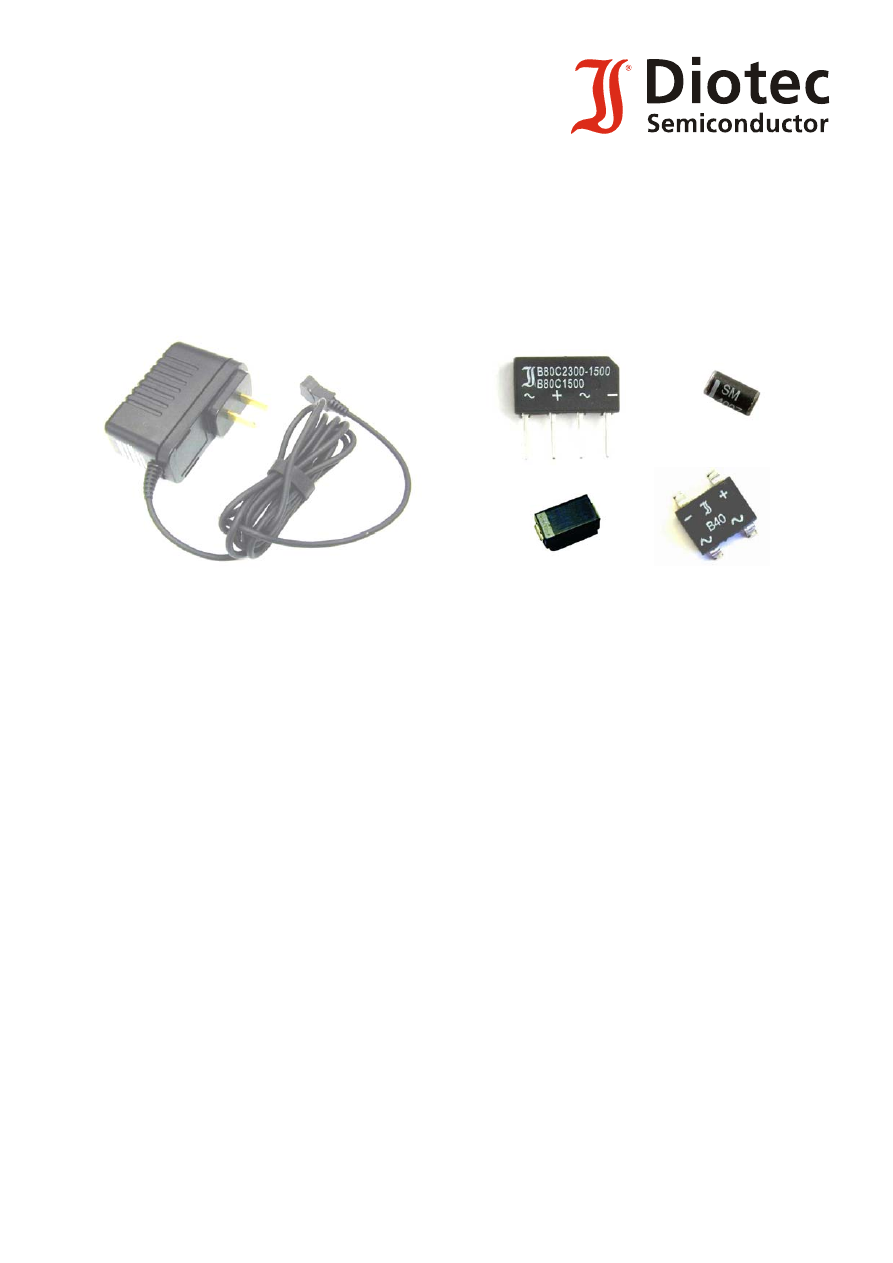
Diotec
Products
for
Power Supplies
Typical Applications:
AC/DC-, DC/DC-Converters, Battery Chargers, Off-Line PS
Line Protection
Î
TVS-Diodes
Input Rectification
Î
Bridge
Rectifiers,
Standard-/Fast Rectifiers
Voltage Regulation
Î
Zener
Diodes
Boost-Diode for PFC
Î
Superfast-/Ultrafast
Rectifiers
Gate Protection (MOS)
Î
Zener-Diodes,
TVS-Diodes
Clamping Network (Flyback)
Î
Fast-Diodes,TVS-Diodes
Demagnetization (Forward)
Î
Fast-Diodes
Output Rectification
Î
Schottky
Diodes,
Superfast-/Ultrafast Rectifiers
OR-ing Diodes
Î
Schottky Diodes,
Standard Rectifiers