
Please contact ..........
Specifications are subject to change without notice.
ASCTB376E-1 20170
9
-3YKN
Electromechanical Control Business Division
1006, Oaza Kadoma, Kadoma-shi, Osaka 571-8506, Japan
industrial.panasonic.com/ac/e/
©Panasonic Corporation 2017
8mm
industrial.panasonic.com/ac/e/
2017-2018
Motorcycle
Commercial Vehicle
Passenger Car
Automotive
Relays
Automation Controls
Group Catalog
Auto
mation Co
ntro
ls Gro
up Catalo
g
2017
-20
18
Automotive Relays
automotive-relay_en-html.html

1
ASCTB299E 201709-T
T A B L E O F C O N T E N T S
Page
Line up
......................................................................................2
Application
................................................................................4
Automotive Relays Selector Chart .............................................8
Configuration and Construction................................................19
Definition of Relay Terminology ................................................20
Cautions for Use.......................................................................22
Automotive Relay Users Guide ................................................23
CJ RELAYS ..............................................................................47
CN-H RELAYS .........................................................................55
CN-M RELAYS .........................................................................59
CP RELAYS .............................................................................64
CP RELAYS POWER TYPE.....................................................69
CQ RELAYS .............................................................................73
CT RELAYS..............................................................................77
CT RELAYS POWER TYPE .....................................................83
CW RELAYS ............................................................................88
TA RELAYS ..............................................................................91
TB RELAYS..............................................................................95
TB RELAYS POWER TYPE ...................................................104
TC RELAYS............................................................................109
TE RELAYS............................................................................118
TG RELAYS ...........................................................................126
TH RELAYS............................................................................131
TJ RELAYS ............................................................................136
TL RELAYS ............................................................................140
TM RELAYS ...........................................................................145
CA RELAYS ...........................................................................150
CB RELAYS ...........................................................................157
CM RELAYS ...........................................................................165
CV-N RELAYS ........................................................................170
CN-L RELAYS ........................................................................174
EC-N RELAYS........................................................................178
EV RELAYS............................................................................183
EV SWITCHES ......................................................................201
ISO14001, ISO9001, ISO/TS16949 Certificate of
Approval
................................................................................207
Automation Controls Sales Network
..................................208
automotive-relay_en-html.html

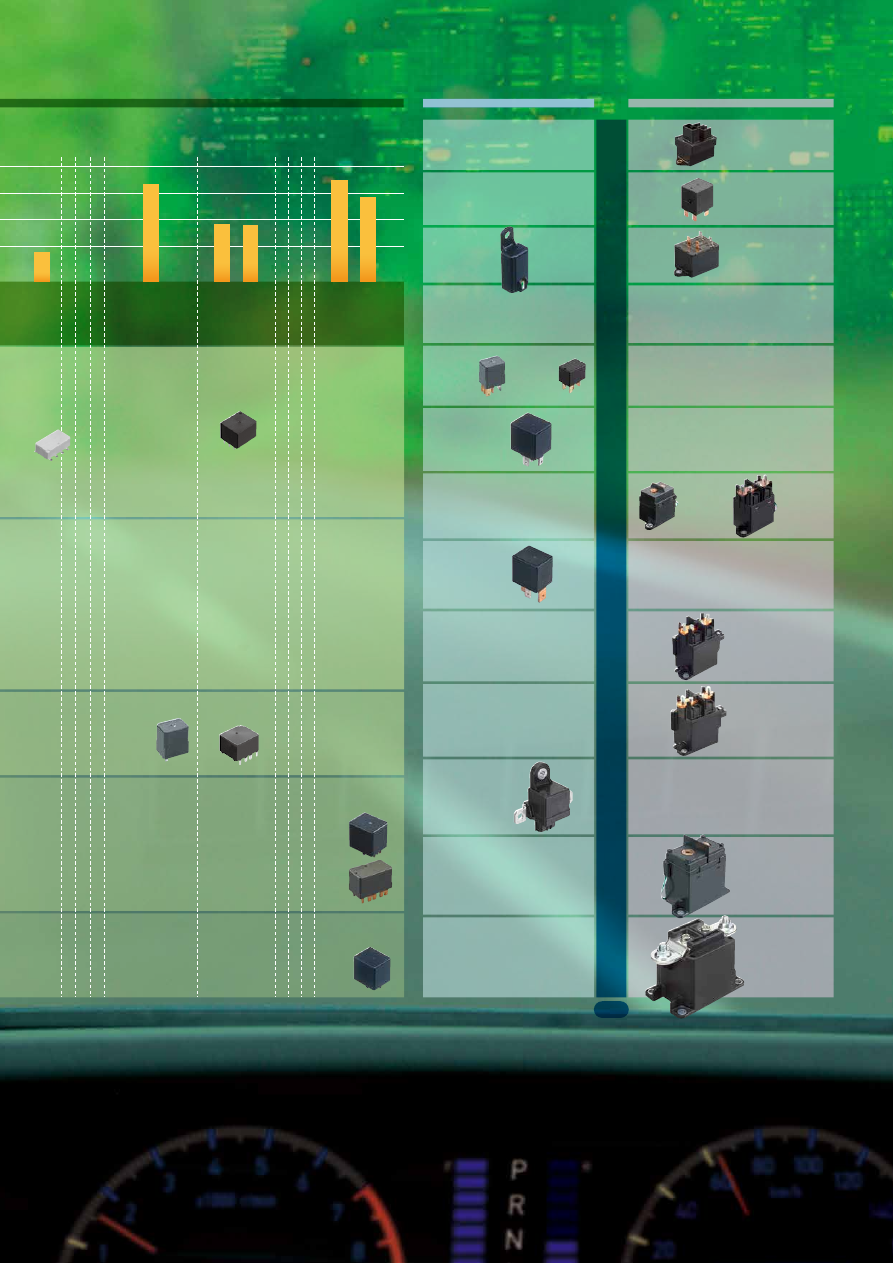
Line up
10A
15A
20A
30A
35A
120A
150A
200A
80A
40A
70A
300A
EV 300A
EV 120A
EV 200A
EV 80A
EV 20A
EV 10A
CB High
capacity
(1a)
Mini ISO
60A
CB Standard
(1a,1c)
Mini ISO
CA
(1a,1b1c)
JIS terminal
CM
(1a,1c)
Micro ISO
EV60A
Quiet type
EV60A
Compact high
short-circuit
capacity type
Foot print
Height
Capacity
Capacity
10mm
100 120
130
140
160
170
180
190
220
240
250
230
260 300
320
340 500
20A
30A
35A
40A
70A
15mm
20mm
30mm
.394inch
.591inch
.787inch
1.181inch
mm
2
PC-BOARD
HIGH-VOLTAGE
PLUG-IN
TE
(1c)
TE
(1c×2)
TG
(1a,1c)
TG
TC
TH
CT
CT-P
TB
CB
CJ
TE
CT
CT-P
TB
TB-P
CP
CP-P
CJ
TE
TJ
TH
TA
CM
TM
CW
CW
TL
CJ
(1c)
CT
(1c)
CT-P
(1c)
TB
(1a,1c)
TB
(1c×2)
TH
(1c)(SMD)
CJ
(1c×2)
CN-H
(1a)
CN-M
(1a,1c)
CN-M
(1a,1c)
(SMD)
TB-P
(1a)
CQ
(1c)
CM
(1a,1c)
Micro ISO
*24V type only
CT
(1c×2)
TH
(1c×2)
(SMD)
CQ
CN-H
CN-M
TC
(1a,1c,2a)
TJ
(1c)
TA
(1c)
CB High
capacity
(1a)
CB Standard
(1a,1c)
Mini ISO
CW
(2a)
CN-L
(1a)
Latching type
CT-P
(1c×2)
CP
(1a,1c)
CP-P
(1a,1c)
CP
(1c)
(SMD)
CV-N
(1a)
Micro ISO
EC-N
(1a)
DC relay
TM
(1a,1c)
TL
(2a)
ASCTB385E 201709-T
2
automotive-relay_en-html.html
Line up
10A
15A
20A
30A
35A
120A
150A
200A
80A
40A
70A
300A
EV 300A
EV 120A
EV 200A
EV 80A
EV 20A
EV 10A
CB High
capacity
(1a)
Mini ISO
60A
CB Standard
(1a,1c)
Mini ISO
CA
(1a,1b1c)
JIS terminal
CM
(1a,1c)
Micro ISO
EV60A
Quiet type
EV60A
Compact high
short-circuit
capacity type
Foot print
Height
Capacity
Capacity
10mm
100 120
130
140
160
170
180
190
220
240
250
230
260 300
320
340 500
20A
30A
35A
40A
70A
15mm
20mm
30mm
.394inch
.591inch
.787inch
1.181inch
mm
2
PC-BOARD
HIGH-VOLTAGE
PLUG-IN
TE
(1c)
TE
(1c×2)
TG
(1a,1c)
TG
TC
TH
CT
CT-P
TB
CB
CJ
TE
CT
CT-P
TB
TB-P
CP
CP-P
CJ
TE
TJ
TH
TA
CM
TM
CW
CW
TL
CJ
(1c)
CT
(1c)
CT-P
(1c)
TB
(1a,1c)
TB
(1c×2)
TH
(1c)(SMD)
CJ
(1c×2)
CN-H
(1a)
CN-M
(1a,1c)
CN-M
(1a,1c)
(SMD)
TB-P
(1a)
CQ
(1c)
CM
(1a,1c)
Micro ISO
*24V type only
CT
(1c×2)
TH
(1c×2)
(SMD)
CQ
CN-H
CN-M
TC
(1a,1c,2a)
TJ
(1c)
TA
(1c)
CB High
capacity
(1a)
CB Standard
(1a,1c)
Mini ISO
CW
(2a)
CN-L
(1a)
Latching type
CT-P
(1c×2)
CP
(1a,1c)
CP-P
(1a,1c)
CP
(1c)
(SMD)
CV-N
(1a)
Micro ISO
EC-N
(1a)
DC relay
TM
(1a,1c)
TL
(2a)
ASCTB385E 201709-T
3
automotive-relay_en-html.html
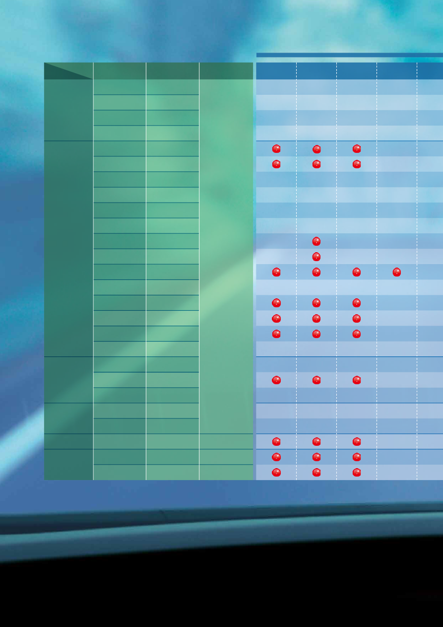
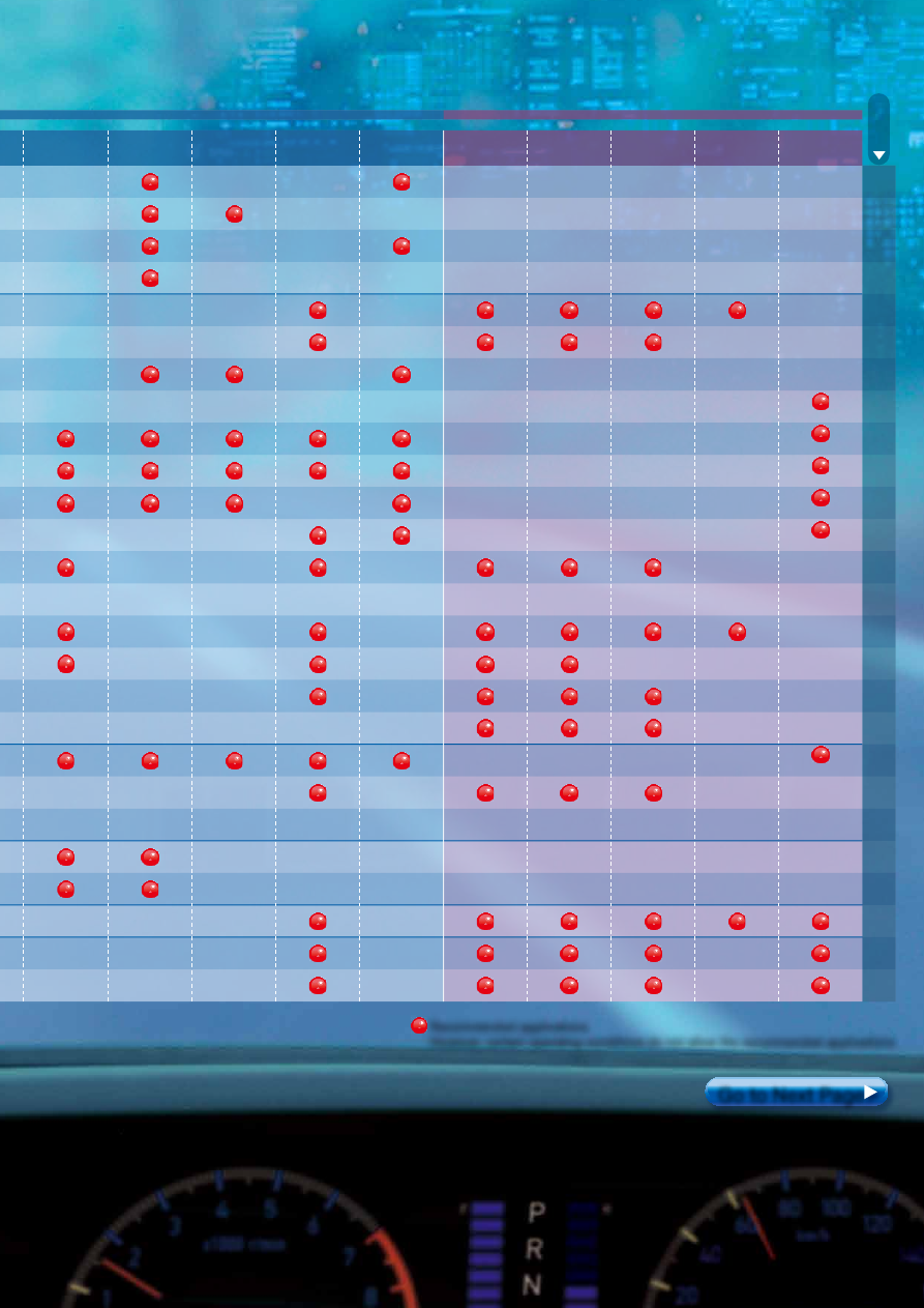
Application :
1
Safety
Power Train Control
Head lights
(incl. HID)
Tail
lamps
Fog lamps
(Front and rear)
Powered mirror
(incl. ones
with heaters)
Washers
Defogger
Blower fan
Engine
starter motor
EPS (Electrical
power steering)
Magnetic
clutch
Page
Radiator
fan motor
Horn
Wipers,
Intermittent
wipers
Flashers
Recommended applications
However, certain operating conditions do not allow the recommended applications
Go to Next Page
Type
Product name
Contact
arrangement
Coil voltage
Twin
SMD
Quiet
Mini ISO
Micro ISO
CT/CT-P
CJ
TB
TE
CN-H
CN-M
CT/CT-P
CJ
CP-P
CP
TB
TB-P
TC
TE
TG
TJ
TL
TM
CP
CN-M
TH
CQ
TA
CB
CM
CV-N
Single
1c × 2
1c × 2
1c × 2
1c × 2
1a
1a, 1c
1c
1c
1a, 1c
1a, 1c
1a, 1c
1a
1c
1a, 1c
1c
1a, 1c
1c
1a, 1c
1c, 1c × 2
1c
1c
1a, 1c
1a, 1c
1a
1a, 1c, Double
make contact 2a
Double make
contact 2a
12V
12V, 24V
12V
Standard: 12V, 24V
1a High capacity: 12V
77/83
47
95
118
55
59
77/83
47
69
64
95
104
109
118
126
136
140
145
64
59
131
73
91
157
165
170
(with Di)
(with Di)
(with Di)
(with Di)
(with Di)
(with Di)
ASCTB385E 201709-T
4
automotive-relay_en-html.html
Application :
1
Safety
Power Train Control
Head lights
(incl. HID)
Tail
lamps
Fog lamps
(Front and rear)
Powered mirror
(incl. ones
with heaters)
Washers
Defogger
Blower fan
Engine
starter motor
EPS (Electrical
power steering)
Magnetic
clutch
Page
Radiator
fan motor
Horn
Wipers,
Intermittent
wipers
Flashers
Recommended applications
However, certain operating conditions do not allow the recommended applications
Go to Next Page
Type
Product name
Contact
arrangement
Coil voltage
Twin
SMD
Quiet
Mini ISO
Micro ISO
CT/CT-P
CJ
TB
TE
CN-H
CN-M
CT/CT-P
CJ
CP-P
CP
TB
TB-P
TC
TE
TG
TJ
TL
TM
CP
CN-M
TH
CQ
TA
CB
CM
CV-N
Single
1c × 2
1c × 2
1c × 2
1c × 2
1a
1a, 1c
1c
1c
1a, 1c
1a, 1c
1a, 1c
1a
1c
1a, 1c
1c
1a, 1c
1c
1a, 1c
1c, 1c × 2
1c
1c
1a, 1c
1a, 1c
1a
1a, 1c, Double
make contact 2a
Double make
contact 2a
12V
12V, 24V
12V
Standard: 12V, 24V
1a High capacity: 12V
77/83
47
95
118
55
59
77/83
47
69
64
95
104
109
118
126
136
140
145
64
59
131
73
91
157
165
170
(with Di)
(with Di)
(with Di)
(with Di)
(with Di)
(with Di)
ASCTB385E 201709-T
5
automotive-relay_en-html.html

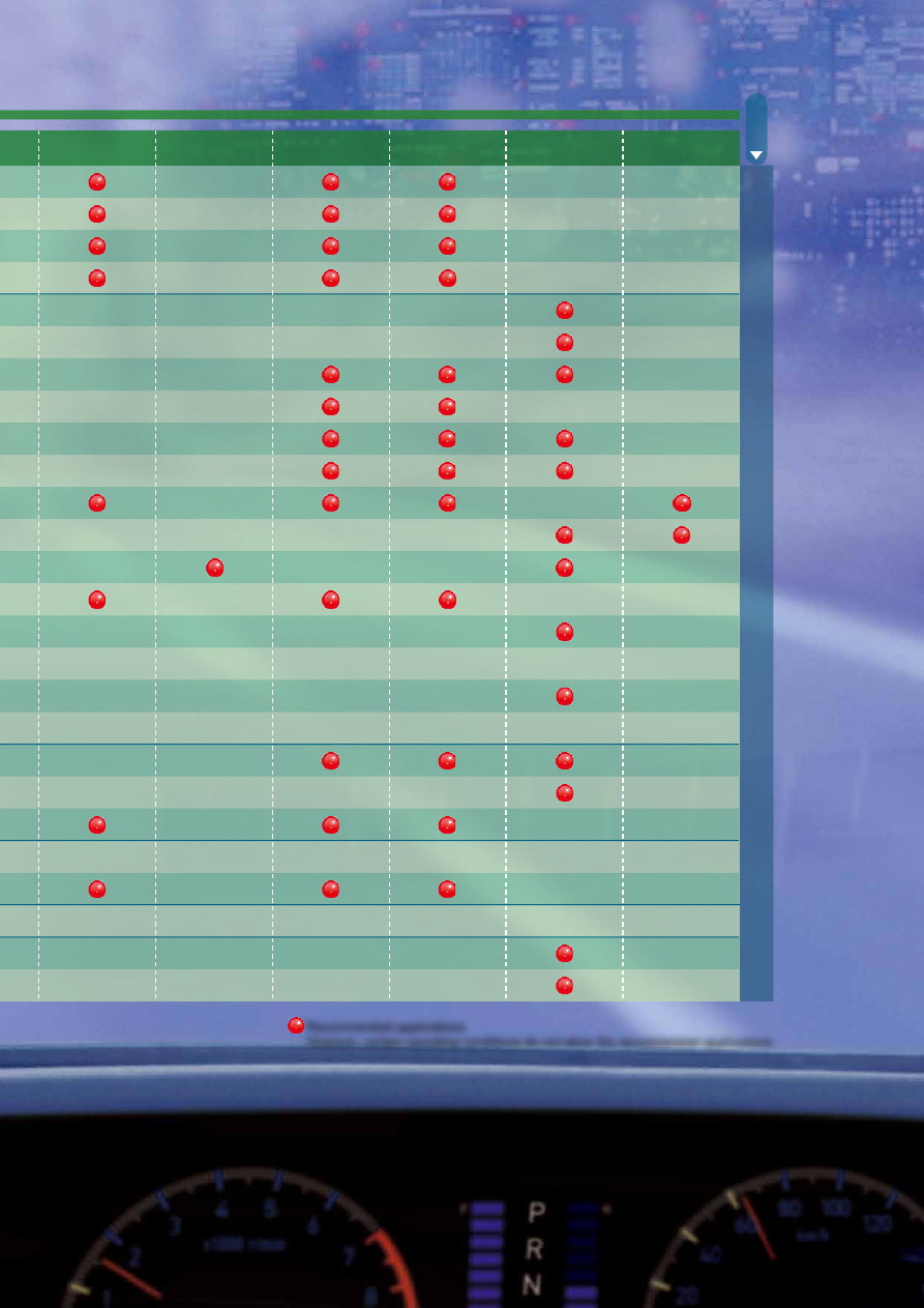
Application :
2
Comfort
Powered
sunroof
Powered seats
Lift gates
Door lock
Slide door
closer
Room lamp
Seat heater
Answerback lamp for
keyless entry
Powered window
motor
77/83
47
95
118
55
59
77/83
47
69
64
95
104
109
118
126
136
140
145
64
59
131
73
91
157
165
170
Twin
SMD
Quiet
Mini ISO
Micro ISO
Type
Product name
CT/CT-P
CJ
TB
TE
CN-H
CN-M
CT/CT-P
CJ
CP-P
CP
TB
TB-P
TC
TE
TG
TJ
TL
TM
CP
CN-M
TH
CQ
TA
CB
CM
CV-N
Single
1c × 2
1c × 2
1c × 2
1c × 2
1a
1a, 1c
1c
1c
1a, 1c
1a, 1c
1a, 1c
1a
1c
1a, 1c
1c
1a, 1c
1c
1a, 1c
1c, 1c × 2
1c
1c
1a, 1c
1a, 1c
1a
Contact
arrangement
Coil voltage
12V
12V, 24V
12V
Standard: 12V, 24V
1a High capacity: 12V
1a, 1c, Double
make contact 2a
Page
Recommended applications
However, certain operating conditions do not allow the recommended applications
Double make
contact 2a
ASCTB385E 201709-T
6
automotive-relay_en-html.html
Application :
2
Comfort
Powered
sunroof
Powered seats
Lift gates
Door lock
Slide door
closer
Room lamp
Seat heater
Answerback lamp for
keyless entry
Powered window
motor
77/83
47
95
118
55
59
77/83
47
69
64
95
104
109
118
126
136
140
145
64
59
131
73
91
157
165
170
Twin
SMD
Quiet
Mini ISO
Micro ISO
Type
Product name
CT/CT-P
CJ
TB
TE
CN-H
CN-M
CT/CT-P
CJ
CP-P
CP
TB
TB-P
TC
TE
TG
TJ
TL
TM
CP
CN-M
TH
CQ
TA
CB
CM
CV-N
Single
1c × 2
1c × 2
1c × 2
1c × 2
1a
1a, 1c
1c
1c
1a, 1c
1a, 1c
1a, 1c
1a
1c
1a, 1c
1c
1a, 1c
1c
1a, 1c
1c, 1c × 2
1c
1c
1a, 1c
1a, 1c
1a
Contact
arrangement
Coil voltage
12V
12V, 24V
12V
Standard: 12V, 24V
1a High capacity: 12V
1a, 1c, Double
make contact 2a
Page
Recommended applications
However, certain operating conditions do not allow the recommended applications
Double make
contact 2a
ASCTB385E 201709-T
7
automotive-relay_en-html.html
Panasonic Corporation 2017
©
Panasonic Corporation Electromechanical Control Business Division
industrial.panasonic.com/ac/e/
ASCTB283E 201709-T
–8–
Automotive Relays Selector Chart
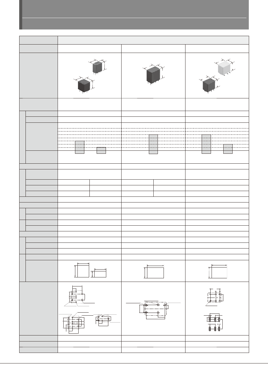
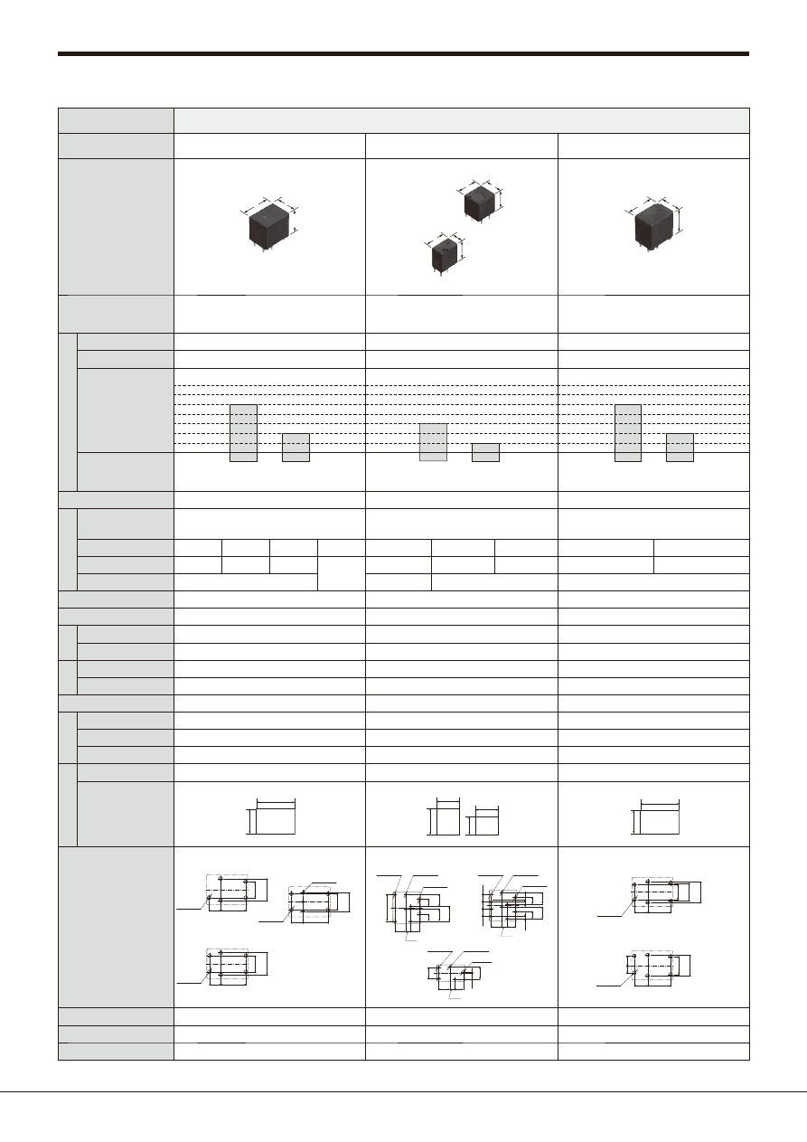
Type
Automotive relays
Product name
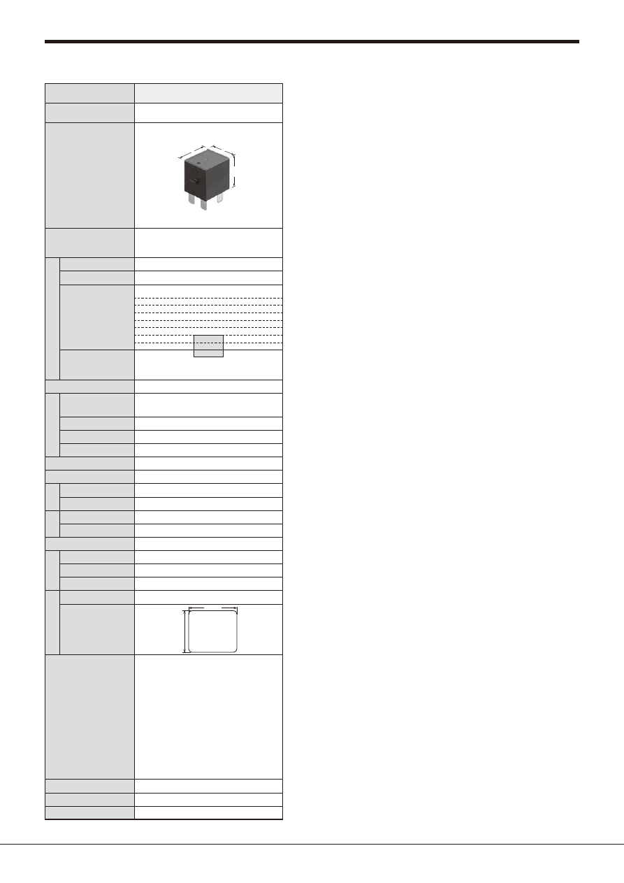
CJ RELAYS
CN-H RELAYS
CN-M RELAYS
Appearance
configuration
(Standoff height included,
Unit: mm
inch
)
Part No.
ACJ
(8-pin)
7.2
12.2
13.5
13.7
12.2
13.5
.283
.480
.531
.539
.480
.531
ACNH
10.6
17
18.3
.417
.669
.720
ACNM
11
15.5
14.4
.433
.610
.567
11
15.5
15.1
.433
.610
.594
Features
Compact Slim Twin and Single Type
Automotive Relay
High Load Relay for Smart J/B
Middle Load Relay for Smart J/B
Con
tact
data
Contact arrangement 1 Form C, 1 Form C×2 (8 pins), 1 Form C×2 (10 pins)
1 Form A
1 Form A, 1 Form C
Contact material
Ag alloy
Ag alloy
Ag alloy
Rated
switching
capacity
(resistive)
1A 14V DC
20A 14V DC
N.O.
10A 14V DC
N.C.
1A 14V DC
30A 14V DC
N.O.
30A 14V DC
N.O.
15A 14V DC
N.C.
1A 14V DC
Min. switching load
(resistive)
Latching type
−
−
−
Coi
l data
Rated coil voltage
12V DC
12V DC
12V DC
Rated operating power
640mW
800mW
450mW
640mW
640mW
Operate (Set) voltage at 20°C
68°F
(initial)
Max. 7.2V DC
Max. 6.5V DC
Max. 6.5V DC
Max. 5.5V DC
Max. 7.2V DC
Release (Reset) voltage at 20°C
68°F
(initial)
Min. 1.0V DC
Min. 0.8V DC
Min. 1.0V DC
Min. 0.8V DC
Min. 1.0V DC
Operate (Set) time (Rated voltage at 20°C
68°F
)
Max. 10ms (without bounce time)
Max. 10ms (without bounce time)
Max. 10ms (without bounce time)
Release (Reset) time (Rated voltage at 20°C
68°F
) Max. 10ms (without bounce time) (without diode) Max. 10ms (without bounce time) (without diode) Max. 10ms (without bounce time) (without diode)
Ex
pe
ct
ed
lif
e
Mechanical
Min. 10
7
Min. 10
7
Min. 10
7
Electrical
Min. 2 × 10
5
(at 14 V DC, inrush: 25 A, steady: 5 A)
Min. 10
5
(at 14 V DC, 25 A Motor lock)
Min. 3 × 10
5
(at 14 V DC, inrush: 84 A, steady: 18 A)
Min. 2 × 10
5
(at 14 V DC, 84 A, steady: 12 A Lamp)
Min. 2 × 10
5
(at 14 V DC, inrush: 80 A, steady: 16 A)
Min. 10
5
(at 14 V DC, 84 A steady: 12 A Lamp)
Diel
ect
ric st
ren
gth
Between open contacts (initial)
500 Vrms for 1 min.
500 Vrms for 1 min.
500 Vrms for 1 min.
Between contacts and coil (initial)
500 Vrms for 1 min.
500 Vrms for 1 min.
500 Vrms for 1 min.
Ambient temperature
–40 to +85°C
–40 to +185°F
–40 to +110°C
–40 to +230°F
Standard type: –40 to +85°C
–40 to +185°F
High heat-resistant type: –40 to +110°C
–40 to +230°F
Prot
ec
tiv
e c
on
str
uc
tio
n
Dust cover
−
−
−
Flux tight
●
(PIP type)
−
−
Sealed
●
●
●
E
xt
e
rnal
d
imensions
Height (mm
inch
)
Included standoff
13.5
.531
/13.8
.543
(PIP type)
18.3
.720
14.4
.567
(Surface-mount: 15.1
.594
)
Foot print (mm
inch
)
13.7
12.2
12.2
.480
.480
7.2
.539
.283
(8-pin)
10.6
.417
17
.669
11
.433
15.5
.610
PC board pattern
1 Form C type
Twin type (8-pin)
Twin type (10-pin)
10.45
4.0
.411
.157
6.5
.256
4.5
2.0
4.5
.177
.079
.177
2×1.5
dia. hole
0.1
0
2×.059
dia. hole
.004
0
4×1.0
dia. hole
0.1
0
4×.039
dia. hole
.004
0
2×1.5
dia. hole
0.1
0
2×.059
dia. hole
.004
0
2×1.5
dia. hole
0.1
0
2×.059
dia. hole
.004
0
10.45
4.0
.411
.157
4.5
.177
2.7
.106
7.2
.283
7.2
.283
3.6
.142
3.6
.142
0.3
.012
4.5
.177
4×1.5
dia. hole
0.1
0
4×.059
dia. hole
.004
0
4×1.0
dia. hole
0.1
0
4×.039
dia. hole
.004
0
10.45
4.0
.411
.157
0.3
4.5
.012
3.6
.142
.177
2×1.5
dia. hole
0.1
0
2×.059
dia. hole
.004
0
2×1.0
dia. hole
0.1
0
2×.039
dia. hole
.004
0
1.5
dia. hole
0.1
0
.059
dia. hole
.004
0
1.7
dia. hole
+0.1
0
.067
dia. hole
+.004
0
2×1.6
dia. hole
+0.1
0
2×.063
dia. hole
+.004
0
2×1.6
dia. hole
+0.1
0
2×.063
dia. hole
+.004
0
14.95
.589
5.5
.217
3.0
.118
6.4
.252
5.6
.220
PC board terminal type
1 Form C
1 Form C
Surface-mount terminal type
4.65
.183
10.95
.431
6×1.5
dia.
8
.315
+0.1
0
6×.059
dia.
+.004
0
11.2
4.6
.441
.181
4.65
.183
6×1.7
6×.067
10.95
.431
Weight (approx.)
6.5 g
.23 oz
(Twin type), 3.5 g
.12 oz
(1 Form C type)
9 g
.32 oz
5.5 g
.19 oz
Remarks
10 pins and PIP types available
−
−
Page
47
55
59
40A−
35A−
30A−
25A−
20A−
15A−
10A−
automotive-relay_en-html.html
Automotive Relays Selector Chart
Panasonic Corporation 2017
©
Panasonic Corporation Electromechanical Control Business Division
industrial.panasonic.com/ac/e/
ASCTB283E 201709-T
–9–
Type
Automotive relays
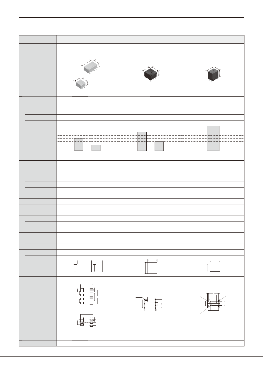
Product name
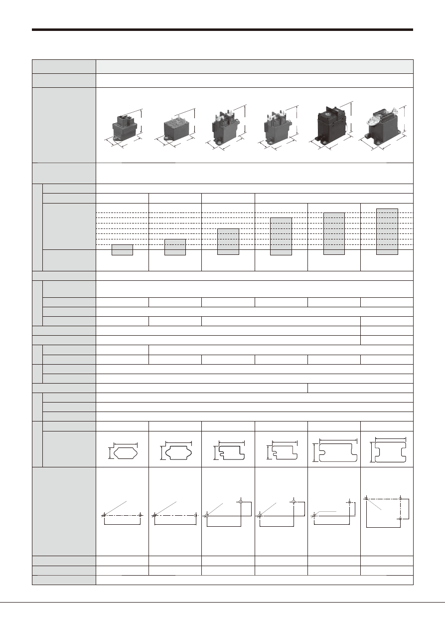
CP RELAYS
CP RELAYS POWER TYPE
CQ RELAYS
Appearance
configuration
(Standoff height included,
Unit: mm
inch
)
Part No.
ACP
14
13
9.5
.551
.512
.374
14
13
10.5
.551
.512
.413
ACPP
14
13
9.5
.551
.512
.374
ACQ
13
17
16.6
.512
.669
.654
Features
Compact Flat Size for Automotive Relay
High Carrying Current Type
Miniature Low Profile Automotive Relay
1 Form C Automotive Quiet Relay
Con
tact
data
Contact arrangement
1 Form A, 1 Form C
1 Form A, 1 Form C
1 Form C
Contact material
Ag alloy
Ag alloy
Ag alloy
Rated
switching
capacity
(resistive)
20A 14V DC
N.O.
10A 14V DC
1A 14V DC
N.C.
20A 14V DC
N.O.
10A 14V DC
N.C.
1A 14V DC
1A 14V DC
20A 14V DC
N.O.
10A 14V DC
N.C.
Min. switching load
(resistive)
Latching type
−
−
−
Coi
l data
Rated coil voltage
12V DC
12V DC
12V DC
Rated operating power
640mW
450mW
640mW
640mW
Operate (Set) voltage at 20°C
68°F
(initial)
Max. 7.2 V DC
Max. 7.2V DC
Max. 6.5V DC
Max. 7.2V DC
Release (Reset) voltage at 20°C
68°F
(initial)
Min. 1.0 V DC
Min. 1.0V DC
Min. 1.0V DC
Operate (Set) time (Rated voltage at 20°C
68°F
)
Max. 10ms (without bounce time)
Max. 10ms (without bounce time)
Max. 10ms (without bounce time)
Release (Reset) time (Rated voltage at 20°C
68°F
) Max. 10ms (without bounce time) (without diode) Max. 10ms (without bounce time) (without diode) Max. 10ms (without bounce time) (without diode)
Ex
pe
ct
ed
lif
e
Mechanical
Min. 10
7
Min. 10
7
Min. 10
7
Electrical
Min. 2 × 10
5
(at 14 V DC, inrush: 25 A, steady: 5 A)
Min. 10
5
(Capacitor load)
(at 14 V DC, Inrush 60A, Steady 1A)
Min. 3 x 10
5
(at 14 V DC, Inrush 30A, Steady 5A)
Diel
ect
ric st
ren
gth
Between open contacts (initial)
500 Vrms for 1 min.
500 Vrms for 1 min.
500 Vrms for 1 min.
Between contacts and coil (initial)
500 Vrms for 1 min.
500 Vrms for 1 min.
500 Vrms for 1 min.
Ambient temperature
–40 to +85°C
–40 to +185°F
–40 to +85°C
–40 to +185°F
–40 to +85°C
–40 to +185°F
Prot
ec
tiv
e c
on
str
uc
tio
n
Dust cover
−
−
−
Flux tight
−
−
−
Sealed
●
●
●
E
xt
e
rnal
d
imensions
Height (mm
inch
)
Included standoff
9.5
.374
(Surface mount: 10.5
.413
)
9.5
.374
16.6
.654
Foot print (mm
inch
)
13
.512
14
.551
13
.512
14
.551
13
.512
17
.669
PC board pattern
PC board terminal type
1 From C
1 From C
Surface mount terminal type
4.5
.177
5.4
.213
2.0
.079
(R)
10.7
.421
2×.051
+.004
0
dia. hole
2×1.3
+0.1
0
dia. hole
3×.035
+.004
0
3×.079
+.004
0
3×0.9
+0.1
0
3×2.0
dia.
dia.
dia.
dia.
+0.1
0
6.0
.236
5.0
.197
2.0
2.0
.079
.079
4.8
4.0
4.7
4.8
.189
.157
6.0
.236
2.5
.098
.185
.189
4.2
.165
3.8
.150
4.4
.173
2.5
.098
4.8
.189
1 Form C
0.9
.035
6.0
2.0
.236
5.0
.197
10.7
.421
.079
5.4
.213
4.5
.177
3.5
.138
(R 0.45)
(R .018)
3×.079
+.004
0
3×2.0
+0.1
0
4×.035
+.004
0
4×0.9
+0.1
0
.098
+.004
0
2.5
+0.1
0
2×1.3 dia. (hole)
+0.1
0
2×.051 dia. (hole)
+.004
0
2.5
5×1.5
+0.1
0
10.2
10.0
.098
.402
.394
5×.059
dia. hole
dia. hole
+.004
0
Weight (approx.)
4g
.14 oz
4.5 g
.16 oz
6.5g
.23 oz
Remarks
−
−
−
Page
64
69
73
40A−
35A−
30A−
25A−
20A−
15A−
10A−
automotive-relay_en-html.html
Automotive Relays Selector Chart
Panasonic Corporation 2017
©
Panasonic Corporation Electromechanical Control Business Division
industrial.panasonic.com/ac/e/
ASCTB283E 201709-T
–10–
Type
Automotive relays
Product name
CT RELAYS
CT RELAYS POWER TYPE
CW RELAYS
Appearance
configuration
(Standoff height included,
Unit: mm
inch
)
Part No.
ACT
14
17.4
13.5
.551
7.2
.283
.685
.531
17.4
13.5
.685
.531
ACTP
14
17.4
13.5
.551
7.2
.283
.685
.531
17.4
13.5
.685
.531
ACW
18
32
19
.709
1.260
.748
Features
Small & Slim Twin/1 Form C type
Automotive Relay
High Carrying Current Type Small & Slim
Automotive Relay
Automotive Relay for Failsafe Circuits in
High Output Motors (EPS)
Con
tact
data
Contact arrangement 1 Form C, 1 Form C × 2 (8 pins) and 1 Form C × 2 (10 pins) 1 Form C, 1 Form C × 2 (8 pins) and 1 Form C × 2 (10 pins)
2 Form A
Contact material
Ag alloy
Ag alloy
Ag alloy
Rated
switching
capacity
(resistive)
1A 14V DC
20A 14V DC
N.O.
10A 14V DC
N.C.
1A 14V DC
30A 14V DC
N.O.
10A 14V DC
N.C.
70A 14V DC
<Max. carrying current>
45A 14V DC
120A 14V DC
1 min.
at 85°C
185°F
Continuous
at 85°C
185°F
5 s
at 20°C
68°F
1A 14V DC
Min. switching load
(resistive)
Latching type
−
−
−
Coi
l data
Rated coil voltage
12V DC
12V DC
12V DC
Rated operating power
800mW
1,000mW
1.4W
Operate (Set) voltage at 20°C
68°F
(initial)
Max. 7.2V DC
Max. 7.2V DC
Max. 6.2V DC
Release (Reset) voltage at 20°C
68°F
(initial)
Min. 1.0V DC
Min. 1.0V DC
Min. 0.5V DC
Operate (Set) time (Rated voltage at 20°C
68°F
)
Max. 10ms (without bounce time)
Max. 10ms (without bounce time)
Max. 20ms (without bounce time)
Release (Reset) time (Rated voltage at 20°C
68°F
) Max. 10ms (without bounce time) (without diode) Max. 10ms (without bounce time) (without diode) Max. 20ms (without bounce time) (without diode)
Ex
pe
ct
ed
lif
e
Mechanical
Min. 10
7
Min. 10
6
Min. 2 x 10
5
Electrical
Min. 2 × 10
5
(at 14 V DC, inrush: 25 A, steady: 5 A)
Min. 10
5
(at 14 V DC, 25 A motor lock condition)
Min. 10
5
(at 14 V DC, inrush: 30 A, steady: 7 A)
Min. 5 x 10
4
(at 14 V DC, 30 A motor lock condition)
−
Diel
ect
ric st
ren
gth
Between open contacts (initial)
500 Vrms for 1 min.
500 Vrms for 1 min.
500 Vrms for 1 min.
Between contacts and coil (initial)
500 Vrms for 1 min.
500 Vrms for 1 min.
500 Vrms for 1 min.
Ambient temperature
–40 to +85°C
–40 to +185°F
–40 to +85°C
–40 to +185°F
–40 to +125°C
–40 to +257°F
Prot
ec
tiv
e c
on
str
uc
tio
n
Dust cover
−
−
−
Flux tight
−
−
−
Sealed
●
●
●
E
xt
e
rnal
d
imensions
Height (mm
inch
)
Included standoff
13.5
.531
13.5
.531
19
.748
Foot print (mm
inch
)
14
.551
17.4
.685
7.2
.283
17.4
.685
14
.551
17.4
.685
7.2
.283
17.4
.685
18
0.709
32
1.260
PC board pattern
Twin type (8 pins)
Twin type (10 pins)
1 Form C type
3.15
4.3
4.3
2.5
6.8
4×1.1 dia.
(Coil terminal)
(Coil terminal)
+0.1
0
+0.04
0
9.5
6
3
15
4×1.4 dia.
(Except coil terminal)
(Except coil terminal)
(Coil terminal)
(Except coil terminal)
+0.1
0
+0.04
0
.124
.169
.169
.098
.268
4×.043 dia.
.374
.236
.118
.591
4×.055 dia.
3.15
3.15
0.65
0.65
4.3
4.3
2.5
6.8
9.5
6
15
6×1.4 dia.
+0.1
0
+0.04
0
4×1.1 dia.
+0.1
0
+0.04
0
.124
.124
.026
.026
.169
.169
.098
.268
.374
.236
.591
6×.055 dia.
4×.043 dia.
3.15
4.3
2×1.1 dia.
+0.1
0
+0.04
0
3×1.4 dia.
15
0.65
9.5
6
.124
.169
2×.043 dia.
3×.055 dia.
.591
.026
.374
.236
Twin type (8 pins)
Twin type (10 pins)
1 Form C type
3.15
4.3
4.3
2.5
6.8
4×1.1 dia.
+0.1
0
+0.04
0
9.5
6
3
15
4×1.4 dia.
+0.1
0
+0.04
0
.124
.169
.169
.098
.268
.374
.236
.118
.591
4×.043 dia.
(Coil terminal)
4×.055 dia.
(Except coil terminal)
3.15
3.15
0.65
0.65
4.3
4.3
2.5
6.8
9.5
6
15
6×1.4 dia.
+0.1
0
+0.04
0
4×1.1 dia.
+0.1
0
+0.04
0
.124
.124
.026
.026
.169
.169
.098
.268
.374
.236
.591
6×.055 dia.
(Except coil terminal)
4×.043 dia.
(Coil terminal)
3.15
4.3
2×1.1 dia.
+0.1
0
+0.04
0
15
0.65
9.5
6
3×1.4 dia.
+0.1
0
+0.04
0
.124
.169
.591
.026
.374
.236
2×.043 dia.
(Coil terminal)
3×.055 dia.
(Except coil terminal)
Mounting dimensions
(Bottom view)
*This is not a PCB terminal.
8.0
7.1
r
0.5 12.0
r
0.5
9.0
r
0.5
12.8
2×0.4
2.0
14.0
4×0.8
.315
.280
r
.020.472
r
.020 .354
r
.020
.504
2.6
.102
2×.016
.079
.551
2.0
.079
4×.031
Weight (approx.)
8 g
.28 oz
(Twin type), 4 g
.14 oz
: (1 Form C type) 8 g
.28 oz
(Twin type), 4 g
.14 oz
: (1 Form C type)
26 g
.92 oz
Remarks
10 pins type available
10 pins type available
Welding terminal
Page
77
83
88
40A−
35A−
30A−
25A−
20A−
15A−
10A−
automotive-relay_en-html.html
Automotive Relays Selector Chart
Panasonic Corporation 2017
©
Panasonic Corporation Electromechanical Control Business Division
industrial.panasonic.com/ac/e/
ASCTB283E 201709-T
–11–
Type
Automotive relays
Product name
TA RELAYS
TB RELAYS
TB RELAYS POWER TYPE
Appearance
configuration
(Standoff height included,
Unit: mm
inch
)
Part No.
ACTA
17
19.8
14
.669
.780
.551
ACTB
9.2
14
13.5
.362
.551
.531
14
17.4
13.5
.551
.685
.531
ACTBP
9.2
14
14
.362
.551
.551
Features
1 Form C Automotive Quiet Relay
Miniature PC Board, Twin/1 Form C Type
Automotive Relay
High Carrying Current 1 Form A Type Relay
for Miniature PC board
Con
tact
data
Contact arrangement
1 Form C
1 Form A, 1 Form C, 1 Form C × 2 (8 pins) and 1 Form C × 2 (10 pins)
1 Form A
Contact material
Ag alloy
Ag alloy
Ag alloy
Rated
switching
capacity
(resistive)
1A 14V DC
20A 14V DC
N.O.
10A 14V DC
N.C.
1A 14V DC
20A 14V DC
N.O.
10A 14V DC
N.C.
1A 14V DC
30A 14V DC
N.O.
Min. switching load
(resistive)
Latching type
−
−
−
Coi
l data
Rated coil voltage
12V DC
12V DC
12V DC
Rated operating power
900mW
640mW
1,440mW
900mW
640mW
480mW
Operate (Set) voltage at 20°C
68°F
(initial)
Max. 6.5V DC
Max. 7.7V DC
Max. 5.5V DC Max. 6.5V DC Max. 7.7V DC
Max. 7.0V DC
Release (Reset) voltage at 20°C
68°F
(initial)
Min. 0.8V DC
Min. 0.5V DC
Min. 0.8V DC
Min. 0.5V DC
Operate (Set) time (Rated voltage at 20°C
68°F
)
Max. 10ms (without bounce time)
Max. 10ms (without bounce time)
Max. 10ms (without bounce time)
Release (Reset) time (Rated voltage at 20°C
68°F
) Max. 10ms (without bounce time) (without diode) Max. 10ms (without bounce time) (without diode) Max. 10ms (without bounce time) (without diode)
Ex
pe
ct
ed
lif
e
Mechanical
Min. 10
7
Min. 10
7
Min. 5 x 10
6
Electrical
Min. 10
5
Min. 10
5
Min. 10
5
Diel
ect
ric st
ren
gth
Between open contacts (initial)
500 Vrms for 1 min.
500 Vrms for 1 min.
500 Vrms for 1 min.
Between contacts and coil (initial)
500 Vrms for 1 min.
500 Vrms for 1 min.
500 Vrms for 1 min.
Ambient temperature
–40 to +85°C
–40 to +185°F
Standard type: –40 to +85°C
–40 to +185°F
High heat-resistant/Pin in Paste compliant type: –40 to +110°C
–40 to +230°F
–40 to +110°C
–40 to +230°F
Prot
ec
tiv
e c
on
str
uc
tio
n
Dust cover
−
−
−
Flux tight
−
●
(PIP type)
●
(PIP type)
Sealed
●
●
●
E
xt
e
rnal
d
imensions
Height (mm
inch
)
Included standoff
14
.551
13.5
.531
/14.0
.551
(PIP type)
14
.551
Foot print (mm
inch
)
17
.669
19.8
.780
14
17.4
.685
14
.551
.551
9.2
.362
14
.551
9.2
.362
PC board pattern
18.2
5×1.6 dia.
5×.063 dia.
5
.197
5
.197
.717
Twin type (8 pins)
1 Form C type
Twin type (10 pins)
1 Form A type
4.8
8.4
.331
4
.157
.189
2×1.6 dia.
2×.063 dia.
2×1.1 dia.
2×.043 dia.
4.8
8.4
.331
4
.157
.189
3×1.6 dia.
3×.063 dia.
2×1.1 dia.
2×.043 dia.
8.4
.331
4
.157
13
.512
8.2
.323
4.8
.189
4.8
.189
4×1.1 dia.
4×.043 dia.
4×1.6 dia.
4×.063 dia.
8.4
.331
4
.157
4.8
.189
4.8
.189
4×1.1 dia.
4×.043 dia.
6×1.6 dia.
6×.063 dia.
13
.512
8.2
.323
1 Form A type
4.8
8.4
.331
4
.157
.189
4×1.9 dia.
4×.075 dia.
2×1.1 dia.
2×.043 dia.
Weight (approx.)
8 g
.28 oz
Single type: 5 g
.176 oz
, Twin type: 9.5 g
.335 oz
5 g
.176 oz
Remarks
−
10 pins type available
−
Page
91
95
104
40A−
35A−
30A−
25A−
20A−
15A−
10A−
automotive-relay_en-html.html
Automotive Relays Selector Chart
Panasonic Corporation 2017
©
Panasonic Corporation Electromechanical Control Business Division
industrial.panasonic.com/ac/e/
ASCTB283E 201709-T
–12–
Type
Automotive relays
Product name
TC RELAYS
TE RELAYS
TG RELAYS
Appearance
configuration
(Standoff height included,
Unit: mm
inch
)
Part No.
ACTC
13
17.8
16
.512
.701
.630
ACTE
7.2
12
13.5
.283
.472
.531
12
13.6
13.5
.472
.535
.531
ACTG
12.6
17.8
18
.496
.701
.709
Features
High Load Relay for Smart J/B
Miniature PC Board, Twin Type, 1 Form C
Automotive Relay
High Load Relay for Smart J/B
Con
tact
data
Contact arrangement
1 Form A (Standard type), 1 Form C (Standard type), Double make contact 2 Form A
(Standard type) and Double make contact 2 Form A (2 coil latching type)
1 Form C, 1 Form C × 2 (8 pins) and 1 Form C × 2 (10 pins)
1 Form A and 1 Form C
Contact material
Ag alloy
Ag alloy
Ag alloy
Rated
switching
capacity
(resistive)
1A 14V DC
30A 14V DC
N.O.
15A 14V DC
N.C.
1A 14V DC
20A 14V DC
N.O.
10A 14V DC
N.C.
1A 14V DC
30A 14V DC
N.O.
15A 14V DC
N.C.
Min. switching load
(resistive)
Latching type
●
−
−
Coi
l data
Rated coil voltage
12V DC
12V DC
12V DC
Rated operating power 1,309mW
900mW
640mW
1,920mW
1,309mW
900mW
655mW
640mW
450mW
Operate (Set) voltage at 20°C
68°F
(initial) Max. 6.5 V DC Max. 7.0 V DC Max. 7.5 V DC
Max. 7.5 V DC
Max. 5.5V DC Max. 6.5V DC Max. 7.7V DC
Max. 6.5V DC
Max. 7.0V DC
Release (Reset) voltage at 20°C
68°F
(initial)
Min. 0.5 V DC
Min. 0.6V DC
Min. 0.8V DC
Min. 0.8V DC
Operate (Set) time (Rated voltage at 20°C
68°F
)
Max. 10ms (without bounce time)
Max. 10ms (without bounce time)
Max. 10ms (without bounce time)
Release (Reset) time (Rated voltage at 20°C
68°F
) Max. 10ms (without bounce time) (without diode) Max. 10ms (without bounce time) (without diode) Max. 10ms (without bounce time) (without diode)
Ex
pe
ct
ed
lif
e
Mechanical
Min. 10
7
Min. 10
6
(2 coil latching type)
Min. 10
7
Min. 10
7
Electrical
Min. 10
5
Min. 10
5
Min. 10
5
Diel
ect
ric st
ren
gth
Between open contacts (initial)
500 Vrms for 1 min.
500 Vrms for 1 min.
500 Vrms for 1 min.
Between contacts and coil (initial)
500 Vrms for 1 min.
500 Vrms for 1 min.
500 Vrms for 1 min.
Ambient temperature
Standard type: –40 to +85°C
–40 to +185°F
High heat-resistant/Pin in Paste compliant type: –40 to +110°C
–40 to +230°F
–40 to +110°C
–40 to +230°F
–40 to +110°C
–40 to +230°F
Prot
ec
tiv
e c
on
str
uc
tio
n
Dust cover
−
−
−
Flux tight
●
(PIP type)
●
(PIP type)
−
Sealed
●
●
●
E
xt
e
rnal
d
imensions
Height (mm
inch
)
Included standoff
16.0
.630
/16.4
.646
(PIP type)
13.5
.531
/14.0
.551
(PIP type)
18.0
.709
Foot print (mm
inch
)
17.8
.701
13
.512
12
13.6
12
.472
.472
7.2
.535
.283
17.8
.701
12.6
.496
PC board pattern
1 Form A type
2 coil latching type
1 Form C type
5×1.6 dia.
9.6
.378
7
10.8
.425
5
.197
.276
5×.063 dia.
9.6
.378
7
10.8
.425
5
.197
.276
6×1.6 dia.
6×.063 dia.
8
.315
7
10.8
.425
5
.197
.276
4×1.6 dia.
4×.063 dia.
3×1.1 dia.
3×.043 dia.
Twin type (8 pins)
1 Form C type
Twin type (10 pins)
4.8
.189
3.7
.146
2.2
.087
0.5
.020
5.2
.205
2×1.5 dia.
2×.059 dia.
2×1.1 dia.
2×.043 dia.
1.6 dia.
.063 dia.
4.8
.189
11.6
.457
6.4
.252
5.2
.205
5.2
.205
2×1.5 dia.
2×.059 dia.
4×1.1 dia.
4×.043 dia.
2×1.6 dia.
2×.063 dia.
3.7
.146
2.2
.087
4.8
.189
3.1
.122
3.1
.122
5.2
.205
5.2
.205
4×1.5 dia.
4×.059 dia.
4×1.1 dia.
4×.043 dia.
2×1.6 dia.
2×.063 dia.
3.7
.146
2.2
.087
4.8
.189
3.1
.122
3.1
.122
3.2
.126
3.2
.126
3.2
.126
1
.039
1
.039
1 Form A type
1 Form C type
6×1.6 dia.
6×.063 dia.
6.4
.252
7.8
.307
9
.354
10
.394
5.8
.228
4.1
.161
3.2
.126
7.8
.307
9
.354
10
.394
5.8
.228
6×1.6 dia.
6×.063 dia.
Weight (approx.)
10 g
.35 oz
Single type: 3.5 g
.12 oz
, Twin type: 6.5 g
.23 oz
12 g
.42 oz
Remarks
−
10 pins type available
−
Page
109
118
126
40A−
35A−
30A−
25A−
20A−
15A−
10A−
automotive-relay_en-html.html
Automotive Relays Selector Chart
Panasonic Corporation 2017
©
Panasonic Corporation Electromechanical Control Business Division
industrial.panasonic.com/ac/e/
ASCTB283E 201709-T
–13–
Type
Automotive relays
Product name
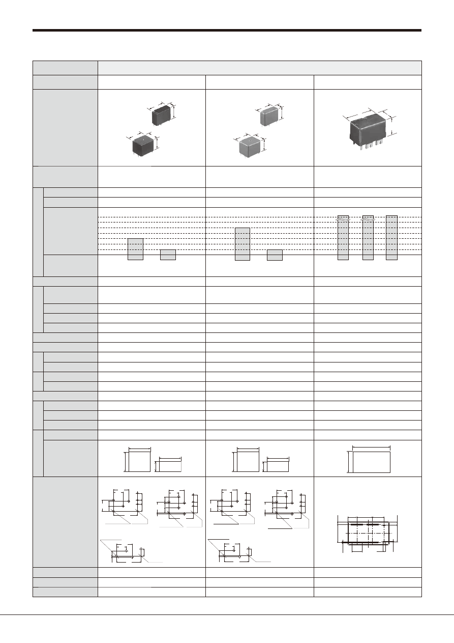
TH RELAYS
TJ RELAYS
TL RELAYS
Appearance
configuration
(Standoff height included,
Unit: mm
inch
)
Part No.
ACTH
12
11
8.8
.472
.433
.346
12
21.6
8.8
.472
.850
.346
ACTJ
16
15
11.2
.630
.591
.441
ACTL
11
14.4
16
.433
.567
.630
Features
Miniature PC Board, Twin, 1 Form C,
Surface-mount Type Automotive Relay
Middle Load Relay for Smart J/B
High Load Relay for Smart Junction Box
Con
tact
data
Contact arrangement
1 Form C and 1 Form C × 2 (10 pins)
1 Form C
Double make contact 2 Form A
Contact material
Ag alloy
Ag alloy
Ag alloy
Rated
switching
capacity
(resistive)
1A 14V DC
20A 14V DC
N.O.
10A 14V DC
N.C.
1A 14V DC
30A 14V DC
N.O.
15A 14V DC
N.C.
1A 14V DC
40A 14V DC
N.O.
Min. switching load
(resistive)
Latching type
−
−
−
Coi
l data
Rated coil voltage
12V DC
12V DC
12V DC
Rated operating power
900mW
655mW
450mW
640mW
Operate (Set) voltage at 20°C
68°F
(initial)
Max. 6.5V DC
Max. 7.7V DC
Max. 7.0V DC
Max. 6.5V DC
Release (Reset) voltage at 20°C
68°F
(initial)
Min. 0.6V DC
Min. 0.8V DC
Min. 0.5V DC
Operate (Set) time (Rated voltage at 20°C
68°F
)
Max. 10ms (without bounce time)
Max. 10ms (without bounce time)
Max. 10ms (without bounce time)
Release (Reset) time (Rated voltage at 20°C
68°F
) Max. 10ms (without bounce time) (without diode) Max. 10ms (without bounce time) (without diode) Max. 10ms (without bounce time) (without diode)
Ex
pe
ct
ed
lif
e
Mechanical
Min. 10
7
Min. 10
7
Min. 5 x 10
6
Electrical
Min. 10
5
Min. 10
5
Min. 10
5
Diel
ect
ric st
ren
gth
Between open contacts (initial)
500 Vrms for 1 min.
500 Vrms for 1 min.
500 Vrms for 1 min.
Between contacts and coil (initial)
500 Vrms for 1 min.
500 Vrms for 1 min.
500 Vrms for 1 min.
Ambient temperature
–40 to +110°C
–40 to +230°F
–40 to +110°C
–40 to +230°F
–40 to +110°C
–40 to +230°F
Prot
ec
tiv
e c
on
str
uc
tio
n
Dust cover
−
−
−
Flux tight
●
−
●
(PIP type)
Sealed
●
●
●
E
xt
e
rnal
d
imensions
Height (mm
inch
)
Included standoff
Surface mount: 8.8
.346
11.2
.441
16
.630
Foot print (mm
inch
)
21.6
12
11
.850
.433
12
.472
.472
15
.591
16
.630
14.4
.567
11
.433
PC board pattern
Twin type (10 pins)
1 Form C type
2×2
2×.079
3.85
16.4
.646
.152
3.85
.152
3×2.5
3×.098
4
.157
4
.157
5.2
.205
4×2
4×.079
3.85
16.4
.646
.152
3.85
.152
6×2.5
6×.098
10.6
.417
8
.315
8
.315
5.2
.205
5.2
.205
14.3
4×R 0.45
4×R .018
1.7
.067
.563
(0.85)
(.033)
5.7
.224
3.8
.150
5.7
.224
10.8
.425
4.8
6
9.6
.378
3.5
.138
5.9
.189
.236
.232
0.9
2×R1
2×R.039
2.2
1.1
.035
.043
2×R1.1
2×R.043
2.2
.087
.087
2×1.1 dia.
2×.043 dia.
Weight (approx.)
1 Form C type: 3 g
.106 oz
, Twin type: 6 g
.21 oz
7 g
.25 oz
6.5 g
.23 oz
Remarks
−
−
−
Page
131
136
140
40A−
35A−
30A−
25A−
20A−
15A−
10A−
automotive-relay_en-html.html
Automotive Relays Selector Chart
Panasonic Corporation 2017
©
Panasonic Corporation Electromechanical Control Business Division
industrial.panasonic.com/ac/e/
ASCTB283E 201709-T
–14–
Type
Automotive relays
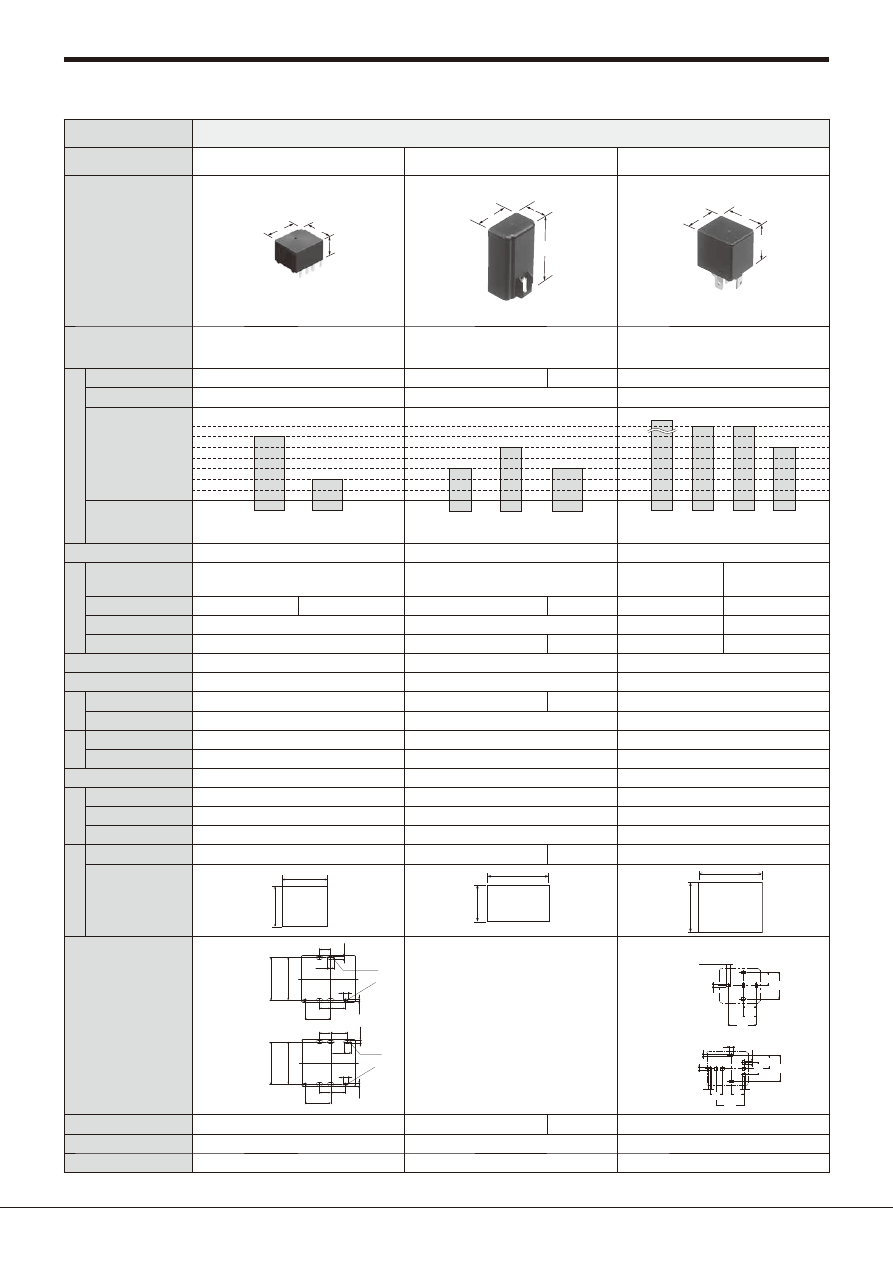
Product name
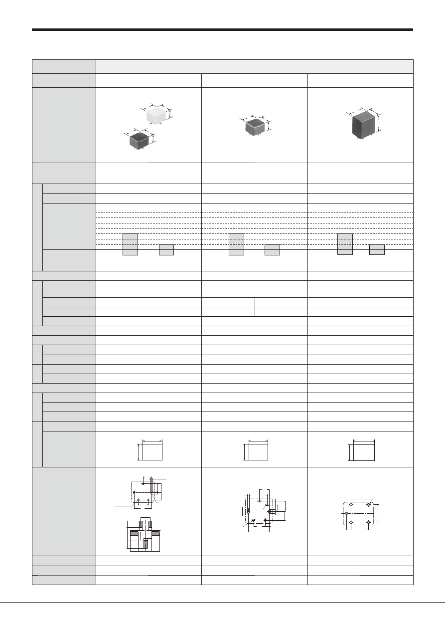
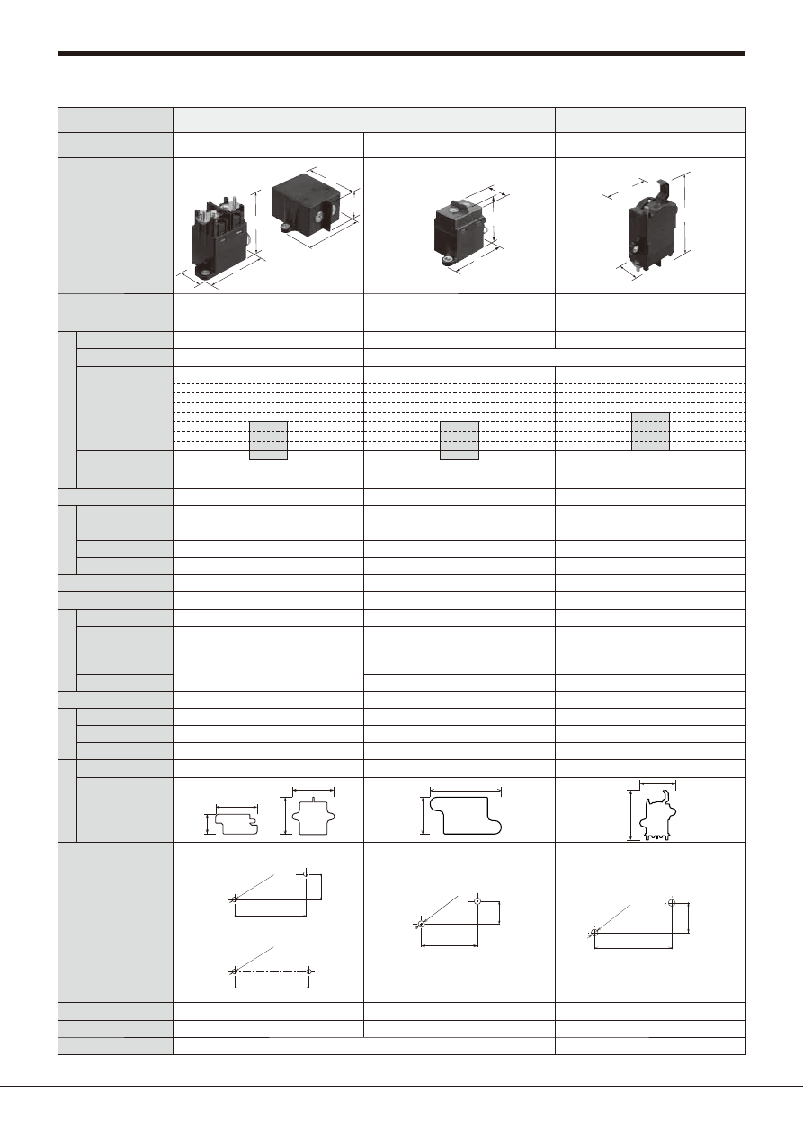
TM RELAYS
CA RELAYS
CB RELAYS
Appearance
configuration
(Standoff height included,
Unit: mm
inch
)
Part No.
ACTM
16.8
19.2
13.6
.661
.756
.535
ACA
21.5
.846
14.4
37
.567
1.457
ACB
26
22
25
1.024
.866
.984
Features
High Capacity Relay for Smart Junction
Box
Small Size, Light Weight Automotive Power
Relays
Mini-ISO Automotive Relay
Con
tact
data
Contact arrangement
1 Form A and 1 Form C
1 Form A and 1 Form B
1 Form C
1 Form A and 1 Form C
Contact material
Ag alloy
Ag alloy
Ag alloy
Rated
switching
capacity
(resistive)
1A 14V DC
35A 14V DC
N.O.
15A 14V DC
N.C.
1A 14V DC
30A 12V DC
(1.8 W type)
20A 12V DC
(1.4 W type)
20A 12V DC
1b,1c
1a
1a
30A 14V DC
1c
N.C.
40A 14V DC
1c
N.O.
40A 14V DC
1a
70A 14V DC
High
contact
capacity
1a
1A 14V DC
Min. switching load
(resistive)
Latching type
−
−
−
Coi
l data
Rated coil voltage
12V DC
12, 24V DC
12V DC
24V DC
Rated operating power
450mW
360mW
1.4W/1.8W
1.8W
Standard: 1.4 W
1 Form A High contact capacity: 1.8 W
1.8W
Operate (Set) voltage at 20°C
68°F
(initial)
Max. 7.0V DC
12V DC: Max. 8.0V DC
24V DC: Max. 16V DC
3.0 to 7.0V DC
6.0 to 14V DC
Release (Reset) voltage at 20°C
68°F
(initial)
Min. 0.5V DC
12V DC: 0.6 to 6.0V DC
24V DC: 1.2 to 12V DC
12V: Min. 0.6V DC
24V: Min. 1.2V DC
1.2 to 4.2V DC
2.4 to 8.4V DC
Operate (Set) time (Rated voltage at 20°C
68°F
)
Max. 10ms (without bounce time)
Max. 10ms (without bounce time)
Max. 15ms (without bounce time)
Release (Reset) time (Rated voltage at 20°C
68°F
) Max. 10ms (without bounce time) (without diode) Max. 10ms (without bounce time) (without diode) Max. 15ms (without bounce time) (without diode)
Ex
pe
ct
ed
lif
e
Mechanical
Min. 5 x 10
6
Min. 10
6
Min. 5 × 10
5
Min. 10
6
Electrical
Min. 10
5
Min. 10
5
1 Form A 1.8 W type: 2 × 10
4
(at 30 A)
Min. 10
5
(Sealed: Min. 5×10
4
)
Diel
ect
ric st
ren
gth
Between open contacts (initial)
500 Vrms for 1 min.
500 Vrms for 1 min.
500 Vrms for 1 min.
Between contacts and coil (initial)
500 Vrms for 1 min.
500 Vrms for 1 min.
500 Vrms for 1 min.
Ambient temperature
–40 to +110°C
–40 to +230°F
–30 to +80°C
–22 to +176°F
Standard: –40 to +85°C
–40 to +185°F
Heat resistant: –40 to +125°C
–40 to +257°F
Prot
ec
tiv
e c
on
str
uc
tio
n
Dust cover
−
●
−
Flux tight
−
−
●
Sealed
●
●
●
E
xt
e
rnal
d
imensions
Height (mm
inch
)
Included standoff
13.6
.535
37
1.457
40
1.575
PC board type: 26
1.024
, Plug-in type: 25
.984
Bracket type: 41
1.614
Foot print (mm
inch
)
19.2
.756
16.8
.661
14.4
.567
21.5
.846
1c: 31.2×19.4
1.228×.764
22
.866
26
1.024
PC board pattern
1 Form A type
1 Form C type
(Coil-N/0 terminal
between centers)
(COM-N/0 terminal
between centers)
.602
.606
15.3
15.4
2×R0.45
2×R.018
2×R0.6
2×R.024
4
.157
4
5.3
.157 .209
9.3
.366
1.2
.047
0.9
.035
2.6
.102
.067
1.7
(Coil-N/0 terminal
between centers)
(COM-N/0 terminal
between centers)
.602
.606
15.3
15.4
2×R0.45
2×R.018
2×R0.6
2×R.024
4
.157
6
.236
4
5.3
.157 .209
9.3
.366
1.2
.047
0.9
.035
2.6
.102
.067
1.7
−
1 Form A High contact capacity
1 Form C
Mini ISO
4(or5)×2.6
30
87a
87
85
86
8.4
16.8
4(or5)×1.4
17.9
8.4
8.0
.331
.661
.705
.331
.315
4(or5)×.102
4(or5)×.055
30
87
85
86
2.6
1.4
3×1.8
3×1.8
3×2.15
3×2.15
16.8
8.4
7.8
8.4
17.9
7.8
.102
.055
3×.071
3×.071
3×.085
3×.085
.661
.331
.307
.331
.705
.307
Weight (approx.)
11.6 g
.41 oz
Rubber bracket A type: 23 g
.81 oz
,
Screw-mounting type: 19 g
.67 oz
31 g
1.09 oz
33 g
1.16 oz
Remarks
−
Rubber bracket type and screw-mounting type available PC board type and bracket type available
Page
145
150
157
40A−
35A−
30A−
25A−
20A−
15A−
10A−
automotive-relay_en-html.html
Automotive Relays Selector Chart
Panasonic Corporation 2017
©
Panasonic Corporation Electromechanical Control Business Division
industrial.panasonic.com/ac/e/
ASCTB283E 201709-T
–15–
Type
Automotive relays
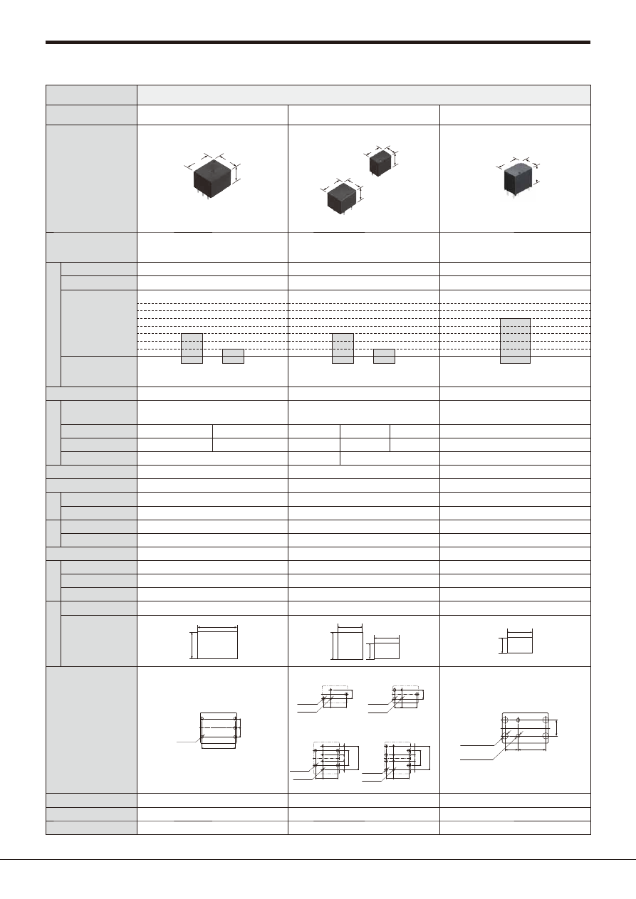
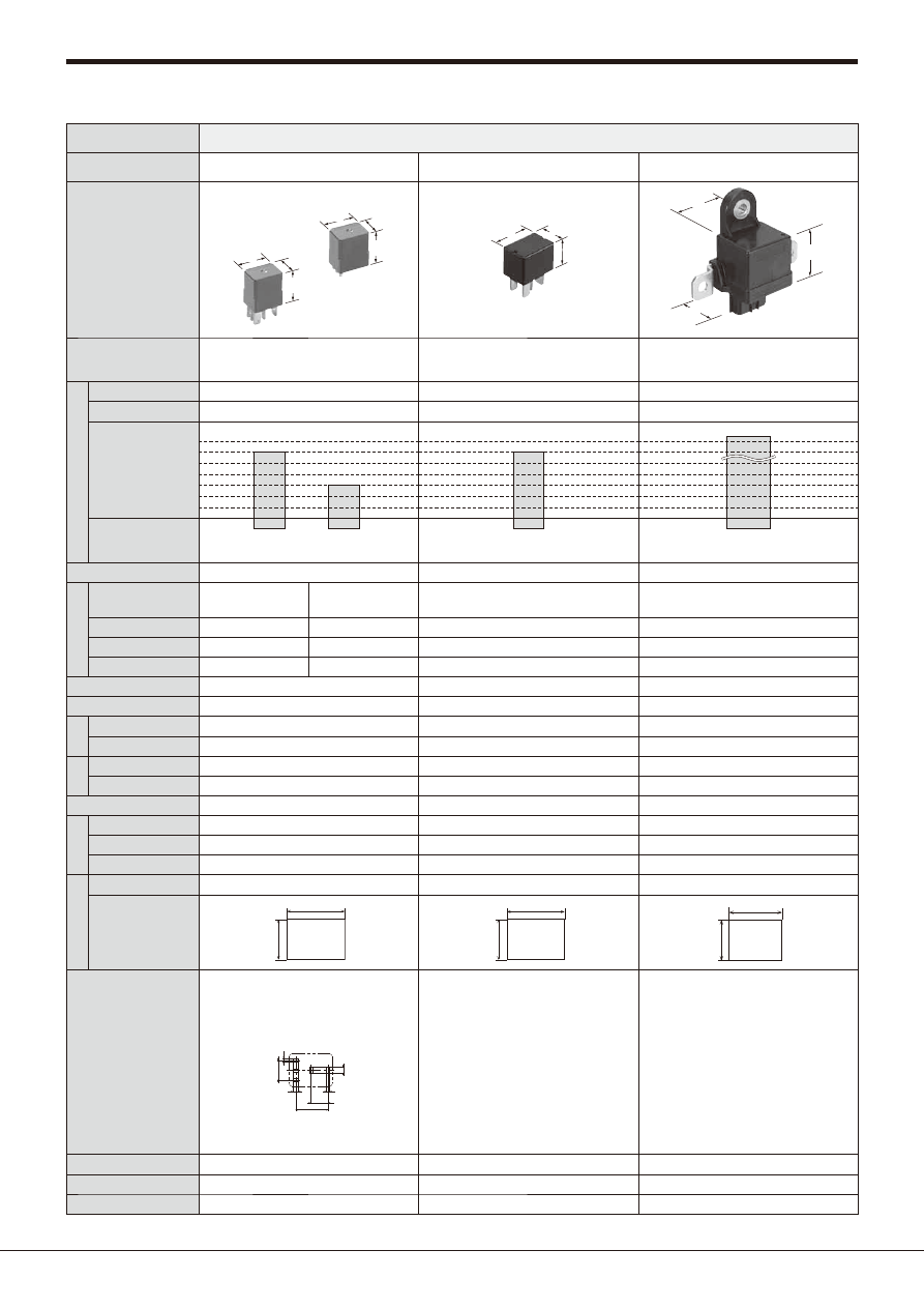
Product name
CM RELAYS
CV-N RELAYS
CN-L RELAYS
Appearance
configuration
(Standoff height included,
Unit: mm
inch
)
Part No.
Micro ISO (Plug-in)
Micro ISO (PC board)
*(24V only)
ACM
15
20
22
.591
.787
.866
15
20
23
.591
.787
.906
Micro ISO
ACVN
15
22.5
15.7
.591
.886
.618
ACNL
38.5
48
37
1.516
1.890
1.457
Features
Micro-ISO Automotive Relay
Low Profile Micro-ISO Automotive Relay
Max. 150 A Continuous Carrying
Current Latching Relay
Con
tact
data
Contact arrangement
1 Form A and 1 Form C
1 Form A
1 Form A
Contact material
Ag alloy
Ag alloy
Ag alloy
Rated
switching
capacity
(resistive)
1A 14V DC
For rated coil voltage 12 V DC type
35A 14V DC
N.O.
20A 14V DC
N.C.
1A 14V DC
35A 14V DC
N.O.
1A 14V DC
150A 14V DC
Min. switching load
(resistive)
Latching type
−
−
●
Coi
l data
Rated coil voltage
12V DC
24V DC
12V DC
12V DC
Rated operating power
1.5W
1.8W
800mW
30W
Operate (Set) voltage at 20°C
68°F
(initial)
3.0 to 7.0V DC
6.0 to 14V DC
Max. 7.0V DC
Max. 7.0V DC
Release (Reset) voltage at 20°C
68°F
(initial)
1.2 to 4.2V DC
2.4 to 8.4V DC
Min. 0.5V DC
Max. 7.0V DC
Operate (Set) time (Rated voltage at 20°C
68°F
)
Max. 10ms (without bounce time)
Max. 10ms (without bounce time)
Max. 10ms (without bounce time)
Release (Reset) time (Rated voltage at 20°C
68°F
) Max. 10ms (without bounce time) (without diode) Max. 10ms (without bounce time) (without diode) Max. 10ms (without bounce time) (without diode)
Ex
pe
ct
ed
lif
e
Mechanical
Min. 10
6
(at 120 cpm)
Min. 10
6
(at 120 cpm)
Min. 3 x 10
5
Electrical
Min. 10
5
(resistive)
(Sealed: Min. 5 × 10
4
)
Min. 10
5
(resistive)
Min. 3 x 10
4
Diel
ect
ric st
ren
gth
Between open contacts (initial)
500 Vrms for 1 min.
500 Vrms for 1 min.
500 Vrms for 1 min.
Between contacts and coil (initial)
500 Vrms for 1 min.
500 Vrms for 1 min.
500 Vrms for 1 min.
Ambient temperature
–40 to +85°C
–40 to +185°F
–40 to +85°C
–40 to +185°F
–40 to +125°C
–40 to +257°F
Prot
ec
tiv
e c
on
str
uc
tio
n
Dust cover
−
−
−
Flux tight
●
−
−
Sealed
●
●
●
E
xt
e
rnal
d
imensions
Height (mm
inch
)
Included standoff
PC board type: 23
.906
, Plug-in type: 22
.866
15.7
.618
38.5
1.516
Foot print (mm
inch
)
15
.591
20
.787
15
.591
22.5
.886
48
1.890
38.5
1.516
PC board pattern
Micro-ISO (24V only)
9.0
r
0.05
.354
r
.002
2×1.4
+0.1
0
2×.055
+.004
0
2×2.7
+0.1
0
2×.106
+.004
0
2 (or 3)×1.4
+0.1
0
2 (or 3)×.055
+.004
0
2 (or 3)×2.4
+0.1
0
2 (or 3)×.094
+.004
0
15.0
r
0.05
.591
r
.002
8.0
r
0.05
.315
r
.002
−
−
Weight (approx.)
20 g
.71 oz
12 g
.42 oz
150 g
5.29 oz
Remarks
−
−
−
Page
165
170
174
40A−
35A−
30A−
25A−
20A−
15A−
10A−
automotive-relay_en-html.html
Automotive Relays Selector Chart
Panasonic Corporation 2017
©
Panasonic Corporation Electromechanical Control Business Division
industrial.panasonic.com/ac/e/
ASCTB283E 201709-T
–16–
Type
Automotive relays
Product name
EC-N RELAYS
Appearance
configuration
(Standoff height included,
Unit: mm
inch
)
Part No.
AECN
25
29
28.9
.984
1.142
1.138
Features
Small, High capacity, High voltage DC
Plug in Relay
Con
tact
data
Contact arrangement
1 Form A
Contact material
Ag alloy
Rated
switching
capacity
(resistive)
1A 12V DC
15A 400V DC
Min. switching load
(resistive)
Latching type
−
Coi
l data
Rated coil voltage
12V DC
Rated operating power
1.4
W
Operate (Set) voltage at 20°C
68°F
(initial)
Max. 6.8V DC
Release (Reset) voltage at 20°C
68°F
(initial)
Min. 0.5V DC
Operate (Set) time (Rated voltage at 20°C
68°F
)
Max. 50ms (without bounce time)
Release (Reset) time (Rated voltage at 20°C
68°F
) Max. 30ms (without bounce time) (without diode)
Ex
pe
ct
ed
lif
e
Mechanical
Min. 2 x 10
5
Electrical
15A 400V DC, Min. 100,000 cycles (inrush)
Diel
ect
ric st
ren
gth
Between open contacts (initial)
2,500 Vrms for 1 min.
Between contacts and coil (initial)
2,500 Vrms for 1 min.
Ambient temperature
–40 to +85°C
–40 to +185°F
Prot
ec
tiv
e c
on
str
uc
tio
n
Dust cover
−
Flux tight
−
Sealed
●
E
xt
e
rnal
d
imensions
Height (mm
inch
)
Included standoff
28.9
1.138
Foot print (mm
inch
)
25
.984
29
1.142
PC board pattern
−
Weight (approx.)
40 g
1.41 oz
Remarks
−
Page
178
40A−
35A−
30A−
25A−
20A−
15A−
10A−
automotive-relay_en-html.html
Automotive Relays Selector Chart
Panasonic Corporation 2017
©
Panasonic Corporation Electromechanical Control Business Division
industrial.panasonic.com/ac/e/
ASCTB283E 201709-T
–17–
Type
Automotive relays
Product name
EV RELAYS
Appearance
configuration
(Standoff height included,
Unit: mm
inch
)
Part No.
37.9
1.492
10A
80A
40
1.575
300A
120A
40
1.575
20A
40
40
1.575
1.575
AEV
200A
63
63
2.480
2.480
45
45
1.772
1.772
111
111
4.370
4.370
66.8
66.8
2.630
2.630
49.7
49.7
1.957
1.957
48.1
48.1
1.894
1.894
78
78
3.071
3.071
75.5
75.5
2.972
2.972
79
79
3.110
3.110
80
80
3.150
3.150
75.5
75.5
2.972
2.972
86.4
86.4
3.402
3.402
95
95
3.740
3.740
74.7
74.7
2.941
2.941
Features
Compact and High voltage High capacity DC Cut-off Relays using Capsule Contact Mechanism
Con
tact
data
Contact arrangement
1 Form A
Contact material
Molybdenum
Copper alloy
Tungsten and copper
alloy
Copper alloy
Rated
switching
capacity
(resistive)
10A 450V DC
1A 12V DC
20A 400V DC
1A 12V DC
80A 450V DC
1A 12V DC
120A 450V DC
1A 12V DC
1A 12V DC
200A 450V DC
1A 24V DC
300A 450V DC
Min. switching load
(resistive)
Latching type
−
Coi
l data
Rated coil voltage
12, 24V DC
(Please inquire our sales representative for more information about EV20A with nominal coil voltage of 24V DC.)
Rated operating power
1.24W
3.9W
4.2W
4.2W
6.0W
12V: 37.9 W (Inrush), 3.6 W (Stable)
24V: 44.4 W (Inrush), 3.8 W (Stable)
Operate (Set) voltage at 20°C
68°F
(initial)
12V: Max. 9V DC, 24V: Max. 18V DC
Release (Reset) voltage at 20°C
68°F
(initial)
12V: Min. 1.0V DC
24V: Min. 2.0V DC
12V: Min. 0.5V DC
12V: Min. 1.0V DC, 24V: Min. 2.0V DC
12V: Min. 2.0V DC
24V: Min. 4.0V DC
Operate (Set) time (Rated voltage at 20°C
68°F
)
Max. 50ms (without bounce time)
Max. 30ms (without bounce time)
Release (Reset) time (Rated voltage at 20°C
68°F
)
Max. 30ms
Max. 10ms
Ex
pe
ct
ed
lif
e
Mechanical
Min. 10
5
Min. 2 x 10
5
Electrical
10A 450V DC, Min. 30,000
cycles (resistive)
20A 400V DC, Min. 3,000
cycles (resistive)
80A 450V DC, Min. 1,000
cycles (resistive)
30A 450V DC, Min. 1,000
cycles (resistive)
200A 450V DC, Min. 3,000
cycles (resistive)
300A 450V DC, Min. 1,000
cycles (resistive)
Diel
ect
ric st
ren
gth
Between open contacts (initial)
2,500 Vrms for 1 min.
Between contacts and coil (initial)
2,500 Vrms for 1 min.
Ambient temperature
–40 to +80°C
–40 to +176°F
–40 to +85°C
–40 to +185°F
Prot
ec
tiv
e c
on
str
uc
tio
n
Dust cover
−
Flux tight
−
Sealed
●
(Power capsule)
E
xt
e
rnal
d
imensions
Height (mm
inch
)
Included standoff
49.7
1.957
48.1
1.894
79
3.110
80
3.150
86.4
3.402
74.7
2.941
Foot print (mm
inch
)
31.6
1.244
66.8
2.630
40
1.575
78
3.071
40
1.575
75.5
2.972
40
1.575
75.5
2.972
45
1.772
95
3.740
60
2.362
92
3.622
Mounting dimensions
Mounting hole
2×4.2
r
0.1 dia.
2×.165
r
.004 dia.
55.9
r
0.1
2.201
r
.004
Mounting hole
2×6.0
r
0.2 dia.
2×.236
r
.008 dia.
64.0
r
0.2
2.520
r
.008
Mounting hole
2×6.0
r
0.2 dia.
2×.236
r
.008 dia.
63.5
r
0.2
2.500
r
.008
26.0
r
0.2
1.024
r
.008
Mounting hole
2×6.0
r
0.2 dia.
2×.236
r
.008 dia.
63.5
r
0.2
2.500
r
.008
26.0
r
0.2
1.024
r
.008
Mounting hole
2×6.0
r
0.2 dia.
2×.236
r
.008 dia.
82
r
0.2
3.228
r
.008
31
r
0.2
1.220
r
.008
Mounting hole
3×6.0
r
0.2 dia.
3×.236
r
.008 dia.
79.0
r
0.2
3.110
r
.008
47.0
r
0.2
1.850
r
.008
Weight (approx.)
90 g
3.17 oz
180 g
6.35 oz
400 g
14.11 oz
400 g
14.11 oz
600 g
21.16 oz
750 g
26.46 oz
Remarks
−
−
−
−
−
−
Page
183
200A−
120A−
100A−
80A−
60A−
20A−
10A−
automotive-relay_en-html.html
Automotive Relays Selector Chart
Panasonic Corporation 2017
©
Panasonic Corporation Electromechanical Control Business Division
industrial.panasonic.com/ac/e/
ASCTB283E 201709-T
–18–
Type
Automotive relays
Automotive safety switches
Product name
EV RELAYS Quiet Type
EV Relay Compact High Short-circuit Capacity Type
EV SWITCHES
Appearance
configuration
(Standoff height included,
Unit: mm
inch
)
Part No.
AEVS
67.8
67.8
36
36
76
76
2.669
2.669
1.417
1.417
2.992
2.992
72.3
72.3
2.846
2.846
37.7
37.7
1.484
1.484
77
77
3.031
3.031
AEVG
64
64
52.8
52.8
2.520
2.520
2.079
2.079
33
1.299
AEVD
82.3
114.3
3.240
34.6
1.362
4.500
Features
Unique Silencing Technology and
Low Operation Noise
Compact and Short Circuit Capacity 4.5kA
High voltage DC Cut-off Switches
using Capsule Contact Mechanism
Con
tact
data
Contact arrangement
1 Form A
1 Form A
1 Form A
Contact material
Tungsten and copper alloy
Copper alloy
Rated
switching
capacity
(resistive)
1A 12V DC
60A 450V DC
60A 450V DC
1A 12V DC
80A 400V DC
Min. switching load
(resistive)
Latching type
−
−
−
Coi
l data
Rated coil voltage
12V DC
12V DC
−
Rated operating power
4.5W
5.2W
−
Operate (Set) voltage at 20°C
68°F
(initial)
Max. 9.0V DC
Max. 9.0V DC
−
Release (Reset) voltage at 20°C
68°F
(initial)
Min. 1.0V DC
Min. 0.5V DC
−
Operate (Set) time (Rated voltage at 20°C
68°F
)
Max. 50ms (without bounce time)
Max. 50ms (without bounce time)
−
Release (Reset) time (Rated voltage at 20°C
68°F
)
Max. 50ms
Max. 30ms
−
Ex
p
ec
te
d l
ife Mechanical
Min. 2 × 10
5
Min. 2 × 10
5
Min. 100
Electrical
60A 450V DC, Min. 800 cycles
(resistive)
30A 450V DC (Inrush resistance),
Min. 70,000 cycles
400A 400V DC, 5 times cut-off (L/R
≦
1ms)
Diel
ect
ric st
ren
gth
Between open contacts (initial)
Vertical type: 2,500 Vrms for 1 min.
Horizontal type: 2,000 Vrms for 1 min.
2,500 Vrms for 1 min.
2,500 Vrms for 1 min. (Between contacts and lever surface)
Between contacts and coil (initial)
2,500 Vrms for 1 min.
−
Ambient temperature
–40 to +80°C
–40 to +176°F
–40 to +80°C
–40 to +176°F
–40 to +80°C
–40 to +176°F
Prot
ec
tiv
e c
on
str
uc
tio
n
Dust cover
−
−
−
Flux tight
−
−
−
Sealed
●
(Power capsule)
●
(Power capsule)
●
(Power capsule)
E
xt
e
rnal
d
imensions
Height (mm
inch
)
Included standoff
Vertical type: 72.3
2.846
Horizontal type: 37.7
1.484
52.8
2.079
34.6
1.362
Foot print (mm
inch
)
76
36
77
2.992
3.031
67.8
1.417
2.669
33
1.299
64
2.520
114.3
4.500
82.3
3.240
Mounting dimensions
Vertical type
Horizontal type
Mounting hole
2×6.0
r
0.2 dia.
2×.236
r
.008 dia.
62.0
r
0.2
2.441
r
.008
22.0
r
0.2
.866
r
.008
Mounting hole
2×6.0
r
0.2 dia.
2×.236
r
.008 dia.
65.0
r
0.2
2.559
r
.008
Mounting hole
2×6.0
r
0.2 dia.
2×.236
r
.008 dia.
52.0
r
0.2
2.047
r
.008
21.0
r
0.2
.827
r
.008
67.3
r
0.2
2.650
r
.008
26
r
0.2
1.024
r
.008
Mounting hole
2×6.0
r
0.2 dia.
2×.236
r
.008 dia.
Weight (approx.)
Vertical type: 250 g
8.82 oz
Horizontal type: 240 g
8.47 oz
165 g
5.82 oz
230 g
8.11 oz
Remarks
−
−
−
Page
183
201
200A−
120A−
100A−
80A−
60A−
20A−
10A−
automotive-relay_en-html.html
Configuration and Construction
–19–
ASCTB300E 201709-T
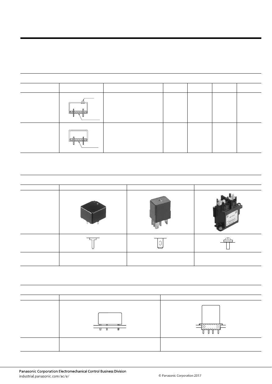
PROTECTIVE CONSTRUCTION
CONSTRUCTION AND CHARACTERISTIC
(
: Yes,
: No,
: Care)
*Since the plastic breathes, please do not use in an atmosphere that contains silicon.
TERMINAL CONFIGURATION
MOUNTING METHOD
Configuration and Construction
Type
Construction
Characteristics
Automatic
Soldering
Automatic
Cleaning
Dust
Resistance
Harmful Gas
Resistance
Flux-Tight
Terminals, case, and base are filled
with sealing resin.
Sealed
Sealed construction with terminals,
case and base sealed shut with
sealing resin.
*
Type
PC board through hole terminal
Plug-in terminal
Screw terminal
Typical relay
Terminal
configuration
Typical relay type
CP relay,
CN-H relay,
TB relay
CM relay,
CB relay,
CV-N relay
EV relay
Type
Insertion mount
Socket mount
Mounting
method
Typical relay type
CP relay,
CN-H relay,
TB relay
CM relay,
CB relay,
CV-N relay
1. Flux-Tight
The relay is constructed so that flux will not enter inside the relay
during automatic soldering. However, cleaning is not possible.
2. Sealed
Construction is designed to prevent seeping of flux when
soldering and cleaning fluid when cleaning.
Sealing resin
Air hole
Sealing resin
Socket
automotive-relay_en-html.html
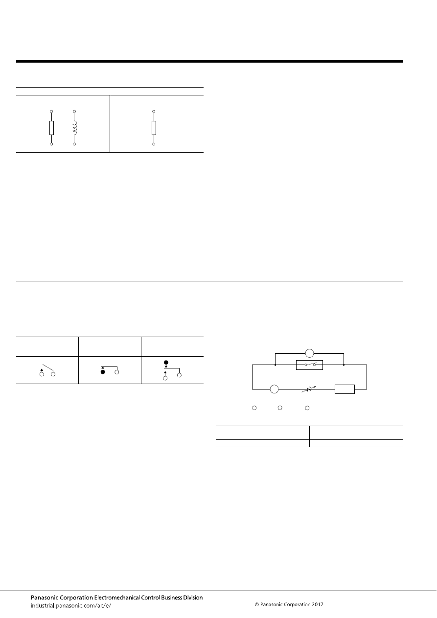
Definition of Relay Terminology
–20–
ASCTB301E 201709-T
COIL
(also referred to as primary or input)
CONTACTS
(secondary or output)
Definition of Relay Terminology
1. Coil Designation
2. Rated Coil Voltage
The voltage applied to the operating coil during normal use of
the relay. The expected life and other guaranteed values are
based on the rated coil voltage.
3. Rated Operating Current
The value of current flow in the coil when rated voltage is applied
on the coil
4. Rated Operating Power
The value of power used by the coil at rated voltage.
(Rated Operating Power = Rated Coil Voltage
×
Rated Operating
Current.)
5. Coil Resistance
This is the DC resistance of the coil in DC type relays for the
temperature conditions listed in the catalog. (Note that for
certain types of relays, the DC resistance may be for
temperatures other than the standard 20
°
C
68
°
F
.)
6. Operate (Set) Voltage
As the voltage on an unoperated relay is increased, the value
which all contacts must function.
7. Release (Reset) Voltage
As the voltage on an operated relay is decreased, the value
which all contacts must revert to their unoperated position. In the
catalog, operate voltage and release voltage values are usually
indicated for when the temperature condition is 20
°
C
68
°
F
,
however, for some relays, the values are indicated for when the
temperature condition is 25
°
C
77
°
F
.
8. Maximum Applied Voltage
The maximum voltage within the allowable range that can be
applied to the operating coil. Continuous operation at this
maximum value, however, is not allowable. Since the value
depends on the ambient temperature, for each type, please
check the value listed in the catalog.
Single side stable type
Non-polarized
Polarized
or
+
—
1. Contact Arrangement
Denotes the contact mechanism and number of contacts in the
contact circuit.
2. Contact Symbols
Form A contacts are also called N.O. contacts or make contacts.
Form B contacts are also called N.C. contacts or break contacts.
Form C contacts are also called transfer contacts.
3. Rated Switching Capacity
Derived from the contact voltage and contact current, this is the
reference value that determines the performance of the
switching section.
4. Maximum Carrying Current
The maximum value for carrying current through the contact
section. It is necessary to pay attention to carrying conditions
during use.
5. Continuous Carrying Current
The current that, when the contact is closed, without raising
beyond the specified limits the temperature of the relay contact
and all other parts, can continuously carrying the contact
section.
6. Contact Resistance
This value is the combined resistance of the resistance when the
contacts are touching each other, the resistance of the terminals
and contact spring. The contact resistance is measured using
the voltage-drop method as shown below. The measuring
currents are designated.
Test Currents
In general, for relays with a contact rating of 1A or more,
measure using the voltage-drop method at 1A 6V DC.
Form A contacts
(normally open contacts)
Form B contacts
(normally closed
contacts)
Form C contacts
(changeover contacts)
Rated Contact Current or
Switching Current (A)
Test Current (mA)
1 or more
1,000
A
V
R
Ammeter
A :
V :
Voltmeter
R :
Variable resister
(AC or DC)
Power
source
Measured contact
automotive-relay_en-html.html
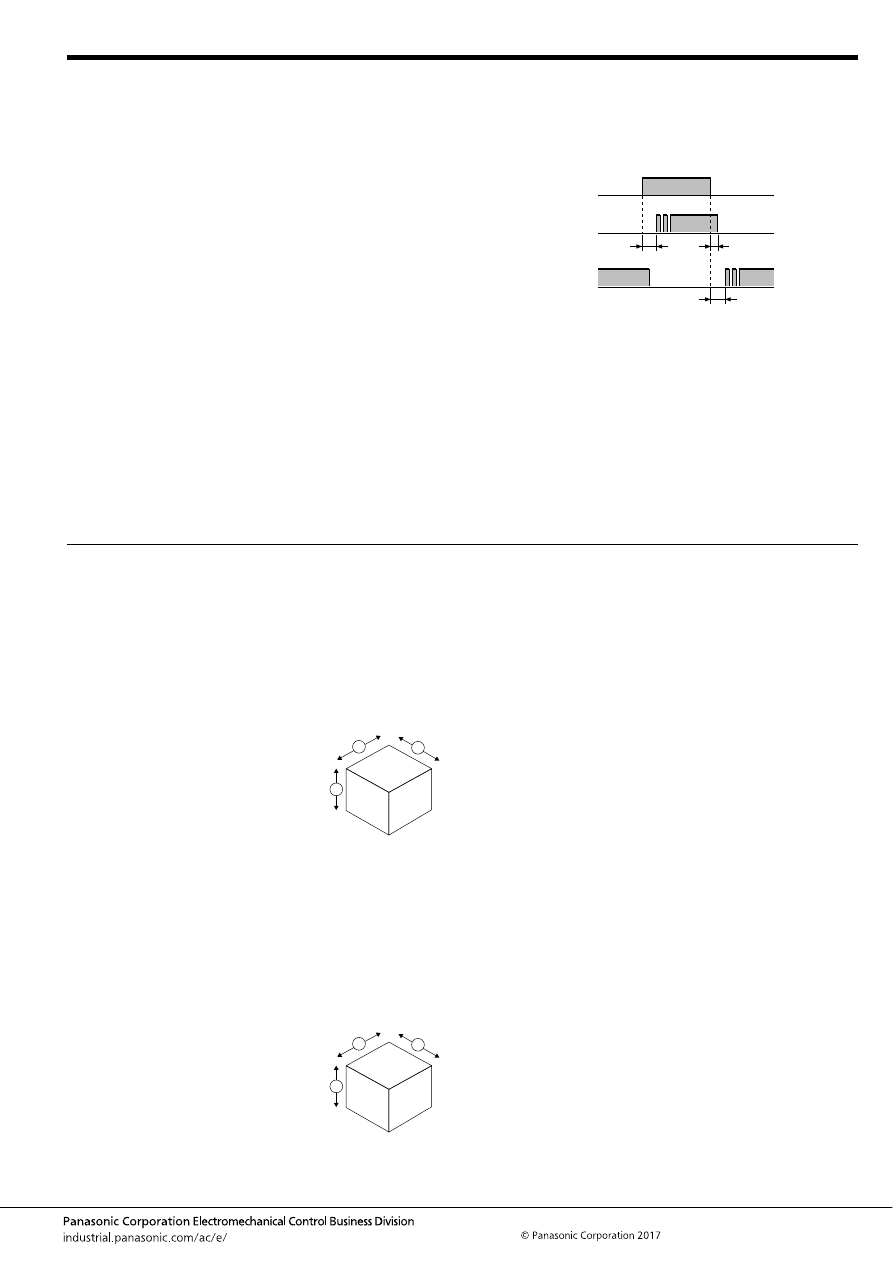
Definition of Relay Terminology
–21–
ASCTB301E 201709-T
ELECTRICAL PERFORMANCE
MECHANICAL PERFORMANCE AND LIFE
1. Insulation Resistance
The resistance value between all mutually isolated conducting
sections of the relay, i.e. between coil and contacts, across open
contacts and between coil or contacts to any core or frame at
ground potential. This value is for the relay alone, and does not
take into consideration the solder land on the PC board or other
factors.
(1) Between contact and coil: between all contact terminals and
coil terminals
(2) Between open contacts: between open contact terminals
(3) Between contact sets: between contact sets terminals
2. Dielectric Strength
When a high voltage is applied for 1 minute at the same points
where insulated resistance is measured, the limit value for non-
occurrence of dielectric breakdown. Leakage current is usually
set at 10 mA. In special cases, however, it may be set at 1 mA or
3 mA.
3. Operate (Set) Time
The elapsed time from the initial application of power to the coil,
until the closure of the Form A (normally open) contacts. This
time does not include any bounce time.
4. Release (Reset) Time
The elapsed time from the initial removal of coil power until the
reclosure of the Form B (normally closed) contacts. This time
does not include any bounce time. Or, for relays with only
Form A contact (1 Form A, 2 Form A), the time taken until the
contact opens.
5. Contact Bounce (Time)
Generally expressed in time (ms), this refers to the intermittent
switching phenomenon of the contacts which occurs due to the
collision between the movable metal parts or contacts, when the
relay is operated or released.
Release time
Operate time
ON
ON
OFF
OFF
OFF
ON
Relay release
time for Form
A contact only
Form A
contact
Form B
contact
Coil
1. Shock Resistance
Shock resistance is categorized as either functional shock or
destructive shock, which are defined below.
1) Functional
The shock which can be tolerated by the relay during operation,
without causing the closed contacts to open for more than the
specified time. The contact opening time itself is specified as 10
μ
s or less.
2) Destructive
The shock which can be withstood by the
relay during shipping, installation or use
without it suffering damage, and without
causing a change in its operating
characteristics.
Testing is carried out with shock forces
applied along each of the three axial
directions.
2. Vibration Resistance
Vibration resistance is categorized as either functional vibration
or destructive vibration, which are defined below.
1) Functional
The vibration which can be tolerated by the relay during service,
without causing the closed contacts to open for more than the
specified time. Here, the contact opening time value, is the same
as for functional shock.
2) Destructive
The vibration which can be withstood by
the relay during shipping, installation or
use without it suffering damage, and
without causing a change in its operating
characteristics. Testing is carried out with
vibratory forces applied along each of
the three axial directions.
3. Mechanical Life
The number of times the relay can be operated under nominal
conditions with no load on the contacts.
4. Electrical Life
The number of times the relay can be operated under nominal
conditions with a specific load being switched by the contacts.
5. Maximum Switching Frequency
This refers to the maximum switching frequency which satisfies
the mechanical life or electrical life under repeated operations by
applying a pulse train at the rated voltage to the operating coil.
Notes:
1. Except where otherwise specified, the tests above are
conducted under JIS standard temperature and humidity
(15
°
C to 35
°
C
59
°
F to 95
°
F
, 25 to 85%).
2. The coil applied voltage in the switching tests is a rectangular
wave at the rated voltage.
2
1
3
2
1
3
automotive-relay_en-html.html

Cautions for Use
–22–
ASCTB302E 201709-T
Cautions for Use
1. Before using relays under any operating condition other
than those listed in the catalog, please inquire our sales
representative. After checking the specifications requested
by your company, we will check the operating conditions in
an actural environment as required.
2. Before using relays, please check “Automotive Relays
Users Guide”.
3. Switching life data are based on the standard testing
condition (temperature 15
°
C to 35
°
C
59
°
F to 95
°
F
, humidity
25%RH to 85%RH) specified by JIS C 5442. Switching life
varies by coil drive circuit, load type, ambient environment,
etc. Please check performance using an actual presumptive
operating environment, or inquire our sales representative.
4. Dropping a relay could cause a functional disorder. Do
not use a relay that has been dropped.
5. Coil drive current must be pure DC current, as a rule. If
the current includes ripples, the ripple factor should be less
than 5%. However, check it with an actual circuit since the
characteristics may differ slightly. Power waveform must be
rectangular, as a rule.
6. The case is designed not to be removed in normal
handling. Do not remove the case for product performance
maintenance.
7. Relays generate failures with certain probability.
Durability also varies by operating environment and
condition. When using relays, always check performance
with an actual circuit and operating environment. Continued
operation with deteriorated performance could generate
abnormal heat, smoke, or fire due to deteriorated insulation.
In order to avoid human accident, fire accident or public
harm as a result of a product failure or end-of-life
performance, appropriate safety designs such as redundant
design, fire spread prevention design and malfunction
prevention design must be implemented together with
scheduled maintenance.
8. Use of relays in normal temperature and humidity
conditions with less dust and organic gas is recommended.
Use of silicone-based resin around a relay must be
absolutely avoided. For more details, please refer to
“Automotive Relays Users Guide”.
automotive-relay_en-html.html
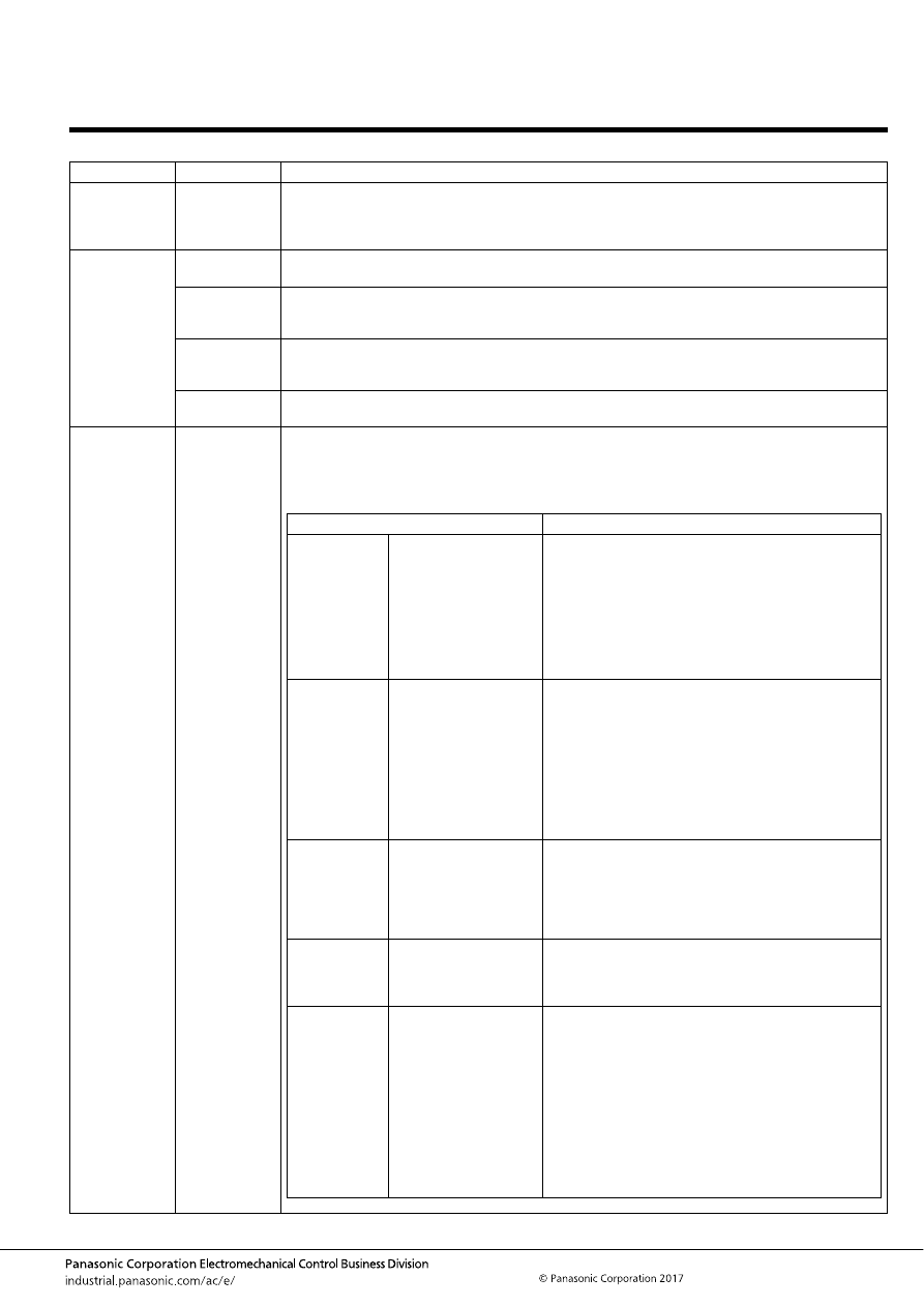
Automotive Relay Users Guide
–23–
ASCTB237E 201709-T
Please use the check sheet.
Automotive Relay Users Guide
Category
Section
Contents
1. Confirmation
under the
actual use
condition
1. Confirmation
under the
actual use
The rated switching power and life mentioned in the specification and catalog are given only as guides.
A relay may encounter a variety of ambient conditions during actual use resulting in unexpected failure.
Therefore, it is necessary for proper use of the relay to test and review with actual load and actual
application under actual operating conditions.
2. Safety
precautions
1. Specification
range
Use that exceeds the specification ranges such as the coil rating, contact rating and expected life
should be absolutely avoided. Doing so may lead to abnormal heating, smoke, and fire.
2. Installation,
maintenance
Never touch energized parts when power is applied to the relay. Doing so may cause electrical shock.
When installing, maintaining, or troubleshooting a relay (including connecting parts such as terminals
and sockets), be sure that the power is turned off.
3. Connection
When connecting terminals, please follow the internal connection diagrams in the catalog to ensure
that connections are done correctly. Be warned that an incorrect connection may lead to unexpected
operation error, abnormal heating, and fire.
4. Fail-safe
If there is a possibility that adhesion, contact failure, or breaking of wire could endanger assets or
human life, please make sure that a fail-safe system is equipped in the vehicle.
3. Selection of
relay type
1. Selection
In order to use the relays properly, the characteristics of the selected relay should be well known, and
the conditions of use of the relay should be investigated to determine whether they are matched to the
environmental conditions, and at the same time, the coil specification, contact specification, and the
ambient conditions for the relay that is actually used must be fully understood in advance.
In the table below, please refer to the consideration points regarding selection of relay.
Items
Consideration points regarding selection
Coil
a ) Rating
b ) Operate voltage
(current)
c ) Release voltage
(current)
d ) Maximum applied
voltage (current)
e ) Coil resistance
f ) Temperature rise
- Select relay with consideration for power source
voltage.
- Give sufficient consideration to ambient temperature
and for the coil temperature rise, and hot start.
- When driving the relay with semiconductors, careful
with the voltage drop.
- When starting up, careful with the voltage drop.
Contact
a ) Contact arrangement
b ) Contact rating
c ) Contact material
d ) Expected life
e ) Contact resistance
- Note that the relay expected life is balanced with the
life of the device the relay is used in.
- Is the contact material matched to the type of load? It
is necessary to take care particularly with low level
usage.
- The expected life may become reduced when used at
high temperatures. Life should be verified in the actual
use atmosphere.
- It is necessary to be tested and reviewed under actual
use conditions with actual load and actual application.
Operate time
a ) Operate time
b ) Release time
c ) Bounce time
d ) Switching frequency
- Note that ambient temperature and applied voltage
cause the change of operate time and bounce time.
- Note that operate time and release time do not include
bounce time.
- Give consideration that expected life changes
depending on switching frequency.
Mechanical
characteristics
a ) Vibration resistance
b ) Shock resistance
c ) Ambient temperature
d ) Expected life
- Give consideration to performance under vibration and
shock in the use location.
- Confirm the allowable ambient temperature of the
relay.
Other items
a ) Dielectric strength
b ) Mounting,
Connection
c ) Size
d ) Protection
construction
- Selection can be made for connection method with
plug-in type, printed circuit board type, soldering, and
screw fastening type.
- Selection of protection construction can be made for
PCB mounting method such as soldering and
cleaning.
- For use in an adverse atmosphere, sealed
construction type should be selected.
In some environments, the sealing performance may
fail. Therefore, it is necessary to confirm device
performance in actual atmosphere.
- Are there any special conditions?
automotive-relay_en-html.html
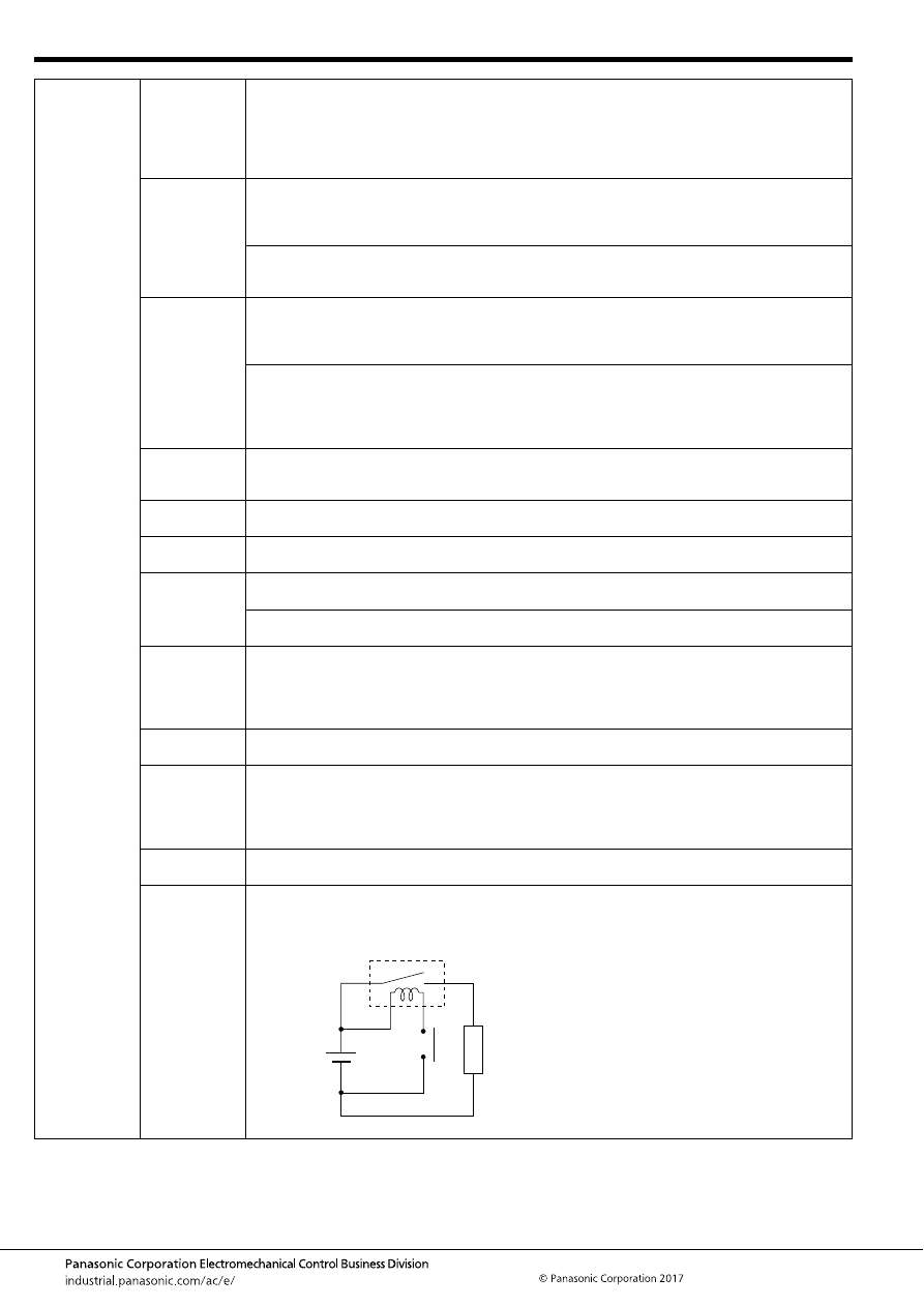
Automotive Relay Users Guide
–24–
ASCTB237E 201709-T
4. Load,
Electrical life
1. General
Contact performance is significantly influenced by voltage and current values applied to the contacts
(in particular, the voltage and current waveforms at the time of application and release), the type of
load, frequency of switching, ambient atmosphere, contact switching speed, and of bounce, which lead
the various other damages such as unsuitable operation contact transfer, welding, abnormal wear,
increase in contact resistance. Therefore, please confirm that in actual use conditions such as actual
circuit and actual load. Also, note that the automotive relay cannot be applied AC load.
2. Inductive
load
In the case of switching on and off with inductive loads such as coil, magnet crutch, and solenoid, the
arc at switching can cause a severe damage on contacts and greatly shortening of life. In addition, in
the case of switching at a high frequency, a blue-green corrosion may be developed. So, please inquire
our sales representative to use it.
If the current in the inductive load is relatively small, the arc discharge decomposes organic matter
contained in the air and causes black deposits (oxides, carbides) to develop on the contacts. This may
result in contact failure. So, please inquire our sales representative to use it.
3. Lamp load
Large inrush current enhancing contact welding will be impressed. Its current value is greatly affected
by wiring resistance, switching frequency and ambient temperature. The load current characteristics in
actual circuit and actual use condition must be examined and sufficient margin of safety must be
provided in selection of a relay.
It is dangerous to use a lamp load whose nominal current is small even a large nominal current has
been tested beforehand.
Please inquire our sales representative when switching at nominal current with a small lamp load (40W
or less), because continuous ON failure may occur due to locking caused by contact-transfer
phenomenon when switching arc is locally concentrated.
4. Electric-
discharge
lamp load
Its load current tends to cause contact welding easily because its inrush current is larger than that of
the regular lamp load. The load current characteristics in actual circuit and actual use condition must
be examined and sufficient margin of safety must be provided in selection of a relay.
5. LED lamp
load
It is necessary to check the contact reliability because the load current of the LED load is very small.
Please inquire our sales representative before use.
6. Other lamp
load
Please inquire our sales representative before use of new structured lamp except for halogen, Electric-
discharge lamp, and LED.
7. Motor load
When using of N.C. contact side of 1 Form C contact for the motor brake, electrical life might be
affected by the brake current. Therefore, verify in actual use conditions with actual circuit.
The larger inductivity of motor may cause contact damage and transfer even the motor load current is
same. Therefore, verify in actual use conditions with actual circuit.
8. Capacitor
load
Note that its load current tends to cause contact welding and contact transfer easily because its inrush
current is generally large which has a small break current and a short time period to reach an inrush
peak value.
Also, inrush current value is influenced by wiring resistance. Therefore, the inrush current in actual
circuit must be examined and sufficient margin of safety must be provided in selection of a relay.
9. Resistance
load
This load causes relatively-less contact damage since its inrush current is not large. Select a relay
based on the rating control capacity.
10. Small
electric
current load
- Under small current loading, high contact resistance values may result when performing continuity
checks of contacts.
- If the switching current is small (1A or less), contact reliability decreases since the contact surface is
not cleaned by switching arc.
Please inquire our sales representative if you are using the above-mentioned use method.
11. Load
polarity
Electrical life may be affected by load polarity (+/-) connecting to relay contacts. So, please verify them
in actual use polarity.
12. Voltage
drop of
power
supply
Under a circuit which inrush current is applied to such as lamps and capacitors, the moment the
contact is closed, voltage drop to the coil, return of relay, or chattering may occur. Note that it may
remarkably reduce the electrical life.
Load
automotive-relay_en-html.html
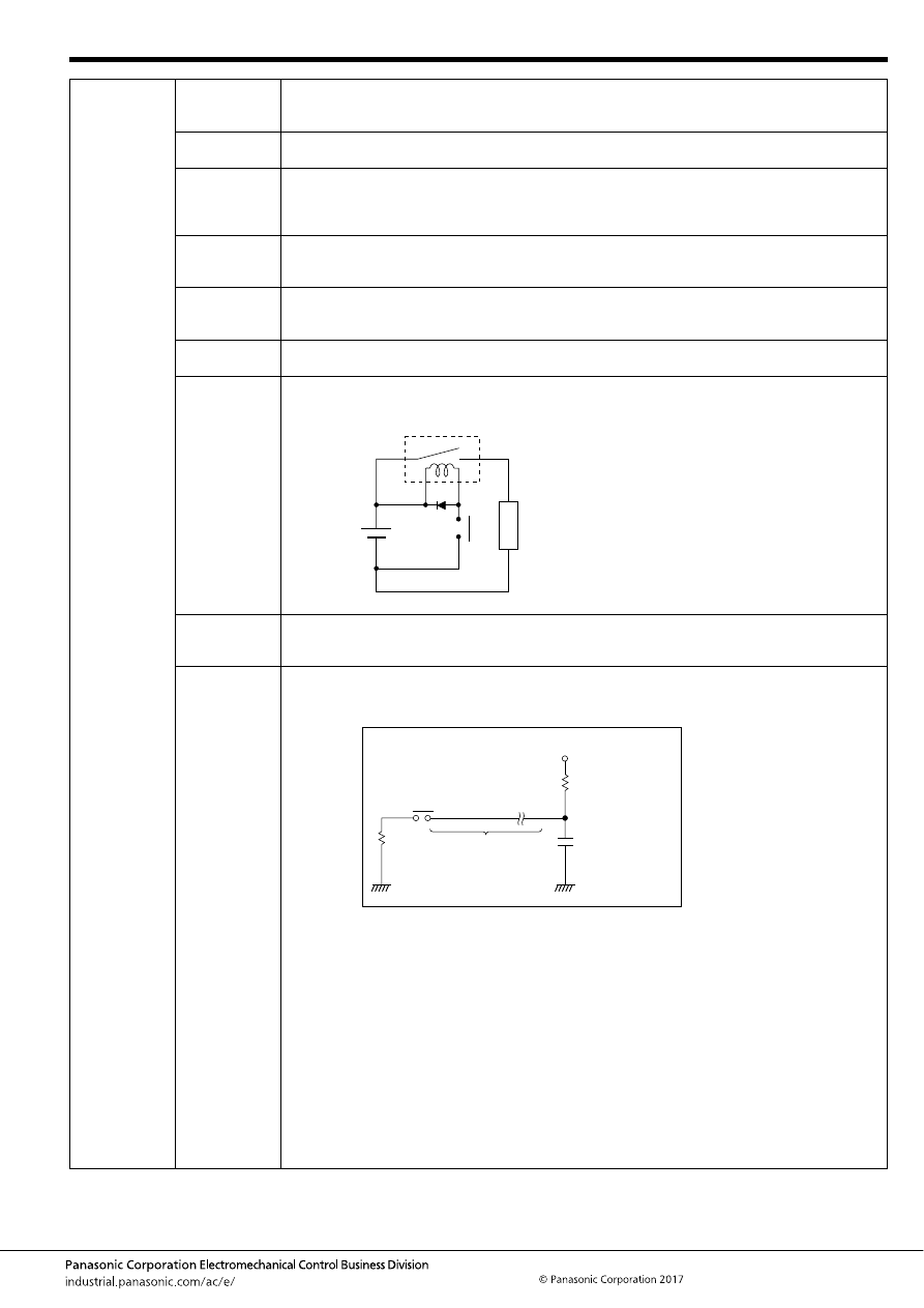
Automotive Relay Users Guide
–25–
ASCTB237E 201709-T
4. Load,
Electrical life
13. Load
voltage
If the load voltage is high, the arc energy which generated at contact switching increases, which may
decrease the electrical life. Therefore, it is necessary to give consideration to the voltage which could
occur in actual use condition.
14. Coil voltage
If coil applied voltage gets higher, the relay operate time gets faster. However, contact bounce gets
also larger so that the electrical life may decrease.
15. Coil short-
pulse input
When the short-pulse signal is input to the relay coil, the relay movable part may operate and touch
lightly to the contact. Therefore, please avoid short pulse input (100ms or less) since it may cause
contact welding due to less contact pressure. Please test adequately, for example when a relay is
operated by external manual switch (such as key switch.)
16. High-
frequency
of switching
When the switching frequency is high, the electrical life may decrease. Please confirm if there is a
high-frequent switching caused by abnormal mode in actual use condition.
17. Low-
frequency
of switching
Note that if the contact has not been switched for a long time period, organic film tends to be generated
on the contact surface, which may cause contact instability.
18. Ambient
temperature
Verify in the actual use condition since electrical life may be affected by use at high temperatures.
19. Connection
of coil surge
absorption
circuit
If resistor, diode, zener diode are connected parallel to the relay coil and decrease the surge voltage
when the relay coil being turned off, the relay release time will get longer and may decrease the
electrical life or cause light-welding.
20. Sneak or
remaining
current
Please test a relay in actual vehicle condition since there is a risk of deterioration at relay function or
switching performance such as slower release time which is caused by sneak current due to diode,
zener diode, capacitor mounted on a vehicle or by remaining current soon after a motor is turned off.
21. Wire length
If long wires (a few ten meters) are to be used in a relay contact circuit, inrush current may become a
problem due to the stray capacitance existing between wires. In such case, add a resistor in series with
the contacts.
Load
Recommended zener diode
• Zener voltage 24V or higher (12V rating)
• Zener voltage 48V or higher (24V rating)
Recommended resistor
• 680
Ω
to 1000
Ω
(12V rating)
• 2800
Ω
to 4700
Ω
(24V rating)
Contacts
Added resistor
10 to 50
Ω
Wire
Stray capacitance
of wire
Equivalent circuit
+
automotive-relay_en-html.html
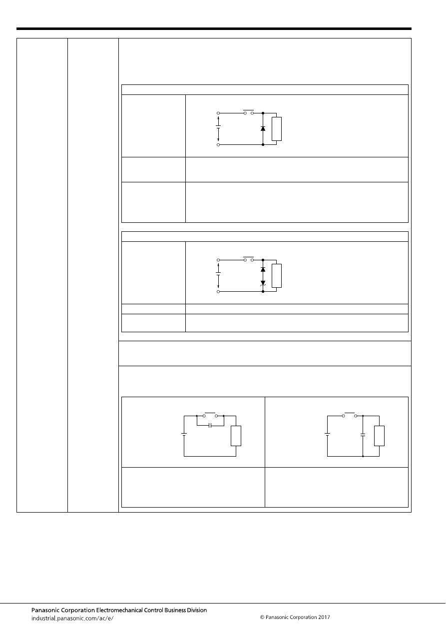
Automotive Relay Users Guide
–26–
ASCTB237E 201709-T
4. Load,
electrical life
22. Contact
protective
circuit
Use of contact protective devices or protection circuits can suppress the counter electromotive force to
a low level. However, note that incorrect use will result in an adverse effect. Typical contact protection
circuits are given in the table below.
Also, note that release time will slow down due to sneak in the circuit and may cause the electrical life
to shorten and slight-welding.
In the actual circuit, it is necessary to mount the protective device (diode etc.) in the immediate vicinity
of the load. If it is mounted too far away, the effectiveness of the protective device may diminish. As a
guide, the distance should be within 50cm.
Avoid using the protection circuits shown in the figures below.
Although it is usually more difficult to switch with DC inductive loads compared to resistive loads, use
of the proper protection circuit will raise the characteristics to that for resistive loads.
Diode circuit
Circuit
Features/Others
The diode connected in parallel causes the energy stored in the coil to flow to
the coil in the form of current and dissipates it as joule heat at the resistance
component of the inductive load. This circuit delays the release time.
Devices Selection
Use a diode with a reverse breakdown voltage at least 10 times the circuit
voltage and a forward current at least as large as the load current.
In electronic circuits where the circuit voltages are not so high, a diode can be
used with a reverse breakdown voltage of about 2 to 3 times the power supply
voltage.
Diode and zener diode circuit
Circuit
Features/Others
It is effective in the diode circuit when the release time is too long.
Devices Selection
Use a zener diode with a zener voltage about the same as the power supply
voltage
Contact
Inductiv
e load
Diode
Contact
Inductiv
e load
Although it is extremely effective in arc
suppression as the contacts open, the contacts
are susceptible to welding since energy is stored
in C when the contacts open and discharge
current flows from C when the contacts close.
Although it is extremely effective in arc
suppression as the contacts open, the contacts
are susceptible to welding since charging current
flows to C when the contacts close.
Contact
Power
supply
Load
No good
C
Contact
Power
supply
Load
No good
C
automotive-relay_en-html.html
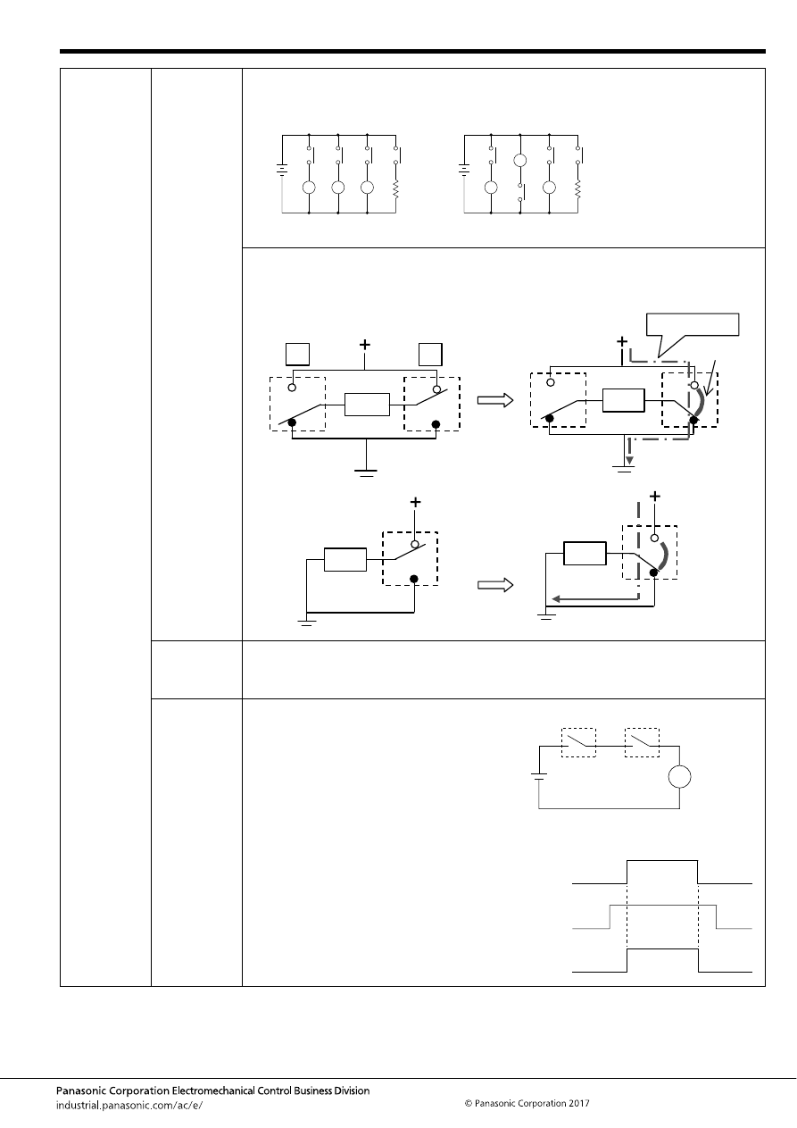
Automotive Relay Users Guide
–27–
ASCTB237E 201709-T
4. Load,
electrical life
23. Connection
of load
Connect the load to one side of the power supply as shown in Fig. (a). Connect the contacts to the
other side. This prevents high voltages from developing between contacts. If contacts are connected to
both side of the power supply as shown in Fig. (b), there is a risk of shorting of the power supply when
relatively close contacts short.
Note that regarding the following circuit constructions with 2-coil relays (twin relays) or single-pole
relays, an arc between contacts may be generated when breaking of load current depending on the
type of load current, voltage, and load.
24. Short
between
inter
electrodes
When using of multiple pole relays such as 2-coil relays (twin relays), verify insulation and dielectric
strength between contacts in each pole in order to avoid an accident caused by short.
25. Dry-
switching
The two relays are connected in series as
shown in the right side figure. When each relay
is controlled with a different timing chart
(shown in the right side figure bottom), the
relay No.2 does not flow the load current during
operation and release time. This relay No.2
operation is called “Dry-switching”.
Dry-switching can reduce the consumption of
contact material without current conduction, on
the other hand, as the contact cleaning effect
disappear, conduction failure may occur.
For the abovementioned reasons, note that our
relay application in this dry-switching condition
is not recommended in applying our relay.
Fig. (a) Good example
(b) Bad example
R
y
E
R
y
R
y
(a)
R
y
E
R
y
R
y
(b)
Load
Load
Load
A
B
Load
Short current
Arcing
OFF
B side OFF
<2-coil relay (twin relay) or two of single-pole relays>
<Single-pole relay>
Contact load
Timing chart:
Relay No.1
Relay No.1
Relay No.2
Load current
Relay No.2
ON
ON
OFF
OFF
automotive-relay_en-html.html
Automotive Relay Users Guide
–28–
ASCTB237E 201709-T
5. Coil operate
voltage
1. Hot start
voltage
After continuous applying of current to coil and contacts, if the current is turned OFF then immediately
turned ON again, coil resistance and operate voltage will increase due to the temperature rise in the
coil.
Temperature rise value of coil is greatly affected by circuit board, connected harness, connected
connector, heat dissipation of system/modules, and heat source around relay. Please verify whether it
is operating properly or inoperative under actual vehicle and actual use conditions.
2. Ambient
temperature
characteristic
Coil resistance and operate voltage will increase when the relay is used in a higher temperature
atmosphere. The resistance/temperature coefficient of copper wire is about 0.4% for 1
°
C, and the coil
resistance increases with this ratio. On the other hand, coil resistance and the release voltage will
decrease at lower temperature. Coil resistance change decreases with the same ratio at higher
temperature, about 0.4% for 1
°
C.
Therefore, please confirm the relay operation in used operating temperature range, with attention to
such temperature characteristic.
The ambient usage temperature should be set as around the relay inside the box because a heat
generated by a relay itself or other instruments causes increase of temperature inside the box.
3. Applied
voltage
Note that application of a voltage equal to or greater than the maximum applied voltage may cause a
temperature rise that could cause coil burning or a layer short. Furthermore, do not exceed the usable
ambient temperature range listed in the catalog. Please inquire our sales representative regarding
PWM control.
4. Twin-relay
coil
simultaneous
operation
For relays which have multiple coils such as twin relay for forward-reverse operation of motor, if the
coils are continuously turned on at the same time, the coil temperature may exceed the tolerance in a
short time due to heat generation of each coil. Please inquire our sales representative before use.
5. Continuous
current
Coil heating due to continuous current applying to coil for extensive time periods will cause
deterioration in insulation performance for coil.
For such circuit types, please consider the fail-safe circuit design in case of contact failure or breaking
of coil.
automotive-relay_en-html.html
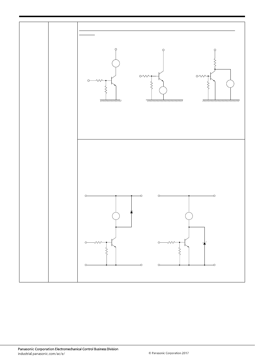
Automotive Relay Users Guide
–29–
ASCTB237E 201709-T
6. Coil
operating
circuit
1. Relay drive
by means of
a transistor
1. Connection method
Collector connection method is the most recommendable when the relay is driven by means of a
transistor.
To avoid troubles in use, the rated voltage should always be applied on the relay in the ON time and
zero voltage be done in the OFF time.
2. Countermeasures for surge voltage of relay control transistor
If the coil current is suddenly interrupted, a sudden high voltage pulse is developed in the coil. If this
voltage exceeds the dielectric strength of the transistor, the transistor will be degraded, and this will
lead to damage. It is absolutely necessary to connect a diode in the circuit as a means of preventing
damage from the counter emf. In case of DC relay, connection of Diode is effective. As suitable ratings
for this diode, the average rectified current should be equivalent to the coil current, and the reverse
blocking voltage should be about 3 times the value of the power source voltage. Connection of a diode
is an excellent way to prevent voltage surges, but there will be a considerable time delay when the
relay is open. Consequently, electrical switching performance of relay may be reduced. If it is need to
reduce this time delay, performance will be improved by connecting a Zener diode that is rated for
more than double the voltage in the circuit between the transistor’s Collector and Emitter.
Take care of Area of Safe Operation (ASO).
(Good) Collector connection
This is the most common
connection, which operation is
usually stable with.
(Care) Emitter connection
When the circumstances make
the use of this connection
unavoidable, the voltage may
not be completely applied on
the relay and the transistor
would not conduct completely.
(Care) Parallel connection
As the power consumption of
the entire circuit increases, the
relay voltage should be
considered.
R
1
R
2
Tr
Ry
Tr
Ry
R
Tr
Ry
T
r
R
y
Diode
R
y
T
r
<Recommended circuit>
Zener diode
automotive-relay_en-html.html
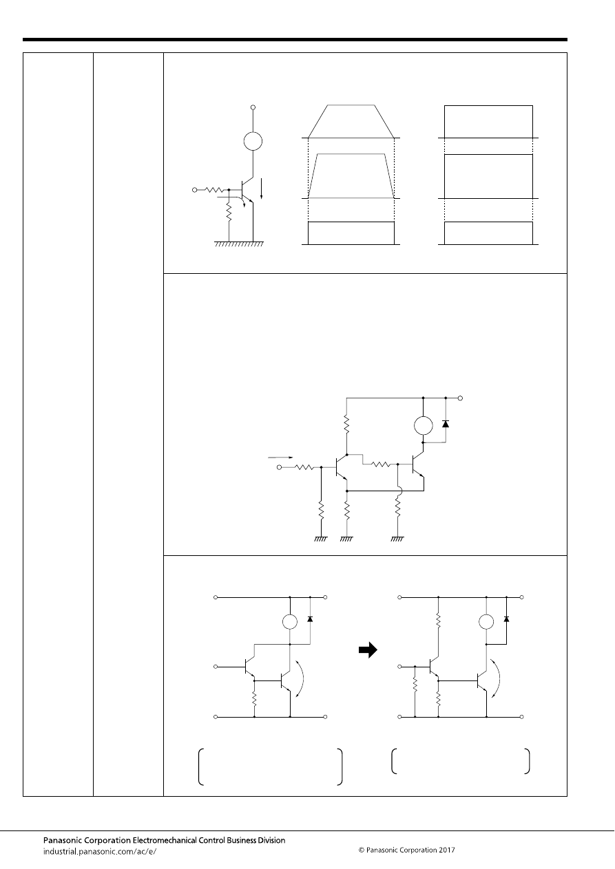
Automotive Relay Users Guide
–30–
ASCTB237E 201709-T
6. Coil
operating
circuit
1. Relay drive
by means of
a transistor
3. Snap action (Characteristic of relay with voltage rise and fall)
It is necessary for the relay coil not to apply voltage slowly but to apply the rated voltage in a short time
and also to drop the voltage to zero in a short time.
4. Schmitt circuit (Snap action circuit)
When the input signal does not produce a snap action, ordinarily a Schmitt trigger circuit is used to
produce safe snap action.
- The common emitter resistor RE must have a sufficiently small value compared with the resistance of
the relay coil.
- Due to the relay coil current, the difference in the voltage between at point P when Tr2 is conducting
and at point P when Tr1 is conducting creates hysteresis in the detection capability of Schmitt circuit,
and care must be taken in setting the values.
- When there is chattering in the input signal because of waveform oscillation, an CR time constant
circuit should be inserted in the stage before the Schmitt trigger circuit. (However, the response
speed drops.)
5. Avoid Darlington circuit connections.
Care must be taken in this circuit due to increase of VCESAT. It does not cause a failure immediately,
but it may lead to troubles by using for a long period or by operating with many units.
I
B
Tr Ic
Ry
ON
OFF
Ry
I
B
I
C
Non-pulse signal
(No Good) Without snap action
Pulse signal (square wave)
(Good) Snap action
R
2
R
3
R
1
R
E
P
Ry
Signal
Tr
1
Tr
2
V
CESAT
=
About 0.7V
V
CESAT
=
About 0.1V
GND
Tr
1
Tr
1
Tr
2
Tr
2
Ry
Ry
(No good) Darlington connection
-
-
Due to excessive consumption
of power, heat is generated.
A strong Tr1 is necessary.
(Good) Emitter connection
- Tr2 conducts completely.
- Tr1 is sufficient for signal use.
automotive-relay_en-html.html
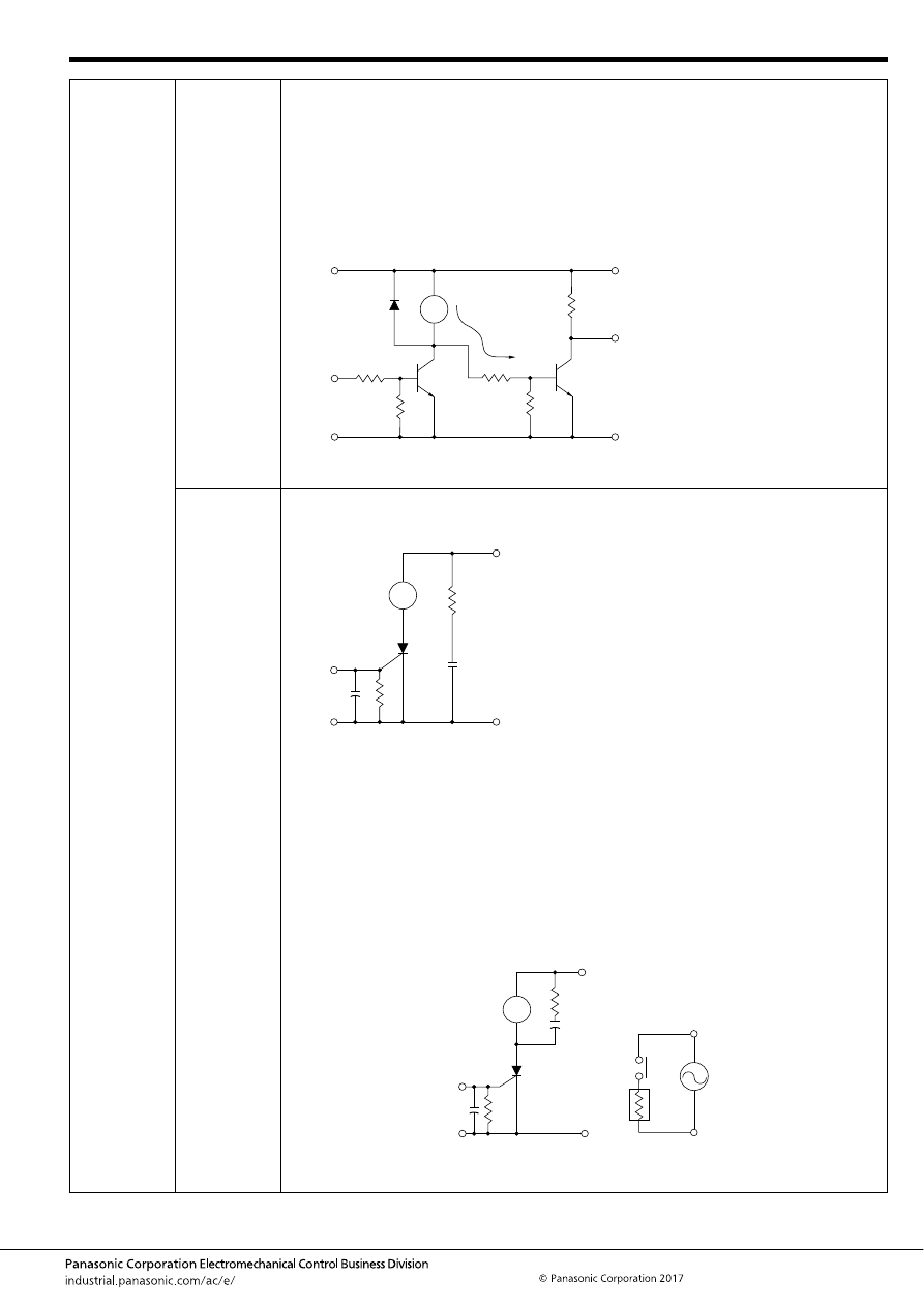
Automotive Relay Users Guide
–31–
ASCTB237E 201709-T
6. Coil
operating
circuit
1. Relay drive
by means of
a transistor
6. Residual Coil Voltage
In switching operation where a semiconductor (transistor, UJT, etc.) is connected to the coil, a residual
voltage is retained at the relay coil which may cause incomplete restoration and faulty operation. Using
of DC coils may cause incomplete restoration or reduction in contact pressure and vibration resistance,
because its release voltage is lower than that of AC coil (10% or more of the rated voltage) also
because there is a tendency to increase the life by lowering the release voltage.
When the signal from the transistor’s collector is taken and used to drive another circuit as shown in
the figure as follows, a minute dark current flows to the relay even if the transistor is off. This may also
cause the problems described above.
Connection to the next stage through collector
2. Relay drive
by means of
SCR
1. Ordinary drive method
For SCR drive, it is necessary to take particular care with regard to gate sensitivity and erroneous
operation due to noise.
2. Cautions regarding ON/OFF control circuits
(when used for temperature control circuits or similar one)
Care must be taken because the electrical life suffers extreme shortening when the relay contacts
close simultaneously with an AC single phase power source.
1. When the relay is turned ON and OFF using a SCR, the SCR serves as a half wave power source as
it is, and there are ample cases where the SCR is easily restored.
2. In this manner the relay operation and restoration timing are easily synchronized with the power
source frequency, and the timing of the load switching also is easily synchronized.
3. In case of the load for temperature control whose load is a high current load such as a heater, some
relays switch only peak values and some other relays switch only zero phase values as a phenomenon
of this type of control. (Depending upon the sensitivity and response speed of the relay)
4. Accordingly, it causes either an extremely long life or an extremely short life resulting in wide
variation. So, it is necessary to take care with the initial device quality check.
Ry
T
2
I
O
T
1
I
O
: dark current
(No good)
R
GK
I
GT
C
R
S
Ry
There is no problem even with more than 3 times
the rated current.
1K ohms must be connected.
This is for prevention of switching error due to a
sudden rise in the power source or to noise.
:
:
:
I
GT
R
GK
RC
S
Ry
Ry
Heater
automotive-relay_en-html.html
Automotive Relay Users Guide
–32–
ASCTB237E 201709-T
7. Contact
reliability
1. Load
switching
Note that when switching with a very small load after switching with a large load, contact failure by
small load switching may occur due to particles generated during switching of the contact with large
load.
2. Installation
condition
Note that if it is connected or installed with a high heat-capacity such as bus bar, connector, harness,
and PCB, heat removal phenomenon at low temperature will make relay terminals and contacts cool
and condensate a small amount of organic gas inside the relay, which may cause a contact failure. So,
please inquire our sales representative before use.
8. Contact
resistance
1. Transient
state
Contact resistance consists of dynamic and static contact resistance. Contact resistance on the
catalogue and the specifications refers to static contact resistance. Note that dynamic contact
resistance usually shows a large value due to just after the contact operation.
2. Contact
voltage,
current
Note that if the contact-applied voltage is small (at 6V or less) and contact-applied current is small (at
1A or less), contact resistance may become a larger value due to a small amount of film on a contact
surface.
9. Operation
noise
1. Coil applied
voltage
Mechanical relays produce an operational noise at operate and release time. Note that if the coil-
applied voltage is higher at operate time, the noise becomes larger.
2. Operation
noise after
installation
It is necessary to test relays in actual installation condition because operation noise may become
larger in the installation condition than with a relay by itself due to resonance and sympathetic
vibrations of installation PCB and system module.
10. Mechanical
noise
1. Abnormal
noise
Note that if a large current is applied to the contact, electromagnetic repulsion makes contact vibrate
and may produce small abnormal noise. Please inquire our sales representative if quietness is
required.
Note that if an external vibration and shock are applied to a relay while the relay turns off, a movable
part of the relay may vibrate and produce a noise. If quietness is required, after mounting, please test
in the actual use condition.
11. Electrical
noise
1. Surge
voltage
When the relay turns off, surge voltage is generated from the coil. This surge voltage can be reduced if
a resistor is connected in parallel to the coil. Likewise, it can be reduced more if a diode instead of
resistor is connected in parallel.
However, please note that if a resistor and a diode is connected in parallel electrical life may be
affected due to slowing down of release time.
automotive-relay_en-html.html
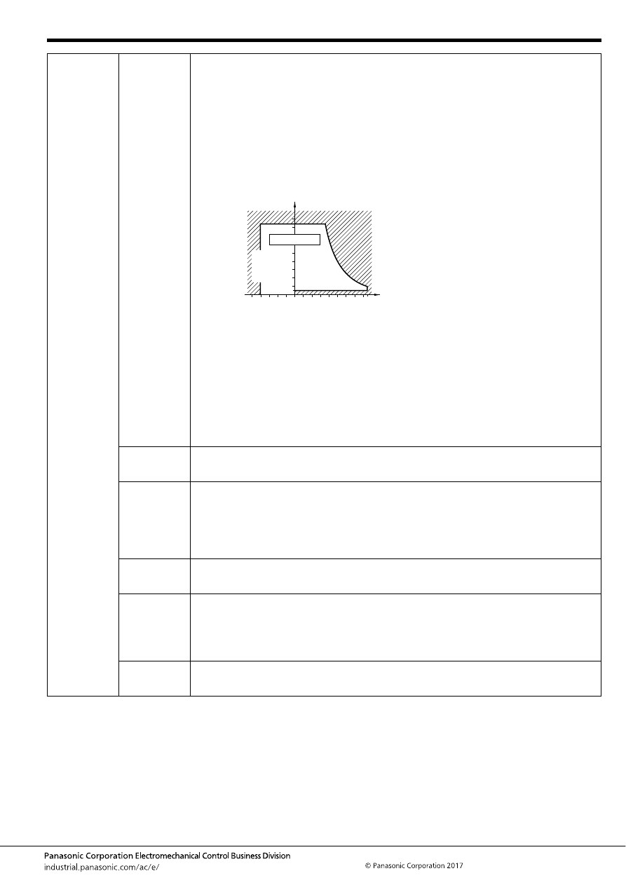
Automotive Relay Users Guide
–33–
ASCTB237E 201709-T
12. Usage
ambient
condition
1. Temperature,
humidity, air
pressure
During usage, storage, or transportation, avoid locations subject to direct sunlight and maintain normal
temperature, humidity, and pressure conditions.
The allowable specifications for environments suitable for usage, storage, and transportation are given
below.
1. Temperature: The allowable temperature range differs with each relay, so refer to the relay’s
individual specifications. In addition, note that in the case of transporting and storing relays in a tube
package, the temperature may differ from the allowable range of the relay.
2. Humidity: 5 to 85% R.H.
3. Pressure: 86 to 106 kPa
*1. The humidity range varies with the temperature. So, use relays within the range indicated in the
graph below.
*2. If products are air freighted, as long as they are kept in a regular air transportation environment
(approx. 80 kPa), product quality will not be affected.
(The allowable temperature range differs for each relay.)
- Be sure the usage ambient temperature does not exceed the value listed in the catalog.
- When switching with a load which easily generates arc in high-humidity environment, the NOx
generated by the arc and the water absorbed from outside the relay combine to produce nitric acid.
This corrodes the internal metal parts and adversely affects operation. Avoid using them at an
ambient humidity of 85%RH or higher (at 20
°
C). If it is unavoidable to use them in such environment,
please consult us.
- Sealed relays are especially not suited for use in environments which require severe airtight
condition. Although there is no problem if they are used at sea level, avoid using them in air pressures
beyond 96
±
10kPa. Also avoid using them in an atmosphere containing flammable or explosive gases.
2. Dust
It is recommendable to use relays in a normal temperature and humidity with less dust, sulfur gases
(SO
2
, H
2
S), and organic gases.
Sealed relays should be considered for applications in an adverse environment.
3. Silicone
When a source of silicone gas (silicone rubber, silicone oil, silicone coating materials and silicone
filling materials etc.) is used around the relay, the silicone gas (low molecular siloxane etc.) may be
produced.
The produced silicone gas may penetrate the plastic case and enter the inside of the relay. When the
relay is kept and used in this condition, silicone compound may adhere to the relay contacts. The
silicone compound may be changed to the insulator which may cause the contact failure. Do not use
any sources of silicone gas around the relay.
4. Magnetism
If relays are proximately installed each other or installed near highly-magnetized parts such as motor
and speaker, the relay may change its operational characteristics or cause malfunction. Therefore,
after mounting, check performance in actual operational conditions.
5. Vibration
Vibration of the area where relay is installed may be enhanced more than expected depending on
installation condition of PCB. So, please verify in actual use condition. N.O. contact is the
recommended contact for the use at the vibration-frequent area because the vibration resistance
performance of N.C. contact is generally inferior to that of N.O. contact.
In addition, owing to adverse effects on the characteristics of the relay, ensure that devices are not
exposed to ultorasonic or high frequency vibrations.
6. Shock
It is ideal for mounting of relay that the movement of the contacts and movable parts is perpendicular
to the direction of vibration or shock. Especially note that the vibration and shock resistance of N.C.
contacts while the coil is not excited is greatly affected by the mounting direction of the relay.
85
5
Humidity, %RH
Tolerance range
(Avoid
condensation
when used at
temperatures
higher than
0
°
C
32
°
F
)
(Avoid icing
when used at
temperatures
lower than
0
°
C
32
°
F
)
85
0
–40
+185
+32
–40
Temperature,
°
C
°
F
automotive-relay_en-html.html
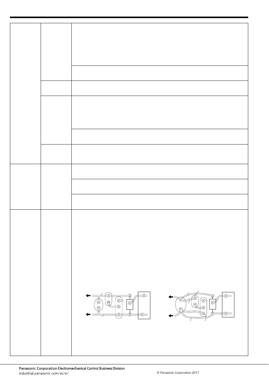
Automotive Relay Users Guide
–34–
ASCTB237E 201709-T
12. Usage
ambient
condition
7. Dew
condensation
Water condensation occurs when the ambient temperature drops suddenly from a high temperature
and humidity, or, the relay is suddenly transferred from a low ambient temperature to a high
temperature and humidity.
Condensation causes the failures like insulation deterioration, wire disconnection and rust etc.
Panasonic Corporation does not guarantee the failures caused by condensation.
The heat conduction by the equipment may accelerate the cooling of relay itself, and the condensation
may occur. Please confirm no condensation in the worst condition of the actual usage.
(Special attention should be paid when high temperature heating parts are close to the relay. Also
please consider the condensation may occur inside of the relay.)
Note that if a relay is connected or installed with a high heat-capacity such as bus bar, connector,
harness, and PCB, heat removal phenomenon will accelerate cooling of the relay inside and promote
condensation. So, please verify in actual installation condition.
8. Water
resistance
Do not use PC board type in environments where wetting may occur.
Since we have different types with various water resistance specifications, please inquire our sales
representative.
9. Icing
Please check the icing when an ambient temperature is lower than 0
°
C. Water drop adheres to the
relay by the condensation or the abnormal high humidity and is frozen to the ice when the ambient
temperature becomes lower than 0
°
C. The icing causes the sticking of movable portion, the operation
delay and the contact conduction failure etc. Panasonic Corporation does not guarantee the failures
caused by the icing.
The heat conduction by the equipment may accelerate the cooling of relay itself and the icing may
occur. Please confirm no icing in the worst condition of the actual usage.
Note that if a relay is connected or installed with a high heat-capacity such as bus bar, connector,
harness, and PCB, heat removal phenomenon will accelerate cooling of the relay inside and promote
freezing. So, please verify in actual installation condition.
10. Low tem-
perature,
low humid-
ity
The plastic becomes brittle if the relay is exposed to a low temperature, low humidity environment for
long periods of time.
13. Installation
1. Connector
connection
Please consider the vibration at installation area to avoid loosely-contact.
Also, note that even a microscopic vibration may cause contact failure at the contact area of relay
terminal and connector.
Decrease of mated performance of connector may cause abnormal heat at connector contact area
depending on use temperature and applying heat. Sufficient margin of safety must be provided in
selection of a connector.
Please select the proper material of connector and surface treatment to avoid corrosion at the contact
area of relay terminal and connector and increase of resistance at connecting area which may be
caused depending on ambient environment.
14. PC board
design
1. PC board
design
consideration
1. Cautions regarding Pattern Layout for Relays
Operating relays may generate noise that can affect electrical circuits. Therefore, the following points
should be noted.
• Keep relays away from semiconductor devices.
• Design the pattern traces with the shortest length.
• Place the surge absorber (diode, etc.) near the relay coil.
• Avoid routing pattern traces susceptible to noise (such as for audio signals) underneath the relay coil
section.
• Avoid through-holes in places which cannot be seen from the top (e.g. at the base of the relay).
Solder flowing up through such a hole may cause damage such as a sealing failure.
• Even for the same circuit, it is necessary to consider the pattern design in order to minimize the
influence of the on/off operations of the relay coil and lamp on other electronic circuits, as shown in
the figure below.
A
B
Tr
Constant
voltage
Electronic
circuit
Relay coil Ry
(No good)
Diode br
idge
B
2
B
1
A
1
A
2
Ry
Tr
Constant
voltage
Electronic
circuit
Diode br
idge
(Good)
- Relay coil currents consist only of A1 and B1.
- Electronic circuit currents consist only of A2
and B2. A simple design can change safety of
the operation.
- Relay currents and electronic circuit
currents flow through A and B.
automotive-relay_en-html.html
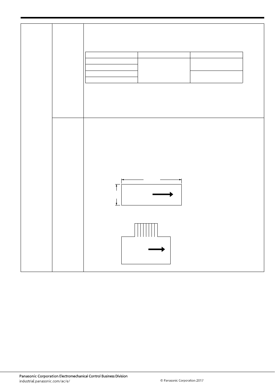
Automotive Relay Users Guide
–35–
ASCTB237E 201709-T
14. PC board
design
2. Hole and
Land
diameter
The Hole and Land diameter are made with the hole slightly larger than the lead wire so that the
component may be inserted easily. Also, when soldering, the solder will build up in an eyelet condition,
increasing the mounting strength. The standard dimensions for the Hole diameter and Land are shown
in the table below.
(Remarks)
• The Hole diameter is made 0.2 to 0.5 mm
.008 to .020 inch
larger than the lead diameter.
However, if the jet method (wave type, jet type) of soldering is used, solder may pass through to the
component side. Therefore, it is more suitable to make the hole diameter equal to the lead diameter
+0.2 mm.
• The Land diameter should be 2 to 3 times the Hole diameter.
• Do not put more than 1 lead in one hole.
3. Expansion
and
shrinkage of
copper-clad
laminates
Because copper-clad laminates have a longitudinal and lateral direction, the manner of punching
fabrication and layout must be observed with care. Expansion and shrinkage in the longitudinal
direction due to heat is about 1/15 to 1/2 of that in the lateral, and accordingly, after the punching
fabrication, the distortion in the longitudinal direction will be about 1/15 to 1/2 of that in the lateral
direction. The mechanical strength in the longitudinal direction is about 10 to 15% greater than that in
the lateral direction. Because of this difference between the longitudinal and lateral directions, when
products having long configurations are to be fabricated, the lengthwise direction of the configuration
should be made in the longitudinal direction, and PC boards having a connector section should be
made with the connector along the longitudinal side. (The figure below)
Example: As shown in the drawing below, the 150 mm
5.906 inch
direction is taken in the longitudinal
direction.
Also, as shown in the drawing below, when the pattern has a connector section, the direction is taken
as shown by the arrow in the longitudinal direction.
Standard dimensions for the Hole and Land diameter
Standard hole
Tolerance
Land diameter
0.8
.031
±
0.1
±
.039
2.0 to 3.0
.079 to .118
1.0
.039
1.2
.047
3.5 to 4.5
.138 to .177
1.6
.063
(Unit: mm
inch
)
Longitudinal
150
5.906
70
Longitudinal
direction
2.756
Longitudinal
direction
automotive-relay_en-html.html
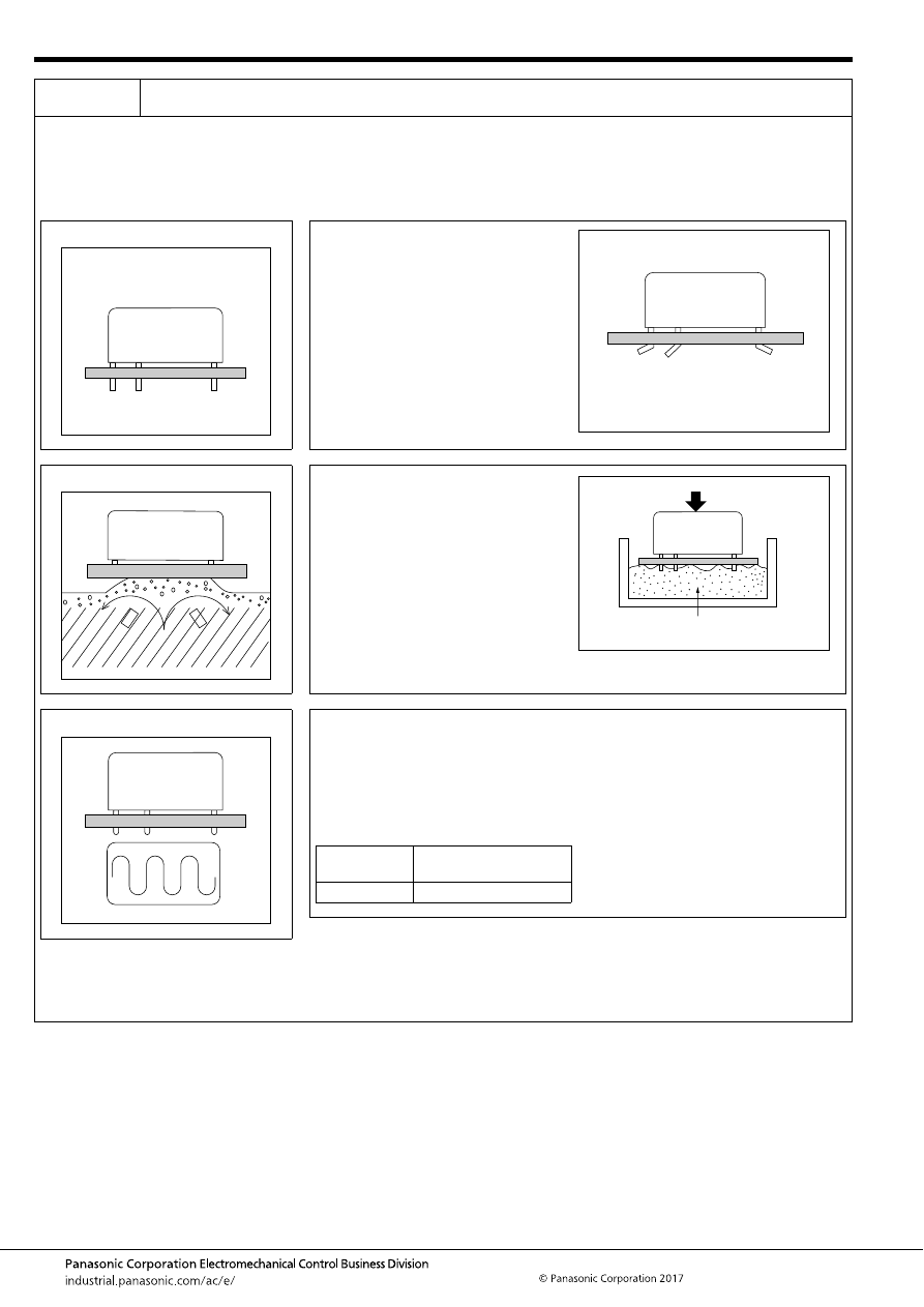
Automotive Relay Users Guide
–36–
ASCTB237E 201709-T
15. PCB
mounting
1. Through-hole type
In keeping with making devices compact, it is becoming more common to solder the relay to a PC board along with the semiconductors
instead of using the previous plug-in type in which relays were plugged into sockets.
With this style, loss of function may occur because of seepage into the relay of flux, which is applied to the PC board. Therefore, the
following precautions are provided for soldering a relay onto a PC board. Please refer to them during installation in order to avoid problems.
The type of protective structure will determine suitability for automatic soldering or automatic cleaning. Therefore, please review the parts
on construction and characteristics.
1. Mounting of Relay
• Avoid bending the terminals to make the
relay self-clinching. Relay performance
cannot be guaranteed if the terminals
are bent.
• Correctly make the PC board according
to the given PC board pattern
illustration.
• Tube packaging for automatic mounting
is available depending on the type of
relay. (Be sure that the relays don’t
rattle.) Interference may occur internally
if the gripping force of the tab of the
surface mounting machine is too great.
This could impair relay performance.
2. Flux Application
• Adjust the position of the PC board so
that flux does not overflow onto the top
of it. This must be observed especially
for dust-cover type relays.
• Use rosin-based non-corrosive flux.
• If the PC board is pressed down into a
flux-soaked sponge as shown on the
right, the flux can easily penetrate a
dust-cover type relay. Never use this
method. Note that if the PC board is
pressed down hard enough, flux may
even penetrate a flux tight type relay.
3. Preheating
• Be sure to preheat before using automatic
soldering. For dust-cover type relays and
flux tight type relays, preheating acts to
prevent the penetration of flux into the
relay when soldering. Solderability also
improves.
• Preheat according to the following
conditions.
• Note that long exposure to high
temperatures (e.g. due to a malfunctioning
unit) may affect relay characteristics.
Note: CB and CM relays are not applicable. Please refer to individual product catalog.
Bad example
Bad example
Temperature
100
°
C
212
°
F
or less
(PCB solder surface)
Time
Within 2 minutes
automotive-relay_en-html.html
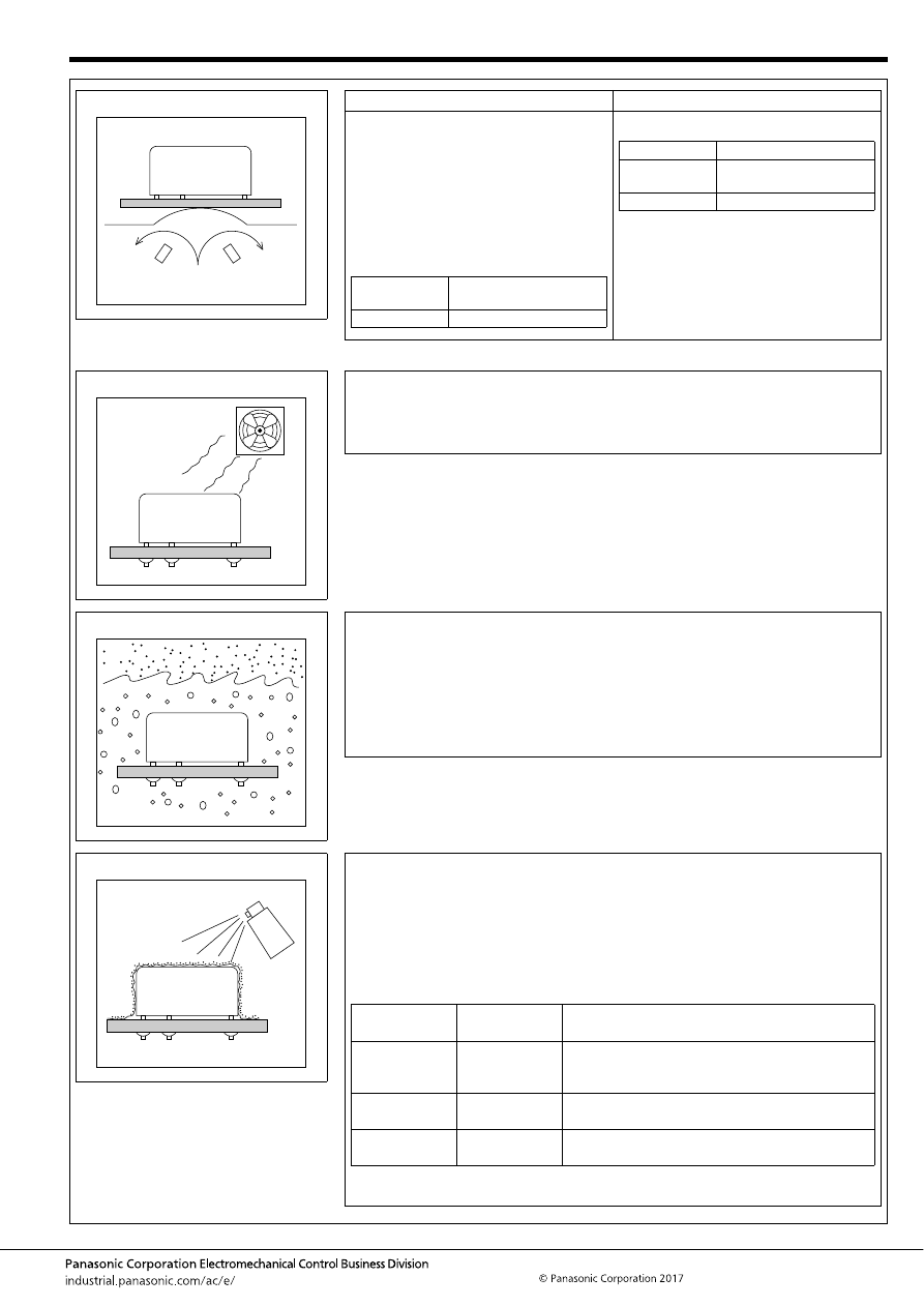
Automotive Relay Users Guide
–37–
ASCTB237E 201709-T
4. Soldering
Automatic soldering
Hand soldering
• Wave solder is the optimum method for
soldering.
• Adjust the level of solder so that it does not
overflow onto the top of the PC board.
• Unless otherwise specified, solder under
the following conditions depending on the
type of relay.
• Please take caution with multi-layer boards.
Relay performance may degrade due to the
high thermal capacity of these boards.
• Keep the tip of the soldering iron clean.
Note: CB and CM relays are not applicable. Please refer to individual product catalog.
5. Cooling
• Immediate air cooling is recommend to prevent deterioration of the relay and surrounding
parts due of soldering heat.
• Avoid immersing the relay into cold liquid (such as cleaning solvent and coating material)
immediately after soldering. Doing so may deteriorate the sealing performance.
6. Cleaning
• Do not clean products that are not compatible with cleaning.
• For products that may be cleaned, use alcohol-based cleaning solvent. Use of other
cleaning solvents (e.g. Trichlene, chloroethene, thinner, benzyl alcohol, gasoline) may
damage the relay case.
• Avoid ultrasonic cleaning on relays. Use of ultrasonic cleaning may cause breaks in the
coil or slight sticking of the contacts due to the ultrasonic energy.
• Do not cut the terminals. When terminals are cut, breaking of coil wire and slight sticking
of the contacts may occur due to vibration of the cutter.
7. Coating
• If the PC board is to be coated to prevent the insulation of the PC board from
deteriorating due to corrosive gases and high temperatures, note the following.
• Do not coat dust-cover type relays and flux tight type relays, since the coating material
may penetrate the relay and cause contact failure. Or, mount the relay after coating.
• Depending on the type, some coating materials may have an adverse affect on relays.
Furthermore, some solvents (e.g. xylene, toluene, MEK, I.P.A.) may damage the case or
chemically dissolve the epoxy and break the seal. Select coating materials carefully.
• If the relay and all components (e.g. ICs) are to be coated, be sure to carefully check the
flexibility of the coating material. The solder may peel off from thermal stress.
Solder
temperature
260
°
C
500
°
F
or less
Soldering time
Within 5 seconds
Soldering iron
30W to 60W
Iron tip
temperature
300
°
C
572
°
F
Soldering time
Within 3 seconds
Please inquire our sales representative about coating materials other than those listed
above. Also please follow individual specification.
Coating
material type
Suitability for
relays
Features
Epoxy-base
Good
Good electrical insulation.
Although slightly difficult to apply, does not affect
relay contacts.
Urethane-base
Care
Good electrical insulation, easy to apply. Solvent
may damage case. Check before use.
Silicone-base
No Good
Silicone gas becomes the cause of contact failure.
Do not use the silicone-base type.
automotive-relay_en-html.html
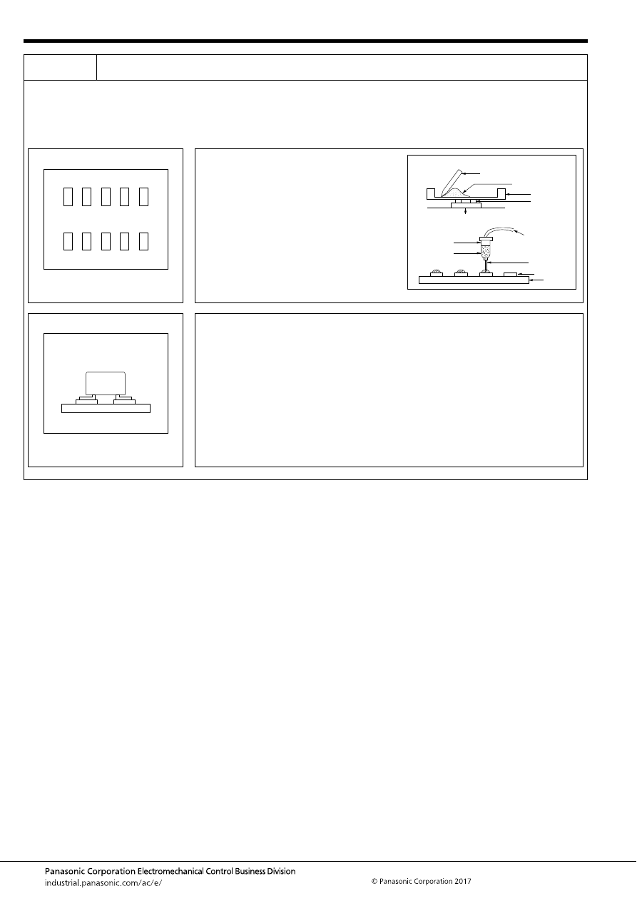
Automotive Relay Users Guide
–38–
ASCTB237E 201709-T
15. PCB
mounting
2. SMD type
To meet the market demand for downsizing to smaller, lighter, and thinner products, PC boards also need to proceed from insertion
mounting to surface mounting technology.
To meet this need, we offer a line of surface mount relays. The following describes some cautions required for surface mount relay
installation to prevent malfunction and incorrect operation.
*Please inquire our sales representative for or reflow soldering of through-hole terminal type.
1. Paste Soldering
• Mounting pads on PC boards must be
designed to absorb placement errors while
taking account of solderability and insulation.
Refer to the suggested mounting pad layout
in the application data for the required relay
product.
• Paste solder may be applied on the board
with screen printing or dispenser techniques.
For either method, the paste solder must be
coated to appropriate thickness and shapes
to achieve good solder wetting and adequate
insulation.
2.Relay mounting
• A self-alignment effect is expected during soldering of small and lightweight (approx. 100 mg
or less) components such as chip components but such effect cannot be expected for electro-
mechanical components such as relays. Positional alignment of a relay and lands on a circuit
board requires precise positioning on its soldering pads.
• Excessive pickup force exerted by a placement machine could cause internal damage, and
performance of the relay cannot be warranted.
• Component taping compatible with automated placement is adopted for this product.
• Once the humidity controlled package of product is opened, relays should be used promptly.
(For possible storage period after opening a package, please refer to the catalog for the
product concerned. If products are not used within the possible storage period, they should
be stored in a humidity-controlled desiccator or in a moisture-prevention bag with silica gel.)
Squeegee
Paste solder
(for screen printing)
Mask
Pad
PC board
Screen Printing
Solder Dispenser
Syringe
Paste solder
(for dispenser)
Air
Needle
Pad
PC board
automotive-relay_en-html.html
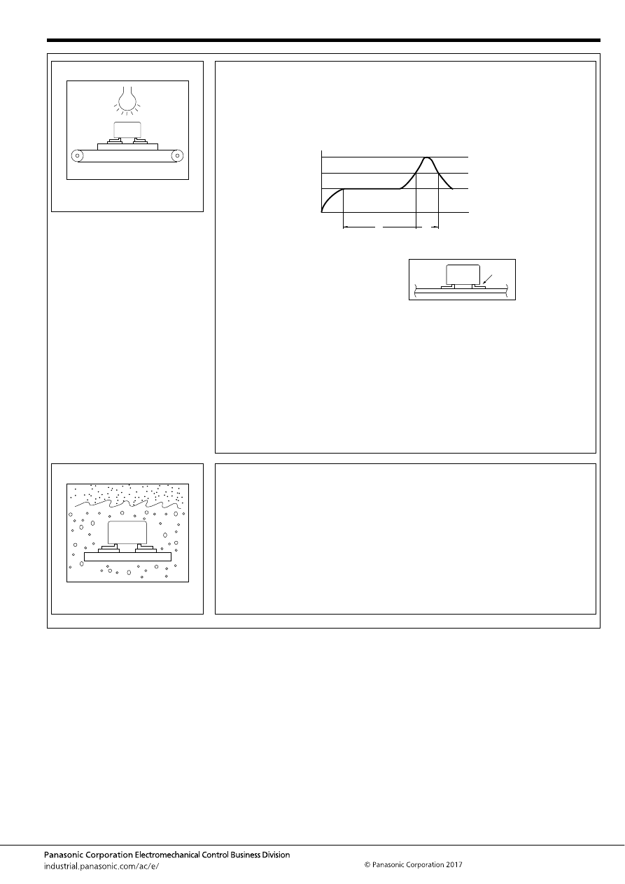
Automotive Relay Users Guide
–39–
ASCTB237E 201709-T
3. Reflow
• Even when highly heat resistance surface mount type relays are used, depending on the
product airtight implementation, reflow solder heating method, type of PC board and other
factors, the outer casing and internal parts of the relay may reach extremely high
temperatures and this may break airtightness. Devices should be thoroughly evaluated in
actual operation.
<Example of recommended soldering condition for surface mount relays>
1. IRS profile
Note: Temperature profile indicates the temperature of the soldered part (*1) of terminals on
the surface of a circuit board. The exterior temperature of a relay may be extremely high
depending on the component density on the board or the heating method of the reflow
oven or circuit board type. Sufficient verification under actual processing conditions is
required. Performance-guaranteed temperature varies by product. Please refer to the
relevant product catalog.
<Others>
For other solder methods except for the above (such as hot air heating, hot plate heating, laser
heating, pulse heating, etc.), please check for mounting and soldering condition before use.
It is recommended that the soldered pad be immediately cooled to prevent thermal damage to
the relay and its associated components.
4. Cooling / Cleaning
• In order to avoid deterioration of relays and other components caused by soldering heat,
immediate air cooling is recommended.
• Avoid cleaning (ultrasonic cleaning, boiling cleaning, etc.) and coating in order to prevent
negative impacts on relay characteristics.
t
1
t
2
T
3
T
2
T
1
T
1
= 150 to 180
°
C
T
2
= 230
°
C
T
3
= Less than 250
°
C
302 to 356
°
F
446
°
F
or more
482
°
F
t
1
= 60 to 120 sec.
t
2
= Less than 30 sec.
*1
automotive-relay_en-html.html
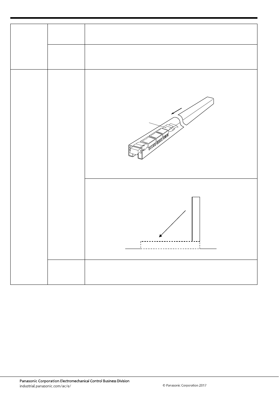
Automotive Relay Users Guide
–40–
ASCTB237E 201709-T
16. Storage,
transportation
1. Transportation
Relay’s functional damage may occur if strong vibration, shock or heavy weight is applied to a
relay during transportation of a device in which a relay is installed. Therefore, please pack them
in a way, using shock-absorbing material, so that the allowable range for vibration and shock is
not exceeded.
2. Storage
If the relay is stored for extended periods of time (including transportation period) at high
temperatures or high humidity levels or in atmospheres with organic gas or sulfide gas, sulfide
film or oxide film may be formed on surface of the contacts, which may cause contact instability,
contact failure and functional failure. Please check the atmosphere in which the units are to be
stored and transported.
17. Product
handling
1. Tube packing
Some types of relays are supplied with tube packaging. If you remove some relays from the tube,
be sure to slide a stop plug into one end of a tube to hold the remaining relays firmly and avoid
rattling of relay inside the tube. Note that rattling may cause a damage on appearance and/or
performance.
Do not use the relays if they were dropped or fallen down in a tube packing condition because
there is a risk of characteristic failure.
2. Cautions after
relay mounting
If PC boards are processed after relays have been mounted on the board, it is possible that
swarf or other foreign matter resulting from machining or other processes may get inside the
relays and cause malfunctions or contact failure. Pay particular attention if using flux tight relays
or relays with vent hole. In addition, take care to avoid vibrations and shocks during PC board
processing that may affect the characteristics and structural integrity of the relay.
Slide in the plug.
Stop plug
Fall of tube
automotive-relay_en-html.html
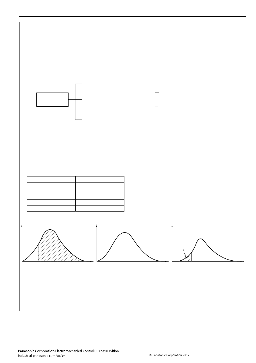
Automotive Relay Users Guide
–41–
ASCTB237E 201709-T
18. Reliability
[1] What is Reliability?
1. Reliability in a Narrow Sense of the Term
In the industrial world, reliability is an index of how long a particular product serves without failure during use period.
2. Reliability in a Board Sense of the Term
Every product has a finite service lifetime. This means that no product can continue normal service infinitely. When a product has broken
down, the user may throw it away or repair it. The reliability of repairable products is recognized as “reliability in a broad sense of the
term.” For repairable products, their serviceability or maintainability is another problem. In addition, reliability of product design is
becoming a serious concern for the manufacturing industry. In short, reliability has three senses: i.e. reliability of the product itself,
serviceability of the product, and reliability of product design.
3. Intrinsic Reliability and Reliability of Use
Reliability is “built” into products. This is referred to as intrinsic reliability which consists mainly of reliability in the narrow sense. Product
reliability at the user’s site is called “reliability of use,” which consists mainly of reliability in the broad sense. In the relay industry, reliability
of use has a significance in aspects of servicing.
[2] Reliability Measures
The following list contains some of the most popular reliability measures:
Reliability
(broad sense)
1.
2.
3.
Reliability (narrow sense), durability
Long life time: MTTF, B
10
, R(T),
Low failure rate: Lamda (
λ
), MTBF
Maintainability
MTTR
Preventive maintenance, predicted
maintenance
Design reliability
Human factor, redundancy,
fool-proof, fail-safe
Availability
Reliability measure
Sample representation
Degree of reliability R(T)
99.9%
MTBF
100 hours
MTTF
100 hours
Failure rate lambda
20 fit, 1%/hour
Safe life B10
50 hours
f(t)
T
Time
(a) R(T)
(b) MTTF
MTTF
10%
B
10
(c) Safe life
automotive-relay_en-html.html
Automotive Relay Users Guide
–42–
ASCTB237E 201709-T
1. Degree of Reliability
Degree of reliability represents percentage ratio of reliability. For example, if none of 10 light bulbs has failed for 100 hours, the degree of
reliability defined in, 100 hours of time is 10/10 = 100%. If only three bulbs remained alive, the degree of reliability is 3/10 = 30%. The JIS
Z8115 standard defines the degree of reliability as follows: The probability at which a system, equipment, or part provides the specified
functions over the intended duration under the specified conditions.
2. MTBF
MTBF is an acronym of Mean Time Between Failures. It indicates the mean time period in which a system, equipment, or part operates
normally between two incidences of repair. MTBF only applies to repairable products.
MTBF tells how long a product can be used without the need for repair. Sometimes MTBF is used to represent the service lifetime before
failure.
3. MTTF
MTTF is an acronym of Mean Time To Failure. It indicates the mean time period until a product becomes faulty MTTF normally applies to
unrepairable products such as parts and materials.
The relay is one of such objective of MTTF.
4. Failure Rate
Failure rate includes mean failure rate and momentary failure rate. Mean failure rate is defined as follows: Mean failure rate = Total failure
count/total operating hours
In general, failure rate refers to momentary failure rate. This represents the probability at which a system, equipment, or par t, which has
continued normal operation to a certain point of time, becomes faulty in the subsequent specified time period.
Failure rate is often represented in the unit of percent/hours. For parts with low failure rates, “failure unit (Fit) = 10-9 /hour” is often used
instead of failure rate. Percent/count is normally used for relays.
5. Safe Life
Safe life is an inverse of degree of reliability. It is given as value B which makes the following equation true:
1 - R(B) = t%
In general, “B[1 - R(B)] = 10%” is more often used. In some cases this represents a more practical value of reliability than MTTF.
automotive-relay_en-html.html
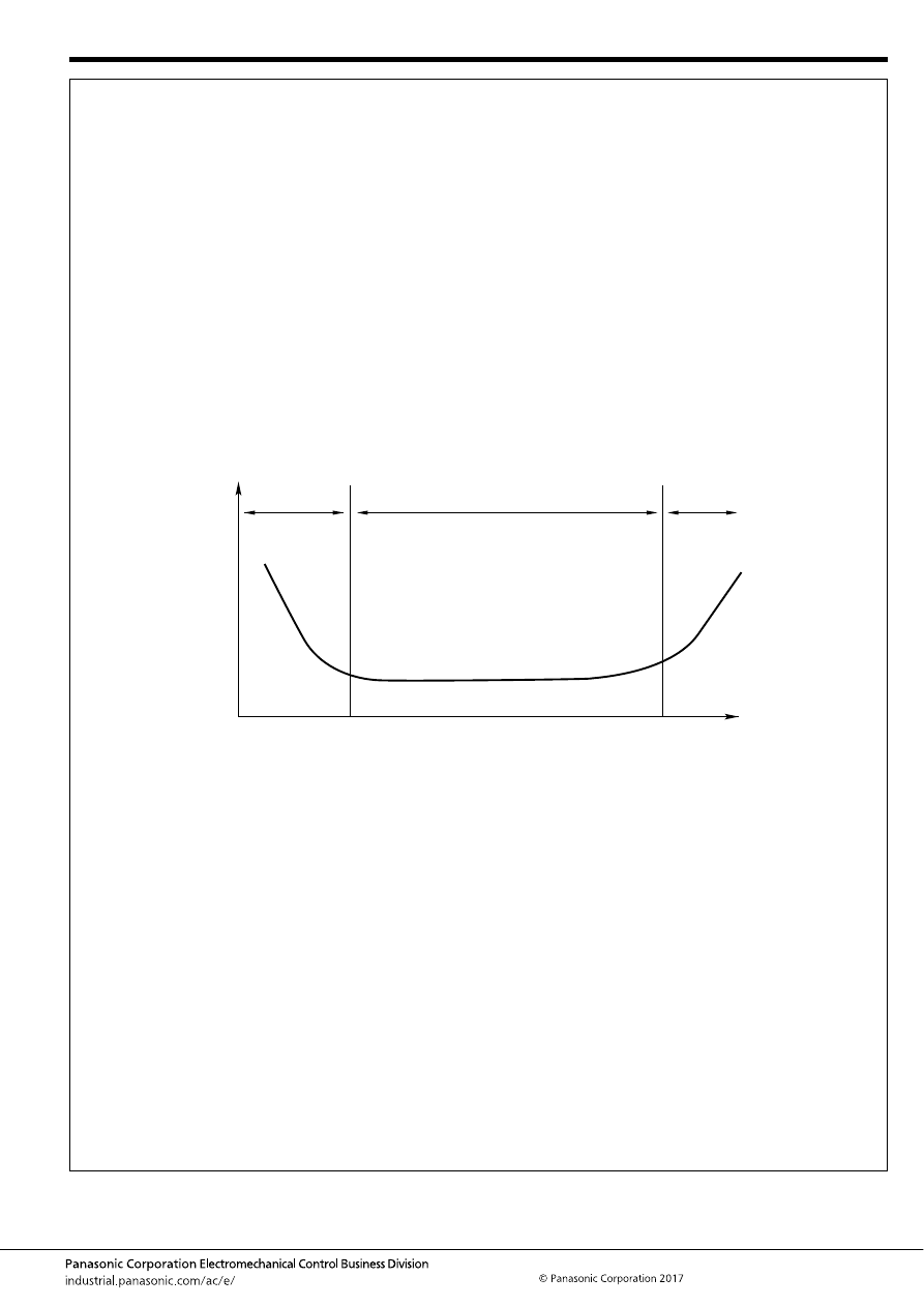
Automotive Relay Users Guide
–43–
ASCTB237E 201709-T
[3] Failure
1. What is Failure?
Failure is defined as a state of system, equipment, or component in which par t of all of its functions are impaired or lost.
2. Bathtub Curve
Product’s failure rate throughout its lifetime is depicted as a bathtub curve, as shown below. Failure rate is high at the beginning and end
of its service lifetime.
(I)
Initial failure period
The high failure rate in the initial failure period is derived from latent design errors, process errors, and many other causes. This
process is called debugging, performing aging or screening in order to find out initial failures.
(II) Accidental failure period
The initial failure period is followed by a long period with low, stable failure rate. In this period, called accidental failure period, failures
occurs at random along the time axis. While zero accidental failure rate is desirable, this is actually not practical in the real world.
(III) Wear-out failure period
In the final stage of the product’s service lifetime comes the wear-out failure period, in which the life of the product expires due to wear
of fatigue. Preventive maintenance is effective for this type of failure. The timing of a relay’s wear-out failure can be predicted with a
certain accuracy from the past record of uses. The use of a relay is intended only in the accidental failure period, and this period
virtually represents the service lifetime of the relay.
( I )
( II )
( III )
m < 1
m = 1
m > 1
F
ailure r
ate
Time
automotive-relay_en-html.html
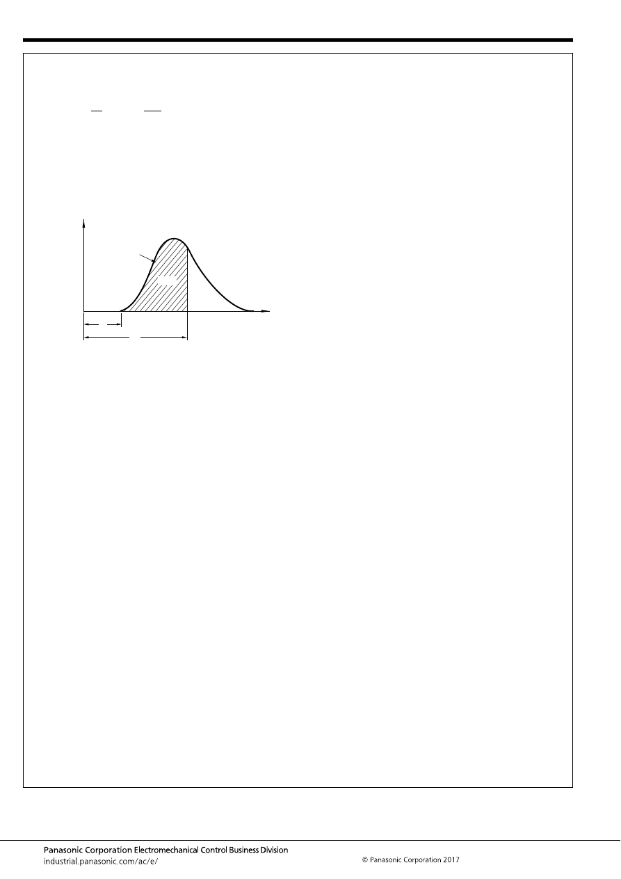
Automotive Relay Users Guide
–44–
ASCTB237E 201709-T
3. Weibull Analysis
Weibull analysis is often used for classifying a product’s failure patterns and to determine its lifetime.
Weibull distribution is expressed by the following equation:
Weibull distribution can be adopted to the actual failure rate distribution if the three variables above are estimated.
The Weibull probability chart is a simpler alternative of complex calculation formulas. The chart provides the following advantages:
(1) The Weibull distribution has the closest proximity to the actual failure rate distribution.
(2) The Weibull probability chart is easy to use.
(3) Different types of failures can be identified on the chart.
The following describes the correlation with the bathtub curve. The value of the parameter “m” represents the type of the failure.
(1) When m < 1: Initial failures
(2) When m = 1: Accidental failures
(3) When m > 1: Wear-out failures
(x) =
e
m
m
m
(
χ
–
γ
)
(
χ
–
γ
)
f
α
α
–1
–
m
α
γ
: Figure parameter
: Measurement parameter
: Position parameter
where
m
63%
F
ailure r
ate
γ
α
Time
automotive-relay_en-html.html
Automotive Relay Users Guide
–45–
ASCTB237E 201709-T
CHECK SHEET
Category
Check
box
Check item
Refer to the following
Category - Section
Safety
Does the vehicle system have a fail-safe in case of a relay failure?
1-1, 2-4
Load/
Electrical life
Has it been confirmed by testing under actual load, actual circuit, and actual
condition?
4-1
Have load type, load current characteristic, and current value been checked?
4-2 to 4-9
Isn’t the applied contact current too small? (Small current is likely to decrease the
contact reliability.)
4-10
Has connecting load polarity been checked?
4-11
Is the load likely to cause instant voltage drop?
4-12
Isn’t the applied contact voltage too high? (High voltage decreases electrical life.)
4-13
Isn’t applied coil voltage too high? (High voltage affects electrical life.)
4-14
Isn’t short pulse applied to coil?
4-15
Isn’t the switching frequency too high even including at abnormality?
4-16
Doesn’t switching continue for a long time?
4-17
Does it switch under high temperature?
4-18
Have precautions been checked for using of coil surge absorption circuit?
4-19
Have you checked there is no sneak current or voltage to the relay coil?
4-20
Is there stray capacitance between lead wires?
4-21
Have precautions been checked for using of contact protective circuit?
4-22
Is there a risk of dead short in the power supply?
4-23
Is there a risk of short circuit in the power supply at load rejection?
4-23
Is there a risk of insulation and dielectric strength between contacts in each pole
when high voltage is applied to a twin relay?
4-24
Is dry switching occurring?
4-25
Coil operation
voltage
Has hot start been considered?
5-1
Is the ambient temperature within the range of use? Also, is the ambient
temperature characteristics considered?
5-2
Is the applied voltage below the maximum continuous applied voltage?
5-3
Is there a risk of using PWM control? (PWM control requires careful attention.)
5-3
Doesn’t coil of twin relay operate at the same time?
5-4
Hasn’t the current continuously applied to coil over a long period?
5-5
Coil operation
circuit
In case of relay operation by electric circuit, is the circuit designed in consideration
of mal-function?
6-1, 6-2
Doesn’t the surge voltage of relay cause mal-function or destruction of transistor
circuit?
6-1, 6-2
When relay is applied to an electric circuit, has voltage drop caused by other
electric components on the circuit been considered?
6-1, 6-2
automotive-relay_en-html.html
Automotive Relay Users Guide
–46–
ASCTB237E 201709-T
Category
Check
box
Check item
Refer to the following
Category - Section
Contact reliability
Have precautions been checked in the case of switching with both high and low
loads by the same contact?
7-1
Doesn’t heat dissipation occur under low temperature?
7-2
Contact
resistance
Has transient state of contact resistance been considered?
8-1
Are contact voltage and current 6V 1A or higher?
8-2
Operating sound
Are there any problems regarding operating sound of relay?
9-1, 9-2
Mechanical noise
Are there any problems regarding abnormal weak noise of relay?
10-1
Use
environmental
condition
Is temperature, humidity, atomosphere pressure within the range of use?
12-1
Have precautions been checked in the case of switching under high humidity?
12-1
Is the ambient environment free from particles, dusts, sulfidizing gas, organic gas?
12-2
Is the ambient environment free from silicone?
12-3
Is the ambient environment free from high-field magnetic instruments such as
speaker?
12-4
Are the ambient vibration and shock below the relay’s vibration and impact
characteristics? Also, is there no resonance after the relay is mounted on PC
board?
12-5, 12-6
Isn’t there a risk of icing and dewing of relay?
7-2, 12-7, 12-9
Isn’t there a risk of water or oil adhesion?
12-8
Mounting
Doesn’t vibration or shock cause poor connection between a relay and a
connector?
13-1
PCB mounting
Have precautions been checked for operating of flux applying and automatic
soldering?
15-1, 15-2
Have precautions been checked for cleaning operation of print board?
15-1, 15-2
Isn’t glass shot performed for flux cleaning? (Particle of the glass may get inside
the relay and cause operation failure.)
15-1, 15-2
Has there been any warping of the PC board? Force applied on the relay terminals
may change the relay characteristics.
15-1, 15-2
Isn’t the unused terminal cut? (Applied force on terminal can change the
characteristics.)
12-5, 15-1, 15-2
Has the relay been applied to ultrasonic vibration during processing?
12-5, 15-1, 15-2
Is soldering carried out in proper conditions? (temperature duration, etc.)
15-1, 15-2
Storage,
transportation
Aren’t load, shock, or vibration which is out of the allowable range applied during
transportation?
16-1
Are temperature and humidity within the allowable range?
16-2
Is the ambient atomosphere free from organic gas and sulfidizing gas?
16-2
Product handling
Aren’t dropped or fallen tube packages used?
17-1
Are processing of PC board or other procedures carried out after relay mounting?
If so, are the relays subject to vibration or shock?
12-5, 17-2
automotive-relay_en-html.html
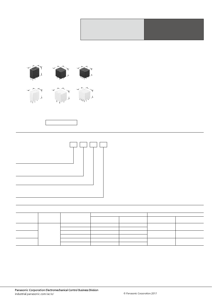
CJ (ACJ)
–47–
ASCTB221E 201709-T
ORDERING INFORMATION
TYPES
Compact Slim
Twin and Single Type
Automotive Relay
CJ RELAYS
Contact
arrangement
Rated coil voltage
Operate (Set) voltage
(at 20
°
C
68
°
F
) (Initial)
Part No.
Packing
Standard type
Pin in Paste compliant
type
Carton (tube)
Case
1 Form C
12 V DC
Max.6.5 V DC
ACJ1112
ACJ1112P
70 pcs.
2,800 pcs.
Max.7.2 V DC
ACJ1212
ACJ1212P
1 Form C
×
2
(8 pins)
Max.6.5 V DC
ACJ2112
ACJ2112P
40 pcs.
1,000 pcs.
Max.7.2 V DC
ACJ2212
ACJ2212P
1 Form C
×
2
(10 pins)
Max.6.5 V DC
ACJ5112
ACJ5112P
35 pcs.
1,400 pcs.
Max.7.2 V DC
ACJ5212
ACJ5212P
FEATURES
• It is extremely compact at approx. 2/3 the size of previous
CT relay.
• Compact and high-capacity 25 A load switching
• Pin in Paste compliant model added
TYPICAL APPLICATIONS
• Powered windows, Automatic door locks, Powered
mirrors, Powered sunroofs, Powered seats, Lift gates,
Smart J/B related products, etc.
<Protective construction>
Standard type: Sealed
Pin in Paste compliant type: Flux tight
(8 pins)
(10 pins)
7.2
12.2
13.5
13.7
12.2
13.5
7.2
12.2
13.8
13.7
12.2
13.8
12.2
13.5
14.4
12.2
13.8
14.4
.283
.480
.531
.539
.480
.531
.283
.480
.543
.539
.480
.543
.480
.531
.567
.480
.543
.567
(Unit: mm
inch
)
RoHS compliant
Contact arrangement
1: 1 Form C
2: 1 Form C
×
2 (8 pins)
5: 1 Form C
×
2 (10 pins)
ACJ
Rated coil voltage, DC
12: 12 V
Operate (Set) voltage
1: Max. 6.5 V DC
2: Max. 7.2 V DC
Mounting type
Nil:
P:
Standard type
Pin in Paste compliant type
automotive-relay_en-html.html
CJ (ACJ)
–48–
ASCTB221E 201709-T
RATING
1. Coil data
Note: *Other usable voltage range types are also available. Please inquire our sales representative for details.
2. Specifications
Notes: *1. Depends on connection conditions. Also, this does not guarantee repeated switching. We recommend that you confirm operation under actual conditions.
*2. This value can change due to the switching frequency, environmental conditions, and desired reliability level, therefore it is recommended to check this with the
actual load.
*3. The upper operation ambient temperature limit is the maximum temperature that can satisfy the coil temperature rise value. For details, please refer to the
“Automotive Relay Users Guide”.
Please inquire our sales representative if you will be using the relay in a high temperature atmosphere (110
°
C
230
°
F
).
If the relay is used continuously for long periods of time with coils on both sides in an energized condition, breakdown might occur due to abnormal heating depending on
the carrying condition. Therefore, please inquire our sales representative when using with a circuit that causes an energized condition on both sides simultaneously.
Rated coil
voltage
Operate (Set) voltage
(at 20
°
C
68
°
F
) (Initial)
Release (Reset)
voltage
(at 20
°
C
68
°
F
) (Initial)
Rated operating current
[
±
10%] (at 20
°
C
68
°
F
)
Coil resistance
[
±
10%] (at 20
°
C
68
°
F
)
Rated operating power
(at 20
°
C
68
°
F
)
Usable voltage range*
12 V DC
Max. 7.2 V DC
Min. 1.0 V DC
53.3 mA
225
Ω
640 mW
10 to 16 V DC
Max. 6.5 V DC
Min. 0.8 V DC
66.7 mA
180
Ω
800 mW
9 to 16 V DC
Item
Specifications
Contact data
Contact arrangement
1 Form C, 1 Form C
×
2
Contact resistance (initial)
Max. 50m
Ω
(N.O.: Typ. 7m
Ω
, N.C.: Typ. 10m
Ω
) (By voltage drop 1A 6V DC)
Contact material
Ag alloy
Rated switching capacity
(resistive)
N.O. side: 20A 14V DC, N.C. side: 10A 14V DC
Max. carrying current*
1
N.O. side: 20 A for 1 hour, 30 A for 2 minutes (Coil applied voltage 14 V DC at 20
°
C
68
°
F
)
Min. switching load
(resistive)*
2
1A 14V DC (at 20
°
C
68
°
F
)
Insulated resistance (initial)
Min. 100 M
Ω
(at 500V DC, Measurement at same location as “Dielectric strength” section.)
Dielectric
strength (initial)
Between open contacts
500 Vrms for 1 min. (Detection current: 10mA)
Between contacts and coil
500 Vrms for 1 min. (Detection current: 10mA)
Time
characteristics
(initial)
Operate (Set) time
(at Rated voltage)
Max. 10ms (at 20
°
C
68
°
F
, without bounce time)
Release (Reset) time
(at Rated voltage)
Max. 10ms (at 20
°
C
68
°
F
, without bounce time) (without diode)
Shock
resistance
Functional
Min. 100 m/s
2
{approx. 10G} (Half-wave pulse of sine wave: 11ms; detection time: 10
μ
s)
Destructive
Min. 1,000 m/s
2
{approx. 100G} (Half-wave pulse of sine wave: 6ms)
Vibration
resistance
Functional
10 to 100 Hz, Min. 44.1m/s
2
{approx. 4.5G} (detection time: 10
μ
s)
Destructive
10 to 500 Hz, Min. 44.1m/s
2
{approx. 4.5G}
Time of vibration for each direction; X, Y direction: 2 hours, Z direction: 4 hours
Expected life
Mechanical
Min. 10
7
(at 120 cpm)
Electrical
[Standard type]
<Resistive load>
Min. 10
5
(at rated switching capacity, operating frequency: 1s ON, 9s OFF)
<Motor load>
N.O. side: Min. 2
×
10
5
: at 25 A (inrush), 5 A (steady), 14 V DC; Min. 10
5
: at 25 A 14 V DC (Motor lock)
N.C. side: Min. 2
×
10
5
: at 20 A 14 V DC (brake) (Operating frequency: 0.5s ON, 9.5s OFF)
[Pin in Paste compliant type]
<Resistive load>
Min. 10
5
(at rated switching capacity, operating frequency: 1s ON, 9s OFF)
<Motor load>
N.O. side: Min. 10
5
: at 25 A (inrush), 5 A (steady), 14 V DC; Min. 5
×
10
4
: at 25 A 14 V DC (Motor lock)
N.C. side: Min. 10
5
: at 20 A 14 V DC (brake) (Operating frequency: 0.5s ON, 9.5s OFF)
Conditions
Conditions for usage,
transport and storage*
3
Ambient temperature: –40 to +85
°
C
–40 to +185
°
F
Humidity: 5 to 85% R.H. (Please avoid icing or condensation)
Weight
1 Form C type: approx. 3.5 g
.12 oz
, Twin type: approx. 6.5 g
.23 oz
∗
automotive-relay_en-html.html
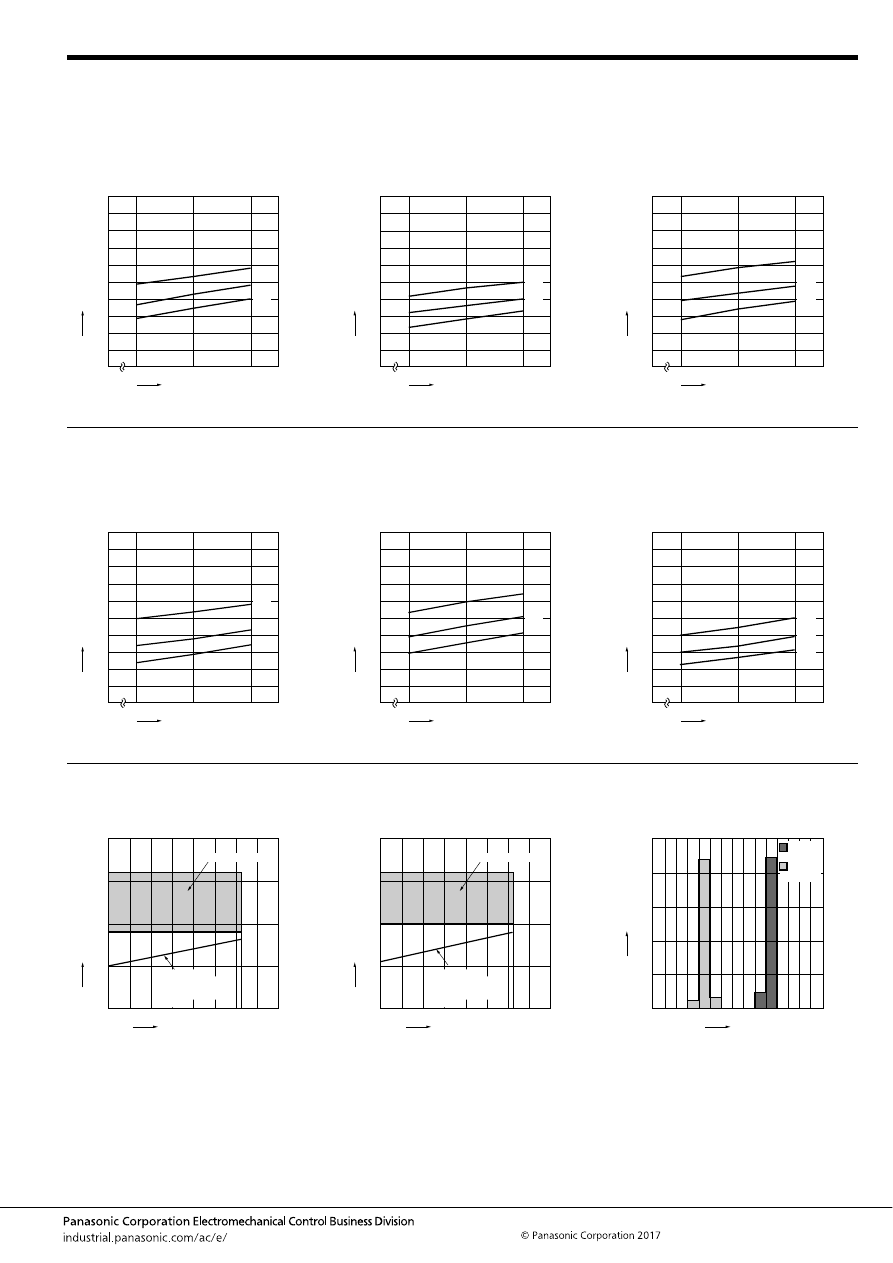
CJ (ACJ)
–49–
ASCTB221E 201709-T
REFERENCE DATA
1.-(1) Coil temperature rise (at room
temperature)
Sample: ACJ1212, 3pcs
Measured portion: Inside the coil
Carrying current: 10A, 15A, 20A
Ambient temperature: 25
°
C
77
°
F
1.-(2) Coil temperature rise (at 85
°
C
185
°
F
)
Sample: ACJ1212, 3pcs
Measured portion: Inside the coil
Carrying current: 10A, 15A, 20A
Ambient temperature: 85
°
C
185
°
F
1.-(3) Coil temperature rise (at room
temperature)
Sample: ACJ2212, 3pcs
Measured portion: Inside the coil
Carrying current: 10A, 15A, 20A
Ambient temperature: 25
°
C
77
°
F
0
80
60
40
20
12
0
16
200
160
140
180
120
100
14
20A
15A
10A
Coil applied voltage, V
T
emper
ature r
ise
,
°
C
0
80
60
40
20
12
0
16
200
160
140
180
120
100
14
20A
15A
10A
Coil applied voltage, V
T
emper
ature r
ise
,
°
C
0
80
60
40
20
12
0
16
200
160
140
180
120
100
14
20A
15A
10A
Coil applied voltage, V
T
e
mper
ature r
ise
,
°
C
(when coil powered on one side)
1.-(4) Coil temperature rise (at 85
°
C
185
°
F
)
Sample: ACJ2212, 3pcs
Measured portion: Inside the coil
Carrying current: 10A, 15A, 20A
Ambient temperature: 85
°
C
185
°
F
1.-(5) Coil temperature rise (at room
temperature)
Sample: ACJ5212, 3pcs
Measured portion: Inside the coil
Carrying current: 10A, 15A, 20A
Ambient temperature: 25
°
C
77
°
F
1.-(6) Coil temperature rise (at 85
°
C
185
°
F
)
Sample: ACJ5212, 3pcs
Measured portion: Inside the coil
Carrying current: 10A, 15A, 20A
Ambient temperature: 85
°
C
185
°
F
0
80
60
40
20
12
0
16
200
160
140
180
120
100
14
20A
15A
10A
Coil applied voltage, V
T
e
mper
ature r
ise
,
°
C
(when coil powered on one side)
0
80
60
40
20
12
0
16
200
160
140
180
120
100
14
20A
15A
10A
Coil applied voltage, V
T
e
mper
ature r
ise
,
°
C
(when coil powered on one side)
0
80
60
40
20
12
0
16
200
160
140
180
120
100
14
20A
15A
10A
Coil applied voltage, V
T
emper
ature r
ise
,
°
C
(when coil powered on one side)
2.-(1) Ambient temperature and usable voltage
range
2.-(2) Ambient temperature and usable voltage
range
3.-(1) Distribution of operate (set) and release
(reset) voltage
Sample: ACJ2112, 50pcs.
Ambient temperature: Room temperature
Ambient temperature,
°
C
Operate voltage:
ACJ1112, ACJ1112P
ACJ2112, ACJ2112P
ACJ5112, ACJ5112P
(cold start)
Coil applied v
oltage
,
VDC
120
20
15
10
5
0
-40 -20
0
20
40
60
80
100
Usable voltage range
Coil applied v
oltage
,
VDC
Ambient temperature,
°
C
Operate voltage:
ACJ1212, ACJ1212P
ACJ2212, ACJ2212P
ACJ5212, ACJ5212P
(cold start)
120
20
15
10
5
0
-40 -20
0
20
40
60
80
100
Usable voltage range
Quantity
, n
Voltage, V
0
50
40
30
20
10
0
1
2
3
4
5
6
7
Operate
voltage
Release
voltage
automotive-relay_en-html.html
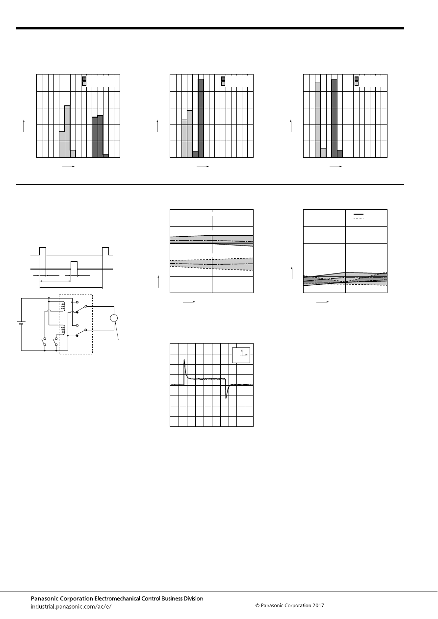
CJ (ACJ)
–50–
ASCTB221E 201709-T
3.-(2) Distribution of operate (set) and release
(reset) voltage
Sample: ACJ2212, 50pcs.
Ambient temperature: Room temperature
4.-(1) Distribution of operate (set) and release
(reset) time
Sample: ACJ2112, 50pcs.
Ambient temperature: Room temperature
4.-(2) Distribution of operate (set) and release
(reset) time
Sample: ACJ2212, 50pcs.
Ambient temperature: Room temperature
Quantity
, n
Voltage, V
0
50
40
30
20
10
0
1
2
3
4
5
6
7
Operate voltage
Release voltage
Quantity
, n
Time, ms
0
50
40
30
20
10
0
1
2
3
4
5
6
7
*Without diode
Operate time
Release time
Quantity
, n
Time, ms
0
50
40
30
20
10
0
1
2
3
4
5
6
7
*Without diode
Operate time
Release time
5.-(1) Electrical life test (Motor free)
Sample: ACJ2212, 3pcs
Load: Inrush current: 25A, Steady current: 5A,
Power window motor actual load (free condition)
Tested voltage: 14V DC
Switching frequency: ON 0.5s, OFF 9.5s
Switching cycle: 2
×
10
5
Ambient temperature: Room temperature
Circuit:
Change of operate (set) and release (reset)
voltage
Load current waveform
Load; Inrush current: 25A, Steady current: 6A,
Brake current: 13A
Change of contact resistance
No. 1
side
No. 2
side
0.5s
0.5s
5s
10s (1 cycle)
P/W motor
(free condition)
M
14V DC
No. of operations,
×
10
4
Oper
ate and release v
oltage
,
V
20
10
0
0
8
6
4
2
10
Max.
Max.
Min.
Min.
Ave.
Ave.
Operate voltage
Release voltage
Contact welding: 0 time
Miscontact: 0 time
100ms
10A
N.O. side
N.C. side
0
No. of operations,
×
10
4
Contact resistance
, m
Ω
Max.
Min.
Ave.(N.C.)
10
30
20
40
50
0
20
10
Max.
Min.
Ave.(N.O.)
automotive-relay_en-html.html
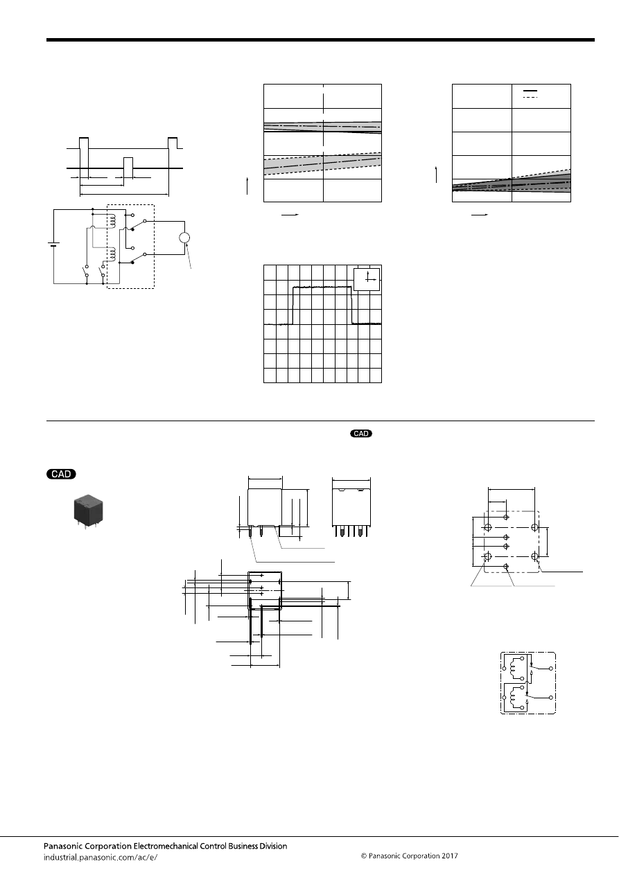
CJ (ACJ)
–51–
ASCTB221E 201709-T
DIMENSIONS
(mm
inch
)
1. Twin type (8-pin)
5.-(2) Electrical life test (Motor lock)
Sample: ACJ2212, 3pcs
Load: Steady current: 25A, Power window motor
actual load (lock condition)
Tested voltage: 14V DC
Switching frequency: ON 0.5s, OFF 9.5s
Switching cycle: 10
5
Ambient temperature: Room temperature
Circuit:
Change of operate (set) and release (reset)
voltage
Load current waveform
Change of contact resistance
No. 1
side
No. 2
side
0.5s
0.5s
5s
10s (1 cycle)
P/W motor
(lock condition)
M
14V DC
No. of operations,
×
10
4
Oper
ate and release v
oltage
,
V
10
5
0
0
8
6
4
2
10
Max.
Max.
Min.
Min.
Ave.
Ave.
Operate voltage
Release voltage
Contact welding: 0 time
Miscontact: 0 time
100ms
10A
Current value: 25A
N.O. side
N.C. side
0
No. of operations,
×
10
4
Contact resistance
, m
Ω
Max.
Min.
Ave.(N.C.)
10
30
20
40
50
0
5
10
Max.
Min.
Ave.(N.O.)
mark can be downloaded from: http://industrial.panasonic.com/ac/e/
The CAD data of the products with a
Standard type
External dimensions
12.2
13.5
.531
0.4
3.5
.016
.138
A surface level
13.7
.480
.539
6.5
.256
2
×
1.2
4
×
0.25
2
×
1
2
.079
10.45
.411
4
.157
2
×
0.6
4
×
0.6
2
×
0.32
0.8
±
0.3
.031
±
.012
4.5
.177
Pre-soldering (all terminals)
4.5
.177
Max.
1.0
Max.
.039
+
0.3
−
0.1
2
×
.024
+
.012
−
.004
+
0.3
−
0.1
4
×
.024
+
.012
−
.004
+
0.3
−
0.1
2
×
.013
+
.012
−
.004
+
0.3
−
0.1
+
0.3
−
0.1
2
×
.039
+
.012
−
.004
+
0.3
−
0.1
2
×
.047
4
×
.010
+
.012
−
.004
+
.012
−
.004
Dimension:
Tolerance
Max. 1mm
.039 inch
:
±
0.1
±
.004
1 to 3mm
.039 to .118 inch
:
±
0.2
±
.008
Min. 3mm
.118 inch
:
±
0.3
±
.012
* Dimensions (thickness and width) of terminal is measured before pre-soldering.
Intervals between terminals is measured at A surface level.
PC board pattern
(Bottom view)
Tolerance:
±
0.1
±
.004
Schematic
(Bottom view)
10.45
4.0
.411
.157
6.5
.256
4.5
2.0
4.5
.177
.079
.177
2
×
1.5
dia.
+
0.1
0
2
×
.059
dia.
+
.004
0
4
×
1.0
dia.
+
0.1
0
4
×
.039
dia.
+
.004
0
2
×
1.5
dia.
+
0.1
0
2
×
.059
dia.
+
.004
0
COIL
COM
COM
COIL
N.C.
N.O.
automotive-relay_en-html.html
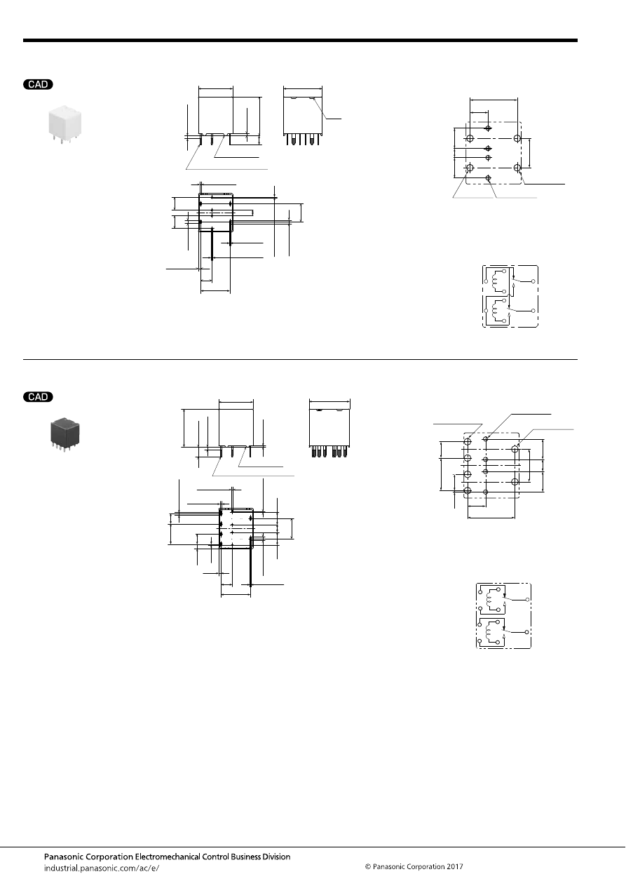
CJ (ACJ)
–52–
ASCTB221E 201709-T
2. Twin type (8-pin)
3. Twin type (10-pin)
Pin in Paste compliant type
External dimensions
A surface level
12.2
13.8
.543
3.2
.126
0.7
.028
Vent
13.7
.480
.539
6.5
.256
2
.079
2
×
1.2
4
×
0.25
4
.157
2
×
0.6
4
×
0.6
0.8
±
0.3
.031
±
.012
Pre-soldering (all terminals)
4.5
.177
4.5
.177
Max.
1.0
Max.
.039
+
0.3
−
0.1
2
×
.024
+
.012
−
.004
+
0.3
−
0.1
4
×
.024
+
.012
−
.004
+
0.3
−
0.1
+
0.3
−
0.1
2
×
.047
4
×
.010
+
.012
−
.004
+
.012
−
.004
2
×
1
+
0.3
−
0.1
2
×
.039
+
.012
−
.004
10.45
.411
2
×
0.32
+
0.3
−
0.1
2
×
.013
+
.012
−
.004
Dimension:
Tolerance
Max. 1mm
.039 inch
:
±
0.1
±
.004
1 to 3mm
.039 to .118 inch
:
±
0.2
±
.008
Min. 3mm
.118 inch
:
±
0.3
±
.012
* Dimensions (thickness and width) of terminal is measured before pre-soldering.
Intervals between terminals is measured at A surface level.
PC board pattern
(Bottom view)
Tolerance:
±
0.1
±
.004
Schematic
(Bottom view)
10.45
4.0
.411
.157
6.5
.256
4.5
2.0
4.5
.177
.079
.177
2
×
1.5
dia.
+
0.1
0
2
×
.059
dia.
+
.004
0
4
×
1.0
dia.
+
0.1
0
4
×
.039
dia.
+
.004
0
2
×
1.5
dia.
+
0.1
0
2
×
.059
dia.
+
.004
0
COIL
COM
COM
COIL
N.C.
N.O.
Standard type
External dimensions
12.2
13.5
.531
0.4
3.5
.016
.138
A surface level
14.4
.480
.567
2.7
.106
7.2
.283
7.2
.283
2
×
1.2
4
×
0.25
4
×
1
10.45
.411
4
.157
4
×
0.6
2
×
0.32
0.8
.031
Pre-soldering (all terminals)
4.5
.177
4.5
.177
Max.
1.0
Max.
.039
+
0.3
−
0.1
4
×
.024
+
.012
−
.004
4
×
0.6
+
0.3
−
0.1
4
×
.024
+
.012
−
.004
+
0.3
−
0.1
2
×
.013
+
.012
−
.004
+
0.3
−
0.1
+
0.3
−
0.1
4
×
.039
+
.012
−
.004
+
0.3
−
0.1
2
×
.047
4
×
.010
+
.012
−
.004
+
.012
−
.004
0.3
.012
1.65
3.6
.142
3.6
.142
.065
Dimension:
Tolerance
Max. 1mm
.039 inch
:
±
0.1
±
.004
1 to 3mm
.039 to .118 inch
:
±
0.2
±
.008
Min. 3mm
.118 inch
:
±
0.3
±
.012
* Dimensions (thickness and width) of terminal is measured before pre-soldering.
Intervals between terminals is measured at A surface level.
PC board pattern
(Bottom view)
Tolerance:
±
0.1
±
.004
Schematic
(Bottom view)
2
×
1.5
dia.
+
0.1
0
2
×
.059
dia.
+
.004
0
10.45
4.0
.411
.157
4.5
.177
2.7
.106
7.2
.283
7.2
.283
3.6
.142
3.6
.142
0.3
.012
4.5
.177
4
×
1.5
dia.
+
0.1
0
4
×
.059
dia.
+
.004
0
4
×
1.0
dia.
+
0.1
0
4
×
.039
dia.
+
.004
0
COIL
COM
N.O.
N.C.
COIL
COM
N.O.
N.C.
automotive-relay_en-html.html
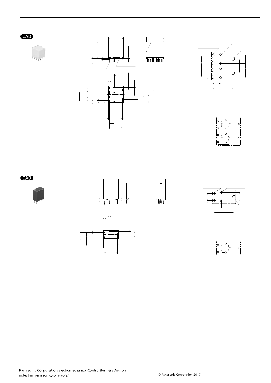
CJ (ACJ)
–53–
ASCTB221E 201709-T
4. Twin type (10-pin)
5. Slim 1 Form C
Pin in Paste compliant type
External dimensions
12.2
Vent
13.8
.543
0.7
3.2
.028
.126
A surface level
14.4
.480
.567
2.7
.106
7.2
.283
7.2
.283
2
×
1.2
4
×
0.25
4
×
1
10.45
.411
4
.157
4
×
0.6
2
×
0.32
0.8
.031
Pre-soldering (all terminals)
4.5
.177
4.5
.177
Max.
1.0
Max.
.039
+
0.3
−
0.1
4
×
.024
+
.012
−
.004
4
×
0.6
+
0.3
−
0.1
4
×
.024
+
.012
−
.004
+
0.3
−
0.1
2
×
.013
+
.012
−
.004
+
0.3
−
0.1
+
0.3
−
0.1
4
×
.039
+
.012
−
.004
+
0.3
−
0.1
2
×
.047
4
×
.010
+
.012
−
.004
+
.012
−
.004
0.3
.012
1.65
3.6
.142
3.6
.142
.065
Dimension:
Tolerance
Max. 1mm
.039 inch
:
±
0.1
±
.004
1 to 3mm
.039 to .118 inch
:
±
0.2
±
.008
Min. 3mm
.118 inch
:
±
0.3
±
.012
* Dimensions (thickness and width) of terminal is measured before pre-soldering.
Intervals between terminals is measured at A surface level.
PC board pattern
(Bottom view)
Tolerance:
±
0.1
±
.004
Schematic
(Bottom view)
2
×
1.5
dia.
+
0.1
0
2
×
.059
dia.
+
.004
0
10.45
4.0
.411
.157
4.5
.177
2.7
.106
7.2
.283
7.2
.283
3.6
.142
3.6
.142
0.3
.012
4.5
.177
4
×
1.5
dia.
+
0.1
0
4
×
.059
dia.
+
.004
0
4
×
1.0
dia.
+
0.1
0
4
×
.039
dia.
+
.004
0
COIL
COIL
COM
COM
N.O.
N.C.
N.O.
N.C.
Standard type
External dimensions
12.2
13.5
.531
3.5
.138
0.4
.016
A surface level
.480
7.2
.283
3.6
.142
1.2
2
×
0.25
2
×
1
10.45
.411
2
×
0.6
0.32
0.8
.031
4
.157
4.5
.177
Pre-soldering (all terminals)
0.3
.012
1.65
.065
Max.
1.0
Max.
.039
+
0.3
−
0.1
2
×
.024
+
.012
−
.004
2
×
0.6
+
0.3
−
0.1
2
×
.024
+
.012
−
.004
+
0.3
−
0.1
.013
+
.012
−
.004
+
0.3
−
0.1
+
0.3
−
0.1
2
×
.039
+
.012
−
.004
+
0.3
−
0.1
.047
2
×
.010
+
.012
−
.004
+
.012
−
.004
Dimension:
Tolerance
Max. 1mm
.039 inch
:
±
0.1
±
.004
1 to 3mm
.039 to .118 inch
:
±
0.2
±
.008
Min. 3mm
.118 inch
:
±
0.3
±
.012
* Dimensions (thickness and width) of terminal is measured before pre-soldering.
Intervals between terminals is measured at A surface level.
PC board pattern
(Bottom view)
Tolerance:
±
0.1
±
.004
Schematic
(Bottom view)
10.45
4.0
.411
.157
0.3
4.5
.012
3.6
.142
.177
2
×
1.5
dia.
+
0.1
0
2
×
.059
dia.
+
.004
0
2
×
1.0
dia.
+
0.1
0
2
×
.039
dia.
+
.004
0
1.5
dia.
+
0.1
0
.059
dia.
+
.004
0
COIL
COM
N.O.
N.C.
automotive-relay_en-html.html
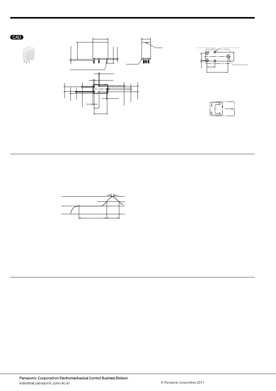
CJ (ACJ)
–54–
ASCTB221E 201709-T
6. Slim 1 Form C
NOTES
Mounting and cleaning conditions for Pin-in-Paste type
For general cautions for use, please refer to the “Automotive Relay Users Guide”.
Pin in Paste compliant type
External dimensions
12.2
13.8
.543
0.7
.028
3.2
.126
A surface
level
Vent
.480
7.2
.283
1.2
2
×
0.25
2
×
1
10.45
.411
2
×
0.6
0.32
0.8
.031
4
.157
4.5
.177
Pre-soldering (all terminals)
0.3
.012
1.65
.065
3.6
.142
Max.
1.0
Max.
.039
+
0.3
−
0.1
2
×
.024
+
.012
−
.004
2
×
0.6
+
0.3
−
0.1
2
×
.024
+
.012
−
.004
+
0.3
−
0.1
.013
+
.012
−
.004
+
0.3
−
0.1
+
0.3
−
0.1
2
×
.039
+
.012
−
.004
+
0.3
−
0.1
.047
2
×
.010
+
.012
−
.004
+
.012
−
.004
Dimension:
Tolerance
Max. 1mm
.039 inch
:
±
0.1
±
.004
1 to 3mm
.039 to .118 inch
:
±
0.2
±
.008
Min. 3mm
.118 inch
:
±
0.3
±
.012
* Dimensions (thickness and width) of terminal is measured before pre-soldering.
Intervals between terminals is measured at A surface level.
PC board pattern
(Bottom view)
Tolerance:
±
0.1
±
.004
Schematic
(Bottom view)
10.45
4.0
.411
.157
0.3
4.5
.012
3.6
.142
.177
2
×
1.5
dia.
+
0.1
0
2
×
.059
dia.
+
.004
0
2
×
1.0
dia.
+
0.1
0
2
×
.039
dia.
+
.004
0
1.5
dia.
+
0.1
0
.059
dia.
+
.004
0
COIL
COM
N.O.
N.C.
When soldering this relay, please observe the following
conditions.
[I.R.S. method (recommended)]
(Recommended number of reflows: 1)
• Cautions for mounting
1. The temperature profile shows the temperature at the
soldering portion on the PCB surface.
2. Depending on the mounting density condition, reflow
heating method, and PCB type (metal etc.), the relay’s
exterior and interior temperature may become extremely
high.
Therefore, please confirm well under the actual use
condition before use.
The other cautions of reflow soldering:
1. When soldering condition is out of recommendation, the
relay performance may be adversely affected.
If soldering conditions are out of our recommendation,
please contact us before operation.
2. Please check the effect at the actual soldering because
heat stress to relay is changed by PCB type and
manufacturing process condition.
3. Solder creepage, wettability or soldering strength will be
affected by the mounting condition or soldering material.
Please check the actual production condition in detail.
4. Do not wash the relay as failures may occur.
5. This product is not plastic sealed type. Please perform
coating with sufficient attention to avoid infiltration of the
solvent to the inside. Also, please pay careful attention to
use and store them with no contamination of foreign
material.
t
1
= 60 to 120 sec.
t
2
= Less than 30 sec.
t
3
= Less than 5 sec.
T
1
= 150 to 180
°
C
T
2
= 230
°
C
T
3
= Less than 250
°
C
302 to 356
°
F
446
°
F
or more
482
°
F
T
1
T
3
T
2
t
1
t
2
t
3
automotive-relay_en-html.html
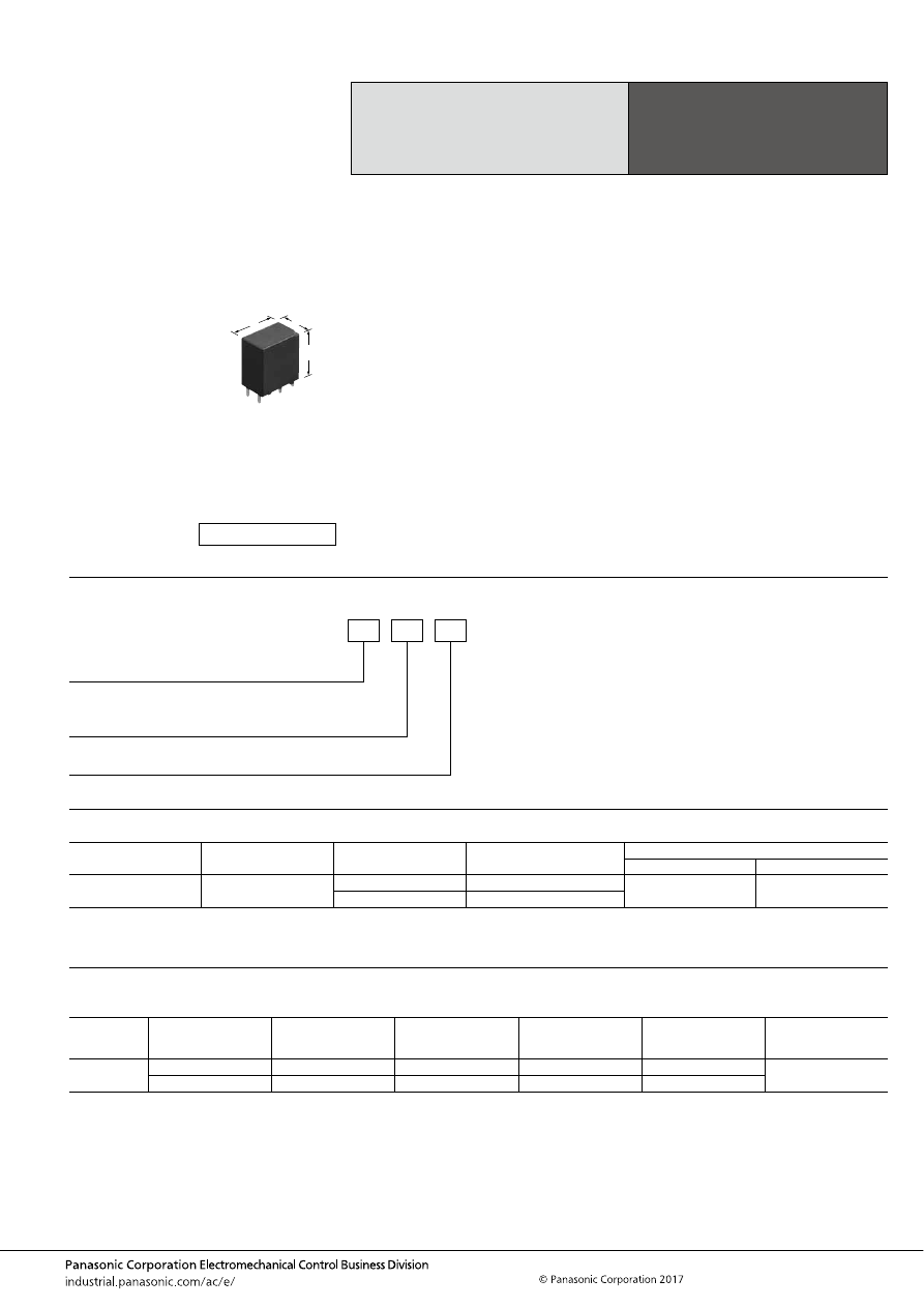
CN-H (ACNH)
–55–
ASCTB223E 201709-T
ORDERING INFORMATION
TYPES
RATING
1. Coil data
High Load Relay
for Smart J/B
CN-H RELAYS
Contact arrangement
Rated coil voltage
Operate (Set) voltage
(at 20
°
C
68
°
F
) (Initial)
Part No.
Packing
Carton (tube)
Case
1 Form A
12V DC
Max. 6.5 V DC
ACNH3212
50 pcs.
1,000 pcs.
Max. 5.5 V DC
ACNH3112
Rated coil
voltage
Operate (Set) voltage
(at 20
°
C
68
°
F
) (Initial)
Release (Reset)
voltage
(at 20
°
C
68
°
F
) (Initial)
Rated operating current
[
±
10%] (at 20
°
C
68
°
F
)
Coil resistance
[
±
10%] (at 20
°
C
68
°
F
)
Rated operating power
(at 20
°
C
68
°
F
)
Usable voltage range
12 V DC
Max. 6.5 V DC
Min. 1.0 V DC
37.5 mA
320
Ω
450 mW
10 to 16 V DC
Max. 5.5 V DC
Min. 0.8 V DC
53.3 mA
225
Ω
640 mW
FEATURES
• Space saving most suitable for smart J/B
• Large capacity switching despite small size. Can replace
micro ISO terminal type relays.
• Terminals for PC board pattern designs are easily
allocated.
TYPICAL APPLICATIONS
• Head lamp, Fog lamp, Fan motor, EPS, Defogger, Seat
heater, etc.
<Protective construction>
Sealed
10.6
17
18.3
.417
.669
.720
(Unit: mm
inch
)
RoHS compliant
ACNH
Operate (Set) voltage
1: Max. 5.5V DC
2: Max. 6.5V DC
Contact arrangement
3: 1 Form A
Rated coil voltage (DC)
12: 12V
automotive-relay_en-html.html
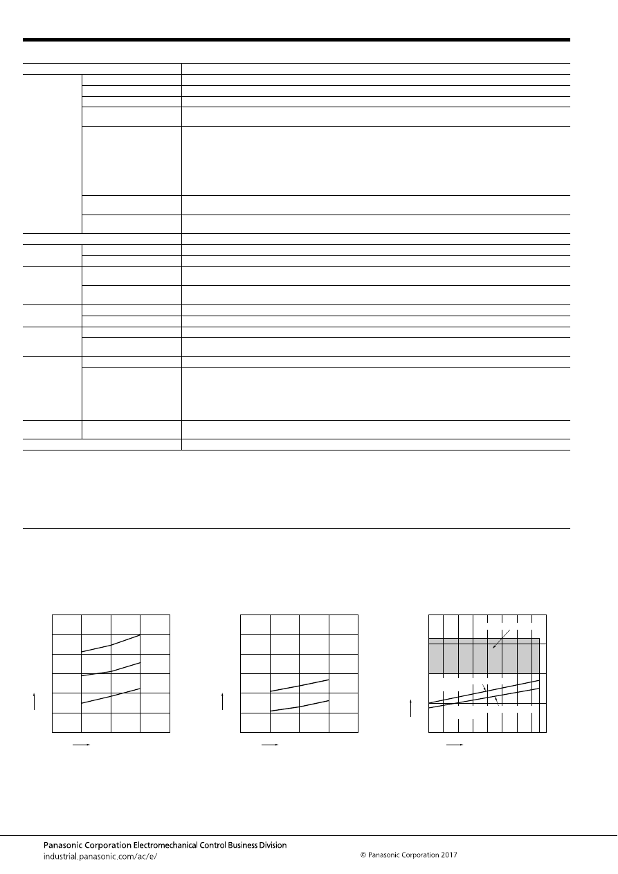
CN-H (ACNH)
–56–
ASCTB223E 201709-T
2. Specifications
Notes: *1. Depends on connection conditions. Also, this does not guarantee repeated switching. We recommend that you confirm operation under actual conditions.
*2. This value can change due to the switching frequency, environmental conditions, and desired reliability level, therefore it is recommended to check this with the
actual load.
*3. The upper operation ambient temperature limit is the maximum temperature that can satisfy the coil temperature rise value. For details, please refer to the
“Automotive Relay Users Guide”.
Please inquire our sales representative if you will be using the relay in a high temperature atmosphere (110
°
C
230
°
F
).
REFERENCE DATA
Item
Specifications
Contact data
Contact arrangement
1 Form A
Contact resistance (initial)
Max. 30m
Ω
(Typ. 5m
Ω
) (By voltage drop 1A 6V DC)
Contact material
Ag alloy
Rated switching capacity
(resistive)
30A 14V DC
Max. carrying current*
1
<450mW>
35A/1 hour, 45A/2 min. (Coil applied voltage 16V DC, at 20
°
C
68
°
F
)
30A/1 hour, 40A/2 min. (Coil applied voltage 16V DC, at 85
°
C
185
°
F
)
25A/1 hour, 35A/2 min. (Coil applied voltage 16V DC, at 110
°
C
230
°
F
)
<640mW>
30A/1 hour, 40A/2 min. (Coil applied voltage 16V DC, at 20
°
C
68
°
F
)
25A/1 hour, 35A/2 min. (Coil applied voltage 16V DC, at 85
°
C
185
°
F
)
20A/1 hour, 30A/2 min. (Coil applied voltage 16V DC, at 110
°
C
230
°
F
)
Continuous carrying current
20A 14V DC (450mW) at 110
°
C
230
°
F
15A 14V DC (640mW) at 110
°
C
230
°
F
Min. switching load
(resistive)*
2
1A 14V DC (at 20
°
C
68
°
F
)
Insulated resistance (initial)
Min. 100 M
Ω
(at 500V DC, Measurement at same location as “Dielectric strength” section.)
Dielectric
strength (initial)
Between open contacts
500 Vrms for 1 min. (Detection current: 10mA)
Between contacts and coil
500 Vrms for 1 min. (Detection current: 10mA)
Time
characteristics
(initial)
Operate (Set) time
(at Rated voltage)
Max. 10ms (at 20
°
C
68
°
F
, without contact bounce time)
Release (Reset) time
(at Rated voltage)
Max. 10ms (at 20
°
C
68
°
F
) (without diode)
Shock
resistance
Functional
Min. 100 m/s
2
{approx. 10G} (Half-wave pulse of sine wave: 11ms; detection time: 10
μ
s)
Destructive
Min. 1,000 m/s
2
{approx. 100G} (Half-wave pulse of sine wave: 6ms)
Vibration
resistance
Functional
10 to 100 Hz, Min. 44.1m/s
2
{approx. 4.5G} (Detection time: 10
μ
s)
Destructive
10 to 500 Hz, Min. 44.1m/s
2
{approx. 4.5G}
Time of vibration for each direction; X, Y direction: 2 hours, Z direction: 4 hours
Expected life
Mechanical
Min. 10
7
(at 120 cpm)
Electrical
<Resistive load>
Min. 10
5
(at rated switching capacity, operating frequency: 1s ON, 1s OFF)
<Motor load>
Min. 3
×
10
5
(motor free) (at inrush 84 A, steady 18 A, 14 V DC operating frequency: ON 2s, OFF 5s)
<Lamp load>
Min. 2
×
10
5
(at inrush 84 A, steady 12 A, 14 V DC operating frequency: ON 1s, OFF 14s)
Conditions
Conditions for usage,
transport and storage*
3
Ambient temperature: –40 to +110
°
C
–40 to +230
°
F
Humidity: 2 to 85% R.H. (Please avoid icing or condensation)
Weight
Approx. 9 g
.32 oz
1-(1). Coil temperature rise (at room
temperature)
Sample: ACNH3212, 3pcs
Measured portion: Inside the coil
Carrying current: 10A, 20A, 30A
Ambient temperature: 25
°
C
77
°
F
1-(2). Coil temperature rise (at 110
°
C
230
°
F
)
Sample: ACNH3212, 3pcs
Measured portion: Inside the coil
Carrying current: 10A, 20A
Ambient temperature: 110
°
C
230
°
F
2. Ambient temperature and usable voltage
range
10A
20A
30A
Coil applied voltage, V
T
e
mper
ature r
ise
,
°
C
18
16
14
12
10
120
100
80
60
40
20
0
10A
20A
Coil applied voltage, V
T
e
mper
ature r
ise
,
°
C
18
16
14
12
10
120
100
80
60
40
20
0
-40
-20
0
20
40
60
80 100 110 120
20
15
10
5
0
Ambient temperature,
°
C
Coil applied v
oltage
,
VDC
Operate voltage: ACNH3212
(cold start)
Operate voltage: ACNH3112
(cold start)
Usable voltage range
automotive-relay_en-html.html
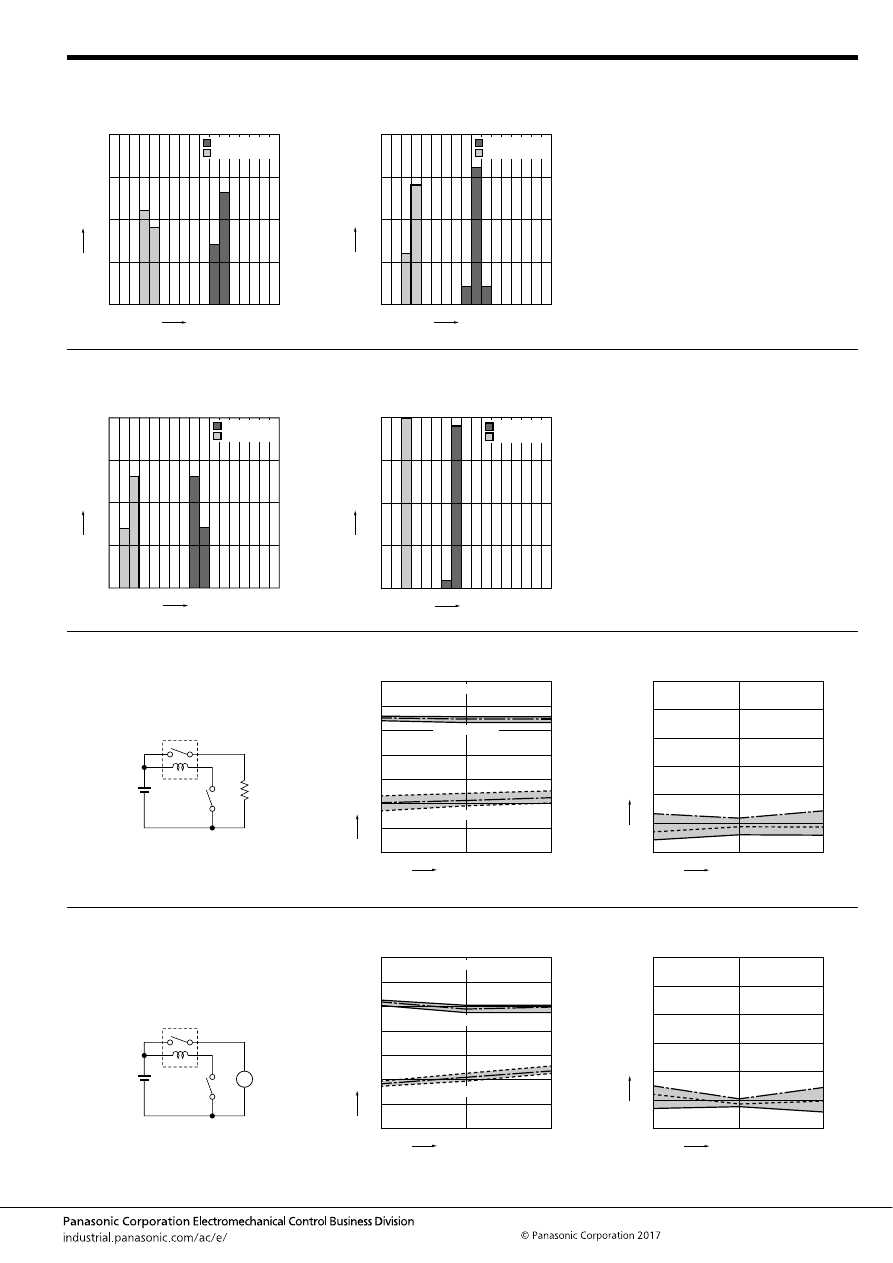
CN-H (ACNH)
–57–
ASCTB223E 201709-T
3-(1). Distribution of operate (set) and release
(reset) voltage
Sample: ACNH3212, 20pcs.
3-(2). Distribution of operate (set) and release
(reset) voltage
Sample: ACNH3112, 20pcs.
Voltage, V
Operate voltage
Release voltage
Quantity
, n
20
15
10
5
0
0
1
2
3
4
5
6
7
8
Voltage, V
Quantity
, n
Operate voltage
Release voltage
20
15
10
5
0
0
1
2
3
4
5
6
7
8
4-(1). Distribution of operate (set) and release
(reset) time
Sample: ACNH3212, 20pcs.
4-(2). Distribution of operate (set) and release
(reset) time
Sample: ACNH3112, 20pcs.
Quantity
, n
Time, ms
Operate time
Release time
20
15
10
5
0
0
1
2
3
4
5
6
7
8
*Without diode
Quantity
, n
Time, ms
Operate time
Release time
20
15
10
5
0
0
1
2
3
4
5
6
7
8
*Without diode
5-(1). Electrical life test (Resistive load)
Sample: ACNH3212, 6pcs.
Load: Resistive load: 30A 14V DC
Operating frequency: ON 1s, OFF 1s
Ambient temperature: Room temperature
Circuit:
Change of operate (set) and release (reset)
voltage
Change of contact resistance
14V DC
10
5
0
Oper
ate and release v
oltage
,
V
No. of operations,
×
10
4
Contact welding: 0 time
Miscontact: 0 time
Max.
Ave.
Min.
Max.
Ave.
Min.
Operate voltage
Release voltage
7
6
5
4
3
2
1
0
10
5
0
No. of operations,
×
10
4
Max.
Ave.
Min.
Contact resistance
, m
Ω
30
25
20
15
10
5
0
5-(2). Electrical life test (Motor load)
Sample: ACNH3212, 3pcs.
Load: inrush: 84A, steady: 18A,
radiator fan actual load (motor free)
Operating frequency: ON 2s, OFF 5s
Ambient temperature: 110
°
C
230
°
F
Circuit:
Change of operate (set) and release (reset)
voltage
Change of contact resistance
14V DC
M
30
15
0
Oper
ate and release v
oltage
,
V
No. of operations,
×
10
4
Contact welding: 0 time
Miscontact: 0 time
Max.
Ave.
Min.
Max.
Ave.
Min.
Operate voltage
Release voltage
7
6
5
4
3
2
1
0
30
15
0
No. of operations,
×
10
4
Max.
Ave.
Min.
Contact resistance
, m
Ω
30
25
20
15
10
5
0
automotive-relay_en-html.html
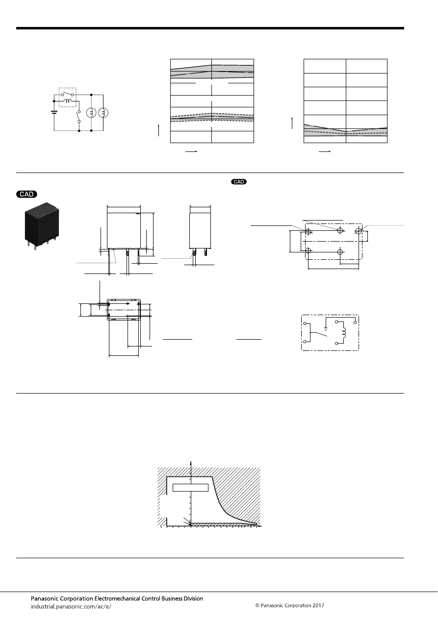
CN-H (ACNH)
–58–
ASCTB223E 201709-T
DIMENSIONS
(mm
inch
)
NOTES
For general cautions for use, please refer to the “Automotive Relay Users Guide”.
5-(3). Electrical life test (Lamp load)
Sample: ACNH3212, 6pcs.
Load: 60W
×
2, inrush: 84A, steady: 12A
Operating frequency: ON 1s, OFF 14s
Ambient temperature: Room temperature
Circuit:
Change of operate (set) and release (reset)
voltage
Change of contact resistance
14V DC
60W
60W
20
10
0
Oper
ate and release v
oltage
,
V
No. of operations,
×
10
4
Contact welding: 0 time
Miscontact: 0 time
Max.
Ave.
Min.
Max.
Ave.
Min.
Operate voltage
Release voltage
7
6
5
4
3
2
1
0
20
10
0
No. of operations,
×
10
4
Max.
Ave.
Min.
Contact resistance
, m
Ω
30
25
20
15
10
5
0
mark can be downloaded from: http://industrial.panasonic.com/ac/e/
The CAD data of the products with a
External dimensions
17
3.5
.138
18.3
.720
0.4
.016
Pre-soldering
(all terminals)
A surface level
.669
10.6
.417
2
×
1.2
14.95
.589
5.5
.217
1.1
.043
2
×
0.32
5.6
.220
6.4
.252
3
.118
Max.
1.0
Max.
.039
0.6
+
0.3
−
0.1
.024
+
.012
−
.004
2
×
1.2
+
0.3
−
0.1
2
×
.047
+
.012
−
.004
1.2
+
0.3
−
0.1
.047
+
.012
−
.004
+
0.3
−
0.1
2
×
.013
+
.012
−
.004
+
0.3
−
0.1
2
×
.047
+
.012
−
.004
2
×
0.3
+
0.3
−
0.1
2
×
.012
+
.012
−
.004
Dimension:
Tolerance
Max. 1mm
.039 inch
:
±
0.1
±
.004
1 to 3mm
.039 to .118 inch
:
±
0.2
±
.008
Min. 3mm
.118 inch
:
±
0.3
±
.012
PC board pattern
(Bottom view)
Tolerance:
±
0.1
±
.004
Schematic
(Bottom view)
1.7
dia. (hole)
+0.1
0
.067
dia. (hole)
+.004
0
2
×
1.6
dia. (hole)
+0.1
0
2
×
.063
dia. (hole)
+.004
0
2
×
1.6
dia. (hole)
+0.1
0
2
×
.063
dia. (hole)
+.004
0
14.95
.589
5.5
.217
3.0
.118
6.4
.252
5.6
.220
Coil
COM
N.O.
Coil
COM
* Dimensions (thickness and width) of terminal is measured before pre-soldering.
Intervals between terminals is measured at A surface level.
Usage, transport and storage
conditions
1) Ambient temperature, humidity, and air
pressure during usage, transport, and
storage of the relay:
(1) Temperature:
–40 to +110
°
C
–40 to +230
°
F
(2) Humidity: 2 to 85% RH
(Avoid icing and condensation.)
(3) Air pressure: 86 to 106 kPa
The humidity range varies with the
temperature. Use within the range
indicated in the graph below.
(Temperature and humidity range for
usage, transport, and storage)
85
5
2
110
85
0
–40
+230
+185
+32
–40
Humidity, %RH
Temperature,
°
C
°
F
Tolerance range
(Avoid
condensation
when used at
temperatures
higher than
0
°
C
32
°
F
)
(Avoid icing
when used at
temperatures
lower than
0
°
C
32
°
F
)
automotive-relay_en-html.html
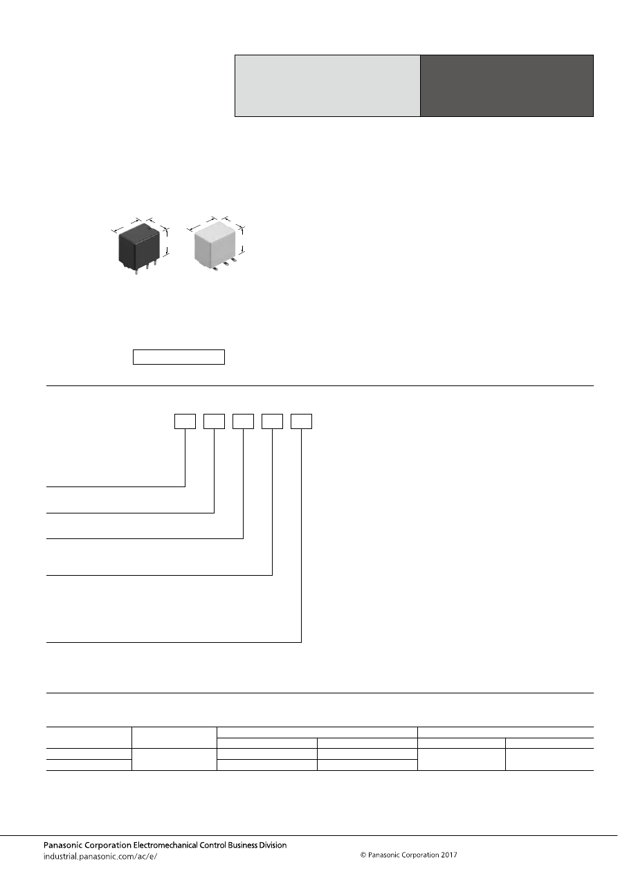
CN-M (ACNM)
–59–
ASCTB224E 201709-T
ORDERING INFORMATION
TYPES
1. PC board terminal type
Middle Load Relay
for Smart J/B
CN-M RELAYS
Contact arrangement
Rated coil voltage
Part No.
Packing
Standard type
High heat-resistant type
Carton (tube)
Case
1 Form A
12V DC
ACNM3112
ACNM7112
50 pcs.
1,500 pcs.
1 Form C
ACNM1112
ACNM5112
FEATURES
• Space saving most suitable for smart J/B
• Compact and high-capacity 30A load switching.
• Full line up (High heat-resistant type and SMD type)
• Terminals for PC board pattern designs are easily
allocated.
TYPICAL APPLICATIONS
• Defogger, Seat heater, Head lamp, Fog lamp, Fan motor,
etc.
<Protective construction>
Sealed
11
15.5
14.4
.433
.610
.567
11
15.5
15.1
.433
.610
.594
(Unit: mm
inch
)
RoHS compliant
Contact arrangement*
1
1: 1 Form C
3: 1 Form A
5: 1 Form C high heat-resistant type
7: 1 Form A high heat-resistant type
Packing style*
2
Nil:
X:
Z:
Tube packing
Tape and reel packing
(Reverse N.O. terminal direction in pull-out direction)
Tape and reel packing
(Normal N.O. terminal direction in pull-out direction)
ACNM
Operate (Set) voltage
1: Max. 7.2V DC
Rated coil voltage (DC)
12: 12V
Terminal shape
Nil:
SA:
PC board terminal type
Surface-mount terminal type
Notes: *1. Surface-mount terminal type is available in high heat-resistant type only.
*2. Tube packing: PC board terminal type only
Tape and reel packing: Surface-mount type only
automotive-relay_en-html.html
CN-M (ACNM)
–60–
ASCTB224E 201709-T
2. Surface-mount terminal type
Notes: *1. Surface-mount terminal type is available in high heat-resistant type only.
*2. An “X” at the end of the part number indicates, for tape and reel packing, reverse N.O. terminal direction in pull-out direction.
A “Z” at the end of the part number indicates, for tape and reel packing, normal N.O. terminal direction in pull-out direction.
Tape and reel packing symbol “z” or “x” are not marked on the relay.
RATING
1. Coil data
2. Specifications
Notes: *1. Depends on connection conditions. Also, this does not guarantee repeated switching. We recommend that you confirm operation under actual conditions.
*2. This value can change due to the switching frequency, environmental conditions, and desired reliability level, therefore it is recommended to check this with the
actual load.
*3. The upper operation ambient temperature limit is the maximum temperature that can satisfy the coil temperature rise value. For details, please refer to the
“Automotive Relay Users Guide”.
Please inquire our sales representative if you will be using the relay in a high temperature atmosphere (110
°
C
230
°
F
).
Contact arrangement
Rated coil voltage
Part No.
Packing
High heat-resistant type
Carton (tube)
Case
1 Form A
12V DC
ACNM7112SAX
200 pcs.
600 pcs.
ACNM7112SAZ
1 Form C
ACNM5112SAX
ACNM5112SAZ
Rated coil
voltage
Operate (Set) voltage
(at 20
°
C
68
°
F
) (Initial)
Release (Reset)
voltage
(at 20
°
C
68
°
F
) (Initial)
Rated operating current
[
±
10%] (at 20
°
C
68
°
F
)
Coil resistance
[
±
10%] (at 20
°
C
68
°
F
)
Rated operating power
(at 20
°
C
68
°
F
)
Usable voltage range
12 V DC
Max. 7.2 V DC
Min. 1.0 V DC
53.3 mA
225
Ω
640 mW
10 to 16 V DC
Item
Specifications
Contact data
Contact arrangement
1 Form A, 1 Form C
Contact resistance (initial)
Max. 30m
Ω
(Typ. 5m
Ω
) (By voltage drop 1A 6V DC)
Contact material
Ag alloy
Rated switching capacity
(resistive)
N.O. side: 30A 14V DC, N.C. side: 15A 14V DC
Max. carrying current*
1
N.O. side
30A/1 hour, 40A/2 min. (Coil applied voltage 16V DC, at 20
°
C
68
°
F
)
25A/1 hour, 35A/2 min. (Coil applied voltage 16V DC, at 85
°
C
185
°
F
)
20A/1 hour, 30A/2 min. (Coil applied voltage 16V DC, at 110
°
C
230
°
F
) (High heat-resistant type)
Min. switching load
(resistive)*
2
1A 14V DC (at 20
°
C
68
°
F
)
Insulated resistance (initial)
Min. 100 M
Ω
(at 500V DC, Measurement at same location as “Dielectric strength” section.)
Dielectric
strength (Initial)
Between open contacts
500 Vrms for 1 min. (Detection current: 10mA)
Between contacts and coil
500 Vrms for 1 min. (Detection current: 10mA)
Time
characteristics
(initial)
Operate (Set) time
(at Rated voltage)
Max. 10ms (at 20
°
C
68
°
F
, without bounce time)
Release (Reset) time
(at Rated voltage)
Max. 10ms (at 20
°
C
68
°
F
, without bounce time) (without diode)
Shock
resistance
Functional
Min. 100 m/s
2
{approx. 10G} (Half-wave pulse of sine wave: 11ms; detection time: 10
μ
s)
Destructive
Min. 1,000 m/s
2
{approx. 100G} (Half-wave pulse of sine wave: 6ms)
Vibration
resistance
Functional
10 to 100 Hz, Min. 44.1m/s
2
{approx. 4.5G} (Detection time: 10
μ
s)
Destructive
10 to 500 Hz, Min. 44.1m/s
2
{approx. 4.5G}
Time of vibration for each direction; X, Y direction: 2 hours, Z direction: 4 hours
Expected life
Mechanical
Min. 10
7
(at 120 cpm)
Electrical
<Resistive load>
Min. 10
5
(At rated switching capacity, operating frequency: ON 1s, OFF 9s)
<Motor load>
Min. 2
×
10
5
(motor free): at 80 A (inrush), 16 A (steady), 14 V DC (Operating frequency: ON 2s, OFF 6s)
<Lamp load>
Min. 10
5
: at 84 A (inrush), 12 A (steady), 14 V DC (Operating frequency: ON 1s, OFF 14s)
Conditions
Conditions for usage,
transport and storage*
3
Standard type;
Ambient temperature: –40 to +85
°
C
–40 to +185
°
F
, Humidity: 5 to 85% R.H.
High heat-resistant type;
Ambient temperature: –40 to +110
°
C
–40 to +230
°
F
, Humidity: 2 to 85% R.H.
(Please avoid icing or condensation)
Weight
Approx. 5.5 g
.19 oz
automotive-relay_en-html.html
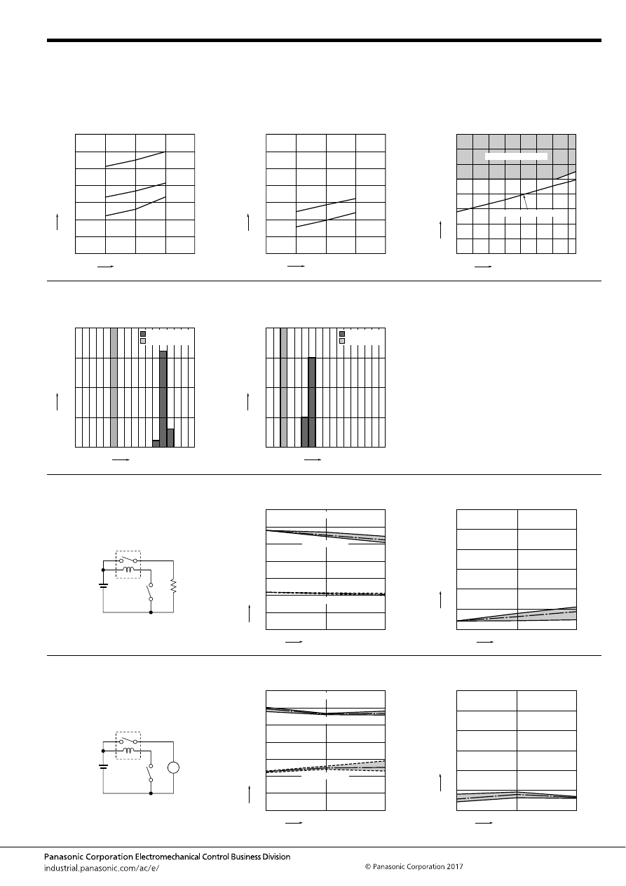
CN-M (ACNM)
–61–
ASCTB224E 201709-T
REFERENCE DATA
1-(1). Coil temperature rise (at room
temperature)
Sample: ACNM1112, 3pcs
Measured portion: Inside the coil
Carrying current: 10A, 20A, 30A
Ambient temperature: 26
°
C
78.8
°
F
1-(2). Coil temperature rise (at 110
°
C
230
°
F
)
Sample: ACNM7112, 3pcs
Measured portion: Inside the coil
Carrying current: 10A, 20A
Ambient temperature: 110
°
C
230
°
F
2. Ambient temperature and usable voltage
range
0
140
80
60
40
20
12
14
16
18
10
10A
20A
30A
100
120
Coil applied voltage, V
T
e
mper
ature r
ise
,
°
C
0
140
120
100
80
60
40
20
12
14
16
18
10
10A
20A
Coil applied voltage, V
T
emper
ature r
ise
,
°
C
-40
-20
0
20
40
60
80
100 110
16
14
12
10
8
6
4
2
0
Operate voltage (cold start)
Ambient temperature,
°
C
Coil applied v
oltage
,
VDC
Usable voltage range
3. Distribution of operate (set) and release
(reset) voltage
Sample: ACNM1112, 20pcs.
4. Distribution of operate (set) and release
(reset) time
Sample: ACNM1112, 20pcs.
0
10
5
15
20
0
1
2
3
5
4
6
7
8
Voltage, V
Quantity
, n
Operate voltage
Release voltage
8
20
15
10
5
0
0
1
2
3
4
5
6
7
Time, ms
Quantity
, n
Operate time
Release time
*Without diode
5-(1). Electrical life test (Resistive load)
Sample: ACNM1112, 3pcs.
Load: Resistive load (N.O. side: 30A 14V DC)
Operating frequency: ON 1s, OFF 9s
Ambient temperature: Room temperature
Circuit:
Change of operate (set) and release (reset)
voltage
Change of contact resistance
14V DC
0
10
5
6
7
4
2
3
5
1
0
Oper
ate and release v
oltage
,
V
No. of operations,
×
10
4
Operate voltage
Release voltage
Contact welding: 0 time
Miscontact: 0 time
Max.
Ave.
Min.
Max.
Ave.
Min.
0
10
5
20
30
10
15
25
5
0
No. of operations,
×
10
4
Max.
Ave.
Min.
Contact resistance
, m
Ω
5-(2). Electrical life test (Motor load)
Sample: ACNM7112, 3pcs.
Load: inrush: 80A/steady: 16A (motor free)
Operating frequency: ON 2s, OFF 6s
Ambient temperature: 110
°
C
230
°
F
Circuit:
Change of operate (set) and release (reset)
voltage
Change of contact resistance
14V DC
M
0
20
10
6
7
4
2
3
5
1
0
Oper
ate and release v
oltage
,
V
No. of operations,
×
10
4
Operate voltage
Release voltage
Contact welding: 0 time
Miscontact: 0 time
Max.
Ave.
Min.
Max.
Ave.
Min.
0
20
10
20
30
10
15
25
5
0
No. of operations,
×
10
4
Contact resistance
, m
Ω
Max.
Ave.
Min.
automotive-relay_en-html.html
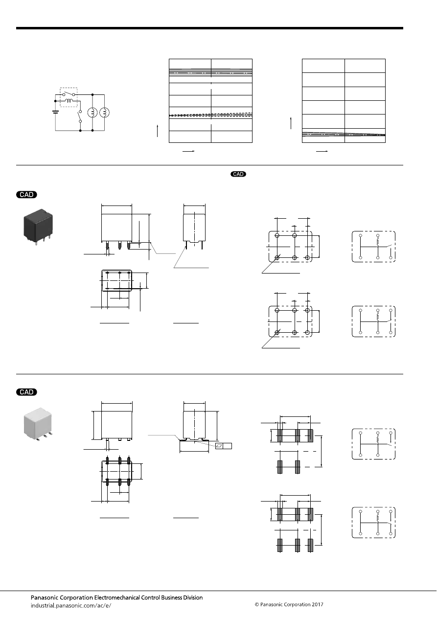
CN-M (ACNM)
–62–
ASCTB224E 201709-T
DIMENSIONS
(mm
inch
)
1. PC board terminal type
2. Surface-mount terminal type
5-(3). Electrical life test (Lamp load)
Sample: ACNM3112, 3pcs.
Load: inrush: 84A/steady: 12A
Operating frequency: ON 1s, OFF 14s
Ambient temperature: Room temperature
Circuit:
Change of operate (set) and release (reset)
voltage
Change of contact resistance
14V DC
60W
60W
0
10
5
6
7
4
2
3
5
1
0
Oper
ate and release v
oltage
,
V
No. of operations,
×
10
4
Operate voltage
Release voltage
Contact welding: 0 time
Miscontact: 0 time
Max.
Ave.
Min.
Max.
Ave.
Min.
0
10
5
20
30
10
15
25
5
0
No. of operations,
×
10
4
Contact resistance
, m
Ω
Max.
Ave.
Min.
mark can be downloaded from: http://industrial.panasonic.com/ac/e/
The CAD data of the products with a
External dimensions
A surface
level
15.5
.610
4.65
.183
10.95
.431
2.95
.116
11
.433
6
×
1.2
6
×
.047
+
0.3
−
0.1
+
.012
−
.004
Pre-soldering
(all terminals)
Max.
1.0
Max.
.039
14.4
.567
8
.315
6
×
0.4
6
×
.016
+
0.3
−
0.1
+
.012
−
.004
3.5
.138
Dimension:
Tolerance
Max. 1mm
.039 inch
:
±
0.1
±
.004
1 to 3mm
.039 to .118 inch
:
±
0.2
±
.008
Min. 3mm
.118 inch
:
±
0.3
±
.012
PC board pattern
(Bottom view)
1 Form A
1 Form C
4.65
.183
10.95
.431
5
×
1.5
dia.
8
.315
+0.1
0
5
×
.059
dia.
+.004
0
4.65
.183
10.95
.431
6
×
1.5
dia.
8
.315
+0.1
0
6
×
.059
dia.
+.004
0
Schematic
(Bottom view)
1 Form A
1 Form C
COM
N.C.
COIL
COM
N.O.
COIL
COM
N.C.
COIL
COM
N.O.
COIL
Tolerance:
±
0.1
±
.004
* Dimensions (thickness and width) of terminal is measured before pre-soldering.
Intervals between terminals is measured at A surface level.
External dimensions
15.5
0.1
.610
4.65
.183
10.95
.431
14.8
.583
2.95
.116
11
.433
6
×
1.2
6
×
.047
+
0.3
−
0.1
+
.012
−
.004
Pre-soldering
(all terminals)
14.4
.567
15.1
.594
8
.315
Dimension:
Tolerance
Max. 1mm
.039 inch
:
±
0.1
±
.004
1 to 3mm
.039 to .118 inch
:
±
0.2
±
.008
Min. 3mm
.118 inch
:
±
0.3
±
.012
Recommended mounting pad
(Top view)
1 Form A
1 Form C
11.2
4.6
.441
.181
4.65
.183
5
×
1.7
5
×
.067
10.95
.431
11.2
4.6
.441
.181
4.65
.183
6
×
1.7
6
×
.067
10.95
.431
Schematic
(Top view)
1 Form A
1 Form C
COM
N.O.
COIL
COM
COIL
COM
N.O.
COIL
COM
N.C.
COIL
Tolerance:
±
0.1
±
.004
automotive-relay_en-html.html
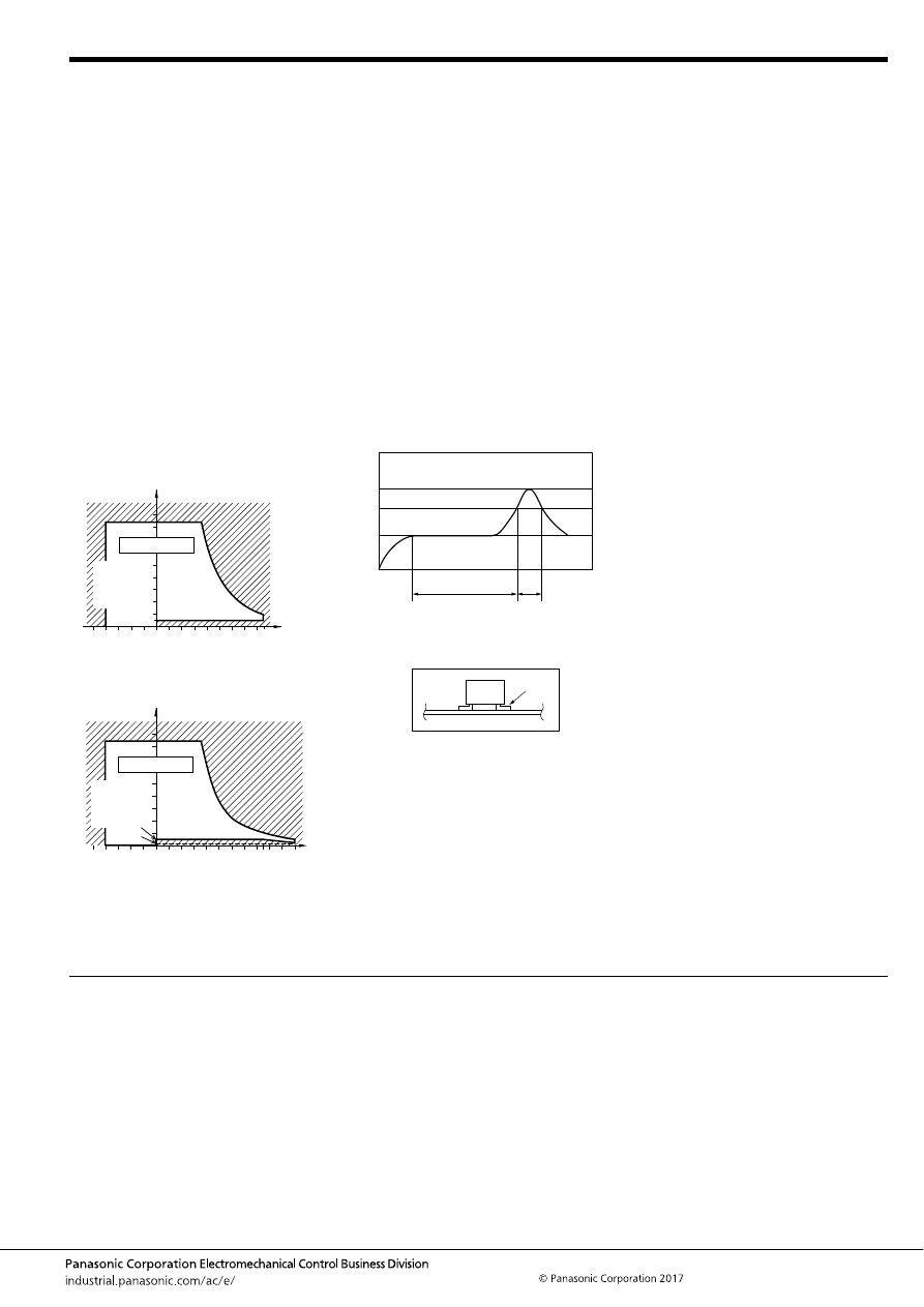
CN-M (ACNM)
–63–
ASCTB224E 201709-T
NOTES
For general cautions for use, please refer to the “Automotive Relay Users Guide”.
1. Usage, transport and storage
conditions
1) Ambient temperature, humidity, and air
pressure during usage, transport, and
storage of the relay:
(1) Temperature:
–40 to +85
°
C
–40 to +185
°
F
(Standard type)
–40 to +110
°
C
–40 to +230
°
F
(High heat-resistant type)
(2) Humidity:
5 to 85% RH (Standard type)
2 to 85% RH (High heat-resistant type)
(Avoid icing and condensation.)
(3) Air pressure: 86 to 106 kPa
The humidity range varies with the
temperature. Use within the range
indicated in the graph below.
[Temperature and humidity range for
usage, transport, and storage]
Standard type
High heat-resistant type
2. Storage condition after opening a
moisture-prevention package
(1) After opening a moisture-prevention
package, use the item as soon as
possible (within 3 days under an
environment of Max. 30
°
C
86
°
F
, Max.
70% RH).
(2) If products are not used within 3 days
after opening a moisture-prevention
package, store them in a humidity-
controlled desiccator or in a storage bag
with silica gel.
3. Mounting and cleaning conditions
for surface-mount terminal type relays
When soldering this relay, please
observe the following conditions.
(Recommended conditions: Number of
reflows: 1, Measurement location:
terminal temperature)
Temperature profile indicates the
temperature of the soldered part (Note 1)
of terminals on the surface of the PC
board, however, for other areas such as
the surface of relay case, make a setting
so that you do not exceed the
recommended conditions.
*The temperature of the relay exterior
and interior may be extremely high
depending on the component density on
the board, the heating method of the
reflow oven or circuit board type.
Other cautions during reflow soldering
(1) Reflow performance may be affected
if you carry out soldering in a way that
exceeds the recommended conditions. If
you need to exceed the recommended
conditions when soldering, please inquire
our sales representative before using in
an application.
(2) Please confirm the heat stress of
relay by using actual board because it
may be changed by board condition or
manufacturing process condition.
(3) Solder creepage, wettability, or
soldering strength will be affected by the
changing of soldering condition or used
solder type. Please check them under the
actual production condition in detail.
(4) Avoid cleaning (ultrasonic cleaning,
boiling cleaning, etc.) and coating in
order to prevent negative impacts on
relay characteristics.
85
5
Humidity, %RH
Tolerance range
(Avoid
condensation
when used at
temperatures
higher than
0
°
C
32
°
F
)
(Avoid icing
when used at
temperatures
lower than
0
°
C
32
°
F
)
85
0
–40
+185
+32
–40
Temperature,
°
C
°
F
85
5
2
110
85
0
–40
+230
+185
+32
–40
Humidity, %RH
Temperature,
°
C
°
F
Tolerance range
(Avoid
condensation
when used at
temperatures
higher than
0
°
C
32
°
F
)
(Avoid icing
when used at
temperatures
lower than
0
°
C
32
°
F
)
T
3
T
2
T
1
t
1
t
2
*1
T
1
= 150 to 180
°
C
T
2
= 230
°
C
T
3
= Less than 250
°
C
t
1
= 60 to 120 sec.
t
2
= Less than 30 sec.
302 to 356
°
F
446
°
F
or more
482
°
F
automotive-relay_en-html.html

CP (ACP)
–64–
ASCTB225E 201709-T
ORDERING INFORMATION
TYPES
1. PC board terminal type
Compact Flat Size Relay
for Automotive
CP RELAYS
Contact arrangement
Rated coil voltage
Type No.
Packing
Carton (tube)
Case
1 Form A
12V DC
CP1a-12V
40 pcs.
1,000 pcs.
1 Form C
CP1-12V
1 Form C for wiper load
CP1W-12V
FEATURES
• Compact flat type
<Height> PC board terminal type: 9.5 mm
.374 inch
• Compact and High capacity (25A) continuous current (at
20
°
C
68
°
F
)
• Simple footprint pattern enables ease of PC board layout
• “PC board terminal” and “Surface mount terminal” types
available
• Model available for wiper load.
TYPICAL APPLICATIONS
• Powered windows, Automatic door locks, Powered
sunroof, Memory seat, Wiper, Defogger, etc.
<Protective construction>
Sealed
14
13
9.5
.551
.512
.374
14
13
10.5
.551
.512
.413
(Unit: mm
inch
)
RoHS compliant
Contact arrangement
1:
1a:
1W:
1 Form C
1 Form A
1 Form C for wiper load
CP
Rated coil voltage (DC)
12 V
Mounting classification
Nil:
SA:
PC board terminal type/wiper load
Surface-mount terminal type
Packing style*
Nil:
X:
Z:
Tube packing
Tape and reel packing (picked from the N.C. terminal side)
Tape and reel packing (picked from the coil terminal side)
Note: * Surface mount terminal type is only supplied in tape and reel packaging. Tube packaging is only available for PC board type.
automotive-relay_en-html.html
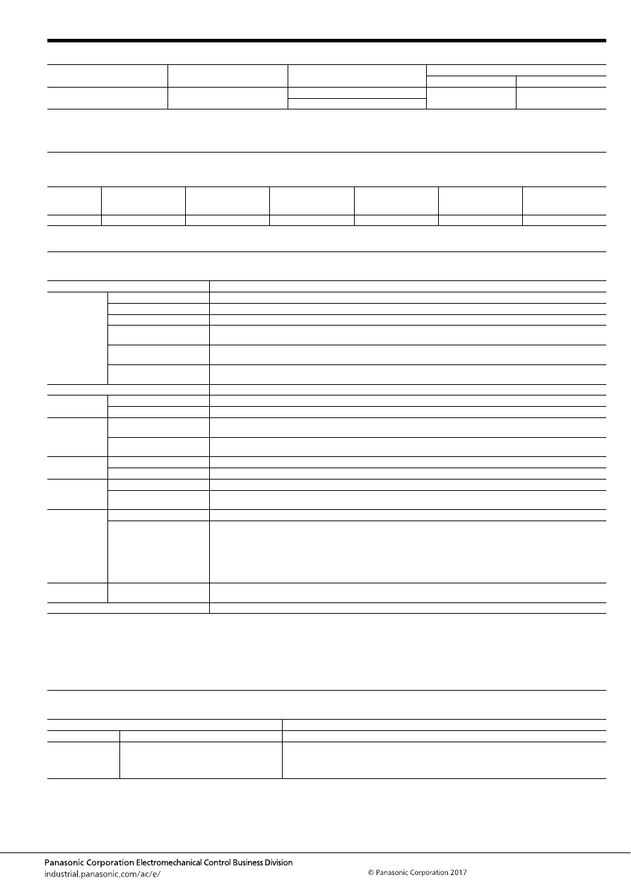
CP (ACP)
–65–
ASCTB225E 201709-T
2. Surface mount terminal type
Notes: 1. Surface-mount terminal type is available only for 1 form C contact arrangement.
2. Surface mount terminal type is only supplied in tape and reel packaging. Tube packaging is only available for PC board type.
Tape and reel packing symbol “-z” or “-x” are not marked on the relay.
RATING
1. Coil data
Note: Other operate (set) voltage types are also available. Please inquire our sales representative for details.
2. Specifications
1) Standard CP relay
Notes: *1. Depends on connection conditions. Also, this does not guarantee repeated switching. We recommend that you confirm operation under actual conditions.
*2. This value can change due to the switching frequency, environmental conditions, and desired reliability level, therefore it is recommended to check this with the
actual load.
*3. The upper operation ambient temperature limit is the maximum temperature that can satisfy the coil temperature rise value. For details, please refer to the
“Automotive Relay Users Guide”.
Please inquire if you will be using the relay in a high temperature atmosphere (110
°
C
230
°
F
).
*4. For wiper motor load, please see the wiper load specifications, below.
2) For wiper load (CP1W-12V)
Anything outside of that given below complies with standard CP relays.
Note: *1. Depends on connection conditions. Also, this does not guarantee repeated switching. We recommend that you confirm operation under actual conditions.
Contact arrangement
Rated coil voltage
Type No.
Packing
Carton (tape and reel)
Case
1 Form C
12V DC
CP1SA-12V-X
300 pcs.
900 pcs.
CP1SA-12V-Z
Rated coil
voltage
Operate (Set) voltage
(at 20
°
C
68
°
F
) (Initial)
Release (Reset)
voltage
(at 20
°
C
68
°
F
) (Initial)
Rated operating current
[
±
10%] (at 20
°
C
68
°
F
)
Coil resistance
[
±
10%] (at 20
°
C
68
°
F
)
Rated operating power
(at 20
°
C
68
°
F
)
Usable voltage range
(at 85
°
C
185
°
F
)
12V DC
Max. 7.2V DC
Min. 1.0V DC
53.3 mA
225
Ω
640 mW
10 to 16V DC
Item
Specifications
Contact data
Contact arrangement
1 Form A, 1 Form C
Contact resistance (initial)
Max. 100m
Ω
(N.O.: Typ. 6m
Ω
, N.C.: Typ. 8m
Ω
) (By voltage drop 1A 6V DC)
Contact material
Ag alloy
Rated switching capacity
(resistive)
N.O. side: 20A 14V DC, N.C. side: 10A 14V DC
Max. carrying current
(initial)*
1
*
4
N.O. side: 40A for 2 minutes, 30A for 1 hour (Coil applied voltage 12 V DC, at 20
°
C
68
°
F
)
35A for 2 minutes, 25A for 1 hour (Coil applied voltage 12 V DC, at 85
°
C
185
°
F
)
Min. switching load
(resistive)*
2
1A 14V DC (at 20
°
C
68
°
F
)
Insulated resistance (initial)
Min. 100 M
Ω
(at 500V DC, Measurement at same location as “Dielectric strength” section.)
Dielectric
strength (initial)
Between open contacts
500 Vrms for 1 min. (Detection current: 10mA)
Between contacts and coil
500 Vrms for 1 min. (Detection current: 10mA)
Time
characteristics
(initial)
Operate (Set) time
(at Rated voltage)
Max. 10ms (at 20
°
C
68
°
F
, without bounce time)
Release (Reset) time
(at Rated voltage)
Max. 10ms (at 20
°
C
68
°
F
, without bounce time) (without diode)
Shock
resistance
Functional
Min. 100 m/s
2
{approx. 10G} (Half-wave pulse of sine wave: 11ms; detection time: 10
μ
s)
Destructive
Min. 1,000 m/s
2
{approx. 100G} (Half-wave pulse of sine wave: 6ms)
Vibration
resistance
Functional
10 to 100 Hz, Min. 44.1 m/s
2
{approx. 4.5G} (Detection time: 10
μ
s)
Destructive
10 to 500 Hz, Min. 44.1 m/s
2
{approx. 4.5G}
Time of vibration for each direction; X, Y direction: 2 hours, Z direction: 4 hours
Expected life
Mechanical
Min. 10
7
(at 120 cpm)
Electrical*
4
<Resistive load>
Min. 10
5
(At rated switching capacity, operating frequency: 1s ON, 9s OFF)
<Motor load>
Min. 2
×
10
5
(N.O. side, Inrush 25A, steady 5A at 14V DC)
Min. 10
5
(N.O. side, 20A 14V DC at motor lock)
Min. 2
×
10
5
(N.C. side, 20A 14V DC at brake current)
(Operating frequency: 0.5s ON, 9.5s OFF)
Conditions
Conditions for usage,
transport and storage*
3
Ambient temperature: –40 to +85
°
C
–40 to +185
°
F
Humidity: 5 to 85% R.H. (Please avoid icing or condensation)
Weight
Approx. 4g
.14 oz
Item
Specifications
Rating
Max. carrying current (initial)*
1
N.O. side: 25A for 1 minutes, 15A for 1 hour (coil applied voltage 12 V DC, at 20
°
C
68
°
F
)
Expected life
Electrical
<Wiper motor load (L = Approx. 1mH) without capacitor>
N.O. side: Min. 5
×
10
5
(Inrush 25A, steady 6A at 14V DC)
N.C. side: Min. 5
×
10
5
(12A 14V DC at brake current)
(Operating frequency: 1s ON, 9s OFF)
automotive-relay_en-html.html
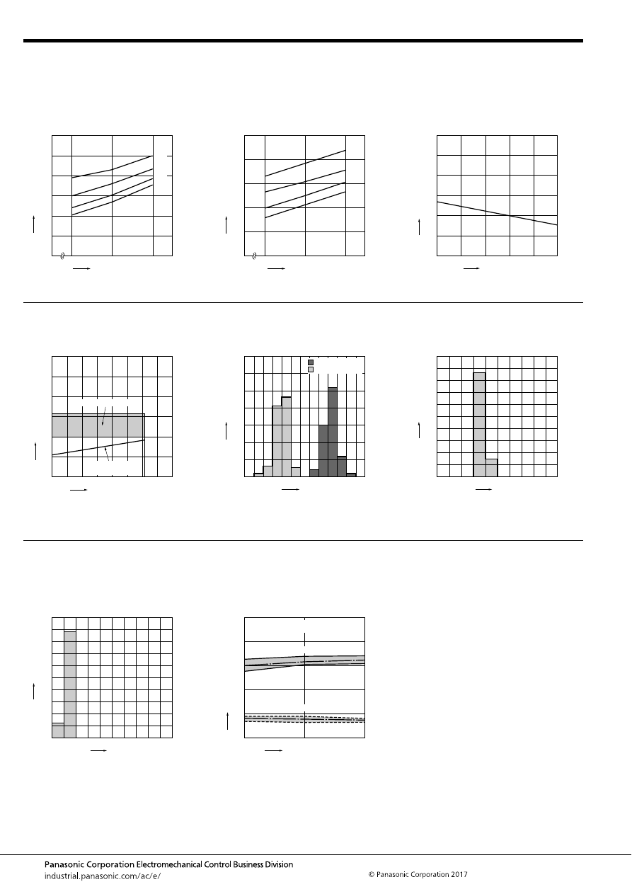
CP (ACP)
–66–
ASCTB225E 201709-T
REFERENCE DATA
1.-(1) Coil temperature rise (at room
temperature)
Sample: CP1-12V, 3pcs
Point measured: Inside the coil
Carrying current: 5A, 10A, 15A, 20A
Ambient temperature 26
°
C
79
°
F
1.-(2) Coil temperature rise (85
°
C
185
°
F
)
Sample: CP1-12V, 6pcs
Point measured: Inside the coil
Carrying current: 5A, 10A, 15A, 20A
Resistance method, ambient temperature 85
°
C
185
°
F
2. Max. switching capability
(Resistive load, Initial)
Coil applied voltage, V
16
20A
5A
10A
15A
14
0
12
120
100
80
60
40
20
0
T
emper
ature r
ise
,
°
C
12
14
0
16
100
80
60
40
20
0
20A
15A
10A
5A
Coil applied voltage, V
T
e
mper
ature r
ise
,
°
C
0
Switching current, A
10
50
40
30
20
60
0
20
Switching v
oltage
,
VDC
30
40
10
50
(N.O. side: room temperature)
3. Ambient temperature and usable voltage
range
4. Distribution of operate (set) and release
(reset) voltage
Sample: CP1-12V, 100pcs
Ambient temperature: 20
°
C
68
°
F
5. Distribution of operate (set) time
Sample: CP1-12V, 100pcs
Ambient temperature: 20
°
C
68
°
F
0
Ambient temperature,
°
C
Coil applied v
oltage
,
VDC
5
10
15
30
25
20
-40 -20
20
40
60
100
0
120
80
Operate voltage
(cold start)
Usable voltage range
0
30
20
10
40
50
60
70
Voltage, V
Quantity
, n
2
3
5
4
6
7
8
Operate voltage
Release voltage
0
30
20
10
40
50
60
70
80
90
100
Time, ms
Quantity
, n
3
2
5
4
6
6. Distribution of release (reset) time
Sample: CP1-12V, 100pcs
Ambient temperature: 20
°
C
68
°
F
7.-(1) Electrical life test (at resistive load)
Sample: CP1-12V
Quantity: n = 4 (N.C. = 2, N.O. = 2)
Load: Resistive load (N.C. side: 10A 14V DC,
N.O. side: 20A 14V DC)
Operating frequency: ON 1s, OFF 9s
Ambient temperature: Room temperature
0
30
20
10
40
50
60
70
80
90
100
0
1
2
3
4
5
Time, ms
Quantity
, n
* Without diode
0
2
4
6
8
10
0
5
10
Operate voltage
Release voltage
Ave.
Ave.
Max.
Max.
Min.
Min.
Oper
ate and release v
oltage
,
V
No. of operations,
×
10
4
Contact welding: 0 times
Miscontact: 0 times
automotive-relay_en-html.html
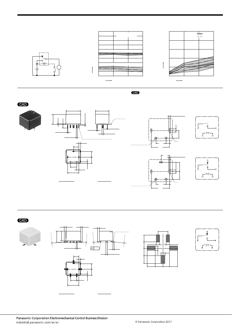
CP (ACP)
–67–
ASCTB225E 201709-T
DIMENSIONS
(mm
inch
)
1. PC board terminal type
2. Surface mount terminal type
7.-(2) Electrical life test for wiper load
(motor free)
Sample: CP1W-12V
Quantity: n = 5
Load: N.O. side: Inrush 25A, steady 6A 14V DC
Load: N.C. side: Brake current 12A 14V DC
Operating frequency: ON 1s, OFF 9s
Ambient temperature: Room temperature
Circuit:
Change of operate (set) and release (reset)
voltage
Change of contact resistance
M
0
25
50
10
6
7
8
9
10
4
2
3
5
1
0
Max.
Min.
Ave.
Max.
Min.
Ave.
Oper
ate and release v
oltage
,
V
No. of operations,
×
10
4
Release voltage
Operate voltage
Contact welding: 0 times
Miscontact: 0 times
Max.
Max.
Min.
Min.
Ave.
Ave.
0
50
25
10
20
30
40
50
10
0
N.C. side
N.O. side
Contact resistance
, m
Ω
No. of operations,
×
10
4
mark can be downloaded from: http://industrial.panasonic.com/ac/e/
The CAD data of the products with a
4.5
.177
5.4
.213
2.0
.079
(R)
10.7
.421
2
×
.051
+.004
0
dia. hole
2
×
1.3
+0.1
0
dia. hole
3
×
.035
+.004
0
3
×
.079
+.004
0
3
×
0.9
+0.1
0
3
×
2.0
dia.
dia.
dia.
dia.
+0.1
0
6.0
.236
5.0
.197
2
×
.051
+.004
0
dia. hole
4.5
.177
2.0
.079
(R)
10.7
2
×
.035
+.004
0
2
×
.079
+.004
0
.421
2
×
1.3
+0.1
0
dia. hole
2
×
0.9
+0.1
0
2
×
2.0
dia.
dia.
dia.
dia.
+0.1
0
6.0
.236
External dimensions
A surface
level
14
.551
13
.512
6
.236
5
.197
10.7
.421
2
.079
1.7
.067
2
×
0.3
2
×
.012
+
0.3
−
0.1
+
.012
−
.004
0.4
.016
+
0.3
−
0.1
+
.012
−
.004
2
×
0.4
2
×
.016
+
0.3
−
0.1
+
.012
−
.004
2
×
1
2
×
.039
+
0.3
−
0.1
+
.012
−
.004
2
×
1.5
2
×
.059
+
0.3
−
0.1
+
.012
−
.004
Pre-soldering (all terminals)
Max.
1.0
Max.
.039
3.5
.138
0.4
.016
9.5
.374
5.4
.213
6
.236
1.5
.059
Dimension:
Tolerance
Max. 1mm
.039 inch
:
±
0.1
±
.004
1 to 3mm
.039 to .118 inch
:
±
0.2
±
.008
Min. 3mm
.118 inch
:
±
0.3
±
.012
* Dimensions (thickness and width) of terminal specified in this catalog is measured after pre-soldering.
Intervals between terminals is measured at A surface level.
PC board pattern
(Bottom view)
1 Form A
1 Form C
Tolerance:
±
0.1
±
.004
Schematic
(Bottom view)
1 Form A
1 Form C
COM
COIL
N.O.
N.C.
N.O.
COIL
COM
External dimensions
1.55
.061
1.45
.057
1.6
.063
1.3
.051
0.1
6
.236
5
.197
10.7
.421
2
.079
1.7
.067
0.4
.016
+
0.3
−
0.1
+
.012
−
.004
0.4
.016
+
0.3
−
0.1
+
.012
−
.004
0.4
.016
+
0.3
−
0.1
+
.012
−
.004
0.3
.012
+
0.3
−
0.1
+
.012
−
.004
2
×
1
2
×
.039
+
0.3
−
0.1
+
.012
−
.004
3
×
1.5
3
×
.059
+
0.3
−
0.1
+
.012
−
.004
Pre-soldering
(all terminals)
9.1
.358
10.5
.413
5.4
.213
6
.236
1.4
.055
Dimension:
Tolerance
Max. 1mm
.039 inch
:
±
0.1
±
.004
1 to 3mm
.039 to .118 inch
:
±
0.2
±
.008
Min. 3mm
.118 inch
:
±
0.3
±
.012
Recommendable mounting pad
(Top view)
Tolerance:
±
0.1
±
.004
2.0
2.0
.079
.079
4.8
4.0
4.7
4.8
.189
.157
6.0
.236
2.5
.098
.185
.189
4.2
.165
3.8
.150
4.4
.173
2.5
.098
4.8
.189
Schematic
(Top view)
COIL
N.C.
N.O.
COM
automotive-relay_en-html.html
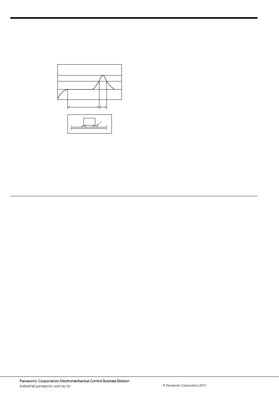
CP (ACP)
–68–
ASCTB225E 201709-T
NOTES
For general cautions for use, please refer to the “Automotive Relay Users Guide”.
1. Mounting and cleaning conditions for Surface-mount
terminal type relays
When soldering this relay, please observe the following
conditions.
(Recommended conditions: Number of reflows: 1, Measurement
location: terminal temperature)
Temperature profile indicates the temperature of the soldered
part (Note 1) of terminals on the surface of the PC board,
however, for other areas such as the surface of relay case, make
a setting so that you do not exceed the recommended
conditions.
*The temperature of the relay exterior and interior may be
extremely high depending on the component density on the
board, the heating method of the reflow oven or circuit board
type.
Other cautions during reflow soldering
(1) Reflow performance may be affected if you carry out
soldering in a way that exceeds the recommended
conditions. If you need to exceed the recommended
conditions when soldering, please inquire our sales
representative before using in an application.
(2) Please confirm the heat stress of relay by using actual board
because it may be changed by board condition or
manufacturing process condition.
(3) Solder creepage, wettability, or soldering strength will be
affected by the changing of soldering condition or used
solder type. Please check them under the actual production
condition in detail.
(4) Avoid cleaning (ultrasonic cleaning, boiling cleaning, etc.)
and coating in order to prevent negative impacts on relay
characteristics.
2. Storage condition after opening a moisture-prevention
package
1) After opening a moisture-prevention package, use the item as
soon as possible (within 4 days under an environment of Max.
30
°
C
86
°
F
, Max. 70% RH).
2) If products are not used within 4 days after opening a
moisture-prevention package, store them in a humidity-
controlled desiccator or in a storage bag with silica gel.
T
3
T
2
T
1
t
1
t
2
Note 1
T
1
= 150 to 180
°
C
T
2
= 230
°
C
T
3
= Less than 250
°
C
t
1
= 60 to 120 sec.
t
2
= Less than 30 sec.
302 to 356
°
F
446
°
F
or more
482
°
F
automotive-relay_en-html.html
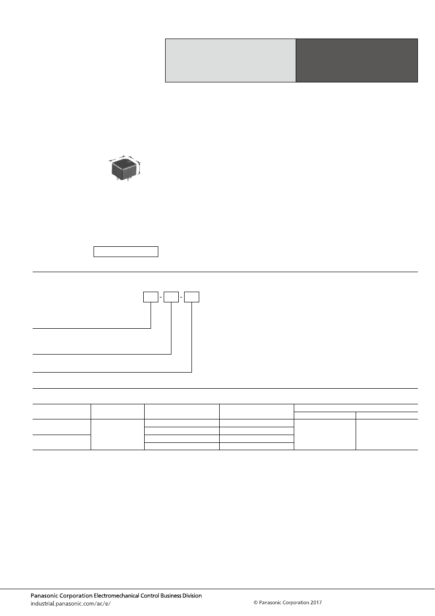
CP-P (ACPP)
–69–
ASCTB226E 201709-T
ORDERING INFORMATION
TYPES
Note: Other operate (set) voltage types are also available. Please inquire our sales representative for details.
High Carrying Current Type
Miniature Low Profile
Automotive Relay
CP RELAYS
POWER TYPE
Contact arrangement
Rated coil voltage
Operate (Set) voltage
(at 20
°
C
68
°
F
) (Initial)
Type No.
Packing
Carton (tube)
Case
1 Form C
12 V DC
Max. 7.2 V DC
CP1H-12V
40 pcs.
1,000 pcs.
Max. 6.5 V DC
CP1H-N-12V
1 Form A
Max. 7.2 V DC
CP1aH-12V
Max. 6.5 V DC
CP1aH-N-12V
FEATURES
• Maximum carrying current of 35 A (450 mW type, 16 V
applied) made possible through using the same size as CP
relays
• Supports capacitor loads required for power supply
applications
TYPICAL APPLICATIONS
• Defoggers, Ignitions, Heaters, Accessories, Powered
windows, etc.
<Protective construction>
Sealed
14
13
9.5
.551
.512
.374
(Unit: mm
inch
)
RoHS compliant
Contact arrangement
1H:
1aH:
1 Form C Power type
1 Form A Power type
CP
Rated coil voltage (DC)
12 V
Operate (Set) voltage
Nil:
N:
Max. 7.2 V DC
Max. 6.5 V DC
automotive-relay_en-html.html
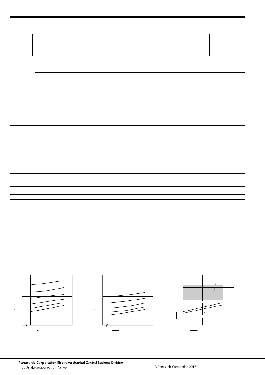
CP-P (ACPP)
–70–
ASCTB226E 201709-T
RATING
1. Coil data
2. Specifications
Notes: *1. Depends on connection conditions. Also, this does not guarantee repeated switching. We recommend that you confirm operation under actual conditions.
*2. This value can change due to the switching frequency, environmental conditions, and desired reliability level, therefore it is recommended to check this with the
actual load.
*3. The upper operation ambient temperature limit is the maximum temperature that can satisfy the coil temperature rise value. For details, please refer to the
“Automotive Relay Users Guide”.
Please inquire our sales representative if you will be using the relay in a high temperature atmosphere (110
°
C
230
°
F
).
REFERENCE DATA
Rated coil
voltage
Operate (Set) voltage
(at 20
°
C
68
°
F
) (Initial)
Release (Reset)
voltage
(at 20
°
C
68
°
F
) (Initial)
Rated operating current
[
±
10%] (at 20
°
C
68
°
F
)
Coil resistance
[
±
10%] (at 20
°
C
68
°
F
)
Rated operating power
(at 20
°
C
68
°
F
)
Usable voltage range
(at 85
°
C
185
°
F
)
12V DC
Max. 7.2 V DC
Min. 1.0 V DC
37.5 mA
320
Ω
450 mW
10 to 16V DC
Max. 6.5 V DC
53.3 mA
225
Ω
640 mW
10 to 16V DC
Item
Specifications
Contact data
Contact arrangement
1 Form A, 1 Form C
Contact resistance (initial)
Max. 100m
Ω
(N.O.: Typ. 6m
Ω
, N.C.: Typ. 8m
Ω
) (By voltage drop 1A 6V DC)
Contact material
Ag alloy
Rated switching capacity
(resistive)
N.O. side: 20 A 14V DC, N.C. side: 10 A 14V DC
Max. carrying current*
1
N.O. side: <For 450 mW>
45 A for 2 minutes, 35 A for 1 hour (Coil applied voltage 16V DC, at 20
°
C
68
°
F
)
40 A for 2 minutes, 30 A for 1 hour (Coil applied voltage 16V DC, at 85
°
C
185
°
F
)
<For 640 mW>
40 A for 2 minutes, 30 A for 1 hour (Coil applied voltage 16V DC, at 20
°
C
68
°
F
)
35 A for 2 minutes, 25 A for 1 hour (Coil applied voltage 16V DC, at 85
°
C
185
°
F
)
Min. switching load
(resistive)*
2
1 A 14V DC (at 20
°
C
68
°
F
)
Insulated resistance (initial)
Min. 100 M
Ω
(at 500V DC, Measurement at same location as “Dielectric strength” section.)
Dielectric
strength (initial)
Between open contacts
500 Vrms for 1 min. (Detection current: 10mA)
Between contacts and coil
500 Vrms for 1 min. (Detection current: 10mA)
Time
characteristics
(initial)
Operate (Set) time
(at Rated voltage)
Max. 10ms (at 20
°
C
68
°
F
, without bounce time)
Release (Reset) time
(at Rated voltage)
Max. 10ms (at 20
°
C
68
°
F
, without bounce time) (without diode)
Shock
resistance
Functional
Min. 100 m/s
2
{approx. 10G} (Half-wave pulse of sine wave: 11ms; detection time: 10
μ
s)
Destructive
Min. 1,000 m/s
2
{approx. 100G} (Half-wave pulse of sine wave: 6ms)
Vibration
resistance
Functional
10 to 100 Hz, Min. 44.1 m/s
2
{approx. 4.5G} (Detection time: 10
μ
s)
Destructive
10 to 500 Hz, Min. 44.1 m/s
2
{approx. 4.5G},
Time of vibration for each direction; X, Y direction: 2 hours, Z direction: 4 hours
Expected life
Mechanical
Min. 10
7
(at 120 cpm)
Electrical
<Resistive load> Min. 10
5
(at rated switching capacity, operating frequency: 1s ON, 9s OFF)
<Capacitor load> Min. 10
5
(at Inrush 60A, Steady 1A 14 V DC, operating frequency: 1s ON, 9s OFF)
Conditions
Conditions for usage,
transport and storage*
3
Ambient temperature: –40 to +85
°
C
–40 to +185
°
F
,
Humidity: 5 to 85% R.H. (Please avoid icing or condensation)
Weight
Approx. 4.5 g
.16 oz
1-(1). Coil temperature rise (at room
temperature)
Sample : CP1H-12V, 3pcs
Point measured : Inside the coil
Carrying current: 10A, 15A, 20A, 25A, 30A, 35A
Ambient temperature: 27
°
C
81
°
F
1-(2). Coil temperature rise (at 85
°
C
185
°
F
)
Sample : CP1H-12V, 3pcs
Point measured : Inside the coil
Carrying current: 10A, 15A, 25A, 30A
Ambient temperature: 85
°
C
185
°
F
2. Ambient temperature and usable voltage
range
12
14
0
16
140
100
120
80
60
40
20
0
20A
15A
10A
25A
30A
35A
Coil applied voltage, V
T
e
mper
ature r
ise
,
°
C
12
14
0
16
140
100
120
80
60
40
20
0
20A
15A
10A
25A
30A
Coil applied voltage, V
T
e
mper
ature r
ise
,
°
C
0
5
10
15
20
-40 -20
20
40
60
100
0
120
80
Operate voltage: CP1H-12V
(cold start)
Operate voltage: CP1H-N-12V
(cold start)
Ambient temperature,
°
C
Coil applied v
oltage
,
VDC
Usable voltage range
automotive-relay_en-html.html
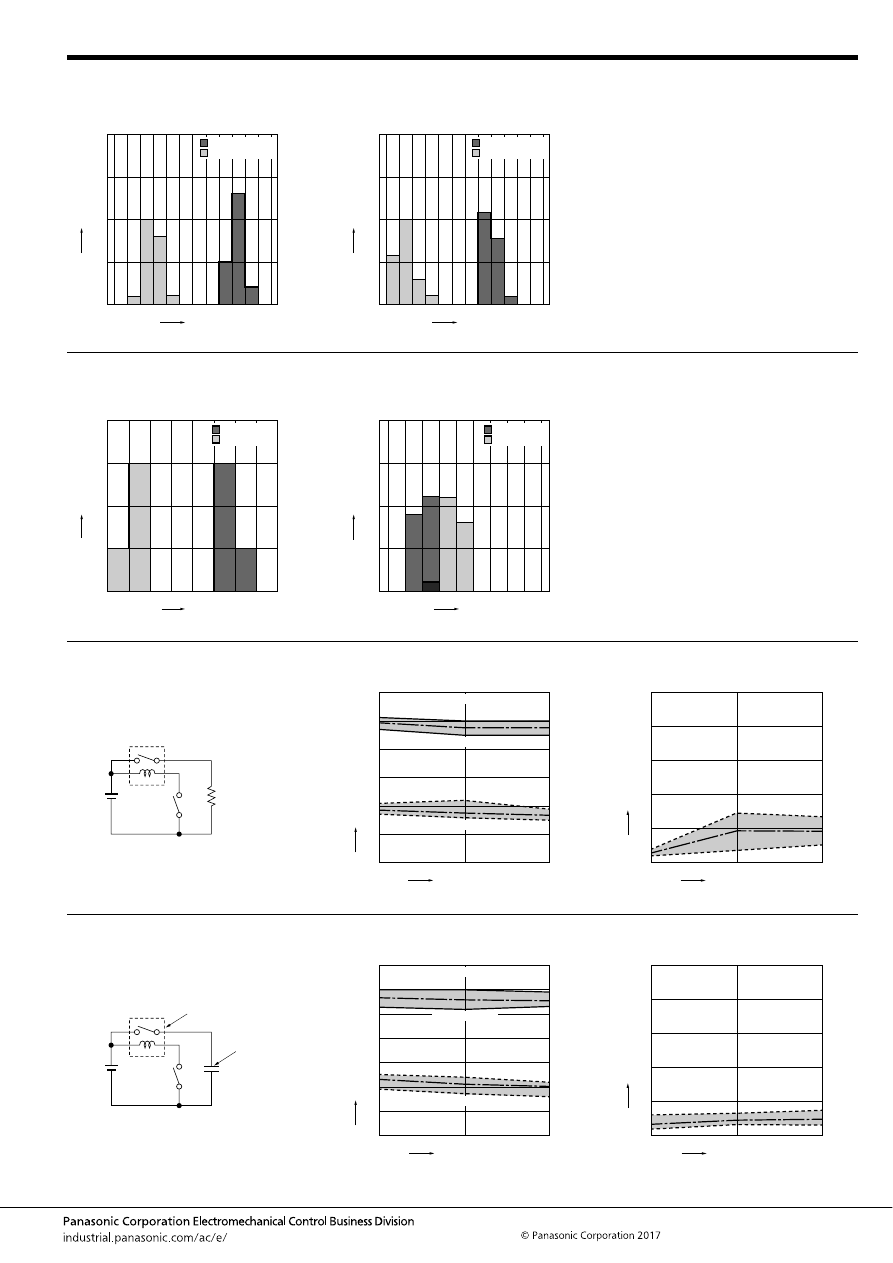
CP-P (ACPP)
–71–
ASCTB226E 201709-T
3-(1). Distribution of operate (set) and release
(reset) voltage
Sample : CP1H-12V, 20pcs.
3-(2). Distribution of operate (set) and release
(reset) voltage
Sample : CP1H-N-12V, 20pcs.
0
0
10
15
20
5
2
3
5
4
6
7
Voltage, V
Quantity
, n
Operate voltage
Release voltage
2
3
5
4
6
7
0
0
10
15
20
5
Voltage, V
Quantity
, n
Operate voltage
Release voltage
4-(1). Distribution of operate (set) and release
(reset) time
Sample : CP1H-12V, 20pcs.
4-(2). Distribution of operate (set) and release
(reset) time
Sample : CP1H-N-12V, 20pcs.
0
0
10
15
20
5
1
2
3
4
Time, ms
Quantity
, n
Operate time
Release time
* Without diode
0
0
10
15
20
5
2
3
5
4
6
Time, ms
Quantity
, n
Operate time
Release time
5-(1). Electrical life test (at rated load)
Sample : CP1H-12V
Quantity : n = 6
Load : Resistive load (N.O. side : 20 A 14 V DC)
Operating frequency : ON 1s, OFF 9s
Ambient temperature : Room temperature
Circuit:
Change of operate (set) and release (reset)
voltage
Change of contact resistance
14V DC
1
0
2
3
4
5
6
0
5
10
Ave.
Max.
Min.
Oper
ate and release v
oltage
,
V
No. of operations,
×
10
4
Operate voltage
Release voltage
Contact welding: 0 times
Miscontact: 0 times
Ave.
Max.
Min.
10
0
20
30
40
50
0
5
10
Contact resistance
, m
Ω
No. of operations,
×
10
4
Ave.
Max.
Min.
5-(2). Electrical life test (at capacitor load)
Sample : CP1H-12V, 6pcs.
Load : Inrush current 60A, steady current 1A
Operating frequency : ON 1s, OFF 9s
Ambient temperature : Room temperature
Circuit:
Change of operate (set) and release (reset)
voltage
Change of contact resistance
Sample
Capacitor
1
0
2
3
4
5
6
7
0
5
10
Ave.
Max.
Min.
Oper
ate and release v
oltage
,
V
No. of operations,
×
10
4
Operate voltage
Release voltage
Contact welding: 0 times
Miscontact: 0 times
Ave.
Max.
Min.
10
0
20
30
40
50
0
5
10
Contact resistance
, m
Ω
No. of operations,
×
10
4
Ave.
Max.
Min.
automotive-relay_en-html.html
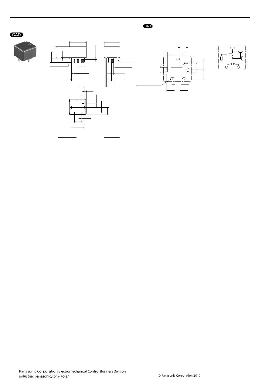
CP-P (ACPP)
–72–
ASCTB226E 201709-T
DIMENSIONS
(mm
inch
)
For general cautions for use, please refer to the “Automotive Relay Users Guide”.
mark can be downloaded from: http://industrial.panasonic.com/ac/e/
The CAD data of the products with a
External dimensions
A surface level
14
.551
13
.512
6
.236
5
.197
10.7
.421
2
.079
1.7
.067
0.9
.035
2
×
0.3
2
×
.012
+
0.3
−
0.1
+
.012
−
.004
2
.079
+
0.3
−
0.1
+
.012
−
.004
2
×
0.4
2
×
.016
+
0.3
−
0.1
+
.012
−
.004
0.4
.016
+
0.3
−
0.1
+
.012
−
.004
2
×
1
2
×
.039
+
0.3
−
0.1
+
.012
−
.004
1.5
.059
+
0.3
−
0.1
+
.012
−
.004
2
×
1.5
2
×
.059
+
0.3
−
0.1
+
.012
−
.004
Pre-soldering
(all terminals)
Max.
1.0
Max.
.039
3.5
.138
0.4
.016
9.5
.374
5.4
.213
4.5
.177
6
.236
3.5
.138
Dimension:
Tolerance
Max. 1mm
.039 inch
:
±
0.1
±
.004
1 to 3mm
.039 to .118 inch
:
±
0.2
±
.008
Min. 3mm
.118 inch
:
±
0.3
±
.012
* Dimensions (thickness and width) of terminal is measured after pre-soldering.
Intervals between terminals is measured at A surface level.
PC board pattern
(Bottom view)
Tolerance:
±
0.1
±
.004
0.9
.035
6.0
2.0
.236
5.0
.197
10.7
.421
.079
5.4
.213
4.5
.177
3.5
.138
(R 0.45)
(R .018)
3
×
.079
+.004
0
3
×
2.0
+0.1
0
4
×
.035
+.004
0
4
×
0.9
+0.1
0
.098
+.004
0
2.5
+0.1
0
2
×
1.3 dia. (hole)
+0.1
0
2
×
.051 dia. (hole)
+.004
0
Schematic
(Bottom view)
N.O.
N.C.
COIL
COM
automotive-relay_en-html.html
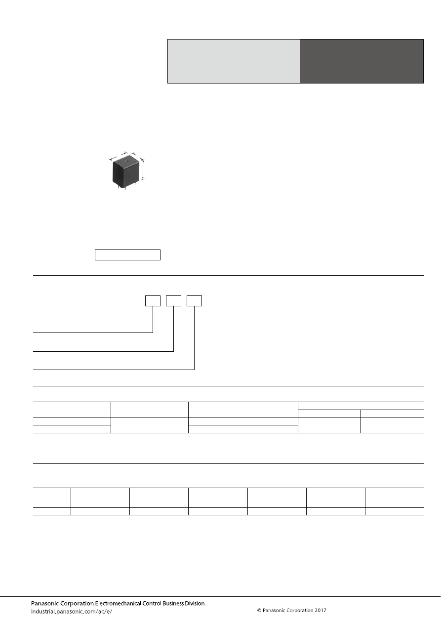
CQ (ACQ)
–73–
ASCTB227E 201709-T
ORDERING INFORMATION
TYPES
RATING
1. Coil data
Note: Other operate (set) voltage types are also available. Please inquire our sales representative for details.
1 Form C Automotive
Quiet Relay
CQ RELAYS
Contact arrangement
Rated coil voltage
Part No.
Packing
Carton (tube)
Case
1 Form C
12V DC
ACQ131
40 pcs.
800 pcs.
1 Form C for wiper load
ACQW131
Rated coil
voltage
Operate (Set) voltage
(at 20
°
C
68
°
F
) (Initial)
Release (Reset)
voltage
(at 20
°
C
68
°
F
) (Initial)
Rated operating current
[
±
10%] (at 20
°
C
68
°
F
)
Coil resistance
[
±
10%] (at 20
°
C
68
°
F
)
Rated operating power
Usable voltage range
12V DC
Max. 7.2V DC
Min. 1.0V DC
53.3 mA
225
Ω
640 mW
10 to 16V DC
FEATURES
• Sound pressure reduced by approx. 20 dB from that of the
conventional non-quiet relays
• Space saving
• Adopting standard terminal pitch (for compact relays)
• Wiper load models are listed
TYPICAL APPLICATIONS
• For intermittent wipers and applications requiring quiet
operation
<Protective construction>
Sealed
13
17
16.6
.512
.669
.654
(Unit: mm
inch
)
RoHS compliant
Contact arrangement
1:
W1:
1 Form C
1 Form C for wiper load
ACQ
3
Rated coil voltage (DC)
1: 12 V
Protective construction
3: Sealed
automotive-relay_en-html.html
CQ (ACQ)
–74–
ASCTB227E 201709-T
2. Specifications
1) Standard CQ relay
Notes: *1. Depends on connection conditions. Also, this does not guarantee repeated switching. We recommend that you confirm operation under actual conditions.
*2. This value can change due to the switching frequency, environmental conditions, and desired reliability level, therefore it is recommended to check this with the
actual load.
*3. The upper operation ambient temperature limit is the maximum temperature that can satisfy the coil temperature rise value. For details, please refer to the
“Automotive Relay Users Guide”.
*4. For wiper motor load, please see the wiper load specifications, below.
2) For wiper load (ACQW131)
Anything outside of that given below complies with standard CQ relays.
Note: *1. Depends on connection conditions. Also, this does not guarantee repeated switching. We recommend that you confirm operation under actual conditions.
Item
Specifications
Contact data
Contact arrangement
1 Form C
Contact resistance (initial)
Max. 100m
Ω
(N.O.: Typ. 7m
Ω
, N.C.: Typ. 8m
Ω
) (By voltage drop 1A 6V DC)
Contact voltage drop (initial)
Max. 0.2V (at 10 A 12V DC)
Contact material
Ag alloy
Rated switching capacity
(resistive)
N.O. side: 20A 14V DC, N.C. side: 10A 14V DC
Max. carrying current
(initial)*
1
*
4
N.O. side: 35A for 2 minutes, 25A for 1 hour (Coil applied voltage 12V DC, at 20
°
C
68
°
F
)
30A for 2 minutes, 20A for 1 hour (Coil applied voltage 12V DC, at 85
°
C
185
°
F
)
Min. switching load
(resistive)*
2
1A 14V DC (at 20
°
C
68
°
F
)
Insulated resistance (initial)
Min. 100 M
Ω
(at 500V DC, Measurement at same location as “Dielectric strength” section.)
Dielectric
strength (initial)
Between open contacts
500 Vrms for 1 min. (Detection current: 10mA)
Between contacts and coil
500 Vrms for 1 min. (Detection current: 10mA)
Time
characteristics
(initial)
Operate (Set) time
(at Rated voltage)
Max. 10ms (at 20
°
C
68
°
F
, without contact bounce time)
Release (Reset) time
(at Rated voltage)
Max. 10ms (at 20
°
C
68
°
F
, without contact bounce time) (without diode)
Shock
resistance
Functional
Min. 100 m/s
2
{approx. 10G} (Half-wave pulse of sine wave: 11ms; detection time: 10
μ
s)
Destructive
Min. 1,000 m/s
2
{approx. 100G} (Half-wave pulse of sine wave: 6ms)
Vibration
resistance
Functional
10 to 100 Hz, Min. 44.1 m/s
2
{approx. 4.5G} (Detection time: 10
μ
s)
Destructive
10 to 500 Hz, Min. 44.1 m/s
2
{approx. 4.5G}
Time of vibration for each direction; X, Y direction: 2 hours, Z direction: 4 hours
Expected life
Mechanical
Min. 10
7
(at 120 cpm)
Electrical*
4
<Resistive load>
Min. 10
5
(at rated switching capacity, operating frequency: 1s ON, 9s OFF)
<Motor load>
Min. 3
×
10
5
(Inrush 30A, steady 5A, 20A 14V DC at brake current)
(Operating frequency: 1s ON, 2s OFF)
Conditions
Conditions for usage,
transport and storage*
3
Ambient temperature: –40 to +85
°
C
–40 to +185
°
F
Humidity: 5 to 85% R.H. (Please avoid icing or condensation)
Weight
Approx. 6.5g
.23 oz
Item
Specifications
Contact data
Max. carrying current (initial)*
1
N.O. side: 25A for 1 minutes, 15A for 1 hour (coil applied voltage 12V DC, at 20
°
C
68
°
F
)
Expected life
Electrical
<Wiper motor load (L = Approx. 1mH) without capacitor>
N.O. side: Min. 5
×
10
5
(Inrush 25A, steady 6A 14V DC)
N.C. side: Min. 5
×
10
5
(12A 14V DC at brake current)
(Operating frequency: 1s ON, 9s OFF)
automotive-relay_en-html.html
CQ (ACQ)
–75–
ASCTB227E 201709-T
REFERENCE DATA
1. Max. switching capability (Resistive load,
initial)
2. Ambient temperature and usable voltage
range
3. Ambient temperature characteristics
0
Switching current, A
Switching v
oltage
,
VDC
10
50
40
30
20
60
0
20
30
40
10
50
(N.O. side Room temperature)
0
Ambient temperature,
°
C
Coil applied v
oltage
,
VDC
5
10
15
35
30
25
20
40
-40 -20
20
40
60
100
0
120
80
Operate voltage
(Cold start)
Usable voltage range
0
Ambient temperature,
°
C
Ratio against the r
ated v
oltage
, %
10
20
30
70
60
50
40
80
-40
20
Operate voltage
upper limit
Operate voltage lower limit
85
4. Distribution of operate (set) and release
(reset) voltage
Sample: ACQ131, 100pcs
5. Distribution of operate (set) time
Sample: ACQ131, 100pcs
6. Distribution of release (reset) time
Sample: ACQ131, 100pcs
0
30
20
10
40
50
60
Voltage, V
Quantity
, n
2
3
5
4
6
7
8
Operate voltage
Release voltage
0
30
20
10
40
50
60
70
80
90
100
Time, ms
Quantity
, n
3
2
5
4
6
0
30
20
10
40
50
60
70
80
90
100
1
0
2
4
3
Time, ms
Quantity
, n
* Without diode
7. Electrical life test for wiper load (motor free)
Sample: ACQW131
Quantity: n = 3
Load: N.O. side: Inrush 25A, steady 6A 14V DC
N.C. side: Brake current 12A 14V DC
Operating frequency: ON 1s, OFF 9s
Ambient temperature: Room temperature
Circuit:
Change of operate (set) and release (reset)
voltage
Change of contact resistance
M
0
25
50
10
6
7
8
9
10
4
2
3
5
1
0
Max.
Min.
Ave.
Max.
Min.
Ave.
Oper
ate and release v
oltage
,
V
No. of operations,
×
10
4
Release voltage
Operate voltage
0
50
25
10
20
30
40
50
10
0
Min.
Min.
Ave.
Max.
Max.
Ave.
Contact resistance
, m
Ω
No. of operations,
×
10
4
N.C. side
N.O. side
8.-(1) Operation noise distribution
When operate
8.-(2) Operation noise distribution
When release
Measuring conditions
Sample: ACQ131, 50 pcs.
Equipment setting: “A” weighted, Fast, Max. hold
Coil voltage: 12V DC
Coil connection device: Diode
Background noise: Approx. 20dB
0
5
10
15
25
20
42
44
46
48
50
52
54
56
Noise level, dB
Quantity
, n
0
5
10
15
25
38
40
42
44
46
48
50
52
20
Noise level, dB
Quantity
, n
Microphone
50mm
1.969inch
Relay
Sponge
automotive-relay_en-html.html
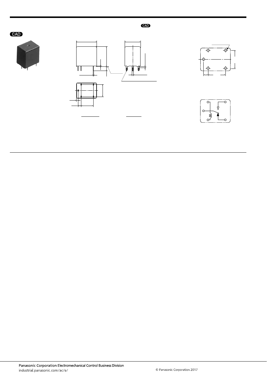
CQ (ACQ)
–76–
ASCTB227E 201709-T
DIMENSIONS
(mm
inch
)
For general cautions for use, please refer to the “Automotive Relay Users Guide”.
mark can be downloaded from: http://industrial.panasonic.com/ac/e/
The CAD data of the products with a
External dimensions
A surface
level
17
.669
13
.512
1.5
.059
10.2
.402
2.5
.098
5
×
1.2
5
×
.047
+
0.3
−
0.1
+
.012
−
.004
5
×
0.25
5
×
.010
+
0.3
−
0.1
+
.012
−
.004
Pre-soldering (all terminals)
Max.
1.0
Max.
.039
0.4
.016
16.6
.654
3.5
.138
10
.394
Dimension:
Tolerance
Max. 1mm
.039 inch
:
±
0.1
±
.004
1 to 3mm
.039 to .118 inch
:
±
0.2
±
.008
Min. 3mm
.118 inch
:
±
0.3
±
.012
* Dimensions (thickness and width) of terminal is measured before pre-soldering.
Intervals between terminals is measured at A surface level.
PC board pattern (Bottom view)
Tolerance:
±
0.1
±
.004
Schematic (Bottom view)
2.5
5
×
1.5
+0.1
0
10.2
10.0
.098
.402
.394
5
×
.059
dia.
dia.
+.004
0
COM
COIL
N.O.
N.C.
automotive-relay_en-html.html
CT (ACT)
–77–
ASCTB228E 201709-T
ORDERING INFORMATION
TYPES
RATING
1. Coil data
Note: Other operate (set) voltage types are also available. Please inquire our sales representative for details.
Small & Slim
Twin/1 Form C type
Automotive Relay
CT RELAYS
Contact arrangement
Rated coil voltage
Part No.
Packing
Carton (tube)
Case
1 Form C
12 V DC
ACT112
30 pcs.
1,500 pcs.
1 Form C
×
2 (8 pins)
ACT212
30 pcs.
900 pcs.
1 Form C
×
2 (10 pins)
ACT512
Rated coil
voltage
Operate (Set) voltage
(at 20
°
C
68
°
F
) (Initial)
Release (Reset)
voltage
(at 20
°
C
68
°
F
) (Initial)
Rated operating current
[
±
10%] (at 20
°
C
68
°
F
)
Coil resistance
[
±
10%] (at 20
°
C
68
°
F
)
Rated operating power
(at 20
°
C
68
°
F
)
Usable voltage range
12V DC
Max. 7.2 V DC
Min. 1.0 V DC
66.7 mA
180
Ω
800 mW
10 to 16V DC
FEATURES
• Terminal layout for simplifying PC board pattern design
• Capable of 25A high-capacity load switching with compact
size
TYPICAL APPLICATIONS
• Powered windows, Automatic door locks, Powered
mirrors, Powered sunroof, Powered seats, Lift gates, Slide
door closers, etc.
<Protective construction>
Sealed
14
17.4
13.5
.551
7.2
.283
.685
.531
17.4
13.5
.685
.531
(Unit: mm
inch
)
RoHS compliant
Contact arrangement
1: 1 Form C
2: 1 Form C
×
2 (8 pins)
5: 1 Form C
×
2 (10 pins)
ACT
Rated coil voltage, DC
12: 12 V
automotive-relay_en-html.html
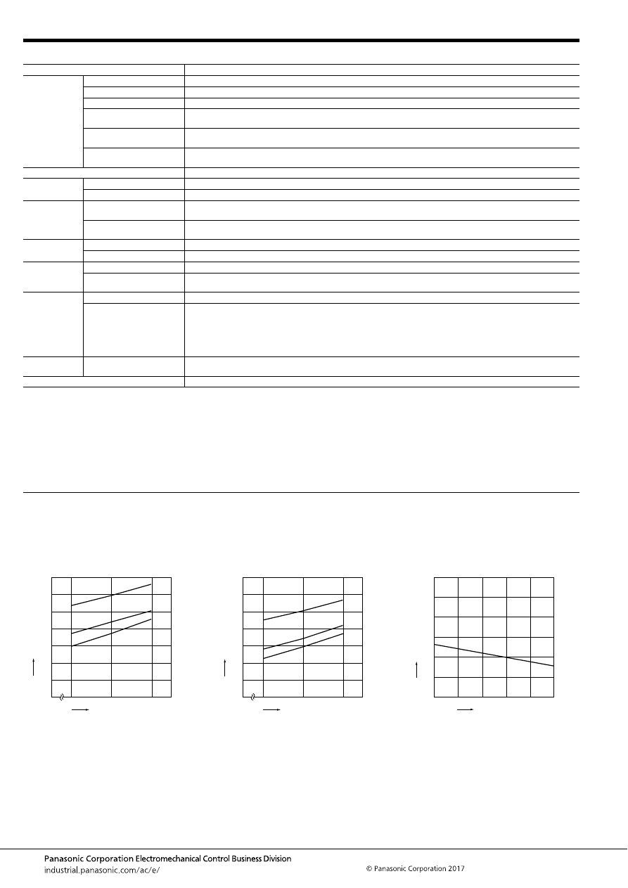
CT (ACT)
–78–
ASCTB228E 201709-T
2. Specifications
Notes: *1. Depends on connection conditions. Also, this does not guarantee repeated switching. We recommend that you confirm operation under actual conditions.
*2. This value can change due to the switching frequency, environmental conditions, and desired reliability level, therefore it is recommended to check this with the
actual load.
*3. The upper operation ambient temperature limit is the maximum temperature that can satisfy the coil temperature rise value. For details, please refer to the
“Automotive Relay Users Guide”.
Please inquire our sales representative if you will be using the relay in a high temperature atmosphere (110
°
C
230
°
F
).
If the relay is used continuously for long periods of time with coils on both sides in an energized condition, breakdown might occur due to abnormal heating
depending on the carrying condition. Therefore, please inquire our sales representative when using with a circuit that causes an energized condition on both sides
simultaneously.
REFERENCE DATA
Item
Specifications
Contact data
Contact arrangement
1 Form C
×
2, 1 Form C
Contact resistance (initial)
Max. 100m
Ω
(N.O.: Typ. 7m
Ω
, N.C.: Typ. 10m
Ω
) (By voltage drop 1A 6V DC)
Contact material
Ag alloy
Rated switching capacity
(resistive)
N.O. side: 20 A 14V DC, N.C. side: 10 A 14V DC
Max. carrying current*
1
N.O. side: 25 A for 1 hour, 35 A for 2 minutes (Coil applied voltage 14V DC, at 20
°
C
68
°
F
)
20 A for 1 hour, 30 A for 2 minutes (Coil applied voltage 14V DC, at 85
°
C
185
°
F
)
Min. switching load
(resistive)*
2
1 A 14V DC (at 20
°
C
68
°
F
)
Insulated resistance (initial)
Min. 100 M
Ω
(at 500V DC, Measurement at same location as “Dielectric strength” section.)
Dielectric
strength (initial)
Between open contacts
500 Vrms for 1 min. (Detection current: 10mA)
Between contacts and coil
500 Vrms for 1 min. (Detection current: 10mA)
Time
characteristics
(initial)
Operate (Set) time
(at Rated voltage)
Max. 10ms (at 20
°
C
68
°
F
, without bounce time)
Release (Reset) time
(at Rated voltage)
Max. 10ms (at 20
°
C
68
°
F
, without bounce time) (without diode)
Shock
resistance
Functional
Min. 100 m/s
2
{approx. 10G} (Half-wave pulse of sine wave: 11ms; detection time: 10
μ
s)
Destructive
Min. 1,000 m/s
2
{approx. 100G} (Half-wave pulse of sine wave: 6ms)
Vibration
resistance
Functional
10 to 100 Hz, Min. 44.1 m/s
2
{approx. 4.5G} (Detection time: 10
μ
s)
Destructive
10 to 500 Hz, Min. 44.1 m/s
2
{approx. 4.5G},
Time of vibration for each direction; X, Y direction: 2 hours, Z direction: 4 hours
Expected life
Mechanical
Min. 10
7
(at 120 cpm)
Electrical
<Resistive load>
Min. 10
5
(at rated switching capacity, operating frequency: 1s ON, 9s OFF)
<Motor load>
N.O. side: Min. 2
×
10
5
at Inrush 25A, Steady 5A 14 V DC,
Min. 10
5
at 25A 14 V DC motor lock condition
N.C. side: Min. 2
×
10
5
at brake current 20A 14 V DC (operating frequency: 0.5s ON, 9.5s OFF)
Conditions
Conditions for usage,
transport and storage*
3
Ambient temperature: –40 to +85
°
C
–40 to +185
°
F
,
Humidity: 5 to 85% R.H. (Please avoid icing or condensation)
Weight
Twin type: approx. 8 g
.28 oz
, 1 Form C type: approx. 4 g
.14 oz
∗
1-(1). Coil temperature rise (at room
temperature)
Sample: ACT212, 3pcs.
Carrying current: 0A, 10A, 20A
Ambient temperature: Room temperature
1-(2). Coil temperature rise (at 85
°
C
185
°
F
)
Sample: ACT212, 3pcs.
Carrying current: 0A, 10A, 20A
Ambient temperature: 85
°
C
185
°
F
2. Max. switching capability (Resistive load,
initial)
0
20
40
60
80
100
120
140
12
14
0
16
20A
10A
0A
Coil applied voltage, V
T
e
mper
ature r
ise
,
°
C
(when coil powered on one side)
0
20
40
60
80
100
120
140
12
14
0
16
20A
10A
0A
Coil applied voltage, V
T
emper
ature r
ise
,
°
C
(when coil powered on one side)
0
Switching current, A
Switching v
oltage
,
VDC
10
50
40
30
20
60
0
20
30
40
10
50
(N.O. side: room temperature)
automotive-relay_en-html.html
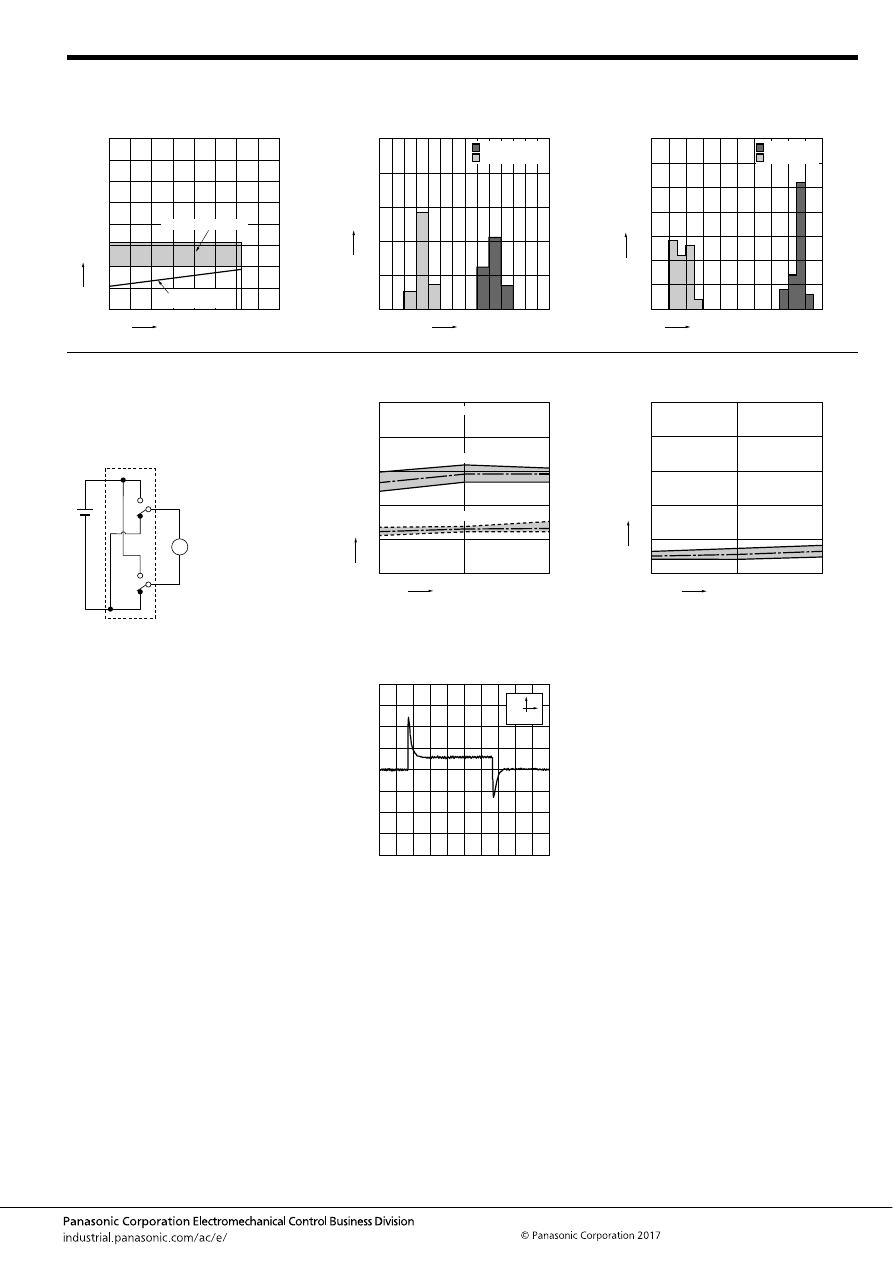
CT (ACT)
–79–
ASCTB228E 201709-T
3. Ambient temperature and usable voltage
range
4. Distribution of operate (set) and release
(reset) voltage
Sample: ACT212, 40pcs.
5. Distribution of operate (set) and release
(reset) time
Sample: ACT212, 40pcs.
0
Ambient temperature,
°
C
Coil applied v
oltage
,
VDC
5
10
15
35
30
25
20
40
-40 -20
20
40
60
100
0
120
80 85
Operate voltage
(Cold start)
Usable voltage range
0
30
20
10
40
50
0 1
2
3
5
4
6
7
Voltage, V
Quantity
, n
Operate voltage
Release voltage
0
35
20
25
20
15
10
5
Operate and release time, ms
Quantity
, n
1.0 1.1 1.2 1.3 1.4 1.5 1.6 1.7 1.8 1.9 2.0
Operate time
Release time
* Without diode
6-(1). Electrical life test (Motor free)
Sample: ACT212, 3pcs.
Load: Inrush 25A, steady 5A
Brake current: 13A 14V DC,
Power window motor actual load (free condition)
Operating frequency: ON 0.5s, OFF 9.5s
Ambient temperature: Room temperature
Circuit:
Change of operate (set) and release (reset)
voltage
Change of contact resistance
M
0
2
4
6
8
10
0
10
20
No. of operations,
×
10
4
Oper
ate and release v
oltage
,
V
Operate voltage
Release voltage
Ave.
Ave.
Max.
Max.
Min.
Min.
Contact welding: 0 time
Miscontact: 0 time
0
No. of operations,
×
10
4
Contact resistance
, m
Ω
Max.
Min.
Ave.
50
40
30
20
10
0
20
10
Load current waveform
Load: Inrush current: 25A, Steady current: 6A
Brake current: 13A
100ms
10A
automotive-relay_en-html.html
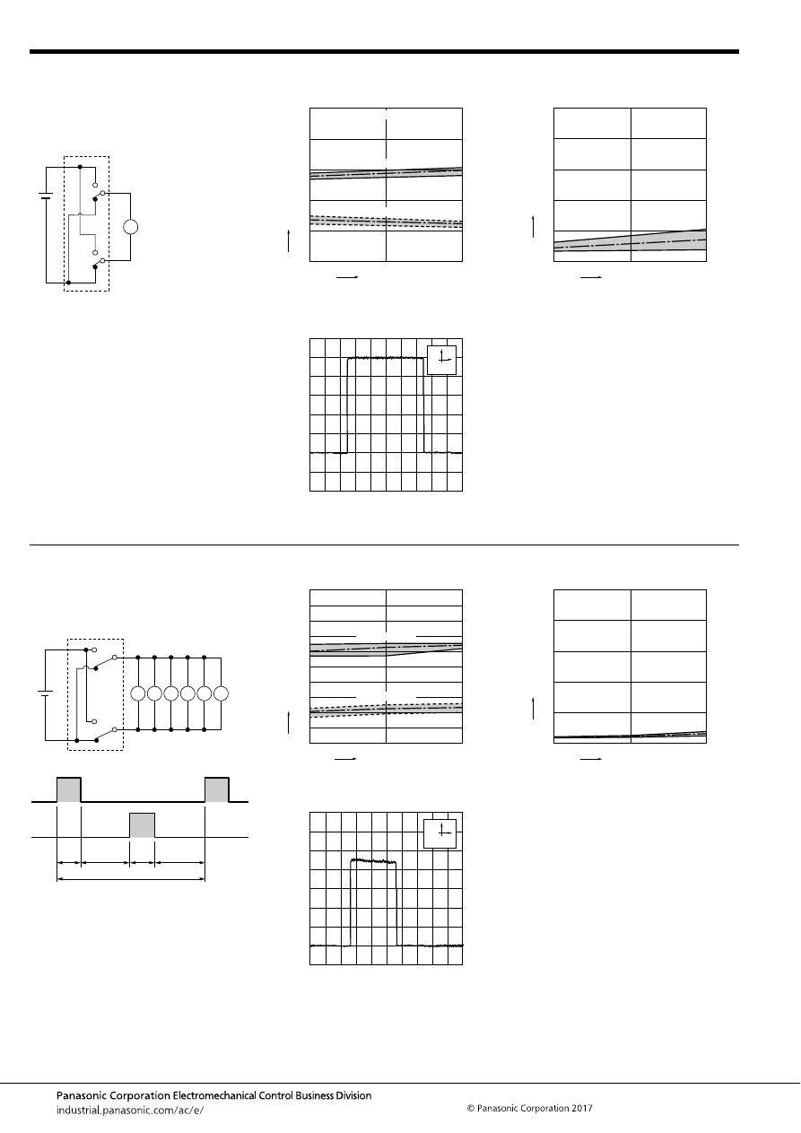
CT (ACT)
–80–
ASCTB228E 201709-T
6-(2). Electrical life test (Motor lock)
Sample: ACT212, 3pcs.
Load: 25A 14V DC
Power window motor actual load (lock condition)
Switching frequency: ON 0.5s, OFF 9.5s
Ambient temperature: Room temperature
Circuit:
Change of operate (set) and release (reset)
voltage
Change of contact resistance
M
0
2
4
6
8
10
0
5
10
No. of operations,
×
10
4
Oper
ate and release v
oltage
,
V
Operate voltage
Release voltage
Ave.
Ave.
Max.
Max.
Min.
Min.
Contact welding: 0 time
Miscontact: 0 time
0
No. of operations,
×
10
4
Contact resistance
, m
Ω
Max.
Min.
Ave.
50
40
30
20
10
0
10
5
Load current waveform
100ms
5A
6-(3). Electrical life test (Motor lock)
Sample: ACT212, 3pcs.
Load: 20A 14V DC,
door lock motor actual load (Lock condition)
Switching frequency: ON 0.3s, OFF 19.7s
Ambient temperature: Room temperature
Circuit:
Change of operate (set) and release (reset)
voltage
Change of contact resistance
Side1
Side2
M
M
M
M
M
M
0
No. of operations,
×
10
4
Oper
ate and release v
oltage
,
V
Max.
Max.
Min.
Min.
Ave.
Ave.
2
1
4
6
8
9
7
5
3
10
0
10
5
Operate voltage
Release voltage
0
No. of operations,
×
10
4
Contact resistance
, m
Ω
Max.
Min.
Ave.
10
20
30
40
50
0
10
5
Load current waveform
Relay 1
Relay 2
0.3s
0.3s
9.7s
9.7s
20s (1 cycle)
100ms
5A
automotive-relay_en-html.html
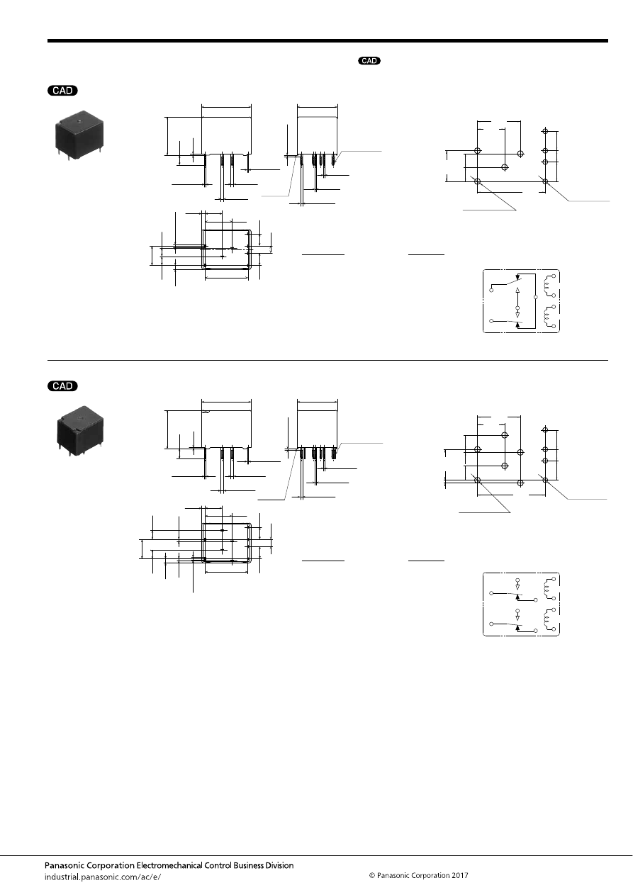
CT (ACT)
–81–
ASCTB228E 201709-T
DIMENSIONS
(mm
inch
)
1. Twin type (8 pins)
2. Twin type (10 pins)
mark can be downloaded from: http://industrial.panasonic.com/ac/e/
The CAD data of the products with a
External dimensions
A surface
level
17.4
.685
14
.551
9.5
.374
1.25
.049
6
.236
15
.591
2
×
1
2
×
.039
+
0.3
−
0.1
+
.012
−
.004
2
×
0.4
2
×
.016
+
0.3
−
0.1
+
.012
−
.004
1
.039
+
0.3
−
0.1
+
.012
−
.004
1
.039
+
0.3
−
0.1
+
.012
−
.004
4
×
0.3
4
×
.012
+
0.3
−
0.1
+
.012
−
.004
0.4
.016
+
0.3
−
0.1
+
.012
−
.004
4
×
0.8
4
×
.031
+
0.3
−
0.1
+
.012
−
.004
0.4
.016
+
0.3
−
0.1
+
.012
−
.004
Pre-soldering
(all terminals)
Max.
1.0
Max.
.039
0.4
.016
3.5
.138
13.5
.531
2.5
.098
4.3
.169
4.3
.169
1.45
.057
3.15
.124
6.8
.268
3
.118
Dimension:
Tolerance
Max. 1mm
.039 inch
:
±
0.1
±
.004
1 to 3mm
.039 to .118 inch
:
±
0.2
±
.008
Min. 3mm
.118 inch
:
±
0.3
±
.012
* Dimensions (thickness and width) of terminal is measured after pre-soldering.
Intervals between terminals is measured at A surface level.
PC board pattern
(Bottom view)
Tolerance:
±
0.1
±
.004
Schematic
(Bottom view)
3.15
4.3
4.3
2.5
6.8
4
×
1.1 dia.
+0.1
0
+0.04
0
9.5
6
3
15
4
×
1.4 dia.
+0.1
0
+0.04
0
.124
.169
.169
.098
.268
4
×
.043 dia.
.374
.236
.118
.591
4
×
.055 dia.
N.C.
N.O.
COM
COM
COIL
COIL
External dimensions
A surface
level
17.4
.685
14
.551
9.5
.374
1.25
.049
6
.236
15
.591
2
×
1
2
×
.039
+
0.3
−
0.1
+
.012
−
.004
2
×
0.4
2
×
.016
+
0.3
−
0.1
+
.012
−
.004
2
×
1
2
×
.039
+
0.3
−
0.1
+
.012
−
.004
2
×
1
2
×
.039
+
0.3
−
0.1
+
.012
−
.004
4
×
0.3
4
×
.012
+
0.3
−
0.1
+
.012
−
.004
2
×
0.4
2
×
.016
+
0.3
−
0.1
+
.012
−
.004
4
×
0.8
4
×
.031
+
0.3
−
0.1
+
.012
−
.004
2
×
0.4
2
×
.016
+
0.3
−
0.1
+
.012
−
.004
Pre-soldering
(all terminals)
Max.
1.0
Max.
.039
0.4
.016
3.5
.138
13.5
.531
2.5
.098
4.3
.169
4.3
.169
1.45
.057
0.65
.026
0.65
.026
3.15
.124
6.8
.268
3
.118
Dimension:
Tolerance
Max. 1mm
.039 inch
:
±
0.1
±
.004
1 to 3mm
.039 to .118 inch
:
±
0.2
±
.008
Min. 3mm
.118 inch
:
±
0.3
±
.012
* Dimensions (thickness and width) of terminal is measured after pre-soldering.
Intervals between terminals is measured at A surface level.
PC board pattern
(Bottom view)
Tolerance:
±
0.1
±
.004
Schematic
(Bottom view)
3.15
3.15
0.65
0.65
4.3
4.3
2.5
6.8
9.5
6
15
6
×
1.4 dia.
+0.1
0
+0.04
0
4
×
1.1 dia.
+0.1
0
+0.04
0
.124
.124
.026
.026
.169
.169
.098
.268
.374
.236
.591
6
×
.055 dia.
4
×
.043 dia.
COM
N.O.
COM
N.O.
N.C.
N.C.
COIL
COIL
automotive-relay_en-html.html
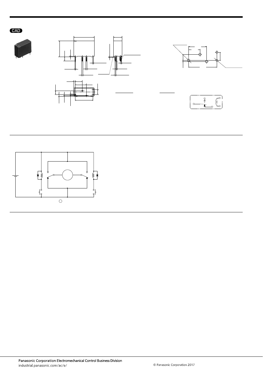
CT (ACT)
–82–
ASCTB228E 201709-T
3. Slim 1c type (8 pins)
EXAMPLE OF CIRCUIT
Forward/reverse control circuits of DC motor for power windows
For general cautions for use, please refer to the “Automotive Relay Users Guide”.
External dimensions
A surface
level
17.4
.685
7.2
.283
9.5
.374
1.25
.049
6
.236
15
.591
1
.039
+
0.3
−
0.1
+
.012
−
.004
0.4
.016
+
0.3
−
0.1
+
.012
−
.004
1
.039
+
0.3
−
0.1
+
.012
−
.004
1
.039
+
0.3
−
0.1
+
.012
−
.004
2
×
0.3
2
×
.012
+
0.3
−
0.1
+
.012
−
.004
0.4
.016
+
0.3
−
0.1
+
.012
−
.004
2
×
0.8
2
×
.031
+
0.3
−
0.1
+
.012
−
.004
0.4
.016
+
0.3
−
0.1
+
.012
−
.004
Pre-soldering
(all terminals)
Max.
1.0
Max.
.039
0.4
.016
3.5
.138
13.5
.531
4.3
.169
1.45
.057
0.65
.026
3.15
.124
Dimension:
Tolerance
Max. 1mm
.039 inch
:
±
0.1
±
.004
1 to 3mm
.039 to .118 inch
:
±
0.2
±
.008
Min. 3mm
.118 inch
:
±
0.3
±
.012
* Dimensions (thickness and width) of terminal is measured after pre-soldering.
Intervals between terminals is measured at A surface level.
PC board pattern
(Bottom view)
Tolerance:
±
0.1
±
.004
Schematic
(Bottom view)
3.15
4.3
2
×
1.1 dia.
+0.1
0
+0.04
0
3
×
1.4 dia.
15
0.65
9.5
6
.124
.169
2
×
.043 dia.
3
×
.055 dia.
.591
.026
.374
.236
N.O.
COM
N.C.
COIL
: Power window motor
12 V DC
SW A
M
M
SW B
N.O.
N.O.
N.C.
N.C.
COM
COM
automotive-relay_en-html.html
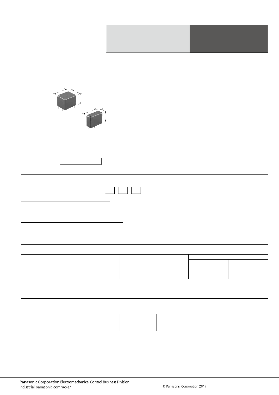
CT-P (ACTP)
–83–
ASCTB229E 201709-T
ORDERING INFORMATION
TYPES
RATING
1. Coil data
Note: Other operate (set) voltage types are also available. Please inquire our sales representative for details.
High Carrying Current Type
Small & Slim
Automotive Relay
CT RELAYS
POWER TYPE
Contact arrangement
Rated coil voltage
Part No.
Packing
Carton (tube)
Case
1 Form C
12 V DC
ACTP112
30 pcs.
1,500 pcs.
1 Form C
×
2 (8 pins)
ACTP212
30 pcs.
900 pcs.
1 Form C
×
2 (10 pins)
ACTP512
Rated coil
voltage
Operate (Set) voltage
(at 20
°
C
68
°
F
) (Initial)
Release (Reset)
voltage
(at 20
°
C
68
°
F
) (Initial)
Rated operating current
[
±
10%] (at 20
°
C
68
°
F
)
Coil resistance
[
±
10%] (at 20
°
C
68
°
F
)
Rated operating power
(at 20
°
C
68
°
F
)
Usable voltage range
12V DC
Max. 7.2 V DC
Min. 1.0 V DC
83.3 mA
144
Ω
1,000 mW
10 to 16V DC
FEATURES
• Maximum carrying current of 35A made possible through
using the same size as the CT relays
• Low operational noise
TYPICAL APPLICATIONS
• Powered windows, Automatic door locks, Powered
sunroof, Powered seats, Slide door closers, etc.
<Protective construction>
Sealed
14
17.4
13.5
.551
7.2
.283
.685
.531
17.4
13.5
.685
.531
(Unit: mm
inch
)
RoHS compliant
P: Power type
ACT
P
Rated coil voltage, DC
12: 12 V
Contact arrangement
1: 1 Form C
2: 1 Form C
×
2 (8 pins)
5: 1 Form C
×
2 (10 pins)
automotive-relay_en-html.html
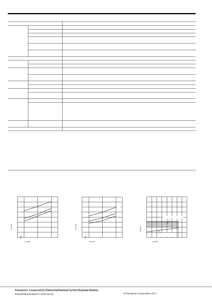
CT-P (ACTP)
–84–
ASCTB229E 201709-T
2. Specifications
Notes: *1. Depends on connection conditions. Also, this does not guarantee repeated switching. We recommend that you confirm operation under actual conditions.
*2. This value can change due to the switching frequency, environmental conditions, and desired reliability level, therefore it is recommended to check this with the
actual load.
*3. The upper operation ambient temperature limit is the maximum temperature that can satisfy the coil temperature rise value. For details, please refer to the
“Automotive Relay Users Guide”.
Please inquire our sales representative if you will be using the relay in a high temperature atmosphere (110
°
C
230
°
F
).
If the relay is used continuously for long periods of time with coils on both sides in an energized condition, breakdown might occur due to abnormal heating
depending on the carrying condition. Therefore, please inquire our sales representative when using with a circuit that causes an energized condition on both sides
simultaneously.
REFERENCE DATA
Item
Specifications
Contact data
Contact arrangement
1 Form C
×
2, 1 Form C
Contact resistance (initial)
Max. 100m
Ω
(N.O.: Typ. 7m
Ω
, N.C.: Typ. 10m
Ω
) (By voltage drop 1A 6V DC)
Contact material
Ag alloy
Rated switching capacity
(resistive)
N.O. side: 30 A 14V DC, N.C. side: 10 A 14V DC
Max. carrying current*
1
N.O. side: 25 A for 1 hour, 40 A for 2 minutes (Coil applied voltage 14V DC, at 20
°
C
68
°
F
)
20 A for 1 hour, 35 A for 2 minutes (Coil applied voltage 14V DC, at 85
°
C
185
°
F
)
Min. switching load
(resistive)*
2
1 A 14V DC (at 20
°
C
68
°
F
)
Insulated resistance (initial)
Min. 100 M
Ω
(at 500V DC, Measurement at same location as “Dielectric strength” section.)
Dielectric
strength (initial)
Between open contacts
500 Vrms for 1 min. (Detection current: 10mA)
Between contacts and coil
500 Vrms for 1 min. (Detection current: 10mA)
Time
characteristics
(initial)
Operate (Set) time
(at Rated voltage)
Max. 10ms (at 20
°
C
68
°
F
, without bounce time)
Release (Reset) time
(at Rated voltage)
Max. 10ms (at 20
°
C
68
°
F
, without bounce time) (without diode)
Shock
resistance
Functional
Min. 100 m/s
2
{approx. 10G} (Half-wave pulse of sine wave: 11ms; detection time: 10
μ
s)
Destructive
Min. 1,000 m/s
2
{approx. 100G} (Half-wave pulse of sine wave: 6ms)
Vibration
resistance
Functional
10 to 100 Hz, Min. 44.1 m/s
2
{approx. 4.5G} (Detection time: 10
μ
s)
Destructive
10 to 500 Hz, Min. 44.1 m/s
2
{approx. 4.5G},
Time of vibration for each direction; X, Y direction: 2 hours, Z direction: 4 hours
Expected life
Mechanical
Min. 10
7
(at 120 cpm)
Electrical
<Resistive load>
Min. 5
×
10
4
(at rated switching capacity, operating frequency: 1s ON, 9s OFF)
<Motor load>
N.O. side: Min. 10
5
at Inrush 30A, Steady 7A 14 V DC,
Min. 5
×
10
4
at 30A 14 V DC motor lock condition
N.C. side: Min. 10
5
at brake current 15A 14 V DC (Operating frequency: 0.5s ON, 9.5s OFF)
Conditions
Conditions for usage,
transport and storage*
3
Ambient temperature: –40 to +85
°
C
–40 to +185
°
F
,
Humidity: 5 to 85% R.H. (Please avoid icing or condensation)
Weight
Twin type: approx. 8 g
.28 oz
, 1 Form C type: approx. 4 g
.14 oz
∗
1-(1). Coil temperature rise (at room
temperature)
Sample: ACTP212, 3pcs.
Carrying current: 0A, 10A, 20A
Ambient temperature: Room temperature
1-(2). Coil temperature rise (at 85
°
C
185
°
F
)
Sample: ACTP212, 3pcs.
Carrying current: 0A, 10A, 20A
Ambient temperature: 85
°
C
185
°
F
2. Ambient temperature and usable voltage
range
0
20
40
60
80
100
120
140
160
12
14
0
16
20A
10A
0A
Coil applied voltage, V
T
emper
ature r
ise
,
°
C
0
20
40
60
80
100
120
140
160
12
14
0
16
20A
10A
0A
Coil applied voltage, V
T
emper
ature r
ise
,
°
C
0
5
10
15
35
30
25
20
40
-40 -20
20
40
60
100
0
120
80
Ambient temperature,
°
C
Coil applied v
oltage
,
VDC
Operate voltage
(Cold start)
Usable voltage range
automotive-relay_en-html.html
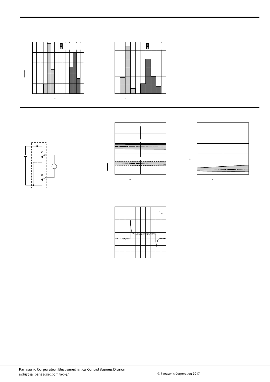
CT-P (ACTP)
–85–
ASCTB229E 201709-T
3. Distribution of operate (set) and release
(reset) voltage
Sample: ACTP212, 80pcs.
4. Distribution of operate (set) and release
(reset) time
Sample: ACTP212, 80pcs.
0
30
20
10
40
50
0 1
2
3
5
4
6
7
Voltage, V
Quantity
, n
Operate voltage
Release voltage
0
30
40
50
60
20
10
1.0
0.8
1.2 1.4 1.6 1.8 2.0 2.2 2.4 2.6 2.8
Operate time
Release time
Operate and release time, ms
Quantity
, n
* Without diode
5. Electrical life test (Motor free)
Sample: ACTP212, 3pcs.
Load: Inrush current: 30A, Steady current: 7A
Brake current: 15A 14V DC,
Power window motor actual load
Operating frequency: ON 0.5s, OFF 9.5s
Ambient temperature: Room temperature
Circuit:
Change of operate (set) and release (reset)
voltage
Change of contact resistance
M
0
2
4
6
8
10
0
5
10
Ave.
Ave.
Max.
Max.
Min.
Min.
Contact welding: 0 time
Miscontact: 0 time
No. of operations,
×
10
4
Oper
ate and release v
oltage
,
V
Operate voltage
Release voltage
0
Max.
Min.
Ave.
50
40
30
20
10
0
10
5
No. of operations,
×
10
4
Contact resistance
, m
Ω
Load current waveform
Load: Inrush current: 30A, Steady current: 7A
Brake current: 15A
100ms
10A
automotive-relay_en-html.html
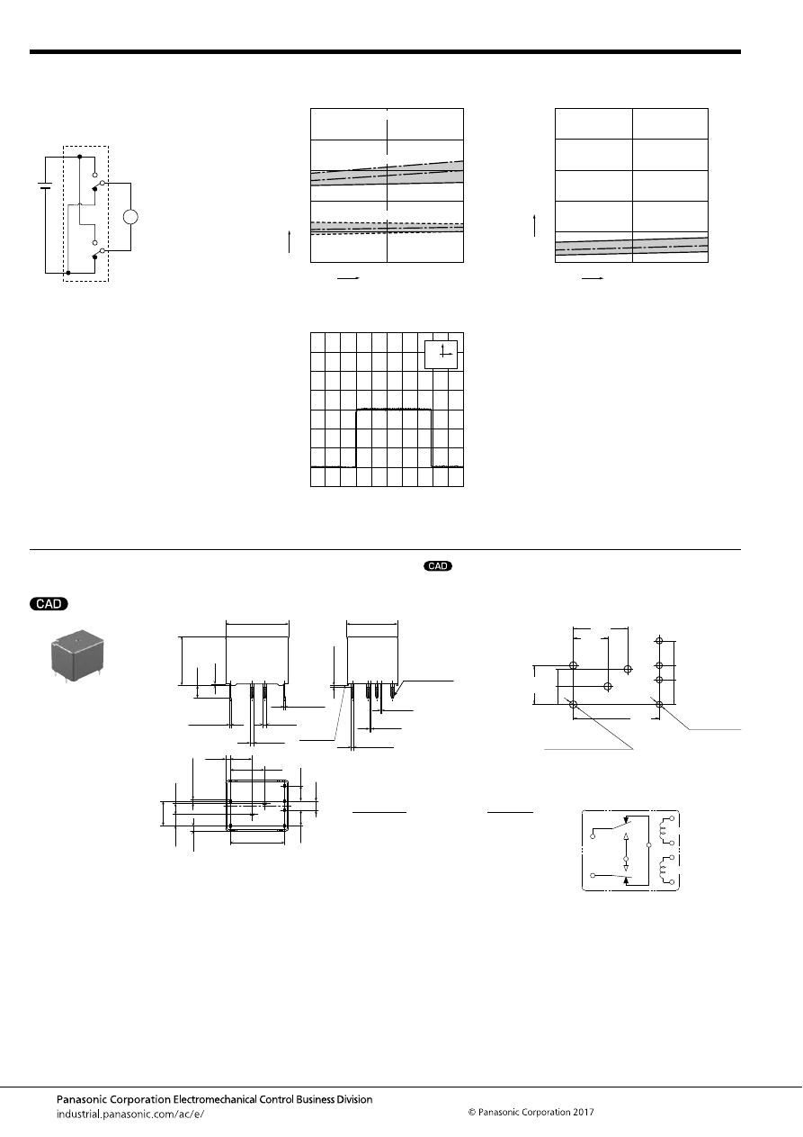
CT-P (ACTP)
–86–
ASCTB229E 201709-T
DIMENSIONS
(mm
inch
)
1. Twin type (8 pins)
6. Electrical life test (Motor lock)
Sample: ACTP212, 3pcs.
Load: 30A 14V DC
Operating frequency: ON 0.5s, OFF 9.5s
Ambient temperature: Room temperature
Circuit:
Change of operate (set) and release (reset)
voltage
Change of contact resistance
M
0
2
4
6
8
10
0
2.5
5
No. of operations,
×
10
4
Oper
ate and release v
oltage
,
V
Ave.
Ave.
Max.
Max.
Min.
Min.
Operate voltage
Release voltage
Contact welding: 0 time
Miscontact: 0 time
0
Max.
50
40
30
20
10
0
5
2.5
Min.
Ave.
No. of operations,
×
10
4
Contact resistance
, m
Ω
Load current waveform
100ms
10A
mark can be downloaded from: http://industrial.panasonic.com/ac/e/
The CAD data of the products with a
External dimensions
A surface
level
17.4
.685
14
.551
9.5
.374
1.25
.049
6
.236
15
.591
2
×
1
2
×
.039
+
0.3
−
0.1
+
.012
−
.004
2
×
0.4
2
×
.016
+
0.3
−
0.1
+
.012
−
.004
1
.039
+
0.3
−
0.1
+
.012
−
.004
1
.039
+
0.3
−
0.1
+
.012
−
.004
4
×
0.3
4
×
.012
+
0.3
−
0.1
+
.012
−
.004
0.4
.016
+
0.3
−
0.1
+
.012
−
.004
4
×
0.8
4
×
.031
+
0.3
−
0.1
+
.012
−
.004
0.4
.016
+
0.3
−
0.1
+
.012
−
.004
Pre-soldering
(all terminals)
Max.
1.0
Max.
.039
0.4
.016
3.5
.138
13.5
.531
2.5
.098
4.3
.169
4.3
.169
1.45
.057
3.15
.124
6.8
.268
3
.118
Dimension:
Tolerance
Max. 1mm
.039 inch
:
±
0.1
±
.004
1 to 3mm
.039 to .118 inch
:
±
0.2
±
.008
Min. 3mm
.118 inch
:
±
0.3
±
.012
* Dimensions (thickness and width) of terminal is measured after pre-soldering.
Intervals between terminals is measured at A surface level.
PC board pattern (Bottom view)
Tolerance:
±
0.1
±
.004
Schematic (Bottom view)
3.15
4.3
4.3
2.5
6.8
4
×
1.1 dia.
+0.1
0
+0.04
0
9.5
6
3
15
4
×
1.4 dia.
+0.1
0
+0.04
0
.124
.169
.169
.098
.268
.374
.236
.118
.591
4
×
.043 dia.
(Coil terminal)
4
×
.055 dia.
(Except coil terminal)
N.C.
N.O.
COM
COM
COIL
COIL
automotive-relay_en-html.html
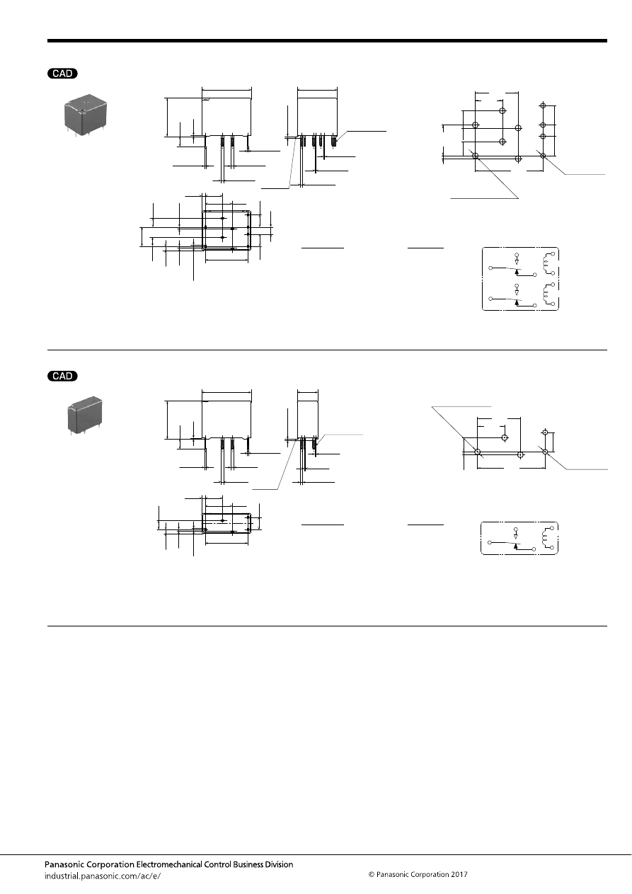
CT-P (ACTP)
–87–
ASCTB229E 201709-T
2. Twin type (10 pins)
3. Single type (1 Form C)
For general cautions for use, please refer to the “Automotive Relay Users Guide”.
External dimensions
A surface
level
17.4
.685
14
.551
9.5
.374
1.25
.049
6
.236
15
.591
2
×
1
2
×
.039
+
0.3
−
0.1
+
.012
−
.004
2
×
0.4
2
×
.016
+
0.3
−
0.1
+
.012
−
.004
2
×
1
2
×
.039
+
0.3
−
0.1
+
.012
−
.004
2
×
1
2
×
.039
+
0.3
−
0.1
+
.012
−
.004
4
×
0.3
4
×
.012
+
0.3
−
0.1
+
.012
−
.004
2
×
0.4
2
×
.016
+
0.3
−
0.1
+
.012
−
.004
4
×
0.8
4
×
.031
+
0.3
−
0.1
+
.012
−
.004
2
×
0.4
2
×
.016
+
0.3
−
0.1
+
.012
−
.004
Pre-soldering
(all terminals)
Max.
1.0
Max.
.039
0.4
.016
3.5
.138
13.5
.531
2.5
.098
4.3
.169
4.3
.169
1.45
.057
0.65
.026
0.65
.026
3.15
.124
6.8
.268
3.15
.124
Dimension:
Tolerance
Max. 1mm
.039 inch
:
±
0.1
±
.004
1 to 3mm
.039 to .118 inch
:
±
0.2
±
.008
Min. 3mm
.118 inch
:
±
0.3
±
.012
* Dimensions (thickness and width) of terminal is measured after pre-soldering.
Intervals between terminals is measured at A surface level.
PC board pattern (Bottom view)
Tolerance:
±
0.1
±
.004
Schematic (Bottom view)
3.15
3.15
0.65
0.65
4.3
4.3
2.5
6.8
9.5
6
15
6
×
1.4 dia.
+0.1
0
+0.04
0
4
×
1.1 dia.
+0.1
0
+0.04
0
.124
.124
.026
.026
.169
.169
.098
.268
.374
.236
.591
6
×
.055 dia.
(Except coil terminal)
4
×
.043 dia.
(Coil terminal)
COM
N.O.
COM
N.O.
N.C.
N.C.
COIL
COIL
External dimensions
A surface
level
17.4
.685
7.2
.283
9.5
.374
1.25
.049
6
.236
15
.591
1
.039
+
0.3
−
0.1
+
.012
−
.004
0.4
.016
+
0.3
−
0.1
+
.012
−
.004
1
.039
+
0.3
−
0.1
+
.012
−
.004
1
.039
+
0.3
−
0.1
+
.012
−
.004
2
×
0.3
2
×
.012
+
0.3
−
0.1
+
.012
−
.004
0.4
.016
+
0.3
−
0.1
+
.012
−
.004
2
×
0.8
2
×
.031
+
0.3
−
0.1
+
.012
−
.004
0.4
.016
+
0.3
−
0.1
+
.012
−
.004
Pre-soldering
(all terminals)
Max.
1.0
Max.
.039
0.4
.016
3.5
.138
13.5
.531
4.3
.169
1.45
.057
0.65
.026
3.15
.124
Dimension:
Tolerance
Max. 1mm
.039 inch
:
±
0.1
±
.004
1 to 3mm
.039 to .118 inch
:
±
0.2
±
.008
Min. 3mm
.118 inch
:
±
0.3
±
.012
* Dimensions (thickness and width) of is measured after pre-soldering.
Intervals between terminals is measured at A surface level.
PC board pattern (Bottom view)
Tolerance:
±
0.1
±
.004
Schematic (Bottom view)
3.15
4.3
2
×
1.1 dia.
+0.1
0
+0.04
0
15
0.65
9.5
6
3
×
1.4 dia.
+0.1
0
+0.04
0
.124
.169
.591
.026
.374
.236
2
×
.043 dia.
(Coil terminal)
3
×
.055 dia.
(Except coil terminal)
N.O.
COM
N.C.
COIL
automotive-relay_en-html.html
CW (ACW)
–88–
ASCTB231E 201709-T
ORDERING INFORMATION
TYPES
RATING
1. Coil data
Automotive Relay
for Failsafe Circuits in
High Output Motors (EPS)
CW RELAYS
Contact arrangement
Rated coil voltage
Part No.
Packing
Carton
Case
2 Form A
12 V DC
ACW212
40 pcs.
160 pcs.
Rated coil
voltage
Operate (Set) voltage
(at 20
°
C
68
°
F
) (Initial)
Release (Reset)
voltage
(at 20
°
C
68
°
F
) (Initial)
Rated operating current
[
±
10%] (at 20
°
C
68
°
F
)
Coil resistance
[
±
10%] (at 20
°
C
68
°
F
)
Rated operating power
(at 20
°
C
68
°
F
)
Usable voltage range
12V DC
Max. 6.2 V DC
Min. 0.5 V DC
117 mA
103
Ω
1.4 W
10 to 16V DC
FEATURES
• Ideal relay for high output 3-phase motors
• High current cutoff
• High carrying current and high heat resistance
TYPICAL APPLICATIONS
• 3-phase motor EPS unit, etc. (for failsafe circuit)
<Protective construction>
Sealed
18
32
19
.709
1.260
.748
(Unit: mm
inch
)
RoHS compliant
Contact arrangement
2: 2 Form A
ACW
2
Rated coil voltage (DC)
12: 12 V
automotive-relay_en-html.html
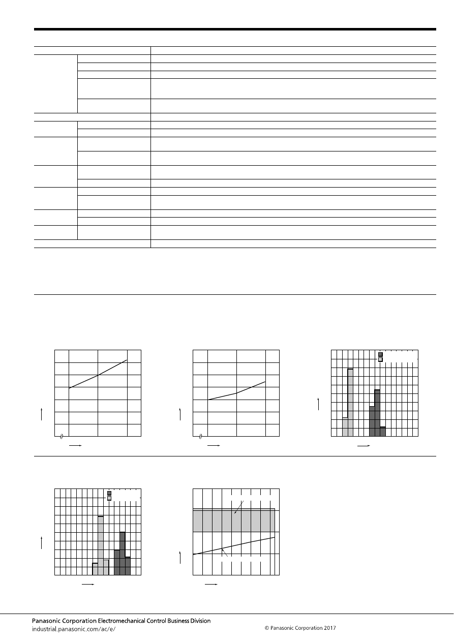
CW (ACW)
–89–
ASCTB231E 201709-T
2. Specifications
Notes: *1. Depends on connection conditions. Also, this does not guarantee repeated switching. We recommend that you confirm operation under actual conditions.
*2. This value can change due to the switching frequency, environmental conditions, and desired reliability level, therefore it is recommended to check this with the
actual load.
*3. The upper operation ambient temperature limit is the maximum temperature that can satisfy the coil temperature rise value. For details, please refer to the
“Automotive Relay Users Guide”.
Please inquire our sales representative if you will be using the relay in a high temperature atmosphere (110
°
C
230
°
F
).
REFERENCE DATA
Item
Specifications
Contact data
Contact arrangement
2 Form A
Contact resistance (initial)
Typ. 1.2 m
Ω
(By voltage drop 1A 6V DC)
Contact material
Ag alloy
Max. carrying current*
1
120 A 14V DC for 5 seconds (Coil applied voltage 14V DC, at 20
°
C
68
°
F
)
70 A 14V DC for 1 minute (Coil applied voltage 14V DC, at 85
°
C
185
°
F
)
45 A 14V DC for continuous (Coil applied voltage 14V DC, at 85
°
C
185
°
F
)
Min. switching load
(resistive)*
2
1 A 14V DC (at 20
°
C
68
°
F
)
Insulated resistance (initial)
Min. 100 M
Ω
(at 500V DC, Measurement at same location as “Dielectric strength” section.)
Dielectric
strength (initial)
Between open contacts
500 Vrms for 1 min. (Detection current: 10mA)
Between contacts and coil
500 Vrms for 1 min. (Detection current: 10mA)
Time
characteristics
(initial)
Operate (Set) time
(at Rated voltage)
Max. 20ms (at 20
°
C
68
°
F
, without bounce time)
Release (Reset) time
(at Rated voltage)
Max. 20ms (at 20
°
C
68
°
F
) (without diode)
Shock
resistance
Functional
Min. 200 m/s
2
{approx. 20G} (Half-wave pulse of sine wave: 11ms; detection time: 10
μ
s)
(12 V DC applied to the coil, at 20
°
C
68
°
F
)
Destructive
Min. 1,000 m/s
2
{approx. 100G} (Half-wave pulse of sine wave: 6ms)
Vibration
resistance
Functional
10 to 500 Hz, Min. 44.1 m/s
2
{approx. 4.5G} (Detection time: 10
μ
s) (12 V DC applied to the coil, at 20
°
C
68
°
F
)
Destructive
10 to 500 Hz, Min. 44.1 m/s
2
{approx. 4.5G},
Time of vibration for each direction; X, Y, Z direction: 4 hours
Expected life
Mechanical
Min. 2
×
10
5
(at 60 cpm)
Electrical (at cut off only)
200 A 14V DC resistive load, Min. 3 times (Without diode)
Conditions
Conditions for usage,
transport and storage*
3
Ambient temperature: –40 to +125
°
C
–40 to +257
°
F
,
Humidity: 2 to 85% R.H. (Please avoid icing or condensation)
Weight
Approx. 26 g
.92 oz
1.-(1) Coil temperature rise (25
°
C
77
°
F
)
Sample: ACW212, 3pcs
Point measured: Inside the coil
Carrying current: 45A
Ambient temperature: 25
°
C
77
°
F
1.-(2) Coil temperature rise (85
°
C
185
°
F
)
Sample: ACW212, 3pcs
Point measured: Inside the coil
Carrying current: 45A
Ambient temperature: 85
°
C
185
°
F
2. Distribution of operate (set) and release
(reset) voltage
Sample: ACW212, 100pcs
12
14
0
16
140
120
100
80
60
20
40
0
45A
Coil applied voltage, V
T
emper
ature r
ise
,
°
C
12
14
0
16
140
120
100
80
60
20
40
0
45A
Coil applied voltage, V
T
emper
ature r
ise
,
°
C
0
30
20
10
40
50
60
70
80
90
100
8
7
6
5
4
3
2
1
0
Operate voltage
Release voltage
Quantity
, n
Voltage, V
3. Distribution of operate (set) and release
(reset) time
Sample: ACW212, 100pcs.
4. Ambient temperature and usable voltage
range
0
30
20
10
40
50
60
70
80
90
100
Quantity
, n
8
7
6
5
4
3
2
1
0
Operate time
Release time
Time, ms
0
5
10
20
15
-40 -20
20
40
60
80
120 125
100
0
Operate voltage (cold start)
Ambient temperature,
°
C
Coil applied v
oltage
,
VDC
Usable voltage range
automotive-relay_en-html.html
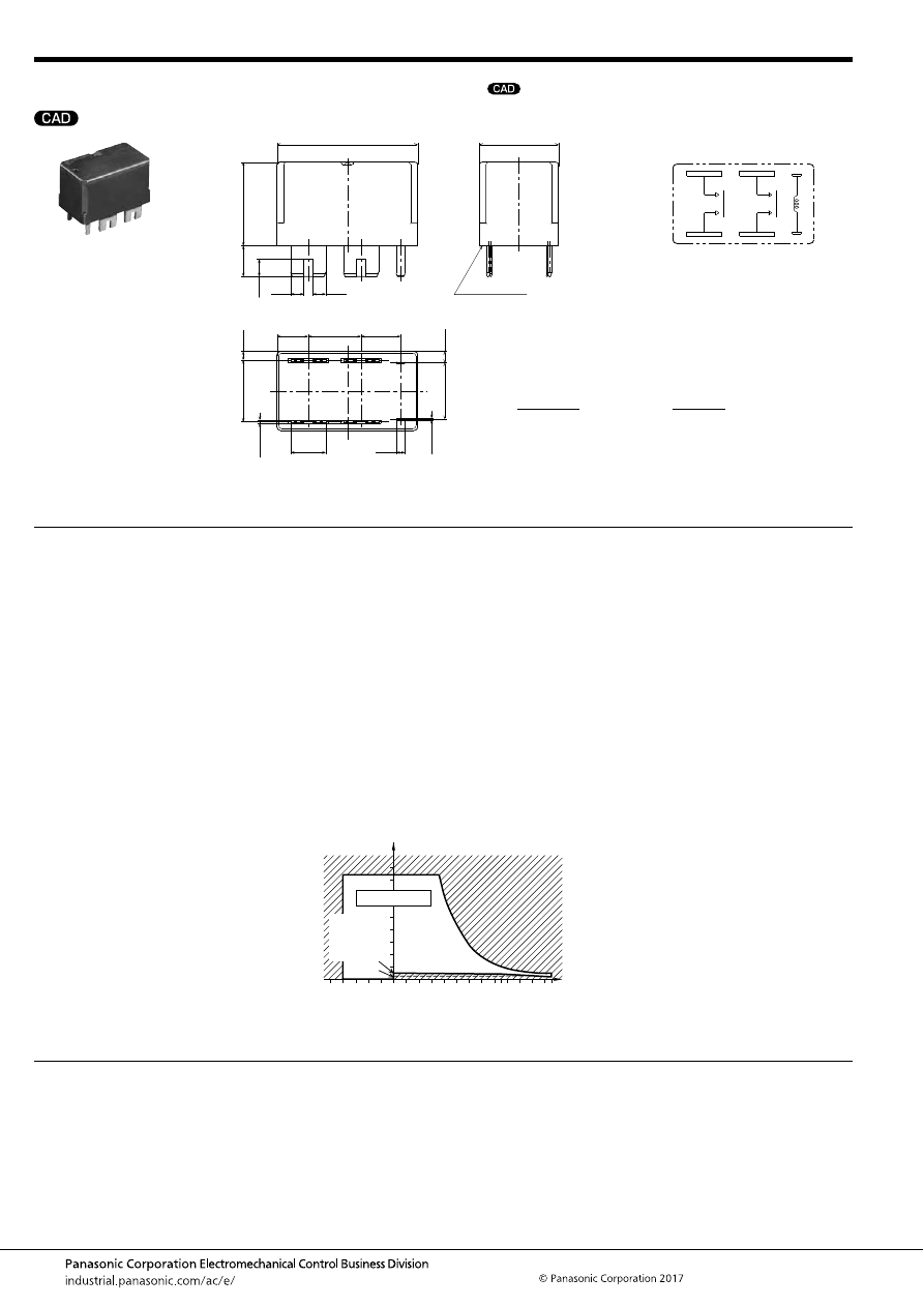
CW (ACW)
–90–
ASCTB231E 201709-T
DIMENSIONS
(mm
inch
)
NOTES
For general cautions for use, please refer to the “Automotive Relay Users Guide”.
mark can be downloaded from: http://industrial.panasonic.com/ac/e/
The CAD data of the products with a
External dimensions
8.0
18.0
32.0
A surface level
3.0
7.1
±
0.5 12.0
±
0.5
9.0
±
0.5
4.0
19.0
12.8
2
×
0.4
2.0
14.0
4
×
0.8
.315
.709
1.260
.118
3.0
.118
.280
±
.020.472
±
.020 .354
±
.020
.157
.748
7.0
.276
.504
2.6
.102
2
×
.016
.079
.551
2.0
.079
4
×
.031
Dimension:
Tolerance
Max. 1mm
.039 inch
:
±
0.1
±
.004
1 to 3mm
.039 to .118 inch
:
±
0.2
±
.008
Min. 3mm
.118 inch
:
±
0.3
±
.012
* Intervals between terminals is measured at A surface level.
Schematic
(Bottom view)
1. Mounting method
These relays are designed for mounting
by welding. Soldering cannot be used for
mounting.
2. Usage, transport and storage
conditions
1) Ambient temperature, humidity, and air
pressure during usage, transport, and
storage of the relay:
(1) Temperature:
–40 to +125
°
C
–40 to +257
°
F
(2) Humidity: 2 to 85% RH (Avoid icing
and condensation.)
(3) Air pressure: 86 to 106 kPa
The humidity range varies with the
temperature. Use within the range
indicated in the graph below.
[Temperature and humidity range for
usage, transport, and storage]
85
5
2
110
85
0
–40
+230
125
+257
+185
+32
–40
Humidity, %RH
Temperature,
°
C
°
F
Tolerance range
(Avoid
condensation
when used at
temperatures
higher than
0
°
C
32
°
F
)
(Avoid icing
when used at
temperatures
lower than
0
°
C
32
°
F
)
automotive-relay_en-html.html
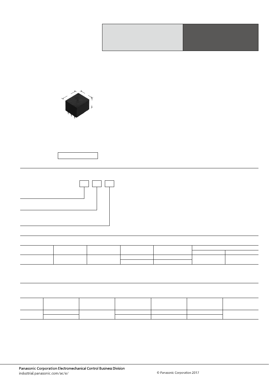
TA (ACTA)
–91–
ASCTB94E 201709-T
ORDERING INFORMATION
TYPES
RATING
1. Coil data
1 Form C Automotive
Quiet Relay
TA RELAYS
Contact arrangement
Contact type
Rated coil voltage
Coil resistance
Part No.
Packing
Carton (tube)
Case
1 Form C
Standard type
12V DC
160
Ω
ACTA22
25 pcs.
1,000 pcs.
225
Ω
ACTA23
Rated coil
voltage
Operate (Set) voltage
(at 20
°
C
68
°
F
) (Initial)
Release (Reset)
voltage
(at 20
°
C
68
°
F
) (Initial)
Rated operating current
[
±
10%] (at 20
°
C
68
°
F
)
Coil resistance
[
±
10%] (at 20
°
C
68
°
F
)
Rated operating power
(at 20
°
C
68
°
F
)
Usable voltage range
12V DC
Max. 6.5V DC
Min. 0.8V DC
75 mA
160
Ω
900 mW
10 to 16V DC
Max. 7.7V DC
53.3 mA
225
Ω
640 mW
FEATURES
• Designed for low operation noise when mounted on PC
board
• Flat type
TYPICAL APPLICATIONS
•
Intermittent wiper, Cruise control, Powered windows,
Automatic door locks, Power supply of car stereo and car
air-conditioner, Powered seats, Powered sunroof, etc.
<Protective construction>
Sealed
17
19.8
14
.669
.780
.551
(Unit: mm
inch
)
RoHS compliant
Contact arrangement
2: 1 Form C
Contact type
Nil: Standard type
Coil resistance
2: 160
Ω
3: 225
Ω
ACTA
automotive-relay_en-html.html
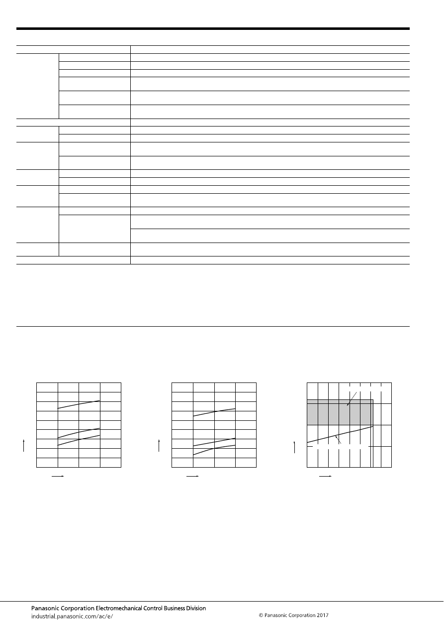
TA (ACTA)
–92–
ASCTB94E 201709-T
2. Specifications
Notes: *1. Depends on connection conditions. Also, this does not guarantee repeated switching. We recommend that you confirm operation under actual conditions.
*2. This value can change due to the switching frequency, environmental conditions, and desired reliability level, therefore it is recommended to check this with the
actual load.
*3. The upper operation ambient temperature limit is the maximum temperature that can satisfy the coil temperature rise value. For details, please refer to the
“Automotive Relay Users Guide”.
Please inquire our sales representative if you will be using the relay in a high temperature atmosphere (110
°
C
230
°
F
).
*4. Do not use for lamp loads, electric discharge lamp loads, any other lamp loads and capacitor loads. Please inquire our sales representative for details.
REFERENCE DATA
Item
Specifications
Contact data
Contact arrangement
1 Form C
Contact resistance (initial)
Max. 100m
Ω
(N.O. side: typ. 5m
Ω
, N.C. side: typ. 6m
Ω
) (By voltage drop 1A 6V DC)
Contact material
Ag alloy
Rated switching capacity
(resistive)
N.O. side: 20A 14V DC, N.C. side: 10A 14V DC
Max. carrying current
(initial)*
1
25A for 3 minutes (Coil applied voltage 12V DC, at 20
°
C
68
°
F
)
Min. switching load
(resistive)*
2
1A 14V DC (at 20
°
C
68
°
F
)
Insulated resistance (initial)
Min. 100 M
Ω
(at 500V DC, Measurement at same location as “Dielectric strength” section.)
Dielectric
strength (initial)
Between open contacts
500 Vrms for 1 min. (Detection current: 10mA)
Between contacts and coil
500 Vrms for 1 min. (Detection current: 10mA)
Time
characteristics
(initial)
Operate (Set) time
(at rated voltage)
Max. 10ms (at 20
°
C
68
°
F
, without contact bounce time)
Release (Reset) time
(at rated voltage)
Max. 10ms (at 20
°
C
68
°
F
, without contact bounce time) (without diode)
Shock
resistance
Functional
Min. 100 m/s
2
{approx. 10G} (Half-wave pulse of sine wave: 11ms; detection time: 10
μ
s)
Destructive
Min. 1,000 m/s
2
{approx. 100G} (Half-wave pulse of sine wave: 6ms)
Vibration
resistance
Functional
10 to 100 Hz, Min. 44.1 m/s
2
{approx. 4.5G} (Detection time: 10
μ
s)
Destructive
10 to 100 Hz, Min. 44.1 m/s
2
{approx. 4.5G},
Time of vibration for each direction; X, Y direction: 2 hours, Z direction: 4 hours
Expected life
Mechanical
Min. 10
7
(at 120 cpm)
Electrical*
4
<Resistive load>
Min. 10
5
at rated switching capacity, operating frequency: 1s ON, 9s OFF
<Motor load>
Min. 10
5
25 A 14V DC at motor lock condition, operating frequency: 0.5s ON, 9.5s OFF
Conditions
Conditions for usage,
transport and storage*
3
Ambient temperature: –40 to +85
°
C
–40 to +185
°
F
,
Humidity: 5 to 85% R.H. (Please avoid icing or condensation)
Weight
Approx. 8 g
.28 oz
1.-(1) Coil temperature rise (at room
temperature)
Sample: ACTA23, 3pcs.
Carrying current: 0A, 10A, 20A
Ambient temperature: Room temperature
1.-(2) Coil temperature rise (at 85
°
C
185
°
F
)
Sample: ACTA23, 3pcs.
Carrying current: 0A, 10A, 20A
Ambient temperature: 85
°
C
185
°
F
2. Ambient temperature and usable voltage
range
Sample: ACTA23
18
Coil applied voltage, V
T
e
mper
ature r
ise
,
°
C
16
14
12
10
20A
10A
0A
180
160
140
120
100
80
60
40
20
0
Coil applied voltage, V
T
e
mper
ature r
ise
,
°
C
18
16
14
12
10
20A
10A
0A
180
160
140
120
100
80
60
40
20
0
Ambient temperature,
°
C
Coil applied v
oltage
,
V
120
-40 -20
0
20
15
10
5
0
20
40
60
80
100
Operate voltage (Cold start)
Usable voltage range
automotive-relay_en-html.html
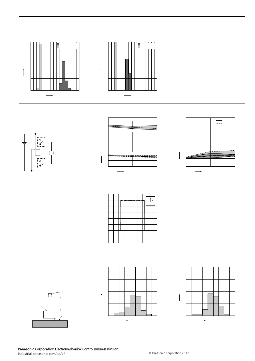
TA (ACTA)
–93–
ASCTB94E 201709-T
3. Distribution of operate (set) and release
(reset) voltage
Sample: ACTA23, 40pcs.
4. Distribution of operate (set) and release
(reset) time
Sample: ACTA23, 40pcs.
Operate voltage
Release voltage
Voltage, V
Quantity
, n
8
0
40
30
20
10
0
1
2
3
4
5
6
7
8
0
40
30
20
10
0
1
2
3
4
5
6
7
Time, ms
Quantity
, n
Operate time
Release time
* Without diode
5.-(1) Electrical life test (Motor lock)
Sample: ACTA23, 3pcs.
Load: 25A 14V DC
Power window motor actual load (lock condition)
Operating frequency: ON 0.5s, OFF 9.5s
Ambient temperature: Room temperature
Circuit:
Change of operate (set) and release (reset)
voltage
Change of contact resistance
M
10
5
Operate voltage
Release voltage
0
8
7
6
5
4
3
2
1
0
Max.
Min.
Ave.
Max.
Min.
Ave.
Oper
ate and release v
oltage
,
V
No. of operations,
×
10
4
Contact welding: 0 time
Miscontact: 0 time
10
5
0
30
25
20
15
10
5
0
Contact resistance
, m
Ω
No. of operations,
×
10
4
N.C. side
N.O. side
Max.
Max.
Min.
Min.
Ave.
Ave.
Load current waveform
Current value: 25A
100ms
5A
6. Noise pressure characteristics
Measuring conditions
Sample: ACTA23, 50 pcs.
Equipment setting: “A” weighted, Fast, Max. hold
Coil voltage: 12V DC
Coil connection device: Diode
Background noise: approx. 35dB
Operate (set) noise
Release (reset) noise
Microphone
Sponge
Relay
50mm
1.969inch
44
46
48
50
52
54
56
58
60
0
30
20
10
40
Noise level, dB
Quantity
, n
42
44
46
48
50
52
54
56
58
0
30
20
10
40
Noise level, dB
Quantity
, n
automotive-relay_en-html.html
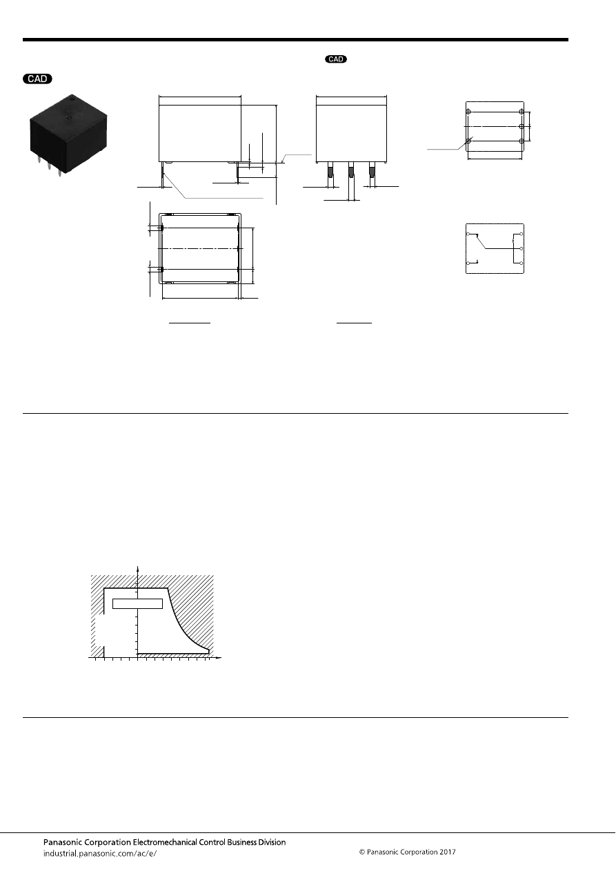
TA (ACTA)
–94–
ASCTB94E 201709-T
DIMENSIONS
(mm
inch
)
NOTES
For general cautions for use, please refer to the “Automotive Relay Users Guide”.
mark can be downloaded from: http://industrial.panasonic.com/ac/e/
The CAD data of the products with a
External dimensions
A surface
level
19.8
±
0.5
.780
±
.020
17
±
0.5
.669
±
.020
18.2
.717
(0.8)
(.031)
1.2
.047
+
0.3
−
0.1
+
.012
−
.004
1.2
.047
+
0.3
−
0.1
+
.012
−
.004
0.3
.012
+
0.3
−
0.1
+
.012
−
.004
0.3
.012
+
0.3
−
0.1
+
.012
−
.004
1.2
.047
+
0.3
−
0.1
+
.012
−
.004
Pre-soldering (all terminals)
Max.
1.0
Max.
.039
0.4
.016
14
±
0.5
.551
±
.020
3.5
±
0.5
.138
±
.020
1.2
.047
+
0.3
−
0.1
+
.012
−
.004
1.2
.047
+
0.3
−
0.1
+
.012
−
.004
10
.394
(3.5)
(.138)
PC board pattern
(Bottom view)
Tolerance:
±
0.1
±
.004
Schematic
(Bottom view)
18.2
5
×
1.6 dia.
5
×
.063 dia.
5
.197
5
.197
.717
COIL
COM
COIL
N.O.
N.C.
* Dimensions (thickness and width) of terminal is measured after pre-soldering.
Intervals between terminals is measured at A surface level.
Dimension:
Less than 1mm
.039inch
:
Min. 1mm
.039inch
less than 3mm
.118 inch
:
Min. 3mm
.118 inch
:
Tolerance
±
0.1
±
.004
±
0.2
±
.008
±
0.3
±
.012
Usage, transport and storage conditions
1) Ambient temperature, humidity, and air pressure during
usage, transport, and storage of the relay:
(1) Temperature: –40 to +85
°
C
–40 to +185
°
F
(2) Humidity: 5 to 85% RH (Avoid icing and condensation.)
(3) Air pressure: 86 to 106 kPa
The humidity range varies with the temperature. Use within the
range indicated in the graph below.
[Temperature and humidity range for
usage, transport, and storage]
85
5
Humidity, %RH
Tolerance range
(Avoid
condensation
when used at
temperatures
higher than
0
°
C
32
°
F
)
(Avoid icing
when used at
temperatures
lower than
0
°
C
32
°
F
)
85
0
–40
+185
+32
–40
Temperature,
°
C
°
F
automotive-relay_en-html.html
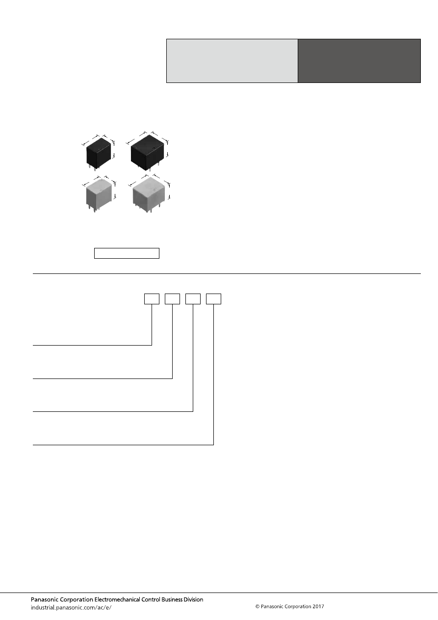
TB (ACTB)
–95–
ASCTB95E 201709-T
ORDERING INFORMATION
Miniature PC Board,
Twin/1 Form C Type
Automotive Relay
TB RELAYS
FEATURES
• Compact and high-capacity 25 A load switching
• Wide line-up
• Pin in Paste compliant model added
TYPICAL APPLICATIONS
• Powered windows, Automatic door locks, Powered
mirrors, Powered sunroof, Powered seats, Lift gates and
Slide door closers, etc.
<Protective construction>
Standard type/High heat-resistant type: Sealed
Pin in Paste compliant type: Flux tight
9.2
14
13.5
.362
.551
.531
9.2
14
14
.362
.551
.551
14
17.4
13.5
.551
.685
.531
14
17.4
14
.551
.685
.551
(Unit: mm
inch
)
RoHS compliant
Coil resistance
1: 100
Ω
2: 160
Ω
3: 225
Ω
Contact arrangement
1: 1 Form A
2: 1 Form C
3: 1 Form C
×
2 (8 pins)
5: 1 Form C
×
2 (10 pins)
Contact type
Nil:
L:
C:
ACTB
Heat resistance/Protective construction
Nil:
H:
R:
Standard type
Lamp control type
Standard type (Ag alloy / Cu clad)
Standard type/Sealed
High heat-resistant type/Sealed
Pin in Paste compliant type/Flux tight
automotive-relay_en-html.html
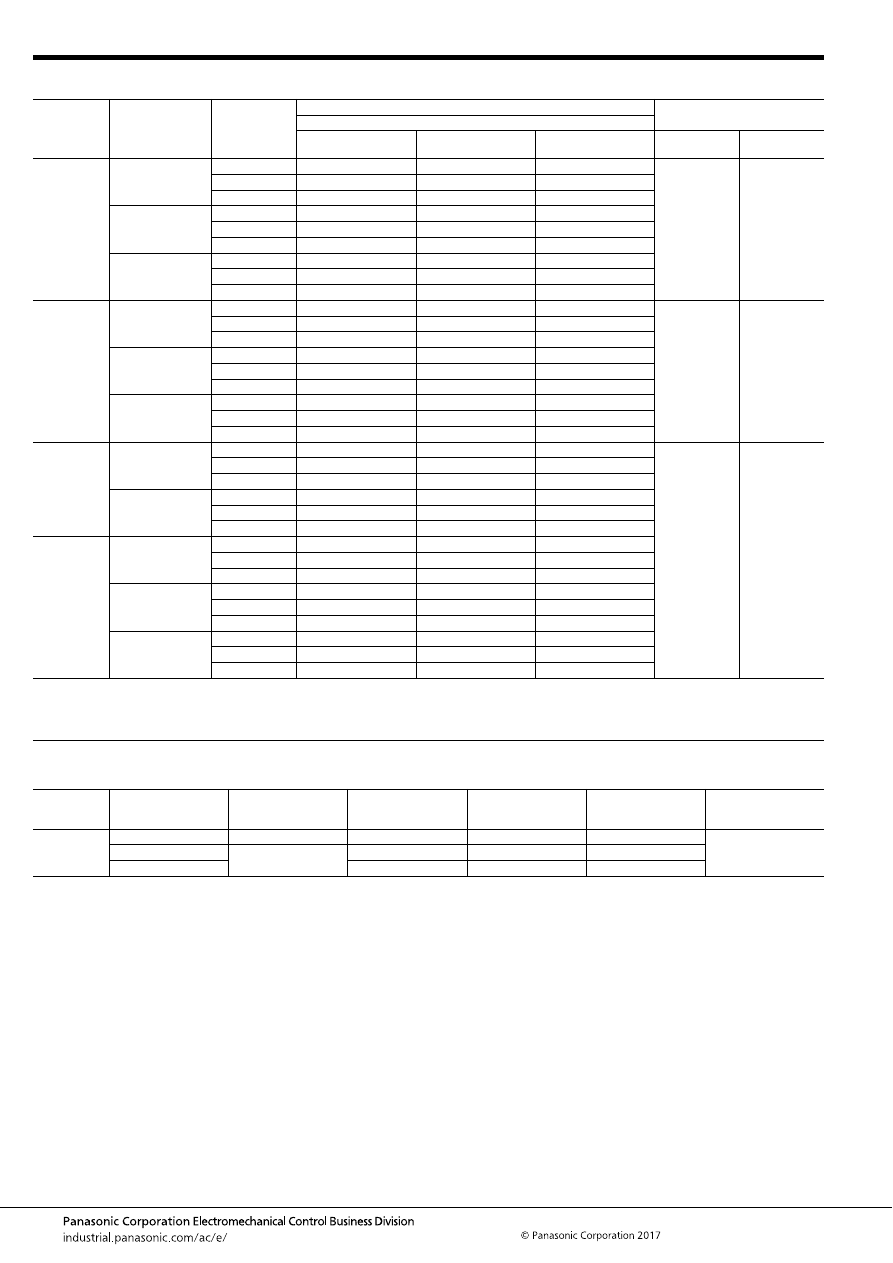
TB (ACTB)
–96–
ASCTB95E 201709-T
TYPES
RATING
1. Coil data
Note: Other operate (set) voltage types are also available. Please inquire our sales representative for details.
Contact
arrangement
Contact type
Coil resistance
Part No.
Packing
Heat resistance
Standard type
High heat-resistant type
Pin in Paste compliant
type
Carton (tube)
Case
1 Form A
Standard type
100
Ω
ACTB11
ACTB1H1
ACTB1R1
50 pcs.
2,000 pcs.
160
Ω
ACTB12
ACTB1H2
ACTB1R2
225
Ω
ACTB13
ACTB1H3
ACTB1R3
Standard type
(Ag alloy / Cu clad)
100
Ω
ACTB1C1
ACTB1CH1
ACTB1CR1
160
Ω
ACTB1C2
ACTB1CH2
ACTB1CR2
225
Ω
ACTB1C3
ACTB1CH3
ACTB1CR3
Lamp control type
100
Ω
ACTB1L1
ACTB1LH1
ACTB1LR1
160
Ω
ACTB1L2
ACTB1LH2
ACTB1LR2
225
Ω
ACTB1L3
ACTB1LH3
ACTB1LR3
1 Form C
Standard type
100
Ω
ACTB21
ACTB2H1
ACTB2R1
50 pcs.
2,000 pcs.
160
Ω
ACTB22
ACTB2H2
ACTB2R2
225
Ω
ACTB23
ACTB2H3
ACTB2R3
Standard type
(Ag alloy / Cu clad)
100
Ω
ACTB2C1
ACTB2CH1
ACTB2CR1
160
Ω
ACTB2C2
ACTB2CH2
ACTB2CR2
225
Ω
ACTB2C3
ACTB2CH3
ACTB2CR3
Lamp control type
100
Ω
ACTB2L1
ACTB2LH1
ACTB2LR1
160
Ω
ACTB2L2
ACTB2LH2
ACTB2LR2
225
Ω
ACTB2L3
ACTB2LH3
ACTB2LR3
1 Form C
×
2
(8 pins)
Standard type
100
Ω
ACTB31
ACTB3H1
ACTB3R1
25 pcs.
1,000 pcs.
160
Ω
ACTB32
ACTB3H2
ACTB3R2
225
Ω
ACTB33
ACTB3H3
ACTB3R3
Standard type
(Ag alloy / Cu clad)
100
Ω
ACTB3C1
ACTB3CH1
ACTB3CR1
160
Ω
ACTB3C2
ACTB3CH2
ACTB3CR2
225
Ω
ACTB3C3
ACTB3CH3
ACTB3CR3
1 Form C
×
2
(10 pins)
Standard type
100
Ω
ACTB51
ACTB5H1
ACTB5R1
160
Ω
ACTB52
ACTB5H2
ACTB5R2
225
Ω
ACTB53
ACTB5H3
ACTB5R3
Standard type
(Ag alloy / Cu clad)
100
Ω
ACTB5C1
ACTB5CH1
ACTB5CR1
160
Ω
ACTB5C2
ACTB5CH2
ACTB5CR2
225
Ω
ACTB5C3
ACTB5CH3
ACTB5CR3
Lamp control type
100
Ω
ACTB5L1
ACTB5LH1
ACTB5LR1
160
Ω
ACTB5L2
ACTB5LH2
ACTB5LR2
225
Ω
ACTB5L3
ACTB5LH3
ACTB5LR3
Rated coil
voltage
Operate (Set) voltage
(at 20
°
C
68
°
F
) (Initial)
Release (Reset)
voltage
(at 20
°
C
68
°
F
) (Initial)
Rated operating current
[
±
10%] (at 20
°
C
68
°
F
)
Coil resistance
[
±
10%] (at 20
°
C
68
°
F
)
Rated operating power
(at 20
°
C
68
°
F
)
Usable voltage range
12V DC
Max. 5.5V DC
Min. 0.5V DC
120 mA
100
Ω
1,440 mW
10 to 16V DC
Max. 6.5V DC
Min. 0.8V DC
75 mA
160
Ω
900 mW
Max. 7.7V DC
53.3 mA
225
Ω
640 mW
automotive-relay_en-html.html
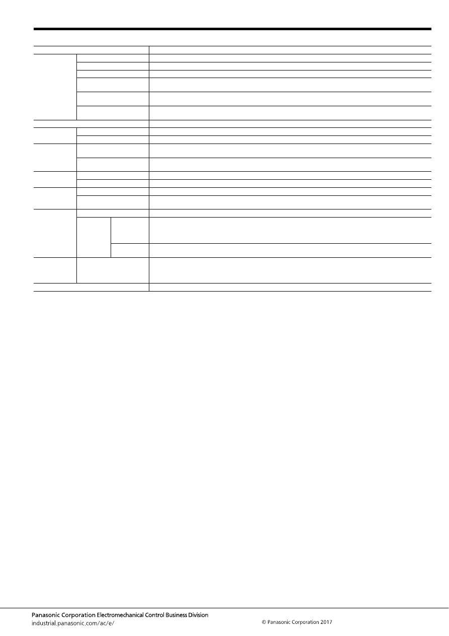
TB (ACTB)
–97–
ASCTB95E 201709-T
2. Specifications
Notes: *1. Depends on connection conditions. Also, this does not guarantee repeated switching. We recommend that you confirm operation under actual conditions.
*2. This value can change due to the switching frequency, environmental conditions, and desired reliability level, therefore it is recommended to check this with the
actual load.
*3. The upper operation ambient temperature limit is the maximum temperature that can satisfy the coil temperature rise value. For details, please refer to the
“Automotive Relay Users Guide”.
Please inquire our sales representative if you will be using the relay in a high temperature atmosphere (110
°
C
230
°
F
).
*4. Part numbers for electric discharge lamp loads or any other lamp loads and for capacitor loads only consist of “ACTB
∗
L
∗∗
”.
When using the lamp control type, connect N.O. to the “+ (plus)” side. Please inquire our sales representative for details.
*If the relay is used continuously for long periods of time with coils on both sides in an energized condition, breakdown might occur due to abnormal heating depending
on the carrying condition. Therefore, please inquire our sales representative when using with a circuit that causes an energized condition on both sides
simultaneously.
Item
Specifications
Contact data
Contact arrangement
1 Form A, 1 Form C, 1 Form C
×
2
Contact resistance (initial)
Max. 50m
Ω
(N.O. side: typ. 3m
Ω
, N.C. side: typ. 4m
Ω
) (By voltage drop 1A 6V DC)
Contact material
Ag alloy
Rated switching capacity
(resistive)
N.O. side: 20A 14V DC, N.C. side: 10A 14V DC
Max. carrying current
(initial)*
1
25A for 10 minutes (Coil applied voltage 12V DC, at 20
°
C
68
°
F
)
Min. switching load
(resistive)*
2
1A 14V DC (at 20
°
C
68
°
F
)
Insulated resistance (initial)
Min. 100 M
Ω
(at 500V DC, Measurement at same location as “Dielectric strength” section.)
Dielectric
strength (initial)
Between open contacts
500 Vrms for 1 min. (Detection current: 10mA)
Between contacts and coil
500 Vrms for 1 min. (Detection current: 10mA)
Time
characteristics
(initial)
Operate (Set) time
(at rated voltage)
Max. 10ms (at 20
°
C
68
°
F
, without contact bounce time)
Release (Reset) time
(at rated voltage)
Max. 10ms (at 20
°
C
68
°
F
, without contact bounce time) (Without diode)
Shock
resistance
Functional
Min. 100 m/s
2
{approx. 10G} (Half-wave pulse of sine wave: 11ms; detection time: 10
μ
s)
Destructive
Min. 1,000 m/s
2
{approx. 100G} (Half-wave pulse of sine wave: 6ms)
Vibration
resistance
Functional
10 to 100 Hz, Min. 44.1 m/s
2
{approx. 4.5G} (Detection time: 10
μ
s)
Destructive
10 to 500 Hz, Min. 44.1 m/s
2
{approx. 4.5G},
Time of vibration for each direction; X, Y direction: 2 hours, Z direction: 4 hours
Expected life
Mechanical
Min. 10
7
(at 120 cpm)
Electrical
Standard type
<Resistive load>
Min. 10
5
at rated switching capacity, operating frequency: 1s ON, 9s OFF
<Motor load>
Min. 10
5
25 A 14V DC at motor lock condition, operating frequency: 0.5s ON, 9.5s OFF
Lamp control
type*
4
<Lamp load>
Min. 10
5
at 56 A (inrush), 8A (steady), 14 V DC, Operating frequency: 1s ON, 14s OFF
Conditions
Conditions for usage,
transport and storage*
3
Standard type Ambient temperature: –40 to +85
°
C
–40 to +185
°
F
, Humidity: 5 to 85% R.H.
High heat-resistant/Pin in Paste compliant type Ambient temperature: –40 to +110
°
C
–40 to +230
°
F
, Humidity: 2 to 85%
R.H.
(Please avoid icing or condensation)
Weight
Single type: approx. 5 g
.176 oz
, Twin type: approx. 9.5 g
.335 oz
automotive-relay_en-html.html
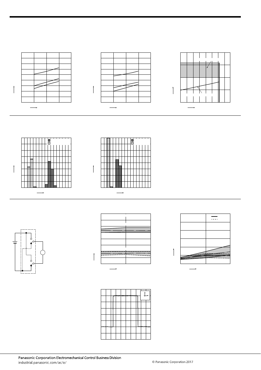
TB (ACTB)
–98–
ASCTB95E 201709-T
REFERENCE DATA
1.-(1) Coil temperature rise (at room
temperature)
Sample: ACTB32, 3pcs.
Carrying current: 0A, 10A, 20A
Ambient temperature: Room temperature
1.-(2) Coil temperature rise (at 85
°
C
185
°
F
)
Sample: ACTB32, 3pcs.
Carrying current: 0A, 10A, 20A
Ambient temperature: 85
°
C
185
°
F
2. Ambient temperature and usable voltage
range
Sample: ACTB32
18
Coil applied voltage, V
T
e
mper
ature r
ise
,
°
C
16
14
12
10
20A
10A
0A
180
160
140
120
100
80
60
40
20
0
18
Coil applied voltage, V
T
e
mper
ature r
ise
,
°
C
16
14
12
10
20A
10A
0A
180
160
140
120
100
80
60
40
20
0
Ambient temperature,
°
C
Coil applied v
oltage
,
V
120
-40 -20
0
20
15
10
5
0
20
40
60
80
100
Operate voltage (Cold start)
Usable voltage range
3. Distribution of operate (set) and release
(reset) voltage
Sample: ACTB32, 40
×
2pcs.
4. Distribution of operate (set) and release
(reset) time
Sample: ACTB32, 40
×
2pcs.
Voltage, V
Quantity
, n
8
0
80
70
60
50
40
30
20
10
0
1
2
3
4
5
6
7
Operate voltage
Release voltage
Time, ms
Quantity
, n
8
0
80
70
60
50
40
30
20
10
0
1
2
3
4
5
6
7
Operate time
Release time
* Without diode
5.-(1) Electrical life test (Motor lock)
Sample: ACTB32, 3pcs.
Load: 25A 14V DC
Power window motor actual load (lock condition)
Operating frequency: ON 0.5s, OFF 9.5s
Ambient temperature: Room temperature
Circuit:
Change of operate (set) and release (reset)
voltage
Change of contact resistance
M
10
5
Operate voltage
Release voltage
0
8
7
6
5
4
3
2
1
0
Max.
Min.
Ave.
Max.
Min.
Ave.
Oper
ate and release v
oltage
,
V
No. of operations,
×
10
4
Contact welding: 0 time
Miscontact: 0 time
10
5
0
30
25
20
15
10
5
0
Min.
Max.
Max.
Min.
Ave.
Ave.
Contact resistance
, m
Ω
No. of operations,
×
10
4
N.C. side
N.O. side
Load current waveform
Current value: 25A
100ms
5A
automotive-relay_en-html.html
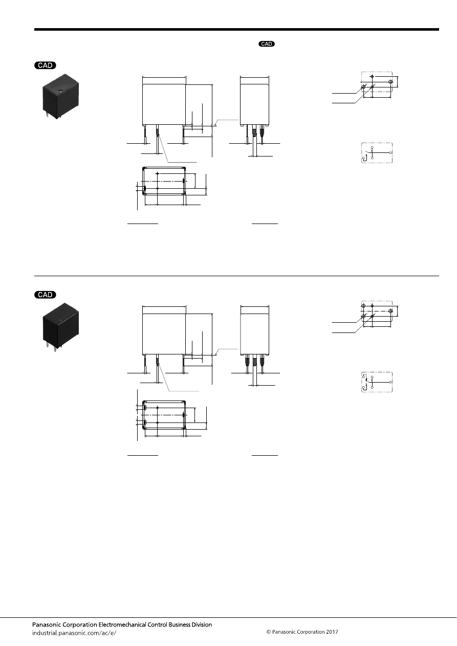
TB (ACTB)
–99–
ASCTB95E 201709-T
DIMENSIONS
(mm
inch
)
1 Form A type
1 Form C type
mark can be downloaded from: http://industrial.panasonic.com/ac/e/
The CAD data of the products with a
External dimensions
8.4
4
4.8
(0.8)
.331
.157
(.031)
(2.2)
.189
(.087)
Pre-soldering
(all terminals)
A surface
level
9.2
±
0.5
.362
±
.020
14
±
0.5
.551
±
.020
Max.
1.0
Max.
.039
0.4
.016
13.5
±
0.5
.531
±
.020
3.5
±
0.5
.138
±
.020
0.4
.016
+
0.3
−
0.1
+
.012
−
.004
0.6
.024
+
0.3
−
0.1
+
.012
−
.004
0.3
.012
+
0.3
−
0.1
+
.012
−
.004
0.3
.012
+
0.3
−
0.1
+
.012
−
.004
0.3
.012
+
0.3
−
0.1
+
.012
−
.004
1.2
.047
+
0.3
−
0.1
+
.012
−
.004
1.2
.047
+
0.3
−
0.1
+
.012
−
.004
PC board pattern (Bottom view)
Tolerance:
±
0.1
±
.004
Schematic (Bottom view)
4.8
8.4
.331
4
.157
.189
2
×
1.6 dia.
2
×
.063 dia.
2
×
1.1 dia.
2
×
.043 dia.
COM
N.O.
COIL
COIL
* The lamp control type has polarized contacts.
Connect N.O. to the “+ (plus)” side.
* Dimensions (thickness and width) of terminal is measured after pre-soldering.
Intervals between terminals is measured at A surface level.
Dimension:
Less than 1mm
.039inch
:
Min. 1mm
.039inch
less than 3mm
.118 inch
:
Min. 3mm
.118 inch
:
Tolerance
±
0.1
±
.004
±
0.2
±
.008
±
0.3
±
.012
External dimensions
8.4
4
4.8
(0.8)
.331
.157
(.031)
(2.2)
.189
(.087)
Pre-soldering
(all terminals)
A surface
level
9.2
±
0.5
.362
±
.020
14
±
0.5
.551
±
.020
Max.
1.0
Max.
.039
0.4
.016
13.5
±
0.5
.531
±
.020
3.5
±
0.5
.138
±
.020
0.4
.016
+
0.3
−
0.1
+
.012
−
.004
0.6
.024
+
0.3
−
0.1
+
.012
−
.004
0.3
.012
+
0.3
−
0.1
+
.012
−
.004
0.3
.012
+
0.3
−
0.1
+
.012
−
.004
0.3
.012
+
0.3
−
0.1
+
.012
−
.004
1.2
.047
+
0.3
−
0.1
+
.012
−
.004
1.2
.047
+
0.3
−
0.1
+
.012
−
.004
1.2
.047
+
0.3
−
0.1
+
.012
−
.004
PC board pattern (Bottom view)
Tolerance:
±
0.1
±
.004
Schematic (Bottom view)
4.8
8.4
.331
4
.157
.189
3
×
1.6 dia.
3
×
.063 dia.
2
×
1.1 dia.
2
×
.043 dia.
COM
N.O.
N.C.
COIL
COIL
* The lamp control type has polarized contacts.
Connect N.O. to the “+ (plus)” side.
* Dimensions (thickness and width) of terminal is measured after pre-soldering.
Intervals between terminals is measured at A surface level.
Dimension:
Less than 1mm
.039inch
:
Min. 1mm
.039inch
less than 3mm
.118 inch
:
Min. 3mm
.118 inch
:
Tolerance
±
0.1
±
.004
±
0.2
±
.008
±
0.3
±
.012
automotive-relay_en-html.html
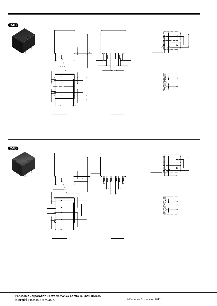
TB (ACTB)
–100–
ASCTB95E 201709-T
Twin type (8 pins)
Twin type (10 pins)
External dimensions
8.4
4
4.8
(0.8)
.331
.157
(.031)
(2.2)
.189
8.2
.323
13
.512
4.8
.189
(.087)
Pre-soldering
(all terminals)
A surface
level
17.4
±
0.5
.685
±
.020
14
±
0.5
.551
±
.020
Max.
1.0
Max.
.039
0.4
.016
13.5
±
0.5
.531
±
.020
3.5
±
0.5
.138
±
.020
0.4
.016
+
0.3
−
0.1
+
.012
−
.004
0.6
.024
+
0.3
−
0.1
+
.012
−
.004
0.3
.012
+
0.3
−
0.1
+
.012
−
.004
0.3
.012
+
0.3
−
0.1
+
.012
−
.004
0.3
.012
+
0.3
−
0.1
+
.012
−
.004
0.3
.012
+
0.3
−
0.1
+
.012
−
.004
0.3
.012
+
0.3
−
0.1
+
.012
−
.004
1.2
.047
+
0.3
−
0.1
+
.012
−
.004
1.2
.047
+
0.3
−
0.1
+
.012
−
.004
1.2
.047
+
0.3
−
0.1
+
.012
−
.004
1.2
.047
+
0.3
−
0.1
+
.012
−
.004
PC board pattern (Bottom view)
Tolerance:
±
0.1
±
.004
Schematic (Bottom view)
8.4
.331
4
.157
13
.512
8.2
.323
4.8
.189
4.8
.189
4
×
1.1 dia.
4
×
.043 dia.
4
×
1.6 dia.
4
×
.063 dia.
COIL
COM
COM
COIL
N.C.
N.O.
* Dimensions (thickness and width) of terminal is measured after pre-soldering.
Intervals between terminals is measured at A surface level.
Dimension:
Less than 1mm
.039inch
:
Min. 1mm
.039inch
less than 3mm
.118 inch
:
Min. 3mm
.118 inch
:
Tolerance
±
0.1
±
.004
±
0.2
±
.008
±
0.3
±
.012
External dimensions
8.4
4
4.8
(0.8)
.331
.157
(.031)
(2.2)
.189
8.2
.323
13
.512
4.8
.189
(.087)
Pre-soldering
(all terminals)
A surface
level
17.4
±
0.5
.685
±
.020
14
±
0.5
.551
±
.020
Max.
1.0
Max.
.039
0.4
.016
13.5
±
0.5
.531
±
.020
3.5
±
0.5
.138
±
.020
0.4
.016
+
0.3
−
0.1
+
.012
−
.004
0.6
.024
+
0.3
−
0.1
+
.012
−
.004
0.3
.012
+
0.3
−
0.1
+
.012
−
.004
0.3
.012
+
0.3
−
0.1
+
.012
−
.004
0.3
.012
+
0.3
−
0.1
+
.012
−
.004
0.3
.012
+
0.3
−
0.1
+
.012
−
.004
0.3
.012
+
0.3
−
0.1
+
.012
−
.004
1.2
.047
+
0.3
−
0.1
+
.012
−
.004
1.2
.047
+
0.3
−
0.1
+
.012
−
.004
1.2
.047
+
0.3
−
0.1
+
.012
−
.004
1.2
.047
+
0.3
−
0.1
+
.012
−
.004
1.2
.047
+
0.3
−
0.1
+
.012
−
.004
1.2
.047
+
0.3
−
0.1
+
.012
−
.004
PC board pattern (Bottom view)
Tolerance:
±
0.1
±
.004
Schematic (Bottom view)
8.4
.331
4
.157
4.8
.189
4.8
.189
4
×
1.1 dia.
4
×
.043 dia.
6
×
1.6 dia.
6
×
.063 dia.
13
.512
8.2
.323
COIL
COM
N.O.
N.O.
N.C.
N.C.
COM
COIL
* The lamp control type has polarized contacts.
Connect N.O. to the “+ (plus)” side.
* Dimensions (thickness and width) of terminal is measured after pre-soldering.
Intervals between terminals is measured at A surface level.
Dimension:
Less than 1mm
.039inch
:
Min. 1mm
.039inch
less than 3mm
.118 inch
:
Min. 3mm
.118 inch
:
Tolerance
±
0.1
±
.004
±
0.2
±
.008
±
0.3
±
.012
automotive-relay_en-html.html
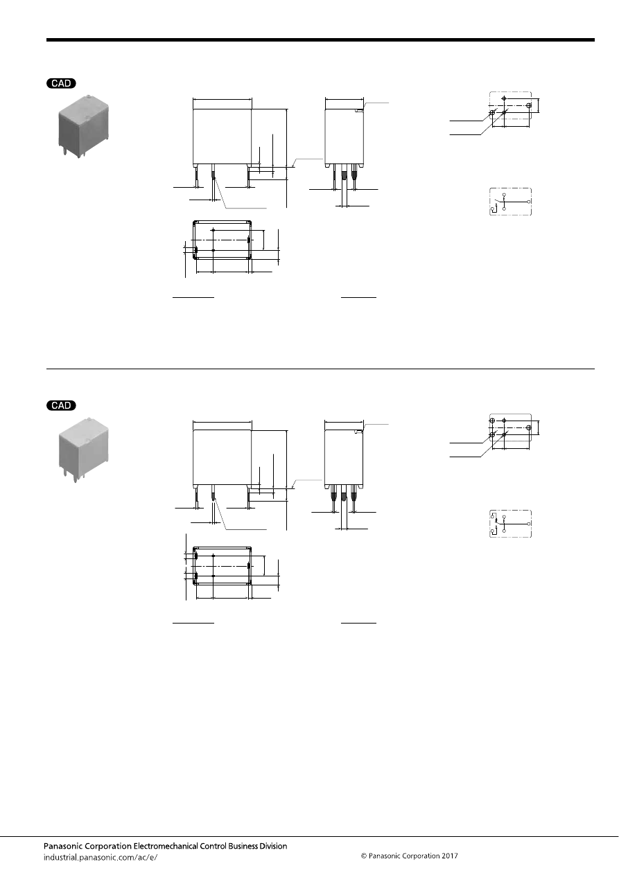
TB (ACTB)
–101–
ASCTB95E 201709-T
1 Form A type
Pin in Paste compliant type
1 Form C type
Pin in Paste compliant type
External dimensions
8.4
4
4.8
(0.8)
.331
.157
(.031)
(2.2)
.189
(.087)
Pre-soldering
(all terminals)
A surface
level
9.2
±
0.5
Air hole
.362
±
.020
14
±
0.5
.551
±
.020
Max.
1.0
Max.
.039
0.9
.035
14
±
0.5
.551
±
.020
3
±
0.5
.118
±
.020
0.4
.016
+
0.3
−
0.1
+
.012
−
.004
0.6
.024
+
0.3
−
0.1
+
.012
−
.004
0.3
.012
+
0.3
−
0.1
+
.012
−
.004
0.3
.012
+
0.3
−
0.1
+
.012
−
.004
0.3
.012
+
0.3
−
0.1
+
.012
−
.004
1.2
.047
+
0.3
−
0.1
+
.012
−
.004
1.2
.047
+
0.3
−
0.1
+
.012
−
.004
PC board pattern (Bottom view)
Tolerance:
±
0.1
±
.004
Schematic (Bottom view)
4.8
8.4
.331
4
.157
.189
2
×
1.6 dia.
2
×
.063 dia.
2
×
1.1 dia.
2
×
.043 dia.
COM
N.O.
COIL
COIL
* The lamp control type has polarized contacts.
Connect N.O. to the “+ (plus)” side.
* Dimensions (thickness and width) of terminal is measured after pre-soldering.
Intervals between terminals is measured at A surface level.
Dimension:
Less than 1mm
.039inch
:
Min. 1mm
.039inch
less than 3mm
.118 inch
:
Min. 3mm
.118 inch
:
Tolerance
±
0.1
±
.004
±
0.2
±
.008
±
0.3
±
.012
External dimensions
8.4
4
4.8
(0.8)
.331
.157
(.031)
(2.2)
.189
(.087)
Pre-soldering
(all terminals)
A surface
level
9.2
±
0.5
Air hole
.362
±
.020
14
±
0.5
.551
±
.020
Max.
1.0
Max.
.039
0.9
.035
14
±
0.5
.551
±
.020
3
±
0.5
.118
±
.020
0.4
.016
+
0.3
−
0.1
+
.012
−
.004
0.6
.024
+
0.3
−
0.1
+
.012
−
.004
0.3
.012
+
0.3
−
0.1
+
.012
−
.004
0.3
.012
+
0.3
−
0.1
+
.012
−
.004
0.3
.012
+
0.3
−
0.1
+
.012
−
.004
1.2
.047
+
0.3
−
0.1
+
.012
−
.004
1.2
.047
+
0.3
−
0.1
+
.012
−
.004
1.2
.047
+
0.3
−
0.1
+
.012
−
.004
PC board pattern (Bottom view)
Tolerance:
±
0.1
±
.004
Schematic (Bottom view)
4.8
8.4
.331
4
.157
.189
3
×
1.6 dia.
3
×
.063 dia.
2
×
1.1 dia.
2
×
.043 dia.
COM
N.O.
N.C.
COIL
COIL
* The lamp control type has polarized contacts.
Connect N.O. to the “+ (plus)” side.
* Dimensions (thickness and width) of terminal is measured after pre-soldering.
Intervals between terminals is measured at A surface level.
Dimension:
Less than 1mm
.039inch
:
Min. 1mm
.039inch
less than 3mm
.118 inch
:
Min. 3mm
.118 inch
:
Tolerance
±
0.1
±
.004
±
0.2
±
.008
±
0.3
±
.012
automotive-relay_en-html.html
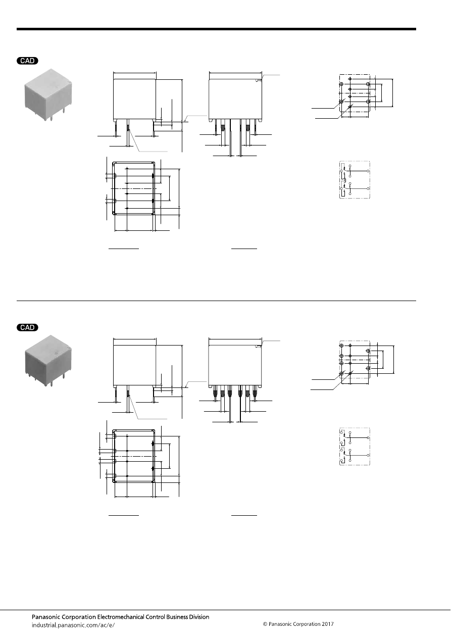
TB (ACTB)
–102–
ASCTB95E 201709-T
Twin type (8 pins)
Pin in Paste compliant type
Twin type (10 pins)
Pin in Paste compliant type
External dimensions
Air hole
8.4
4
4.8
(0.8)
.331
.157
(.031)
(2.2)
.189
8.2
.323
13
.512
4.8
.189
(.087)
Pre-soldering
(all terminals)
A surface
level
17.4
±
0.5
.685
±
.020
14
±
0.5
.551
±
.020
Max.
1.0
Max.
.039
0.9
.035
14
±
0.5
.551
±
.020
3
±
0.5
.118
±
.020
0.4
.016
+
0.3
−
0.1
+
.012
−
.004
0.6
.024
+
0.3
−
0.1
+
.012
−
.004
0.3
.012
+
0.3
−
0.1
+
.012
−
.004
0.3
.012
+
0.3
−
0.1
+
.012
−
.004
0.3
.012
+
0.3
−
0.1
+
.012
−
.004
0.3
.012
+
0.3
−
0.1
+
.012
−
.004
0.3
.012
+
0.3
−
0.1
+
.012
−
.004
1.2
.047
+
0.3
−
0.1
+
.012
−
.004
1.2
.047
+
0.3
−
0.1
+
.012
−
.004
1.2
.047
+
0.3
−
0.1
+
.012
−
.004
1.2
.047
+
0.3
−
0.1
+
.012
−
.004
PC board pattern (Bottom view)
Tolerance:
±
0.1
±
.004
Schematic (Bottom view)
8.4
.331
4
.157
13
.512
8.2
.323
4.8
.189
4.8
.189
4
×
1.1 dia.
4
×
.043 dia.
4
×
1.6 dia.
4
×
.063 dia.
COIL
COM
COM
COIL
N.C.
N.O.
* Dimensions (thickness and width) of terminal is measured after pre-soldering.
Intervals between terminals is measured at A surface level.
Dimension:
Less than 1mm
.039inch
:
Min. 1mm
.039inch
less than 3mm
.118 inch
:
Min. 3mm
.118 inch
:
Tolerance
±
0.1
±
.004
±
0.2
±
.008
±
0.3
±
.012
External dimensions
8.4
4
4.8
(0.8)
.331
.157
(.031)
(2.2)
.189
8.2
.323
13
.512
4.8
.189
(.087)
Pre-soldering
(all terminals)
A surface
level
17.4
±
0.5
.685
±
.020
14
±
0.5
.551
±
.020
Max.
1.0
Max.
.039
0.9
.035
14
±
0.5
.551
±
.020
3
±
0.5
.118
±
.020
0.4
.016
+
0.3
−
0.1
+
.012
−
.004
0.6
.024
+
0.3
−
0.1
+
.012
−
.004
0.3
.012
+
0.3
−
0.1
+
.012
−
.004
0.3
.012
+
0.3
−
0.1
+
.012
−
.004
0.3
.012
+
0.3
−
0.1
+
.012
−
.004
0.3
.012
+
0.3
−
0.1
+
.012
−
.004
0.3
.012
+
0.3
−
0.1
+
.012
−
.004
1.2
.047
+
0.3
−
0.1
+
.012
−
.004
1.2
.047
+
0.3
−
0.1
+
.012
−
.004
1.2
.047
+
0.3
−
0.1
+
.012
−
.004
1.2
.047
+
0.3
−
0.1
+
.012
−
.004
1.2
.047
+
0.3
−
0.1
+
.012
−
.004
1.2
.047
+
0.3
−
0.1
+
.012
−
.004
Air hole
PC board pattern (Bottom view)
Tolerance:
±
0.1
±
.004
Schematic (Bottom view)
8.4
.331
4
.157
13
.512
8.2
.323
4.8
.189
4.8
.189
4
×
1.1 dia.
4
×
.043 dia.
6
×
1.6 dia.
6
×
.063 dia.
COIL
COM
N.O.
N.O.
N.C.
N.C.
COM
COIL
* The lamp control type has polarized contacts.
Connect N.O. to the “+ (plus)” side.
* Dimensions (thickness and width) of terminal is measured after pre-soldering.
Intervals between terminals is measured at A surface level.
Dimension:
Less than 1mm
.039inch
:
Min. 1mm
.039inch
less than 3mm
.118 inch
:
Min. 3mm
.118 inch
:
Tolerance
±
0.1
±
.004
±
0.2
±
.008
±
0.3
±
.012
automotive-relay_en-html.html

TB (ACTB)
–103–
ASCTB95E 201709-T
NOTES
For general cautions for use, please refer to the “Automotive Relay Users Guide”.
Usage, transport and storage conditions
1) Ambient temperature, humidity, and air pressure during
usage, transport, and storage of the relay:
(1) Temperature: –40 to +85
°
C
–40 to +185
°
F
(Standard type)
–40 to +110
°
C
–40 to +230
°
F
(High heat-resistant type/Pin in
Paste compliant type)
(2) Humidity: 2 to 85% RH (Avoid icing and condensation.)
(3) Air pressure: 86 to 106 kPa
The humidity range varies with the temperature. Use within the
range indicated in the graph below.
[Temperature and humidity range for usage, transport,
and storage]
Mounting and cleaning conditions for Pin-in-Paste
compliant type
When soldering this relay, please observe the following
conditions.
[I.R.S. method (recommended)]
(Recommended number of reflows: 1)
• Cautions for mounting
1. The temperature profile shows the temperature at the
soldering portion on the PCB surface.
2. Depending on the mounting density condition, reflow
heating method, and PCB type (metal etc.), the relay’s
exterior and interior temperature may become extremely
high.
Therefore, please confirm well under the actual use
condition before use.
The other cautions of reflow soldering:
1. When soldering condition is out of recommendation, the
relay performance may be adversely affected.
If soldering conditions are out of our recommendation,
please contact us before operation.
2. Please check the effect at the actual soldering because
heat stress to relay is changed by PCB type and
manufacturing process condition.
3. Solder creepage, wettability or soldering strength will be
affected by the mounting condition or soldering material.
Please check the actual production condition in detail.
4. Do not wash the relay as failures may occur.
5. This product is not plastic sealed type. Please perform
coating with sufficient attention to avoid infiltration of the
solvent to the inside. Also, please pay careful attention to
use and store them with no contamination of foreign
material.
85
5
Humidity, %RH
Tolerance range
(Avoid
condensation
when used at
temperatures
higher than
0
°
C
32
°
F
)
(Avoid icing
when used at
temperatures
lower than
0
°
C
32
°
F
)
85
0
–40
+185
+32
–40
Temperature,
°
C
°
F
Standard type
High heat-resistant type
85
5
2
110
85
0
–40
+230
+185
+32
–40
Humidity, %RH
Temperature,
°
C
°
F
Tolerance range
(Avoid
condensation
when used at
temperatures
higher than
0
°
C
32
°
F
)
(Avoid icing
when used at
temperatures
lower than
0
°
C
32
°
F
)
t
1
= 60 to 120 sec.
t
2
= Less than 30 sec.
t
3
= Less than 5 sec.
T
1
= 150 to 180
°
C
T
2
= 230
°
C
T
3
= Less than 250
°
C
302 to 356
°
F
446
°
F
or more
482
°
F
T
1
T
3
T
2
t
1
t
2
t
3
automotive-relay_en-html.html
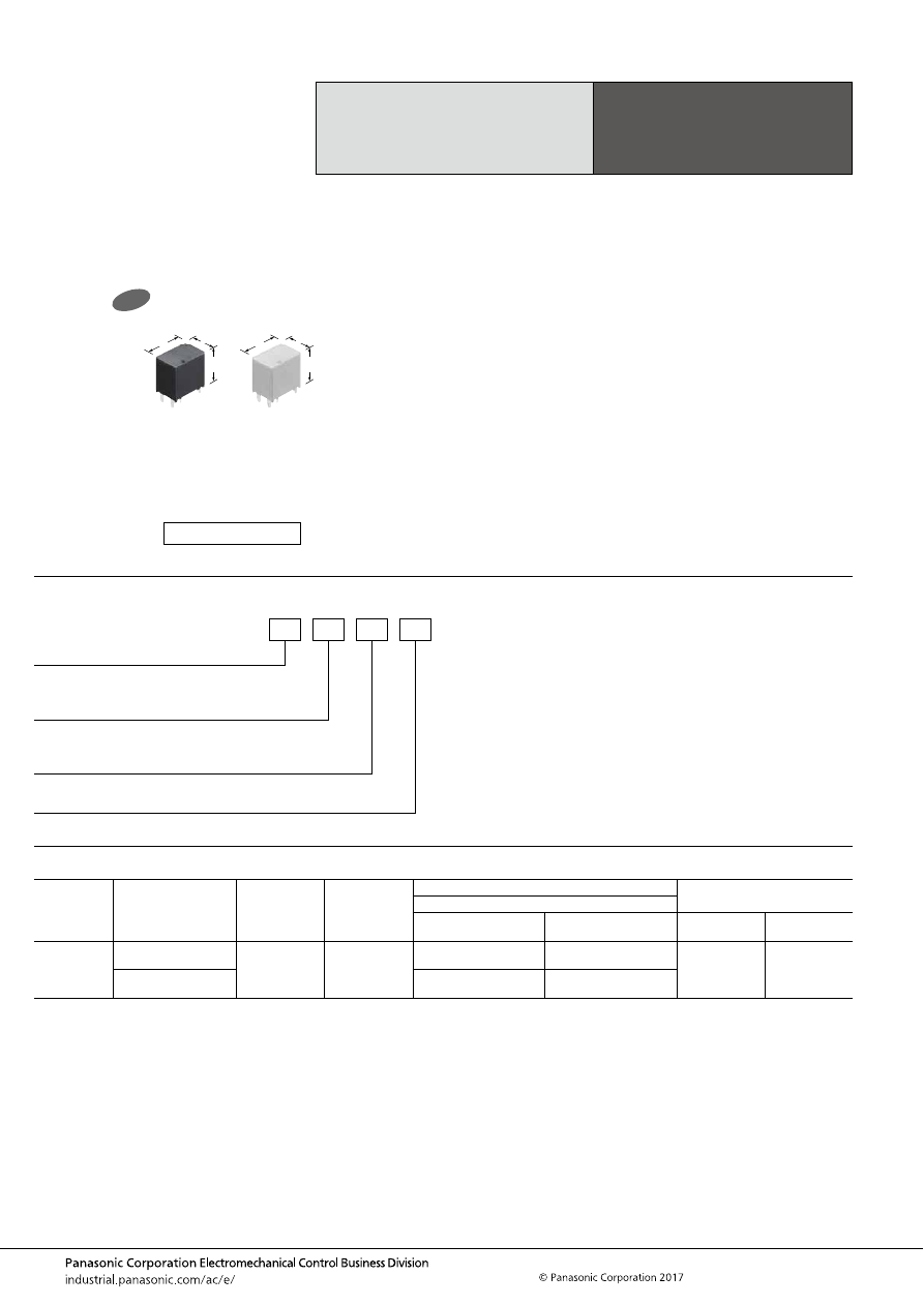
TB-P (ACTBP)
–104–
ASCTB377E 201709-T
ORDERING INFORMATION
TYPES
High Carrying Current
1 Form A Type Relay
for Miniature PC board
TB RELAYS
POWER TYPE
Contact
arrangement
Contact type
Rated coil
voltage
Coil resistance
Part No.
Packing
Heat resistance
High heat-resistant type
Pin in Paste compliant
type
Carton
Case
1 Form A
Standard type
(Ag alloy / Cu clad)
12V DC
300
Ω
ACTBPCH4
ACTBPCR4
50 pcs.
2,000 pcs.
Lamp control type
(Ag alloy / Cu clad)
ACTBPDH4
ACTBPDR4
FEATURES
• Compact, 30A and supports fuse
• Supports capacitor loads and low operating power type
• Pin in Paste compliant model added
TYPICAL APPLICATIONS
• Defoggers, Ignitions, Seat heaters, Powered windows, etc.
<Protective construction>
High heat-resistant type: Sealed
Pin in Paste compliant type: Flux tight
9.2
14
14
.362
.551
.551
9.2
14
14
.362
.551
.551
New
(Unit: mm
inch
)
RoHS compliant
Coil resistance
4: 300
Ω
P: Power type
Contact type
C: Standard type (Ag alloy / Cu clad)
D: Lamp control type (Ag alloy / Cu clad)
ACTB
P
Heat resistance/Protective construction
H: High heat-resistant type/Sealed
R: Pin in Paste compliant type/Flux tight
automotive-relay_en-html.html
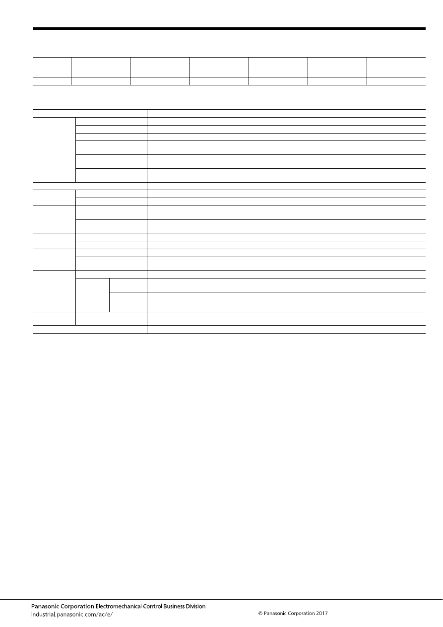
TB-P (ACTBP)
–105–
ASCTB377E 201709-T
RATING
1. Coil data
Note: Other operate (set) voltage types are also available. Please inquire our sales representative for details.
2. Specifications
Notes: *1. Depends on connection conditions. Also, this does not guarantee repeated switching. We recommend that you confirm operation under actual conditions.
*2. This value can change due to the switching frequency, environmental conditions, and desired reliability level, therefore it is recommended to check this with the
actual load.
*3. The upper operation ambient temperature limit is the maximum temperature that can satisfy the coil temperature rise value. For details, please refer to the
“Automotive Relay Users Guide”.
Please inquire our sales representative if you will be using the relay in a high temperature atmosphere (110
°
C
230
°
F
).
*4. Part numbers for electric discharge lamp loads or any other lamp loads and for capacitor loads only consist of “ACTBPD
∗∗
”.
When using the lamp control type, connect N.O. to the “+ (plus)” side. Please inquire our sales representative for details.
Rated coil
voltage
Operate (Set) voltage
(at 20
°
C
68
°
F
) (Initial)
Release (Reset)
voltage
(at 20
°
C
68
°
F
) (Initial)
Rated operating current
[
±
10%] (at 20
°
C
68
°
F
)
Coil resistance
[
±
10%] (at 20
°
C
68
°
F
)
Rated operating power
(at 20
°
C
68
°
F
)
Usable voltage range
12V DC
Max. 7.0V DC
Min. 0.5V DC
40 mA
300
Ω
480 mW
10 to 16V DC
Item
Specifications
Contact data
Contact arrangement
1 Form A
Contact resistance (initial)
Max. 50m
Ω
(Typ. 3m
Ω
) (By voltage drop 1A 6V DC)
Contact material
Ag alloy
Rated switching capacity
(resistive)
30A 14V DC
Max. carrying current
(initial)*
1
30 A for 1 hour (12 V DC at 20
°
C
68
°
F
)
Min. switching load
(resistive)*
2
1A 14V DC (at 20
°
C
68
°
F
)
Insulated resistance (initial)
Min. 100 M
Ω
(at 500V DC, Measurement at same location as “Dielectric strength” section.)
Dielectric
strength (initial)
Between open contacts
500 Vrms for 1 min. (Detection current: 10mA)
Between contacts and coil
500 Vrms for 1 min. (Detection current: 10mA)
Time
characteristics
(initial)
Operate (Set) time
(at rated voltage)
Max. 10ms (at 20
°
C
68
°
F
, without contact bounce time)
Release (Reset) time
(at rated voltage)
Max. 10ms (at 20
°
C
68
°
F
, without contact bounce time) (Without diode)
Shock
resistance
Functional
Min. 100 m/s
2
{approx. 10G} (Half-wave pulse of sine wave: 11ms; detection time: 10
μ
s)
Destructive
Min. 1,000 m/s
2
{approx. 100G} (Half-wave pulse of sine wave: 6ms)
Vibration
resistance
Functional
10 to 100 Hz, Min. 44.1m/s
2
{approx. 4.5G} (Detection time: 10
μ
s)
Destructive
10 to 500 Hz, Min. 44.1m/s
2
{approx. 4.5G}
Time of vibration for each direction; X, Y direction: 2 hours, Z direction: 4 hours
Expected life
Mechanical
Min. 5
×
10
6
(at 120 cpm)
Electrical
Standard type
<Resistive load>
Min. 10
5
at rated switching capacity, operating frequency: 1s ON, 9s OFF
Lamp control
type*
4
<Resistive and capacitor loads>
Min. 10
5
: at 70 A (inrush), 15 A (steady), 14 V DC
Operating frequency: 0.15s ON, 4.85s OFF
Conditions
Conditions for usage,
transport and storage*
3
Ambient temperature: –40 to +110
°
C
–40 to +230
°
F
Humidity: 2 to 85% R.H. (Please avoid icing or condensation)
Weight
approx. 5 g
.176 oz
automotive-relay_en-html.html

TB-P (ACTBP)
–106–
ASCTB377E 201709-T
REFERENCE DATA
1.-(1) Coil temperature rise (at room
temperature)
Sample: ACTBPDH4, 3 pcs.
Carrying current: 0A, 10A, 20A, 30A
Ambient temperature: Room temperature
1.-(2) Coil temperature rise (at 110
°
C
230
°
F
)
Sample: ACTBPDH4, 3 pcs.
Carrying current: 0A, 10A, 20A
Ambient temperature: 110
°
C
230
°
F
2. Ambient temperature and usable voltage
range
Sample: ACTBPDH4
18
Coil applied voltage, V
T
emper
ature r
ise
,
°
C
16
14
12
10
20A
30A
10A
0A
180
160
140
120
100
80
60
40
20
0
18
Coil applied voltage, V
T
emper
ature r
ise
,
°
C
16
14
12
10
20A
10A
0A
180
160
140
120
100
80
60
40
20
0
Ambient temperature,
°
C
Coil applied v
oltage
,
V
120
-40 -20
0
20
15
10
5
0
20
40
60
80
100
Operate voltage (Cold start)
Usable voltage range
3. Distribution of operate (set) and release
(reset) voltage
Sample: ACTBPDH4, 80 pcs.
4. Distribution of operate (set) and release
(reset) time
Sample: ACTBPDH4, 80 pcs.
Voltage, V
Quantity
, n
5
4
3
2
1
0
6
7
8
80
70
60
50
40
30
20
10
0
Operate voltage
Release voltage
5
4
3
2
1
0
6
7
8
Time, ms
Quantity
, n
80
70
60
50
40
30
20
10
0
Operate time
Release time
* Without diode
5.-(1) Electrical life test (Resistive and
capacitor)
Sample: ACTBPDH4, 6 pcs.
Load: Inrush current: 70A, Steady current: 15A 14V
DC
Switching frequency: ON 0.15s, OFF 4.85s
Ambient temperature: Room temperature
Circuit:
Change of operate (set) and release (reset)
voltage
Change of contact resistance
10
5
Operate voltage
Release voltage
0
8
7
6
5
4
3
2
1
0
Max.
Min.
Ave.
Max.
Min.
Ave.
Oper
ate and release v
oltage
,
V
No. of operations,
×
10
4
Contact welding: 0 time
Miscontact: 0 time
10
5
0
50
40
30
20
10
0
Min.
Max.
Ave.
Contact resistance
, m
Ω
No. of operations,
×
10
4
automotive-relay_en-html.html
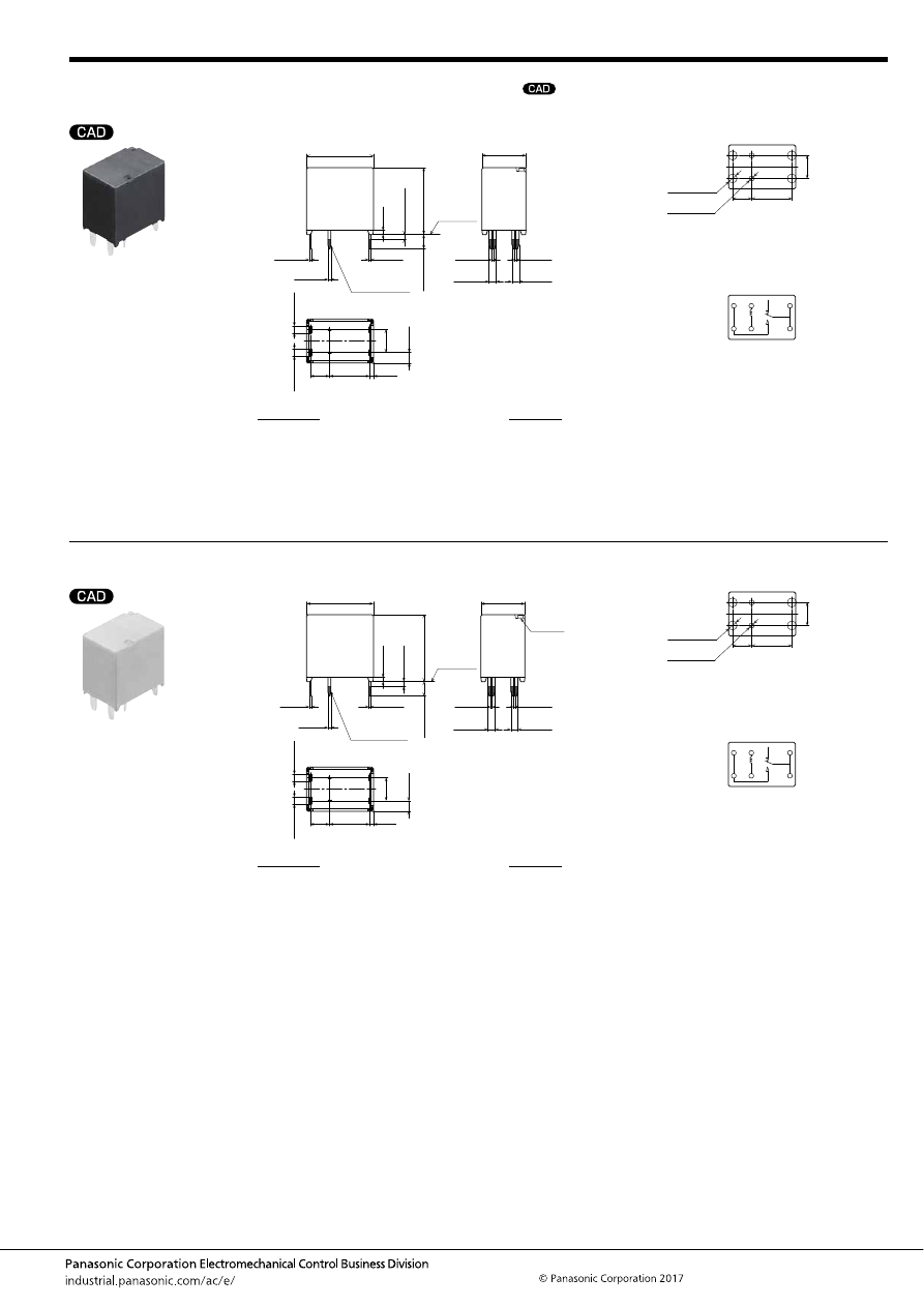
TB-P (ACTBP)
–107–
ASCTB377E 201709-T
DIMENSIONS
(mm
inch
)
1. 1 Form A type
2. 1 Form A type
mark can be downloaded from: http://industrial.panasonic.com/ac/e/
The CAD data of the products with a
External dimensions
8.4
4
4.8
(0.8)
.331
.157
(.031)
(2.2)
.189
(.087)
Pre-soldering
(all terminals)
A surface
level
9.2
±
0.5
.362
±
.020
14
±
0.5
.551
±
.020
Max.
1.0
Max.
.039
0.9
.035
14
±
0.5
.551
±
.020
3
±
0.5
.118
±
.020
0.4
.016
+
0.3
−
0.1
+
.012
−
.004
0.6
.024
+
0.3
−
0.1
+
.012
−
.004
0.3
.012
+
0.3
−
0.1
+
.012
−
.004
0.3
.012
+
0.3
−
0.1
+
.012
−
.004
0.3
.012
+
0.3
−
0.1
+
.012
−
.004
1.5
.059
+
0.3
−
0.1
+
.012
−
.004
1.5
.059
+
0.3
−
0.1
+
.012
−
.004
1.5
.059
+
0.3
−
0.1
+
.012
−
.004
1.5
.059
+
0.3
−
0.1
+
.012
−
.004
PC board pattern (Bottom view)
Tolerance:
±
0.1
±
.004
Schematic (Bottom view)
4.8
8.4
.331
4
.157
.189
4
×
1.9 dia.
4
×
.075 dia.
2
×
1.1 dia.
2
×
.043 dia.
COM
N.O.
COIL
COIL
N.O.
COM
* The lamp control type has polarized contacts.
Connect N.O. to the “+ (plus)” side.
* Dimensions (thickness and width) of terminal is measured after pre-soldering.
Intervals between terminals is measured at A surface level.
Dimension:
Less than 1mm
.039inch
:
Min. 1mm
.039inch
less than 3mm
.118 inch
:
Min. 3mm
.118 inch
:
Tolerance
±
0.1
±
.004
±
0.2
±
.008
±
0.3
±
.012
Pin in Paste compliant type
External dimensions
8.4
4
4.8
(0.8)
.331
.157
(.031)
(2.2)
.189
(.087)
Pre-soldering
(all terminals)
A surface
level
9.2
±
0.5
.362
±
.020
14
±
0.5
.551
±
.020
Max.
1.0
Max.
.039
0.9
.035
14
±
0.5
.551
±
.020
3
±
0.5
.118
±
.020
0.4
.016
+
0.3
−
0.1
+
.012
−
.004
0.6
.024
+
0.3
−
0.1
+
.012
−
.004
0.3
.012
+
0.3
−
0.1
+
.012
−
.004
0.3
.012
+
0.3
−
0.1
+
.012
−
.004
0.3
.012
+
0.3
−
0.1
+
.012
−
.004
1.5
.059
+
0.3
−
0.1
+
.012
−
.004
1.5
.059
+
0.3
−
0.1
+
.012
−
.004
1.5
.059
+
0.3
−
0.1
+
.012
−
.004
1.5
.059
+
0.3
−
0.1
+
.012
−
.004
Air hole
PC board pattern (Bottom view)
Tolerance:
±
0.1
±
.004
Schematic (Bottom view)
4.8
8.4
.331
4
.157
.189
4
×
1.9 dia.
4
×
.075 dia.
2
×
1.1 dia.
2
×
.043 dia.
COM
N.O.
COIL
COIL
N.O.
COM
* The lamp control type has polarized contacts.
Connect N.O. to the “+ (plus)” side.
* Dimensions (thickness and width) of terminal is measured after pre-soldering.
Intervals between terminals is measured at A surface level.
Dimension:
Less than 1mm
.039inch
:
Min. 1mm
.039inch
less than 3mm
.118 inch
:
Min. 3mm
.118 inch
:
Tolerance
±
0.1
±
.004
±
0.2
±
.008
±
0.3
±
.012
automotive-relay_en-html.html
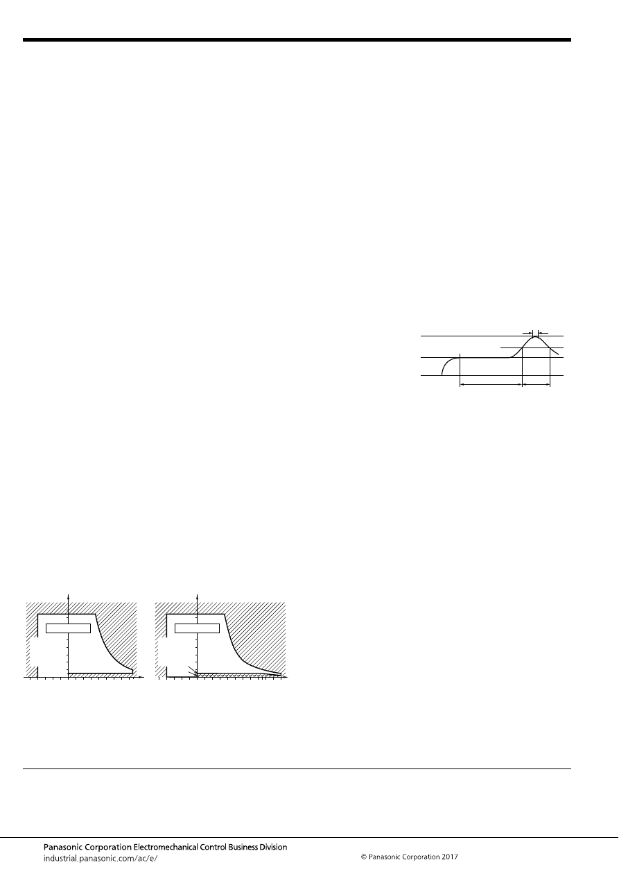
TB-P (ACTBP)
–108–
ASCTB377E 201709-T
NOTES
For general cautions for use, please refer to the “Automotive Relay Users Guide”.
1. Coil operating power
Pure DC current should be applied to the coil. If it includes
ripple, the ripple factor should be less than 5%. However, check
it with the actual circuit since the characteristics may be slightly
different. Also, the power waveform should be rectangular.
2. Coil applied voltage
To ensure proper operation, the voltage applied to the coil
should be the rated operating voltage of the coil. Also, be aware
that the pick-up and drop-out voltages will fluctuate depending
on the ambient temperature and operating conditions.
3. Expected life
Check this with the real device as it is affected by coil driving
circuit, load type, activation frequency, activation phase, ambient
conditions and other factors.
4. Soldering
When soldering the relays, ensure conformance with the
conditions listed below.
1) Automatic soldering
Preheating soldering: 100
°
C
212
°
F
, within 2 sec (surface of
PC board)
Soldering: 260
°
C
500
°
F
, within 5 sec
2) Manual soldering
Tip temperature: 280 to 300
°
C
536 to 572
°
F
.
Soldering iron: 30 to 60W
Soldering time: within 5 sec
5. Usage, transport and storage conditions
1) Ambient temperature, humidity, and air pressure during
usage, transport, and storage of the relay:
(1) Temperature:
–40 to +85
°
C
–40 to +185
°
F
(Standard type)
–40 to +110
°
C
–40 to +230
°
F
(High heat-resistant type)
(2) Humidity: 2 to 85% RH (Avoid icing and condensation.)
(3) Air pressure: 86 to 106 kPa
The humidity range varies with the temperature. Use within the
range indicated in the graph below.
[Temperature and humidity range for usage, transport,
and storage]
2) Condensation
Condensation forms when there is a sudden change in
temperature under high temperature and high humidity
conditions. Condensation will cause deterioration of the relay
insulation.
3) Icing
Condensation or other moisture may ice on the relay when the
temperature is lower than 0
°
C
32
°
F
. This causes problems such
as sticking of movable parts, operational time lags or poor
contact conduction.
4) Low temperature and low humidity environments
The plastic becomes brittle if the relay is exposed to a low
temperature, low humidity environment for long periods of time.
6. Mounting and cleaning conditions for Pin-in-Paste
compliant type
When soldering this relay, please observe the following
conditions.
[I.R.S. method (recommended)]
(Recommended number of reflows: 1)
• Cautions for mounting
1. The temperature profile shows the temperature at the
soldering portion on the PCB surface.
2. Depending on the mounting density condition, reflow
heating method, and PCB type (metal etc.), the relay’s
exterior and interior temperature may become extremely
high.
Therefore, please confirm well under the actual use
condition before use.
The other cautions of reflow soldering:
1. When soldering condition is out of recommendation, the
relay performance may be adversely affected.
If soldering conditions are out of our recommendation,
please contact us before operation.
2. Please check the effect at the actual soldering because
heat stress to relay is changed by PCB type and
manufacturing process condition.
3. Solder creepage, wettability or soldering strength will be
affected by the mounting condition or soldering material.
Please check the actual production condition in detail.
4. Do not wash the relay as failures may occur.
5. This product is not plastic sealed type. Please perform
coating with sufficient attention to avoid infiltration of the
solvent to the inside. Also, please pay careful attention to
use and store them with no contamination of foreign
material.
7. Others handling precautions
Do not use relays that have been dropped, because doing so
may be a cause of faulty operation.
Standard type
High heat-resistant type
85
5
Humidity, %RH
Tolerance range
(Avoid
condensation
when used at
temperatures
higher than
0
°
C
32
°
F
)
(Avoid icing
when used at
temperatures
lower than
0
°
C
32
°
F
)
85
0
–40
+185
+32
–40
Temperature,
°
C
°
F
85
5
2
110
85
0
–40
+230
+185
+32
–40
Humidity, %RH
Temperature,
°
C
°
F
Tolerance range
(Avoid
condensation
when used at
temperatures
higher than
0
°
C
32
°
F
)
(Avoid icing
when used at
temperatures
lower than
0
°
C
32
°
F
)
t
1
= 60 to 120 sec.
t
2
= Less than 30 sec.
t
3
= Less than 5 sec.
T
1
= 150 to 180
°
C
T
2
= 230
°
C
T
3
= Less than 250
°
C
302 to 356
°
F
446
°
F
or more
482
°
F
T
1
T
3
T
2
t
1
t
2
t
3
automotive-relay_en-html.html
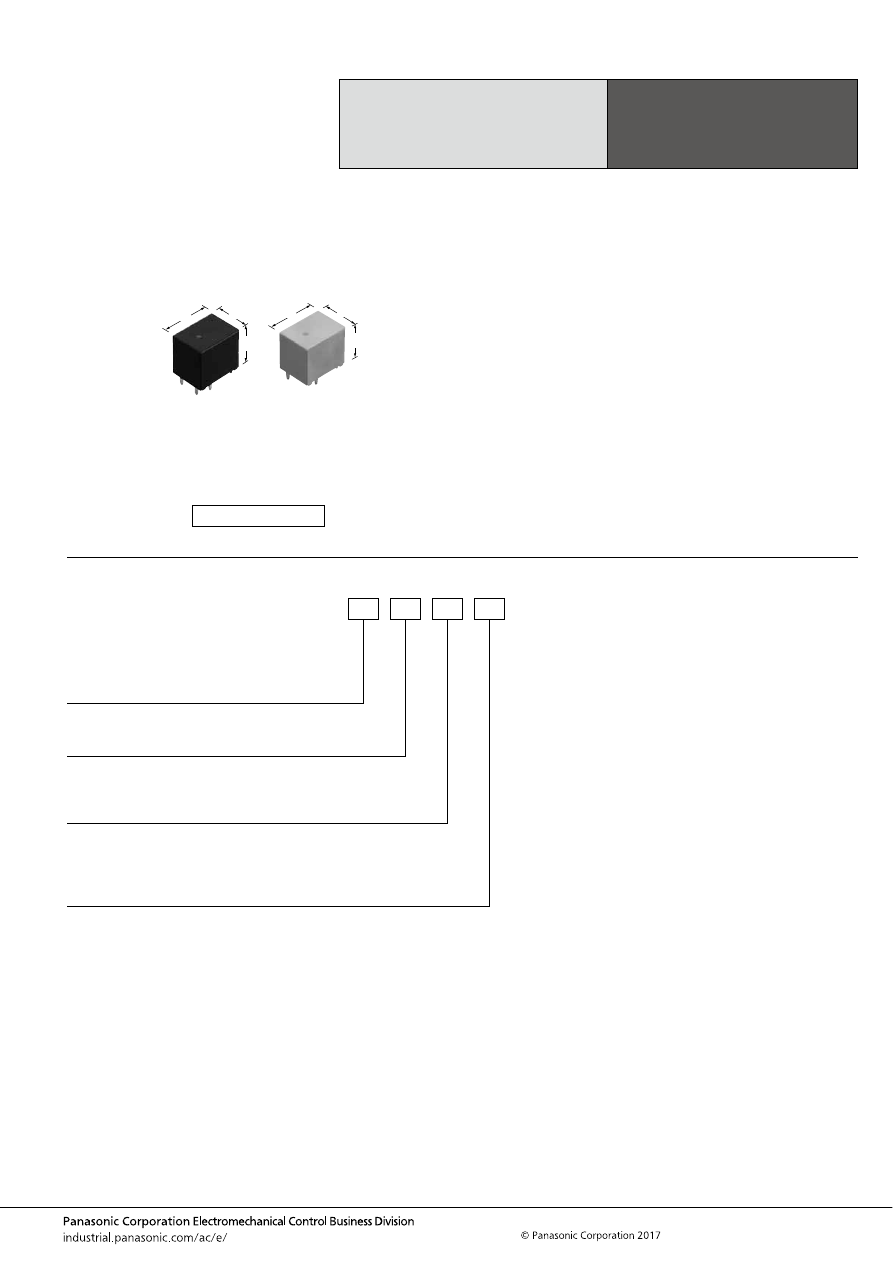
TC (ACTC)
–109–
ASCTB96E 201709-T
ORDERING INFORMATION
High Load Relay
for Smart J/B
TC RELAYS
FEATURES
• Large capacity switching despite small size. Can replace
micro ISO terminal type relays.
• Latching type added
• Pin in Paste compliant model added
TYPICAL APPLICATIONS
• Head lamp, Fog lamp, Fan motor, Defogger, Seat heater,
etc.
<Protective construction>
Standard type/High heat-resistant type: Sealed
Pin in Paste compliant type: Flux tight
13
17.8
16
.512
.701
.630
13
17.8
16.4
.512
.701
.646
(Unit: mm
inch
)
RoHS compliant
Contact arrangement/Operation function
1: 1 Form A/Standard type
2: 1 Form C/Standard type
3: Double make contact 2 Form A/Standard type
6: Double make contact 2 Form A/2 coil latching type
Contact type
Nil:
C:
Standard type
Standard type (Ag alloy / Cu clad)
Heat resistance/Protective construction
Nil:
H:
R:
Standard type/Sealed
High heat-resistant type/Sealed
Pin in Paste compliant type/Flux tight
ACTC
Coil resistance
1: 110
Ω
2: 160
Ω
3: 225
Ω
6: 75
Ω
automotive-relay_en-html.html
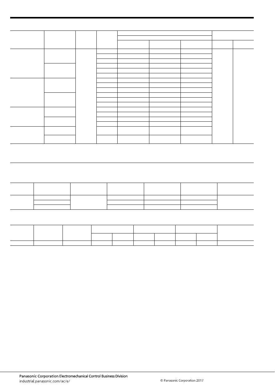
TC (ACTC)
–110–
ASCTB96E 201709-T
TYPES
RATING
1. Coil data
1) Standard type
Note: Other operate (set) voltage types are also available. Please inquire our sales representative for details.
2) 2 coil latching type
Contact arrangement/
Operation function
Contact type
Rated coil
voltage
Coil
resistance
Part No.
Packing
Heat resistance
Standard type
High heat-resistant
type
Pin in Paste
compliant type
Carton
(tube)
Case
1 Form A/Standard
type
Standard type
12V DC
110
Ω
ACTC11
ACTC1H1
ACTC1R1
40 pcs.
800 pcs.
160
Ω
ACTC12
ACTC1H2
ACTC1R2
225
Ω
ACTC13
ACTC1H3
ACTC1R3
Standard type
(Ag alloy / Cu clad)
110
Ω
ACTC1C1
ACTC1CH1
ACTC1CR1
160
Ω
ACTC1C2
ACTC1CH2
ACTC1CR2
225
Ω
ACTC1C3
ACTC1CH3
ACTC1CR3
1 Form C/Standard
type
Standard type
110
Ω
ACTC21
ACTC2H1
ACTC2R1
160
Ω
ACTC22
ACTC2H2
ACTC2R2
225
Ω
ACTC23
ACTC2H3
ACTC2R3
Standard type
(Ag alloy / Cu clad)
110
Ω
ACTC2C1
ACTC2CH1
ACTC2CR1
160
Ω
ACTC2C2
ACTC2CH2
ACTC2CR2
225
Ω
ACTC2C3
ACTC2CH3
ACTC2CR3
Double make contact
2 Form A/
Standard type
Standard type
110
Ω
ACTC31
ACTC3H1
ACTC3R1
160
Ω
ACTC32
ACTC3H2
ACTC3R2
Standard type
(Ag alloy / Cu clad)
110
Ω
ACTC3C1
ACTC3CH1
ACTC3CR1
160
Ω
ACTC3C2
ACTC3CH2
ACTC3CR2
Double make contact
2 Form A/
2 coil latching type
Standard type
75
Ω
ACTC66
ACTC6H6
ACTC6R6
Standard type
(Ag alloy / Cu clad)
75
Ω
ACTC6C6
ACTC6CH6
ACTC6CR6
Rated coil
voltage
Operate (Set) voltage
(at 20
°
C
68
°
F
) (Initial)
Release (Reset)
voltage
(at 20
°
C
68
°
F
) (Initial)
Rated operating current
[
±
10%] (at 20
°
C
68
°
F
)
Coil resistance
[
±
10%] (at 20
°
C
68
°
F
)
Rated operating power
(at 20
°
C
68
°
F
)
Usable voltage range
12V DC
Max. 6.5V DC
Min. 0.5V DC
109 mA
110
Ω
1,309 mW
10 to 16V DC
Max. 7.0V DC
75 mA
160
Ω
900 mW
Max. 7.5V DC
53.3 mA
225
Ω
640 mW
Rated coil
voltage
Operate (Set)
voltage
(at 20
°
C
68
°
F
)
(Initial)
Release (Reset)
voltage
(at 20
°
C
68
°
F
)
(Initial)
Rated operating current
[
±
10%] (at 20
°
C
68
°
F
)
Coil resistance
[
±
10%] (at 20
°
C
68
°
F
)
Rated operating power
(at 20
°
C
68
°
F
)
Usable voltage range
Set coil
Reset coil
Set coil
Reset coil
Set coil
Reset coil
12V DC
Max. 7.2V DC
Max. 7.2V DC
160 mA
160 mA
75
Ω
75
Ω
1,920 mW
1,920 mW
10 to 16V DC
automotive-relay_en-html.html
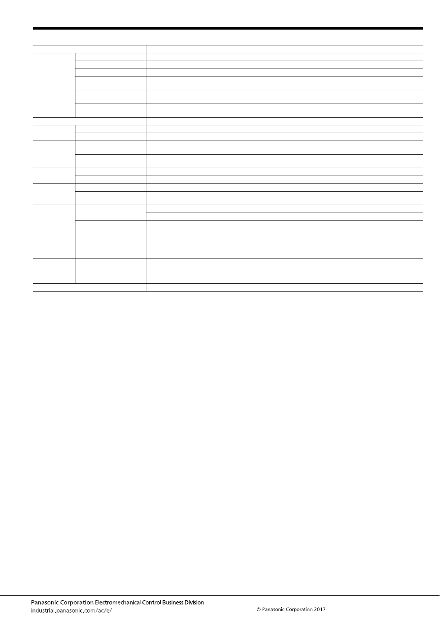
TC (ACTC)
–111–
ASCTB96E 201709-T
2. Specifications
Notes: *1. Depends on connection conditions. Also, this does not guarantee repeated switching. We recommend that you confirm operation under actual conditions.
*2. This value can change due to the switching frequency, environmental conditions, and desired reliability level, therefore it is recommended to check this with the
actual load.
*3. The upper operation ambient temperature limit is the maximum temperature that can satisfy the coil temperature rise value. For details, please refer to the
“Automotive Relay Users Guide”.
Please inquire our sales representative if you will be using the relay in a high temperature atmosphere (110
°
C
230
°
F
).
*4. When using with an electric discharge lamp load or any other lamp load, or a capacitor load, connect COM to the “+ (plus)” side.
Item
Specifications
Contact data
Contact arrangement
1 Form A, 1 Form C, Double make contact 2 Form A
Contact resistance (initial)
Max. 50m
Ω
(N.O. side: typ. 3m
Ω
, N.C. side: typ. 4m
Ω
) (By voltage drop 1A 6V DC)
Contact material
Ag alloy
Rated switching capacity
(resistive)
N.O. side: 30A 14V DC, N.C. side: 15A 14V DC
Max. carrying current
(initial)*
1
35A for 1 hour (Coil applied voltage 12V DC, at 20
°
C
68
°
F
)
Min. switching load
(resistive)*
2
1A 14V DC (at 20
°
C
68
°
F
)
Insulated resistance (initial)
Min. 100 M
Ω
(at 500V DC, Measurement at same location as “Dielectric strength” section.)
Dielectric
strength (initial)
Between open contacts
500 Vrms for 1 min. (Detection current: 10mA)
Between contacts and coil
500 Vrms for 1 min. (Detection current: 10mA)
Time
characteristics
(initial)
Operate (Set) time
(at rated voltage)
Max. 10ms (at 20
°
C
68
°
F
, without contact bounce time)
Release (Reset) time
(at rated voltage)
Max. 10ms (at 20
°
C
68
°
F
, without contact bounce time) (without diode)
Shock
resistance
Functional
Min. 100 m/s
2
{approx. 10G} (Half-wave pulse of sine wave: 11ms; detection time: 10
μ
s)
Destructive
Min. 1,000 m/s
2
{approx. 100G} (Half-wave pulse of sine wave: 6ms)
Vibration
resistance
Functional
10 to 100 Hz, Min. 44.1 m/s
2
{approx. 4.5G} (Detection time: 10
μ
s)
Destructive
10 to 500 Hz, Min. 44.1 m/s
2
{approx. 4.5G},
Time of vibration for each direction; X, Y direction: 2 hours, Z direction: 4 hours
Expected life
Mechanical
Min. 10
7
(at 120 cpm)
Min. 10
6
(at 120 cpm) (2 coil latching type)
Electrical*
4
<Resistive load>
Min. 10
5
at rated switching capacity, operating frequency: 1s ON, 9s OFF
<Motor load>
Min. 10
5
30 A 14V DC at motor lock condition, operating frequency: 0.5s ON, 9.5s OFF
<Lamp load>
Min. 2
×
10
5
at 84 A (inrush), 12A (steady), 14 V DC, Operating frequency: 1s ON, 14s OFF
Conditions
Conditions for usage,
transport and storage*
3
Standard type Ambient temperature: –40 to +85
°
C
–40 to +185
°
F
, Humidity: 5 to 85% R.H.
High heat-resistant/Pin in Paste compliant type Ambient temperature: –40 to +110
°
C
–40 to +230
°
F
, Humidity: 2 to 85%
R.H.
(Please avoid icing or condensation)
Weight
Approx. 10 g
.35 oz
automotive-relay_en-html.html
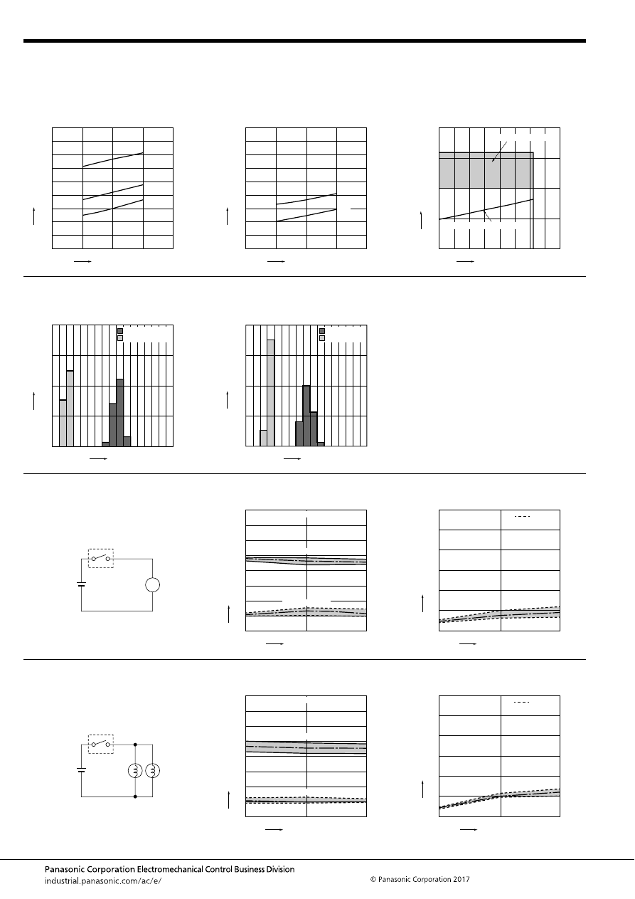
TC (ACTC)
–112–
ASCTB96E 201709-T
REFERENCE DATA
1.-(1) Coil temperature rise (at room
temperature)
Sample: ACTC12, 3pcs.
Carrying current: 10A, 20A, 30A
Ambient temperature: Room temperature
1.-(2) Coil temperature rise (at 85
°
C
185
°
F
)
Sample: ACTC12, 3pcs.
Carrying current: 10A, 20A
Ambient temperature: 85
°
C
185
°
F
2. Ambient temperature and usable voltage
range
Sample: ACTC12
18
Coil applied voltage, V
T
e
mper
ature r
ise
,
°
C
16
14
12
10
30A
20A
10A
180
160
140
120
100
80
60
40
20
0
18
Coil applied voltage, V
T
e
mper
ature r
ise
,
°
C
16
14
12
10
20A
10A
180
160
140
120
100
80
60
40
20
0
Ambient temperature,
°
C
Coil applied v
oltage
,
V
120
-40 -20
0
20
15
10
5
0
20
40
60
80
100
Operate voltage (Cold start)
Usable voltage range
3. Distribution of operate (set) and release
(reset) voltage
Sample: ACTC12, 40pcs.
4. Distribution of operate (set) and release
(reset) time
Sample: ACTC12, 40pcs.
Voltage, V
Quantity
, n
8
0
40
30
20
10
0
1
2
3
4
5
6
7
Operate voltage
Release voltage
Time, ms
Quantity
, n
8
0
40
30
20
10
0
1
2
3
4
5
6
7
Operate time
Release time
* Without diode
5.-(1) Electrical life test (Motor lock)
Sample: ACTC12, 6pcs.
Load: 30A 14V DC
Motor load (lock condition)
Operating frequency: ON 0.5s, OFF 9.5s
Ambient temperature: Room temperature
Circuit:
Change of operate (set) and release (reset)
voltage
Change of contact resistance
14V DC
M
10
5
Operate voltage
Release voltage
0
8
7
6
5
4
3
2
1
0
Max.
Min.
Ave.
Max.
Min.
Ave.
Oper
ate and release v
oltage
,
V
No. of operations,
×
10
4
Contact welding: 0 time
Miscontact: 0 time
Max.
Min.
Ave.
10
5
0
30
25
20
15
10
5
0
Contact resistance
, m
Ω
No. of operations,
×
10
4
N.O. side
5.-(2) Electrical life test (Lamp load)
Sample: ACTC12, 6pcs.
Load: inrush current: 84A, steady current: 12A 14V
DC
Operating frequency: ON 1s, OFF 14s
Ambient temperature: Room temperature
Circuit:
Change of operate (set) and release (reset)
voltage
Change of contact resistance
14V DC
60W
60W
10
5
Operate voltage
Release voltage
0
8
7
6
5
4
3
2
1
0
Max.
Min.
Ave.
Max.
Min.
Ave.
Oper
ate and release v
oltage
,
V
No. of operations,
×
10
4
Contact welding: 0 time
Miscontact: 0 time
10
5
0
30
25
20
15
10
5
0
Contact resistance
, m
Ω
No. of operations,
×
10
4
Max.
Min.
Ave.
N.O. side
automotive-relay_en-html.html

TC (ACTC)
–113–
ASCTB96E 201709-T
DIMENSIONS
(mm
inch
)
1 Form A type/Standard type
1 Form C/Standard type
mark can be downloaded from: http://industrial.panasonic.com/ac/e/
The CAD data of the products with a
External dimensions
10.8
5
9.6
(0.9)
.425
.197
(.035)
(1.7)
.378
7
.276
(.067)
A surface
level
13
±
0.5
.512
±
.020
17.8
±
0.5
.701
±
.020
Max.
1.0
Max.
.039
0.5
.020
16
±
0.5
.630
±
.020
0.6
.024
+
0.3
−
0.1
+
.012
−
.004
1.2
.047
+
0.3
−
0.1
+
.012
−
.004
0.4
.016
+
0.3
−
0.1
+
.012
−
.004
1.2
.047
+
0.3
−
0.1
+
.012
−
.004
1.2
.047
+
0.3
−
0.1
+
.012
−
.004
1.2
.047
+
0.3
−
0.1
+
.012
−
.004
0.4
.016
+
0.3
−
0.1
+
.012
−
.004
0.4
.016
+
0.3
−
0.1
+
.012
−
.004
3.5
±
0.5
.138
±
.020
Pre-soldering (all terminals)
PC board pattern (Bottom view)
Tolerance:
±
0.1
±
.004
Schematic (Bottom view)
5
×
1.6 dia.
9.6
.378
7
10.8
.425
5
.197
.276
5
×
.063 dia.
COM
COIL
N.O.
COIL
COM
* The lamp control type has polarized contacts.
Connect COM to the “+ (plus)” side.
* Dimensions (thickness and width) of terminal is measured after pre-soldering.
Intervals between terminals is measured at A surface level.
Dimension:
Less than 1mm
.039inch
:
Min. 1mm
.039inch
less than 3mm
.118 inch
:
Min. 3mm
.118 inch
:
Tolerance
±
0.1
±
.004
±
0.2
±
.008
±
0.3
±
.012
External dimensions
10.8
5
9.6
(0.9)
.425
.197
(.035)
(1.7)
.378
7
.276
(.067)
A surface
level
13
±
0.5
.512
±
.020
17.8
±
0.5
.701
±
.020
Max.
1.0
Max.
.039
0.5
.020
16
±
0.5
.630
±
.020
0.6
.024
+
0.3
−
0.1
+
.012
−
.004
1.2
.047
+
0.3
−
0.1
+
.012
−
.004
1.2
.047
+
0.3
−
0.1
+
.012
−
.004
0.4
.016
+
0.3
−
0.1
+
.012
−
.004
1.2
.047
+
0.3
−
0.1
+
.012
−
.004
1.2
.047
+
0.3
−
0.1
+
.012
−
.004
1.2
.047
+
0.3
−
0.1
+
.012
−
.004
0.4
.016
+
0.3
−
0.1
+
.012
−
.004
0.4
.016
+
0.3
−
0.1
+
.012
−
.004
3.5
±
0.5
.138
±
.020
Pre-soldering (all terminals)
PC board pattern (Bottom view)
Tolerance:
±
0.1
±
.004
Schematic (Bottom view)
9.6
.378
7
10.8
.425
5
.197
.276
6
×
1.6 dia.
6
×
.063 dia.
COM
COIL
COIL
COM
N.O.
N.C.
* The lamp control type has polarized contacts.
Connect COM to the “+ (plus)” side.
* Dimensions (thickness and width) of terminal is measured after pre-soldering.
Intervals between terminals is measured at A surface level.
Dimension:
Less than 1mm
.039inch
:
Min. 1mm
.039inch
less than 3mm
.118 inch
:
Min. 3mm
.118 inch
:
Tolerance
±
0.1
±
.004
±
0.2
±
.008
±
0.3
±
.012
automotive-relay_en-html.html
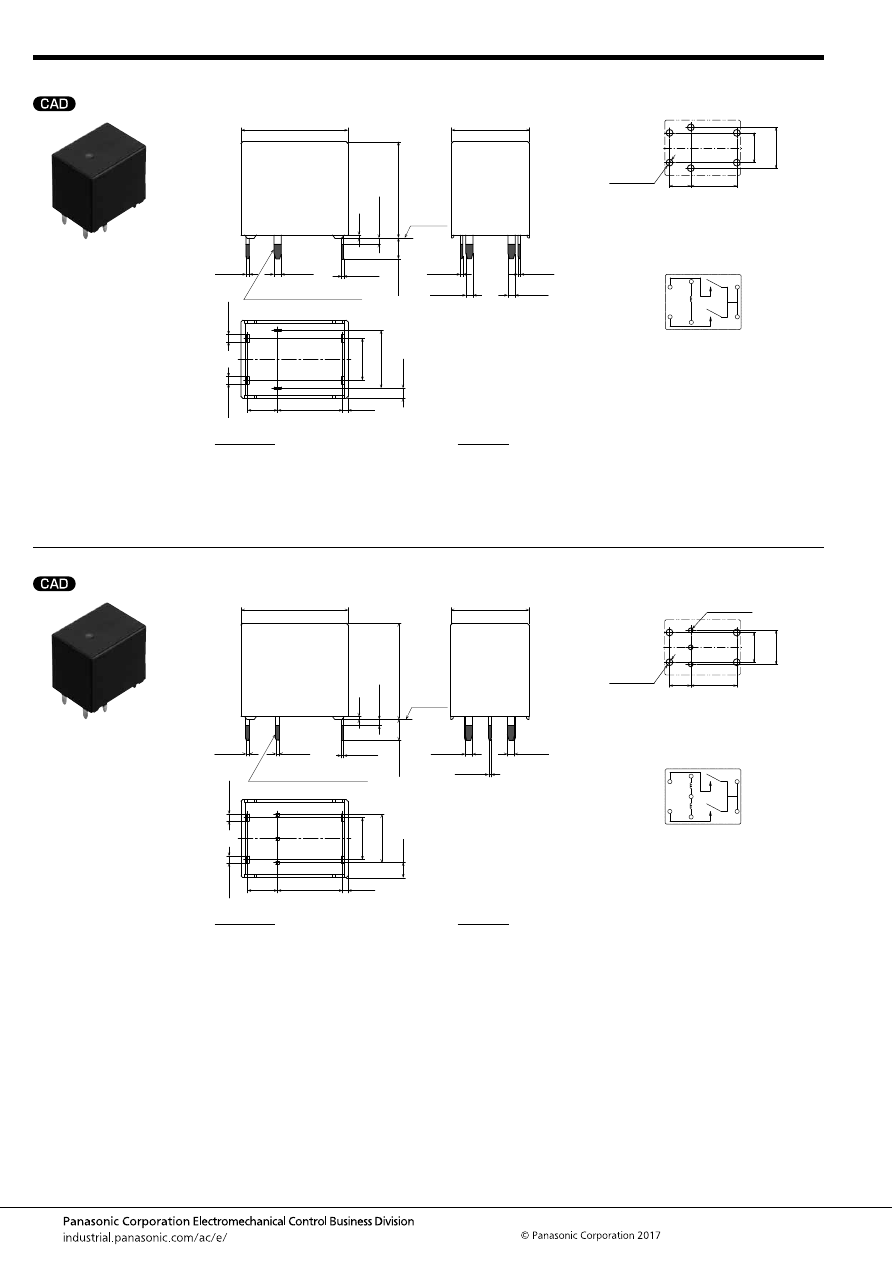
TC (ACTC)
–114–
ASCTB96E 201709-T
Double make contact 2 Form A / Standard type
Double make contact 2 Form A / 2 coil latching type
External dimensions
10.8
5
9.6
(0.9)
.425
.197
(.035)
(1.7)
.378
7
.276
(.067)
A surface
level
13
±
0.5
.512
±
.020
17.8
±
0.5
.701
±
.020
Max.
1.0
Max.
.039
0.5
.020
16
±
0.5
.630
±
.020
0.6
.024
+
0.3
−
0.1
+
.012
−
.004
1.2
.047
+
0.3
−
0.1
+
.012
−
.004
1.2
.047
+
0.3
−
0.1
+
.012
−
.004
0.4
.016
+
0.3
−
0.1
+
.012
−
.004
1.2
.047
+
0.3
−
0.1
+
.012
−
.004
1.2
.047
+
0.3
−
0.1
+
.012
−
.004
1.2
.047
+
0.3
−
0.1
+
.012
−
.004
0.4
.016
+
0.3
−
0.1
+
.012
−
.004
0.4
.016
+
0.3
−
0.1
+
.012
−
.004
3.5
±
0.5
.138
±
.020
Pre-soldering (all terminals)
PC board pattern (Bottom view)
Tolerance:
±
0.1
±
.004
Schematic (Bottom view)
9.6
.378
7
10.8
.425
5
.197
.276
6
×
1.6 dia.
6
×
.063 dia.
COM
COIL
COIL
COM
N.O.
N.O.
* The lamp control type has polarized contacts.
Connect COM to the “+ (plus)” side.
* Dimensions (thickness and width) of terminal is measured after pre-soldering.
Intervals between terminals is measured at A surface level.
Dimension:
Less than 1mm
.039inch
:
Min. 1mm
.039inch
less than 3mm
.118 inch
:
Min. 3mm
.118 inch
:
Tolerance
±
0.1
±
.004
±
0.2
±
.008
±
0.3
±
.012
External dimensions
10.8
5
8
(0.9)
.425
.197
(.035)
(2.5)
.315
7
.276
(.098)
A surface
level
13
±
0.5
.512
±
.020
17.8
±
0.5
.701
±
.020
Max.
1.0
Max.
.039
0.5
.020
16
±
0.5
.630
±
.020
0.6
.024
+
0.3
−
0.1
+
.012
−
.004
1.2
.047
+
0.3
−
0.1
+
.012
−
.004
1.2
.047
+
0.3
−
0.1
+
.012
−
.004
0.4
.016
+
0.3
−
0.1
+
.012
−
.004
1.2
.047
+
0.3
−
0.1
+
.012
−
.004
1.2
.047
+
0.3
−
0.1
+
.012
−
.004
1.2
.047
+
0.3
−
0.1
+
.012
−
.004
0.4
.016
+
0.3
−
0.1
+
.012
−
.004
3.5
±
0.5
.138
±
.020
Pre-soldering (all terminals)
PC board pattern (Bottom view)
Tolerance:
±
0.1
±
.004
Schematic (Bottom view)
8
.315
7
10.8
.425
5
.197
.276
4
×
1.6 dia.
4
×
.063 dia.
3
×
1.1 dia.
3
×
.043 dia.
COM
COIL
COIL
COM
N.O.
N.O.
+
+
–
RESET SET
* The lamp control type has polarized contacts.
Connect COM to the “+ (plus)” side.
* Dimensions (thickness and width) of terminal is measured after pre-soldering.
Intervals between terminals is measured at A surface level.
Dimension:
Less than 1mm
.039inch
:
Min. 1mm
.039inch
less than 3mm
.118 inch
:
Min. 3mm
.118 inch
:
Tolerance
±
0.1
±
.004
±
0.2
±
.008
±
0.3
±
.012
automotive-relay_en-html.html
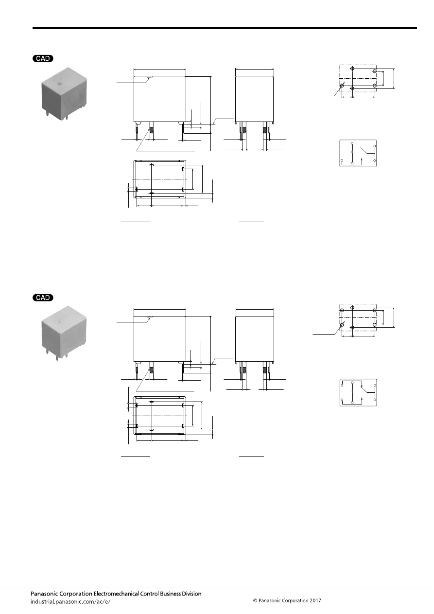
TC (ACTC)
–115–
ASCTB96E 201709-T
1 Form A / Standard type
Pin in Paste compliant type
1 Form C / Standard type
Pin in Paste compliant type
External dimensions
10.8
5
9.6
(0.9)
.425
.197
(.035)
(1.7)
.378
7
.276
(.067)
A surface
level
13
±
0.5
.512
±
.020
17.8
±
0.5
.701
±
.020
Max.
1.0
Max.
.039
0.9
.035
16.4
±
0.5
.646
±
.020
0.6
.024
+
0.3
−
0.1
+
.012
−
.004
1.2
.047
+
0.3
−
0.1
+
.012
−
.004
0.4
.016
+
0.3
−
0.1
+
.012
−
.004
1.2
.047
+
0.3
−
0.1
+
.012
−
.004
1.2
.047
+
0.3
−
0.1
+
.012
−
.004
1.2
.047
+
0.3
−
0.1
+
.012
−
.004
0.4
.016
+
0.3
−
0.1
+
.012
−
.004
0.4
.016
+
0.3
−
0.1
+
.012
−
.004
3.1
±
0.5
.122
±
.020
Pre-soldering (all terminals)
Air hole
PC board pattern (Bottom view)
Tolerance:
±
0.1
±
.004
Schematic (Bottom view)
5
×
1.6 dia.
9.6
.378
7
10.8
.425
5
.197
.276
5
×
.063 dia.
COM
COIL
N.O.
COIL
COM
* The lamp control type has polarized contacts.
Connect COM to the “+ (plus)” side.
* Dimensions (thickness and width) of terminal is measured after pre-soldering.
Intervals between terminals is measured at A surface level.
Dimension:
Less than 1mm
.039inch
:
Min. 1mm
.039inch
less than 3mm
.118 inch
:
Min. 3mm
.118 inch
:
Tolerance
±
0.1
±
.004
±
0.2
±
.008
±
0.3
±
.012
External dimensions
10.8
5
9.6
(0.9)
.425
.197
(.035)
(1.7)
.378
7
.276
(.067)
A surface
level
13
±
0.5
.512
±
.020
17.8
±
0.5
.701
±
.020
Max.
1.0
Max.
.039
0.9
.035
16.4
±
0.5
.646
±
.020
0.6
.024
+
0.3
−
0.1
+
.012
−
.004
1.2
.047
+
0.3
−
0.1
+
.012
−
.004
1.2
.047
+
0.3
−
0.1
+
.012
−
.004
0.4
.016
+
0.3
−
0.1
+
.012
−
.004
1.2
.047
+
0.3
−
0.1
+
.012
−
.004
1.2
.047
+
0.3
−
0.1
+
.012
−
.004
1.2
.047
+
0.3
−
0.1
+
.012
−
.004
0.4
.016
+
0.3
−
0.1
+
.012
−
.004
0.4
.016
+
0.3
−
0.1
+
.012
−
.004
3.1
±
0.5
.122
±
.020
Pre-soldering (all terminals)
Air hole
PC board pattern (Bottom view)
Tolerance:
±
0.1
±
.004
Schematic (Bottom view)
9.6
.378
7
10.8
.425
5
.197
.276
6
×
1.6 dia.
6
×
.063 dia.
COM
COIL
COIL
COM
N.O.
N.C.
* The lamp control type has polarized contacts.
Connect COM to the “+ (plus)” side.
* Dimensions (thickness and width) of terminal is measured after pre-soldering.
Intervals between terminals is measured at A surface level.
Dimension:
Less than 1mm
.039inch
:
Min. 1mm
.039inch
less than 3mm
.118 inch
:
Min. 3mm
.118 inch
:
Tolerance
±
0.1
±
.004
±
0.2
±
.008
±
0.3
±
.012
automotive-relay_en-html.html
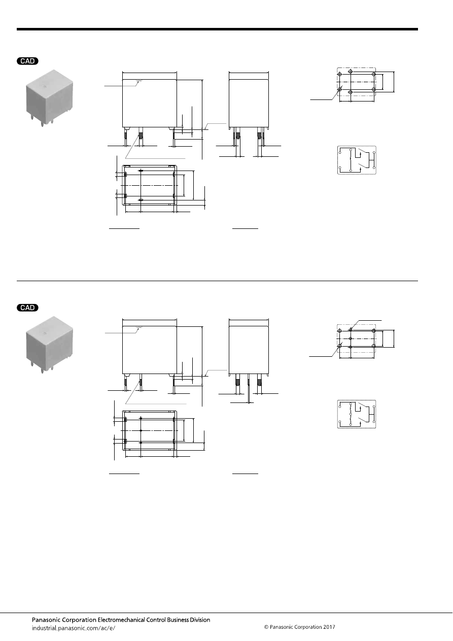
TC (ACTC)
–116–
ASCTB96E 201709-T
Double make contact 2 Form A / Standard type
Pin in Paste compliant type
Double make contact 2 Form A / 2 coil latching type
Pin in Paste compliant type
External dimensions
10.8
5
9.6
(0.9)
.425
.197
(.035)
(1.7)
.378
7
.276
(.067)
A surface
level
13
±
0.5
.512
±
.020
17.8
±
0.5
.701
±
.020
Max.
1.0
Max.
.039
0.9
.035
16.4
±
0.5
.646
±
.020
0.6
.024
+
0.3
−
0.1
+
.012
−
.004
1.2
.047
+
0.3
−
0.1
+
.012
−
.004
1.2
.047
+
0.3
−
0.1
+
.012
−
.004
0.4
.016
+
0.3
−
0.1
+
.012
−
.004
1.2
.047
+
0.3
−
0.1
+
.012
−
.004
1.2
.047
+
0.3
−
0.1
+
.012
−
.004
1.2
.047
+
0.3
−
0.1
+
.012
−
.004
0.4
.016
+
0.3
−
0.1
+
.012
−
.004
0.4
.016
+
0.3
−
0.1
+
.012
−
.004
3.1
±
0.5
.122
±
.020
Pre-soldering (all terminals)
Air hole
PC board pattern (Bottom view)
Tolerance:
±
0.1
±
.004
Schematic (Bottom view)
9.6
.378
7
10.8
.425
5
.197
.276
6
×
1.6 dia.
6
×
.063 dia.
COM
COIL
COIL
COM
N.O.
N.O.
* The lamp control type has polarized contacts.
Connect COM to the “+ (plus)” side.
* Dimensions (thickness and width) of terminal is measured after pre-soldering.
Intervals between terminals is measured at A surface level.
Dimension:
Less than 1mm
.039inch
:
Min. 1mm
.039inch
less than 3mm
.118 inch
:
Min. 3mm
.118 inch
:
Tolerance
±
0.1
±
.004
±
0.2
±
.008
±
0.3
±
.012
External dimensions
10.8
5
8
(0.9)
.425
.197
(.035)
(2.5)
.315
7
.276
(.098)
A surface
level
13
±
0.5
.512
±
.020
17.8
±
0.5
.701
±
.020
Max.
1.0
Max.
.039
0.9
.035
16.4
±
0.5
.646
±
.020
0.6
.024
+
0.3
−
0.1
+
.012
−
.004
0.6
.024
+
0.3
−
0.1
+
.012
−
.004
1.2
.047
+
0.3
−
0.1
+
.012
−
.004
1.2
.047
+
0.3
−
0.1
+
.012
−
.004
0.4
.016
+
0.3
−
0.1
+
.012
−
.004
Air hole
1.2
.047
+
0.3
−
0.1
+
.012
−
.004
1.2
.047
+
0.3
−
0.1
+
.012
−
.004
0.4
.016
+
0.3
−
0.1
+
.012
−
.004
3.1
±
0.5
.122
±
.020
Pre-soldering (all terminals)
PC board pattern (Bottom view)
Tolerance:
±
0.1
±
.004
Schematic (Bottom view)
8
.315
7
10.8
.425
5
.197
.276
4
×
1.6 dia.
4
×
.063 dia.
3
×
1.1 dia.
3
×
.043 dia.
COM
COIL
COIL
COM
N.O.
N.O.
+
+
–
RESET SET
* The lamp control type has polarized contacts.
Connect COM to the “+ (plus)” side.
* Dimensions (thickness and width) of terminal is measured after pre-soldering.
Intervals between terminals is measured at A surface level.
Dimension:
Less than 1mm
.039inch
:
Min. 1mm
.039inch
less than 3mm
.118 inch
:
Min. 3mm
.118 inch
:
Tolerance
±
0.1
±
.004
±
0.2
±
.008
±
0.3
±
.012
automotive-relay_en-html.html
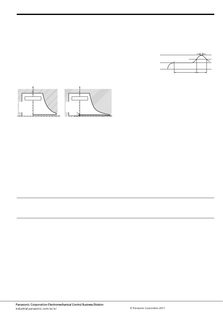
TC (ACTC)
–117–
ASCTB96E 201709-T
NOTES
For general cautions for use, please refer to the “Automotive Relay Users Guide”.
PRECAUTIONS REGARDING LATCHING RELAYS
Usage, transport and storage conditions
1) Ambient temperature, humidity, and air pressure during
usage, transport, and storage of the relay:
(1) Temperature: –40 to +85
°
C
–40 to +185
°
F
(Standard type)
–40 to +110
°
C
–40 to +230
°
F
(High heat-resistant type/Pin in
Paste compliant type)
(2) Humidity: 2 to 85% RH (Avoid icing and condensation.)
(3) Air pressure: 86 to 106 kPa
The humidity range varies with the temperature. Use within the
range indicated in the graph below.
[Temperature and humidity range for usage, transport,
and storage]
Mounting and cleaning conditions for Pin-in-Paste
compliant type
When soldering this relay, please observe the following
conditions.
[I.R.S. method (recommended)]
(Recommended number of reflows: 1)
• Cautions for mounting
1. The temperature profile shows the temperature at the
soldering portion on the PCB surface.
2. Depending on the mounting density condition, reflow
heating method, and PCB type (metal etc.), the relay’s
exterior and interior temperature may become extremely
high.
Therefore, please confirm well under the actual use
condition before use.
The other cautions of reflow soldering:
1. When soldering condition is out of recommendation, the
relay performance may be adversely affected.
If soldering conditions are out of our recommendation,
please contact us before operation.
2. Please check the effect at the actual soldering because
heat stress to relay is changed by PCB type and
manufacturing process condition.
3. Solder creepage, wettability or soldering strength will be
affected by the mounting condition or soldering material.
Please check the actual production condition in detail.
4. Do not wash the relay as failures may occur.
5. This product is not plastic sealed type. Please perform
coating with sufficient attention to avoid infiltration of the
solvent to the inside. Also, please pay careful attention to
use and store them with no contamination of foreign
material.
85
5
Humidity, %RH
Tolerance range
(Avoid
condensation
when used at
temperatures
higher than
0
°
C
32
°
F
)
(Avoid icing
when used at
temperatures
lower than
0
°
C
32
°
F
)
85
0
–40
+185
+32
–40
Temperature,
°
C
°
F
85
5
2
110
85
0
–40
+230
+185
+32
–40
Humidity, %RH
Temperature,
°
C
°
F
Tolerance range
(Avoid
condensation
when used at
temperatures
higher than
0
°
C
32
°
F
)
(Avoid icing
when used at
temperatures
lower than
0
°
C
32
°
F
)
Standard type
High heat-resistant type
t
1
= 60 to 120 sec.
t
2
= Less than 30 sec.
t
3
= Less than 5 sec.
T
1
= 150 to 180
°
C
T
2
= 230
°
C
T
3
= Less than 250
°
C
302 to 356
°
F
446
°
F
or more
482
°
F
T
1
T
3
T
2
t
1
t
2
t
3
• Latching relays are shipped from the factory in the reset
state. A shock to the relay during shipping or installation
may cause it to change to the set state.
Therefore, it is recommended that the relay be used in a
circuit which initializes the relay to the required state
(reset) whenever the power is turned on.
• Avoid impressing voltages to the set coil and reset coil at
the same time.
• The positive “+” and negative “–” connections to the coil
should be done as indicated on the wiring diagram. If
connected incorrectly, it may malfunction or fail to
operate.
• In order to cause setting and resetting of the latching
relay, apply the rated square wave voltage using as a
guide five times or more for the set time or the reset time
of each product. Furthermore, please verify operation.
automotive-relay_en-html.html
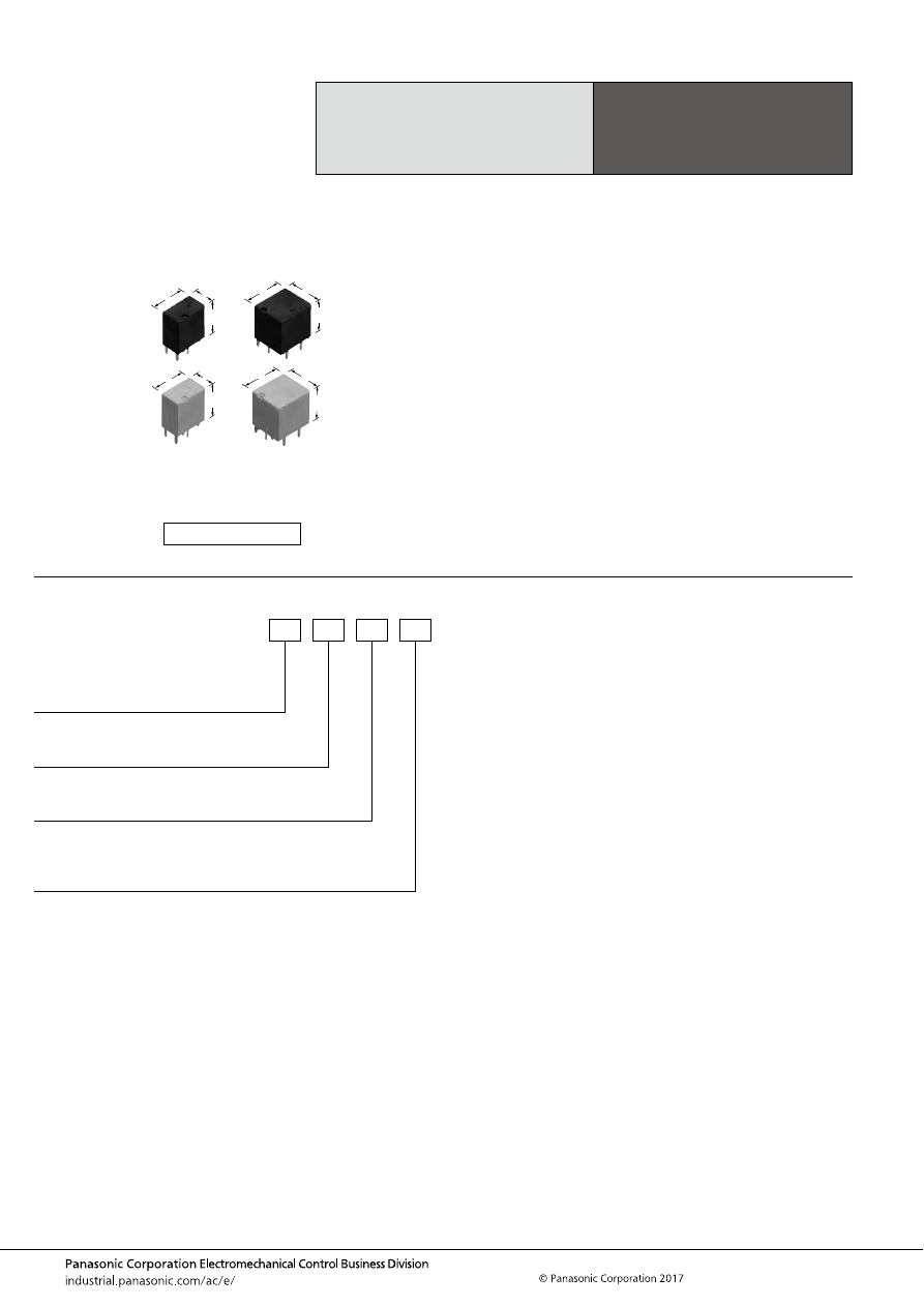
TE (ACTE)
–118–
ASCTB97E 201709-T
ORDERING INFORMATION
Miniature PC Board,
Twin Type, 1 Form C
Automotive Relay
TE RELAYS
FEATURES
• Compact and high-capacity 25 A load switching
• Pin in Paste compliant model added
TYPICAL APPLICATIONS
• Powered windows, Automatic door locks, Powered
mirrors, Powered sunroof, Powered seats, Lift gates and
Slide door closers, etc.
<Protective construction>
High heat-resistant type: Sealed
Pin in Paste compliant type: Flux tight
7.2
12
13.5
.283
.472
.531
7.2
12
14
.283
.472
.551
12
13.6
13.5
.472
.535
.531
12
13.6
14
.472
.535
.551
(Unit: mm
inch
)
RoHS compliant
Contact arrangement
2: 1 Form C
3: 1 Form C
×
2 (8 pins)
5: 1 Form C
×
2 (10 pins)
Contact type
Nil:
C:
Standard type
Standard type (Ag alloy / Cu clad)
ACTE
Heat resistance/Protective construction
H: High heat-resistant type/Sealed
R: Pin in Paste compliant type/Flux tight
Coil resistance
1: 110
Ω
2: 160
Ω
3: 220
Ω
automotive-relay_en-html.html
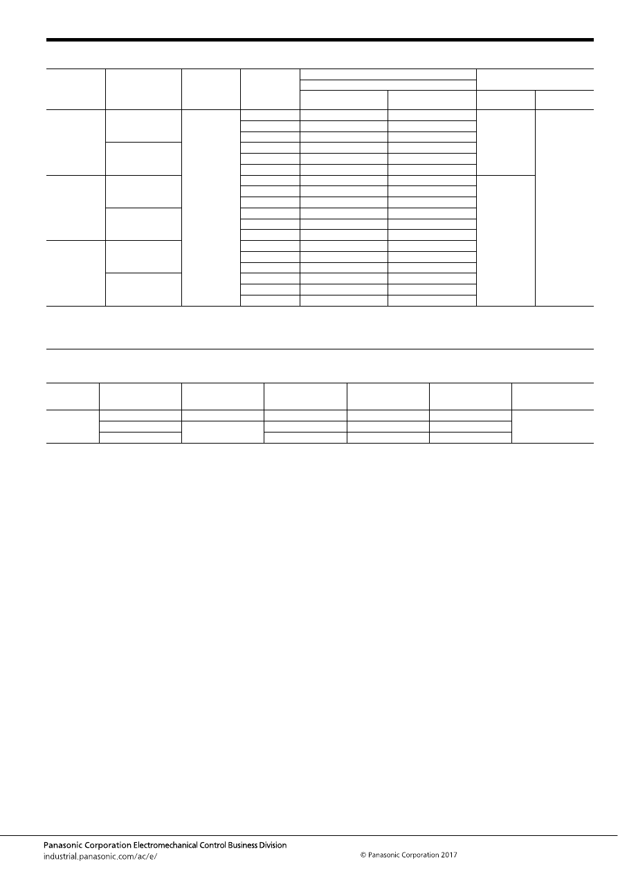
TE (ACTE)
–119–
ASCTB97E 201709-T
TYPES
RATING
1. Coil data
Contact
arrangement
Contact type
Rated coil
voltage
Coil resistance
Part No.
Packing
Heat resistance
High heat-resistant type
Pin in Paste compliant
type
Carton (tube)
Case
1 Form C
Standard type
12V DC
110
Ω
ACTE2H1
ACTE2R1
50 pcs.
2,000 pcs.
160
Ω
ACTE2H2
ACTE2R2
220
Ω
ACTE2H3
ACTE2R3
Standard type
(Ag alloy / Cu clad)
110
Ω
ACTE2CH1
ACTE2CR1
160
Ω
ACTE2CH2
ACTE2CR2
220
Ω
ACTE2CH3
ACTE2CR3
1 Form C
×
2
(8 pins)
Standard type
110
Ω
ACTE3H1
ACTE3R1
40 pcs.
160
Ω
ACTE3H2
ACTE3R2
220
Ω
ACTE3H3
ACTE3R3
Standard type
(Ag alloy / Cu clad)
110
Ω
ACTE3CH1
ACTE3CR1
160
Ω
ACTE3CH2
ACTE3CR2
220
Ω
ACTE3CH3
ACTE3CR3
1 Form C
×
2
(10 pins)
Standard type
110
Ω
ACTE5H1
ACTE5R1
160
Ω
ACTE5H2
ACTE5R2
220
Ω
ACTE5H3
ACTE5R3
Standard type
(Ag alloy / Cu clad)
110
Ω
ACTE5CH1
ACTE5CR1
160
Ω
ACTE5CH2
ACTE5CR2
220
Ω
ACTE5CH3
ACTE5CR3
Rated coil
voltage
Operate (Set) voltage
(at 20
°
C
68
°
F
) (Initial)
Release (Reset)
voltage
(at 20
°
C
68
°
F
) (Initial)
Rated operating current
[
±
10%] (at 20
°
C
68
°
F
)
Coil resistance
[
±
10%] (at 20
°
C
68
°
F
)
Rated operating power
(at 20
°
C
68
°
F
)
Usable voltage range
12V DC
Max. 5.5V DC
Min. 0.6V DC
109 mA
110
Ω
1,309 mW
10 to 16V DC
Max. 6.5V DC
Min. 0.8V DC
75 mA
160
Ω
900 mW
Max. 7.7V DC
54.5 mA
220
Ω
655 mW
automotive-relay_en-html.html
TE (ACTE)
–120–
ASCTB97E 201709-T
2. Specifications
Notes: *1. Depends on connection conditions. Also, this does not guarantee repeated switching. We recommend that you confirm operation under actual conditions.
*2. This value can change due to the switching frequency, environmental conditions, and desired reliability level, therefore it is recommended to check this with the
actual load.
*3. The upper operation ambient temperature limit is the maximum temperature that can satisfy the coil temperature rise value. For details, please refer to the
“Automotive Relay Users Guide”.
Please inquire our sales representative if you will be using the relay in a high temperature atmosphere (110
°
C
230
°
F
).
*4. Do not use for lamp loads, electric discharge lamp loads, any other lamp loads and capacitor loads. Please inquire our sales representative for details.
*If the relay is used continuously for long periods of time with coils on both sides in an energized condition, breakdown might occur due to abnormal heating depending
on the carrying condition. Therefore, please inquire our sales representative when using with a circuit that causes an energized condition on both sides
simultaneously.
Item
Specifications
Contact data
Contact arrangement
1 Form C, 1 Form C
×
2
Contact resistance (initial)
Max. 50m
Ω
(N.O. side: typ. 4m
Ω
, N.C. side: typ. 5m
Ω
) (By voltage drop 1A 6V DC)
Contact material
Ag alloy
Rated switching capacity
(resistive)
N.O. side: 20A 14V DC, N.C. side: 10A 14V DC
Max. carrying current
(initial)*
1
25A for 2 minutes (Coil applied voltage 12V DC, at 20
°
C
68
°
F
)
Min. switching load
(resistive)*
2
1A 14V DC (at 20
°
C
68
°
F
)
Insulated resistance (initial)
Min. 100 M
Ω
(at 500V DC, Measurement at same location as “Dielectric strength” section.)
Dielectric
strength (initial)
Between open contacts
500 Vrms for 1 min. (Detection current: 10mA)
Between contacts and coil
500 Vrms for 1 min. (Detection current: 10mA)
Time
characteristics
(initial)
Operate (Set) time
(at rated voltage)
Max. 10ms (at 20
°
C
68
°
F
, without contact bounce time)
Release (Reset) time
(at rated voltage)
Max. 10ms (at 20
°
C
68
°
F
, without contact bounce time) (Without diode)
Shock
resistance
Functional
Min. 100 m/s
2
{approx. 10G} (Half-wave pulse of sine wave: 11ms; detection time: 10
μ
s)
Destructive
Min. 1,000 m/s
2
{approx. 100G} (Half-wave pulse of sine wave: 6ms)
Vibration
resistance
Functional
10 to 100 Hz, Min. 44.1 m/s
2
{approx. 4.5G} (Detection time: 10
μ
s)
Destructive
10 to 500 Hz, Min. 44.1 m/s
2
{approx. 4.5G},
Time of vibration for each direction; X, Y direction: 2 hours, Z direction: 4 hours
Expected life
Mechanical
Min. 10
7
(at 120 cpm)
Electrical*
4
<Resistive load>
Min. 10
5
at rated switching capacity, operating frequency: 1s ON, 9s OFF
<Motor load>
Min. 10
5
25 A 14V DC at motor lock condition, operating frequency: 0.5s ON, 9.5s OFF
Conditions
Conditions for usage,
transport and storage*
3
Ambient temperature: –40 to +110
°
C
–40 to +230
°
F
, Humidity: 2 to 85% R.H. (Please avoid icing or condensation)
Weight
Single type: approx. 3.5 g
.12 oz
, Twin type: approx. 6.5 g
.23 oz
automotive-relay_en-html.html
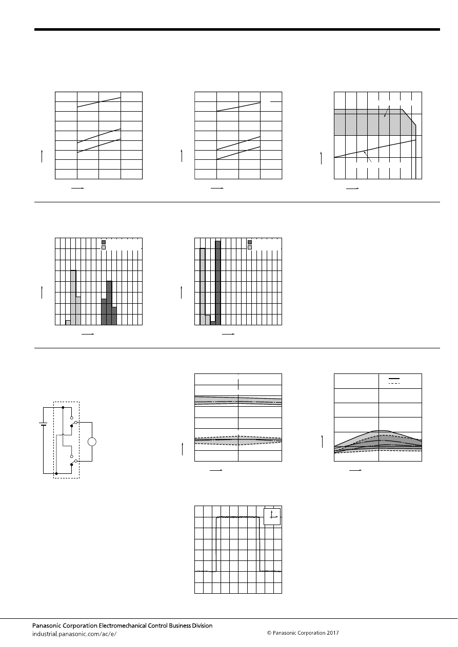
TE (ACTE)
–121–
ASCTB97E 201709-T
REFERENCE DATA
1.-(1) Coil temperature rise (at room
temperature)
Sample: ACTE3H2, 3pcs.
Carrying current: 0A, 10A, 20A
Ambient temperature: Room temperature
1.-(2) Coil temperature rise (at 110
°
C
230
°
F
)
Sample: ACTE3H2, 3pcs.
Carrying current: 0A, 10A, 20A
Ambient temperature: 110
°
C
230
°
F
2. Ambient temperature and usable voltage
range
Sample: ACTE3H2
18
16
14
12
10
180
160
140
120
100
80
60
40
20
0
20A
10A
0A
Coil applied voltage, V
T
e
mper
ature r
ise
,
°
C
18
16
14
12
10
180
160
140
120
100
80
60
40
20
0
20A
0A
10A
Coil applied voltage, V
T
e
mper
ature r
ise
,
°
C
120
-40 -20
0
20
15
10
5
0
20
40
60
80
100
Ambient temperature,
°
C
Coil applied v
oltage
,
V
Operate voltage (Cold start)
Usable voltage range
3. Distribution of operate (set) and release
(reset) voltage
Sample: ACTE3H2, 40
×
2pcs.
4. Distribution of operate (set) and release
(reset) time
Sample: ACTE3H2, 40
×
2pcs.
0
80
70
60
50
40
30
20
10
0
1
2
3
4
5
6
7
8
Voltage, V
Quantity
, n
Operate voltage
Release voltage
0
80
70
60
50
40
30
20
10
0
1
2
3
4
5
6
7
8
Time, ms
Quantity
, n
Operate time
Release time
* Without diode
5.-(1) Electrical life test (Motor lock)
Sample: ACTE3H2, 3pcs.
Load: 25A 14V DC
Power window motor actual load (lock condition)
Operating frequency: ON 0.5s, OFF 9.5s
Ambient temperature: Room temperature
Circuit:
Change of operate (set) and release (reset)
voltage
Change of contact resistance
M
10
5
0
8
7
6
5
4
3
2
1
0
Operate voltage
Release voltage
Max.
Min.
Ave.
Max.
Min.
Ave.
Oper
ate and release v
oltage
,
V
No. of operations,
×
10
4
Contact welding: 0 time
Miscontact: 0 time
10
5
0
30
25
20
15
10
5
0
Max.
Max.
Min.
Min.
Ave.(N.C.)
Ave.(N.O.)
Contact resistance
, m
Ω
No. of operations,
×
10
4
N.C. side
N.O. side
Load current waveform
Current value: 25A
100ms
5A
automotive-relay_en-html.html
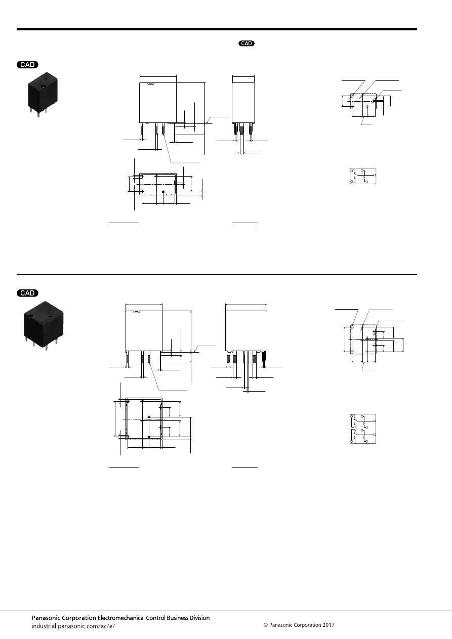
TE (ACTE)
–122–
ASCTB97E 201709-T
DIMENSIONS
(mm
inch
)
1 Form C type
Twin type (8 pins)
mark can be downloaded from: http://industrial.panasonic.com/ac/e/
The CAD data of the products with a
External dimensions
3.7
4.8
4.8
(0.6)
.146
2.2
.087
.189
(.024)
(1)
.189
(.039)
Pre-soldering
(all terminals)
A surface
level
12.5
±
0.5
.492
±
.020
7.2
±
0.5
.283
±
.020
Max.
1.0
Max.
.039
0.4
.016
13.5
±
0.5
.531
±
.020
3.5
±
0.5
.138
±
.020
0.5
.020
5.2
.205
0.5
.020
+
0.3
−
0.1
+
.012
−
.004
0.6
.024
+
0.3
−
0.1
+
.012
−
.004
0.25
.010
+
0.3
−
0.1
+
.012
−
.004
0.3
.012
+
0.3
−
0.1
+
.012
−
.004
0.3
.012
+
0.3
−
0.1
+
.012
−
.004
1.2
.047
+
0.3
−
0.1
+
.012
−
.004
1
.039
+
0.3
−
0.1
+
.012
−
.004
1
.039
+
0.3
−
0.1
+
.012
−
.004
PC board pattern (Bottom view)
Tolerance:
±
0.1
±
.004
Schematic (Bottom view)
4.8
.189
3.7
.146
2.2
.087
0.5
.020
5.2
.205
2
×
1.5 dia.
2
×
.059 dia.
2
×
1.1 dia.
2
×
.043 dia.
1.6 dia.
.063 dia.
4.8
.189
COM
N.C.
COIL
N.O.
COIL
* Dimensions (thickness and width) of terminal is measured after pre-soldering.
Intervals between terminals is measured at A surface level.
Dimension:
Less than 1mm
.039inch
:
Min. 1mm
.039inch
less than 3mm
.118 inch
:
Min. 3mm
.118 inch
:
Tolerance
±
0.1
±
.004
±
0.2
±
.008
±
0.3
±
.012
External dimensions
3.7
4.8
11.6
(0.6)
.146
2.2
.087
.189
(.024)
(1)
.457
(.039)
Pre-soldering
(all terminals)
A surface
level
12.5
±
0.5
.492
±
.020
13.6
±
0.5
.535
±
.020
Max.
1.0
Max.
.039
0.4
.016
13.5
±
0.5
.531
±
.020
3.5
±
0.5
.138
±
.020
3.1
.122
3.1
.122
5.2
.205
5.2
.205
6.4
.252
0.5
.020
+
0.3
−
0.1
+
.012
−
.004
0.6
.024
+
0.3
−
0.1
+
.012
−
.004
0.25
.010
+
0.3
−
0.1
+
.012
−
.004
0.3
.012
+
0.3
−
0.1
+
.012
−
.004
0.3
.012
+
0.3
−
0.1
+
.012
−
.004
0.3
.012
+
0.3
−
0.1
+
.012
−
.004
0.3
.012
+
0.3
−
0.1
+
.012
−
.004
1.2
.047
+
0.3
−
0.1
+
.012
−
.004
1.2
.047
+
0.3
−
0.1
+
.012
−
.004
1
.039
+
0.3
−
0.1
+
.012
−
.004
1
.039
+
0.3
−
0.1
+
.012
−
.004
PC board pattern (Bottom view)
Tolerance:
±
0.1
±
.004
Schematic (Bottom view)
11.6
.457
6.4
.252
5.2
.205
5.2
.205
2
×
1.5 dia.
2
×
.059 dia.
4
×
1.1 dia.
4
×
.043 dia.
2
×
1.6 dia.
2
×
.063 dia.
3.7
.146
2.2
.087
4.8
.189
3.1
.122
3.1
.122
COM
N.C.
COIL
N.O.
COIL
COM
* Dimensions (thickness and width) of terminal is measured after pre-soldering.
Intervals between terminals is measured at A surface level.
Dimension:
Less than 1mm
.039inch
:
Min. 1mm
.039inch
less than 3mm
.118 inch
:
Min. 3mm
.118 inch
:
Tolerance
±
0.1
±
.004
±
0.2
±
.008
±
0.3
±
.012
automotive-relay_en-html.html
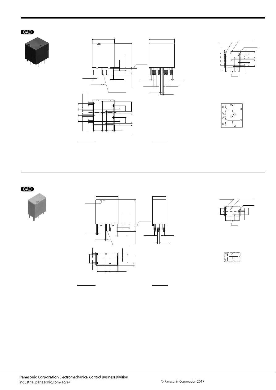
TE (ACTE)
–123–
ASCTB97E 201709-T
Twin type (10 pins)
1 Form C type
Pin in Paste compliant type
External dimensions
3.7
4.8
(0.6)
.146
2.2
.087
.189
(.024)
(1)
(.039)
Pre-soldering
(all terminals)
A surface
level
12
±
0.5
.472
±
.020
13.6
±
0.5
.535
±
.020
Max.
1.0
Max.
.039
0.4
.016
13.5
±
0.5
.531
±
.020
3.5
±
0.5
.138
±
.020
3.1
.122
3.1
.122
5.2
.205
5.2
.205
1
.039
1
.039
0.5
.020
+
0.3
−
0.1
+
.012
−
.004
0.6
.024
+
0.3
−
0.1
+
.012
−
.004
0.25
.010
+
0.3
−
0.1
+
.012
−
.004
0.3
.012
+
0.3
−
0.1
+
.012
−
.004
0.3
.012
+
0.3
−
0.1
+
.012
−
.004
0.3
.012
+
0.3
−
0.1
+
.012
−
.004
0.3
.012
+
0.3
−
0.1
+
.012
−
.004
1.2
.047
+
0.3
−
0.1
+
.012
−
.004
1.2
.047
+
0.3
−
0.1
+
.012
−
.004
1
.039
+
0.3
−
0.1
+
.012
−
.004
1
.039
+
0.3
−
0.1
+
.012
−
.004
1
.039
+
0.3
−
0.1
+
.012
−
.004
1
.039
+
0.3
−
0.1
+
.012
−
.004
3.2
.126
3.2
.126
3.2
.126
PC board pattern (Bottom view)
Tolerance:
±
0.1
±
.004
Schematic (Bottom view)
5.2
.205
5.2
.205
4
×
1.5 dia.
4
×
.059 dia.
4
×
1.1 dia.
4
×
.043 dia.
2
×
1.6 dia.
2
×
.063 dia.
3.7
.146
2.2
.087
4.8
.189
3.1
.122
3.1
.122
3.2
.126
3.2
.126
3.2
.126
1
.039
1
.039
COM
N.C.
COIL
COIL
COM
N.C.
N.O.
N.O.
* Dimensions (thickness and width) of terminal is measured after pre-soldering.
Intervals between terminals is measured at A surface level.
Dimension:
Less than 1mm
.039inch
:
Min. 1mm
.039inch
less than 3mm
.118 inch
:
Min. 3mm
.118 inch
:
Tolerance
±
0.1
±
.004
±
0.2
±
.008
±
0.3
±
.012
External dimensions
7.2
±
0.5
.283
±
.020
0.3
.012
+
0.3
−
0.1
+
.012
−
.004
0.3
.012
+
0.3
−
0.1
+
.012
−
.004
1.2
.047
+
0.3
−
0.1
+
.012
−
.004
Air hole
3.7
4.8
4.8
(0.6)
.146
2.2
.087
.189
(.024)
(1)
.189
(.039)
Pre-soldering
(all terminals)
A surface
level
12.5
±
0.5
.492
±
.020
Max.
1.0
Max.
.039
0.9
.035
14
±
0.5
.551
±
.020
3
±
0.5
.118
±
.020
0.5
.020
5.2
.205
0.5
.020
+
0.3
−
0.1
+
.012
−
.004
0.6
.024
+
0.3
−
0.1
+
.012
−
.004
0.25
.010
+
0.3
−
0.1
+
.012
−
.004
1
.039
+
0.3
−
0.1
+
.012
−
.004
1
.039
+
0.3
−
0.1
+
.012
−
.004
PC board pattern (Bottom view)
Tolerance:
±
0.1
±
.004
Schematic (Bottom view)
4.8
.189
3.7
.146
2.2
.087
0.5
.020
5.2
.205
2
×
1.5 dia.
2
×
.059 dia.
2
×
1.1 dia.
2
×
.043 dia.
1.6 dia.
.063 dia.
4.8
.189
COM
N.C.
COIL
N.O.
COIL
* Dimensions (thickness and width) of terminal is measured after pre-soldering.
Intervals between terminals is measured at A surface level.
Dimension:
Less than 1mm
.039inch
:
Min. 1mm
.039inch
less than 3mm
.118 inch
:
Min. 3mm
.118 inch
:
Tolerance
±
0.1
±
.004
±
0.2
±
.008
±
0.3
±
.012
automotive-relay_en-html.html
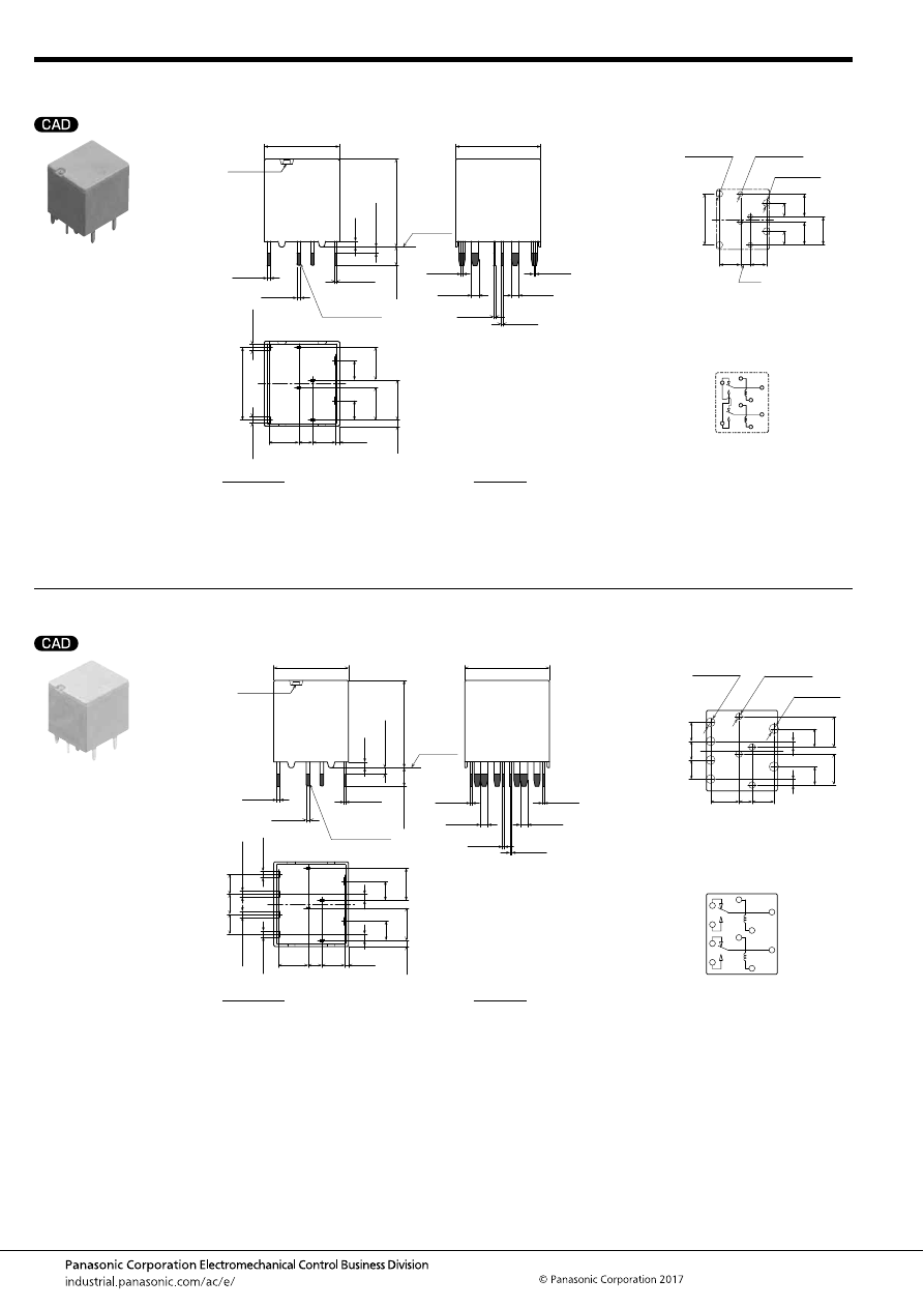
TE (ACTE)
–124–
ASCTB97E 201709-T
Twin type (8 pins)
Pin in Paste compliant type
Twin type (10 pins)
Pin in Paste compliant type
External dimensions
3.7
4.8
11.6
(0.6)
.146
2.2
.087
.189
(.024)
(1)
.457
(.039)
Pre-soldering
(all terminals)
A surface
level
12
±
0.5
.472
±
.020
Max.
1.0
Max.
.039
0.9
.035
14
±
0.5
.551
±
.020
3
±
0.5
.118
±
.020
3.1
.122
3.1
.122
5.2
.205
5.2
.205
6.4
.252
0.5
.020
+
0.3
−
0.1
+
.012
−
.004
0.6
.024
+
0.3
−
0.1
+
.012
−
.004
0.25
.010
+
0.3
−
0.1
+
.012
−
.004
1
.039
+
0.3
−
0.1
+
.012
−
.004
1
.039
+
0.3
−
0.1
+
.012
−
.004
Air hole
13.6
±
0.5
.535
±
.020
0.3
.012
+
0.3
−
0.1
+
.012
−
.004
0.3
.012
+
0.3
−
0.1
+
.012
−
.004
0.3
.012
+
0.3
−
0.1
+
.012
−
.004
0.3
.012
+
0.3
−
0.1
+
.012
−
.004
1.2
.047
+
0.3
−
0.1
+
.012
−
.004
1.2
.047
+
0.3
−
0.1
+
.012
−
.004
PC board pattern (Bottom view)
Tolerance:
±
0.1
±
.004
Schematic (Bottom view)
11.6
.457
6.4
.252
5.2
.205
5.2
.205
2
×
1.5 dia.
2
×
.059 dia.
4
×
1.1 dia.
4
×
.043 dia.
2
×
1.6 dia.
2
×
.063 dia.
3.7
.146
2.2
.087
4.8
.189
3.1
.122
3.1
.122
COM
N.C.
COIL
N.O.
COIL
COM
* Dimensions (thickness and width) of terminal is measured after pre-soldering.
Intervals between terminals is measured at A surface level.
Dimension:
Less than 1mm
.039inch
:
Min. 1mm
.039inch
less than 3mm
.118 inch
:
Min. 3mm
.118 inch
:
Tolerance
±
0.1
±
.004
±
0.2
±
.008
±
0.3
±
.012
External dimensions
3.7
4.8
(0.6)
.146
2.2
.087
.189
(.024)
(1)
(.039)
Pre-soldering
(all terminals)
A surface
level
12
±
0.5
.472
±
.020
13.6
±
0.5
.535
±
.020
Max.
1.0
Max.
.039
0.9
.035
14
±
0.5
.551
±
.020
3
±
0.5
.118
±
.020
3.1
.122
3.1
.122
5.2
.205
5.2
.205
1
.039
1
.039
0.5
.020
+
0.3
−
0.1
+
.012
−
.004
0.6
.024
+
0.3
−
0.1
+
.012
−
.004
0.25
.010
+
0.3
−
0.1
+
.012
−
.004
0.3
.012
+
0.3
−
0.1
+
.012
−
.004
0.3
.012
+
0.3
−
0.1
+
.012
−
.004
0.3
.012
+
0.3
−
0.1
+
.012
−
.004
0.3
.012
+
0.3
−
0.1
+
.012
−
.004
1.2
.047
+
0.3
−
0.1
+
.012
−
.004
1.2
.047
+
0.3
−
0.1
+
.012
−
.004
1
.039
+
0.3
−
0.1
+
.012
−
.004
1
.039
+
0.3
−
0.1
+
.012
−
.004
1
.039
+
0.3
−
0.1
+
.012
−
.004
1
.039
+
0.3
−
0.1
+
.012
−
.004
3.2
.126
3.2
.126
3.2
.126
Air hole
PC board pattern (Bottom view)
Tolerance:
±
0.1
±
.004
Schematic (Bottom view)
5.2
.205
5.2
.205
4
×
1.5 dia.
4
×
.059 dia.
4
×
1.1 dia.
4
×
.043 dia.
3.7
.146
2.2
.087
4.8
.189
3.1
.122
3.1
.122
3.2
.126
3.2
.126
3.2
.126
1
.039
1
.039
2
×
1.6 dia.
2
×
.063 dia.
COM
N.C.
COIL
COIL
COM
N.C.
N.O.
N.O.
* Dimensions (thickness and width) of terminal is measured after pre-soldering.
Intervals between terminals is measured at A surface level.
Dimension:
Less than 1mm
.039inch
:
Min. 1mm
.039inch
less than 3mm
.118 inch
:
Min. 3mm
.118 inch
:
Tolerance
±
0.1
±
.004
±
0.2
±
.008
±
0.3
±
.012
automotive-relay_en-html.html
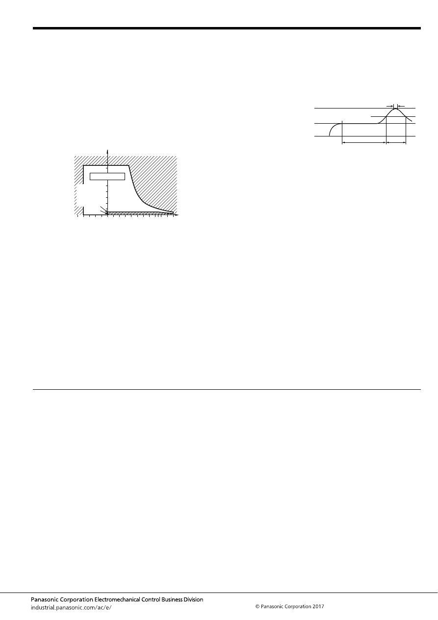
TE (ACTE)
–125–
ASCTB97E 201709-T
NOTES
For general cautions for use, please refer to the “Automotive Relay Users Guide”.
Usage, transport and storage conditions
1) Ambient temperature, humidity, and air pressure during
usage, transport, and storage of the relay:
(1) Temperature: –40 to +110
°
C
–40 to +230
°
F
(High heat-
resistant type/Pin in Paste compliant type)
(2) Humidity: 2 to 85% RH (Avoid icing and condensation.)
(3) Air pressure: 86 to 106 kPa
The humidity range varies with the temperature. Use within the
range indicated in the graph below.
[Temperature and humidity range for
usage, transport, and storage]
Mounting and cleaning conditions for Pin in Paste
compliant type
When soldering this relay, please observe the following
conditions.
[I.R.S. method (recommended)]
(Recommended number of reflows: 1)
• Cautions for mounting
1. The temperature profile shows the temperature at the
soldering portion on the PCB surface.
2. Depending on the mounting density condition, reflow
heating method, and PCB type (metal etc.), the relay’s
exterior and interior temperature may become extremely
high.
Therefore, please confirm well under the actual use
condition before use.
The other cautions of reflow soldering:
1. When soldering condition is out of recommendation, the
relay performance may be adversely affected.
If soldering conditions are out of our recommendation,
please contact us before operation.
2. Please check the effect at the actual soldering because
heat stress to relay is changed by PCB type and
manufacturing process condition.
3. Solder creepage, wettability or soldering strength will be
affected by the mounting condition or soldering material.
Please check the actual production condition in detail.
4. Do not wash the relay as failures may occur.
5. This product is not plastic sealed type. Please perform
coating with sufficient attention to avoid infiltration of the
solvent to the inside. Also, please pay careful attention to
use and store them with no contamination of foreign
material.
85
5
2
110
85
0
–40
+230
+185
+32
–40
Humidity, %RH
Temperature,
°
C
°
F
Tolerance range
(Avoid
condensation
when used at
temperatures
higher than
0
°
C
32
°
F
)
(Avoid icing
when used at
temperatures
lower than
0
°
C
32
°
F
)
t
1
= 60 to 120 sec.
t
2
= Less than 30 sec.
t
3
= Less than 5 sec.
T
1
= 150 to 180
°
C
T
2
= 230
°
C
T
3
= Less than 250
°
C
302 to 356
°
F
446
°
F
or more
482
°
F
T
1
T
3
T
2
t
1
t
2
t
3
automotive-relay_en-html.html
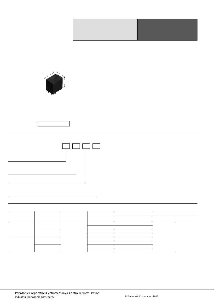
TG (ACTG)
–126–
ASCTB98E 201709-T
ORDERING INFORMATION
TYPES
Note: Please inquire our sales representative for details about products other than those above.
High Load Relay
for Smart J/B
TG RELAYS
Contact arrangement
Contact type
Rated coil voltage
Coil resistance
Part No.
Packing
Heat resistance:
High heat-resistant type
Carton (tube)
Case
1 Form A
Standard type
12V DC
225
Ω
ACTG1H3
40 pcs.
800 pcs.
320
Ω
ACTG1H4
Standard type
(Ag alloy / Cu clad)
225
Ω
ACTG1CH3
320
Ω
ACTG1CH4
1 Form C
Standard type
225
Ω
ACTG2H3
320
Ω
ACTG2H4
Standard type
(Ag alloy / Cu clad)
225
Ω
ACTG2CH3
320
Ω
ACTG2CH4
FEATURES
• Large capacity switching despite small size. Can replace
micro ISO terminal type relays.
• Low operating power type
TYPICAL APPLICATIONS
• Head lamp, Fog lamp, Fan motor, Defogger, Seat heater,
etc.
<Protective construction>
High heat-resistant type: Sealed
12.6
17.8
18
.496
.701
.709
(Unit: mm
inch
)
RoHS compliant
Contact arrangement
1: 1 Form A
2: 1 Form C
Contact type
Nil:
C:
Standard type
Standard type (Ag alloy / Cu clad)
ACTG
Heat resistance/Protective construction
H: High heat-resistant type/Sealed
Coil resistance
3: 225
Ω
4: 320
Ω
automotive-relay_en-html.html
TG (ACTG)
–127–
ASCTB98E 201709-T
RATING
1. Coil data
Note: Other operate (set) voltage types are also available. Please inquire our sales representative for details.
2. Specifications
Notes: *1. Depends on connection conditions. Also, this does not guarantee repeated switching. We recommend that you confirm operation under actual conditions.
*2. This value can change due to the switching frequency, environmental conditions, and desired reliability level, therefore it is recommended to check this with the
actual load.
*3. The upper operation ambient temperature limit is the maximum temperature that can satisfy the coil temperature rise value. For details, please refer to the
“Automotive Relay Users Guide”.
Please inquire our sales representative if you will be using the relay in a high temperature atmosphere (110
°
C
230
°
F
).
Rated coil
voltage
Operate (Set) voltage
(at 20
°
C
68
°
F
) (Initial)
Release (Reset)
voltage
(at 20
°
C
68
°
F
) (Initial)
Rated operating current
[
±
10%] (at 20
°
C
68
°
F
)
Coil resistance
[
±
10%] (at 20
°
C
68
°
F
)
Rated operating power
(at 20
°
C
68
°
F
)
Usable voltage range
12V DC
Max. 6.5V DC
Min. 0.8V DC
53.3 mA
225
Ω
640 mW
10 to 16V DC
Max. 7.0V DC
Min. 0.8V DC
37.5 mA
320
Ω
450 mW
Item
Specifications
Contact data
Contact arrangement
1 Form A, 1 Form C
Contact resistance (initial)
Max. 50m
Ω
(N.O. side: typ. 3m
Ω
, N.C. side: typ. 4m
Ω
) (By voltage drop 1A 6V DC)
Contact material
Ag alloy
Rated switching capacity
(resistive)
N.O. side: 30A 14V DC, N.C. side: 15A 14V DC
Max. carrying current
(initial)*
1
35A for 1 hour (Coil applied voltage 12V DC, at 20
°
C
68
°
F
)
Min. switching load
(resistive)*
2
1A 14V DC (at 20
°
C
68
°
F
)
Insulated resistance (initial)
Min. 100 M
Ω
(at 500V DC, Measurement at same location as “Dielectric strength” section.)
Dielectric
strength (initial)
Between open contacts
500 Vrms for 1 min. (Detection current: 10mA)
Between contacts and coil
500 Vrms for 1 min. (Detection current: 10mA)
Time
characteristics
(initial)
Operate (Set) time
(at rated voltage)
Max. 10ms (at 20
°
C
68
°
F
, without contact bounce time)
Release (Reset) time
(at rated voltage)
Max. 10ms (at 20
°
C
68
°
F
, without contact bounce time) (Without diode)
Shock
resistance
Functional
Min. 100 m/s
2
{approx. 10G} (Half-wave pulse of sine wave: 11ms; detection time: 10
μ
s)
Destructive
Min. 1,000 m/s
2
{approx. 100G} (Half-wave pulse of sine wave: 6ms)
Vibration
resistance
Functional
10 to 100 Hz, Min. 44.1 m/s
2
{approx. 4.5G} (Detection time: 10
μ
s)
Destructive
10 to 500 Hz, Min. 44.1 m/s
2
{approx. 4.5G},
Time of vibration for each direction; X, Y direction: 2 hours, Z direction: 4 hours
Expected life
Mechanical
Min. 10
7
(at 120 cpm)
Electrical
<Resistive load>
Min. 10
5
at rated switching capacity, operating frequency: 1s ON, 9s OFF
<Motor load>
Min. 10
5
30 A 14V DC at motor lock condition, operating frequency: 0.5s ON, 9.5s OFF
<Lamp load>
Min. 2
×
10
5
at 84 A (inrush), 12 A (steady), 14 V DC, Operating frequency: 1s ON, 14s OFF
Conditions
Conditions for usage,
transport and storage*
3
Ambient temperature: –40 to +110
°
C
–40 to +230
°
F
, Humidity: 2 to 85% R.H. (Please avoid icing or condensation)
Weight
Approx. 12 g
.42 oz
automotive-relay_en-html.html
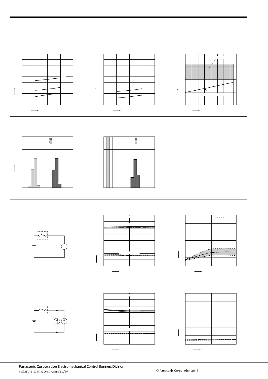
TG (ACTG)
–128–
ASCTB98E 201709-T
REFERENCE DATA
1.-(1) Coil temperature rise (at room
temperature)
Sample: ACTG1H4, 3pcs.
Carrying current: 10A, 20A, 30A
Ambient temperature: Room temperature
1.-(2) Coil temperature rise (at 110
°
C
230
°
F
)
Sample: ACTG1H4, 3pcs.
Carrying current: 10A, 20A
Ambient temperature: 110
°
C
230
°
F
2. Ambient temperature and usable voltage
range
Sample: ACTG1H4
18
16
14
12
10
180
160
140
120
100
80
60
40
20
0
30A
20A
10A
Coil applied voltage, V
T
emper
ature r
ise
,
°
C
18
16
14
12
10
180
160
140
120
100
80
60
40
20
0
20A
10A
Coil applied voltage, V
T
emper
ature r
ise
,
°
C
120
-40 -20
0
20
40
60
80
100
20
15
10
5
0
Ambient temperature,
°
C
Coil applied v
oltage
,
V
Operate voltage (Cold start)
Usable voltage range
3. Distribution of operate (set) and release
(reset) voltage
Sample: ACTG1H4, 40pcs.
4. Distribution of operate (set) and release
(reset) time
Sample: ACTG1H4, 40pcs.
8
0
40
30
20
10
0
1
2
3
4
5
6
7
Voltage, V
Quantity
, n
Operate voltage
Release voltage
8
0
40
30
20
10
0
1
2
3
4
5
6
7
Time, ms
Quantity
, n
Operate time
Release time
* Without diode
5.-(1) Electrical life test (Motor lock)
Sample: ACTG1H4, 6pcs.
Load: 30A 14V DC
Motor load (lock condition)
Operating frequency: ON 0.5s, OFF 9.5s
Ambient temperature: Room temperature
Circuit:
Change of operate (set) and release (reset)
voltage
Change of contact resistance
M
14V DC
Max.
Min.
Ave.
Max.
Min.
Ave.
10
5
0
8
7
6
5
4
3
2
1
0
Operate voltage
Release voltage
Oper
ate and release v
oltage
,
V
No. of operations,
×
10
4
Contact welding: 0 time
Miscontact: 0 time
Max.
Min.
Ave.
10
5
0
30
25
20
15
10
5
0
Contact resistance
, m
Ω
No. of operations,
×
10
4
N.O. side
5.-(2) Electrical life test (Lamp load)
Sample: ACTG1H4, 6pcs.
Load: inrush: 84A, steady: 12A 14V DC
Operating frequency: ON 1s, OFF 14s
Ambient temperature: Room temperature
Circuit:
Change of operate (set) and release (reset)
voltage
Change of contact resistance
60W
60W
14V DC
Oper
ate and release v
oltage
,
V
No. of operations,
×
10
4
Max.
Min.
Ave.
Max.
Min.
Ave.
10
5
0
8
7
6
5
4
3
2
1
0
Operate voltage
Release voltage
Contact welding: 0 time
Miscontact: 0 time
No. of operations,
×
10
4
Max.
Min.
Ave.
10
5
0
30
25
20
15
10
5
0
Contact resistance
, m
Ω
N.O. side
automotive-relay_en-html.html
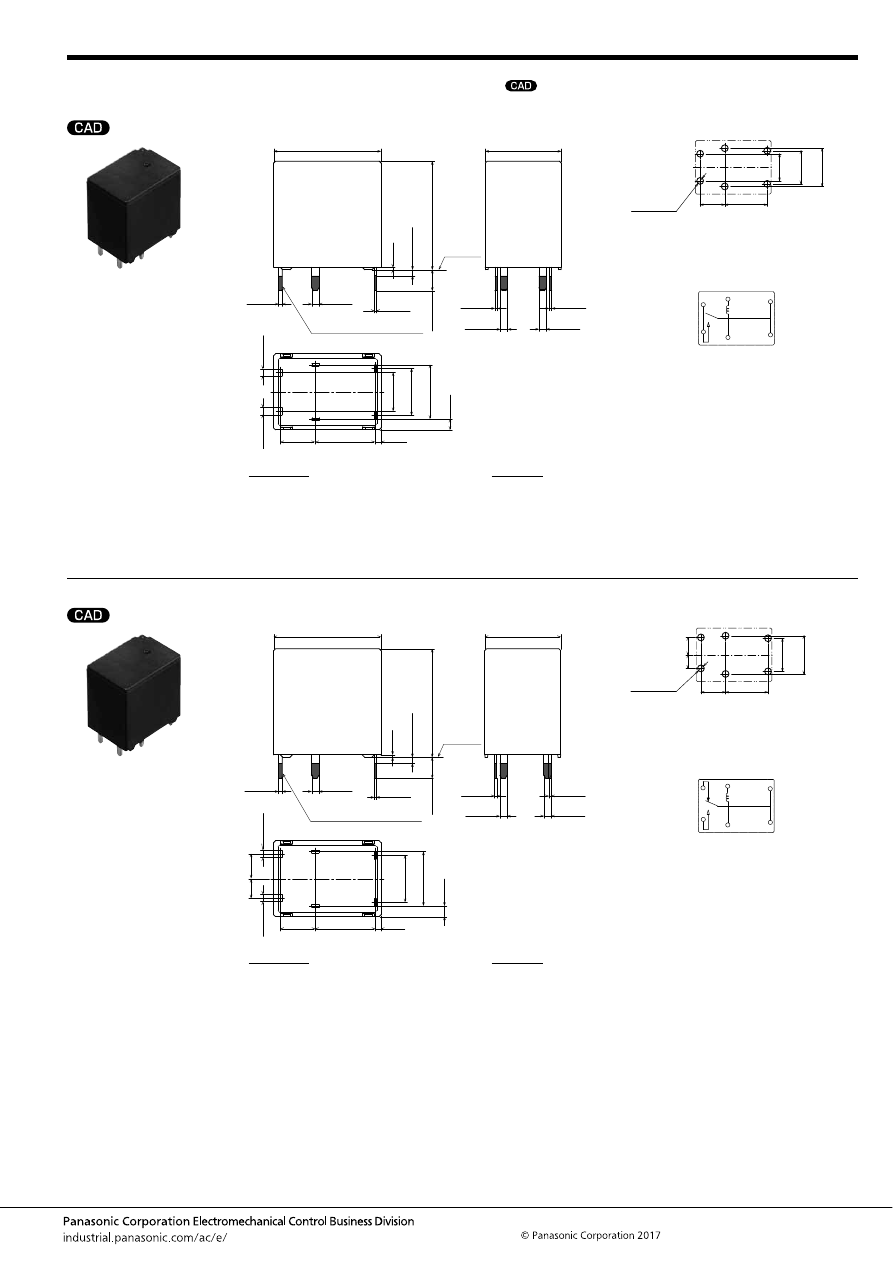
TG (ACTG)
–129–
ASCTB98E 201709-T
DIMENSIONS
(mm
inch
)
1 Form A type
1 Form C type
mark can be downloaded from: http://industrial.panasonic.com/ac/e/
The CAD data of the products with a
External dimensions
10
5.8
9
(0.9)
.394
.228
(.035)
(1.8)
.354
7.8
.307
6.4
.252
(.071)
A surface
level
12.6
±
0.5
.496
±
.020
17.8
±
0.5
.701
±
.020
Max.
1.0
Max.
.039
0.4
.016
18
±
0.5
.709
±
.020
0.6
.024
+
0.3
−
0.1
+
.012
−
.004
1.2
.047
+
0.3
−
0.1
+
.012
−
.004
1.2
.047
+
0.3
−
0.1
+
.012
−
.004
0.3
.012
+
0.3
−
0.1
+
.012
−
.004
1.2
.047
+
0.3
−
0.1
+
.012
−
.004
1.2
.047
+
0.3
−
0.1
+
.012
−
.004
1.2
.047
+
0.3
−
0.1
+
.012
−
.004
0.4
.016
+
0.3
−
0.1
+
.012
−
.004
0.4
.016
+
0.3
−
0.1
+
.012
−
.004
3.5
±
0.5
.138
±
.020
Pre-soldering (all terminals)
PC board pattern (Bottom view)
Tolerance:
±
0.1
±
.004
Schematic (Bottom view)
6
×
1.6 dia.
6
×
.063 dia.
6.4
.252
7.8
.307
9
.354
10
.394
5.8
.228
COIL
COIL
COM
COM
N.O.
N.O.
* Dimensions (thickness and width) of terminal is measured after pre-soldering.
Intervals between terminals is measured at A surface level.
Dimension:
Less than 1mm
.039inch
:
Min. 1mm
.039inch
less than 3mm
.118 inch
:
Min. 3mm
.118 inch
:
Tolerance
±
0.1
±
.004
±
0.2
±
.008
±
0.3
±
.012
External dimensions
10
5.8
9
(0.9)
.394
.228
(.035)
(1.8)
.354
7.8
.307
(.071)
A surface
level
12.6
±
0.5
.496
±
.020
17.8
±
0.5
.701
±
.020
Max.
1.0
Max.
.039
0.4
.016
18
±
0.5
.709
±
.020
0.6
.024
+
0.3
−
0.1
+
.012
−
.004
1.2
.047
+
0.3
−
0.1
+
.012
−
.004
1.2
.047
+
0.3
−
0.1
+
.012
−
.004
0.3
.012
+
0.3
−
0.1
+
.012
−
.004
1.2
.047
+
0.3
−
0.1
+
.012
−
.004
1.2
.047
+
0.3
−
0.1
+
.012
−
.004
1.2
.047
+
0.3
−
0.1
+
.012
−
.004
0.4
.016
+
0.3
−
0.1
+
.012
−
.004
0.4
.016
+
0.3
−
0.1
+
.012
−
.004
3.5
±
0.5
.138
±
.020
Pre-soldering (all terminals)
4.1
.161
3.2
.126
PC board pattern (Bottom view)
Tolerance:
±
0.1
±
.004
Schematic (Bottom view)
4.1
.161
3.2
.126
7.8
.307
9
.354
10
.394
5.8
.228
6
×
1.6 dia.
6
×
.063 dia.
COIL
COIL
COM
COM
N.C.
N.O.
* Dimensions (thickness and width) of terminal is measured after pre-soldering.
Intervals between terminals is measured at A surface level.
Dimension:
Less than 1mm
.039inch
:
Min. 1mm
.039inch
less than 3mm
.118 inch
:
Min. 3mm
.118 inch
:
Tolerance
±
0.1
±
.004
±
0.2
±
.008
±
0.3
±
.012
automotive-relay_en-html.html
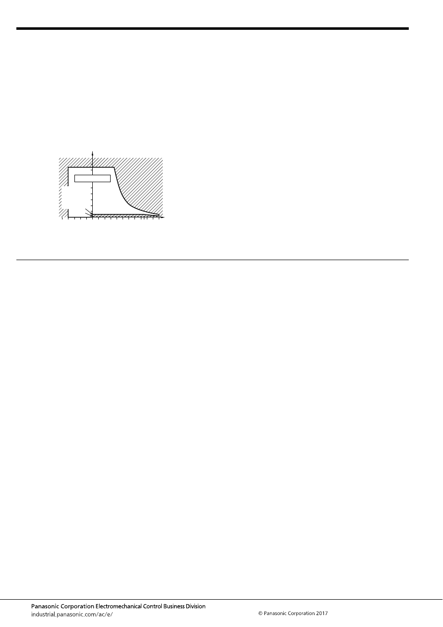
TG (ACTG)
–130–
ASCTB98E 201709-T
NOTES
For general cautions for use, please refer to the “Automotive Relay Users Guide”.
Usage, transport and storage conditions
1) Ambient temperature, humidity, and air pressure during
usage, transport, and storage of the relay:
(1) Temperature: –40 to +110
°
C
–40 to +230
°
F
(High heat-
resistant type)
(2) Humidity: 2 to 85% RH (Avoid icing and condensation.)
(3) Air pressure: 86 to 106 kPa
The humidity range varies with the temperature. Use within the
range indicated in the graph below.
[Temperature and humidity range for
usage, transport, and storage]
85
5
2
110
85
0
–40
+230
+185
+32
–40
Humidity, %RH
Temperature,
°
C
°
F
Tolerance range
(Avoid
condensation
when used at
temperatures
higher than
0
°
C
32
°
F
)
(Avoid icing
when used at
temperatures
lower than
0
°
C
32
°
F
)
automotive-relay_en-html.html
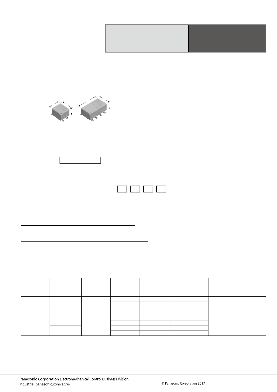
TH (ACTH)
–131–
ASCTB99E 201709-T
ORDERING INFORMATION
TYPES
Miniature PC Board,
Twin, 1 Form C,
Surface-mount Type
Automotive Relay
TH RELAYS
Contact
arrangement
Contact type
Rated coil voltage
Coil resistance
Part No.
Packing
Protective construction
Sealed type
Flux tight type
Carton
(tape and reel)
Case
1 Form C
Standard type
12V DC
160
Ω
ACTH5B2
ACTH5R2
500 pcs.
2,000 pcs.
220
Ω
ACTH5B3
ACTH5R3
Standard type
(Ag alloy / Cu clad)
160
Ω
ACTH5CB2
ACTH5CR2
220
Ω
ACTH5CB3
ACTH5CR3
1 Form C
×
2
(10 pins)
Standard type
160
Ω
ACTH6B2
ACTH6R2
400 pcs.
220
Ω
ACTH6B3
ACTH6R3
Standard type
(Ag alloy / Cu clad)
160
Ω
ACTH6CB2
ACTH6CR2
220
Ω
ACTH6CB3
ACTH6CR3
FEATURES
• Compact flat type
<Height> Surface-mount type: 8.8 mm
.346 inch
• Compact and high-capacity 25 A load switching
TYPICAL APPLICATIONS
• Powered windows, Automatic door locks, Powered
mirrors, Powered sunroof, Powered seats, Lift gates and
Slide door closers, etc.
<Protective construction>
Sealed/Flux tight
12
11
8.8
.472
.433
.346
12
21.6
8.8
.472
.850
.346
(Unit: mm
inch
)
RoHS compliant
Contact arrangement/Terminal shape
5: 1 Form C/Surface-mount terminal type
6: 1 Form C
×
2 (10 pins) Surface-mount terminal type
Contact type
Nil:
C:
Standard type
Standard type (Ag alloy / Cu clad)
Heat resistance/Protective construction
B:
R:
Reflow type/Sealed
Reflow type/Flux tight
ACTH
Coil resistance
2: 160
Ω
3: 220
Ω
automotive-relay_en-html.html
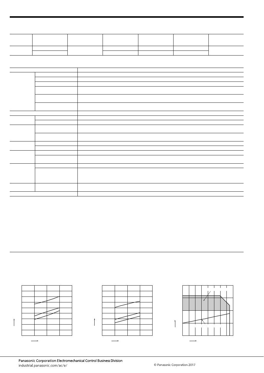
TH (ACTH)
–132–
ASCTB99E 201709-T
RATING
1. Coil data
2. Specifications
Notes: *1. Depends on connection conditions. Also, this does not guarantee repeated switching. We recommend that you confirm operation under actual conditions.
*2. This value can change due to the switching frequency, environmental conditions, and desired reliability level, therefore it is recommended to check this with the
actual load.
*3. The upper operation ambient temperature limit is the maximum temperature that can satisfy the coil temperature rise value. For details, please refer to the
“Automotive Relay Users Guide”.
Please inquire our sales representative if you will be using the relay in a high temperature atmosphere (110
°
C
230
°
F
).
*4. Do not use for lamp loads, electric discharge lamp loads, any other lamp loads and capacitor loads. Please inquire our sales representative for details.
*If the relay is used continuously for long periods of time with coils on both sides in an energized condition, breakdown might occur due to abnormal heating depending
on the carrying condition. Therefore, please inquire our sales representative when using with a circuit that causes an energized condition on both sides
simultaneously.
REFERENCE DATA
Rated coil
voltage
Operate (Set) voltage
(at 20
°
C
68
°
F
) (Initial)
Release (Reset)
voltage
(at 20
°
C
68
°
F
) (Initial)
Rated operating current
[
±
10%] (at 20
°
C
68
°
F
)
Coil resistance
[
±
10%] (at 20
°
C
68
°
F
)
Rated operating power
(at 20
°
C
68
°
F
)
Usable voltage range
12V DC
Max. 6.5V DC
Min. 0.6V DC
75 mA
160
Ω
900 mW
10 to 16V DC
Max. 7.7V DC
54.5 mA
220
Ω
655 mW
Item
Specifications
Contact data
Contact arrangement
1 Form C, 1 Form C
×
2
Contact resistance (initial)
Max. 50m
Ω
(N.O. side: typ. 4.5m
Ω
, N.C. side: typ. 5.5m
Ω
) (By voltage drop 1A 6V DC)
Contact material
Ag alloy
Rated switching capacity
(resistive)
N.O. side: 20A 14V DC, N.C. side: 10A 14V DC
Max. carrying current
(initial)*
1
25A for 10 minutes (Coil applied voltage 12V DC, at 20
°
C
68
°
F
)
Min. switching load
(resistive)*
2
1A 14V DC (at 20
°
C
68
°
F
)
Insulated resistance (initial)
Min. 100 M
Ω
(at 500V DC, Measurement at same location as “Dielectric strength” section.)
Dielectric
strength (initial)
Between open contacts
500 Vrms for 1 min. (Detection current: 10mA)
Between contacts and coil
500 Vrms for 1 min. (Detection current: 10mA)
Time
characteristics
(initial)
Operate (Set) time
(at rated voltage)
Max. 10ms (at 20
°
C
68
°
F
, without contact bounce time)
Release (Reset) time
(at rated voltage)
Max. 10ms (at 20
°
C
68
°
F
, without contact bounce time) (Without diode)
Shock
resistance
Functional
Min. 100 m/s
2
{approx. 10G} (Half-wave pulse of sine wave: 11ms; detection time: 10
μ
s)
Destructive
Min. 1,000 m/s
2
{approx. 100G} (Half-wave pulse of sine wave: 6ms)
Vibration
resistance
Functional
10 to 100 Hz, Min. 44.1 m/s
2
{approx. 4.5G} (Detection time: 10
μ
s)
Destructive
10 to 500 Hz, Min. 44.1 m/s
2
{approx. 4.5G},
Time of vibration for each direction; X, Y direction: 2 hours, Z direction: 4 hours
Expected life
Mechanical
Min. 10
7
(at 120 cpm)
Electrical*
4
<Resistive load>
Min. 10
5
at rated switching capacity, operating frequency: 1s ON, 9s OFF
<Motor load>
Min. 10
5
25 A 14V DC at motor lock condition, operating frequency: 0.5s ON, 9.5s OFF
Conditions
Conditions for usage,
transport and storage*
3
Ambient temperature: –40 to +110
°
C
–40 to +230
°
F
, Humidity: 2 to 85% R.H. (Please avoid icing or condensation)
Weight
Single type: approx. 3 g
.106 oz
, Twin type: approx. 6 g
.21 oz
1.-(1) Coil temperature rise (at room
temperature)
Sample: ACTH6B2, 3pcs.
Carrying current: 0A, 10A, 20A
Ambient temperature: Room temperature
1.-(2) Coil temperature rise (at 110
°
C
230
°
F
)
Sample: ACTH6B2, 3pcs.
Carrying current: 0A, 10A, 20A
Ambient temperature: 110
°
C
230
°
F
2. Ambient temperature and usable voltage
range
Sample: ACTH6B2
18
16
14
12
10
180
160
140
120
100
80
60
40
20
0
20A
10A
0A
Coil applied voltage, V
T
emper
ature r
ise
,
°
C
18
16
14
12
10
180
160
140
120
100
80
60
40
20
0
20A
10A
0A
Coil applied voltage, V
T
emper
ature r
ise
,
°
C
120
-40
20
15
10
5
0
-20
0
20
40
60
80
100
Ambient temperature,
°
C
Coil applied v
oltage
,
V
Operate voltage (Cold start)
Usable voltage range
automotive-relay_en-html.html
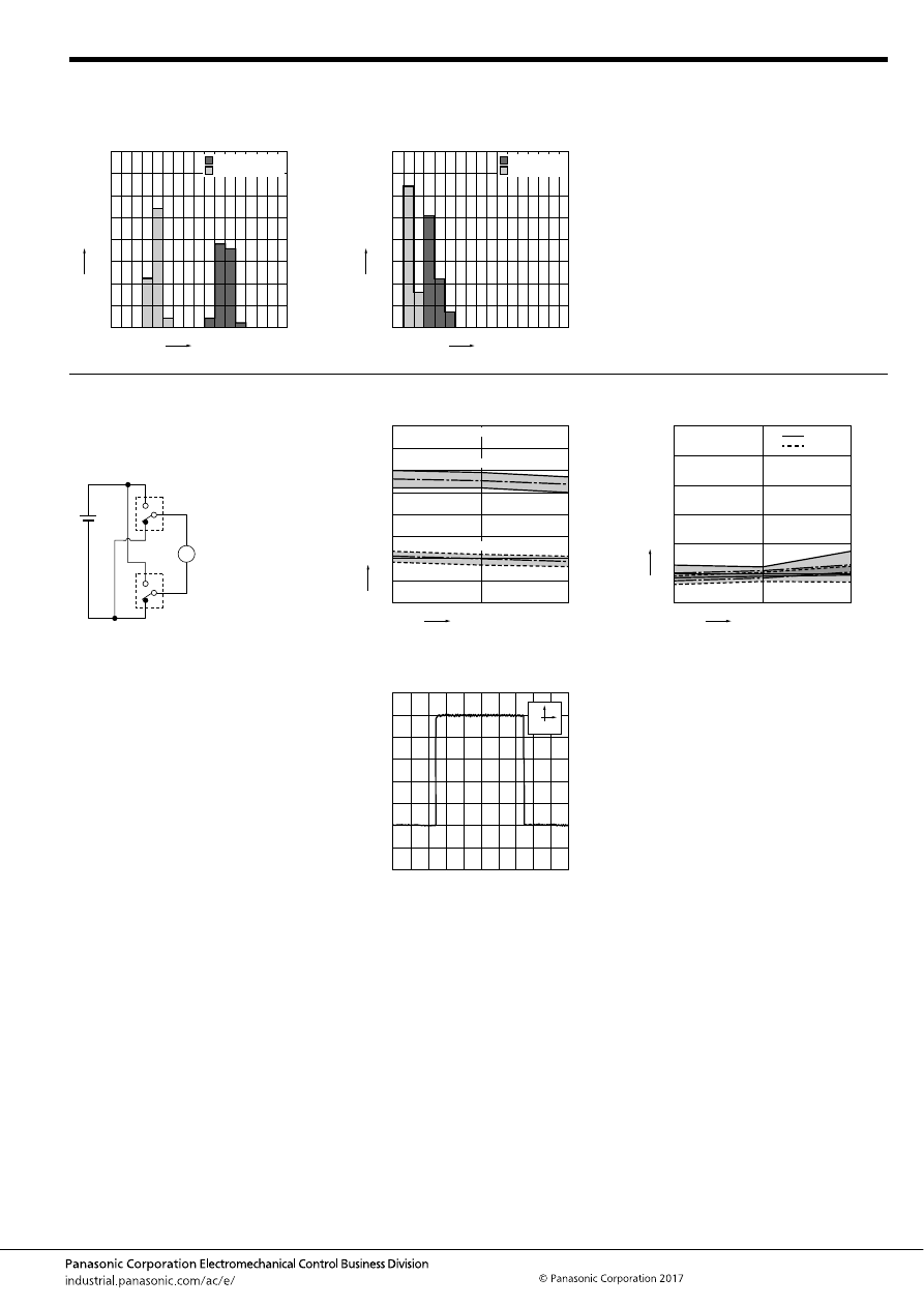
TH (ACTH)
–133–
ASCTB99E 201709-T
3. Distribution of operate (set) and release
(reset) voltage
Sample: ACTH6B2, 40
×
2pcs.
4. Distribution of operate (set) and release
(reset) time
Sample: ACTH6B2, 40
×
2pcs.
0
80
70
60
50
40
30
20
10
0
1
2
3
4
5
6
7
8
Voltage, V
Quantity
, n
Operate voltage
Release voltage
0
80
70
60
50
40
30
20
10
0
1
2
3
4
5
6
7
8
Time, ms
Quantity
, n
Operate time
Release time
* Without diode
5. Electrical life test (Motor lock)
Sample: ACTH6B2, 3pcs.
Load: 25A 14V DC
Power window motor actual load (lock condition)
Operating frequency: ON 0.5s, OFF 9.5s
Ambient temperature: Room temperature
Circuit:
Change of operate (set) and release (reset)
voltage
Change of contact resistance
M
10
5
0
8
7
6
5
4
3
2
1
0
Max.
Min.
Ave.
Max.
Min.
Ave.
Operate voltage
Release voltage
Oper
ate and release v
oltage
,
V
No. of operations,
×
10
4
Contact welding: 0 time
Miscontact: 0 time
10
5
0
30
25
20
15
10
5
0
Max.
Max.
Min.
Min.
Ave.
Ave.
No. of operations,
×
10
4
N.C. side
N.O. side
Contact resistance
, m
Ω
Load current waveform
Current value: 25A
100ms
5A
automotive-relay_en-html.html
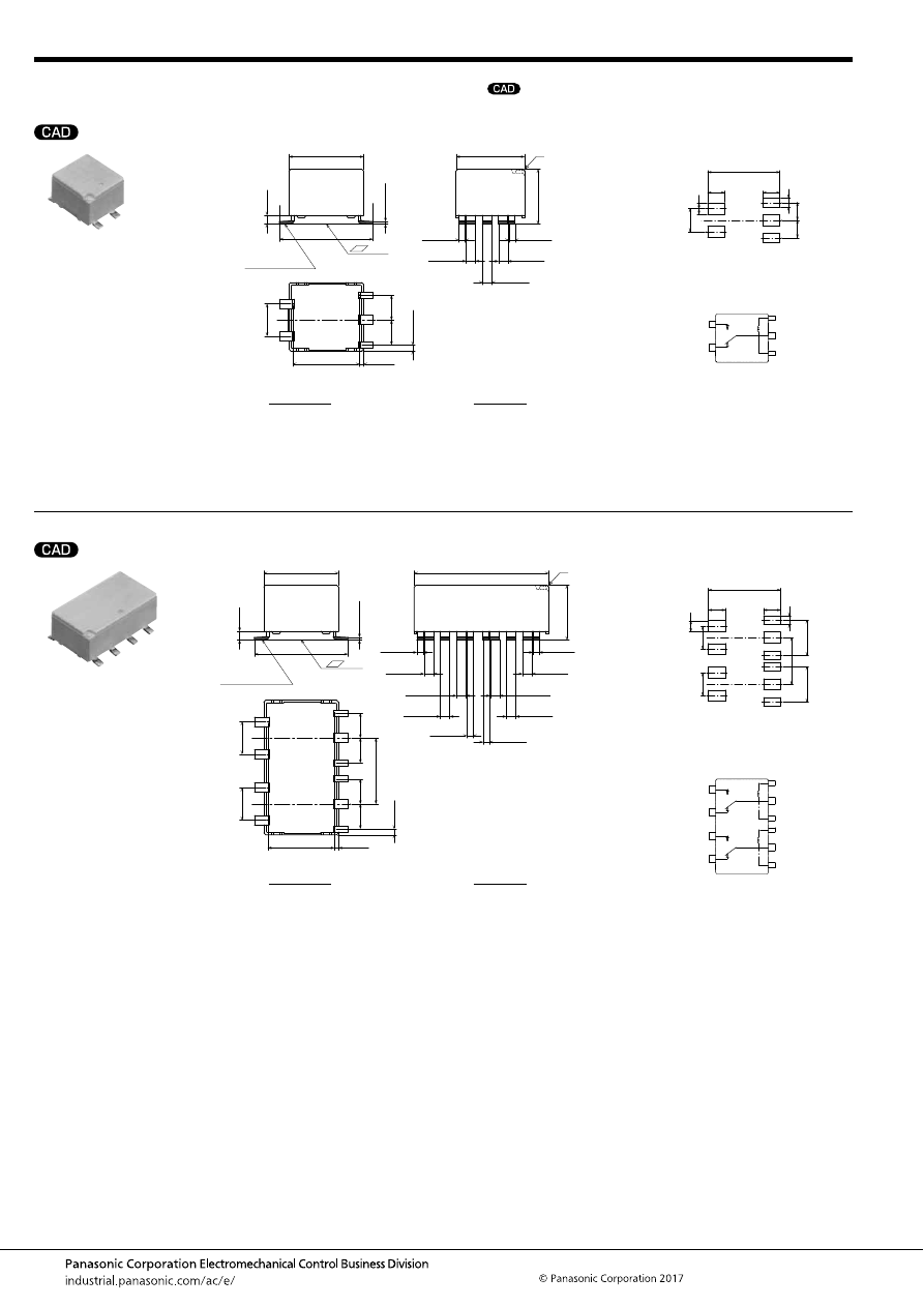
TH (ACTH)
–134–
ASCTB99E 201709-T
DIMENSIONS
(mm
inch
)
1 Form C type
Twin type (10 pins)
mark can be downloaded from: http://industrial.panasonic.com/ac/e/
The CAD data of the products with a
External dimensions
15
.591
(0.65)
(.026)
10.7
.421
11
±
0.5
.433
±
.020
12
±
0.5
.472
±
.020
1.5
.059
+
0.3
−
0.1
+
.012
−
.004
1.5
.059
+
0.3
−
0.1
+
.012
−
.004
1
.039
+
0.3
−
0.1
+
.012
−
.004
1.5
: 0.1
.059
+
0.3
−
0.1
+
.012
−
.004
1
*
.039
+
0.3
−
0.1
+
.012
−
.004
Pre-soldering
(all terminals)
1.4
.055
4
.157
4
.157
(0.95)
(.037)
5.2
.205
0.4
.016
+
0.3
−
0.1
+
.012
−
.004
8.8
±
0.5
.346
±
.020
Recommendable mounting pad
(Top view)
Tolerance:
±
0.1
±
.004
Schematic (Top view)
2
×
2
2
×
.079
3.85
16.4
.646
.152
3.85
.152
3
×
2.5
3
×
.098
4
.157
4
.157
5.2
.205
COIL
COIL
COM
N.O.
N.C.
Note: * Flux tight type has air hole.
Dimension:
Less than 1mm
.039inch
:
Min. 1
.039
less than 3mm
.118 inch
:
Min. 3mm
.118 inch
:
Tolerance
±
0.1
±
.004
±
0.2
±
.008
±
0.3
±
.012
External dimensions
15
.591
(0.65)
(.026)
10.7
.421
21.6
±
0.5
.850
±
.020
12
±
0.5
.472
±
.020
1.5
.059
+
0.3
−
0.1
+
.012
−
.004
1.5
.059
+
0.3
−
0.1
+
.012
−
.004
1.5
.059
+
0.3
−
0.1
+
.012
−
.004
1.5
.059
+
0.3
−
0.1
+
.012
−
.004
1.5
.059
+
0.3
−
0.1
+
.012
−
.004
1
.039
+
0.3
−
0.1
+
.012
−
.004
1
.039
+
0.3
−
0.1
+
.012
−
.004
1
.039
+
0.3
−
0.1
+
.012
−
.004
1.5
: 0.1
.059
+
0.3
−
0.1
+
.012
−
.004
1
*
.039
+
0.3
−
0.1
+
.012
−
.004
Pre-soldering
(all terminals)
1.4
.055
4
.157
4
.157
10.6
.417
4
.157
4
.157
(0.95)
(.037)
5.2
.205
5.2
.205
0.4
.016
+
0.3
−
0.1
+
.012
−
.004
8.8
±
0.5
.346
±
.020
Recommendable mounting pad
(Top view)
Tolerance:
±
0.1
±
.004
Schematic (Top view)
4
×
2
4
×
.079
3.85
16.4
.646
.152
3.85
.152
6
×
2.5
6
×
.098
10.6
.417
8
.315
8
.315
5.2
.205
5.2
.205
COIL
COIL
COIL
COIL
COM
COM
N.O.
N.C.
N.O.
N.C.
Note: * Flux tight type has air hole.
Dimension:
Less than 1mm
.039inch
:
Min. 1
.039
less than 3mm
.118 inch
:
Min. 3mm
.118 inch
:
Tolerance
±
0.1
±
.004
±
0.2
±
.008
±
0.3
±
.012
automotive-relay_en-html.html
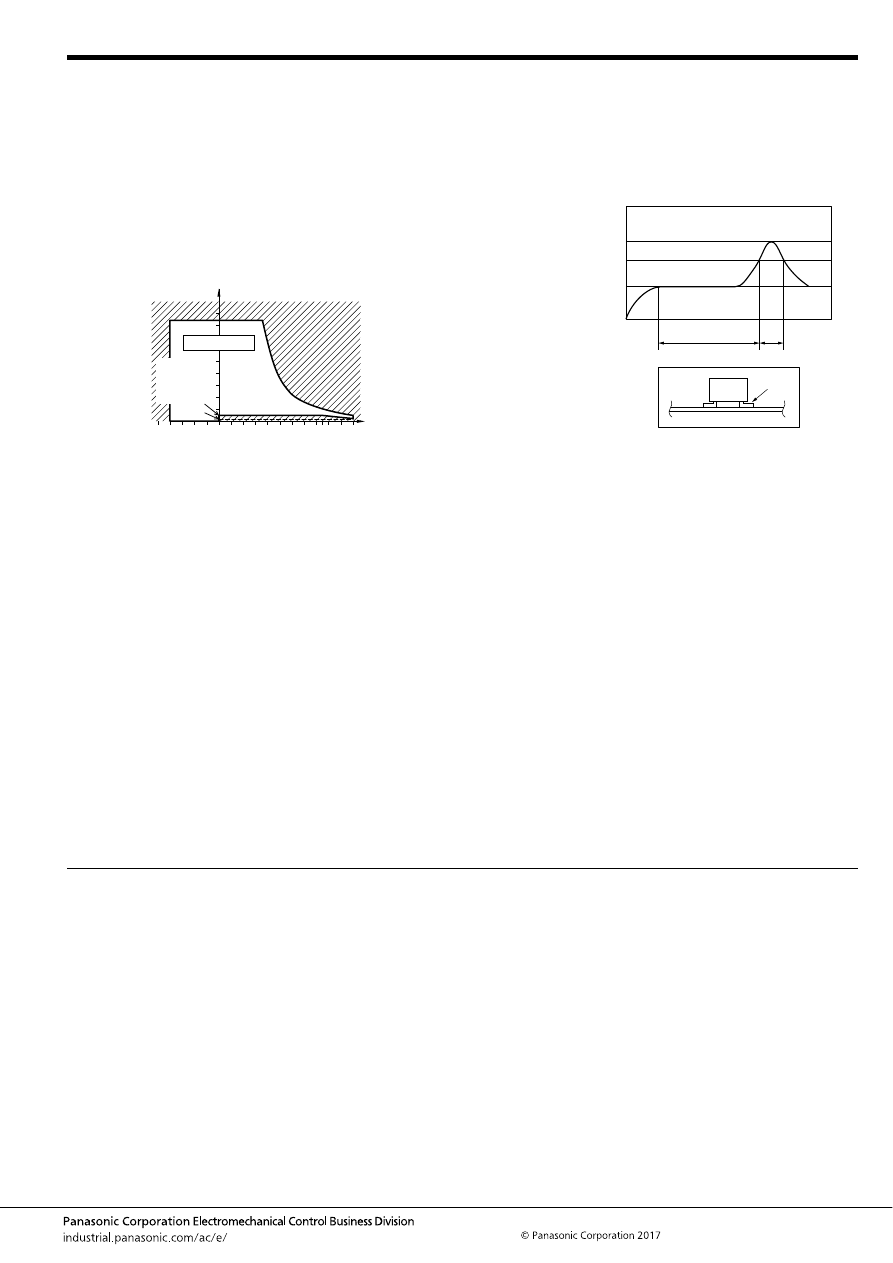
TH (ACTH)
–135–
ASCTB99E 201709-T
NOTES
For general cautions for use, please refer to the “Automotive Relay Users Guide”.
Usage, transport and storage conditions
1) Ambient temperature, humidity, and air pressure during
usage, transport, and storage of the relay:
(1) Temperature: –40 to +110
°
C
–40 to +230
°
F
(2) Humidity: 2 to 85% RH (Avoid icing and condensation.)
(3) Air pressure: 86 to 106 kPa
The humidity range varies with the temperature. Use within the
range indicated in the graph below.
[Temperature and humidity range for
usage, transport, and storage]
Mounting and cleaning conditions for Surface-mount
terminal type relays
When soldering this relay, please observe the following
conditions.
(Recommended conditions: Number of reflows: 1, Measurement
location: terminal temperature)
Temperature profile indicates the temperature of the soldered
part (Note 1) of terminals on the surface of a circuit board.
*The temperature of the relay exterior and interior may be
extremely high depending on the component density on the
board, the heating method of the reflow oven or circuit board
type. Sufficient verification under actual processing conditions is
required.
Other cautions during reflow soldering
(1) Reflow performance may be affected if you carry out
soldering in a way that exceeds the recommended
conditions. If you need to exceed the recommended
conditions when soldering, please inquire our sales
representative before using in an application.
(2) Please confirm the heat stress of relay by using actual board
because it may be changed by board condition or
manufacturing process condition.
(3) Solder creepage, wettability, or soldering strength will be
affected by the changing of soldering condition or used
solder type. Please check them under the actual production
condition in detail.
(4) Avoid cleaning (ultrasonic cleaning, boiling cleaning, etc.)
and coating in order to prevent negative impacts on relay
characteristics.
85
5
2
110
85
0
–40
+230
+185
+32
–40
Humidity, %RH
Temperature,
°
C
°
F
Tolerance range
(Avoid
condensation
when used at
temperatures
higher than
0
°
C
32
°
F
)
(Avoid icing
when used at
temperatures
lower than
0
°
C
32
°
F
)
T
3
T
2
T
1
t
1
t
2
Note 1
T
1
= 150 to 180
°
C
T
2
= 230
°
C
T
3
= Less than 250
°
C
t
1
= 60 to 120 sec.
t
2
= Less than 30 sec.
302 to 356
°
F
446
°
F
or more
482
°
F
automotive-relay_en-html.html
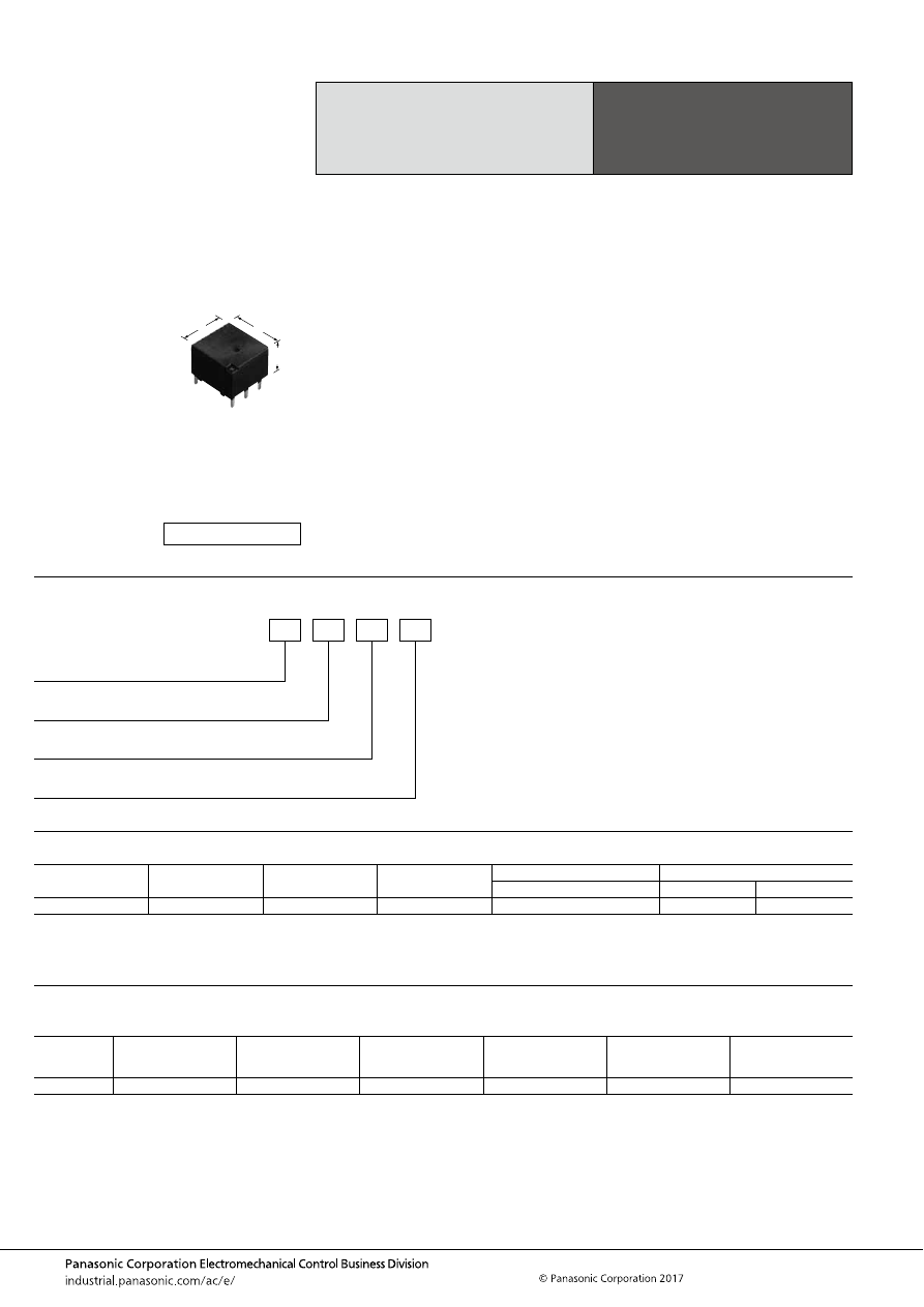
TJ (ACTJ)
–136–
ASCTB100E 201709-T
ORDERING INFORMATION
TYPES
Note: Please inquire our sales representative for details about products other than those above.
RATING
1. Coil data
Middle Load Relay
for Smart J/B
TJ RELAYS
Contact arrangement
Contact type
Rated coil voltage
Coil resistance
Part No.
Packing
High heat-resistant type
Carton (tube)
Case
1 Form C
Standard type
12V DC
320
Ω
ACTJ2H4
40 pcs.
800 pcs.
Rated coil
voltage
Operate (Set) voltage
(at 20
°
C
68
°
F
) (Initial)
Release (Reset)
voltage
(at 20
°
C
68
°
F
) (Initial)
Rated operating current
[
±
10%] (at 20
°
C
68
°
F
)
Coil resistance
[
±
10%] (at 20
°
C
68
°
F
)
Rated operating power
(at 20
°
C
68
°
F
)
Usable voltage range
12V DC
Max. 7.0V DC
Min. 0.8V DC
37.5 mA
320
Ω
450 mW
10 to 16V DC
FEATURES
• Compact flat type (Height: 11.2mm
.441inch
)
• Compact and high-capacity 30A load switching.
TYPICAL APPLICATIONS
• Head lamp, Fog lamp, Fan motor, Defogger, Seat heater,
etc.
<Protective construction>
Sealed
16
15
11.2
.630
.591
.441
(Unit: mm
inch
)
RoHS compliant
Contact arrangement
2: 1 Form C
Contact type
Nil: Standard type
ACTJ
Heat resistance/Protective construction
H: High heat-resistant type/Sealed
Coil resistance
4: 320
Ω
automotive-relay_en-html.html
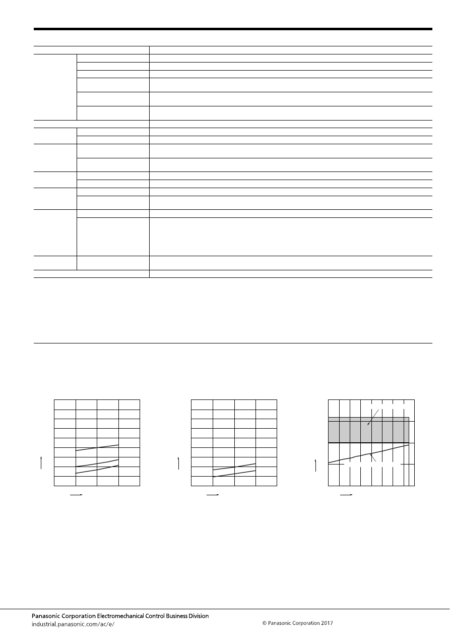
TJ (ACTJ)
–137–
ASCTB100E 201709-T
2. Specifications
Notes: *1. Depends on connection conditions. Also, this does not guarantee repeated switching. We recommend that you confirm operation under actual conditions.
*2. This value can change due to the switching frequency, environmental conditions, and desired reliability level, therefore it is recommended to check this with the
actual load.
*3. The upper operation ambient temperature limit is the maximum temperature that can satisfy the coil temperature rise value. For details, please refer to the
“Automotive Relay Users Guide”.
Please inquire our sales representative if you will be using the relay in a high temperature atmosphere (110
°
C
230
°
F
).
REFERENCE DATA
Item
Specifications
Contact data
Contact arrangement
1 Form C
Contact resistance (initial)
Max. 50m
Ω
(N.O. side: typ. 2.5m
Ω
, N.C. side: typ. 3m
Ω
) (By voltage drop 1A 6V DC)
Contact material
Ag alloy
Rated switching capacity
(resistive)
N.O. side: 30A 14V DC, N.C. side: 15A 14V DC
Max. carrying current
(initial)*
1
30A for 1 hour (Coil applied voltage 12V DC, at 20
°
C
68
°
F
)
Min. switching load
(resistive)*
2
1A 14V DC (at 20
°
C
68
°
F
)
Insulated resistance (initial)
Min. 100 M
Ω
(at 500V DC, Measurement at same location as “Dielectric strength” section.)
Dielectric
strength (initial)
Between open contacts
500 Vrms for 1 min. (Detection current: 10mA)
Between contacts and coil
500 Vrms for 1 min. (Detection current: 10mA)
Time
characteristics
(initial)
Operate (Set) time
(at rated voltage)
Max. 10ms (at 20
°
C
68
°
F
, without contact bounce time)
Release (Reset) time
(at rated voltage)
Max. 10ms (at 20
°
C
68
°
F
, without contact bounce time) (Without diode)
Shock
resistance
Functional
Min. 100 m/s
2
{approx. 10G} (Half-wave pulse of sine wave: 11ms; detection time: 10
μ
s)
Destructive
Min. 1,000 m/s
2
{approx. 100G} (Half-wave pulse of sine wave: 6ms)
Vibration
resistance
Functional
10 to 100 Hz, Min. 44.1 m/s
2
{approx. 4.5G} (Detection time: 10
μ
s)
Destructive
10 to 500 Hz, Min. 44.1 m/s
2
{approx. 4.5G},
Time of vibration for each direction; X, Y direction: 2 hours, Z direction: 4 hours
Expected life
Mechanical
Min. 10
7
(at 120 cpm)
Electrical
<Resistive load>
Min. 10
5
at rated switching capacity, operating frequency: 1s ON, 9s OFF
<Motor load>
Min. 10
5
25 A 14V DC at motor lock condition, operating frequency: 0.5s ON, 9.5s OFF
<Lamp load>
Min. 10
5
at 84 A (inrush), 12 A (steady), 14 V DC, Operating frequency: 1s ON, 14s OFF
Conditions
Conditions for usage,
transport and storage*
3
Ambient temperature: –40 to +110
°
C
–40 to +230
°
F
, Humidity: 2 to 85% R.H. (Please avoid icing or condensation)
Weight
Approx. 7 g
.25 oz
1.-(1) Coil temperature rise (at room
temperature)
Sample: ACTJ2H4, 3pcs.
Carrying current: 10A, 20A, 30A
Ambient temperature: Room temperature
1.-(2) Coil temperature rise (at 110
°
C
230
°
F
)
Sample: ACTJ2H4, 3pcs.
Carrying current: 10A, 20A
Ambient temperature: 110
°
C
230
°
F
2. Ambient temperature and usable voltage
range
Sample: ACTJ2H4
18
Coil applied voltage, V
T
e
mper
ature r
ise
,
°
C
16
14
12
10
30A
20A
10A
180
160
140
120
100
80
60
40
20
0
18
Coil applied voltage, V
T
e
mper
ature r
ise
,
°
C
16
14
12
10
20A
10A
180
160
140
120
100
80
60
40
20
0
Ambient temperature,
°
C
Coil applied v
oltage
,
V
120
-40 -20
0
20
15
10
5
0
20
40
60
80
100
Operate voltage (Cold start)
Usable voltage range
automotive-relay_en-html.html
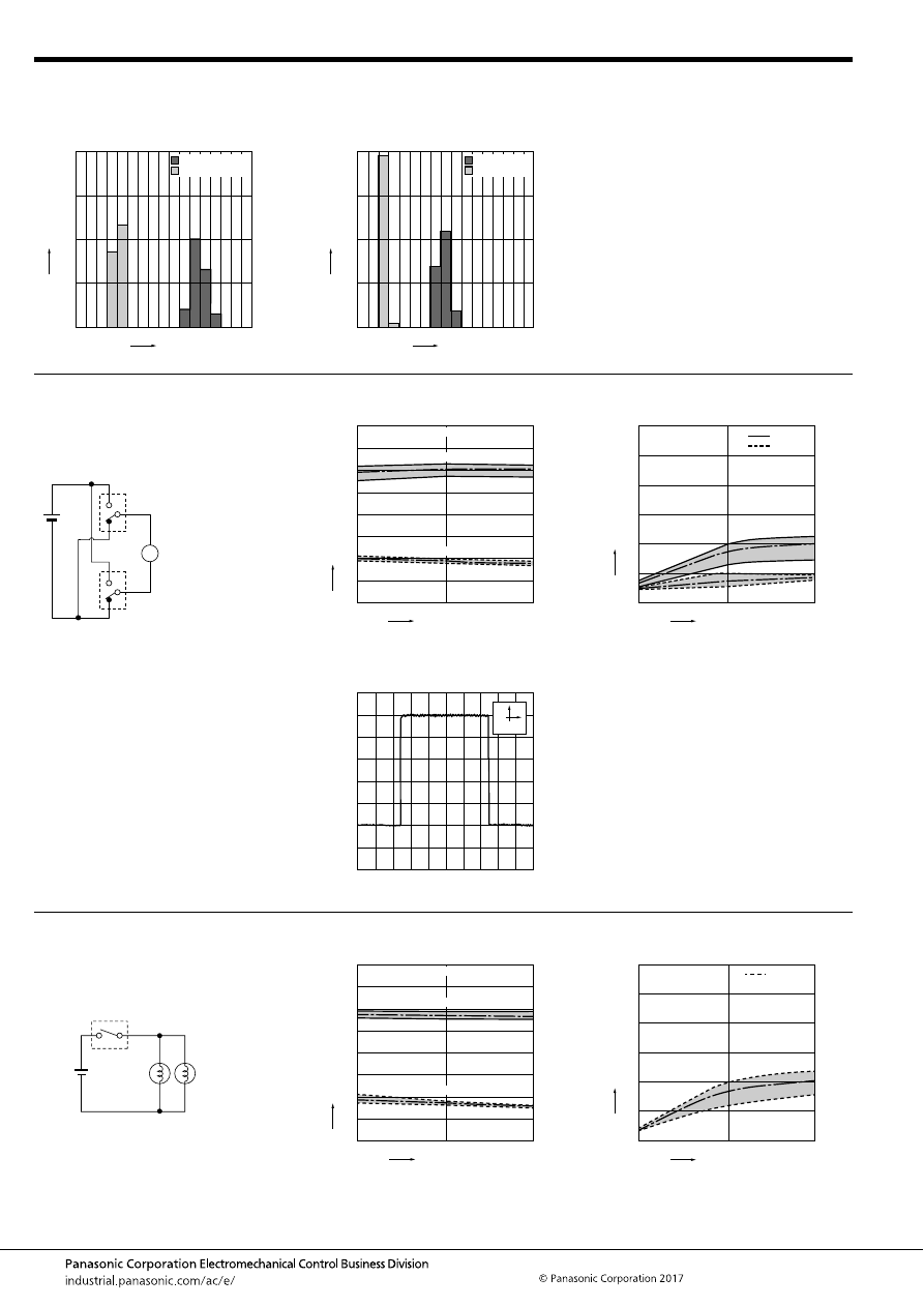
TJ (ACTJ)
–138–
ASCTB100E 201709-T
3. Distribution of operate (set) and release
(reset) voltage
Sample: ACTJ2H4, 40pcs.
4. Distribution of operate (set) and release
(reset) time
Sample: ACTJ2H4, 40pcs.
Voltage, V
Quantity
, n
8
0
40
30
20
10
0
1
2
3
4
5
6
7
Operate voltage
Release voltage
Time, ms
Quantity
, n
8
0
40
30
20
10
0
1
2
3
4
5
6
7
Operate time
Release time
* Without diode
5.-(1) Electrical life test (Motor lock)
Sample: ACTJ2H4, 6pcs.
Load: 25A 14V DC
Power window motor actual load (lock condition)
Operating frequency: ON 0.5s, OFF 9.5s
Ambient temperature: Room temperature
Circuit:
Change of operate (set) and release (reset)
voltage
Change of contact resistance
M
10
5
Operate voltage
Release voltage
0
8
7
6
5
4
3
2
1
0
Max.
Min.
Ave.
Max.
Min.
Ave.
Oper
ate and release v
oltage
,
V
No. of operations,
×
10
4
Contact welding: 0 time
Miscontact: 0 time
Max.
Min.
Ave.
Max.
Min.
Ave.
10
5
0
30
25
20
15
10
5
0
Contact resistance
, m
Ω
No. of operations,
×
10
4
N.C. side
N.O. side
Load current waveform
Current value: 25A
100ms
5A
5.-(2) Electrical life test (Lamp load)
Sample: ACTJ2H4, 6pcs.
Load: inrush current: 84A, steady current: 12A 14V
DC
Operating frequency: ON 1s, OFF 14s
Ambient temperature: Room temperature
Circuit:
Change of operate (set) and release (reset)
voltage
Change of contact resistance
14V DC
60W
60W
10
5
Operate voltage
Release voltage
0
8
7
6
5
4
3
2
1
0
Max.
Min.
Ave.
Max.
Min.
Ave.
Oper
ate and release v
oltage
,
V
No. of operations,
×
10
4
Contact welding: 0 time
Miscontact: 0 time
Max.
Min.
Ave.
10
5
0
30
25
20
15
10
5
0
Contact resistance
, m
Ω
No. of operations,
×
10
4
N.O. side
automotive-relay_en-html.html
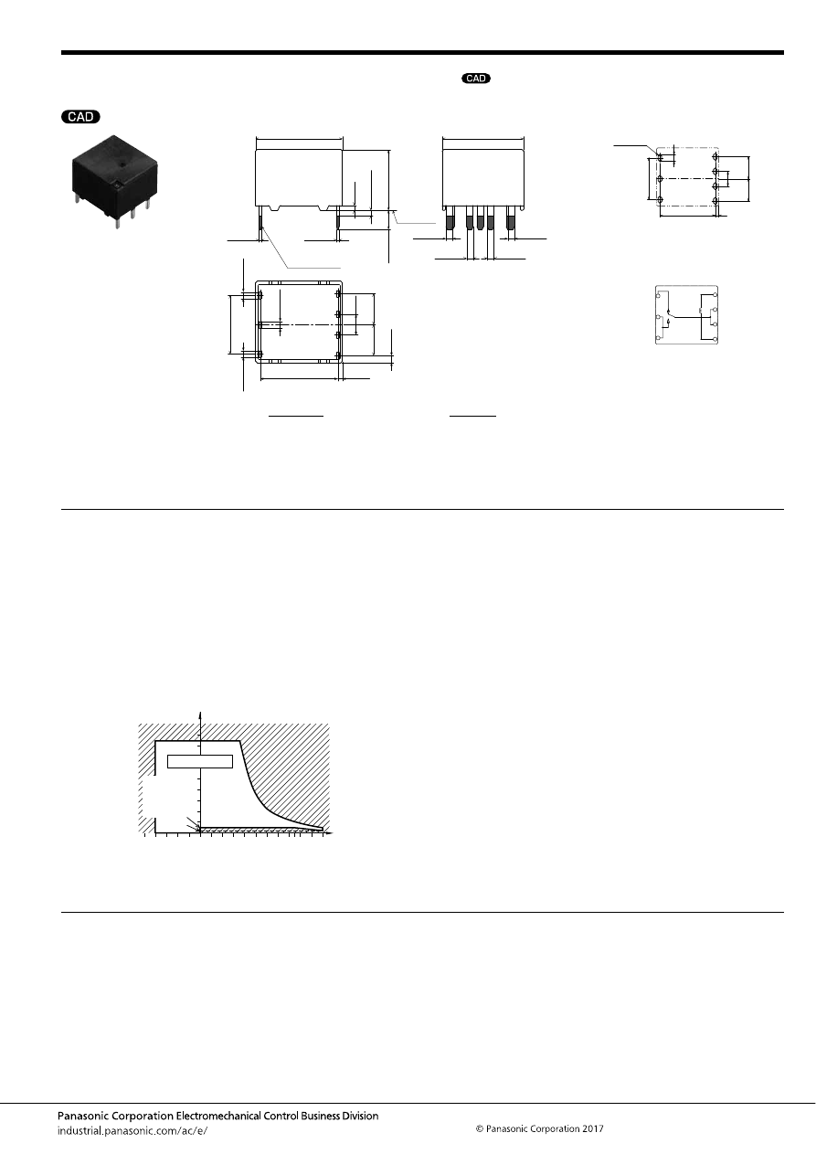
TJ (ACTJ)
–139–
ASCTB100E 201709-T
DIMENSIONS
(mm
inch
)
1 Form C type
NOTES
For general cautions for use, please refer to the “Automotive Relay Users Guide”.
mark can be downloaded from: http://industrial.panasonic.com/ac/e/
The CAD data of the products with a
External dimensions
A surface
level
16
±
0.5
.630
±
.020
15
±
0.5
.591
±
.020
14.3
.563
(0.85)
(.033)
1.2
.047
+
0.3
−
0.1
+
.012
−
.004
0.4
.016
+
0.3
−
0.1
+
.012
−
.004
0.4
.016
+
0.3
−
0.1
+
.012
−
.004
1.2
.047
+
0.3
−
0.1
+
.012
−
.004
1.2
.047
+
0.3
−
0.1
+
.012
−
.004
1.2
.047
+
0.3
−
0.1
+
.012
−
.004
Pre-soldering
(all terminals)
Max.
1.0
Max.
.039
11.2
±
0.5
.441
±
.020
3.5
±
0.5
.138
±
.020
1.2
.047
+
0.3
−
0.1
+
.012
−
.004
1.2
.047
+
0.3
−
0.1
+
.012
−
.004
1.2
.047
+
0.3
−
0.1
+
.012
−
.004
3.8
.150
0.9
.035
(1.3)
(.051)
5.7
.224
10.8
.425
5.7
.224
PC board pattern (Bottom view)
Tolerance:
±
0.1
±
.004
Schematic (Bottom view)
14.3
4
×
R 0.45
4
×
R .018
1.7
.067
.563
(0.85)
(.033)
5.7
.224
3.8
.150
5.7
.224
10.8
.425
N.C.
N.O.
COM
COIL
COIL
* Dimensions (thickness and width) of terminal is measured after pre-soldering.
Intervals between terminals is measured at A surface level.
Dimension:
Less than 1mm
.039inch
:
Min. 1
.039
less than 3mm
.118 inch
:
Min. 3mm
.118 inch
:
Tolerance
±
0.1
±
.004
±
0.2
±
.008
±
0.3
±
.012
Usage, transport and storage conditions
1) Ambient temperature, humidity, and air pressure during
usage, transport, and storage of the relay:
(1) Temperature: –40 to +110
°
C
–40 to +230
°
F
(2) Humidity: 2 to 85% RH (Avoid icing and condensation.)
(3) Air pressure: 86 to 106 kPa
The humidity range varies with the temperature. Use within the
range indicated in the graph below.
[Temperature and humidity range for
usage, transport, and storage]
85
5
2
110
85
0
–40
+230
+185
+32
–40
Humidity, %RH
Temperature,
°
C
°
F
Tolerance range
(Avoid
condensation
when used at
temperatures
higher than
0
°
C
32
°
F
)
(Avoid icing
when used at
temperatures
lower than
0
°
C
32
°
F
)
automotive-relay_en-html.html
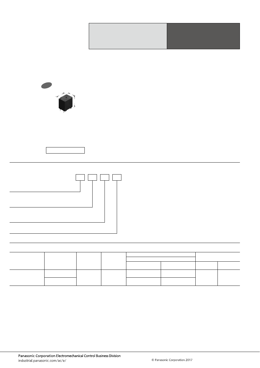
TL (ACTL)
–140–
ASCTB378E 201709-T
ORDERING INFORMATION
TYPES
High Load Relay
for Smart Junction Box
TL RELAYS
Contact arrangement
Contact type
Rated coil
voltage
Coil resistance
Part No.
Packing
Heat resistance
High heat-resistant type
Pin in Paste compliant
type
Carton
Case
Double make contact
2 Form A
Standard type
(Ag alloy / Cu clad)
12V DC
225
Ω
ACTL3CH3
ACTL3CR3
50 pcs.
2,000 pcs.
Lamp control type
(Ag alloy / Cu clad)
ACTL3DH3
ACTL3DR3
FEATURES
• Large capacity switching despite small size. Can replace
micro ISO terminal type relays.
• 40A and supports fuse
• Pin in Paste compliant model added
TYPICAL APPLICATIONS
• Head lamp, Fog lamp, Fan motor, etc.
<Protective construction>
High heat-resistant type: Sealed
Pin in Paste compliant type: Flux tight
11
14.4
16
.433
.567
.630
New
(Unit: mm
inch
)
RoHS compliant
Contact arrangement
3: Double make contact 2 Form A
ACTL
Contact type
C: Standard type (Ag alloy / Cu clad)
D: Lamp control type (Ag alloy / Cu clad)
Heat resistance/Protective construction
H: High heat-resistant type/Sealed
R: Pin in Paste compliant type/Flux tight
Coil resistance
3: 225
Ω
automotive-relay_en-html.html
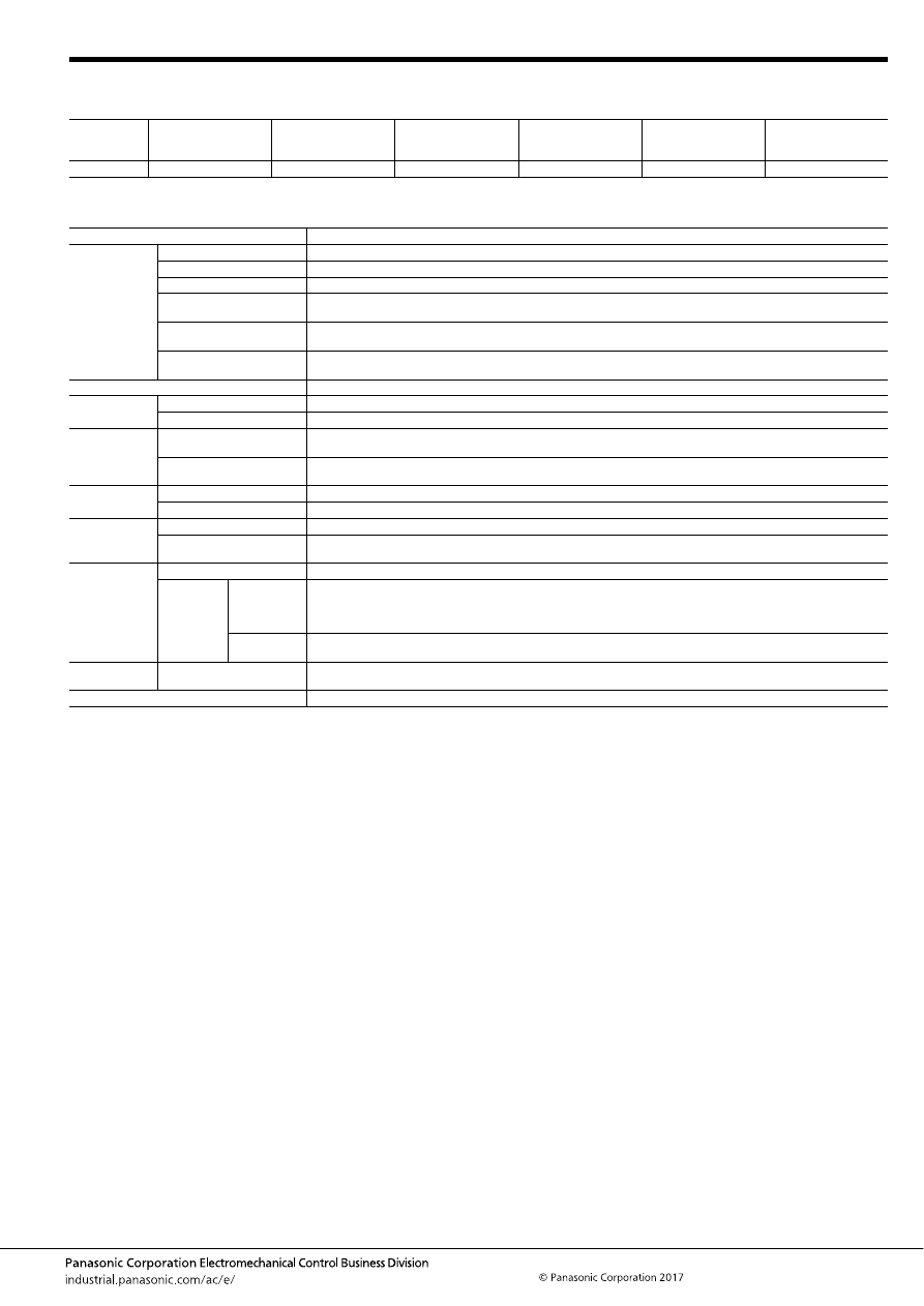
TL (ACTL)
–141–
ASCTB378E 201709-T
RATING
1. Coil data
Note: Other operate (set) voltage types are also available. Please inquire our sales representative for details.
2. Specifications
Notes: *1. Depends on connection conditions. Also, this does not guarantee repeated switching. We recommend that you confirm operation under actual conditions.
*2. This value can change due to the switching frequency, environmental conditions, and desired reliability level, therefore it is recommended to check this with the
actual load.
*3. The upper operation ambient temperature limit is the maximum temperature that can satisfy the coil temperature rise value. For details, please refer to the
“Automotive Relay Users Guide”.
Please inquire our sales representative if you will be using the relay in a high temperature atmosphere (110
°
C
230
°
F
).
*4. When using the lamp control type, connect N.O. to the “+ (plus)” side. Please inquire our sales representative for details.
Rated coil
voltage
Operate (Set) voltage
(at 20
°
C
68
°
F
) (Initial)
Release (Reset)
voltage
(at 20
°
C
68
°
F
) (Initial)
Rated operating current
[
±
10%] (at 20
°
C
68
°
F
)
Coil resistance
[
±
10%] (at 20
°
C
68
°
F
)
Rated operating power
(at 20
°
C
68
°
F
)
Usable voltage range
12 V DC
Max. 6.5 V DC
Min. 0.5 V DC
53.3 mA
225
Ω
640 mW
10 to 16 V DC
Item
Specifications
Contact data
Contact arrangement
Double make contact 2 Form A
Contact resistance (initial)
Max. 50m
Ω
(Typ. 2m
Ω
) (By voltage drop 1A 6V DC)
Contact material
Ag alloy
Rated switching capacity
(resistive)
40A 14V DC
Max. carrying current
(initial)*
1
40A/1 hour (14V DC, at 20
°
C
68
°
F
)
Min. switching load
(resistive)*
2
1A 14V DC (at 20
°
C
68
°
F
)
Insulated resistance (initial)
Min. 100 M
Ω
(at 500V DC, Measurement at same location as “Dielectric strength” section.)
Dielectric
strength (initial)
Between open contacts
500 Vrms for 1 min. (Detection current: 10mA)
Between contacts and coil
500 Vrms for 1 min. (Detection current: 10mA)
Time
characteristics
(initial)
Operate (Set) time
(at rated voltage)
Max. 10ms (at 20
°
C
68
°
F
, without contact bounce time)
Release (Reset) time
(at rated voltage)
Max. 10ms (at 20
°
C
68
°
F
, without contact bounce time) (Without diode)
Shock
resistance
Functional
Min. 100 m/s
2
{approx. 10G} (Half-wave pulse of sine wave: 11ms; detection time: 10
μ
s)
Destructive
Min. 1,000 m/s
2
{approx. 100G} (Half-wave pulse of sine wave: 6ms)
Vibration
resistance
Functional
10 to 100 Hz, Min. 44.1m/s
2
{approx. 4.5G} (Detection time: 10
μ
s)
Destructive
10 to 500 Hz, Min. 44.1m/s
2
{approx. 4.5G}
Time of vibration for each direction; X, Y direction: 2 hours, Z direction: 4 hours
Expected life
Mechanical
Min. 5
×
10
6
(at 120 cpm)
Electrical
Standard type
<Resistive load>
Min. 10
5
at rated switching capacity, operating frequency: ON 1s, OFF 2s
<Resistive and capacitor loads>
Min. 10
5
: at 90 A (inrush), 20 A (steady), 14 V DC, Operating frequency: ON 0.15s, OFF 4.85s
Lamp control
type*
4
<Lamp load>
Min. 10
5
: at 120 A (inrush), 14 A (steady), 14 V DC, Operating frequency: ON 1s, OFF 14s
Conditions
Conditions for usage,
transport and storage*
3
Ambient temperature: –40 to +110
°
C
–40 to +230
°
F
, Humidity: 2 to 85% R.H. (Please avoid icing or condensation)
Weight
Approx. 6.5 g
.23 oz
automotive-relay_en-html.html
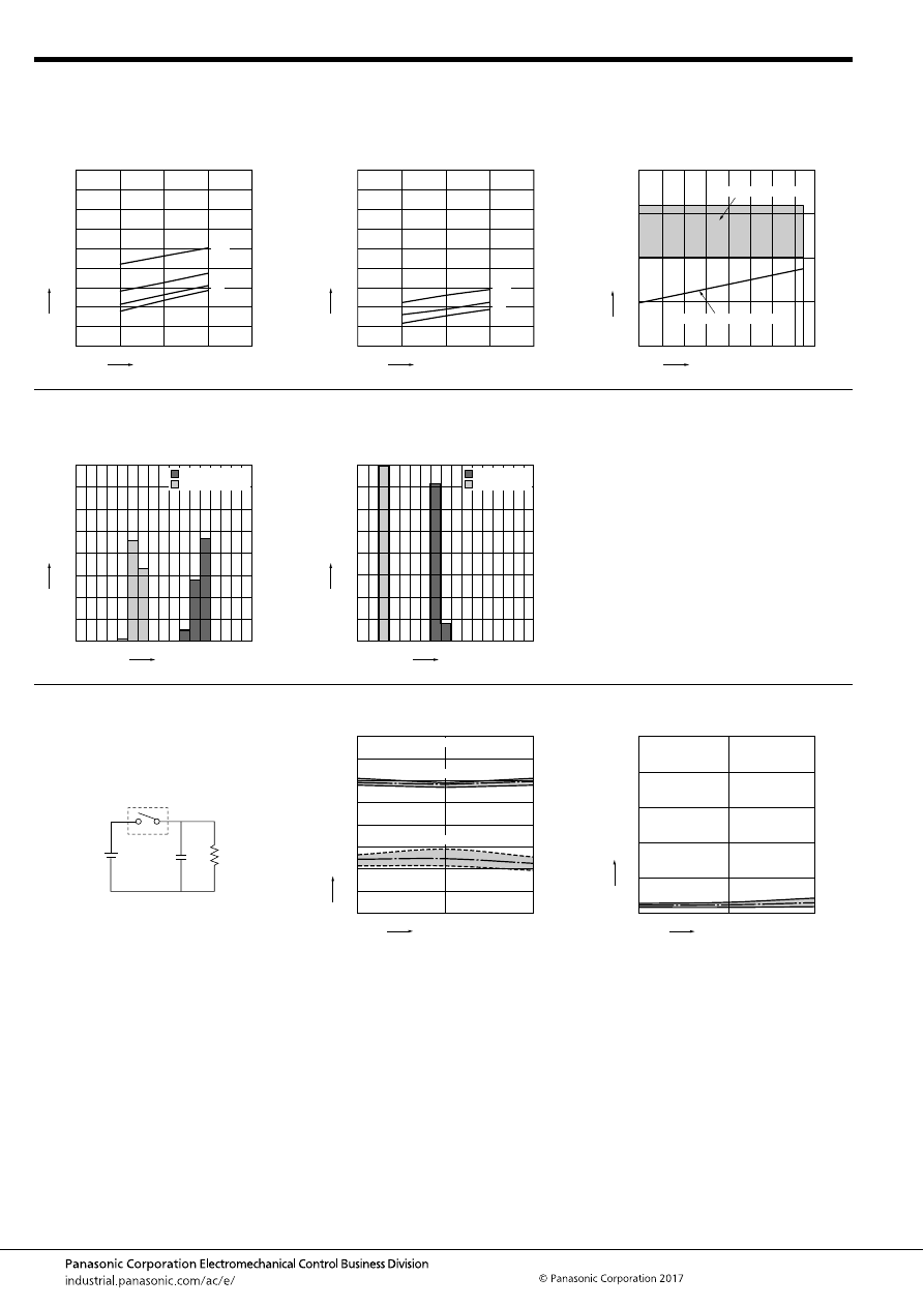
TL (ACTL)
–142–
ASCTB378E 201709-T
REFERENCE DATA
1-(1). Coil temperature rise
Sample: ACTL3CR3, 3pcs
Carrying current: 0A, 10A, 20A, 30A
Ambient temperature: Room temperature
1-(2). Coil temperature rise (110
°
C
230
°
F
)
Sample: ACTL3CR3, 3pcs
Carrying current: 0A, 10A, 20A
Ambient temperature: 110
°
C
230
°
F
2. Ambient temperature and usable voltage
range
Sample: ACTL3CR3
0
140
160
180
80
60
40
20
12
14
16
18
10
100
120
Coil applied voltage, V
T
e
mper
ature r
ise
,
°
C
10A
0A
20A
30A
0
140
160
180
80
60
40
20
12
14
16
18
10
100
120
Coil applied voltage, V
T
e
mper
ature r
ise
,
°
C
10A
0A
20A
-40
-20
0
20
40
60
80
100 120
20
15
10
5
0
Operate voltage (cold start)
Ambient temperature,
°
C
Coil applied v
oltage
,
V
Usable voltage range
3. Distribution of operate (set) and release
(reset) voltage
Sample: ACTL3CR3, 80pcs.
4. Distribution of operate (set) and release
(reset) time
Sample: ACTL3CR3, 80pcs.
0
40
30
20
10
60
50
80
70
5
4
3
2
1
0
6
7
8
Voltage, V
Quantity
, n
Operate voltage
Release voltage
5
4
3
2
1
0
6
7
8
0
40
30
20
10
60
50
80
70
Time, ms
Quantity
, n
Operate time
Release time
* Without diode
5-(1). Electrical life test (Resistive and
capacitor load)
Sample: ACTL3CR3, 6pcs.
Load: Inrush current: 90A, Steady current: 20A 14V
DC
Operating frequency: ON 0.15s, OFF 4.85s
Ambient temperature: Room temperature
Circuit:
Change of operate (set) and release (reset)
voltage
Change of contact resistance
10
5
Operate voltage
Release voltage
0
8
7
6
5
4
3
2
1
0
Max.
Min.
Ave.
Max.
Min.
Ave.
Oper
ate and release v
oltage
,
V
No. of operations,
×
10
4
Contact welding: 0 time
Miscontact: 0 time
10
5
0
50
40
30
20
10
0
Min.
Max.
Ave.
Contact resistance
, m
Ω
No. of operations,
×
10
4
automotive-relay_en-html.html
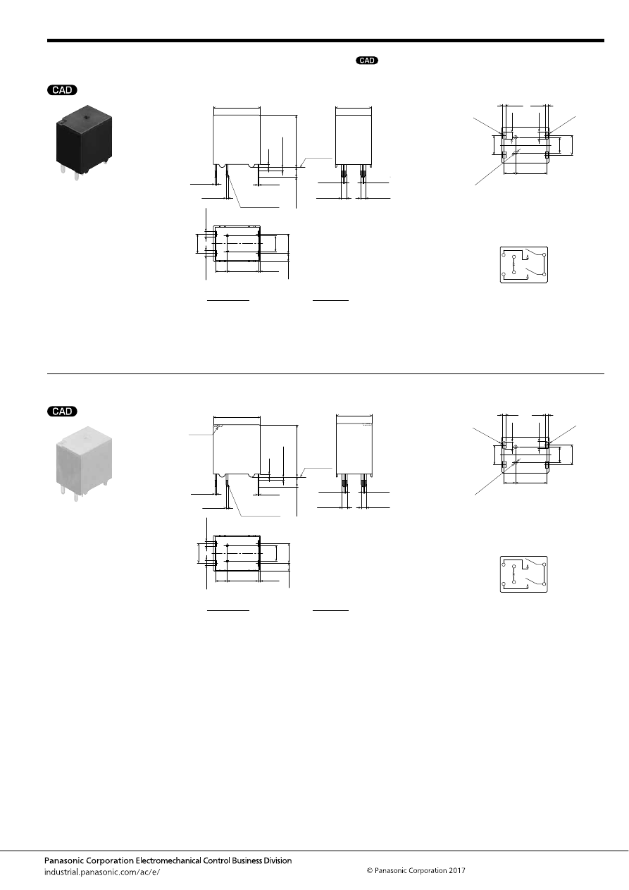
TL (ACTL)
–143–
ASCTB378E 201709-T
DIMENSIONS
(mm
inch
)
Double make contact 2 Form A type
Double make contact 2 Form A type
mark can be downloaded from: http://industrial.panasonic.com/ac/e/
The CAD data of the products with a
External dimensions
9.6
3.5
4.8
(0.6)
.378
.138
(.024)
(2.5)
.189
6
.236
5.9
.232
(.098)
Pre-soldering
(all terminals)
A surface
level
11
±
0.5
.433
±
.020
14.4
±
0.5
.567
±
.020
Max.
1.0
Max.
.039
0.9
.035
16
±
0.5
.630
±
.020
3
±
0.5
.118
±
.020
0.5
.020
+
0.3
−
0.1
+
.012
−
.004
0.6
.024
+
0.3
−
0.1
+
.012
−
.004
0.3
.012
+
0.3
−
0.1
+
.012
−
.004
0.3
.012
+
0.3
−
0.1
+
.012
−
.004
0.3
.012
+
0.3
−
0.1
+
.012
−
.004
1.6
.063
+
0.3
−
0.1
+
.012
−
.004
1.6
.063
+
0.3
−
0.1
+
.012
−
.004
1.6
.063
+
0.3
−
0.1
+
.012
−
.004
1.6
.063
+
0.3
−
0.1
+
.012
−
.004
PC board pattern (Bottom view)
Tolerance:
±
0.1
±
.004
Schematic (Bottom view)
4.8
6
9.6
.378
3.5
.138
5.9
.189
.236
.232
0.9
2
×
R1
2
×
R.039
2.2
1.1
.035
.043
2
×
R1.1
2
×
R.043
2.2
.087
.087
2
×
1.1 dia.
2
×
.043 dia.
COM
COM
COIL
COIL
N.O.
N.O.
N.O.
* The lamp control type has polarized contacts.
Connect N.O. to the “+ (plus)” side.
* Dimensions (thickness and width) of terminal is measured after pre-soldering.
Intervals between terminals is measured at A surface level.
Dimension:
Tolerance
Max. 1mm
.039 inch
:
±
0.1
±
.004
1 to 3mm
.039 to .118 inch
:
±
0.2
±
.008
Min. 3mm
.118 inch
:
±
0.3
±
.012
Pin in Paste compliant type
External dimensions
9.6
3.5
4.8
(0.6)
.378
.138
(.024)
(2.5)
.189
6
.236
5.9
.232
(.098)
Pre-soldering
(all terminals)
A surface
level
11
±
0.5
.433
±
.020
14.4
±
0.5
.567
±
.020
Max.
1.0
Max.
.039
0.9
.035
16
±
0.5
.630
±
.020
3
±
0.5
.118
±
.020
0.5
.020
+
0.3
−
0.1
+
.012
−
.004
0.6
.024
+
0.3
−
0.1
+
.012
−
.004
0.3
.012
+
0.3
−
0.1
+
.012
−
.004
0.3
.012
+
0.3
−
0.1
+
.012
−
.004
0.3
.012
+
0.3
−
0.1
+
.012
−
.004
1.6
.063
+
0.3
−
0.1
+
.012
−
.004
1.6
.063
+
0.3
−
0.1
+
.012
−
.004
1.6
.063
+
0.3
−
0.1
+
.012
−
.004
1.6
.063
+
0.3
−
0.1
+
.012
−
.004
Air hole
PC board pattern (Bottom view)
Tolerance:
±
0.1
±
.004
Schematic (Bottom view)
4.8
6
9.6
.378
3.5
.138
5.9
.189
.236
.232
0.9
2
×
R1
2
×
R.039
2.2
1.1
.035
.043
2
×
R1.1
2
×
R.043
2.2
.087
.087
2
×
1.1 dia.
2
×
.043 dia.
COM
COM
COIL
COIL
N.O.
N.O.
N.O.
* The lamp control type has polarized contacts.
Connect N.O. to the “+ (plus)” side.
* Dimensions (thickness and width) of terminal is measured after pre-soldering.
Intervals between terminals is measured at A surface level.
Dimension:
Tolerance
Max. 1mm
.039 inch
:
±
0.1
±
.004
1 to 3mm
.039 to .118 inch
:
±
0.2
±
.008
Min. 3mm
.118 inch
:
±
0.3
±
.012
automotive-relay_en-html.html
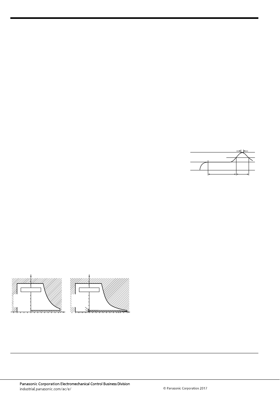
TL (ACTL)
–144–
ASCTB378E 201709-T
NOTES
For general cautions for use, please refer to the “Automotive Relay Users Guide”.
1. Coil operating power
Pure DC current should be applied to the coil. If it includes
ripple, the ripple factor should be less than 5%. However, check
it with the actual circuit since the characteristics may be slightly
different. Also, the power waveform should be rectangular.
2. Coil applied voltage
To ensure proper operation, the voltage applied to the coil
should be the rated operating voltage of the coil. Also, be aware
that the pick-up and drop-out voltages will fluctuate depending
on the ambient temperature and operating conditions.
3. Expected life
Check this with the real device as it is affected by coil driving
circuit, load type, activation frequency, activation phase, ambient
conditions and other factors.
4. Soldering
When soldering the relays, ensure conformance with the
conditions listed below.
1) Automatic soldering
Preheating soldering: 100
°
C
212
°
F
, within 2 sec (surface of PC
board)
Soldering: 260
°
C
500
°
F
, within 5 sec
2) Manual soldering
Tip temperature: 280 to 300
°
C
536 to 572
°
F
.
Soldering iron: 30 to 60W
Soldering time: within 5 sec
5. Usage, transport and storage conditions
1) Ambient temperature, humidity, and air pressure during
usage, transport, and storage of the relay:
(1) Temperature:
–40 to +85
°
C
–40 to +185
°
F
(Standard type)
–40 to +110
°
C
–40 to +230
°
F
(High heat-resistant type)
(2) Humidity: 2 to 85% RH (Avoid icing and condensation.)
(3) Air pressure: 86 to 106 kPa
The humidity range varies with the temperature. Use within the
range indicated in the graph below.
[Temperature and humidity range for usage, transport,
and storage]
2) Condensation
Condensation forms when there is a sudden change in
temperature under high temperature and high humidity
conditions. Condensation will cause deterioration of the relay
insulation.
3) Icing
Condensation or other moisture may ice on the relay when the
temperature is lower than 0
°
C
32
°
F
. This causes problems such
as sticking of movable parts, operational time lags or poor
contact conduction.
4) Low temperature and low humidity environments
The plastic becomes brittle if the relay is exposed to a low
temperature, low humidity environment for long periods of time.
6. Mounting and cleaning conditions for Pin-in-Paste
compliant type
When soldering this relay, please observe the following
conditions.
[I.R.S. method (recommended)]
(Recommended number of reflows: 1)
• Cautions for mounting
1. The temperature profile shows the temperature at the
soldering portion on the PCB surface.
2. Depending on the mounting density condition, reflow
heating method, and PCB type (metal etc.), the relay’s
exterior and interior temperature may become extremely
high.
Therefore, please confirm well under the actual use
condition before use.
The other cautions of reflow soldering:
1. When soldering condition is out of recommendation, the
relay performance may be adversely affected.
If soldering conditions are out of our recommendation,
please contact us before operation.
2. Please check the effect at the actual soldering because
heat stress to relay is changed by PCB type and
manufacturing process condition.
3. Solder creepage, wettability or soldering strength will be
affected by the mounting condition or soldering material.
Please check the actual production condition in detail.
4. Do not wash the relay as failures may occur.
5. This product is not plastic sealed type. Please perform
coating with sufficient attention to avoid infiltration of the
solvent to the inside. Also, please pay careful attention to
use and store them with no contamination of foreign
material.
7. Others handling precautions
Do not use relays that have been dropped, because doing so
may be a cause of faulty operation.
85
5
Humidity, %RH
Tolerance range
(Avoid
condensation
when used at
temperatures
higher than
0
°
C
32
°
F
)
(Avoid icing
when used at
temperatures
lower than
0
°
C
32
°
F
)
85
0
–40
+185
+32
–40
Temperature,
°
C
°
F
85
5
2
110
85
0
–40
+230
+185
+32
–40
Humidity, %RH
Temperature,
°
C
°
F
Tolerance range
(Avoid
condensation
when used at
temperatures
higher than
0
°
C
32
°
F
)
(Avoid icing
when used at
temperatures
lower than
0
°
C
32
°
F
)
Standard type
High heat-resistant type
t
1
= 60 to 120 sec.
t
2
= Less than 30 sec.
t
3
= Less than 5 sec.
T
1
= 150 to 180
°
C
T
2
= 230
°
C
T
3
= Less than 250
°
C
302 to 356
°
F
446
°
F
or more
482
°
F
T
1
T
3
T
2
t
1
t
2
t
3
automotive-relay_en-html.html
TM (ACTM)
–145–
ASCTB379E 201709-T
ORDERING INFORMATION
TYPES
High Capacity Relay
for Smart Junction Box
TM RELAYS
Contact arrangement
Contact type
Rated coil voltage
Coil resistance
Part No.
Packing
High heat-resistant type
Carton
Case
1 Form A
Standard type
(Ag alloy / Cu clad)
12V DC
320
Ω
ACTM1CH4
50 pcs.
2,000 pcs.
400
Ω
ACTM1CH8
1 Form C
320
Ω
ACTM2CH4
FEATURES
• Flat type and ideal height (13.6 mm .535 inch) for smart
junction box
• High capacity and 35A type
TYPICAL APPLICATIONS
• Fan motor, Defogger, etc.
<Protective construction>
Sealed
16.8
19.2
13.6
.661
.756
.535
New
(Unit: mm
inch
)
RoHS compliant
Contact arrangement
1: 1 Form A
2: 1 Form C
ACTM
Contact type
C: Standard type (Ag alloy / Cu clad)
Heat resistance/Protective construction
H: High heat-resistant type/Sealed
Coil resistance
4: 320
Ω
8: 400
Ω
automotive-relay_en-html.html
TM (ACTM)
–146–
ASCTB379E 201709-T
RATING
1. Coil data
Note: Other operate (set) voltage types are also available. Please inquire our sales representative for details.
2. Specifications
Notes: *1. Depends on connection conditions. Also, this does not guarantee repeated switching. We recommend that you confirm operation under actual conditions.
*2. This value can change due to the switching frequency, environmental conditions, and desired reliability level, therefore it is recommended to check this with the
actual load.
*3. The upper operation ambient temperature limit is the maximum temperature that can satisfy the coil temperature rise value. For details, please refer to the
“Automotive Relay Users Guide”.
Please inquire our sales representative if you will be using the relay in a high temperature atmosphere (110
°
C
230
°
F
).
Rated coil
voltage
Operate (Set) voltage
(at 20
°
C
68
°
F
) (Initial)
Release (Reset)
voltage
(at 20
°
C
68
°
F
) (Initial)
Rated operating current
[
±
10%] (at 20
°
C
68
°
F
)
Coil resistance
[
±
10%] (at 20
°
C
68
°
F
)
Rated operating power
(at 20
°
C
68
°
F
)
Usable voltage range
12 V DC
Max. 7.0 V DC
Min. 0.5 V DC
37.5 mA
320
Ω
450 mW
10 to 16 V DC
Max. 7.0 V DC
Min. 0.5 V DC
30 mA
400
Ω
360 mW
Item
Specifications
Contact data
Contact arrangement
1 Form A, 1 Form C
Contact resistance (initial)
Max. 50m
Ω
(N.O. side: typ. 1.5m
Ω
, N.C. side: typ. 3m
Ω
) (By voltage drop 1A 6V DC)
Contact material
Ag alloy
Rated switching capacity
(resistive)
N.O. side: 35A 14V DC, N.C. side: 15A 14V DC
Max. carrying current
(initial)*
1
40A/1 hour (12V DC, at 20
°
C
68
°
F
)
Min. switching load
(resistive)*
2
1A 14V DC (at 20
°
C
68
°
F
)
Insulated resistance (initial)
Min. 100 M
Ω
(at 500V DC, Measurement at same location as “Dielectric strength” section.)
Dielectric
strength (initial)
Between open contacts
500 Vrms for 1 min. (Detection current: 10mA)
Between contacts and coil
500 Vrms for 1 min. (Detection current: 10mA)
Time
characteristics
(initial)
Operate (Set) time
(at rated voltage)
Max. 10ms (at 20
°
C
68
°
F
, without contact bounce time)
Release (Reset) time
(at rated voltage)
Max. 10ms (at 20
°
C
68
°
F
, without contact bounce time) (Without diode)
Shock
resistance
Functional
Min. 100 m/s
2
{approx. 10G} (Half-wave pulse of sine wave: 11ms; detection time: 10
μ
s)
Destructive
Min. 1,000 m/s
2
{approx. 100G} (Half-wave pulse of sine wave: 6ms)
Vibration
resistance
Functional
10 to 100 Hz, Min. 44.1m/s
2
{approx. 4.5G} (Detection time: 10
μ
s)
Destructive
10 to 500 Hz, Min. 44.1m/s
2
{approx. 4.5G}
Time of vibration for each direction; X, Y direction: 2 hours, Z direction: 4 hours
Expected life
Mechanical
Min. 5
×
10
6
(at 120 cpm)
Electrical
<Resistive load>
Min. 10
5
at rated switching capacity, operating frequency: ON 1s, OFF 9s
<Resistive and capacitor loads>
Min. 10
5
at 90 A (Inrush), 20 A (Steady), 14 V DC (Operating frequency: ON 0.15s, OFF 4.85s)
Conditions
Conditions for usage,
transport and storage*
3
Ambient temperature: –40 to +110
°
C
–40 to +230
°
F
, Humidity: 2 to 85% R.H. (Please avoid icing or condensation)
Weight
Approx. 11.6 g
.41 oz
automotive-relay_en-html.html
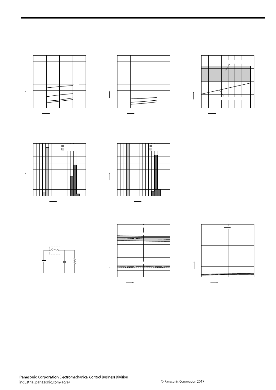
TM (ACTM)
–147–
ASCTB379E 201709-T
REFERENCE DATA
1-(1). Coil temperature rise (Room
temperature)
Sample: ACTM1CH8, 6pcs
Carrying current: 0A, 10A, 20A, 30A
Ambient temperature: Room temperature
1-(2). Coil temperature rise (110
°
C
230
°
F
)
Sample: ACTM1CH8, 6pcs
Carrying current: 0A, 10A, 20A
Ambient temperature: 110
°
C
230
°
F
2. Ambient temperature and usable voltage
range
Sample: ACTM1CH8
0
140
160
180
80
60
40
20
12
14
16
18
10
100
120
Coil applied voltage, V
T
emper
ature r
ise
,
°
C
10A
0A
20A
30A
0
140
160
180
80
60
40
20
12
14
16
18
10
100
120
Coil applied voltage, V
T
emper
ature r
ise
,
°
C
10A
0A
20A
-40
-20
0
20
40
60
80
100 120
20
15
10
5
0
Operate voltage (cold start)
Ambient temperature,
°
C
Coil applied v
oltage
,
V
Usable voltage range
3. Distribution of operate (set) and release
(reset) voltage
Sample: ACTM1CH8, 80pcs.
4. Distribution of operate (set) and release
(reset) time
Sample: ACTM1CH8, 80pcs.
5
4
3
2
1
0
6
7
8
0
40
30
20
10
60
50
80
70
Voltage, V
Quantity
, n
Operate voltage
Release voltage
0
1
2
3
4
5
6
7
8
0
40
30
20
10
60
50
80
70
Time, ms
Quantity
, n
Operate time
Release time
* Without diode
5-(1). Electrical life test (Resistive and
capacitor load)
Sample: ACTM1CH8, 6pcs.
Load: Inrush current: 90A, Steady current: 20A 14V
DC
Operating frequency: ON 0.15s, OFF 4.85s
Ambient temperature: Room temperature
Circuit:
Change of operate (set) and release (reset)
voltage
Change of contact resistance
10
5
Operate voltage
Release voltage
0
8
7
6
5
4
3
2
1
0
Max.
Min.
Ave.
Max.
Min.
Ave.
Oper
ate and release v
oltage
,
V
No. of operations,
×
10
4
Contact welding: 0 time
Miscontact: 0 time
10
5
0
50
40
30
20
10
0
Min.
Max.
Ave.
Contact resistance
, m
Ω
No. of operations,
×
10
4
N.O. side contact
automotive-relay_en-html.html
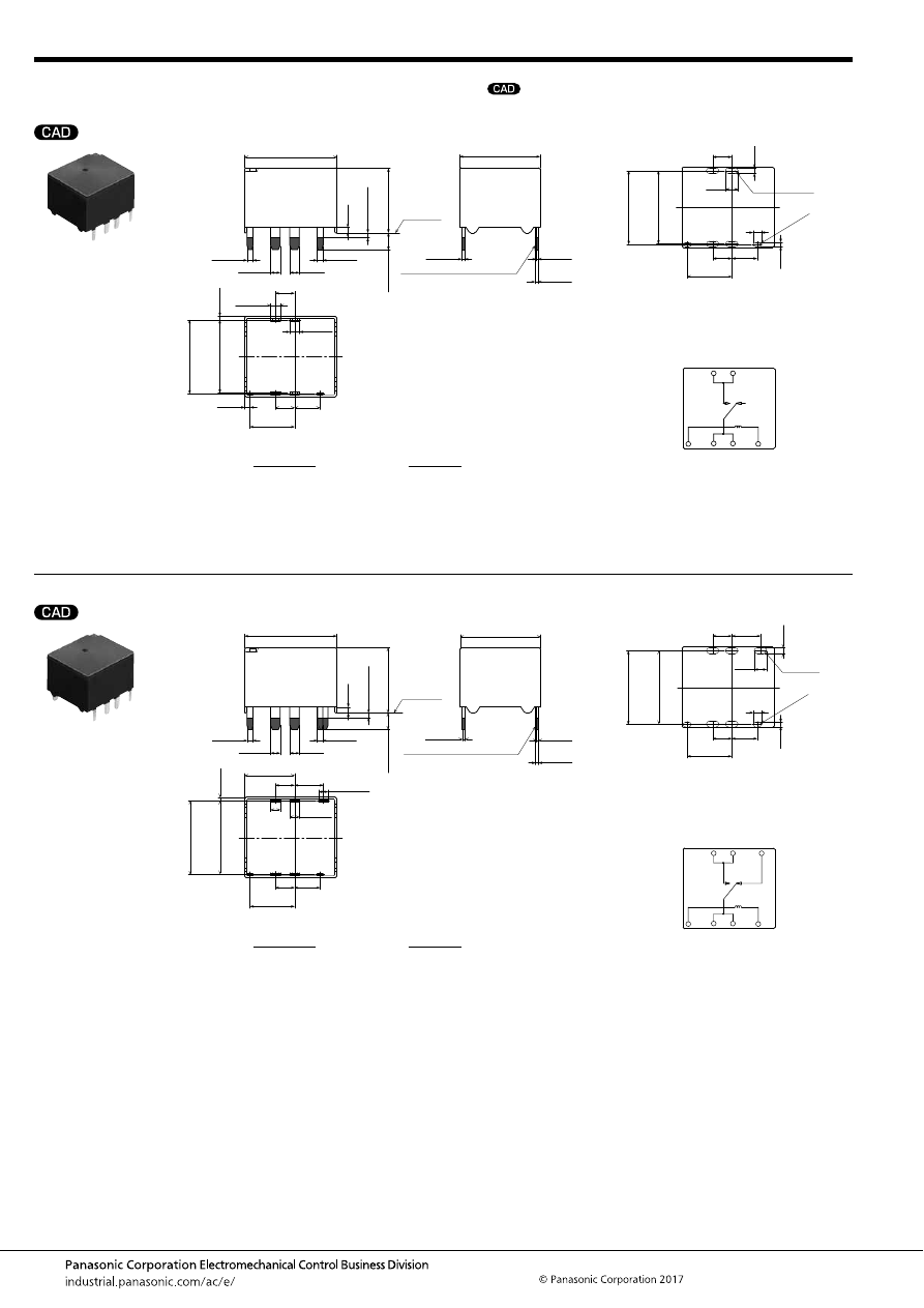
TM (ACTM)
–148–
ASCTB379E 201709-T
DIMENSIONS
(mm
inch
)
1 Form A type
1 Form C type
mark can be downloaded from: http://industrial.panasonic.com/ac/e/
The CAD data of the products with a
External dimensions
4
9.3
(1.1)
.157
.366
4
.157
5.3
.209
(.043)
Pre-soldering (all terminals)
A surface
level
19.2
±
0.5
.756
±
.020
16.8
±
0.5
.661
±
.020
Max.
1.0
Max.
.039
1.2
(Coil-N/0 ter
minal
betw
een centers)
(COM-N/0 ter
minal
betw
een centers)
.047
13.6
±
0.5
.535
±
.020
3.5
±
0.5
.138
±
.020
1.2
.047
+
0.3
−
0.1
+
.012
−
.004
1.2
.047
+
0.3
−
0.1
+
.012
−
.004
2
.079
+
0.3
−
0.1
+
.012
−
.004
2
.079
+
0.3
−
0.1
+
.012
−
.004
2
.079
+
0.3
−
0.1
+
.012
−
.004
2
.079
+
0.3
−
0.1
+
.012
−
.004
0.4
.016
+
0.3
−
0.1
+
.012
−
.004
0.6
.024
+
0.3
−
0.1
+
.012
−
.004
0.6
.024
+
0.3
−
0.1
+
.012
−
.004
.602
.606
15.3
15.4
(0.75)
(.030)
PC board pattern (Bottom view)
Tolerance:
±
0.1
±
.004
Schematic (Bottom view)
(Coil-N/0 ter
minal
betw
een centers)
(COM-N/0 ter
minal
betw
een centers)
.602
.606
15.3
15.4
2
×
R0.45
2
×
R.018
2
×
R0.6
2
×
R.024
4
.157
4
5.3
.157 .209
9.3
.366
1.2
.047
0.9
.035
2.6
.102
.067
1.7
N.O. N.O.
COM COM
COIL
COIL
* The lamp control type has polarized contacts.
Connect N.O. to the “+ (plus)” side.
* Dimensions (thickness and width) of terminal is measured after pre-soldering.
Intervals between terminals is measured at A surface level.
Dimension:
Tolerance
Max. 1mm
.039 inch
:
±
0.1
±
.004
1 to 3mm
.039 to .118 inch
:
±
0.2
±
.008
Min. 3mm
.118 inch
:
±
0.3
±
.012
External dimensions
4
9.3
(10.4)
.157
6
.236
.366
4
.157
5.3
.209
(.409)
Pre-soldering (all terminals)
A surface
level
19.2
±
0.5
.756
±
.020
16.8
±
0.5
.661
±
.020
Max.
1.0
Max.
.039
1.2
(Coil-N/O
.N./C ter
m
inal
betw
een centers)
(COM-N/O
.N./C ter
m
inal
betw
een centers)
.047
13.6
±
0.5
.535
±
.020
3.5
±
0.5
.138
±
.020
1.2
.047
+
0.3
−
0.1
+
.012
−
.004
1.2
.047
+
0.3
−
0.1
+
.012
−
.004
2
.079
+
0.3
−
0.1
+
.012
−
.004
2
.079
+
0.3
−
0.1
+
.012
−
.004
2
.079
+
0.3
−
0.1
+
.012
−
.004
2
.079
+
0.3
−
0.1
+
.012
−
.004
2
.079
+
0.3
−
0.1
+
.012
−
.004
0.4
.016
+
0.3
−
0.1
+
.012
−
.004
0.6
.024
+
0.3
−
0.1
+
.012
−
.004
0.6
.024
+
0.3
−
0.1
+
.012
−
.004
.602
.606
15.3
15.4
(0.75)
(.030)
PC board pattern (Bottom view)
Tolerance:
±
0.1
±
.004
Schematic (Bottom view)
(Coil-N/0 ter
minal
betw
een centers)
(COM-N/0 ter
minal
betw
een centers)
.602
.606
15.3
15.4
2
×
R0.45
2
×
R.018
2
×
R0.6
2
×
R.024
4
.157
6
.236
4
5.3
.157 .209
9.3
.366
1.2
.047
0.9
.035
2.6
.102
.067
1.7
N.O. N.O.
N.C.
COM COM
COIL
COIL
* The lamp control type has polarized contacts.
Connect N.O. to the “+ (plus)” side.
* Dimensions (thickness and width) of terminal is measured after pre-soldering.
Intervals between terminals is measured at A surface level.
Dimension:
Tolerance
Max. 1mm
.039 inch
:
±
0.1
±
.004
1 to 3mm
.039 to .118 inch
:
±
0.2
±
.008
Min. 3mm
.118 inch
:
±
0.3
±
.012
automotive-relay_en-html.html
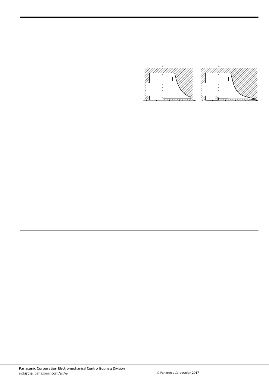
TM (ACTM)
–149–
ASCTB379E 201709-T
NOTES
For general cautions for use, please refer to the “Automotive Relay Users Guide”.
1. Coil operating power
Pure DC current should be applied to the coil. If it includes
ripple, the ripple factor should be less than 5%. However, check
it with the actual circuit since the characteristics may be slightly
different. Also, the power waveform should be rectangular.
2. Coil applied voltage
To ensure proper operation, the voltage applied to the coil
should be the rated operating voltage of the coil. Also, be aware
that the pick-up and drop-out voltages will fluctuate depending
on the ambient temperature and operating conditions.
3. Expected life
Check this with the real device as it is affected by coil driving
circuit, load type, activation frequency, activation phase, ambient
conditions and other factors.
4. Soldering
When soldering the relays, ensure conformance with the
conditions listed below.
1) Automatic soldering
Preheating soldering: 100
°
C
212
°
F
, within 2 sec (surface of PC
board)
Soldering: 260
°
C
500
°
F
, within 5 sec
2) Manual soldering
Tip temperature: 280 to 300
°
C
536 to 572
°
F
.
Soldering iron: 30 to 60W
Soldering time: within 5 sec
5. Usage, transport and storage conditions
1) Ambient temperature, humidity, and air pressure during
usage, transport, and storage of the relay:
(1) Temperature:
–40 to +85
°
C
–40 to +185
°
F
(Standard type)
–40 to +110
°
C
–40 to +230
°
F
(High heat-resistant type)
(2) Humidity: 2 to 85% RH (Avoid icing and condensation.)
(3) Air pressure: 86 to 106 kPa
The humidity range varies with the temperature. Use within the
range indicated in the graph below.
[Temperature and humidity range for usage, transport,
and storage]
2) Water condensation
Condensation forms when there is a sudden change in
temperature under high temperature and high humidity
conditions. Water condensation will cause deterioration of the
relay insulation.
3) Icing
Water condensation or other moisture may ice on the relay when
the temperature is lower than 0
°
C
32
°
F
. This causes problems
such as sticking of movable parts, operational time lags or poor
contact conduction.
4) Low-temperature, low-humidity atmosphere
If the relay is exposed to a low-temperature, low-humidity
atmosphere for a long time, its plastic parts may become brittle
and fagile.
6. Others handling precautions
Do not use relays that have been dropped, because doing so
may be a cause of faulty operation.
85
5
Humidity, %RH
Tolerance range
(Avoid
condensation
when used at
temperatures
higher than
0
°
C
32
°
F
)
(Avoid icing
when used at
temperatures
lower than
0
°
C
32
°
F
)
85
0
–40
+185
+32
–40
Temperature,
°
C
°
F
85
5
2
110
85
0
–40
+230
+185
+32
–40
Humidity, %RH
Temperature,
°
C
°
F
Tolerance range
(Avoid
condensation
when used at
temperatures
higher than
0
°
C
32
°
F
)
(Avoid icing
when used at
temperatures
lower than
0
°
C
32
°
F
)
Standard type
High heat-resistant type
automotive-relay_en-html.html
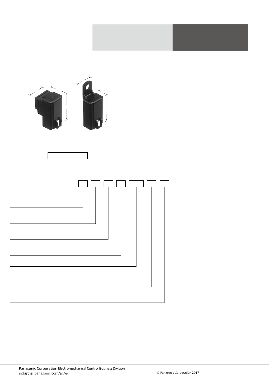
CA (ACA)
–150–
ASCTB219E 201709-T
ORDERING INFORMATION
Small Size, Light Weight
Automotive Power Relays
CA RELAYS
FEATURES
• Small size and light weight
• Since the terminal arrangement complies with JIS
• Low operating power (1.4W) type is available (1 Form A,
1 Form B)
TYPICAL APPLICATIONS
• Motorcycles and automobiles
Motorcycle cell motors, car air conditioners, halogen lamps,
etc.
• Agricultural equipment
• Battery equipped devices such as conveyance vehicles
<Protective construction>
Sealed/Dust cover
24.4
21.5
37
.961
.846
1.457
14.4
21.5
37
.567
.846
1.457
(Unit: mm
inch
)
RoHS compliant
Contact arrangement
1a:
1b:
1:
1 Form A
1 Form B
1 Form C
CA
Protective construction
Nil:
F:
Sealed
Dust cover
Rated operating power
Nil:
S:
Standard type (1.8 W)
Low operating power type (1.4 W) (1 Form A, 1 Form B)
Protective element
Nil:
R:
None
With resistor inside
Rated coil voltage (DC)
12 V, 24 V (1 Form C only)
Mounting method
A:
N:
C:
Rubber bracket A type (1 Form A, 1 Form B)
Screw mounting type
Direct coupling type
Classification by type
Nil:
5:
1 Form C
1 Form A or 1 Form B
automotive-relay_en-html.html
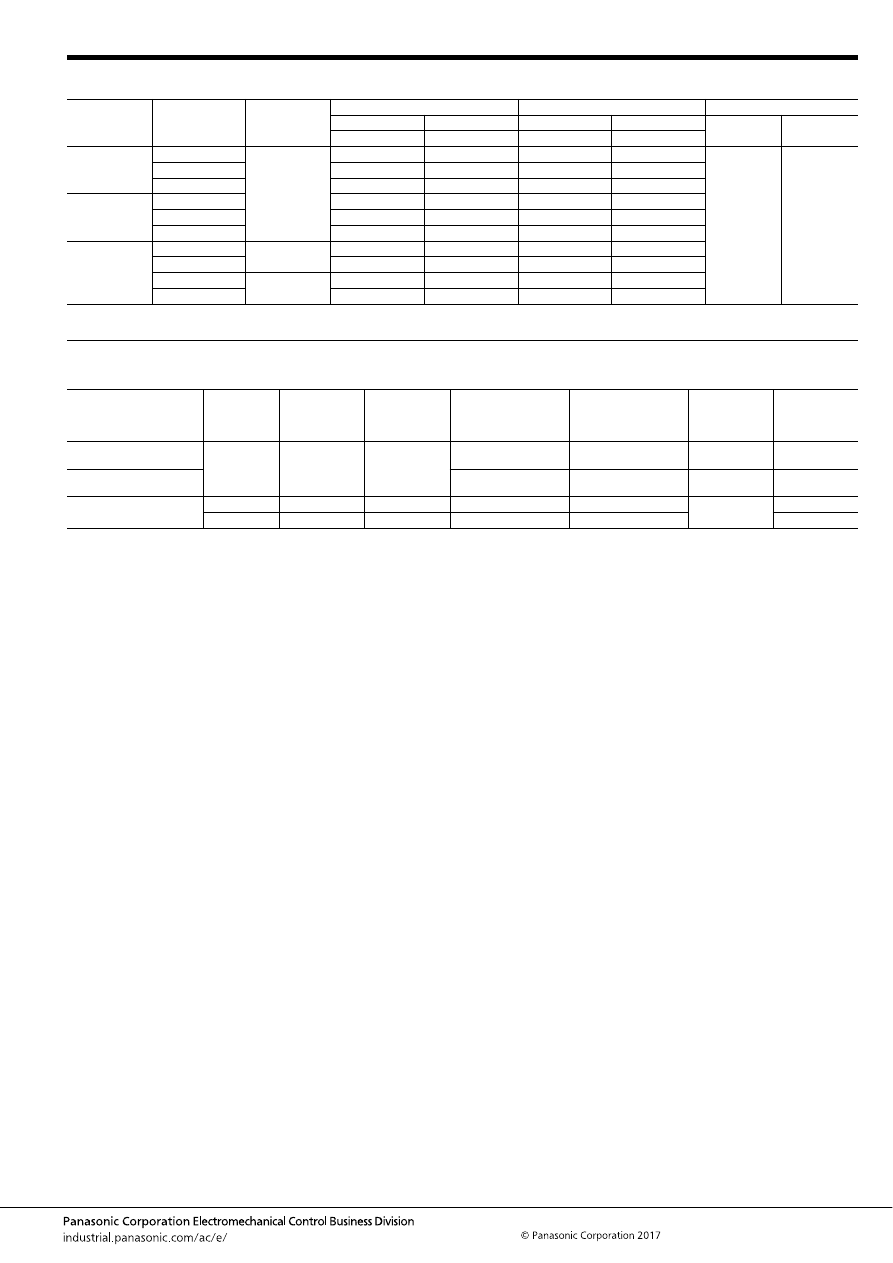
CA (ACA)
–151–
ASCTB219E 201709-T
TYPES
Note: Please use “CA
∗∗
R-
∗
-
∗
-
∗
or CA
∗∗
SR-
∗
-
∗
-
∗
” with resistor inside type. (Asterisks “
∗
” should be filled in from ORDERING INFORMATION.)
RATING
1. Coil data
Note: Other operate (set) voltage types are also available. Please inquire our sales representative for details.
Contact
arrangement
Mounting type
Rated coil
voltage
Standard type (1.8W)
Low operating power type (1.4W)
Packing
Sealed
Dust cover
Sealed
Dust cover
Carton
Case
Type No.
Type No.
Type No.
Type No.
1 Form A
Rubber bracket A
12 V DC
CA1a-12V-A-5
CA1aF-12V-A-5
CA1aS-12V-A-5
CA1aFS-12V-A-5
20 pcs.
200 pcs.
Screw-mounting
CA1a-12V-N-5
CA1aF-12V-N-5
CA1aS-12V-N-5
CA1aFS-12V-N-5
Direct coupling
CA1a-12V-C-5
CA1aF-12V-C-5
CA1aS-12V-C-5
CA1aFS-12V-C-5
1 Form B
Rubber bracket A
CA1b-12V-A-5
CA1bF-12V-A-5
CA1bS-12V-A-5
CA1bFS-12V-A-5
Screw-mounting
CA1b-12V-N-5
CA1bF-12V-N-5
CA1bS-12V-N-5
CA1bFS-12V-N-5
Direct coupling
CA1b-12V-C-5
CA1bF-12V-C-5
CA1bS-12V-C-5
CA1bFS-12V-C-5
1 Form C
Screw-mounting
12 V DC
CA1-12V-N
–
–
–
Direct coupling
CA1-12V-C
–
–
–
Screw-mounting
24 V DC
CA1-24V-N
–
–
–
Direct coupling
CA1-24V-C
–
–
–
Contact arrangement
Rated coil
voltage
Operate (Set)
voltage
(at 20
°
C
68
°
F
)
(Initial)
Release (Reset)
voltage
(at 20
°
C
68
°
F
)
(Initial)
Rated operating current
[
±
10%] (at 20
°
C
68
°
F
)
Coil resistance
[
±
10%] (at 20
°
C
68
°
F
)
Rated operating
power
Usable voltage
range
1 Form A and 1 Form B
(Standard)
12 V DC
Max. 8 V DC
0.6 to 6 V DC
150 mA
80
Ω
1.8 W
10 to 16V DC
1 Form A and 1 Form B
(Low operating power)
120 mA
100
Ω
1.4 W
10 to 16V DC
1 Form C
12 V DC
Max. 8 V DC
Min. 0.6 V DC
150 mA
80
Ω
1.8 W
10 to 15V DC
24 V DC
Max. 16 V DC
Min. 1.2 V DC
75 mA
320
Ω
20 to 30V DC
automotive-relay_en-html.html
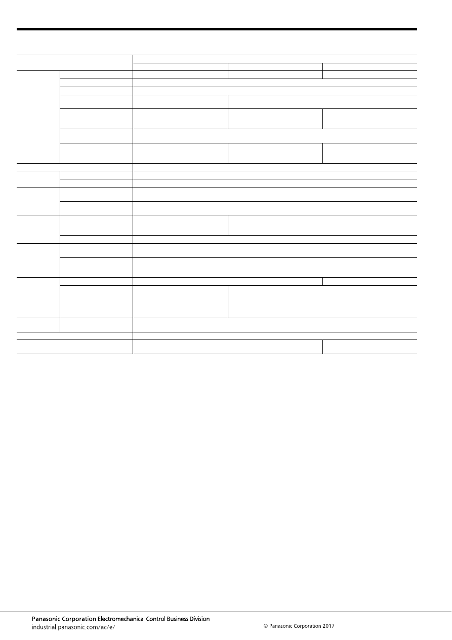
CA (ACA)
–152–
ASCTB219E 201709-T
2. Specifications
1) 12 V DC type
Notes: *1. Depends on connection conditions. Also, this does not guarantee repeated switching. We recommend that you confirm operation under actual conditions.
*2. The upper operation ambient temperature limit is the maximum temperature that can satisfy the coil temperature rise value. For details, please refer to the
“Automotive Relay Users Guide”.
Please inquire our sales representative if you will be using the relay in a high temperature atmosphere (110
°
C
230
°
F
)
Item
Specifications
1 Form A type
1 Form B type
1 Form C type
Contact data
Contact arrangement
1 Form A
1 Form B
1 Form C
Contact resistance (initial)
Max. 50m
Ω
(Typ. 3m
Ω
) (By voltage drop 1A 6V DC)
Contact material
Ag alloy
Rated switching capacity
(resistive)
20 A 12V DC (1.4 W type)
30 A 12V DC (1.8 W type)
20 A 12 V DC
Max. carrying current (at coil
applied voltage 14 V DC, at
80
°
C
176
°
F
)
20 A continuous (1.4 W type)
30 A for 1 min. (1.8 W type)
20 A continuous
20 A continuous
Min. switching load
(resistive)*
1
1 A 14V DC (at 20
°
C
68
°
F
)
Contact voltage drop
(after electrical life test)
Max. 0.3 V
[By carrying 20 A 12 V DC (1.4 W
type), 30 A 12 V DC (1.8 W type)]
Max. 0.3 V
(By carrying 20 A 12 V DC)
Max. 0.4 V
(By carrying 20 A 12 V DC)
Insulated resistance (initial)
Min. 10 M
Ω
(at 500V DC, Measurement at same location as “Dielectric strength” section.)
Dielectric
strength (initial)
Between open contacts
500 Vrms for 1 min. (Detection current: 10mA)
Between contacts and coil
500 Vrms for 1 min. (Detection current: 10mA)
Time
characteristics
(initial)
Operate (Set) time
(at rated voltage)
Max. 10ms (at 20
°
C
68
°
F
, without contact bounce time)
Release (Reset) time
(at rated voltage)
Max. 10ms (at 20
°
C
68
°
F
, without contact bounce time) (Without diode)
Shock
resistance
Functional
Min. 200 m/s
2
{approx. 20G}
(Half-wave pulse of sine wave: 11ms;
detection time: 10
μ
s)
Min. 100 m/s
2
{approx. 10G}
(Half-wave pulse of sine wave: 11ms; detection time: 10
μ
s)
Destructive
Min. 1,000 m/s
2
{approx. 100G} (Half-wave pulse of sine wave: 6ms)
Vibration
resistance
Functional
Rubber bracket A type: 50 to 500 Hz, Min. 100 m/s
2
{approx. 10G}
Screw-mounting and direct coupling type: 33 Hz, Min. 44.1 m/s
2
{approx. 4.5G} (Detection time: 10
μ
s)
Destructive
Rubber bracket A type: 50 to 500 Hz, Min. 100 m/s
2
{approx. 10G}
Screw-mounting and direct coupling type: 33 Hz, Min. 44.1 m/s
2
{approx. 4.5G}, Time of vibration for each direction; X, Y
direction: 2 hours, Z direction: 4 hours
Expected life
Mechanical
Min. 10
6
(at 120 cpm)
Min. 5
×
10
5
(at 120 cpm)
Electrical (at rated switching
capacity)
Min. 10
5
(operating frequency: 2s ON, 2s OFF)
(1.4 W and 1.8 W type at 20 A)
Min. 2
×
10
4
(operating frequency: 3s
ON, 15s OFF) (1.8 W type at 30 A)
Min. 10
5
(operating frequency: 2s ON, 2s OFF)
Conditions
Conditions for usage,
transport and storage*
2
Ambient temperature: –30 to +80
°
C
–22 to +176
°
F
, Humidity: 5 to 85% R.H. (Please avoid icing or condensation)
Water-proof standard
Sealed: JIS D 0203 S2, Dust cover: JIS D 0203 R2
Weight
Rubber bracket A type: approx. 23 g
.81 oz
,
Screw-mounting and direct coupling type: approx. 19 g
.67 oz
approx. 31 g
1.09 oz
automotive-relay_en-html.html
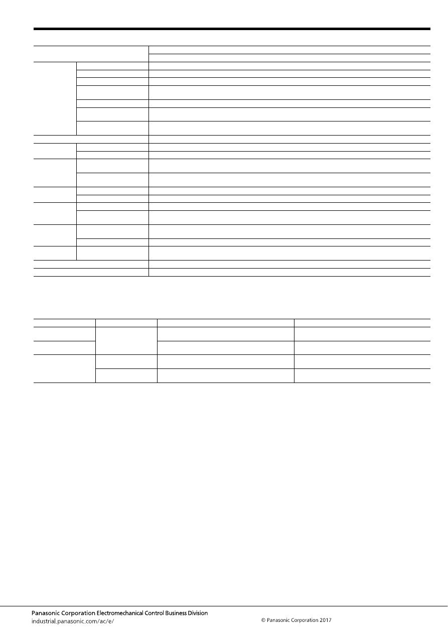
CA (ACA)
–153–
ASCTB219E 201709-T
2) 24 V DC type
Notes: *1. Depends on connection conditions. Also, this does not guarantee repeated switching. We recommend that you confirm operation under actual conditions.
*2. The upper operation ambient temperature limit is the maximum temperature that can satisfy the coil temperature rise value. For details, please refer to the
“Automotive Relay Users Guide”.
Please inquire our sales representative if you will be using the relay in a high temperature atmosphere (110
°
C
230
°
F
)
Electrical life
Item
Specifications
1 Form C type
Contact data
Contact arrangement
1 Form C
Contact resistance (initial)
Max. 50m
Ω
(Typ. 3m
Ω
) (By voltage drop 1A 6V DC)
Contact material
Ag alloy
Rated switching capacity
(resistive)
10 A 24V DC
Max. carrying current
10 A continuous (At coil applied voltage 28 V DC, 80
°
C
176
°
F
)
Min. switching load
(resistive)*
1
1 A 14V DC (at 20
°
C
68
°
F
)
Contact voltage drop
(after electrical life test)
Max. 0.4 V (by voltage drop 24 V DC 10 A)
Insulated resistance (initial)
Min. 10 M
Ω
(at 500V DC, Measurement at same location as “Dielectric strength” section.)
Dielectric
strength (initial)
Between open contacts
500 Vrms for 1 min. (Detection current: 10mA)
Between contacts and coil
500 Vrms for 1 min. (Detection current: 10mA)
Time
characteristics
(initial)
Operate (Set) time
(at rated voltage)
Max. 10ms (at 20
°
C
68
°
F
, without contact bounce time)
Release (Reset) time
(at rated voltage)
Max. 10ms (at 20
°
C
68
°
F
, without contact bounce time)
Shock
resistance
Functional
Min. 100 m/s
2
{approx. 10G} (Half-wave pulse of sine wave: 11ms; detection time: 10
μ
s)
Destructive
Min. 1,000 m/s
2
{approx. 100G} (Half-wave pulse of sine wave: 6ms)
Vibration
resistance
Functional
JIS D1601 Group 1, B type, Stage 4 (33 Hz, Min. 44.1 m/s
2
{approx. 4.5G}) (Detection time: 10
μ
s)
Destructive
JIS D1601 Group 1, B type, Stage 4 (33 Hz, Min. 44.1 m/s
2
{approx. 4.5G}),
Time of vibration for each direction; X, Y direction: 2 hours, Z direction: 4 hours
Expected life
Electrical (at rated switching
capacity)
Min. 10
5
(operating frequency: 2s ON, 2s OFF)
Mechanical
Min. 5
×
10
5
(at 120 cpm)
Conditions
Conditions for usage,
transport and storage*
2
Ambient temperature: –30 to +80
°
C
–22 to +176
°
F
, Humidity: 5 to 85% R.H. (Please avoid icing or condensation)
Water-proof standard
JIS D 0203 S2
Weight
approx. 31 g
1.09 oz
Contact arrangement
Rated coil voltage
Motor load
Halogen lamp load
1 Form A
12 V DC
Operating frequency: 3s ON, 15s OFF
12V DC 30A, Min. 2
×
10
4
—
1 Form B
Operating frequency: 3s ON, 15s OFF
12V DC 20A, Min. 10
5
Operating frequency: 1s ON, 14s OFF
12V DC 20A, Min. 10
5
1 Form C
12 V DC
Operating frequency: 2s ON, 1s OFF
12V DC 20A, Min. 10
5
Operating frequency: 1s ON, 14s OFF
12V DC 20A, Min. 10
5
24 V DC
Operating frequency: 2s ON, 1s OFF
24V DC 10A, Min. 10
5
Operating frequency: 1s ON, 14s OFF
24V DC 6A, Min. 10
5
automotive-relay_en-html.html
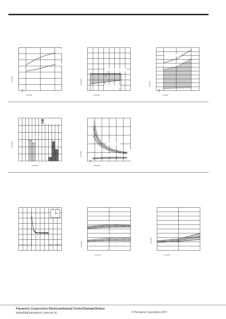
CA (ACA)
–154–
ASCTB219E 201709-T
REFERENCE DATA
1. Coil temperature rise
Samples: CA1aS-12V-N-5, 5pcs.
Measured portion: Inside the coil
Carrying current: 20A
Ambient temperature: Room temperature, 80
°
C
176
°
F
2. Ambient temperature and usable voltage
range
3. Ambient temperature characteristics
(Cold start)
Samples: CA1bS-12V-N-5
12
0
14
16
140
120
100
80
60
40
20
0
Room
temperature
T
emper
ature r
ise
,
°
C
Coil applied voltage, V
80
°
C
176
°
F
0
Ambient temperature,
°
C
Coil applied v
oltage
,
VDC
5
10
15
35
30
25
20
40
-40
-20
-30
20
40
60
100
0
120
8085
Operate voltage
(Cold start)
Usable voltage range
0
Ambient temperature,
°
C
Pic
k-up and drop-out v
oltage
,
V
10
8
6
4
2
11
1
3
5
7
9
-30
20
80
Operate voltage
Release voltage
4. Distribution of operate (set) and release
(reset) voltage
Quantity: 50pcs.
5. Distribution of operate (set) and release
(reset) time
Sample: CA1a-12V-N-5, 10pcs.
0
30
20
10
40
50
60
Voltage, V
Quantity
, n
1
0
2
3
5
4
6
Operate voltage
Release voltage
0
Coil applied voltage, %V
Oper
ate and release time
, ms
15
20
10
5
25
0
16
10
12
14
6
8
Operate time
Release time
Max.
Ave.
Min.
Max.
Ave.
Min.
6.-(1) Electrical life test (Motor load)
Sample: CA1a-12V-C, 3pcs.
Load: Inrush current: 63A, steady current: 23A
Blower fan motor actual load (motor free)
Operating frequency: ON 2s, OFF 2s
Ambient temperature: Room temperature
Load current waveform
Load: Inrush current: 63A, steady current: 23A,
Change of operate (set) and release (reset)
voltage
Change of contact resistance
500ms
10A
0
No. of operations,
×
10
4
Oper
ate and release v
oltage
,
V
Max.
Max.
Min.
Min.
Ave.
Ave.
2
1
4
6
8
9
7
5
3
10
0
20
10
Operate voltage
Release voltage
0
No. of operations,
×
10
4
Contact resistance
, m
Ω
Max.
Min.
Ave.
2
4
6
8
1
3
5
7
9
10
0
20
10
automotive-relay_en-html.html
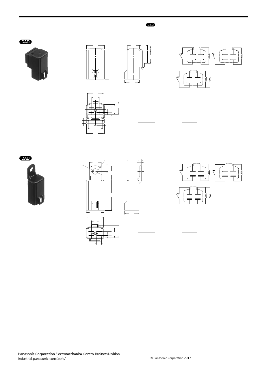
CA (ACA)
–155–
ASCTB219E 201709-T
DIMENSIONS
(mm
inch
)
1. 1 Form A / 1 Form B
2. 1 Form A / 1 Form B
mark can be downloaded from: http://industrial.panasonic.com/ac/e/
The CAD data of the products with a
Rubber bracket A type
External dimensions
21.5
19.5
9
37
14.4
17.4
10
15
2.5
6
21.5
17
0.8
15.4
12.4
5.5
2.4
1.5
2
.846
.768
.354
1.457
.567
.685
.394
.591
.098
.236
.846
.669
.031
.606
.488
.217
.094
.059
.079
Schematic (Bottom View)
1 Form A
Including resistor
(1 Form A)
1 Form B
Note: Including resistor type also available.
Dimension:
Max. 1mm
.039inch
:
1 to 20mm
.039 to .787inch
:
Min. 20mm
.787inch
:
Tolerance
±
0.1
±
.004
±
0.3
±
.012
±
0.5
±
.020
Screw-mounting type
External dimensions
14
9
2
17.4
21.5
3
.079
.118
14.4
.236
6
0.8
15.4
12.4
5.5
2.4
17.5
37
1.457
7
R10
6.5
dia. hole
+0.3
–
0
.256
dia.
+.012
–
0
19.5
.846
.768
.551
.354
.685
.567
.031
.606
.488
.217
.094
.689
1.457
.276
Schematic (Bottom View)
1 Form A
Including resistor
(1 Form A)
1 Form B
Note: Including resistor type also available.
Dimension:
Max. 1mm
.039inch
:
1 to 20mm
.039 to .787inch
:
Min. 20mm
.787inch
:
Tolerance
±
0.1
±
.004
±
0.3
±
.012
±
0.5
±
.020
automotive-relay_en-html.html
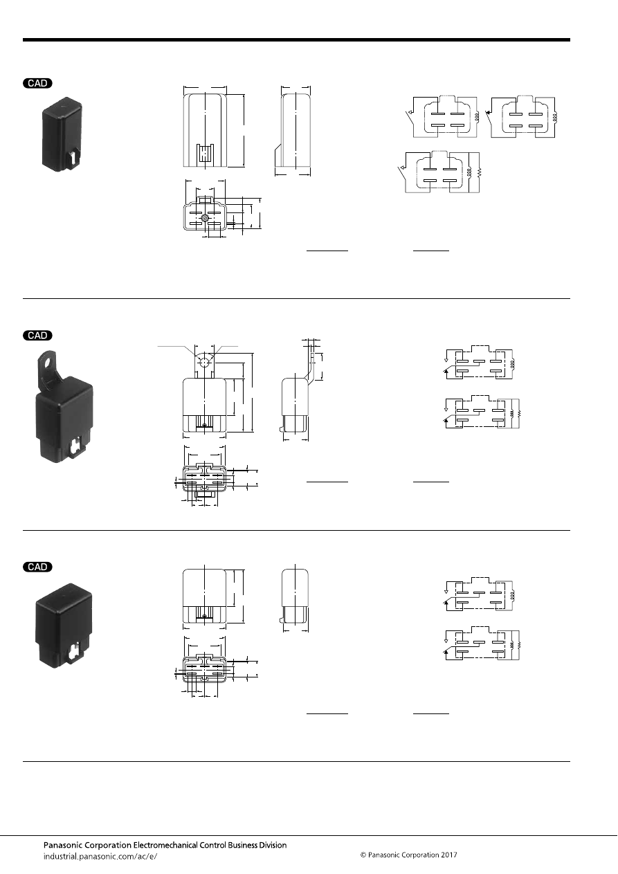
CA (ACA)
–156–
ASCTB219E 201709-T
3. 1 Form A / 1 Form B
4. 1 Form C
5. 1 Form C
For general cautions for use, please refer to the “Automotive Relay Users Guide”.
Direct coupling type
External dimensions
21.5
9
17.4
14.4
.236
6
0.8
15.4
12.4
5.5
2.4
37
19.5
.768
.846
.354
.685
.567
.031
.606
.488
.217
.094
1.457
Schematic (Bottom View)
1 Form A
Including resistor
(1 Form A)
1 Form B
Note: Including resistor type also available.
Dimension:
Max. 1mm
.039inch
:
1 to 20mm
.039 to .787inch
:
Min. 20mm
.787inch
:
Tolerance
±
0.1
±
.004
±
0.3
±
.012
±
0.5
±
.020
Screw-mounting type
External dimensions
14
23.4
19.4
31.2
4
2
5.5
2.4
0.8
12.2
12
40
59
28
R10
6.6 dia. hole
.260 dia.
28.4
1.228
1.118
20
9
9
6
11.4
.551
.921
.764
.157
.079
.217
.094
.031
.480
.472
1.575
2.323
1.102
.787
.354 .354
.236
.449
Schematic (Bottom View)
Note: Including resistor type also available.
Including resistor
1 Form C
Dimension:
Max. 1mm
.039inch
:
1 to 20mm
.039 to .787inch
:
Min. 20mm
.787inch
:
Tolerance
±
0.1
±
.004
±
0.2
±
.008
±
0.5
±
.020
Direct coupling type
External dimensions
19.4
5.5
2.4
0.8
12.2
40
28
9
9
6
11.4
23.4
31.2
28.4
1.228
1.118
.764
.217
.094
.031
.480
1.575
1.102
.354 .354
.236
.449
.921
Schematic (Bottom View)
Note: Including resistor type also available.
Including resistor
1 Form C
Dimension:
Max. 1mm
.039inch
:
1 to 20mm
.039 to .787inch
:
Min. 20mm
.787inch
:
Tolerance
±
0.1
±
.004
±
0.2
±
.008
±
0.5
±
.020
automotive-relay_en-html.html
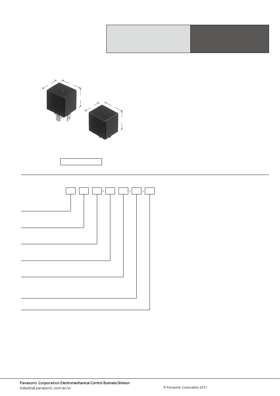
CB (ACB)
–157–
ASCTB220E 201709-T
ORDERING INFORMATION
Mini-ISO
Automotive Relay
CB RELAYS
FEATURES
• This relay has an Mini-ISO (International Organization for
Standardization) terminal arrangement.
• Compact and high capacity
• Features heat resistant type
• Built-in resistor type is also available.
TYPICAL APPLICATIONS
• Automobiles
Cell motors, Air conditioners, ABS, EPS, etc.
• Construction equipment
• Agricultural equipment, Conveyor, etc.
<Protective construction>
Flux tight/Sealed
26
22
25
1.024
.866
.984
26
22
25
1.024
.866
.984
(Unit: mm
inch
)
RoHS compliant
Contact arrangement
1a:
1:
1 Form A
1 Form C
CB
Protective construction
Nil:
F:
Sealed
Flux tight
Heat resistant of types
Nil:
T:
Standard
Heat resistant
Mounting classification
Nil:
P:
M:
Rated coil voltage (DC)
12V, 24 V
Plug-in type
PC board type
Bracket type
Protective element
Nil:
R:
None
With resistor inside
Contact rating
Nil:
H:
Standard
High contact capacity
automotive-relay_en-html.html
CB (ACB)
–158–
ASCTB220E 201709-T
TYPES
Note: Please use “CB
∗∗∗
R
∗∗
” to order with resistor inside type. (Asterisks “
∗
” should be filled in from ORDERING INFORMATION.)
RATING
1. Coil data
1) No protective element
Note: Other operate (set) voltage types are also available. Please inquire our sales representative for details.
2) With resistor inside
Contact
arrangement
Mounting
classification
Rated coil voltage
Standard type
Heat resistant type
Packing
Sealed
Flux tight
Sealed
Flux tight
Carton
Case
Type No.
Type No.
Type No.
Type No.
1 Form A
PC board type
12V DC
CB1a-P-12V
CB1aF-P-12V
CB1a-T-P-12V
CB1aF-T-P-12V
50 pcs.
200 pcs.
24V DC
CB1a-P-24V
CB1aF-P-24V
CB1a-T-P-24V
CB1aF-T-P-24V
Plug-in type
12V DC
CB1a-12V
CB1aF-12V
CB1a-T-12V
CB1aF-T-12V
24V DC
CB1a-24V
CB1aF-24V
CB1a-T-24V
CB1aF-T-24V
Bracket type
12V DC
CB1a-M-12V
CB1aF-M-12V
CB1a-T-M-12V
CB1aF-T-M-12V
24V DC
CB1a-M-24V
CB1aF-M-24V
CB1a-T-M-24V
CB1aF-T-M-24V
1 Form C
PC board type
12V DC
CB1-P-12V
CB1F-P-12V
CB1-T-P-12V
CB1F-T-P-12V
24V DC
CB1-P-24V
CB1F-P-24V
CB1-T-P-24V
CB1F-T-P-24V
Plug-in type
12V DC
CB1-12V
CB1F-12V
CB1-T-12V
CB1F-T-12V
24V DC
CB1-24V
CB1F-24V
CB1-T-24V
CB1F-T-24V
Bracket type
12V DC
CB1-M-12V
CB1F-M-12V
CB1-T-M-12V
CB1F-T-M-12V
24V DC
CB1-M-24V
CB1F-M-24V
CB1-T-M-24V
CB1F-T-M-24V
1 Form A
High contact
capacity
PC board type
12V DC
CB1aH-P-12V
CB1aHF-P-12V
CB1aH-T-P-12V
CB1aHF-T-P-12V
24V DC
CB1aH-P-24V
CB1aHF-P-24V
CB1aH-T-P-24V
CB1aHF-T-P-24V
Plug-in type
12V DC
CB1aH-12V
CB1aHF-12V
CB1aH-T-12V
CB1aHF-T-12V
24V DC
CB1aH-24V
CB1aHF-24V
CB1aH-T-24V
CB1aHF-T-24V
Bracket type
12V DC
CB1aH-M-12V
CB1aHF-M-12V
CB1aH-T-M-12V
CB1aHF-T-M-12V
24V DC
CB1aH-M-24V
CB1aHF-M-24V
CB1aH-T-M-24V
CB1aHF-T-M-24V
Contact
arrangement
Rated coil
voltage
Operate (Set) voltage
(at 20
°
C
68
°
F
) (Initial)
Release (Reset)
voltage
(at 20
°
C
68
°
F
) (Initial)
Rated operating
current
[
±
10%] (at 20
°
C
68
°
F
)
Coil resistance
[
±
10%] (at 20
°
C
68
°
F
)
Rated operating
power
(at 20
°
C
68
°
F
)
Usable voltage
range
1 Form A,
1 Form C
12V DC
3 to 7V DC
1.2 to 4.2V DC
117mA
103
Ω
1.4W
10 to 16V DC
24V DC
6 to 14V DC
2.4 to 8.4V DC
75mA
320
Ω
1.8W
20 to 32V DC
1 Form A
High contact
capacity
12V DC
3 to 7V DC
1.2 to 4.2V DC
117mA
103
Ω
1.4W (PC board type)
10 to 16V DC
150mA
80
Ω
1.8W
24V DC
6 to 14V DC
2.4 to 8.4V DC
58mA
411
Ω
1.4W (PC board type)
20 to 32V DC
75mA
320
Ω
1.8W
Contact
arrangement
Rated coil
voltage
Operate (Set) voltage
(at 20
°
C
68
°
F
) (Initial)
Release (Reset)
voltage
(at 20
°
C
68
°
F
) (Initial)
Rated operating
current
[
±
10%] (at 20
°
C
68
°
F
)
Equivalent coil
resistance
[
±
10%] (at 20
°
C
68
°
F
)
Rated operating
power
(at 20
°
C
68
°
F
)
Usable voltage
range
1 Form A,
1 Form C
12V DC
3 to 7V DC
1.2 to 4.2V DC
134mA
89.5
Ω
1.6W
10 to 16V DC
24V DC
6 to 14V DC
2.4 to 8.4V DC
84mA
287.2
Ω
2.0W
20 to 32V DC
1 Form A
High contact
capacity
12V DC
3 to 7V DC
1.2 to 4.2V DC
134mA
89.5
Ω
1.6W (PC board type)
10 to 16V DC
168mA
71.6
Ω
2.0W
24V DC
6 to 14V DC
2.4 to 8.4V DC
67mA
358
Ω
1.6W (PC board type)
20 to 32V DC
84mA
287.2
Ω
2.0W
automotive-relay_en-html.html
CB (ACB)
–159–
ASCTB220E 201709-T
2. Specifications
1) Standard type (12 V coil voltage)
Notes: *1. Depends on connection conditions. Also, this does not guarantee repeated switching. We recommend that you confirm operation under actual conditions.
*2. The upper operation ambient temperature limit is the maximum temperature that can satisfy the coil temperature rise value. For details, please refer to the
“Automotive Relay Users Guide”.
Please inquire our sales representative if you will be using the relay in a high temperature atmosphere (110
°
C
230
°
F
)
2) Standard type (24 V coil voltage)
Note: All other specifications are the same as those of standard type (12 V coil voltage)
3) Heat resistant type (12 V and 24 V coil voltage)
Notes: 1. All other specifications are the same as those of standard type (12 V coil voltage)
2. *Current value in which carry current is possible when the coil temperature is 180
°
C
356
°
F
Item
Specification
Contact data
Contact arrangement
1 Form A
1 Form C
1 Form A High contact capacity
Contact resistance (initial)
Max. 15m
Ω
(Typ. 2m
Ω
) (By voltage drop 1A 6V DC)
Contact material
Ag alloy
Rated switching capacity
(resistive)
40A 14V DC
N.O. side: 40A 14V DC
N.C. side: 30A 14V DC
70A 14V DC (at 20
°
C
68
°
F
)
50A 14V DC (at 85
°
C
185
°
F
)
Max. carrying current (initial)
(coil applied voltage 14V DC,
at 85
°
C
185
°
F
, continuous)
N.O. side: 40A
N.O. side: 40A
N.C. side: 30A
N.O. side: 40A
Min. switching load
(resistive)*
1
1A 14V DC (at 20
°
C
68
°
F
)
Insulated resistance (initial)
Min. 20 M
Ω
(at 500V DC, Measurement at same location as “Dielectric strength” section.)
Dielectric
strength (initial)
Between open contacts
500 Vrms for 1 min. (Detection current: 10mA)
Between contacts and coil
500 Vrms for 1 min. (Detection current: 10mA)
Time
characteristics
(initial)
Operate (Set) time
(at rated coil voltage)
Max. 15ms (at 20
°
C
68
°
F
, without contact bounce time)
Release (Reset) time
(at rated coil voltage)
Max. 15ms (at 20
°
C
68
°
F
, without contact bounce time) (Without diode)
Shock
resistance
Functional
Min. 200 m/s
2
{approx. 20G} (Half-wave pulse of sine wave: 11ms; detection time: 10
μ
s)
Destructive
Min. 1,000 m/s
2
{approx. 100G} (Half-wave pulse of sine wave: 6ms)
Vibration
resistance
Functional
10 to 500 Hz, Min. 44.1m/s
2
{approx. 4.5G} (Detection time: 10
μ
s)
Destructive
10 to 2,000 Hz, Min. 44.1m/s
2
{approx. 4.5G} Time of vibration for each direction; X. Y. Z direction: 4 hours
Expected life
Mechanical
Min. 10
6
(at 120 cpm)
Electrical (at rated switching
capacity)
Flux tight: Min. 10
5
, Sealed: Min. 5
×
10
4
(Operating frequency: 2s ON, 2s OFF)
Conditions
Conditions for usage,
transport and storage*
2
Standard; Ambient temperature: –40 to +85
°
C
–40 to +185
°
F
, Humidity: 5 to 85% R.H. (Please avoid icing or
condensation)
Heat resistant; Ambient temperature: –40 to +125
°
C
–40 to +257
°
F
, Humidity: 5 to 85% R.H. (Please avoid icing or
condensation)
Weight
Approx. 33 g
1.16 oz
Item
Specifications
Contact data
Contact arrangement
1 Form A
1 Form C
1 Form A High contact capacity
Contact resistance (initial)
Max. 15m
Ω
(By voltage drop 1A 6V DC)
Contact material
Ag alloy
Rated switching capacity
(resistive)
20A 28V DC
N.O. side: 20A 28V DC
N.C. side: 10A 28V DC
20A 28V DC
Max. carrying current (initial)
(28V DC, at 85
°
C
185
°
F
,
continuous)
20A
N.O. side: 20A
N.C. side: 10A
20A
Item
Specifications
12V
24V
Contact data
Contact arrangement
1 Form A
1 Form C
1 Form A
High contact
capacity
1 Form A
1 Form C
1 Form A
High contact
capacity
Contact resistance (initial)
Max. 15m
Ω
(By voltage drop 1A 6V DC)
Contact material
Ag alloy
Rated switching capacity
(resistive)
40A 14V DC
N.O. side:
40A 14V DC
N.C. side:
30A 14V DC
40A 14V DC
20A 28V DC
N.O. side:
20A 28V DC
N.C. side:
10A 28V DC
20A 28V DC
Max. carrying current (initial)
(at 85
°
C
185
°
F
, continuous)*
50A 14V DC
N.O. side:
50A 14V DC
N.C. side:
30A 14V DC
45A
14V DC
50A
14V DC
25A 28V DC
N.O. side:
25A 28V DC
N.C. side:
10A 28V DC
25A 28V DC
automotive-relay_en-html.html
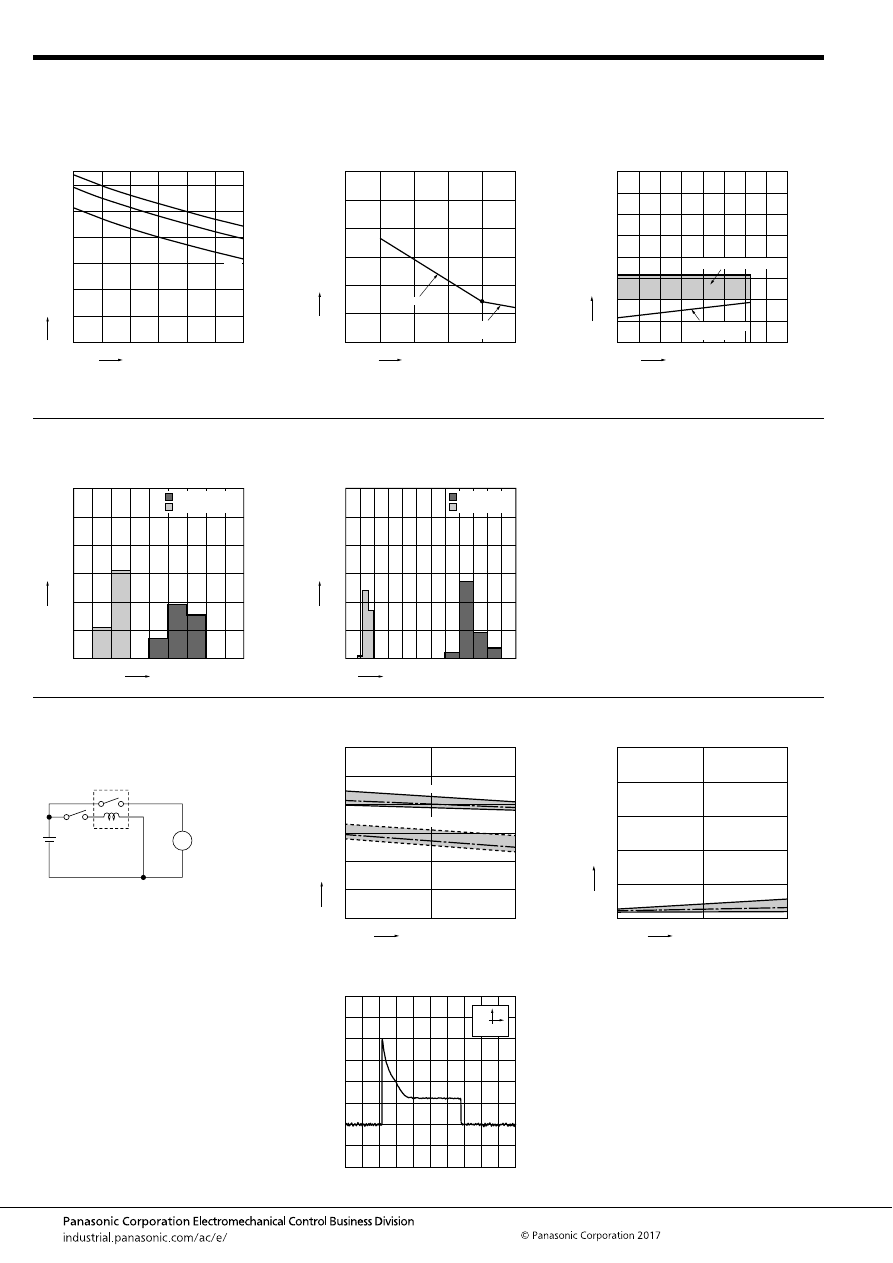
CB (ACB)
–160–
ASCTB220E 201709-T
REFERENCE DATA
CB RELAYS (Standard)
1. Allowable ambient temperature
(Heat resistant and standard)
2. Max. switching capability (Resistive)
(Standard)
3. Ambient temperature and usable voltage
range
(Standard)
20
40
60
80
100
120
140
150
90
100
110
120
130
140
150
Applied coil voltage, %V
Maxim
um allo
w
ab
le ambient temper
ature
,
°
C
30A
40A
20A
0
Switching current, A
Switching v
oltage
,
VDC
10
50
40
30
20
60
0
20
30
40
10
50
10
5
cycle line
Actual value
(Max. 10
5
cycle)
(N.O. side Room temperature)
0
Ambient temperature,
°
C
Coil applied v
oltage
,
VDC
5
10
15
35
30
25
20
40
-40 -20
20
40
60
100
0
120
8085
Operate voltage
(Cold start)
Usable voltage range
Notes:
• Maximum mean coil temperature: 180
°
C
356
°
F
• Curves are based on 1.4W (Nominal power consumption of the unsupprressed coil at nominal voltage)
4. Distribution of operate (set) and release
(reset) voltage
Sample: CB1-P-12V, 42pcs.
5. Distribution of operate (set) and release
(reset) time
Sample: CB1-P-12V, 42pcs.
0
30
20
10
40
50
60
2
3
5
4
6
Operate voltage
Release voltage
Voltage, V
Quantity
, n
0
30
20
10
40
50
60
3
2
1
5
4
6
7
Operate time
Release time
Operate and release time, ms
Quantity
, n
* Without diode
6. Electrical life test (Motor free)
Sample: CB1F-12V, 5pcs.
Load: 25A 14V DC, motor free actual load
Operating frequency: ON 1s, OFF 9s
Ambient temperature: Room temperature
Circuit:
Change of operate (set) and release (reset)
voltage
Change of contact resistance
M
0
No. of operations,
×
10
4
Oper
ate and release v
oltage
,
V
Max.
Max.
Min.
Min.
Ave.
Ave.
2
1
4
6
5
3
0
10
5
Operate voltage
Release voltage
0
No. of operations,
×
10
4
Contact resistance
, m
Ω
Max.
Min.
Ave.
20
40
10
3
50
0
10
5
Load current waveform
Load; Inrush current: 80A, Steady current: 25A
200ms
20A
automotive-relay_en-html.html
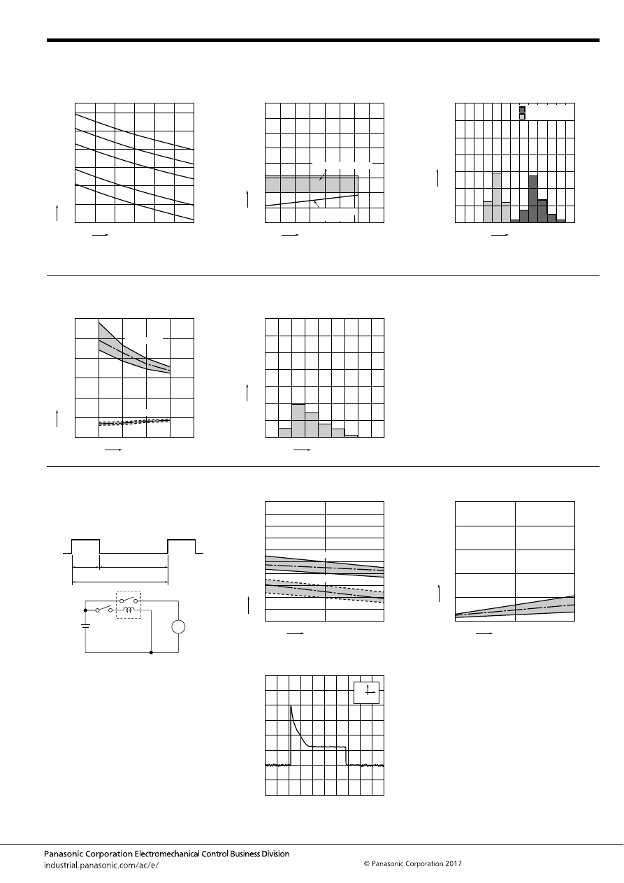
CB (ACB)
–161–
ASCTB220E 201709-T
CB RELAYS (High contact capacity)
1. Allowable ambient temperature
(High resistant and high contact capacity)
2. Ambient temperature and usable voltage
range
(High contact capacity and standard)
3. Distribution of operate (set) and release
(reset) voltage
Sample: CB1aHF-12V, 53pcs.
20
40
60
80
100
120
140
150
90
100
110
120
130
140
150
Applied coil voltage, %V
Maxim
um allo
w
ab
le ambient temper
ature
,
°
C
70A
30A
40A
50A
60A
Ambient temperature,
°
C
Coil applied v
oltage
,
VDC
0
5
10
15
35
30
25
20
40
-40 -20
20
40
60
100
0
120
80 85
Operate voltage
(Cold start)
Usable voltage range
0
30
20
10
40
50
60
70
1
0
2
3
5
4
6
Voltage, V
Quantity
, n
Operate voltage
Release voltage
Notes:
• Maximum mean coil temperature: 180
°
C
356
°
F
• Curves are based on 1.4W (Nominal power consumption of the unsupprressed coil at nominal voltage)
4. Distribution of operate and release time
Sample: CB1aHF-12V, 53pcs.
5. Contact resistance
Sample: CB1aHF-12V, 53pcs.
(By voltage drop 1A 6V DC)
0
6
4
2
8
10
12
12
10
8
14
Release time
Coil voltage, V
Oper
ate and release time
, ms
Operate time
0
30
20
10
40
50
60
70
Resistance, m
Ω
Quantity
, n
1.0 1.2 1.4 1.6 1.8
2.2 2.4
2.0
2.6 2.8
6. Electrical life test (Motor free)
Sample: CB1aH-12V, 3pcs.
Load: Inrush current: 64A, Steady current: 35A
Fan motor actual load (motor free) 12V DC
Operating frequency: ON 3s, OFF 7s
Ambient temperature: Room temperature
Circuit:
Change of operate (set) and release (reset)
voltage
Change of contact resistance
10s
3s
7s
M
0
No. of operations,
×
10
4
Oper
ate and release v
oltage
,
V
Max.
Max.
Min.
Min.
Ave.
Ave.
2
1
4
6
8
9
7
5
3
10
0
10
5
Operate voltage
Release voltage
0
No. of operations,
×
10
4
Contact resistance
, m
Ω
Max.
Min.
Ave.
10
50
20
30
40
0
10
5
Load current waveform
Load; Inrush current: 64A, Steady current: 35A
500ms
10A
automotive-relay_en-html.html
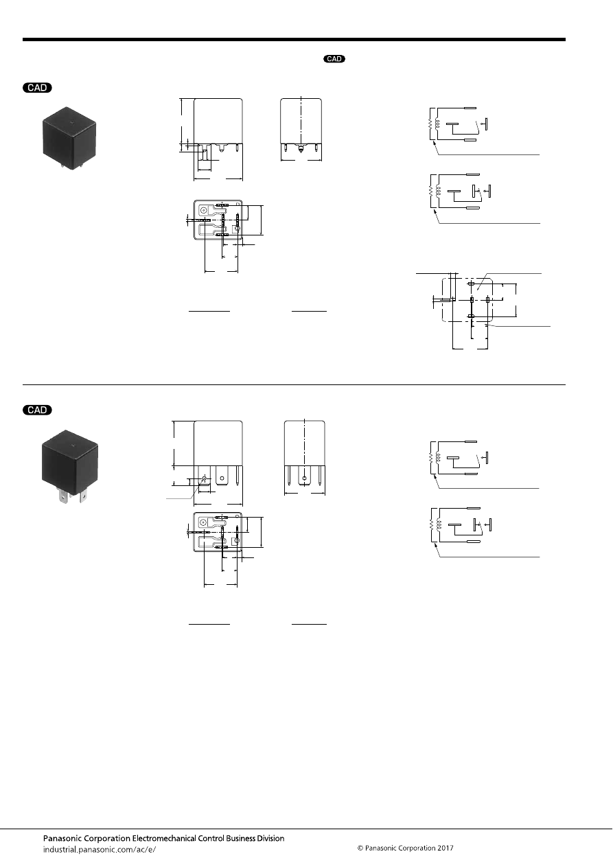
CB (ACB)
–162–
ASCTB220E 201709-T
DIMENSIONS
(mm
inch
)
1. PC board type
2. Plug-in type
mark can be downloaded from: http://industrial.panasonic.com/ac/e/
The CAD data of the products with a
External dimensions
86
87a
87
30
85
6.3
.248
25
.984
1
.039
4.5
.177
2.15
.085
26.0
1.024
22
.866
0.8
.031
8.4
.331
16.8
.661
2.6
.102
17.9
.705
8.4
.331
8
.315
Dimension:
Tolerance
Max. 1mm
.039 inch
:
±
0.1
±
.004
1 to 3mm
.039 to .118 inch
:
±
0.2
±
.008
Min. 3mm
.118 inch
:
±
0.3
±
.012
Schematic (Bottom view)
PC board pattern (Bottom view)
Tolerance:
±
0.1
±
.004
86
30
85
87
86
30
85
87
87a
1 Form A
1 Form C
Including resistor type also available
Including resistor type also available
1 Form C type only
1 Form C type only
4(or5)
×
2.6
30
87a
87
85
86
8.4
16.8
4(or5)
×
1.4
17.9
8.4
8.0
.331
.661
.705
.331
.315
4(or5)
×
.102
4(or5)
×
.055
External dimensions
86
87a
87
85
30
5
×
6.3
5
×
.248
25
.984
11.0
.433
4.0
.157
1.7 dia.
.067 dia.
26.0
1.024
22
.866
0.8
.031
8.4
.331
16.8
.661
2.6
.102
17.9
.705
8.4
.331
8
.315
Dimension:
Tolerance
Max. 1mm
.039 inch
:
±
0.1
±
.004
1 to 3mm
.039 to .118 inch
:
±
0.2
±
.008
Min. 3mm
.118 inch
:
±
0.3
±
.012
Schematic
(Bottom view)
86
30
85
87
86
30
85
87
87a
1 Form A
1 Form C
Including resistor type also available
Including resistor type also available
automotive-relay_en-html.html
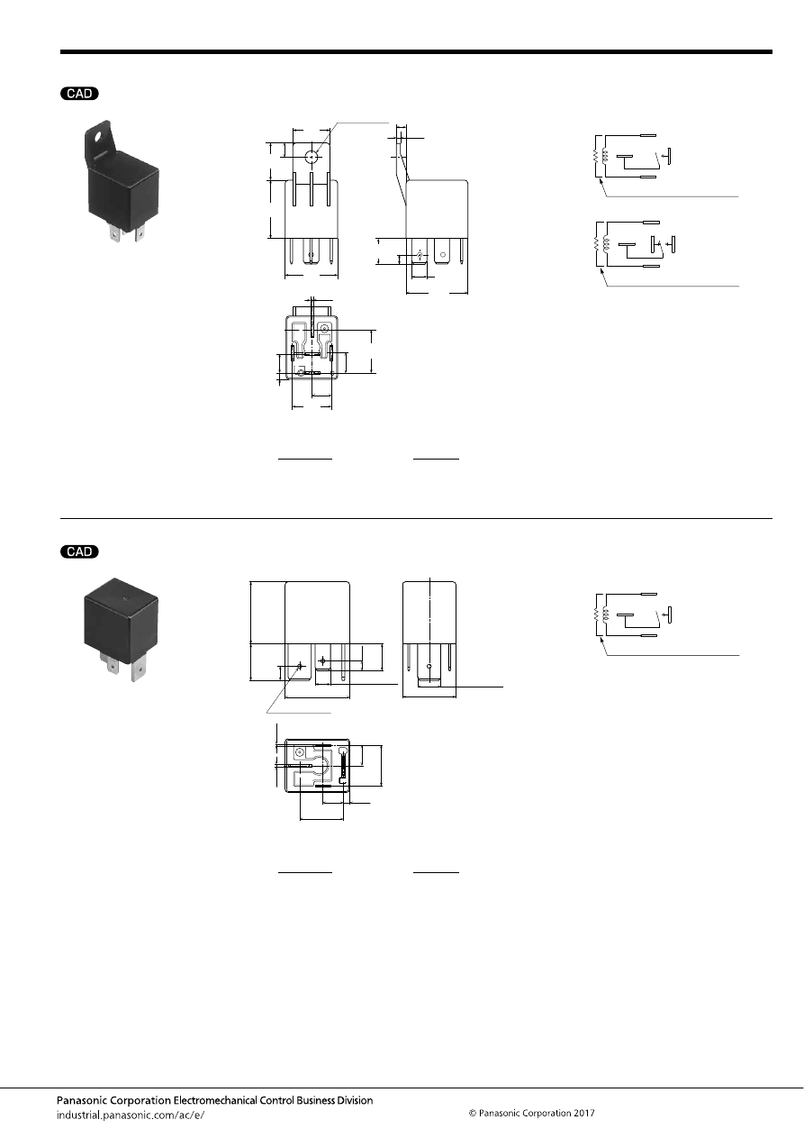
CB (ACB)
–163–
ASCTB220E 201709-T
3. Bracket type
4. 1 Form A high contact capacity (Plug-in type)
External dimensions
86
87a*
87
85
30
5
×
6.3
5
×
.248
25
.984
16.0
.630
11.0
.433
4
.157
5.4
±
0.1 dia.
.213
±
.004 dia.
26
1.024
22.0
.866
16.0
.630
0.8
.031
8.4
.331
6
.236
2.6
.102
17.9
.705
8.4
.331
8
.315
1.7
.067
4
.157
16.8
.661
Dimension:
Tolerance
Max. 1mm
.039 inch
:
±
0.1
±
.004
1 to 3mm
.039 to .118 inch
:
±
0.2
±
.008
Min. 3mm
.118 inch
:
±
0.3
±
.012
Schematic
(Bottom view)
86
30
85
87
86
30
85
87
87a
1 Form A
1 Form C
Including resistor type also available
Including resistor type also available
External dimensions
85
86
30
87
11.0
.433
2
×
9.5
±
0.08
2
×
.374
±
.003
2
×
6.3
±
0.08
2
×
.248
±
.003
4
×
1.7 dia. hole
4
×
.067 dia. hole
22.0
.866
8.4
.331
2.6
.102
17.9
.705
26.5
1.043
8.4
.331
0.8
.031
25.5
1.004
15.0
.591
5.8
.228
1.2
.047
4.0
.157
16.8
.661
Dimension:
Tolerance
Max. 1mm
.039 inch
:
±
0.1
±
.004
1 to 3mm
.039 to .118 inch
:
±
0.2
±
.008
Min. 3mm
.118 inch
:
±
0.3
±
.012
Schematic
(Bottom view)
86
30
85
87
Including resistor type also available
automotive-relay_en-html.html
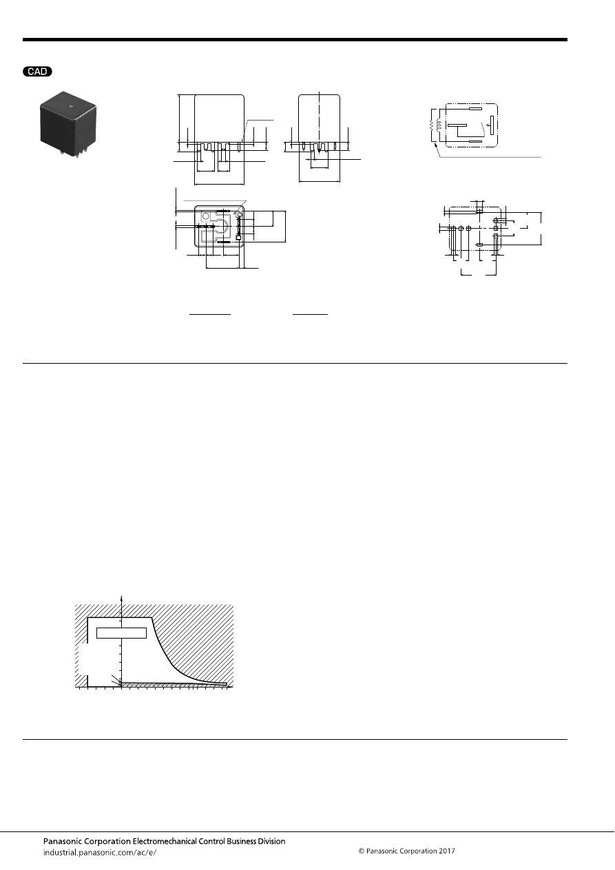
CB (ACB)
–164–
ASCTB220E 201709-T
5. 1 Form A high contact capacity (PC board type)
NOTES
For general cautions for use, please refer to the “Automotive Relay Users Guide”.
External dimensions
86
30
85
87
3
×
1.7
3
×
.067
3
×
1.7
3
×
.067
2
×
2.15
2
×
.085
9.5
.374
9.5
.374
6.3
.248
22.0
.866
8.4
.331
3.9
.154
3.9
.154
2.6
.102
17.9
.705
26.5
1.043
8.4
.331
2
×
0.8
2
×
.031
25.5
1.004
5.3
.209
3.9
.154
3.9
.154
5.3
.209
2
×
1.2
2
×
.047
1.0
.039
1.0
.039
1.0
.039
4.5
.177
4.5
.177
16.8
.661
A surface
level
Sealed by epoxy resin
Dimension:
Tolerance
Max. 1mm
.039 inch
:
±
0.1
±
.004
1 to 3mm
.039 to .118 inch
:
±
0.2
±
.008
Min. 3mm
.118 inch
:
±
0.3
±
.012
* Intervals between terminals is measured at A surface level.
Schematic
(Bottom view)
PC board pattern (Bottom view)
Tolerance:
±
0.1
±
.004
30
86
85
87
Including resistor type also available
30
87
85
86
2.6
1.4
3
×
1.8
3
×
1.8
3
×
2.15
3
×
2.15
16.8
8.4
7.8
8.4
17.9
7.8
.102
.055
3
×
.071
3
×
.071
3
×
.085
3
×
.085
.661
.331
.307
.331
.705
.307
1. Soldering
Max. 350
°
C
662
°
F
(solder temperature), within 3 seconds
(soldering time)
The effect on the relay depends on the actual PC board used.
Please verify the PC board to be used.
2. Usage, transport and storage conditions
1) Ambient temperature, humidity, and air pressure during
usage, transport, and storage of the relay:
(1) Temperature: –40 to +85
°
C
–40 to +185
°
F
(Standard type)
–40 to +125
°
C
–40 to +257
°
F
(High heat-resistant type)
(2) Humidity: 2 to 85% RH (Avoid icing and condensation.)
(3) Air pressure: 86 to 106 kPa
The humidity range varies with the temperature. Use within the
range indicated in the graph below.
[Temperature and humidity range for
usage, transport, and storage]
85
5
2
110
85
0
–40
+230
125
+257
+185
+32
–40
Humidity, %RH
Temperature,
°
C
°
F
Tolerance range
(Avoid
condensation
when used at
temperatures
higher than
0
°
C
32
°
F
)
(Avoid icing
when used at
temperatures
lower than
0
°
C
32
°
F
)
automotive-relay_en-html.html
CM (ACM)
–165–
ASCTB222E 201709-T
ORDERING INFORMATION
TYPES
Standard type
Note: Please use “CM
∗∗
-R-
∗
-
∗
” built-in resistor type. (Asterisks “
∗
” should be filled in from ORDERING INFORMATION.)
Micro-ISO
Automotive Relay
CM RELAYS
Contact
arrangement
Rated coil
voltage
Plug-in type
PC board type
Packing
Sealed
Flux tight
Sealed
Flux tight
Carton
Case
Type No.
Type No.
Type No.
Type No.
1 Form A
12 V DC
CM1a-12V
CM1aF-12V
—
—
50 pcs.
200 pcs.
24 V DC
CM1a-24V
CM1aF-24V
CM1a-P-24V
CM1aF-P-24V
1 Form C
12 V DC
CM1-12V
CM1F-12V
—
—
24 V DC
CM1-24V
CM1F-24V
CM1-P-24V
CM1F-P-24V
FEATURES
• Micro-ISO type terminals and small size
• Wide line-up
• Compact and high-capacity switching
TYPICAL APPLICATIONS
• Fan motor, Heater, Head lump, Air compressor, ABS,
Blower fan, Defogger, etc.
<Protective construction>
Flux tight/Sealed
15
20
22
.591
.787
.866
15
20
23
.591
.787
.906
(Unit: mm
inch
)
RoHS compliant
Contact arrangement
1a:
1:
1 Form A
1 Form C
CM
Protective construction
Nil:
F:
Sealed
Flux tight
Mounting classification
Nil:
P:
Plug-in type
PC board type (24 V only)
Protective element
Nil:
R:
None
With resistor inside
Rated coil voltage (DC)
12 V, 24 V
automotive-relay_en-html.html
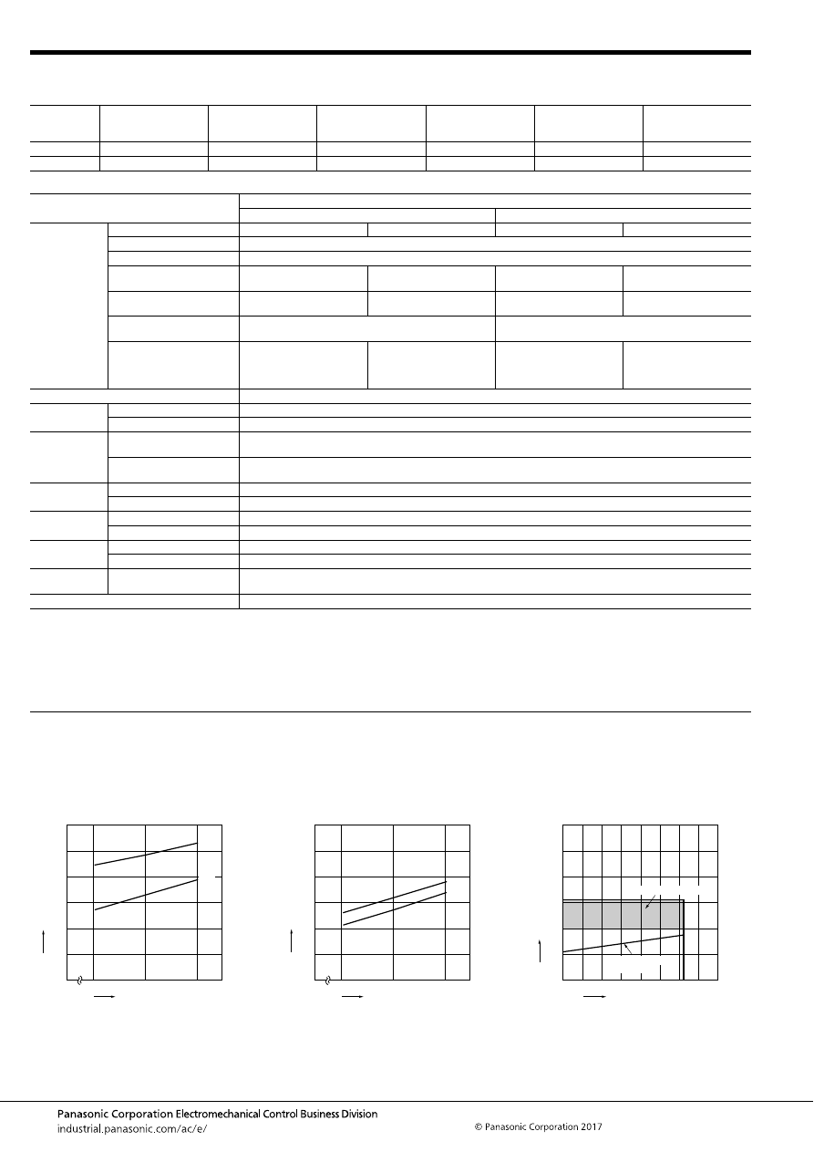
CM (ACM)
–166–
ASCTB222E 201709-T
RATING
1. Coil data
2. Specifications
Notes: *1. Depends on connection conditions. Also, this does not guarantee repeated switching. We recommend that you confirm operation under actual conditions.
*2. This value can change due to the switching frequency, environmental conditions, and desired reliability level, therefore it is recommended to check this with the
actual load.
*3. The upper operation ambient temperature limit is the maximum temperature that can satisfy the coil temperature rise value. For details, please refer to the
“Automotive Relay Users Guide”.
Please inquire our sales representative if you will be using the relay in a high temperature atmosphere (110
°
C
230
°
F
)
REFERENCE DATA
Rated coil
voltage
Operate (Set) voltage
(at 20
°
C
68
°
F
) (Initial)
Release (Reset)
voltage
(at 20
°
C
68
°
F
) (Initial)
Rated operating current
[
±
10%] (at 20
°
C
68
°
F
)
Coil resistance
[
±
10%] (at 20
°
C
68
°
F
)
Rated operating power
Usable voltage range
12 V DC
3 to 7 V DC
1.2 to 4.2 V DC
125 mA
96
Ω
1.5 W
10 to 16V DC
24 V DC
6 to 14 V DC
2.4 to 8.4 V DC
75 mA
320
Ω
1.8 W
20 to 32V DC
Item
Specifications
12 V DC
24 V DC
Contact data
Contact arrangement
1 Form A
1 Form C
1 Form A
1 Form C
Contact resistance (initial)
Max. 15m
Ω
(Typ. 2m
Ω
) (By voltage drop 1A 6V DC)
Contact material
Ag alloy
Rated switching capacity
(resistive)
N.O. side: 35 A 14V DC
N.O. side: 35 A 14V DC
N.C. side: 20 A 14V DC
N.O. side: 15 A 28V DC
N.O. side: 15 A 28V DC
N.C. side: 8 A 28V DC
Max. carrying current
(at 85
°
C
185
°
F
, continuous)*
1
N.O. side: 20 A 14V DC
N.O. side: 20 A 14V DC
N.C. side: 10 A 14V DC
N.O. side: 15 A 28V DC
N.O. side: 15 A 28V DC
N.C. side: 8 A 28V DC
Min. switching load
(resistive)*
2
1 A 14V DC (at 20
°
C
68
°
F
)
1 A 14V DC (at 20
°
C
68
°
F
)
Contact voltage drop
(after electrical life test)
N.O. side: Max. 0.5 V (By
voltage drop 35 A 14 V DC)
N.O. side: Max. 0.5 V (By
voltage drop 35 A 14 V DC)
N.C. side: Max. 0.3 V (By
voltage drop 20 A 14 V DC)
N.O. side: Max. 0.3 V (By
voltage drop 15 A 28 V DC)
N.O. side: Max. 0.3 V (By
voltage drop 15 A 28 V DC)
N.C. side: Max. 0.2 V (By
voltage drop 8 A 28 V DC)
Insulated resistance (initial)
Min. 20 M
Ω
(at 500V DC, Measurement at same location as “Dielectric strength” section.)
Dielectric
strength (initial)
Between open contacts
500 Vrms for 1 min. (Detection current: 10mA)
Between contacts and coil
500 Vrms for 1 min. (Detection current: 10mA)
Time
characteristics
(initial)
Operate (Set) time
(at rated coil voltage)
Max. 10ms (at 20
°
C
68
°
F
, without bounce time)
Release (Reset) time
(at rated coil voltage)
Max. 10ms (at 20
°
C
68
°
F
, without bounce time) (Without diode)
Shock
resistance
Functional
Min. 200 m/s
2
{approx. 20G} (Half-wave pulse of sine wave: 11ms; detection time: 10
μ
s)
Destructive
Min. 1,000 m/s
2
{approx. 100G} (Half-wave pulse of sine wave: 6ms)
Vibration
resistance
Functional
10 to 500 Hz, Min. 44.1 m/s
2
{approx. 4.5G}
Destructive
10 to 2,000 Hz, Min. 44.1 m/s
2
{approx. 4.5G}, Time of vibration for each direction; X, Y, Z direction: 4 hours
Expected life
Mechanical
Min. 10
6
(at 120 cpm)
Electrical
Flux tight: Min. 10
5
, Sealed: Min. 5
×
10
4
(Operating frequency: 2s ON, 2s OFF)
Conditions
Conditions for usage,
transport and storage*
3
Ambient temperature: –40 to +85
°
C
–40 to +185
°
F
, Humidity: 5 to 85% R.H. (Please avoid icing or condensation)
Weight
Approx. 20 g
.71 oz
1.-(1) Coil temperature rise (12V type, 85
°
C
185
°
F
)
Sample: CM1F-12V, 3 pcs.
Measured portion: Inside the coil
Contact carrying current: 20A, 35A
Ambient temperature: 85
°
C
185
°
F
1.-(2) Coil temperature rise (24V type, 85
°
C
185
°
F
)
Sample: CM1F-24V, 4 pcs.
Measured portion: Inside the coil
Contact carrying current: 0A, 15A
Ambient temperature: 85
°
C
185
°
F
2. Ambient temperature and usable voltage
range (12V type)
12
14
16
0
120
100
80
60
40
20
0
35A
20A
Coil applied voltage, V
T
e
mper
ature r
ise
,
°
C
24
28
32
0
120
100
80
60
40
20
0
15A
0A
Coil applied voltage, V
T
e
mper
ature r
ise
,
°
C
0
Ambient temperature,
°
C
Coil applied v
oltage
,
VDC
5
10
15
30
25
20
-40 -20
20
40
60
8085 100
0
120
Operate voltage
(Cold start)
Usable voltage range
automotive-relay_en-html.html
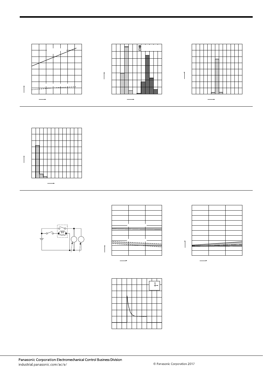
CM (ACM)
–167–
ASCTB222E 201709-T
3. Ambient temperature characteristics
(Cold/initial)
4. Distribution of operate (set) and release
(reset) voltage
Sample: CM1F-12V, 100pcs.
5. Distribution of operate (set) time
Sample: CM1F-12V, 30pcs.
* Max. 10ms standard (excluding contact bounce)
0
Ambient temperature,
°
C
Ratio against the r
ated v
oltage
, %
20
40
60
70
50
30
10
80
-40 -20
20
40
60
80
0
100
Operate voltage
upper limit
Release voltage lower limit
0
30
20
10
40
50
60
70
Voltage, V
Quantity
, n
2
3
5
4
6
7
1
Operate voltage
Release voltage
0
30
20
10
40
25
15
5
35
Time, ms
Quantity
, n
1
2
3
4
5
6
7
6. Distribution of release (reset) time
Sample: CM1F-12V, 30pcs.
* Max. 10ms standard (excluding contact bounce)
0
30
20
10
40
25
15
5
35
Time, ms
Quantity
, n
1
2
3
4
5
6
7
7.-(1) Electrical life test (Motor free)
Sample: CM1aF-R-12V, 6pcs.
Load: 16 A 13.5 V DC
Cooling fan motor actual load
(free condition)
Operating frequency: ON 2s, OFF 6s
Ambient temperature: Room temperature
Circuit:
Change of operate (set) and release (reset)
voltage
Change of contact resistance
M
M
Cooling fan motor
13.5V DC
0
No. of operations,
×
10
4
Oper
ate and release v
oltage
,
V
Max.
Max.
Min.
Min.
2
1
4
6
8
9
7
5
3
10
0
10
20
35
Operate voltage
Release voltage
0
No. of operations,
×
10
4
Contact resistance
, m
Ω
Max.
Min.
2
1
4
6
8
9
7
5
3
10
0
10
20
35
Ave.
Load current waveform
Load; Inrush current: 85A, Steady current: 18A
500ms
20A
automotive-relay_en-html.html
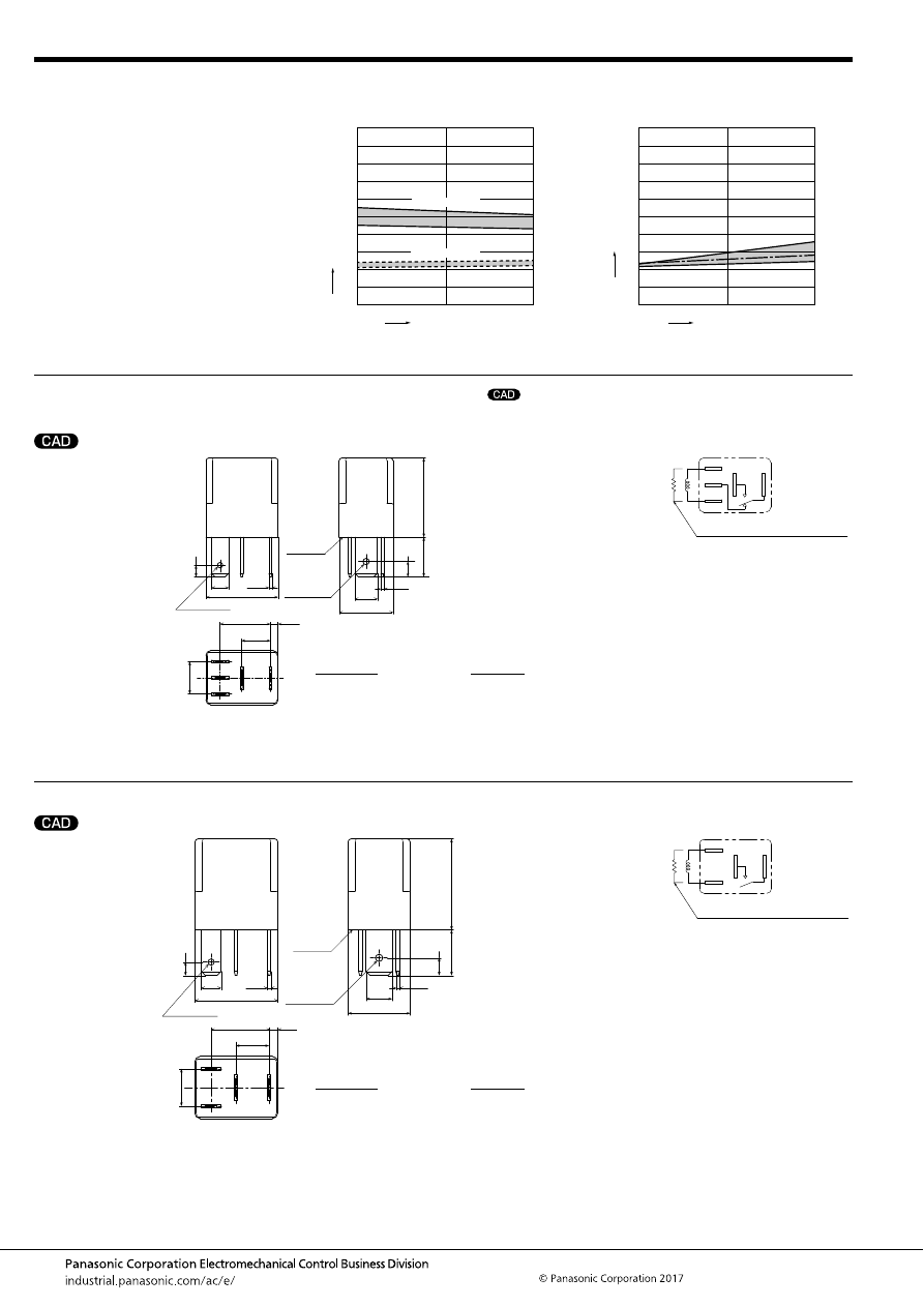
CM (ACM)
–168–
ASCTB222E 201709-T
DIMENSIONS
(mm
inch
)
1. Plug-in type (1 Form C)
2. Plug-in type (1 Form A)
7.-(2) Electrical life test (Halogen lamp load)
Sample: CM1aF-R-12V, 6pcs.
Load: 20A 13.5V DC
Operating frequency: ON 1s, OFF 14s
Ambient temperature: Room temperature
Change of operate (set) and release (reset)
voltage
Change of contact resistance
0
No. of operations,
×
10
4
Oper
ate and release v
oltage
,
V
Max.
Max.
Min.
Min.
2
1
4
6
8
9
7
5
3
10
0
5
10
Operate voltage
Release voltage
0
No. of operations,
×
10
4
Contact resistance
, m
Ω
Max.
Min.
2
1
4
6
8
9
7
5
3
10
0
5
10
Ave.
mark can be downloaded from: http://industrial.panasonic.com/ac/e/
The CAD data of the products with a
External dimensions
86
85
87a
87
30
2
×
1.75 dia.
3
×
1.5 dia.
A surface
level
8
2.1
20
15
0.8
4.8
6.3
14
0.8
3.25
9
11
22
4.25
.248
.031
.433
.866
.167
2
×
.069 dia.
.591
.083
.354
.315
.551
3
×
.059 dia.
.787
.031
.128
.189
Dimension:
Tolerance
Max. 1mm
.039 inch
:
±
0.1
±
.004
1 to 3mm
.039 to .118 inch
:
±
0.2
±
.008
Min. 3mm
.118 inch
:
±
0.3
±
.012
* Intervals between terminals is measured at A surface level.
Schematic (Bottom view)
Including resistor type also available
30
85
86
87a
87
External dimensions
86
85
87a
87
30
2
×
1.75 dia.
2
×
1.5 dia.
8
2.1
20
15
0.8
4.8
6.3
14
0.8
3.25
9
11
22
4.25
2
×
.069 dia.
.591
.248
.031
.433
.866
.167
.083
.354
.315
.551
2
×
.059 dia.
.787
.189
.031
.128
A surface
level
Dimension:
Tolerance
Max. 1mm
.039 inch
:
±
0.1
±
.004
1 to 3mm
.039 to .118 inch
:
±
0.2
±
.008
Min. 3mm
.118 inch
:
±
0.3
±
.012
* Intervals between terminals is measured at A surface level.
Schematic (Bottom view)
30
85
86
87
Including resistor type also available
automotive-relay_en-html.html
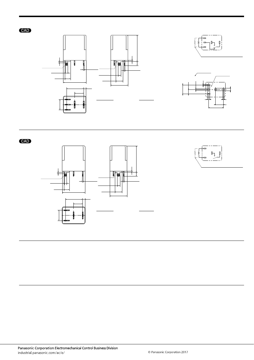
CM (ACM)
–169–
ASCTB222E 201709-T
3. PC board type (1 Form C, 24V only)
4. PC board type (1 Form A, 24V only)
NOTES
For general cautions for use, please refer to the “Automotive Relay Users Guide”.
External dimensions
86
85
87a
87
30
Pre-soldering
(All terminals)
8
2.1
20
15
15
9
23
MAX. 1.2
1
3.5
.591
.906
.039
.138
.083
.354
.315
.591
MAX. .047
.787
3
×
4.8
3
×
.189
2
×
6.3
2
×
.248
A surface
level
3
×
2.1
3
×
.083
+
0.3
−
0.1
+
.012
−
.004
2
×
0.8
2
×
.031
+
0.4
−
0.1
+
.016
−
.004
3
×
0.8
3
×
.031
+
0.4
−
0.1
+
.016
−
.004
2
×
2.5
2
×
.098
+
0.3
−
0.1
+
.012
−
.004
Dimension:
Tolerance
Max. 1mm
.039 inch
:
±
0.1
±
.004
1 to 3mm
.039 to .118 inch
:
±
0.2
±
.008
Min. 3mm
.118 inch
:
±
0.3
±
.012
* Dimensions (thickness and width) of terminal is measured after pre-soldering.
Intervals between terminals is measured at A surface level.
Schematic (Bottom view)
PC board pattern (Bottom view)
Tolerance:
±
0.1
±
.004
Including resistor type also available
30
85
86
87a
87
87
87a
86
85
30
1c type only
1c type only
9.0
±
0.05
.354
±
.002
2
×
1.34
+0.1
0
2
×
.053
+.004
0
2
×
2.7
+0.1
0
2
×
.106
+.004
0
1.4
+0.1
0
.055
+.004
0
1.4
+0.1
0
.055
+.004
0
2 (or 3)
×
2.4
+0.1
0
2 (or 3)
×
.094
+.004
0
4.5
±
0.05
.177
±
.002
15.0
±
0.05
.591
±
.002
8.0
±
0.05
.315
±
.002
External dimensions
86
85
87
30
Pre-soldering
(All terminals)
8
2.1
20
15
15
9
23
MAX. 1.2
1
3.5
.591
.906
.039
.138
.083
.354
.315
.591
MAX. .047
.787
2
×
4.8
2
×
.189
2
×
6.3
2
×
.248
A surface
level
2
×
2.1
2
×
.083
+
0.3
−
0.1
+
.012
−
.004
2
×
0.8
2
×
.031
+
0.4
−
0.1
+
.016
−
.004
2
×
0.8
2
×
.031
+
0.4
−
0.1
+
.016
−
.004
2
×
2.5
2
×
.098
+
0.3
−
0.1
+
.012
−
.004
Dimension:
Tolerance
Max. 1mm
.039 inch
:
±
0.1
±
.004
1 to 3mm
.039 to .118 inch
:
±
0.2
±
.008
Min. 3mm
.118 inch
:
±
0.3
±
.012
* Dimensions (thickness and width) of terminal is measured after pre-soldering.
Intervals between terminals is measured at A surface level.
Schematic (Bottom view)
30
85
86
87
Including resistor type also available
1. Soldering
Max. 350
°
C
662
°
F
(solder temperature), within 3 seconds
(soldering time)
The effect on the relay depends on the actual PC board used.
Please verify the PC board to be used.
automotive-relay_en-html.html
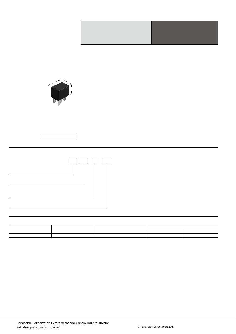
CV-N (ACVN)
–170–
ASCTB297E 201709-T
ORDERING INFORMATION
TYPES
Note: Please use “ACVN
∗∗
2
∗∗
” to order with resistor inside type. (Asterisks “
∗
” should be filled in from ORDERING INFORMATION.)
Low Profile Micro-ISO
Automotive Relay
CV-N RELAYS
Contact arrangement
Rated coil voltage
Part No.
Packing
Carton
Case
1 Form A
12 V DC
ACVN51012
50 pcs.
200 pcs.
FEATURES
• Low profile automotive relays for Micro-ISO terminal
• Compact and high-capacity load switching
TYPICAL APPLICATIONS
• Headlights, Magnetic clutches, Radiator fans, Blowers,
Fog lamps, Tail lights, Heaters, Defoggers, Condenser
fans, etc.
<Protective construction>
Sealed
15
22.5
15.7
.591
.886
.618
(Unit: mm
inch
)
RoHS compliant
Contact arrangement
5: 1 Form A
ACVN
Protective element
0: None
2: With resistor inside
Mounting classification
1: Micro ISO plug-in type
Rated coil voltage, DC
12: 12 V
automotive-relay_en-html.html
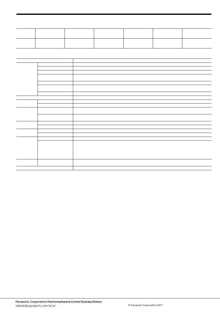
CV-N (ACVN)
–171–
ASCTB297E 201709-T
RATING
1. Coil data
2. Specifications
Notes: *1. Depends on connection conditions. Also, this does not guarantee repeated switching. We recommend that you confirm operation under actual conditions.
*2. This value can change due to the switching frequency, environmental conditions, and desired reliability level, therefore it is recommended to check this with the
actual load.
*3. The upper operation ambient temperature limit is the maximum temperature that can satisfy the coil temperature rise value. For details, please refer to the
“Automotive Relay Users Guide”.
*4. Please inquire our sales representative if you will be using the relay in a high temperature atmosphere.
Rated coil
voltage
Operate (Set) voltage
(at 20
°
C
68
°
F
) (Initial)
Release (Reset)
voltage
(at 20
°
C
68
°
F
) (Initial)
Rated operating current
[
±
10%] (at 20
°
C
68
°
F
)
Coil resistance
[
±
10%] (at 20
°
C
68
°
F
)
Rated operating power
(at 20
°
C
68
°
F
)
Usable voltage range
12V DC
Max. 7.0 V DC
Min. 0.5 V DC
66.7 mA,
74.7 mA (with resistor
inside)
180
Ω
,
160.7
Ω
(with resistor
inside)
800 mW,
900 mW (with resistor
inside)
10 to 16V DC
Item
Specifications
Contact data
Contact arrangement
1 Form A
Contact resistance (initial)
Max. 15m
Ω
(Typ. 3m
Ω
) (By voltage drop 1A 6V DC)
Contact material
Ag alloy
Rated switching capacity
(resistive)
N.O. side: 35 A 14V DC
Max. carrying current*
1
N.O. side: 20 A 14V DC (at 85
°
C
185
°
F
, continuous)
Min. switching load
(resistive)*
2
1 A 14V DC (at 20
°
C
68
°
F
)
Contact voltage drop (initial)
N.O. side: Max. 0.5 V (By voltage drop 14 V DC 35 A)
Insulated resistance (initial)
Min. 20 M
Ω
(at 500V DC, Measurement at same location as “Dielectric strength” section.)
Dielectric
strength (initial)
Between open contacts
500 Vrms for 1 min. (Detection current: 10mA)
Between contacts and coil
500 Vrms for 1 min. (Detection current: 10mA)
Time
characteristics
(initial)
Operate (Set) time
(at rated coil voltage)
Max. 10ms (at 20
°
C
68
°
F
, without contact bounce time)
Release (Reset) time
(at rated coil voltage)
Max. 10ms (at 20
°
C
68
°
F
, without contact bounce time) (Without diode)
Shock
resistance
Functional
Min. 100 m/s
2
{approx. 10G} (Half-wave pulse of sine wave: 11ms; detection time: 10
μ
s)
Destructive
Min. 1,000 m/s
2
{approx. 100G} (Half-wave pulse of sine wave: 6ms)
Vibration
resistance
Functional
10 to 100 Hz, Min. 44.1 m/s
2
{approx. 4.5G} (Detection time: 10
μ
s)
Destructive
10 to 500 Hz, Min. 44.1 m/s
2
{approx. 4.5G}, Time of vibration for each direction; X, Y, Z direction: 4 hours
Expected life
Mechanical
Min. 10
6
(at 120 cpm)
Electrical
<Resistive load>
Min. 10
5
at rated switching capacity, operating frequency: 2s ON, 2s OFF
<Motor load>
Min. 3
×
10
5
at inrush 84 A, steady 18 A, 14 V DC, Operating frequency: 2s ON, 5s OFF
<Lamp load>
Min. 2
×
10
5
at inrush 84 A, steady 12 A, 14 V DC, Operating frequency: 1s ON, 14s OFF
Conditions
Conditions for usage,
transport and storage*
3
Ambient temperature: –40 to +85
°
C
–40 to +185
°
F
*
4
, Humidity: 5 to 85% R.H. (Please avoid icing or condensation)
Weight
Approx. 12 g
.42 oz
automotive-relay_en-html.html
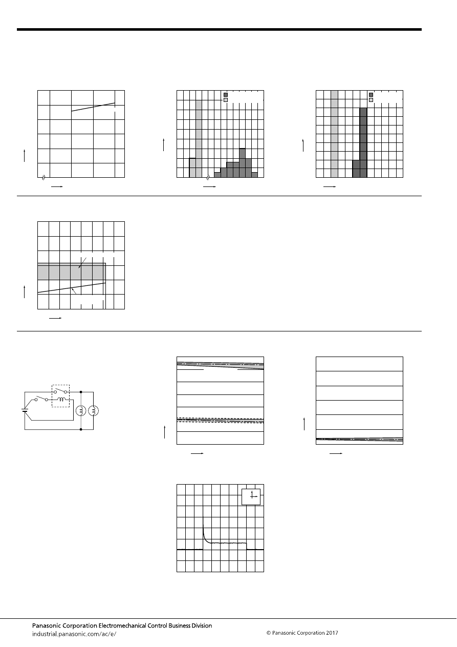
CV-N (ACVN)
–172–
ASCTB297E 201709-T
REFERENCE DATA
1. Coil temperature rise
Point measured: Inside the coil
Carrying current: 20A
Coil applied voltage: 12V, 14V, 16V
Ambient temperature: 85
°
C
185
°
F
2. Distribution of operate (set) and release
(reset) voltage
Sample: ACVN51012, 20pcs
3. Distribution of operate (set) time and release
(reset) time
Sample: ACVN51012, 20pcs.
10
12
14
0
16
180
150
120
90
60
30
0
85
°
C 20A
Coil applied voltage, %V
T
emper
ature r
ise
,
°
C
0
18
16
14
12
10
8
6
4
2
0
1.4
1.8
5.0
5.4
5.8
6.2
6.6
Voltage, V
Quantity
, n
Operate voltage
Release voltage
0
6
4
2
8
10
12
14
16
18
20
3
2
1
0
5
6
4
Operate and release time, ms
Quantity
, n
Operate time
Release time
4. Ambient temperature and usable voltage
range
0
5
10
15
30
25
20
-40 -20
20
40
60
80 85 100
0
120
Operate voltage
(Cold start)
Coil applied v
oltage
,
VDC
Ambient temperature,
°
C
Usable voltage range
5.-(1) Electrical life test (Lamp load)
Sample: ACVN51012, 3pcs.
Load: Inrush: 84A, Steady: 12A,
halogen lamp load (60W
×
2)
Switching frequency: ON 1s, OFF 14s
Ambient temperature: 85
°
C
185
°
F
Circuit:
Change of operate (set) and release (reset)
voltage
Change of contact resistance
0
Max.
Min.
Ave.
2
1
4
6
7
5
3
0
20
Max.
Min.
Ave.
No. of operations,
×
10
4
Oper
ate and release v
oltage
,
V
Operate voltage
Release voltage
0
Max.
Min.
Ave.
10
5
20
30
25
15
0
20
No. of operations,
×
10
4
Contact resistance
, m
Ω
Load current waveform
Load: Inrush current: 84A, steady current: 12A
200ms
20A
automotive-relay_en-html.html
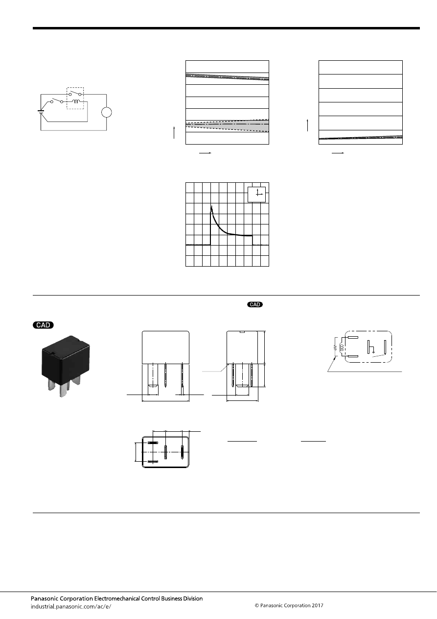
CV-N (ACVN)
–173–
ASCTB297E 201709-T
DIMENSIONS
(mm
inch
)
1. Micro ISO plug-in type
For general cautions for use, please refer to the “Automotive Relay Users Guide”.
5.-(2) Electrical life test (Motor load)
Sample: ACVN51012, 3pcs.
Load: Inrush: 80A, Steady: 18A,
Radiator fan motor (motor free)
Switching frequency: ON 1s, OFF 4s
Ambient temperature: 85
°
C
185
°
F
Circuit:
Change of operate (set) and release (reset)
voltage
Change of contact resistance
M
No. of operations,
×
10
4
Oper
ate and release v
oltage
,
V
0
Max.
Min.
Ave.
2
1
4
6
7
5
3
0
30
Max.
Min.
Ave.
Operate voltage
Release voltage
Contact welding: 0 time
Miscontact: 0 time
0
Max.
Min.
Ave.
10
5
20
30
25
15
0
30
No. of operations,
×
10
4
Contact resistance
, m
Ω
Load current waveform
Load: Inrush current: 80A, Steady current: 18A
200ms
20A
mark can be downloaded from: http://industrial.panasonic.com/ac/e/
The CAD data of the products with a
External dimensions
22.5
.886
6
.236
8
.315
3.25
.128
15
.591
2
×
4.8
2
×
.189
4
×
0.8
4
×
.031
2
×
6.3
2
×
.248
11
.433
15.7
.618
9
.354
A surface
level
Dimension:
Tolerance
Max. 1mm
.039 inch
:
±
0.1
±
.004
1 to 3mm
.039 to .118 inch
:
±
0.2
±
.008
Min. 3mm
.118 inch
:
±
0.3
±
.012
Note: Intervals between terminals is measured at A surface level.
Schematic (Bottom view)
COIL
COM
N.O.
COIL
Including resistor type also available
automotive-relay_en-html.html
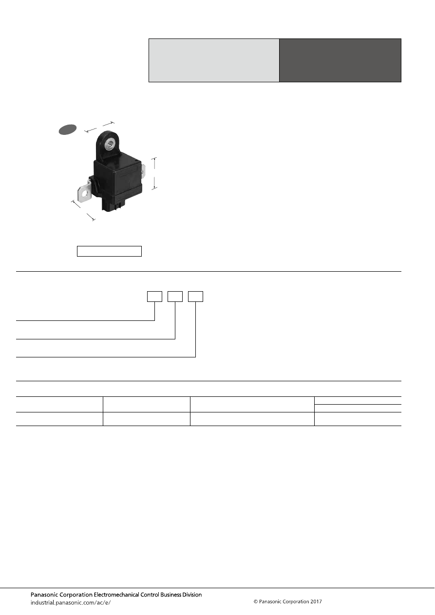
CN-L (ACNL)
–174–
ASCTB364E 201709-T
ORDERING INFORMATION
TYPES
Max. 150 A Continuous
Carrying Current
Latching Relay
CN-L RELAYS
Contact arrangement
Rated coil voltage
Part No.
Packing
Case
1 Form A
(Latching type)
12V DC
ACNL111
25 pcs.
FEATURES
• Continuous carrying current possible at 150 A (at 85
°
C
185
°
F
) or 80 A (at 125
°
C
257
°
F
)
• Maximum 1,500 A conductivity
• Can be used in environments with 125
°
C
257
°
F
ambient
temperature
TYPICAL APPLICATIONS
• Main relay application for protection of lithium batteries,
etc.
• Battery disconnect application (safe circuit shutoff
possible during malfunctions)
• Dual power supply switching application
<Protective construction>
Sealed
38.5
48
37
1.516
1.890
1.457
New
(Unit: mm
inch
)
RoHS compliant
ACNL
Contact capacity
1: 150A
Rated coil voltage (DC)
1: 12V
Contact arrangement
1: 1 Form A (Screw mounting)
automotive-relay_en-html.html
CN-L (ACNL)
–175–
ASCTB364E 201709-T
RATING
1. Coil data
* However, Impulse length is 100
±
50 ms (both Operate (Set) and Release (Reset) sides) and operation interval is 5 seconds or higher (Operate (Set)/Release (Reset)
switching).
2. Specifications
Notes: *1. This does not guarantee repeated switching. We recommend that you confirm operation under actual conditions.
*2. This value can change due to the switching frequency, environmental conditions, and desired reliability level, therefore it is recommended to check this with the
actual load.
*3. The upper operation ambient temperature limit is the maximum temperature that can satisfy the coil temperature rise value. For details, please refer to the
“Automotive Relay Users Guide”.
Rated coil
voltage
Operate (Set) voltage*
(at 20
°
C
68
°
F
) (Initial)
Release (Reset)
voltage*
(at 20
°
C
68
°
F
) (Initial)
Rated operating current
[
±
10%] (at 20
°
C
68
°
F
)
Coil resistance
[
±
10%] (at 20
°
C
68
°
F
)
Rated operating power
(at 20
°
C
68
°
F
)
Max. applied voltage
12V DC
Max. 7.0V DC
Max. 7.0V DC
2.5A
4.8
Ω
30W
16V DC
Item
Specifications
Contact data
Contact arrangement
1 Form A (Latching type)
Contact resistance (initial)
Max. 1.5m
Ω
(Typ. 0.4m
Ω
) (By voltage drop 1A 6V DC)
Max. 1.0m
Ω
(By voltage drop 10A 6V DC)
Contact material
Ag alloy
Rated switching capacity
(resistive)
150A 14V DC
Continuous carrying current
150 A (at 85
°
C
185
°
F
, Connection cable: 38 mm
2
)
80 A (at 125
°
C
257
°
F
, Connection cable: 38 mm
2
)
Max. carrying current*
1
1,500 A for 0.5 seconds ([at forward direction] at 20
°
C
68
°
F
, Connection cable: 38 mm
2
)
Max. cut-off current
350 A 14 V DC (1,000 times or more in forward direction, Switching frequency: 1s ON, 9s OFF, at 20
°
C
68
°
F
, Connection
cable: 38 mm
2
)
Min. switching load
(resistive)*
2
1 A 14 V DC (at 20
°
C
68
°
F
)
Contact voltage drop (initial)
Max. 0.1 V (at 100 A, 12 V DC)
Insulated resistance (initial)
Min. 10 M
Ω
(at 500 V DC)
Dielectric
strength (initial)
Between open contacts
500 Vrms for 1 min. (Detection current: 10mA)
Between contacts and coil
500 Vrms for 1 min. (Detection current: 10mA)
Time
characteristics
(initial)
Operate (Set) time
(at rated coil voltage)
Max. 10ms (at 20
°
C
68
°
F
, without bounce time)
Release (Reset) time
(at rated coil voltage)
Max. 10ms (at 20
°
C
68
°
F
) (without diode)
Shock
resistance
Functional
Min. 250 m/s
2
(N.O. side: closing)
Min. 500 m/s
2
(N.O. side: open, set/reset reversal) (Half-wave pulse of sine wave: 11ms; detection time: 10
μ
s)
Destructive
Min. 1,000 m/s
2
(Half-wave pulse of sine wave: 6ms)
Vibration
resistance
Functional
10 to 500 Hz, Min. 44.1m/s
2
(Detection time: 10
μ
s)
Destructive
10 to 500 Hz, Min. 44.1m/s
2
(Time of vibration for each direction; X, Y direction: 2 hours, Z direction: 4 hours)
Expected life
Mechanical
Min. 3
×
10
5
(Switching frequency: 30 times/min.)
Electrical
150 A 14 V DC resistive load, Min. 3
×
10
4
(Switching frequency: 1s ON, 9s OFF, at 85
°
C
185
°
F
, Connection cable: 38 mm
2
)
Conditions
Conditions for usage,
transport and storage*
3
Ambient temperature: –40 to +125
°
C
–40 to +257
°
F
Humidity: 2 to 85% R.H. (Please avoid icing or condensation)
Weight
Approx. 150 g
5.29 oz
automotive-relay_en-html.html
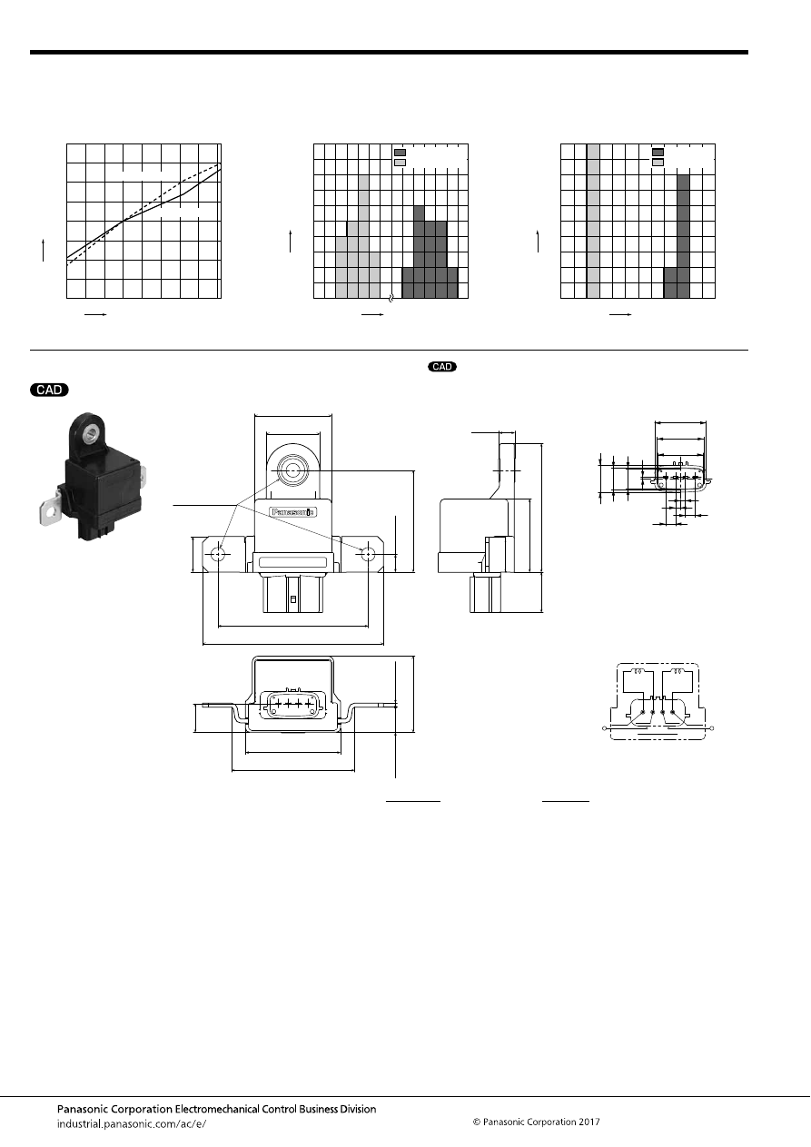
CN-L (ACNL)
–176–
ASCTB364E 201709-T
REFERENCE DATA
DIMENSIONS
(mm
inch
)
1. Ambient temperature characteristics
Sample: ACNL111, 3pcs.
2. Distribution of operate (set) and release
(reset) voltage
Sample: ACNL111, 20pcs.
3. Distribution of operate (set) time and release
(reset) time
Sample: ACNL111, 20pcs.
Operate voltage
Release voltage
-40
40
Change r
ate
, %
30
20
10
0
-10
-20
-30
-40
-20
0
20
40
60
80 100 120
Ambient temperature,
°
C
Quantity
, n
5.2
4.8
Voltage, V
4.4
Operate voltage
Release voltage
4.0
3.0
2.6
2.2
0
10
8
6
4
2
0
Quantity
, n
6
0
1
2
3
4
5
Time, ms
Operate time
Release time
20
18
16
14
12
10
8
6
4
2
0
* Without diode
mark can be downloaded from: http://industrial.panasonic.com/ac/e/
The CAD data of the products with a
External dimensions
8.25
27
39
1.063
1.535
91.5
48
Matching female connector:
DL090/6195-0030 (manufactured by Sumitomo)
20.3
65
37
.325
.799
2.559
1.457
76
±
0.3
3.602
2.992
±
.012
62
±
0.5
1.890
2.441
±
.020
38.5
12.7
±
0.3
2
±
0.1
1.516
.500
±
.012
.079
±
.004
51.5
±
0.3
2.028
±
.012
9
±
0.3
.354
±
.012
18
.709
14.5
.571
3-7 dia.
3-.276 dia.
M6,
Screw tightening
area
Connector area enlarged view
Schematic
(Bottom view)
2.5
.098
2.5
.098
5
.197
5
.197
22.9
23.5
26.1
.902
.925
1.028
13.6
.535
11
.433
10.4
.409
0.8
.031
Connector non-specified general tolerance
Max. 10mm:
±
0.15
Max. .394inch:
±
.006
10 to 50mm:
±
0.2
.394 to 1.969inch:
±
.008
(
+
)
(
−
)
1(
+
)
2(
−
)
3(
−
)
4(
+
)
Load side terminals
Coil terminals
Set side: 1-2 / Reet side: 3-4
Dimension:
Max. 10mm
.394inch
:
10 to 50mm
.394 to 1.969 inch
:
Min. 50mm
1.969 inch
:
Tolerance
±
0.3
±
.012
±
0.6
±
.024
±
1.0
±
.039
automotive-relay_en-html.html
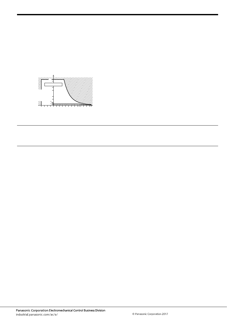
CN-L (ACNL)
–177–
ASCTB364E 201709-T
NOTES
For general cautions for use, please refer to the “Automotive Relay Users Guide”.
PRECAUTIONS REGARDING LATCHING RELAYS
Usage, transport and storage conditions
1) Ambient temperature, humidity, and air pressure during
usage, transport, and storage of the relay:
(1) Temperature: –40 to +125
°
C
–40 to +257
°
F
(2) Humidity: 2 to 85% RH (Avoid icing and condensation.)
(3) Air pressure: 86 to 106 kPa
The humidity range varies with the temperature. Use within the
range indicated in the graph below.
[Temperature and humidity range for
usage, transport, and storage]
5
2
85
125
85
0
–40
+257
+185
+32
–40
Temperature,
°
C
°
F
Allowable range
(Avoid
condensation
when used at
temperatures
higher than
0
°
C
32
°
F
)
(Avoid icing
when used at
temperatures
lower than
0
°
C
32
°
F
)
Humidity, %RH
• Latching relays are shipped from the factory in the reset
state. A shock to the relay during shipping or installation
may cause it to change to the set state.
Therefore, it is recommended that the relay be used in a
circuit which initializes the relay to the required state
(reset) whenever the power is turned on.
• Avoid impressing voltages to the set coil and reset coil at
the same time.
• When connecting coils, refer to the wiring diagram to
prevent mis-operation or malfunction.
automotive-relay_en-html.html
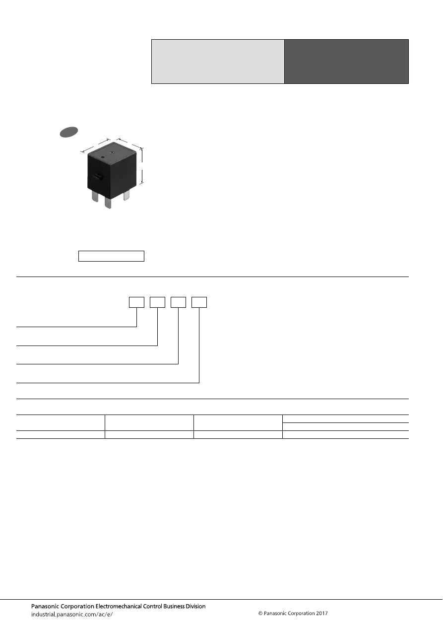
EC-N (AECN)
–178–
ASCTB380E 201709-T
ORDERING INFORMATION
TYPES
Small, High Capacity,
High Voltage DC
Plug in Type Relay
EC-N RELAYS
Contact arrangement
Rated coil voltage
Part No.
Packing
Carton
1 Form A plug in type
12 V DC
AECN11012
100 pcs. (Packed with 100 pcs/1 tray)
FEATURES
• Small and High capacity
Use of an arc space and optimal placement of arc extinction
parts has enabled extreme form-factor reduction, down to half
the size of our previous equivalent product (EC relay).
• Easy-connect plug in terminal
Plug in insertion to box and may be locked in with case
catches.
TYPICAL APPLICATIONS
• High voltage pre-charge relay applications for electric
vehicles (HEV, PHEV, BEV, FCV), etc.
<Protective construction>
Sealed
25
29
28.9
.984
1.142
1.138
New
(Unit: mm
inch
)
RoHS compliant
Contact arrangement/terminal shape
1: 1 Form A plug in type
AECN
Protective construction
0: Sealed
Contact capacity
1: 15 A
Rated coil voltage
12: 12 V DC
automotive-relay_en-html.html
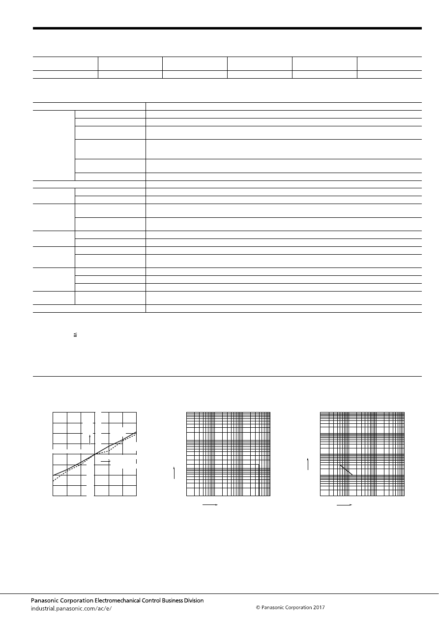
EC-N (AECN)
–179–
ASCTB380E 201709-T
RATING
1. Coil data
Note: *1. When continually powered, the maximum allowable voltage is 14V DC.
2. Specifications
Notes: *1. This value can change due to the switching frequency, environmental conditions, and desired reliability level, therefore it is recommended to check this with the
actual load.
*2. Switch-off life when a varistor (ZNR) is used to absorb surge from coil. Please be warned that working life will be reduced when a diode is used.
*3. at L/R 1ms
*4. The upper operation ambient temperature limit is the maximum temperature that can satisfy the coil temperature rise value. For details, please refer to the
“Automotive Relay Users Guide”.
REFERENCE DATA
Rated coil voltage
Operate (Set) voltage
(at 20
°
C
68
°
F
) (Initial)
Release (Reset) voltage
(at 20
°
C
68
°
F
) (Initial)
Coil resistance
[
±
10%] (at 20
°
C
68
°
F
)
Rated operating power
(at 20
°
C
68
°
F
)
Max. applied voltage*
1
12 V DC
Max. 6.8 V DC
Min. 0.5 V DC
103
Ω
1.4 W
16 V DC
Item
Specifications
Contact data
Contact arrangement
1 Form A
Contact material
Ag alloy
Rated switching capacity
(resistive)
15A 400V DC
Max. allowed current
5A Continuity
10A 5min,
20A 1 min. (2mm
2
wire)
Min. switching load
(resistive)*
1
1A 12V DC (at 20
°
C
68
°
F
)
Contact voltage drop (initial)
Max. 0.5V (10 A carrying current)
Insulated resistance (initial)
Min. 100 M
Ω
(at 500V DC, Measurement at same location as “Dielectric strength” section.)
Dielectric
strength (initial)
Between open contacts
2,500 Vrms for 1 min. (Detection current: 10mA)
Between contacts and coil
2,500 Vrms for 1 min. (Detection current: 10mA)
Time
characteristics
(initial)
Operate (Set) time
(at rated coil voltage)
Max. 50ms (at 20
°
C
68
°
F
, without bounce time)
Release (Reset) time
(at rated coil voltage)
Max. 30ms (at 20
°
C
68
°
F
, without bounce time) (Without diode)
Shock
resistance
Functional
Min. 196 m/s
2
{approx. 20G} (Half-wave pulse of sine wave: 11ms; detection time: 10
μ
s)
Destructive
Min. 490 m/s
2
{approx. 50G} (Half-wave pulse of sine wave: 6ms)
Vibration
resistance
Functional
10 to 200 Hz, 44.1m/s
2
{approx. 4.5G} (Detection time: 10
μ
s)
Destructive
10 to 200 Hz, 44.1m/s
2
{approx. 4.5G}
Time of vibration for each direction; X, Y, Z direction: 4 hours
Expected life
Mechanical
2
×
10
5
(at 60 cpm)
Switch-off life *
2,
*
3
15A 400V DC, Min. 10 times
Inrush current (capacitor)
15A 400V DC, Min. 10
5
times
Conditions
Conditions for usage,
transport and storage*
4
Ambient temperature: –40 to +85
°
C
–40 to +185
°
F
, Humidity: 5 to 85% R.H. (Please avoid icing or condensation)
Weight
approx. 40 g
1.41 oz
1. Ambient temperature characteristics
Sample: AECN11012, 3 pcs.
2. Max. value for switching capacity
Sample: AECN11012, 3 pcs.
3. Switch-off life curve (Forward direction)
Sample: AECN11012, 3 pcs.
-40
-20
60
80
0
40
20
40
30
20
10
-30
-10
-20
-40
Operate
voltage
Release
voltage
V
a
riation
ratio
, %
Ambient
temperature,
°
C
10
1
100
1,000
1,000
100
10
1
Contact voltage, V
Contact current, A
10,000
1,000
100
10
1
1
10
100
Contact current, A
Lif
e
, cycle
1,000
automotive-relay_en-html.html
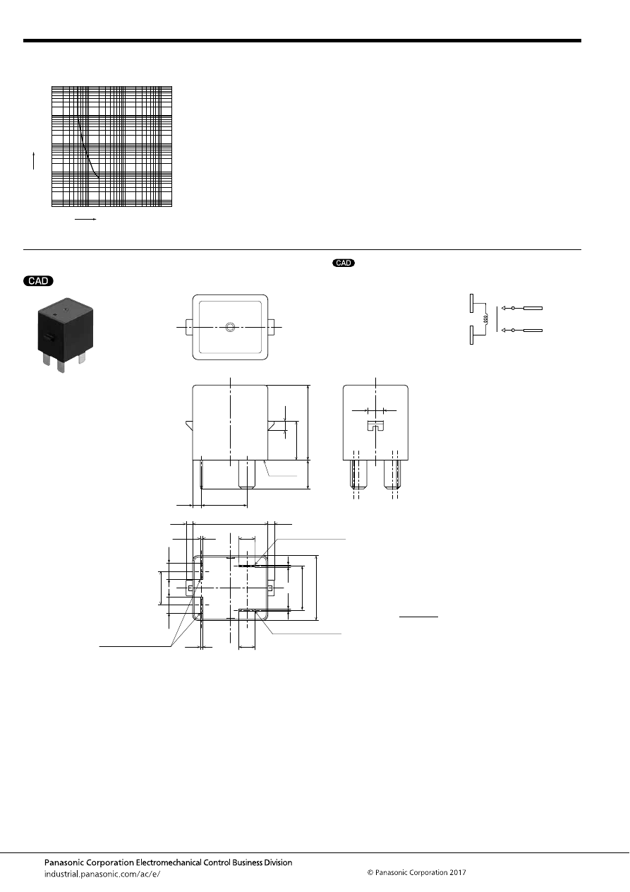
EC-N (AECN)
–180–
ASCTB380E 201709-T
DIMENSIONS
(mm
inch
)
4. Carrying performance curve (85
°
C
185
°
F
)
Sample: AECN11012, 3 pcs.
1
10
100
1,000
100,000
10,000
10
100
1,000
Carrying current, A
Time
, sec
mark can be downloaded from: http://industrial.panasonic.com/ac/e/
The CAD data of the products with a
External dimensions
11.1
.437
28.9
1.138
15.0
.591
6.3
6.3
0.8
.248
.031
3.6
.142
0.8
6.3
.031
.248
29.0
17.0
25.0
.669
.984
13.0
6.3
.248
.512
.248
0.8
0.8
.031
.031
3.4
17.5
.134
.689
6.0
.236
2.5
2.5
1.142
.098
.098
A surface
level
Main terminal (
+
) (#250)
Coil terminal (No polarity)
(#250)
Main terminal (
−
) (#250)
* The terminal position or intervals between terminals is measured at A surface level.
Schematic (Bottom view)
(
+
)
Coil
Coil
(
−
)
Tolerance;
Less than 10mm
.394inch
:
10 to 50mm
.394 to 1.969 inch
:
More than 50mm
1.969 inch
:
±
0.3
±
.012
±
0.6
±
.024
±
1.0
±
.039
automotive-relay_en-html.html
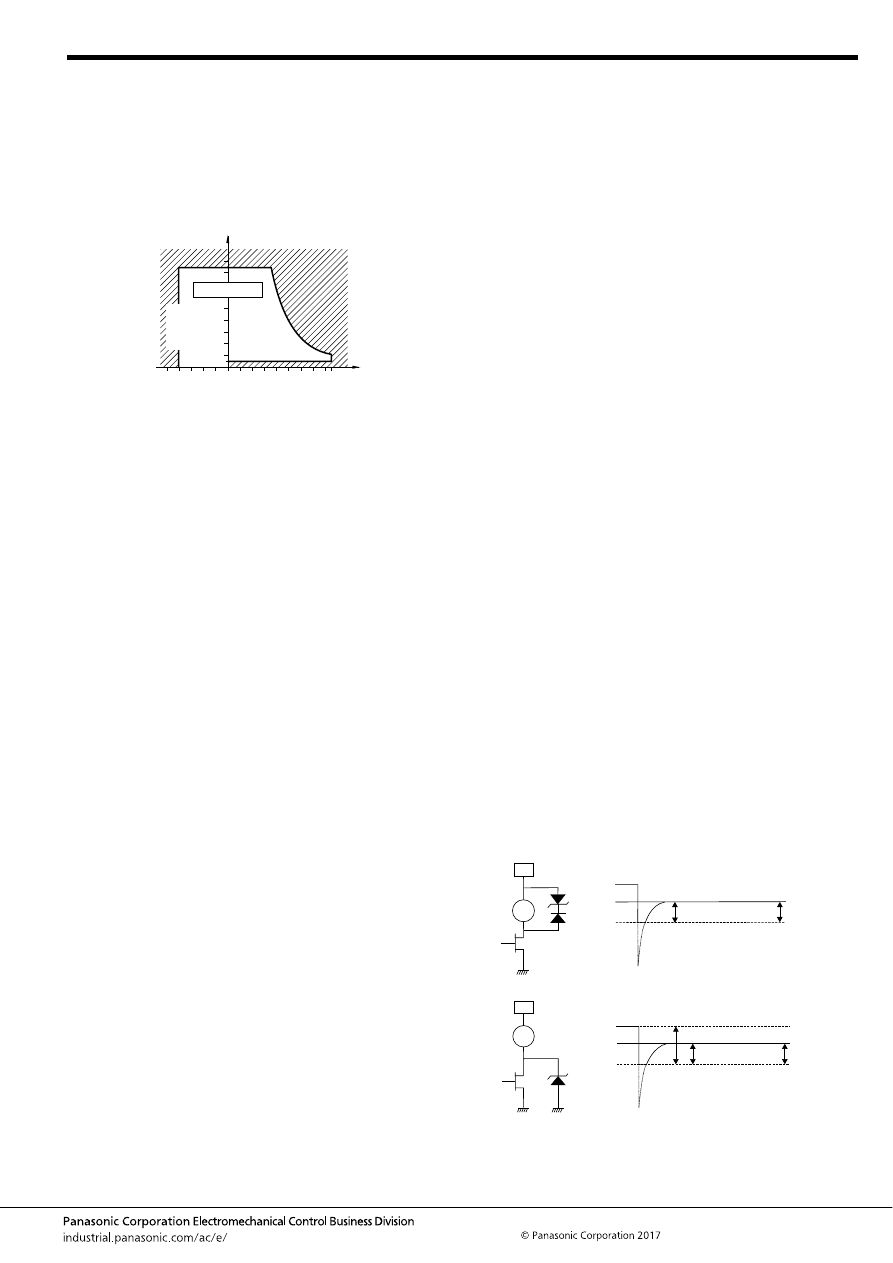
EC-N (AECN)
–181–
ASCTB380E 201709-T
1. Usage, transport and storage conditions
1) Temperature: –40 to +85
°
C
–40 to +185
°
F
2) Humidity: 5 to 85% RH (Avoid icing and condensation.)
The humidity range varies with the temperature. Use within the
range indicated in the graph below.
3) Air pressure: 86 to 106 kPa
[Temperature and humidity range for
usage, transport, and storage]
4) Water condensation
Water condensation occurs when the ambient temperature
drops suddenly from a high temperature and humidity, or, the
relay is suddenly transferred from a low ambient temperature to
a high temperature and humidity. Condensation causes the
failures like insulation deterioration, wire disconnection and rust
etc.
Panasonic Corporation does not guarantee the failures caused
by condensation.
5) Low-temperature, low-humidity atmosphere;
If the relay is exposed to a low-temperature, low-humidity
atmosphere for a long time, its plastic parts may become brittle
and fragile.
6) Icing
Please check the icing when an ambient temperature is lower
than 0
°
C
+32
°
F
. Water drop adheres to the relay by the
condensation or the abnormal high humidity and is frozen to the
ice when the ambient temperature becomes lower than 0
°
C
+32
°
F
. The icing causes the sticking of movable portion, the
operation delay and the contact conduction failure etc.
Panasonic Corporation does not guarantee the failures caused
by the icing.
The heat conduction by the equipment may accelerate the
cooling of relay itself and the icing may occur. Please confirm no
icing in the worst condition of the actual usage.
7) Storage
Do not keep under high-temperature and high-humidity.
2. Electrical life
This relay is a high-voltage direct-current switch. In its final
breakdown mode, it may lose the ability to provide the proper
switch-off. Therefore, do not exceed the indicated switching
capacity and life.
(Please treat the relay as a product with limited life and replace it
when necessary.)
In the event that the relay loses switch-off ability, there is a
possibility that burning may spread to surrounding parts, so
configure the layout so that the power is turned off within one
second.
3. The contacts of the relay are polarized, so follow the
connection schematic when connecting the contacts.
4. Be careful that foreign matter and oils and fats kind don’t
stick to the main terminal parts because it is likely to cause
terminal parts to give off unusual heat.
Also, please use the following materials for connected
harnesses and bus bars.
• Nominal cross-sectional area: Min. 2 mm
2
5. As a guide, the insertion strength of the plug-in terminal
into the relay tab terminal should be 40 to 80N. Please
select a plug-in terminal (flat connection terminal) which
comply with JIS C2809-1999.
• Plate thickness 0.8mm and #250 tab terminal
6. Other cautions for use
1) Please make sure to contact our company when the product
is used not in accordance with its specifications. Your nearest
sales office will review the required specification from your
company and perform confirmation tests in actual condition as
needed. Please check “Automotive relay user’s guide” for use of
relays.
2) When the voltage is applied to the relay coil beyond the max.
allowable voltage range, the relay operation cannot be assured.
Additionally the ambient temperature and condition of your
application should be considered under the worst condition of
the actual usage because they may change the relay operate
and release voltage.
* It is not allowed to apply the continuous maximum voltage to
the coil.
In order to obtain the specified performance, please apply the
rated voltage.
3) If it includes ripple, the ripple factor should be max. 5%.
In addition, do not have a parallel connection with diode for the
purpose of coil surge absorber.
If only diode is connected in parallel to the relay coil, break
performance of relay cannot be assured because contact
release speed becomes slower. So do not use such a circuit.
Instead of diode, a Varistor (ZNR) or Zener diode (ZD) when
clamp voltage is 1.5 times larger than the rated voltage (Min.
18V for the rated 12V-relay), shall be used for the absorber.
Ex.1 When Varistor (ZNR) is used
Recommended Varistor; Energy capability: Min 1 J
(However, please set up the value with consideration of the
worst value in use condition.)
Varistor Voltage: Min. 18V at 12V DC
Ex.2 When Zener diode (circuit) is used
85
5
Humidity, %RH
Tolerance range
(Avoid
condensation
when used at
temperatures
higher than
0
°
C
32
°
F
)
(Avoid icing
when used at
temperatures
lower than
0
°
C
32
°
F
)
0
–40
85
+185
+32
–40
Temperature,
°
C
°
F
12V
Relay
Coil
ZD18V
D
ZD18V
+
Diode voltage
Clamp voltage
(1)
12V
Relay
Coil
ZD30V
Clamp voltage
ZD30V Zener voltage
30V
−
12V=18V
(2)
automotive-relay_en-html.html

EC-N (AECN)
–182–
ASCTB380E 201709-T
For general cautions for use, please refer to the “Automotive Relay Users Guide”.
4) Lifetime is specified under the standard test conditions in JIS
C 5442. (temperature 15
°
C to 35
°
C
59
°
F to 95
°
F
, humidity
25%RH to 75%RH)
Lifetime is dependent on the coil driving circuit, load type,
operation frequency and ambient conditions.
Check lifetime under the actual condition. Especially, contact
terminals have polarity. So if the contact terminals were
connected with opposite pole, the electrical life would be
shortened.
5) If the relay is dropped, it should not be used again.
6) Please contact our sales representative when AC load gets
applied to this relay.
Careful handing is required for switching AC load with this relay.
7) Please check the internal connection diagram in the catalog
or specification, and connect the terminals correctly.
If any wrong connection is made, it may cause circuit damage by
unexpected malfunction, abnormal heat, fire, and so on.
8) Please check the insulation distance between each terminal
and ground.
9) Please assure the evaluation of the relay under the actual
worst condition to enhance the reliability for the actual usage.
10) Please absolutely avoid the ultrasonic and high frequency
vibration to the relay that adversely affects its performance.
11) Minimum switching load is the lower limit switching current
under the micro-load. When the relay is used below minimum
switching load, reliability becomes lower. Please use the relay
beyond minimum switching load.
Additionally, minimum switching load is changed by coil drive
circuit, type of load, switching frequency and environment
condition.
So please confirm the reliability with actual load under the
assumed actual environment.
12) The relay should not be installed near strong magnetic fields
(transformers, magnets, etc.) and should not be installed near
heat source.
13) If the several relays are mounted closely or a heat-
generation object is close to the relay, it may cause troubles the
abnormal temperature-rise and the short insulation distance
terminals outside of the relay so please assure the evaluation of
the relay under the actual worst condition.
14) After that the relay has been applied with the rated voltage
and current to the coil continuously and then the relay is once
switched off and switched on immediately, the relay coil
resistance may be increased due to the coil temperature
increase.
This will result in higher operate voltage and the value will
surpass the rated operate voltage value. In order to avoid this
failure, the following countermeasures are recommended.
- decrease of the load current
- restriction of time to apply voltage
- restriction of operating ambient temperature, etc.
15) If an inductive load (L/R > 1ms) is applied, add surge
protection in parallel with the inductive load. If this is not done,
the electrical life will be shortened and cut-off failure may occur.
16) In case using a capacitive load (C-load), please take a
countermeasure as pre-charging to the capacitive load so that
the inrush current will not surpass 15A. The relay may have a
contact welding without such countermeasure.
17) Use the suitable wire or bus bar according to the current. If
the wire diameter is thin, maximum allowable contact current
cannot be assured.
Ex.) Carrying current; 10A: diameter of 2mm
2
(minimum) (for
wire at the load side)
18) Take care to disconnect from the power supply when wiring.
19) The relay satisfies water resistance level of JIS D0203 R2.
Please take any countermeasures additionally if it is installed in
the place where higher water resistance level is required.
20) Do not use this product in such atmosphere where any kind
of organic solvent (as benzene, thinner and alcohol) and the
strong alkali (as ammonia and caustic soda) may be adhered to
this product.
21) Be careful that oils and foreign matter do not stick to the
main terminal part because it is likely to cause a terminal part to
give off unusual heat.
22) Do not make additional manufacturing upon the relay
housing.
23) Maximum overcurrent value in this specification is limited as
single operation only. In the case of multiple operation, this relay
may cause malfunction by heating. So, please confirm the
temperature / operation using your application.
In the case of multiple operation, please stop applying the over
current to secure the relay’s temperature under the maximum
ambient temperature.
24) When applying current which includes precipitous changes
or ripple, the relay may generate buzzing sound.
Therefore, please confirm with the actual load.
automotive-relay_en-html.html
EV (AEV, AEVG, AEVS)
–183–
ASCTB384E 201709-T
EV Relay
[Normal type]
ORDERING INFORMATION
High voltage DC, High
capacity Cut-off Relays
using Capsule Contact
Mechanism
EV RELAYS
FEATURES
• Compact, lightweight and safety
To realize quick gap cutoff with high voltage DC, hydrogen gas, which
has superior arc cooling capability, is sealed in the capsule contact
chamber. At the same time, superior safety is achieved owing to an
explosion-proof construction that prevents arc leakage.
• High contact reliability
Since the contact portion is sealed in hydrogen gas, there is no contact
oxidation. It is also dustproof and waterproof.
• Richly varied lineup
Types that are quiet in operation types and high short-circuit capacity
types are also available.
Moreover, the lineup includes plenty of all plug-in types, as well as high
carrying current types.
TYPICAL APPLICATIONS
• Electric vehicles (HEV, PHEV, BEV, and FCV)
• Battery charge and discharge systems
• High voltage DC applications such as hybrid construction
equipment
<Protective construction>
80 A
300 A
120 A
200 A
10 A
20 A
Normal types
Compact high short-
circuit capacity type
Quiet types
Vertical type
Horizontal type
Capsule contact
New
RoHS compliant
Contact arrangement
1: 1 Form A (Screw terminal, 10 A TM type)
5: 1 Form A (20 A TM type)
AEV
0
Contact rating
1: 10 A
2: 20 A
8: 80 A
4: 120 A
7: 200 A
9: 300 A
Rated coil voltage
12: 12 V DC
24: 24 V DC
Coil terminal structure
Nil:
2:
Faston terminal (for 20 A type),
Connector (for 80 A, 120 A and 300 A), Lead wire (for 200 A)
Faston terminal (for 10 A type with terminal protection cover)
* EV80A, EV120A, and EV200A have vertical type, EV120A has high short-circuit capacity type, and high carrying current type (135A, 200A):
please inquire our sales representative for more information.
automotive-relay_en-html.html
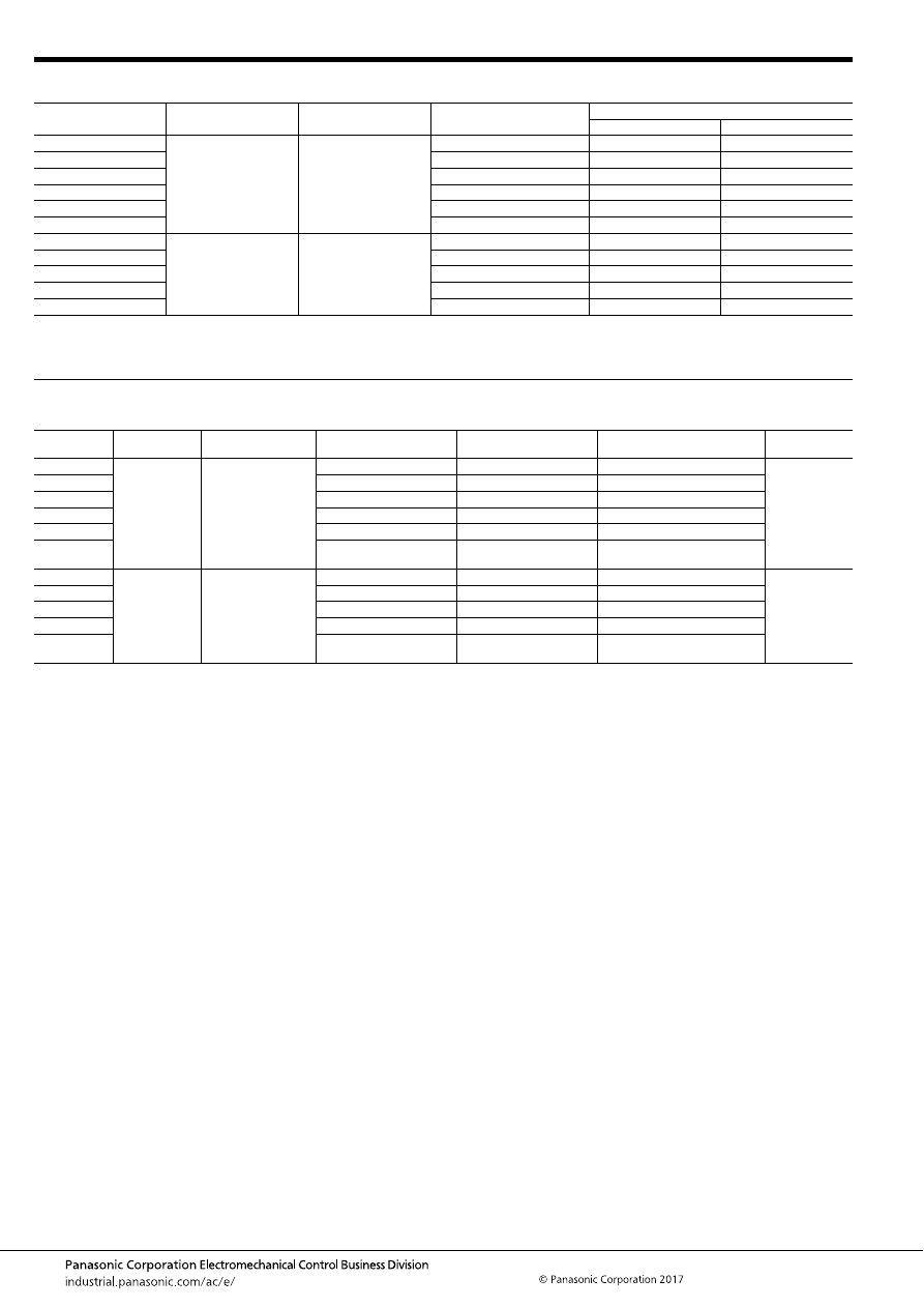
EV (AEV, AEVG, AEVS)
–184–
ASCTB384E 201709-T
TYPES
RATING
1. Coil data
Notes: *1. Please inquire our sales representative for more information about EV20A with rated coil voltage of 24V DC.
*2. Max. continuous applied voltage to the coil is the same as max. allowable voltage.
Contact rating
Contact arrangement
Rated coil voltage
Part No.
Packing
Carton
Case
10 A
1 Form A
12V DC
AEV110122
25 pcs.
100 pcs.
20 A
AEV52012
25 pcs.
50 pcs.
80 A
AEV18012
1 pc.
20 pcs.
120 A
AEV14012
1 pc.
20 pcs.
200 A
AEV17012
1 pc.
10 pcs.
300 A
AEV19012
1 pc.
5 pcs.
10 A
1 Form A
24V DC
AEV110242
25 pcs.
100 pcs.
80 A
AEV18024
1 pc.
20 pcs.
120 A
AEV14024
1 pc.
20 pcs.
200 A
AEV17024
1 pc.
10 pcs.
300 A
AEV19024
1 pc.
5 pcs.
Contact rating
Rated coil
voltage
Operate (Set) voltage
(at 20
°
C
68
°
F
) (initial)
Release (Reset) voltage
(at 20
°
C
68
°
F
) (initial)
Rated operating current
[
±
10%] (at 20
°
C
68
°
F
)
Rated operating power
(at 20
°
C
68
°
F
)
Max. allowable
voltage*
2
10 A
12V DC
Max. 9 V DC
Min. 1 V DC
0.103 A
1.24 W
16V DC
20 A*
1
Min. 0.5 V DC
0.327 A
3.9 W
80 A
Min. 1 V DC
0.353 A
4.2 W
120 A
Min. 1 V DC
0.353 A
4.2 W
200 A
Min. 1 V DC
0.5 A
6 W
300 A
Min. 2 V DC
3.2 A (Inrush)
Inrush: 37.9 W (approx. 0.1 sec.)
Stable: 3.6 W
10 A
24V DC
Max. 18 V DC
Min. 2 V DC
0.052 A
1.24 W
32V DC
80 A
Min. 2 V DC
0.176 A
4.2 W
120 A
Min. 2 V DC
0.176 A
4.2 W
200 A
Min. 2 V DC
0.25 A
6 W
300 A
Min. 4 V DC
1.85 A (Inrush)
Inrush: 44.4 W (approx. 0.1 sec.)
Stable: 3.8 W
automotive-relay_en-html.html
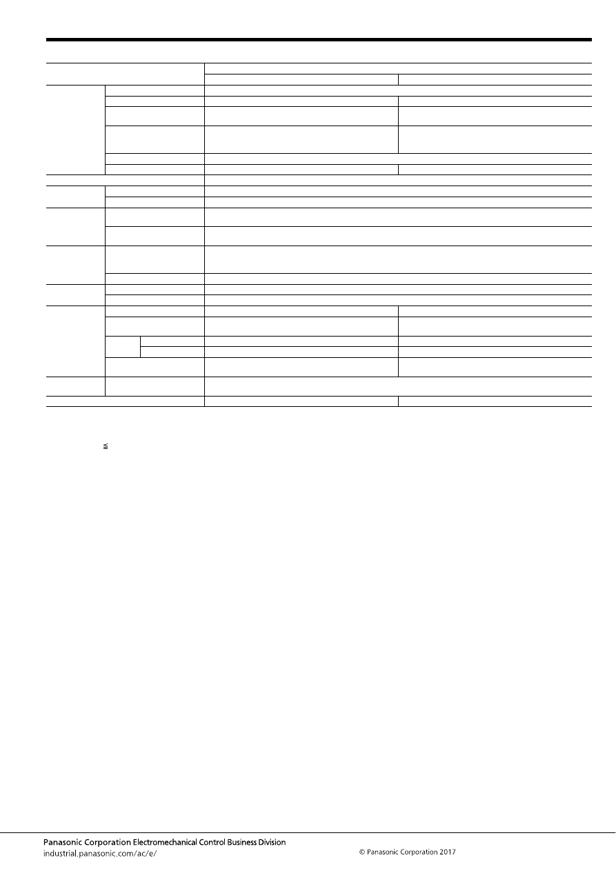
EV (AEV, AEVG, AEVS)
–185–
ASCTB384E 201709-T
2. Specifications
Notes: The coil voltage 12V DC type and 24V DC type have the same specifications.
*1. This value can change due to the switching frequency, environmental conditions, and desired reliability level, therefore it is recommended to check this with the
actual load.
*2. The performance value applies when a varistor is connected in parallel to the coil. Please be warned that working life will be reduced when a diode is used.
*3. at L/R 1ms
*4. The upper operation ambient temperature limit is the maximum temperature that can satisfy the coil temperature rise value. For details, please refer to the
“Automotive Relay Users Guide”.
Item
Specifications
10A type
20A type
Contact data
Contact arrangement
1 Form A
Contact material
Molybdenum
Copper alloy
Rated switching capacity
(resistive)
10A 450V DC
20A 400V DC
Max. carrying current
10A Continuity
15A 2 min.
30A 30 sec. (2mm
2
wire)
20A Continuity
40A 10 min.
60A 1 min. (3mm
2
wire)
Min. switching load*
1
1A 12V DC (resistive, at 20
°
C
68
°
F
)
Contact voltage drop (initial)
Max. 0.5V (By voltage drop 10A 6V DC)
Max. 0.2V (By voltage drop 20A 6V DC)
Insulated resistance (initial)
Min. 100 M
Ω
(at 500V DC, Measurement at same location as “Dielectric strength” section.)
Dielectric
strength (initial)
Between open contacts
2,500 Vrms for 1 min. (Detection current: 10mA)
Between contacts and coil
2,500 Vrms for 1 min. (Detection current: 10mA)
Time
characteristics
(initial)
Operate (Set) time
(at rated coil voltage)
Max. 50ms (at 20
°
C
68
°
F
, without contact bounce time)
Release (Reset) time
(at rated coil voltage)
Max. 30ms (at 20
°
C
68
°
F
) (Without diode)
Shock
resistance
Functional
For ON: Min. 196m/s
2
{approx. 20 G} (Half-wave pulse of sine wave: 11ms; detection time: 10
μ
s)
10A type for OFF: Min. 196m/s
2
{approx. 20 G} (Half-wave pulse of sine wave: 11ms; detection time: 10
μ
s)
20A type for OFF: Min. 98m/s
2
{approx. 10 G} (Half-wave pulse of sine wave: 11ms; detection time: 10
μ
s)
Destructive
Min. 490 m/s
2
{approx. 50 G} (Half-wave pulse of sine wave: 6ms)
Vibration
resistance
Functional
10 to 200 Hz, acceleration: 43 m/s
2
{approx. 4.4G} (Detection time: 10
μ
s)
Destructive
10 to 200 Hz, acceleration: 43 m/s
2
{approx. 4.4G} X, Y, Z direction: 4 hours
Expected life
Mechanical life
Min. 10
5
(at 60 cpm)
Min. 2
×
10
5
(at 60 cpm)
Electrical life (resistive)*
2
10A 400V DC, Min. 75,000 cycles
10A 450V DC, Min. 30,000 cycles
20A 400V DC, Min. 3,000 cycles
Switch-
off life*
2, 3
Forward direction
30A 450V DC, Min. 50 cycles
60A 400V DC, Min. 50 cycles
Reverse direction
—
—
Inrush resistance current
(capacitor)
30A 400V DC, Min. 50,000 cycles
15A 450V DC, Min. 70,000 cycles
40A 400V DC, Min. 75,000 cycles
Conditions
Conditions for usage,
transport and storage*
4
Ambient temperature: –40 to +80
°
C
–40 to +176
°
F
(Storage: Max. +85
°
C
+185
°
F
),
Humidity: 5 to 85% R.H. (Please avoid icing or condensation)
Weight
Approx. 90 g
3.17 oz
Approx. 180 g
6.35 oz
automotive-relay_en-html.html
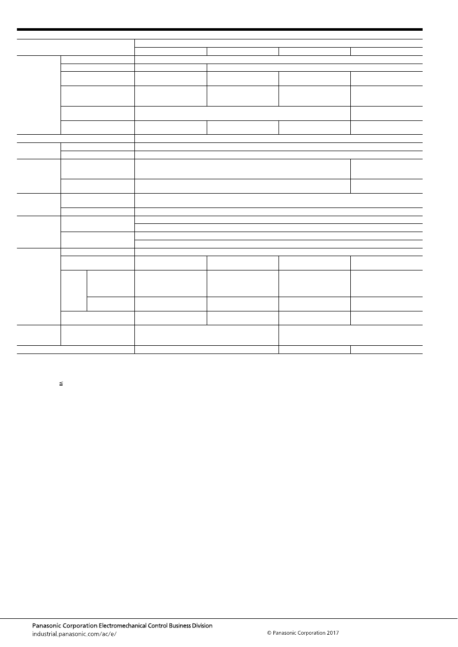
EV (AEV, AEVG, AEVS)
–186–
ASCTB384E 201709-T
Notes: The coil voltage 12V DC type and 24V DC type have the same specifications.
*1. This value can change due to the switching frequency, environmental conditions, and desired reliability level, therefore it is recommended to check this with the
actual load.
*2. The performance value applies when a varistor is connected in parallel to the coil. Please be warned that working life will be reduced when a diode is used.
*3. at L/R 1ms
*4. Condition: Nominal switching 10 cycles, each switch-off 2,500A.
*5. The upper operation ambient temperature limit is the maximum temperature that can satisfy the coil temperature rise value. For details, please refer to the
“Automotive Relay Users Guide”.
Item
Specifications
80A type
120A type
200A type
300A type
Contact data
Contact arrangement
1 Form A
Contact material
Tungsten and copper alloys
Copper alloy
Rated switching capacity
(resistive)
80A 450V DC
120A 450V DC
200A 450V DC
300A 450V DC
Max. carrying current
80A Continuity
120A 15 min.
180A 2 min. (15mm
2
wire)
120A Continuity
225A 3 min.
400A 30 sec. (38mm
2
wire)
200A Continuity
300A 15 min. (60mm
2
wire)
300A Continuity
400A 10 min. (100mm
2
wire)
Min. switching load
(resistive)*
1
1A 12V DC (at 20
°
C
68
°
F
)
1A 24V DC (at 20
°
C
68
°
F
)
Contact voltage drop (initial)
Max. 0.067V (By voltage
drop 20A 6V DC)
Max. 0.03V (By voltage drop
20A 6V DC)
Max. 0.1V (200A carry
current)
Max. 0.06V
(300A carry current)
Insulated resistance (initial)
Min. 100 M
Ω
(at 500V DC, Measurement at same location as “Dielectric strength” section.)
Dielectric
strength (initial)
Between open contacts
2,500 Vrms for 1 min. (Detection current: 10mA)
Between contacts and coil
2,500 Vrms for 1 min. (Detection current: 10mA)
Time
characteristics
(initial)
Operate (Set) time
(at rated coil voltage)
Max. 50ms
(at 20
°
C
68
°
F
, without contact bounce time)
Max. 30ms
(at 20
°
C
68
°
F
, without
contact bounce time)
Release (Reset) time
(at rated coil voltage)
Max. 30ms (at 20
°
C
68
°
F
) (Without diode)
Max. 10ms (at 20
°
C
68
°
F
)
Shock
resistance
Functional
For ON: Min. 196m/s
2
{approx. 20 G} (Half-wave pulse of sine wave: 11ms; detection time: 10
μ
s)
For OFF: Min. 98m/s
2
{approx. 10 G} (Half-wave pulse of sine wave: 11ms; detection time: 10
μ
s)
Destructive
Min. 490 m/s
2
{approx. 50 G} (Half-wave pulse of sine wave: 6ms)
Vibration
resistance
Functional
80A, 120A and 200A type: 10 to 200 Hz: 43 m/s
2
{approx. 4.4G} (Detection time: 10
μ
s)
300A type: 10 to 200 Hz: 44.1 m/s
2
{approx. 4.5G} (Detection time: 10
μ
s)
Destructive
80A, 120A and 200A type: 10 to 200 Hz: 43 m/s
2
{approx. 4.4G} X, Y, Z direction: 4 h
300A type: 10 to 200 Hz: 44.1 m/s
2
{approx. 4.5G} X, Y, Z direction: 4 h
Expected life
Mechanical life
Min. 2
×
10
5
(at 60 cpm)
Electrical life (resistive)*
2
80A 450V DC, Min. 1,000
cycles
30A 450V DC, Min. 1,000
cycles
200A 450V DC, Min. 3,000
cycles
300A 450V DC, Min. 1,000
cycles
Switch-
off life*
2, 3
Forward direction
800A 300V DC, Min. 1 cycle
120A 450V DC, Min. 50
cycles
1,200A 300V DC, Min. 1
cycle
120A 450V DC, Min. 50
cycles
2,000A 350V DC, Min. 1
cycle
400A 450V DC, Min. 50
cycles
2,500A 300V DC, Min. 3
cycles*
4
600A 450V DC, Min. 50
cycles
Reverse direction
-120A 200V DC, Min.50
cycles
-120A 200V DC, Min. 50
cycles
-200A 200V DC, Min. 1,000
cycles
-300A 200V DC, Min. 100
cycles
Inrush resistance current
(capacitor)
150A 20V DC, Min. 70,000
cycles
120A 20V DC, Min. 70,000
cycles
140A 20V DC, Min. 70,000
cycles
240A 20V DC, Min. 70,000
cycles
Conditions
Conditions for usage,
transport and storage*
5
Ambient temperature: –40 to +80
°
C
–40 to +176
°
F
Humidity: 5 to 85% R.H. (Please avoid icing or
condensation)
Ambient temperature: –40 to +85
°
C
–40 to +185
°
F
Humidity: 5 to 85% R.H. (Please avoid icing or
condensation)
Weight
Approx. 400 g
14.11 oz
Approx. 600 g
21.16 oz
Approx. 750 g
26.46 oz
automotive-relay_en-html.html
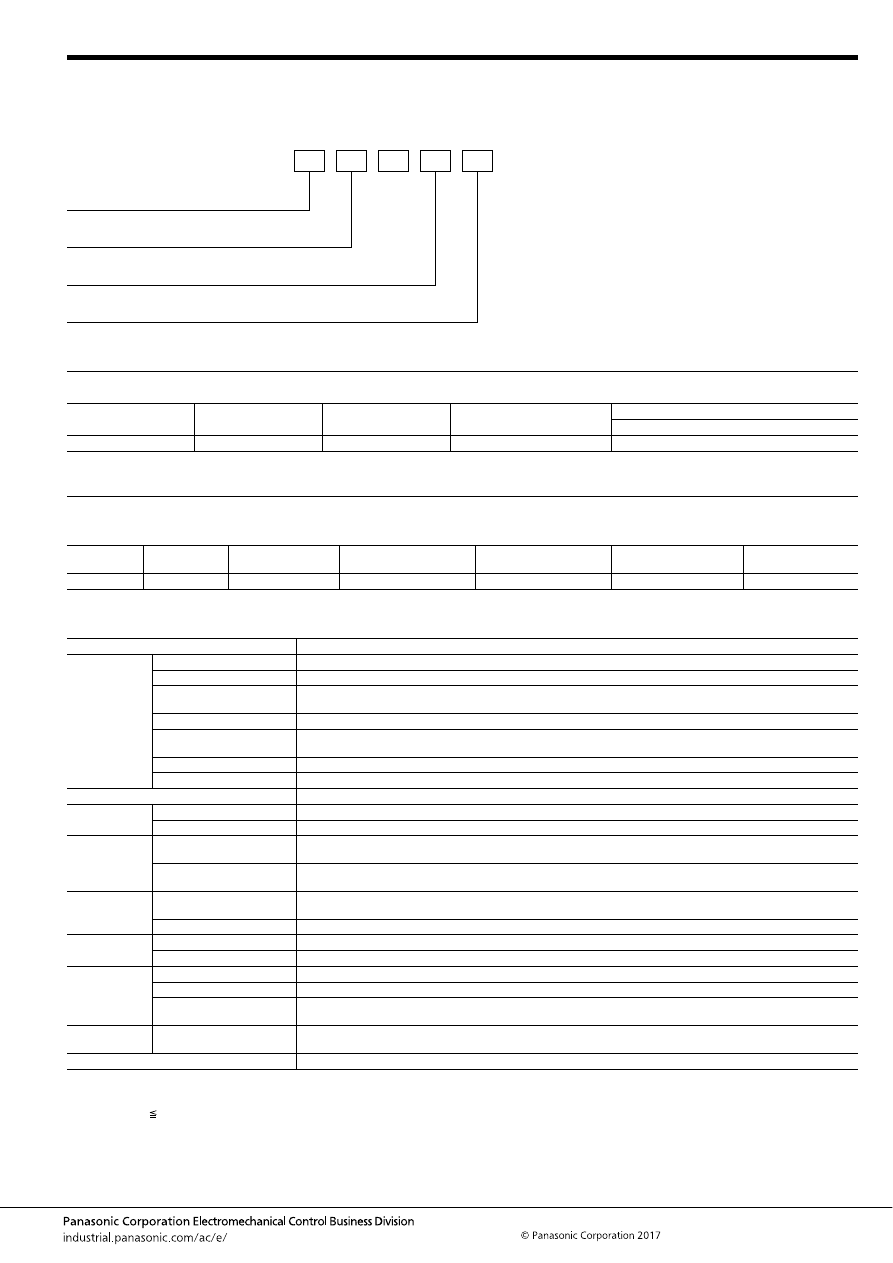
EV (AEV, AEVG, AEVS)
–187–
ASCTB384E 201709-T
EV Relay
[Compact high short-circuit capacity type]
ORDERING INFORMATION
TYPES
RATING
1. Coil data
Note: *1. When continually powered, the applied voltage is 14 V DC.
2. Specifications
Notes: *1. This value can change due to the switching frequency, environmental conditions, and desired reliability level, therefore it is recommended to check this with the
actual load.
*2. The performance value applies when a varistor is connected in parallel to the coil. Please be warned that working life will be reduced when a diode is used.
*3. at L/R 1ms
*4. The upper operation ambient temperature limit is the maximum temperature that can satisfy the coil temperature rise value. For details, please refer to the
“Automotive Relay Users Guide”.
Contact rating
Contact arrangement
Rated coil voltage
Part No.
Packing
Case
60A
1 Form A
12V DC
AEVG16012
40 pcs (Carton 40 pcs./1 tray)
Contact rating
Rated coil
voltage
Operate (Set) voltage
(at 20
°
C
68
°
F
) (initial)
Release (Reset) voltage
(at 20
°
C
68
°
F
) (initial)
Rated operating current
[
±
10%] (at 20
°
C
68
°
F
)
Rated operating power
(at 20
°
C
68
°
F
)
Max. allowable
voltage*
1
60A
12V DC
Max. 9 V DC
Min. 0.5 V DC
0.429A
5.2W
16V DC
Item
Specifications
Contact data
Contact arrangement
1 Form A
Contact material
Copper alloy
Rated switching capacity
(resistive)
60A 450V DC
Max. carrying current
60A Continuity, 120A 5 min., 180A 30 sec. (15mm
2
wire)
Min. switching load
(resistive)*
1
1A 12V DC (at 20
°
C
68
°
F
)
Contact voltage drop (initial)
Max. 0.15V (By voltage drop 60A 6V DC)
Short circuit capacity
4,500A (at Max. 10 ms), No smoke and no ignition
Insulated resistance (initial)
Min. 100 M
Ω
(at 1,000V DC, Measurement at same location as “Dielectric strength” section.)
Dielectric
strength (initial)
Between open contacts
2,500 Vrms for 1 min. (Detection current: 10mA)
Between contacts and coil
2,500 Vrms for 1 min. (Detection current: 10mA)
Time
characteristics
(initial)
Operate (Set) time
(at rated coil voltage)
Max. 50ms (at 20
°
C
68
°
F
, without contact bounce time)
Release (Reset) time
(at rated coil voltage)
Max. 30ms (at 20
°
C
68
°
F
, without contact bounce time) (Without diode)
Shock
resistance
Functional
For ON: Min. 196m/s
2
{approx. 20 G} (Half-wave pulse of sine wave: 11ms; detection time: 10
μ
s)
For OFF: Min. 98m/s
2
{approx. 10 G} (Half-wave pulse of sine wave: 11ms; detection time: 10
μ
s)
Destructive
Min. 490 m/s
2
{approx. 50 G} (Half-wave pulse of sine wave: 6ms)
Vibration
resistance
Functional
10 to 200 Hz, 44.1 m/s
2
{approx. 4.5G} (Detection time: 10
μ
s)
Destructive
10 to 200 Hz, 44.1 m/s
2
{approx. 4.5G} X, Y, Z direction: 4 hours
Expected life
Mechanical life
Min. 2
×
10
5
(at 60 cpm)
Switch-off life*
2, 3
400A 300V DC, Min. 1 cycles (No polarity)
Inrush resistance current
(capacitor)
30A 450V DC, Min. 70,000 cycles
120A 20V DC, Min. 70,000 cycles
Conditions
Conditions for usage,
transport and storage*
4
Ambient temperature: –40 to +80
°
C
–40 to +176
°
F
Humidity: 5 to 85% R.H. (Please avoid icing or condensation)
Weight
Approx. 165 g
5.82 oz
Contact arrangement
1: 1 Form A (Screw terminal)
AEVG
0
Contact rating
6: 60 A
Rated coil voltage
12: 12V DC
Coil terminal structure
Nil: Lead wire
* There are also all plug-in types: please inquire our sales representative for more information.
automotive-relay_en-html.html
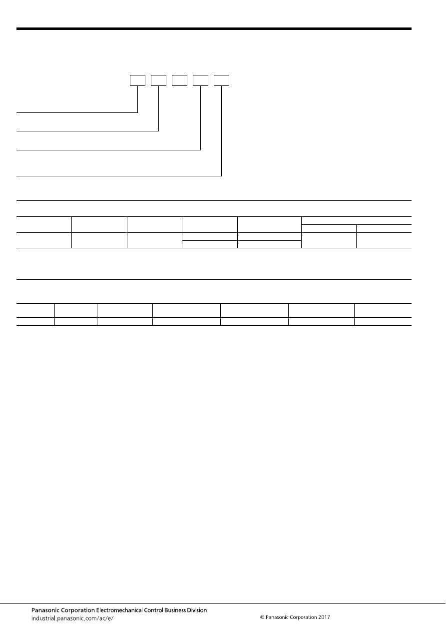
EV (AEV, AEVG, AEVS)
–188–
ASCTB384E 201709-T
EV Relay
[Quiet type]
ORDERING INFORMATION
TYPES
RATING
1. Coil data
Note: *1. When continually powered, the applied voltage is 14 V DC (at 65
°
C
149
°
F
).
Contact rating
Contact arrangement
Rated coil voltage
Installation type
Part No.
Packing
Carton
Case
60A
1 Form A
12V DC
Vertical type
AEVS16012
1 pc.
20 pcs.
Horizontal type
AEVS960122
Contact rating
Rated coil
voltage
Operate (Set) voltage
(at 20
°
C
68
°
F
) (initial)
Release (Reset) voltage
(at 20
°
C
68
°
F
) (initial)
Rated operating current
[
±
10%] (at 20
°
C
68
°
F
)
Rated operating power
(at 20
°
C
68
°
F
)
Max. allowable
voltage*
1
60A
12V DC
Max. 9 V DC
Min. 1 V DC
0.375A
4.5W
16V DC
Contact arrangement/Installation type
1: 1 Form A (Screw terminal, Vertical type)
9: 1 Form A (Screw terminal, Horizontal type)
AEVS
0
Contact rating
6: 60 A
Rated coil voltage
12: 12V DC
Coil terminal structure
Nil:
2:
Lead wire
Faston terminal
* There are also all plug-in types and 150A carry current type: please inquire our sales representative for more information.
automotive-relay_en-html.html
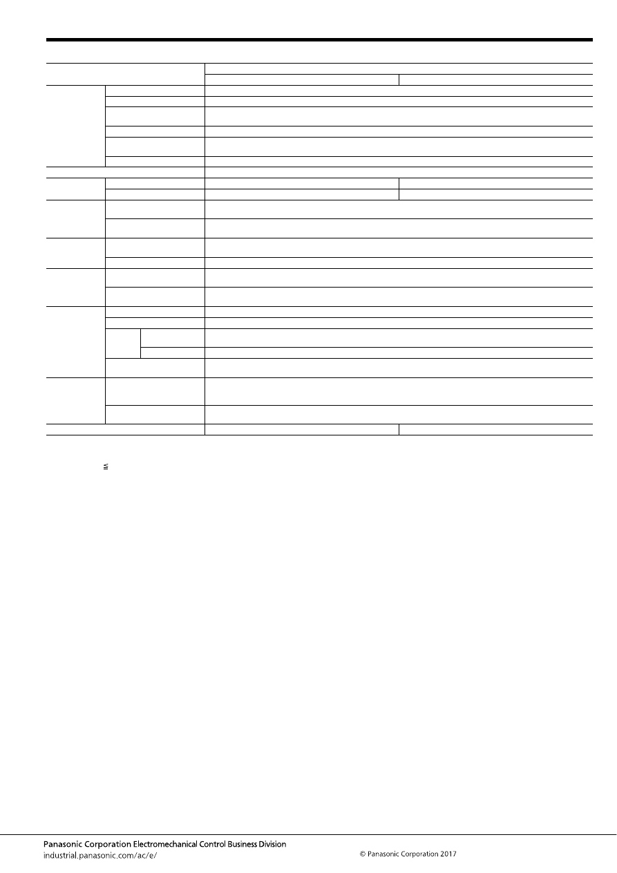
EV (AEV, AEVG, AEVS)
–189–
ASCTB384E 201709-T
2. Specifications
Notes: *1. This value can change due to the switching frequency, environmental conditions, and desired reliability level, therefore it is recommended to check this with the
actual load.
*2. The performance value applies when a varistor is connected in parallel to the coil. Please be warned that working life will be reduced when a diode is used.
*3. at L/R 1ms
*4. The upper operation ambient temperature limit is the maximum temperature that can satisfy the coil temperature rise value. For details, please refer to the
“Automotive Relay Users Guide”.
Item
Specifications
Vertical type
Horizontal type
Contact data
Contact arrangement
1 Form A
Contact material
Tungsten and copper alloys
Rated switching capacity
(resistive)
60A 450V DC
Max. carrying current
60A Continuity, 100A 10 min., 180A 1 min. (15mm
2
wire)
Min. switching load
(resistive)*
1
1A 12V DC (at 20
°
C
68
°
F
)
Contact voltage drop (initial)
Max. 0.067V (By voltage drop 20A 6V DC)
Insulated resistance (initial)
Min. 100 M
Ω
(at 500V DC, Measurement at same location as “Dielectric strength” section.)
Dielectric
strength (initial)
Between open contacts
2,500 Vrms for 1 min. (Detection current: 10mA)
2,000 Vrms for 1 min. (Detection current: 10mA)
Between contacts and coil
2,500 Vrms for 1 min. (Detection current: 10mA)
2,000 Vrms for 1 min. (Detection current: 10mA)
Time
characteristics
(initial)
Operate (Set) time
(at rated coil voltage)
Max. 50ms (at 20
°
C
68
°
F
, without contact bounce time)
Release (Reset) time
(at rated coil voltage)
Max. 50ms (at 20
°
C
68
°
F
, without contact bounce time) (Without diode)
Shock
resistance
Functional
For ON: Min. 196m/s
2
{approx. 20 G} (Half-wave pulse of sine wave: 11ms; detection time: 10
μ
s)
For OFF: Min. 98m/s
2
{approx. 10 G} (Half-wave pulse of sine wave: 11ms; detection time: 10
μ
s)
Destructive
Min. 490 m/s
2
{approx. 50 G} (Half-wave pulse of sine wave: 6ms)
Vibration
resistance
Functional
10 to 100 Hz, acceleration: 43 m/s
2
{approx. 4.4G}
10 to 200 Hz, acceleration: 19.6 m/s
2
{approx. 2G} (Detection time: 10
μ
s)
Destructive
10 to 100 Hz, acceleration: 43 m/s
2
{approx. 4.4G}
10 to 200 Hz, acceleration: 19.6 m/s
2
{approx. 2G} X, Y, Z direction: 4 hours
Expected life
Mechanical life
Min. 2
×
10
5
(at 60 cpm)
Electrical life (resistive)
60A 450V DC, Min. 800 cycles
Switch-
off life*
2, 3
Forward direction
600A 300V DC, Min. 5 cycles
120A 450V DC, Min. 50 cycles
Reverse direction
-120A 200V DC, Min. 50 cycles
Inrush resistance current
(capacitor)
60A 20V DC, Min. 70,000 cycles
Conditions
Conditions for usage*
4
Ambient temperature: –40 to +80
°
C
–40 to +176
°
F
(When continuous steady current at 14 V DC: –40 to +65
°
C
–40 to
+149
°
F
)
Humidity: 5 to 85% R.H. (Please avoid icing or condensation)
Conditions for transport and
storage
Ambient temperature: –40 to +80
°
C
–40 to +176
°
F
Humidity: 5 to 85% R.H. (Please avoid icing or condensation)
Weight
Approx. 250 g
5.82 oz
Approx. 240 g
5.82 oz
automotive-relay_en-html.html
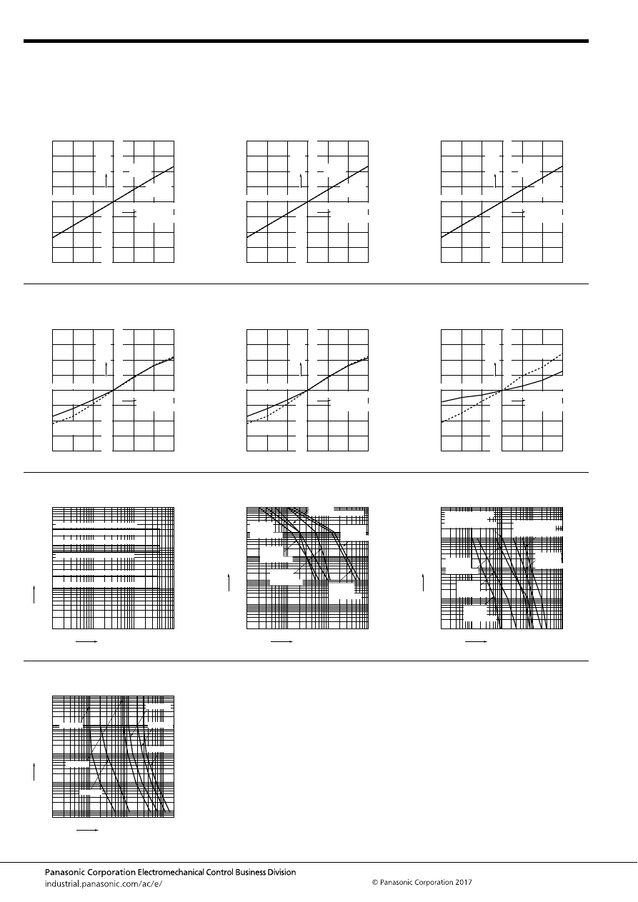
EV (AEV, AEVG, AEVS)
–190–
ASCTB384E 201709-T
EV Relay
[Normal type]
REFERENCE DATA
1.-(1) Ambient temperature characteristics
(10A type)
Sample: AEV110122, 3 pcs.
1.-(2) Ambient temperature characteristics
(20A type)
Sample: AEV52012, 3 pcs.
1.-(3) Ambient temperature characteristics
(80A type)
Sample: AEV18012, 3 pcs.
-40
-20
60
80
0
40
20
40
30
20
10
-30
-10
-20
-40
V
a
riation
ratio
, %
Ambient
temperature,
°
C
Operate
voltage
Release
voltage
-40
-20
60
80
0
40
20
40
30
20
10
-30
-10
-20
-40
V
a
riation
ratio
, %
Ambient
temperature,
°
C
Operate
voltage
Release
voltage
-40
-20
60
80
0
40
20
40
30
20
10
-30
-10
-20
-40
V
a
riation
ratio
, %
Ambient
temperature,
°
C
Operate
voltage
Release
voltage
1.-(4) Ambient temperature characteristics
(120A type)
Sample: AEV14012, 3 pcs.
1.-(5) Ambient temperature characteristics
(200A type)
Sample: AEV17012, 3 pcs.
1.-(6) Ambient temperature characteristics
(300A type)
Sample: AEV19012, 3 pcs.
-40
-20
60
80
0
40
20
40
30
20
10
-30
-10
-20
-40
V
a
riation
ratio
, %
Ambient
temperature,
°
C
Operate
voltage
Release
voltage
-40
-20
60
80
0
40
20
40
30
20
10
-30
-10
-20
-40
V
a
riation
ratio
, %
Ambient
temperature,
°
C
Operate
voltage
Release
voltage
-40
-20
60
80
0
40
20
40
30
20
10
-30
-10
-20
-40
V
a
riation
ratio
, %
Ambient
temperature,
°
C
Operate
voltage
Release
voltage
2. Max. value for switching capacity
3. Switching life curve (Forward direction)
4. Switch-off life curve (Forward direction)
1
1,000
100
10
1
10
Contact voltage, V
Contact current, A
100
1,000
300A type 450V DC resistive load
200A type 450V DC resistive load
120A type 450V DC resistive load
80A type 450V DC resistive load
20A type 400V DC resistive load
10A type 450V DC resistive load
1
100,000
10,000
1,000
100
10
1
10
Contact current, A
Lif
e
, cycle
100
1,000
20A type
400V DC
resistive load
80A type
450V DC
resistive load
200A type
450V DC
resistive load
300A type
450V DC
resistive load
120A type
450V DC resistive load
10A type
450V DC
resistive load
1
10,000
1,000
100
10
1
10
Contact current, A
Lif
e
, cycle
100
1,000
10,000
10A type
450V DC
resistive load
20A type
400V DC
resistive load
120A type
450V DC
resistive load
200A type
450V DC
resistive load
300A type 450V DC
resistive load (for
Min. 1,000A, 350V DC)
80A type 450V DC
resistive load (for
Min. 600A, 300V DC)
5. Carrying performance curve (85
°
C
185
°
F
)
*For 200 A and 300 A, at 85
°
C
185
°
F
1
100,000
10,000
1,000
100
10
10
Contact current, A
Time
, sec
100
1,000
10A type
80A type
20A type
120A type
200A type
300A type
automotive-relay_en-html.html
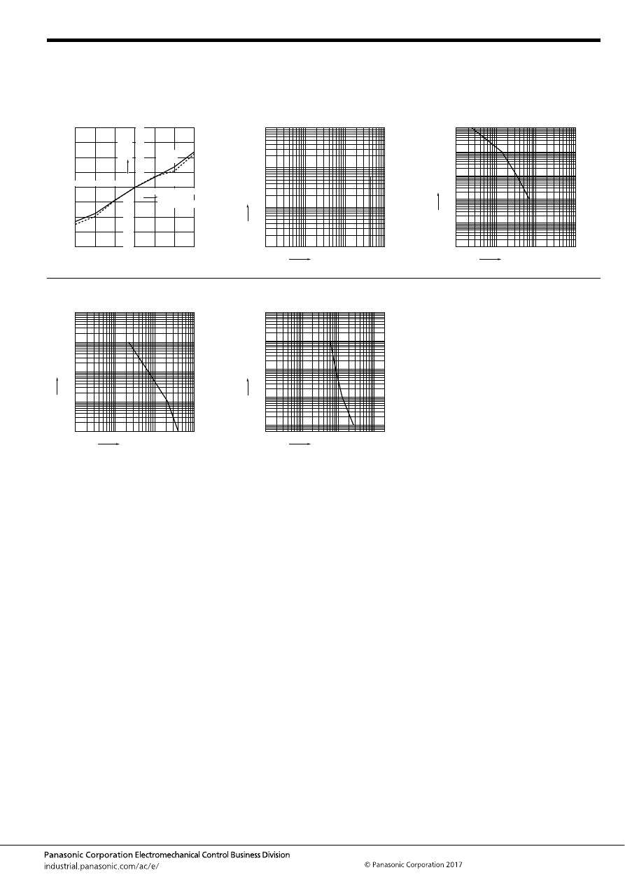
EV (AEV, AEVG, AEVS)
–191–
ASCTB384E 201709-T
EV Relay
[Compact high short-circuit capacity type]
REFERENCE DATA
1. Ambient temperature characteristics
Sample: AEVG16012, 3 pcs.
2. Max. value for switching capacity
Sample: AEVG16012, 3 pcs.
3. Switching life curve (Forward direction)
Sample: AEVG16012, 3 pcs.
-40
-20
60
80
0
40
20
40
30
20
10
-30
-10
-20
-40
V
a
riation
ratio
, %
Ambient
temperature,
°
C
Operate
voltage
Release
voltage
1
1,000
100
10
1
10
Contact voltage, V
Contact current, A
100
1,000
1
100,000
10,000
1,000
100
10
1
10
Contact current, A
Lif
e
, cycle
100
1,000
4. Switch-off life curve (Forward direction)
Sample: AEVG16012, 3 pcs.
5. Carrying performance curve (80
°
C
176
°
F
)
Sample: AEVG16012, 3 pcs.
1
10,000
1,000
100
10
1
10
Contact current, A
Lif
e
, cycle
100
1,000
1
100,000
10,000
1,000
100
10
10
Contact current, A
Time
, sec
100
1,000
automotive-relay_en-html.html
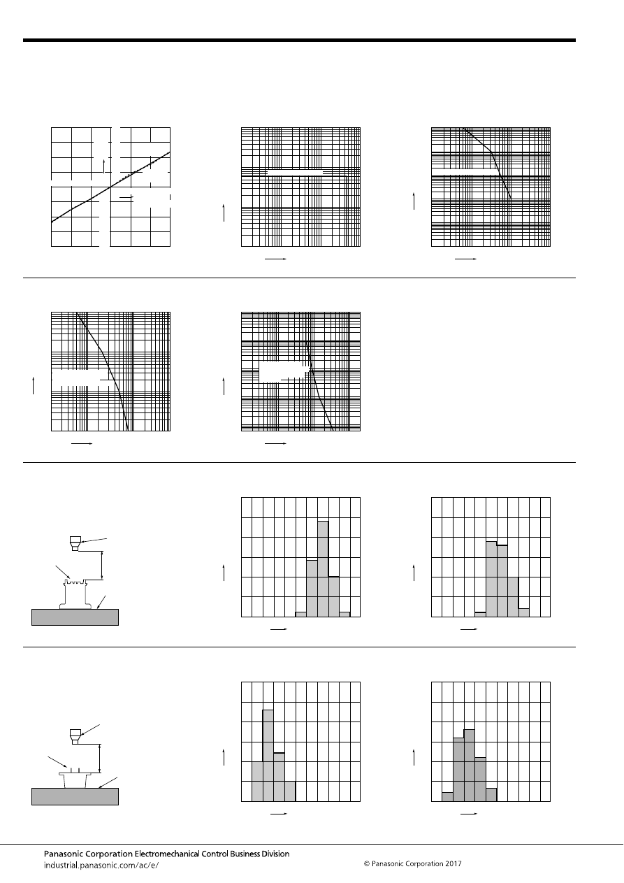
EV (AEV, AEVG, AEVS)
–192–
ASCTB384E 201709-T
EV Relay
[Quiet type]
REFERENCE DATA
1. Ambient temperature characteristics
Sample: AEVS16012, 3 pcs.
2. Max. value for switching capacity
Sample: AEVS16012, 3 pcs.
3. Switching life curve
Sample: AEVS16012, 3 pcs.
-40
-20
60
80
0
40
20
40
30
20
10
-30
-10
-20
-40
V
a
riation
ratio
, %
Ambient
temperature,
°
C
Operate
voltage
Release
voltage
typ.
typ.
1
1,000
100
10
1
10
Contact voltage, V
Contact current, A
100
1,000
450V DC resistive load
1
100,000
10,000
1,000
100
10
1
10
Contact current, A
Lif
e
, cycle
100
1,000
450V DC resistive load
4. Switch-off life curve (Forward direction)
Sample: AEVS16012, 3 pcs.
5. Carrying performance curve (80
°
C
176
°
F
)
Sample: AEVS16012, 3 pcs.
10
1,000
100
10
1
Switch-off current, A
Lif
e
, cycle
100
1,000
10,000
450V DC resistive load
(However, 300V DC
when 600A is exceeded.)
1
100,000
10,000
1,000
100
10
10
Contact current, A
Time
, sec
100
1,000
Up to 65
°
C
ambient temperature
when continuously
powered
149
°
F
6.-(1)-1 Operation noise distribution (vertical type)
Measuring conditions
Sample: AEVS16012, 50pcs
Equipment setting: “A” weighted, Fast, Max. hold
Coil voltage: 12V DC
Coil connection device: 18V zener diode
Background noise: approx. 20dB
When operate
When release
Microphone
Sponge
Relay
30cm
11.811inch
40
38
42 44 46 48 50 52 54 56 58 60
0
5
10
15
20
25
30
Noise level, dB
Quantity
, n
40
38
42 44 46 48 50 52 54 56 58 60
0
5
10
15
20
25
30
Noise level, dB
Quantity
, n
6.-(2)-1 Operation noise distribution (horizontal type)
Measuring conditions
Sample: AEVS960122, 50pcs
Equipment setting: “A” weighted, Fast, Max. hold
Coil voltage: 12V DC
Coil connection device: 18V zener diode
Background noise: approx. 20dB
When operate
When release
Microphone
Measured
with terminals
facing up
Sponge
30cm
11.811inch
40
38
42 44 46 48 50 52 54 56 58 60
0
5
10
15
20
25
30
Noise level, dB
Quantity
, n
40
38
42 44 46 48 50 52 54 56 58 60
0
5
10
15
20
25
30
Noise level, dB
Quantity
, n
automotive-relay_en-html.html
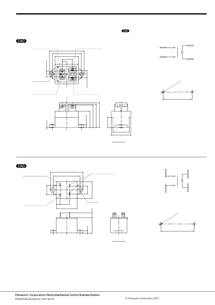
EV (AEV, AEVG, AEVS)
–193–
ASCTB384E 201709-T
EV Relay
[Normal type]
DIMENSIONS
(mm
inch
)
1. 10A type
2. 20A type
mark can be downloaded from: http://industrial.panasonic.com/ac/e/
The CAD data of the products with a
External dimensions
1
6
2
5
0.4
.016
1.957
49.7
1.248
31.7
(1.791)
(45.5)
Max.
1.772
Max.
45
5.7
.224
19.5
.768
1.492
1.244
37.9
31.6
66.8
1-Load input terminal (
+
)
#187 tab, 0.5t
2-Load input terminal (
−
)
#187 tab, 0.5t
6-Coil terminal (No polarity)
#187 tab, 0.5t
5-Coil terminal (No polarity)
#187 tab, 0.5t
45
55.9
±
0.3
11.3
±
0.3
.445
±
.012
14.1
±
0.3
.555
±
.012
19.6
2.630
1.772
2.201
±
.012
.772
8.6
.339
2
×
4.5
±
0.2 dia.
2
×
.177
±
.008 dia.
Schematic (TOP VIEW)
Mounting dimensions
Load side has polarities (
+
) and (
−
).
6:Coil
5:Coil
1 (
+
)
2 (
−
)
Mounting hole
2
×
4.2
±
0.1 dia.
2
×
.165
±
.004 dia.
55.9
±
0.1
2.201
±
.004
Tolerance;
Less than 10mm
.394inch
:
10 to 50mm
.394 to 1.969inch
:
More than 50mm
1.969inch
:
±
0.3
±
.012
±
0.6
±
.024
±
1.0
±
.039
External dimensions
11.1
5.8
37.0
±
1.0
.437
.228
1.457
±
.039
50
3.071
22.8
2.520
78
64
40
9.2
1.969
.898
.362
19
1.575
.748
22.5
.886
Coil terminal (No polarity)
#250 tab, 0.8t
1-Load input terminal (
+
)
#250 tab, 0.8t
2-Load input terminal (
−
)
#250 tab, 0.8t
2
×
6.0 dia.
2
×
.236 dia.
Schematic (TOP VIEW)
Mounting dimensions
Coil
Load side has polarities (
+
) and (
−
).
Coil
1 (
+
)
2 (
−
)
Mounting hole
2
×
6.0
±
0.2 dia.
2
×
.236
±
.008 dia.
64.0
±
0.2
2.520
±
.008
Tolerance;
Less than 10mm
.394inch
:
10 to 50mm
.394 to 1.969inch
:
More than 50mm
1.969inch
:
±
0.3
±
.012
±
0.6
±
.024
±
1.0
±
.039
automotive-relay_en-html.html
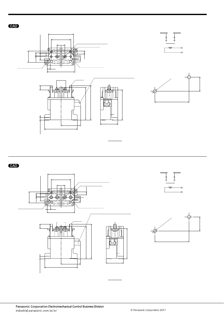
EV (AEV, AEVG, AEVS)
–194–
ASCTB384E 201709-T
3. 80A type
4. 120A type
External dimensions
1
2
40
75
69
2.717
.079
Collar height
(Both ends of bus bar)
57.9
2.280
(M5 bolt pitch)
44.9
1.768
16.0
.630
(.705)
(17.9)
63.5
2.500
7.25
.285
26
(Bus bar width)
1.024
.276
2
7
75.5
2.972
79
2.953
3.110
7.25
2-Load input bus bar (
−
)
1-Load input bus bar (
+
)
Connector Part No.: 7282-1020 (Yazaki)
(Supplement) Harness side
Female connector Part No.: 7283-1020*
.285
10
.394
(M4)
M5 bolt
5.7
.224
(Connector position)
45
1.772
1.575
8.0 dia.
.315 dia.
(Flat washer)
2
×
6.0 dia.
2
×
.236 dia.
* Separate connection of the terminal and lead wire is required.
Schematic (TOP VIEW)
Mounting dimensions
Coil
Load side has polarities (
+
) and (
−
).
1 (
+
)
2 (
−
)
Coil
Mounting hole
2
×
6.0
±
0.2 dia.
2
×
.236
±
.008 dia.
63.5
±
0.2
2.500
±
.008
26.0
±
0.2
1.024
±
.008
Tolerance;
Less than 10mm
.394inch
:
10 to 50mm
.394 to 1.969inch
:
More than 50mm
1.969inch
:
±
0.3
±
.012
±
0.6
±
.024
±
1.0
±
.039
External dimensions
2
1
(Both ends of bus bar)
61.9
2.437
(M6 bolt pitch)
44.9
1.768
(.705)
(17.9)
16
.630
(Bus bar width)
2-Load input bus bar (
−
)
63.5
2.500
7.25
.285
.079
26
1.024
.276
27
7.25
.285
1-Load input bus bar (
+
)
(M4)
M6 bolt
Collar height
10
.394
5.7
.224
75.5
2.972
(Connector position)
45
1.772
75
80
2.953
3.150
Connector Part No.: 7282-1020 (Yazaki)
(Supplement) Harness side
Female connector Part No.: 7283-1020*
40
70
2.756
1.575
8.0 dia.
.315 dia.
(Flat washer)
2
×
6.0 dia.
2
×
.236 dia.
* Separate connection of the terminal and lead wire is required.
Schematic (TOP VIEW)
Mounting dimensions
Coil
Load side has polarities (
+
) and (
−
).
Coil
1 (
+
)
2 (
−
)
Mounting hole
2
×
6.0
±
0.2 dia.
2
×
.236
±
.008 dia.
63.5
±
0.2
2.500
±
.008
26.0
±
0.2
1.024
±
.008
Tolerance;
Less than 10mm
.394inch
:
10 to 50mm
.394 to 1.969inch
:
More than 50mm
1.969inch
:
±
0.3
±
.012
±
0.6
±
.024
±
1.0
±
.039
automotive-relay_en-html.html

EV (AEV, AEVG, AEVS)
–195–
ASCTB384E 201709-T
5. 200A type
6. 300A type
External dimensions
Coil connection lead wire
(No polarity)
1.110
1.220
1.772
28.2
31
45
(2)
(2.1)
(.079)
(.083)
1.063
2.126
2.638
3.228
3.740
27
54
67
82
95
3.402
2.953
86.4
75
5.7
(Collar height)
.224
0.5
.020
1-Load input terminal (
+
)
2-Load input terminal (
−
)
M6 (Threaded portion: Min. 8)
2
×
6 dia.
2
×
.236 dia.
200
±
20
7.874
±
.787
Schematic (TOP VIEW)
Mounting dimensions
Coil
Load side has polarities (
+
) and (
−
).
Coil
1 (
+
)
2 (
−
)
Mounting hole
2
×
6.0
±
0.2 dia.
2
×
.236
±
.008 dia.
82
±
0.2
3.228
±
.008
31
±
0.2
1.220
±
.008
Tolerance;
Less than 10mm
.394inch
:
10 to 50mm
.394 to 1.969inch
:
More than 50mm
1.969inch
:
±
0.3
±
.012
±
0.6
±
.024
±
1.0
±
.039
External dimensions
5
1
2
6
1.732
3.386
3.110
±
.012
3.622
4.370
1.063
2.362
1.850
±
.012
2.480
27
60
47
±
0.3
63
61.7
3
.118
24.5
.965
1.063
44
86
79
±
0.3
92
111
27
48.7
5.7
74.7
39.3
1.917
1.547
73.4
2.429
.224
2.941
2.890
(13)
(.512)
1-Load input bus bar (
+
)
2-Load input bus bar (
−
)
6-Coil terminal (GND)
5-Coil terminal (V
+
)
M8 bolt
M8 flange nut
Connector Part No.: 7282-1020 (Yazaki)
(Supplement) Harness side
Female connector Part No.: 7283-1020 Note1
3
×
6.0
±
0.3 dia.
3
×
.236
±
.012 dia.
Note 1. Separate connection of the terminal and lead wire is required.
Schematic (TOP VIEW)
Mounting dimensions
6:Coil (GND)
Load side has polarities (
+
) and (
−
).
5:Coil (V
+
)
1 (
+
)
2 (
−
)
Mounting hole
3
×
6.0
±
0.2 dia.
3
×
.236
±
.008 dia.
79.0
±
0.2
3.110
±
.008
47.0
±
0.2
1.850
±
.008
Tolerance;
Less than 10mm
.394inch
:
10 to 50mm
.394 to 1.969inch
:
50 to 100mm
1.969 to 3.937inch
:
More than 100mm
3.937inch
:
±
0.3
±
.012
±
0.6
±
.024
±
1.0
±
.039
±
1.6
±
.063
automotive-relay_en-html.html
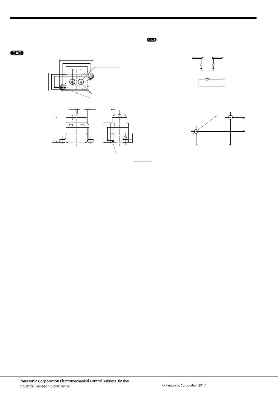
EV (AEV, AEVG, AEVS)
–196–
ASCTB384E 201709-T
EV Relay
[Compact high short-circuit capacity type]
DIMENSIONS
(mm
inch
)
mark can be downloaded from: http://industrial.panasonic.com/ac/e/
The CAD data of the products with a
External dimensions
3.4
2.047
.630
.827
1.299
1.555
2.520
52
16
39.5
64
1.102
21
33
28
M4 (Threaded portion: Min. 6.0)
6 dia.
.236 dia.
Load input terminal
(No polarity)
1.445
(5.906)
36.7
(150)
5.7
.224
.295
7.5
Coil connection lead wire
(No polarity)
1.882
2.079
47.8
52.8
2
.134
.079
Schematic (TOP VIEW)
Mounting dimensions
Coil
There is no polarity on the load side.
Coil
Mounting hole
2
×
6.0
±
0.2 dia.
2
×
.236
±
.008 dia.
52.0
±
0.2
2.047
±
.008
21.0
±
0.2
.827
±
.008
Tolerance;
Less than 10mm
.394inch
:
10 to 50mm
.394 to 1.969inch
:
More than 50mm
1.969inch
:
±
0.3
±
.012
±
0.6
±
.024
±
1.0
±
.039
automotive-relay_en-html.html
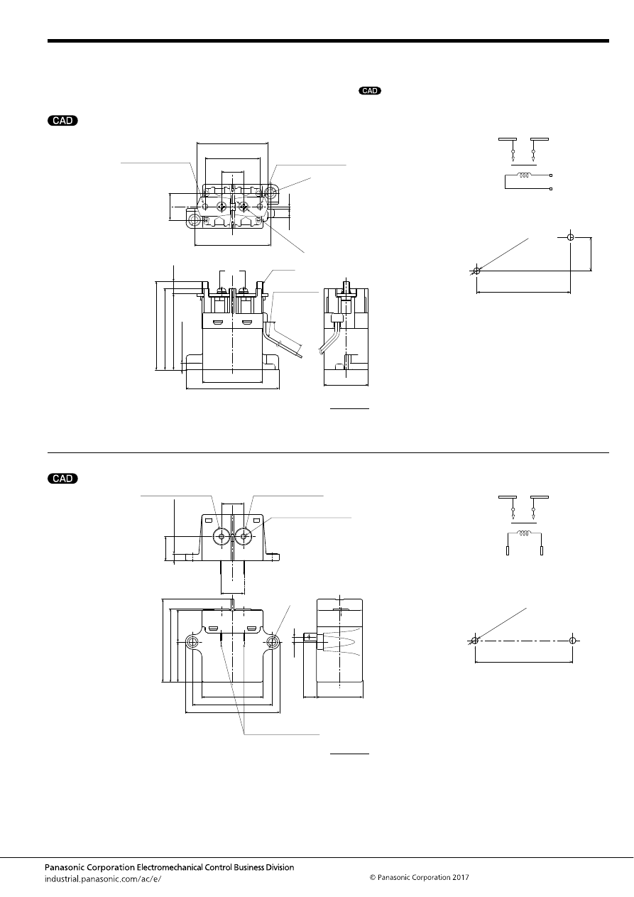
EV (AEV, AEVG, AEVS)
–197–
ASCTB384E 201709-T
EV Relay
[Quiet type]
DIMENSIONS
(mm
inch
)
1. 60A Vertical type
2. 60A Horizontal type
mark can be downloaded from: http://industrial.panasonic.com/ac/e/
The CAD data of the products with a
External dimensions
2
1
2.846
62
±
0.5
2.441
±
.020
2.630
2.453
72.3
66.8
62.3
Collar height
.224
5.7
10
.394
.705
17.9
72
.276
.079
1-Load input bus bar (
+
)
2-Load input bus bar (
−
)
(Both ends of bus bar)
(M5 bolt pitch)
2.280
1.768
57.9
(Flat w
asher)
.315
8.0
44.9
22
±
0.5
.866
±
.020
1.929
M5 bolt
Coil connection
lead wire
(No polarity)
1.417
36
5.906
±
.197
150
±
5
2.992
49
76
(M4)
2
×
6.0 dia.
2
×
.236 dia.
Schematic (TOP VIEW)
Mounting dimensions
Coil
Coil
1 (
+
)
2 (
−
)
Mounting hole
2
×
6.0
±
0.2 dia.
2
×
.236
±
.008 dia.
62.0
±
0.2
2.441
±
.008
22.0
±
0.2
.866
±
.008
Tolerance;
Less than 10mm
.394inch
:
10 to 50mm
.394 to 1.969inch
:
More than 50mm
1.969inch
:
±
0.3
±
.012
±
0.6
±
.024
±
1.0
±
.039
External dimensions
1
+
2
−
(Threaded portion: Min. 7.2)
3.031
.705
17.9
19.7
.776
10.9
4.25
.167
37.7
.429
1.484
2.669
1.969
1.035
1.289
2.559
77
50
65
2.356
67.8
26.3
32.75
59.85
.748
19
Collar height
5.7
.224
M4
1-Load input terminal (
+
)
Coil terminal (No polarity)
#250 tab, 0.8t
2-Load input terminal (
−
)
2
×
6.0 dia.
2
×
.236 dia.
Schematic (TOP VIEW)
Mounting dimensions
Coil
Coil
1 (
+
)
2 (
−
)
Mounting hole
2
×
6.0
±
0.2 dia.
2
×
.236
±
.008 dia.
65.0
±
0.2
2.559
±
.008
Tolerance;
Less than 10mm
.394inch
:
10 to 50mm
.394 to 1.969inch
:
More than 50mm
1.969inch
:
±
0.3
±
.012
±
0.6
±
.024
±
1.0
±
.039
automotive-relay_en-html.html
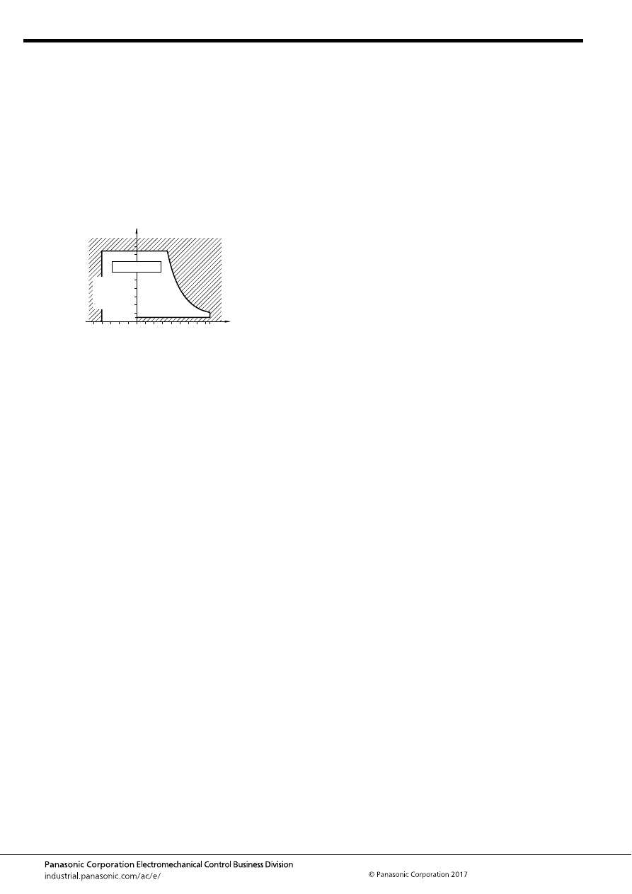
EV (AEV, AEVG, AEVS)
–198–
ASCTB384E 201709-T
NOTES
1. Usage, transport and storage conditions
Ambient temperature, humidity, and air pressure during usage,
transport, and storage of the relay
1) Temperature: –40 to +80
°
C
–40 to +176
°
F
(200 A and 300 A
types: –40 to +85
°
C
–40 to +185
°
F
)
2) Humidity: 5 to 85% RH
(Avoid icing and condensation.)
The humidity range varies with the temperature. Use within the
range indicated in the graph below.
3) Air pressure: 86 to 106 kPa
[Temperature and humidity range for
usage, transport, and storage]
4) Water condensation
Water condensation occurs when the ambient temperature
drops suddenly from a high temperature and humidity, or, the
relay is suddenly transferred from a low ambient temperature to
a high temperature and humidity. Condensation causes the
failures like insulation deterioration, wire disconnection and rust
etc.
Panasonic Corporation*3 does not guarantee the failures
caused by condensation.
5) Low-temperature, low-humidity atmosphere;
If the relay is exposed to a low-temperature, low-humidity
atmosphere for a long time, its plastic parts may become brittle
and fragile.
6) Storage
Do not keep under high-temperature and high-humidity.
2. Condition of tightening screw
Tighten each screw within the rated range given below.
Exceeding the maximum torque may result in breakage.
Mounting is possible in either direction.
<Relay attaching portion>
• M4 screw (for 10A type): 1.8 to 2.7 N·m
• M5 screw (for except 10A type): 3 to 4 N·m
<Main terminal attaching portion>
• M4 bolt (for Compact high short-circuit capacity and Quiet
horizontal types): 2.2 to 2.8 N·m
• M5 nut (for 80A and Quiet type): 3 to 4 N·m
• M6 nut (for 120A and 200A type): 6 to 8 N·m
• M8 nut (for 300A type): 10 to 12 N·m
3. Electrical life
This relay is a high-voltage direct-current switch. In its final
breakdown mode, it may lose the ability to provide the proper
switch-off. Therefore, do not exceed the indicated switching
capacity and life.
(Please treat the relay as a product with limited life and replace it
when necessary.)
In the event that the relay loses switch-off ability, there is a
possibility that burning may spread to surrounding parts, so
configure the layout so that the power is turned off within one
second.
4. Permeation life of internal gas
This relay uses a hermetically encased contact (capsule
contact) with gas inside. The gas has a permeation life that is
affected by the temperature inside the capsule contact (ambient
temperature and temperature rise due to flow of electrical
current). For this reason, make sure the ambient operating
temperature is between –40 and +80
°
C
–40 and +176
°
F
(200A
and 300A types: Max. +85
°
C
+185
°
F
), and the ambient storage
temperature is between –40 and +85
°
C
–40 and +185
°
F
.
5. The coils (300A type) and contacts (except compact high
short-circuit capacity type) of the relay are polarized, so
follow the connection schematic when connecting the coils
and contacts.
The 300A type contains a reverse surge voltage absorption
circuit; therefore a surge protector is not needed.
6. For the 300A type, drive the coil with a quick startup.
(Built-in one-shot pulse generator circuit)
7. After the ON signal enters the 300A type, automatic coil
current switching occurs after approximately 0.1 seconds.
Do not repeatedly turn it OFF within that 0.1 seconds interval, as
doing so may damage the relay.
8. Be careful that foreign matter and oils and fats kind don’t
stick to the main terminal portion because it is likely to
cause terminal portion to give off unusual heat.
Also, please use the following materials for connected
harnesses and bus bars.
10A type: Min. 2 mm
2
nominal cross-sectional area
20A type: Min. 3 mm
2
nominal cross-sectional area
60A and 80A types: Min. 15 mm
2
nominal cross-sectional area
120A type: Min. 38 mm
2
nominal cross-sectional area
200A type: Min. 60 mm
2
nominal cross-sectional area
300A type: Min. 100 mm
2
nominal cross-sectional area
9. As a guide, the insertion strength of the plug-in terminal
into the relay tab terminal should be 40 to 70N (10A type), 40
to 80N (20A and Quiet horizontal types). Please select a
plug in terminal (flat connection terminal) which comply
with JIS C2809-2014.
10A type: for plate thickness 0.5mm
.020inch
and #187 tab
terminal
20A and Quiet horizontal types: for plate thickness 0.8mm
.031inch
and #250 tab terminal
10. Avoid excessive load applied to the terminal in case of
installing such as a bus bar etc., Because it might adversely
affect the switching performance.
11. Use the specified connector for the connector terminal
connection (80A, 120A and 300A types).
Yazaki Corporation 7283 – 1020 or equivalent
85
5
Humidity, %RH
Tolerance range
(Avoid
condensation
when used at
temperatures
higher than
0
°
C
32
°
F
)
(Avoid icing
when used at
temperatures
lower than
0
°
C
32
°
F
)
80
0
–40
+176
85
+185
+32
–40
Temperature,
°
C
(200A, 300A types)
°
F
automotive-relay_en-html.html
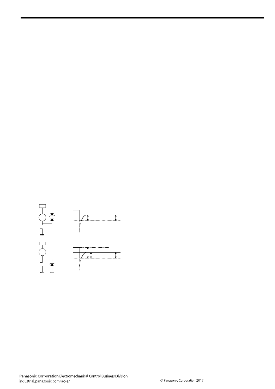
EV (AEV, AEVG, AEVS)
–199–
ASCTB384E 201709-T
12. Other cautions for use
1) Please make sure to contact our company when the product
is used not in accordance with its specifications. Your nearest
sales office will review the required specification from your
company and perform confirmation tests in actual condition as
needed. Please check “Automotive relay user’s guide” for use of
relays.
2) When the voltage is applied to the relay coil beyond the max.
allowable voltage range, the relay operation cannot be assured.
Additionally the ambient temperature and condition of your
application should be considered under the worst condition of
the actual usage because they may change the relay operate
and release voltage.
* It is not allowed to apply the continuous maximum voltage to
the coil.
In order to obtain the specified performance, please apply the
rated voltage.
3) If it includes ripple, the ripple factor should be max. 5%.
In addition, do not have a parallel connection with diode for the
purpose of coil surge absorber.
If only diode is connected in parallel to the relay coil, break
performance of relay cannot be assured because contact
release speed becomes slower. So do not use such a circuit.
Instead of diode, a Varistor (ZNR) or Zener diode (ZD) when
clamp voltage is 1.5 times larger than the rated voltage (Min.
18V for the rated 12V-relay), shall be used for the absorber.
Ex.1 When Varistor (ZNR) is used
Recommended Varistor; Energy capability: Min 1 J
(However, please set up the value with consideration of the
worst value in use condition.)
Varistor Voltage: Min. 18V at 12V DC
Min. 36V at 24V DC
Ex.2 When Zener diode (circuit) is used
4) Lifetime is specified under the standard test conditions in JIS
C 5442. (temperature 15
°
C to 35
°
C
59
°
F to 95
°
F
, humidity
25%RH to 75%RH)
Lifetime is dependent on the coil driving circuit, load type,
operation frequency and ambient conditions.
Check lifetime under the actual condition. Especially, contact
terminals have polarity. So if the contact terminals were
connected with opposite pole, the electrical life would be
shortened.
5) If the relay is dropped, it should not be used again.
6) Please contact our sales representative when AC load gets
applied to this relay.
Careful handing is required for switching AC load with this relay.
7) Please check the internal connection diagram in the catalog
or specification, and connect the terminals correctly.
If any wrong connection is made, it may cause circuit damage by
unexpected malfunction, abnormal heat, fire, and so on.
8) Please check the insulation distance between each terminal
and ground.
9) Please assure the evaluation of the relay under the actual
worst condition to enhance the reliability for the actual usage.
10) Please absolutely avoid the ultrasonic and high frequency
vibration to the relay that adversely affects its performance.
11) Minimum switching load is the lower limit switching current
under the micro-load. When the relay is used below minimum
switching load, reliability becomes lower. Please use the relay
beyond minimum switching load.
Additionally, minimum switching load is changed by coil drive
circuit, type of load, switching frequency and environment
condition.
So please confirm the reliability with actual load under the
assumed actual environment.
12) As for the screws of fixing relay-body and screws of fixing
contact terminal, the tightening torque must be within the
specified range.
• The purpose of the tightening torque for the contact terminal is
to secure adhesion force (axial force) at the fixing part and
provide stable electrical connection.
Therefore, do not use the screws (bolts and nuts) which require
rotation torque of locking type (prevailing torque type) because
sufficient adhesion force (axial force) may not be secured.
In addition, if the locking type nut is used, an excessive torque
may be applied to the case before generating of axial force and
may cause breakage of the case.
• Regarding the screw for fixing relay body, please use suitable
screws after adequate verification at user’s side.
13) The relay should not be installed near strong magnetic fields
(transformers, magnets, etc.) and should not be installed near
heat source.
14) If the several relays are mounted closely or a heat-
generation object is close to the relay, it may cause troubles the
abnormal temperature-rise and the short insulation distance
terminals outside of the relay so please assure the evaluation of
the relay under the actual worst condition.
15) The relay contacts are encapsulated in an inert gas
atmosphere. So, please avoid using or storing beyond the
allowable ambient temperature range.
16) After that the relay has been applied with the rated voltage
and current to the coil continuously and then the relay is once
switched off and switched on immediately, the relay coil
resistance may be increased due to the coil temperature
increase.
This will result in higher operate voltage and the value will
surpass the rated operate voltage value. In order to avoid this
failure, the following countermeasures are recommended.
- decrease of the load current
- restriction of time to apply voltage
- restriction of operating ambient temperature, etc.
17) If an inductive load (L/R > 1ms) is applied, add surge
protection in parallel with the inductive load. If this is not done,
the electrical life will be shortened and cut-off failure may occur.
18) In case using a capacitive load (C-load), please take a
countermeasure as pre-charging to the capacitive load so that
the inrush current will not surpass performance condition. The
relay may have a contact welding without such countermeasure.
19) Use the suitable wire or bus bar according to the current. If
the wire diameter is thin, maximum allowable contact current
cannot be assured.
Ex.) Carrying current; 120A: diameter of 38mm
2
(minimum) (for
wire at the load side)
20) Take care to disconnect from the power supply when wiring.
Relay
coil
12V
(1)
D
ZD18V
Clamp voltage
ZD18V +
Diode operating voltage
12V
ZD30V
Clamp voltage
30V–12V=18V
ZD30V Operating voltage
Relay
coil
(2)
automotive-relay_en-html.html
EV (AEV, AEVG, AEVS)
–200–
ASCTB384E 201709-T
For general cautions for use, please refer to the “Automotive Relay Users Guide”.
21) The tension load applied to the coil lead wire when wiring
should be max. 10N. In addition, take care not to bend at the
lead wire pullout portion when wiring or apply a stationary load
to the lead wire after wiring to avoid failure of the relay such as
breaking of wire.
22) The relay satisfies water resistance level of JIS D 0203 R2.
Please take any countermeasures additionally if it is installed in
the place where higher water resistance level is required.
23) Do not use this product in such atmosphere where any kind
of organic solvent (as benzene, thinner and alcohol) and the
strong alkali (as ammonia and caustic soda) may be adhered to
this product.
24) Be careful that oils and foreign matter do not stick to the
main terminal part because it is likely to cause a terminal part to
give off unusual heat.
25) Do not make additional manufacturing upon the relay
housing.
26) Maximum overcurrent value in this specification is limited as
single operation only. In the case of multiple operation, this relay
may cause malfunction by heating. So, please confirm the
temperature / operation using your application.
In the case of multiple operation, please stop applying the over
current to secure the relay's temperature under the maximum
ambient temperature.
27) When applying current which includes precipitous changes
or ripple, the relay may generate buzzing sound.
Therefore, please confirm with the actual load.
automotive-relay_en-html.html
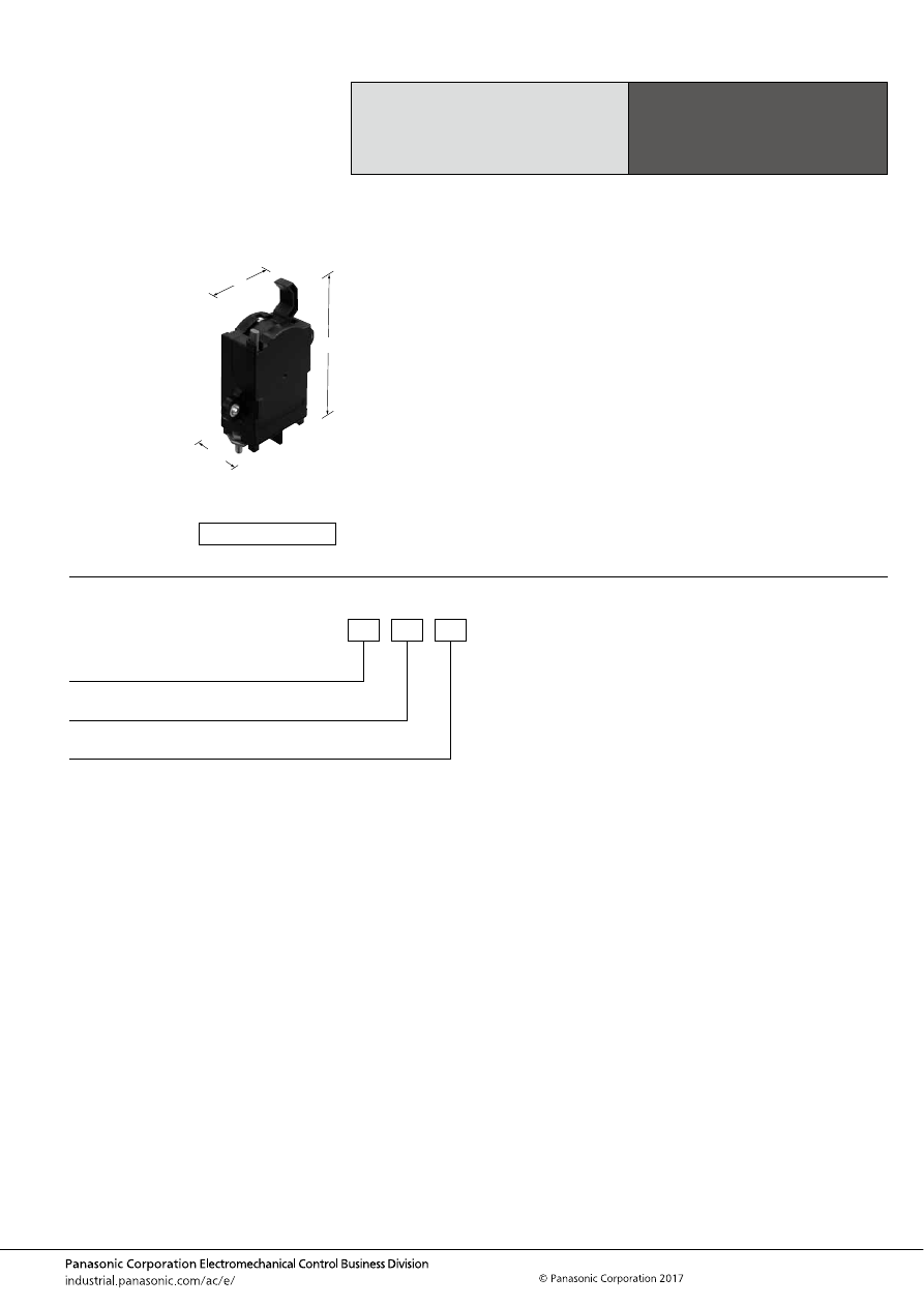
EV SWITCHES (AEVD)
–201–
ASCTB291E 201709-T
ORDERING INFORMATION
Capsule Contact
High Voltage
Cut-off Switch
EV SWITCHES
FEATURES
• High reliability with capsule contact technology
Since the contact portion is sealed in hydrogen gas, there is no
contact oxidation. It is also dustproof and waterproof.
• High voltage manual cut-off performance
To realize manual cutoff with high voltage DC, hydrogen gas,
which has superior arc cooling capability, is sealed in the
capsule contact chamber. At the same time, superior safety is
achieved owing to an explosion-proof construction that
prevents arc leakage.
• Safety function
Designed with interlock button to prevent false energization
TYPICAL APPLICATIONS
• This safety switch is for cut-off the battery power from the
system circuit when maintaining electric vehicles (HEV,
PHEV, BEV), etc.
<Protective construction>
Capsule contact
82.3
114.3
3.240
34.6
1.362
4.500
(Unit: mm
inch
)
RoHS compliant
Contact arrangement
1: 1 Form A
AEVD
Current carrying capacity
1: 80 A
Rated voltage
1: 400V DC
automotive-relay_en-html.html
EV SWITCHES (AEVD)
–202–
ASCTB291E 201709-T
TYPES
RATING
Specifications
Notes: *1. No-load application when ON.
*2. at L/R 1ms
Contact arrangement
Current carrying capacity
Part No.
Packing
Case
1 Form A
80 A
AEVD111
20 pcs. (Packed with 20 pcs/1 tray)
Item
Specifications
80 A type
Contact data
Contact arrangement
1 Form A
Rated voltage
400 V DC
Max. carrying current
80 A continuity
120 A 600s 5,560A 0.03s (20 mm
2
)
Contact voltage drop (initial)
Max. 0.16 V (at 80 A)
Insulation resistance (initial) (Between open
contacts, Between contacts and lever surface)
Min. 100 M
Ω
(at 500 V DC Megger)
Breakdown voltage (initial) (Between open
contacts, Between contacts and lever surface)
2,500 Vrms for 1 min. (Detection current: 10 mA)
Lever operation force
<OFF
⇒
ON> 10 to 25N (Measurement position: center of lever)
<ON
⇒
OFF> 3 to 9N (Measurement position: tip of lever)
Interlock button operation force
(when canceling a lock)
4
±
1N
Shock
resistance
(Switch: ON
condition)
Functional
Min. 490 m/s
2
{approx. 50 G} (Half-wave pulse of sine wave: 11 ms; detection time: 10
μ
s)
Destructive
Min. 790 m/s
2
{approx. 80.6 G} (Half-wave pulse of sine wave: 6 ms)
Vibration
resistance
(Switch: ON
condition)
Functional
20 to 200 Hz, acceleration: 44 m/s
2
{approx. 4.5 G} (Detection time: 10
μ
s)
Destructive
20 to 200 Hz, acceleration: 44 m/s
2
{approx. 4.5 G} X, Y, Z direction: 4 hours each
Expected life
Mechanical life
Min. 100 times
Switch-
off life*
1, 2
Forward direction
400 A 400 V DC, Min. 5 times
Reverse direction
–120 A 200 V DC, Min. 5 times
Conditions
Conditions for usage,
transport and storage
Ambient temperature: –40 to +80
°
C
–40 to +176
°
F
Humidity: 5 to 85% R.H. (Please avoid icing or condensation)
Weight
Approx. 230 g
8.11 oz
automotive-relay_en-html.html
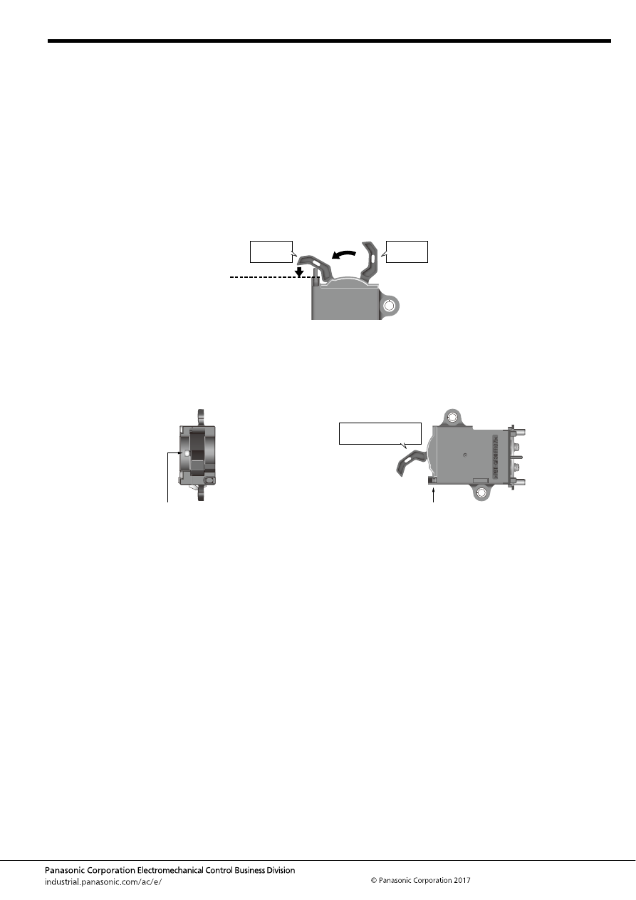
EV SWITCHES (AEVD)
–203–
ASCTB291E 201709-T
DESCRIPTION OF USAGE
1. Application
EV switch is a safety switch for cut-off a battery power supply from a system circuit, in order to protect a human body from the electric
shock accidents at the time of a maintenance, etc.
2. How to use
1) When the switch is turned ON and OFF, in principle the battery power is already cut-off by the system side (no current-passing
condition). Please turn the lever to the ON side and the OFF side. Do not switch current by contact turning ON. However, the switch
can cut-off the power directly, even when power is not cut-off by the system. Please refer to the specification regarding the cut-off
performance.
2) When turning the switch ON, the product is designed to prevent malfunction by not allowing it to turn ON unless the interlock button
is pressed when the lever is operated.
*1: At the time of OFF operation, the lever can change to OFF position without operation of the interlock button.
*2: Please operate the lever after making the interlock button slide down completely to the side of the cover.
[If contact welding occurs]
Contact welding may occur if current is switched by contact turning ON or if current that exceeds the specifications is continuously
applied when the power is ON. This switch indicates contact welding by doing (1) and (2), below.
(1) The lever will not go all the way to the OFF position when you try to turn it off, and when you release the lever it returns to the
window that displays “RED”.
(2) The interlock button does not return.
*Please be careful. In this state the switch’s contacts are not OFF.
Position of
Lever-ON
Position of
Lever-OFF
The Interlock button
is slid down to the
cover side.
(1)
The lever is
operated in the
ON direction.
(2)
>PBT‑
GF30 FR
( 17
) <
(1) The display window becomes “RED”.
* Usually display: “ON” or “OFF”
(2) The interlock button does not return.
Position of lever during
contact welding
automotive-relay_en-html.html
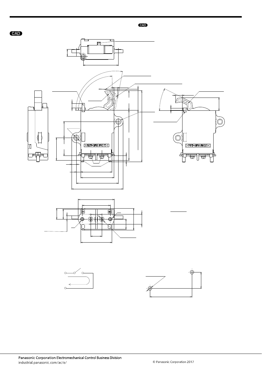
EV SWITCHES (AEVD)
–204–
ASCTB291E 201709-T
DIMENSIONS
(mm
inch
)
mark can be downloaded from: http://industrial.panasonic.com/ac/e/
The CAD data of the products with a
8 dia.
.315 dia.
(Flat washer)
50
1.969
17.3
.681
16.1
.634
16.1
.634
34.6
10
±
0.6
(114.3)
(4.500)
(11.06)
(.435)
(20.8)
(.819)
(3.5)
(.138)
(31.5)
80
3.150
(1.240)
.394
±
.024
1.363
(17.9)
(.705)
(M5 bolt pitch)
44.9
57.9
1.768
2.280
3.240
2.650
±
.020
2.098
82.3
67.3
±
0.5
1.024
±
.020
26
±
0.5
1.134
±
.039
28.8
±
1
1.417
36
.433
11
2.217
56.3
53.3
2
×
.236 dia.
2
×
6 dia.
1.969
50
M5 bolt
(M4)
(7)
(.276)
(7.5)
(.295)
(7.2)
(.283)
(5.8)
(.228)
(Both ends of bus bar)
(
−
)
(
+
)
Contact condition display window
Movement line of lever
Lever OFF free angle maximum position
Position of Lever-ON
Position of
Lever-OFF
5.7
.224
Collar seating face
and collar height
15.9
.626
(Bus bar width)
(Max.
le
v
er height:
34.3
1.350
)
Position of
Interlock button-ON
Position of
Interlock button-OFF
M5
bolt collar
(101
°
)
(89
°
)
(26
°
)
Tolerance;
Less than 10mm
.394inch
:
10 to 50mm
.394 to 1.969inch
:
More than 50mm
1.969inch
:
±
0.3
±
.012
±
0.6
±
.024
±
1.0
±
.039
External dimensions
Schematic (TOP VIEW)
(Reference) Mounting dimensions
(
−
)
(
+
)
There is polarity (
+
) and (
−
) on the load side.
Forward direction
67.3
±
0.2
2.650
±
.008
26
±
0.2
1.024
±
.008
2
×
6.0
±
0.2 dia.
Mounting hole:
2
×
.236
±
.008 dia.
automotive-relay_en-html.html
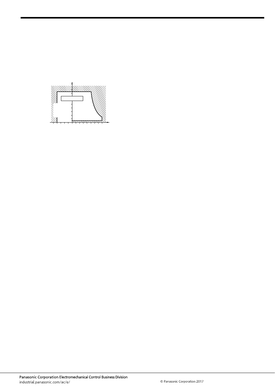
EV SWITCHES (AEVD)
–205–
ASCTB291E 201709-T
NOTES
1. Usage, transport and storage conditions
1) Temperature: –40 to +80
°
C
–40 to +176
°
F
2) Humidity: 5 to 85% RH
(Avoid icing and condensation.)
The humidity range varies with the temperature. Use within the
range indicated in the graph below.
3) Air pressure: 86 to 106 kPa
[Temperature and humidity range
for usage, transport, and storage]
4) Water condensation
Water condensation occurs when the ambient temperature
drops suddenly from a high temperature and humidity, or, the
relay is suddenly transferred from a low ambient temperature to
a high temperature and humidity. Condensation causes the
failures like insulation deterioration, wire disconnection and rust
etc.
Panasonic Corporation*3 does not guarantee the failures
caused by condensation.
5) Low-temperature, low-humidity atmosphere;
If the relay is exposed to a low-temperature, low-humidity
atmosphere for a long time, its plastic parts may become brittle
and fragile.
6) Icing
Please check the icing when an ambient temperature is lower
than 0
°
C
+32
°
F
. Water drop adheres to the relay by the
condensation or the abnormal high humidity and is frozen to the
ice when the ambient temperature becomes lower than 0
°
C
+32
°
F
. The icing causes the sticking of movable portion, the
operation delay and the contact conduction failure etc.
Panasonic Corporation does not guarantee the failures caused
by the icing.
The heat conduction by the equipment may accelerate the
cooling of relay itself and the icing may occur. Please confirm no
icing in the worst condition of the actual usage.
7) Storage
Do not keep under high-temperature and high-humidity.
2. When installing the switch, always use washers to
prevent the screws from loosening.
Regarding the torque value for contact terminal, it is
intended that secure an electrical connection stability by
getting enough contact pressure (Axial force) of fixing part.
Therefore, please do not use the screw (a bolt and a nut)
preventing looseness needing running torque (Prevailing
torque type and Self lock type) because enough tightening
force in axial direction may not be secured.
In addition, there is high possibility that a case of a switch
may be broken if users use the nut for EV switch.
Because excessive torque is applied to a case of a switch
before generation of contact pressure. (Axial force).
Regarding the torque value for the main body of a switch,
please use suitable screw on own verification.
3. Attachment environment
<Attached position>
• Same as the automotive vehicle interior environment
• Please consider the prevention of dew condensation and
dusts.
<Mounting arrangement>
Body: Fastening and fixing with a bolt. (M5
×
2)
Terminal: Fastening and fixing with a nut. (M5
×
2)
<Screw-fastening torque>
Body: 3.5
±
0.5 N·m
Terminal: 3.5
±
0.5 N·m
4. Please do not remove the assembly screw of the switch.
Otherwise the performance cannot be guaranteed.
Moreover, in order to prevent from removing the assembly
screw easily, please attach the assembly screw showing its
backside.
5. Please note the polarity of the terminal. Please abide by
the connection of polarity described to this catalog. The
performance cannot be satisfied when reversely connected.
It becomes a cause of the accident.
6. The switch should not be installed near strong magnetic
fields (transformers, magnets, etc.) and should not be
installed near heat source.
7. If the several switches are mounted closely or a heat-
generation object is close to the switch, take care to check
the abnormal temperature-rise and the insulation distance
between the terminals outside of the switch.
8. The switch contacts are encapsulated type filled with gas.
Therefore, care must be exercised when the switch is to be
used or stored at high ambient temperature.
9. If the switch is used for an inductive load (L load) such
that L/R > 1ms, add surge protection in parallel with the
inductive load. If this is not done, the electrical life will
decrease and cut-off failure may occur.
10. When the short-circuit current is large, there is
possibility that the switch will be destroyed by the time the
power supply is intercepted with the fuse. Therefore, please
confirm it enough with the system.
11. There is a possibility of performance change due to
transfer effect through terminal from connected
components and radiation heat (e.g. fuse) around the
switch.
12. Please consider the layout which avoids conductive
liquid on solvent such as water etc. from the switch for the
prevention of electric shock.
13. If the switch is used exceeding the contact rating or
cycle lifetime, this may result in the risk of overheating.
Humidity, %RH
Tolerance range
85
5
(Avoid
condensation
when used at
temperatures
higher than
0
°
C
32
°
F
)
(Avoid icing
when used at
temperatures
lower than
0
°
C
32
°
F
)
80
0
–40
+176
+32
–40
Temperature,
°
C
°
F
automotive-relay_en-html.html

EV SWITCHES (AEVD)
–206–
ASCTB291E 201709-T
For general cautions for use, please refer to the “Automotive Relay Users Guide”.
14. Contact welding may occur if current is switched by
contact turning ON or if current that exceeds the
specifications is continuously applied when the power is
ON.
The switch indicates ‘RED’ on the display window if contact
welding occur. (Please refer to ‘Description of usage’)
However when abnormalities such as fuse disconnection
etc. occurred, even if the display window does not become
RED, please check the OFF state of the contact with a tester
etc. and be sure to wear protective equipment before
operating.
15. Please consider safety measures such as detection of
ON/OFF state of a high voltage circuit, earth fault detection,
and temperature detection by a system for high voltage
circuit. Moreover, please consider safety measures that
high voltage part work cannot be performed, if it is not in a
high voltage circuit OFF state with a system or structure,
when operating high voltage part work.
16. If the switch is dropped, it should not be used again.
17. Take care to avoid cross connections as they may cause
malfunctions or overheating.
18. Use the suitable wire/bus bar according to the current.
*Recommendation: more than 20 mm
2
Moreover, please consider the layout that the wire/bus bar
can fix to the plate and please do not free the load-side
electric wire/bus bar linked to a switch.
When terminal of switch and load-side wire/bus bar have a
clearance gap, please do not carry out Screw-fastening with
force. Please set up the order of fixation and layout which
can make the smallest clearance gap at the time of screw-
fastening.
19. Do not use this product in such atmosphere where any
kind of organic solvent (as benzene, thinner and alcohol)
and the strong alkali (as ammonia caustic soda) might be
adhered to this product.
20. Although the gas enclosure type seal contact is used
inside the switch (capsule contact), since the product itself
is not a seal type, please do not use it under dust
environment or the environment where direct water and a
solvent adhere to the product.
21. Be careful that oil or foreign matter do not stick to the
main terminal part because it is likely to cause the terminal
part to give off unusual heat.
22. Do not make additional manufacturing upon the switch
housing.
23. For AC cut-off these is no contact polarity, but confirm
the electric life using the actual load.
automotive-relay_en-html.html
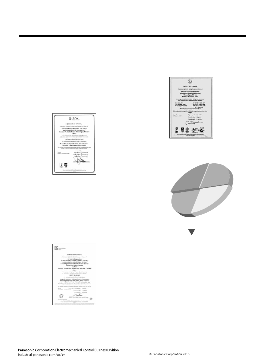
–207–
AACTB5E 201602-T
ISO14001, ISO9001, ISO/TS16949 Certificate of Approval
ISO14001 Certificate of approval
Panasonic Electromechanical Control Business Division, which
develops, manufactures and sells such as relays, switches and
sensors is certified according to the ISO 14001 environmental
management system standard established by the International
Standards for Organization (ISO).
Through our business activities, which objectives are to live in
harmony with the global environment and contribute to the
realization of a sustainable society, we have been making efforts
to reduce greenhouse gases and promote recycling of
resources. Furthermore, with due consideration to biodiversity,
we have been working for improving the global environment and
living in harmony with the international community.
ISO/TS16949 Certificate of approval
Our Electromechanical Control Business Division has been
accredited for ISO/TS16949, covering our quality management
system for an entire spectrum of automotive products for relays,
switches and connectors.
ISO/TS16949 is a standard based on ISO9001 that adds items
necessary for the automobile industry.
It calls for a comprehensive quality management system that
includes CS, cost performance, ongoing improvement, and
many other aspects of quality management.
ISO9001 Certificate of approval
Our Electromechanical Control Business Division, which
handles from development to production and marketing for
relays, switches and sensors, has been approved for certification
of the ISO9001 quality assurance standard established by the
International Standards for Organization (ISO).
The Necessity and
Pursuit of ISO Certification
A P
C D
•
Strengthening and upgrading quality assurance
•
organizational structures applicable on an international
•
basis
•
Technology can be accumulated and disseminated
•
through documentation and records
•
Leads to improved reliability of the manufacturer’s quality
•
and improved CS (customer satisfaction)
Advantages
•• Check on how internal quality
audit is being performed.
audit is being performed.
• Check on how internal quality
audit is being performed.
• Instructional activities relating to
Instructional activities relating to
ISO
• Preparation of quality manuals and
Preparation of quality manuals and
quality planning manuals
quality planning manuals
• Establishment of new quality
systems and expanding them to
systems and expanding them to
business operations
• Upgrading internal quality
monitoring
• Instructional activities relating to
ISO
• Preparation of quality manuals and
quality planning manuals
• Establishment of new quality
systems and expanding them to
business operations
• Upgrading internal quality
monitoring
• Expanding to other
overseas bases
• Expanding to affiliated
companies and
cooperating companies
• Expanding to other
overseas bases
• Expanding to affiliated
companies and
cooperating companies
• ISO9000
Certification Acquisition
• ISO9000
Certification Acquisition
automotive-relay_en-html.html
–208–
AACTB6E 201703-T
automotive-relay_en-html.html
Please contact ..........
Specifications are subject to change without notice.
ASCTB376E-1 20170
9
-3YKN
Electromechanical Control Business Division
1006, Oaza Kadoma, Kadoma-shi, Osaka 571-8506, Japan
industrial.panasonic.com/ac/e/
©Panasonic Corporation 2017
8mm
industrial.panasonic.com/ac/e/
2017-2018
Motorcycle
Commercial Vehicle
Passenger Car
Automotive
Relays
Automation Controls
Group Catalog
Auto
mation Co
ntro
ls Gro
up Catalo
g
2017
-20
18
Automotive Relays