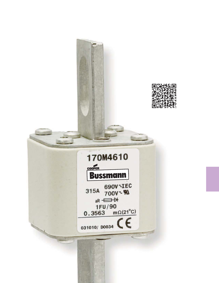
background image

121

High Speed

Fuses

High Speed Fuses

Section Contents

Page

General Applications . . . . . . . . . . . . . . . . . . . . . . .122-123

North American fuses & accessories . . . . . . . . . . .124-141

DFJ - High speed Class J fuse  . . . . . . . . . . . . . . . . . . 125

Square Body fuses & accessories  . . . . . . . . . . . . 142-213

BS 88 fuses & accessories . . . . . . . . . . . . . . . . . .214-222

Ferrule fuses & accessories. . . . . . . . . . . . . . . . . .223-243

TM

Scan this tag to get the

latest product information for 

High Speed Fuses.

Courtesy of Steven Engineering, Inc. - (800) 258-9200 - sales@steveneng.com - www.stevenengineering.com

bussmann-HIGH-SPEED-FUSES-html.html
background image

Power Factor

For other power factor
values, the total clearing
integral can be
calculated as a multiple
of the clearing integrals,
the correction factor K
and the correction factor
X.

Arc Voltage

This curve gives the
peak arc voltage, UL,
which may appear
across the fuse during its
operation as a function
of the applied working
voltage, Eg, (rms) at a
power 
factor of 15%.

Power Losses

Watts loss at rated 
current is given in the
electrical characteristics.
The curve allows the 
calculation of the power
losses at load currents
lower than the rated 
current . The correction
factor, Kp , is given as a
function of the RMS load
current, Ib , in % of the
rated current .

Cut-Off Current

A fuse operation relating to short-circuits only. When a fuse
operates in its current-limiting range, it will clear a short-

circuit in less than 

1

2

cycle. Also, it will limit the instantaneous

peak let-through current to a value substantially less than

For product data sheets, visit www.cooperbussmann.com/DatasheetsEle

122

High Speed Fuses

Prospective Current in Amps RMS

Peak Let-Through Current

10

 10

2

2

10

3

10

4

10

5

10

3

10

4

10

5

10

6

A

B

General Applications

Rated Voltage

The AC voltage rating of Bussmann fuses is given in volts
rms. Fuses tested to IEC are tested at 5% above their rated
voltage. British Style BS 88 fuses are tested at 10% above
its rated voltage. UL recognition tests are performed at the
rated voltage.

Rated Current

Rated current is given in amps rms. Bussmann fuses can
continuously carry the rated current.

Melting Characteristic

The melting
characteristic
shows the virtual
melting time in
seconds as a
function of the
prospective current
in amps rms. The
fuses are specially
constructed for
short-circuit
protection against
high level fault
currents. Loading
and operation of
the fuse in the non-
continuous/dashed
section of the melt
curve must be
avoided. The curve
can also be read
as the real melting
time as a function
of the RMS value
of the pre-arc current.

Clearing Integrals

The total clearing I

2

t at

rated voltage and at
power factor of 15% are
given in the electrical
characteristics. For
other voltages, the
clearing I

2

t is found by

multiplying by correction
factor, K, given as a
function of applied
working voltage, Eg,

(rms).

10

4

10

3

10

2

10

1

2

2

4

6

8

2

10

2

2

4

6

8 10

3

2

4

6

2

6
4

10

0

2

6
4

10

1

2

6
4

2

6
4

2

6
4

6
4

2

6

2

4

Prospective Current In Amperes RMS

Vir

tual Pre-Arcing 

Time In Seconds

10

–4

10

–3

10

–2

10

–1

K

1.5

1.0

0.5

0.4

0.3

0.2

100 200 300 400 500 600 660

E

g

1.0

0.9

0.8

0.7

0.1

0.2

0.3

0.4

0.5

     COS 

X

U

L

1.4
1.2

10

3

6

8
7

9

5

4

3

200 300

400

500

600 660

E

g

K

p

1.0
0.8

0.4

0.5

0.6

0.3

0.2

0.1

30 40 50

60

70

80 90 100%

I

b

Courtesy of Steven Engineering, Inc. - (800) 258-9200 - sales@steveneng.com - www.stevenengineering.com

bussmann-HIGH-SPEED-FUSES-html.html
background image

For product data sheets, visit www.cooperbussmann.com/DatasheetsEle

123

High Speed

Fuses

General Applications

that obtainable in the same circuit if that fuse were replaced
with a solid conductor of equal impedance.

A asymmetrical current
B symmetrical current

Parallel Connection

When fuses are connected in parallel it is recommended that
the applied voltage does not exceed 0.9 UN (the rated 

voltage of the fuse). This is due to the fact that the energy
released within the fuses may be unevenly shared between
the parallel connected barrels.

When fuses are connected in parallel, one must take into
account that the current sharing is not necessarily equal. And
it must be checked, that the maximum load current is not
exceeded.

Series Connection

Fuses in series may not equally divide the applied voltage. It
is recommended that series connected fuses should only be
operated at fault currents that yield melting times less than
10 ms and a recovery voltage per fuse of less than or equal
to 0.9 UN (the rated voltage of the fuse).

Mounting Guidance

The recommendations below have to be followed when
mounting a Bussmann fuse with end plate threaded holes.

1. Screw in studs: 5 N•m Max, 3 N•m Min
2. Attachment of the fuse to bussbar by means of nut and  

washer:

Thread

Torque (N•m)*

Configuration

Max

Min

5

16

” – 18, M8

25

20

3

8

” – 16, M10

45

40

3

8

” – 24

45

40

1

2

” – 13, M12

65

50

1

2

” – 20

65

50

*1 N•m = 0.7375 lb-ft

Overloads

The design of Bussmann fuses is such that they can be
operated under rather severe operating conditions imposed
by overloads (any load current in excess of the maximum
permissible load current).

In applications, there will be a maximum overload current,
Imax, which can be imposed on the fuse with a 
corresponding duration and frequency of occurrence.

Time durations fall into two categories:

1. Overloads longer than one second
2. Overloads less than one second termed “impulse” loads.

The following table gives general application guidelines
which, in the expression Imax < (% factor) x It. It is the 

melting current corresponding to the time “t” of the overload
duration as read from the time-current curve of the fuse. The
guidelines in the table below determine the acceptability of
the selected fuses for a given Imax.

Frequency of Occurrence

Overloads (> 1 sec)

Impulse Loads (< 1 sec)

Less than once per month

Imax < 80% x It

Imax < 70% x It

Less than twice per week

Imax < 70% x It

Imax < 60% x It

Several times per day

Imax < 60% x It

When impulse loads are an intrinsic/normal parameter of the
load current either as single pulse or in trains of pulses or
when their level is higher than the melting current at 0.01
seconds (per time-current curve), contact Bussmann for
application assistance.

In addition to the parameters set forth in the preceding table,
the RMS value of the load current as calculated for any 
period of 10 minutes or more should not exceed the 
maximum permissible load current.

Furthermore, it is important that a fuse should not be applied
in the non-continuous/dashed portion of the associated 
time-current curve.

Any time-current combination point which falls in the 
non-continuous/dashed portion of the time-current curve is
beyond the capability of the fuse to operate properly.

DC Operation

Depending upon the short-circuit time constant and the 
magnitude of the prospective short-circuit current, the dc
voltage at which a fuse can be applied may be less than its
ac rating. Long time constants require a lower dc voltage.
Conversely, however, higher available prospective short-
circuit currents result in faster fuse openings and thus permit
a fuse to be operated at a higher DC voltage.

Consult Bussmann for
additional information and
application assistance
when fuses have to 
operate under DC 
conditions.

Load Current Versus

Conductor Cross

Section

Reduction of permissible
load current when the conductor cross section is less than
that given in IEC Publication 269-1 & 4 valid for Bussmann
high speed fuses.

Application Assistance

If you have application problems or need a fuse outside our
standard program, please contact the nearest Bussmann
representative. Phone numbers are shown on the back
cover.

1 . 0

0 . 9

0 . 8

0 . 5

0 . 6

0 . 7

0 . 8

0 . 9

1 . 0

≈ (IEC cross section)

Reduction Factor

High Speed Fuses

Courtesy of Steven Engineering, Inc. - (800) 258-9200 - sales@steveneng.com - www.stevenengineering.com

bussmann-HIGH-SPEED-FUSES-html.html
background image

Introduction

North American Contents

Catalog

Amp

Number

Volts

Range

Page

DFJ

600

1-600

125

FWA

130

1000-4000

126-127

FWA

150

70-1000

128-129

FWX

250

35-2500

130-131

FWH

500

35-1600

132-133

KAC

600

1-1000

134

KBC

600

35-800

135

FWP

700

5-1200

136-138

FWJ

1000

35-2000

139-140

Accessories

Fuse Bases

141

North American Fuse Ranges

Amps

Volts

AC

DC

1000-4000

130

X

X

70-1000

150

X

X

35-2500

250

X

X

35-1600

500

X

X

1-1000

600

X —

5-1200

700

X

X

40-600

800

X

35-2000

1000

X

For product data sheets, visit www.cooperbussmann.com/DatasheetsEle

124

High Speed Fuses

North American Fuses

General Information

Bussmann offers a complete range of North American blade
and flush-end style fuses and accessories. Their design and
construction were optimized to provide:

•  Low energy let-through (I

2

t)

•  Low watts loss
•  Superior cycling capability
•  Low arc voltage
•  Excellent DC performance

North American style fuses provide an excellent solution for
medium power applications. While there are currently no
published standards for these fuses, the industry has
standardized on mounting centers that accept Bussmann
fuses.

Voltage Rating

All Bussmann North American style fuses are tested at their
rated voltage. Bussmann should be consulted for applications
exceeding those values.

Accessories

External and internal open fuse indication is available for
selected portions of the North American line. Fuse blocks are
available for most applications.

Courtesy of Steven Engineering, Inc. - (800) 258-9200 - sales@steveneng.com - www.stevenengineering.com

bussmann-HIGH-SPEED-FUSES-html.html
background image

For product data sheets, visit www.cooperbussmann.com/datasheetsele

125

High Speed

Fuses

High Speed Fuses

Specifications
Description:

High speed, current-limiting fuse. The

Bussmann Drive Fuse will provide maximum protection for
AC and DC drives and controllers and meet NEC

®

branch

circuit protection requirements. The Drive Fuse has the 
lowest I

2

t of any branch circuit fuse to protect power 

semiconductor devices that utilize diodes, GTOs, SCRs and
SSRs.

Dimensions:

See page 21 for Class J dimensions.

Construction:

Melamine tube with silver fuse element.

Ratings:

Volts — 600Vac (or less), 450Vdc (or less)

Amps — 1-600A

IR — 200kA RMS Sym., 100kA DC

Agency Information:

CE, Std. 248-8, Class J, UL Listed,

Guide JDDZ, File E4273, CSA Certified, Class 1422-02, File
53787.

Features and Benefits

• Easily coordinated with existing and new variable speed 

drives and electric controllers.

• Standard Class J dimensions allowing the use of readily

available fuse blocks, holders, and switches.

• Allows the lowest let-thru energy of any branch circuit 

overcurrent protective device.

Typical Applications

• Protection of AC and DC drives
• Equipment using power semiconductor devices

Catalog Numbers (Amps)

DFJ-1

DFJ-15

DFJ-70

DFJ-225

DFJ-2

DFJ-20

DFJ-80

DFJ-250

DFJ-3

DFJ-25

DFJ-90

DFJ-300

DFJ-4

DFJ-30

DFJ-100

DFJ-350

DFJ-5

DFJ-35

DFJ-110

DFJ-400

DFJ-6

DFJ-40

DFJ-125

DFJ-450

DFJ-8

DFJ-45

DFJ-150

DFJ-500

DFJ-10

DFJ-50

DFJ-175

DFJ-600

DFJ-12

DFJ-60

DFJ-200

Data Sheet: 1048

DFJ Class J

Drive Fuse High Speed Fuses

Time-Current Characteristic Curves—Average Melt

Current Limitation Curves

Courtesy of Steven Engineering, Inc. - (800) 258-9200 - sales@steveneng.com - www.stevenengineering.com

bussmann-HIGH-SPEED-FUSES-html.html
background image

For product data sheets, visit www.cooperbussmann.com/DatasheetsEle

126

High Speed Fuses

Dimensions - in

Catalog Number

Fig. B

C

D

Thread Depth

FWA-1000AH-2000AH

1

2.0

1.0

Tapped 

3

8

”-24 x 

1

2

FWA-2500AH-3000AH

1

3.0

1.5

Tapped 

1

2

”-20 x 

1

2

FWA-4000AH

2

3.5

1.5

1.5

Tapped 

1

2

”-20 x 

1

2

1mm = 0.0394˝ / 1˝ = 25.4mm

Fig. 1: 1000-3000A

Fig. 2: 4000A

1.875

B

C

1.875

C

B

D

Arc Voltage

This curve gives the peak
arc voltage, UL, which

may appear across the
fuse during its operation
as a function of the
applied working voltage,
Eg, (rms) at a power 

factor of 15%.

Power Losses

Watts loss at rated current
is given in the electrical
characteristics. The curve
allows the calculation of
the power losses at load
currents lower than the
rated current. The 
correction factor, Kp, is

given as a function of the
RMS load current, Ib, in %

of the rated current.

Catalog Numbers

Electrical Characteristics

I

2

t (A

2

Sec)

Catalog

Rated Current

Clearing

Watts

Numbers

RMS-Amps

Pre-arc

at 130V

Loss

FWA-1000AH

1000

170000

460000

60

FWA-1200AH

1200

270000

730000

70

FWA-1500AH

1500

520000

1400000

78

FWA-2000AH

2000

860000

2400000

108

FWA-2500AH

2500

1500000

4100000

130

FWA-3000AH

3000

2100000

5700000

150

FWA-4000AH

4000

3400000

9200000

257

• Watts loss provided at rated current.
• See accessories on page 141.

Features and Benefits

• Excellent DC performance
• Low arc voltage and low energy let-through (I

2

t)

• Low watts loss
• Superior cycling capability

Typical Applications

• DC Common bus
• DC Drives
• Power converters/rectifiers
• Reduced voltage starters

North American — FWA 130V:  1000-4000A

FWA

Specifications
Description:

North American

style flush-end high speed fuses.

Dimensions:

See Dimensions

illustrations.

Ratings:

Volts: — 130Vac

Amps: — 1000-4000A

IR: — 200kA RMS Sym.

— 50kA @130Vdc

Agency Information:

CE, UL Recognized JFHR2.E91958

on 1000-2000A fuses

Electrical Characteristics

Total Clearing I

2

t

The total clearing I

2

t at

rated voltage and at power
factor of 15% are given in
the electrical 
characteristics. For other
voltages, the clearing I

2

t is

found by multiplying by
correction factor, K, given
as a function of applied
working voltage, Eg, (rms).

130

104

65

26

1.5

1.0

0.5

0.3

0.2

0.15

E

g

K

U

L

E

g

200

100

100

150

50

300

K

p

1.0
0.8

0.4

0.5

0.6

0.3

0.2

0.1

30 40 50

60

70

80 90 100%

I

b

Data Sheet: 720001

Courtesy of Steven Engineering, Inc. - (800) 258-9200 - sales@steveneng.com - www.stevenengineering.com

bussmann-HIGH-SPEED-FUSES-html.html
background image

For product data sheets, visit www.cooperbussmann.com/DatasheetsEle

127

High Speed

Fuses

North American — FWA 130V:  1000-4000A

FWA 1000-4000A: 130V

Time-Current Curve

10

3

2

2

4

6

8

2

10

4

2

4

6

8

10

5

Prospective Current In Amps RMS

2

4

6

2

6
4

10

0

2

6
4

10

1

2

6
4

2

6
4

2

6
4

V

irtual Pr

e-Ar

cing Time In Seconds

6
4

2

6

2

4

10

–1

10

–2

10

–3

10

–4

10

2

10

3

10

4

FWA-4000AH

FWA-3000AH

FWA-2500AH

FWA-2000AH

FWA-1500AH

FWA-1200AH

FWA-1000AH

FWA-4000AH

FWA-3000AH

FWA-2500AH

FWA-2000AH

FWA-1500AH

FWA-1200AH

FWA-1000AH

Prospective Short-Circuit Current Symmetrical RMS

Peak Let-Thr

ough Curr

ent

2

6

4

2

6

4

2

2

4

6

2

4

6

2

4

6

10

4

10

5

10

3

10

4

10

5

10

3

Peak Let-Through Curve

Data Sheet: 35785301

High Speed Fuses

Courtesy of Steven Engineering, Inc. - (800) 258-9200 - sales@steveneng.com - www.stevenengineering.com

bussmann-HIGH-SPEED-FUSES-html.html
background image

For product data sheets, visit www.cooperbussmann.com/DatasheetsEle

128

High Speed Fuses

2.656

1.936

2.188

1.156

0.312

0.438

0.750

1.000

0.125

Dimensions - in

Fig. 1: 70-400A

1.500

0.250

3.500

2.438

1.250

1.000

0.406

Fig. 2: 500-1000A

1mm = 0.0394” / 1” = 25.4mm

North American — FWA 150V:  70-1000A

FWA

Specifications
Description:

North American style 

stud-mount  fuses.

Dimensions:

See Dimensions 

illustrations.

Ratings:

Volts: — 150Vac/dc*

Amps: — 70-1000A

IR: — 100kA Sym. (70-400A)

— 200kA Sym. (450-1000A)

— 20kA @150Vdc (70-800A)

— 100kA @ 80Vdc (70-1000A)

*1000A rated @ 80Vdc.

Agency Information:

CE, UL Recognized JFHR2.E91958

Electrical Characteristics

Total Clearing I

2

t

The total clearing I

2

t at rated

voltage and at power factor 
of 15% are given in the 
electrical characteristics. For
other voltages, the clearing 
I

2

t is found by multiplying by 

correction factor, K, given as
a function of applied working
voltage, Eg, (rms).

Arc Voltage

This curve gives the peak
arc voltage, UL, which may

appear across the fuse 
during its operation as a
function of the applied
working voltage, Eg, (rms)

at a power factor of 15%.

Power Losses

Watts loss at rated current
is given in the electrical
characteristics. The curve
allows the calculation of
the power losses at load
currents lower than the
rated current. The 
correction factor, Kp, is

given as a function of the
RMS load current, Ib, in %

of the rated current.

Catalog Numbers

Electrical Characteristics

Rated

I

2

t (A

2

Sec)

Catalog

Current

Clearing

Watts

Number

RMS-Amps

Pre-arc

at 150V

Loss

FWA-70B

70

470

4000

6.9

FWA-80B

80

670

6000

7.7

FWA-100B

100

1200

12000

9.0

FWA-125B

125

1870

18000

11.2

FWA-150B

150

2700

26000

13.5

FWA-200B

200

4780

45000

17.6

FWA-250B

250

7470

70000

22.5

FWA-300B

300

10760

100000

27.0

FWA-350B

350

15700

140000

30.6

FWA-400B

400

20300

180000

35.2

FWA-500A

500

39000

120000

35.0

FWA-600A

600

46000

140000

47.0

FWA-700A

700

75000

220000

49.0

FWA-800A

800

92000

280000

58.0

FWA-1000A

1000

170000

510000

60.0

• Watts loss provided at rated current.
• See accessories on page 141.

Features and Benefits

• Excellent DC performance
• Low arc voltage and low energy let-through (I

2

t)

• Low watts loss
• Superior cycling capability

Typical Applications

• DC Common bus
• DC Drives
• Power converters/rectifiers
• Reduced voltage starters

150

102

70

22

1.5

1.0

0.5

0.3

0.2

0.15

Eg

K

1)

2)

K

p

1.0
0.8

0.4

0.5

0.6

0.3

0.2

0.1

30 40 50

60

70

80 90 100%

I

b

U

L

E

g

200

100

100

150

50

300

1) 500-1000A Range
2) 70-400A Range

Data Sheet: 720002

Courtesy of Steven Engineering, Inc. - (800) 258-9200 - sales@steveneng.com - www.stevenengineering.com

bussmann-HIGH-SPEED-FUSES-html.html
background image

For product data sheets, visit www.cooperbussmann.com/DatasheetsEle

129

High Speed

Fuses

North American — FWA 150V:  70-1000A

Prospective Current In Amps RMS

V

irtual Pr

e-Ar

cing Time In Seconds

10

2

2

4

6

8

10

3

2

4

6

8

10

4

2

4

6

2

6
4

10

0

2

6
4

10

1

2

6
4

2

6
4

2

6
4

6
4

2

6

2

4

10

–1

10

–2

10

–3

10

–4

10

2

10

3

10

4

FWA-1000A

FWA-800A

FWA-700A

FWA-600A

FWA-500A

FWA-200A

FWA-400A

FWA-350A

FWA-300A

FWA-250A

FWA-150A

FWA-70A
FWA-80A
FWA-100A
FWA-125A

FWA 70-1000A: 150V

Time-Current Curve

Prospective Short-Circuit Current Symmetrical RMS

Peak Let-Thr

ough Curr

ent

2

6

4

2

6

4

2

6

4

2

4

6

2

4

6

2

4

6

10

2

10

3

10

4

10

6

10

2

10

3

10

4

10

5

2

FWA-400A

FWA-350A

FWA-300A

FWA-250A

FWA-200A

FWA-150A

FWA-100A

FWA-80A

FWA-70A

Peak Let-Through Curve

Data Sheet: 35785310

High Speed Fuses

Courtesy of Steven Engineering, Inc. - (800) 258-9200 - sales@steveneng.com - www.stevenengineering.com

bussmann-HIGH-SPEED-FUSES-html.html
background image

For product data sheets, visit www.cooperbussmann.com/DatasheetsEle

130

High Speed Fuses

North American — FWX 250V: 35-2500A

FWX

Specifications
Description:

North American

style stud-mount and flush-end
fuses.

Dimensions:

See Dimensions

illustrations.

Ratings:

Volts: — 250Vac/dc

Amps: — 35-2500A

IR: — 200kA RMS Sym.

50kA@250Vdc (35-800A)

Agency Information:

CE, UL Recognized JFHR2.E56412

& CSA Component Acceptance file Class 1422-30, (53787)
on 35-800A fuses (50kA IR @250Vdc).

Electrical
Characteristics

Total Clearing I

2

t

The total clearing I

2

t at rated

voltage and at power factor
of 15% are given in the
electrical characteristics.
For other voltages, the
clearing I

2

t is found by 

multiplying by correction
factor, K, given as a 
function of applied working
voltage, Eg, (rms).

Arc Voltage

This curve gives the peak
arc voltage, UL, which may

appear across the fuse 
during its operation as a
function of the applied 
working voltage, Eg, (rms)

at a power factor of 15%.

Power Losses

Watts loss at rated current is
given in the electrical char
acteristics. The curve allows 
the calculation of the power 
losses at load currents lower
than the rated current . The
correction factor, Kp , is 
given as a function of the 
RMS load current, Ib , in % 
of the rated current .

Catalog Numbers

Electrical Characteristics

Rated

I

2

t (A

2

Sec)

Catalog

Current

Clearing

Watts

Number

RMS-Amps

Pre-arc

at 250V

Loss

FWX-35A

35

50

230

4.2

FWX-40A

40

60

310

5.2

FWX-45A

45

80

390

5.7

FWX-50A

50

100

520

6.0

FWX-60A

60

140

740

8.1

FWX-70A

70

330

1400

7.2

FWX-80A

80

430

1850

8.1

FWX-90A

90

570

2450

9.0

FWX-100A

100

740

3150

10.0

FWX-125A

125

1130

4850

12.5

FWX-150A

150

1620

6950

15.7

FWX-175A

175

2170

9300

18.5

FWX-200A

200

2790

12000

22

FWX-225A

225

3210

14700

24

FWX-250A

250

3960

18100

27

FWX-275A

275

4720

21600

31

FWX-300A 300

6000

27300

32

FWX-350A

350

10600

48600

39

FWX-400A

400

14500

66100

44

FWX-450A

450

22100

101000

49

FWX-500A

500

28000

128000

54

FWX-600A

600

41100

188000

62

FWX-700A

700

48800

190000

72

FWX-800A

800

59000

230000

84

FWX-1000AH

1000

44000

360000

100

FWX-1200AH

1200

92000

750000

103

FWX-1500AH

1500

120000

880000

140

FWX-1600AH

1600

160000

1200000

140

FWX-2000AH

2000

320000

2300000

151

FWX-2500AH

2500

670000

4700000

163

• Watts loss provided at rated current.     • See accessories on page 141.

Features and Benefits

• Excellent DC performance
• Low arc voltage and low

energy let-through (I

2

t)

• Superior cycling capability

K

p

1.0
0.8

0.4

0.5

0.6

0.3

0.2

0.1

30 40 50

60

70

80 90 100%

I

b

1.5

1.0

0.5

0.3

0.2

0.15

75

125

300

200

250

E

g

K

1)

2)

U

L

1.4
1.2

10

3

800

600

500

400

300

200

50

100

150

200

250

E

g

1)

2)

1) 35-800A Range
2) 1000-2500A Range

1) 35-800A Range
2) 1000-2500A Range

A

E

D

C

F

J

G

B

H

A

B

C

A

B

C

D

Fig. 1:

35-800A

Fig. 2:

1000-1200A

Fig. 3:

1500-2500A

Dimensions - in

Tapped

Amp

Thread

Range

Fig. A

B

C

D

E

F

G

H

J

Depth

35-60

1

3.19 0.81 1.59 2.59 2.25 0.34 0.63 0.13 0.52 —

70-200

1

3.13 1.22 1.59 2.44 2.19 0.34 1.00 0.19 0.47 —

225-600

1

3.84 1.50 1.59 2.94 2.25 0.41 1.00 0.25 0.75 —

700-800

1

3.84 2.00 1.59 3.03 2.28 0.41 1.50 0.25 0.78 —

1000-1200

2

2.59 3.00 1.50 —

3

8

”-24 x 

1

2

1500-2500

3

2.59 3.50 1.50 1.50 —

3

8

”--24 x 

1

2

1mm = 0.0394” / 1” = 25.4mm

Typical Applications

• DC Common bus
• DC Drives
• Power converters/rectifiers
• Reduced voltage starters

Data Sheet: 720005

Courtesy of Steven Engineering, Inc. - (800) 258-9200 - sales@steveneng.com - www.stevenengineering.com

bussmann-HIGH-SPEED-FUSES-html.html
background image

For product data sheets, visit www.cooperbussmann.com/DatasheetsEle

131

High Speed

Fuses

North American — FWX 250V: 35-2500A

10

4

10

3

10

2

10

2

10

3

10

4

10

1

10

0

10

–1

10

–2

10

–3

10

–4

2

Prospective Current In Amps RMS

V

irtual Pr

e-ar

cing Time In Seconds

FWX-800A

FWX-600A

FWX-500A

FXW-400A

FWX-350A

FWX-200A

FWX-150A

FWX-70A

FWX-60A

FWX-40A

FWX-35A

FWX-100A

10

3

2

2

4

6

8

2

10

4

2

4

6

8

10

5

2

4

6

2

6
4

10

0

2

6
4

2

6
4

2

6
4

2

6
4

6
4

2

6

2

4

10

–1

10

–2

10

–3

10

–4

10

2

10

1

10

3

10

4

FWX-2500AH

FWX-2000AH

FWX-1600AH

FWX-1500AH

FWX-1200AH

FWX-1000AH

Prospective Current In Amps RMS

V

irtual Pr

e-Ar

cing Time In Seconds

FWX 1000-2500A(H): 250V

Time-Current Curve

FWX 35-800A: 250V

Time-Current Curve

FWX-150A
FWX-100A
FWX-70A
FWX-60A
FWX-45A
FWX-35A

FWX-200A

FWX-300A

FWX-400A

FWX-600A

FWX-800A

10

2

10

3

10

4

10

5

10

2

10

3

10

4

10

5

Prospective Short-Circuit Current Symmetrical RMS

P

eak Let-Through Current

A

B

Prospective Short-Circuit Current Symmetrical RMS

Peak Let-Thr

ough Curr

ent

2

6

4

2

6

4

2

4

6

2

4

6

2

4

6

10

3

10

4

10

5

FWX-2000AH

FWX-1600AH

 FWX-1500AH

FWX-1200AH

 FWX-1000AH

10

3

10

4

10

5

FWX-2500AH

Peak Let-Through Curve

Peak Let-Through Curve

Data Sheet: 359

Data Sheet: 35785299

High Speed Fuses

Courtesy of Steven Engineering, Inc. - (800) 258-9200 - sales@steveneng.com - www.stevenengineering.com

bussmann-HIGH-SPEED-FUSES-html.html
background image

For product data sheets, visit www.cooperbussmann.com/DatasheetsEle

132

High Speed Fuses

North American — FWH 500V:  35-1600A

FWH

Specifications
Description:

North American style

stud-mount fuses.

Dimensions:

See Dimensions 

illustration.

Ratings:

Volts: — 500Vac/dc (35-800A only)

Amps: — 35-1600A

IR: — 200kA Sym.

— 50kA @ 500Vdc (35-800A)

Agency Information:

CE, UL Recognition JFHR2.E91958

FWH-_B (35-200A, 1000-1200A), JFHR2.E56412 
FWH-_A (225-600A), CSA Component Acceptance Class
1422-30, File 53787 (35-1600A).

Electrical Characteristics

Total Clearing I

2

t

The total clearing I

2

t at rated

voltage and at power factor of
15% are given in the electrical
characteristics. For other 
voltages, the clearing I

2

t is

found by multiplying by 
correction factor, K, given as a
function of applied working
voltage, Eg, (rms).

Arc Voltage

This curve gives the peak
arc voltage, UL, which

may appear across the
fuse during its operation
as a function of theapplied
working voltage, Eg, (rms)

at a power 
factor of 15%.

Power Losses

Watts loss at rated 
current is given in the
electrical characteristics.
The curve allows the 
calculation of the power
losses at load currents
lower than the rated 
current. The correction
factor, Kp, is given as a

function of the RMS load
current, Ib, in % of the
rated current.

Catalog Numbers

Electrical Characteristics

Rated

I

2

t (A

2

Sec)

Catalog

Current

Clearing

Watts

Numbers

RMS-Amps

Pre-arc

at 500V

Loss

FWH-35B

35

34

150

8

FWH-40B

40

76

320

7.5

FWH-45B

45

105

450

7.5

FWH-50B

50

135

670

7.5

FWH-60B

60

210

900

9.9

FWH-70B

70

210

900

10.6

FWH-80B

80

305

1400

12.7

FWH-90B

90

360

1600

15

FWH-100B

100

475

2000

17

FWH-125B

125

800

3500

25

FWH-150B

150

1100

4600

30

FWH-175B

175

1450

6200

35

FWH-200B

200

1900

8500

40

FWH-225A

225

4600

23300

39

FWH-250A

250

6300

32200

41

FWH-275A

275

7900

40300

46

FWH-300A

300

9800

49800

51

FWH-325A

325

13700

63800

53

FWH-350A

350

14500

72900

58

FWH-400A

400

19200

96700

65

FWH-450A

450

24700

127000

74

FWH-500A

500

29200

149000

84

FWH-600A

600

41300

206000

108

FWH-700A

700

55000

298000

120

FWH-800A

800

76200

409000

129

FWH-1000A

1000

92000

450000

145

FWH-1200A

1200

122000

600000

180

FWH-1400A

1400

200000

1000000

210

FWH-1600A

1600

290000

1400000

230

• Watts loss provided at rated current.     • See accessories on page 141.

Features and Benefits

• Excellent DC performance
• Low arc voltage and low 

energy let-through (I

2

t)

• Superior cycling capability

500

400

250

100

1.5

1.0

0.5

0.3

0.2

0.15

E

g

K

1)

2)

U

L

2.0

1.6

1.2

10

3

800

600

500

400

300

100

400

300

200

500

E

g

1

2)

1)

1) 35-200 & 1000-1600A Range
2) 225-800A Range

A

E

D

C

F

J

G

B

H

10.219

3.219

0.625

4.25

0.75

3.5

6.219

0.125

0.5

1.625

1.750

8.969

Fig. 1: 35-1200A

Fig. 2: 1400-1600A

Dimensions - in

Amp
Range

Fig. A

B

C

D

E

F

G

H

J

35-60

1

3.188 0.813 1.593 2.541 2.193 0.344 0.719 0.125 0.518

70-100

1

3.625 0.947 1.736 2.853 2.807 0.352 0.750 0.125 0.375

125-200

1

3.625 1.156 1.836 2.892 2.768 0.344 1.000 0.188 0.406

225-400

1

4.340 1.500 2.090 3.440 2.750 0.410 1.000 0.250 0.750

450-600

1

4.340 2.000 2.090 3.530 2.780 0.410 1.500 0.250 0.780

700-800

1

6.340 2.500 2.090 4.970 3.440 0.530 2.000 0.380 1.300

1000-1200

1

6.969 3.000 3.219 5.465 4.475 0.625 2.375 0.438 1.120

1400-1600

2

See Drawing

1mm = 0.0394” / 1” = 25.4mm

K

p

1.0
0.8

0.4

0.5

0.6

0.3

0.2

0.1

30 40 50

60

70

80 90 100%

I

b

1) 35-800A Range
2) 1000-1600A Range

Typical Applications

• DC Common bus
• DC Drives
• Power converters/rectifiers
• Reduced voltage starters

Data Sheet: 720007

Courtesy of Steven Engineering, Inc. - (800) 258-9200 - sales@steveneng.com - www.stevenengineering.com

bussmann-HIGH-SPEED-FUSES-html.html
background image

For product data sheets, visit www.cooperbussmann.com/DatasheetsEle

133

High Speed

Fuses

North American — FWH 500V:  35-1600A

2

4

6

8

10

2

2

2

4

6

8

2

10

3

2

4

6

8

10

4

2

4

6

2

6
4

2

6
4

2

6
4

2

6
4

2

6
4

6
4

2

6

2

4

10

0

10

1

10

–1

10

–2

10

–3

10

–4

10

2

10

3

10

4

FWH-90B

FWH-80B

FWH-125B

FWH-100B

FWH-175B
FWH-200B

FWH-150B

FWH-60B
FWH-70B

FWH-50B

FWH-45B

FWH-40B

FWH-35B

FWH-1200A
FWH-1400A

FWH-900A
FWH-1000A

FWH-1600A

Prospective Current In Amps RMS

10

–3

10

–2

10

–1

10

0

10

1

10

2

10

3

10

–4

FWH-300A

FWH-400A

FWH-500A

FWH-600A

FWH-800A

Prospective Current In Amps RMS

V

irtual Pre-Arcing 

T

ime In Seconds

10

2

10

3

10

4

10

5

FWH 250-800A: 500V

Time-Current Curve

FWH 35-200A(B) & 900-1600A(A): 500V

Time-Current Curve

FWH-200B

FWH-150B

FWH-125B

FWH-100B

FWH-80B

FWH-60B

FWH-50B

FWH-35B

FWH-40B

FWH-1000A

FWH-1200A

FWH-1400A

FWH-1600A

Prospective Short-Circuit Current Symmetrical RMS

Peak Let-Thr

ough Curr

ent

2

4

2

6

6

4

2

6

4

2

4

6

2

4

6

2

4

6

2

10

2

10

3

10

4

10

5

10

2

10

3

10

4

10

5

FWH-800A
FWH-600A
FWH-500A
FWH-400A
FWH-300A
FWH-250A

10

2

10

5

10

4

10

3

10

3

10

4

10

5

10

2

Prospective Short-Circuit Current Symmetrical RMS

Peak Let-Thr

ough Curr

ent

A

B

Peak Let-Through Curve

Peak Let-Through Curve

Data Sheet: 35785304

Data Sheet: 360

High Speed Fuses

Courtesy of Steven Engineering, Inc. - (800) 258-9200 - sales@steveneng.com - www.stevenengineering.com

bussmann-HIGH-SPEED-FUSES-html.html
background image

For product data sheets, visit www.cooperbussmann.com/DatasheetsEle

134

High Speed Fuses

North American — KAC 600V:  1-1000A

F

G

A

C

B1

H

D

Fig. 1: 1-30 & 450-1000A

A

B3

B2

C

E

D

F

H

G

Fig. 2: 35-400A

Dimensions - in

KAC

Specifications
Description:

North American style 

stud-mount fuses. These 600V fuses are 
supplied as replacements only. For new
installations, Bussmann recommends the
700V FWP Series fuse.

Dimensions:

See Dimensions illustrations.

Ratings:

Volts: — 600Vac

Amps: — 1-1000A

IR: — 200kA RMS Sym.

Agency Information:

CE, UL Recognition

JFHR2.E56413 on 1-600A only.

Catalog Numbers (Amps)

KAC-1

KAC-25

KAC-175

KAC-2

KAC-30

KAC-200

KAC-3

KAC-35

KAC-225

KAC-4

KAC-40

KAC-250

KAC-5

KAC-45

KAC-300

KAC-6

KAC-50

KAC-350

KAC-7

KAC-60

KAC-400

KAC-8

KAC-70

KAC-450

KAC-9

KAC-80

KAC-500

KAC-10

KAC-90

KAC-600

KAC-12

KAC-100

KAC-700

KAC-15

KAC-110

KAC-800

KAC-17.5

KAC-125

KAC-1000

KAC-20

KAC-150

• See accessories on page 141.

Features and Benefits

• Low arc voltage and low energy let-through (I

2

t)

• Low watts loss
• Superior cycling capability

Typical Applications

• Power converters/rectifiers
• Reduced voltage starters

Data Sheet: 720009

Amp
Range

Fig.

A

B1

B2

B3

C

D

E

F

G

H

1-30A

1

2.875

2.500

1.875

0.406

0.563

0.063

0.257

35-60A

2

4.375

3.750

3.500

2.750

0.625

0.343

0.813

0.094

0.468

70-100A

2

5.000

4.063

3.656

2.750

0.750

0.406

1.000

0.125

0.609

110-200A

2

5.140

4.390

3.766

2.906

1.000

0.406

1.500

0.188

0.718

225-400A

2

6.182

4.815

4.565

3.000

1.625

0.562

2.000

0.250

0.687

450-800A

1

6.250

4.750

3.063

2.000

2.500

0.250

0.563

1000A

1

7.250

4.750

3.063

2.750

3.500

0.375

0.563

1mm = 0.0394˝ / 1˝ = 25.4mm

Courtesy of Steven Engineering, Inc. - (800) 258-9200 - sales@steveneng.com - www.stevenengineering.com

bussmann-HIGH-SPEED-FUSES-html.html
background image

For product data sheets, visit www.cooperbussmann.com/DatasheetsEle

135

High Speed

Fuses

North American — KBC 600V:  35-800A

Dimensions - in

Amp
Range

Fig. A

B

C

D

E

F

G

H

I

35-60A

1

4.375

3.750

3.500 2.750 0.343 0.625 0.813 0.094 0.468

70-100A

2

See Drawing

110-200A

1

4.406

3.719

3.594 2.906 0.312 0.875 1.219 0.187 0.375

225-400A

1

5.125

4.188

3.563 2.906 0.406 1.000 1.500 0.250 0.719

450-600A

1

5.125

4.389

3.687 2.875 0.406 1.500 2.000 0.250 0.757

800A

3

See Drawing

1mm = 0.0394” / 1” = 25.4mm

KBC

Specifications
Description:

North American

style stud-mount and flush-end
fuses. These 600V fuses are 
supplied as replacements only. 
For new installations, Bussmann
recommends the  700V FWP
Series fuse.

Dimensions:

See Dimensions

illustrations.

Ratings:

Volts: — 600Vac

Amps: — 35-800A

IR: — 200kA RMS Sym.

Agency Information:

CE, UL Recognition JFHR2.E56412

on 35-600A only.

A

C

B

D

E

F

G

I

H

Fig. 1: 35-60 and 110-600A

Fig. 2: 70-100A

4.000

3.750

2.859

2.500

0.750

0.750

/

•" - 24 ≈ ⁄

/

™"

Fig. 3: 800A

0.750

3.656

4.406

2.906

0.312

1.000

0.125

Catalog Numbers (Amps)

KBC-35

KBC-100

KBC-300

KBC-40

KBC-110

KBC-350

KBC-45

KBC-125

KBC-400

KBC-50

KBC-150

KBC-450

KBC-60

KBC-175

KBC-500

KBC-70

KBC-200

KBC-600

KBC-80

KBC-225

KBC-800

KBC-90

KBC-250

• See accessories on page 141.

Features and Benefits

• Low arc voltage and low energy let-through (I

2

t)

• Low watts loss
• Superior cycling capability

Typical Applications

• Power converters/rectifiers
• Reduced voltage starters

Data Sheet: 720010

High Speed Fuses

Courtesy of Steven Engineering, Inc. - (800) 258-9200 - sales@steveneng.com - www.stevenengineering.com

bussmann-HIGH-SPEED-FUSES-html.html
background image

For product data sheets, visit www.cooperbussmann.com/DatasheetsEle

136

High Speed Fuses

North American — FWP 700V:  5-1200A

FWP

Specifications
Description:

North American

style stud-mount fuses.

Dimensions:

See Dimensions

illustrations.

Ratings:

Volts: — 700Vac/dc

Amps: — 5-1200A

IR: — 200kA RMS Sym.

— 50kA @700Vdc

Agency Information:

CE, UL Recognition JFHR2.E91958

FWP-_B (5-100A, 700-1200A), JFHR2.E56412 FWP-_A
(125-600A) & CSA Component Acceptance file Class 
1422-30, (53787) on 5-800A

Electrical Characteristics

Total Clearing I

2

t

The total clearing I

2

t at rated

voltage and at power factor of
15% are given in the electrical
characteristics. For other 
voltages, the clearing I

2

t is

found by multiplying by 
correction factor, K, given as 
a function of applied working
voltage, Eg, (rms).

Arc Voltage

This curve gives the peak arc
voltage, UL, which may

appear across the fuse 
during its operation as a
function of the applied 
working voltage, Eg, (rms) at

a power factor of 15%.

Power Losses

Watts loss at rated current is
given in the electrical 
characteristics. The curve
allows the calculation of the
power losses at load 
currents lower than the rated
current. The correction factor,
Kp, is given as a function of

the RMS load current, Ib, in

% of the rated current.

Catalog Numbers

Electrical Characteristics

Rated

I

2

t (A

2

Sec)

Catalog

Current

Clearing

Watts

Numbers

RMS-Amps

Pre-arc

at 700V

Loss

FWP-5B

5

1.6

10

1.5

FWP-10B

10

3.6

20

4

FWP-15B

15

10

75

5.5

FWP-20B

20

26

180

6

FWP-25B

25

44

340

7

FWP-30B

30

58

450

9

FWP-35B

35

34

160

12

FWP-40B

40

76

320

12

FWP-50B

50

135

600

12

FWP-60B

60

210

950

15.5

FWP-70B

70

305

2000

18

FWP-80B

80

360

2400

21

FWP-90B

90

415

2700

25

FWP-100B

100

540

3500

27

FWP-125A

125

1800

7300

28

FWP-150A

150

2900

11700

32

FWP-175A

175

4200

16700

35

FWP-200A

200

5500

22000

43

FWP-225A

225

7700

31300

45

FWP-250A

250

10500

42500

48

FWP-300A

300

17600

71200

58

FWP-350A

350

23700

95600

65

FWP-400A

400

31000

125000

78

FWP-450A

450

36400

137000

94

FWP-500A

500

45200

170000

107

FWP-600A

600

66700

250000

122

FWP-700A

700

54000

300000

125

FWP-800A

800

78000

450000

140

FWP-900A

900

91500

530000

150

FWP-1000A

1000

120000

600000

170

FWP-1200A

1200

195000

1100000

190

• Watts loss provided at rated current.  • See accessories on page 141.

Features and Benefits

• Excellent DC performance
• Low arc voltage and low

energy let-through (I

2

t)

• Superior cycling capability

700

604

460

316

1.5

1.0

0.5

0.3

0.2

0.15

E

g

K

1)

3)

2)

U

L

2

1.6
1.4
1.2
10

3

8

6
5

4

3

400

300

500

600

700

E

g

1)

2)

K

p

1.0
0.8

0.4

0.5

0.6

0.3

0.2

0.1

30 40 50

60

70

80 90 100%

I

b

1) 125-600A Range
2) 35-100 & 700-1200A Range

1) 35-100A Range
2) 125-600A Range
3) 700-1200A Range

A

E

D

C

F

J

G

B

H

Fig. 1: 5-800A

Dimensions - in

Amp
Range

Fig.

A

B

C

D

E

F

G

H

I

5-30

1

2.870 0.563 1.855 2.477 2.477 0.250 0.405 0.063 0.250

35-60

1

4.375 0.813 2.750 3.708 3.312 0.344 0.725 0.125 0.542

70-100

1

4.406 0.947 2.594 3.625 3.563 0.344 0.750 0.125 0.375

125-200

1

5.090 1.500 2.840 4.190 3.500 0.410 1.000 0.250 0.750

225-400

1

5.090 2.000 2.840 4.280 3.530 0.410 1.500 0.250 0.780

450-600

1

7.090 2.500 2.840 5.720 4.190 0.530 2.000 0.380 1.300

700-800

1

6.630 2.000 2.844 5.562 5.062 0.625 1.500 0.250 0.875

900-1000 2

See Drawing

1200

3

See Drawing

1mm = 0.0394” / 1” = 25.4mm

7.594

0.5

3.500

3.844

1.031

0.625

2.750

5.966

5.154

1.375

Fig. 2: 900-1000A

Fig. 3: 1200A

10.844

3.844 

0.625

4.250

0.750

3.500

6.840

0.125

0.500

1.625
1.750

9.590

Typical Applications

• DC Common bus
• DC Drives
• Power converters/rectifiers
• Reduced voltage starters

Data Sheet: 720012

Courtesy of Steven Engineering, Inc. - (800) 258-9200 - sales@steveneng.com - www.stevenengineering.com

bussmann-HIGH-SPEED-FUSES-html.html
background image

For product data sheets, visit www.cooperbussmann.com/DatasheetsEle

137

High Speed

Fuses

North American — FWP 700V:  5-1200A

2

4

6

8

10

2

2

2

4

6

8

2

10

3

2

4

6

8

10

4

2

4

6

2

6
4

2

6
4

10

1

10

0

2

6
4

2

6
4

2

6
4

6
4

2

6

2

4

10

–1

10

–2

10

–3

10

–4

10

2

10

3

10

4

FWP-35B

FWP-80B
FWP-90B
FWP-100B

FWP-60B
FWP-70B

FWP-40B
FWP-50B

FWP-900A

FWP-1200A

FWP-1000A

FWP-800A

FWP-700A

Prospective Current In Amps RMS

V

irtual Pr

e-Ar

cing Time In Seconds

FWP 35-100A(B) & 700-1200A(A): 700V

Time-Current Curve

Prospective Short-Circuit Current

Peak Let-Thr

ough Curr

ent

2

6

4

2

6

4

2

6

4

2

4

6

2

4

6

2

4

6

10

2

10

3

10

4

10

6

10

2

10

3

10

4

10

5

2

FWP-700A

FWP-800A

FWP-1000A

FWP-100B

FWP-35B

FWP-70B

FWP-40B

FWP-50B

FWP-60B

FWP-1200A

Peak Let-Through Curve

2

4

6

8

10

1

2

2

4

6

8

2

10

2

2

4

6

8

10

3

2

4

6

2

6
4

2

6
4

2

6
4

2

6
4

2

6
4

6
4

2

6

2

4

10

–1

10

–2

10

–3

10

–4

10

2

10

1

10

0

10

3

10

4

Prospective Current In Amps RMS

V

irtual Pr

e-Ar

cing Time In Seconds

FWP-10B
FWP-15B
FWP-20B

FWP-5B

FWP-30B

FWP-25B

FWP 5-30A(B): 700V

Time-Current Curve

Prospective Short-Circuit Current

Peak Let-Thr

ough Curr

ent

2

4

2

6

6

4

2

6

4

2

4

6

2

4

6

2

4

6

2

4

6

10

1

10

2

10

3

10

4

10

1

10

2

10

3

10

4

10

5

FWP- 5B

FWP-10B

FWP-15B

FWP-20B

FWP-25B

FWP-30B

2

Peak Let-Through Curve

Data Sheet: 35785308

Data Sheet: 35785316

High Speed Fuses

Courtesy of Steven Engineering, Inc. - (800) 258-9200 - sales@steveneng.com - www.stevenengineering.com

bussmann-HIGH-SPEED-FUSES-html.html
background image

For product data sheets, visit www.cooperbussmann.com/DatasheetsEle

138

High Speed Fuses

North American — FWP 700V:  5-1200A

10

–4

10

–3

10

–2

10

–1

10

0

10

1

10

2

10

3

FWP-150A

FWP-200A

FWP-300A

FWP-400A

FWP-600A

Prospective Current In Amperes RMS

V

irtual Pre-Arcing 

T

ime In Seconds

10

2

10

3

10

4

10

5

Prospective Current In Amps RMS

FWP 150-600A: 700V

Time-Current Curve

FWP-600A
FWP-400A
FWP-300A
FWP-200A
FWP-150A

10

2

10

3

10

4

10

5

10

2

10

3

10

4

10

5

Prospective Short-Circuit Current Symmetrical RMS

Peak Let-Through Current

A

B

Peak Let-Through Curve

Data Sheet: 361

Courtesy of Steven Engineering, Inc. - (800) 258-9200 - sales@steveneng.com - www.stevenengineering.com

bussmann-HIGH-SPEED-FUSES-html.html
background image

For product data sheets, visit www.cooperbussmann.com/DatasheetsEle

139

High Speed

Fuses

North American — FWJ 1000V:  35-2000A

FWJ

Specifications
Description:

North American

style stud-mount fuses.

Dimensions:

See Dimensions

illustration.

Ratings:

Volts: — 1000Vac/800Vdc

Amps: — 35-2000A

IR: — 25kA (35-200A)

— 100kA (250-2000A)

— 50kA @ 800Vdc 

(35-200A, 450-600A)

Agency Information:

CE, UL

Recognition JFHR8.E91958 on 
35-600A only. 

Electrical Characteristics

Total Clearing I

2

t

The total clearing I

2

t at rated

voltage and at power factor of
15% are given in the electrical
characteristics. For other 
voltages, the clearing I

2

t is

found by multiplying by 
correction factor, K, given as
a function of applied working
voltage, Eg, (rms).

Arc Voltage

This curve gives the peak arc
voltage, UL, which may

appear across the fuse 
during its operation as a
function of the applied 
working voltage, Eg, (rms) 

at a power factor of 15%.

Power Losses

Watts loss at rated current is
given in the electrical 
characteristics. The curve
allows the calculation of the
power losses at load 
currents lower than the
rated current. The 
correction factor, Kp, is

given as a function of the
RMS load current, Ib, in %

of the rated current.

Catalog Numbers

Electrical Characteristics

Rated

I2t (A2 Sec)

Catalog

Current

Clearing

Watts

Numbers

RMS-Amps

Pre-arc

at 1000V

Loss

FWJ-35A

35

210

2000

7

FWJ-40A

40

300

2500

8

FWJ-50A

50

470

3500

10

FWJ-60A

60

670

5000

11

FWJ-70A

70

1100

6900

12

FWJ-80A

80

1550

9700

13

FWJ-90A

90

1900

12000

14

FWJ-100A

100

2800

17500

15

FWJ-125A

125

4800

35000

16

FWJ-150A

150

6300

45000

25

FWJ-175A

175

7500

65000

30

FWJ-200A

200

11700

80000

32

FWJ-250A

250

16000

112000

50

FWJ-300A

300

23500

164000

56

FWJ-350A

350

33000

231000

62

FWJ-400A

400

47000

330000

67

FWJ-500A

500

39500

329000

95

FWJ-600A

600

61000

520000

105

FWJ-800A

800

87000

500000

182

FWJ-1000A

1000

190000

1100000

206

FWJ-1200A

1200

370000

2100000

240

FWJ-1400A

1400

470000

2700000

248

FWJ-1600A

1600

700000

4000000

267

FWJ-1800A

1800

925000

5300000

239

FWJ-2000A

2000

1330000

7600000

244

• Watts loss provided at rated current.
• See accessories on page 141.

Features and Benefits

• Excellent DC performance
• Low arc voltage and low energy let-through (I

2

t)

• Low watts loss
• Superior cycling capability

Typical Applications

• DC Common bus
• DC Drives
• Power converters/rectifiers
• Reduced voltage starters

2000

1600

1200

800

400

200

600

1000 1400 1800

U

L

E

g

K

p

1.0
0.8

0.4

0.5

0.6

0.3

0.2

0.1

30 40 50

60

70

80 90 100%

I

b

1000

800

500

200

1.5

1.0

0.5

0.3

0.2

0.15

Eg

K

A

E

D

C

F

J

G

B

H

Fig. 1: 35-2000A

Dimensions - in

Amp
Range

Fig.

A

B

C

D

E

F

G

H

I

35-60

1

5.000 0.940 3.110 4.235 4.180 0.352 0.750 0.125 0.380

70-100

1

4.932 1.125 3.085 4.266 4.156 0.352 1.000 0.188 0.407

125-200 1

5.685 1.526 3.261 4.803 4.055 0.445 1.000 0.250 0.819

250-400 1

5.768 2.000 3.500 4.811 4.150 0.433 1.500 0.250 0.764

500-600 1

7.201 2.500 3.465 5.984 4.706 0.562 2.000 0.375 1.201

800-2000 1

6.811 3.500 3.312 5.472 4.962 0.625 2.750 0.500 0.880

1mm = 0.0394” / 1” = 25.4mm

Data Sheet: 720027

High Speed Fuses

Courtesy of Steven Engineering, Inc. - (800) 258-9200 - sales@steveneng.com - www.stevenengineering.com

bussmann-HIGH-SPEED-FUSES-html.html
background image

For product data sheets, visit www.cooperbussmann.com/DatasheetsEle

140

High Speed Fuses

North American — FWJ 1000V:  35-2000A

2

4

6

8

10

3

2

2

4

6

8

2

10

4

2

4

6

8

10

5

2

4

6

2

6
4

10

0

2

6
4

10

1

2

6
4

2

6
4

2

6
4

6
4

2

6

2

4

10

–1

10

–2

10

–3

10

–4

10

2

10

3

10

4

FWJ-1800A
FWJ-2000A

FWJ-800A
FWJ-1000A
FWJ-1200A
FWJ-1400A
FWJ-1600A

Prospective Current In Amperes RMS

V

irtual Pre-Arcing 

T

ime In Seconds

Prospective Current in Amps

FWJ 800-2000A: 1000V

Time-Current Curve

Prospective Current In Amps RMS

V

irtual Pr

e-Ar

cing Time In Seconds

10

2

2

2

4

6

8

2

10

3

2

4

6

8

10

4

2

4

6

2

6
4

10

0

2

6
4

2

6
4

2

6
4

2

6
4

6
4

2

6

2

4

10

–1

10

–2

10

–3

10

–4

10

2

10

3

10

4

FWJ-125A
FWJ-150A

FWJ-60A

FWJ-100A

FWJ-90A

FWJ-80A

FWJ-70A

FWJ-50A

FWJ-40A

FWJ-600A

FWJ-200A

FWJ-250A

FWJ-300A

FWJ-350A

FWJ-400A

FWJ-500A

FWJ-175A

10

1

FWJ 35-600A: 1000V

Time-Current Curve

Prospective Short-Circuit Current Symmetrical RMS

Peak Let-Thr

ough Curr

ent

2

4

2

6

6

4

2

6

4

2

2

4

6

2

4

6

2

4

6

2

4

6

10

2

10

3

10

4

10

5

10

2

10

3

10

4

10

5

FWJ-40A

FWJ-50A

FWJ-60A

FWJ-70A

FWJ-80A

FWJ-90A

FWJ-100A

FWJ-125A

FWJ-150A

FWJ-175A

FWJ-200A

FWJ-500A

FWJ-350A

FWJ-300A

FWJ-250A

FWJ-600A
FWJ-800A

FWJ-2000A
FWJ-1800A
FWJ-1600A
FWJ-1400A
FWJ-1250A
FWJ-1000A

FWJ-400A

Peak Let-Through Curve

Data Sheet: 35785303

Data Sheet: 35785309

Courtesy of Steven Engineering, Inc. - (800) 258-9200 - sales@steveneng.com - www.stevenengineering.com

bussmann-HIGH-SPEED-FUSES-html.html
background image

For product data sheets, visit www.cooperbussmann.com/DatasheetsEle

141

High Speed

Fuses

North American Fuse Accessories

Stud Type

C5268 Series

BS Style

Connector Type

Fixed Center

Fuse Bases (Blocks)

Modular Style

Bussmann offers a comprehensive line of fuse bases that
provide the user with design and manufacturing flexibility.
Two identical half bases make up a Bussmann modular fuse
base. These “split” units can be panel mounted any distance
apart to accommodate any length fuse.

Stud Type (Not sold in pairs)

The simpler design is the C5268 Series modular fuse base.
With this design, the fuse terminal and cable (with 
termination) are mounted on the same stud, minimizing labor
needed for installation. The stud type base is available in the
configuration shown in the table below.

Catalog

Max Fuse

Stud

Stud Dia.

Number

Amp Rating

Height (in)

& Threads

C5268-1

200

1.00

5

16

˝-18

C5268-2

200

1.75

5

16

˝-18

C5268-3

200

0.75

5

16

˝-18

C5268-4

100

1.00

1

4

˝-20

C5268-5

100

1.75

1

4

˝-20

Connector Type

Bussmann also offers a modular style fuse base that utilizes
a tin-plated connector (for wire termination and heat 
dissipation) and a plated-steel stud (for fuse mounting). The 
connector type fuse base is available in the configurations
shown below. Consult Bussmann for additional product
details.

Modular

Max

Max Fuse

Data Sheet

Base Style

Voltage

Amp Rating

Number

1BS101

600

100

1206

1BS102

600

400

1207

1BS103

600

400

1208

1BS104

600

600

1209

BH-0xxx

700

100

1200

BH-1xxx

2500

400

1201

BH-2xxx

5000

400

1202

BH-3xxx

1250

700

1203

Fixed Center Base Style

Bussmann offers a comprehensive line of fixed mount style
fuse bases under the trademark TRON

rectifier fuse blocks.

The cable and fuse connections are similar to the stud type
fuse base — both are mounted on the same stud. Consult
Bussmann for complete product details.

Refer to page 306 for BH style holders.

High Speed Fuses

Courtesy of Steven Engineering, Inc. - (800) 258-9200 - sales@steveneng.com - www.stevenengineering.com

bussmann-HIGH-SPEED-FUSES-html.html
background image

For product data sheets, visit www.cooperbussmann.com/DatasheetsEle

High Speed Fuses

142

Square Body Fuses

General Information

Designed and tested to:

•  IEC 60269: Part 4
•  UL Recognized

Bussmann offers a complete range of square body style
fuses and accessories. Their unique design and 
construction provide:

•  Minimal energy let-through (I

2

t)

•  Low operating temperature
•  Low watts loss

Square body style fuses are a very attractive solution for high
power applications which require a compact design with
superior performance. The construction and design of square
body style fuses make it easy for Bussmann to manufacture
custom products. Our cataloged offering provides only a 
sample of the wide variety of product which 
is available.

Each square body style fuse is available with a number of 
different end fittings. Options include:

•  DIN 43 653
•  DIN 43 620
•  Flush End (Metric/US)
•  French Style
•  US Style

Voltage Rating

All Bussmann square body style fuses are tested to IEC
60269: Part 4. This standard requires a test voltage which is
5% higher than the rated voltage. In North America, fuses are
required to clear only their rated voltage.

Accessories

Square Body style fuses are available with three different
open fuse indicator systems. Options include visual 
indication and indication utilizing a microswitch. Fuse 
blocks are also available for most applications.

Introduction

Square Body Contents

Page

Application Information

143-144

Accessories

Page

Indicator System

212

Fuse Bases

213

Square Body Fuse Ranges

Amps

Volts

AC

DC

10-7500

690

X

50-1400

1250

X

Volts

(IEC/UL)

Size

Class

Fuse Style

Page

aR

DIN 43 653

145-147

000,00

aR

Flush End Contact

145-147

aR

DIN 43 620

148-149

aR

DIN 43 653

150-151

aR

Flush End Contact

152-153

690/700

1*, 1, 2, 3

aR

US Style

154-155

aR

French Style

156-157

aR

Fuse Curves

158-159

1*, 2, 3

aR

DIN 43 620

160-162

4

aR

Flush End Contact

163-164

23, 24

aR

Flush End Contact

165-166

00, 1, 2, 3

aR

DIN 43 620

168-171

00

aR

DIN 43 653

172-173

aR

DIN 43 653

174-175

1*, 1, 2, 3

aR

Flush End Contact

176-177

1000

aR

US Style

178-179

aR

Fuse Curves

180-181

4

aR

Flush End Contact

182-184

24

aR

Flush End Contact

185-186

aR

DIN 43 653

187-188

1*, 1, 2, 3

aR

Flush End Contact

189-190

aR

US Style

191-192

1250/1300

aR

Fuse Curves

193-194

4

aR

Flush End Contact

195-197

23

aR

Flush End Contact

198-199

1000-2000

5

aR

Flush End Contact

200

DC Fuses

201-211

Courtesy of Steven Engineering, Inc. - (800) 258-9200 - sales@steveneng.com - www.stevenengineering.com

bussmann-HIGH-SPEED-FUSES-html.html
background image

143

Square Body Applications

Maximum Permissible Load Current

The rated current value of Bussmann fuses is based on the
ambient temperature in the space immediately below the fuse
of 20°C. The following graph gives correction factors (k) for a
range of temperatures (–40°C to +80°C). Maximum 
permissible continuous load currents can be calculated by
applying the following formula:

Ib

In

 k 

 (1 + 0.05 V) x Kb

where

Ib = Maximum permissible continuous load current
In = Rated current of fuse
k

= Temperature correction factor

v

= Velocity of cooling air in m/s (max. 5 m/s).

Kb = Fuse load constant 1.0 

Temperature Correction Curve

The maximum permissible continuous load current Ib of a
fuse can be checked empirically (i.e., by satisfying the 
formula below) by making simple voltage and temperature
measurements under actual operating conditions after the
fuse has been installed in its operating location and loaded 
at the calculated Ib value:

E

2

 (0.92 + 0.004t) 

 N

E

1

where

E

1

= Voltage drop across fuse after 5 seconds

E

2

= Voltage drop across fuse after 2 hours

t

= Air temperature at start of test (°C)

N = Constant 

Fuse Rated Voltage (IEC) N

690

1.5

1250

1.6


Body Cross Section 

Standard fuse program includes barrels with different cross sections. 

Size 

000 00 1

Maximum 

Cross-section 

(mm) 

21 ≈ 36 

30 ≈ 47 

45 ≈ 45 

53 ≈ 53 

61 ≈ 61 

76 ≈ 76 

105 ≈ 105 


1 . 4

1 . 2

1

0 . 8

0 . 6

k

4 0

2 0

0

4 0

2 0

6 0

8 0

C

For product data sheets, visit www.cooperbussmann.com/DatasheetsEle

High Speed

Fuses

High Speed Fuses

Courtesy of Steven Engineering, Inc. - (800) 258-9200 - sales@steveneng.com - www.stevenengineering.com

bussmann-HIGH-SPEED-FUSES-html.html
background image

For product data sheets, visit www.cooperbussmann.com/DatasheetsEle

High Speed Fuses

144

Square Body Applications

Example Application of Square Body High Speed

Fuses Subject to Overload and Impulse Loading

Select a short-blade indicating fuse with indicator/adapter to
permit the use of a single-pole microswitch for remote 
indication and determine if the fuse selected will meet the 
following application parameters.

Application Parameters

Load Currents Expected

Load Type

Duration

Frequency of Occurrence

Amps

(

1) Normal

Continuous

300A

(2) Overload

60 Seconds

Once Per Hour

500A

(3a)

10 Seconds

2-3 Times Per Week

(3b)

Overload

20 Seconds (max.) Once Per Month

700A

(4) Impulse

0.5 Seconds

Less Than Once Per Month

1100A

Voltage Data

(5) Voltage Applied to Fuse During Fault Conditions

400V

(+10%)

Temperature Data

(6) Temperature Inside Cubicle in Which Fuse is Located (Natural Convection Cooling Only)
60°C

Thyrister Data

(7) Thyrister Peak Voltage Withstand

1000V

(8) Thyrister I

2

t Withstand at 10 Milliseconds*

90,000A

2

s

*Note: The I

2

t withstand of the thyrister may be given for other impulse durations (i.e., 1.5 ms,

3.5 ms, or 8.3 ms); however, the stated fuse I

2

t is valid for all impulse durations of 10 ms or

less.

Application Procedure

Step

Procedure

Remarks

(1)  Select a short-blade fuse to permit

1.1 Taking into consideration only the

mounting of microswitch 170H0069

continuous load current and ambient

temperature, from Table on page 127 

tentatively select fuse 170M3669

400A, 690V).

(2) Determine I

2

t (total clearing) at 440V.

2.1 See Table, page 127. Note I

2

t is

105,000A

2

s at rated voltage of 690V.

2.2 From the figure on page 126, note that

OK

correction factor K = 0.65.

2.3 I

2

t660V

K = I

2

t440V

105,000 

0.65 = 68,250

(3) Determine maximum arc voltage

3.1 From the figure on page 126, note that

at 440V

maximum voltage at 440V is 900V

OK

(4) Determine maximum permissible

4.1 Per page 115 data,

continuous load current Ib.

Ib = In ≈ k ≈ (1 + 0.05V) ≈ Kb

Ib = 400A ≈ 0.8 ≈ (1 + 0) ≈ 1

Ib = 320A

(5) Plot a “line profile” showing the

5.0 Calculate Imax per Table, 

expected load and overload currents.

High Speed Fuse Application Guide

Determine that overload and impulse

page 16, for each overload and impulse

load currents do not exceed their

load.

maximum permissible values.

(Item 2)

5.1 

Imax < 60% ≈ It

500A < 60% 

950A

OK

500A < 570A

(Item 3a)

5.2 Imax < 60% ≈ It

700A < 60% ≈ 1360A

OK

700A < 780A

(Item 3b)

5.3 Imax < 70% ≈ It

700A < 70% ≈ 1150A

OK

700A < 805A

(Item 4)

5.4 Imax < 70% ≈ It

1100A < 70% ≈ 1800A

OK

1100A < 1260A

The tentatively selected fuse 170M3669 with microswitch 170H0069 meets all application parameters; no further
selection would be necessary.

10

2

10

3

10

–2

10

–1

10

0

10

1

10

2

10

3

Current In Amperes

T

ime In Seconds

A

A

170M3669  (400A)

Profile Line

Calculation of Watt Loss

From the Table on page 127, watt loss at 400 amps is 60
watts. The continuous load current of 300A is 75% of rated
current (400A). From page 126, the correction factor 
Kp = 0.5.

Watt Loss 75% = Watt Loss 100% 

≈ 

Kp

= 60W 

0.5

= 30 watts

Special Fuses

Other high speed fuses are available from Bussmann with
voltage ratings of 380 to 10,000V and current ratings up to
10,000A in a single unit configuration. Fuses can be 
supplied with open fuse, “pin” indicators. Various types of
microswitches are also available (see page 212).

Courtesy of Steven Engineering, Inc. - (800) 258-9200 - sales@steveneng.com - www.stevenengineering.com

bussmann-HIGH-SPEED-FUSES-html.html
background image

145

Square Body DIN 43 653 — 690V/700V (IEC/UL):  10-400A

working voltage, Eg,

(rms).

Arc Voltage

This curve gives the
peak arc voltage, UL,

which may appear
across the fuse during
its operation as a 
function of the applied
working voltage, Eg,

(rms) at a power factor of 15%.

Power Losses

Watts loss at rated 
current is given in the
electrical characteristics.
The curve allows the
calculation of the power
losses at load currents
lower than the rated 
current. The correction
factor, Kp, is given as a

function of the RMS load current, Ib, in % of the rated 

current.

Features and Benefits

• Excellent DC performance
• Low arc voltage and low energy let-through (I

2

t)

• Low watts loss
• Superior cycling capability

Typical Applications

• DC Common bus
• DC Drives
• Power converters/rectifiers

*

690V/700V (IEC/UL)  10-400A

Specifications
Description:

Square body DIN

43-653 stud mount high speed
fuses.

Dimensions:

See dimensions 

illustration.

Ratings:

Volts: — 690Vac (IEC)

— 700Vac (UL)

Amps: — 10-400A

IR: — 200kA RMS Sym.

Agency Information:

CE,

Designed and tested to  IEC
60269: Part 4. UL Recognized
E125085.JFHR2, CSA Certified:
Class 53787, File 1422-30 on
Size 000.

Electrical 
Characteristics

Total Clearing I

2

t

The total clearing I

2

t at

rated voltage and at power
factor of 15% are given 
in the electrical 
characteristics. For other
voltages, the clearing I

2

t is

found by multiplying by
correction factor, K, given
as a function of applied

100 200 300 400 500 600

K

1.5

1.0

0.5

0.4

0.3

0.2

E

g

690

U

L

1.4

1.2

10

3

6

8
7

9

5

4

3

E

g

200

300

400

500

600 690

K

p

30 40 50

60

70

80 90 100%

I

b

1.0
0.8

0.4

0.5

0.6

0.3

0.2

0.1

F

100

78

D

E

G

H

K

54

Indicator

Dimensions - mm

Type -U/80, -/80, -TN/80

Size

D

E

F

G

H

K

000

40

21

20

51

8

2

00

51

30

28

67

10

2

1mm = 0.0394” / 1” = 25.4mm

* Indication for Size 00 fuses is a red pin.

54 Max

64

30

48

62

M8

6

Indicator

Dimensions (mm)

Type 00B/60, 00BTN/60

1mm = 0.0394” / 1” = 25.4mm

For Other Voltage Ratings in This Body Style  

• See page 172 (1000V)

For product data sheets, visit www.cooperbussmann.com/DatasheetsEle

High Speed

Fuses

High Speed Fuses

Courtesy of Steven Engineering, Inc. - (800) 258-9200 - sales@steveneng.com - www.stevenengineering.com

bussmann-HIGH-SPEED-FUSES-html.html
background image

For product data sheets, visit www.cooperbussmann.com/DatasheetsEle

High Speed Fuses

146

Square Body DIN 43 653 — 690V/700V (IEC/UL):  10-400A

Catalog Numbers

Catalog Numbers

-TN/80

00BTN/60                           

Electrical Characteristics

-U/80

-/80

Type T

00B/60

Type T

Rated

I

2

t (A

2

Sec)

Without

Visual

Indicator

Visual

Indicator

Current

Clearing

Watts

Indicator

Indicator

for Micro

Indicator

for Micro

Size

RMS-Amps

Pre-arc

at 660V

Loss

170M1308

170M1358

170M1408

10

3.8

25.5

3.0

170M1309

170M1359

170M1409

16

7.2

48

5.5

170M1310

170M1360

170M1410

20

11.5

78

7

170M1311

170M1361

170M1411

25

19

130

9

170M1312

170M1362

170M1412

32

40

270

10

170M1313

170M1363

170M1413

40

69

460

12

170M1314

170M1364

170M1414

50

115

770

15

170M1315

170M1365

170M1415

000

63

215

1450

16

170M1316

170M1366

170M1416

80

380

2550

19

170M1317

170M1367

170M1417

100

695

4650

24

170M1318

170M1368

170M1418

125

1200

8500

28

170M1319

170M1369

170M1419

160

2300

16000

32

170M1320

170M1370

170M1420

200

4200

28000

37

170M1321

170M1371

170M1421

250

7750

51500

42

170M1322

170M1372

170M1422

315

12000

80500

52

170M2608

170M2658

170M2708

170M2758

25

19

130

6

170M2609

170M2659

170M2709

170M2759

32

28.5

195

7

170M2610

170M2660

170M2710

170M2760

40

50

360

9

170M2611

170M2661

170M2711

170M2761

50

95

640

10

170M2612

170M2662

170M2712

170M2762

63

170

1200

12

170M2613

170M2663

170M2713

170M2763

80

310

2100

15

170M2614

170M2664

170M2714

170M2764

00

100

620

4150

20

170M2615

170M2665

170M2715

170M2765

125

1000

6950

25

170M2616

170M2666

170M2716

170M2766

160

1900

13000

30

170M2617

170M2667

170M2717

170M2767

200

3400

23000

35

170M2618

170M2668

170M2718

170M2768

250

6250

42000

45

170M2619

170M2669

170M2719

170M2769

315

10000

68500

55

170M2620

170M2670

170M2720

170M2770

350

13500

91500

60

170M2621

170M2671

170M2721

170M2771

400

18000

125000

70

• Watts loss provided at rated current.
• Microswitch indicator ordered separately.
• See accessories on pages 212-213.
• For fuse curves see page 147.

Courtesy of Steven Engineering, Inc. - (800) 258-9200 - sales@steveneng.com - www.stevenengineering.com

bussmann-HIGH-SPEED-FUSES-html.html
background image

Square Body Size 000, 00 — 690V/700V (IEC/UL):  10-400A

1x10

1

10

2

10

3

10

4

1x10

–4

10

–3

10

–2

10

–1

10

0

10

1

10

2

10

3

10

4

Prospective Current In Amps RMS

V

irtual Pre-Arcing 

T

ime In Seconds

10A

16A

20A

25A

32A

40A

50A

63A

80A

100

A

125

A

160

A

200

A

250

A

315

A

A

A

1x10

1

10

2

10

3

10

4

1x10

–4

10

–3

10

–2

10

–1

10

0

10

1

10

2

10

3

10

4

Prospective Current in Amps RMS

V

irtual Pre-Arcing 

T

ime In Seconds

25A

32A

40A

50A

63A

80A

100

A

125

A

160

A

200

A

250

A

315

A

350

A

400

A

A

A

Size 00 — 25-400A: 690V

Time-Current Curve

Size 000 — 10-315A: 690V

Time-Current Curve

1x10

1

10

2

10

3

10

4

10

5

2x10

1

10

2

10

3

10

4

Prospective Short-Circuit Current Symmetrical RMS

P

eak Let-Through Current

10A

16A

20A

25A

32A

40A

50A

63A

80A

100A

125A

160A

200A

250A

A

B

315A

1x10

1

10

2

10

3

10

4

10

5

2x10

1

10

2

10

3

10

4

Prospective Short-Circuit Current Symmetrical RMS

P

eak Let-Through Current

25A

32A

40A

50A

63A

80A

100A

125A

160A

200A

250A

315A

350A

400A

A

B

Peak Let-Through Curve

Peak Let-Through Curve

Data Sheet: 17056310

Data Sheet: 172056312

For product data sheets, visit www.cooperbussmann.com/DatasheetsEle

147

High Speed

Fuses

High Speed Fuses

Courtesy of Steven Engineering, Inc. - (800) 258-9200 - sales@steveneng.com - www.stevenengineering.com

bussmann-HIGH-SPEED-FUSES-html.html
background image

For product data sheets, visit www.cooperbussmann.com/DatasheetsEle

148

High Speed Fuses

Square Body DIN 43 620 — 690V (IEC/UL):  10-315A

690V (IEC/UL) 10-315A

Specifications

Description:

Square body DIN 43

620 blade style high speed fuses.

Dimensions:

See dimensions

illustration.

Ratings:

Volts: — 690Vac

Amps: — 10-315A

IR: — 200kA RMS Sym.

Agency Information: 

CE, Designed and tested to IEC

60269: Part 4. UL Recognized E125085.JFHR2. & CSA
Component Acceptance file Class 1422-30, (53787)

Electrical 
Characteristics

Total Clearing I

2

t

The total clearing I

2

t at

rated voltage and at power
factor of 15% are given in
the electrical characteris-
tics. For other voltages,
the clearing I

2

t is found by

multiplying by correction
factor, K, given as a func-
tion of applied working
voltage, Eg, (rms).

54 Ma

x

79

48

21

6

35

15

I

ndicator

Dimensions - mm

DIN 000 Type T

1mm = 0.0394” / 1” = 25.4mm

Arc Voltage

This curve gives the peak
arc voltage, UL, which

may appear across the
fuse during its operation
as a function of theapplied
working voltage, Eg, (rms)

at a power factor of 15%.

Power Losses

Watts loss at rated current
is given in the electrical
characteristics. The curve
allows the calculation of
the power losses at load
currents lower than the
rated current. The correc-
tion factor, Kp, is given as

a function of the RMS load
current, Ib, in % of the

rated current.

Features and Benefits

• Excellent DC performance
• Low arc voltage and low energy let-through (I

2

t)

• Low watts loss
• Superior cycling capability

Typical Applications

• DC Common bus
• DC Drives
• Power converters/rectifiers
• Reduced voltage starters

Courtesy of Steven Engineering, Inc. - (800) 258-9200 - sales@steveneng.com - www.stevenengineering.com

bussmann-HIGH-SPEED-FUSES-html.html
background image

For product data sheets, visit www.cooperbussmann.com/DatasheetsEle

149

Catalog Numbers

Catalog Numbers
DIN

Electrical Characteristics

Type T

Rated

I

2

t (A

2

Sec)

Indicator

Current

Clearing

Watts

for Micro

Size

RMS-Amps

Pre-arc

at 660V

Loss

170M1558D

10

4

27

2.5

170M1559D

16

7

51

4

170M1560D

20

11.5

82.5

5

170M1561D

25

19

140

6

170M1562D

32

40

285

7

170M1563D

40

65

490

8.5

170M1564D

000

50

115

815

9.5

170M1565D

63

215

1550

11.5

170M1566D

80

380

2700

15

170M1567D

100

695

4950

16.5

170M1568D

125

1180

8250

21.5

170M1569D

160

2300

16500

25

170M1570D

200

4350

31000

29.5

170M1571D

250

7900

56000

35.5

170M1572D

00

315

12000

84500

45

• Watts loss provided at rated current.
• Microswitch indicator ordered separately. See accessories on pages 212-213.

Rated Current

The rated current of this fuse range has been given with 
copper conductors that have a current density of 1.3A/mm

2

(IEC 60269-4). For conductor cross section according to IEC
60269-1, the fuses with a rated current higher than 125A
must be derated. Please contact Bussmann for 
application assistance.

Square Body DIN 43 620 — 690V (IEC/UL):  10-315A

Size 000 — 10-315A: 690V

Time-Current Curve

Peak Let-Through Curve

Data Sheet: 72056310

High Speed

Fuses

High Speed Fuses

Courtesy of Steven Engineering, Inc. - (800) 258-9200 - sales@steveneng.com - www.stevenengineering.com

bussmann-HIGH-SPEED-FUSES-html.html
background image

For product data sheets, visit www.cooperbussmann.com/DatasheetsEle

High Speed Fuses

150

Square Body DIN 43 653 — 690V/700V (IEC/UL):
40-2000A

690V/700V (IEC/UL)  40-2000A

Specifications

Description: Square body DIN 43
653 stud-mount high speed fuses.

Dimensions:

See dimensions

illustration.

Ratings:

Volts: — 690Vac (IEC)

— 700Vac (UL)

Amps: — 40-2000A

IR: — 200kA RMS Sym.

Agency Information:

CE,

Designed and tested to  IEC
60269: Part 4. UL Recognized
E125085.JFHR2, CSA Certified:
Class 53787, File 1422-30.

Electrical 
Characteristics

Total Clearing I

2

t

The total clearing I

2

t at

rated voltage and at power
factor of 15% are given in
the electrical 
characteristics. For other
voltages, the clearing I

2

t is

found by multiplying by
correction factor, K, given
as a function of applied
working voltage, Eg, (rms).

Arc Voltage

This curve gives the peak
arc voltage, UL, which

may appear across the
fuse during its operation
as a function of theapplied
working voltage, Eg, (rms)

at a power factor of 15%.

Power Losses

Watts loss at rated current
is given in the electrical
characteristics. The curve
allows the calculation of
the power losses at load
currents lower than the
rated current. The 
correction factor, Kp, is

given as a function of the
RMS load current, Ib, in %

of the rated current.

Features and Benefits

• Excellent DC performance
• Low arc voltage and low energy let-through (I

2

t)

• Low watts loss
• Superior cycling capability

Typical Applications

• DC Common bus
• DC Drives
• Power converters/rectifiers
• Reduced voltage starters

U

L

1.4

1.2

10

3

6

8
7

9

5

4

3

E

g

200

300

400

500

600 690

K

p

1.0
0.8

0.4

0.5

0.6

0.3

0.2

0.1

30 40 50

60

70

80 90 100%

I

b

100 200 300 400 500 600 690

K

1.5

1.0

0.5

0.4

0.3

0.2

E

g

1)

2)

1) Rated voltage 600V
2) Rated voltage 550V

A

B

C

D

E

E

6

11

H

Dimensions - mm

Size

A

B

B**

C

C**

D***

E

H

1*

50

104

134

78

108

58

45

22

1

50

108

138

78

108

66

53

25

2

50

108

138

78

108

75

61

25

3

51

109

139

78

108

90

76

30

**Valid for fuses type -/110, -TN/110.
***Microswitch.
1mm = 0.0394” / 1” = 25.4mm

Type -KN/80, -KN/110

Type -/80, -TN/80, -/110, -TN/110.

C

B

A

H

11

6

E

E

D

For Other Voltage Ratings in This Body Style  

• See pages 174 (1000V) and 187 (1250V/1300V)

Courtesy of Steven Engineering, Inc. - (800) 258-9200 - sales@steveneng.com - www.stevenengineering.com

bussmann-HIGH-SPEED-FUSES-html.html
background image

Square Body DIN 43 653 — 690V/700V (IEC/UL): 
40-2000A

151

Catalog Numbers

-/80

-TN/80

-KN/80

-TN/110

-KN/110

Electrical Characteristics

Visual

Type T

Type K

-/110

Type T

Type K

I

2

t (A

2

Sec)

Watts

Indicator

Indicator

Visual

Indicator

Indicator

Rated

Current

Clearing

Indicator

for Micro

for Micro

for Micro

for Micro

-KN/80

Size

RMS-Amps

Pre-arc

at 660V

Loss

170M3008

170M3058

170M3108

170M3158

170M3208

170M3258

40

40

270

9

170M3009

170M3059

170M3109

170M3159

170M3209

170M3259

50

77

515

11

170M3010

170M3060

170M3110

170M3160

170M3210

170M3260

63

115

770

14

170M3011

170M3061

170M3111

170M3161

170M3211

170M3261

80

185

1250

18

170M3012

170M3062

170M3112

170M3162

170M3212

170M3262

100

360

2450

21

170M3013

170M3063

170M3113

170M3163

170M3213

170M3263

125

550

3700

26

170M3014

170M3064

170M3114

170M3164

170M3214

170M3264

160

1100

7500

30

170M3015

170M3065

170M3115

170M3165

170M3215

170M3265

200

2200

15000

35

170M3016

170M3066

170M3116

170M3166

170M3216

170M3266

1*

250

4200

28500

40

170M3017

170M3067

170M3117

170M3167

170M3217

170M3267

315

7000

46500

50

170M3018

170M3068

170M3118

170M3168

170M3218

170M3268

350

10000

68500

55

170M3019

170M3069

170M3119

170M3169

170M3219

170M3269

400

15000

105000

60

170M3020

170M3070

170M3120

170M3170

170M3220

170M3270

450

21000

140000

65

170M3021

170M3071

170M3121

170M3171

170M3221

170M3271

500

27000

180000

70

170M3022

170M3072

170M3122

170M3172

170M3222

170M3272

550

34000

230000

75

170M3023

170M3073

170M3123

170M3173

170M3223

170M3273

630

48500

325000

80

170M4008

170M4058

170M4108

170M4158

170M4208

170M4258

200

1650

11500

45

170M4009

170M4059

170M4109

170M4159

170M4209

170M4259

250

3100

21000

55

170M4010

170M4060

170M4110

170M4160

170M4210

170M4260

315

6200

42000

58

170M4011

170M4061

170M4111

170M4161

170M4211

170M4261

350

8500

59000

60

170M4012

170M4062

170M4112

170M4162

170M4212

170M4262

400

13500

91500

65

170M4013

170M4063

170M4113

170M4163

170M4213

170M4263

450

17000

120000

70

170M4014

170M4064

170M4114

170M4164

170M4214

170M4264

1

500

25000

170000

72

170M4015

170M4065

170M4115

170M4165

170M4215

170M4265

550

34000

230000

75

170M4016

170M4066

170M4116

170M4166

170M4216

170M4266

630

52000

350000

80

170M4017

170M4067

170M4117

170M4167

170M4217

170M4267

700

69500

465000

85

170M4018

170M4068

170M4118

170M4168

170M4218

170M4268

800

105000

725000

95

170M4019

170M4069

170M4119

170M4169

170M4219

170M4269

‡900

155000

‡850000

100

170M5008

170M5058

170M5108

170M5158

170M5208

170M5258

400

11000

74000

65

170M5009

170M5059

170M5109

170M5159

170M5209

170M5259

450

15500

105000

70

170M5010

170M5060

170M5110

170M5160

170M5210

170M5260

500

21500

145000

75

170M5011

170M5061

170M5111

170M5161

170M5211

170M5261

550

28000

190000

80

170M5012

170M5062

170M5112

170M5162

170M5212

170M5262

630

41000

275000

90

170M5013

170M5063

170M5113

170M5163

170M5213

170M5263

2

700

60500

405000

95

170M5014

170M5064

170M5114

170M5164

170M5214

170M5264

800

86000

575000

105

170M5015

170M5065

170M5115

170M5165

170M5215

170M5265

900

125000

840000

110

170M5016

170M5066

170M5116

170M5166

170M5216

170M5266

1000

180000

1250000

115

170M5017

170M5067

170M5117

170M5167

170M5217

170M5267

1100

245000

1600000

120

170M5018

170M5068

170M5118

170M5168

170M5218

170M5268

1250

365000

2400000

130

170M6008

170M6058

170M6108

170M6158

170M6208

170M6258

500

14000

95000

95

170M6009

170M6059

170M6109

170M6159

170M6209

170M6259

550

19500

135000

100

170M6010

170M6060

170M6110

170M6160

170M6210

170M6260

630

31000

210000

105

170M6011

170M6061

170M6111

170M6161

170M6211

170M6261

700

44500

300000

110

170M6012

170M6062

170M6112

170M6162

170M6212

170M6262

800

69500

465000

115

170M6013

170M6063

170M6113

170M6163

170M6213

170M6263

900

100000

670000

120

170M6014

170M6064

170M6114

170M6164

170M6214

170M6264

3

1000

140000

945000

125

170M6015

170M6065

170M6115

170M6165

170M6215

170M6265

1100

190000

1300000

130

170M6016

170M6066

170M6116

170M6166

170M6216

170M6266

1250

290000

1950000

140

170M6017

170M6067

170M6117

170M6167

170M6217

170M6267

1400

370000

2450000

155

170M6018

170M6068

170M6118

170M6168

170M6218

170M6268

1500

460000

3100000

160

170M6019

170M6069

170M6119

170M6169

170M6219

170M6269

1600

580000

3900000

160

170M6020

170M6070

170M6120

170M6170

170M6220

170M6270

†1800

880000

†5250000

165

170M6021

170M6071

170M6121

170M6171

170M6221

170M6271

‡2000

1150000

‡6350000

175

†Rated voltage (IEC) 600V.
‡Rated voltage (IEC) 550V.
• Watts loss provided at rated current.
• Microswitch indicator ordered separately. See accessories on pages 212-213.
• For fuse curves see pages 158 and 159.

For product data sheets, visit www.cooperbussmann.com/DatasheetsEle

High Speed

Fuses

Catalog Numbers

High Speed Fuses

Courtesy of Steven Engineering, Inc. - (800) 258-9200 - sales@steveneng.com - www.stevenengineering.com

bussmann-HIGH-SPEED-FUSES-html.html
background image

For product data sheets, visit www.cooperbussmann.com/DatasheetsEle

High Speed Fuses

152

Arc Voltage

This curve gives the peak
arc voltage, UL, which

may appear across the
fuse during its operation
as a function of theapplied
working voltage, Eg, (rms)

at a power factor of 15%.

Power Losses

Watts loss at rated current
is given in the electrical
characteristics. The curve
allows the calculation of
the power losses at load
currents lower than the
rated current. The 
correction factor, Kp, is

given as a function of the
RMS load current, Ib, in %

of the rated current.

Features and Benefits

• Excellent DC performance
• Low arc voltage and low energy let-through (I

2

t)

• Low watts loss
• Superior cycling capability

Typical Applications

• DC Common bus
• DC Drives
• Power converters/rectifiers
• Reduced voltage starters

Square Body Flush End Contact — 690V/700V (IEC/UL):
40-2000A

K

p

30 40 50

60

70

80 90 100%

I

b

1.0
0.8

0.4

0.5

0.6

0.3

0.2

0.1

690V/700V (IEC/UL)  40-2000A

Specifications

Description:

Square body flush

end contact high speed fuses.

Dimensions:

See dimensions

illustrations.

Ratings:

Volts: — 690Vac (IEC)

— 700Vac (UL)

Amps: — 40-2000A

IR: — 200kA RMS Sym.

Agency Information:

CE, Designed and tested to IEC

60269: Part 4. UL Recognized E125085.JFHR2, CSA
Certified: Class 53787, File 1422-30.

Electrical 
Characteristics

Total Clearing I

2

t

The total clearing I

2

t at

rated voltage and at power
factor of 15% are given in
the electrical 
characteristics. For other
voltages, the clearing I

2

t is

found by multiplying by
correction factor, K, given
as a function of applied
working voltage, Eg, (rms).

A

B

D

E

E

H

G

F

Dimensions - mm

Type -B/-, -BKN/-, -G/-, -GKN/-

Size

A

B

D

E

F

F** (in)

G

H

1*

50

51

59

45

M8

5

16

” - 18 UNC-2B

5

ø17

1

50

51

69

53

M8

5

16

” - 18 UNC-2B

8

ø20

2

50

51

77

61

M10

3

8

” - 16 UNC-2B

10

ø24

3

51

53

92

76

M12

1

2

” - 13 UNC-2B

10

ø30

**Valid for fuses type -G/- & -GKN/-.
NB: B = 65 for:

Size 2, 1100-1250A
Size 3, 1600-2000A

1mm = 0.0394” / 1” = 25.4mm

U

L

1.4

1.2

10

3

6

8
7

9

5

4

3

E

g

200

300

400

500

600 690

K

1.5

1.0

0.5

0.4

0.3

0.2

E

g

1)

2)

100 200 300 400 500 600 690

1) Rated voltage 600V.
2) Rated voltage 550V

For Other Voltage Ratings in This Body Style  

• See pages 176 (1000V) and 189 (1250V/1300V)

Courtesy of Steven Engineering, Inc. - (800) 258-9200 - sales@steveneng.com - www.stevenengineering.com

bussmann-HIGH-SPEED-FUSES-html.html
background image

153

Square Body Flush End Contact — 690V/700V (IEC/UL):
40-2000A

Catalog Numbers

-BKN/-

-GKN/-

Electrical Characteristics

-B/-

Type K

-G/-

Type K

Rated

I

2

t (A

2

Sec)

Visual

Indicator

Visual

Indicator

Current

Clearing

Watts

Indicator

for Micro

Indicator

for Micro

Size

RMS-Amps

Pre-arc

at 660V

Loss

170M3408

170M3458

170M3508

170M3558

40

40

270

9

170M3409

170M3459

170M3509

170M3559

50

77

515

11

170M3410

170M3460

170M3510

170M3560

63

115

770

14

170M3411

170M3461

170M3511

170M3561

80

185

1250

18

170M3412

170M3462

170M3512

170M3562

100

360

2450

21

170M3413

170M3463

170M3513

170M3563

125

550

3700

26

170M3414

170M3464

170M3514

170M3564

160

1100

7500

30

170M3415

170M3465

170M3515

170M3565

200

2200

15000

35

170M3416

170M3466

170M3516

170M3566

1*

250

4200

28500

40

170M3417

170M3467

170M3517

170M3567

315

7000

46500

50

170M3418

170M3468

170M3518

170M3568

350

10000

68500

55

170M3419

170M3469

170M3519

170M3569

400

15000

105000

60

170M3420

170M3470

170M3520

170M3570

450

21000

140000

65

170M3421

170M3471

170M3521

170M3571

500

27000

180000

70

170M3422

170M3472

170M3522

170M3572

550

34000

230000

75

170M3423

170M3473

170M3523

170M3573

630

48500

325000

80

170M4408

170M4458

170M4508

170M4558

200

1650

11500

45

170M4409

170M4459

170M4509

170M4559

250

3100

21000

55

170M4410

170M4460

170M4510

170M4560

315

6200

42000

58

170M4411

170M4461

170M4511

170M4561

350

8500

59000

60

170M4412

170M4462

170M4512

170M4562

400

13500

91500

65

170M4413

170M4463

170M4513

170M4563

450

17000

120000

70

170M4414

170M4464

170M4514

170M4564

1

500

25000

170000

72

170M4415

170M4465

170M4515

170M4565

550

34000

230000

75

170M4416

170M4466

170M4516

170M4566

630

52000

350000

80

170M4417

170M4467

170M4517

170M4567

700

69500

465000

85

170M4418

170M4468

170M4518

170M4568

800

105000

725000

95

170M4419

170M4469

170M4519

170M4569

‡900

155000

‡850000

100

170M5408

170M5458

170M5508

170M5558

400

11000

74000

65

170M5409

170M5459

170M5509

170M5559

450

15500

105000

70

170M5410

170M5460

170M5510

170M5560

500

21500

145000

75

170M5411

170M5461

170M5511

170M5561

550

28000

190000

80

170M5412

170M5462

170M5512

170M5562

630

41000

275000

90

170M5413

170M5463

170M5513

170M5563

2

700

60500

405000

95

170M5414

170M5464

170M5514

170M5564

800

86000

575000

105

170M5415

170M5465

170M5515

170M5565

900

125000

840000

110

170M5416

170M5466

170M5516

170M5566

1000

180000

1250000

115

170M5417

170M5467

170M5517

170M5567

1100

245000

1600000

120

170M5418

170M5468

170M5518

170M5568

1250

365000

2400000

130

170M6408

170M6458

170M6508

170M6558

500

14000

95000

95

170M6409

170M6459

170M6509

170M6559

550

19500

135000

100

170M6410

170M6460

170M6510

170M6560

630

31000

210000

105

170M6411

170M6461

170M6511

170M6561

700

44500

300000

110

170M6412

170M6462

170M6512

170M6562

800

69500

465000

115

170M6413

170M6463

170M6513

170M6563

900

100000

670000

120

170M6414

170M6464

170M6514

170M6564

3

1000

140000

945000

125

170M6415

170M6465

170M6515

170M6565

1100

190000

1300000

130

170M6416

170M6466

170M6516

170M6566

1250

290000

1950000

140

170M6417

170M6467

170M6517

170M6567

1400

370000

2450000

155

170M6418

170M6468

170M6518

170M6568

1500

460000

3100000

160

170M6419

170M6469

170M6519

170M6569

1600

580000

3900000

160

170M6420

170M6470

170M6520

170M6570

†1800

880000

†5250000

165

170M6421

170M6471

170M6521

170M6571

‡2000

1150000

‡6350000

175

†Rated voltage (IEC) 600V.
‡Rated voltage (IEC) 550V.
• Watts loss provided at rated current.
• Microswitch indicator ordered separately. See accessories on pages 212-213.
• For fuse curves see pages 158 and 159.

For product data sheets, visit www.cooperbussmann.com/DatasheetsEle

High Speed

Fuses

Catalog Numbers

High Speed Fuses

Courtesy of Steven Engineering, Inc. - (800) 258-9200 - sales@steveneng.com - www.stevenengineering.com

bussmann-HIGH-SPEED-FUSES-html.html
background image

For product data sheets, visit www.cooperbussmann.com/DatasheetsEle

High Speed Fuses

154

Arc Voltage

This curve gives the peak
arc voltage, UL, which

may appear across the
fuse during its operation
as a function of theapplied
working voltage, Eg, (rms)

at a power factor of 15%.

Power Losses

Watts loss at rated current
is given in the electrical
characteristics. The curve
allows the calculation of
the power losses at load
currents lower than the
rated current. The 
correction factor, Kp, is

given as a function of the
RMS load current, Ib, in %

of the rated current.

Features and Benefits

• Excellent DC performance
• Low arc voltage and low energy let-through (I

2

t)

• Low watts loss
• Superior cycling capability

Typical Applications

• DC Common bus
• DC Drives
• Power converters/rectifiers
• Reduced voltage starters

Square Body US Style — 690V/700V (IEC): 
40-2000A

690V/700V (IEC)  40-2000A

Specifications

Description:

Square body US

style high speed fuses.

Dimensions:

See dimensions

illustration.

Ratings:

Volts: — 690Vac (IEC)

— 700Vac (UL)

Amps: — 40-200A

IR: — 200kA RMS Sym.

Agency Information: 

CE, Designed and tested to  IEC

60269: Part 4. UL Recognized E125085.JFHR2, CSA
Certified: Class 53787, File 1422-30.

Electrical 
Characteristics

Total Clearing I

2

t

The total clearing I

2

t at rated

voltage and at power factor
of 15% are given in the 
electrical characteristics. For
other voltages, the clearing
I

2

t is found by multiplying by

correction factor, K, given as
a function of applied working
voltage, Eg, (rms).

B

C2

D

E

E

6

I

C1

A

Dimensions - mm

Type -FU/-, -FKE/-, FU/115-, -FKE/115

Size

A

B

B**

C1

C1**

C2

C2** D

E

H

I

1*

50

110

148

85

123

72

110

59

45

20

10

1

50

136

157

104

126

78

100

69

53

25

14

2

50

135

159

105

125

78

99

77

61

25

14

3

51

135

155

106

125

77

97

92

76

36

16

**Valid for fuses type -FU/115 & -FKE/115.
1mm = 0.0394” / 1” = 25.4mm

K

1.5

1.0

0.5

0.4

0.3

0.2

1)

2)

100 200 300 400 500 600 690

U

L

1.4

1.2

10

3

6

8
7

9

5

4

3

E

g

200

300

400

500

600 690

K

p

1.0
0.8

0.4

0.5

0.6

0.3

0.2

0.1

30 40 50

60

70

80 90 100%

I

b

1) Rated voltage 600V.
2) Rated voltage 550V

For Other Voltage Ratings in This Body Style  

• See pages 178 (1000V) and 191 (1250V/1300V)

Courtesy of Steven Engineering, Inc. - (800) 258-9200 - sales@steveneng.com - www.stevenengineering.com

bussmann-HIGH-SPEED-FUSES-html.html
background image

155

Square Body US style — 690V/700V (IEC):  40-2000A

Catalog Numbers

-FKE/-

-FKE/115

Electrical Characteristics

-FU/-

Type K

-FU/115

Type K

Rated

I

2

t (A

2

Sec)

Without

Indicator

Without

Indicator

Current

Clearing

Watts

Indicator

for Micro

Indicator

for Micro

Size

RMS-Amps

Pre-arc

at 660V

Loss

170M3608

170M3658

170M3708

170M3758

40

40

270

9

170M3609

170M3659

170M3709

170M3759

50

77

515

11

170M3610

170M3660

170M3710

170M3760

63

115

770

14

170M3611

170M3661

170M3711

170M3761

80

185

1250

18

170M3612

170M3662

170M3712

170M3762

100

360

2450

21

170M3613

170M3663

170M3713

170M3763

125

550

3700

26

170M3614

170M3664

170M3714

170M3764

160

1100

7500

30

170M3615

170M3665

170M3715

170M3765

200

2200

15000

35

170M3616

170M3666

170M3716

170M3766

1*

250

4200

28500

40

170M3617

170M3667

170M3717

170M3767

315

7000

46500

50

170M3618

170M3668

170M3718

170M3768

350

10000

68500

55

170M3619

170M3669

170M3719

170M3769

400

15000

105000

60

170M3620

170M3670

170M3720

170M3770

450

21000

140000

65

170M3621

170M3671

170M3721

170M3771

500

27000

180000

70

170M3622

170M3672

170M3722

170M3772

550

34000

230000

75

170M3623

170M3673

170M3723

170M3773

630

48500

325000

80

170M4608

170M4658

170M4708

170M4758

200

1650

11500

45

170M4609

170M4659

170M4709

170M4759

250

3100

21000

55

170M4610

170M4660

170M4710

170M4760

315

6200

42000

58

170M4611

170M4661

170M4711

170M4761

350

8500

59000

60

170M4612

170M4662

170M4712

170M4762

400

13500

91500

65

170M4613

170M4663

170M4713

170M4763

1

450

17000

120000

70

170M4614

170M4664

170M4714

170M4764

500

25000

170000

72

170M4615

170M4665

170M4715

170M4765

550

34000

230000

75

170M4616

170M4666

170M4716

170M4766

630

52000

350000

80

170M4617

170M4667

170M4717

170M4767

700

69500

465000

85

170M4618

170M4668

170M4718

170M4768

800

105000

725000

95

170M4619

170M4669

170M4719

170M4769

‡900

155000

‡850000

100

170M5608

170M5658

170M5708

170M5758

400

11000

74000

65

170M5609

170M5659

170M5709

170M5759

450

15500

105000

70

170M5610

170M5660

170M5710

170M5760

500

21500

145000

75

170M5611

170M5661

170M5711

170M5761

550

28000

190000

80

170M5612

170M5662

170M5712

170M5762

630

41000

275000

90

170M5613

170M5663

170M5713

170M5763

2

700

60500

405000

95

170M5614

170M5664

170M5714

170M5764

800

86000

575000

105

170M5615

170M5665

170M5715

170M5765

900

125000

840000

110

170M5616

170M5666

170M5716

170M5766

1000

180000

1250000

115

170M5617

170M5667

170M5717

170M5767

1100

245000

1600000

120

170M5618

170M5668

170M5718

170M5768

1250

365000

2400000

130

170M6608

170M6658

170M6708

170M6758

500

14000

95000

95

170M6609

170M6659

170M6709

170M6759

550

19500

135000

100

170M6610

170M6660

170M6710

170M6760

630

31000

210000

105

170M6611

170M6661

170M6711

170M6761

700

44500

300000

110

170M6612

170M6662

170M6712

170M6762

800

69500

465000

115

170M6613

170M6663

170M6713

170M6763

900

100000

670000

120

170M6614

170M6664

170M6714

170M6764

1000

140000

945000

125

170M6615

170M6665

170M6715

170M6765

3

1100

190000

1300000

130

170M6616

170M6666

170M6716

170M6766

1250

290000

1950000

140

170M6617

170M6667

170M6717

170M6767

1400

370000

2450000

155

170M6618

170M6668

170M6718

170M6768

1500

460000

3100000

160

170M6619

170M6669

170M6719

170M6769

1600

580000

3900000

160

170M6620

170M6670

170M6720

170M6770

†1800

880000

†5250000

165

170M6621

170M6671

170M6721

170M6771

‡2000

1150000

‡6350000

175

†Rated voltage (IEC) 600V.
‡Rated voltage (IEC) 550V.
• Watts loss provided at rated current.
• Microswitch indicator ordered separately. See accessories on pages 212-213.
• For fuse curves see pages 158 and 159.

For product data sheets, visit www.cooperbussmann.com/DatasheetsEle

High Speed

Fuses

Catalog Numbers

High Speed Fuses

Courtesy of Steven Engineering, Inc. - (800) 258-9200 - sales@steveneng.com - www.stevenengineering.com

bussmann-HIGH-SPEED-FUSES-html.html
background image

For product data sheets, visit www.cooperbussmann.com/DatasheetsEle

High Speed Fuses

156

Arc Voltage

This curve gives the peak
arc voltage, UL, which

may appear across the
fuse during its operation
as a function of theapplied
working voltage, Eg, (rms)

at a power factor of 15%.

Power Losses

Watts loss at rated current
is given in the electrical
characteristics. The curve
allows the calculation of
the power losses at load
currents lower than the
rated current. The 
correction factor, Kp, is

given as a function of the
RMS load current, Ib, in %

of the rated current.

Features and Benefits

• Excellent DC performance
• Low arc voltage and low energy let-through (I

2

t)

• Low watts loss
• Superior cycling capability

Typical Applications

• DC Common bus
• DC Drives
• Power converters/rectifiers
• Reduced voltage starters

Square Body French Style — 690V/700V (IEC/UL):
40-1500A

690V/700V (IEC/UL)  40-1500A

Specifications

Description:

Square body French

style high speed fuses.

Dimensions:

See dimensions

illustration.

Ratings:

Volts: — 690Vac (IEC)

— 700Vac (UL)

Amps: — 40-1500A

IR: — 200kA RMS Sym.

Agency Information:

CE, Designed and tested to  IEC

60269: Part 4. UL Recognized E125085.JFHR2 & CSA
Component Acceptance file Class 1422-30, (53787) on Sizes
(1, 2, 3) only

Electrical 
Characteristics

Total Clearing I

2

t

The total clearing I

2

t at

rated voltage and at power
factor of 15% are given in
the electrical 
characteristics. For other
voltages, the clearing I

2

t is

found by multiplying by
correction factor, K, given
as a function of applied
working voltage, Eg, (rms).

A

B

C

D

E

J

E

6

H

I

Dimensions - mm

Type -E/-, -EKN/-

Size

A

B

C

D

E

H

I

J

1*

50

102

76

59

45

18

9

13

1

50

111

86

69

53

25

11

11

2

50

126

91

77

61

30

13

12

3

51

126

91

92

76

36

13

13

1mm = 0.0394” / 1” = 25.4mm

K

1.5

1.0

0.5

0.4

0.3

0.2

E

g

100 200 300 400 500 600 690

U

L

1.4

1.2

10

3

6

8
7

9

5

4

3

E

g

200

300

400

500

600 690

K

p

1.0
0.8

0.4

0.5

0.6

0.3

0.2

0.1

30 40 50

60

70

80 90 100%

I

b

Courtesy of Steven Engineering, Inc. - (800) 258-9200 - sales@steveneng.com - www.stevenengineering.com

bussmann-HIGH-SPEED-FUSES-html.html
background image

Square Body French Style — 690V/700V (IEC/UL):  40-1500A

157

1x10

2

10

3

10

4

10

5

1x10

–4

10

–3

10

–2

10

–1

10

0

10

1

10

2

10

3

10

4

Prospective Current In Amperes RMS

Vir

tual Pre-Arcing 

Time In Seconds

400A

450A

500A

550A

630A

700A

800A

900A

1000A

1100A

1250A

A

A

Catalog Numbers
-E/

-EKN/-

Electrical Characteristics

Type T

Type K

Rated

I2t (A2 Sec)

Indicator

Indicator

Current

Clearing

Watts

For Micro

for Micro

Size

RMS-Amps

Pre-arc

at 660V

Loss

170M3308

170M3358

40

40

270

9

170M3309

170M3359

50

77

515

11

170M3310

170M3360

63

115

770

14

170M3311

170M3361

80

185

1250

18

170M3312

170M3362

100

360

2450

21

170M3313

170M3363

125

550

3700

26

170M3314

170M3364

160

1100

7500

30

170M3315

170M3365

1*

200

2200

15000

35

170M3316

170M3366

250

4200

28500

40

170M3317

170M3367

315

7000

46500

50

170M3318

170M3368

350

10000

68500

55

170M3319

170M3369

400

15000

105000

60

170M3320

170M3370

450

21000

140000

65

170M3321

170M3371

500

27000

180000

70

170M4308

170M4358

200

1650

11500

45

170M4309

170M4359

250

3100

21000

55

170M4310

170M4360

315

6200

42000

58

170M4311

170M4361

350

8500

59000

60

170M4312

170M4362

400

13500

91500

65

170M4313

170M4363

1

450

17000

120000

70

170M4314

170M4364

500

25000

170000

72

170M4315

170M4365

550

34000

230000

75

170M4316

170M4366

630

52000

350000

80

170M4317

170M4367

700

69500

465000

85

170M4318

170M4368

800

105000

725000

95

170M5308

170M5358

400

11000

74000

65

170M5309

170M5359

450

15500

105000

70

170M5310

170M5360

500

21500

145000

75

170M5311

170M5361

550

28000

190000

80

170M5312

170M5362

2

630

41000

275000

90

170M5313

170M5363

700

60500

405000

95

170M5314

170M5364

800

86000

575000

105

170M5315

170M5365

900

125000

840000

110

170M5316

170M5366

1000

180000

1250000

115

170M6308

170M6358

500

14000

95000

95

170M6309

170M6359

550

19500

135000

100

170M6310

170M6360

630

31000

210000

105

170M6311

170M6361

700

44500

300000

110

170M6312

170M6362

800

69500

465000

115

170M6313

170M6363

3

900

100000

670000

120

170M6314

170M6364

1000

140000

945000

125

170M6315

170M6365

1100

190000

1300000

130

170M6316

170M6366

1250

290000

1950000

140

170M6317

170M6367

1400

370000

2450000

155

170M6318

170M6368

1500

460000

3100000

160

• Watts loss provided at rated current.
• Microswitch indicator ordered separately. See accessories on pages 212-213.
• For fuse curves see pages 158 and 159.

For product data sheets, visit www.cooperbussmann.com/DatasheetsEle

High Speed

Fuses

Catalog Numbers

High Speed Fuses

Courtesy of Steven Engineering, Inc. - (800) 258-9200 - sales@steveneng.com - www.stevenengineering.com

bussmann-HIGH-SPEED-FUSES-html.html
background image

For product data sheets, visit www.cooperbussmann.com/DatasheetsEle

High Speed Fuses

158

Square Body, French Style - Size 1*, 1 — 690V/700V
(IEC/UL): 40-2000A

1

x

10

2

10

3

10

4

10

5

1

x

10

–4

10

–3

10

–2

10

–1

10

0

10

1

10

2

10

3

10

4

Prospective Current 

I

n Amps

V

irtual Pre-Arcing 

T

ime 

I

n Seconds

200A

250A

315

A

350A

400

A

450A

500

A

550A

630

A

700A

800

A

900A

A

A

Size 1 — 200-900A: 690V

Time-Current Curve

Size 1* — 40-630A: 690V

Time-Current Curve

1x10

2

10

3

10

4

10

5

10

6

2x10

2

10

3

10

4

10

5

Prospective Short-Circuit Current Symmetrical RMS

Peak Let-Through Current

50A

40A

63A

80A

100A

125A

160A

200A

250A

315A

350A

400A

450A

500A

550A

630A

A

B

1x10

2

10

3

10

4

10

5

10

6

2x10

2

10

3

10

4

10

5

P

eak Let-Through Current

200A

250A

315A

350A

400A

450A

500A

550A

630A

700A

800A

900A

A

B

Peak Let-Through Curve

Peak Let-Through Curve

900 amp fuse is derated to 550V (IEC).

Data Sheet: 17056316

Data Sheet: 17056314

Courtesy of Steven Engineering, Inc. - (800) 258-9200 - sales@steveneng.com - www.stevenengineering.com

bussmann-HIGH-SPEED-FUSES-html.html
background image

159

Square Body, French Style - Size 2, 3 — 690V/700V
(IEC/UL): 40-2000A

1x10

2

10

3

10

4

10

5

1x10

–4

10

–3

10

–2

10

–1

10

0

10

1

10

2

10

3

10

4

Prospective Current In Amps RMS

V

irtual Pre-Arcing 

T

ime In Seconds

400A

450A

500A

550A

630A

700A

800A

900A

1000A

11

0

0

A

1250A

A

A

1x10

2

10

3

10

4

10

5

1x10

–4

10

–3

10

–2

10

–1

10

0

10

1

10

2

10

3

10

4

Prospective Current In Amps RMS

V

irtual Pre-Arcing 

T

ime In Seconds

500A 550A

630A

700A

800A

900A

1000

A

11

0

0

A

1250

A

1400A

1500

A

1600A

1800

A

2000A

A

A

Size 3 — 500-2000A: 690V

Time-Current Curve

Size 2 — 400-1250A: 690V

Time-Current Curve

1x10

3

10

4

10

5

10

6

10

7

2x10

3

10

4

10

5

10

6

Prospective Short-Circuit Current Symmetrical RMS

P

eak Let-Through Current

400A

450A

500A

550A

630A

700A

800A

900A

1000A

1100A

1250A

A

B

1x10

3

10

4

10

5

10

6

10

7

2x10

3

10

4

10

5

10

6

Prospective Short-Circuit Current Symmetrical RMS

P

eak Let-Through Current

500A

550A

630A

700A

800A

900A

1000A

1100A

1250A

1400A

1500A

1600A

1800A

2000A

A

B

Peak Let-Through Curve

Peak Let-Through Curve

1800A fuse is derated to 600V (IEC).
2000A fuse is derated to 550V (IEC).

Data Sheet: 17056318

Data Sheet: 17056320

For product data sheets, visit www.cooperbussmann.com/DatasheetsEle

High Speed

Fuses

High Speed Fuses

Courtesy of Steven Engineering, Inc. - (800) 258-9200 - sales@steveneng.com - www.stevenengineering.com

bussmann-HIGH-SPEED-FUSES-html.html
background image

For product data sheets, visit www.cooperbussmann.com/DatasheetsEle

High Speed Fuses

160

Arc Voltage

This curve gives the peak
arc voltage, UL, which

may appear across the
fuse during its operation
as a function of theapplied
working voltage, Eg, (rms)

at a power factor of 15%.

Power Losses

Watts loss at rated current
is given in the electrical
characteristics. The curve
allows the calculation of
the power losses at load
currents lower than the
rated current. The 
correction factor, Kp, is

given as a function of the
RMS load current, Ib, in %

of the rated current.

Features and Benefits

• Excellent DC performance
• Low arc voltage and low energy let-through (I

2

t)

• Low watts loss
• Superior cycling capability

Typical Applications

• DC Common bus
• DC Drives
• Power converters/rectifiers
• Reduced voltage starters

Square Body DIN 43 620 — 690V/700V (IEC/UL): 
40-1000A

690V/700V (IEC/UL)  40-1000A

Specifications

Description:

Square body DIN

43 620 blade style high speed
fuses.

Dimensions:

See dimensions

illustration.

Ratings:

Volts: — 690Vac (IEC)

— 700Vac (UL)

Amps: — 40-1000A

IR: — 200kA RMS Sym.

Agency Information:

CE, Designed and tested to  IEC

60269: Part 4. UL Recognized E125085.JFHR2.

Electrical 

Characteristics

Total Clearing I

2

t

The total clearing I

2

t at

rated voltage and at power
factor of 15% are given in
the electrical 
characteristics. For other
voltages, the clearing I

2

t is

found by multiplying by
correction factor, K, given
as a function of applied
working voltage, Eg, (rms).

A

B

D

E

F

6

H

Indicator

Dimensions (mm)

Type DIN 1*, DIN 2, DIN 3

Size

A

B

D

E

F

H

1*

69

135

58

45

40

20

2

69

150

71

55

48

26

3

68

150

88

76

60

33

1mm = 0.0394” / 1” = 25.4mm

For Full Range Fuses in This Body Style  

• See page 168

Courtesy of Steven Engineering, Inc. - (800) 258-9200 - sales@steveneng.com - www.stevenengineering.com

bussmann-HIGH-SPEED-FUSES-html.html
background image

161

Square Body DIN 43 620 — 690V/700V (IEC/UL): 
40-600A

Catalog Numbers

Electrical Characteristics

DIN Type T

Rated

I

2

t (A

2

Sec)

Indicator

Current

Clearing

Watts

for Micro

Size

RMS-Amps

Pre-arc

at 660V

Loss

170M3808D

40

40

285

4

170M3809D

50

78

550

4.5

170M3810D

63

120

850

6.5

170M3811D

80

185

1350

8.5

170M3812D

100

360

2600

10

170M3813D

125

550

3900

11

170M3814D

160

1150

8250

12

170M3815D

200

2300

16500

12.5

170M3816D

1*

250

4350

31000

16

170M3817D

315

7300

52000

20

170M3818D

350

10000

73000

21.5

170M3819D

400

16000

115000

60

170M4863D

450

21500

155000

26.3

170M4864D

500

27000

190000

28.5

170M4865D

550

33500

240000

33

170M4866D

630

48500

345000

37.5

170M4867D

700

69500

495000

39

170M5808D

400

11000

79000

29

170M5809D

450

16000

115000

32

170M5810D

500

21500

155000

34

170M5811D

550

29000

215000

36

170M5812D

2

630

41000

295000

42

170M5813D

700

60500

430000

43

170M5814D

800

86000

610000

48

170M5820D

900

125000

895000

52

170M5816D

1000

180000

1300000

53

170M5817D

1100

245000

1750000

56

170M6808D

500

14000

99500

43

170M6809D

550

19500

140000

44

170M6810D

630

31000

220000

45

170M6811D

700

45000

320000

46

170M6812D

800

69500

490000

48

170M6813D

3

900

100000

720000

50

170M6814D

1000

140000

985000

56

170M6892D

1100

190000

1400000

57

170M8554D

1250

300000

2150000

61

170M8555D

1400

380000

2700000

70

170M8556D

1500

470000

3350000

72

170M8557D

1600

585000

4150000

74

• Watts loss provided at rated current.
• Microswitch indicator ordered separately. See accessories on pages 212-213.
• For fuse curves see page 162.

Rated Current

The rated current of this fuse range has been given with 
copper conductors that have a current density of 1.3A/mm

2

(IEC 60269-4). For conductor cross section according to IEC
60269-1, the fuses must be derated. Please contact
Bussmann for application assistance.

Size 1* — 40-630A: 690V

Time-Current Curve

Peak Let-Through Curve

Data Sheet: 17056314

For product data sheets, visit www.cooperbussmann.com/DatasheetsEle

High Speed

Fuses

Catalog Numbers

High Speed Fuses

Courtesy of Steven Engineering, Inc. - (800) 258-9200 - sales@steveneng.com - www.stevenengineering.com

bussmann-HIGH-SPEED-FUSES-html.html
background image

For product data sheets, visit www.cooperbussmann.com/DatasheetsEle

High Speed Fuses

162

Square Body DIN 43 620 — 690V/700V (IEC/UL): 
40-1000A

Size 3 — 500-2000A: 690V

Time-Current Curve

Peak Let-Through Curve

Size 2 — 400-1250A: 690V

Time-Current Curve

Peak Let-Through Curve

Data Sheet: 17056318

Data Sheet: 17056320

Courtesy of Steven Engineering, Inc. - (800) 258-9200 - sales@steveneng.com - www.stevenengineering.com

bussmann-HIGH-SPEED-FUSES-html.html
background image

163

Arc Voltage

This curve gives the peak
arc voltage, UL, which

may appear across the
fuse during its operation
as a function of the
applied working voltage,
Eg, (rms) at a power 

factor of 15%.

Power Losses

Watts loss at rated 
current is given in the
electrical characteristics.
The curve allows the 
calculation of the power
losses at load currents
lower than the rated 
current. The correction
factor, Kp, is given as a

function of the RMS load
current, Ib, in % of the

rated current.

Features and Benefits

• Excellent DC performance
• Low arc voltage and low energy let-through (I

2

t)

• Low watts loss
• Superior cycling capability

Typical Applications

• DC Common bus
• DC Drives
• Power converters/rectifiers
• Reduced voltage starters

Square Body Flush End Contact — 690/700V (IEC/UL): 
1000-4000A

690V (IEC)  1000-4000A

Specifications

Description:

Square body flush

end contact high speed fuses.

Dimensions:

See dimensions

illustrations.

Ratings:

Volts: — 690Vac

Amps: — 1000-4000A

IR: — 200kA RMS Sym.

Agency Information:

CE, Designed and tested to  IEC

60269: Part 4. UL Recognized E125085.JFHR2.

Electrical 
Characteristics

Total Clearing I

2

t

The total clearing I

2

t at

rated voltage and at power
factor of 15% are given in
the electrical 
characteristics. For other
voltages, the clearing I

2

t is

found by multiplying by
correction factor, K, given
as a function of applied
working voltage, Eg, (rms).

K

1.5

1.0

0.5

0.4

0.3

0.2

E

g

1)

100 200 300 400 500 600 690

K

p

30 40 50

60

70

80 90 100%

I

b

1.0
0.8

0.4

0.5

0.6

0.3

0.2

0.1

1) Rated voltage 500V

U

L

1.4

1.2

10

3

6

8
7

9

5

4

3

E

g

200

300

400

500

600 690

53

105

67

15

F

G

105

Ø4

Ø56

Dimensions - mm

Type 4B/-, 4BKN/-, 4G/-, 4GKN/-

Size

F (in)

G

4B

M10 10 deep

33

4G

1

2

” -13 UNC-2B 10 deep

38

1mm = 0.0394” / 1” = 25.4mm

For Other Voltage Ratings in This Body Style  

• See pages 182 (1000V) and 195 (1250V)

For product data sheets, visit www.cooperbussmann.com/DatasheetsEle

High Speed

Fuses

High Speed Fuses

Courtesy of Steven Engineering, Inc. - (800) 258-9200 - sales@steveneng.com - www.stevenengineering.com

bussmann-HIGH-SPEED-FUSES-html.html
background image

For product data sheets, visit www.cooperbussmann.com/DatasheetsEle

High Speed Fuses

164

Square Body Flush End Contact — 690V (IEC): 
1000-4000A

1x10

3

10

4

10

5

10

6

1x10

–4

10

–3

10

–2

10

–1

10

0

10

1

10

2

10

3

10

4

Prospective Current in Amps RMS

V

irtual Pre-Arcing 

T

ime In Seconds

1000A

1250A

1400

A

1600A

2000

A

2200A

2500

A

3000A

3500

A

4000A

A

A

Size 4 — 1000-4000A: 690V

Time-Current Curve

1x10

3

10

4

10

5

10

6

10

7

2x10

3

10

4

10

5

10

6

Prospective Short-Circuit Current Symmetrical RMS

P

eak Let-Through Current

1000A

1250A

1400A

1600A

2000A

2200A

2500A

3000A

3500A

4000A

A

B

Peak Let-Through Curve

4000A fuse is derated to 500V (IEC).

Catalog Numbers

-BKN/-

-GKN/-

Electrical Characteristics

-B/-

Type K

-G/-

Type K

Rated Current RMS

I

2

t (A

2

Sec)

Watts Loss

Visual

Indicator

Visual

Indicator

Norm.

Liquid

Clearing

Norm.

Liquid

Indicator

for Micro

Indicator

for Micro

Size

Cool.

Cool.

Pre-arc

at 660V

Cool.

Cool.

170M7058

170M7078

170M7098

170M7118

1000

1350

76000

505000

175

315

170M7059

170M7079

170M7099

170M7119

1250

1700

145000

965000

195

355

170M7060

170M7080

170M7100

170M7120

1400

1900

205000

1400000

205

375

170M7061

170M7081

170M7101

170M7121

1600

2200

305000

2050000

220

405

170M7062

170M7082

170M7102

170M7122

4

2000

2700

600000

3950000

245

445

170M7063

170M7083

170M7103

170M7123

2500

3400

1200000

7800000

275

495

170M7064

170M7084

170M7104

170M7124

3000

4100

2000000

13500000

305

555

170M7065

170M7085

170M7105

170M7125

3500

4700

3250000

22000000

325

585

170M7066

170M7086

170M7106

170M7126

†4000

†5400

4700000

†28000000

355

640

†Rated voltage (IEC) 500V.
• Watts loss provided at rated current.
• Liquid Cool. = Liquid cooling. Temperature on the terminals not to exceed 60°C.
• Microswitch indicator ordered separately. See accessories on pages 212-213.

Data Sheet: 17056328

Catalog Numbers

Courtesy of Steven Engineering, Inc. - (800) 258-9200 - sales@steveneng.com - www.stevenengineering.com

bussmann-HIGH-SPEED-FUSES-html.html
background image

165

Square Body Flush End Contact Size 23, 24 — 660V
(IEC): 1000-7500A

660V (IEC) 1000-7500A

Specifications

Description:

High speed

square body fuses, for the 
protection of the power rectifier
section of the equipment.

Dimensions:

See dimensions

illustrations.

Ratings:

Volts: — 660Vac

Amps: — 1000-4000A

IR: — 300kA RMS Sym.

Agency Information:

CE, Designed and tested to  IEC

60269: Part 4. UL Recognized E125085.JFHR2.

Electrical Characteristics

Total clearing I

2

t

The total clearing I

2

t at rated voltage and at power factor of

15% are given in the electrical characteristics. For other 
voltages, the clearing I

2

t is found by multiplying by correction

factor, K, given as a function of applied working voltage, 
Eg, (rms).

Arc Voltage

This curve gives the peak arc voltage, UL, which may

appear across the fuse during its operation as a function of
the applied working voltage Eg , (rms) at a power factor of

15%.

Power Losses

Watts loss at rated current is given in the electrical 
characteristics. The curve allows the calculation of the power
losses at load currents lower than the rated current. The 
correction factor, Kp, is given as a function of the RMS load

current, Ib, in % of the rated current.

Features and Benefits

• Low watts loss
• Superior cycling capability

For Other Voltage Ratings in This Body Style  

• See pages 185 (1000V) and 198 (1250V)

Size 24

Size 23

Size 24

Size 24

Size 23

Size 23

Typical Applications

• Power converters/rectifiers
• Reduced voltage starters

For product data sheets, visit www.cooperbussmann.com/DatasheetsEle

High Speed

Fuses

High Speed Fuses

Courtesy of Steven Engineering, Inc. - (800) 258-9200 - sales@steveneng.com - www.stevenengineering.com

bussmann-HIGH-SPEED-FUSES-html.html
background image

For product data sheets, visit www.cooperbussmann.com/DatasheetsEle

High Speed Fuses

166

Square Body Flush End Contact Size 23, 24 — 660V
(IEC): 1000-7500A

-BU/55
Visual 

Indicator

Catalogue Number

Electrical Characteristics

I

2

t (A

2

Sec)

-BKE/55

Type K

Indicator

-BKN/55

Type K 

Indicator

-GU/55
Visual 

Indicator

-GKE/55

Type K

Indicator

-GKN/55

Type K 

Indicator

Watt

Loss

(W)

Rated

Voltage

(V)

Rated 

Current

RMS-Amp

Fuse
Size

Pre-arc

Clearing

at 660V

Data Sheet: 170K6326

170M6858 170M6898 170M6878 170M6918 170M6958 170M6938 

1000

79,000

530,000

170.0

170M6859 170M6899 170M6879 170M6919 170M6959 170M6939 

1100

95,000

635,000

185.0

170M6860 170M6900 170M6880 170M6920 170M6960 170M6940 

1250

155,000

1,050,000

190.0

170M6861 170M6901 170M6881 170M6921 170M6961 170M6941 

1400

200,000

1,350,000

210.0

170M6862 170M6902 170M6882 170M6922 170M6962 170M6942 

1500

240,000

1,650,000

215.0

23

170M6863 170M6903 170M6883 170M6923 170M6963 170M6943  660 

1600

315,000

2,150,000

220.0

170M6864 170M6904 170M6884 170M6924 170M6964 170M6944 

1800

450,000

3,050,000

230.0

170M6865 170M6905 170M6885 170M6925 170M6965 170M6945 

2000

625,000

4,200,000

240.0

170M6866 170M6906 170M6886 170M6926 170M6966 170M6946 

2200

805,000

5,400,000

255.0

170M6867 170M6907 170M6887 170M6927 170M6967 170M6947 

2500

1,250,000

8,350,000

265.0

170M6868 170M6908 170M6888 170M6928 170M6968 170M6948 

3000

2,250,000

15,500,000

285.0

170M6869 170M6909 170M6889 170M6929 170M6969 170M6949  600

3500

3,450,000

21,000,000

315.0

170M6870 170M6910 170M6890 170M6930 170M6970 170M6950  550

4000

5,000,000

27,500,000

340.0

170M7138 170M7158 170M7198 170M7218 

2000

340000

2300000

340

170M7139 170M7159 170M7199 170M7219 

2500

650000

4350000

390

170M7140 170M7160 170M7200 170M7220 

3000

1100000

7300000

430

170M7141 170M7161 170M7201 170M7221 

3500

1800000

12000000

460

170M7142 170M7162 170M7202 170M7222 

4000

2700000

18000000

490

24

170M7143 170M7163 170M7203 170M7223  690

4500

3800000

25500000

520

170M7144 170M7164 170M7204 170M7224 

5000

5450000

36500000

540

170M7145 170M7165 170M7205 170M7225 

5500

7400000

49500000

560

170M7146 170M7166 170M7206 170M7226 

6000

9600000

64000000

580

170M7147 170M7167 170M7207 170M7227 

6500

12500000

83000000

600

170M7148 170M7168 170M7208 170M7228 

7000

15000000

100000000

630

170M7149 170M7169 170M7209 170M7229  500

7500

18500000

93000000

660

-BU/60

without 

Indicator

Catalogue Number

Electrical Characteristics

I

2

t (A

2

Sec)

-BKN/60

Type K 

Indicator

-GU/60

without 

Indicator

-GKN/60

Type K 

Indicator

Watts

Loss

(W)

Rated

Voltage

(V)

Rated 

Current

RMS-Amp

Fuse
Size

Pre-arc

Clearing at

660V

† A

2

s @ 500V

Data Sheet: 170K6332

Catalog Numbers:

Size

24BKN

2x3 M12

24GKN

2x3 

1

/

2

” 16UNC-2B

Size 23 

Type –  BU/ 55,  - BKE/ 55,  - BKN/ 55,  - GU/ 55,  - GKE/ 55,  - GKN/ 55

Size 24

Type –  BU/ 55,  - BKE/ 55,  - BKN/ 55,  - GU/ 55,  - GKE/ 55,  - GKN/ 55

Dimensions - mm

Size

23G

2x2 M10

23B

3

/

8

” 16UNC-2B

Courtesy of Steven Engineering, Inc. - (800) 258-9200 - sales@steveneng.com - www.stevenengineering.com

bussmann-HIGH-SPEED-FUSES-html.html
background image

167

Square Body Flush End Contact Size 23, 24 — 660V
(IEC): 1000-7500A

Size 24 — 2000-7500A: 660V

Time-Current Curve

Size 23 — 10000-4000A: 660V

Time-Current Curve

Peak Let-Through Curve

Peak Let-Through Curve

Data Sheet: Available upon request

Data Sheet: Available upon request

Prospective Current in Amps RMS

Prospective Current in Amps RMS

For product data sheets, visit www.cooperbussmann.com/DatasheetsEle

High Speed

Fuses

High Speed Fuses

Courtesy of Steven Engineering, Inc. - (800) 258-9200 - sales@steveneng.com - www.stevenengineering.com

bussmann-HIGH-SPEED-FUSES-html.html
background image

For product data sheets, visit www.cooperbussmann.com/DatasheetsEle

High Speed Fuses

168

Square Body DIN 43 620 — 690V (IEC): 10-800A
Class gR — Full Range Fuses

690V (IEC) 10-800A

Specifications

Description:

Square body DIN 43

620 blade style high speed fuses.

Dimensions:

See dimensions

illustration.

Ratings:

Volts: — 690Vac (IEC)

Amps: — 10-800A

IR: — 300kA RMS Sym.

Agency Information:

CE, Designed and tested to  IEC

60269: Part 4. UL Recognized E125085.JFHR2.

Electrical

Characteristics

Total clearing I

2

t

The total clearing I

2

t at

rated voltage and at power
factor of 15% are given in
the electrical 
characteristics. For other
voltages, the clearing I

2

t is

found by multiplying by
correction factor, K, given
as a function of applied
working voltage, Eg, (rms).

Arc Voltage

This curve gives the
peak arc voltage, UL,

which may appear
across the fuse during
its operation as a 
function of the applied
working voltage Eg ,

(rms) at a power factor
of 15%.

Power Losses

Watts loss at rated current
is given in the electrical
characteristics. The curve
allows the calculation of
the power losses at load
currents lower than the
rated current. The 
correction factor, Kp, is

given as a function of the
RMS load current, Ib, in %

of the rated current.

Features and Benefits

• Excellent DC performance
• Low arc voltage and low energy let-through (I

2

t)

• Low watts loss
• Superior cycling capability

Typical Applications

• DC Common bus
• DC Drives
• Power converters/rectifiers
• Reduced voltage starters

Dimensions - mm

Type DIN 00, DIN 1, DIN 2, DIN 3

Size

A

B Max

D Max

E

F Min

H

00

49

78.5

60

30

35

15

1

68

135

66

52

40

20

2

68

150

74

60

48

25

3

68

150

89

75

60

32

1 mm = 0.0394” 1” = 25.4 mm

1,5

1,0

0,5

0,4

0,3

0,2

K   

Eg   

200     300     400       500      600    700

3

2,5

2

1,8

1,6

1,4

1,2

10

3

8
7
6
5

4

3

U

L


Eg   

200      300     400      500     600    700

1,0

0,8
0,7
0,6
0,5

0,4

0,3

0,2

0,15

0,1

K

p


I

b

30    40     50    60    70     80   90    100%

For Operating Class aR Fuses in This Body Style  

• See page 160

Courtesy of Steven Engineering, Inc. - (800) 258-9200 - sales@steveneng.com - www.stevenengineering.com

bussmann-HIGH-SPEED-FUSES-html.html
background image

169

Square Body DIN 43 620 — 690V (IEC): 10-800A
Class gR — Full Range Fuses

Catalog
Numbers

Electrical Characteristics

Type T

RMS

I

2

t (A

2

Sec)

Indicator Amp

Clearing

Watts

For Micro

Size 

Rating*

Pre-arc

at 600V

Loss

170M2691

10

3.8

20

3.5

170M2692

16

7.2

38

5.5

170M2693

20

13

70

6

170M2694

25

24

125

8

170M2695

32

53

275

9

170M2696

40

95

490

10

170M2697

00

50

185

1000

11

170M2698

63

345

1800

14

170M2699

80

695

3600

16

170M2700

100

1250

6650

19

170M2701

125

2300

12000

23

170M2702

160

4350

22500

29

170M4176

50

135

705

12

170M4177

63

245

1300

15

170M4178

80

500

2600

17

170M4179

100

950

4850

20

170M4180

125

1850

9500

23

170M4181

1

160

3450

18000

28

170M4182

200

6750

34500

31

170M4183

250

13500

70500

35

170M4184

315

26000

135000

41

170M4185

350

34000

175000

45

170M4186

400

48500

250000

48

170M5881

200

5650

29000

33

170M5882

250

10000

52500

40

170M5883

315

19500

105000

46

170M5884

350

26000

135000

50

170M5885

2

400

39500

205000

53

170M5886

450

55500

290000

59

170M5887

500

73000

375000

66

170M5888

550

100000

515000

70

170M5889

630

150000

770000

79

170M6080

350

23000

120000

55

170M6081

400

34000

175000

59

170M6082

450

48500

250000

62

170M6083

500

64000

330000

67

170M6084

3

550

84500

435000

70

170M6085

630

125000

645000

85

170M6086

700

160000

840000

93

170M6087

800

245000

1300000

99

*The RMS amp rating of this fuse range is given with open fuse bases connected to copper
conductors according to IEC 60269, Part 1, table 10. When used in enclosed fuse bases/
disconnects, derating factors have to be observed.
Please contact Bussmann for application assistance.
• Watts loss provided at rated current.
• Microswitch ordered separately. See accessories on page 212-213.
• For fuse curves see pages 170 and 171.

For product data sheets, visit www.cooperbussmann.com/DatasheetsEle

High Speed

Fuses

Catalog Numbers

High Speed Fuses

Courtesy of Steven Engineering, Inc. - (800) 258-9200 - sales@steveneng.com - www.stevenengineering.com

bussmann-HIGH-SPEED-FUSES-html.html
background image

For product data sheets, visit www.cooperbussmann.com/DatasheetsEle

High Speed Fuses

170

Square Body, DIN 43 620 - Size 00, 1 — 690V (IEC): 
10-800A Class gR — Full Range Fuses

10

4

10

3

10

2

10

1

s

10

-1

10

-2

10

-3

10

-4

Vir

tual Pre-arcing 

Time In Seconds

Prospective Current In Amp RMS

10

10

2

10

3

10

4

16

A

2

5A

4

0A

63A

100A

160A

125A

2

0A

80A

1

0A

5

0

A

32

A

10

5

10

4

10

3

2x10

2

P

eak Let-Through Current In Amperes

Prospective Short-Circuit Current Symmetrical RMS

10

10

2

10

3

10

4

Amp

10

5

160A

125A100A

80A

63A

50A 40A
32A

25A

20A 16A
10A

10

4

10

3

10

2

10

1

s

10

-1

10

-2

10

-3

10

-4

Vir

tual Pre-arcing 

Time In Seconds

Prospective Current In Amp RMS

5x10

1

10

2

10

3

10

4

5x10

4

63A

100A

160A

250A

350A

400A

80A

3

15
A

50A

200A

125A

10

5

10

4

10

3

2x10

2

P

eak Let-Through Current In Amperes

Prospective Short-Circuit Current Symmetrical RMS

10

10

2

10

3

10

4

Amp

10

5

400A350A
315A250A

200A160A

125A100A

80A 63A

50A

Size 00 — 10-160A: 690V

Time-Current Curve

Size 1 — 50-400A: 690V

Time-Current Curve

Peak Let-Through Curve

Peak Let-Through Curve

Courtesy of Steven Engineering, Inc. - (800) 258-9200 - sales@steveneng.com - www.stevenengineering.com

bussmann-HIGH-SPEED-FUSES-html.html
background image

171

Square Body, DIN 43 620 - Size 2, 3 — 690V (IEC): 
10-800A Class gR — Full Range Fuses

10

4

10

3

10

2

10

1

s

10

-1

10

-2

10

-3

10

-4

Vir

tual Pre-arcing 

Time In Seconds

Prospective Current In Amp RMS

10

2

10

3

10

4

10

5

200A

315A

400A

500A

630A

350A

250A

550A

450A

10

5

10

4

10

3

2x10

2

P

eak Let-Through Current In Amperes

Prospective Short-Circuit Current Symmetrical RMS

10

2

10

3

10

4

10

5

Amp

10

6

630A

550A 500A
450A 100A
350A 315A

250A 200A

10

4

10

3

10

2

10

1

s

10

-1

10

-2

10

-3

10

-4

Vir

tual Pre-arcing 

Time In Seconds

Prospective Current In Amp RMS

10

2

10

3

10

4

10

5

45

0

A

3

50

A

7

0

0A

5

50

A

800A

630A

500A

400A

10

5

10

4

10

3

2x10

2

P

eak Let-Through Current In Amperes

Prospective Short-Circuit Current Symmetrical RMS

10

2

10

3

10

4

10

5

Amp

10

6

800A

700A 630A
550A 00A
450A 400A
350A

Size 2 — 200-630A: 690V

Time-Current Curve

Size 3 — 350-800A: 690V

Time-Current Curve

Peak Let-Through Curve

Peak Let-Through Curve

For product data sheets, visit www.cooperbussmann.com/DatasheetsEle

High Speed

Fuses

High Speed Fuses

Courtesy of Steven Engineering, Inc. - (800) 258-9200 - sales@steveneng.com - www.stevenengineering.com

bussmann-HIGH-SPEED-FUSES-html.html
background image

For product data sheets, visit www.cooperbussmann.com/DatasheetsEle

High Speed Fuses

172

1000V (IEC) 20-315A

Specifications

Description: Square body DIN 43
653 stud-mount high speed fuses.

Dimensions:

See dimensions

illustration.

Ratings:

Volts: — 1000Vac (20-250A)

— 900Vac (315A)

Amps: — 20-315A

IR: — 150kA RMS Sym.

Agency Information:

CE, Designed and tested to 

IEC 60269: Part 4. UL Recognized E125085.JFHR2.

Electrical 

Characteristics

Total clearing I

2

t

The total clearing I

2

t at rated

voltage and at power factor
of 15% are given in the 
electrical characteristics. For
other voltages, the clearing
I

2

t is found by multi-plying by

correction factor, K, given as
a function of applied working
voltage, Eg, (rms).

Square Body DIN 43 653 — 1000V (IEC): 20-315A

1,5

1,0

0,5

0,4

0,3

0,2

K   

Eg   

200 400 600  800 1000

*Rated voltage 900V

*

Arc Voltage

This curve gives the peak
arc voltage, UL, which may

appear across the fuse 
during its operation as a
function of the applied
working voltage Eg, (rms)

at a power factor of 15%.

Power Losses

Watts loss at rated current
is given in the electrical
characteristics. The curve
allows the calculation of
the power losses at load
currents lower than the
rated current. The 
correction factor, Kp, is

given as a function of the
RMS load current, Ib, in %

of the rated current.

Features and Benefits

• Excellent DC performance
• Low arc voltage and low energy let-through (I

2

t)

• Low watts loss
• Superior cycling capability

Typical Applications

• DC Common bus
• DC Drives
• Power converters/rectifiers
• Reduced voltage starters

3

2,5

2

1,8

1,6

1,4

1,2

10

3

8
7
6
5

4

3

U

L


Eg   

200 400 600  800 1000

1,0

0,8
0,7
0,6
0,5

0,4

0,3

0,2

0,15

0,1

K

p


I

b

30 40 50 60 70 

80 90 

100%

Dimensions - mm

Type 00TN/80 – 00/80

Size

Max A

B

C

D

Max E

F

G

H

00/80

54

98

78

51

30

28

10

00TN/80

54

98

78

51

30

28

67

10

1mm = 0.0394” / 1” = 25.4mm

For Other Voltage Ratings in This Body Style  

• See page 145 (690V/700V)

Courtesy of Steven Engineering, Inc. - (800) 258-9200 - sales@steveneng.com - www.stevenengineering.com

bussmann-HIGH-SPEED-FUSES-html.html
background image

173

Catalog Numbers

Electrical Characteristics

00/80

00TN/80

I

2

t (A

2

Sec)

Visual

Type T

Rated

Clearing

Indicator for Indicator for

Rated

Current

at Rated Watts

Micro

Micro

Size Voltage RMS Amps

Pre-arc

Voltage

Loss

170M4802

170M4822

1000

20

20

140

5

170M4803

170M4823

1000

25

30

210

7

170M4804

170M4824

1000

32

55

390

9

170M4805

170M4825

1000

35

69

500

10

170M4806

170M4826

1000

40

100

690

11

170M4807

170M4827

1000

50

170

1200

13

170M4808

170M4828

1000

63

280

2000

18

170M4809

170M4829

00

1000

80

500

3500

22

170M4810

170M4830

1000

100

950

6850

25

170M4811

170M4831

1000

125

1500

11500

33

170M4812

170M4832

1000

160

3000

22000

37

170M4813

170M4833

1000

200

5600

40500

40

170M4814

170M4834

1000

250

10000

74000

48

170M4815

170M4835

900

315

18000

115000

58

• Watts loss provided at rated current.
• Microswitch ordered separately. See accessories on page 212-213.

Square Body DIN 43 653 — 1000V (IEC): 20-315A

10

4


10

10

2


10 

1

s


10

-1 

10

-2 

10

-3 

10

-4 

V

irtual Pre-arcing 

T

ime In Seconds 

Prospective Current In Amp RMS

10 10

10

10

4


25A 

35A 

50A 

80

A


125A 

20

0A 

315A

25

0A


63A 

4

0A 

32A


20A 

100A 

16

0A 

10

10

10

2


2x10 

Peak Let-Through Current In 

Amperes 

Prospective Short-Circuit Current symmetrical RMS 

10 10

10

10

Amp


10

5


315A 

250A 

200A


160A 

125A 100A 

80A  63A 
50A  40A 
35A  32A


25A  20A


Prospective Short-Circuit Current Symmetrical RMS

Size 00 — 20-315A: 1000V

Time-Current Curve

Peak Let-Through Curve

* 315A fuse is derated to 900V

For product data sheets, visit www.cooperbussmann.com/DatasheetsEle

High Speed

Fuses

Catalog Numbers

High Speed Fuses

Courtesy of Steven Engineering, Inc. - (800) 258-9200 - sales@steveneng.com - www.stevenengineering.com

bussmann-HIGH-SPEED-FUSES-html.html
background image

For product data sheets, visit www.cooperbussmann.com/DatasheetsEle

High Speed Fuses

174

Square Body DIN 43 653 — 1000V (IEC): 50-1400A

1000V (IEC) 50-1400A

Specifications

Description:

Square body mount

high speed fuses.

Dimensions:

See dimensions

illustrations.

Ratings:

Volts: — 1000Vac.

Amps: — 50-1400A

IR: — 125kA RMS Sym.

Agency Information:

CE, Designed and tested to  IEC

60269: Part 4. UL Recognized E125085.JFHR2.

Electrical 

Characteristics

Total clearing I

2

t

The total clearing I

2

t at

rated voltage and at power
factor of 15% are given in
the electrical 
characteristics. For other
voltages, the clearing I

2

t is

found by multiplying by
correction factor, K, given
as a function of applied
working voltage, Eg, (rms).

Arc Voltage

This curve gives the peak
arc voltage, UL, which

may appear across the
fuse during its operation
as a function of the
applied working voltage
E

g

, (rms) at a power factor

of 15%.

Power Losses

Watts loss at rated current
is given in the electrical
characteristics. The curve
allows the calculation of
the power losses at load
currents lower than the
rated current. The 
correction factor, Kp, is
given as a function of the
RMS load current, Ib, in %

of the rated current.

Features and Benefits

• Excellent DC performance
• Low arc voltage and low energy let-through (I

2

t)

• Low watts loss
• Superior cycling capability

Typical Applications

• DC Common bus
• DC Drives
• Power converters/rectifiers
• Reduced voltage starters

1,5

1,0

0,5

0,4

0,3

0,2

K   

Eg   

500  

600 

700 

800 

900  1000

*Rated voltage 900V

*

3

2,5

2

1,8

1,6

1,4

1,2

10

3

8
7
6
5

4

3

U

L


Eg   

500  

600 

700 

800 

900  1000

1,0

0,8
0,7
0,6
0,5

0,4

0,3

0,2

0,15

0,1

K

p


I

b

30 40 50 60 70 

80 90 

100%

Type-TN/110

Type-KN/110

Dimensions - mm

Type –KN/110

Size

A

B

C

Max D1 E

G

H

I

1*KN/110 80

138

108

61

43

6

22

11

1KN/110

80

138

108

69

51

6

25

11

2KN/110

80

138

108

77

59

6

25

11

3KN/110

81

139

108

92

74

6

30

11

Type –TN/110

Size

A

B

C

Max D2 E

G

H

I

1*TN/110 80

138

108

61

43

6

22

11

1TN/110

80

138

108

69

51

6

25

11

2TN/110

80

138

108

75

59

6

25

11

3TN/110

81

139

108

90

74

6

30

11

1mm = 0.0394” / 1” = 25.4mm

For Other Voltage Ratings in This Body Style  

• See pages 150 (690V/700V) and 187 (1250V/1300V)

Courtesy of Steven Engineering, Inc. - (800) 258-9200 - sales@steveneng.com - www.stevenengineering.com

bussmann-HIGH-SPEED-FUSES-html.html
background image

175

Square Body DIN 43 653 — 1000V (IEC): 50-1400A

Catalog Numbers

Electrical Characteristics

-KN/110

-TN/110

Rated

I

2

t (A

2

Sec)

Type K

Type T

Current

Clearing

Indicator for

Indicator for

Rated

RMS

at Rated

Watts

Micro

Micro

Size

Voltage

Amps

Pre-arc

Voltage

Loss

170M3965

170M3981

1000

50

135

815

20

170M3966

170M3982

1000

63

215

1300

25

170M3967

170M3983

1000

80

460

2750

30

170M3968

170M3984

1000

100

860

5100

35 

170M3969

170M3985

1000

125

1450

8600

40

170M3970

170M3986

1*

1000

160

2850

17500

45

170M3971

170M3987

1000

200

4950

29500

48

170M3972

170M3988

1000

250

9550

57000

50

170M3973

170M3989

1000

315

21500

130000

60

170M3974

170M3990

1000

350

29000

175000

65

170M3975

170M3991

1000

400

42000

250000

70

170M4965

170M4980

1000

160

2200

13500

40

170M4966

170M4981

1000

200

4150

24500

45

170M4967

170M4982

1000

250

7750

46000

52

170M4968

170M4983

1000

315

16500

98500

60

170M4969

170M4984

1

1000

350

21500

130000

65

170M4970

170M4985

1000

400

31000

185000

70

170M4971

170M4986

1000

450

44500

265000

80

170M4972

170M4987

1000

500

63000

375000

85

170M4973

170M4988

1000

550

84500

500000

90

170M4974

170M4989

1000

630

125000

755000

98

170M5966

170M5981

1000

250

6750

40000

65

170M5967

170M5982

1000

315

13500

81500

75

170M5968

170M5983

1000

350

16500

99000

80

170M5969

170M5984

1000

400

26000

155000

85

170M5970

170M5985

1000

450

35500

210000

90

170M5971

170M5986

2

1000

500

49500

295000

95

170M5972

170M5987

1000

550

66000

390000

100

170M5973

170M5988

1000

630

93500

555000

110

170M5974

170M5989

1000

700

130000

770000

115

170M5975

170M5990

1000

800

195000

1200000

125

170M8614

170M8629

1000

315

9200

54500

90

170M8615

170M8630

1000

350

13000

77500

95

170M8616

170M8631

1000

400

19000

115000

105

170M8617

170M8632

1000

450

27000

160000

107

170M8618

170M8633

1000

500

37500

225000

110

170M8619

170M8634

1000

550

52000

310000

115

170M8620

170M8635

3

1000

630

82500

490000

120

170M8621

170M8636

1000

700

115000

700000

125

170M8622

170M8637

1000

800

170000

1050000

135

170M8623

170M8638

1000

900

250000

1500000

145

170M8624

170M8639

1000

1000

340000

2050000

150

170M8625

170M8640

1000

1100

460000

2750000

155

170M8626

170M8641

1000

1250

575000

3400000

175

170M8627

170M8642

900

1400

795000

4200000

185

• Watts loss provided at rated current.
• Microswitch ordered separately. See accessories on page 212-213.
• For fuse curves see pages 180 and 181.

For product data sheets, visit www.cooperbussmann.com/DatasheetsEle

High Speed

Fuses

Catalog Numbers

High Speed Fuses

Courtesy of Steven Engineering, Inc. - (800) 258-9200 - sales@steveneng.com - www.stevenengineering.com

bussmann-HIGH-SPEED-FUSES-html.html
background image

For product data sheets, visit www.cooperbussmann.com/DatasheetsEle

High Speed Fuses

176

Arc Voltage

This curve gives the peak
arc voltage, UL, which may

appear across the fuse
during its operation as a
function of the applied
working voltage Eg, (rms)

at a power factor of 15%.

Power Losses

Watts loss at rated current
is given in the electrical
characteristics. The curve
allows the calculation of
the power losses at load
currents lower than the
rated current. The 
correction factor, Kp, is

given as a function of the
RMS load current, Ib, in %

of the rated current.

Features and Benefits

• Excellent DC performance
• Low arc voltage and low energy let-through (I

2

t)

• Low watts loss
• Superior cycling capability

Typical Applications

• DC Common bus
• DC Drives
• Power converters/rectifiers
• Reduced voltage starters

Square Body Flush End Contact — 1000V (IEC):
50–1400A

1000V (IEC) 50–1400A

Specifications

Description:

Square body flush

end contact high speed fuses.

Dimensions:

See dimensions

illustration.

Ratings:

Volts: — 1000Vac.

Amps: — 50-1400A

IR: — 150kA (Est. 300kA) RMS Sym.

Agency Information:

CE, Designed and tested to IEC

60269: Part 4. UL Recognized E125085.JFHR2.

Electrical 

Characteristics

Total clearing I

2

t

The total clearing I

2

t at

rated voltage and at power
factor of 15% are given in
the electrical 
characteristics. For other
voltages, the clearing I

2

t is

found by multiplying by
correction factor, K, given
as a function of applied
working voltage, Eg, (rms).

1,5

1,0

0,5

0,4

0,3

0,2

K   

Eg   

500  

600 

700 

800 

900  1000

*Rated voltage 900V

*

3

2,5

2

1,8

1,6

1,4

1,2

10

3

8
7
6
5

4

3

U

L


Eg   

500  

600 

700 

800 

900  1000

Dimensions - mm

Type –BKN/- and –GKN/-

Size

A

B

Max D E

F

F* (in)

Min G

H

1*BKN/75+GKN/75

72.5

74

61

43

M8

5

16

” – 18 UNC-2B

5

ø17.5

1BKN/75+GKN/75

73.2

74

69

52

M8

5

16

” – 18 UNC-2B

8

ø20

2BKN/75+GKN/75

73.2

74.4

77

59

M10

3

8

” – 16 UNC-2B

10

ø24

3BKN/75+GKN/75

73.3

75.4

92

74

M12

1

2

” – 13 UNC-2B

10

ø30

3BKN/90+GKN/90

80.3

91.4

92

74

M12

1

2

” – 13 UNC-2B

10

ø30

* Valid for fuses type –GKN/-.
1mm = 0.0394” / 1” = 25.4mm

1,0

0,8
0,7
0,6
0,5

0,4

0,3

0,2

0,15

0,1

K

p


I

b

30 40 50 60 70 

80 90 

100%

For Other Voltage Ratings in This Body Style  

• See pages 152 (690V/700V) and 189 (1250V/1300V)

Courtesy of Steven Engineering, Inc. - (800) 258-9200 - sales@steveneng.com - www.stevenengineering.com

bussmann-HIGH-SPEED-FUSES-html.html
background image

177

Square Body Flush End Contact — 1000V (IEC):
50–1400A

Catalog Numbers

Electrical Characteristics

-BKN/-

-GKN/-

I

2

t (A

2

Sec) 

Type K

Type K

Rated

Clearing

Indicator for Indicator for

Rated

Current

at Rated

Watts

Micro

Micro

Size

Voltage

RMS-Amps

Pre-arc

Voltage

Loss

170M3951

170M3921

1000

50

135

815

20

170M3952

170M3922

1000

63

215

1300

25

170M3953

170M3923

1000

80

460

2750

30

170M3954

170M3924

1000

100

860

5100

35

170M3955

170M3925

1000

125

1450

8600

40

170M3956

170M3926

1*

1000

160

2850

17500

45

170M3957

170M3927

1000

200

4950

29500

48

170M3958

170M3928

1000

250

9550

57000

50

170M3959

170M3929

1000

315

21500

130000

60

170M3960

170M3930

1000

350

29000

175000

65

170M3961

170M3931

1000

400

42000

250000

70

170M4951

170M4921

1000

160

2200

13500

40

170M4952

170M4922

1000

200

4150

24500

45

170M4953

170M4923

1000

250

7750

46000

52

170M4954

170M4924

1000

315

16500

98500

60

170M4955

170M4925

1

1000

350

21500

130000

65

170M4956

170M4926

1000

400

31000

185000

70

170M4957

170M4927

1000

450

44500

265000

80

170M4958

170M4928

1000

500

63000

375000

85

170M4959

170M4929

1000

550

84500

500000

90

170M4960

170M4930

1000

630

125000

755000

98

170M5952

170M5922

1000

250

6750

40000

65

170M5953

170M5923

1000

315

13500

81500

75

170M5954

170M5924

1000

350

16500

99000

80

170M5955

170M5925

1000

400

26000

155000

85

170M5956

170M5926

1000

450

35500

210000

90

170M5957

170M5927

2

1000

500

49500

295000

95

170M5958

170M5928

1000

550

66000

390000

100

170M5959

170M5929

1000

630

93500

555000

110

170M5960

170M5930

1000

700

130000

770000

115

170M5961

170M5931

1000

800

195000

1200000

125

170M8600

170M8500

1000

315

9200

54500

90

170M8601

170M8501

1000

350

13000

77500

95

170M8602

170M8502

1000

400

19000

115000

105

170M8603

170M8503

1000

450

27000

160000

107

170M8604

170M8504

1000

500

37500

225000

110

170M8605

170M8505

1000

550

52000

310000

115

170M8606

170M8506

3

1000

630

82500

490000

120

170M8607

170M8507

1000

700

115000

700000

125

170M8608

170M8508

1000

800

170000

1050000

135

170M8609

170M8509

1000

900

250000

1500000

145

170M8610

170M8510

1000

1000

340000

2050000

150

170M8611

170M8511

1000

1100

460000

2750000

155

170M8612** 170M8512**

1000

1250

575000

3400000

175

170M8613** 170M8513**

900

1400

795000

4200000

185

**Overall length is 90mm, for all other fuses the overall length is 75mm.
• Watts loss provided at rated current.
• Microswitch ordered separately. See accessories on page 212-213.
• For fuse curves see pages 180 and 181.

For product data sheets, visit www.cooperbussmann.com/DatasheetsEle

High Speed

Fuses

Catalog Numbers

High Speed Fuses

Courtesy of Steven Engineering, Inc. - (800) 258-9200 - sales@steveneng.com - www.stevenengineering.com

bussmann-HIGH-SPEED-FUSES-html.html
background image

For product data sheets, visit www.cooperbussmann.com/DatasheetsEle

High Speed Fuses

178

Arc Voltage

This curve gives the peak
arc voltage, UL, which

may appear across the
fuse during its operation
as a function of the applied
working voltage Eg, (rms)

at a power factor of 15%.

Power Losses

Watts loss at rated current
is given in the electrical
characteristics. The curve
allows the calculation of
the power losses at load
currents lower than the
rated current. The 
correction factor, Kp, is

given as a function of the
RMS load current, Ib, in %

of the rated current.

Features and Benefits

• Excellent DC performance
• Low arc voltage and low energy let-through (I

2

t)

• Low watts loss
• Superior cycling capability

Typical Applications

• DC Common bus
• DC Drives
• Power converters/rectifiers
• Reduced voltage starters

Square Body US style — 1000V (IEC): 50-1400A

1000V (IEC) 50-1400A

Specifications

Description:

Square body US

style high speed fuses.

Dimensions:

See dimensions

illustration.

Ratings:

Volts:

— 1000Vac.

Amps:

— 50-1400A

IR:

— 150kA RMS Sym.

Agency Information:

CE, Designed and tested to  IEC

60269: Part 4. UL Recognized E125085.JFHR2.

Electrical 

Characteristics

Total clearing I

2

t

The total clearing I

2

t at rated

voltage and at power factor
of 15% are given in the
electrical characteristics. For
other voltages, the clearing
I

2

t is found by multiplying by

correction factor, K, given as
a function of applied 
working voltage, Eg, (rms).

1,5

1,0

0,5

0,4

0,3

0,2

K   

Eg   

500  

600 

700 

800 

900  1000

*Rated voltage 900V

*

3

2,5

2

1,8

1,6

1,4

1,2

10

3

8
7
6
5

4

3

U

L


Eg   

500  

600 

700 

800 

900  1000

1,0

0,8
0,7
0,6
0,5

0,4

0,3

0,2

0,15

0,1

K

p


I

b

30 40 50 60 70 

80 90 

100%

Dimensions - mm

Type –FKE/115

Size

B

C1

C2

D

E

H

I

1*FKE/115

156

130

101

59

45

20

10

1FKE/115

160

127

102

69

53

25

14

2FKE/115

160

127

102

77

61

25

14

3FKE/115

159

128

101

92

76

36

16

1mm = 0.0394” / 1” = 25.4mm

For Other Voltage Ratings in This Body Style  

• See pages 154 (690V/700V) and 191 (1250V/1300)

Courtesy of Steven Engineering, Inc. - (800) 258-9200 - sales@steveneng.com - www.stevenengineering.com

bussmann-HIGH-SPEED-FUSES-html.html
background image

179

Square Body US style — 1000V (IEC): 50-1400A

Catalog Numbers

-FKE/115

Electrical Characteristics

Type K

Rated

I

2

t (A

2

Sec)

Indicator for

Current

Clearing

Watts

Micro

Size

RMS-Amps

Pre-arc

at 1000V

Loss

170M3531

50

135

815

20

170M3532

63

215

1300

25

170M3533

80

460

2750

30

170M3534

100

860

5100

35

170M3535

125

1450

8600

40

170M3536

1*

160

2850

17500

45

170M3537

200

4950

29500

48

170M3538

250

9550

57000

50

170M3539

315

21500

130000

60

170M3540

350

29000

175000

65

170M3541

400

42000

250000

70

170M4531

160

2200

13500

40

170M4532

200

4150

24500

45

170M4533

250

7750

46000

52

170M4534

315

16500

98500

60

170M4535

350

21500

130000

65

170M4536

1

400

31000

185000

70

170M4537

450

44500

265000

80

170M4538

500

63000

375000

85

170M4539

550

84500

500000

90

170M4540

630

125000

755000

98

170M5531

250

6750

40000

65

170M5532

315

13500

81500

75

170M5533

350

16500

99000

80

170M5534

400

26000

155000

85

170M5535

450

35500

210000

90

170M5536

2

500

49500

295000

95

170M5537

550

66000

390000

100

170M5538

630

93500

555000

110

170M5539

700

130000

770000

115

170M5540

800

195000

1200000

125

170M8531

315

9200

54500

90

170M8532

350

13000

77500

95

170M8533

400

19000

115000

105

170M8534

450

27000

160000

107

170M8535

500

37500

225000

110

170M8536

550

52000

310000

115

170M8537

3

630

82500

490000

120

170M8538

700

115000

700000

125

170M8539

800

170000

1050000

135

170M8540

900

250000

1500000

145

170M8541

1000

340000

2050000

150

170M8542

1100

460000

2750000

155

170M8543

1250

575000

3400000

175

170M8544*

1400

795000

4200000*

185

* Rated voltage 900V.
• Watts loss provided at rated current.
• Microswitch ordered separately. See accessories on pages 212-213.
• For fuse curves see pages 180 and 181.

For product data sheets, visit www.cooperbussmann.com/DatasheetsEle

High Speed

Fuses

Catalog Numbers

High Speed Fuses

Courtesy of Steven Engineering, Inc. - (800) 258-9200 - sales@steveneng.com - www.stevenengineering.com

bussmann-HIGH-SPEED-FUSES-html.html
background image

For product data sheets, visit www.cooperbussmann.com/DatasheetsEle

High Speed Fuses

180

Square Body, US style - Size 1*, 1 — 1000V (IEC): 
50-1400A

1s 

10

-1 

10

-2


10

-3 

10

-4 

V

irtual Pre-arcing 

T

ime In Seconds 

Prospective Current In Amp RMS

5x10

10

2

 10

10

5x10

4


50A 

80A 

1

25A 

200A 

315

400A 

350A 

63A 

160A 

2

50A 

100A 

10

5


10

10

3


2x10

Peak Let-Through Current In 

Amperes 

Prospective Short-Circuit Current Symmetrical RMS

10

2

 10

10

10

Amp


10

6


400A


350A


315A


250A


200A 

160A 

50A


630A


80A


100A 

125A 

Size 1* — 50-400A: 1000V

Time-Current Curve

Peak Let-Through Curve

10

4


10

10

2


10 

1

s


10

-1 

10

-2 

10

-3 

10

-4 

V

irtual Pre-arcing 

T

ime In Seconds 

Prospective Current In Amp RMS

10

2

 10

10

10

5


200A 

315A


400A 

500A 

630A 

16

0A 

35

0A 

25

0A 

450A 

5

50A 

10

5


10

10

3


2x10

Peak Let-Through Current In 

Amperes 

Prospective Short-Circuit Current Symmetrical RMS

10

2

 10

10

10

Amp


10

6


550A 

500A


450A 

400A

 350A 

315A 

630A


160A


200A


250A


Size 1 — 160-630A: 1000V

Time-Current Curve

Peak Let-Through Curve

Courtesy of Steven Engineering, Inc. - (800) 258-9200 - sales@steveneng.com - www.stevenengineering.com

bussmann-HIGH-SPEED-FUSES-html.html
background image

181

Square Body, US style - Size 2, 3 — 1000V (IEC): 
50-1400A

Size 2 — 250-800A: 1000V

Time-Current Curve

Peak Let-Through Curve

10

4


10

10

2


10 

1

s


10

-1 

10

-2 

10

-3 

10

-4 

V

irtual Pre-arcing 

T

ime In Seconds 

Prospective Current In Amp RMS

10

2

 10

10

10

5


250A 

350A 

550A  70

0A 

315A 

500A 

400

630A 

800A 

450A 

10

5


10

10

3


2x10

Peak Let-Through Current In 

Amperes 

Prospective Short-Circuit Current Symmetrical RMS

10

2

 10

10

10

Amp


10

6


700A


800A 

630A 
500A 

550A 

450A


250A


315A


350A 

400A 

10

4


10

10

2


10 

1

s


10

-1 

10

-2 

10

-3 

10

-4 

V

irtual Pre-arcing 

T

ime In Seconds 

Prospective Current In Amp RMS

10

2

 10

10

10

5


350A 

450A 

700A 

900A 

315A 

500A 

40

0A 

630A 

800A 

550A 

1100A  1400A* 

1000A  1250A 

10

5


10

10

3


2x10

Peak Let-Through Current In 

Amperes 

Prospective Short-Circuit Current Symmetrical RMS

10

2

 10

10

10

Amp


10

6


1250A


1400A

1100A 
900A 

1000A 

800A 

500A 

550A


630A 

700A 

450A  400A 
350A

  315A


Size 3 — 315-1400A: 1000V

Time-Current Curve

Peak Let-Through Curve

For product data sheets, visit www.cooperbussmann.com/DatasheetsEle

High Speed

Fuses

High Speed Fuses

Courtesy of Steven Engineering, Inc. - (800) 258-9200 - sales@steveneng.com - www.stevenengineering.com

bussmann-HIGH-SPEED-FUSES-html.html
background image

For product data sheets, visit www.cooperbussmann.com/DatasheetsEle

High Speed Fuses

182

Square Body Flush End Contact Size 4 — 1000V (IEC):
1000-2700A

1000V (IEC) 1000-2700A

Specifications

Description:

Square body DIN

43 620 blade style high speed
fuses.

Dimensions:

See dimensions

illustration.

Ratings:

Volts: — 1000Vac (IEC)

Amps: — 1000-2700A

IR: — 125kA RMS Sym.

Agency Information:

CE, Designed and tested to  IEC

60269: Part 4. UL Recognized E125085.JFHR2.

Electrical 

Characteristics

Total clearing I

2

t

The total clearing I

2

t at

rated voltage and at power
factor of 15% are given in
the electrical 
characteristics. For other
voltages, the clearing I

2

t is

found by multiplying by
correction factor, K, given
as a function of applied
working voltage, Eg, (rms).

Arc Voltage

This curve gives the
peak arc voltage, UL,

which may appear
across the fuse during
its operation as a 
function of the applied
working voltage Eg ,

(rms) at a power factor
of 15%.

Power Losses

Watts loss at rated current
is given in the electrical
characteristics. The curve
allows the calculation of
the power losses at load
currents lower than the
rated current. The 
correction factor, Kp, is

given as a function of the
RMS load current, Ib, in %

of the rated current.

Features and Benefits

• Excellent DC performance
• Low arc voltage and low energy let-through (I

2

t)

• Low watts loss
• Superior cycling capability

Typical Applications

• DC Common bus
• DC Drives
• Power converters/rectifiers
• Reduced voltage starters

For Other Voltage Ratings in This Body Style  

• See pages 163 (690V/700V) and 195 (1250V)

-BKN/95

Type K

Indicator

Catalog Number

Electrical Characteristics

I

2

t (A

2

Sec)

-SBKN/90

Type K

Indicator

Watt

Loss

(W)

Rated 

Voltage

(V)

Rated

Current

RMS-Amp

Fuse

Size

Pre-arc

Clearing

at 1000V

— 170M7542 

1000

180000

1100000

195

170M7031 1100

250000

1500000

200

170M7636 170M7548 

1500

600000

3600000

250

170M7639 170M7034 

1700

850000

5000000

260

4

170M7963 170M7544 

1000

2000

1450000

8600000

270

170M7090

170M7035 2200

2000000

12000000

280

170M7640 170M7036 

2500

3000000

18000000

295

170M7658

170M7037 2700

3700000

22000000

310

Catalog Numbers

Courtesy of Steven Engineering, Inc. - (800) 258-9200 - sales@steveneng.com - www.stevenengineering.com

bussmann-HIGH-SPEED-FUSES-html.html
background image

183

Square Body Flush End Contact Size 4 — 1000V (IEC):
1000-2700A

Dimensions - mm 

Type 4BKN/ 95

Type 4SBKN/ 95

For product data sheets, visit www.cooperbussmann.com/DatasheetsEle

High Speed

Fuses

High Speed Fuses

Courtesy of Steven Engineering, Inc. - (800) 258-9200 - sales@steveneng.com - www.stevenengineering.com

bussmann-HIGH-SPEED-FUSES-html.html
background image

For product data sheets, visit www.cooperbussmann.com/DatasheetsEle

High Speed Fuses

184

Square Body Flush End Contact Size 4 — 1000V (IEC):
1000-2700A

Size 4 — 1000-2700A: 660V

Time-Current Curve

Peak Let-Through Curve

Data Sheet: Available upon request

Prospective Current in Amps RMS

Courtesy of Steven Engineering, Inc. - (800) 258-9200 - sales@steveneng.com - www.stevenengineering.com

bussmann-HIGH-SPEED-FUSES-html.html
background image

185

Square Body Flush End Contact Size 24 — 1000V (IEC):
2000-5000A

Arc Voltage

This curve gives the peak arc voltage, UL, which may

appear across the fuse during its operation as a function of
the applied working voltage Eg , (rms) at a power factor of

15%.

Power Losses

Watts loss at rated current is given in the electrical 
characteristics. The curve allows the calculation of the power
losses at load currents lower than the rated current. The 
correction factor, Kp, is given as a function of the RMS load

current, Ib, in % of the rated current.

Features and Benefits

• Low watts loss
• Superior cycling capability

For Other Voltage Ratings in This Body Style  

• See pages 165 (660V) and 198 (1250V)

4200-5000A

4200-5000A

2000-3500A

2000-3500A

Typical Applications

• Power converters/rectifiers
• Reduced voltage starters

For product data sheets, visit www.cooperbussmann.com/DatasheetsEle

High Speed

Fuses

Catalog Numbers

170M7608 2000

885000

5700000

345

170M7680 3000

2900000

19000000

430

170M7567 3200

3300000

20000000 

440 

24

170M7568 1000

3500

4500000

27000000

450

170M7569 4000

6800000

40000000 

475 

170M7498 4200

8000000

47500000

485

170M7488 4500

10000000

59000000

495

170M7622 5000

14000000

82500000

540

-BKN/85

Type K

Indicator

Cat. Number

Electrical Characteristics

I

2

t (A

2

Sec)

Watt

Loss

(W)

Rated

Voltage

(V)

Rated

Current

RMS-Amp

Fuse

Size

Pre-arc

Clearing at

1000V

Data Sheet: 170K7540, 170K8514

Dimensions - mm

High Speed Fuses

1000V (IEC) 2000-5000A

Specifications

Description:

High speed square

body fuses, for the protection of 
the power rectifier section of the
equipment.

Dimensions:

See dimensions 

illustration.

Ratings:

Volts: — 1000Vac

Amps: — 2000-5000A

IR: — 300kA RMS Sym.

Agency Information:

CE, Designed and tested to IEC

60269: Part 4. UL Recognized E125085.JFHR2.

Electrical Characteristics

Total clearing I

2

t

The total clearing I

2

t at rated voltage and at power factor of

15% are given in the electrical characteristics. For other 
voltages, the clearing I

2

t is found by multiplying by correction

factor, K, given as a function of applied working voltage, 
Eg, (rms).

Courtesy of Steven Engineering, Inc. - (800) 258-9200 - sales@steveneng.com - www.stevenengineering.com

bussmann-HIGH-SPEED-FUSES-html.html
background image

Square Body Flush End Contact Size 24 — 1000V (IEC):
2000-5000A

Size 24 — 4200-5000A: 1000V

Time-Current Curve

Size 24 — 2000-3500A: 1000V

Time-Current Curve

Peak Let-Through Curve

Peak Let-Through Curve

Data Sheet: Available upon request

Data Sheet: Available upon request

Prospective Current in Amps RMS

Prospective Current in Amps RMS

For product data sheets, visit www.cooperbussmann.com/DatasheetsEle

High Speed Fuses

186

Courtesy of Steven Engineering, Inc. - (800) 258-9200 - sales@steveneng.com - www.stevenengineering.com

bussmann-HIGH-SPEED-FUSES-html.html
background image

187

For product data sheets, visit www.cooperbussmann.com/DatasheetsEle

High Speed

Fuses

High Speed Fuses

Arc Voltage

This curve gives the peak
arc voltage, UL, which

may appear across the
fuse during its operation
as a function of theapplied
working voltage, Eg, (rms)

at a power factor of 15%.

Power Losses

Watts loss at rated current
is given in the electrical
characteristics. The curve
allows the calculation of
the power losses at load
currents lower than the
rated current. The 
correction factor, Kp, is

given as a function of the
RMS load current, Ib, in %

of the rated current.

Features and Benefits

• Excellent DC performance
• Low arc voltage and low energy let-through (I

2

t)

• Low watts loss
• Superior cycling capability

Typical Applications

• DC Common bus
• DC Drives
• Power converters/rectifiers
• Reduced voltage starters

Square Body DIN 43 653 — 1250V/1300V (IEC/UL): 
50-1400A

1250V/1300V (IEC/UL)  50-1400A

Specifications

Description:

Square body DIN

43 653 stud-mount high speed
fuses.

Dimensions:

See dimensions

illustration.

Ratings:

Volts: — 1250Vac (IEC)

— 1300Vac (UL)

Amps: — 50-1400A

IR: — 100kA RMS Sym.

Agency Information:

CE, Designed and tested to  IEC

60269: Part 4. UL Recognized E125085.JFHR2, CSA
Certified: Class 53787, File 1422-30.

Electrical 

Characteristics

Total Clearing I

2

t

The total clearing I

2

t at

rated voltage and at
power factor of 15% are
given in the electrical
characteristics. For other
voltages, the clearing I

2

t

is found by multiplying by
correction factor, K,
given as a function of
applied working voltage,
Eg, (rms).

UL

3

2.5

8

10

3

1.4

1.8

6

4

5

3

400

600

800

1000 1200 1400

E

g

Dashed lines (- - - - - -) apply to the following
amperages:.
Size

Amps.

1*

400A

1

500-630A

2

630-1000A

3

800-1400A

K

1.5

1.0

1.25

0.5

0.4

0.3

0.2

400

600

800

1000 1200

1400

E

g

K

p

30 40 50

60

70

80 90 100%

I

b

1.0
0.8

0.4

0.5

0.6

0.3

0.2

0.1

A

B

108

D

E

E

6

H

11

Dimensions - mm

Type -/110, -TN/110

Size A

B

D** E

H

1*

80

138

58

45

20

1

80

138

66

53

25

2

80

138

75

61

25

3

81

139

90

76

30

**Microswitch.
1mm = 0.0394” / 1” = 25.4mm

For Other Voltage Ratings in This Body Style  

• See pages 150 (690V/700V) and 176 (1000V)

C

B

A

H

11

6

E

E

D

Type -KN/110

Size

A

B

D

E

H

1*

80

138

58

45

20

1

80

138

66

53

25

2

80

138

75

61

25

3

81

139

90

76

30

1mm = 0.0394” / 1” = 25.4mm

Courtesy of Steven Engineering, Inc. - (800) 258-9200 - sales@steveneng.com - www.stevenengineering.com

bussmann-HIGH-SPEED-FUSES-html.html
background image

Square Body DIN 43 653 — 1250V/1300V (IEC/UL): 
50-1400A

Catalog Numbers

-TN/110

-KN/110

Electrical Characteristics

-/110

Type T

Type K

Rated

I

2

t (A

2

Sec)

Visual

Indicator

Indicator

Current

Clearing

Clearing

Watts

Indicator

for Micro

for Micro

Size

RMS-Amps

Pre-arc

at 1000V

at 1250V

Loss

170M3138

170M3188

170M3238

50

135

815

1100

15

170M3139

170M3189

170M3239

63

215

1300

1750

20

170M3140

170M3190

170M3240

80

420

2500

3350

25

170M3141

170M3191

170M3241

100

750

4450

5950

30

170M3142

170M3192

170M3242

125

1450

9000

11500

35

170M3143

170M3193

170M3243

1*

160

2600

16000

21000

40

170M3144

170M3194

170M3244

200

5150

31000

41000

45

170M3145

170M3195

170M3245

250

9200

54500

73000

55

170M3146

170M3196

170M3246

315

18500

115000

150000

60

170M3147

170M3197

170M3247

350

27000

165000

220000

65

170M3148

170M3198

170M3248

400

53000

265000

335000

70

170M4138

170M4188

170M4238

160

1900

11500

15500

45

170M4139

170M4189

170M4239

200

3800

22500

30000

50

170M4140

170M4190

170M4240

250

7750

46000

61500

60

170M4141

170M4191

170M4241

315

15000

90000

120000

65

170M4142

170M4192

170M4242

1

350

20000

125000

165000

70

170M4143

170M4193

170M4243

400

29500

175000

235000

75

170M4144

170M4194

170M4244

450

42000

250000

335000

80

170M4145

170M4195

170M4245

500

69500

340000

435000

85

170M4146

170M4196

170M4246

550

95000

465000

590000

95

170M4147

170M4197

170M4247

630†

130000

660000

100

170M5138

170M5188

170M5238

250

6500

38500

51500

65

170M5139

170M5189

170M5239

280

9350

55500

74500

70

170M5140

170M5190

170M5240

315

13000

77500

105000

75

170M5141

170M5191

170M5241

350

16500

97500

135000

80

170M5142

170M5192

170M5242

400

23000

140000

180000

85

170M5143

170M5193

170M5243

450

34000

205000

270000

90

170M5144

170M5194

170M5244

2

500

48000

285000

380000

95

170M5145

170M5195

170M5245

550

62000

370000

495000

100

170M5146

170M5196

170M5246

630

115000

575000

730000

110

170M5147

170M5197

170M5247

700

160000

795000

1050000

115

170M5148

170M5198

170M5248

800

245000

1200000

1550000

120

170M5149

170M5199

170M5249

900†

360000

1750000

125

170M5150

170M5200

170M5250

1000†

480000

2350000

135

170M6138

170M6188

170M6238

315

9500

58000

77500

85

170M6139

170M6189

170M6239

350

13500

81500

110000

90

170M6140

170M6190

170M6240

400

19500

120000

160000

95

170M6141

170M6191

170M6241

450

31000

185000

245000

100

170M6142

170M6192

170M6242

500

39000

235000

310000

105

170M6143

170M6193

170M6243

550

55000

325000

435000

110

170M6144

170M6194

170M6244

3

630

83500

495000

665000

115

170M6145

170M6195

170M6245

700

115000

705000

940000

120

170M6146

170M6196

170M6246

800‡

205000

995000

1300000

125

170M6147

170M6197

170M6247

900‡

305000

1500000

1900000

130

170M6148

170M6198

170M6248

1000‡

450000

2150000

2750000

135

170M6149

170M6199

170M6249

1100‡

575000

2800000

3600000

140

170M6150

170M6200

170M6250

1250†

810000

3950000

145

170M6151

170M6201

170M6251

1400†

1250000

6000000

150

†Rated voltage (IEC) 1100V.
‡Rated voltage (IEC) 1250V.
• Watts loss provided at rated current.
• Microswitch indicator ordered separately. See accessories on pages 212-213.
• For fuse curves see pages 193 and 194.

For product data sheets, visit www.cooperbussmann.com/DatasheetsEle

High Speed Fuses

188

Catalog Numbers

Courtesy of Steven Engineering, Inc. - (800) 258-9200 - sales@steveneng.com - www.stevenengineering.com

bussmann-HIGH-SPEED-FUSES-html.html
background image

189

For product data sheets, visit www.cooperbussmann.com/DatasheetsEle

High Speed

Fuses

High Speed Fuses

Arc Voltage

This curve gives the peak
arc voltage, UL, which

may appear across the
fuse during its operation
as a function of theapplied
working voltage, Eg, (rms)

at a power factor of 15%.

Power Losses

Watts loss at rated current
is given in the electrical
characteristics. The curve
allows the calculation of
the power losses at load
currents lower than the
rated current. The 
correction factor, Kp, is

given as a function of the
RMS load current, Ib, in %

of the rated current.

Features and Benefits

• Excellent DC performance
• Low arc voltage and low energy let-through (I

2

t)

• Low watts loss
• Superior cycling capability

Typical Applications

• DC Common bus
• DC Drives
• Power converters/rectifiers
• Reduced voltage starters

Square Body Flush End Contact — 1250V/1300V (IEC/UL):
50-1400A

1250V/1300V (IEC/UL)  50-1400A

Specifications

Description:

Square body flush

end contact high speed fuses.

Dimensions:

See dimensions

illustrations.

Ratings:

Volts: — 1250Vac (IEC)

— 1300Vac (UL)

Amps: — 50-1400A

IR: — 100kA RMS Sym.

Agency Information:

CE, Designed and tested to IEC

60269: Part 4. UL Recognized E125085.JFHR2, CSA
Certified: Class 53787, File 1422-30.

Electrical 

Characteristics

Total Clearing I

2

t

The total clearing I

2

t at rated

voltage and at power factor
of 15% are given in the 
electrical characteristics. For
other voltages, the clearing
I

2

t is found by multiplying by

correction factor, K, given as
a function of applied working
voltage, Eg, (rms).

A

B

D

E

E

H

G

F

Dimensions - mm

Type -BKN/-, -GKN/-

Size Type

A

B

D

E

F

F** (in)

G

H

1*

BKN + GKN/75

74

75

59

45

M8

5

16

” - 18 UNC-2B

5

Ø17

1*

BKN/80

80

81

59

45

M8

5

Ø17

1

BKN + GKN/75

74

75

69

53

M8

5

16

” - 18 UNC-2B

8

Ø20

1

BKN/80

80

81

69

53

M8

8

Ø20

2

BKN + GKN/75

74

75

77

61

M10

3

8

” - 16 UNC-2B

10

Ø24

2

BKN/80

80

81

77

61

M10

10

Ø24

2

BKN + GKN/90

80

91

77

61

M10

3

8

” - 16 UNC-2B

10

Ø24

3

BKN + GKN/75

74

76

92

76

M12

1

2

” - 13 UNC-2B

10

Ø30

3

BKN/80

81

83

92

76

M12

10

Ø30

3

BKN + GKN/90

81

91

92

76

M12

1

2

” - 13 UNC-2B

10

Ø30

**Valid for fuses type -GKN/-.
1mm = 0.0394” / 1” = 25.4mm

K

1.5

1.0

1.25

0.5

0.4

0.3

0.2

400

600

800

1000 1200

1400

E

g

UL

3

2.5

8

10

3

1.4

1.8

6

4

5

3

400

600

800

1000 1200 1400

E

g

K

p

30 40 50

60

70

80 90 100%

I

b

1.0
0.8

0.4

0.5

0.6

0.3

0.2

0.1

Dashed lines (- - - - - -) apply to the
following amperages:.

Size

Amps.

1*

400A

1

500-630A

2

630-1000A

3

800-1400A

For Other Voltage Ratings in This Body Style  

• See pages 152 (690V/700V) and 176 (1000V)

Courtesy of Steven Engineering, Inc. - (800) 258-9200 - sales@steveneng.com - www.stevenengineering.com

bussmann-HIGH-SPEED-FUSES-html.html
background image

Square Body Flush End Contact — 1250V/1300V (IEC/UL):
50-1400A

Catalog Numbers

Electrical Characteristics

-BKN/75

-BKN/80

-BKN/90

-GKN/75

-GKN/90

Rated

Type K

Type K

Type K

Type K

Type K

Current

I

2

t (A

2

Sec)

Indicator

Indicator

Indicator

Indicator

Indicator

RMS-

Clearing

Clearing

Watts

for Micro

for Micro

for Micro

for Micro

for Micro

Size Amps

Pre-arc

at 1000V

at 1250V

Loss

170M3388

170M3438

170M3488

50

135

815

1100

15

170M3389

170M3439

170M3489

63

215

1300

1750

20

170M3390

170M3440

170M3490

80

420

2500

3350

25

170M3391

170M3441

170M3491

100

750

4450

5950

30

170M3392

170M3442

170M3492

125

1450

9000

11500

35

170M3393

170M3443

170M3493

1*

160

2600

16000

21000

40

170M3394

170M3444

170M3494

200

5150

31000

41000

45

170M3395

170M3445

170M3495

250

9200

54500

73000

55

170M3396

170M3446

170M3496

315

18500

115000

150000

60

170M3397

170M3447

170M3497

350

27000

165000

220000

65

170M3448

400

53000

265000

335000

70

170M4388

170M4438

170M4488

160

1900

11500

15500

45

170M4389

170M4439

170M4489

200

3800

22500

30000

50

170M4390

170M4440

170M4490

250

7750

46000

61500

60

170M4391

170M4441

170M4491

315

15000

90000

120000

65

170M4392

170M4442

170M4492

350

20000

125000

165000

70

170M4393

170M4443

170M4493

1

400

29500

175000

235000

75

170M4394

170M4444

170M4494

450

42000

250000

335000

80

170M4395† 170M4445

170M4495†

500

69500

340000

435000

85

170M4396‡ 170M4446

170M4496‡

550

95000

465000

590000

95

170M4397‡ 170M4447†

170M4497‡

630

130000

660000

100

170M5388

170M5438

170M5588

250

6500

38500

51500

65

170M5389

170M5439

170M5589

280

9350

55500

74500

70

170M5390

170M5440

170M5590

315

13000

77500

105000

75

170M5391

170M5441

170M5591

350

16500

97500

135000

80

170M5392

170M5442

170M5592

400

23000

140000

180000

85

170M5393

170M5443

170M5593

450

34000

205000

270000

90

170M5394

170M5444

170M5494

170M5594

170M5644

2

500

48000

285000

380000

95

170M5395

170M5445

170M5495

170M5595

170M5645

550

62000

370000

495000

100

170M5396† 170M5446

170M5496

170M5596†

170M5646

630

115000

575000

730000

110

170M5397‡ 170M5447†

170M5497

170M5597‡

170M5647

700

160000

795000

1050000

115

170M5398‡ 170M5448‡

170M5498

170M5598‡

170M5648

800

245000

1200000

1550000

120

170M5499

170M5649

900†

360000

1750000

125

170M5500

170M5650

1000†

480000

2350000

135

170M6338

170M6538

170M6588

315

9500

58000

77500

85

170M6339

170M6539

170M6589

350

13500

81500

110000

90

170M6340

170M6540

170M6590

400

19500

120000

160000

95

170M6341

170M6541

170M6591

450

31000

185000

245000

100

170M6342

170M6542

170M6592

500

39000

235000

310000

105

170M6343

170M6543

170M6593

550

55000

325000

435000

110

170M6344

170M6544

170M6494

170M6594

170M6644

630

83500

495000

665000

115

170M6345

170M6545

170M6495

170M6595

170M6645

3

700

115000

705000

940000

120

170M6346† 170M6546

170M6496¥

170M6596†

170M6646¥

800

205000

995000

1300000

125

170M6347‡ 170M6547†

170M6497¥

170M6597‡

170M6647¥

900

305000

1500000

1900000

130

170M6348‡ 170M6548†

170M6498¥

170M6598‡

170M6648¥

1000

450000

2150000

2750000

135

170M6349‡ 170M6549‡

170M6499¥

170M6599‡

170M6649¥

1100

575000

2800000

3600000

140

170M6500

170M6650

1250†

810000

3950000

145

170M6501

170M6651

1400†

1250000

6000000

150

†Rated voltage (IEC) 1100V.
‡Rated voltage (IEC) 1000V.
¥Rated voltage (IEC) 1250V.
• Watts loss provided at rated current.
• Microswitch indicator ordered separately. See accessories on pages 212-213.
• For fuse curves see pages 193 and 194.

For product data sheets, visit www.cooperbussmann.com/DatasheetsEle

High Speed Fuses

190

Catalog Numbers

Courtesy of Steven Engineering, Inc. - (800) 258-9200 - sales@steveneng.com - www.stevenengineering.com

bussmann-HIGH-SPEED-FUSES-html.html
background image

191

For product data sheets, visit www.cooperbussmann.com/DatasheetsEle

High Speed

Fuses

High Speed Fuses

Arc Voltage

This curve gives the peak
arc voltage, UL, which

may appear across the
fuse during its operation
as a function of theapplied
working voltage, Eg, (rms)

at a power factor of 15%.

Power Losses

Watts loss at rated current
is given in the electrical
characteristics. The curve
allows the calculation of
the power losses at load
currents lower than the
rated current. The 
correction factor, Kp, is

given as a function of the
RMS load current, Ib, in %

of the rated current.

Features and Benefits

• Excellent DC performance
• Low arc voltage and low energy let-through (I

2

t)

• Low watts loss
• Superior cycling capability

Typical Applications

• DC Common bus
• DC Drives
• Power converters/rectifiers
• Reduced voltage starters

Square Body US Style — 1250V/1300V (IEC/UL):  50-1400A

1250V/1300V (IEC/UL)  50-1400A

Specifications

Description:

Square body US

style high speed fuses.

Dimensions:

See dimensions

illustration.

Ratings:

Volts: — 1250Vac (IEC)

— 1300Vac (UL)

Amps: — 50-1400A

IR: — 100kA RMS Sym.

Agency Information:

CE,

Designed and tested to  IEC
60269: Part 4. UL Recognized
E125085.JFHR2, CSA Certified:
Class 53787, File 1422-30.

Electrical 

Characteristics

Total Clearing I

2

t

The total clearing I

2

t at

rated voltage and at power
factor of 15% are given in
the electrical 
characteristics. For other
voltages, the clearing I

2

t is

found by multiplying by
correction factor, K, given as
a function of applied working
voltage, Eg, (rms).

B

C2

D

E

E

6

I

C1

A

Dimensions - mm

Type -FU/115, -FKE/115

Size

B

C1

C2

D

E

H

I

1*

156

130

101

59

45

20

10

1

160

127

102

69

53

25

14

2

160

127

102

77

61

25

14

3

159

128

101

92

76

36

16

1mm = 0.0394” / 1” = 25.4mm

K

1.5

1.0

1.25

0.5

0.4

0.3

0.2

400

600

800

1000 1200

1400

E

g

UL

3

2.5

8

10

3

1.4

1.8

6

4

5

3

400

600

800

1000 1200 1400

E

g

K

p

30 40 50

60

70

80 90 100%

I

b

1.0
0.8

0.4

0.5

0.6

0.3

0.2

0.1

Dashed lines (- - - - - -) apply to the
following amperages:.

Size

Amps.

1*

400A

1

500-630A

2

630-1000A

3

800-1400A

For Other Voltage Ratings in This Body Style  

• See pages 153 (690V/700V) and 178 (1000V)

Courtesy of Steven Engineering, Inc. - (800) 258-9200 - sales@steveneng.com - www.stevenengineering.com

bussmann-HIGH-SPEED-FUSES-html.html
background image

Square Body US Style — 1250V/1300V (IEC/UL):  50-1400A

Catalog Numbers

-FKE/115

Electrical Characteristics

-FU/115

Type K

Rated

I

2

t (A

2

Sec)

Without

Indicator

Current

Clearing

Clearing

Watts

Indicator

for Micro

Size

RMS-Amps

Pre-arc

at 1000V

at 1250V

Loss

170M3688

170M3738

50

135

815

1100

15

170M3689

170M3739

63

215

1300

1750

20

170M3690

170M3740

80

420

2500

3350

25

170M3691

170M3741

100

750

4450

5950

30

170M3692

170M3742

125

1450

9000

11500

35

170M3693

170M3743

1*

160

2600

16000

21000

40

170M3694

170M3744

200

5150

31000

41000

45

170M3695

170M3745

250

9200

54500

73000

55

170M3696

170M3746

315

18500

115000

150000

60

170M3697

170M3747

350

27000

165000

220000

65

170M4688

170M4738

160

1900

11500

15500

45

170M4689

170M4739

200

3800

22500

30000

50

170M4690

170M4740

250

7750

46000

61500

60

170M4691

170M4741

315

15000

90000

120000

65

170M4692

170M4742

1

350

20000

125000

165000

70

170M4693

170M4743

400

29500

175000

235000

75

170M4694

170M4744

450

42000

250000

335000

80

170M4695

170M4745

500†

69500

340000

85

170M4696

170M4746

550†

95000

465000

95

170M4697

170M4747

630‡

130000

660000

100

170M5688

170M5738

250

6500

38500

51500

65

170M5689

170M5739

280

9350

55500

74500

70

170M5690

170M5740

315

13000

77500

105000

75

170M5691

170M5741

350

16500

97500

135000

80

170M5692

170M5742

400

23000

140000

180000

85

170M5693

170M5743

450

34000

205000

270000

90

170M5694

170M5744

2

500

48000

285000

380000

95

170M5695

170M5745

550

62000

370000

495000

100

170M5696

170M5746

630

115000

575000

730000

110

170M5697

170M5747

700†

160000

795000

115

170M5698

170M5748

800†

245000

1200000

120

170M5699

170M5749

900‡

360000

1750000

125

170M5700

170M5750

1000‡

480000

2350000

135

170M6688

170M6738

315

9500

58000

77500

185

170M6689

170M6739

350

13500

81500

110000

90

170M6690

170M6740

400

19500

120000

160000

95

170M6691

170M6741

450

31000

185000

245000

100

170M6692

170M6742

500

39000

235000

310000

105

170M6693

170M6743

550

55000

325000

435000

110

170M6694

170M6744

3

630

83500

495000

665000

115

170M6695

170M6745

700

115000

705000

940000

120

170M6696

170M6746

800

205000

995000

1300000

125

170M6697

170M6747

900

305000

1500000

1900000

130

170M6698† 170M6748†

1000¥

450000

2150000

135

170M6699† 170M6749†

1100¥

575000

2800000

140

170M6700‡ 170M6750‡

1250¥

810000

3950000

145

170M6701‡ 170M6751‡

1400¥

1250000

6000000

150

†Rated voltage (IEC) 1100.
‡Rated voltage (IEC) 1000V.
¥ UL Recognition at 1000V.
• Watts loss provided at rated current.
• Microswitch indicator ordered separately. See accessories on pages 212-213.
• For fuse curves see pages 193 and 194.

For product data sheets, visit www.cooperbussmann.com/DatasheetsEle

High Speed Fuses

192

Catalog Numbers

Courtesy of Steven Engineering, Inc. - (800) 258-9200 - sales@steveneng.com - www.stevenengineering.com

bussmann-HIGH-SPEED-FUSES-html.html
background image

193

For product data sheets, visit www.cooperbussmann.com/DatasheetsEle

High Speed

Fuses

High Speed Fuses

Square Body Size 1*, 1 — 1250V/1300V (IEC/UL): 
50-1400A

Size 1* — 50-400A:1250V

Time-Current Curve

1x10

2

10

3

10

4

10

5

10

6

2x10

2

10

3

10

4

10

5

Prospective Short-Circuit Current Symmetrical RMS

P

eak Let-Through Current 

50A

63A

80A

100A

125A

160A

200A

250A

315A

350A

400A

A

B

1

Peak Let-Through Curve

1x10

10

10

10

1x10

–4 

10

–3 

10

–2 

10

–1 

10

10

10

10

10

Prospective Current In Amp RMS

V

irtual Pre-Arcing 

T

ime In Seconds 

160A


200A


250A


315A

  350A


400A

  450A


500A

  550A


630A


Size 1 — 160-630A: 1250V

Time-Current Curve

1x10

2

10

3

10

4

10

5

10

6

2x10

2

10

3

10

4

10

5

Prospective Short-Circuit Current Symmetrical RMS

P

eak Let-Through In Amperes

160A

200A

250A

315A

350A

400A

450A

500A

550A

630A

A

B

Peak Let-Through Curve

630A fuse is derated to 1100V (IEC).

Data Sheet: 17056630

Data Sheet: 17056632

Square Body Size 1*, 1 — 1250V/1300V (IEC/UL): 
50-1400A

Courtesy of Steven Engineering, Inc. - (800) 258-9200 - sales@steveneng.com - www.stevenengineering.com

bussmann-HIGH-SPEED-FUSES-html.html
background image

Square Body Size 2, 3 — 1250V/1300V (IEC/UL): 
50-1400A

1x10

10

10

10

5

1x10

–4 

10

–3 

10

–2 

10

–1 

10

10

10

10

10

Prospective Current In Amp RMS

V

irtual Pre-Arcing 

T

ime In Seconds 

250A


280A


315A


350A


400A


450A


500A


550A


630A


700A


800A


900A


1000A


Size 2 — 250-1000A: 1250V

Time-Current Curve

1x10

2

10

3

10

4

   10

10

6

2x10

2

10

3

10

4

10

5

Prospective Short-Circuit Current Symmetrical RMS

P

eak Let-Through Current

250A

280A

315A

350A

400A

450A

500A

550A

630A

700A

800A

900A

1000A

A

B

Peak Let-Through Curve

900-1000A fuses are derated to 1100V (IEC).

Size 3 — 315-1400A: 1250V

Time-Current Curve

Peak Let-Through Curve

1250-1400A fuses are derated to 1100V (IEC).

Data Sheet: 17056634

Data Sheet: 17056636

For product data sheets, visit www.cooperbussmann.com/DatasheetsEle

High Speed Fuses

194

Courtesy of Steven Engineering, Inc. - (800) 258-9200 - sales@steveneng.com - www.stevenengineering.com

bussmann-HIGH-SPEED-FUSES-html.html
background image

195

For product data sheets, visit www.cooperbussmann.com/DatasheetsEle

High Speed

Fuses

High Speed Fuses

Square Body Flush End Contact Size 4 — 1250V (IEC):
1400-2500A

1250V (IEC) 1400-2500A

Specifications

Description:

High speed

square body fuses, for the 
protection of the power rectifier
section of the equipment.

Dimensions:

See dimensions

illustration.

Ratings:

Volts: — 1250Vac (IEC)

Amps: — 1400-2500A

IR: — 125kA RMS Sym.

Agency Information:

CE, Designed and tested to IEC

60269: Part 4. UL Recognized E125085.JFHR2.

Electrical 

Characteristics

Total clearing I

2

t

The total clearing I

2

t at

rated voltage and at power
factor of 15% are given in
the electrical 
characteristics. For other
voltages, the clearing I

2

t is

found by multiplying by
correction factor, K, given
as a function of applied
working voltage, Eg, (rms).

Arc Voltage

This curve gives the
peak arc voltage, UL,

which may appear
across the fuse during
its operation as a 
function of the applied
working voltage Eg ,

(rms) at a power factor
of 15%.

Power Losses

Watts loss at rated current
is given in the electrical
characteristics. The curve
allows the calculation of
the power losses at load
currents lower than the
rated current. The 
correction factor, Kp, is

given as a function of the
RMS load current, Ib, in %

of the rated current.

Features and Benefits

• Excellent DC performance
• Low arc voltage and low energy let-through (I

2

t)

• Low watts loss
• Superior cycling capability

Typical Applications

• DC Common bus
• DC Drives
• Power converters/rectifiers
• Reduced voltage starters

For Other Voltage Ratings in This Body Style  

• See pages 163 (690V/700V) and 182 (1000V)

-BKN/105

Type K

Indicator

Catalog Number

Electrical Characteristics

I

2

t (A

2

Sec)

-SBKN/105

Type K

Indicator

Watt

Loss

(W)

Rated

Voltage

(V)

Rated

Current

RMS-Amp

Fuse

Size

Pre-arc

Clearing

at 1250V

Data Sheet: 170K6640 , 170K6642

170M7217 170M7512 

1400

800000

5000000

195

170M7597

170M7510 1500

1000000

6200000

200

170M7676 170M7511 

1700

1400000

8700000

220

4

170M7532 170M7976 

1250

1800

1700000

11000000

225

170M7633 170M7513 

2000

2300000

14500000

235

170M7592 170M7546 

2200

3100000

19500000

245

170M7107 170M7516 

2400

4000000

25000000

255

170M7595 170M7978 

2500

4500000

28000000

260

Catalog Numbers

Courtesy of Steven Engineering, Inc. - (800) 258-9200 - sales@steveneng.com - www.stevenengineering.com

bussmann-HIGH-SPEED-FUSES-html.html
background image

Square Body Flush End Contact Size 4 — 1250V (IEC):
1400-2500A

Dimensions - mm 

Type 4BKN/ 105

Type 4SBKN/ 105

106.6

For product data sheets, visit www.cooperbussmann.com/DatasheetsEle

High Speed Fuses

196

Courtesy of Steven Engineering, Inc. - (800) 258-9200 - sales@steveneng.com - www.stevenengineering.com

bussmann-HIGH-SPEED-FUSES-html.html
background image

197

For product data sheets, visit www.cooperbussmann.com/DatasheetsEle

High Speed

Fuses

High Speed Fuses

Square Body Flush End Contact Size 4 — 1250V (IEC):
1400-2500A

Size 4 — 2300-2500A: 1250V

Time-Current Curve

Size 4 — 1400-2400A: 1250V

Time-Current Curve

Peak Let-Through Curve

Peak Let-Through Curve

Data Sheet: Available upon request

Data Sheet: Available upon request

Prospective Current in Amps RMS

Prospective Current in Amps RMS

Courtesy of Steven Engineering, Inc. - (800) 258-9200 - sales@steveneng.com - www.stevenengineering.com

bussmann-HIGH-SPEED-FUSES-html.html
background image

Square Body Flush End Contact Size 23— 1250V
(IEC/UL): 630-2800A

1250V (IEC) 630-2800A

Specifications

Description:

High speed square

body fuses, for the protection of the
power rectifier section of the 
equipment.

Dimensions:

See dimensions 

illustration.

Ratings:

Volts: — 1250Vac (IEC)

Amps: — 630-2800A

IR: — 125kA RMS Sym.

Agency Information:

CE, Designed and tested to IEC

60269: Part 4. UL Recognized.

Electrical 

Characteristics

Total clearing I

2

t

The total clearing I

2

t at

rated voltage and at power
factor of 15% are given in
the electrical 
characteristics. For other
voltages, the clearing I

2

t is

found by multiplying by
correction factor, K, given
as a function of applied
working voltage, Eg, (rms).

Arc Voltage

This curve gives the
peak arc voltage, UL,

which may appear
across the fuse during
its operation as a 
function of the applied
working voltage Eg ,

(rms) at a power factor
of 15%.

Power Losses

Watts loss at rated current
is given in the electrical
characteristics. The curve
allows the calculation of
the power losses at load
currents lower than the
rated current. The 
correction factor, Kp, is

given as a function of the
RMS load current, Ib, in %

of the rated current.

Features and Benefits

• Excellent DC performance
• Low arc voltage and low energy let-through (I

2

t)

• Low watts loss
• Superior cycling capability

Typical Applications

• DC Common bus
• DC Drives
• Power converters/rectifiers
• Reduced voltage starters

For Other Voltage Ratings in This Body Style  

• See pages 165 (660V) and 185 (1000V)

Catalog Numbers

170M6775 170M6795 170M6785 

630

38000

310000

170

170M6776 170M6796 170M6786 

700

54000

440000

180

170M6777 170M6797 170M6787 

800

78000

640000

190

170M6805 170M6807 170M6806 

900

120000

980000

200

170M6778 170M6798 170M6788 

1000

155000

1250000

210

23

170M6779 170M6799 170M6789 

1250 

1100

220000

1750000

220

170M6780 170M6800 170M6790 

1250

330000

2700000

230

170M6781 170M6801 170M6791 

1400

460000

3800000

240

170M6782 170M6802 170M6792 

1600

820000

5200000

250

170M6783 170M6803 170M6793 

1800

1200000

7600000

260

170M6784 170M6804 170M6794 

2000

1800000

11000000

270

170M6815 170M6833 170M6827 

2200

2300000

14500000

280

170M6816 170M6834 170M6828 

1100

2500

3200000

16000000

290

170M6817 170M6835 170M6829 

2800

5000000

24000000

300

-BU/75

without

Indicator

Catalog Number

Electrical Characteristics

I

2

t (A

2

Sec)

-BKE/75

Type K

Indicator

-BKN/75

Type K

Indicator

-BU/80

without

Indicator

-BKE/80

Type K

Indicator

-BKN/80

Type K

Indicator

Watts

Loss

(W)

Rated

Voltage

(V)

Rated

Current

RMS-Amp

Fuse
Size

Pre-arc

Clearing at

1250V

† A

2

s @ 1000V

Data Sheet: 170K6638

For product data sheets, visit www.cooperbussmann.com/DatasheetsEle

High Speed Fuses

198

Courtesy of Steven Engineering, Inc. - (800) 258-9200 - sales@steveneng.com - www.stevenengineering.com

bussmann-HIGH-SPEED-FUSES-html.html
background image

199

For product data sheets, visit www.cooperbussmann.com/DatasheetsEle

High Speed

Fuses

High Speed Fuses

Square Body Flush End Contact Size 23— 1250V
(IEC/UL): 630-2800A

Size 23 — 630-2800A: 1250V

Time-Current Curve

Peak Let-Through Curve

Prospective Current in Amps RMS

Dimensions - mm

Courtesy of Steven Engineering, Inc. - (800) 258-9200 - sales@steveneng.com - www.stevenengineering.com

bussmann-HIGH-SPEED-FUSES-html.html
background image

Square Body Flush End Contact Size 5— 1000V-2000V:
1800-5000A

1000V (IEC) 1800-5000A

Specifications

Description:

High speed

square body fuses, for the 
protection or isolation for 
components such as diodes,
silicon controlled rectifiers
(SCRs), Gate torn-Off
Thyristors (GTOs) and IGBTs. 

Dimensions:

See dimensions 

illustration.

Ratings:

Volts: — 1000-2000Vac (IEC)

Amps: — 1800-5000A

IR: — 300kA RMS Sym. estimated, 197kA tested

Agency Information:

Consult Bussmann.

bulehighspeedtechnical@cooperindustries.com

Features and Benefits

• Excellent DC performance
• Low arc voltage and low energy let-through (I

2

t)

• Low watts loss
• Superior cycling capability

Typical Applications

• AC and DC drives
• High power converters/rectifiers

This dimension drawing is an example of the range of size 5 fuses available.

Dimensions - mm (in)

Contact Bussmann for available parts and technical information.

For product data sheets, visit www.cooperbussmann.com/DatasheetsEle

High Speed Fuses

200

Courtesy of Steven Engineering, Inc. - (800) 258-9200 - sales@steveneng.com - www.stevenengineering.com

bussmann-HIGH-SPEED-FUSES-html.html
background image

201

For detailed information, visit the Electrical IEC section at www.cooperbussmann.com

High Speed

Fuses

High Speed Fuses

Square Body DC Fuses — 750Vdc:  63-500A

750Vdc 63-500A

Specifications

Description:

High speed fuses, for the 

protection of DC circuits in equipment.

Dimensions:

See dimensions 

illustration.

Ratings:

Volts: — 750Vdc

Amps: — 63-500A

IR: — 750Vdc IR: 100kA, L/R = 100 ms.

— 1000Vdc IR: 100kA, L/R = 40 ms

Agency Information:

Consult Cooper

Bussmann.

Electrical Characteristics

Arc Voltage

This curve gives the
peak arc voltage, UL,

which may appear
across the fuse during
its operation as a 
function of the applied
working voltage Eg.

Power Losses

Watts loss at rated current
is given in the electrical
characteristics. The curve
allows the calculation of
the power losses at load
currents lower than the
rated current. The 
correction factor, Kp, is

given as a function of the
RMS load current, Ib, in %

of the rated current.

Features and Benefits

• Excellent DC performance
• Low arc voltage and low energy let-through (I

2

t)

• Low watts loss
• Superior cycling capability

Typical Applications

• DC common bus
• DC drives
• Power converters/rectifiers
• Reduced voltage starters

Catalog Numbers

170E3577 170E3583 

63

10.0

170E3578 170E3584 

80

13.0

1*

170E3579 170E3585 

100

16.0

170E3580 170E3586 

125

21.0

170E3581 170E3587 

160

26.0

1

170E5417 170E5420  750

200

37.0

170E5418 170E5421 

250

46.0

170E8335 170E8345 

250

47.0

2

170E8336 170E8346 

315

57.0

170E8337 170E8347 

400

73.0

3

170E9681 170E9685 

500

91.0

-BK/130

-EK/-

Catalog Numbers

Electrical Characteristics

Watt

Loss

(W)

Rated

Voltage

(Vdc)

Rated

Current

RMS-Amp

Fuse

Size

Data Sheet: Size 1*: 170K3620

Size 1:

170K3622

Size 2:

170K3624

Size 3:

170K3626

Microswitch: 170H0069, 170H3027 (gold)

Courtesy of Steven Engineering, Inc. - (800) 258-9200 - sales@steveneng.com - www.stevenengineering.com

bussmann-HIGH-SPEED-FUSES-html.html
background image

Square Body DC Fuses — 750Vdc:  63-500A

Dimensions - mm

Type – BK/ 130

Type – EK/ -

Size/Type

A

B

1* BK/130

129

43

61

1 BK/130

130

51

69

2 BK/130

130

59

77

3 BK/130

131

74

90

Size/Type

A

B

C

D

E

F

G

H

I

1* EK/155

124

156

129

180

43

36

41

9

9

18

1 EK/165

124

166

129

191

51

37

41

11

14

25

2 EK/170

124

170

129

205

59

42

48

13

21

30

3 EK/170

125

170

130

206

74

51

56

13

20

36

For detailed information, visit the Electrical IEC section at www.cooperbussmann.com

High Speed Fuses

202

Courtesy of Steven Engineering, Inc. - (800) 258-9200 - sales@steveneng.com - www.stevenengineering.com

bussmann-HIGH-SPEED-FUSES-html.html
background image

203

For detailed information, visit the Electrical IEC section at www.cooperbussmann.com

High Speed

Fuses

High Speed Fuses

Square Body DC Fuses — 750Vdc:  63-500A

Square Body DC Fuse — 200-250A: 750V

Time-Current Curve

Square Body DC Fuse — 63-160A: 750V

Time-Current Curve

Peak Let-Through Curve

Peak Let-Through Curve

Data Sheet: Available upon request

Data Sheet: Available upon request

Prospective Current in Amps RMS

Prospective Current in Amps RMS

Courtesy of Steven Engineering, Inc. - (800) 258-9200 - sales@steveneng.com - www.stevenengineering.com

bussmann-HIGH-SPEED-FUSES-html.html
background image

Square Body DC Fuses — 750Vdc:  63-500A

Square Body DC Fuse — 500A: 750V

Time-Current Curve

Square Body DC Fuse — 250-400A: 750V

Time-Current Curve

Peak Let-Through Curve

Peak Let-Through Curve

Data Sheet: Available upon request

Data Sheet: Available upon request

Prospective Current in Amps RMS

Prospective Current in Amps RMS

For detailed information, visit the Electrical IEC section at www.cooperbussmann.com

High Speed Fuses

204

Courtesy of Steven Engineering, Inc. - (800) 258-9200 - sales@steveneng.com - www.stevenengineering.com

bussmann-HIGH-SPEED-FUSES-html.html
background image

205

For detailed information, visit the Electrical IEC section at www.cooperbussmann.com

High Speed

Fuses

High Speed Fuses

Square Body DC Fuses — 1200Vdc:  160-420A

1200Vdc 160-420A

Specifications

Description:

High speed fuses that 

provide superior protection in light and
heavy harsh DC traction applications as
1200Vdc and below circuits, and as DC
link/power converters.

Dimensions:

See dimensions 

illustration.

Ratings:

Volts: — 1200Vdc

Amps: — 160-420A

IR: — 1200Vdc = 100kA L/R: 15 ms.

Agency Information:

Consult Cooper Bussmann.

Electrical 

Characteristics

Arc Voltage

This curve gives the
peak arc voltage, UL,

which may appear
across the fuse during
its operation as a 
function of the applied
working voltage Eg.

Power Losses

Watts loss at rated current
is given in the electrical
characteristics. The curve
allows the calculation of
the power losses at load
currents lower than the
rated current. The 
correction factor, Kp, is

given as a function of the
RMS load current, Ib, in %

of the rated current.

Features and Benefits

• Excellent DC performance
• Low arc voltage and low energy let-through (I

2

t)

• Low watts loss
• Superior cycling capability

Typical Applications

• DC Common bus
• DC Drives
• Power converters/rectifiers
• Reduced voltage starters

Catalog Numbers

Dimensions - mm 

170F8230

160

12000

20000

75.0

170F8231

200

20000

35000

85.0

2SKN / 140

170F8232

1200

250

43000

75000

94.0

170F8233

315

87000

150000

104.0

170F8234

400

180000

310000

120.0

170F8235 420

215000

375000

122.0

-SKNB/140

Type K

Indicator 

Electrical Characteristics

Max I

2

t (A

2

Sec) @ 1000Vdc

Watts

Loss

(W)

Rated

Voltage

(Vdc)

Rated

Current

RMS-Amp

Fuse

Type

Cat. 

Numbers

L/R = 15ms

L/R = 45ms

Data Sheet: 170K5520
Microswitch: 170H0069, 170H3027 (gold)

Courtesy of Steven Engineering, Inc. - (800) 258-9200 - sales@steveneng.com - www.stevenengineering.com

bussmann-HIGH-SPEED-FUSES-html.html
background image

Square Body DC Fuses — 1200Vdc:  160-420A

Square Body DC Fuse — 160-420A: 1200V

Time-Current Curve

Data Sheet: Available upon request

Prospective Current in Amps RMS

For detailed information, visit the Electrical IEC section at www.cooperbussmann.com

High Speed Fuses

206

Courtesy of Steven Engineering, Inc. - (800) 258-9200 - sales@steveneng.com - www.stevenengineering.com

bussmann-HIGH-SPEED-FUSES-html.html
background image

207

For detailed information, visit the Electrical IEC section at www.cooperbussmann.com

High Speed

Fuses

High Speed Fuses

Square Body DC fuses — 2000Vdc:  10-125A

2000Vdc 10-125A

Specifications

Description:

High speed fuses for the 

protection of DC circuits in equipment.

Dimensions:

See dimensions 

illustration.

Ratings:

Volts: — 1200Vdc

Amps: — 160-420A

IR: — 1200Vdc = 100kA L/R: 15 ms.

Agency Information:

Consult Bussmann.

Electrical 

Characteristics

Arc Voltage

This curve gives the
peak arc voltage, UL,

which may appear
across the fuse during
its operation as a 
function of the applied
working voltage Eg.

Power Losses

Watts loss at rated current
is given in the electrical
characteristics. The curve
allows the calculation of
the power losses at load
currents lower than the
rated current. The 
correction factor, Kp, is

given as a function of the RMS load current, Ib, in % of the

rated current.

Features and Benefits

• Excellent DC performance
• Low arc voltage and low energy let-through (I

2

t)

• Low watts loss
• Superior cycling capability

Typical Applications

• DC Common bus
• DC Drives
• Power converters/rectifiers
• Reduced voltage starters

Catalog Numbers

170E3976 10

7

170E3970 16

11

170E3950 20

13

170E3951 25

17

1*SKN/246 170E3952 2000 

32

22

170E3953 40

27

170E3954 50

34

170E3955 63

43

170E3956 80

50

-SKN/246

Type K

Indicator

Rated

Current

RMS-Amp

Cat. Number

Electrical Characteristics

Watt

Loss

(W)

Rated

Voltage

(Vdc)

Fuse 
Type

170E3937 20

13

170E3938 25

16

170E3939 32

20

170E3940 40

25

1*SKN/246

170E3941 2000 

50

32

170E3942 63

40

170E3943 80

51

170E3944 100

64

170E3945 125

80

-SKN/246

Type K

Indicator

Rated

Current

RMS-Amp

Cat. Number

Electrical Characteristics

Watt

Loss

(W)

Rated

Voltage

(Vdc)

Fuse

Type

Dimensions - mm

Data Sheet: 170K4538
Microswitch: 170H0239, 170H3030 (gold)

Data Sheet: 170K4900
Microswitch: 170H0239, 170H3030 (gold)

Courtesy of Steven Engineering, Inc. - (800) 258-9200 - sales@steveneng.com - www.stevenengineering.com

bussmann-HIGH-SPEED-FUSES-html.html
background image

Square Body DC fuses — 2000Vdc:  10-125A

Square Body DC Fuses — 10-80A: 2000V

Time-Current Curve

Peak Let-Through Curve

Data Sheet: Available upon request

Prospective Current in Amps RMS

Square Body DC Fuses — 20-125A: 2000V

Time-Current Curve

Peak Let-Through Curve

Data Sheet: Available upon request

Prospective Current in Amps RMS

For detailed information, visit the Electrical IEC section at www.cooperbussmann.com

High Speed Fuses

208

Courtesy of Steven Engineering, Inc. - (800) 258-9200 - sales@steveneng.com - www.stevenengineering.com

bussmann-HIGH-SPEED-FUSES-html.html
background image

209

For detailed information, visit the Electrical IEC section at www.cooperbussmann.com

High Speed

Fuses

High Speed Fuses

Square Body DC Fuses — 4000Vdc:  20-450A

4000Vdc 20-450A

Specifications

Description:

High speed fuses for the 

protection of DC circuits in equipment.

Dimensions:

See dimensions 

illustration.

Ratings:

Volts: — 4000Vdc

Amps: — 20-450A

IR: — 60kA L/R: 25 ms.

Agency Information:

Consult Bussmann.

Electrical 

Characteristics

Arc Voltage

This curve gives the
peak arc voltage, UL,

which may appear
across the fuse during
its operation as a 
function of the applied
working voltage Eg.

Power Losses

Watts loss at rated current is
given in the electrical charac-
teristics. The curve allows the
calculation of the power loss-
es at load currents lower than
the rated current. The 
correction factor, Kp, is given

as a function of the RMS load
current, Ib, in % of the rated current.

Features and Benefits

• Excellent DC performance
• Low arc voltage and low 

energy let-through (I

2

t)

• Low watts loss
• Superior cycling capability

Typical Applications

• DC Common bus
• DC Drives
• Power converters/rectifiers
• Reduced voltage starters

Catalog Numbers

170E3914 20

23

170E3915 25

28

170E3916 32

34

170E3917 40

45

1*SKN/394

170E3918 50

57

170E3919 63

72

170E3984 80

91

170E3933 4000 

100

114

170E3922 125

143

170E8882

160

182

2 SKN/394 

170E8883

200

228

170E8884

250

285

170E8885 315

360

2//2SKN/394

170E8886 350

400

170E8887 400

455

170E8888 450

515

-SKN/394

Type K

Indicator

Cat. Numbers

Electrical Characteristics

Watts

Loss

(W)

Rated

Voltage

(Vdc)

Rated

Current

RMS-Amp

Fuse

Type

Courtesy of Steven Engineering, Inc. - (800) 258-9200 - sales@steveneng.com - www.stevenengineering.com

bussmann-HIGH-SPEED-FUSES-html.html
background image

DC Fuses — 4000Vdc:  20-450A

Dimensions - mm

Type 1* SKN/ 394

Type 2SKN/ 394

Type  2/ / SKN/ 394

For detailed information, visit the Electrical IEC section at www.cooperbussmann.com

High Speed Fuses

210

Courtesy of Steven Engineering, Inc. - (800) 258-9200 - sales@steveneng.com - www.stevenengineering.com

bussmann-HIGH-SPEED-FUSES-html.html
background image

211

For detailed information, visit the Electrical IEC section at www.cooperbussmann.com

High Speed

Fuses

High Speed Fuses

Square Body DC Fuses — 4000Vdc:  20-450A

Square Body DC Fuses — 20-125A: 2000V

Time-Current Curve

Peak Let-Through Curve

Data Sheet: Available upon request

Prospective Current in Amps RMS

Square Body DC Fuses — 160-450A: 4000V

Time-Current Curve

Peak Let-Through Curve

Data Sheet: Available upon request

Prospective Current in Amps RMS

Courtesy of Steven Engineering, Inc. - (800) 258-9200 - sales@steveneng.com - www.stevenengineering.com

bussmann-HIGH-SPEED-FUSES-html.html
background image

DIN 43 653

DIN 43 620

French Style

Flush End

US Style

Size

Type T

Type K

Type T

Type K

Type T

Type K

Type T

Type K

Type K

000

170H0236

170H0236

170H0238

170H0238

00

170H0235

170H0235

170H0237

170H0237

1*

170H0235

170H0069

170H0235

170H0236

170H0069

170H0069

170H0069

170H0237

170H0237

170H0238

1

170H0235

170H0069

170H0236

170H0069

170H0069

170H0069

170H0237

170H0238

2

170H0235

170H0069

170H0235

170H0236

170H0069

170H0069

170H0069

170H0237

170H0237

170H0238

3

170H0235

170H0069

170H0236

170H0236

170H0069

170H0069

170H0069

170H0237

170H0238

170H0238

4

170H0069

23

170H0069

24

170H0069

Square Body Fuse Accessories

Indicator Systems

Typower ZILOX fuses are available with three different 
indicator systems.

1. Visual Indicator

The indicator situated in one cover plate is clearly visible as
soon as the fuse has operated. The minimum voltage for
operating the indicator is 20V.

2. Type T Indicator

The indicator is situated on one cover plate with a cover
plate tag to accommodate an auxiliary switch. The minimum
voltage for operating the indicator is 20V. A special low 
voltage indicator (1.5V) is available on request.

3. Type K Indicator

This indicator is situated on the fuse body. It is covered by
an adapter for snap-on mounting of an auxiliary switch. The
operating voltage of the indicator is 1.5V. As a matter of 
safety, the factory mounted adapter must not be removed
from the fuse.

Microswitch

The Typower ZILOX fuses with either type T indicator or type
K indicator can be equipped with a microswitch for remote
electrical indication of fuse operations. All microswitches
have one normally open and one normally closed contact.
Ratings are 2A, 250Vac.

6.3 x 0.8mm

2.8 x 0.5mm

Indicator

Microswitch

Lugs

Lugs

Type

170H0235

X

T

170H0236

X

T

170H0237

X

T

170H0238

X

T

170H0069

X

K

For detailed information, visit the Electrical IEC section at www.cooperbussmann.com

High Speed Fuses

212

Courtesy of Steven Engineering, Inc. - (800) 258-9200 - sales@steveneng.com - www.stevenengineering.com

bussmann-HIGH-SPEED-FUSES-html.html
background image

213

For product data sheets, visit www.cooperbussmann.com/DatasheetsEle

High Speed

Fuses

High Speed Fuses

Square Body Fuse Accessories

1BS Series Example

170H3004

170H1013

Fuse Bases (Blocks)

DIN 43 653 Fuse Bases

For the Typower ZILOX fuses according to DIN 43 653, the
following fuse bases are available:

Catalog

Max

Amp

Center

Number

Volts

Rating

Distance

170H3003

1000

630

80mm

170H3004

1000

1250

80mm

170H3005

1400

630

110mm

170H3006

1400

1250

110mm

The fuse bases rated 1250A can also be used for the fuses
with higher rated current if the maximum load current is 
derated according to the table below:

Fuse Amp

Max Amp Load

Rating

In Fuse Base

1400

1325

1500

1400

1600

1500

1800

1650

2000

1800

Fixed Center

Max

Max. Fuse

Fuse

Base Style

Volts

Amp Rating

Size

170H1007

1000

400

00, 000

170H1013

660

200

0000,000

UL Recognized to UL 512.

Universal Fuse Bases

For the Typower ZILOX fuses according to DIN 43 653,
French style and North American style, the following fuse
bases are available:

Modular

Max

Max. Fuse

Base Style

Volts

Amp Rating

Data Sheet

1BS101

600

100

1206

1BS102

600

400

1207

1BS103

600

400

1208

1BS104

600

600

1209

BH-0xxx

700

200

1200

BH-1xxx

2500

400

1201

BH-2xxx

5000

400

1202

BH-3xxx

1250

700

1203

Modular fuse bases are UL Recognized to UL 512 and meet
the spacing requirements of UL 347. Contact your Bussmann
sales representative for more complete ordering information.

DIN 43 620 Fuse Bases

Size

Part Number

000-00

SB00-D

1*, 1

SB1-D

2,3

SB2-D

Courtesy of Steven Engineering, Inc. - (800) 258-9200 - sales@steveneng.com - www.stevenengineering.com

bussmann-HIGH-SPEED-FUSES-html.html
background image

For product data sheets, visit www.cooperbussmann.com/DatasheetsEle

214

High Speed Fuses

British BS 88 Fuses

General Information

Designed and tested to:

•  BS 88: Part 4
•  IEC 269: Part 4
•  UL Recognized

Bussmann offers the industry’s widest range of British style
semiconductor fuses and accessories.

Bussmann British style products use innovative arc 
quenching techniques and high grade materials to provide:

•  Minimal energy let-through (I

2

t)

•  Excellent DC performance
•  Good surge withstand profile

British style fuses are typically found in equipment 
manufactured in the United Kingdom or British
Commonwealth countries. However, North American 
manufacturers have begun to specify British style fuses —
particularly in UPS applications at 240V or less — to take
advantage of their size, performance and cost benefits.

Voltage Rating

All Bussmann British style fuses are tested to IEC 269: Part
4. This standard requires a test voltage which is 5% higher
than the rated voltage. In North America, fuses are required
to clear only their rated voltage.

Accessories

Trip-indicator fuses are available for use in parallel with the
main fuse. Indicator fuses can be attached to the associated
fuselink, or mounted separately in panel-mounted fuseclips.
In addition, a push-on adapter and microswitch attachment
are available, to provide remote indication. Fuse blocks are
also available for most applications.

Introduction

British BS 88 Contents

Fuse

Amp

Volts

Range

Page

240

6-900

215-217

690

6-710

218-221

Accessories

Indicator System &  Fuse Bases

222

British BS 88 Fuse Ranges

Amps

Vac

Vdc

6-900

240

150

6-710

690

500

Courtesy of Steven Engineering, Inc. - (800) 258-9200 - sales@steveneng.com - www.stevenengineering.com

bussmann-HIGH-SPEED-FUSES-html.html
background image

For product data sheets, visit www.cooperbussmann.com/DatasheetsEle

215

High Speed

Fuses

High Speed Fuses

Arc Voltage

This curve gives the peak
arc voltage, UL, which

may appear across the
fuse during its operation
as a function of theapplied
working voltage, Eg, (rms)

at a power factor of 15%.

Power Losses

Watts loss at rated current
is given in the electrical
characteristics. The curve
allows the calculation of
the power losses at load
currents lower than the
rated current. The correc-
tion factor, Kp, is given as

a function of the RMS load
current, Ib, in % of the

rated current.

Catalog Numbers

Electrical Characteristics

Rated

I

2

t (A

2

Sec)

Catalog

Current

Clearing

Clearing

Watts

Numbers

Type

RMS-Amps

Pre-arc

at 120V

at 240V

Loss

6LCT

6

2

6

9

1.0

10LCT

10

3.8

12

22

2.5

12LCT

LCT

12

7

22

32

2.5

16LCT

16

20

50

100

2.5

20LCT

20

25

80

160

4.0

25LET

25

18

120

250

4.0

32LET

32

32

200

450

5.0

35LET

35

50

320

600

5.0

50LET

50

100

500

1400

7.0

63LET

LET

63

180

1100

2200

9.0

80LET

80

300

1900

3800

10.0

100LET

100

600

3800

7500

10.0

125LET

125

600

3800

7500

16.0

160LET

160

1100

7000

16000

20.0

180LETa

180

1600

12000

29000

21.0

160LMT

160

1100

7000

16000

17.0

200LMT

200

1500

10000

20000

28.0

250LMT

250

3200

20000

40000

28.0

315LMT

LMT

315

6000

35000

75000

35.0

355LMT

355

8000

50000

100000

35.0

400LMT

400

14000

70000

160000

40.0

450LMT

450

18000

100000

220000

42.0

400LMMT

400

6000

35000

80000

60.0

500LMMT

500

14000

80000

170000

64.0

630LMMT

LMMT

630

24000

150000

300000

75.0

710LMMT

710

32000

200000

460000

77.0

800LMMT

800

52000

300000

600000

82.0

900LMMT

900

75000

400000

800000

97.0

• Watts loss provided at rated current.
• Note: 7LET, 10LET, 12LET and 16LET are available for replacement purposes on existing

equipment.

• See accessories on page 222.

Features and Benefits

• Excellent cycling capability
• Excellent DC performance
• Low arc voltage and low 

energy let-through (I

2

t)

British BS 88 — 240V:  6-900A

56

41.8

26.2

17.7

19.1

12.7

7.1

9.7

Fig. 2: LET

47

38

28

6.4

8.4

8.7

4

5.5

Dimensions - mm

Fig. 1: LCT

1mm = 0.0394” / 1” = 25.4mm

LCT, LET, LMT, LMMT

Specifications
Description:

BS 88 style 

stud-mount fuses.

Dimensions:

See dimensions

illustrations.

Ratings:

Volts: — 240Vac/150Vdc

Amps: — 6-900A

IR: — 200kA RMS Sym.

Agency Information:

CE, Designed and tested to: BS 88

Part 4, IEC 269 Part 4, UL Recognized. All fuses above have
been tested at 318Vac. Consult Bussmann for specific UL
Recognition status.

Electrical Characteristics

Total Clearing I

2

t

The total clearing I

2

t at rated

voltage and at power factor
of 15% are given in the 
electrical characteristics. For
other voltages, the clearing
I

2

t is found by multiplying by

correction factor, K, given as
a function of applied working
voltage, Eg, (rms).

84

59

31

83

38

25.4

13.5

10.3

0.2

0.4

0.6

0.8

1.0

1.2

1.4

1.6

100

50

150

200

250

1)

2)

E

g

K

84

59

31

41

38.1

25.4

10.3

13.5

Fig. 3: LMT

Fig. 4: LMMT

Indicator (Optional)

1) LCT
2) LET, LMT, LMMT

K

p

1.0
0.8

0.4

0.5

0.6

0.3

0.2

0.1

30 40 50

60

70

80 90 100%

I

b

750

500

250

100

200

300

1)

2)

E

g

U

L

1) LCT
2) LET, LMT, LMMT

Typical Applications

• DC Common bus
• AC and DC drives
• Power converters/rectifiers
• Reduced voltage starters

Data Sheet: 720004

Courtesy of Steven Engineering, Inc. - (800) 258-9200 - sales@steveneng.com - www.stevenengineering.com

bussmann-HIGH-SPEED-FUSES-html.html
background image

British BS 88 — 240V:  6-900A

Peak Let-Through Curve

LET 25-180A: 240V

Time-Current Curve

LCT 6-20A: 240V

Time-Current Curve

10

4

10

3

10

2

10

–1

10

–2

10

–3

10

–4

Prospective Current In Amps RMS

V

irtual Pre-Arcing 

T

ime In Seconds

2

4

6

8

10

1

2

2

4

6

8

2

10

2

2

4

6

8

10

3

2

4

6

2

6
4

10

0

2

6
4

10

1

2

6
4

2

6
4

2

6
4

6
4

2

6

2

4

20LCT

16LCT

12LCT

10LCT

6LCT

10

4

10

3

10

2

10

1

2

2

4

6

8

2

10

2

2

4

6

8 10

3

2

4

6

2

6
4

10

0

2

6
4

10

1

2

6
4

2

6
4

2

6
4

6
4

2

6

2

4

Prospective Current In Amps RMS

V

irtual Pre-Arcing 

T

ime In Seconds

63LET

50LET

35LET

32LET

25LET

180LETa

160LET

125LET

100LET

 80LET

10

–4

10

–3

10

–2

10

–1

Prospective Short-Circuit Current Symmetrical RMS

10

1

10

2

2

6

4

2

4

6

10

3

2

4

6

10

4

2

4

6

10

5

P

eak Let-Through Current

  10

1

6

2

4

2

  10

2

4

6

2

10

3

6

4

10

4

6

4

2

2

10

5

SYMMETRICAL FAULT

FULLY ASYMMETRICAL FAULT

20LCT
16LCT
12LCT
10LCT

 6LCT

25LET

32LET

35LET

50LET

63LET

 80LET

125 & 100LET

160LET & LMT

200LMT

180LET

250LMT

315LMT

355LMT

400 & 500LMMT

450LMT

630LMMT

710LMMT

800LMMT

900LMMT

For product data sheets, visit www.cooperbussmann.com/DatasheetsEle

216

High Speed Fuses

Data Sheet: 35785296

Data Sheet: 35785293

Courtesy of Steven Engineering, Inc. - (800) 258-9200 - sales@steveneng.com - www.stevenengineering.com

bussmann-HIGH-SPEED-FUSES-html.html
background image

For product data sheets, visit www.cooperbussmann.com/DatasheetsEle

217

High Speed

Fuses

High Speed Fuses

British BS 88 — 240V:  6-900A

10

–4

10

–3

10

–1

10

2

10

2

2

2

4

6

8

2

10

3

2

4

6

8

10

4

2

4

6

2

6
4

10

0

2

6
4

10

1

2

6
4

2

6
4

2

6
4

6
4

2

6

2

4

10

4

315LMT

450LMT

400LMT

355LMT

250LMT

200LMT

160LMT

Prospective Current In Amps RMS

V

irtual Pre-Arcing 

T

ime In Seconds

10

3

10

–2

10

–1

10

–3

10

–2

10

2

10

3

10

4

10

2

2

2

4

6

8

2

10

3

2

4

6

8 10

4

2

4

6

2

6
4

10

0

2

6
4

10

1

2

6
4

2

6
4

2

6
4

6
4

2

6

2

4

Prospective Current In Amps RMS

V

irtual Pre-Arcing 

T

ime In Seconds

10

–4

710LMMT

900LMMT

800LMMT

630LMMT

500LMMT

400LMMT

Prospective Short-Circuit Current Symmetrical RMS

10

1

10

2

2

6

4

2

4

6

10

3

2

4

6

10

4

2

4

6

10

5

P

eak Let-Through Current

  10

1

6

2

4

2

  10

2

4

6

2

10

3

6

4

10

4

6

4

2

2

10

5

SYMMETRICAL FAULT

FULLY ASYMMETRICAL FAULT

20LCT
16LCT
12LCT
10LCT

 6LCT

25LET

32LET

35LET

50LET

63LET

 80LET

125 & 100LET

160LET & LMT

200LMT

180LET

250LMT

315LMT

355LMT

400 & 500LMMT

450LMT

630LMMT

710LMMT

800LMMT

900LMMT

Peak Let-Through Curve

LMMT 400-900A: 240V

Time-Current Curve

LMT 160-450A: 240V

Time-Current Curve

Data Sheet: 35785294

Data Sheet: 35785295

Courtesy of Steven Engineering, Inc. - (800) 258-9200 - sales@steveneng.com - www.stevenengineering.com

bussmann-HIGH-SPEED-FUSES-html.html
background image

British BS 88 — 690V:  6-710A

For product data sheets, visit www.cooperbussmann.com/DatasheetsEle

218

High Speed Fuses

CT, ET, FE, EET, FEE, FM, FMM, MT, MMT

Specifications
Description:

BS 88 style 

stud-mount fuses.

Dimensions:

See dimensions

illustrations.

Ratings:

Volts: — 690Vac/500Vdc

Amps: — 6-710A

IR: — 200kA RMS Sym.

Agency Information:

CE, Designed and tested to: BS 88

Part 4, IEC 269 Part 4, UL Recognized. MT and MMT —
350Vdc (IEC) rating. Consult Bussmann for UL Recognition
status.

Electrical 

Characteristics

Total Clearing I

2

t

The total clearing I

2

t at rated

voltage and at power factor
of 15% are given in the 
electrical characteristics. For
other voltages, the clearing
I

2

t is found by multiplying by

correction factor, K, given as
a function of applied working
voltage, Eg, (rms).

Dimensions - mm

Fig. 1: CT

77

63.5

48

17.1

19.1

12.7

7.1

9.7

94

70

46

37

19

31.8

8.7

11.9

113

A

50

41

38.1

25.4

10.3

13.5

113

A

50

83

38

25.4

10.3

14

Fig. 2: ET, FE

74.6

64.3

54.8

6.4

8.7

8.7

4

5.5

Fig. 3: EET, FEE

Fig. 4: FM, MT

Fig. 5: FMM, MMT

1mm = 0.0394” / 1” = 25.4mm

Figs. 4 & 5 “A” Dimensions

Type

“A”

FM

80-85mm

FMM

80-85mm

MT

85mm

MMT

85mm

Arc Voltage

This curve gives the
peak arc voltage, UL,

which may appear
across the fuse during its
operation as a function
of the applied working
voltage, Eg, (rms) at a

power factor of 15%.

Power Losses

Watts loss at rated 
current is given in the
electrical characteristics.
The curve allows the
calculation of the power
losses at load currents
lower than the rated 
current. The correction
factor, Kp, is given as a

function of the RMS load
current, Ib, in % of the
rated current.

Features and Benefits

• Excellent cycling capability
• Excellent DC performance
• Low arc voltage and low energy let-through (I

2

t)

• Low watts loss

Typical Applications

• DC Common bus
• DC Drives
• Power converters/rectifiers
• Reduced voltage starters

1500

1000

500

200

400

600 660

E

g

U

L

1)

2)

1) CT
2) ET, FE, EET, FEE, FM, FMM

200

300

400

500

600

690

0.2

0.4

0.6

0.8

1.0

1.2

1.4

1.6

1)

2)

E

g

K

1) CT, ET, EET, FE, FEE, MT, MMT
2) FM, FMM

K

p

1.0
0.8

0.4

0.5

0.6

0.3

0.2

0.1

30 40 50

60

70

80 90 100%

I

b

Data Sheet: 720024

Courtesy of Steven Engineering, Inc. - (800) 258-9200 - sales@steveneng.com - www.stevenengineering.com

bussmann-HIGH-SPEED-FUSES-html.html
background image

For product data sheets, visit www.cooperbussmann.com/DatasheetsEle

219

High Speed

Fuses

High Speed Fuses

British BS 88 — 690V:  6-710A

10

3

10

–1

2

4

6

8

10

1

2

2

4

6

8

2

10

2

2

4

6

8 10

3

2

4

6

2

6
4

10

0

2

6
4

10

1

2

6
4

2

6
4

2

6
4

6
4

2

6

2

4

10CT
12CT
16CT
20CT

 6CT

32ET

25ET

Prospective Current In Amps RMS

V

irtual Pre-Arcing 

T

ime In Seconds

56ET

80ET

63ET

45ET

40ET

35ET

10

–4

10

–3

10

–2

10

2

10

4

Prospective Short-Circuit Current Symmetrical RMS

P

eak Let-Through Current

2

4

2

6

6

4

2

4

6

4

2

6

4

2

6

2

4

6

2

4

6

2

4

6

2

4

6

10

1

10

2

10

3

10

4

10

5

10

1

10

2

10

3

10

4

10

5

2

20CT
16CT
12CT
10CT

6CT

80ET
63ET
56ET
45ET
40ET
35ET
32ET
25ET

710MMT
630MMT
560MMT
500MMT
450MMT

315MT  355MT  400MMT

280MT  355MMT
250MT  315MMT

280MMT

 200MT

180MT  225MMT
160MT  200MMT

180MMT

160EET
140EET
110EET
90EET

Peak Let-Through Curve

CT 6-20, ET 25-80A: 690V

Time-Current Curve

Electrical Characteristics

Rated

I

2

t (A

2

Sec)

Catalog

Current

Clearing

Clearing

Watts

Numbers

Type

RMS-Amps

Pre-arc

at 415V

at 660V

Loss

6CT

6

1.8

8.5

12

2

10CT

10

7

30

48

3

12CT

CT

12

10

40

65

3

16CT

16

16

66

110

7

20CT

20

32

150

220

7

25ET

25

25

150

250

7

32ET

32

32

190

350

11

35ET

35

52

310

500

11

40ET

ET

40

103

600

900

9

45ET

45

103

680

1100

11

56ET

56

135

950

1500

14

63ET

63

171

1200

2000

16

80ET

80

360

2500

4000

18

35FE

35

33

130

200

9

40FE

40

52

180

300

9

45FE

45

76

270

450

11

50FE

50

103

380

600

11

63FE

FE

63

135

480

750

12

71FE

71

210

600

950

17

80FE

80

250

900

1500

20

90FE

90

360

1300

2100

20

100FE

100

470

1800

2800

23

90EET

90

490

3000

4500

19

110EET

EET

110

600

4000

6500

27

140EET

140

1050

7000

12000

35

160EET

160

1500

10000

17000

39

100FEE

100

400

1600

2400

24

120FEE

120

540

1900

3100

32

140FEE

FEE

140

850

2500

3800

36

160FEE

160

1000

3700

5700

46

180FEE

180

1400

5300

8400

46

200FEE

200

1900

7100

11400

52

180FM

180

1400

7500

13500

40

200FM

200

2600

10500

18500

40

225FM

225

3700

14500

26500

44

250FM

FM

250

5200

20500

37500

48

280FM

280

7000

30500

55000

48

315FM

315

10000

40000

77000

55

350FM

350

15000

60000

105000

55

400FMM

400

10000

40000

72500

85

450FMM

450

15000

60000

105000

90

500FMM

FMM

500

20000

82000

150000

100

550FMM

550

30000

120000

215000

100

630FMM

630

45000

180000

310000

100

700FMM

700

60000

245000

420000

120

160MT

160

2400

15000

25000

26

180MT

180

3800

25000

38000

26

200MT

200

6000

40000

58000

27

250MT

MT

250

11500

80000

110000

32

280MT

280

16500

100000

150000

35

315MT

315

19000

125000

180000

42

355MT

355

22000

160000

200000

51

180MMT

180

1650

12000

18000

42

200MMT

200

2200

16000

23000

42

225MMT

225

3700

26000

40000

42

280MMT

280

6600

47000

70000

47

315MMT

315

8600

62000

91000

51

355MMT

MMT

355

13500

97000

140000

54

400MMT

400

21000

150000

220000

60

450MMT

450

30000

220000

320000

57

500MMT

500

42000

300000

450000

64

560MMT

560

60000

430000

640000

64

630MMT

630

68500

500000

720000

86

710MMT

710

78000

600000

850000

105

• Watts loss provided at rated current.
• Note: FC, 8ET, 12ET, 15ET, 20ET, 65EET and 75EET are available for replacement 

purposes on existing equipment.

• See accessories on page 222.

Data Sheet: 35785312

Catalog Numbers

Courtesy of Steven Engineering, Inc. - (800) 258-9200 - sales@steveneng.com - www.stevenengineering.com

bussmann-HIGH-SPEED-FUSES-html.html
background image

British BS 88 — 690V:  6-710A

For product data sheets, visit www.cooperbussmann.com/DatasheetsEle

220

High Speed Fuses

10

3

10

4

10

2

10

–1

10

–2

2

4

6

8

10

2

2

2

4

6

8

2

10

3

2

4

6

8 10

4

2

4

6

2

6
4

10

0

2

6
4

10

1

2

6
4

2

6
4

2

6
4

6
4

2

6

2

4

Prospective Current In Amps RMS

V

irtual Pre-Arcing 

T

ime In Seconds

160EET

140EET

110EET

90EET

200MT

355MT

315MT

280MT

250MT

180MT

160MT

10

–4

10

–3

Prospective Short-Circuit Current Symmetrical RMS

P

eak Let-Through Current

2

4

2

6

6

4

2

4

6

4

2

6

4

2

6

2

4

6

2

4

6

2

4

6

2

4

6

10

1

10

2

10

3

10

4

10

5

10

1

10

2

10

3

10

4

10

5

2

20CT
16CT
12CT
10CT

6CT

80ET
63ET
56ET
45ET
40ET
35ET
32ET
25ET

710MMT
630MMT
560MMT
500MMT
450MMT

315MT  355MT  400MMT

280MT  355MMT
250MT  315MMT

280MMT

 200MT

180MT  225MMT
160MT  200MMT

180MMT

160EET
140EET
110EET
90EET

Peak Let-Through Curve

EET 90-160A, MT 160-355A: 690V

Time-Current Curve

10

4

10

3

10

2

10

–1

10

–3

Prospective Current In Amps RMS

V

irtual Pre-Arcing 

T

ime In Seconds

10

2

2

2

4

6

8

2

10

3

2

4

6

8

10

4

2

4

6

2

6
4

10

0

2

6
4

10

1

2

6
4

2

6
4

2

6
4

6
4

2

6

2

4

280MMT

355MMT

315MMT

225MMT

200MMT

180MMT

630MMT
710MMT

560MMT

500MMT

450MMT

400MMT

10

–4

10

–2

MMT 180-710A: 690V

Time-Current Curve

Data Sheet: 35785313

Data Sheet: 35785311

Courtesy of Steven Engineering, Inc. - (800) 258-9200 - sales@steveneng.com - www.stevenengineering.com

bussmann-HIGH-SPEED-FUSES-html.html
background image

For product data sheets, visit www.cooperbussmann.com/DatasheetsEle

221

High Speed

Fuses

High Speed Fuses

British BS 88 — 690V:  6-710A

10

4

10

3

10

2

10

–1

10

–2

10

–3

10

–4

10

2

2

2

4

6

8

2

10

3

2

4

6

8

10

4

2

4

6

2

6
4

10

0

2

6
4

10

1

2

6
4

2

6
4

2

6
4

6
4

2

6

2

4

120FEE
140FEE
160FEE
180FEE
200FEE

100FEE

550FMM

700FMM

630FMM

500FMM

450FMM

400FMM

Prospective Current In Amps RMS

V

irtual Pre-Arcing 

T

ime In Seconds

FEE 100-200A & FMM 400-700A: 690V

Time-Current Curve

Prospective Short-Circuit Current Symmetrical RMS

P

eak Let-Through Current

10

2

2

4

6

2

4

6

10

3

8

2

8

4

6

10

4

2

4

6

8

10

3

2

4

6

10

4

2

4

6

10

5

2

180FEE

100FEE

120FEE

140FEE

160FEE

200FEE

400FMM

450FMM

500FMM

550FMM

630FMM

700FMM

Peak Let-Through Curve

10

3

10

2

10

–1

10

–2

10

–4

2

4

6

8

10

2

2

2

4

6

8

2

10

3

2

4

6

8 10

4

2

4

6

2

6
4

10

0

2

6
4

10

1

2

6
4

2

6
4

2

6
4

6
4

2

6

2

4

100FE

35FE
40FE
45FE
50FE
63FE
71FE
80FE
90FE

350FM

315FM

280FM

250FM

220FM

200FM

180FM

Prospective Current In Amps RMS

V

irtual Pre-Arcing 

T

ime In Seconds

10

–3

10

4

FE 35-100A & FM 180-350A: 690V

Time-Current Curve

Prospective Short-Circuit Current Symmetrical RMS

P

eak Let-Through Current

2

4

2

6

6

4

2

6

4

2

6

4

2

4

6

2

4

6

2

4

6

2

4

6

10

1

10

2

10

3

10

4

10

5

10

1

10

2

10

3

10

4

10

5

2

350FM
315FM
280FM
250FM
225FM
200FM
180FM

100FE
90FE
80FE
71FE
63FE
50FE
45FE
40FE
35FE

Peak Let-Through Curve

Data Sheet: 35785314

Data Sheet: 35785292

Courtesy of Steven Engineering, Inc. - (800) 258-9200 - sales@steveneng.com - www.stevenengineering.com

bussmann-HIGH-SPEED-FUSES-html.html
background image

British BS 88 Fuse Accessories

For product data sheets, visit www.cooperbussmann.com/DatasheetsEle

222

High Speed Fuses

Indicator System

Trip-Indicators

Trip-indicators are available for use in parallel with the
main fuse. They can either be attached to the associated
fuse or mounted separately in panel mounted fuse clips,
reference CL1. A push-on adapter and microswitch 
attachment is available for use with the trip indicator to
give the facility of remote indication, reference MAI.

Fuse ratings of 20A and below cannot usually 
accommodate a trip-indicator.

When a trip-indicator is to be attached to the main fuse an
accessory pack comprising a pair of mounting clips and an
appropriate trip indicator would be required. The clips are
snapped onto the fuse end caps and the indicator is
pressed into clips as shown.

Electrical Specifications

Type

TI500

TI700

Maximum RMS Voltage

500

700

Maximum Peak Voltage

700

1000

Maximum DC Voltage

130

350

Cold Resistance (ohms)

0.3

0.45

Maximum permissible steady-state current

1.5A

1.5A

Interrupting Capacity (RMS Symm.)

100,000

100,000

Pre-Arcing I

2

t

23

23

Total I

2

t (max volts)

46

46

Microswitch Adapter – MAI

We offer a microswitch, complete with adapter for 
securing the indicator. The microswitch is provided with
double pole, single throw contacts, having both a normally
open and a normally closed position. A special material has
been employed in the construction of the adapter to 
provide reliable operation in the range of temperatures
associated with standard operating conditions and during
fuse operation.

Microswitch and Adapter Type MAI

Current Rating:

AC 50/60Hz resistive load @ 250V RMS

4A

AC 50/60Hz resistive load @ 127V RMS

6A

DC, resistive load @ 110Vdc

0.7A DC

DC, resistive load @ 30Vdc

2A DC

Maximum Working Voltage:

Contact-to-contact (RMS)

1000V

Contact-to-contact (RMS)

1500V

Maximum DC Volts:

110Vdc

Ref.

Dim. “A” (mm)

RMS Volts

TI250

37.6

250

TI500

47.5

500

TI600

55.7

600

TI700

61.8

700

TI1100

98.4

1100

TI1500

120.6

1500

TI2000

147.5

2000

TI2500

198.3

2500

RMS

For use

Kit. Ref.

Details

Volts

with Fuse Ref.

EC-250

Fuse Mount

250

LET

MC250

Indicator Kits

250

LMT & LMMT

EC-600

(Includes one

660

FE, FEE & ET

MC600

indicator

660

FM & FMM

MC700

and two clips)

700

MT & MMT

E

C

A

B

D

F

6

21

0.8

6.8

6.35

NO
NC

NC
NO

Terminal Arrangement

Trip-Indicator 
Dimensions - mm

Dimensions in mm

Fuse Indicator Kits

6.0

8.7

50.8

B

14

CL1 Panel Mount Clips

CL1 Panel mount fuse clips
are available for mounting a
trip-indicator when mounting
directly on the fuse is 
impractical. Order part 
number CL1.

CL1 Panel Mount Clip 
Dimensions - mm

Trip 
Indicator

Courtesy of Steven Engineering, Inc. - (800) 258-9200 - sales@steveneng.com - www.stevenengineering.com

bussmann-HIGH-SPEED-FUSES-html.html
background image

For product data sheets, visit www.cooperbussmann.com/DatasheetsEle

223

High Speed

Fuses

Table of Contents

Basic Catalog

Amp

Number

Volts

Range

Page

FWA

150

5-60

224-225

FWX

250

1-50

226-227

FWH

500

0.25-30

228-231

FWC

600

6-32

232-233

FWP

690V/700

1-100

234-237

FWK

750

5-60

238-239

FWJ

1000

20-30

240-241

FWL/FWS

1250/1500/2000

2-30

242

Accessories

Fuse Holders

241

Ferrule Fuse Ranges

Volts

Amps

AC

DC

150

5-60

X

X

250

1-50

X

X

500

0.25-30

X

X

600

6-32

X

X

700 (22 x 58mm)

20-100

X

700 (14 x 51mm)

1-50

X

X

750

5-60

X

X

1000

20-30

X

X (800Vdc)

1250

20-30

X

X (1000Vdc)

1500

8-15

X

X (1000Vdc)

2000

2-6

X

X (1000Vdc)

General Information

Bussmann offers a full line of ferrule style (cylindrical 
clip-mounted) fuses, designed and tested to meet standards
and requirements in various locations around the world.
Their unique design and construction provide:

• Superior cycling capability
• Low energy let-through (I

2

t)

Ferrule fuses provide an excellent solution for small UPS,
small ac drives and other low power applications where
space is at a premium.

Voltage Rating

All Bussmann ferrule fuses — except 690V — have been
tested at their rated voltage. The 690V ferrule fuse has been
tested to the IEC 60269 standard, which requires clearing at
the rated voltage +5%.

Accessories

Ferrule fuses may be mounted in fuseclips, fuse holders,
fuse blocks or fused switches. A variety of products are 
available. Please consult Bussmann Application Engineering
to discuss your requirement.

Ferrule Fuses

High Speed Fuses

Courtesy of Steven Engineering, Inc. - (800) 258-9200 - sales@steveneng.com - www.stevenengineering.com

bussmann-HIGH-SPEED-FUSES-html.html
background image

For product data sheets, visit www.cooperbussmann.com/DatasheetsEle

224

High Speed Fuses

Arc Voltage

This curve gives the peak
arc voltage, UL, which

may appear across the
fuse during its operation
as a function of theapplied
working voltage, Eg, (rms)

at a power factor of 15%.

Power Losses

Watts loss at rated current
is given in the electrical
characteristics. The curve
allows the calculation of
the power losses at load
currents lower than the
rated current. The 
correction factor, Kp, is

given as a function of the
RMS load current, Ib, in %

of the rated current.

Catalog Numbers

Electrical Characteristics

I

2

t (A

2

Sec)

Rated

Catalog

Current

Clearing

Watts

Numbers

Size

RMS-Amps

Pre-arc

at 150V

Loss

FWA-5A10F

5

1.6

8

1

FWA-10A10F

10

3.6

16

2.7

FWA-15A10F

10 x 38mm

15

14

55

3.3

FWA-20A10F

(

13

32

” x 1

1

2

”)

20

33

130

3.8

FWA-25A10F

25

58

220

4.9

FWA-30A10F

30

100

400

4.9

FWA-35A21F

35

75

800

4.5

FWA-40A21F

21 x 51mm

40

100

1000

5.1

FWA-45A21F

(

13

16

” x 2”)

45

130

1300

6

FWA-50A21F

50

170

1600

7.3

FWA-60A21F

60

250

2400

8.0

• Watts loss provided at rated current.
• See accessories on page 243.

Features and Benefits

• Excellent cycling capability and DC performance
• Low arc voltage and low energy let-through (I

2

t)

• Low watts loss in a compact size
• Used with finger-safe holders/blocks

Typical Applications

• DC Common bus
• DC Drives
• Power converters/rectifiers
• Reduced voltage starters

Ferrule — FWA 150V: 5-60A

Dimensions - in (mm)

Amp

Dimensions

Range

A

B

C

5-30

1.5 (38.1)

0.375 (9.5)

0.406 (10.3)

35-60

2.0 (50.8)

0.625 (15.9)

0.811 (20.6)

U

L

E

g

200

100

100

150

50

300

K

p

1.0
0.8

0.4

0.5

0.6

0.3

0.2

0.1

30 40 50

60

70

80 90 100%

I

b

A

B

C

FWA 5-30A (10 x 38mm)

35-60A (21 X 51mm)

Specifications
Description:

Ferrule style high

speed fuses.

Dimensions:

See dimensions 

illustration.

Ratings:

Volts: — 150Vac/dc

Amps: — 5-60A

IR: — 100kA Sym.

Agency Information:

CE, UL Recognition JFHR2.E91958

Electrical 

Characteristics

Total Clearing I

2

t

The total clearing I

2

t at

rated voltage and at power
factor of 15% are given in
the electrical 
characteristics. For other
voltages, the clearing I

2

t is

found by multiplying by
correction factor, K, given
as a function of applied
working voltage, Eg, (rms).

150

102

70

22

1.5

1.0

0.5

0.3

0.2

0.15

Eg

K

1)

2)

1) 5-30A Range
2) 35-60A Range

Data Sheet: 720003

Courtesy of Steven Engineering, Inc. - (800) 258-9200 - sales@steveneng.com - www.stevenengineering.com

bussmann-HIGH-SPEED-FUSES-html.html
background image

For product data sheets, visit www.cooperbussmann.com/DatasheetsEle

225

High Speed

Fuses

Ferrule — FWA 150V: 5-60A

10

–4 

2 4 

10

2 4 

10

2 4 

10


10


10


10

–1 

10

–2 

10

–3 

10

10

10

FWA-10A10F 

FWA-30A10F 

FWA-25A10F 

FWA-20A10F 

FWA-15A10F 

FWA-5A10F 

V

irtual Pre-Arcing 

T

ime In Seconds 

Prospective Current In Amps RMS

10

1

2

2

4

6

8

2

10

2

2

4

6

8

10

3

2

4

6

2

6
4

10

0

2

6
4

10

1

2

6
4

2

6
4

2

6
4

6
4

2

6

2

4

10

–1

10

–2

10

–3

10

–4

10

2

10

3

10

4

FWA-45A21F
FWA-50A21F
FWA-60A21F

FWA-35A21F
FWA-40A21F

V

irtual Pre-Arcing 

T

ime In Seconds

Prospective Current In Amps RMS

Prospective Short-Circuit Current Symmetrical RMS

Peak Let-Through Current

2

4

2

6

6

4

2

6

4

2

4

6

2

4

6

2

4

6

2

4

6

10

1

10

2

10

3

10

4

10

1

10

2

10

3

10

4

10

5

FWA-20A10F

FWA-25A10F

FWA-30A10F

FWA-15A10F

FWA-12A10F

FWA-5A10F

FWA-10A10F

2

Prospective Short-Circuit Current Symmetrical RMS

Peak Let-Through Current

2

4

2

6

6

4

2

6

4

2

4

6

2

4

6

2

4

6

2

4

6

10

1

10

2

10

3

10

4

10

1

10

2

10

3

10

4

10

5

FWA-35A21F

FWA-40A21F

FWA-45A21F

FWA-50A21F

FWA-60A21F

2

Peak Let-Through Curve

Peak Let-Through Curve

FWA 35-60A: 150V (21 x 51mm)

Time-Current Curve

FWA 5-30A: 150V (10 x 38mm)

Time-Current Curve

Data Sheet: 35785317

Data Sheet: 35785305

High Speed Fuses

Courtesy of Steven Engineering, Inc. - (800) 258-9200 - sales@steveneng.com - www.stevenengineering.com

bussmann-HIGH-SPEED-FUSES-html.html
background image

For product data sheets, visit www.cooperbussmann.com/DatasheetsEle

226

High Speed Fuses

Ferrule — FWX 250V (UL): 1-50A

FWX (14 x 51mm)

Specifications
Description:

Ferrule style high

speed fuses.

Dimensions:

See dimensions

illustration.

Ratings:

Volts: — 250Vac/dc

Amps: — 1-50A

IR: — 200kA RMS Sym.

— 50kA @ 250Vdc

Agency Information:

CE, UL Recognition JFHR2.E91958

1-50A & CSA Component Acceptance file Class 1422-30,
1422-90 (53787) 5-30A

Electrical

Characteristics

Total Clearing I

2

t

The total clearing I

2

t at

rated voltage and at power
factor of 15% are given in
the electrical 
characteristics. For other
voltages, the clearing I

2

t is

found by multiplying by
correction factor, K, given
as a function of applied
working voltage, Eg, (rms).

Dimensions - mm (in)

50.8

(2.000")

15.5

(0.610")

14.3

(0.563")

Arc Voltage

This curve gives the
peak arc voltage, UL,

which may appear
across the fuse during
its operation as a 
function of the applied
working voltage, Eg,

(rms) at a power factor
of 15%.

Power Losses

Watts loss at rated current
is given in the electrical
characteristics. The curve
allows the calculation of
the power losses at load
currents lower than the
rated current. The 
correction factor, Kp, is

given as a function of the
RMS load current, Ib, in %

of the rated current.

Catalog Numbers

Electrical Characteristics

Rated

I

2

t (A

2

Sec)

Catalog

Current

Clearing

Watts

Number

Size

RMS-Amps

Pre-arc

at 250V

Loss

FWX-1A14F

1

FWX-2A14F

2

FWX-3A14F

3

FWX-4A14F

4

FWX-5A14F

14 x 51mm

5

1.6

13

1.3

FWX-10A14F

(

9

16

” x 2”)

10

3.6

24

3.4

FWX-15A14F

15

14

83

3.8

FWX-20A14F

20

33

200

4.6

FWX-25A14F

25

58

300

5.3

FWX-30A14F

30

100

500

5.9

FWX-50A14F

50

200

1800

5.7

• Watts loss provided at rated current.
• (250Vdc/Interrupting rating 50kA) UL Recognition & CSA Component Acceptance on 5
through 30A only. Consult Bussmann for additional ratings.
• See accessories on page 243.

Features and Benefits

• Excellent cycling capability and DC performance
• Low arc voltage and low energy let-through (I

2

t)

• Low watts loss in a compact size
• Used with finger-safe holders/blocks

Typical Applications

• DC Common bus
• DC Drives
• Power converters/rectifiers
• Reduced voltage starters

1.5

1.0

0.5

0.3

0.2

0.15

75

125

300

200

250

E

g

K

1)

2)

U

L

1.4
1.2

10

3

800

600

500

400

300

200

50

100

150

200

250

E

g

1)

2)

K

p

1.0
0.8

0.4

0.5

0.6

0.3

0.2

0.1

30 40 50

60

70

80 90 100%

I

b

Data Sheet: 720006

Courtesy of Steven Engineering, Inc. - (800) 258-9200 - sales@steveneng.com - www.stevenengineering.com

bussmann-HIGH-SPEED-FUSES-html.html
background image

For product data sheets, visit www.cooperbussmann.com/DatasheetsEle

227

High Speed

Fuses

Ferrule — FWX 250V (UL): 1-50A

Prospective Current In Amps RMS

Prospective Current In Amps RMS

Peak Let-Through Curve

FWX 1-30A: 250V (14 x 51mm)

Time-Current Curve

Data Sheet: 35785302

High Speed Fuses

Courtesy of Steven Engineering, Inc. - (800) 258-9200 - sales@steveneng.com - www.stevenengineering.com

bussmann-HIGH-SPEED-FUSES-html.html
background image

For product data sheets, visit www.cooperbussmann.com/DatasheetsEle

228

High Speed Fuses

Ferrule — FWH 500V: 0.25-30A

FWH (6 x 32mm)

Specifications
Description:

Ferrule style high

speed fuses.

Dimensions:

See dimensions

illustrations.

Ratings:

Volts: — 500Vac (0.25-6.3A)

500Vdc (2-5A)

Amps: — 0.25-30A

IR: — 50kA at ≥ 20% pf (0.25-20A)

— 20kA at ≥ 20% pf (25-30A)

Agency Information:

CE, UL Recognition JFHR2.E91958

0.25-30A, CSA Component Acceptance file Class 1422-30,
1422-90 (53787) 0.25-7A

Opening Times

Amp Ratings

150%

200%

300%

0.25-7

> 30 min

< 30 min

≤ 10 sec

10-30

< 30 min

< 30 min

≤ 10 sec

31.8

(1.25")

3.2

(0.125")

6.4

(0.25")

Dimensions - mm (inches)

Catalog Numbers

Electrical Characteristics

Rated

I

2

t (A

2

Sec)

Catalog

Current

Clearing

Watts

Numbers

Size

RMS-Amps

Pre-arc

at 500V

Loss

FWH-.250A6F

0.25*

0.01

0.05

2.7

FWH-.500A6F

0.5*

0.05

0.25

1.2

FWH-001A6F

1*

0.4

2

1.7

FWH-002A6F

2*

1.3

3.5

3.2

FWH-3.15A6F

3.15*

3.1

7.7

2.9

FWH-005A6F

5*

15

40

2.1

FWH-6.30A6F 6 x 32mm

6.3*

36

90

2.3

FWH-007A6F

(

1

4

” x 1

1

4

”)

7*

50

125

2.5

FWH-010A6F

10**

9.9

139

2.86 

FWH-12.5A6F

12.5**

20

60

3.53

FWH-015A6F

15**

44

146

3.08

FWH-016A6F

16**

48

177

4.48

FWH-020A6F

20**

75

259

4.26

FWH-025A6F

25**

126

345

FWH-030A6F

30**

145

430

*300% minimum opening current at rated voltage.
**200% minimum opening current at rated voltage.
• Consult Bussmann for DC ratings.
• See accessories on page 243.

Features and Benefits

• Excellent cycling capability and DC performance
• Low arc voltage and low energy let-through (I

2

t)

• Low watts loss in a compact size
• Used with finger-safe holders/blocks

Typical Applications

• DC Common bus
• DC Drives
• Power converters/rectifiers
• Reduced voltage starters

Data Sheet: 720038

Courtesy of Steven Engineering, Inc. - (800) 258-9200 - sales@steveneng.com - www.stevenengineering.com

bussmann-HIGH-SPEED-FUSES-html.html
background image

For product data sheets, visit www.cooperbussmann.com/DatasheetsEle

229

High Speed

Fuses

Ferrule — FWH 500V: 0.25-30A

.2

.4

.6

.8

10

0

2

2

4

6

8

2

10

1

2

4

6

8

2

10

2

Prospective Current In Amps RMS

2

4

6

2

6

4

2

6

4

2

6

4

2

6

4

2

6

4

10

–1

10

–2

4x10

–3

10

0

10

1

10

2

10

3

10

4

V

irtual Pre-Arcing 

T

ime In Seconds

FWH-002A6F

FWH-3.15A6F

FWH-005A6F

FWH-6.30A6F

FWH-001A6F

FWH-.500A6F

FWH-.250A6F

FWH-007A6F

FWH 0.25-7A: 500V (6 x 32mm)

Time-Current Curve

FWH 10-30A: 500V (6 x 32mm)

Time-Current Curve

Data Sheet: 35785256

Data Sheet: 50955

High Speed Fuses

Courtesy of Steven Engineering, Inc. - (800) 258-9200 - sales@steveneng.com - www.stevenengineering.com

bussmann-HIGH-SPEED-FUSES-html.html
background image

For product data sheets, visit www.cooperbussmann.com/DatasheetsEle

230

High Speed Fuses

Data Sheet: 720008

Dimensions - mm (inches)

50.8

(2.000")

15.5

(0.610")

14.3

(0.563")

FWH (14 x 51mm)

Specifications
Description:

Ferrule style high

speed fuses.

Dimensions:

See Dimensions

illustration.

Ratings:

Volts: — 500Vac

Amps: — 1-30A

IR: — 200kA RMS Sym.

— 50kA @500Vdc

Agency Information:

CE, UL Recognition 1- 30A & CSA

Component Acceptance file Class 1422-30, (53787) on: 
5 - 30A. 

Electrical Characteristics

Total Clearing I

2

t

The total clearing I

2

t at rated

voltage and at power factor
of 15% are given in the 
electrical characteristics. For
other voltages, the clearing
I

2

t is found by multiplying by

correction factor, K, given as
a function of applied working
voltage, Eg, (rms).

500

400

250

100

1.5

1.0

0.5

0.3

0.2

0.15

E

g

K

Arc Voltage

This curve gives the peak
arc voltage, UL, which may

appear across the fuse 
during its operation as a
function of the applied 
working voltage, Eg, (rms)

at a power factor of 15%.

Power Losses

Watts loss at rated current
is given in the electrical
characteristics. The curve
allows the calculation of the
power losses at load 
currents lower than the
rated current. The correction
factor, Kp, is given as a

function of the RMS load
current, Ib, in % of the rated

current.

Catalog Numbers

Electrical Characteristics

Rated

I

2

t (A

2

Sec)

Catalog

Current

Clearing

Watts

Numbers

Size

RMS-Amps

Pre-arc

at 500V

Loss

FWH-1A14F

14 x 51mm

1

FWH-2A14F

(

9

16

” x 2”)

2

FWH-3A14F

3

2.3

FWH-4A14F

4

FWH-5A14F

5

1.6

6.4

1.5

FWH-6A14F

6

1.6

6.4

1.5

FWH-10A14F

10

3.6

13

4

FWH-12A14F

12

FWH-15A14F

15

10

40

5.5

FWH-20A14F

20

26

96

6

FWH-25A14F

25

49

191

7

FWH-30A14F

30

58

232

9

• Watts loss provided at rated current.
• See accessories on page 243.

Features and Benefits

• Excellent cycling capability and dc performance
• Low arc voltage and low energy let-through (I

2

t)

• Low watts loss in a compact size
• Used with finger-safe holders/blocks

Typical Applications

• DC common bus
• DC drives
• Power converters/rectifiers
• Reduced voltage starters

U

L

2.0

1.6

1.2

10

3

800

600

500

400

300

100

400

300

200

500

E

g

-

K

p

1.0
0.8

0.4

0.5

0.6

0.3

0.2

0.1

30 40 50

60

70

80 90 100%

I

b

Ferrule — FWH 500V: 1-30A

Courtesy of Steven Engineering, Inc. - (800) 258-9200 - sales@steveneng.com - www.stevenengineering.com

bussmann-HIGH-SPEED-FUSES-html.html
background image

For product data sheets, visit www.cooperbussmann.com/DatasheetsEle

231

High Speed

Fuses

Ferrule — FWH 500V: 1-30A

Peak Let-Through Curve

2

4

6

8

10

1

2

2

4

6

8

2

10

2

2

4

6

8

10

3

2

4

6

2

6
4

2

6
4

2

6
4

2

6
4

2

6
4

6
4

2

6

2

4

FWH-5A14F
FWH-10A14F
FWH-15A14F
FWH-20A14F
FWH-25A14F
FWH-30A14F

V

irtual Pre-Arcing 

T

ime In Seconds

Prospective Current In Amps RMS

10

3

10

0

10

1

10

4

10

2

10

–4

10

–3

10

–2

10

–1

FWH 1-30A: 500V (14 x 51mm)

Time-Current Curve

Prospective Short-Circuit Current Symmetrical RMS

Peak Let-Through Current

2

4

2

6

6

4

2

6

4

2

4

6

2

4

6

2

4

6

2

4

6

10

1

10

2

10

3

10

4

10

1

10

2

10

3

10

4

10

5

FWH-5A14F

FWH-10A14F

FWH-15A14F

FWH-20A14F

FWH-25A14F

FWH-30A14F

2

Data Sheet: 35785298

High Speed Fuses

Courtesy of Steven Engineering, Inc. - (800) 258-9200 - sales@steveneng.com - www.stevenengineering.com

bussmann-HIGH-SPEED-FUSES-html.html
background image

For product data sheets, visit www.cooperbussmann.com/DatasheetsEle

232

High Speed Fuses

Ferrule — FWC 600V: 6-32A

Dimensions - mm (in)

38.1

(1.500")

9.5

(0.375")

10.3

(0.406")

FWC (10 x 38mm)

Specifications
Description:

Ferrule style high

speed fuses.

Dimensions:

See dimensions

illustration.

Ratings:

Volts: — 600Vac/700Vdc (6-25A)

600Vac (30-32A)

Amps: — 6-32A

IR: — 200kA RMS Sym.

— 50kA @ 700Vdc (6-25A)

Agency Information:

CE, UL Recognition JFHR8.E91958

6-32A. & CSA Component Acceptance file Class 1422-30,
(53787) on (6-32A)

Electrical Characteristics

Total Clearing I

2

t

The total clearing I

2

t at rated

voltage and at power factor
of 15% are given in the 
electrical characteristics. For
other voltages, the clearing
I

2

t is found by multiplying by

correction factor, K, given as
a function of applied working

voltage, Eg, (rms).

Arc Voltage

This curve gives the peak
arc voltage, UL, which

may appear across the
fuse during its operation
as a function of theapplied
working voltage, Eg, (rms)

at a power 
factor of 15%.

Power Losses

Watts loss at rated 
current is given in the
electrical characteristics.
The curve allows the 
calculation of the power
losses at load currents
lower than the rated 
current. The correction
factor, Kp, is given as a

function of the RMS load
current, Ib, in % of the

rated current.

Catalog Numbers

Electrical Characteristics

Rated

I

2

t (A

2

Sec)

Catalog

Current

Clearing

Watts

Numbers

Size

RMS-Amps

Pre-arc

at 600V

Loss

FWC-6A10F

6

4

30

1.5

FWC-8A10F

8

6

50

2.0

FWC-10A10F

10

9

70

2.5

FWC-12A10F

10 x 38mm

12

15

120

3.0

FWC-16A10F

(

13

32

” x 1

1

2

”)

16

25

150

3.5

FWC-20A10F

20

34

260

4.8

FWC-25A10F

25

60

390

6.0

FWC-30A10F

30

95

600

7.5

FWC-32A10F

32

95

600

7.5

• Watts loss provided at rated current.
• See accessories on page 243.

Features and Benefits

• Excellent cycling capability and DC performance
• Low arc voltage and low energy let-through (I

2

t)

• Low watts loss in a compact size
• Used with finger-safe holders/blocks

Typical Applications

• DC Common bus
• DC Drives
• Power converters/rectifiers
• Reduced voltage starters

500

600

400

250

100

1.5

1.0

0.5

0.3

0.2

0.15

E

g

K

U

L

2.0

1.6

1.2

10

3

800

600

500

400

300

400

300

200

500      600

E

g

K

p

1.0
0.8

0.4

0.5

0.6

0.3

0.2

0.1

30 40 50

60

70

80 90 100%

I

b

Data Sheet: 720011

Courtesy of Steven Engineering, Inc. - (800) 258-9200 - sales@steveneng.com - www.stevenengineering.com

bussmann-HIGH-SPEED-FUSES-html.html
background image

For product data sheets, visit www.cooperbussmann.com/DatasheetsEle

233

High Speed

Fuses

Ferrule — FWC 600V: 6-32A

10

3

10

4

10

2

10

–1

10

–2

10

–3

10

–4

10

1

2

2

4

6

8

2

10

2

2

4

6

8 10

3

2

4

6

2

6
4

10

0

2

6
4

10

1

2

6
4

2

6
4

2

6
4

6
4

2

6

2

4

Prospective Current In Amps RMS

V

irtual Pre-Arcing 

T

ime In Seconds

FWC-10A10F

FWC-30A10F & FWC-32A10F

FWC-20A10F
FWC-25A10F

FWC-12A10F
FWC-16A10F

 FWC-8A10F

 FWC-6A10F

Prospective Short-Circuit Current Symmetrical RMS

Peak Let-Through Current

2

4

2

6

6

4

2

6

4

2

4

6

2

4

6

2

4

6

2

4

6

10

1

10

2

10

3

10

4

10

1

10

2

10

3

10

4

10

5

FWC-6A10F

FWC-8A10F

FWC-10A10F

FWC-12A10F

FWC-16A10F

FWC-20A10F

FWC-25A10F

FWC-30A10F & FWC-32A10F

Peak Let-Through Curve

FWC 6-32A: 600V (10 x 38mm)

Time-Current Curve

Data Sheet: 35785306

High Speed Fuses

Courtesy of Steven Engineering, Inc. - (800) 258-9200 - sales@steveneng.com - www.stevenengineering.com

bussmann-HIGH-SPEED-FUSES-html.html
background image

For product data sheets, visit www.cooperbussmann.com/DatasheetsEle

234

High Speed Fuses

Ferrule — FWP 690V/700V (IEC/UL): 1-50A,
Striker Optional

Dimensions - mm (in)

51 (2.00")

59 (2.323")

13 (0.511")

14.3

(0.563")

5 (0.197")

FWP (14 x 51mm)

Specifications
Description:

Ferrule style high

speed fuses with and without 
indicating striker.

Dimensions:

See dimensions

illustrations.

Ratings:

Volts: — 690Vac (IEC)

— 700Vac (UL)

— 800Vdc (5-50A)

Amps: — 1-50A

IR: — 200kA RMS Sym.

— 50kA @800Vdc

Agency Information:

CE, UL Recognition JFHR2.E91958,

CSA Component Acceptance file Class 1422-30, 1422-90
(53787) for versions without indicator only. Designed and 
tested to IEC 60269: Part 4.

Electrical 

Characteristics

Total Clearing I

2

t

The total clearing I

2

t at

rated voltage and at power
factor of 15% are given in
the electrical 
characteristics. For other
voltages, the clearing I

2

t is

found by multiplying by
correction factor, K, given
as a function of applied working
voltage, Eg, (rms).

Arc Voltage

This curve gives the peak
arc voltage, UL, which

may appear across the
fuse during its operation
as a function of theapplied
working voltage, Eg, (rms)

at a power factor of 15%.

Power Losses

Watts loss at rated current
is given in the electrical
characteristics. The curve
allows the calculation of
the power losses at load
currents lower than the
rated current. The 
correction factor, Kp, is

given as a function of the
RMS load current, Ib, in %

of the rated current.

Catalog Numbers

Rated

I

2

t (A

2

Sec)

Catalog

Current

Minimum

Clearing At

Watts

Numbers

Size

RMS-Amps

Melting

Rated Voltage

Loss

Without Striker
FWP-1A14F

1

—        

FWP-2A14F

2

FWP-2.5A14F

2.5

FWP-3A14F

3

FWP-4A14F

4

FWP-5A14F

14 x 51mm

5

1.6

11.0

1.5

FWP-10A14F

(

9

16

" x 2")

10

3.6

38.5

4

FWP-15A14F

15

8.6

70

5.5

FWP-20A14F

20

26.0

230

6

FWP-25A14F

25

46.5

375

7

FWP-30A14F

30

58

485

9

FWP-32A14F

32

68

600

7.6

FWP-40A14F

40

84

750

8

FWP-50A14F

50

200

1800

9

With Striker*
FWP-10A14FI

10

3.6

38.5

4

FWP-15A14FI

15

8.6

70

5.5

FWP-20A14FI

14 x 51mm

20

26.0

230

6

FWP-25A14FI

(

9

16

” x 2”)

25

46.5

375

7

FWP-30A14FI

30

58

485

9

FWP-32A14FI

32

68

600

7.6

FWP-40A14FI

40

84

750

8

FWP-50A14FI

50

200

1800

9

*Striker range is 600Vdc only
• Watts loss provided at rated current.
• See accessories on page 243.

Features and Benefits

• Excellent cycling capability and DC performance
• Low arc voltage and low energy let-through (

I2

t)

• Low watts loss in a compact size
• Used with finger-safe holders/blocks

U

L

1.4

1.2

10

3

6

8
7

9

5

4

3

200

300

400

500

600

700

E

g

K

p

1.0
0.8

0.4

0.5

0.6

0.3

0.2

0.1

30 40 50

60

70

80 90 100%

I

b

K

1.4

1.2

1.0

0.6

0.8
0.7

0.9

0.5

0.4

0.3

200

300

400

500

600

700

E

g

1)

2)

1) 5-30A Range
2) 32-50A Range

50.8

(2.000")

15.5

(0.610")

14.3

(0.563")

With Striker

Without Striker

FWP with

striker option.

Electrical Characteristics

Data Sheet: 720025

Courtesy of Steven Engineering, Inc. - (800) 258-9200 - sales@steveneng.com - www.stevenengineering.com

bussmann-HIGH-SPEED-FUSES-html.html
background image

For product data sheets, visit www.cooperbussmann.com/DatasheetsEle

235

High Speed

Fuses

Ferrule — FWP 690V/700V (IEC/UL): 1-50A,
Striker Optional

10

3

10

2

10

–1

10

–2

10

–3

10

–4

FWP-10A14F
FWP-15A14F
FWP-20A14F

FWP-5A14F

FWP-50A14F

FWP-30A14F
FWP-32A14F
FWP-40A14F

FWP-25A14F

2

4

6

8

10

1

2

2

4

6

8

2

10

2

2

4

6

8

10

3

2

4

6

2

6
4

10

0

2

6
4

10

1

2

6
4

2

6
4

2

6
4

6
4

2

6

2

4

Prospective Current In Amps RMS

V

irtual Pre-Arcing 

T

ime In Seconds

10

4

Prospective Short-Circuit Current Symmetrical RMS

Peak Let-Through Current

2

4

2

6

6

4

2

6

4

2

4

6

2

4

6

2

4

6

2

4

6

10

1

10

2

10

3

10

4

10

1

10

2

10

3

10

4

10

5

FWP-5A14F

FWP-10A14F

FWP-15A14F

FWP-20A14F

FWP-25A14F

FWP-30A14F

FWP-32A14F

FWP-40A14F

FWP-50A14F

2

Peak Let-Through Curve

Without Striker
FWP 5-50A: 660V/700V (14 x 51mm)

Time-Current Curve

Data Sheet: 35785307

High Speed Fuses

Courtesy of Steven Engineering, Inc. - (800) 258-9200 - sales@steveneng.com - www.stevenengineering.com

bussmann-HIGH-SPEED-FUSES-html.html
background image

For product data sheets, visit www.cooperbussmann.com/DatasheetsEle

236

High Speed Fuses

Ferrule — FWP 690V/700V (IEC/UL):
20-100A, Striker Optional

Dimensions - mm (in)

66 (2.598")

58 (2.283")

16 (0.630"

22.2 (0.874")

5

(0.197")

FWP (22 x 58mm)

Specifications
Description:

Ferrule style high

speed fuses with and without
indicating striker.

Dimensions:

See dimensions

illustration.

Ratings:

Volts: — 690Vac (IEC)

— 700Vac (UL)

— 500Vac 

— 500Vdc (20-100A)

Amps: — 20-100A

IR: — 200kA RMS Sym.

— 50kA @ 500Vdc

Agency Information:

CE, UL Recognition JFHR2.E91958,

CSA Component Acceptance file Class 1422-30, 1422-90
(53787)

Electrical 

Characteristics

Total Clearing I

2

t

The total clearing I

2

t at

rated voltage and at power
factor of 15% are given in
the electrical 
characteristics. For other
voltages, the clearing I

2

t is

found by multiplying by
correction factor, K, given
as a function of applied
working voltage, Eg, (rms).

Arc Voltage

This curve gives the peak
arc voltage, UL, which

may appear across the
fuse during its operation
as a function of theapplied
working voltage, Eg, (rms)

at a power factor of 15%.

Power Losses

Watts loss at rated current
is given in the electrical
characteristics. The curve
allows the calculation of
the power losses at load
currents lower than the
rated current. The 
correction factor, Kp, is

given as a function of the
RMS load current, Ib, in %

of the rated current.

Catalog Numbers

Electrical Characteristics

Rated

I

2

t (A

2

Sec)

Catalog

Current

Minimum

Clearing At

Watts

Numbers

Size

RMS-Amps

Melting

Rated Voltage

Loss

Without Striker
FWP-20A22F

20

19.0

260

5

FWP-25A22F

25

34.0

410

6

FWP-32A22F

22 x 58mm

32

53.5

605

8

FWP-40A22F

(

7

8

" x 2

9

32

")

40

68

750

9

FWP-50A22F

50

135

1600

9.5

FWP-63A22F

63

280

3080

11

FWP-80A22F

80

600

6600

13.5

FWP-100A22F

100*

1100

12500

16

With Striker
FWP-20A22FI

20

19.0

260

5

FWP-25A22FI

25

34.0

410

6

FWP-32A22FI

22 x 58mm

32

53.5

605

8

FWP-40A22FI

(

7

8

" x 2

9

32

")

40

68

750

9

FWP-50A22FI

50

135

1600

9.5

FWP-63A22FI

63

280

3080

11

FWP-80A22FI

80

600

6600

13.5

FWP-100A22FI

100*

1100

12500

16

*IEC/UL Voltage rating 690/700

Features and Benefits

• Excellent cycling capability and DC performance
• Low arc voltage and low energy let-through (I

2

t)

• Low watts loss in a compact size
• Used with finger-safe holders/blocks

Typical Applications

• DC Common bus
• DC Drives
• Power converters/rectifiers
• Reduced voltage starters

K

1.4

1.2

1.0

0.6

0.8
0.7

0.9

0.5

0.4

0.3

200

300

400

500

600

700

E

g

U

L

1.4

1.2

10

3

6

8
7

9

5

4

3

200

300

400

500

600

700

E

g

K

p

1.0
0.8

0.4

0.5

0.6

0.3

0.2

0.1

30 40 50

60

70

80 90 100%

I

b

Data Sheet: 720026

58.0

(2.283")

15.0

(0.591")

22.2

(0.875")

With Striker

Without Striker

FWP with

striker

option.

Courtesy of Steven Engineering, Inc. - (800) 258-9200 - sales@steveneng.com - www.stevenengineering.com

bussmann-HIGH-SPEED-FUSES-html.html
background image

For product data sheets, visit www.cooperbussmann.com/DatasheetsEle

237

High Speed

Fuses

Ferrule — FWP 690V/700V (IEC/UL): 20-100A,
Striker Optional

10

1

2

2

4

6

8

2

10

2

2

4

6

8

10

3

2

4

6

2

6
4

2

6
4

2

6
4

2

6
4

2

6
4

6
4

2

6

2

4

10

1

10

0

10

–1

10

–2

10

–3 

10

–4

10

2

10

3

10

4

Prospective Current In Amps RMS

V

irtual Pre-Arcing 

T

ime In Seconds

FWP-20A22F
FWP-25A22F
FWP-32A22F
FWP-40A22F

FWP-50A22F
FWP-63A22F
FWP-80A22F
FWP-100A22F

10

4

Prospective Short-Circuit Current Symmetrical RMS

P

eak Let-Through Current

2

6

4

2

6

4

2

4

6

2

4

6

2

4

6

10

2

10

3

10

2

10

3

10

4

10

5

FWP-20A22F

FWP-25A22F

FWP-32A22F

FWP-40A22F

FWP-50A22F

FWP-63A22F

FWP-80A22F

FWP-100A22F

2

Peak Let-Through Curve

Without Striker
FWP  20-100A: 660V/700V (22 x 58mm)

Time-Current Curve

Data Sheet: 35785291

High Speed Fuses

Courtesy of Steven Engineering, Inc. - (800) 258-9200 - sales@steveneng.com - www.stevenengineering.com

bussmann-HIGH-SPEED-FUSES-html.html
background image

For product data sheets, visit www.cooperbussmann.com/DatasheetsEle

238

High Speed Fuses

Ferrule — FWK 750V: 5-60A

Dimensions - mm (in)

Fig. 1: 5-30A

146.05

(5.75")

25.4

(1")

20.64

(0.813")

Fig. 2: 35-60A

127.0

(5.000")

16.0

(0.630")

20.5

(0.807")

FWK 5-30A (20 x 127mm

35-60A (25 x 146mm)

Specifications
Description:

Ferrule style high speed fuses.

Dimensions:

See Dimensions illustrations.

Ratings:

Volts: — 750Vac

— 750Vdc (Time constant = 10-15mS)

Amps: — 5-60A

IR: — 45kA RMS Sym.

Agency Information:

CE

Catalog Numbers

Electrical Characteristics

Rated

I

2

t (A

2

Sec)

Catalog

Current

Clearing

Numbers

Size

RMS-Amps

Pre-arc

at 750Vdc

FWK-5A20F

5

8.5

16

FWK-8A20F

8

50

100

FWK-10A20F

10

95

200

FWK-15A20F

20 x 127mm

15

100

240

FWK-20A20F

(

13

16

” x 5”)

20

125

315

FWK-25A20F

25

400

1100

FWK-30A20F

30

800

2600

FWK-35A25F

35

1300

4300

FWK-40A25F

25 x 146mm

40

1600

5300

FWK-50A25F

(1” x 5

3

4

”)

50

3100

12000

FWK-60A25F

60

5900

24000

Recommended fuseholders for 20x127, -2, -3
Recommended fuseclips for 20x127, 1A1837
Recommended fuseclips for 25x146, A3354705

Features and Benefits

• Excellent cycling capability and DC performance
• Low arc voltage and low energy let-through (I

2

t)

• Low watts loss in a compact size
• Used with finger-safe holders/blocks

Typical Applications

• DC Common bus
• DC Drives
• Power converters/rectifiers
• Reduced voltage starters

Data Sheet: 720039

Courtesy of Steven Engineering, Inc. - (800) 258-9200 - sales@steveneng.com - www.stevenengineering.com

bussmann-HIGH-SPEED-FUSES-html.html
background image

For product data sheets, visit www.cooperbussmann.com/DatasheetsEle

239

High Speed

Fuses

Ferrule — FWK 750V: 5-60A

2

4

6

8

10

1

2

2

4

6

8

2

10

2

2

4

6

8

10

3

2

4

6

2

6

4

2

6

4

2

6

4

2

6

4

2

6

4

10

±

1

10

±

2

4x10

±

3

10

0

10

1

10

2

10

3

10

4

FWK-15A20F

FWK-20A20F

FWK-25A20F

FWK-30A20F

FWK-40A25F

FWK-50A25F

FWK-60A25F

 FWK-5A20F

 FWK-8A20F

FWK-10A20F

Prospective Current In Amps RMS

V

irtual Pre-Arcing 

T

ime In Seconds

FWK 750V: 5-30A (20 x 127mm)

35-60A (25 x 146mm)

Time-Current Curve

High Speed Fuses

Data Sheet: 720028

Courtesy of Steven Engineering, Inc. - (800) 258-9200 - sales@steveneng.com - www.stevenengineering.com

bussmann-HIGH-SPEED-FUSES-html.html
background image

For product data sheets, visit www.cooperbussmann.com/DatasheetsEle

240

High Speed Fuses

Data Sheet: 35785031

Ferrule — FWJ 1000V: 20-30A

Dimensions - mm (in)

66.7

(2.626")

15.9

(0.625")

14.5

(0.571")

FWJ (14 x 67mm)

Specifications
Description:

Ferrule style high

speed fuses.

Dimensions:

See dimensions

illustration.

Ratings:

Volts: — 1000Vac/800Vdc

Amps: — 20-30A

IR: — 25kA RMS Sym.

— 20kA @ 800Vdc

Agency Information:

CE, UL Recognized JFHR2.E91958

Electrical 

Characteristics

Total Clearing I

2

t

The total clearing I

2

t at

rated voltage and at power
factor of 15% are given in
the electrical 
characteristics. For other
voltages, the clearing I

2

t is

found by multiplying by
correction factor, K, given
as a function of applied
working voltage, Eg, (rms).

Arc Voltage

This curve gives the peak
arc voltage, UL, which

may appear across the
fuse during its operation
as a function of theapplied
working voltage, Eg, (rms)

at a power factor of 15%.

Power Losses

Watts loss at rated current
is given in the electrical
characteristics. The curve
allows the calculation of
the power losses at load
currents lower than the
rated current. The 
correction factor, Kp, is
given as a function of the
RMS load current, Ib, in %

of the rated current.

Catalog Numbers

Electrical Characteristics

Rated

I

2

t (A

2

Sec)

Catalog

Current

Clearing

Watts

Numbers

Size

RMS-Amps

Pre-arc

at 1000V

Loss

FWJ-20A14F

14 x 67mm

20

25

220

9

FWJ-25A14F

(

9

16

” x 2

5

8

”)

25

33

350

11

FWJ-30A14F

30

52

450

14

• Watts loss provided at rated current.
• See accessories on page 243.

Features and Benefits

• Excellent cycling capability and DC performance
• Low arc voltage and low energy let-through (I

2

t)

• Low watts loss in a compact size
• Used with finger-safe holders/blocks

Typical Applications

• DC Common bus
• DC Drives
• Power converters/rectifiers
• Reduced voltage starters

1000

800

500

200

1.5

1.0

0.5

0.3

0.2

0.15

Eg

K

2000

1600

1200

800

400

200

600

1000 1400 1800

U

L

E

g

K

p

1.0
0.8

0.4

0.5

0.6

0.3

0.2

0.1

30 40 50

60

70

80 90 100%

I

b

Fuseclips:

• Catalog Number: 5591 (see data sheet 2132)

Courtesy of Steven Engineering, Inc. - (800) 258-9200 - sales@steveneng.com - www.stevenengineering.com

bussmann-HIGH-SPEED-FUSES-html.html
background image

For product data sheets, visit www.cooperbussmann.com/DatasheetsEle

241

High Speed

Fuses

Ferrule — FWJ 1000V: 20-30A

FWJ-20A14F
FWJ-25A14F
FWJ-30A14F

10

1

2

2

4

6

8

2

10

2

2

4

6

8 10

3

2

4

6

2

6
4

2

6
4

2

6
4

2

6
4

2

6
4

6
4

2

6

2

4

10

–4

10

0

10

1

10

–1

10

–2

10

–3

10

2

10

3

10

4

Prospective Current In Amps RMS

V

irtual Pre-Arcing 

T

ime In Seconds

FWJ 20-30A: 1000V (14 x 67mm)

Time-Current Curve

Prospective Short-Circuit Current Symmetrical RMS

P

eak Let-Through Current

2

4

2

6

6

4

2

6

4

2

4

6

2

4

6

2

4

6

2

4

6

10

1

10

2

10

3

10

4

10

1

10

2

10

3

10

4

10

5

FWJ-20A14F

FWJ-25A14F

FWJ-30A14F

2

Peak Let-Through Curve

Data Sheet: 35785315

High Speed Fuses

Courtesy of Steven Engineering, Inc. - (800) 258-9200 - sales@steveneng.com - www.stevenengineering.com

bussmann-HIGH-SPEED-FUSES-html.html
background image

For product data sheets, visit www.cooperbussmann.com/DatasheetsEle

242

High Speed Fuses

Ferrule — FWS/FWL 1000Vdc: 2-30A

Dimensions - mm (in)

127.0

(5.000")

16.0

(0.630")

20.5

(0.807")

Indicating Version – Dimensions - mm (in)

127.0

(5.000")

16.0

(0.630")

20.5

(0.807")

2.0

(0.079")

2.0

8.0

(0.315")

FWL/FWS 2-30A: 1000Vdc 2-30A 
(20 x 127mm)

Time-Current Curve

FWS 2-15A (20 x 127mm)
FWL 20-30A (20 x 127mm)

Specifications
Description:

Ferrule style full range

fuses.

Dimensions:

See dimensions 

illustrations.

Ratings:

Volts: — 1200Vac (FWL 20-30A)

— 1400Vac (FWS 8-15A)

— 2100Vac (FWS 2-6A)

— 1000Vdc (FWL/FWS 2-30)

Amps: — 2-30A

IR: — 45kA RMS Sym.

— 30kA @ 1000Vdc

Agency Information:

CE, IEC 60077

Catalog Numbers

Electrical Characteristics

Rated

I

2

t (A

2

Sec)

Catalog

Current

Clearing

Watts

Numbers

Size

RMS-Amps

Pre-arc

at 1000Vdc

Loss

FWS-2A20F

2

0.8

2.4

4.4

FWS-6A20F

6

27

81

6.7

FWS-8A20F

20 x 127mm

8

64

192

7.6

FWS-10A20F

(

13

16

” x 5”)

10

118

277

3.0

FWS-12A20F

12

170

380

3.4

FWS-15A20F

15

209

500

5.0

FWL-20A20F

20 x 127mm

20

675

1550

5.9

FWL-25A20F

(

13

16

” x 5”)

25

1200

2760

6.5

FWL-30A20F

30

1850

4300

7.5

• ADD “I” to catalog number for indicating version.
• Enclosed finger-safe fuse holder – CH127
• See accessories on page 243.
• Watts loss provided at rated current.

Features and Benefits

• Excellent cycling capability and DC performance
• Low arc voltage and low energy let-through (I

2

t)

• Low watts loss in a compact size
• Used with finger-safe holders/blocks

Typical Applications

• DC Common bus
• DC Drives
• Power converters/rectifiers
• Reduced voltage starters
• Traction aux circuits
• Capacitor protection

Data Sheet: 720040

Courtesy of Steven Engineering, Inc. - (800) 258-9200 - sales@steveneng.com - www.stevenengineering.com

bussmann-HIGH-SPEED-FUSES-html.html
background image

For product data sheets, visit www.cooperbussmann.com/DatasheetsEle

243

High Speed

Fuses

Ferrule Fuse Accessories

Data Sheet: 2053

Fuse Holders

Specifications
Catalog Symbol:

CH Series

Description:

DIN-Rail mount

fuse holders

Agency Information:

UL File E14853, Guide IZLT
Listed, IZLT2 Recognized
CSA: File 47235, CHPV and
CHM - Class 6225-30, 
CHCC - Class 6225-01

Ratings:

600V/30A (UL)
690V/32A (IEC)

Features and Benefits

• Finger-safe design - No exposed contacts
• DIN-Rail mount (35mm) - Fits standard mounting rails
• Optional open fuse indication lights tells fuse status at a

glance

• Handle/fusepuller easily installs and removes fuses
• Available in single and multi-pole configurations
• Wire ready lugs and spade terminal connections save 

installation time

• CE marking
• Available up to 1000Vdc
• PLC device available for remote monitoring

Typical Applications

• Switchboard panel, control consoles, small motors, 

transformers, and similar applications

Recommended Cooper Bussmann Fuse Types

Class CC North American Class CC Fuses - LP-CC, 

FNQ-R, KTK-R

10 x 38

North American Midget Fuses - FNQ, KTK, AGU,

BAF, BAN, FNM, FWA, FWC, & PV

14 x 51

FWX, FWH, FWP & NON

22 x 58

FWP

See pages 274-280 for CH Series fuse holder information.

Fuse Blocks

Specifications
Catalog Symbol:

J70100,
J70032

Description:

Fuse blocks 

for 22x58mm & 14x51mm
fuses. 

Ratings:

Volts: — 700Vac/dc

Amps: — 32-100A

Withstand: — 200kA RMS Sym.

Agency Information:

CE, UL Recognized, Guide IZLT2,

File E14853

Flammability Rating:

UL 94V0

Catalog Numbers

Catalog

Fuse

Max Wire

Numbers

Size

Amps

Poles

Size

Terminations

J70032-1CR

32

1

#2 

J70032-2CR

32

2

#2

Box Lug w/

J70032-3CR

32

3

#2

Retaining Clip

J70100-1CR

100

1

#2

J70100-2CR

22x58

100

2

#2

J70100-3CR

100

3

#2

Data Sheet: 1211

Box Lug w/

Retaining Clip

14x51

22x58

High Speed Fuses

Courtesy of Steven Engineering, Inc. - (800) 258-9200 - sales@steveneng.com - www.stevenengineering.com

bussmann-HIGH-SPEED-FUSES-html.html
background image

244

Faster lead-time.
Better protection.
More energy efficient.

High speed fuses

Courtesy of Steven Engineering, Inc. - (800) 258-9200 - sales@steveneng.com - www.stevenengineering.com