Panduit continually provides new designs to meet the application challenges encountered by our
customers. Panduit offers a wide assortment of Pan-Term
®
termination products to meet customer
needs at the lowest installed cost.
For technical assistance in the U.S., call 866-405-6654 (outside the U.S., see inside back cover for directory)
ELECTRICAL SOLUTIONS
D1.61
B2.
Cable
Accessories
C1.
Wiring
Duct
C3.
Abrasion
Protection
C4.
Cable
Management
D1.
Terminals
D2.
Power
Connectors
E1.
Labeling
Systems
E2.
Labels
E3.
Pre-Printed
& Write-On
Markers
F.
Index
B3.
Stainless
Steel Ties
C2.
Surface
Raceway
E5.
Lockout/
Tagout
& Safety
Solutions
B1.
Cable Ties
A.
System
Overview
D3.
Grounding
Connectors
E4.
Permanent
Identification
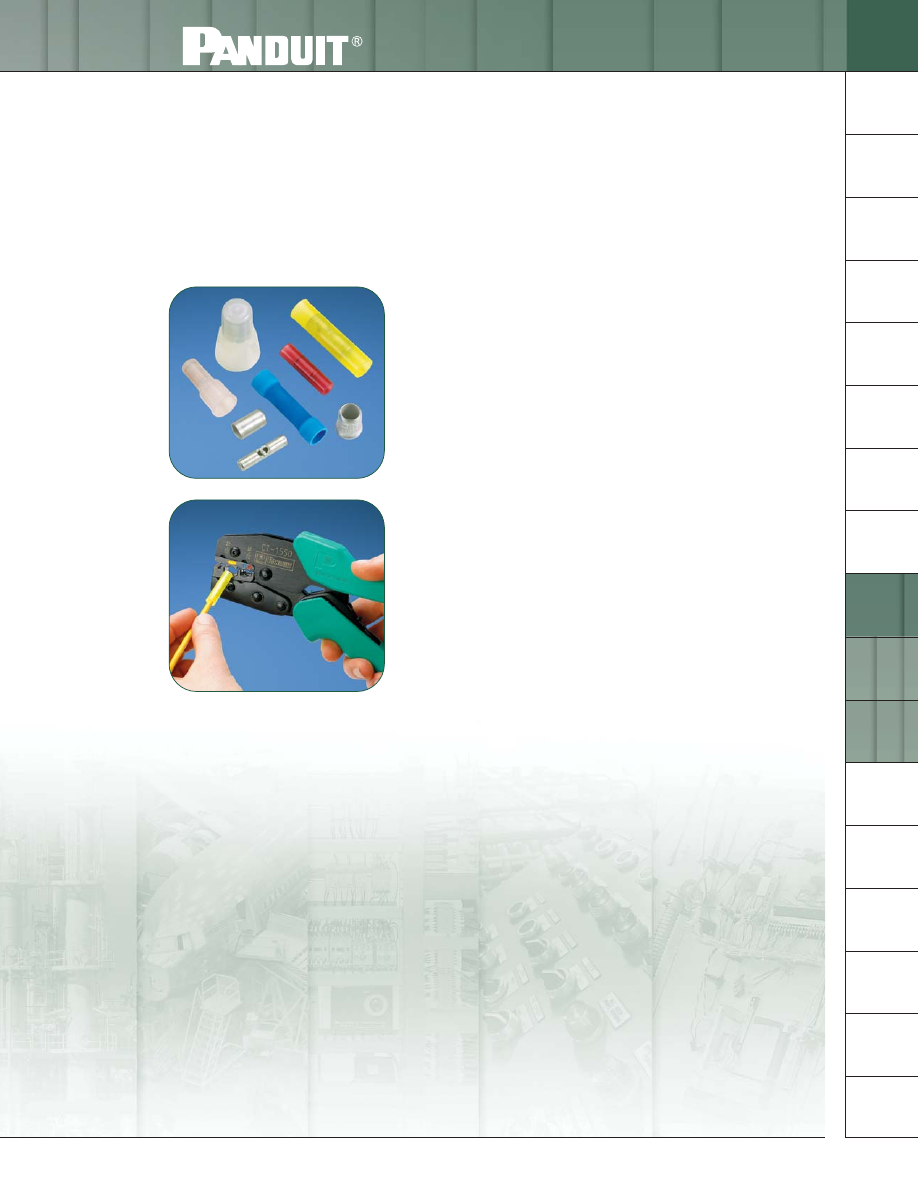
P
AN
-T
ERM
®
S
PLICES
Panduit
®
Pan-Term
®
Splices are designed and manufactured for fast assembly, and long reliable
performance. As the demand for splices increases, it becomes essential to provide a complete system for
termination products. We provide an extensive line of tooling designed specifically to provide optimum
performance when used as a system for terminating.
• Suitable for in-line, parallel, and group splicing
of wires
• Nylon and vinyl insulated as well as non-insulated
• Available in sizes from #26 – 10 AWG
• Internal wire stops on butt splices prevent over
insertion of wires
• Applicable sizes are UL Listed and CSA Certified,
as noted
• Wide assortment of manual, controlled cycle,
battery operated hydraulic and pneumatic
crimping tools for reliable connections at the
lowest installed cost