background image

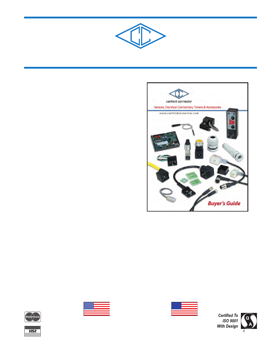
canfield connector


Quality is our goal. 

Canfield Connector is a manufacturer of interconnection devices, 
electronic timers, modules and specialty electronic devices targeted 
at the fluid power industry. Our 

Complete Quality Control Program 

(CQCP) protects our customers by assuring them of 100% test 
and inspection prior to shipment of all items produced at Canfield 
Connector.  Most items are tested during the manufacturing pro-
cess and again during final inspection, making our products double 
or triple tested for function prior to shipment.  Our Quality Policy 
at  Canfield  Industries  is:  Total  Customer  Satisfaction  Through 
Unmatched Quality, Products, Service, and Integrity.  Our Quality 
Objectives are Customer Satisfaction, On-Time Delivery, Sales 
and Profit Growth, High Quality Products, and Superior Supplier 
Performance.  Canfield  Connector  operations  have  been  certi-
fied  to  the  ISO  9001  With  Design  International  Quality  System 
Standard. 

1 year warranty 

All products manufactured by Canfield Connector are warranted 
by Canfield Connector to be free of defects in material and work-
manship for a period of one year from the purchase date. Canfield 
Connector’s obligation under this warranty is limited to repair or 
replacement of the defective product or refund of the purchase price 
paid solely at the discretion of Canfield Connector and provided 
such defective product is returned to Canfield Connector freight 
prepaid and upon examination by Canfield Connector such product 
is found defective.  This warranty shall be void in the event that 
the product has been subject to misuse, misapplication, improper 
maintenance, or tampering.  This warranty is expressed in lieu of 
all other warranties, expressed or implied from Canfield Connector 
representatives or employees. 

Technical assistance 

Our trained technical staff is available at (330) 758-8299 or 1-800-
554-5071  to  help  you  with  your  questions  concerning  Canfield 
products. All questions are welcome. We are constantly developing 
new product lines and custom products for different applications. 
Ask our sales representative for more details. 

Ordering made easy 

Our order desk is open 8:00 AM to 5:00 PM EST Monday through 
Friday. Call us at (330) 758-8299 or 1-800-554-5071 to place your 
order or fax us at (330) 758-8912. 

Designs and published data 

All designs and specifications are subject to change without notice. 
Such  changes  are  not  to  be  considered  retroactive,  and  seller 
assumes no responsibility for revision of models already in the 
field.  All data is sufficiently accurate for general use, but seller 
assumes no responsibility for errors or omissions.  Certified prints 
are available on request, at a reasonable charge. 

*DISCLAIMER: Product changes including specifications, features, 
designs, and availability are subject to change anytime without 
notice. For critical dimensions or specifications, contact factory. 

MADE IN USA 

canfieldconnector-catalog-html.html
background image

STANDARD TERMS OF SALE AND RESTOCKING


1.  GENERAL: 

a.) This contract contains the entire agreement between parties and supersedes any prior or contempo-

raneous oral or written agreements or communications between them relating to the subject matter 

hereof. 

b.) This contract may not be assigned, modified or cancelled without Seller’s prior written consent, and 

any attempt to assign, modify or cancel it without consent shall be absolutely void. 

c) No delay or omission to exercise any right, p.er or remedy accruing to Seller upon breach or default by 

Buyer under this contract shall impair any such right, power or remedy of Seller, or shall be construed 

as a waiver of any such beach or default.  All waivers must be in writing. 

d.) In the event of any of the provisions hereof shall, for any reason, be held void or unenforceable, the 

remaining provisions shall remain in full force and effect and shall control. 

e.) Any provisions of this contact prohibited by law of any state shall as to said state, be ineffective to the 

extent of such prohibition without invalidating the remaining provisions of this contact. 

f.) This contract shall be governed by and construed in accordance with the laws of the State of Ohio, 

excluding however, Ohio law pertaining to conflicts of law. 

2. SELLER’S LIMITED WARRANTY AND LIMITATIONS OF LIABILITIES: 

All goods sold hereunder are warranted to be free from defects in material and workmanship 

for 

a period of one (1) year from the date of manufacture 

unless otherwise agreed upon in writing, 

and to conform to applicable specifications, drawings, blueprints and/or samples. These express 

warranties are in lieu of and exclude all other warranties, express or implied.  Seller’s sole obligation 

under these warranties shall be to issue credit, repair, or replace any item or part thereof which is 

proved to be other than as warranted; no allowance shall be made for any labor charges of Buyer for 

replacement of parts, adjustment or repairs, or any other work, unless such charges are authorized in 

advance by Seller.  If goods are claimed to be defective in material or workmanship or not to conform 

to specifications, drawings, blueprints and/or samples, Seller upon notice promptly given will either 

examine the goods at their site, or issue shipping instructions for return to Seller (transportation costs 

prepaid by Buyer).  In the event any goods are proved to be other than as warranted, transportation 

costs to and from Seller’s plant will be borne by Seller and reimbursement or credit will be made for 

amounts so expended by Buyer. In particular, seller makes no warranty respecting the merchantability 

of the products or their suitability or fitness for any particular purpose or use or respecting infringe

-

ment.  These warranties shall not extend to any goods or parts thereof which have been subjected 

to misuse or neglect, damage by accident, rendered defective by reason of improper installation or 

by the performance of repairs or alterations outside of Seller’s plant except when performed under 

Seller’s specific authority.  These warranties shall not apply to any goods or parts thereof furnished 

by Buyer or acquired from others at Buyer’s request and/or to Buyer’s specifications.  BUYER SHALL 

NOT IN ANY EVENT BE ENTITLED TO, AND SELLER SHALL NOT BE LIABLE FOR INDIRECT, 

SPECIAL, INCIDENTAL OR CONSEQUENTIAL DAMAGES OF ANY NATURE INCLUDING, WITH

-

OUT BEING LIMITED TO, LOSS OF PROFIT, LOSS OF DATA, LOSS OF USE, PROMOTIONAL OR 

MANUFACTURING EXPENSES, OVERHEAD, INJURY TO REPUTATION OR LOSS OF CUSTOM

-

ERS. BUYER’S RECOVERY FROM SELLER FOR ANY CLAIM SHALL NOT EXCEED BUYER’S 

PURCHASE PRICE FOR THE PRODUCTS IRRESPECTIVE OF THE NATURE OF THE CLAIM, 

WHETHER IN CONTRACT, TORT, WARRANTY,  OR OTHERWISE. 

3.  PAYMENT: 

a.) Checks are accepted subject to collection and the date of collection shall be deemed the date of pay

-

ment.  Any check received from Buyer may be applied by Seller against any obligation owing by Buyer 

to Seller, under this or any other contract, regardless of any statement appearing on or referring to 

such check, without discharging Buyer’s liability for any additional amounts owing by Buyer to Seller; 

and the acceptance by Seller of such check shall not constitute a waiver of Seller’s right to pursue 

the collection of any remaining balance. 

b.) On any invoice not paid by maturity date (net thirty (30) days), Buyer shall pay interest from maturity 

to date of payment at the annual percentage rate of 18% (or such lower rate as may be the maximum 

allowable by law), together with Seller’s costs of collection (including reasonable attorneys’ fees). 

c.) Buyer agrees to pay the entire net amount of each invoice rendered by Seller pursuant to the terms 

of each such invoice without offset or deduction. 

d.) Prices for any undeliverable Products may be increased by Seller in the event of any increase in 

Seller’s cost of supplies, raw materials, labor or services, or any increase in Seller’s cost resulting 

from government action or other cause beyond Seller’s control. 

4. CREDIT: 

Seller may in its sole discretion at any time and from time to time change the terms of Buyer’s credit, 

require payment in cash before shipment of any or all of the Products specified herein, and/or require 

anticipated payment of any or all amounts due or to become due under this contract.  If Seller believes 

in good faith that Buyer’s ability to make payments called for by this contract is or may be impaired, 

Seller may cancel this contract or any remaining balance thereof, Buyer remaining liable to pay for 

any Products already shipped. 

5. TAXES/FREIGHT: 

Unless otherwise agreed in writing, the amount of all transportation charges from Seller’s location and 

all taxes or other charges now or hereafter imposed by any government authority upon sale, purchase, 

resale, delivery, manufacture, production or possession of the Products specified herein, which may 

be paid by Seller or for which Seller may be liable, shall be paid to Seller by Buyer in addition to the 

purchase price of the Products. 

6. ORDERS: 

a.) Each order for Products is subject to acceptance in writing by Seller. 

b.) Orders may not be cancelled or rescheduled after delivery by Seller to the carrier. In the event of alloca

-

tion of Products, orders that are accepted by Seller will be accepted using a fair schedule method. 

c.) Special Orders - Special orders for items not normally stocked are non-cancelable and non-return

-

able. 

7. DELIVERIES/TITLE: 

a.) All goods shall be packed in suitable containers for protection in shipment and storage.  No special 

charges for packing or crating shall be made unless specifically listed as an additional and separate 

charge on Seller’s quotation or acceptance of Buyer’s order. 

b.) Subject to Seller’s right of stoppage in transit, delivery of the Products to a carrier shall constitute 

delivery to Buyer, and risk of loss shall thereupon pass to Buyer; however, title shall remain in Seller 

until Buyer makes payment in full under contract.  Products invoiced and held by Seller for any reason 

shall be at Buyer’s risk and expense.  Delivery route shall be the election of Seller unless specifically 

designated by Buyer. 

c.) Delivery of any installment of Products within 30 days after the date specified therefor shall constitute 

a timely delivery.  Thereafter, delivery shall be deemed timely unless prior to shipment Seller has 

received written notice of cancellation. Delivery of a quantity which does not vary by more than 10% 

from the quantity specified therefor shall constitute full performance of such delivery.  Delay in delivery 

of one installment shall entitle Buyer to cancel that installment only. 

d.) Should delivery of all or part of the Products specified herein (or any other obligation of Seller) be 

delayed by events beyond Seller’s control, Seller’s time for performance shall be extended by the 

period of delay, or Seller may, at its option, cancel this contract without liability, Buyer remaining 

liable for shipments already made. Sellers shall not be  liable for any delays in or failures of delivery 

due to acts of God or public authority, labor disturbances, accidents, fires, floods, extreme weather 

conditions, failures of and delays by carriers, shortages of material, delays of a supplier due to causes 

beyond its  control. 

e.) Buyer is deemed to have accepted the Products unless notice of rejection is given within a reason

-

able time, which is agreed to be within seven (7) days after receipt.  Buyer waives any right to revoke 

acceptance thereafter. 

f.)  No return of Products will be accepted by Seller without a return materials authorization number 

(RMA#), which will be issued in Seller’s sole discretion. Returned Products must be in original ship

-

ping cartons, and must be freight prepaid.  In the event any goods are proved to be other than as 

warranted, transportation costs to and from Seller’s plant will be borne by Seller and reimbursement 

or credit will be made for amounts so expended by Buyer. Notice of defective Products must be 

made within seven (7) calendar days of receipt.  A complete description regarding the nature of the 

defect must be included with all returned Products.  All items not eligible for credit will be returned to 

Buyer, transportation collect. 

8. SPECIFICATIONS AND DESIGNS: 

a.) Should Buyer request that changes be made in the specifications or design relating to any goods, 

delivery dates and schedules shall be revised accordingly, if necessary, and an equitable adjustment, 

upward or downward, shall be made in price in so far as warranted. 

b.) Any designs, tools, patterns, material, drawings, information or equipment furnished by Buyer, or any 

special tools made  or acquired for the Buyer by the Seller which becomes Buyer’s property, shall be 

used only in the production of the goods called for herein and not otherwise, unless by Buyer’s written 

consent.  Seller agrees to exercise reasonable care with respect to such property and equipment 

while in its possession and control, but shall not be responsible for loss or damage occurring without 

its fault or negligence or for ordinary wear and tear. 

9. USE OF PRODUCTS: 

a.) If technical advice is offered or given in connection with the use of any Products it will be as an 

accommodation to Buyer and without charge and Seller shall have no responsibilities or liabilities 

whatsoever for the content or use of such advice. 

b.) Products sold by Seller are not designed for use in life support or nuclear applications. Seller’s cus

-

tomers using or selling Products for use in life support or nuclear applications do so at their own risk, 

agree that Seller and the Manufacturer of Products are not liable, in whole or in part, for any claim 

or damage arising from such use, and agree to fully indemnify Seller and the Manufacturer from and 

against any and all damages, loss, cost, expense or liability arising out of or in connection with the 

use or performance of Products in life support or nuclear applications. 

c.) Should the Buyer notify the Seller that its order is placed under a prime contract with an agency of 

the United States Government, the following terms and conditions shall be incorporated into Seller’s 

terms of sale in so far as the Buyer is required to incorporate such provisions in its purchase orders 

or subcontracts of terms in so far as applicable to the goods sold hereunder. 

d.) The following clause set forth or referred to in Sections 7 and 12 of the Armed Services Procurement 

Regulations are hereby incorporated by reference:  Renegotiation (7-103.13), Eight Hour Law of 

1912 (7-103.16 12-303.1), Walsh-Healy Public Contracts Act (7-103.17 12-604), Nondiscrimination 

in Employment (7-103.18 12-802), Officials Not to Benefit (7-103.19), Buy American Act (7-104.3 

6-104.5), Notice to the Government of Labor Disputes (7-104.4), Excess Profit (7-104.11), Military 

Security Requirements (7-104.12), Examination of Records (7-104.15), Convict Labor (7-104.17 12-

203).  In order to make the context of the above clauses applicable to these terms of sale, the word 

“Buyer” shall be substituted for the word “Government” and the word “Seller” shall be submitted for 

the word “contractor” whenever necessary. 

e.) Unless the design for the goods shall have been furnished by the Buyer to the Seller and used by the 

Seller in manufacturing the goods, Seller shall defend and save harmless the Buyer from any claim 

that any product or article sold to the Buyer hereunder in and of itself infringes any United States 

letters patent by reason of its sale or use/ provided Seller is notified in writing within ten (10) days 

after any such claim is made against the Buyer, and provided further that Seller is permitted to defend 

the same in Buyer’s name if action be brought.  If the product or article sold to the Buyer hereunder is 

manufactured by the Seller according to a design furnished by the Buyer, the Buyer will defend and 

save harmless the Seller from any claims of infringement of any United States Letters patent. 

10. TOOLING: 

Tool, die, and pattern charges, if any, are in addition to the price of the Goods and are due and payable 

upon completion of the tooling. All such tools, dies and patterns shall be and remain the property of 

Seller. Charges for tools, dies, and patterns do not convey to Buyer, title, ownership interest in, or 

rights to possession or removal, or prevent their use by Seller for other purchasers, except as other

-

wise expressly provided by Seller and Buyer in writing with reference to this provision. 

11. INSTALLATION/TRAINING: 

Buyer acknowledges that no installation, training or education is contracted for or purchased under 

terms of this contract unless specifically agreed in writing. In the event that Buyer receives any training 

from Seller with respect to the Products, then, in that event, such training is personal to the persons 

receiving such training, and Buyer acknowledges that any persons receiving such training may not 

be capable of operating the Products. 

12. RESTOCKING POLICY: 

Merchandise that is returned must be accompanied by pre-approved return materials authorization 

number (RMA#).  Return authorizations will be approved by Canfield Connector.  When materials are 

received, an inspection will be performed to determine if restocking charges are applicable.  Material 

that does not have an authorization will be returned to the purchaser at their expense. 

RETURNED ITEMS MAY ENTAIL A RESTOCKING CHARGE.  CONSULT FACTORY FOR EXACT 

RESTOCKING FEES. AS CHARGES MAY VARY DEPENDING ON THE AMOUNT OF SPECIALTY 

OF THE ITEMS BEING RETURNED. 

CUSTOM PARTS & “9-” NUMBERS ARE NON-RETURNABLE AND NON-REFUNDABLE 

(EXCEPT IN CASES OF WARRANTY) 

canfieldconnector-catalog-html.html
background image

Canfield Connector Buyer's Guide 

Table of Contents 

page 

SOLENOID VALVE  CONNECTORS 

10 

12 

14 

16 

18 

20 

22 

24 

26 

28 

31 

33 

34 

38 

40 

42 

Series 5000 

Series 5000 ISO 

Series 5000 MINI 

Series 5000 Sub-Micro 

Series 5F 

Series 5J 

Series 5FR 

Series 5JR 

Series 5FFAC 

Series 5JFAC 

Series R5000 

Series D5400 

Series P5600 

Series FAC 

Series iLW 

Series M5 

Model MCCR 

CanTop 

DCP 

General Line Solenoid Valve Connectors 

ISO Solenoid Valve Connectors 

MINI Solenoid Valve Connectors 

Sub-Micro Solenoid Valve Connectors 

Molded Solenoid Valve Connectors 

Molded Solenoid Valve Connectors 

Rectified Molded Solenoid Valve Connectors 

Rectified Molded Solenoid Valve Connectors 

Fieldbus Adapter Solenoid Valve Connectors 

Fieldbus Adapter Solenoid Valve Connectors 

Rectified Solenoid Valve Connectors 

Micro Solenoid Driver (MSD) 

Solenoid Valve Connectors with Surge Suppression 

Round Connector to Solenoid Valve Adapter Connectors 

Interposed Lighted Wafers for Connectors 

Male Connectors 

Multiple Control Connector 

Cord Grips 

DIN Coil Protectors 

TIMERS, PROPORTIONAL AND ELECTRONIC CIRCUITS 

43 

Series 5800 

47 

Series 5950 

49 

Series B5950 

51 

Sandwich CRT 

53 

Series EOS 

57 

Series EOS 2 

59 

Model MBT 

Micro Logic Timer (MLT) Connector 

Micro Proportional Driver (MPD) 

Block-Style Micro Proportional Driver 

Sandwich-Style Condensation Removal Timer 

End of Stroke Pneumatic & Hydraulic Sensor 

Block-Style End of Stroke Pneumatic & Hydraulic Sensor 

Multifunction Block Timer 

CYLINDER PROXIMITY SENSORS AND ACCESSORIES 

64 

66 

67 

68 

71 

73 

75 

77 

79 

82 

85 

87 

89 

91 

93 

95 

Series 7000 

Series 7HL 

Series 7GL 

Series 8000 

Series 8D 

Series 8E 

Series 8WS 

Series 9C 

Series 9D 

Series 9E 

Series 9F 

Series 9G 

Series 9H 

Series 9M50 

Series 9N 

Series 9T 

Reed & Electronic Magnetic Sensors 

Reed Switch for Hazardous Location 

General Location Magnetic Sensors 

Reed & Electronic Magnetic Sensors 

Reed & Electronic Magnetic Sensors 

Reed & Electronic Magnetic Sensors 

Reed & Electronic Sensor for 12mm Dovetail Applications 

Reed & Electronic Sensor for Round Keyway Applications 

Reed & Electronic Sensor for Universal Applications 

Reed & Electronic Sensor for Universal Applications 

Reed & Electronic Sensor for 4mm "T" Slot Applications 

Reed & Electronic Sensor for 6.3mm "T" Slot Applications 

Reed & Electronic Sensor for 4.2mm "T" Slot Applications 

Reed & Electronic Sensor for 6.5mm Groove Applications 

Reed & Electronic Sensor for 4.25mm Round Groove Applications 

Reed & Electronic Sensor for 7.2mm "T" Slot Applications 

ROUND CONNECTORS 

97 

B-Type 

Quick Connect/Disconnect Round Sensor Connectors 

CONVEYOR CONTROLS 

OSV 

Optical Sensor Valve Photo-Eye Accumulation System 

99 

APPENDIX 

102 

Wire Installation 

103 

104 

Wire Terminology 

OHMS Law 

105 

Environmental Protection Classifications 

106 

Units and Conversions 

107 

Glossary of Terms 

canfieldconnector-catalog-html.html
background image

canfield connector 

8510 Foxwood Court


Youngstown, Ohio  44514


(330) 758-8299  Fax: (330) 758-8912


www.canfieldconnector.com


SERIES 5000 

SOLENOID VALVE CONNECTORS 

GENERAL PRODUCT OVERVIEW 

General Description 

The ISO and 8mm Sub-Micro connectors are made according to DIN 43650 / ISO 4400, EN175301-803:2000.  The 

MINI and 9.4mm Sub-Micro connectors are industry standards.  All are used as protective enclosures for electrical con­

nection in conjunction with hydraulic and pneumatic solenoid valves.  These connectors offer distinct advantages over 

“hardwired” solenoid valves because of their modular design.  Used where rapid installation and service are a must. 

Better than molded construction when special wire is needed or when using one long wire run. 

ALL DIMENSIONS ARE IN MILLIMETERS UNLESS OTHERWISE NOTED 

Dimensional Data 

 (COMPLETE DIMENSIONAL INFORMATION IS PROVIDED ON INDIVIDUAL PAGES) 

MINI 

ISO 

Sub-Micro 

DIN 43650 Form "A" / ISO 4400, 

(8mm) DIN 43650 Form "C" / ISO 4400, 

EN175301-803:2000 

EN175301-803:2000 

40


27


40 

26.5 

37 

16 

16  8 

21  11 

PG9 

26.5 18 

PG9 

PG9 

8mm Strain Relief 

*Ground spade offset by 0.2mm toward pin 1.

PG9 / HT PG9 

PG11 / HT PG11 

40 

26.5 

40 

26.5 

47 

16 

1/2"

26.5 18 

16  8

PG11

58 

NPTF 

27 

8mm 1/2" Conduit

*Ground spade offset by 0.2mm toward pin 1.

3/8"

21  11 

NPTF 

3/8" Conduit 

1/2"

26.518 

16 9.4

NPTF 

37 

16 

9.4mm Strain Relief 

1/2" Conduit 

44 

47 

27 

16 

40

26.5 

23.8 

1/2" 

1/2"

1/2" 

26.518 

16  9.4

21  11 

NPTF 

NPTF

NPTF 

1/2" Conduit 

HT 1/2" Conduit 

9.4mm 1/2" Conduit 

4


canfieldconnector-catalog-html.html
background image

Gasket 

1 - Nitrile 

2 - Silicone 

3 - Nitrile profile** 

Each connector kit contains fastening hardware and gasket assembly. 

NOT

 Available in MINI 

**

NOT

 Available in Sub-Micro 

Not all combinations are available. Consult factory for details. 

† High Top Housing for easy wiring. 

Contacts 

0 - 2+ ground 

1 - 3+ ground* 

Housing Color 

0 - Standard “B” 

1 - Gray “A” 

Connector Types 

01 - MINI strain relief PG9 

02 - MINI 3/8" conduit 

03 - MINI 1/2" conduit 

08 - ISO strain relief PG9 

09 - ISO strain relief PG11 

10 - ISO 1/2" conduit 

11 - ISO HT strain relief PG9

† 

12 - ISO HT strain relief PG11

† 

13 - ISO HT 1/2" conduit

† 

90 - Sub-Micro PG7 DIN interface (8mm) 

91 - Sub-Micro 1/2" conduit interface (8mm) 

95 - Sub-Micro 1/2" conduit (9.4mm) 

99 - Sub-Micro strain relief PG7 (9.4mm) 

Ordering Information 

Orientation 

1 - Ground down 

Other ground orientations available. 

Please consult factory. 

Lighting Specification 

0 - Unlighted 

3 - 6 - 48V AC/DC 50/60 Hz 

7 - 48 - 120 VDC 

100 - 240 VAC 50/60 Hz 

-

0  0

Use a prefix of "G" for Individually Bagged 

NOTE:  When using MAC Valves with 9.4mm Sub-Micro, 

consult our factory. 

MAC is the registered trademark of MAC Valves, Inc. 

Ordering Example: 

5100-1010000 

Ground down, unlighted, nitrile gasket, MINI strain relief 

PG9 connector, 2+ ground contacts, standard house 

C


US


Consult factory for available versions listed

by Canadian Standards Association for use

with certified electrical equipment. 

5


canfieldconnector-catalog-html.html
background image

canfield connector 

8510 Foxwood Court


Youngstown, Ohio  44514


(330) 758-8299  Fax: (330) 758-8912


www.canfieldconnector.com


SERIES 5000 

ISO 

SOLENOID VALVE CONNECTOR 

General Description 

Wiring Information 

Canfield Connector’s Series 5000 ISO connector connects solenoid valves using the DIN 

43650 Form "A" / ISO 4400, EN175301-803:2000 specification.  This standard permits in­

dustry interchangeability and has been embraced by the solenoid valve industry worldwide. 

Features include the ability for the user to wire the connector into existing installations or the 

connector can be prewired at the factory.  Wire connections are made inside the connector 

housing and the wire inlet is either PG9, PG11 or 1/2" conduit. Canfield has added to this line 

with the HT (High Top) housing.  The HT accommodates the user with more room for larger 

wire diameters.  The standard ISO connectors are still available for those applications with 

space constraints.  Maximum current rating is 10 Amps with a maximum conductor size of 

14 AWG with an outer jacket not to exceed .410 inches diameter. There are CSA approved 

versions as well as versions with indicator lights depicting the “on” state.  The connectors 

are NEMA 4 and IP 65 environment rated. 

Dimensional Data 

ALL DIMENSIONS ARE IN MILLIMETERS UNLESS OTHERWISE NOTED 

PG9 / PG11 

HT** PG9 / PG11 

26.5  18 

26.5 

1.5 

gasket 

26.5 

PG9/PG11 

40 

6.2 min. 

M3 

26.5 

26.5  18 

PG9/PG11 

40 

6.2 min. 

33.1 

1.5 

M3

gasket 

1/2" Conduit 

HT** 1/2" Conduit 

26.5  18 

27.9 

1.5 

gasket 

26.5 

1/2"NPTF 

44.7 

4.4 

M3 

26.5 

26.5  18 

1/2" NPTF 

40 

23.8


33.1 

1.5 

M3

gasket 

Normal polarity:  1 = (+) Positive, High 

2 = (-) Negative, Neutral

 =  Chassis Ground 

**HT refers to High Top - Larger connector for larger wire gauge and easy installation. 

6


canfieldconnector-catalog-html.html
background image

Technical Data 

• The cable outlet can be assembled in 90°  increments 

• Color:  black, gray or translucent for lighted styles 

• Cable diameter:  PG9 - .236 to .315 inches O.D. 

PG11 - .315 to .394 inches O.D. 

1/2" Conduit - .410 inches max. 

• Cross section of the conductor wire max.:  14 AWG 

• Maximum approved current:  10 Amps 

• Rated voltage max.:  300 VDC / 250 VAC 50/60 Hz 

• No. of contacts:  2+ ground 

3+ ground 

• Environmental protection:  NEMA 4 and IP 65 dust tight 

and water resistant 

• Maximum rated temperatures for gaskets: 

Nitrile gasket:  -25° to +90°C 

Silicone gasket:  -40° to +125°C 

Derating Curve 

Ordering Information 

Connector Type 

08 - ISO strain relief PG9 

09 - ISO strain relief PG11 

10 - ISO 1/2" conduit 

11 - ISO HT strain relief PG9** 

12 - ISO HT strain relief PG11** 

13 - ISO HT 1/2" conduit 

Gasket 

1 - Nitrile 

2 - Silicone 

3 - Nitrile profile 

Lighting Specification 

0 - Unlighted 

3 - 6 - 48V AC/DC 50/60 Hz 

7 - 48 - 120 VDC 

100 - 240 VAC 50/60 Hz 

Contacts 

0 - 2 + ground 

1 - 3 + ground 

Housing Color 

0 - Black “B” standard.  Translucent if lighted. 

1 - Gray “A” 

**

HT refers to High Top - Larger connector for

larger wire gauge and easy installation. 

-

0  0 

SERIES 5000 ISO 

Can-Pak 

Part Number 

Qty 

CP-5100-1080000-025 

25 

CP-5100-1080000-100 

100 

CP-5100-1100000-025 

25 

CP-5100-1100000-100 

100 

CP-5103-1080000-025 

25 

CP-5103-1080000-100 

100 

CP-5107-1080000-025 

25 

CP-5107-1080000-100 

100 

Use a prefix of "G" for Individually Bagged 

Orientation 

1 - Ground down 

Other ground orientations available. 

Please consult factory. 

Each connector kit contains fastening 

hardware and gasket assembly. 

C


US


Ordering Example: 

5100-1080000 

Consult factory for available versions listed

by Canadian Standards Association for use

with certified electrical equipment. 

Ground down, nitrile gasket, ISO strain relief PG9, 

2+ ground contacts, black house 

7


canfieldconnector-catalog-html.html
background image

General Description 

The Canfield Connector field wireable MINI solenoid valve connector is a high quality in­

terconnection device for use with solenoid valves and pressure switches.  The connector 

features a PG9 strain relief, 3/8" or 1/2" conduit wire pass through, all with screw terminals 

for wire connections.  The MINI accommodates wire from .240" to .410" diameter as a 

standard with an AWG of 14 maximum.  Environment resistance of NEMA 4 / IP 65 along 

with versions which are CSA approved ensure long trouble free service.  Current maximum 

of 10 Amps and the temperature rating of -40° to +125°C encompasses most applications. 

The interface is an industry standard. 

canfield connector 

8510 Foxwood Court


Youngstown, Ohio  44514


(330) 758-8299  Fax: (330) 758-8912


www.canfieldconnector.com


SERIES 5000 

MINI 

SOLENOID VALVE CONNECTOR 

Dimensional Data 

ALL DIMENSIONS ARE IN MILLIMETERS UNLESS OTHERWISE NOTED 

Strain Relief 

3/8" Conduit 

1/2" Conduit 

21 11 

27.9 

1.5 

gasket 

27 

40 

M3 

PG9 

4.9 min. 

21  11 

30 

1.5 

gasket 

27 

58 

M3 

3/8" NPTF 

21 11 

31.4 

1.5 

gasket 

27 

1/2" NPTF 

44 

M3 

Wiring Information 

Normal polarity:  1 = (+) Positive, High 

2 = (-) Negative, Neutral

 =  Chassis Ground 

Ground Up 

Ground Down 

canfieldconnector-catalog-html.html
background image

Technical Data 

• The cable outlet can be assembled in 180°  increments 

• Color:  black, gray or translucent for lighted styles 

• Cable diameter:  PG9 - .236 to .315 inches O.D. 

3/8" & 1/2" Conduit - .410 inches max. 

• Cross section of the conductor wire max.:  14 AWG 

• Rated voltage max.:  300 VDC / 250 VAC 50/60 Hz 

• Maximum approved current:  10 Amps 

• No. of contacts:  2+ ground 

• Environmental protection:  NEMA 4 and IP 65 dust tight

 and water resistant 

• Maximum rated temperatures for gaskets: 

Nitrile gasket -25° to +90°C 

Silicone gasket -40° to +125°C 

Derating Curve 

Lighting Specification 

0 - Unlighted 

3 - 6 - 48V AC/DC 50/60 Hz 

7 - 48 - 120 VDC 

100 - 240 VAC 50/60 Hz 

Housing Color 

0 - Black “B” standard.  Translucent if lighted. 

1 - Gray “A” 

Connector Types 

01 - MINI strain relief PG9 

02 - MINI 3/8" conduit 

03 - MINI 1/2" conduit 

Gasket 

1 - Nitrile 

2 - Silicone 

3 - Nitrile profile 

Ordering Information 

-

0  0

Use a prefix of "G" for Individually Bagged 

SERIES 5000 MINI 

Can-Pak 

Part Number 

Qty 

CP-5100-1010000-025 

25 

CP-5100-1010000-100 

100 

CP-5100-1030000-025 

25 

CP-5100-1030000-100 

100 

CP-5103-1010000-025 

25 

CP-5103-1010000-100 

100 

CP-5107-1010000-025 

25 

CP-5107-1010000-100 

100 

CP-5163-1010000-010 

10 

CP-5163-1010000-050 

50 

CP-5167-1010000-010 

10 

CP-5167-1010000-050 

50 

Orientation 

1 - Ground down 

Other ground orientations available. 

Please consult factory. 

Each connector kit contains fastening 

hardware and gasket assembly. 

C


US


Ordering Example: 

5100-1010000 

Ground down, unlighted, nitrile gasket, MINI strain

Consult factory for available versions listed

by Canadian Standards Association for use 

relief PG9 connector, black house 

with certified electrical equipment. 

9


canfieldconnector-catalog-html.html
background image

General Description 

Canfield Connector’s Series 5000 Sub-Micro connector is made to connect solenoid valves 

using the DIN 43650 Form “C”, EN175301-803:2000 (8mm pin center) and the industry 

standard 9.4mm pin center. These standards permit industry interchangeability and have 

been embraced by the solenoid valve industry worldwide. Features include the ability for 

the user to wire the connector into existing installations or the connector can be prewired 

at the factory. Wire connections are made inside the connector housing. The wire inlet is 

either PG7 or 1/2" conduit. Maximum current rating is 6 amps with a maximum conductor

size of 20 gauge with an outer jacket not to exceed .260 inches diameter. There are ver­

sions with indicator lights depicting the “on” state. The connectors are NEMA 4 and IP 65 

environment rated. 

Wiring Information 

canfield connector 

8510 Foxwood Court


Youngstown, Ohio  44514


(330) 758-8299  Fax: (330) 758-8912


www.canfieldconnector.com


SUB-MICRO

SERIES 5000 

SOLENOID VALVE CONNECTOR 

Dimensional Data 

ALL DIMENSIONS ARE IN MILLIMETERS UNLESS OTHERWISE NOTED 

PG7, 8mm center 

PG7, 9.4mm center 

16


16


8


37


PG7


29


25.5


M2.5


16


16


9.4 

37


PG7


25.5


29


M3


1/2" Conduit, 8mm center 

1/2" Conduit, 9.4mm center 

16


16


8


1/2" NPTF 

47 

25.4 

25.5


29.5


M2.5


16


16


9.4 

1/2" NPTF 

47 

25.4 

25.5


29.5


M3


Normal polarity:  1 = (+) Positive, High 

2 = (-) Negative, Neutral

 =  Chassis Ground 

*Ground


spade


offset


by


0.2mm


toward


pin


1.


10


canfieldconnector-catalog-html.html
background image

Technical Data 

Derating Curve 

•  The cable outlet can be assembled in 90°  increments 

-

0  0 

Ordering Information 

Housing Color 

0 - Black “B” standard.  Translucent if lighted. 

1 - Gray “A” 

Contacts 

0 - 2 +ground 

1 - 3 +ground* 

Lighting Specification 

0 - Unlighted 

3 - 6 - 48V AC/DC 50/60 Hz 

7 - 48 - 120 VDC 

100 - 240 VAC 50/60 Hz 

Gasket 

1 - Nitrile 

2 - Silicone 

Connector Type 

90 - Sub-Micro strain relief PG7 DIN interface (8mm) 

91 - Sub-Micro 1/2" conduit DIN interface (8mm) 

95 - Sub-Micro 1/2" conduit (9.4mm) 

99 - Sub-Micro strain relief PG7 (9.4mm) 

*

3+ ground 

NOT

 available 

in lighted version. 

•  Color:  black, gray or translucent for lighted styles 

•  Cable diameter:  PG7 - .157 - .236 inch O.D. 

1/2" Conduit 8mm & 9.4mm - .250 inch max. 

•  Cross section of the conductor wire max.:  20 AWG 

•  Rated voltage max.:  250 VAC 50/60 Hz or VDC 

•  Maximum approved current:  6 Amps 

•  No. of contacts:  2+ ground, 

3+ ground (

NOT

 available on lighted units) 

•  Environmental protection:  NEMA 4 and IP 65 dust tight 

and water resistant 

•  Maximum rated temperatures for gaskets: 

Nitrile gasket:  -25° to +90°C 

Silicone gasket:  -40° to +125° C 

Use a prefix of "G" for Individually Bagged 

NOTE:  When using MAC Valves with 9.4mm Sub-Micro, 

consult our factory. 

Ordering Example: 

SERIES 5000 SUB-MICRO 

Can-Pak 

Part Number 

Qty 

CP-5100-1900000-025 

25 

CP-5100-1900000-100 

100 

CP-5100-1990000-025 

25 

CP-5100-1990000-100 

100 

CP-5103-1900000-025 

25 

CP-5103-1900000-100 

100 

CP-5103-1990000-025 

25 

CP-5103-1990000-100 

100 

CP-5107-1900000-025 

25 

CP-5107-1900000-100 

100 

CP-5107-1990000-025 

25 

CP-5107-1990000-100 

100 

Orientation 

1 - Ground down 

Other ground orientations available. 

Please consult factory. 

Each connector kit contains screw, 

washer and gasket assembly. 

Consult factory for available versions listed

by Canadian Standards Association for use

with certified electrical equipment.

C


US


5100-1900000 

Ground down, unlighted, nitrile gasket, Sub-Micro strain 

relief PG7 DIN interface, 2+ ground contacts, black house 

11


canfieldconnector-catalog-html.html
background image

canfield connector 

8510 Foxwood Court


Youngstown, Ohio  44514


(330) 758-8299  Fax: (330) 758-8912


www.canfieldconnector.com


SERIES 5F 

LIGHTED AND LOAD SUPPRESSED MOLDED MINI, ISO 

AND SUB-MICRO SOLENOID VALVE CONNECTORS 

Dimensional Data 

General Description 

The Canfield Series 5F all-molded DIN solenoid valve connector/gasket/cord assembly 

offers  a  completely  molded  design  that  is  far  better  for  environmental  integrity  than 

field wire versions. Made from rugged yet flexible polyurethane, the connector housing 

boasts  high  durability  factors  and  application  versatility.  The  low  profile  “straight-line”

interface/cord  configuration  allows  for  installation  in  many  limited  space  applications. 

The integrated gasket design boasts an IP67/NEMA 6 rating and makes it impossible to 

lose the gasket.  The 5F and 5J are the only molded valve connectors in the industry that 

feature a HARD USAGE cord as a standard option in any length required, bi-directional 

indicator lights, and load suppression (not intended for UL 1449).  UL and CSA versions 

are available as well.  Canfield offers any version of the 5F connector with special wires 

including high flex, media compatible wire, special use wire, high temperature wire on 

request. 

Technical Data 

ISO shown above 

ALL DIMENSIONS ARE IN MILLIMETERS UNLESS OTHERWISE NOTED 

MINI 

28 

21 11 

40 

25.5 

M3 

4.0 

ISO 

DIN 43650 Form “A” 

27 

27 18 

40 

25.5 

18 

M3

Available in 3+ Ground 

4.0 

SUB-MICRO 

DIN 43650 Form “C” =  8mm, Standard = 9.4mm 

16 

37 

8 or

16 

9.4mm 

25.5 

Available in 3+ Ground 

L=2.5 M3, (9.4mm) 

L=1.9, M2.5 (8mm) 

• Cable outlet:  Molded construction with wire exiting out perpendicular

to the face of the coil 

• Available in no circuit, lighted and load suppressed version for all 

connectors 

• Cable conductor colors: 

European color code: Brown, blue, and yellow/green,  

(with 4

th

 conductor version black)

US color code:  White, black, and green, 

(with 4

th

 conductor version red)

Specials on request


• Cable types:  Pressure extruded PVC jacket 

Hard Usage cordage

“S” type with SJTOW standard PVC jacket

(ISO and Mini only) 

• Cross section of conductor wire: 


18 Gauge standard (ISO and Mini)

20 Gauge standard (Sub-Micro) 

• Rated voltage max.:  250V AC 50/60 Hz, 300V DC 
• Rated current max.:  10 Amps (ISO and Mini), 6 Amps (Sub-Micro) 
• Enclosure and molded in gasket materials:  Polyurethane 
• Ambient rated temperatures:  -25° to 80°C 
• Environment protection: 


IP 67 and NEMA 6, dust tight and water

resistant 

• Available in four sizes: 

DIN 43650 Form “A” (ISO), EN175301-803:2000

DIN Form “C” (Sub-Micro 8mm), EN175301-803:2000

Industry standard (Sub-Micro 9.4mm pin spacing)

Industry standard (Mini 11mm pin spacing) 

• Pin configurations: 


For single solenoid valves - 2 connections plus

ground – Mini, ISO, Sub-Micro 8mm and Sub-Micro 9.4mm 

For pressure switches, double solenoid valves and other devices, 3

connections plus ground – ISO, Sub-Micro 8mm and 9.4mm 

Note:  Slight discoloration may occur to translucent material after

prolonged exposure to UV rays.


Consult factory for available versions listed

by Canadian Standards Association for use

with certified electrical equipment.

C


US


Consult factory for available versions

recognized under the Component

Program of Underwriters Laboratories, Inc. 

12


canfieldconnector-catalog-html.html
background image

Wiring Information

Ordering Information 

5 F 

-

-

Connector Type 

3 - 8mm SM* 

4 - 9.4mm SM* 

5 - MINI** 

6 - ISO 

Wire Length 

6 - 6 ft cord 

F - 15 ft cord 

Operating Voltage 

0 - No light, no suppression*** 

2 - 6-24V AC/DC 50/60 Hz 

5 - 48-120V AC/DC 50/60Hz 

8 - 208-240V AC 50/60Hz 

A - 6-24VDC 

Lighting Option 

0 - Unlighted 

1 - Lighted** 

Suppression Type 

0 - None 

1 - Diode (DC only) 

5 - Metal Oxide Varistor (MOV)** 

Contacts 

0 - 2+ground**** 

1 - 3+ground 

(ISO/8mm/9.4mm only) 

Wire Option 

US - U.S.A. wire code / PVC jacket 

EU - European wire code / PVC jacket 

HU - Hard Usage / SJTOW jacket 

(MINI & ISO only) 

Housing Color 

0 - Black (standard) 

Translucent (if lighted) 

1 - Gray 

For additional Wire Lengths, consult factory. 

Packaging Code 

A  - Bulk 

G - Individual bagged 

L  - Bulk MAC screw 

N - Individual bagged MAC screw 

MAC is the registered trademark of MAC Valves, Inc. 

High flex, shielded and high temperature wire available on request. 

All connectors come standard with integrated gasket. 

* 240 VAC voltage suppression and lighting not available.


** 

NOT

 available in 3+ ground.


*** Rated 250V AC 50/60Hz, 300V DC.


**** ISO, Sub-Micro dual ground.


MINI 

ISO 

SUB-MICRO


EUR 

US 

HU 

yel & grn 

grn 

brn 

blk 

blu 
wht 

yel & grn 

grn 

brn 

blk 

blu 
wht 

blk 
red 

1  2  3

1  2 

yel & grn 

grn 

brn 

blk 

blu 
wht 

blk
 red 

1  2  3 

Note: 

ISO & SUB-MICRO 

connectors available 

in 3+ Ground 

G


G


G


Normal polarity: 

1  = (+) Positive, Hot 
2  = (-) Negative, Neutral 

= Chassis Ground 

For convenience and faster shipping, this 

series is available in Can-Paks. 

Accessories: 

WM-315 ISO/MINI Standard Wire Markers 10X Bag 
WM-218 Sub-Micro Standard Wire Markers 10X Bag 

Ordering Example: 

5F360-250-US0A 

8mm SM, 6 ft wire length, 2+ ground, 6-24V AC/DC 50/60 Hz, 

MOV, unlighted, U.S.A. wire code / PVC jacket, standard 

housing color, bulk 

13


canfieldconnector-catalog-html.html
background image

canfield connector 

8510 Foxwood Court


Youngstown, Ohio  44514


(330) 758-8299  Fax: (330) 758-8912


www.canfieldconnector.com


SERIES 5J 

LIGHTED AND LOAD SUPPRESSED MOLDED MINI, ISO 

AND SUB-MICRO SOLENOID VALVE CONNECTORS 

General Description 

The  Canfield  Series  5J  all-molded  DIN  solenoid  valve  connector/gasket/cord 

assembly  offers  a  completely  molded  design  that  is  far  better  for  environmental 

integrity than field wire versions. Made from rugged yet flexible polyurethane, the 

connector housing boasts high durability factors and application versatility. The low 

profile “90°” interface/cord configuration allows for installation in many limited space 

applications. The integrated gasket design boasts an IP67/NEMA 6 rating and makes 

it impossible to lose the gasket. The 5J and 5F are the only molded valve connectors 

in the industry that feature a HARD USAGE cord as a standard option in any length 

required, bi-directional indicator lights, and load suppression (not intended for UL 

1449).  UL and CSA versions are available as well.  Canfield offers any version of the 

5J connector with special wires including high flex, media compatible wire, special 

use wire, high temperature wire on request. 

Technical Data 

ISO shown above 

Dimensional Data 

ALL DIMENSIONS ARE IN MILLIMETERS UNLESS OTHERWISE NOTED 

MINI 

48.5 

28 

21 11 

25.5 

4.0 

M3 

ISO 

DIN 43650 Form “A” 

27 

27  18 

18 

4.0 

48.5 

25.5 

M3 

Available in 3+ Ground 

SUB-MICRO 

DIN 43650 Form “C” =  8mm, Standard = 9.4mm 

16 

8 or

16 

9.4mm 

27 

L

L=2.5 M3, (9.4mm) 

L=1.9, M2.5 (8mm) 

• Cable outlet:  Molded construction with wire exiting out perpendicular

to the face of the coil 

• Available in no circuit, lighted and load suppressed version for all 

connectors 

• Cable conductor colors: 

European color code: Brown, blue, and yellow/green,  

(with 4

th

 conductor version black)

US color code:  White, black, and green, 

(with 4

th

 conductor version red)

Specials on request


• Cable types:  Pressure extruded PVC jacket 

Hard Usage cordage

“S” type with SJTOW standard PVC jacket

(ISO and Mini only) 

• Cross section of conductor wire: 


18 Gauge standard (ISO and Mini)

20 Gauge standard (Sub-Micro) 

• Rated voltage max.:  250V AC 50/60 Hz, 300V DC 
• Rated current max.:  10 Amps (ISO and Mini), 6 Amps (Sub-Micro) 
• Enclosure and molded in gasket materials:  Polyurethane 
• Ambient rated temperatures:  -25° to 80°C 
• Environment protection: 


IP 67 and NEMA 6, dust tight and water

resistant 

• Available in four sizes: 

DIN 43650 Form “A” (ISO), EN175301-803:2000

DIN Form “C” (Sub-Micro 8mm), EN175301-803:2000

Industry standard (Sub-Micro 9.4mm pin spacing)

Industry standard (Mini 11mm pin spacing) 

• Pin configurations: 


For single solenoid valves - 2 connections plus

ground – Mini, ISO, Sub-Micro 8mm and Sub-Micro 9.4mm 

For pressure switches, double solenoid valves and other devices, 3

connections plus ground – ISO, Sub-Micro 8mm and 9.4mm 

Note:  Slight discoloration may occur to translucent material after

prolonged exposure to UV rays.


Consult factory for available versions listed

by Canadian Standards Association for use

with certified electrical equipment.

C


US


Consult factory for available versions

recognized under the Component

Program of Underwriters Laboratories, Inc. 

Available in 3+ Ground 

14


canfieldconnector-catalog-html.html
background image

Ordering Information 

5 J 

-

-

Connector Type 

3 - 8mm SM* 

4 - 9.4mm SM* 

5 - MINI** 

6 - ISO 

Wire Length 

6 - 6 ft cord 

F - 15 ft cord 

Operating Voltage 

0 - No light, no suppression*** 

2 - 6-24V AC/DC 50/60 Hz 

5 - 48-120V AC/DC 50/60Hz 

8 - 208-240V AC 50/60Hz 

A - 6-24VDC 

Lighting Option 

0 - Unlighted 

1 - Lighted** 

Suppression Type 

0 - None 

1 - Diode (DC only) 

5 - Metal Oxide Varistor (MOV)** 

Contacts 

0 - 2+ground down (MINI only) 

1 - 2+ground up (MINI only) 

2 - 3+ground down 

3 - 3+ground up 

4 - 2+dual ground 

(ISO/8mm/9.4mm only) 

Wire Option 

US - U.S.A. wire code / PVC jacket 

EU - European wire code / PVC jacket 

HU - Hard Usage / SJTOW jacket 

(MINI & ISO only) 

Housing Color 

0 - Black (standard) 

Translucent (if lighted) 

1 - Gray 

For additional wire lengths, consult factory. 

Packaging Code 

A  - Bulk 

G - Individual bagged 

L  - Bulk MAC screw 

N - Individual bagged MAC screw 

MAC is the registered trademark of MAC Valves, Inc. 

High flex, shielded and high temperature wire available on request. 

Ground left / right available, consult factory. 

All connectors come standard with integrated gasket. 

* 240 VAC voltage suppression and lighting not available.


** 

NOT

 available in 3+ ground.


*** Rated 250V AC 50/60Hz, 300V DC.


Wiring Information 

MINI 

ISO 

SUB-MICRO


EUR 

US 

HU 

yel & grn 

grn 

brn 

blk 

blu 
wht 

yel & grn 

grn 

brn 

blk 

blu 
wht 

blk 
red 

1  2  3

1  2 

yel & grn 

grn 

brn 

blk 

blu 
wht 

blk
 red 

1  2  3 

Note: 

ISO & SUB-MICRO 

connectors available 

in 3+ Ground 

G


G


G


Normal polarity: 

1  = (+) Positive, Hot 
2  = (-) Negative, Neutral 

= Chassis Ground 

Ground Up: 

Ground Down: 

For convenience and faster shipping, this 

series is available in Can-Paks. 

Accessories: 

WM-315 ISO/MINI Standard Wire Markers 10X Bag 
WM-218 Sub-Micro Standard Wire Markers 10X Bag 

Ordering Example: 

5J360-251-US0A 

8mm SM, 6 ft wire length, 2+ ground, 6-24V AC/DC 

50/60 Hz, MOV, lighted, U.S.A. wire code / PVC 

jacket, standard housing color, bulk w/ Canfield p/n 

15


canfieldconnector-catalog-html.html
background image

canfield connector 

8510 Foxwood Court


Youngstown, Ohio  44514


(330) 758-8299  Fax: (330) 758-8912


www.canfieldconnector.com


SerieS 5Fr 

RECTIFIED MOLDED 

SOLENOID vALvE CONNECTORS 

General Description 

The Canfield Series 5FR solenoid valve connectors incorporate a full-wave bridge rectifier inside a fully molded connector. The 

5FR converts alternating current to direct current reducing coil burnout due to valve sticking.  Also, direct current eliminates 

AC "hum" inherent to alternating current.  Made from rugged yet flexible polyurethane, the connector housing boasts high 

durability factors and application versatility.  The low profile "straight-line" interface/cord configuration allows for installation 

in many limited space applications.  The integrated gasket design boasts an IP67/NEMA 6 rating and makes it impossible to 

lose the gasket!  Features bi-directional indicator lights, and load suppression (not intended for UL 1449).  The Series 5FR is 

Proudly Made in the U.S.A

Dimensional Data 

ALL DIMENSIONS ARE IN MILLIMETERS UNLESS OThERwISE NOTED 

40 

25.5 

4.0 

M3 

iSO 

18 

18

27 

27 

MiNi 

21  11 

28 

ISO shown above 

+ contact 1 

MOv 

~2 

AC 

~1 

- contact 2 

DC 

Technical Data 

• Cable outlet:  Molded construction with wire exiting out 

parallel to the face of the coil 

• Color: 


Black standard or white translucent 

(for lighted versions) 

• Cable conductor colors: 

European color code:  Brown, blue, and yellow/green 

US color code:  white, black, and green 

Specials on request 

• Cable types:Pressure extruded PvC jacket 

hU - SJTOw jacket 

• Cross section of conductor wire:  18 Gauge standard 

• Rated voltage max.:  250v AC 50/60 hz 

• Current max: 


Continuous - 1 Amp

 Inrush - 15 Amps for 15 ms 

• All versions include MOv suppression 

• Enclosure and molded in gasket materials:  Polyurethane 

• Ambient rated temperatures:  -25° to 80°C 

• Environment protection: 


IP 67 and NEMA 6, dust tight and 

water resistant 

• Available: 

DIN 43650 Form “A” (ISO), EN175301-803:2000 

Industry standard (MINI 11mm pin spacing) 

• Pin configurations: 


For single solenoid valves - 2 connections 

plus ground 

• voltage drop:  2.2 volt max. 

16


canfieldconnector-catalog-html.html
background image

Wiring information 

iSO


MiNi 

Note:  Slight discoloration 

may occur to translucent 

material after prolonged 

exposure to Uv rays. 

yel & grn  brn  blu 

yel & grn  brn  blu

EUR 

US 

grn 

blk 

wht


grn 

blk 

wht

hU 

Consult factory for available versions

recognized under the Component

Program of Underwriters Laboratories, Inc.

Normal polarity:


1  = (+) Positive, hot 
2  = (-) Negative, Neutral 
3  = NC 

= Chassis Ground 

Consult factory for available versions listed

by Canadian Standards Association for use

Note:  ISO is dual ground 

with certified electrical equipment.

C


US


Ordering information 

5 F R 

0  -

Wire Length 

6 - 6 ft cord 

F - 15 ft cord 

Operating Voltage* 

0 - No light, 0-240 vAC 50/60hz*** 

2 - 6-24 vAC 50/60 hz 

5 - 48-120 vAC 50/60 hz 

8 - 208-240 vAC 50/60 hz 

For additional wire Lengths, consult factory. 

Connector Type 

5 - Mini 

6 - ISO**


-

Lighting Option 

0 - Unlighted 

1 - Lighted* 

Wire Option 

US - U.S.A. wire code / PvC jacket 

EU - European wire code / PvC jacket 

hU - U.S.A. wire code / SJTOw jacket 

Packaging Code 

A  - Bulk 

G - Individual bagged 

1  2

G


G

1

Ordering example: 

All connectors come standard with integrated gasket. 

* Includes rated MOv suppression 

** 2+ dual ground 

*** Rated 250v AC 50/60 hz.  Includes 250v MOv suppression 

5FR660-2A1-US0A 

ISO, 6 ft wire length, 6-24 vAC 50/60 hz, lighted, 

U.S.A. wire code / PvC jacket, bulk packaged 

17 

canfieldconnector-catalog-html.html
background image

canfield connector 

8510 Foxwood Court


Youngstown, Ohio  44514


(330) 758-8299  Fax: (330) 758-8912


www.canfieldconnector.com


SerieS 5Jr 

RECTIFIED MOLDED 

SOLENOID vALvE CONNECTORS 

General Description 

The Canfield Series 5JR solenoid valve connectors incorporate a full-wave bridge rectifier inside a fully molded connector. The 

5JR converts alternating current to direct current reducing coil burnout due to valve sticking.  Also, direct current eliminates 

AC "hum" inherent to alternating current.  Made from rugged yet flexible polyurethane, the connector housing boasts high 

durability factors and application versatility.  The low profile 90° interface/cord configuration allows for installation in many 

limited space applications.  The integrated gasket design boasts an IP67/NEMA 6 rating and makes it impossible to lose the 

gasket!  Features bi-directional indicator lights, and load suppression (not intended for UL 1449).  The Series 5JR is 

Proudly

Made in the U.S.A

Dimensional Data 

ALL DIMENSIONS ARE IN MILLIMETERS UNLESS OThERwISE NOTED 

4.0 

M3 

48.5 

25.5 

iSO 

27 

27  18 

18 

28 

21  11 

MiNi 

ISO shown above 

+ contact 1 

MOv 

~2 

AC 

~1 

- contact 2 

DC 

Technical Data 

• Cable outlet:  Molded construction with wire exiting out 

parallel to the face of the coil 

• Color: 


Black standard or white translucent 

(for lighted versions) 

• Cable conductor colors: 

European color code:  Brown, blue, and yellow/green 

US color code:  white, black, and green 

Specials on request 

• Cable types:Pressure extruded PvC jacket 

hU - SJTOw jacket 

• Cross section of conductor wire:  18 Gauge standard 

• Rated voltage max.:  250v AC 50/60 hz 

• Current max: 


Continuous - 1 Amp

 Inrush - 15 Amps for 15 ms 

• All versions include MOv suppression 

• Enclosure and molded in gasket materials:  Polyurethane 

• Ambient rated temperatures:  -25° to 80°C 

• Environment protection: 


IP67 and NEMA 6, dust tight and 

water resistant 

• Available: 

DIN 43650 Form “A” (ISO), EN175301-803:2000 

Industry standard (MINI 11mm pin spacing) 

• Pin configurations: 


For single solenoid valves - 2 connections 

plus ground 

• voltage drop:  2.2 volt max. 

18


canfieldconnector-catalog-html.html
background image

Wiring information 

iSO


MiNi 

G


1

G


1

2


EUR


yel & grn  brn  blu 

yel & grn  brn  blu


US 

grn 

blk 

wht


grn 

blk 

wht

hU 

Normal polarity:


1  = (+) Positive, hot 
2  = (-) Negative, Neutral 
3  = NC 

= Chassis Ground 

Note:  ISO is dual ground 

C


Ordering information 

5 J R 

Wire Length 

6 - 6 ft cord 

F - 15 ft cord 

Contacts 

0 - 2+ ground down (MINI) 

1 - 2+ ground up (MINI) 

4 - 2+ dual ground (ISO) 

5 - 2+ ground left / right (ISO) 

For additional wire Lengths, consult factory. 

Connector Type 

5 - Mini 

6 - ISO


-

-

MiNi


Ground Up


MiNi


Ground Down


Note:  Slight discoloration 

may occur to translucent 

material after prolonged 

exposure to Uv rays. 

Consult factory for available versions

recognized under the Component

Program of Underwriters Laboratories, Inc. 

Consult factory for available versions listed

by Canadian Standards Association for use

with certified electrical equipment.

US


Packaging Code 

A  - Bulk 

G - Individual bagged 

Wire Option 

US - U.S.A. wire code / PvC jacket 

EU - European wire code / PvC jacket 

hU - U.S.A. wire code / SJTOw jacket 

Operating Voltage* 

0 - No light, 0-240 vAC 50/60 hz*** 

2 - 6-24 vAC 50/60 hz 

5 - 48-120 vAC 50/60 hz 

8 - 208-240 vAC 50/60 hz 

Lighting Option 

0 - Unlighted 

1 - Lighted* 

Ordering example: 

All connectors come standard with integrated gasket. 

5JR664-2A1-US0A 

* Includes rated MOv suppression 

ISO, 6 ft wire length, 2+ dual ground, 6-24 vAC 50/60 hz, 

*** Rated 250v AC 50/60 hz.  Includes 250 MOv suppression 

lighted, U.S.A. wire code / PvC jacket, bulk packaged 

19 

canfieldconnector-catalog-html.html
background image

canfield connector 

8510 Foxwood Court


Youngstown, Ohio  44514


(330) 758-8299  Fax: (330) 758-8912


www.canfieldconnector.com


SERIES 5FFAC 

FIELDBUS ADAPTER 

SOLENOID VALVE CONNECTORS 

General Description 

The Canfield Series 5FFAC all-molded DIN solenoid valve connector/gasket/cord offer a completely molded plug and play 

design that interfaces female ISO (DIN 43650 Form “A”), MINI and 9.4mm (Industry Standard) and 8mm Sub-Micro (DIN 

43650 “C”) solenoid connections to 8mm or 12mm (round) circular connectors as shown on the following pages. Made from 

rugged yet flexible polyurethane, the connector housing boasts high durability factors and application versatility. The low 

profile “straight line” interface/cord configuration allows for installation in many limited space applications. The integrated 

gasket design boasts an IP67/NEMA 6 rating, is far better for environmental integrity than field wire versions and makes 

it impossible to lose the gasket! The 5FFAC and 5JFAC are the only molded valve connectors in the industry that feature 

bi-directional indicator lights and load suppression (not intended for UL 1449). UL and CSA versions are available as well. 

The Series 5FFAC is proudly 

Made in the U.S.A

Dimensional Data 

ALL DIMENSIONS ARE IN MILLIMETERS UNLESS OTHERWISE NOTED 

12mm 

Male Input 

8mm 

Male Input 

8 or 

9.4

16 

39 

X Meters 

M8x1  Ø9 

Ø9.7 

16 

(8mm shown) 

ISO shown above 

SUB-MICRO 

28 

11

21 

MINI 

27 

18

27 

ISO 

37 

25.5 

L=2.5 M3, (9.4mm) 

L=1.9, M2.5 (8mm) 

(SUB-MICRO) 

46 

X Meters 

M12x1 Ø13 

Ø14.5 

(12mm shown) 

X Meters 

38.8 

31

(12mm 90° shown) 

40 

25.5 

M3 

4.0 

(MINI / ISO) 

M12x1 

Ø14.5 

20


canfieldconnector-catalog-html.html
background image

Technical Data 

• Cable outlet:  Molded construction with wire exiting out

parallel to the face of the coil 

• Color: 


Black (standard) or white translucent

(for lighted versions) 

• Cable types:Black PVC or PUR with & without shield 

• Rated voltage max.:  120V AC/DC 50/60 Hz 

• Voltage drop:  2.2 volt max. 

• Current max: 


Continuous - 4 Amp

Inrush - 15 Amps for 15 ms 

Ordering Guide 

5 F F A C -

0 -

-

Connector Type 

3 - 8mm SM 

4 - 9.4mm SM 

5 - MINI 

6 - ISO 

Wire Length 

U - 2 Meter 

X - 5 Meter 

Lighting Voltage 

0 - No light, no suppression* 

2 - 6-24V AC/DC 50/60 Hz 

5 - 48-120V AC/DC 50/60Hz 

A - 6-24VDC 

Wire Type 

0 - PVC 

1 - PUR 

Suppression Type 

0 - No light, no suppression* 

1 - Diode (DC only) 

5 - Metal Oxide Varistor (MOV) 

For additional Wire Lengths, consult factory. 

Packaging Code 

A  - Bulk 

G - Individual bagged 

L  - Bulk MAC screw 

N - Individual bagged MAC screw 

Wire / Circuit Type 

0  - M12  3 Pin  male  Straight 

1  - M12  3 Pin  male  90° 

2  - M12  4 Pin  male  Straight 

3  - M12  4 Pin  male  90° 

4  - M12  5 Pin  male  Straight 

5  - M12  5 Pin  male  90° 

6  - M8 

3 Pin  male  Straight 

* Rated 120V AC/DC 50/60Hz 

MAC is the registered trademark of MAC Valves, Inc.


All connectors come standard with integrated gasket.


• Enclosure and molded in gasket materials:  Polyurethane 

• Ambient rated temperatures:  -25° to 80°C 

• Environment protection:  IP 67 and NEMA 6 

• Available in four sizes: 

DIN 43650 Form “A” (ISO), EN175301-803:2000

DIN Form “C” (Sub-Micro 8mm), EN175301-803:2000

Industry standard (Sub-Micro 9.4mm pin spacing)

Industry standard (Mini 11mm pin spacing) 

• Pin configurations:

For single solenoid valves, 2 connections plus ground,

Mini, ISO, Sub-Micro 8mm and Sub-Micro 9.4mm 

Circuit Types 

Ordering Example: 

5FFAC-3U0-250-2A 

8mm SM, 2 meter wire length, 6-24V AC/DC 

50/60 Hz, lighted, MOV, PVC wire type, M12, 

4 pin, male, straight, bulk 

Note: 


Slight discoloration may occur to translucent 

material after prolonged exposure to UV rays. 

21


canfieldconnector-catalog-html.html
background image

canfield connector 

8510 Foxwood Court


Youngstown, Ohio  44514


(330) 758-8299  Fax: (330) 758-8912


www.canfieldconnector.com


SERIES 5JFAC 

FIELDBUS ADAPTER 

SOLENOID VALVE CONNECTORS 

General Description 

The Canfield Series 5JFAC all-molded DIN solenoid valve connector/gasket/cord offer a completely molded plug and play 

design that interfaces female ISO (DIN 43650 Form “A”), MINI and 9.4mm (Industry Standard) and 8mm Sub-Micro (DIN 

43650 “C”) solenoid connections to 8mm or 12mm (round) circular connectors as shown on the following pages. Made from 

rugged yet flexible polyurethane, the connector housing boasts high durability factors and application versatility.  The low 

profile “straight line” interface/cord configuration allows for installation in many limited space applications. The integrated 

gasket design boasts an IP67/NEMA 6 rating, is far better for environmental integrity than field wire versions and makes 

it impossible to lose the gasket! The 5FFAC and 5JFAC are the only molded valve connectors in the industry that feature 

bi-directional indicator lights and load suppression (not intended for UL 1449). UL and CSA versions are available as well. 

Dimensional Data 

The Series 5JFAC is proudly 

Made in the U.S.A

ALL DIMENSIONS ARE IN MILLIMETERS UNLESS OTHERWISE NOTED 

28 

11

21 

46 

X Meters 

M12x1  Ø13 

Ø14.5 

8 or 

9.4 

16 

39 

X Meters 

M8x1  Ø9 

Ø9.7 

16 

SUB-MICRO 

(8mm shown) 

MINI 

(12mm shown) 

12mm 

Male Input 

8mm 

Male Input 

27 

L=2.5 M3, (9.4mm) 

L=1.9, M2.5 (8mm) 

ISO shown above 

(SUB-MICRO) 

X Meters 

27 

18

27 

38.8 

M3 

48.5 

25.5 

(12mm 90° shown) 

31 

4.0 

ISO 

(MINI / ISO) 

M12x1 

Ø14.5 

22


canfieldconnector-catalog-html.html
background image

Technical Data 

• Cable outlet:  Molded construction with wire exiting out

parallel to the face of the coil 

• Color: 


Black (standard) or white translucent

(for lighted versions) 

• Cable types:Black PVC or PUR with & without shield 
• Rated voltage max.:  120V AC 50/60 Hz 
• Voltage drop:  2.2 volt max. 
• Current max: 


Continuous - 4 Amp

Inrush - 15 Amps for 15 ms 

• Enclosure and molded in gasket materials:  Polyurethane 

Ordering Guide 

5 J F A C -

-

-

Connector Type 

3 - 8mm SM 

4 - 9.4mm SM 

5 - MINI 

6 - ISO 

Wire Length 

U - 2 Meter 

X - 5 Meter 

Lighting Voltage 

0 - No light, no suppression* 

2 - 6-24V AC/DC 50/60 Hz 

5 - 48-120V AC/DC 50/60Hz 

A - 6-24VDC 

Wire Type 

0 - PVC 

1 - PUR 

Suppression Type 

0 - No light, no suppression* 

1 - Diode (DC only) 

5 - Metal Oxide Varistor (MOV) 

For additional Wire Lengths, consult factory. 

Packaging Code 

A  - Bulk 

G - Individual bagged 

L  - Bulk MAC screw 

N  - Individual bagged MAC screw 

Wire / Circuit Type 

0  - M12  3 Pin  male  Straight 

1  - M12  3 Pin  male  90° 

2  - M12  4 Pin  male  Straight 

3  - M12  4 Pin  male  90° 

4  - M12  5 Pin  male  Straight 

5  - M12  5 Pin  male  90° 

6  - M8 

3 Pin  male  Straight 

Contacts 

0 - 2+ ground down (MINI only) 

1 - 2+ ground up (MINI only) 

4 - 2+ dual ground up/down 

Ground left / right available, consult factory. 

* Rated 120V AC/DC 50/60Hz 

MAC is the registered trademark of MAC Valves, Inc.


All connectors come standard with integrated gasket.


• Ambient rated temperatures:  -25° to 80°C 
• Environment protection:  IP 67 and NEMA 6 
• Available in four sizes: 

DIN 43650 Form “A” (ISO), EN175301-803:2000

DIN Form “C” (Sub-Micro 8mm), EN175301-803:2000

Industry standard (Sub-Micro 9.4mm pin spacing)

Industry standard (Mini 11mm pin spacing) 

• Pin configurations:

For single solenoid valves, 2 connections plus ground,

Mini, ISO, Sub-Micro 8mm and Sub-Micro 9.4mm 

Circuit Types 

Ordering Example: 

5JFAC-3U4-250-2A 

8mm SM, 2 meter wire length, 2+ ground down 

up/down, 6-24V AC/DC 50/60 Hz, lighted, MOV, 

PVC wire type, M12, 4 pin, male, straight, bulk 

Note:  Slight discoloration may occur to translucent 

material after prolonged exposure to UV rays. 

23


canfieldconnector-catalog-html.html
background image

General Description 

Canfield Connector’s R5000 Series solenoid valve connectors incorporate full-wave bridge 

rectifiers inside the DIN 43650 Form "A" / ISO 4400, EN175301-803:2000 connectors. This 

standard permits industry interchange-ability and has been embraced by the solenoid valve 

industry worldwide.  The R5000 converts alternating current to direct current reducing coil 

burnout due to valve sticking.  Also, direct current eliminates AC “hum” inherent to alter­

nating current.  Features include the ability for the user to wire the connector into existing 

installations.  Wire connections are made inside the connector housing and the wire inlet 

is either PG9 strain relief, 3/8" or 1/2" conduit.  The R5000 has a maximum current rating 

of 1 Amp continuous with maximum wire gauge diameter of 14 AWG.  An indicator light is 

offered for instant diagnostics and to aid setup and installation. 

canfield connector 

8510 Foxwood Court


Youngstown, Ohio  44514


(330) 758-8299  Fax: (330) 758-8912


www.canfieldconnector.com


SERIES R5000 

ISO RECTIFIED 

SOLENOID VALVE CONNECTORS 

Dimensional Data 

ALL DIMENSIONS ARE IN MILLIMETERS UNLESS OTHERWISE NOTED 

ISO HT PG9** 

ISO HT 1/2" Conduit** 

26.5  18 

33.1 

1.5 

gasket 

26.5 

PG9/PG11 

40 

6.2 min. 

M3 

DIN 43650 Form 

"A" / ISO 4400 

EN175301-803:2000 

26.5  18 

33.1 

1.5 

gasket 

26.5 

1/2" NPTF 

40 

23.8 

M3 

DIN 43650 Form 

"A" / ISO 4400 

EN175301-803:2000 

MOV 

~2 

AC 

~1 

+ contact 1 

Schematic 

DC 

- contact 2 

Consult factory for available versions listed

by Canadian Standards Association for use

with certified electrical equipment.

C


US


24


canfieldconnector-catalog-html.html
background image

Technical Data 

Derating Curve 

• Voltage max.:  250 VAC 50/60 Hz 
• Voltage drop:  2.2 volt max. 
• Current max.:  Continuous - 1 Amps

Inrush - 15 Amps for 15 ms 

• Wire gauge max.:  14 AWG 

Ordering Information 

*  With ISO only

** HT refers to High Top - Larger connector for 

larger wire gauge and easy installation. 

Not all combinations are available.  Consult factory for details. 

Each connector kit contains fastening hardware and gasket assembly. 

• Recommended cable diameter: 

PG9 - .236 to .315 inches O.D. 

PG11 - .315 to .394 inches O.D. 

3/8" Conduit - .410 inch max.

1/2" Conduit - .410 inch max. 

• Gaskets temperature max.: 


Nitrile -25° to +90°C 

Silicone -40° to +125°C 

• Environmental protection:  NEMA 4 and IP 65 dust tight 

and water resistant 

Connector Types 

08 - ISO HT strain relief PG9** 

09 - ISO HT strain relief PG11** 

10 - ISO HT 1/2" conduit** 

18 - ISO HT strain relief PG9 gray** 

19 - ISO HT strain relief PG11 gray** 

20 - ISO HT 1/2" conduit gray** 

R 5 

-

0 0 0 0 

Lighting Specification 

0 - Unlighted (black housing) 

3 - 6 - 48 VAC 50/60 Hz 

(translucent housing) 

7 - 100 - 240 VAC 50/60 Hz 

(translucent housing) 

Gasket 

1 - Nitrile 

2 - Silicone 

3 - Nitrile profile 

Use a prefix of "G" for Individually Bagged 

Orientation 

1 - Ground down 

Other ground orientations available. 

Please consult factory. 

Ordering Example: 

R5100-1080000 

Rectified, ground down, unlighted, nitrile 

gasket, ISO HT strain relief PG9 connector 

25


canfieldconnector-catalog-html.html
background image

canfield connector 

8510 Foxwood Court


Youngstown, Ohio  44514


(330) 758-8299  Fax: (330) 758-8912


www.canfieldconnector.com


Output Voltage Adjustment 

SERIES D5400 (MSD) 

MICRO SOLENOID DRIVER, POWER CONVERTER 

General Description 

The Canfield Connector Series D5400 Micro Solenoid Driver is a NEMA 

4 DIN 43650 Form "A" / ISO 4400, EN175301-803:2000 and MINI type 

connector with a built in electronic circuit used to induce solenoid pull-in 

and reduce holding current. The time proven MSD has been designed 

into many applications where heat buildup occurs which reduces operat-

ing efficiency and life span of solenoid valves. The MSD has two main 

functions: one is to induce faster or stronger than usual response times 

at solenoid pull-in, the second is to reduce the net wattage of the solenoid 

during hold-in. The MSD drives the coil with a high input voltage for a 

fixed time period until the coil has shifted at which time the MSD reduces 

the holding voltage, which saves power, and the solenoid runs cool. The 

MSD is often used to replace low voltage power supplies where a 24 

VDC solenoid valve can then be operated by 120 VAC. The Alternating 

current is rectified and the duty cycle reduced so as to operate the valve 

at proper voltage and wattage ranges. An additional advantage can be 

found when the MSD drops the holding voltage, which then reduces heat 

and current requirements. 

Dimensional Data 

ALL DIMENSIONS ARE IN MILLIMETERS UNLESS OTHERWISE NOTED 

® 

9 ft cable 

22 AWG/PVC for DC

18 AWG/PVC for AC 

Reduce Heat 

 Increase Speed 

ISO Connector 

MINI & ISO Profile View 

MINI Connector 

27  18 

27 

PG9 

47.2 

1.5 

gasket 

40 

6.2 min. 

M3 

27 

27  21  11 

PG9 

Features 

•  Speed operator cycle rates with greater consistency 
•  Enable coils to be energized for extended periods 

without burnout 

•  Save energy by reducing overall coil consumption 
•  Reduce hold-in voltage to reduce coil heat related 

losses 

•  Enclosure NEMA 4 accepted 

•  MINI or DIN 43650 Form "A" / ISO 4400, EN175301­

803:2000 electrical connector enclosure saves hook 
up space and is a generally accepted quick connect 
interface 

•  Increases coil life expectancy 
•  All versions have LED indicator lights 
•  9 ft cable is standard on all versions 

26


canfieldconnector-catalog-html.html
background image

Technical Data 

• Ambient temperature range:  -20° to +50° C 
• Maximum input voltage tolerance: 10% 
• Input voltage:  AC or DC (in different versions) 
• Output voltage:  DC 
• Peak output voltage: Supply -.5v 

• Maximum output current:  8 Amps inrush for 50 ms / 

1 Amp holding 

• Maximum allowable input  DC ripple:  20% peak to peak 
• 2 ms max. response time 

How it Works 

The MSD allows the input line voltage directly to the coil for a fixed single shot of 50 milliseconds.  After that period, the 

MSD automatically pulses the input voltage to the coil.  In either fixed or adjustable versions, the MSD turns the power 

on and off so fast that the armature does not respond.  By adjusting the off period so that it is longer than the on period, 

the net RMS voltage decreases and wattage is decreased.  Many coils can be adjusted much lower than expected due 

to the fact that much less energy is required for hold-in as opposed to pull-in. 

Output Waveforms 

MSD  AC to DC 

MSD  DC to DC 

50 ms 

100 ms 

50 ms 

100 ms 

VOLTAGE

VOLTAGE 

TIME 

TIME 

Output Frequency = 1.6 KHz 

Ordering Information 

Orientation 

1 - ISO ground up & down 

2 - ISO ground left & right 

3 - MINI ground down 

4 - MINI ground up 

Each connector kit contains screw, washer and gasket assembly. 

Ordering Example: 

D5439 - 11005 

MINI ground down,  adjustable output, 120 VAC 

D 5 4      9 - 1 1 0 

Input Voltage 

2 - 12 - 24 VDC 

4 - 12 - 24 VAC 

5 - 120 VAC 

6 - 240 VAC 

Output Voltage

 (% of Input V) 

0 - Adjustable 10-75% 

1 - 10% 

2 - 20% 

3 - 30% 

4 - 40% 

(fixed) 

5 - 50% 

6 - 60% 

7 - 70% 

27


canfieldconnector-catalog-html.html
background image

canfield connector 

8510 Foxwood Court


Youngstown, Ohio  44514


(330) 758-8299  Fax: (330) 758-8912


www.canfieldconnector.com


SERIES P5600 (MPC)


MICRO PROTECTIVE CONNECTORS


General Description 

The Micro Protective Connectors are available in standard MINI, DIN 43650 Form "A" / ISO 4400, EN175301-803:2000 

and Sub-Micro 8mm and 9.4mm. The Canfield Connector MPCs provide electrical controllers surge suppression against 

voltage spikes caused by the solenoids used on hydraulic and pneumatic solenoid valves.

Dimensional Data 

ALL DIMENSIONS ARE IN MILLIMETERS UNLESS OTHERWISE NOTED  (COMPLETE DIMENSIONAL INFORMATION IS PROVIDED ON INDIVIDUAL PAGES) 

MINI 

ISO 

Sub-Micro 

DIN 43650 Form "A" / ISO 4400, 

(8mm) DIN 43650 Form "C" / ISO 4400, 

EN175301-803:2000 

EN175301-803:2000 

40 

40

27 

26.5 

37 

16 

16  8 

21  11 

PG9 

26.5 18 

PG9 

PG9 

8mm Strain Relief 

*Ground spade offset by 0.2mm toward pin 1.

PG9 / HT PG9 

PG11 / HT PG11 

40 

26.5 

40 

26.5 

47 

16 

1/2"

26.5 18 

16  8

PG11

58 

NPTF 

27 

8mm 1/2" Conduit

*Ground spade offset by 0.2mm toward pin 1.

3/8"

21  11 

NPTF 

3/8" Conduit 

1/2"

26.518 

16 9.4

NPTF 

37 

16 

9.4mm Strain Relief 

1/2" Conduit 

44 

47 

27 

16 

40

26.5 

23.8 

1/2" 

1/2"

1/2" 

26.518 

16  9.4

21  11 

NPTF 

NPTF

NPTF 

1/2" Conduit 

HT 1/2" Conduit 

9.4mm 1/2" Conduit 

28


canfieldconnector-catalog-html.html
background image

• Voltage max.:  240 VAC / 120 VDC

Technical Data 

• Current max.:


ISO  - 10 Amps

MINI  - 10 Amps

Sub-Micro  - 6 Amps

• Wire gauge max.:


ISO  - 14 AWG 

MINI  - 14 AWG 

Sub-Micro  - 20 AWG 

NOTE:


When using MAC Valves with 9.4mm Sub-Micro, 

consult our factory. 

Advantages of Suppression 

•  Ideal for use with reed switch proximity sensor.

•  Reduce contact burnoff, increasing switch life.

•  High frequency interference pulses reduced, lowering

electronic noise. 

MPC Types 

Type 1* 

Diode in parallel with coil.  When switch (S

1

) is opened, 

the energy stored in the coil is trapped and dissipated 

by the diode (D

1

). 

• Increases drop out time 

• Works only with DC voltage 

• Polarity dependent 

• Supply and switch are protected 

Type 2 

Diode & Zener in parallel with coil.  When switch (S

1

is opened, the energy stored in the coil is trapped and 

dissipated by the diode (D

1

) and zener diode (Z

1

) and 

the coil resistance. 

• Exact limitation of inductive spikes 

• Works only with DC voltage 

• Polarity dependent 

• Supply and switch are protected 

Transorb in parallel with coil.  When switch (S

1

) is opened 

or closed, the energy stored in the coil is limited by 

transorb. 

• Good drop out time 

• Works with AC or DC voltage 

• NOT polarity dependent 

• Coil, supply and switch are protected 

Type 3 

• Recommended cable diameter: 

PG7  - .157 to .236 inches O.D. 

PG9  - .236 to .315 inches O.D. 

PG11  - .315 to .394 inches O.D. 

1/2" Conduit  - .410 inch max. for MINI & ISO 

1/2" Conduit  - .250 inch max. for Sub-Micro 

• Gaskets temperature max.: 


Nitrile:  -25° to +90°C 

Silicone:  -40° to +125°C 

• Environmental protection:


NEMA 4 and IP 65 dust 

tight and water resistant 

•  Protect programmable controllers and other types of

electronic devices from inductive spikes.

•  Addition of extra modules or hardware is not required.

•  Most suppression systems are available with standard 

connectors. 

Type 5* 

MOV (metal oxide varistor) in parallel with coil.  When 

switch (S

1

) is opened or closed, the energy stored in the 

coil is limited by the MOV. 

• Good drop out time 

• Works with AC or DC voltage 

• NOT polarity dependent 

• Coil, supply and switch are protected 

Type 6 

RC Network in parallel with coil.  When switch (S

1

is opened or closed, the energy stored in the coil is 

absorbed by the capacitor (C

1

) and dissipated by the 

resistor (R

1

). 

• Good drop out time 

• Works with AC or DC voltage 

• NOT polarity dependent 

• Coil, supply and switch are protected 

*

Most Commonly Used 

29


canfieldconnector-catalog-html.html
background image

P 5 

-

0  0 

Lighting Specification 

0 - Unlighted 

1 - Lighted 

Gasket 

1 - Nitrile 

2 - Silicone 

3 - Nitrile profile

†† 

† 

NOT available in Operating Voltage 7

†† 

NOT available in Sub-Micro 

*  NOT available in MINI type connectors 
**  MPC Circuits 1 & 5 only  

Consult factory for custom configurations. 

Ordering Information 

MPC Circuit 

1 - Diode (DC Only) 

2 - Diode & Zener diode (DC Only) 

3 - Transorb (AC/DC)

† 

5 - MOV (AC/DC) 

6 - RC network (AC/DC) 

Connector Type 

3  - MINI strain relief PG9 

4  - MINI 3/8" conduit 

5  - MINI 1/2" conduit 

6  - ISO strain relief PG9 

7  - ISO strain relief PG11 

8  - ISO 1/2" conduit 

B - Sub-Micro strain relief PG7 (9.4mm)** 

C - Sub-Micro 1/2" conduit (9.4mm)** 

D - Sub-Micro strain relief PG7 (8mm)** 

E - Sub-Micro 1/2" conduit (8mm)** 

Operating Voltage 

3 - 6 - 48 VDC 

4 - 48 - 120 VDC 

5 - 6 - 48 V AC/DC 50/60 Hz 

6 - 48 - 120 V AC/DC 50/60 Hz 

7 - 120 - 240  V AC/DC 50/60Hz 

Housing Color 

0 - Black "B" standard.  Translucent if lighted. 

1 - Gray “A” 

Use a prefix of "G" for Individually Bagged 

SERIES P5600 

Can-Pak 

Part Number 

Qty 

CP-P5103-1311000-025  25 

CP-P5103-1311000-100  100 

CP-P5103-1351000-025  25 

CP-P5103-1351000-100  100 

CP-P5107-1351000-025  25 

CP-P5107-1351000-100  100 

CP-P5103-1611000-025  25 

CP-P5103-1611000-100  100 

CP-P5103-1651000-025  25 

CP-P5103-1651000-100  100 

CP-P5107-1651000-025  25 

CP-P5107-1651000-100  100 

Orientation 

1 - Ground down 

Other ground orientations available. 

Please consult factory. 

Each connector kit contains screw, washer and gasket assembly. 

NOTE:  When using MAC Valves with 9.4mm Sub-Micro, 

consult our factory. 

Ordering Example: 

P5103-1310000 

Ground down, 6 - 48 VDC, nitrile gasket, MINI 

strain relief PG9, Diode, unlighted, black house 

30


canfieldconnector-catalog-html.html
background image

canfield connector 

8510 Foxwood Court


Youngstown, Ohio  44514


(330) 758-8299  Fax: (330) 758-8912


www.canfieldconnector.com


SERIES FAC 

FIELDBUS ADAPTER 

SOLENOID VALVE CONNECTORS 

The FAC series connectors are modular interface connectors made to conform to 

industry standard configurations. These connectors interface female ISO, MINI and 

Sub-Micro solenoid connections to industry standard male 7/8" (MINI) and 12mm 

(Micro) circular connectors. These are as shown on the following pages. These 

rugged modular connectors offer rapid installation and environmental protection 

designed to IP 65 and NEMA 4. Options include indication LED, surge suppres­

sion and various pre-wired circuit configurations to connect with popular multi-port 

electronic interconnection systems and field-bus systems. 

Dimensional Data 

General Description 

ALL DIMENSIONS ARE IN MILLIMETERS UNLESS OTHERWISE NOTED 

MINI 

ISO 

SUB-MICRO 

8mm or 9.45mm 

21  11 

27 

26.5 

26.5  18 

DIN 43650 Form "A" / ISO 4400, 

EN17530-803:2000 

16 

16 

8 or 9.4 

DIN 43650 Form "C", 

EN17530-803:2000 

† 

Optional Circuit Types 

PNP Type 0 - 4 pole 

PNP Type 0 - 5 pole 

NPN Type 1 - 4 pole 

NPN Type 1 - 5 pole 

Male connector color code (Pole 1 - Brown, Pole 2 - White, Pole 3 - Blue, Pole 4 - Black, Pole 5 - Gray) 

Automotive Standard Circuit Types 

3 pole to ISO or MINI 

5 pole to 3+G ISO

5 pole to ISO or MINI 

31


canfieldconnector-catalog-html.html
background image

Technical Data 

• Wire:  Black PVC 

• Nominal Voltage Rating:  See Connector Type 

• Max. Nominal Current:  3/4 Pole 4 Amps 

5 Pole 3 Amps 

• Environmental Protection:  IP 65/NEMA 4 

• Temperature Rating:  -25° to +85°C 

Consult factory for available versions listed

by Canadian Standards Association for use

with certified electrical equipment.

C


US


12mm to MINI Connector,  ISO, or Sub-Micro 

MINI 

ISO 

Sub-Micro 

Automotive Standard to MINI Connector or ISO 

MINI 

ISO 

F A C 2 1 1 M 

Males Contact (Poles)

03 - 3 poles 

05 - 5 poles 

Lighting Options

0 - No light indicator 

3 - With indicator light 

6-48V AC/DC 

4 - With indicator light 

& surge suppression 

6-48V AC/DC** 

7 - With indicator light 

100-240 VAC/48-120 VDC 

8 - With indicator light 

& surge suppression 

100-240 VAC/48-120 VDC** 

Ordering Information 

Connector Type

1 - MINI** 

2 - ISO 

DIN Orientation 

1 - Ground down 

3 - Ground up 

Female Contacts 

0 - 2+ ground 

1 - 3+ ground 

F A C 1 2 S M 

Contact (Poles)

04 - 4 poles 

05 - 5 poles* 

Lighting Options

0 - No light indicator 

3 - With indicator light 

6-48V AC/DC 

4 - With indicator light 

& surge suppression 

6-48V AC/DC 

7 - With indicator light 

100-240 VAC/48-120 VDC 

8 - With indicator light 

& surge suppression 

100-240 VAC/48-120 VDC 

DIN Orientation 

1 - Ground down 

3 - Ground up 

Circuit Type

† 

0 - PNP 

1 - NPN 

*5 pole maximum rating of 30 VDC 

(not available with lighting options 7 & 8) 

Connector Type

1 - MINI 

2 - ISO 

3 - Sub-Micro 8mm 

4 - Sub-Micro 9.4mm 

Ordering Information 

** 2+G version only 

† See chart at bottom of page 31 

32


canfieldconnector-catalog-html.html
background image

canfield connector 

8510 Foxwood Court


Youngstown, Ohio  44514


(330) 758-8299  Fax: (330) 758-8912


www.canfieldconnector.com


SERIES iLW 

INTERPOSED LIGHTED WAFER 

(MRO) RETRO-FIT INDICATOR LIGHT 

Dimensional Data 

ALL DIMENSIONS ARE IN MILLIMETERS UNLESS OTHERWISE NOTED 

General Description 

The Canfield Interposed Lighted Wafer is an electronic, 

state of the art lighting module designed to install between 

a DIN type coil and the mating connector.  Utilizing SMT 

(Surface Mount Technology), the iLW’s ultra-thin design 

and  high  luminescence  Gallium  Arsenide  LEDs  enable 

the lighted wafer to retrofit existing applications or to be 

used in conjunction with unlighted connectors.  Designed 

to “sandwich” between the connector and the coil, the iLW 

seals from dust and moisture.  The iLW can be installed 

several times without degradation of the contact surfaces 

and is not polarity dependent. 

DIN 43650 Form "A" / ISO 4400

Sub-Micro 

MINI 

Technical Data

Electrical Data 

• Retrofits:  Sub-Micro 8mm 

Sub-Micro 9.4mm 

MINI Standard 

DIN 43650 Form "A" / ISO 4400,

EN175301-803:2000 

• Environmental protection:  NEMA 4 and IP 65 dust 

tight and water resistant 

• Ambient temperature range:  -20° to +90°C 
• Polyurethane encapsulation 

• Voltages available:  12 - 24V AC/DC  10 mA max. 

120V AC 

6 mA max. 

240V AC 

9 mA max. 

• Light source:  Gallium Arsenide light emitting diode 
• Not polarity dependent 

Ordering Information 

Ordering Example:

i L W - 0 0 

iLW-00170 

MINI standard, 120 VAC 50/60 Hz. 

NOTE:


When using MAC Valves with 

9.4mm Sub-Micro, consult our factory. 

MAC is the registered trademark of MAC Valves, Inc. 

Interface Type 

1 - MINI standard 

3 - ISO/DIN 43650 

4 - Sub-Micro 8mm 

5 - Sub-Micro 9.4mm 

Voltage 

2 - 12 - 24V AC/DC 50/60 Hz 

7 - 120 VAC 50/60 Hz 

8 - 240 VAC 50/60 Hz 

33


canfieldconnector-catalog-html.html
background image

canfield connector 

8510 Foxwood Court


Youngstown, Ohio  44514


(330) 758-8299  Fax: (330) 758-8912


www.canfieldconnector.com


SERIES M5 

MALE CONNECTORS


General Description 

Canfield male connectors are used as electrical quick disconnect interfaces 

for pneumatic and hydraulic valves and sensors.  They are available in 

standard MINI, DIN 43650 Form "A" / ISO 4400, EN175301-803:2000, Sub-

Micro 8mm, 9.4mm, and conduit arrangements.  Some male connectors 

are available with 2+ ground or 3+ ground terminal options. 

M03010 MINI Male for Molding 

ThisMINImaleconnectorisusedasanelectricalquickconnect. 

It is generally applied during the molding, potting, or epoxy­

ing process for pneumatic and hydraulic valves or pressure 

21 

17

switches.  The M03010 male connector is built to mate with 

the Series 5000 or other standard MINI female connectors. 

17.5 

15 

Features 

• 2+ Ground Terminals 

M3 Thd. 

5

• 250V AC/DC max. 

2.5

• 10 Amps max. rating 

• Glass Fiber Reinforced Nylon 

• Temp. rating -40° to +125° C 

28 

M03110 MINI Male for Plate Mounting 

This MINI male connector is used as an electrical quick con­

nect for pneumatic and hydraulic valves.  The M03110 male 

connector is built to mate with the Series 5000 or other stan­

dard MINI female connectors.  This connector can be used 

for mounting on a plate, panel or bulkhead. 

Features 

• 2+ Ground Terminals 

• 250V AC/DC max. 

• 10 Amps max. rating 

• Glass Fiber Reinforced Nylon 

7 Max 

• Nitrile Gasket 

• Temp. rating -25° to +90° C 

27 

19.5 

26.5 

12 

M4 

28.5 

19.5 

M4 

M3 

5.9 

6.5 

34


canfieldconnector-catalog-html.html
background image

P10020 ISO Male for Molding 

This male DIN 43650 Form "A" / ISO 4400, EN175301-803:

2000 connector can be integrated in tooling to provide a cost 

effective quick connect electrical interface.  The P10020 is 

designed to mate with Series 5000 or other DIN 43650 Form 

"A" / ISO 4400, EN175301-803:2000 female electrical con­

nectors. 

Features 

• DIN 43650 Form "A" / ISO 4400, 

EN175301-803:2000 configuration 

• 2+ or 3+ Ground versions 

• 250V AC/DC max. 

• Glass Fiber Reinforced Nylon 

• 10 Amps max. rating 

• Temp. rating -40° to +125° C 

24 

M3 

18 

12 

19 

27 

P10121 ISO Male for 2 Hole Plate Mounting 

This plate mount DIN 43650 Form "A" / ISO 4400, EN175301­

803:2000 male connector is offered in either 2+ or 3+ ground 

versions. Easy to install using the template in the dimensional 

data.  The P10121 connector is designed to mate with Series 

5000 or other DIN 43650 Form "A" / ISO 4400, EN175301­

803:2000 female connectors. 

Features 

• DIN 43650 Form "A" / ISO 4400, 

EN175301-803:2000 configuration 

• 2+ or 3+ Ground versions 

• 250V AC/DC max. 

• 10 Amps max. rating 

• Glass Fiber Reinforced Nylon 

• Nitrile Gasket 

• Temp. rating -25° to +90° C 

• Panel mounting screws provided 

29.6 x 29.6 

M3 

18 

20.5 

8.5 

6.4 

8.5 

18.25 

M3 

M3 

P10122 ISO Male for 4 Hole Plate Mounting 

This  plate  mount  DIN  43650  Form  "A"  /  ISO  4400, 

EN175301-803:2000 male connector is offered in either 2+ 

or 3+ ground versions. Easy to install using the template in 

the dimensional data.  The P10122 connector is designed 

to mate with Series 5000 or other DIN 43650 Form "A" / 

ISO 4400, EN175301-803:2000 female connectors. 

Features 

• DIN 43650 Form "A" / ISO 4400, 

EN175301-803:2000 configuration 

• 2+ or 3+ Ground versions 

• 250V AC/DC max. 

• 10 Amps max. rating 

• Glass Fiber Reinforced Nylon 

• Nitrile Gasket 

• Temp. rating -25° to +90° C 

• For high vibration, mobile applications 

• Panel mounting screws provided 

29.6 x 29.6 

M3 

18 

20.5 

8.5 

6.4 

8.5 

18.25 

M3 (4 PLCS) 

M3 

35


canfieldconnector-catalog-html.html
background image

P10222 ISO Male for Sheet Metal Mounting 

This DIN 43650 Form "A" / ISO 4400, EN175301-803:2000 

male  connector  is  specifically  designed  for  mounting  in 

sheet metal.  It has an arc over insulating plastic ridge 

and  includes  a  gasket  and  four  mounting  screws.  The 

P10222 connector is designed to mate with Series 5000 

or other DIN 43650 Form "A" / ISO 4400, EN175301-803:

2000 female connectors. 

29.6 x 29.6 

21.4 

5.3 

Features 

• DIN 43650 Form "A" / ISO 4400, 

EN175301-803:2000 configuration 

• 2+ or 3+ Ground versions 

• 250V AC/DC max. 

• 10 Amps max. rating 

• Glass Fiber Reinforced Nylon 

• Nitrile Gasket 

• Temp. rating -25° to +90° C 

20 x 20 

M3 

22.5 

M3 

20 x 20 

P10500 ISO Male for 1/2" Conduit Male Thread 

This male DIN 43650 Form "A" / ISO 4400, EN175301-803:

2000 connector is specifically designed to attach to systems 

with 1/2" conduit connections and mate with Series 5000 or 

other DIN 43650 Form "A" / ISO 4400, EN175301-803:2000 

female connectors.  These units are pre-wired for ease of 

installation and epoxy encapsulated in an aluminum shell. 

Features 

• DIN 43650 Form "A" / ISO 4400, 

EN175301-803:2000 configuration 

• 2+ or 3+ Ground versions 

• 1/2" NPTF Male Thread Connection 

• 18 Gauge Wire Standard (6" leads) 

• 250V AC/DC max. 

• 10 Amps max. rating 

• Temp. rating -40° to +105° C 

Aluminum Shell 

(3) Red - Units with 3+ ground only 

31.8mm 

1/2" NPT 

6" Leads 

28.7mmSq 

Green 

(1) Black 

(2) White 

M3 

DIN 43650 Form "A" / 

ISO 4400 EN175301­

803:2000 Configuration 

3 plus ground version shown.  2 plus ground version available. 

P20020 Sub-Micro 8mm Male for Molding 

This Sub-Micro 8mm male connector is designed as a small 

electrical interface that can be molded into other products 

creatinganenvironmentallyprotectedquickconnectinterface. 

The P20020 male connector is designed to mate with Series 

5000 8mm female connectors. 

Features 

M2.5 

• 2+ or 3+ Ground versions 

• 8mm Centers 

• Glass Fiber Reinforced Nylon 

• 250V AC/DC max. 

• 6 Amps max. rating 

• Temp. rating -40° to +125° C 

15.5 

14 

8

2.5 

12 

36


canfieldconnector-catalog-html.html
background image

P30120 Sub-Micro 9.4mm Male for Plate Mounting 

This Sub-Micro 9.4mm male plate mount connector is offered 

in either 2+ or 3+ ground versions.  Easy to install using the 

templateinthedimensionaldata. TheP30120connectorisbuilt 

to mate with Series 5000 9mm center female connectors. 

15 

16 

7.5 

M3 

Features 

• 2+ or 3+ Ground versions 

M3 

• 9.4mm Centers 

• Glass Fiber Reinforced Nylon 

• 250V AC/DC max. 

6

• 6 Amps max. rating 

• Nitrile gasket 

• Temp. rating -40° to +125° C 

Ordering Information 

10.6 

M 5  

Contacts 

2  - 2+ ground 

3  - 3+ ground 

-

0 0 

Connector Type 

M03010 - MINI for molding 

M03110 ­

MINI for plate* 

P10020 ­

ISO for molding 

P10121 ­

ISO for plate 2 hole 

P10122 - ISO for plate 4 hole 

P10222 ­

ISO for sheet metal 

P10500 ­

ISO for 1/2" conduit 

P20020 ­

Sub-Micro 8mm molding 

P30120 - Sub-Micro 9.4mm for plate mount 

Ordering Example: 

* 2+ Ground Terminals Only 

M5P10222-300

Each connector kit contains all mounting hardware. 

Model P10222 ISO Male Connector for 

Sheet Metal with 3+ ground terminals 

37


canfieldconnector-catalog-html.html
background image

canfield connector 

8510 Foxwood Court


Youngstown, Ohio  44514


(330) 758-8299  Fax: (330) 758-8912


www.canfieldconnector.com


MODEL MCCR


MULTIPLE CONTROL CONNECTOR


General Description 

The Canfield Connector MCCR is a cable distribution connector which uses pass-through technology to allow control of multiple 

parallel or independent devices.  Devised with double solenoids and solenoid valve manifolds in mind, the MCCR allows for 

simplified wiring and easy replacement of components in an automated, modular environment.  The gasket-thin head fits between 

a single female connector and the associated male device with the DIN 43650 Form "A", EN175301-803:2000 interface.  Exiting 

from the MCCR head is a three conductor cable with ISO  HT PG9 strain relief connector attached.  Two available circuits 

allow for separate (independent) or parallel (simultaneous) control of the downstream device.  The environment resistant quick 

connect style allows for plug and play designs in the factory that require modern hydraulic or pneumatic systems. 

Dimensional Data 

ALL DIMENSIONS ARE IN MILLIMETERS UNLESS OTHERWISE NOTED 

13 

1.75 

6.7 or 7.5 

(Cable Diameter) 

6.2 min. 

40 

33.1 

18  26.5 

31 

33.5 

27  18 

26.5

Wire 

Length 

3.25" + Wire Length 

31 

33.5 

27  18 

Wire 

Length 

Cable Version 

(No Connector) 

Patent # 6,846,198 

Consult factory for available versions listed

by Canadian Standards Association for use

with certified electrical equipment.

C


US


Features


Technical Data 

• Control two solenoids with one connection to controller 

• Maximum current: 

10 Amps 

• Clean up installation, less wires


• Rated voltage max.:  300 VDC/250 VAC 50/60 Hz 

• DIN 43650 Form "A"/ISO 4400, EN175301-803:2000


• No. of contacts: 

2+ ground 

quick disconnect design 

2+ dual ground 

• Can control large numbers of coils simultaneously


• Degree of protection:  NEMA Type 4 and IP65 dust 

tight and water resistant

• Ease of installation and repair 

• Temperature Range:  -40° to 80° C 

• Incorporated polyurethane seal 

38


canfieldconnector-catalog-html.html
background image

Circuit Diagram 

Circuit Type #1 and Circuit Type #2

Circuit Type #3

Separate Control 

2+G Parallel Control 

MCCR 

MCCR 

Solenoid B 

Interface 

Input (3+G Connector) 

Solenoid A 

Interface 

Input (2+G Connector) 


2

Solenoid A 

MCCR 

Solenoid B 

MCCR 

Connector or Cable 

Connector or Cable 

Applications 

Separate Control


(Circuit Type #1 and Circuit Type #2)


Solenoid A 

Solenoid B 

Input 3+ Ground 

Connector 

Wire Length** 

01  -

1 in. 

02  -

2 in. 

03  -

3 in. 

04  -

4 in. 

05  -

5 in. 

06  -

6 in. 

07  -

7 in. 

08  -

8 in. 

09  -

9 in. 

10  -

10 in. 

11  -

11 in. 

12  -

12 in. 

Ordering Information 

M C C R -

**See Dimensional Data Section

 on Previous Page 

MCCR 

Ground Down 

MCCR 

Dual Ground 

Connector

MCCR 

Ground Up

Ground Up 

Parallel Control / Simultaneous Solenoid Operation 

(Circuit Type #3) 

- 1 0 

Connector Type* 

0  - Cable (no connector) 

1  - ISO HT PG9 connector (ground up) 

2  - ISO HT PG9 connector (ground down) 

Circuit Type 

1 - Separate control ground down 

2 - Separate control ground up 

3 - Parallel control 2+dual ground 

* For indicator lights and surge suppression, please contact factory 

Ordering Example: 

MCCR-01111-10 

Multiple control connector, 1 in. wire

length, separate control ground down,

ISO HT PG9 connector (ground up) 

Each connector kit contains fastening 

hardware and gasket assembly.

Connector


Ground Down


39


canfieldconnector-catalog-html.html
background image

canfield connector 

8510 Foxwood Court


Youngstown, Ohio  44514


(330) 758-8299  Fax: (330) 758-8912


www.canfieldconnector.com


CANTOP 

CORD GRIPS


General Description 

The Canfield Connector CanTop (brand) is a series of wire bulkhead feed through connectors which have integrated 

wire strain relief and sealing mechanism.  The CanTop (brand) is made from rugged engineered materials which are 

impervious to dust and moisture.  Available in thread sizes NPT 3/8", 1/2", 3/4" and compatible with wire diameters from 

.157 to .984 (.709 for Flex), the CanTop ensures a tight fit while enhancing any wire installation. 

ALL DIMENSIONS ARE IN MILLIMETERS UNLESS OTHERWISE NOTED 

Dimensional Data 

CanTop Strain Relief Connector 

PART NUMBER 

DIMENSION 

B ( In) 

C (In) 

D (In) 

E  Range (In) 

CANTOP-S211 

NPT 3/8" 

0.748 

0.591 

1.614 

0.157-0.315 

CANTOP-S221 

NPT 3/8" 

0.748 

0.591 

1.614 

0.079-0.236 

CANTOP-S231 

NPT 1/2" 

0.945 

0.591 

1.693 

0.236-0.472 

CANTOP-S241 

NPT 1/2" 

0.945 

0.591 

1.693 

0.197-0.354 

CANTOP-S251 

NPT 3/4" 

1.299 

0.591 

2.047 

0.512-0.709 

CANTOP-S261 

NPT 3/4" 

1.299 

0.591 

2.047 

0.354-0.630 

CANTOP-S271 

NPT 1" 

1.614 

0.630 

2.205 

0.709-0.984 

CANTOP-S281 

NPT 1" 

1.614 

0.630 

2.205 

0.512-0.787 

40


canfieldconnector-catalog-html.html
background image

Dimensional Data Continued 

ALL DIMENSIONS ARE IN MILLIMETERS UNLESS OTHERWISE NOTED 

CanTop Flex Strain Relief Connector 

PART NUMBER 

DIMENSION 

B ( In) 

C (In) 

D (In) 

E  Range (In) 

CANTOP-F271 

NPT 3/8" 

0.787 

0.591 

3.346 

0.157-0.315 

CANTOP-F281 

NPT 3/8" 

0.787 

0.591 

3.346 

0.079-0.238 

CANTOP-F291 

NPT 1/2" 

0.945 

0.591 

4.134 

0.236-0.472 

CANTOP-F301 

NPT 1/2" 

0.945 

0.591 

4.134 

0.197-0.354 

CANTOP-F311 

NPT 3/4" 

1.339 

0.591 

5.079 

0.512-0.709 

CANTOP-F321 

NPT 3/4" 

1.339 

0.591 

5.079 

0.354-0.630 

Technical Data 

• Temperature Range: Operational from -40° to +100°C 
• All versions designed to meet NEMA 4 / IP65 

specifications 

• Housing Material - Nylon 

• Grommet Material - Neoprene 
• Wire Outer Diameter Range - .157" - .984" for Strain Relief 

- .157" - .709"  for Flex 

Features 

• Miniature liquid-tight cord grip 
• All plastic construction 
• Durable and reliable design. 
• Corrosion resistant 
• Multiple colors available.  Consult factory. 

41


canfieldconnector-catalog-html.html
background image

canfield connector 

8510 Foxwood Court


Youngstown, Ohio  44514


(330) 758-8299  Fax: (330) 758-8912


www.canfieldconnector.com


DCP 

SOLENOID VALVE 

DIN COIL PROTECTORS 

Dimensional Data 

ALL DIMENSIONS ARE IN MILLIMETERS UNLESS OTHERWISE NOTED 

General Description 

The Canfield Connector DCP coil pin protectors are low cost replace­

ments for solenoid connectors that ensure protection of solenoid terminals 

during shipping and handling. They can also be used to protect spade 

style terminals on a variety of other products. DCPs are available in a 

host of colors and styles as well as special logo markings to match the 

application. Constructed of  low cost yet rugged polymers, the DCP adds 

aesthetic appeal and advertising value to the solenoid valve. There is 

a DCP available for ISO, industry standard MINI, Sub-Micro, and dual 

spade hydraulic coils. 

MINI 

Sub-Micro 

Dual Spade 

ISO 

Technical Data 

• Units  to  fit  DIN  43650  Form  "A"  /  ISO  4400, 

EN175301-803:2000,  Industry  standard  MINI, 

Sub-Micro and Dual Spade. 

•Materials:  HDPE 
•*Colors:  Many colors available upon request 

with minimum 20,000 quantity buy. 

Custom logos available upon request
with nominal one time tooling charge
and minimum quantity buy of 20,000. 

D C P 1 0 0  ­

Ordering Example: 

DCP100 - 111 

DIN Coil Protector, ISO, black 

Ordering Information 

Color * 

1 - Black 

Coil Type 

1 - ISO 

2 - MINI (Ind. Standard) 

3 - Sub-Micro 

5 - Dual Spade Hydraulic 

42


canfieldconnector-catalog-html.html
background image

canfield connector 

8510 Foxwood Court


Youngstown, Ohio  44514


(330) 758-8299  Fax: (330) 758-8912


www.canfieldconnector.com


SERIES 5800 MICRO LOGIC TIMER  (MLT) 

DIN  CONNECTOR WITH 

INTERNAL TIMER CIRCUIT 

General Description 

The Canfield Connector Micro Logic Timer is a solid state 

electronic timing unit incorporated inside the standard 

MINI and DIN 43650 Form "A" / ISO 4400, EN175301­

803:2000 electrical connectors. The MLT allows precise 

timing  and  logic  functions  in  a  small,  easily  mounted 

enclosure.  There are eight standard timer types.  Each 

timer incorporates circuitry for AC or DC operation with 

a wide voltage range. 

9 ft cable

Timing

Adjustments 

Dimensional Data 

ALL DIMENSIONS ARE IN MILLIMETERS UNLESS OTHERWISE NOTED 

ISO Connector 

MINI & ISO Profile View 

MINI Connector 

27  18 

27 

PG9 

47.2 

1.5 

gasket 

40 

6.2 min. 

M3 

27 

27  21  11 

PG9 

Features 

•  Makes any logic valve multifunctional 
•  Easy installation pre-wired timers mount 

directly to valve 

•  Built-in surge suppression 
•  Custom configurations available 
•  High range of adjustability 
•  Highly compact design 
•  Load indicator light, standard 

•  Interchangeable AC/DC power supply 
•  NEMA 4 and IP 65 rated 
•  Polycarbonate Makrolon housing material 
•  Quick disconnect design 
•  Timer repeat accuracy +/- 0.5% under normal 

conditions 

•  Wide operating voltage range 
•  9 ft PVC cable standard 

C


US


Consult factory for available versions listed

by Canadian Standards Association for use

with certified electrical equipment. 

43


canfieldconnector-catalog-html.html
background image

Technical Data 

•  Input Voltage Range:


12-240 VDC 
24-240 VAC (50/60 Hz) 

•  Maximum timer current draw:  15 mA 
•  Maximum input voltage tolerance:  +/-10% 
•  Maximum output current:  1 Amp 
•  Frequency:  AC 50/60 Hz or DC 

Timing Diagrams 

Interval Delay/(One Shot) 

On Delay/(Delay On Make) 

Off Delay/(Triggered One Shot) 

•  Ambient temperature range:  -20° to +60°C 
•  15 turn time adjustment potentiometers for accuracy 
•  Wire gauge:  20 AWG standard 
•  Time ranges:  0.1 seconds to 33 minutes in standard 

versions, other times available upon request 

Timer Type 1 

Solenoid is energized for 

∆Τ


upon  application  of  power. 

Reset occurs when power is 

removed. 

Timer Type 2 

Solenoid remains OFF for 

∆Τ


upon  application  of  power. 

Reset occurs when power is 

removed. 

Timer Type 3 

44 

Cycle Timer 

When power is applied, sole­

noid remains OFF.  Solenoid 

is energized for 

∆Τ


only upon 

closure  of  a  normally  open 

momentary  contact  switch 

(trigger). Reset occurs when 

solenoid is OFF and trigger is 

re-applied. 

Solenoid  cycles 

∆Τ

1


OFF 

and 

∆Τ

2


ON when  power  is 

applied.  Reset occurs when 

power is removed.  Timer is 

availablein normally on (Type 

A)  or  normally  off  (Type  4) 

versions. 

Timer Type 4 / Type A 

canfieldconnector-catalog-html.html
background image

Timing Diagrams Continued 

Square Wave Cycle Timer 

Timer Type 5 / Type 9 

Delay On Break Normally On 

Delay On Break Normally Off 

Triggered One Shot Normally On 

SolenoidcycleswithequalON 

and OFF times when power is 

applied.  Reset occurs when 

power is removed.  Timer is 

available in normally on (Type 

5)  or  normally  off  (Type  9) 

versions. 

When power is applied, sole­

noidremainsOFF. Solenoidis 

energized for 

T

T when 

trigger  switch  is  closed  and 

opened.  Reset occurs when 

solenoid is OFF and trigger is 

re-applied. 

When power is applied, sole­

noidis energized and remains 

energized  until  the  trigger 

switch is closed.  Solenoid is 

then OFF for 

T

T. Reset 

occurs when solenoid is ON 

and the trigger is re-applied. 

Timer Type 6 

Timer Type 7 

Timer Type 8 

Single Cycle Timer 

45


Whenpowerisapplied,theso­

lenoid is energized. Solenoid 

de-energizesfor 

Tonlyupon 

closure  of  a  normally  open 

momentary  contact  switch 

(trigger).  Reset occurs when 

solenoid is ON and the trigger 

is re-applied. 

Timer Type B / C 

Solenoid  cycles 

∆Τ

1


OFF 

and 

∆Τ

2


ON  when  power  is 

applied.  Reset occurs when 

power is removed.  Timer is 

available in normally off (Type 

B)  or  normally  on  (Type  C) 

versions. 

canfieldconnector-catalog-html.html
background image

Ordering Information 

- 9 1 0 

Connector Orientation 

1 - ISO ground up & down 

2 - ISO ground right & left 

3 - MINI ground down 

4 - MINI ground up 

5 8 

Timer Type 

1 - Interval delay 

one shot 

2 - On delay 

delay on make 

3 - Off delay 

triggered one shot 

4 - Cycle timer 

normally off 

5 - Square wave cycle timer 

normally on 

6 - Delay on break 

normally off 

7 - Delay on break 

normally on 

8 - Triggered one shot 

normally on 

9 - Square wave cycle timer 

normally off 

A - Cycle timer 

normally on 

B - Single cycle timer 

normally off 

C - Single cycle timer 

normally on 

Period Delay 

A - 0.5 to 

5 seconds 

B - 0.5 to 

25 seconds 

C - 0.5 to 

50 seconds 

D - 0.5 to 

100 seconds 

E - 2.0 to 

20 seconds 

F - 2.0 to 

200 seconds 

G - 2.0 to 

400 seconds 

H - 5.0 to 

50 seconds 

I  - 5.0 to 

500 seconds 

J  - 10.0 to 

100 seconds 

K - 10.0 to  1000 seconds 

L  - 10.0 to  2000 seconds 

Z - 0.1 to 

5 seconds 

Each kit contains fastening hardware and gasket assembly. 

Custom Time Ranges are Available.

Consult Factory for Details. 

Ordering Example: 

5811 - 910A3 

Interval Delay, ISO ground up & down, 

0.5 to 5 second delay 

Optional Adjustment Tool 

part # 5000-TOOL 

46


canfieldconnector-catalog-html.html
background image

canfield connector 

8510 Foxwood Court


Youngstown, Ohio  44514


(330) 758-8299  Fax: (330) 758-8912


www.canfieldconnector.com


SERIES 5950 

MICRO PROPORTIONAL DRIVER


General Description 

A Micro Proportional Driver provides accurate control of hydraulic and pneumatic proportional solenoid valves used in mobile 

construction equipment and industrial processes.  The MPD can control the flow of air or liquid linearly at a setting from 

0.10-20 seconds.  One example of use would be in a paint system.  The MPD allows a solenoid to oscillate, significantly 

reducing system shock and wear commonly found in non-oscillation digital valve systems.  The Micro Proportional Driver 

is a compact electronic circuit built into an environment-resistant miniaturized enclosure.  The circuit features control of 

proportional solenoids and operators.  Functions include minimum and maximum current limiting, control signals from 0-10V 

or 0-20 mA (with a step function at 0.2V or 0.4 mA included for minimum current), a 0.1-20 sec. linear ramp up/ramp down 

adjustment and output current proportional to input command signal. 
This unit incorporates the DIN 43650 Form "A" / ISO 4400, EN175301-803:2000 connector male and female interface.  The 

unit is mounted by use of a single mounting screw, DIN connector and two gaskets.  Built to meet NEMA 4 environment 

standards, the MPD is made from engineered polymers for resistance to harsh chemicals and ingress of water or foreign 

substances.  Adjustments are made on the top surface of the unit.  The unit can control any proportional solenoid valve 

operation within the values specified below using variable pulse width modulation. 

Note:  Polarity Protection on 1.5 Amp Version Only. 

Dimensional Data 

ALL DIMENSIONS ARE IN MILLIMETERS UNLESS OTHERWISE NOTED 

27 

32 

77.5 

95.5 

Output 

(To Valve) 

DIN 43650 

Form "A" / 

ISO 4400, 

EN175301-

803:2000 

Supply 

Voltage 

12-30 VDC 

Control 

Voltage 

0-10 VDC 

or 

Control 

Current 

0-20 mA 

Input 

15 Turn Adjustment 

(CW to Increase) 

RED Power Indicator LED 

YELLOW Output Indicator LED 

(varies intensity with current output) 

Pin 1 

Pin 2 

Pin 3 

Technical Data 

Parameter


All


Versions


Supply


Voltage


11.5V


DC


min.


- 32


VDC


max.


Supply


Current


45


mA


max.


(no


load)


Input


Control


Signal


Control


Voltage


0


- 10


VDC


(500


K


impedance)


Control


Current:


0


- 20


mA


(100


impedance)


Regulation


V


+/- 0.2%


/


V


Regulation


T


+/- 0.1%


/


°C


Ramping


Up/Down


Time


0.1


- 20


sec.


linear


(+/- 0.1%


/


°C)


PWM


Frequency


95


- 225


Hz


Output


Leap


to


I


min.


@


0.2


V


or


0.4


mA


control


(+/- 15%)


Operating


Temp.


-25


to


85°


C


Parameter


High


Resolution


Version


High


Output


Version


Output


Current


@


25°


C


T

A


Continuous


1.5


Amps


max.


3.0


Amps


max.


Peak


Pulsed


(16ms)


4.7


Amps


max.


17.0


Amps


max.


I


min.


(+/- 20%)


0


- 0.5


Amps


max.


0


- 1.0


Amps


max.


I


max.


(+/- 20%)


I


min.


+


1.0


Amps


max.


I


min.


+


2.0


Amps


max.


47


canfieldconnector-catalog-html.html
background image

Function 

Minimum Current & Maximum Current

 - These two adjustments

will vary the minimum and maximum output current limits. 

The minimum current can be set between 0 - 500 mA or 0 

- 1 A, depending on output current option.  The maximum 

current can be set in the range between the minimum cur­

rent setting and the minimum current setting plus 1 A or 2 A, 

depending on output current option.  The minimum current 

must be set first as described below. 

Minimum Current Adjustment

 - Set both min. and max. current 

adjusters max. counterclockwise.  Apply an input command

signal of approximately 0.5 volts or 1.0 mA.  Adjust the min. 

current adjuster for a minimum current or to a desired system 

response.  Back up adjuster until system stops responding.

Proceed to max. current adjuster. 

Maximum Current Adjustment

 - Increase the input command

signal to 10 volts or 20 mA.  Adjust max. current adjuster for

a maximum current limit or to a desired system response. 

Note:

  To minimize any effect of supply voltage, load resis­

tance or temperature variation, make setup adjustments

when these parameters are at the midpoint of the expected

operating range for a particular installation.  For example, if 

the expected operating temperature range is 20° C to 60° C, 

make final setup adjustments when system is approximately

40° C.  If the supply voltage has a tolerance of 22 to 32 volts,

make adjustments when the supply voltage is approximately

27 VDC. 

Ramp Up/Ramp Down

 - Adjust to desired ramp up/ramp down time 

(0.10 - 20 sec.).  Ramp time is linear and is proportional to the 

step change in the control signal.  For example:  0.2 - 10 VDC 

change in control signal gives max. ramp of 20 sec. 0.2-5 VDC 

change in control signal gives max. ramp of 10 sec. 

PWM Frequency 

- The output is pulse-width modulated to control

output current within the minimum and maximum current

settings.  The frequency of the modulation is continuously

adjustable from 95 - 225 Hz. 

Output

 - The output is current regulated and will remain constant

(within the limits specified under Technical Data on previous

page) at the level set by the input command signal.  Varia­

tions in supply voltage and load resistance have little effect

as long as these values satisfy the equality stated below. 

Min. Supply Voltage

Maximum Required Currents < 

Max. Load Resistance 

Installation 

(Pin 1) Blue - Supply Voltage + 
(Pin 2) Brown - Supply Voltage ­
(Pin 3) Black - Control Voltage 
(Pin 4) Yellow & Green - Control Current 

Note: Mounting screw must

be securely tightened to meet

NEMA 4 standards. 

Ordering Information 

Valve not included 

Ordering Example: 

5 9 5 0  - 1 0  1  0 1 

Output Current Options 

0 - 1.5 Amps max. (high resolution) 

1 - 3.0 Amps max. (high output)

Control Options 

0 - Control voltage and control current 

input (no reference voltage output) 

1 - Control voltage input and reference 

voltage output (no control current input) 

5950 - 1010100 

ISO molded 6 ft. cordset, control voltage and 

control current input, 1.5 amps max. output 

48


canfieldconnector-catalog-html.html
background image

canfield connector 

8510 Foxwood Court


Youngstown, Ohio  44514


(330) 758-8299  Fax: (330) 758-8912


www.canfieldconnector.com


SERIES B5950 

BLOCK MICRO PROPORTIONAL DRIVER


General Description 

The Canfield Connector Series B5950 is a rugged proportional driver built into an epoxy potted enclosure designed to 

control linear proportional solenoid operators.  Features include selectable control signal inputs from 0-5V or 0-20 mA with 

adjustable min/max current output.  The output steps to the minimum current setting when 0.1V or 0.4 mA is applied to 

the control signal input.  Also included in the compact package is a 0.1 to 20 second adjustable ramp-up and ramp-down 

output and sine wave dithering (PWM) with adjustable amplitude and frequency.  The B5950 has an output current that is 

proportional to the command signal input. 
Assembly and mounting of the unit is accomplished by use of a 6mm diameter mounting hole in the body of the unit. 

Connection is made by use of a miniature header strip which accommodates stranded or solid wire to 3mm diameter. 

Adjustments are easily accessible on the top surface of the unit.  Additional features include on-board diagnostics such as

a red indicator light for power and a yellow indicator light for output to the solenoid.  The B5950 can be used to control any 

19


13


solenoid operator designed to meet the technical specifications as shown on this brochure. 

Dimensional Data 

ALL DIMENSIONS ARE IN MILLIMETERS UNLESS OTHERWISE NOTED 

Ramp


Up


Ramp


Down


I


Max.


I


Min.


Dither


Amp


Dither


Frq.


(18 Turn Adjustment) 

Clockwise to 

Increase All Pots 

Yellow Output 

Indicator LED 

Red Power 

LED 

Command


Current


51 

Ø 6.0 Mounting Hole 

Command Voltage 

5.0 VDC Reference 

Supply Voltage -

Supply Voltage + 

Output


-

Output + 

Ø 3.0 Wire 

Terminal 

Option 

77 

Technical Data 

Parameter


All


Versions


Supply


Voltage


9.0V


DC


min.


- 32


VDC


max.


Supply


Current


45


mA


max.


(no


load)


Input


Control


Signal


*Control


Voltage


0


- 5


VDC


(300


K


impedance)


Control


Current:


0


- 20


mA


(100


impedance)


Ramping


Up/Down


Time


0.1


- 20


sec.


linear


(+/- 0.1%


/


°C)


PWM


Frequency


1.2


KHz


fixed


Output


Leap


to


I


min.


@


0.1


V


or


0.4


mA


control


(+/- 15%)


Dithering


Frequency


30


-150


Hz


Dithering


Aplitude


0


- 500


mA


peak


to


peak


Voltage


Reference


5.0V


+/- 5%


regulated


Operating


Temp.


-25


to


85°


C


Parameter


High


Resolution


Version


High


Output


Version


Output


Current


@


25°


C


T

A


Continuous


1.5


Amps


max.


3.0


Amps


max.


Peak


Pulsed


(16ms)


4.7


Amps


max.


17.0


Amps


max.


I


min.


(+/- 20%)


0


- 0.5


Amps


max.


0


- 1.0


Amps


max.


I


max.


(+/- 20%)


I


min.


+


1.0


Amps


max.


I


min.


+


2.0


Amps


max.


Regulation


V


+/- 0.2%


/


V


Regulation


T


+/- 0.1%


/


°C


* Also available with 0 - 10 VDC control voltage (see ordering information) 

49


canfieldconnector-catalog-html.html
background image

Function 

Minimum Current & Maximum Current

 - These two adjustments

will vary the minimum and maximum output current limits.  The 

minimum current can be set between 0 - 500 mA or 0 - 3 A, 

depending on output current option.  The maximum current 

can be set in the range between the minimum current setting 

and the minimum current setting plus 1 A or 2 A depending on 

output current option.  The minimum current must be set first 

as described below. 

Minimum Current Adjustment

 - Set both min. and max. current 

adjusters max. counterclockwise.  Apply the minimum input

command signal (approximately 0.5 volts or 1.0 mA). Adjust 

the min. current adjuster for a minimum current or to a de­

sired system response.  Back up adjuster until system stops

responding.  Proceed to max. current adjuster. 

Maximum Current Adjustment

 - Increase the input command sig­

nal to maximum. Adjust max. current adjuster for a maximum

current limit or to a desired system response. 

Note:

 To minimize any effect of supply voltage, load resistance or 

temperature variation, make setup adjustments when these pa­

rameters are at the midpoint of the expected operating range for

a particular installation.  For example, if the expected operating

temperature range is 20° C to 60° C, make final setup adjust­

ments when system is approximately 40° C.  If the supply volt­

age has a tolerance of 22 to 32 volts, make adjustments when

the supply voltage is approximately 27 VDC. 

Maximum Required Currents < 

Ordering Information 

B 5 9 5 0  - 1 0  0  0 1 

Output Current Options 

0 - 3.0 Amps max. (High Output) 

1 - 1.5 Amps max. (High Resolution) 

Control Options 

0 - 0 - 5 V control voltage 

1 - 0 - 10 V control voltage 

Ramp Up/Ramp Down

 - Adjust to desired ramp up/ramp down time

(0.10 - 20 sec.).  Ramp time is linear and is proportional to the

step change in the control signal.  For example:  0.1 - 5 VDC 

change in control signal gives max. ramp of 20 sec. 0.1 - 2.5 

VDC change in control signal gives max. ramp of 10 sec. 

PWM Frequency 

- The output is pulse-width modulated to control

output current within the minimum and maximum current set­

tings.  The frequency of the modulation is fixed at 1.2 KHz. 

Dither - 

The coil current is sine wave modulated with adjustable fre­

quency (30 - 150 Hz) and amplitude (0 - .5A peak to peak). 

Reference Voltage -

A regulated 5.0 VDC voltage is available for

on site command voltage.  Use of a 10K - 100K potentiom­

eter connected from 5.0 VDC Reference to Supply Voltage

(-) is recommended. 

Output

 - The output is current regulated and will remain constant

(within the limits specified under Technical Data on previous

page) at the level set by the input command signal.  Varia­

tions in supply voltage and load resistance have little effect

as long as these values satisfy the equality stated below. 

Min. Supply Voltage


Max. Load Resistance


Ordering Example: 

B5950 - 1000100 

Block Micro Proportional Driver 

(MPD) 3.0 Amps max 

50


canfieldconnector-catalog-html.html
background image

canfield connector 

8510 Foxwood Court


Youngstown, Ohio  44514


(330) 758-8299  Fax: (330) 758-8912


www.canfieldconnector.com


SANDWICH CRT


CONDENSATION REMOVAL TIMER (CRT)


DIN 43650 Form "A" / ISO

4400, EN175301-803:2000 

female Connector on Rear. 

Timer can be rotated 180°. 

DIN 43650 Form "A" / ISO 4400,

EN175301-803:2000 male 

Connector on Front. 

Dimensional Data 

ALL DIMENSIONS ARE IN MILLIMETERS UNLESS OTHERWISE NOTED 

General Description 

This Canfield Connector miniature timer makes any valve, with the DIN 43650 Form “A”/ISO 4400, 

EN175301-803:2000 electrical interface, able to operate as a compressed air system condensate 

removal valve.  The unit installs in a modular form between an existing coil and connector.  No 

new wiring is necessary. Retrofits on virtually any installation. It works with the valve brand of your 

choice.  The cycle and on times are easily adjustable and two indicator lights show status. 

27 

95.5 

77.5 

32 

Consult factory for available versions listed

by Canadian Standards Association for use 

C


US


with certified electrical equipment. 

Technical Data 

•  Voltage ranges:  12 to  


60 VDC 

12 to 240 VAC 50/60 Hz 

•  Current draw:


1 Amp max. AC 
1 Amp max. DC 

•  Ambient temperature range:  -20° to +65°C 
•  ISO DIN interface: 


DIN 43650 Form "A" / ISO 4400, 

EN175301-803:2000 

•  Transient suppression:  AC – MOV 

DC – Diode 

Adjust by hand or screwdriver

LEDs can be seen from side view. 

Features 

•  Make any valve a condensate removal system 
•  Environmental protection: dust tight and water resistant 
•  All solid state; No moving parts to wear 
•  Indicator lights standard for power and valve status 
•  Optional 6 ft PVC cable w/grounded plug available 
•  Manual override switch 

51


canfieldconnector-catalog-html.html
background image

Timer Function 

Upon application of power to the input terminals, the OFF 

time is initiated.  At the end of the preset CYCLE time, the 

solenoid is energized and the ON time begins.  At the end 

of the preset ON time, power is removed from the solenoid 

and a new cycle begins.  Cycling continues until power is 

removed from the input terminals. 

Installation 

T

1

 = Cycle Rate (1 min. to 45 min.)

T

2

 = Valve ON Time (.25 sec. to 25 sec.) 

Valve not included 

Solenoid Valve 

Gasket 

Molded Cordset 

Plug 

w/Voltage Range 5 Only 

Screw 

Timer 

(Rotated Position Shown as Shaded) 

Applications 

Moisture


Separator


COMPRESSOR 

Ordering Information 

Power Connection 

0 - Without molded cordset 

1 - With molded cordset 

2 - With ISO 1/2" conduit connector 

5 9 4 0  -

Ordering Example: 

Voltage Range 

2 - 12 - 60 VDC 

4 - 12 - 120 VAC 

5 - 120 - 240 VAC 

0 0 0 

5940 - 10005 

Sandwich Timer (CRT) with molded

cordset, 120 to 240 VAC 

Custom Time Ranges are Available.

Consult Factory for Details. 

52


canfieldconnector-catalog-html.html
background image

canfield connector 

8510 Foxwood Court


Youngstown, Ohio  44514


(330) 758-8299  Fax: (330) 758-8912


www.canfieldconnector.com


SERIES EOS 

Patent # 5,585,536 

TACTILE END OF STROKE PNEUMATIC / 

HYDRAULIC WELD FIELD IMMUNE SENSOR 

Features 

Technical Data 

General Description 

The Canfield Connector EOS differential pressure switch is a compact 

device used, in place of proximity switches, to sense the end of stroke 

and/or clamping pressure of a linear actuator. The basic working principle 

of the EOS is that port “A” and “B” connect in the pressure line between 

the actuator and the valve. Using a highly accurate differential solid state 

pressure sensor, the pressures are compared electronically within the 

EOS.  Extremely consistent and repeatable proximity sensing based on 

reference pressure (from exhaust line) and dependent pressure (from 

input line) bring an added dimension to end of stroke sensing. The EOS 

is unaffected by changes in stroke length.  Trip points are adjustable 

based on forces applied by the actuator.  This unit is especially useful 

for clamping various size work pieces, for spot welding applications, or 

where electronic magnetic proximity devices need to be constantly re-

calibrated if the application requires changing trip points.  Installation 

does not require specialized cylinders (i.e. magnetic pistons, special 

flanged end caps, specialized keyways, or aluminum barrels) and works 

especially well on short stroke cylinders.  The EOS features an analog 

output for analysis of pressure profiles used in clamping, staking, swaging 

or welding. This output can be connected to data acquisition or S.P.C. 

programs for process monitoring and control.  The EOS is 100% AC or 

DC weldfield immune since its function is not dependent on magnetic 

or electrical fields. 

• Remote installations / Can be mounted away from the 

cylinder and work area 

• Quick Connect circular electrical connector 
• Sub-based pneumatic / hydraulic interface 
• Senses proximity in both directions from one unit 
• Simple connection between valve and cylinder 
• One sensor for both ends of stroke 
• Adjustable precise trip points 
• Sensing independent of magnetic bands or 


metal 

proximity 

• Designed for welding operations but can sense any 

clamping or end of stroke movement 

• No electronics affected by stray magnetic fields 
• User selectable sinking or sourcing output 
• Weld field immune (AC or DC) 
• Designed to NEMA 4 environmental protection 

• Supply Volt. Range:  12 - 30 VDC 

24 - 48, 120 VAC 

• Supply Current:  20 mA max. 
• Current Output:  .5 Amps AC / DC 
• Analog Output:  3 -5 VDC (4v @ 0 PSI) 5 mA max. 
• Sensing Range:  0 to 100 PSI 
• Response Time:  10 ms 
• Repeatability:  +/- 0.1 PSI 
• Hysteresis:  4 PSI max. 
• Max. Pressure:  200 PSI 
• Adjustability:  0.1 PSI 
• Temp. Range:  -25° to +85°C 
• Enclosure Material:  Polyetherimide 
• Flame Rating:  (UL94) V-O 
• Media Compatibility:  Liquids and gas compatible 

with glass, ceramic, silicone, RTV and nickel. 

53


canfieldconnector-catalog-html.html
background image

Dimensional Data 

ALL DIMENSIONS ARE IN MILLIMETERS UNLESS OTHERWISE NOTED 

Base Module (no sub-base) option 0 

25.5 

12mm 5 Pin NEMA 4 Male Connector (DC)

12mm 4 Pin NEMA 4 Male Connector (AC) 

51 

76 

#4-40 Slotted Screw 

#8-32 x 1 SH Screw 

Indicator Lights 

12.45 

27.94 

5.82 

Tap Drill for #8-32 (2 plcs) 

Ø 2.79 (2 plcs)

Pressure Ports 

3.05 

6.35 

Bore 

Ø 6.35 (2 plcs)

1.524 DP 

Base Module and Standard Sub-base option 1 

Port Size 1/8" NPT (4 plcs) 

#8-32 Screw for Front Mounting

Indicator Lights 

9.4 

22.4 

9.4 

28.4 

25.5 

19 

44.5 

9.65 

9.65 

13.46 

34.54 

9.65 

21.59 

7.11 

9.65 

Typical Application and Installation 

#10-32 Screw for Rear Mounting 

Connect Anywhere Between Valve and Cylinder, but for Best 

Sensitivity Adjustment, Connect Between Cylinder and Flow Control. 

Figure 1 

12mm 5 Pin Male Connector (DC)

Port B 

12mm 4 Pin Male Connector (AC) 

Pin 1 (BRN)  =  Supply (+/AC)


Pin 2 (WHT) =  Output (B)

Pin 3 (BLU)  =  Supply (-/AC)


Pin 4 (BLK)  =  Output (A)

Pin 5 (GRY)  =  Analog Out (DC Only)


Internal Jumper Settings 

4 Way Valve 

Pressure 

Port A 

Port B 

Port A

Double Acting Cylinder 

EOS 

Sourcing Output *

(PNP) for DC Units 

Sinking Output

(NPN) for DC Units 

Note: 

Sensitivity Adjustment

Use Clean, Dry Shop Air 

(Clockwise to Increase

for Best Performance 

Pressure Trip Point) 

*Factory Settings 

54


canfieldconnector-catalog-html.html
background image

EOS Applications 

Pad Printing

Offset Gravure, commonly known 

as Pad Printing, uses air valves 

and cylinders in order to place 

high quality markings on custom 

made products.  Although there are 

many configurations of machines, 

all commonly use a motion which 

moves the pad down to pick up the 

ink image.  The next motion moves 

the pad into an up position, then 

the last motion has the pad moving 

down again to place the image on the product.  Conventional 

stops and proximity switches are commonly used to accomplish 

this marking motion as shown by items P.S.1, P.S.2 and P.S.3 

in the graphic.

EOS Advantage: 

 Replace conventional proximity switch­

es with the EOS.  Very important in this process is the pressure 

applied to the cliche image and then again to the product. The 

EOS gives +/- 1% repeatability on this force essentially giving 

the cylinder a tactile “feel”.  Since the EOS triggers on precise 

pad force (independent of proximity), changing work piece 

height settings are eliminated.  The result is highly repeatable 

images with lower setup costs. 

Material Handling

A pneumatic conveyor system uses 

the constant flow of low pressure 

air to move powder material at 3 

PSI.  Along the way the material 

often clogs and the flow becomes 

stopped.

EOS Advantage:

 Large 2 

way air valves under high pressure 

are stationed along the way.  The 

EOS is connected In the upstream 

and downstream flow of air. If the 

blockage creates a pressure differential in the line, the EOS 

senses, trips and sends a signal to the valve to throw a burst of 

air down the line in just the right area to unstop the clog. 

Riveting

Rivet machines use an anvil and 

swaging tool in order to join two or 

more parts together.  One manu­

facturer offers a .250 inch diameter 

rivet which comes in many lengths 

from .250 inch to 3.5 inches.  In an 

automated installation a ram cylin­

der is used to swage the cupped 

end of the rivet. 

EOS Advantage:

  Chang­

ing rivet lengths play havoc with 

proximity devices which need elaborate adjustment systems in 

order to sense the ram stroke and deliver the correct amount 

of force.  The EOS ensures consistency of force applied and 

triggers at the same force every time regardless of rivet length 

without proximity adjustment. 

Pick and Place 

Pick and place machines are a 

key feature in modern specialized 

assembly equipment.  In fact, these 

machines are actually dedicated 

robots which have the responsibility 

of material handling of products in 

and out of processing work stations. 

While these machines vary broadly 

in their scope, it is a common ap­

plication to have stacks of paper, 

metal slabs or for the use of our 

example, printed circuit boards (PCBs) waiting in a que to be 

used by the work cell.  In the queuing area for a PCB assembly 

machine, PCBs are stacked one on top of the other.  A pick and 

place robot feeds the PCBs one at a time into the equipment as 

is needed.  An expensive DC drive mechanism is used in order 

to present the PCB to the exact height the pick and place robot 

needs in order to acquire it properly.

EOS Advantage:

 Using a pick and place robot equipped 

with a cylinder and EOS combination saves time and is more 

forgiving to variations in workplace height.  The Z axis cylinder 

becomes positioned over the PCB stack which is stationary. 

The cylinder extends toward the PCB until the EOS senses that 

the proper preset force (tactile) is met and grasps the top PCB 

regardless of stack height.  The EOS switches sending a signal 

immediately back to the control whereby the cylinder retracts 

and feeds the PCB into the machine.  The next cycle repeats 

and the EOS senses regardless of stroke length until the last 

PCB is removed. 

Wire Terminal Crimping

A well known maker of wire har­

nesses for automobiles cuts, strips 

and terminates wires in several op­

erations on automated machinery. 

The problem was that their crimping 

tools would often times crush the ter­

minations or not apply enough force 

to ensure a good continuity and 

crimp connection.

EOS Advantage: 

By applying 

the EOS to the ram cylinders of the 

termination presses, crimp forces were brought under control and 

quality of the process was attained.  Now the machines apply the 

same force each time regardless of fluctuations in input pres­

sures. 

Field Service Indicator 

for Air Filters 

Many air systems need clean, 

consistent air quality for instrumen­

tation and working components.

EOS Advantage:

 Connection 

of the EOS In the upstream (port A) 

and downstream (port B) will sense 

differentials of pressures and trigger 

when the pressure reaches a set 

point indicating electronically when 

filters are becoming obstructed with 

debris. 

55


canfieldconnector-catalog-html.html
background image

Typical Application and Installation 

Resistance Welding

Many resistance welders used in 

the automotive industry rely on 

proximity devices in order to se­

quence the force, time and current 

needed to produce welds.

EOS Advantage: 

Since the 

EOS adjusts to finite triggering 

based on cylinder (tactile) force, 

precise trip points based on those 

forces save time to weld.  The 

reason for this is that the weld can 

be accomplished without the need to add time frames for flow 

restrictions and pressure drops inherent in each system.  The 

EOS also remains unaffected by weld fields as the principle of 

operation and does not use magnetism or inductive sensing. 

Additionally, differing thicknesses of metals and weld tip ero­

sion can not change the trip points of the EOS.  The EOS can 

be mounted either at or away from the cylinder.  The EOS will 

not trip in low pressure situations as proximity sensors would 

ensuring quality welds.  The EOS is also available with an SPC 

output in the DC version.  Pressure profiles can be fed back 

into a computer data acquisition terminal where the pressure 

profiles for each individual weld can be stored for quality assur­

ance. 

How It Works 

Refer to Schematic (

Figure 1)

 and Graph (

Figure 2

). 

1.)


Four way valve shifts switching pressure from port “A” to 

port “B”. 

2.)


Pressure builds in line “B” and drops in line “A” until cylinder 

load / friction are overcome. 

3.)


Dependent upon the response time and valve flow, “B” 

line pressure exceeds “A” line pressure. 

4.)  Friction / load overcome, cylinder travel begins. 
5.)


End of stroke or clamping force begins, “B” line pressure 

increases and “A” line pressure decays. 

6.)


When the pressure differential between port “A” and “B” 

(B PSI - A PSI = 

p) increases to the preset trip point 

output “B” will activate. 

Automatic Door Closing 

and Obstacle Sensing

Some doors and covers which are 

used to separate rooms in plants or 

sections of machinery are closed by 

use of air cylinders.

EOS Advantage: 

An EOS 

attached to the circuit replaces 

electric eyes and tape switches. 

Setting the EOS to the proper force, 

an obstacle of varying sizes can be 

placed anywhere along the path 

of the door.  A resistance great enough to create a pressure 

differential signals the control that an obstacle is in the way of 

normal travel which in turn reverses the travel of the door. A 

conventional proximity device is in place at the end of the door 

travel which negates the EOS output and signals to the control 

that the door is in fact closed.  The EOS gives the door a tactile 

response.  In this application the EOS is simply a single compo­

nent of a more elaborate safety system. 

PORT A 

PRESSURE (PSI)

PORT B 

TIME 

Figure 2 

The sensor can be set to trip anywhere in the 

shaded region depending on desired clamping 

force and/or delay. 

Cordset 

0 - Without cordset 

1 - With 6 ft straight female cordset 

2 - With 6 ft 90° female cordset 

Ordering Information 

E O S  - 1 

Supply Voltage 

1 - 12-24 VDC 

2 - 24-48 VAC * 

3 - 120 VAC * 

Module Style 

0 - Module only 

1 - Module and standard sub-base 

* AC voltage versions are not available with analog output 

Ordering Example: 

EOS-1111 

12-24 VDC, module and subbase, 

6 ft. straight female cordset 

56


canfieldconnector-catalog-html.html
background image

canfield connector 

8510 Foxwood Court


Youngstown, Ohio  44514


(330) 758-8299  Fax: (330) 758-8912


www.canfieldconnector.com


MODEL EOS-2 

TACTILE END OF STROKE PNEUMATIC 

AND HYDRAULIC SENSOR 

General Description 

The Canfield Connector EOS differential pressure switch is a compact device 

used in place of proximity switches to sense the end of stroke and/or clamp­

ing pressure of a linear actuator.  Sensing the pressure on the exhaust and 

pressure side of the double acting cylinder enables the EOS to determine 

when the end of stroke is reached.  The end of stroke is determined based on 

pressure, not proximity.  Trip points are adjustable based on forces applied 

by the actuator.  This unit is especially useful in applications with inconsistent 

size work pieces, clamping, staking, swaging, welding or where electronic 

magnetic proximity devices do not work as well.  The EOS can replace prox­

imity devices on applications where these devices are used to sense end of 

stroke. Installation is easier than standard proximity devices and cylinders 

can be made of any material.  Cylinders need not incorporate any magnetic 

pistons or special flanged end caps. 

Dimensional Data 

ALL DIMENSIONS ARE IN MILLIMETERS UNLESS OTHERWISE NOTED 

On-Board Adjust 

Ø .125" DIFFERENTIAL PRESSURE 

SENSING PORTS 

51 

19 

76 

Ø 6.0 MOUNTING HOLE 

Technical Data 

• Supply Voltage Range: 12 - 30 VDC / 24-48, 120 VAC 

• Supply Current:  20 mA max. 

• Current Output:  .5 Amps AC / DC 

• Analog Output:  3-5 VDC (4V @ 0 PSI) 5 mA max. 

• Sensing Range:  0 to 100 PSI 

• Response Time:  10 ms 

• Repeatability:  0.1 PSI 

• Hysteresis:  4 PSI max. 

Off-Board Adjust 

Ø .125" DIFFERENTIAL PRESSURE 

76 

51 

Ø 6.0 MOUNTING HOLE 

19 

13 

SENSING PORTS 

• Max. Pressure:  200 PSI 

• Adjustability:  0.1 PSI 

• Temperature Range:  -25° to +85°C 

• Enclosure Material:  ABS, Epoxy 

• Flame Rating:  (UL94) V-O 

• Media Compatibility:  Liquids and gas compatible 

with glass, ceramic, silicone, RTV and nickel 

57


13 

canfieldconnector-catalog-html.html
background image

How It Works 

Refer to Schematic (

Figure 1)

 and Graph (

Figure 2

). 

PORT A 

1.)


Four way valve shifts switching pressure from port “A” to 

port “B”.


2.)


Pressure  builds  in  line  “B”  and  drops  in  line  “A”  until 

cylinder load / friction are overcome.


3.)


Dependent upon the response time and valve flow, “B” 

line pressure exceeds “A” line pressure.


4.)  Friction / load overcome, cylinder travel begins. 
5.)


End of stroke or clamping force begins, “B” line pressure 

increases and “A” line pressure decays.


TIME


Figure 2 

6.)  When the pressure differential between port “A” and “B” 

The sensor can be set to trip anywhere in

(B PSI - A PSI = 

∆π

) increases to the preset trip output 

the shaded region depending on desired

point “B” will activate. 

clamping force and/or delay. 

PRESSURE (PSI)

PORT B 

Typical Application and Installation for Remote Adjust 

Connect Anywhere Between Valve and Cylinder, but for Best 

Sensitivity Adjustment, Connect Between Cylinder and Flow Control. 

Off-Board Adjust** 

Figure 1 

Note: 

Use Clean, Dry Shop Air 

for Best Performance 

4 Way Valve 

Pressure 

Port B 

Port A 

Port B 

Port A 

Double Acting Cylinder 

B

B -

Adjust

Clockwise 

to Increase 

Remote Adjust Connections 

Pin 1 = Remote + 

Pin 2 = Remote Adjust A 

Pin 3 = Output A

Pin 4 = Supply +/AC 

Pin 5 = Analog Out (DC Only)

Pin 6 = Supply -/AC 

Pin 7 = Output B

Pin 8 = Remote Adjustment B 

Pin 9 = Remote ­

Port B 

Port A 

A -

Adjust

Clockwise 

to Increase 

On-Board Adjust Connections 

Pin 1 = Output A

Pin 2 = Supply +/AC 

Pin 3 = Analog Out (DC Only)

Pin 4 = Supply -/AC 

Pin 5 = Output B 

.125" ID 

Tubing 

Port B 

Port A 

On-Board Adjust 

Ordering Information 

E O S - 2 

Supply Voltage/Output Type 

1 - 12-24 VDC / NPN (sinking) 

2 - 12-24 VDC / PNP (sourcing) 

3 - 24-48 VAC / triac * 

4 - 120 VAC / triac* 

Module Style 

0 - With on-board adjustments 

1 - With off-board adjustments 

Ordering Example: 

* AC voltage versions are not available with analog output. 

EOS-2110 

** Customer must supply two 100k ohm potentiometers.

Shielded cable is recommended for remote potentiometer

hook-up. 

12-24 VDC / NPN (sinking), 

with off-board adjustments 

58


canfieldconnector-catalog-html.html
background image

canfield connector 

8510 Foxwood Court


Youngstown, Ohio  44514


(330) 758-8299  Fax: (330) 758-8912


www.canfieldconnector.com


MODEL MBT 

MULTIFUNCTION BLOCK TIMER 

12 FUNCTIONS IN 1 TIMER 

General Description 

The Canfield Connector model MBT Multifunction Block Timer is designed as a full featured multiple mode of operation, 

multiple voltage, all-in-one timer.  The unit is offered in a small epoxy encapsulated housing with on board mode switches 

and adjustments.  The unit has a time range adjustable from 0.1 seconds to 33.3 hours.  Features include twelve modes 

of operation including a multitude of logic function possibilities and an indicator light for fast troubleshooting.  The unit can 

be used to trigger another MBT in a cascade type arrangement, to meet complex functions or longer time ranges. With a 

voltage range of 12-240 VDC / 24-240 VAC 50/60 Hz, the MBT can instantly handle all mobile, industrial and automation 

applications right off the shelf.  Each timer is 100% tested for function and quality and is resistant to dust, vibration and 

humidity.  Mounting is accomplished by use of a through hole able to accommodate up to a 6mm diameter screw.  Electrical 

Dimensional Data 

connections are .250" AMP Fasten posts for crimp type push-on connectors. 

• 

All solid state 

• 

12-240 Volts in one unit 

• 

Time range .1 sec. to 33.3 hours 

• 

Indicator light 

• 

Transient protection 

• 

Stock one timer for all functions 

• 

Fasten connections 

• 

Cascade trigger 

• 

12 timing modes in one unit 

• 

On board adjustment 

20 

13 

LOGIC 

TRIGGER 

OUTPUTS 

25.5 

77 

#1 

25.5 

#2

#1 DELAY 

#2 DELAY 

SUPPLY 

INPUT 

LOAD 

OUTPUT 

TRIGGER 

COMMON 

MECHANICAL 

TRIGGER IN 

#5 

MOUNTING 

HOLE 

LOGIC 

TRIGGER 

IN 

DIGITAL 

TIME 

DELAY 

& RANGE 

SELECTION 

51 

SINGLE TURN TIMING ADJUSTMENT 

(COUNTERCLOCKWISE TO INCREASE) 

ALL DIMENSIONS ARE IN MILLIMETERS UNLESS OTHERWISE NOTED

 Features 

Technical Data 

• Maximum timer current draw:  2 mA (No Load) 
• Absolute max. input voltage:  240V AC/DC 
• Input voltage range:  24-240 VAC (50/60Hz) 

12-240 VDC 

• Maximum output current:  1 Amp 
• Logic trigger in:  5-48 VDC (10k input impedance) 
• Logic trigger out:  5.5 V @ .55 mA max. 
• Mechanical trigger in:  80 mA max. current draw 

• Ambient temp. range:  -20° to +60°C 
• Max. reset time:  50 ms 
• Repeat accuracy: ± 0.1% or 10 ms. 

(whichever is greater) 

• Time delay variable over ambient temp. range:  +/- 2% 
• Enclosure material:  ABS 
• Potting:  Epoxy 

59


canfieldconnector-catalog-html.html
background image

#1  Off delay (retriggerable) 

#2  On delay (retriggerable) 

#3a Cycle (on first) 

#3b Cycle (off first) 

#4a Square wave (on first) 

#4b Square wave (off first) 

#5  Delay on break (normally off) 

#6  Delay on break (normally on) 

#7  Delay on make (normally off) 

#8  Delay on make (normally on) 

#9a Toggle (on first) 

#9b Toggle (off first) 

.10 - 4.70 

0.36 - 18.0 

2.80 - 150 

23.0 - 1200 

Delay = range X 1 

Delay = range X 100 

Timer Programming 

0.10 - 4.70 

0.36 - 18.0 

2.80 - 150 

23.0 - 1200 

Delay = range X 1 

Delay = range X 100 

Chart 1 

Chart 3 

Switch Symbols 

Operation 

Function 

Switch 

Settings 

#2 Delay Range (seconds) 

Cycle Function Only 

Switch 

Settings 

#1 Delay Range (seconds) 

All Function 

Switch 

Settings 

Chart 2 

General Description

 - The MBT is a solid state timer/ 

toggle latch, programmable in 12 modes of operation 

(refer to chart 3).  It can be operated individually or 

cascaded to perform virtually any timing sequence 

desired. 

Mechanical Trigger Input

 - A switch closure at this 

input begins or resets the timing period of any non-

cycling MBT function.  R

efer to pages 61-62 for ti

ming 

diagrams. 

Logic Trigger Input

 - A sourcing or sinking voltage 

signal (5 - 48 volts) at this input begins or resets the 

timing period of any non-cycling MBT function.  Refer 

to pages 61-62 for timing diagrams. 

Logic Trigger Outputs

 - The logic output produces a 

voltage signal in sync with the timing cycle (see tim­

ing diagrams, pages 61-62).  Timers can be cascad­

ed when the logic output of one timer is connected to 

the logic input of other timers.  The logic signal output 

is inactive when power is initially applied to the timer. 

The #1 logic output produces a voltage level opposite 

the #2 logic output. 

Cascading Multiple Timers

 - There is no limit to the 

number of MBTs that can be cascaded in series (the 

logic output of one MBT connected to the logic input 

of another MBT).  However the number of parallel 

MBTs (the same logic output connected to the logic 

input of more than one other MBT) should be limited 

to 10 MBTs. 

60


canfieldconnector-catalog-html.html
background image

Timing Diagrams 

Off Delay (Retriggerable) 

Function #1 

On Delay (Retriggerable) 

Cycle 

Load is energized for 

∆Τ


upon application of power.  Reset occurs 

when power is removed or trigger is applied. 

Refer to charts 1 and 3 on page 60 for switch settings. 

*Trigger Output #2 level is always opposite of Trigger Output #1. 

Function #2 

Load remains Off for 

∆Τ


upon application of power.  Reset occurs 

when power is removed or trigger is applied.


Refer to charts 1 and 3 on page 60 for switch settings.


*Trigger Output #2 level is always opposite of Trigger Output #1. 

Function #3a / 3b 

Load cycles 

∆Τ

1

 and 

∆Τ

2

 when power is applied.

Reset occurs when power is removed. 

Refer to charts 1, 2 and 3 on page 60 for switch settings. 

*Trigger Output #2 level is always opposite of Trigger Output #1. 

Square Wave 

Function #4a / 4b 

Load cycles with equal On and Off times when power is applied.

Reset occurs when power is removed.


Refer to charts 1 and 3 on page 60 for switch settings.


*Trigger Output #2 level is always opposite of Trigger Output #1. 

Delay On Break (Normally Off) 

Function #5 

When power is applied, load remains Off.  Load is energized

when trigger switch is closed.  When trigger switch is opened,

∆Τ 

begins.  The load de-energizes at completion of 

∆Τ

.  Reset 

occurs when load is Off and trigger is re-applied. 

Refer to charts 1 and 3 on page 60 for switch settings. 

*Trigger Output #2 level is always opposite of Trigger Output #1. 

61


canfieldconnector-catalog-html.html
background image

Timing Diagrams con't 

Delay On Break (Normally On) 

Function #6 

When power is applied, load is energized and remains

energized until the trigger switch is closed.  Load is then Off 

for 

∆Τ

c

 + ∆Τ

.  Reset occurs when load is On and the trigger is

re-applied. 

Refer to charts 1 and 3 on page 60 for switch settings. 

*Trigger Output #2 level is always opposite of Trigger Output #1. 

Delay On Make (Normally Off) 

Function #7 

When power is applied, load remains Off.  Load is energized 

for 

∆Τ


only upon closure of a normally open momentary contact 

switch (trigger).  Reset occurs when load is Off and the trigger 

switch is closed. 

Refer to charts 1 and 3 on page 60 for switch settings. 

*Trigger Output #2 level is always opposite of Trigger Output #1. 

Function #8 

When power is applied, load is energized.  Load de-energizes

for 

∆Τ

 only upon closure of a normally open momentary con­

tact switch (trigger).  Reset occurs when load is On and the 

trigger switch is closed. 

Refer to charts 1 and 3 on page 60 for switch settings. 

*Trigger Output #2 level is always opposite of Trigger Output #1. 

Delay On Make (Normally On) 

Toggle 

Function #9a / 9b 

When power is applied, load is On. Load switches state (On/Off) 

with each application of trigger


Refer to chart 3 on page 60 for switch settings.


*Trigger Output #2 level is always opposite of Trigger Output #1. 

62


canfieldconnector-catalog-html.html
background image

Model # MBT-1000-00 

Ordering Information 

Optional Adjustment Tool 

part # 5000-TOOL 

Hook-Up 

Single Timer 

Hook-up 

Example of 

Cascading Timers 

Hook-up 

Consult factory for available versions listed

by Canadian Standards Association for use

with certified electrical equipment.

C


US


63


canfieldconnector-catalog-html.html
background image

canfield connector 

8510 Foxwood Court


Youngstown, Ohio  44514


(330) 758-8299  Fax: (330) 758-8912


www.canfieldconnector.com


SERIES 7000 

REED AND ELECTRONIC SENSORS FOR 

2" TO 8" BORE TIE ROD CYLINDERS 

General Description 

The Canfield Series 7000 proximity sensors are used to sense position on cylinders from 2 to 8 inch bore.  This proven 

design is rugged yet cost effective.  All switches feature a self adjusting clamp that grips standard NFPA and custom 

cylinders eliminating stocking requirements of many clamps for different bore sizes.  The Series 7000 boasts the larg­

est number of custom circuits to match applications found in the market.  Examples include; 1 or 4 Amp reed switches, 

normally open, normally closed or SPDT switch types, reed or electronic sensing elements in the same package style, 

and the industry’s first 120 VAC Hall sensor.  A wide range of enclosures and connector options are available. 

Dimensional Data 

ALL DIMENSIONS ARE IN MILLIMETERS UNLESS OTHERWISE NOTED 

Standard Cable Module (9 ft) 

Style 0 

12mm Quick Connect 

Style 5 

Consult factory for available versions listed

by Canadian Standards Association for use 

C


US


with certified electrical equipment. 

Technical Data


Features 

• Temperature Range:  Operational from -20° to +80°C. 
• Shock: 


Operational up to 30G (11 ms.) reeds only. 

Not applicable for electronics. 

• Vibration: 


Operational up to 20 G (10 - 55Hz) reeds 

only.  Not applicable for electronics. 

• Sensitivity and orientation: 


85 gauss parallel minimum 

required for proper operation, as measured on sensor 

surface.  Size of sensing area depends on size and 

strength of magnet and thickness of cylinder wall. 

• One switch for a majority of voltages and cylinder sizes 
• 2" - 6" bore, same clamp (8" bore optional) 
• Wash down compatible NEMA 6 (most versions) 
• Materials: Ultem

®

, Nylon, PVC wire and stainless steel 

• CSA approved versions 
• “Floating” clamp 
• Surge suppression 
• Compatible with IS (Intrinsically Safe) barriers 

64


canfieldconnector-catalog-html.html
background image

Ordering Information 

Connector Style 

0 - Standard cable module (9 ft) 

5 - 12mm quick connect male* 

7 1 0 -

0 0  -

Brown = Pin 1 

Blue = Pin 3 

Black = Pin 4 

N/C = Pin 2 

N/C = Pin 5 

Order part number 

RC12S-F0M030120 (2m length)

RC12S-F0M030150 (5m length) 

*Mates with cordset RC12S-F0M030120 (2m)

or RC12S-F0M030150 (5m) shown at right. 

12mm female molded 

locking connector (3 pole) 

250VAC/DC  4 Amps max. 

ALL DIMENSIONS ARE IN MILLIMETERS UNLESS OTHERWISE NOTED 

Clamp Style 

0 - Universal tie rod clamp (for cylinders 2" to 6" bore) 

9 - 5/8" tie rod 6" to 8" bore cylinder clamp 

Type 

Description 

Function 

Switching

Voltage 

Switching

Current 

Switching

Power 

Switching

Speed 

Voltage

Drop 

01 

Reed Switch, 2 Wire 

Normally Open 

SPST 

0 - 240V AC/DC 

50/60 Hz 

1 Amp max. 

30 watts max. 

0.6 ms operate 

0.05 ms release 

0 Volts 

04 

Reed Switch, MOV, LED, 

2 Wire 

Normally Open 

SPST 

5 - 240V AC/DC 

50/60 Hz 

1 Amp max. 

.005 Amps min. 

30 watts max. 

0.6 ms operate 

0.05 ms release 

3 Volts 

05 

Reed Switch, 

2 Wire 

Normally Closed 

SPST 

0 - 120V AC/DC 

50/60 Hz 

1 Amp max. 

20 watts max. 

1.0 ms operate 

0.02 ms release 

0 Volts 

06 

Reed Switch, LED, 

3 Wire 

Single Pole, 

Double Throw 

5 - 120V AC/DC 

50/60 Hz 

1 Amp max. 

.005 Amps min. 

20 watts max. 

1.0 ms operate 

0.02 ms release 

3Volts/load1 

0Volts/load2 

09 

Reed Switch, MOV, LED, 

2 Wire 

Normally Closed 

SPST 

5 - 120V AC/DC 

50/60 Hz 

1 Amp max. 

.005 Amps min. 

20 watts max. 

1.0 ms operate 

0.02 ms release 

3 Volts 

15 

AC Electronic Sensor 

for Reed Magnets, 

LED,  3 Wire 

Normally Open 

TRIAC output 

12-24 VAC 

600 mA max. 

5 Amps Inrush 

15 watts max. 

1.5 µs operate 

0.5 µs release 

1 Volt 

16 

AC Electronic Sensor 

for Reed Magnets, 

LED,3 Wire 

Normally Open 

TRIAC output 

120 VAC 

4 Amps max. 

50 Amps Inrush 

100 watts max. 

0.6 µs operate

 0.05 µs release 

1 Volt 

21 

Reed Switch, MOV, 

2 Wire 

Normally Open 

TRIAC output 

10 - 240 VAC 

50/60 Hz 

4 Amps max. 

50 Amps Inrush 

100 watts max. 

0.6 ms operate

 0.05 ms release 

1 Volt 

23 

Reed Switch, MOV, LED, 

3 Wire 

Normally Open 

TRIAC output 

10 - 50 VAC 

50/60 Hz 

4 Amps max. 

50 Amps Inrush 

.005 Amps min. 

100 watts max 

0.6 ms operate 

0.05 ms release 

1 Volt 

24 

Reed Switch, MOV, LED, 

3 Wire 

Normally Open 

TRIAC output 

24 - 240 VAC 

50/60 Hz 

4 Amps max. 

50 Amps Inrush 

.005 Amps min. 

100 watts max 

0.6 ms operate 

0.05 ms release 

1 Volt 

25 

Reed Switch, MOV, 

2 Wire 

Normally Closed 

TRIAC output 

10-120 VAC 

50/60 Hz 

4 Amps max. 

50 Amps Inrush 

100 watts max 

0.6 ms operate 

0.05 ms release 

1 Volt 

29 

Reed Switch, MOV, LED, 

3 Wire 

Normally Closed 

TRIAC Output 

10-120 VAC 

50/60 Hz 

4 Amps Max. 

50 Amps Inrush 

.005 Amps Min. 

100 Watts 

Max. 

06 ms operate 

0.05 ms release 

1 Volts 

31 

Electronic for Reed 

Magnet, LED & Sourcing, 

3 Wire 

Normally Open 

PNP 

6 - 24 VDC 

1 Amp Max. 

24 Watts Max. 

1.5 µs operate 

0.5 µs release 

0.5 Volts 

32 

Electronic for Reed 

Magnet, LED & Sinking, 

3 Wire 

Normally Open 

NPN 

6 - 24 VDC 

1 Amp Max. 

24 Watts Max. 

1.5 µs operate 

0.5 µs release 

0.5 Volts 

Each switch supplied with clamp assembly 

For convenience and faster shipping, this 

series is available in Can-Paks. 

Ordering Example: 

710-000-004 

Universal tie rod clamp, Standard cable,  reed 

switch, lighted, MOV surge suppression, normally 

open, 5 - 240V AC/DC 50/60 Hz 

65


canfieldconnector-catalog-html.html
background image

canfield connector 

8510 Foxwood Court


Youngstown, Ohio  44514


(330) 758-8299  Fax: (330) 758-8912


www.canfieldconnector.com


SERIES 7HL 

HAZARDOUS LOCATION MAGNETIC PROXIMITY 

SENSORS FOR TIE ROD CYLINDERS 

General Description 

The Canfield Connector 7HL is a rugged magnetic proximity sensor designed to sense actuator position in stringent, 

hazardous location applications.  The switch features a robust, epoxy-filled, aircraft aluminum body, and has a vi­

bration and shock resistant, electronic circuit.  The 7HL is an expansion of the popular Series 7000 “floating” clamp 

design and will clamp on 2 to 8 inch bore NFPA tie rod linear actuators.  This product is designed to operate in 

hazardous locations, this switch is CSA approved for Class I, Division 2, Groups A, B, C, and D;  Class II, Division 

2, Groups F and G;  and Class III. 

Dimensional Data 

9' -0/+1.5" 

1.450 

1.375 

1.500 

1/2" Conduit 

Electrical, Mounting Installation

SWITCH 

-

BLK 

*WHT 

LOAD 

+  ~ 

HOT 

-

- ~ 

NEUTRAL 

GRN 

GROUND 

-

Both direct and alternating current

Earth (ground) TERMINAL 

*White wire must be permanently reidentified to indicate its use as 

an  ungrounded  conductor,  by  painting  or  other  effective  means  at 

its termination, and each location where the conductor is visible and 

accessible.  Per NEC Article (200.7)

 Technical Data 

•  Temperature Range:  Operational from -20° to +80°C

•  Shock:  Operational up to 30 G (11ms)

•  Vibration:  Operational up to 20 G (10 - 55 Hz)

•  Sensitivity: 


85 Gauss parallel minimum, as measured

on the surface of actuator 

•  Pollution Degree:  3 

•  Environmental protection:  NEMA 1, 4 and 13 

•  Hazardous location ratings:

CSA:


Class I, Division 2, Groups A, B, C and D;

Class II, Division 2, Groups F and G; and Class III

•  Body Material:  Anodized 6061-T6 Aluminum, Epoxy

encapsulated printed circuit board

•  Wire:  SJE00W 18/3 Leads

•  Circuit:  S.P.S.T., Normally Open

•  Operating Voltage:  0 - 120 V AC/DC 50/60 Hz

•  Maximum Load (Power Rating): 10W, Resistive Only

•  Maximum Current:  0.5A Max. 

•  Response Time ON:  0.5ms 

•  Response Time OFF:  0.1ms 

MOUNTING

Consult factory for available versions listed

by Canadian Standards Association for use 

C


US


with certified electrical equipment. 

Features 

•  Meets hazardous location specifications 

•  Metal body with robust 1/2" conduit 

•  Fully encapuslated electronics 

•  Cam-lock clamp ensures proper assembly and 

sensor position 

•  Compatible for wash down and corrosive  environments 

•  Compatible with anodized 6061 Aluminum material

Ordering Information 

Order # 7 H L 1 0 - 0 0 0 - 0 0 1 

66


canfieldconnector-catalog-html.html
background image

canfield connector 

8510 Foxwood Court


Youngstown, Ohio  44514


(330) 758-8299  Fax: (330) 758-8912


www.canfieldconnector.com


SERIES 7GL 

GENERAL LOCATION MAGNETIC PROXIMITY 

SENSORS FOR TIE ROD CYLINDERS 

General Description 

The Canfield Connector 7GL is an expansion of the popular Series 7000 “floating” clamp design, which adapts to NFPA tie rod 

linear actuators with 2 to 8 inch bore.  This rugged magnetic proximity sensor can sense actuator position in stringent, gen­

eral location applications.  The switch features a robust, aircraft aluminum body, epoxy-filled, vibration and shock resistant, 

electronic circuit.  Available in a normally open contact, the 7GL can switch current up to .5 Amps and has a voltage range of 

0-120VAC/VDC 50/60 Hz. 

Dimensional Data

RED 

-

SWITCH 

Electrical, Mounting Installation 

9' -0/+1.5" 

1.450 

1.375 

1.500 

1/2" Conduit 

GRN 

BLK 

LOAD 

-

Both direct and alternating current 

+  ~ 

HOT 

-

- ~ 

NEUTRAL 

GROUND 

Earth (ground) TERMINAL 

Technical Data 

•  Temperature Range:  Operational from -20° to +80°C 

•  Shock:  Operational up to 30 G (11ms) 

•  Vibration:  Operational up to 20 G (10 - 55 Hz) 

•  Sensitivity: 


85 Gauss parallel minimum, as 

measured on the surface of actuator 

•  Environmental protection:  NEMA 1, 4 and 13 

•  Body Material: 


Anodized 6061-T6 Aluminum, Epoxy 

encapsulated printed circuit board 

•  Wire:  PVC 20/3 Leads 

•  Circuit:  S.P.S.T., Normally Open 

•  Operating Voltage:  0 - 120 V AC/DC 50/60 Hz 

•  Maximum Load (Power Rating): 10W, Resistive Only 

•  Maximum Current:  0.5A Max. 

•  Response Time ON:  0.5ms 

•  Response Time OFF:  0.1ms 

MOUNTING 

Features 

•  Normally open reed switch for general location 

•  Metal body with robust 1/2" conduit 

•  Fully encapsulated electronics 

•  Cam-lock clamp ensures proper assembly and 

sensor position 

•  Compatible for wash down 

•  Compatible with anodized 6061 Aluminum material

Ordering Information 

Order # 7 G L 1 0 - 0 0 0 - 0 0 1 

67


canfieldconnector-catalog-html.html
background image

canfield connector 

8510 Foxwood Court


Youngstown, Ohio  44514


(330) 758-8299  Fax: (330) 758-8912


www.canfieldconnector.com


SERIES 8000 

REED & ELECTRONIC SENSORS FOR 

ROUND, TIE-ROD, OR EXTRUDED CYLINDERS 

General Description 

The Canfield Connector Series 8000 Reed and Electronic sensors are compact units designed for sensing applications 

on round cylinders from 9/16" - 4" and tie-rod pneumatic cylinders from 3/4" - 8" bore. These sensors offer a wide 

voltage range from 0-120 VAC/VDC 50/60 Hz and high current capacity up to 0.5 Amps. They include high intensity 

indicator lights and a wide viewing angle. The sensor's small package can fit easily on the smallest cylinder without 

appearing too large. The Series 8000's design promotes ease of installation with a tight fit. Options include 9ft. PVC or 

8mm quick connect male pigtail. 

• 

Extremely consistent repeatability 

• 

Compact design 

• 

Surge suppression available (standard on electronic) 

• 

Reverse polarity protection 

• 

Wide voltage range 

• 

Compatible with IS (Intrinsically Safe) barriers 

• 

High intensity light (LED) standard on most models 

• 

Compatible with most corrosive and washdown

applications 

• 

High current capacity for small size

(up to 10 times the competition) 

Features 

• 

Both reed and electronic versions work with 

the same (reed) magnet 

• 

Encapsulated circuit for wet environment 

Technical Data 

• Temperature Range:  Operational from -20° to +80°C 
• Shock:  Operational up to 30G (11 ms.) reeds only.  Not applicable for electronic 
• Vibration:  Operational up to 20G (10 - 55 Hz) reeds only.  Not applicable for electronic 
• Sensitivity and orientation: 


85 gauss parallel (standard minimum required for proper operation, 

as measured on sensor surface. Size of sensing area depends on size and strength of magnet and 

thickness of cylinder wall 

• Most versions designed to meet NEMA 6/IP67 specifications 
• Note: Not compatible with alcohol based fluids.  Contact factory for suitable replacement 

C


US


Consult factory for available versions listed

by Canadian Standards Association for use

with certified electrical equipment. 

68


canfieldconnector-catalog-html.html
background image

Dimensional Data 

ALL DIMENSIONS ARE IN MILLIMETERS UNLESS OTHERWISE NOTED 

9 FT. CABLE 

13.5 

9.0 

23.0 

29.0 

8MM PIGTAIL CONNECTOR 

Strap for round 

cylinders 

from 9/16" to 

4" bore 

9.5 

25.5 

11 

Standard 

Round Cylinder

Universal Clamp

(Style 0) 

Straps

for round 

cylinders

from 1/2" to

2 1/2" bore. 

9.5 

Low-Profile 

Round Cylinder Clamp

(Style 5-9)


Clamp Styles 

Standard 

Tie-Rod 

Cylinder Clamp

(Style 2) 

Clamp for tie-rod 

cylinders from 

3/4" to 4"  bore. 

19 

33 

Max. Ø 

to 5/16" 

Side Adjust

Round Cylinder Clamp

(Style A) 

Strap for 

round cylinders from 

9/16" to 4" bore with 

side adjustment. 

11 

20 

17 

Clamp for NFPA

33 

Max. Ø 

to 3/8" 

tie-rod cylinders from 

2 1/2" to 4"  bore. 

NFPA Tie-Rod 

Cylinder Clamp

(Style B) 

Clamp for extruded

cylinders from

1 1/2" to 4"  bore. 

39 

Extruded 

Cylinder Clamp

(Style 3) 

Max. Ø 

to 5/8" 

41 

Clamp for NFPA

 tie-rod cylinders from 

5" to 8"  bore. 

Max. Ø 

to 5/8" 

NFPA Tie-Rod 

Cylinder Clamp

(Style C) 

69


canfieldconnector-catalog-html.html
background image

Ordering Information 

Mating Cordsets

8 1 0 -

0 0 -

Clamp Styles 

0 - Universal round cylinder clamp 

1 - No clamp 

2 - Universal tie-rod clamp 

3 - Extruded cylinder clamp 

5 - Clamp loop / no clamp*** 

6 - Clamp loop / 1/2" - 3/4" clamp 

7 - Clamp loop / 1" - 1 1/2" clamp 

8 - Clamp loop / 1 1/2" - 2" clamp 

9 - Clamp loop / 2" - 2 1/2" clamp 

A - Side adjust round cylinder clamp 

B - NFPA 2 1/2" - 4" tie-rod cylinder clamp 

C - NFPA 5" - 8" tie-rod cylinder clamp 

Connection Options 

0 - 9 ft PVC cable 

1 - 8mm quick connect male pigtail* 

***Uses 5/16" wide band clamp 

Brown = Pin 1 

Blue = Pin 3 

Black = Pin 4 

Order part number 

RC08S-F0M030120 (2m length) 

RC08S-F0M030150 (5m length) 

8mm female molded locking connectors 

*Mates with cordsets shown at right. 

(for sensor types 01, 02, 04, 31, 32) 

Type 

Description 

Function 

Switching

Voltage 

Switching

Current 

Switching

Power 

Voltage

Drop 

Magnetic

Sensitivity 

01 

Reed Switch 

Normally Open 

0 - 120V AC/DC 

0.5 Amps Max. 

10 watts Max. 

0 Volts 

85 Ga. 

02 

Reed Switch & LED 

SPST 

Normally Open 

5 - 120V AC/DC 

0.025 Amps Max. 

0.001 Amps Min. 

3 watts Max.  6.0 Volts 

85 Ga. 

04 

Reed Switch, LED & MOV 

SPST 

Normally Open 

5 - 120V AC/DC 

0.5 Amps Max. 

0.005 Amps Min.  10 watts Max.  3.0 Volts 

85 Ga. 

31 

Electronic for Reed 

Magnet, LED & Sourcing 

Normally Open 

(PNP) 

6 - 24 VDC 

0.3 Amps Max. 

7.2 watts 

Max. 

.5 Volts 

85 Ga. 

32 

Electronic for Reed 

Magnet, LED & Sinking 

Normally Open 

(NPN) 

6 - 24 VDC 

0.3 Amps Max. 

7.2 watts 

Max. 

.5 Volts 

85 Ga. 

SERIES 8000 

Can-Pak 

Function 

Part Number 

Qty  Normally

Open 

Switch 

Type 

CP-810-000-002-010  10 

SPST 

Reed 

CP-810-200-002-010  10 

PNP 

Reed 

CP-810-000-102-010  10 

NPN 

Reed 

CP-810-200-102-010  10 

SPST 

Reed 

Ordering Example: 

810-000-002 

Universal round cylinder clamp, 9ft PVC cable, 

reed switch with LED, SPST, normally open, 

5 - 120V AC/DC 

70


canfieldconnector-catalog-html.html
background image

canfield connector 

8510 Foxwood Court


Youngstown, Ohio  44514


(330) 758-8299  Fax: (330) 758-8912


www.canfieldconnector.com


SERIES 8D 

REED & ELECTRONIC SENSORS FOR 

ROUND, TIE-ROD, OR EXTRUDED CYLINDERS 

General Description 

The Canfield Connector Series 8D is a robust yet compact switch designed to sense  position of pneumatic cylinders with 

magnetic pistons.  The switch features an all encapsulated design with a metal over housing that protects the internal 

components from harsh environments.  The switch comes in reed, or electronic versions and has either 9 ft. PVC or 8mm 

quick connect male pigtail  A broad range of clamping styles make this a very versatile alternative for sensing round or tie 

rod type linear actuator.  The switch comes standard with an indicator light that shows switching condition. 

12.6 

29.2 

10.8 

Dimensional Data 

ALL DIMENSIONS ARE IN MILLIMETERS UNLESS OTHERWISE NOTED 

Standard 

Round Cylinder

Universal Clamp

(Style 0) 

Strap for round 

cylinders 

from 9/16" to 

4" bore 

9.5 

25.5 

11 

19 

Clamp Styles 

Max. Ø 

to 5/16" 

Standard 

Tie-Rod 

Cylinder Clamp

(Style 2) 

Clamp for tie-rod 

cylinders from 

3/4" to 4"  bore. 

33 

Features 

• Quick connect versions available 
• Extremely consistent repeatability 
• Compact design 
• Reverse polarity protection 
• Both reed and electronic versions work with the same (reed) magnet 
• Encapsulated circuit for wet environment (NEMA 6) 
• Available for tie-rod, round or extruded cylinder mounting 

71


canfieldconnector-catalog-html.html
background image

Technical Data 

• Temperature Range: Operational from -10° to +70°C 
• Shock: Operational up to 30G (11 ms.) reeds, 50G electronic 
• Vibration:  Operational up to 9G parallel 
• Sensitivity and orientation: 


60G parallel (standard minimum required for proper operation, 

as measured on sensor surface. Size of sensing area depends on size and strength of 

magnet and thickness of cylinder wall 

• Most versions designed to meet NEMA 6/IP67 specifications 

Ordering Information 

Clamp Styles 

0 - Universal round cylinder clamp 

1 - No clamp 

2 - Universal tie-rod clamp 

Connection Options 

0 - 9 ft PVC cable 

1 - 8mm quick connect male pigtail* 

8 D 1 0 -

0 0 -

Brown = Pin 1 

Blue = Pin 3 

Black = Pin 4 

Order part number 

RC08S-F0M030120 (2m length) 

RC08S-F0M030150 (5m length) 

Mating Cordsets 

8mm female molded locking connectors 

*Mates with cordsets shown at right. 

(for sensor types 01, 04, 31, 32) 

**Minimum gauss rating required for proper operation; as measured 4.5 above sensing surface.

 Size of sensing area depends upon size and strength of magnet and thickness of cylinder wall. 

Type 

Description 

Function 

Switching

Voltage 

Switching

Current 

Switching

Power 

Voltage

Drop 

** Magnetic

Sensitivity 

01 

Reed Switch 

Normally Open 

0 - 240V AC/DC 

0.5 Amps Max. 

10 watts Max. 

0 Volts 

60 Ga. 

04 

Reed Switch, LED & MOV 

SPST 

Normally Open 

5 - 240V AC/DC 

100 mA 

10 watts Max.  2.5 Volts 

60 Ga. 

31 

Electronic for Reed 

Magnet, LED & Sourcing 

Normally Open 

(PNP) 

5 - 28 VDC 

.2 Amps Max. 

6 watts Max.  1.5 Volts 

60 Ga. 

32 

Electronic for Reed 

Magnet, LED & Sinking 

Normally Open 

(NPN) 

5 - 28 VDC 

.2 Amps Max. 

6 watts Max.  1.5 Volts 

60 Ga. 

Ordering Example: 

8D10-000-004 

Universal round cylinder clamp, 9 ft. cable, 

standard style reed switch with LED & MOV, 

SPST, normally open, 5 - 240V AC/DC 

72


canfieldconnector-catalog-html.html
background image

canfield connector 

8510 Foxwood Court


Youngstown, Ohio  44514


(330) 758-8299  Fax: (330) 758-8912


www.canfieldconnector.com


SERIES 8E 

REED & ELECTRONIC SENSORS FOR 

ROUND, TIE-ROD, OR EXTRUDED CYLINDERS 

General Description 

The Canfield Connector Series 8E is a linear actuator magnetic sensor designed for harsh industrial applications.  With 

mounting styles for tie rod or round type linear actuators, the 8E features an all encapsulated body that is covered by a 

metal housing for strength.  The switch is available in reed or electronic versions and electrical connection is made by use 

of 9 ft. PVC or 8mm quick connect male pigtail.  The 8E is water resistant and dust tight to IP-67. 

12.6 

28.1 

10.8 

Dimensional Data 

ALL DIMENSIONS ARE IN MILLIMETERS UNLESS OTHERWISE NOTED 

Standard 

Round Cylinder

Universal Clamp

(Style 0) 

Strap for round 

cylinders 

from 9/16" to 

4" bore 

9.5 

25.5 

11 

19 

Clamp Styles 

Max. Ø 

to 5/16" 

Standard 

Tie-Rod 

Cylinder Clamp

(Style 2) 

Clamp for tie-rod 

cylinders from 

3/4" to 4"  bore. 

33 

Features 

• Quick connect versions available 
• Extremely consistent repeatability 
• Compact design 
• Reverse polarity protection 
• Both reed and electronic versions work with the same (reed) magnet 
• Encapsulated circuit for wet environment (NEMA 6) 
• Available for tie-rod, round or extruded cylinder mounting 

73


canfieldconnector-catalog-html.html
background image

Technical Data 

• Temperature Range: Operational from -10° to +70°C 
• Shock: Operational up to 30G (11 ms.) reeds, 50G electronic 
• Vibration:  Operational up to 9G parallel 
• Sensitivity and orientation: 


60G parallel (standard minimum required for proper operation, 

as measured on sensor surface. Size of sensing area depends on size and strength of 

magnet and thickness of cylinder wall 

• Most versions designed to meet NEMA 6/IP67 specifications 

Ordering Information 

Clamp Styles 

0 - Universal round cylinder clamp 

1 - No clamp 

2 - Universal tie-rod clamp 

Connection Options 

0 - 9 ft PVC cable 

1 - 8mm quick connect male pigtail* 

8 E 1 0 -

0 0 -

Brown = Pin 1 

Blue = Pin 3 

Black = Pin 4 

Order part number 

RC08S-F0M030120 (2m length) 

RC08S-F0M030150 (5m length) 

Mating Cordsets 

8mm female molded locking connectors 

*Mates with cordsets shown at right. 

(for sensor types 04, 01, 31, 32) 

Type 

Description 

Function 

Switching

Voltage 

Switching

Current 

Switching

Power 

Voltage

Drop 

** Magnetic

Sensitivity 

01 

Reed Switch 

Normally Open 

0 - 240V AC/DC 

0.5 Amps Max. 

10 watts Max. 

0 Volts 

60 Ga. 

04 

Reed Switch, LED & MOV 

SPST 

Normally Open 

5 - 240V AC/DC 

100 mA 

10 watts Max.  2.5 Volts 

60 Ga. 

31 

Electronic for Reed 

Magnet, LED & Sourcing 

Normally Open 

(PNP) 

5 - 28 VDC 

0.2 Amps Max. 

6 watts Max.  1.5 Volts 

60 Ga. 

32 

Electronic for Reed 

Magnet, LED & Sinking 

Normally Open 

(NPN) 

5 - 28 VDC 

0.2 Amps Max. 

6 watts Max.  1.5 Volts 

60 Ga. 

**Minimum gauss rating required for proper operation; as measured 4.5 above sensing surface.

 Size of sensing area depends upon size and strength of magnet and thickness of cylinder wall. 

Ordering Example: 

8E10-000-004 

Universal round cylinder clamp, 9 ft. cable, 

standard style reed switch with LED & MOV, 

SPST, normally open, 5 - 240V AC/DC 

74


canfieldconnector-catalog-html.html
background image

canfield connector 

8510 Foxwood Court


Youngstown, Ohio  44514


(330) 758-8299  Fax: (330) 758-8912


www.canfieldconnector.com


SERIES 8WS (WORLDSWITCH) 

REED & ELECTRONIC SENSORS FOR 

PNEUMATIC CYLINDERS WITH 12MM DOVETAIL 

General Description 

The Canfield Connector Series 8WS reed and electronic magnet sensors are rugged yet compact switches used to 

sense position on pneumatic actuators equipped with a magnetic piston and 12mm dovetail groove. The switch can be 

slipped in and tightened from anywhere along the groove that is fabricated into the cylinder wall or clamping system. 

The switch features a die cast holder which clamps to the cylinder groove while the electronics are fully encapsulated 

and resistance to environment. These sensors offer a wide voltage range from 0-120 V AC/DC 50/60Hz and have a up 

to a 500 mA switching current rating. The switch has a high intensity indicator light which indicates power to the switch 

and load. The switch comes standard with 9 ft. PVC or 8mm quick connect male pigtail. 

Dimensional Data 

ALL DIMENSIONS ARE IN MILLIMETERS UNLESS OTHERWISE NOTED 

13.5 

23.4 

14.2 

8MM PIGTAIL CONNECTOR 

11 

12 

10.3 

3.4 

GROOVE 

DIMENSIONS 

9 FT. CABLE 

75


canfieldconnector-catalog-html.html
background image

Ordering Information 

Technical Data


Features 

• Temperature Range:  Operational from -20° to +80°C 
• Shock: 


Operational up to 30G (11 ms.) reeds only. 

Not applicable for electronic. 

• Vibration: 


Operational up to 20G (10 - 55 Hz) reeds 

only.  Not applicable for electronic. 

• Sensitivity and orientation: 


85 gauss parallel 

(standard minimum required for proper operation, 

as measured on sensor surface. Size of sensing 

area depends on size and strength of magnet and 

thickness of cylinder wall. 

• Most versions designed to meet NEMA 6/IP67 

specifications 

Installation 

• Robust design 
• Metal housing 
• Simple installation 
• Reverse polarity 
• Quick connect designs available 
• Wide voltage range 
• High current capacity 
• Over voltage protection 
• Indicator light can be seen from all angles 

Consult factory for available versions listed

by Canadian Standards Association for

use with certified electrical equipment.

C


US


Connection Options 

0 - 9 ft PVC cable 

1 - 8mm quick connect male pigtail* 

8 W S 1 0 - 0 0 0 -

*Mates with cordset shown at right. 

Brown = Pin 1 

Blue = Pin 3 

Black = Pin 4 

Order part number 

RC08S-F0M030120 (2m length) 

RC08S-F0M030150 (5m length) 

Mating Cordsets

8mm female molded locking connectors 

(for sensor types 01, 02, 04, 31, 32) 

Type 

Description 

Function 

Switching

Voltage 

Switching

Current 

Switching

Power 

Voltage

Drop 

** Magnetic

Sensitivity 

01 

Reed Switch 

Normally Open 

0 - 120V AC/DC 

0.5 Amps Max. 

10 watts Max. 

0 Volts 

85 Ga. 

02 

Reed Switch & LED 

SPST 

Normally Open 

5 - 120V AC/DC 

0.025 Amps Max. 

0.001 Amps Min. 

3 watts Max. 

6.0 Volts 

85 Ga. 

04 

Reed Switch, LED & MOV 

SPST 

Normally Open 

5 - 120V AC/DC 

0.5 Amps Max. 

0.005 Amps Min. 

10 watts Max.  3.0 Volts 

85 Ga. 

31 

Electronic for Reed 

Magnet, LED & Sourcing 

Normally Open 

(PNP) 

6 - 24 VDC 

0.3 Amps Max. 

7.2 watts Max. 

.5 Volts 

85 Ga. 

32 

Electronic for Reed 

Magnet, LED & Sinking 

Normally Open 

(NPN) 

6 - 24 VDC 

0.3 Amps Max. 

7.2 watts Max. 

.5 Volts 

85 Ga. 

**Minimum gauss rating required for proper operation; as measured 4.5 

above sensing surface.  Size of sensing area depends upon size and 

strength of magnet and thickness of cylinder wall. 

Ordering Example: 

8WS10-000-002 

9 ft. PVC cable, reed switch for PLC with LED, 

SPST normally open, 5 - 120V AC/DC 

76


canfieldconnector-catalog-html.html
background image

canfield connector 

8510 Foxwood Court


Youngstown, Ohio  44514


(330) 758-8299  Fax: (330) 758-8912


www.canfieldconnector.com


SERIES 9C 

REED & ELECTRONIC MAGNETIC SENSORS 

FOR ROUND KEYWAY GROOVE 

General Description 

The Series 9C is a compact, universal, magnetically operated proximity switch commonly used on aluminum extruded 

profile type linear actuators equipped with magnetic pistons.  The switches are available in both reed and electronic 

styles and made to fit into a 4mm key hole type slot.  Position fixing is accomplished by means of a screw that is supplied 

in the switch body.  The on board indicator light shows instant switch diagnostics to minimize downtime and facilitate 

installation and can be seen from wide angles.  Available in  the standard 9 ft. PVC wired or  optional 8mm quick con­

nect, the switch can handle AC or DC current in several configurations.  The 9C is assembled in engineered polymers 

and designed to meet NEMA 6 / IP 67 environmental specifications. 

Dimensional Data 

ALL DIMENSIONS ARE IN MILLIMETERS UNLESS OTHERWISE NOTED 

2.8 

REED SWITCH 

ELECTRONIC SWITCH 

25.5 

25.5 

Sensing Point 

Sensing Point 

13.00 

4.6 

7.4

4.0 

3.05 +/- 0.1 

GROOVE 

DIMENSIONS 

2.53 Min. +/- 0.1 

R 2.13 +/- 0.05 

77


canfieldconnector-catalog-html.html
background image

Features 

Technical Data 

• 

Ultra small sensor fits where other sensors will not 

• 

Temperature Range: operational from -10° to +70°C 

• 

Reverse polarity protection and surge suppression 

(electronic) 

• 

Sensitivity and orientation: 40 gauss parallel (electronic)

 60 gauss parallel (reed) 

• 

Indicator light 

• 

Meets NEMA 6 / IP65 specifications 

• 

Corrosion and washdown resistance 

• 

CE Approved 

• 

Solid state version available (no moving parts) 

• 

Quick connect version 

• 

9 ft cable standard 

Ordering Information 

Connection Options 

0 - 9 ft PVC cable 

3 - 8mm quick connect male pigtail* 

9 C 1  0 - 0 0 0 -

*Mates with cordsets shown at right. 

**Minimum gauss rating required for proper operation.  Size of sensing area 

depends upon size and strength of magnet and thickness of cylinder wall. 

Ordering Example: 

9C10-000-032 

9 ft. PVC cable, electronic for reed magnet, 

LED, sinking, NPN, 5 - 28 VDC 

Brown = Pin 1 

Blue = Pin 3 

Black = Pin 4 

Order part number 

RC08S-F0M030120 (2m length) 

RC08S-F0M030150 (5m length) 

(for sensor types 02, 31, 32) 

Mating Cordsets 

8mm female molded locking connectors 

Type 

Description 

Function 

Switching

Voltage 

Switching

Current 

Switching

Power 

Voltage

Drop 

** Magnetic

Sensitivity 

02 

Reed Switch & LED 

SPST 

5 - 120V AC/DC 

50/60 Hz 

0.1 Amps Max. 

10 watts Max. 

2.5 Volts 

@ 40mA 

60 Ga. 

31 

Electronic for Reed 

Magnet, LED & Sourcing 

(PNP) 

5 - 28 VDC 

0.2 Amps Max. 

6 watts Max. 

.5 Volts 

@ 200mA 

40 Ga. 

32 

Electronic for Reed 

Magnet, LED & Sinking 

(NPN) 

5 - 28 VDC 

0.2 Amps Max. 

6 watts Max. 

.5 Volts 

@ 200mA 

40 Ga. 

78


canfieldconnector-catalog-html.html
background image

canfield connector 

8510 Foxwood Court


Youngstown, Ohio  44514


(330) 758-8299  Fax: (330) 758-8912


www.canfieldconnector.com


SERIES 9D 

REED & ELECTRONIC SENSORS 

FOR UNIVERSAL APPLICATIONS 

General Description 

The Canfield Connector Series 9D is a universal, ultra-small, magnetic proximity switch available in both solid state 

electronic and reed styles.  These sensors are designed to fit the most stringent space requirements by use of a stan­

dard .250 inch dovetail slot.  Many other mounting options are also available.  The electronic sensor exhibits greater 

sensitivity to magnetism with reduced dead-band and hysteresis as compared to competitive devices.  The reed sensor 

offers a wide operating voltage range.  The molded switch has an on board indicator light that can be viewed from wide 

angles.  Standard connection to the sensor is provided by a 9 ft. PVC or 8mm quick connect male pigtail.  The rugged 

20% glass-filled polypropylene switch is shipped with mounting hardware ready for installation. 

Technical Data 

Features 

Dimensional Data 

ALL DIMENSIONS ARE IN MILLIMETERS UNLESS OTHERWISE NOTED 

11.0 

6.0 

4.0 

14.0 

19.0 

6.0 

Ø 2.6 

120° 

Ø 2.3 

6.35 

4.82 

1.52 

2.3 To Center of 

Sensing Area for

Electronic Style 

6.0 To Center of Sensing 

Area for Reed Style 

GROOVE 

DIMENSIONS 

• Temperature Range: Operational from -20° to +80°C 
• Shock:  Operational up to 30G (11 ms.) reeds only. 

Not applicable for electronic. 

• Vibration:  Operational up to 20G (10 - 55 Hz) reeds

 only.  Not applicable for electronic. 

• Most versions designed to meet NEMA 6 / IP67 

specifications 

• Sensitivity and Orientation:  85 gauss parallel 

(standard for reeds) 

25 gauss parallel 

(standard for electronic) 

• Small sensor fits most space requirements. 
• Stand-alone mounting into any 1/4" dovetail slot

(machined or extruded) 

• Other special mounting clamp styles available 
• Indicator light 
• Corrosion and washdown resistance. 
• Electronic sensing version (no moving parts) 
• 60° wire outlet for close mounting 
• Reverse polarity protection 
• DC or AC voltage versions 
• Compatible with IS (Intrinsically Safe) barriers 
• Molded construction for wet environment (NEMA 6) 
• Available for dovetail, round, tie-rod and rodless 

cylinder mountings. 

79


canfieldconnector-catalog-html.html
background image

Mounting Adapter Data 

80


canfieldconnector-catalog-html.html
background image

Ordering Information 

9 D 1 0 -

0 0 -

Mating Cordsets 

Connection Options 

0  - 9 ft PVC cable 

3  - 8mm quick connect male pigtail* 

*Mates with cordsets shown at right. 

Mounting Styles 

0  - 1/4" 60° dovetail (standard) 

1  - 12mm 60° dovetail adapter 

2  - 3/8" 60° dovetail adapter 

3  - Round cylinder clamp 3/4" - 4" bore 

4  - 14mm 60° dovetail adapter 

F  - NFPA tie-rod cylinder clamp 1" - 2 1/2" bore 

G - Flat series cylinder clamp 3/4" - 2" bore 

H - Flat series cylinder clamp 2 1/4" - 4" bore 

J  - NFPA tie-rod cylinder clamp 3 1/4" - 8" bore 

SERIES 9D 

Can-Pak 

Function 

Part Number 

Qty  Normally 

Switch 

Open 

Type 

CP-9D10-000-002-010  10 

SPST 

Reed 

CP-9D10-000-031-010  10 

PNP 

Electronic 

CP-9D10-000-032-010  10 

NPN 

Electronic 

CP-9D10-000-302-010  10 

SPST 

Reed 

CP-9D10-000-331-010  10 

PNP 

Electronic 

CP-9D10-000-332-010  10 

NPN 

Electronic 

Brown = Pin 1 

Blue = Pin 3 

Black = Pin 4 

Order part number 

RC08S-F0M030120 (2m length) 

RC08S-F0M030150 (5m length) 

(for sensor types 01, 02, 04, 31, 32) 

8mm female molded locking connectors 

Type 

Description 

Function 

Switching

Voltage 

Switching

Current 

Switching

Power 

Switching

Speed 

Voltage

Drop 

Magnetic

Sensitivity 

01 

Reed Switch 

Normally Open  0 - 120V AC/DC 

50/60 Hz 

0.25 Amps Max. 

5 watts Max. 

0.4 ms operate 

0.1 ms release 

0 Volts 

85 Ga. 

02 

Reed Switch for PLC's, 

LED (current limiting) 

SPST 

Normally Open 

5 - 120V AC/DC 

50/60 Hz 

0.03 Amps Max. 

0.001 Amps Min. 

4 watts Max. 

0.4 ms operate 

0.1 ms release 

3.5 Volts 

@ 5mA 

85 Ga. 

04 

Reed Switch, & LED 

SPST 

Normally Open 

5 - 120V AC/DC 

50/60 Hz 

0.20 Amps Max. 

0.001 Amps Min. 

5 watts Max. 

0.4 ms operate 

0.1 ms release  3.0 Volts 

85 Ga. 

31 

Electronic for Reed 

Magnet, LED & Sourcing 

Normally Open 

(PNP) 

5 - 28 VDC 

0.2 Amps Max. 

4.8 watts Max. 

4 µs operate 

4 µs release 

1.0 Volts 

25 Ga. 

32 

Electronic for Reed 

Magnet, LED & Sinking 

Normally Open 

(NPN) 

5 - 28 VDC 

0.2 Amps Max. 

4.8 watts Max. 

4 µs operate 

4 µs release 

1.0 Volts 

25 Ga. 

Ordering Example: 

9D10-000-002 

1/4" dovetail, 9 ft. PVC cable, reed switch for PLC's with 

LED, SPST, normally open, 5 - 120V AC/DC 50/60 Hz 

81


canfieldconnector-catalog-html.html
background image

canfield connector 

8510 Foxwood Court


Youngstown, Ohio  44514


(330) 758-8299  Fax: (330) 758-8912


www.canfieldconnector.com


SERIES 9E 

REED & ELECTRONIC SENSORS 

FOR UNIVERSAL APPLICATIONS 

General Description 

The Canfield Connector Series 9E is a universal, ultra-small, magnetic proximity switch available in both solid state 

electronic and reed styles.  These sensors are designed to fit the most stringent space requirements by use of a stan­

dard .250 inch dovetail slot.  Many other mounting options are also available.  The electronic sensor exhibits greater 

sensitivity to magnetism with reduced dead-band and hysteresis as compared to competitive devices.  The reed sensor 

offers a wide operating voltage range.  The molded switch has an on board indicator light that can be viewed from wide 

angles.  Standard connection to the sensor is provided by a 9 ft. PVC or 8mm quick connect male pigtail.  The rugged 

20% glass-filled polypropylene switch is shipped with mounting hardware ready for installation. 

Dimensional Data 

ALL DIMENSIONS ARE IN MILLIMETERS UNLESS OTHERWISE NOTED 

4.5 

6.0 

5.0 

21.5 

2.0 

6.0 

Ø 2.6 

120° 

Ø 2.3 

6.35 

4.82 

1.52 

GROOVE 

DIMENSIONS 

6.9 To Center of 

Sensing Area for

Electronic Style 

10.5 To Center of Sensing 

Area for Reed Style 

Technical Data 

Features 

• Temperature Range: Operational from -20° to +80°C 
• Shock:  Operational up to 30G (11 ms.) reeds only. 

Not applicable for electronic. 

• Vibration:  Operational up to 20G (10 - 55 Hz) reeds only. 

Not applicable for electronic. 

• Most versions designed to meet NEMA 6 / IP67 

specifications 

• Sensitivity and Orientation:  85 gauss parallel 

(standard for reeds) 

25 gauss parallel 

(standard for electronic) 

• Small sensor fits most space requirements. 
• Stand-alone mounting into any 1/4" dovetail slot

(machined or extruded) 

• Other special mounting clamp styles available 
• Indicator light 
• Corrosion and washdown resistance. 
• Electronic sensing version (no moving parts) 
• Reverse polarity protection 
• DC or AC voltage versions 
• Compatible with IS (Intrinsically Safe) barriers 
• Molded construction for wet environment (NEMA 6) 
• Available for dovetail, round, tie-rod and rodless 

cylinder mountings. 

82


canfieldconnector-catalog-html.html
background image

Mounting Adapter Data 

83


canfieldconnector-catalog-html.html
background image

Ordering Information 

Connection Options 

0  - 9 ft PVC cable 

3  - 8mm quick connect male pigtail* 

9 E 1 0 -

0 0 -

*Mates with cordsets shown at right. 

Mounting Styles 

0  - 1/4" 60° dovetail (standard) 

1  - 12mm 60° dovetail adapter 

2  - 3/8" 60° dovetail adapter 

3  - Round cylinder clamp 3/4" - 4" bore 

4  - 14mm 60° dovetail adapter 

F  - NFPA tie-rod cylinder clamp 1" - 2 1/2" bore 

G - Flat series cylinder clamp 3/4" - 2" bore 

H - Flat series cylinder clamp 2 1/4" - 4" bore 

J  - NFPA tie-rod cylinder clamp 3 1/4" - 8" bore 

Brown = Pin 1 

Blue = Pin 3 

Black = Pin 4 

Order part number 

RC08S-F0M030120 (2m length) 

RC08S-F0M030150 (5m length) 

(for sensor types 01, 02, 31, 32) 

Mating Cordsets 

8mm female molded locking connectors 

Type 

Description 

Function 

Switching

Voltage 

Switching

Current 

Switching

Power 

Switching

Speed 

Voltage

Drop 

Magnetic

Sensitivity 

01 

Reed Switch 

SPST 

Normally Open 

0 - 120V AC/DC 

50/60 Hz 

0.25 Amps Max. 

5 watts Max. 

0.4 ms operate 

0.1 ms release 

0 Volts 

85 Ga. 

02 

Reed Switch for PLC's, 

LED (current limiting) 

SPST 

Normally Open 

5 - 120V AC/DC 

50/60 Hz 

0.03 Amps Max. 

0.001 Amps Min. 

4 watts Max. 

0.4 ms operate 

0.1 ms release 

3.5 Volts 

@ 5mA 

85 Ga. 

31 

Electronic for Reed 

Magnet, LED & Sourcing 

Normally Open 

(PNP) 

5 - 28 VDC 

0.2 Amps Max. 

4.8 watts Max. 

4 µs operate 

4 µs release 

1.0 Volts 

25 Ga. 

32 

Electronic for Reed 

Magnet, LED & Sinking 

Normally Open 

(NPN) 

5 - 28 VDC 

0.2 Amps Max. 

4.8 watts Max. 

4 µs operate 

4 µs release 

1.0 Volts 

25 Ga. 

SERIES 9E 

Can-Pak 

Function 

Part Number 

Qty  Normally

Open 

Switch 

Type 

CP-9E10-000-002-010  10 

SPST 

Reed 

CP-9E10-000-031-010  10 

PNP 

Electronic 

CP-9E10-000-032-010  10 

NPN 

Electronic 

CP-9E10-000-302-010  10 

SPST 

Reed 

CP-9E10-000-331-010  10 

PNP 

Electronic 

CP-9E10-000-332-010  10 

NPN 

Electronic 

Ordering Example: 

9E10-000-002 

1/4" dovetail, 9 ft. PVC cable, reed switch for PLC's with 

LED, SPST, normally open, 5 - 120V AC/DC 50/60 Hz 

84


canfieldconnector-catalog-html.html
background image

canfield connector 

8510 Foxwood Court


Youngstown, Ohio  44514


(330) 758-8299  Fax: (330) 758-8912


www.canfieldconnector.com


SERIES 9F 

REED & ELECTRONIC SENSORS 

FOR UNIVERSAL APPLICATIONS 4mm "T" SLOT 

General Description 

The Canfield Connector Series 9F is a universal, ultra-small, magnetic proximity switch available in both solid state 

electronic and reed styles.  These sensors are designed to fit the most stringent space requirements by using a 4mm 

"T" slot.  The electronic sensor exhibits greater sensitivity to magnetism with reduced dead-band and hysteresis as 

compared to competitive devices.  The reed sensor offers a wide operating voltage range.  The molded switch has an 

on board indicator light that can be viewed from wide angles.  Standard connection to the sensor is provided by a 9 ft. 

PVC or 8mm quick connect male pigtail.  The rugged 20% glass-filled polypropylene switch is shipped with mounting 

hardware ready for installation. 

Dimensional Data 

ALL DIMENSIONS ARE IN MILLIMETERS UNLESS OTHERWISE NOTED 

GROOVE 

DIMENSIONS 

5.1 

3.2

4.4 

6.5 

11.2 

6.1 

4.0 

14.0 

19.0 

5.0 

Ø 2.6 

6.4 

2.3 To Center of 

Sensing Area for

Electronic Style 

6.0 To Center of Sensing

Area for Reed Style 

6.0 

Technical Data 

Features 

• Temperature Range: Operational from -20° to +80°C 
• Shock:  Operational up to 30G (11 ms.) reeds only. 

Not applicable for electronic. 

• Vibration:  Operational up to 20G (10 - 55 Hz) reeds only. 

Not applicable for electronic. 

• Most versions designed to meet NEMA 6 / IP67 

specifications 

• Sensitivity and Orientation:  85 gauss parallel 

(standard for reeds) 

25 gauss parallel 

(standard for electronic) 

• Small sensor fits most space requirements. 
• Stand-alone mounting into any 4mm "T" slot 

(machined or extruded) 

• Indicator light 
• Corrosion and washdown resistance. 
• Electronic sensing version (no moving parts) 
• 60° wire outlet for close mounting 
• Reverse polarity protection 
• Compatible with IS (Intrinsically Safe) barriers 
• High temperature versions available 

85


canfieldconnector-catalog-html.html
background image

Ordering Information 

9 F 1 0 - 0 0 0 -

Mating Cordsets 

8mm female molded locking connectors 

Connection Options 

0  - 9 ft PVC cable 

3  - 8mm quick connect male pigtail* 

(for sensor types 01, 02, 04, 31, 32) 

*Mates with cordsets shown at right. 

Order part number

Brown = Pin 1 

RC08S-F0M030120 (2m length) 

Blue = Pin 3


Black = Pin 4 

RC08S-F0M030150 (5m length)


Type 

Description 

Function 

Switching

Voltage 

Switching

Current 

Switching

Power 

Switching

Speed 

Voltage

Drop 

Magnetic

Sensitivity 

01 

Reed Switch 

Normally Open  0 - 120V AC/DC 

50/60 Hz 

0.25 Amps Max. 

5 watts Max. 

0.4 ms operate 

0.1 ms release 

0 Volts 

85 Ga. 

02 

Reed Switch for PLC's, 

LED (current limiting) 

SPST 

Normally Open 

5 - 120V AC/DC 

50/60 Hz 

0.03 Amps Max. 

0.001 Amps Min. 

4 watts Max. 

0.4 ms operate 

0.1 ms release 

3.5 Volts 

@ 5mA 

85 Ga. 

04 

Reed Switch, & LED 

SPST 

Normally Open 

5 - 120V AC/DC 

50/60 Hz 

0.20 Amps Max. 

0.001 Amps Min. 

5 watts Max. 

0.4 ms operate 

0.1 ms release  3.0 Volts 

85 Ga. 

31 

Electronic for Reed 

Magnet, LED & Sourcing 

Normally Open 

(PNP) 

5 - 28 VDC 

0.2 Amps Max. 

4.8 watts Max. 

4 µs operate 

4 µs release 

1.0 Volts 

25 Ga. 

32 

Electronic for Reed 

Magnet, LED & Sinking 

Normally Open 

(NPN) 

5 - 28 VDC 

0.2 Amps Max. 

4.8 watts Max. 

4 µs operate 

4 µs release 

1.0 Volts 

25 Ga. 

Ordering Example: 

9F10-000-002 

9 ft. PVC cable, reed switch for PLC's with LED, 

SPST, normally open, 5 - 120V AC/DC 50/60 Hz 

86


canfieldconnector-catalog-html.html
background image

canfield connector 

8510 Foxwood Court


Youngstown, Ohio  44514


(330) 758-8299  Fax: (330) 758-8912


www.canfieldconnector.com


SERIES 9G 

REED & ELECTRONIC SENSORS 

FOR 6.3MM "T" SLOT APPLICATIONS 

General Description 

The Canfield Connector 9G linear magnetic position sensor is designed to work with aluminum extrusion type actuators 

that have a 6.2mm X 4.4mm rectangular groove designed into the body.  Available in reed or electronic versions, the 9G 

fits into commonly used sensor grooves.  Standard connection to the sensor is provided by a 9 ft. PVC or 8mm quick 

connect male pigtail. The switch is water resistant and dust tight to IP-67. 

Dimensional Data 

ALL DIMENSIONS ARE IN MILLIMETERS UNLESS OTHERWISE NOTED 

4.4 

6.2 

29 

8.0 To Center of Sensing 

Area for Electronic Style 

17.5 To Center of Sensing 

Area for Reed Style 

Technical Data 

Features 

• Temperature Range: Operational from -10° to +70°C 
• Shock:  Operational up to 30G reed and

 up to 50G for electronic 

• Vibration:  Operational up to 9G reed and electronic 
• All versions designed to meet NEMA 6 / IP67 

specifications 

• Sensitivity and Orientation: 40 gauss parallel (electronic) 

60 gauss parallel (reed) 

5.0 

R 0.2 

4.4  3.1 

6.3 

GROOVE 

DIMENSIONS 

• T-slot body to fit many popular linear actuators 

• All encapsulated body resists environment and 

vibration 

• Available in Reed NPN or PNP Electronic versions 

• Reverse polarity protection 

• Quick connect versions 

87


canfieldconnector-catalog-html.html
background image

Ordering Information 

9 G 1 0 - 0 0 0 ­

Brown = Pin 1 

Blue = Pin 3 

Black = Pin 4 

Order part number 

RC08S-F0M030120 (2m length) 

RC08S-F0M030150 (5m length) 

(for sensor types 02, 31, 32) 

Mating Cordsets 

8mm female molded locking connectors 

Connection Options 

0  - 9 ft PVC cable 

3  - 8mm quick connect male pigtail* 

*Mates with cordsets shown at right. 

Switch 

Type 

Description 

Function 

Switching

Voltage 

Switching

Current 

Switching

Power 

Voltage

Drop 

Magnetic

Sensitivity 

02 

Reed Switch with Red LED 

SPST 

5-240V AC/DC 

0.1 Amps Max. 

10 watts Max. 

2.5 Volts 

@ 100 mA DC 

40 Ga. 

31 

Electronic for Reed Magnet, 

with Grn LED & Sourcing 

PNP 

5-28 VDC 

0.2 Amps Max. 

6 watts Max. 

1.5 Volts 

@ 200 mA 

60 Ga. 

32 

Electronic for Reed Magnet, 

with Red LED & Sinking 

NPN 

5-28 VDC 

0.2 Amps Max. 

6 watts Max. 

1.5 Volts 

@ 200 mA 

60 Ga. 

Ordering Example: 

9G10-000-002 

9 ft. PVC cable, reed switch wiyh red LED, 

SPST, 5 - 240V AC/DC 50/60 Hz 

88


canfieldconnector-catalog-html.html
background image

canfield connector 

8510 Foxwood Court


Youngstown, Ohio  44514


(330) 758-8299  Fax: (330) 758-8912


www.canfieldconnector.com


SERIES 9H 

REED & ELECTRONIC MAGNETIC SENSORS 

FOR 4.2MM "T" SLOT APPLICATIONS 

General Description 

The Canfield Connector Series 9H is a profile mounting type switch that fits in a 4mm X 4mm square groove which 

normally is designed into an aluminum extrusion type linear actuator.  Available in reed or electronic versions, the 9H 

is also available with a 9 ft. PVC or 8mm quick connect male pigtail.  The switch is IP-67 which is dust tight and water 

resistant. 

Dimensional Data 

ALL DIMENSIONS ARE IN MILLIMETERS UNLESS OTHERWISE NOTED 

4.0 

25.5 

13 To Center of Sensing 

Area for Reed Style 

7.4 To Center of Sensing 

Area for Electronic Style 

4.0 

3.05 

R 0.2 

4.2 

4.2 

5.0 

Technical Data 

• Temperature Range: Operational from -10° to +70°C 
• Shock:  Operational up to 30G reed and

 up to 50G for electronic 

• Vibration:  Operational up to 9G reed and electronic 
• All versions designed to meet NEMA 6 / IP67 

specifications 

• Sensitivity and Orientation:  40 gauss parallel (electronic) 

60 gauss parallel (reed) 

GROOVE 

DIMENSIONS


Features 

• Small sensor fits most space requirements. 
• Indicator light 
• Corrosion and washdown resistance 
• Electronic sensing version (no moving parts) 
• Reverse polarity protection 
• CE approved 
• AC/DC for reed.  DC only for electronic 
• Compatible with IS (Intrinsically Safe) barriers 

89


canfieldconnector-catalog-html.html
background image

Ordering Information 

9 H 1 0 - 0 0 0 ­

Brown = Pin 1 

Blue = Pin 3 

Black = Pin 4 

Order part number 

RC08S-F0M030120 (2m length) 

RC08S-F0M030150 (5m length) 

(for sensor types 02, 31, 32) 

Mating Cordsets 

8mm female molded locking connectors 

Connection Options 

0  - 9 ft PVC cable 

3  - 8mm quick connect male pigtail* 

*Mates with cordsets shown at right. 

Type 

Description 

Function 

Switching

Voltage 

Switching

Current 

Switching

Power 

Voltage

Drop 

Magnetic

Sensitivity 

02 

Reed Switch with Red LED 

SPST 

5 - 120V AC/DC 

0.1 Amps Max. 

10 watts Max. 

2.5 Volts 

@ 100mA 

60 Ga. 

31 

Electronic for Reed Magnet, 

with Grn LED & Sourcing 

PNP 

5 - 28 VDC 

0.2 Amps Max. 

6 watts Max. 

.5 Volts 

@ 200 mA 

40 Ga. 

32 

Electronic for Reed Magnet, 

with Red LED & Sinking 

NPN 

5 - 28 VDC 

0.2 Amps Max. 

6 watts Max. 

.5 Volts 

@ 200 mA 

40 Ga. 

Ordering Example: 

9H10-000-002 

9 ft. PVC cable, reed switch wiyh red LED, 

SPST, 5 - 120V AC/DC 50/60 Hz 

90


canfieldconnector-catalog-html.html
background image

canfield connector 

8510 Foxwood Court


Youngstown, Ohio  44514


(330) 758-8299  Fax: (330) 758-8912


www.canfieldconnector.com


SERIES 9M50 

REED & ELECTRONIC SENSORS 

FOR 6.5MM GROOVE APPLICATIONS 

General Description 

The Canfield Connector 9M50 is a compact full featured magnetic proximity switch designed to fit a “D” shaped groove 

detail designed into linear actuators. The innovative design allows the switch to be inserted anywhere along the linear 

actuator  and  then  rotated  and  locked  into  position.  When  installed  the  switch  lies  flat  against  the  cylinder  housing 

and does not protrude beyond the cylinder face making installations neat and clean. The fully encapsulated switch is 

offered in reed, and electronic styles in either NPN or PNP. The robust epoxy encapsulated design meets IP67, NEMA 

6 environmental protection. Voltage ranges are available from 5 to 120 VAC/DC in multiple versions. Maximum current 

draw is 200 mA. Standard connection is provided by a 9 ft. PVC or 8mm quick connect male pigtail. 

Dimensional Data 

ALL DIMENSIONS ARE IN MILLIMETERS UNLESS OTHERWISE NOTED 

5.30 

6.30 

16.0 To Center of Sensing Area for Reed Style 

31.40 

8.0 To Center of Sensing Area for Electronic Style 

5.1 +/-0.1 

R 3.25 

GROOVE 

DIMENSIONS 

Technical Data 

• Temperature Range: Operational from -10° to +70°C 
• Shock:  Operational up to 30G reed and 

up to 50G for electronic 
• Vibration:  Operational up to 9G reed and electronic 
• All versions designed to meet NEMA 6 / IP67 

specifications 

• Sensitivity and Orientation:  40 gauss parallel (electronic) 

60 gauss parallel (reed) 

5.5  +/-0.1 

0

Features 

• Small sensor fits most space requirements. 
• Indicator light 
• Corrosion and washdown resistance. 
• Electronic sensing version (no moving parts) 
• Reverse polarity protection 
• CE approved 
• DC or AC voltage versions 
• Compatible with IS (Intrinsically Safe) barriers 
• Molded construction for wet environment (NEMA 6) 
• Available in Normally Closed versions 

91


canfieldconnector-catalog-html.html
background image

Ordering Information 

Connection Options 

0  - 9 ft PVC cable 

3  - 8mm quick connect male pigtail* 

9 M 5 0 1 0 - 0 0 0 -

*Mates with cordsets shown at right. 

Brown = Pin 1 

Blue = Pin 3 

Black = Pin 4 

Order part number 

RC08S-F0M030120 (2m length) 

RC08S-F0M030150 (5m length) 

(for sensor types 02, 31, 32) 

Mating Cordsets 

8mm female molded locking connectors 

Type 

Description 

Function 

Switching

Voltage 

Switching

Current 

Switching

Power 

Voltage

Drop 

Magnetic

Sensitivity 

02 

Reed Switch with Red LED 

SPST 

5 - 120V AC/DC 

0.1 Amps Max. 

10 watts Max. 

2.5 Volts 

@ 100mA 

40 Ga. 

31 

Electronic for Reed Magnet, 

with Grn LED & Sourcing 

PNP 

5 - 28 VDC 

0.2 Amps Max. 

6 watts Max. 

1.5 Volts 

@ 200 mA 

60 Ga. 

32 

Electronic for Reed Magnet, 

with Red LED & Sinking 

NPN 

5 - 28 VDC 

0.2 Amps Max. 

6 watts Max. 

1.5 Volts 

@ 200 mA 

60 Ga. 

Ordering Example: 

9M5010-000-002 

9 ft. PVC cable, reed switch with red LED, 

SPST, 5 - 120V AC/DC 50/60 Hz 

92


canfieldconnector-catalog-html.html
background image

canfield connector 

8510 Foxwood Court


Youngstown, Ohio  44514


(330) 758-8299  Fax: (330) 758-8912


www.canfieldconnector.com


SERIES 9N 

REED & ELECTRONIC SENSORS FOR 

4.25MM ROUND GROOVE APPLICATIONS 

General Description 

The Canfield Connector 9N is a right angle version of the popular 4.25mm round groove type switches commonly used 

in aluminum extrusion type linear actuators.  The 9N features reed or electronic versions and are available in standard 

9 ft. PVC or 8mm quick connect male pigtail.  The 9N is IP-67 which makes it dust tight and water resistant. 

Dimensional Data 

ALL DIMENSIONS ARE IN MILLIMETERS UNLESS OTHERWISE NOTED 

6.6 

To Center of Sensing 

Area for Reed Style 

22.5 

13 

6.6 

To Center of Sensing

Area for Electronic Style 

18 

4.6 

3.05 

R0.5 

Ø4.25 

4.65 

GROOVE 

DIMENSIONS


Features 

• Small sensor fits most space requirements. 
• Indicator light 
• Corrosion and washdown resistance. 
• Electronic sensing version (no moving parts) 
• Reverse polarity protection 
• CE approved 
• AC/DC for reed versions, DC only for electronic 

93


canfieldconnector-catalog-html.html
background image

Technical Data 

• Temperature Range: Operational from -10° to +70°C 
• Shock:  Operational up to 30G reed and 

up to 50G for electronic 

• Vibration:  Operational up to 9G reed and electronic 
• All versions designed to meet NEMA 6 / IP67 

specifications 

• Sensitivity and Orientation:  40 gauss parallel (electronic) 

60 gauss parallel (reed) 

Ordering Information 

9 N 1 0 - 0 0 0 ­

Brown = Pin 1 

Blue = Pin 3 

Black = Pin 4 

Order part number 

RC08S-F0M030120 (2m length) 

RC08S-F0M030150 (5m length) 

(for sensor types 02, 31, 32) 

Mating Cordsets 

8mm female molded locking connectors 

Connection Options 

0  - 9 ft PVC cable 

3  - 8mm quick connect male pigtail* 

*Mates with cordsets shown at right. 

Switch 

Type 

Description 

Function 

Switching

Voltage 

Switching

Current 

Switching

Power 

Voltage

Drop 

*Magnetic

Sensitivity 

02 

Reed Switch with Red LED 

SPST 

5-120V AC/DC 

0.1 Amps Max. 

10 watts Max. 

2.5 Volts 

@ 40 mA DC 

60 Ga. 

31 

Electronic for Reed Magnet, 

with Grn LED & Sourcing 

PNP 

5-28 VDC 

0.2 Amps Max. 

6 watts Max. 

.5 Volts 

@ 200 mA 

40 Ga. 

32 

Electronic for Reed Magnet, 

with Red LED & Sinking 

NPN 

5-28 VDC 

0.2 Amps Max. 

6 watts Max. 

.5 Volts 

@ 200 mA 

40 Ga. 

Ordering Example: 

9N10-000-002 

9 ft. PVC cable, reed switch with red LED, 

SPST, 5 - 120V AC/DC 50/60 Hz 

94


canfieldconnector-catalog-html.html
background image

canfield connector 

8510 Foxwood Court


Youngstown, Ohio  44514


(330) 758-8299  Fax: (330) 758-8912


www.canfieldconnector.com


SERIES 9T 

REED & ELECTRONIC MAGNETIC SENSORS 

FOR 7.2MM "T" SLOT APPLICATIONS 

General Description 

The Canfield Connector Series 9T is a compact yet robust switch used to sense position of magnetic pistons designed 

into aluminum extrusion type linear actuators.  The 9T fits a 7.2mm X  3.9mm rectangular groove which is designed into 

the actuator body.  Available in reed or electronic versions, the 9T features standard 9 ft. PVC or 8mm quick connect 

male pigtail, and are rated IP-67 against the ingress of dust and water. 

Dimensional Data 

4.4 

6.2 

17.5 To Center of Sensing 

Area for Reed Style 

31.4 

8.0 To Center of Sensing 

Area for Electronic Style 

ALL DIMENSIONS ARE IN MILLIMETERS UNLESS OTHERWISE NOTED 

Technical Data 

• Temperature Range: Operational from -10° to +70°C 
• Shock:  Operational up to 30G reed and 

up to 50G for electronic 

• Vibration:  Operational up to 9G reed and electronic 
• All versions designed to meet NEMA 6 / IP67 

specifications 

• Sensitivity and Orientation:  40 gauss parallel 

5.5 

1.06 

3.9 

7.2 

GROOVE 

DIMENSIONS 

Features 

• Small sensor fits most space requirements. 
• Indicator light 
• Corrosion and washdown resistance. 
• Electronic sensing version (no moving parts) 
• Reverse polarity protection 
• CE approved 
• AC/DC for reed.  DC only for electronic 
• Compatible with IS (Intrinsically Safe) barriers 
• Molded construction for wet environment (NEMA 6) 

95


canfieldconnector-catalog-html.html
background image

Ordering Information 

9 T 1 0 - 0 0 0 ­

Brown = Pin 1 

Blue = Pin 3 

Black = Pin 4 

Order part number 

RC08S-F0M030120 (2m length) 

RC08S-F0M030150 (5m length) 

(for sensor types 02, 31, 32) 

Mating Cordsets 

8mm female molded locking connectors 

Connection Options 

0  - 9 ft PVC cable 

3  - 8mm quick connect male pigtail* 

*Mates with cordsets shown at right. 

Type 

Description 

Function 

Switching

Voltage 

Switching

Current 

Switching

Power 

Voltage

Drop 

Magnetic

Sensitivity 

02 

Reed Switch with Red LED 

SPST 

5 - 240V AC/DC 

0.1 Amps Max. 

10 watts Max. 

2.5 Volts 

@ 100mA 

60 Ga. 

31 

Electronic for Reed Magnet, 

with Grn LED & Sourcing 

PNP 

5 - 28 VDC 

0.2 Amps Max. 

6 watts Max. 

.5 Volts 

@ 200 mA 

40 Ga. 

32 

Electronic for Reed Magnet, 

with Red LED & Sinking 

NPN 

5 - 28 VDC 

0.2 Amps Max. 

6 watts Max. 

.5 Volts 

@ 200 mA 

40 Ga. 

Ordering Example: 

9T10-000-002 

9 ft. PVC cable, reed switch with red LED, 

SPST, 5 - 240V AC/DC 50/60 Hz 

96


canfieldconnector-catalog-html.html
background image

canfield connector 

8510 Foxwood Court


Youngstown, Ohio  44514


(330) 758-8299  Fax: (330) 758-8912


www.canfieldconnector.com


B-TYPE / SENSOR CONNECTORS 

FOR USE WITH CANFIELD 

PROXIMITY DEVICES 

Dimensional Data 

ALL DIMENSIONS ARE IN MILLIMETERS UNLESS OTHERWISE NOTED 

12mm Female Molded Locking Connector 

12mm Male x 12mm Female Molded Locking Cable 

250V AC/DC  4 Amps max. 

12mm Male Field Wireable Connector 

250V AC/DC  3 Amps max. 

12mm Female Field Wireable Connector 

250V AC/DC  3 Amps max. 

Order part number 

RC12S-F0M030120  (3 pin / 2m) 

RC12S-F0M030150  (3 pin / 5m) 

Order part number 

RC12B-F0F0400  (4 pin / 4-6mm cable dia.) 

RC12B-F0F0401  (4 pin / 6-8mm cable dia.) 

Order part number 

RC12B-M0F0400  (4 pin / 4-6mm cable dia.) 

RC12B-M0F0401  (4 pin / 6-8mm cable dia.) 

Order part number 

RCA-12SM00-12SF0041 (4 pin / 1m) 

RCA-12SM00-12SF0042 (4 pin / 2m) 

250V AC/DC  4 Amps max. 

41.5 

28.6 

Ø14.5 

M12x1 

Ø13 

Ø14.5 

Ø14.5 

46 

41.5 

28.6 

28.6 

Ø13 

M12x1 

M12x1 

Ø20 

M12x1 

~ 54 

~ 60 

Ø20 

M12x1 

97


canfieldconnector-catalog-html.html
background image

Dimensional Data 

ALL DIMENSIONS ARE IN MILLIMETERS UNLESS OTHERWISE NOTED 

8mm Female Molded Locking Connector 

120V AC/DC  4 Amps max. 

32 

Ø9.7 

Ø4.5 

Order part number 

RC08S-F0M030120  (3 pin / 2m) 

RC08S-F0M030150  (3 pin / 5m)


RC08S-F0M040120  (4 pin / 2m) 

RC08S-F0M040150  (4 pin / 5m) 

12mm Male x 8mm Female Molded Locking Cable 

120V AC/DC  4 Amps max. 

Order part number 

RCA-12SM00-08SF0031  (3 pin / 1m) 

RCA-12SM00-08SF0032  (3 pin / 2m) 

N/C on Pin 2 

Ø14.5 

28.6 

46 

Ø13 

Ø4.5 

Ø9.7 

M12x1 

32 

8mm Female Field Wireable Connector 

120V AC/DC  4 Amps max. 

Ø12 

~ 45 

M8x1 

38.1 

Order part number 

RC08B-F0F0330  (3 pin)

Cable Ø 

from 3.5 

up to 5 

8mm Male Field Wireable Connector 

120V AC/DC  4 Amps max. 

Order part number 

RC08B-M0F0330  (3 pin) 

Ø12 

~ 50 

M8x1 

42.7 

Cable Ø 

from 3.5 

up to 5 

98


canfieldconnector-catalog-html.html
background image

canfield connector 

8510 Foxwood Court


Youngstown, Ohio  44514


(330) 758-8299  Fax: (330) 758-8912


www.canfieldconnector.com


MODEL OSV 

OPTICAL SENSOR VALVE 

PHOTO-EYE ACCUMULATION SYSTEM 

Dimensional Data 

General Description 

ALL DIMENSIONS ARE IN MILLIMETERS UNLESS OTHERWISE NOTED 

The  Canfield  Connector  Model  OSV  is  a  fully-modular,  easily-installable,  optical 

sensor and valve combination for conveyor automation.  This unit is designed for 

sensing objects moving through conveyor zones in order to maximize product flow 

while  preventing  product  damage.  By  incorporating  solid-state  electronics  and 

a  low  wattage  solenoid  valve,  the  OSV  uses  logic  and  manual  inputs  to  reliably 

control  a  pneumatic  actuator.  The  actuator  either  extends  or  retracts,  controlling 

the  movement  of  the  conveyor  zone.  Features  include  adjustable  sensitivity  and 

output delay with LEDs to facilitate troubleshooting and a visual display of sensor 

modes.  These  LEDs  indicate  power  status, beam  alignment, beam clear, object 

detected, valve output, and slug mode.  The modular design allows easy component 

replacement .  The OSV is a reliable alternative to expensive, high-maintenance, 

pneumatic accumulation zones. 

*WARNING -

When using metal fittings do not exceed 40 

in. lbs. torque or material failure can occur 

Ø 6 Mounting Hole 

89 

117 

Receiver 

Transmitter 

*1/8'' NPT

Inlet 

Time Delay

Adjustment

25 

50 

30.5 

50 

Optical Sensor 

*1/8'' NPT

Outlet 

25 

38 

14

BRN (+) 

BLU


(-)

BLK


(SLUG


SIGNAL)


WHT


(BEAM


SIGNAL


OUTPUT)


Beam


Signal


Input


(Diffused)


Slug Signal (Retro -Reflective) 

(-) 

(+) 

(+), (-), and (SLUG SIGNAL) 

are passthrough connections 

18

(+), (-), and (SLUG SIGNAL) 

are passthrough connections 

9.9 

15.1 

Ø3.8, 5 Dp for #8

Self Tapping Screw 

Consult factory for available versions listed

by Canadian Standards Association for

use with certified electrical equipment. 

(Retro-Reflective) 
Sensitivity

Adjustment


Retro-Reflective 

Diffused 

Green - Ready

Amber - Ready

Green - Power 

Red - Blocked 

Green - Zone Off 

Amber - Slug (Retro-Reflective) 

Amber - Zone Off 

C


US


99


canfieldconnector-catalog-html.html
background image

Features


Technical Data 

•  Designed for minimal installation / setup 
•  Sensing distances up to 6 ft. (retro-reflective) 
•  Detection of a wide variety of materials 
•  Cascadable up to 100 units 
•  Adjustable (0.02 - 3 sec) valve time delay

(retro-reflective) 

•  Adjustable sensitivity 
•  Multi-color intelligent indicators for 

diagnostics / status 

•  Infrared light technology 
•  Optional wire lengths 

• Supply Voltage:  20 - 28 VDC 
• Supply Current:  65mA with 0.9W coil energized 
• Slug Signal (input): 


12µA max. per sensor sinking 

(NPN) (retro-reflective) 

• Beam Signal (input):  5mA max. sourcing (PNP) (diffused) 
• Beam Signal (output):  200mA max. sinking (NPN) 
• Valve Orifice / Pressure:  1.0mm / 0 - 30 psi 
• Valve Type:  Normally Closed 
• Operating Temperature:  -10 to 50° C 

Function 

Retro-Reflective Accumulation 

Retro-Reflective Accumulation 

Normally Open Operation

When Beam is CLEAR (no object detected)

1) Status LED is GREEN

2) Valve is OPEN

3) Beam Signal is ON (sinking 200mA max)

When Beam is BLOCKED (object detected)

1) Status LED turn RED for  the set amount of time delay

(0.02 - 3sec) then turns AMBER

2) Valve CLOSES after the set time delay

3) Beam Signal turns off immediately (no time delay)

4) If an override is needed, a GND signal to the Slug Input will

OPEN all valves connected inline


Normally Closed Operation

When Beam is CLEAR (no object detected)

1) Status LED is GREEN

2) Valve is CLOSED

3) Beam Signal is ON (sinking 200mA max)

When Beam is BLOCKED (object detected)

1) Status LED turn RED for  the set amount of time delay

(0.02 - 3sec) then turns AMBER

2) Valve OPENS after the set time delay

3) Beam Signal turns off immediately (no time delay)

4) If an override is needed, a GND signal to the Slug Input will

CLOSE all valves connected inline


Diffused Accumulation 

(no time delay or slug) 

Diffused Accumulation


ON


Normally Open Operation

When Beam is CLEAR (no object detected)

1) Status LED is AMBER

2) Valve is OPEN

3) Beam Signal is ON (sinking 200mA max)

When Beam is BLOCKED (object detected)

1) Status LED is GREEN (no time delay)

2) Valve is CLOSED (no time delay)

3) Beam Signal turns off immediately (no time delay) 

Normally Closed Operation

When Beam is CLEAR (no object detected)

1) Status LED is AMBER

2) Valve is CLOSED

3) Beam Signal is ON (sinking 200mA max)

When Beam is BLOCKED (object detected)

1) Status LED is GREEN (no time delay)

2) Valve is OPEN (no time delay)

3) Beam Signal turns off immediately (no time delay) 

*Beam Status Signal follows the pattern 

as the Beam itself.  When the Beam is 

clear the Beam Status Signal is ON. 

100


canfieldconnector-catalog-html.html
background image

Retro-Reflective Indexing Normally Closed 

Retro-Reflective Indexing

Normally Closed Operation

Downstream Sensor Beam is CLEAR (no object detected)

1) Downstream Sensor Status LED is GREEN

2) Downstream Sensor valve is CLOSED

3) Downstream Sensor Beam Signal is LOW providing a CLEAR

signal to the Upstream sensor

4) Upstream Sensor valve is CLOSED no matter if its beam is

CLEAR of BLOCKED 

Downstream Sensor Beam is BLOCKED (object detected)

1) Downstream Sensor Status LED turns RED for the set time

delay (0.02 - 3sec) then turns AMBER

2. Downstream Sensor valve OPENS after the set time delay

3) Downstream Sensor Beam Signal immediately changes

HIGH (no time delay), providing a BLOCKED signal to the

Upstream Sensor

4) Upstream Sensor valve is CLOSED until its Beam is BLOCKED

5) If both Downstream and Upstream sensors are BLOCKED their

valves will be OPEN 

6) If an override is needed, a GND signal to the Slug Input will

CLOSE all valves connected inline 

Diffused Indexing Normally Closed 

(no time delay or slug) 

Diffused Indexing

Normally Closed Operation

Downstream Sensor Beam is CLEAR (no object detected)

1) Downstream Sensor status LED is AMBER

2) Downstream Sensor valve is CLOSED

3) Downstream Sensor Beam Signal is LOW, providing a

CLEAR signal to the Upstream sensor

4) Upstream Sensor valve is CLOSED no matter if its beam is

CLEAR of BLOCKED


Downstream Sensor Beam is BLOCKED (object detected)

1) Downstream Sensor Status LED turns GREEN

(no time delay)

2) Downstream Sensor valve OPENS (no time delay)

3) Downstream Sensor Beam Signal immediately changes

HIGH (no time delay), providing a BLOCKED signal to the

Upstream Sensor

4) Upstream Sensor valve is CLOSED until its Beam is BLOCKED

5) If both Downstream and Upstream sensors are BLOCKED their

valves will be OPEN


6) To release the LAST Downstream sensor, apply a 24VDC

signal to the Beam Signal Input wire.  (This only releases

the last downstream sensor, no other sensors are affected)


Ordering Information 

O S V 

Sensing Type 

1 - Retro-reflective 

2 - Diffused 

Zone Control 

0 - Accumulation 

1 - Indexing 

-

OSV Male Patch Cord Accessory 

9 ft 

1 1 1 0 

1 0 

Valve Option 

0 - Without 

1 - Normally Open Operation 

2 - Normally Closed Operation 

Zone Lengths 

1 - 2 ft. 

2 - 3 ft. 

3 - 4 ft. 

4 - 5 ft. 

Custom zone lengths

available, consult factory. 

Ordering Example: 

OSV10-11110010 

WOSV10-910

Retro-reflective, accumulation, 

2 ft. zone length, without valve

Retro Reflector  -

OSVR10-002 

101


canfieldconnector-catalog-html.html
background image

Wiring Installation 

ALL WIRING DIMENSIONS ARE IN MILLIMETERS 
ALL WIRE ENDS SHOULD BE STRIPPED TO 6.35 MILLIMETERS IN LENGTH 

Wire (3) for 3+ Ground Connector only. 

ISO CONNECTOR 

Ground Left

Ground Up 

Ground Down 

Ground Right 

19 

22 

32 

19 

22 

32 

32 

22 

22 

19 

19 

32 

1 2 3 

1 2 3 

1 2 3 

1 2 3 

Ground Down 

Ground Right 

Ground Up 

Ground Left 

ISO RECTIFIED 

CONNECTOR 

16

16 

41 

41 

41 

41 

16

16 

1 2 

1 2 

32 

32 

1 2 

1 2 

32 

32 

SUB MICRO  CONNECTOR 

Ground Down 

Ground Right 

Wire (3) for 3+ Ground Connector only. 

Ground Up 

Ground Left 

19 

25 

22 

19 

22 

25 

25 

25 

22 

19 

19 

22 

1 2 3 

1 2 3 

1 2 3 

1 2 3 

MINI and MINI RECTIFIED 

CONNECTOR 

Ground Up 

Ground Down 

19 

32 

32 

19 

1 2 

1 2 

102


canfieldconnector-catalog-html.html
background image

Wire Terminology 

Flat Wire: 

SPT -

Stranded, Parallel, Thermoplastic


This is always followed by a -1, -2 or -3, signifying insulation thickness for different applications.


HPN -


Heater, Parallel, Neoprene


Required for heater-type applications, such as irons, toasters, etc.


Note:


We can run some 20 AWG, but mostly we run 18, 16 and 14 AWG, 2 or 3 conductors. 

P is always Parallel Wire (Flat). 

Jacketed Wire: 

S -

Stranded (or Service Wire) 

J -

Junior Service (300 Volt).  If no "J" is in the wire type, then it is a hard service (600 Volt). 

T -

Thermoplastic.  If no "T" is in the wire type, then it has a rubber jacket. 

O -

Oil-Resistant Compound 

W -

Weather-Resistant Compound 

V -

Vacuum - as in vacuum cleaner.  This is a small O.D. Jacketed wire, very flexible and initially used 

for vacuum cleaners but now used on many different types of products.  Available only in 18 AWG. 

Examples: 

SV -

Stranded Vacuum Rubber Jacketed (NO "T") 

SJT -

Stranded Junior Thermoplastic 

SJTOW -

Stranded Junior Thermoplastic, Oil and Weather resistant for UL and CSA. 

Inner Conductor Colors 

Function 

North American (NA) 

International (ICC) 

Hot 

Black 

Brown 

Neutral 

White 

Blue 

Earth (Ground) 

Green 

Green w/ Yellow Stripe 

103


canfieldconnector-catalog-html.html
background image

Variations of Ohms Law 

Volts 

Amperes 

Watts = 

Volts = Amperes x Ohms 

Volts 

Volts = 

Watts x Ohms 

Watts

Volts =  Amperes 

Ohms 

Ohms = 

Volts

Ohms = 

Watts 

Watts

Ohms = 

Amperes

Amperes 

Watts

Amperes = 

Ohms 

Watts

Amperes = 

Volts 

Volts

Amperes = 

Ohms 

Watts 

Volts

Ohms 

Watts = Amperes

2

 x Ohms 

Watts = Volts x Amperes 

104


canfieldconnector-catalog-html.html
background image

Environmental Protection Classifications 

INDEX OF PROTECTION (IP) RATINGS

(International Electrotechnical Commission Index of Protection) 

PROTECTION AGAINST SOLID OBJECTS -

FIRST DIGIT 

No Protection 

Protected from solid objects up to 50mm 

(e.g. accidental touch by hands) 

Protected from solid objects up to 12mm 

(e.g. accidental touch fingers) 

Protected from solid objects larger than 2.5mm 

(e.g. tools and small wires) 

Protected from solid objects larger than 1mm 

(e.g. small wires) 

Protected from dust; limited entrance 

(no harmful deposit) 

Totally protected from dust 

PROTECTION AGAINST LIQUIDS -

SECOND DIGIT 

No Protection 

Protected from vertically falling drops of water 

(e.g. condensation) 

Protected from direct sprays of water up to 15° 

from vertical 

Protected from direct sprays of water up to 60° 

from vertical 

Protected from water sprayed from all directions; 

Limited entrance allowed 

Protected from low pressure jets of water from all 

directions; limited entrance allowed 

Protected from strong jets of water; limited entrance 

allowed (e.g. for use on ship decks) 

Protected from the effects of immersion between 

15 cm and 1 m for 30 minutes 

Protected from extended periods of immersion 

under pressure 

EXAMPLE -

IP67 

Totally protected from dust 

Protected from the effects of immersion between 

15 cm and 1 m for 30 minutes 

NEMA STANDARDS 

(National Electrical Manufactures Association) 

ENCLOSURE TYPES FOR NON-HAZARDOUS LOCATIONS 

Type 1

 GENERAL PURPOSE 

Enclosures are intended for indoor use primarily 

to provide a degree of protection against contact 

with the enclosed equipment or locations where 

unusual service conditions do not exist. 

Type 2

 DRIP TIGHT 

Enclosures are intended for indoor use primarily 

to provide a degree of protection against limited 

amounts of falling water and dirt. 

Type 3

 WEATHERPROOF (Weather Resistant) 

Enclosures are intended for outdoor use primarily 

to provide a degree of protection against wind­

blown dust, rain and sleet; undamaged by the 

formation of ice on the enclosure. 

Type 3R 

RAINTIGHT 

Enclosures are intended for outdoor use primarily 

to provide a degree of protection against falling 

rain and sleet; undamaged by the formation of ice 

on the enclosure. 

Type 4

 WATERTIGHT 

Enclosures are intended for indoors and outdoors 

use primarily to provide a degree of protection 

against windblown dust and rain, splashing water 

and hose-directed water; undamaged by the for­

mation of ice on the enclosure. 

Type 4X 

WATERTIGHT 

Enclosures are intended for indoors and outdoors 

use primarily to provide a degree of protec­

tion against corrosion, windblown dust and rain, 

splashing water and hose-directed water; undam­

aged by the formation of ice on the enclosure. 

Type 5

 No NEMA equivalent. 

Type 6

 SUBMERSIBLE 

Enclosures are intended for indoors and outdoors 

where occasional submersion is encountered. 

Type 12

 INDUSTRIAL USE 

Enclosures are intended for indoor and outdoor 

use primarily to provide a degree of protection 

against dust falling dirt, and dripping non-corrosive 

liquids. 

Type 13

 DUSTPROOF 

Enclosures are intended for indoor and outdoor 

use primarily to provide a degree of protection 

against dust spraying of water, oil, and non-cor­

rosive coolant. 

105


canfieldconnector-catalog-html.html
background image

Units and Conversion Factors 

Metric to Standard Conversions

METRIC


TO


STANDARD


CONVERSIONS


Millimeters


(mm)


x


0.03937


=


inches


(")


(in)


Centimeters


(cm)


x


0.3937


=


inches


(")


(in)


Meters


(m)


x


39.37


=


inches


(")


(in)


Meters


(m)


x


3.281


=


feet


(')


(ft)


Meters


(m)


x


1.094


=


yards


(yds)


Kilometers


(km)


x


0.62137


=


miles


(mi)


Kilometers


(km)


x


3280.87


=


feet


(')


(ft)


Liters


(l)


x


0.2642


=


gallons


(U.S.)


(gals)


Liters


(l)


x


0.0353


=


cubic


feet


Bars


x


14.5038


=


pounds


per


square


inch


(PSI)


Kilograms


(kg)


x


2.205


=


pounds


(P)


Kilometers


(km)


x


1093.62


=


yards


(yds)


Square


centimeters


x


0.155


=


square


inches


Square


meters


x


10.76


=


square


feet


Square


kilometers


x


0.386


=


square


miles


Cubic


centimeters


x


0.06102


=


cubic


inches


Cubic


meters


x


35.315


=


cubic


feet


Temperature


°F  =  (1.8 x °C) + 32 
°C  =  0.555 (°F - 32) 
°K  =  °C + 273.2 

Fahrenheit


Celsius


Rankine


Kelvin


602


316.7


1061.7


589.9


572


300.0


1031.7


573.2


542


283.3


1001.7


556.5


512


266.7


971.7


539.9


482


250.0


941.7


523.2


452


233.3


911.7


506.5


422


216.7


881.7


489.9


392


200.0


851.7


473.2


362


183.3


821.7


456.5


332


166.7


791.7


439.9


302


150.0


761.7


423.2


272


133.3


731.7


406.5


242


116.7


701.7


389.9


212


100.0


671.7


373.2


182


83.3


641.7


356.5


152


66.7


611.7


339.9


122


50.0


581.7


323.2


92


33.3


551.7


306.5


62


16.7


521.7


289.9


32


0.0


491.7


273.2


2


-16.7


461.7


256.5


-28


-33.3


431.7


239.9


-58


-50.0


401.7


223.2


-88


-66.7


371.7


206.5


-118


-8303


341.7


189.9


-148


-100.0


311.7


173.2


-178


-116.7


281.7


156.5


-208


-133.3


251.7


139.9


-238


-150.0


221.7


123.2


-268


-166.7


191.7


106.5


-298


-183.3


161.7


89.9


-328


-200.0


131.7


73.2


-358


-216.7


101.7


56.5


-388


-233.3


71.7


39.9


-418


-250.0


41.7


23.2


-459.7


-273.2


0.0


0.0


106


canfieldconnector-catalog-html.html
background image

Glossary of Terms 

AC 

- Acronym for Alternating Current. 

AMP (A)

 - Abbreviation of Ampere, a unit of measure for 

electrical current 

AWG - American Wire Gage

 is a numerical standard 

used to refer to the diameter cross sectional area 

of a wire.  Smaller numbers refer to larger cross 

sectional areas. 

Bridge Rectifier 

- This is an electrical device made up 

of four diodes, which perform the function of full 

wave rectification (converts the full AC sine wave to 

DC). 

Capacitor

 - This is an electronic device used to store 

an electric charge or to allow varying current to flow. 

The ideal capacitor will not allow steady state or DC 

current to flow.  The capacitor is used in many ap­

plications including transient suppression, electrical 

noise filtering, timing circuits, etc. 

Conductor

 - This is a material that can easily conduct 

(flow) electrical current.  Metals are considered to be 

good conductors of electricity. 

Current Surge

 - This is a short term (transient) condition 

causing a larger than normal amount of current to 

flow through a conductor.  A current surge can often 

cause damage to an electrical device that is not 

properly protected. 

DC

 - Acronym for 

Direct Current

DIN

 - This is an acronym used for the 

Deutsches 

Institut fur Normung

 (German Standardization 

Institute). 

DIN 43650 -

A German standard stating the character­

istics and requirements of connectors for magnetic 

valves used in hydraulics and pneumatics. 

Diode

 - This is a solid state electronic component that 

allows current to flow in only one direction, similar to 

a check valve used in hydraulic or pneumatic appli­

cations.  The diode is used in applications including 

transient suppression, power supply circuits etc. 

Electronic Magnetic Sensor

 - This is a solid state 

device used to sense a magnetic field. Canfield Con­

nector uses magneto-resistive sensors on all elec­

tronic magnetic sensors. 

Gauss (Ga)

 - Unit of measure for magnetic flux density. 

Ground

 - This term is used to define an electrical con­

nection normally common to the chassis of a device 

or earth ground. 

Hertz (Hz)

 - The unit of measure for frequency in cycles 

per second. 

IP65 -

An environmental protection rating of enclosures 

according to the German Standard DIN 40050. 

ISO

 - This is an acronym used for the 

International 

Standards Organization

LED

 - An acronym for 

Light Emitting Diode

.  A solid 

state diode which emits light when current passes 

through it in the proper direction. 

MOV

 - An acronym for 

Metal Oxide Varistor

.  A solid 

state device used to suppress voltage surges/spikes. 

NEMA - 

An acronym for 

National Electric Manufacturers 

Association

Nitrile (Buna)

 - This is a rubber-like man-made material 

used extensively in gasket and sealing applications. 

Normally Closed

 - The state of the output or switch is 

ON with no external influence. 

Normally Open 

- The state of the output or switch is OFF 

with no external influence. 

NPN (Sinking)

 - Acronym used to describe the polar­

ization of bipolar junction transistors (BJTs).  Also 

associated with a sinking output. 

Opto-Coupled

 - Refers to a technique used to optically 

activate (turn on) an electronic device, usually a 

transistor or triac, and physically separate two sides 

of a circuit.  This action is similar to a solenoid relay. 

The typical opto-coupler incorporates an LED (light 

emitting diode) as the actuating device. 

107


canfieldconnector-catalog-html.html
background image

Glossary Continued 

Parallel Magnet Polarity

 - The term used to describe the 

polar orientation of the piston magnet with respect to 

the cylinder stroke.  In this case, the north and south 

poles are oriented in the same direction parallel to 

the cylinder stroke. 

Perpendicular Magnet Polarity

 - The term used to 

describe the polar orientation of the piston magnet 

with respect to the cylinder stroke.  In this case, the 

north and south poles are oriented perpendicular to 

the cylinder stroke. 

PNP (Sourcing)

 - Acronym used to describe the polar­

ization of bipolar junction transistors (BJTs).  Also 

associated with a sourcing output. 

Rectification 

- This is a term used to describe an electri­

cal process which converts AC (alternating current) 

to DC (direct current). 

Reed Switch

 - This is a miniature mechanical switch that 

changes state when a magnetic field is applied. 

Resistor

 - This is an electronic device that resists the 

flow of current.  Higher resistor Ohm values offer 

more resistance to the flow of current. 

Silicone

 - This is a rubber-like man-made material used 

extensively in gasket and sealing applications.  It is 

very resistant to a wide range of chemicals including 

oils and solvents, and has a very wide temperature 

range. 

Sinking

 - The term is used here to describe the way a 

switch is connected in the circuit.  If the switch com­

pletes the electrical circuit by connecting the load to 

ground/(-), it is considered to be sinking the load.  In 

a solid state device this is equivalent to a NPN ouput. 

Solid State

 - This is a term often used to describe an 

electronic device made up of solid components (no 

moving parts). 

Sourcing

 - The term is used here to describe the way 

a switch is connected in the circuit.  If the switch 

completes the electrical circuit by connecting the load 

to the positive/(+), it is considered to be sourcing the 

load. In a solid state device this is equivalent to a 

PNP output. 

SPST

 - Acronym used for 

Single Pole Single Throw 

switches. 

SPDT

 - Acronym used for 

Single Pole Double Throw 

switches. 

Transistor 

- This is a solid state device used in electronic 

circuits.  It is often used in switching or amplifier ap­

plications. 

Triac

 - This is a solid state device often used to switch 

AC voltage/current. 

Volt (V)

 - The unit of measure for electrical potential. 

Voltage Spike

 - This is a short term (transient) condition 

causing a larger than normal amount of voltage to be 

applied to a circuit.  Voltage spikes can often cause 

damage to an electric device that is not properly 

protected. 

Watt (W)

 - The unit of measure for electrical power. 

108


canfieldconnector-catalog-html.html
background image

109 

canfieldconnector-catalog-html.html
background image

110