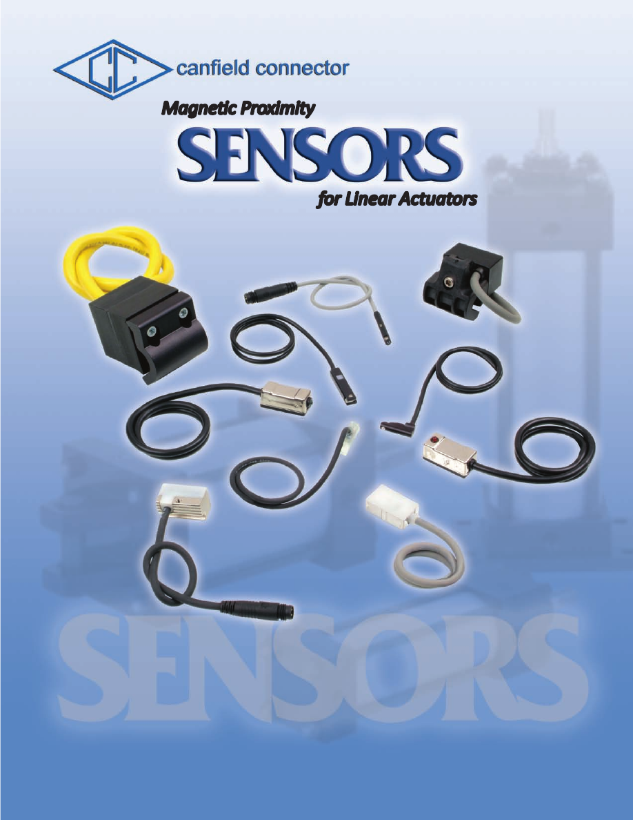
background image

1

8510 Foxwood Court  

  Youngstown, Ohio  

  44514

ph: 330-758-8299  

  fx: 330-758-8912

www.canfieldconnector.com

8510 Foxwood Court  

  Youngstown, Ohio  

  44514

ph: 330-758-8299  

  fx: 330-758-8912

www.canfieldconnector.com

for Linear Actuators

Magnetic Proximity

canfieldconnector-sensors-html.html
background image

canfield connector

*DISCLAIMER: Product changes including specifications, features, designs, and availability are subject to change anytime 

without notice. For critical dimensions or specifications, contact factory.  Such changes are not to be considered retroactive, and 

seller assumes no responsibility for revision of models already in the field.  All data is sufficiently accurate for general use, but 

seller assumes no responsibility for errors or omissions.  Certified prints are available on request, at a reasonable charge. 

Quality is our goal.

Canfield Connector is a manufacturer of interconnection devices, electronic timers, modules and specialty electronic 

devices targeted at the fluid power industry.  Our 

Complete Quality Control Program

 (CQCP) protects our customers by 

assuring them of 100% test and inspection prior to shipment of all items produced at Canfield Connector.  Most items are 

tested during the manufacturing process and again during final inspection, making our products double or triple tested for 

function prior to shipment. 


Our Quality Policy at Canfield Industries is:  Total Customer Satisfaction Through Unmatched 

Quality, Products, Service, and Integrity.  Our Quality Objectives are Customer Satisfaction, On-Time Delivery, Sales 

and Profit Growth, High Quality Products, and Superior Supplier Performance.  Canfield Connector operations have 

been certified to the ISO 9001 With Design International Quality System Standard.


1 year warranty

All products manufactured by Canfield Connector are warranted by Canfield Connector to be free of defects in material 

and workmanship for a period of one year from the purchase date.  Canfield Connector’s obligation under this warranty 

is limited to repair or replacement of the defective product or refund of the purchase price paid solely at the discretion 

of Canfield Connector and provided such defective product is returned to Canfield Connector freight prepaid and upon 

examination by Canfield Connector such product is found defective.  This warranty shall be void in the event that the 

product has been subject to misuse, misapplication, improper maintenance, or tampering.  This warranty is expressed 

in lieu of all other warranties, expressed or implied from Canfield Connector representatives or employees.


Technical assistance

Our trained technical staff is available at (330) 758-8299 or 1-800-554-5071 to help you with your questions concerning 

Canfield products.  All questions are welcome. We are constantly developing new product lines and custom products 

for different applications.  Ask our sales representative for more details.


Ordering made easy

Our order desk is open 8:00 AM to 5:00 PM EST Monday through Friday.  Call us at (330) 758-8299 or 1-800-554-5071 

to place your order or fax us at (330) 758-8912.  

MADE IN USA

Canfield Industries, Inc.

canfieldconnector-sensors-html.html
background image

Canfield Connector 

8510 Foxwood Court  

  Youngstown, OH  44514

STANDARD TERMS OF SALE AND RESTOCKING

1.  GENERAL

:

a.)  This contract contains the entire agreement between parties and supersedes any prior or contemporane-

ous oral or written agreements or communications between them relating to the subject matter hereof.

b.)  This contract may not be assigned, modified or cancelled without Seller’s prior written consent, and any 

attempt to assign, modify or cancel it without consent shall be absolutely void.

c.)  No delay or omission to exercise any right, per or remedy accruing to Seller upon breach or default by 

Buyer under this contract shall impair any such right, power or remedy of Seller, or shall be construed as 

a waiver of any such beach or default.  All waivers must be in writing.

d.) In the event of any of the provisions hereof shall, for any reason, be held void or unenforceable, the 

remaining provisions shall remain in full force and effect and shall control.

e.) Any provisions of this contact prohibited by law of any state shall as to said state, be ineffective to the 

extent of such prohibition without invalidating the remaining provisions of this contact.

f.)  This contract shall be governed by and construed in accordance with the laws of the State of Ohio, 

excluding however, Ohio law pertaining to conflicts of law.

2.   SELLER’S LIMITED WARRANTY AND LIMITATIONS OF LIABILITIES

:

a.) The information in this brochure is based on data obtained by our own research and is considered ac-

curate.  However, no warranty is expressed or implied regarding the accuracy of these data, the results 

to be obtained from the use thereof, or that any such use will not infringe any patent.  This information 

is furnished upon the condition that the person receiving it shall make his own tests to determine the 

suitability thereof for his particular purpose.

b.)  All Goods manufactured by Seller will be free from defects in material and workmanship and meet Seller's 

published specifications at the time of shipment under normal use and regular service and maintenance 

for a period of one (1) year from the date of manufacture

 of the Good by Seller, unless 

otherwise agreed upon in writing, and to conform to applicable specifications, drawings, blueprints and/

or samples. These express warranties are in lieu of and exclude all other warranties, express or implied.  

Seller’s sole obligation under these warranties shall be to issue credit, repair, or replace any item or part 

thereof which is proved to be other than as warranted; no allowance shall be made for any labor charges 

of Buyer for replacement of parts, adjustment or repairs, or any other work, unless such charges are 

authorized in advance by Seller.  If goods are claimed to be defective in material or workmanship or not 

to conform to specifications, drawings, blueprints and/or samples, Seller upon notice promptly given will 

either examine the goods at their site, or issue shipping instructions for return to Seller (transportation 

costs prepaid by Buyer).  In the event any goods are proved to be other than as warranted, transporta-

tion costs to and from Seller’s plant will be borne by Seller and reimbursement or credit will be made for 

amounts so expended by Buyer. In particular, seller makes no warranty respecting the merchantability 

of the products or their suitability or fitness for any particular purpose or use or respecting infringement.  

These warranties shall not extend to any goods or parts thereof which have been subjected to misuse 

or neglect, damage by accident, rendered defective by reason of improper installation or by the perfor-

mance of repairs or alterations outside of Seller’s plant except when performed under Seller’s specific 

authority.  These warranties shall not apply to any goods or parts thereof furnished by Buyer or acquired 

from others at Buyer’s request and/or to Buyer’s specifications.  BUYER SHALL NOT IN ANY EVENT 

BE ENTITLED TO, AND SELLER SHALL NOT BE LIABLE FOR INDIRECT, SPECIAL, INCIDENTAL OR 

CONSEQUENTIAL DAMAGES OF ANY NATURE INCLUDING, WITHOUT BEING LIMITED TO, LOSS 

OF PROFIT, LOSS OF DATA, LOSS OF USE, PROMOTIONAL OR MANUFACTURING EXPENSES, 

OVERHEAD, INJURY TO REPUTATION OR LOSS OF CUSTOMERS. BUYER’S RECOVERY FROM 

SELLER FOR ANY CLAIM SHALL NOT EXCEED BUYER’S PURCHASE PRICE FOR THE PRODUCTS 

IRRESPECTIVE OF THE NATURE OF THE CLAIM, WHETHER IN CONTRACT, TORT, WARRANTY,  

OR OTHERWISE.

3.   PAYMENT

:

a.)  Checks are accepted subject to collection and the date of collection shall be deemed the date of pay

-

ment.  Any check received from Buyer may be applied by Seller against any obligation owing by Buyer 

to Seller, under this or any other contract, regardless of any statement appearing on or referring to such 

check, without discharging Buyer’s liability for any additional amounts owing by Buyer to Seller; and the 

acceptance by Seller of such check shall not constitute a waiver of Seller’s right to pursue the collection 

of any remaining balance.

b.)  On any invoice not paid by maturity date (net thirty (30) days), Buyer shall pay interest from maturity 

to date of payment at the annual percentage rate of 18% (or such lower rate as may be the maximum 

allowable by law), together with Seller’s costs of collection (including reasonable attorneys’ fees).

c.)  Buyer agrees to pay the entire net amount of each invoice rendered by Seller pursuant to the terms of 

each such invoice without offset or deduction.

d.)  Prices for any undeliverable Products may be increased by Seller in the event of any increase in Seller’s 

cost of supplies, raw materials, labor or services, or any increase in Seller’s cost resulting from govern

-

ment action or other cause beyond Seller’s control.

4.   CREDIT

:

Seller may in its sole discretion at any time and from time to time change the terms of Buyer’s credit, 

require payment in cash before shipment of any or all of the Products specified herein, and/or require 

anticipated payment of any or all amounts due or to become due under this contract.  If Seller believes 

in good faith that Buyer’s ability to make payments called for by this contract is or may be impaired, 

Seller may cancel this contract or any remaining balance thereof, Buyer remaining liable to pay for any 

Products already shipped.

5.   TAXES/FREIGHT

:

Unless otherwise agreed in writing, the amount of all transportation charges from Seller’s location and 

all taxes or other charges now or hereafter imposed by any government authority upon sale, purchase, 

resale, delivery, manufacture, production or possession of the Products specified herein, which may 

be paid by Seller or for which Seller may be liable, shall be paid to Seller by Buyer in addition to the 

purchase price of the Products.

6.  ORDERS

:

a.)  Each order for Products is subject to acceptance in writing by Seller.

b.)  Orders may not be cancelled or rescheduled after delivery by Seller to the carrier. In the event of allocation 

of Products, orders that are accepted by Seller will be accepted using a fair schedule method.

c.)  Special Orders - Special orders for items not normally stocked are non-cancelable and non-returnable.

7.   DELIVERIES/TITLE

:

a.) All goods shall be packed in suitable containers for protection in shipment and storage.  No special 

charges for packing or crating shall be made unless specifically listed as an additional and separate 

charge on Seller’s quotation or acceptance of Buyer’s order.

b.)  Subject to Seller’s right of stoppage in transit, delivery of the Products to a carrier shall constitute delivery 

to Buyer, and risk of loss shall thereupon pass to Buyer; however, title shall remain in Seller until Buyer 

makes payment in full under contract.  Products invoiced and held by Seller for any reason shall be at 

Buyer’s risk and expense.  Delivery route shall be the election of Seller unless specifically designated by 

Buyer.

c.) Delivery of any installment of Products within 30 days after the date specified therefor shall constitute a 

timely delivery.  Thereafter, delivery shall be deemed timely unless prior to shipment Seller has received 

written notice of cancellation. Delivery of a quantity which does not vary by more than 10% from the 

quantity specified therefor shall constitute full performance of such delivery.  Delay in delivery of one 

installment shall entitle Buyer to cancel that installment only.

d.) Should delivery of all or part of the Products specified herein (or any other obligation of Seller) be delayed 

by events beyond Seller’s control, Seller’s time for performance shall be extended by the period of delay, 

or Seller may, at its option, cancel this contract without liability, Buyer remaining liable for shipments 

already made. Sellers shall not be  liable for any delays in or failures of delivery due to acts of God or 

public authority, labor disturbances, accidents, fires, floods, extreme weather conditions, failures of and 

delays by carriers, shortages of material, delays of a supplier due to causes beyond its  control.

e.) Buyer is deemed to have accepted the Products unless notice of rejection is given within a reasonable 

time, which is agreed to be within seven (7) days after receipt.  Buyer waives any right to revoke ac

-

ceptance thereafter.

f.)  No return of Products will be accepted by Seller without a return materials authorization number (RMA#), 

which will be issued in Seller’s sole discretion. Returned Products must be in original shipping cartons, 

and must be freight prepaid.  In the event any goods are proved to be other than as warranted, trans-

portation costs to and from Seller’s plant will be borne by Seller and reimbursement or credit will be 

made for amounts so expended by Buyer. Notice of defective Products must be made within seven (7) 

calendar days of receipt.  A complete description regarding the nature of the defect must be included 

with all returned Products.  All items not eligible for credit will be returned to Buyer, transportation collect.

8. SPECIFICATIONS AND DESIGNS

:

a.) Should Buyer request that changes be made in the specifications or design relating to any goods, delivery 

dates and schedules shall be revised accordingly, if necessary, and an equitable adjustment, upward or 

downward, shall be made in price in so far as warranted.

b.) Any designs, tools, patterns, material, drawings, information or equipment furnished by Buyer, or any 

special tools made  or acquired for the Buyer by the Seller which becomes Buyer’s property, shall be 

used only in the production of the goods called for herein and not otherwise, unless by Buyer’s written 

consent.  Seller agrees to exercise reasonable care with respect to such property and equipment while 

in its possession and control, but shall not be responsible for loss or damage occurring without its fault 

or negligence or for ordinary wear and tear.

9. USE OF PRODUCTS

:

a.) If technical advice is offered or given in connection with the use of any Products it will be as an accom

-

modation to Buyer and without charge and Seller shall have no responsibilities or liabilities whatsoever 

for the content or use of such advice.

b.) Products sold by Seller are not designed for use in life support or nuclear applications. Seller’s customers 

using or selling Products for use in life support or nuclear applications do so at their own risk, agree that 

Seller and the Manufacturer of Products are not liable, in whole or in part, for any claim or damage arising 

from such use, and agree to fully indemnify Seller and the Manufacturer from and against any and all 

damages, loss, cost, expense or liability arising out of or in connection with the use or performance of 

Products in life support or nuclear applications. 

c.) Should the Buyer notify the Seller that its order is placed under a prime contract with an agency of the 

United States Government, the following terms and conditions shall be incorporated into Seller’s terms of 

sale in so far as the Buyer is required to incorporate such provisions in its purchase orders or subcontracts 

of terms in so far as applicable to the goods sold hereunder.

d.) The following clause set forth or referred to in Sections 7 and 12 of the Armed Services Procurement 

Regulations are hereby incorporated by reference:  Renegotiation (7-103.13), Eight Hour Law of 1912 

(7-103.16 12-303.1), Walsh-Healy Public Contracts Act (7-103.17 12-604), Nondiscrimination in Employ

-

ment (7-103.18 12-802), Officials Not to Benefit (7-103.19), Buy American Act (7-104.3 6-104.5), Notice 

to the Government of Labor Disputes (7-104.4), Excess Profit (7-104.11), Military Security Requirements 

(7-104.12), Examination of Records (7-104.15), Convict Labor (7-104.17 12-203).  In order to make the 

context of the above clauses applicable to these terms of sale, the word “Buyer” shall be substituted 

for the word “Government” and the word “Seller” shall be submitted for the word “contractor” whenever 

necessary.

e.) Unless the design for the goods shall have been furnished by the Buyer to the Seller and used by the 

Seller in manufacturing the goods, Seller shall defend and save harmless the Buyer from any claim that 

any product or article sold to the Buyer hereunder in and of itself infringes any United States letters patent 

by reason of its sale or use/ provided Seller is notified in writing within ten (10) days after any such claim 

is made against the Buyer, and provided further that Seller is permitted to defend the same in Buyer’s 

name if action be brought.  If the product or article sold to the Buyer hereunder is manufactured by the 

Seller according to a design furnished by the Buyer, the Buyer will defend and save harmless the Seller 

from any claims of infringement of any United States Letters patent.

10. TOOLING

:

Tool, die, and pattern charges, if any, are in addition to the price of the Goods and are due and payable 

upon completion of the tooling. All such tools, dies and patterns shall be and remain the property of Seller. 

Charges for tools, dies, and patterns do not convey to Buyer, title, ownership interest in, or rights to pos

-

session or removal, or prevent their use by Seller for other purchasers, except as otherwise expressly 

provided by Seller and Buyer in writing with reference to this provision.

11. INSTALLATION/TRAINING

:

Buyer acknowledges that no installation, training or education is contracted for or purchased under terms 

of this contract unless specifically agreed in writing. In the event that Buyer receives any training from 

Seller with respect to the Products, then, in that event, such training is personal to the persons receiving 

such training, and Buyer acknowledges that any persons receiving such training may not be capable of 

operating the Products.

12. RESTOCKING POLICY:  

Merchandise that is returned must be accompanied by pre-approved return materials authorization 

number (RMA#).  Return authorizations will be approved by Canfield Connector.  When materials are 

received, an inspection will be performed to determine if restocking charges are applicable.  Material that 

does not have an authorization will be returned to the purchaser at their expense.

RETURNED ITEMS MAY ENTAIL A RESTOCKING CHARGE.  CONSULT FACTORY FOR EXACT 

RESTOCKING FEES. AS CHARGES MAY VARY DEPENDING ON THE AMOUNT OF SPECIALTY OF 

THE ITEMS BEING RETURNED.   CUSTOM PARTS & “9-” NUMBERS ARE NON-RETURNABLE AND 

NON-REFUNDABLE  (EXCEPT IN CASES OF WARRANTY)

canfieldconnector-sensors-html.html
background image

Sensor / Groove Cross Reference Chart

Reed or Electronic

Proximity Sensor Types 


Series 7000 

Reed & Electronic Magnetic Sensors 

Series 7GL 

General Location Magnetic Sensors

10 

Series 7HL 

Reed Switch for Hazardous Location 

11 

Series 8000 

Reed & Electronic Magnetic Sensors 

14 

Series 8D 

Reed & Electronic Magnetic Sensors

16 

Series 8E 

Reed & Electronic Magnetic Sensors

18 

Series 8F 

Reed & Electronic Sensor for Universal Applications

20 

Series 8WF 

Weld Field Immune Electronic Sensor Round, Tie-rod Applications

23 

Series 8WS 

Reed & Electronic Sensor for 12mm Dovetail Applications

25 

Series 9C 

Reed & Electronic Sensor for Round Keyway Applications

27 

Series 9D 

Reed & Electronic Sensor for Universal Applications 

30 

Series 9E 

Reed & Electronic Sensor for Universal Applications 

33 

Series 9F 

Reed & Electronic Sensor for 4mm "T" Slot Applications

35 

Series 9G 

Reed & Electronic Sensor for 6.3mm "T" Slot Applications

37 

Series 9H 

Reed & Electronic Sensor for 4.2mm "T" Slot Applications

39 

Series 9M50 

Reed & Electronic Sensor for 6.5mm Groove Applications

41 

Series 9N  

Reed & Electronic Sensor for 4.25mm Round Groove Applications

43 

Series 9Q 

Reed & Electronic Sensor for Universal "T" Slot Applications

45 

Series 9T 

Reed & Electronic Sensor for 7.2mm "T" Slot Applications

MAGNETIC PROXIMITY SENSORS

TABLE OF CONTENTS

canfieldconnector-sensors-html.html
background image

4

Note: All trademarks used in this catalog are the property of their respective owners.

Sensor / Groove Cross Reference Chart

8F

4.1

R3.7

3.7

6.5

Ø 7.4

Clearance

for M4

Wika

8WS

12

10.3

3.4

Numatics

9C

R 2.13 +/-  0.05

2.53 Min. +/-  0.1

3.05 +/-  0.1

DE-STA-CO


Robohand


SMC


Bimba


Compact Air

9D

1.52

4.82

6.35

Fabco


Numatics


Rotomation

9E

6.35

4.82

1.52

Fabco


Numatics


Rotomation

9F

5.1

3.2

4.4

6.5

Fabco

Festo


Numatics


Rotomation

9G

5.0

R 0.2

6.3

3.1

4.4

Fabco


Numatics


Rotomation

9H

3.05

R 0.2

4.2

4.2

5.0

4x4 Groove

9M50

5.5  +/-0.1

R 3.25

5.1 +/-0.1

Norgren

9N

3.05

R0.5

Ø

4.25

4.65

SMC

9Q

5.1

3.2

4.4

6.5

Parker

9T

5.5

7.2

3.9

1.06

SMC

canfieldconnector-sensors-html.html
background image

5

Principles of Operation for Magnetic Proximity Switches

Reed / Electronic Switch Working Principle

Sinking (NPN) vs. Sourcing (PNP)

Our reed switch sensors contain hermetically sealed reed elements (mechanical contacts) which can be open or closed in 

their normal state depending on the version selected.  When a magnetic field moves within proximity of the switch, magnetism 

is induced into the leads and forces the contacts to change state (open if normally closed or closed if normally open).  Typically 

used with air cylinders that are built with internal magnetic pistons.

Electronic switches are available in Sinking or Sourcing versions.  The basic difference between these two ways of solid state 

switching is as follows:

The Sourcing method connects or switches one side of the load to the positive (+) side of the supply.  The negative (-) side is 

connected directly to the other side of the load as shown in figure 1.  PNP is the acronym used to describe the transistor that 

performs this type of switching in a solid state sensor.

The Sinking method connects or switches one side of the load to the negative (-) side of the supply.  The positive (+) side is 

connected directly to the other side of the load as shown in figure 2.  NPN is the acronym used to describe the transistor that 

performs this type of switching in a solid state sensor.

Which type of sensor should I use?  

Reed

 or 

Electronic

?

The type of sensor that is  best for a particular application depends on the operating parameters and cost related issues.  

Canfield Connector is proud to offer the industry's best value in Reed and Electronic Sensors.  However if our sensors are mis-

applied, they could fail prematurely.  Therefore, give careful consideration when selecting the proper proximity sensor for your 

application.  We have prepared this catalog with all the necessary information in order to aid in this decision.  If you require 

more assistance or have any questions, please feel free to call.  Our customer service and engineering staff will be happy to 

assist you.  

For technical assistance, please call - (330) 758-8299 or visit our web site at www.canfieldconnec

tor.com

Reed Switch Sensors:

If initial cost and versatility are most important, then reed switch sensors should be considered.  For example the 7000 Series 

Type 04 reed switch will operate from 5 to 240 volts AC or DC.  Generally, one switch can be stocked to cover a large majority 

of common applications.  Please note, reed sensors do to work well with inrush surge currents and transients (common to in-

ductive & capacitive loads; i.e. relays, coils & long wire runs).  If inrush surge currents and transients must be accommodated, 

switch Types 21 - 29 may be specified.  These parameters should be given careful consideration when selecting a proximity 

device that will be best suited for an application.

Electronic Sensors:

In general, if longevity is a major concern, electronic sensors should be used whenever they fit within the operating parameters 

specified for a given application.  They should receive special attention when high cycle rates are required.  If electronic sen-

sors are used within their operating range they will always outperform and out last mechanical reed sensors.  The initial added 

cost associated with a electronic sensor will be outweighed should the application require high cycle rates.

Note: Arrows indicate movement of magnet in relation to switch surface.

canfieldconnector-sensors-html.html
background image

6

Proximity Sensor Types

Reed Switch Sensors:


Type 01 & 05 -

These two sensors are the most basic types.  They are made up of a reed element only.  The Type 01 is single pole, single 

throw, normally open and the Type 05 is single pole, single throw, normally closed.  These sensors act as an in line switch 

which is actuated in a magnetic field, with no minimum current requirement.


Features:  • Lowest cost 

• AC or DC operation 

• High power capacity 


  • Non polarity dependent 

• Zero leakage current 

• Nema 6 versions available 


  • CSA versions available


   Type 02 and 04 & 09 -

The Type 02 is current limiting and is  single pole, single throw, normally open. The Type 04 is single pole, single throw, nor-

mally open and Type 09 is single pole, single throw, normally closed.  They act as an in line switch which is actuated in a 

magnetic field.  These sensors also include an LED indicator and surge suppression.  Surge suppression helps to extend the 

life of the sensor when it is used to switch higher current loads and / or inductive loads.  The Type 04 & 09 are similar to the 

Type 01 & 05, in that they perform the same function.


Features:  • Lowest cost 

• AC or DC operation 

• High power capacity


  • Polarity protection 

• Zero leakage current 

• Nema 6 versions available 


  • CSA versions available 

• LED indicator 


   Type 06 - 

This sensor is a reed type sensor which uses a single pole, double throw element.  This enables the switching of two separate 

loads.  One side of the switch is normally closed and the other is normally open.  This sensor also included an LED indicator 

which is connected to the normally open side of the switch.  The LED indicator operates when the normally open side is closed 

with a minimum 5mA current flowing through the switch and a typical 3 volt drop.


Features:  • AC or DC operation 

• Zero leakage current 

• LED indicator on normally open   


  • High power capacity 

• CSA versions available 

• Nema 6 versions available

   Type 21 & 25 and 23, 24 & 29 -

These sensors are designed specifically to switch high power AC loads (including inductive loads) and loads with high tran-

sient or inrush currents, although they are not limited to these applications.  These sensor types all use a reed element to 

sense a magnetic field and a triac to drive the output, and include standard surge suppression.  This configuration provides 

excellent longevity even under the most demanding conditions.  The Type 21 & 25 utilize a two wired switch has no LED and 

Types 23, 24 & 29 utilize a three wired switch with LED.


Features:  • Solid state triac output = long life 

• Low voltage drop 

• Zero leakage current   


  • High power capacity 

• Resistant to current inrush 

• Nema 6 versions available 


  • CSA versions available


Electronic Sensors:

   Type 15 & 16 -

These two sensors use magnetoresistive elements with no magnetic polarity.  They are 100% solid state, and have no moving 

parts, resulting in extremely long life expectancy.  These virtually vibration and shock proof sensors utilize a rugged triac to 

switch power convenient AC voltage (common to reed switches) combined with the reliability of solid state technology (com-

mon to electronic switches).


Features:  • Solid state circuitry = long life 

• Low voltage drop 

• AC operation


  • LED indicator 

• CSA versions available 

• Resistant to shock and vibration  


  • Resistant to current inrush 

• Nema 6 versions available 

• No minimum current to operate

   Type 31 & 32 -

These sensors use magnetoresistive elements with no magnetic polarity.  They are 100% solid state, and have no moving 

parts, resulting in extremely long life expectancy.  They are designed to operate within 6 to 24V DC, and are available in two 

configurations:  NPN (Sinking) output and PNP (Sourcing) output.  Both include an indicator light which illuminates when the 

switch is actuated.  No minimum load current and low voltage drop make them ideal for use with programmable controllers.


Features:  • Solid state circuitry = long life 

• Low voltage drop 

• No minimum current to operate   


  • LED indicator 

• CSA versions available 

• High power capacity


  • Resistant to current inrush 

• Nema 6 versions available 

• Highly shock and vibration resistant

canfieldconnector-sensors-html.html
background image

canfield connector

8510 Foxwood Court

Youngstown, Ohio  44514

(330) 758-8299   Fax: (330) 758-8912

www.canfieldconnector.com

7

SERIES 7000 

REED AND ELECTRONIC SENSORS FOR 

2" TO 8" BORE TIE ROD CYLINDERS

OR 3/4" TO 4" ROUND CYLINDERS

• Temperature Range:  Operational from -20° to +80°C.


• Shock:  Operational up to 30G (11 ms.) reeds only.  

  Not applicable for electronics.


• Vibration:  Operational up to 20 G (10 - 55Hz) reeds only.  

Not applicable for electronics.


• Sensitivity and orientation:  85 gauss parallel minimum 

required for proper operation, as measured on sensor sur-

face.  Size of sensing area depends on size and strength of 

magnet and thickness of cylinder wall.


General Description

The Canfield Series 7000 proximity sensors are used to sense position on cylinders. They accommodate 2 to 8 inch bore tie 

rod cylinders or 3/4 to 4 inch round cylinders.  This proven design is rugged yet cost effective.  The Series 7000 boasts the 

largest number of custom circuits to match applications found in the market.  Examples include; 1 or 4 Amp reed switches, 

normally open, normally closed or SPDT switch types, reed or electronic sensing elements in the same package style, and 

the industry’s first 120 VAC Hall sensor.  A wide range of enclosures and connector options are available.  To reduce stocking 

requirements, two clamp options feature a self-adjusting clamp for NFPA and other tie rod cylinders from 2 to 8 inch bore.  

Another clamp option features a band clamp from 3/4 to 4 inch round cylinders.  

• One switch for a majority of voltages and cylinder sizes

• 2" to 6" bore, 6" to 8" bore or 3/4" to 4" round cylinders

• Wash down compatible NEMA 6 (most versions)

• Materials: Ultem

®

, Nylon, PVC wire and stainless steel

• CSA approved versions

• “Floating” clamp

• Surge suppression

• Compatible with IS (Intrinsically Safe) barriers

Features


Dimensional Data

ALL DIMENSIONS ARE IN MILLIMETERS UNLESS OTHERWISE NOTED

Standard Cable Module (9 ft)

Style 0

12mm Quick Connect

Style 5

Consult factory for available versions listed 

by Canadian Standards Association for use 

with certified electrical equipment.

C           US

(Standard switch shown below.  Mix and match with switch styles)

cross-sectional view of cylinder

cross-sectional view of cylinder

cross-sectional view of cylinder

Universal 2" to 6" Bore 

NFPA Tie Rod

3/4" to 4" 

Round Cylinder

6" to 8" Bore 

NFPA Tie Rod

Clamp Styles

Technical Data

canfieldconnector-sensors-html.html
background image

8


Ordering Information

Connector Style

0 - Standard cable module (9 ft)

5 - 12mm quick connect male*

Each switch supplied with clamp assembly

7 1 0 -       0 0  - 

Brown = Pin 1

Blue = Pin 3

Black = Pin 4

N/C = Pin 2

N/C = Pin 5

Order part number

RC12S-F0M030120 (2m length)

RC12S-F0M030150 (5m length)

*Mates with cordset RC12S-F0M030120 (2m) 

or RC12S-F0M030150 (5m) shown at right.

Ordering Example:

  710-000-004   

    Universal tie rod clamp, Standard cable,  reed switch, lighted,


    MOV surge suppression, normally open, 5 - 240V AC/DC 50/60 Hz

12mm female molded

locking connector (3 pole)

250VAC/DC  4 Amps max.

ALL DIMENSIONS ARE IN MILLIMETERS UNLESS OTHERWISE NOTED

Clamp Style

0 - Universal tie rod clamp 2" to 6" bore

1 - Round cylinder bracket

2 - Round cylinder 3/4" to 1 3/4" bore

3 - Round cylinder 1 9/16" to 2 1/2" bore

4 - Round cylinder 2 5/16" to 3 1/4" bore

5 - Round cylinder 3 1/16" to 4" bore

9 - 5/8" tie rod clamp 6" to 8" bore 

For convenience and faster shipping, this 

series is available in Can-Paks.

Type

Description

Function

Switching 

Voltage

Switching

Current

Switching 

Power

Switching 

Speed

Voltage 

Drop

01

Reed Switch, 2 Wire

Normally Open 

SPST

0 - 240V AC/DC 

50/60 Hz

1 Amp max.

30 Watts max.

0.6 ms operate 

0.05 ms release

0 Volts

04

Reed Switch, MOV, LED, 

2 Wire

Normally Open 

SPST

5 - 240V AC/DC 

50/60 Hz

1 Amp max.

.005 Amps min.

30 Watts max.

0.6 ms operate 

0.05 ms release

3 Volts

05

Reed Switch,

2 Wire

Normally Closed 

SPST

0 - 120V AC/DC 

50/60 Hz

1 Amp max.

20 Watts max.

1.0 ms operate 

0.02 ms release

0 Volts

06

Reed Switch, LED,

3 Wire

Single Pole, 

Double Throw

5 - 120V AC/DC 

50/60 Hz

1 Amp max.

.005 Amps min.

20 Watts max.

1.0 ms operate 

0.02 ms release

3Volts/load1    

0Volts/load2

09

Reed Switch, MOV, LED, 

2 Wire

Normally Closed 

SPST

5 - 120V AC/DC 

50/60 Hz

1 Amp max.

.005 Amps min.

20 Watts max.

1.0 ms operate 

0.02 ms release

3 Volts

15

AC Electronic Sensor 

for Reed Magnets, 

LED,  3 Wire

Normally Open 

TRIAC output

12-24 VAC

600 mA max.

5 Amps Inrush

15 Watts max.

1.5 

µ

s operate

0.5 

µ

s release

1 Volt

16

AC Electronic Sensor 

for Reed Magnets, 

LED,3 Wire

Normally Open 

TRIAC output

120 VAC

600 mA max.

5 Amps Inrush

72 Watts max.

1.5 

µ

s operate

0.5 

µ

s release

1 Volt

21

Reed Switch, MOV, 

2 Wire

Normally Open 

TRIAC output

10 - 240 VAC      

50/60 Hz

4 Amps max.

50 Amps Inrush

100 Watts max.

0.6 ms operate

 0.05 ms release

1 Volt

23

Reed Switch, MOV, LED, 

3 Wire

Normally Open 

TRIAC output

10 - 50 VAC        

50/60 Hz

4 Amps max.

50 Amps Inrush 

.005 Amps min.

100 Watts max.

0.6 ms operate 

0.05 ms release

1 Volt

24

Reed Switch, MOV, LED, 

3 Wire

Normally Open 

TRIAC output

24 - 240 VAC      

50/60 Hz

4 Amps max.

50 Amps Inrush 

.005 Amps min.

100 Watts max.

0.6 ms operate 

0.05 ms release

1 Volt

25

Reed Switch, MOV, 

2 Wire

Normally Closed 

TRIAC output

10-120 VAC        

50/60 Hz

4 Amps max.

50 Amps Inrush

100 Watts max.

0.6 ms operate 

0.05 ms release

1 Volt

29

Reed Switch, MOV, LED, 

3 Wire

Normally Closed 

TRIAC Output

10-120 VAC

50/60 Hz

4 Amps max.

50 Amps Inrush

.005 Amps min.

100 Watts max.

06 ms operate 

0.05 ms release

1 Volts

31

Electronic for Reed 

Magnet, LED & Sourcing, 

3 Wire

Normally Open  

PNP

6 - 24 VDC

1 Amp max.

24 Watts max.

1.5 µs operate 

0.5 µs release

0.5 Volts

32

Electronic for Reed 

Magnet, LED & Sinking, 

3 Wire

Normally Open 

NPN

6 - 24 VDC

1 Amp max.

24 Watts max.

1.5 µs operate 

0.5 µs release

0.5 Volts

canfieldconnector-sensors-html.html
background image

canfield connector

8510 Foxwood Court

Youngstown, Ohio  44514

(330) 758-8299   Fax: (330) 758-8912

www.canfieldconnector.com

9

SERIES 7GL

GENERAL LOCATION MAGNETIC PROXIMITY 

SENSORS FOR TIE ROD CYLINDERS


General Description

The Canfield Connector 7GL is an expansion of the popular Series 7000 “floating” clamp design, which adapts to NFPA tie rod 

linear actuators with 2 to 8 inch bore.  This rugged magnetic proximity sensor can sense actuator position in stringent, gen-

eral location applications.  The switch features a robust, aircraft aluminum body, epoxy-filled, vibration and shock resistant, 

electronic circuit.  Available in a normally open contact, the 7GL can switch current up to .5 Amps and has a voltage range of 

0-120VAC/VDC 50/60 Hz.  

•  Normally open reed switch for general location

•  Metal body with robust 1/2" conduit

•  Fully encapsulated electronics

•  Cam-lock clamp ensures proper assembly and 

  sensor position

•  Compatible for wash down

•  Compatible with anodized 6061 Aluminum material

    Dimensional Data

    Technical Data

•  Temperature Range:  Operational from -20° to +80°C

•  Shock:  Operational up to 30 G (11ms)

•  Vibration:  Operational up to 20 G (10 - 55 Hz)

•  Sensitivity:  85 Gauss parallel minimum, as 

  measured on the surface of actuator

•  Environmental protection:  NEMA 1, 4 and 13 

•  Body Material:  Anodized 6061-T6 Aluminum, Epoxy


  encapsulated printed circuit board

•  Wire:  PVC 20/3 Leads

•  Circuit:  S.P.S.T., Normally Open

•  Operating Voltage:  0 - 120 V AC/DC 50/60 Hz

•  Maximum Load (Power Rating): 10W, Resistive Only

•  Maximum Current:  0.5A Max.

•  Response Time ON:  0.5ms

•  Response Time OFF:  0.1ms


Features


Ordering Information

Order # 7 G L 1 0 - 0 0 0 - 0 0 1

GRN

RED

BLK

LOAD

GROUND

+

HOT

-

~

-

NEUTRAL

-

~

SWITCH

-

~

Both direct and alternating current

Earth (ground) TERMINAL

MOUNTING

Electrical, Mounting Installation

9' -0/+1.5"

1.450

1.375

1.500

1/2" Conduit

canfieldconnector-sensors-html.html
background image

canfield connector

8510 Foxwood Court

Youngstown, Ohio  44514

(330) 758-8299   Fax: (330) 758-8912

www.canfieldconnector.com

10

SERIES 7HL

HAZARDOUS LOCATION MAGNETIC PROXIMITY 

SENSORS FOR TIE ROD CYLINDERS


General Description

The Canfield Connector 7HL is a rugged magnetic proximity sensor designed to sense actuator position in stringent, 

hazardous location applications.  The switch features a robust, epoxy-filled, aircraft aluminum body, and has a vi-

bration and shock resistant, electronic circuit.  The 7HL is an expansion of the popular Series 7000 “floating” clamp 

design and will clamp on 2 to 8 inch bore NFPA tie rod linear actuators.   This product is designed to operate in 

hazardous locations, this switch is CSA approved for Class I, Division 2, Groups A, B, C, and D;  Class II, Division 

2, Groups F and G;  and Class III.  

•  Meets hazardous location specifications

•  Metal body with robust 1/2" conduit

•  Fully encapsulated electronics

•  Cam-lock clamp ensures proper assembly and 

  sensor position

•  Compatible for wash down and corrosive  environments

•  Compatible with anodized 6061 Aluminum material

    Dimensional Data

9' -0/+1.5"

1.450

1.375

1.500

1/2" Conduit

Order # 7 H L 1 0 - 0 0 0 - 0 0 1

*White wire must be permanently reidentified to indicate its use as 

an  ungrounded  conductor,  by  painting  or  other  effective  means  at 

its termination, and each location where the conductor is visible and 

accessible.  Per NEC Article (200.7)

    Technical Data

•  Temperature Range:  Operational from -20° to +80°C

•  Shock:  Operational up to 30 G (11ms)

•  Vibration:  Operational up to 20 G (10 - 55 Hz)

•  Sensitivity:  85 Gauss parallel minimum, as measured


  on the surface of actuator

•  Pollution Degree:  3

•  Environmental protection:  NEMA 1, 4 and 13 

•  Hazardous location ratings:  

    CSA:  Class I, Division 2, Groups A, B, C and D; 


Class II, Division 2, Groups F and G; and Class III

•  Body Material:  Anodized 6061-T6 Aluminum, Epoxy


  encapsulated printed circuit board

•  Wire:  SJE00W 18/3 Leads

•  Circuit:  S.P.S.T., Normally Open

•  Operating Voltage:  0 - 120 V AC/DC 50/60 Hz

•  Maximum Load (Power Rating): 10W, Resistive Only

•  Maximum Current:  0.5A Max.

•  Response Time ON:  0.5ms

•  Response Time OFF:  0.1ms

Electrical, Mounting Installation

GRN

BLK

*WHT

LOAD

GROUND

+

HOT

-

~

-

NEUTRAL

-

~

SWITCH

-

~

Both direct and alternating current

Earth (ground) TERMINAL

MOUNTING

    Features

Consult factory for available versions listed 

by Canadian Standards Association for use 

with certified electrical equipment.

C           US

Ordering Information

canfieldconnector-sensors-html.html
background image

canfield connector

8510 Foxwood Court

Youngstown, Ohio  44514

(330) 758-8299   Fax: (330) 758-8912

www.canfieldconnector.com

11

SERIES 8000


General Description

The Canfield Connector Series 8000 Reed and Electronic sensors are compact units designed for sensing applications 

on round cylinders from 9/16" - 4" and tie-rod pneumatic cylinders from 3/4" - 8" bore. These sensors offer a wide 

voltage range from 0-120 VAC/VDC 50/60 Hz and high current capacity up to 0.5 Amps. They include high intensity 

indicator lights and a wide viewing angle. The sensor's small package can fit easily on the smallest cylinder without 

appearing too large. The Series 8000's design promotes ease of installation with a tight fit. Options include 9ft. PVC or 

8mm quick connect male pigtail.

• 

Extremely consistent repeatability

• 

Compact design

• 

Surge suppression available (standard on electronic)

• 

Reverse polarity protection

• 

Wide voltage range

• 

Compatible with IS (Intrinsically Safe) barriers

• 

High intensity light (LED) standard on most models

• 

Compatible with most corrosive and washdown 

  applications

• 

High current capacity for small size 

  (up to 10 times the competition)

• 

Both reed and electronic versions work with 

   the same (reed) magnet

• 

Encapsulated circuit for wet environment

REED & ELECTRONIC SENSORS FOR

ROUND, TIE-ROD, OR EXTRUDED CYLINDERS

Features

• Temperature Range:  Operational from -20° to +80°C
• Shock:  Operational up to 30G (11 ms.) reeds only.  Not applicable for electronic
• Vibration:  Operational up to 20G (10 - 55 Hz) reeds only.  Not applicable for electronic
• Sensitivity and orientation:  85 gauss parallel (standard minimum required for proper operation,


  as measured on sensor surface. Size of sensing area depends on size and strength of magnet and 


  thickness of cylinder wall
• Most versions designed to meet NEMA 4/IP65 specifications


Technical Data

Consult factory for available versions listed 

by Canadian Standards Association for use 

with certified electrical equipment.

C           US

canfieldconnector-sensors-html.html
background image

12


Dimensional Data

ALL DIMENSIONS ARE IN MILLIMETERS UNLESS OTHERWISE NOTED

Clamp Styles

Strap for round 

cylinders 

from 9/16" to 

4" bore

9.5

25.5

11

Standard 

Round Cylinder 

Universal Clamp 

(Style 0)

Low-Profile 

Round Cylinder Clamp 

(Style 5-9)

Side Adjust 

Round Cylinder Clamp

(Style A)

Extruded 

Cylinder Clamp 

(Style 3)

Standard 

Tie-Rod 

Cylinder Clamp 

(Style 2)

NFPA Tie-Rod 

Cylinder Clamp  

(Style B)

NFPA Tie-Rod 

Cylinder Clamp  

(Style C)

Straps 


for round 

cylinders 

from 1/2" to 

2 1/2" bore. 

9.5

Clamp for extruded 

cylinders from 

1 1/2" to 4"  bore.

39

Max. Ø

to 5/8"

Strap for 

round cylinders from 

9/16" to 4" bore with 

side adjustment. 

11

20

17

Clamp for NFPA

 tie-rod cylinders from 

2 1/2" to 4"  bore.

33

Max. Ø 

to 3/8"

Clamp for NFPA

 tie-rod cylinders from 

5" to 8"  bore.

41

Max. Ø 

to 5/8"

Clamp for tie-rod 

cylinders from 

3/4" to 4"  bore.

19

33

Max. Ø

to 5/16"

9 ft PVC Cable Switch

Type 0

9 ft, 24 gauge PVC cable standard

8mm Quick Connect Male Pigtail 

Type 1

canfieldconnector-sensors-html.html
background image

13


Ordering Information

Clamp Styles

0 - Universal round cylinder clamp

1 - No clamp

2 - Universal tie-rod clamp

3 - Extruded cylinder clamp

5 - Clamp loop / no clamp***

6 - Clamp loop / 1/2" - 3/4" clamp

7 - Clamp loop / 1" - 1 1/2" clamp

8 - Clamp loop / 1 1/2" - 2" clamp

9 - Clamp loop / 2" - 2 1/2" clamp

A - Side adjust round cylinder clamp

B - NFPA 2 1/2" - 4" tie-rod cylinder clamp

C - NFPA 5" - 8" tie-rod cylinder clamp

Connection Options

0 - 9 ft PVC cable

1 - 8mm quick connect male pigtail*

Ordering Example:


  810-000-002

    Universal round cylinder clamp, 9ft PVC cable, 


    reed switch with LED, SPST, normally open, 


    5 - 120V AC/DC

8 1 0 -       0 0 - 

***Uses 5/16" wide band clamp

Brown = Pin 1

Blue = Pin 3

Black = Pin 4

Order part number

RC08S-F0M030120 (2m length)

RC08S-F0M030150 (5m length)

Mating Cordsets

8mm female molded locking connectors

*Mates with cordsets shown at right.

Type

Description

Function

Switching 

Voltage

Switching

Current

Switching 

Power

Voltage 

Drop

Magnetic 

Sensitivity

01

Reed Switch

Normally Open

SPST

0 - 120V AC/DC

0.5 Amps Max.

10 watts Max.

0 Volts

85 Ga.

02

Reed Switch & LED

Normally Open

SPST

5 - 120V AC/DC

0.025 Amps Max. 

0.001 Amps Min.

3 watts Max.

6.0 Volts

85 Ga.

04

Reed Switch, LED & MOV

Normally Open

SPST

5 - 120V AC/DC

0.5 Amps Max. 

0.005 Amps Min.

10 watts Max. 3.0 Volts

85 Ga.

31

Electronic for Reed 

Magnet, LED & Sourcing

Normally Open  

PNP

6 - 24 VDC

0.3 Amps Max.

7.2 watts 

Max.

.5 Volts

85 Ga.

32

Electronic for Reed 

Magnet, LED & Sinking

Normally Open 

NPN

6 - 24 VDC

0.3 Amps Max.

7.2 watts 

Max.

.5 Volts

85 Ga.

For convenience and faster shipping, this 

series is available in Can-Paks.

canfieldconnector-sensors-html.html
background image

canfield connector

8510 Foxwood Court

Youngstown, Ohio  44514

(330) 758-8299   Fax: (330) 758-8912

www.canfieldconnector.com

14

SERIES 8D


General Description

The Canfield Connector Series 8D is a robust yet compact switch designed to sense  position of pneumatic cylinders with 

magnetic pistons.  The switch features an all encapsulated design with a metal over housing that protects the internal 

components from harsh environments.  The switch comes in reed, or electronic versions and has either 9 ft. PVC or 8mm 

quick connect male pigtail  A broad range of clamping styles make this a very versatile alternative for sensing round or tie 

rod type linear actuator.  The switch comes standard with an indicator light that shows switching condition.

REED & ELECTRONIC SENSORS FOR

ROUND, TIE-ROD, OR EXTRUDED CYLINDERS

Clamp Styles

Standard 

Round Cylinder 

Universal Clamp 

(Style 0)

Standard 

Tie-Rod 

Cylinder Clamp 

(Style 2)

12.6

29.2

10.8


Dimensional Data

ALL DIMENSIONS ARE IN MILLIMETERS UNLESS OTHERWISE NOTED

• Quick connect versions available
• Extremely consistent repeatability
• Compact design
• Reverse polarity protection
• Both reed and electronic versions work with the same (reed) magnet
• Encapsulated circuit for wet environment (NEMA 6)
• Available for tie-rod, round or extruded cylinder mounting

Features

Strap for round 

cylinders 

from 9/16" to 

4" bore

9.5

25.5

11

Clamp for tie-rod 

cylinders from 

3/4" to 4"  bore.

19

33

Max. Ø

to 5/16"

canfieldconnector-sensors-html.html
background image

15

For convenience and faster shipping, this 

series is available in Can-Paks.

• Temperature Range: Operational from -10° to +70°C
• Shock: Operational up to 30G (11 ms.) reeds, 50G electronic 


• Vibration:  Operational up to 9G parallel
• Sensitivity and orientation:  60G parallel (standard minimum required for proper operation, 

  as measured on sensor surface. Size of sensing area depends on size and strength of 


  magnet and thickness of cylinder wall
• Most versions designed to meet NEMA 6/IP67 specifications


Technical Data


Ordering Information

Clamp Styles

0 - Universal round cylinder clamp

1 - No clamp

2 - Universal tie-rod clamp

Connection Options

0 - 9 ft PVC cable

1 - 8mm quick connect male pigtail*

Ordering Example:


  8D10-000-004

    Universal round cylinder clamp, 9 ft. cable,


    standard style reed switch with LED & MOV, 


    SPST, normally open, 5 - 240V AC/DC

8 D 1 0 -       0 0 - 

Brown = Pin 1

Blue = Pin 3

Black = Pin 4

Order part number

RC08S-F0M030120 (2m length)

RC08S-F0M030150 (5m length)

Mating Cordsets

8mm female molded locking connectors

*Mates with cordsets shown at right.

**Minimum gauss rating required for proper operation; as measured 4.5 above sensing surface.

   Size of sensing area depends upon size and strength of magnet and thickness of cylinder wall.

Type

Description

Function

Switching 

Voltage

Switching

Current

Switching 

Power

Voltage 

Drop

** Magnetic 

Sensitivity

01

Reed Switch

Normally Open

SPST

0 - 240V AC/DC

0.5 Amps Max.

10 watts Max.

0 Volts

60 Ga.

04

Reed Switch, LED & MOV

Normally Open

SPST

5 - 240V AC/DC

100 mA

10 watts Max. 2.5 Volts

60 Ga.

31

Electronic for Reed 

Magnet, LED & Sourcing

Normally Open  

PNP

5 - 28 VDC

.2 Amps Max.

6 watts Max.

1.5 Volts

60 Ga.

32

Electronic for Reed 

Magnet, LED & Sinking

Normally Open 

NPN

5 - 28 VDC

.2 Amps Max.

6 watts Max.

1.5 Volts

60 Ga.

canfieldconnector-sensors-html.html
background image

canfield connector

8510 Foxwood Court

Youngstown, Ohio  44514

(330) 758-8299   Fax: (330) 758-8912

www.canfieldconnector.com

16

SERIES 8E


General Description

The Canfield Connector Series 8E is a linear actuator magnetic sensor designed for harsh industrial applications.  With  

mounting styles for tie rod or round type linear actuators, the 8E features an all encapsulated body that is covered by a 

metal housing for strength.  The switch is available in reed or electronic versions and electrical connection is made by use 

of 9 ft. PVC or 8mm quick connect male pigtail.  The 8E is water resistant and dust tight to IP67.

REED & ELECTRONIC SENSORS FOR

ROUND, TIE-ROD, OR EXTRUDED CYLINDERS

Clamp Styles

Standard 

Round Cylinder 

Universal Clamp 

(Style 0)

Standard 

Tie-Rod 

Cylinder Clamp 

(Style 2)

Clamp for tie-rod 

cylinders from 

3/4" to 4"  bore.

19

33

Max. Ø

to 5/16"

12.6

28.1

10.8


Dimensional Data

ALL DIMENSIONS ARE IN MILLIMETERS UNLESS OTHERWISE NOTED

• Quick connect versions available
• Extremely consistent repeatability
• Compact design
• Reverse polarity protection
• Both reed and electronic versions work with the same (reed) magnet
• Encapsulated circuit for wet environment (NEMA 6)
• Available for tie-rod, round or extruded cylinder mounting

Features

Strap for round 

cylinders 

from 9/16" to 

4" bore

9.5

25.5

11

canfieldconnector-sensors-html.html
background image

17

• Temperature Range: Operational from -10° to +70°C
• Shock: Operational up to 30G (11 ms.) reeds, 50G electronic 


• Vibration:  Operational up to 9G parallel
• Sensitivity and orientation:  60G parallel (standard minimum required for proper operation, 

  as measured on sensor surface. Size of sensing area depends on size and strength of 


  magnet and thickness of cylinder wall
• Most versions designed to meet NEMA 6/IP67 specifications


Technical Data


Ordering Information

Clamp Styles

0 - Universal round cylinder clamp

1 - No clamp

2 - Universal tie-rod clamp

Connection Options

0 - 9 ft PVC cable

1 - 8mm quick connect male pigtail*

Ordering Example:


  8E10-000-004

    Universal round cylinder clamp, 9 ft. cable,


    standard style reed switch with LED & MOV, 


    SPST, normally open, 5 - 240V AC/DC

8 E 1 0 -       0 0 - 

Brown = Pin 1

Blue = Pin 3

Black = Pin 4

Order part number

RC08S-F0M030120 (2m length)

RC08S-F0M030150 (5m length)

Mating Cordsets

8mm female molded locking connectors

*Mates with cordsets shown at right.

**Minimum gauss rating required for proper operation; as measured 4.5 above sensing surface.

   Size of sensing area depends upon size and strength of magnet and thickness of cylinder wall.

Type

Description

Function

Switching 

Voltage

Switching

Current

Switching 

Power

Voltage 

Drop

** Magnetic 

Sensitivity

01

Reed Switch

Normally Open

SPST

0 - 240V AC/DC

0.5 Amps Max.

10 watts Max.

0 Volts

60 Ga.

04

Reed Switch, LED & MOV

Normally Open

SPST

5 - 240V AC/DC

100 mA

10 watts Max. 2.5 Volts

60 Ga.

31

Electronic for Reed 

Magnet, LED & Sourcing

Normally Open  

PNP

5 - 28 VDC

0.2 Amps Max.

6 watts Max.

1.5 Volts

60 Ga.

32

Electronic for Reed 

Magnet, LED & Sinking

Normally Open 

NPN

5 - 28 VDC

0.2 Amps Max.

6 watts Max.

1.5 Volts

60 Ga.

For convenience and faster shipping, this 

series is available in Can-Paks.

canfieldconnector-sensors-html.html
background image

canfield connector

8510 Foxwood Court

Youngstown, Ohio  44514

(330) 758-8299   Fax: (330) 758-8912

www.canfieldconnector.com

18

SERIES 8F

The Canfield Connector Series 8F is a compact yet rugged magnetic reed type proximity sensor designed for rigorous 

applications where critical magnetic sensing is needed.  The tough nylon shell is over-molded with polyurethane to create 

an environmentally resilient seal from the elements and is rated to IP67.  The compact size and cylindrical shape are ideal 

for mounting in a simple hole or cylindrical shape.  There is a tab mounting version also available.  The 8F can be mounted 

solidly and fit into many common magnetic sensing applications.  Offered standard with 9ft. cord or an M8 quick connect 

connector, the switch is also available in either normally open or normally closed switch types.

REED SENSORS FOR

UNIVERSAL APPLICATION

38.4


Dimensional Data

ALL DIMENSIONS ARE IN MILLIMETERS UNLESS OTHERWISE NOTED

General Description

Ø 7.2

18.6

To center of sensing area

35.1

15.3

To center of sensing area

M4x0.7 THRU

13.3

R3.6

6.5

GROOVE DIMENSIONS

4.1

R3.7

3.7

6.5

Ø 7.4

Clearance

for M4

canfieldconnector-sensors-html.html
background image

19

• Temperature Range: Operational from 


 -20° to +80°C

• Shock: Operational up to 30G (11 ms.)  


• Vibration:  Operational up to 20G (10-55 Hz)
• Environmental Protection:  NEMA 6 / IP67
• Sensitivity and Orientation:  85 Gauss parallel


Technical Data


Ordering Information

Clamp Styles

0 - Straight body with set screw

1 - Straight body with mounting tab

Connection Options

0 - 9 ft PVC cable

1 - 8mm quick connect male pigtail*

Ordering Example:


  8F10-000-001

    Straight body with set screw, 9 ft. cable,


    reed switch, normally open, 0 - 120V AC/DC

8 F 1 0 -       0 0 - 

Brown = Pin 1

Blue = Pin 3

Black = Pin 4

Order part number

RC08S-F0M030120 (2m length)

RC08S-F0M030150 (5m length)

Mating Cordsets

8mm female molded locking connectors

*Mates with cordsets shown at right.

**Minimum gauss rating required for proper operation; as measured 4.5 above sensing surface.

   Size of sensing area depends upon size and strength of magnet and thickness of cylinder wall.

Type

Description

Function

Switching 

Voltage

Switching

Current

Switching 

Power

Voltage 

Drop

** Magnetic 

Sensitivity

01

Reed Switch

Normally Open

0 - 120V AC/DC

2 Amps Max.

40 Watts Max.

0 Volts

85 Ga.

06

Reed Switch

SPDT

0 - 120V AC/DC

0.25 Amps Max.

5 Watts Max.

0 Volts

85 Ga.

09

Reed Switch

Normally Closed

0 - 120V AC/DC

0.25 Amps Max.

5 Watts Max.

0 Volts

85 Ga.

• Small sensor fits most space requirements
• Corrosion and washdown resistance
• Compatible with IS (Intrinsically Safe) barriers
• Molded construction for wet environments 


  (NEMA 6 / IP67)

Features

canfieldconnector-sensors-html.html
background image

canfield connector

8510 Foxwood Court

Youngstown, Ohio  44514

(330) 758-8299   Fax: (330) 758-8912

www.canfieldconnector.com

20

SERIES 8WF


General Description

The Canfield Connector Series 8WF weld field immune electronic sensors are compact magnetic sensors designed for 

sensing position magnetic pistons on pneumatic actuators while ignoring electromagnetic pulses generated from AC 

weld fields.   Designed for round type cylinders with diameters from 9/16" - 4" and tie-rod type cylinders from 3/4" - 8" 

bore, the 8WF features a rugged stainless steel and nylon enclosure and high current capacity up to 0.2 Amps and 

24VDC input.  Included in the sensor is a high intensity indicator light that can be seen from a wide viewing angle. The 

sensor's small package can fit easily on the smallest cylinder without appearing too large. The Series 8WF design 

promotes ease of installation with a tight fit. Options include 9ft. PVC or 8mm quick connect male pigtail.

• 

Extremely consistent repeatability

• 

Compact design

• 

Reverse polarity protection

• 

Wide voltage range

• 

Compatible with IS (Intrinsically Safe) barriers

• 

High intensity light (LED) standard on most models

• 

Compatible with most corrosive and washdown 

  applications

• 

High current capacity for small size 

  (up to 10 times the competition)

• 

Encapsulated circuit for wet environment

WELD FIELD IMMUNE ELECTRONIC SENSORS FOR

ROUND, TIE-ROD, OR EXTRUDED CYLINDERS

Features

• Temperature Range:  Operational from -20° to +80°C
• Sensitivity and orientation:  85 gauss parallel (standard minimum required for proper operation,


  as measured on sensor surface. Size of sensing area depends on size and strength of magnet and 


  thickness of cylinder wall
• Most versions designed to meet NEMA 4/IP65 specifications


• Minimum magnetic field application time to activate output - 15m sec.


Technical Data

canfieldconnector-sensors-html.html
background image

21


Dimensional Data

ALL DIMENSIONS ARE IN MILLIMETERS UNLESS OTHERWISE NOTED

Clamp Styles

Strap for round 

cylinders 

from 9/16" to 

4" bore

9.5

25.5

11

Standard 

Round Cylinder 

Universal Clamp 

(Style 0)

Low-Profile 

Round Cylinder Clamp 

(Style 5-9)

Side Adjust 

Round Cylinder Clamp

(Style A)

Extruded 

Cylinder Clamp 

(Style 3)

Standard 

Tie-Rod 

Cylinder Clamp 

(Style 2)

NFPA Tie-Rod 

Cylinder Clamp  

(Style B)

NFPA Tie-Rod 

Cylinder Clamp  

(Style C)

Straps 


for round 

cylinders 

from 1/2" to 

2 1/2" bore. 

9.5

Clamp for extruded 

cylinders from 

1 1/2" to 4"  bore.

39

Max. Ø

to 5/8"

Strap for 

round cylinders from 

9/16" to 4" bore with 

side adjustment. 

11

20

17

Clamp for NFPA

 tie-rod cylinders from 

2 1/2" to 4"  bore.

33

Max. Ø 

to 3/8"

Clamp for NFPA

 tie-rod cylinders from 

5" to 8"  bore.

41

Max. Ø 

to 5/8"

Clamp for tie-rod 

cylinders from 

3/4" to 4"  bore.

19

33

Max. Ø

to 5/16"

9 ft PVC Cable Switch

Type 0

9 ft, 24 gauge PVC cable standard

8mm Quick Connect Male Pigtail 

Type 1

canfieldconnector-sensors-html.html
background image

22


Ordering Information

Clamp Styles

0 - Universal round cylinder clamp

1 - No clamp

2 - Universal tie-rod clamp

3 - Extruded cylinder clamp

5 - Clamp loop / no clamp***

6 - Clamp loop / 1/2" - 3/4" clamp

7 - Clamp loop / 1" - 1 1/2" clamp

8 - Clamp loop / 1 1/2" - 2" clamp

9 - Clamp loop / 2" - 2 1/2" clamp

A - Side adjust round cylinder clamp

B - NFPA 2 1/2" - 4" tie-rod cylinder clamp

C - NFPA 5" - 8" tie-rod cylinder clamp

Connection Options

0 - 9 ft PVC cable

1 - 8mm quick connect male pigtail*

Ordering Example:


  8WF10-000-031

    Universal round cylinder clamp, 9ft PVC cable, 


    Electronic for Reed Magnet, LED & Sourcing,


    Normally Open, 6-24 VDC

8 W F 1 0 -       0 0 - 

***Uses 5/16" wide band clamp

Brown = Pin 1

Blue = Pin 3

Black = Pin 4

Order part number

RC08S-F0M030120 (2m length)

RC08S-F0M030150 (5m length)

Mating Cordsets

8mm female molded locking connectors

*Mates with cordsets shown at right.

Type

Description

Function

Switching 

Voltage

Switching

Current

Switching 

Power

Voltage 

Drop

Magnetic 

Sensitivity

31

Electronic for Reed 

Magnet, LED & Sourcing

Normally Open  

PNP

6 - 24 VDC

0.2 Amps Max.

4.8 watts 

Max.

1 Volts

85 Ga.

32

Electronic for Reed 

Magnet, LED & Sinking

Normally Open 

NPN

6 - 24 VDC

0.2 Amps Max.

4.8 watts 

Max.

1 Volts

85 Ga.

canfieldconnector-sensors-html.html
background image

canfield connector

8510 Foxwood Court

Youngstown, Ohio  44514

(330) 758-8299   Fax: (330) 758-8912

www.canfieldconnector.com

23

SERIES 8WS (WORLDSWITCH)


General Description

REED & ELECTRONIC SENSORS FOR

PNEUMATIC CYLINDERS WITH 12MM DOVETAIL

The Canfield Connector Series 8WS reed and electronic magnet sensors are rugged yet compact switches used to 

sense position on pneumatic actuators equipped with a magnetic piston and 12mm dovetail groove. The switch can be 

slipped in and tightened from anywhere along the groove that is fabricated into the cylinder wall or clamping system. 

The switch features a die cast holder which clamps to the cylinder groove while the electronics are fully encapsulated 

and resistance to environment. These sensors offer a wide voltage range from 0-120 V AC/DC 50/60Hz and have a up 

to a 500 mA switching current rating. The switch has a high intensity indicator light which indicates power to the switch 

and load. The switch comes standard with 9 ft. PVC or 8mm quick connect male pigtail.


Dimensional Data

ALL DIMENSIONS ARE IN MILLIMETERS UNLESS OTHERWISE NOTED

9 FT. CABLE

13.5

23.4

14.2

8MM PIGTAIL CONNECTOR

11

12

10.3

3.4

GROOVE

DIMENSIONS

Groove:

Numatics

canfieldconnector-sensors-html.html
background image

24

• Temperature Range:  Operational from -20° to +80°C
• Shock:  Operational up to 30G (11 ms.) reeds only.   

  Not applicable for electronic.
• Vibration:  Operational up to 20G (10 - 55 Hz) reeds  

  only.  Not applicable for electronic.
• Sensitivity and orientation:  85 gauss parallel 

  (standard minimum required for proper operation, 

  as measured on sensor surface. Size of sensing 

  area depends on size and strength of magnet and

  thickness of cylinder wall.
• Most versions designed to meet NEMA 6/IP67 

  specifications

• Robust design
• Metal housing
• Simple installation
• Reverse polarity
• Quick connect designs available
• Wide voltage range
• High current capacity
• Over voltage protection
• Indicator light can be seen from all angles


Technical Data


Features


Installation


Ordering Information

Connection Options

0 - 9 ft PVC cable

1 - 8mm quick connect male pigtail*

Ordering Example:


  8WS10-000-002

    9 ft. PVC cable, reed switch for PLC with LED,

    SPST normally open, 5 - 120V AC/DC

8 W S 1 0 - 0 0 0 - 

*Mates with cordset shown at right.

Brown = Pin 1

Blue = Pin 3

Black = Pin 4

Order part number

RC08S-F0M030120 (2m length)

RC08S-F0M030150 (5m length)

Mating Cordsets


8mm female molded locking connectors

**Minimum gauss rating required for proper operation; as measured 4.5 above sensing surface.  

Size of sensing area depends upon size and strength of magnet and thickness of cylinder wall.

Consult factory for available versions listed 

by Canadian Standards Association for 

use with certified electrical equipment.

C           US

Type

Description

Function

Switching 

Voltage

Switching

Current

Switching 

Power

Voltage 

Drop

** Magnetic 

Sensitivity

01

Reed Switch

Normally Open

SPST

0 - 120V AC/DC

0.5 Amps Max.

10 watts Max.

0 Volts

85 Ga.

02

Reed Switch & LED

SPST

Normally Open

5 - 120V AC/DC

0.025 Amps Max. 

0.001 Amps Min.

3 watts Max.

6.0 Volts

85 Ga.

04

Reed Switch, LED & MOV

SPST

Normally Open

5 - 120V AC/DC

0.5 Amps Max. 

0.005 Amps Min.

10 watts Max.

3.0 Volts

85 Ga.

31

Electronic for Reed 

Magnet, LED & Sourcing

Normally Open  

(PNP)

6 - 24 VDC

0.3 Amps Max.

7.2 watts Max.

.5 Volts

85 Ga.

32

Electronic for Reed 

Magnet, LED & Sinking

Normally Open 

(NPN)

6 - 24 VDC

0.3 Amps Max.

7.2 watts Max.

.5 Volts

85 Ga.

For convenience and faster shipping, this 

series is available in Can-Paks.

canfieldconnector-sensors-html.html
background image

canfield connector

8510 Foxwood Court

Youngstown, Ohio  44514

(330) 758-8299   Fax: (330) 758-8912

www.canfieldconnector.com

25

SERIES 9C


General Description

The Series 9C is a compact, universal, magnetically operated proximity switch commonly used on aluminum extruded 

profile type linear actuators equipped with magnetic pistons.  The switches are available in both reed and electronic 

styles and made to fit into a 4mm key hole type slot.  Position fixing is accomplished by means of a screw that is supplied 

in the switch body.  The on board indicator light shows instant switch diagnostics to minimize downtime and facilitate 

installation and can be seen from wide angles.  Available in  the standard 9 ft. PVC wired or  optional 8mm quick con-

nect, the switch can handle AC or DC current in several configurations.  The 9C is assembled in engineered polymers 

and designed to meet NEMA 6 / IP 67 environmental specifications.

REED & ELECTRONIC MAGNETIC SENSORS

FOR ROUND KEYWAY GROOVE


Dimensional Data

ALL DIMENSIONS ARE IN MILLIMETERS UNLESS OTHERWISE NOTED

REED SWITCH

Sensing Point

4.6

2.8

7.4

4.0

13.00

25.5

Sensing Point

ELECTRONIC SWITCH

25.5

R 2.13 +/-  0.05

2.53 Min. +/-  0.1

3.05 +/-  0.1

GROOVE

DIMENSIONS

Groove:  DE-STA-CO, Robohand, SMC, Bimba, Compact Air

canfieldconnector-sensors-html.html
background image

26

Ordering Information

Connection Options

0 - 9 ft PVC cable

3 - 8mm quick connect male pigtail*

9 C 1  0 - 0 0 0 - 

*Mates with cordsets shown at right.

**Minimum gauss rating required for proper operation.  Size of sensing area 

depends upon size and strength of magnet and thickness of cylinder wall.

Ordering Example:


9C10-000-032

9 ft. PVC cable, electronic for reed magnet, 


LED, sinking, NPN, 5 - 28 VDC

Brown = Pin 1

Blue = Pin 3

Black = Pin 4

Order part number

RC08S-F0M030120 (2m length)

RC08S-F0M030150 (5m length)

Mating Cordsets

8mm female molded locking connectors


Features


Technical Data

• 

Temperature Range: operational from -10° to +70°C

• 

Sensitivity and orientation: 40 gauss parallel (electronic)


        60 gauss parallel (reed)

• 

Meets NEMA 6 / IP67 specifications

• 

CE Approved

• 

Ultra small sensor fits where other sensors will not

• 

Reverse polarity protection and surge suppression 

(electronic)

• 

Indicator light

• 

Corrosion and washdown resistance

• 

Solid state version available (no moving parts)

• 

Quick connect version

• 

9 ft cable standard

Type

Description

Function

Switching 

Voltage

Switching

Current

Switching 

Power

Voltage 

Drop

** Magnetic 

Sensitivity

02

Reed Switch & LED

Normally Open

SPST

5 - 120V AC/DC

50/60 Hz

0.03 Amps Max.

4 watts Max.

2.5 Volts

@ 40mA

60 Ga.

31

Electronic for Reed 

Magnet, LED & Sourcing

Normally Open

PNP

5 - 28 VDC

0.2 Amps Max.

4.8 watts 

Max.

.5 Volts

@ 200mA

40 Ga.

32

Electronic for Reed 

Magnet, LED & Sinking

Normally Open

NPN

5 - 28 VDC

0.2 Amps Max.

4.8 watts 

Max.

.5 Volts

@ 200mA

40 Ga.

For convenience and faster shipping, this 

series is available in Can-Paks.

canfieldconnector-sensors-html.html
background image

canfield connector

8510 Foxwood Court

Youngstown, Ohio  44514

(330) 758-8299   Fax: (330) 758-8912

www.canfieldconnector.com

27

SERIES 9D


General Description

The Canfield Connector Series 9D is a universal, ultra-small, magnetic proximity switch available in both solid state 

electronic and reed styles.  These sensors are designed to fit the most stringent space requirements by use of a stan-

dard .250 inch dovetail slot.  Many other mounting options are also available.  The electronic sensor exhibits greater 

sensitivity to magnetism with reduced dead-band and hysteresis as compared to competitive devices.  The reed sensor 

offers a wide operating voltage range.  The molded switch has an on board indicator light that can be viewed from wide 

angles.  Standard connection to the sensor is provided by a 9 ft. PVC or 8mm quick connect male pigtail.  The rugged 

20% glass-filled polypropylene switch is shipped with mounting hardware ready for installation.

• Temperature Range: Operational from -20° to +80°C
• Shock:  Operational up to 30G (11 ms.) reeds only.  


  Not applicable for electronic.
• Vibration:  Operational up to 20G (10 - 55 Hz) reeds


  only.  Not applicable for electronic.
• Sensitivity and Orientation:  85 gauss parallel 


(standard for reeds)


25 gauss parallel 


(standard for electronic)


• Most versions designed to meet NEMA 6/IP67 

  specifications

REED & ELECTRONIC SENSORS 

FOR UNIVERSAL APPLICATIONS

• Small sensor fits most space requirements.
• Stand-alone mounting into any 1/4" dovetail slot 


(machined or extruded)

• Other special mounting clamp styles available
• Indicator light
• Corrosion and washdown resistant.
• Electronic sensing version (no moving parts)
• 60° wire outlet for close mounting
• Reverse polarity protection
• DC or AC voltage versions
• Compatible with IS (Intrinsically Safe) barriers
• Available for dovetail, round, tie-rod and rodless 


cylinder mountings.


Technical Data


Features


Dimensional Data

ALL DIMENSIONS ARE IN MILLIMETERS UNLESS OTHERWISE NOTED

11.0

6.0

4.0

14.0

19.0

6.0

Ø 

2.6

120° 

Ø 

2.3

6.35

4.82

1.52

2.3 To Center of 

Sensing Area for 

Electronic Style 

6.0 To Center of Sensing 

Area for Reed Style 

GROOVE

DIMENSIONS

Groove:  Fabco, Numatics, Rotomation

canfieldconnector-sensors-html.html
background image

28


Mounting Adapter Data

canfieldconnector-sensors-html.html
background image

29


Ordering Information

Connection Options

0  - 9 ft PVC cable 

3  - 8mm quick connect male pigtail*

9 D 1 0 -      0 0 - 

*Mates with cordsets shown at right.

Mounting Styles

0  -  1/4" 60° dovetail (standard)

1  -  12mm 60° dovetail adapter

2  -  3/8" 60° dovetail adapter

3  -  Round cylinder clamp 3/4" - 4" bore

4  -  14mm 60° dovetail adapter

F  -  NFPA tie-rod cylinder clamp 1" - 2 1/2" bore

G -  Flat series cylinder clamp 3/4" - 2" bore

H -  Flat series cylinder clamp 2 1/4" - 4" bore

J  -  NFPA tie-rod cylinder clamp 3 1/4" - 8" bore

Brown = Pin 1

Blue = Pin 3

Black = Pin 4

Order part number

RC08S-F0M030120 (2m length)

RC08S-F0M030150 (5m length)

Mating Cordsets

8mm female molded locking connectors

Ordering Example:


  9D10-000-002

    1/4" dovetail, 9 ft. PVC cable, reed switch for PLC's with 


    LED, SPST, normally open, 5 - 120V AC/DC 50/60 Hz

Type

Description

Function

Switching 

Voltage

Switching

Current

Switching 

Power

Switching

Speed

Voltage 

Drop

Magnetic 

Sensitivity

01

Reed Switch

Normally Open

SPST

0 - 120V AC/DC

50/60 Hz

0.25 Amps Max.

5 watts Max.

0.4 ms operate

0.1 ms release

0 Volts

85 Ga.

02

Reed Switch for PLC's,

LED (current limiting)

Normally Open

SPST

5 - 120V AC/DC

50/60 Hz

0.03 Amps Max. 

0.001 Amps Min.

4 watts Max.

0.4 ms operate

0.1 ms release

3.5 Volts

@ 5mA

85 Ga.

31

Electronic for Reed 

Magnet, LED & Sourcing

Normally Open  

PNP

5 - 28 VDC

0.2 Amps Max.

4.8 watts Max.

4 µs operate

4 µs release

1.0 Volts

25 Ga.

32

Electronic for Reed 

Magnet, LED & Sinking

Normally Open 

NPN

5 - 28 VDC

0.2 Amps Max.

4.8 watts Max.

4 µs operate

4 µs release

1.0 Volts

25 Ga.

For convenience and faster shipping, this 

series is available in Can-Paks.

canfieldconnector-sensors-html.html
background image

canfield connector

8510 Foxwood Court

Youngstown, Ohio  44514

(330) 758-8299   Fax: (330) 758-8912

www.canfieldconnector.com

30

SERIES 9E


General Description

The Canfield Connector Series 9E is a universal, ultra-small, magnetic proximity switch available in both solid state 

electronic and reed styles.  These sensors are designed to fit the most stringent space requirements by use of a stan-

dard .250 inch dovetail slot.  Many other mounting options are also available.  The electronic sensor exhibits greater 

sensitivity to magnetism with reduced dead-band and hysteresis as compared to competitive devices.  The reed sensor 

offers a wide operating voltage range.  The molded switch has an on board indicator light that can be viewed from wide 

angles.  Standard connection to the sensor is provided by a 9 ft. PVC or 8mm quick connect male pigtail.  The rugged 

20% glass-filled polypropylene switch is shipped with mounting hardware ready for installation.

REED & ELECTRONIC SENSORS 

FOR UNIVERSAL APPLICATIONS


Technical Data


Features


Dimensional Data

ALL DIMENSIONS ARE IN MILLIMETERS UNLESS OTHERWISE NOTED

4.5

6.0

5.0

21.5

2.0

6.0

Ø 

2.6

120° 

Ø 

2.3

6.35

4.82

1.52

GROOVE

DIMENSIONS

• Temperature Range: Operational from -20° to +80°C
• Shock:  Operational up to 30G (11 ms.) reeds only.  


  Not applicable for electronic.
• Vibration:  Operational up to 20G (10 - 55 Hz) reeds only.  

  Not applicable for electronic.
• Sensitivity and Orientation:   85 gauss parallel 


(standard for reeds)


25 gauss parallel 


(standard for electronic)


• Most versions designed to meet NEMA 6/IP67 

  specifications

• Small sensor fits most space requirements.
• Stand-alone mounting into any 1/4" dovetail slot 


(machined or extruded)

• Other special mounting clamp styles available
• Indicator light
• Corrosion and washdown resistant.
• Electronic sensing version (no moving parts)
• Reverse polarity protection
• DC or AC voltage versions
• Compatible with IS (Intrinsically Safe) barriers
• Available for dovetail, round, tie-rod and rodless 


cylinder mountings.

6.9 To Center of 

Sensing Area for 

Electronic Style 

10.5 To Center of Sensing 

Area for Reed Style 

Groove:  Fabco, Numatics, Rotomation

canfieldconnector-sensors-html.html
background image

31


Mounting Adapter Data

canfieldconnector-sensors-html.html
background image

32


Ordering Information

Connection Options

0  - 9 ft PVC cable 

3  - 8mm quick connect male pigtail*

9 E 1 0 -      0 0 - 

*Mates with cordsets shown at right.

Mounting Styles

0  -  1/4" 60° dovetail (standard)

1  -  12mm 60° dovetail adapter

2  -  3/8" 60° dovetail adapter

3  -  Round cylinder clamp 3/4" - 4" bore

4  -  14mm 60° dovetail adapter

F  -  NFPA tie-rod cylinder clamp 1" - 2 1/2" bore

G -  Flat series cylinder clamp 3/4" - 2" bore

H -  Flat series cylinder clamp 2 1/4" - 4" bore

J  -  NFPA tie-rod cylinder clamp 3 1/4" - 8" bore

Brown = Pin 1

Blue = Pin 3

Black = Pin 4

Order part number

RC08S-F0M030120 (2m length)

RC08S-F0M030150 (5m length)

Mating Cordsets

8mm female molded locking connectors

Type

Description

Function

Switching 

Voltage

Switching

Current

Switching 

Power

Switching

Speed

Voltage 

Drop

Magnetic 

Sensitivity

01

Reed Switch

Normally Open

SPST

0 - 120V AC/DC

50/60 Hz

0.25 Amps Max.

5 watts Max.

0.4 ms operate

0.1 ms release

0 Volts

85 Ga.

02

Reed Switch for PLC's,

LED (current limiting)

Normally Open

SPST

5 - 120V AC/DC

50/60 Hz

0.03 Amps Max. 

0.001 Amps Min.

4 watts Max.

0.4 ms operate

0.1 ms release

3.5 Volts

@ 5mA

85 Ga.

31

Electronic for Reed 

Magnet, LED & Sourcing

Normally Open  

PNP

5 - 28 VDC

0.2 Amps Max.

4.8 watts Max.

4 µs operate

4 µs release

1.0 Volts

25 Ga.

32

Electronic for Reed 

Magnet, LED & Sinking

Normally Open 

NPN

5 - 28 VDC

0.2 Amps Max.

4.8 watts Max.

4 µs operate

4 µs release

1.0 Volts

25 Ga.

Ordering Example:


  9E10-000-002

    1/4" dovetail, 9 ft. PVC cable, reed switch for PLC's with 


    LED, SPST, normally open, 5 - 120V AC/DC 50/60 Hz

For convenience and faster shipping, this 

series is available in Can-Paks.

canfieldconnector-sensors-html.html
background image

canfield connector

8510 Foxwood Court

Youngstown, Ohio  44514

(330) 758-8299   Fax: (330) 758-8912

www.canfieldconnector.com

33

SERIES 9F


General Description

The Canfield Connector Series 9F is a universal, ultra-small, magnetic proximity switch available in both solid state 

electronic and reed styles.  These sensors are designed to fit the most stringent space requirements by using a 4mm 

"T" slot.  The electronic sensor exhibits greater sensitivity to magnetism with reduced dead-band and hysteresis as 

compared to competitive devices.  The reed sensor offers a wide operating voltage range.  The molded switch has an 

on board indicator light that can be viewed from wide angles.  Standard connection to the sensor is provided by a 9 ft. 

PVC or 8mm quick connect male pigtail.  The rugged 20% glass-filled polypropylene switch is shipped with mounting 

hardware ready for installation.

• Temperature Range: Operational from -20° to +80°C
• Shock:  Operational up to 30G (11 ms.) reeds only.  


  Not applicable for electronic.
• Vibration:  Operational up to 20G (10 - 55 Hz) reeds only.  

  Not applicable for electronic.
• Sensitivity and Orientation:  85 gauss parallel 


(standard for reeds)


25 gauss parallel 


(standard for electronic)


• Most versions designed to meet NEMA 6/IP67 

  specifications

REED & ELECTRONIC SENSORS 

FOR UNIVERSAL APPLICATIONS 4mm "T" SLOT

• Small sensor fits most space requirements.
• Stand-alone mounting into any 4mm "T" slot 


(machined or extruded)

• Indicator light
• Corrosion and washdown resistant.
• Electronic sensing version (no moving parts)
• 60° wire outlet for close mounting
• Reverse polarity protection
• Compatible with IS (Intrinsically Safe) barriers
• High temperature versions available


Technical Data


Features


Dimensional Data

ALL DIMENSIONS ARE IN MILLIMETERS UNLESS OTHERWISE NOTED

GROOVE

DIMENSIONS

5.1

3.2

4.4

6.5

11.2

6.1

4.0

14.0

19.0

5.0

Ø 

2.6

6.4

2.3 To Center of 

Sensing Area for 

Electronic Style 

6.0 To Center of Sensing 

Area for Reed Style 

6.0

Groove:  Fabco, Festo, Numatics, Rotomation

canfieldconnector-sensors-html.html
background image

34


Ordering Information

Connection Options

0  - 9 ft PVC cable 

3  - 8mm quick connect male pigtail*

9 F 1 0 - 0 0 0 - 

*Mates with cordsets shown at right.

Brown = Pin 1

Blue = Pin 3

Black = Pin 4

Order part number

RC08S-F0M030120 (2m length)

RC08S-F0M030150 (5m length)

Mating Cordsets

8mm female molded locking connectors

Type

Description

Function

Switching 

Voltage

Switching

Current

Switching 

Power

Switching

Speed

Voltage 

Drop

Magnetic 

Sensitivity

01

Reed Switch

Normally Open

SPST

0 - 120V AC/DC

50/60 Hz

0.25 Amps Max.

5 watts Max.

0.4 ms operate

0.1 ms release

0 Volts

85 Ga.

02

Reed Switch for PLC's,

LED (current limiting)

Normally Open

SPST

5 - 120V AC/DC

50/60 Hz

0.03 Amps Max. 

0.001 Amps Min.

4 watts Max.

0.4 ms operate

0.1 ms release

3.5 Volts

@ 5mA

85 Ga.

31

Electronic for Reed 

Magnet, LED & Sourcing

Normally Open  

PNP

5 - 28 VDC

0.2 Amps Max.

4.8 watts Max.

4 µs operate

4 µs release

1.0 Volts

25 Ga.

32

Electronic for Reed 

Magnet, LED & Sinking

Normally Open 

NPN

5 - 28 VDC

0.2 Amps Max.

4.8 watts Max.

4 µs operate

4 µs release

1.0 Volts

25 Ga.

Ordering Example:


  9F10-000-002

    9 ft. PVC cable, reed switch for PLC's with LED, 


    SPST, normally open, 5 - 120V AC/DC 50/60 Hz

For convenience and faster shipping, this 

series is available in Can-Paks.

canfieldconnector-sensors-html.html
background image

canfield connector

8510 Foxwood Court

Youngstown, Ohio  44514

(330) 758-8299   Fax: (330) 758-8912

www.canfieldconnector.com

35

SERIES 9G


General Description

The Canfield Connector 9G linear magnetic position sensor is designed to work with aluminum extrusion type actuators 

that have a 6.2mm X 4.4mm rectangular groove designed into the body.  Available in reed or electronic versions, the 9G 

fits into commonly used sensor grooves.  Standard connection to the sensor is provided by a 9 ft. PVC or 8mm quick 

connect male pigtail. The switch is water resistant and dust tight to IP67.

• Temperature Range: Operational from -10° to +70°C
• Shock:  Operational up to 30G reed and


  up to 50G for electronic  


• Vibration:  Operational up to 9G reed and electronic
• All versions designed to meet NEMA 6 / IP67 

  specifications
• Sensitivity and Orientation: 40 gauss parallel (electronic)


60 gauss parallel (reed)


REED & ELECTRONIC SENSORS 

FOR 6.3MM "T" SLOT APPLICATIONS

• T-slot body to fit many popular linear actuators

• All encapsulated body resists environment and 

  vibration

• Available in Reed NPN or PNP Electronic versions

• Reverse polarity protection

• Quick connect versions


Technical Data


Features


Dimensional Data

ALL DIMENSIONS ARE IN MILLIMETERS UNLESS OTHERWISE NOTED

4.4

6.2

17.5 To Center of Sensing 

Area for Reed Style

29

8.0 To Center of Sensing 

Area for Electronic Style

GROOVE 

DIMENSIONS

5.0

R 0.2

6.3

3.1

4.4

Groove:  Fabco, Numatics, Rotomation

canfieldconnector-sensors-html.html
background image

36


Ordering Information

9 G 1 0 - 0 0 0 -

Brown = Pin 1

Blue = Pin 3

Black = Pin 4

Order part number

RC08S-F0M030120 (2m length)

RC08S-F0M030150 (5m length)

Mating Cordsets

8mm female molded locking connectors

Connection Options

0  - 9 ft PVC cable 

3  - 8mm quick connect male pigtail*

*Mates with cordsets shown at right.

Switch

Type

Description

Function

Switching

Voltage

Switching

Current

Switching

Power

Voltage

Drop

Magnetic

Sensitivity

02

Reed Switch with Red LED

Normally Open

SPST

5-120V AC/DC

0.03 Amps 

Max.

4 watts Max.

2.5 Volts

@ 100 mA DC

60 Ga.

31

Electronic for Reed Magnet, 

with Grn LED & Sourcing

Normally Open

PNP

5-28 VDC

0.2 Amps Max.

4.8 watts 

Max.

1.5 Volts

@ 200 mA

40 Ga.

32

Electronic for Reed Magnet,

with Red LED & Sinking

Normally Open

NPN

5-28 VDC

0.2 Amps Max.

4.8 watts 

Max.

1.5 Volts

@ 200 mA

40 Ga.

Ordering Example:


  9G10-000-002

    9 ft. PVC cable, reed switch with red LED, 


    SPST, 5 - 240V AC/DC 50/60 Hz

For convenience and faster shipping, this 

series is available in Can-Paks.

canfieldconnector-sensors-html.html
background image

canfield connector

8510 Foxwood Court

Youngstown, Ohio  44514

(330) 758-8299   Fax: (330) 758-8912

www.canfieldconnector.com

37

SERIES 9H


General Description

The Canfield Connector Series 9H is a profile mounting type switch that fits in a 4mm X 4mm square groove which nor-

mally is designed into an aluminum extrusion type linear actuator.  Available in reed or electronic versions, the 9H is also 

available with a 9 ft. PVC or 8mm quick connect male pigtail.  The switch is IP67 which is dust tight and water resistant.

• Temperature Range: Operational from -10° to +70°C
• Shock:  Operational up to 30G reed and


  up to 50G for electronic  


• Vibration:  Operational up to 9G reed and electronic
• All versions designed to meet NEMA 6 / IP67 

  specifications
• Sensitivity and Orientation:  40 gauss parallel (electronic)


60 gauss parallel (reed)

REED & ELECTRONIC MAGNETIC SENSORS 

FOR 4.2MM "T" SLOT APPLICATIONS

• Small sensor fits most space requirements.
• Indicator light
• Corrosion and washdown resistant
• Electronic sensing version (no moving parts)
• Reverse polarity protection
• CE approved
• AC/DC for reed.  DC only for electronic
• Compatible with IS (Intrinsically Safe) barriers


Technical Data


Features


Dimensional Data

ALL DIMENSIONS ARE IN MILLIMETERS UNLESS OTHERWISE NOTED

GROOVE 

DIMENSIONS

3.05

R 0.2

4.2

4.2

5.0

4.0

25.5

13 To Center of Sensing 

Area for Reed Style

7.4 To Center of Sensing 

Area for Electronic Style

4.0

Groove:  4x4

canfieldconnector-sensors-html.html
background image

38


Ordering Information

9 H 1 0 - 0 0 0 -

Brown = Pin 1

Blue = Pin 3

Black = Pin 4

Order part number

RC08S-F0M030120 (2m length)

RC08S-F0M030150 (5m length)

Mating Cordsets

8mm female molded locking connectors

Connection Options

0  - 9 ft PVC cable 

3  - 8mm quick connect male pigtail*

*Mates with cordsets shown at right.

Type

Description

Function

Switching 

Voltage

Switching

Current

Switching 

Power

Voltage 

Drop

Magnetic 

Sensitivity

02

Reed Switch with Red LED

Normally Open

SPST

5 - 120V AC/DC

0.03 Amps Max.

4 watts Max.

2.5 Volts

@ 100mA

60 Ga.

31

Electronic for Reed Magnet, 

with Grn LED & Sourcing

Normally Open

SPST

5 - 28 VDC

0.2 Amps Max.

4.8 watts 

Max.

.5 Volts

@ 200 mA

40 Ga.

32

Electronic for Reed Magnet, 

with Red LED & Sinking

Normally Open

NPN

5 - 28 VDC

0.2 Amps Max.

4.8 watts 

Max.

.5 Volts

@ 200 mA

40 Ga.

Ordering Example:


  9H10-000-002

    9 ft. PVC cable, reed switch with red LED, 


    SPST, 5 - 120V AC/DC 50/60 Hz

For convenience and faster shipping, this 

series is available in Can-Paks.

canfieldconnector-sensors-html.html
background image

canfield connector

8510 Foxwood Court

Youngstown, Ohio  44514

(330) 758-8299   Fax: (330) 758-8912

www.canfieldconnector.com

39

SERIES 9M50


General Description

The Canfield Connector 9M50 is a compact full featured magnetic proximity switch designed to fit a “D” shaped groove 

detail designed into linear actuators. The innovative design allows the switch to be inserted anywhere along the linear 

actuator  and  then  rotated  and  locked  into  position.  When  installed  the  switch  lies  flat  against  the  cylinder  housing 

and does not protrude beyond the cylinder face making installations neat and clean. The fully encapsulated switch is 

offered in reed, and electronic styles in either NPN or PNP. The robust epoxy encapsulated design meets IP67, NEMA 

6 environmental protection. Voltage ranges are available from 5 to 120 VAC/DC in multiple versions. Maximum current 

draw is 200 mA. Standard connection is provided by a 9 ft. PVC or 8mm quick connect male pigtail. 


• Temperature Range: Operational from -10° to +70°C
• Shock:  Operational up to 30G reed and

   up to 50G for electronic  


• Vibration:  Operational up to 9G reed and electronic
• All versions designed to meet NEMA 6 / IP67 

  specifications
• Sensitivity and Orientation:  40 gauss parallel (electronic)


60 gauss parallel (reed)

REED & ELECTRONIC SENSORS 

FOR 6.5MM GROOVE APPLICATIONS

• Small sensor fits most space requirements.
• Indicator light
• Corrosion and washdown resistant.
• Electronic sensing version (no moving parts)
• Reverse polarity protection
• CE approved
• DC or AC voltage versions
• Compatible with IS (Intrinsically Safe) barriers
• Molded construction for wet environment (NEMA 6)
• Available in Normally Closed versions


Technical Data


Features


Dimensional Data

ALL DIMENSIONS ARE IN MILLIMETERS UNLESS OTHERWISE NOTED

5.30

6.30

16.0 To Center of Sensing Area for Reed Style

31.40

8.0 To Center of Sensing Area for Electronic Style

GROOVE 

DIMENSIONS

5.5  +/-0.1

R 3.25

5.1 +/-0.1

Groove:  Norgren

canfieldconnector-sensors-html.html
background image

40


Ordering Information

Connection Options

0  - 9 ft PVC cable 

3  - 8mm quick connect male pigtail*

9 M 5 0 1 0 - 0 0 0 - 

*Mates with cordsets shown at right.

Brown = Pin 1

Blue = Pin 3

Black = Pin 4

Order part number

RC08S-F0M030120 (2m length)

RC08S-F0M030150 (5m length)

Mating Cordsets

8mm female molded locking connectors

Type

Description

Function

Switching 

Voltage

Switching

Current

Switching 

Power

Voltage 

Drop

Magnetic 

Sensitivity

02

Reed Switch with Red LED

Normally Open

SPST

5 - 120V AC/DC

0.03 Amps Max.

4 watts Max.

2.5 Volts

@ 100mA

60 Ga.

31

Electronic for Reed Magnet, 

with Grn LED & Sourcing

Normally Open

PNP

5 - 28 VDC

0.2 Amps Max.

4.8 watts 

Max.

1.5 Volts

@ 200 mA

40 Ga.

32

Electronic for Reed Magnet, 

with Red LED & Sinking

Normally Open

NPN

5 - 28 VDC

0.2 Amps Max.

4.8 watts 

Max.

1.5 Volts

@ 200 mA

40 Ga.

Ordering Example:


  9M5010-000-002

    9 ft. PVC cable, reed switch with red LED, 


    SPST, 5 - 120V AC/DC 50/60 Hz

For convenience and faster shipping, this 

series is available in Can-Paks.

canfieldconnector-sensors-html.html
background image

canfield connector

8510 Foxwood Court

Youngstown, Ohio  44514

(330) 758-8299   Fax: (330) 758-8912

www.canfieldconnector.com

41

SERIES 9N


General Description

The Canfield Connector 9N is a right angle version of the popular 4.25mm round groove type switches commonly used 

in aluminum extrusion type linear actuators.  The 9N features reed or electronic versions and are available in standard 

9 ft. PVC or 8mm quick connect male pigtail.  The 9N is IP67 which makes it dust tight and water resistant.

REED & ELECTRONIC SENSORS FOR

4.25MM ROUND GROOVE APPLICATIONS

• Small sensor fits most space requirements.
• Indicator light
• Corrosion and washdown resistant.
• Electronic sensing version (no moving parts)
• Reverse polarity protection
• CE approved
• AC/DC for reed versions, DC only for electronic


Features


Dimensional Data

ALL DIMENSIONS ARE IN MILLIMETERS UNLESS OTHERWISE NOTED

GROOVE 

DIMENSIONS

3.05

R0.5

Ø

4.25

4.65

4

To Center of Sensing 

Area for Reed Style

13

To Center of Sensing 

Area for Electronic Style

22.5

6

18

4.6

6.6

6.6

Groove:  SMC

canfieldconnector-sensors-html.html
background image

42


Ordering Information

9 N 1 0 - 0 0 0 -

Brown = Pin 1

Blue = Pin 3

Black = Pin 4

Order part number

RC08S-F0M030120 (2m length)

RC08S-F0M030150 (5m length)

Mating Cordsets

8mm female molded locking connectors

Connection Options

0  - 9 ft PVC cable 

3  - 8mm quick connect male pigtail*

*Mates with cordsets shown at right.

• Temperature Range: Operational from -10° to +70°C
• Shock:  Operational up to 30G reed and


up to 50G for electronic  


• Vibration:  Operational up to 9G reed and electronic
• All versions designed to meet NEMA 6 / IP67 

  specifications
• Sensitivity and Orientation:  40 gauss parallel (electronic)


60 gauss parallel (reed)


Technical Data

Switch

Type

Description

Function

Switching

Voltage

Switching

Current

Switching

Power

Voltage

Drop

*Magnetic

Sensitivity

02

Reed Switch with Red LED

Normally Open

SPST

5-120V AC/DC 0.03 Amps Max.

4 watts Max.

2.5 Volts

@ 40 mA DC

60 Ga.

31

Electronic for Reed Magnet, 

with Grn LED & Sourcing

Normally Open

PNP

5-28 VDC

0.2 Amps Max.

4.8 watts Max.

.5 Volts

@ 200 mA

40 Ga.

32

Electronic for Reed Magnet,

with Red LED & Sinking

Normally Open

NPN

5-28 VDC

0.2 Amps Max.

4.8 watts Max.

.5 Volts

@ 200 mA

40 Ga.

Ordering Example:


  9N10-000-002

    9 ft. PVC cable, reed switch with red LED, 


    SPST, 5 - 120V AC/DC 50/60 Hz

For convenience and faster shipping, this 

series is available in Can-Paks.

canfieldconnector-sensors-html.html
background image

canfield connector

8510 Foxwood Court

Youngstown, Ohio  44514

(330) 758-8299   Fax: (330) 758-8912

www.canfieldconnector.com

43

SERIES 9Q


General Description

The Canfield Connector Series 9Q is a magnetic proximity switch that is engineered to fit into extruded actuators that are made 

with a “T” slot.  The unique design of the 9Q enables it to be installed anywhere along the slot and assembled in place without 

taking off the actuator end-cap. The rugged polyurethane encapsulated switch features an innovative design that incorporates 

a hard nylon shell. The switches are available in reed or electronic sensing and features a standard on board indicator light. 

Offered as a flying lead or 8mm quick connect, the sensors are quickly and easily wired in to any application. The sensors 

meet NEMA 6 / IP67 environmental specifications and are corrosion and wash-down compatible. This sensor is proudly made 

in the USA.

• Temperature Range: Operational from -20° to +80°C
• Shock:  Operational up to 30G (11 ms.) reeds only.  


  Not applicable for electronic.
• Vibration:  Operational up to 20G (10 - 55 Hz) reeds


  only.  Not applicable for electronic.
• Most versions designed to meet NEMA 6 / IP67 

  specifications
• Sensitivity and Orientation:  85 gauss parallel 


(standard for reeds)


25 gauss parallel 


(standard for electronic)

REED & ELECTRONIC SENSORS 

FOR UNIVERSAL "T" SLOT APPLICATIONS

• Small sensor fits most space requirements.
• Indicator light
• Corrosion and washdown resistance.
• Electronic sensing version (no moving parts)
• Reverse polarity protection
• DC or AC voltage versions
• Compatible with IS (Intrinsically Safe) barriers
• Molded construction for wet environment (NEMA 6 / IP67)


Technical Data


Features


Dimensional Data

ALL DIMENSIONS ARE IN MILLIMETERS UNLESS OTHERWISE NOTED

6.2

35.6

4.4

9.8 To Center of 

Sensing Area for 

Electronic Style 

12.5 To Center of

Sensing Area for 

Reed Style 

GROOVE DIMENSIONS

5.1

3.2

4.4

6.5

NOTE:  DO NOT EXCEED 20oz/in (1.25 lb/in) 
 

WHEN FASTENING SWITCH

Groove: Parker

canfieldconnector-sensors-html.html
background image

44


Ordering Information

Connection Options

0  - 9 ft PVC cable 

3  - 8mm quick connect male pigtail*

9 Q 1 0 -  0 0 0 - 

*Mates with cordsets shown at right.

Brown = Pin 1

Blue = Pin 3

Black = Pin 4

Order part number

RC08S-F0M030120 (2m length)

RC08S-F0M030150 (5m length)

Mating Cordsets

8mm female molded locking connectors

(for sensor types 01, 02, 31, 32)

Ordering Example:


  9Q10-000-002

    9 ft. PVC cable, reed switch for PLC's with 


    LED, SPST, normally open, 5 - 120V AC/DC 50/60 Hz

Type

Description

Function

Switching 

Voltage

Switching

Current

Switching 

Power

Switching

Speed

Voltage 

Drop

Magnetic 

Sensitivity

01

Reed Switch

Normally Open

0 - 120V AC/DC

50/60 Hz

0.25 Amps Max.

5 watts Max.

0.4 ms operate

0.1 ms release

0 Volts

85 Ga.

02

Reed Switch for PLC's,

LED (current limiting)

SPST

Normally Open

5 - 120V AC/DC

50/60 Hz

0.03 Amps Max. 

0.001 Amps Min.

4 watts Max.

0.4 ms operate

0.1 ms release

3.5 Volts

@ 5mA

85 Ga.

31

Electronic for Reed 

Magnet, LED & Sourcing

Normally Open  

(PNP)

5 - 28 VDC

0.2 Amps Max.

4.8 watts Max.

4 µs operate

4 µs release

1.0 Volts

25 Ga.

32

Electronic for Reed 

Magnet, LED & Sinking

Normally Open 

(NPN)

5 - 28 VDC

0.2 Amps Max.

4.8 watts Max.

4 µs operate

4 µs release

1.0 Volts

25 Ga.

canfieldconnector-sensors-html.html
background image

canfield connector

8510 Foxwood Court

Youngstown, Ohio  44514

(330) 758-8299   Fax: (330) 758-8912

www.canfieldconnector.com

45

SERIES 9T


General Description

The Canfield Connector Series 9T is a compact yet robust switch used to sense position of magnetic pistons designed 

into aluminum extrusion type linear actuators.  The 9T fits a 7.2mm X  3.9mm rectangular groove which is designed into 

the actuator body.  Available in reed or electronic versions, the 9T features standard 9 ft. PVC or 8mm quick connect 

male pigtail, and are rated IP67 against the ingress of dust and water.

• Temperature Range: Operational from -10° to +70°C
• Shock:  Operational up to 30G reed and


up to 50G for electronic  


• Vibration:  Operational up to 9G reed and electronic
• All versions designed to meet NEMA 6 / IP67 

  specifications
• Sensitivity and Orientation:  40 gauss parallel (electronic)


60 gauss parallel (reed) 

REED & ELECTRONIC MAGNETIC SENSORS 

FOR 7.2MM "T" SLOT APPLICATIONS

• Small sensor fits most space requirements.
• Indicator light
• Corrosion and washdown resistant.
• Electronic sensing version (no moving parts)
• Reverse polarity protection
• CE approved
• AC/DC for reed.  DC only for electronic
• Compatible with IS (Intrinsically Safe) barriers
• Molded construction for wet environment (NEMA 6)


Technical Data


Features


Dimensional Data

ALL DIMENSIONS ARE IN MILLIMETERS UNLESS OTHERWISE NOTED

4.4

6.2

17.5 To Center of Sensing 

Area for Reed Style

31.4

8.0 To Center of Sensing 

Area for Electronic Style

GROOVE 

DIMENSIONS

5.5

7.2

3.9

1.06

Groove:  SMC

canfieldconnector-sensors-html.html
background image

46


Ordering Information

9 T 1 0 - 0 0 0 -

Brown = Pin 1

Blue = Pin 3

Black = Pin 4

Order part number

RC08S-F0M030120 (2m length)

RC08S-F0M030150 (5m length)

Mating Cordsets

8mm female molded locking connectors

Connection Options

0  - 9 ft PVC cable 

3  - 8mm quick connect male pigtail*

*Mates with cordsets shown at right.

Type

Description

Function

Switching 

Voltage

Switching

Current

Switching 

Power

Voltage 

Drop

Magnetic 

Sensitivity

02

Reed Switch with Red LED

Normally Open

SPST

5 - 120V AC/DC

0.03 Amps Max.

4 watts Max.

2.5 Volts

@ 100mA

60 Ga.

31

Electronic for Reed Magnet, 

with Grn LED & Sourcing

Normally Open

PNP

5 - 28 VDC

0.2 Amps Max.

4.8 watts 

Max.

.5 Volts

@ 200 mA

40 Ga.

32

Electronic for Reed Magnet, 

with Red LED & Sinking

Normally Open

NPN

5 - 28 VDC

0.2 Amps Max.

4.8 watts 

Max.

.5 Volts

@ 200 mA

40 Ga.

Ordering Example:


  9T10-000-002

    9 ft. PVC cable, reed switch with red LED, 


    SPST, 5 - 240V AC/DC 50/60 Hz

For convenience and faster shipping, this 

series is available in Can-Paks.

canfieldconnector-sensors-html.html
background image

canfield connector

8510 Foxwood Court

Youngstown, Ohio  44514

(330) 758-8299   Fax: (330) 758-8912

www.canfieldconnector.com

47

NOTES

:

canfieldconnector-sensors-html.html
background image

canfield connector

8510 Foxwood Court

Youngstown, Ohio  44514

(330) 758-8299   Fax: (330) 758-8912

www.canfieldconnector.com

48

NOTES

:

canfieldconnector-sensors-html.html
background image

A56-2026  Rev. 03

5/11

8510 Foxwood Court

Youngstown, OH 44514

Phone:  (330) 758-8299

Fax:  (330) 758-8912

www.canfieldconnector.com

We appr

eciate your business!