CMC® OEM Products
Connecting Power to Your World
CMC® OEM Products
Connecting Power to Your World

www.cmclugs.com 513.860.4455
CMC® OEM Products
Solutions to Support Original Equipment Manufacturers
Continuous Innovation for the OEM Market
For more than 70 years, Connector Manufacturing Company (CMC®) has been dedicated to
engineering, designing and manufacturing quality products for the OEM industry. Thanks to this long
history, CMC® has a solid understanding of industry challenges and provides the flexibility and
expertise to provide solutions that:
• Improve reliability
• Increase efficiency
• Reduce acquisition and operational costs
Tap our knowledge and you’ll benefit from our wide-reaching capabilities, such as:
• Complete in-house engineering and design
• A certified UL third-party test facility equipped to perform UL, ANSI and CSA test requirements
• Customer service that consistently provides knowledgeable answers to our distributors and end-users
As a result, CMC® provides competitively priced connector and neutral bar solutions
that minimize installation time while ensuring the highest level of quality and safety.
Surpassing Industry Standards
Headquartered in Ohio, CMC® is home to one of the industry’s most comprehensive third-party testing
facilities in the United States. The CMC® lab is qualified under the ISO Guide 17025-2008 certification
requirements for lab accreditation. We have teams of lab technicians at multiple lab facilities to perform
tests that include:
• Electrical (current cycle, fault current, static heat)
• Mechanical (sustained load, pullout, secureness, fatigue)
• Environmental (freeze/thaw, salt spray)
• Metallurgical (grain structure, heat treatment, failure analysis)
www.cmclugs.com 513.860.4455
Thanks to our long history, CMC® has a solid understanding
of industry challenges. We offer a dedicated and specialized engineering team,
masterful in the ability to work with customers from all markets to design,
fabricate, and deliver CUSTOMIZED connectors and SOLUTIONS for your
specific applications. WE’VE GOT YOU!
Here are some examples:
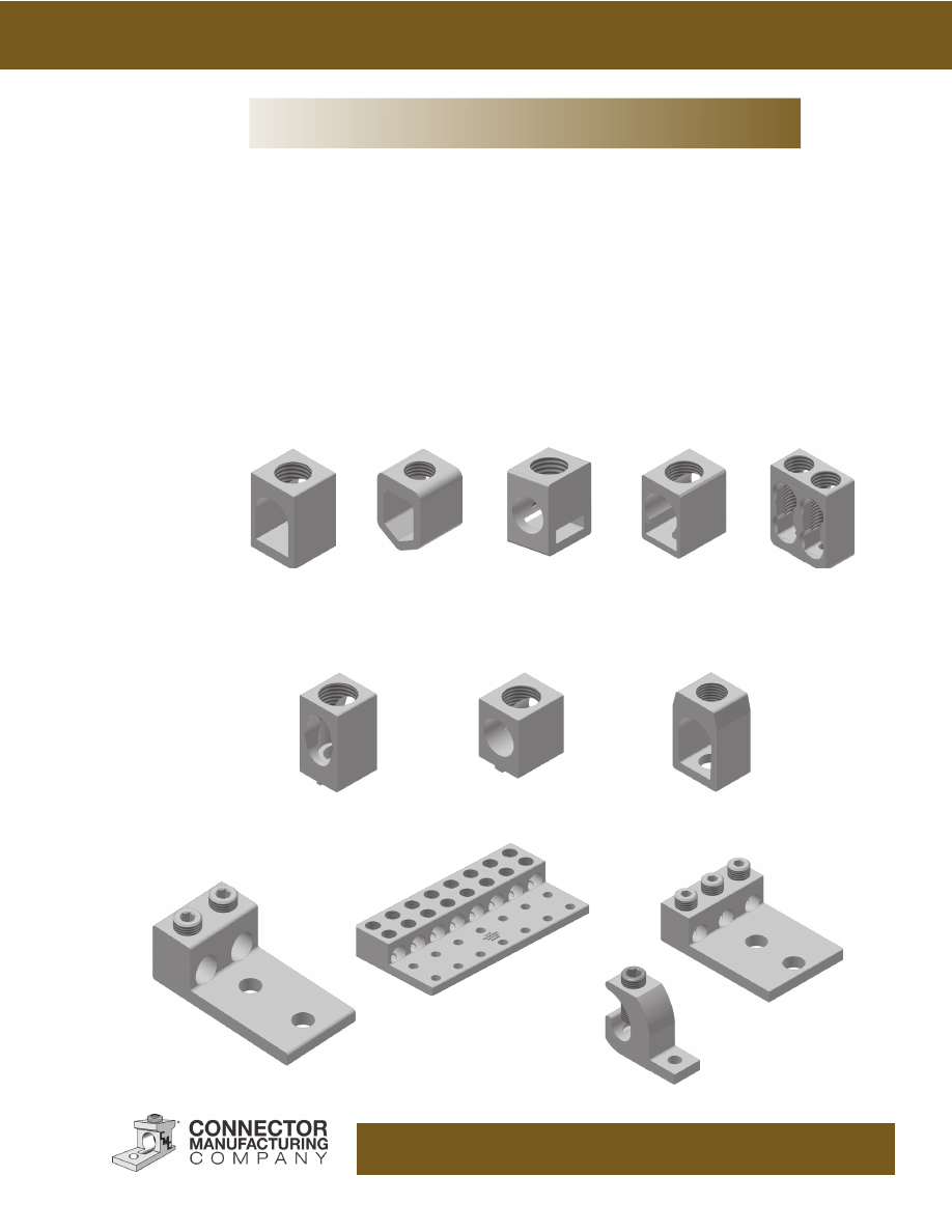
Special Inside-Mounted Connectors
Special Top-Mounted Connectors
Special Styles
Custom Connectors
www.cmclugs.com 513.860.4455
Aluminum Dual Rated Mechanical Connectors
A new generation in mechanical connector performance.
Cool running over 500 heat cycles. Versatile, simple to use and low cost.
Introduction
CMC®
introduces PosiGrip
®
aluminum dual-rated mechanical connectors. The PosiGrip
® line is designed to meet the rigorous
requirements of 486B and CSA 1165A specifications covering connectors for use with aluminum and copper conductors.
The PosiGrip® line is fully listed by Underwriters Laboratories, Inc. and Canadian Standards Association. In addition, these
connectors are EU RoHS compliant.
Low Resistance Design
Low initial contact resistance is the key to long life for any electrical connection and is the major element in meeting the
demanding performance requirements of UL 486B. Connector Manufacturing Company’s engineers have incorporated special
new design concepts into the PosiGrip® line. Uniquely designed I-Beam bodies and conductor hole configuration along
with specially designed and treated screws; minimize high resistance connector failures due to thermal expansion, creep,
and insufficient clamping force. The superior gripping action of the I-Bean design allows the set screw to separate conductor
strands and break down inner stand oxidation even on compressed and compact aluminum conductors. Therefore, superior
performance and long connector life are assured regardless of the type of conductor being used.
Versatility
Each PosiGrip® connector will accommodate a wide range of aluminum or copper conductor sizes of concentric, compressed
or compact configurations. Only eleven connector sizes cover the range from #14 thru 1000 kcmil. In addition, they are UL
listed and CSA certified for use with conductors having thermal insulation ratings of 90
°
C or less. This means greater flexibility
in the type of conductor being used, less inventory to carry and fewer call backs because the installer doesn’t have the right part.
Easy to install; all you need is a screwdriver or an allen wrench.
Quality Assurance
To identify UL 486B connectors, UL requires such connectors to be marked CU9AL when listed for use with 90
° C rated
conductors. To be sure that the connector you buy meets all UL requirements, CMC
®
inspects each lot of PosiGrip® connectors
for integrity of physical dimensions, aluminum properties, set screw and conductor hole alignment, plating, along with screw
and body thread class. Only connector lots meeting industry accepted quality levels are approved for shipment.
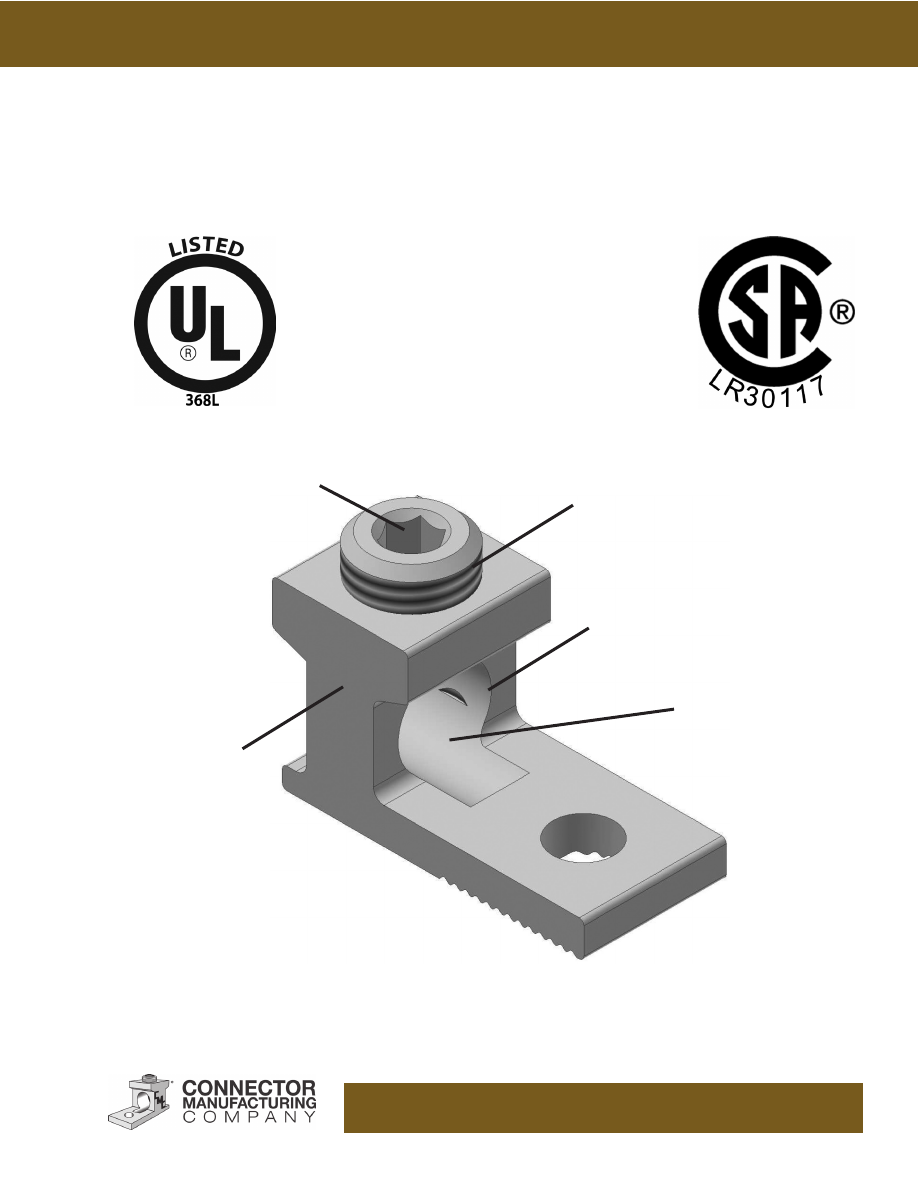
PosiGrip
®
Lug Features
1. The unique ridges formed on the bottom of the contact surface are designed to provide positive contact points for an
electrically secure joint of the lowest resistance for current flow. Just as a tri-pod provides tilt free contact on a smooth
surface, this connector is designed to cause specific contact points where current can flow without “hot spots” created when
two flat surfaces are joined together.
2. The screws used to clamp the conductor are designed to extend beyond the barrel sides of the connector to allow a better,
more secure compression of the conductor. This design spreads conductor strands to help dis sipate heat. In addition, this
causes the maximum conductor to spread slightly more than the wire way opening which when installed improves its pull out
safety features and capabilities.
3. The design of the wire way opening allows the conductor to enter the lug at the lowest point possible near the tang of the
lug to provide optimum transfer of current creating a straight line flow through the connec tor for the least possible path of
electrical resistance. A positive wire stop is provided with a step in the connec tor tang.
PosiGrip®
www.cmclugs.com 513.860.4455
A NEW, IMPROVED
PATENTED LUG
DESIGN
New generation of UL-486B Listed CSA Certified 90° C Rated Connectors
Unique body and screw
design minimizes thermal
expansion problems
Listed for use with concentric,
compact and compressed
conductors
Tin-Plated Body
No special tooling required
for installation
No adaptor or
conversion kits required
PosiGrip®
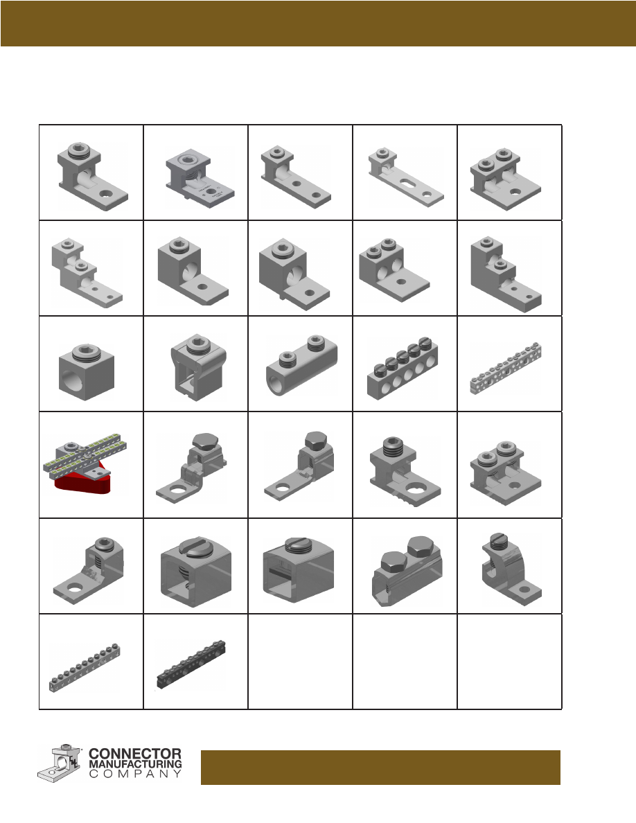
www.cmclugs.com 513.860.4455
AB
AB Anti-Turn
A1B2
ABSG
2AB
ABV
LA
LA Anti-Turn
DLA
PV
CA
LI
SR
NA
SCB
SNB-350
CF
CFS
BC
2BC
FT
C
CS
C2/C4
CL
N70
LCB
Pictoral Index

Notes

www.cmclugs.com 513.860.4455
CMC® is proud to supply the industry with a line of electrical connectors fabricated from the very best
aluminum alloy, 6061-T6. This choice was predicated upon many design factors to achieve the best
balance between strength and conductivity. Both factors are of extreme importance in connector design
calculations. The aluminum extrusions have almost a two-to-one advantage in yield strength to that of a
sand cast alloy 356 or die cast alloy AXS679, permitting an extra margin of safety while the conductivity
is a most favorable 43% IACS.
The set and socket screw mechanical connectors are designed to utilize the advantages of the 6061-
T6 alloy temper for high yield strength while providing a connector of low stress. Screw pressure is
designed to break through aluminum conductor oxide by cold flow process that ensures a low resistance
connection. Sufficient pressure is maintained on the conductor to prevent the reforming of the aluminum
oxide. The pressure, combined with the high conductivity factor, will result in a connector operating
temperature below that of the conductor.
We therefore, offer these advantages in connector design:
1. Compact design
2. High strength aluminum
3. Relative light weight construction
4. Economic
5. Tested products in accordance with the Underwriters Laboratories and the Canadian Standards
Association requirements for listing.
These factors together with our dedication for the highest quality standards available and an unsurpassed
service level, provide our customers with maximum reliability.
CMC® Aluminum Connectors
www.cmclugs.com 513.860.4455
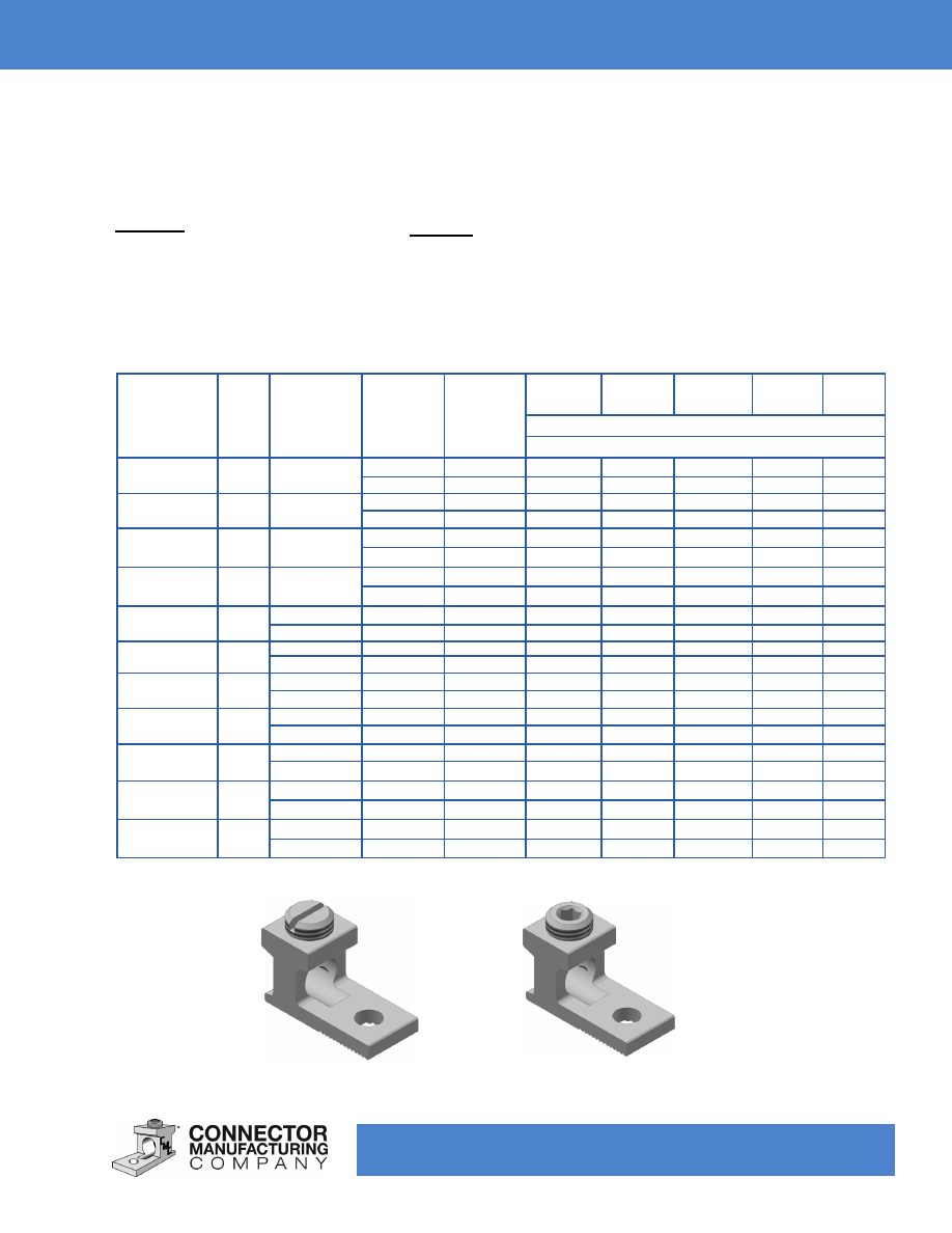
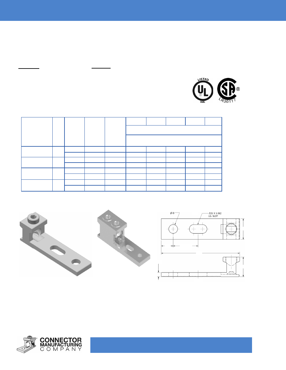
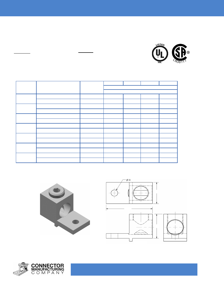
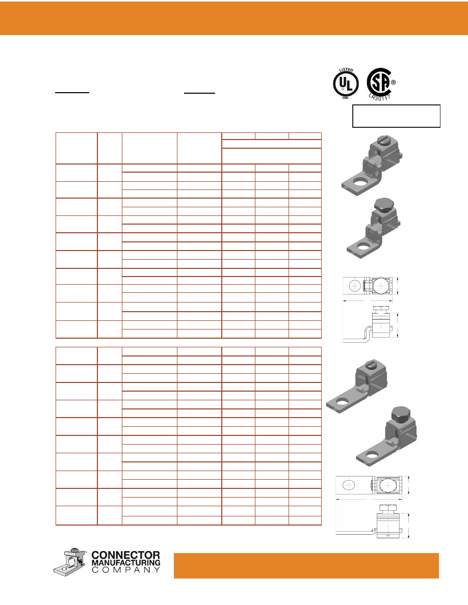
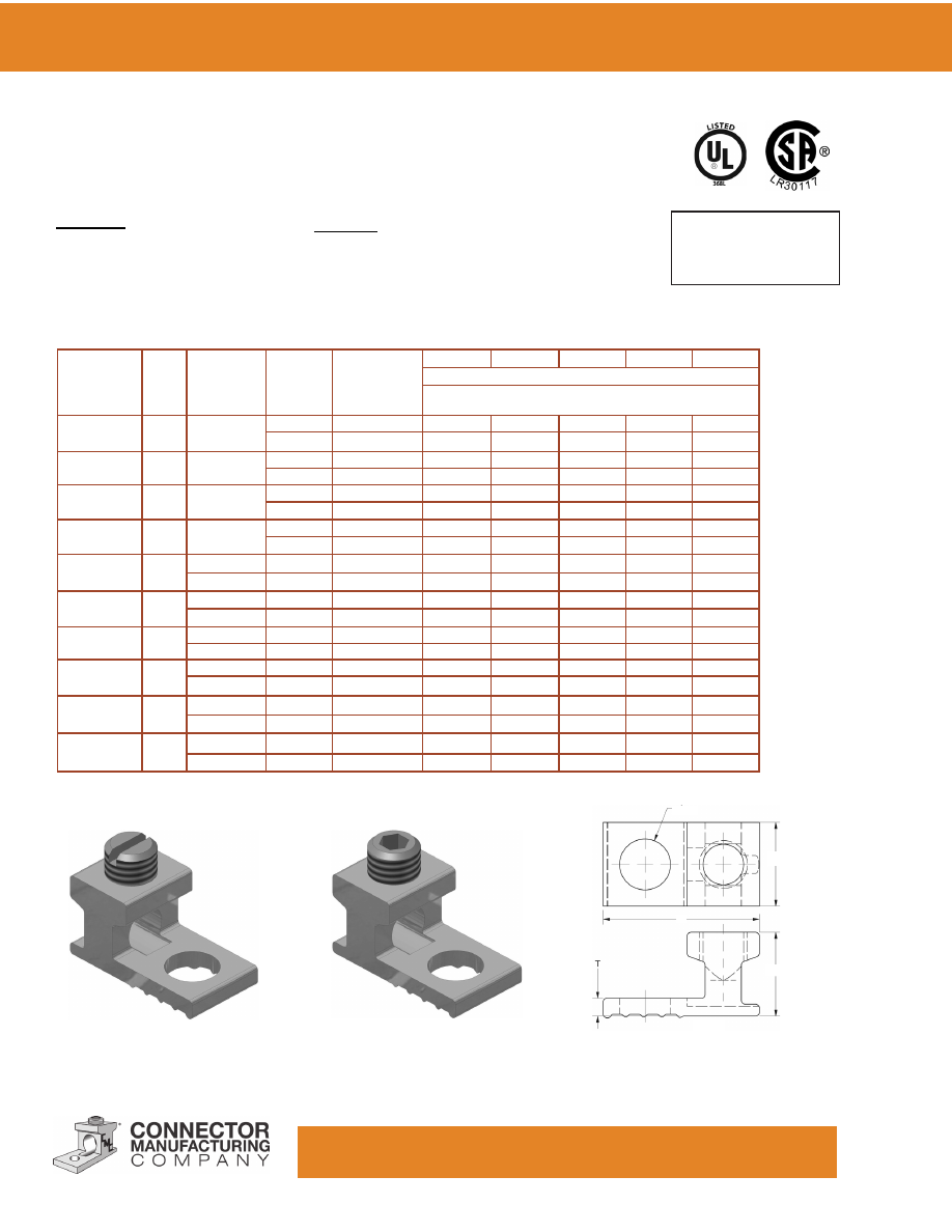
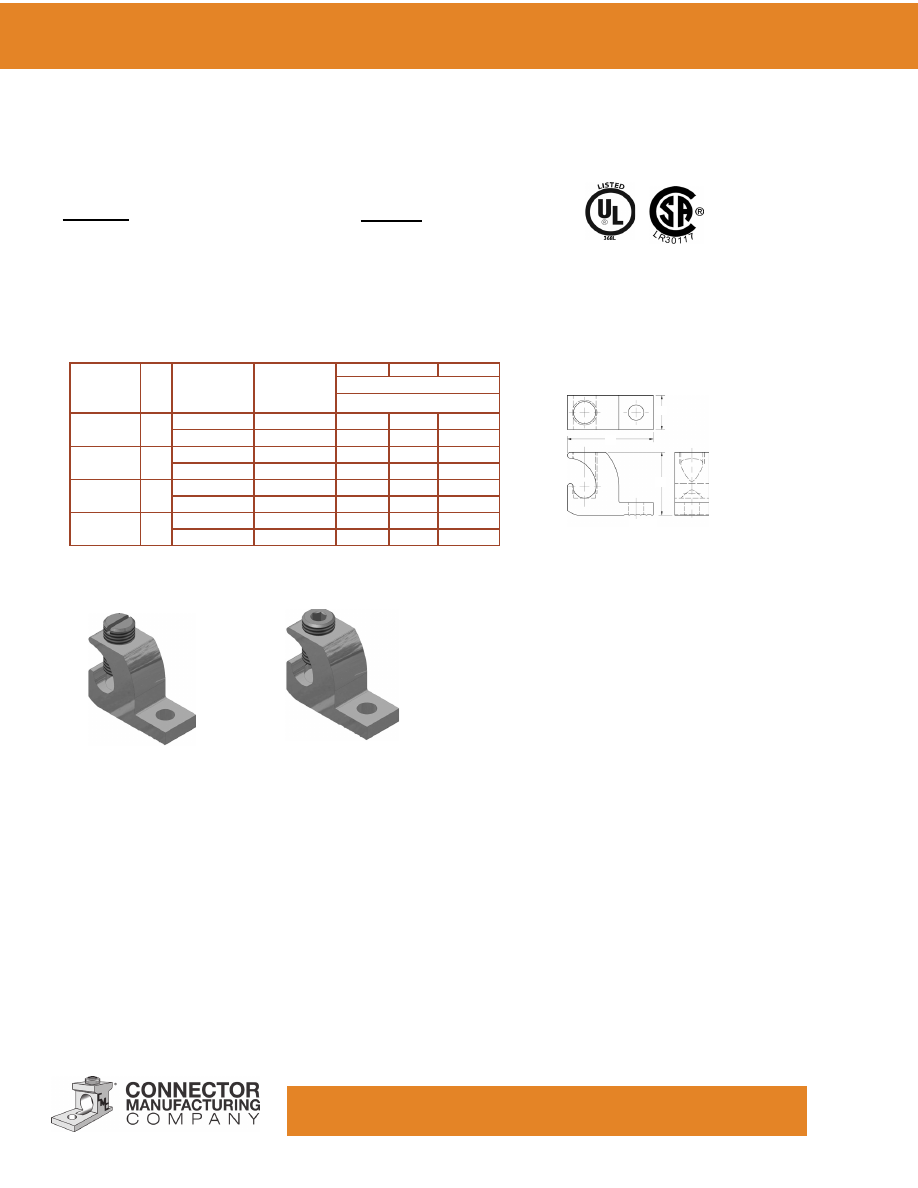
TYPE: AB
Features
•
Made of 6061-T6 Aluminum Alloy
•
Electro-Tin Plated
•
Patented PosiGrip® Design
•
Positive Wire Stop
•
Dual-Rated
Single Conductor Solderless Lugs
Catalog
Number
Fig
Screw
Stud Size*
mm
Cond.
Range
mm²
H
W
L
G
T
Dimensions - inches
Dimensions - millimeters
AB-50-S
1
Slot
1/4
6-14
.49
.5
1.06
.31
.09
6.35
16-1.5
12.45
12.70
26.92
7.87
2.29
AB-70-S
1
Slot
1/4
2-14
.55
.50
1.16
.31
.10
6.35
25-1.5
13.97
12.70
29.46
7.87
2.54
AB-112S
1
Slot or Hex
1/4
1/0-14
.78
.62
1.31
.31
.16
6.35
50-1.5
19.81
15.75
33.27
7.87
4.06
AB-125S
1
Slot or Hex
1/4
2/0-14
.78
.63
1.47
.38
.19
6.35
50-1.5
19.81
16.00
37.34
9.65
4.83
AB-250S
2
0.31H
5/16
250-6
1.09
.88
2.00
.44
.22
7.87
7.94
120-16
27.69
22.35
50.80
11.18
5.59
AB-300S
2
.31H
3/8
300-6
1.13
1.00
2.00
.50
.25
7.87
9.53
150-16
28.70
25.40
50.8
12.70
6.35
AB-350S
2
.31H
5/16
350-6
1.19
1.00
2.25
.56
.25
7.87
7.94
185-16
30.23
25.40
57.15
14.22
6.35
AB-500S
2
.38H
3/8
500-4
1.44
1.25
2.63
.63
.31
9.65
9.53
240-16
36.58
31.75
66.80
16.00
7.87
AB-600S
2
.38H
3/8
600-2
1.56
1.43
3.19
.88
.38
9.65
9.53
300-25
39.62
36.32
81.03
22.35
9.65
AB-750S
2
.38H
5/8
750-1/0
1.80
1.43
3.25
.88
.44
9.65
15.88
300-50
45.72
36.32
82.55
22.35
11.18
AB-1000S
2
.50H
1/2
1000-500
1.94
1.62
3.50
.88
.44
12.70
12.7
500-240
49.28
41.15
88.90
22.35
11.18
Fig.1
*This dimension can be altered per customer requirements.
Benefits
• Easy Installation
•
Improved Pull-Out and Safety Features
Custom configurations available upon request.
Fig.2
www.cmclugs.com 513.860.4455
Single Conductor Solderless Lugs
TYPE: AB - Anti-Turn Series
Features
•
Made of 6061-T6 Aluminum Alloy
•
Electro-Tin Plated
•
Patented PosiGrip® Design
•
Positive Wire Stop
•
Dual-Rated
Benefits
• Easy Installation
•
Improved Pull-Out and Safety Features
Catalog
Number
Fig
Cond. Range
AWG
mm²
Stud Size*
mm
H
W
L
Dimensions - inches
Dimensions - millimeters
AB-112-R
1
1/0-14
1/4
.78
.63
1.31
50-1.5
6.35
19.81
16.00
33.27
AB-125-R
1
2/0-14
1/4
.78
.63
1.47
50-1.5
6.35
19.81
16.00
37.34
AB-300-R
1
300-6
1/4
1.13
.88
1.78
150-16
6.35
28.70
22.35
45.21
AB-500-1
2
500-4
3/8
1.44
1.38
2.48
240-16
9.53
36.58
35.05
62.99
AB-600-1
2
600-2
3/8
1.56
1.38
2.75
300-25
9.53
39.62
35.05
69.85
PosiGrip®
90° C Rating (486B Listed)
Custom configurations available upon request.
*This dimension can be altered per customer requirements.
Products marked “-1” use the PosiGrip® Design.
Fig.1
Fig.2
www.cmclugs.com 513.860.4455
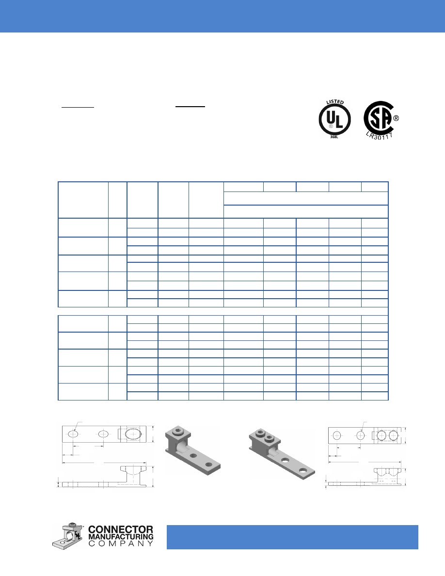
Fig. 2
T
L
G
1.7250
(44.45)
H
W
Ø D (2PL.)
Fig. 1
ØD (2PL.)
W
1.750
(44.45)
G
L
H
T
Catalog
Number
Fig
Screw
Type
mm
Stud
Size*
mm
Cond.
Range
AWG
mm²
H
W
L
G
T
Dimensions - inches
Dimensions - millimeters
A1B2-350
1
.31H
1/2
350-6
1.19
1.00
4.25
.63
.25
7.87
12.70
185-16
30.23
25.4
107.95
16.00
6.35
A1B2-500
1
.38H
1/2
500-2
1.56
1.25
4.59
.63
.38
9.65
12.70
240-25
39.62
31.75
116.59
16.00
9.65
A1B2-600
1
.38H
1/2
600-2
1.56
1.25
4.59
.63
.38
9.65
12.70
300-25
39.62
31.75
116.59
16.00
9.65
A1B2-750
1
.38H
1/2
750-1
1.81
1.43
4.84
.63
.44
9.65
12.70
300-35
45.97
36.32
122.94
16.00
11.18
A1B2-1000
1
.50H
1/2
1000-500
1.94
1.63
4.94
.63
.44
12.70
12.70
500-240
49.28
41.40
125.48
16.00
11.18
A1B2-350-2
2
.31H
1/2
350-6
1.19
1.13
5.37
.62
.25
7.87
12.70
185-16
30.23
28.70
136.40
15.75
6.35
A1B2-500-2
2
.38H
1/2
500-4
1.56
1.50
5.62
.63
.38
9.65
12.70
240-16
39.62
38.10
142.75
16.00
9.65
A1B2-600-2
2
.38H
1/2
600-2
1.56
1.50
5.62
.63
.38
9.65
12.70
300-25
39.62
38.10
142.75
16.00
9.65
A1B2-750-2
2
.38H
1/2
750-300
1.94
1.50
6.19
.63
.44
9.65
12.70
300-150
49.28
38.10
157.23
16.00
11.18
A1B2-1000-2
2
.50H
1/2
1000-500
1.94
1.63
6.19
.63
.44
12.70
12.70
500-240
49.28
41.40
157.23
16.00
11.18
Fig. 1
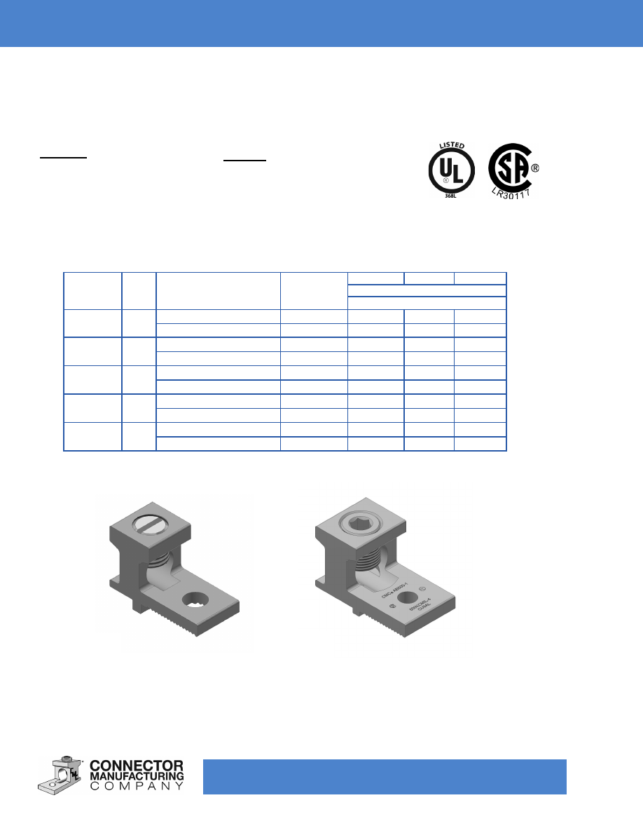
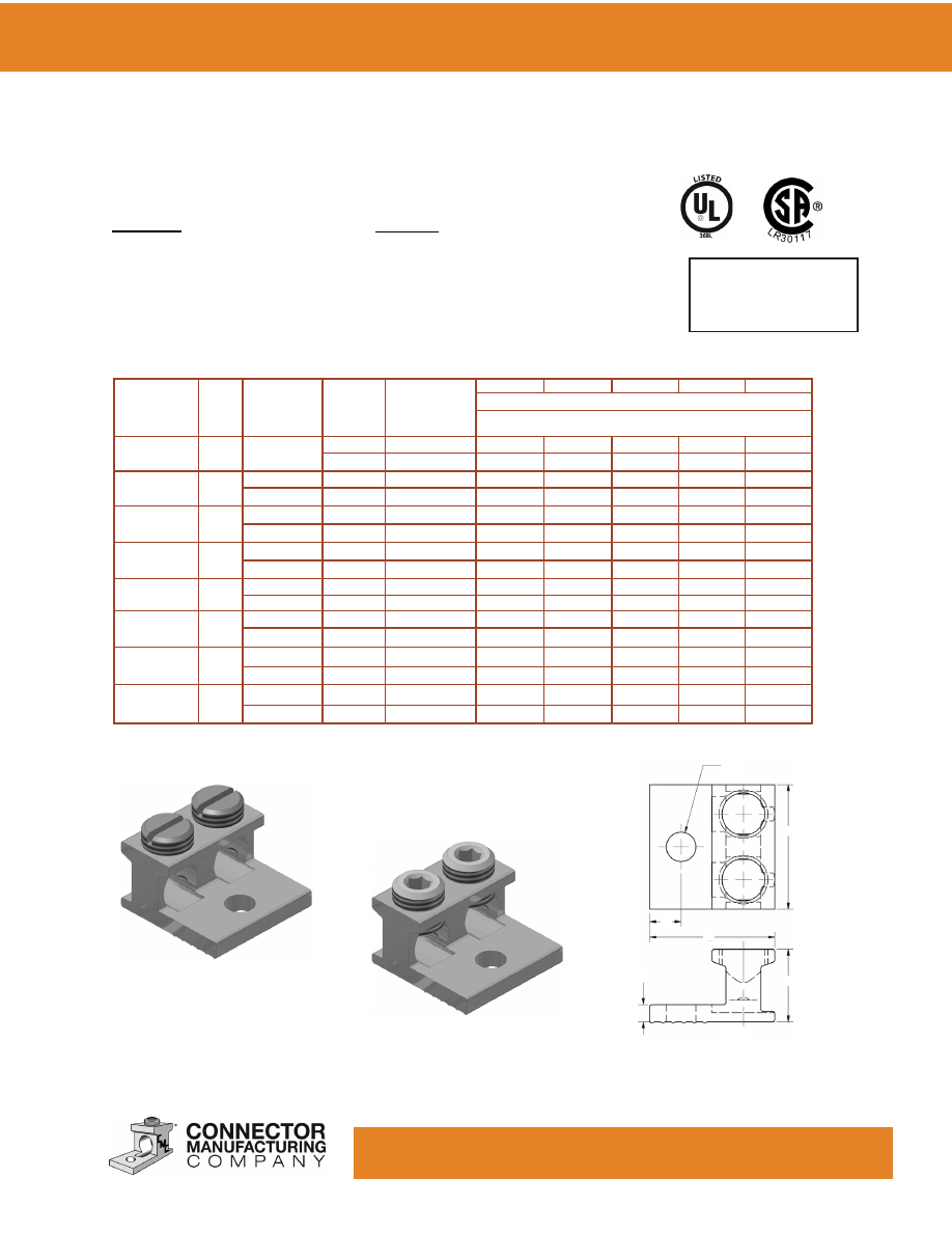
TYPE: A1B2/A1B2-2
Features
•
Made of 6061-T6 Aluminum
Alloy
•
Electro-Tin Plated
•
Patented PosiGrip® Design
•
Positive Wire Stop
•
Dual-Rated
Single Conductor Solderless Lugs
PosiGrip®
90° C Rating (486B Listed)
*This dimension can be altered per customer requirements.
Benefits
• Easy Installation
•
Improved Pull-Out and Safety Features
Custom configurations available upon request.
www.cmclugs.com 513.860.4455
Catalog
Number
Fig
Screw
Type
mm
Stud
Size*
mm
Cond.
Range
AWG
mm²
H
W
L
G
T
Dimensions - inches
Dimensions - millimeters
ABSG-350
1
.31H
1/2
350-4
1.19
1.25
4.68
.72
.25
7.87
12.70
185-16
30.23
31.75
118.87
18.29
6.35
ABSG-500
1
.38H
1/2
500-400
1.44
1.25
4.68
.72
.31
9.65
12.70
240-185
36.58
31.75
118.87
18.29
7.87
ABSG-750
2
.38H
1/2
750-300
1.94
1.62
6.19
.72
.44
9.65
12.70
300-150
49.28
41.15
157.23
18.29
11.18
ABSG-1000
2
.50H
1/2
1000-300
1.94
1.62
6.19
.72
.44
12.70
12.70
500-150
49.28
41.15
157.23
18.29
11.18
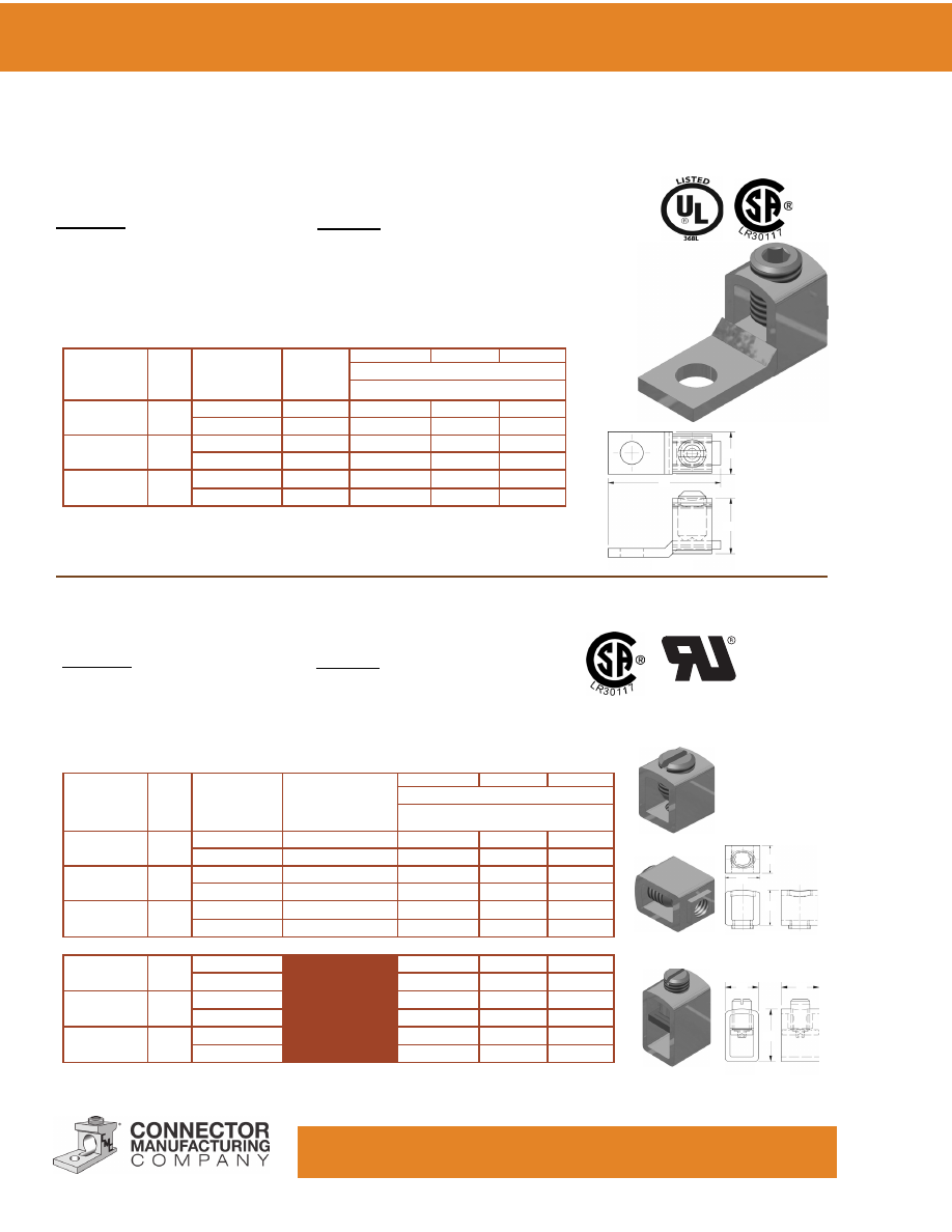
Switchgear Connectors
TYPE: ABSG
Features
•
Made of 6061-T6 Aluminum
Alloy
•
Electro-Tin Plated
•
Patented PosiGrip® Design
•
Positive Wire Stop
•
Dual-Rated
PosiGrip®
90° C Rating (486B Listed)
*This dimension can be altered per customer requirements.
Fig. 1
Ø D
.531 X 1.062
LG Slot
W
G
1.500
(38.10)
L
T
H
Benefits
• Easy Installation
•
Improved Pull-Out and Safety Features
Custom configurations available upon request.
Fig. 2
www.cmclugs.com 513.860.4455
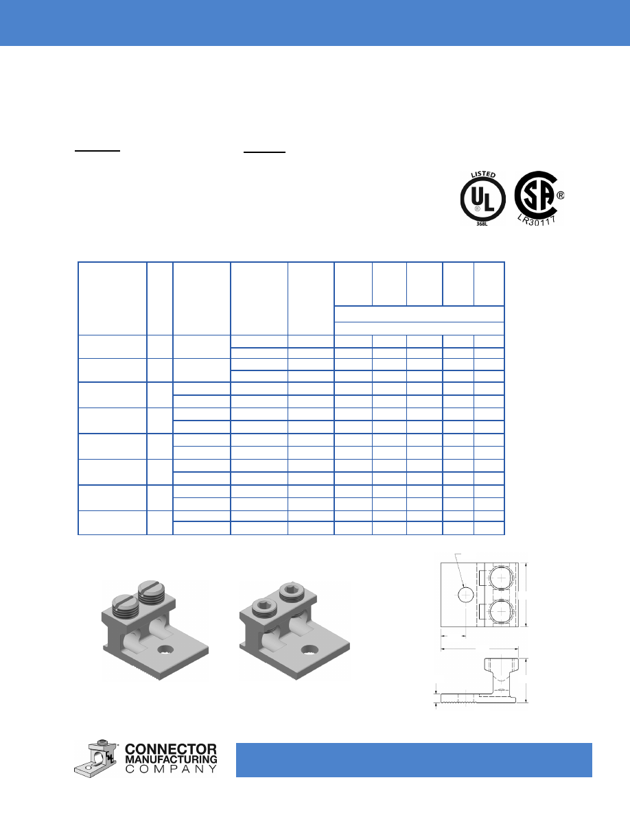
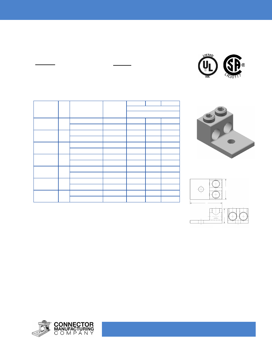
TYPE: 2AB/2AB2
Features
•
Made of 6061-T6 Aluminum
Alloy
•
Electro-Tin Plated
•
Patented PosiGrip® Design
•
Positive Wire Stop
•
Dual-Rated
Two Conductor Solderless Lugs
*This dimension can be altered per customer requirements.
Catalog
Number
Fig
Screw
Type
mm
Stud Size*
mm
Cond.
Range
AWG
mm²
H
W
L
G
T
Dimensions - inches
Dimensions - millimeters
2AB-112
1 Slot or Hex
1/4
1/0-14
.78
1.13
1.31
.44
.16
6.35
50-1.5
19.81 28.70 33.27 11.18 4.06
2AB-125
1 Slot or Hex
1/4
2/0-14
.78
1.25
1.47
.42
.19
6.35
50-1.5
19.81 31.75 37.34 10.67 4.83
2AB-250
2
.31H
3/8
250-6
1.09
1.62
2.56
.53
.22
7.87
9.53
120-16 27.69 41.15 65.02 13.46 5.59
2AB-350
2
.31H
3/8
350-6
1.19
1.92
2.88
.63
.25
7.87
9.53
185-16 30.23 48.77 73.15 16.00 6.35
2AB-500
2
.38H
1/2
500-4
1.44
2.41
2.63
.63
.31
9.65
12.70
240-16 36.58 61.21 66.80 16.00 7.87
2AB-600
2
.38H
1/2
600-2
1.56
2.41
3.19
.63
.38
9.65
12.70
300-25 39.62 61.21 81.03 16.00 9.65
2AB-750
2
.38H
1/2
750-1/0
1.81
3.50
3.25
.88
.44
9.65
12.70
300-50 45.97 88.90 82.55 22.35 11.18
2AB-1000
2
.50H
1/2
1000-500 1.94
3.50
3.50
.88
.44
12.70
12.70
500-240 49.28 88.90 88.90 22.35 11.18
Fig 1
Fig 2
Ø D
W
G
L
H
T
Benefits
• Easy Installation
•
Improved Pull-Out and Safety Features
Custom configurations available upon request.
PosiGrip®
90° C Rating (486B Listed)
www.cmclugs.com 513.860.4455
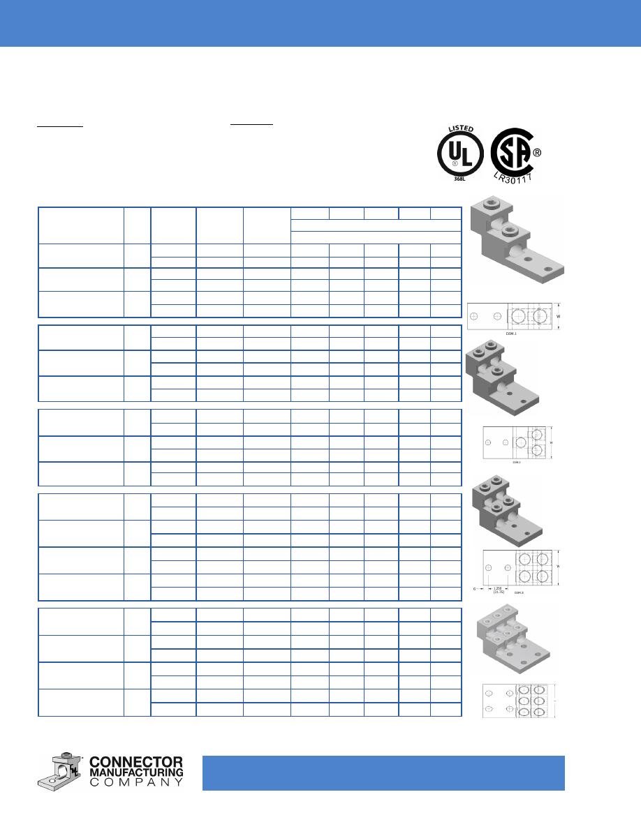
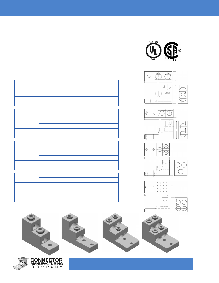
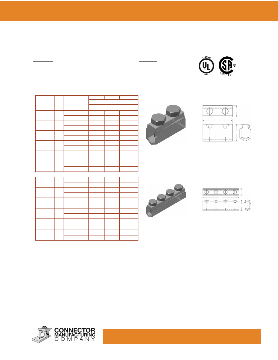
TYPE: ABV / ABV-2N
Features
•
Made of 6061-T6 Aluminum Alloy
•
Electro-Tin Plated
•
Patented PosiGrip® Design
•
Positive Wire Stop
•
Dual-Rated
90° C Rating (486B Listed)
Panelboard Solderless Lugs
*This dimension can be altered per customer requirements.
Fig 1
Benefits
• Easy Installation
•
Improved Pull-Out and Safety Features
Custom configurations available upon request.
**Products marked “-2N” or “-4N” are NEMA spaced.
Fig 2
Fig 3
Fig 4
PosiGrip®
Catalog
Number
Fig
Screw
Stud
Size*
mm
Cond.
Range
H
W
L
G
T
Dimensions - inches
Dimensions - millimeters
2ABV-500
1
.38H
3/8
500-4
3.00
1.50
4.91
.38
.50
9.65
9.53
240-16 76.20 38.10 124.71 9.65 12.70
2ABV-600
1
.38H
3/8
600-2
3.00
1.50
4.91
.38
.50
9.65
9.53
300-25 76.20 38.10 124.71 9.65 12.70
2ABV-750
1
.38H
3/8
750-1/0
3.00
1.50
4.91
.38
.50
9.65
9.53
300-50 76.20 38.10 124.71 9.65 12.70
3ABV-500
2
.38H
3/8
500-4
3.00
2.50
4.91
.38
.50
9.65
9.53
240-16 76.20 63.50 124.71 9.65 12.70
3ABV-600
2
.38H
3/8
600-2
3.00
2.50
4.91
.38
.50
9.65
9.53
300-25 76.20 63.50 124.71 9.65 12.70
3ABV-750
2
.38H
3/8
750-1/0
3.00
2.50
4.91
.38
.50
9.65
9.53
300-50 76.20 63.50 124.71 9.65 12.70
4ABV-500
3
.38H
3/8
500-4
3.00
2.50
4.91
.38
.50
9.65
9.53
240-16 76.20 63.50 124.71 9.65 12.70
4ABV-600
3
.38H
3/8
600-2
3.00
2.50
4.91
.38
.50
9.65
9.53
300-25 76.20 63.50 124.71 9.65 12.70
4ABV-750
3
.38H
3/8
750-1/0
3.00
2.63
4.91
.38
.50
9.65
9.53
300-50 76.20 66.80 124.71 9.65 12.70
2ABV-600-2N**
1
.38H
1/2
600-2
3.00
1.50
5.34
.63
.50
9.65
12.70
300-25 76.20 38.10 135.74 16.00 12.70
3ABV-600-2N**
2
.38H
1/2
600-2
3.00
2.50
5.34
.63
.50
9.65
12.70
300-25 76.20 63.50 135.74 16.00 12.70
4ABV-600-2N**
3
.38H
1/2
600-2
3.00
2.47
5.34
.63
.50
9.65
12.70
300-25 76.20 62.74 135.74 16.00 12.70
6ABV-600-2N**
4
.38H
1/2
600-2
3.00
3.75
5.34
.63
.50
9.65
12.70
300-25 76.20 95.25 135.74 16.00 12.70
2ABV-750-4N**
1
.38H
1/2
750-1/0
3.00
1.50
5.34
.50
.50
9.65
12.70
300-50 76.20 38.10 135.74 12.70 12.70
3ABV-750-4N**
2
.38H
1/2
750-1/0
3.00
2.50
5.34
.50
.50
9.65
12.70
300-50 76.20 63.50 135.74 12.70 12.70
4ABV-750-4N**
3
.38H
1/2
750-1/0
3.00
2.75
5.34
.50
.50
9.65
12.70
300-50 76.20 69.85 135.74 12.70 12.70
6ABV-750-4N**
4
.38H
1/2
750-1/0
3.00
3.75
5.34
.50
.50
9.65
12.70
300-50 76.20 95.25 135.74 12.70 12.70
www.cmclugs.com 513.860.4455
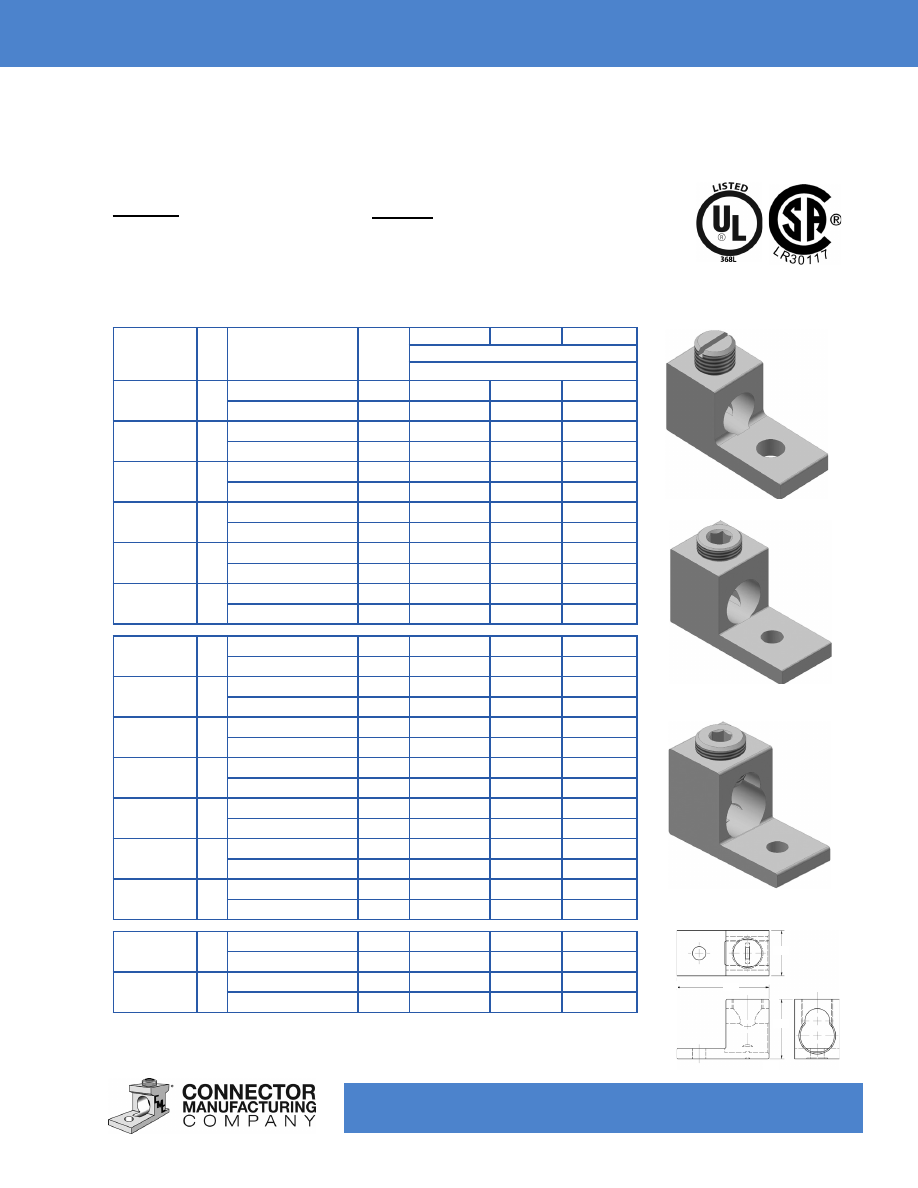
TYPE: LA
Features
•
Made of 6061-T6 Aluminum Alloy
•
Electro-Tin Plated
•
Dual-Rated
90° C Rating (486B Listed)
Single Conductor Solderless Lugs
Fig 1
Catalog
Number
Fig.
No.
Cond. Range
AWG
mm
Stud
Size*
mm
H
W
L
Dimensions - inches
Dimensions - millimeters
LA-6-1
1
6-14
15/64
0.50
0.38
1.06
16-1.5
5.85
12.70
9.65
26.92
LA-6
1
6-14
1/2
0.49
0.50
1.06
16-1.5
6.35
12.45
12.70
26.92
LA-6-2
1
4-14
1/2
0.49
0.50
1.06
16-1.5
6.35
12.45
12.70
26.92
LA-2
1
2-14
1/2
0.55
0.50
1.16
25-1.5
6.35
13.97
12.70
29.46
LA-1/0
1
1/0-14
3/8
0.78
0.63
1.47
50-1.5
9.65
19.81
16.00
37.34
LA-2/0
1
2/0-14
1/2
0.78
0.63
1.47
50-1.5
6.35
19.81
16.00
37.34
LA-250
2
250-6
5/16
1.13
1.00
2.00
120-16
7.87
28.70
25.40
50.80
LA-300
2
300-6
5/16
1.13
1.00
2.00
150-16
7.87
28.70
25.40
50.80
LA-350
2
350-6
3/8
1.25
1.13
2.25
185-16
9.65
31.75
28.70
57.15
LA-500
2
500-4
3/8
1.56
1.25
2.81
240-16
9.65
39.62
31.75
71.37
LA-600
2
600-2
3/8
1.56
1.50
3.19
300-25
9.65
39.62
38.10
81.03
LA-800
2
800-300
5/8
1.94
1.75
3.50
400-150
16.00
49.28
44.45
88.90
LA-1000
2
1000-500
5/8
1.94
1.75
3.50
500-240
16.00
49.28
44.45
88.90
LA-630
3
600-4/(2) 250-1/0
3/8
1.81
1.38
2.81
300-16/(2) 120-50 9.65
45.97
35.05
71.37
LA-750
3
750-2 /(2)300-1/0
3/8
1.81
1.38
2.81
300-25/(2)150-50 9.65
45.97
35.05
71.37
Fig 2
Fig 3
*This dimension can be altered per customer requirements.
L
H
W
Benefits
• Easy Installation
• Connectors are Reusable
Custom configurations available upon request.
www.cmclugs.com 513.860.4455
TYPE: LA - Anti-Turn Series
Features
•
Made of 6061-T6 Aluminum Alloy
•
Anti-Turn Design
•
Electro-Tin Plated
•
Dual-Rated
90° C Rating (486B Listed)
Single Conductor Solderless Lugs
Catalog
Number
Cond. Range
AWG
mm
Stud Size*
mm
H
W
L
R
Dimensions - inches
Dimensions - millimeters
LA-2R
4-14
1/4
.55
.50
1.16
.52
16-1.5
6.35
13.97
12.70
29.46
13.21
LA-1/0R
1/0-14
1/4
.81
.63
1.47
.50
50-1.5
6.35
20.57
16.00
37.34
12.70
LA-2/0R
2/0-14
1/4
.78
.60
1.20
.30
50-1.5
6.35
19.81
15.24
30.48
11.94
LA-300R
300-6
1/4
1.13
.98
2.00
.49
150-16
6.35
28.70
24.89
50.80
12.45
LA-350R
350-6
5/16
1.13
1.00
1.91
.50
185-16
7.87
28.70
25.40
48.51
12.70
LA-625R
(1) 600-2 / (2) 250-1/0
3/8
1.62
1.38
2.62
1.14
(1) 400-25 / (2) 150-50
9.65
39.88
35.05
66.55
22.35
LA-600R
600-2
3/8
1.57
1.38
2.75
.88
300-25
9.65
39.88
35.05
69.85
22.35
W
L
H
*This dimension can be altered per customer requirements.
Benefits
• Easy Installation
• Connectors are Reusable
Custom configurations available upon request.
www.cmclugs.com 513.860.4455
TYPE: DLA
Features
•
Made of 6061-T6 Aluminum Alloy
•
Electro-Tin Plated
•
Dual-Rated
90° C Rating (486B Listed)
Two Conductor Solderless Lugs
Catalog
Number
Fig.
No.
Cond. Range
AWG
mm
Stud Size*
mm
H
W
L
Dimensions, inches
Dimensions, millimeters
DLA-112
1
1/0-14 (2)
1/4
.78
1.13
1.47
50-1.5 (2)
6.35
19.81
28.70
37.34
DLA-125
1
2/0-14 (2)
1/4
.78
1.25
1.47
50-1.5 (2)
6.35
19.81
31.75
34.34
DLA-250
1
250-6 (2)
3/8
1.19
1.64
2.56
120-16 (2)
9.65
30.23
41.66
65.02
DLA-350
1
350-6 (2)
1/2
1.25
1.92
2.88
185-16 (2)
12.70
31.75
48.77
73.15
DLA-600
1
600-2 (2)
1/2
1.56
2.41
3.19
300-25 (2)
12.70
39.62
61.21
81.03
DLA-800
1
800-300 (2)
5/8
1.94
3.50
3.50
400-150 (2)
16.00
49.28
88.90
88.90
DLA-1000
1
1000-500 (2)
5/8
1.94
3.50
3.50
500-240
(2)
16.00
49.28
88.90
88.90
Fig. 1
*This dimension can be altered per customer requirements.
H
W
L
Benefits
• Easy Installation
• Connectors are Reusable
Custom configurations available upon request.
www.cmclugs.com 513.860.4455
TYPE: PV
Features
•
Made of 6061-T6 Aluminum Alloy
•
Electro-Tin Plated
•
Dual-Rated
90° C Rating (486B Listed)
Panelboard Solderless Lugs
Catalog
Number
Fig.
No.
Cond. Range
AWG
mm²
Stud Size*
mm
H
W
L
Dimensions, inches
Dimensions, millimeters
PV2-300 1
300-6 (2)
5/16
2.00
1.00
3.00
150-16 (2)
7.87
50.80 25.40 76.20
PV2-500 2
500-2 (2)
3/8 (2)
3.00
1.50
4.91
240-25 (2)
9.65 (2)
76.20 38.10 124.71
PV2-600 2
600-2 (2)
3/8 (2)
3.00
1.50
4.91
300-25 (2)
9.65 (2)
76.20 38.10 124.71
PV2-750 2
750-1/0 (2)
3/8 (2)
3.00
1.56
4.91
300-50 (2)
9.65 (2)
76.20 39.62 124.71
PV3-500 3
500-2 (2)
3/8 (2)
3.00
2.50
4.91
240-25 (2)
9.65 (2)
76.20 63.50 124.71
PV3-600 3
600-2 (3)
3/8 (2)
3.00
2.47
4.91
300-25 (3)
9.65 (2)
76.20 62.74 124.71
PV3-750 3
750-1/0 (3)
3/8 (2)
3.00
2.84
4.91
300-50 (3)
9.65 (2)
76.20 72.14 124.71
PV4-500 4
500-2 (2)
3/8 (2)
3.00
2.50
4.91
240-25 (2)
9.65 (2)
76.20 63.50 124.71
PV4-600 4
600-2 (4)
3/8 (2)
3.00
2.47
4.91
300-25 (4)
9.65 (2)
76.20 62.74 124.71
PV4-750 4
750-1/0 (4)
3/8 (2)
3.00
2.84
4.91
300-50 (4)
9.65 (2)
76.20 72.14 124.71
Fig. 1
Fig. 2
Fig. 3
Fig. 4
Fig. 1
Fig. 2
Fig. 3
Fig. 4
*This dimension can be altered per customer requirements.
H
H
L
W
L
W
W
H
L
H
L
W
Benefits
• Easy Installation
• Connectors are Reusable
Custom configurations available upon request.
www.cmclugs.com 513.860.4455
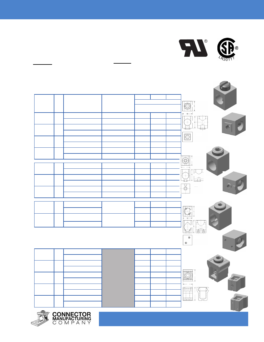
TYPE: CA / LI
Features
•
Made of 6061-T6 Aluminum Alloy
•
Electro-Tin Plated
•
Dual-Rated
Rectangular Connectors
Catalog
Number
Fig.
No.
Cond. Range
AWG
mm²
Boss Tap*
mm
H
W
L
Dimensions, inches
Dimensions, millimeters
CA-40S
1
4-14
.22 / 10-32
.48
.38
.38
16-1.5
5.59
12.19
9.65
9.65
CA-60S
1
2-14
.22 / 10-32
.56
.47
.47
25-1.5
5.84
14.22 11.94 11.94
CA-110S 1
1/0-14
.22 / 10-32
.61
.53
.62
50-1.5
5.84
15.49 13.46 15.75
CA-150S 1
2/0-14
.22 / 10-32
.76
.58
.63
50-1.5
5.84
19.30 14.73 16.00
CA-210
2
250-6
.29D / 1/4-20
1.00
.81
.94
120-16
7.37D
25.40 20.57 23.88
CA-360
2
300-4
.29D / 1/4-20
1.00
.81
1.00
150-16
7.37D
25.40 20.57 25.40
CA-380
2
350-6
.29D / 1/4-20
1.13
1.00
.94
185-16
7.37D
28.70 25.40 23.88
CA-635
3
600-4 / (2) 250-4
Flat / 1/4-20 (2)
1.69
1.22
1.25
200-16 / (2) 120-16
42.93 30.99 31.75
CA-750
3
750-250 / (2) 250-3/0
Flat / 1/4-20 (2)
2.06
1.38
1.25
300-120 / (2) 120-85
52.32 35.05 31.75
LI-250
4
250-6
1.40
1.25
1.00
120-10
35.56 31.75 25.40
LI-500
4
500-3/0
1.63
1.66
1.50
240-70
41.40 42.16 38.10
LI-501
4
600-2
2.00
1.50
1.25
400-25
50.80 38.10 31.75
LI-750
4
750-1/0
2.50
1.62
1.50
300-50
63.50 41.15 38.10
LI-3501
4
350-6
1.40
1.35
1.00
n/a
n/a
n/a
n/a
Fig. 1
Fig. 2
Fig. 3
Fig. 4
*This dimension can be altered per customer requirements.
Lay-in style collars - Use where lay-in feature is desired.
H
L
W
H
W
L
H
W
L
H
W
L
Benefits
• Easy Installation
• Connectors are Reusable
Custom configurations available upon request.
www.cmclugs.com 513.860.4455
TYPE: SR- Solid Bearers
Features
•
Made of 6061-T6 Aluminum Alloy
•
Electro-Tin Plated
•
Dual-Rated
•
Specialized Design
90° C Rating (486B Listed)
Splicers /
Reducers
Catalog
Number
Fig.
No.
Cond. Range
AWG
mm²
Strip
Length
mm
H
W
L
Dimensions, inches
Dimensions, millimeters
SR-2
1
2-14
.63
.56
.50
1.38
25-1.5
16.00
14.22
12.70
35.05
SR-0
1
1/0-14
.88
.75
.75
1.91
50-1.5
22.35
19.05
19.05
48.51
SR-250
2
250-6
.94
1.13
1.00
3.94
120-16
23.88
28.70
25.40
100.08
SR-350
2
350-6
2.06
1.19
1.13
4.19
185-16
52.32
30.23
28.70
106.43
SR-500
2
500-2
2.44
1.50
1.38
5.00
240-25
61.98
38.10
35.05
127.00
SR-750
3
750-250
3.06
1.75
1.63
6.25
300-120
77.72
44.45
41.40
158.75
SR-1000
3
1000-500
3.94
2.00
1.75
8.00
500-240
100.08
50.80
44.45
203.20
Fig. 1
Fig. 3
Fig. 2
H
H
L
L
W
W
A
Benefits
• Easy Installation
•
Center Barrier Prevents Dissimiliar
Metals from Contact
A
Custom configurations available upon request.
www.cmclugs.com 513.860.4455
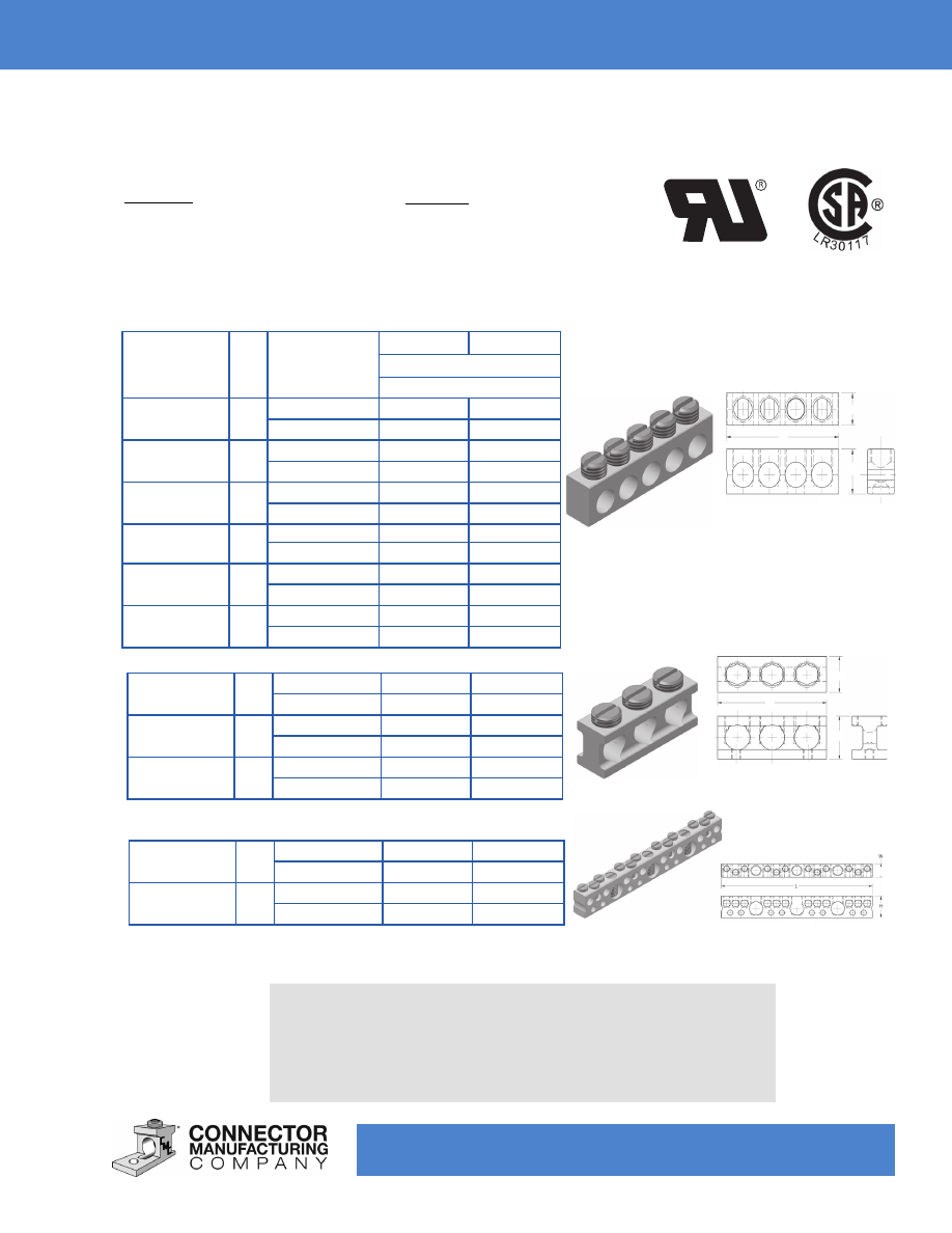
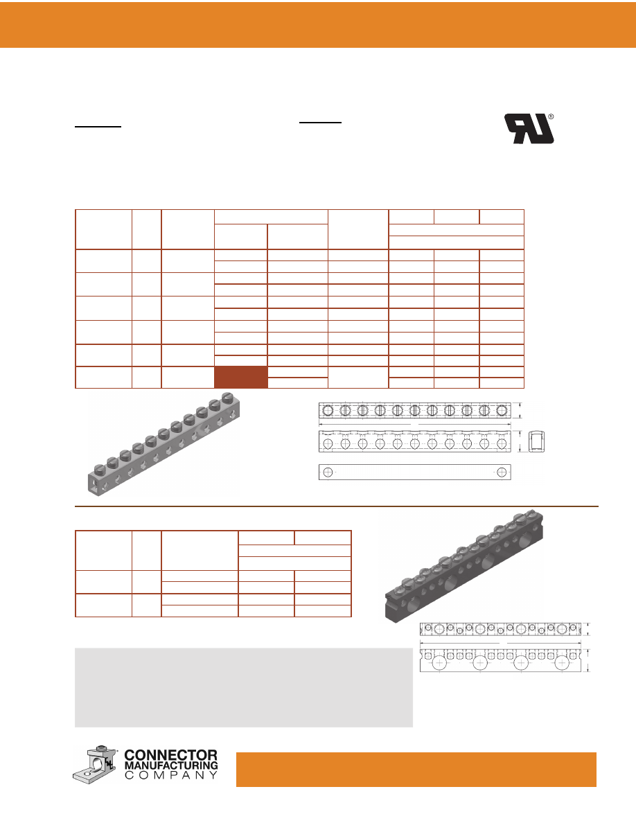
TYPE: NA / SCB
Features
•
Made of 6061-T6 Aluminum Alloy
•
Electro-Tin Plated
•
Dual-Rated
Aluminum
Neutral Bars
Catalog
Number
Fig.
No.
Conductor
Range
mm²
H
W
Dimensions, inches
Dimensions, millimeters
NA-30
1
6-14
.44
.31
16-1.5
11.18
7.87
NA-35
1
4-14
.50
.31
16-1.5
12.70
7.87
NA-70
1
4-14
.50
.38
16-1.5
12.70
9.65
NA-125
1
1/0-14
.75
.56
50-1.5
19.05
14.22
NA-150
1
2/0-6
.75
.56
50-10
19.05
14.22
NA-250
1
250-6
1.00
.88
120-16
25.40
22.35
Fig. 1
NA-130
2
1/0-14
.75
.56
50-1.5
19.05
14.22
NA-140
2
2/0-14
.75
.56
50-1.5
19.05
14.22
NA-300
2
300-6
1.16
.97
150-16
29.46
24.64
*SCB-1/0
3
1/0-14 / 6-14
.62
.38
50-1.5 / 16-1.5
15.75
9.65
*SCB-2/0
3
2/0-14 / 6-14
.69
.38
50-1.5 / 16-1.5
17.45
9.65
Fig. 3
W
L
H
W
L
H
W
L
H
Fig. 2
Benefits
• Easy Installation
Custom configurations available upon request.
The number of outlets, outlet spacing and mounting hole locations can
be established according to individual requirements.
When ordering
neutral bars please add a suffix to indicate the number of usable
wire ports required. Ex: NA30-8 would result in an NA30 style
neutral bar with eight (8) wire ports.
*This bar is also approved as an equipment ground and is
90° C rated.
www.cmclugs.com 513.860.4455
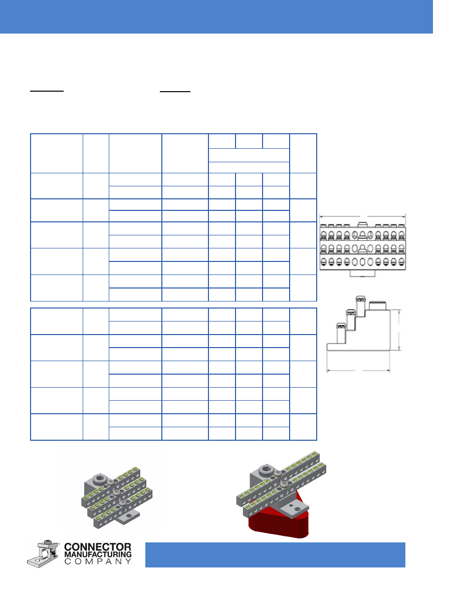
Aluminum
Neutral Bar Assemblies
Custom configurations available upon request.
Catalog
Number
Fig.
No.
Conductor
Range
mm²
Wire Tap
Range
mm²
H
W
L
Circuit
Holes
Dimensions, inches
Dimensions, millimeters
SNB-350-12
1
350-6
6-14
1.13
2.53
2.17
12
185-16
16-1.5
28.70 64.26 55.12
SNB-350-24
1
350-6
6-14
1.13
2.53
3.43
24
185-16
16-1.5
28.70 64.26 87.12
SNB-350-30
1
350-6
6-14
1.13
2.53
4.06
30
185-16
16-1.5
28.70 64.26 103.12
SNB-350-36
1
350-6
6-14
1.13
2.53
4.77
36
185-16
16-1.5
28.70 64.26 121.16
SNB-350-42
1
350-6
6-14
1.13
2.53
5.27
42
185-16
16-1.5
28.70 64.26 133.86
SNB-350-12
W/SNBI-1
2
350-6
6-14
1.13
2.53
2.17
12
185-16
16-1.5
28.70 64.26 55.12
SNB-350-24
W/SNBI-1
2
350-6
6-14
1.13
2.53
3.43
24
185-16
16-1.5
28.70 64.26 87.12
SNB-350-30
W/SNBI-1
2
350-6
6-14
1.13
2.53
4.06
30
185-16
16-1.5
28.70 64.26 103.12
SNB-350-36
W/SNBI-1
2
350-6
6-14
1.13
2.53
4.77
36
185-16
16-1.5
28.70 64.26 121.16
SNB-350-42
W/SNBI-1
2
350-6
6-14
1.13
2.53
5.27
42
185-16
16-1.5
28.70 64.26 133.86
TYPE: SNB-350
Features
•
Made of 6061-T6 Aluminum Alloy
•
Electro-Tin Plated
•
Dual-Rated
Benefits
• Easy Installation
•
Can Be Used with Insulating Block
Fig. 1
Fig. 2
W
H
L
The number of outlets, outlet spacing and mounting hole locations can be
established according to individual requirements.


www.cmclugs.com 513.860.4455
Connector Manufacturing Company® fabricates the best in electrolytic copper electrical
connectors. Copper connectors are formed from 100% pure electrolytic copper to eliminate the
effects upon conductivity when alloys are utilized to reduce costs.
CMC® copper connectors are either extruded from pure electrolytic copper or formed from copper
tubing carefully shaped to size. They may also be produced from copper strip which is used to
form the tang or bus connection. These light weight connectors will perform better than many of
the heavier, bulkier cast copper alloyed products on the market. This saves the customer the cost of
metal, freight and space, while gaining top conductivity.
We therefore, offer these advantages in connector design:
1. Compact Design.
2. High Strength - low heat rise copper.
3. Relatively light weight construction.
4.
Economy and efficiency.
5. Tested products in accordance with Underwriters Laboratories and the Canadian Standards
Association requirements for listing.
These features together with our dedication for the highest quality standards available and an
unsurpassed service level, provide our customers with maximum reliability.
CMC
®
Copper Connectors
www.cmclugs.com 513.860.4455
Copper
Solderless Lugs
Catalog
Number
Fig.
No.
Cond. Range
AWG
mm²
Stud Size*
mm
H
W
L
Dimensions, inches
Dimensions, millimeters
CF-25
1
10-14
1/8
.37
.31
1.00
4-1.5
3.18
9.40
7.87
25.40
CF-35
1
6-14
3/16
.56
.37
1.09
16-1.5
4.76
14.22
9.40
27.69
CF-70
1
4-14
1/4
.62
.50
1.31
16-1.5
6.35
15.75
12.70
33.27
CF-90
1
2-8
1/4
.72
.50
1.47
25-10
6.35
18.29
12.70
37.34
CF-125
1
1/0-2
3/8
.88
.62
1.79
50-25
9.53
22.35
15.75
45.47
CF-175
2
3/0-4
3/8
1.03
.75
2.05
70-16
9.53
26.16
19.05
52.07
CF-225
2
4/0-2
3/8
1.20
1.00
2.56
95-25
9.53
30.48
25.40
65.02
CF-300
2
350-1/0
3/8
1.41
1.00
3.25
185-50
9.53
35.81
25.40
82.55
CF-400
2
500-1/0
3/8
1.56
1.50
4.31
240-50
9.53
39.62
38.10
109.47
CF-650
2
1000-600
1/2
2.34
2.00
4.75
500-300
12.70
59.44
50.80
120.65
CFS-25
3
10-14
1/8
.37
.31
1.00
4-1.5
3.18
9.40
7.87
25.40
CFS-35
3
6-14
3/16
.56
.38
1.14
16-1.5
4.76
14.22
9.65
28.96
CFS-70
3
4-14
1/4
.63
.50
1.25
16-1.5
6.35
16.00
12.70
31.75
CFS-90
3
2-8
1/4
.71
.50
1.46
25-10
6.35
18.03
12.70
37.08
CFS-125
3
1/0-2
3/8
.88
.62
1.94
50-25
9.53
22.35
15.75
49.28
CSF-175
4
3/0-4
3/8
1.03
.75
2.23
70-16
9.53
26.16
19.05
56.64
CFS-225
4
4/0-2
3/8
1.20
1.00
2.38
95-25
9.53
30.48
25.40
60.45
CFS-300
4
350-1/0
3/8
1.41
1.00
3.25
185-50
9.53
35.81
25.40
82.55
CFS-400
4
500-1/0
3/8
1.56
1.50
3.87
240-50
9.53
39.62
38.10
98.30
CFS-650
4
1000-600
1/2
2.34
2.00
5.00
500-300
12.70
59.44
50.80
127.00
Fig. 1
Fig. 2
Fig. 3
Fig. 4
*This dimension can be altered per customer requirements.
W
L
H
W
L
H
Benefits
• Easy Installation
• Connectors are Reusable
•
Specialized for Copper Conductors ONLY
Custom configurations
available upon request.
TYPE: CF / CFS
Features
• Made of Pure Electrolytic
Copper
• Plain Copper Finish
www.cmclugs.com 513.860.4455
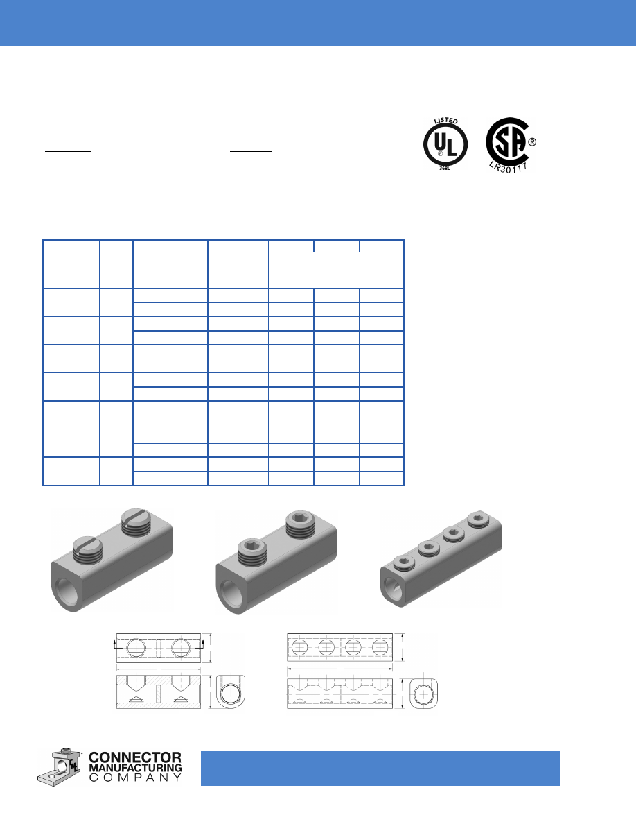
TYPE: BC
Features
• Made of Pure Electrolytic Copper
•
PosiGrip®
•
Unique I-Beam Design
•
Positive Wire Stop
Copper
Solderless Lugs
Catalog
Number
Fig.
No.
Screw
Type
Stud
Size*
mm
Cond. Size
AWG
mm²
H
W
L
G
T
Dimensions, inches
Dimensions, millimeters
BC-50
1
Slot
1/4
6-14
.44
.44
.81
.22
.09
6.35
16-1.5
12.19
12.19
20.57
5.59
2.92
BC-70
1
Slot
1/4
2-14
.50
.50
1.00
.27
.09
6.35
25-1.5
12.70
12.70
25.40
6.86
2.92
BC-112
1
Slot
1/4
1/0-14
.66
.56
1.12
.28
.16
6.35
50-1.5
16.76
14.22
28.45
7.11
4.06
BC-125
1
Slot
1/4
2/0-14
.78
.56
1.25
.31
.19
6.35
50-1.5
19.81
14.22
31.75
7.87
4.83
BC-250
2
.31H
5/16
250-6
.97
.88
1.72
.44
.19
7.87
7.94
120-16
24.64
22.35
43.69
11.18
4.83
BC-350
2
.31H
5/16
350-6
1.13
.94
2.00
.45
.19
7.87
7.94
185-16
28.70
23.88
50.80
11.43
4.83
BC-500
2
.38H
3/8
500-4
1.38
1.25
2.37
.63
.26
9.65
9.53
240-16
35.05
31.75
60.20
16.00
6.60
BC-600
2
.38H
3/8
600-2
1.50
1.19
2.50
.75
.26
9.65
9.53
300-25
38.10
30.23
63.50
19.05
6.60
BC-750
2
.38H
5/8
800-300
1.68
1.38
2.75
.75
.31
9.65
15.88
500-150
42.67
35.05
69.85
19.05
7.87
BC-1000
2
.50H
5/8
1000-500
1.88
1.50
2.87
.75
.31
12.70
15.88
500-240
47.75
38.10
72.70
19.05
7.87
U.S. Patent 4,946,405
U.S. Patent 309,129
U.S. Patent 5,030,131
90° C Rating (486B Listed)
PosiGrip®
*This dimension can be altered per customer requirements.
Fig. 1
Fig. 2
W
L
H
Ø D
Benefits
• Easy Installation
•
Improved Pull-Out and Safety Features
•
Specialized for Copper Conductors ONLY
Custom configurations available upon request.
G
www.cmclugs.com 513.860.4455
TYPE: 2BC
Features
• Made of Pure Electrolytic Copper
•
PosiGrip®
•
Unique I-Beam Design
•
Positive Wire Stop
Copper
Solderless Lugs
Catalog
Number
Fig.
No.
Screw
Type
Stud
Size*
mm
Cond. Size
AWG
mm²
H
W
L
G
T
Dimensions, inches
Dimensions, millimeters
2BC-112
1
Slot
1/4
1/0-14
.66
1.13
1.12
.28
.16
6.35
50-1.5
16.76
28.70
28.45
7.11
4.06
2BC-125
1
.19H
1/4
2/0-14
.78
1.25
1.25
.31
.19
4.83
6.35
50-1.5
19.81
31.75
31.75
7.87
4.83
2BC-250
2
.31H
3/8
250-6
.97
1.62
1.72
.44
.19
7.87
9.53
120-16
24.64
41.15
43.69
11.18
4.83
2BC-350
2
.31H
1/2
350-6
1.13
1.92
2.00
.50
.19
7.87
12.70
185-16
28.70
48.77
50.80
12.70
4.83
2BC-500
2
.31H
1/2
500-4
1.38
2.41
2.37
.56
.26
7.87
12.70
240-16
35.05
61.21
60.20
14.22
6.60
2BC-600
2
.31H
1/2
600-2
1.50
2.41
2.50
.63
.26
7.87
12.70
300-25
38.10
61.21
63.50
16.00
6.60
2BC-750
2
.31H
5/8
750-300
1.68
3.25
2.75
.75
.31
7.87
15.88
300-150
42.67
82.55
69.85
19.05
7.87
2BC-1000
2
.50H
5/8
1000-500
1.88
3.50
2.87
.75
.31
12.70
15.88
500-300
47.75
88.90
72.90
19.05
7.87
U.S. Patent 4,946,405
U.S. Patent 309,129
U.S. Patent 5,030,131
90° C Rating (486B Listed)
PosiGrip®
*This dimension can be altered per customer requirements.
Fig. 1
Fig. 2
W
H
L
T
G
Ø D
Benefits
• Easy Installation
•
Improved Pull-Out and Safety Features
•
Specialized for Copper Conductors ONLY
Custom configurations available upon request.
www.cmclugs.com 513.860.4455
TYPE: FT
Features
• Made of Pure Electrolytic Copper
• Plain Copper Finish
Copper
Solderless
Connectors and Collars
Catalog
Number
Fig.
No.
Cond. Range
AWG
mm²
Stud
Size*
mm
H
W
L
Dimensions, inches
Dimensions, millimeters
FT-65
1
6-14
1/8
.48
.38
1.00
16-1.5
3.18
12.19
9.65
25.40
FT-70
1
4-14
1/8
.52
.50
1.25
16-1.5
3.18
13.21
12.70
31.75
FT-90
1
1/0-14
3/16
.75
.62
1.26
50-1.5
4.76
19.05
15.75
32.00
90° C Rating (486B Listed)
*This dimension can be altered per customer requirements.
Fig. 1
Fig. 2
TYPE: C / CS
Features
• Made of Pure Electrolytic Copper
• Plain Copper Finish
Catalog
Number
Fig.
No.
Cond. Range
AWG
mm²
Boss Tap*
mm
H
W
L
Dimensions, inches
Dimensions, millimeters
C-54-S
2
6-14
.22S / 10-32
.47
.35
.38
16-1.5
5.59
11.94
8.89
9.65
C-58-S
2
4-14
.25S / 10-32
.52
.46
.46
16-1.5
6.35
13.21
11.68
11.68
C-68-S
2
1/0-14
.25S / 12-24
.61
.53
.62
50-1.5
6.35
15.49
13.46
15.75
CS-105
3
1/0-14
.88
.55
.63
50-1.5
22.35
13.97
16.00
CS-175
3
4/0-2
1.09
.75
.88
95-25
27.69
19.05
22.35
CS-200
3
250-6
.88
.81
1.00
120-16
22.35
20.57
25.40
Fig. 3
W
L
H
W
W
H
H
L
L
*This dimension can be altered per customer requirements.
Benefits
• Easy Installation
• Connectors are Reusable
•
Specialized for Copper Conductors ONLY
Benefits
• Easy Installation
• Connectors are Reusable
Custom configurations available upon request.
Custom configurations available upon request.
www.cmclugs.com 513.860.4455
TYPE: C2/C4
Features
• Made of Pure Electrolytic Copper
• Plain Copper Finish
Copper
Splicers
Catalog
Number
Fig.
No.
Cond. Range
AWG
mm²
H
W
L
Dimensions, inches
Dimensions, millimeters
C2-25
1
8-12
.48
.25
.56
10-2.5
12.19 6.35
14.22
C2-35
1
6
.56
.34
.88
16
14.22 8.64
22.35
C2-50
1
4
.63
.39
.88
16
16.00 9.91
22.35
C2-70
1
2
.72
.50
1.00
25
18.29 12.70 25.40
C2-125 1
2/0-1/0
.88
.59
1.25
70-50
22.35
14.99 31.75
C2-225 1
250-3/0
1.31
.86
2.31
120-70
33.27 21.84 58.67
C4-25
2
8-12
.45
.25
1.63
10-2.5
11.43 6.35
41.40
C4-35
2
6
.69
.33
1.75
16
17.53 8.38
44.45
C4-50
2
4
.75
.38
1.75
16
19.05 9.65
44.45
C4-70
2
2
.91
.47
2.00
25
23.11 11.94 50.80
C4-125 2
2/0-1/0
.88
.59
2.50
70-50
22.35
14.99 63.50
C4-225 2
250-3/0
1.31
.86
4.63
120-70
33.27 21.84 117.60
90° C Rating (486B Listed)
Fig. 1
Fig. 2
W
H
L
W
H
L
Benefits
• Easy Installation
• Connectors are Reusable
Custom configurations available upon request.
www.cmclugs.com 513.860.4455
90° C Rating (486B Listed)
TYPE: CL
Features
• Made of Pure Electrolytic Copper
• Plain Copper Finish
•
Designed for Conduit Grounding Bushings
•
UL Approved for Direct Burial.
*This dimension can be altered per customer requirements.
Catalog
Number
Fig.
No.
Cond. Range
AWG
mm²
Stud Size*
mm
H
W
L
Dimensions, inches
Dimensions, millimeters
CL-50S
1
4-14
3/16
.78
.38
1.07
16-1.5
4.76
19.81 9.65
27.18
CL-112S 1
1/0-14
1/4
1.17
.60
1.50
50-1.5
6.35
29.72 15.24 38.10
CL-200S 2
3/0-6
5/16
1.56
.80
2.00
70-16
7.94
39.62 20.32 50.80
CL-252S 2
250-6
5/16
1.79
.80
2.20
120-16
7.94
45.47 20.32 55.88
Fig. 2
Fig. 1
W
H
L
Benefits
• Easy Installation
• Connectors are Reusable
•
Specialized for Copper Conductors ONLY
Copper
Grounding Connectors
Custom configurations available upon request.
www.cmclugs.com 513.860.4455
TYPE: N70 / LCB
Features
• Made of Pure Electrolytic Copper
• Plain Copper Finish
Copper
Neutral Bars
Catalog
Number
Fig.
No.
No. of
Taps
Wire Range
Stud Size*
mm
H
W
L
Line
mm
Circuit
mm
Dimensions, inches
Dimensions, millimeters
N70-8-1
1
6
4-14
6-14
3/16 (2)
.48
.35
3.57
16-1.5
16-1.5
4.76 (2)
12.19
8.89
90.68
N70-10-1
1
8
4-14
6-14
3/16 (2)
.48
.35
4.37
16-1.5
16-1.5
4.76 (2)
12.19
8.89
111.00
N70-12-1
1
10
4-14
6-14
3/16 (2)
.48
.35
5.16
16-1.5
16-1.5
4.76 (2)
12.19
8.89
131.06
N70-14-1
1
12
4-14
6-14
3/16 (2)
.48
.35
5.95
16-1.5
16-1.5
4.76 (2)
12.19
8.89
151.13
N70-16-1
1
14
4-14
6-14
3/16 (2)
.48
.35
6.74
16-1.5
16-1.5
4.76 (2)
12.19
8.89
171.20
N70-174
1
174
6-14
None
.47
.34
68.91
16-1.5
11.94
8.64
1750.31
The number of outlets, outlet spacing and mounting hole locations can
be established according to individual requirements.
When ordering
neutral bars please add a suffix to indicate the number of usable
wire ports required. Ex: NA30-8 would result in an NA30 style
neutral bar with eight (8) wire ports.
Fig. 1
Catalog
Number
Fig.
No.
Cond. Range
mm²
H
W
Dimensions, inches
Dimensions, millimeters
*LCB-1/0
2
1/0-14 / 6-14
.63
.38
50-1.5 / 16-1.5
16.00
9.65
*LCB-2/0
2
2/0-14 / 6-14
.69
.38
50-1.5 / 16-1.5
17.45
9.65
Fig. 2
W
H
L
W
H
L
Benefits
• Easy Installation
• Connectors are Reusable
•
Specialized for Copper Conductors ONLY
Custom configurations available upon request.
Custom configurations available upon request.
*This bar is also approved as an equipment ground.
www.cmclugs.com 513.860.4455
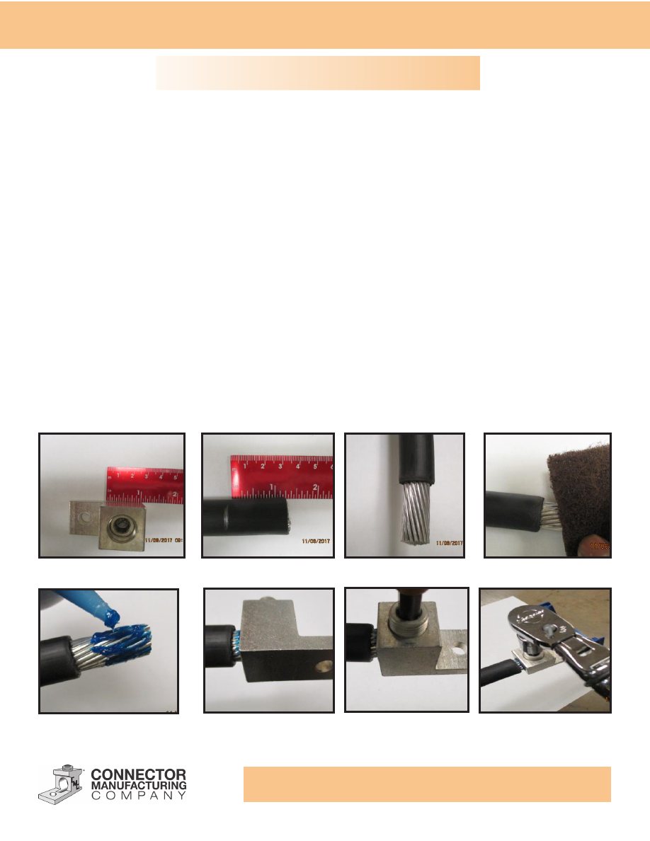
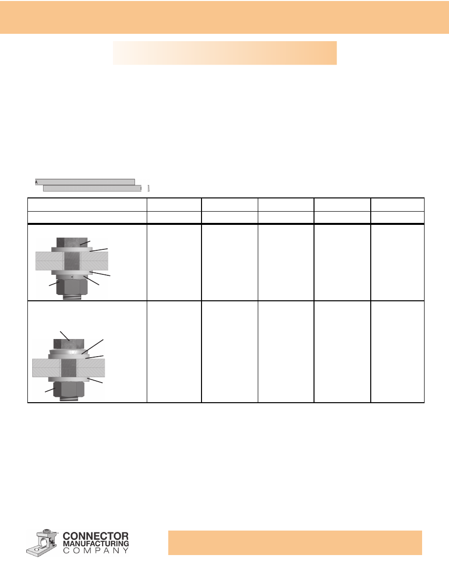
1. Measure the length of the wire hole in the connector, with a measuring device.
2. Measure and mark the conductor cable approximately 1/4” longer than the connector.
3. Strip the insulation from the cable with an appropriate stripping tool; be careful not to damage the
conductor wire while performing this operation.
4. If the wire cable (conductor) is corroded or blemished in any way, clean the exposed end of the cable
with emery cloth or wire brush dependent upon the severity of the corrosion to remove oxides from the
surface of the conductor.
5. Prior to installation of the conductor to the connector, apply a generous amount of oxide inhibitor to the
bare portion of the conductor.
6. Rotate the conductor back and forth to evenly distribute the inhibitor.
7. Install the conductor into the connector leaving approximate 1/4” of exposed conductor visible. Be sure
the installed conductor is equal in length of the wire hole. Snug with an Allen wrench.
8. Torque the set screw to the recommended value with a torque wrench. After a minute, retighten the
screw again to the recommended torque value.
1
3
4
2
8
6
5
7
Installation Instructions
www.cmclugs.com 513.860.4455
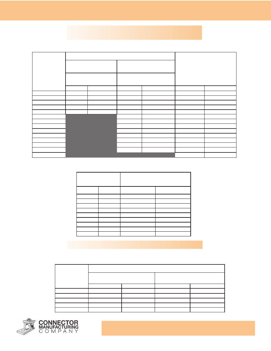
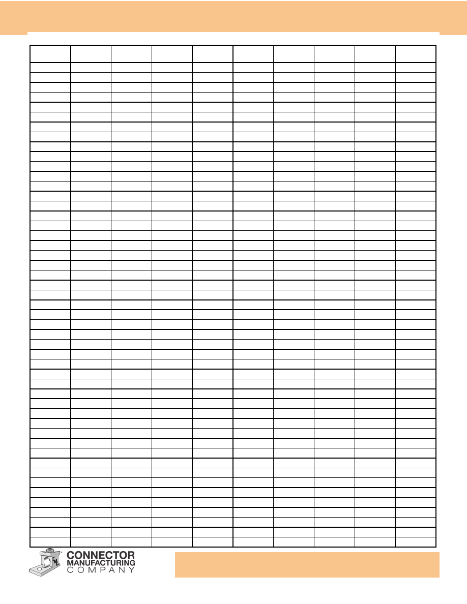
Tightening Torque Values for Mechanical Screw Connectors
Table shows the recommended Tightening torques for silicon bronze, stainless steel, galvanized steel and aluminum
alloy hardware.
Internal Socket Size
Across Flats
Tightening Torque
in
mm
Inch Pounds
Newton Meters
1/8
3.2
45
5.1
5/32
4.0
100
11.3
3/16
4.8
120
13.6
7/32
5.6
150
16.9
1/4
6.4
200
22.6
5/16
7.9
275
31.1
3/8
9.5
375
42.4
1/2
12.7
500
56.5
9/16
14.3
600
67.8
Tightening Torque Values for Socket Head Screw Connectors
Bolt Diameter
Nominal Torque Values
Silicon Bronze, Galvanized or
Stainless Steel
Aluminum Alloy (lubricated)
Ft. - Lbs.
Inch-Lbs.
Ft. - Lbs.
Inch - Lbs.
5/16-18
15
180
-
-
3/8-16
20
240
14
168
1/2-13
40
480
25
300
5/8-11
55
660
40
480
3/4-10
80
960
70
840
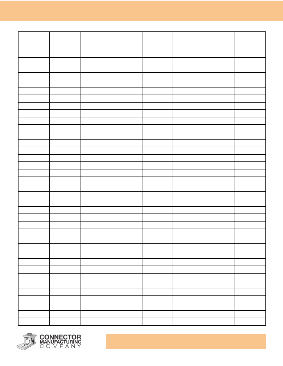
AWG.
or Circular
Mill Size
Slotted Head Screws
Hexagonal Head Screw
Slot Width
.047 in (1.2 mm) or less
Slot Width
More than .047 in (1.2 mm)
Slot Length
.25 in (6.4 mm) or less
Slot Length
More than .25 in (6.4 mm)
in-lbf
N-m
in-lbf
N-m
in-lbf
N-m
30-10
20
2.3
35
4.0
75
8.5
8
25
2.8
40
4.5
75
8.5
6-4
35
4.0
45
5.1
110
12.4
3
35
4.0
50
5.6
150
16.9
2
40
4.5
50
5.6
150
16.9
1
50
5.6
150
16.9
1/0 - 2/0
50
5.6
180
20.3
3/0 - 4/0
50
5.6
250
28.2
250-350
50
5.6
325
36.7
400
50
5.6
325
36.7
500
50
5.6
375
42.4
600-750
50
5.6
375
42.4
800-1000
50
5.6
500
56.5
1250-2000
600
67.8
Tightening Torque Values
Additional Torque Information
www.cmclugs.com 513.860.4455
For optimum efficiency, it is necessary that the correct bolt, nut, and washer combination be used with the correct
combination of conductor materials. This table shows acceptable methods of joining different combination of bus bar.
Where different combinations of metals are being joined, a follow-up device such as a conical pressure washer is usually
recommended if one, or both, bus materials are soft drawn aluminum. If both bars are hard drawn, large flat washers will
suffice regardless of the bolt materials.
Other considerations which should be taken into account when selecting hardware are corrosion and vibration. For
example, if severe corrosion is anticipated, non-corrosive materials such as stainless steel or silicon bronze, should be
selected in preference to galvanized steel. If vibration is anticipated, the use of locking washers should be considered.
Methods of Joining Bus Bars
Bar Connections:
The Tang of a compression or mechanical connector is a bus bar, which connects to another bus bar. If you remember the
rule about wire brushing and using joint compound with bare (unplated) aluminum, you cannot go wrong. Plated parts
should be cleaned with a solvent if they are dirty, but never abrade or otherwise disturb the plating! Figure shows a typical
bar connection and the type of hardware used.
Contact surface must be clean. Use a joint compound with bare aluminum. Conical pressure washer is usually
recommended if one, or both, bus materials are soft drawn aluminum.
(1) Denotes preferred hardware usage.
Note: Contact sealant recommended between aluminum to aluminum and alumi-
num to copper connections unless other protective measures are taken.
If “A” Bar is
Copper
Aluminum
Steel
Aluminum
Steel
If “B” Bar is
Copper
Copper
Copper
Aluminum
Aluminum
(1) Silicon Bronze
(2) Stainless Steel
(1) Silicon Bronze
(2) Aluminum
(3) Stainless Steel
(1) Aluminum
(2) Stainless Steel
(1) Aluminum
(2) Stainless Steel
(3) Silicon Bronze,
Plated
(1) Aluminum
(2) Stainless Steel
(1) Silicon Bronze
(2) Stainless Steel
(1) Silicon Bronze
(2) Aluminum
(3) Stainless Steel
(4) Conical Pressure
Washer Plated or
Stainless Steel
(1) Silicon Bronze
(2) Stainless Steel
(1) Aluminum
(2) Stainless Steel
(3) Silicon Bronze
Plated
(4) Conical Pressure
Washer Plated or
Stainless Steel
(1) Aluminum
(2) Stainless Steel
(3) Silicon Bronze
Plated
(4) Conical
Pressure Washer
Plated or Stainless
Steel
Hand drawn bus such as Al Alloy
Bolt
Large Flat
Washer
Large Flat
Washer
Split or Tooth
Lock Washer
Nut
Large Flat
Washer
Large Flat
Washer
Conical Pressure
Washer
Bolt
Nut
Soft drawn bus such as EC-H13 AL
A
B
Additional Torque Information
www.cmclugs.com 513.860.4455
Decimal Equivalents
Drill
Equivalent
Drill
Equivalent
Drill
Equivalent
Drill
Equivalent
Drill
Equivalent
1/16
.0625
53/64
.8281
1 19/32
1.59737
2 3/64
2.3593
3 1/4
3.2500
5/64
.07812
27/32
.8437
1 39/64
1.6093
2 3/8
2.3750
3 9/32
3.2812
3/32
.09375
55/64
.8593
1 5/8
1.6250
2 25/64
2.3906
3 5/16
3.3125
7/64
.10937
7/8
.8750
1 41/64
1.6406
2 13/32
2.4062
3 11/32
3.3437
1/8
.125
57/64
.8906
1 21/32
1.6562
2 27/64
2.4218
3 3/8
3.3750
9/64
.14062
29/32
.9062
1 43/64
1.6718
2 7/16
2.4375
3 13/32
3.4062
5/32
.15625
59/64
.9218
1 11/16
1.6875
2 29/64
2.4531
3 7/16
3.4375
11/64
.17187
15/16
.9375
1 45/64
1.7031
2 15/32
2.4687
3 15/32
3.4687
3/16
.1875
61/64
.9531
1 23/32
1.7187
2 31/64
2.4843
3 1/2
3.5000
13/64
.20312
31/32
.9687
1 47/64
1.7343
2 1/2
2.5000
3 17/32
3.5312
7/32
.21875
63/64
.9843
1 3/4
1.7500
2 33/64
2.5156
3 9/16
3.5625
15/64
.23437
1
1.0000
1 49/64
1.7656
2 17/32
2.5312
3 19/32
3.5937
1/4
.25
1 1/64
1.0156
1 25/32
1.7812
2 35/64
2.5468
3 5/8
3.6250
17/64
.26562
1 1/32
1.0312
1 51/64
1.7968
2 9/16
2.5625
3 21/32
3.6562
9/32
.28125
1 3/64
1.0468
1 13/16
1.8125
2 37/64
2.5781
3 11/16
3.6875
19/64
.29687
1 1/16
1.0625
1 53/64
1.8281
2 19/32
2.5937
3 23/32
3.7187
5/16
.3125
1 5/64
1.0781
1 27/32
1.8437
2 39/64
2.6093
3 3/4
3.7500
21/64
.32812
1 3/32
1.0937
1 55/64
1.8593
2 5/8
2.6250
3 25/32
3.7812
11/32
.34375
1 7/64
1.1093
1 7/8
1.8750
2 41/64
2.6406
3 13/16
3.8125
23/64
.35937
1 1/8
1.1250
1 57/64
1.8906
2 21/32
2.6562
3 27/32
3.8437
3/8
.375
1 9/64
1.1406
1 29/32
1.9062
2 43/64
2.6718
3 7/8
3.8750
25/64
.39062
1 5/32
1.1562
1 59/64
1.9218
2 11/16
2.6875
3 29/32
3.9062
13/32
.40625
1 11/64
1.1718
1 15/16
1.9375
2 45/64
2.7031
3 15/16
3.9375
27/64
.42187
1 3/16
1.1875
1 61/64
1.9531
2 23/32
2.7187
3 31/32
3.9687
7/16
.4375
1 3/64
1.2031
1 31/32
1.9687
2 47/64
2.7343
4
4.0000
29/64
.45312
1 7/32
1.2187
1 63/64
1.9843
2 3/4
2.7500
4 4/16
4.0625
15/32
.46875
1 5/64
1.2343
2
2.0000
2 49/64
2.7656
4 1/8
4.1250
31/64
.48437
1 1/4
1.2500
2 1/64
2.0156
2 25/32
2.7812
4 3/16
4.1875
1/2
.50
1 17/64
1.2656
2 1/32
2.0312
2 51/64
2.7968
4 1/4
4.2500
33/64
.5156
1 9/32
1.2812
2 3/64
1.0468
2 13/16
2.8125
4 15/16
4.3125
17/32
.5312
1 19/64
1.2968
2 1/16
2.0625
2 53/64
2.8281
4 3/8
4.3750
35/64
.5468
1 5/16
1.3125
2 5/64
2.0781
2 27/32
2.8437
4 7/16
4.4375
9/16
.5625
1 21/64
1.3281
2 3/32
2.0937
2 55/64
2.8593
4 1/2
4.5000
37/64
.5781
1 11/32
1.3437
2 7/64
2.1093
2 7/8
2.8750
4 9/16
4.5625
19/32
.5937
1 23/64
1.3593
2 1/8
2.1250
2 57/64
2.8906
5 5/8
4.6250
39/64
.6093
1 3/8
1.3750
2 9/64
2.1406
2 29/32
2.9062
4 11/16
4.6875
5/8
.6250
1 25/64
1.3906
2 5/32
2.1562
2 59/64
2.9218
4 3/4
4.7500
41/64
.6406
1 13/32
1.4062
2 11/64
2.1718
2 15/16
2.9375
4 13/16
4.8125
21/32
.6562
1 27/64
1.4218
2 3/16
2.1875
2 61/64
2.9531
4 7/8
4.8750
43/64
.6718
1 7/16
1.4375
2 13/64
2.2031
2 31/32
2.9687
4 15/16
4.9375
11/16
.6975
1 29/64
1.4531
2 7/32
2.2187
2 63/64
2.9843
5
5.0000
45/64
.7031
1 15/32
1.4687
2 15/64
2.2343
3
3.0000
5 1/8
5.1250
23/32
.7187
1 31/64
1.4843
2 1/4
2.2500
3 1/32
3.0312
5 1/4
5.2500
47/64
.7343
1 1/2
1.5000
2 17/64
2.2656
3 1/16
3.0625
5 3/8
5.3750
3/4
.7500
1 33/64
1.5156
2 9/32
2.2812
3 3/32
3.0937
5 1/2
5.5000
49/64
.7656
1 17/32
1.5312
2 19/64
2.2968
3 1/8
3.1250
5 5/8
5.6250
25/32
.7812
1 35/64
1.5468
2 5/16
2.3125
3 5/32
3.1562
5 3/4
5.7500
51/64
.7968
1 9/16
1.5625
2 21/64
2.3281
3 3/16
3.1875
5 7/8
5.8750
13/16
.8125
1 37/64
1.5781
2 11/32
2.3437
3 7/32
3.2187
6
6.0000
www.cmclugs.com 513.860.4455
Wire Ranges
Size
AWG-MCM
No. of Wires
Dia. Each
Wire Inches
Dia. Inches
Clearance Drill
Present Clearance
Between
Conductor Dia. &
Hole Dia.
Proposed or
Suggested Drill
Sizes for Wire
Holes
Clearance
Between
Conductor &
Proposed Drill
Sizes
18
Solid
0.0403
0.0403
0.0469
18
7
0.0403
0.0469
16
Solid
0.0508
0.0508
0.0625
16
7
0.0508
0.0625
14
Solid
0.0641
0.0641
0.078
14
7
0.0641
0.078
12
Solid
0.0808
0.0808
0.098
12
7
0.0808
0.098
10
Solid
0.1019
0.1019
0.120
10
7
0.1019
0.120
8
Solid
0.1285
0.1285
0.156
8
7
0.1285
0.156
6
7
0.0612
0.184
0.219
0.035
4
7
0.0772
0.232
0.250
0.018
0.265
0.033
3
7
0.0867
0.260
0.281
0.021
0.296
0.036
2
7
0.0974
0.292
0.312
0.020
0.328
0.036
1
19
0.0664
0.332
0.368
0.036
0
19
0.0745
0.372
0.406
0.034
00
19
0.0837
0.418
0.437
0.019
0.453
0.035
000
19
0.0940
0.470
0.500
0.030
0000
19
0.1055
0.528
0.562
0.034
250
37
0.0822
0.575
0.609
0.034
0.625
0.050
300
37
0.0900
0.630
0.656
0.026
0.687
0.057
350
37
0.0973
0.681
0.719
0.038
0.734
0.053
400
37
0.1040
0.728
0.781
0.053
500
37
0.1162
0.813
0.875
0.062
600
61
0.0992
0.893
0.938
0.045
0.953
0.060
700
61
0.1071
0.964
0.984
0.020
1.035
0.069
750
61
0.1109
0.998
1.035
0.037
1.062
0.064
800
61
0.1145
1.030
1.094
0.064
900
61
0.1215
1.090
1.140
0.050
1.152
0.062
1000
61
0.1280
1.150
1.219
0.069
1.234
0.084
1250
91
0.1172
1.289
1.390
0.101
1.375
0.086
1500
91
0.1284
1.410
1.500
0.090
1750
127
0.1174
1.526
1.593
0.067
1.625
0.099
2000
127
0.1255
1.630
1.697
0.057
1.734
0.104

www.cmclugs.com 513.860.4455
WWW.CMCLUGS.COM
Follow us on Social Media
February 2021
We’re here to support you.
Customer Service - 513-860-4455, press 2
Pricing/Quotations - 513-860-4455, press 3
TO ORDER:
cmcorders@cmclugs.com
02/2021
OEMDCAT0121
Copyright © 2020 Hubbell Incorporated. All rights reserved. Please refer to online specifications
for most up-to-date content as specifications are subject to change without notice.

NOTES:

NOTES:
