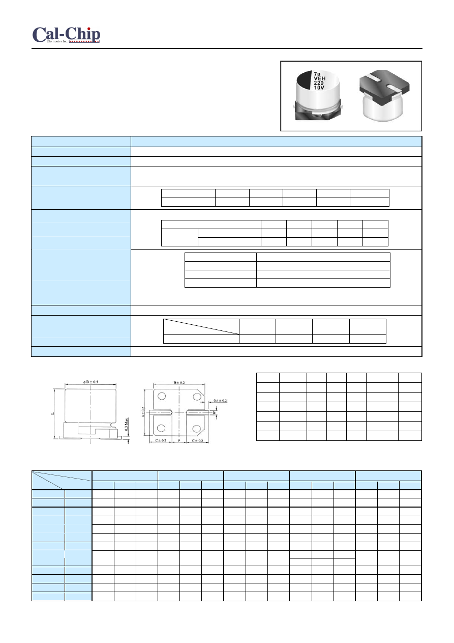
SMD Aluminum Electrolytic Capacitors
CVY
Features
‧
4 ~ 10
φ
, 105
℃
, 2,000 hours assured
‧
Vertical chip type miniaturized
‧
Low impedance capacitors
‧
Designed for surface mounting on high density PC board.
‧
RoHS Compliance
SPECIFICATIONS
Items
Performance
Operating Temperature Range
-55
℃
~ +105
℃
Capacitance Tolerance
±
20%
(at 120Hz, 20
℃
)
Leakage Current (at 20 )
℃
I = 0.01CV or 3 (
μ
A) whichever is greater (after 2 minutes)
Where, C= rated capacitance in
μ
F. V = rated DC working voltage in V.
Rated
Voltage
6.3 10 16 25 35
Tan
δ
(max) 0.30 0.26 0.22 0.16 0.13
Dissipation Factor
(Tan
δ
at 120Hz, 20 )
℃
Impedance ratio shall not exceed the values given in the table below.
Rated
Voltage
6.3 10 16 25 35
Z(-25
℃
)/Z(+20
℃
) 4 3 2 2 2
Impedance
Ratio
Z(-40
℃
)/Z(+20
℃
) 8 5 4 3 3
Low Temperature
Characteristics (at 120Hz)
Test Time
2,000 Hrs
Capacitance Change
Within
±
20% of initial value(
φ
≦
6.3 : ±25%)
Dissipation Factor
Less than 200% of specified value
Leakage Current
Within specified value
Load Life Test
* The above specifications shall be satisfied when the capacitors are restored to 20
℃
after the rated voltage
applied for 2,000 hrs at 105
℃
.
Shelf Life Test
Test time: 1,000 hrs; other items are the same as those for the load life test.
Freq.(Hz)
V.DC(V)
50, 60
120
1K
10K up
6.3 ~ 35
0.64
0.8
0.93
1.0
Ripple Current &
Frequency Multipliers
Other Standards
JIS C 5101-1, -18
LEAD SPACING AND DIAMETER
Unit: mm
φ
D
L A
B
C W P±0.2
4
5.7±0.3
4.3
4.3
2.0
0.5 to 0.8
1.0
5
5.7±0.3
5.3
5.3
2.3
0.5 to 0.8
1.5
6.3
5.7±0.3
6.3
6.3
2.7
0.5 to 0.8
2.0
8
10±0.5
8.4
8.4
3.0
0.7 to 1.1
3.1
DIAGRAM OF DIMENSIONS
10
10±0.5
10.4
10.4
3.3
0.7 to 1.1
4.7
10
10.3±0.5
10.4
10.4
3.3
0.7 to 1.1
4.7
Dimension:
φ
D × L(mm)
Ripple Current: mA/rms at 100K Hz, 105
℃
DIMENSION & PERMISSIBLE RIPPLE CURRENT
Impedance:
Ω
/ at 100K Hz, 20
℃
V.DC
6.3V (0J)
10V (1A)
16V (1C)
25V (1E)
35V (1V)
μ
F
Contents
φ
D×L
Imp.
mA
φ
D×L
Imp.
mA
φ
D×L
Imp.
mA
φ
D×L
Imp.
mA
φ
D×L
Imp.
mA
4.7
4R7
4×5.7
3.2
65
4×5.7
3.2
65
10
100
4×5.7
3.2
65
5×5.7
1.5
110
5×5.7
1.5
110
22
220
5×5.7
1.5
110
6.3×5.7
0.85
170
6.3×5.7
0.85
170
33
330 4×5.7 3.2 65 5×5.7 1.5 110
6.3×5.7
0.85 170
6.3×5.7
0.85 170
6.3×5.7
0.85 170
47
470 5×5.7 1.5 110
6.3×5.7
0.85 170
6.3×5.7
0.85 170
6.3×5.7
0.85 170 8×10 0.45 450
100
101 6.3×5.7
0.85 170
6.3×5.7
0.85 170 8×10 0.45 450 8×10 0.45 450 8×10 0.45 450
150
151 6.3×5.7
0.85 170
6.3×5.7
0.85 170 8×10 0.45 450 8×10 0.45 450 8×10 0.45 450
8×10 0.45 450
220
221 6.3×5.7
0.85 170 8×10 0.45 450 8×10 0.45 450
10 x10
0.25
670
10×10 0.25 670
330
331 8×10 0.45 450 8×10 0.45 450 8×10 0.45 450
10×10.3
0.25 670
470
471 8×10 0.45 450 8×10 0.45 450 10×10
0.25 670
820
821
10×10
0.25
670
10×10
0.25
670
1000
102
10×10
0.25
670