background image

Rev 1.1 (September 2013)                                                      1                                           

©

 2013 DLP Design, Inc.  


D

D

L

L

P

P

-

-

7

7

9

9

7

7

0

0

A

A

B

B

P

P


B

B

o

o

o

o

s

s

t

t

e

e

r

r

P

P

a

a

c

c

k

k


U

U

s

s

e

e

r

r

s

s


G

G

u

u

i

i

d

d

e


FEATURES: 


•    13.56MHz HF RFID Reader/Writer 
•    Compatible with the NFCLink Library 
•    Compatible with the MSP-EXP430G2X LaunchPad 
•    Compatible with the MSP-EXP430F5529LP LaunchPad 
•    Compatible with the C2000 LaunchPad 
•    Compatible with the TIVA C Series LaunchPad 
•    Compatible with the Hercules LaunchPad 
•    Supports ISO 15693, 18000-3, 14443A/B and FeliCa 
•    RFID/NFC Reader, NFC Peer or Card-Emulation Mode 
•    NFCIP-1 (ISO/IEC 18092) and NFCIP-2 (ISO/IEC 21481) 
•    On-Board Antenna 
•    FCC/IC Approvals in Place 


•    Operational Power Supplied by the LaunchPad 


1.0   INTRODUCTION 


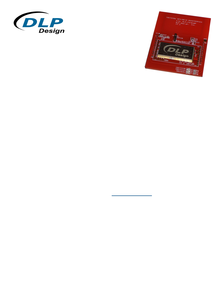
The DLP-7970ABP is an add-on board designed to fit TI’s MCU LaunchPads that incorporates  
DLP Design’s DLP-RFID2 RFID module.  This BoosterPack allows the software application developer to 
get familiar with the functionalities of the TRF7970A multi-protocol, fully-integrated, 13.56MHz RFID/NFC 
IC on their Texas Instruments embedded microcontroller platform of choice without having to worry about 
developing the RF section. 
 
The NFCLink library is an industry-proven modular firmware/software solution that provides a 
programming interface for TI’s family of TRF79XX NFC devices supporting the hardware level up through 
the host operating system via an API.  NFCLink is a library of NFC and HF RFID firmware using the NCI 
protocol to communicate with a host OS or MPU.  NFCLink currently supports MSP430 5XX and 6XX 
series devices.  Visit the TI website for more details:  

www.ti.com/tool/nfclink


This document provides direction for TRF79XX users implementing a 13.56MHz RFID reader solution 
using the TRF79XX IC connected to a Texas Instruments embedded microcontroller or microprocessor 
development platform.  Examples of such development platforms are the MSP-EXP430G2 LaunchPad 
and the MSP-EXP430F5529LP LaunchPad. 

LaunchPads from Texas Instruments are easy-to-use flash programming and debugging tools for the 
MSP430, C2000, TIVA, etc. line of microcontrollers.  They feature everything you need to start 
developing on a Texas Instruments microcontroller device.  They have on-board emulation for 
programming and debugging, on-board button switches and LED’s and BoosterPack-compatible pinouts 
to support a wide range of plug-in modules like the DLP-7970ABP. 


dlp-7970abp-ds-v11-html.html
background image

Rev 1.1 (September 2013)                                                      2                                           

©

 2013 DLP Design, Inc.  

Free software development tools are also available, such as TI’s Eclipse-based Code Composer Studio. 
Open-source development is also available thanks to community-driven projects such as the MSPGCC 
compiler or Energia, a branch of the popular Wiring framework. 


2.0  SCOPE 


This document describes the DLP-7970ABP module for evaluation and development purposes in 
conjunction with Texas Instruments embedded development platforms.  This manual does not cover the 
in-depth details of the TRF79XX reader IC family as those details are documented in the datasheets for 
those parts along with application notes that can be found on the product pages (see the hyperlinks in 
Section 3). 


3.0  REFERENCES 


•  DLP-RFID2:  

www.dlpdesign.com


•  TRF7970A product page:  

http://www.ti.com/product/trf7970a


•  TRF7970A datasheet:  

http://www.ti.com/lit/ds/slos743g/slos743g.pdf


4.0  MODULE DESCRIPTION 


The DLP-7970ABP BoosterPack (see Figure 1) allows the software application developer to become 
familiar with the functionalities of TRF7970A multi-standard, fully integrated, 13.56MHz RFID reader IC 
with the freedom to develop on the Texas Instruments embedded microcontroller development platform 
of choice. 
 
The DLP-7970ABP module also allows customer-driven antenna tuning with an onboard coil antenna. 
The module is hardwired for SPI communication with the associated LaunchPad; and it supports slave 
select, TRF7970A Direct Mode 2 (default), Direct Mode 1 and Direct Mode 0 operations.  The user also 
has access to and full control over the TRF7970A EN line, allowing for design and development of ultra 
low-power/high-frequency (HF) RFID systems. 
 
The DLP Design module has been modified from its original form by removing the onboard 
microcontroller (MSP430F2370) so that the RF circuitry on the module can be controlled by the 
microcontroller on the connected LaunchPad.  Additionally, the I/O pins required by the TRF7970A’s SPI 
interface have been brought out of the DLP-RFID2 module for connection to the microcontroller on the 
LaunchPad. 
 
An impedance-matching circuit from 4

 to 50

 is designed into the DLP-RFID2 module, and is 

connected to a tuned 50

 antenna system that consists of an onboard five-turn coil with series and 

parallel passive elements (capacitors and a resistor). 


Connection to Texas Instruments LaunchPad platforms are made via 10-pin, 0.1-inch spaced,  
0.025-square inch post female headers located on the back of the board. 


dlp-7970abp-ds-v11-html.html
background image

Rev 1.1 (September 2013)                                                      3                                           

©

 2013 DLP Design, Inc.  


Figure 1.  DLP-7970ABP Evaluation Module


5.0  MODULE PINOUT 


DLP-7970ABP MODULE PIN CONNECTIONS TO THE LAUNCHPAD 

VCC - 3.0V power from the LaunchPad 

P1.0 - Unused by the DLP-7970ABP 

UART RXD - Unused by the DLP-7970ABP 

UART TXD - Unused by the DLP-7970ABP 

P1.3 - Unused by the DLP-7970ABP 

P1.4 - Unused by the DLP-7970ABP 

DATA_CLK - Clock for the SPI interface 

IRQ - Interrupt request from the TRF7970A to the microcontroller on the 
LaunchPad 

Slave Select - Used by the SPI interface 

10 

EN - Used to enable the TRF7970A 

11 

P2.3 - I/O used to light an LED on the DLP-7970ABP when an ISO14443B tag is 
present in the RFID field 

12 

P2.4 - I/O used to light an LED on the DLP-7970ABP when an ISO14443A tag is 
present in the RFID field 

13 

P2.5 - I/O used to light an LED on the DLP-7970ABP when an ISO15693 tag is 
present in the RFID field 

14 

MISO - SPI serial data from the TRF7970A to the microcontroller on the 
LaunchPad 

15 

MOSI - SPI serial data to the TRF7970A from the microcontroller on the 
LaunchPad 

16 

RESET 

17 

TEST - Unused by the DLP-7970ABP 

18 

XOUT - Alternate interrupt source from the LaunchPad (see Section 6.0) 

19 

XIN - Unused by the DLP-7970ABP 

20 

GROUND 


dlp-7970abp-ds-v11-html.html
background image

Rev 1.1 (September 2013)                                                      4                                           

©

 2013 DLP Design, Inc.  

6.0  IRQ_SEL 


A 3-pin jumper selection labeled as “IRQ_SEL” is provided to allow the user to connect the “IRQ” 
interrupt source generated by the TRF7970A RFID IC on the BoosterPack to the interrupt input on the 
microcontroller located on the LaunchPad.  Since this BoosterPack is designed to work with several TI 
LaunchPads, and the interrupts are located on different pins on the various LaunchPads, this 3-pin 
jumper was provided to make the selection.  (Position 2 is typically used with the MSP-EXP430G2 
LaunchPad, and Position 1 is typically used with all other LaunchPads.) 
 

7.0  QUICK START GUIDE 


1.  Plug the DLP-7970ABP module into the LaunchPad microcontroller development platform of choice. 
 
2.  Apply power by connecting a USB cable to the LaunchPad. 
 
3.  Load and run base application firmware specific to the selected platform. 
 
4.  Test for basic communication and functionality by holding RFID tags close to the onboard loop 
antenna.  A corresponding red, green or blue LED will light for ISO15693, ISO44443A and ISO14443B 
tags that are presented to the antenna. 
 
5.  Modify and debug code as desired for the specific application or protocol. 


8.0  BASE APPLICATION FIRMWARE 


DLP-7970ABP Module Application Firmware for the various Texas Instruments LaunchPads is available 
from the DLP Design website.  Visit the product page on the DLP Design site for all available firmware 
project downloads. 


9.0  MECHANICAL DIMENSIONS – Inches (mm) 


DLP-RFID2

2.60 typ

(66.0 typ)

2.1  typ

(53.3 typ)

Loop Antenna

14443B
14443A

15693

1.8  typ

(45.7 typ)

1.0  typ

(25.4 typ)

1.14  typ

(29.1 typ)

0.34 typ

(8.6 typ)


dlp-7970abp-ds-v11-html.html
background image

Rev 1.1 (September 2013)                                                      5                                           

©

 2013 DLP Design, Inc.  

10.0  ANTENNA TUNING DETAILS 


This module’s antenna, as shipped, is tuned for 50

 impedance at 13.56MHz.  It has a nominal 

bandwidth of 1.3MHz, which results in a Q (quality factor) of approximately 10.  The PCB trace loop 
antenna on the DLP-7970ABP has a nominal value of approximately 2.0

μ

H at 13.56MHz.  The 

dampening resistor value was set at 1.3K

 to achieve this value of Q, which is an appropriate value for 

supporting ISO15693, ISO14443A and ISO14443B tags. 
Figures 2 and 3 show the Smith Charts for the actual measurements of the loop antenna used on the 
DLP-7970ABP module: 


Figure 2


Figure 3. 


dlp-7970abp-ds-v11-html.html
background image

Rev 1.1 (September 2013)                                                      6                                           

©

 2013 DLP Design, Inc.  

11.0  REGULATORY AGENCY CONSIDERATIONS


11.1  AGENCY IDENTIFICATION NUMBERS


Compliance with the appropriate regulatory agencies is essential in the deployment of all transceiver 
devices.  DLP Design has obtained modular approval for this RF product such that an OEM need only 
meet a few basic requirements in order to utilize their end product under this approval.  Corresponding 
agency identification numbers are listed below: 
 

PART NUMBER  

      US/FCC  

CAN/IC  

DLP-RFID2 

      SX9RFID2 

5675A-RFID2 


11.2  EXTERNAL ANTENNAS


The DLP-RFID2 is approved for use with an external antenna.  The maximum gain allowed for the 
external antenna is a gain of 1.  All loop antennas properly tuned for 50

 at 13.56MHz have a gain  

of 1. 


11.3  FCC/IC REQUIREMENTS FOR MODULAR APPROVAL 


Any changes or modifications to the DLP-RFID2’s printed circuit board could void the user’s authority to 
operate the equipment.  Operation of an unapproved antenna could void the user’s authority to operate 
the equipment.


11.4  WARNINGS 


Operation is subject to the following two conditions:  (1) This device may not cause harmful interference, 
and (2) this device must accept any interference received, including interference that may cause 
undesirable operation. 
 
This device is intended for use under the following conditions: 
 
1.  The transmitter module may not be co-located with any other transmitter or antenna. 
 
2.  The module is approved using the FCC “unlicensed modular transmitter approval” method. 
 
As long as these two conditions are met, further transmitter testing will not be required.  However, the 
OEM integrator is still responsible for testing their end product for any additional compliance measures 
necessitated by the installation of this module (i.e. digital device emissions, PC peripheral requirements, 
etc.). 
 
Note:  In the event that these conditions cannot be met (i.e. co-location with another transmitter), then 
the FCC authorization is no longer valid, and the corresponding FCC ID may 

not

 be used on the final 

product.  Under these circumstances, the OEM integrator will be


responsible for re-evaluating the end 

product (including the transmitter) and obtaining a separate FCC authorization. 


dlp-7970abp-ds-v11-html.html
background image

Rev 1.1 (September 2013)                                                      7                                           

©

 2013 DLP Design, Inc.  

11.5  OEM PRODUCT LABELING


The final end product must be labeled in a visible area with the following text: 
 

“Contains TX FCC ID: SX9RFID2” 


11.6  RF EXPOSURE


In order to comply with FCC RF exposure compliance requirements, the antenna used for this transmitter 
must not be co-located or operating in conjunction with any other antenna or transmitter. 


11.7  ADDITIONAL INFORMATION FOR OEM INTEGRATORS


The end user should NOT be provided with any instructions on how to remove or install the  
DLP-RFID2. 


12.0  DISCLAMER 


Neither the whole nor any part of the information contained herein nor the product described in this 
datasheet may be adapted or reproduced in any material or electronic form without the prior written 
consent of the copyright holder. 
 
This product and its documentation are supplied on an as-is basis, and no warranty as to their suitability 
for any particular purpose is either made or implied.  DLP Design will not accept any claim for damages 
whatsoever arising as a result of the use or failure of this product.  Your statutory rights are not affected. 
 
This product or any variant of it is not intended for use in any medical appliance, device or system in 
which the failure of the product might reasonably be expected to result in personal injury. 
 
This document provides preliminary information that may be subject to change without notice. 


13.0  CONTACT INFORMATION 


DLP Design, Inc. 
1605 Roma Lane 
Allen, TX  75013 
 
Phone: 469-964-8027 
Fax: 415-901-4859 
Email: support@dlpdesign.com 
Internet:      http://www.dlpdesign.com