Power Capacitors
Series/Type:
B25834
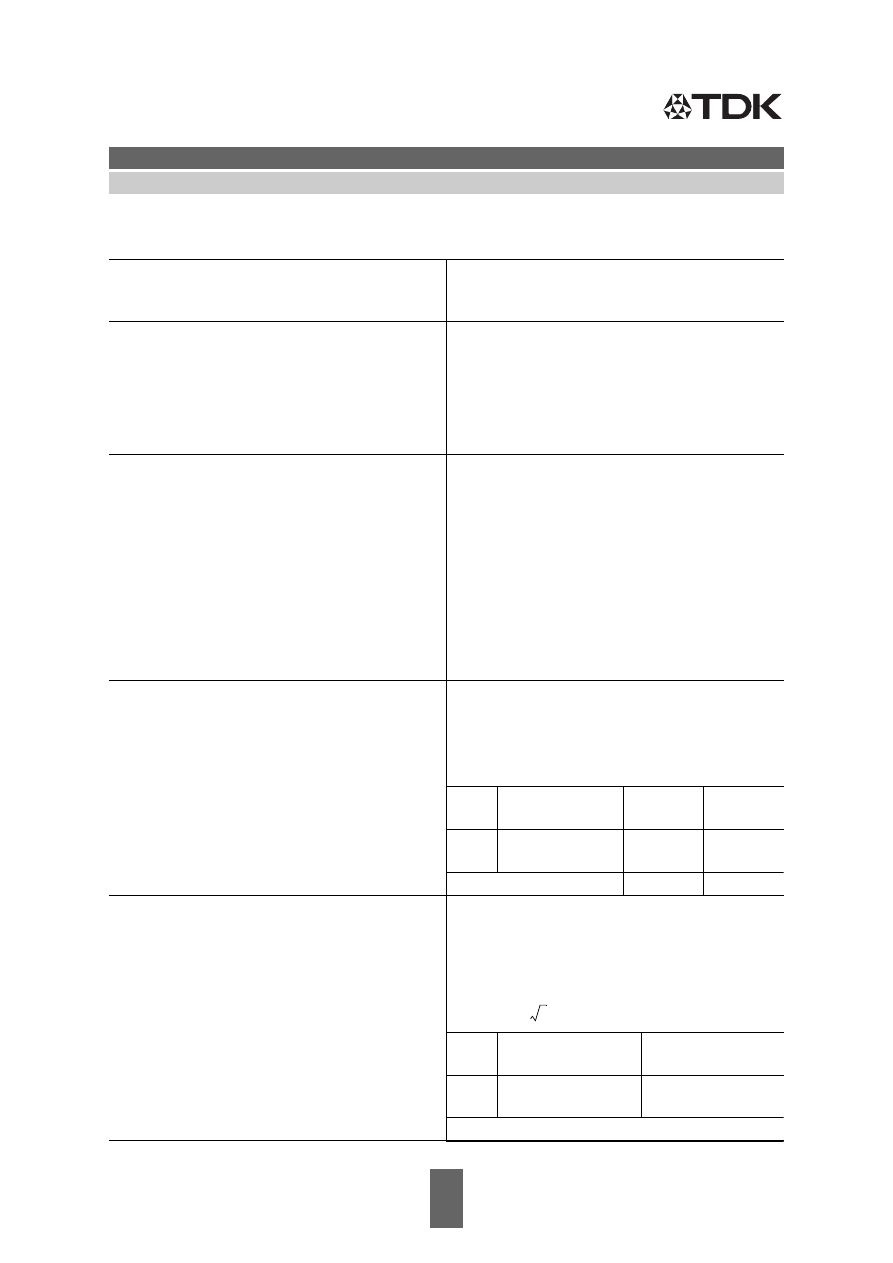
The following products presented in this data sheet are being withdrawn.
Ordering Code
Substitute Product
Date of
Withdrawal
Deadline Last
Orders
Last Shipments
B25834L7685K009
2014-08-14
2015-03-31
2016-09-30
B25834L7475K009
2014-08-14
2015-03-31
2016-09-30
B25834L6685K009
2014-08-14
2015-03-31
2016-09-30
EPCOS AG 2015. Reproduction, publication and dissemination of this publication, enclosures hereto and
the information contained therein without EPCOS' prior express consent is prohibited.
EPCOS AG is a TDK Group Company.
epcos/E12-96-series-En-html.html
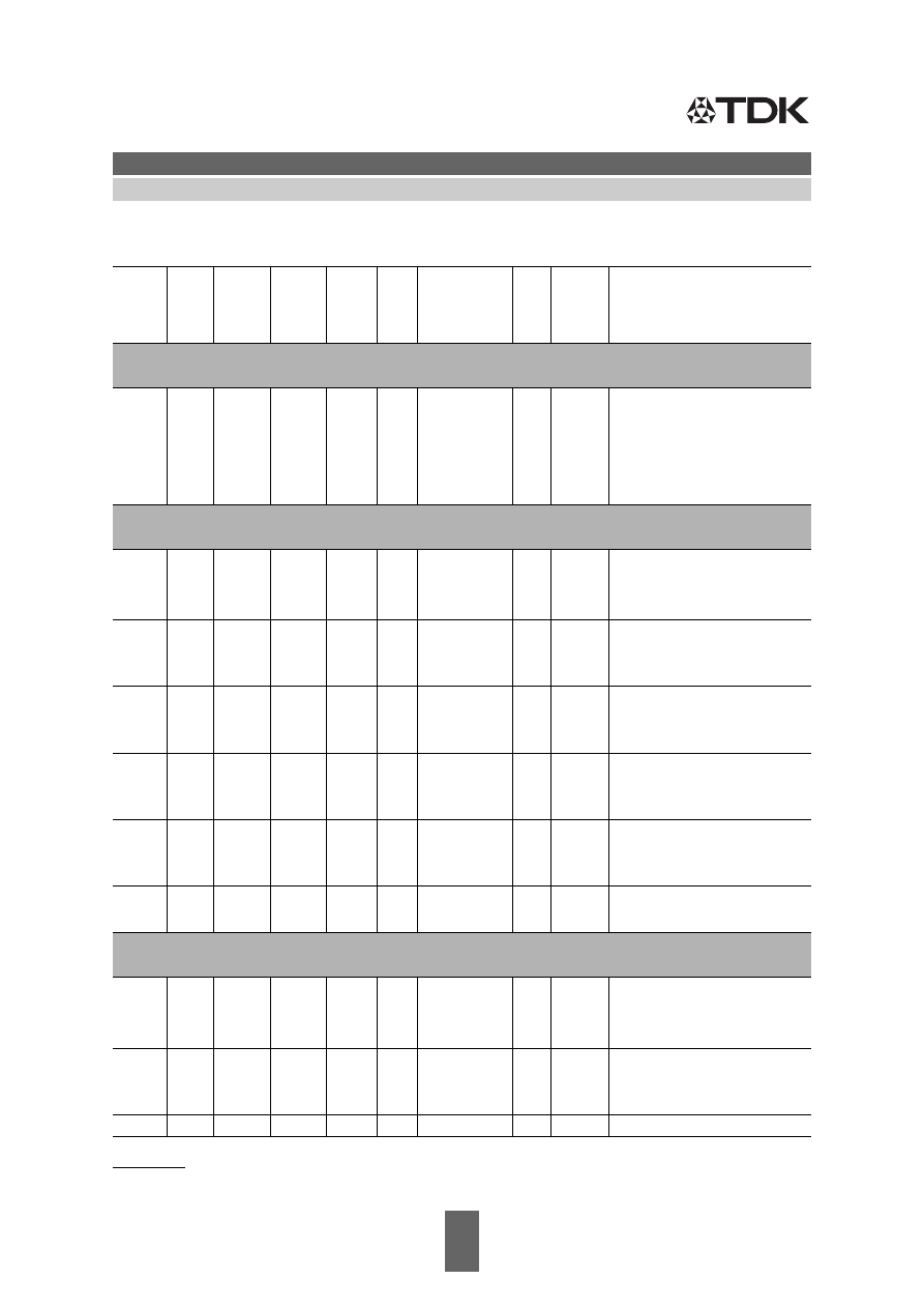
Ordering Code
Substitute Product
Date of
Withdrawal
Deadline Last
Orders
Last Shipments
B25834L6475K009
2014-08-14
2015-03-31
2016-09-30
B25834L6106K009
2014-08-14
2015-03-31
2016-09-30
B25834L5686K009
2014-08-14
2015-03-31
2016-09-30
B25834L5685K009
2014-08-14
2015-03-31
2016-09-30
B25834L5156K009
2014-08-14
2015-03-31
2016-09-30
B25834L5106K009
2014-08-14
2015-03-31
2016-09-30
B25834L4156K009
2014-08-14
2015-03-31
2016-09-30
B25834L4106K009
2014-08-14
2015-03-31
2016-09-30
B25834L3336K009
2014-08-14
2015-03-31
2016-09-30
B25834F6684M001
2014-08-14
2015-03-31
2016-09-30
B25834F6474M001
2014-08-14
2015-03-31
2016-09-30
B25834F6335K001
2014-08-14
2015-03-31
2016-09-30
B25834F6334M001
2014-08-14
2015-03-31
2016-09-30
B25834F6225K001
2014-08-14
2015-03-31
2016-09-30
B25834F6224M001
2014-08-14
2015-03-31
2016-09-30
B25834F6155K001
2014-08-14
2015-03-31
2016-09-30
B25834F6154M001
2014-08-14
2015-03-31
2016-09-30
B25834F6105K001
2014-08-14
2015-03-31
2016-09-30
B25834F6104M001
2014-08-14
2015-03-31
2016-09-30
B25834F5475K001
2014-08-14
2015-03-31
2016-09-30
B25834F4685K001
2014-08-14
2015-03-31
2016-09-30
B25834F4684M001
2014-08-14
2015-03-31
2016-09-30
B25834F4475K001
2014-08-14
2015-03-31
2016-09-30
B25834F4335K001
2014-08-14
2015-03-31
2016-09-30
B25834F4225K001
2014-08-14
2015-03-31
2016-09-30
B25834F4155K001
2014-08-14
2015-03-31
2016-09-30
B25834F4105K001
2014-08-14
2015-03-31
2016-09-30
B25834D7336K004
2014-08-14
2015-03-31
2016-09-30
B25834D7226K004
2014-08-14
2015-03-31
2016-09-30
B25834D7156K004
2014-08-14
2015-03-31
2016-09-30
B25834D7106K004
2014-08-14
2015-03-31
2016-09-30
B25834D6686K004
2014-08-14
2015-03-31
2016-09-30
B25834D6476K004
2014-08-14
2015-03-31
2016-09-30
B25834D6336K004
2014-08-14
2015-03-31
2016-09-30
B25834D6226K009
2014-08-14
2015-03-31
2016-09-30
B25834D6226K004
2014-08-14
2015-03-31
2016-09-30
B25834D6156K009
2014-08-14
2015-03-31
2016-09-30
B25834D6156K004
2014-08-14
2015-03-31
2016-09-30
epcos/E12-96-series-En-html.html
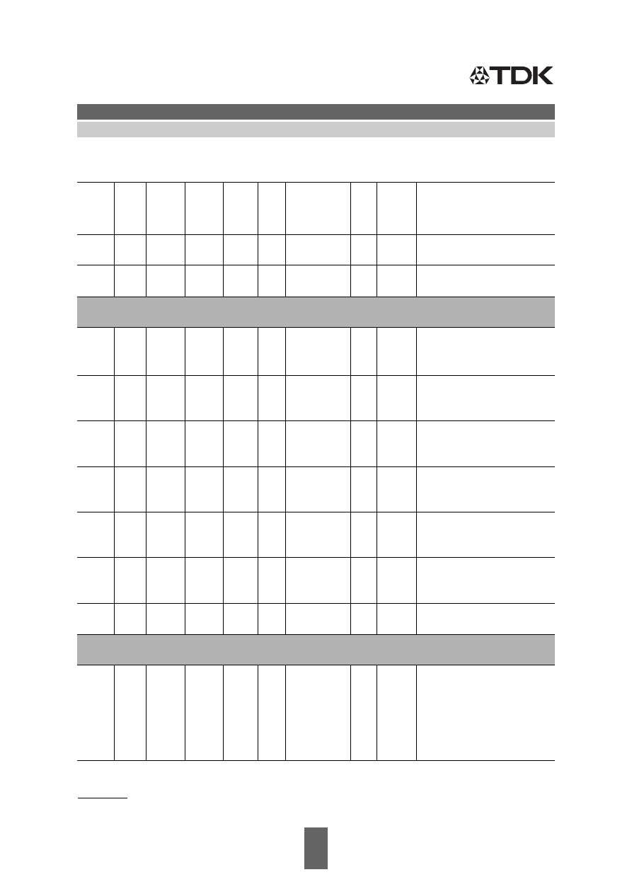
Ordering Code
Substitute Product
Date of
Withdrawal
Deadline Last
Orders
Last Shipments
B25834D5686K004
2014-08-14
2015-03-31
2016-09-30
B25834D5476K004
2014-08-14
2015-03-31
2016-09-30
B25834D5336K009
2014-08-14
2015-03-31
2016-09-30
B25834D5336K004
2014-08-14
2015-03-31
2016-09-30
B25834D5226K009
2014-08-14
2015-03-31
2016-09-30
B25834D5226K004
2014-08-14
2015-03-31
2016-09-30
B25834D5107K004
2014-08-14
2015-03-31
2016-09-30
B25834D4686K004
2014-08-14
2015-03-31
2016-09-30
B25834D4476K009
2014-08-14
2015-03-31
2016-09-30
B25834D4476K004
2014-08-14
2015-03-31
2016-09-30
B25834D4336K009
2014-08-14
2015-03-31
2016-09-30
B25834D4336K004
2014-08-14
2015-03-31
2016-09-30
B25834D4226K004
2014-08-14
2015-03-31
2016-09-30
B25834D4157K004
2014-08-14
2015-03-31
2016-09-30
B25834D4107K004
2014-08-14
2015-03-31
2016-09-30
B25834D3686K004
2014-08-14
2015-03-31
2016-09-30
B25834D3476K004
2014-08-14
2015-03-31
2016-09-30
B25834D3227K004
2014-08-14
2015-03-31
2016-09-30
B25834D3107K004
2014-08-14
2015-03-31
2016-09-30
B25834D2685K004
2014-08-14
2015-03-31
2016-09-30
B25834D2475K004
2014-08-14
2015-03-31
2016-09-30
B25834D2335K004
2014-08-14
2015-03-31
2016-09-30
B25834D2156K004
2014-08-14
2015-03-31
2016-09-30
B25834D2106K004
2014-08-14
2015-03-31
2016-09-30
B25834D1685K004
2014-08-14
2015-03-31
2016-09-30
B25834D1475K004
2014-08-14
2015-03-31
2016-09-30
B25834D1226K004
2014-08-14
2015-03-31
2016-09-30
B25834D1156K004
2014-08-14
2015-03-31
2016-09-30
B25834D1106K004
2014-08-14
2015-03-31
2016-09-30
B25834D0685K004
2014-08-14
2015-03-31
2016-09-30
B25834D0475K004
2014-08-14
2015-03-31
2016-09-30
B25834D0226K004
2014-08-14
2015-03-31
2016-09-30
B25834D0156K004
2014-08-14
2015-03-31
2016-09-30
B25834D0106K004
2014-08-14
2015-03-31
2016-09-30
For further information please contact your nearest EPCOS sales office, which will also support you in selecting a suitable
substitute. The addresses of our worldwide sales network are presented at www.epcos.com/sales.
epcos/E12-96-series-En-html.html
Please read Cautions and warnings and
2
09/05
Important notes at the end of this document.
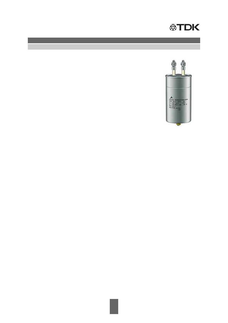
MKV AC Capacitors
Damping, Commutating
B25834
Features
■
High dielectric strength
■
High peak-current capability
Applications
■
For damping and commutating in
the medium frequency range
■
For general AC applications
Construction
■
Self-healing
■
Plastic dielectric
■
Oil-impregnated tubular windings (no PCB)
■
Metal-sprayed end faces ensure reliable contacting
■
Cylindrical aluminum case
■
Plastic or ceramic lead-throughs
■
Mounting bolts M8 or M12
Terminals
■
Screw terminals M10
■
Tab connectors 6.3 mm
■
Dual tab connectors 6.3 mm and 9.5 mm
Mounting
■
If the vibration stress is
≤
5
g
and the capacitors are
≤
60 mm
in diameter and
≤
160 mm in height, the bolt is used for mounting.
Grounding
■
Mounting bolts for grounding in accordance with VDE 0100
■
Grounding identification in accordance with DIN 40 011
Overpressure disconnector (mechanical)
When the overpressure disconnector responds,
the capacitor extends by up to 8 mm.
So leave sufficient space above the terminals when mounting the capacitor.
Individual data sheets
Individual data sheets contain detailed specification incl. thermal data.
Upon request, these data sheets are available for each capacitor type.
epcos/E12-96-series-En-html.html
Please read Cautions and warnings and
3
09/05
Important notes at the end of this document.
MKV AC Capacitors
Damping, Commutating
B25834
Technical data
Standards
IEC 1071-1/2
EN 61071-1/2
VDE 0560 part 120 and 121
Dielectric dissipation factor
tan
δ
0
2 x 10
–4
Capacitance tolerance
For C
N
<
1.0
μ
F
±
20 %, for C
N
≥
1.0
μ
F
±
10 %
Max. repetitive rate
of voltage rise
(du/dt)
max
Max. non-repetitive rate
of voltage rise
(du/dt)
s
Climatic data:
Min. operating temperature
T
min
– 25
°
C
Max. operating temperature
T
max
+ 85
°
C
Average relative humidity
≤
95 % (screw terminals/dual tab 9.5 mm)
≤
75 % (dual tab 6.3 mm/tab 6.3 mm)
Failure quota
α
FQ(co)
300 failures per 10
9
component hours
Load duration
t
LD(co)
100 000 h
Storage temperature limit
T
stg
– 55/+ 85
°
C
IEC climatic category
(IEC 68-1 and 2)
25/085/56
Test A, cold
Test B, dry heat
Test Ca, damp heat, steady state
– 25
°
C
+ 85
°
C
56 days/40
°
C/93 % rel. humidity
Values after test Ca:
Capacitance change
Δ
C/C
≤
1 %
Insulation resistance
R
ins
Self-discharge time constant
τ
= R
ins
x C
Dissipation factor change
Δ
tan
δ
Test data:
AC test voltage
between terminals
V
TT
1.25 x V
N
, 50 Hz, 10 s (or DC 1.75 x V
N
, 10 s)
between terminals and case
V
TC
2 x V
i
+ 1000 V, 50 Hz, 10 s
Insulating voltage V
i
= max. recurrent peak
voltage /
Insulation resistance
R
ins
Self-discharge time constant
τ
= R
ins
x C
Dissipation factor (50 Hz)
tan
δ
î
C
----
I
S
C
----
C
R
Screw terminals,
dual tab 9.5 mm
Dual tab
6.3 mm
Tab
6.3 mm
≤
1
μ
F
≥
10 000 M
Ω
≥
3000 M
Ω ≥
1000 M
Ω
> 1
μ
F
≥
10 000 s
≥
3000 s
≥
1000 s
≤
1 x 10
–4
≤
3 x 10
–4
≤
3 x 10
–4
v
ˆ
2
C
R
Screw terminals,
dual tab 9.5 mm
Dual tab 6.3 mm,
tab 6.3 mm
≤
1
μ
F
≥
10 000 M
Ω
≥
3000 M
Ω
> 1
μ
F
≥
10 000 s
≥
3000 s
≤
3 x 10
–4
epcos/E12-96-series-En-html.html
Please read Cautions and warnings and
4
09/05
Important notes at the end of this document.
MKV AC Capacitors
Damping, Commutating
B25834
Characteristics and ordering codes
C
R
1)
μ
F
I
max
A
î
A
I
s
A
R
S
20
°
C
m
Ω
L
self
nH
Dimensions
d
×
l
mm
Fig. Appr.
weight
g
Ordering code
V
R
= AC 500 V
= 600 V
v
s
= 860 V
V
TT
= AC 620 V, 10 s
V
TC
= AC 2000 V, 10 s
33
18
1300
3300
4.9
90 60
×
86
3
290
B25834-L3336-K009
47
80
1900
4700
1.9
110 79.2
×
104
2
610
B25834-D3476-K004
68
80
2700
6800
1.5
110 99.3
×
104
2
970
B25834-D3686-K004
100
80
4000
10000
1.4
180 79.2
×
248
2
1500
B25834-D3107-K004
220
80
8800
22000
1.2
180 99.3
×
248
2
2300
B25834-D3227-K004
V
R
= AC 600 V
= 750 V
v
s
= 1000 V
V
TT
= AC 750 V, 10 s
V
TC
= AC 2100 V, 10 s
0.68 10
110
270 25.0
50 25
×
48
5
30
B25834-F4684-M001
1.0
10
160
400 18.0
50 25
×
48
5
30
B25834-F4105-K001
1.5
16
240
600 14.0
50 30
×
48
6
50
B25834-F4155-K001
2.2
16
350
880 10.0
50 30
×
48
6
50
B25834-F4225-K001
3.3
16
530
1300
8.7
50 35
×
48
7
60
B25834-F4335-K001
4.7
16
190
470 16.0
90 30
×
80
6
70
B25834-F4475-K001
6.8
16
270
680 13.0
90 35
×
80
7
100
B25834-F4685-K001
10
18
400
1000
8.0
90 40
×
86
3
130
B25834-L4106-K009
15
18
600
1500
6.5
90 50
×
86
3
200
B25834-L4156-K009
22
60
880
2200
3.1
110 64.2
×
104
2
400
B25834-D4226-K004
33
80
1300
3300
2.4
110 79.2
×
104
2
610
B25834-D4336-K004
33
64
1300
3300
2.4
110 79.2
×
104
4
610
B25834-D4336-K009
47
80
1900
4700
2.0
110 89.3
×
104
2
780
B25834-D4476-K004
47
64
1900
4700
2.0
110 89.3
×
104
4
780
B25834-D4476-K009
68
80
2700
6800
1.7
180 64.2
×
248
2
960
B25834-D4686-K004
100
80
4000
10000
1.5
180 79.2
×
248
2
1500
B25834-D4107-K004
150
80
6000
15000
1.3
180 89.3
×
248
2
1900
B25834-D4157-K004
V
R
= AC 750 V
= 940 V
v
s
= 1300 V
V
TT
= AC 930 V, 10 s
V
TC
= AC 2400 V, 10 s
4.7
16
240
590 13.0
90 35.0
×
80
7
100
B25834-F5475-K001
6.8
18
340
850
8.4
90 40.0
×
86
3
130
B25834-L5685-K009
10
18
500
1250
7.0
90 50.0
×
86
3
200
B25834-L5106-K009
15
18
750
1900
5.9
90 60.0
×
86
3
290
B25834-L5156-K009
22
80
1100
2800
2.6
110 79.2
×
104
2
610
B25834-D5226-K004
22
64
1100
2800
2.5
110 79.2
×
104
4
610
B25834-D5226-K009
33
80
1700
4100
2.0
110 89.3
×
104
2
780
B25834-D5336-K004
1) Other capacitance values upon request
vˆ
vˆ
vˆ
epcos/E12-96-series-En-html.html
Please read Cautions and warnings and
5
09/05
Important notes at the end of this document.
MKV AC Capacitors
Damping, Commutating
B25834
33
64
1700
4100
1.9
110 89.3
×
104
4
780
B25834-D5336-K009
47
80
2400
5900
1.7
180 64.2
×
248
2
960
B25834-D5476-K004
68
80
3400
8500
1.6
180 79.2
×
248
2
1500
B25834-D5686-K004
100
80
5000
12500
1.4
180 89.3
×
248
2
1900
B25834-D5107-K004
V
R
= AC 900 V
= 1100 V
v
s
= 1500 V
V
TT
= AC 1150 V, 10 s
V
TC
= AC 2600 V, 10 s
0.10 10
50
120 33.0
50 25.0
×
48
5
30
B25834-F6104-M001
0.15 10
70
180 24.0
50 25.0
×
48
5
30
B25834-F6154-M001
0.22 10
100
260 17.0
50 25.0
×
48
5
30
B25834-F6224-M001
0.33 10
90
220 29.0
50 25.0
×
48
5
30
B25834-F6334-M001
0.47 10
130
320 21.0
50 25.0
×
48
5
30
B25834-F6474-M001
0.68 10
180
460 16.0
50 25.0
×
48
5
30
B25834-F6684-M001
1.0
16
300
750 12.0
50 30.0
×
48
6
50
B25834-F6105-K001
1.5
16
450
1100
9.8
50 35.0
×
48
7
60
B25834-F6155-K001
2.2
16
150
390 18.0
90 30.0
×
80
6
70
B25834-F6225-K001
3.3
16
230
580 14.0
90 35.0
×
80
7
100
B25834-F6335-K001
4.7
18
330
820
9.0
90 40.0
×
86
3
130
B25834-L6475-K009
6.8
18
480
1200
7.3
90 50.0
×
86
3
200
B25834-L6685-K009
10
18
700
1750
6.1
90 60.0
×
86
3
290
B25834-L6106-K009
15
60
1100
2600
2.8
100 79.2
×
104
2
610
B25834-D6156-K004
15
60
1100
2600
2.7
100 79.2
×
104
4
610
B25834-D6156-K009
22
80
1500
3900
2.2
110 89.3
×
104
2
780
B25834-D6226-K004
22
64
1500
3900
2.1
110 89.3
×
104
4
780
B25834-D6226-K009
33
80
2300
5800
1.8
180 64.2
×
248
2
960
B25834-D6336-K004
47
80
3300
8200
1.6
180 79.2
×
248
2
1500
B25834-D6476-K004
68
80
4800
12000
1.4
180 89.3
×
248
2
1900
B25834-D6686-K004
V
R
= AC 1100 V
= 1400 V
v
s
= 1900 V
V
TT
= AC 1400 V, 10 s
V
TC
= AC 3000 V, 10 s
4.7
18
380
940
17.0
140 40.0
×
156
3
240
B25834-L7475-K009
6.8
18
540
1400
13.0
140 50.0
×
156
3
370
B25834-L7685-K009
10
60
800
2000
6.3
150 64.2
×
176
1
680
B25834-D7106-K004
15
80
1200
3000
4.9
150 79.2
×
176
1
1000
B25834-D7156-K004
22
80
1800
4400
3.7
150 89.3
×
176
1
1300
B25834-D7226-K004
33
80
2600
6600
2.8
150 99.3
×
176
1
1600
B25834-D7336-K004
Characteristics and ordering codes
C
R
1)
μ
F
I
max
A
î
A
I
s
A
R
S
20
°
C
m
Ω
L
self
nH
Dimensions
d
×
l
mm
Fig. Appr.
weight
g
Ordering code
1) Other capacitance values upon request
vˆ
vˆ
epcos/E12-96-series-En-html.html
Please read Cautions and warnings and
6
09/05
Important notes at the end of this document.
MKV AC Capacitors
Damping, Commutating
B25834
V
R
= AC 1400 V
= 1800 V
v
s
= 2400 V
V
TT
= AC 1800 V, 10 s
V
TC
= AC 3600 V, 10 s
4.7
60
470
1200
9.3
150 64.2
×
176
1
680
B25834-D0475-K004
6.8
60
680
1700
6.6
150 64.2
×
176
1
680
B25834-D0685-K004
10
80
1000
2500
5.2
150 79.2
×
176
1
1000
B25834-D0106-K004
15
80
1500
3800
3.8
150 89.3
×
176
1
1300
B25834-D0156-K004
22
80
2200
5500
2.9
150 99.3
×
176
1
1600
B25834-D0226-K004
V
R
= AC 1700 V
= 2100 V
v
s
= 2900 V
V
TT
= AC 2100 V, 10 s
V
TC
= AC 4000 V, 10 s
4.7
60
560
1400
13.0
220 64.2
×
248
1
960
B25834-D1475-K004
6.8
60
820
2000
9.0
220 64.2
×
248
1
960
B25834-D1685-K004
10
80
1200
3000
7.0
220 79.2
×
248
1
1500
B25834-D1106-K004
15
80
1800
4500
5.3
220 89.3
×
248
1
1900
B25834-D1156-K004
22
80
2600
6600
3.9
220 99.3
×
248
1
2300
B25834-D1226-K004
V
R
= AC 2100 V
= 2600 V
v
s
= 3600 V
V
TT
= AC 2600 V, 10 s
V
TC
= AC 4800 V, 10 s
3.3
60
530
1300
13.0
220 64.2
×
248
1
960
B25834-D2335-K004
4.7
60
750
1900
9.4
220 64.2
×
248
1
960
B25834-D2475-K004
6.8
80
1100
2700
7.4
220 79.2
×
248
1
1500
B25834-D2685-K004
10
80
1600
4000
5.4
220 89.3
×
248
1
1900
B25834-D2106-K004
15
80
2400
6000
4.1
220 99.3
×
248
1
2300
B25834-D2156-K004
Characteristics and ordering codes
C
R
1)
μ
F
I
max
A
î
A
I
s
A
R
S
20
°
C
m
Ω
L
self
nH
Dimensions
d
×
l
mm
Fig. Appr.
weight
g
Ordering code
vˆ
vˆ
vˆ
1) Other capacitance values upon request
epcos/E12-96-series-En-html.html
Please read Cautions and warnings and
7
09/05
Important notes at the end of this document.
MKV AC Capacitors
Damping, Commutating
B25834
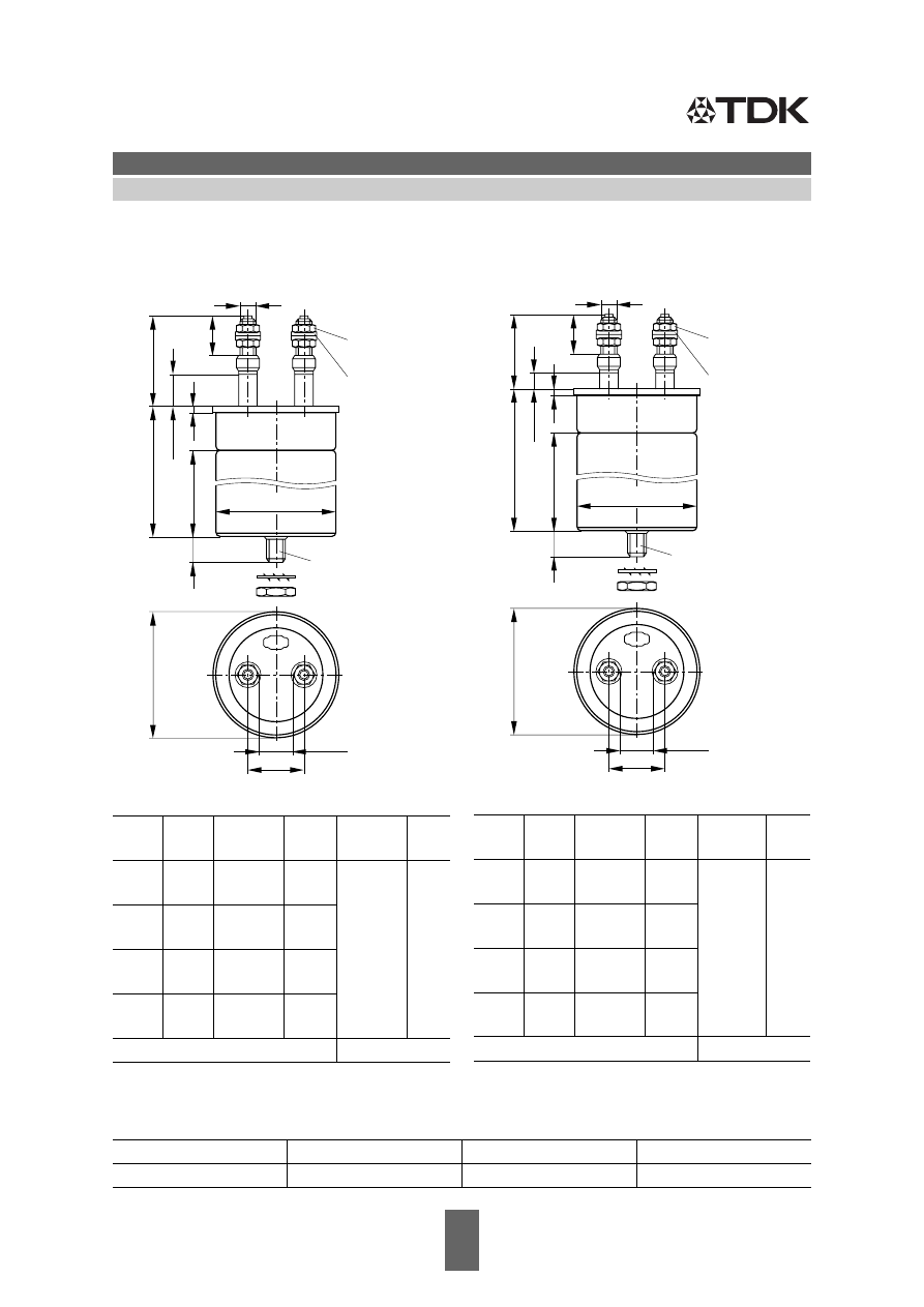
Dimensional drawing 1
Screw terminals M10 (Dimensions in mm)
1) Dimensions for guidance only, subject for modification
Mounting parts
(included in delivery)
d –1,2 l –4
∅
d
1
–0,4
l
1
min
Creepage
distance
Clear-
ance
64.2
64.2
176
248
60.2
60.2
135
204
20
13
79.2
79.2
176
248
75.2
75.2
135
204
89.3
89.3
176
248
85.2
85.2
135
204
99.3
99.3
176
248
95.2
95.2
135
204
Max. torque terminals*)
7 Nm
Threaded bolt
Max. torque
Toothed washer
Hex nut
M12
10 Nm
J 12,5 DIN 6797
M12 DIN 439
KLK1413-6
~
16+1
l
M10
ød
1
13 min.
Hex nut
M12
35
M10 ISO 4035
1
10,5 DIN 433
Washer
4~
20 min.
l
d
3
57
_
_
24,5
2
*) The terminal torque must not act upon the ceramic. So the lead should be locked between two nuts..
Dimensional drawing 2
Screw terminals M10 (Dimensions in mm)
d –1,2 l –4
∅
d
1
–0,4
l
1
min
Creepage
distance
Clear-
ance
64.2
64.2
104
248
60.2
60.2
135
204
10
10
79.2
79.2
104
248
75.2
75.2
75
204
89.3
89.3
104
248
85.2
85.2
75
204
99.3
99.3
104
248
95.2
95.2
75
204
Max. torque terminals*)
7 Nm
KLK1412-X
~
16+1
l
M10
ød
1
13 min.
Hex nut
M12
35
M10 ISO 4035
1
10,5 DIN 433
Washer
4~
10 min.
l
d
3
47
_
_
24,5
2
epcos/E12-96-series-En-html.html
Please read Cautions and warnings and
8
09/05
Important notes at the end of this document.
MKV AC Capacitors
Damping, Commutating
B25834
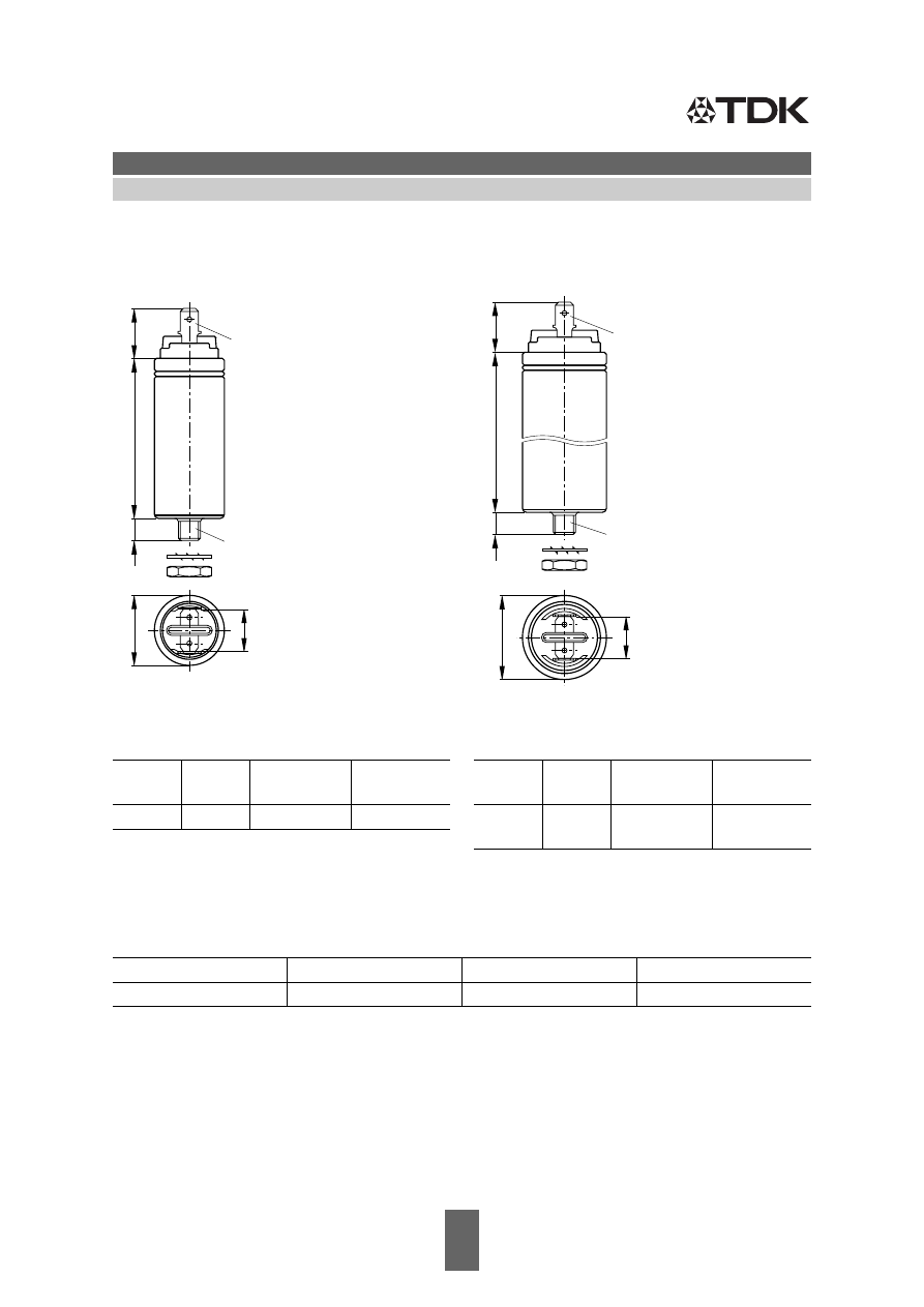
Dimensional drawing 4
Dual tab connectors 9.5 mm
Dimensions in mm
d –1,2
l –4
∅
d
1
–0,4 Creepage
distance
Clear-
ance
79.2
104
75.2
10
10
89.3
104
85.2
KLK1294-P
M12
l
ød
1
15,5 min.
35±2
4
16+1
Tab connector
A 9,5 x 1,2
3
_
33
~ ~
75 min.
d
DIN 46 244
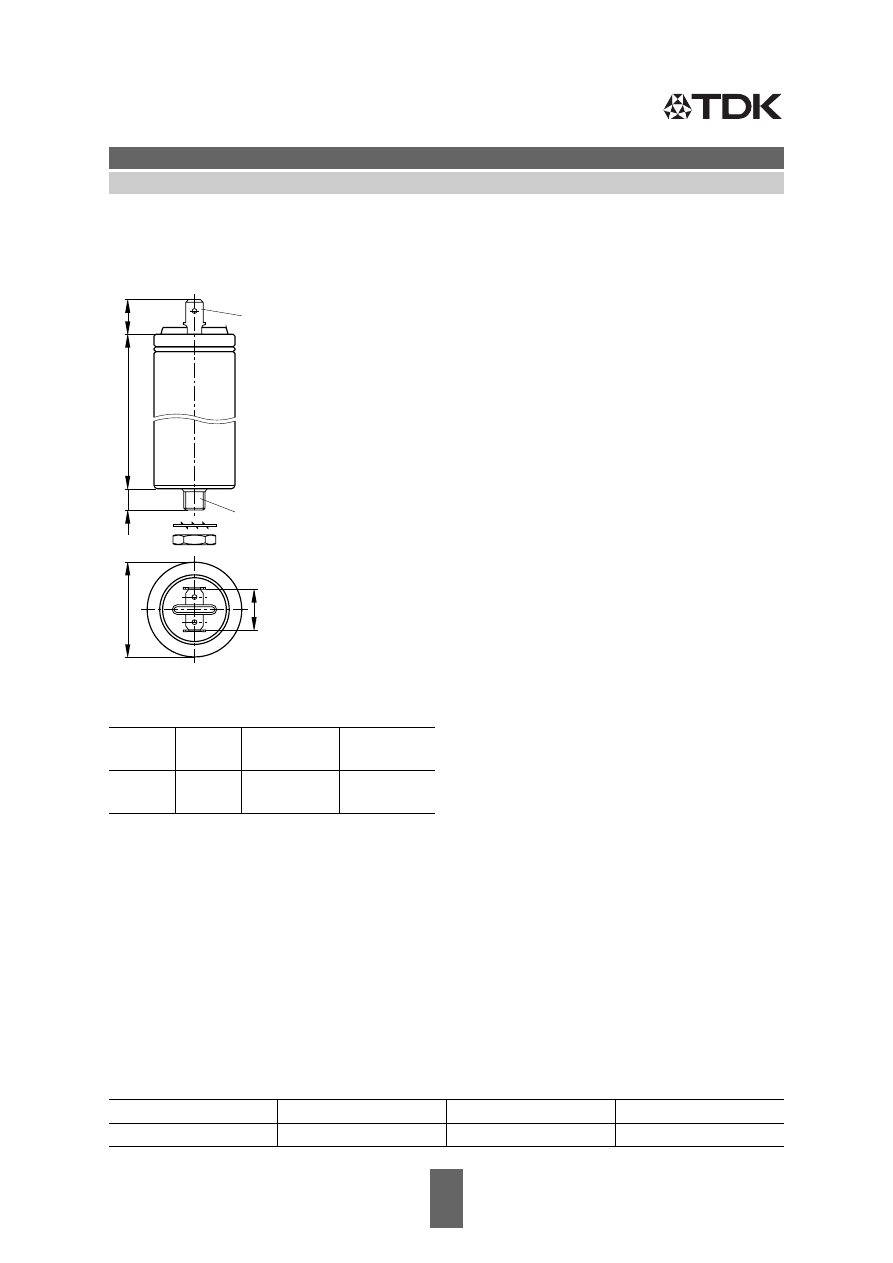
Dimensional drawing 3
Dual tab connectors 6.3 mm
Dimensions in mm
*) 8 mm = threaded bolt M8
12 mm = threaded bolt M12
Mounting parts
(included in delivery)
d
l
l
1
+1*) Creepage
distance
Clearance
40
86
8
10
6
40
156
8
50
86
12
50
156
12
60
86
12
Toothed washer
Hex nut
J 8.2 DIN 6797
M 8 ISO 4035
J 12.5 DIN 6797
M12 ISO 4035
KLK1297-E
24
6,8+0,2
0,8±0,04
8+0,5
6,3±0,1
17,5 max.
l
l
1
d
+0,5
–0,2
+1
–2
epcos/E12-96-series-En-html.html
Please read Cautions and warnings and
9
09/05
Important notes at the end of this document.
MKV AC Capacitors
Damping, Commutating
B25834
Dimensional drawing 6
Tab connectors 6.3 mm
Dimensions in mm
d
l
±
2
Creepage
distance
Clearance
30
48
9
7
30
80
KLK1416-V
18 max.
Tab connector
M8
8+1
A 6,3 x 0,8
DIN 46 244
l
d
15,5±0,5
12
+0,5
–0,2
Dimensional drawing 5
Tab connectors 6.3 mm
Dimensions in mm
Mounting parts
(included in delivery)
d
l
±
2
Creepage
distance
Clearance
25
48
9
7
Threaded bolt
Max. torque
Toothed washer
Hex nut
M8
4 Nm
J 8.2 DIN 6797
M 8 DIN 439
KLK1415-M
18 max.
Tab connector
M8
8+1
A 6,3 x 0,8
DIN 46 244
l
d
15,5±0,5
12
+0,5
–0,2
epcos/E12-96-series-En-html.html
Please read Cautions and warnings and
10
09/05
Important notes at the end of this document.
MKV AC Capacitors
Damping, Commutating
B25834
Dimensional drawing 7
Tab connectors 6,3 mm
Dimensions in mm
Mounting parts
(included in delivery)
d
l
±
2
Creepage
distance
Clearance
35
48
6
6
35
80
Threaded bolt
Max. torque
Toothed washer
Hex nut
M8
4 Nm
J 8,2 DIN 6797
M 8 DIN 439
KLK1418-C
13 max.
Tab connector
M8
8+1
A 6,3 x 0,8
DIN 46 244
l
d
15,5±0,5
12
+0,5
–0,2
epcos/E12-96-series-En-html.html

11
09/05
MKV AC Capacitors
Damping, Commutating
B25834
Cautions and warnings
Safety
■
In case of dents of more than 1 mm depth or any other mechanical damage, capacitors must not
be used at all. This applies also in cases of oil leakage.
■
Electrical or mechanical misapplication of capacitors may be hazardous. Personal injury or prop-
erty damage may result from bursting of the capacitor or from expulsion of oil or melted material
due to mechanical disruption of the capacitor.
■
Ensure good, effective grounding for capacitor enclosures.
■
Observe appropriate safety precautions during operation (self-recharging phenomena and the
high energy contained in capacitors).
■
Handle capacitors carefully, because they may still be charged even after disconnection.
■
The terminals of capacitors, connected bus bars and cables as well as other devices may also
be energized.
■
Follow good engineering practice.
■
Failure to follow cautions may result, worst case, in premature failures, bursting and fire.
Thermal load
After installation of the capacitor it is necessary to verify that maximum hot-spot temperature is not
exceeded at extreme service conditions (see www.epcos.com/thermal_design).
Mechanical protection
The capacitor has to be installed in a way that mechanical damages and dents in the aluminum can
are avoided.
Storage and Operating Conditions
Do not use or store capacitors in corrosive atmosphere especially where chloride gas, sulfide gas,
acid, alkali, salt or the like are present. In dusty environments, regular maintenance and cleaning
especially of the terminals is required to avoid conductive path between phases and/or phases and
ground.
Overpressure disconnector
To ensure full functionality of an overpressure disconnector, the following must be observed:
■
The elastic elements must not be hindered, i.e.
– connecting lines must be flexible leads (cables),
– there must be sufficient space (minimum 12 mm) above the connections for expansion of the
overpressure disconnector,
– folding crimps must not be retained by clamps.
■
Stress parameters of the capacitor must be within the IEC61071 specification.
Service life expectancy
Electrical components do not have an unlimited service life expectancy; this applies to self-healing
capacitors too. The maximum service life expectancy may vary depending on the application the
capacitor is used in.
epcos/E12-96-series-En-html.html

12
09/05
Important notes
The following applies to all products named in this publication:
1. Some parts of this publication contain
statements about the suitability of our products for
certain areas of application
. These statements are based on our knowledge of typical require-
ments that are often placed on our products in the areas of application concerned. We neverthe-
less expressly point out
that such statements cannot be regarded as binding statements
about the suitability of our products for a particular customer application.
As a rule, EPCOS is either unfamiliar with individual customer applications or less familiar with
them than the customers themselves. For these reasons, it is always ultimately incumbent on the
customer to check and decide whether an EPCOS product with the properties described in the
product specification is suitable for use in a particular customer application.
2. We also point out that
in individual cases, a malfunction of passive electronic components
or failure before the end of their usual service life cannot be completely ruled out in the
current state of the art, even if they are operated as specified.
In customer applications re-
quiring a very high level of operational safety and especially in customer applications in which the
malfunction or failure of a passive electronic component could endanger human life or health
(e.g. in accident prevention or life-saving systems), it must therefore be ensured by means of suit-
able design of the customer application or other action taken by the customer (e.g. installation of
protective circuitry or redundancy) that no injury or damage is sustained by third parties in the
event of malfunction or failure of a passive electronic component.
3.
The warnings, cautions and product-specific notes must be observed
.
4. In order to satisfy certain technical requirements,
some of the products described in this pub-
lication may contain substances subject to restrictions in certain jurisdictions (e.g. be-
cause they are classed as “hazardous”)
. Useful information on this will be found in our Material
Data Sheets on the Internet (www.epcos.com/material). Should you have any more detailed
questions, please contact our sales offices.
5. We constantly strive to improve our products. Consequently,
the products described in this
publication may change from time to time
. The same is true of the corresponding product
specifications. Please check therefore to what extent product descriptions and specifications
contained in this publication are still applicable before or when you place an order.
We also
reserve the right to discontinue production and delivery of products
. Consequent-
ly, we cannot guarantee that all products named in this publication will always be available.
6. Unless otherwise agreed in individual contracts,
all orders are subject to the current version
of the “General Terms of Delivery for Products and Services in the Electrical Industry”
published by the German Electrical and Electronics Industry Association
(ZVEI)
.
7. The trade names EPCOS, CeraDiode, CSSP, PhaseCap, PhaseMod, SilverCap, SIFI, SIMID,
SIKOREL, SIOV, SIP5D, SIP5K, TOPcap, UltraCap, WindCap are
trademarks registered or
pending
in Europe and in other countries. Further information will be found on the Internet at
www.epcos.com/trademarks.