
CONNECTOR OVERVIEW
ELECTRONICS
CONNECTOR OVERVIEW
ELECTRONICS
2
FCI: SETTING
THE STANDARD
FOR CONNECTORS
With 13,000 employees
in 30 countries and sales of
1.25 billion euros in 2008,
FCI is a leading manufacturer
of connectors for various
markets such as automotive,
telecommunication
infrastructures and consumer
and industrial electronics.
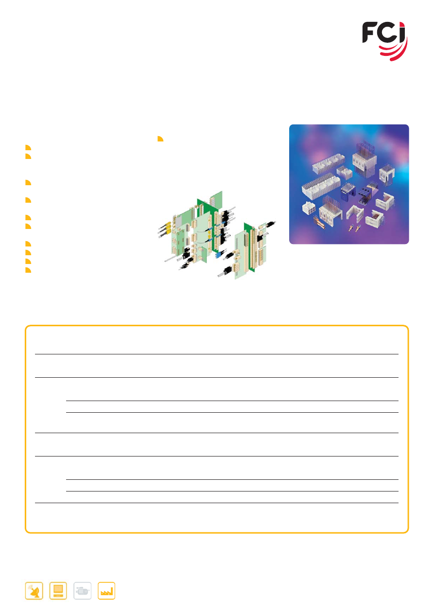
FCI ELECTRONICS is a key supplier to companies that manufacture computing,
networking, telecommunications, and personal communications equipment
ranging from servers and storage devices to base stations and switches to
cellular telephones, personal computers and cashless payment systems.
FCI is the leading innovator in the design, development and high volume
manufacturer of Ball Grid Array (BGA) connectors for dense mezzanine board
packaging operating at extremely high signal rates. In the field of smart cards,
FCI provides both the micro-flex circuitry for semi-conductor packaging and
the chip card connectors for applications that include pay phones,
banking machines, health data applications, and toll payment systems.
FCI is also a world leader in providing cost-effective and innovative
backplane, board-to-board, and I/O interconnect solutions that satisfy
increasingly-demanding performance requirements in the converging
Datacom and Telecom markets.
ELECTRONICS
www.fci.com
3
HOW TO USE THIS BROCHURE
Welcome to the Product Overview brochure for FCI ELECTRONICS. In this brochure,
you will find an overview of each of our major product lines accompanied by a list of
some of the most commonly used parts within that connector family. Using those
references you can go directly to FCI’s home page on the internet, enter the part
number and see full data sheets and drawings for that part. We also indicate the link to
the landing page in our interactive Catalog where you can obtain more information for
these and other part numbers within each connector family.
FCI also has 9 micro sites available that offer more direct
access to specific products and all technical related product
details like: customer drawings, technical specifications,
3D-models, mating half information and more:
www.fci.com/backpanel
www.fci.com/basics
www.fci.com/cableassembly
www.fci.com/flex
www.fci.com/highspeed
www.fci.com/io (available fall 2009)
www.fci.com/mezzselect
www.fci.com/powersolutions
www.fci.com/storageinterface
www.fci.com
Or go directly to the landing page
DATA
COMMUNICATION
CON
S
UMER
INDU
S
TRIAL
Use icon to find application
View data sheet and drawings online
www.fci.com
Enter the part reference in FCI web site
4
CONTENTS
www.fci.com
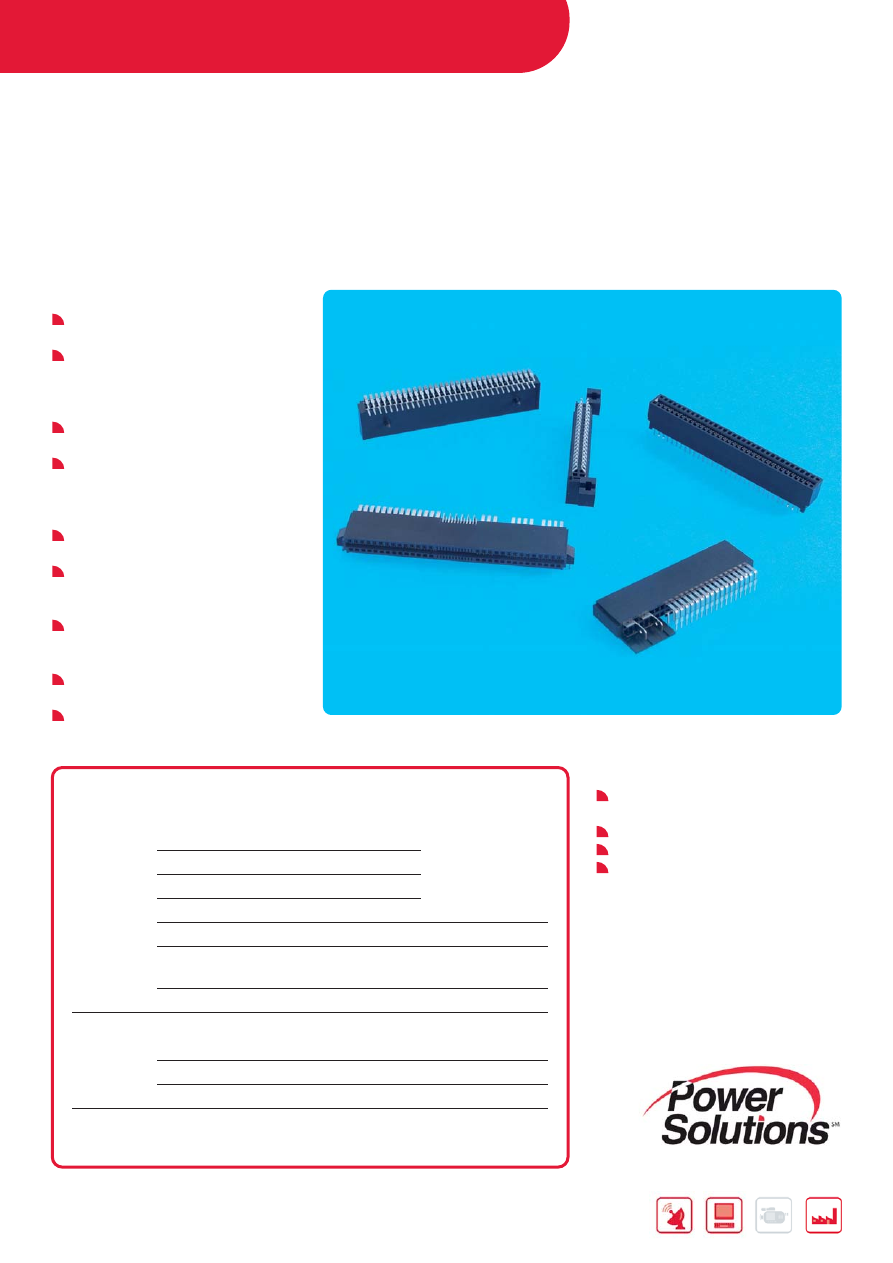
BACKPLANE CONNECTORS
XCEDE
®
HIGH-PERFORMANCE BACKPLANE SYSTEM
UNIQUE RESONANCE DAMPING SHIELD TECHNOLOGY
..................
●
...............
●
...............
●
...............
●
.............
6
ZIPLINE™
HIGH-DENSITY, HIGH-PERFORMANCE CONNECTOR SYSTEM
.........
●
...............
●
...............
●
...............
●
.............
7
AIRMAX VS
®
HIGH SPEED BACKPLANE CONNECTORS
..........................................
●
...............
●
...............
●
...............
●
.............
8
METRAL
®
1000, 2000, 4000
HIGH SPEED BACKPLANE CONNECTORS
.........................................
●
...............
●
...............
●
...............
●
...........
10
METRAL
®
2 MM MODULAR INTERCONNECT SYSTEM
......................................
●
...............
●
...............
●
...............
●
...........
11
MILLIPACS
®
HARD METRIC 2 MM CONNECTORS
.................................................
●
...............
●
...............
●
...............
●
...........
12
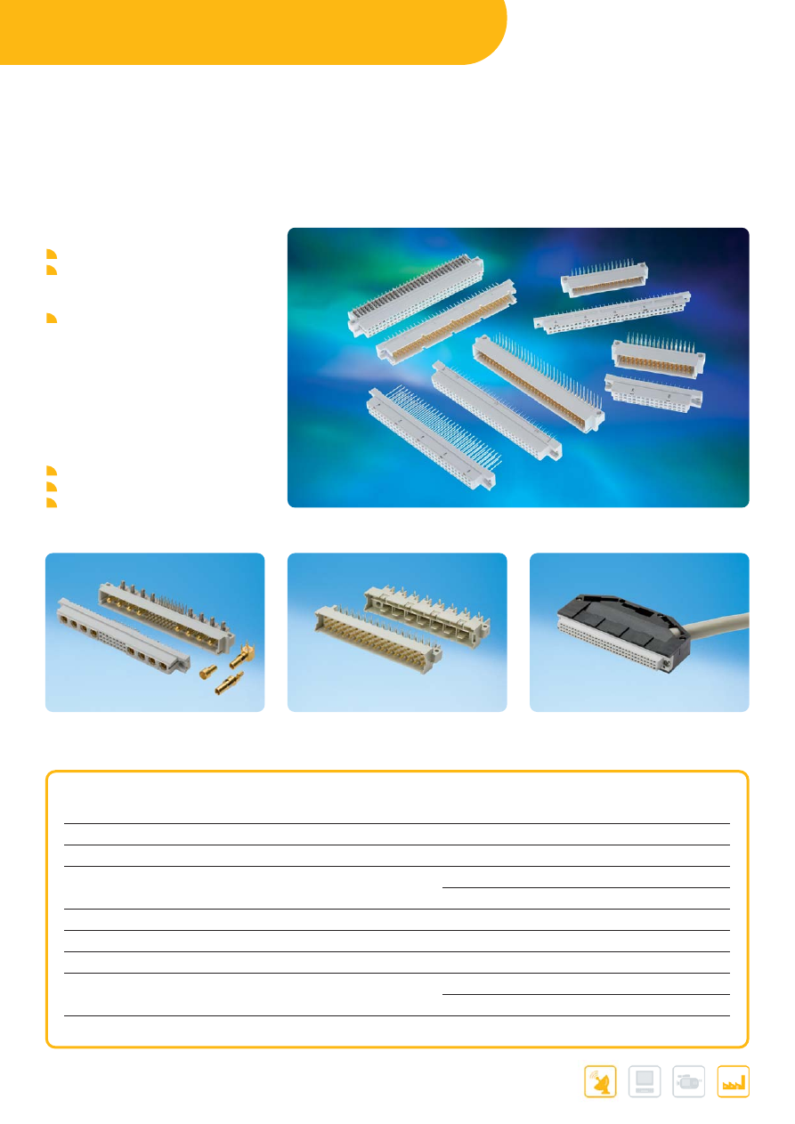
DIN 41612
..........................................................................................
●
...............
●
...............
●
...............
●
...........
14
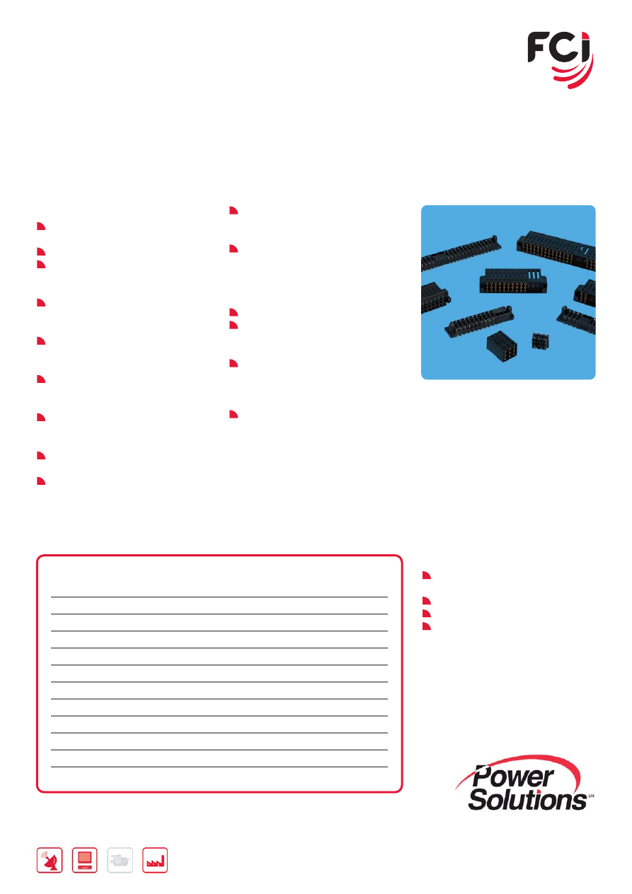
POWER CONNECTORS / POWER CABLE ASSEMBLIES
PWRBLADE
®
AC/DC POWER DISTRIBUTION CONNECTOR SYSTEM
.....................
●
...............
●
...............
●
...............
●
...........
16
POWER CARD EDGE
LOW PROFILE AC/DC POWER DISTRIBUTION CONNECTOR SYSTEM
..
●
...............
●
...............
●
...............
●
...........
18
HCI
®
AC/DC HIGH POWER DISTRIBUTION CONNECTOR SYSTEM
...........
●
...............
●
...............
●
...............
●
...........
19
HARD METRIC HIGH POWER CONNECTORS
........................
●
...............
●
...............
●
...............
●
...........
20
HCI
®
HIGH POWER
HIGH POWER BACKPLANE/MIDPLANE CONNECTOR SYSTEM
........
●
...............
●
...............
●
...............
●
...........
21
PWR PROFILE+™
LOW PROFILE I/O CABLE ASSEMBLIES
.............................................
●
...............
●
...............
●
...............
●
...........
22
PWRBLADE
®
POWER I/O CABLE ASSEMBLIES
.......................................................
●
...............
●
...............
●
...............
●
...........
23
PWR TWINBLADE™
HIGH POWER I/O CABLE ASSEMBLIES
..............................................
●
...............
●
...............
●
...............
●
...........
24
BOARD-TO-BOARD / WIRE-TO-BOARD CONNECTORS
MEG-ARRAY
®
HIGH SPEED MEZZANINE CONNECTORS
..........................................
●
...............
●
...............
●
...............
●
...........
26
GIG-ARRAY
®
HIGH SPEED MEZZANINE CONNECTORS
..........................................
●
...............
●
...............
●
...............
●
...........
28
BERGSTAK
®
0.8 MM
FINE PITCH, MEZZANINE CONNECTORS
...........................................
●
...............
●
...............
●
...............
●
...........
29
CONAN
®
1.0 MM
FINE PITCH, MEZZANINE CONNECTORS
...........................................
●
...............
●
...............
●
...............
●
...........
30
RIB-CAGE™ 1.27 MM
MEZZANINE CONNECTORS
................................................................
●
...............
●
...............
●
...............
●
...........
31
MEZZOSTAK™ 0.5 MM HERMAPHRODITIC
FINE PITCH, MEZZANINE CONNECTORS
...........................................
●
...............
●
...............
●
...............
●
...........
32
FLOATING BOARD-TO-BOARD
BTFW SERIES
.......................................................................................
●
...............
●
...............
●
...............
●
...........
33
FFC - FPC CONNECTORS
............................................................
●
...............
●
...............
●
...............
●
...........
34
BERGSTIK
®
/ DUBOX™ / QUICKIE
®
/ PV™
2.54 MM MODULAR SYSTEM
.............................................................
●
...............
●
...............
●
...............
●
...........
36
MINITEK™
2 MM MODULAR SYSTEM
..................................................................
●
...............
●
...............
●
...............
●
...........
38
CARD EDGE CONNECTORS
FOR SFP, XFP AND XENPAK APPLICATIONS
......................................
●
...............
●
...............
●
...............
●
...........
39
CARD EDGE CONNECTORS
FOR MICROTCA™ APPLICATIONS
......................................................
●
...............
●
...............
●
...............
●
...........
40
CARD EDGE CONNECTORS
FOR PCI EXPRESS* TECHNOLOGY
....................................................
●
...............
●
...............
●
...............
●
...........
41
New
Product
New
New
product
product
New
Product
New
New
product
product
New
Product
New
New
product
product
New
Product
New
New
product
product
5
www.fci.com
STORAGE INTERFACE CONNECTORS
SAS
SERIAL ATTACHED SCSI
.....................................................................
●
...............
●
...............
●
...............
●
...........
42
SCA-2 CONNECTOR SYSTEM
....................................................
●
...............
●
...............
●
...............
●
...........
44
SATA
SERIAL ATA I/O
....................................................................................
●
...............
●
...............
●
...............
●
...........
46
eSATA CONNECTORS
....................................................................
●
...............
●
...............
●
...............
●
...........
48
MICRO SATA CONNECTORS
.......................................................
●
...............
●
...............
●
...............
●
...........
49
SLIMLINE SATA CONNECTORS
..................................................
●
...............
●
...............
●
...............
●
...........
50
iVDR CONNECTORS
INFORMATION VERSATILE DISK FOR REMOVABLE USAGE
..............
●
...............
●
...............
●
...............
●
...........
51
INPUT/OUTPUT CONNECTORS / CABLE ASSEMBLIES
MINI MULTILANE EXTERNAL
MINI SAS OR MINI SATA 4X LINKS CABLE ASSEMBLIES
....................
●
...............
●
...............
●
...............
●
...........
52
SFP+ COPPER CABLE ASSEMBLIES
FOR ETHERNET AND FIBER CHANNEL APPLICATIONS
....................
●
...............
●
...............
●
...............
●
...........
53
DENSISHIELD™ I/O SYSTEM
......................................................
●
...............
●
...............
●
...............
●
...........
54
EYEMAX
®
HIGH SPEED I/O SYSTEM
...................................................................
●
...............
●
...............
●
...............
●
...........
55
OUTDOOR I/O
OUTDOOR I/O SOLUTIONS
.................................................................
●
...............
●
...............
●
...............
●
...........
56
METRAL
®
HDXS
HIGH SPEED FRONT I/O INTERCONNECTION SYSTEM
....................
●
...............
●
...............
●
...............
●
...........
57
METRAL
®
CABLE CONNECTORS
CABLE CONNECTORS FOR METRAL AND IEC 2MM PCB HEADERS
....
●
...............
●
...............
●
...............
●
...........
58
SOFIX
®
FRONT I/O INTERCONNECTION SYSTEM
...........................................
●
...............
●
...............
●
...............
●
...........
59
LOW PROFILE SUBSCRIBER INTERFACE
SIGNAL & POWER FOR DSL SUBSCRIBER ACCOUNTS
...................
●
...............
●
...............
●
...............
●
...........
60
USB
UNIVERSAL SERIAL BUS
.....................................................................
●
...............
●
...............
●
...............
●
...........
61
HDMI
HIGH DEFINITION MULTIMEDIA INTERFACE
.......................................
●
...............
●
...............
●
...............
●
...........
62
MAGNETIC JACKS CONNECTORS
............................................
●
...............
●
...............
●
...............
●
...........
63
MODULAR JACKS
...........................................................................
●
...............
●
...............
●
...............
●
...........
64
D-SUBMINIATURE
PCB APPLICATIONS
.............................................................................
●
...............
●
...............
●
...............
●
...........
66
CABLE APPLICATIONS
........................................................................
●
...............
●
...............
●
...............
●
...........
67
LATCH-N-LOK™
I/O CONNECTOR SYSTEM
..................................................................
●
...............
●
...............
●
...............
●
...........
68
CARD SYSTEMS
DDR2 MEMORY MODULE SOCKETS
........................................
●
...............
●
...............
●
...............
●
..........
70
DDR3 MEMORY MODULE SOCKETS
........................................
●
...............
●
...............
●
...............
●
..........
71
SMART CARD CONNECTORS
.....................................................
●
...............
●
...............
●
...............
●
..........
72
PC CARD HEADERS
......................................................................
●
...............
●
...............
●
...............
●
..........
74
EXPRESSCARD™ SYSTEMS
EXPRESSCARD MODULE CARD KITS AND HOST SYSTEMS
...........
●
...............
●
...............
●
...............
●
..........
76
New
Product
New
New
product
product
New
Product
New
New
product
product
New
Product
New
New
product
product
New
Product
New
New
product
product
BACKPLANE CONNECTORS
6
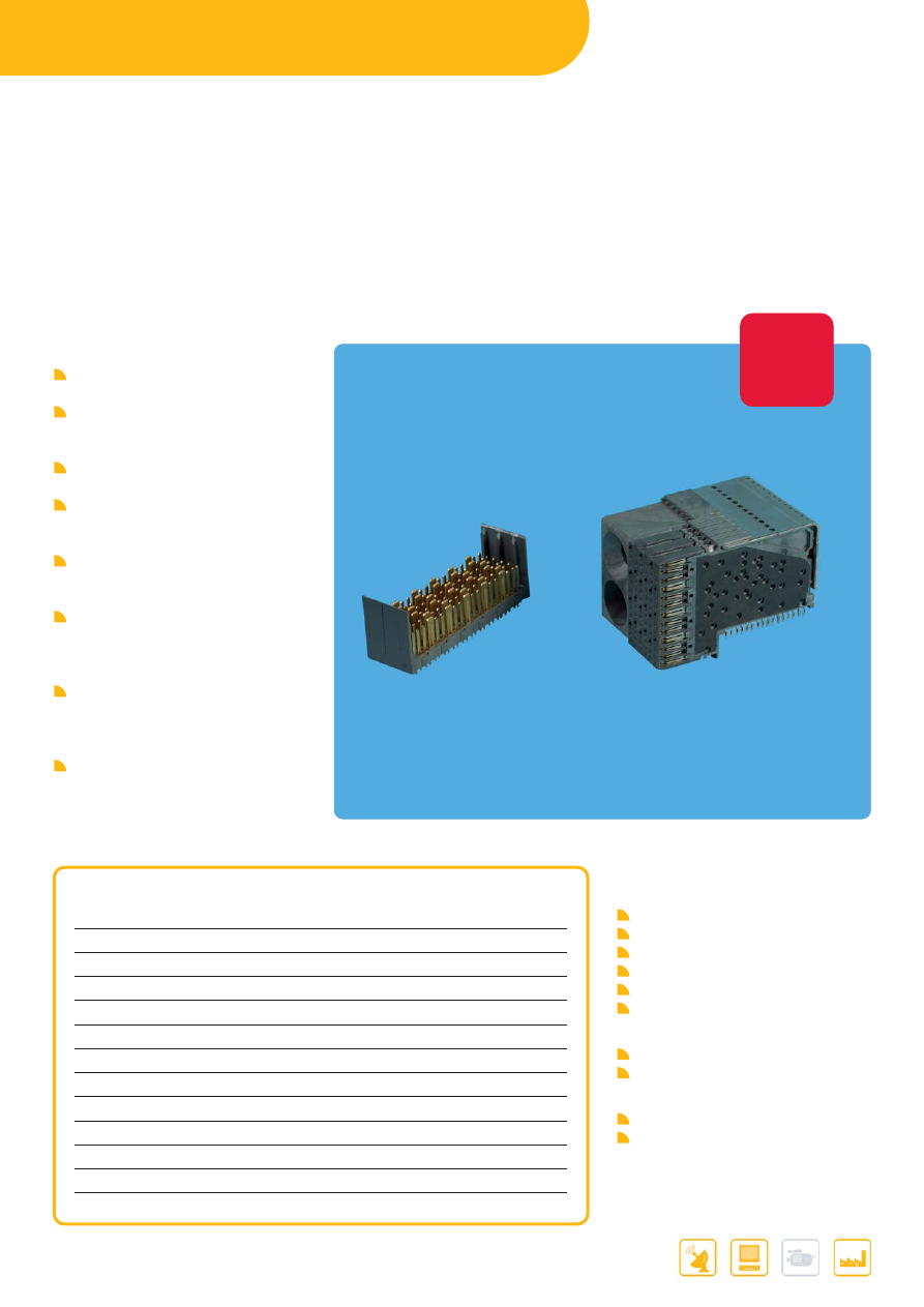
XCEDE
®
HIGH-PERFORMANCE
BACKPLANE CONNECTOR SYSTEM
UNIQUE RESONANCE DAMPING SHIELD TECHNOLOGY
ENABLES VERY LOW CROSSTALK
FEATURES & BENEFITS
High-speed backplane system capable
of 20+ Gb/s
Use of advanced engineering materials
in the shield aids in elimination of
crosstalk resonances
1.85mm column pitch offers high linear
signal density
4 pair 6 column fits 25mm card slot
pitch and provides 55 differential
pairs / inch
Two ground vias between differential
pairs allow elongated antipads to
further improve impedance
Optional short compliant pin permits
deeper backdrilling and dual diameter
vias to enhance return loss
performance
Wide shield contacts feature a
stiffening rib and are advanced well
ahead of signals for exceptional
robustness and signal pin protection
Intermateable, electrically and
mechanically interchangeable second
source to Amphenol TCS
APPLICATIONS
Communications
Routers
Switches
Networking
Access
Transport
Wireless
Data
Servers
Storage Systems
Industrial
Medical
Test & Measurement
PART REFERENCES
MAIN PRODUCTS
Description
FCI P/N
4 pair 6 column 2 wall Open Module
10091767-00C-10DLF
4 pair 6 column 2 wall Open Module
10091767-00C-20B
4 pair 6 column 2 wall Open Module
10091767-00C-20DLF
4 pair 6 column Left Polarization Guidance Module
10091767-A0C-20DLF
4 pair 6 column Left Polarization Guidance Module
10091767-C0C-20DLF
4 pair 6 column Left Polarization Guidance Module w/o Key 10091767-J0C-20B
4 pair 6 column 3 wall Left Module
10091767-L0C-20B
4 pair 6 column 3 wall Left Module
10091767-L0C-20DLF
4 pair 6 column 3 wall Right Module
10091767-M0C-20DLF
4 pair 6 column Right Polarization Guidance Module
10091767-P0C-20DLF
4 pair 6 column Right Polarization Guidance Module
10091767-R0C-20DLF
4 pair 6 column Right Polarization Guidance Module w/o Key 10091767-Y0C-20B
Further information can be found at:
www.fci.com/highspeed
XCede
®
is a registered trademark of Amphenol
Corporation
New
Product
New
New
product
product
Parts will become available in January 2010
7
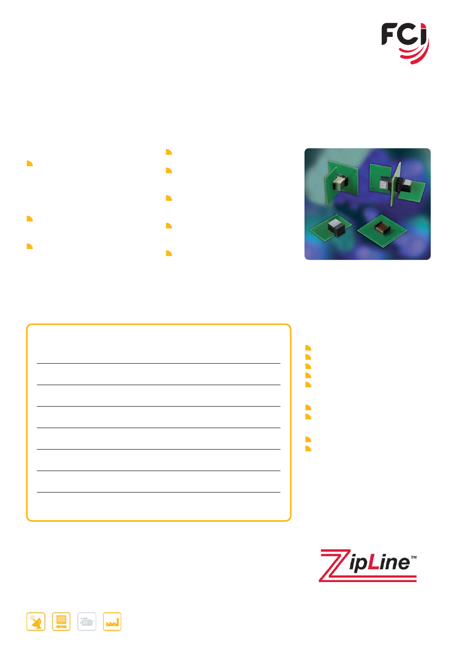
ZIPLINE™
HIGH-DENSITY, HIGH-PERFORMANCE
CONNECTOR SYSTEM
FEATURES & BENEFITS
Supports backplane and orthogonal
midplane applications 6-pair modules
with IMLAs on 1.8 mm column pitch
deliver 84.6 differential pairs per inch
of card edge while allowing a minimum
1-inch card slot pitch
Supports coplanar applications with
6-pair module with IMLAs on 1.8 mm
column pitch
6-pair modules can also be configured
on 1.5 mm column pitch to provide
>100 pairs per inch for even more
density 3-pair configuration is under
development to enable use on 15 mm
card slot pitch
Provides maximum signal density
available at data rates up to 12.5 Gb/s
Use innovative shield-less design and
air dielectric between conductors to
deliver low insertion loss and crosstalk
Allows for mixed differential (orthogonal
or backplane), single-ended or power
pin assignments within a connector
A special power wafer, with up to 36A
capacity, can be integrated within a
6-pair module
Compatible with Hard Metric
equipment practice
APPLICATIONS
Communications
Routers
Switches
Networking
Access
Transport
Data
Servers
Storage Systems
Industrial
Medical
Test & Measurement
PART REFERENCES
MAIN PRODUCTS
10076197-101LF
6 pairs/column x 12 columns (72 differential pairs)
vertical backplane header
10076209-101LF
6 pairs/column x 12 columns (72 differential pairs)
right-angle receptacle
10076222-101LF
6 pairs/column x 12 columns (72 differential pairs)
orthogonal midplane header
10084164-101LF
1 power wafer + 6 pairs/column x 11 columns
(66 differential pairs) right-angle receptacle
10084164-102LF
2 power wafers + 6 pairs/column x 10 columns
(60 differential pairs) right-angle receptacle
10084166-101LF
1 power wafer + 6 pairs/column x 11 columns
(66 differential pairs) vertical backplane header
10084166-103LF
2 power wafers + 6 pairs/column x 10 columns
(60 differential pairs) vertical backplane Header
10077555-101LF
6 pairs/column x 12 columns (72 differential pairs)
right-angle coplanar header
Further information can be found at:
www.fci.com/zipline
www.fci.com/highspeed
BACKPLANE CONNECTORS
8
Further information can be found at:
www.fci.com/airmax
www.fci.com/highspeed
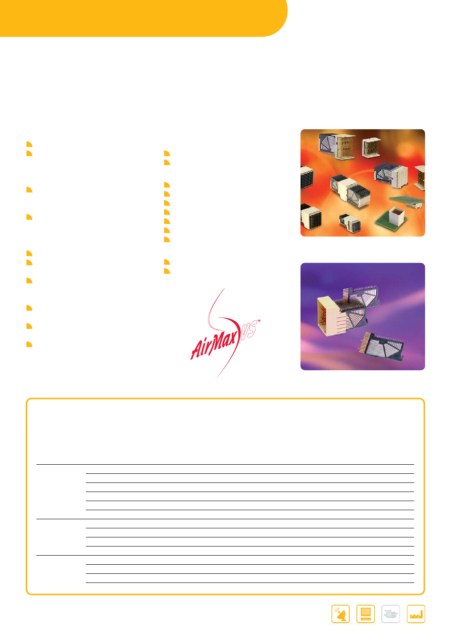
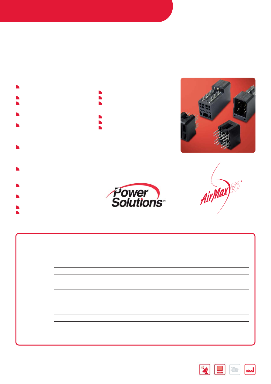
AIRMAX VS
®
HIGH SPEED BACKPLANE CONNECTORS
FEATURES & BENEFITS
A full set of building blocks for Vertical
Header or Vertical receptacle on
backplane, co-planar, mezzanine, and
cable-to-board applications in Hard
Metric building practices
Uses air dielectric between adjacent
conductors to deliver lowest insertion
loss and crosstalk
High-speed serial data rates that can
scale from 2.5Gb/s to beyond
12.5Gb/s without requiring a redesign
of the basic platform
Opposed dual-beam receptacle
Contact structure provides high
reliability
Contains no interleaving shields
reducing connector weight, cost, and
PCB routing complexity
Available with Power and guide
accessories
“Eye of the Needle” (EON)-compliant
tail for press-fit PCB termination
Lead-free and RoHS-compatible
APPLICATIONS
Data
Servers
Storage systems
Communications
IP routers
IP Switches & gateways
ATM switches
IP PBX’s
Enterprise routers
3G Base stations
ATCA
®
Zone 3
Industrial
Medical
Test & measurement
AIRMAX VS
®
QUICK SELECTOR GUIDE
# Contacts # Differential Nominal Plug
Contact pitch
Header
Receptacle
per module
pairs
In Unit pitch
(columns)
Drawing
Drawing
Impedence
per module
[mm]
Number
Number
[
Ω
]
APPLICATION: BACK PANEL, GENDER: RIGHT ANGLE HEADER, VERTICAL RECEPTACLE
"5 pair"
150
50 25 2
mm
10025613
10016527
10016537
100
150
50 25 3
mm
10037324
10037323
10035146
100
150
50 25 2
mm
10097311
10099767
85
150
50 25 3
mm
10087771
10099768
85
120
40 25 3
mm
10064489
10064488
10064493
100
120
40 25 2
mm
10041460
10041746
10040993
100
"4 pair"
120
40 20 2
mm
10028436
10029391
10028264
100
120
40 20 3
mm
10035515
10035514
10035465
100
96 32 20 2
mm
10052838
10052837
10052842
100
72 24 20 2
mm
10052825
10052824
10052829
100
"3 pair"
90 30 17 2
mm
10034249
10034264
10034251
100
72 24 17 2
mm
10045267
10045266
10045271
100
54 18 17 2
mm
10039851
10040862
10043546
100
54 18 17 2
mm
10097256
10096461
85
9
Further information can be found at:
www.fci.com/airmax
www.fci.com/highspeed
Telcordia
®
is a registered trademark of Telcordia
®
.
* Parts will become available in Q1 2010
AIRMAX VS
®
QUICK SELECTOR GUIDE
# Contacts # Differential Nominal Plug
Contact pitch
Header
Receptacle
per module
pairs
In Unit pitch
(columns)
Drawing
Drawing
Impedence
per module
[mm]
Number
Number
[
Ω
]
APPLICATION: BACK PANEL, GENDER: RIGHT ANGLE RECEPTACLE, VERTICAL HEADER
"5 pair"
150
50 25 2
mm
10056098
10034475
100
150
50 25 3
mm
10056427
10057041
100
120
40 25 2
mm
10055140
10045548
100
150
50 25 2
mm
10095500
10095504
85
*
150
50 25 3
mm
10073377
10095505
85
*
"4 pair"
120
40 20 2
mm
10056100
10035754
100
120
40 20 3
mm
10056430
10045722
100
96 32 20 3
mm
10056429
10076645
100
96 32 20 2mm
10055307
10060905
100
"3 pair"
90 30 17 2
mm
10056103
10056335
100
54 18 17 2
mm
10056101
10053656
100
APPLICATION: COPLANAR, RIGHT ANGLE RECEPTACLE TO RIGHT ANGLE HEADER
"5 pair"
150
50 25 2
mm
10025613
10016527
10034475
100
150
50 25 3
mm
10037324
10037323
10057041
100
120
40 25 2
mm
10041460
10041746
10045548
100
150
50 25 2
mm
10097311
10095504
85
*
150
50 25 3
mm
10087771
10095505
85
*
"4 pair"
120
40 20 2
mm
10028436
10029391
10035754
100
120
40 20 3
mm
10035515
10035514
10045722
100
96 32 20 2
mm
10052838
10052837
10060905
100
"3 pair"
90 30 17 2
mm
10034249
10034264
10056335
100
72 24 17 2
mm
10052838
10052837
10077323
100
54 18 17 2
mm
10039851
10040862
10053656
100
APPLICATION: MEZZANINE, VERTICAL RECEPTACLE TO VERTICAL HEADER
"5 pair"
150 50 12.5 2
mm
10056098
10016537
100
150
50 26 2
mm
10056246
10016537
100
150 50 12.5 3
mm
10056427
10035146
100
150
50 26 3
mm
10059957
10035146
100
120 32 12.5 2
mm
10055140
10040993
100
150
50
12.5
2 mm
10095500
10099767
85 *
150
50
12.5
3 mm
10073377
10099768
85 *
"4 pair"
120 40 12.5 2
mm
10056100
10028264
100
120 40 12.5 3
mm
10056430
10035465
100
96 32 12.5
3
mm
10056429
-
100
"3 pair"
90 30 12.5
2
mm
10056103
10034251
100
54 18 12.5
2
mm
10056101
10043546
100
APPLICATION: FRONT IO AND REAR PLUG UP
"4 pair"
120
40 25 2
mm
10041268
vertical
na
100
120
40 25 2
mm
10041398
right
angle
na
100
96 32 25 2
mm
10061399
right
angle
na
100
72 24 25 3
mm
10062319
right
angle
na
100
APPLICATION: ORTHOGONAL
"5 pair"
48 16 20 4.2
mm
10073718
10074050
100
Further information can be found at:
www.fci.com/metral
www.fci.com/highspeed
www.fci.com/backpanel
METRAL
®
1000, 2000, 4000
HIGH SPEED BACKPLANE CONNECTORS
FEATURES & BENEFITS
Metral
®
1000, 2000, 4000.
IEC 61076-4-104 / Telcordia*
GR-1217-CORE
Optimized Signal Integrity
performance for 5 Gb/sec and more
Part of the Metral
®
system to allow
performance and cost efficiency
2 mm square pitch for efficient
straight vertical and horizontal routing
APPLICATIONS
Communications
Routers
Switches
Networking
Access
Transport
Data
Servers
Storage Systems
Industrial
Medical
Test & Measurement
MAIN PRODUCTS
PART REFERENCES
5 row
8 row
Metral 1000
Header 84817
74983
Receptacle 84688
74981
Metral 2000
Header 74977
74978
Receptacle 84688
74981
Metral 4000
Header 55003
55004
Receptacle 52057
Shrouds
Metral 1000
73993
74993
Metral 2000
84621
84625
1000 Header
2000 Header
4000 Header
1000 Receptacle
622 Mb/s
1.25 Gb/s
2.5 Gb/s
4000 Receptacle
1.25 Gb/s
2.5 Gb/s
5 Gb/s
*Telcordia
®
is a registered trademark of Telcordia
®
.
BACKPLANE CONNECTORS
10
11
Further information can be found at:
www.fci.com/metral
www.fci.com/backpanel
METRAL
®
2 MM MODULAR INTERCONNECT SYSTEM
FEATURES & BENEFITS
Low-cost application solutions:
Press-Fit termination for backplanes
Pin-in-Paste terminations for
daughter-cards
Scalability and flexibility:
Mix low and high speed signal
modules
Mix signal and power modules
Power Distribution solutions:
Ranging from 3 amps up to 60 amps
Straight or inverse solutions
Complete I/O solutions:
Rear-plug-up or front I/O
Shielded or non-shielded
Speeds from 2 Mb/s up to 5 Gb/s
Designed in accordance with IEC
61076-4-104, performance according
Telcordia
®
GR-1217-CORE
APPLICATIONS
Transmission & switching equipment
for data & telecommunications,
medical equipment.
MAIN PRODUCTS
PART REFERENCES
4-row Signal
4-row Power
5-row Signal
5-row Power
Headers
Press-Fit
70232
70236
89006
89099
Right angle Receptacles
Pin-in-Paste
72651
63793
Solder
89035
89039
85863
85876
Press-Fit
HM1F41FDP000H6LF
HM1F51FDP000H6LF
88945
88949
89047
89096
Straight Receptacles
Press-Fit
85757
85761
Right angle Headers
Pin-in-Paste
58361-101LF
Contact FCI
HM1L51LFP000H6PLF Contact FCI
Solder
HM1L41LAP000H6PLF HM1K41DAP000H6PLF HM1L51LAP000H6PLF
Press-Fit
HM1L41LDP000H6PLF HM1K41LDP000H6PLF HM1L51LDP000H6PLF HM1K51DDP000H6PLF
Cable Connectors
IDC
72476 / 72477
-
72478 / 72479
-
BACKPLANE CONNECTORS
12
Further information can be found at:
www.fci.com/millipacs
www.fci.com/compactPCI
www.fci.com/backpanel
MILLIPACS
®
HARD METRIC 2 MM CONNECTORS
FEATURES & BENEFITS
Millipacs
®
is a 2.00 mm modular
board to board or cable to board
Interconnection system in Hard
Metric configuration, designed in
accordance with IEC 917 and
IEC 61076 - 4 - 101
Fits DIN 43356 and IEEE1301 Hard
Metric Equipment Practice
UL and CSA recognized
Qualified by Bellcore as defined by
GR-1217-CORE
Versions meetings requirements of
CompactPCI specifications
5+2 row and 8+2 row high density
connectors
Popular Versions include Vertical &
Right Angle Headers, Vertical & Right
Angle Receptacles, Cable Connectors
Accessories with functionalities:
Keying, Guiding, Power and Coax
inserts, Shielding & Shrouds
Headers with Staggered contacts with
differential lengths
Terminations with Standard EON
pressfit. Also Pin-in-Paste (PIP)
Version for select positions of
Vertical Headers
APPLICATIONS
Switches
Base stations
Embedded computers
Medical testing
PLC’s & all applications requiring
high density connectors
13
Further information can be found at:
www.fci.com/millipacs
www.fci.com/backpanel
MAIN PRODUCTS
PART REFERENCES
No. of
Type
Header
Receptacle
Max No. of
Mounting
signal rows
Series
Pin orientation
Series
Pin orientation
signal pins
style
5
A
HM2P07P
Vertical
HM2R01P /HM2R10P
Right Angle
110
Press-fit
HM2J07PE
Right Angle
HM2S01P /HM2S10P
Vertical
B
HM2P08P
Vertical
HM2R02P
Right Angle
125
Press-fit
HM2J08PE
Right Angle
HM2S02P
Vertical
B22
HM2P70P
Vertical
HM2R70P
Right Angle
110
Press-fit
HM2J70P
Right Angle
HM2S70P
Vertical
B19
HM2P71P
Vertical
HM2R71P
Right Angle
95
Press-fit
HM2J71P
Right Angle
HM2S71P
Vertical
AB
HM2P65P
Vertical
HM2R65P
Right Angle
125
Press-fit
AB22
HM2P66P
Vertical
HM2R66P
Right Angle
110
Press-fit
AB19
HM2P67P
Vertical
HM2R67P
Right Angle
95
Press-fit
C
HM2P09P
Vertical
HM2R03P /HM2R30P
Right Angle
55
Press-fit
HM2J09P
Right Angle
HM2S30P
Vertical
CR
HM2P80P
Vertical
HM2R20P
Right Angle
55
Press-fit
L
HM2A30P
Vertical HM2E30P
Right
Angle
6
Spl.
Press-fit
M
HM2P11P
Vertical
HM2R05P
Right Angle
3 Spl.+ 55
Press-fit
N
HM2A32P
Vertical
HM2E32P
Right Angle
3 Spl.
Press-fit
8
D
HM2P87P
Vertical
HM2R87P /HM2R81P
Right Angle
176
Press-fit
DE
HM2P95P
Vertical
HM2R95P
Right Angle
200
Press-fit
E
HM2P88P
Vertical
HM2R88P
Right Angle
200
Press-fit
F
HM2P89P
Vertical
HM2R89P /HM2R83P
Right Angle
88
Press-fit
5
C
HM2P09S
Vertical
55
PIP
M
HM2P11S
Vertical
3 Spl.+ 55
PIP
MAIN PRODUCTS
PART REFERENCES
Other Options
Features
Application
Series
Cable Connectors
Non shielded/Shielded
Input/Output
HM2C---
Coding Devices
Plug and Receptacle with pre defined RAL colours
Prevent incorrect insertion HM2DK---
Power Contacts
High Precision Pin and Socket contacts
Hybrid, Power, Coax for
RM……..(Pin) /
increased durability
RC………(Sockets)
Millipacs Shrouds
5 row and 8 row available
Rear-Plug-up
HM2H---
Bottom Shield
Pre-assembled shields for Right Angle Receptacles
Shielding
HM2LS---
Guiding Pins
Stackable, Different Pin lengths
Guiding & Premating
HM2G….
BACKPLANE CONNECTORS
14
Further information can be found at:
www.fci.com/din41612
www.fci.com/backpanel
DIN 41612
FEATURES & BENEFITS
Standardized per DIN 41612
Full interconnect system
- BTB and I/O solutions
- Signal and power
Low cost application solutions
- Press-fit termination, receptacle and
header
- IDC cable termination
APPLICATIONS
Switching & transmission
Radio base stations
PBX’s
STANDARD SIGNAL
PART REFERENCES
Style
No. rows
pos.
Termination
Part Reference
Style B right angle header
2 row
64
solder-to-board
8609 264 51 13 XXX XX LF
Style B/2 right angle header
2 row
32
solder-to-board
8609 232 53 13 XXX XX LF
Style C right angle header
3 row
96
solder-to-board
8609 396 71 13 XXX XX LF
press-fit
8609 396 71 94 XXX XX LF
Style C/2 right angle header
3 row
48
solder-to-board
8609 348 73 13 XXX XX LF
Style B straight receptacle
2 row
64
solder-to-board
8609 264 61 14 XXX XX LF
Style B/2 straight receptacle
2 row
32
solder-to-board
8609 232 63 14 XXX XX LF
Style C straight receptacle
3 row
96
solder-to-board
8609 396 81 14 XXX XX LF
press-fit
8609 396 81 94 XXX XX LF
Style C/2 straight receptacle
3 row
48
solder-to-board
8609 348 83 14 XXX XX LF
DIN Style M
DIN Style F, H & F24/H7
DIN standard and reversed signal
DIN IDC
15
Further information can be found at:
www.fci.com/din41612
www.fci.com/backpanel
REVERSED SIGNAL
PART REFERENCES
Style
No. rows
pos.
Termination
Part Reference
Style R straight header
3 row
96
solder-to-board
8609 396 78 14 XXX XX LF
press-fit
8609 396 78 94 XXX XX LF
Style R/2 straight header
3 row
48
solder-to-board
8609 348 76 14 XXX XX LF
Style R right angle receptacle
3 row
96
solder-to-board
8609 396 88 13 XXX XX LF
press-fit
8609 396 88 94 XXX XX LF
Style R/2 right angle receptacle
3 row
48
solder-to-board
8609 348 86 13 XXX XX LF
STYLE M PART
REFERENCES
Style
Signal pos.
Insert pos.
Termination
Part Reference
Style M right angle header
24
8
solder-to-board
8609 324 G1 13 XXX XX LF
42
6
solder-to-board
8609 342 E1 13 XXX XX LF
60
4
solder-to-board
8609 360 C1 13 XXX XX LF
78
2
solder-to-board
8609 378 A1 13 XXX XX LF
Style M straight receptacle
24
8
press-fit
8609 324 H1 94 XXX XX LF
42
6
press-fit
8609 342 F1 94 XXX XX LF
60
4
press-fit
8609 360 D1 94 XXX XX LF
78
2
press-fit
8609 378 B1 94 XXX XX LF
POWER
PART REFERENCES
Style
No. rows
pos.
Termination
Part Reference
Style F right angle header
3 row
48
medium - 5.5A
5159 009 48 63 94 XXX LF
Style F straight receptacle
3 row
48
medium - 5.5A
5159 009 48 63 94 XXX LF
Style H right angle header
3 row
48
high - 15A
5159 029 15 23 XXX LF
Style H straight receptacle
3 row
48
high - 15A
5159 029 15 19 XXX LF
Style F24/H7 right angle header
3 row
24 / 7
medium/high
5159 002 31 23 54 XXX LF
Style F24/H7 straight receptacle
3 row
24 / 7
medium/high
5159 002 31 18 93 XXX LF
IDC
PART REFERENCES
Style
No. rows
pos.
Termination
Part Reference
IDC cable connector
3 row
96
IDC
BPS 8B 96 FLD XXX XX LF
21
IDC
BPS 8B 21 FLD XXX XX LF
9
IDC
BPS 8B 09 FLD XXX XX LF
POWER CONNECTORS /
POWER CABLE ASSEMBLIES
16
Further information can be found at:
www.fci.com/pwrblade
www.fci.com/powersolutions
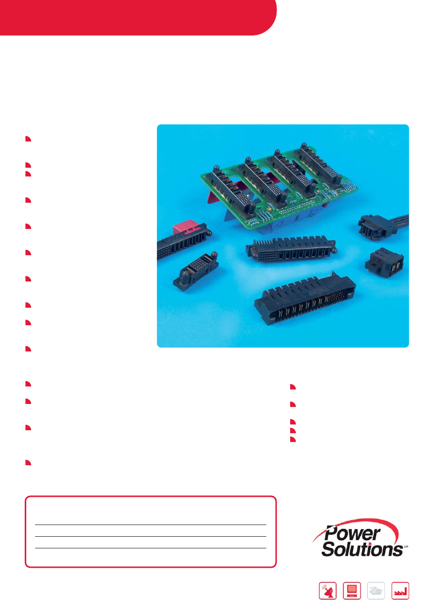
PWRBLADE
®
AC/DC POWER DISTRIBUTION CONNECTOR SYSTEM
FEATURES & BENEFITS
48A/individual power contact;
30A/contact for 10 adjacent contacts
at 30°C temperature rise in still air
60A/contact using UL test guidelines
SSI-compliant connector interface for
pluggable power supplies & power
distribution applications
Provides power contacts for power
distribution and signal contacts for
power control
Number and placement of power and
signal contacts are highly configurable
for custom power needs
Power contact spacing options exist
for AC (300V max), DC (200V max) or
high-density power (at same voltage)
Meets applicable UL current
interruption criteria for hot plug
applications
Rugged, molded-in guides enable
blind mating
Up to 3 levels of sequential contact
including a short detect pin for hot
swap applications
Existing tooling capabilities
accommodate up to 20 power
contacts and 148 signal contacts in a
single molded housing
Solder or press-fit tail options are
available for termination flexibility
Board retention devices are provided
to secure connectors during wave
solder process
AC cable port option (cable pass-
through) as well as direct attach to
busbars for power distribution are
available
Lead free plating is available for RoHS
compliance
APPLICATIONS
AC/DC pluggable power supplies in
data, telecom & datacom/networking
Server System Infrastructure (SSI)-
compliant server systems
Industrial PCs
Industrial controls & instrumentation
Medical
MAIN PRODUCTS
PART REFERENCES
Power+Signal+Power Right Angle Header
51720-1XXXXXXXXXLF
Power+Signal+Power Vertical Header
51700-1XXXXXXXXXLF
Power+Signal+Power Right Angle Receptacle
51760-1XXXXXXXXXLF
Power+Signal+Power Vertical Receptacle
51740-1XXXXXXXXXLF
17
Further information can be found at:
www.fci.com/pwrblade
www.fci.com/powersolutions
MAIN PRODUCTS
PART REFERENCES
SERVER SYSTEM INFRASTRUCTURE (SSI STANDARD)
High-End Power Supply (24 Signal + 12 Power Configuration)
Server
Right Angle Receptacle
51416-001LF
Vertical Press-Fit Receptacle
51666-001LF
Power Supply
Right Angle Header
51415-001LF
Vertical Header
51952-001LF
Vertical Press-Fit Header
51952-002LF
High-End Power Supply (12 Power + 24 Signal Configuration)
Server Vertical
Receptacle
51261-XX001LF
Vertical Press-Fit Receptacle
51617-XX002LF
Power Supply
Right Angle Header
51219-XX002LF
Mid-Range Power Supply (5 Power + 24 Signal + 6 Power Configuration)
Server
Right Angle Receptacle
51625-XX001LF
Vertical Press-Fit Receptacle
51667-XX001LF
Power Supply
Right Angle Header
51624-XX001LF
Vertical Header
51860-001LF
Vertical Press-Fit Header
51860-002LF
AC CABLE PORT RIGHT ANGLE RECEPTACLE
Cable+Power+Signal+Power
51894-YYYLF
Cable+Signal+Power
51921-YYYLF
Cable+Power+Signal
51923-YYYLF
AC CABLE PORT VERTICAL RECEPTACLE
Cable+Power+Signal+Power
51897-YYYLF
Cable
51897-YYYLF
Power+Signal+Cable
51897-YYYLF/51927-YYYLF
Cable+Power+Signal
51929-YYYLF
Note: The XX and YYY utilized in the part numbers above are placeholders for certain product specific criteria.
Reference the product drawings to obtain detailed dimensions and complete part numbers.
For non-SSI applications other configurations are available upon request.Please contact your local FCI representative.
Further information can be found at:
www.fci.com/pwrcardedge
www.fci.com/powersolutions
POWER CARD EDGE
LOW PROFILE AC/DC POWER DISTRIBUTION
CONNECTOR SYSTEM
FEATURES
7A/contact for multiple contacts at
30°C temperature rise in still air
One-piece card edge design enables
cost-effective power delivery for 1U
and 2U power supplies or power
distribution applications
Low-profile design maximizes airflow
for system cooling
Right angle option is available with
both power contacts for power
distribution and signal contacts for
power control
Integrated power and signal design
simplifies board assembly
Right angle product range includes
version with molded posts or metal
fork locks for board retention
Straddle-mount connectors feature
mounting ears for secure PCB
attachment
Optional AC cable port is available for
a cable pass-through solution
Lead free plating is available for RoHS
compliance
APPLICATIONS
AC/DC pluggable power supplies in
data, telecom & datacom/networking
Industrial PCs
Industrial controls & instrumentation
Medical
MAIN PRODUCTS
PART REFERENCES
Right Angle Solutions
10P + 24S + 10P
14P + 24S + 14P
20P + 24S + 20P
10028886
28P + 24S + 28P
With AC power port
10055090
2x14, 2x17, 2x22, 2x25, 2x28, 2x29,
2x31, 2x32 power
10035388
2x32 power w/ housing stand-offs
10053363
Vertical Solutions
2x19, 2x31, 2x32, 2x35 power
10046971
2x8 power w/ mounting ears
10046972
2x19, 2x31 power w/ press-fit tails
10075664
Straddle-Mount Solutions
2x19, 2x23 power
10034908
POWER CONNECTORS /
POWER CABLE ASSEMBLIES
18
19
Further information can be found at:
www.fci.com/hci
www.fci.com/powersolutions
MAIN PRODUCTS
PART REFERENCES
2DC+16S+4DC Right Angle Header
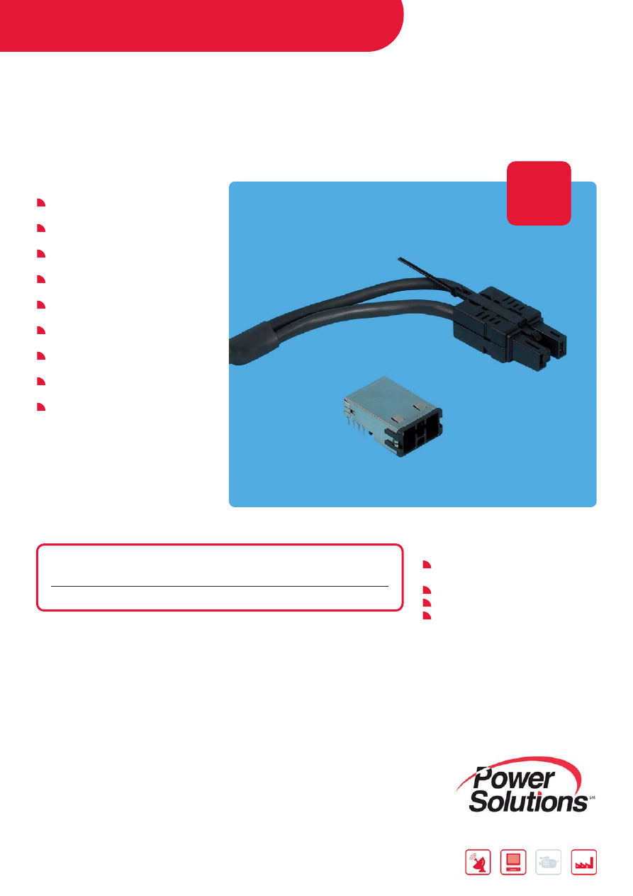
10074864-003LF
2DC+16S+4DC Vertical Receptacle
10074866-001LF
20S+8DC Right Angle Header
10078546-001LF
20S+8DC Vertical Receptacle
10078548-001LF
10DC+24S Right Angle Header
10065864-003LF
10DC+24S Vertical Receptacle
10065127-001LF
11DC+24S Right Angle Header
10082091-003LF
11DC+24S Vertical Receptacle
10082093-001LF
7DC+24S+4DC Right Angle Header
10082722-001LF
7DC+24S+4DC Right Angle Receptacle
10082724-001LF
14DC+24S+14DC Right Angle Header
10084757-001LF
14DC+24S+14DC Vertical Receptacle
10084759-001LF
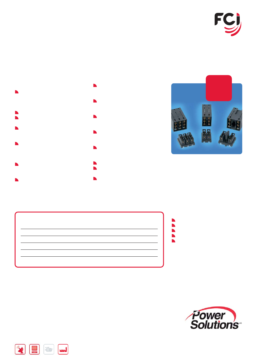
HCI
®
AC/DC HIGH POWER DISTRIBUTION
CONNECTOR SYSTEM
FEATURES & BENEFITS
Up to 82A/ power contact;
at 30°C temperature rise in still air
95A/contact using UL test guidelines
For high-wattage or high current
density needs in power supplies &
power distribution applications
Provides power contacts for power
distribution and signal contacts for
power control
Number and placement of power and
signal contacts are highly configurable
for custom power needs
Power contact spacing options exist
for AC (400V max) and DC (250V
max) power
Highly vented housing design
maximizes airflow effects around and
through the connector system
Rugged, molded-in guides enable
blind mating
Connector housing does not
overhang the board edge so the
board-to-board spacing can be
adjusted if needed
Up to 3 levels of sequential contact
including a short detect pin for hot
swap applications
Two and three position modules are
available for use alongside the
ZipLine™, AirMax VS
®
or Millipacs
®
Hard Metric-compatible connector
series
UL/CSA and TUV approved
Board retention devices are provided
to secure connectors during wave
solder process
AC cable port option (cable pass-
through) as well as direct attach to
busbars for power distribution are
available
Lead free plating is available for RoHS
compliance
APPLICATIONS
AC/DC pluggable power supplies in
data, telecom & datacom/networking
Industrial PCs
Industrial controls & instrumentation
Medical
Custom configurations are readily available upon request. Please contact your local FCI representative.
POWER CONNECTORS /
POWER CABLE ASSEMBLIES
20
Further information can be found at:
www.fci.com/hmhighpower
www.fci.com/powersolutions
HARD METRIC HIGH POWER CONNECTORS
FEATURES & BENEFITS
Current rating to 80 amps for 1x2 or
2x2 modules
Hard Metric (HM) Equipment Practice
Layout compatible with AirMax VS
®
Zipline™ and Millipacs
®
connector series
1x2, 2x2 or 2x3 contact configurations
for backplane applications
Standard-profile 1x2 and 2x2 right-
angle modules extend 14.7 mm
above the PCB (compatible with
4 and 5 pair AirMax VS
®
modules)
Lower-profile 2x2 and 2x3 modules
stand only 11.5 mm above board
(compatible with 3 pair AirMax VS
®
modules)
Options for first-mate/last-break
sequencing, 2 mating lengths
available
Protected Backplane connector
UL 60950 Compliant (Finger Probe)
Options for 1x2 or 2x2 Co-planar
applications
Press-fit termination
Compatible with lead-free processing
temperatures
APPLICATIONS
Data
Servers
Storage Devices
Computing Platforms
Communications
Switches
Routers
Internet Equipment
Medical
Instrumentation
MAIN PRODUCTS
PART REFERENCES
NUMBER OF
CONTACT
HEIGHT
PART NUMBERS
CONTACTS
ARRAY
ABOVE PCB
Vertical Receptacle
Right-Angle Header
Backplane
2
1x2
14.7 mm
10028916-xxxxP00LF**
10028918-001LF
Application
4
2x2
14.7 mm
10028916-xxxxP00LF**
10028917-001LF
4 2x2*
11.5
mm
10028916-xxxxP00LF**
10073379-001LF
6 2x3*
11.5
mm
10061290-xxxxxxPLF**
10061289-001LF
Right-Angle Receptacle
Right-Angle Header
Co-planar
2 1x2
14.7
mm
10052620-xxxxP00LF
10028918-001LF
Application
4 2x2
14.7
mm
10052620-xxxxP00LF
10028917-001LF
4 2x2*
11.5
mm
10052620-xxxxP00LF
10073379-001LF
Notes: * indicates the connector set matches the above-board height of an AirMax VS 3-pair signal connector.
** xxxx and xxxxxx are placeholders for contact mating length combinations. Reference the product drawings for available options.
21
Further information can be found at:
www.fci.com/hcihighpower
www.fci.com/powersolutions
MAIN PRODUCTS
PART REFERENCES
1x2 Right Angle Header w/o Integrated Guide
10078770-001LF
1x2 Vertical Receptacle w/o Integrated Guide
10078768-001LF
1x2 Right Angle Header w/ Integrated Guide
10087937-001LF
1x2 Vertical Receptacle w/ Integrated Guide
10087939-001LF
1x3 Right Angle Header
10078904-001LF
1x3 Vertical Receptacle
10078902-001LF
HCI
®
HIGH POWER
HIGH POWER BACKPLANE/MIDPLANE
CONNECTOR SYSTEM
FEATURES & BENEFITS
83A/ contact for the two-position
module, 75A/contact for the three-
position module at 30°C temperature
rise in still air
95A/contact using UL test guidelines
For high current density needs in
backplane/midplane applications
Power contact spacing options exist
for operating voltages of 300V and
beyond
Design is compliant with the Hard
Metric (HM) Equipment Practice and
compatible with the ZipLine™, AirMax
VS
®
and Millipacs
®
connector series
Connector housing does not overhang
the board edge so the board-to-board
spacing can be adjusted if needed
Two- and three-position modules
support backplane or midplane
applications
The two-position module with
integrated center guide can eliminate
the need for separate guidance
Housing walls surround the power
contacts to ensure that adjacent
contacts cannot short together
Highly vented housing design
maximizes airflow effects around and
through the connector system
Two contact mating length options
provide capability for sequentially
mating power and ground contacts
Protected backplane/midplane
receptacle is UL 60950 compliant (Test
Finger & Test Probe)
UL/CSA and TUV approved
Press-fit termination is available for
thicker, higher-layer-count boards
Lead free plating is available for RoHS
compliance
APPLICATIONS
Data - servers & storage enclosures
Telecommunications
Datacom/networking
Industrial controls & instrumentation
Medical
Note: For right angle headers with one first mate/last break contact, please use the -002LF dash number option
per the applicable product drawing.
New
Product
New
New
product
product
POWER CONNECTORS /
POWER CABLE ASSEMBLIES
22
Further information can be found at:
www.fci.com/cableassembly
www.fci.com/powersolutions
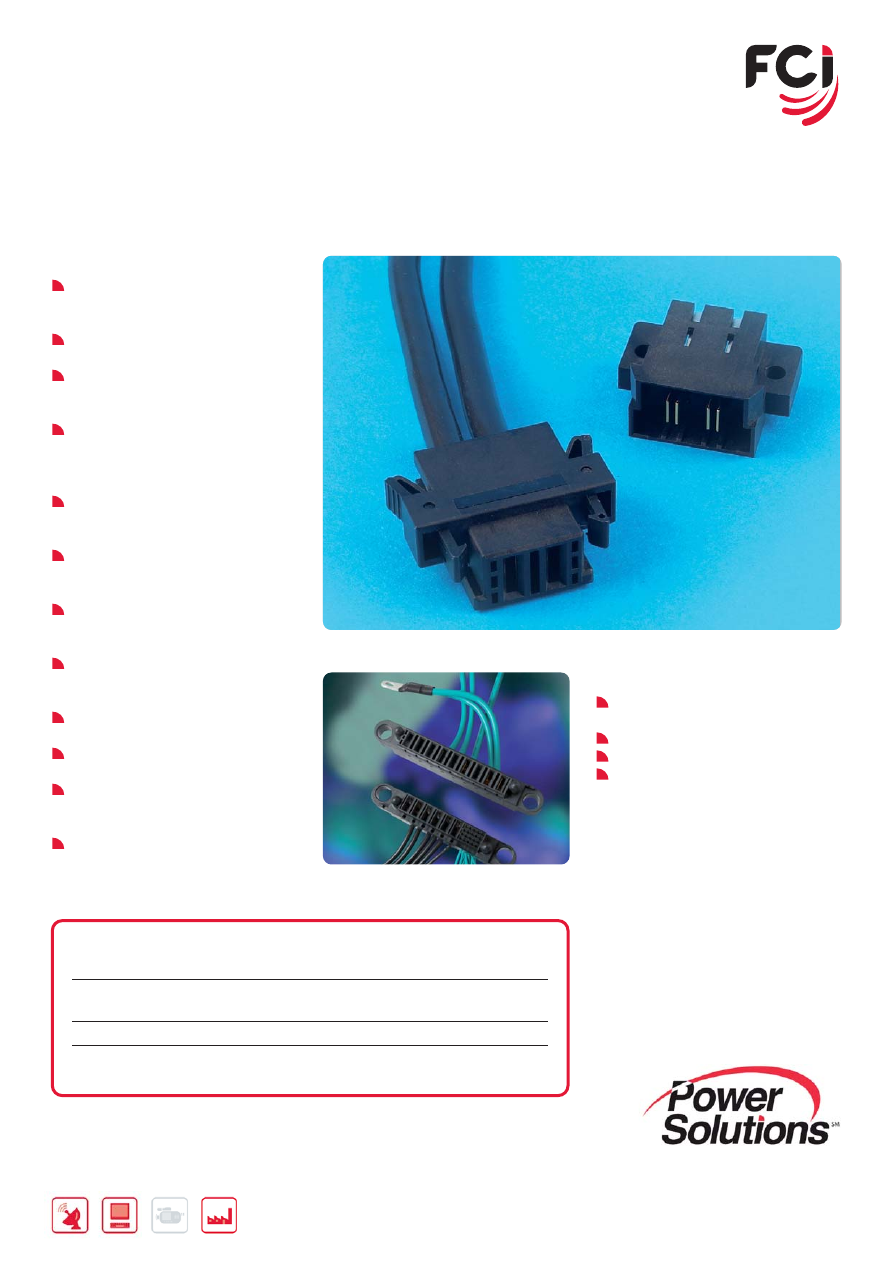
PWR PROFILE+™
LOW PROFILE I/O CABLE ASSEMBLIES
FEATURES & BENEFITS
35A/contact for two contacts at 30°C
temperature rise in still air
Compact design is ideal for limited
space applications
Low 8.35mm profile height maximizes
airflow for system cooling
Vented cable housing design
maximizes heat dissipation
Two signal contacts are available for
presence detection or power control
Integrated latching system minimizes
connector/cable footprint
Robust design includes touch-proof
safety features
Polarized housing design ensures
proper mating
Lead free plating is available for RoHS
compliance
APPLICATIONS
Power I/O & distribution in data,
telecom & datacom/networking
Uninterruptible power supplies (UPS)
Industrial controls & instrumentation
Medical
MAIN PRODUCTS
PART REFERENCES
Right Angle Board Mount Header w/ Grounding Shield
10089872-101LF
Right Angle Board Mount Header w/o Grounding Shield
10089870-101LF
Please contact your local FCI representative for applicable receptacle cable assembly part number information.
New
Product
New
New
product
product
23
Further information can be found at:
www.fci.com/cableassembly
www.fci.com/powersolutions
PWRBLADE
®
POWER I/O CABLE ASSEMBLIES
FEATURES & BENEFITS
48A/individual power contact;
30A/contact for 10 adjacent contacts
at 30°C temperature rise in still air
Right angle board connector enables
front I/O applications
Vertical board connector enables
power distribution to mid-board
components
Panel-mount option or squeeze-to-
release latches are available to
accommodate various system
configurations
Supports multiple wire sizes including
8 - 14 AWG wire for power contacts
and 22 - 26 AWG for signal contacts
Power contact spacing options exist
for AC (300V max) or DC (200V max)
power
Provides power contacts for power
distribution and signal contacts for
power control
Number and placement of power
and signal contacts are highly
configurable for custom power needs
Rugged, molded-in guides on panel-
mount version enable blind mating
Polarized housing design ensures
proper mating
Up to 3 levels of sequential contact
including a short detect pin for hot
swap applications
Lead free plating is available for
RoHS compliance
APPLICATIONS
Power I/O & distribution in data,
telecom & datacom/networking
Uninterruptible power supplies (UPS)
Industrial controls & instrumention
Medical
MAIN PRODUCTS
PART REFERENCES
2P Right Angle Board Mount Header
51939-198LF
2P Cable Receptacle w/ Squeeze-To-Release Latches
10080594-1AD0078LF
(8 AWG wire; 1 m cable length)
24S+6P Right Angle Board Mount Header
51721-10002406AALF
24S+6P Cable Receptacle For Panel-Mount
10080591-HAB0023LF
(10 AWG wire; 1 m cable length)
Additional custom cable assemblies are readily available upon request. Please contact your local FCI representative.
POWER CONNECTORS /
POWER CABLE ASSEMBLIES
24
Further information can be found at:
www.fci.com/cableassembly
www.fci.com/powersolutions
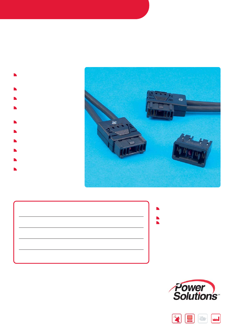
PWR TWINBLADE™
HIGH POWER I/O CABLE ASSEMBLIES
FEATURES & BENEFITS
Up to 100A/twin contact for two
conductors at 30°C temperature rise
in still air
Right angle board connector enables
front I/O applications
Straight and right angle cable exit
options facilitate routing flexibility
Supports multiple wire sizes including
10 mm
2
, 16 mm
2
or 25 mm
2
wire as
well as 2 x 6 mm
2
wires
Rated up to 300V DC for higher
voltage applications
Robust connector design includes
touch-proof safety features
Integrated latching system minimizes
connector/cable footprint
Polarized housing design ensures
proper mating
Four coding options allow keying to
block insertion of incorrect cables
Lead free plating is available for RoHS
compliance
APPLICATIONS
Power I/O & distribution in data,
telecom & datacom/networking
Uninterruptible power supplies (UPS)
Industrial controls & instrumention
MAIN PRODUCTS
PART REFERENCES
Right Angle Board Mount Header
51939-219LF
Right Angle Exit Cable Receptacle Assembly
(10 mm
2
wire; 1 m cable length)
10080068-4FEL100LF
Right Angle Exit Cable Receptacle Assembly
(16 mm
2
wire; 1 m cable length)
10080068-4GEL100LF
Right Angle Exit Cable Receptacle Assembly
(25 mm
2
wire; 1 m cable length)
10080068-4HEL100LF
Straight Exit Cable Receptacle Assembly
(16 mm
2
wire; 1 m cable length)
10080068-2GEL100LF
Additional custom cable assemblies are available upon request. Please contact your local FCI representative.

25
NOTES
BOARD-TO-BOARD /
WIRE-TO-BOARD CONNECTORS
26
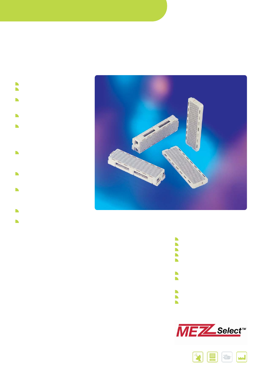
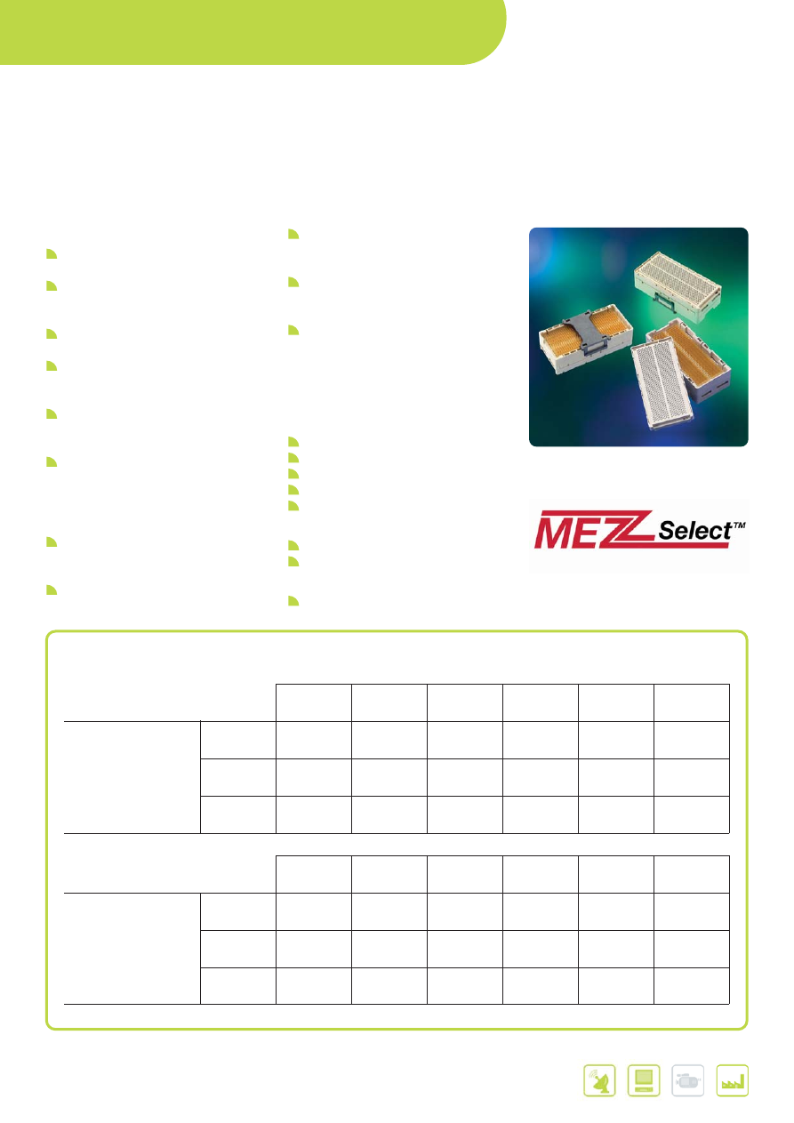
MEG-ARRAY
®
HIGH SPEED MEZZANINE CONNECTORS
FEATURES & BENEFITS
RoHS Compliant (Lead-Free)
Ball Grid Array (BGA) termination for
process friendly attachment
.050" x .050" BGA interface pitch
optimizes routing and electrical
performance
Stack Heights available from 4 mm to
14 mm
Connector sizes of 81 signals to
528 signals providing 80 usable
signals per linear cm (205 signals per
linear inch) allow for optimization of
board space and signal requirements
Up to 10 Gb/s differential pair
performance at less than 1% cross-
talk meets the needs of high speed
mezzanine applications
Meets Telcordia GR-1217-CORE and
NPS-25298-2 specifications for
utilization in telecom applications
Demonstrated solder joint reliability
of greater than 22 years life (per
IPC-SM-785) is unmatched for a
BGA mezzanine connector
Polarized design assures proper
mating of the connector
Back to Back testing connector
(Interposer) available upon special
request
APPLICATIONS
Communications
Transmission
Access
Switching
Optics
Networking
Data
Servers
Storage
I&I
Industrial controls & equipment
Analytical & diagnostic
Medical
*Telcordia
®
is a registered trademark of Telcordia
®
.
Further information can be found at:
www.fci.com/megarray
www.fci.com/mezzselect
www.fci.com/highspeed
27
MAIN PRODUCTS
PART REFERENCES
Total Mated Height
Size
Type
4.0 mm
6.0 mm
8.0 mm
10.0 mm
12.0 mm
14.0 mm
81 Position
Plug
55714
9 x 9
Receptacle
55715
100 Position
Plug
84512
10 x 10
Receptacle
84513
200 Position
Plug
84516
84516
84516
84530
84530
84530
10 x 20
Receptacle
84517
55724
84535
84517
55724
84535
300 Position
Plug
84500
84500
84500
84578
84578
84578
10 x 30
Receptacle
84501
84502 for
84553
84501
84502 for
84553
5.5 mm BTB
11.5 mm BTB
400 Position
Plug
84740
84740
84740
84520
84520
84520
10 x 40
Receptacle
74221
74388
74390
74221
74388
74390
240 Position
Plug
74213
74213
8 x 30
Receptacle
74217
55755
528 Position
Plug
10022671
12 x 44
Receptacle
10026846
Further information can be found at:
www.fci.com/megarray
www.fci.com/mezzselect
www.fci.com/highspeed
BOARD-TO-BOARD /
WIRE-TO-BOARD CONNECTORS
28
Further information can be found at:
www.fci.com/gigarray
www.fci.com/mezzselect
www.fci.com/highspeed
MAIN PRODUCTS
PART REFERENCES
Plug Height**
200 Positions*
10 mm
12 mm
13 mm
15 mm
20 mm
25 mm
55737
10026802
10060910
55738
55739
10054783
Receptacle Height**
5 mm
15 mm
17 mm
18 mm
20 mm
25 mm
30 mm
55740
11 mm
21 mm
23 mm
24 mm
26 mm
31 mm
36 mm
10081497
15 mm
25 mm
27 mm
28 mm
30 mm
35 mm
40 mm
10060912
Plug Height**
296 Positions*
10 mm
12 mm
13 mm
15 mm
20 mm
25 mm
55720
10026804
10060911
55700
55727
10054784
Receptacle Height**
5 mm
15 mm
17 mm
18 mm
20 mm
25 mm
30 mm
55701
11 mm
21 mm
23 mm
24 mm
26 mm
31 mm
36 mm
10081496
15 mm
25 mm
27 mm
28 mm
30 mm
35 mm
40 mm
10060913
*Signal contacts only, ground contacts not included **Base part number listed under connector height
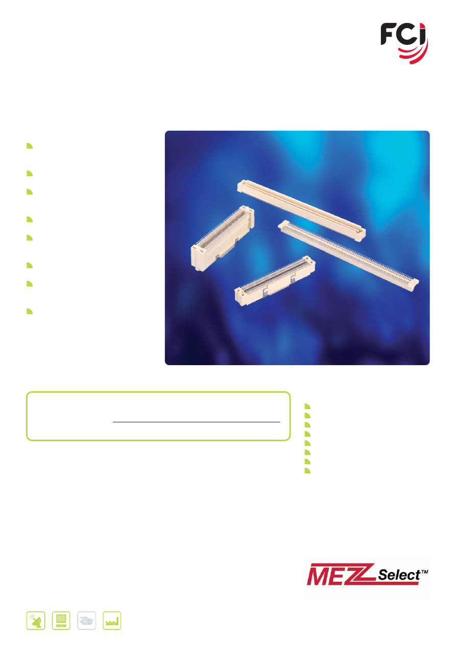
GIG-ARRAY
®
HIGH SPEED MEZZANINE CONNECTORS
FEATURES & BENEFITS
RoHS compliant (Lead-Free) options
are available
Optimized design for utilization in
high-density, high-speed mezzanine
applications
Ball Grid Array (BGA) termination for
process friendly attachment
1 mm x 0.65 mm BGA interface pitch
optimizes routing and electrical
performance
Stack Heights available from 15 mm
to 40 mm provide mezzanine design
flexibility
Connector sizes of 200 and 296
signals providing 62 signal contacts
per linear cm (158 signal contacts per
linear inch) allow for optimization of
board space and signal requirements
100 Ohm differential pair matched
impedance assures consistent high
speed performance
Up to 10 Gb/s differential pair
performance
Very low cross-talk (VLC) design of
less than 1% allows for required
signal integrity performance
Dual beam signal contacts provide
two points of contact increasing
product reliability
Polarized design assures proper
mating of the connector
APPLICATIONS
Communications
Transmission
Access
Switching
Optics
Networking
Data
Servers
Storage
I&I
Industrial controls & equipment
29
Further information can be found at:
www.fci.com/bergstak
www.fci.com/mezzselect
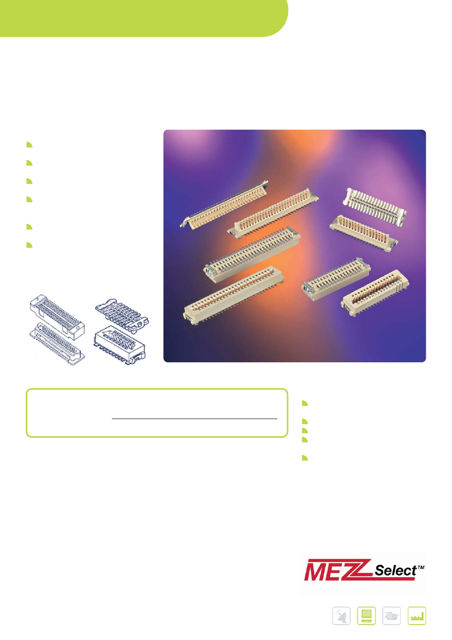
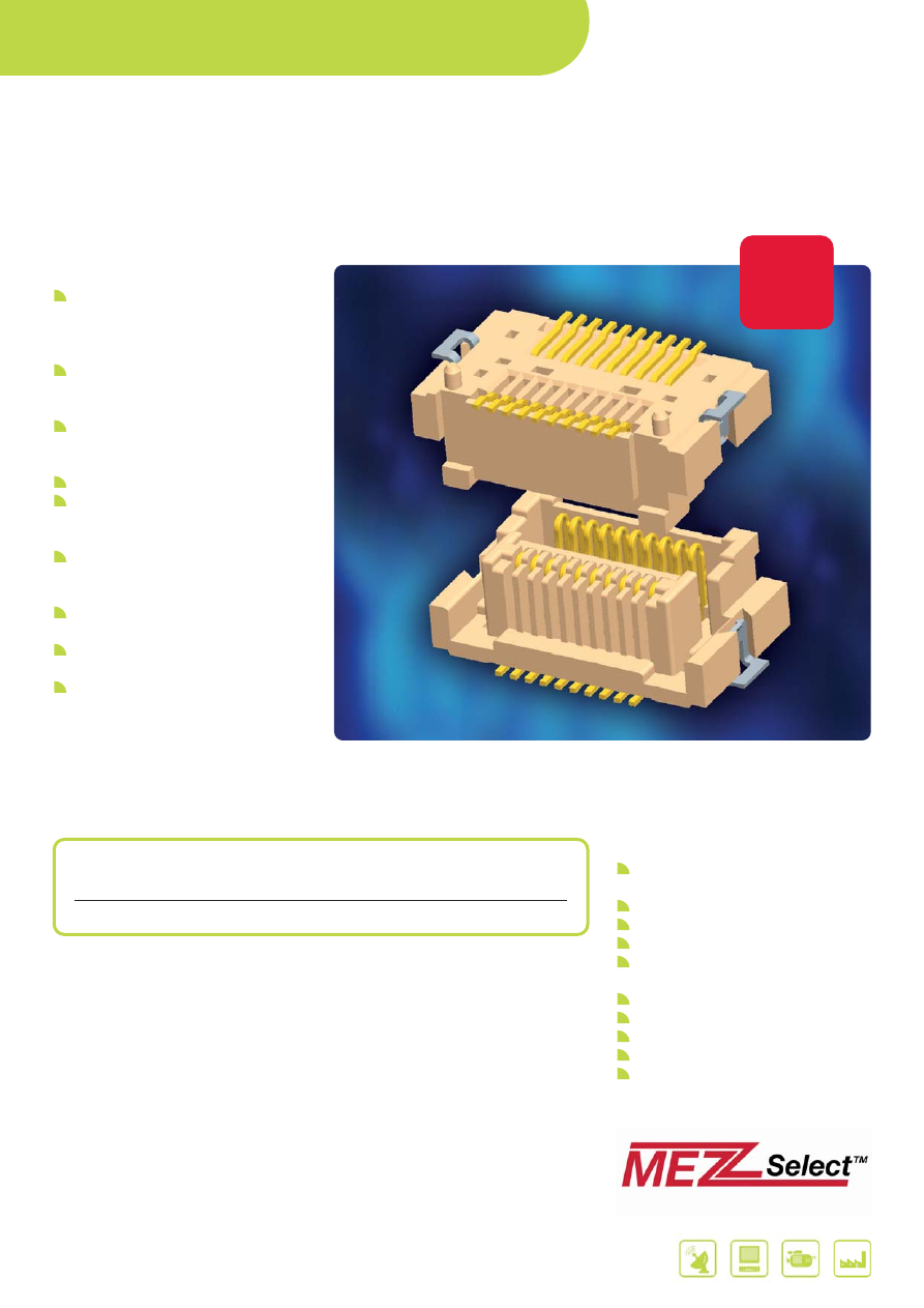
BERGSTAK
®
0.8 MM
FINE PITCH, MEZZANINE CONNECTORS
FEATURES & BENEFITS
Vast range of heights and sizes
- 5 mm to 16 mm stack heights
- 40 to 200 positions
Blade-on-beam contacts prevent
“stubbing” and allow “peeling”
Surface mount product design,
mounting and packaging support
automated assembly
Generous lead-in angles and mate
polarization provide worry free mating
Precision mini-contact design assures,
easy mating, long term performance
and reliability
Fully inter-matable with similar
competitive connectors
Early receptacle contact point
increases mating wipe and allows
early engagement/late disengagement
Tapered PCB locator pegs increase
the ease and accuracy of hand
assembly
APPLICATIONS
Routers
Servers
Telecom/Datacom equipment
Office equipment
IP phones
Test and measurement
Point-of-sale terminals
Portable industrial terminals
MAIN PRODUCTS
PART REFERENCES
BergStak
®
system
Receptacle
61082
Header
61083
BOARD-TO-BOARD /
WIRE-TO-BOARD CONNECTORS
30
Further information can be found at:
www.fci.com/conan
www.fci.com/mezzselect
CONAN
®
1.0 MM
FINE PITCH, MEZZANINE CONNECTORS
FEATURES & BENEFITS
Blade-on-beam contacts prevent
“stubbing” and allow “peeling”
High un-mating force is ideal for
portable and mobile electronics
Snap engagement contacts signal
reliable mating with and audible “click”
Surface mount product design,
mounting and packaging support
automated assembly
Generous lead-in angles and mate
polarization provide worry free mating
Focused range of heights and sizes
- 5 stack heights between 4.15 mm
and 7 mm
- 9 sizes between 9 and 69 positions
APPLICATIONS
Mobile, personal and high end
computing
Servers and routers
Office equipment
Measuring equipment, Industrial
control
POS, Retail equipment and Motor
Vehicle
MAIN PRODUCTS
PART REFERENCES
Conan
®
system
Receptacle
91921 / 91931
Header
91901 / 91911
31
Further information can be found at:
www.fci.com/ribcage
www.fci.com/mezzselect
RIB-CAGE™ 1.27 MM
MEZZANINE CONNECTORS
FEATURES & BENEFITS
Exclusive Rib-Cage™ multi-point
receptacle contacts provide optimal
reliability in high vibration and
shock-prone applications
High density 1.27 mm (.050 in.) x
1.27 mm (.050 in.) system for
connecting PCBs
Multiple stack height options
Polarization option prevents mis-
mating
Surface mount and through-hole
attachment options
Versatile range of heights
- 3 stack heights between 6.4 mm
and 9,9 mm
- 10 sizes between 10 and 100
positions
Competitive commercial pricing
APPLICATIONS
Handheld test and diagnostic
equipment
Outdoor test and measurement
devices
Military communication equipment
Security systems and access control
Point-of-sale terminals
Electronic sub-assemblies used in
conjunction with fans, motors and
mechanical devices
MAIN PRODUCTS
PART REFERENCES
Headers
Vertical Surface Mount
87409 / 90098 / 87849 /
93221 / 73546 / 73547
Right Angle Through Hole
87402
Receptacles
Vertical, Surface Mount
87021 / 87022 / 87023 /
87024
Reference to data sheet: 950521-010
BOARD-TO-BOARD /
WIRE-TO-BOARD CONNECTORS
32
MEZZOSTAK™ 0.5 MM HERMAPHRODITIC
FINE PITCH, MEZZANINE CONNECTORS
FEATURES & BENEFITS
Hermaphroditic design “mates to itself”
- Consolidates connector selection,
documentation and purchasing
- Polarization prevents mis-mating
Pressure-managed, dual-point contact
interface provides easier use, fault
tolerance and added reliability.
Long 1 mm minimum wipe assures
reliable contact and accommodates
system mechanical tolerances.
Tactile feedback signals effective mating
Extreme operating temperature range
assures reliable performance between
-40 and 125 degrees C
Precise 0.08 mm maximum SMT lead
co-planarity eases attachment of
connector leads to PCBs
Optional hold-downs increase strength
of PCB solder attachment
Footprint compatible with major
competitors
0.5 mm high density contact pitch in
two rows
- 7 Stack heights: 4 mm to 7 mm
(0.5 mm increments)
- 7 Sizes: 10 to 70 positions
(10 position increments)
Further information can be found at:
www.fci.com/mezzostak
www.fci.com/mezzselect
MAIN PRODUCTS
PART REFERENCES
Hermaphroditic
Standard with Hold-downs, Pegs
10090503
Connectors
Short
10090504
New
Product
New
New
product
product
APPLICATIONS
Portable and mobile electronic
equipment
Medical and Instrumentation
Point-of-Sale/Retail equipment
Hand-held terminals
Automatic Identification and Data
Capture (AIDC)
Sensors
Motor-vehicle
Military
Communications and Networking
Data and mass-storage
33
Further information can be found at:
www.fci.com/boardmate
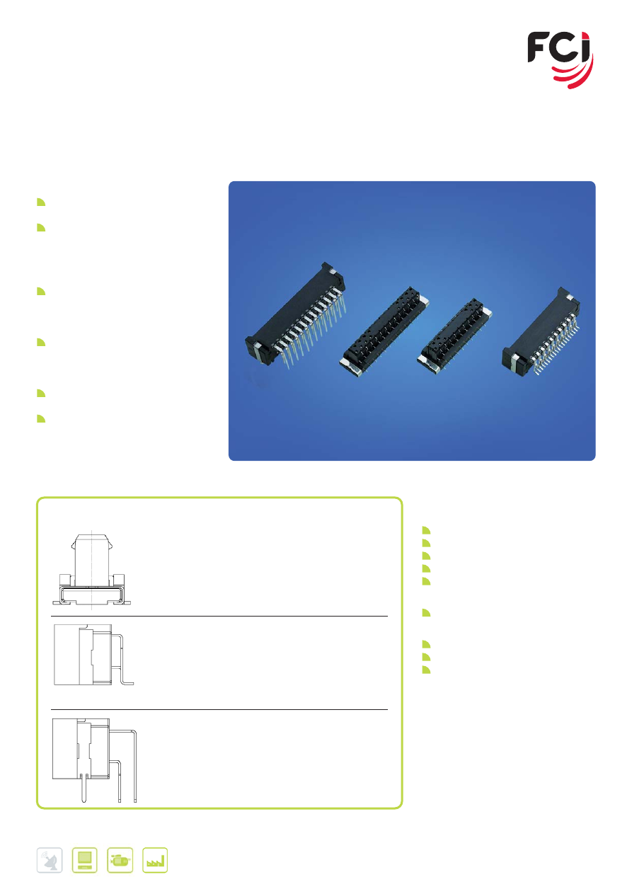
FLOATING BOARD-TO-BOARD
BTFW SERIES
FEATURES & BENEFITS
1 mm (0.039 in.) staggered contact
design saves valuable board space
Wide floating allowance absorbs mating
shift between plug and receptacle,
permitting self alignment of the mating
connectors; and provides highly reliable
mechanical performance
Rigid entry guide design withstands
rough handling such as angled insertion,
preventing contact deformation; and
provides vibration shock absorption
Wide guide distance for mating assures
easy handling and correct mating of the
plug and receptacle, and allows blind
mating
Mounting plates on both sides of the
plug and receptacle assure PCB retention
Flat top surfaces of SMT housings allow
pickup with vacuum nozzle and
eliminate the need for pickup covers that
must be removed after soldering
APPLICATIONS
Consumer
PDP displayer & TV
LCD displayer & TV
Set top boxes
DVD players/recorders
D-VHS players
Data
Entertainment PC
Other
POS terminals
Barcode scanners
Other handheld equipment
MAIN PRODUCTS
PART NUMBERS
Plug: BTFW_ _ P-3SSTAE4LF
10, 12, 14, 16, 18, 20, 22, 24, 26, 28, 30 contacts
Vertical (Straight)
Surface mount (SMT)
Gold or Tin plating (Contact area)
Tape & Reel packaging (Card Board or Plastic)
Lead Free / Rohs compliant
Receptacle: BTFW_ _ R-3RSTAE4LF
10, 12, 14, 16, 18, 20, 22, 24, 26, 28, 30 contacts
Right Angle
Surface mount (SMT)
Gold or Tin plating (Contact area)
Tape & Reel packaging (Card Board or Plastic)
Lead Free / Rohs compliant
Receptacle: BTFW_ _ R-3RDA7MLF
10, 12, 14, 16, 18, 20, 22, 24, 26, 28, 30 contacts
Right Angle
Dip
Gold or Tin plating (Contact area)
Tray packaging
Lead Free / Rohs compliant
BOARD-TO-BOARD /
WIRE-TO-BOARD CONNECTORS
34
Further information can be found at:
www.fci.com/flex
FFC - FPC CONNECTORS
FEATURES & BENEFITS
Suitable for FFC / FPC / CIC cable
0.30 - 0.40 - 0.50 - 1.00 - 2.54 mm
pitch sizes
Highly reliable Gas Tight High
pressure (GTH) contact system
Zero Insertion Force (ZIF) and Low
Insertion Force (LIF) options
Straight and Right-Angle versions
Surface Mount and Through Hole
APPLICATIONS
LC Display to Board connections
Interior Automotive electronics
Membrane Switches
DVD / HDD connection
Mobile phone and Digital camera
35
Further information can be found at:
www.fci.com/flex
PITCH
FAMILY
HEIGHT
CONTACT
ZIF / NON-ZIF(*)
PART REFERENCE
NAME
(MM)
LOCATION
0.3mm
SFY
2,0
Bottom
Non-ZIF (FF)
62789
SFYL-D
1,2
Bottom
Non-ZIF (FF)
10013057
SFYL-U
1,2
Top
Non-ZIF (FF)
10017251
YLL-D
0,9
Bottom
ZIF (FF)
10061122
YLL-U
0,9
Top
Non-ZIF (FF)
10064555
0.4mm
GLH
1,2
Bottom
ZIF (FF)
10051806
0.5mm
OPU-D
2,0
Bottom
ZIF (SL)
62684
OPU-U
2,0
Top
ZIF (SL)
62684
SFVA
2,0
Top and Bottom
Non-ZIF (BF)
10014265
SFVE
1,2
Top
ZIF (FF)
10054365
SFVL-D
0,9
Bottom
ZIF (BF)
59453
SFVL-U
0,9
Top
ZIF (BF)
59453
SFV-R
1,8
Top, Bottom
ZIF (SL)
SFVxxR
SFV-S
4,1
N/A
ZIF (SL)
62674
VHC
2,0
Bottom
ZIF (FF)
10085901
VLH
1,3
Bottom
ZIF (BF)
10042867
VLK
1,3
Bottom
ZIF (FF)
10076529
VLL
1,2
Bottom
ZIF (BF)
10051922
VLP
0,7
Bottom
ZIF (BF)
10062827
0.8mm
SFR
2,5
Bottom
ZIF (SL)
SFRxxR
1.0mm
HFW-R
1,9
Top, Bottom
Non-ZIF
HFWxxR
HFW-S
5,3
N/A
Non-ZIF
HFWxxS
HLW-R
3,9
Top
Non-ZIF
HLWxxR
HLW-S
5,9
N/A
Non-ZIF
HLWxxS
SFW-R
2,7
Top, Bottom
ZIF (SL)
SFWxxR
SFW-S
5,3
N/A
ZIF (SL)
SFWxxS
SLW-R
4,0
Bottom
ZIF (SL)
SLWxxR
SLW-S
5,5
N/A
ZIF (SL)
SLWxxS
1.25mm
SLD-R
7,0
Bottom
ZIF (SL)
SLDxxR
SLD-S
8,0
N/A
ZIF (SL)
SLDxxS
SLP-R
5,0
Top
ZIF (SL)
SLPxxR
SLP-S
5,5
N/A
ZIF (SL)
SLPxxS
2.54mm
Duflex
Contactand Housings
76785/67013/66987
Clincher
pre-assembled snap-shut system
65801/67516/66226/
(mates to PCB Headers
10027313/10022753
Shrouded PCB headers for 2.54mm Clincher
95735/95736
(*) ZIF (SL): Slider action
ZIF/Non-ZIF (FF): Front side flip
ZIF/Non-ZIF (BF): Back side flip
BOARD-TO-BOARD /
WIRE-TO-BOARD CONNECTORS
36
BERGSTIK
®
/ DUBOX™ / QUICKIE
®
/ PV™
2.54 MM MODULAR SYSTEM
FEATURES & BENEFITS
Versatile 2.54 mm modular system
includes board-to-board, wire-to-
board and flat cable interconnects,
offering complete design flexibility
Range: 1x2 to 2x36 positions
Selective plating is reliable and
economical
Easy part number selection at
www.fci.com/basics
Bergstik unshrouded headers
available in custom configurations
APPLICATIONS
Electronic equipment or devices
requiring a parallel, planar or
perpendicular board-to-board, wire-
to-board or flat cable interconnects
Uses span industry segments (e.g.
base stations, measuring equipment,
industrial control)
Further information can be found at:
www.fci.com/basics
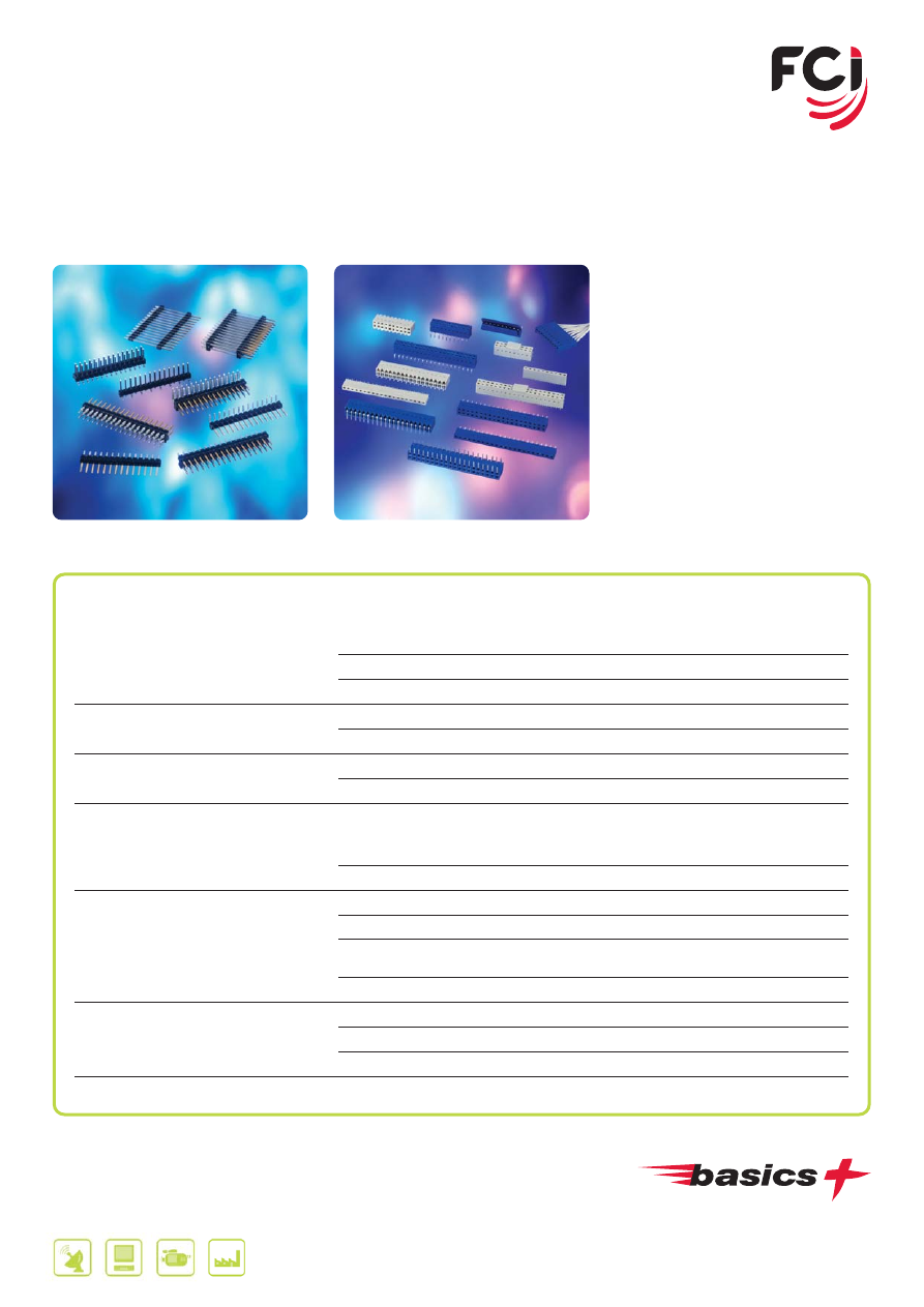
37
MAIN PRODUCTS
PART REFERENCES
BergStik
®
Unshrouded Headers
Straight
77311 / 77313 / 95293 / 95278 / 98401 / 67997 /
68000 / 68001 / 68002 / 67996 / 68602
Right-Angle
77315 / 77317 / 68015 / 68020 / 68016 / 68021
Stacking
54111 / 54121 / 54112 / 54122 / 54242
Dubox™ Shrouded Headers
Straight
76384 / 76385
Right-Angle
76382 / 76383
PV
®
Shrouded Headers
Straight
69167 / 69168
Right-Angle
78208 / 78207
Dubox™ PCB-Mounted Receptacles
Vertical
91601 / 89898 / 91614 / 91615 / 91618 / 71991 /
87606 / 76341 / 76342 / 71991 / 75915/ 71920 /
89891
Horizontal
71607 / 71609 / 89882 / 89883
Crimp-to-Wire Receptacles
Dubox™ contacts
76347 / 76357
Dubox™ housings
65239 / 65240
PV
®
contacts
48049 / 48231 / 48047 / 48048 / 48051 / 48045
48050 / 48052 / 48046 / 75543
PV
®
housings
65039 / 65043 / 65846 / 78211
Quickie
®
IDC System
IDC receptacles
71600 / 69830
Eject latch headers
71918 / 71922
Low profile headers
75867 / 75869 / 10056844 / 10056845 / 72454
Shunts
68786 / 69145 / 63429
Further information can be found at:
www.fci.com/basics
BergStik
®
Dubox™
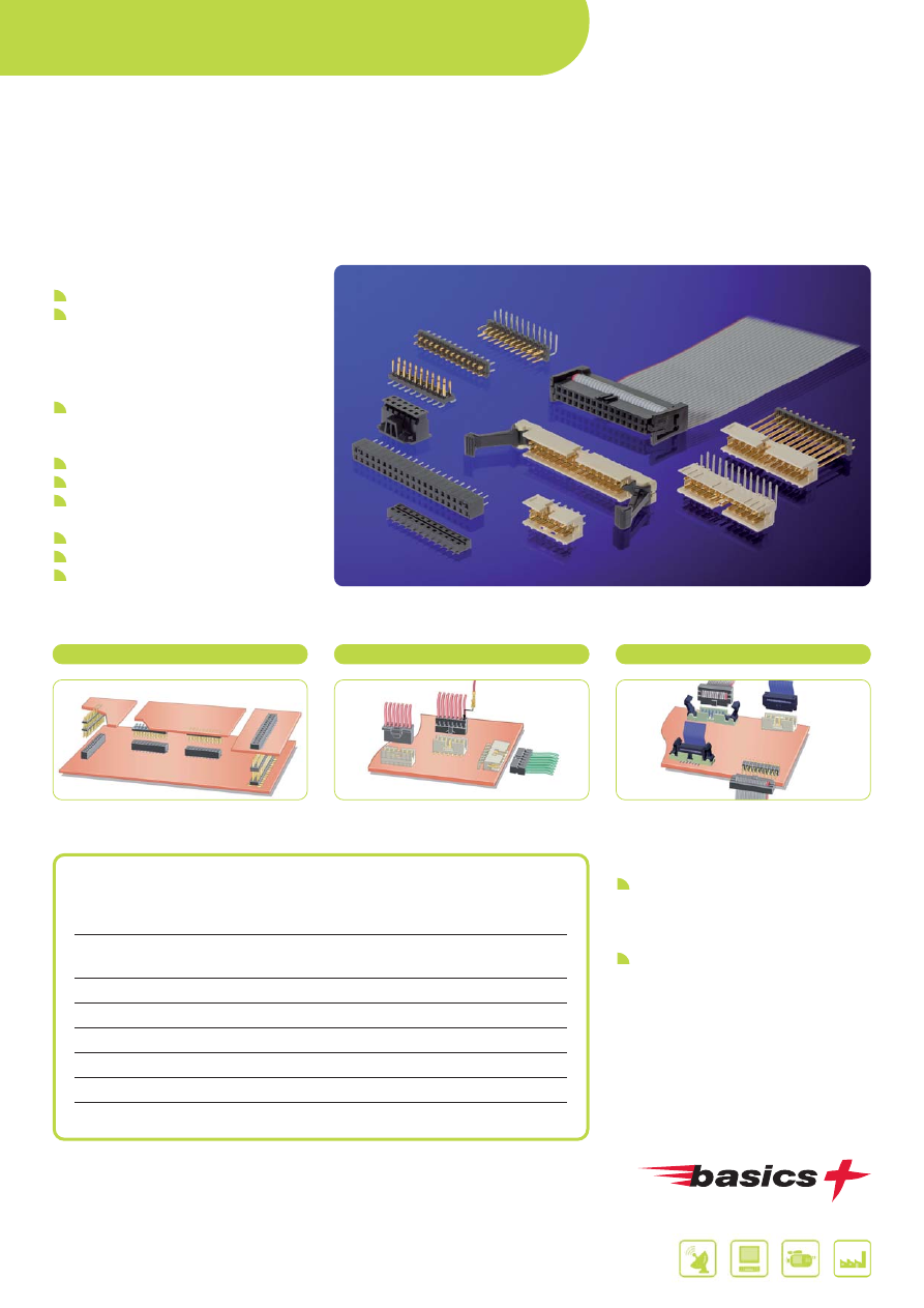
BOARD-TO-BOARD /
WIRE-TO-BOARD CONNECTORS
38
Further information can be found at:
www.fci.com/minitek
www.fci.com/basics
MINITEK™
2 MM MODULAR SYSTEM
FEATURES & BENEFITS
Everything intermateable!
The most complete 2 mm system
ever!
- Board-to-Board
- Wire-to-Board
- Flat Cable-to-Board
38% less board space, yet fully
equivalent to 2.54 mm systems like
BergStik
®
, Dubox™ , etc.
Lowest profile eject header
Lowest coplanarity at 0.1 mm
Operating temperatures as high as
125°C
New optional active latch
Pin-in-Paste headers
Lowest profile strain relief
APPLICATIONS
Electronic equipment or devices
requiring a parallel or perpendicular
board-to-board, wire-to-board or flat
cable interconnection
Uses span industry segments, e.g.
mobile base stations, measuring
equipment, industrial controls,
computers
MAIN PRODUCTS
PART REFERENCES
Unshrouded Headers
57102 / 57202 / 98423 / 10072353 /
10075024
Shrouded Headers
98414 / 98424 / 98464 / 10075025 /
10072354
Stacking Headers
59112 / 59132 / 59202
PCB receptacles (4.5 and 2.3 mm)
55510 / 55508 / 91596 / 63453
IDC receptacles
89361 / 89947
CTW housings
10073599 / 90311
CTW contacts
77138
Shunts
86730
Wire-to-Board
Flat Cable-to-Board
Board-to-Board
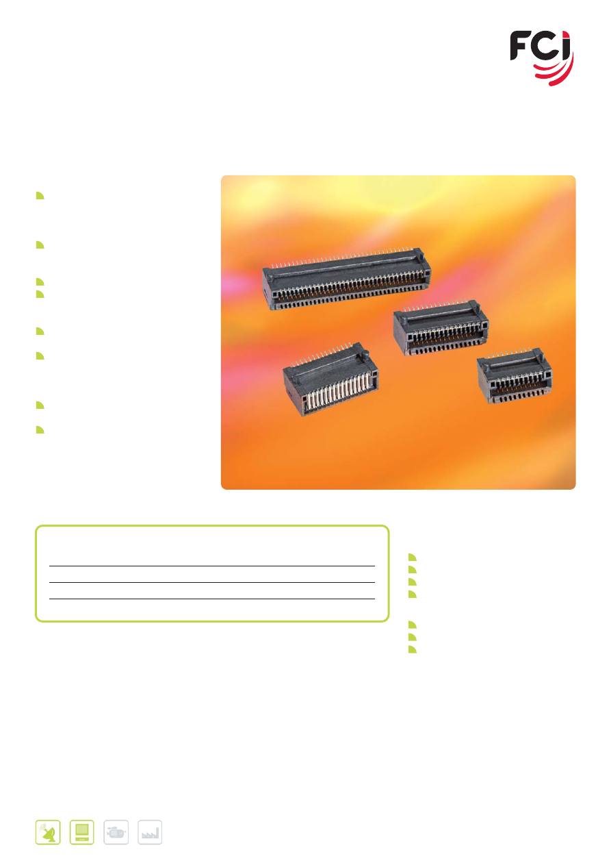
39
Further information can be found at:
www.fci.com/cardedge
FEATURES & BENEFITS
0.8 mm pitch connectors accept
1.0 mm thick PCBs used in MSA-
compliant pluggable transceiver
modules
Available 20, 30 and 70-position sizes
provide interfaces for SFP, XFP,
XENPAK, X2 or XPAK modules
Surface-mount (SMT) termination
Formed contacts provide smooth
contact surfaces for improved
reliability
Alignment posts aid placement during
board assembly
SMT design and short posts enable
connectors to be placed “belly-to-
belly” on opposite sides of a host
board
Tape-on-reel packaging to support
automated placement
RoHS-compatible
APPLICATIONS
Communications
Switches
Routers
Network interface cards (NICs)
Host bus adapters (HBAs)
Data
Servers
Storage systems
Storage controller cards
CARD EDGE CONNECTORS
FOR SFP, XFP AND XENPAK APPLICATIONS
MAIN PRODUCTS
PART REFERENCES
MSA
# Contacts
Part Number
SFP
20 position
10084423-X01LF
XFP
30 position
10084423-X02LF
XENPAK, X2, XPAK
70 position 10084423-X03LF
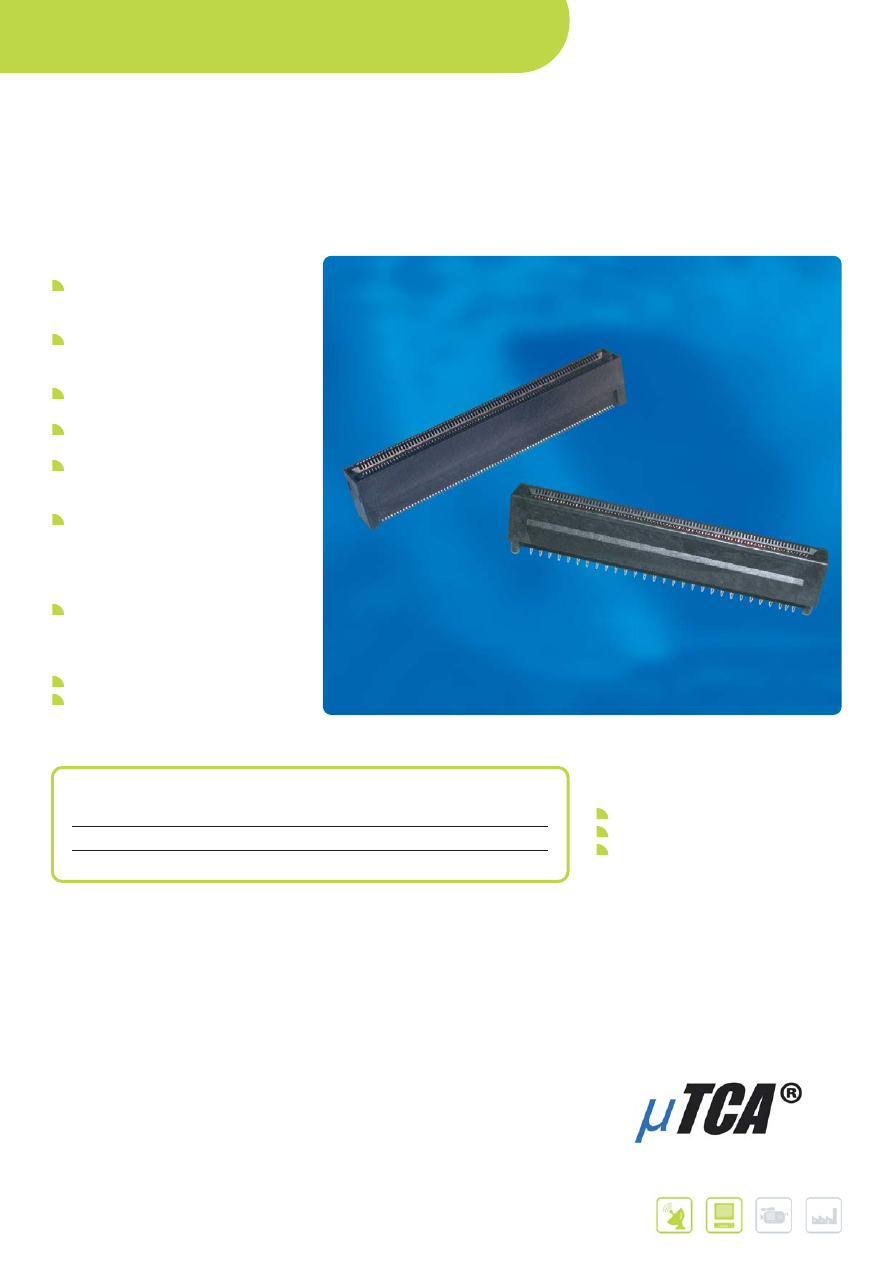
Further information can be found at:
www.fci.com/cardedge
MAIN PRODUCTS
PART REFERENCES
Termination style
Drawing Number*
Surface-mount (SMT)
10058835
Press-fit
10058831
CARD EDGE CONNECTORS
FOR MICRO
TCA
®
APPLICATIONS
PICMG
®
, AdvancedMC™, AMC™, and MicroTCA
®
are trademarks of
the PCI Industrial Computer Manufacturers Group.
FEATURES & BENEFITS
FCI connectors are in full compliance
with the MicroTCA
®
standard
developed within PICMG
®
Designed to enable AdvancedMC™
(AMC™) modules directly to a
backplane
170 position card edge interface with
0.75 mm contact pitch
Options for press-fit or surface-mount
(SMT) termination
Metal retention clips at ends of SMT
connector provide additional
mechanical strength after soldering
Balanced Signal Integrity
Characteristics. Very low loss and
crosstalk for low voltage differential
signaling at data rates up to 12.5 Gb/s
per lane
SMT footprint allows for increased
flexibility in routing PCB traces with
multiple widths and multiple
configurations
Telcordia UE compliant
Lead-free and RoHS-compatible
APPLICATIONS
Telecommunications
Radio Base Stations
RF antenna units
IP gateways
BOARD-TO-BOARD /
WIRE-TO-BOARD CONNECTORS
40
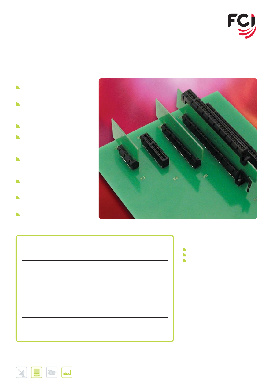
41
Further information can be found at:
www.fci.com/pciexpress
CARD EDGE CONNECTORS
FOR PCI EXPRESS
®
TECHNOLOGY
FEATURES & BENEFITS
Base connector range offers 1, 4, 8, or
16 serial PCI Express
®
links to scale to
different bandwidth requirements
Each serial link supports 2.5 Gb/s (per
direction) in PCI Express Gen. 1 systems
and 5.0Gb/s in PCI Express Gen. 2
systems
Options for through-hole solder, press-fit,
or surface-mount termination
Straddle-mount connectors feature
mounting ears for additional mechanical
support and a molded post to assure
proper alignment to the host PCB
Options for rugged stand-alone
mechanisms or a x16 connector with an
integrated retention arm to retain graphics
cards during shipping and handling
Larger 200, 230 (x24), and 280 position
vertical connectors accept server riser
cards
ExpressModule™ versions provide an
expanded lead-in window for blind-mate
server applications
RoHS-compliant connector versions are
available
APPLICATIONS
Data
Desktop PCs
Servers
Workstations
Industrial
SHB Express backplanes per PICMG
1.3 specification
MAIN PRODUCTS
PART REFERENCES
x1, x4, x8 or x16 suitable for wave soldering
10018784
x1, x4, x8 or x16 suitable for reflow soldering
10018783
x1, x4, x8 or x16 surface-mount (SMT)
10061913
x1, x4, x8 or x16 straddle-mount for extender cards 10025026 / 10069690
200-position vertical, solder version
10054652
230-position (x24) vertical, solder version
10063960
280-position vertical, solder version
10027747 / 10037901/
10057596 / 10066356
x8 vertical to mount on x16 PCB layout
10036767
x16 Integrated Type PCI Express
®
10083987/10085429
Graphics card retention mechanism
10042618
x1, x4, x8 or x16 ExpressModule™-type,
surface-mount (SMT)
10073228
PCI Express
®
and ExpressModule™ are
trademarks of PCI-SIG. SHB Express™ is a
trademark of PICMG
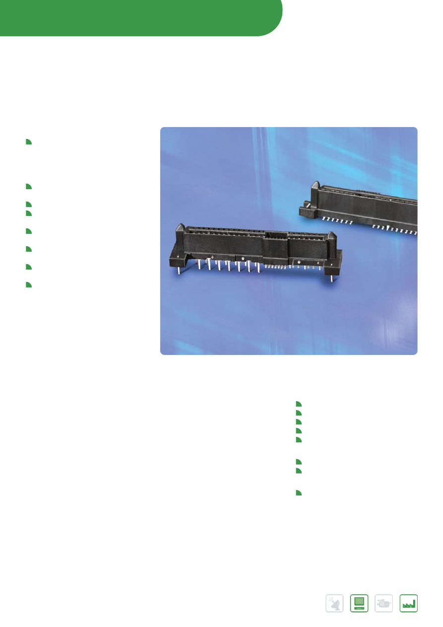
STORAGE INTERFACE CONNECTORS
42
Further information can be found at:
www.fci.com/storageinterface
www.fci.com/SAS
SAS
SERIAL ATTACHED SCSI
FEATURES & BENEFITS
29-position SAS receptacle and plug
connectors enable the high-speed,
Serial Attached SCSI (SAS) hard disk
drive (HDD) interface that is replacing
the SCSI
Designed to support differential
signaling of up to 6 Gb/s.
Connectors conform to SFF-8482
Provide dual signal ports (7 contacts/
port) and 15 contacts for power
SAS receptacles also accept SATA
drives
Designed to support hot-plugging and
blind-mating of HDDs
Connector retainers provide additional
mechanical strength after soldering
RoHS-compliant and compatible with
lead-free processing temperatures
APPLICATIONS
Data
Servers
Server and storage blades
External storage systems
HDDs
HDD carriers
Communications
Processor and storage blades
Mezzanine cards
Industrial, Instrumentation & Medical
Embedded system boards
43
Further information can be found at:
www.fci.com/storageinterface
www.fci.com/SAS
MAIN PRODUCTS
PART REFERENCES
Drive Device Plug
Straddle / Non-Straddle Mount
Contact FCI for information / customization
Adapter Plug
Vertical SMT
10031193 (See Note 1) / 10041724
Vertical, SMT (with rivet holes)
10045105 (also : see SATA 10045103)
Vertical, SMT, Wide Base
10071375
Right Angle, SMT
10034524 (See Note 2)
Host Receptacle
Vertical, Wide Base, Hybrid Footprint
10036876 (See Note 1) / 10036312
Vertical , Wide Base, Thru Hole
10039748 / 10045665
Vertical, Press Fit
10031077 (See Note 1)
Vertical , Wide Base, SMT
10039845 (See Note 1) / 10076579 (See Note 1)
Vertical, SMT
10031567 (See Note 1) / 10077259 (See Note 1)
Vertical, Wide Base, Press Fit
10038064 (See Note 2) / 10045782 (See Note 2)
Vertical, Thru Hole
10018182
Vertical, SMT, Extended Height
10038334
Right-Angle, SMT
10035202 (See Note 2)
Right-Angle, SMT, Reversed
10036587
Right-Angle, SMT, High Rise
10044002
4 Lane Internal Plug
Vertical, Press Fit
10028542
Vertical, SMT
10045646
Vertical, Thru Hole
10044625
Right-Angle, Thru Hole
10035104
NOTES :
(1) Product meet 6 Gb/s data rate, per SAS specification.
(2) Product capable of 6 Gb/s data depending on customer application & design optimisation.
Consult FCI Technical team for further information.
FCI’s SAS connector is capable of up to 6 Gb/s.
For latest 6 Gb/s SAS product offerings, pls consult FCI team or visit www.fci.com/SAS
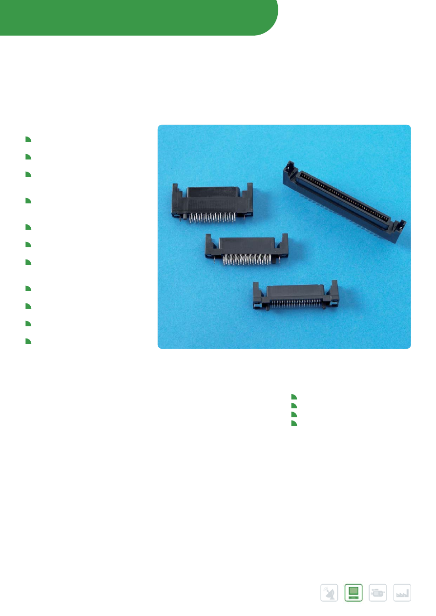
STORAGE INTERFACE CONNECTORS
44
Further information can be found at:
www.fci.com/storageinterface
www.fci.com/sca2
SCA-2 CONNECTOR SYSTEM
FEATURES & BENEFITS
Meet requirements of SFF-8451
specification
Options for through-hole solder,
press-fit or SMT board termination
Enhanced SMT receptacle meets
requirements of SFF-8454
specification
Enhanced version improves
impedance and insertion loss profiles
and reduces crosstalk
Blade-on-beam contact design
delivers high reliability
Molded alignment and polarization
features enable blind mating
First-Mate-Last-Break (FMLB)
contacts in accordance with SFF
requirements
ESD contacts provide static discharge
paths to prevent damage
Vertical receptacle range includes
11.5 mm and 17.5 mm body heights
High temperature plastic suitable for
wave or reflow soldering
Lead-free and RoHS-compliant
versions are available
APPLICATIONS
Data
Storage backplanes
External storage systems
Servers
HDDs
Note: * symbol designates enhanced SCA-2 receptacle for 4G or 8G Fibre Channel applications
45
Further information can be found at:
www.fci.com/storageinterface
www.fci.com/sca2
MAIN PRODUCTS
PART REFERENCES
HDD Interface
Number
Connector
Orientation
Termination
Part
Interface
of contacts
Type
Type
References
Fibre Channel
40
Receptacle
Vertical
Through-hole solder
71781
40
Receptacle
Vertical
Press-fit
87567
40
Receptacle*
Vertical
Surface-mount
10038339 (See Note 1)
40
Receptacle*
Vertical
Surface - mount
10073037 (See Note 1)
40
Receptacle
Vertical
Through-hole solder
72437
40
Receptacle
Vertical
Press-fit
72443
SCSI
20
Plug
Right-angle
Straddle-mount
72547
80
Receptacle
Vertical
Through-hole solder
71780
80
Receptacle
Vertical
Press-fit
87566
80
Receptacle
Vertical
Through-hole solder
72436
80
Receptacle
Vertical
Press-fit
72442
80
Plug
Right-angle
Straddle-mount
71292
NOTES :
(1) * symbol designates enhanced SCA-2 receptacle for 4G or 8G Fibre Channel applications
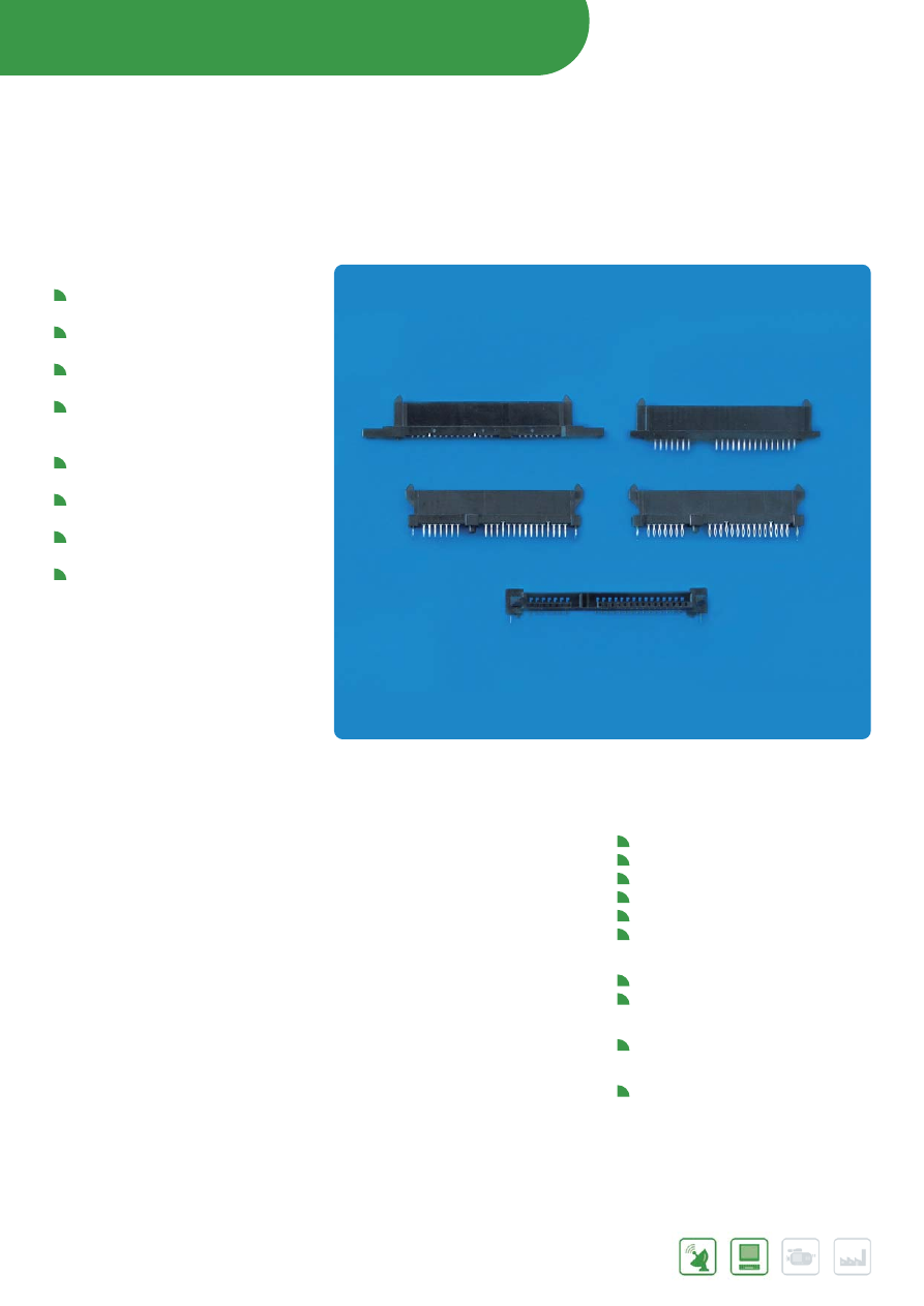
STORAGE INTERFACE CONNECTORS
46
Further information can be found at:
www.fci.com/storageinterface
www.fci.com/SATA
SATA
SERIAL ATA I/O
FEATURES & BENEFITS
For implementation of high-speed
Serial-ATA storage interface
Designed to support differential
signaling of up to 6 Gb/s.
Connectors meet requirements of
Serial ATA Specification
22-position connectors provide
7 contacts for signal port and
15 contacts for power
Designed to support hot-plugging and
blind-mating of HDDs
7-position signal plugs for internal
cable connections
Connector retainers provide additional
mechanical strength after soldering
RoHS-compliant and compatible with
lead-free processing temperatures
APPLICATIONS
Data
Notebook & Desktop PCs
Servers
Server and storage blades
External storage systems
HDDs
HDD carriers
Communications
Processor and storage blades
Mezzanine cards
Industrial, Instrumentation & Medical
Embedded system boards
Consumer
Audio/video storage
47
Further information can be found at:
www.fci.com/storageinterface
www.fci.com/SATA
MAIN PRODUCTS
PART REFERENCES
7-Position Signal Plug, 2 Wall
Right-Angle, SMT
59335
Vertical, Thru Hole
59333 / 10028860
Vertical, SMT
59334
7-Position Signal Plug, 4 wall
Vertical, Thru Hole
10035690
Vertical, SMT
10035691
7-Position Signal Plug, 3 wall
Right-Angle, SMT
10035692
22-Position Device Plug
Straddle Mount, SMT
10035541
Right-Angle, SMT (Interposer)
10039651
Right-Angle, SMT (4 Wall Latch Feature)
10052369
Right-Angle, Thru Hole (4 Wall Latch Feature)
10038031
Contact FCI for customization
22-Position Host Receptacle
Vertical, SMT
10029065/59337/10042140
Vertical, SMT (With Rivet Holes)
10045103
Vertical, Thru Hole
10017660
Vertical, Press Fit
10022676
Vertical , Cable Solder Tab
10043820
Right-Angle, SMT
10029364 / 10034814
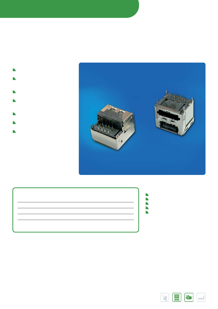
STORAGE INTERFACE CONNECTORS
48
Further information can be found at:
www.fci.com/storageinterface
www.fci.com/esata
eSATA CONNECTORS
FEATURES & BENEFITS
Compliant with eSATA requirements in
Serial ATA Specification
Up to five times faster than USB2.0
or FireWire 400 external storage
solutions
Supports Gen 1 (1.5Gb/s) and Gen 2
(3Gb/s) data rates
Provide external data backup and
protection at up to 3Gb/s data
transfer rate
High-durability design supports 2500
cycles
RoHS-compliant and compatible with
lead-free processing temperatures
Available range includes eSATA,
eSATA/USB (2-in-1), and eSATA/ USB
(2-in-1) + USB combo types
APPLICATIONS
Desktop / Notebook PC
Set top box
Gaming equipment
External portable storage
USB related applications product/
equipment
MAIN PRODUCTS
PART REFERENCES
eSATA
right-angle plug, through-hole solder
10067172
eSATA
right-angle, upright plug, through-hole solder
10074141
eSATA
2-in-1 right-angle plug, through-hole solder
10074703
eSATA
2-in-1 reversed right-angle plug, through-hole solder
10069848
USB
over eSATA 2-in-1 right angle combo plug,
10081268
reversed, through-hole solder
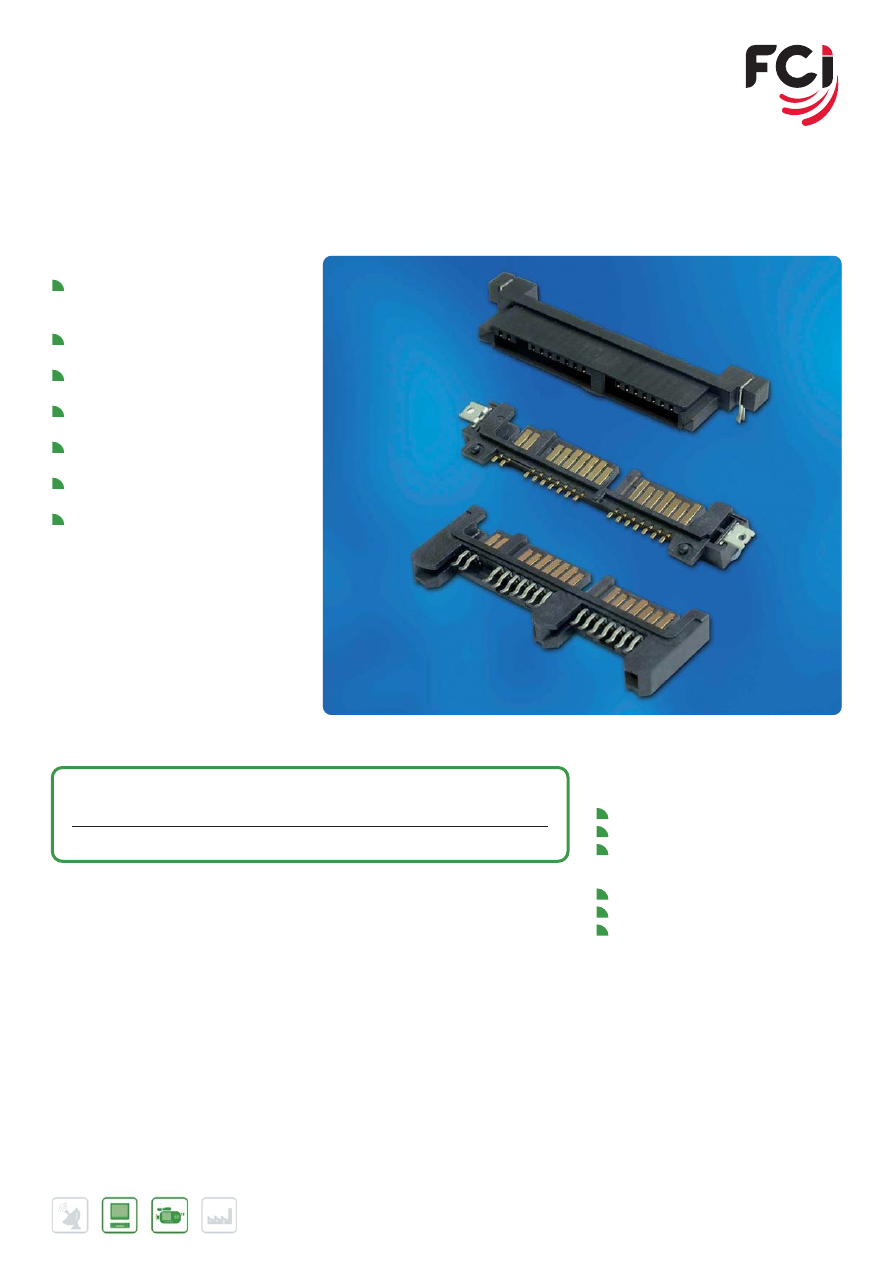
49
Further information can be found at:
www.fci.com/storageinterface
www.fci.com/microsata
MICRO SATA CONNECTORS
FEATURES & BENEFITS
Compliant with Micro SATA
requirements in Serial ATA
Specification
16 contacts on 1.27 mm pitch: 7 for
signals and 7+2 for power
Supports Gen 1 (1.5Gb/s) and Gen 2
(3Gb/s) data rates
High-durability design supports 500
mating cycles
Designed to support hot-plugging and
blind-mating
Connector retainers provide additional
mechanical strength after soldering
RoHS-compliant and compatible with
lead-free processing temperatures
APPLICATIONS
Data
Notebook PC
Sub-notebook PC
Portable storage (external drive)
Consumer
Set top box
Gaming console
Audio / Video storage
MAIN PRODUCTS
PART REFERENCES
Micro SATA
Plug -straddle mount
10078287
Micro SATA
Receptacle - through hole mount
10080211
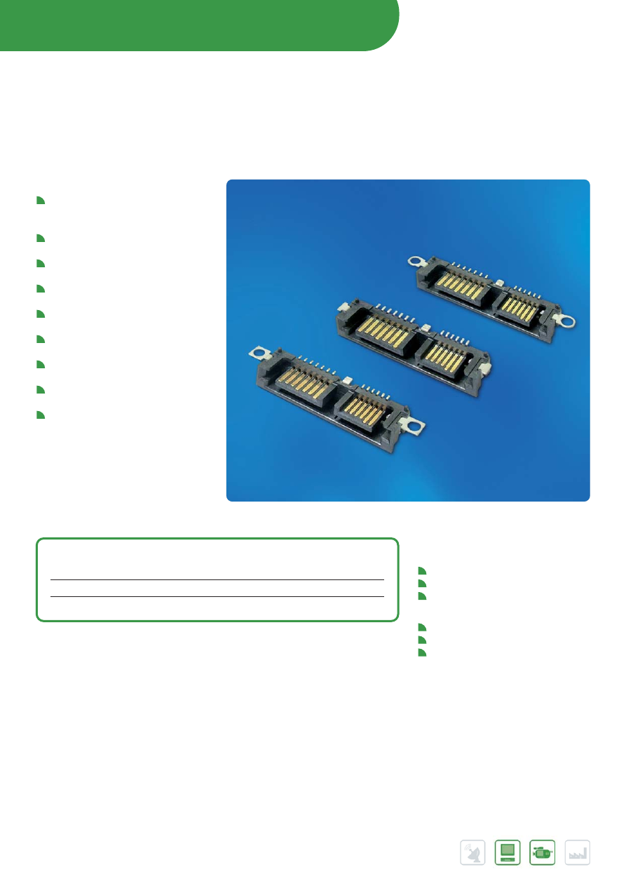
Further information can be found at:
www.fci.com/storageinterface
www.fci.com/slimlinesata
STORAGE INTERFACE CONNECTORS
50
SLIMLINE SATA CONNECTORS
FEATURES & BENEFITS
Compliant with Slimline SATA
requirements in Serial ATA
Specification
Supports Gen 1 (1.5Gb/s) and Gen 2
(3Gb/s) data rates
7 contacts on 1.27 mm pitch for
signals
6 contacts on 1 mm pitch for 5V
power delivery
High-durability design supports 500
mating cycles
Designed to support warm-plugging
and blind-mating
Connector retainers provide additional
mechanical strength after soldering
Options for screw-attachment of plug
connector
RoHS-compliant and compatible with
lead-free processing temperatures
APPLICATIONS
Data
Desktop PC
Notebook PC
Optical disk drive (ODD)
Consumer
Set top box
Gaming equipment
Optical disk drive (ODD)
MAIN PRODUCTS
PART REFERENCES
SMT
right-angle plug with rounded screw-hole tabs
10085303
SMT
right-angle plug with square screw-hole tabs
10085304
SMT
right-angle plug with solder-tab retainers
10085305
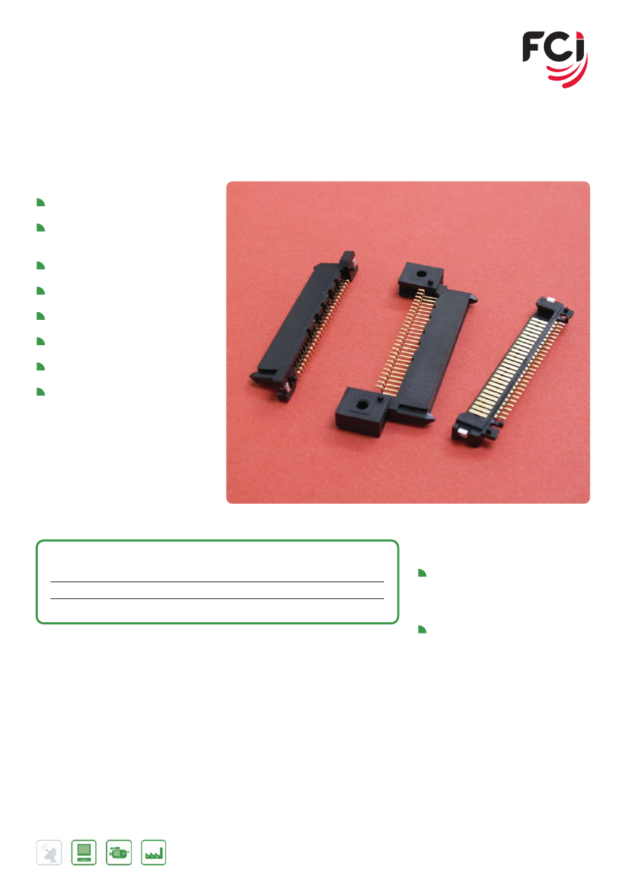
51
iVDR CONNECTORS
INFORMATION VERSATILE DISK FOR REMOVABLE USAGE
FEATURES & BENEFITS
Provide 26 contacts in a single row
on 1.27 mm pitch
Surface-mount design is RoHS-
compliant and compatible with lead-
free soldering temperatures
Low insertion force for high
durability:10,000 mating cycles
External dimensions match standard
22-position SATA connector
The right-angle plug provides solder
tabs for added retention
Options for right-angle or vertical
receptacle provide capability to install
Cartridges in either orientation to host
board
The right-angle receptacle features a
fixed screw hole at each end while
the vertical type features a solder tab
retainer at each end
APPLICATIONS
iVDR Plug:
Media cartridge, internal port
termination, hard disk drive, solid state
drive.
iVDR Receptacle:
Host application with iVDR interface,
such as home recorder, Set-top box,
PC, server, TV, automobile. Auto-
loading mechanism at host
applications.
MAIN PRODUCTS
PART REFERENCES
SMT
Right-angle receptacle with screw holes
10033998
SMT
Vertical receptacle with solder tab retainers
10034273
SMT
Right-angle plug with holddown
10079510
Further information can be found at:
www.fci.com/storageinterface
www.fci.com/ivdr
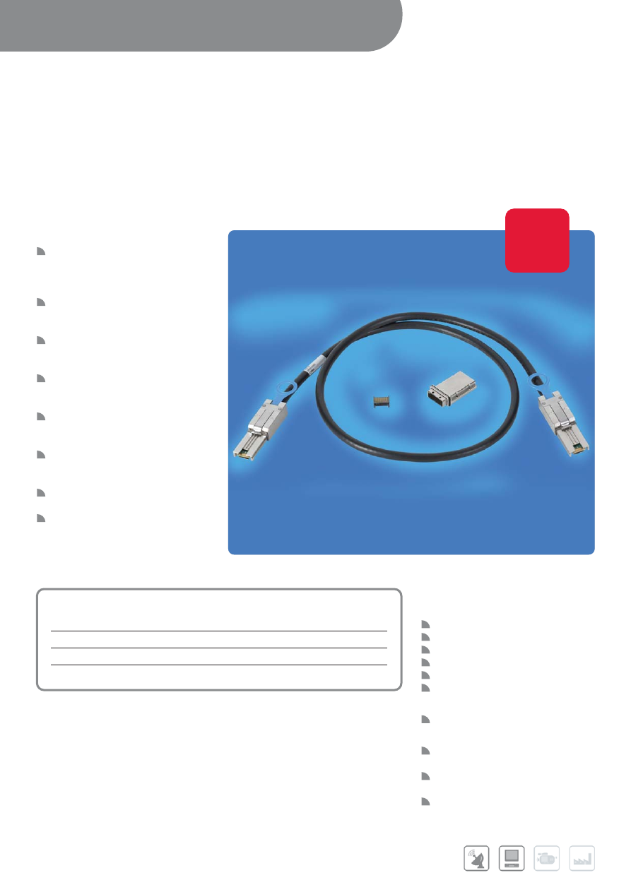
INPUT/OUTPUT CONNECTORS /
CABLE ASSEMBLIES
52
MINI MULTILANE EXTERNAL
CABLE ASSEMBLIES
FOR HIGH-SPEED SERIAL MINI SAS (2.0 & 2.1) OR
MINI SATA 4X LINKS
FEATURES & BENEFITS
Ruggedized 26-position cabling
interconnect system is SFF- 8088
(shielded – external) and SFF-8086
compatible
Available options support Mini SAS
(SAS 2.0 & 2.1) and Mini SATA 4x
external cable requirements
Paddle card design is optimized for
signal integrity and mechanical
performance
Low profile “pull-to-release” latching
system provides secure connection
and allows stacking
Adaptive, robust EMI Gasket and die-
cast backshell assure proper EMI
shielding
Robust cable strain relief system
isolates cable termination from
mechanical stress
Reduced backshell protrusion
provides short cable exit
Controlled wire management and
termination process assures
consistent high-speed electrical
performance RoHS compliant
APPLICATIONS
Data
Servers
RAID systems
Storage racks
External Storage systems
SAS/SATA HBA interfaces
Direct-attached storage (DAS)
Communications
Switches
Industry Standards
SATA-IO Serial ATA (SATA)
Specification
INCITS/ANSI Serial-Attached SCSI
(SAS 2.0 & 2.1) specifications
SFF-8088 and SFF-8086
MAIN PRODUCTS
PART REFERENCES
Unequalized Mini-Multilane SAS / SATA cable assemblies
10084749
Mini-Multilane 20 position connector
10098870
Mini-Multilane single port cage - 0° and 1°
10098871
Mini-Multilane 1x2 ganged port cage - 0° and 1°
10098872
Further information can be found at:
www.minisas.com
www.fci.com/hsio
www.fci.com/highspeed
New
Product
New
New
product
product
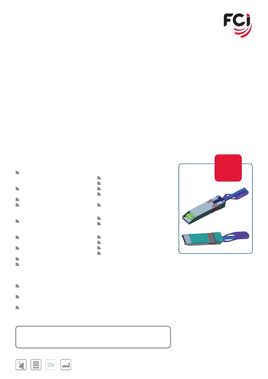
53
MAIN PRODUCTS
PART REFERENCES
Unequalized SFP+ cable assembly
10101497
Further information can be found at:
www.fci.com/hsio
SFP+ COPPER CABLE ASSEMBLIES
FOR ETHERNET AND FIBER CHANNEL APPLICATIONS
FEATURES & BENEFITS
Fully compatible with all SFP+
interfaces & mechanical backwards
compatibility with SFP
Designed to be compliant with SFF-
8431 industry standard
100 ohm differential impedance
Allows for 10Gb/s per channel
transmission up to 7 meters (passive
cable assembly)
Allows for 10Gb/s per channel
transmission up to 15 meters (actively
equalized cable assembly)
Optimized PCB interface board to
minimize crosstalk and insertion loss
Stamped EMI girdle to assure
superior EMI shielding effectiveness
EEPROM for cable signature
Actively equalized cables enable
longer cable lengths or the use of
smaller cable diameters for shorter
cable lengths
Lower cost and lower power solution
when compared to fiber optic links
32 AWG to 24 AWG cable sizes
available
RoHS compliant
APPLICATIONS
Data
Servers
Networked storage systems
External storage systems
High Performance Computing (HPC)
applications
Data Center networking
Communications
Switches
Routers
Industry Standards
10 Gigabit-Ethernet (10 GBASE-CU)
Gigabit-Ethernet ( IEEE 802.3ae)
8G FC and 10G FCoE
SFF-8431
FCI’s SFP+ cable assemblies are designed to meet data center, storage networking and high performance computing application
needs for a high density cabling interconnect system capable of 10Gb/s per channel transmission rates. These cable assemblies are
designed to meet the requirements of Small Form Factor industry standard SFF-8431. The SFP+ cables support the bandwidth
transmission requirements as defined by 10Gigabit-Ethernet (10G Base-CU), 8G Fibre Channel (FC) and 10G Fibre Channel over
Ethernet ( FCoE) specifications
The cable assembly’s printed circuit paddle card has been designed to not only address the stringent mechanical interface
requirements but also the higher-bandwidth signal integrity requirements for 10Gb/s per channel transmission. It has also been
designed to accommodate EEPROM cable signature needs as well as address applications for both passive and active equalized
cable assembly applications. The assembly also includes robust diecast covers and an EMI girdle to assure proper EMI shielding
effectiveness and termination. FCI manufactures these cable assemblies using highly controlled and stable cable assembly
manufacturing processes minimize wire management and termination variations that impact the performance of the cable assembly.
Robust final test and quality systems assure high quality cable assemblies conforming to the high-speed electrical performance
requirements in industry specifications.
New
Product
New
New
product
product
Part will become available in Q4 2009
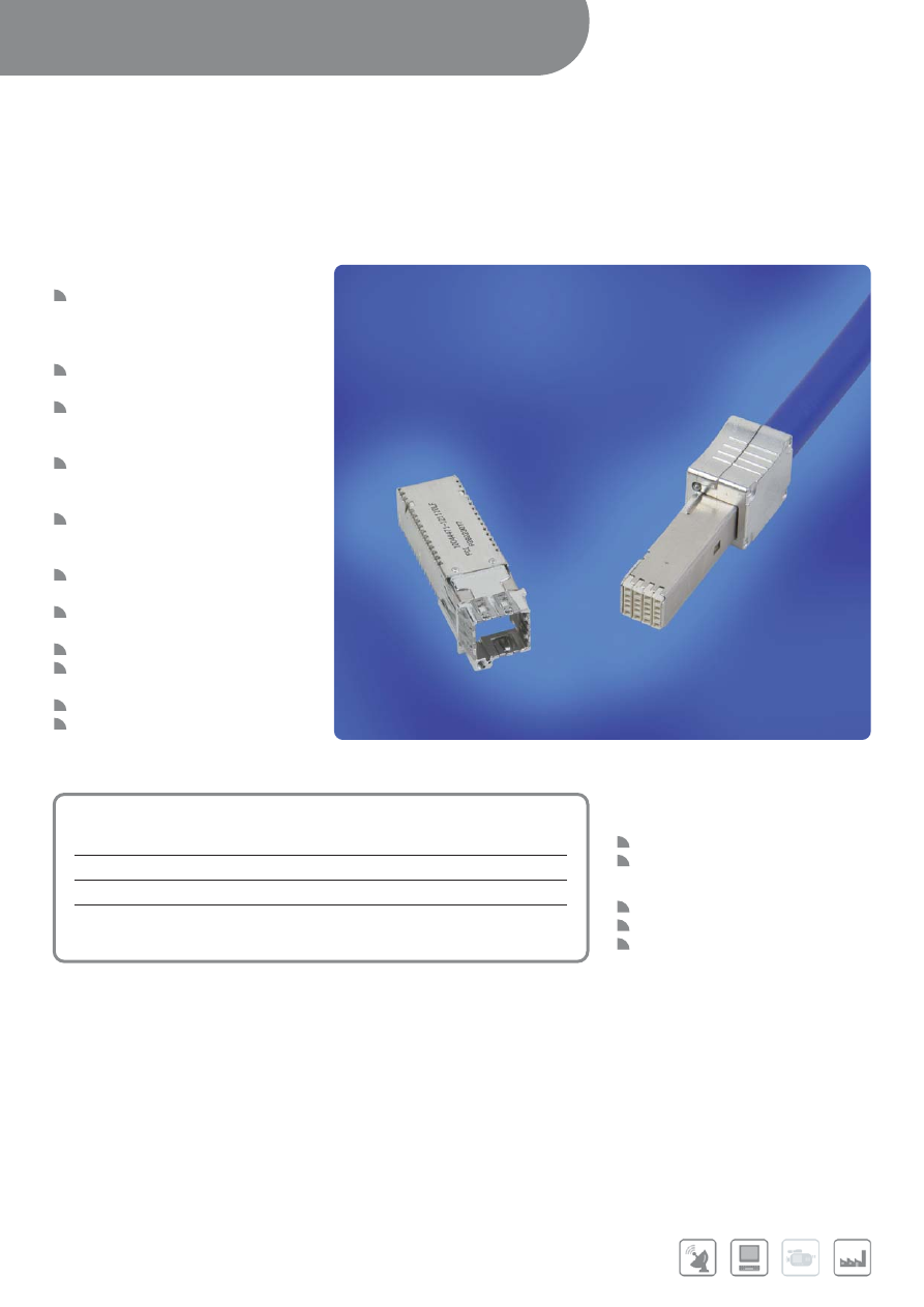
INPUT/OUTPUT CONNECTORS /
CABLE ASSEMBLIES
54
Further information can be found at:
www.densishield.com
www.fci.com/hsio
www.fci.com/highspeed
DENSISHIELD™ I/O SYSTEM
FEATURES & BENEFITS
8-pair connectors can be mounted
side by side on 12.5 mm pitch
enabling multiple I/O ports along a
card edge
Connects EMC shield to chassis panel
and provides shielding to PCB level
Low vertical profile allows use in
systems having 15 mm pitch card slot
spacing
Low crosstalk between differential pairs
with controlled 100-ohm impedance to
match 100-ohm shielded pair cable
Crimp ferrule system reliably terminates
EMC shield of cable to connector
covers
Connects EMC shield to chassis panel
and provides shielding to PCB level
Signal ground is isolated from EMC
ground
SMT reflow-compatible PCB connector
Dual-beam contact system provides
redundancy and long term reliability
RoHS-compliant
µTCA
®
profile compliant Header
available
APPLICATIONS
Data
Servers
Storage systems
Communications
Switches
Routers
Base stations
Medical
Instrumentation
Test equipment
MAIN PRODUCTS
PART REFERENCES
PCB Mount Board Connector
10044471
Cable Mount Plug Kit
10044473
Cable assemblies
10054999
PCB board mount connector
10076181
for single-width Micro TCA
®
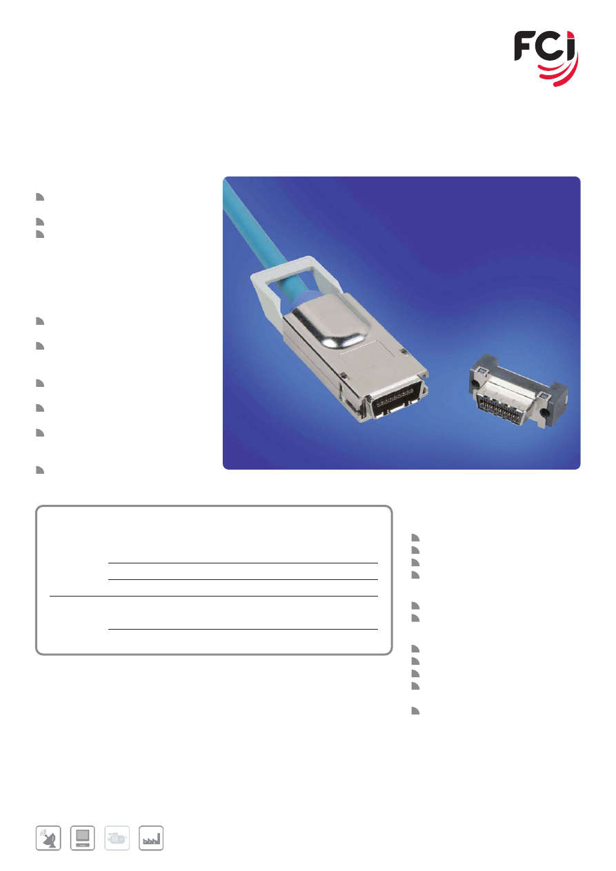
55
Further information can be found at:
www.eyemax.com
www.fci.com/hsio
www.fci.com/highspeed
EYEMAX
®
HIGH SPEED I/O SYSTEM
FEATURES & BENEFITS
Robust pull-to-release latching or
thumbscrew cable-lock hardware
4x version provides 8 differential pairs
High-speed data rates:
- Infiniband SDR: 2.5 Gb/s per
channel
- Infiniband DDR: 5.0 Gb/s per
channel
- Ethernet CX4: 3.125 Gb/s per
channel
Custom paddle-card design for
improved crosstalk performance
Impedance-controlled paddle card
with capability to upgrade for
equalization
Die-cast shells for enhanced EMI
shielding performance
Cable assembly offering available with
various high-speed raw cable options
Right-angle, surface-mount PCB
receptacles offer variety of locating
post and panel-mount options
RoHS compliant
APPLICATIONS
Data
Servers
Server clusters
Storage systems
HPC and data centers
Communications
Switches
Routers
Industry standards
Infiniband architecture
Infiniband SDR, DDR
10G Fibre Channel
10G Base-CX4 Ethernet
(IEEE 802.3ak)
SFF-8470 for SATA or SAS
MAIN PRODUCTS
PART REFERENCES
Receptacles
4x Latch type, clip mount
58368
4x Latch type, screw mount
58369
4x Thumbscrew version, screwlock mount
10009629
Plug Kits for cable assemblies
4x Latch type
58441
4x Thumbscrew version
10013923
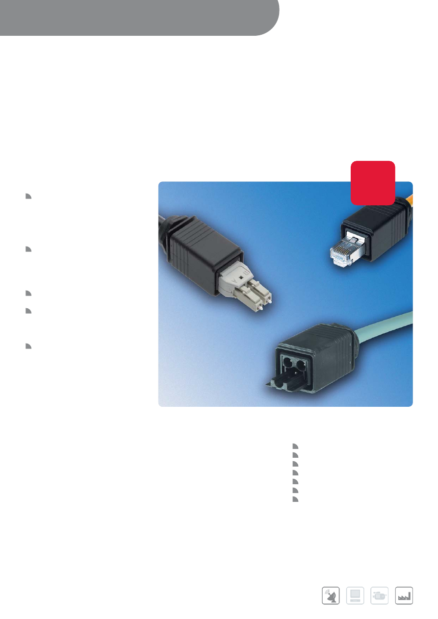
INPUT/OUTPUT CONNECTORS /
CABLE ASSEMBLIES
56
OUTDOOR I/O
OUTDOOR I/O SOLUTIONS
FEATURES & BENEFITS
Standardized cost effective housings
allows for integration of many standard
FCI solutions
- Power
- High Speed Copper
- Fiber
Easy PushPull engagement provides
reliable, audible connectivity
- Audible click assures optimal
insertion versus competitive
“screw-tight” solutions
IP 65 and IP67 compliant to meet
harsh environmental conditions
Easy Installation facilitates field
installable solutions
- Optimized design allows for easy
maintenance and repair
The flexible form factor can be
dedicated for single mode or
multimode fiber
The Outdoor I/O product is a ruggedized-waterproof product ideal for outdoor applications. The product supports multiple product
variations with the utilization of various inserts (Power, Ethernet, and Fiber) to be snapped into a standard container. This flexible and
cost effective solution easily adapts to increasing market needs for high speed and power transmission in a ruggedized form factor
that meets international protection code testing.
APPLICATIONS
FTTH – Fiber to the home
FTTA – Fiber to the antenna
Base Stations
WIMAX
Mobile Infrastructure
Industrial
Video Broadcast Equipment
Further information can be found at:
www.fci.com/outdoorio
New
Product
New
New
product
product
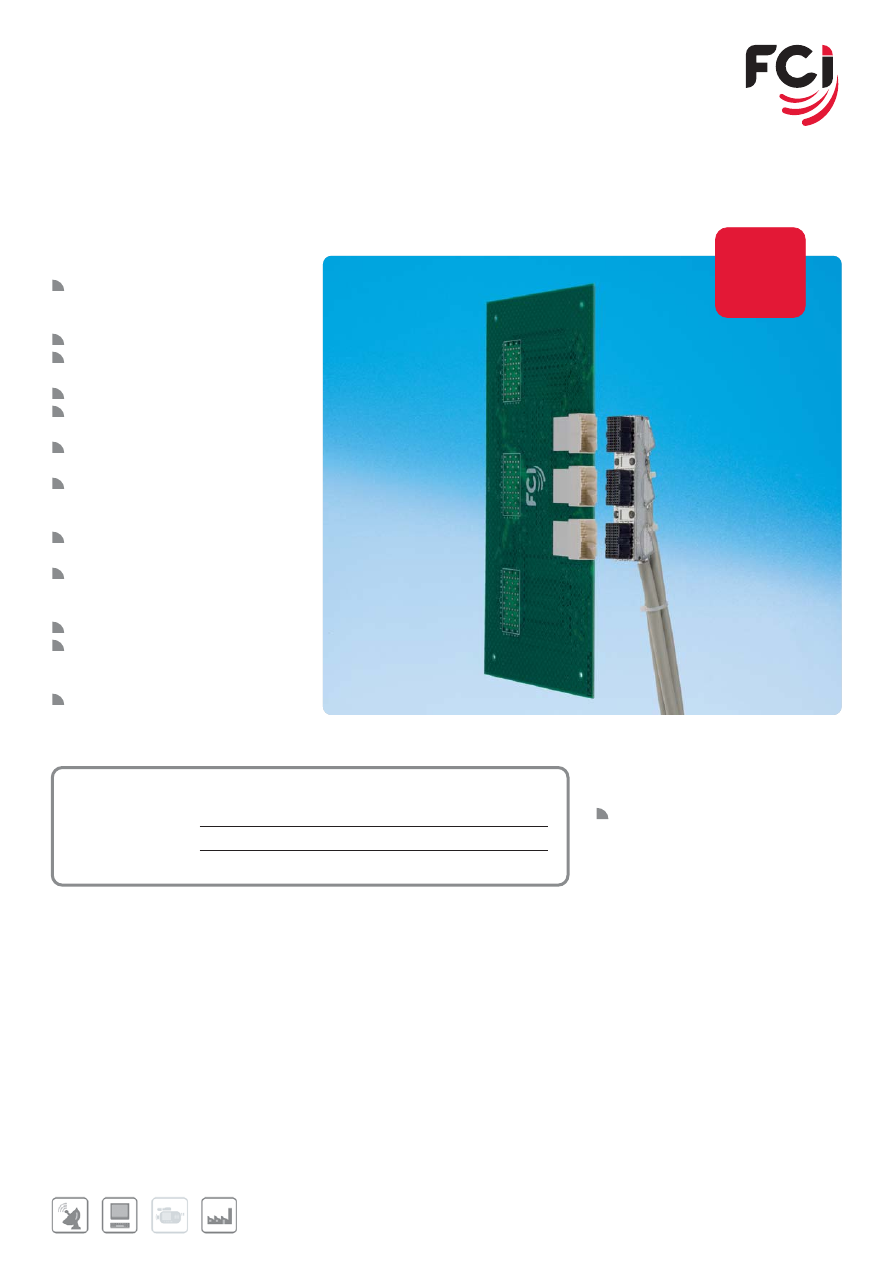
57
METRAL
®
HDXS
HIGH SPEED FRONT I/O INTERCONNECTION SYSTEM
FEATURES & BENEFITS
Complies with standard telecom
building practices (IEC 60917-2-2 &
IEC 60297-3)
24 and 72 pair VDSL-2
Resistibility to over-voltage of up to
2500V
Robust design
RoHS design allows for environmental
friendly end application
Die cast shells for enhanced EMI
shielding performance
Right-Angle, Press-Fit board
connectors suitable for 1.6 and
2.4mm PCB thickness
Meets Telcordia GR1217-CORE
performance CO
Insulation Displacement Technology
with mechanical relief per individual
wire
Polarized design prevents mis-mating
Integral screw hardware fastens
connector to the panel preventing
accidental unmating
Available as custom cable assemblies
APPLICATIONS
Communications
ADSL, VDSL, VDSL-2 networks
MAIN PRODUCTS
PART REFERENCES
Metral HDXS
Board Connector
10075388-101LF
Cable assembly 72 pair
Customized
Cable assembly 24 pair
Customized
Further information can be found at:
www.fci.com/metralhdxs
www.fci.com/highspeed
New
Product
New
New
product
product
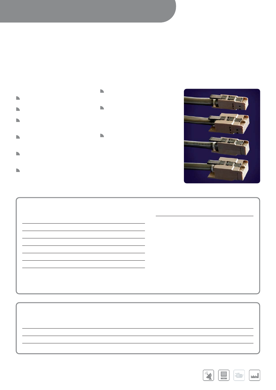
INPUT/OUTPUT CONNECTORS /
CABLE ASSEMBLIES
58
METRAL
®
CABLE CONNECTORS
CABLE CONNECTORS FOR METRAL
AND IEC 2MM PCB HEADERS
FEATURES & BENEFITS
Interface compatible with IEC 61076-
4-104 backplane connectors
Next generation design offers easy
and fast cable assembly
Four Row versions provide 24 or 48
contacts; Five Row versions provide
30 or 60 contacts
Insulation displacement design offers
quick termination without the need to
strip conductors
Active backshell latches securely
connect assembled cable connectors
to standard Metral
®
headers
Different latch designs are available to
satisfy ergonomic and mechanical
requirements
End-stackable cable connectors
enable adjacent connectors to plug to
headers without loss of positions
Application tooling supported by FCI
APPLICATIONS
Applications in communications, data,
and industrial electronics using IEC
61076-4-104/Metral
®
-compatible
connector architecture
MAIN PRODUCTS
PART REFERENCES
Standard cable connector kits
4 rows x 6 = 24 positions, standard latch
4 rows x 12 = 48 positions, standard latch
5 rows x 6 = 30 positions, standard latch
5 rows x 12 = 60 positions, standard latch
4 rows x 6 = 24 positions, short latch
4 rows x 12 = 48 positions, short latch
5 rows x 6 = 30 positions,short latch
MAIN PRODUCTS
PART REFERENCES
Right angle Metral
®
headers
4 Rows x 6 = 24 Positions
HM1L41LAP000H6PLF
HM1L41LDP000H6P
4 Rows x 12 = 48 Positions
HM1L42LAP000H6PLF
HM1L41LDP000H6P
5 Rows x 6 = 30 Positions
HM1L51LAP000H6PLF
HM1L51LDP000H6P
5 Rows x 12 = 60 Positions
HM1L52LAP000H6PLF
HM1L52LDP000H6P
7247V-WXY1LF
V Number of Positions
6=4 Rows x 6 = 24 Positions
7=4 Rows x 12 = 48 Positions
8=5 Rows x 6 = 30 Positions
9=5 Rows x 12 = 60 Positions
W Plating Section
1=Gold plating on mating face
X Latch Style
1=Standard finger latch for easiest actuation
2=Short finger latch for extra large diameter cable
Y Wire / Conductor Size
1=For 26 to 24 AWG wire
2=For 30 to 28 AWG wire
Further information can be found at:
www.fciccom/metral
www.fci.com/cableassembly
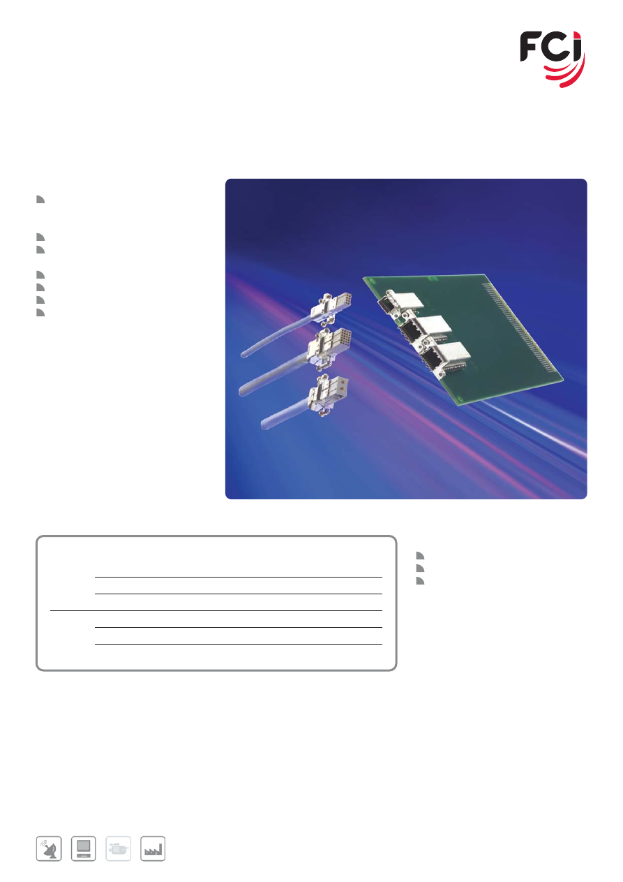
59
Further information can be found at:
www.fci.com/sofix
SOFIX
®
FRONT I/O INTERCONNECTION SYSTEM
FEATURES & BENEFITS
Complies with standard telecom
building practices (IEC 60917-2-2 &
IEC 60297-3)
Signal and power modules
Both 10/100 BaseT and 1000 BaseT
8 position solutions
Hot plugable
Robust design
15 mm slot pitch
RoHS design allows for environmental
friendly end application
APPLICATIONS
Wireless
Switching (mobile)
Transmission (Ethernet & GbE line
lines, E1/T1, 2 Mb).
MAIN PRODUCTS
PART REFERENCES
2x4
Sofix Board Connector
72860
Sofix Cable Connector 10/100 BaseT
72861
Sofix Cable Connector 1000 BaseT
53389
4x6
Sofix Board Connector
72844
Sofix Cable Connector Coax Twisted pair
HM1C16D2J110EBLF
Sofix Cable Connector Coax Quad
72817
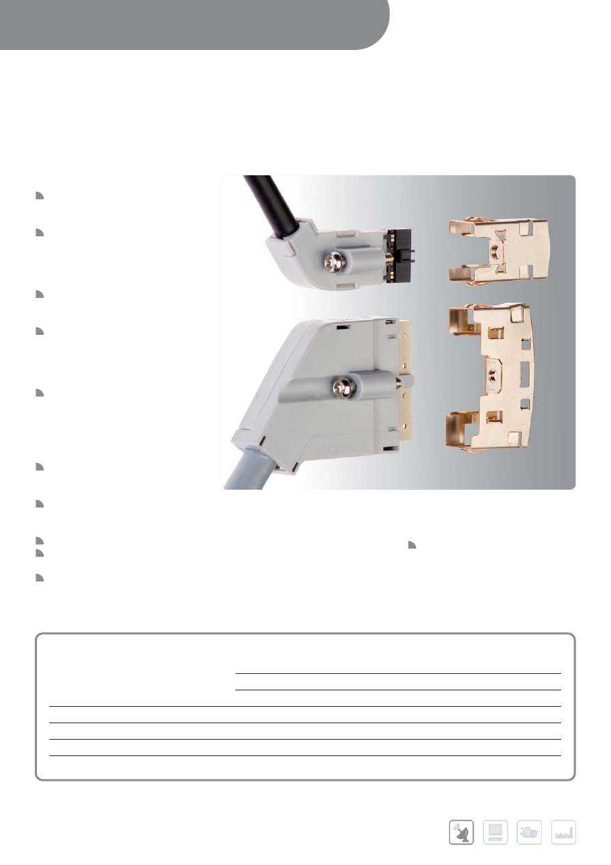
LOW PROFILE SUBSCRIBER INTERFACE
SIGNAL & POWER FOR DSL SUBSCRIBER ACCOUNTS
FEATURES & BENEFITS
Versatile, turnkey system designed
especially for subscriber connection
applications
SIGNAL connectors have 24 contacts
on 2.00 mm pitch. PCB header uses
minimal space: 16 mm (depth from
edge of card) x 33 mm (along edge of
card) x 13 mm (height off card)
Custom pin assignments are available to
achieve very low cross-talk performance
(<-55 dB) for vDSL applications
POWER connectors have 2 contacts on
2.54 mm pitch. PCB header uses
minimal space: 20 mm (depth from
edge of card) x 14 mm (along edge of
card) x 13 mm (height off card)
Power cable connector design employs
two additional first-mate/last-break
(FMLB) sacrificial contacts to prevent
arcing to the primary contacts and
enable “hot” mating 35 degree angled
cable exits provide easy cable routing
Dual-metal PV
®
power contacts and
dual-beam signal contacts maximize
durability and optimize reliability
Integral screw hardware fastens
connectors together to prevent
accidental un-mating
Polarized design prevents mis-mating
Lead-free, RoHS compatible design
satisfies environmental regulations
Available from FCI in component kits or
as custom cable assemblies
APPLICATIONS
Communications
• aDSL / vDSL access networks
• Wireless base stations
Further information can be found at:
www.fci.com/cableassembly
INPUT/OUTPUT CONNECTORS /
CABLE ASSEMBLIES
60
MAIN PRODUCTS
PART REFERENCES
Cable Assemblies
Signal
10076684
Power: Single-ended
10076685
Power Double-ended
10076686
Power Cable Connector Kit
1x4, 2.54 mm contact pitch
10074342-001LF/ 10074342-001LF
Power PCB Header Connector
1x4, 2.54 mm contact
10066619-001LF
Signal Cable Connector Kit
2x12, 2.00 mm contact
10073976-001LF
Signal PCB Header Connector
2x12, 2.00 mm contact
10069230-001LF
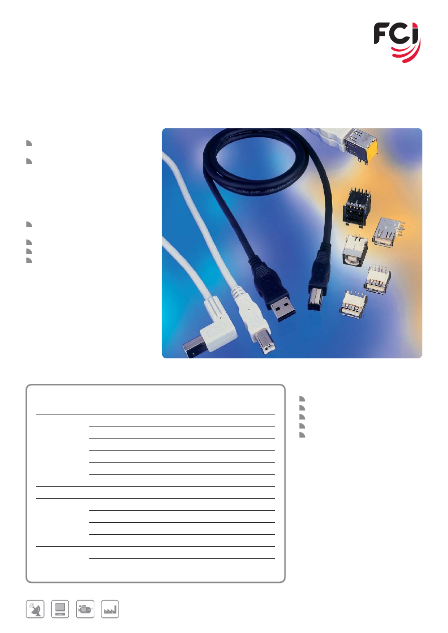
61
Further information can be found at:
www.fci.com/usb
www.fci.com/powersolutions
www.fci.com/cableassembly
USB
UNIVERSAL SERIAL BUS
FEATURES & BENEFITS
USB 2.0 compliant, speed to
480 Mb/sec
Type A (Host) receptacles, 4 position
- Through hole and SMT versions
- PCB mount options: Position,
orientation, hold-down.
- Panel fixing and grounding options
- Additional sensor contact versions
- Double deck, 8 position version
Type B (peripheral) receptacles,
4 position
Mini USB receptacles, 5 position
Plug kits for overmold cable assembly
USB + power versions available
APPLICATIONS
Computers, laptops, servers
Printers, external drive units, monitors
Digital cameras, TV’s, set-top box
Modems, keyboards, instrumentation
Point-of-sale equipment.
MAIN PRODUCTS
PART REFERENCES
Style
A
S/D Upright, Through hole Receptacle
73725
S/D Right angle, Through hole Receptacle
87520
D/D Right angle, Through hole Receptacle
72309
S/D Right angle, Through hole Reversed Receptacle
74552
S/D Right angle, SMT Receptacle
87583
S/D Right angle, SMT Reversed Receptacle
74626
B
S/D Right angle, Through hole Receptacle
61729
USB+POWER
S/D Right angle, Through hole Receptacle (Full range) 55917
Plug Kit (Full range)
74233
S/D Right angle, Through hole Receptacle
57489
Plug Kit
57496
Cable Assembly
Single-ended
10084088/10084089
Double-ended (USB+POWER and LNL)
10089745/10089743
10083511/10083512
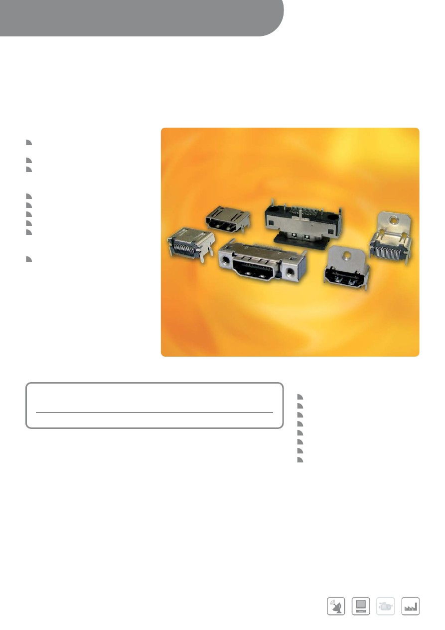
APPLICATIONS
Plasma Displays&TVs
LCD Display&TVs
Set-Top-Boxes
DVD Players/Recorders
Audio/Video Receivers
D-VHS Players
High-Definition Monitors
Entertainment PC
Further information can be found at:
www.fci.com/hdmi
INPUT/OUTPUT CONNECTORS /
CABLE ASSEMBLIES
62
HDMI
HIGH DEFINITION MULTIMEDIA INTERFACE
FEATURES & BENEFITS
Choice of partial SMT/PIP or full SMT
mounting style
Right angle and straight versions
Metal shell for better EMI shielding
protection, especially for the straight
version
Excellent durability
HDMI 1.3a compliance
RoHS compliant
Low impedance mismatch
Straight version features additional
grounding pins for enhanced EMI
performance
Backward compatible with DVI
MAIN PRODUCTS
PART REFERENCES
Right angle, with or without flange
10029449
Straight
10078837
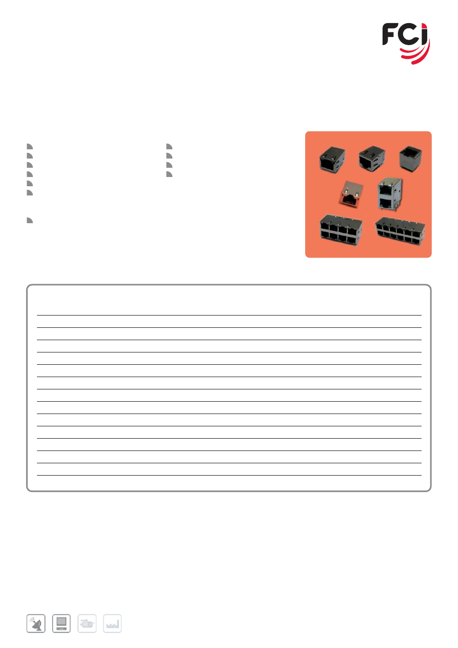
63
MAGNETIC JACKS CONNECTORS
FEATURES & BENEFITS
10/100 or 1000 BaseT option
With or without LED
Spring fingers on shells for better EMI
Tab up and tab down options
Low profile design option
Modular transformer design to
decrease production output rate and
reduce process cost
RoHS compatible
APPLICATIONS
Servers, Switching Hubs, Routers
Set Top Box, Digital TV, LCD TV
Printers
Desktop and Notebook PC’s
MAIN PRODUCTS
PART REFERENCES
Product Type
No. of Position
Tab Type
With LED
With Springs
Xfrm Performance
1x1
12
Up
Yes
Yes
10/100
10084428
1x1
14
Up
Yes
Yes
1000
10084429
2x1
28
-
Yes
Yes
10/100
10084432
2x1
28
-
Yes
Yes
1000
10084433
2x1
20
-
No
Yes
10/100
10082590
1x1
8
Down
No
Yes
10/100
10085058
1x1
17
Up
Yes
Yes
10/100
10085073
1x1
17
Up
Yes
Yes
1000
10085074
1x1
10
Up
Yes
Yes
10/100
10085077
1x1
8
-
No
No
10/100
10085078
2x4
112
-
Yes
Yes
10/100
10085079
2x4
112
-
Yes
Yes
1000
10085080
2x6
168
-
Yes
Yes
10/100
10085081
2x6
168
-
Yes
Yes
1000
10085082
Further information can be found at:
www.fci.com/modjacks
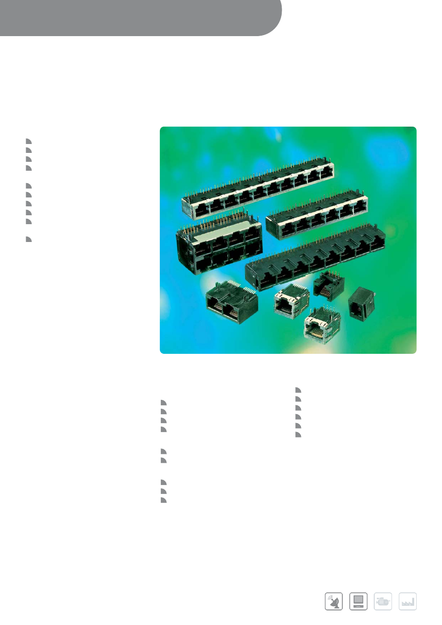
INPUT/OUTPUT CONNECTORS /
CABLE ASSEMBLIES
64
Further information can be found at:
www.fci.com/modjacks
MODULAR JACKS
FEATURES & BENEFITS
Right angle or straight
Through mount or SMT
Cat3, Cat5 performance category
4, 6, 8 positions, fully or selectively
loaded
Single to Stacked Multi-ports
Shielded or non-shielded
Magnetic option
Inverted latch options
Standard, raised or low profile
versions
Snap or diamond pegs options
APPLICATIONS
Networking
Network servers
Hubs
Routers
Ethernet switches
Computers and Peripherals
Laptops
Modems
Telecom
PBX systems
Fax machines
Phone line security systems
Office and Home Equipment
ATM machines
Point of sales terminals
Vending machines
Security systems
Set-top boxes
Medical analysis equipment
65
MAIN PRODUCTS
PART REFERENCES
Single Port Cat3
Positions
Pegs
Part Series
Right angle
Through mount
4, 6, 8
Snap
87180 / 54601
8, 10
Snap
54602
SMT
4
73306
6
73305
8
73304
Straight
Through Mount
4
Snap
90511
4
Diamond
69253
6
Snap
90512
6
Diamond
69254
8
Diamond
69255
SMT
4
87543/98431
6
87545/98432/98433 (keyed)
8
87547/98435/87549 (keyed)
Multiport Cat3
Ports
Shield
Part Series
Right angle
Through Mount
4, 8
Yes
94910
2, 4, 7, 8
No
94911
2 (6P+6P)
No
10053565
2 x4 (Stacked)
Yes
74633
Straight
Through Mount
3 (4P+4P+6P)
No
92266
Multiport Cat5
Ports
Shield
Part Series
Right angle
Though Mount
4, 8 (Filter)
Yes
95672
4, 8
Yes
95678
2, 4, 6, 8
No
95679
Further information can be found at:
www.fci.com/modjacks
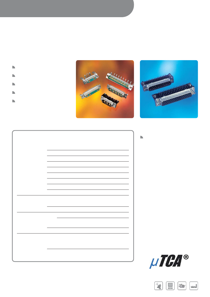
INPUT/OUTPUT CONNECTORS /
CABLE ASSEMBLIES
66
Further information can be found at:
www.fci.com/dsub
D-SUBMINIATURE
PCB APPLICATIONS
FEATURES & BENEFITS
Signal: 9 to 50 way connectors -
standard density
Signal: 15 to 78 way connectors high
density
Power: wide range of layouts from
2V2 to 36W4
Solder to board and press-fit and Pin-
in-Paste (THR) terminations available
Dedicated website
APPLICATIONS
Our D-Sub connectors are suitable
for every type of equipment including
those in harsh environments
MAIN PRODUCTS
SERIES
Standard application
Signal
Right angled solder-to-board
Delta D
Right angle press-fit
Delta D
Right angle pin-in-paste
Delta D
Straight solder-to-board
Delta D
Straight press-fit
Delta D
Straight pin-in-paste
Delta D
High Density solder-to-board
Compact D
High Density press-fit
Compact D
High Density pin-in-paste
Compact D
Less Demanding application
Right angled solder-to-board
Economy Range
Straight solder-to-board
Economy Range
Demanding application
Full and mix power
Straight and Right angle
solder-to-board and press-fit
DW series
High Power I/O PCB connectors
µTCA
®
Severe environment application
Signal
Right angle solder-to-board, Wire-wrap
and Straight solder-to-board
DP series
Right angle solder-to-board, Wire-wrap
and Straight solder-to-board
DM series
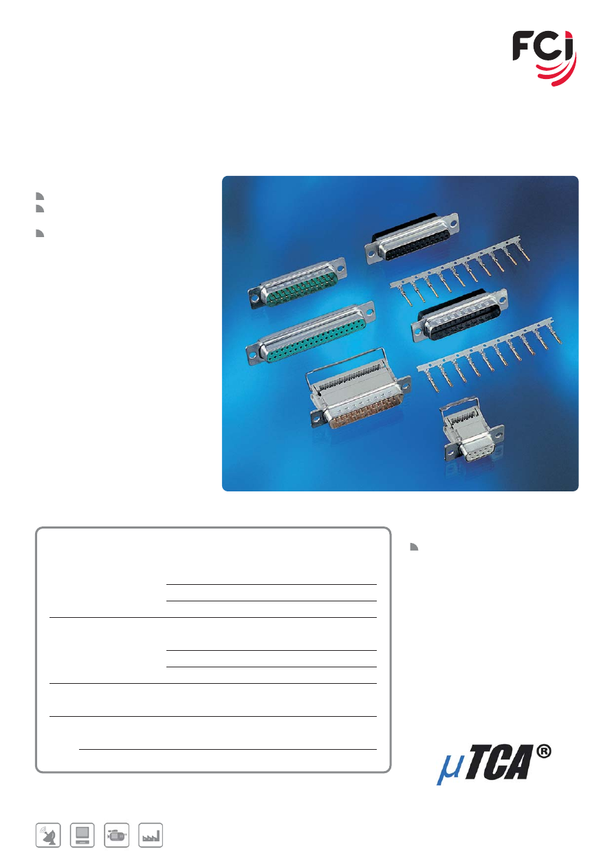
67
Further information can be found at:
www.fci.com/dsub
D-SUBMINIATURE
CABLE APPLICATIONS
FEATURES & BENEFITS
Signal: 9 to 50 way connectors
Power: wide range of layouts from
2V2 to 36W4
Solder bucket, crimp and IDC
available
APPLICATIONS
Our D-sub connectors are suitable for
almost every type of equipment
including those in demanding
environments
MAIN PRODUCTS
PART REFERENCES
Standard application
Solder bucket
D series
Crimp connectors and contacts
8656 series
IDC flat cable connector
8657 series
Demanding application
Full and mix power
Solder bucket
DW series
Crimp connectors and contacts
DW series
High Power I/O Cable connectors
µTCA
®
Demanding application
Solder bucket
DP series
Accessories
Hoods
Plastic, metallized and metalic.
Locking devices
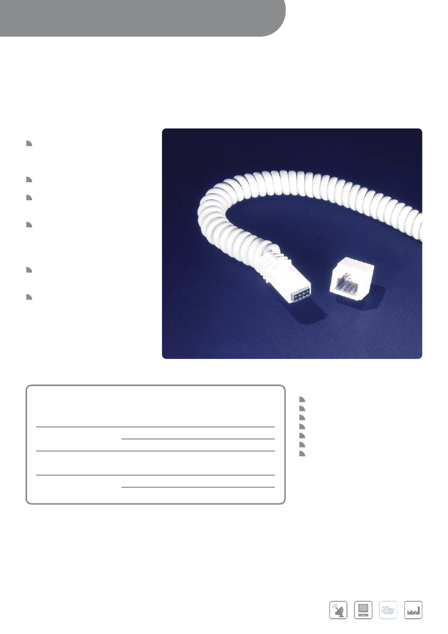
INPUT/OUTPUT CONNECTORS /
CABLE ASSEMBLIES
68
LATCH-N-LOK™
I/O CONNECTOR SYSTEM
FEATURES & BENEFITS
Versatile cable-to-board system
includes PCB headers and cable
connector kits for signal, power,
grounding and shielding applications.
Supports high speed, serial data
transmission
Quick disconnect system provides
positive latching with an audible
“click.”
High reliability design features FCI
PV™ receptacle contacts mating to
phosphor bronze .025”sq pin
contacts in single and double row
configurations.
Polarized housings prevent mis-
mating; Keying options prevent the
mating of incorrect cables.
Cable connectors accommodate a
wide variety of cable diameters and
wires ranging from 20AWG to
32AWG
APPLICATIONS
Medical Instrumentation
Handheld devices
POS Equipment
Test and Measurement
Inventory Equipment
USB Plus Power
Telecommunications
MAIN PRODUCTS
PART REFERENCES
PCB Receptacle
Right angle,Through hole
1x4,1x6,1x8
69273/78304/69913
Right angle,Through hole
2x3,2x4,2x4
78097/69958/74355
2x6,2x8,2x10
78098/69901/79610
Cable plug kits
Enhanced shelding
1x4,1x8,2x3,2x4
74901/74903/74902/98028
Standard shelding
1x4,1x6,1x8,2x3
91481/91482/91483/91485
2x4,2x6,2x8,2x10
91486/91487/91488/91489
Further information can be found at:
www.fci.com/latchnlok

69
NOTES
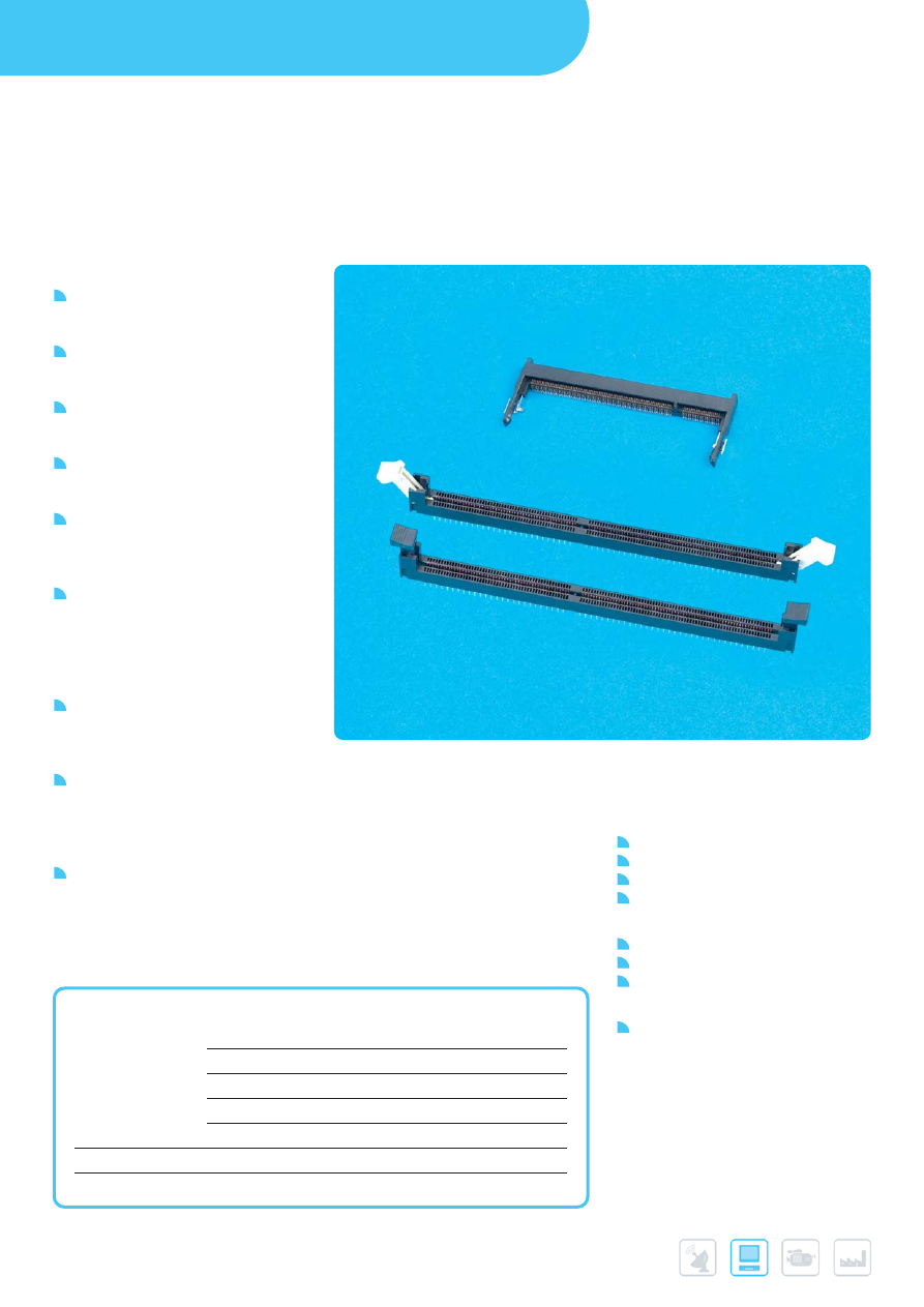
CARD SYSTEMS
70
DDR2 MEMORY MODULE SOCKETS
FEATURES & BENEFITS
Support convenient, add-on memory
expansion with standard memory
module assemblies
Connectors provide mechanical voltage
keying and end latches for module
retention and ejection.
DDR2 FB-DIMM connectors accept
module assemblies that conform to
JEDEC MO-256
DDR2 DIMM connectors accept
assemblies that conform to JEDEC
MO-237.
240-position FB-DIMM and DIMM
connectors feature a low insertion-force
socket design that requires less than
24 pounds force for module installation.
Available solder tail options for vertical
DDR2 DIMM connectors support use
on 1.58 mm (.062”) or 2.36 mm (.093”)
thick motherboards, while press-fit
options extend use to thicker
motherboards.
Contact design protects against
stubbing and supports high-speed
serial differential signaling at data rates
extending to 4.8 Gb/s for FB-DIMM.
DDR2 SO-DIMM connectors offer
keying options for standard and reverse
module orientation. The 200-postion
horizontal sockets accept modules that
conform to JEDEC MO-224.
RoHS-Compliant and “Lead-free”
process-compatible options are
available to aid compliance with lead
elimination initiatives.
APPLICATIONS
Data
Servers
Workstations
Desktop PCs
Notebook PCs
Communications
Routers
Switches
Base Stations
Industrial
Embedded systems
MAIN PRODUCTS
PART REFERENCES
240 position
Vertical DDR2 DIMM
10005639 / 10023061
Vertical DDR2, press-fit
10034542
Vertical DDR2, low-profile
10052286
Vertical DDR2, SMT
10070983
DDR2 FB-DIMM
10037402 / 10057443
200 position
DDR2 SO-DIMM
10033853 / 10033854
144 position
16b/32b SO-DIMM
10062086
Further information can be found at:
www.fci.com/ddr
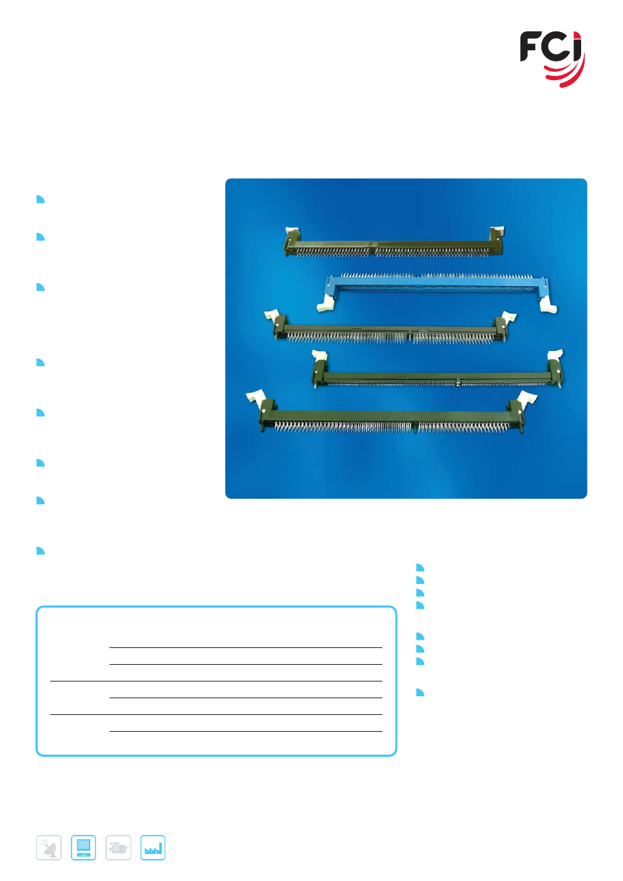
71
DDR3 MEMORY MODULE SOCKETS
FEATURES & BENEFITS
Connector provides mechanical
voltage keying and latches for
modules retention and ejection
DIMM connectors feature a low
insertion-force socket design that
requires less than 24 pounds force for
module installation
Available solder tall options for vertical
DDR3 connectors support use on
1.58 mm (.062”) or 2.36 mm (.93”)
thick motherboards, while press-fit
options extend use to thicker
motherboards
Contact design protects against
stubbling and supports high-speed
serial differential signalling at data
rates extending to 4.8 Gb/s for DDR3
RoHS Compliant and “lead free”
process compatible options are
available to aid compliance with lead
elimination initiatives
Low Level Contact Resistance (LLCR)
featured on DDR3 sockets accept
RDDIMM DD3 modules
VLP form factors provide connector
heights of less than 21 mm above the
board, while accepting modules with
a seating height of less than 2.4 mm
Slim latch and connector body
designs facilitates optimized airflow
APPLICATIONS
Data
Servers
Workstations
Desktop PCs
Notebook PCs
Communications
Routers
Switches
Base Stations
Industrial
Embedded systems
Further information can be found at:
www.fci.com/ddr
MAIN PRODUCTS
PART REFERENCES
240-position vertical DDR3 RDIMM sockets
Trough mount and metal clip
10081530
Trough mount and plastic post
10081531
Very low profile (VLP) , through hole
Trough mount and metal clip
10079192
Very Low Profile (VLP), surface mount
Surface mount with metal hold down
10079248
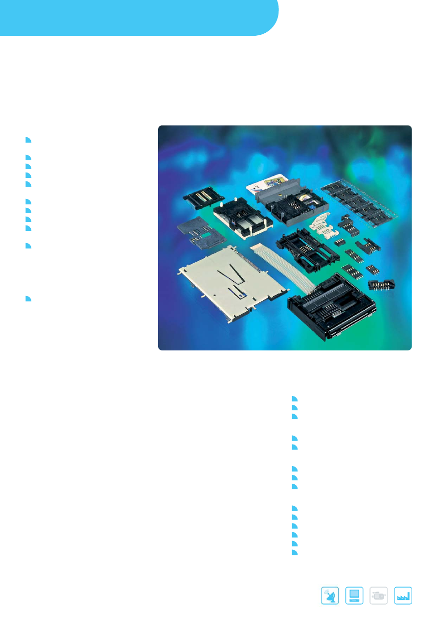
CARD SYSTEMS
72
Further information can be found at:
www.fci.com/smartcards
SMART CARD CONNECTORS
FEATURES & BENEFITS
Through mount, SMT or Flex
mounted
Sliding or landing contact technology
Durability: From 10K to 200K cycles
Vandalism-proof designs
Suitable for friendly, harsh, portable or
automotive environments
EMV, NDS approved
Blade or sealed switch available
6, 8 or 16 data contacts available
SIM, SAM or full size card connectors
available
Smart Card Reader with customized
FPC/FFC offer flexibility to solder onto
the appropriate position of a PCB.
The very low profile provides superior
space savings, especially for
Notebook PC application.
Customization available upon request
APPLICATIONS
Networking
Analog or digital set-top box
Internet decoder
Laptops
Telecom
Mobile phones
Public phones
Automotive
Car radio
GPS
Tachograph / Tachometer
Others
Point of sale terminals
Vending machines
Access control
Customer loyalty equipment
E-purse
Gas, water, electricity meters
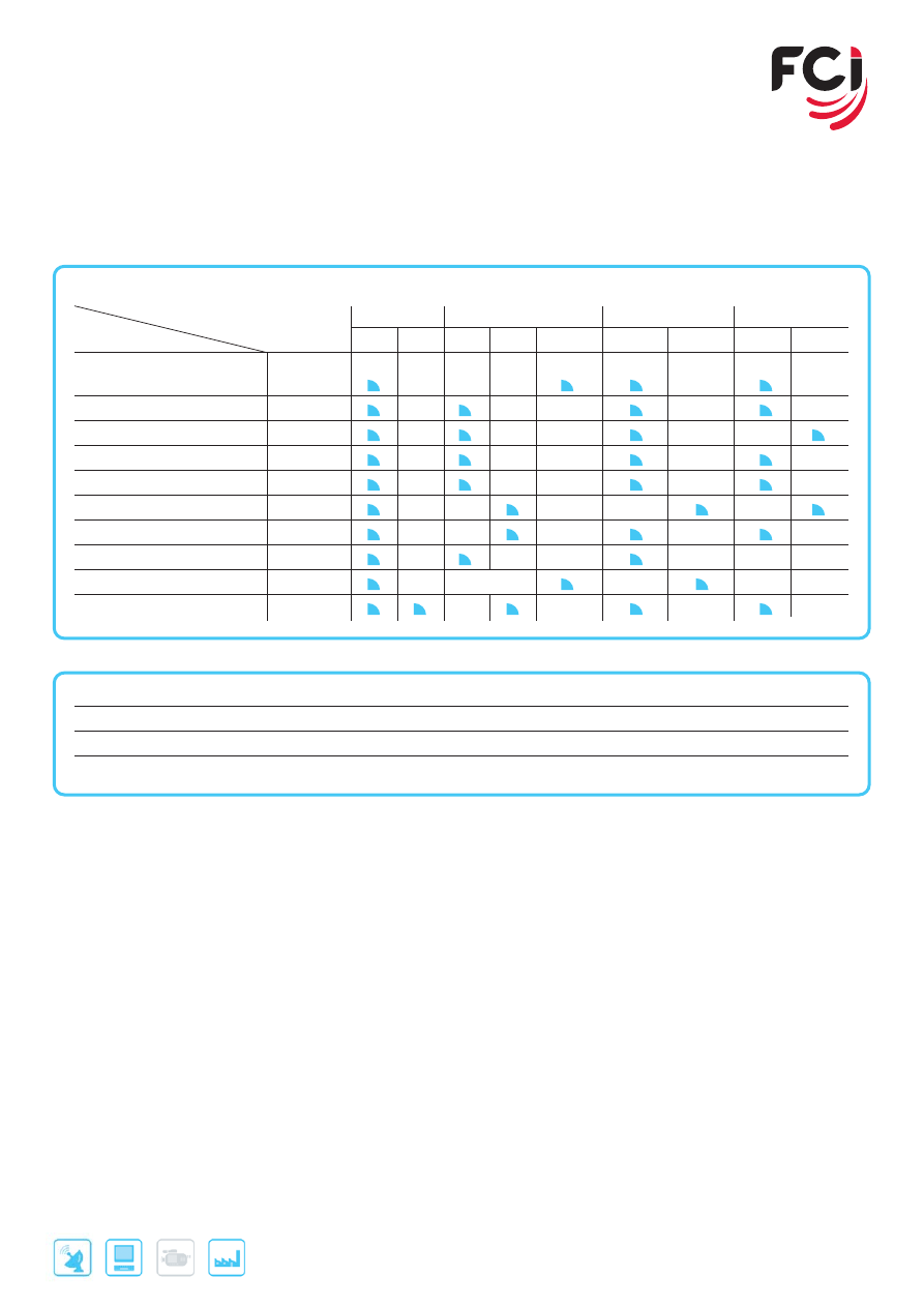
73
Further information can be found at:
www.fci.com/smartcards
MAIN PRODUCTS
SERIES
Number
Card Size
Termination
Contact Technology
Switch Type
Product
of Cycles
Full
SIM
TMT
SMT FFC/FPC
Sliding
Landing
Blade Sealed
Smart Card Reader
10010556 / 556040 Series
10K / 25K
L04 Series
100K
L08/L10 Series
100K
L26 Series High Performance
10K - 100K
+ Flex
L26 Series
2.5K
E Series
200K
+ Flex
P Series
100K
+ Flex
C Series
100K
Z Series
10K - 100K
Panel
S Series
10K
Part Number
Termination
Pin
Thickness
Push-Pull Cycles
10010556-0**LF
Customized FPC/FFC
8
3.6 mm
Without push-push
10026297-00*LF
Customized FPC
8
3.8 mm
10K
55640-2*20*LF/-20211LF
Customized FPC
8
3.7 mm
10K/25K
CARD SYSTEMS
74
Further information can be found at:
www.fci.com/pcmcia
PC CARD HEADERS
FEATURES & BENEFITS
Conform to PCMCIA and CardBus
standards
- CardBus PC Cards can meet high
signal transmission requiring bandwidth
(32 bits) and clock rate (33 MHz)
Suitable for type I, II, III, 3.3 and 5V
- Standard and CardBus PC Cards
- Various stand-off options available
- Single and double deck
Eject and non eject mechanism
available
Through Mount, SMT In-Line, SMT
- Staggered, Flex or patented SMT
- Vertical Transition Board versions
available
Optional EMI metal shield cover
(CardBus)
APPLICATIONS
Notebooks, portable PCs, industrial
PCs, network PCs
Set-top boxes, digital TV, home
entertainment devices
Telecom, datacom equipments
(switches, routers, remote access
servers)
Machine control systems
Test & measurement devices, medical
instrumentation
75
Further information can be found at:
www.fci.com/pcmcia
MAIN PRODUCTS
PART REFERENCES
Type
F/G
Mounting
Voltage
Deck
Ejector
Remark
PCMCIA
61126
T/H or SMT
3.3V
Single
Yes
95620/94050
T/H or SMT
5.0V
Single/Double
Yes
84648
T/H or SMT
3.3V
Single
None
92789
T/H or SMT
5.0V
Single
None
92193/92194
T/H or SMT
5.0V
Single/Double
None
57991
T/H or SMT
3.3V
Double
Yes
84654
T/H or SMT
3.3V
Double
Yes
61125/61124
VTB
3.3V
Single/Double
Yes
Mating with 91931
95547
VTB
5.0V
Single
Yes
Mating with 91931
10003526
VTB
3.3V
Single
Yes
Mating with 91931
88640
VTB
5.0V
Single
None
Mating with 91931
74423
VTB
3.3V
Single
None
Mating with 91931
58431
VTB
3.3V
Single
Yes
Mating with 91931
10074998
VTB
3.3V
Single
Yes
Mating with 91931
10067972
T/H or SMT
3.3V
Single
None
Short Body
10074595
T/H or SMT
5.0V
Single
None
Short Body
92150/90937
T/H or SMT
5.0V
Single
None
Short Body
87536
T/H or SMT
5.0V
Single
None
Short Body
Card Bus I
71299/71240
VTB
3.3V
Single/Double
Yes
Mating with 73277
52599
VTB
3.3V
Single
None
Mating with 73277
72305/72306
VTB
3.3V
Single/Double
None
Mating with 73277

EXPRESSCARD™ SYSTEMS
EXPRESSCARD MODULE CARD KITS
FEATURES & BENEFITS
Meet high-speed electrical
requirements as outlined in
ExpressCard™ Standard
Simple beam-on-blade contact
interface is rated for up to 10,000
cycles
Single-row, in-line solder tail
configuration for easy soldering
Longer power and ground contacts
on the module connector provide
first-mate and last-disconnect in
relation to signal contacts.
Snap-together module design enables
card assembly without requiring the
use of adhesives or ultrasonic
equipment
Modules provide EMI/ESD contact
areas, notches to facilitate optional
security lock, and a finger grip ridge
for manual module removal
ExpressCard™ technology will replace
PC Card and CardBus technology in
desktop and notebook PCs
RoHS compliant
APPLICATIONS
Communications - Wireless and wired
cards
Storage - SFF optical and magnetic
drives
I/O - Additional ports and legacy I/O
Multimedia - TV tuners, PVR
Security - Identity cards and sensors
Adapters - Consumer memory cards
MAIN PRODUCTS
PART REFERENCES
Product Type
34 mm (close end)
54 mm (close end)
34 mm (open end)
54 mm (open end)
Module Connector P/N
10030570-2113LF
10030570-2113LF
10030570-2113LF
10030570-2113LF
Top Shield P/N
10030573-100LF
10030581-100LF
10030573-200LF
10030581-200LF
Bottom Shield P/N
10030574-2100LF
10030582-2100LF
10030574-0010LF
10030582-0010LF
76
Further information can be found at:
www.fci.com/expresscard
CARD SYSTEMS
Note: ExpressCard™ is a registered trademark of PCMCIA
77
Further information can be found at:
www.fci.com/expresscard
EXPRESSCARD™ SYSTEMS
EXPRESSCARD HOST SYSTEMS
FEATURES & BENEFITS
Connector electrical performance is
validated at the initial PCI Express
data rate of 2.5 Gb/s and the
anticipated second-generation speed
of 5.0 Gb/s
Simple beam-on-blade contact
interface is rated for 5,000 cycles
Single-row, in-line configuration for
surface-mount solder tails to facilitate
easy soldering and inspection
Standoff options range between
0.0mm, which provides the lowest
vertical profile for “thin” host systems,
and 2.2mm, which provides clearance
to mount PCB components between
the slot and the host PCB
Options available to support slot
placement either above or below the
host PCB
”Card push” ejection mechanism
eliminates need for push rods
Available “grab and pull” version
supports manual card removal with
reduced mechanical complexity
RoHS compliant
APPLICATIONS
Notebooks, portable PCs, industrial
PCs, network PCs
Set-top boxes, digital TV, home
entertainment devices
Telecom, datacom equipments
(switches, routers, remote access
servers)
Machine control systems
Test & measurement devices, medical
instrumentation
MAIN PRODUCTS
PART REFERENCES
Note: ExpressCard™ is a registered trademark of PCMCIA
Host Connector
P/N
10056265-
122ABTLF
10047129-
118ABTLF
10055606-
110ABTLF
10053826-
100ABTLF
10055262-
100BBTLF
10056422-
122BBTLF
Host System
(Card Push) P/N
10038774-
22ALF
10047130-
18ALF
10055607-
10ALF
10053827-
00ALF
10055263-
00BLF
10056423-
22BLF
Standoff Height
2.2 mm
1.8 mm
1.0 mm
0.0 mm
0.0 mm
2.2 mm
Mounting Type
Above
Above
Above
Above
Below
Below

78
NOTES

79

Americas - Tel.: 1 (800) 237 2374
Europe - Tel.: 33 1 39 49 21 83
Asia/Pacific - Tel.: 65 6549 6666
For more information on FCI sales offices,
headquarters, agents and local distributors,
visit
www.fci.com
ELXOVER
VIEW0909EA4
BLEU
CERISE