ET
RoHS Compliant
■
Introduction
The
ET
series is Copal
ʼ
s standard size high capacity
toggle switch. The
ET
series are available in various
current rating, switching functions, and terminals.
The housing is made of self-extinguishing phenol
resin which has excellent heat resistance, arc
resistance, and tracking resistance. The contacts are
designed to eliminate chattering and bouncing to
prevent insulation deterioration.
(
ON
)
and
(
OFF
)
:
Momentary.
7SLHZLYLMLY[V7MVY*VTTVU:WLJPÄJH[PVUZ
ET
Standard Size Toggle Switch
■
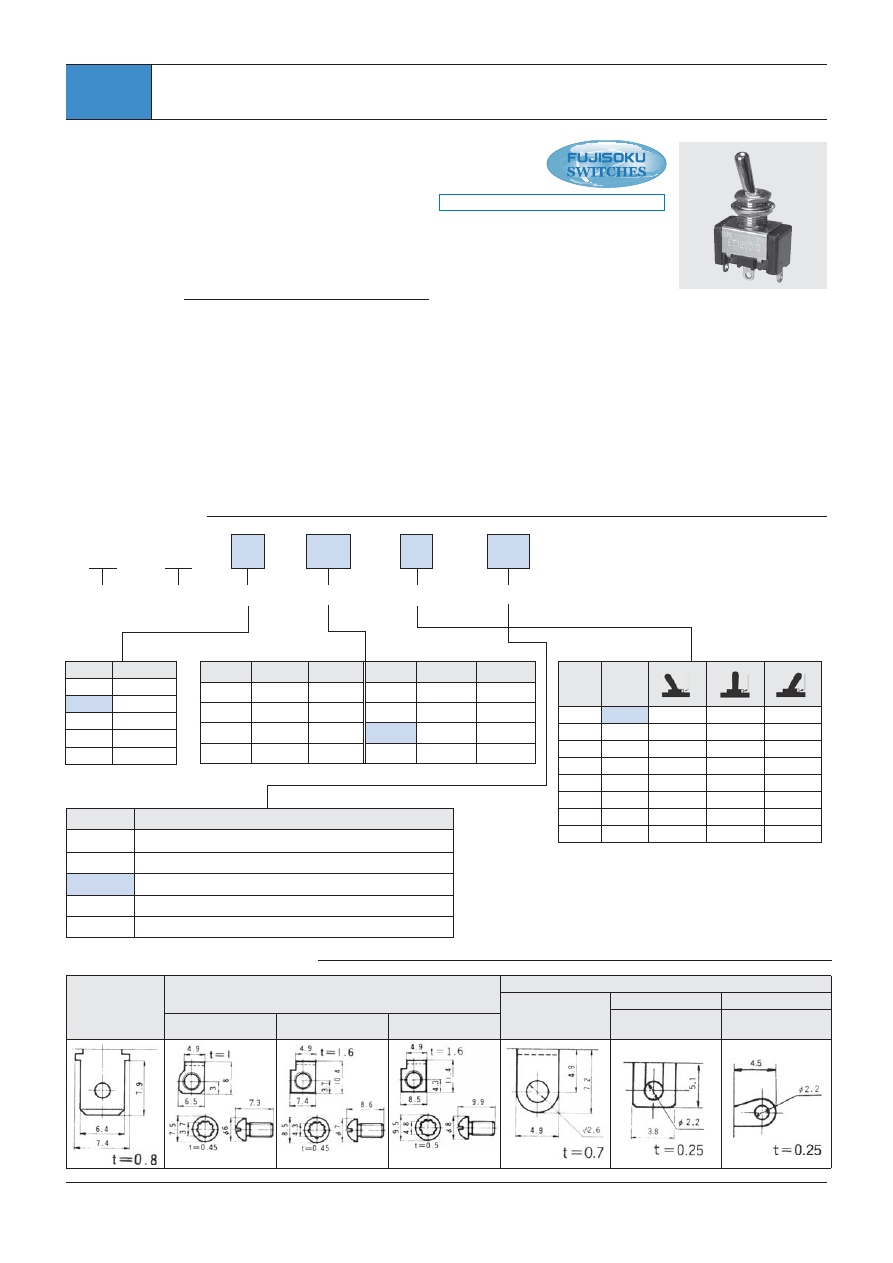
Part Numbering
■
Terminal Style and Dimentions
E
T
2
25
Z
−
Series code Actuator shape No. of poles
Swiching function
Terminal styles
Current
1
1 pole
2
2 poles
3
3 poles
4
4 poles
6
6 poles
1 pole
3 poles
2 poles
4 poles
6 poles
Key way
Key way
A
K
ON
−−
−−
OFF
B
L
ON
−−
(OFF)
C
M
OFF
−−
(ON)
D
N
ON
−−
ON
E
P
ON
OFF
ON
F
R
ON
−−
(ON)
G
S
(ON)
OFF
(ON)
H
T
ON
OFF
(ON)
AC125V AC250V
03
3A
05
5A
3A
06
6A
(2A)
10
10A
(7A)
Fig.
Fig.
Fig.
None
10
12
13
32
Terminal style
TAB # 250
Screw Terminal
Solder Terminal
Plate Connect SolderTerminal
Solder Terminal
K
12
AC125V AC250V
15
15A
10A
20
20A
12A
25
25A
15A
30
30A
(25A)
Fig.
No. of poles
Key way
TAB # 250
(Style:−)
Screw Terminal(Style:
10
)
Solder Terminal
Solder Terminal
(Style:
12
・
13
)
Style:12
Style:32
ET103
□
12
ET206
□
12
Type
ET103
□
32
Type
M3.5 × 0.6
M4 × 0.7
M4.5 × 0.75
ET115・215
Type
Type
Type
ET120・220
ET125・225・230