RLC
32
Style
K
R470
TP
F
•
Features
1. Most suitable for a detection of current in power source circuits,
motor circuits, etc.
2. Raised Rated dissipation compared with RMC (except 2010,2512 size).
3. Stability Class : 5%
•
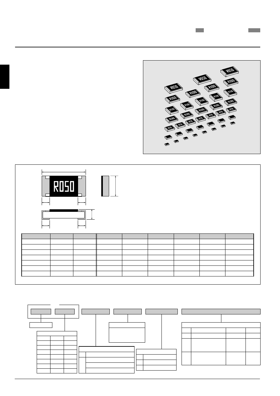
Dimensions
Rated resistance is marked with 4-digit on the over coating. (RLC20~RLC63)
RLC10 : only No marking is available.
Please contact KAMAYA for marking of RLC16.
•
Part Number Description
Example
Product Type
Tolerance on Rated Resistance
F
1%
G
2%
J
5%
e.g.: R050=50m ohm
R100=100m ohm
1R00=1 ohm
* Packaging & Standard Qty. (Min.)
Bulk (Loose Package)
RLC35
RLC50
RLC63
B
Paper Tape
TP
RLC16
RLC20
RLC32
RLC10
Embossed Tape
TE
*Refer to Tape and Packaging information on pages 48 and 49.
All Styles
1,000pcs.
5,000pcs.
Paper Tape(2mm pitch)
TH
10,000pcs.
4,000pcs.
Rated Resistance
Temperature Coefficient of Resistance
–
K
100
10
-6
/
°
C
0
∼
200
10
-6
/
°
C
0
∼
250
10
-6
/
°
C
0
∼
300
10
-6
/
°
C
KAMAYA OHM
RLC
FIXED THICK FILM CHIP RESISTORS; RECTANGULAR TYPE & LOW OHM
RLC32
3.1
0.2
0.1
0.5
0.25
2.0
0.15
0.1
0.4
0.2
3216
W
L
1.25
0.10
0.15
0.15
0805
1206
H
c
0.4
0.2
d
0.2
0.1
0.1
0.3
0.05
0.10
0.25
RLC35
3.1
0.2
0.6
0.15
0.5
0.25
9mg
5mg
16mg
3225
1210
0.2
0.3
1.6
2.5
0.15
RLC50
5.0
0.2
0.6
0.15
0.6
0.2
0.6
0.2
25mg
2.5
0.15
RLC63
6.3
0.2
0.6
0.15
0.6
0.2
0.6
0.2
40mg
3.2
0.6
RLC20
0.05
RLC10
1.0
0.05
0.2
0.1
1mg
0.6
0.05
0.35
RLC16
1.6
0.1
0.3
0.1
0.3
0.1
0.15
0.05
0.8
2mg
0.10
0.45
W
d
d
L
c
c
H
0.5
Unit : mm
*Values for reference
Style
Metric
Inch
*Unit weight/pc.
5025
2010
6332
2512
2012
1005
0402
1608
0603
Code
Metric
Inch
Size
16
1608
10
1005
32
3216
50
5025
20
2012
35
3225
63
6332
0603
0402
1206
2010
0805
1210
2512
16
Product specifications contained in this catalogue are subject to change at any time without notice. Please confirm specifications with your order.
【
RoHS
】
Chip
Resistors
RLC