©2004 LEMO USA, Inc. 6/04
If you have any
questions or
require customer
assistance, please
contact us directly
at (800) 444-5366.
LEMO USA, Inc.
635 Park Court, Rohnert Park, CA 94928
P.O. Box 2408, Rohnert Park, CA 94927-2408
(800) 444-5366
• (707) 578-8811 • fax: (707) 578-0869
www.LEMOusa.com
• e-mail: info@lemousa.com
1
1
6
5
8
9
1
4
3
3
2
FH
●
7
3
1
5
5
2
1
3
4
7
3
1
5
Solder
5
2
1
3
4
7
Solder
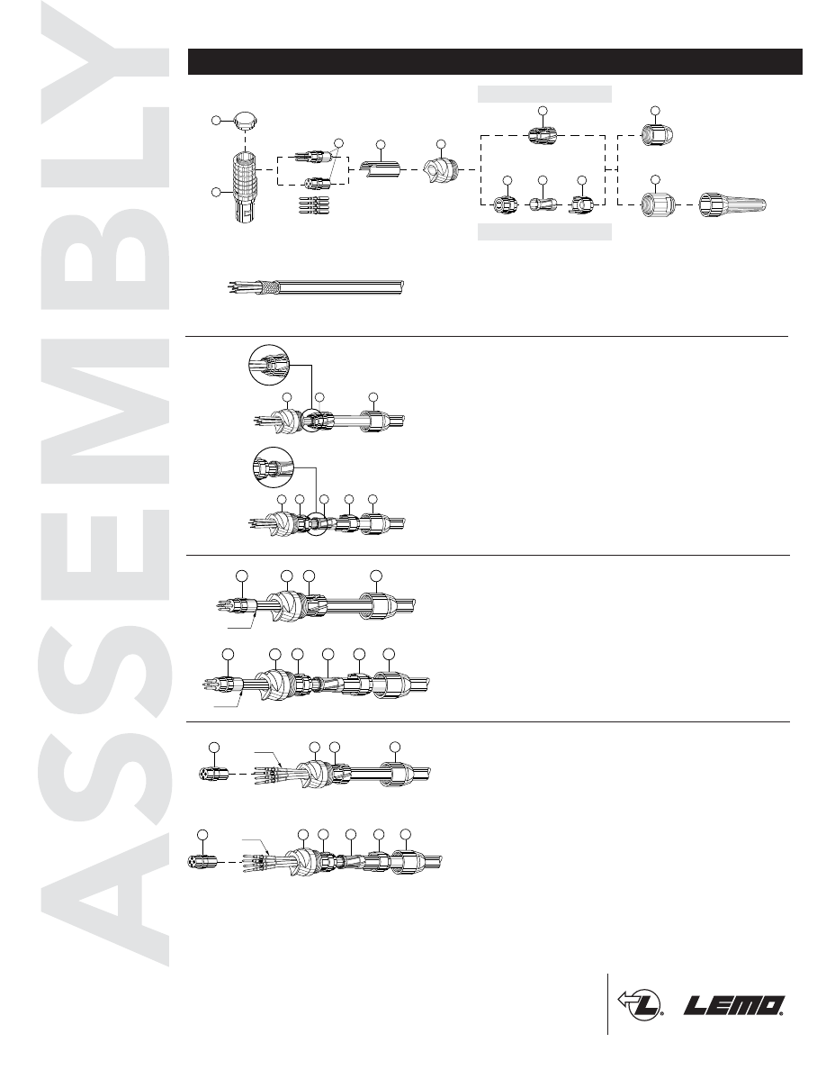
1.
Strip the cable according to the dimensions
indicated in the table on page 3. For connectors
with solder contacts, the length L should be
reduced to correspond with interior contact
lengths.
2.
Slide the following onto the cable:
for
type D cable clamping
, bend relief if provided,
collet nut
➀
, collet
➂
and elbow outlet
➄
.
for
type M cable clamping
, bend relief if
provided, collet system
➁➂➃
, and elbow outlet
➄
.
In the case of a shielded cable, fold back the
shielding around the whole circumference of the
end of the collet and cut off any surplus. For type
M cable clamping, position the collet into the pin
of the reducer and position the reducing cone
onto the reducer.
3.
For solder contact, solder the conductors to the
contacts, making sure that the insulator
➆
and the
cable remain clean.
7
5
2
1
3
4
Crimp
7
3
1
5
Crimp
4.
For crimp contacts, fix the appropriate positioner
into the crimping tool (see catalog) and set the
selector to the number corresponding to the AWG
of the conductor used. Fit the conductor into the
contact; make sure that the conductor is visible
through the contact's inspection hole. Slide the
contact-conductor assembly into the open
crimping tool; make sure that the contact is
pushed fully into the positioner. Close the tool.
Remove from crimping tool and check that
conductor is secure in the contact and shows in
the inspection hole.
Type D Cable Clamping
Type M Cable Clamping
Type D Cable Clamping
Type M Cable Clamping
Type D Cable Clamping
Type M Cable Clamping
Type D Cable Clamping
Type M Cable Clamping
B Series - Crimp/Solder Contacts - Elbow Plugs (90º)
B
©2004 LEMO USA, Inc. 6/04
If you have any
questions or
require customer
assistance, please
contact us directly
at (800) 444-5366.
LEMO USA, Inc.
635 Park Court, Rohnert Park, CA 94928
P.O. Box 2408, Rohnert Park, CA 94927-2408
(800) 444-5366
• (707) 578-8811 • fax: (707) 578-0869
www.LEMOusa.com
• e-mail: info@lemousa.com
2
6
9
5
1
7
3
5
4
3
2
1
6
7
F
● ●
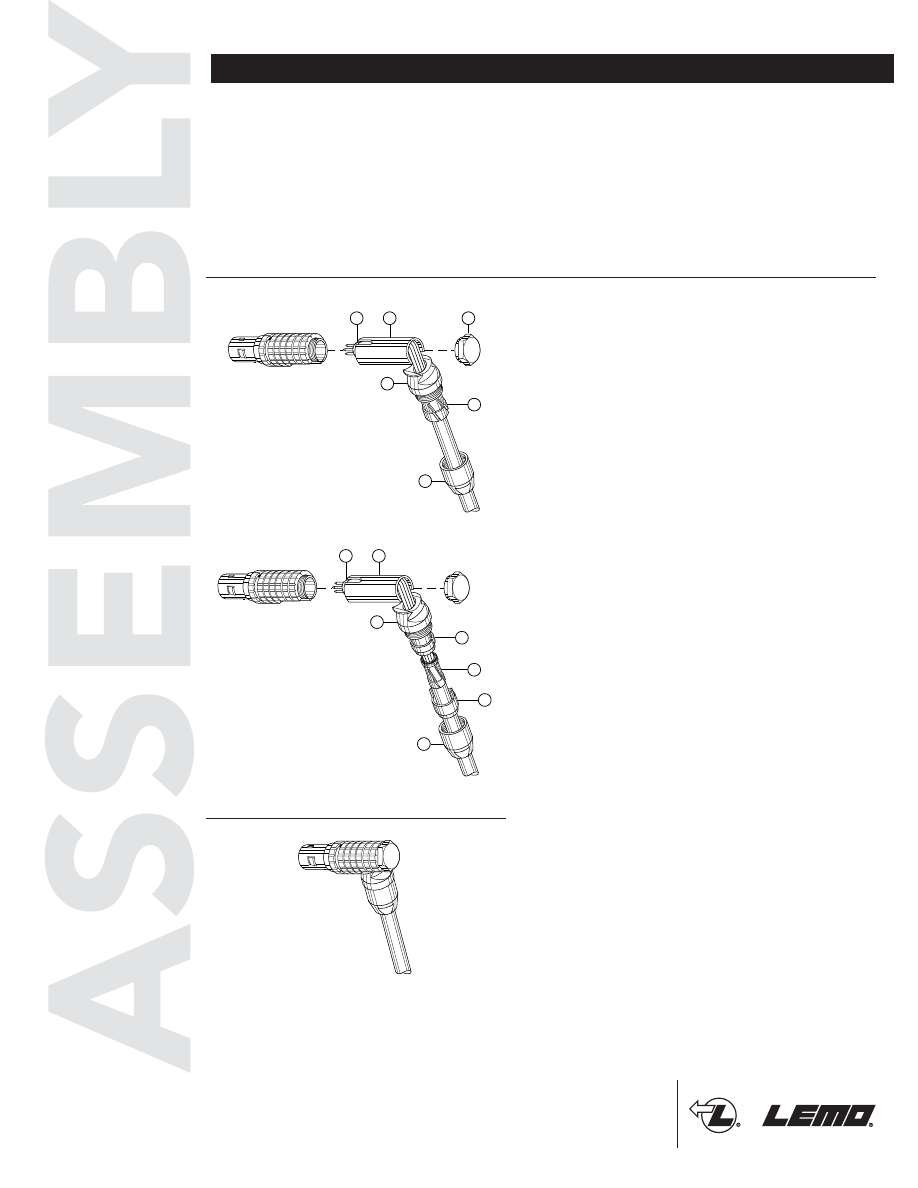
Connector with type M cable clamping
Fit the collet into the pin of the reducer, position
the reducing cone on the reducer and position the
whole assembly in the elbow outlet. Using the
appropriate tooling (see catalog) to ensure that
internal components do not turn in the housing,
screw on the collet nut
➄
with appropriate torque
(see page 3). Fix the bend relief (if provided) onto
the collet nut.
6.
Position the midpiece
➅
onto the insulator's
➆
notch. Fit the pre-assembly into the housing and
position it in the housing's opening. Slide the
elbow outlet
➄
into the housing as shown. Screw
on the hex cap
➈
, with appropriate torque(see
page 3)
.
Connector with type D cable clamping
Fit the collet into the pin of the elbow outlet
➄
.
Using the appropriate tooling (see catalog) to
ensure that internal components do not turn in the
housing, screw on the collet nut
➄
with
appropriate torque (see page 3). Fix the bend
relief (if provided) onto the collet nut.
Type D Cable Clamping
Type M Cable Clamping
5.
Arrange the contact-conductor assemblies
according to the insert marking, avoiding any
twisting of the conductors. Fit the contacts gently
into the insulator
➅
; check that no conductor
overlaps another, and push the contacts into the
insulator. Check that all the contacts are correctly
located in the insulator: 1) by verifying the
alignment of the contacts at the front of the
insulator and 2) by gently pulling on the insulator;
the contact alignment must remain in correct
position.
©2004 LEMO USA, Inc. 6/04
If you have any
questions or
require customer
assistance, please
contact us directly
at (800) 444-5366.
LEMO USA, Inc.
635 Park Court, Rohnert Park, CA 94928
P.O. Box 2408, Rohnert Park, CA 94927-2408
(800) 444-5366
• (707) 578-8811 • fax: (707) 578-0869
www.LEMOusa.com
• e-mail: info@lemousa.com
3
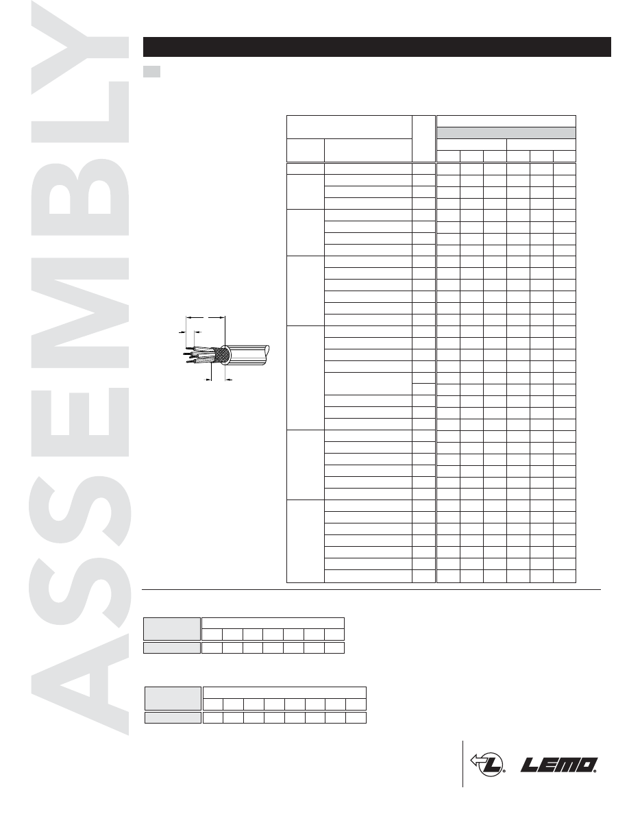
Cable stripping lengths (mm)
M3
Solder
Crimp
L
S
T
L
S
T
Elbow plugs with cable collet
M3
00
302/303/304
0.5
302/303
0.9
0B
1)
304/305
0.7
306/307/309
2)
0.5
302/303
1.3
304/305
0.9
306/307/308
0.7
310/314/316
0.5
302
2.0
303
1.6
304/305/306/307
1.3
308/310
0.9
312/314/316/318/319
0.7
326/332
0.5
302
3.0
303/304
2.0
305/306/307
1.6
308
1.3
1.3
2.0
310
1.3
312/314/316/318
0.9
320/322/324/326/330
0.7
304
3.0
306/307
2.0
310
1.6
312
1.3
316/320/324/330
0.9
340/348
0.7
302
6.0
304
4.0
310
3.0
314/316
2.0
320
1.6
330/340/348
1.3
350/354/364
0.9
309
S
T
L
Connector
Series
Type
9.5
4
2.5
12.5
4
3.0
18.0
7
3.0
22.0
7
4.0
18.0
7
3.0
22.0
7
4.0
19.0
7
2.5
23.0
7
3.0
25.0
8
3.5
28.0
8
4.0
25.0
8
3.0
28.0
8
4.0
25.0
8
3.0
28.0
8
4.0
27.5
8
2.5
–
–
–
30.0
9
4.0
33.0
9
5.5
30.0
9
3.5
33.0
9
5.5
29.0
9
3.5
31.0
9
4.0
28.0
9
3.0
31.0
9
4.0
28.0
9
3.0
31.0
9
4.0
28.0
9
2.5
–
–
–
35.0
10
4.5
39.0
10
5.5
34.0
10
4.0
38.0
10
5.5
34.0
10
3.5
38.0
10
5.5
33.0
10
3.5
36.0
10
4.0
33.0
10
3.5
36.0
10
4.0
33.0
10
4.0
36.0
10
5.5
33.0
10
3.5
36.0
10
4.0
32.0
10
3.0
36.0
10
4.0
32.0
10
3.0
36.0
10
4.0
41.0
12
4.5
45.0
12
5.5
41.0
12
4.0
45.0
12
5.5
39.0
12
3.5
43.0
12
5.5
39.0
12
3.5
43.0
12
4.0
39.0
12
3.0
43.0
12
4.0
39.0
12
3.0
43.0
12
4.0
70.0
18
7.5
–
–
–
75.0
18
5.5
78.0
18
7.0
75.0
18
4.5
78.0
18
7.0
74.0
18
4.0
77.0
18
5.5
74.0
18
3.5
77.0
18
5.5
74.0
18
3.5
77.0
18
4.0
74.0
18
3.0
77.0
18
4.0
Cable Stripping Lengths & Torque Values
ø contact
(mm)
1B
1)
4B
3B
2B
5B
1)
Maximum hex cap tightening torque
Series
00
0B
1B
2B
3B
4B
5B
0.3
0.6
1
1
1.5
3
5
Torque (Nm)
Maximum collet nut tightening torque
Series
00
0B
1B
2B
2G
3B
4B
5B
0.25 0.5
1.5
2.5
2.5
4
7
10
Torque (Nm)
1Nm = 8.85 lbf-in
Note:
the tolerances on these dimensions
are: L: ± 0.5 mm
S: ± 0.5 mm
T: ± 0.2 mm
Note:
1)
In 0B and 1B series, «L» and «S»
dimensions shall be increased by 2
mm for the largest collet (D56 in 0B
series; D76 in 1B series). In 5B
series, «L» and «S» dimensions
shall be increased by 13 mm for the
largest collet (D25).
2)
Crimp contacts are available only
for connectors fitted with male con-
tacts.
©2004 LEMO USA, Inc. 6/04
If you have any
questions or
require customer
assistance, please
contact us directly
at (800) 444-5366.
LEMO USA, Inc.
635 Park Court, Rohnert Park, CA 94928
P.O. Box 2408, Rohnert Park, CA 94927-2408
(800) 444-5366
• (707) 578-8811 • fax: (707) 578-0869
www.LEMOusa.com
• e-mail: info@lemousa.com
4
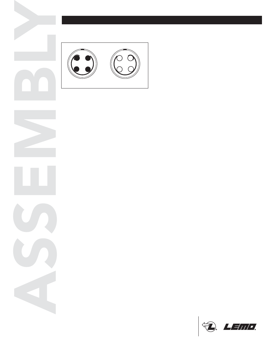
Contact Numbering
Contact Numbering Example
Contacts are numbered counterclockwise on the
male insert and clockwise in the female insert, as
viewed from the termination side. Contact number
1 is marked with a half circle.
1
3
4
4
3
2
1
Male Insert
Female Insert
2