ETALDOC 590/8
Page 1 of 4
December 2003
PRODUCT DATA SHEET
MICROPROFILE SMD
P3191
LINE MATCHING TRANSFORMER
Features
Applications
∗
Surface Mount
∗
Telecommunications
∗
Lead-free (Pb-free)
∗
V.34 modems
∗
7mm seated height
∗
Portable computers
∗
Vacuum encapsulated
∗
Fax/Modems
∗
IEC 60950 and UL 60950 certified
∗
UL Recognized Component
∗
Simple 600
Ω
match
DESCRIPTION
P3191 is a low distortion microprofile transformer
for applications where high performance and safety
isolation to international standards are required in an
extremely small case size.
Designed specifically as a surface mount device, the
P3191 features a 7mm seated height and is offered
in the same package as the now familiar P2781.
The part is completely lead-free and suitable for
lead-free and conventional placement and reflow.
Despite the subminiature size, the performance is
superior to that of much larger components. The
P3191 offers reinforced insulation, is ideal for data
communications at high data rates whilst capable of
being matched to both 600
Ω
and complex
impedance telephone lines.
When used with 600
Ω
lines no external
compensation components are required.
At moderate transmit power levels (e.g. -10dBm)
performance to 33,600 bits/second may be
achieved.
P3191 is certified to IEC 60950 and UL 60950.
P3191 is a UL Recognized Component, and is
supported an IEC CB Test Certificate.
P3191
ETALDOC 590/8
Page 2 of 4
December 2003
SPECIFICATIONS
Electrical
At T = 25ºC and as circuit Fig. 2 unless otherwise stated.
Parameter
Conditions
Min
Typ
Max
Units
Insertion Loss
f = 2kHz
-
-
4.5
dB
Frequency response
-3dB LF cutoff
-3dB HF cutoff
200Hz - 4kHz
-
-
-
50
35
-
-
-
±0.2
Hz
kHz
dB
Return Loss
200Hz - 4kHz
16
-
-
dB
Third Harmonic
Distortion
(1)
600Hz -10dBm in line
-
-93
-
dBm
Balance
DC - 5kHz
Method TG25
80
-
-
dB
Saturation
Excitation 50Hz
250Vrms.
Output voltage
across line
-
-
-
-
10
65
Vrms
Vpeak
Voltage
isolation
(2)
50Hz
DC
3.88
5.5
-
-
-
-
kVrms
kV
Operating range:
Functional
Storage
(5)
Humidity
Ambient temperature
-25
–40
-
-
-
-
+85
+125
95
ºC
ºC
%R.H.
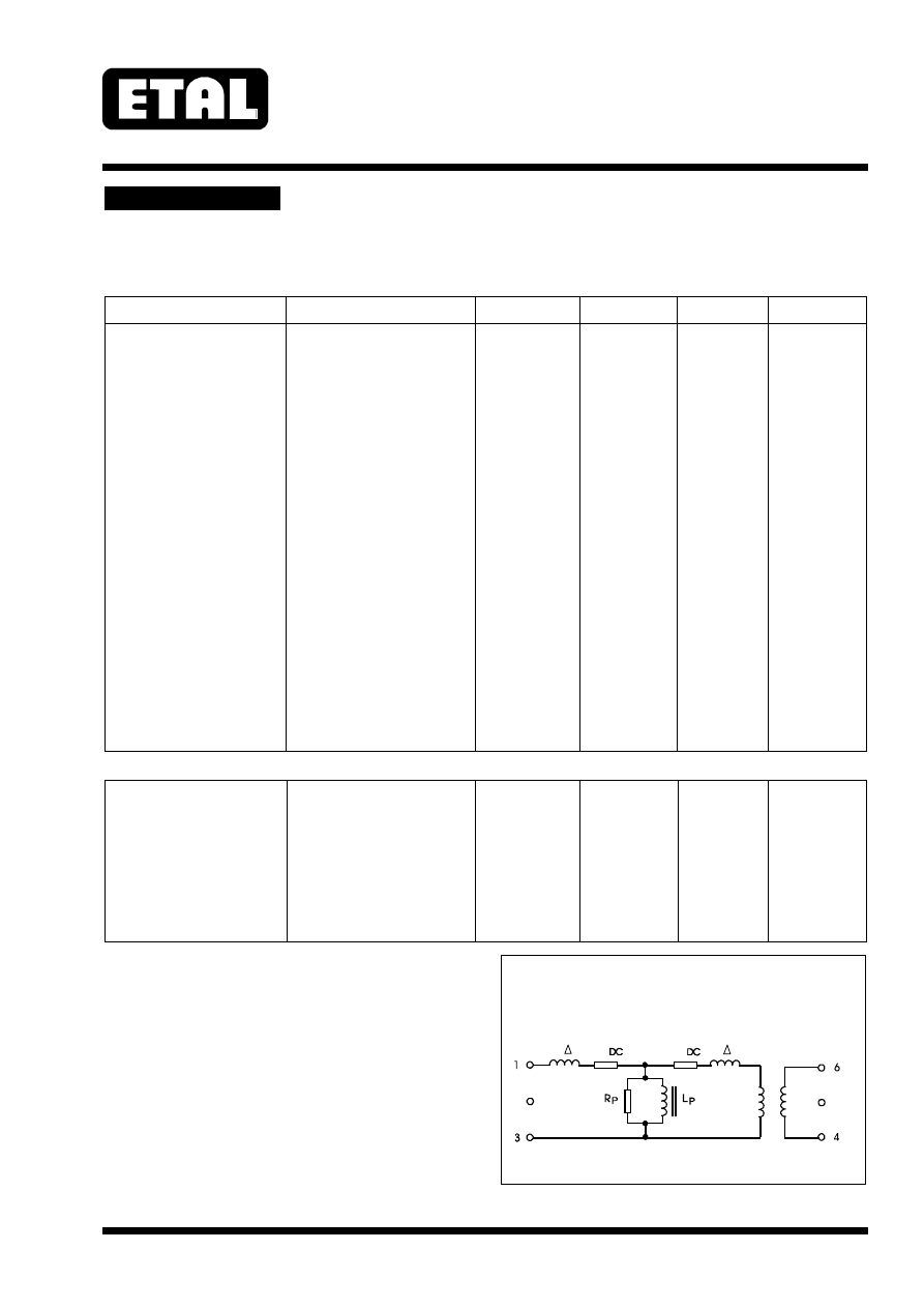
Lumped equivalent circuit parameters as Fig. 1
DC resistance, R
DC
(3)
Sum of windings
270
-
340
Ω
Leakage
inductance
∆
L
-
5.6
-
mH
Shunt
inductance Lp
(4)
10mv 200Hz
2.4
-
-
H
Shunt loss Rp
(4)
10mV 200Hz
7
-
-
k
Ω
Notes
1. Third harmonic typically exceeds other
harmonics by 20dB.
2. Components are 100% tested at 6.5 kVDC.
3. Caution: do not pass DC through windings.
Telephone line current, etc. must be diverted
using choke or semiconductor line hold circuit.
4. At signal levels greater than 100mV, Lp will
increase and Rp will decrease slightly but the
effect is usually favourable to the return loss
characteristic.
5. Excludes shipping materials. Components
are dry-packed and sealed as shipped.
Handle in accordance with IPC/JEDEC
J-STD-033A procedure for components
classified as IPC/JEDEC J-STD-020B Level
5a.
Equivalent Circuit
Fig. 1
IDEAL
1:1
½ L
½ L
½ R
½ R
P3191
ETALDOC 590/8
Page 3 of 4
December 2003
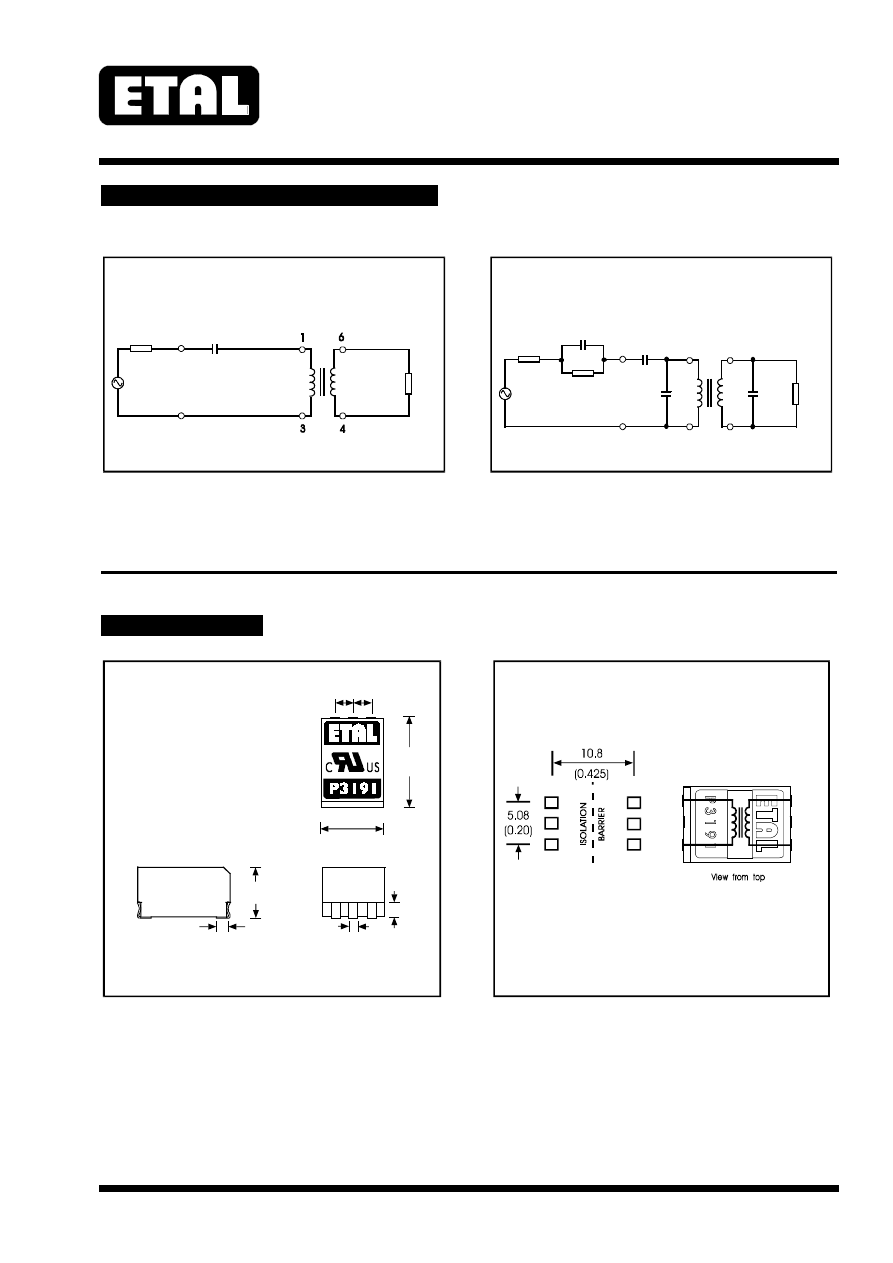
MATCHING RECOMMENDATIONS
In practice, the 910
Ω
load resistor will connect to a low output impedance TX driver. The 100nF capacitor
should appear in parallel with the 910
Ω
load resistor (rather than in parallel with transformer winding) to
obtain optimum TX flatness to line.
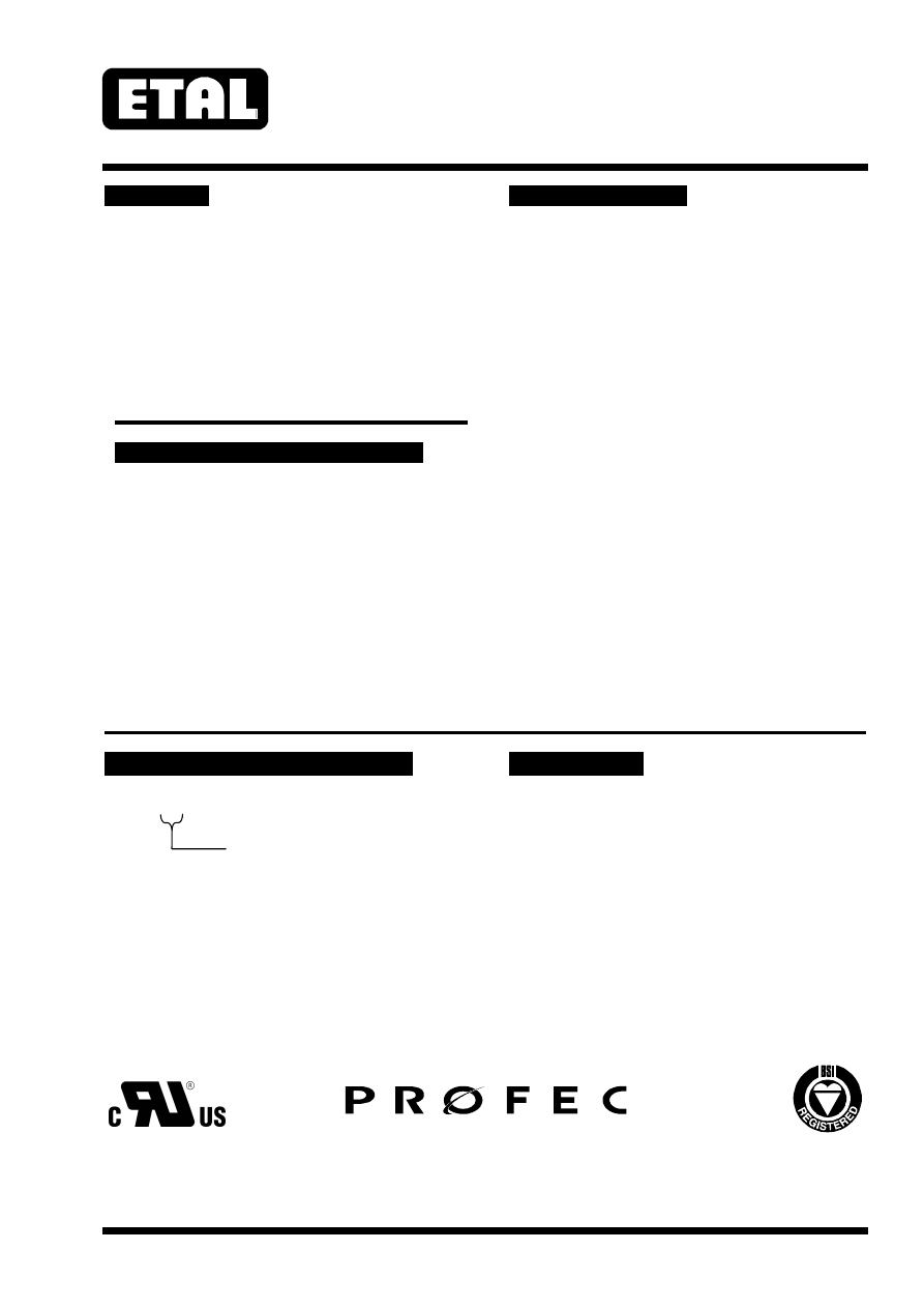
CONSTRUCTION
Dimensions shown are in millimetres (inches).
Geometric centres of outline and pad grid coincide within a tolerance circle of 0.3mm
∅.
Windings may be used interchangeably as primary or secondary.
Recommended Circuit
Fig 2
430
LINE
600
µ
6.8 F
600 MATCH
Ω
EUROPEAN CTR21 COMPLEX MATCH
Recommended Circuit
Fig 3
910
LINE
270
750
100n
15n
150nF
µ
2.2 F
2.54 2.54
13.0 max
(0.51)
9.0 max
(0.36)
7.0 max
(0.28)
(0.1) (0.1)
NOTE:
Dimensions shown are in millimetres (inches)
Dimensions
Fig 3
(0.06)
1.5
1.32
1.77
(0.052)
(0.07)
Tolerance 0.3mm
Terminals electroplated pure tin (Sn) 5 m minimum
Terminal size : 1.5 (0.06) long, 1.32 (0.05) wide
±
µ
Connections
Fig 4
1
2
3
4
5
6
P3191
ETALDOC 590/8
Page 4 of 4
December 2003
SAFETY
CERTIFICATION
Manufactured from materials conforming to
flammability requirements of UL94V-0.
Distance through reinforced insulation 0.4mm
minimum.
Creepage and clearances in circuit are 7mm
minimum where PCB pads do not exceed 3mmØ.
Construction complies with IEC
60950-1,
EN
60950-1 and UL
60950-1, reinforced
insulation, 250Vrms maximum working voltage.
ABSOLUTE MAXIMUM RATINGS
(Ratings of components independent of circuit).
Short term isolation voltage (2s)
4.6 kVrms,
6.5kVDC
DC current
100
µ
A
Storage temperature
-40ºC to
+125ºC
Soldering temperature
Profile peak – either
or
or
240ºC
60s
250ºC
30s
260ºC
10s
Certified by BSI to IEC 60950 Third Edition
(1999) (IEC CB Test Certificate No. GB592W)
sub-clauses 1.5, 1.5.1, 1.5.2, 2.9, 2.9.1, 2.9.2,
2.9.3, 2.9.4, 2.9.5, 2.10, 2.10.1, 2.10.2, 2.10.3,
2.10.3.1, 2.10.3.2, 2.10.4, 2.10.5, 2.10.5.1,
2.10.7, 2.10.8, 4.7, 4.7.3, 4.7.3.1, 4.7.3.4,
(Flammability Class V-0) ,5.2, 5.2.1, and 5.2.2 for
a maximum working voltage of 250Vrms, nominal
mains supply voltage not exceeding 250Vrms
and a maximum operating temperature of +85ºC
in Pollution Degree 2 environment, reinforced
insulation.
Recognized under the Component Recognition
Program of Underwriters Laboratories Inc. to US and
Canadian requirements CAN/CSA C22.2
No. 60950-1-03/UL60950-1, First Edition, based on
IEC
60950-1, First Edition, maximum working
voltage 250Vrms, Pollution Degree 2, reinforced
insulation.
UL File number E203175.
Additionally, Profec Technologies certifies all
transformers as providing voltage isolation of
3.88kVrms, 5.5kV DC minimum. All shipments
are supported by a Certificate of Conformity to
current applicable safety standards.standards.
ORDERING CODE
COPYRIGHT
P3191
ÿÿ
TR = Tape and Reel
(Blank) = Bulk in tubes.
Carrier tape width 24mm,
600 parts per 13” reel.
ETAL, P3191 and P2781 are Trade Marks of
Profec Technologies Ltd.
The Trade Mark ETAL is registered at the UK
Trade Marks Registry.
Profec Technologies Ltd. is the owner of the
design right under the Copyright Designs and
Patents Act 1988 and no rights or licences are
hereby granted or implied to any third party.
© 1998 - 2003 Profec Technologies Ltd.
Reproduction prohibited.
T R A N S F O R M I N G T H E F U T U R E
Profec Technologies Ltd., 10 Betts Avenue, Martlesham Heath, Ipswich, IP5 3RH, England
Telephone: +44 (0) 1473 611422
Fax: +44 (0) 1473 611919
Website: www.profec.com
Email: info@profec.co.uk sales@profec.com
FM 25326
ISO 9001
E203175