B
L I N D
T
H R E A D E D
I
N S E R T S
TM
1203
B
L I N D
T
H R E A D E D
I
N S E R T S
TM
1203

AE-2
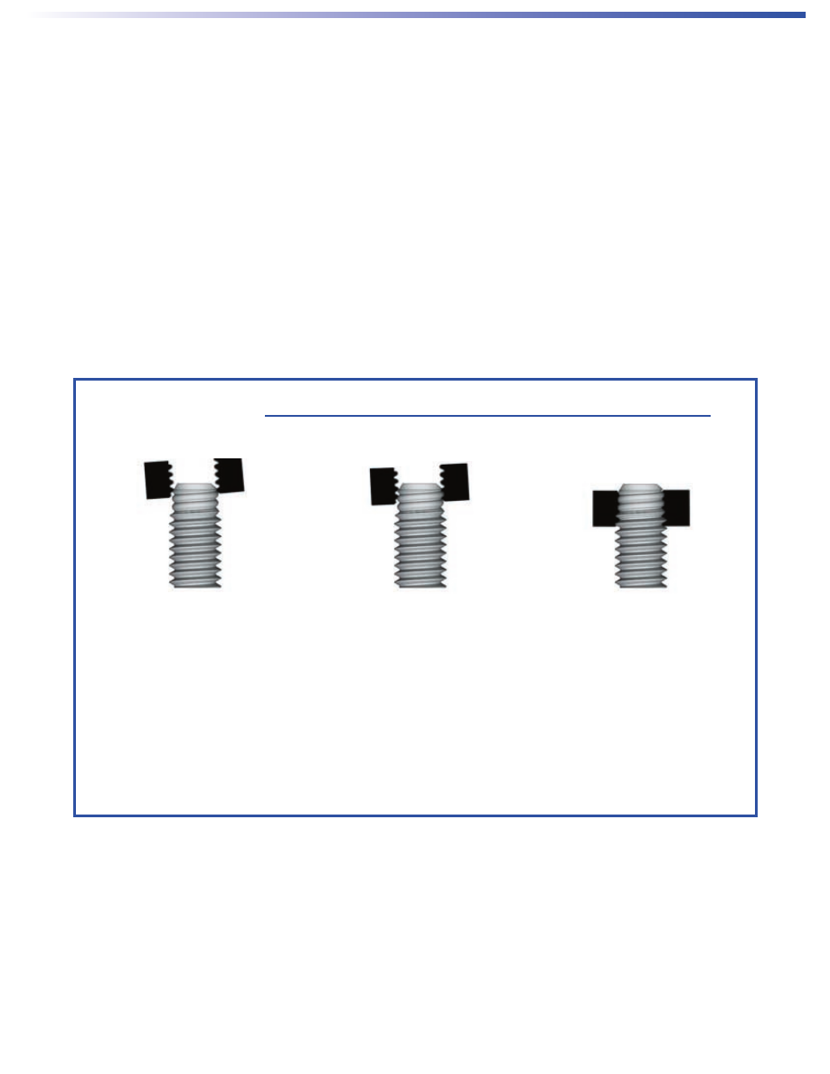
Atlas Blind threaded inserts are designed to provide
strong threads in thin panel sections. They are called
“blind” because they can be installed from one side of the
panel. Access to both sides is not required. That’s why
these fasteners are ideally suited for tubing, extrusion,
and other similar types of applications.
There are three types: SpinTite
®
, MaxTite
®
, and Plus+Tite
™
fasteners. The SpinTite types are used for most
applications where strong threads are required for blind
applications. Most commonly known as “blind threaded
inserts”, they are installed from one side using a spin/
spin technique. The clockwise spinning action of the
pneumatic tool draws the fastener in, compressing the
unthreaded portion of the fastener wall. The bulge that
is created presses against the panel creating a clamping
force which tightly grips the sheet. In addition to high
thread strength and torque-out, these fasteners have
minimal inventory requirements since each size can
accommodate many grip ranges.
The heavy duty MaxTite types, most commonly known
as “blind threaded rivet nuts” are designed for the most
demanding applications. They are installed from one side
using a “spin/pull” technique. A hydraulic/pneumatic tool
is used to draw the fastener in, creating the bulge and
clamping force as described above.
The blind Plus+Tite inserts feature a pre-bulbed slotted
body that folds into four petals upon installation, gripping
the backside of the parent material. These inserts can
be installed into single, variable, or multiple thickness
materials using Atlas Series 800 pneumatic tools or an
Atlas Series AE 40 pneumatic/hydraulic tool.
The advantages of blind threaded insert technology
include:
•
Fast, easy one-sided installation.
•
Strong, permanent threads in thin panels.
•
Installs anytime during production, in painted
panels, in the field, and repair applications.
•
Works in close-to-edge applications.
•
Attaches to panels of any hardness.
•
Utilizes light, compact, cost-effective
installation tooling.
•
Can assemble multiple dissimilar materials during
installation.
ATLAS
™
BLIND
THREADED INSERTS
©2003 SpinTite, MaxTite, and Plus+Tite are brand names and trademarks for
products manufactured exclusively by PennEngineering Fastening Technologies.
1
2
3

AE-3
INDEX
SpinTite
®
Blind Threaded Inserts
TYPE AEH - HALF-HEX SHANK LOW PROFILE HEAD SERIES
. . . . . . . . . . . . . . . . . . . . . . . . . . . . . . . . . . . . . . . . . . Page 4
• Features a hex body design.
• Improved torque-out resistance.
• Easy to install using spin/spin tooling.
• Able to be installed after finish.
TYPE AEL - LOW-PROFILE HEAD
. . . . . . . . . . . . . . . . . . . . . . . . . . . . . . . . . . . . . . . . . . . . . . . . . . . . . . . . . . . . . . . . Page 5
• Feature a large diameter, low-profile head and knurled shank.
• Offers highest all around strength
TYPE AEK - MINIMIZED-PROFILE HEAD
. . . . . . . . . . . . . . . . . . . . . . . . . . . . . . . . . . . . . . . . . . . . . . . . . . . . . . . . . . . Page 6
• Same as the AEL but with a minimized-profile head.
• Allows near-flush installations with no need for special hole preparations such as countersinking or dimpling.
TYPE AEO - THIN-WALL LOW PROFILE HEAD SERIES
. . . . . . . . . . . . . . . . . . . . . . . . . . . . . . . . . . . . . . . . . . . . . . . Page 7
• Features a low profile head design.
• Achieves flush installations with no need for countersink drilling or dimpling of the parent material.
TYPE AET - 360° SWAGING LOW-PROFILE HEAD SERIES
. . . . . . . . . . . . . . . . . . . . . . . . . . . . . . . . . . . . . . . . . . . . Page 8
• Works in any thickness over .029” /0.76 mm including blind hole.
• High resistance to torque out.
• Minimal backside protrusion for restricted space applications.
TYPE AES - BLIND THREADED STUDS
. . . . . . . . . . . . . . . . . . . . . . . . . . . . . . . . . . . . . . . . . . . . . . . . . . . . . . . . .Pages 9-10
• Provide strong external threads in blind applications.
• Easy to install using spin/spin tooling.
• Optional anti cross-threading feature available.
OPTIONAL ANTI CROSS-THREADING FEATURE FOR STUDS
. . . . . . . . . . . . . . . . . . . . . . . . . . . . . . . . . . . . . . . . . . Page 11
SpinTite INSTALLATION
. . . . . . . . . . . . . . . . . . . . . . . . . . . . . . . . . . . . . . . . . . . . . . . . . . . . . . . . . . . . . . . . . . . . . . Page 12
SpinTite PERFORMANCE DATA
. . . . . . . . . . . . . . . . . . . . . . . . . . . . . . . . . . . . . . . . . . . . . . . . . . . . . . . . . . . . . .Pages 13-14
Atlas Plus+Tite
™
Blind Threaded Inserts
TYPE AE – DESIGNED FOR SUPERIOR PULLOUT RESISTANCE IN PLASTICS AND THIN SHEET METAL
. . . . . . . . Page 15
• Internal formed threads are compatible with unified grade 5 or metric class 9.8 screws.
• Shoulder provides self-locating feature.
• All surfaces are plated for superior corrosion resistance.
Atlas MaxTite
®
Blind Threaded Inserts
TYPE AE - DESIGNED FOR HIGH LOAD APPLICATIONS
. . . . . . . . . . . . . . . . . . . . . . . . . . . . . . . . . . . . . . . . . . .Pages 16-20
• Thread sizes 440 - 1/2” and M3-M12.
• Countersunk feature allow fastener to be installed flush with the surface of the sheet.
• Available with rib, key or full hex features for high torque applications.
MaxTite SPECIFICATIONS AND INSTALLATION
. . . . . . . . . . . . . . . . . . . . . . . . . . . . . . . . . . . . . . . . . . . . . . . . .Pages 21-23
MaxTite PERFORMANCE DATA
. . . . . . . . . . . . . . . . . . . . . . . . . . . . . . . . . . . . . . . . . . . . . . . . . . . . . . . . . . . . . .Pages 24-25
Atlas Installation Tools
. . . . . . . . . . . . . . . . . . . . . . . . . . . . . . . . . . . . . . . . . . . . . . . . . . . . . . . . . . . . . Page 26
Custom Hardware Options
. . . . . . . . . . . . . . . . . . . . . . . . . . . . . . . . . . . . . . . . . . . . . . . . . . . . . . . . . Page 27
AE-4
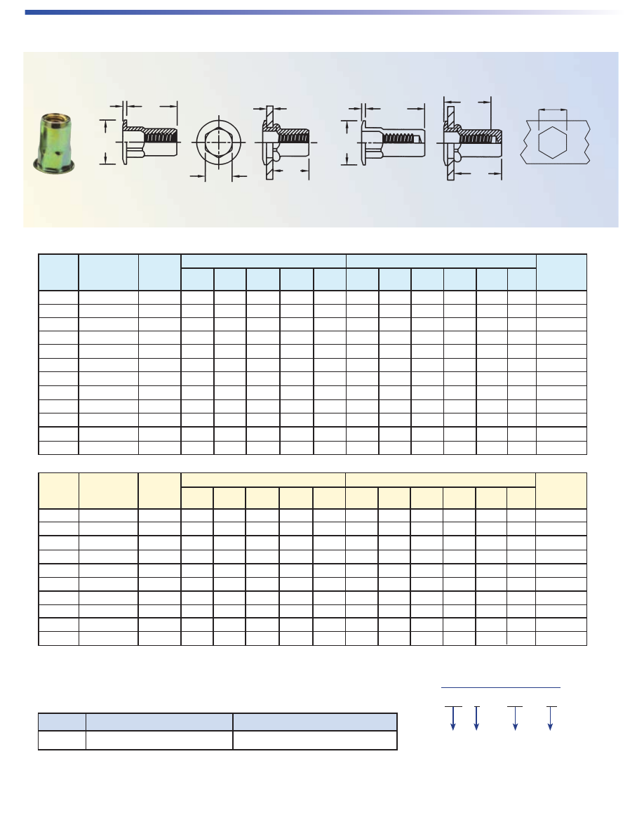
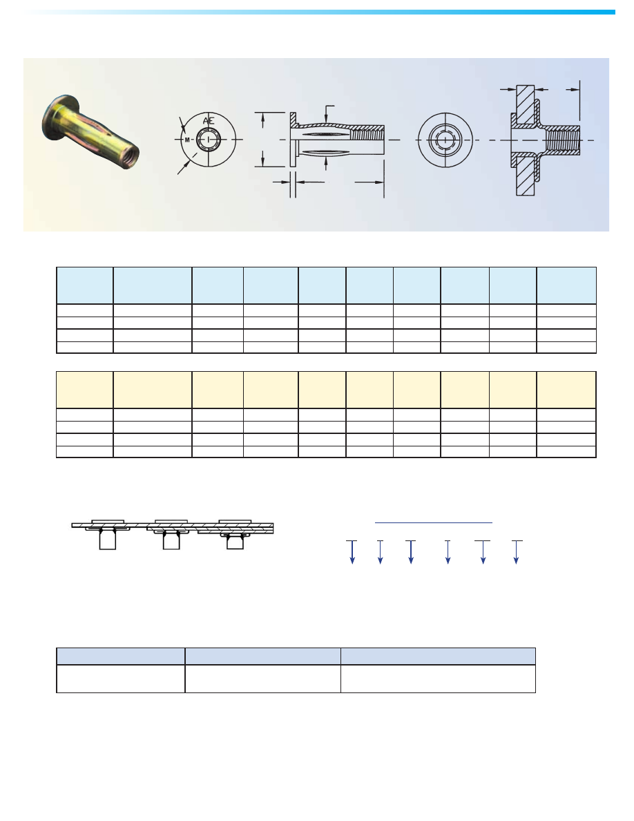
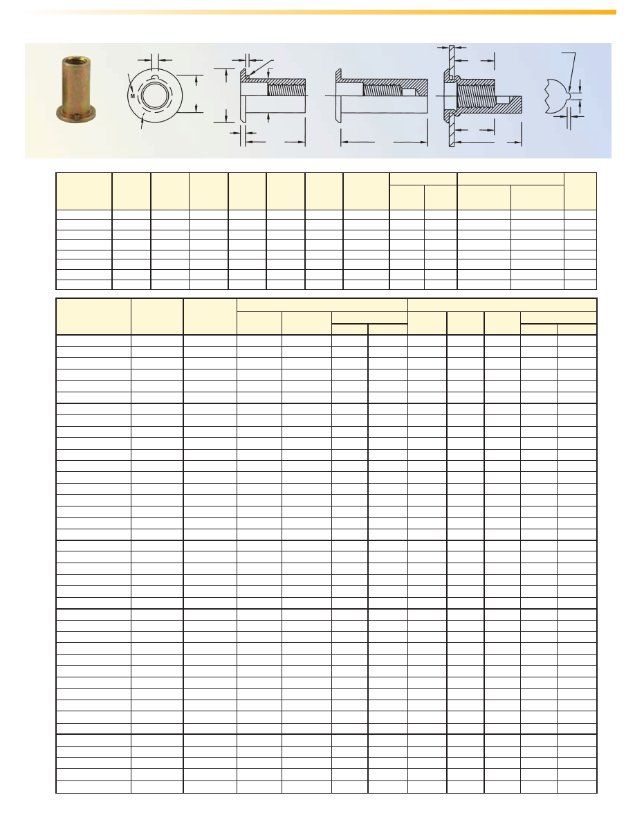
SpinTite – HALF-HEX SHANK LOW-PROFILE HEAD-TYPE AEH
All dimensions are in inches.
Thread Part Grip Hex Hole
Size Number Range A B C D M A B C D K M Size In Sheet
(1)
(1)
±.015 ±.015 Nom. Max. Ref ±.015 ±.015 Nom. Max. Min. Ref. +.006 -.000
#6-32 AEHS-632-80 .020 - .080 .385 .375 .027 .249 .295 .740 .375 .027 .249 .43 .640 .250
#6-32 AEHS-632-130 .080 - .130 .435 .375 .027 .249 .295 .740 .375 .027 .249 .43 .580 .250
#8-32 AEHS-832-80 .020 - .080 .385 .375 .027 .249 .295 .740 .375 .027 .249 .43 .640 .250
#8-32 AEHS-832-130 .080 - .130 .435 .375 .027 .249 .295 .740 .375 .027 .249 .43 .580 .250
#10-32 AEHS-1032-130 .020 - .130 .435 .390 .027 .280 .275 1.030 .390 .027 .280 .58 .845 .281
#10-32 AEHS-1032-225 .130 - .225 .535 .390 .027 .280 .275 1.030 .390 .027 .280 .58 .735 .281
1/4-20 AEHS-420-165 .027 - .165 .585 .510 .030 .374 .400 1.190 .510 .030 .374 .70 1.015 .375
1/4-20 AEHS-420-260 .165 - .260 .685 .510 .030 .374 .400 1.190 .510 .030 .374 .70 .915 .375
5/16-18 AEHS-518-150 .027 - .150 .685 .655 .035 .499 .530 1.445 .655 .035 .499 .82 1.235 .500
5/16-18 AEHS-518-312 .150 - .312 .845 .655 .035 .499 .515 1.445 .655 .035 .499 .82 1.220 .500
3/8-16 AEHS-616-150 .027 - .150 .685 .655 .035 .499 .530 1.445 .655 .035 .499 .83 1.235 .500
3/8-16 AEHS-616-312 .150 - .312 .845 .655 .035 .499 .515 1.445 .655 .035 .499 .83 1.220 .500
All dimensions are in millimeters.
Thread Part Grip Hex Hole
Size x Number Range A B C D M A B C D K M Size In Sheet
Pitch
(1)
(1)
±0.38 ±0.38 Nom. Max. Ref. ±0.38 ±0.38 Nom. Max. Min. Ref. +0.15
M4 x 0.7 AEHS-470-2.0 0.5 - 2 9.78 9.53 0.68 6.35 7.49 18.8 9.53 0.68 6.35 11.6 16.26 6.35
M4 x 0.7 AEHS-470-3.3 2 - 3.3 11.05 9.53 0.68 6.35 7.49 18.8 9.53 0.68 6.35 11.6 14.73 6.35
M5 x 0.8 AEHS-580-3.3 0.5 - 3.3 11.05 9.91 0.68 7.1 6.99 26.16 9.91 0.68 7.1 15.6 21.46 7.14
M5 x 0.8 AEHS-580-5.7 3.3 - 5.7 13.59 9.91 0.68 7.1 6.99 26.16 9.91 0.68 7.1 15.6 18.67 7.14
M6 x 1 AEHS-610-4.2 0.7 - 4.2 14.86 12.96 0.76 9.5 10.16 30.23 12.96 0.76 9.5 17.5 25.78 9.53
M6 x 1 AEHS-610-6.6 4.2 - 6.6 17.4 12.96 0.76 9.5 10.16 30.23 12.96 0.76 9.5 17.5 23.24 9.53
M8 x 1.25 AEHS-8125-3.8 0.7 - 3.8 17.4 16.64 0.89 12.7 13.46 36.7 16.64 0.89 12.7 20.2 31.37 12.7
M8 x 1.25 AEHS-8125-7.9 3.8 - 7.9 21.46 16.64 0.89 12.7 13.08 36.7 16.64 0.89 12.7 20.2 30.99 12.7
M10 x 1.5 AEHS-1015-3.8 0.7 - 3.8 17.4 16.64 0.89 12.7 13.46 36.7 16.64 0.89 12.7 20.8 31.37 12.7
M10 x 1.5 AEHS-1015-7.9 3.8 - 7.9 21.46 16.64 0.89 12.7 13.08 36.7 16.64 0.89 12.7 20.8 30.99 12.7
(1) Additional thread sizes and grip ranges available.
Part Number Designation
AEH S - 632 - 80
Type Material
Max.
Grip
Thread
Code
MATERIAL & FINISH SPECIFICATIONS
Type Material Standard Finish
AEH Steel, C-1008 or C-1010, or Equivalent Zinc Plate per ASTM B 633, Fe/Zn 8, Type II
Open Closed
Open Closed
A
B
C
D
Grip Range
Hex
Hole Size
M
A
B
C
M
K
OPEN END
CLOSED END
All dimensions are in millimeters.
All dimensions are in inches.
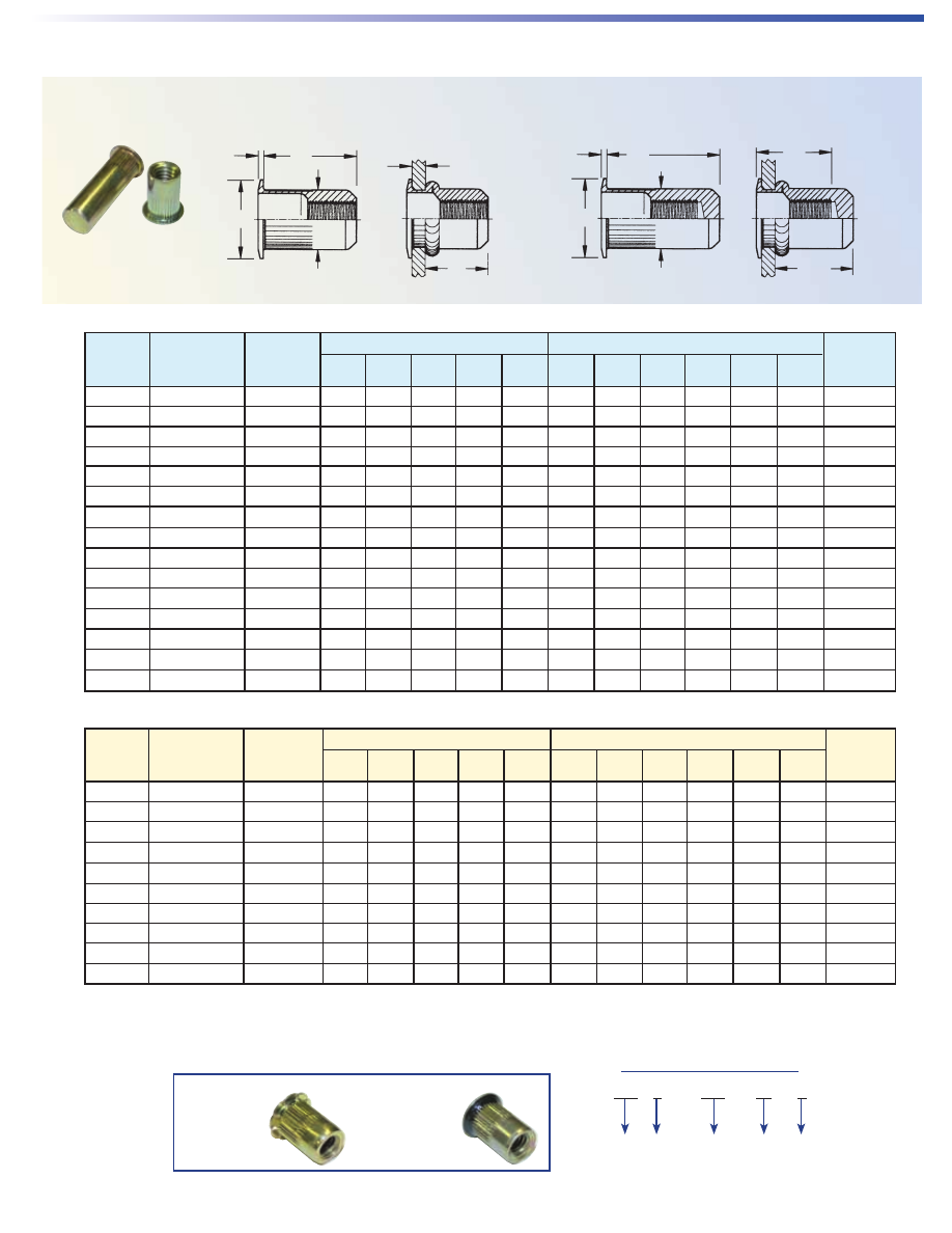
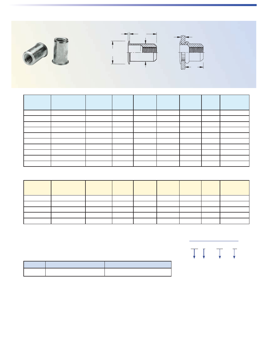
SpinTite – LOW-PROFILE HEAD-TYPE AEL
Thread Part Grip Hole Size
Size Number Range A B C ØD M A B C ØD K M In Sheet
(1)
(2)
(1)
±.015 ±.015 Nom. Max. Ref. ±.015 ±.015 Nom. Max. Min. Max. +.006 -.000
#6-32 AELS-632-80 .020 - .080 .420 .390 .030 .265 .305 .740 .390 .030 .265 .43 .640 .266
#6-32 AELS-632-130 .080 - .130 .470 .390 .030 .265 .305 .740 .390 .030 .265 .43 .580 .266
#8-32 AELS-832-80 .020 - .080 .420 .390 .030 .265 .305 .740 .390 .030 .265 .43 .640 .266
#8-32 AELS-832-130 .080 - .130 .470 .390 .030 .265 .305 .740 .390 .030 .265 .43 .580 .266
#10-32 AELS-1032-130 .020 - .130 .475 .415 .030 .296 .315 .990 .415 .030 .296 .58 .845 .297
#10-32 AELS-1032-225 .130 - .225 .585 .415 .030 .296 .315 .990 .415 .030 .296 .58 .735 .297
1/4-20 AELS-420-165 .027 - .165 .580 .500 .030 .390 .380 1.190 .500 .030 .390 .70 1.005 .391
1/4-20 AELS-420-260 .165 - .260 .680 .500 .030 .390 .380 1.190 .500 .030 .390 .70 .905 .391
5/16-18 AELS-518-150 .027 - .150 .690 .685 .035 .530 .470 1.390 .685 .035 .530 .82 1.175 .531
5/16-18 AELS-518-312 .150 - .312 .805 .685 .035 .530 .425 1.390 .685 .035 .530 .82 1.025 .531
3/8-16 AELS-616-150 .027 - .150 .690 .685 .035 .530 .470 1.390 .685 .035 .530 .83 1.175 .531
3/8-16 AELS-616-312 .150 - .312 .805 .685 .035 .530 .425 1.390 .685 .035 .530 .83 1.025 .531
1/2-13 AELS-813-200 .063 - .200 1.150 .865 .047 .685 .850 —— —— —— —— —— —— .688
1/2-13 AELS-813-350 .200 - .350 1.300 .865 .047 .685 .850 —— —— —— —— —— —— .688
1/2-13 AELS-813-500 .350 - .500 1.450 .865 .047 .685 .850 —— —— —— —— —— —— .688
Thread Part Grip Hole Size
Size x Number Range A B C ØD M A B C ØD K M In Sheet
Pitch
(1)
(2)
(1)
±0.38 ±0.38 Nom. Max. Ref. ±0.38 ±0.38 Nom. Max. Min. Max. +0.15
M4 x 0.7 AELS-470-2.0 0.5 - 2 10.67 9.91 0.76 6.73 7.75 18.8 9.91 0.76 6.73 11.6 16.26 6.75
M4 x 0.7 AELS-470-3.3 2 - 3.3 11.94 9.91 0.76 6.73 7.75 18.8 9.91 0.76 6.73 11.6 14.73 6.75
M5 x 0.8 AELS-580-3.3 0.5 - 3.3 12.07 10.54 0.76 7.52 8 25.15 10.54 0.76 7.52 15.6 21.46 7.6
M5 x 0.8 AELS-580-5.7 3.3 - 5.7 14.86 10.54 0.76 7.52 8 25.15 10.54 0.76 7.52 15.6 18.67 7.6
M6 x 1 AELS-610-4.2 0.7 - 4.2 14.73 12.7 0.76 9.91 9.65 30.23 12.7 0.76 9.91 17.5 25.53 10
M6 x 1 AELS-610-6.6 4.2 - 6.6 17.27 12.7 0.76 9.91 9.65 30.23 12.7 0.76 9.91 17.5 22.99 10
M8 x 1.25 AELS-8125-3.8 0.7 - 3.8 17.53 17.4 0.89 13.46 11.94 35.31 17.4 0.89 13.46 20.2 29.85 13.5
M8 x 1.25 AELS-8125-7.9 3.8 - 7.9 20.45 17.4 0.89 13.46 10.8 35.31 17.4 0.89 13.46 20.2 26.04 13.5
M10 x 1.5 AELS-1015-3.8 0.7 - 3.8 17.53 17.4 0.89 13.46 11.94 35.31 17.4 0.89 13.46 20.8 29.85 13.5
M10 x 1.5 AELS-1015-7.9 3.8 - 7.9 20.45 17.4 0.89 13.46 10.8 35.31 17.4 0.89 13.46 20.8 26.04 13.5
(1) Additional thread sizes and grip ranges available.
(2) For closed end, add a “B” to the end of the part number.
Part Number Designation
AEL S - 632 - 80 B
Type Material
Max.
Grip
Thread
Code
Closed
End
Designation
A
B
C
ØD
Grip Range
M
OPEN END
CLOSED END
A
ØD
K
M
B
C
Also available . . .
Wedge Head
Wedges under
the head provide
greater torque,
especially in soft
or thin materials.
Sealed Head
A PVC foam seal
is bonded to the
underside of the
head to provide a
weathertight seal.
Open Closed
Open Closed
AE-5
AE-6
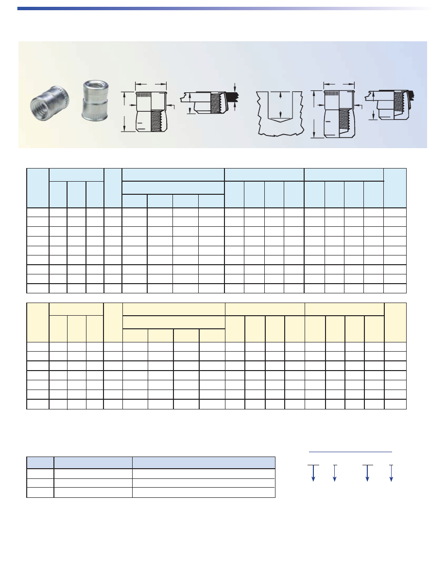
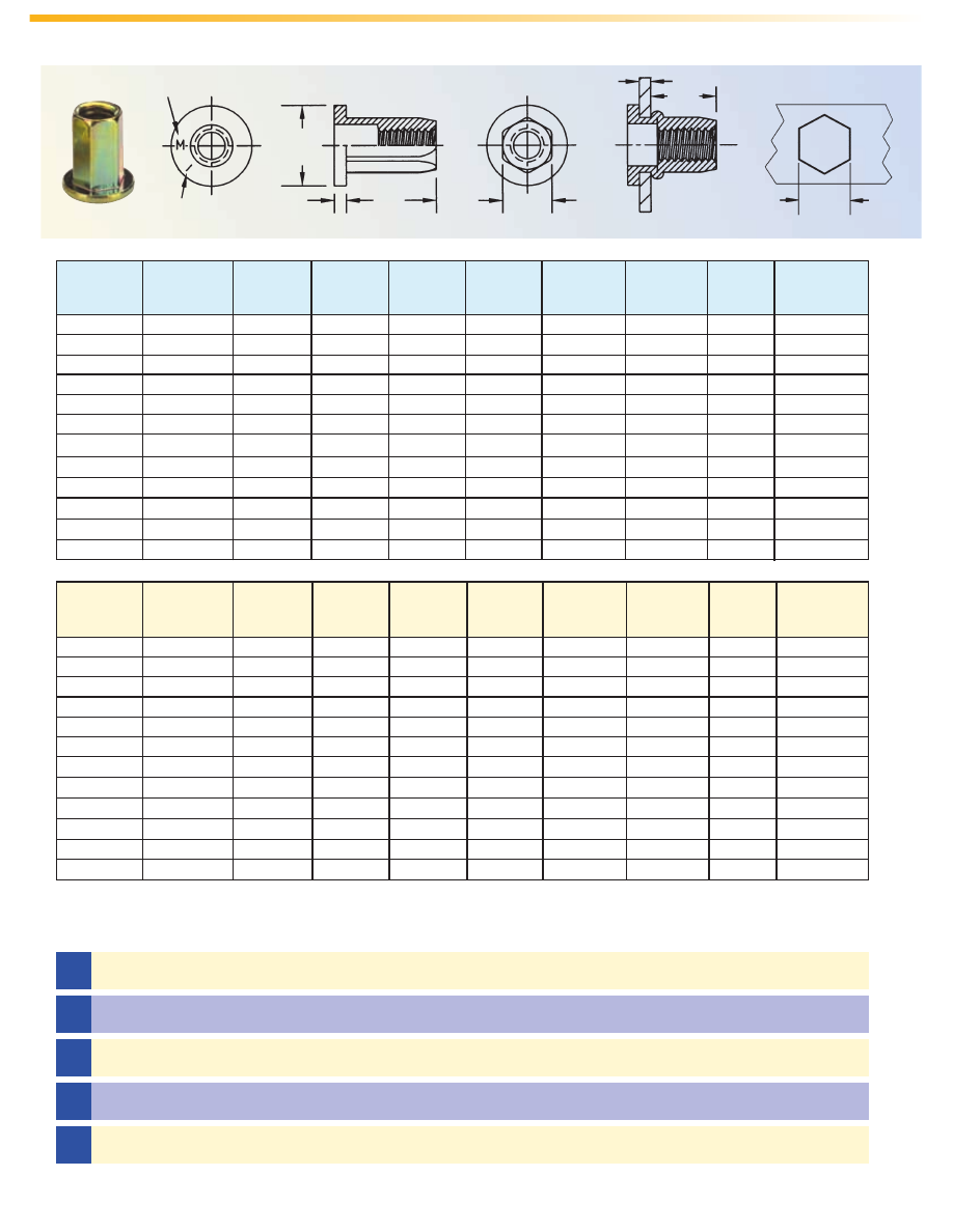
SpinTite – MINIMIZED-PROFILE HEAD-TYPE AEK
MATERIAL & FINISH SPECIFICATIONS
(1) Additional thread sizes and grip ranges available.
(2) For closed end, add a “B” to the end of the part number.
A
B
C
ØD
Grip Range
M
OPEN END
ØD
M
CLOSED END
A
K
B
C
Part Number Designation
AEK S - 632 - 80 B
Type Material
Max.
Grip
Thread
Code
Closed
End
Designation
All dimensions are in millimeters.
Thread Part Grip Hole Size
Size x Number Range A B C ØD M A B C ØD K M In Sheet
Pitch
(1)
(2)
(1)
±0.38 ±0.38 Nom. Max. Ref. ±0.38 ±0.38 Nom. Max. Min. Max. +0.15
M4 x 0.7 AEKS-470-2.0 0.5 - 2 10.67 7.87 0.48 6.73 7.75 18.8 7.78 0.48 6.73 11.6 16.26 6.75
M4 x 0.7 AEKS-470-3.3 2 - 3.3 11.94 7.87 0.48 6.73 7.75 18.8 7.87 0.48 6.73 11.6 14.73 6.75
M5 x 0.8 AEKS-580-3.3 0.5 - 3.3 12.07 8.64 0.48 7.52 8 25.15 8.64 0.48 7.52 15.6 21.46 7.6
M5 x 0.8 AEKS-580-5.7 3.3 - 5.7 14.86 8.64 0.48 7.52 8 25.15 8.64 0.48 7.52 15.6 18.67 7.6
M6 x 1 AEKS-610-4.2 0.7 - 4.2 14.73 11.56 0.55 9.91 9.65 30.23 11.56 0.55 9.91 17.5 25.53 10
M6 x 1 AEKS-610-6.6 4.2 - 6.6 17.27 11.56 0.55 9.91 9.65 30.23 11.56 0.55 9.91 17.5 22.99 10
M8 x 1.25 AEKS-8125-3.8 0.7 - 3.8 17.53 15.11 0.55 13.46 11.94 35.31 15.11 0.55 13.46 20.2 29.85 13.5
M8 x 1.25 AEKS-8125-7.9 3.8 - 7.9 20.45 15.11 0.55 13.46 10.8 35.31 15.11 0.55 13.46 20.2 26.04 13.5
M10 x 1.5 AEKS-1015-3.8 0.7 - 3.8 17.53 15.11 0.55 13.46 11.94 35.31 15.11 0.55 13.46 20.8 29.85 13.5
M10 x 1.5 AEKS-1015-7.9 3.8 - 7.9 20.45 15.11 0.55 13.46 10.8 35.31 15.11 0.55 13.46 20.8 26.04 13.5
Open Closed
All dimensions are in inches.
Thread Part Grip Hole Size
Size Number Range A B C ØD M A B C ØD K M In Sheet
(1)
(2)
(1)
±.015 ±.015 Nom. Max. Ref. ±.015 ±.015 Nom. Max. Min. Max. +.006 -.000
#6-32 AEKS-632-80 .020 - .080 .420 .310 .019 .265 .305 .740 .310 .019 .265 .43 .640 .266
#6-32 AEKS-632-130 .080 - .130 .470 .310 .019 .265 .305 .740 .310 .019 .265 .43 .580 .266
#8-32 AEKS-832-80 .020 - .080 .420 .310 .019 .265 .305 .740 .310 .019 .265 .43 .640 .266
#8-32 AEKS-832-130 .080 - .130 .470 .310 .019 .265 .305 .740 .310 .019 .265 .43 .580 .266
#10-32 AEKS-1032-130 .020 - .130 .475 .340 .019 .296 .315 .990 .340 .019 .296 .58 .845 .297
#10-32 AEKS-1032-225 .130 - .225 .585 .340 .019 .296 .315 .990 .340 .019 .296 .58 .735 .297
1/4-20 AEKS-420-165 .027 - .165 .580 .455 .022 .390 .380 1.190 .455 .022 .390 .70 1.005 .391
1/4-20 AEKS-420-260 .165 - .260 .680 .455 .022 .390 .380 1.190 .455 .022 .390 .70 .905 .391
5/16-18 AEKS-518-150 .027 - .150 .690 .595 .022 .530 .470 1.390 .595 .022 .530 .82 1.175 .531
5/16-18 AEKS-518-312 .150 - .312 .805 .595 .022 .530 .425 1.390 .595 .022 .530 .82 1.025 .531
3/8-16 AEKS-616-150 .027 - .150 .690 .595 .022 .530 .470 1.390 .595 .022 .530 .83 1.175 .531
3/8-16 AEKS-616-312 .150 - .312 .805 .595 .022 .530 .425 1.390 .595 .022 .530 .83 1.025 .531
Open Closed
Type Material Standard Finish
AEL / AEK Steel, C-1008 or C-1010, or Equivalent Zinc Plate per ASTM B 633, Fe/Zn 8, Type II
All dimensions are in millimeters.
All dimensions are in inches.
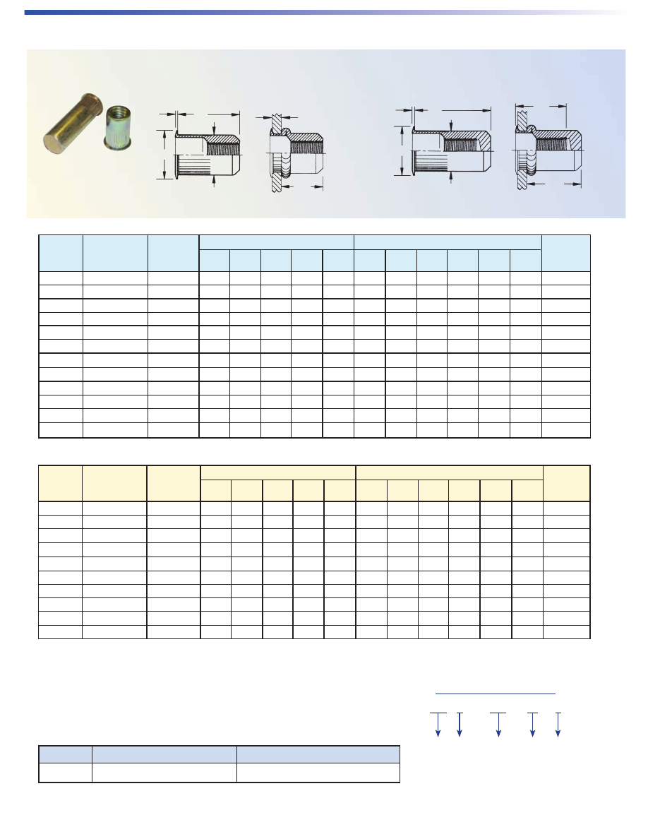
SpinTite – THIN-WALL LOW-PROFILE HEAD-TYPE AEO
Thread Part Grip A B C ØD M Hole Size
Size
(1)
Number Range
(1)
±.015 ±.015 Nom. max. Ref. In Sheet
+.006 -.000
#6-32 AEOS-632-80 .020 - .080 .385 .295 .018 .249 .315 .250
#8-32 AEOS-832-80 .020 - .080 .385 .295 .018 .249 .315 .250
#10-24 AEOS-1024-130 .020 - .130 .440 .320 .020 .280 .330 .281
#10-32 AEOS-1032-130 .020 - .130 .440 .320 .020 .280 .330 .281
1/4-20 AEOS-420-165 .030 - .165 .580 .425 .022 .374 .440 .375
1/4-28 AEOS-428-165 .030 - .165 .580 .425 .022 .374 .440 .375
5/16-18 AEOS-518-200 .040 - .200 .690 .560 .022 .499 .540 .500
5/16-24 AEOS-524-200 .040 - .200 .690 .560 .022 .499 .540 .500
3/8-16 AEOS-616-200 .040 - .200 .690 .560 .022 .499 .540 .500
3/8-24 AEOS-624-200 .040 - .200 .690 .560 .022 .499 .540 .500
A
B
C
ØD
Grip Range
M
Thread Part Grip A B C ØD M Hole Size
Size x Number Range
(1)
±0.38 ±0.25 Nom. max. Ref. In Sheet
Pitch
(1)
+0.15
M4 x 0.7 AEOS-470-2.0 0.5 - 2 9.78 7.49 0.46 6.32 8 6.4
M5 x 0.8 AEOS-580-3.3 0.5 - 3.3 11.18 8.13 0.51 7.11 8.38 7.2
M6 x 1 AEOS-610-4.2 0.76 - 4.2 14.73 10.8 0.56 9.5 11.18 9.6
M8 x 1.25 AEOS-8125-5.1 1.02 - 5.1 17.53 14.22 0.56 12.67 13.72 12.7
M10 x 1.5 AEOS-1015-5.1 1.02 - 5.1 17.53 14.22 0.56 12.67 13.72 12.7
(1) Additional thread sizes and grip ranges available.
Part Number Designation
AEO S - 632 - 80
Type Material
Max.
Grip
Thread
Code
MATERIAL & FINISH SPECIFICATIONS
Type Material Standard Finish
AEO Steel, C-1008 or C-1010, or Equivalent Zinc Plate per ASTM B 633, Fe/Zn 8, Type I
AE-7
AE-8
A
ØC
D
Grip
Range
Blind Hole
OPEN END
CLOSED END
B
Hole
Depth
ØC
D
B
A
SpinTite – 360˚ SWAGING LOW-PROFILE HEAD-TYPE AET
Type Installation Hole Size Open Closed Blind
Thread Thread Hole
Size
(1)
Code
Grip Range
(1)
Depth
Stain- Alum-
A B ØC D A B ØC D Min.
Steel less inum
.030 - .090 .091 - .124 .125 - .186 .187 - OVER
±.005 ±.015 Max. Max. ±.005 ±.015 Max. Max.
#4-40 AETS AETC AETA 440 .188 .194 .194 .196 .211 .370 .1875 .205 .211 .660 .1875 .495 .400
#6-32 AETS AETC AETA 632 .219 .221 .228 .228 .240 .370 .2185 .205 .240 .675 .2185 .505 .400
#8-32 AETS AETC AETA 832 .250 .257 .266 .266 .269 .370 .2495 .205 .269 .675 .2495 .505 .400
#10-24 AETS AETC AETA 024 .281 .290 .290 .297 .306 .370 .2805 .205 .306 .685 .2805 .520 .400
#10-32 AETS AETC AETA 032 .281 .290 .290 .297 .306 .370 .2805 .205 .306 .685 .2805 .520 .400
1/4-20 AETS AETC AETA 420 .375 .375 .386 .391 .400 .515 .3745 .275 .400 1.005 .3745 .760 .540
5/16-18 AETS AETC AETA 518 .500 .500 .516 .516 .528 .615 .4995 .325 .528 1.065 .4995 .770 .640
3/8-16 AETS AETC AETA 616 .563 .563 .578 .578 .588 .745 .5615 .390 .588 1.450 .5615 1.095 .770
1/2-13 AETS AETC AETA 813 .750 .766 .781 .790 .800 .935 .7485 .485 .800 NA .7485 NA .960
Type Installation Hole Size Open Closed Blind
Thread Thread Hole
Size x Code
Grip Range
(1)
Depth
Pitch
(1)
Stain- Alum-
A B ØC D A B ØC D Min.
Steel
less inum
1.52 - 2.3 2.31 - 3.15 3.16 - 4.75 4.76 - OVER
±0.13 ±0.38 Max. Max. ±0.13 ±0.38 Max. Max.
M3x0.5 AETS AETC AETA 350 4.75 4.9 4.9 4.97 5.36 9.4 4.76 5.21 5.36 16.77 4.76 12.57 10.16
M4x0.7 AETS AETC AETA 470 6.35 6.5 6.74 6.74 6.83 9.4 6.34 5.21 6.83 17.15 6.34 12.83 10.16
M5x0.8 AETS AETC AETA 580 7.14 7.37 7.4 7.54 7.77 9.4 7.12 5.21 7.77 17.4 7.12 13.21 10.16
M6x1 AETS AETC AETA 610 9.52 9.52 9.8 9.92 10.16 13.08 9.51 6.99 10.16 25.53 9.51 19.3 13.72
M8x1.25 AETS AETC AETA 8125 12.7 12.7 13.09 13.09 13.41 15.62 12.69 8.26 13.41 27.05 12.69 19.56 16.26
M10x1.5 AETS AETC AETA 1015 14.28 14.28 14.68 14.68 14.94 18.92 14.26 9.91 14.94 36.83 14.26 27.81 19.56
M12x1.75 AETS AETC AETA 12175 19.05 19.44 19.84 20.05 20.32 23.75 19.01 12.32 20.32 NA 19.01 NA 24.38
(1) Additional thread sizes and grip ranges available.
MATERIAL & FINISH SPECIFICATIONS
Type Material Standard Finish
AETS 12L14 Steel or equivalent Cadmium Plate per SAE AMS-QQ-P-416, Class III, Type I
AETC 300 Series Stainless Steel Cadmium Plate per SAE AMS-QQ-P-416, Class III, Type I
AETA 5056 Aluminum or equivalent Cadmium Plate per SAE AMS-QQ-P-416, Class III, Type I
Part Number Designation
AET S - 632 B
Type Material
Thread
Code
Closed
End
Designation
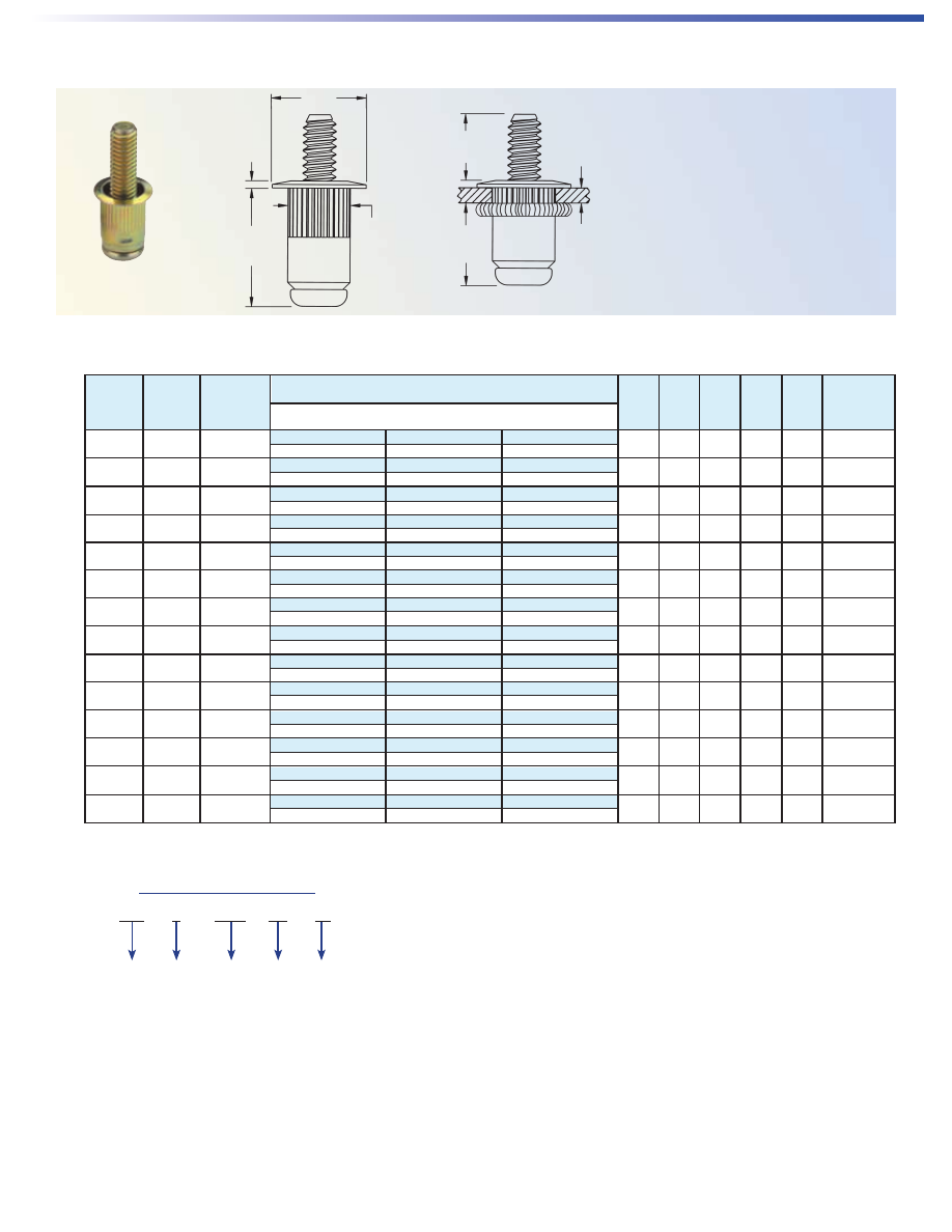
SpinTite – BLIND THREADED STUDS-TYPE AES–UNIFIED
All dimensions are in inches.
A
B
C
ØD
M
L
Grip
NOTE:
The “L” dimension is the height
of the installed stud at max grip. The
height of the stud will increase if it
is installed into thinner material. To
calculate “actual L” use this formula:
max grip - actual grip + L = “actual L”
#6-32 80 .020 - .080
.500 .625 .750
.490 .390 .030 .265 .375 .266
AESS-632-80-500 AESS-632-80-625 AESS-632-80-750
#6-32 130 .080 - .130
.450 .575 .700
.540 .390 .030 .265 .375 .266
AESS-632-130-450 AESS-632-130-575 AESS-632-130-700
#8-32 80 .020 - .080
.500 .625 .750
.490 .390 .030 .265 .375 .266
AESS-832-80-500 AESS-832-80-625 AESS-832-80-750
#8-32 130 .080 - .130
.450 .575 .700
.540 .390 .030 .265 .375 .266
AESS-832-130-450 AESS-832-130-575 AESS-832-130-700
#10-24 130 .020 - .130
.500 .625 .750
.545 .415 .030 .296 .385 .297
AESS-1024-130-500 AESS-1024-130-625 AESS-1024-130-750
#10-24 225 .130 - .225
.405 .530 .655
.655 .415 .030 .296 .385 .297
AESS-1024-225-405 AESS-1024-225-530 AESS-1024-225-655
#10-32 130 .020 - .130
.500 .625 .750
.545 .415 .030 .296 .385 .297
AESS-1032-130-500 AESS-1032-130-625 AESS-1032-130-750
#10-32 225 .130 - .225
.405 .530 .655
.655 .415 .030 .296 .385 .297
AESS-1032-225-405 AESS-1032-225-530 AESS-1032-225-655
1/4-20 165 .027 - .165
.625 .8125 1.000
.670 .500 .030 .390 .470 .391
AESS-420-165-625 AESS-420-165-8125 AESS-420-165-1000
1/4-20 260 .165 - .260
.530 .7175 .905
.770 .500 .030 .390 .470 .391
AESS-420-260-530 AESS-420-260-7175 AESS-420-260-905
5/16-18 150 .027 - .150
.625 .875 1.125
.805 .685 .035 .530 .585 .531
AESS-518-150-625 AESS-518-150-875 AESS-518-150-1125
5/16-18 312 .150 - .312
.508 .713 .963
.920 .685 .035 .530 .540 .531
AESS-518-312-463 AESS-518-312-713 AESS-518-312-963
3/8-16 150 .027 - .150
.750 1.000 1.250
.805 .685 .035 .530 .585 .531
AESS-616-150-750 AESS-616-150-1000 AESS-616-150-1250
3/8-16 312 .150 - .312
.508 .838 1.088
.920 .685 .035 .530 .540 .531
AESS-616-312-588 AESS-616-312-838 AESS-616-312-1088
Thread Grip
Grip
Stud Length “L” Nom. (at Max. Grip)
A B C ØD M
Hole Size
Size Code Range
±.020 ±.015 Nom. Max. Ref.
In Sheet
Part Number +.006 -.000
AE-9
Part Number Designation
AES S - 1015 - 3.8 - 20
Type
Thread
Size
Max.
Grip
Stud
Length
Material
AE-10
MATERIAL & FINISH SPECIFICATIONS
Threads Material Standard Finish
Unified 2A/21 Per ASME B1.1 Insert - Steel, C-1008 or C-1010, or Equivalent Zinc Yellow Plate per ASTM B 633, Fe/Zn 8, Type II
Metric 6g/21 Per ASME B1.13M Stud - Heat-treated medium carbon steel
Part Number Designation
AES S - 1015 - 3.8 - 20
Type
Thread
Size
Max.
Grip
Stud
Length
Material
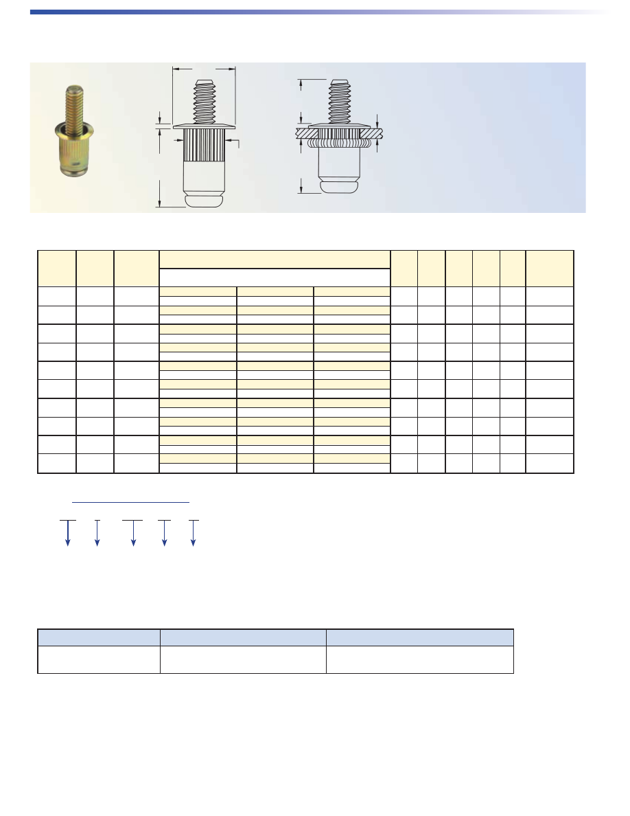
SpinTite – BLIND THREADED STUDS-TYPE AES–METRIC
All dimensions are in millimeters.
M4 x 0.7 2.0 0.5 - 2.0
12 15 20
12.45 9.91 0.76 6.73 9.53 6.75
AESS-470-2.0-12.0 AESS-470-2.0-15.0 AESS-470-2.0-20.0
M4 x 0.7 3.3 2.0- 3.3
10.7 13.7 18.7
13.72 9.91 0.76 6.73 9.53 6.75
AESS-470-3.3-10.7 AESS-470-3.3-13.7 AESS-470-3.3-18.7
M5 x 0.8 3.3 0.5 - 3.3
12 15 20
13.85 10.54 0.76 7.52 9.78 7.6
AESS-580-3.3-12.0 AESS-580-3.3-15.0 AESS-580-3.3-20.0
M5 x 0.8 5.7 3.3 - 5.7
9.6 12.6 17.6
16.64 10.54 0.76 7.52 9.78 7.6
AESS-580-5.7-9.6 AESS-580-5.7-12.6 AESS-580-5.7-17.6
M6 x 1 4.2 0.7 - 4.2
15 20 25
17.02 12.7 0.76 9.91 11.94 10
AESS-610-4.2-15.0 AESS-610-4.2-20.0 AESS-610-4.2-25.0
M6 x 1 6.6 4.2 - 6.6
12.6 17.6 22.6
19.56 12.7 0.76 9.91 11.94 10
AESS-610-6.6-12.6 AESS-610-6.6-17.6 AESS-610-6.6-22.6
M8 x 1.25 3.8 0.7 - 3.8
16 22 28
20.45 17.4 0.89 13.46 14.86 13.5
AESS-8125-3.8-16.0 AESS-8125-3.8-22.0 AESS-8125-3.8-28.0
M8 x 1.25 7.9 3.8 - 7.9
13 17.9 23.9
23.37 17.4 0.89 13.46 13.72 13.5
AESS-8125-7.9-11.9 AESS-8125-7.9-17.9 AESS-8125-7.9-23.9
M10 x 1.5 3.8 0.7 - 3.8
20 25 30
20.45 17.4 0.89 13.46 14.86 13.5
AESS-1015-3.8-20.0 AESS-1015-3.8-25.0 AESS-1015-3.8-30.0
M10 x 1.5 7.9 3.8 - 7.9
17 20.9 25.9
23.37 17.4 0.89 13.46 13.72 13.5
AESS-1015-7.9-5.9 AESS-1015-7.9-20.9 AESS-1015-7.9-25.9
Thread
Grip
Grip
Stud Length “L” Nom. (at Max. Grip)
A B C ØD M
Hole Size
Size x
Code Range
±0.51 ±0.38 Nom. Max. Ref.
In Sheet
Pitch Part Number +0.15
A
B
C
ØD
M
L
Grip
NOTE:
The “L” dimension is the height
of the installed stud at max grip. The
height of the stud will increase if it
is installed into thinner material. To
calculate “actual L” use this formula:
max grip - actual grip + L = “actual L”
AE-11
ATLAS TYPE AES STUDS AVAILABLE
WITH OPTIONAL ANTI CROSS-THREADING FEATURE
PennEngineering Fastening Technologies is a licensee for MAThread
®
anti cross-threading technology. Originally
developed for the demands of the automotive industry, this patented design helps speed assembly and eliminates
failures, repairs, scrap, downtime, and warranty service associated with thread damage.
• Eases assembly!
• Aligns components!
• Slides through clogged internal threads!
• Improves assembly line productivity!
MAThread is a trademark of MAThread, Inc.
HOW IT WORKS
Misaligned Axis:
This design offers
users the benefits of
self-aligning, anti cross-
threading threads.
Threads Cam:
As the threads come into
contact, the patented anti
cross-thread begins to cam
over the female thread.
Threads Drive Normally:
The design promotes
alignment of the thread
helixes. The fasteners drive
easily with reduced effort.
AE-12
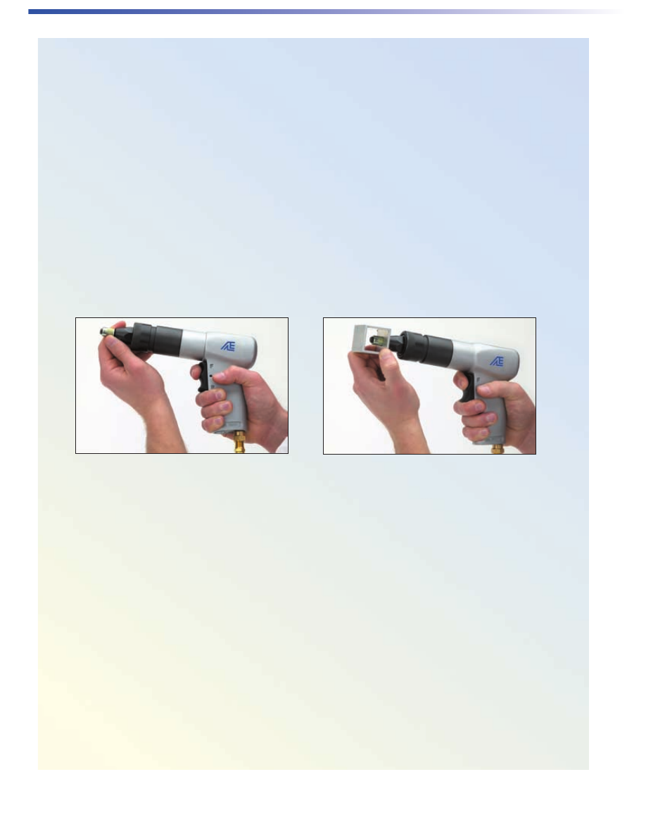
SpinTite INSTALLATION USING
ATLAS SERIES 800 TOOL
With the tool disconnected from the air source, check to see that the socket head cap screw extends
beyond the face of the anvil far enough to allow at least one thread of the screw to extend beyond the
end of the insert. If the screw is not long enough, measure what is required and obtain a socket head cap
screw that is long enough.
If you set up a first grip fastener and you are going to install second grip inserts in the same work area,
obtain a screw that is long enough to extend at least one thread beyond the end of the longest fastener.
Figure 1
Figure 2
Now, connect the air line to the tool. Hold the threaded insert to the tool mandrel. Actuate position “F”
of the trigger (top rocker) and start engagement of the insert threads on the mandrel (Fig. 1).
Insert the fastener into the installation hole of a test plate, that is the same material and thickness as
the actual application (Fig. 2). Actuate position “F” of the trigger and let the mandrel drive through the
fastener and clinch it securely into the test plate and allow the air tool to stall. Actuate position “R” of
the trigger (the bottom rocker) to disengage the mandrel from the installed fastener
AE-13
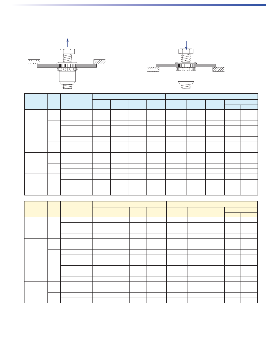
PERFORMANCE DATA
(5)
(1) For pullout, test sheet is supported with a bushing diameter of three times the ØD Max.
(2) Spinout testing conducted by inserting a screw into shank end of insert and tightening until insert spins in sheet.
(3) For pushout, test sheet is supported with a bushing diameter of three times the ØD Max.
(4) Pushout testing conducted only for near max grip steel sheet. For this condition type AEK has lower pushout than type AEL due to thinner head height.
Pullout and spinout performance is the same for type AEL and AEK.
(5) All performance values shown are the average of three or more lots.
Near Minimum Grip Near Maximum Grip
Thread Max. Test Thickness Sheet Pullout Spinout Thickness Sheet Pullout Pushout (lbs.)
(3) (4)
Size Grip Sheet (in.) Hardness (lbs.)
(1)
(in. lbs.)
(2)
(in.) Hardness (lbs.)
(1)
AEL AEK
.080
Aluminum .032 HRB 48 339 —— .060 HRB 67 897 —— ——
6-32 & 8-32
Cold-rolled Steel .030 HRB 37 339 19 .071 HRB 43 969 689 390
.130
Aluminum .090 HRB 66 1515 —— .123 HRB 63 1684 —— ——
Cold-rolled Steel .087 HRB 75 1514 18 .115 HRB 52 1869 689 390
.130
Aluminum .030 HRB 28 342 —— .125 HRB 57 2284 —— ——
10-32 & 10-24
Cold-rolled Steel .029 HRB 47 469 24 .128 HRB 49 2429 940 408
.225
Aluminum .136 HRB 20 2464 —— .185 HRB 57 2220 —— ——
Cold-rolled Steel .165 HRB 56 2530 24 .187 HRB 77 2442 940 408
.165
Aluminum .032 HRB 48 561 —— .125 HRB 57 2441 —— ——
1/4-20 & Cold-rolled Steel .030 HRB 43 581 80 .165 HRB 56 3448 744 615
1/4-28
.260
Aluminum .185 HRB 58 2798 —— .250 HRB 60 3796 —— ——
Cold-rolled Steel .165 HRB 56 3028 64 .247 HRB 96 3370 744 615
5/16-18,
.150
Aluminum .032 HRB 48 668 —— .125 HRB 57 3602 —— ——
5/16-24, &
Cold-rolled Steel .030 HRB 43 687 100 .115 HRB 52 3478 1505 901
3/8-16
.312
Aluminum .185 HRB 60 5152 —— .312 HRB 52 6451 —— ——
Cold-rolled Steel .165 HRB 60 4934 59 .312 HRB 90 5975 1505 901
Near Minimum Grip Near Maximum Grip
Thread Max. Test Thickness Sheet Pullout Spinout Thickness Sheet Pullout Pushout (kN)
(3) (4)
Size Grip Sheet (mm) Hardness (kN)
(1)
(N•m)
(2)
(N•m) Hardness (kN)
(1)
AEL AEK
2.0
Aluminum 0.8 HRB 48 1.5 —— 1.5 HRB 67 4 —— ——
M4
Cold-rolled Steel 0.8 HRB 37 1.5 2.1 1.8 HRB 43 4.3 3.1 1.7
3.3
Aluminum 2.3 HRB 66 6.7 —— 3.1 HRB 63 7.5 —— ——
Cold-rolled Steel 2.2 HRB 75 6.7 2 2.9 HRB 52 8.3 3.1 1.7
3.3
Aluminum 0.8 HRB 28 1.5 —— 3.1 HRB 57 10.2 —— ——
M5
Cold-rolled Steel 0.7 HRB 47 2.1 2.7 3.3 HRB 49 10.8 4.2 1.8
5.7
Aluminum 3.5 HRB 20 11 —— 4.7 HRB 57 9.9 —— ——
Cold-rolled Steel 4.2 HRB 56 11.3 4.1 4.7 HRB 77 10.9 4.2 1.8
4.2
Aluminum 0.8 HRB 48 2.5 —— 3.2 HRB 57 10.9 —— ——
M6
Cold-rolled Steel 0.8 HRB 43 2.6 9 4.2 HRB 56 15.3 3.3 2.7
6.6
Aluminum 4.7 HRB 58 12.4 —— 6.4 HRB 60 16.9 —— ——
Cold-rolled Steel 4.2 HRB 56 13.5 7.2 6.3 HRB 96 15 3.3 2.7
3.8
Aluminum 0.8 HRB 48 3 —— 3.2 HRB 57 16 —— ——
M8 & M10
Cold-rolled Steel 0.8 HRB 43 3.1 11.3 2.9 HRB 52 15.5 6.7 4
7.9
Aluminum 4.7 HRB 60 22.9 —— 7.9 HRB 52 28.7 —— ——
Cold-rolled Steel 4.2 HRB 60 21.9 6.7 7.9 HRB 90 26.6 6.7 4
Pullout
is the force
required to pull the insert
from the sheet.
(1)
PULLOUT
Test Bushing
Pushout
is the force
required to push the
insert from the sheet.
(3)
PUSHOUT
Test Bushing
SpinTite TYPES AEH, AEL, AEK, AEO, AND AET
AE-14
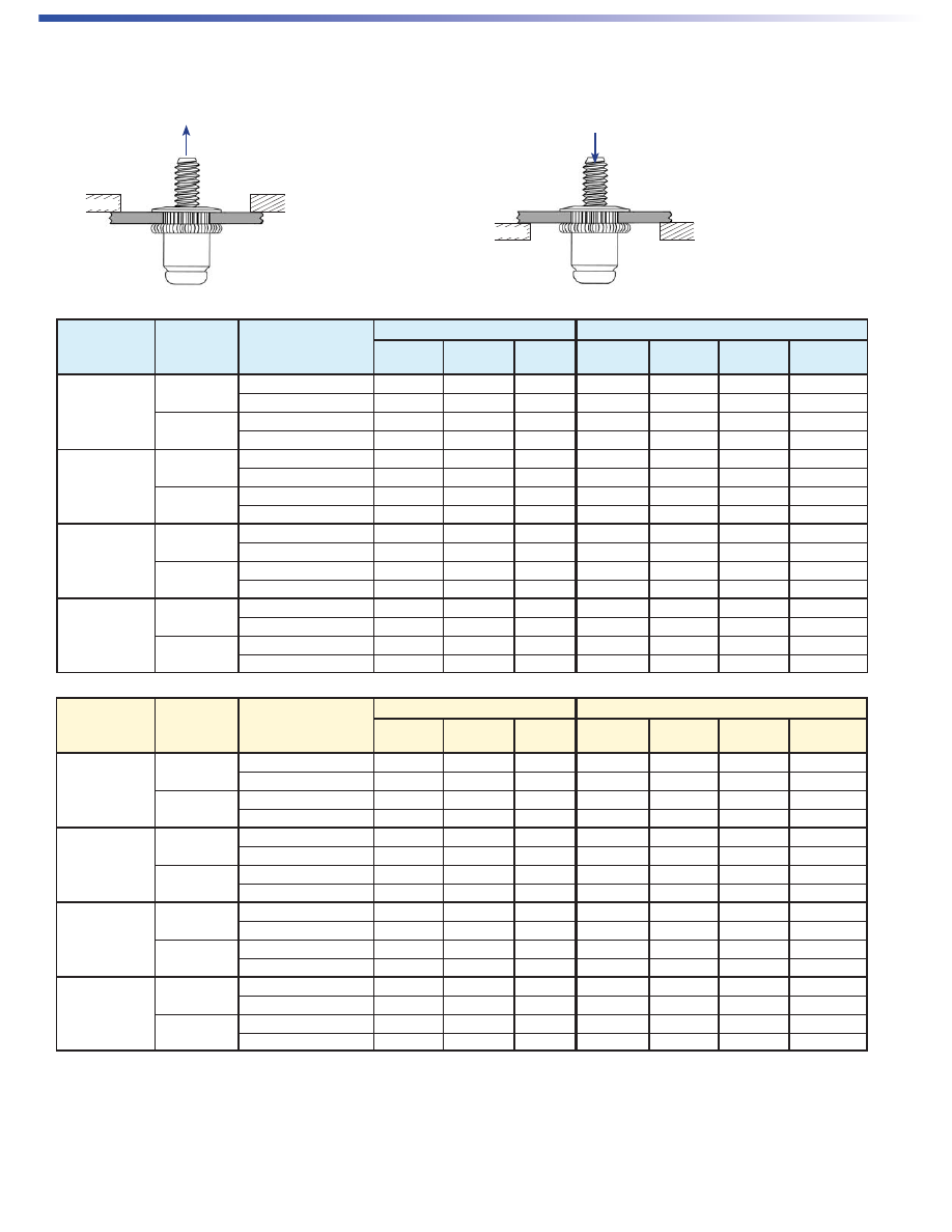
PERFORMANCE DATA
(3)
Near Minimum Grip Near Maximum Grip
Thread Max. Test Thickness Sheet Pullout Thickness Sheet Pullout Pushout
Size Grip Sheet (in.) Hardness (lbs.)
(1)
(in.) Hardness (lbs.)
(1)
(lbs.)
(2) (3)
.080
Aluminum .032 HRB 48 339 .060 HRB 67 897 ——
6-32 & 8-32
Cold-rolled Steel .030 HRB 37 339 .071 HRB 43 969 689
.130
Aluminum .090 HRB 66 1515 .123 HRB 63 1684 ——
Cold-rolled Steel .087 HRB 75 1514 .115 HRB 52 1869 689
.130
Aluminum .030 HRB 28 342 .125 HRB 57 2284 ——
10-32 & 10-24
Cold-rolled Steel .029 HRB 47 469 .128 HRB 49 2429 940
.225
Aluminum .136 HRB 20 2464 .185 HRB 57 2220 ——
Cold-rolled Steel .165 HRB 56 2530 .187 HRB 77 2442 940
.165
Aluminum .032 HRB 48 561 .125 HRB 57 2441 ——
1/4-20 & 1/4-28
Cold-rolled Steel .030 HRB 43 581 .165 HRB 56 3448 744
.260
Aluminum .185 HRB 58 2798 .250 HRB 60 3796 ——
Cold-rolled Steel .165 HRB 56 3028 .247 HRB 96 3370 744
5/16-18,
.150
Aluminum .032 HRB 48 668 .125 HRB 57 3602 ——
5/16-24, &
Cold-rolled Steel .030 HRB 43 687 .115 HRB 52 3478 1505
3/8-16
.312
Aluminum .185 HRB 60 5152 .312 HRB 52 6451 ——
Cold-rolled Steel .165 HRB 60 4934 .312 HRB 90 5975 1505
(1) For pullout, test sheet is supported with a bushing diameter three times ØD Max.
(2) For pushout, test sheet is supported with a bushing diameter three times ØD Max.
(3) All performance values shown are the average of three or more lots.
Near Minimum Grip Near Maximum Grip
Thread Max. Test Thickness Sheet Pullout Thickness Sheet Pullout Pushout
Size Grip Sheet (mm) Hardness (kN)
(1)
(N•m) Hardness (kN)
(1)
(kN)
(2) (3)
2.0
Aluminum 0.8 HRB 48 1.5 1.5 HRB 67 4 ——
M4
Cold-rolled Steel 0.8 HRB 37 1.5 1.8 HRB 43 4.3 3.1
3.3
Aluminum 2.3 HRB 66 6.7 3.1 HRB 63 7.5 ——
Cold-rolled Steel 2.2 HRB 75 6.7 2.9 HRB 52 8.3 3.1
3.3
Aluminum 0.8 HRB 28 1.5 3.1 HRB 57 10.2 ——
M5
Cold-rolled Steel 0.7 HRB 47 2.1 3.3 HRB 49 10.8 4.2
5.7
Aluminum 3.5 HRB 20 11 4.7 HRB 57 9.9 ——
Cold-rolled Steel 4.2 HRB 56 11.3 4.7 HRB 77 10.9 4.2
4.2
Aluminum 0.8 HRB 48 2.5 3.2 HRB 57 10.9 ——
M6
Cold-rolled Steel 0.8 HRB 43 2.6 4.2 HRB 56 15.3 3.3
6.6
Aluminum 4.7 HRB 58 12.4 6.4 HRB 60 16.9 ——
Cold-rolled Steel 4.2 HRB 56 13.5 6.3 HRB 96 15 3.3
3.8
Aluminum 0.8 HRB 48 3 3.2 HRB 57 16 ——
M8 & M10
Cold-rolled Steel 0.8 HRB 43 3.1 2.9 HRB 52 15.5 6.7
7.9
Aluminum 4.7 HRB 60 22.9 7.9 HRB 52 28.7 ——
Cold-rolled Steel 4.2 HRB 60 21.9 7.9 HRB 90 26.6 6.7
Pullout
is the force
required to pull the insert
from the sheet.
(1)
PULLOUT
Test Bushing
Pushout
is the force
required to push the insert
through the sheet.
(2)
PUSHOUT
Test Bushing
SpinTite TYPE AES
AE-15
Metric Thread
Identifier
Radial (Rad.) / Identification Marks
(See Table)
ØB
ØD
C
A
Grip
M
Plus+Tite – PRE-BULBED INSERT
NOTE:
The Atlas pneumatic tools will install Plus+Tite series inserts. Material hardness will affect the published grip ranges. Trial installations of this product in your
application are recommended. We will be happy to provide samples for this purpose.
All dimensions are in inches.
Thread Part Grip Identification A ØB C ØD M Hole Size
Size Number Range Mark ±.015 Nom. Nom. Max. Max. In Sheet
+.006 -.000
1/4-20 AES25P280PB .020 - .280 None 1.000 .625 .057 .384 .520 .390
1/4-20 AES25P500PB .280 - .500 1 Rad. 1.235 .625 .057 .384 .520 .390
5/16-18 AES31P280PB .020 - .280 None 1.118 .750 .062 .495 .570 .500
5/16-18 AES31P500PB .280 - .500 1 Rad. 1.348 .750 .062 .495 .570 .500
All dimensions are in millimeters.
Thread Part Grip Identification A ØB C ØD M Hole Size
Size x Number Range Mark ±0.38 Nom. Nom. Max. Max. In Sheet
Pitch +0.15
M6 x 0.1 AESM6P7.1PB 0.50 - 7.1 None 25.4 15.88 1.45 9.75 13.2 9.91
M6 x 0.1 AESM6P12.7PB 7.1 - 12.7 1 Rad. 31.34 15.88 1.45 9.75 13.2 9.91
M8 x 1.25 AESM8P7.1PB 0.50 - 7.1 None 28.4 19.05 1.57 12.57 14.48 12.7
M8 x 1.25 AESM8P12.7PB 7.1 - 12.7 1 Rad. 34.24 19.05 1.57 12.57 14.48 12.7
MATERIAL & FINISH SPECIFICATIONS
Threads Material Standard Finish
Unified 2B/21 Per ASME B1.1 Steel, C-1008 or C-1010, or Equivalent Zinc Yellow Plate per ASTM B 633, Fe/Zn 8, Type II,
Metric 6H/21 Per ASME B1.13M .0003” thick with clear protective coating
Part Number Designation
AE S 25 P 280 PB
Type Material
Pre-bulbed
Designation
Thread
Code
Max.
Grip
PlusTite
Designation
Installs into single, variable, or multiple thickness materials.
AE-16
Thread- Grip Indent.
Grip Range Mark A M Wt. (lbs./1000) L J K Wt. (lbs./1000) L J K Wt. (lbs./1000)
Number ±.015 Ref. Alum. Steel ±.015 Ref. Ref. Alum. Steel ±.015 Ref. Ref. Alum. Steel
Open End Keyed and Keyless
4-81 .050 - .081 Blank .370 .235 .4 1.3 .525 .390 .235 .6 1.9 .525 .390 .235 .6 1.9
4-106 .081 - .106 1 Rad. .395 .235 .4 1.3 .550 .390 .235 .6 1.9 .550 .390 .235 .6 1.9
4-131 .106 - .131 2 Rad. .420 .235 .4 1.4 .575 .390 .235 .7 2.0 .575 .390 .235 .7 2.0
4-156 .131 - .156 3 Rad. .450 .235 .5 1.4 .600 .390 .235 .7 2.0 .600 .390 .235 .7 2.0
4-181 .156 - .181 4 Rad. .475 .235 .5 1.5 .625 .390 .235 .7 2.1 .625 .390 .235 .7 2.1
4-206 .181 - .206 5 Rad. .500 .235 .5 1.5 .650 .390 .235 .7 2.1 .650 .390 .235 .7 2.1
6-106 .065 - .106 Blank .500 .325 .8 2.5 .687 .510 .325 1.2 3.6 .812 .635 .425 1.4 4.2
6-161 .106 - .161 2 Rad. .500 .280 .8 2.4 .687 .465 .280 1.2 3.5 .812 .590 .380 1.3 4.1
6-201 .161 - .201 4 Rad. .562 .295 .9 2.6 .687 .420 .260 1.1 3.4 .812 .545 .335 1.3 4.0
6-241 .201 - .241 1 Circ. .625 .315 .9 2.9 .812 .505 .295 1.3 4.0 .812 .505 .295 1.3 4.0
6-281 .241 - .281 2 Circ. .625 .270 .9 2.8 .812 .465 .265 1.3 3.9 .812 .465 .265 1.3 3.9
6-321 .281 - .321 3 Circ. .687 .290 1.0 3.0 .844 .455 .265 1.3 4.0 .844 .455 .265 1.3 4.0
8-106 .065 - .106 Blank .500 .325 1.0 3.1 .687 .510 .325 1.5 4.6 .812 .635 .425 1.8 5.4
8-161 .106 - .161 2 Rad. .500 .280 1.0 3.0 .687 .465 .280 1.5 4.5 .812 .590 .380 1.7 5.3
8-201 .161 - .201 4 Rad. .562 .290 1.1 3.3 .687 .415 .255 1.4 4.4 .812 .540 .330 1.7 5.2
8-241 .201 - .241 1 Circ. .625 .310 1.2 3.6 .875 .560 .290 1.8 5.5 .875 .560 .290 1.8 5.5
8-281 .241 - .281 2 Circ. .687 .325 1.1 3.2 .875 .515 .290 1.8 5.4 .875 .515 .290 1.8 5.4
8-321 .281 - .321 3 Circ. .687 .295 1.2 3.8 .875 .485 .300 1.7 5.2 .875 .485 .300 1.7 5.2
10-116 .065 - .116 Blank .578 .395 1.4 4.3 .828 .645 .395 2.2 6.7 .828 .645 .395 2.2 6.7
10-166 .116 - .166 1 Rad. .625 .385 1.5 4.6 .875 .635 .385 2.3 6.9 .875 .635 .385 2.3 6.9
10-216 .166 - .216 2 Rad. .687 .400 1.6 4.9 .938 .650 .400 2.4 7.2 .938 .650 .400 2.4 7.2
10-266 .216 - .266 3 Rad. .734 .390 1.7 5.1 .984 .640 .390 2.5 7.5 .984 .640 .390 2.5 7.5
10-316 .266 - .316 4 Rad. .781 .385 1.8 5.4 1.031 .635 .385 2.5 7.7 1.031 .635 .385 2.5 7.7
10-366 .316 - .366 5 Rad. .844 .400 1.9 5.7 1.094 .650 .400 2.6 8.0 1.094 .650 .400 2.6 8.0
25-151 .089 - .151 Blank .687 .440 3.2 9.8 1.000 .750 .435 5.0 15.1 1.000 .750 .435 5.0 15.1
25-211 .151 - .211 1 Rad. .750 .440 3.4 10.3 1.062 .750 .435 5.2 15.7 1.062 .750 .435 5.2 15.7
25-271 .211 - .271 2 Rad. .812 .440 3.6 10.9 1.125 .750 .435 5.4 16.3 1.125 .750 .435 5.4 16.3
25-331 .271 - .331 3 Rad. .875 .435 3.8 11.5 1.187 .750 .435 5.5 16.9 1.187 .750 .435 5.5 16.9
25-391 .331 - .391 4 Rad. .937 .435 4.0 12.1 1.250 .750 .435 5.7 17.5 1.250 .750 .435 5.7 17.5
25-451 .391 - .451 5 Rad. 1.000 .445 4.2 12.7 1.312 .760 .445 5.9 18.1 1.312 .760 .445 5.9 18.1
31-181 .106 - .181 Blank .844 .540 5.9 17.8 1.218 .915 .540 9.0 27.5 1.218 .915 .540 9.0 27.5
31-256 .181 - .256 1 Rad. .937 .560 6.3 19.3 1.312 .935 .560 9.5 28.9 1.312 .935 .560 9.5 29.0
31-331 .256 - .331 2 Rad. 1.000 .550 6.6 20.1 1.406 .955 .550 10.0 30.4 1.406 .955 .550 10.0 30.5
31-406 .331 - .406 3 Rad. 1.093 .565 7.1 21.5 1.468 .940 .565 10.2 31.1 1.468 .940 .565 10.2 31.2
31-481 .406 - .481 4 Rad. 1.156 .555 7.3 22.3 1.562 .960 .555 10.7 32.6 1.562 .960 .555 10.8 32.7
31-556 .481 - .556 5 Rad. 1.250 .575 7.8 23.7 1.625 .950 .575 10.9 33.3 1.625 .950 .575 11.0 33.4
37-211 .125 - .211 Blank .938 .580 8.9 27.0 1.375 1.020 .655 13.9 42.3 1.375 1.020 .655 13.9 42.4
37-296 .211 - .296 1 Rad. 1.031 .590 9.4 28.7 1.468 1.030 .655 14.5 44.1 1.468 1.030 .655 14.5 44.1
37-381 .296 - .381 2 Rad. 1.125 .600 10.0 30.5 1.562 1.040 .675 15.0 45.8 1.562 1.040 .675 15.1 45.9
37-466 .381 - .466 3 Rad. 1.219 .615 10.6 32.3 1.656 1.050 .690 15.6 47.6 1.656 1.050 .690 15.7 47.7
37-551 .466 - .551 4 Rad. 1.312 .625 11.2 34.0 1.750 1.065 .705 16.2 49.4 1.750 1.065 .705 16.2 49.5
37-636 .551 - .636 5 Rad. 1.422 .650 11.9 36.2 1.859 1.090 .715 16.9 51.6 1.859 1.090 .715 17.0 51.7
50-226 .125 - .226 Blank .984 .610 14.0 43.2 1.406 1.030 .610 21.9 66.6 1.406 1.030 .610 21.9 66.6
50-326 .226 - .326 1 Rad. 1.094 .620 15.0 45.7 1.515 1.040 .620 22.9 69.7 1.515 1.040 .620 22.9 69.7
50-426 .326 - .426 2 Rad. 1.218 .640 16.2 49.2 1.625 1.050 .640 23.8 72.6 1.625 1.050 .640 23.8 72.6
50-526 .426 - .526 3 Rad. 1.312 .635 16.9 51.6 1.750 1.075 .635 25.0 76.3 1.750 1.075 .635 25.0 76.3
Closed End Keyless
Closed End Keyed
Thread B C ØD E F Install Pull
Size* Ref. Max. +.000 Max. +.005 Drill Size P H Up
-.004 -.000 (Ref.) Min. Max. +.003 -.000 Factor
#4-40 .263 .051 .155 .198 .054 5/32 .155 .157 .062 .046 - .048 .055
#6-32 .323 .063 .189 .240 .054 #12 .189 .193 .062 .056 - .058 .065
#8-32 .355 .063 .221 .271 .054 #2 .221 .226 .062 .056 - .058 .065
#10-32 .391 .065 .250 .302 .054 1/4 .250 .256 .062 .056 - .058 .080
1/4-20 .529 .089 .332 .382 .054 Q .332 .338 .062 .056 - .058 .095
5/16-18 .656 .104 .413 .505 .120 Z .413 .423 .128 .097 - .102 .120
3/8-16 .770 .124 .490 .597 .120 12.5mm .490 .500 .128 .110 - .115 .155
1/2-13 .906 .124 .625 .733 .120 5/8 .625 .635 .128 .110 - .115 .185
Install Hole Size
Keyway Dimensions
* Both UNC and UNF threads available in No. 10 and larger thread sizes. Check for availability of other grip ranges and designs.
All dimensions are in inches.
See page AE–20 for part number key.
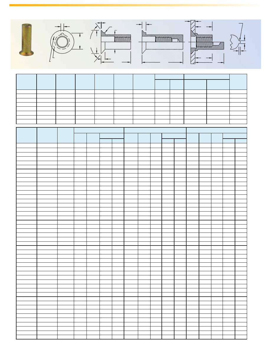
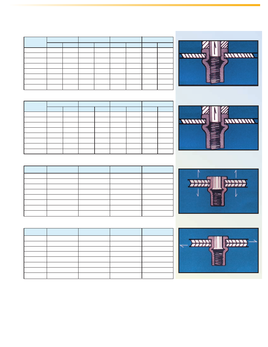
MaxTite
®
– COUNTERSUNK HEAD–UNIFIED
F
Radial Mark (Rad.)
C
A
.004” Nom.
Key When Specified
ØD
L
K
J
M
Grip
Full Radius
Keyway Detail
P
H
Identification Marks (See Table)
Open End Type
Closed End Type
Typical Installation
Circumferential Mark (Circ.)
C
E
Max.
B
100˚
±1˚
Keyed
Closed End
Shown
AE-17
MaxTite – COUNTERSUNK HEAD–METRIC
All dimensions are in millimeters.
See page AE–20 for part number key.
Thread- Grip Indent.
Grip Range Mark A M Wt. (lbs./1000) L J K Wt. (lbs./1000)
Number ±0.38 Ref. Alum. Steel ±0.38 Ref. Ref. Alum. Steel
M3 - 2.1 1.29 - 2.1 Blank 9 5.48 .3 1 13 9.52 5.48 .5 1.6
M3 - 2.86 2.1 - 2.86 1 Rad. 9.75 5.48 .4 1.1 13.75 9.52 5.48 .6 1.7
M3 - 3.6 2.86 - 3.6 2 Rad. 10.5 5.48 .4 1.2 14.5 9.52 5.48 .6 1.8
M3 - 4.36 3.6 - 4.36 3 Rad. 11.25 5.48 .4 1.2 15.25 9.52 5.48 .6 1.8
M3 - 5.1 4.36 - 5.1 4 Rad. 12 5.48 .4 1.2 16 9.52 5.48 .6 1.8
M3 - 5.86 5.1 - 5.86 5 Rad. 12.75 5.48 .4 1.3 16.75 9.52 5.48 .6 1.9
M4 - 3.1 1.6 - 3.1 Blank 12 6.98 1 3 16.5 11.5 6.98 1.5 4.6
M4 - 4.1 3.1 - 4.1 1 Rad. 13 6.98 1 3.2 17.5 11.5 6.98 1.6 4.7
M4 - 5.1 4.1 - 5.1 2 Rad. 14 6.98 1.1 3.4 18.5 11.5 6.98 1.6 4.8
M4 - 6.1 5.1 - 6.1 3 Rad. 15 6.98 1.1 3.5 19.5 11.5 6.98 1.6 5
M4 - 7.1 6.1 - 7.1 4 Rad. 16 6.98 1.2 3.7 20.5 11.5 6.98 1.7 5.2
M4 - 8.1 7.1 - 8.1 5 Rad. 17 6.98 1.2 3.8 21.5 11.5 6.98 1.8 5.3
M5 - 3.6 1.8 - 3.6 Blank 16 9.98 2.1 6.3 22 15.97 9.98 3.1 9.5
M5 - 5.1 3.6 - 5.1 1 Rad. 17.5 9.98 2.2 6.6 23.5 15.97 9.98 3.2 9.8
M5 - 6.6 5.1 - 6.6 2 Rad. 19 9.98 2.3 7 25 15.97 9.98 3.3 10.1
M5 - 8.1 6.6 - 8.1 3 Rad. 20.5 9.98 2.4 7.3 26.5 15.97 9.98 3.4 10.5
M5 - 9.6 8.1 - 9.6 4 Rad. 22 9.98 2.5 7.6 28 15.97 9.98 3.5 10.8
M5 - 11.1 9.6 - 11.1 5 Rad. 23.5 9.98 2.6 8 29.5 15.97 9.98 3.7 11.2
M6 - 4.1 2.25 - 4.1 Blank 18 10.96 3.3 10.1 25 17.97 10.96 5 15.1
M6 - 5.6 4.1 - 5.6 1 Rad. 19.5 10.96 3.5 10.6 26.5 17.97 10.96 5.1 15.6
M6 - 7.1 5.6 - 7.1 2 Rad. 21 10.96 3.6 11.1 28 17.97 10.96 5.3 16
M6 - 8.6 7.1 - 8.6 3 Rad. 22.5 10.96 3.8 11.6 29.5 17.97 10.96 5.4 16.5
M6 - 10.1 8.6 - 10.1 4 Rad. 24 10.96 4 12.2 31 17.97 10.96 5.6 17.1
M6 - 11.6 10.1 - 11.6 5 Rad. 25.5 10.96 4.2 12.7 32.5 17.97 10.96 5.8 17.7
M8 - 5.1 2.69 - 5.1 Blank 20.5 12.23 5.2 15.9 28.5 20.23 12.23 7.9 24.2
M8 - 7.1 5.1 - 7.1 1 Rad. 22.5 12.23 5.5 16.7 30.5 20.23 12.23 8.3 25.2
M8 - 9.1 7.1 - 9.1 2 Rad. 24.5 12.23 5.8 17.7 32.5 20.23 12.23 8.5 26
M8 - 11.1 9.1 - 11.1 3 Rad. 26.5 12.23 6.1 18.6 34.5 20.23 12.23 8.9 27
M8 - 13.1 11.1 - 13.1 4 Rad. 28.5 12.23 6.4 19.6 36.5 20.23 12.23 9.1 27.8
M8 - 15.1 13.1 - 15.1 5 Rad. 30.5 12.23 6.7 20.4 38.5 20.23 12.23 9.5 28.9
M10 - 6.1 3.17 - 6.1 Blank 23 12.72 7.6 23.1 31.5 21.47 12.72 11.4 34.7
M10 - 8.6 6.1 - 8.6 1 Rad. 25.5 12.72 8 24.4 34 21.47 12.72 11.8 36
M10 - 11.1 8.6 - 11.1 2 Rad. 28 12.72 8.4 25.7 36.5 21.47 12.72 12.2 37.2
M10 - 13.6 11.1 - 13.6 3 Rad. 30.5 12.72 8.9 27 39 21.47 12.72 12.7 38.6
M10 - 16.1 13.6 - 16.1 4 Rad. 33 12.72 9.3 28.4 41.5 21.47 12.72 13.1 39.8
M12 - 6.1 3.17 - 6.1 Blank 27 16.35 14.2 43.2 35 24.34 16.35 20.3 61.7
M12 - 8.6 6.1 - 8.6 1 Rad. 29.5 16.35 15.1 46 37.5 24.34 16.35 21.1 64.4
M12 - 11.1 8.6 - 11.1 2 Rad. 32 16.35 15.9 48.3 40 24.34 16.35 21.9 66.8
M12 - 13.6 11.1 - 13.6 3 Rad. 34.5 16.35 16.9 51.4 42.5 24.34 16.35 22.9 69.8
M12 - 16.1 13.6 - 16.1 4 Rad. 37 16.35 17.7 53.9 45 24.34 16.35 23.8 72.6
Thread B C ØD E F Install Pull
Size x Ref. Max. -0.1 Max. +0.13 Drill Size P H Up
Pitch (Ref.) Min. Max. +0.08 Facto
r
M3 x 0.5 6.68 1.29 3.93 5.03 1.37 4 3.94 4.01 1.57 1.17 - 1.22 1.4
M4 x 0.7 9.01 1.6 5.61 6.88 1.37 5.6 5.6 5.74 1.57 1.42 - 1.47 1.9
M5 x 0.8 11.17 1.83 7.13 8.73 1.85 7.2 7.2 7.3 2.06 1.7 - 1.75 2.4
M6 x 1 13.43 2.26 8.43 10.33 2.23 8.5 8.5 8.6 2.44 2.06 - 2.13 2.92
M7 x 1 14.92 2.39 9.37 11.27 2.23 9.4 9.4 9.5 2.44 2.06 - 2.13 2.92
M8 x 1.25 16.65 2.64 10.48 12.82 3.05 10.5 10.5 10.75 3.25 2.46 - 2.59 3.18
M10 x 1.5 19.50 3.15 12.44 15.15 3.05 12.5 12.5 12.7 3.25 2.79 - 2.92 3.94
M12 x 1.75 22.79 3.15 15.88 18.2 3.05 15.5 15.5 15.74 3.25 2.79 - 2.92 4.58
F
Radial Mark (Rad.)
C
A
0.1mm Nom.
Key When Specified
ØD
L
K
J
M
Grip
Full Radius
Keyway Detail
P
H
Identification Marks (See Table)
Open End Type
Closed End Type
Typical Installation
C
Metric
Thread
Identity
E
Max.
B
100˚
±1˚
Keyless
Open End
Shown
Open End Keyed and Keyless
Closed End Keyed and Keyless
Install Hole Size
Keyway Dimensions
AE-18
Thread- Grip Indent.
Grip Range Mark A M Wt. (lbs./1000) L J K Wt. (lbs./1000) L J K Wt. (lbs./1000)
Number ±.015 Ref. Alum. Steel ±.015 Ref. Ref. Alum. Steel ±.015 Ref. Ref. Alum. Steel
Open End Keyed and Keyless
4-60 .010 - .060 Blank .345 .230 .4 1.3 .500 .385 .230 .6 1.9 .500 .385 .230 .6 1.9
4-85 .060 - .085 1 Rad. .370 .230 .4 1.4 .525 .385 .230 .7 2.0 .525 .385 .230 .7 2.0
4-110 .085 - .110 2 Rad. .400 .230 .5 1.4 .555 .390 .230 .7 2.0 .555 .390 .230 .7 2.0
4-135 .110 - .135 3 Rad. .425 .230 .5 1.5 .580 .385 .230 .7 2.1 .580 .385 .230 .7 2.1
4-160 .135 - .160 4 Rad. .450 .230 .5 1.5 .605 .385 .230 .7 2.1 .605 .385 .230 .7 2.1
4-185 .160 - .185 5 Rad. .480 .230 .5 1.6 .635 .385 .230 .7 2.2 .635 .385 .230 .7 2.2
6-75 .010 - .075 1 Rad. .438 .300 .8 2.4 .625 .490 .305 1.2 3.5 .750 .615 .405 1.4 4.1
6-120 .075 - .120 3 Rad. .500 .315 .9 2.6 .625 .440 .255 1.1 3.4 .750 .565 .355 1.3 4.0
6-160 .120 - .160 5 Rad. .500 .270 .9 2.6 .750 .520 .260 1.3 4.0 .750 .520 .310 1.3 4.0
6-200 .160 - .200 1 Circ. .562 .290 .9 2.8 .750 .480 .260 1.3 3.9 .750 .480 .260 1.3 3.9
6-240 .200 - .240 2 Circ. .625 .310 1.0 3.0 .750 .435 .260 1.3 3.8 .750 .435 .260 1.3 3.8
6-280 .240 - .280 3 Circ. .687 .330 1.1 3.3 .812 .455 .265 1.3 4.1 .812 .455 .265 1.3 4.1
8-75 .010 - .075 1 Rad. .438 .300 1.0 3.0 .625 .490 .305 1.5 4.5 .750 .615 .405 1.7 5.3
8-120 .075 - .120 3 Rad. .500 .315 1.1 3.3 .625 .440 .255 1.4 4.4 .750 .565 .355 1.7 5.2
8-160 .120 - .160 5 Rad. .500 .270 1.1 3.2 .750 .520 .260 1.7 5.1 .750 .520 .310 1.7 5.1
8-200 .160 - .200 1 Circ. .625 .350 1.3 3.9 .750 .475 .265 1.6 5.0 .750 .475 .265 1.6 5.0
8-240 .200 - .240 2 Circ. .625 .305 1.2 3.8 .875 .555 .310 1.9 5.6 .875 .555 .310 1.9 5.6
8-280 .240 - .280 3 Circ. .687 .340 1.3 4.1 .875 .530 .290 1.8 5.6 .875 .530 .290 1.8 5.6
10-80 .010 - .080 Blank .531 .380 1.5 4.5 .781 .630 .380 2.3 6.8 .781 .630 .380 2.3 6.8
10-130 .080 - .130 1 Rad. .594 .390 1.6 4.9 .843 .640 .390 2.4 7.2 .843 .640 .390 2.4 7.2
10-180 .130 - .180 2 Rad. .641 .390 1.7 5.1 .891 .640 .390 2.4 7.4 .891 .640 .390 2.4 7.4
10-230 .180 - .230 3 Rad. .703 .395 1.8 5.4 .953 .645 .395 2.6 7.8 .953 .645 .395 2.6 7.8
10-280 .230 - .280 4 Rad. .750 .395 1.9 5.7 1.000 .645 .395 2.6 8.0 1.000 .645 .395 2.6 8.0
10-330 .280 - .330 5 Rad. .797 .385 1.9 5.9 1.047 .630 .385 2.7 8.2 1.047 .630 .385 2.7 8.2
25-80 .020 - .080 Blank .625 .450 3.2 9.7 .937 .760 .440 4.9 15.1 .937 .760 .440 5.0 15.1
25-140 .080 - .140 1 Rad. .687 .450 3.4 10.3 1.000 .760 .440 5.1 15.7 1.000 .760 .440 5.1 15.7
25-200 .140 - .200 2 Rad. .750 .450 3.6 10.9 1.062 .760 .440 5.3 16.2 1.062 .760 .440 5.3 16.3
25-260 .200 - .260 3 Rad. .812 .445 3.8 11.5 1.125 .755 .445 5.5 16.8 1.125 .755 .445 5.5 16.8
25-320 .260 - .320 4 Rad. .875 .445 4.0 12.0 1.187 .755 .445 5.7 17.4 1.187 .755 .445 5.7 17.4
25-380 .320 - .380 5 Rad. .937 .445 4.1 12.6 1.250 .755 .445 5.9 18.0 1.250 .755 .445 5.9 18.0
31-125 .030 - .125 Blank .750 .505 6.0 18.2 1.187 .940 .550 9.6 29.1 1.187 .940 .550 9.6 29.2
31-200 .125 - .200 1 Rad. .875 .555 6.7 20.3 1.281 .960 .555 10.1 30.6 1.281 .960 .555 10.1 30.7
31-275 .200 - .275 2 Rad. .937 .540 6.9 21.1 1.343 .950 .560 10.3 31.4 1.343 .950 .560 10.3 31.5
31-350 .275 - .350 3 Rad. 1.032 .560 7.4 22.6 1.437 .965 .570 10.8 32.9 1.437 .965 .570 10.8 32.9
31-425 .350 - .425 4 Rad. 1.125 .580 7.9 24.0 1.531 .985 .575 11.3 34.3 1.531 .985 .575 11.3 34.4
31-500 .425 - .500 5 Rad. 1.187 .565 8.2 24.9 1.593 .975 .580 11.5 35.1 1.593 .975 .580 11.6 35.2
37-115 .030 - .115 Blank .844 .585 9.7 29.7 1.281 1.020 .660 14.8 45.0 1.281 1.020 .660 14.8 45.1
37-200 .115 - .200 1 Rad. .938 .595 10.3 31.4 1.375 1.030 .670 15.4 46.8 1.375 1.030 .670 15.4 46.9
37-285 .200 - .285 2 Rad. 1.031 .605 10.9 33.2 1.468 1.040 .680 15.9 48.5 1.468 1.040 .680 16.0 48.6
37-370 .285 - .370 3 Rad. 1.125 .615 11.5 34.9 1.562 1.050 .690 16.5 50.3 1.562 1.050 .690 16.5 50.4
37-455 .370 - .455 4 Rad. 1.218 .630 12.0 36.7 1.656 1.065 .710 17.1 52.1 1.656 1.065 .710 17.1 52.2
37-540 .455 - .540 5 Rad. 1.312 .635 12.6 38.5 1.750 1.075 .715 17.7 53.8 1.750 1.075 .715 17.7 53.9
50-150 .050 - .150 Blank .906 .605 14.0 42.6 1.328 1.030 .605 21.9 66.6 1.328 1.030 .605 21.9 66.6
50-250 .150 - .250 1 Rad. 1.031 .630 15.2 46.3 1.453 1.055 .630 23.1 70.3 1.453 1.055 .630 23.1 70.3
50-350 .250 - .350 2 Rad. 1.141 .640 16.2 49.2 1.562 1.060 .640 24.0 73.2 1.562 1.060 .640 24.0 73.2
50-450 .350 - .450 3 Rad. 1.250 .650 17.1 52.2 1.671 1.070 .650 25.0 76.1 1.671 1.070 .650 25.0 76.1
Closed End Keyless
Closed End Keyed
Thread B C ØD E F G Install Pull
Size* ±.015 Nom. +.000 Max. +.005 Max. Drill Size P H Up
-.004 -.000 (Ref.) Min. Max. +.003 -.000 Factor
#4-40 .270 .025 .155 .198 .054 .023 5/32 .155 .157 .062 .046 - .048 .055
#6-32 .325 .032 .189 .240 .054 .023 #12 .189 .193 .062 .056 - .058 .065
#8-32 .357 .032 .221 .271 .054 .023 #2 .221 .226 .062 .056 - .058 .065
#10-32 .406 .038 .250 .302 .054 .023 1/4 .250 .256 .062 .056 - .058 .080
1/4-20 .475 .058 .332 .382 .054 .035 Q .332 .338 .062 .056 - .058 .095
5/16-18 .665 .062 .413 .505 .120 .040 Z .413 .423 .128 .097 - .102 .120
3/8-16 .781 .088 .490 .597 .120 .040 12.5mm .490 .500 .128 .110 - .115 .155
1/2-13 .906 .085 .625 .733 .120 .040 5/8 .625 .635 .128 .110 - .115 .185
Install Hole Size
Keyway Dimensions
* Both UNC and UNF threads available in No. 10 and larger thread sizes. Check for availability of other grip ranges and designs.
All dimensions are in inches.
See page AE–20 for part number key.
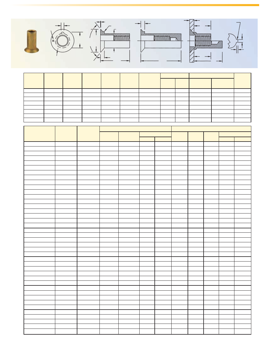
MaxTite – FLATHEAD–UNIFIED
F
E Max.
B
Circumferential Mark (Circ.)
Radial Mark (Rad.)
C
A
G Max.
Key When Specified
ØD
L
K
J
M
Grip
Full Radius
Keyway Detail
P
H
Identification Marks (See Table)
Open End Type
Closed End Type
Typical Installation
Ribbed
Open End
Shown
AE-19
Thread B C ØD E F G Install Pull
Size x ±0.38 Nom. -0.1 Max. +0.13 Max. Drill Size P H Up
Pitch (Ref.) Min. Max. +0.08 Factor
M3 x 0.5 6.68 0.63 3.93 5.03 1.37 0.58 4 3.94 4.01 1.57 1.17 - 1.22 1.4
M4 x 0.7 9.01 0.81 5.61 6.88 1.37 0.58 5.6 5.6 5.74 1.57 1.42 - 1.47 1.9
M5 x 0.8 11.17 1.22 7.13 8.73 1.85 0.58 7.2 7.2 7.3 2.06 1.7 - 1.75 2.4
M6 x 1 13.43 1.47 8.43 10.33 2.23 0.89 8.5 8.5 8.6 2.44 2.06 - 2.13 2.9
M7 x 1 14.92 1.47 9.37 11.27 2.23 0.89 9.4 9.4 9.5 2.44 2.06 - 2.13 2.9
M8 x 1.25 16.65 1.57 10.48 12.82 3.05 1.02 10.5 10.5 10.75 3.25 2.46 - 2.59 3.18
M10 x 1.5 19.5 2.23 12.44 15.15 3.05 1.02 12.5 12.5 12.7 3.25 2.79 - 2.92 3.94
M12 x 1.75 22.79 2.23 15.88 18.2 3.05 1.02 15.5 15.5 15.74 3.25 2.79 - 2.92 4.57
All dimensions are in millimeters.
See page AE–20 for part number key.
Install Hole Size
Keyway Dimensions
Thread- Grip Indent.
Grip Range Mark A M Wt. (lbs./1000) L J K Wt. (lbs./1000)
Number ±0.38 Ref. Alum. Steel ±0.38 Ref. Ref. Alum. Steel
Open End Keyed and Keyless
M3 - 1 0.25 - 1 Blank 8 5.61 .3 1 12 9.62 5.61 .5 1.6
M3 - 1.75 1 - 1.75 1 Rad. 8.75 5.61 .4 1.1 12.75 9.62 5.61 .5 1.7
M3 - 2.5 1.75 - 2.5 2 Rad. 9.5 5.61 .4 1.1 13.5 9.62 5.61 .6 1.7
M3 - 3.25 2.5 - 3.25 3 Rad. 10.25 5.61 .4 1.2 14.24 9.62 5.61 .6 1.7
M3 - 4 3.25 - 4 4 Rad. 11 5.61 .4 1.2 15 9.62 5.61 .6 1.8
M3 - 4.75 4 - 4.75 5 Rad. 11.75 5.61 .4 1.3 15.75 9.62 5.61 .6 1.9
M4 - 2 0.25 - 2 Blank 11 7.08 1 3.1 16 12.08 7.08 1.6 5
M4 - 3 2 - 3 1 Rad. 12 7.08 1.1 3.3 17 12.08 7.08 1.7 5.2
M4 - 4 3 - 4 2 Rad. 13 7.08 1.1 3.4 18 12.08 7.08 1.8 5.3
M4 - 5 4 - 5 3 Rad. 14 7.08 1.2 3.5 19 12.08 7.08 1.8 5.5
M4 - 6 5 - 6 4 Rad. 15 7.08 1.2 3.7 20 12.08 7.08 1.9 5.7
M4 - 7 6 - 7 5 Rad. 16 7.08 1.3 3.8 21 12.08 7.08 1.9 5.8
M5 - 2 0.25 - 2 Blank 14.5 10.09 2.2 6.6 20 15.6 10.09 3 9.3
M5 - 3.5 2 - 3.5 1 Rad. 16 10.09 2.3 6.9 21.5 15.6 10.09 3.2 9.6
M5 - 5 3.5 - 5 2 Rad. 17.5 10.09 2.4 7.2 23 15.6 10.09 3.2 9.9
M5 - 6.5 5 - 6.5 3 Rad. 19 10.09 2.5 7.5 24.5 15.6 10.09 3.4 10.3
M5 - 8 6.5 - 8 4 Rad. 20.5 10.09 2.6 7.9 26 15.6 10.09 3.5 10.6
M5 - 9.5 8 - 9.5 5 Rad. 22 10.09 2.7 8.2 27.5 15.6 10.09 3.6 11.1
M6 - 2 0.75 - 2 Blank 15.5 10.58 3.4 10.3 23 18.07 10.58 5.1 15.5
M6 - 3.5 2 - 3.5 1 Rad. 17 10.58 3.5 10.7 24.5 18.07 10.58 5.3 16
M6 - 5 3.5 - 5 2 Rad. 18.5 10.58 3.7 11.2 26 18.07 10.58 5.4 16.5
M6 - 6.5 5 - 6.5 3 Rad. 20 10.58 3.8 11.7 27.5 18.07 10.58 5.6 17
M6 - 8 6.5 - 8 4 Rad. 21.5 10.58 4 12.2 29 18.07 10.58 5.7 17.5
M6 - 9.5 8 - 9.5 5 Rad. 23 10.58 4.2 12.7 30.5 18.07 10.58 5.9 18
M8 - 3 0.75 - 3 Blank 18 11.83 5.2 15.9 26 19.82 11.83 7.9 24
M8 - 5 3 - 5 1 Rad. 20 11.83 5.7 16.9 28 19.82 11.83 8.2 25
M8 - 7 5 - 7 2 Rad. 22 11.83 5.9 17.9 30 19.82 11.83 8.6 26
M8 - 9 7 - 9 3 Rad. 24 11.83 6.2 19 32 19.82 11.83 8.9 27.2
M8 - 11 9 - 11 4 Rad. 26 11.83 6.5 19.7 34 19.82 11.83 9.1 27.8
M8 - 13 11 - 13 5 Rad. 28 11.83 6.8 20.8 36 19.82 11.83 9.5 28.8
M10 - 3 1 - 3 Blank 20 13.2 8 24.5 29 22.18 13.2 12.2 37.3
M10 - 5.5 3 - 5.5 1 Rad. 22.5 13.2 8.5 25.9 31.5 22.18 13.2 12.6 38.4
M10 - 8 5.5 - 8 2 Rad. 25 13.2 8.9 27 34 22.18 13.2 13.1 39.5
M10 - 10.5 8 - 10.5 3 Rad. 27.5 13.2 9.3 28.4 36.5 22.18 13.2 13.4 41
M10 - 13 10.5 - 13 4 Rad. 30 13.2 9.7 29.6 39 22.18 13.2 13.8 42.1
M12 - 3 1 - 3 Blank 24 16.45 14.9 45.5 32 24.44 16.45 21.1 64.1
M12 - 5.5 3.99 - 5.5 1 Rad. 26.5 16.45 15.9 48.3 34.5 24.44 16.45 21.9 66.7
M12 - 8 5.5 - 8 2 Rad. 29 16.45 16.6 50.7 37 24.44 16.45 22.7 69.3
M12 - 10.5 8 - 10.5 3 Rad. 31.5 16.45 17.6 53.5 39.5 24.44 16.45 23.6 71.9
M12 - 13 10.5 - 13 4 Rad. 34 16.45 18.5 56.3 42 24.44 16.45 24.5 74.7
Closed End Keyed and Keyless
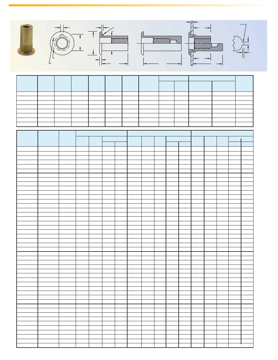
MaxTite – FLATHEAD–METRIC
Keyed
Open End
shown
F
E Max.
B
Radial Mark (Rad.)
C
A
G Max.
Key When Specified
ØD
L
K
J
M
Full Radius
Keyway Detail
P
H
Identification Marks (See Table)
Open End Type
Closed End Type
Typical Installation
Metric
Thread
Identity
Grip
AE-20
PART NUMBER DESIGNATION
4 =
4-40
6 =
6-32
8 =
8-32
10 =
10-32
25 =
1/4-20
31 =
5/16-18
37 =
3/8-16
50 =
1/2-13
(For metric use thread designation. Example M3=M3)
“–” =
Keyless open end
K =
Keyed open end
B =
Keyless closed end
KB =
Keyed closed end
R =
Ribbed shank
H =
Full-hex body
A =
Aluminum
S =
Steel
NM =
300 Series Stainless
SS =
430 Stainless Steel
BR =
Brass
CH =
4037 Alloy Steel
MaxTite – STANDARD FULL-HEX
All dimensions are in inches.
C
A
D
B
M
Grip
Hex Hole
Size
Typical Installation
Radial Mark (Rad.)
Identification Marks (See Table)
Metric
Thread
Identity
All dimensions are in millimeters.
Thread Part Grip
Identification A B C D M Hex Hole
Size Number Range
Mark ±0.38 ±0.38 Nom. Max. Ref. Size In Sheet
(1)
(1)
+0.13
M5 x 0.8 AESM5H215 0.5 - 2.15
Blank 10.3 9.52 1.09 6.35 6.72 6.36
M5 x 0.8 AESM5H355 2.15 - 3.55
1 Rad. 11.9 9.52 1.09 6.35 6.72 6.36
M5 x 0.8 AESM5H505 3.55 - 5.05
2 Rad. 13.48 9.52 1.09 6.35 6.72 6.36
M6 x 1 AESM6H215 0.5 - 2.15
Blank 10.3 11.09 1.09 7.52 6.22 7.54
M6 x 1 AESM6H365 2.15 - 3.65
1 Rad. 11.9 11.09 1.09 7.52 6.22 7.54
M6 x 1 AESM6H520 3.65 - 5.2
2 Rad. 13.48 11.09 1.09 7.52 6.22 7.54
M8 x 1.25 AESM8H255 0.5 - 2.55
Blank 15.86 15.07 1.57 10.08 10.35 10.11
M8 x 1.25 AESM8H455 2.5 - 4.55
1 Rad. 17.84 15.07 1.57 10.08 10.35 10.11
M8 x 1.25 AESM8H660 4.55 - 6.6
2 Rad. 19.82 15.07 1.57 10.08 10.35 10.11
M10 x 1.5 AESM10H295 0.75 - 2.95
Blank 15.88 17.48 1.57 11.89 13.08 11.91
M10 x 1.5 AESM10H520 2.95 - 5.2
1 Rad. 18.24 17.48 1.57 11.89 13.08 11.91
M10 x 1.5 AESM10H750 5.2 - 7.5
2 Rad. 20.62 17.48 1.57 11.89 13.08 11.91
(1) Additional thread sizes and grip ranges are available.
Thread Part Grip
Identification
A B C D M Hex Hole
Size Number Range
Mark
±.015 ±.015 Nom. Max. Ref. Size In Sheet
(1)
(1)
+.005 -.000
#10-32 AES10H85 .010 - .085
Blank
.344 .344 .043 .223 .200 .224
#10-32 AES10H135 .085 - .135
1 Rad.
.406 .344 .043 .223 .210 .224
#10-32 AES10H185 .135 - .185
2 Rad.
.453 .344 .043 .223 .210 .224
1/4-20 AES25H85 .020 - .085
Blank
.406 .437 .043 .296 .245 .297
1/4-20 AES25H145 .085 - .145
1 Rad.
.469 .437 .043 .296 .250 .297
1/4-20 AES25H205 .145 - .205
2 Rad.
.531 .437 .043 .296 .250 .297
5/16-18 AES31H105 .030 - .105
Blank
.562 .562 .048 .368 .375 .369
5/16-18 AES31H175 .105 - .175
1 Rad.
.640 .562 .048 .368 .380 .369
5/16-18 AES31H245 .175 - .245
2 rad.
.703 .562 .048 .368 .375 .369
3/8-16 AES37H115 .030 - .115
Blank
.625 .656 .058 .437 .400 .438
3/8-16 AES37H205 .115 - .205
1 Rad.
.718 .656 .058 .437 .405 .438
3/8-16 AES37H295 .205 - .295
2 Rad.
.812 .656 .058 .437 .410 .438
For parts other than steel with cadmium plating, call the factory for an additional part number code.
AE
Type
SS
Material
25
Thread Code
KB
Style
80
Grip Range
80 =
.020 to .080 grip range (See charts for other ranges).
Grip Range Codes ending in 0 or 5 are flathead, and 1 or 6 have countersunk heads.
AE-21
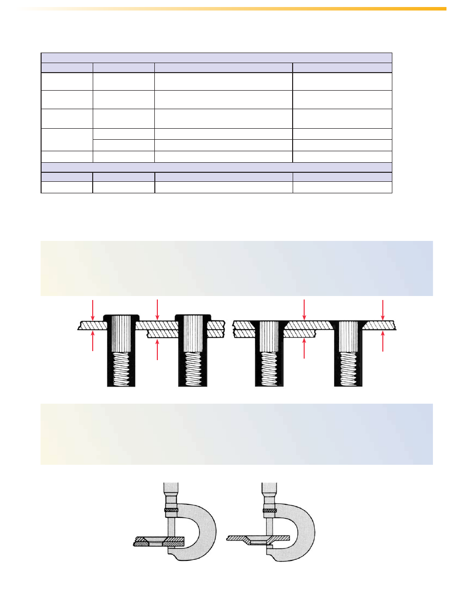
All fasteners are designed for installation into a range of material thickness. Maximum Grip represents the
greatest material thickness into which a specific fastener should be properly installed. Minimum Grip represents
the least thickness of material into which a specific fastener should be properly installed. The zone of material
thickness between the minimum and maximum grip is the grip range.
In surface installations or machine countersunk installations, the grip is the same as the material thickness
(see figure “A”). For dimple or press countersunk holes, the grip is the measurement from the top metal surface
to the underside of the dimple hole (see figure “B”).
IMPORTANT:
Measurements must include air gaps, paint and any burrs that cannot be removed.
Figure “A”
Figure “B”
MaxTite GRIP RANGE
Minimum
Grip
Maximum
Grip
Minimum
Grip
Maximum
Grip
MATERIAL & FINISH SPECIFICATIONS
Weights:
For brass fasteners, multiply weight of aluminum equivalent by 3.13. Weights for CH (4037 alloy steel) and SS (Type 430 stainless steel) same as steel.
Round Body
Material Type Standard Finish Min. Tensile Strength (PSI Ult.)
Aluminum 6053-T4 6061-T4 Anodized in accordance with 25,000
SAE AMS-A-8625, Type II
Steel C-1010 or Cadmium Plate - .0002” Minimum 42,000
C-1110 Thickness Per SAE AMS-QQ-P-416 Class 3, Type I
Alloy Steel 4037 Cadmium Plate - .0003” Minimum 55,000 (No. 4 & No. 6 Thread Size)
Thickness Per SAE AMS-QQ-P-416 Class 2, Type II 85,000 (No. 8 to 1/2” Thread Sizes)
Stainless Steel
430 Pickled and Passivated Per SAE AMS QQ-P-35, Type II 67,000
300 Series Pickled and Passivated Per SAE AMS QQ-P-35, Type II 80,000
Brass Alloy No. 260 None - Bright as Machined 50,000
Hex Body
Material Type No. Standard Finish Min. Tensile Strength (PSI Ult.)
Steel C-1008 C-1010 Zinc Plate per ASTM B 633, Fe/Zn 8, Type II 45,000
MaxTite
AE-22
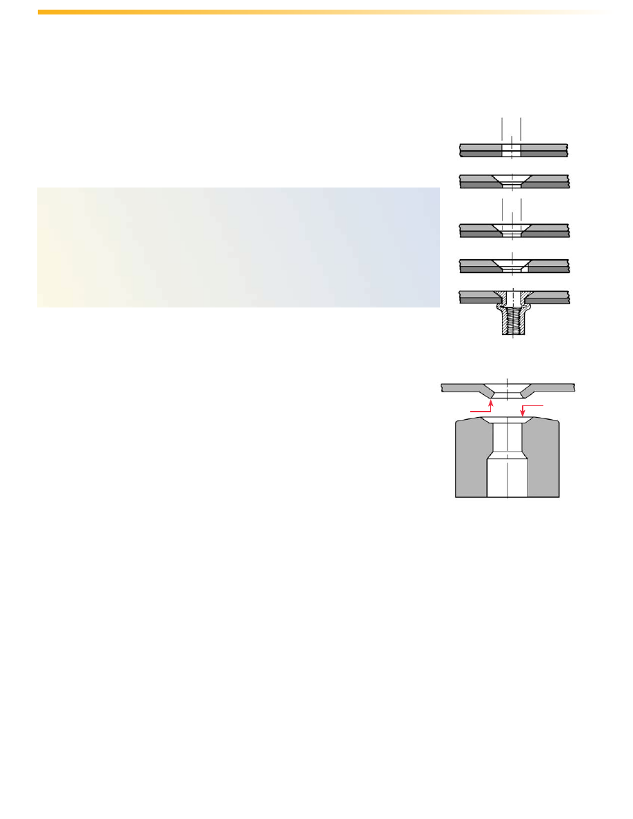
DIMPLE COUNTERSINKING INSTALLATION
Sheets thinner than a fastener head thickness require a dimple countersink
installation.
The ideal bulge on any fastener installation will always be formed against a flat
under-surface. The bell-mouth that results from ordinary dimpling will not permit the
fastener to form a proper bulge and these fasteners will form a weak bulge, a spread
shank, and may possibly shear.
A ledge at the bottom of the dimpling die must be used to provide a flat surface
in the dimpling operation. The “flat” on the dimple will save costly deburring before
dimpling and enables the fastener to form normally, providing maximum strength.
MACHINE COUNTERSINKING INSTALLATION
To obtain a precision hole and countersink, follow these steps:
Step 1
Drill an undersized hole in the sheet.
Step 2
Countersink the hole.
Step 3
Drill correct diameter hole with finish drill.
Step 4
If keyed fastener is to be used, cut a keyway with a round file or guided drill.
Step 5
Install fastener.
COUNTERSUNK HOLE PREPARATION
MaxTite
Flat
Ledge
AE-23
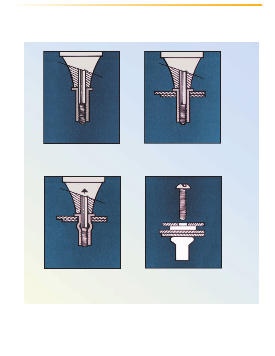
STEP 1
The fastener is threaded onto
the pull-up stud of an installation tool.
STEP 2
The fastener, on the pull-up
stud, is inserted into the drilled or
punched hole.
STEP 3
The pull-up stud retracts
and bulges the unthreaded portion
of the fastener shank against the flat
undersurface.
STEP 4
The installation tool stud is
removed, leaving the fastener secure
and ready for the attachment screw.
INSTALLATION
NOTE:
For open end fasteners, the pull-up stud tip protrudes beyond the end of the MaxTite fastener. On closed end
fasteners, screw the pull-up stud into the fastener about seven or eight turns. Be sure the anvil rests on the fastener
head.
MaxTite
AE-24
Torque Required to Turn Fastener (in. lbs.)
Aluminum Brass Steel Stainless Steel
Thread Size Key Keyless Key Keyless Key Keyless Key Keyless
#4-40 9 4 20 8 20 8 45 8
#6-32 12 4 30 8 29 13 46 15
#8-32 20 9 37 12 34 21 66 38
#10-32 22 12 46 23 43 23 77 38
1/4-20 55 30 100 50 93 51 134 78
5/16-18 101 46 NA 103 176 70 360 115
3/8-16 116 83 300 198 361 131 400 201
1/2-13 216 130 NA NA NA 300 NA NA
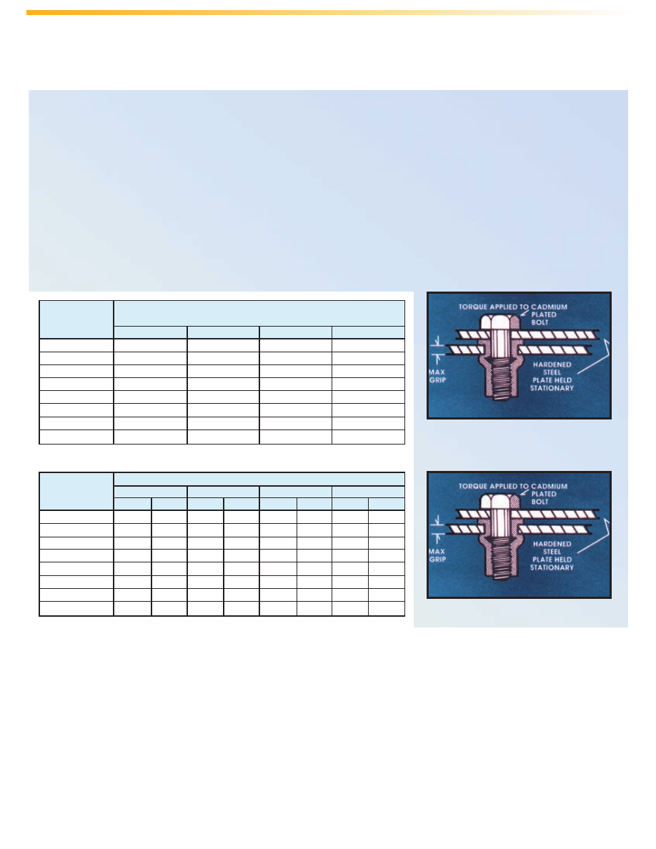
TORQUE STRENGTH DATA - TORQUE-AXIAL LOAD RELATIONSHIP
Used as nut plates, these fasteners may be safely loaded to torque equivalent of their maximum upset loads.
Surpassing these loads will cause the screw to break, or the fastener will continue to upset until ultimate strip load
is attained.
Because of the many variables such as type of lubrication, plating, type and grade of screw or bolt, it is
recommended that a pilot test be conducted to determine the optimum assembly torque.
TORQUE-OUT STRENGTH
Although these fasteners are never used as shown in this view, it is used to illustrate the effects of accidental
imposition of torque by: over-length screw bottoming in a blind end fastener; unthreaded shank area of an
insufficiently threaded screw bottoming in the first thread of a fastener; cross threading in inserting screw.
Torque Equiv. of Max. Upset
Load (in. lbs.)
(1)
Thread Size Aluminum Brass Steel Stainless Steel
#4-40 8 15 15 15
#6-32 12 24 24 30
#8-32 16 40 38 45
#10-32 25 45 45 60
1/4-20 60 130 130 160
5/16-18 100 156 156 260
3/8-16 190 345 344 400
1/2-13 350 NA 660 NA
(1) These values are averages only.
Aluminum fasteners tested in aluminum plates. Steel and brass fasteners tested in steel plates. Stainless
steel fasteners tested in stainless steel plates. These values are averages only and based on controlled
tests - certain variations must be expected in actual practice.
NA - Test data not available.
PERFORMANCE DATA
TORQUE STRENGTH
MaxTite
TORQUE-OUT STRENGTH
AE-25
Thread Size Aluminum Brass Steel Stainless Steel
#4-40 261 474 458 621
#6-32 373 678 656 889
#8-32 485 882 853 1153
#10-32 617 1120 1085 1470
1/4-20 1150 2020 1850 2510
5/16-18 1600 2995 2750 3730
3/8-16 2075 3925 3900 5280
1/2-13 3100 NA 4900 NA
Thread Size Aluminum Brass Steel Stainless Steel
#4-40 158 300 316 515
#6-32 230 430 460 749
#8-32 294 558 588 958
#10-32 374 710 748 1220
1/4-20 710 1230 1100 1790
5/16-18 930 1850 1750 2850
3/8-16 1260 2425 2420 3940
1/2-13 2150 NA 3400 NA
Aluminum fasteners tested in aluminum plates. Steel and brass fasteners tested in steel plates. Stainless steel fasteners tested in stainless steel plates. These
values are averages only and based on controlled tests - certain variations must be expected in actual practice. Performance testing of this product in your
application is recommended. We will be happy to provide samples for this purpose.
NA - Test data not available.
ULTIMATE TENSILE STRENGTH (lbs.)
ULTIMATE SHEAR STRENGTH (lbs.)
PERFORMANCE DATA
(Continued)
Aluminum Brass Steel Stainless Steel
Thread Size Min. Grip Max. Grip Min. Grip Max. Grip Min. Grip Max. Grip Min. Grip Max. Grip
#4-40 400 450 700 800 700 800 800 900
#6-32 500 600 800 950 850 1000 1000 1300
#8-32 600 700 1300 1500 1000 1250 1400 1650
#10-32 750 800 1600 1800 1300 1500 1900 2000
1/4-20 1300 1450 2570 2880 2300 2610 3300 3400
5/16-18 1900 2150 3870 4210 3300 3650 4800 5600
3/8-16 2570 2700 4620 4940 4965 5325 6100 6660
1/2-13 4000 4400 NA NA 6700 7200 NA NA
UPSET LOAD (lbs.)
Aluminum Brass Steel Stainless Steel
Thread Size Min. Grip Max. Grip Min. Grip Max. Grip Min. Grip Max. Grip Min. Grip Max. Grip
#4-40 675 575 1265 1075 1180 1000 1600 1300
#6-32 964 820 1740 1480 1705 1450 2400 2000
#8-32 1095 935 2050 1740 1920 1630 3000 2200
#10-32 1600 1450 3025 2525 3000 2500 4000 3500
1/4-20 2500 2400 4900 4250 5240 4520 6000 5100
5/16-18 4000 3700 7795 6840 7625 6300 8700 7500
3/8-16 4700 4450 11600 11200 11500 10450 11700 9650
1/2-13 7900 6400 NA NA 17250 14500 NA NA
ULTIMATE THREAD STRENGTH (lbs.)
MaxTite
AE-26
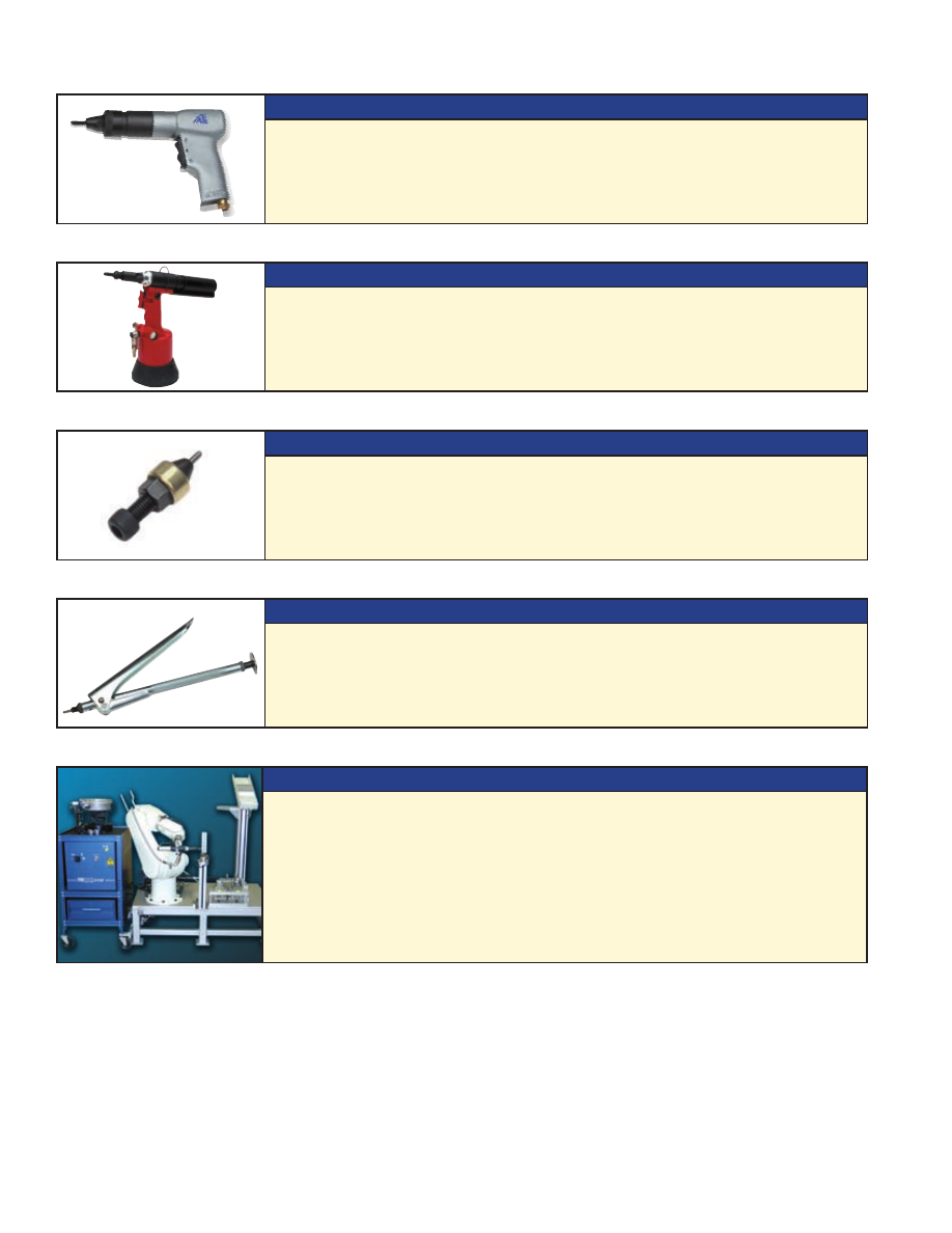
INSTALLATION TOOLS
SERIES 800 SPIN/SPIN TOOL
Atlas Series 800 tools provide totally pneumatic, spin/spin operation to easily install
all Atlas SpinTite and Plus+Tite fasteners. They are lightweight, economical, low
maintenance, ergonomically designed, and portable.
AE 40 SPIN/PULL TOOL
The Atlas AE 40 portable tool provides a hydraulic/pneumatic action to install Atlas
MaxTite products for those heavy-duty applications. It is a powerful, efficient, and
quiet tool, designed to provide long life and trouble free service.
HEX WRENCH INSTALLATION TOOL
The Atlas Hex Wrench Tool is designed for installing MaxTite fasteners. This tool is
ideal for field installations, repair work, and prototype applications.
L6000 INSTALLATION TOOL
The Atlas hand operated L6000 tool installs SpinTite fasteners in most types and
sizes and is also suitable for light production requirements.
For more complete tool information see Bulletin PS
ROBOTIC SYSTEM CAPABILITIES
Atlas robotic technology offers a completely automated and intelligent system for
worker-free part handling and fastener installation. The robotic assembly system
can reduce installed fastener costs, increase quality installations, improve job
productivity, and reduce floor-space requirements. We provide the fastener feed
module and the installation tool that works with your robot or we can provide the
entire system. System components and capabilities are configured to meet your
specific assembly needs.
AE-27
Custom Hardware Options
In addition to catalog standard hardware and equipment, our “custom solution”
capabilities can solve the most demanding design or assembly challenge.
Our approach focuses all our product, application and automation
experience on your specific requirement. Working together
we can help you gain a competitive edge, providing solutions from unique
fasteners to complete assembly systems, engineered and delivered to optimize
and add value to your operation.
AE-28
���� ��� �������
���� ������� ���������� ������
���������� ����� ��������� � ��� ���� �������
������� ���������������
���� ����� ������ � ���� ����� ������
����� �������������
���� ��� ������ ����
�������� �� ����� ���
������� �����������������
���� ������������ � ���� ������������
�������������
��������� ���������� �������
��� ���� ����� ���� ������ � ��������� ������
������� ������������������������
���� � ��� ���� � ���� � ��� ����
Specifications subject to change without notice.
Printed in U.S.A.
CAGE-46384
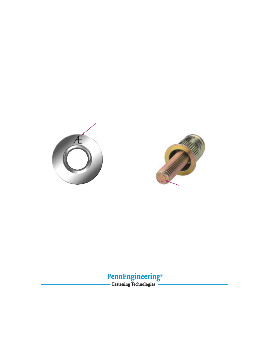
Look for the “ring” identifier
on Atlas brand studs.
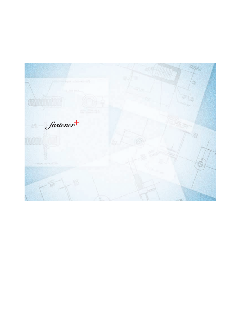
Look for the “AE” on
Atlas Plus+Tite and
MaxTite inserts.
WORLDWIDE REPRESENTATIVES
For representatives and distributors, or more information on Atlas brand products,
visit www.pennfast.com or call us at 877-682-2505 (USA Only) or 330-676-1006.