4915 Walnut Grove Ave., San Gabriel, CA 91776 (626) 287-5297 www.ustoyofan.com Email: sales@ustoyofan.com FAX (626) 287-7350
- 4 -
U.S. TOYO
FAN CORP.
Stat
ic
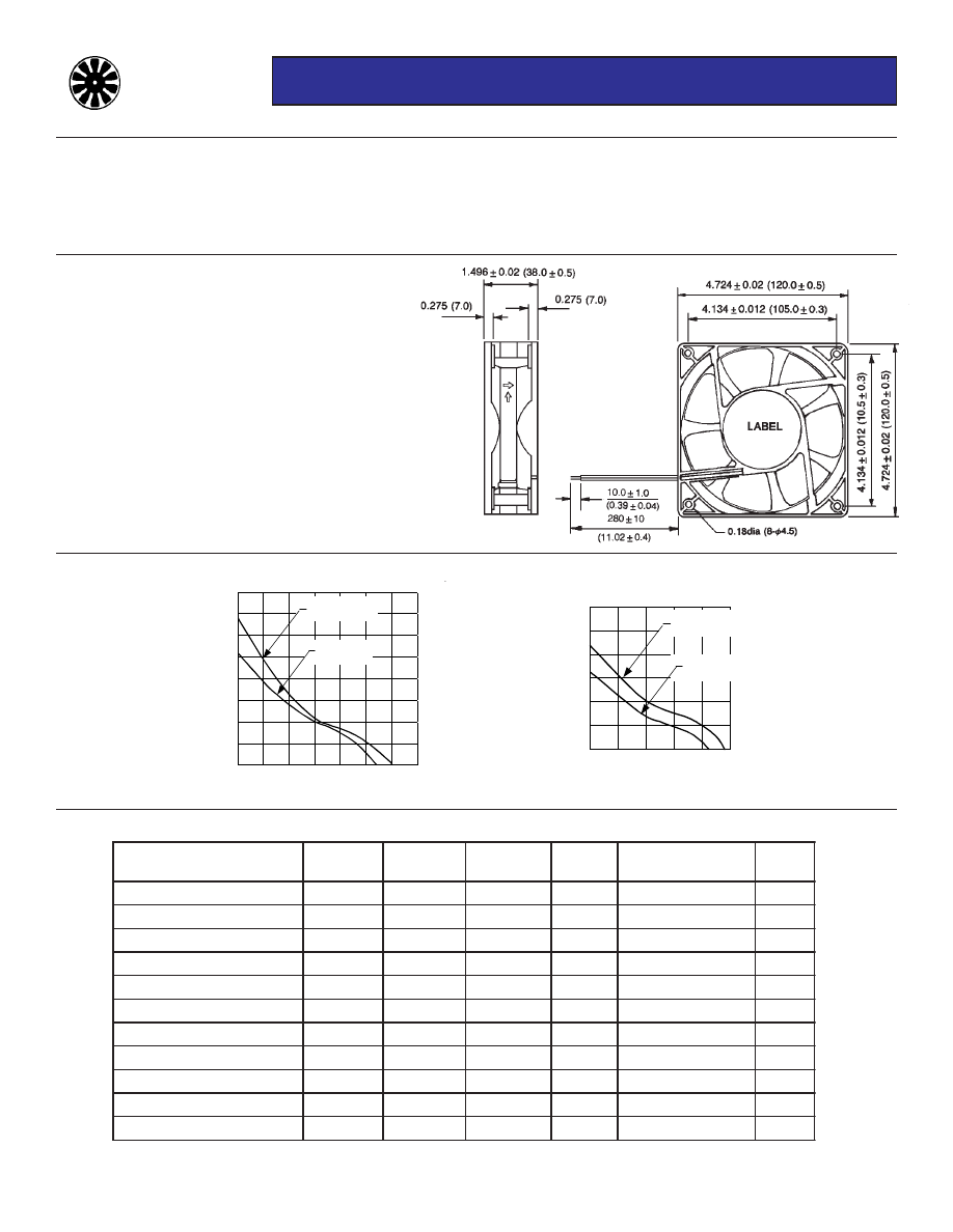
P
re
ssu
re
(
in
H
2
O
)
0.40
0.35
0.30
0.25
0.20
0.15
0.10
0.05
0.00
0 20 40 60 80 100 120 140
Air Flow (CFM)
H Speed
VH Speed
USTF12038 Series
Size:
4.72 in sq. x 1.5 in. thk
(120mm sq. x 38mm thk.)
Airflow:
85 - 120 CFM
Acoustical Noise:
34 - 44.5 dB (A)
USTF12038 Series
DC Brushless Fans
MATERIAL:
Frame - Black PBT (UL 94V-0)
Bearings - Ball
Impeller - Black PBT (UL 94V-0)
WEIGHT:
9.1 oz. (258g)
TERMINATION:
Lead Wires (UL 1007, AWG24)
OPERATING TEMPERATURE:
-10
0
to +70
0
C (+60° on “H” models)
INSULATION RESISTANCE:
10 megohms min @ 500 VDC
DIELECTRIC STRENGTH:
500 VAC for 1 min.
INSULATION:
Class A
SAFTEY:
Impedance & Polarity Protected
SAFTEY APPROVALS:
UL, CSA & VDE
OPERATING VOLTAGE:
12 VDC (6 to 13.8) - 24 VDC (14 to 27.6)
48 VDC (38 to 56)
SPECIFICATIONS:
(All values are typical)
MODELS AVAILABLE ON REQUEST:
Failure Detector - rotation sensing - Add Suffix “SR” to part number
Speed Controller - tach output - Add Suffix “SF” to part number
R
E
B
M
U
N
T
R
A
P
S
T
L
O
V
S
T
T
A
W
S
P
M
A
M
P
R
E
S
I
O
N
M
1
@
)
A
(
B
d
M
F
C
W
H
V
2
1
8
3
0
2
1
F
T
S
U
C
D
V
2
1
2
5
.
8
1
7
.
0
0
0
8
2
5
.
4
4
0
2
1
W
H
2
1
8
3
0
2
1
F
T
S
U
C
D
V
2
1
0
2
.
7
0
6
.
0
0
2
5
2
3
.
1
4
8
0
1
W
M
2
1
8
3
0
2
1
F
T
S
U
C
D
V
2
1
4
8
.
3
2
3
.
0
0
4
2
2
6
.
7
3
6
9
W
L
2
1
8
3
0
2
1
F
T
S
U
C
D
V
2
1
6
7
.
2
3
2
.
0
0
5
9
1
4
.
4
3
5
8
W
H
V
4
2
8
3
0
2
1
F
T
S
U
C
D
V
4
2
2
1
.
9
8
3
.
0
0
0
8
2
5
.
4
4
0
2
1
W
H
4
2
8
3
0
2
1
F
T
S
U
C
D
V
4
2
8
6
.
7
2
3
.
0
0
2
5
2
3
.
1
4
8
0
1
W
M
4
2
8
3
0
2
1
F
T
S
U
C
D
V
4
2
6
7
.
5
4
2
.
0
0
4
2
2
6
.
7
3
6
9
W
L
4
2
8
3
0
2
1
F
T
S
U
C
D
V
4
2
2
3
.
4
6
1
.
0
0
5
9
1
4
.
4
3
5
8
W
H
8
4
8
3
0
2
1
F
T
S
U
C
D
V
8
4
4
2
.
6
3
1
.
0
0
2
5
2
3
.
1
4
8
0
1
W
M
8
4
8
3
0
2
1
F
T
S
U
C
D
V
8
4
2
3
.
4
9
0
.
0
0
4
2
2
6
.
7
3
6
9
W
L
8
4
8
3
0
2
1
F
T
S
U
C
D
V
8
4
8
8
.
2
6
0
.
0
0
5
9
1
4
.
4
3
5
8
PERFORMANCE CURVES:
(Obtained with test chamber and methods in accordance with AMCA Std. 210-74)
0.30
0.25
0.20
0.15
0.10
0.05
0.00
St
a
ti
c P
ressur
e
(i
n
. H
2
O)
0 20 40 60 80 100
Air Flow (CFM)
M Speed
L Speed