Rev. 7b
RB
Series
(General Purposes)
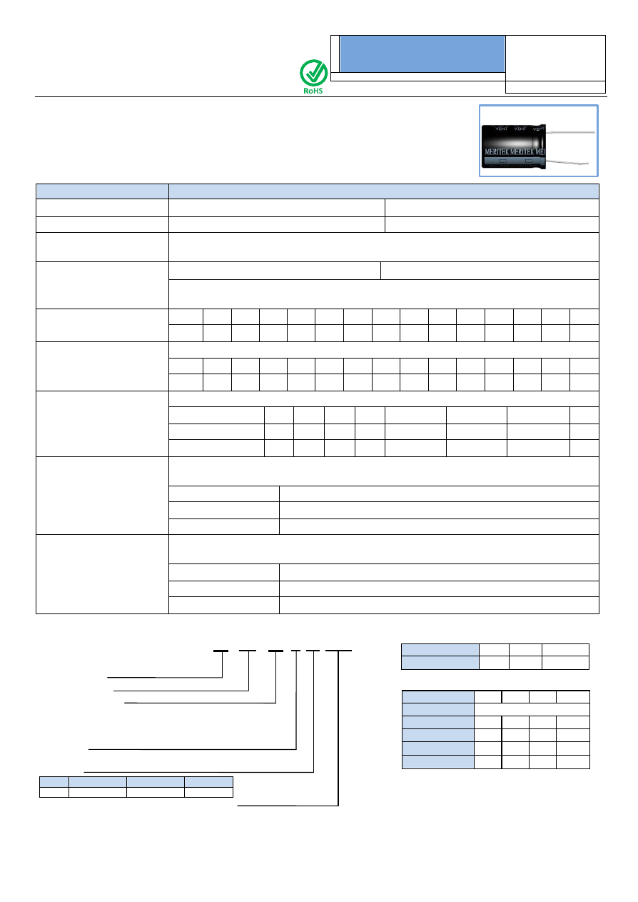
MERITEK
Aluminum Electrolytic Capacitors
Temperature(
C)
65
75
85
Multiplier
1.25 1.14
1.00
Frequency(Hz)
60
120
1K
10k
W.V.
Multiplier
6.3~25V
0.85 1.00 1.10 1.20
35~100V
0.80 1.00 1.15 1.25
160~250V
0.75 1.00 1.25 1.40
350~450V
0.70 1.00 1.30 1.50
F
EATURES
This series has high value of CV for general purposes
S
PECIFICATIONS
Item
Characteristic
Operating Temp Range
- 40 ~ +85
C
- 25 ~ +85
C
Rated Working Voltage
6.3 ~ 100VDC
160 ~ 450VDC
Capacitance Tolerance
(120Hz 20
C)
20%(M)
Leakage Current
(20
C)
6.3 ~ 100 VDC
I
0.01CV or 4 (
A)
160 ~ 450 VDC
I
0.03CV + 40 (
A) max
*
Whichever is greater after 3 minutes
I : Leakage Current (
A)
C : Rated Capacitance(
F)
V : Working Voltage (V)
Surge Voltage
(20
C)
W.V.
6.3
10
16
25
35
50
63
100
160
200
250
350
400
450
S.V.
8
13
20
32
44
63
79
125
200
250
300
400
450
500
Dissipation Factor ( tan
)
(120Hz 20
C)
add 0.02 per 1000uF for more than 1000uF
W.V.
6.3
10
16
25
35
50
63
100
160
200
250
350
400
450
tan
0.22 0.19 0.16 0.14 0.12 0.10 0.10 0.08 0.15 0.15 0.15 0.20 0.20 0.20
Low Temperature Stability
Impedance ratio at 120Hz
Rated Voltage (V)
6.3
10
16
25
35~100
160~250
350~400
450
-25
C / +20
C
4
3
2
2
2
3
6
15
-40
C / +20
C
8
6
4
3
3
6
6
-
Load Life
After 2000 hours application of W.V. and +85
C ripple current value
, the capacitor shall meet
the following limits. ( DC + ripple peak voltage
rated working voltage )
Capacitance Change
20% of initial value
Dissipation Factor
150% of initial specified value
Leakage Current
initial specified value
Shelf Life
At +85
C no voltage application after 1000 hours the capacitor shall meet the following limits.
( with voltage treatment )
Capacitance Change
20% of initial
Dissipation Factor
200% of initial specified value
Leakage Current
200% of initial specified value
P
ART
N
UMBER
S
YSTEM
R
IPPLE
C
URRENT
C
OEFFICIENTS
RB 50V 331 M TA 10x20
Meritek Series
Rated Voltage
Rated Capacitance
Express in micro farad(uF), First two digits are
significant figures, Third digit denotes number of
zeros.
‘R’ denotes decimal point for values less
than 10uF
Tolerance
M -
20%
Package
Code
TA
TR
Blank
Tape & Ammo
Tape & Reel
Case size
–
(D) Diameter x (L) Length in mm (Optional)