Thermal motor protector
Temperature limiter
Thermal cut-out
Applications
- Motors
- Transformers
- Coils
- Electronics, sensors
Benefits
- Small dimensions
- Shock and vibration tested
- Leadframe version
- Various kinds of insulations
13
20
23
Thermal motor protector
Temperature limiter
Thermal cut-out
Applications
- Motors
- Transformers
- Coils
- Electronics, sensors
Benefits
- Small dimensions
- Shock and vibration tested
- Leadframe version
- Various kinds of insulations
13
20
23
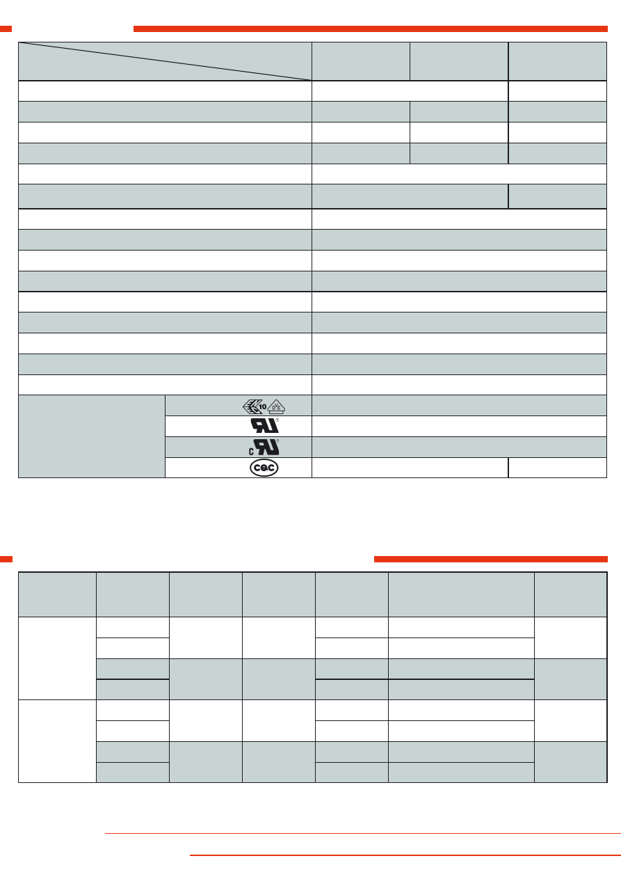
Technical data
Standard wire
( length 100 ± 10 mm, stripped 6 ± 1 mm )
control type
ratings
F13A
F23A / E
F20B / G
version
normally closed
normally open
rated current at 250 V 50/60 Hz ( power factor 0.95 / 0.6 )
3.0 A / 2.5 A
3.0 A / 3.0 A
2.0 A / 1.6 A
switching cycles under rated current
10,000
10,000
7,000
max. current under failure condition at 250 V 50/60 Hz ( power factor 0.95 )
4.0 A
6.0 A
4.0 A
switching cycles under max. current
3,000
temperature rating T
a
( steps in 5 K )
70°C ... 190°C /
... 160°C CQC
70°C ... 185°C
tolerances
standard: ± 5 K
feature of automatic action
2.C, 1.C
contact resistance ( incl. wire of 100 mm )
< 50 mΩ
hysteresis
30 K ± 15 K
2)
dielectric strength ( standard insulation )
2 kV
shock / vibration testing ( similar to EN 50155 )
400 m/s
2
sine half wave / 100 m/s
2
5 Hz ... 2,000 Hz sine
resistances to impregnation
tight against ordinary resins and lacquers
degrees of protection provided by enclosures ( EN 60529 )
IP00
suitable for use in protection category
I, II
approvals
VDE / ENEC
EN 60730-1 / -2-9
UL
UL 2111 / UL 873
1)
cUL
C22.2 No. 77 / C22.2 No. 24
1)
CQC
GB14536.1-2008 / GB14536.10-2008
3)
-
lead
code
temperature
max.
operating
voltage
max.
approx.
diameter
insulation
approx. cross section
diameter
1)
UL
style
stranded
white
L300
150 °C
300 V
1.50 mm
AWG24 / 0.25 mm
2
3398
L310
1.82 mm
AWG20 / 0.50 mm
2
L360
200 °C
600 V
1.20 mm
AWG24 / 0.25 mm
2
10086
L370
1.60 mm
AWG20 / 0.50 mm
2
solid
yellow
L400
150 °C
300 V
1.35 mm
AWG24 / 0.50 mm
3398
L410
1.66 mm
AWG20 / 0.80 mm
L430
200 °C
300 V
1.16 mm
AWG24 / 0.50 mm
1332
L440
1.54 mm
AWG20 / 0.80 mm
1)
AWG24 is recommended
1)
on request
2)
at the T
a
(upper and lower) limits the hysteresis could deviate
3)
different power rating
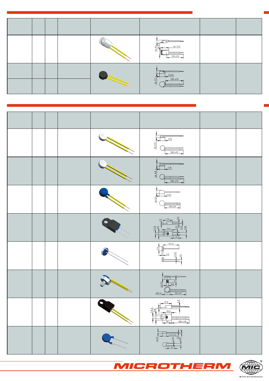
Specific variations
Standard insulation
control
type
nc
normally
closed
no
normally
open
code
illustration
drawing
dimensions ( mm )
technical
specification
approvals
F13
A
not insulated
potted
VDE, UL
cUL
F20
F23
A
B
not insulated
potted
VDE, UL,
cUL
F13
F20
F23
A
A
B
U112
different dimensions for F20, F23
coated
T
a
max. 160 °C
VDE, UL
cUL
F20
F23
A
B
A150 U280
housing of PPS
leadframe leads
grid dimension 5.08
potted
VDE, UL,
cUL
F13
F20
F23
A
A
B
A800
different dimensions for F20, F23
not insulated
potted
VDE, UL
cUL
F20
F23
E
G
G700
alluminium housing
thread M4x6
potted
T
a
max. 150 °C
VDE, UL,
cUL
F13
A
U282
housing of PPS
potted
VDE, UL
cUL
F13
F20
F23
A
A
B
A150 U112
different dimensions for F20, F23
leadframe leads
grid dimension 5.08
coated
T
a
max. 160 °C
VDE, UL,
cUL
control
type
nc
normally
closed
no
normally
open
code
illustration
drawing
dimensions ( mm )
technical
specification
approvals
F13
F20
F23
A
A
B
U254
different dimensions for F20, F23
shrink cap
potted
VDE, UL,
cUL
F13
A
U198
different dimensions for F20, F23
cap of PPS
potted
VDE, UL,
cUL
F20
F23
A
B
U185
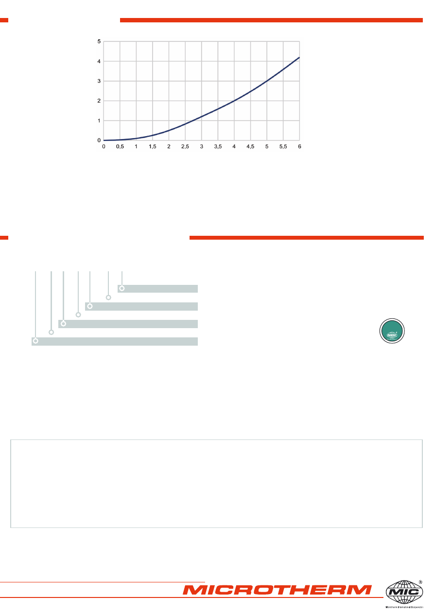
Heating by current
Fon: +49 (0)7231 787-0
Fax : +49 (0)7231 787-155
E-Mail: info@microtherm.de
Internet: www.microtherm.de
Microtherm GmbH
Täschenwaldstraße 3
Postfach 1208
D-75112 Pforzheim
The characteristic curve in the diagram is measured with a thermal control without any insulation in an oil bath.
Attention:
The heating depends on the thermal conduction of the control to the equipment or part which should be
protected.
Ordering example
Marking
shrink cap insulation
length 100 mm
lead wire white, AWG24
tolerance
temperatue
normally closed
type
F13A
type (F13 nc)
12005
response temperature (120°C), tolerance (± 5K)
025D
date of manufacture (February 2015), country (D=Germany)
F13 A 120 05 L300 100 U254
Representation office:
Deviations from standard controls on request.
010.2015 HB Technical subject to change without notice
RoHS
compliant
product
current [A]
self-heating [K]
Ordering and marking example